Orignial manual | EN - CB6467 - download
104
Orignial manual | EN CB6467 Computerboard 19.08.2020 | Version: 1.1
-
Upload
khangminh22 -
Category
Documents
-
view
1 -
download
0
Transcript of Orignial manual | EN - CB6467 - download

Orignial manual | EN
CB6467Computerboard
19.08.2020 | Version: 1.1


Table of content
CB6467 3Version: 1.1
Table of content1 Documentation issue status..................................................................................................................... 5
2 Notes on the documentation .................................................................................................................... 6
3 Safety instructions .................................................................................................................................... 7
4 Overview..................................................................................................................................................... 94.1 Properties .......................................................................................................................................... 94.2 List of features ................................................................................................................................. 104.3 Specifications and documents......................................................................................................... 11
5 Detailed description ................................................................................................................................ 125.1 Power supply ................................................................................................................................... 125.2 CPU ................................................................................................................................................. 125.3 Memory............................................................................................................................................ 125.4 M.2 Key M........................................................................................................................................ 125.5 M.2 Key B ........................................................................................................................................ 13
6 External connections .............................................................................................................................. 146.1 Note on the use of cables................................................................................................................ 146.2 Connector Map ................................................................................................................................ 146.3 List of interfaces .............................................................................................................................. 156.4 Front panel: Power supply (X101) ................................................................................................... 166.5 Front panel: LAN 1 – 4 (X102 - X105) ............................................................................................. 176.6 Front panel: USB 3.0 A - D (X106 - X109) ...................................................................................... 186.7 Front panel: DisplayPorts (X110, X111) .......................................................................................... 19
7 Internal connections................................................................................................................................ 207.1 Internal: Memory.............................................................................................................................. 207.2 Internal: M.2..................................................................................................................................... 257.3 Internal: BeaCon140 (with Q370) .................................................................................................... 307.4 Internal: FAN ................................................................................................................................... 337.5 Internal: Battery ............................................................................................................................... 34
8 LEDs.......................................................................................................................................................... 358.1 LED: Power controller...................................................................................................................... 358.2 LED: SATA ...................................................................................................................................... 368.3 LED: TwinCAT................................................................................................................................. 378.4 LED: UPS-OCT................................................................................................................................ 38
9 BIOS.......................................................................................................................................................... 399.1 Using the setup................................................................................................................................ 399.2 Main................................................................................................................................................. 409.3 Advanced Menu............................................................................................................................... 41
9.3.1 RC ACPI Settings ............................................................................................................ 429.3.2 CPU Configuration........................................................................................................... 439.3.3 Trusted Computing .......................................................................................................... 449.3.4 ACPI Settings Enabled .................................................................................................... 449.3.5 ACPI Settings Disabled ................................................................................................... 459.3.6 Hardware Monitor ............................................................................................................ 46

Table of content
CB64674 Version: 1.1
9.3.7 AMI Graphic Output Protocol Policy ................................................................................ 479.3.8 PCI Subsystem Settings .................................................................................................. 489.3.9 USB Configuration ........................................................................................................... 509.3.10 NVMe Configuration ........................................................................................................ 519.3.11 Power Controller Options................................................................................................. 529.3.12 BAseCon* Configuration.................................................................................................. 539.3.13 SATA And RST Configuration ......................................................................................... 549.3.14 AMT Configuration........................................................................................................... 579.3.15 TLs Auth Configuration .................................................................................................... 619.3.16 Network Stack Configuration ........................................................................................... 639.3.17 Network Stack Configuration enabled ............................................................................. 639.3.18 Intel Rapid Storage Technology ...................................................................................... 649.3.19 Driver Health.................................................................................................................... 64
9.4 Chipset ............................................................................................................................................ 659.4.1 System Agent (SA) Configuration.................................................................................... 669.4.2 PCH-IO Configuration...................................................................................................... 68
9.5 Security............................................................................................................................................ 749.5.1 Secure Boot ..................................................................................................................... 75
9.6 Boot ................................................................................................................................................. 909.6.1 Advanced Fixed Boot Order Parameters......................................................................... 91
9.7 Save & Exit ...................................................................................................................................... 92
10 Mechanical drawings .............................................................................................................................. 9310.1 PCB: Holes ...................................................................................................................................... 9310.2 PCB: Pin 1 distances....................................................................................................................... 9410.3 PCB: Dimensions ............................................................................................................................ 95
11 Technical data.......................................................................................................................................... 9611.1 Electrical data .................................................................................................................................. 9611.2 Environmental conditions ................................................................................................................ 9611.3 Technical specifications................................................................................................................... 97
12 Support and Service................................................................................................................................ 9812.1 Beckhoff Support ............................................................................................................................. 9812.2 Beckhoff Service.............................................................................................................................. 9812.3 Beckhoff headquarters .................................................................................................................... 98
13 Appendix I: Post Codes .......................................................................................................................... 99
14 Appendix II: Resources......................................................................................................................... 10014.1 Interrupt ......................................................................................................................................... 10014.2 PCI devices ................................................................................................................................... 10114.3 SMB devices.................................................................................................................................. 102

Documentation issue status
CB6467 5Version: 1.1
1 Documentation issue status Version Modifications 0.1 Preliminary version, mechanical only 0.2 Preliminary version with Bios entries 0.3 Preliminary version with updated BIOS version 0.05 0.4 Preliminary version G2 with Family BIOS 0.07 0.5 Preliminary version G2 with BIOS 0.11 and adapted block diagram 1.0 Initial release, incl. change from BAseCon140 to BeaCon140 1.1 BIOS update to version 0.13 and new front page

Notes on the documentation
CB64676 Version: 1.1
2 Notes on the documentationThis description is only intended for the use of trained specialists in control and automation engineering whoare familiar with the applicable national standards.It is essential that the documentation and the following notes and explanations are followed when installingand commissioning the components. It is the duty of the technical personnel to use the documentation published at the respective time of eachinstallation and commissioning.
The responsible staff must ensure that the application or use of the products described satisfy all therequirements for safety, including all the relevant laws, regulations, guidelines and standards.
Disclaimer
The documentation has been prepared with care. The products described are, however, constantly underdevelopment.We reserve the right to revise and change the documentation at any time and without prior announcement.No claims for the modification of products that have already been supplied may be made on the basis of thedata, diagrams and descriptions in this documentation.
Trademarks
Beckhoff®, TwinCAT®, EtherCAT®, EtherCAT G®, EtherCAT G10®, EtherCAT P®, Safety over EtherCAT®,TwinSAFE®, XFC®, und XTS® and XPlanar®, are registered trademarks of and licensed by BeckhoffAutomation GmbH.Other designations used in this publication may be trademarks whose use by third parties for their ownpurposes could violate the rights of the owners.
Patent Pending
The EtherCAT Technology is covered, including but not limited to the following patent applications andpatents:EP1590927, EP1789857, EP1456722, EP2137893, DE102015105702with corresponding applications or registrations in various other countries.
EtherCAT® is registered trademark and patented technology, licensed by Beckhoff Automation GmbH,Germany
Copyright
© Beckhoff Automation GmbH & Co. KG, Germany.The reproduction, distribution and utilization of this document as well as the communication of its contents toothers without express authorization are prohibited.Offenders will be held liable for the payment of damages. All rights reserved in the event of the grant of apatent, utility model or design.

Safety instructions
CB6467 7Version: 1.1
3 Safety instructionsSafety regulations
Please note the following safety instructions and explanations!Product-specific safety instructions can be found on following pages or in the areas mounting, wiring,commissioning etc.
Exclusion of liability
All the components are supplied in particular hardware and software configurations appropriate for theapplication. Modifications to hardware or software configurations other than those described in thedocumentation are not permitted, and nullify the liability of Beckhoff Automation GmbH & Co. KG.
Personnel qualification
This description is only intended for trained specialists in control, automation and drive technology who arefamiliar with the applicable national standards.
Description of symbols
In this documentation the following symbols are used with an accompanying safety instruction or note. Thesafety instructions must be read carefully and followed without fail!
DANGERSerious risk of injury!Failure to follow the safety instructions associated with this symbol directly endangers the life and health ofpersons!
WARNINGRisk of injury!Failure to follow the safety instructions associated with this symbol endangers the life and health of per-sons!
CAUTIONPersonal injuries!Failure to follow the safety instructions associated with this symbol can lead to injuries to persons!
NOTEDamage to the environment or devicesFailure to follow the instructions associated with this symbol can lead to damage to the environment orequipment.
Tip or pointerThis symbol indicates information that contributes to better understanding.
UL noteThis symbol indicates important information regarding UL certification.
Intended use
The CB6467 Computer Board was designed and developed exclusively for configuration in automationprocesses. To that end the board is equipped with external interfaces in order to acquire or output digital oranalog signals or forward them to higher-level components.

Safety instructions
CB64678 Version: 1.1
Any other use is regarded as inappropriate.
The specified limits for electrical and technical data must be adhered to.

Overview
CB6467 9Version: 1.1
4 Overview
4.1 PropertiesThe CB6467 has been designed as a high-performance compact board based on Intel® Coffeelakeprocessors. State-of-the-art DDR4 technology enables a memory extension up to 64 GB using SO-DIMM260.
Two DisplayPort connectors, 4 Gigabit-LAN connectors and 4 USB 3.0 ports are available as standardinterfaces on the front panel. The two DisplayPorts++ enable the connection of an HDMI adapter for anHDMI signal. The connection of an HDMI display with adapter is possible.
There are two versions available, version 1 with a Q370 chipset and version 2 with an H310 chipset as alow-cost version.
Internally, the CB6467 has an M.2 (B) socket (2280), an M.2 (M) socket (2280) and a BeaCon140 plug.Depending on the chipset in use, various signals are fed out via the internal connectors. These signals arelisted in the respective chapter.
Power is supplied via a 4-pin isolated connector on the front panel.
Fig. 1: CB6467 – block diagram

Overview
CB646710 Version: 1.1
4.2 List of features CB6467 120 x 120 Board CPU versions Intel® Celeron® G4900 3.1 GHz, 2 cores, 2 MB LLC
Intel® Pentium® G5400 3.7 GHz, 2 cores, 4 MB LLC Intel® Core™ i3-9100E 3.1 GHz, 4 cores, 6 MB LLC Intel® Core™ i5-9500E 3.0 GHz, 6 cores, 9 MB LLC Intel® Core™ i7-9700E 2.6 GHz, 8 cores, 12 MB LLC
Memory 2x SO-DIMM260 1.2 V DDR4-2666 Maximum memory extension 64 GB
I/O on front panel 2x DisplayPort++(connection of an HDMI adapter for an HDMI signal is possible.) 4x GB LAN 4x USB3.0
Internal I/O 1x M.2 (M) socket, signals depend on chipset (see chapter M.2 Internal: M.2 [} 25] 1x M.2 (B) socket, signals depend on chipset (see chapter M.2 Internal: M.2 [} 25] 1x BeaCon140 (for signals, see chapter BeaCon140 Internal: BeaCon140 (with Q370) [} 30]
Graphic resolution DisplayPort: 4096x2304@60Hz HDMI1.4: 2560x1600@60 Hz; 4096x2160@24 Hz DVI: 1920x1200@60 Hz
RTC Exchangeable, horizontal on-board battery Optional: horizontal battery on expansion card
BIOS AMI® Aptio V Power supply 24 V (+20 % / -15 %) Format 120 x 120 mm
Availability of the processorsThe list of features lists all the processors that can be ordered. Their actual availability depends onthe manufacturer.
Real-time applicationsThe Ethernet port connected via PCIe is usually suitable for cycle times <= 1 ms and for distributedclock applications with EtherCAT.The Ethernet port integrated in the chipset is usually suitable for real-time Ethernet applications withcycle times > 1 ms (without distributed clocks).

Overview
CB6467 11Version: 1.1
4.3 Specifications and documentsThe following documents, specifications or webpages were used for the preparation of this manual or asfurther technical documentation respectively.
• PCI specification• Version 2.3 or 3.0• www.pcisig.com• PCI Express® Base Specification• Version 5.0• www.pcisig.com• ACPI specification• Version 5.0• www.acpi.info• ATA/ATAPI specification• Version 7 Rev. 1• www.t13.org• USB specifications• www.usb.org• SM-Bus specification• Version 2.0• www.smbus.org• Intel® chip descriptions• Intel® Core™ processor product family data sheet• www.intel.com• Intel® chip description• I219 data sheet• i210 datasheet• www.intel.com• SMSC® chip description• SCH3114 datasheet (NDA required)• www.smsc.com• American Megatrends®• Aptio™ Text Setup Environment (TSE) User Manual• www.ami.com• American Megatrends®• Aptio™ 5.x Status Codes• www.ami.com

Detailed description
CB646712 Version: 1.1
5 Detailed description
5.1 Power supplyThe board is supplied with an isolated input voltage with a nominal rating of 24 V. In normal operation theDC/DC power rail is supplied with this voltage. A UPS can also be implemented via an OCT signal (OCT =One Cable Technology).
UPS-OCTThe UPS OCT can only be implemented with the Beckhoff CU81XX-xxxx UPS.
5.2 CPUIntel® Core processors of the 8th and 9th generation (Coffee Lake and Coffee Lake Refresh) are used. Theprocessors of both generations are characterized by very low power consumption and offer contemporaryperformance with clock rates of currently up to 4.4 GHz (max. turbo clock frequency).
5.3 MemorySO-DIMM260 memory modules (DDR4-2666), as commonly used in notebooks, are used on the CB6467board. For technical and mechanical reasons, it is possible that certain memory modules cannot be used.Information regarding the recommended memory modules can be obtained from your distributor.
Depending on the product version, a memory extension up to 64 GB is possible with the currently availableSO-DIMM260 modules. Care should be taken to ensure that the same memory modules are inserted in bothmemory sockets.
5.4 M.2 Key MExpansion cards that fulfill the M.2 specification are characterized by an extremely small format and –depending on the card type – flexible dimensions.
M.2 cards can easily and simply be inserted by plugging them into the slot and fixing them with a screw.
This M.2 socket (2280) of the CB6467 supports Key M. Different signals are supported, depending on thechipset used. The table in chapter M.2 lists all the interfaces supported, depending on the chipset in use.
Driver compatibilityFor optimum driver compatibility, we recommend the use of a Microsoft® Windows 10 operatingsystem.

Detailed description
CB6467 13Version: 1.1
5.5 M.2 Key BExpansion cards that fulfill the M.2 specification are characterized by an extremely small format and –depending on the card type – flexible dimensions.
M.2 cards can easily and simply be inserted by plugging them into the slot and fixing them with a screw.
This M.2 socket (2280) of the CB6467 supports Key B. Different signals are supported, depending on thechipset used. The table in chapter M.2 lists all the interfaces supported, depending on the chipset in use.
Driver compatibilityFor optimum driver compatibility, we recommend the use of a Microsoft® Windows 10 operatingsystem.

External connections
CB646714 Version: 1.1
6 External connections
6.1 Note on the use of cablesRequirement for the cabling!The cables used must meet certain requirements for most interfaces. For example, twisted andshielded cables are necessary for a reliable USB 2.0 connection. Limitations in the maximum cablelength are also no rarity. All of these interface-specific requirements are to be taken from the re-spective specifications and observed accordingly.
6.2 Connector MapThe plug connections on the component side of the CB6467 board are summarized in the illustration below.The function of the respective connector can be taken from the table below the illustration, as can the pageof the manual on which further information about this connection can be read.
Fig. 2: CB6467 connector map

External connections
CB6467 15Version: 1.1
6.3 List of interfaces Number Function (designation) Page P1500 Vin (X101) Front panel: Power supply (X101) [} 16] P1100 LAN 1 (X102) Front panel: LAN 1 – 4 (X102 - X105) [} 17] P1100 LAN 2 (X103) Front panel: LAN 1 – 4 (X102 - X105) [} 17] P1101 LAN 3 (X104) Front panel: LAN 1 – 4 (X102 - X105) [} 17] P1101 LAN 4 (X105) Front panel: LAN 1 – 4 (X102 - X105) [} 17] P1102 USB3.0 (X106) Front panel: USB 3.0 A - D (X106 - X109) [} 18] P1102 USB3.0 (X107) Front panel: USB 3.0 A - D (X106 - X109) [} 18] P1102 USB3.0 (X108) Front panel: USB 3.0 A - D (X106 - X109) [} 18] P1102 USB3.0 (X109) Front panel: USB 3.0 A - D (X106 - X109) [} 18] P1103 DisplayPorts (X110, X111) Front panel: DisplayPorts (X110, X111) [} 19] P1200* M.2 (Key M) 2280 Internal: M.2 [} 25] P1201* M.2 (Key B) 2280 Internal: M.2 [} 25] P1203* BeaCon140 Internal: BeaCon140 (with Q370) [} 30] P500/501 FAN Internal: FAN [} 33] BT1200* Battery Internal: Battery [} 34] U600 SODIMM Internal: Memory [} 20] U601 SODIMM Internal: Memory [} 20]
*not shown (see underside of the board)
The numbers in brackets correspond to the labeling of the external interfaces on the housing on thefront panel of the Industrial PC.

External connections
CB646716 Version: 1.1
6.4 Front panel: Power supply (X101)The connection to the power supply is implemented as a 2x2-pin housing plug (Phoenix ContactP20THR-1818504). The main supply voltage (24 V) for the module is on PIN 3. This can also beimplemented as UPS-OCT (One Cable Technology), i.e. the signal for the UPS is also transmitted to theboard via this cable.
Fig. 3: CB6467 power supply (X101)
90° plugAs the plug is a 90° plug, the plug symbol in the illustration is oriented to what you see when youlook at the board from the side (instead of from above).
Pin assignment of the power plug: Description Signal Pin Signal Description PC_On: Input for starting and shutting down the PC. Low (0 V or open contact): PC starts. High (>3 V): PC shuts down.
PC_On 1 3 Vin 24 V supply voltage UPS-OCT is supported.
Power status: Output of the Power Status. Thevoltage corresponds to thepositive supply voltage and can be loaded up to 500 mA. Low (0 V): PC is off. High (Vin): PC is on.
PC_ACTIVE 2 4 GND Ground

External connections
CB6467 17Version: 1.1
6.5 Front panel: LAN 1 – 4 (X102 - X105)The board has four Gigabit-LAN connections, which are implemented with 2 standard connectors, each withtwo connections. Network components compatible with 10BaseT, 100BaseT and 1000BaseT can beconnected to all of them. The required speed is selected automatically. Auto-Cross and Auto-Negotiate areavailable as well as PXE, RPL and WOL functionality. Intel® i219 (PHY) is the controller for LAN1, whileIntel® i210 (MAC/PHY) is used as the controller for LAN 2 to 4.
Fig. 4: CB6467 LAN (X102-X105)
Real-time applicationsThe Ethernet port connected via PCIe is usually suitable for cycle times <= 1 ms and for distributedclock applications with EtherCAT.The Ethernet port integrated in the chipset is usually suitable for real-time Ethernet applications withcycle times > 1 ms (without distributed clocks).
90° plugAs the plug is a 90° plug, the plug symbol in the illustration is oriented to what you see when youlook at the board from the side (instead of from above).
The LEDs of the LAN interfaces indicate the activity and speed of the data transmission:
Mbit/s Flashing during data ransmission
Steadily lit
1000 Green Green 100 Green Orange 10 Green None

External connections
CB646718 Version: 1.1
6.6 Front panel: USB 3.0 A - D (X106 - X109)The CB6467 provides four USB3.0 ports in a combination connector.
The USB channels support the USB specification 3.0. All necessary settings for USB can be made by theBIOS. Note that the "USB mouse and keyboard" function in the BIOS setup is only required if the operatingsystem does not offer USB support. This function should not be selected for settings in the setup and forbooting Windows with a USB mouse and keyboard connected, because this would lead to considerableperformance limitations.
The individual USB interfaces can supply a current of up to 900 mA and are electronically protected.
Fig. 5: CB6467 USB (X106-X109)
Switch-off of the USB ports by overcurrent protectionUSB ports A and B and USB ports C and D are each protected by a common overcurrent detection.In the event of overcurrent occurring on one of the ports, therefore, both commonly protected USBports will be switched off.
90° plugAs the plug is a 90° plug, the plug symbol in the illustration is oriented to what you see when youlook at the board from the side (instead of from above).

External connections
CB6467 19Version: 1.1
6.7 Front panel: DisplayPorts (X110, X111)For devices with a DisplayPort connection a corresponding standard connector (Foxconn 3VD11203-DPA1-4H) with two DisplayPort connections is available.
The interface additionally provides HDMI/DVI signals that can be used with aid of an adapter. Please consultyour distributor with regard to a suitable adapter.
Fig. 6: CB6467 Display Port (X110-X111)
90° plugAs the plug is a 90° plug, the plug symbol in the illustration is oriented to what you see when youlook at the board from the side (instead of from above).
Pin assignment of DisplayPort plug: Description Signal Pin Signal Description Display Port Lane 0 + L0 1 2 GND Ground Display Port Lane 0 - L#0 3 4 L1 Display Port Lane 1 + Ground GND 5 6 L#1 Line 1 - Display Port Lane 2 + L2 7 8 GND Ground Display Port Lane 2 - L#2 9 10 L3 Display Port Lane 3 + Ground GND 11 12 L#3 Display Port Lane 3 - DP / HDMI HDMI# 13 14 GND Ground Auxiliary plus AUX 15 16 GND Ground Auxiliary minus AUX# 17 18 HPD Hot Plug Detect Ground GND 19 20 3.3 V Supply voltage 3.3 V
Switching to HDMIDisplayPort signals are led out via the interface by default. With the use of a level shifter cable theboard switches the DisplayPort specification 1.1 automatically to HDMI signals.

Internal connections
CB646720 Version: 1.1
7 Internal connections
7.1 Internal: MemoryOn the CB6467 board there are two SO-DIMM260 memory sockets for DDR4-2666 RAM. For technical andmechanical reasons, it is possible that certain memory modules cannot be used. Information regarding therecommended memory modules can be obtained from your distributor.
With two sockets, a memory extension up to 64 GB is possible with currently available modules. Identicalmemory modules should be inserted in the two memory sockets.
All timing parameters for the different makes and versions are automatically set by the BIOS.
Fig. 7: CB6467 SODIMM

Internal connections
CB6467 21Version: 1.1
Memory socket pin assignment: Description Signal Pin1 Signal Description Ground GND 1 2 GND Ground Data line 5 DQ5 3 4 DQ4 Data line 4 Ground GND 5 6 GND Ground Data line 1 DQ1 7 8 DQ0 Data line 0 Ground GND 9 10 GND Ground Data strobe 0 - DQS0_c 11 12 NC Reserved Data strobe 0 + DQS0_t 13 14 GND Ground Ground GND 15 16 DQ6 Data line 6 Data line 7 DQ7 17 18 GND Ground Ground GND 19 20 DQ2 Data line 2 Data line 3 DQ3 21 22 GND Ground Ground GND 23 24 DQ12 Data line 12 Data line 13 DQ13 25 26 GND Ground Ground GND 27 28 DQ8 Data line 8 Data line 9 DQ9 29 30 GND Ground Ground GND 31 32 DQS1_c Data strobe 1 - Reserved NC 33 34 DQS1_t Data strobe 1 + Ground GND 35 36 GND Ground Data line 15 DQ15 37 38 DQ14 Data line 14 Ground GND 39 40 GND Ground Data line 10 DQ10 41 42 DQ11 Data line 11 Ground GND 43 44 GND Ground Data line 21 DQ21 45 46 DQ20 Data line 20 Ground GND 47 48 GND Ground Data line 17 DQ17 49 50 DQ16 Data line 16 Ground GND 51 52 GND Ground Data strobe 2 - DQS2_c 53 54 NC Reserved Data strobe 2 + DQS2_t 55 56 GND Ground Ground GND 57 58 DQ22 Data line 22 Data line 23 DQ23 59 60 GND Ground Ground GND 61 62 DQ18 Data line 18 Data line 19 DQ19 63 64 GND Ground Ground GND 65 66 DQ28 Data line 28 Data line 29 DQ29 67 68 GND Ground Ground GND 69 70 DQ24 Data line 24 Data line 25 DQ25 71 72 GND Ground Ground GND 73 74 DQS3_c Data strobe 3 - Reserved NC 75 76 DQS3_t Data strobe 3 + Ground GND 77 78 GND Ground Data line 30 DQ30 79 80 DQ31 Data line 31 Ground GND 81 82 GND Ground Data line 26 DQ26 83 84 DQ27 Data line 27 Ground GND 85 86 GND Ground Reserved NC 87 88 NC Reserved Ground GND 89 90 GND Ground Reserved NC 91 92 NC Reserved Ground GND 93 94 GND Ground
Internal connections
CB646722 Version: 1.1
Memory socket pin assignment: Description Signal Pin1 Signal Description Data strobe 8 - DQS8_c 95 96 NC Reserved Data strobe 8 + DQS8_t 97 98 GND Ground Ground GND 99 100 NC Reserved Reserved NC 101 102 GND Ground Ground GND 103 104 N C Reserved Reserved NC 105 106 GND Ground Ground GND 107 108 RESET_n Reset Clock Enable 0 CKE0 109 110 CKE1 Clock Enable 1 Supply voltage 1.2 V
VCC 111 112 VCC Supply voltage 1.2 V
Bank Group Input 1
BG1 113 114 ACT_n Activation Command Input
Bank Group Input 0 BG0 115 116 ALERT_n Alert Supply voltage 1.2 V
VCC 117 118 VCC Supply voltage 1.2 V
Address line 12 A12 119 120 A11 Address line 11 Address line 9 A9 121 122 A7 Address line 7 Supply voltage 1.2 V
VCC 123 124 VCC Supply voltage 1.2 V
Address line 8 A8 125 126 A5 Address line 5 Address line 6 A6 127 128 A4 Address line 4 Supply voltage 1.2 V
VCC 129 130 VCC Supply voltage 1.2 V
Address line 3 A3 131 132 A2 Address line 2 Address line 1 A1 133 134 EVENT_n Event Supply voltage 1.2 V
VCC 135 136 VCC Supply voltage 1.2 V
Clock Signal 0 + CK0_t 137 138 CK1_t Clock 1+ Clock Signal 0 - CK0_c 139 140 CK1_c Clock 1 - Supply voltage 1.2 V
VCC 141 142 VCC Supply voltage 1.2 V
Even parity check Parity 143 144 A0 Address line 0 SDRAM Bank 2 BA1 145 146 A10/AP Address line
10/Autoprecharge Supply voltage 1.2 V
VCC 147 148 VCC Supply voltage 1.2 V
Chip Select 0 CS0_n 149 150 BA0 Bank Address 0 Address line 14/Write Enable
A14/WE_n 151 152 A16/RAS_n Address line 16/ Row Address Strobe
Supply voltage 1.2 V
VCC 153 154 VCC Supply voltage 1.2 V
On Die Termination 0 ODT0 155 156 A15/CAS_n Address line 15/ Column Address Strobe
Chip Select 1 CS1_n 157 158 A13 Address line 13 1.2 V VCC 159 160 VCC Supply
voltage 1.2 V On Die Termination 1 ODT1 161 162 NC Reserved Supply voltage 1.2 V
VCC 163 164 VREFCA Reference voltage
Reserved NC 165 166 SA2 SPD Address 2

Internal connections
CB6467 23Version: 1.1
Memory socket pin assignment: Description Signal Pin1 Signal Description Ground GND 167 168 GND Ground Data line 37 DQ37 169 170 DQ36 Data line 36 Ground GND 171 172 GND Ground Data line 33 DQ33 173 174 DQ32 Data line 32 Ground GND 175 176 GND Ground Data strobe 4 - DQS4_c 177 178 NC Reserved Data strobe 4 + DQS4_t 179 180 GND Ground Ground GND 181 182 DQ39 Data line 39 Data line 38 DQ38 183 184 GND Ground Ground GND 185 186 DQ35 Data line 35 Data line 34 DQ34 187 188 GND Ground Ground GND 189 190 DQ45 Data line 45 Data line 44 DQ44 191 192 GND Ground Ground GND 193 194 DQ41 Data line 41 Data line 40 DQ40 195 196 GND Ground Ground GND 197 198 DQS5_c Data strobe 5 - Reserved NC 199 200 DQS5_t Data strobe 5 + Ground GND 201 202 GND Ground Data line 46 DQ46 203 204 DQ47 Data line 47 Ground GND 205 206 GND Ground Data line 42 DQ42 207 208 DQ43 Data line 43 Ground GND 209 210 GND Ground Data line 52 DQ52 211 212 DQ53 Data line 53 Ground GND 213 214 GND Ground Data line 49 DQ49 215 216 DQ48 Data line 48 Ground GND 217 218 GND Ground Data strobe 6 - DQS6_c 219 220 NC Reserved Data strobe 6 + DQS6_t 221 222 GND Ground Ground GND 223 224 DQ54 Data line 54 Data line 55 DQ55 225 226 GND Ground Ground GND 227 228 DQ50 Data line 50 Data line 51 DQ51 229 230 GND Ground Ground GND 231 232 DQ60 Data line 60 Data line 61 DQ61 233 234 GND Ground Ground GND 235 236 DQ57 Data line 57 Data line 56 DQ56 237 238 GND Ground Ground GND 239 240 DQS7_c Data strobe 7 - Reserved NC 241 242 DQS7_t Data strobe 7 + Ground GND 243 244 GND Ground Data line 62 DQ62 245 246 DQ63 Data line 63 Ground GND 247 248 GND Ground Data line 58 DQ58 249 250 DQ59 Data line 59 Ground GND 251 252 GND Ground SMBus Clock SCL 253 254 SDA SMBus data I²C power for SPD EEProm
VCCSPD 255 256 SA0 SPD Address 0

Internal connections
CB646724 Version: 1.1
Memory socket pin assignment: Description Signal Pin1 Signal Description DRAM Activating Power
VPP 257 258 VTT Termination voltage
DRAM Activating Power
VPP 259 260 SA1 SPD Address 1

Internal connections
CB6467 25Version: 1.1
7.2 Internal: M.2The CB6467 is equipped with two M.2 sockets, into which an M.2-2280 card (Key M, P1200) and anM.2-2280 card (Key B, P1201) can be inserted. Adapter cards with standard plug connectors are availableas accessories. Please contact your distributor for this.
Fig. 8: CB6467 M.2 cut-out

Internal connections
CB646726 Version: 1.1
Pin assignment M.2 (Key M): Description Signal Pin Signal Description Ground GND 1 2 3.3 V1 Standby
supply voltage S3.3 V
Ground GND 3 4 3.3 V2 Standby supply voltage S3.3 V
PCIe Lane Receive - PER3# 5 6 N/C (not led out) PCIe Lane Receive + PER3 7 8 N/C (not led out) Ground GND 9 10 GPIO9
DAS DDS LED1
(not led out)
PCIe Lane Transmit - PET3# 11 12 3.3 V3 Standby supply voltage S3.3 V
Pcie Lane Transmit + PET3 13 14 3.3 V4 Standby supply voltage S3.3 V
Ground GND 15 16 3.3 V5 Standby supply voltage S3.3 V
PCIe Lane Receive - PER2# 17 18 3.3 V6 Standby supply voltage S3.3 V
PCIe Lane Receive + PER2 19 20 N/C (not led out) Configuration pin Config 0 21 22 N/C (not led out) PCIe Lane Transmit - PET2# 23 24 N/C (not led out) PCIe Lane Transmit + PET2 25 26 N/C (not led out) Ground GND 27 28 N/C (not led out) PCIe Lane Receive - PER1# 29 30 N/C (not led out) PCIe Lane Receive PER1 31 32 N/C (not led out) Ground GND 33 34 N/C (not led out) PCIe Lane Transmit - PET1# 35 36 N/C (not led out) PCIe Lane Transmit + PET1 37 38 DEVSLP DeviceSleep Ground GND 39 40 N/C (not led out) PCIe Lane 1 Receive +
PER0# SATAB
41 42 N/C (not led out)
PCIe Lane 1 Receive -
PER0 SATAB#
43 44 N/C (not led out)
Ground GND 45 46 N/C (not led out) PCIe Lane 1 Transmit -
PET0# SATAA#
47 48 N/C (not led out)
PCIe Lane 1 Transmit +
PET0 SATAA
49 50 PRST# PCIe Reset active low
Ground GND 51 52 CLKREQ# PCIe Clock Enable active low
PCIe Lane 1 Reference Clock -
REFCLK# 53 54 PEWAKE# Link Reactivation active low
PCIe Lane 1 Reference Clock +
REFCLK 55 56 N/C (not led out)
Ground GND 57 58 N/C (not led out) (not led out) N/C 59 60 N/C (not led out)

Internal connections
CB6467 27Version: 1.1
Pin assignment M.2 (Key M): Description Signal Pin Signal Description (not led out) N/C 61 62 N/C (not led out) (not led out) N/C 63 64 N/C (not led out) (not led out) N/C 65 66 N/C (not led out) Reset N/C 67 68 SUSCLK System clock Configuration pin CFG1 69 70 3.3 V Standby
supply voltage S3.3 V
Ground GND 71 72 3.3 V Standby supply voltage S3.3 V
Ground GND 73 74 3.3V Standby supply voltage S3.3V
Ground GND 75

Internal connections
CB646728 Version: 1.1
Pin assignment M.2 (Key B): Description Signal Pin Signal Description Configuration pin CONFIG_3 1 2 3.3 V1 Standby
supply voltage S3.3 V
Ground GND 3 4 3.3 V2 Standby supply voltage S3.3 V
Ground GND 5 6 FCPWROFF# Full Card Power OFF active low
USB data + USB D+ 7 8 WDISABLE# (not led out) USB data - USB D- 9 10 GPIO9
DAS DDS LED1
(not led out)
Ground GND 11 12 Connector Key Connector Key 13 14
15 1617 1819 20 GPIO5 (not led out)
Configuration pin Config 0 21 22 GPIO6 (not led out) (not led out) GPIO11 23 24 GPIO7 (not led out) (not led out) DPR 25 26 GPIO10 (not led out) Ground GND 27 28 GPIO8 (not led out) USB 3.0 SuperSpeed Receive -
PER1# USB3RX# SSICRX#
29 30 UIM RST (not led out)
USB 3.0 SuperSpeed Receive
PER1 USB3RX SSICRX
31 32 UIM CLK (not led out)
Ground GND 33 34 UIM DATA (not led out) USB 3.0 SuperSpeed Transmit -
PET1#USB3TX#SSICTX#
35 36 UIM PWR (not led out)
USB 3.0 SuperSpeed Transmit +
PET1 USB3TX SSICTX
37 38 DEVSLP DeviceSleep
Ground GND 39 40 GPIO0 (not led out) PCIe Lane 1 Receive +
PER0# SATAB
41 42 GPIO1 (not led out)
PCIe Lane 1 Receive -
PER0 SATAB#
43 44 GPIO2 (not led out)
Ground GND 45 46 GPIO3 (not led out) PCIe Lane 1 Transmit -
PET0# SATAA#
47 48 GPIO4 (not led out)
PCIe Lane 1 Transmit +
PET0 SATAA
49 50 PRST# PCIe Reset active low
Ground GND 51 52 CLKREQ# PCIe Clock Enable active low
PCIe Lane 1 Reference Clock -
REFCLK# 53 54 PEWAKE# Link Reactivation active low
PCIe Lane 1 Reference Clock +
REFCLK 55 56 N/C (not led out)
Ground GND 57 58 N/C (not led out)

Internal connections
CB6467 29Version: 1.1
Pin assignment M.2 (Key B): Description Signal Pin Signal Description (not led out) ANTCTL0 59 60 COEX3 (not led out) (not led out) ANTCTL1 61 62 COEX2 (not led out) (not led out) ANTCTL2 63 64 COEX1 (not led out) (not led out) ANTCTL3 65 66 SIM DETECT (not led out) Power good RESET# 67 68 SUSCLK System clock Configuration pin CFG1 69 70 3.3 V Standby
supply voltage S3.3 V
Ground GND 71 72 3.3 V Standby supply voltage S3.3 V
Ground GND 73 74 3.3V Standby supply voltage S3.3V
Configuration pin CFG2 75

Internal connections
CB646730 Version: 1.1
7.3 Internal: BeaCon140 (with Q370)In conjunction with the Q370 chipset, the BeaCon140 connector enables the flexible extension of the I/Ofunctions of the CB6467. It provides up to 8 PCIe lanes, of which a maximum of 4 can be multiplexed withSATA 2.0 (3G) and a maximum of 4 with PCIe lines, as well as a maximum of 4 PCIe lines with a maximumof 4 USB3.0 lines (see table). DisplayPort, SSIC, SMBus and 1-Wire signals can be fed out via theBeaCon140 connector. The extension board takes care of the configuration of the IO functions. A PIC on theexpansion card contains the configuration data, which are communicated to the board upon connection andthus enable an uncomplicated and self-configuring extension of the I/O options.
Observe the current limits!In order to avoid damaging the device, it is essential to observe the following current limits:A maximum load of 2.8 A per pin must not be exceeded. On account of the different current con-sumptions of the usable processors the actual current consumption may be lower. The respectivemaximum values can be obtained from your distributor on inquiry.Irrespective of the CPU in use, a maximum total load of 100 W must not be exceeded.
Fig. 9: CB6467 BeaCon

Internal connections
CB6467 31Version: 1.1
Pin assignment of BeaCon140 connector: Description Signal Pin Signal Description P_VLoad 24 V SUSV output
VOLOAD/ P_VOLOAD1
2 1 P_VIN1/VIN1 V_IN SUSV input
P_VLoad 24 V SUSV output
VOLOAD/ P_VOLOAD2
4 3 S UPS IN2 P_VIN SUSV input
(not led out) 5 V NC1 6 5 GND Ground (not led out) 5 V NC2 8 7 GND Ground
INSULATION
S VCC S5V 14 13 S3.3 V Standby supply voltage 3.3 V
Ground GND 16 15 GND Ground PCIe Lane 1 Transmit +
PE1 TX/ SATA4 TX
18 17 SATA4 RX/ PE1 RX
PCIe Lane 1 Receive +
PCIe Lane 1 Transmit -
PE1 TX#/ SATA4 TX#
20 19 SATA4 RX #/ PE1 RX#
PCIe Lane 1 Receive -
Ground GND 22 21 GND Ground PCIe Clock Lane 1 + PECLK1 24 23 PECLK2 PCIe Clock Lane 2 + PCIe Clock Lane 1 -
PECLK1# 26 25 PECLK2# PCIe Clock Lane 2 -
Ground GND 28 27 GND Ground PCI Lane 2 Transmit +
PE2 TX/ SATA3 TX
30 29 SATA3 RX/ PE2 RX
PCIe Lane 2 Receive
PCI Lane 2 Transmit -
PE2 TX#/ SATA3 TX#
32 31 SATA3 RX#/ PE2 RX#
PCIe Lane 2 Receive -
Ground GND 34 33 GND Ground PCIe Lane 3 Transmit +
PE3-TX/ SATA2-TX
36 35 SATA2 RX/ PE3 RX
PCIe Lane 3 Receive +
PCIe Lane 3 Transmit -
PE3-TX#/ SATA2-TX#
38 37 SATA2 RX#/ PE3 RX#
PCIe Lane 3 Receive -
Ground GND 40 39 GND Ground PCIe Lane 3 Clock + PECLK3 42 41 PECLK4 PCIe Clock 4 + PCIe Lane 3 Clock 3 - PECLK3# 44 43 PECLK4# PCIe Clock 4 - Ground GND 46 45 GND Ground SATA Lane 2 Transmit +
PE4-TX/ SATA1-TX
48 47 SATA1 RX/ PE4 RX
SATA Lane 2 Receive +
SATA Lane 2 Transmit -
PE4-TX#/ SATA1-TX#
50 49 SATA1 RX#/ PE4 RX#
SATA Lane 2 Receive -
Ground GND 52 51 GND Ground PCIe Clock Enable Lane 1 active low
PCKE1#/DEVSLP4
54 53 PCKE2#/DEVSLP3
PCIe Lane 2 Clock Enable active low
PCIe Clock Enable Lane 3 -
PCKE3#/DEVSLP2
56 55 PCKE4#/DEVSLP1
PCIe Lane 4 Clock Enable -
PCIe Reset active low
PERST# 58 57 PEWAKE# PCIe Wake active low
SMBus Clock SMBCLK 60 59 SMBDAT SMBus DatadKEY
SMBus Alert active low
SMB-Alert# 62 61 1Wire 1-Wire

Internal connections
CB646732 Version: 1.1
Pin assignment of BeaCon140 connector: Description Signal Pin Signal Description PCIe Clock Enable Lane 5
PCKE5/OC4# 64 63 PCKE6#/OC3# PCIe Lane 6 Clock Enable 6 -
KEY PCIe Clock Enable Lane 7
PCKE7/OC2# 66 65 PCKE8#/OC1# USB Overcurrent active low
Ground GND 68 67 GND Ground PCIe Lane 5 Transmit +
PE5-TX/ USB3-4-TX/ USBC1-TX
70 69 USBC1 RX/ USB3-4 RX/ PE5 RX
PCIe Lane 5 Receive +
PCIe Lane 5 Transmit -
PE5-TX#/ USB3-4-TX#/ USBC1_TX#
72 71 USBC1 RX#/ USB3-4 RX# PE5 RX#
PCIe Lane 5 Receive -
USB 2.0 Channel 7 + USB2-4# (GND)
74 73 USB2-3 (GND)
USB 2.0 Channel 8 Data +
PCIe Clock Lane 5 + PECLK5/ USBC-SBU1 (GND)
76 75 PECLK6 (GND)
PCIe Lane 6 Clock +
PCIe Clock 5 - PECLK5#/ USBC-SBU2 (GND)
78 77 PECLK6# (GND)
PCIe Clock Lane 6 -
USB 2.0 Channel 7 - USB2-4# (GND)
80 79 USB2-3 D# (GND)
USB 2.0 channel 8
PCIe Lane 6 Transmit +
PE6-TX/ USB3-3-TX/ USBC2-TX
82 81 USBC2 RX/ USB3-3 RX PE6 RX
PCIe Lane 6 Receive +
PCIe Lane 6 Transmit -
PE6-TX#/ USB3-3-TX#/ USBC2-TX#
84 83 USBC2 RX#/ USB3-3 RX#/ PE6 RX#
PCIe Lane 6 Receive -
Ground GND 86 85 GND Ground PCIe Lane 7 Transmit +
PE7-TX/ USB3-2-TX
88 87 USB3-2 RX/ PE7 RX
PCIe Lane 7 Receive +
PCIe Lane 7 Transmit -
PE7-TX#/ USB3-2-TX#
90 89 USB3 -2 RX#/ PE7 RX#
PCIe Lane 7 Receive -
USB 2.0 Channel 9 + USB2-2 (GND) 92 91 USB2-1 (GND) USB 2.0 Channel 10 + PCIe Lane 8 Transmit +
PECLK7 (GND) 94 93 PECLK8 (GND) PCIe Lane 8 Clock +
PCIe Lane 8 Transmit -
PECLK7# (GND) 96 95 PECLK8# (GND) PCIe Clock Lane 8 -
USB 2.0 Channel 9 - USB2-2# (GND) 98 97 USB2-1# (GND) USB 2.0 Channel 10 - PCIe Lane 8 Transmit +
PE8-TX/ USB3-1-TX
100 99 USB3-1 RX/ PE8 RX
PCIe Lane 8 Receive +
PCIe Lane 8 Transmit -
PE8-TX#/ USB3-1-TX#
102 101 USB3-1 RX#/ PE8 RX#
PCIe Lane 8 Receive -
Ground GND 104 103 GND GroundKEY
SATA GP1 SATAGP1 106 105 SATAGP2/ SATA GP 2( not led out)
SATAGP3/ USBC-CC1
108 107 USB-CC2/ SATAGP4/
(not led out)
TwinCAT LED Red TCLEDR 110 109 TCLEDG TwinCAT LED Green TwinCAT LED Blue TCLEDB 112 111 GPIO8 (not led out) SATA LED active low SATA-LED 114 113 USBPWREN USB Power Enable RTC Battery BATT 116 115 PWRFAIL SUSV

Internal connections
CB6467 33Version: 1.1
Pin assignment of BeaCon140 connector: Description Signal Pin Signal Description Power Management Event active low
PME# 118 117 PWRGOOD Power good
Power button active low
PWRBTN# 120 119 MRST# Reset button active low
PSON PSON 122 121 ATXPWRGD ATX Power good Ground GND 124 123 GND Ground DisplayPort - / HDMID
DP#/DVI 126 125 DDCC/DPAUX DDC Clock DisplayPort Aux +/
DisplayPort Hot Plug Detect
DPHPD 128 127 DDCD/DPAUX# DDC Data DisplayPort Aux -
Ground GND 130 129 GND Ground DisplayPort Lane 0 + DPL0 132 131 DPL1 DisplayPort Lane 1+ DisplayPort Lane 0 - DPL0# 134 133 DPL1# DisplayPort Lane 1 - Ground GND 136 135 GND Ground DisplayPort Lane 2+ DPL2 138 137 DPL3 DisplayPort 3 + DisplayPort Lane 2 - DPL2# 140 139 DPL3# DisplayPort 3 -
7.4 Internal: FANThe module has two 4-pin fan connections. This enables fans with a supply voltage of 12 V to be connecteddirectly to the module. A signal is also available for monitoring the fan speed.
Fig. 10: CB6467 fan cut-out
Pin assignment of fan connector:Pin Signal Description1 GND Ground2 12 V Supply voltage 12 V regulated3 TACHO Speed monitoring4 PWM Speed control

Internal connections
CB646734 Version: 1.1
7.5 Internal: BatteryThe board is delivered with a CR2032 battery holder (Renata VBH2032-1) including a 3 V battery.
UL conformityAll technical measures for UL conformity are already integrated on the board.Accordingly, no additional actions are necessary for the connection of an RTC battery. Thebattery must be connected directly.
Fig. 11: CB6467 BAT
Synchronism of the RTCThe quartz of the RTC reacts to temperature fluctuations. Therefore, correct synchronism of theRTC is possible only with suitable and sufficient cooling!

LEDs
CB6467 35Version: 1.1
8 LEDs
8.1 LED: Power controllerThe RGB LED indicates status messages of the power controller by means of colors and flashing intervals.
Fig. 12: CB6467 Power LED
Color Interval Meaning None Steadily lit System in error state White Steadily lit Power fail Cyan Steadily lit Reserved Magenta Steadily lit S UPS active (if existent) Blue Steadily lit Reserved Yellow Steadily lit S5 state Green Steadily lit S0 state Red Steadily lit Reset/Start Green/yellow Flashing Bootloader running without error Red/yellow Flashing Bootloader is starting (start sequence is
being run through) Yellow Flashing (6 s) S4 state Yellow Flashing (3 s) S3 state Magenta Flashing (0.5 s) S UPS capacitance test (if S UPS exists) Red/magenta Flashing Checksum error during the I2C transmission in the
bootloader
A steadily lit red LED can indicate a hardware error.
Adaptation of the status codeIt is possible to adapt the status codes (e.g. as TwinCAT LED). To do this, the system colors can bechanged with the aid of an SMB command. This change remains in force until the next restart or re-set. A change of the default colors is indicated by the additional flashing of the white LED.

LEDs
CB646736 Version: 1.1
8.2 LED: SATAThe RGB LED indicates the hard disk activity.
Fig. 13: CB6467 SATA LED
Color Interval Meaning Red Flashing Activity (access)

LEDs
CB6467 37Version: 1.1
8.3 LED: TwinCATThe RGB LED indicates status messages for TwinCAT by means of colors and flashing intervals.
Fig. 14: CB6467 TC LED
Color Interval Meaning Green Steadily lit TwinCAT Run Mode Blue Steadily lit TwinCAT Config Mode Red Steadily lit TwinCAT Stop
Adaptation of the status codesIt is possible to adapt the status codes (e.g. as TwinCAT LED). To do this, the system colors can bechanged with the aid of an SMB command. This change remains in force until the next restart or re-set. A change of the default colors is indicated by the additional flashing of the white LED.

LEDs
CB646738 Version: 1.1
8.4 LED: UPS-OCTThe RGB LED indicates the transmission quality of the UPS-OCT signals by means of colors and flashingintervals.
Fig. 15: CB6467 OCT LED
Color Interval Meaning None Steadily lit No UPS-OCT connected Blue Flashing Bootloader active Yellow Steadily lit Moderate signal quality Green Steadily lit Good signal quality Red Steadily lit Poor signal quality
If the LED is not lit, no UPS-OCT is connected.
Adaptation of the status codesIt is possible to adapt the status codes (e.g. as UPS-OCT-LED). To do this, the system colors canbe changed with the aid of an SMB command. This change remains in force until the next restart orreset.

BIOS
CB6467 39Version: 1.1
9 BIOS
9.1 Using the setupWithin the individual setup pages the last saved settings can be restored can at any time with F2 (”PreviousValues”). Use F3 (”Optimized Defaults”) to load the factory defaults. Use F2/F3 to load the complete set ofsettings and F4 to save them (“Save & Reset”).
A “►” sign in front of the menu item indicates that a submenu is available. Use the arrow keys to navigatebetween menu items. Use the Enter key to select menu items and call submenus or selection dialogs.
For each setup option a help text is displayed at the top right, which in many cases contains usefulinformation about the option and permitted values, etc.
Note on Setup DocumentationThe BIOS is regularly updated so that the available setup options can change at any time withoutnotice. This may result in differences between the options actually available and those describedbelow. It should also be noted that the settings shown in the setup menus below are not necessarilythe recommended or default settings. Which settings must be selected depends on the applicationscenario in which the board is operated.

BIOS
CB646740 Version: 1.1
9.2 Main Aptio Setup Utility - Copyright (C) 2020 American Megatrends, Inc. Main Advanced Chipset Security Boot Save & Exit┌─────────────────────────────────────────────────────────────────┬────────────────────────────────┐│ │Set the Date. Use Tab to ││ Board Information │switch between Date elements. ││ Board CB6467 │Default Ranges: ││ Revision 2 │Year: 2005─2099 ││ Bios Version 0.13 │Months: 1─12 ││ │Days: dependent on month ││ Processor Information │ ││ Name CoffeeLake DT │ ││ Type Intel(R) Celeron(R) │ ││ G4900 CPU @ 3.10GHz │ ││ Speed 3100 MHz │ ││ ID 0x906ED │ ││ Stepping B0 │────────────────────────────────││ Number of Processors 2Core(s) / 2Thread(s) │→←: Select Screen ││ Microcode Revision C6 │↑↓: Select Item ││ GT Info GT1 (0x3E93) │Enter: Select ││ │+/─: Change Opt. ││ IGFX VBIOS Version N/A │F1: General Help ││ IGFX GOP Version 9.0.1105 │F2: Previous Values ││ Memory RC Version 0.7.1.112 │F3: Optimized Defaults ││ Total Memory 4096 MB │F4: Save & Reset ││ Memory Frequency 2400 MHz │ESC: Exit ││ │ ││ PCH Information │ ││ Name CNL PCH─H │ ││ Stepping BO │ ││ │ ││ ME FW Version 0.0.0.0 │ ││ │ ││ System Date [Tue 11/01/2020] │ ││ System Time [04:00:35] │ │└─────────────────────────────────────────────────────────────────┴────────────────────────────────┘ Version 2.20.1275. Copyright (C) 2020 American Megatrends, Inc.
BIOS-Entry Options Board* None Revision None Bios Version None Processor Information Name None Type None Speed None ID None Stepping None Number of Processors None Microcode Revision None GT Info None IGFX VBIOS Version None IGFX GOP Version None Memory RC Version None Total Memory None Memory Frequency None System Date Here the system date can be changed. System Time Here the system time can be changed.
NOTEBIOS VersionBIOS description according to example of Intel® Celeron® CPU G4900 / Coffee Lake.

BIOS
CB6467 41Version: 1.1
9.3 Advanced Menu Aptio Setup Utility - Copyright (C) 2020 American Megatrends, Inc. Main Advanced Chipset Security Boot Save & Exit┌─────────────────────────────────────────────────────────────────┬────────────────────────────────┐│ PowerSupply Type [ATX] │Select the Type of the Power ││ SoftOff on Overheat [Disabled] │Supply: AT/ATX ││ Show Postcode on screen [Disabled] │ ││> RC ACPI Settings │ ││> CPU Configuration │ ││> Trusted Computing │ ││> ACPI Settings │ ││> Hardware Monitor │ ││> AMI Graphic Output Protocol Policy │ ││> PCI Subsystem Settings │ ││> USB Configuration │ ││> NVMe Configuration ├────────────────────────────────┤│> Power Controller Options │ ││> BAseCon* Configuration │→←: Select Screen ││> SATA And RST Configuration │↑↓: Select Item ││ AMT Configuration │Enter: Select ││> Tls Auth Configuration │+/-: Change Opt. ││> Network Stack Configuration │F1: General Help ││> Intel(R)Rapid Storage Technology │F2: Previous Values ││ │F3: Optimized Defaults ││> Driver Health │F4: Save & Reset ││ │ESC: Exit ││ │ │└─────────────────────────────────────────────────────────────────┴────────────────────────────────┘ Version 2.20.1275. Copyright (C) 2020 American Megatrends, Inc.
BIOS-Entry Options Power-Supply Type ATX / AT SoftOff on Overheat Disabled / Enabled / Enabled (Emulate PwrBtn) Show postcode on screen Disabled / Enabled RC ACPI Settings Submenu see: RC ACPI Settings [} 42] CPU Configuration Submenu see: CPU Configuration [} 43] Trusted Computing Submenu see: Trusted Computing [} 44] ACPI Settings Submenu see: ACPI Settings Disabled [} 45]
Submenu see: ACPI Settings Enabled [} 44] Hardware Monitor Submenu see: Hardware Monitor [} 46] AMI Graphic Output Protocol Policy Submenu see: AMI Graphic Output Protocol Policy [} 47] PCI Subsystem Settings Submenu see: PCI Subsystem Settings [} 48] USB Configuration Submenu see: USB Configuration [} 50] NVME Configuration Submenu see: NVMe Configuration [} 51] Power Controller Options Submenu see: Power Controller Options [} 52] BAseCon Configuration Submenu see: BAseCon* Configuration [} 53] SATA and RST Configuration Submenu see: SATA And RST Configuration [} 54] AMT Configuration Submenu see: AMT Configuration [} 57]
Tls Auth Configuration Submenu see: TLs Auth Configuration [} 61] Network Stack Configuration Submenu see: Network Stack Configuration [} 63] Intel® Rapid Store Technology Submenu see: Intel Rapid Storage Technology [} 64] Driver Health Submenu see: Driver Health [} 64]
*Former designation for BEACon140.

BIOS
CB646742 Version: 1.1
9.3.1 RC ACPI Settings Aptio Setup Utility - Copyright (C) 2020 American Megatrends, Inc. Advanced┌─────────────────────────────────────────────────────────────────┬────────────────────────────────┐│ RC ACPI Settings │PTID Support will be loaded if ││ │enabled. ││ PTID Support [Enabled] │ ││ PECI Access Method [Direct I/O] │ ││ Native PCIE Enable [Enabled] │ ││ PUIS Enable [Disabled] │ ││ │ ││ PCI Delay Optimization │────────────────────────────────││ MSI enabled [Enabled] │→←: Select Screen ││ │↑↓: Select Item ││ │Enter: Select ││ │+/─: Change Opt. ││ │F1: General Help ││ │F2: Previous Values ││ │F3: Optimized Defaults ││ │F4: Save & Reset ││ │ESC: Exit ││ │ │└─────────────────────────────────────────────────────────────────┴────────────────────────────────┘ Version 2.20.1275. Copyright (C) 2020 American Megatrends, Inc.
BIOS-Entry Options RC ACPI Settings
PTID Support Enabled / Disabled PECI Access Method Direct I/O Native PCIE Enable Enabled / Disabled PUIS Enable None
MSI enabled Enabled / Disabled

BIOS
CB6467 43Version: 1.1
9.3.2 CPU Configuration Aptio Setup Utility - Copyright (C) 2020 American Megatrends, Inc. Advanced┌─────────────────────────────────────────────────────────────────┬────────────────────────────────┐│ CPU Configuration │Enable/Disable Software Guard ││ │Extensions (SGX) ││ Type Intel(R) Celeron(R) │ ││ G4900 CPU @ 3.10GHz │ ││ ID 0x906EB │ ││ Speed 3100 MHz │ ││ L1 Data Cache 32 KB x 2 │ ││ L1 Instruction Cache 32 KB x 2 │ ││ L2 Cache 256 KB x 2 │ ││ L3 Cache 2 MB │ ││ L4 Cache N/A │ ││ VMX Supported │ ││ SMX/TXT Not Supported ├────────────────────────────────┤│ │→←: Select Screen ││ Software Guard Extensions (SGX) [Disabled] │↑↓: Select Item ││ Hardware Prefetcher [Enabled] │Enter: Select ││ Adjacent Cache Line Prefetch [Enabled] │+/─: Change Opt. ││ Intel (VMX) Virtualization [Enabled] │F1: General Help ││ Technology │F2: Previous Values ││ PECI [Enabled] │F3: Optimized Defaults ││ Active Processor Cores [All] │F4: Save & Reset ││ AES [Enabled] │ESC: Exit │└─────────────────────────────────────────────────────────────────┴────────────────────────────────┘ Version 2.20.1275. Copyright (C) 2020 American Megatrends, Inc.
BIOS-Entry Options CPU Configuration Type None ID None Speed None L1 Data Cache None L1 Instruction Cache None L2 Cache None L3 Cache None L4 Cache None VMX None SMX/TXT None
Software Guard Extensions (SGX) Disabled / Enabled / Software Controlled Hardware Prefetcher Enabled / Disabled Adjacent Cache Line Prefetch Enabled / Disabled Intel (VMX) Virtualization Technology Enabled / Disabled PECI Enabled / Disabled Active Processor Cores All / 1 AES Enabled / Disabled

BIOS
CB646744 Version: 1.1
9.3.3 Trusted Computing Aptio Setup Utility - Copyright (C) 2020 American Megatrends, Inc. Advanced┌─────────────────────────────────────────────────────────────────┬────────────────────────────────┐│ Configuration │Enables or Disables BIOS ││ Security Device Support [Disable] │support for security device. ││ NO Security Device Found │O.S. will not show Security ││ │Device. TCG EFI protocol and ││ │INT1A interface will not be ││ │available. ││ ├────────────────────────────────┤│ │→←><: Select Screen ││ │↑↓: Select Item ││ │Enter: Select ││ │+/─: Change Opt. ││ │F1: General Help ││ │F2: Previous Values ││ │F3: Optimized Defaults ││ │F4: Save & Reset ││ │ESC: Exit │└─────────────────────────────────────────────────────────────────┴────────────────────────────────┘ Version 2.20.1275. Copyright (C) 2020 American Megatrends, Inc.
BIOS-Entry Options Configuration Security Device Support Enable / Disable No Security Device Found None
9.3.4 ACPI Settings Enabled Aptio Setup Utility - Copyright (C) 2020 American Megatrends, Inc. Advanced┌─────────────────────────────────────────────────────────────────┬────────────────────────────────┐│ ACPI Settings │Enables or Disables BIOS ACPI ││ │Auto Configuration. ││ Enable ACPI Auto Configuration [Enabled] │ ││ ├────────────────────────────────┤│ │→←: Select Screen ││ │↑↓: Select Item ││ │Enter: Select ││ │+/─: Change Opt. ││ │F1: General Help ││ │F2: Previous Values ││ │F3: Optimized Defaults ││ │F4: Save & Reset ││ │ESC: Exit │└─────────────────────────────────────────────────────────────────┴────────────────────────────────┘ Version 2.20.1275. Copyright (C) 2020 American Megatrends, Inc.
BIOS-Entry Options ACPI Settings
Enable ACPI Auto Configuration Enabled / Disabled

BIOS
CB6467 45Version: 1.1
9.3.5 ACPI Settings Disabled Aptio Setup Utility - Copyright (C) 2020 American Megatrends, Inc. Advanced┌─────────────────────────────────────────────────────────────────┬────────────────────────────────┐│ ACPI Settings │Enables or Disables BIOS ACPI ││ │Auto Configuration. ││ Enable ACPI Auto Configuration [Disabled] │ ││ │ ││ Enable Hibernation [Enabled] │ ││ Lock Legacy Resources [Disabled] │ ││ ├────────────────────────────────┤│ │→←: Select Screen ││ │↑↓: Select Item ││ │Enter: Select ││ │+/─: Change Opt. ││ │F1: General Help ││ │F2: Previous Values ││ │F3: Optimized Defaults ││ │F4: Save & Reset ││ │ESC: Exit ││ │ │└─────────────────────────────────────────────────────────────────┴────────────────────────────────┘ Version 2.20.1275. Copyright (C) 2020 American Megatrends, Inc.
BIOS-Entry Options ACPI Settings
Enable ACPI Auto Configuration Enabled / Disabled
Enable Hibernation Disabled / Enabled Lock Legacy Resources Disabled / Enabled

BIOS
CB646746 Version: 1.1
9.3.6 Hardware Monitor Aptio Setup Utility - Copyright (C) 2020 American Megatrends, Inc. Advanced┌─────────────────────────────────────────────────────────────────┬────────────────────────────────┐│ Pc Health Status │Enable or Disable smart fan ││ │control ││ CPU dig. : +38 'C │ ││ 1.05V : +1.02 V │ ││ VCCCORE : +0.89 V │ ││ 5V : +5.04 V │ ││ 12V : +12.51 V │ ││ Memory VDD : +1.23 V │ ││ 3.3V : +3.30 V │ ││ FAN 1 : 1142 RPM │ ││ FAN 2 : N/A │ ││ MB Temp : +29 'C │ ││ Memory Temp : +29 'C ├────────────────────────────────┤│ PwrCtrlTemp : +37 'C │→←: Select Screen ││ PwrCtrlVCC : +5.10 V │↑↓: Select Item ││ │Enter: Select ││ Smart Fan [Enabled] │+/─: Change Opt. ││ │F1: General Help ││ │F2: Previous Values ││ │F3: Optimized Defaults ││ │F4: Save & Reset ││ │ESC: Exit │└─────────────────────────────────────────────────────────────────┴────────────────────────────────┘ Version 2.20.1275. Copyright (C) 2020 American Megatrends, Inc.
BIOS-Entry Options PC Health Status Keine
Smart Fan Enabled / Disabled

BIOS
CB6467 47Version: 1.1
9.3.7 AMI Graphic Output Protocol Policy Aptio Setup Utility - Copyright (C) 2020 American Megatrends, Inc. Advanced┌─────────────────────────────────────────────────────────────────┬────────────────────────────────┐│ Intel(R) Graphics Controller │Output Interface ││ Intel(R) GOP Driver [9.0.1105] │ ││ Output Select [HDMI2] │ ││ ├────────────────────────────────┤│ │→←: Select Screen ││ │↑↓: Select Item ││ │Enter: Select ││ │+/─: Change Opt. ││ │F1: General Help ││ │F2: Previous Values ││ │F3: Optimized Defaults ││ │F4: Save & Reset ││ │ESC: Exit │└─────────────────────────────────────────────────────────────────┴────────────────────────────────┘ Version 2.20.1275. Copyright (C) 2020 American Megatrends, Inc.
BIOS-Entry Options Intel® Graphics Controller Intel® GOP Driver [9.0.1105]
Output Select None

BIOS
CB646748 Version: 1.1
9.3.8 PCI Subsystem Settings Aptio Setup Utility - Copyright (C) 2020 American Megatrends, Inc. Advanced┌─────────────────────────────────────────────────────────────────┬────────────────────────────────┐│ PCI Bus Driver Version A5.01.17 │Value to be programmed into ││ │PCI Latency Timer Register. ││ PCI Devices Common Settings: │ ││ PCI Latency Timer [32 PCI Bus Clocks] │ ││ PCI─X Latency Timer [64 PCI Bus Clocks] │ ││ VGA Palette Snoop [Disabled] │ ││ PERR# Generation [Disabled] │ ││ SERR# Generation [Disabled] │ ││ BME DMA Mitigation [Disabled] │ ││ │ ││> PCI Hot─Plug Settings │ ││ ├────────────────────────────────┤│ │→←: Select Screen ││ │↑↓: Select Item ││ │Enter: Select ││ │+/─: Change Opt. ││ │F1: General Help ││ │F2: Previous Values ││ │F3: Optimized Defaults ││ │F4: Save & Reset ││ │ESC: Exit │└─────────────────────────────────────────────────────────────────┴────────────────────────────────┘ Version 2.20.1275. Copyright (C) 2020 American Megatrends, Inc.
BIOS-Entry Options PCI Bus Driver Version None PCI Device Common Settings: PCI Latency Timer 32 / 64 / 96 / 128 / 160 /192 / 224 / 248 /
PCI Bus Clocks PCI─X Latency Timer 32 / 64 / 96 / 128 / 160 /192 / 224 / 248 /
PCI Bus Clocks VGA Palette Snoop Disabled / Enabled PERR# Generation Disabled / Enabled SERR# Generation Disabled / Enabled Above 4G Decoding Disabled / Enabled
PCI Hot-Plug Settings Submenu see: PCI Hot-Plug Settings [} 49]

BIOS
CB6467 49Version: 1.1
9.3.8.1 PCI Hot-Plug Settings Aptio Setup Utility - Copyright (C) 2020 American Megatrends, Inc. Advanced┌─────────────────────────────────────────────────────────────────┬────────────────────────────────┐│ │If ENABLED allows BIOS build ││ PCI Hot─Plug Settings │in Hot─Pug support. Use this ││ │feature if OS does not support ││ BIOS Hot─Plug Support [Enabled] │PCI Express and SHPC hot─plug ││ │natively. ││ PCI Buses Padding [1] │ ││ I/O Resources Padding [4 K] │ ││ MMIO 32 bit Resources Padding [16 M] │ ││ PFMMIO 32 bit Resources Padding [16 M] │ ││ ├────────────────────────────────┤│ │→←: Select Screen ││ │↑↓: Select Item ││ │Enter: Select ││ │+/─: Change Opt. ││ │F1: General Help ││ │F2: Previous Values ││ │F3: Optimized Defaults ││ │F4: Save & Reset ││ │ESC: Exit │└─────────────────────────────────────────────────────────────────┴────────────────────────────────┘ Version 2.20.1275. Copyright (C) 2020 American Megatrends, Inc.
BIOS-Entry Options PCI Hot-Plug Settings
BIOS Hot-Plug Support Enabled / Disabled PCI Buses Padding Disabled / 1 / 2 / 3 / 4 / 5 I/O Resources Padding Disabled / 4 K / 8 K / 16 K / 32 K MMIO 32 bit Resources Padding Disabled / 1 M / 2 M / 4 M / 8 M / 16 M / 32 M / 64 M / 128 M PFMMIO 32 bit Resources Padding Disabled / 1 M / 2 M / 4 M / 8 M / 16 M / 32 M / 64 M / 128 M

BIOS
CB646750 Version: 1.1
9.3.9 USB Configuration Aptio Setup Utility - Copyright (C) 2020 American Megatrends, Inc. Advanced┌─────────────────────────────────────────────────────────────────┬────────────────────────────────┐│ USB Configuration │Enables Legacy USB support. ││ │AUTO option disables legacy ││ USB Module Version 23 │support if no USB devices are ││ │connected. DISABLE option will ││ USB Controllers: │keep USB devices available ││ 1 XHCI │only for EFI applications. ││ USB Devices: │ ││ 1 Keyboard │ ││ │ ││ Legacy USB Support [Enabled] │ ││ XHCI Hand-off [Enabled] │ ││ USB Mass Storage Driver Support [Enabled] │ ││ ├────────────────────────────────││ USB hardware delays and time─outs: │→←: Select Screen ││ USB transfer time─out [20 sec] │↑↓: Select Item ││ Device reset time─out [20 sec] │Enter: Select ││ Device power─up delay [Auto] │+/─: Change Opt. ││ │F1: General Help ││ │F2: Previous Values ││ │F3: Optimized Defaults ││ │F4: Save & Reset ││ │ESC: Exit ││ │ │└─────────────────────────────────────────────────────────────────┴────────────────────────────────┘ Version 2.20.1275. Copyright (C) 2020 American Megatrends, Inc.
BIOS-Entry Options USB Configuration
USB Module Version None USB Controllers: 1XHCI
None
USB Devices: 1 Keyboard
None
Legacy USB Support Enabled / Disabled / Auto XHCI Hand-off Enabled / Disabled USB Mass Storage Driver Support Enabled / Disabled
USB hardware delays and time-outs: USB transfer time-out 1 / 5 / 10 / 20 sec Device reset time-out 10 / 20 / 30 / 40 sec Device power-up delay Auto / Manual

BIOS
CB6467 51Version: 1.1
9.3.10 NVMe Configuration Aptio Setup Utility - Copyright (C) 2020 American Megatrends, Inc. Advanced┌─────────────────────────────────────────────────────────────────┬────────────────────────────────┐│ NVMe controller and Drive information │ ││ │ ││ No NVME Device Found │ ││ ├────────────────────────────────┤│ │→←: Select Screen ││ │↑↓: Select Item ││ │Enter: Select ││ │+/─: Change Opt. ││ │F1: General Help ││ │F2: Previous Values ││ │F3: Optimized Defaults ││ │F4: Save & Reset ││ │ESC: Exit ││ │ │└─────────────────────────────────────────────────────────────────┴────────────────────────────────┘ Version 2.20.1275. Copyright (C) 2020 American Megatrends, Inc.
BIOS-Entry Options NVMe controller and Drive Information
No NVME Device Found None
NOTENVMe Raid 0/1 is not supported.

BIOS
CB646752 Version: 1.1
9.3.11 Power Controller Options Aptio Setup Utility - Copyright (C) 2020 American Megatrends, Inc. Advanced┌─────────────────────────────────────────────────────────────────┬────────────────────────────────┐│ Bootloader Version 1.01─37 │Select Power line for external ││ Firmware Version 1.02─28 │USB devices, if powered─down ││ Mainboard Serial No ................ │ ││ Mainboard Prod. Date (Week.Year) 03.20 │ ││ Mainboard BootCount 11129 │ ││ Mainboard Operation Time 1923min (32h) │ ││ Voltage (Min/Max) 5.00V / 5.10V │ ││ Temperature (Min/Max) 23'C /81'C │ ││ │ ││ ext. USB─Port Voltage [Off in S3─5] │ ││ WatchDogTimer Mode [Normal Mode] │ ││ WDT OSBoot timeout [Disabled] ├────────────────────────────────┤│ │→←: Select Screen ││ OCT─Transmitter Revision 1.39 │↑↓: Select Item ││ No OCT─Receiver (or OCTUPS) found │Enter: Select ││ No OCT─UPS detected │+/─: Change Opt. ││ │F1: General Help ││ USB disabled or USB─cable not connected │F2: Previous Values ││ UPS─ACPI─Device [Disabled] │F3: Optimized Defaults ││ │F4: Save & Reset ││ │ESC: Exit │└─────────────────────────────────────────────────────────────────┴────────────────────────────────┘ Version 2.20.1275. Copyright (C) 2020 American Megatrends, Inc.
BIOS-Entry Options Bootloader Version None Firmware Version None Mainboard Serial No None Mainboard Prod. Date (Week.Year) None Mainboard BootCount None Mainboard Operation Time None Voltage /Min/Max) None Temperature (Min/Max) None
ext. USB-Port Voltage Off in S3-5 / by SCVV
WatchDogTimer Mode Normal Mode / Compatibility Mode WDT OSBoot Timeout Disabled / 45 / 60 / ... / 255 Seconds
OCT-Transmitter Revision None No OCT-Receiver (or OCT-UPS) found None No OCT-UPS detected None OCT-UPS CU8130-240 SN:$BTN None USB disabled or USB-cable not connected None UPS-ACPI-Device Disabled / Prefer OCT / Prefer USB / Use OCT /
Use USB

BIOS
CB6467 53Version: 1.1
9.3.12 BAseCon* Configuration Aptio Setup Utility - Copyright (C) 2020 American Megatrends, Inc. Advanced┌─────────────────────────────────────────────────────────────────┬────────────────────────────────┐│ BAseCon* Configuration │Select Power line for external ││ │USB devices, if powered─down ││ BAseCon 1 serial number 19391519199991 │ ││ revision 5 │ ││ │ ││ │ ││ ├────────────────────────────────┤│ │→←: Select Screen ││ │↑↓: Select Item ││ │Enter: Select ││ │+/─: Change Opt. ││ │F1: General Help ││ │F2: Previous Values ││ │F3: Optimized Defaults ││ │F4: Save & Reset ││ │ESC: Exit │└─────────────────────────────────────────────────────────────────┴────────────────────────────────┘ Version 2.20.1275. Copyright (C) 2020 American Megatrends, Inc.
BIOS-Entry Options BAseCon Configuration
BAseCon 1 serial numberrevision
None
*Former designation for the BeaCon140.

BIOS
CB646754 Version: 1.1
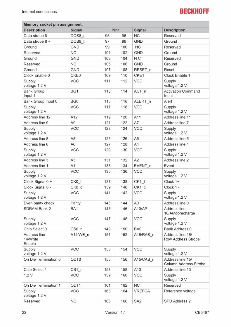
9.3.13 SATA And RST Configuration Aptio Setup Utility - Copyright (C) 2020 American Megatrends, Inc. Advanced┌─────────────────────────────────────────────────────────────────┬────────────────────────────────┐│ SATA And RST Configuration │Enable/Disable SATA Device. ││ │ ││ SATA Controller(s) [Enabled] │ ││ SATA Mode Selection [Intel RST Premium] │ ││ With Intel Optane │ ││ System Acceleration] │ ││ SATA Interrupt Selection [Msix] │ ││ SATA Test Mode [Disabled] │ ││ RAID Device ID [Client] │ ││> Software Feature Mask Configuration │ ││ Aggressive LPM Support [Disabled] │ ││ │ ││ Serial ATA Port 0 Empty │ ││ Software Preserve Unknown │ ││ Port 0 [Enabled] │ ││ Hot Plug [Disabled] │ ││ Configured as eSATA Hot Plug supported ├────────────────────────────────┤│ External [Disabled] │→←: Select Screen ││ Spin Up Device [Disabled] │↑↓: Select Item ││ SATA Device Type [Hard Disk Drive] │Enter: Select ││ SATA Port 0 DevSlp [Disabled] │+/─: Change Opt. ││ DITO Configuration [Disabled] │F1: General Help ││ Serial ATA Port 1 Empty │F2: Previous Values ││ Software Preserve Unknown │F3: Optimized Defaults ││ Port 1 [Enabled] │F4: Save & Reset ││ Hot Plug [Disabled] │ESC: Exit ││ Configured as eSATA Hot Plug supported │ ││ External [Disabled] │ ││ Spin Up Device [Disabled] │ ││ SATA Device Type [Hard Disk Drive] │ ││ SATA Port 1 DevSlp [Disabled] │ ││ DITO Configuration [Disabled] │ ││ SATA Port 4 (disabled on BAseCon) Empty │ ││ Software Preserve Unknown │ ││ Port 4 [Enabled] │ ││ Hot Plug [Disabled] │ ││ Configured as eSATA Hot Plug supported │ ││ External [Disabled] │ ││ Spin Up Device [Disabled] │ ││ SATA Device Type [Hard Disk Drive] │ ││ SATA Port 4 DevSlp [Disabled] │ ││ DITO Configuration [Disabled] │ ││ SATA Port 5 (disabled on BAseCon) Empty │ ││ Software Preserve Unknown │ ││ Port 5 [Enabled] │ ││ Hot Plug [Disabled] │ ││ Configured as eSATA Hot Plug supported │ ││ External [Disabled] │ ││ Spin Up Device [Disabled] │ ││ SATA Device Type [Hard Disk Drive] │ ││ SATA Port 5 DevSlp [Disabled] │ ││ DITO Configuration [Disabled] │ │└─────────────────────────────────────────────────────────────────┴────────────────────────────────┘ Version 2.20.1275. Copyright (C) 2020 American Megatrends, Inc.
BIOS
CB6467 55Version: 1.1
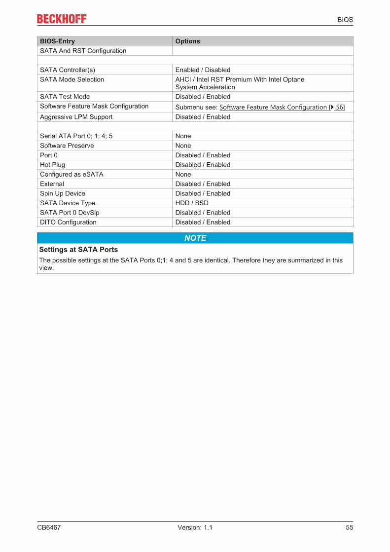
BIOS-Entry Options SATA And RST Configuration
SATA Controller(s) Enabled / Disabled SATA Mode Selection AHCI / Intel RST Premium With Intel Optane
System Acceleration SATA Test Mode Disabled / Enabled Software Feature Mask Configuration Submenu see: Software Feature Mask Configuration [} 56] Aggressive LPM Support Disabled / Enabled
Serial ATA Port 0; 1; 4; 5 None Software Preserve None Port 0 Disabled / Enabled Hot Plug Disabled / Enabled Configured as eSATA None External Disabled / Enabled Spin Up Device Disabled / Enabled SATA Device Type HDD / SSD SATA Port 0 DevSlp Disabled / Enabled DITO Configuration Disabled / Enabled
NOTESettings at SATA PortsThe possible settings at the SATA Ports 0;1; 4 and 5 are identical. Therefore they are summarized in thisview.

BIOS
CB646756 Version: 1.1
9.3.13.1 Software Feature Mask Configuration Aptio Setup Utility - Copyright (C) 2020 American Megatrends, Inc. Advanced┌─────────────────────────────────────────────────────────────────┬────────────────────────────────┐│ Software Feature Mask Configuration │If enabled, indicates that the ││ │HDD password unlock in the OS ││ HDD Unlock [Enabled] │is enabled. ││ LED Locate [Enabled] │ ││ RAID0 [Enabled] │ ││ RAID1 [Enabled] │ ││ RAID10 [Enabled] │ ││ RAID5 [Enabled] │ ││ Intel Rapid Recovery Technology [Enabled] │ ││ OROM UI and BANNER [Enabled] │ ││ IRRT Only on eSATA [Enabled] │ ││ Smart Response Technology [Enabled] │ ││ OROM UI Normal Delay [2 secs] │ ││ RST Force Form [Disabled] │ ││ System Acceleration with Intel(R) [Enabled] │ ││ Optane(TM) Memory │ ││ CPU Attached Storage [Enabled] │ ││ ├────────────────────────────────┤│ │→←: Select Screen ││ │↑↓: Select Item ││ │Enter: Select ││ │+/─: Change Opt. ││ │F1: General Help ││ │F2: Previous Values ││ │F3: Optimized Defaults ││ │F4: Save & Reset ││ │ESC: Exit ││ │ │└─────────────────────────────────────────────────────────────────┴────────────────────────────────┘ Version 2.20.1275. Copyright (C) 2020 American Megatrends, Inc.
BIOS-Entry Options Software Feature Mask Configuration
HDD Unlock Enabled / Disabled LED Locate Enabled / Disabled RAID0 Enabled / Disabled RAID1 Enabled / Disabled RAID10 Enabled / Disabled RAID5 Enabled / Disabled Intel Rapid Recovery Technology Enabled / Disabled OROM UI and BANNER Enabled / Disabled IRRT Only on eSATA Enabled / Disabled Smart Response Technology Enabled / Disabled OROM UI Normal Delay 2 / 4 / 6 / 8 secs RST Force Form Disable / Enabbled System Acceleration with Intel® Optane™ Memory
Enabled / Disabled
CPU Attached Storage Enabled / Disabled

BIOS
CB6467 57Version: 1.1
9.3.14 AMT Configuration Aptio Setup Utility - Copyright (C) 2020 American Megatrends, Inc. Advanced┌─────────────────────────────────────────────────────────────────┬────────────────────────────────┐│ ASF support [Enabled] │Enable/Disable Alert Standard ││ │Format support. ││ USB Provisioning of AMT [Disabled] │ ││> CIRA Configuration │ ││> ASF Configuration │ ││> Secure Erase Configuration │ ││> OEM Flags Settings │ ││> MEBx Resolution Settings │ ││ │ ││ Headlessmode [Disabled] │ ││ ├────────────────────────────────┤│ │→←: Select Screen ││ │↑↓: Select Item ││ │Enter: Select ││ │+/─: Change Opt. ││ │F1: General Help ││ │F2: Previous Values ││ │F3: Optimized Defaults ││ │F4: Save & Reset ││ │ESC: Exit ││ │ │└─────────────────────────────────────────────────────────────────┴────────────────────────────────┘ Version 2.20.1275. Copyright (C) 2020 American Megatrends, Inc.
BIOS-Entry Options ASF Support Disabled / Enabled
USB Provisioning of AMT Disabled / Enabled CIRA Configuration Submenu see: CIRA Configuration [} 58] ASF Configuration Submenu see: ASF Configuration [} 59] Secure Erase Configuration Submenu see: Secure Erase Configuration [} 59] OEM Flags Settings Submenu see: OEM Flags Settings [} 60] MEBx Resolution Settings Submenu see: MEBx Resolution Settings [} 61]
Headlessmode Diabled / Enabled

BIOS
CB646758 Version: 1.1
9.3.14.1 CIRA Configuration Aptio Setup Utility - Copyright (C) 2020 American Megatrends, Inc. Advanced┌─────────────────────────────────────────────────────────────────┬────────────────────────────────┐│ Activate Remote Assistance Process [Disabled] │Trigger CIRA boot ││ CIRA Timeout 0 │Note: ││ │Network Access must be ││ │activated first from MEBx ││ │Setup. ││ ├────────────────────────────────┤│ │→←: Select Screen ││ │↑↓: Select Item ││ │Enter: Select ││ │+/─: Change Opt. ││ │F1: General Help ││ │F2: Previous Values ││ │F3: Optimized Defaults ││ │F4: Save & Reset ││ │ESC: Exit ││ │ │└─────────────────────────────────────────────────────────────────┴────────────────────────────────┘ Version 2.20.1275. Copyright (C) 2020 American Megatrends, Inc.
BIOS-Entry Options Activate Remote Assistance Process Disabled / Enabled CIRA Timeout None

BIOS
CB6467 59Version: 1.1
9.3.14.2 ASF Configuration Aptio Setup Utility - Copyright (C) 2020 American Megatrends, Inc. Advanced┌─────────────────────────────────────────────────────────────────┬────────────────────────────────┐│ PET Progress [Enabled] │Enable/Disable PET Events ││ WatchDog [Disabled] │Progress to receive PET Events. ││ OS Timer 0 │ ││ BIOS Timer 0 │ ││ ASF Sensors Table [Disabled] │ ││ │ ││ ├────────────────────────────────┤│ │→←: Select Screen ││ │↑↓: Select Item ││ │Enter: Select ││ │+/─: Change Opt. ││ │F1: General Help ││ │F2: Previous Values ││ │F3: Optimized Defaults ││ │F4: Save & Reset ││ │ESC: Exit ││ │ │└─────────────────────────────────────────────────────────────────┴────────────────────────────────┘ Version 2.20.1275. Copyright (C) 2020 American Megatrends, Inc.
BIOS-Entry Options PET Progress Disabled / Enabled WatchDog Disabled / Enabled OS Timer None BIOS Timer None ASF Sensors Table Disabled / Enabled
9.3.14.3 Secure Erase Configuration Aptio Setup Utility - Copyright (C) 2020 American Megatrends, Inc. Advanced┌─────────────────────────────────────────────────────────────────┬────────────────────────────────┐│ Secure Erase mode [Simulated] │Change Secure Erase module ││ Force Secure Erase [Disabled] │behavior: ││ │Simulated: Performs SE flow ││ │without erasing SSD ││ │Real: Erase SSD. ││ │ ││ ├────────────────────────────────┤│ │→←: Select Screen ││ │↑↓: Select Item ││ │Enter: Select ││ │+/─: Change Opt. ││ │F1: General Help ││ │F2: Previous Values ││ │F3: Optimized Defaults ││ │F4: Save & Reset ││ │ESC: Exit ││ │ ││ │ │└─────────────────────────────────────────────────────────────────┴────────────────────────────────┘ Version 2.20.1275. Copyright (C) 2020 American Megatrends, Inc.
BIOS-Entry Options Secure Erase Mode Simulated / Real Force Secure Erase Disabled / Enabled

BIOS
CB646760 Version: 1.1
9.3.14.4 OEM Flags Settings Aptio Setup Utility - Copyright (C) 2020 American Megatrends, Inc. Advanced┌─────────────────────────────────────────────────────────────────┬────────────────────────────────┐│ MEBx hotkey Pressed [Disabled] │OEMFLag Bit 1: ││ MEBx Selection Screen [Disabled] │Enable automatic MEBx hotkey ││ Hide Unconfigure ME Confirmation [Disabled] │press. ││ Prompt │ ││ MEBx OEM Debug Menu Enable [Disabled] │ ││ Unconfigure ME [Disabled] │ ││ │ ││ ├────────────────────────────────┤│ │→←: Select Screen ││ │↑↓: Select Item ││ │Enter: Select ││ │+/─: Change Opt. ││ │F1: General Help ││ │F2: Previous Values ││ │F3: Optimized Defaults ││ │F4: Save & Reset ││ │ESC: Exit ││ │ │└─────────────────────────────────────────────────────────────────┴────────────────────────────────┘ Version 2.20.1275. Copyright (C) 2020 American Megatrends, Inc.
BIOS-Entry Options MBEx hotkey Pressed Disabled / Enabled MBEx Selection Screen Disabled / Enabled Hide Unconfigure ME Confirmation Prompt Disabled / Enabled MBEx OEM Debug Menu Enable Disabled / Enabled Unconfigure ME Disabled / Enabled

BIOS
CB6467 61Version: 1.1
9.3.14.5 MEBx Resolution Settings Aptio Setup Utility - Copyright (C) 2020 American Megatrends, Inc. Advanced┌─────────────────────────────────────────────────────────────────┬────────────────────────────────┐│ Non─UI Mode Resolution [Auto] │Resolution for non─UI text ││ UI Mode Resolution [Auto] │mode. ││ Graphics Mode Resolution [Auto] │ ││ │ ││ ├────────────────────────────────┤│ │→←: Select Screen ││ │↑↓: Select Item ││ │Enter: Select ││ │+/─: Change Opt. ││ │F1: General Help ││ │F2: Previous Values ││ │F3: Optimized Defaults ││ │F4: Save & Reset ││ │ESC: Exit ││ │ │└─────────────────────────────────────────────────────────────────┴────────────────────────────────┘ Version 2.20.1275. Copyright (C) 2020 American Megatrends, Inc.
BIOS-Entry Options Non-UI Resolution Auto / 80x25 / 100x31 UI Mode Resolution Auto / 80x25 / 100x31 Graphics Mode Resolution Auto / 640x480 / 800x600 / 1024x768
9.3.15 TLs Auth Configuration Aptio Setup Utility - Copyright (C) 2020 American Megatrends, Inc. Advanced┌─────────────────────────────────────────────────────────────────┬────────────────────────────────┐│ │Press <Enter> to configure ││> Server CA Configuration │Server CA. ││ │ ││> Client Cert Configuration │ ││ ├────────────────────────────────┤│ │→←: Select Screen ││ │↑↓: Select Item ││ │Enter: Select ││ │+/─: Change Opt. ││ │F1: General Help ││ │F2: Previous Values ││ │F3: Optimized Defaults ││ │F4: Save & Reset ││ │ESC: Exit │└─────────────────────────────────────────────────────────────────┴────────────────────────────────┘ Version 2.20.1275. Copyright (C) 2020 American Megatrends, Inc.
BIOS-Entry Options Server CA Configuration Submenu see: Server CA Configuration [} 62] Client Cert Configuration None

BIOS
CB646762 Version: 1.1
9.3.15.1 Server CA Configuration Aptio Setup Utility - Copyright (C) 2020 American Megatrends, Inc. Advanced┌─────────────────────────────────────────────────────────────────┬────────────────────────────────┐│ │Press <Enter> to enroll cert. ││> Enroll Cert │ ││ │ ││> Delete Cert │ ││ ├────────────────────────────────┤│ │→←: Select Screen ││ │↑↓: Select Item ││ │Enter: Select ││ │+/─: Change Opt. ││ │F1: General Help ││ │F2: Previous Values ││ │F3: Optimized Defaults ││ │F4: Save & Reset ││ │ESC: Exit ││ │ │└─────────────────────────────────────────────────────────────────┴────────────────────────────────┘ Version 2.20.1275. Copyright (C) 2020 American Megatrends, Inc.
BIOS-Entry Options Enroll Cert Submenu see: Enroll Cert [} 62] Delete Cert None
9.3.15.1.1 Enroll Cert Aptio Setup Utility - Copyright (C) 2020 American Megatrends, Inc. Advanced┌─────────────────────────────────────────────────────────────────┬────────────────────────────────┐│ │Enroll Cert Using File ││> Enroll Cert Using File │ ││ Cert GUID │ ││> Commit Changes and Exit │ ││> Discard Changes and Exit │ ││ ├────────────────────────────────┤│ │→←: Select Screen ││ │↑↓: Select Item ││ │Enter: Select ││ │+/─: Change Opt. ││ │F1: General Help ││ │F2: Previous Values ││ │F3: Optimized Defaults ││ │F4: Save & Reset ││ │ESC: Exit │└─────────────────────────────────────────────────────────────────┴────────────────────────────────┘ Version 2.20.1275. Copyright (C) 2020 American Megatrends, Inc.
BIOS-Entry Options Enroll CertEnroll Cert Using File None
Cert GUID None Commit Changes and Exit None Discard Changes and Exit None

BIOS
CB6467 63Version: 1.1
9.3.16 Network Stack Configuration Aptio Setup Utility - Copyright (C) 2020 American Megatrends, Inc. Advanced┌─────────────────────────────────────────────────────────────────┬────────────────────────────────┐│ Network Stack [Disabled] │Enable/Disable UEFI Network ││ │Stack ││ │ ││ ├────────────────────────────────┤│ │→←: Select Screen ││ │↑↓: Select Item ││ │Enter: Select ││ │+/─: Change Opt. ││ │F1: General Help ││ │F2: Previous Values ││ │F3: Optimized Defaults ││ │F4: Save & Reset ││ │ESC: Exit ││ │ │└─────────────────────────────────────────────────────────────────┴────────────────────────────────┘ Version 2.20.1275. Copyright (C) 2020 American Megatrends, Inc.
BIOS-Entry Options Network Stack Disabled / Enabled
NOTENetwork Stack EnabledIf Network Stack is „enabled“, further menu items for display and setting of the LAN Controller are shown.To achieve, make a reset.
9.3.17 Network Stack Configuration enabledr Aptio Setup Utility - Copyright (C) 2020 American Megatrends, Inc. Advanced┌─────────────────────────────────────────────────────────────────┬────────────────────────────────┐│ Network Stack [Enabled] │Enable/Disable UEFI Network ││ Ipv4 PXE Support [Enabled] │Stack ││ Ipv4 HTTP Support [Disabled] │ ││ Ipv6 PXE Support [Disabled] │ ││ Ipv6 HTTP Support [Disabled] │ ││ IPSEC Certificate [Enabled] │ ││ PXE boot wait time 0 │ ││ Media detect count 1 │ ││ ├────────────────────────────────┤│ │→←: Select Screen ││ │↑↓: Select Item ││ │Enter: Select ││ │+/─: Change Opt. ││ │F1: General Help ││ │F2: Previous Values ││ │F3: Optimized Defaults ││ │F4: Save & Reset ││ │ESC: Exit ││ │ │└─────────────────────────────────────────────────────────────────┴────────────────────────────────┘ Version 2.20.1275. Copyright (C) 2020 American Megatrends, Inc.
BIOS-Entry Options Network Stack Disabled / Enabled Ipv4 PXE Support Disabled / Enabled Ipv4 HTTP Support Disabled / Enabled Ipv6 PXE Support Disabled / Enabled Ipv6 HTTP Support Disabled / EnabledIPSEC Certificate Enabled / Disabled PXE boot wait time None Media detect count None

BIOS
CB646764 Version: 1.1
NOTEPXE Boot availablePXE Boot is available if you set Network Stack and Ipv4 PXE support to „Enable“.
9.3.18 Intel Rapid Storage Technology Aptio Setup Utility - Copyright (C) 2020 American Megatrends, Inc. Advanced┌─────────────────────────────────────────────────────────────────┬────────────────────────────────┐│ Intel (R) RST 17.8.0.4414 RAID Driver │ ││ │ ││ No disks connected to system │ ││ ├────────────────────────────────┤│ │→←: Select Screen ││ │↑↓: Select Item ││ │Enter: Select ││ │+/─: Change Opt. ││ │F1: General Help ││ │F2: Previous Values ││ │F3: Optimized Defaults ││ │F4: Save & Reset ││ │ESC: Exit │└─────────────────────────────────────────────────────────────────┴────────────────────────────────┘ Version 2.20.1275. Copyright (C) 2020 American Megatrends, Inc.
BIOS-Entry Options Intel® RST 17.8.0.4414 RAID Driver
No disks connected to system None
9.3.19 Driver Health Aptio Setup Utility - Copyright (C) 2020 American Megatrends, Inc. Advanced┌─────────────────────────────────────────────────────────────────┬────────────────────────────────┐│> Intel (R) Gigabit 0.0.24 Healthy │ ││ ├────────────────────────────────┤│ │→←: Select Screen ││ │↑↓: Select Item ││ │Enter: Select ││ │+/─: Change Opt. ││ │F1: General Help ││ │F2: Previous Values ││ │F3: Optimized Defaults ││ │F4: Save & Reset ││ │ESC: Exit │└─────────────────────────────────────────────────────────────────┴────────────────────────────────┘ Version 2.20.1275. Copyright (C) 2020 American Megatrends, Inc.
BIOS-Entry Options Intel® Gigabit 0.0.24 None

BIOS
CB6467 65Version: 1.1
9.4 Chipset Aptio Setup Utility - Copyright (C) 2020 American Megatrends, Inc. Main Advanced Chipset Security Boot Save & Exit┌─────────────────────────────────────────────────────────────────┬────────────────────────────────┐│> System Agent (SA) Configuration │System Agent (SA) Parameters ││> PCH─IO Configuration │ ││ ├────────────────────────────────┤│ │→←: Select Screen ││ │↑↓: Select Item ││ │Enter: Select ││ │+/─: Change Opt. ││ │F1: General Help ││ │F2: Previous Values ││ │F3: Optimized Defaults ││ │F4: Save & Reset ││ │ESC: Exit ││ │ │└─────────────────────────────────────────────────────────────────┴────────────────────────────────┘ Version 2.20.1275. Copyright (C) 2020 American Megatrends, Inc.
BIOS-Entry Options System Agent (SA) Configuration Submenu see: System Agent (SA) Configuration [} 66] PCH-IO Configuration Submenu see: PCH-IO Configuration [} 68]

BIOS
CB646766 Version: 1.1
9.4.1 System Agent (SA) Configuration Aptio Setup Utility - Copyright (C) 2020 American Megatrends, Inc. Chipset┌─────────────────────────────────────────────────────────────────┬────────────────────────────────┐│ System Agent (SA) Configuration │Graphics Configuration ││ │ ││ SA PCIe Code Version 7.0.110.64 │ ││ VT─d Supported │ ││> Graphics Configuration │ ││ Stop Grant Configuration [Auto] │ ││ VT─d [Enabled] │ ││ CHAP Device (B0:D7:F0) [Disabled] ├────────────────────────────────┤│ Thermal Device (B0:D4:F0) [Disabled] │→←: Select Screen ││ GNA Device (B0:D8:F0) [Enabled] │↑↓: Select Item ││ CRID Support [Disabled] │Enter: Select ││ Above 4GB MMIO BIOS assignment [Disabled] │+/─: Change Opt. ││ X2APIC Opt Out [Disabled] │F1: General Help ││ IPU Device (B0:D5:F0) [Disabled] │F2: Previous Values ││ │F3: Optimized Defaults ││ │F4: Save & Reset ││ │ESC: Exit ││ │ │└─────────────────────────────────────────────────────────────────┴────────────────────────────────┘ Version 2.20.1275. Copyright (C) 2020 American Megatrends, Inc.
BIOS-Entry Options System Agent (SA) Configuration
SA PCIe Code Version None VT-d None Graphics Configuration Submenu see: Graphics Configuration [} 67] Stop Grant Configuration Auto / Manual VT-d Enabled / Disabled CHAP Device (B0:07:F0) Disabled / Enabled Thermal Device (B0:D4:F0) Enabled / Disabled GNA Device (B0:D8:F0) Enabled / Disabled CRID Support Disabled / Enabled Above 4GB MMIO BIOS assignment Disabled / Enabled X2APIC Opt Out Disabled / Enabled IPU Device (B0:D5:F0) Disabled / Enabled

BIOS
CB6467 67Version: 1.1
9.4.1.1 Graphics Configuration Aptio Setup Utility - Copyright (C) 2020 American Megatrends, Inc. Chipset┌─────────────────────────────────────────────────────────────────┬────────────────────────────────┐│ Graphics Configuration │Graphics turbo IMON current ││ │values supported (14─31) ││ Graphics Turbo IMON Current 31 │ ││ Skip Scaning of External Gfx Card [Disabled] │ ││ │ ││ Primary Display [Auto] │ ││> External Gfx Card Primary Display Configuration │ ││ Internal Graphics [Auto] │ ││ GTT Size [8MB] │ ││ Aperture Size [256MB] │ ││ PSMI SUPPORT [Disabled] │ ││ DVMT Pre─Allocated [32M] ├────────────────────────────────┤│ DVMT Total Gfx Mem [256M] │→←: Select Screen ││ Intel Graphics Pei Display Peim [Disabled] │↑↓: Select Item ││ VDD Enable [Enabled] │Enter: Select ││ PM Support [Disabled] │+/─: Change Opt. ││ PAVP Enable [Enabled] │F1: General Help ││ Cdynmax Clamping Enable [Enabled] │F2: Previous Values ││ Cd Clock Frequency [675 Mhz] │F3: Optimized Defaults ││ │F4: Save & Reset ││ │ESC: Exit │└─────────────────────────────────────────────────────────────────┴────────────────────────────────┘ Version 2.20.1275. Copyright (C) 2020 American Megatrends, Inc.
BIOS-Entry Options Graphics Configuration
Graphics Turbo IMON Current None Skip Scaning of External Gfx Card Disabled / Enabled
Primary Display Auto / IGFX / PCI / SG External Gfx Card Primary Display Configuration
None
Internal Graphics Auto / Disabled / Enabled GTT Size 2 / 4 / 8 MB Aperture Size 128 / 256 / 512 / 1024 / 2048 MB PSMI SUPPORT Disabled / Enabled DVMT Pre-Allocated 0M, 32M…60M DVMT Total Gfx Mem 128M / 256M / MAX Intel Graphics Pei Display Peim Disabled / Enabled VDD Enable Enabled / Disabled PM Support None PAVP Enable Enabled / Disabled Cdynmax Clamping Enable Enabled / Disabled Cd Clock Frequency 337.5 / 450 / 540 / 675 Mhz

BIOS
CB646768 Version: 1.1
9.4.2 PCH-IO Configuration Aptio Setup Utility - Copyright (C) 2020 American Megatrends, Inc. Chipset┌─────────────────────────────────────────────────────────────────┬────────────────────────────────┐│ PCH─IO Configuration │PCI Express Configuration ││ │settings ││> PCI Express Configuration │ ││> USB Configuration │ ││> HD Audio Configuration │ ││ │ ││ PCH LAN Controller [Enabled] │ ││ Wake on LAN Enable [Enabled] │ ││ Second LAN Controller [Enabled] │ ││ Third LAN Controller [Enabled] │ ││ Forth LAN Controller [Enabled] │ ││ PS_ON Enable [Disabled] │ ││ M.2─Slot 0 NC─PCIe │ ││ M.2─Slot 1 Not Present │ ││ ├────────────────────────────────┤│ CLKRUN# logic [Enabled] │→←: Select Screen ││ State After G3 [S0 State] │↑↓: Select Item ││ Compatible Revision ID [Disabled] │Enter: Select ││ Legacy IO Low Latency [Enabled] │+/─: Change Opt. ││ Enable TCO Timer [Enabled] │F1: General Help ││ │F2: Previous Values ││ │F3: Optimized Defaults ││ │F4: Save & Reset ││ │ESC: Exit ││ │ │└─────────────────────────────────────────────────────────────────┴────────────────────────────────┘ Version 2.20.1275. Copyright (C) 2020 American Megatrends, Inc.
BIOS-Entry Options PCH-IO Configuration
PCI Express Configuration Submenu see: PCI Express Configuration [} 69] USB Configuration Submenu see: USB Configuration [} 73] HD Audio Configuration Submenu see: HD Audio Configuration [} 73]
PCH LAN Controller Enabled / Disabled Wake on LAN Enable Enabled / Disabled Second LAN Controller Enabled / Disabled Third LAN Controller Enabled / Disabled Forth LAN Controller Enabled / Disabled PS_ON Enable Disabled / Enabled
M.2-Slot 0 None M.2-Slot 1 None
CLKRUB# logic Enabled / Disabled State After G3 S0 State / S5 State Compatible Revision ID None Legacy IO Low Latency Enabled / Disabled Enable TCO Timer Disabled / Enabled

BIOS
CB6467 69Version: 1.1
9.4.2.1 PCI Express Configuration Aptio Setup Utility - Copyright (C) 2020 American Megatrends, Inc. Chipset┌─────────────────────────────────────────────────────────────────┬────────────────────────────────┐│ PCI Express Configuration │PCI Express Clock Gating ││ │Enable/Disable for each root ││ PCI Express Clock Gating [Disabled] │port. ││ PCIE Port assigned to LAN 5 │ ││ Peer Memory Write Enable [Disabled] │ ││ Compliance Test Mode [Disabled] │ ││ PCIe─USB Glitch W/A [Disabled] │ ││ │ ││ PCIe RP 1 (disabled on BeaCon) │ ││ PCIe RP 2 (disabled on BeaCon) │ ││ PCIe RP 3 (disabled on BeaCon) │ ││ PCIe RP 4 (disabled on BeaCon) │ ││ PCIe Port 5 is assigned to LAN1 ├────────────────────────────────┤│ PCIe Root Port 9 (to M.2─Slot0) │→←: Select Screen ││ PCIe Root Port 10 (to M.2─Slot0) Shadowed by x2/x4 port │↑↓: Select Item ││ PCIe Root Port 11 (to M.2─Slot0) Shadowed by x2/x4 port │Enter: Select ││ PCIe Root Port 12 (to M.2─Slot0) Shadowed by x2/x4 port │+/─: Change Opt. ││ PCIe Root Port 13 (to M.2─Slot1) │F1: General Help ││ PCIe Root Port 11 (to M.2─Slot0) │F2: Previous Values ││ PCIe Root Port 12 (to M.2─Slot0) │F3: Optimized Defaults ││ PCIe RP 17 (disabled on BeaCon) │F4: Save & Reset ││ PCIe RP 18 (disabled on BeaCon) │ESC: Exit ││ PCIe RP 19 (disabled on BeaCon) │ ││ PCIe RP 20 (disabled on BeaCon) │ │└─────────────────────────────────────────────────────────────────┴────────────────────────────────┘ Version 2.20.1275. Copyright (C) 2020 American Megatrends, Inc.
BIOS-Entry Options PCI Express Configuration
PCI Express Clock Gating Disabled / Enabled PCIE Port assigned to LAN None Peer Memory Write Enable Disabled / Enabled Compliance Test Mode Disabled / Enabled PCIe-USB Glitch W/A Disabled / Enabled
PCIe RP 1 - 4 Disabled / Enabled PCIe Root Port 9 (to M.2-Slot0) Disabled / Enabled PCIe Root Port 10 (toM.2-Slot0) None PCIe Root Port 11 (to M.2-Slot0) None PCIe Root Port 12 (to M.2-Slot0) None PCIe Root Port 13 (to M.2-Slot1) Disabled / Enabled PCIe RP 17 - 20 Disabled / Enabled

BIOS
CB646770 Version: 1.1
9.4.2.1.1 PCI Express Root Port 1 Aptio Setup Utility - Copyright (C) 2020 American Megatrends, Inc. Chipset
┌─────────────────────────────────────────────────────────────────┬────────────────────────────────┐│ PCI Express Root Port 1 [Enabled] │Control the PCI Express Root ││ Disable Gen2 Pll Shutdown and L1 [Disabled] │Port. ││ Controller Power gating │ ││ Connection Type [Slot] │ ││ Gen3 Eq Phase3 Method [Hardware] │ ││ UPTP 5 │ ││ DPTP 7 │ ││ ACS [Enabled] │ ││ PTM [Enabled] │ ││ DPC [Enabled] │ ││ EDPC [Enabled] │ ││ URR [Disabled] │ ││ FER [Disabled] ├────────────────────────────────┤┤ NFER [Disabled] │→←: Select Screen ││ CER [Disabled] │↑↓: Select Item ││ CTO [Disabled] │Enter: Select ││ SEFE [Disabled] │+/─: Change Opt. ││ SENFE [Disabled] │F1: General Help ││ SECE [Disabled] │F2: Previous Values ││ PME SCI [Enabled] │F3: Optimized Defaults ││ Hot Plug [Disabled] │F4: Save & Reset ││ Advanced Error Reporting [Enabled] │ESC: Exit ││ PCIe Speed [Auto] │ ││ Transmitter Half Swing [Disabled] │ ││ Detect Timeout 0 │ ││ Extra Bus Reserved 0 │ ││ Reserved Memory 10 │ ││ Reserved I/O 0 │ ││ │ ││ PCH PCIe LTR Congguration │ ││ LTR [Enabled] │ ││ Snoop Latency Override [Auto] │ ││ Non Snoop Latency Override [Auto] │ ││ Force LTR Override [Disabled] │ ││ │ ││ LTR Lock [Disabled] │ ││ >Extra Options │ ││ │ │└─────────────────────────────────────────────────────────────────┴────────────────────────────────┘ Version 2.20.1275. Copyright (C) 2020 American Megatrends, Inc.

BIOS
CB6467 71Version: 1.1
BIOS-Entry Options PCI Express Root Port 1 Disabled / Enabled Disable Gen2 Pll Shutdown and L1 and Controller Power gating
Disabled / Enabled
Connection Type Built-in / Slot Gen3 Eq Phase3 Method Hardware / Static Coeff. UPTP None DPTP None ACS Enabled / Disabled PTM Enabled / Disabled DPC Enabled / Disabled EDPC Enabled / Disabled URR Disabled / Enabled FER Disabled / Enabled NFER Disabled / Enabled CER Disabled / Enabled CTO Disabled / Enabled SEFE Disabled / Enabled SENFE Disabled / Enabled PME SCI Enabled / Disabled Hot Plug Disabled / Enabled Advanced Error Reporting Enabled / Disabled PCIe Speed Auto / Gen1 / Gen2 / Gen3 Transmitter Half Swing Disabled / Enabled Detect Timeout None Extra Bus Reserved None Reserved Memory None Reserved I/O None
PCH PCIe LTR Configuration LTR Enabled / Disabled Snoop Latency Override Disbaled / Manual / Auto Non Snoop Latency Override Disbaled / Manual / Auto Force LTR Override Disabled / Enabled
LTR Lock Disabled / Enabled Extra Options Submenu see: Extra Options [} 72]
NOTEPCI Express ConfigurationThe BIOS-entries and the optiones at the ports 1 – 4, 9, 13 und 17 - 20 are identical. Port 1 is shown as ex-ample.

BIOS
CB646772 Version: 1.1
Extra Options Aptio Setup Utility - Copyright (C) 2020 American Megatrends, Inc. Chipset┌─────────────────────────────────────────────────────────────────┬────────────────────────────────┐│ Detect Non─Compliance Device [Disabled] │Detect Non─Compliance PCI ││ Prefetchable Memory 10 │Express Device. If enable, it ││ Reserved Memory Alignment 1 │will take more time at POST ││ Prefetchable Memory Alignment 1 │time. ││ │────────────────────────────────││ │→←: Select Screen ││ │↑↓: Select Item ││ │Enter: Select ││ │+/─: Change Opt. ││ │F1: General Help ││ │F2: Previous Values ││ │F3: Optimized Defaults ││ │F4: Save & Reset ││ │ESC: Exit ││ │ │└─────────────────────────────────────────────────────────────────┴────────────────────────────────┘ Version 2.20.1275. Copyright (C) 2020 American Megatrends, Inc.
BIOS-Entry Options Detect Non-Compliance Device Disabled / Enabled Prefetchable Memory None Reserved Memory Alignment None Preftechable Memory Alignment None

BIOS
CB6467 73Version: 1.1
9.4.2.2 USB Configuration Aptio Setup Utility - Copyright (C) 2020 American Megatrends, Inc. Chipset┌─────────────────────────────────────────────────────────────────┬────────────────────────────────┐│ USB Configuration │Option to enable Compliance ││ │Mode. Default is to disable ││ XHCI Compliance Mode [Disabled] │Compliance Mode. Change to ││ │enabled for Compliance Mode ││ USB Port Disable Override [Disable Link] │testing. ││ ├────────────────────────────────┤│ │→←: Select Screen ││ │↑↓: Select Item ││ │Enter: Select ││ │+/─: Change Opt. ││ │F1: General Help ││ │F2: Previous Values ││ │F3: Optimized Defaults ││ │F4: Save & Reset ││ │ESC: Exit ││ │ │└─────────────────────────────────────────────────────────────────┴────────────────────────────────┘ Version 2.20.1275. Copyright (C) 2020 American Megatrends, Inc.
BIOS-Entry Options USB Configuration
XHCI Compliance Mode Disabled / Enabled
USB Port Disable Override Disable Link / Select Per-Pin
9.4.2.3 HD Audio Configuration Aptio Setup Utility - Copyright (C) 2020 American Megatrends, Inc. Chipset┌─────────────────────────────────────────────────────────────────┬────────────────────────────────┐│ HD Audio Subsystem Configuration Settings │Control Detection of the ││ │HD─Audio device. ││ HD Audio [Enabled] │Disabled = HDA will be ││ │unconditionally disabled ││ │Enabled = HDA will be ││ │unconditionally enabled. ││ │ ││ ├────────────────────────────────┤│ │→←: Select Screen ││ │↑↓: Select Item ││ │Enter: Select ││ │+/─: Change Opt. ││ │F1: General Help ││ │F2: Previous Values ││ │F3: Optimized Defaults ││ │F4: Save & Reset ││ │ESC: Exit ││ │ │└─────────────────────────────────────────────────────────────────┴────────────────────────────────┘ Version 2.20.1275. Copyright (C) 2020 American Megatrends, Inc.
BIOS-Entry Options HD Audio Subsystem Configuration Settings
HD Audio Enabled / Disabled

BIOS
CB646774 Version: 1.1
9.5 Security Aptio Setup Utility - Copyright (C) 2020 American Megatrends, Inc. Main Advanced Chipset Security Boot Save & Exit┌─────────────────────────────────────────────────────────────────┬────────────────────────────────┐│ Password Description │Set Administrator Password ││ │ ││ Minimum length 3 │ ││ Maximum length 20 │ ││ │ ││ Administrator Password │ ││ │ ││ User Mode available [Enabled] │ ││ │ ││> Secure Boot │ ││ ├────────────────────────────────┤│ │→←: Select Screen ││ │↑↓: Select Item ││ │Enter: Select ││ │+/─: Change Opt. ││ │F1: General Help ││ │F2: Previous Values ││ │F3: Optimized Defaults ││ │F4: Save & Reset ││ │ESC: Exit ││ │ │└─────────────────────────────────────────────────────────────────┴────────────────────────────────┘ Version 2.20.1275. Copyright (C) 2020 American Megatrends, Inc.
BIOS-Entry Options Password Description Minimum length None Maximum length None Administrator Password Set here an administrator-password. User Mode available Enabled / Disabled Secure Boot Submenu see: Secure Boot [} 75]

BIOS
CB6467 75Version: 1.1
9.5.1 Secure Boot Aptio Setup Utility - Copyright (C) 2020 American Megatrends, Inc. Security┌─────────────────────────────────────────────────────────────────┬────────────────────────────────┐│ System Mode User │Secure Boot feature is Active ││ │if Secure Boot is Enabled, ││ Secure Boot [Disabled] │Platform Key(PK) is enrolled ││ Not Active │and the System is in User mode. ││ │The mode change requires ││ Secure Boot Mode [Custom] │platform reset ││> Restore Factory Keys │ ││> Reset To Setup Mode │ ││ │ ││> Key Management │ ││ ├────────────────────────────────┤│ │→←: Select Screen ││ │↑↓: Select Item ││ │Enter: Select ││ │+/─: Change Opt. ││ │F1: General Help ││ │F2: Previous Values ││ │F3: Optimized Defaults ││ │F4: Save & Reset ││ │ESC: Exit ││ │ │└─────────────────────────────────────────────────────────────────┴────────────────────────────────┘ Version 2.20.1275. Copyright (C) 2020 American Megatrends, Inc.
BIOS-Entry Options System Mode None Secure Boot Disabled / Enabled
Not Active
Secure Boot Mode Custom / Standard Restore Factory Keys Submenu see: Restore Factory Keys [} 76] Reset To Setup Mode Submenu see: Reset To Setup Mode [} 77]
Key Management Untermenü see: Key Management [} 78]

BIOS
CB646776 Version: 1.1
9.5.1.1 Restore Factory Keys Aptio Setup Utility - Copyright (C) 2020 American Megatrends, Inc. Security┌─────────────────────────────────────────────────────────────────┬────────────────────────────────┐│ System Mode User │Force System to User Mode. ││ │Install factory default Secure ││ Secure Boot [Disabled] │Boot key databases ││ Not Active │ ││ │ ││ Secure Boot Mode [Custom] │ ││> Restore Factory Keys │ ││> Reset To Setup Mode │ ││ │ ││> Key Management ┌─────── Install factory defaults ──────┐ ││ │ │ ││ │ Press 'Yes' to proceed 'No' to cancel │ ││ │ │ ───────────────────────────││ │───────────────────────────────────────│ elect Screen ││ │ Yes No │ elect Item ││ └───────────────────────────────────────┘ : Select ││ Change Opt. ││ │F1: General Help ││ │F2: Previous Values ││ │F3: Optimized Defaults ││ │F4: Save & Reset ││ │ESC: Exit ││ │ │└─────────────────────────────────────────────────────────────────┴────────────────────────────────┘ Version 2.20.1275. Copyright (C) 2020 American Megatrends, Inc.
BIOS-Entry Options System Mode None Secure Boot Disabled / Enabled
Secure Boot Mode Custom / Standard Restore Factory Keys Install factory defaults, see box

BIOS
CB6467 77Version: 1.1
9.5.1.2 Reset To Setup Mode Aptio Setup Utility - Copyright (C) 2020 American Megatrends, Inc. Security┌─────────────────────────────────────────────────────────────────┬────────────────────────────────┐│ System Mode User │Delete all Secure Boot key ││ │databases from NVRAM ││ Secure Boot [Disabled] │ ││ Not Active │ ││ │ ││ Secure Boot Mode [Custom] │ ││> Restore Factory Keys │ ││> Reset To Setup Mode │ ││ ┌───────── Reset To Setup Mode ─────────┐ ││> Key Management │ │ ││ │ Deleting all variables will reset the │ ││ │ System to Setup Mode │ ││ │ Do you want to proceed? │ ───────────────────────────││ │ │ elect Screen ││ │───────────────────────────────────────│ elect Item ││ │ Yes No │ : Select ││ └───────────────────────────────────────┘ Change Opt. ││ eneral Help ││ │F2: Previous Values ││ │F3: Optimized Defaults ││ │F4: Save & Reset ││ │ESC: Exit ││ │ │└─────────────────────────────────────────────────────────────────┴────────────────────────────────┘ Version 2.20.1275. Copyright (C) 2020 American Megatrends, Inc.
BIOS-Entry Options System Mode None Secure Boot Disabled / Enabled
Not Active
Secure Boot Mode Custom / Standard Reset To Setup Mode Reset To Setup Mode (see box)
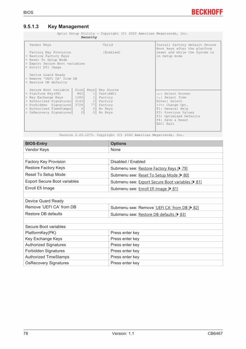
BIOS
CB646778 Version: 1.1
9.5.1.3 Key Management Aptio Setup Utility - Copyright (C) 2020 American Megatrends, Inc. Security┌─────────────────────────────────────────────────────────────────┬────────────────────────────────┐│ Vendor Keys Valid │Install factory default Secure ││ │Boot keys after the platform ││ Factory Key Provision [Enabled] │reset and while the System is ││> Restore Factory Keys │in Setup mode ││> Reset To Setup Mode │ ││> Export Secure Boot variables │ ││> Enroll Efi Image │ ││ │ ││ Device Guard Ready │ ││> Remove 'UEFI CA' from DB │ ││> Restore DB defaults │ ││ │ ││ Secure Boot variable │ Size│ Keys│ Key Source ├────────────────────────────────┤│> Platform Key(PK) │ 862│ 1│ Test(AMI) │→←: Select Screen ││> Key Exchange Keys │ 1560│ 1│ Factory │↑↓: Select Item ││> Authorized Signatures│ 3143│ 2│ Factory │Enter: Select ││> Forbidden Signatures│ 3724│ 77│ Factory │+/─: Change Opt. ││> Authorized TimeStamps│ 0│ 0│ No Keys │F1: General Help ││> OsRecovery Signatures│ 0│ 0│ No Keys │F2: Previous Values ││ │F3: Optimized Defaults ││ │F4: Save & Reset ││ │ESC: Exit ││ │ │└─────────────────────────────────────────────────────────────────┴────────────────────────────────┘ Version 2.20.1275. Copyright (C) 2020 American Megatrends, Inc.
BIOS-Entry Options Vendor Keys None
Factory Key Provision Disabled / Enabled Restore Factory Keys Submenu see: Restore Factory Keys [} 79] Reset To Setup Mode Submenu see: Reset To Setup Mode [} 80] Export Secure Boot variables Submenu see: Export Secure Boot variables [} 81] Enroll Efi Image Submenu see: Enroll Efi Image [} 81]
Device Guard Ready Remove ’UEFI CA’ from DB Submenu see: Remove ’UEFI CA’ from DB [} 82] Restore DB defaults Submenu see: Restore DB defaults [} 83]
Secure Boot variables PlatformKey(PK) Press enter key Key Exchange Keys Press enter key Authorized Signatures Press enter key Forbidden Signatures Press enter key Authorized TimeStamps Press enter key OsRecovery Signatures Press enter key

BIOS
CB6467 79Version: 1.1
9.5.1.3.1 Restore Factory Keys Aptio Setup Utility - Copyright (C) 2020 American Megatrends, Inc. Security┌─────────────────────────────────────────────────────────────────┬────────────────────────────────┐│ Vendor Keys Valid │Force System to User Mode. ││ │Install factory default Secure ││ Factory Key Provision [Disabled] │Boot key databases ││> Restore Factory Keys │ ││> Reset To Setup Mode │ ││> Export Secure Boot variables │ ││> Enroll Efi Image │ ││ │ ││ Device Guard Ready │ ││> Remove 'UEFI CA' from DB ┌─────── Install factory defaults ──────┐ ││> Restore DB defaults │ │ ││ │ Press 'Yes' to proceed 'No' to cancel │ ││ Secure Boot variable │ Siz│ │ ───────────────────────────││> Platform Key(PK) │ 86│───────────────────────────────────────│ elect Screen ││> Key Exchange Keys │ 156│ Yes No │ elect Item ││> Authorized Signatures│ 314└───────────────────────────────────────┘ : Select ││> Forbidden Signatures│ 3724│ Change Opt. ││> Authorized TimeStamps│ 0│ 0│ No Keys │F1: General Help ││> OsRecovery Signatures│ 0│ 0│ No Keys │F2: Previous Values ││ │F3: Optimized Defaults ││ │F4: Save & Reset ││ │ESC: Exit ││ │ │└─────────────────────────────────────────────────────────────────┴────────────────────────────────┘ Version 2.20.1275. Copyright (C) 2020 American Megatrends, Inc.
BIOS-Entry Options Vendor Keys None
Restore Factory Keys Restore Factory Keys, see box

BIOS
CB646780 Version: 1.1
9.5.1.3.2 Reset To Setup Mode Aptio Setup Utility - Copyright (C) 2020 American Megatrends, Inc. Security┌─────────────────────────────────────────────────────────────────┬────────────────────────────────┐│ Vendor Keys Valid │Delete all Secure Boot key ││ │databases from NVRAM ││ Factory Key Provision [Disabled] │ ││> Restore Factory Keys │ ││> Reset To Setup Mode │ ││> Export Secure Boot variables │ ││> Enroll Efi Image │ ││ │ ││ Device Guard Ready ┌───────── Reset To Setup Mode ─────────┐ ││> Remove 'UEFI CA' from DB │ │ ││> Restore DB defaults │ Deleting all variables will reset the │ ││ │ System to Setup Mode │ ││ Secure Boot variable │ Siz│ Do you want to proceed? │ ───────────────────────────││> Platform Key(PK) │ 86│ │ elect Screen ││> Key Exchange Keys │ 156│───────────────────────────────────────│ elect Item ││> Authorized Signatures│ 314│ Yes No │ : Select ││> Forbidden Signatures│ 372└───────────────────────────────────────┘ Change Opt. ││> Authorized TimeStamps│ 0│ eneral Help ││> OsRecovery Signatures│ 0│ 0│ No Keys │F2: Previous Values ││ │F3: Optimized Defaults ││ │F4: Save & Reset ││ │ESC: Exit ││ │ │└─────────────────────────────────────────────────────────────────┴────────────────────────────────┘ Version 2.20.1275. Copyright (C) 2020 American Megatrends, Inc.
BIOS-Entry Options Vendor Keys None
Reset To Setup Mode Reset To Setup Mode, see box

BIOS
CB6467 81Version: 1.1
9.5.1.3.3 Export Secure Boot variables Aptio Setup Utility - Copyright (C) 2020 American Megatrends, Inc. Security┌─────────────────────────────────────────────────────────────────┬────────────────────────────────┐│ Vendor Keys Valid │Copy NVRAM content of Secure ││ │Boot variables to files in a ││ Factory Key Provision [Disabled] │root folder on a file system ││> Restore Factory Keys │device ││> Reset To Setup Mode │ ││> Export Secure Boot variables │ ││> Enroll Efi Image │ ││ │ ││ Device Guard Ready │ ││> Remove 'UEFI CA' from DB ┌───────── File System ──────────┐ ││> Restore DB defaults │ │ ││ │ No Valid File System Available │ ││ Secure Boot variable │ Size│ K│ │ ──────────────────────────────││> Platform Key(PK) │ 862│ │────────────────────────────────│ : Select Screen ││> Key Exchange Keys │ 1560│ │ Ok │ : Select Item ││> Authorized Signatures│ 3143│ └────────────────────────────────┘ ter: Select ││> Forbidden Signatures│ 3724│ 7 ─: Change Opt. ││> Authorized TimeStamps│ 0│ 0│ No Keys │F1: General Help ││> OsRecovery Signatures│ 0│ 0│ No Keys │F2: Previous Values ││ │F3: Optimized Defaults ││ │F4: Save & Reset ││ │ESC: Exit ││ │ │└─────────────────────────────────────────────────────────────────┴────────────────────────────────┘ Version 2.20.1275. Copyright (C) 2020 American Megatrends, Inc.
BIOS-Entry Options Vendor Keys None
Export Secure Boot variables File System, see box
9.5.1.3.4 Enroll Efi Image Aptio Setup Utility - Copyright (C) 2020 American Megatrends, Inc. Security┌─────────────────────────────────────────────────────────────────┬────────────────────────────────┐│ Vendor Keys Valid │Copy NVRAM content of Secure ││ │Boot variables to files in a ││ Factory Key Provision [Disabled] │root folder on a file system ││> Restore Factory Keys │device ││> Reset To Setup Mode │ ││> Export Secure Boot variables │ ││> Enroll Efi Image │ ││ │ ││ Device Guard Ready │ ││> Remove 'UEFI CA' from DB ┌───────── File System ──────────┐ ││> Restore DB defaults │ │ ││ │ No Valid File System Available │ ││ Secure Boot variable │ Size│ K│ │ ──────────────────────────────││> Platform Key(PK) │ 862│ │────────────────────────────────│ : Select Screen ││> Key Exchange Keys │ 1560│ │ Ok │ : Select Item ││> Authorized Signatures│ 3143│ └────────────────────────────────┘ ter: Select ││> Forbidden Signatures│ 3724│ 7 ─: Change Opt. ││> Authorized TimeStamps│ 0│ 0│ No Keys │F1: General Help ││> OsRecovery Signatures│ 0│ 0│ No Keys │F2: Previous Values ││ │F3: Optimized Defaults ││ │F4: Save & Reset ││ │ESC: Exit ││ │ │└─────────────────────────────────────────────────────────────────┴────────────────────────────────┘ Version 2.20.1275. Copyright (C) 2020 American Megatrends, Inc.
BIOS-Entry Options Vendor Keys None
Enroll Efi Image File System, see box

BIOS
CB646782 Version: 1.1
9.5.1.3.5 Remove UEFI CA from DB Aptio Setup Utility - Copyright (C) 2020 American Megatrends, Inc. Security┌─────────────────────────────────────────────────────────────────┬────────────────────────────────┐│ Vendor Keys Valid │Device Guard ready system must ││ │not list 'Microsoft UEFI CA' ││ Factory Key Provision [Disabled] │Certificate in Authorized ││> Restore Factory Keys │Signature database (db) ││> Reset To Setup Mode │ ││> Export Secure Boot variables │ ││> Enroll Efi Image │ ││ │ ││ Device Guard Ready │ ││> Remove 'UEFI CA' from DB ┌─────── Remove 'UEFI CA' from DB ──────┐ ││> Restore DB defaults │ │ ││ │ Press 'Yes' to proceed 'No' to cancel │ ││ Secure Boot variable │ Siz│ │ ───────────────────────────││> Platform Key(PK) │ 86│───────────────────────────────────────│ elect Screen ││> Key Exchange Keys │ 156│ Yes No │ elect Item ││> Authorized Signatures│ 314└───────────────────────────────────────┘ : Select ││> Forbidden Signatures│ 3724│ Change Opt. ││> Authorized TimeStamps│ 0│ 0│ No Keys │F1: General Help ││> OsRecovery Signatures│ 0│ 0│ No Keys │F2: Previous Values ││ │F3: Optimized Defaults ││ │F4: Save & Reset ││ │ESC: Exit ││ │ │└─────────────────────────────────────────────────────────────────┴────────────────────────────────┘ Version 2.20.1275. Copyright (C) 2020 American Megatrends, Inc.
BIOS-Entry Options Vendor Keys None
Remove ‘UEFI CA‘ from DB Remove ‘UEFI CA‘ from DB, see box

BIOS
CB6467 83Version: 1.1
9.5.1.3.6 Restore DB Faults Aptio Setup Utility - Copyright (C) 2020 American Megatrends, Inc. Security┌─────────────────────────────────────────────────────────────────┬────────────────────────────────┐│ Vendor Keys Valid │Restore DB variable to factory ││ │defaults ││ Factory Key Provision [Disabled] │ ││> Restore Factory Keys │ ││> Reset To Setup Mode │ ││> Export Secure Boot variables │ ││> Enroll Efi Image │ ││ │ ││ Device Guard Ready │ ││> Remove 'UEFI CA' from DB ┌───────── Restore DB defaults ─────────┐ ││> Restore DB defaults │ │ ││ │ Press 'Yes' to proceed 'No' to cancel │ ││ Secure Boot variable │ Siz│ │ ───────────────────────────││> Platform Key(PK) │ 86│───────────────────────────────────────│ elect Screen ││> Key Exchange Keys │ 156│ Yes No │ elect Item ││> Authorized Signatures│ 314└───────────────────────────────────────┘ : Select ││> Forbidden Signatures│ 3724│ Change Opt. ││> Authorized TimeStamps│ 0│ 0│ No Keys │F1: General Help ││> OsRecovery Signatures│ 0│ 0│ No Keys │F2: Previous Values ││ │F3: Optimized Defaults ││ │F4: Save & Reset ││ │ESC: Exit ││ │ │└─────────────────────────────────────────────────────────────────┴────────────────────────────────┘ Version 2.20.1275. Copyright (C) 2020 American Megatrends, Inc.
BIOS-Entry Options Vendor Keys None
Restore DB Faults Restore DB Faults, see box

BIOS
CB646784 Version: 1.1
9.5.1.3.7 Platform Key (PK) Aptio Setup Utility - Copyright (C) 2020 American Megatrends, Inc. Security┌─────────────────────────────────────────────────────────────────┬────────────────────────────────┐│ Vendor Keys Valid │Enroll Factory Defaults or ││ │load certificates from a file: ││ Factory Key Provision [Disabled] │ 1.Public Key Certificate: ││> Restore Factory Keys │ a)EFI_SIGNATURE_LIST ││> Reset To Setup Mode │ b)EFI_CERT_X509 (DER) ││> Export Secure Boot variables │ c)EFI_CERT_RSA2048 (bin) ││> Enroll Efi Image │ d)EFI_CERT_SHAXXX ││ ┌──────────────────────────────┐│ 2.Authenticated UEFI Variable ││ Device Guard Ready │ Platform Key(PK) ││ 3.EFI PE/COFF Image(SHA256) ││> Remove 'UEFI CA' from DB │──────────────────────────────││Key Source: ││> Restore DB defaults │ Details ││ Factory,External,Mixed ││ │ Export ││ ││ Secure Boot variable │ Size│ Ke│ Update ││────────────────────────────────││> Platform Key(PK) │ 862│ │ Delete ││→←: Select Screen ││> Key Exchange Keys │ 1560│ └──────────────────────────────┘│↑↓: Select Item ││> Authorized Signatures│ 3143│ 2│ Factory │Enter: Select ││> Forbidden Signatures│ 3724│ 77│ Factory │+/─: Change Opt. ││> Authorized TimeStamps│ 0│ 0│ No Keys │F1: General Help ││> OsRecovery Signatures│ 0│ 0│ No Keys │F2: Previous Values ││ │F3: Optimized Defaults ││ │F4: Save & Reset ││ │ESC: Exit ││ │ │└─────────────────────────────────────────────────────────────────┴────────────────────────────────┘ Version 2.20.1275. Copyright (C) 2020 American Megatrends, Inc.
BIOS-Entry Options Vendor Keys None
Platform Key (PK) Platform Key (PK), see box

BIOS
CB6467 85Version: 1.1
9.5.1.3.8 Platform Key (PK) Aptio Setup Utility - Copyright (C) 2020 American Megatrends, Inc. Security┌─────────────────────────────────────────────────────────────────┬────────────────────────────────┐│ Vendor Keys Valid │Enroll Factory Defaults or ││ │load certificates from a file: ││ Factory Key Provision [Disabled] │ 1.Public Key Certificate: ││> Restore Factory Keys │ a)EFI_SIGNATURE_LIST ││> Reset To Setup Mode │ b)EFI_CERT_X509 (DER) ││> Export Secure Boot variables │ c)EFI_CERT_RSA2048 (bin) ││> Enroll Efi Image │ d)EFI_CERT_SHAXXX ││ ┌──────────────────────────────┐│ 2.Authenticated UEFI Variable ││ Device Guard Ready │ Platform Key(PK) ││ 3.EFI PE/COFF Image(SHA256) ││> Remove 'UEFI CA' from DB │──────────────────────────────││Key Source: ││> Restore DB defaults │ Details ││ Factory,External,Mixed ││ │ Export ││ ││ Secure Boot variable │ Size│ Ke│ Update ││────────────────────────────────││> Platform Key(PK) │ 862│ │ Delete ││→←: Select Screen ││> Key Exchange Keys │ 1560│ └──────────────────────────────┘│↑↓: Select Item ││> Authorized Signatures│ 3143│ 2│ Factory │Enter: Select ││> Forbidden Signatures│ 3724│ 77│ Factory │+/─: Change Opt. ││> Authorized TimeStamps│ 0│ 0│ No Keys │F1: General Help ││> OsRecovery Signatures│ 0│ 0│ No Keys │F2: Previous Values ││ │F3: Optimized Defaults ││ │F4: Save & Reset ││ │ESC: Exit ││ │ │└─────────────────────────────────────────────────────────────────┴────────────────────────────────┘ Version 2.20.1275. Copyright (C) 2020 American Megatrends, Inc.
BIOS-Entry Options Vendor Keys None
Platform Key (PK) Platform Key (PK), see box

BIOS
CB646786 Version: 1.1
9.5.1.3.9 Authorized Signatures Aptio Setup Utility - Copyright (C) 2020 American Megatrends, Inc. Security┌─────────────────────────────────────────────────────────────────┬────────────────────────────────┐│ Vendor Keys Valid │Enroll Factory Defaults or ││ │load certificates from a file: ││ Factory Key Provision [Disabled] │ 1.Public Key Certificate: ││> Restore Factory Keys │ a)EFI_SIGNATURE_LIST ││> Reset To Setup Mode │ b)EFI_CERT_X509 (DER) ││> Export Secure Boot variables │ c)EFI_CERT_RSA2048 (bin) ││> Enroll Efi Image │ d)EFI_CERT_SHAXXX ││ ┌──────────────────────────────┐│ 2.Authenticated UEFI Variable ││ Device Guard Ready │ Authorized Signatures ││ 3.EFI PE/COFF Image(SHA256) ││> Remove 'UEFI CA' from DB │──────────────────────────────││Key Source: ││> Restore DB defaults │ Details ││ Factory,External,Mixed ││ │ Export ││ ││ Secure Boot variable │ Size│ Ke│ Update ││────────────────────────────────││> Platform Key(PK) │ 862│ │ Append ││→←: Select Screen ││> Key Exchange Keys │ 1560│ │ Delete ││↑↓: Select Item ││> Authorized Signatures│ 3143│ └──────────────────────────────┘│Enter: Select ││> Forbidden Signatures│ 3724│ 77│ Factory │+/─: Change Opt. ││> Authorized TimeStamps│ 0│ 0│ No Keys │F1: General Help ││> OsRecovery Signatures│ 0│ 0│ No Keys │F2: Previous Values ││ │F3: Optimized Defaults ││ │F4: Save & Reset ││ │ESC: Exit ││ │ │└─────────────────────────────────────────────────────────────────┴────────────────────────────────┘ Version 2.20.1275. Copyright (C) 2020 American Megatrends, Inc.
BIOS-Entry Options Vendor Keys None
Authorized Signatures Authorized Signatures, see box
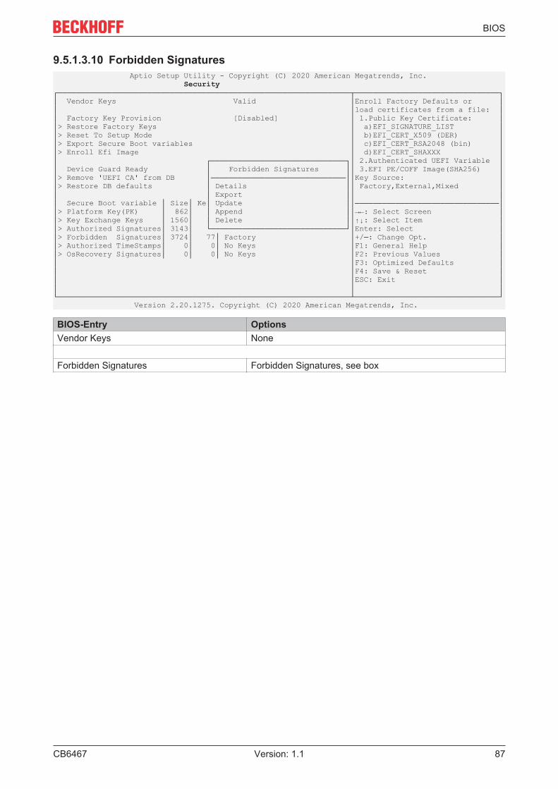
BIOS
CB6467 87Version: 1.1
9.5.1.3.10 Forbidden Signatures Aptio Setup Utility - Copyright (C) 2020 American Megatrends, Inc. Security┌─────────────────────────────────────────────────────────────────┬────────────────────────────────┐│ Vendor Keys Valid │Enroll Factory Defaults or ││ │load certificates from a file: ││ Factory Key Provision [Disabled] │ 1.Public Key Certificate: ││> Restore Factory Keys │ a)EFI_SIGNATURE_LIST ││> Reset To Setup Mode │ b)EFI_CERT_X509 (DER) ││> Export Secure Boot variables │ c)EFI_CERT_RSA2048 (bin) ││> Enroll Efi Image │ d)EFI_CERT_SHAXXX ││ ┌──────────────────────────────┐│ 2.Authenticated UEFI Variable ││ Device Guard Ready │ Forbidden Signatures ││ 3.EFI PE/COFF Image(SHA256) ││> Remove 'UEFI CA' from DB │──────────────────────────────││Key Source: ││> Restore DB defaults │ Details ││ Factory,External,Mixed ││ │ Export ││ ││ Secure Boot variable │ Size│ Ke│ Update ││────────────────────────────────││> Platform Key(PK) │ 862│ │ Append ││→←: Select Screen ││> Key Exchange Keys │ 1560│ │ Delete ││↑↓: Select Item ││> Authorized Signatures│ 3143│ └──────────────────────────────┘│Enter: Select ││> Forbidden Signatures│ 3724│ 77│ Factory │+/─: Change Opt. ││> Authorized TimeStamps│ 0│ 0│ No Keys │F1: General Help ││> OsRecovery Signatures│ 0│ 0│ No Keys │F2: Previous Values ││ │F3: Optimized Defaults ││ │F4: Save & Reset ││ │ESC: Exit ││ │ │└─────────────────────────────────────────────────────────────────┴────────────────────────────────┘ Version 2.20.1275. Copyright (C) 2020 American Megatrends, Inc.
BIOS-Entry Options Vendor Keys None
Forbidden Signatures Forbidden Signatures, see box

BIOS
CB646788 Version: 1.1
9.5.1.3.11 Authorized TimeStamps Aptio Setup Utility - Copyright (C) 2020 American Megatrends, Inc. Security┌─────────────────────────────────────────────────────────────────┬────────────────────────────────┐│ Vendor Keys Valid │Enroll Factory Defaults or ││ │load certificates from a file: ││ Factory Key Provision [Disabled] │ 1.Public Key Certificate: ││> Restore Factory Keys │ a)EFI_SIGNATURE_LIST ││> Reset To Setup Mode │ b)EFI_CERT_X509 (DER) ││> Export Secure Boot variables │ c)EFI_CERT_RSA2048 (bin) ││> Enroll Efi Image │ d)EFI_CERT_SHAXXX ││ │ 2.Authenticated UEFI Variable ││ Device Guard Ready ┌──────────────────────────────┐│ 3.EFI PE/COFF Image(SHA256) ││> Remove 'UEFI CA' from DB │ Authorized TimeStamps ││Key Source: ││> Restore DB defaults │──────────────────────────────││ Factory,External,Mixed ││ │ Update ││ ││ Secure Boot variable │ Size│ Ke│ Append ││────────────────────────────────││> Platform Key(PK) │ 862│ └──────────────────────────────┘│→←: Select Screen ││> Key Exchange Keys │ 1560│ 1│ Factory │↑↓: Select Item ││> Authorized Signatures│ 3143│ 2│ Factory │Enter: Select ││> Forbidden Signatures│ 3724│ 77│ Factory │+/─: Change Opt. ││> Authorized TimeStamps│ 0│ 0│ No Keys │F1: General Help ││> OsRecovery Signatures│ 0│ 0│ No Keys │F2: Previous Values ││ │F3: Optimized Defaults ││ │F4: Save & Reset ││ │ESC: Exit ││ │ │└─────────────────────────────────────────────────────────────────┴────────────────────────────────┘ Version 2.20.1275. Copyright (C) 2020 American Megatrends, Inc.
BIOS-Entry Options Vendor Keys None
Authorized TimeStamps Authorized TimeStamps, see box

BIOS
CB6467 89Version: 1.1
9.5.1.3.12 OsRecovery Signatures Aptio Setup Utility - Copyright (C) 2020 American Megatrends, Inc. Security┌─────────────────────────────────────────────────────────────────┬────────────────────────────────┐│ Vendor Keys Valid │Enroll Factory Defaults or ││ │load certificates from a file: ││ Factory Key Provision [Disabled] │ 1.Public Key Certificate: ││> Restore Factory Keys │ a)EFI_SIGNATURE_LIST ││> Reset To Setup Mode │ b)EFI_CERT_X509 (DER) ││> Export Secure Boot variables │ c)EFI_CERT_RSA2048 (bin) ││> Enroll Efi Image │ d)EFI_CERT_SHAXXX ││ │ 2.Authenticated UEFI Variable ││ Device Guard Ready ┌──────────────────────────────┐│ 3.EFI PE/COFF Image(SHA256) ││> Remove 'UEFI CA' from DB │ OsRecovery Signatures ││Key Source: ││> Restore DB defaults │──────────────────────────────││ Factory,External,Mixed ││ │ Update ││ ││ Secure Boot variable │ Size│ Ke│ Append ││────────────────────────────────││> Platform Key(PK) │ 862│ └──────────────────────────────┘│→←: Select Screen ││> Key Exchange Keys │ 1560│ 1│ Factory │↑↓: Select Item ││> Authorized Signatures│ 3143│ 2│ Factory │Enter: Select ││> Forbidden Signatures│ 3724│ 77│ Factory │+/─: Change Opt. ││> Authorized TimeStamps│ 0│ 0│ No Keys │F1: General Help ││> OsRecovery Signatures│ 0│ 0│ No Keys │F2: Previous Values ││ │F3: Optimized Defaults ││ │F4: Save & Reset ││ │ESC: Exit ││ │ │└─────────────────────────────────────────────────────────────────┴────────────────────────────────┘ Version 2.20.1275. Copyright (C) 2020 American Megatrends, Inc.
BIOS-Entry Options Vendor Keys None
OsRecovery Signatures OsRecovery Signatures, see box

BIOS
CB646790 Version: 1.1
9.6 Boot Aptio Setup Utility ─ Copyright (C) 2020 American Megatrends, Inc. Main Advanced Chipset Security Boot Save & Exit┌─────────────────────────────────────────────────────────────────┬────────────────────────────────┐│ Boot Configuration │Number of seconds to wait for ││ Setup Prompt Timeout 1 │setup activation key. ││ Bootup NumLock State [Off] │65535(0xFFFF) means indefinite ││ │waiting. ││ F7 Boot Menu [Enabled] │ ││ │ ││ Quiet Boot [Enabled] │ ││ Fast Boot [Disable Link] │ ││ │ ││ Boot mode select [UEFI] │ ││ │ ││ FIXED BOOT ORDER Priorities │ ││ Boot Option #1 [UEFI Service Stick] │ ││ Boot Option #2 [UEFI CFast] │ ││ Boot Option #3 [UEFI SSD] ├────────────────────────────────┤│ Boot Option #4 [UEFI HDD] │→←: Select Screen ││ Boot Option #5 [UEFI CD/DVD] │↑↓: Select Item ││ Boot Option #6 [UEFI USB Stick] │Enter: Select ││ Boot Option #7 [UEFI USB Floppy] │+/─: Change Opt. ││ Boot Option #8 [UEFI USB Hard Disk] │F1: General Help ││ Boot Option #9 [UEFI USB CD/DVD] │F2: Previous Values ││ Boot Option #10 [UEFI Network] │F3: Optimized Defaults ││ Boot Option #11 [UEFI USB Lan] │F4: Save & Reset ││ │ESC: Exit ││> Advanced Fixed Boot Order Parameters │ ││ │ │└─────────────────────────────────────────────────────────────────┴────────────────────────────────┘ Version 2.20.1275. Copyright (C) 2020 American Megatrends, Inc.
BIOS-Entry Options Boot Configuration Setup Prompt Timeout None Bootup NumLok State On / Off
F7 Boot Menu Enabled / Disabled
Quiet Boot Enabled / Disabled Fast Boot Disable Link / Enabled
Driver Option Priorities Boot mode select None
Fixed Boot Order Priorities Boot Option #1 - 11 Set here the order of boot media to be used. Advanced Fixed Boot Order Parameters Submenu see: Advanced Fixed Boot Order Parameters
[} 91]

BIOS
CB6467 91Version: 1.1
9.6.1 Advanced Fixed Boot Order Parameters Aptio Setup Utility - Copyright (C) 2020 American Megatrends, Inc. Boot┌─────────────────────────────────────────────────────────────────┬────────────────────────────────┐│ Min. CFast capacity (GB) 0 │Lower capacity limit for boot ││ Max. CFast capacity (GB) 119 │group CFast in GB ││ Min. SSD capacity (GB) 119 │ ││ Max. SSD capacity (GB) 481 │ ││ Min. HDD capacity (GB) 481 │ ││ Max. HDD capacity (GB) 8000000 │ ││ Max. USB Stick capacity (GB) 64 │ ││ │ ││ UEFI BDS Boot Filter [Enabled] │ ││ Re─enable UEFI Disks [Enabled] │ ││ ├────────────────────────────────┤│ │→←: Select Screen ││ │↑↓: Select Item ││ │Enter: Select ││ │+/─: Change Opt. ││ │F1: General Help ││ │F2: Previous Values ││ │F3: Optimized Defaults ││ │F4: Save & Reset ││ │ESC: Exit ││ │ │└─────────────────────────────────────────────────────────────────┴────────────────────────────────┘ Version 2.20.1275. Copyright (C) 2020 American Megatrends, Inc.
BIOS-Entry Options Min. CFast capacity (GB) None Max. CFast capacity (GB) None Min. SSD capacity (GB) None Max. SSD capacity (GB) None Min. HDD capacity (GB) None Max. HDD capacity (GB) None Max. USB Stick capacity (GB) None
UEFI BDS Boot Filter Enabled / DisabledRe-enable UEFI Disks Enabled / Disabled

BIOS
CB646792 Version: 1.1
9.7 Save & Exit Aptio Setup Utility - Copyright (C) 2020 American Megatrends, Inc. Main Advanced Chipset Security Boot Save & Exit┌─────────────────────────────────────────────────────────────────┬────────────────────────────────┐│ Save Changes and Reset │Reset the system after saving ││ Discard Changes and Reset │the changes. ││ │ ││ Restore Defaults │ ││ │ ││ Boot Override │ ││ Launch EFI Shell from filesystem device │ ││ ├────────────────────────────────┤│ │→←: Select Screen ││ │↑↓: Select Item ││ │Enter: Select ││ │+/─: Change Opt. ││ │F1: General Help ││ │F2: Previous Values ││ │F3: Optimized Defaults ││ │F4: Save & Reset ││ │ESC: Exit │└─────────────────────────────────────────────────────────────────┴────────────────────────────────┘ Version 2.20.1275. Copyright (C) 2020 American Megatrends, Inc.
BIOS-Entry Options Save Changes and Reset Discard Changes and Reset Press enter key
Restore Optimized Defaults Press enter key
Boot Override Launch EFI Shell from filesystem device Press enter key

Mechanical drawings
CB6467 93Version: 1.1
10 Mechanical drawings
10.1 PCB: Holes
Fig. 16: MZ MH CB6467

Mechanical drawings
CB646794 Version: 1.1
10.2 PCB: Pin 1 distances
Fig. 17: MZ PIN1 CB6467

Mechanical drawings
CB6467 95Version: 1.1
10.3 PCB: Dimensions
Fig. 18: MZ CB6467

Technical data
CB646796 Version: 1.1
11 Technical data
11.1 Electrical data Power supply Board 24 VDC power supply unit (+20 % / - 15 %) RTC ≥3A
Power transformer 95 W continuous load
150 W peak load
Current consumption RTC ≤ 10 µm
11.2 Environmental conditionsTemperature rangeOperating 0 °C to +60 °C (extended temperature range on
request)Storage -25 °C to +85 °CDispatch -25 °C to +85 °C, for packed boards
Temperature changesOperating 0.5 °C per minute, 7.5 °C in 30 minutesStorage 1.0 °C per minuteDispatch 1.0 °C per minute, for packed boards
Relative humidityOperating 5% to 85% (non-condensing)Storage 5% to 95% (non-condensing)Dispatch 5% to 100% (non-condensing), for packed boards
ImpactOperating 150 m/s², 6 msStorage 400 m/s², 6 msDispatch 400 m/s², 6 ms, for packed boards
VibrationOperating 10 to 58 Hz, amplitude 0.075 mmStorage 5 to 9 Hz, amplitude 3.5 mm
9 to 500 Hz, 10 m/s²Dispatch 5 to 9 Hz, amplitude 3.5 mm
9 to 500 Hz, 10 m/s², for packed boards
Note on impact and vibration resistanceThe specifications for impact and vibration resistance refer only to the motherboard itself withoutheat sink, memory module, cabling, etc.
Technical data
CB6467 97Version: 1.1
11.3 Technical specificationsThe board is specified for an ambient temperature range of 0 °C to +60 °C (extended temperature range onrequest). In addition, care must be taken that the temperature of the processor die does not exceed 100 °C.To ensure this a suitable cooling concept must be implemented that is oriented to the maximum powerconsumption of the processor/chipset. It must also be ensured that any existing controllers are included inthe cooling concept. The power consumption of these function blocks may be of the same order ofmagnitude as the power consumption of the processor. The board is prepared with suitable holes for the useof modern cooling solutions. We have a series of compatible cooling components in our range. Yourdistributor will be pleased to assist you in selecting suitable solutions.
NOTEPrevent the maximum die temperature being exceeded!It is the end customer's responsibility to ensure that the die temperature of the processor does not exceed100 °C! Continuous overheating can destroy the board!If the temperature exceeds 100 °C, the ambient temperature needs to be reduced. Ensure sufficient air cir-culation if necessary.

Support and Service
CB646798 Version: 1.1
12 Support and Service
12.1 Beckhoff SupportBeckhoff Support offers you comprehensive technical assistance, helping you not only with the application ofindividual Beckhoff products, but also with other, wide-ranging services:
• world-wide support• design, programming and commissioning of complex automation systems• extensive training program for Beckhoff system components.
Hotline: +49(0)5246/963-157
Fax: +49(0)5246/963-9157
E-mail: [email protected]
12.2 Beckhoff ServiceThe Beckhoff Service Center supports you in all matters of after-sales service:
• on-site service• repair service• spare parts service• hotline service
Hotline: +49(0)5246/963-460
Fax: +49(0)5246/963-479
E-mail: [email protected]
12.3 Beckhoff headquartersBeckhoff Automation GmbH & Co. KG
Hülshorstweg 20
33415 Verl
Germany
Phone: +49(0)5246/963-0
Fax: +49(0)5246/963-198
E-mail: [email protected]
Web: www.beckhoff.de
Further Support and Service addresses can be found on our website at http://www.beckhoff.de.
You will also find further documentation for Beckhoff components there.

Appendix I: Post Codes
CB6467 99Version: 1.1
13 Appendix I: Post CodesDuring the boot phase, the BIOS generates a series of status messages (so-called "POST Codes"), whichcan be output with the help of a suitable reading device (POST Code card). The meanings of the POSTCodes are explained in the document "Aptio™ 5.x Status Codes" from American Megatrends®, which isavailable from the website http://www.ami.com. In addition, the following OEM POST Codes are output:
Code Description 87h BIOS-API started 88h PCA9535 started 89h PWRCTRL firmware started

Appendix II: Resources
CB6467100 Version: 1.1
14 Appendix II: Resources
14.1 InterruptThe resources used are independent of the setup setting. The listed interrupts and their use are given by theAT compatibility. If interrupts are to be available only on the ISA side, they must be reserved by the BIOSsetup. Exclusivity on the PCI side is neither given nor possible.
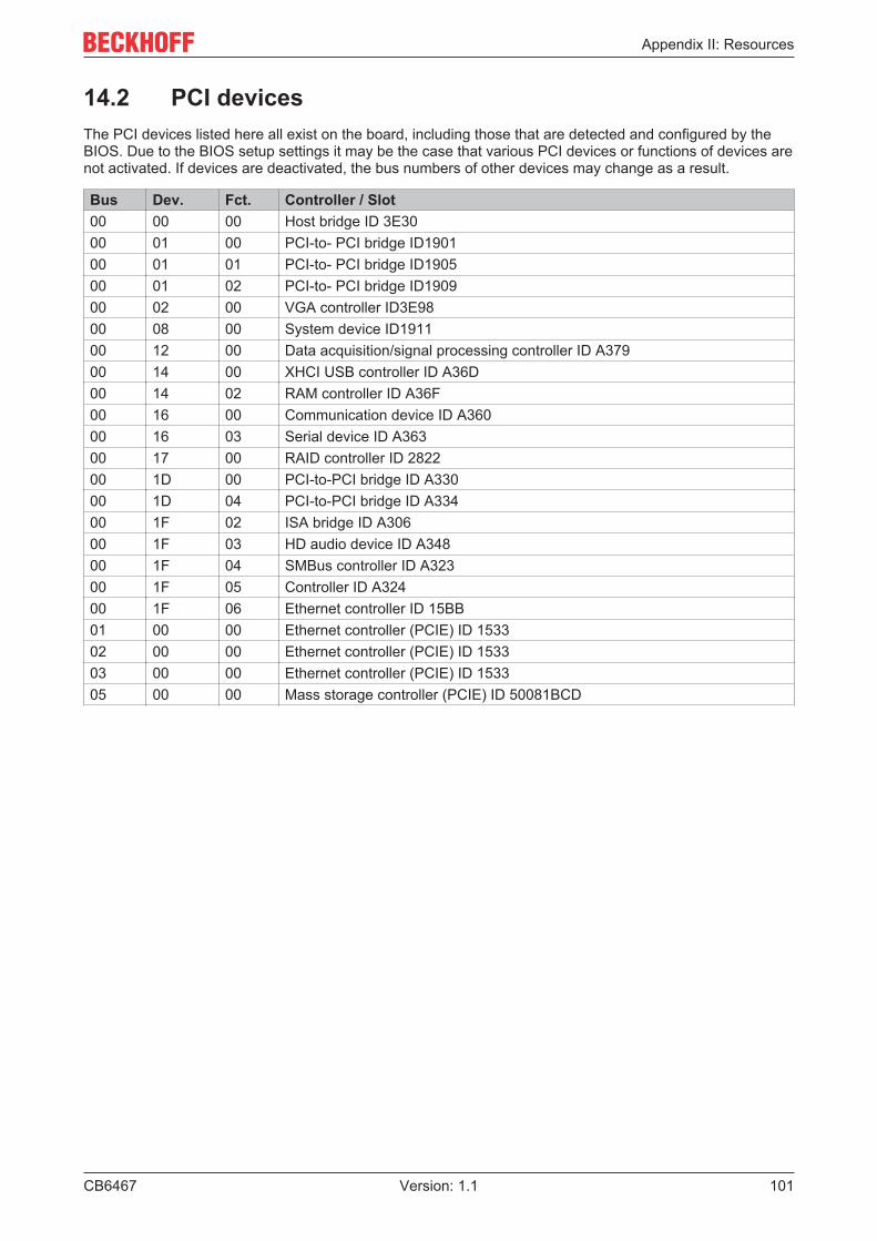
Appendix II: Resources
CB6467 101Version: 1.1
14.2 PCI devicesThe PCI devices listed here all exist on the board, including those that are detected and configured by theBIOS. Due to the BIOS setup settings it may be the case that various PCI devices or functions of devices arenot activated. If devices are deactivated, the bus numbers of other devices may change as a result.
Bus Dev. Fct. Controller / Slot 00 00 00 Host bridge ID 3E30 00 01 00 PCI-to- PCI bridge ID1901 00 01 01 PCI-to- PCI bridge ID1905 00 01 02 PCI-to- PCI bridge ID1909 00 02 00 VGA controller ID3E98 00 08 00 System device ID1911 00 12 00 Data acquisition/signal processing controller ID A379 00 14 00 XHCI USB controller ID A36D 00 14 02 RAM controller ID A36F 00 16 00 Communication device ID A360 00 16 03 Serial device ID A363 00 17 00 RAID controller ID 2822 00 1D 00 PCI-to-PCI bridge ID A330 00 1D 04 PCI-to-PCI bridge ID A334 00 1F 02 ISA bridge ID A306 00 1F 03 HD audio device ID A348 00 1F 04 SMBus controller ID A323 00 1F 05 Controller ID A324 00 1F 06 Ethernet controller ID 15BB 01 00 00 Ethernet controller (PCIE) ID 1533 02 00 00 Ethernet controller (PCIE) ID 1533 03 00 00 Ethernet controller (PCIE) ID 1533 05 00 00 Mass storage controller (PCIE) ID 50081BCD

Appendix II: Resources
CB6467102 Version: 1.1
14.3 SMB devicesThe following table lists the reserved SM-Bus device addresses in 8-bit notation.
NOTEThese address ranges may not be used by external devices even if the component assigned in the tabledoesn't exist on the motherboard.
Address Function 34-35 API access to power supply unit 36-39 Reserved 5C-5D NCT7491 60-6F Reserved for DDR4 70-73 POST Code output 88-89 Slave address defined by BIOS A0-A7 Reserved for DDR4 B0-B3 Power controller (access via BIOS-API) B8-BB Power controller (access via BIOS-API)


Beckhoff Automation GmbH & Co. KGHülshorstweg 2033415 VerlGermanyPhone: +49 5246 [email protected]