current science of methane fuelled explosions and best ...
76
COALTECH RESEARCH ASSOCIATION NPC CURRENT SCIENCE OF METHANE FUELLED EXPLOSIONS AND BEST INTERNATIONAL PRACTICE FOR PROTECTION STRUCTURES By R.P.van Wyk (Pr.Eng.) May 2015 1 1 Copyright COALTECH This document is for the use of COALTECH only, and may not be transmitted to any other party, in whole or in part, in any form without the written permission of COALTECH. PROJECT 2.6
-
Upload
khangminh22 -
Category
Documents
-
view
1 -
download
0
Transcript of current science of methane fuelled explosions and best ...
COALTECH RESEARCH ASSOCIATION NPC
CURRENT SCIENCE OF METHANE FUELLED
EXPLOSIONS AND BEST INTERNATIONAL
PRACTICE FOR PROTECTION STRUCTURES
By
R.P.van Wyk (Pr.Eng.)
May 2015 1
1 Copyright COALTECH
This document is for the use of COALTECH only, and may not be transmitted to any other party, in
whole or in part, in any form without the written permission of COALTECH.
PROJECT 2.6
Information Circular CT2014/02
CURRENT SCIENCE OF METHANE FUELED EXPLOSIONS AND BEST
INTERNATIONAL PRACTICE FOR PROTECTION STRUCTURES
By: Roedolf P.van Wyk (Pr.Eng.)
DISCLAIMERS
The findings and conclusions in this report are those of the author and do not necessarily represent
the views of Coaltech. Reference to work by any other institution is in accordance to each individual
document’s disclaimers. Mention of any company or product does not imply endorsement by
Coaltech.
DISCLAIMER
The report does not provide any recommendations on the design and
construction of seals in the South African mining community. It is beyond the
scope of this report to provide guidelines regarding the design of generic
seals. This report should only be used as a summary of information from other
publications in the field or legislation from foreign countries.

Executive Summary
Two schools of thought exist within the international ventilation community regarding protection
against explosions from within sealed of abandoned panels, namely:
Event prevention ‐ Measure, Inertisize and Control the atmosphere in the panel. (Mainly
Australia) This approached was derived after the 1994 Moura Number 2 disaster.
Event Control ‐ Construct seals capable of withstanding overpressures generated during
Methane/Coal Dust fuelled explosion. (Typically USA) US Final Rule 2008 was developed
after the 2006 Sago disaster.
The US Final Rule 2008 legislation challenged current international seal practice and expanded the
knowledge regarding the chemistry and physics of Methane/Coal Dust fuelled confined explosions.
The legislation introduced dramatic changes to US seal pressure ratings from the historic 20psi
(140kPa) value to present 50psi, 120psi and above 120psi (345kPa, 827kPa ,>827kPa) ratings.
Furthermore this new legislation specifies standards towards seal design, approval, construction and
material or atmosphere testing methods, etc.
The Australian mining sector intensively scrutinized the above US legislation. The industry
communally decided that their system of preventing an incident through risk analysis and “world
best practice” standards by which they control the sealed atmosphere better suits their industry
than the US system of avoiding failure by constructing stronger seals. The New South Wales
government has however adopted the learning from both the Sago Mine explosion report and Final
Rule 2008 in a safety bulletin published in August 2013. The bulletin addresses protection against
lightning strikes, new seal pressure ratings and procedures when the sealed atmosphere passes
through the explosive zone.
Current South African legislation regarding sealing of abandoned panels does not directly conform to
either of these international legislations. The South African seal pressure rates closely resemble the
Australian values. The Australian legislation is primarily based on two header road longwall mining
extraction methods seldom found in South Africa. The US legislation was developed in reaction to
explosions in board‐and‐pillar type mines. This mining method is typically used South African Coal
mining.
The aim of the report is to inform the reader of the current international sealing practice by
discussing recent published scientific reports regarding Methane/Coal Dust fuelled confined
explosions, the origin and implementation of U.S. and Australian sealing legislation as well as new
developments in the industry.

Table of Contents
Executive Summary i
Table of units and abreviations 8
1. Introduction 9
2. History of mine seals
United States of America 12
Australia 14
U.K. & European Practices 17
3. Theory of Methane‐Air explosions
Diffusion of Methane in Air 18
Thermodynamic analysis 19
Tunnel explosion mechanics 19
Experimental proof 24
Summary 25
4. 140kPa & 400kPa Experimental Results
Plug Seal 27
Meshblock Seal 28
Gunmesh Stopping 29
Testing Methodology 31
Structural Analysis 31
Ingwe Spec Walls 33
Conclusions 33
5. Panel Inertization 34
6. U.S.Legislation
Background 38
Legislation 39
7. US Army Corps of Engineers
Introduction 42
Protective Structure Design and Analysis Methods 43
Protective structure design 43
Analysis of Pre‐2006 NIOSH and USBM Seal Tests 44
Analysis of seal foundations 44
Analysis of seal structures 44
Guidelines for Design of Coal Mine Seals 45
Behaviour of 120‐psi Seals Subject to Methane‐Air 45
Detonation Pressure
Blast wave attenuators 46
Summary 48
8. Current Australian Sealing practice
ACARP Project C7015 50
Industry questionnaire survey 50
Relevant differences between US & Australian mines 51

Views on changed US approach 51
SIMTARS Propagation Tube Test Work 51
ACARP Report Summary 53
Comments on ACARP report 53
NSW Safety Bulletin – SB13‐04 55
9. Summary 57
References 59
Annexures
A ‐ EXAMPLES OF TYPICAL APPROVED 120psi CONTAINMENT STRUCTURE DESIGNS AND RELATED
COST COMPARISONS
8 | P a g e
Table of Units and abbreviations
Abbreviations ACARP ‐ Australian Coal Industry Research Program CV ‐ Constant Volume DDT ‐ Deflagration to Detonation Transition DIF ‐ Dynamic Increase Factor DLF ‐ Dynamic Load Factor DME ‐ Department of minerals and Energy Affairs (South Africa) LLEM ‐ Lake Lynn Experimental Mine, Pennsylvania MSHA ‐ Mine Safety and Health Administration NIOSH ‐ National Institute of Occupational Safety and Health SIMTARS ‐ Safety In Mines Testing And Research Station USACE ‐ United States Army Core of Engineers
Units
kPa ‐ Kilo Pascals (1,000 Pa)
MPa ‐ Mega Pascals (1,000,000 Pa)
psi ‐ Pounds per Square Inche
m ‐ Meter
mm ‐ Millimeter
m/s ‐ Meter per Second
Practical Information Boxes ‐ Information provided within these information boxes are remarks by
the author aimed at simplifying the scientific text with information
specifically relating to the South African mining community.
9 | P a g e
INTRODUCTION
Current South African mining regulations require appointed managers to control Methane risks in
mined‐out areas of coal mines and thereby reduce explosion risk from Methane build‐up by either
ventilating or sealing those areas. Continued ventilation of abandoned areas is costly and may divert
ventilating air away from other, more productive uses. Seals are barriers constructed in underground
coal mines to isolate abandoned mining panels from active workings. At present South African mining
regulations require the following:
Any abandoned underground panel must be sealed in accordance with the DME Guideline for the Compilation of a mandatory Code of Practice for the prevention Coal Dust Explosions in Underground Mines. The requirement calls for: The monitoring of the atmosphere behind the containment walls provides the manager with the input to the risk assessment of the abandoned area. Two conditions are likely to exist. 1. The atmosphere in the area has stabilized above or below the explosive range of flammable
gas. As an explosion cannot occur under these conditions, the containment walls now only require regular monitoring in order to verify safe conditions. ….Containment walls must be designed to withstand a static pressure of approximately 140kPa….
2. The atmosphere in the sealed area remains within the explosive range of flammable gas. Further action is then required, e.g.:‐
o Install approved explosion proof seal. ….”Explosion proof seals” means a seal which is designed to withstand a static pressure of typically 0,4MPa and requires an approved design endorsed by a Professional Civil Engineer.
The international coal mining industry is divided into two schools of thought on the management of sealed abandoned panels:
Event Control ‐ Construction of structurally sound seals to guard against failure (Typically practiced in the USA), vs.
Event Prevention ‐ Measure, Monitor and Inert the atmosphere to prevent an incident from occurring. (Typically practiced in Australia)
Both these schools of thought are being successfully implemented in different regions of the world to assure the safety of miners. All of this work is based on tragic lessons learned from previous explosive events. The truth of the matter is that after a tragedy the investigation committee on the incident, the industry as a whole and the lawmakers work together to prevent a reoccurrence of the event. The US department of labour in co‐operation with MSHA in 2006 appointed research teams from both NIOSH and US Army Corps of Engineers to investigate the causes of the Sago Mine tragedy as well as research international best sealing practice. The preliminary findings of both teams were published in separate reports in 2007. The NIOSH report IC9500 provided the then latest knowledge on Methane/Coal‐Dust fuelled explosions specifically towards the chemistry, thermodynamics and overpressures expected during such an event. Furthermore the document made recommendations on pressure ratings to be used for future US seal designs. This information is the cornerstone of the 2008 Final Rules for US seal design. Australian coal mining went through a similar review of coal mine safety in the mid 1990s after Moura Number 2 explosion. The Australian industry adopted a different approach to managing sealed abandoned panels compared to the US, due to differences in mine safety management and mining
10 | P a g e
methods. Much of the recent research conducted by the Americans on the science behind Methane/Coal‐Dust fuelled explosions has challenged and expanded international understanding on the subject. As a result there has been a move for some states in Australia to consider and possibly adopt new US standards for seal pressure rating codes. However industry as a whole, including mines’ management, state inspectorates and mining unions have decided not to adopt the principles dictated of the 2008 US seal regulations. Australian approaches are formulated on a risk assessment basis under which hazards must be identified and appropriate “world’s best practice” systems adopted. The principal approach in Australia to explosive events is early prevention of hazardous situations through use of real time gas monitoring from the goaf periphery to ensure the maintenance of goaf inert atmospheric conditions. Another line of defence is having inert gas systems on hand (most commonly jet or diesel engine exhaust, nitrogen or CO2) to proactively ensure potentially explosive gas concentrations cannot form or are handled appropriately. The final approach is through use of well‐engineered seal structures constructed to segregate all worked out areas where there is any likelihood of explosive gas concentrations occurring. Seals on gassy goafs most commonly are designed to meet a 140kPa rating. Recent regulations by the New South Wales Government do recommend that for the time period during which sealed areas pass through the explosion range the mine be abandoned if only 140kPa(20psi) seals are used, but that the mine may remain open if 827kPa(120psi) are used. This pressure rating follows directly from the US final rule 2008 pressure ratings.
Coaltech aims to remain relevant and up‐to‐date with international safety and best practice standards for all activities in the coal mine industry. The recent US Final Rule 2008 legislation changes regarding the design of explosion proof bulkheads as well as research conducted in the U.S. on the science behind Methane and Coal Dust explosions came to the attention of the Coaltech board. This information prompted the board to commission a research into the current international best practice regarding containment seals. From this desktop research study based on report and other publications on the internet plus correspondence with researchers in the U.S. via email it was decided to send a fact finding team to the U.S. to investigate the relevance of the U.S. work to South African coal mining. During May 2014 a delegation consisting of a Mining Engineer, Ventilation Officer, Rock Engineer and Structural Engineer was sent to the U.S. on a ten day fact finding mission. The itinerary for the mission was mostly planned by Dr.Zipf a renowned and respected researcher and engineer involved in the development of the new US seal standards. The itinerary included official meetings with:
MSHA (Mine Safety and Health Administration) head office
MSHA Tech Support Laboratories
NIOSH (National Institute of Occupational Safety and Health) Laboratories
USACE (United States Army Core of Engineers) Laboratories
Cardno, MM&A and ECSI Consulting engineers
Minova and Strata Worldwide Construction companies
Signal Peak Energy Company, Billings mine and BHP Billiton, Farmington mine. This itinerary covered a comprehensive cross section of the US Coal mining industry involved with the 2008 Final Rule Legislation representing the legislators, researchers, design engineers, construction companies and end‐users. The Coaltech research team learned from the meetings and additional information provided by the U.S. delegates how and why the legislation changed, how the science has affected the legislation, new developments in this field as well as practical considerations regarding construction of these seals. This information gained will be discussed in further detail in this report. The report aims to provide information and is not aimed at delivering an opinion to the implementation or changes to the current South African seal standards. This report should enable readers to understand the current state of the

11 | P a g e
art of coal mine seal design plus legislation in both the U.S. and Australia. The reader should determine to his/her own discretion the applicability of these standards to South African mining conditions. It remains the prerogative of the reader to decide the relevance of both the US and Australian schools of thought towards the sealing practice in South Africa. This document does not recommend one standard above the other, but provides a mosaic of portions from several documents published by the above institutions. The author attempted to present the information in a logical manner to a cross section of readers from related disciplines regarding the subject as well as providing a reference for readers with an in depth background in the field. This document does not provide a complete knowledge of the subject nor does it provide new information to the field, what the document aims to do is provide an overview of the subject with a logical and chronological presentation of relevant information.
12 | P a g e
1. HISTORY OF MINE SEALS
United States of America
Zipf et.al states in IC9500(2007) that the earliest known engineering standards for seals in U.S. underground coal mines is a 1921 regulation for sealing connections between coal mines located on U.S. government‐owned lands. Rice et al.[1931] stated that this regulation required seals to withstand a pressure of 345‐kPa(50 psi) and that it was “based on the general opinion of men experienced in mine‐explosion investigations.” Evidently, the intent of the regulation was to prevent an explosion in one mine from propagating to a neighbouring mine. In Germany and Poland, authorities decided that seals should be designed to withstand 500‐kPa based on observations from moderate‐strength experimental coal mine explosions.
The U.S.Federal Coal Mine Health and Safety Act of 1969 required mined‐out areas to be ventilated or sealed with ‘explosion‐proof bulkheads’ that were constructed with ‘solid, substantial and incombustible materials.’ In the publication Explosion‐Proof Bulkheads: Present Practices, Mitchell (1971) reviewed coal mine explosions and recommended what became 20‐psi (140kPa) criterion for coal mine seals. The general premise behind Michell’s recommendation was that coal mine explosions originate in the active areas of coal mines that is ventilated and has only limited quantities of Methane or coal dust. An explosion within the sealed area was not considered, because it was commonly believed that sealed areas were inert and either contained methane‐rich or oxygen‐poor atmospheres. Mitchell noted that more than 60m from the origin of an explosion of a small amount of explosive mix in 15m of entry, the explosive pressure seldom exceeded 140‐kPa. Most sealed areas are far from the active mining area, so Mitchell concluded that a seal may be considered “explosion‐proof” if it is designed to withstand a static load of 140‐kPa.
Prior to 1992, the Code of Federal Regulations (CFR) lacked a definitive design specification for explosion‐proof mine seals. Stephan (1990) reviewed Mitchell’s work and also concluded that the explosive pressure on seals generally does not exceed 20‐psi. As a result of the Stephan report, the explosion pressure performance criterion for seals became 20‐psi in the 1992 change to Code of Federal Regulations Rule 30 CFR 75∙335(a)(2). This rule change is generally referred to as the “Alternative Seals Rule”, since it facilitated the development of alternatives to the conventional Mitchell‐Barrete seal of solid concrete blocks used up to this time. Examples of alternatives include cement foam plug seals, polyurethane foam and aggregate plug seals, Omega Block seals and wood crib block seals (Zipf et al. 2009). To determine whether an alternative seal design met the 20‐psi requirement, the Mine Safety and Health Administration (MSHA) relied on full‐scale explosion tests conducted by the National Institute for Occupational Safety and Health Administration (NIOSH) in their Lake Lynn Experimental Mine (LLEM) in Pennsylvania.
Working under the direction of MSHA and the seal manufacturers, NIOSH researchers constructed actual full‐scale alternative seals at the LLEM and subjected them to a side‐on (i.e., quasi‐static) pressure of 20‐psi that was generated by a test methane explosion. The candidate seal passed the test if it survived the explosion pressure without any visible damage such as cracking or displacement. Air leakage across the seal was then measured to determine if it also met leakage requirement.
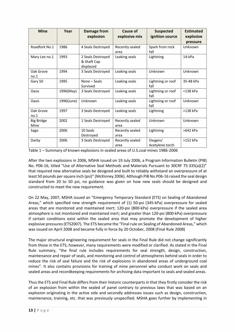
Between 1986 and 2006, 12 known explosions occurred within sealed areas of active U.S. underground coal mines. Table 1 summarizes the known characteristics of these explosions as determined by the relevant MSHA accident investigation reports
13 | P a g e
Mine Year Damage from explosion
Cause of explosive mix
Suspected ignition source
Estimated explosive pressure
Roadfork No.1 1986 4 Seals Destroyed Recently sealed area
Spark from rock fall
Unknown
Mary Lee no.1 1993 2 Seals Destroyed & Shaft Cap displaced
Leaking seals Lightning 14‐kPa
Oak Grove no.1
1994 3 Seals Destroyed Leaking seals Unknown Unknown
Gary 50 1995 None – Seals Survived
Leaking seals Lightning or roof fall
35‐48 kPa
Oasis 1996(May) 3 Seals Destroyed Leaking seals Lightning or roof fall
<138 kPa
Oasis 1996(June) Unknown Leaking seals Lightning or roof fall
Unknown
Oak Grove no.1
1997 3 Seals Destroyed Leaking seals Lightning >138 kPa
Big Bridge Mine
2002 1 Seals Destroyed Recently sealed area
Unknown Unknown
Sago 2006 10 Seals Destroyed
Recently sealed area
Lightning >642 kPa
Darby 2006 3 Seals Destroyed Recently sealed area
Oxygen/Acetylene torch
>152 kPa
Table 1 – Summary of known explosions in sealed areas of U.S.coal mines 1986‐2006
After the two explosions in 2006, MSHA issued on 19 July 2006, a Program Information Bulletin (PIB) No. P06‐16, titled “Use of Alternative Seal Methods and Materials Pursuant to 30CRF 75∙335(a)(2)” that required new alternative seals be designed and built to reliably withstand an overpressure of at least 50 pounds per square inch (psi)” (McKinney 2006). Although PIB No.P06‐16 raised the seal design standard from 20 to 50 psi, no guidance was given on how new seals should be designed and constructed to meet the new requirement. On 22 May, 2007, MSHA issued an “Emergency Temporary Standard (ETS) on Sealing of Abandoned Areas,” which specified new strength requirement of (1) 50‐psi (345‐kPa) overpressure for sealed areas that are monitored and maintained inert; 120‐psi (800‐kPa) overpressure if the sealed area atmosphere is not monitored and maintained inert; and greater than 120‐psi (800‐kPa) overpressure if certain conditions exist within the sealed area that may promote the development of higher explosive pressures (ETS2007). The ETS became the “Final rule on Sealing of Abandoned Areas,” which was issued on April 2008 and became fully in force by 20 October, 2008 (Final Rule 2008) The major structural engineering requirement for seals in the Final Rule did not change significantly from those in the ETS; however, many requirements were modified or clarified. As stated in the Final Rule summary, “the final rule includes requirements for seal strength, design, construction, maintenance and repair of seals, and monitoring and control of atmospheres behind seals in order to reduce the risk of seal failure and the risk of explosions in abandoned areas of underground coal mines”. It also contains provisions for training of mine personnel who conduct work on seals and sealed areas and recordkeeping requirements for archiving data important to seals and sealed areas. Thus the ETS and Final Rule differs from their historic counterparts in that they firstly consider the risk of an explosion from within the sealed of panel contrary to previous laws that was based on an explosion originating in the active side and secondly addresses issues such as design, construction, maintenance, training, etc. that was previously unspecified. MSHA goes further by implementing in
14 | P a g e
the Final Rule controls over end‐users and installers. The mine management, designers, and contractor have to prove their compliance to the legislator. It is relevant to know that the ETS and Final Rule were introduced within a period of less than 22 months. Thus all the research and preparation required to develop the legislation was condensed into a few months. Furthermore the time and extent of public hearing remarks to the proposed legislation were abbreviated by the rushed nature of this legislation. Due to the nature of the U.S. legal system any changes to the existing legislation has to follow the same stringent route of public hearings and scrutiny as the original approval procedure. As a result there is a resistance to implementing any subsequent knowledge and industry developments in regards to seal science and practice. Thus even when new science proves a part of the legislation wrong or when a revolutionary engineering design is developed none of these are considered by the Final Rule. The inflexibility of the law system means that the Final Rule is applied in a blanket fashion to all mines irrespective to the mine’s specific gas conditions and other risk factors that are not addressed in the Final Rule. The blanket application of the law has as a direct result the construction of large seals in areas where no risk for explosions exists, thus unnecessary cost to the operator. It furthermore has resulted in a lack of motivation to develop attenuation measures aimed at reducing the pressure peaks that could result in cheaper equally effective seals. The current U.S. legislation for the design of seals in coal mines has evolved over nearly a hundred years, from its primitive empirical estimated values, to sound scientific foundations and practical implementations based on the lessons learned from historic disasters. The rigid nature of the U.S. law system will resist any major changes to the current legislation bar catastrophe or fundamental scientific fact. Australia In Australia, within Queensland according to Standards for Seals and Airlocks 1967 issued by Coal Operations Branch, Safety and Health Division, Queensland Department of Mines and Energy (QDME), four specific elements must be addressed when installing seals. These are;
design and specification,
location,
construction, and
maintenance and monitoring. Stoppings, as defined by Hartman et al (1997), are physical barriers erected between intakes, returns or abandoned mine voids to prevent air from mixing. Stoppings are classified according to construction, length of service, and purpose as temporary or permanent. Temporary stoppings are extensively used in areas where frequent adjustment to air directions are necessary. They are moderately airtight and are normally hung in active workings where changes occur rapidly in the mining and ventilation methods. They must be readily movable and are generally reusable. Permanent stoppings, also called bulkheads, are installed in places where a permanent or a long‐term control of flow is needed, such as between the main intakes and returns or belt entries. In the past these have been constructed of frame, sheet metal (prefabricated sections), masonry (stone, brick, or concrete block) or “shotcrete” sprayed on wire mesh. Because their purpose is to stop airflow for an indefinite period, they must be made airtight by tapping, plastering or caulking and resistant to cracking from blasting concussion or ground movement. Permanent stoppings are also used as fire bulkheads to seal off abandoned workings. Abandoned workings may in time hold toxic or explosive gas mixtures and so these bulkheads must both stop atmospheric mixing and be able to withstand a pressure event. A seal is a special stopping used to isolate abandoned workings and goafs or as fire bulkheads. Seals
15 | P a g e
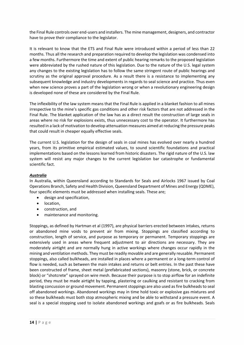
eliminate the need to ventilate those areas; they may also be used to isolate fire zones or areas susceptible to spontaneous combustion. According to the above survey questionnaire, prior to 1997 various materials were used to segregate different areas of the mine ventilation from one another. A summary of the materials and specific applications are shown in Table 2. It is clear from the table that no clear pressure rating was available to the industry at the time. Table 2 – Questionnaire results for materials used as seals Belt Road
Segregation Main intake / Belt Segregation from
Return
Segregate intake from Belt Air in panel Gateroads
Final Panel seal segregation from adjacent panels
Final panel seal segregation from
Mains
Brattice 2
Plasterboard 2 2 7 3 2
Sheet Metal 1 1
Mortar Blocks 1 6 4
Blocks 2 4 2
Low Density Blocks 2
Reinforced Cementitios
4 2 1 1
Composite Polymer 1
Nothing Remainder
On August 7, 1994, 11 miners and 1 contractor were killed when a methane‐air mixture ignited within a recently sealed room‐and‐pillar panel at the BHP Australia Coal Moura No. 2 coal mine in Queensland, Australia [Roxborough 1997]. The most likely ignition source was determined to be the heating caused by spontaneous combustion within the sealed area. The overpressures generated from the methane ignition resulted in the failure of several seals that were newly installed about 22hr before the ignition. As a result of this disaster, a considerable public outcry demanded that an in‐depth inquiry be conducted to determine the cause of the explosion and to recommend ways to prevent future occurrences in the Queensland coal mines. In late 1997 and early 1998, NIOSH Pittsburgh Research Laboratory (PRL) collaborated on a joint research project with Barclay Mowlem Construction Ltd. Of Queensland, Australia, to investigate the capability of various seal and stopping designs and an overcast design to meet or exceed the requirements of the Queensland Department of Mines and Energy's [1996] Approved Standard for Ventilation Control Devices. This standard was the result of deliberations and investigations by Task Group 5, which was formed by the recommendation of the Warden's Inquiry concerning the Moura No. 2 mine explosion [Roxborough 1997]. Task Group 5 was charged with the reassessment of the regulatory provisions for explosion‐resistant seals and the investigation of mine inerting techniques. Prior to the enactment of new regulations on 16 March, 2001 in Queensland, introduction of the Queensland Mines Department Approved Standard for Ventilation Control Devices provided prescriptive ratings for seals and stoppings and required live testing of seals and stoppings in an “internationally recognized mine testing explosion gallery”. Control devices in Australia are as follows: 14kPa, 35kPa, 140kPa, and 345 kPa (2psi, 5psi, 20psi, and 50 psi). The expected outcome of these standards for seals and airlocks in Queensland is that all ventilation control structures will have an overpressure rating based on an assessment of the risk and purpose of the particular control structure. These standards do not address the structural design or the material to be used in seal construction. As part of the enormous amount of research undertaken at the time after the recommendations of Task Group 5 (Oberholzer and Lyne, 2002) in establishing practical design criteria to assist mining engineers to minimize the risks of seal failure. Gateroad seal design more or less conformed to seal ratings used in the United States since 1971 where it was stated in 39 CFR 75.335 (Mine Safety and Health Administration – Title 30 Code of Federal Regulations, 1997) requires a seal to “withstand a
16 | P a g e
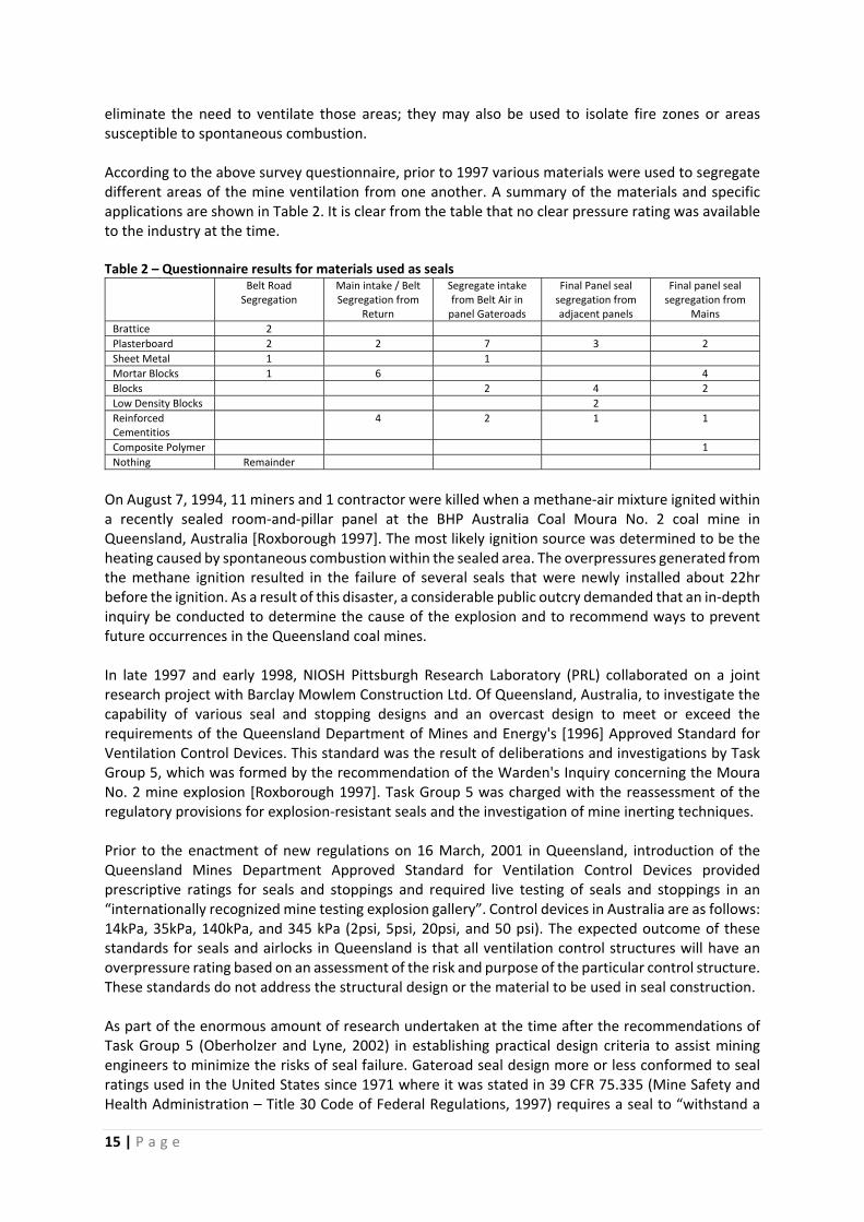
static horizontal overpressure of 138 kPa (20 psi). Previous research by the former U.S Bureau of Mines (Weiss et al, 1999) indicated that it would be unlikely for overpressures exceeding 20 psi (138kPa) to occur very far from the explosion origin provided that the area on either side of the seal contained sufficient incombustible and minimal coal dust accumulations. Current legislation in Queensland depends on the purpose or intent of the seal and its location, different design criteria are recommended by QDME. These recommended design criteria are listed in Table 3. Table 3. Queensland approved standard for ventilation control devices.
Location Purpose or Intent
Type A (2 psi)
14 kPa
(Recommended)
Limited Life
Production Panel
All VCDs installed are to remain “fit for purpose” for the life of the panel and be
capable of withstanding an overpressure of 14 kPa.
Type B (5 psi)
35 kPa
(Recommended)
Main Roadways
All VCDs constructed as part of the main ventilation system are to remain “fit for purpose” for the life of that area of the mine and always capable of withstanding an overpressure of 35 kPa.
Sealed Areas For use in mines where the level of naturally occurring of flammable gas is insufficient
to reach the lower explosive limit under any circumstances.
Type C (20 psi)
140 kPa
Sealed Areas For use in all circumstances not covered by Type B and D seals.
Type D (50 psi)
345 kPa
Sealed Areas When persons are to remain underground whilst an explosive atmosphere exists in
a sealed area and the possibility of spontaneous combustion, incendive spark or
some other ignition source could exist.
Type E (10 psi)
70 kPa
Surface
Infrastructure
Surface entry stoppings for temporary emergency use and may include
‐ Surface air locks, Main fan housing
New South Wales Trade & Investment Mine Safety Bulletin SB13‐04 published on 29 August 2013 Titled: “Sealing of a goaf or mined out area in an underground coal mine and management of legacy sealed areas” states the following. “The Mine Safety and Health Administration USA report into the Sago Mine explosion now means that the possibility of a lightning strike to the surface over and surrounding such areas must be considered as a direct ignition source in addition to mine infrastructure that may be capable of conducting electrical energy into a mine.” “It is recommended that any coal operator in NSW that cannot quantitatively demonstrate that their existing sealing arrangements for goaves or mined out areas are tolerable and maintained as low as reasonably possible (ALARP), then one of the following measures be implemented to eliminate or control the risk of explosion post sealing: … b. Evacuate the mine until a sealed goaf or mined out area has passed through the explosive range and employ normal 20 psi overpressure rated mine seals.
17 | P a g e
c. Permit the goaf or mined out area to pass through the explosive range, without evacuation of the mine, after the installation of 120 psi or 120 psi plus overpressure rated seals in all entrances to the goaf or mined out area…” UK and European Practices. The issue of explosion resistant seals has been addressed a number of times in the UK by committee. In 1942 (3), descriptions of various explosion resistant seals were given, some of which had been successfully used to contain explosions within sealed areas after sealing of fires or heatings. Generally, the seals were very long (30 feet or so), but no particular explosion rating was stated. In 1962 (4), it was assumed that seals should be designed to withstand explosion pressures in the range of 20 to 50 psi (140 to 350 kPa). Construction methods were described again, but these were based on past practice rather than any design methods or tested seals. In 1985 (5), the design of explosion resistant seals was again reviewed. Explosion resistance rating appears to have been increased to 524 kPa (76 psi) based on observed pressures developed by methane/coal dust explosions. The length of a monolithic gypsum pack was established to resist this pressure was given as : L = (H+W)/2 + 0.6 Where L = length of seal (m) H = height of seal (m) W= width of seal (m) It was also acknowledged that If it were not for the possible risk of explosion, the operation of sealing‐off would consist simply of providing a seal designed solely to prevent access of air to the fire and requiring little or no mechanical strength." There does not appear to be any requirement for explosion resistance ratings on any other ventilation structures other than seals used to control fire and spontaneous combustion. Very little information has been obtained on the standards for explosion resistant seals in European coal mining operations. West German coal mines are required to comply with a "Directive for the construction of stoppings" (6) , which requires the explosion resistant stoppings be capable of withstanding maximum static pressures of 0.5 MPa (5 bar, 75 psi). It would appear that these structures are intended to "seal off, hermetically, parts of the mine workings," to prevent the propagation of "mechanical, thermal and toxic effects" to other areas of the mine. From a search of abstracts, Cybulski et al (7), indicate that explosion pressures in sealed off areas had been recorded at more than 30 bar (450 psi). However, conceding the difficulty of building a stopping of such a strength , it is assumed that, in Poland, less strong stoppings of about 5 bar (75 psi) would be sufficient in practice. Again it is considered that explosion resistant seals are required to prevent an explosion from propagating from within a sealed area.
18 | P a g e
3. THEORY OF METHANE‐AIR EXPLOSIONS
Diffision of Methane in Air
A common misconception exist that Methane layering will develop within the still air of a sealed area,
similar to the way it can occur in ventilated working areas of the mine. This misconception arises
because it is common knowledge that Methane tends to collect along the roof and that miners are
instructed to measure Methane concentrations in a coal mine 1ft from the roof. The density of
Methane is about 0.55 times that of air, so buoyancy effects do exist. However, in the complete still
air within a sealed area, diffusion processes will dominate over buoyancy effects, which will lead to
development of a homogeneous Methane‐Air mix within a few days or less.
It is probably this misconception that firstly gave rise to the idea that explosions from within sealed
areas are not possible. The belief was that Methane will accumulate in a layer near the roof and
become inert due to saturation levels above 17%. Thus if all the Methane released from within the
sealed panel will rise and become inert in a layer near the roof, the chance for an explosive event is
thus near zero.
The diffusion rate can be calculated from the kinetic theory of gases. If a gas component is present in
non‐uniform concentration, and at uniform constant pressure and temperature in the absence of
external fields, that component diffuses to render its concentration uniform. The rate that the
diffusion process occurs under most conditions is proportional to the concentration gradient times
the diffusion constant. This elementary relationship is called Fick’s first law of diffusion, in which the
diffusion constant for Methane in air is 0.157 cm³/s (McCabe and Smith 1967).
Zlochower (2007a) used diffusion theory to estimate the time required for methane concentrated at
the roof of a 2.1m high coal seam to diffuse uniformly from roof to floor. The methane concentration
reaches uniformity within 10% in about 21 hours. His calculations assume a slow methane influx rate.
If the methane influx is rapid or from the floor, then convective mass transfer will only enhance
component mixing and decrease the mixing time.
In summary, contrary to common misconceptions about methane layering, the completely still air
within a sealed area will develop a fairly uniform mixture of methane and air within a matter of days
after sealing. Diffusion processes dominate buoyancy effects, and the mixing process is only enhanced
by any convective mass transfer.
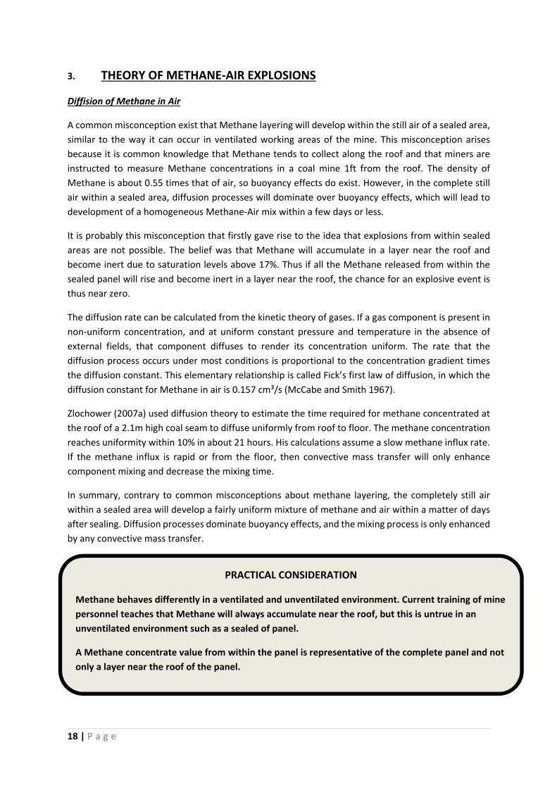
PRACTICAL CONSIDERATION
Methane behaves differently in a ventilated and unventilated environment. Current training of mine
personnel teaches that Methane will always accumulate near the roof, but this is untrue in an
unventilated environment such as a sealed of panel.
A Methane concentrate value from within the panel is representative of the complete panel and not
only a layer near the roof of the panel.
19 | P a g e
Thermodynamic analysis
The chemical reaction for an ideal stoichiometric mix of about 10% by volume Methane in air is given
by:
CH4 + 2O2 → CO2 + 2H2O + Energy (A)
To develop a respect for the amount of energy potential in a Methane‐air mix note that the energy
content in 1m³ of ideal Methane air mix is about equivalent to 0.75 kg of TNT.
Zipf et.al in IC9500 states that thermodynamic theory provides us with information regarding the
pressures and temperatures that can be achieved with Methane‐air mix explosions. Possible
temperature within the explosion of 2670 K and a pressure increase of 800‐kPa is predicted in theory.
Combustion of nonstoichiometric Methane‐air mixes produces lower temperature and pressure
increases. Experimental data prove that these values are accurate especially in places where the ratio
of surface area to enclosed volume is small such as found in mine entries. Natural gas in coal mines
usually consist of 90% or more Methane, but it may also contain other alkanes such as Ethane,
Propane, Butane and Pentane. These higher hydrocarbons may increase the energy release and the
pressure somewhat. As it is not possible to predict the composition of an explosive Methane‐air mix
within a sealed area, prudent engineering requires that we plan for the highest potential explosion
pressure, i.e. the pressure developed by the ideal stoichiometric mix.
Thermodynamic theory provides us with similar information relating to Coal‐Dust‐air mix explosions
as with Methane‐air mix explosions. Coal dust explosion data presented by Hertzberg and Cashdollar
[1987], Wiemann [1986] and Cashdollar[1996] show that rapid combustion of coal dust in air will
develop a Constant Volume (CV) explosion pressure similar to that for Methane‐air.
Tunnel explosion mechanics
The above results for CV explosions are based on three key assumptions: (1) the reaction vessel is
small and spherical so that dynamic effects due to pressure waves are negligible; (2) the ignition occurs
at the centre of the vessel, (3) the flame speed remains small and well below the speed of sound
(Subsonic). However, Methane‐Air ignitions in mines propagate along mine entries (tunnels) and the
physics is much more complex than a simple reaction vessel. These complexities can lead to the
FACT 1
Combustion of stoichiometric (≈10%) Methane‐Air mix in a
closed volume raises the absolute pressure from 101 to 908 kPa
FACT 2
Combustion of fuel‐rich coal dust‐Air mix in a closed volume
raises the absolute pressure from 101 to 790‐890 kPa, which is
only slightly less than combustion of Methane‐Air mix.
20 | P a g e
development of much higher explosion pressures. Numerous authors have described the combustion
process as it initiates from ignition point in a fuel‐air mixture and develops into an explosion [Zucrow
and Hoffman 1976; Baker et al. 1983; Zeldovich et al. 1985; Landau and Lifshitz 1987; Lewis and von
Elbe 1987; Gexcon 2007]
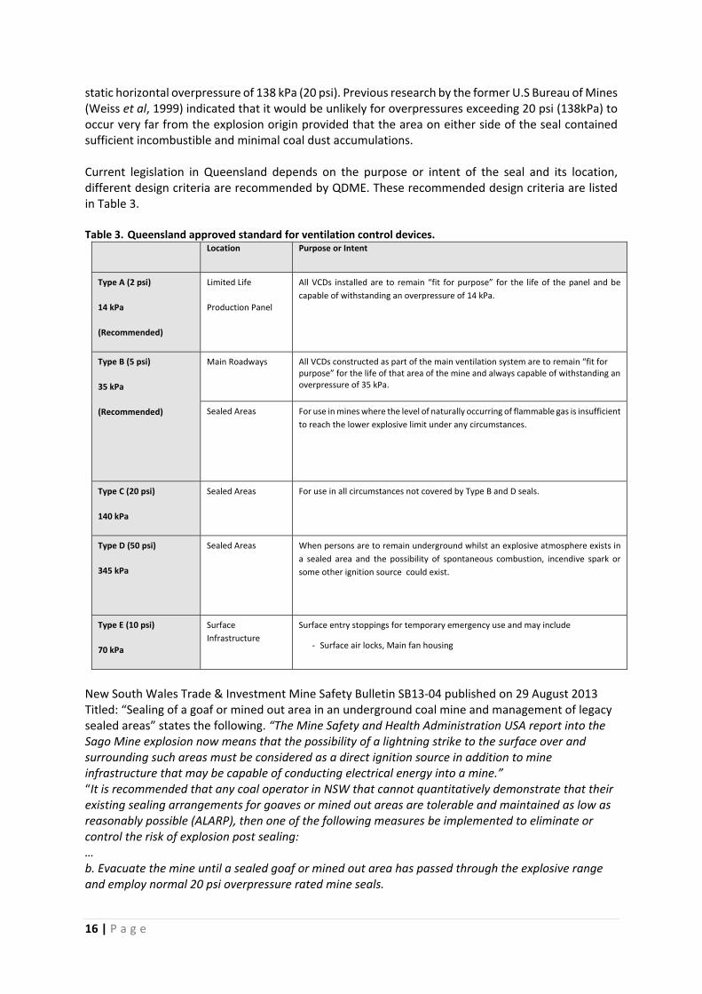
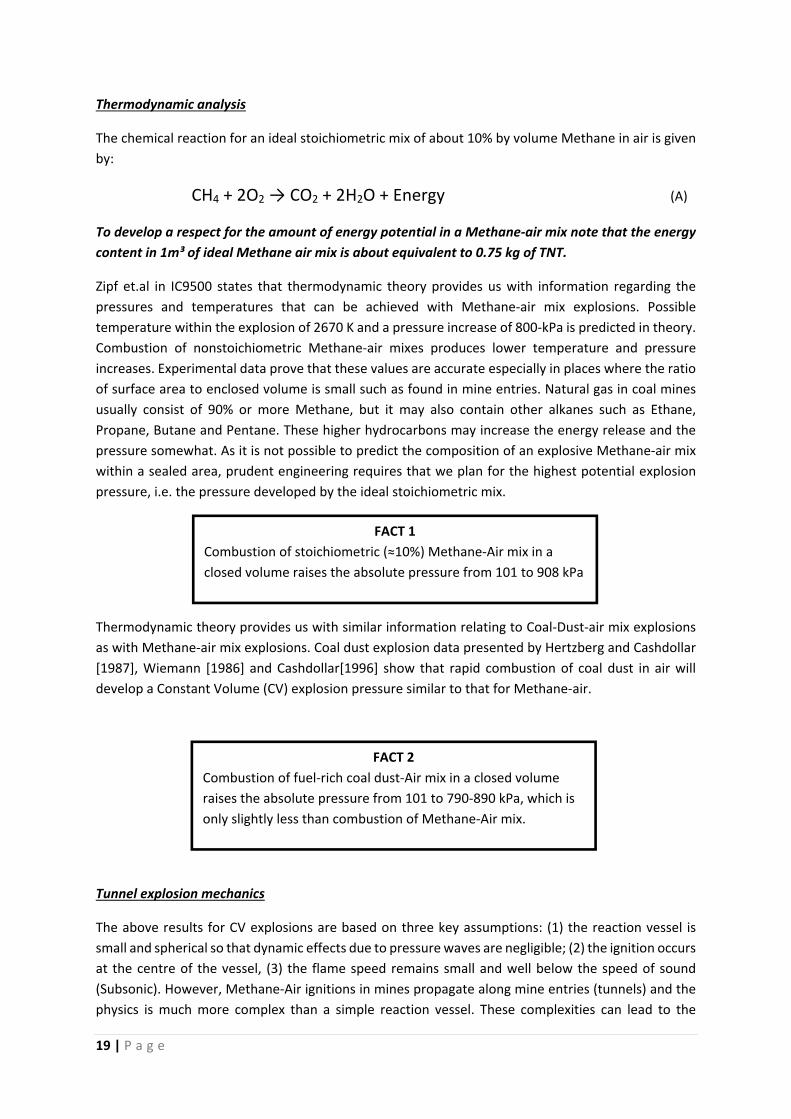
Consider a mine entry closed at both ends and filled with Methane‐Air mix as shown in Figure 1.
Ignition occurs at the far right end and the flame propagates to the left. Upon ignition the initial
laminar flame speed is only 3 m/s; however a slow deflagration accelerates and the turbulent flame
speed may increase to 300m/s. The pressure in the burner gas behind the flame front increases to
908‐kPa CV explosion pressure. The combustion front acts as a piston, compressing the unburned gas
in front of it. The leading edge of the acoustic wave propagates to the left at the local sound speed of
about 341 m/s. In between this wave front and the flame front, the unburned gas acquires velocity to
the left and the static pressure inside this region will increase. This pressure ahead of the flame front
is termed “pressure piling”
Figure 1 – Slow Deflagration diagram and Equivalent pressure profile along tunnel
As the velocity of the unburned gas ahead of the flame front increases, the turbulence in the flow will
increase. The degree of turbulence depends on both the flow velocity and the roughness of the tunnel.
Obstructions roof and rib falls, ground support, machinery and wall roughness are possible forms of
tunnel roughness that will enhance turbulent flow. The increased turbulent flow in the unburned gas
ahead of the flame will increase the combustion rate and the flame front will begin to catch up to the
pressure wave front. At higher but still subsonic flame front speed, the combustion process becomes
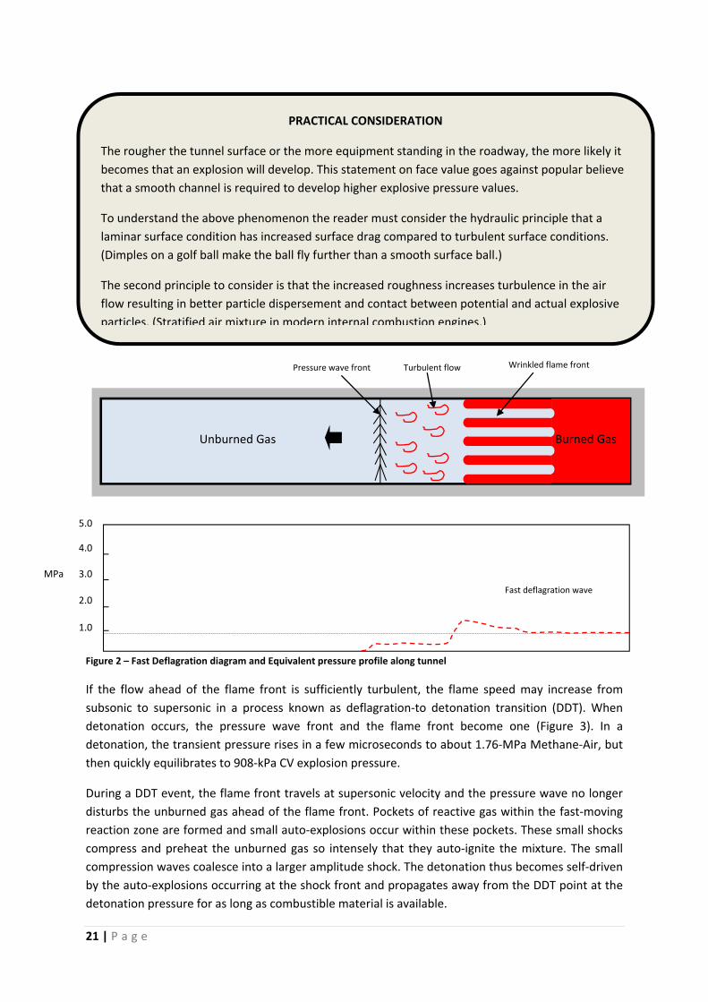
fast deflagration as shown in Figure 2. Combustion of precompressed unburned gases leads to
pressures greater than the 908‐kPa CV explosion pressure. These transient pressure waves will
equilibrate and the overall pressure inside the closed tunnel will eventually settle balance to 908‐kPa.
Wrinkled flame frontTurbulent flow
Pressure wave front
Unburned Gas
Slow deflagration wave1.0
2.0
3.0
4.0
5.0
MPa
21 | P a g e
Figure 2 – Fast Deflagration diagram and Equivalent pressure profile along tunnel
If the flow ahead of the flame front is sufficiently turbulent, the flame speed may increase from
subsonic to supersonic in a process known as deflagration‐to detonation transition (DDT). When
detonation occurs, the pressure wave front and the flame front become one (Figure 3). In a
detonation, the transient pressure rises in a few microseconds to about 1.76‐MPa Methane‐Air, but
then quickly equilibrates to 908‐kPa CV explosion pressure.
During a DDT event, the flame front travels at supersonic velocity and the pressure wave no longer
disturbs the unburned gas ahead of the flame front. Pockets of reactive gas within the fast‐moving
reaction zone are formed and small auto‐explosions occur within these pockets. These small shocks
compress and preheat the unburned gas so intensely that they auto‐ignite the mixture. The small
compression waves coalesce into a larger amplitude shock. The detonation thus becomes self‐driven
by the auto‐explosions occurring at the shock front and propagates away from the DDT point at the
detonation pressure for as long as combustible material is available.
MPa
5.0
2.0
1.0
3.0
4.0
Fast deflagration wave
Pressure wave front Wrinkled flame frontTurbulent flow
Burned Gas Unburned Gas
PRACTICAL CONSIDERATION
The rougher the tunnel surface or the more equipment standing in the roadway, the more likely it
becomes that an explosion will develop. This statement on face value goes against popular believe
that a smooth channel is required to develop higher explosive pressure values.
To understand the above phenomenon the reader must consider the hydraulic principle that a
laminar surface condition has increased surface drag compared to turbulent surface conditions.
(Dimples on a golf ball make the ball fly further than a smooth surface ball.)
The second principle to consider is that the increased roughness increases turbulence in the air
flow resulting in better particle dispersement and contact between potential and actual explosive
particles. (Stratified air mixture in modern internal combustion engines.)
22 | P a g e
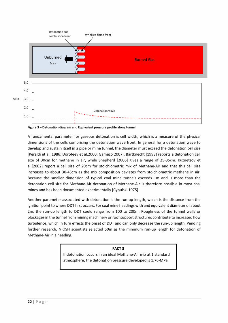
Figure 3 – Detonation diagram and Equivalent pressure profile along tunnel
A fundamental parameter for gaseous detonation is cell width, which is a measure of the physical
dimensions of the cells comprising the detonation wave front. In general for a detonation wave to
develop and sustain itself in a pipe or mine tunnel, the diameter must exceed the detonation cell size
[Peraldi et al. 1986; Dorofeev et al.2000; Gamezo 2007]. Bartknecht [1993] reports a detonation cell
size of 30cm for methane in air, while Shepherd [2006] gives a range of 25‐35cm. Kuznetsov et
al.[2002] report a cell size of 20cm for stoichiometric mix of Methane‐Air and that this cell size
increases to about 30‐45cm as the mix composition deviates from stoichiometric methane in air.
Because the smaller dimension of typical coal mine tunnels exceeds 1m and is more than the
detonation cell size for Methane‐Air detonation of Methane‐Air is therefore possible in most coal
mines and has been documented experimentally [Cybulski 1975]
Another parameter associated with detonation is the run‐up length, which is the distance from the
ignition point to where DDT first occurs. For coal mine headings with and equivalent diameter of about
2m, the run‐up length to DDT could range from 100 to 200m. Roughness of the tunnel walls or
blockages in the tunnel from mining machinery or roof support structures contribute to increased flow
turbulence, which in turn effects the onset of DDT and can only decrease the run‐up length. Pending
further research, NIOSH scientists selected 50m as the minimum run‐up length for detonation of
Methane‐Air in a heading.
MPa
4.0
3.0
5.0
2.0
1.0
Detonation wave
FACT 3
If detonation occurs in an ideal Methane‐Air mix at 1 standard
atmosphere, the detonation pressure developed is 1.76‐MPa.
Wrinkled flame frontDetonation and
combustion front
Burned Gas Unburned
Gas
23 | P a g e
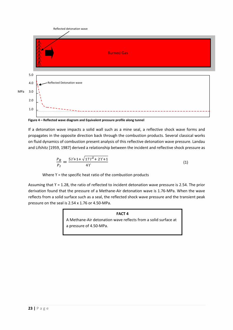
Figure 4 – Reflected wave diagram and Equivalent pressure profile along tunnel
If a detonation wave impacts a solid wall such as a mine seal, a reflective shock wave forms and
propagates in the opposite direction back through the combustion products. Several classical works
on fluid dynamics of combustion present analysis of this reflective detonation wave pressure. Landau
and Lifshitz [1959, 1987] derived a relationship between the incident and reflective shock pressure as
ϒ ϒ ϒ
ϒ (1)
Where ϒ = the specific heat ratio of the combustion products
Assuming that ϒ = 1.28, the ratio of reflected to incident detonation wave pressure is 2.54. The prior
derivation found that the pressure of a Methane‐Air detonation wave is 1.76‐MPa. When the wave
reflects from a solid surface such as a seal, the reflected shock wave pressure and the transient peak
pressure on the seal is 2.54 x 1.76 or 4.50‐MPa.
Reflected detonation wave
Burned Gas
MPa
5.0
4.0
3.0
2.0
1.0
Reflected Detonation wave
FACT 4
A Methane‐Air detonation wave reflects from a solid surface at
a pressure of 4.50‐MPa.
24 | P a g e
Experimental proof
The theoretical calculations above gives a CV explosion pressure of 908‐kPa detonation pressure of
1.76‐MPa and reflective pressure of 4.50‐MPa. Test explosions conducted at experimental mines in
the United States and Europe confirms the reality of these pressures.
Nagy [1981] summarized decades of Methane and Coal Dust explosion research conducted in the
Bruceton Experimental Mine. In all cases, these tests were open‐ended, i.e. the explosive mixture is
partially confined and able to vent, unlike the totally confined environment within a sealed area. A
few of the larger tests developed peak pressures of 1.04‐MPa and indicate that some pressure piling
occurred as the explosion propagated. Early work at the Tremonia Mine in Germany [Schultze‐
Rhonhof 1952] developed pressures of 1‐MPa in similar open‐ended experiments, supporting the U.S.
findings.
Cybulski et al. [1967] described nine experimental Methane‐Air explosion experiments in a 57 m long
tunnel at the Maja Mine in Poland. The amount of explosive mix ranged from 10 to 1,000m³ and the
length of the gas zone ranged from 4.3m to the full 57m length of the experimental tunnel. Two tests
in which the explosive mix completely filled the tunnel produced peak pressures greater than 3.2‐
MPa. Pressure piling clearly occurred during these particular tests. Flame speed was measured
1,200m/s corresponding to Mach 3.5, which suggests the possibility that detonation occurred. Other
tests in which the tunnel was not completely filled with explosive mix developed peak pressures in the
range 0.2‐MPa to 1.5‐MPa. These experimental results showed a clear relationship between the length
of the explosive mix zone and the maximum explosive pressure. A gas zone length more than 50m
long can develop peak explosion pressures of more than 2.0‐MPa which in turn lead to detonation.
In test #1397 conducted at Experimental Mine Barbara in Poland, Cybulski [1975] back‐calculated
explosion pressures in excess of 4.1‐MPa. The experimental explosion was initiated in coal dust about
200m from the closed end of a tunnel. Three measurements of pressure wave speed ranged from
1,600 m/s to 2,000 m/s which clearly suggest detonation. Unfortunately, sensors could not measure
the pressure directly, however the explosion punched a 1.4m² hole into a 32mm thick steel door.
In his Ph.D. dissertation, Genthe [1968] examined peak explosive pressure, flame speed and the length
of an explosive mix zone in order to determine their relationship. Experimental explosions with
PRACTICAL CONSIDERATION
The maximum combustion overpressure that can be developed during a Coal‐Dust‐Fuelled
explosion is 790kPa. The maximum combustion overpressure that can be developed during a
Methane‐Fuelled explosion is 1760kPa.
This fact is contrary to the popular South African mining believe that a Coal‐Dust‐Fuelled (CDF)
explosion develops higher pressures than what a Methane‐Fuelled (MF) explosion can develop.
The chief reason for the lower pressure in a CDF explosion is the amount of energy required from
the explosion process to move and disperse coal particles into the atmosphere prevents the
development of detonation conditions. Due to the well dispersed particle concentrate in MF
explosions as explained by diffusion the MF explosion can develop detonation.
25 | P a g e
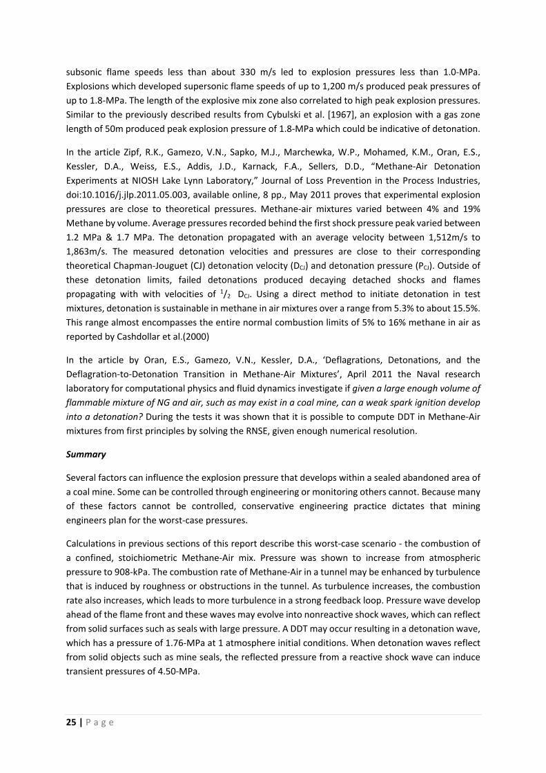
subsonic flame speeds less than about 330 m/s led to explosion pressures less than 1.0‐MPa.
Explosions which developed supersonic flame speeds of up to 1,200 m/s produced peak pressures of
up to 1.8‐MPa. The length of the explosive mix zone also correlated to high peak explosion pressures.
Similar to the previously described results from Cybulski et al. [1967], an explosion with a gas zone
length of 50m produced peak explosion pressure of 1.8‐MPa which could be indicative of detonation.
In the article Zipf, R.K., Gamezo, V.N., Sapko, M.J., Marchewka, W.P., Mohamed, K.M., Oran, E.S.,
Kessler, D.A., Weiss, E.S., Addis, J.D., Karnack, F.A., Sellers, D.D., “Methane‐Air Detonation
Experiments at NIOSH Lake Lynn Laboratory,” Journal of Loss Prevention in the Process Industries,
doi:10.1016/j.jlp.2011.05.003, available online, 8 pp., May 2011 proves that experimental explosion
pressures are close to theoretical pressures. Methane‐air mixtures varied between 4% and 19%
Methane by volume. Average pressures recorded behind the first shock pressure peak varied between
1.2 MPa & 1.7 MPa. The detonation propagated with an average velocity between 1,512m/s to
1,863m/s. The measured detonation velocities and pressures are close to their corresponding
theoretical Chapman‐Jouguet (CJ) detonation velocity (DCJ) and detonation pressure (PCJ). Outside of
these detonation limits, failed detonations produced decaying detached shocks and flames
propagating with with velocities of 1/2 DCJ. Using a direct method to initiate detonation in test
mixtures, detonation is sustainable in methane in air mixtures over a range from 5.3% to about 15.5%.
This range almost encompasses the entire normal combustion limits of 5% to 16% methane in air as
reported by Cashdollar et al.(2000)
In the article by Oran, E.S., Gamezo, V.N., Kessler, D.A., ‘Deflagrations, Detonations, and the
Deflagration‐to‐Detonation Transition in Methane‐Air Mixtures’, April 2011 the Naval research
laboratory for computational physics and fluid dynamics investigate if given a large enough volume of
flammable mixture of NG and air, such as may exist in a coal mine, can a weak spark ignition develop
into a detonation? During the tests it was shown that it is possible to compute DDT in Methane‐Air
mixtures from first principles by solving the RNSE, given enough numerical resolution.
Summary
Several factors can influence the explosion pressure that develops within a sealed abandoned area of
a coal mine. Some can be controlled through engineering or monitoring others cannot. Because many
of these factors cannot be controlled, conservative engineering practice dictates that mining
engineers plan for the worst‐case pressures.
Calculations in previous sections of this report describe this worst‐case scenario ‐ the combustion of
a confined, stoichiometric Methane‐Air mix. Pressure was shown to increase from atmospheric
pressure to 908‐kPa. The combustion rate of Methane‐Air in a tunnel may be enhanced by turbulence
that is induced by roughness or obstructions in the tunnel. As turbulence increases, the combustion
rate also increases, which leads to more turbulence in a strong feedback loop. Pressure wave develop
ahead of the flame front and these waves may evolve into nonreactive shock waves, which can reflect
from solid surfaces such as seals with large pressure. A DDT may occur resulting in a detonation wave,
which has a pressure of 1.76‐MPa at 1 atmosphere initial conditions. When detonation waves reflect
from solid objects such as mine seals, the reflected pressure from a reactive shock wave can induce
transient pressures of 4.50‐MPa.

26 | P a g e
An inhomogeneous, poorly mixed or layered explosive gas cloud will generate lower explosion
pressure. However, according to previous discussions, diffusion leads to homogeneous, well‐mixed
and non‐layered explosive mixtures within the still atmosphere of a sealed area. Five additional major
factors affect the pressures developed during a gas explosion:
1) the concentration of Methane in air,
2) the overall volume of explosive mix,
3) the degree of filling of the volume with explosive mix,
4) the degree of confinement of the explosive mix, and
5) the degree of venting possible for an explosion.
Experimental work in mines has proven the above theoretical values as being realistic and relevant.
27 | P a g e
4. 140kPa & 400kPa WALL EXPERIMENTAL RESULTS
Over the past 40 years thousands of explosion tests have been conducted on different types of seals
and plugs. Although the pressures used to design these seals are lower than the current U.S. three
tiered pressure rates, the results from these tests remain relevant and applicable. The author has
included the results from a small number of tests on Gunnite type seals in the Lake Lyne Experimental
Mine (LLEM) from the report “Evaluation of Reinforced Cementitious Seals” [Weiss, Cashdollar,
Mutton, Kohli, Slivensky – 1999]. The results are shown due to their relevance to seals currently used
in South African.
Three types of seals (Plug Seal, Meshblock Seal and Gunmesh Stopping) are briefly discussed regarding
their construction methodology, material characteristics, anchoring mechanism.
Plug Seal
The specific seal construction consisted of two of 75mm thick Gunmesh and shotcrete stoppings
providing the outer walls of the 1200mm thick plug seal. The interior was filled with an injected lower
density core of Aquablend with a designed compressive strength of 3.45‐MPa. A description of the
construction technique of a Gunmesh stopping is presented in the “Gunmesh Stoppings” section later
in the report. Aquablend is the trade name for a low‐density, pumpable, cementitious product. The
Gunmesh walls provide a permanent shutter for the wet‐mix core filling material. Steel spacers located
at 1300mm from the floor and spaced across the crosscut at 600mm centres provide lateral support
to the two stopping walls, which were subjected to hydraulic head by the Aquablend wet mix. The
wet‐mix slurry core is placed using an air‐driven Langley Placer in a continuous process.
Three 32mm diameter injection ports were cast into the inside face Gunmesh shutter stopping. These
ports were located 400mm from the mine roof. One port was located 900mm from the left rib, the
second port was located near the middle of the crosscut and the third port was located 900mm from
the right rib. Plastic extension pipes (air bleeders) were located within the stopping walls 300mm from
the mine roof. These pipes were angled towards the mine roof to the highest cavities to ensure
complete filling to the roof. The Aquablend was injected simultaneously through all three injection
ports. As the Aquablend reached the roof and came out of the bleeder pipes, these pipes were
progressively closed. The last injection port was pressurized until refusal of the placer at 1.38‐MPa
slurry pressure. This ensured that the slurry level was in direct contact with the mine roof.
28 | P a g e
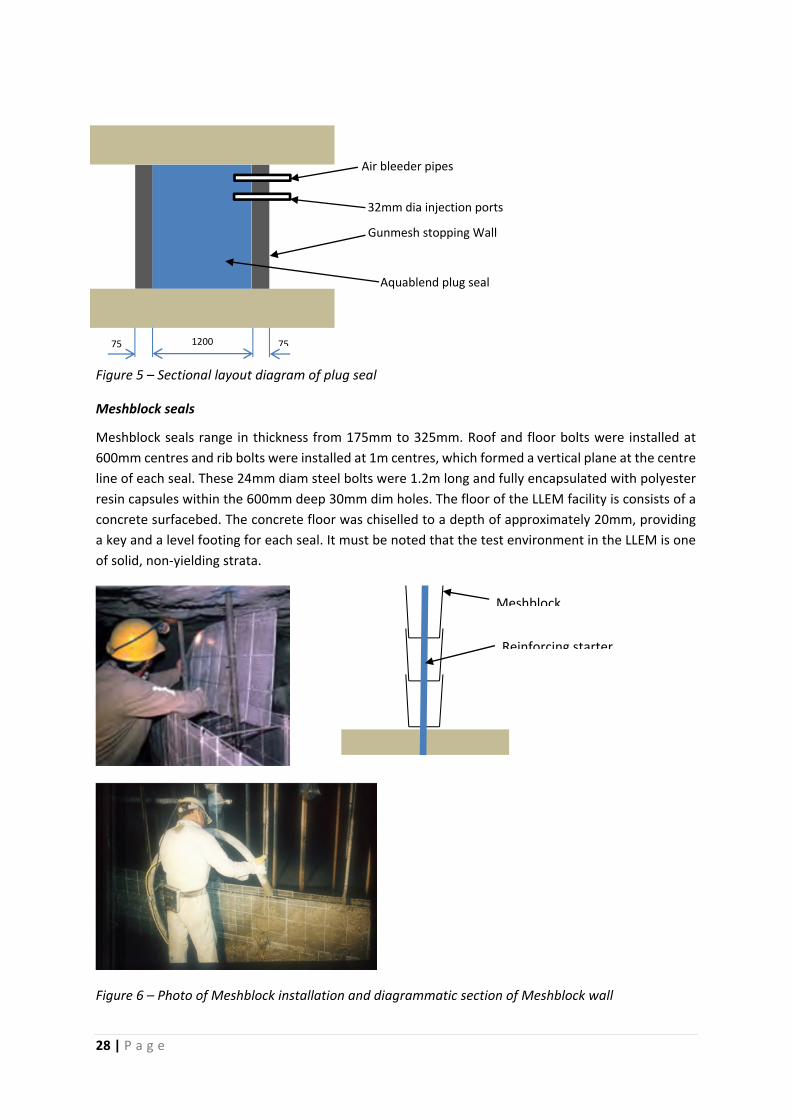
Figure 5 – Sectional layout diagram of plug seal
Meshblock seals
Meshblock seals range in thickness from 175mm to 325mm. Roof and floor bolts were installed at
600mm centres and rib bolts were installed at 1m centres, which formed a vertical plane at the centre
line of each seal. These 24mm diam steel bolts were 1.2m long and fully encapsulated with polyester
resin capsules within the 600mm deep 30mm dim holes. The floor of the LLEM facility is consists of a
concrete surfacebed. The concrete floor was chiselled to a depth of approximately 20mm, providing
a key and a level footing for each seal. It must be noted that the test environment in the LLEM is one
of solid, non‐yielding strata.
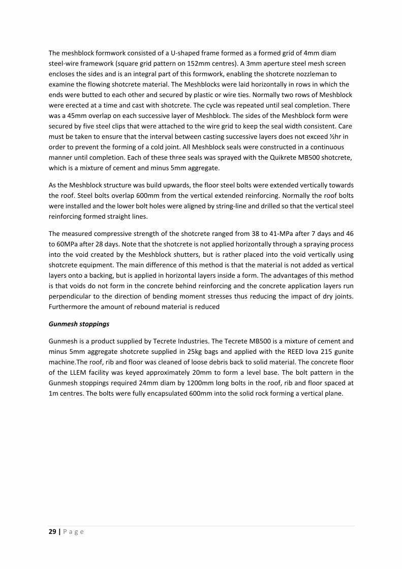
Figure 6 – Photo of Meshblock installation and diagrammatic section of Meshblock wall
75 751200
Air bleeder pipes
32mm dia injection ports
Gunmesh stopping Wall
Aquablend plug seal
Reinforcing starter
Meshblock
29 | P a g e
The meshblock formwork consisted of a U‐shaped frame formed as a formed grid of 4mm diam
steel‐wire framework (square grid pattern on 152mm centres). A 3mm aperture steel mesh screen
encloses the sides and is an integral part of this formwork, enabling the shotcrete nozzleman to
examine the flowing shotcrete material. The Meshblocks were laid horizontally in rows in which the
ends were butted to each other and secured by plastic or wire ties. Normally two rows of Meshblock
were erected at a time and cast with shotcrete. The cycle was repeated until seal completion. There
was a 45mm overlap on each successive layer of Meshblock. The sides of the Meshblock form were
secured by five steel clips that were attached to the wire grid to keep the seal width consistent. Care
must be taken to ensure that the interval between casting successive layers does not exceed ½hr in
order to prevent the forming of a cold joint. All Meshblock seals were constructed in a continuous
manner until completion. Each of these three seals was sprayed with the Quikrete MB500 shotcrete,
which is a mixture of cement and minus 5mm aggregate.
As the Meshblock structure was build upwards, the floor steel bolts were extended vertically towards
the roof. Steel bolts overlap 600mm from the vertical extended reinforcing. Normally the roof bolts
were installed and the lower bolt holes were aligned by string‐line and drilled so that the vertical steel
reinforcing formed straight lines.
The measured compressive strength of the shotcrete ranged from 38 to 41‐MPa after 7 days and 46
to 60MPa after 28 days. Note that the shotcrete is not applied horizontally through a spraying process
into the void created by the Meshblock shutters, but is rather placed into the void vertically using
shotcrete equipment. The main difference of this method is that the material is not added as vertical
layers onto a backing, but is applied in horizontal layers inside a form. The advantages of this method
is that voids do not form in the concrete behind reinforcing and the concrete application layers run
perpendicular to the direction of bending moment stresses thus reducing the impact of dry joints.
Furthermore the amount of rebound material is reduced
Gunmesh stoppings
Gunmesh is a product supplied by Tecrete Industries. The Tecrete MB500 is a mixture of cement and
minus 5mm aggregate shotcrete supplied in 25kg bags and applied with the REED lova 215 gunite
machine.The roof, rib and floor was cleaned of loose debris back to solid material. The concrete floor
of the LLEM facility was keyed approximately 20mm to form a level base. The bolt pattern in the
Gunmesh stoppings required 24mm diam by 1200mm long bolts in the roof, rib and floor spaced at
1m centres. The bolts were fully encapsulated 600mm into the solid rock forming a vertical plane.
30 | P a g e
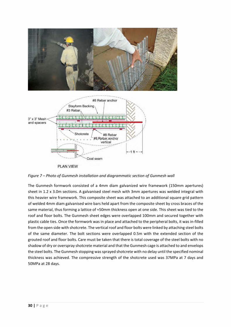
Figure 7 – Photo of Gunmesh installation and diagrammatic section of Gunmesh wall
The Gunmesh formwork consisted of a 4mm diam galvanized wire framework (150mm apertures)
sheet in 1.2 x 3.0m sections. A galvanised steel mesh with 3mm apertures was welded integral with
this heavier wire framework. This composite sheet was attached to an additional square grid pattern
of welded 4mm diam galvanised wire bars held apart from the composite sheet by cross braces of the
same material, thus forming a lattice of ≈50mm thickness open at one side. This sheet was tied to the
roof and floor bolts. The Gunmesh sheet edges were overlapped 100mm and secured together with
plastic cable ties. Once the formwork was in place and attached to the peripheral bolts, it was in‐filled
from the open side with shotcrete. The vertical roof and floor bolts were linked by attaching steel bolts
of the same diameter. The bolt sections were overlapped 0.5m with the extended section of the
grouted roof and floor bolts. Care must be taken that there is total coverage of the steel bolts with no
shadow of dry or overspray shotcrete material and that the Gunmesh cage is attached to and envelops
the steel bolts. The Gunmesh stopping was sprayed shotcrete with no delay until the specified nominal
thickness was achieved. The compressive strength of the shotcrete used was 37MPa at 7 days and
50MPa at 28 days.
31 | P a g e
Testing Methodology
All the explosion tests on the various seals were conducted in the LLEM which is located outside of
Pittsburgh Pennsylvania. The underground entries consist of approximately of 7,620m long workings
developed in the mid‐1960’s for the commercial extraction of limestone and 2,286m of entries
developed by the former USBM in 1980‐82 for research [Mattes et al. 1983]. Each of the seals are
constructed in the crosscuts along a 500m long tunnel. Nearly 19m³ of natural gas is injected into the
closed end of the tunnel that is sealed off by a plastic diaphragm within a 210m ignition zone. An
electric fan with an explosion‐proof motor housing is used to mix the natural gas with the air in the
ignition zone. Three electrically activated matches across the face of the entry are used to ignite the
flammable Gas‐Air mixture. Barrels filled with water are placed in the ignition zone to create
turbulence.
To achieve an explosion pressure pulse significantly in excess of 138kPa, coal dust is used along the
tunnel length. The coal dust is loaded onto shelves suspended from the mine roof at 3m increments
along the tunnel length. The mass of coal dust is increased to produce higher explosive pressures.
Pressure data is gathered by strain gauge pressure transducers fixed to the side of the test tunnel and
optical sensors to detect flame arrival. The pressure transducers are from Dynisco, Viatran or Ginesco
and are rated at 0‐100 psia, with 0‐5V output, infinite resolution and response time <1ms. The sensor
data gathered during the explosion tests were relayed from the data gathering stations to an
underground instrumentation room. A high speed, 64 channel, PC‐based computer data acquisition
system was used to collect and analyze the data. This system collected the sensor data at a rate of
1,500 samples per second over a 5 second period. The data was then processed using LabView, Excel
and PSI‐Plot software. The report pressure data was averaged over 10ms to achieve a 15‐point
smoothing.
Structural analysis
Table 3 summarizes the explosion test results on the five test walls. Each of the wall types,
construction dimensions and peak explosion pressures are indicated. This information alone does not
explain the full extent of how each seal performed. An example hereof is that the Meshblock seal in
crosscut 2 survived a peak pressure of 425‐kPa while the equal thickness and type of wall in crosscut
3 was damaged by a peak pressure of 300‐kPa.
The author of this report is a Professional Structural engineer. Based on the author’s expertize in
structural engineering he deducted that the test seals can be analysed as reinforced flat slabs with
rotational freedom and translation fixture to all slab edges. The methodology of this analysis is to
enter the structures dimensions and maximum blast pressure, as a static pressure, into finite element
slab analysis software. This software produces the maximum bending moment that the slab will
experience in both span directions. From the bending moment the pressure in the concrete is
calculated using elastic bending equations. These equations produce a more conservative pressure
than what can be expected from full plastic deformation of the concrete section. With the small data
set available, a more conservative approach is required and thus the elastic deformation equations
will suffice.
32 | P a g e
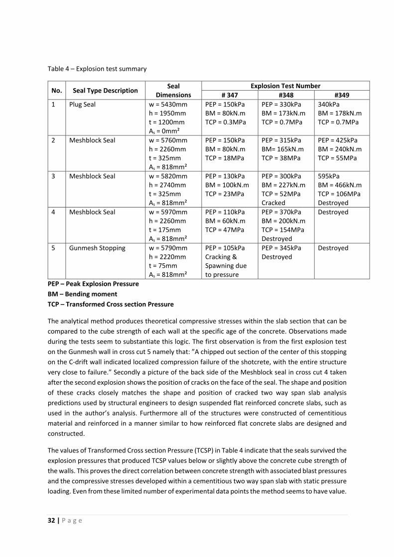
Table 4 – Explosion test summary
No. Seal Type Description Seal
Dimensions Explosion Test Number
# 347 #348 #349
1 Plug Seal w = 5430mm h = 1950mm t = 1200mm As = 0mm²
PEP = 150kPa BM = 80kN.m TCP = 0.3MPa
PEP = 330kPa BM = 173kN.m TCP = 0.7MPa
340kPa BM = 178kN.m TCP = 0.7MPa
2 Meshblock Seal w = 5760mm h = 2260mm t = 325mm As = 818mm²
PEP = 150kPa BM = 80kN.m TCP = 18MPa
PEP = 315kPa BM= 165kN.m TCP = 38MPa
PEP = 425kPa BM = 240kN.m TCP = 55MPa
3 Meshblock Seal w = 5820mm h = 2740mm t = 325mm As = 818mm²
PEP = 130kPa BM = 100kN.m TCP = 23MPa
PEP = 300kPa BM = 227kN.m TCP = 52MPa Cracked
595kPa BM = 466kN.m TCP = 106MPa Destroyed
4 Meshblock Seal w = 5970mm h = 2260mm t = 175mm As = 818mm²
PEP = 110kPa BM = 60kN.m TCP = 47MPa
PEP = 370kPa BM = 200kN.m TCP = 154MPa Destroyed
Destroyed
5 Gunmesh Stopping w = 5790mm h = 2220mm t = 75mm As = 818mm²
PEP = 105kPa Cracking & Spawning due to pressure
PEP = 345kPa Destroyed
Destroyed
PEP – Peak Explosion Pressure
BM – Bending moment
TCP – Transformed Cross section Pressure
The analytical method produces theoretical compressive stresses within the slab section that can be
compared to the cube strength of each wall at the specific age of the concrete. Observations made
during the tests seem to substantiate this logic. The first observation is from the first explosion test
on the Gunmesh wall in cross cut 5 namely that: ”A chipped out section of the center of this stopping
on the C‐drift wall indicated localized compression failure of the shotcrete, with the entire structure
very close to failure.” Secondly a picture of the back side of the Meshblock seal in cross cut 4 taken
after the second explosion shows the position of cracks on the face of the seal. The shape and position
of these cracks closely matches the shape and position of cracked two way span slab analysis
predictions used by structural engineers to design suspended flat reinforced concrete slabs, such as
used in the author’s analysis. Furthermore all of the structures were constructed of cementitious
material and reinforced in a manner similar to how reinforced flat concrete slabs are designed and
constructed.
The values of Transformed Cross section Pressure (TCSP) in Table 4 indicate that the seals survived the
explosion pressures that produced TCSP values below or slightly above the concrete cube strength of
the walls. This proves the direct correlation between concrete strength with associated blast pressures
and the compressive stresses developed within a cementitious two way span slab with static pressure
loading. Even from these limited number of experimental data points the method seems to have value.
33 | P a g e
Ingwe spec walls
One of the more popular seal designs currently used in South African coal mines is know as “Ingwe
Spec” walls. This dry‐crete reinforced concrete thin structural member with doweled shear connection
to the surround shares many structural similarities with Meshblock seals. Assuming that the above
physical explosion tests on Meshblock seals are valid, then it stands to reason that the above results
are applicable to similar cementitious walls. Thus the observed results from explosions against
Meshblock seals can be used to back calculate the explosive pressure that an Ingwe spec wall will be
able to withstand in a similar experimental explosion.
With this assumption as basis the author calculated the explosive pressure that a Type‐I Ingwe spec
wall will withstand. Type‐I walls was used because it represents the typical mine header opening size
in South African mines. The analysis assumes that the compressive concrete strength and all
dimensions are according to the construction specifications and no construction defects are present.
According to the author’s back calculation of the “Ingwe spec” construction specification compared
to the known experimental results of Meshblock seals, the maximum explosive pressure that a “Type‐
I Ingwe Spec” wall can withstand is ±110kPa. This value is supported by similar results from static finite
element analysis of the same Ingwe spec wall. Both the back calculated and finite element analysis
calculated value of 110kPa is only a quarter of the suggested 400kPa design load.
It is worrying that both the finite element analysis and back calculations are based on perfectly
constructed edge conditions. The experimental seals were constructed within the LLEM with concrete
surfacebed floor and surrounding limestone roof plus sidewalls having high compressive strength that
does not deteriorate over time. In a real coal mine the roof, floor and side wall strata usually consist
of materials with weaker compressive strength compared to the experimental mine conditions.
Furthermore the compressive strength of the strata in a coal mine reduces over time as the coal
oxidizes or the minerals in the strata are exposed to water. The difference in edge constraint values
between actual conditions and theoretical calculation values has as a result that the actual wall
strength will be less both in bending and shear capacity compared to the theoretical calculations.
Conclusions
There exists a vast amount of experimental data relating to seal performance in experimental
Methane‐Air explosion tests. Even a basic structural analysis, such as attempted above, produces
valuable equations that can be used to predict the performance of a seal. These results were used by
the U.S. Army Core of Engineers (USACE) to calibrate their single degree of freedom structural analysis
software Wall Analysis Code (WAC), which underlines the value of this historic information.
34 | P a g e
5. PANEL INERTIZATION
Ventilation is maintained in mined‐out areas during seal construction up to the point of final seal
completion. Upon sealing, the typical coal mine atmosphere contains about 21% Oxygen and 79%
Nitrogen and less than 1% Methane. When ventilation to the abandoned area ceases, composition of
that atmosphere will begin to change depending on the geologic characteristics of the coal. Some
coals will slowly oxidize and therefore remove oxygen and release carbon dioxide into the atmosphere
of the abandoned area. However, with few exceptions, all underground coalbeds liberate Methane,
and thus the Methane concentration within the sealed areas will increase. Methane is explosive from
5% to 16% by volume. Most sealed areas will eventually enter this explosive range at some point in
time after sealing. Methane will continue to accumulate in the sealed area; when the concentration
exceeds 16%, that atmosphere is no longer explosive. The time required for the atmosphere in the
sealed area to pass beyond the upper limit and become inert ranges from about 1 day to several weeks
or more depending on the mine’s Methane liberation rate.
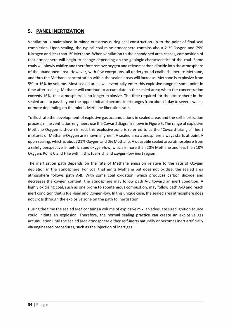
To illustrate the development of explosive gas accumulations in sealed areas and the self‐inertization
process, mine ventilation engineers use the Coward diagram shown in Figure 5. The range of explosive
Methane‐Oxygen is shown in red; this explosive zone is referred to as the “Coward triangle”. Inert
mixtures of Methane‐Oxygen are shown in green. A sealed area atmosphere always starts at point A
upon sealing, which is about 21% Oxygen and 0% Methane. A desirable sealed area atmosphere from
a safety perspective is fuel‐rich and oxygen‐low, which is more than 20% Methane and less than 10%
Oxygen. Point C and F lie within this fuel‐rich and oxygen‐low inert region.
The inertization path depends on the rate of Methane emission relative to the rate of Oxygen
depletion in the atmosphere. For coal that emits Methane but does not oxidize, the sealed area
atmosphere follows path A‐B. With some coal oxidation, which produces carbon dioxide and
decreases the oxygen content, the atmosphere may follow path A‐C toward an inert condition. A
highly oxidizing coal, such as one prone to spontaneous combustion, may follow path A‐D and reach
inert condition that is fuel‐lean and Oxygen‐low. In this unique case, the sealed area atmosphere does
not cross through the explosive zone on the path to inertization.
During the time the sealed area contains a volume of explosive mix, an adequate sized ignition source
could initiate an explosion. Therefore, the normal sealing practice can create an explosive gas
accumulation until the sealed area atmosphere either self‐inerts naturally or becomes inert artificially
via engineered procedures, such as the injection of inert gas.
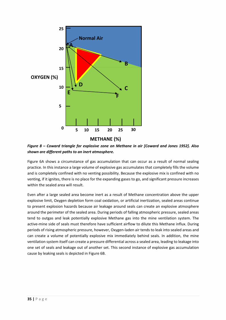
35 | P a g e
Figure 8 – Coward triangle for explosive zone on Methane in air [Coward and Jones 1952]. Also
shown are different paths to an inert atmosphere.
Figure 6A shows a circumstance of gas accumulation that can occur as a result of normal sealing
practice. In this instance a large volume of explosive gas accumulates that completely fills the volume
and is completely confined with no venting possibility. Because the explosive mix is confined with no
venting, if it ignites, there is no place for the expanding gases to go, and significant pressure increases
within the sealed area will result.
Even after a large sealed area become inert as a result of Methane concentration above the upper
explosive limit, Oxygen depletion form coal oxidation, or artificial inertization, sealed areas continue
to present explosion hazards because air leakage around seals can create an explosive atmosphere
around the perimeter of the sealed area. During periods of falling atmospheric pressure, sealed areas
tend to outgas and leak potentially explosive Methane gas into the mine ventilation system. The
active‐mine side of seals must therefore have sufficient airflow to dilute this Methane influx. During
periods of rising atmospheric pressure, however, Oxygen‐laden air tends to leak into sealed areas and
can create a volume of potentially explosive mix immediately behind seals. In addition, the mine
ventilation system itself can create a pressure differential across a sealed area, leading to leakage into
one set of seals and leakage out of another set. This second instance of explosive gas accumulation
cause by leaking seals is depicted in Figure 6B.
3025201510 5
25
20
15
10
5
0
OXYGEN (%)
METHANE (%)
Normal Air
A
B
D
FE
C
36 | P a g e
Figure 9 – Two general types of explosive gas accumulation within sealed area
As mentioned earlier in Section 2 of this report, the use of type C seals (Australia) designed to
withstand a 140‐kPa explosion overpressure requires routine gas sampling and analysis to ensure that
the sealed area atmosphere contains no explosive mix. Demonstrating this lack of explosive mix
requires a monitoring system along with management plan to collect the requisite data, analyze and
interpret it in a timely manner, take the necessary actions, such as withdrawal of people or
inertization, if required.
With regard to the traditional Coward triangle graph representing the Methane‐Air explosive zone,
the Queensland monitoring standards defines an explosive risk buffer zone whose boundaries are less
than 2,5% or greater than 22% Methane and greater than 8% Oxygen. This standard requires “a regular
sampling regime such that a maximum change in the Methane concentration of 0.5% Methane
absolute can be detected between samples” [Lyne 1998]. In many situations, a sampling frequency
every few hours is common practice.
To meet the required sampling frequency, most Australian longwall mines have deployed tube‐bundle
systems for continuous gas monitoring. Monitoring tubes enter the mine via a borehole. Typical tube‐
bundle systems will monitor from 20 to 40 points or more, with about half located in the active mining
area and the other half in the sealed areas. Pumps draw air samples continuously from each
monitoring point to the monitoring shed for analysis. Inside the shed is a solenoid‐valve‐manifold
system activated by a programmable logic controller. Samples are automatically directed to an on‐line
gas analyzer and analyzed for Carbon Monoxide, Carbon Dioxide, Methane and Oxygen. It is assumed
that Nitrogen and Argon comprise the balance. Real‐time data are displayed at the mine’s control
centre, where trained operators can respond as necessary.
In addition to monitoring to ensure that the sealed area does not contain any explosive mix, many
Australian coal mines artificially inert sealed areas. Artificial inertization is mainly employed at mines
with high risk of spontaneous combustion. Two major systems are in use at this time: Nitrogen gas
injection and the Tomlinson boiler. Nitrogen injection systems may use molecular membranes to
separate Nitrogen from the atmosphere. While these systems are adequate for routine Nitrogen
A – Volume filled with explosive atmosphere
(Completely confined with no venting)
B – Leaking seals with explosive atmosphere
(Partially completely confined with venting into inert atmosphere)
KEY
Seals
Explosive atmosphere
Inert atmosphere
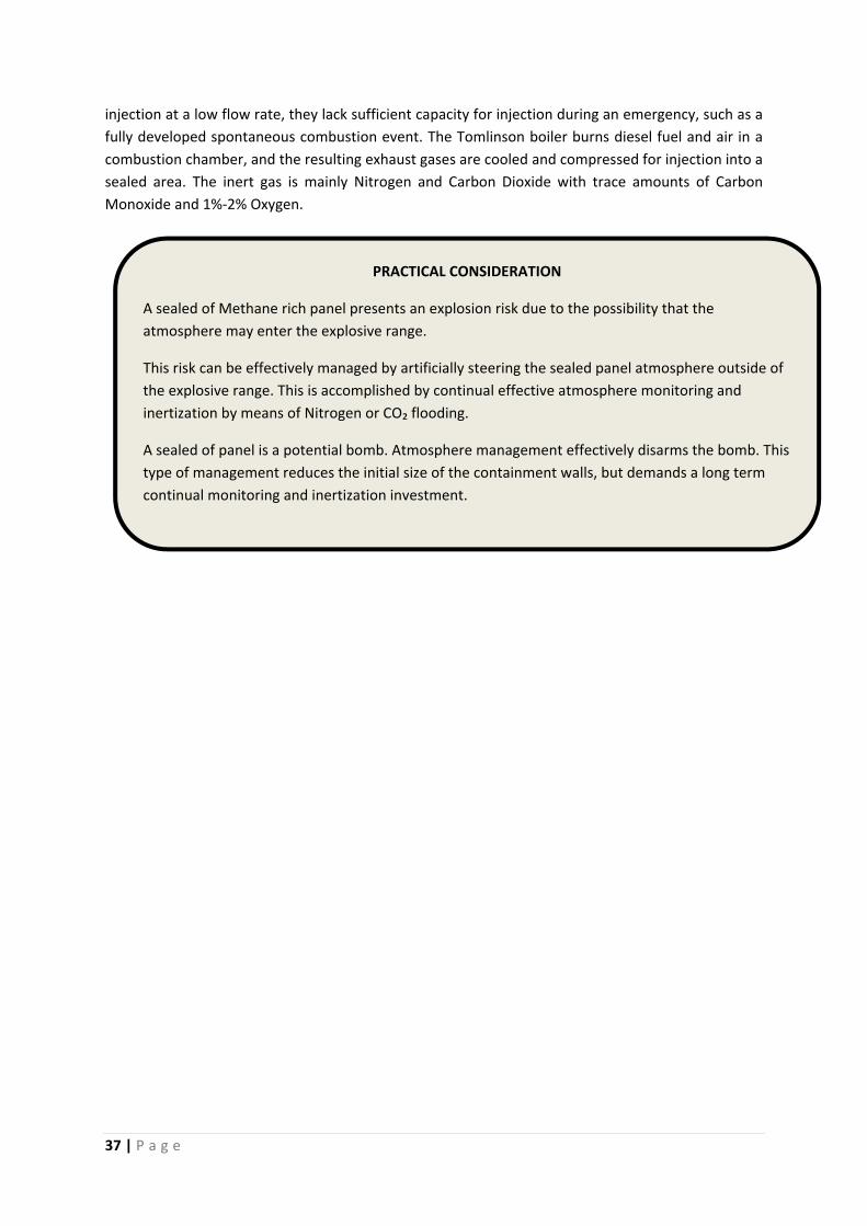
37 | P a g e
injection at a low flow rate, they lack sufficient capacity for injection during an emergency, such as a
fully developed spontaneous combustion event. The Tomlinson boiler burns diesel fuel and air in a
combustion chamber, and the resulting exhaust gases are cooled and compressed for injection into a
sealed area. The inert gas is mainly Nitrogen and Carbon Dioxide with trace amounts of Carbon
Monoxide and 1%‐2% Oxygen.
PRACTICAL CONSIDERATION
A sealed of Methane rich panel presents an explosion risk due to the possibility that the
atmosphere may enter the explosive range.
This risk can be effectively managed by artificially steering the sealed panel atmosphere outside of
the explosive range. This is accomplished by continual effective atmosphere monitoring and
inertization by means of Nitrogen or CO₂ flooding.
A sealed of panel is a potential bomb. Atmosphere management effectively disarms the bomb. This
type of management reduces the initial size of the containment walls, but demands a long term
continual monitoring and inertization investment.
38 | P a g e
6. U.S. Legislation
U.S. Federal legislation known as ‘Final Rule 2008’ (30 CFR Part 75 : Sealing of Abandoned Areas:
Final Rule) is the current document used for the design of all new seals in U.S. coal mines. The final
rule includes requirements for seal strength, design, construction, maintenance and repair of seals
and monitoring and control of atmospheres behind seals in order to reduce risk of seal failure and
the risk of explosions in abandoned areas of underground coal mines. It also addresses the level of
overpressure for new seals.
Background
In order to understand how the Final Rule 2008 is implemented it is imperative for the reader to
understand the fundamental relationship between the U.S. mining industry and to the legislator
MSHA. MSHA (Mine Health and Safety Administration) is a department under the direction of the
U.S. Federal Department of Labour tasked with the administration of health and safety at all mines
in the U.S.A. MSHA has a department under its direction responsible for evaluation of technical and
engineering related mine health and safety issues known as ‘MSHA Tech Support’.
The mining community throughout the U.S. is divided into twelve geographical districts. At the head
of each mining district is a District Manager responsible for all district mining activities according to
federal and district legislation, including ventilation control. All mines have to submit their planned
support and ventilation plans to their designated District Manager for approval before work may
commence. The ventilation plans must, along with all other ventilation layouts, include details and
layouts of sealed off abandoned panels with specific reference to the type of seals to be used. The
type of seals the mine intends to use must feature on the list of seals approved by ‘Tech Support’.
This list of approved seals is posted on the MSHA single source web site for approved seals. The
District Manager will refer the ventilation plan to ‘Tech Support’ for approval off all technical
matters regarding seals. If both the layout and the type of seals to be used are to the satisfaction of
the District Manager and ‘Tech Support’ approval for the ventilation plan will be given in writing.
Only when the written approval has been obtained from the District Manager may construction
commence under the guidelines set out in the Final Rule 2008.
Before a new seal design may be listed on the approved seals list by MSHA it must undergo
meticulous scrutiny from ‘Tech Support’. The new seal design must conform in all aspects to the
Final Rule 2008 regarding strength, design, construction, maintenance and repair of seals. The seal
design with all its required specifications is then published on the MSHA single source website for all
users, installers and designers to peruse.
All work must be carried out according to the specifications set out by the specific seal design. All
test result of material samples have to be reported to the District Manager who conveys the
information to ‘Tech Support’ for approval. All documents have to be stored or shared according to
the Final Rule 2008 with the District Manager. Inspections of all work before, during and after
completion will be performed by qualified representatives of the District Manager and reports will
be submitted in this regard.
39 | P a g e
Legislation
Below follows the text of the law known as ‘30 CFR § 75.335 Seal strengths, design applications, and
installation’. This text should be read in conjunction with all addendums, tables, graphs, figures and
official explanations that form part of the legislation. The excerpt below is quoted to indicate the
amount of detail and encompassing scope of the legislation.
“(a) Seal strengths. Seals constructed on or after October 20, 2008 shall be designed, constructed,
and maintained to withstand‐‐
(1)(i) At least 50‐psi overpressure when the atmosphere in the sealed area is monitored and
maintained inert and designed using a pressure‐time curve with an instantaneous overpressure of at
least 50 psi. A minimum overpressure of at least 50 psi shall be maintained for at least four seconds
then released instantaneously.
(ii) Seals constructed to separate the active longwall panel from the longwall panel previously mined
shall be designed using a pressure‐ time curve with a rate of pressure rise of at least 50 psi in 0.1
second. A minimum overpressure of at least 50 psi shall be maintained; or
(2)(i) Overpressures of at least 120 psi if the atmosphere in the sealed area is not monitored, is not
maintained inert, the conditions in paragraphs (a)(3)(i) through (iii) of this section are not present,
and the seal is designed using a pressure‐time curve with an instantaneous overpressure of at least
120 psi. A minimum overpressure of 120 psi shall be maintained for at least four seconds then
released instantaneously.
(ii) Seals constructed to separate the active longwall panel from the longwall panel previously mined
shall be designed using a pressure‐ time curve with a rate of pressure rise of 120 psi in 0.25 second. A
minimum overpressure of 120 psi shall be maintained; or
(3) Overpressures greater than 120 psi if the atmosphere in the sealed area is not monitored and is
not maintained inert, and
(i) The atmosphere in the sealed area is likely to contain homogeneous mixtures of methane between
4.5% and 17.0% and oxygen exceeding 17.0% throughout the entire area;
(ii) Pressure piling could result in overpressures greater than 120 psi in the area to be sealed; or
(iii) Other conditions are encountered, such as the likelihood of a detonation in the area to be sealed.
(iv) Where the conditions in paragraphs (a)(3)(i), (ii), or (iii) of this section are encountered, the mine
operator shall revise the ventilation plan to address the potential hazards. The plan shall include seal
strengths sufficient to address such conditions.
(b) Seal design applications. Seal design applications from seal manufacturers or mine operators shall
be in accordance with paragraphs (b)(1) or (b)(2) of this section and submitted for approval to
MSHA's Office of Technical Support, Pittsburgh Safety and Health Technology Center, P.O. Box 18233,
Cochrans Mill Road, Pittsburgh, PA 15236.
(1) An engineering design application shall‐‐
(i) Address gas sampling pipes, water drainage systems, methods to reduce air leakage, pressure‐
time curve, fire resistance characteristics, flame spread index, entry size, engineering design and
analysis, elasticity of design, material properties, construction specifications, quality control, design
references, and other information related to seal construction;
(ii) Be certified by a professional engineer that the design of the seal is in accordance with current,
prudent engineering practices and is applicable to conditions in an underground coal mine; and
(iii) Include a summary of the installation procedures related to seal construction; or
40 | P a g e
(2) Each application based on full‐scale explosion tests or equivalent means of physical testing shall
address the following requirements to ensure that a seal can reliably meet the seal strength
requirements:
(i) Certification by a professional engineer that the testing was done in accordance with current,
prudent engineering practices for construction in a coal mine;
(ii) Technical information related to the methods and materials;
(iii) Supporting documentation;
(iv) An engineering analysis to address differences between the seal support during test conditions
and the range of conditions in a coal mine; and
(v) A summary of the installation procedures related to seal construction.
(3) MSHA will notify the applicant if additional information or testing is required. The applicant shall
provide this information, arrange any additional or repeat tests, and provide prior notification to
MSHA of the location, date, and time of such test(s).
(4) MSHA will notify the applicant, in writing, whether the design is approved or denied. If the design
is denied, MSHA will specify, in writing, the deficiencies of the application, or necessary revisions.
(5) Once the seal design is approved, the approval holder shall promptly notify MSHA, in writing, of
all deficiencies of which they become aware.
(c) Seal installation approval. The installation of the approved seal design shall be subject to approval
in the ventilation plan. The mine operator shall‐‐
(1) Retain the seal design approval and installation information for as long as the seal is needed to
serve the purpose for which it was built.
(2) Designate a professional engineer to conduct or have oversight of seal installation and certify that
the provisions in the approved seal design specified in this section have been addressed and are
applicable to conditions at the mine. A copy of the certification shall be submitted to the District
Manager with the information provided in paragraph (c)(3) of this section and a copy of the
certification shall be retained for as long as the seal is needed to serve the purpose for which it was
built.
(3) Provide the following information for approval in the ventilation plan‐‐
(i) The MSHA Technical Support Approval Number;
(ii) A summary of the installation procedures;
(iii) The mine map of the area to be sealed and proposed seal locations that include the deepest
points of penetration prior to sealing. The mine map shall be certified by a professional engineer or a
professional land surveyor.
(iv) Specific mine site information, including‐‐
(A) Type of seal;
(B) Safety precautions taken prior to seal achieving design strength;
(C) Methods to address site‐specific conditions that may affect the strength and applicability of the
seal including set‐back distances;
(D) Site preparation;
(E) Sequence of seal installations;
(F) Projected date of completion of each set of seals;
(G) Supplemental roof support inby and outby each seal;
(H) Water flow estimation and dimensions of the water drainage system through the seals;
(I) Methods to ventilate the outby face of seals once completed;
(J) Methods and materials used to maintain each type of seal;

41 | P a g e
(K) Methods to address shafts and boreholes in the sealed area;
(L) Assessment of potential for overpressures greater than 120 psi in sealed area;
(M) Additional sampling locations; and
(N) Additional information required by the District Manager.”
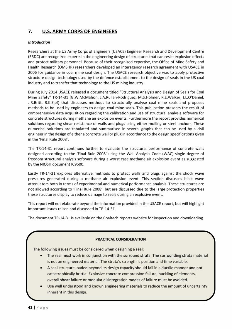
42 | P a g e
7. U.S. ARMY CORPS OF ENGINEERS
Introduction
Researchers at the US Army Corps of Engineers (USACE) Engineer Research and Development Centre (ERDC) are recognized experts in the engineering design of structures that can resist explosion effects and protect military personnel. Because of their recognized expertise, the Office of Mine Safety and Health Research (OMSHR) researchers developed an interagency research agreement with USACE in 2006 for guidance in coal mine seal design. The USACE research objective was to apply protective structure design technology used by the defence establishment to the design of seals in the US coal industry and to transfer that technology to the US mining industry.
During July 2014 USACE released a document titled “Structural Analysis and Design of Seals for Coal Mine Safety” TR‐14‐31 (G.W.McMahon, J.A.Rullan‐Rodriguez, M.S.Holmer, R.E.Walker, J.L.O’Daniel, J.R.Britt, R.K.Zipf) that discusses methods to structurally analyse coal mine seals and proposes methods to be used by engineers to design coal mine seals. This publication presents the result of comprehensive data acquisition regarding the calibration and use of structural analysis software for concrete structures during methane air explosion events. Furthermore the report provides numerical solutions regarding shear resistance of walls and plugs using either moiling or steel anchors. These numerical solutions are tabulated and summarised in several graphs that can be used by a civil engineer in the design of either a concrete wall or plug in accordance to the design specifications given in the ‘Final Rule 2008’.
The TR‐14‐31 report continues further to evaluate the structural performance of concrete walls designed according to the ‘Final Rule 2008’ using the Wall Analysis Code (WAC) single degree of freedom structural analysis software during a worst case methane air explosion event as suggested by the NIOSH document IC9500.
Lastly TR‐14‐31 explores alternative methods to protect walls and plugs against the shock wave pressures generated during a methane air explosion event. This section discusses blast wave attenuators both in terms of experimental and numerical performance analysis. These structures are not allowed according to ‘Final Rule 2008’, but are discussed due to the large protection properties these structures display to reduce damage to seals during an explosive event.
This report will not elaborate beyond the information provided in the USACE report, but will highlight important issues raised and discussed in TR‐14‐31.
The document TR‐14‐31 is available on the Coaltech reports website for inspection and downloading.
Important concepts to design engineers
PRACTICAL CONSIDERATION
The following issues must be considered when designing a seal:
The seal must work in conjunction with the surround strata. The surrounding strata material
is not an engineered material. The strata’s strength is position and time variable.
A seal structure loaded beyond its design capacity should fail in a ductile manner and not
catastrophically brittle. Explosive concrete compression failure, buckling of elements,
overall shear failure or modular disintegration modes of failure must be avoided.
Use well understood and known engineering materials to reduce the amount of uncertainty
inherent in this design.
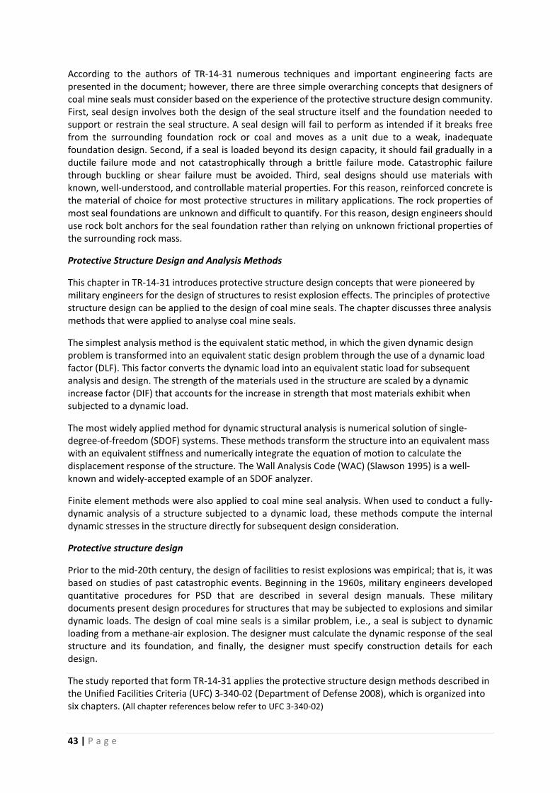
43 | P a g e
According to the authors of TR‐14‐31 numerous techniques and important engineering facts are presented in the document; however, there are three simple overarching concepts that designers of coal mine seals must consider based on the experience of the protective structure design community. First, seal design involves both the design of the seal structure itself and the foundation needed to support or restrain the seal structure. A seal design will fail to perform as intended if it breaks free from the surrounding foundation rock or coal and moves as a unit due to a weak, inadequate foundation design. Second, if a seal is loaded beyond its design capacity, it should fail gradually in a ductile failure mode and not catastrophically through a brittle failure mode. Catastrophic failure through buckling or shear failure must be avoided. Third, seal designs should use materials with known, well‐understood, and controllable material properties. For this reason, reinforced concrete is the material of choice for most protective structures in military applications. The rock properties of most seal foundations are unknown and difficult to quantify. For this reason, design engineers should use rock bolt anchors for the seal foundation rather than relying on unknown frictional properties of the surrounding rock mass.
Protective Structure Design and Analysis Methods
This chapter in TR‐14‐31 introduces protective structure design concepts that were pioneered by military engineers for the design of structures to resist explosion effects. The principles of protective structure design can be applied to the design of coal mine seals. The chapter discusses three analysis methods that were applied to analyse coal mine seals.
The simplest analysis method is the equivalent static method, in which the given dynamic design problem is transformed into an equivalent static design problem through the use of a dynamic load factor (DLF). This factor converts the dynamic load into an equivalent static load for subsequent analysis and design. The strength of the materials used in the structure are scaled by a dynamic increase factor (DIF) that accounts for the increase in strength that most materials exhibit when subjected to a dynamic load.
The most widely applied method for dynamic structural analysis is numerical solution of single‐degree‐of‐freedom (SDOF) systems. These methods transform the structure into an equivalent mass with an equivalent stiffness and numerically integrate the equation of motion to calculate the displacement response of the structure. The Wall Analysis Code (WAC) (Slawson 1995) is a well‐known and widely‐accepted example of an SDOF analyzer.
Finite element methods were also applied to coal mine seal analysis. When used to conduct a fully‐dynamic analysis of a structure subjected to a dynamic load, these methods compute the internal dynamic stresses in the structure directly for subsequent design consideration.
Protective structure design
Prior to the mid‐20th century, the design of facilities to resist explosions was empirical; that is, it was based on studies of past catastrophic events. Beginning in the 1960s, military engineers developed quantitative procedures for PSD that are described in several design manuals. These military documents present design procedures for structures that may be subjected to explosions and similar dynamic loads. The design of coal mine seals is a similar problem, i.e., a seal is subject to dynamic loading from a methane‐air explosion. The designer must calculate the dynamic response of the seal structure and its foundation, and finally, the designer must specify construction details for each design.
The study reported that form TR‐14‐31 applies the protective structure design methods described in the Unified Facilities Criteria (UFC) 3‐340‐02 (Department of Defense 2008), which is organized into six chapters. (All chapter references below refer to UFC 3‐340‐02)
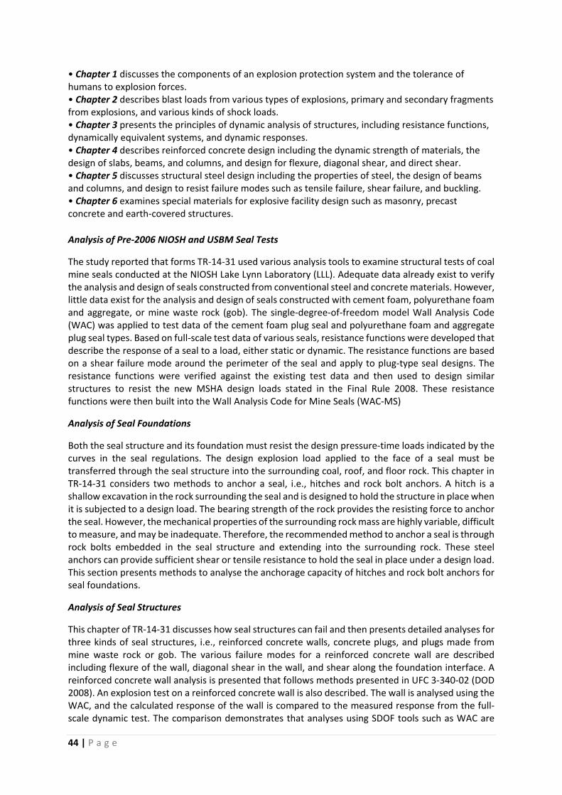
44 | P a g e
• Chapter 1 discusses the components of an explosion protection system and the tolerance of humans to explosion forces. • Chapter 2 describes blast loads from various types of explosions, primary and secondary fragments from explosions, and various kinds of shock loads. • Chapter 3 presents the principles of dynamic analysis of structures, including resistance functions, dynamically equivalent systems, and dynamic responses. • Chapter 4 describes reinforced concrete design including the dynamic strength of materials, the design of slabs, beams, and columns, and design for flexure, diagonal shear, and direct shear. • Chapter 5 discusses structural steel design including the properties of steel, the design of beams and columns, and design to resist failure modes such as tensile failure, shear failure, and buckling. • Chapter 6 examines special materials for explosive facility design such as masonry, precast concrete and earth‐covered structures.
Analysis of Pre‐2006 NIOSH and USBM Seal Tests
The study reported that forms TR‐14‐31 used various analysis tools to examine structural tests of coal mine seals conducted at the NIOSH Lake Lynn Laboratory (LLL). Adequate data already exist to verify the analysis and design of seals constructed from conventional steel and concrete materials. However, little data exist for the analysis and design of seals constructed with cement foam, polyurethane foam and aggregate, or mine waste rock (gob). The single‐degree‐of‐freedom model Wall Analysis Code (WAC) was applied to test data of the cement foam plug seal and polyurethane foam and aggregate plug seal types. Based on full‐scale test data of various seals, resistance functions were developed that describe the response of a seal to a load, either static or dynamic. The resistance functions are based on a shear failure mode around the perimeter of the seal and apply to plug‐type seal designs. The resistance functions were verified against the existing test data and then used to design similar structures to resist the new MSHA design loads stated in the Final Rule 2008. These resistance functions were then built into the Wall Analysis Code for Mine Seals (WAC‐MS)
Analysis of Seal Foundations
Both the seal structure and its foundation must resist the design pressure‐time loads indicated by the curves in the seal regulations. The design explosion load applied to the face of a seal must be transferred through the seal structure into the surrounding coal, roof, and floor rock. This chapter in TR‐14‐31 considers two methods to anchor a seal, i.e., hitches and rock bolt anchors. A hitch is a shallow excavation in the rock surrounding the seal and is designed to hold the structure in place when it is subjected to a design load. The bearing strength of the rock provides the resisting force to anchor the seal. However, the mechanical properties of the surrounding rock mass are highly variable, difficult to measure, and may be inadequate. Therefore, the recommended method to anchor a seal is through rock bolts embedded in the seal structure and extending into the surrounding rock. These steel anchors can provide sufficient shear or tensile resistance to hold the seal in place under a design load. This section presents methods to analyse the anchorage capacity of hitches and rock bolt anchors for seal foundations.
Analysis of Seal Structures
This chapter of TR‐14‐31 discusses how seal structures can fail and then presents detailed analyses for three kinds of seal structures, i.e., reinforced concrete walls, concrete plugs, and plugs made from mine waste rock or gob. The various failure modes for a reinforced concrete wall are described including flexure of the wall, diagonal shear in the wall, and shear along the foundation interface. A reinforced concrete wall analysis is presented that follows methods presented in UFC 3‐340‐02 (DOD 2008). An explosion test on a reinforced concrete wall is also described. The wall is analysed using the WAC, and the calculated response of the wall is compared to the measured response from the full‐scale dynamic test. The comparison demonstrates that analyses using SDOF tools such as WAC are
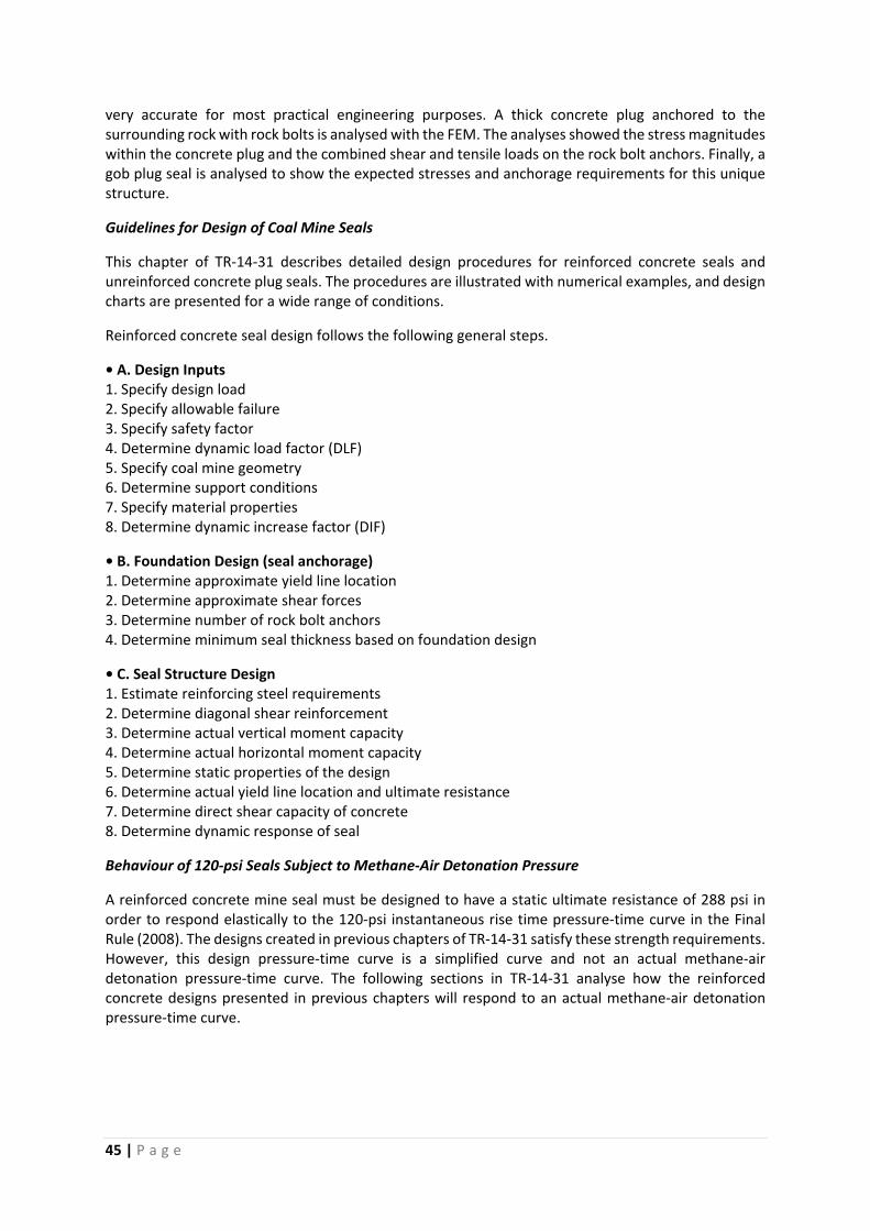
45 | P a g e
very accurate for most practical engineering purposes. A thick concrete plug anchored to the surrounding rock with rock bolts is analysed with the FEM. The analyses showed the stress magnitudes within the concrete plug and the combined shear and tensile loads on the rock bolt anchors. Finally, a gob plug seal is analysed to show the expected stresses and anchorage requirements for this unique structure.
Guidelines for Design of Coal Mine Seals
This chapter of TR‐14‐31 describes detailed design procedures for reinforced concrete seals and unreinforced concrete plug seals. The procedures are illustrated with numerical examples, and design charts are presented for a wide range of conditions.
Reinforced concrete seal design follows the following general steps.
• A. Design Inputs 1. Specify design load 2. Specify allowable failure 3. Specify safety factor 4. Determine dynamic load factor (DLF) 5. Specify coal mine geometry 6. Determine support conditions 7. Specify material properties 8. Determine dynamic increase factor (DIF)
• B. Foundation Design (seal anchorage) 1. Determine approximate yield line location 2. Determine approximate shear forces 3. Determine number of rock bolt anchors 4. Determine minimum seal thickness based on foundation design
• C. Seal Structure Design 1. Estimate reinforcing steel requirements 2. Determine diagonal shear reinforcement 3. Determine actual vertical moment capacity 4. Determine actual horizontal moment capacity 5. Determine static properties of the design 6. Determine actual yield line location and ultimate resistance 7. Determine direct shear capacity of concrete 8. Determine dynamic response of seal
Behaviour of 120‐psi Seals Subject to Methane‐Air Detonation Pressure
A reinforced concrete mine seal must be designed to have a static ultimate resistance of 288 psi in order to respond elastically to the 120‐psi instantaneous rise time pressure‐time curve in the Final Rule (2008). The designs created in previous chapters of TR‐14‐31 satisfy these strength requirements. However, this design pressure‐time curve is a simplified curve and not an actual methane‐air detonation pressure‐time curve. The following sections in TR‐14‐31 analyse how the reinforced concrete designs presented in previous chapters will respond to an actual methane‐air detonation pressure‐time curve.
46 | P a g e
Blast wave attenuators
TR‐14‐31 states that a blast wave attenuator is “a stationary device used to reduce or lessen the blast wave effects by reducing the interior increase in pressure” (ASCE 1997). They are used to protect buildings in petrochemical facilities or underground rooms in military complexes from the effects of a nearby explosion. As an example of blast wave attenuator construction, sand and rocks may be placed in the ventilation shafts of an underground bunker in order to decrease blast wave effects while allowing ventilation airflow. Alternatively, a system of air intake baffles may be used that have little effect on airflow but that dramatically reduce the transmission of a short‐duration blast pressure into the structure (Baker and Harrell 1992).
Figure 10. Gob plug seal concept by Lusk, Unrug, and Perry (2009) composed of (1) blasted roof rock, (2) a
light‐weight construction seal, and (3) filler material between the seal and blasted rock.
Figure 11. “Shot‐rock” concept by Sapko et al. (2010) composed of (1) blasted roof rock and (2) an optional
borrowed gob foundation
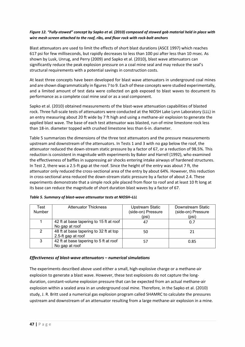
47 | P a g e
Figure 12. “Fully‐stowed” concept by Sapko et al. (2010) composed of stowed gob material held in place with
wire mesh screen attached to the roof, ribs, and floor rock with rock‐bolt anchors
Blast attenuators are used to limit the effects of short blast durations (ASCE 1997) which reaches 617 psi for few milliseconds, but rapidly decreases to less than 100 psi after less than 10 msec. As shown by Lusk, Unrug, and Perry (2009) and Sapko et al. (2010), blast wave attenuators can significantly reduce the peak explosion pressure on a coal mine seal and may reduce the seal’s structural requirements with a potential savings in construction costs.
At least three concepts have been developed for blast wave attenuators in underground coal mines and are shown diagrammatically in figures 7 to 9. Each of these concepts were studied experimentally, and a limited amount of test data were collected on gob exposed to blast waves to document its performance as a complete coal mine seal or as a seal component.
Sapko et al. (2010) obtained measurements of the blast‐wave attenuation capabilities of blasted rock. Three full‐scale tests of attenuators were conducted at the NIOSH Lake Lynn Laboratory (LLL) in an entry measuring about 20 ft wide by 7 ft high and using a methane‐air explosion to generate the applied blast wave. The base of each test attenuator was blasted, run‐of‐mine limestone rock less than 18‐in. diameter topped with crushed limestone less than 6‐in. diameter.
Table 5 summarizes the dimensions of the three test attenuators and the pressure measurements upstream and downstream of the attenuators. In Tests 1 and 3 with no gap below the roof, the attenuator reduced the down‐stream static pressure by a factor of 67, or a reduction of 98.5%. This reduction is consistent in magnitude with experiments by Baker and Harrell (1992), who examined the effectiveness of baffles in suppressing air shocks entering intake airways of hardened structures. In Test 2, there was a 2.5‐ft gap at the roof. Since the height of the entry was about 7 ft, the attenuator only reduced the cross‐sectional area of the entry by about 64%. However, this reduction in cross‐sectional area reduced the down‐stream static pressure by a factor of about 2.4. These experiments demonstrate that a simple rock pile placed from floor to roof and at least 10 ft long at its base can reduce the magnitude of short duration blast waves by a factor of 67.
Table 5. Summary of blast‐wave attenuator tests at NIOSH–LLL
Test Number
Attenuator Thickness Upstream Static (side-on) Pressure
(psi)
Downstream Static (side-on) Pressure
(psi) 1 42 ft at base tapering to 15 ft at roof
No gap at roof 47 0.7
2 48 ft at base tapering to 32 ft at top 2.5-ft gap at roof
50 21
3 42 ft at base tapering to 5 ft at roof No gap at roof
57 0.85
Effectiveness of blast‐wave attenuators – numerical simulations The experiments described above used either a small, high‐explosive charge or a methane‐air
explosion to generate a blast wave. However, these test explosions do not capture the long‐
duration, constant‐volume explosion pressure that can be expected from an actual methane‐air
explosion within a sealed area in an underground coal mine. Therefore, in the Sapko et al. (2010)
study, J. R. Britt used a numerical gas explosion program called SHAMRC to calculate the pressures
upstream and downstream of an attenuator resulting from a large methane‐air explosion in a mine.
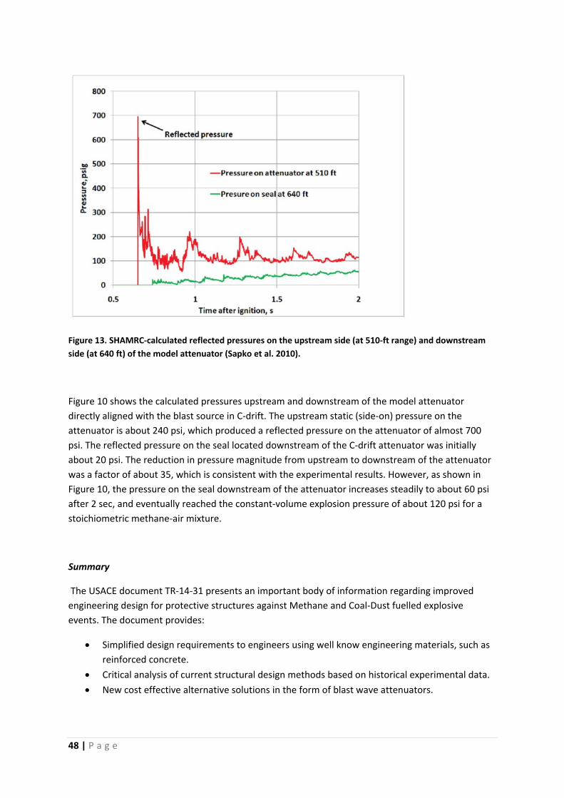
48 | P a g e
Figure 13. SHAMRC‐calculated reflected pressures on the upstream side (at 510‐ft range) and downstream
side (at 640 ft) of the model attenuator (Sapko et al. 2010).
Figure 10 shows the calculated pressures upstream and downstream of the model attenuator
directly aligned with the blast source in C‐drift. The upstream static (side‐on) pressure on the
attenuator is about 240 psi, which produced a reflected pressure on the attenuator of almost 700
psi. The reflected pressure on the seal located downstream of the C‐drift attenuator was initially
about 20 psi. The reduction in pressure magnitude from upstream to downstream of the attenuator
was a factor of about 35, which is consistent with the experimental results. However, as shown in
Figure 10, the pressure on the seal downstream of the attenuator increases steadily to about 60 psi
after 2 sec, and eventually reached the constant‐volume explosion pressure of about 120 psi for a
stoichiometric methane‐air mixture.
Summary
The USACE document TR‐14‐31 presents an important body of information regarding improved
engineering design for protective structures against Methane and Coal‐Dust fuelled explosive
events. The document provides:
Simplified design requirements to engineers using well know engineering materials, such as
reinforced concrete.
Critical analysis of current structural design methods based on historical experimental data.
New cost effective alternative solutions in the form of blast wave attenuators.

49 | P a g e
This document diverts from many current design practices in the U.S., but considering the vast
knowledge base on blast protection measures and structures available to the USACE it would be
foolish to ignore the recommendations and design considerations of this document.
50 | P a g e
8. CURRENT AUSTRALIAN SEALING PRACTICE
This portion of the work is a pure desktop study of research articles and other information published
on the internet. The authors of the work were not interrogated regarding scientific proof or on the
interpretation of the work.
ACARP project C17015
Most of this section refers to the document published in 2011 titled “Australian Sealing Practice and use of Risk Assesment Criteria (ACARP) project C17015” by Hsin Wei Wy (Gillies Wu Mining Technology), A.D.S.Gillies (Missouri University of Science and Technology), J.W.Oberholzer (SIMTARS), R.Davis (SIMTARS). This document states that the purpose of the research and this resultant document was:”…to examine views of Australian operating mines on the industry’s approach to the use of seals; also the new US approaches to sealing and their possible application to Australian conditions…”
The document states that while many approaches to underground coal mining in Australia and the US are similar, Australian approaches to the management of hazardous mine atmospheres differ significantly. Australian risk management approach to handling hazardous situations implies adoption of international industry best practices. The Australian industry has gone through a debate on how the new US information on seal behaviour and new regulations should be incorporated, if at all, into Australian practice. However the Australian coal mining industry as a whole have decided not to adopt the principal dictates of the 2008 US seal regulations.
The second part of the ACARP research project being led by SIMTARS is undertaking further physical testing study of the risk of explosions in sealed areas. The propagation tube study of the consequences of explosions is being conducted to both determine the nature of the explosion overpressure that a structure can be subjected to and also the nature of the pressure pulse that will impact on the structure.
Industry questionnaire survey
The industry questionnaire survey that the document refers to was conducted in 2008 on a large number of Australian mines to establish how mine managers were handling seal design and implementation. In brief the questionnaire sought the following information:
Ventilation network details, such as main fans, underground monitoring systems, etc.
Specific questions regarding whether sealed areas pass through the explosive range.
Possible dimensions for explosion propagation, propensity for propagation and probability of explosion.
Current approach to installing Ventilation Control Devices (VCD) and seals.
Ground stress relationships and seal integrity and time dependent stress on seal during life of seal.
Additional issues: Sources of explosion Should seals be designed as impervious membrane or as explosion barrier? How should seals be designed and tested? Should design be by structural analysis or physical destruction testing? Pressure balancing Contractors vs Company labour installing VCD
51 | P a g e
Relevant differences between US and Australian mines
Some of the relevant physical and operational difference highlighted in the report between US and Australian mines are:
Most (±80%) US longwall gate roads have three headings compared to two headings in Australian mines. The middle heading in US mines can be expected with a gas initiation to lead to an explosion disturbance characterized by a long run‐up distance.
US mines have a significantly lower take up of electronic monitoring. Only one US mine makes use of “Tube bundle” gas monitoring. Little proactive use of inertisation in US mines Limited use of ventilation network programs in US mines Limited usage of trained Ventilation Officers in US mines
The report raised the following cultural and implementation differences between US and Australian mines:
Currently many changes are occurring in the handling of mine atmospheres and potential flammability conditions as a result of the Sago Mine disaster.
There are a large number of small mines in the US MSHA adopts a system of “prescriptive regulations” and in general there is lower acceptance
of risk assessment approaches. There is a perceived lack of trust between managers and inspectors. US underground mining industry is more diverse and larger than the Australian industry, as a
result the industry is less cohesive and there is less available data, less sharing of information and less frequent industry forums.
Views on changed US approach
According to the results summarized in the document the Australian industry agrees that it should not adopt the new MSHA regulations, but should rather stick with what appears to work best for Australian conditions. The Australian industry should use appropriate risk levels for seal design. The proposed 840kPa seal design in the US is considered excessive and the US move to this rating is an overreaction. It is the believe in Australia that regardless of application of seal pressure rating requirements it is impossible to contain some explosions in the highly variable mine environment. The introduction of prescriptive US seal pressure ratings does not appear to have been formulated on any risk assessment basis. There are impressions that the US is coming from a lower standard compared to current Australian practice.
Australian approaches to health and safety management are formulated on a risk assessment basis under which hazards must be identified and appropriate “world’s best practice” systems adopted. The principal approach in Australia to goaf management is early prevention of hazardous situations through use of real time gas monitoring from the goaf periphery to ensure the maintenance of goaf inert atmospheric conditions. The comment has been made that the US approach of principally and almost exclusively considering “seal rating” is one of “guarding against failure rather than adopting an approach of prevention”.
SIMTARS Propagation Tube Test Work
The Queensland group SIMTARS is examining consequences of explosions through testing being conducted in a propagation tube as part of the effort to determine the risk of explosions in sealed off areas. This is being investigated not only to determine the nature of the explosion overpressures that a structure can be subjected to but also the nature of the pressure pulses impacting on the structure.
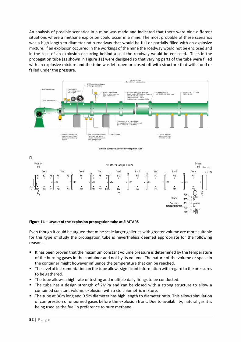
52 | P a g e
An analysis of possible scenarios in a mine was made and indicated that there were nine different situations where a methane explosion could occur in a mine. The most probable of these scenarios was a high length to diameter ratio roadway that would be full or partially filled with an explosive mixture. If an explosion occurred in the workings of the mine the roadway would not be enclosed and in the case of an explosion occurring behind a seal the roadway would be enclosed. Tests in the propagation tube (as shown in Figure 11) were designed so that varying parts of the tube were filled with an explosive mixture and the tube was left open or closed off with structure that withstood or failed under the pressure.
Fi
Figure 14 – Layout of the explosion propagation tube at SIMTARS
Even though it could be argued that mine scale larger galleries with greater volume are more suitable for this type of study the propagation tube is nevertheless deemed appropriate for the following reasons.
It has been proven that the maximum constant volume pressure is determined by the temperature of the burning gases in the container and not by its volume. The nature of the volume or space in the container might however influence the temperature that can be reached.
The level of instrumentation on the tube allows significant information with regard to the pressures to be gathered.
The tube allows a high rate of testing and multiple daily firings to be conducted. The tube has a design strength of 2MPa and can be closed with a strong structure to allow a
contained constant volume explosion with a stoichiometric mixture. The tube at 30m long and 0.5m diameter has high length to diameter ratio. This allows simulation
of compression of unburned gases before the explosion front. Due to availability, natural gas it is being used as the fuel in preference to pure methane.
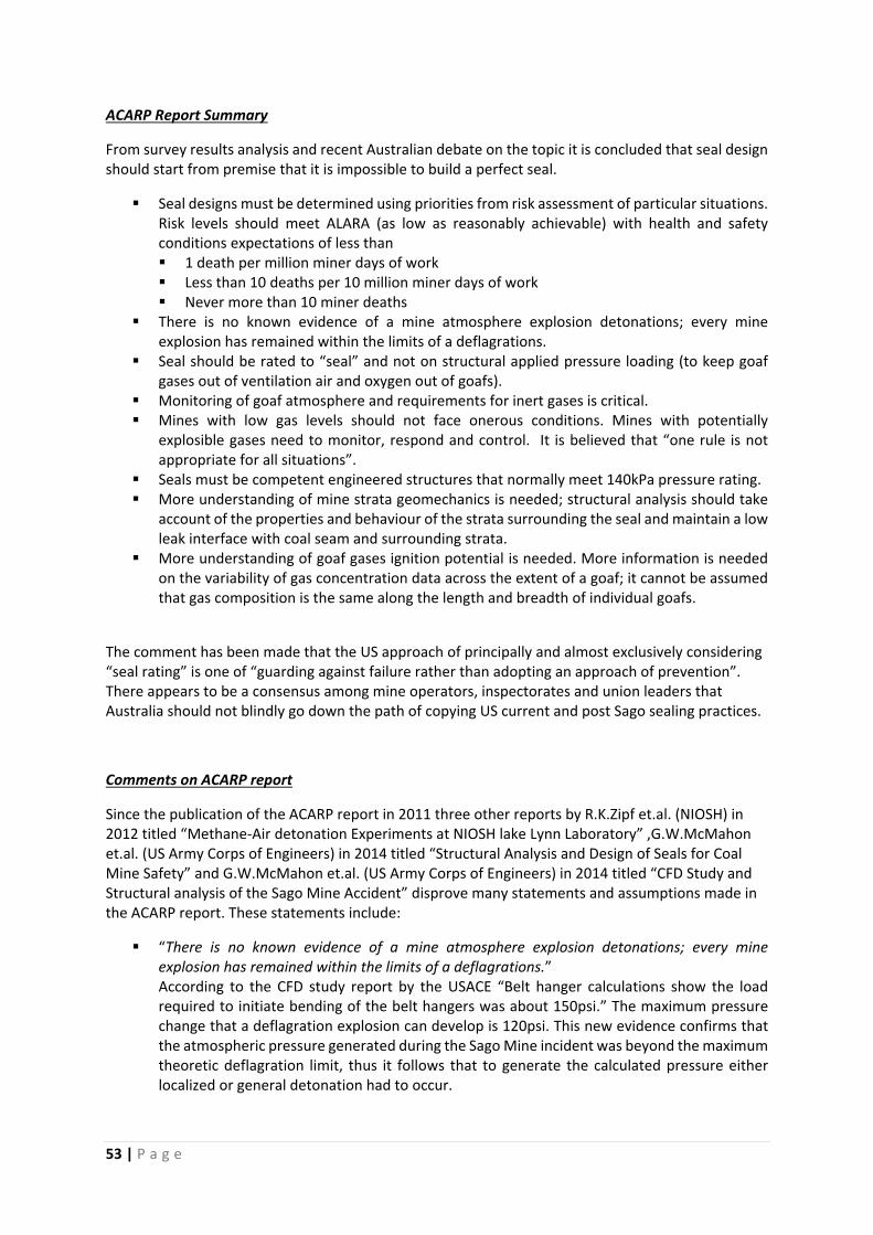
53 | P a g e
ACARP Report Summary
From survey results analysis and recent Australian debate on the topic it is concluded that seal design should start from premise that it is impossible to build a perfect seal.
Seal designs must be determined using priorities from risk assessment of particular situations. Risk levels should meet ALARA (as low as reasonably achievable) with health and safety conditions expectations of less than 1 death per million miner days of work Less than 10 deaths per 10 million miner days of work Never more than 10 miner deaths
There is no known evidence of a mine atmosphere explosion detonations; every mine explosion has remained within the limits of a deflagrations.
Seal should be rated to “seal” and not on structural applied pressure loading (to keep goaf gases out of ventilation air and oxygen out of goafs).
Monitoring of goaf atmosphere and requirements for inert gases is critical. Mines with low gas levels should not face onerous conditions. Mines with potentially
explosible gases need to monitor, respond and control. It is believed that “one rule is not appropriate for all situations”.
Seals must be competent engineered structures that normally meet 140kPa pressure rating. More understanding of mine strata geomechanics is needed; structural analysis should take
account of the properties and behaviour of the strata surrounding the seal and maintain a low leak interface with coal seam and surrounding strata.
More understanding of goaf gases ignition potential is needed. More information is needed on the variability of gas concentration data across the extent of a goaf; it cannot be assumed that gas composition is the same along the length and breadth of individual goafs.
The comment has been made that the US approach of principally and almost exclusively considering “seal rating” is one of “guarding against failure rather than adopting an approach of prevention”. There appears to be a consensus among mine operators, inspectorates and union leaders that Australia should not blindly go down the path of copying US current and post Sago sealing practices.
Comments on ACARP report
Since the publication of the ACARP report in 2011 three other reports by R.K.Zipf et.al. (NIOSH) in 2012 titled “Methane‐Air detonation Experiments at NIOSH lake Lynn Laboratory” ,G.W.McMahon et.al. (US Army Corps of Engineers) in 2014 titled “Structural Analysis and Design of Seals for Coal Mine Safety” and G.W.McMahon et.al. (US Army Corps of Engineers) in 2014 titled “CFD Study and Structural analysis of the Sago Mine Accident” disprove many statements and assumptions made in the ACARP report. These statements include:
“There is no known evidence of a mine atmosphere explosion detonations; every mine explosion has remained within the limits of a deflagrations.” According to the CFD study report by the USACE “Belt hanger calculations show the load required to initiate bending of the belt hangers was about 150psi.” The maximum pressure change that a deflagration explosion can develop is 120psi. This new evidence confirms that the atmospheric pressure generated during the Sago Mine incident was beyond the maximum theoretic deflagration limit, thus it follows that to generate the calculated pressure either localized or general detonation had to occur.
54 | P a g e
In the NIOSH detonation experiments it was found that detonation can be achieved with methane‐air mixtures varying between 4% and 15% methane by volume that encompasses the entire normal combustion limits. This was achieved using a larger diameter test pipe (105cm) with baffle restrictions along the length with Br of 0.3 or 0.6 and a length‐to‐diameter ratio of 70. This larger equipment compared to the SIMTARS propagation tube proved that detonation is more likely to occur than what was previously believed. The larger diameter allows detonation cells to develop near the outer mixture limits that cannot be achieved in the SIMTARS equipment. Furthermore the disturbances along the length of the pipe better represents underground condition than the smooth pipe used in the SIMTARS tests. The 524kPa peak pressure measure in the SIMTARS experiments across a small mixture range of 8.5% to 9.5% methane air mixture is significantly lower than the peak shock pressure range between 1,2MPa and 1,7MPa measured by the NIOSH experiments.
“…it is impossible to contain some explosions in the highly variable mine environment …” The USACE have developed several design tools such as the WAC single degree of freedom structural analysis software, that was calibrated according to pressure and deflection measurements of actual explosions, that can calculate to a high degree of certainty the expected performance of a seal during an explosion. This software in conjunction with ventilation control structures such as blast attenuation walls and sound engineering practice can be combined to design seals that will survive a worst case explosion event.
The ACARP document highlights several differences between US and Australian mining practice that should be considered in relation to South African mining conditions.
13 of the 14 respondents to the questionnaire use long wall mining methods and the remaining mine uses the board‐and‐pillar mining method, but do not install any seals within their operations. This distribution of extraction methods is not representative of South African mining conditions where most mines use board‐and‐pillar mining plus make extensive use of seals in closing off of abandoned panels.
The ACARP document specifically refers to the “…middle heading in US mines can be expected with a gas initiation to lead to an explosion disturbance characterized by a long run‐up distance.” Thus it identifies that this header presents a significantly different risk due to the higher potential to develop a detonation along the longer run‐up length. This middle heading is analogue to typical board‐and‐pillar mining environment where long run‐up distances are inherent to the process. Furthermore is has to be remembered that the Sago Mine incident occurred in a board‐and‐pillar type mine similar to South African mining practice.
The ACARP document states that: o US mines have a significantly lower take up of electronic monitoring. o Only one US mine makes use of “Tube bundle” gas monitoring. o Little proactive use of inertisation in US mines o Limited use of ventilation network programs in US mines o Limited usage of trained Ventilation Officers in US mines
All the above statements are true for typical South African mines as well. To implement an Australian approaches to health and safety management formulated on a risk assessment basis under which hazards must be identified and appropriate “world’s best practice” systems adopted the South African mining industry will have to invest in the above systems and technologies.
The ACARP project C17015 report should not be read in isolation neither should its findings be assumed to suite the South African mining industry. As shown above newly published work in the
55 | P a g e
understanding of Methane fuelled explosions render many assumptions and statement made in this document incorrect. More importantly a reader of the ACARP report must bear in mind the differences between Australian and South African mining practice to understand why the sealing practice used in Australia is supported in the report. It follows from the ACARP report that if a South African mine would like to adopt the Australian sealing practice governed by risk management of hazardous mine atmospheres several improvement will have to be made towards technology and management processes to achieve international industry best practices. NSW Safety Bulletin SB13‐04
New South Wales Trade & Investment Mine Safety Bulletin SB13‐04 published on 29 August 2013 Titled: “Sealing of a goaf or mined out area in an underground coal mine and management of legacy sealed areas” states the following. The Mine Safety and Health Administration USA report into the Sago Mine explosion now means that the possibility of a lightning strike to the surface over and surrounding such areas must be considered as a direct ignition source in addition to mine infrastructure that may be capable of conducting electrical energy into a mine. It further goes on to make the following recommendations. It is recommended that any coal operator in NSW that cannot quantitatively demonstrate that their existing sealing arrangements for goaves or mined out areas are tolerable and maintained as low as reasonably possible (ALARP), then one of the following measures be implemented to eliminate or control the risk of explosion post sealing:
a. Maintain the goaf or mined out area inert before and after sealing, and employ normal 20 psi overpressure rated mine seals.
b. Evacuate the mine until a sealed goaf or mined out area has passed through the explosive range and employ normal 20 psi overpressure rated mine seals.
c. Permit the goaf or mined out area to pass through the explosive range, without evacuation of the mine, after the installation of 120 psi or 120 psi plus overpressure rated seals in all entrances to the goaf or mined out area.
d. Ensure all ratings of seals are for a tested design that meets the overpressure rating awarded. Design testing must be for full scale seals. Testing and rating of seals must be undertaken by an organisation approved by the Chief Inspector.
56 | P a g e
9. SUMMARY
Design of protective structures and measures against Methane and Coal‐Dust fuelled explosion
events have evolved significantly from first official 50 psi standard in 1921 “based on the general
opinion of men experienced in mine‐explosion investigations” to the current standards based on time
dependant overpressure experimental and thermodynamically calculated values or risk based
atmosphere management. This report aimed to provide information regarding the international
history of mine seal design to explain the current legacy of mine seals.
The report presents the current accepted science of Methane and Coal‐Dust fuelled explosions. The
information presented explains the relevance of the theoretical and experimental observations in
relationship to the coal mine environment. The concept of diffusion of Methane into the still
atmosphere is discussed to highlight the current misconception that Methane will become inert
along a thin layer near the roof of a sealed of panel. The complete ignition to detonation process is
explained according to current accepted science in order to predict time vs pressure wave/pulse
values for different underground environments.
Previously it was thought that detonation or even ignition of sealed off panels was so unlikely that it
was not worth considering. This assumption was the basis of the 20psi (140kPa) seal standards in the
U.S. (1971‐Mitchell) and later implemented in other mining countries including South Africa and
Australia. The latest science shows that detonation of methane fuelled explosion in sealed of panels
is indeed possible as was tragically proven in both SAGO and Darby mine explosions. As a result the
U.S. Federal Department of Labour introduced through MSHA new legislation known as the Final
Rule 2008 for the design and management of seals in coal mines. This legislation is quoted in the
report to show the extent of the design, implementation and maintenance requirements demanded
by the new US law.
After the Moura Number 2 mine explosion in 1994 the Austalian coal mining industry experienced a
similar industry wide re‐evaluation of panel sealing methodology. Task Team 5 under the guidance
of Oberholzer developed a different approach to sealing of abandoned panels compared to the US.
The approach in the Australian mines is governed by risk assessment and management of the sealed
atmosphere. As a result the pressure ratings required from their seals is significantly lower than the
equivalent US seals, but the latest recommendations in the Australian industry do use the US seal
pressure ratings during specific conditions. It must be recognised and considered in light of the
South African mining industry that the Australian sealing standards are primarily based on Longwall
mining methods with two road headers. This type of mining method is not common in South African
mines.
Not all mines exhibit equal risk in terms of developing an explosive atmosphere within a sealed of
panel. As a result the report briefly discusses the option of continual monitoring and management of
the sealed atmosphere by inertization as is typical in Australian mines.
Against the comprehensive knowledge and experience of the U.S.Army Corps of Engineers in the
design of structures to protect against explosions, their document TR‐14‐31 provides a valuable
source of information in the design of coal mine seals. TR‐14‐31 was developed by a group of
engineers and scientists with the view of providing a useable and comprehensive design guide to
structural and mining engineers in the development of seals for coal mines. Furthermore the

57 | P a g e
document provides a critical review of current design standards in the US as well as proposes
alternative methods to protect against underground coal mine explosion events.
This report provides a summary of the history, current science and engineering behind
coal mine seals. This report does not provide conclusions, nor recommendations or
guidelines regarding the design of seals or management of sealed off panels.
58 | P a g e
REFERENCES
1. Federal Register, [2008], “Rules and Regulations Sealing of Abandoned Areas‐Final Rule”, Title
30 CFR Part 75.335 CFR, Code of Federal Regulations, Washington DC: U.S. Government Printing
Office, Office of the Federal Register 73(76), Friday, April 18, 2008.
2 Mine Safety and Health Administration, [2010A], “Guidelines for the Seal Design Application”,
http://www.msha.gov/Seals/GuidelinesSealDesignApplications.pdf access February 2010,
11pp.
3. Mitchell D.W., [1971], “Explosion‐Proof Bulkheads – Present Practices”, U.S.Department of the
Interior, Bureau of Mines, Pittsburgh, PA: RI 7581, pp 1‐16.
4. Zipf, R.K., E.S. Weiss, S.P. Harteis, and M.J. Sapko, [2009], “Compendium of Structural Testing
Data for 20‐psi Coal Mine Seals”, IC 9515, U.S. Department of Health and Human Services,
National Institute for Occupational Safety and Health, 143 pp.
5. Hyde, D., Walker, R.E., O’Daniel, J.L., and McMahon, G.W., [2010], “Wall Analysis Code for Mine
Seals”, Proceedings of the 80th Shock & Vibration Symposium, San Diego, CA.
6. Slawson TR, [1995]. Wall Response to Airblast Loads: The Wall Analysis Code (WAC). Structures
Laboratory, U.S. Army Engineer Waterways Experiment Station, Vicksburg, MS.ATTN CEWES‐SS.
7. E.S. Weiss, K.L. Cashdollar, I.V.S. Mutton, D.R.Kohli, and W.A. Slivensky, [1999], “Evaluation of
Reinforced Cementitious Seals”, U.S. Department of Health and Human Services, National
Institute for Occupational Safety and Health, RI 9647
8. A.P. Cook, J.N. van der Merwe, [2000], “Design, construction and testing of underground seals”,
Itasca Africa (Pty)Ltd, Safety in Mines Research Advisory Committee.
9. C.Strydom, [1999], “Method Statement for Explosion Resistant Underground Containment
Stoppings Using the Space Frame / Gunite Wall”, Ingwe Coal Corporation, South Africa
10. R.K. Zipf Jnr. (Ph.D., P.E.), Micheal J.Sapko, and J.F. Brune (Ph.D.), [2007], “Explosion Pressure
Design Criteria for New Seals in U.S. Coal Mines”, U.S. Department of Health and Human
Services, National Institute for Occupational Safety and Health, IC9500
11. Gordon W. McMahon, Jose A. Rullán‐Rodríguez, Matthew S. Holmer, Robert E. Walker, James
L. O’Daniel, James R. Britt, and Richard K. Zipf, [2014], “Structural Analysis and Design of Seals
for Coal Mine Safety”, U.S.Army Corps of Engineers, Engineering Research and Development
Centre
12. C.Classen, Goaf Inertisation and Sealing Utilising Methane from In‐Seam Gas Drainage System,
11th Underground Coal Operators’ Conference, University of Wollongong & the Australian
Institute of Mining and Metallurgy, 2011, 369‐374
13. D.R.Humphreys, J.McCracken, “Task Group 5 – Final Report” 622.8684 TAS 1998
59 | P a g e
14. Ian Anderson, Mine Safety Report No. SB13‐04, “Sealing of a goaf or mined out area in an
underground coal mine and management of legacy sealed areas”, August 2013
15. Mutton, IV and Remennikov, A, “Designing explosion rated ventilation seals for coal mines using
high‐fidelity physis‐based computer modelling”, in Aziz, 10th Underground Coal
Operators’Conference, University of Wollongong & the Australian Institute of Mining and
Metallurgy, 2010, 312‐325
16. Oran, E.S.; Gamezo, V.N.; Kessler, D.A.; “Deflagrations, Detonations, and the Deflagration‐to‐
Detonation Transition in Methane‐Air Mixtures”, Laboratory for Computational Physics and
Fluid Dynamics, Naval Research Laboratory, NRL/MR/6400‐11‐9332, April 2011
17. Zipf, R.K.Jr.; Gamezo, V.N.; Sapko, M.J.; Marchewka, W.P.; Mohamed, K.M.; Oran, E.S.; Kessler,
D.A.; Weiss, E.S.; Addis, J.D.; Karnack, F.A.; Sellers, D.D.; Office of Mine Safety and Health
Research (OMSHR), National Institute for Occupational Safety and Health (NIOSH), Laboratory
for Computational Physics and Fluid Dynamics (LCPFD), Naval Research Laboratory (NRL),
“Methane‐Air Detonation Experiments at NIOSH Lake Lynn Laboratory”, 2011
18. Cashdollar, K.L.; Weiss, E.S.; Harteis, S.P.; Sapko, M.J.; Urosek, J.E.; “Results of In‐Mine Research
in Support of the Investigation of the Sago Mine Explosion”, Report for Investigations 9678,
Department of Health and Human Services, September 2009
19. L. Kim Davis, Robert E. Walker, G.W.McMahon, J.Robert Britt, James L. O’Daniel, “CFD Study
and Structural Analysis of the Sago Mine Accident” – Final Draft, Geotechnical and Structures
Laboratory – US Army Corps of Engineers, May 2007
20. Department of Mineral Resources Republic of South Africa – “Guidelines for the Compilation of a Mandatory Code of Practice for the Prevention of Coal Dust explosions in Underground Coal Mines”, Feb 2002

60 | P a g e
ANNEXURE A
EXAMPLES OF TYPICAL APPROVED 120psi
CONTAINMENT STRUCTURE DESIGNS
AND RELATED COST COMPARISONS
61 | P a g e
COALTECH RESEARCH ASSOCIATION NPC
EXAMPLES OF TYPICAL APPROVED 120psi
CONTAINMENT STRUCTURE DESIGNS
AND RELATED COST COMPARISONS
By
R.P.van Wyk (Pr.Eng.)
March 2015 1
1 Copyright COALTECH
This document is for the use of COALTECH only, and may not be transmitted to any other party, in
whole or in part, in any form without the written permission of COALTECH.
62 | P a g e
IMPORTANT NOTICE
THE DESIGNS AND COST COMPARISONS IN THIS DOCUMENT ARE EXAMPLES ONLY.
COALTECH DOES NOT PRESCRIBE OR RECOMMEND ANY OF THESE DESIGNS, THEY ARE MERELY EXAMPLES AIMED AT STIMULATING IDEAS AND DESIGNS FOR THE VARIOUS MINES AND MINING COMPANIES.
Mr ROEDOLF VAN WYK OF MANTELLA TRADING 310 WAS APPOINTED AS A DESIGN CONSULTANT BY COALTECH TO DRAW UP THIS DOCUMENT. COALTECH DOES NOT RECOMMEND OR SUPPORT ANY SPECIFIC SUPPLIER, CONSULTANT OR GROUP OF CONSULTANTS.
63 | P a g e
Introduction
The current standard in U.S. and Australian coal mines calls for the construction of 120psi (830kPa)
seals in high explosion potential areas. This report investigates the estimated cost of constructing
these 120psi standard seals in South African mines.
Currently in South African coal mines only 140kPa and 400kPa seals of varying design are being
constructed. This report will make no reference to these current designs and will only examine the
cost of 120psi (830kPa) seals. At this point in time the only approved designs that comply to the new
120psi specifications are those being constructed in the U.S. under the control of the U.S. Mines
Health and Safety Association (MSHA). Several new designs have been proposed by the U.S. Army
Corps of Engineers (USACE) in co‐operation with MSHA. The cost of constructing these MSHA and
USACE seal designs will be investigated in this report.
The MSHA and USACE designs can be grouped into three structural types based on the intrinsic
method on which each structure functions. These structural types are:
Flexural walls (Flexural bending of structure)
Mass Plugs (Internal arching of thick section)
Attenuation barriers (Energy dissipation through compaction of material)
Each of these seal construction types vary according to:
Equipment requirement
Personnel required
Services required
Work methodology
These requirement headings are discussed and elaborated on for each type of seal. This discussion
will assist the uninitiated the reader in understanding the logistical and practical requirement to
construct each type of seal. The ultimate aim is to guide the reader to determine the most suitable
type of structure for his requirements and not be preferential towards any one design.
In order to make a directly cost comparison between each type of the seals, a set off physical
constants is assumed as typical to most coal mine environments in South Africa. If the reader wishes
to apply these seal costs to a specific mine then it has to be noted that these assumed physical
conditions may vary from the actual mine conditions. These costs may be further influence by
availability of materials, physical attributes relating to roadway opening, strata conditions and
construction skill sets available. The quoted costs are applicable to only one set of physical
conditions and are only an indication of cost, not an actual tender.
It thus remains the responsibility of the mine to employ a Structural Engineer or other suitable
designer to determine the suitability of each design to actual mining conditions. A fair market tender
will determine actual cost for each type of seal.
64 | P a g e
Design assumptions
The following assumptions will be made regarding the seal design to enable a fair comparison
between each design type:
Roadway opening : 7m wide x 4m high
Design Load : 830kPa (120psi) with dynamic load factor of 2 plus a safety factor
of 1.5 according to MSHA Final Rule specifications. Each type of material will have a specific
safety factor assigned to it according to industry standards.
Strata conditions : Competent Hard Roof, Competent Hard Floor, Coal sidewalls (CM
Section). “Hard” classified as having a constrained compressive strength of greater than
50MPa.
Strata preparation : The strata in the roof, floor and sidewalls are to be protected from
oxidation by injection of polycarbonate resin grout under pressure into 2m deep perimeter
surrounding the wall position.
Area preparation : Access road between the shaft entrance and the work site is well
constructed and maintained. All roof and sidewall support along these access roads is
adequately supported. Work area where wall must be constructed to be swept clean with
LHD.
Travel distance : Travelling time from the shaft bottom to the wall is less than 30
minutes.
Services : Water and 1000V electricity supply is available within 100m of wall.
Surface conditions : Access is available on surface for installation of a borehole and
delivery of materials.
Ready mixed concrete : A ready mixed batching plant of good reputation is available within
a 30km radius of the wall.
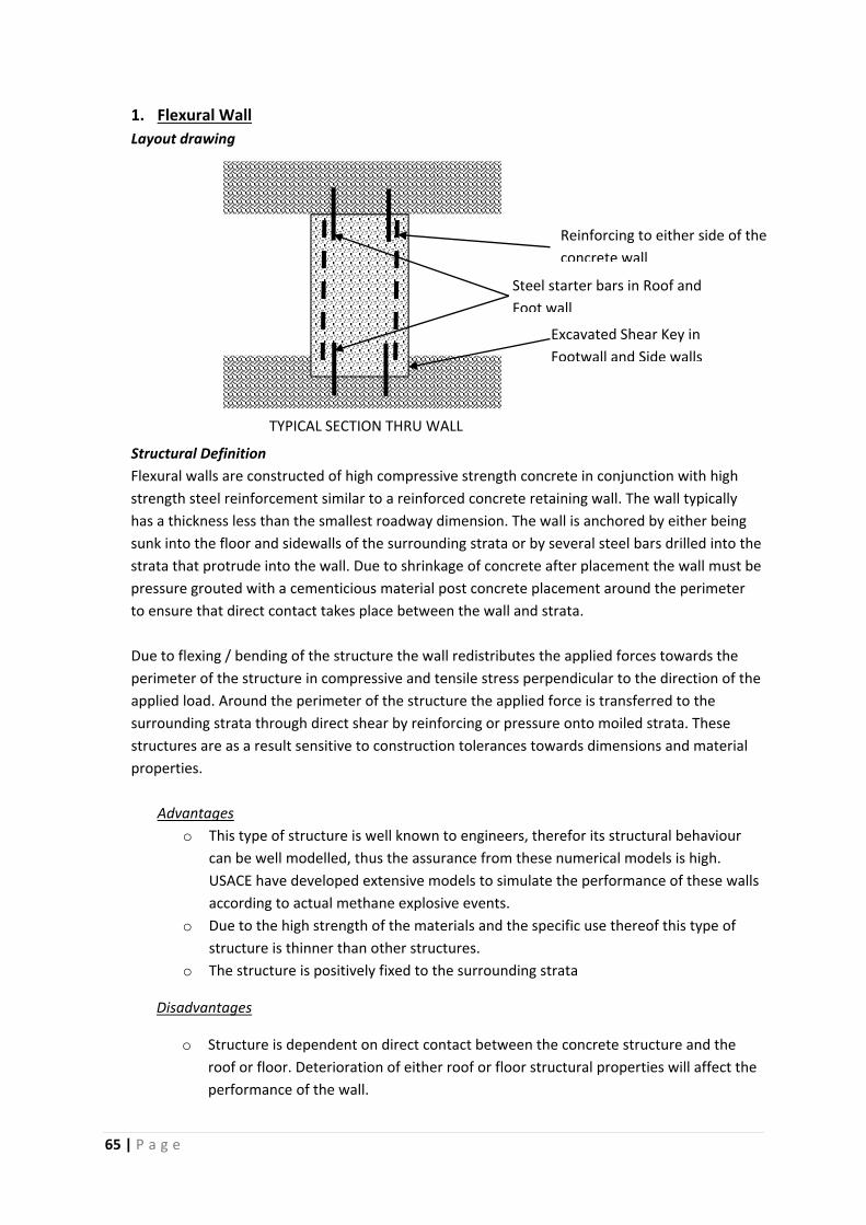
65 | P a g e
1. Flexural Wall
Layout drawing
Structural Definition
Flexural walls are constructed of high compressive strength concrete in conjunction with high
strength steel reinforcement similar to a reinforced concrete retaining wall. The wall typically
has a thickness less than the smallest roadway dimension. The wall is anchored by either being
sunk into the floor and sidewalls of the surrounding strata or by several steel bars drilled into the
strata that protrude into the wall. Due to shrinkage of concrete after placement the wall must be
pressure grouted with a cementicious material post concrete placement around the perimeter
to ensure that direct contact takes place between the wall and strata.
Due to flexing / bending of the structure the wall redistributes the applied forces towards the
perimeter of the structure in compressive and tensile stress perpendicular to the direction of the
applied load. Around the perimeter of the structure the applied force is transferred to the
surrounding strata through direct shear by reinforcing or pressure onto moiled strata. These
structures are as a result sensitive to construction tolerances towards dimensions and material
properties.
Advantages
o This type of structure is well known to engineers, therefor its structural behaviour
can be well modelled, thus the assurance from these numerical models is high.
USACE have developed extensive models to simulate the performance of these walls
according to actual methane explosive events.
o Due to the high strength of the materials and the specific use thereof this type of
structure is thinner than other structures.
o The structure is positively fixed to the surrounding strata
Disadvantages
o Structure is dependent on direct contact between the concrete structure and the
roof or floor. Deterioration of either roof or floor structural properties will affect the
performance of the wall.
Reinforcing to either side of the
concrete wall
Excavated Shear Key in
Footwall and Side walls
Steel starter bars in Roof and
Foot wall
TYPICAL SECTION THRU WALL
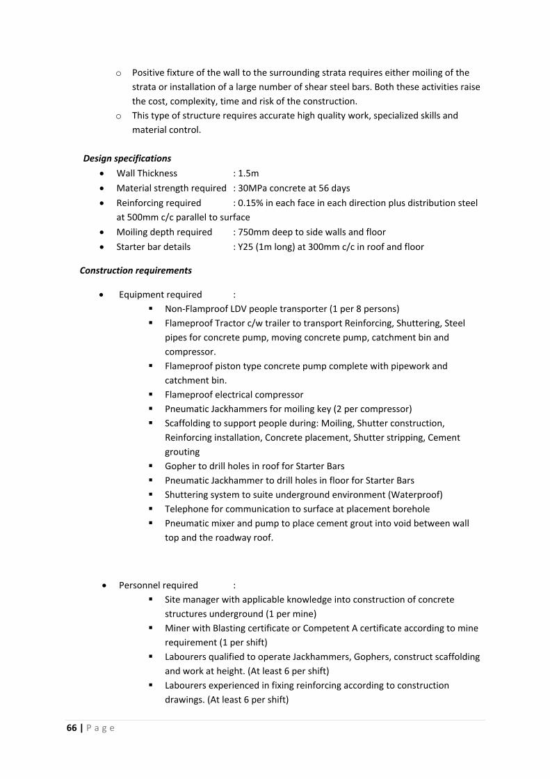
66 | P a g e
o Positive fixture of the wall to the surrounding strata requires either moiling of the
strata or installation of a large number of shear steel bars. Both these activities raise
the cost, complexity, time and risk of the construction.
o This type of structure requires accurate high quality work, specialized skills and
material control.
Design specifications
Wall Thickness : 1.5m
Material strength required : 30MPa concrete at 56 days
Reinforcing required : 0.15% in each face in each direction plus distribution steel
at 500mm c/c parallel to surface
Moiling depth required : 750mm deep to side walls and floor
Starter bar details : Y25 (1m long) at 300mm c/c in roof and floor
Construction requirements
Equipment required :
Non‐Flamproof LDV people transporter (1 per 8 persons)
Flameproof Tractor c/w trailer to transport Reinforcing, Shuttering, Steel
pipes for concrete pump, moving concrete pump, catchment bin and
compressor.
Flameproof piston type concrete pump complete with pipework and
catchment bin.
Flameproof electrical compressor
Pneumatic Jackhammers for moiling key (2 per compressor)
Scaffolding to support people during: Moiling, Shutter construction,
Reinforcing installation, Concrete placement, Shutter stripping, Cement
grouting
Gopher to drill holes in roof for Starter Bars
Pneumatic Jackhammer to drill holes in floor for Starter Bars
Shuttering system to suite underground environment (Waterproof)
Telephone for communication to surface at placement borehole
Pneumatic mixer and pump to place cement grout into void between wall
top and the roadway roof.
Personnel required :
Site manager with applicable knowledge into construction of concrete
structures underground (1 per mine)
Miner with Blasting certificate or Competent A certificate according to mine
requirement (1 per shift)
Labourers qualified to operate Jackhammers, Gophers, construct scaffolding
and work at height. (At least 6 per shift)
Labourers experienced in fixing reinforcing according to construction
drawings. (At least 6 per shift)
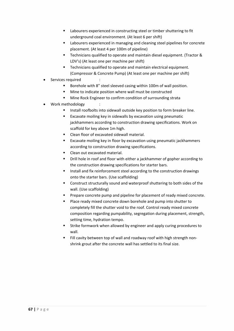
67 | P a g e
Labourers experienced in constructing steel or timber shuttering to fit
underground coal environment. (At least 6 per shift)
Labourers experienced in managing and cleaning steel pipelines for concrete
placement. (At least 4 per 100m of pipeline)
Technicians qualified to operate and maintain diesel equipment. (Tractor &
LDV’s) (At least one per machine per shift)
Technicians qualified to operate and maintain electrical equipment.
(Compressor & Concrete Pump) (At least one per machine per shift)
Services required :
Borehole with 8” steel sleeved casing within 100m of wall position.
Mine to indicate position where wall must be constructed
Mine Rock Engineer to confirm condition of surrounding strata
Work methodology :
Install roofbolts into sidewall outside key position to form breaker line.
Excavate moiling key in sidewalls by excavation using pneumatic
jackhammers according to construction drawing specifications. Work on
scaffold for key above 1m high.
Clean floor of excavated sidewall material.
Excavate moiling key in floor by excavation using pneumatic jackhammers
according to construction drawing specifications.
Clean out excavated material.
Drill hole in roof and floor with either a jackhammer of gopher according to
the construction drawing specifications for starter bars.
Install and fix reinforcement steel according to the construction drawings
onto the starter bars. (Use scaffolding)
Construct structurally sound and waterproof shuttering to both sides of the
wall. (Use scaffolding)
Prepare concrete pump and pipeline for placement of ready mixed concrete.
Place ready mixed concrete down borehole and pump into shutter to
completely fill the shutter void to the roof. Control ready mixed concrete
composition regarding pumpability, segregation during placement, strength,
setting time, hydration tempo.
Strike formwork when allowed by engineer and apply curing procedures to
wall.
Fill cavity between top of wall and roadway roof with high strength non‐
shrink grout after the concrete wall has settled to its final size.
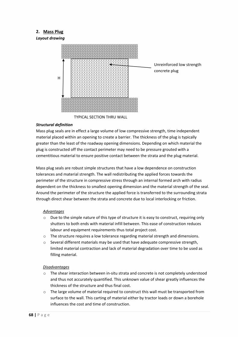
68 | P a g e
2. Mass Plug
Layout drawing
Structural definition
Mass plug seals are in effect a large volume of low compressive strength, time independent
material placed within an opening to create a barrier. The thickness of the plug is typically
greater than the least of the roadway opening dimensions. Depending on which material the
plug is constructed off the contact perimeter may need to be pressure grouted with a
cementitious material to ensure positive contact between the strata and the plug material.
Mass plug seals are robust simple structures that have a low dependence on construction
tolerances and material strength. The wall redistributing the applied forces towards the
perimeter of the structure in compressive stress through an internal formed arch with radius
dependent on the thickness to smallest opening dimension and the material strength of the seal.
Around the perimeter of the structure the applied force is transferred to the surrounding strata
through direct shear between the strata and concrete due to local interlocking or friction.
Advantages
o Due to the simple nature of this type of structure it is easy to construct, requiring only
shutters to both ends with material infill between. This ease of construction reduces
labour and equipment requirements thus total project cost.
o The structure requires a low tolerance regarding material strength and dimensions.
o Several different materials may be used that have adequate compressive strength,
limited material contraction and lack of material degradation over time to be used as
filling material.
Disadvantages
o The shear interaction between in‐situ strata and concrete is not completely understood
and thus not accurately quantified. This unknown value of shear greatly influences the
thickness of the structure and thus final cost.
o The large volume of material required to construct this wall must be transported from
surface to the wall. This carting of material either by tractor loads or down a borehole
influences the cost and time of construction.
H
Unreinforced low strength
concrete plug
TYPICAL SECTION THRU WALL
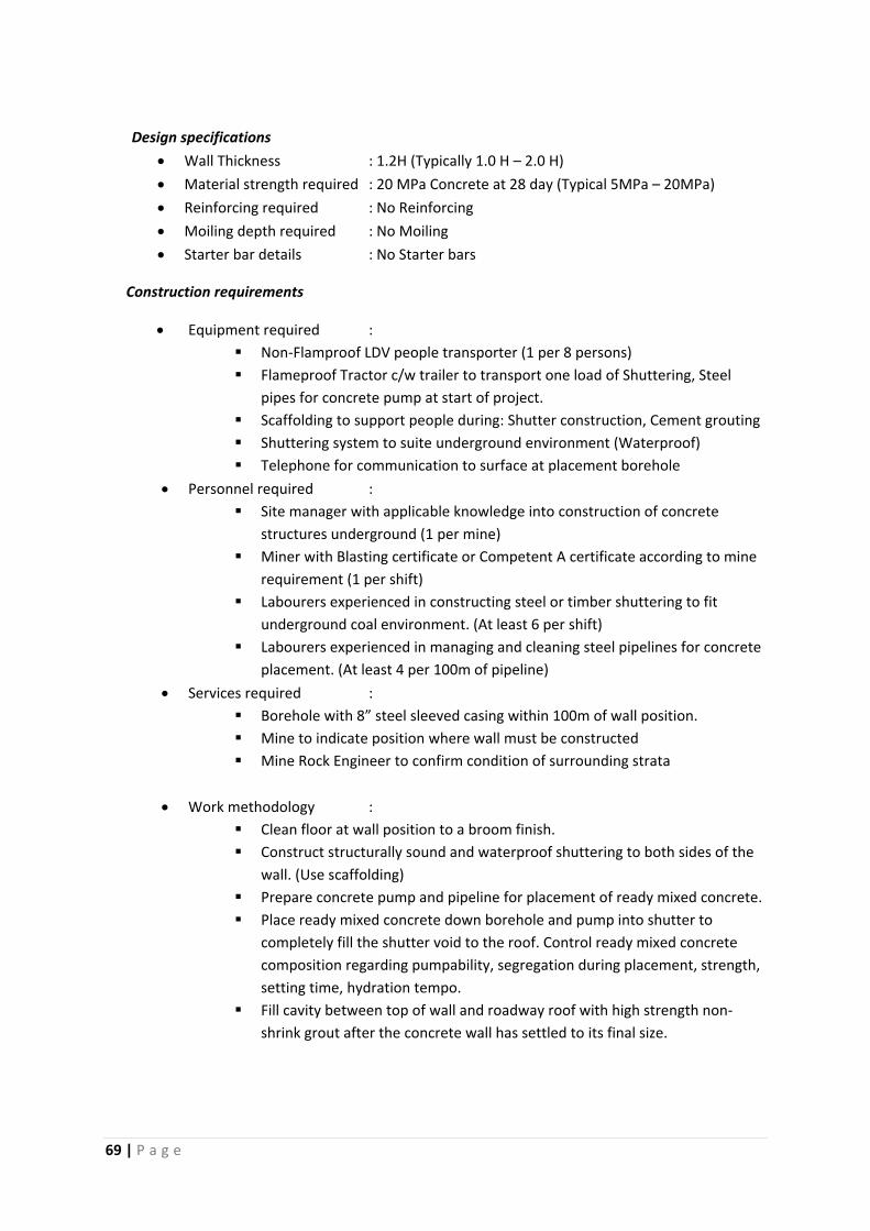
69 | P a g e
Design specifications
Wall Thickness : 1.2H (Typically 1.0 H – 2.0 H)
Material strength required : 20 MPa Concrete at 28 day (Typical 5MPa – 20MPa)
Reinforcing required : No Reinforcing
Moiling depth required : No Moiling
Starter bar details : No Starter bars
Construction requirements
Equipment required :
Non‐Flamproof LDV people transporter (1 per 8 persons)
Flameproof Tractor c/w trailer to transport one load of Shuttering, Steel
pipes for concrete pump at start of project.
Scaffolding to support people during: Shutter construction, Cement grouting
Shuttering system to suite underground environment (Waterproof)
Telephone for communication to surface at placement borehole
Personnel required :
Site manager with applicable knowledge into construction of concrete
structures underground (1 per mine)
Miner with Blasting certificate or Competent A certificate according to mine
requirement (1 per shift)
Labourers experienced in constructing steel or timber shuttering to fit
underground coal environment. (At least 6 per shift)
Labourers experienced in managing and cleaning steel pipelines for concrete
placement. (At least 4 per 100m of pipeline)
Services required :
Borehole with 8” steel sleeved casing within 100m of wall position.
Mine to indicate position where wall must be constructed
Mine Rock Engineer to confirm condition of surrounding strata
Work methodology :
Clean floor at wall position to a broom finish.
Construct structurally sound and waterproof shuttering to both sides of the
wall. (Use scaffolding)
Prepare concrete pump and pipeline for placement of ready mixed concrete.
Place ready mixed concrete down borehole and pump into shutter to
completely fill the shutter void to the roof. Control ready mixed concrete
composition regarding pumpability, segregation during placement, strength,
setting time, hydration tempo.
Fill cavity between top of wall and roadway roof with high strength non‐
shrink grout after the concrete wall has settled to its final size.
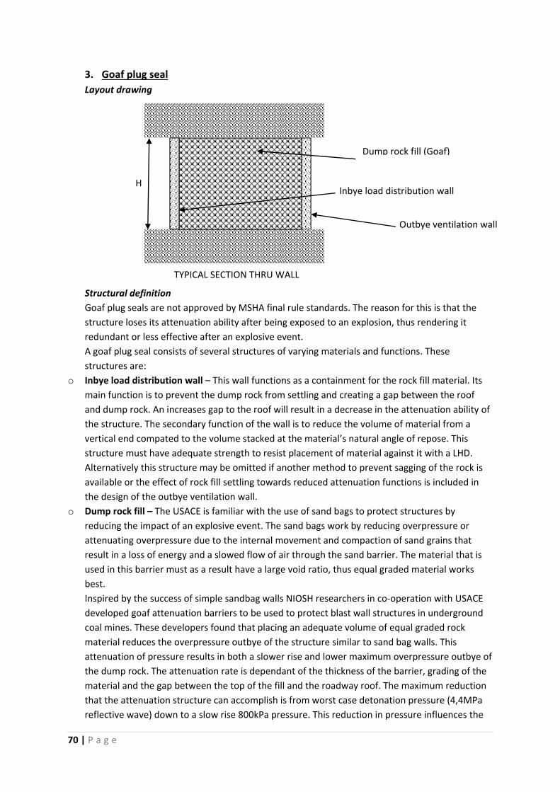
70 | P a g e
3. Goaf plug seal
Layout drawing
Structural definition
Goaf plug seals are not approved by MSHA final rule standards. The reason for this is that the
structure loses its attenuation ability after being exposed to an explosion, thus rendering it
redundant or less effective after an explosive event.
A goaf plug seal consists of several structures of varying materials and functions. These
structures are:
o Inbye load distribution wall – This wall functions as a containment for the rock fill material. Its
main function is to prevent the dump rock from settling and creating a gap between the roof
and dump rock. An increases gap to the roof will result in a decrease in the attenuation ability of
the structure. The secondary function of the wall is to reduce the volume of material from a
vertical end compated to the volume stacked at the material’s natural angle of repose. This
structure must have adequate strength to resist placement of material against it with a LHD.
Alternatively this structure may be omitted if another method to prevent sagging of the rock is
available or the effect of rock fill settling towards reduced attenuation functions is included in
the design of the outbye ventilation wall.
o Dump rock fill – The USACE is familiar with the use of sand bags to protect structures by
reducing the impact of an explosive event. The sand bags work by reducing overpressure or
attenuating overpressure due to the internal movement and compaction of sand grains that
result in a loss of energy and a slowed flow of air through the sand barrier. The material that is
used in this barrier must as a result have a large void ratio, thus equal graded material works
best.
Inspired by the success of simple sandbag walls NIOSH researchers in co‐operation with USACE
developed goaf attenuation barriers to be used to protect blast wall structures in underground
coal mines. These developers found that placing an adequate volume of equal graded rock
material reduces the overpressure outbye of the structure similar to sand bag walls. This
attenuation of pressure results in both a slower rise and lower maximum overpressure outbye of
the dump rock. The attenuation rate is dependant of the thickness of the barrier, grading of the
material and the gap between the top of the fill and the roadway roof. The maximum reduction
that the attenuation structure can accomplish is from worst case detonation pressure (4,4MPa
reflective wave) down to a slow rise 800kPa pressure. This reduction in pressure influences the
H
Dump rock fill (Goaf)
TYPICAL SECTION THRU WALL
Outbye ventilation wall
Inbye load distribution wall
71 | P a g e
design of the outbye ventilation wall by negating the Dynamic Load constant and additional
Safety factors due the unknown load application resulting in a thinner cheaper wall.
o Outbye Ventilation wall – This structure can be constructed as either a plug seal or flexural wall
with a reduced design pressure compared to a similar wall with no attenuation structure inbye
of it.
Advantages
o The attenuation function of the rock dump greatly reduces the impact force on the
ventilation wall. This reduction in force will result in a lighter ventilation structure with
subsequent reduced cost.
o The ready availability of equal graded dump rock in the mine may reduce the cost of
constructing the dump rock attenuator.
Disadvantages
o The structure is constructed from at least two separate structures and possibly a third
structure. This number of structures increases the final cost of construction.
o If correctly graded rock is not available on‐site then the material needs to be imported
at a considerable cost.
o Even though the design pressure on the ventilation wall is reduces, the subsequent
reduction in cost may not justify the additional cost of constructing the attenuation
barrier if cheap rock fill material is not available.
o An attenuation barrier reduces the overpressure due to the internal movement and
compression of the rock. Once this reduction in void spaces has occurred the structure
changes its structural behaviour closer to a mass plug seal than an attenuation
structure. There is currently no quantitive information available on how an attenuation
barrier will behave during subsequent explosive events. Thus the structure poses a
significant risk in future until this behaviour is understood and quantified.
Design specifications
Wall specifications:
Inbye gunnite wall – 400mm thick 25MPa spray applied concrete on Ref 617
welded mesh reinforcing and 1m long Y25 shear bars at 1m c/c all round
Goaf Fill – 2 H
Outbye ventilation wall – 800mm thick 25MPa concrete wall with 0.15%
reinforcing in both directions to both faces of wall. Wall to be fixed to
surround by moiling 750mm deep into floor and side wall.
Construction requirements
Equipment required :
Similar to flexural wall.
Flameproof diesel LHD. In order to stack the ballast rock to the roof it is
imperative that the bucket be equipped with a hydraulic push plate. This is
72 | P a g e
not an industry standard and will require a dedicated machine for the
purpose.
Personnel required :
Site manager with applicable knowledge into construction of underground
structures (1 per mine)
Miner with Blasting certificate or Competent A certificate according to mine
requirement (1 per shift)
Similar to flexural wall
Services required :
Borehole with 20” steel sleeved casing within 100m of wall position for
ballast stone if not available on site.
Mine to indicate position where wall must be constructed
Mine Rock Engineer to confirm condition of surrounding strata
Work methodology :
Clean floor at wall position to a broom finish.
Construct a gunnite type wall similar to Ingwe spec 400kPa wall as load
distribution wall.
Dump equal graded hard weather resistant dump rock with 80% of material
not passing a 63mm sieve down borehole.
Move dump rock from borehole with LHD and stack against inbye wall to fill
roadway opening from floor to roof. LHD will have to use a hydraulic push
plate in the bucket to stack the ballast up to the roof.
Construct a wall similar to the flexural wall, but with thickness of only
800mm as ventilation wall.
73 | P a g e
ANNEXURE 1
COST CALCULATIONS:
Flexural Wall
Mass Plug
Goaf Plug Seal
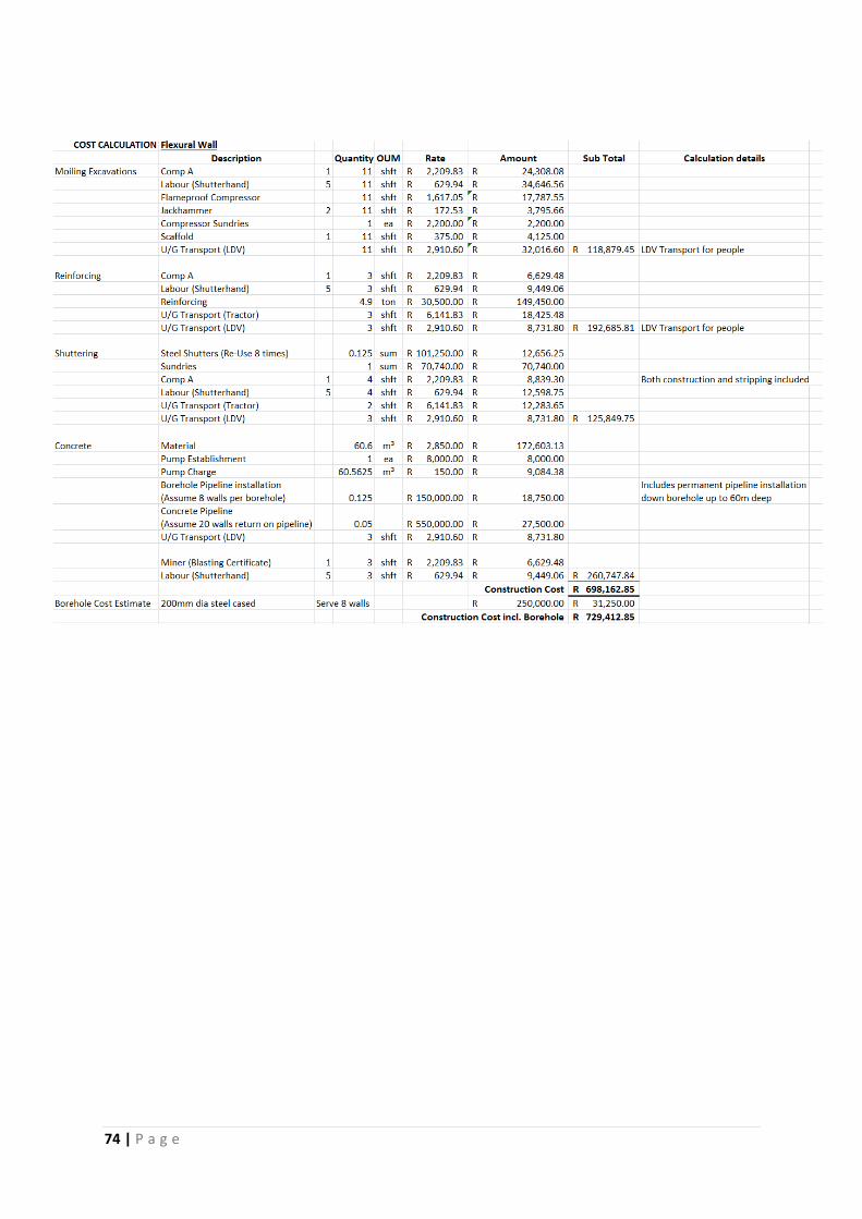
74 | P a g e
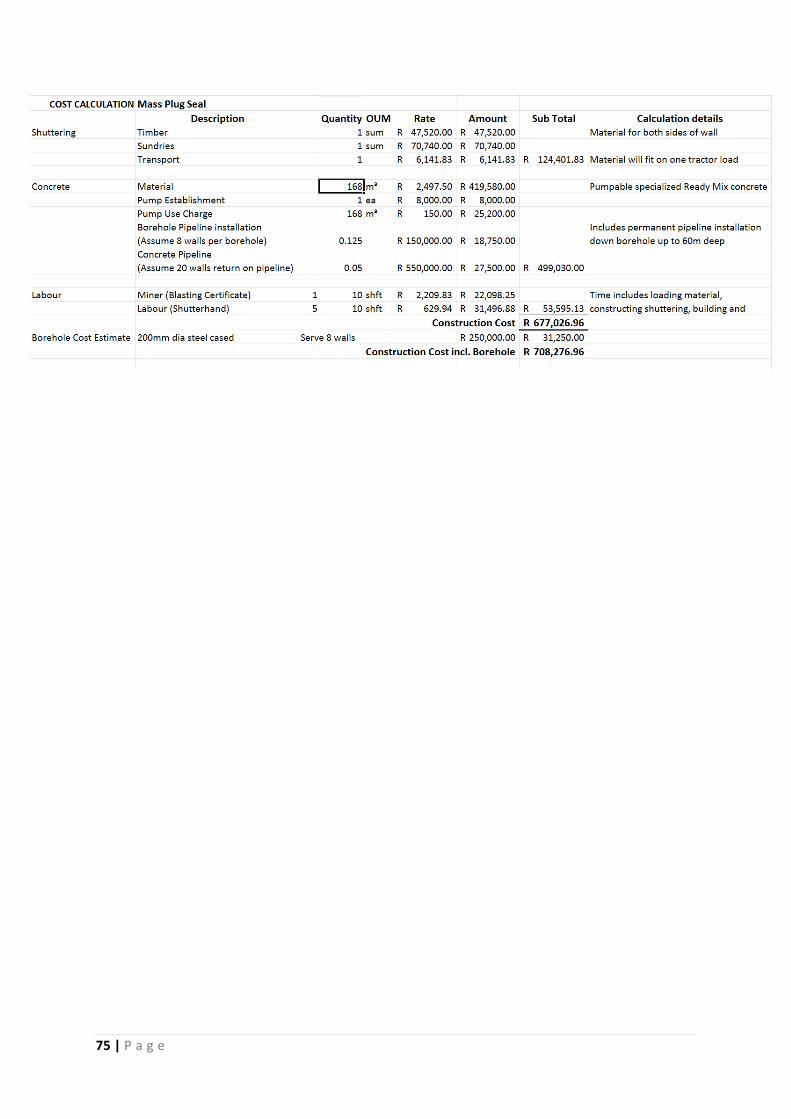
75 | P a g e
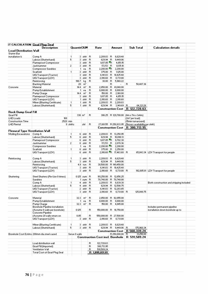
76 | P a g e