Current Research Issue, Trend & Applications of Powder Mixed Dielectric Electric Discharge...
24
[Choudhary, 3(7): July, 2014] ISSN: 2277-9655 Scientific Journal Impact Factor: 3.449 (ISRA), Impact Factor: 1.852 http: // www.ijesrt.com (C)International Journal of Engineering Sciences & Research Technology [335-358] IJESRT INTERNATIONAL JOURNAL OF ENGINEERING SCIENCES & RESEARCH TECHNOLOGY Current Research Issue, Trend & Applications of Powder Mixed Dielectric Electric Discharge Machining (PM-EDM): A Review Sushil Kumar Choudhary * 1 , R.S Jadoun 2 *1, 2 Industrial & Production Engineering, G.B.Pant University of Agriculture & Technology, Pantnagar, Uttarakhand, India [email protected] Abstract In this paper new concept of manufacturing uses non-conventional energy sources like sound, light, mechanical, chemical, electrical, electrons and ions. With the industrial and technological growth, development of harder and difficult to machine materials, which find wide application in aerospace, nuclear engineering and other industries owing to their high strength to weight ratio, hardness and heat resistance qualities has been witnessed. New developments in the field of material science have led to new engineering metallic materials, composite materials and high tech ceramics having good mechanical properties and thermal characteristics as well as sufficient electrical conductivity so that they can readily be machined by spark erosion. Erosion pulse discharge occurs in a small gap between the work piece and the electrode. This removes the unwanted material from the parent metal through melting and vaporizing in presence of dielectric fluid. In recent years, EDM researchers have explored a number of ways to improve EDM Process parameters such as Electrical parameters, Non-Electrical Parameters, tool Electrode based parameters & Powder based parameters. This new research shares the same objectives of achieving more efficient metal removal rate reduction in tool wear and improved surface quality. This paper reviews the research work carried out from the inception to the development of Powder Mixed Dielectric electric Discharge Machining within the past decade. & also briefly describing the Current Research technique Trend in EDM & optimization Technique used in the Powder mix Electric Discharge Machining research field. Keyword: EDM, PMEDM, MRR, TWR, SR, SQ, HAZ, RLT Introduction EDM as a process was introduced over fifty years ago; improvements in technology have led to increases in both cutting speeds and component precision. Developing from initially tool making industry sectors of press tool and mould tools, the EDM process is now mainly found within production engineering, aerospace, motor sport, medical and scientific industries. Electrical Discharge Machining (EDM) is non traditional, no physical cutting forces between the tool and the workpiece, high precision metal removal process using thermal energy by generating a spark to erode the workpiece. The workpiece must be a conductive electricity material which is submerged into the dielectric fluid for better erosion. EDM machine has wide application in production of die cavity with large components, deep small diameter whole and various intricate holes and other precision part. The history of EDM Machining Techniques goes as far back as 1770, when English chemist Joseph Priestly discovered the erosive effect of electrical discharges or sparks. The EDM process was invented by two Russian scientists, Dr. B.R. Lazarenko and Dr. N.I. Lazarenko in 1943. The spark generator used in 1943, known as the Lazarenko circuit, has been employed over many years in power supplies for EDM machines and proved to be used in many current applications . The Lazarenko EDM system uses resistance- capacitance type of power supply, which was widely used at the EDM machine in the 1950's and later served as the model for successive development in EDM . Further developments in the 1960's of pulse and solid state generators reduced previous problems with weak electrode as well as the inventions of orbiting systems. In the 1970's the number of electrodes is reduced to create cavities. Finally, in the 1980's a computer numerical controlled (CNC) EDM was
Transcript of Current Research Issue, Trend & Applications of Powder Mixed Dielectric Electric Discharge...

[Choudhary, 3(7): July, 2014] ISSN: 2277-9655 Scientific Journal Impact Factor: 3.449
(ISRA), Impact Factor: 1.852
http: // www.ijesrt.com (C)International Journal of Engineering Sciences & Research Technology
[335-358]
IJESRT INTERNATIONAL JOURNAL OF ENGINEERING SCIENCES & RESEARCH
TECHNOLOGY Current Research Issue, Trend & Applications of Powder Mixed Dielectric Electric
Discharge Machining (PM-EDM): A Review Sushil Kumar Choudhary* 1, R.S Jadoun 2
*1, 2 Industrial & Production Engineering, G.B.Pant University of Agriculture & Technology,
Pantnagar, Uttarakhand, India
Abstract In this paper new concept of manufacturing uses non-conventional energy sources like sound,
light, mechanical, chemical, electrical, electrons and ions. With the industrial and technological growth,
development of harder and difficult to machine materials, which find wide application in aerospace, nuclear
engineering and other industries owing to their high strength to weight ratio, hardness and heat resistance
qualities has been witnessed. New developments in the field of material science have led to new
engineering metallic materials, composite materials and high tech ceramics having good mechanical
properties and thermal characteristics as well as sufficient electrical conductivity so that they can readily be
machined by spark erosion. Erosion pulse discharge occurs in a small gap between the work piece and the
electrode. This removes the unwanted material from the parent metal through melting and vaporizing in
presence of dielectric fluid. In recent years, EDM researchers have explored a number of ways to improve
EDM Process parameters such as Electrical parameters, Non-Electrical Parameters, tool Electrode based
parameters & Powder based parameters. This new research shares the same objectives of achieving more
efficient metal removal rate reduction in tool wear and improved surface quality. This paper reviews the
research work carried out from the inception to the development of Powder Mixed Dielectric electric
Discharge Machining within the past decade. & also briefly describing the Current Research technique
Trend in EDM & optimization Technique used in the Powder mix Electric Discharge Machining research
field.
Keyword: EDM, PMEDM, MRR, TWR, SR, SQ, HAZ, RLT
Introduction EDM as a process was introduced over
fifty years ago; improvements in technology
have led to increases in both cutting speeds and
component precision. Developing from initially
tool making industry sectors of press tool and
mould tools, the EDM process is now mainly
found within production engineering, aerospace,
motor sport, medical and scientific industries.
Electrical Discharge Machining (EDM) is non
traditional, no physical cutting forces between
the tool and the workpiece, high precision metal
removal process using thermal energy by
generating a spark to erode the workpiece. The
workpiece must be a conductive electricity
material which is submerged into the dielectric
fluid for better erosion. EDM machine has wide
application in production of die cavity with large
components, deep small diameter whole and
various intricate holes and other precision part.
The history of EDM Machining Techniques goes
as far back as 1770, when English chemist
Joseph Priestly discovered the erosive effect of
electrical discharges or sparks. The EDM process
was invented by two Russian scientists, Dr. B.R.
Lazarenko and Dr. N.I. Lazarenko in 1943. The
spark generator used in 1943, known as the
Lazarenko circuit, has been employed over many
years in power supplies for EDM machines and
proved to be used in many current applications .
The Lazarenko EDM system uses resistance-
capacitance type of power supply, which was
widely used at the EDM machine in the 1950's
and later served as the model for successive
development in EDM . Further developments in
the 1960's of pulse and solid state generators
reduced previous problems with weak electrode
as well as the inventions of orbiting systems. In
the 1970's the number of electrodes is reduced to
create cavities. Finally, in the 1980's a computer
numerical controlled (CNC) EDM was

[Choudhary, 3(7): July, 2014] ISSN: 2277-9655 Scientific Journal Impact Factor: 3.449
(ISRA), Impact Factor: 1.852
http: // www.ijesrt.com (C)International Journal of Engineering Sciences & Research Technology
[335-358]
introduced in USA. Electric Discharge
Machining (EDM) Process shown in the fig.1
Fig-1: Schematic of EDM Process
[Choudhary& Jadoun (2014)]
1.1Technology of powder mixed EDM
In this process suitable material in the powder
form & mixed into the dielectric fluid in tank.
For better circulation of the dielectric fluid by
stirring system. For constant reuse of powder in
the dielectric fluid by the special circulation
system. Various powders of particle that can be
added into the dielectric fluid include Aluminum
(Al) , graphite, copper (Cu) , chromium (Cr),
Silicon carbide etc. spark gap provided by the
additives particles. When the voltage applied
between the tool electrode and workpiece are 80-
320V with the gap of 25-50µm & electric field
range 105 - 107 V/m was created. The powder
particles of the material get energized & behave
like a zigzag way manner. under the sparking
zone, the particles of the material powder comes
close to each other & arrange themselves in the
form of chain like structure between the
workpiece surface & tool electrode. The
interlocking between the different powder
particles occurs in the direction of flow current.
The chain formation helps in bridging the
discharge gap between the electrodes. Because of
bridging effect, the insulating strength of the
dielectric fluid decreases resulting in easy short
circuit. This causes early explosion in the gap
and series discharge’ starts under the electrode
area. The faster sparking within a discharge
causes faster erosion from the work piece surface
and hence the material removal rate increases.
Fig.-2: Line Diagram of PMEDM Setup
1.2 Major Component of Powder mixed
Electrical discharge Machining
1. Power supply: The power supply is an
important part of any EDM system. It
transform the alternating current from the
main utility supply into the pulse direct
current (DC) required to produce the spark
discharge at the machining gap.
2. Pulse Generator & Control Unit: is
responsible for supplying pulses at a certain
voltage and current for specific amount of
time. The power supply control the amount
of energy consumed. First, it has a time
control function which controls the length of
time that current flows during each pulse;
this is called “on time.” Then it is control the
amount of current allowed to flow during
each pulse. The control unit is control the all
function of the machining for example of
Ton, Ip, duty cycle, putting the values and
maintain the workpiece the tool gap.
3. The servo system to feed the tool: The
servo control unit is provided to maintain
the pre determined gap. It senses the gap
voltage and compares it with the present
value and the different in voltage is then
used to control the movement of servo
motor to adjust the gap.
4. Tool holder: The tool holder holds the tool
with the process of machining.
5. Circulating Pump: Circulation of powder
mixed dielectric.

[Choudhary, 3(7): July, 2014] ISSN: 2277-9655 Scientific Journal Impact Factor: 3.449
(ISRA), Impact Factor: 1.852
http: // www.ijesrt.com (C)International Journal of Engineering Sciences & Research Technology
[335-358]
6. Electrode: The EDM electrode is the tool
that determines the shape of the cavity to be
produce
7. Permanent magnet: Magnetic forces are
used to separate the debris from the
dielectric fluid. For this purpose, two
permanent magnets are placed at the bottom
of machining tank
8. Machining Tank: The system consists of a
transparent bath-like container, called the
machining tank. It is placed in the work tank
of the EDM, and the machining is performed
in this container. 9. Working tank with work holding device:
All the EDM oil kept in the working tank
working tank is used to the supply the fluid
during the process of machining.
10. X-y table accommodating the working
table: They are used to the moment of the
workpiece form X and Y directio
1.3 - PM-EDM Application, Advantages & Limitations
Table-1
A. Applications
1. Enhancement of machined surface functional properties, such as wear resistance,
corrosion resistance and reduced friction coefficient, through surface modification.
2. Improvements in performance parameters such as MRR, WR and SQ
3. Making and machining of micro product & sophisticated micro mechanical Element. It is
the use of light, thin, compact, special purposes work such as micro-engines, micro-
pumps, micro-robots etc.
4. The production of these microelements with traditional methods is restricted due to
various Complications.
5. Machining of insulating materials Such as Si3N4 ceramics
6. Improve surface characteristics like mirror finish by graphite & silicon powder mixed
into the dielectric fluid of EDM
B. Advantages
1. Any material that is electrical conductive can be machined, regardless of its hardness,
strength, toughness and microstructure etc.
2. Work piece can be machined in hardness Conditions that is, the deformation caused by
the hardened process does not affect the final dimensions.
3. Complicated die contours in hard materials can be produced to a high degree of accuracy
and surface finish.
4. No stresses are produced in the work, as there is no physical contact between the work
piece and the tool electrode.
5. PMEDM process is totally burring free.
6. Secondary finishing operations like grinding are generally eliminated.
7. The surface produced by EDM consists if a number of small craters that help in oil
retention and better lubrication, especially for the components such as tools and dies,
where proper lubrication is very important for the life of the component.
8. A die punch can be used as electrode to reproduce its shape in the machining die block,
completely with the necessary clearances. As a result better dies and moulds can be
produced at reasonable costs.
C. Limitations
[Choudhary, 3(7): July, 2014] ISSN: 2277-9655 Scientific Journal Impact Factor: 3.449
(ISRA), Impact Factor: 1.852
http: // www.ijesrt.com (C)International Journal of Engineering Sciences & Research Technology
[335-358]
1. MRR is low making the process economical only for very hard and difficult to machine
materials.
2. The materials to be machined must be electrically conductive.
3. Fast electrode wear can prove costly.
4. The process cannot be monitored during machining. Hence any errors on malfunctions
are detected only after the entire cut.
5. Only highly skilled persons can operate the machine.
1.4 Principle of PMEDM
When voltage is applied the powder particles
become energized and behave in a zigzag
fashion. These charged particles are accelerated
due to the electric field and act as conductors
promoting breakdown in the gap. This increases
the spark gap between tool and the work piece.
Under the sparking area, these particles come
close to each other and arrange themselves in the
form of chain like structures. The interlocking
between the powder particles occurs in the
direction of flow of current. The chain formation
helps in bridging the discharge gap between the
electrodes. Because of bridging effect, the
insulating strength of the dielectric fluid
decreases resulting in easy short circuit. This
causes early explosion in the gap and series
discharge’ starts under the electrode area. The
faster sparking within a discharge causes faster
erosion from the work piece surface and hence
the material removal rate increases.
Fig-3: working principle of PMEDM
2. Parameters of PM-EDM. EDM Parameters mainly classified into two
categories.
1. Process Parameters 2. Performance Parameters
2.1. Process Parameters: The process
parameters in EDM are used to control the
performance measures of the machining process.
Process parameters are generally controllable
machining input factors that determine the
conditions in which machining is carried out. These
machining conditions will affect the process
performance result, which are gauged using various
performance measures.
2.1.1 Electrical Parameters
1. Polarity: Polarity of the electrode can be
either positive or negative
i. Straight polarity: Electrode (-) &
workpiece (+)
ii. Reverse polarity: Electrode (+) &
workpiece (-)
2. Supply voltage: The input voltage applied
across the tool electrode and workpiece is
called the supply or open circuit voltage.
3. Discharge voltage: This is the electrical
energy that is available for material removal.
The magnitude of Em is calculated from
measured pulse on time, discharge voltage and
discharge current values.
4. Discharge Current: The discharge current
(Id) is a measure of the amount of electrical
charges flowing between the tool and
workpiece electrode. As the flow of electrical
charges is the heating mechanism in electro-
thermal erosion,
5. Gap Voltage: The preset gap-voltage
determines the width of the spark gap
between the leading edge of the electrode
and the workpiece. High voltage settings
increase the gap and hence the flushing and
machining. However when using graphite
electrodes, high open gap voltage drastically
increases the electrode wear.
6. Peak Current: This is the amount of power
used in discharge machining, measured in
units of amperage, and is the most important
machining parameter in EDM .During each
on-time pulse, the current increases until it
reaches a preset level, which is expressed as
the peak current. In both die-sinking and
wire-EDM applications, the maximum

[Choudhary, 3(7): July, 2014] ISSN: 2277-9655 Scientific Journal Impact Factor: 3.449
(ISRA), Impact Factor: 1.852
http: // www.ijesrt.com (C)International Journal of Engineering Sciences & Research Technology
[335-358]
amount of amperage is governed by the
surface area of the cut. Higher amperage is
used in roughing operations and in cavities
or details with large surface areas. Higher
currents will improve MRR, but at the cost
of surface finish and tool wear. This is all
more important in EDM because the
machined cavity is a replica of tool electrode
and excessive wear will hamper the
accuracy of machining.
Fig-4
7. Average Current: Peak current is the
maximum current available for each pulse
from the power supply/generator. Average
current is the average of the amperage in the
spark gap measured over a complete cycle.
It is calculated by multiplying peak current
by duty factor.
Average Current (A) = Duty Factor (%) × Peak
Current (1)
8. Pulse On-time (pulse time or Ton): The
duration of time (μs) the current is allowed
to flow per cycle. Material removal is
directly proportional to the amount of
energy applied during this on-time. This
energy is really controlled by the peak
current and the length of the on-time. To
observe the effect of pulse -on time on MRR
and SR Value of peak current is varied while
keeping the other parameter like pulse- off
time, servo voltage, wire feed rate fixed.
9. Pulse on Time: The pulse on time
represents the duration of discharge and is
the time during which the electrode material
is heated by the high temperature plasma
channel. Material removal is directly
proportional to the amount of energy applied
during this on-time .A longer pulse on time
will increase the discharge energy.
10. Pulse off time: The pulse off time represents
the duration when no discharge exists and
the dielectric is allowed to deionise and
recover its insulating properties. A longer
pulse off time improves machining stability
as arcing is eliminated.
11. Pulse Frequency: Pulse frequency is the
number of cycles produced across the gap in
one second. The higher the frequency, finer
is the surface finish that can be obtained.
Pulse frequency is calculated by dividing
1000 by the total cycle time (on-time + off-
time) in microseconds.
(2) 12. Pulse waveform: The pulse shape is
normally rectangular, but generators with
other pulse shapes have also been
developed. Using a generator which can
produce trapezoidal pulses, Bruyn (1968)
13. Electrode Gap: It is the distance between
the electrode and the part during the process
of EDM. An electro-mechanical and
hydraulic systems are used to respond to
average gap voltage. To obtain good
performance and gap stability a suitable gap
should be maintained. For the reaction
speed, it must obtain a high speed so that it
can respond to short circuits or even open
gap circuits. Gap width is not measured
directly, but can be inferred from the
average gap voltage.
14. Duty Factor: Duty factor is a percentage of
the pulse duration relative to the total cycle
time. Generally, a higher duty factor means
increased cutting efficiency.
(3)
2.1.2. Non-Electrical Parameters
1. Nozzle flushing: Flushing is defined as the
correct circulation of dielectric solution
between the electrodes and workpiece.
Suitable flushing conditions are essential to
obtain the highest machining efficiency. The
sinker EDM process has primarily used oil
for the dielectric fluid. Flushing system
mainly two type:
1. Normal flow 2. Reverse flow

[Choudhary, 3(7): July, 2014] ISSN: 2277-9655 Scientific Journal Impact Factor: 3.449
(ISRA), Impact Factor: 1.852
http: // www.ijesrt.com (C)International Journal of Engineering Sciences & Research Technology
[335-358]
Fig-5: Flushing system
2. Functions of a Dielectric Fluid: The dielectric
fluid id in a EDM serves a number of functions: The dielectric oil acts as a medium
through which controlled electrical
discharges occur.
Cool the section that was heated by the
discharging effect
Flush the eroded particles from the
machining gap
Provide insulation between the
electrode and the workpiece
The dielectric oil acts as a medium
used to carry away the solidified EDM
debris from the discharge gap to the
filter system.
The dielectric oil acts as a heat transfer
medium to absorb and carry away the
heat generated by the discharges from
both the electrode and the workpiece
3. Types of dielectric fluid
Mineral Oils liquid petroleum is a by-
product in the distillation of petroleum.
Kerosene was one of the first popular
dielectric oils. Its primary benefit is that it
has very low viscosity and flushes very well.
Transformer Oil is another mineral oil based
product that was adapted for use in EDMs
due to its dielectric properties. Earlier
generations of transformer oil were
compounded with PCBs. Transformer oil
has no current application in EDM.
EDM Oils: There are currently numerous
choices of mineral oils formulated
specifically for EDM
Synthetic oil: Synthetic oil is oil consisting
of chemical compounds which were not
originally present in crude oil (petroleum),
but were artificially made (synthesized)
from other compounds. Synthetic oil is used
as a substitute for oil refined from
petroleum, stated, to provide superior
mechanical and chemical properties than
those found in traditional mineral oils.
4. Properties & Characteristics of Dielectric
Fluid
Viscosity is the property that describes a
fluids resistance to flow.
Flash Point “The flash point of a flammable
liquid is the lowest temperature at which it
can form an ignitable mixture in air.” The
flash point for commonly used EDM
dielectric oils ranges from 160º F to 255º F.
Obviously for reasons of safety, the higher
the flash point the better.” The oil
temperature at which ignition of the
resulting vapor occurs is the Flash Point.
Flash points for common liquids are listed
below:
a. Gasoline -40º F
b. Ethanol 55º F
c. Kerosene 120º F
d. Diesel 143º F
e. Vegetable Oil 620º F
Oxidation Stability is a measure of the
dielectric fluids tendency to react with
oxygen.
Volatility is a measure of the tendency of a
dielectric fluid to vaporize
Acid Number is used to quantify the amount
of acid present in a sample of dielectric oil.
Excessive levels of acid in dielectric oil
could lead to corrosion in the dielectric
system. The acid number is expressed in
units of mg KOH/g, or the amount of
Sodium Hydroxide necessary to neutralize
the acid present in an oil sample.
Color of dielectric oil can be classified by an
ASTM test. Ideally, a dielectric fluid should
be water white for maximum visibility of the
workpiece.
Odor. Quite frankly, no one wants to work
in a smelly environment, and no one wants
to go home smelling like an EDM machine.
Thus, odor is an important consideration in
maintaining a decent work environment for
the employees.
Pour Point of oil is the temperature below
which the oil no longer pours freely.
5. Electrode lifts time
6. Working Time
7. Gain

[Choudhary, 3(7): July, 2014] ISSN: 2277-9655 Scientific Journal Impact Factor: 3.449
(ISRA), Impact Factor: 1.852
http: // www.ijesrt.com (C)International Journal of Engineering Sciences & Research Technology
[335-358]
2.1.3 Powder Based Parameters
1. Powder type
The powder added into the dielectric fluid could
increase the MRR and decrease the tool wear
rate (TWR) and improve the surface quality of
the work quite clearly. But the different powders
would have different impact on the output
characteristics of the EDM process. Some kinds
of inorganic oxide powders cannot disperse
uniformly and persistently in kerosene,
concentrate and precipitate quickly, so they do
not play a good role in improving the MRR,
decreasing the SR and TWR.
A powder which can be suspended into dielectric
fluid of EDM must have following properties:-
It should be electrical conductive in nature.
It must be non-magnetic in nature.
It must have good suspension capabilities.
It should have good thermal conductivities.
It should be in toxic and odorless.
2. Concentration of added powder
Addition of appropriate amount of powder into
dielectric fluid plays a very important role on
MRR, TWR and SR. The material removal depth
reached the maximum value at appropriate
concentration. Further increase or decrease in the
concentration of the added powder would
decrease the MRR.
3. Mesh size of powders
The size of the powder particles affects the
PMEDM performance. A large diameter of the
powder particle increases the gap but
simultaneously decreases the MRR and then
increases the SR.
4. Electrical properties of powders
The electrical conductivity of the added Powder
directly affects EDM performance. This is
because the added powder increases the
Conductivity of the dielectric fluid and results in
the extension of the gap distance.
5. Powder conductivity
6. Powder density
2.1.4 Electrode Based Parameters
1. Electrode material: EDM electrode materials
need to have properties that easily allow charge
and yet resist the erosion that the EDM process
encourages and stimulates in the metals it
machines. Alloys have properties which provide
different advantages based on the needs of the
application.
Brass is an alloy of copper and zinc. Brass
materials are used to form EDM wire and
small tubular electrodes. Brass does
not resist wear as well as copper or tungsten,
but is much easier to machine and can be
die-cast or extruded for specialized
applications. EDM wire does not need
to provide wear or arc erosion
resistance since new wire is fed
continuously during the EDM wiring cutting
process.
Copper and copper alloys have better EDM
wear resistance than brass, but are more
difficult to machine than either brass or
graphite. It is also more expensive than
graphite. Copper is, however, a common
base material because it is highly conductive
and strong. It is useful in the EDM
machining of tungsten carbide, or in
applications requiring a fine finish.
Copper tungsten materials are composites of
tungsten and copper. They are produced
using powder metallurgy processes. Copper
tungsten is very expensive compared to
other electrode materials, but is useful for
making deep slots under poor flushing
conditions and in the EDM machining of
tungsten carbide. Copper tungsten materials
are also used in resistance welding
electrodes and some circuit breaker
applications.
Graphite provides a cleaning action at low
speeds. Carbon graphite was one of the first
brush material grades developed and is
found in many older motors and
generators. It has an amorphous structure.
Molybdenum is used for making EDM wire.
It is the wire of choice for small slot work
and for applications requiring exceptionally
small corner radii. Molybdenum exhibits
high tensile strength and good conductivity,
making it ideal where small diameter wire is
needed for demanding applications.
Silver tungsten material is tungsten carbide
particles dispersed in a matrix of
silver. Silver offers high electrical
conductivity and tungsten provides excellent
erosion resistance and good anti-welding
characteristics in high-power applications.
This composite is thus the perfect choice for
EDM electrode applications where
maximizing conductivity is crucial.

[Choudhary, 3(7): July, 2014] ISSN: 2277-9655 Scientific Journal Impact Factor: 3.449
(ISRA), Impact Factor: 1.852
http: // www.ijesrt.com (C)International Journal of Engineering Sciences & Research Technology
[335-358]
Tellurium copper is useful in EDM
machining applications requiring a fine
finish. Tellurium copper has a machinability
that is similar to brass and better than pure
copper.
2. Electrode Shape& size: The performance of
die sinking EDM due to the shape configuration
of the electrode. The effect of electrode shape on
material removal rate (MRR), electrode wear rate
(EWR), wear ratio (WR), and average surface
roughness (Ra) has been investigated for mild
steel work material and copper electrode. The
shapes of the electrodes were round, square,
triangular, and diamond of constant cross-
sectional area of 64 mm2
. Khan A., et al, (2009)
study the effect of electrode shape on material
removal rate (MRR), electrode wear rate (EWR),
wear ratio (WR), and average surface roughness
(Ra) has been investigated for mild steel work
material and copper electrode. The shapes of the
electrodes were round, square, triangular, and
diamond of constant cross-sectional area of 64
mm2
.
Fig-6: Electrode shape
3. Electrode Properties:
High electrical conductivity – electrons are
cold emitted more easily and there is less
bulk electrical heating.
High thermal conductivity – for the same
heat load, the local temperature rise would
be less due to faster heat conducted to the
bulk of the tool and thus less tool wear.
Higher density – for the same heat load and
same tool wear by weight there would be
less volume removal or tool wear and thus
less dimensional loss or inaccuracy.
High melting point – high melting point
leads to fewer tools wear due to less tool
material melting for the same heat load.
Easy manufacturability.
Cost – cheap.
2.2 Performance Parameters
These parameters measure the various process
performances of EDM results. Performance
parameters classified into following Categories.
i. Material removal Rate: The Material removal
rate is expressed as the weight of material
removed from workpiece over a period of
machining time in minutes
(4)
ii. Tool wear Rate: The TWR is calculated by
using the weight loss from the tool divided by
the time of machining.
(5)
iii. Relative Wear Ratio: WR is the ratio of
TWR/MRR and is used as a performance
measure for quantifying tool-workpiece
material combination pairs since different
material combinations gives rise to different
TWR and MRR values. A material
combination pair with the lowest WR indicates
that the tool-workpiece material combination
gives the optimal TWR and MRR condition.
The relative wear ratio of the workpiece and
tool is expressed.
(6)
iv. Surface Roughness: SR is a classification of
surface parameter used to describe an
amplitude feature, which translates to
roughness of the surface finish. Of the many
parameters available to quantify SR, the most
commonly used in EDM are arithmetical mean
surface roughness (Ra), maximum peak-to-
valley surface roughness (Rmax) and root
mean square surface roughness (Rq). The
Surface Roughness of the workpiece can be
expressed in different ways like,
a. Arithmetic average (Ra)
b. Average peak to valley height (RZ)
c. Peak roughness (RP), etc.
Defined as the arithmetic average roughness of
the deviations of the roughness profile from the
central line along the measurement.
(7)
Where h(x) is the value of the roughness
profile and ‘L’ is the evaluation length.
v. Surface quality (SQ): Surface quality is a
broad performance measure used to describe
the condition of the machined surface. It

[Choudhary, 3(7): July, 2014] ISSN: 2277-9655 Scientific Journal Impact Factor: 3.449
(ISRA), Impact Factor: 1.852
http: // www.ijesrt.com (C)International Journal of Engineering Sciences & Research Technology
[335-358]
comprises components such as surface
roughness (SR), extent of heat affected zone
(HAZ), recast layer thickness and micro-crack
density.
vi. Heat affected Zone (HAZ): HAZ refers to the
region of a workpiece that did not melt during
electrical discharge but has experienced a phase
transformation, similar to that of heat treatment
processes, after being subjected to the high
temperatures of electrical discharge. vii. Recast layer Thickness (RLT): The recast layer
refers to the region of resolidified molten
material occurring as the top most layer of the
machined surface. The recast layer is usually
located above the heat affected zone.
3. Literature review
Table-2 PMEDM Research Contribution Year wise national & International standard
Researcher Contribution year wise
Erden A., et al., (1980) Reported during the machining of mild steel that the machining rate increases by
the addition of powder particles (aluminium, copper, iron) in the dielectric fluid of dielectric machining.
Here improvement in the Break Down characteristics of the dielectric fluid is observed with the addition of
powder particles, but after a certain critical concentration of powder short circuiting take place which
causes poor machining.
Jeswani M.L., et al., (1981) Study the effect of addition of graphite powder to kerosene used as dielectric
fluid in the EDM. He concluded that addition of about 4gm/litre of fine powder having average size of
particle as 10Hm increases the MRR (Material Removal Rate) by 60% and TWR (tool wear rate) by 15%
in electrical discharge machine. Wear ratio is also reduced by 30%. He concluded that there is 30%
reduction in the breakdown voltage of kerosene at spark gap of 50Hm was observed.
Narumiya H., et al., (1989) Used silicon, aluminium and graphite as powder materials. The concentration
range of the powder was between 2gm/l to 40gm/l. Their conclusion showed that the gap distance increases
with the powder concentration and is larger for the aluminium powder but there is no direct relation
between the surface roughness and the gap distance. The best results concerning the surface finish were
achieved for low powder concentrations levels and that also for silicon and graphite powders.
Mohri, et al. (1992)Found that an EDM finishing process using dielectric mixed with silicon powder
provides a mirror surface of up to 500 cm2, area. Recently this machining method has been introduced in
commercial machine tools and practically applied in industry.
Kobayashi K., et al., (1992) Have concluded that silicon powder mixed in the dielectric improves the
surface finish of SKD-61 tool steel. It has also been observed, however, that at specific machining
conditions in the EDM of steel the aluminium and graphite powders generate better surface roughness than
silicon powder.
Yan and Chen (1994) That the powder particles contribute to the reduction of surface cracks and to the
smoothness and homogenization of the white layer. The lowest surface roughness levels and a correct
balance between the discharge energy density and the discharge rate were observed for a powder
concentration within the range of 2 to 5 g/l
Ming and He (1995) Indicates that some conductive powder can lower the surface roughness and the
tendency of cracks in middle finish and finish machining but the inorganic oxide additive does not have
such effect.
Uno et al. (1998) Observed that nickel powder mixed working fluid modifies the surface of aluminum
bronze components. Nickel powder was purposely used to deposit a layer on an EDM surface to make the
surface abrasion-resistant.
Wong Y.S., et al., (1998) Study the powder mixed dielectric electric discharge machining (PMD-EDM) by
employing a current of 1A and pulse on time as 0.75Hs to produce a near mirror finish on SKH-54 tool
steel. The conclusion was that the resulting machining surface was composed of well defined, uniformly

[Choudhary, 3(7): July, 2014] ISSN: 2277-9655 Scientific Journal Impact Factor: 3.449
(ISRA), Impact Factor: 1.852
http: // www.ijesrt.com (C)International Journal of Engineering Sciences & Research Technology
[335-358]
sized, smoothly overlapped and shallow craters. The analysis was carried out by varying the silicon powder
concentration and the flushing flow rate.
Chow et al. (2000) Studied the EDM process by adding SiC and aluminum powders nto kerosene for the
micro- slit machining of titanium alloy. The addition of both SiC and aluminum powder to the kerosene
enhanced the gap distance, resulting in higher debris removal rate and material removal depth.
Furutani K., et al., (2001) Used titanium powder in dielectric fluid (Kerosene) and found that the layer of
titanium carbide of hardness 1600HV (Vickers hardness number) on a carbon steel with negative polarized
copper electrode, peak current 3A and 2 Hs pulse duration. Titanium and titanium Carbide are found in X-
Ray diffraction (XRD) analysis of machine surface. It was concluded that the breakdown of dielectric takes
place and carbon came from it.
Tzeng Y.F., et al., (2001) Examines the effect of powder characteristics on machining efficiency of
electrical discharge machining. They reach to a conclusion that 70- 80nm powder suspended in dielectric
produces the greatest material removal rate and least increase in the spark gap.
Yan BH., et al., (2001) Studied the electric discharge machining with powder suspended working media
and reported that the gap length become shorter regardless of a mixed powder with a decrease of the pulse
duration at a duty factor of 0.5.
Kozak J., et al., (2003) Reported that the material removal rate and tool wear rate were decreased by
addition of powder. Consequently the machined surface becomes smooth.
Peças P, et al., (2003) Investigated the influence of silicon powder mixed dielectric on conventional EDM.
The relationship between the roughness and pulse energy was roughly investigated under a few sets of the
conditions in the removal process. However, the effect of the energy was not systematically analyzed.
Klocke F., et al., (2004) Used HSFC high speed forming camera technique to find out that in comparison to
standard electrode, the aluminium mixed dielectric forms larger plasma channel. It was concluded that
discharge energy distribution is on the larger part on the work piece surface. The type and concentration of
the powder mixed in the dielectric fluid also found to have direct effect on the machining performance
output.
Wu KL., et al., (2005) Study the problem of powder settling by adding a surfactant with aluminium powder
in dielectric fluid and observed that a surface roughness (Ra value) of less than 0.2μm. This is because of
more apparent discharge distribution. It was also reported that negative polarity of the tool resulted in
better hardness of the surface.
Biing Hwa Yan et al. (2005) Investigates the influence of the machining characteristics on pure titanium
metals using an electrical discharge machining (EDM) with the addition of urea into distilled water.
Experimental results indicate that the nitrogen element decomposed from the dielectric that contained urea,
migrated to the work piece, forming a TiN hard layer, resulting in good wear resistance of the machined
surface after EDM. They have concluded that Adding urea into the dielectric, MRR and EWR increased
with an increase in peak current. Moreover MRR and EWR declined as the pulse duration increased. The
surface roughness deteriorated with an increase in peak current.
H.K. Kansal et al. (2005) Optimized the process parameters of powder mixed electrical discharge
machining (PMEDM) on tool steel using Response surface methodology. Pulse on time, duty cycle, peak
current and concentration of the silicon powder added into the dielectric fluid of EDM were chosen as
variables to study the process performance in terms of material removal rate and surface roughness. The
silicon powder suspended in the dielectric fluid of EDM affects both MRR and SR. They concluded that
more improvement in MRR and SR are expected at still higher concentration level of silicon powder.
Bai and Koo (2006) Investigated the effects of kerosene and distilled water as dielectric during electrical
discharge surface alloying of super alloys.
Kansal H.K., et al. (2006) Establishes optimum process conditions for PMEDM of Al– 10%SiCP Metal
Matrix Composites by an experimental investigation using Response Surface Methodology. Aluminium

[Choudhary, 3(7): July, 2014] ISSN: 2277-9655 Scientific Journal Impact Factor: 3.449
(ISRA), Impact Factor: 1.852
http: // www.ijesrt.com (C)International Journal of Engineering Sciences & Research Technology
[335-358]
powder was suspended into the dielectric fluid of EDM.
Yeo S H., et al., (2007) The experiments were conducted using dielectric with and without additive and at
low discharge energies of 2.5μJ, 5μJ and 25μJ, and was observed that a considerable difference in crater
morphology is seen between craters in dielectric with and without the powder at low discharge energy of
2.5μJ, 5μJ and 25μJ. More circular shapes with smaller diameters are produced with powder additive as
compared to without powder additive. Craters with the additives are smaller and have more consistent
depth than in dielectric without additive. They reported that dielectric with additive in it lower the amount
of discharge flowing between the work piece and the tool electrode and slows down the rate at which these
charges flow.
H.K. Kansal et al. (2007) Have also identified number of issues that need to be addressed in future for
implementation of PSD-EDM of this modified process of machining. Few of them are discussed here.
Many researchers have shown that powder suspended EDM machining can distinctly improve the SR and
surface quality in the finish machining phase and obtain nearly mirror surface effects. Despite the
promising results, PMEDM process is used in industry at very slow pace. One of the key reasons is that
many fundamental issues of this new development, including the machining mechanism are still not well
understood. The complexity of this process, particularly in context with thermo physical properties of the
suspended particles deserves a thorough investigation. Secondly, the difficulty in operation of dielectric
interchange, the high amounts of powder consumption, the environmental requirements of fluid disposal
and its higher initial cost (two to three times higher than the one required for a conventional EDM system)
have restricted its frequent use
Norliana Mohd Abbas et al. (2007) Have reported a review on current research trends in electrical
discharge machining (EDM). They have observed that Fine abrasive powder is mixed into the dielectric
fluid.The hybrid material removal process is called powder mixed EDM (PMEDM) where it works steadily
at low pulse energy and it significantly affects the performance of EDM process.
Peças P. et al., (2008) Study the effect of silicon powder particles suspended in dielectric fluid. The powder
concentration and flushing flow rate are two input parameters. They reach to a conclusion that even for
small level of powder concentration there is evident amount of reduction in crater depth, crater diameter
and the white layer thickness. They reported that for a particular experimental configuration used, we can
find the powder concentration that generates better surface morphology. It was observed that there is
dielectric flow rate that minimizes the surface roughness for each electrode area and for larger flow rates,
no positive effect on the surface morphology.
Han-Ming Chow et al. (2008) Have investigated the the use of SiC powder in water as dielectric for micro-
slit EDM machining of titanium (Ti) alloy. They have concluded that SiC powder suspended in pure water
causes a larger expanding-slit and electrode wear than those of using pure water alone. Also, pure water
and a SiC powder attain a smaller amount of machined burr than that of using pure water alone.
Beri and Anil (2008) Performed experimentation on EDM of AISID2 steel in kerosene with copper
tungsten (30% Cu and 70% W) electrode (made through Powder Metallurgy technique) and conventional
Cu electrode. An L18 orthogonal array of Taguchi methodology was used to identify the effect of process
input factors (viz. current, duty cycle and flushing pressure) on the output factors (viz. material removal
rate and surface roughness). It was recommended to use conventional Cu electrode for higher MRR and
CuW electrode made through PM for low SR.
Chiang K.T. (2008) Proposes mathematical models for the modeling and analysis of the effects of
machining parameters on the performance characteristics in the EDM process of Al2O3+TiC mixed
ceramic. It was concluded that discharge current and the duty factor affects significantly the value of MRR.
The discharge current and the pulse on time also have statistical significance on both the value of the
electrode wear ratio and the surface roughness.
Furutani K., et al., (2009) The conditions for deposition machining by Ti powder suspended EDM was
investigated with respect to discharge current and pulse duration in this paper. They concluded that the
discharge energy affected the deposit able condition range. TiC could be deposited in the case that both
discharge energy and powder density was small. They reported that the hardness of the deposition achieved
was 2000Hv. The matrix surface was also hardened.

[Choudhary, 3(7): July, 2014] ISSN: 2277-9655 Scientific Journal Impact Factor: 3.449
(ISRA), Impact Factor: 1.852
http: // www.ijesrt.com (C)International Journal of Engineering Sciences & Research Technology
[335-358]
Kun Ling Wua et al. (2009) Explored the influence of surfactant on the characteristics of electrical
discharge machining (EDM) process on mold steel (SKD61). In this study, particle agglomeration is
reduced after surfactant molecules cover the surface of debris and carbon dregs in kerosene solution. The
experimental results show that after the addition of Span 20 (30 g/L) to dielectric, the conductivity of
dielectric is increased. The machining efficiency is thus increased due to a shorter relay time of electrical
discharge. When proper working parameters are chosen, the material removal rate is improved by as high
as 40–80%. Although the improvement of surface roughness is not obvious, the surface roughness is not
deteriorated since the material removal rate is great.
Kung et al., (2009) Reported that the material removal rate and electrode wear ratio in powder mixed
electrical discharge machining of cobalt-bonded tungsten carbide by suspending aluminium powder in
dielectric fluid. They observed that the powder particles disperses and makes the discharging energy
dispersion uniform.
Prihandana G.S., et al. (2009) Presents a new method that consists of suspending micro-MoS2 powder in
dielectric fluid and using ultrasonic vibration during μ-EDM processes. It was observed that the
introduction of MoS2 micro-powder in dielectric fluid and using ultrasonic vibration significantly increase
the MRR and improves surface quality.
Kibria G., et al. (2009) Compares different dielectrics in micro- EDM machining operation and reported
that the machining characteristics are greatly influenced by the nature of dielectric used during micro-EDM
machining. From the available literature, it is concluded that the machining characteristics of some hard
and difficult to cut material can be studied by suspending powder of some material in the dielectric fluid of
EDM.
Kumar S., et al., (2010) Found that significant amount of material transfer takes place from the manganese
powder suspended in dielectric fluid to the machined surface under appropriate machining conditions
which changes the surface composition and its properties. They reported that percentage of manganese
increased to0.95% from 0.52% and that of carbon to 1.03% from 0.82% that result in increase in the micro
hardness. For surface alloying favourable machining conditions were found to be low peak current (4 A),
shorter pulse on-time (5μs), longer pulse offtime (85μs),
Singh P. et al., (2010) investigate the Concentrations of aluminium powder and grain size of powder mixed
in dielectric fluid strongly affects the machining performance of EDM process
Sharma S. et al (2010) Study the effect of aluminium powder on the machining performance of
conventional EDM with reverse polarity. The machining performance is evaluated in terms of material
removal rate, tool wear rate, percentage wear rate, surface roughness. Concentration and grain size of
aluminium powder are taken as the input powder parameters and its effect are presented on machining
performance. It is found experimentally that powder characteristics significantly affect machining
characteristics.
Sharma S. et al. (2011) Study the effect of graphite powder on the machining performance of conventional
EDM. The machining performance is evaluated in terms of tool wear rate. Concentration of graphite
powder, polarity, electrode type, peak current, pulse on time, duty cycle gap voltage and retract distance is
taken as the input parameters and their effect are presented on machining performance. Conventional
copper electrode and cold treated copper electrodes were used during the experimentation. It is found
experimentally that with the addition of the powder particles in the dielectric and the use of cold treated
electrode Tool Wear Rate decreased.
SYED K. H. et al., (2012) Investigations on addition of aluminium metal powder to dielectric fluid in
electric discharge machining (EDM). As more emphasis is given nowadays to the green manufacturing
concept, the present investigation uses distilled water mixed with aluminium powder as dielectric fluid
instead of conventional hydrocarbon-based oils. The workpiece and electrode materials chosen for the
investigation are W300 die-steel and electrolytic copper, respectively. Taguchi design of experiments is
used to conduct experiments by varying the parameters peak current, pulse on-time, concentration of the
powder, and polarity. The process performance is measured in terms of material removal rate (MRR),
electrode wear ratio (EWR), average surface roughness (Ra), and white layer thickness (WLT). The
experimental results indicate that the polarity significantly affects the machining performance. Signal-to-

[Choudhary, 3(7): July, 2014] ISSN: 2277-9655 Scientific Journal Impact Factor: 3.449
(ISRA), Impact Factor: 1.852
http: // www.ijesrt.com (C)International Journal of Engineering Sciences & Research Technology
[335-358]
noise (S/N) ratio and the analysis of variance (ANOVA) are employed to find the optimal levels for the
process parameters to achieve maximum MRR, low EWR, Ra, and WLT values.
4. Research progress in powder mix dielectric discharge machining (PM-EDM)
Table-3
Author
/year
Process
parameters
Tool
Electrode
Workpiece Research finding
Ming,
Q.Y. et al.
(1995)
Current
Pulse width,
Pulse interval,
Additives
powder
concentration
Copper high-carbon
steel The surface roughness decreased
with increase in powder
concentration, but increased with
excessive powder concentration.
The tendency for crack inception and
extent of crack propagation on the
machined surface was reduced.
The recast layer was thinner and
denser
Tzeng,
Y.F. et al.
(2001) Aluminium
chromium
copper &
silicon
carbide
powders
concentration
Copper SKD-11 The discharge gap distance and
material removal rate increased as
powder granularity was increased.
Of the powder materials capable of
remaining in suspension during
machining, aluminium produced the
largest discharge gap enlargement
and silicon carbide produced the
smallest.
Zhao,
W.S., et al.
(2002 )
Pulse on time
Peak current
Discharge gap
Pulse width
Concentration
of Al powder
Copper Steel
workpiece PMD-EDM was applied to
improving the efficiency of rough
machining.
PMD-EDM enabled a 70 %
improvement in machining
efficiency over EDM in powder-free
dielectric while achieving similar
machined surface roughness
Pecas p. et
al. (2003)
Peak current
Duty Cycle
Polarity
Flushing
Concentration
of Silicon
powder
Electrolytic
Copper AISI H13 The positive influence of the Si
powder in the reduction of the
operating time, achieve a specific
SQ, and in the decrease of the SR,
allowing the generation of mirror-
like surfaces.
Klocke, F.,
et al.
(2004 )
Polarity
Voltage
Pulse duration
Duty Cycle
Concentration
Tungsten
electrodes
Inconel 718
superalloy The powder additives caused greater
expansion of plasma channel
compared to a powder-free
dielectric.
The powder additives changed the

[Choudhary, 3(7): July, 2014] ISSN: 2277-9655 Scientific Journal Impact Factor: 3.449
(ISRA), Impact Factor: 1.852
http: // www.ijesrt.com (C)International Journal of Engineering Sciences & Research Technology
[335-358]
of Aluminum,
& Silicon
thermal material removal mechanism
and affected the composition and
morphology of the recast layer.
Kansal et
al. (2005)
Pulse on time,
Duty cycle,
Peak current,
Concentration
of the added
silicon
powder
Copper EN 31 tool
steel MRR increased with the increase in
the concentration of silicon powder.
Surface roughness improves with
increased concentration of silicon
powder.
Tzeng et
al. (2005)
Concentration
of Al, Cr, Cu
& SiC
powders
Copper SKD-11 Results show that the particle size of
additives in the dielectric oil affects
the SQ of EDMed work. While the
smallest particles (70–80 nm)
generates the best surface finish of
the machined work, the greater the
particle size the less the
improvement in the SR
Particle size has opposite effect on
the recast layer, as the smallest
particles generated the thickest recast
layer of the EDMed surface, and the
greater the particle size the thinner
the recast layer.
Kansal H.
K. et. al.
(2006)
Peak current,
pulse
duration,
Duty cycle,
Concentration
of silicon
powder
Copper H-11 Die
Steel The concentration of Added silicon
powder, pulse duration, & peak
current significantly affect the
material removal rate & Surface
roughness in powder mix electrical
discharge machining.
Addition Of appropriate quantity of
silicon powder into dielectric fluid of
EDM enhances the material erosion
rate.
Kansal H.
K. et. al.
(2007)
peak current,
pulse on time,
pulse-off
time,
concentration
of powder,
gain, and
nozzle
flushing
Copper AISI D2 Die
Steel The concentration of Si powder into
the dielectric fluid of EDM
appreciably enhances material
removal rate. Peak current, concentration of the Si
powder, pulse-on time, pulse-off
time, & gain significantly affect the
MR in PMEDM.
The nozzle flushing when applied at
the interface of tool electrode and
workpiece does not significantly
affect the MR.
Celik S. A.
et al.
(2007)
peak current,
pulse on time,
pulse-off
time, Gap
Voltage,
Copper AISI D2 tool
steel The PM Workpiece on lower surface
roughness on standard tool steel
For its finer surface finish Quality,
PM materials could be used where
high Accuracy needed.

[Choudhary, 3(7): July, 2014] ISSN: 2277-9655 Scientific Journal Impact Factor: 3.449
(ISRA), Impact Factor: 1.852
http: // www.ijesrt.com (C)International Journal of Engineering Sciences & Research Technology
[335-358]
Pecas et al.
(2008)
Powder
concentration
& flushing
flow rate.
copper hardened
mould steel
AISI H13
Crater diameter, crater depth and the
white-layer thickness are reduced by
the use of silicon powder particles
suspended in the dielectric.
The increase of the silicon content
for higher values only slightly
reduces the crater dimensions.
Chow,
H.M.,
et al.
(2008)
Polarity, Peak
current,
Pulse duration
Concentration
of Si. powder
Copper Ti–6Al–4V, PMD-EDM using pure water was
applied to the fabrication of micro-
slits.
Using SiC increased the electrical
conductivity of water which
increased discharge gap and
dispersed the discharge energy.
PMD-EDM produced a larger slit
expansion and electrode wear but a
smaller amount of machined burr
compared to powder-free dielectric.
Furutani,
K., et al.
(2009)
Discharge
current, Pulse
duration,
Concentration
of Titanium
Powder
copper Titanium
carbide
PMD-EDM was applied to accretion
process.
Deposition of TiC was possible at
discharge energies below 5 mJ under
certain discharge current and pulse
on time combinations.
There existed a maximum discharge
current for deposition.
The larger the discharge current, the
smaller the range of pulse on time
durations available for deposition.
Sharma s.
et al.
(2010)
concentration
of Al. powder
and the grain
size of the
Powder
particles,
Reverse
Polarity
Current,
voltage, pulse
on time, duty
cycle
Copper Hastelloy The surface roughness of the work
material continuously decreases with
the increase in the concentration of
aluminium powder and with change
in the grain size of the powder
particles.
With the increase in the
concentration of the powder,
percentage wear rate decreases
sharply.
With change in the grain size of the
powder, the percentage wear rate
decreases continuously.
With the increase in the
concentration of additive powder in
the dielectric fluid, the tools wear
increases.
With the addition of aluminium
powder in the dielectric fluid of
EDM, the material removal rate
increases.
Singh P. et
al. (2010)
Concentration
s of aluminum
Copper
electrode. Hastelloy The addition of Al powder in
dielectric fluid increases MRR,

[Choudhary, 3(7): July, 2014] ISSN: 2277-9655 Scientific Journal Impact Factor: 3.449
(ISRA), Impact Factor: 1.852
http: // www.ijesrt.com (C)International Journal of Engineering Sciences & Research Technology
[335-358]
powder and
grain size of
powder
decreases TWR and improves
surface finish of Hastelloy.
Ojha et Al.
(2011)
Peak current,
Pulse on time,
Dia of
electrode,
Concentration
of Cr powder
Copper EN-8 Steel Current powder concentration &
electrode diameter are significant factor
affecting both MRR & TWR. MRR
shows increasing trend for increase in
powder concentration. TWR increases
with lower range of powder concentration
but than de-crease.
Singh G. et
al. (2012)
Polarity,
peak Current,
pulse on time,
duty Cycle,
gap Voltage,
Concentration
of abrasive
Powder
Copper H 13 steel Negative polarity of tool electrode is
desirable lowering of surface
roughness.
Increasing pulse on time leads to
produce more rough surfaces.
Addition of powder particles in
dielectric fluid decreases surface
roughness of specimen in EDM
process.
Higher peak currents produce more
rough surfaces in EDM process.
Syed &
Palaniyand
i (2012)
peak current,
pulse on-time,
Polarity,
Concentration
of Al powder,
electrolytic copper,
W300 die-
steel Uses distilled water mixed with
aluminium powder improve the
performance of MRR, SR & WLT.
High MRR, is obtained in positive
polarity, whereas better surface
quality (surface roughness and white
layer thickness) is achieved in
negative polarity. Hence for rough
machining positive polarity can be
selected to achieve higher MRR and
during finishing a better surface is
achieved by changing the polarity.
Mathapath
i U. et al.
(2013)
Pulse on time,
Pulse off time
Peak current
Tool
electrode lift
time,
Concentration
of graphite &
Cr powder
Copper ASI
D3/HCHCR TWR in PMEDM is smaller as
compared with the conventional
EDM.
MRR has increased by adding the
powder in dielectric fluid as
compared with conventional EDM.
MRR is maximum effected by the
increase of peak current.
MRR has been decreased by
increasing the pulse off time.
As the tool electrode lift time has
increased, the MRR.
Muniu
J.M. et al.
(2013)
Concentration
of Copper,
Diatomite,
Aluminium
Graphite Mild steel MRR for copper, aluminium and
diatomite powder increases to
maximum and then decreases with
further increase in powder
concentration.

[Choudhary, 3(7): July, 2014] ISSN: 2277-9655 Scientific Journal Impact Factor: 3.449
(ISRA), Impact Factor: 1.852
http: // www.ijesrt.com (C)International Journal of Engineering Sciences & Research Technology
[335-358]
Goyal S. et
al.(2014)
Current,
Voltage,
Pulse on time,
Duty factor
Grain size of
Al. powder &
Concentration
of
Aluminium
powder
Copper AISI 1045
steel Mixing of Aluminium (Al) powder
in Di-electric fluid ensures improved
Metal removal rate and surface
finishing.
5. Current research trend in EDM
EDM basically two kinds of research trends are
carried out by the researchers viz modeling
technique and noble techniques. Modeling
technique includes mathematical modeling,
artificial intelligence and optimization
techniques such as regression analysis, artificial
neural network, genetic algorithm etc. The
modeling Techniques are used to validate the
efforts of input parameters on output parameter
since EDM is a complicated process of more
controlled input parameters such as machining
depth, tool radius, pulse on time, pulse off time,
discharge current, offset depth, output
parameters like material removal rate surface and
quality. Novel technique deal with hour other
machining principles either conventional or
unconventional such as ultrasonic can be
incorporated into EDM to improve efficiency of
machining processes to get better material
removal rate and surface quality. Mostly used
optimization technique in powder mix electric
discharge machining (PM-EDM) is: Taguchi
Methodology, Genetic Algorithm. Response
surface methodology (RSM), artificial neural
Network technique (ANN), Grey relational
analysis (GRA), Entropy measurement method
etc.
5.1 Summary of Optimization Technique Used In Improving & Optimization Performance
Measure of PMEDM
Table-4
S.
N
o.
Author/
year
Process
parameters
Performance
Measures
Name of
Optimization
Technique
Remark
1. 1
.
Kansal et al.
(2005)
Peak current,
Pulse duration,
Duty Cycle
Concentration of
silicon powder
MRR,
Surface
roughness
RSM The Increasing powder
concentration of silicon
powder in the dielectric
fluid increases MRR &
improve SR
2. 2
.
Kansal et al.
(2006)
Peak current,
Pulse duration,
Duty Cycle
Powder
concentration
MRR,
TWR,
SR
Taguchi
Method
Concentration of added
silicon powder in dielectric
fluid & peak current are
the most influential
parameters for TWR,MRR,
& surface roughness
3. 3
.
Kansal et al.
(2007)
Peak current, pulse
on time,
Pulse off time,
Gain , nozzle
flushing, powder
concentration
Material
removal
Rate
Taguchi
Method
Powder mixing into the
dielectric fluid in EDM
achieved the better MRR at
desired surface quality
4. 4 Tzeng Open circuit Precision Fuzzy logic Simple & efficient in

[Choudhary, 3(7): July, 2014] ISSN: 2277-9655 Scientific Journal Impact Factor: 3.449
(ISRA), Impact Factor: 1.852
http: // www.ijesrt.com (C)International Journal of Engineering Sciences & Research Technology
[335-358]
. &Chen
(2007)
voltage,
Pulse duration,
peak current,
Powder
concentration,
Electrode Lift,
time interval for
electrode lift
Accuracy analysis
coupled with
Taguchi
developing a high speed
Electric discharge
machining process
capability.
5. Kolahan et
al. (2008)
Discharge current
Pulse on time
Grain size of
Aluminum
powder,
concentration of
powder,
Metal removal
rate (MRR)
and Electrode
wear rate
(EWR).
Genetic
Algorithm
Optimize the desire output
value. such as MRR
increase & reduced the
electrode wear
6. Ojha et Al.
(2011)
Peak current,
Pulse on time,
Dia of electrode,
Concentration of
Cr powder
MRR & TWR RSM Current powder
concentration & electrode
diameter are significant
factor affecting both MRR
& TWR. MRR shows
increasing trend for
increase in powder
concentration. TWR
increases with lower range
of powder concentration
but than de-crease.
7. 5
.
Kumar et
al.(2012)
Peak current, pulse
on time, polarity,
Duty cycle, gap
voltage,
Retract distance
concentration of
fine graphite
powder
TWR,Wear
ratio
Taguchi
Method
TWR &WR are minimum
with the use of
cryogenically treated Cu
electrode
8. 6
.
Syed &
Palaniyandi
(2012)
Peak current, pulse
on time, polarity,
concentration Al.
of the powder
MRR, EWR,
SR, White
layer thickness
Taguchi
Method
Addition of Al powder in
distill water is result in
high MRR , good surface
finish,& minimum .white
layer thickness
9. 7
.
Padhee et al.
(2012)
Peak current
Pulse on time
Duty cycle
Concentration of
powder in
dielectric fluid.
Material
removal rate
& surface
finish
Response
surface
methodology
(RSM)
Mathematical models for
prediction of MRR & SR
through the knowledge of
four process variable are
developed using RSM &
Statistically validated.
10. 8
.
Padhee et
al.(2012)
Peak current
Pulse on time
Duty cycle
Concentration of
powder in
dielectric fluid.
MRR&
Surface finish.
Genetic
Algorithms
(GA)
In order to simultaneously
optimize Both MRR & SR,
NSGA II is adopted to
obtain the Pareto optimal
solution.
[Choudhary, 3(7): July, 2014] ISSN: 2277-9655 Scientific Journal Impact Factor: 3.449
(ISRA), Impact Factor: 1.852
http: // www.ijesrt.com (C)International Journal of Engineering Sciences & Research Technology
[335-358]
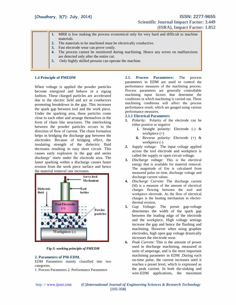
11. 9 Modi &
Agarwal
(2013)
current, pulse-
duration, wheel-
speed, duty-cycle
and powder-
concentration
MRR &
Average
surface
roughness
Response
surface
methodology
(RSM)
The highest MRR is
achieved when current,
Pulse on-time and wheel
speed are at peak levels.
Similarly, The highest
MRR is achieved when the
Duty cycle is at the lowest
level. Surface roughness
less comparison of
dielectric EDM.
12. 1
0
Kumar A. et
al.(2013)
electrode polarity,
electrode type,
peak current, pulse
on time, duty
cycle, gap voltage,
flushing pressure
& abrasive
concentration
effect on
dimensional
accuracy in
terms of
overcut
Taguchi
Method
By optimizing the
machining parameters the
overcut is minimized
which enhances the quality
of machining process.
13. 1
1
Syed et
al.(2013)
Pulse peak current,
pulse on-time and
concentration of
aluminum powder
White layer
thickness
(WLT)
Response
surface
Method
(RSM)
Result show Low thickness
of white layer 17.14 μm is
obtained at high
concentration of powder of
4 g/l and low peak current
of 6 A.
14. Ganachari et
al, (2013)
pulse on time, duty
cycle, gap voltage,
peak current,
concentration of
(Al + Si) powder
Surface
Roughness,
MRR
Taguchi
method with
GRA
optimization
The proportion of the
powder is 1:1. Oil quantity
10 lit. Flow rate 5 lit/min
Taguchi method with GRA
optimization is adopted to
study the effect of
independent variables on
responses and develop
predictive models
15. Vhatkar et
al. (2013)
Peak current, Pulse
on time, Pulse off
time, gap voltage,
and concentration
of fine silicon
powder added
MRR & SR Taguchi
Method
With the addition of the
powders in the dielectric,
MRR has been increased to
a great extent and the SR
has been reduced.
Silicon gives better results
in terms of MRR & SR.
16. Agrawal A.
et al.(2013)
Peak current
Pulse on time
Pulse of time
Powder
concentration
Tool wear rate
(TWR)
ANN Mixing graphite powder in
dielectric significantly
reduces the TWR during
machining of MMC.
The peak current has been
identified as most
significant control factor
affecting TWR, followed
by powder concentration.
The developed ANN
model is reliable and
adequate to predict the
TWR with negligible
prediction error.

[Choudhary, 3(7): July, 2014] ISSN: 2277-9655 Scientific Journal Impact Factor: 3.449
(ISRA), Impact Factor: 1.852
http: // www.ijesrt.com (C)International Journal of Engineering Sciences & Research Technology
[335-358]
The optimization result
shows considerable
reduction of 94.57 % in
TWR.
17. 1
2
Goyal et al.
(2014)
Current, Voltage,
Pulse on time,
Duty factor
constant and by
varying two
parameters i.e.
Grain size of Al.
powder &
Concentration of
Al. powder.
MRR &
Surface
Roughness
Taguchi
Method
Grain size of powder and
concentration of powder
have a great influence on
the SR & MRR) in powder
mixed EDM.
6. Conclusions
Use of powder mix in electrolyte
provide mirror like surface finish and
increase in material removal rate.
Proper work piece and powder
combination must be used for better
results.
Totally Burr free & no stresses produced
in work piece.
The material removal rate increased by
mixing powder in the dielectric fluid as
compared with conventional EDM
process
Tool wear rate in PMEDM is smaller as
compared with the conventional EDM
Process.
Material removal rate is maximum
effected by the increase of peak current.
Material Removal Rate has been
decreased by increasing the pulse off
time.
Additive mixed EDM enhance
machining rate appreciably.
Reference
1. Agrawal, A., Dubey, A. K., & Shrivastava,
P. K. (2013) “Modeling and Optimization of
Tool Wear Rate in Powder Mixed EDM of
MMC”, 2nd International Conference on
Mechanical and Robotics Engineering
(ICMRE'2013) Dec. 17-18, 2013 Pattaya
(Thailand).pp.1-6.
2. Bai, C.Y. and Koo, C.H., (2006) “Effects of
Kerosene or Distilled Water as Dielectric on
Electrical Discharge Alloying of\ Superalloy
Haynes 230 with Al-Mo Composite
Electrode”, Surface and Coatings
Technology, 200, 4127-4135,.
3. Beri N, Kumar A, (2008)“Performance
evaluation of powder metallurgy electrode
in electrical discharge machining of AISI D2
steel using Taguchi method” International
Journal of Mechanical, Industrial and
Aerospace Engineering,2 (3), 167-171.
4. Biing Hwa Yan, Hsien Chung Tsai, Fuang
Yuan Huang S, (2005) The effect in EDM of
a dielectric of a urea solution in water on
modifying the surface of titanium,
International Journal of Machine Tools &
Manufacture 45 ,194–200.
5. Celik, S. A. (2007) “Surface Roughness
Investigation in the Electric Discharge
Machining of powder metal Material”,
Journal of Applied Science l7 (12), 1608-
1613.
6. Chiang K.T., (2008) “Modeling and analysis
of the effects of machining parameters on
the performance characteristics in the EDM
process of Al2O3+TiC mixed ceramic.” The
International Journal of Advanced
Manufacturing Technology 37(5-6), 523-
533.
7. Chow H.-M., Yang L.-D., Lin C.-T. & Chen
Y.-F. (2008) “The use of SiC powder in
water as dielectric for micro-slit EDM
machining”, Journal of Materials Processing
Technology.195 (1-3), 160-170.
8. Chow, H.M.; Yan, B.H.; Huang, F.Y.; and
Hung, J.C. (2000) “Study of added powder
in kerosene for the micro-slit machining of
titanium alloy using electro-discharge
machining.” Journal of Materials Processing
Technology Volume101, 95-103.
9. Electrical discharge machining”,
International Journal of Machine Tools &
Manufacture 43,

[Choudhary, 3(7): July, 2014] ISSN: 2277-9655 Scientific Journal Impact Factor: 3.449
(ISRA), Impact Factor: 1.852
http: // www.ijesrt.com (C)International Journal of Engineering Sciences & Research Technology
[335-358]
10. Erden, A., Bilgin, S. (1980) “Role of
impurities in electric discharge machining.”
Proceedings of 21st International Machine
Tool Design and Research Conference, 345-
350.
11. Furutani K, Saneto A, Takezawa H, Mohri
N, Miyake H (2001) “Accretion of titanium
carbide by electrical discharge machining
with powder suspended in working fluid.”
Precision Engg 25, 138– 144
12. Furutani K., Sato H. and Suzuki M. (2009)
“Influence of electrical conditions on
performance of electrical discharge
machining with powder suspended in
working oil for titanium carbide deposition
process”,International Journal of Advanced
Manufacturing Technology 40(11), 1093-
1101.
13. Ganachari et al, (2013) “Effect of mixture
of Al and SiC Powder on surface roughness
in PMEDM using Taguchi method with
GRA optimization”, International Journal of
Advanced Engineering Research and
Studies, E-ISSN, 2249–8974.
14. Goyal S. & Singh R. K. (2014) “Parametric
Study of Powder Mixed EDM and
Optimization of MRR & Surface
Roughness”, International Journal of
Scientific Engineering and Technology 3
(1), 56-62.
15. Gurtej Singh, Paramjit Singh, Gaurav Tejpal
& Baljinder Singh (2012) “effect of
machining parameters on surface Roughness
of H 13 steel in EDM process using Powder
mixed fluid”, International Journal of
Advanced Engineering Research and Studies
2 (1 ) , 148-150.
16. Han-Ming Chowa, Lieh-Dai Yangb, Ching-
Tien Lina, Yuan-Feng Chena, (2008) “The
use of SiC powder in water as dielectric for
micro-slit EDM machining,”, Journal of
materials processing technology 195 ,160–
170.
17. Jeswani ML (1981) “Effect of the addition
of Graphite Powder to Kerosene used as the
dielectric fluid in electrical discharge
Machining” Wear 70, 133-139.
18. Kansal H.K, Singh S., Kumar P., (2007)
“Technology and research developments in
powder mixed electric discharge machining
(PMEDM)”, Journal of Materials Processing
Technology 184, 32–41.
19. Kansal H.K., Singh H., Kumar P. (2007) “
Effect of Silicon Powder Mixed EDM on
Machining Rate of AISI D2 Die Steel”,
Journal of Manufacturing Processes, 9 (1),
13-22.
20. Kansal, H.K., Singh, S., Kumar, P.,(2006)
“An experimental study of the machining
parameters in powder mixed electric
discharge machining of Al–10%SiC metal
matrix composites”, International Journal of
Machining and Machinability of Materials
1(4) , 396-411.
21. Kansal H.K.,Singh S, Kumar P. (2005)
“Parametric optimization of powder mixed
electrical discharge machining by response
surface methodology,” Journal of Materials
Processing Technology 169, 427–436.
22. Kansal, Sehijpal Singh & P. Kumar (2006)
“Performance parameter optimization of
powder mixed electric discharges machining
(PMEDM) by Taguchi method”, West
Indian journal of Engineering 29(1),81-94.
23. Kansal, Sehijpal Singh & P. Kumar (2006)
“Performance parameter optimization (multi
characteristics) of powder mixed electric
discharges machining (PMEDM) through
Taguchi method & utility concept”,. Indian
journal of Engineering & Materials
Science,13(3), 209-216.
24. Kansal, Sehijpal Singh & P. Kumar (2007)
“Effect of silicon powder mixed EDM on
machining rate of AISI D2 Die steel”,
Journal of manufacturing Process 9(1), 13-
22.
25. Kibria, G., Sarkar, B.R., Pradhan, B.B.,
Bhattacharyya, B., (2009) “Comparative
study of differ-ent dielectrics for micro-
EDM performance during microhole
machining of Ti-6Al-4V alloy”, The
International Journal of Advanced
Manufacturing Technology, ISSN 0268-
3768.
26. Klocke, F., Lung, D., Antonoglou, G.,
Thomaidis, D., (2004) “The effects of
powder suspended dielectrics on the thermal
influenced zone by electrodischarge
machining with small discharge energies”,
Int J Mater Process Technol 149, 191–197.
27. Kobayashi, K., Magara, T., Ozaki, Y., and
Yatomi, T. (1992) “The present and future
developments of electrical discharge
machining”, In Proceedings of the 2nd
International Conference on Die and Mould
Technology, Singapore , 35-47.
28. Kolahan,F. & Bironro, M. (2008) “Modeling
and Optimization of Process Parameters in
PMEDM by Genetic Algorithm”
proceedings of world academy of science,
[Choudhary, 3(7): July, 2014] ISSN: 2277-9655 Scientific Journal Impact Factor: 3.449
(ISRA), Impact Factor: 1.852
http: // www.ijesrt.com (C)International Journal of Engineering Sciences & Research Technology
[335-358]
engineering and technology volume 36,
1311-1315.
29. Kozak J, Rozenek M, Dabrowski L (2003)
“Study of electrical discharge machining
using powder-suspended working media”,
Proc Inst Mech Eng Pt B 217(B11),1597–
1602 .
30. Kumar, A., Beri, A., Pungotra, H., Nripjit,
Singh, P. (2013) “Machining Parameters
Evaluations on Dimensional Accuracy in
Abrasive Electric Discharge Machining
(AEDM) Process Using Taguchi
Methodology”,. International Journal of
Scientific & Engineering Research 4 (8),
August 2013, ISSN 2229-5518.
31. Kumar, S. & Singh, R., (2010)
“Investigating surface properties of OHNS
die steel after electrical discharge machining
with manganese powder mixed in the
dielectric,” Int J Adv Manuf Technol DOI
10.1007/s00170-010-2536-3.
32. Kumar, A., Maheshwari, S.,& Sharma , C.,
(2012) “ Machining efficiency Evaluation of
cryogenically Treated copper Electrode in
Additive Mixed EDM” Material &
Manufacturing Processes 27 (10), 1051-058.
33. Kun Ling Wua, Biing Hwa Yanb, Jyh-Wei
Lee, Chun Gian Ding, (2009) “Study on the
characteristics of electrical discharge
machining using dielectric with surfactant”,
journal of materials processing technology 2
( 9), 3783–3789.
34. Kung, K. Y., Horng, J. T., Chiang, K. T.
(2009) “Material removal rate and electrode
wear ratio study on the powder mixed
electrical discharge machining of cobalt
bonded tungsten carbide”, The International
Journal of Advanced Manufacturing
Technology 40(1-2), 95-104.
35. Mathapathi, U., Jeevraj, S., Kumar S.,
Ramola, I.C. (2013) “analysis of material
removal rate with powder mixed dielectric”,
IJCAE 4(3), 316-332.
36. Ming, Q.Y. and He, L.Y. (1995) “Powder-
suspension dielectric fluid for EDM”,
Journal of Materials Processing Technology.
52 (1 ) ,44-54.
37. Modi, M.& Agarwal, G. (2013) “Powder-
Mixed Electro-Discharge Diamond Surface
Grinding Process: Modelling, Comparative
Analysis and Multi-Output Optimisation
Using Weighted Principal Components
Analysis”,. Strojniški vestnik - Journal of
Mechanical Engineering 59, 735-747.
38. Mohri, N., Saito, N., Narumiya, H.,
Kawatsu, Y., Ozaki, K. T. and Kobayashi,
K., (1992). “Finish Machining by EDM
Using Powder Suspended Working Fluids”,
Journal of JSEME 49.
39. Muniu, J.M., Ikua, B. W., Nyaanga, D.M. &
Gicharu, S. N. (2013) “Study on Effects of
Powder-Mixed Dielectric Fluids on
Electrical Discharge Machining Processes”,
International Journal of Engineering
Research & Technology 2(10), 2449-2456.
40. Narumiya, H., Mohri, N., Saito, N., Ootake,
H., Tsunekawa, Y., Takawashi, T.,
Kobayashi K (1989) “EDM by powder
suspended working fluid”, Proc Int Sympo
Electro- Machining” IX Japan, 5-8.
41. Norliana, M. A., Darius, G. Solomon, Md.
F. B. (2007) “A review on current research
trends in electrical discharge machining
(EDM)”, International Journal of Machine
Tools & Manufacture 47, 1214–1228.
42. Ojha K., Garg R. K., Singh K. K. (2011)
“Experimental Investigation and Modeling
of PMEDM Process with Chromium Powder
Suspended Dielectric”, International Journal
of Applied Science and Engineering 9(2) ,
65-81.
43. P. Singh, A. Kumar, N. Beri, V. Kumar,
(2010) “Some experimental investigation on
aluminium powder mixed EDM on
machining performance of hastelloy steel”,
International Journal of Advance
Engineering Technology 1(2), 28-45.
44. Padhee, S.; Nayak, N.; Panda, S. K.; Dhal,
P.R.; Mahapatra, S.S. (2012) “ Multi
objective Parametric optimization of powder
mixed electro discharge machining using
response surface methodology & non
dominated sorting geneting algorithms”,
sadhana- Academy proceeding in
Engineering Science37(2), 223-240.
45. Peças P, Henriques (2008) “Effect of the
powder concentration and dielectric flow in
the surface morphology in electrical
discharge machining with powder-mixed
dielectric (PMD-EDM)”, International
Journal Advanced Manufacturing
Technology 37, 1120–1132.
46. Peças, P., Henriques, E., (2003) “Influence
of silicon powder-mixed dielectric on
conventional electrical discharge
machining” Int J Mach Tools Manuf 43(14),
1465–1471.
47. Prihandana, G.S., Mahardika, M., Hamdi,
M., Wong , Y.S., Mitsui, K., (2009) “Effect
[Choudhary, 3(7): July, 2014] ISSN: 2277-9655 Scientific Journal Impact Factor: 3.449
(ISRA), Impact Factor: 1.852
http: // www.ijesrt.com (C)International Journal of Engineering Sciences & Research Technology
[335-358]
of micro-powder suspension and ultrasonic
vibration of dielectric fluid in micro-EDM
processes— Taguchi approach”,
International Journal of Machine Tools and
Manufacture 49 (12-13),1035-1041.
48. Q. Yan Ming, L. You He, (1995) “Powder-
suspension dielectric fluid for EDM”,
Journal of Materials Processing Technology
52, 44–54.
49. S H Yeo, P C Tan and W Kurnia (2007)
“Effects of powder additives suspended in
dielectric on crater characteristics for micro
electrical discharge machining.” J.
Micromech. Microeng 17, N91–N98.
50. S. Sharma, A. Kumar, N. Beri & D. Kumar
(2010) “Effect of aluminium powder
addition in dielectric during electric
discharge machining of hastelloy on
machining performance using Reverse
polarity”, International Journal of Advanced
Engineering Technology 1(3), 13-24.
51. Saurabh Sharma, Anil Kumar, Naveen Beri
(2011) “Study of tool wear rate during
powder mixed EDM of Hastelloy steel.”
International Journal of Advanced
Engineering Technology, E-ISSN 0976-
3945.
52. Singh P., Kumar A., Beri N. & Kumar V.
(2010) “some experimental investigation on
aluminum powder mixed EDM on
machining performance of hastelloy steel”,
International Journal of Advanced
Engineering Technology, Vol.1 No.2, pp.28-
45.
53. Singh, S., Kansal, H.K., Kumar, P., (2005),
“Parametric optimization of powder mixed
electrical discharge machining by response
surface methodology”, Journal of Materials
Processing Technology, 169 (3), 427– 436.
54. Syed, K. H., Palaniyandi, K., (2012)
“Performance of electrical discharge
machining using aluminium Powder
suspended distilled water”, Turkish J. Eng.
Env. Sci. 36(3), 195 – 207.
55. Syed, K.H. & Kuppan, P. (2013) “Studies on
Recast-layer in EDM using Aluminium
Powder Mixed Distilled Water Dielectric
Fluid”, International Journal of Engineering
and Technology 5 (2), 1775-1780.
56. Tzeng, Y.-F. & Lee C.-Y. (2001) “Effects
of powder characteristics on
electrodischarge machining efficiency”,
International Journal of Advanced
Manufacturing Technology 17(8), 586-92.
57. Tzeng Yih-fong, Chen Fu-chen, (2005)
“Investigation into some surface
characteristics of electrical discharge
machined SKD-11 using powder-suspension
dielectric oil”, Journal of Materials
Processing Technology 170, 385–391.
58. Tzeng, Y.F., Chen, F.C. (2007) “Multi
objective optimization of high speed
electrical discharge machining process using
a Taguchi fuzzy-based approach”,
International journal of Material & design
28(2), 1159-1168.
59. Uno, Y.; Okada, A.; Hayashi, Y.; and
Tabuchi, Y. (1998). “Surface integrity in
EDM of aluminum bronze with nickel
powder mixed fluid”, Journal of Japanese
Society of Electrical Machining Engineers
32(70), 24-31.
60. Vhatkar, D. R. & Jadhav, B. R. (2013) “An
Experimental Study on Parametric
Optimization of High Carbon Steel (EN-31)
by using Silicon Powder Mixed Dielectric
EDM Process”, International Journal of
Science and Research 2(1), 431-436.
61. W.S. Jhao, Q.G. Meng & Z.L. Wang (2002)
“The application on research on powder
mixed EDM in rough machining.” Journal
of material processing Technology 129, 30-
33.
62. Wong Y S, Lim L C, Rahuman I and Tee W
M (1998) “Near-mirror-finish phenomenon
in EDM using powder-mixed dielectric,” J.
Mater. Process. Technol. (Switzerland) 79,
30–40.
63. Wu KL, Yan BH, Huang FY, Chen SC
(2005) “Improvement of surface finish on
SKD steel using electro-discharge
machining with aluminium and surfactant
added dielectric.” Int J Mach Tools Manuf
45, 1195–1201.
64. Yan B H, Chen S L (1994) “Characteristics
of SKD11 by complex process of electrical
discharge machining using liquid suspended
with alumina powder.” J Japan Inst Metals
58–9, 1067
65. Yan BH, Lin YC, Huang FY, Wang CH
(2001) “Surface modification of SKD 61
during EDM with metal powder in the
dielectric.” Mater Trans 42(12), 2597– 2604
66. Yan, B.H. and Chen, S.L. (1993) “Effects of
dielectric with suspended aluminum powder
on EDM.” Journal of the Chinese Society of
Mechanical Engineers 14 (3), 307-312.
BIOGRAPHIES

[Choudhary, 3(7): July, 2014] ISSN: 2277-9655 Scientific Journal Impact Factor: 3.449
(ISRA), Impact Factor: 1.852
http: // www.ijesrt.com (C)International Journal of Engineering Sciences & Research Technology
[335-358]
Er. Sushil Kumar Choudhary
Pursuing Phd from Industrial &
Production Engineering, G.B.Pant
University of Agriculture &
Technology Pantnagar,
Uttarakhand, India.
Email:[email protected]
Dr. R.S. Jadoun, Professor & Head
of Department Industrial &
Production Engineering, G.B.Pant
University of Agriculture &
Technology, Pantnagar,
Uttarakhand, INDIA
Email.;[email protected]