CS 459 The assessment of bridge substructures, retaining ...
51
Design Manual for Roads and Bridges Highway Structures & Bridges Inspection & Assessment CS 459 The assessment of bridge substructures, retaining structures and buried structures (formerly BA 55/06) Revision 1 Summary The use of this document enables the safety and serviceability of bridge substructures, retaining structures and buried structures to be assessed, providing key information that is required to manage risks and maintain a safe and operational network. This document covers the assessment of existing structures affected by interaction with the ground or affected by earth pressures. Application by Overseeing Organisations Any specific requirements for Overseeing Organisations alternative or supplementary to those given in this document are given in National Application Annexes to this document. Feedback and Enquiries Users of this document are encouraged to raise any enquiries and/or provide feedback on the content and usage of this document to the dedicated Highways England team. The email address for all enquiries and feedback is: [email protected] This is a controlled document.
-
Upload
khangminh22 -
Category
Documents
-
view
4 -
download
0
Transcript of CS 459 The assessment of bridge substructures, retaining ...

Design Manual for Roads and Bridges
Highway Structures & BridgesInspection & Assessment
CS 459The assessment of bridge substructures,retaining structures and buried structures(formerly BA 55/06)
Revision 1
SummaryThe use of this document enables the safety and serviceability of bridge substructures, retainingstructures and buried structures to be assessed, providing key information that is required tomanage risks and maintain a safe and operational network. This document covers theassessment of existing structures affected by interaction with the ground or affected by earthpressures.
Application by Overseeing OrganisationsAny specific requirements for Overseeing Organisations alternative or supplementary to those given in this documentare given in National Application Annexes to this document.
Feedback and EnquiriesUsers of this document are encouraged to raise any enquiries and/or provide feedback on the content and usageof this document to the dedicated Highways England team. The email address for all enquiries and feedback is:[email protected]
This is a controlled document.

CS 459 Revision 1 Contents
Contents
Release notes 3
Foreword 4Publishing information . . . . . . . . . . . . . . . . . . . . . . . . . . . . . . . . . . . . . . . . . . . . . . . . 4Contractual and legal considerations . . . . . . . . . . . . . . . . . . . . . . . . . . . . . . . . . . . . . . . . 4
Introduction 5Background . . . . . . . . . . . . . . . . . . . . . . . . . . . . . . . . . . . . . . . . . . . . . . . . . . . . . . 5Assumptions made in the preparation of the document . . . . . . . . . . . . . . . . . . . . . . . . . . . . . . 5
Abbreviations 6
Symbols 7
Terms and definitions 8
1. Scope 10Aspects covered . . . . . . . . . . . . . . . . . . . . . . . . . . . . . . . . . . . . . . . . . . . . . . . . . . . 10Implementation . . . . . . . . . . . . . . . . . . . . . . . . . . . . . . . . . . . . . . . . . . . . . . . . . . . 10Use of GG 101 . . . . . . . . . . . . . . . . . . . . . . . . . . . . . . . . . . . . . . . . . . . . . . . . . . . . 10
2. Assessment processes 11Inspection for assessment . . . . . . . . . . . . . . . . . . . . . . . . . . . . . . . . . . . . . . . . . . . . . . 11
Defects and structure stability . . . . . . . . . . . . . . . . . . . . . . . . . . . . . . . . . . . . . . . . . 12Materials, geometry and loads . . . . . . . . . . . . . . . . . . . . . . . . . . . . . . . . . . . . . . . . 13Scour . . . . . . . . . . . . . . . . . . . . . . . . . . . . . . . . . . . . . . . . . . . . . . . . . . . . . . 13Bearings . . . . . . . . . . . . . . . . . . . . . . . . . . . . . . . . . . . . . . . . . . . . . . . . . . . . . 13
Assessment . . . . . . . . . . . . . . . . . . . . . . . . . . . . . . . . . . . . . . . . . . . . . . . . . . . . . . 14Qualitative assessment . . . . . . . . . . . . . . . . . . . . . . . . . . . . . . . . . . . . . . . . . . . . 15Assessment by calculation . . . . . . . . . . . . . . . . . . . . . . . . . . . . . . . . . . . . . . . . . . 15
Reporting of the assessment . . . . . . . . . . . . . . . . . . . . . . . . . . . . . . . . . . . . . . . . . . . . 16Management of substandard structures . . . . . . . . . . . . . . . . . . . . . . . . . . . . . . . . . . . . . . 16
3. Assessment by calculation 17Basis of assessment . . . . . . . . . . . . . . . . . . . . . . . . . . . . . . . . . . . . . . . . . . . . . . . . . 17
Scope and methodology . . . . . . . . . . . . . . . . . . . . . . . . . . . . . . . . . . . . . . . . . . . . 17Assessment situations and limit states . . . . . . . . . . . . . . . . . . . . . . . . . . . . . . . . . . . . 17Options for basis of assessment . . . . . . . . . . . . . . . . . . . . . . . . . . . . . . . . . . . . . . . 17
Ground properties and geotechnical parameters . . . . . . . . . . . . . . . . . . . . . . . . . . . . . . . . . 20Actions . . . . . . . . . . . . . . . . . . . . . . . . . . . . . . . . . . . . . . . . . . . . . . . . . . . . . . . . 20Analysis . . . . . . . . . . . . . . . . . . . . . . . . . . . . . . . . . . . . . . . . . . . . . . . . . . . . . . . . 20Structural resistance . . . . . . . . . . . . . . . . . . . . . . . . . . . . . . . . . . . . . . . . . . . . . . . . . 21
4. Additional structure-specific assessment requirements 22General . . . . . . . . . . . . . . . . . . . . . . . . . . . . . . . . . . . . . . . . . . . . . . . . . . . . . . . . 22Spread and piled foundations . . . . . . . . . . . . . . . . . . . . . . . . . . . . . . . . . . . . . . . . . . . . 22
Assessment by calculation of spread and piled foundations . . . . . . . . . . . . . . . . . . . . . . . . 22Gravity retaining structures and non-integral bridge abutments . . . . . . . . . . . . . . . . . . . . . . . . . 22
Assessment by calculation for gravity retaining structures and non-integral bridge abutments . . . . . 23Embedded retaining walls . . . . . . . . . . . . . . . . . . . . . . . . . . . . . . . . . . . . . . . . . . . . . . 23
Inspection for assessment for embedded retaining walls . . . . . . . . . . . . . . . . . . . . . . . . . . 23Assessment by calculation for embedded retaining walls . . . . . . . . . . . . . . . . . . . . . . . . . . 23
Integral bridge abutments . . . . . . . . . . . . . . . . . . . . . . . . . . . . . . . . . . . . . . . . . . . . . . 24Inspection for assessment for integral bridge abutments . . . . . . . . . . . . . . . . . . . . . . . . . . 24Assessment by calculation for integral bridge abutments . . . . . . . . . . . . . . . . . . . . . . . . . . 24
Buried concrete box and portal frame structures . . . . . . . . . . . . . . . . . . . . . . . . . . . . . . . . . 25
1

CS 459 Revision 1 Contents
Inspection for assessment for buried concrete box and portal frame structures . . . . . . . . . . . . . 25Assessment by calculation for buried concrete box and portal frame structures . . . . . . . . . . . . . 26
Corrugated steel buried structures . . . . . . . . . . . . . . . . . . . . . . . . . . . . . . . . . . . . . . . . . 28Inspection for assessment for CSBS . . . . . . . . . . . . . . . . . . . . . . . . . . . . . . . . . . . . . 28Assessment by calculation for CSBS . . . . . . . . . . . . . . . . . . . . . . . . . . . . . . . . . . . . . 28
Reinforced soil structures . . . . . . . . . . . . . . . . . . . . . . . . . . . . . . . . . . . . . . . . . . . . . . 29Assessment by calculation for reinforced soil structures . . . . . . . . . . . . . . . . . . . . . . . . . . 29
Dry-stone walls . . . . . . . . . . . . . . . . . . . . . . . . . . . . . . . . . . . . . . . . . . . . . . . . . . . . 30Masonry spandrel walls . . . . . . . . . . . . . . . . . . . . . . . . . . . . . . . . . . . . . . . . . . . . . . . 30
5. Properties of materials and drainage 31Geotechnical information . . . . . . . . . . . . . . . . . . . . . . . . . . . . . . . . . . . . . . . . . . . . . . 31Structural materials . . . . . . . . . . . . . . . . . . . . . . . . . . . . . . . . . . . . . . . . . . . . . . . . . 31Drainage . . . . . . . . . . . . . . . . . . . . . . . . . . . . . . . . . . . . . . . . . . . . . . . . . . . . . . . 32
6. Normative references 33
7. Informative references 34
Appendix A. Lateral loading of piles 36A1 General . . . . . . . . . . . . . . . . . . . . . . . . . . . . . . . . . . . . . . . . . . . . . . . . . . . . . . 36
A1.1 Step 1 . . . . . . . . . . . . . . . . . . . . . . . . . . . . . . . . . . . . . . . . . . . . . . . . . . . 36A1.2 Step 2 . . . . . . . . . . . . . . . . . . . . . . . . . . . . . . . . . . . . . . . . . . . . . . . . . . . 36A1.3 Step 3 . . . . . . . . . . . . . . . . . . . . . . . . . . . . . . . . . . . . . . . . . . . . . . . . . . . 36A1.4 Step 4 . . . . . . . . . . . . . . . . . . . . . . . . . . . . . . . . . . . . . . . . . . . . . . . . . . . 37A1.5 Notes . . . . . . . . . . . . . . . . . . . . . . . . . . . . . . . . . . . . . . . . . . . . . . . . . . . 37
Appendix B. Buried concrete box and portal frame structures 38B1 Cases to be considered for buried concrete structure assessment . . . . . . . . . . . . . . . . . . . . . 38
Appendix C. Dry-stone walls 47C1 Construction and behaviour . . . . . . . . . . . . . . . . . . . . . . . . . . . . . . . . . . . . . . . . . . . 47
Appendix D. Spandrel walls 48D1 Construction and behaviour . . . . . . . . . . . . . . . . . . . . . . . . . . . . . . . . . . . . . . . . . . . 48
2

CS 459 Revision 1 Release notes
Release notesVersion Date Details of amendments1 Mar 2020 Revision 1 (March 2020) Update to references only. Revision 0 (May 2019) CS
459 replaces BA 55/06. This full document has been re-written to make itcompliant with the new Highways England drafting rules.The key technicalthemes of the update are as follows:1) Some content relevant to assessmenthas been moved from previous documents BD21, BA16, BA42, BA87, andBA88.2) BA55 previously referred extensively to design documents, includingBD30, BD31, BD42 and BD74, that have now been withdrawn and replaced byEurocodes and Eurocode-aligned documents. There has therefore been aneed to include and refer to Eurocode content in this document, including anew option to use a Eurocode-based approach for the basis of assessment. 3)Some content that is no longer needed has been removed, including modelsfor dispersal of BD21 loads that were specific to the old loading arrangements.In the updated version the approaches for dispersal and traffic surcharge canbe applied for any traffic loading model.
3

CS 459 Revision 1 Foreword
Foreword
Publishing informationThis document is published by Highways England.
This document supersedes BA 55/06, which is withdrawn.
This document contains revision to material relevant to assessment taken from previously withdrawndocuments BD 30, BD 31, BD 42 and BD 74.
Material previously covered in BD 21, BA 16, BA 42, BA 87 and BA 88 related to the assessment ofsubstructures has also been incorporated into this revision.
Contractual and legal considerationsThis document forms part of the works specification. It does not purport to include all the necessaryprovisions of a contract. Users are responsible for applying all appropriate documents applicable totheir contract.
4

CS 459 Revision 1 Introduction
Introduction
BackgroundThe use of this document enables the safety and serviceability of bridge substructures, retainingstructures and buried structures to be assessed, providing key information that is required to managerisks and maintain a safe and operational network.
This document covers the assessment of existing structures affected by interaction with the ground oraffected by earth pressures. The development of this document has been influenced by the changes tothe standards that are used for the design of new structures, particularly the introduction of theEurocodes, which enabled a unified limit state approach to be taken for the design of both structuresand geotechnics for the first time in the UK.
Assessment of existing structures affected by interaction with the ground was previously undertakenusing a combination of British Standards BS 8002 [Ref 4.N], BS 8004 [Ref 5.N], BS 8081 [Ref 2.N], ISECP2 1951 [Ref 7.I], and DMRB documents BD 30/87, BD 31/01, BD 42/00, and BD 74/00, following theadvice in BA 55/06. However, with the implementation of the Eurocodes all conflicting nationalstandards were withdrawn, including many of the standards and documents that had been used for theassessment of geotechnical structures. British Standards BS 8002 [Ref 4.N], BS 8004 [Ref 5.N] andBS 8081 [Ref 2.N] were revised to be fully compatible with Eurocodes and limit state principles.
This document is based on an updating of BA 55/06, and includes the same phased approach ofallowing a qualitative assessment to be used, with an assessment by calculation carried out followingthe qualitative assessment only when required.
It has been necessary in this document to allow two different approaches to be used for theassessment by calculation: one approach is based on the use of CS 454 [Ref 1.N], the secondapproach is based on the use of Eurocodes. This document includes an option to use Eurocodesbecause the standardised methods for verifying geotechnical ultimate limit states are now found in theEurocodes and Eurocode-aligned documents. However, the verification of structural ultimate limitstates can be carried out using CS 454 [Ref 1.N], which can be more convenient to apply forassessment. Conversely, as many of the partial factors in the Eurocodes are lower than in CS 454 [Ref1.N], it can be more economic to use the Eurocode-based approach. Hence both options have beenincluded in this document.
Assumptions made in the preparation of the documentThe assumptions made in GG 101 [Ref 15.N] apply to this document.
5
CS 459 Revision 1 Abbreviations
Abbreviations
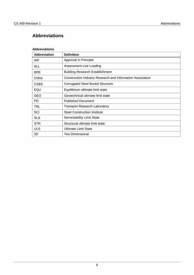
AbbreviationsAbbreviation Definition
AIP Approval in Principle
ALL Assessment Live Loading
BRE Building Research Establishment
CIRIA Construction Industry Research and Information Association
CSBS Corrugated Steel Buried Structure
EQU Equilibrium ultimate limit state
GEO Geotechnical ultimate limit state
PD Published Document
TRL Transport Research Laboratory
SCI Steel Construction Institute
SLS Serviceability Limit State
STR Structural ultimate limit state
ULS Ultimate Limit State
2D Two Dimensional
6
CS 459 Revision 1 Symbols
Symbols
Symbols
Symbol Definition
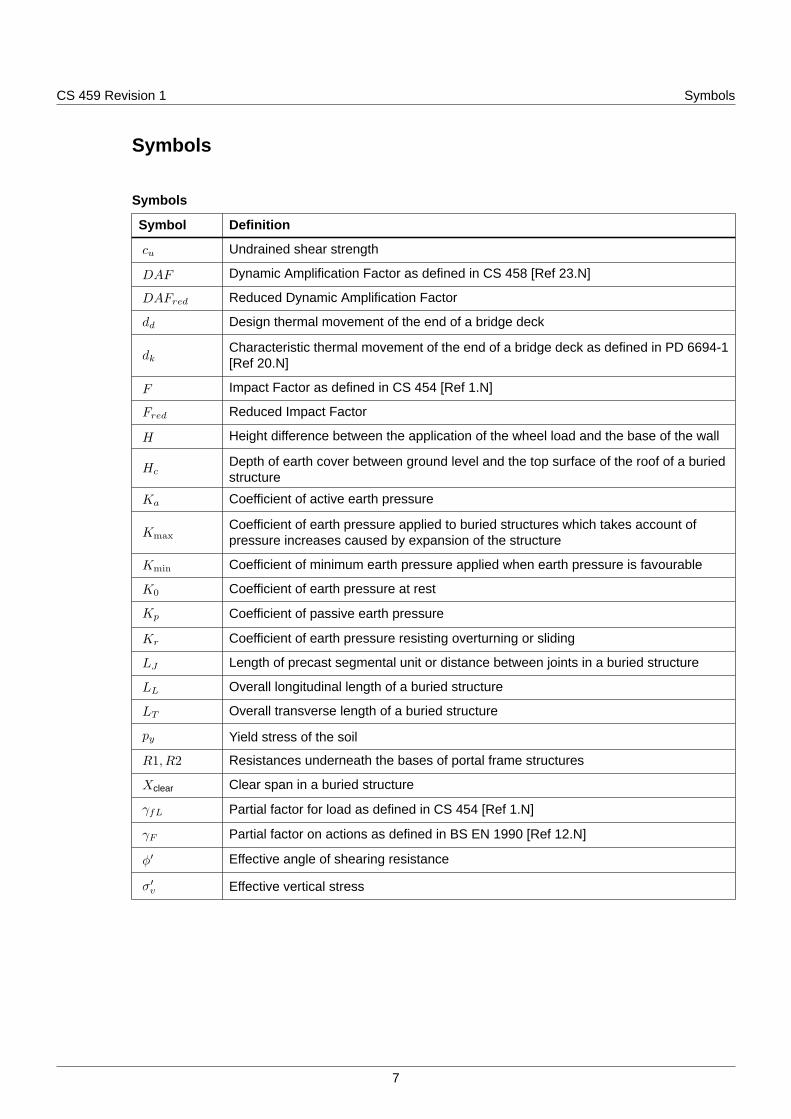
cu Undrained shear strength
DAF Dynamic Amplification Factor as defined in CS 458 [Ref 23.N]
DAFred Reduced Dynamic Amplification Factor
dd Design thermal movement of the end of a bridge deck
dkCharacteristic thermal movement of the end of a bridge deck as defined in PD 6694-1[Ref 20.N]
F Impact Factor as defined in CS 454 [Ref 1.N]
Fred Reduced Impact Factor
H Height difference between the application of the wheel load and the base of the wall
HcDepth of earth cover between ground level and the top surface of the roof of a buriedstructure
Ka Coefficient of active earth pressure
KmaxCoefficient of earth pressure applied to buried structures which takes account ofpressure increases caused by expansion of the structure
Kmin Coefficient of minimum earth pressure applied when earth pressure is favourable
K0 Coefficient of earth pressure at rest
Kp Coefficient of passive earth pressure
Kr Coefficient of earth pressure resisting overturning or sliding
LJ Length of precast segmental unit or distance between joints in a buried structure
LL Overall longitudinal length of a buried structure
LT Overall transverse length of a buried structure
py Yield stress of the soil
R1, R2 Resistances underneath the bases of portal frame structures
Xclear Clear span in a buried structure
γfL Partial factor for load as defined in CS 454 [Ref 1.N]
γF Partial factor on actions as defined in BS EN 1990 [Ref 12.N]
ϕ′ Effective angle of shearing resistance
σ′v Effective vertical stress
7

CS 459 Revision 1 Terms and definitions
Terms and definitions
TermsTerm Definition
AbutmentEnd wall or structure to which horizontal earth pressure loads areapplied.
Assessment
The process of determining in terms of vehicle loading the load that anexisting structure can carry with an acceptable probability withoutsuffering serious damage that can endanger any persons on or near thestructure.
Assessment actions Actions, which can be either imposed loads or imposed displacements,which have been determined for assessment.
Assessment properties Properties of soils, rock and other materials which have been derived forassessment.
Assessment situation
Assessment situations are sets of physical conditions representing thereal conditions occurring during a certain time interval for which theassessment demonstrates that relevant limit states are not exceeded.NOTE: Assessment situations can consider the structure during normaluse, in a temporary condition or during an accidental exceptionalcondition.
Cover Depth of fill between ground level and the top of a structure.
Embedded retaining wall
Retaining structure, the main stability of which is provided by having asignificant length of wall stem embedded in the ground.NOTE: Embedded retaining walls can be cantilevered, propped at eitherthe top or at excavation level, doubly-propped or anchored.
Ground levelFinished carriageway level, or the temporary ground level on whichtraffic can run during construction.
Hard-soft piling system
A hard/soft secant pile wall consists of overlapping piles.NOTE 1: The primary piles are cast first and consist of a soft pile mix,typically cement and bentonite, or cement, bentonite and sand with acharacteristic compressive strength of 1 to 3N/mm2.NOTE 2: The soft piles are unreinforced.
Longitudinal Perpendicular to the abutments, or in the direction of traffic.
8
CS 459 Revision 1 Terms and definitions
Terms (continued)
Term Definition
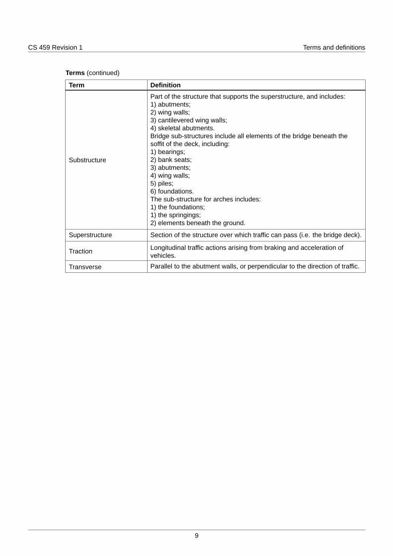
Substructure
Part of the structure that supports the superstructure, and includes:1) abutments;2) wing walls;3) cantilevered wing walls;4) skeletal abutments.Bridge sub-structures include all elements of the bridge beneath thesoffit of the deck, including:1) bearings;2) bank seats;3) abutments;4) wing walls;5) piles;6) foundations.The sub-structure for arches includes:1) the foundations;1) the springings;2) elements beneath the ground.
Superstructure Section of the structure over which traffic can pass (i.e. the bridge deck).
Traction Longitudinal traffic actions arising from braking and acceleration ofvehicles.
Transverse Parallel to the abutment walls, or perpendicular to the direction of traffic.
9

CS 459 Revision 1 1. Scope
1. Scope
Aspects covered1.1 This document shall be used for the assessment of bridge substructures (including bearings, bank
seats, abutments, wing walls, piles and foundations), retaining structures and buried structures.
NOTE 1 This document does not deal with the structural aspects of bridge decks, bridge piers and arches, but itdoes cover assessment of their foundations.
NOTE 2 This document includes methods for the assessment of structures and structural elements where theirbehaviour is directly influenced by soil-structure interaction or affected by earth pressures.
NOTE 3 In general, the behaviour of substructures is more complex than that of superstructures. Actions appliedto superstructures are largely unaffected by the resulting deformations and movements, whereas earthpressures at soil / structure interfaces can be influenced by the movement of the structure.
NOTE 4 This document includes specific requirements for the assessment of the following types of structure:
1) spread and piled foundations;2) gravity retaining structures and non-integral bridge abutments;3) embedded retaining walls;4) integral bridge abutments;5) buried concrete boxes and portal frame structures;6) corrugated-steel buried structures;7) reinforced soil structures;8) dry-stone walls;9) spandrel walls.
1.1.1 This document may be used for the assessment of associated ancillary structures.
1.2 The assessment of bridge superstructures, including arches, shall be carried out using CS 454 [Ref1.N].
Implementation1.3 This document shall be implemented forthwith on all schemes involving the assessment of bridge
substructures, retaining structures and buried structures on the Overseeing Organisations' motorwayand all-purpose trunk roads according to the implementation requirements of GG 101 [Ref 15.N].
Use of GG 1011.4 The requirements contained in GG 101 [Ref 15.N] shall be followed in respect of activities covered by
the document.
10
CS 459 Revision 1 2. Assessment processes
2. Assessment processes2.1 The assessment shall be carried out according to the requirements for assessment processes given in
CS 454 [Ref 1.N], supplemented by the additional requirements in this section.
NOTE The assessment processes in CS 454 [Ref 1.N] include:
1) structural review;2) inspection for assessment;3) assessment;4) reporting of the assessment;5) management of substandard structures.
Inspection for assessment2.2 The inspection for assessment shall include the identification and recording of any evidence of defects
or movements, including:
1) tilting and rotation, in any direction;
2) rocking;
3) cracking, splitting and spalling;
4) reinforcement corrosion;
5) internal degradation of concrete;
6) locked bearings;
7) damage due to thermal movement;
8) scour and erosion beneath the water level;
9) weathering and other material deterioration, including loss, cracking and lack of pointing for masonryand brickwork;
10) detrimental growth of vegetation, on and near the structure;
11) ineffective drainage;
12) washout and leaching of the fill;
13) settlement of the fill;
14) settlement of the structure, including global and differential movements;
15) ground slope instabilities, in front of and behind the structure;
16) evidence of vehicular impact.
NOTE 1 These requirements supplement those given in CS 454 [Ref 1.N].
NOTE 2 Principal deficiencies in the substructure can be manifested in the form of excessive movement of thestructure (tilting, sliding, etc.) or of part of it (bulging, differential settlement, etc.) and problems arisingfrom water seepage.
NOTE 3 Movement of the structure at the soil/structure interface can result from earth pressure changes in thebackfill pressure due to the forward rotation of a retaining wall on its base or soil reaction pressures onan integral-bridge end support due to temperature generated expansion and contraction of thesupported bridge deck.
NOTE 4 Inspection and maintenance records can sometimes provide useful information regarding hidden orinaccessible parts of the structure.
2.2.1 Inspections should include both:
1) close inspection methods;
2) inspection from a distance.
11

CS 459 Revision 1 2. Assessment processes
NOTE 1 Structural defects leading to excessive movement or misalignment can be overlooked during closeinspection but can be apparent from a distance.
NOTE 2 Sighting along restraint systems, handrails, string courses or other features can be used to detectmisalignment.
Defects and structure stability
2.3 The inspection and maintenance records shall be examined for evidence of historical and ongoingstability problems with the structure.
2.4 Signs of failure in the structure (including signs of distress, damage, deterioration or partial/localisedcollapse) and movement in the surrounding ground shall be investigated.
NOTE 1 Evidence of foundation deterioration or failure can be manifested as tilting, distortion or cracking ofelements in other parts of a structure; for example excessive movement at joints between the deck andabutments.
NOTE 2 Differential movement of a substructure can be easier to detect than the overall movement of a wholepier or abutment.
NOTE 3 Due to the hidden or sometimes obscured location of these structures, the warning signs of failuremight not be readily visible during a structural inspection.
NOTE 4 In arch bridge foundations, movement or arch spreading is generally apparent from cracks showingdistress in the arch rings and spandrels; diagonal cracking of the arch can be indicative of differentialsettlement of the foundations.
NOTE 5 Gross deformations in culverts and buried structures can be evident from instability in the adjacentembankment or overlying highway.
2.5 Signs of damage to the structure that are due to aggressive ground conditions shall be recorded.
NOTE 1 Further guidance is found in BRE SD-1 2005 [Ref 20.I], which includes information on the assessmentof the surrounding ground, backfill, groundwater and effluent carried by the structure.
NOTE 2 Argillaceous rocks such as shale and mudstone could increase earth pressures on retaining walls byswelling. They might also release sulphuric acid, putting adjacent concrete structures at serious risk,and could contribute to the blocking of drainage materials by the formation of crystalline sulphates.
2.5.1 Adjacent structures and buried services in the vicinity should be examined for signs of instability anddistress where this could assist in the assessment process and understanding of the performance ofthe structure.
2.6 Where the movement (or the continuing movement) of a structure presents an immediate risk, thecause of the instability shall be investigated and the structure managed as an immediate risk structurein accordance with CS 470 [Ref 17.N].
2.6.1 Where a remedial solution is used to stabilise a structure, an instrumentation and monitoring regimeshould be implemented to monitor further movement and demonstrate the performance of the solution.
NOTE The need for instrumentation can depend on the type of remedial solution. In some cases monitoringwithout instrumentation can be appropriate.
2.6.2 Where an instrumentation and monitoring regime is used, the monitoring system should allow fortrends in behaviour to be monitored and the results compared with well defined trigger points in a timelymanner so that contingency actions can be implemented prior to a critical condition of instability andrisk to safety occurring.
NOTE 1 Simple visual aids such as tell-tales can be useful to determine if the structure is moving or in atemporary equilibrium.
NOTE 2 Guidance for the geotechnical monitoring of structures is provided in BS EN 1997-1 [Ref 11.N] andCIRIA C760 [Ref 14.N].
12

CS 459 Revision 1 2. Assessment processes
NOTE 3 A description of available methods for the remote monitoring of highways structures for the purposes ofproviding information to assist the management of these structures can be found in TRL PPR 197 [Ref10.I].
Materials, geometry and loads
2.7 Where the material types used in the construction and filling of the substructure are needed for theassessment, they shall be established through investigation.
NOTE Estimation of the material properties for assessment is covered in Section 5.
2.8 Loads due to excessive fill, previous strengthening operations and installation of services shall beidentified and recorded.
2.8.1 Where practical, dimensional checks should be undertaken prior to assessment.
NOTE 1 Dimensional checks can be used to prepare sketches for analysis, estimate permanent loads andconfirm the as-built information.
NOTE 2 Excavation or probing can be used to determine the depth and the extent of the sub-structure andfoundations.
2.9 Excavation or probing shall not adversely affect the stability of the structure or damage anyunderground services.
2.9.1 Excavations and sampling should not be undertaken in the case of dry-stone walls.
2.10 Where there is a significant change in the actions on the structure or the structure is being altered, theextent of the foundation shall be determined, unless it can be demonstrated that knowledge of theexact foundation extent is not critical to the assessment.
NOTE A study of realistic ranges of foundation geometries can be used to demonstrate whether the results ofthe assessment are sensitive to the assumed geometry.
2.11 Where estimates and assumptions regarding the probable dimensions of the sub-structure, foundationsor retaining wall are made, those estimates and assumptions shall be recorded.
Scour
2.12 Where an inspection for assessment of a structure founded in water is required, underwater inspectiontechniques shall be used to confirm the condition and identify defects, including scour.
NOTE 1 Flow of water can cause leaching and scour to foundations and sub-structures.
NOTE 2 Requirements for the assessment of scour and other hydraulic actions at highway structures crossingor adjacent to waterways are included in BD 97 [Ref 22.I]. Further information can be found in CIRIAR742 [Ref 16.I].
NOTE 3 The depth of scour holes which can occur during a flood are generally greater than those observedduring periods of slack water. Evidence of the natural refilling of scour holes is sometimes apparent ifmaterial of a coarser or differing nature is present within the scour zone.
NOTE 4 Many arch bridges were built on shallow foundations and are vulnerable to scour.
2.13 Where information regarding the underwater parts of the structure, its foundations or the riverbed isneeded for the assessment or for monitoring of deterioration, underwater photography or imaging shallbe used.
NOTE Underwater photography or imaging is of particular assistance to the engineer in establishingconditions below water level. It also serves as a permanent record of the condition at the time of theinspection and can be subsequently referred to and quoted during the assessment process.
2.14 Unexpected water flows shall be investigated, to determine the cause and any resultant deterioration.
13

CS 459 Revision 1 2. Assessment processes
Bearings
2.15 The presence or absence of bearings shall be recorded.
2.16 Bearings shall be inspected to obtain information on the following:
1) general condition;
2) binding or jamming;
3) looseness;
4) reaching the limit of rotational or translational movement;
5) condition of seating, bedding and plinth;
6) obstacles preventing correct operation of the bearings.
NOTE Thermal movements in response to temperature changes can be assessed in accordance with CS 454[Ref 1.N].
2.16.1 Where no bearings exist or their efficiency is impaired, the ability of a bridge to cater for thermalmovements and forces should be assessed.
NOTE 1 In many early bridges, bearings were either omitted or only rudimentary forms of bearing were provided.
NOTE 2 In bridges without bearings or where the bearings have failed to function correctly, there can be localcrushing or cracking of the supports, especially where they are constructed from stone or brickwork.
Assessment2.17 The scope of the assessment, including the limit states to be assessed, shall be defined in the AIP in
accordance with CG 300 [Ref 21.N].
2.18 The assessment shall verify whether or not the structure or substructure has sufficient resistance for itsintended use.
2.19 The significance of defects, stability problems, the likely cause and the effect on the sub-structureresistance shall be evaluated and recorded.
2.20 The assessment shall be based on limit state verifications.
2.20.1 Limit states may include:
1) STR, for example, ULS verification of bending or shear resistance;
2) GEO, for example, ULS verification of sliding, bearing, deep-slip and rotational failures;
3) EQU, for example, ULS verification of overturning;
4) SLS, for example, settlement or crack widths.
2.20.2 The assessment should progress through successive levels of assessment, if needed to demonstratethe adequacy of the structure or parts of the structure, as follows:
1) qualitative assessment;
2) assessment by calculation;
3) assessment by calculation with updated material parameters or refined analysis models.
2.20.3 The adequacy of the structure may be demonstrated by:
1) applying the same assessment level to the entire structure;
2) applying different assessment levels to parts of the structure.
2.21 A structure, or parts of the structure, whose adequacy has not been demonstrated by a qualitativeassessment or assessment by calculation shall be managed as a substandard structure in accordancewith CS 470 [Ref 17.N].
14

CS 459 Revision 1 2. Assessment processes
2.21.1 When a superstructure is to be strengthened or replaced, the adequacy of the existing substructure andfoundations may be verified based on:
1) a qualitative assessment according to this document; or
2) calculations using the standards for new design.
Qualitative assessment
2.22 The qualitative assessment shall include an assessment of the following:
1) the condition of the structure, including the extent and severity of defects;
2) the satisfactory past performance in service;
3) whether the behaviour of the structure can be readily understood;
4) anticipated changes in condition, loading or the structural form.
2.22.1 The qualitative assessment of the structure or part of the structure should be taken as satisfactory andno further assessment is necessary if all of the following apply:
1) there are no signs of significant or worsening distress, damage or deterioration;
2) there is no evidence of scour;
3) satisfactory performance has been demonstrated since construction or significant repairs oralteration, over a sufficiently long period of time to assess the performance in service;
4) the behaviour of the structure can readily be understood;
5) there are no anticipated modifications to the structure or changes in use.
NOTE Qualitatively assessing satisfactory performance of a structure or part of a structure in service reliesupon the structure having experienced loading conditions that are representative of those that can beanticipated over its remaining life, which is more readily justifiable for parts of a structure thatexperience predominantly permanent loading than those significantly affected by traffic loading.
2.22.2 The qualitative assessment should be based on an assessment of the performance over a time periodof at least five years, or a shorter period of time where it can be justified that this is sufficient tounderstand and assess the performance of the structure in service.
2.22.3 A qualitative assessment may be used to demonstrate the adequacy for changes in the loading whereboth of the following apply:
1) there is no net increase in the total action effects;
2) there is no significant reduction in permanent vertical actions that could affect the stability.
2.22.4 Results of previous inspections and assessments should be used to inform the assessment.
2.22.5 Assessment of ground movements should be based upon relevant field data and from experience ofsimilar structures in similar ground conditions.
2.22.6 A bearing may be assessed to be satisfactory if:
1) its seating shows no sign of distress;
2) movements including rotations are free to take place;
3) there is no significant increase in loading envisaged;
4) there are no signs of significant or worsening distress, damage or deterioration in the bearing andthe structure within the vicinity of the bearing.
Assessment by calculation
2.23 Assessment by calculation shall be undertaken following a qualitative assessment when:
1) the qualitative assessment has not successfully demonstrated adequacy for the structure or part ofthe structure at the relevant limit states; and
15

CS 459 Revision 1 2. Assessment processes
2) there is an established method of quantitative theoretical assessment available.
NOTE Assessment by calculation is covered in Section 3.
2.24 The conclusions from the assessment shall be subjected to a plausibility review, to explain differencesbetween the results of the assessment and the observed condition or performance.
Reporting of the assessment2.25 The assessment shall be documented in a report summarising the assumptions and methodology of the
assessment, the conclusion of the assessment and recommendations for management interventions.
NOTE Requirements for reporting assessments are provided in CS 451 [Ref 21.I].
2.25.1 Where the assessment process has included the development of remedial works, for example whererudimentary maintenance would be sufficient to restore the structure to a state that would be no longerbe substandard, the assessment report should include the details of the proposed remedial works.
Management of substandard structures2.26 In cases where the final conclusion of the assessment process is that a structure is substandard the
structure shall be managed in accordance with CS 470 [Ref 17.N].
NOTE Movements or rotations can occur early in the life of the structure and subsequently reach a state ofequilibrium that is no longer a cause for concern.
2.26.1 The observational method may be used to monitor, control or manage movements.
NOTE Principles and application of the observational method can be found in BS EN 1997-1 [Ref 11.N], CIRIAR185 [Ref 25.I], CIRIA C760 [Ref 14.N] and TRL Report TRL 228 [Ref 17.I].
16

CS 459 Revision 1 3. Assessment by calculation
3. Assessment by calculation
Basis of assessmentScope and methodology
3.1 Where an assessment by calculation is necessary, the scope and methodology for the assessmentshall be agreed with the Overseeing Organisation and recorded.
3.1.1 The scope and methodology for the assessment should include the following:
1) assessment actions, comprising imposed loads and imposed displacements;2) assessment properties of soils, rocks and other materials;3) geometrical data;4) analysis of the structure and the soil at the relevant limit states for assessment;5) verifications at the relevant limit states for assessment.
3.1.2 The assessment situations and limit states to be assessed by calculation may be recorded in:
1) the AIP; or2) the assessment certificate (for example for CAT 0 structures without an AIP).
NOTE Section 4 includes requirements for assessing specific structure types, additional to the requirements ofthis section.
Assessment situations and limit states
3.2 The assessment situations and limit states to be assessed by calculation shall be agreed with theOverseeing Organisation and recorded.
NOTE 1 Guidance on factors to be included in defining design situations and limit states is included in BS EN1997-1 [Ref 11.N], which can be used in defining the assessment situations and limit states.
NOTE 2 Limit states can include STR, GEO, EQU and SLS, as covered in Section 2.
3.2.1 The assessment situations and limit states to be assessed by calculation may be recorded in:
1) the AIP; or2) the assessment certificate (for example for CAT 0 structures without an AIP).
3.2.2 The limit states to be included in the assessment by calculation for the structure or part of the structureshould be defined based on the findings of the qualitative assessment for the structure or part of thestructure.
3.2.3 Verifications of limit states that have already been satisfied using qualitative assessment for thestructure or the part of a structure should be omitted from the assessment by calculation for thestructure or the part of the structure.
NOTE Verification at the GEO and EQU limit states can often be satisfied qualitatively and omitted from theassessment by calculation, for example where there is no evidence of settlement, tilting or sliding, andwhere the structure is not being modified.
3.2.4 Verifications of serviceability limit states should not be included in the assessment by calculation unlessrequired in Section 4 or agreed with the Overseeing Organisation.
NOTE Serviceability criteria can be assessed using qualitative assessment or monitoring.
3.3 Assessment situations shall consider both short term and long term conditions.
Options for basis of assessment
3.4 The assessment by calculation for the structure or part of the structure shall be carried out using one ofthe two options for basis of assessment set out in Table 3.4a, depending on the limit state beingassessed, as follows:
17

CS 459 Revision 1 3. Assessment by calculation
1) Option 1;
2) Option 2 (Eurocodes).
Table 3.4a Options for basis of assessment
Option 1 Option 2 (Eurocodes)
Possible limit states STR, SLS STR, GEO, EQU, SLS
Actions As defined in CS 454 [Ref 1.N] See Table 3.4b
Combinations of actions As defined in CS 454 [Ref 1.N] As defined in BS EN 1990 [Ref12.N]
Partial factors on actions As defined in CS 454 [Ref 1.N] See Table 3.4b
Partial factors ongeotechnical materialparameters
1.0As defined in BS EN 1997-1 [Ref11.N] for the limit state[1]
Resistance As defined in CS 454 [Ref 1.N]andthe related assessmentdocuments.
As defined in BS EN 1997-1 [Ref11.N], BS EN 1990 [Ref 12.N] andPD 6694-1 [Ref 20.N] for GEO,EQU, SLS.
As defined in CS 454 [Ref 1.N] andthe related assessmentdocuments, or using the relevantEurocode documents for STR.
Application of γf3 As defined in CS 454 [Ref 1.N] γf3 = 1.0 [2]
Note 1: In BS EN 1997-1 [Ref 11.N] Design Approach 1, partial factors are applied to actions and toground strength parameters in two combinations, denoted Combination 1 and Combination 2, whichare used for STR and GEO limit states. Combination 2 has lower partial factors on actions, butapplies partial factors to geotechnical parameters that can result in higher effects of geotechnicalactions. Further guidance is provided in PD 6694-1 [Ref 20.N]Note 2: When using Option 2 (Eurocodes) there is no γf3 applied to the effects of actions (and theeffect of γf3 has already been included in the calibration of the partial factors on actions as set out inTable 3.4b). However, if CS 456 [Ref 24.N] is used to assess resistance using Option 2 (Eurocodes)then γf3 does appear in the formulae for resistance, and setting γf3 to unity avoids the effect of γf3being double-counted.
18

CS 459 Revision 1 3. Assessment by calculation
Table 3.4b Partial factors on actions for Option 2 (Eurocodes)
Limit statesSTR,GEO
Actions Load modelDesign
Approach 1[1]
Combination1
DesignApproach 1[1
]
Combination2
EQU SLS
Normal and restrictedtraffic (including trafficsurcharge effects)
As defined in CS454 [Ref 1.N] 1.65 1.41 1.65 1.2
Abnormal traffic andaccompanying normaltraffic (including trafficsurcharge effects)
As defined in CS458 [Ref 23.N]but without theoverload factorapplied[2]
1.35 1.15 1.35 1.0
Other actions
As defined in therelevant parts ofBS EN 1991 [Ref13.N]
As defined inBS EN 1990[Ref 12.N][3]
As definedin BS EN1990 [Ref12.N][3]
As defined inBS EN 1990[Ref 12.N] [4]
1.0
Note 1: In BS EN 1997-1 [Ref 11.N] Design Approach 1, partial factors are applied to actions and toground strength parameters in two combinations, denoted Combination 1 and Combination 2.Combination 1 and Combination 2 can be critical for different aspects of the same assessment.Note 2: The effect of the overload factor is already accounted for in the values of the partial factors.Note 3: The set of partial factors to be used from BS EN 1990 [Ref 12.N] for Combination 1 orCombination 2 is defined in BS EN 1997-1 [Ref 11.N] Design Approach 1. Further guidance isprovided in PD 6694-1 [Ref 20.N].Note 4: The set of partial factors to be used for the EQU limit state is defined in BS EN 1990 [Ref12.N].
NOTE The use of Eurocodes for the design of highway structures is covered in CD 350 [Ref 23.I] which alsoincludes requirements and advice regarding the use of Eurocodes for assessment.
3.4.1 Either Option 1 or Option 2 in Table 3.4a may be used for the assessment of the STR limit state.
NOTE 1 It can be more convenient to apply Option 1, for example, when assessing abutments or wing walls of abridge that is being assessed using CS 454 [Ref 1.N].
NOTE 2 It can be more economic to apply Option 2, for example, to benefit from lower values of partial factors.
NOTE 3 In CS 454 [Ref 1.N], STR is referred to as ULS.
3.4.2 Either Option 1 or Option 2 may be used for the assessment of structural SLS verifications.
3.5 Option 1 shall not be used for any of the following:
1) assessments of embedded walls;
2) assessments at the GEO limit state;
3) assessments at the EQU limit state;
4) assessments of geotechnical SLS verifications.
3.6 Where the assessment is based on the partial factors for earth pressures in CS 454 [Ref 1.N], theadditional model factor on earth pressure coefficients described in PD 6694-1 [Ref 20.N] shall not beapplied.
19

CS 459 Revision 1 3. Assessment by calculation
NOTE The partial factor for horizontal earth pressure in CS 454 [Ref 1.N] is higher than the partial factor forvertical earth pressures in CS 454 [Ref 1.N]. This already accounts for the effect included in theadditional model factor described in PD 6694-1 [Ref 20.N].
Ground properties and geotechnical parameters3.7 The assessment shall be carried out based on geotechnical parameters that:
1) have been interpreted for the limit state being assessed, and
2) take account of the possible differences between the ground properties and geotechnicalparameters obtained from test results and those governing the behaviour of the structure.
3.7.1 Assessment may be carried out using geotechnical parameters established or estimated from availablesite information or default values taken from published literature.
NOTE 1 Parameters established or estimated from available site information is likely to be more reliable andaccurate than default values taken from published literature.
NOTE 2 Further information on ground properties and geotechnical parameters for assessment can be found inSection 5.
Actions3.8 Actions for assessment shall be applied in accordance with Table 3.4a.
NOTE The traffic actions contained in CS 454 [Ref 1.N] includes the rules for the application of impact factors,transverse separation of vehicles between lanes, traffic flow factors and notional lane factors.
Analysis3.9 The analysis model shall represent the behaviour of the structure and the ground at the relevant limit
state.
NOTE The ability of structures to redistribute load can be particularly relevant in assessment. A structure thatis showing local signs of movement or cracking has not necessarily exceeded an ultimate limit state,particularly for ductile structures.
3.10 The horizontal effects of traffic surcharge actions through the fill shall be based on representativeanalyses of the stresses in the soil.
3.10.1 When a more detailed analysis model is not used, the simplified methods in PD 6694-1 [Ref 20.N] maybe used to model the horizontal effects of traffic surcharge actions on structures.
NOTE The model for traffic surcharge on wingwalls in PD 6694-1 [Ref 20.N] can be used for any wheel loadarrangement and magnitude for assessment according to CS 454 [Ref 1.N] or CS 458 [Ref 23.N]. Incontrast, the model in PD 6694-1 [Ref 20.N] for traffic surcharge on abutments is specific to Eurocodedesign load models and can result in excessive earth pressures for assessment purposes.
3.10.2 The model for traffic surcharge on wingwalls in PD 6694-1 [Ref 20.N] may be used for assessing thehorizontal effects of traffic on any retaining structure, including abutments, and applied as follows:
1) draw the arrangement of wheel loads and their positions relative to the structure for the traffic loadcase being assessed;
2) omit wheel loads further away than 1.5H from the structure, where H is the height differencebetween the application of the wheel load and the base of the wall;
3) to simplify the calculation, group closely spaced wheels into a combined patch load, extending to theedges of the wheel group, where each patch does not exceed 2.5 m in any direction;
4) calculate the distribution of earth pressures on the wall for each patch using the model for trafficsurcharge on wing walls in PD 6694-1 [Ref 20.N];
5) superpose the effects of the patches to calculate a total surcharge pressure distribution;
20

CS 459 Revision 1 3. Assessment by calculation
6) analyse the wall for the effects of the traffic surcharge.
3.10.3 The assumed width of the patch and transverse distribution of traffic surcharge through the fill forsegmental structures should consider the segmentation of the structure when determining horizontaleffects of traffic where there is little or no transverse strength.
Structural resistance3.11 The assessment resistance of structural elements shall be calculated in accordance with the relevant
structural assessment documents, as described in Table 3.4a.
21

CS 459 Revision 1 4. Additional structure-specific assessment requ...
4. Additional structure-specific assessment requirements
General4.1 The structure-specific requirements of this section are supplementary to the general requirements and
shall be applied in addition to the requirements elsewhere in this document.
NOTE This section includes additional requirements for aspects of the assessment of specific structure types.
4.2 Where a structure is supported on a number of individual foundations, the individual foundations shallbe assessed.
4.3 Retaining structures shall be assessed for the effects of an additional minimum surcharge which is:
1) applied to the ground surface on the retained side of the structure;
2) calculated in accordance with BS 8002 [Ref 4.N];
3) not combined with traffic loading; and
4) not applied if it has a relieving effect.
Spread and piled foundations4.4 Lateral loading of piled foundations shall be assessed where there is a likelihood of soil‑induced
horizontal loading being developed.
NOTE 1 Further information of piles subject to horizontal loading is contained in PD 6694-1 [Ref 20.N].
NOTE 2 In certain types of locations such as river valleys, the material overlying the founding stratum for thepiles often consists of soft clays, silts, loose sands and gravels and, occasionally, peat. When piledfoundations are used in such ground conditions the possibility of soil induced horizontal loading is high.
NOTE 3 Studies into the effect of lateral loading of piled foundations supporting highway structures have beencarried out for Highways England, the results of which are contained in TRL Project Reports TRL PR98 [Ref 2.I] and TRL PR 112 [Ref 12.I], and TRL Report TRL 246 [Ref 13.I].
Assessment by calculation of spread and piled foundations
4.5 Where an assessment of spread and piled foundations is carried out by calculation, the assessmentshall be based on representative models suitable for assessment of the relevant limit states andassessment situations.
4.5.1 The models, methods and recommendations contained in BS 8004 [Ref 5.N] and PD 6694-1 [Ref 20.N]should be used for the assessment of spread and piled foundations by calculation.
NOTE 1 The revised and updated information previously contained in BD 74 is now contained in PD 6694-1 [Ref20.N].
NOTE 2 Guidance on the determination of horizontal effects on piled foundations can be found in the followingdocuments.
1) CIRIA R103 [Ref 4.I];2) Pile Foundation Analysis and Design PFAD [Ref 19.I];3) TRL Contractor Report TRL CR196 [Ref 24.I]; and4) TRL Project Report TRL PR 71 [Ref 1.I].
NOTE 3 A procedure for the calculation of horizontal effects on piled foundations can be found in Appendix A.
4.6 When horizontal actions due to traction and braking forces or skew effects are included in theassessment, the assessment shall include a verification of sliding of the foundation as a whole.
NOTE Sliding can include translation and rotation. Rotational sliding can occur with skewed in-situ structuresand also with eccentric traction.
22
CS 459 Revision 1 4. Additional structure-specific assessment requ...
Gravity retaining structures and non-integral bridge abutmentsAssessment by calculation for gravity retaining structures and non-integral bridge abutments
4.7 Where an assessment of a gravity retaining structure or a non-integral bridge abutment is carried outby calculation, the assessment shall be based on representative models, including earth pressurecoefficients, suitable for assessment of the relevant limit states and assessment situations.
4.7.1 The models contained in BS 8002 [Ref 4.N] and PD 6694-1 [Ref 20.N] should be used for theassessment of gravity-retaining structures and non-integral bridge abutments by calculation.
NOTE The revised and updated information previously contained in BD 30/87 is now contained in PD 6694-1[Ref 20.N].
Embedded retaining wallsInspection for assessment for embedded retaining walls
4.8 Where a piling system for an embedded retaining wall includes the use of cement-bentonite piles, theinspection for assessment shall check for evidence of deterioration or failure, including seepagethrough the soft piles.
NOTE 1 Soft cement-bentonite piles can exhibit poor durability.
NOTE 2 Sprayed concrete facings have been used over the exposed sections of soft piles where there hasbeen a need to enhance durability. Further details can be found in TRL Report TRL 438 [Ref 18.I]
4.9 The inspection for assessment shall include a visual check for signs of movement and distress in thefollowing elements:
1) the prop slab (or the carriageway over it);
2) the tunnel roof and the lower prop slab (or the carriageway over it) for doubly-propped structures,such as cut-and-cover tunnels; and
3) the carriageway over the base for structures with a stabilising base.
NOTE Where there is movement, cracking can develop above the end of the base remote from the wall.
4.10 Where lateral support is provided by ground anchors, the externally accessible elements of the anchorsshall be inspected.
NOTE Anchor head caps can be provided as part of the structural protection and would need to be removed tofacilitate the inspection of the anchor elements.
4.10.1 Where lateral support is provided by ground anchors, testing may be used to verify the performance orthe load in the ground anchors.
NOTE 1 Lift-off checks can provide an estimate of the load in ground anchors.
NOTE 2 Ground anchors can also be referred to as grouted anchors.
NOTE 3 Guidance on the testing and monitoring the service behaviour of grouted anchors is obtained in BS8081 [Ref 2.N].
Assessment by calculation for embedded retaining walls
4.11 The assessment of embedded retaining walls by calculation shall include the assessment of the in-situstress state, the value of the at-rest earth pressure coefficient, K0 , and the material type, strength andstiffness.
NOTE 1 The value of K0 can be influenced by the construction process, the flexibility of the retaining wallsystem, the in-service period and the depositional and erosional history of the ground.
NOTE 2 Embedded walls that are integral bridge abutments can experience higher earth pressures than K0.The assessment of integral bridge abutments is covered within Section 4 of this document.
23

CS 459 Revision 1 4. Additional structure-specific assessment requ...
4.11.1 The models, methods and recommendations contained in BS 8002 [Ref 4.N] and CIRIA C760 [Ref14.N] should be used for the assessment by calculation of embedded retaining walls.
NOTE 1 Guidance on the use of steel sheet piles or H-piles that resist vertical effects is included in SCI P335[Ref 9.I].
NOTE 2 Guidance on the use of steel sheet piles as bridge abutments can be found in SCI P187 [Ref 3.I]although aspects of this guide are not aligned to the requirements of the Eurocodes.
4.12 The effects of over-consolidation of soil shall be included in the assessment by calculation ofembedded retaining walls.
4.12.1 Assessment by calculation of embedded retaining walls in over-consolidated soils should includeassessment at the serviceability limit state.
NOTE The serviceability limit state can be more onerous than the ultimate limit state for walls embedded inover-consolidated soils.
4.13 The assessment by calculation shall include an assessment of the global and local movements whichhave occurred following construction.
4.14 Lateral earth pressure effects due to the effects of backfill compaction and swelling in compactedcohesive materials shall be taken into account in the assessment.
NOTE Clayton et. al. Clayton, Hiedra-Cobo & Symons [Ref 14.I] and Clayton, Symons & Hiedra-Cobo [Ref26.I], TRL Project Report TRL PR 72 [Ref 27.I] and TRL Report TRL 152 [Ref 6.I] provide guidance onthe effects of swelling on earth pressures in compacted cohesive materials.
Integral bridge abutmentsInspection for assessment for integral bridge abutments
4.15 The abutments of integral bridges shall be examined for signs of cracking caused by movementsresulting from the thermal expansion and contraction of the bridge deck.
NOTE 1 Bridge decks with integral abutments experience repeated movements of the abutments in and out ofthe backfill as the bridge superstructure expands and contracts with diurnal and seasonal temperaturechanges.
NOTE 2 Over a period of time cyclic movements of integral bridge abutments can cause an increase in thebackfill soil stiffness and enhanced earth pressures.
Assessment by calculation for integral bridge abutments
4.16 The assessment of integral bridges shall include an assessment by calculation at the STR limit state,including assessment of enhanced earth pressures caused by cyclic thermal movements.
NOTE The enhanced earth pressures on integral bridge abutments can have a significant effect on the wholestructure including the deck.
4.17 The assessment by calculation of integral bridge abutments shall be based on representative models,suitable for assessment of the relevant limit states and assessment situations, including theassessment of enhanced earth pressures caused by cyclic thermal movements.
4.17.1 The assessment of earth pressures on integral bridge abutments should be carried out in accordancewith PD 6694-1 [Ref 20.N] except where modified within this Section 4 of this document.
NOTE The revised and updated information previously contained in BA 42/96 is now contained in PD 6694-1[Ref 20.N].
4.17.2 The assessment by calculation of earth pressures on integral bridge abutments should be based on arange of values of the triaxial effective angle of shearing resistance of the backfill, from the inferiorcharacteristic value to the superior characteristic value.
24

CS 459 Revision 1 4. Additional structure-specific assessment requ...
NOTE 1 Guidance on evaluating the characteristic values of the triaxial effective angle of shearing resistance ofthe backfill using peak and constant volume effective angles of shearing resistance is contained in PD6694-1 [Ref 20.N].
NOTE 2 An underestimation of ϕ′ can underestimate earth pressures during thermal expansion. Anoverestimation of ϕ′ can overestimate the abutment's resistance to longitudinal braking forces.
NOTE 3 In general granular materials comprising compacted rounded particles of uniform grading can have apeak angle of internal friction, ϕ′ , as low as 35 degrees, and can accommodate thermal expansionwithout high earth pressures. However, they are somewhat vulnerable to settlement. Fill of compacted,well-graded, hard angular particles can have a peak angle of internal friction as high as 55 degrees withvery high resistance to thermal expansion and are less vulnerable to settlement.
4.17.3 Where assessment actions and partial factors are assessed using CS 454 [Ref 1.N], the enhancedearth pressures due to strain ratcheting should be calculated using the procedures contained in PD6694-1 [Ref 20.N] but with the design value of the movement dd calculated using Equation 4.17.3.
Equation 4.17.3 Value of the movement where BD21 is used
dd =1
2dk(1 + γfL)
where:
dkis the characteristic value of thermal movement calculated in accordance with PD 6694-1[Ref 20.N], but using the thermal actions given in CS 454 [Ref 1.N].
γfLis the partial factor for thermal actions (restrained movement) taken from CS 454 [Ref1.N].
4.18 Enhanced earth pressures shall be applied as a permanent action.
Buried concrete box and portal frame structuresInspection for assessment for buried concrete box and portal frame structures
4.19 The inspection for assessment of buried concrete box and portal frame structures shall include theidentification of the following:
1) shrinkage cracks on cast in-situ structures;
2) differential settlement;
3) failure in the joints between structural units;
4) deterioration of structural waterproofing and evidence of water ingress;
5) localised deterioration due to detailing faults and poor workmanship during construction;
6) scour and undercutting of the end elevations;
7) subsidence resulting in ground movements in the vicinity of the structure;
8) degradation and deterioration of the reinforced concrete;
9) cracking through excessive loading.
NOTE 1 Management of buried concrete box structures is covered in CM 432 [Ref 15.I]and CS 432 [Ref 11.I].
NOTE 2 Degradation and deterioration of reinforced concrete can occur due to aggressive ground andgroundwater, environmental effects, the aggregate properties and internal composition of the concrete,reinforcement corrosion and chemical attack.
4.20 Where clearance of silt, debris or vegetation is carried out during an inspection for assessment, theclearance shall be carried out without damaging the structure.
25

CS 459 Revision 1 4. Additional structure-specific assessment requ...
NOTE 1 Clearance of silt, debris and other vegetation can be necessary in order to inspect the invert of thestructure.
NOTE 2 Silting of an invert commonly occurs with culverts built on waterlogged ground or where flow rates arelow.
Assessment by calculation for buried concrete box and portal frame structures
4.21 The assessment of buried concrete box and portal frame structures shall include an assessment bycalculation at the STR limit state.
4.22 The assessment by calculation for buried concrete box and portal frame structures shall be based onrepresentative models, suitable for assessment of the relevant limit states and assessment situations,including the assessment of earth pressures acting on the faces of the structure.
4.22.1 The assessment by calculation of buried concrete box and portal frame structures for which the overalllongitudinal length LL does not exceed 15 m in length and the depth of earth cover HC does notexceed 11 m should be undertaken based on PD 6694-1 [Ref 20.N] as modified by Section 4 andAppendix B of this document.
4.22.2 The assessment by calculation of buried concrete box and portal frame structures for which the overalllongitudinal length LL exceeds 15 m in length may:
1) conservatively be assessed as an integral bridge; or
2) be assessed assuming that the earth pressure at any depth varies linearly between the values for aburied structure of 15 m overall length to the values for an integral bridge with a 10 m expansionlength.
NOTE 1 Revised and updated design information previously contained in BD 31/01 is now contained in PD6694-1 [Ref 20.N].
NOTE 2 Figure 4.21.2N2 illustrates the format for the symbols defining the geometry of buried boxes.
Figure 4.22.2N2 Symbols for typical buried box structure
4.23 Assessment of the foundations at the GEO limit state shall be assessed if there is evidence ofsettlement, tilting or sliding.
NOTE 1 Tilting of a buried concrete box structure is an extremely unlikely event and can be observed due to thepassage of traffic loading or from the washout of the fill material.
NOTE 2 Tilting and cracking adjacent to the junction of the walls and roof could be indicative of issues arisingfrom the effects of traction, braking or unbalanced traffic surcharge actions.
26

CS 459 Revision 1 4. Additional structure-specific assessment requ...
NOTE 3 The likelihood of any buried concrete box structure failing by sliding on its base or overturning aboutone of its bottom edges is remote.
4.24 Assessment at the STR and GEO limit states for longitudinal traffic actions shall be assessed if thereare signs of tilting or cracking adjacent to the junction of the walls and roof.
NOTE Signs of tilting, or cracking adjacent to the junction of the walls and roof can be the result of longitudinalor unbalanced traffic surcharge actions.
4.25 The traffic actions acting on a buried concrete box or portal structure shall be based on the relevanttraffic actions from CS 454 [Ref 1.N] or CS 458 [Ref 23.N], dispersed and applied to the structure inaccordance with this document.
4.26 The dispersal of traffic actions and traffic surcharge actions through the fill shall be based onrepresentative analyses of the stresses in the soil.
4.26.1 Where a more detailed analysis model is not used, the simplified methods in PD 6694-1 [Ref 20.N] maybe used to model the dispersed vertical effects of traffic actions on structures.
NOTE The horizontal effects of traffic surcharge loading are covered in Section 3.
4.26.2 The dynamic effects of vehicle loading may be reduced accounting for the damping effect of the depthof cover.
4.26.3 For normal and restricted traffic modelled using ALL model 1 in CS 454 [Ref 1.N], the impact factor maybe reduced according to Equation 4.26.3.
Equation 4.26.3 Reduced impact factor for normal and restricted traffic
Fred = max
{1 + (F − 1)(1− 0.5Hc)
1.2
where:
Fred is the reduced impact factor
Hc is the depth of cover in metres
F is the impact factor taken from CS 454 [Ref 1.N]
4.26.4 For abnormal traffic modelled using CS 458 [Ref 23.N], the dynamic amplification factor may bereduced according to Equation 4.26.4.
Equation 4.26.4 Reduced impact factor for abnormal traffic
DAFred = max
{1 + (DAF − 1)(1− 0.5Hc)1 + 0.25(DAF − 1)
where:
DAFred is the reduced dynamic amplification factor
Hc is the depth of cover in metres
DAF is the dynamic amplification factor taken from CS 458 [Ref 23.N]
4.27 The permanent action due to the weight of soil acting on the roof of buried box structures and portalstructures shall be assessed based on the weight of the soil and accounting for adverse arching effects(negative arching).
4.27.1 The supplementary model factor in PD 6694-1 [Ref 20.N] accounting for negative arching may beomitted from the maximum value of the vertical permanent load where there is no evidence thatconsolidation or settlement of the fill has occurred.
27

CS 459 Revision 1 4. Additional structure-specific assessment requ...
4.28 The structure shall be analysed as a continuous frame, with pin joints where the walls are notcontinuous or fully integral with the roof slab or base.
4.28.1 The stiffness of any corner fillets may be included in the calculations.
4.28.2 Portal frames should be checked to ensure that they are structurally capable of carrying the appliedloads in conjunction with the frictional resistance forces.
4.29 The horizontal earth pressures acting on the walls of buried concrete box structures and portal framestructures shall be assessed accounting for the effects of strain ratcheting, wall friction and thermalexpansion and contraction.
4.29.1 The earth pressure coefficients may be assessed using one of the following methods:
1) using directly determined values;
2) by calculation.
4.29.2 When the method of assessment adopts the use of directly determined values, the earth pressurescoefficients should be taken from:
1) Appendix B where the assessment is undertaken to CS 454 [Ref 1.N];
2) PD 6694-1 [Ref 20.N] where the assessment is undertaken to BS EN 1997-1 [Ref 11.N] and BS EN1990 [Ref 12.N].
NOTE The directly determined earth pressure coefficients in Appendix B and PD 6694-1 [Ref 20.N] includethe effects of strain ratcheting, wall friction and thermal expansion and contraction.
4.29.3 Where the earth pressure coefficients are assessed by calculation, earth pressure coefficients shouldbe based on geotechnical parameters derived from the results of a geotechnical investigation.
NOTE Further guidance is provided in PD 6694-1 [Ref 20.N] and BS EN 1997-1 [Ref 11.N].
4.29.4 Where the earth pressure coefficients are assessed by calculation, the enhanced earth pressures dueto strain ratcheting (including Kmin and Kmax ) should be calculated using the requirements for integralbridge abutments in this document.
Corrugated steel buried structuresInspection for assessment for CSBS
4.30 The distortion of the CSBS shall be measured.
NOTE Management of CSBS is covered in CS 460 [Ref 16.N].
4.31 Where the bolts on a CSBS are badly corroded the extent of corrosion shall be measured andaccounted for in the resistance verification.
NOTE Visual inspection of a core, including a bolt and the surrounding section of the plates that form theseam can enable measurements to be made on the extent of corrosion.
Assessment by calculation for CSBS
4.32 Corrugated steel buried structures shall be assessed by calculation when any of the following apply:
1) there is evidence of corrosion or deterioration of the corrugated steel exceeding 10% of thethickness over a substantial area of the structure;
2) there is movement of the structure's profile outside the CS 460 [Ref 16.N] limits for cross sectiondeviation;
3) the structure exhibits longitudinal distortion.
NOTE Signs of deterioration in CSBS can include cracking around the boltholes, separation at seams, localbuckling or signs of reverse curvature.
28

CS 459 Revision 1 4. Additional structure-specific assessment requ...
4.33 Assessment by calculation for CSBS, including checks on wall stress, seam strength and buckling,shall be undertaken in accordance with the methods and models in CD 375 [Ref 7.N].
NOTE 1 The seams in bolted structures are designed to fail in compression through distortion and tearing of theplates around the bolts, but not through failure of the bolts.
NOTE 2 Bolt failure is one of the potentially catastrophic failure modes because the failure of a single bolt couldlead to load shedding and subsequent overloading of adjacent bolts.
NOTE 3 Determination of material properties suitable for assessment is covered in Section 5.
4.33.1 No deductions should be made for future corrosion of the CSBS in the assessment.
4.33.2 The method contained in CD 375 [Ref 7.N] may be used to predict the future remaining life of thestructure.
4.33.3 Where further information is needed for the assessment of a CSBS, guidance should be sought fromthe manufacturers or other specialists to assist in the assessment of CSBS.
NOTE Corrugated steel buried structures are proprietary manufactured structures and the design could havebeen undertaken by the manufacturer or other specialist as part of the structure procurement.
4.34 The assessment of CSBS outside the scope of CD 375 [Ref 7.N] shall be agreed with the OverseeingOrganisation.
4.35 The assessment of a CSBS whose shape is outside the deviation limits for cross section, or exhibitslongitudinal distortion, shall be based on an analysis method that accounts for the effect of thedistortion.
NOTE 1 In most cases, the greater the deviation from the nominal cross section the greater the loss in capacity;and the larger the span, the greater the sensitivity to deformation.
NOTE 2 Assessment of a structure that has suffered longitudinal distortion can require specialised analysis.
NOTE 3 Longitudinal distortion can be caused by differential settlement or by mining subsidence.
4.35.1 Where longitudinal distortion has occurred, the calculation of the area of section and the secondmoment of area should include the effects of hogging strains in the longitudinal direction.
NOTE Hogging strains can reduce the area and second moment of area of corrugated sections.
Reinforced soil structuresAssessment by calculation for reinforced soil structures
4.36 Reinforced soil structures shall be assessed by calculation where there is reliable as-built informationon the fill and the reinforcement properties and layout, and:
1) there are signs of movement or cracking; or
2) there is evidence of corrosion or some other form of deterioration of the reinforcement exceedingthat allowed for in the design.
NOTE 1 There are two resistance elements providing global stability in reinforced soil structures (the soil andthe reinforcement). It is unlikely that there will be signs of movement or cracking at the facing unlessthere is loss of strength in the soil or the reinforcement.
NOTE 2 Reinforced soil structures can suffer local failure of the facing, without danger of global failure, wherethe reinforcement attached to the rear of the facing fails due to local corrosion or some other form ofdeterioration in non-metallic elements.
NOTE 3 For anchored earth structures, the facing panels can play a major role in providing global stability.
4.36.1 Assessment by calculation of reinforced soil structures and soil nail structures should be undertaken inaccordance with BS 8006-1 [Ref 3.N] and BS 8006-2 [Ref 6.N].
29
CS 459 Revision 1 4. Additional structure-specific assessment requ...
NOTE 1 For complex structures involving reinforced soil and soil nails, both BS 8006-1 [Ref 3.N] and BS 8006-2[Ref 6.N] can be needed.
NOTE 2 Strengthened and reinforced soil structures is not covered in BS EN 1997-1 [Ref 11.N].
4.36.2 Where further information is needed for the assessment of a reinforced soil structure, guidance may besought from the manufacturers or other specialists.
NOTE Reinforced soil structures, or components of, are proprietary manufactured structures and the designcould have been undertaken by the manufacturer or other specialist as part of the structureprocurement.
Dry-stone walls4.37 Dry-stone walls shall be assessed qualitatively.
4.37.1 The assessment of dry-stone walls should be based upon the results of visual inspections and surveys.
4.38 The inspection for assessment of dry-stone walls shall include the identification of the following:
1) the type, size and shape of stone(s);
2) the age of the wall;
3) the skill with which the stones have been laid or replaced;
4) signs of bulging or loss of profile;
5) stone loss, particularly at the top of the wall;
6) the likely nature of the retained material supporting the wall foundations;
7) the existing loads carried by the wall(s) in terms of traffic volume;
8) the presence (in and around the wall) of vegetation; and
9) influence of trees and vegetation on the wall stability.
NOTE 1 Qualitative judgements are difficult since conditions will vary greatly with the quality of stone used, age,subsoil conditions, geometry, weathering factors and local expectations.
NOTE 2 Advice on the interpretation of the observations from the visual inspection, the seriousness of thevarious defects which can occur and the application to the assessment for dry-stone walls is containedin Appendix D.
4.39 Assessment of dry-stone walls shall include a comparison with the performance of adjacent structures.
4.39.1 Local experience of the behaviour and comparison with past performance of the structure should beused to inform the assessment when available.
Masonry spandrel walls4.40 Masonry spandrel walls shall be assessed qualitatively.
4.40.1 The assessment of masonry spandrel walls should be based upon the results of visual inspections andsurveys.
NOTE Advice on the interpretation of the observations from the visual inspection, the serious of the variousdefects which can occur and the application to the assessment for masonry spandrel walls is containedin Appendix E.
4.41 Masonry spandrel walls shall be assessed separately from the arch barrel.
30

CS 459 Revision 1 5. Properties of materials and drainage
5. Properties of materials and drainage
Geotechnical information5.1 Geotechnical information and data obtained for the assessment process shall identify the properties of
the geotechnical materials so that any risks can be identified and the structure managed.
5.1.1 Geotechnical information should be obtained from desk studies and/or geotechnical investigations.
NOTE Geotechnical information can be established from existing or newly obtained geotechnical data.
5.1.2 Where geotechnical information exists, the information may be reassessed by carrying out furtherstudies and investigation to refine the understanding, obtain more reliable values and extend theknowledge of the ground for the purpose of the assessment.
5.2 Geotechnical investigation shall be undertaken when it is required for the assessment.
5.2.1 Geotechnical investigations should be carried out if the information obtained can improve the reliabilityof the assessment.
NOTE 1 Desk studies are normally sufficient for the purpose of a qualitative assessment.
NOTE 2 Geotechnical investigations are unlikely to be required unless there is a requirement for an assessmentby calculation.
5.2.2 The geotechnical investigation should gather relevant knowledge about the site required for theassessment including:
1) establishment of the geotechnical material and groundwater conditions;
2) determination of the properties of the geotechnical materials; and
3) the pore pressure distributions.
5.2.3 The planning and reporting of ground investigations, interpretation and evaluation of test results, andthe derivation of values of geotechnical parameters and coefficients should be carried out inaccordance with BS EN 1997-2 [Ref 8.I].
5.3 Where geotechnical information is required for the assessment, the geotechnical activities shall becertified in accordance with CD 622 [Ref 18.N].
Structural materials5.4 Properties of structural materials and cross sections, including the effects of deterioration and damage,
shall be determined in accordance with:
1) CS 454 [Ref 1.N] when assessment by calculation is undertaken to Option 1;
2) BS EN 1990 [Ref 12.N] and BS EN 1997-1 [Ref 11.N] when assessment by calculation isundertaken to Option 2 (Eurocode); and
3) the relevant material standards.
NOTE 1 CS 454 [Ref 1.N], CS 455 [Ref 22.N] and CS 456 [Ref 24.N] provide requirements for structural materialproperties, including the effects of deterioration and damage, for assessment by calculation to Option 1.
NOTE 2 BS EN 1990 [Ref 12.N], BS EN 1992-2 [Ref 8.N], BS EN 1993-2 [Ref 9.N], BS EN 1994-2 [Ref 10.N]and BS EN 1997-1 [Ref 11.N] provide requirements for structural and geotechnical material properties,including the effects of deterioration and damage, for assessment by calculation to Option 2 (Eurocode).
NOTE 3 Where measurement of the present cross section is not feasible, such as for buried elements,estimates of the loss in section can be made with reference to published literature taking into accountthe age of the structure.
5.5 Where estimates of the cross-sectional loss are made, the method of estimation and the assumed lossshall be recorded.
31

CS 459 Revision 1 5. Properties of materials and drainage
5.6 The estimated degradation of exposed components and surfaces shall include an assessment of theeffects of the following:
1) aggressivity of the ground;
2) groundwater (where present);
3) corrosivity of the atmosphere.
NOTE With water, oxygen, organic matter and salt all likely to be in regular contact the conditions prevailing atthe exposed component and surfaces of structures can be more onerous then those applicable toburied components.
Drainage5.7 The assessment shall include a review of the effectiveness of the surface and sub-surface drainage
provisions to the structure, including drainage provided to intercept and convey surface water awayfrom an earth retaining structure or the backfill.
NOTE 1 As-built drawings can indicate the drainage provisions that were originally intended.
NOTE 2 Facilities can be present for rodding the drainage system from inspection manholes, which can bepositioned at the foot of a wall.
NOTE 3 Weep holes located just above ground level can provide a visual check that the system is functioningcorrectly, and can limit the rise in water level in the event of a drainage failure.
5.7.1 Where the drainage system is not functioning effectively, the consequences of malfunction of thedrainage system should be reviewed and included in the assessment.
5.7.2 The following features should be noted, with respect to changing groundwater levels:
1) the possibility of rise in pore water pressures caused by malfunction of the drainage system orresulting from fracture of water mains located in the vicinity;
2) rising groundwater levels, particularly in urban environments, and their effect on the long-termmagnitude and distribution of water pressures;
3) damage to adjacent structures due to depression of the water table.
5.7.3 The following features should also be noted:
1) whether the vertical drainage layer (where present) has a direct connection with the drainage pipes;
2) whether suitable exits with positive outfall are provided for any drainage system;
3) whether drains are oversized to allow for blockage during working life to enable better access forrodding.
NOTE In highly permeable backfill a vertical drainage layer can be absent.
32

CS 459 Revision 1 6. Normative references
6. Normative referencesThe following documents, in whole or in part, are normative references for this document and areindispensable for its application. For dated references, only the edition cited applies. For undatedreferences, the latest edition of the referenced document (including any amendments) applies.
Ref 1.N Highways England. CS 454, 'Assessment of highway bridges and structures'
Ref 2.N BSI. BS 8081, 'Code of practice for grouted anchors'
Ref 3.N BSI. BS 8006-1, 'Code of practice for strengthened / reinforced soils and other fills'
Ref 4.N BSI. BS 8002, 'Code of practice for earth retaining structures'
Ref 5.N BSI. BS 8004, 'Code of practice for foundations'
Ref 6.N BSI. BS 8006-2, 'Code of practice for strengthened / reinforced soils Part 2: Soil naildesign'
Ref 7.N Highways England. CD 375, 'Design of corrugated steel buried structures'
Ref 8.N BSI. BS EN 1992-2, 'Eurocode 2. Design of concrete structures. Part 2: Concretebridges. Design and detailing rules'
Ref 9.N BSI. BS EN 1993-2, 'Eurocode 3. Design of steel structures Part 2: Steel bridges'
Ref 10.N BSI. BS EN 1994-2, 'Eurocode 4. Design of composite steel and concrete structures.Part 2: General rules and rules for bridges'
Ref 11.N BSI. BS EN 1997-1, 'Eurocode 7: Geotechnical design - Part 1: General rules'
Ref 12.N BSI. BS EN 1990, 'Eurocode: Basis of structural design'
Ref 13.N BSI. BS EN 1991, 'Eurocode 1: Actions on structures'
Ref 14.N CIRIA. Gaba, A., Hardy, S., Doughty, L., Powrie, W. and Selemetas, D.. CIRIA C760,'Guidance on embedded retaining wall design'
Ref 15.N Highways England. GG 101, 'Introduction to the Design Manual for Roads andBridges'
Ref 16.N Highways England. CS 460, 'Management of corrugated steel buried structures'
Ref 17.N Highways England. CS 470, 'Management of sub-standard highway structures'
Ref 18.N Highways England. CD 622, 'Managing geotechnical risk'
Ref 19.N Highways England. MCHW, 'Manual of Contract Documents for Highway Works'
Ref 20.N BSI. PD 6694-1, 'Recommendations for the design of structures subject to trafficloading to BS EN 1997-1:2004'
Ref 21.N Highways England. CG 300, 'Technical approval of highway structures'
Ref 22.N Highways England. CS 455, 'The assessment of concrete highway bridges andstructures'
Ref 23.N Highways England. CS 458, 'The assessment of highway bridges and structures forthe effects of special type general order (STGO) and special order (SO) vehicles '
Ref 24.N Highways England. CS 456, 'The assessment of steel highway bridges andstructures'
33

CS 459 Revision 1 7. Informative references
7. Informative referencesThe following documents are informative references for this document and provide supportinginformation.
Ref 1.I Transport Research Laboratory. Seaman, J.W.. TRL PR 71, 'A guide toaccommodating or avoiding soil-induced lateral loading of piled foundations forhighway bridges'
Ref 2.I Transport Research Laboratory. Springman, S.M., Ng, C.W.W., Ellis, E.A.. TRL PR98, 'Centrifuge and analytical studies of full height bridge abutment on piledfoundation subjected to lateral loading'
Ref 3.I SCI. Yandzio, E.. SCI P187, 'Design Guide for Steel Sheet Pile Bridge Abutments'
Ref 4.I CIRIA. Elson, W.K. CIRIA R103, 'Design of laterally-loaded piles'
Ref 5.I ICE Publishing. Stewart, D.P., Jewell R.J., and Randolph M.F.. Geotechnique Vol.44, 2, p277, 'Design of piled bridge abutments on soft clay for loading from lateral soilmovements'
Ref 6.I TRL. Brookes, A.H.,Carder, D.R., Darley, P.. TRL 152, 'Earth pressures against anexperimental retaining wall backfilled with Lias Clay'
Ref 7.I Institution of Structural Engineers. ISE CP2, 'Earth retaining structures' , 1951
Ref 8.I BSI. BS EN 1997-2, 'Eurocode 7 - Geotechnical design - Part 2: Ground investigationand testing'
Ref 9.I SCI. Biddle, A.R.. SCI P335, 'H-Pile Design Guide'
Ref 10.I TRL Limited. Daly, AF, and Watts, Guy RA. TRL PPR 197, 'High-Tech RemoteMonitoring for the Management of Highway Structures'
Ref 11.I Highways England. CS 432, 'Inspection of buried concrete box structures'
Ref 12.I Transport Research Laboratory. Carder, D.R.,Gent, A.J.C., Darley, P.. TRL PR 112,'Lateral loading of piled foundations at Dartford Creek bridge'
Ref 13.I TRL. Darley, P., Carder, D.R., Ryley, M.D.. TRL 246, 'Lateral loading of piledfoundations at Wiggenhall Road overbridge (A47)'
Ref 14.I VIII CPMSIF - PCSMFE. Cartagena, Columbia, Vol 2, 473 - 483. Clayton C.R.I.,Hiedra-Cobo J.C. and Symons I.F.. Clayton, Hiedra-Cobo & Symons, 'Lateralpressures induced by compaction of clay backfill'
Ref 15.I Highways England. CM 432, 'Maintenance of buried concrete box structures'
Ref 16.I Department for Transport. Kirby, Roca, Kitchen, etal. CIRIA R742, 'Manual on scourat bridges and other hydraulic structures'
Ref 17.I Transport Research Laboratory. Card, G.B., Carder, D.R.. TRL 228, 'Movementtrigger limits when applying the Observational Method to embedded retaining wallconstruction on highway schemes'
Ref 18.I Transport Research Laboratory. Carder, D.R.,Steele, D.P.. TRL 438, 'Performance ofthe hard-soft piling system at A12 Hackney to M11 Link Road'
Ref 19.I John Wiley and Sons. Poulos, H.G. and Davis, E.H.. PFAD, 'Pile Foundation Analysisand Design'
Ref 20.I BRE. BRE SD-1 2005, 'Special Digest 1:2005, Third edition, Concrete in aggressiveground.'
Ref 21.I Highways England. CS 451, 'Structural review and assessment of highway structures'
34

CS 459 Revision 1 7. Informative references
Ref 22.I Highways England. BD 97, 'The Assessment of Scour and Other Hydraulic Actions atHighway Structures'
Ref 23.I Highways England. CD 350, 'The design of highway structures'
Ref 24.I TRL. Springman, S.M., Bolton, M.D.. TRL CR196, 'The effect of surcharge loadingadjacent to piles'
Ref 25.I CIRIA. Nicholson, DP, Tse, C and Penny, C. CIRIA R185, 'The Observational Methodin ground engineering – principles and applications'
Ref 26.I Canadian Geotechnical Journal, Vol 28, 282 - 297.. Clayton C.R.I., Symons I.F. andHiedra-Cobo J.C.. Clayton, Symons & Hiedra-Cobo, 'The pressure of clay backfillagainst retaining structures'
Ref 27.I Transport Research Laboratory. O'Connor, K.,Taylor, R.N.. TRL PR 72, 'The swellingpressure of compacted clayey fill'
35

CS 459 Revision 1 Appendix A. Lateral loading of piles
Appendix A. Lateral loading of piles
A1 GeneralThe following procedure can be used for the determination of soil‑induced lateral loading effects onpiles for assessment.
A1.1 Step 1
Analyse the behaviour of the soil cross‑section to obtain the soil displacements over the length of thepiles but omitting the pile structural elements and the pile actions transferred from the structure.
Any numerical method capable of analysing non-linear soil behaviour may be used for this purpose.
Soil displacements should be calculated at the position of the piles perpendicular to the pile shaft alongthe length of the piles.
About 10 regularly spaced deflection points along each pile should be sufficient although more may beneeded to accurately represent the deflected shape of the piles.
A1.2 Step 2
The soil displacements calculated in Step 1 should be applied to the individual piles as lateraldisplacements with due regard to their end fixities considering each pile as a free-standing frameelement without the surrounding soil.
Only differential displacements, that is displacements with respect to one end of the pile, should beused and input as imposed displacements on the structural element.
Any continuous beam or frame analysis structural software package can be used for this.
The points at which the displacements should be applied need to correspond with the soil displacementpoints selected in Step 1.
The output reactions represent the magnitude of the action required to produce the calculateddisplacement profile of the piles.
A1.3 Step 3
Calculate the lateral pressures developed along the piles which would result due to the applieddeflections.
The lateral pressures can be obtained by dividing the calculated reaction at each displacement point bythe contributing pile area, that is the length of pile taken as the mid-point distance between adjacentdisplacement nodes multiplied by the diameter or the width of the pile.
If in any part of the pile this pressure exceeds the yield stress, py , of the soil, the excess pressureshould be redistributed uniformly along the remainder of the pile.
Each pile should then to be analysed using the redistributed total pressure as the applied pressure.
The yield stress, py , of the soil can be taken as the greater of Equation A.1 and A.2 according to theresponse of the material.
36

CS 459 Revision 1 Appendix A. Lateral loading of piles
Equation A.1 Yield stress of cohesionless soils for pile analysis
py = 3Kpσ′v
where:
py is the yield stress of the soil
Kp is the coefficient of passive earth pressure
σ′v is the effective vertical stress
Equation A.2 Yield stress of cohesive soils for pile analysis
py = 9cu
where:
py is the yield stress of the soil
cu is the undrained shear strength
A1.4 Step 4
The effects of actions (shear forces and bending moments) and any other effects calculated in the pilesat the end of the Step 4 should be superimposed on the effects in the pile determined from the pileanalysis of the actions transferred to the piles from the structure.
Partial factors can be applied to the effects of actions in accordance with the code provisions tocalculate the design effects of actions for both the ultimate and serviceability limit states.
A1.5 Notes
The above procedure is a conservative method to calculate lateral forces and moments induced into asingle pile as it has the following simplifications:
1) It makes the assumption that the presence of the pile does not influence the ground movement;
2) It does not allow for soil yield and flow around the pile;
3) No allowance is made for increase in strength as the soil consolidates under the embankmentsurcharge.
The method can be refined by using "link elements" which model interaction between the soil and thepile (for example, Geotechnique Vol. 44, 2, p277 [Ref 5.I]).
Appendix A of TRL TRL PR 71 [Ref 1.I] describes various design approaches and their advantages andlimitations.
37

CS 459 Revision 1 Appendix B. Buried concrete box and portal frame structur...
Appendix B. Buried concrete box and portal frame structures
B1 Cases to be considered for buried concrete structure assessmentFigure B.1 to Figure B.2 and Table B.1 to Table B.6 show cases to be considered and the directlydetermined values of earth pressure coefficients that may be used with various loading combinationswhen the assessment is being undertaken to CS 454 [Ref 1.N] (modified after PD 6694-1 [Ref 20.N]).
These directly determined values of earth pressure coefficient values apply to backfill classes 6N and6P, specified, installed and compacted in accordance with the MCHW [Ref 19.N], and to structureswhere there is uniformity of ground conditions.
Figure B.1 Maximum vertical load with maximum horizontal load
38

CS 459 Revision 1 Appendix B. Buried concrete box and portal frame structur...
Table B.1 Maximum vertical load with maximum horizontal load
Directly determined design values of the earth pressure coefficient K that may be applied at variouslimit states
Horizontal trafficsurcharge K0
Earth pressureKmax
Limitstate
Earth pressureKmax
Horizontal trafficsurcharge K0
0.50 0.60 SLS 0.60 0.50
0.50 0.60 STR 0.60 0.50
Figure B.2 Minimum vertical load with maximum horizontal load
39

CS 459 Revision 1 Appendix B. Buried concrete box and portal frame structur...
Table B.2 Minimum vertical load with maximum horizontal load
Directly determined design values of the earth pressure coefficient K that may be applied at variouslimit states
Horizontal trafficsurcharge K0
Earth pressureKmax
Limitstate
Earth pressureKmax
Horizontal trafficsurcharge K0
0.50 0.60 SLS 0.60 0.50
0.50 0.60 STR 0.60 0.50
Figure B.3 Maximum vertical load with minimum horizontal load
40

CS 459 Revision 1 Appendix B. Buried concrete box and portal frame structur...
Table B.3 Maximum vertical load with minimum horizontal load
Directly determined design values of the earth pressure coefficient K that may be applied at variouslimit states
Earth pressure Kmin Limit state Earth pressure Kmin
0.20 SLS 0.20
0.20 STR 0.20
Figure B.4 Braking and acceleration with maximum vertical load and activepressure
41

CS 459 Revision 1 Appendix B. Buried concrete box and portal frame structur...
Table B.4 Braking and acceleration with maximum vertical load and active pressure
Directly determined design values of the earth pressure coefficient K that may be applied at variouslimit states
Horizontal traffic surcharge Ka Earth pressure Ka Limit state Earth pressure Kmax
0.33 0.33 SLS 0.60
0.33 0.33 STR 0.60
NOTE 1 If the structure sways towards the active side, this load case may be ignored.NOTE 2 The earth pressure coefficient for the passive wall may be taken as greater than Kmax forbearing, sliding and overturning provided the associated displacements are acceptable at therelevant limit state.
42

CS 459 Revision 1 Appendix B. Buried concrete box and portal frame structur...
Figure B.5 Braking and acceleration with minimum vertical load and activepressures
43

CS 459 Revision 1 Appendix B. Buried concrete box and portal frame structur...
Table B.5 Braking and acceleration with minimum vertical load and active pressures
Directly determined design values of the earth pressure coefficient K that may be applied at variouslimit states
Horizontal traffic surcharge Ka Earth pressure Ka Limit state Earth pressure Kmax
0.33 0.33 SLS 0.60
0.33 0.33 STR 0.60
NOTE 1 If the structure sways towards the active side, this load case may be ignored.NOTE 2 The earth pressure coefficient for the passive wall may be taken as greater than Kmax forbearing, sliding and overturning provided the associated displacements are acceptable at therelevant limit state.
44

CS 459 Revision 1 Appendix B. Buried concrete box and portal frame structur...
Figure B.6 Sliding
45

CS 459 Revision 1 Appendix B. Buried concrete box and portal frame structur...
Table B.6 Sliding
Directly determined design values of the earth pressure coefficient K that may be applied at variouslimit states
Horizontal traffic surcharge Ka Earth pressure Ka Limit state Earth pressure Kmax
0.33 0.33 SLS Kr
0.33 0.33 STR Kr
46

CS 459 Revision 1 Appendix C. Dry-stone walls
Appendix C. Dry-stone walls
C1 Construction and behaviourDry-stone walls are normally constructed without recognisable foundations and out of marginal qualitymaterial. Only the front face contains dressed masonry, the remainder usually being rubble.
Dry-stone walls were constructed as facing walls to vertical or near vertical cuts in unstable or friablematerial or as free-standing burr and retaining walls. In the latter cases construction and backfillingproceeded together.
The absence of mortar results in stone to stone contact, and since the stones used in the walls areusually irregular or roughly squared off, point contact between stones is common.
Contact pressure may be high especially at the base of tall stones and crushing is often evident.
Dry-stone walls can move and distort until sufficient interlock strength has been gained between stones.This can give an irregular profile however the wall can still provide satisfactory performance in service.
The open nature of a dry-stone wall permits weathering of the face and in the open joints, reducing thearea of contact and encouraging further crushing.
Percolation of ground water and waterborne salts through the fabric of the wall results in weatheringand the leaching of fines from within the structure.
Salt spray resulting from deicing salts may cause deterioration in the fabric of the lower parts of the wall.
Weathering occurs more in some areas of wall than in others due to the very variable quality of themasonry used.
Random weathering and unsatisfactory foundations results in differential settlements, movements andbulging which induces acute stresses in some elements of the structure causing cracking whilstelsewhere stones become loose and may be dislodged.
47

CS 459 Revision 1 Appendix D. Spandrel walls
Appendix D. Spandrel walls
D1 Construction and behaviourSpandrel walls are normally formed from dressed material and suffer the normal problems associatedwith exposed masonry such as weathering, loss of pointing and so forth. In addition, deterioration ofbridge spandrels is frequently a function of permanent and variable lateral actions generated throughthe bridge infilling or as a result of direct vehicular impact. In both cases some outward movement iscaused.
Lateral actions may cause the wall to rotate outward from the arch barrel, to slide on the arch barrel, tobe displaced bodily outwards whilst taking part of the arch ring with it, or to bulge (see Figure D.1).
Figure D.1 Masonry spandrel wall failures
Dry-stone spandrel walls are not common. Where they occur there are difficulties, which are similar tothose of dry-stone retaining walls, but the effects of variable actions are more significant.
Spandrel walls are more vulnerable to damage or displacement if no footway exists to restrain vehiclespassing close to the side of the bridge. Without footpaths, vehicular impact is more likely and theeffects of the lateral actions generated by the vehicle through the bridge fill may be more acute.
48

CS 459 Revision 1 Appendix D. Spandrel walls
Poor bridge drainage may also be a feature leading to deterioration of the spandrel, particularly ifsaturation of the bridge fill occurs. Work on Statutory Undertakers' and Private Utilities' equipmentpassing through the bridge may also lead to deterioration of the spandrels by permitting an increase ofwater percolation into the fill, thereby reducing the shear strength of the fill.
49

© Crown copyright 2020.You may re-use this information (not including logos) free of charge in any format or medium, under the terms of the
Open Government Licence. To view this licence:visit www.nationalarchives.gov.uk/doc/open-government-licence/,
write to the Information Policy Team, The National Archives, Kew, London TW9 4DU,or email [email protected].