Crystal Structures, Properties and Reactivity of ... - CORE
214
Crystal Structures, Properties and Reactivity of Selected Macrocyclic and Chelate Complexes of Ni(II) A dissertation submitted to The Faculty of Chemistry The University of Warsaw in partial fulfilment of the requirements for the Degree of Doctor of Philosophy by Andrew James Churchard under the supervision of dr. hab. Wojciech Grochala, Professor UW June 2012
-
Upload
khangminh22 -
Category
Documents
-
view
0 -
download
0
Transcript of Crystal Structures, Properties and Reactivity of ... - CORE
Crystal Structures, Properties and Reactivity of
Selected Macrocyclic and Chelate Complexes of Ni(II)
A dissertation submitted to
The Faculty of Chemistry
The University of Warsaw
in partial fulfilment of the requirements for the
Degree of Doctor of Philosophy
by
Andrew James Churchard
under the supervision of
dr. hab. Wojciech Grochala, Professor UW
June 2012

ii

iii
Abstract
In this dissertation we describe the structure, properties and decomposition reactions of a series of
Ni(II) coordination complexes formed from reaction of the appropriate macrocyclic or chelating
ligand with a simple nickel salt. The ligands used were 12aneS4 (1,4,7,10-tetrathiacyclododecane),
14aneS4 (1,4,8,11-tetrathiacyclotetradecane), cyclam (1,4,8,11-tetraazacyclotetradecane), dppe (1,2-
(diphenylphosphino)ethane), and PP3 (tris-(2-(diphenylphosphino)ethyl)phosphine). The work falls
into three broad sections related to, respectively: catalysis of the reversible decomposition of
complex hydrides for hydrogen storage; the unusual structure of [Ni(H2O)6][Ni(cyclam)(SO4)2]; and
the facile reversible hydration of Ni(12aneS4)(BF4)2.
The ability of transition metal salts, particularly those of titanium, to catalyse the
dehydrogenation/rehydrogenation of complex hydride hydrogen stores such as NaAlH4 is well
known. Unfortunately the activity of these simple salts is not sufficient for commercial use in light
vehicles, and further improvements to the catalysts are hampered both by the limited scope for
adjusting the catalyst, and the lack of detailed knowledge of the active species.
Instead of using such simple salts, we have investigated complexes of Ni(II) and 12aneS4, 14aneS4,
cyclam, dppe and PP3. This approach was taken to serve two objectives: the first that should
catalytic activity be found, we should have a good idea of the active species and thus be better able
to improve upon it; and second, that such complexes often form molecular crystals which should be
significantly easier to disperse in the hydrogen store by high-energy milling than the ionic crystals of
the simple salts.
The stability of the complexes was tested with a series of lithium and sodium borohydride and
alanate compounds with progressively more aggressive reducing properties. The tetrathioether
complexes were not resistant to reduction, even by dilute NaBH4 solution, forming black/brown tars
or solids with poorly defined infrared spectra and showing no peaks in their XRD patterns. The
cyclam complexes (Ni(cyclam)SO4, Ni(cyclam)(ClO4)2 or Ni(cyclam)(BF4)2), however, could be
reacted with either NaBH4 or LiBH4 to form a nickel borohydride complex, Ni(cyclam)(BH4)2, of
unusual stability. Both cis and trans isomers of this distorted octahedral complex were obtained,
and their crystal structures investigated in some detail, including by powder neutron diffraction.
The potential of Ni(cyclam)(BH4)2 for catalysis in complex hydride hydrogen stores was assessed by
simultaneous thermogravimetric analysis and differential scanning calorimetry (TGA/DSC) and the
gases evolved analysed in real-time by infrared spectroscopy and/or mass spectrometry. A difference
in the decomposition profile of the two isomers (with the cis configuration decomposing at lower
temperature than the trans) demonstrated the importance of the geometry of such complexes when
iv
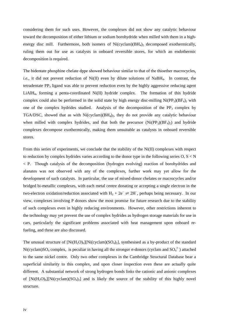
considering them for such uses. However, the complexes did not show any catalytic behaviour
toward the decomposition of either lithium or sodium borohydride when milled with them in a high-
energy disc mill. Furthermore, both isomers of Ni(cyclam)(BH4)2 decomposed exothermically,
ruling them out for use as catalysts in onboard reversible stores, for which an endothermic
decomposition is required.
The bidentate phosphine chelate dppe showed behaviour similar to that of the thioether macrocycles,
i.e., it did not prevent reduction of Ni(II) even by dilute solutions of NaBH4. In contrast, the
tetradentate PP3 ligand was able to prevent reduction even by the highly aggressive reducing agent
LiAlH4, forming a penta-coordinated Ni(II) hydride complex. The formation of this hydride
complex could also be performed in the solid state by high energy disc-milling Ni(PP3)(BF4)2 with
one of the complex hydrides studied. Analysis of the decomposition of the PP3 complex by
TGA/DSC, showed that as with Ni(cyclam)(BH4)2, they do not provide any catalytic behaviour
when milled with complex hydrides, and that both the precursor (Ni(PP3)(BF4)2) and hydride
complexes decompose exothermically, making them unsuitable as catalysts in onboard reversible
stores.
From this series of experiments, we conclude that the stability of the Ni(II) complexes with respect
to reduction by complex hydrides varies according to the donor type in the following series O, S < N
< P. Though catalysis of the decomposition (hydrogen evolving) reaction of borohydrides and
alanates was not observed with any of the complexes, further work may yet allow for the
development of such catalysts. In particular, the use of mixed-donor chelates or macrocycles and/or
bridged bi-metallic complexes, with each metal centre donating or accepting a single electron in the
two-electron oxidation/reduction associated with H2 + 2e− ⇌ 2H
−, perhaps being necessary. In our
view, complexes involving P donors show the most promise for future research due to the stability
of such complexes even in highly reducing environments. However, other restrictions inherent to
the technology may yet prevent the use of complex hydrides as hydrogen storage materials for use in
cars, particularly the significant problems associated with heat management upon onboard re-
fueling, and these are also discussed.
The unusual structure of [Ni(H2O)6][Ni(cyclam)(SO4)2], synthesised as a by-product of the standard
Ni(cyclam)SO4 complex, is peculiar in having all the stronger σ-donors (cyclam and SO42−
) attached
to the same nickel centre. Only two other complexes in the Cambridge Structural Database bear a
superficial similarity to this complex, and upon closer inspection even these are actually quite
different. A substantial network of strong hydrogen bonds links the cationic and anionic complexes
of [Ni(H2O)6][Ni(cyclam)(SO4)2] and is likely the source of the stability of this highly novel
structure.

v
Ni(12aneS4)(BF4)2 was found to absorb and desorb water very easily, with hydration of a powdered
sample occurring in minutes (and surface effects clearly visible in seconds) by simple exposure to
atmospheric air, and dehydration within seconds by heating to about 100 °C, in minutes by reducing
the pressure to a few mbar, or over several hours in a dry atmosphere at room temperature and
pressure. The structures of the complexes were solved from powder synchrotron X-ray diffraction
patterns and found to have a clear topotactic relationship with highly anisotropic expansion of lattice
parameters. Upon hydration, the flexibility of the 12aneS4 ring allows it to fold back and make room
for the two water molecules that attach directly to the nickel to form [Ni(12aneS4)(H2O)2](BF4)2.
The thermodynamic and kinetic aspects of the solid state reaction were investigated by TGA/DSC.
With a very slow temperature ramp (as low as 0.02 K min−1
) and no purging gas, this technique
showed two separate processes occurring for both hydration and dehydration, attributed to the
addition or loss of one equivalent of water at each step. The enthalpy, entropy and activation energy
for each step in static air and for the overall reaction with purging gas were estimated using both the
Kissinger and Ozawa-Flynn-Wall approaches. The calculated activation energy was found to be
highly dependent on whether the sample chamber was purged during the experiment with dry Ar gas
or not, which in removing water from the crystallite surfaces, points to the important role the
reversibility of the reaction plays in the overall kinetics.
The anhydrous complex, expected to have a low-spin d8 electronic configuration, shows
‘anomalous’ magnetic susceptibility, most likely due to its slight deviation away from square planar
geometry and therefore imperfect quenching of the orbital angular momentum. The octahedral
hydrated complex, however, shows magnetic behaviour typical of a high-spin d8 configuration.

vi
vii
Streszczenie
W niniejszej pracy doktorskiej opisałem strukturę krystaliczną, właściwości fizykochemiczne oraz
proces rozkładu termicznego serii związków kompleksowych zawierających nikiel (II)
koordynowany makrocyklicznymi ligandami chelatowymi. Kompleksy syntezowałem w reakcjach
prostych soli niklu (II) z odpowiednimi ligandami: 12aneS4 (1,4,7,10-tetratiocyklododekan),
14aneS4 (1,4,8,11-tetratiocyklotetradekan), cyklam (1,4,8,11-tetraazacyklotetradekan), dppe (1,2-
(difenylofosfino)etan), oraz PP3 (tris-(2-(difenylofosfino)etylo)fosfina). Niniejsza praca podzielona
jest na trzy rozdziały tematyczne. Pierwszy rozdział dotyczy katalizy procesu odwodornienia
wodorków kompleksowych służących jako magazyny wodoru. Drugi rozdział poświęcony jest
ciekawej strukturze krystalicznej kompleksu [Ni(H2O)6][Ni(cyclam)(SO4)2]. W trzecim rozdziale
opisuję odwracalny proces uwodnienia kompleksu Ni(12aneS4)(BF4)2.
Zdolność soli metali przejściowych do katalizy odwracalnego procesu odwodornienia i
uwodornienia jest dobrze znana. Szczególne znaczenie w tej grupie związków mają sole tytanu
katalizujące wydzielanie i absorpcję wodoru przez glinowodorek sodu, NaAlH4. Niestety aktywność
tych katalizatorów jest zbyt niska by móc je z powodzeniem zastosować w lekkich pojazdach
napędzanych wodorem. Obecnie odchodzi się od badania katalizatorów tego typu z powodu
niewielkiej możliwości modyfikacji parametrów układu oraz niejasnego mechanizmu katalizy.
Podczas swoich badań zajmowałem się związkami kompleksowymi niklu (II) z 12aneS4, 14aneS4,
cyclam, dppe and PP3 jako potencjalnymi katalizatorami procesu odwodornienia. Katalizatory
kompleksowe wybrałem z dwóch powodów. Po pierwsze, związek kompleksowy można w łatwy
sposób modyfikować zmieniając jego właściwości. Daje to możliwość zaprojektowania układu
katalitycznego i modyfikowania go w miarę poznawania mechanizmu katalizy. Po drugie związki
kompleksowe tworzą zwykle kryształy molekularne, co daje możliwość ich lepszego
zdyspergowania w materiale stanowiącym magazyn wodoru.
Trwałość kompleksów w kontakcie z silnymi reduktorami była testowana przy użyciu serii
reduktorów o narastającej mocy: NaBH4, LiBH4, NaAlH4, oraz LiAlH4. Kompleksy tetratioeterowe
ulegały rozkładowi nawet w kontakcie z rozcieńczonymi roztworami borowodorku sodu dając jako
produkty substancje smołowate, czarno-brązowe, lub amorficzne ciała stałe nie dające wyraźnych
widm absorpcyjnych w podczerwieni. Kompleksy cyklamowe (Ni(cyklam)SO4, Ni(cyklam)(ClO4)2
or Ni(cyklam)(BF4)2) reagowały z NaBH4 oraz LiBH4 dając kompleks niklowo-borowodorkowy,
Ni(cyklam)(BH4)2, o zaskakująco dużej stabilności kinetycznej. Otrzymałem dwa izomery, cis i
trans, tego kompleksu. Zbadałem ich strukturę krystaliczną wykorzystując techniki rentgenowskie
oraz dyfrakcję neutronową.
viii
Właściwości katalityczne kompleksu Ni(cyklam)(BH4)2 zostały zbadane w eksperymencie
termograwimetrycznym z jednoczesnym różnicowym pomiarem kalorymetrycznym (TGA/DSC)
oraz badaniem składu gazu wydzielanego metodami spektrometrii mas oraz spektroskopii
podczerwieni. Nie wykryłem efektu katalitycznego kompleksu Ni(cyklam)(BH4)2 w procesie
odwodornienia borowodorku sodu i borowodorku litu (po przeprowadzeniu ich domieszkowania
metodą mielenia wysokoenergetycznego). Co więcej, oba izomery kompleksu cyklamowego
rozkładały się w reakcji egzotermicznej, co wyklucza możliwość zastosowania ich do konstrukcji
odwracalnego magazynu wodoru, gdzie potrzebne są związki rozkładające się w procesie
umiarkowanie endotermicznym. Zaobserwowałem jednak, że geometria układu katalitycznego
może mieć kluczowe znaczenie dla przebiegu procesu wydzielania wodoru (izomer cis rozkładał się
w niższej temperaturze niż izomer trans).
Dwukleszczowe chelatowe kompleksy fosfinowe niklu (II) z ligandem dppe wykazywały podobne
właściwości do makrocyklicznych kompleksów tioeterowych, ponieważ rozkładały się już w
kontakcie z rozcieńczonym borowodorkiem sodu. Z kolei czterokleszczowe kompleksy PP3 były
stabilne nawet w kontakcie z bardzo agresywnym reduktorem, glinowodorkiem litu, tworząc
wodorkowy kompleks niklu (II), prawdopodobnie o liczbie koordynacyjnej 5. Kompleksy tego typu
otrzymałem również w reakcji mechanochemicznej kompleksu Ni(PP3)(BF4)2 z odpowiednim
glinowodorkiem. Badanie rozkładu mieszanin wodorków z kompleksem niklu z ligandem PP3
metodą TGA/DSC wykazało brak właściwości katalitycznych kompleksu PP3, podobnie jak
kompleksu Ni(cyclam)(BH4)2. Co więcej reakcja rozkładu była egzotermiczna, co wyklucza użycie
również tego kompleksu jako katalizatora rozkładu stałych magazynów wodoru.
Zbadanie trwałości różnych kompleksów niklu (II) pozwoliło mi na stworzenie stwierdzenie, że
odporność jonu niklu (II) na redukcję wodorkami kompleksowymi rośnie w zależności od rodzaju
heteroatomu w pierścieniu makrocyklicznym w kolejności: O, S < N < P. Nie zaobserwowałem
efektu katalitycznego dla wydzielania wodoru z borowodorków i glinowodorków dla żadnego z
badanych związków kompleksowych; istnieje jednak szansa, że dalsze badania rozwiną tą gałąź
chemii katalizatorów. Do zachodzenia odwracalnej reakcji H2 + 2e− ⇌ 2H
− potrzebna jest obecność
ligandów chelatowych albo makrocyklicznych lub zastosowanie bimetalicznych układów
mostkowych, w których każde centrum metaliczne mogło pełnić rolę donora lub akceptora jednego
elektronu w dwuelektronowej reakcji utleniania-redukcji. Zgodnie z wynikami eksperymentalnymi
kompleksy Ni (II) ligandy zawierające fosfor wykazują największa stabilność w kontakcie z silnymi
reduktorami i dlatego są najlepszymi prekursorami do syntezy katalizatorów odwodornienia. Jednak
przy opracowywaniu układu magazynującego wodór istotne mogą być również inne aspekty, m.in.
efekty cieplne przy jego regeneracji, co stanowi istotny problem układów opartych na wodorkach
kompleksowych.
ix
W trakcie prowadzenia badań otrzymałem również (jako produkt uboczny syntezy kompleksu
Ni(cyklam)SO4) nieznany wcześniej kompleks [Ni(H2O)6][Ni(cyklam)(SO4)2] o ciekawej strukturze
krystalicznej. Unikalność jego struktury krystalicznej polega głównie na tym, że wszystkie silnie σ-
donorowe ligandy (cyclam, SO42−
) koordynują tylko jeden z dwóch niezależnych kationów niklu
(II). W bazie danych strukturalnych (Cambridge Structural Database) występują tylko dwa inne
kompleksy wykazujące podobną, choć nie identyczną budowę. Gęsta sieć silnych wiązań
wodorowych łączy ligandy kationowe i anionowe przyczyniając się do stabilności kompleksu
[Ni(H2O)6][Ni(cyklam)(SO4)2].
Z kolei kompleks Ni(12aneS4)(BF4)2 wykazywał bardzo szybką kinetykę procesu absorpcji i
desorpcji wody. Próbki proszkowe ulegały uwodnieniu w ciągu wystawienia na powietrze
atmosferyczne na kilka minut, a pierwsze wyraźne efekty obserwowałem już po kilku sekundach
reakcji. Dehydratacja następowała w wyniku kilkusekundowego ogrzewania w 110°C lub w ciągu
kilku minut po obniżeniu ciśnienia do 2–3 milibarów w temperaturze pokojowej. Rozwiązałem
strukturę krystaliczną kompleksu w formie uwodnionej i bezwodnej. Zaobserwowałem zależność
topotaktyczną obu form, która wynika z silnie anizotropowej ekspansji parametrów komórki
elementarnej. W trakcie hydratacji pierścienie ligandu 12aneS4 ulęgają deformacji tworząc tym
samym miejsce na dwie cząsteczki wody wbudowujące się w sieć krystaliczną przy tworzeniu
uwodnionego kompleksu [Ni(12aneS4)(H2O)2](BF4)2.
Zbadałem termodynamikę oraz kinetykę reakcji uwodnienia i odwodnienia w ciele stałym metodą
TGA/DSC. Podczas bardzo powolnych pomiarów (0,02 K min−1
) prowadzonych przy zerowym
przepływie gazu nośnego zaobserwowałem dwa etapy absorpcji i desorpcji wody. Każdy z etapów
odpowiada wymianie jednego równoważnika cząsteczek wody. Entalpia, entropia oraz energia
aktywacji została wyznaczona metodami Kissingera oraz Ozawy-Flynna-Walla. Obliczona energia
aktywacji była silnie zależna od tego, czy komora pomiarowa była przepłukiwana w trakcie pomiaru
suchym argonem czy nie, co wynika przypuszczalnie ze skomplikowanego mechanizmu reakcji, w
którym bardzo dobra odwracalność kinetyczna gra główną rolę.
Bezwodna postać kompleksu, ktora jak sądziłem powinna zawierać kationy Ni (II) o niskospinowej
konfiguracji d8, wykazuje ‘anomalną’ zależność podatności magnetycznej od temperatury, zapewne
z powodu występowania zauważalnej dystorsji otoczenia kationu od idealnej formy płaskiego
kwadratu, co ma wpływ na niepełną redukcję orbitalnego momentu spinowego. Z kolei uwodniona
postać kompleksu, o oktaedrycznym otoczeniu kationu Ni (II), wykazuje właściwości magnetyczne
typowe dla wysokospinowej konfiguracji d8.

x

xi
for my parents

xii
xiii
Note on previously published and co-authored work
This work contains work previously published by the author, including co-authored work. Any
inclusion is primarily the work of the author of this thesis under the supervision of Wojciech
Grochala. Co-authored work primarily performed by an author other than the author of this thesis is
cited appropriately in the text as such.
In particular:
Chapter 3 contains sections from Churchard et al., Physical Chemistry Chemical Physics, 2011,
16955, which were the work of the author of this dissertation under the supervision of Prof.
Wojciech Grochala, with additional valuable advice from Prof. Geert-Jan Kroes, Department of
Chemistry, University of Leiden, Netherlands.
Chapter 6 contains sections from Churchard et al., Energy & Environmental Science, 2010, 3, 1973.
Chapter 7 substantially consists of work published in Churchard et al., Acta Crystallographica
Section C, 2010, 66, m263.
Chapter 8 substantially consists of work published in Churchard et al., Dalton Transactions, 2012,
41, 5172.

xiv

xv
Acknowledgements
First and foremost I must thank by supervisor, Professor Wojciech Grochala, who has helped and
guided me through the maze of hydrogen storage, generously sharing his valuable knowledge, and
who has also been a very good friend throughout my time in Warsaw.
My parents have provided continual support from afar, without which I may not have made it to the
end, and their frequent visits to Warsaw and regular deliveries of post and tea-bags have been very
much appreciated. Sonja, who has so patiently accepted the delays this thesis has caused to our life
together, has been also been a constant source of support and I can’t thank her enough. Thank you
also to my sisters, Claire and Freya, who, for unknown reasons, have an unwavering faith in me.
I am very grateful to my friends in Warsaw, in particular Karol, Tomek, Dominik and Przemek, who
helped keep me sane and who never complained of my frequent requests for help with Polish
language and bureaucracy. My gratitude also goes to the other members of LTNFM who have
variously provided me with much help and entertainment.
Finally, thanks to my friends back in Britain who haven’t given up on me despite my infrequent
communication, and who I look forward to seeing more often in the future. In particular thanks to
Chris, Chris, Emily, Emma, Julia and Lucy who travelled to Poland (even on more than one
occasion) to visit me.

xvi
xvii
Table of Contents
Abstract (in English) ............................................................................................................................... iii
Abstract (in Polish) ................................................................................................................................ vii
Dedication .............................................................................................................................................. xi
Note on previously published and co-authored work ......................................................................... xiii
Acknowledgements .............................................................................................................................. xv
1 Introduction ......................................................................................................................................... 1
Literature Review
2 A very brief introduction to nickel ....................................................................................................... 3
2.1 The discovery of nickel, its sources and its uses ...................................................................... 4
2.2 The oxidation states of nickel .................................................................................................. 5
2.3 Toxicity and environmental considerations ............................................................................ 9
3 Hydrogen storage and the rationale for using nickel complexes as catalysts for complex hydride
decomposition .................................................................................................................................... 11
3.1 The motivation for a hydrogen economy .............................................................................. 12
3.2 The challenges still to be overcome ...................................................................................... 13
3.3 Overview of hydrogen storage technologies ......................................................................... 15
3.4 The thermodynamics of the complex hydrides ..................................................................... 23
3.5 History of catalysis for the decomposition of the complex hydrides .................................... 26
3.6 Non-catalytic modifications to improve decomposition characteristics ............................... 27
3.7 Nickel specific research ......................................................................................................... 28
3.8 Decomposition temperature and the standard electrode potential ..................................... 31
4 Introduction to chelates and macrocycles ......................................................................................... 39
4.1 The chelate effect .................................................................................................................. 40
4.2 The macrocyclic effect ........................................................................................................... 41
4.3 General classification and characterisation of chelates and macrocycles ............................ 43
4.4 Synthesis ................................................................................................................................ 46
4.5 Selection of donors ................................................................................................................ 49
4.8 Crystal structures of chelates and macrocycles with N, S and P donors ............................... 50
4.9 Electrochemistry .................................................................................................................... 61
4.10 Mixed donor chelates and macrocycles ................................................................................ 66
xviii
5 Reversible thermal dehydration in solid state transition metal complexes ...................................... 73
5.1 Introduction .......................................................................................................................... 74
5.2 Types of interaction .............................................................................................................. 75
5.3 Dehydration reactions as models for generalised solid state decompositions .................... 75
5.4 Experimental methods for the investigation of solid-state reactions .................................. 76
5.5 Reaction mechanisms ........................................................................................................... 81
5.6 Examples of dehydration reactions involving nickel ............................................................. 86
Experimental Work
6 Characterisation of complexes and reactions with borohydrides and alanates ............................... 93
6.1 Methodologies for synthesis and analysis ............................................................................ 94
Results and discussion ................................................................................................................... 105
6.2 Nickel cyclam complexes .................................................................................................... 105
6.3 Nickel thioether complexes ................................................................................................ 132
6.4 Nickel phosphine complexes ............................................................................................... 137
6.5 Conclusions and assessment of potential of complexes as hydrogen store catalysts ........ 146
6.6 Summary ............................................................................................................................. 148
7 The unusual structure of [Ni(H2O)6][Ni(SO4)2(cyclam)]·2H2O .......................................................... 151
7.1 Methodology for synthesis, analysis and database queries ............................................... 152
7.2 Results and discussion ........................................................................................................ 153
7.3 Summary ............................................................................................................................. 159
8 Facile reversible dehydration decomposition of Ni(12aneS4)(BF4)2·2H2O....................................... 161
8.1 Methodology for synthesis and analysis ............................................................................. 162
8.2 Results and discussion ........................................................................................................ 167
8.3 Summary and future work .................................................................................................. 187
9 Summary .......................................................................................................................................... 189
10 Outlook .......................................................................................................................................... 191
xix
List of acronyms
ACN acetonitrile
CCD charge coupled device
CCDC Cambridge Crystallographic Data Centre
CSD Cambridge Structural Database
DCM dichloromethane
DFT density functional theory
DMP dimethoxypropane
DMSO dimethyl sulfoxide
DOE Department of Energy (USA)
DSC differential scanning calorimetry
DTA differential thermal analysis
EDS energy dispersive X-ray spectroscopy
EGA evolved gas analysis
EGA-FTIR evolved gas analysis by FTIR spectroscopy
EGA-MS evolved gas analysis by mass spectrometry
FC field cooled
FTIR Fourier Transform Infrared
HOMO highest occupied molecular orbital
HRPT High Resolution Powder Diffractometer for Thermal Neutrons (PSI, Switzerland)
ICE internal combustion engine
ICM Interdisciplinary Centre for Mathematical and Computational Modelling
IR infrared
IUPAC International Union of Pure and Applied Chemistry
LUMO lowest unoccpuied molecular orbital
MAS NMR magical angle spinning nuclear magnetic resonance
MOF metal organic framework
MS mass spectrometry
NATAS North American Thermal Analysis Society
Nd:YAG neodymium-doped yttrium aluminum garnet
NIK non-isothermal kinetics
NIST National Institute of Standards and Technology (USA)
NMR nuclear magnetic resonance
ORTEP Oak Ridge Thermal Elipsoid Plot
PEM polymer electrolyte membrane or proton exchange membrane
xx
PSI Paul Scherrer Institute, Switzerland
RSC Royal Society of Chemistry (UK)
SCE saturated calomel electrode
SEM scanning electron microscopy
SHE standard hydrogen electrode
SINQ Swiss Spallation Neutron Source (PSI, Switzerland)
STA simultaneous thermal analysis
SWNT single-walled carbon nanotube
TGA thermogravimetric analysis
THF tetrahydrofuran
TM transition metal
WET water evolution type
XAFS X-ray absorption fine structure
XRD X-ray diffraction
ZFC zero-field cooled
xxi
List of ligand abbreviations
12aneS4 1,4,7,10-tetrathiacyclododecane
14aneN2S2 1,8-diaza-4,11-dithiacyclotetradecane
14aneS4 1,4,8,11-tetrathiacyclotetradecane
bipy 2,2’-bipyridine
bpe 1,2-bis(4-pyridyl)ethane
cyclam 1,4,8,11-tetraazacyclotetradecane
dhtp 2,5-dihydroxyterephthalic acid
dien diethylenediamine
dppe diphenylphosphinoethane
en ethylenediamine
es2−
ethanedithiolate
iso-14aneN2S2 1,7-diaza-4,11-dithiacyclotetradecane
NP3 tris(2-diphenylphosphinoethyl)amine
NP3E tris(2-diethylphosphinoethyl)amine
NS3iPr
tris[(isopropylthio)-ethyl]amine
NS3tBu
tris[(ter-butylthio)-ethyl]amine
phen 1,10-phenanthroline
PP3 tris(2-diphenylphosphinoethyl)phosphine
PP3E tris(2-diethylphosphinoethyl)phosphine
terpy terpyridine
tmbp 4,4’,5,5’-tetramethyl-2,2’-biphosphinine
tren Tris(2-aminoethyl)amine
trien triethylenediamine
n.b., some of the more complex ligands are not listed here as they are better described by means of a
diagram, which in these cases will be found near to the text where they are discussed.

xxii
1
1. Introduction
This dissertation sets out the work carried out in pursuance of the degree of Doctor of Philosophy at
the University of Warsaw within the Faculty of Chemistry and the Interdisciplinary Centre for
Mathematical and Computational Modelling.
The primary motivating aim was to develop catalysts for use with solid complex hydride hydrogen
stores. Of course, it is natural when embarking upon a specific line of enquiry, to keep one’s eyes
open for other interesting paths on the way, indeed it is not unusual for significant advances to be
made in just this way. Two such serendipitous side projects were pursued, such that hypotheses
across three different but related areas were developed.
The first of these three, constituting the majority of the work carried out, was that macrocycles and
chelates could be used to stabilise Ni(II) cations in the highly reducing atmosphere ofcomplex
hydride hydrogen stores, allowing them to partake in catalytic reactions for the evolution of
hydrogen at approximately 100 °C, and the storage of hydrogen at room temperature.This was tested
over a period of four years with three main types of ligand: a tetraaminemacrocycle (cyclam),
tetrathioether macrocycles, and phosphine chelates.Cyclam wastested first as a reliable ligand of
Ni(II), known from electrochemical experiments to stabilise it with respect to reduction. The use of
the tetrathioether macrocycles arose from conclusions drawn from the experiments with cyclam, and
phosphines from the further knowledge gained after testing the tetrathioethers.
The first serendipitous discovery concerned an unusual looking crystal structure found in a by-
product of the Ni(cyclam)SO4 synthesis, with further research carried outwith the aim of
determining just how exceptional it was and placing it in the context of previously reported
structures.This provided an interesting but brief diversion from the main area of research.
The final area, constituting about one third of the work, was the investigation of the facile absorption
of water by Ni(12aneS4)(BF4)2, and the effects on the chemical properties of the complexes. Such
dehydration reactions are formally thermal decomposition reactions, providing a direct link to the
study of thermal decomposition of the complex hydrides, which formed the main part of this
dissertation.

2

3
2. A very brief introduction to nickel
2.1 The discovery of nickel, its sources and its uses ....................................................................... 4
2.2 The oxidation states of nickel ................................................................................................... 5
2.2.1 Ni(−I) .................................................................................................................................. 5
2.2.2 Ni(0) ................................................................................................................................... 6
2.2.3 Ni(I) .................................................................................................................................... 6
2.2.4 Ni(II) ................................................................................................................................... 7
2.2.5 Ni(III) .................................................................................................................................. 8
2.2.6 Ni(IV) .................................................................................................................................. 8
2.3 Toxicity and environmental considerations .............................................................................. 9
References ........................................................................................................................................... 10
4
2.1 The discovery of nickel, itssources and its uses Nickel is a well-known and much used metal. The Chinese were using cupronickel alloy, with the
nickel content (6 – 16 %) likely extracted from NiAs ores, as long ago as the 2nd century C.E. and
there were accusations of currency debasement from the second century B.C.E. that could quite
possibly be blamed on manufacturers of this alloy.[1]
In the history of modern western science, nickel
was isolated, identified and named in 1751 by A.F. Cronstedtin Sweden, with its properties more
accurately measured by J. B. Richter some 50 years later.[2]
Estimations of crustal abundance vary quite widely, reflecting the significant variation in different
locations and the resulting challenge in producing a single number for the entire crust. The website
WebElements[3]
has assessed data from 8 sources and gives the crustal abundance of nickel as 32
ppm by number of atoms (90 ppm by mass), an abundance comparable to that of most other first row
transition metals, with the exceptions of manganese at 420 ppm, titanium at 2,900 ppm and iron at
23,000 ppm. It is vastly more abundant than its group 10 congeners, palladium at 0.001 ppm and
platinum at 0.004 ppm, which otherwise might be preferred for much of nickel’s chemical uses.
Nickel is the fifth most abundant element on Earth as a whole as it is a significant component of the
Earth’s core,[4]
but these resources are not available for exploitation with current technology.
Annual production of nickel stands at around 106 tonnes per annum.
[5] Until relatively recently the
major source ore was pentlandite, (Fe, Ni)9S8, due to the greater ease withwhich the sulphides could
be processed compared to laterite (silicate and oxide) ores. However, increased demand for nickel
and improving processing technology has caused laterites to form an increasingly significant
proportion of total productionand it is likely future demand will also be met by the more common
laterite ores.[4]
The main use of nickel is in alloying with other metals, particularly in the production
of stainless steel, with nickel plating the second most common use, but accounting for only about
10% of the total.
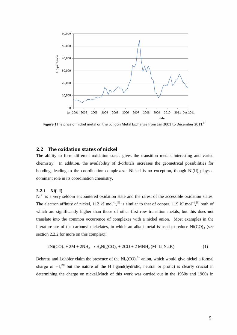
The price of nickel has proven to be rather volatile (see Figure 1), with a particularly severe price
spike in 2007 due to the increased demand for stainless steel, mainly driven by the rapidly growing
economies of Asia and South America. Though substitution of nickel in such steels did occur, the
inability of such substitutes to fully match the performance of nickel alloys limits the degree to
which this can occur.In terms of supply matching demand, the British Geological Survey rates,
nickel as a low risk to supply disruption, comparable to zinc, sodium or chlorine.[6]
However, the
apparent price inelasticity of the current uses of nickel is an important factor when considering new
technologies that might require a significant proportion of the current annual production of nickel.
5
Figure 1The price of nickel metal on the London Metal Exchange from Jan 2001 to December 2011.[7]
2.2 The oxidation states of nickel The ability to form different oxidation states gives the transition metals interesting and varied
chemistry. In addition, the availability of d-orbitals increases the geometrical possibilities for
bonding, leading to the coordination complexes. Nickel is no exception, though Ni(II) plays a
dominant role in its coordination chemistry.
2.2.1 Ni(−I)
Ni1−
is a very seldom encountered oxidation state and the rarest of the accessible oxidation states.
The electron affinity of nickel, 112 kJ mol−1
,[8]
is similar to that of copper, 119 kJ mol−1
,[8]
both of
which are significantly higher than those of other first row transition metals, but this does not
translate into the common occurrence of complexes with a nickel anion. Most examples in the
literature are of the carbonyl nickelates, in which an alkali metal is used to reduce Ni(CO)4 (see
section 2.2.2 for more on this complex):
2Ni(CO)4 + 2M + 2NH3 → H2Ni2(CO)6 + 2CO + 2 MNH2 (M=Li,Na,K) (1)
Behrens and Lohöfer claim the presence of the Ni2(CO)62−
anion, which would give nickel a formal
charge of −1,[9]
but the nature of the H ligand(hydridic, neutral or protic) is clearly crucial in
determining the charge on nickel.Much of this work was carried out in the 1950s and 1960s in
6
Germany,* but a more recent review suggests that these results should be treated with care as the
analysis was incomplete and relied heavily on inference from indirect methods.[10]
Nickel clusters open up the possibility of creating many more species with Ni bearing a (partial)
negative charge, for example if the reaction in equation (1) is carried out in tetrahydrofuran rather
than liquid ammonia, Ni5(CO)122−
, Ni6(CO)122−
, Ni7(CO)152−
and larger clusters may be formed.[10,11]
We will not, however, delve further into this complex area in this short introduction.
2.2.2 Ni(0)
Ni(0) has played an important role in the development of nickel chemistry, as it was Ni0(CO)4 that
first allowed very pure nickel to be produced. During the late 1880s, Ludwig Monddiscovered that
the nickel valves used in one of his processes were corroding with the formation of a black solid.[12]
This deposit was found to consist mostly of carbon, allowing the exceptional industrial chemist to
associate the problem with traces of carbon monoxide in the supposedly inert nitrogen gas used to
flush the equipment. This important accident proved to be of incredible value to Mond, as it
provided him with two important processes, one that allowed him to remove CO from his Mond
gas,†and the second that allowed the production of nickel of exceptional purity, even from lower
quality ores.
Beyond its role in the purification of the elemental metal, Ni(0) is a common hydrogenation catalyst,
either as an alloy (e.g., Raney nickel) or as a coordination complex (e.g., K4[Ni0(CN)4]
‡,[13]).It also
forms other coordination complexes,such as the tetrahedral Mg2[Ni0H4], whose hydrogen storage
properties will be discussed in section 3.7.2 on page 29, and particularly with phosphines capable of
stabilising this low, soft oxidation state, which we will discuss further in section 4.6 on page 50.
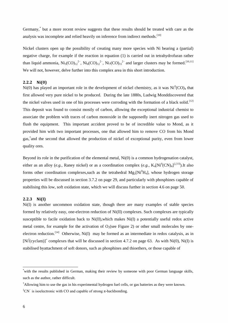
2.2.3 Ni(I)
Ni(I) is another uncommon oxidation state, though there are many examples of stable species
formed by relatively easy, one-electron reduction of Ni(II) complexes. Such complexes are typically
susceptible to facile oxidation back to Ni(II),which makes Ni(I) a potentially useful redox active
metal centre, for example for the activation of O2(see Figure 2) or other small molecules by one-
electron reduction.[14]
Otherwise, Ni(I) may be formed as an intermediate in redox catalysis, as in
[NiI(cyclam)]
+ complexes that will be discussed in section 4.7.2 on page 63. As with Ni(0), Ni(I) is
stabilised byattachment of soft donors, such as phosphines and thioethers, or those capable of
*with the results published in German, making their review by someone with poor German language skills,
such as the author, rather difficult.
†Allowing him to use the gas in his experimental hydrogen fuel cells, or gas batteries as they were known.
‡CN
− is isoelectronic with CO and capable of strong π-backbonding.
7
significant π-backbonding (such as the diketiminate in Figure 2).Ni(I) may be susceptible to
disproportionation into Ni(0) and Ni(II), and the reverse, comproportionation, is also possible,
particularly when phosphine ligands are involved, for example:
[NiII(dppe)2](BF4)2 + Ni
0(dppe) → 2[Ni
I(dppe)2]BF4
(wheredppe = 1,2-bis(diphenylphosphino)ethane) proceeds to almost quantitative yield.[15]
(dppe
complexes of nickel will be discussed in more detail in section 4.6.1 on page 50.)
Figure 2Schematic diagram for the activation of O2 by a Ni(I) complex
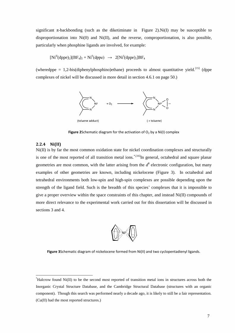
2.2.4 Ni(II)
Ni(II) is by far the most common oxidation state for nickel coordination complexes and structurally
is one of the most reported of all transition metal ions.*,[16]
In general, octahedral and square planar
geometries are most common, with the latter arising from the d8 electronic configuration, but many
examples of other geometries are known, including nickelocene (Figure 3). In octahedral and
tetrahedral environments both low-spin and high-spin complexes are possible depending upon the
strength of the ligand field. Such is the breadth of this species’ complexes that it is impossible to
give a proper overview within the space constraints of this chapter, and instead Ni(II) compounds of
more direct relevance to the experimental work carried out for this dissertation will be discussed in
sections 3 and 4.
Figure 3Schematic diagram of nickelocene formed from Ni(II) and two cyclopentadienyl ligands.
*Halcrow found Ni(II) to be the second most reported of transition metal ions in structures across both the
Inorganic Crystal Structure Database, and the Cambridge Structural Database (structures with an organic
component). Though this search was performed nearly a decade ago, it is likely to still be a fair representation.
(Cu(II) had the most reported structures.)

8
2.2.5 Ni(III)
Ni(III) is a moderately strong oxidising agent and Lewis acid, requiring good σdonors to stabilise
it.[17]
Amines are a key donor in the coordination chemistry of Ni(III), particularly chelates and
macrocycles(some of which will be discussed in sections 4.6 – 4.8). As d7 complexes, the
octahedral geometries undergo Jahn-Teller distortion (e.g., [(NiIII
(CN)6]3−
, though the tetragonal
distortions in frozen aqueous solution vibrationally interconvert between the three axes at
temperatures above −35 °C, Figure 4).[18]
Figure 4 Schematic showing the Jahn-Teller distortion of [NiIII
(CN)6]3−
, vibrational interconversion of the axes occurs at temperatures above −35 °C.
NiF3 may be formed in variety of ways, most reliably from the Ni(IV) fluorides, NiF4 and K2NiF6. In
fact three crystal structures of NiF3 are relatively easy to synthesise by use of anhydrous hydrogen
fluoride (aHF) and modest changes (Δ20 °C) in the reaction temperature:[19]
NiF4 (solid) → P-NiF3 + ½ F2 (T> −55 °C)
NiF4 (aHF) → R-NiF3 + ½ F2 (T = 0 °C)
NiF4 (aHF) → H-NiF3 + ½ F2 (T = 20 °C)
where the P-, R-, and H- prefixes denote different polymorphs. These decompose at 138 °C, 39 °C,
and 72°C, respectively, by evolving F2.[19]
2.2.6 Ni(IV)
At the extreme end of the oxidation states, Ni(IV) is a powerful oxidiser, most commonly formed
with O and F donors.At least twoNi(IV)oxides are known, simple dioxide, NiIV
O2, and a di-peroxide,
NiIV
(O2)2,[20]
though experimental syntheses of these oxides have been contradictory.[21]
K2NiF6 is
both commercially available and relatively inexpensive. NiF4 may be formed from it, using BF3,[19]
with low temperatures (< 60 °C) required to prevent decomposition to NiF3 (see section above).
9
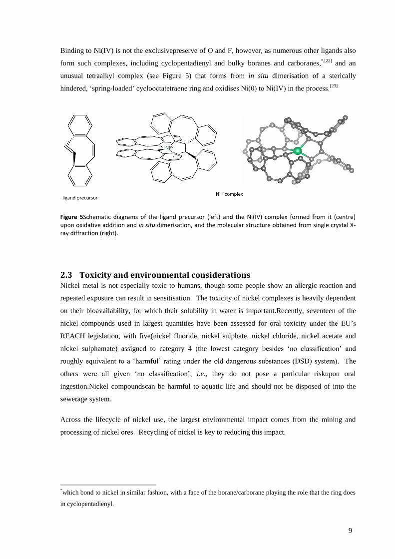
Binding to Ni(IV) is not the exclusivepreserve of O and F, however, as numerous other ligands also
form such complexes, including cyclopentadienyl and bulky boranes and carboranes,*,[22]
and an
unusual tetraalkyl complex (see Figure 5) that forms from in situ dimerisation of a sterically
hindered, ‘spring-loaded’ cyclooctatetraene ring and oxidises Ni(0) to Ni(IV) in the process.[23]
Figure 5Schematic diagrams of the ligand precursor (left) and the Ni(IV) complex formed from it (centre) upon oxidative addition and in situ dimerisation, and the molecular structure obtained from single crystal X-ray diffraction (right).
2.3 Toxicity and environmental considerations Nickel metal is not especially toxic to humans, though some people show an allergic reaction and
repeated exposure can result in sensitisation. The toxicity of nickel complexes is heavily dependent
on their bioavailability, for which their solubility in water is important.Recently, seventeen of the
nickel compounds used in largest quantities have been assessed for oral toxicity under the EU’s
REACH legislation, with five(nickel fluoride, nickel sulphate, nickel chloride, nickel acetate and
nickel sulphamate) assigned to category 4 (the lowest category besides ‘no classification’ and
roughly equivalent to a ‘harmful’ rating under the old dangerous substances (DSD) system). The
others were all given ‘no classification’, i.e., they do not pose a particular riskupon oral
ingestion.Nickel compoundscan be harmful to aquatic life and should not be disposed of into the
sewerage system.
Across the lifecycle of nickel use, the largest environmental impact comes from the mining and
processing of nickel ores. Recycling of nickel is key to reducing this impact.
*which bond to nickel in similar fashion, with a face of the borane/carborane playing the role that the ring does
in cyclopentadienyl.
10
References 1 J. Needham, Science and Civilisation in China, Cambridge University Press, 1974, pp. 229.
2 N. N. Greenwood, A. Earnshaw, The Chemistry of the Elements (2nd
Edition), Elsevier, 1997, p. 1144.
3 Webelements, http://www.webelements.com/periodicity/abundance_crust_a/.
4 T. Bide, L. Hetherington, G. Gunn, A. Minks, Nickel, British Geological Survey, Nottingham, 2008, p. 1.
5 World Nickel Statistics, International Nickel Study Group, Lisbon, 2010, accessed online at:
http://www.insg.org/stats.aspx.
6 British Geological Survey Press Release, “Risk List 2011”, citingR. L. Rudnick, S. Gao, Composition of the
Continental Crust, in The Crust (Ed. R. L. Rudnick), Elsevier-Pergamon, Oxford, 2003, pp. 1-64.
7 http://www.lme.com/nickel_graphs.asp.
8 J. G. Speight,Lange's Handbook of Chemistry (16th Edition), McGraw-Hill.2005, p. 1.146.
9 H. Behrens, F.Lohöfer, ChemischeBerichte, 1961, 94, 1391.
10 J. K. Beattie, A. F. Masters and J. T. Meyer, Polyhedron, 1995, 14, 829.
11 E. Wiberg, N, Wiberg, A. F. Holleman, Inorganic Chemistry, Academic Press,2001, p. 1569.
12 J. M. Cohen, The Life of Ludwig Mond, Methuen, London, 1956, p. 282.
13 N. Meksi, M. Kechida, F. Mhenni, Chemical Engineering Journal,2007, 131, 187.
14 S. Yao, M. Driess, Accounts of Chemical Research,2012, 45, 276.
15 V. V. Saraev, P. B. Kraikivskii, D. A. Matveev, A. S. Kuzakov, A. I. Vil’ms, A. A. Fedonina, Russian Journal of
Coordination Chemistry,2008, 34, 438.
16 M. A. Halcrow, Dalton Transactions,2003, 4375.
17 R. S. Drago, E. I. Baucom, Inorganic Chemistry,1972, 11, 2064.
18 Y. L. Wang, M. W. Beach, T. L. Pappenhagen, D. W. Margerum, Inorganic Chemistry,1988, 27, 4464.
19 B. Žemva, K. Lutar, L. Chacón, M. Fele-Beuermann, J. Allman, C. Shen, N. Bartlett, Journal of the American
Chemical Society,1995, 117, 10025.
20 S. Riedel, M. Kaupp, Coordination Chemistry Reviews,2009, 253, 606.
21 F. Allouti, L. Manceron, M. E. Alikhani, Physical chemistry chemical physics,2006, 8, 44.
22 K. Nag, A. Chakravorty, Coordination Chemistry Reviews,1980, 33, 87.
23 M. Carnes, D. Buccella, J. Y.-C. Chen, A. P. Ramirez, N. J. Turro, C. Nuckolls, M. Steigerwald,
AngewandteChemie (International Edition),2009, 48, 290.
11
3 Hydrogen storage and the rationale for using nickel complexes as
catalysts for complex hydride decomposition
3.1 The motivation for a hydrogen economy ................................................................................ 12
3.2 The challenges still to be overcome ......................................................................................... 13
3.3 Overview of hydrogen storage technologies ........................................................................... 15
3.3.1 Physical containment ....................................................................................................... 15
3.1.1 Physisorption .................................................................................................................... 17
3.1.2 Chemically bound hydrogen ............................................................................................ 18
3.1.3 Alternatives to hydrogen.................................................................................................. 22
3.4 The thermodynamics of the complex hydrides........................................................................ 23
3.5 History of catalysis for the decomposition of the complex hydrides ...................................... 26
3.6 Non-catalytic modifications to improve decomposition characteristics ................................. 28
3.7 Nickel specific research ............................................................................................................ 28
3.7.1 Nickel hydride, borohydride and alanate ......................................................................... 28
3.7.2 Mg–Ni alloys ..................................................................................................................... 29
3.7.3 NiCl2 as catalyst ................................................................................................................ 30
3.7.4 Ni metal as catalyst .......................................................................................................... 30
3.8 Decomposition temperature and the standard electrode potential ....................................... 31
References ............................................................................................................................................ 33

12
3.1 The motivation for a hydrogen economy Transportation accounts for one third of all energy use in the EU,
[1] and a fifth globally (see Figure
1).[2]
As the increasingly wealthy populations of developing countries start to discover the joys and
freedom that travel brings and that the west has had the privilege of enjoying for decades, energy use
for transportation will continue to grow.[2]
This travel will take many forms, but a significant
proportion will involve the private car,[3]
and so the source of the energy to drive millions of new
automobiles will play a crucial role in the energy dynamics of the coming century.
Figure 1Categories of energy use in the EU (left) and globally (centre), and the split of global transport bymode of transport (right). Sources: EU: reference 1, global: reference 2.
There are many reasons for moving away from oil-derived petroleum. Whether it is peak oil, the
increasing cost of crude, air quality, energy security, the transfer of hard currency to unfriendly oil-
states or simply climate change aggravated by anthropogenic CO2 emissions, it is clear that the
status quo cannot continue indefinitely.
A paradigm shift in the structure of the world’s energy supply is a necessarily complicated affair.
Happily, it can be broken down into a number of more manageable problems, one of which is the
nature of the energy carrier, that is, the method used to transfer energy from its place of production
to the place of use. To further limit the scope of the problem, we will deal here only with the nature
of powering small road vehicles, such as private cars.
As an energy carrier, hydrogen possesses a number of characteristics that make it an ideal material.
The reaction with O2 is highly exothermic (ΔG°f H2O(l) = −237.1 kJ mol−1[4]
) whilst hydrogen's status
as the lightest element makes it incredibly efficient with respect to weight. It may be produced from
a variety of energy sources, such as solar, wind, wave, tidal, hydro, geothermal or nuclear electricity
(through the electrolysis of water), reforming of coal, oil or natural gas, or from pyrolysis of
biomass. Hydrogen may be burnt in an internal combustion engine (ICE), but even better it may be
combined with O2 in a fuel cell to run an electric motor, gaining significant efficiency improvements
over technology limited by the Carnot cycle and mechanical transmission and driveshafts. When

13
hydrogen is passed through a fuel cell (as opposed to ICE, where NOx may be formed), the only
emission at the exhaust pipe is water vapour, a major step to improving the air quality in our cities
and urban areas.[5]
3.2 The challenges still to be overcome Given this, a newcomer to the field might wonder why we are not already driving around in H2
powered cars. The reason is that as well as the considerable advantages, hydrogen faces a number of
formidable challenges. These relate to four key areas: production, transport of the hydrogen, storage
and conversion to end-use (see Figure 2). The experimental work presented in section 6 of this
dissertation is concerned with the third area, storage, but it is worth quickly mentioning the others.
Figure 2The four stages required for a successful hydrogen economy.
The production of hydrogen is clearly of prime importance for the successful implementation of the
hydrogen economy. One of the key advantages of H2 as a fuel is the possible energy security
benefits arising from the range of sources from which it may be produced and this is reflected in the
extensive and diverse research being carried out in the area. Currently, almost all H2 is generated
from fossil fuels particularly by steam reforming of natural gas (though oil and coal are also used)[6]
in the reaction:
CH4 + H2O → CO + 3H2,* (T > 700 °C, nickel catalyst)
followed by the water-gas shift reaction:
CO + H2O → CO2 + H2 (multi-stage:first, T = 350°C – 600 °C; second 150°C –
300 °C,various transition metal catalysts)[7]
This diminishes many of the intended benefits of H2 as a fuel, and hydrogen production from
renewable sources is widely seen as the long-term goal. For this to occur, substantial improvements
need to be made in the efficiency of the underlying renewable electricity generation technologies
and theprocesses of electrolysis of water. To some extent the main challenges for hydrogen
production involve increasing the efficiency/reducing the cost of existing technologies, but the
barriers presented are still significant.[8]
*and similar reactions for higher hydrocarbons.

14
As it is not realistic for all hydrogen to be produced where it is needed, the second area, transport of
hydrogen, involves physically moving the hydrogen from where it is produced to where it is to be
consumed. Though it is distinct from the problems of storagethere are significant potential synergies,
for example improved storage materials may make transport easier. The two main methods for
conveying H2 are pipelines and road-tankers but these are complicated by the low volumetric density
of H2, the high cost of compression/liquefaction and the tendency of H2 to embrittle many common
engineering metals and alloys. Nevertheless, in this area, the challenges consist mainly of cost
reductions in and commercialisation of technologies that are already well developed.[9]
The third area, storage, will be discussed in detail below. The fourth, conversion to end-use, has
seen great strides made in fuel cell technology such that most research is now concerned with cost
reductions.[10]
Nevertheless, introduction of novel technologies could benefit other areas of research
into the hydrogen economy, for example proton exchange membranes capable of operating at higher
temperatures would ease some of the problems associated with chemical hydrogen storage.
Though significant progress has been made in the last decade, storage is still a key barrier to the
implementation of the hydrogen economy.[11]
The source of this barrier is the prevailing idea that
consumers will not accept diminished performance compared to their fossil fuel powered cars, and
that any replacement must therefore at least match the latter’s driving range, re-fuelling time,
durability, price and safety. By working back from the current performance levels, the U.S.
Department of Energy (DOE) developed targets that a hydrogen storage system would have to meet
to be considered a replacement. The targets, which are widely worked to, were released by the DOE
in 2003 and then revised in 2009[12]
to reflect more accurate data gathered in the meantime from
prototype hydrogen powered vehicles (see Table 1). Though some parameters tend to get more
attention than others in the literature (especially gravimetric and volumetric capacity), the DOE
states that all should be met if the implementation of the material as a hydrogen carrier is to be
Table 1Selected US Department of Energy revised targets for hydrogen storagea(published 2009)
[12]
units 2010 2015 ultimate
gravimetric capacity wt % usable H2 4.5 5.5 7.5
volumetric capacity kg usable H2 m−3
28 40 70
min/max operating temp °C −30/50 −40/60 −40/60
purity % H2 ← 99.97 (dry) →
a note that these are system level efficiencies (i.e., including the tanks, piping, control systems etc., so the
actual chemical store must be more efficient)
15
successful. We will now look at each of the three broad categories of storing hydrogen, physical
containment, physisorption and chemical bonding.
3.3 Overview of hydrogen storage technologies The field of hydrogen storage is vast. Indicative of the effort that has gone into solving the hydrogen
storage problem are the many, many systems that have been tested. Broadly, each can be placed into
one of three categories:
physical containment (e.g., compression and liquefaction)
physisorption (e.g., adsorption of H2onto the surface of highly porous materials)
chemical bonding (e.g., metal hydrides, ammonia)
Many excellent reviews have been published on this subject[13,14]
and we will restrict ourselves to a
brief introduction to each of these groupings before focusing on the last of them.
3.3.1 Physical containment
The first category, physical containment, is perhaps the most obvious. Simply storing hydrogen as a
compressed gas has two important factors to recommend it: the ready availability of the hydrogen to
the fuel cell and the relative simplicity and maturity of the technology involved. For these reasons,
many of the prototype and demonstration vehicles have used compressed gas cylinders, and much
work has gone into optimising design and reducing costs. Modern cylinders store H2 at 350 or 700
bar using light carbon fibre-resin composites to provide the required tensile strength with either
polymer or metal internal liners to act as diffusion barriers and a third, protective material on the
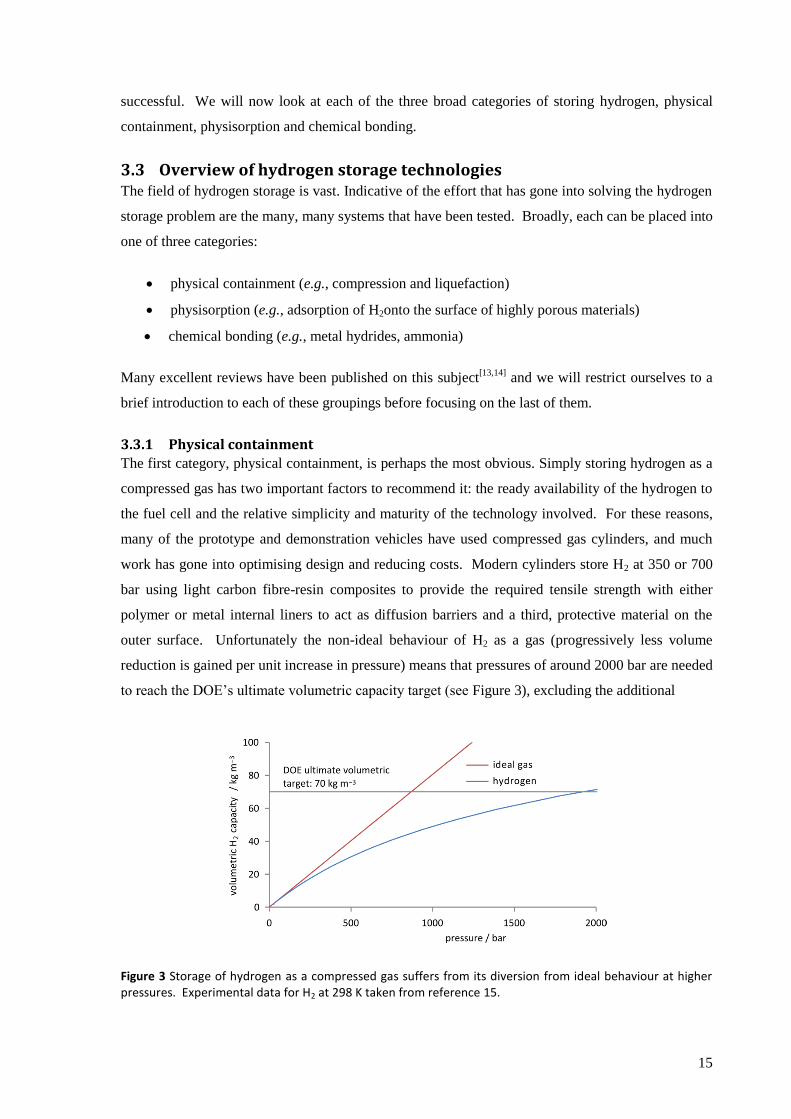
outer surface. Unfortunately the non-ideal behaviour of H2 as a gas (progressively less volume
reduction is gained per unit increase in pressure) means that pressures of around 2000 bar are needed
to reach the DOE’s ultimate volumetric capacity target (see Figure 3), excluding the additional
Figure 3 Storage of hydrogen as a compressed gas suffers from its diversion from ideal behaviour at higher pressures. Experimental data for H2 at 298 K taken from reference 15.
16
system volume. To compound the problem, higher pressure tanks are significantly heavier,
requiring a compromise between the gravimetric and the volumetric capacity. The conclusions from
a comprehensive study were that neither of the current research standard pressures, 350 bar and 700
bar, could produce tanks to meet even the DOE’s 2015 targets.[16]
Liquefaction of H2 by cooling to about 20K is just about able to meet the volumetric targets that
compressed gas fails, if the volume of the tank itself is ignored. As these systems rely on open tanks
to prevent a build-up of dangerous pressures, prevention of boil-off of H2 must be carefully
managed. However, liquid H2 does not present a realistic solution for on-board storage due to the
excessive energy cost of producing liquid hydrogen (an equivalent of 30% of the fuel's energy is
used in the process).
Cryo-compression, however, marries these two inadequate technologies to offer a distinctly
promising alternative. Fuelling with either liquid hydrogen or cooled, compressed H2, (likely a
supercritical fluid, Tc(H2) = 33.24 K, pc(H2) = 12.97 bar[17]
) increases the volumetric capacity, whilst
the ability to withstand high pressures reduces losses from boil-off. With a minimum of one short
journey every two days losses can be all but eliminated and if left for several days there will still be
sufficient compressed gas in the tank to allow the car to be driven a considerable distance.[18]
Perhaps even better, however, the system leaves the choice with the consumer: it may be filled by
either cheaper ambient temperature compressed gas, which provides a lower range but may be
sufficient for the driver’s immediate needs, or more expensive liquid hydrogen if a longer trip is
planned with a wish to avoid re-fuelling. In this way, the designers no longer need to second-guess
the preferences of drivers but rather provide them with the flexibility to choose their fuel to best
meet their requirements. Unfortunately the technology is not ready yet: the high-price of liquefying
H2 must still be paid, the tanks themselves are too expensive and, though improved, the volumetric
capacities (45 g L–1
) are still below the DOE ultimate targets.[19]
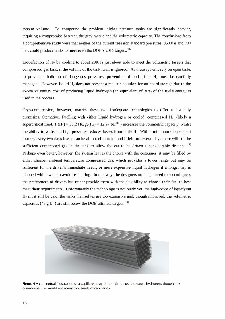
Figure 4 A conceptual illustration of a capillary array that might be used to store hydrogen, though any commercial use would use many thousands of capillaries.
17
A more exotic form of physical containment is micro-encapsulation involving hollow glass
spheres[20]
or capillaries,[21]
(see Figure 4) and at the nano-scale, clathrates,[22]
where a lattice of
molecules (the host) encloses and traps another type of molecule (the guest). In hydrogen storage,
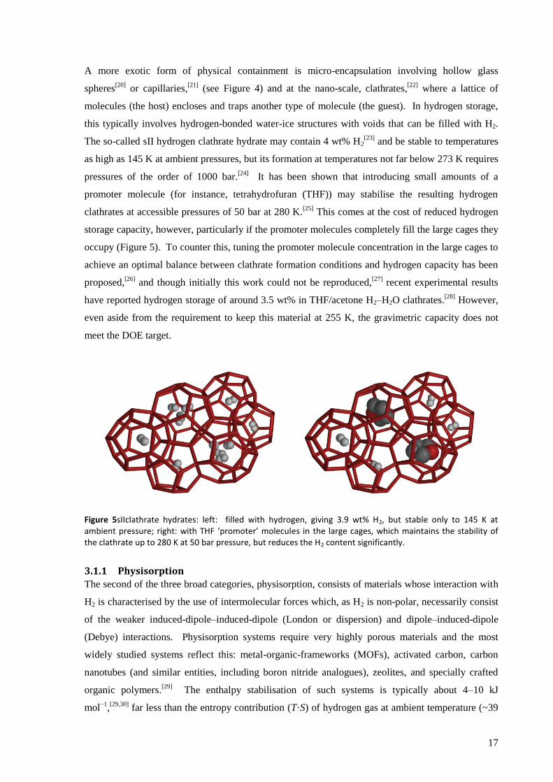
this typically involves hydrogen-bonded water-ice structures with voids that can be filled with H2.
The so-called sII hydrogen clathrate hydrate may contain 4 wt% H2[23]
and be stable to temperatures
as high as 145 K at ambient pressures, but its formation at temperatures not far below 273 K requires
pressures of the order of 1000 bar.[24]
It has been shown that introducing small amounts of a
promoter molecule (for instance, tetrahydrofuran (THF)) may stabilise the resulting hydrogen
clathrates at accessible pressures of 50 bar at 280 K.[25]
This comes at the cost of reduced hydrogen
storage capacity, however, particularly if the promoter molecules completely fill the large cages they
occupy (Figure 5). To counter this, tuning the promoter molecule concentration in the large cages to
achieve an optimal balance between clathrate formation conditions and hydrogen capacity has been
proposed,[26]
and though initially this work could not be reproduced,[27]
recent experimental results
have reported hydrogen storage of around 3.5 wt% in THF/acetone H2–H2O clathrates.[28]
However,
even aside from the requirement to keep this material at 255 K, the gravimetric capacity does not
meet the DOE target.
Figure 5sIIclathrate hydrates: left: filled with hydrogen, giving 3.9 wt% H2, but stable only to 145 K at ambient pressure; right: with THF ‘promoter’ molecules in the large cages, which maintains the stability of the clathrate up to 280 K at 50 bar pressure, but reduces the H2 content significantly.
3.1.1 Physisorption
The second of the three broad categories, physisorption, consists of materials whose interaction with
H2 is characterised by the use of intermolecular forces which, as H2 is non-polar, necessarily consist
of the weaker induced-dipole–induced-dipole (London or dispersion) and dipole–induced-dipole
(Debye) interactions. Physisorption systems require very highly porous materials and the most
widely studied systems reflect this: metal-organic-frameworks (MOFs), activated carbon, carbon
nanotubes (and similar entities, including boron nitride analogues), zeolites, and specially crafted
organic polymers.[29]
The enthalpy stabilisation of such systems is typically about 4–10 kJ
mol−1
,[29,30]
far less than the entropy contribution (T·S) of hydrogen gas at ambient temperature (~39
18
kJ mol−1
) and it is therefore necessary to cool these systems to around liquid nitrogen temperature
(77 K, T·S(H2) = 10 kJ mol−1
) to achieve acceptable performance. It is also possible to overcome the
entropy barrier by storing at high pressure rather than low temperature, but these systems have very
deficient capacities.[31]
Increasing the enthalpy of adsorption allows it to occur at higher temperatures (nearer ambient)
and/or improves capacity. This may be achieved by introducing groups with a higher affinity for H2,
typically involving dissociation of H2 to H atoms, and so moves into the realm of chemisorption, a
grey area between the second and third broad categories. A number of approaches have been
investigated, such as doping carbon materials with boron,[32]
doping with metals to create a ‘spill-
over’ effect[33]
or using ‘built-in’ features such as designing MOFs with more exposed cationic metal
centres.[34]
However, the increased enthalpy of adsorption manifests itself as greater heat generated
on re-fuelling which may require additional components to prevent overheating, thus a compromise
must be struck. Despite the considerable amount of research conducted into physisorption on carbon
substrates, according to Züttel et al. even the most ideal system of graphene sheets covered with full
monolayers of H2 can achieve only 3 wt% H2,[35]
and in the absence of new phenomena beyond
physisorption any such carbon based system will be inadequate. Indeed, none of the physisorption
systems, carbon based or not, meet the DOE targets.[36]
3.1.2 Chemically bound hydrogen
The third broad category is chemically bound hydrogen. Materials containing chemically bound
hydrogen can offer high volumetric capacity, for example, LaNi5H6 (a well-known system), has a
useable volumetric capacity of about 90 g l−1
,[37]
easily surpassing that of liquid hydrogen at
71 g l−1
.[38]
The reversibility is also good, with relatively easy hydrogen uptake and release occurring
around room temperature, with fine-tuning of properties possible by adding additional elements to
the alloy.[37]
This system and many others like it fail, however, on gravimetric capacity, as it contains
a very poor 1.4 wt% H (nominal). The use of such heavy metals (lanthanum’s molar mass is 139 g
mol−1
) is clearly the problem, in fact, the range of elements available for building the hydrogen store
is in practise limited by this mass requirement to combinations of H, Li, B, C, N, O, Na, Mg, Al,
with the exception that period four metals may also be considered in combination with the
exceptionally light, hydrogen rich anions, BH4−and AlH4
−. n.b., Be, F, P and Si are excluded on the
grounds of toxicity and/or awkward chemistry with hydrogen.[14]
It is of course important that the hydrogen is released from the store without too much difficulty.
For chemical stores the corollary of easily released hydrogen is often difficult re-fuelling. For
example, water and a reducing agent are an efficient hydrogen store, the following reaction stores 8
wt% H:
19
2H2O + 2Li→ 2LiOH + H2↑
and there are other substances, such as hydrides, borohydrides and alanates, that will release even
more hydrogen upon reaction with water. However, the products (typically metal hydroxides and
borates) are then too thermodynamically stable to easily regenerate the hydrogen store (i.e., re-fuel
the vehicle). This then requires off-site regeneration which is expensive and often impractical[39]
and
thus to be avoided.
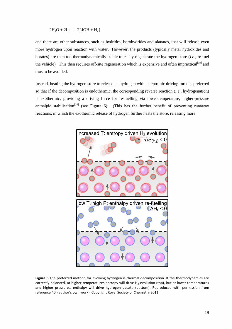
Instead, heating the hydrogen store to release its hydrogen with an entropic driving force is preferred
so that if the decomposition is endothermic, the corresponding reverse reaction (i.e., hydrogenation)
is exothermic, providing a driving force for re-fuelling via lower-temperature, higher-pressure
enthalpic stabilisation[14]
(see Figure 6). (This has the further benefit of preventing runaway
reactions, in which the exothermic release of hydrogen further heats the store, releasing more
Figure 6 The preferred method for evolving hydrogen is thermal decomposition. If the thermodynamics are correctly balanced, at higher temperatures entropy will drive H2 evolution (top), but at lower temperatures and higher pressures, enthalpy will drive hydrogen uptake (bottom). Reproduced with permission from reference 40 (author’s own work). Copyright Royal Society of Chemistry 2011.

20
hydrogen, and so the loop continues). This approach, that the hydrogen should be released by
heating the store (thermal decomposition), was used in the experimental work set out later in this
dissertation.
In order to improve efficiency, it is in practice required that the waste heat of the fuel cell be used to
drive this hydrogen evolution, which, though not a prescription of the DOE,* establishes an
additional target that the hydrogen should be evolved by heating to no more than about 90 °C.†41
Given these constraints, the remaining possible hydrogen stores can be placed in the following main
categories:
metal hydrides (e.g., LiH, MgH2, AlH3 plus mixed cation variants);
complex hydrides (a large group of compounds consisting of hydrogen bound to boron or a
metal to form a hydridic anion balanced by a metal cation. The anions most relevant to
hydrogen storage are BH4− and AlH4
−, forming the borohydrides and alanates respectively)
amides and imides (a set of compounds sometimes erroneously classed as complex
hydrides, but as hydrogen is bound to more electronegative N, the H are protonic in
character, e.g., LiNH2, Li2NH)
ammonia
ammonia boranes and amidoboranes (NH3BH3, which may be reacted with metal hydrides
to form amidoboranes, e.g., reaction with LiH to form LiNH2BH3)
hydrocarbons (involve cycling between saturated and unsaturated forms, e.g.,
cyclohexane ⇌ benzene + 3H2)
The hydrides of sufficiently light metals either decompose at too high a temperature (e.g., LiH
(910 °C),[42]
MgH2 (327 °C),[43]
CaH2 (> 650 °C),[44]
Ca4Mg3H14 (> 300 °C)[45]
or are very difficult to
refuel (e.g., AlH3), making their use as hydrogen stores highly problematic, though the more
favourable bond enthalpy of MgH2 has made it the subject of a lot more research than other metal
hydrides. It decomposes according to the reaction
* Note, the DOE targets do specify that the hydrogen must not enter the fuel cell above 85 °C, but that is a
separate issue from the temperature at which the hydrogen is evolved from the store.
† This value is derived for the common nafion
® membrane fuel cells, which use liquid water as the proton
carrier and cannot operate above 100 °C. One of the goals for PEM fuel cells is to operate at higher
temperatures (using a different class of membrane), even up to 200 °C, so the challenge for the store may
become easier as further progress is made in fuel cells. For a very accessible introduction to the subject, see
reference 41.
21
MgH2 → Mg + H2↑ (T > 327 °C)
The reduced metals formed on hydrogen evolution from such systems (e.g., Mg0 in the equation
above) are highly sensitive to moisture and oxygen, traces of which are highly likely to be present in
the re-fuelling H2 stream, which reduces the effective lifetime of the store.
Of the complex hydrides, monocationic compounds have received most attention (e.g., LiBH4,
Mg(BH4)2, LiAlH4, NaAlH4, Na3AlH6), but given their generally unfavourable thermodynamics (see
Table 2 on page 25) much effort has been put into combining different metal cations with
borohydride or alanate anions to improve this. Notable examples include LiK(BH4)2,[46]
NaZn2(BH4)5[47]
and Na2LiAlH6.[48]
A large scale screening of over 700 borohydride compounds
using computational methods was carried out, which found that (Li/Na/K)(Al/Mn/Fe)(BH4)4,
(Li/Na)Zn(BH4)3 and (Na/K)(Ni/Co)(BH4)3 (where ‘/’ denotes alternatives) may show suitable
thermodynamics[49]
and preliminary experimental results appear to confirm at least some of these
predictions.[50]
Unfortunately, a key problem for the borohydrides is their tendency to release boron
hydrides upon thermal decomposition, for example:
NaBH4 → NaH + B + H2↑ + BxHy↑ (non-stoichiometric equation, reported temperatures
vary, but T > 400 °C required)
which can be toxic, poison fuel cells, and cause depletion of the hydrogen store. The equivalent
aluminium species in the decomposition of the alanates are not volatile and so do not suffer from
potential contaminants of the hydrogen stream, a significant advantage.
Of the amides, LiNH2 has received most interest but evolves hydrogen at too high a temperature.
Various additives (especially metal hydrides) have been used in attempts to improve the hydrogen
uptake/release properties, but none have attained the required standard. These systems are also prone
to ammonia evolution,[51]
leading to contamination of the hydrogen and depletion of the store
(similar to the borohydrides).
Ammonia has been investigated as a hydrogen store, generating hydrogen through onboard
reforming which can even be integrated into the fuel cell. Its major drawback is its toxicity, though
to some extent this may be overcome by storing it in the solid state as ammine complexes with very
low NH3 vapour pressures, such as Mg(NH3)6Cl2.[52]
Ammonia borane, NH3BH3 is an intriguing compound, isoelectronic with ethane but a very different
chemical entity, and nominally capable of storing a massive 19 wt% H (the related chemical
ammonium borohydride, NH4BH4, reaches 24%, the highest wt% H for any solid known, but is
much less stable, decomposing slowly at or even below room temperature[53]
). This family of
22
chemicals also includes the amidoboranes, such as NaNH2BH3, which again have subtly different
chemical characters.[54]
All, however, decompose exothermically (thus requiring off-board
regeneration) and there are concerns over the purity of the hydrogen released. The first stage of
ammonia borane’s thermal decomposition is according to the following equation:
nNH3BH3 → (NH2BH2)n + nH2↑ (T = 70 – 110 °C)
Finally, hydrocarbon systems have been pursued with some vigour, particularly the
methylcyclohexane/toluene, decalin/napthalene and cyclohexane/benzenesystems.[55]
Heteroatoms
may also be introduced, such as in N-ethylcarbazole.[56]
Though their maximum gravimetric
capacities of around 7% are modest, they would require storage tanks only slightly more
sophisticated than those already used in light vehicles, thus mass attributable to the system could be
low compared to cryogenic, compressed gas or complex solid systems. They suffer, however, from
too high decomposition temperatures and difficulty in separating H2 from the organic gases.
Aside: Another proposition is the use of synthetic hydrocarbons formed from CO2 and H2:
nCO2 + (3n+1)H2 CnHn+2 + 2nH2O n = 5 – 12 in petrol (1)
These depart from the hydrogen carriers discussed above in that they would not be used with a fuel
cell (losing the associated efficiency gains), but would be burnt directly in a combustion engine and
so form a direct replacement for fossil hydrocarbons. This would obviate the need for replacing
current fuel distribution infrastructure, a significant benefit, and at this point there is indeed good
reason to think that such liquid fuels may provide a more realistic alternative to fossil fuels.
However, the technology for efficiently carrying out reaction (1) is still far from commercial and as
this promising technology is considered out-of-scope for this dissertation it will not be considered
further.
3.1.3 Alternatives to hydrogen
All these systems have their proponents and their detractors, but none is capable of meeting all the
DOE targets, so let us very briefly consider what other than fossil fuels or hydrogen might be used as
an energy carrier. Compressed air has been mooted as a possible source of locomotion for light
vehicles (see Figure 7), but the energy density is extremely low, less than one twentieth that
prescribed by the DOE for H2.[57]
Flywheels and supercapacitors have excellent characteristics for
fast-charging, ideal for recovering energy through regenerative breaking, but both suffer from low
energy density and energy loss over longer-time periods (through friction and self-discharge,
respectively).[58,59]
Better known and (and probably more viable) solutions include storage in

23
batteries and biomass derived gases or liquids. The former suffer from similar volumetric and
gravimetric hindrances as current hydrogen storage technology,[60]
and the latter from poor
efficiency of land use, concerns over competition with food crops and technological problems
originating from a naturally variable feedstock.[61]
Thus, there is no panacea for energy storage in
light vehicles, and the tough challenges facing hydrogen use are not particularly greater than for
other technologies.
Given this, let us now consider the thermodynamics of the hydrogen storage problem we have set
ourselves and, in order to keep the following discussions within reasonable limits, focus on the
complex hydrides, the targeted stores for the experimental part of this dissertation.
Figure 7 Honda ‘Air’ concept car, envisaged to run on compressed air, submitted to the LA Auto Show’s 2010 LA Design Challenge competition.
3.4 The thermodynamics of the complex hydrides It has long been noted
[62] that analysis of the thermodynamics of the system can be significantly
simplified, without introducing too great an error, by recognising that the entropy change arises
primarily from the transformation of H in the solid to H2 gas and assuming that all other
contributions are negligible.*,[63]
If we further assume that the H in the solid has essentially zero
*Sholl et al. used a range of 100 – 130 J K
−1 (mol H2)
−1 in a similar calculation, the lower bound taken from the
entropy change in the thermal decomposition of LiBH4.[63]
Since then, however, more accurate measurements
have determined the entropy change for this reaction to be 115 J K−1
(mol H2)−1
,[69]
thus the assumption made
appears reasonable.
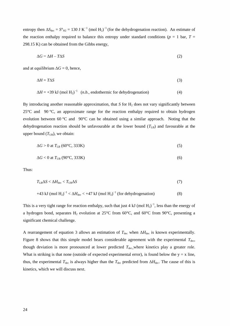
24
entropy then ΔSdec = S°H2 = 130 J K−1
(mol H2)−1
(for the dehydrogenation reaction). An estimate of
the reaction enthalpy required to balance this entropy under standard conditions (p = 1 bar, T =
298.15 K) can be obtained from the Gibbs energy,
ΔG = ΔH – TΔS (2)
and at equilibrium ΔG = 0, hence,
ΔH = TΔS (3)
ΔH = +39 kJ (mol H2)−1
(n.b., endothermic for dehydrogenation) (4)
By introducing another reasonable approximation, that S for H2 does not vary significantly between
25°C and 90 °C, an approximate range for the reaction enthalpy required to obtain hydrogen
evolution between 60 °C and 90°C can be obtained using a similar approach. Noting that the
dehydrogenation reaction should be unfavourable at the lower bound (TLB) and favourable at the
upper bound (TUB), we obtain:
ΔG > 0 at TLB (60°C, 333K) (5)
ΔG < 0 at TUB (90°C, 333K) (6)
Thus:
TLBΔS < ΔHdec < TUBΔS (7)
+43 kJ (mol H2)−1
< ΔHdec < +47 kJ (mol H2)−1
(for dehydrogenation) (8)
This is a very tight range for reaction enthalpy, such that just 4 kJ (mol H2)−1
, less than the energy of
a hydrogen bond, separates H2 evolution at 25°C from 60°C, and 60°C from 90°C, presenting a
significant chemical challenge.
A rearrangement of equation 3 allows an estimation of Tdec when ΔHdec is known experimentally.
Figure 8 shows that this simple model bears considerable agreement with the experimental Tdec,
though deviation is more pronounced at lower predicted Tdec¸where kinetics play a greater role.
What is striking is that none (outside of expected experimental error), is found below the y = x line,
thus, the experimental Tdec is always higher than the Tdec predicted from ΔHdec. The cause of this is
kinetics, which we will discuss next.
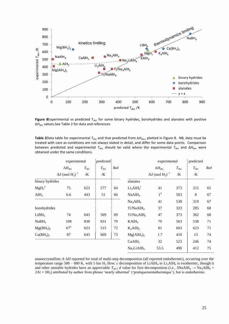
25
Figure 8Experimental vs predicted Tdec for some binary hydrides, borohydrides and alanates with positive ΔHdec values.See Table 2 for data and references
Table 2Data table for experimental Tdec and that predicted from ΔHdec, plotted in Figure 8. NB, data must be treated with care as conditions are not always stated in detail, and differ for some data points. Comparison between predicted and experimental Tdec should be valid where the experimental Tdec and ΔHdec were obtained under the same conditions.
experimental predicted experimental predicted
ΔHdec
/kJ (mol H2)−1
Tdec
/K
Tdec
/K
Ref ΔHdec
/kJ (mol H2)−1
Tdec
/K
Tdec
/K
Ref
binary hydrides
alanates
MgH2a 75 623 577 64 Li3AlH6
c 41 373 315 65
AlH3 6.6 443 51 66 NaAlH4 1d 503 8 67
Na3AlH6 41 538 319 67
borohydrides Ti/NaAlH4 37 323 285 68
LiBH4 74 643 569 69 Ti/Na3AlH6 47 373 362 68
NaBH4 108 838 831 70 KAlH4 70 563 538 71
Mg(BH4)2 67b 623 515 72 K3AlH6 81 603 623 71
Ca(BH4)2 87 643 669 73 Mg(AlH4)2 1.7 410 13 74
CaAlH5 32 523 246 74
Na2LiAlH6 53.5 490 412 75
ananocrystalline; b ΔH reported for total of multi-step decomposition (all reported endothermic), occurring over the
temperature range 580 – 680 K, with 5 bar H2 flow; c decomposition of LiAlH4 to Li3AlH6 is exothermic, though it
and other unstable hydrides have an appreciable Tdec; d value for first decomposition (i.e., 3NaAlH4 → Na3AlH6 +
2Al + 3H2) attributed by author from phrase ‘nearly athermal’ (‘pratiquementathermique’), but is endothermic.
26
3.5 History of catalysis for the decomposition of the complex hydrides It transpires that kinetics is a very important consideration in the realm of complex hydrides. As
shown in Figure 8, the experimentally found Tdec deviates considerably from that expected from
simple theory, and indeed kinetics are the generally accepted cause of this. This can be considered a
better position than where the thermodynamics are at fault, as kinetics can be altered. A kinetic
bottleneck may have a number of different causes, so understanding the mechanism of the reaction
you seek to influence is important. Unfortunately, the decomposition and rehydrogenation reactions
of many of the complex hydrides were not well understood at the time of the initiation of the
experimental work set out in section 6, and it was not known which step was rate-limiting. Even
now, despite extensive efforts from groups around the world, considerable ambiguities remain.
Typical ways of inducing changes in kinetics (which may also cause changes in thermodynamics)
include introduction of defects, nano-structuring, nano-confinement and of course catalysis. Early
work often focused more on the catalyst, but in recent years more sophisticated combinations of
these effects have been employed, in particular the role of mechanical milling has become well-
recognised and its use is standard.
Much work has been done on the development of catalysts for complex hydrides. Bogdanović and
Schwikardi’s seminal paper, published in 1997, on the thermal decomposition of NaAlH4 doped with
Ti[76]
is seen as a turning point, with conclusive evidence for the improved performance of such
stores.* Their report of both lowering the decomposition temperature and significantly increasing re-
hydrogenation at 150 bar H2, sparked renewed enthusiasm for the complex hydrides. Though
impressive, the improvements were not sufficient to solve the hydrogen storage problem, and the
tumult of research that has followed has attempted to build and improve upon their work. NaAlH4
releases H2 in a two stage process:
3NaAlH4 Na3AlH6 + 2Al + 3H2↑ (9)
Na3AlH6 3NaH +Al + 1½H2↑ (10)
Initial work used a ‘wet-doping’ method, where NaAlH4was impregnated with the Ti salt in ether
solution, but this was quickly superseded by the preferred mechanochemical method of high-energy
milling,[77]
which lowered further the temperature required for the first stage in the two-step
decomposition process.[78]
The nature of the salt dopant was also improved from the original
* Though routinely described as a catalysed system, this is not strictly true, as the Ti doping changes the
thermodynamics of the system: c.f. NaAlH4 and Ti/NaAlH4 in Figure 8 and Table 2.
27
Ti(OBun)4 to TiCl3, which itself was a compromise between efficiency and cost (TiF3 is lighter but
more expensive).77
Other metals have been investigated, with a particularly extensive study involving salts of Ag+, Cd
+,
Ce3+
, Co3+
, Cr2+
, Cr3+
, Cu+, Fe
2+, Fe
3+, Ga
3+, Gd
3+, Ge
4+, Hf
4+, Mn
2+, Mo
2+, Nb
4+, Pd
2+, Pt
2+, Rh
3+,
Ru3+
, Sr2+
,Ti2+
,Ti3+
, Ti4+
, V2+
, V3+
, V4+
, Yb3+
, Zn2+
and Zr4+
, all at 2 mol%.[79]
Other studies have also
tested Eu3+
, La3+
, Nd3+
, Pr3+
, Sc3+
and Sm3+
,[80]
and metals Ti, Co and Ni,[81]
thus covering most of
the period 4 and 5 d-block and period 6 f-block metals, and a few others for good measure. Such
studies have shown that Ti (for all the metal cations are reduced to their metallic state in the store), is
one of the best catalysts, and though claims of better performance with other metals have
occasionally been made (e.g., for Sc, Ce and Pr in ref. 80), these all suffer from at least one of:
poor characterisation
marginal improvement
being rare/expensive
and thus have not had a major impact on the research literature.
Doping with more than one salt, however, does appear to achieve more practical improvements, for
example the use of Ti/Zr, with the rationale that Ti is a better catalyst for the first stage of
dehydrogenation (equation 9), and Zr the second (equation 10), providing an overall better
catalyst.[82]
Improvements have also been claimed for Ti/Fe,[83]
with a systematic study of
combinations of the three dopants (Ti, Zr, Fe) reported,[84]
Ti/Sn,[85]
and Ti/(graphite, activated C, or
molecular sieve MSM-41).[86]
However, none of these systems have shown the required properties for hydrogen uptake, storage
and release to make them a viable solution though at least in part this is due to the inherent limits of
NaAlH4, particularly the 5.5 wt% H storage after discounting the H that must remain as NaH. In this
respect, it is a little surprising how much attention NaAlH4 has received, and the argument that it is a
model system being used to learn until the ideal material appears is somewhat diminished given that
the nature of the active catalyst is still disputed. NaAlH4 was the first and perhaps the most studied
of such systems, but many others, such as LiAlH4 and KAlH4, have been tested extensively and none
have proved adequate.
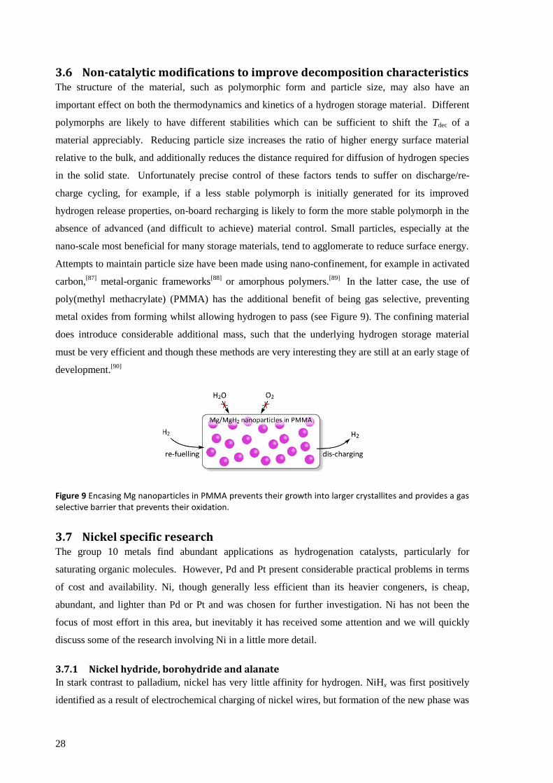
28
3.6 Non-catalytic modifications to improve decomposition characteristics The structure of the material, such as polymorphic form and particle size, may also have an
important effect on both the thermodynamics and kinetics of a hydrogen storage material. Different
polymorphs are likely to have different stabilities which can be sufficient to shift the Tdec of a
material appreciably. Reducing particle size increases the ratio of higher energy surface material
relative to the bulk, and additionally reduces the distance required for diffusion of hydrogen species
in the solid state. Unfortunately precise control of these factors tends to suffer on discharge/re-
charge cycling, for example, if a less stable polymorph is initially generated for its improved
hydrogen release properties, on-board recharging is likely to form the more stable polymorph in the
absence of advanced (and difficult to achieve) material control. Small particles, especially at the
nano-scale most beneficial for many storage materials, tend to agglomerate to reduce surface energy.
Attempts to maintain particle size have been made using nano-confinement, for example in activated
carbon,[87]
metal-organic frameworks[88]
or amorphous polymers.[89]
In the latter case, the use of
poly(methyl methacrylate) (PMMA) has the additional benefit of being gas selective, preventing
metal oxides from forming whilst allowing hydrogen to pass (see Figure 9). The confining material
does introduce considerable additional mass, such that the underlying hydrogen storage material
must be very efficient and though these methods are very interesting they are still at an early stage of
development.[90]
Figure 9 Encasing Mg nanoparticles in PMMA prevents their growth into larger crystallites and provides a gas selective barrier that prevents their oxidation.
3.7 Nickel specific research The group 10 metals find abundant applications as hydrogenation catalysts, particularly for
saturating organic molecules. However, Pd and Pt present considerable practical problems in terms
of cost and availability. Ni, though generally less efficient than its heavier congeners, is cheap,
abundant, and lighter than Pd or Pt and was chosen for further investigation. Ni has not been the
focus of most effort in this area, but inevitably it has received some attention and we will quickly
discuss some of the research involving Ni in a little more detail.
3.7.1 Nickel hydride, borohydride and alanate
In stark contrast to palladium, nickel has very little affinity for hydrogen. NiHx was first positively
identified as a result of electrochemical charging of nickel wires, but formation of the new phase was
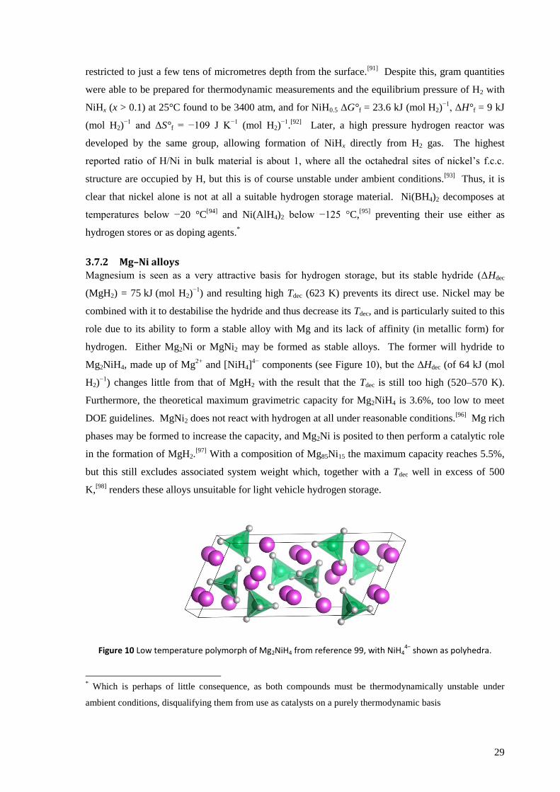
29
restricted to just a few tens of micrometres depth from the surface.[91]
Despite this, gram quantities
were able to be prepared for thermodynamic measurements and the equilibrium pressure of H2 with
NiHx (x > 0.1) at 25°C found to be 3400 atm, and for NiH0.5 ΔG°f = 23.6 kJ (mol H2)−1
, ΔH°f = 9 kJ
(mol H2)−1
and ΔS°f = −109 J K−1
(mol H2)−1
.[92]
Later, a high pressure hydrogen reactor was
developed by the same group, allowing formation of NiHx directly from H2 gas. The highest
reported ratio of H/Ni in bulk material is about 1, where all the octahedral sites of nickel’s f.c.c.
structure are occupied by H, but this is of course unstable under ambient conditions.[93]
Thus, it is
clear that nickel alone is not at all a suitable hydrogen storage material. Ni(BH4)2 decomposes at
temperatures below −20 °C[94]
and Ni(AlH4)2 below −125 °C,[95]
preventing their use either as
hydrogen stores or as doping agents.*
3.7.2 Mg–Ni alloys
Magnesium is seen as a very attractive basis for hydrogen storage, but its stable hydride (ΔHdec
(MgH2) = 75 kJ (mol H2)−1
) and resulting high Tdec (623 K) prevents its direct use. Nickel may be
combined with it to destabilise the hydride and thus decrease its Tdec, and is particularly suited to this
role due to its ability to form a stable alloy with Mg and its lack of affinity (in metallic form) for
hydrogen. Either Mg2Ni or MgNi2 may be formed as stable alloys. The former will hydride to
Mg2NiH4, made up of Mg2+
and [NiH4]4−
components (see Figure 10), but the ΔHdec (of 64 kJ (mol
H2)−1
) changes little from that of MgH2 with the result that the Tdec is still too high (520–570 K).
Furthermore, the theoretical maximum gravimetric capacity for Mg2NiH4 is 3.6%, too low to meet
DOE guidelines. MgNi2 does not react with hydrogen at all under reasonable conditions.[96]
Mg rich
phases may be formed to increase the capacity, and Mg2Ni is posited to then perform a catalytic role
in the formation of MgH2.[97]
With a composition of Mg85Ni15 the maximum capacity reaches 5.5%,
but this still excludes associated system weight which, together with a Tdec well in excess of 500
K,[98]
renders these alloys unsuitable for light vehicle hydrogen storage.
Figure 10 Low temperature polymorph of Mg2NiH4 from reference 99, with NiH44−
shown as polyhedra.
* Which is perhaps of little consequence, as both compounds must be thermodynamically unstable under
ambient conditions, disqualifying them from use as catalysts on a purely thermodynamic basis

30
3.7.3 NiCl2 as catalyst
Kojima et al. found that NiCl2 was a poor catalyst for LiAlH4, and further suggested that it is Al3Ni
that is responsible for the slight improvement that is seen.[100]
Zhang et al. reported more success
when NiCl2 is combined with LiBH4, claiming a reduction in temperature for full decomposition to
just 300°C, attributed to both thermodynamic (destabilisation of LiBH4) and kinetic effects.[101]
However, crucial cycling experiments were not given, and given the reliance on a high doping ratio
(2:1 LiBH4:NiCl2) to achieve full dehydrogenation, together with clear formation of LiCl from XRD
measurements, this suggests an irreversible chemical reaction is responsible for the high desorption
rates. An X-ray absorption spectroscopy study on the LiBH4/MgH2 system, doped with 11 wt%
NiCl2, showed that Ni2+
was reduced to Ni0 and formed nano-clusters with B very similar in
structure to crystalline Ni3B. DFT calculations suggested the (100) surface of these clusters was
capable of facilely splitting H2, and thus responsible for the catalytic affect.[102]
This reduction to
nickel metal can be generally assumed for the simple nickel salts in complex hydrides, and
necessarily results in the formation of an unwanted group 1 or 2 metal salt (such as the LiCl in the
case above), which is very hard to separate and constitutes a dead weight.
3.7.4 Ni metal as catalyst
Doping with Ni metal avoids problem of dead weight, but high surface area is needed. NaAlH4
doped with Ni metal via ball-milling showed very little desorption at 150°C. Ti (metal) shows a
similarly poor result, which is surprising, but as no details were given on the parameters of the Ni
used (e.g. particle size), drawing conclusions from these data is difficult.[103]
The importance of
particle size was confirmed, however, in another study where it was found that 20 nm nanoparticles
were significantly better at improving dehydrogenation than 800 μm particles.100
This is not
surprising given that mass transport is a major issue in solids, and the smaller particles would
achieve greater dispersion in the bulk NaAlH4, thus requiring shorter diffusion distances for any
activated species. Smaller particles also have a larger surface area to mass ratio.
In LiAlH4, Ni nanoparticles lower the first step (equivalent to equation 9) decomposition
temperature to 138°C from 201°C (measured by DSC at 10 K min−1
scanning speed, showing an
exothermic peak), but must be ball-milled, simple mixing is insufficient. This lowers the
decomposition below LiAlH4’s melting point of about 150°C essentially preventing its melting,[104]
but the process is still exothermic, precluding on-board refuelling. The same group also studied the
change in activation energy, finding a reduction from 92.5 kJ mol−1
for undoped ball-milled LiAlH4
to 70 kJ mol−1
for nano-Ni doped LiAlH4 for the decomposition to Li3AlH6. Interestingly, the
activation energy for the decomposition of Li3AlH6 to LiH, Al and H2 (step 2) is reported as
31
increasing from 92.5 kJ mol−1
to 100 kJ mol−1
, though the kinetics improve.[105]
This suggests
something is amiss with these results.
In combination with LiBH4, Ni powder (40 μm) (2:1 mol ratio) releases 4.5 wt% hydrogen at
400°C, 1 bar H2, against 1.9 wt% for undoped LiBH4,[106]
though this improvement is still
insufficient for a useful application. Ni nano-particles were found to reduce the decomposition
temperature of LiMn(BH4)3, but perform badly with hydrogenation/dehydrogenation cycling.[107]
The effect of Ni in combination with single-walled carbon nanotubes (SWNT) balled milled with
LiBH4 was investigated by Fang et al., showing a considerable reduction in decomposition
temperature, though control experiments using Ni powder (< 100 nm particle size) and Ni2B showed
a similar effect. They maintained their claim that the SWNTs did have an effect, however, having
used purified SWNTs (Ni was present from the SWNT manufacturing method) with similar results,
but do not describe the purification process used,[108]
so it is not possible to know how rigorous this
was. Ni-decorated activated carbon was found to catalyse dehydrogenation of NaAlH4 beyond that
attributable to the nano-confinement in the carbon matrix, but Ti was a still better catalyst.[109]
Of
course such systems suffer considerably from the additional mass of the carbon.
3.8 Decomposition temperature and the standard electrode potential Testing of these metals (not just nickel) has failed to produce a suitable system. Though there is the
possibility that a new combination of metals might provide the required breakthrough, as more
permutations have been tested the possibility becomes more and more remote. Thus it seemed that
the problem would benefit from a new paradigm, a new type of catalyst.
Inpiration for such a catalyst came from the valuable insight that a relationship existed between Tdec
and the standard reduction potential, shown in Figure 11*,[14]
. Considering the dehydrogenation
reaction, and assuming that the catalyst achieves its activity by binding hydrogen prior to evolution,
the reaction of the hydrogenated metal catalyst is equivalent to the decomposition reactions that
form this pattern. Thus, if the relationship holds true, we may predict the effect that altering a metal
catalyst’s reduction potential may have on its Tdec. The power of this insight comes from the fact
that it is well-known that a metal’s reduction potential may be altered by modifying its chemical
environment, and in particular complexation of suitable ligands can produce a strong effect. This
* The relationship was elucidated by recognising similarities between the processes involved in the heat of
formation (the reverse of ΔHdec) of a metal hydride and reduction of a metal in solution. See reference 14,
sections 4 and 5.

32
potentially allows us to tune the hydrogenation/dehydrogenation properties to suit our needs by
careful choice of ligand type and geometry.
In consequence, rather than use bald metal or simple salts, we chose to investigate transition metal
complexes as catalysts for use with the complex hydrides, into which there is a surprising dearth of
research despite the myriad possibilities they provide. Furthermore, chelate and macrocycle ligands
may create more stable complexes than the equivalent monodentate versions, which seems a
valuable factor in the extreme reducing environments the intended catalysts are to work in. We
continue, then, with a more general introduction to chelates and macrocycles from which inspiration
may be drawn for our experimental work.
Figure 11 Exposition of the relationship between Tdec and E°.Reproduced with permission from reference 14. Copyright 2004 American Chemical Society.
33
References 1 Eurostat, Final energy consumption by sector, (CSI 027/ENER 016), September 2010.
2 U.S. Energy Information Administration, International Energy Outlook 2010, DOE/EIA-0484(2010), July
2010, p. 237. n.b., the report draws a distinction between total energy and delivered energy, which
excludes electricity-related losses, and states transport makes up 27 % of delivered energy (p. 15). Here
we use the total energy figure to calculate the percent attributable to transport, as this seems the fairer
treatment in this case.
3 Road transport accounts for 71 % of transport energy consumption in the EU: Eurostat, Transport final
energy consumption by mode, (TERM 001), January 2011.
4 D. F. Shriver, P. W. Atkins, Inorganic Chemistry, 3rd
Ed., OUP, Oxford, 1999, p.279.
5 M. Z. Jacobson, W. G. Colella, D. M. Golden, Science, 2005, 308, 1901.
6 marketsandmarkets.com, Hydrogen Generation Market - by Merchant & Captive Type, Distributed &
Centralized Generation, Application & Technology - Trends & Global Forecasts (2011 - 2016), December
2011, accessed online:http://www.marketsandmarkets.com/Market-Reports/hydrogen-generation-
market-494.html
7 C. A. Callaghan, PhD Thesis, Kinetics and Catalysis of the Water-Gas-Shift Reaction: A Microkinetic and
Graph Theoretic Approach, Worcester Polytechnic Institute, 2006, p. 41.
8 S. Dillich, Hydrogen Production Sub-Program Overview, in U.S. Department of Energy Hydrogen Program
Annual Progress Report 2010, DOE/GO-102011-3178,February 2011, pp. 19-22.
9 S. Dillich, Hydrogen Production Sub-Program Overview,inU.S. Department of Energy Hydrogen Program
Annual Progress Report 2010, DOE/GO-102011-3178,February 2011, pp. 251-254.
10 D.Papageorgopoulos, Fuel Cells Sub-Program Overview, in U.S. Department of Energy Hydrogen
Program Annual Progress Report 2010, DOE/GO-102011-3178,February 2011, pp. 655-660.
11 N. Stetson, Hydrogen Production Sub-Program Overview, in U.S. Department of Energy Hydrogen
Program Annual Progress Report 2010, DOE/GO-102011-3178,February 2011, pp. 351-359.
12 US Department of Energy Office of Energy Efficiency and Renewable Energy and The FreedomCAR and
Fuel Partnership, Targets for Onboard Hydrogen Storage Systems for Light-Duty Vehicles, 2009,
http://www1.eere.energy.gov/hydrogenandfuelcells/storage/pdfs/targets_onboard_hydro_storage_ex
planation.pdf
13 L. Schlapbach, A. Züttel, Nature, 2001, 414, 353; B. Sakintuna, F. Lamari-Darkrim, M. Hirscher,
International Journal of Hydrogen Energy, 2007, 32, 1121; J. Graetz, Chemical Society Reviews, 2009, 38,
73;J. Yang, A. Sudik, C. Wolverton, D. J. Siegel, Chemical Society Reviews, 2010, 39, 656.
14 W. Grochala, P. P. Edwards, Chemical Reviews, 2004, 104, 1283.
15 A. Michels, W. De Graaff, T. Wassenaar, J. M. H. Levelt, P. Louwerse, Physica, 1959, 25, 25 cited in M.
Tkacz, A. Litwiniuk, Journal of Alloys and Compounds, 2002, 330-332, 89.
16
T. Q. Hua, R. K. Ahluwalia, J.-K.Peng, M. Kromer, S. Lasher, K. McKenney, K. Law, J. Sinha, International
Journal of Hydrogen Energy, 2011, 36, 3037.
17 J. G. Speight, Lange’s Handbook of Chemistry, Section 1: Inorganic Chemistry, McGraw-Hill, 16th
Ed.,
2005, p. 235.
18 S. M. Aceves, F. Espinosa-Loza, E. Ledesma-Orozco, T. O. Ross, A. H. Weisberg, T. C. Brunner, O. Kircher,
International Journal of Hydrogen Energy, 2010, 35, 1219.
19 R. K. Ahluwalia, T. Q. Hua, J.-K.Peng, S. Lasher, K. McKenney, J. Sinha, M. Gardiner, International Journal
of Hydrogen Energy, 2010, 35, 4171.
34
20 D. Kohli, R. Khardekar, R. Singh, P. Gupta, International Journal of Hydrogen Energy, 2008, 33, 417.
21 N. K. Zhevago, E. I. Denisov, V. I. Glebov, International Journal of Hydrogen Energy, 2010, 35, 169.
22 V. V. Struzhkin, B. Militzer, W. L. Mao, H.-K. Mao, R. J. Hemley, Chemical Reviews, 2007, 107, 4133.
23 K. Lokshin, Y. Zhao, D. He, W. Mao, H.-K.Mao, R. Hemley, M. Lobanov, M. Greenblatt, Physical Review
Letters, 2004, 93, 1.
24 W. L. Mao, H.-k. Mao, A. F. Goncharov, V. V. Struzhin, Q. Guo, J. Hu, J. Shu, R. J. Hemley, M. Somayazulu,
Y. Zhao, Science,2002, 297, 2247.
25 L. J. Florusse, C. J. Peters, J. Schoonman, K. C. Hester, C. A. Koh, S. F. Dec, K. N. Marsh, E. D. Sloan,
Science,2004, 306, 469.
26 H. Lee, J. W. Lee, D. Y. Kim, J. Park, Y. T. Seo, H. Zeng, I. L. Moudrakovski, C. I. Ratcliffe, J. A. Ripmeester,
Nature,2005, 434, 743.
27 T. A. Strobel, C. J. Taylor, K. C. Hester, S. F. Dec, C. a Koh, K. T. Miller, E. D. Sloan, The Journal of Physical
Chemistry. B, 2006, 110, 17121.
28 T. Sugahara, J. C. Haag, P. S. R. Prasad, A. A. Warntjes, E. D. Sloan, A. K. Sum, C. A. Koh, Journal of the
American Chemical Society,2009, 131, 14616; T. Sugahara, J. C. Haag, A. A. Warntjes, P. S. R. Prasad, E.
D. Sloan, C. A. Koh, A. K. Sum, Journal of Physical Chemistry C,2010, 114, 15218.
29
K. M. Thomas, Catalysis Today, 2007, 120, 389.
30 B. Schmitz, U. Müller, N. Trukhan, M. Schubert, G. Férey, M. Hirscher, ChemPhysChem, 2008, 9, 2181.
31 L. J. Simpson, Overview of the DOE Hydrogen Sorption Center of Excellence, U.S. Department of Energy
Hydrogen Program Annual Progress Report 2010, DOE/GO-102011-3178,February 2011.
32
L. Firlej, S. Roszak, B. Kuchta, P. Pfeifer, C. Wexler, Journal of Chemical Physics, 2009, 131, 164702.
33 A. Lueking, R. Yang, Applied Catalysis A, 2004, 265, 259.
34 J. G. Vitillo, L. Regli, S. Chavan, G. Ricchiardi, G. Spoto, P. D. C. Dietzel, S. Bordiga, A. Zecchina, Journal of
the American Chemical Society, 2008, 130, 8386.
35 A. Züttel, A. Remhof, A. Borgschulte, O. Friedrichs, Philosophical Transactions Series A, 2010, 368, 3329.
36 U. Eberle, M. Felderhoff F. Schüth, AngewandteChemie, International Edition,2009, 48, 6608.
37 G. Sandrock, Journal of Alloys and Compounds, 1999, 295, 877.
38 http://encyclopedia.airliquide.com/Encyclopedia.asp?GasID=36 (retrieved on 10/11/2011)
39 US Department of Energy, Go/No-Go Recommendation for Sodium Borohydride for On-Board Vehicular
Hydrogen Storage, NationalRenewable Energy Laboratory Report, NREL/MP-150-42220.
40 A. J. Churchard, E. M. Banach, A. Borgschulte, R. Caputo, J.-C. Chen, D. Clary, K. J. Fijalkowski, H.
Geerlings, R. V. Genova, W. Grochala, T. Jaroo, J. C. Juanes-Marcos, B. Kasemo, G.-J.Kroes, I. Ljubid, N.
Naujoks, J. K. Nørskov, R. A. Olsen, F. Pendolino, A. Remhof, L. Románszki, A. Tekin, T. Vegge, M. Zäch,
A. Züttel, Physical Chemistry Chemical Physics, 2011, 13, 16955.
41 L. Gubler, G. G. Scherer, Desalination, 2010, 250, 1034.
42 J. Sangster,A. D. Pelton, in Phase Diagrams of Binary Hydrogen Alloys, Ed.F. D. Manchester, ASM
International, Materials Park, Ohio,2000; p 74. cited in J. J. Vajo, F. Mertens, C. C. Ahn, R. C. Bowman,, B.
Fultz, The Journal of Physical Chemistry B, 2004, 108, 13977.
43 A. Zaluska, L. Zaluski, J. O. Ström–Olsen, Journal of Alloys and Compounds, 1999, 288, 217.
44 Z. Xiong, P. Chen, G. Wu, J. Lin, K. Lee Tan, Journal of Materials Chemistry, 2003, 13, 1676.
45 K. Yvon, ZeitschriftfürKristallographie, 2003, 218, 108.
35
46 E. A. Nickels, M. O. Jones, W. I. F. David, S. R. Johnson, R. L. Lowton, M. Sommariva, P. P. Edwards,
AngewandteChemie, International Edition, 2008, 47, 2817.
47 D. Ravnsbaek, Y. Filinchuk, Y. Cerenius, H. J. Jakobsen, F. Besenbacher, J. Skibsted, T. R. Jensen,
AngewandteChemie, International Edition,2009, 48, 6659.
48 J. Graetz, Y. Lee, J. Reilly, S. Park, T. Vogt, Physical Review B, 2005, 71, 184115.
49 J. S. Hummelshøj, D. D. Landis, J. Voss, T. Jiang, A. Tekin, N. Bork, M. Dułak, J. J. Mortensen, L. Adamska,
J. Andersin, J. D. Baran, G. D. Barmparis, F. Bell, A. L. Bezanilla, J. Bjork, M. E. Björketun, F. Bleken, F.
Buchter, M.Bürkle, P. D. Burton, B. B. Buus, A. Calborean, F. Calle-Vallejo, S. Casolo, B. D. Chandler, D. H.
Chi, I. Czekaj, S. Datta, A. Datye, A. DeLaRiva, V. Despoja, S. Dobrin, M. Engelund, L. Ferrighi, P.
Frondelius, Q. Fu, A. Fuentes, J. Fürst, A. García-Fuente, J. Gavnholt, R. Goeke, S. Gudmundsdottir, K. D.
Hammond, H. A. Hansen, D. Hibbitts, E. Hobi, J. G. Howalt, S. L. Hruby, A. Huth, L. Isaeva, J. Jelic, I. J. T.
Jensen, K. A. Kacprzak, A. Kelkkanen, D. Kelsey, D. S. Kesanakurthi, J. Kleis, P. J. Klüpfel, I. Konstantinov,
R. Korytar, P. Koskinen, C. Krishna, E. Kunkes, A. H. Larsen, J. M. G. Lastra, H. Lin, O. Lopez-Acevedo, M.
Mantega, J. I. Martínez, I. N. Mesa, D. J. Mowbray, J. S. G. Mýrdal, Y. Natanzon, A. Nistor, T. Olsen, H.
Park, L. S. Pedroza, V. Petzold, C. Plaisance, J. A. Rasmussen, H. Ren, M. Rizzi, A. S. Ronco, C. Rostgaard,
S. Saadi, L. A. Salguero, E. J. G. Santos, A. L. Schoenhalz, J. Shen, M. Smedemand, O. J. Stausholm-Møller,
M. Stibius, M. Strange, H. B. Su, B. Temel, A. Toftelund, V. Tripkovic, M. Vanin, V. Viswanathan, A.
Vojvodic, S. Wang, J. Wellendorff, K. S. Thygesen, J. Rossmeisl, T. Bligaard, K. W. Jacobsen, J. K. Nørskov,
T. Vegge, Journal of Chemical Physics, 2009, 131, 014101.
50 I. Lindemann, R. DomènechFerrer, L. Dunsch, Y. Filinchuk, R. Cerný, H. Hagemann, V. D’Anna, L. M.
Lawson Daku, L. Schultz, O. Gutfleisch, Chemistry - A European Journal, 2010, 16, 8707; I. Lindemann, R.
D. Ferrer, L. Dunsch, R. Černý, H. Hagemann, V. D’Anna, Y. Filinchuk, L. Schultz, O. Gutfleisch, Faraday
Discussions, 2011, 151, 231.
51 H. Wu, Journal of the American Chemical Society, 2008, 130, 6515.
52 R. Z. Sørensen, J. S. Hummelshøj, A. Klerke, J. B. Reves, T. Vegge, J. K. Nørskov, C. H. Christensen, Journal
of the American Chemical Society, 2008, 130, 8660.
53 A. Karkamkar, S. M. Kathmann, G. K. Schenter, D. J. Heldebrant, N. Hess, M. Gutowski, T. Autrey,
Chemistry of Materials, 2009, 21, 4356.
54 Z. Xiong, C. K. Yong, G. Wu, P. Chen, W. Shaw, A. Karkamkar, T. Autrey, M. O. Jones, S. R. Johnson, P. P.
Edwards, W. I. F. David, Nature Materials, 2008, 7, 138;K. J. Fijałkowski, W. Grochala, Journal of
Materials Chemistry, 2009, 19, 2043; K. J. Fijałkowski, R.V. Genowa, Y. Filinchuk, A. Budzianowski, M.
Derzsi, P. Leszczyoski, W. Grochala, Dalton Transactions,2011, 40, 4407.
55 K. Oda, K. Akamatsu, T. Sugawara, R. Kikuchi, A. Segawa, S.-ichiNakao, Industrial & Engineering
Chemistry Research,2010, 49, 11287.
56 D. Teichmann, W. Arlt, P. Wasserscheid, R. Freymann, Energy & Environmental Science,2011, 4, 2767.
57 H. Chen, Y. Ding, Y. Li, X. Zhang, C. Tan, Applied Energy, 2011, 88, 337.
58 A. Boretti, International Journal of Hydrogen Energy, 2010, 35, 8417.
59 P. Bentley, D. A. Stone, N. Schofield, Journal of Power Sources, 2005, 147, 288.
60 X.-P. Gao, H.-X. Yang, Energy & Environmental Science, 2010, 3, 174.
61 S. N. Naik, V. V. Goud, P. K. Rout, A. K. Dalai, Renewable and Sustainable Energy Reviews, 2010, 14, 578.
62 H. Oesterreicher, Applied Physics, 1981, 24, 169; N.B. we use a figure for ΔS°(H2) of 130 J K−1
mol−1
rather than 120 J K−1
mol−1
used by Oesterreicher.
63 S. V. Alapati, J. K. Johnson, D. S. Sholl, Physical Chemistry Chemical Physics, 2007, 9, 1438.
36
64 A. Zaluska, L. Zaluski, J. O. Ström-Olsen, Journal of Alloys and Compounds, 1999, 288, 217.
65 J. Chen, N. Kuriyama, Q. Xu, H. T. Takeshita, T. Sakai, Journal of Physical Chemistry B, 2001, 105, 11214.
66 J. Graetz, J. J. Reilly, J. G. Kulleck, R. C. Bowman, Journal of Alloys and Compounds, 2007, 446-447, 271.
67 P. Claudy, B. Bonnetot, G. Chahine, J. M. Letoffe, ThermochimicaActa, 1980, 38, 75.
68 B. Bogdanovid, R. A. Brand, A. Marjanovic, M. Schwickardi, J. Tolle, Journal of Alloys and Compounds,
2000, 302, 36.
69 P. Mauron, F. Buchter, O. Friedrichs, A. Remhof, M. Bielmann, C. N. Zwicky, A. Züttel, Journal of Physical
Chemistry. B, 2008, 112, 906.
70 P. Martelli, R. Caputo, A. Remhof, P. Mauron, A. Borgschulte, A. Züttel, Journal of Physical Chemistry C,
2010, 114, 7173.
71 J. R. Ares, K.-F.Aguey-Zinsou, F. Leardini, I. J. Ferrer, J.-francisco Fernandez , Z.-xiaoGuo, C. Sanchez,
Journal of Physical Chemistry C, 2009, 113, 6845.
72 K. Chłopek, C. Frommen, A. Léon, O. Zabara, M. Fichtner, Journal of Materials Chemistry, 2007, 17,
3496.
73 J. Mao, Z. Guo, C. K. Poh, A. Ranjbar, Y. Guo, X. Yu, H. Liu, Journal of Alloys and Compounds, 2010, 500,
200.
74 M. Mamatha, B. Bogdanovid, M. Felderhoff, a Pommerin, W. Schmidt, F. Schüth, C. Weidenthaler,
Journal of Alloys and Compounds, 2006, 407, 78.
75 J. Graetz, Y. Lee, J. Reilly, S. Park, T. Vogt, Physical Review B, 2005, 71, 1.
76 B. Bogdanovic M. Schwickardi, Journal of Alloys and Compounds, 1997, 253, 1.
77 B. Bogdanovid, F. Michael, S. Guido, Journal of the Serbian Chemical Society, 2009, 74, 183.
78 C. M. Jensen, K. J. Gross, Applied Physics A Materials Science & Processing, 2001, 72, 213.
79 D. L. Anton, Journal of Alloys and Compounds, 2003, 356-357, 400.
80 B. Bogdanovid, M. Felderhoff, A Pommerin, F. Schüth, N. Spielkamp, Advanced Materials, 2006, 18,
1198.
81 Z. Xueping, L. Shenglin, L. Donglin, International Journal of Hydrogen Energy, 2009, 34, 2701.
82 R. A. Zidan, S. Takara, A. G. Hee, C. Jensen, International Journal of Hydrogen Energy, 1999, 24, 461.
83 B. Bogdanovid, R. A. Brand, A. Marjanovic, M. Schwickardi, J. Tolle, Journal of Alloys and Compounds,
2000, 302, 36.
84 J. Wang, A. D. Ebner, R. Zidan, J. A. Ritter, Journal of Alloys and Compounds, 2005, 391, 245.
85 Q. J. Fu, S. C. Tsang, Fuel, 2006, 85, 2141.
86 Y. Suttisawat, P. Rangsunvigit, B. Kitiyanan, S. Kulprathipanja, International Journal of Hydrogen Energy,
2008, 33, 6195; J. Wang, A. Ebner, T. Prozorov, R. Zidan, J. Ritter, Journal of Alloys and Compounds,
2005, 395, 252.
87 M. Fichtner, Z. Zhao-Karger, J. Hu, A. Roth, P. Weidler, Nanotechnology, 2009, 20, 204029.
88 E. M. Banach, H. A. Stil, H. Geerlings, Journal of Materials Chemistry, 2012, 22, 324.
89 K.-J. Jeon, H. R. Moon, A. M. Ruminski, B. Jiang, C. Kisielowski, R. Bardhan, J. J. Urban, Nature Materials,
2011, 10, 286.
90 P. E. de Jongh, P. Adelhelm, ChemSusChem, 2010, 3, 1332-48; R. Bardhan, A. M. Ruminski, A. Brand, J. J.
Urban, Energy & Environmental Science, 2011, 4, 4882.
91 B. Baranowski, S. M. Filipek, Journal of Alloys and Compounds, 2005, 404-406, 2.

37
92 B. Baranowski, K. Bocheoska, ZeitschriftfürPhysikalischeChemie, 1965, 45, 140.
93 M. Hanson, H. J. Bauer, Journal of Alloys and Compounds, 1992, 179, 339.
94 J. Aubry, G. Monnier, Bulletin de la SociétéChimique de France, 1955, 4, 482.
95 G. Monnier, Bulletin de la SociétéChimique de France, 1955, 1138.
96 S. Orimo, H. Fujii, Applied Physics A Materials Science & Processing, 2001, 72, 167.
97 J. J. Reilly, R. H. Wiswall, Inorganic Chemistry, 1968, 7, 2254.
98 E. A. Lass, Materials Chemistry and Physics, 2011, 130, 937.
99 P. Zolliker, K. Yvon, J. D. Jorgensen, F. J. Rotella, Inorganic Chemistry, 1986, 25, 3590.
100 Y. Kojima, Y. Kawai, M. Matsumoto, T. Haga, Journal of Alloys and Compounds, 2008, 462, 275.
101 B. J. Zhang, B. H. Liu, International Journal of Hydrogen Energy, 2010, 35, 7288.
102 J. Graetz, S. Chaudhuri, T. T. Salguero, J. J. Vajo, M. S. Meyer, F. E. Pinkerton, Nanotechnology, 2009, 20,
204007.
103 Z. Xueping, L. Shenglin, L. Donglin, International Journal of Hydrogen Energy, 2009, 34, 2701.
104 R. A. Varin, L. Zbroniec, T. Czujko, Z. S. Wronski, International Journal of Hydrogen Energy, 2011, 36,
1167.
105 R. A. Varin, L. Zbroniec, Journal of Alloys and Compounds, 2010, 506, 928.
106 G. L. Xia, Y. H. Guo, Z. Wu, X. B. Yu, Journal of Alloys and Compounds, 2009, 479, 545.
107 P. Choudhury, S. S. Srinivasan, V. R. Bhethanabotla, Y. Goswami, K. McGrath, E. K. Stefanakos,
International Journal of Hydrogen Energy, 2009, 34, 6325; R. A. Varin, L. Zbroniec, International Journal
of Hydrogen Energy, 2010, 35, 3588.
108 Z. Z. Fang, X. D. Kang, H. B. Dai, M. J. Zhang, P. Wang, H. M. Cheng, ScriptaMaterialia, 2008, 58, 922.
109 S. S.-Y. Lin, J. Yang, H. H. Kung, International Journal of Hydrogen Energy, 2012, 37, 2737.

38

39
4 Introduction to chelates and macrocycles
4.1 The chelate effect .......................................................................................................................40
4.1.1 Thermodynamic origins ..................................................................................................... 40
4.1.2 Kinetic origins .................................................................................................................... 41
4.2 The macrocyclic effect ...............................................................................................................41
4.3 General classification and characterisation of chelates and macrocycles ..................................43
4.4 Synthesis ....................................................................................................................................46
4.5 Selection of donors .....................................................................................................................49
4.6 Crystal structures of chelates and macrocycles with N, S and P donors ....................................50
4.6.1 Bidentate chelates ............................................................................................................... 50
4.6.2 Higher dentate chelates ...................................................................................................... 52
4.6.3 Macrocycles ....................................................................................................................... 55
4.6.4 Milling of molecular crystals ............................................................................................. 58
4.7 Electrochemistry ........................................................................................................................62
4.7.1 Ligand effects on the reduction potential of Nin+
............................................................... 62
4.7.2 Speculation on the similarities between the reduction of H2 and CO2 by [Ni(cyclam)]2+
.. 64
4.7.3 Speculation on expulsion of halide from [NiII(η
4-PP3)L]
+ complexes ............................... 65
4.8 Mixed donor chelates and macrocycles......................................................................................67
References ..............................................................................................................................................70

40
4.1 The chelate effect
Chelation is a property of a coordination complex where at least one ligand is bound to the central
atom by two separate donor atoms simultaneously (the simultaneity is what differentiates it from an
ambidentate ligand, which may bind using either of two donors but not both at the same time to the
same atom). The word originates from the ancient Greek for claw, χηλαί,[1]
(chelai) used because of
the similarity of the ligands to lobster claws grasping the central atom (Figure 1).
Figure 1 Lobsters chelating a central atom with their claws (not to scale)
The physical and chemical differences caused by chelation are usually called the chelate effect, and
arise from the increased stability of a complex with a multidentate ligand compared to a complex
with the equivalent monodentate ligands. The origin of the effect has been the subject of some
debate over the years, with a number of explanations of both a thermodynamic and kinetic nature
being put forward.[2]
4.1.1 Thermodynamic origins
The thermodynamic effect may arise from both entropic and enthalpic contributions. In broad terms,
an unbound but potentially chelating ligand has fewer degrees of translational freedom than its
monodentate equivalents, and thus lower entropy. However, once a complex is formed, the
translational entropy of the chelated and monodentate complexes are essentially the same. This
leads to greater stability for the chelated complex as the entropic driving force for dissociating the
chelating ligand is smaller than for the monodentate equivalents. Working against the stability of the
chelation complex is the reduced rotational freedom on chelation (due to the formation of a cycle
including the central atom),[3]
but due to the greater influence of translational entropy, the overall
effect is for chelate stabilisation. Thus, a chelating ligand may displace similar monodentate ligands
from a complex in solution.
The enthalpic contribution to the macrocyclic effect is more complex. It may be positive or
negative, and may be negligible or of significant magnitude, depending on the system. A stabilising
enthalpic contribution may arise if the chelating ligand is less well solvated than the monodentate
equivalents, or if electrostatic or steric repulsions in the monodentate complex are significant, in
which case the chelate may have them „built-in‟ to the ligand, and thus no further enthalpy price

41
need be paid upon complexation. A destabilising contribution may arise from ring strain, where the
ring formed on chelation causes sub-optimal bond angles. Combinations of such effects lead to the
considerable variation in magnitude possible. These effects are very system specific and will not be
entered into in detail here. There seems to be a general consensus in the modern literature that the
chelate effect arises predominantly from entropic considerations, with the proportion arising from
enthalpy heavily dependent on the specifics of the individual system.
4.1.2 Kinetic origins
The kinetic explanation (which does not exclude the thermodynamic considerations above) arises
from the increased apparent concentration of the second (and subsequent) donor. It is likely that the
attachment of the first donor of a chelating ligand will be comparable to that of an equivalent
monodentate ligand. However, once bound to the central atom, the other donor site(s) on the
chelating ligand is (are) necessarily kept in the vicinity of the central atom, increasing the chance of
a close encounter that may lead to bonding (equivalent to an increase in the local concentration).
Similarly, in order to dissociate the ligand once a chelate complex is formed all bonds must be
broken, with the increased likelihood that any broken bond will reconstitute before the other
required bonds are broken, a statistically less likely event than that required to remove the equivalent
monodentate ligands, where each bond breakage is (to a first approximation) an independent event.
4.2 The macrocyclic effect
Figure 2 shows a series of ligands based on NHx which form increasingly stable complexes with a
typical metal cation, progressing from monodentate NH3, to the chelates en and trien. It should be
clear from the figure that the next step is to complete the ring and form a macrocycle.
Figure 2 A series of ligands based on NHx, demonstrating the chelate and macrocyclic effects.
Such molecules have been known for a long time, for example Lüttringhaus and Ziegler reported
macrocyclic polyethers in 1937,[4]
but it wasn‟t until the 1960s that their role as macrocyclic ligands
became mainstream.[5]
In 1960 Pedersen began his work on the crown-ethers (for which he would
win the 1987 Nobel Prize),[6]
publishing his first paper on the subject in 1967,[7]
and Curtis did much
of the early work on the cyclic amines in the early 1960s.[8]
In 1969, Cabbiness and Margerum

42
described the macrocyclic effect as the increased stability of a closed ring ligand as compared to its
open chain equivalent,[9]
and differentiated it from the chelate effect in not originating from changes
in translational entropy (thus a macrocycle benefits from both the chelate and macrocyclic effects
when compared to monodentate equivalents). In modern coordination chemistry, a generally
accepted definition of a macrocycle is for it to have at least nine members in the ring with at least
three donor atoms.[10]
(It is worth mentioning that organic chemists not concerned with the
molecule‟s function as a ligand tend not to include the need for donor capable atoms in their
definition of macrocycles.)
As with chelation, the precise cause of the effect has been the subject of quite some debate.
Margerum (who first reported the effect) and co-workers came down heavily on the side of enthalpic
effects dominating[11]
(originating in a similar fashion to the stabilising enthalpy effects associated
with the chelate effect), whilst others considered entropy to be of greater importance.[12]
Martell and
Hancock claim that the entropy contribution dwindles to insignificance if you compare macrocyclic
and chelating complexes of similar steric strain,[13]
and thus raise the issue of what, by definition,
should the macrocyclic effect be considered to encompass (it was named before it was understood,
thus there is some ambiguity). Furthermore, Busch suggests that chelation complexes may suffer
from an increased dissociation rate of donors located at the „end‟ of ligands due to steric strain
relative to monodentate ligands; macrocycles do not have such end groups, so benefit from enhanced
kinetic stability.[14]
The many combinations of factors that may contribute to the macrocyclic effect
in amounts that vary in different systems leads Paoletti et al. to summarise the situation thus: “the
macrocyclic effect is an experimental observation but its correct quantitative evaluation is an
arduous task”.[15]
It is worth noting that the explanations discussed so far arise from studies of solution chemistry, and
there must be some consideration of how well they apply to the solid state reactions that are the main
concern of this dissertation.* Certainly, the entropy difference between free monodentate ligands and
free polydentate ligands is less of a factor in a solid, where translational entropy is considerably
arrested,† however, enthalpy and kinetics considerations can still lead to a macrocyclic effect in the
solid state.
* The syntheses of the complexes were carried out in solution (with the exception of a few experimental solid-
state high energy milling reactions), and thus the macrocyclic effect has a more conventional bearing on these
reactions.
† However, diffusion of small molecules in the solid is considerably more tenable than for larger molecules
(for example comparing NH3 with ethylenediamine), thus there could remain a minor role for entropy.

43
This leads us into a general classification of such factors, including the fields of host-guest chemistry
and supramolecular chemistry.
4.3 General classification and characterisation of chelates and
macrocycles
Busch (building primarily on the work of Cram who shared the 1987 Nobel Prize with Pedersen[16]
)
provides a very useful classification of the factors contributing to the significant stabilisation of
chelates and macrocycles.[14 ]
„Complementarity‟, linked with the idea of molecular recognition, is
the idea that interacting molecules must have compatible size, shape (or geometry) and electronic
structure, akin to the very old theory of „lock and key‟ associated with enzyme/substrate
complexes.[17]
Busch considered these “obvious to the modern chemist”[14]
and stressed that they are
the minimum requirements for strong affinity. Two more subtle factors, grouped under the term
„constraints‟, may then be used to enhance (or optimise) the affinity: connectedness (or topology)
and rigidity, with the proviso that they should not compromise (significantly) complementarity. It is
from these latter two that the chelate and macrocycle effects may be considered to arise (Figure 3).
Figure 3 Summary of the classification provided by Busch of the factors contributing to the stability of
transition metal complexes
The linking together of two or more monodentate ligands into a chelate is classified as an
enhancement due to connectedness. The closing of a chain into a macrocycle is an example of
rigidity increasing the stability, the macrocycle is less flexible than the open chain chelate. Rigidity
may be introduced in to a chelate or further added to a macrocycle in other ways, for example the
use of rings (particularly aromatic) external to the main macrocycle that further limit the flexibility
of the ring, always with the proviso that they must not compromise the complementarity of the metal
and the ligand.
The complementarity of the size and shape of chelates and macrocycles with a metal atom or ion is
often evaluated using some simple (and not always reliable) measures. For chelates, bite angle

44
(which is fairly easy to define) is typically used, whilst for macrocycles hole (or cavity) size is a key
measure (see Figure 4). In macrocyclic complexes, the idea of size-match selectivity (matching the
hole size to the size of the metal species to be complexed) is commonly encountered, but is actually
rather more complex and less useful than a superficial consideration might suggest. Minor problems
occur with the definition and measurement of the hole size; it is normally stated as the radius or
diameter of a sphere that would fit within the cavity, but such a cavity is not necessarily spherical
and there are different ways to define the boundary of the ligand and the hole (Figure 4). More
significantly, it is also necessary to decide which conformation of the ligand is to be used as most
macrocycles often have at least some degree of flexibility, and may „tune‟ their hole size according
to the metal they have the opportunity to bind. Furthermore, if the metal is not positioned close to
the plane of the donor atoms the hole size does not really have any bearing. Indeed, Hancock
suggests that the importance of hole-size is overstated, and it is the chelate ring-size that drives
much of the behaviour often attributed to hole size.[18]
Thus, hole size can only be used as a rough
guide for the expected chemistry of a macrocycle.[19]
Finally, steric bulk may be measured using the
cone-angle and is used for chelates but rarely with macrocycles and is not particularly relevant to the
experimental work in this dissertation.
Figure 4 a) illustration of how the bite angle is defined, b) some problems associated with defining the hole
size of a macrocycle
Alternative vocabulary commonly used in supramolecular chemistry is „preorganisation‟, the
arrangement of atomic species, and indeed even electronic orbitals, in the conformation they will
assume in the complex, prior to actually binding the guest species. Direct parallels can be drawn to
the discussion above: in a chelate, the donor atoms are preorganised to be in close proximity to each
other; in a macrocycle, they are preorganised into a spatial arrangement even closer to that found in
the final complex. Further preorganisation may be achieved by placement of suitable groups to
influence the preferred structure of the ligand, for example, Desper and Gellman, used suitable
placement of geminal dimethyl groups to preorganise the S atoms in a tetrathia macrocycle (which
we will see later in this section and in experimental section 6.3 on page 132) into a more appropriate
arrangement for binding of a central cation (see Figure 5). As measured by direct competition
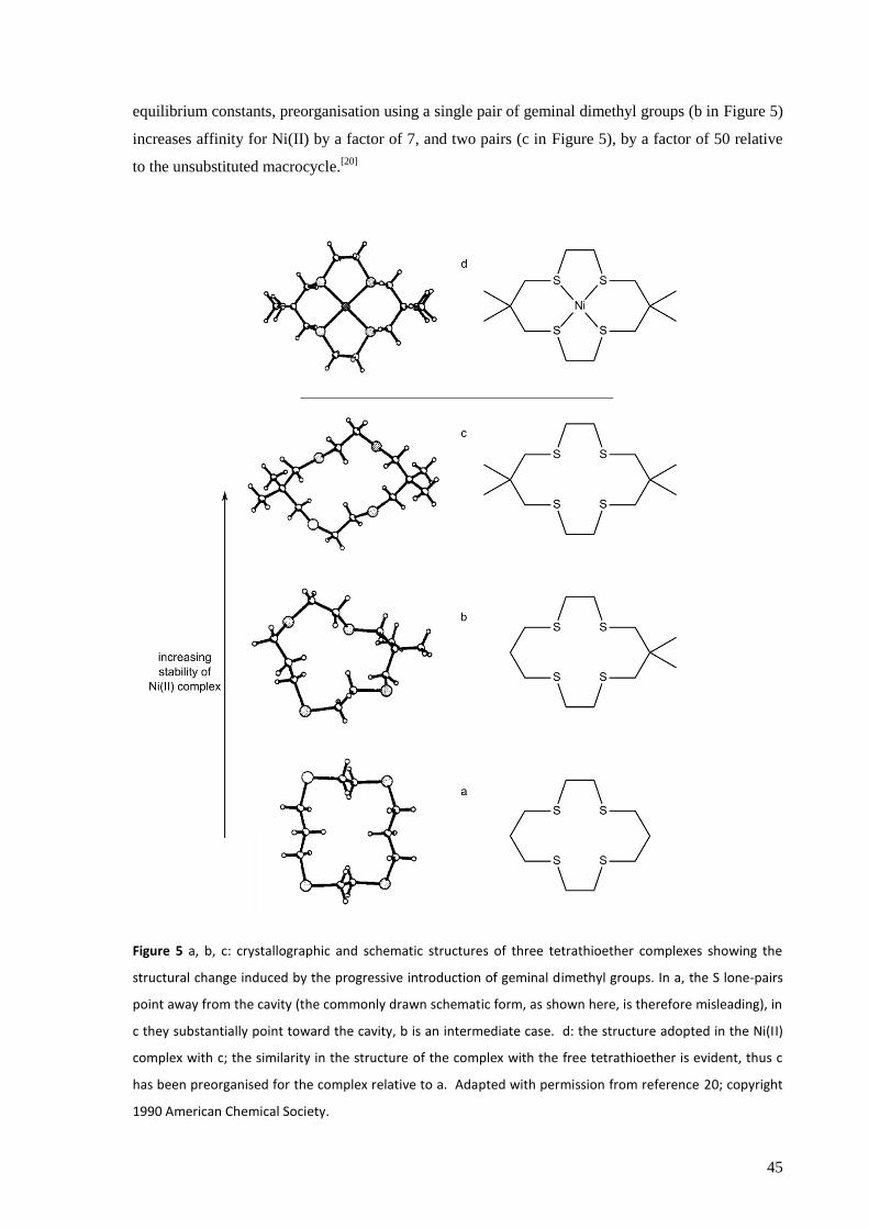
45
equilibrium constants, preorganisation using a single pair of geminal dimethyl groups (b in Figure 5)
increases affinity for Ni(II) by a factor of 7, and two pairs (c in Figure 5), by a factor of 50 relative
to the unsubstituted macrocycle.[20]
Figure 5 a, b, c: crystallographic and schematic structures of three tetrathioether complexes showing the
structural change induced by the progressive introduction of geminal dimethyl groups. In a, the S lone-pairs
point away from the cavity (the commonly drawn schematic form, as shown here, is therefore misleading), in
c they substantially point toward the cavity, b is an intermediate case. d: the structure adopted in the Ni(II)
complex with c; the similarity in the structure of the complex with the free tetrathioether is evident, thus c
has been preorganised for the complex relative to a. Adapted with permission from reference 20; copyright
1990 American Chemical Society.
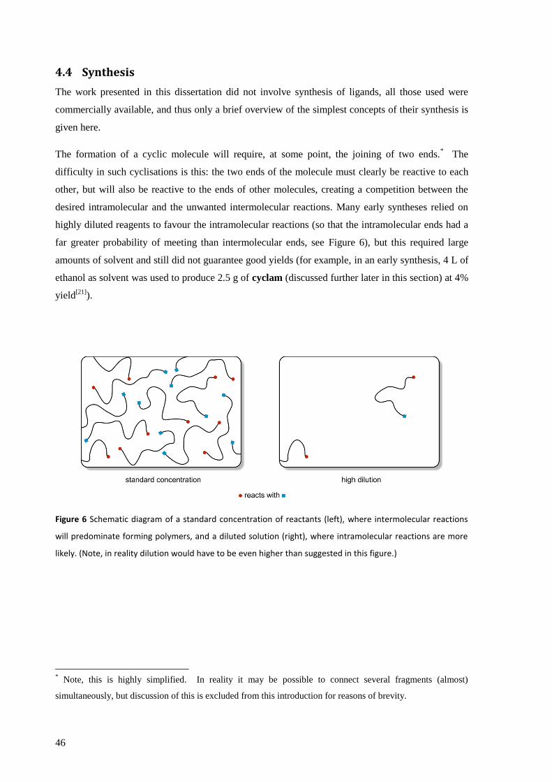
46
4.4 Synthesis
The work presented in this dissertation did not involve synthesis of ligands, all those used were
commercially available, and thus only a brief overview of the simplest concepts of their synthesis is
given here.
The formation of a cyclic molecule will require, at some point, the joining of two ends.* The
difficulty in such cyclisations is this: the two ends of the molecule must clearly be reactive to each
other, but will also be reactive to the ends of other molecules, creating a competition between the
desired intramolecular and the unwanted intermolecular reactions. Many early syntheses relied on
highly diluted reagents to favour the intramolecular reactions (so that the intramolecular ends had a
far greater probability of meeting than intermolecular ends, see Figure 6), but this required large
amounts of solvent and still did not guarantee good yields (for example, in an early synthesis, 4 L of
ethanol as solvent was used to produce 2.5 g of cyclam (discussed further later in this section) at 4%
yield[21]
).
Figure 6 Schematic diagram of a standard concentration of reactants (left), where intermolecular reactions
will predominate forming polymers, and a diluted solution (right), where intramolecular reactions are more
likely. (Note, in reality dilution would have to be even higher than suggested in this figure.)
* Note, this is highly simplified. In reality it may be possible to connect several fragments (almost)
simultaneously, but discussion of this is excluded from this introduction for reasons of brevity.
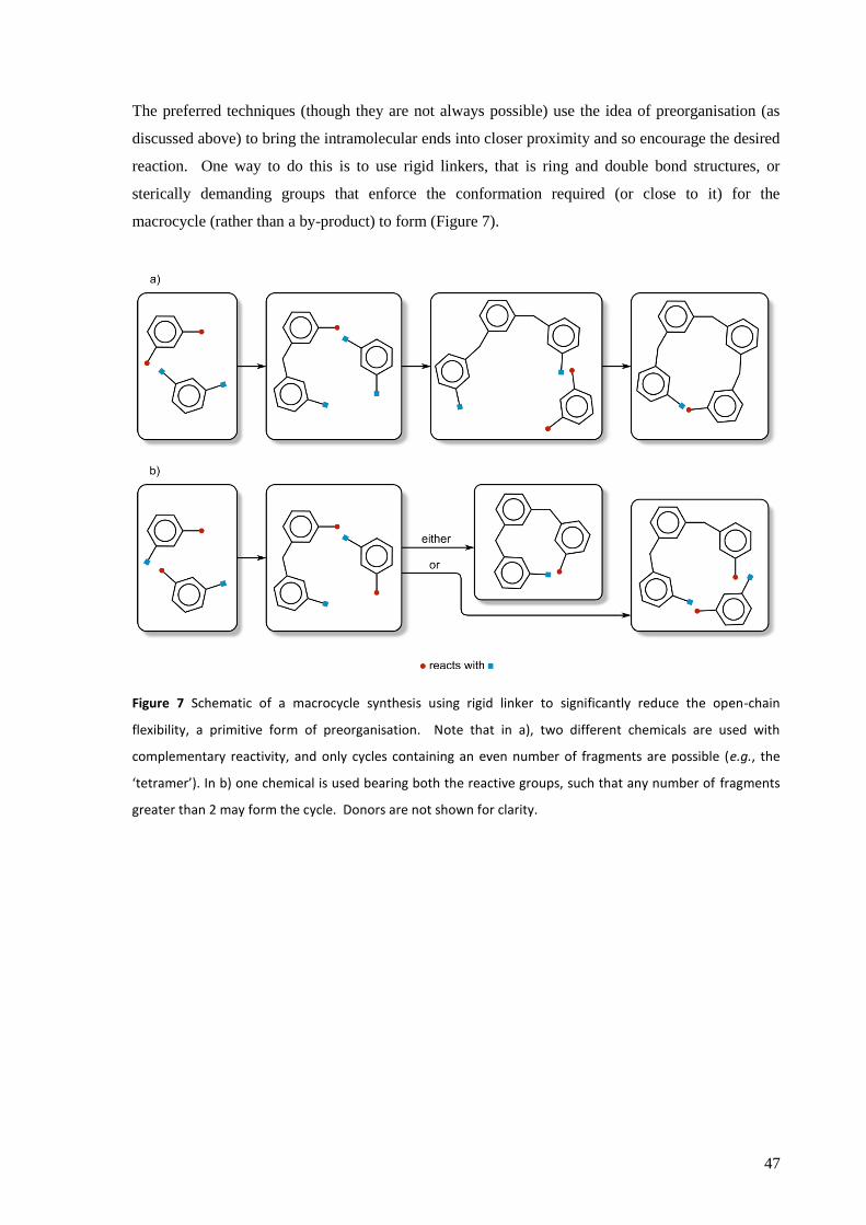
47
The preferred techniques (though they are not always possible) use the idea of preorganisation (as
discussed above) to bring the intramolecular ends into closer proximity and so encourage the desired
reaction. One way to do this is to use rigid linkers, that is ring and double bond structures, or
sterically demanding groups that enforce the conformation required (or close to it) for the
macrocycle (rather than a by-product) to form (Figure 7).
Figure 7 Schematic of a macrocycle synthesis using rigid linker to significantly reduce the open-chain
flexibility, a primitive form of preorganisation. Note that in a), two different chemicals are used with
complementary reactivity, and only cycles containing an even number of fragments are possible (e.g., the
‘tetramer’). In b) one chemical is used bearing both the reactive groups, such that any number of fragments
greater than 2 may form the cycle. Donors are not shown for clarity.
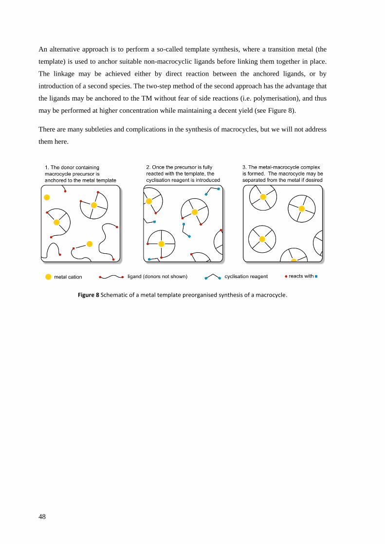
48
An alternative approach is to perform a so-called template synthesis, where a transition metal (the
template) is used to anchor suitable non-macrocyclic ligands before linking them together in place.
The linkage may be achieved either by direct reaction between the anchored ligands, or by
introduction of a second species. The two-step method of the second approach has the advantage that
the ligands may be anchored to the TM without fear of side reactions (i.e. polymerisation), and thus
may be performed at higher concentration while maintaining a decent yield (see Figure 8).
There are many subtleties and complications in the synthesis of macrocycles, but we will not address
them here.
Figure 8 Schematic of a metal template preorganised synthesis of a macrocycle.
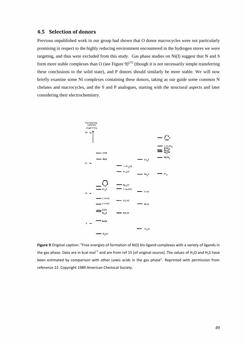
49
4.5 Selection of donors
Previous unpublished work in our group had shown that O donor macrocycles were not particularly
promising in respect to the highly reducing environment encountered in the hydrogen stores we were
targeting, and thus were excluded from this study. Gas phase studies on Ni(I) suggest that N and S
form more stable complexes than O (see Figure 9)[22]
(though it is not necessarily simple transferring
these conclusions to the solid state), and P donors should similarly be more stable. We will now
briefly examine some Ni complexes containing these donors, taking as our guide some common N
chelates and macrocycles, and the S and P analogues, starting with the structural aspects and later
considering their electrochemistry.
Figure 9 Original caption: “Free energies of formation of Ni(I) bis-ligand complexes with a variety of ligands in
the gas phase. Data are in kcal mol−1
and are from ref 15 [of original source]. The values of H2O and H2S have
been estimated by comparison with other Lewis acids in the gas phase”. Reprinted with permission from
reference 22. Copyright 1989 American Chemical Society.
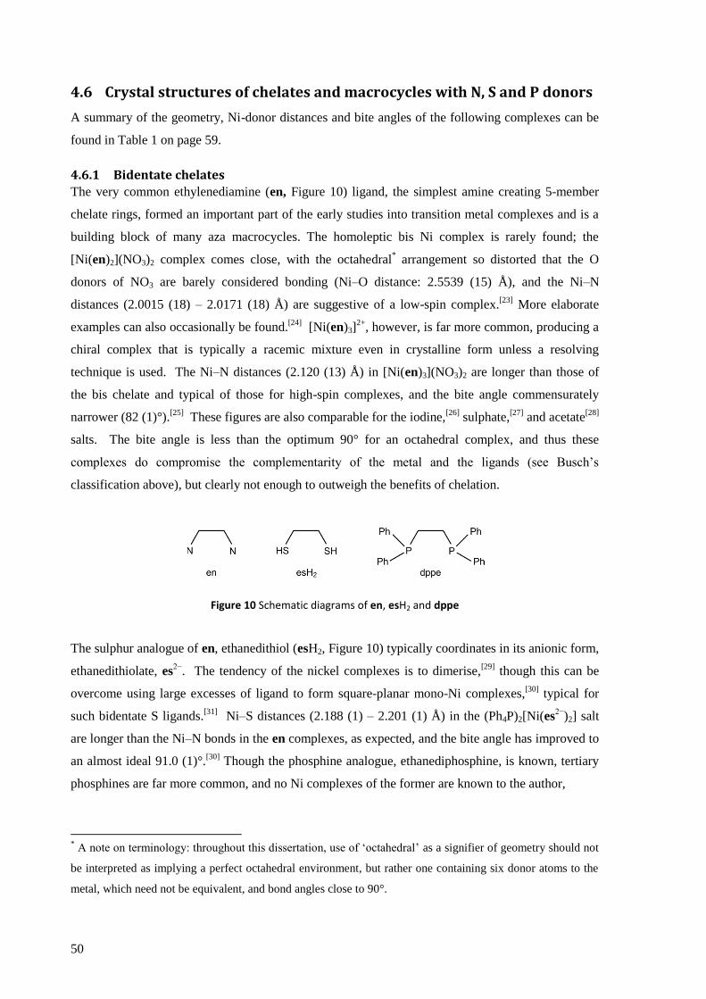
50
4.6 Crystal structures of chelates and macrocycles with N, S and P donors
A summary of the geometry, Ni-donor distances and bite angles of the following complexes can be
found in Table 1 on page 59.
4.6.1 Bidentate chelates
The very common ethylenediamine (en, Figure 10) ligand, the simplest amine creating 5-member
chelate rings, formed an important part of the early studies into transition metal complexes and is a
building block of many aza macrocycles. The homoleptic bis Ni complex is rarely found; the
[Ni(en)2](NO3)2 complex comes close, with the octahedral* arrangement so distorted that the O
donors of NO3 are barely considered bonding (Ni–O distance: 2.5539 (15) Å), and the Ni–N
distances (2.0015 (18) – 2.0171 (18) Å) are suggestive of a low-spin complex.[23]
More elaborate
examples can also occasionally be found.[24]
[Ni(en)3]2+
, however, is far more common, producing a
chiral complex that is typically a racemic mixture even in crystalline form unless a resolving
technique is used. The Ni–N distances (2.120 (13) Å) in [Ni(en)3](NO3)2 are longer than those of
the bis chelate and typical of those for high-spin complexes, and the bite angle commensurately
narrower (82 (1)°).[25]
These figures are also comparable for the iodine,[26]
sulphate,[27]
and acetate[28]
salts. The bite angle is less than the optimum 90° for an octahedral complex, and thus these
complexes do compromise the complementarity of the metal and the ligands (see Busch‟s
classification above), but clearly not enough to outweigh the benefits of chelation.
Figure 10 Schematic diagrams of en, esH2 and dppe
The sulphur analogue of en, ethanedithiol (esH2, Figure 10) typically coordinates in its anionic form,
ethanedithiolate, es2−
. The tendency of the nickel complexes is to dimerise,[29]
though this can be
overcome using large excesses of ligand to form square-planar mono-Ni complexes,[30]
typical for
such bidentate S ligands.[31]
Ni–S distances (2.188 (1) – 2.201 (1) Å) in the (Ph4P)2[Ni(es2−
)2] salt
are longer than the Ni–N bonds in the en complexes, as expected, and the bite angle has improved to
an almost ideal 91.0 (1)°.[30]
Though the phosphine analogue, ethanediphosphine, is known, tertiary
phosphines are far more common, and no Ni complexes of the former are known to the author,
* A note on terminology: throughout this dissertation, use of „octahedral‟ as a signifier of geometry should not
be interpreted as implying a perfect octahedral environment, but rather one containing six donor atoms to the
metal, which need not be equivalent, and bond angles close to 90°.

51
whilst there are many variations of the latter. 1,2-(bis(diphenylphosphino)ethane (dppe, Figure 10)
is a particularly common ligand, and its complexes with Ni are well known and commercially
available. A key difference between these phosphine ligands and those of N and S is that the former
are able to form stable Ni(0) complexes, i.e., [Ni0(dppe)2],
[32] as well as Ni(II) complexes, such as
[NiII(dppe)2](NO3)2,
[33] in agreement with the rule of thumb arising from the hard and soft acids and
bases theory that soft ligands stabilise low oxidation states. In tetrahedral [Ni0(dppe)2], the Ni–P
distance is 2.152 (3) – 2.177 (3) Å, and the bite angle, at 90.1 (1) – 90.8 (1)°,[34]
is a very long way
from the ideal of 109.5°. In the square-planar d8 system of [Ni
II(dppe)2](NO3)2, the Ni–P distances
lengthen to 2.256 (3) – 2.261 (3) Å, and as a result the bite angle closes to 83.25 (12)° such that it
still deviates from the ideal, now of 90°.[33]
2,2‟-bipyridine (bipy, Figure 11) is another common ligand, structurally similar to en, but
electronically very different due to the incorporation of the N donors into an aromatic ring system
and the ability to delocalise charge on the ligand.[35]
The nickel complexes have been known since
the 19th century
[36] but they are not as widely studied as those of some other metals, such as Ru,
which show good light harvesting properties. As with tris-en complexes, the tris-bipy complexes
are chiral,[37]
but the Ni–N distances (taken from [Ni(bipy)3]SO4·7.5H2O) are slightly shorter at
2.082 (8) – 2.103 (7) Å and the bite angle slightly further from ideal at 78.4 (4) – 79.0 (4)°.[38]
1,10-
phenanthroline (phen, Figure 11) is very closely related to bipy, but contains an additional ring that
fuses the molecule into a planar arrangement and thus leads to greater rigidity, which according to
Busch‟s classification should enhance the stability of the Ni complex compared to bipy ligands.
This is indeed found to be the case, with the rate of dissociation of a ligand (or racemisation of an
optically active sample) of [Ni(phen)3]2+
complexes 5 – 8 times slower* than that of [Ni(bipy)3]
2+.[39]
The Ni–N distances in [Ni(phen)3]Br2·8H2O (2.081 (6) – 2.098 (6) Å) are very similar to those of
the tris-bipy complex above, and the bite angle only slightly larger (79.8 (2) – 80.1 (2)°).[40]
Figure 11 Schematic diagrams of bipy and phen
* The situation is more complicated than presented here due to the dependence on pH of the rates associated
with the Ni(bipy)32+
complex, but the general picture presented is fair.

52
In the case of sulphur donors, bithiophene (see Figure 12) is not known to form any nickel
complexes, nor indeed generally found to be a useful transition metal ligand, and though nickel may
be used to catalyse the polymerisation of thiophene derivatives during which bithiophene derivatives
may attach to the metal, they do not attach as a chelate, nor even through the S functionality.[41]
The
closest phosphorous analogue of bipy is 4,4‟,5,5‟-tetramethyl-2,2‟-biphosphinine (tmbp, Figure 12),
first synthesised in 1991.[42]
The chemistry of its nickel complex was found to be quite different
from that of bipy, however, as the ligand shows a strong preference for electron rich metal centres[43]
and an air stable complex containing Ni(0) was formed, [Ni(tmbp)2], which could be reversibly
reduced electrochemically to [Ni(tmbp)2]2−
, though with the charge localised on the ligands rather
than Ni.[44]
There have been no reports of a Ni(II) complex, and there are reasons to believe it would
be unstable.[43]
The Ni–P distances of [Ni(tmbp)2] are in the range 2.141 (1) – 2.149 (1) Å, only
slightly shorter than those of [Ni(dppe)2], but the bite angle, at 85.29 (4)° is considerably lower,
moving even further away from the ideal of 109.5° for this distorted tetrahedral complex.[44]
Figure 12 Schematic diagrams of bithiophene and tmbp
4.6.2 Higher dentate chelates
Higher dentate chelates such as dien, trien, terpy (Figure 13) et cetera can be made by combining
multiples of these basic blocks, but further discussion here will be confined to the tripodal N and P
ligands, tren and PP3 (Figure 13), the latter of which was used in the experimental part of this
dissertation.
Though tren is a tetradentate chelate, the flexibility of its structure (in contrast to the macrocycles
we will meet shortly), means that it does not always coordinate in a tetradentate fashion. As well
bridging structures (which we will not go into here), a tridentate complex can form leaving one
amine group uncoordinated to any metal centre.[45]
The tetradentate form, which is of most interest
in this discussion, is exhibited by complexes such as [Ni(tren)(H2O)Cl)]Cl[46]
and
[NiII(tren)(N(CN)2)2].
[47] The distorted octahedra show apical to terminal N (see Figure 13 for
nomenclature) bite angles of 81.5 – 84.3°, and a small survey of nine such complexes gave Ni–N
bond lengths of 2.08 – 2.14 Å, with negligible difference between the apical and the terminal N
donors.[46]
The impact of the ring strain has also been investigated, by sequentially replacing each of
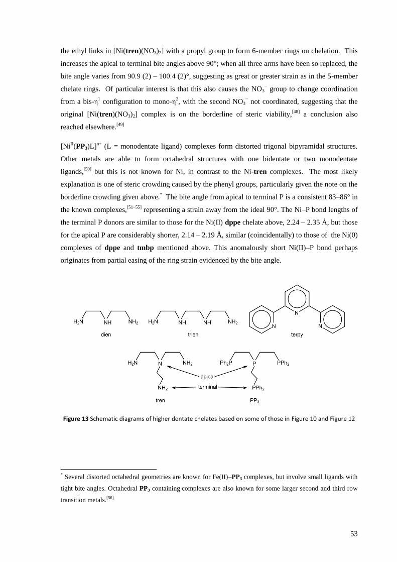
53
the ethyl links in [Ni(tren)(NO3)2] with a propyl group to form 6-member rings on chelation. This
increases the apical to terminal bite angles above 90°; when all three arms have been so replaced, the
bite angle varies from 90.9 (2) – 100.4 (2)°, suggesting as great or greater strain as in the 5-member
chelate rings. Of particular interest is that this also causes the NO3− group to change coordination
from a bis-η1 configuration to mono-η
2, with the second NO3
− not coordinated, suggesting that the
original [Ni(tren)(NO3)2] complex is on the borderline of steric viability,[48]
a conclusion also
reached elsewhere.[49]
[NiII(PP3)L]
n+ (L = monodentate ligand) complexes form distorted trigonal bipyramidal structures.
Other metals are able to form octahedral structures with one bidentate or two monodentate
ligands,[50]
but this is not known for Ni, in contrast to the Ni-tren complexes. The most likely
explanation is one of steric crowding caused by the phenyl groups, particularly given the note on the
borderline crowding given above.* The bite angle from apical to terminal P is a consistent 83–86° in
the known complexes,[51–55]
representing a strain away from the ideal 90°. The Ni–P bond lengths of
the terminal P donors are similar to those for the Ni(II) dppe chelate above, 2.24 – 2.35 Å, but those
for the apical P are considerably shorter, 2.14 – 2.19 Å, similar (coincidentally) to those of the Ni(0)
complexes of dppe and tmbp mentioned above. This anomalously short Ni(II)–P bond perhaps
originates from partial easing of the ring strain evidenced by the bite angle. 56
Figure 13 Schematic diagrams of higher dentate chelates based on some of those in Figure 10 and Figure 12
* Several distorted octahedral geometries are known for Fe(II)–PP3 complexes, but involve small ligands with
tight bite angles. Octahedral PP3 containing complexes are also known for some larger second and third row
transition metals.[56]
54
4.6.3 Macrocycles
Macrocycles have been very widely studied as ligands for transition metals and Ni is no exception.
In its +2 oxidation state Ni shows a particular affinity for 14-member tetraamine macrocycles in
both high- and low-spin forms relative to 12-, 13-, 15- and 16-member rings.[57]
Given the
difference in preferred Ni–N bond length between the low- and high-spin species, approximately 1.9
Å and 2.1 Å respectively,[58,59]
this is perhaps a little surprising, but has been rationalised on the
basis that the 13-member ring (which might otherwise be expected to be more stable than the 14-
member for low-spin Ni(II)), suffers from eclipsed methyl groups when adopting the conformation
required to direct the N lone-pairs towards the metal centre, raising the total energy of the
complex.[58]
It should be noted that these stability data were recorded in aqueous solution, thus the
thermodynamics are affected by coordinated water and any further structure induced in the solvent
in the second coordination sphere and beyond,[60]
which may not be relevant in solids. Nevertheless,
the 14-member structures also seem a reasonable starting point for solid state enquiries.
Of such rings, the most commonly encountered is 1,4,8,11-tetraazacyclotetradecane (cyclam) and
this is the one we shall look at in detail (the 12-member ring, 1,4,7,10-tetraazacyclotetradecane
(cyclen) is also common, but not discussed here). Many structures of tetradentate cyclam with
Ni(II) are known. The majority of reported octahedral structures adopt the trans configuration, often
with the Ni located at an inversion centre such that the Ni and 4N atoms are crystallograpically
coplanar. The reported cis configrations have been obtained by intentional manipulation, for
example using en to force cyclam into a cis geometry and then replacing the bidentate ligand (by
protonating it with a suitable acid, such as HCl) to form cis-[Ni(cyclam)(H2O)2]Cl2, which slowly
isomerises back to the trans isomer in aqueous solution.[61]
trans-octahedral complexes typically
have Ni–N bonds in the range 2.05 – 2.07 Å, whilst those reported for the cis complex just
mentioned are 2.092 (2) – 2.109 (2) Å. cyclam, possessing both ethyl and propyl alkane linkers,
forms both 5-member and 6-member chelate rings, with typical bite angles in the octahedral trans
complexes of 85.5 ± 1° for the former and 95.4 ± 1° for the latter,[62–66]
and in the cis-
[Ni(cyclam)(H2O)2]Cl2 complex the bite angles only differed slightly, at 83.5° and 92.8°
respectively.[67]
Square-planar complexes form shorter Ni–N bonds, consistent with their low-spin
state, typically in the range 1.90 – 2.00 Å, but the pattern for bite angles is similar to that for the
octahedral complexes.[ 68–71]
An interesting exception is found in a square-planar complex with an
unusual conformation that is reported as having bite angles ranging from 89.4 (5) – 90.5 (3)°, very
close to the ideal of 90°.* The conformation of cyclam and similar rings is typically described using
the scheme proposed by Bosnich et al.,[72]
(see Figure 14), and whereas the majority of
* Though in this case Ni is not at an inversion centre and the four N atoms do not quite sit in a perfect plane

55
Figure 14 Top: schematic diagrams of the five conformations of cyclam with the classification by Bosnich et
al.[72]
in Roman numerals above. Bottom: the lowest energy configurations for the trans and cis complexes
when considering ring strain and staggered/eclipsed positions of hydrogens. The chair configurations of the
two six-membered chelate rings in trans-III and the boat configurations in cis-V, which are major factors in
their low energy, are indicated in red. (Methylene hydrogens omitted for clarity)
Figure 15 Some common derivatives of cyclam, including (far right) a bi-pendant ligand capable of forming a
hexadentate complex.
octahedral complexes have the trans-III conformation,[59]
this unusual square-planar complex has the
energetically disfavoured trans-V conformation and was obtained as a kinetic product.[67]
cyclam may also be decorated with various groups to alter its properties (see Figure 15). When
complexed with nickel, such ligands are most commonly found in a trans-octahedral configuration,
thus joined by two monodentate ligands, but cis-octahedral, 5 coordinate square pyramidal and
trigonal bipyramidal, and 4 coordinate square planar are also known.[59]

56
There are few Ni complexes of mono-dentate thioethers in the condensed phase (contrast this with
the apparent stability of the gas phase complexes, (Figure 9), and the chelate and macrocyclic effects
are generally needed to improve the stability of these otherwise poor ligands for Ni.[73]
The
macrocycles suffer, however, from adopting an exodentate form when not bound to a metal (for
example see Figure 5 on page 45). This is at least in part responsible for the lower macrocyclic
effect observed for 14aneS4 (Figure 16) relative to cyclam; where the former has increased stability
(as determined by the equilibrium constant) over its non-cyclic analogue of 180 times, the latter‟s is
of the order of 106 times.
[74] A number of Ni tetrathioether macrocyclic complexes have
nevertheless been reported, though significantly less than for the amine macrocycles. In the only
known Ni 14aneS4 complex, the bite angle for both the 5- and 6-member chelate rings are 90° to
within experimental uncertainty,[75]
in contrast to the cyclam complexes. The Ni–S distances of
2.176 Å seem typical for a low-spin, square planar complex.[76,77]
The latter show considerably
longer Ni–S distances, with an inter-quartile range of 2.37 – 2.43 Å,[78]
as seen in the octahedral
geometry of the bridged (μ-Cl)2 cis complex[79]
and a ring-functionalised 14aneS4 trans complex.[77]
As a 12-membered tetrathioether macrocycle (12aneS4, Figure 16) was also investigated in the
experimental work of this dissertation, we will briefly mention the only such nickel complex
reported prior to our work, the cis configured, dimeric [Ni2(12aneS4)2(μ-Cl)2]2+
. The bite angles for
S–Ni–S adjacent on the ring are 83.73 (9) – 87.54 (9)°, and for S–Ni–S across the ring 94.42°. Ni–S
distances reflect the high-spin octahedral environment, and are 2.373 (3) – 2.4144 (25) Å.
Figure 16 Schematic diagrams of 12aneS4, 14aneS4 and 18aneP4Y2.
The synthesis of macrocyclic phosphine ligands has proved difficult, certainly compared to those of
the cyclic amines and crown ethers. Early attempts (in the 1970s) were made using
cyclocondensation reactions but yields were poor. These improved with the use of rigid linkers (see
above), but still typically required high dilution to prevent the formation of polymers, resulting in
long reaction times.[80]
Template reactions were first proposed[81]
and carried out[82]
using nickel
which further eased their synthesis, but the lack of commercial availability and still somewhat
inconvenient syntheses are the likely reason for the relative paucity of research in this area. No
crystal structures for 14-member tetraphosphine complexes are known, though an interesting series
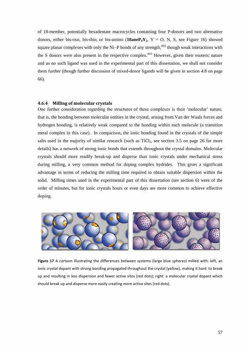
57
of 18-member, potentially hexadentate macrocycles containing four P-donors and two alternative
donors, either bis-oxo, bis-thio, or bis-amino (18aneP4Y2, Y = O, N, S, see Figure 16) showed
square planar complexes with only the Ni–P bonds of any strength,[80]
though weak interactions with
the S donors were also present in the respective complex.[83]
However, given their esoteric nature
and as no such ligand was used in the experimental part of this dissertation, we shall not consider
them further (though further discussion of mixed-donor ligands will be given in section 4.8 on page
66).
4.6.4 Milling of molecular crystals
One further consideration regarding the structures of these complexes is their „molecular‟ nature,
that is, the bonding between molecular entities in the crystal, arising from Van der Waals forces and
hydrogen bonding, is relatively weak compared to the bonding within each molecule (a transition
metal complex in this case). In comparison, the ionic bonding found in the crystals of the simple
salts used in the majority of similar research (such as TiCl3, see section 3.5 on page 26 for more
details) has a network of strong ionic bonds that extends throughout the crystal domains. Molecular
crystals should more readily break-up and disperse than ionic crystals under mechanical stress
during milling, a very common method for doping complex hydrides. This gives a significant
advantage in terms of reducing the milling time required to obtain suitable dispersion within the
solid. Milling times used in the experimental part of this dissertation (see section 6) were of the
order of minutes, but for ionic crystals hours or even days are more common to achieve effective
doping.
Figure 17 A cartoon illustrating the differences between systems (large blue spheres) milled with: left, an
ionic crystal dopant with strong bonding propagated throughout the crystal (yellow), making it hard to break
up and resulting in less dispersion and fewer active sites (red dots); right: a molecular crystal dopant which
should break up and disperse more easily creating more active sites (red dots).
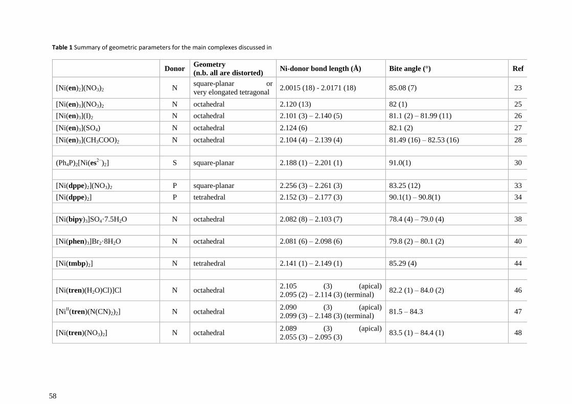
58
Table 1 Summary of geometric parameters for the main complexes discussed in
Donor
Geometry
(n.b. all are distorted) Ni-donor bond length (Å) Bite angle (°) Ref
[Ni(en)2](NO3)2 N square-planar or
very elongated tetragonal 2.0015 (18) - 2.0171 (18) 85.08 (7) 23
[Ni(en)3](NO3)2 N octahedral 2.120 (13) 82 (1) 25
[Ni(en)3](I)2 N octahedral 2.101 (3) – 2.140 (5) 81.1 (2) – 81.99 (11) 26
[Ni(en)3](SO4) N octahedral 2.124 (6) 82.1 (2) 27
[Ni(en)3](CH3COO)2 N octahedral 2.104 (4) – 2.139 (4) 81.49 (16) – 82.53 (16) 28
(Ph4P)2[Ni(es
2−)2] S square-planar 2.188 (1) – 2.201 (1) 91.0(1) 30
[Ni(dppe)2](NO3)2 P square-planar 2.256 (3) – 2.261 (3) 83.25 (12) 33
[Ni(dppe)2] P tetrahedral 2.152 (3) – 2.177 (3) 90.1(1) – 90.8(1) 34
[Ni(bipy)3]SO4·7.5H2O N octahedral 2.082 (8) – 2.103 (7) 78.4 (4) – 79.0 (4) 38
[Ni(phen)3]Br2·8H2O N octahedral 2.081 (6) – 2.098 (6) 79.8 (2) – 80.1 (2) 40
[Ni(tmbp)2] N tetrahedral 2.141 (1) – 2.149 (1) 85.29 (4) 44
[Ni(tren)(H2O)Cl)]Cl N octahedral 2.105 (3) (apical)
2.095 (2) – 2.114 (3) (terminal) 82.2 (1) – 84.0 (2) 46
[NiII(tren)(N(CN)2)2] N octahedral
2.090 (3) (apical)
2.099 (3) – 2.148 (3) (terminal) 81.5 – 84.3 47
[Ni(tren)(NO3)2] N octahedral 2.089 (3) (apical)
2.055 (3) – 2.095 (3) 83.5 (1) – 84.4 (1) 48
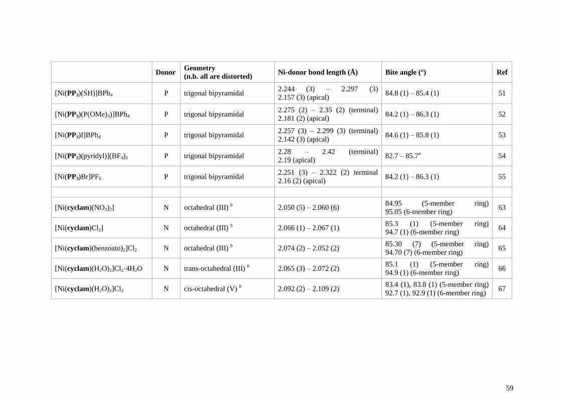
59
Donor
Geometry
(n.b. all are distorted) Ni-donor bond length (Å) Bite angle (°) Ref
[Ni(PP3)(SH)]BPh4 P trigonal bipyramidal 2.244 (3) – 2.297 (3)
2.157 (3) (apical) 84.8 (1) – 85.4 (1) 51
[Ni(PP3)(P(OMe)3)]BPh4 P trigonal bipyramidal 2.275 (2) – 2.35 (2) (terminal)
2.181 (2) (apical) 84.2 (1) – 86.3 (1) 52
[Ni(PP3)I]BPh4 P trigonal bipyramidal 2.257 (3) – 2.299 (3) (terminal)
2.142 (3) (apical) 84.6 (1) – 85.8 (1) 53
[Ni(PP3)(pyridyl)](BF4)2 P trigonal bipyramidal 2.28 – 2.42 (terminal)
2.19 (apical) 82.7 – 85.7
a 54
[Ni(PP3)Br]PF6 P trigonal bipyramidal 2.251 (3) – 2.322 (2) terminal
2.16 (2) (apical) 84.2 (1) – 86.3 (1) 55
[Ni(cyclam)(NO3)2] N octahedral (III) b 2.050 (5) – 2.060 (6)
84.95 (5-member ring)
95.05 (6-member ring) 63
[Ni(cyclam)Cl2] N octahedral (III) b 2.066 (1) – 2.067 (1)
85.3 (1) (5-member ring)
94.7 (1) (6-member ring) 64
[Ni(cyclam)(benzoato)2]Cl2 N octahedral (III) b 2.074 (2) – 2.052 (2)
85.30 (7) (5-member ring)
94.70 (7) (6-member ring) 65
[Ni(cyclam)(H2O)2]Cl2·4H2O N trans-octahedral (III) b 2.065 (3) – 2.072 (2)
85.1 (1) (5-member ring)
94.9 (1) (6-member ring) 66
[Ni(cyclam)(H2O)2]Cl2 N cis-octahedral (V) b 2.092 (2) – 2.109 (2)
83.4 (1), 83.8 (1) (5-member ring)
92.7 (1), 92.9 (1) (6-member ring) 67
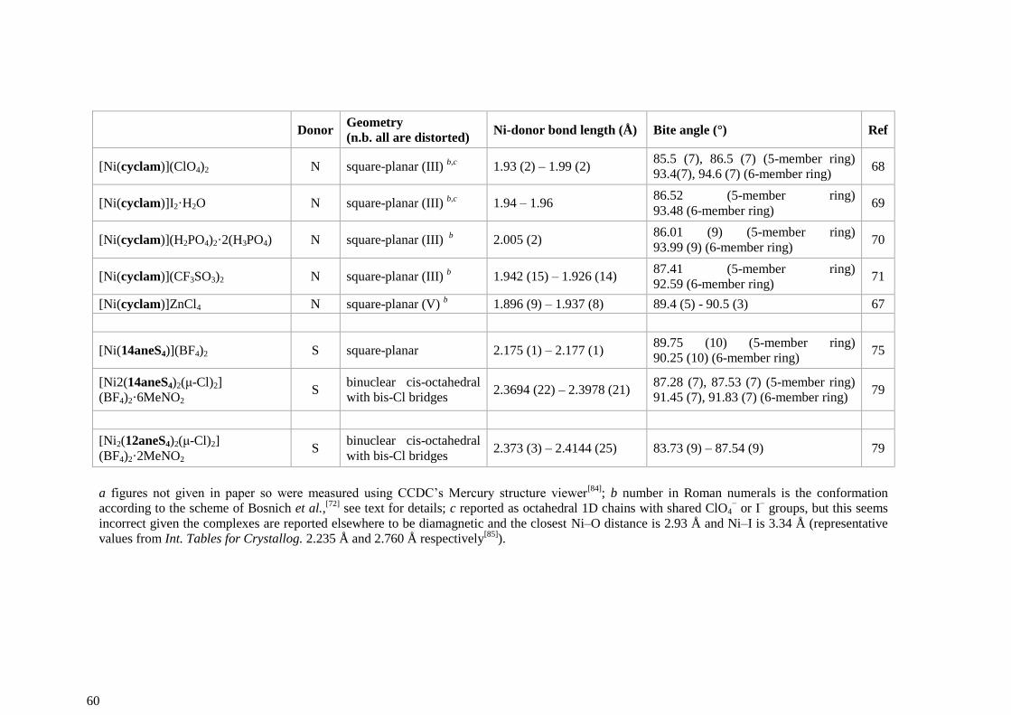
60
Donor
Geometry
(n.b. all are distorted) Ni-donor bond length (Å) Bite angle (°) Ref
[Ni(cyclam)](ClO4)2 N square-planar (III) b,c
1.93 (2) – 1.99 (2) 85.5 (7), 86.5 (7) (5-member ring)
93.4(7), 94.6 (7) (6-member ring) 68
[Ni(cyclam)]I2·H2O N square-planar (III) b,c
1.94 – 1.96 86.52 (5-member ring)
93.48 (6-member ring) 69
[Ni(cyclam)](H2PO4)2·2(H3PO4) N square-planar (III) b 2.005 (2)
86.01 (9) (5-member ring)
93.99 (9) (6-member ring) 70
[Ni(cyclam)](CF3SO3)2 N square-planar (III) b 1.942 (15) – 1.926 (14)
87.41 (5-member ring)
92.59 (6-member ring) 71
[Ni(cyclam)]ZnCl4 N square-planar (V) b 1.896 (9) – 1.937 (8) 89.4 (5) - 90.5 (3) 67
[Ni(14aneS4)](BF4)2 S square-planar 2.175 (1) – 2.177 (1) 89.75 (10) (5-member ring)
90.25 (10) (6-member ring) 75
[Ni2(14aneS4)2(μ-Cl)2]
(BF4)2·6MeNO2 S
binuclear cis-octahedral
with bis-Cl bridges 2.3694 (22) – 2.3978 (21)
87.28 (7), 87.53 (7) (5-member ring)
91.45 (7), 91.83 (7) (6-member ring) 79
[Ni2(12aneS4)2(μ-Cl)2]
(BF4)2·2MeNO2 S
binuclear cis-octahedral
with bis-Cl bridges 2.373 (3) – 2.4144 (25) 83.73 (9) – 87.54 (9) 79
a figures not given in paper so were measured using CCDC‟s Mercury structure viewer
[84]; b number in Roman numerals is the conformation
according to the scheme of Bosnich et al.,[72]
see text for details; c reported as octahedral 1D chains with shared ClO4− or I
− groups, but this seems
incorrect given the complexes are reported elsewhere to be diamagnetic and the closest Ni–O distance is 2.93 Å and Ni–I is 3.34 Å (representative
values from Int. Tables for Crystallog. 2.235 Å and 2.760 Å respectively[85]
).
61
4.7 Electrochemistry
We will now briefly examine the known electrochemistry of some of the complexes mentioned above
and discuss how this relates to their possible role in reducing H2 or oxidising H−. Our aim in doing
this is not to draw detailed insight, as the significant role of solvation in electrochemical measurements
prohibits this when designing solid state catalysts, but to broadly illustrate how ligands may be used to
adjust the reduction potential of nickel to become redox active in the highly reducing atmosphere of a
complex hydride hydrogen store.
4.7.1 Ligand effects on the reduction potential of Nin+
If Ni is to be used as a redox catalyst it is necessary that at least two oxidation states be accessible
under the operating conditions of the catalyst. For the Ni(II)/(0) couple in acidic solution, E° = −0.26
V vs SHE (standard hydrogen electrode) and in basic solution shifts to −0.72 V vs SHE. *,[86]
Either of
these would thus be easily reduced by a hypothetical H− solution (H2 + 2e
− → 2H
−, E° = −2.25 V vs
SHE[87]
) and clearly unprotected Ni(II) would not be viable in complex hydride hydrogen stores.
However, by attaching suitably stabilising ligands, particularly strong electron donors, the higher
oxidation states of Ni may be stabilised sufficiently for them to become feasible even in the presence
of complex hydrides.
This idea may be extended through the inverse correlation between the standard reduction potential
and the decomposition temperature of hydrides: more negative potentials (i.e., a higher resistance to
electrochemical reduction) result in higher decomposition temperatures (see section 3.8 on page 31).
If this relationship holds true, deliberately manipulating the reduction potential through appropriate
choice of ligands should allow us to tune the decomposition temperature of associated hydrides. Let
us then look at the electrochemistry of some of the complexes we have just been considering the
structures of above.
(A note on the electrode chosen as reference for the following discussion: accurate conversion of
electrode potentials across different solvent systems and different measurement conditions is complex,
but in our case these complexities can be mostly ignored as we are seeking broad trends rather than
precise values. Given the data at hand, the simplest electrode to use is the saturated calomel electrode
(SCE) and values reported against other references have been converted.)
* This large difference in potentials caused by changing the pH of the solution from 0 to 14 is a prominent
example of the difficulties of applying electrochemical insights, where the role of the solvent is crucial, to solid
state systems. In this case, as H− is a strong base, the basic solution may be considered as more relevant.
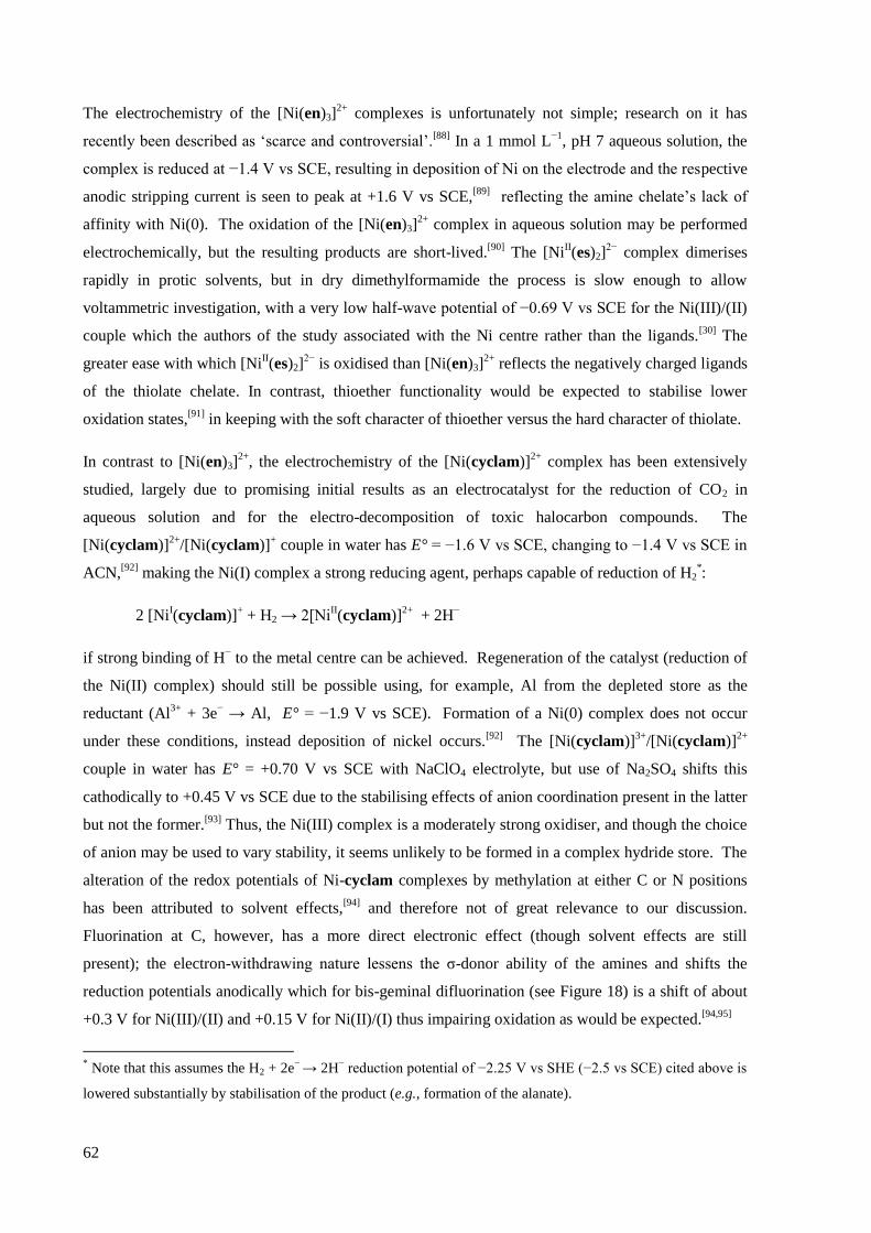
62
The electrochemistry of the [Ni(en)3]2+
complexes is unfortunately not simple; research on it has
recently been described as „scarce and controversial‟.[88]
In a 1 mmol L−1
, pH 7 aqueous solution, the
complex is reduced at −1.4 V vs SCE, resulting in deposition of Ni on the electrode and the respective
anodic stripping current is seen to peak at +1.6 V vs SCE,[89]
reflecting the amine chelate‟s lack of
affinity with Ni(0). The oxidation of the [Ni(en)3]2+
complex in aqueous solution may be performed
electrochemically, but the resulting products are short-lived.[90]
The [NiII(es)2]
2− complex dimerises
rapidly in protic solvents, but in dry dimethylformamide the process is slow enough to allow
voltammetric investigation, with a very low half-wave potential of −0.69 V vs SCE for the Ni(III)/(II)
couple which the authors of the study associated with the Ni centre rather than the ligands.[30]
The
greater ease with which [NiII(es)2]
2− is oxidised than [Ni(en)3]
2+ reflects the negatively charged ligands
of the thiolate chelate. In contrast, thioether functionality would be expected to stabilise lower
oxidation states,[91]
in keeping with the soft character of thioether versus the hard character of thiolate.
In contrast to [Ni(en)3]2+
, the electrochemistry of the [Ni(cyclam)]2+
complex has been extensively
studied, largely due to promising initial results as an electrocatalyst for the reduction of CO2 in
aqueous solution and for the electro-decomposition of toxic halocarbon compounds. The
[Ni(cyclam)]2+
/[Ni(cyclam)]+ couple in water has E° = −1.6 V vs SCE, changing to −1.4 V vs SCE in
ACN,[92]
making the Ni(I) complex a strong reducing agent, perhaps capable of reduction of H2*:
2 [NiI(cyclam)]
+ + H2 → 2[Ni
II(cyclam)]
2+ + 2H
−
if strong binding of H− to the metal centre can be achieved. Regeneration of the catalyst (reduction of
the Ni(II) complex) should still be possible using, for example, Al from the depleted store as the
reductant (Al3+
+ 3e− → Al, E° = −1.9 V vs SCE). Formation of a Ni(0) complex does not occur
under these conditions, instead deposition of nickel occurs.[92]
The [Ni(cyclam)]3+
/[Ni(cyclam)]2+
couple in water has E° = +0.70 V vs SCE with NaClO4 electrolyte, but use of Na2SO4 shifts this
cathodically to +0.45 V vs SCE due to the stabilising effects of anion coordination present in the latter
but not the former.[93]
Thus, the Ni(III) complex is a moderately strong oxidiser, and though the choice
of anion may be used to vary stability, it seems unlikely to be formed in a complex hydride store. The
alteration of the redox potentials of Ni-cyclam complexes by methylation at either C or N positions
has been attributed to solvent effects,[94]
and therefore not of great relevance to our discussion.
Fluorination at C, however, has a more direct electronic effect (though solvent effects are still
present); the electron-withdrawing nature lessens the σ-donor ability of the amines and shifts the
reduction potentials anodically which for bis-geminal difluorination (see Figure 18) is a shift of about
+0.3 V for Ni(III)/(II) and +0.15 V for Ni(II)/(I) thus impairing oxidation as would be expected.[94,95]
* Note that this assumes the H2 + 2e
− → 2H
− reduction potential of −2.25 V vs SHE (−2.5 vs SCE) cited above is
lowered substantially by stabilisation of the product (e.g., formation of the alanate).
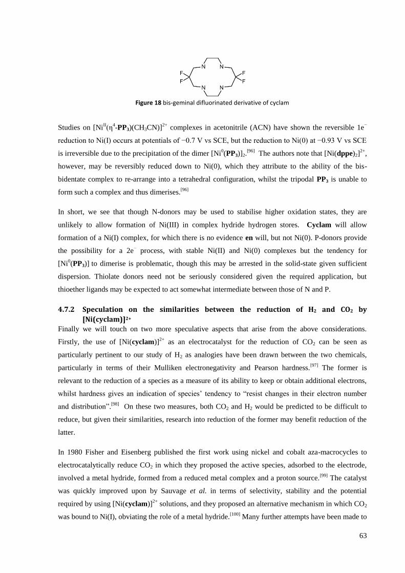
63
Figure 18 bis-geminal difluorinated derivative of cyclam
Studies on [NiII(η
4-PP3)(CH3CN)]
2+ complexes in acetonitrile (ACN) have shown the reversible 1e
−
reduction to Ni(I) occurs at potentials of −0.7 V vs SCE, but the reduction to Ni(0) at −0.93 V vs SCE
is irreversible due to the precipitation of the dimer [Ni0(PP3)]2.
[96] The authors note that [Ni(dppe)2]
2+,
however, may be reversibly reduced down to Ni(0), which they attribute to the ability of the bis-
bidentate complex to re-arrange into a tetrahedral configuration, whilst the tripodal PP3 is unable to
form such a complex and thus dimerises.[96]
In short, we see that though N-donors may be used to stabilise higher oxidation states, they are
unlikely to allow formation of Ni(III) in complex hydride hydrogen stores. Cyclam will allow
formation of a Ni(I) complex, for which there is no evidence en will, but not Ni(0). P-donors provide
the possibility for a 2e− process, with stable Ni(II) and Ni(0) complexes but the tendency for
[Ni0(PP3)] to dimerise is problematic, though this may be arrested in the solid-state given sufficient
dispersion. Thiolate donors need not be seriously considered given the required application, but
thioether ligands may be expected to act somewhat intermediate between those of N and P.
4.7.2 Speculation on the similarities between the reduction of H2 and CO2 by
[Ni(cyclam)]2+
Finally we will touch on two more speculative aspects that arise from the above considerations.
Firstly, the use of [Ni(cyclam)]2+
as an electrocatalyst for the reduction of CO2 can be seen as
particularly pertinent to our study of H2 as analogies have been drawn between the two chemicals,
particularly in terms of their Mulliken electronegativity and Pearson hardness.[97]
The former is
relevant to the reduction of a species as a measure of its ability to keep or obtain additional electrons,
whilst hardness gives an indication of species‟ tendency to “resist changes in their electron number
and distribution”.[98]
On these two measures, both CO2 and H2 would be predicted to be difficult to
reduce, but given their similarities, research into reduction of the former may benefit reduction of the
latter.
In 1980 Fisher and Eisenberg published the first work using nickel and cobalt aza-macrocycles to
electrocatalytically reduce CO2 in which they proposed the active species, adsorbed to the electrode,
involved a metal hydride, formed from a reduced metal complex and a proton source.[99]
The catalyst
was quickly improved upon by Sauvage et al. in terms of selectivity, stability and the potential
required by using [Ni(cyclam)]2+
solutions, and they proposed an alternative mechanism in which CO2
was bound to Ni(I), obviating the role of a metal hydride.[100]
Many further attempts have been made to
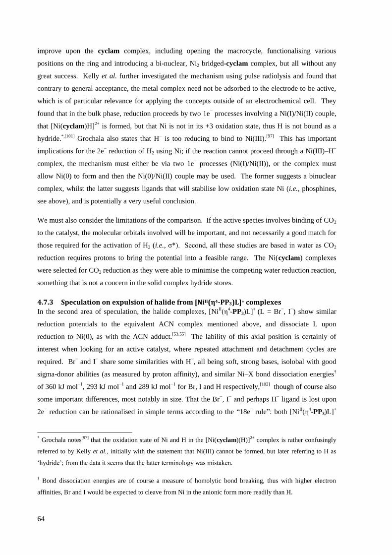
64
improve upon the cyclam complex, including opening the macrocycle, functionalising various
positions on the ring and introducing a bi-nuclear, Ni2 bridged-cyclam complex, but all without any
great success. Kelly et al. further investigated the mechanism using pulse radiolysis and found that
contrary to general acceptance, the metal complex need not be adsorbed to the electrode to be active,
which is of particular relevance for applying the concepts outside of an electrochemical cell. They
found that in the bulk phase, reduction proceeds by two 1e− processes involving a Ni(I)/Ni(II) couple,
that [Ni(cyclam)H]2+
is formed, but that Ni is not in its +3 oxidation state, thus H is not bound as a
hydride.*,[101]
Grochala also states that H− is too reducing to bind to Ni(III).
[97] This has important
implications for the 2e− reduction of H2 using Ni; if the reaction cannot proceed through a Ni(III)–H
−
complex, the mechanism must either be via two 1e− processes (Ni(I)/Ni(II)), or the complex must
allow Ni(0) to form and then the Ni(0)/Ni(II) couple may be used. The former suggests a binuclear
complex, whilst the latter suggests ligands that will stabilise low oxidation state Ni (i.e., phosphines,
see above), and is potentially a very useful conclusion.
We must also consider the limitations of the comparison. If the active species involves binding of CO2
to the catalyst, the molecular orbitals involved will be important, and not necessarily a good match for
those required for the activation of H2 (i.e., σ*). Second, all these studies are based in water as CO2
reduction requires protons to bring the potential into a feasible range. The Ni(cyclam) complexes
were selected for CO2 reduction as they were able to minimise the competing water reduction reaction,
something that is not a concern in the solid complex hydride stores.
4.7.3 Speculation on expulsion of halide from [NiII(η4-PP3)L]+ complexes
In the second area of speculation, the halide complexes, [NiII(η
4-PP3)L]
+ (L = Br
−, I
−) show similar
reduction potentials to the equivalent ACN complex mentioned above, and dissociate L upon
reduction to Ni(0), as with the ACN adduct.[53,55]
The lability of this axial position is certainly of
interest when looking for an active catalyst, where repeated attachment and detachment cycles are
required. Br− and I
− share some similarities with H
−, all being soft, strong bases, isolobal with good
sigma-donor abilities (as measured by proton affinity), and similar Ni–X bond dissociation energies†
of 360 kJ mol−1
, 293 kJ mol−1
and 289 kJ mol−1
for Br, I and H respectively,[102]
though of course also
some important differences, most notably in size. That the Br−, I
− and perhaps H
− ligand is lost upon
2e− reduction can be rationalised in simple terms according to the “18e
− rule”: both [Ni
II(η
4-PP3)L]
+
* Grochala notes
[97] that the oxidation state of Ni and H in the [Ni(cyclam)(H)]
2+ complex is rather confusingly
referred to by Kelly et al., initially with the statement that Ni(III) cannot be formed, but later referring to H as
„hydride‟; from the data it seems that the latter terminology was mistaken.
† Bond dissociation energies are of course a measure of homolytic bond breaking, thus with higher electron
affinities, Br and I would be expected to cleave from Ni in the anionic form more readily than H.

65
and [Ni0(η
4-PP3)] satisfy it. More rigorously, extended Hückel calculations (based on model
complexes) indicate that the LUMO (see Figure 19) of [NiII(η
4-PP3)I]
+ is anti-bonding with respect to
the axial ligands,[53]
and population of it by 2e
− reduction of the complex results in breaking of the Ni–
I bond (the axial P donor of PP3 is of course held in place by the chelate connectivity, and expulsion of
I− causes the HOMO of the reduced complex to become less anti-bonding towards it).
Figure 19 left: LUMO of the Ni(II), trigonal bipyramidal [NiII(η
4-PP3)L]
+ complex, note the anti-bonding nature
with respect to the axial ligands, particularly I−; right: HOMO after 2e
− reduction and elimination of I
− to form
[Ni0(η
4-PP3)]. Adapted with permission from reference 53. Copyright (1990) Springer.
Unfortunately, though, these circumstances also suggest significant problems with such a catalyst.
The expulsion of the anion occurs when an external reductant introduces additional electrons into the
coordinatively saturated complex. In the case cited above this was achieved by electrochemical
means, but in the hydrogen store would require a pathway for electron transfer from reduced metal
(for example Al), to the Ni, which seems problematic given the ligand structure. Otherwise, reduction
of hydrogen would require a somewhat inverse behaviour to that described above, with attachment of
neutral species to low valent metal complexes and detachment of anionic species from high valent
metal complexes. Also, the HOMO of [Ni0(η
4-PP3)] (see Figure 19) does not have the required
symmetry for overlap with the σ* orbital of H2, though this does not preclude HOMO – 1 or slightly
lower energy orbitals (which are not reported) from providing the suitable geometry.
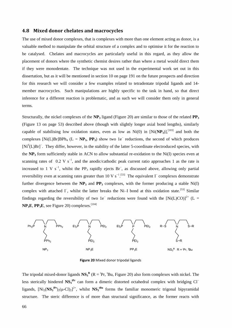
66
4.8 Mixed donor chelates and macrocycles
The use of mixed donor complexes, that is complexes with more than one element acting as donor, is a
valuable method to manipulate the orbital structure of a complex and to optimise it for the reaction to
be catalysed. Chelates and macrocycles are particularly useful in this regard, as they allow the
placement of donors where the synthetic chemist desires rather than where a metal would direct them
if they were monodentate. The technique was not used in the experimental work set out in this
dissertation, but as it will be mentioned in section 10 on page 191 on the future prospects and direction
for this research we will consider a few examples related to tetradentate tripodal ligands and 14-
member macrocycles. Such manipulations are highly specific to the task in hand, so that direct
inference for a different reaction is problematic, and as such we will consider them only in general
terms.
Structurally, the nickel complexes of the NP3 ligand (Figure 20) are similar to those of the related PP3
(Figure 13 on page 53) described above (though with slightly longer axial bond lengths), similarly
capable of stabilising low oxidation states, even as low as Ni(0) in [Ni(NP3)],[103]
and both the
complexes [Ni(L)Br]BPh4 (L = NP3, PP3) show two 1e− reductions, the second of which produces
[Ni0(L)Br]
−. They differ, however, in the stability of the latter 5-coordinate electroduced species, with
the NP3 form sufficiently stable in ACN to allow substantial re-oxidation to the Ni(I) species even at
scanning rates of 0.2 V s−1
, and the anodic/cathodic peak current ratio approaches 1 as the rate is
increased to 1 V s−1
, whilst the PP3 rapidly ejects Br−, as discussed above, allowing only partial
reversibility even at scanning rates greater than 10 V s−1
.[53]
The equivalent I− complexes demonstrate
further divergence between the NP3 and PP3 complexes, with the former producing a stable Ni(I)
complex with attached I−, whilst the latter breaks the Ni–I bond at this oxidation state.
[53] Similar
findings regarding the reversibility of two 1e− reductions were found with the [Ni(L)CO)]
2+ (L =
NP3E, PP3E, see Figure 20) complexes.[104]
Figure 20 Mixed donor tripodal ligands
The tripodal mixed-donor ligands NS3R (R =
iPr,
tBu, Figure 20) also form complexes with nickel. The
less sterically hindered NS3iPr
can form a dimeric distorted octahedral complex with bridging Cl−
ligands, [Ni2(NS3iPr
)2(μ-Cl)2]2+
, whilst NS3tBu
forms the familiar monomeric trigonal bipyramidal
structure. The steric difference is of more than structural significance, as the former reacts with
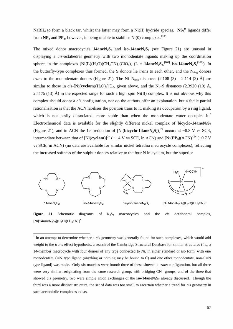
67
NaBH4 to form a black tar, whilst the latter may form a Ni(II) hydride species. NS3R ligands differ
from NP3 and PP3, however, in being unable to stabilise Ni(0) complexes.[105]
The mixed donor macrocycles 14aneN2S2 and iso-14aneN2S2 (see Figure 21) are unusual in
displaying a cis-octahedral geometry with two monodentate ligands making up the coordination
sphere, in the complexes [Ni(L)(H2O)(CH3CN)](ClO4)2 (L = 14aneN2S2,[106]
iso-14aneN2S2[107]
). In
the butterfly-type complexes thus formed, the S donors lie trans to each other, and the Nring donors
trans to the monodentate donors (Figure 21). The Ni–Nring distances (2.108 (3) – 2.114 (3) Å) are
similar to those in cis-[Ni(cyclam)(H2O)2]Cl2, given above, and the Ni–S distances (2.3920 (10) Å,
2.4175 (13) Å) in the expected range for such a high spin Ni(II) complex. It is not obvious why this
complex should adopt a cis configuration, nor do the authors offer an explanation, but a facile partial
rationalisation is that the ACN labilises the position trans to it, making its occupation by a ring ligand,
which is not easily dissociated, more stable than when the monodentate water occupies it.*
Electrochemical data is available for the slightly different nickel complex of bicyclo-14aneN2S2
(Figure 21), and in ACN the 1e− reduction of [Ni(bicyclo-14aneN2S2)]
2+ occurs at −0.8 V vs SCE,
intermediate between that of [Ni(cyclam)]2+
(−1.4 V vs SCE, in ACN) and [Ni(PP3)(ACN)]2+
(−0.7 V
vs SCE, in ACN) (no data are available for similar nickel tetrathia macrocycle complexes), reflecting
the increased softness of the sulphur donors relative to the four N in cyclam, but the superior
Figure 21 Schematic diagrams of N2S2 macrocycles and the cis octahedral complex,
[Ni(14aneN2S2)(H2O)(CH3CN)]+
* In an attempt to determine whether a cis geometry was generally found for such complexes, which would add
weight to the trans effect hypothesis, a search of the Cambridge Structural Database for similar structures (i.e., a
14-member macrocycle with four donors of any type connected to Ni, in either standard or iso form, with one
monodentate C≡N type ligand (anything or nothing may be bound to C) and one other monodentate, non-C≡N
type ligand) was made. Only six matches were found: three of these showed a trans configuration, but all three
were very similar, originating from the same research group, with bridging CN− groups, and of the three that
showed cis geometry, two were simple anion exchanges of the iso-14aneN2S2 already discussed. Though the
third was a more distinct structure, the set of data was too small to ascertain whether a trend for cis geometry in
such acetonitrile complexes exists.

68
stabilisation of low oxidation states by P in PP3. [Ni(bicyclo-14aneN2S2)]2+
is oxidised to a Ni(III)
species at +0.9 V vs SCE, a more anodic potential by 0.2 V than for the cyclam complex.*
An N2P2 mixed donor macrocycle has been synthesised (12aneN2P2, Figure 22),[108]
though as yet no
complex with nickel has been reported. Interestingly though, it is able to form Al(I) complexes,
including the hydride upon reaction of [AlI(12aneN2P2)Cl] with LiAlH4,
109 highlighting the ability of
such ligands to stabilise low oxidation states.
Figure 22 Schematic diagram of 12aneN2P2 macrocycle
This concludes the introduction to chelates and macrocycles. We will now look at a quite different
topic that arose during our investigations of nickel tetrathioether macrocycle complexes, hydration and
dehydration reactions.
* The authors make an interesting observation that increasing the ring size from 13 to 15 members facilitates
reduction from Ni(II) to Ni(I) through a reduction of the in-plane ligand field (i.e., the repulsion experienced by,
and thus energy of, the dx2−y2 orbital), but concomitantly hinders the oxidation from Ni(II) to Ni(III), such that
the Ni(III)/Ni(I) gap measured by cyclic voltammetry remains about 1.8 V.
69
References
1 S. C. Woodhouse, English-Greek Dictionary: A Vocabulary of the Attic Language, George Routledge & Sons,
London, 1910, p. 136.
2 There are many, sometimes contradicting, introductions to the chelate and macrocyclic effects. In
addition to those specifically cited below, the following provide useful information: E. L. Simmons, Journal
of Chemical Education, 1979, 56, 578; C.-S. Chung, Journal of Chemical Education, 1984, 61, 1062; D. H.
Busch, Chemical Reviews 1993, 93, 847; E. C. Constable, Coordination Chemistry of Macrocyclic
Compounds, OUP, Oxford, 1999, pp. 54-68; T. Hubin, Coordination Chemistry Reviews, 2003, 241, 27; J. R.
Gispert, Coordination Chemistry, Wiley-VCH, Weiheim, 2008, pp.208-215; J. W. Steed, J. L. Atwood,
Supramolecular Chemistry, John Wiley & Sons, 2009, pp.17-21.
3 F. Westheimer, L. L. Ingraham, Journal of Physical Chemistry, 1956, 60, 1668.
4 A. Lüttringhaus, K. Ziegler, Liebigs Annalen, 1937, 528, 155 (in German), as cited in reference 7.
5 D. H. Busch, Helvetica Chimica Acta, 1967, 50, 174.
6 "Charles J. Pedersen - Autobiography". Nobelprize.org. Retrieved 26 Oct 2011
http://www.nobelprize.org/nobel_prizes/chemistry/laureates/1987/pedersen-autobio.html
7 C. J. Pedersen, Journal of the American Chemical Society, 1967, 89, 7017.
8 Some of the earlier works include: M. M. Blight, N. F. Curtis, Journal of the Chemical Society (Resumed),
1962, 3016; D. A. House, N. F. Curtis, Journal of the American Chemical Society, 1964, 86, 223; N. F. Curtis,
Journal of the Chemical Society (Resumed), 1964, 2644.
9 D. K. Cabbiness, D. W. Margerum, Journal of the American Chemical Society, 1969, 91, 6540.
10 E. C. Constable, Coordination Chemistry of Macrocyclic Compounds, OUP, Oxford, 1999, p. 1.
11 F. P. Hinz, D. W. Margerum, Inorganic Chemistry, 1974, 13, 2941; G. F. Smith, D. W. Margerum, Journal of
the Chemical Society, Chemical Communications, 1975, 807.
12 L. Fabbrizzi, P. Paoletti, A. B. P. Lever, Inorganic Chemistry, 1976, 15, 1502; M. Kodama, E. Kimura, Journal
of the Chemical Society, Dalton Transactions, 1978, 1081; L. Fabbrizzi, P. Paoletti, R. M. Clay, Inorganic
Chemistry, 1978, 17, 1042.
13 A. E. Martell, R. D. Hancock, Metal Complexes in Aqueous Solutions, Plenum Press, New York, 1996, pp.
98-100.
14 D. H. Busch, Chemical Reviews, 1993, 93, 847.
15 A. Bianchi, M. Micheloni, P. Paoletti, Coordination Chemistry Reviews, 1991, 110, 17; also cited in E. C.
Constable, Coordination Chemistry of Macrocyclic Compounds, OUP, Oxford, 1999, p. 55.
16 D. J. Cram, Journal of Inclusion Phenomena, 1988, 6, 397.
17 M. A. Fox, J. K. Whitesell, Organic Chemistry, 2nd Ed., Jones and Bartlett, Sudbury, MA, 1997, p. 20-36
18 R. D. Hancock, Journal of Chemical Education, 1992, 69, 615; A. Martell, R. Hancock, R. Motekaitis,
Coordination Chemistry Reviews, 1994, 133, 3.
19 E. C. Constable, Coordination Chemistry of Macrocyclic Compounds, OUP, Oxford, 1999, pp. 19-26.
20 J. M. Desper, S. H. Gellman, Journal of the American Chemical Society, 1990, 112, 6732.
21 B. Bosnich, C. K. Poon, M. L. Tobe, Inorganic Chemistry, 1965, 4, 1102.
22 R. D. Hancock, A. E. Martell, Chemical Reviews, 1989, 89, 1875.
23 J. A. K. Bauer, S. E. Edison, M. J. Baldwin, Acta Crystallographica Section E, 2004, 61, 82.
24 M. Singh, A. K. Pandey, R. J. Butcher, N. K. Singh, Polyhedron, 2009, 28, 461.

70
25 L. N. Swink, M. Atoji, Acta Crystallographica, 1960, 13, 639.
26 G. Brewer, R. J. Butcher, J. P. Jasinski, Acta crystallographica. Section E, 2009, 66, m103.
27 C. N. Caughlan, K. Emerson, Inorganic Chemistry, 1970, 9, 2421.
28 R. E. Cramer, W. Van Doorne, J. T. Huneke, Inorganic Chemistry, 1976, 15, 529.
29 D. L. Leussing, G. S. Alberts, Journal of the American Chemical Society, 1960, 82, 4458; J. R. Dorfman, C. P.
Rao, R. H. Holm, Inorganic Chemistry, 1985, 24, 453.
30 N. Baidya, P. K. Mascharak, D. W. Stephan, C. F. Campagna, Inorganica Chimica Acta, 1990, 177, 233.
31 M. A. Halcrow, G. Christou, Chemical Reviews, 1994, 94, 2421.
32 J. Chatt, F. A. Hart, Journal of the Chemical Society (Resumed), 1960, 1378.
33 A. F. Williams, Acta Crystallographica Section C, 1989, 45, 1002.
34 H. Hartung, U. Baumeister, B. Walther, M. Maschmeier, Zeitschrift für Anorganische und Allgemeine
Chemie, 1989, 578, 177.
35 W. Kaim, Coordination Chemistry Reviews, 1987, 76, 187.
36 F. Blau, Monatshefte für Chemie, 1898, 19, 647; G. T. Morgan, F. H. Burstall, Journal of the Chemical
Society (Resumed) , 1931, 2213.
37 G. K. Schweitzer, J. M. Lee, Journal of the American Chemical Society, 1952, 56, 195.
38 A. Wada, N. Sakabe, J. Tanaka, Acta Crystallographica Section B, 1976, 32, 1121.
39 F. Basolo, J. C. Hayes, H. M. Neumann, Journal of the American Chemical Society, 1953, 75, 5102.
40 R. E. Norman, M. Xie, Journal of Coordination Chemistry, 2004, 57, 425.
41 R. Miyakoshi, A. Yokoyama, T. Yokozawa, Journal of the American Chemical Society, 2005, 127, 17542.
42 P. Le Floch, D. Carmichael, L. Ricard, F. Mathey, A. Jutand, C. Amatore, Organometallics, 1992, 11, 2475.
43 P. Le Floch, Coordination Chemistry Reviews, 2006, 250, 627.
44 P. Le Floch, L. Ricard, F. Mathey, A. Jutand, C. Amatore, Inorganic Chemistry, 1995, 34, 11.
45 J. Ellermeier, R. Stähler, W. Bensch, Acta Crystallographica Section C, 2002, 58, m70.
46 A. Marzotto, D. A. Clemente, G. Valle, Acta Crystallographica Section C, 1993, 49, 1252.
47 F. Březina, Z. Trávníček, Z. Šindelář, R. Pastorek, J. Marek, Transition Metal Chemistry, 1999, 24, 459.
48 C. Ochs, F. E. Hahn, T. Lügger, European Journal of Inorganic Chemistry, 2001, 2001, 1279.
49 M. Ciampolini, N. Nardi, Inorganic Chemistry, 1966, 5, 41.
50 J. Hierso, R. Amardeil, E. Bentabet, R. Broussier, B. Gautheron, P. Meunier, P. Kalck, Coordination
Chemistry Reviews, 2003, 236, 143.
51 M. Di Vaira, S. Midollini, L. Sacconi, Inorganic Chemistry, 1977, 16, 1518.
52 W. H. Hohman, D. J. Kountz, D. W. Meek, Inorganic Chemistry, 1986, 25, 616.
53 C. A. Ghilardi, C. Mealli, S. Midollini, A. Orlandini, D. M. Proserpio, A. Cinquantini, P. Zanello, Structural
Chemistry, 1990, 1, 441.
54 M. Di Vaira, P. Stoppioni, J. A. McCleverty, Gazzeta Chimica Italiana, 1995, 125, 277.
55 T. Whyte, A. T. Casey, G. A. Williams, Inorganic Chemistry, 1995, 34, 2781.
56 K. Linn, D. Masi, C. Mealli, C. Bianchini, M. Peruzzini, Acta Crystallographica Section C, 1992, 48, 2220; C.
Bianchini, D. Masi, M. Peruzzini, M. Casarin, C. Maccato, G. A. Rizzi, Inorganic Chemistry, 1997, 36, 1061.
57 P. Paoletti, Pure and Applied Chemistry, 1980, 52, 2433.
58 V. J. Thöm, R. D. Hancock, Journal of the Chemical Society, Dalton Transactions, 1985, 1877.

71
59 M. A. Donnelly, M. Zimmer, Inorganic Chemistry, 1999, 38, 1650.
60 L. Fabbrizzi, Journal of the Chemical Society, Dalton Transactions, 1979, 1857.
61 E. J. Billo, Inorganic Chemistry, 1981, 20, 4019.
62 L. Prasad, A. McAuley, Acta Crystallographica Section C, 1983, 39, 1175.
63 V. J. Thöm, C. C. Fox, J. C. A. Boeyens, R. D. Hancock, Journal of the American Chemical Society, 1984, 106,
5947.
64 T. Ito, M. Kato, H. Ito, Bulletin of the Chemical Society of Japan, 1984, 57, 2641.
65 L. F. Lindoy, M. S. Mahinay, B. W. Skelton, A. H. White, Journal of Coordination Chemistry, 2003, 56, 1203.
66 K. Mochizuki, T. Kondo, Inorganic Chemistry, 1995, 34, 6241.
67 E. K. Barefield, A. Bianchi, E. J. Billo, P. J. Connolly, P. Paoletti, J. S. Summers, D. G. Van Derveer, Inorganic
Chemistry, 1986, 25, 4197.
68 L. Prasad, S. C. Nyburg, A. McAuley, Acta Crystallographica Section C, 1987, 43, 1038.
69 L. Prasad, A. McAuley, Acta Crystallographica Section C, 1983, 39, 1175.
70 S. N. Cherni, A. Driss, Analytical Sciences: X-ray Structure Analysis Online, 2007, 23, x3.
71 M. Boiocchi, L. Fabbrizzi, F. Foti, M. Vazquez, Dalton Transactions, 2004, 2616.
72 B. Bosnich, C. K. Poon, M. L. Tobe, Inorganic Chemistry, 1965, 4, 1102.
73 S. G. Murray, F. R. Hartley, Chemical Reviews, 1981, 81, 365.
74 G. F. Smith, D. W. Margerum, Journal of the Chemical Society, Chemical Communications, 1975, 807.
75 P. H. Davis, L. K. White, R. L. Belford, Inorganic Chemistry, 1975, 14, 1753.
76 J. M. Desper, S. H. Gellman, R. E. Wolf, S. R. Cooper, Journal of the American Chemical Society, 1991, 113,
8663; J. M. Desper, J. R. Vyvyan, M. J. Mayer, L. A. Ochrymowycz, S. H. Gellman, Inorganic Chemistry,
1993, 32, 381.
77 C. P. Kulatilleke, S. N. Goldie, M. J. Heeg, L. A. Ochrymowycz, D. B. Rorabacher, Inorganic chemistry, 2000,
39, 1444.
78 A. G. Orpen, L. Brammer, F. H. Allen, D. G. Watson, R. Taylor, in International Tables for Crystallography
Vol.C (Ed.: E. Prince), 2006, Table 9.13.1.1, accessed online.
79 A. J. Blake, M. A. Halcrow, M. Schröder, Journal of the Chemical Society, Dalton Transactions, 1994, 12,
1463.
80 C. D. Swor, Synthesis, Coordination Chemistry, and Reactivity of Functionalized Phosphines: Toward Water-
soluble Macrocyclic Phosphine Complexes, PhD Thesis, University of Oregon, 2011.
81 L. Horner, H. Kunz, Chemische Berichte, 1971, 104, 717.
82 T. A. DelDonno, W. Rosen, Journal of the American Chemical Society, 1977, 99, 8051.
83 M. Ciampolini, P. Dapporto, N. Nardi, F. Zanobini, Inorganica Chimica Acta, 1980, 45, L239.
84 C. F. Macrae, I. J. Bruno, J. A. Chisholm, P. R. Edgington, P. McCabe, E. Pidcock, L. Rodriguez-Monge, R.
Taylor, J. van de Streek, P. A. Wood, Journal Applied Crystallography, 2008, 41, 466.
85 A. G. Orpen, L. Brammer, F. H. Allen, D. G. Watson, R. Taylor, in International Tables for Crystallography
Vol.C (Ed.: E. Prince), 2006, Tables 5.21.1.1 and 15.1.1.2 respectively.
86 http://www.webelements.com/nickel/compounds.html
87 http://www.webelements.com/hydrogen/compounds.html
88 N. V. Peganova, V. I. Kravtsov, R. K. Astakhova, Russian Journal of Electrochemistry, 2002, 38, 725.

72
89 T. Melki, A. Zouaoui, B. Bendemagh, I. M. F. D. Oliveira, G. F. D. Oliveira, J.-C. Leprêtre, C. Bucher, J.-C.
Moutet, Journal of the Brazilian Chemical Society, 2009, 20, 1523.
90 J. Lati, D. Meyerstein, Inorganic Chemistry, 1972, 11, 2397.
91 P. J. Farmer, J. H. Reibenspies, P. A. Lindahl, M. Y. Darensbourg, Journal of the American Chemical Society,
1993, 115, 4665.
92 J.-P. Collin, A. Jouaiti, J.-P. Sauvage, Inorganic Chemistry, 1988, 27, 1986.
93 E. Zeigerson, G. Ginzburg, L. Kirschenbaum, D. Meyerstein, Journal of Electroanalytical Chemistry, 1981,
127, 113.
94 I. Zilbermann, E. Maimon, H. Cohen, D. Meyerstein, Chemical Reviews, 2005, 105, 2609.
95 M. Shionoya, E. Kimura, Y. Iitaka, Journal of the American Chemical Society, 1990, 112, 9237.
96 D. L. DuBois, A. Miedaner, Inorganic Chemistry, 1986, 25, 4642.
97 W. Grochala, Physical Chemistry Chemical Physics, 2006, 8, 1340.
98 R. G. Pearson, Proceedings of the National Academy of Sciences of the United States of America, 1986, 83,
8440.
99 B. J. Fisher, R. Eisenberg, Journal of the American Chemical Society, 1980, 102, 7361.
100 M. Beley, J.-P. Collin, R. Ruppert, J.-P. Sauvage, Journal of the Chemical Society, Chemical Communications,
1984, 2, 1315; J.-P. Collin, M. Beley, J.-P. Sauvage, R. Ruppert, Journal of the American Chemical Society,
1986, 108, 7461.
101 C. A. Kelly, Q. G. Mulazzani, M. Venturi, E. L. Blinn, M. A. J. Rodgers, Journal of the American Chemical
Society, 1995, 117, 4911; C. A. Kelly, E. L. Blinn, N. Camaioni, M. D’Angelantonio, Q. G. Mulazzani,
Inorganic Chemistry, 1999, 38, 1579.
102 J. A. Dean, Lange’s Handbook of Chemistry, Mcgraw-hill, 1999, p. 166.
103 L. Sacconi, C. A. Ghilardi, C. Mealli, F. Zanobini, Inorganic Chemistry, 1975, 14, 1380.
104 A. Miedaner, C. J. Curtis, S. A. Wander, P. A. Goodson, D. L. DuBois, Organometallics, 1996, 15, 5185.
105 P. Stavropoulos, M. C. Muetterties, M. Carrie, R. H. Holm, Journal of the American Chemical Society, 1991,
113, 8485.
106 W. Malasi, Synthesis and Complexation of Functionalized Mixed Thia-aza-macrocyclic and Medium Sized
Ligands, PhD Thesis, University of Akron, 2009.
107 J. D. Chartres, M. S. Davies, L. F. Lindoy, G. V. Meehan, G. Wei, Inorganic Chemistry Communications,
2006, 9, 751.
108 M. D. Fryzuk, J. B. Love, S. J. Rettig, Chemical Communications, 1996, 2783.
109 M. D. Fryzuk, G. R. Giesbrecht, S. J. Rettig, G. P. Yap, Journal of Organometallic Chemistry, 1999, 591, 63.

73
5. Reversible thermal dehydration in solid state transition metal
complexes
5.1. Introduction .................................................................................................................................... 74
5.2. Types of interaction ....................................................................................................................... 75
5.3. Dehydration reactions as models for generalised solid state decompositions ............................... 75
5.4. Experimental methods for the investigation of solid-state reactions ............................................. 76
5.4.1. Thermal analysis and reaction kinetics ................................................................................... 76
5.5. Reaction mechanisms ..................................................................................................................... 81
5.6. Examples of dehydration reactions involving nickel ..................................................................... 86
5.6.1. Simple salts and complexes .................................................................................................... 86
5.6.2. Coordination polymers ............................................................................................................ 88
References ............................................................................................................................................. 91
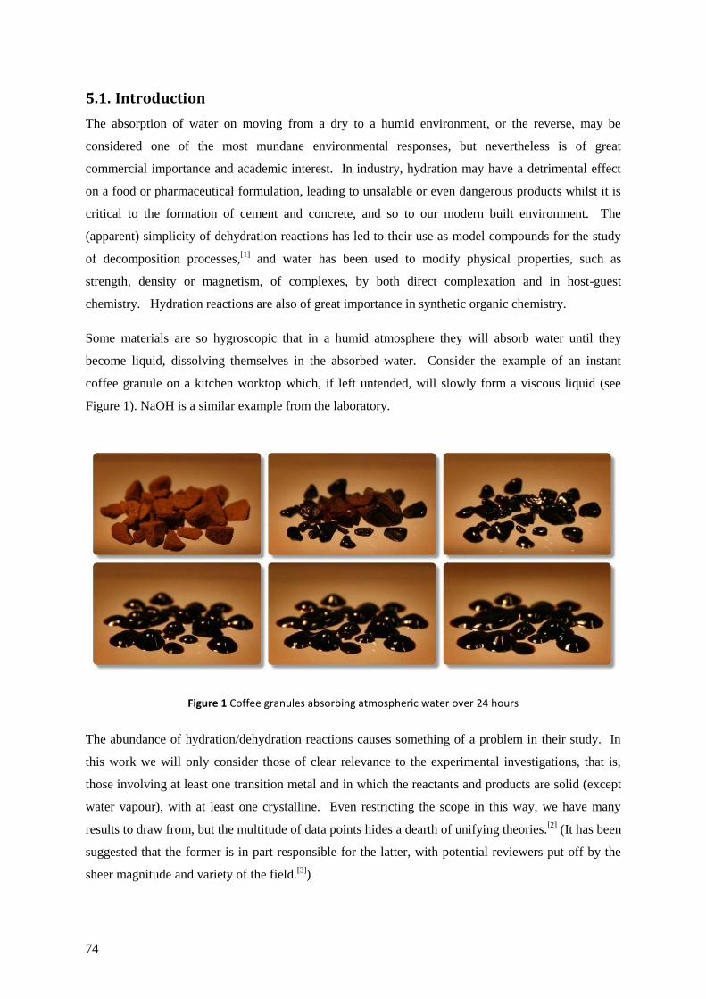
74
5.1. Introduction
The absorption of water on moving from a dry to a humid environment, or the reverse, may be
considered one of the most mundane environmental responses, but nevertheless is of great
commercial importance and academic interest. In industry, hydration may have a detrimental effect
on a food or pharmaceutical formulation, leading to unsalable or even dangerous products whilst it is
critical to the formation of cement and concrete, and so to our modern built environment. The
(apparent) simplicity of dehydration reactions has led to their use as model compounds for the study
of decomposition processes,[1]
and water has been used to modify physical properties, such as
strength, density or magnetism, of complexes, by both direct complexation and in host-guest
chemistry. Hydration reactions are also of great importance in synthetic organic chemistry.
Some materials are so hygroscopic that in a humid atmosphere they will absorb water until they
become liquid, dissolving themselves in the absorbed water. Consider the example of an instant
coffee granule on a kitchen worktop which, if left untended, will slowly form a viscous liquid (see
Figure 1). NaOH is a similar example from the laboratory.
Figure 1 Coffee granules absorbing atmospheric water over 24 hours
The abundance of hydration/dehydration reactions causes something of a problem in their study. In
this work we will only consider those of clear relevance to the experimental investigations, that is,
those involving at least one transition metal and in which the reactants and products are solid (except
water vapour), with at least one crystalline. Even restricting the scope in this way, we have many
results to draw from, but the multitude of data points hides a dearth of unifying theories.[2]
(It has been
suggested that the former is in part responsible for the latter, with potential reviewers put off by the
sheer magnitude and variety of the field.[3]
)
75
5.2. Types of interaction
When water is absorbed it interacts with the absorbent in one of two ways:
via covalent bonds using the lone pair of the oxygen atom to form a coordination complex
(this typically occurs with metal cations);
hydrogen bonds and weaker van der Waals forces
The latter, typically occurring in the second or further coordination spheres, may be classified
according to the stability of the crystal in their absence: if the crystal structure will change drastically
or even collapse it is often called a water of crystallisation; where the underlying structure changes
only minimally (for example contraction of the crystal lattice) and the underlying bonding remains
consistent, these are generally known as host-guest systems.
5.3. Dehydration reactions as models for generalised solid state
decompositions
In his treatise on dehydration reactions, Galwey states “A dehydration reaction that involves loss of a
coordinated H2O ligand is, therefore, correctly regarded as the decomposition of a coordination
compound”.[3]
Thus, dehydrations form a subset of this larger category of reactions, solid state
decompositions, of which the hydrogen desorption reactions discussed in sections 3.6 – 3.8 and
explored experimentally in section 6 are another subset. We may also note that with regard to
thermodynamics, the ease of the absorption/desorption of water represents a fine balance between the
increased entropy of water vapour, and the more favourable enthalpy of the bonding of the absorbed
water to the absorbent, just as in the case of hydrogen storage. The kinetics and mechanisms of
thermal decomposition reactions have received consistent attention over a long time period, and have
often provided the model chemicals for investigations into the fundamental theories of solid state
reactions. There exists, therefore, the possibility to apply the lessons from this mature field to that of
solid state hydrogen storage, as well as being of relevance to the hydration/dehydration experimental
work detailed in section 8.
Unfortunately the lessons do not make for easy reading, as the first paragraph to M.E. Brown‟s paper
accompanying his NATAS-Mettler Outstanding Achievement Award makes clear:
“When one attempts to read the intimidating and rather indigestible literature of kinetics of solid
state processes and, in particular, the papers on non-isothermal kinetics (NIK), one cannot help
noticing the similarities between Science and Religion. Those who believe that they have found
the „true way‟ promote their points-of-view with evangelistic fervour and often mention with
contempt, or even attack, the practices of the „heathen‟. The field is full of dogma: „Thou shalt do
this ..... and thou shalt not do the other‟! An agnostic in the field (defined as a person who is
uncertain or noncommital) searches, perhaps in vain, for what is useful and what is not.”[4]
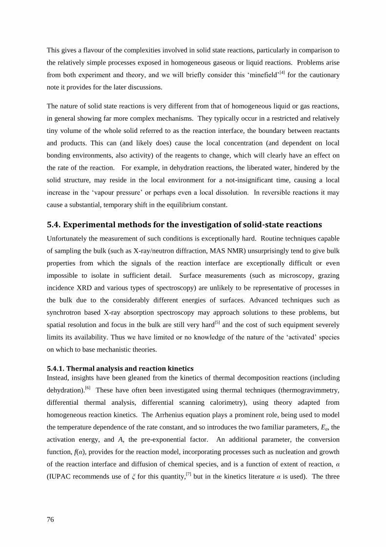
76
This gives a flavour of the complexities involved in solid state reactions, particularly in comparison to
the relatively simple processes exposed in homogeneous gaseous or liquid reactions. Problems arise
from both experiment and theory, and we will briefly consider this „minefield‟[4]
for the cautionary
note it provides for the later discussions.
The nature of solid state reactions is very different from that of homogeneous liquid or gas reactions,
in general showing far more complex mechanisms. They typically occur in a restricted and relatively
tiny volume of the whole solid referred to as the reaction interface, the boundary between reactants
and products. This can (and likely does) cause the local concentration (and dependent on local
bonding environments, also activity) of the reagents to change, which will clearly have an effect on
the rate of the reaction. For example, in dehydration reactions, the liberated water, hindered by the
solid structure, may reside in the local environment for a not-insignificant time, causing a local
increase in the „vapour pressure‟ or perhaps even a local dissolution. In reversible reactions it may
cause a substantial, temporary shift in the equilibrium constant.
5.4. Experimental methods for the investigation of solid-state reactions
Unfortunately the measurement of such conditions is exceptionally hard. Routine techniques capable
of sampling the bulk (such as X-ray/neutron diffraction, MAS NMR) unsurprisingly tend to give bulk
properties from which the signals of the reaction interface are exceptionally difficult or even
impossible to isolate in sufficient detail. Surface measurements (such as microscopy, grazing
incidence XRD and various types of spectroscopy) are unlikely to be representative of processes in
the bulk due to the considerably different energies of surfaces. Advanced techniques such as
synchrotron based X-ray absorption spectroscopy may approach solutions to these problems, but
spatial resolution and focus in the bulk are still very hard[5]
and the cost of such equipment severely
limits its availability. Thus we have limited or no knowledge of the nature of the „activated‟ species
on which to base mechanistic theories.
5.4.1. Thermal analysis and reaction kinetics
Instead, insights have been gleaned from the kinetics of thermal decomposition reactions (including
dehydration).[6]
These have often been investigated using thermal techniques (thermogravimmetry,
differential thermal analysis, differential scanning calorimetry), using theory adapted from
homogeneous reaction kinetics. The Arrhenius equation plays a prominent role, being used to model
the temperature dependence of the rate constant, and so introduces the two familiar parameters, Ea, the
activation energy, and A, the pre-exponential factor. An additional parameter, the conversion
function, f(α), provides for the reaction model, incorporating processes such as nucleation and growth
of the reaction interface and diffusion of chemical species, and is a function of extent of reaction, α
(IUPAC recommends use of ξ for this quantity,[7]
but in the kinetics literature α is used). The three
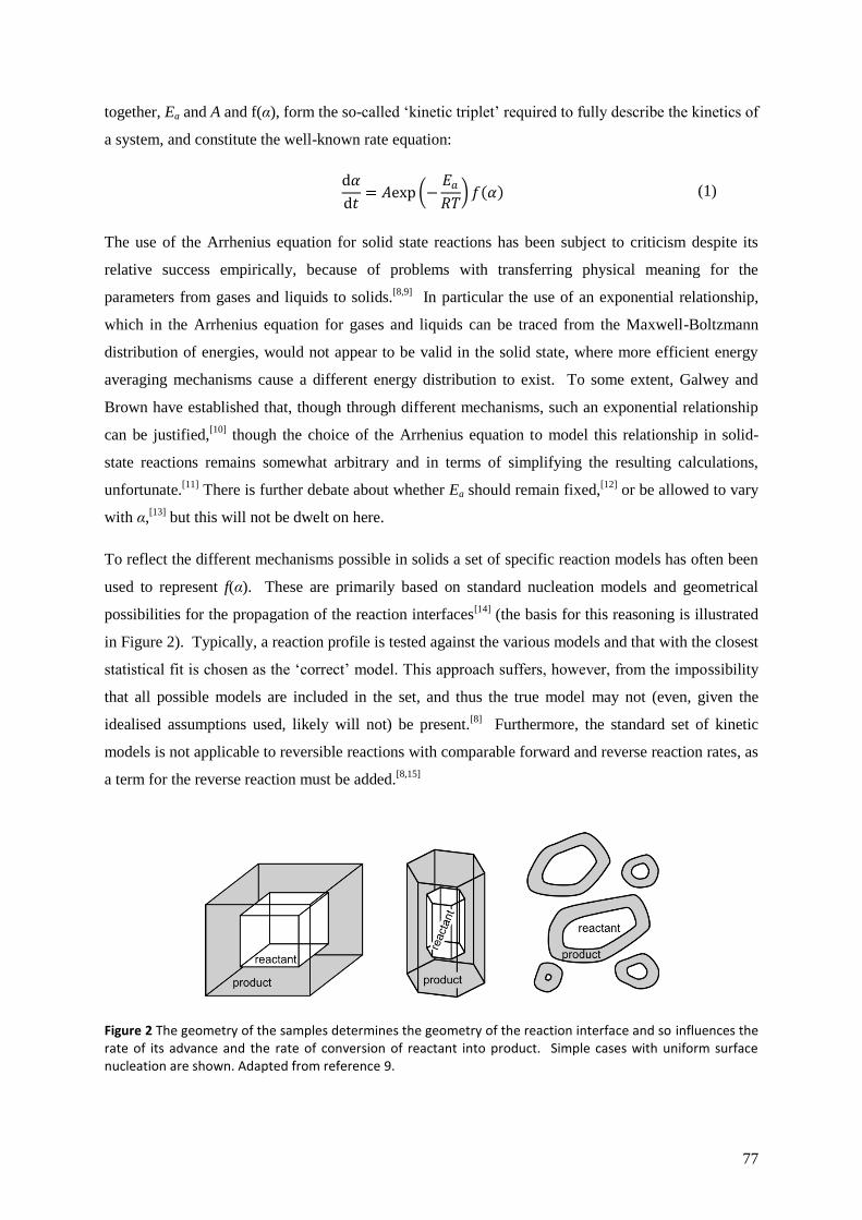
77
together, Ea and A and f(α), form the so-called „kinetic triplet‟ required to fully describe the kinetics of
a system, and constitute the well-known rate equation:
d𝛼
d𝑡= 𝐴exp −
𝐸𝑎
𝑅𝑇 𝑓 𝛼 (1)
The use of the Arrhenius equation for solid state reactions has been subject to criticism despite its
relative success empirically, because of problems with transferring physical meaning for the
parameters from gases and liquids to solids.[8,9]
In particular the use of an exponential relationship,
which in the Arrhenius equation for gases and liquids can be traced from the Maxwell-Boltzmann
distribution of energies, would not appear to be valid in the solid state, where more efficient energy
averaging mechanisms cause a different energy distribution to exist. To some extent, Galwey and
Brown have established that, though through different mechanisms, such an exponential relationship
can be justified,[10]
though the choice of the Arrhenius equation to model this relationship in solid-
state reactions remains somewhat arbitrary and in terms of simplifying the resulting calculations,
unfortunate.[11]
There is further debate about whether Ea should remain fixed,[12]
or be allowed to vary
with α,[13]
but this will not be dwelt on here.
To reflect the different mechanisms possible in solids a set of specific reaction models has often been
used to represent f(α). These are primarily based on standard nucleation models and geometrical
possibilities for the propagation of the reaction interfaces[14]
(the basis for this reasoning is illustrated
in Figure 2). Typically, a reaction profile is tested against the various models and that with the closest
statistical fit is chosen as the „correct‟ model. This approach suffers, however, from the impossibility
that all possible models are included in the set, and thus the true model may not (even, given the
idealised assumptions used, likely will not) be present.[8]
Furthermore, the standard set of kinetic
models is not applicable to reversible reactions with comparable forward and reverse reaction rates, as
a term for the reverse reaction must be added.[8,15]
Figure 2 The geometry of the samples determines the geometry of the reaction interface and so influences the rate of its advance and the rate of conversion of reactant into product. Simple cases with uniform surface nucleation are shown. Adapted from reference 9.
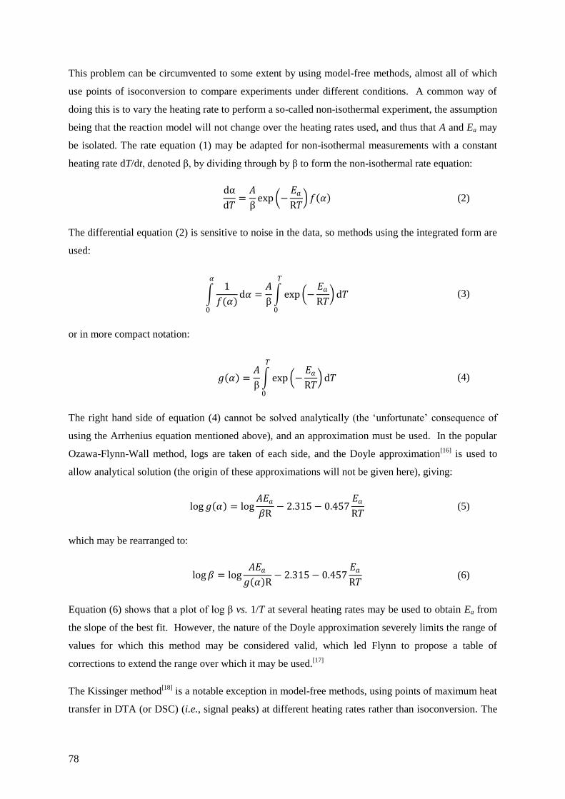
78
This problem can be circumvented to some extent by using model-free methods, almost all of which
use points of isoconversion to compare experiments under different conditions. A common way of
doing this is to vary the heating rate to perform a so-called non-isothermal experiment, the assumption
being that the reaction model will not change over the heating rates used, and thus that A and Ea may
be isolated. The rate equation (1) may be adapted for non-isothermal measurements with a constant
heating rate dT/dt, denoted β, by dividing through by β to form the non-isothermal rate equation:
dα
d𝑇=
𝐴
βexp −
𝐸𝑎
R𝑇 𝑓 𝛼 (2)
The differential equation (2) is sensitive to noise in the data, so methods using the integrated form are
used:
1
𝑓(𝛼)d𝛼
𝛼
0
=𝐴
β exp −
𝐸𝑎
R𝑇 d𝑇
𝑇
0
(3)
or in more compact notation:
𝑔 𝛼 =𝐴
β exp −
𝐸𝑎
R𝑇 d𝑇
𝑇
0
(4)
The right hand side of equation (4) cannot be solved analytically (the „unfortunate‟ consequence of
using the Arrhenius equation mentioned above), and an approximation must be used. In the popular
Ozawa-Flynn-Wall method, logs are taken of each side, and the Doyle approximation[16]
is used to
allow analytical solution (the origin of these approximations will not be given here), giving:
log𝑔 𝛼 = log
𝐴𝐸𝑎
𝛽R− 2.315− 0.457
𝐸𝑎
R𝑇 (5)
which may be rearranged to:
log𝛽 = log
𝐴𝐸𝑎
𝑔 𝛼 R− 2.315− 0.457
𝐸𝑎
R𝑇 (6)
Equation (6) shows that a plot of log β vs. 1/T at several heating rates may be used to obtain Ea from
the slope of the best fit. However, the nature of the Doyle approximation severely limits the range of
values for which this method may be considered valid, which led Flynn to propose a table of
corrections to extend the range over which it may be used.[17]
The Kissinger method[18]
is a notable exception in model-free methods, using points of maximum heat
transfer in DTA (or DSC) (i.e., signal peaks) at different heating rates rather than isoconversion. The
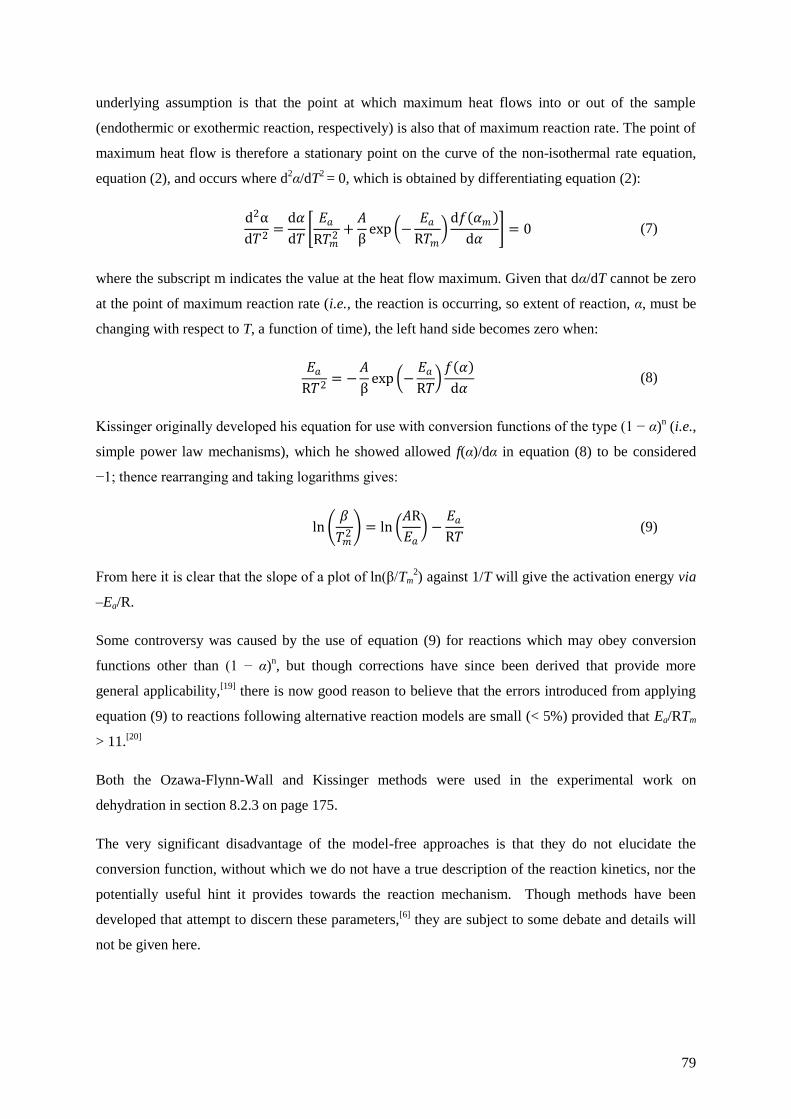
79
underlying assumption is that the point at which maximum heat flows into or out of the sample
(endothermic or exothermic reaction, respectively) is also that of maximum reaction rate. The point of
maximum heat flow is therefore a stationary point on the curve of the non-isothermal rate equation,
equation (2), and occurs where d2α/dT
2 = 0, which is obtained by differentiating equation (2):
d2α
d𝑇2=d𝛼
d𝑇 𝐸𝑎
R𝑇𝑚2 +
𝐴
βexp −
𝐸𝑎
R𝑇𝑚 d𝑓 𝛼𝑚
d𝛼 = 0 (7)
where the subscript m indicates the value at the heat flow maximum. Given that dα/dT cannot be zero
at the point of maximum reaction rate (i.e., the reaction is occurring, so extent of reaction, α, must be
changing with respect to T, a function of time), the left hand side becomes zero when:
𝐸𝑎
R𝑇2= −
𝐴
βexp −
𝐸𝑎
R𝑇 𝑓 𝛼
d𝛼 (8)
Kissinger originally developed his equation for use with conversion functions of the type (1 − α)n (i.e.,
simple power law mechanisms), which he showed allowed f(α)/dα in equation (8) to be considered
−1; thence rearranging and taking logarithms gives:
ln
𝛽
𝑇𝑚2 = ln
𝐴R
𝐸𝑎 −
𝐸𝑎
R𝑇 (9)
From here it is clear that the slope of a plot of ln(β/Tm2) against 1/T will give the activation energy via
–Ea/R.
Some controversy was caused by the use of equation (9) for reactions which may obey conversion
functions other than (1 − α)n, but though corrections have since been derived that provide more
general applicability,[19]
there is now good reason to believe that the errors introduced from applying
equation (9) to reactions following alternative reaction models are small (< 5%) provided that Ea/RTm
> 11.[20]
Both the Ozawa-Flynn-Wall and Kissinger methods were used in the experimental work on
dehydration in section 8.2.3 on page 175.
The very significant disadvantage of the model-free approaches is that they do not elucidate the
conversion function, without which we do not have a true description of the reaction kinetics, nor the
potentially useful hint it provides towards the reaction mechanism. Though methods have been
developed that attempt to discern these parameters,[6]
they are subject to some debate and details will
not be given here.

80
In order to improve the alignment of text, tables and figures, this page is not used.

81
5.5. Reaction mechanisms
Determination of reaction mechanisms in the solid-state is extremely difficult. In part this arises from
the limited information available to inform the analysis (see section above), but also from important
variables that may significantly influence a reaction, such as the partial pressures of any gaseous
products (i.e., water vapour in dehydration reactions) and the initial distribution of defects and other
nucleating points. The role of the former is seen in the rather odd behaviour of certain salts in which
the reaction rate is seen to depend on the water vapour pressure in a complex manner (see Figure 3),
termed the Smith-Topley (or Topley-Smith) effect.[21]
One possible explanation (perhaps the most
popular[22]
) is that the initial decrease in reaction rate at low water vapour pressure is caused by
adsorption on microchannels blocking water‟s escape route. The subsequent rise in reaction rate is
caused by the catalytic effect of water in the recrystallisation of the product phase,[21b]
which in turn
induces stresses that cause larger cracks to appear, allowing water to escape from the solid more
easily. As the water vapour pressure rises further, the usual equilibrium between competing forward
and reverse reactions starts to dominate and another decline in reaction rate is seen. (It is worth
stressing that this explanation has not been universally accepted, nor does it seem to account for all
reports of this effect,[23]
and the Smith-Topley effect can be seen as another cautionary tale of the
complexities of solid state reactions.)
Figure 3 Schematic of Smith-Topley effect (based on tabulated data in reference 21a),
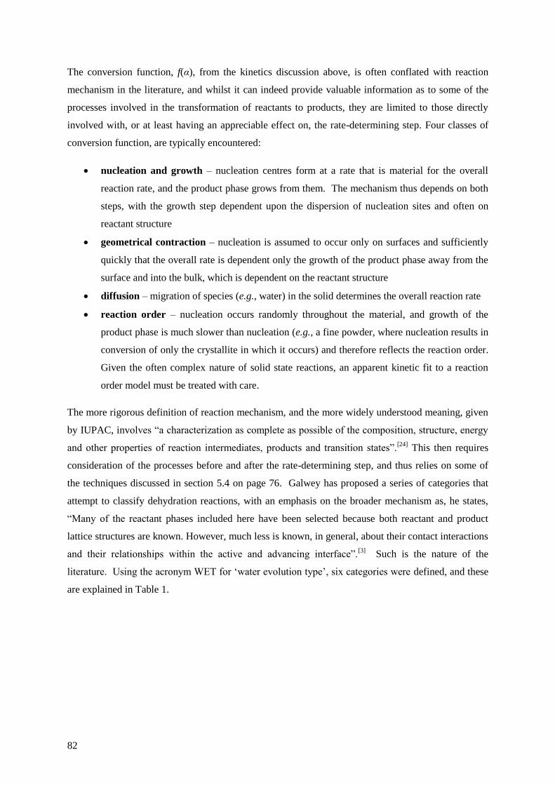
82
The conversion function, f(α), from the kinetics discussion above, is often conflated with reaction
mechanism in the literature, and whilst it can indeed provide valuable information as to some of the
processes involved in the transformation of reactants to products, they are limited to those directly
involved with, or at least having an appreciable effect on, the rate-determining step. Four classes of
conversion function, are typically encountered:
nucleation and growth – nucleation centres form at a rate that is material for the overall
reaction rate, and the product phase grows from them. The mechanism thus depends on both
steps, with the growth step dependent upon the dispersion of nucleation sites and often on
reactant structure
geometrical contraction – nucleation is assumed to occur only on surfaces and sufficiently
quickly that the overall rate is dependent only the growth of the product phase away from the
surface and into the bulk, which is dependent on the reactant structure
diffusion – migration of species (e.g., water) in the solid determines the overall reaction rate
reaction order – nucleation occurs randomly throughout the material, and growth of the
product phase is much slower than nucleation (e.g., a fine powder, where nucleation results in
conversion of only the crystallite in which it occurs) and therefore reflects the reaction order.
Given the often complex nature of solid state reactions, an apparent kinetic fit to a reaction
order model must be treated with care.
The more rigorous definition of reaction mechanism, and the more widely understood meaning, given
by IUPAC, involves “a characterization as complete as possible of the composition, structure, energy
and other properties of reaction intermediates, products and transition states”.[24]
This then requires
consideration of the processes before and after the rate-determining step, and thus relies on some of
the techniques discussed in section 5.4 on page 76. Galwey has proposed a series of categories that
attempt to classify dehydration reactions, with an emphasis on the broader mechanism as, he states,
“Many of the reactant phases included here have been selected because both reactant and product
lattice structures are known. However, much less is known, in general, about their contact interactions
and their relationships within the active and advancing interface”.[3]
Such is the nature of the
literature. Using the acronym WET for „water evolution type‟, six categories were defined, and these
are explained in Table 1.
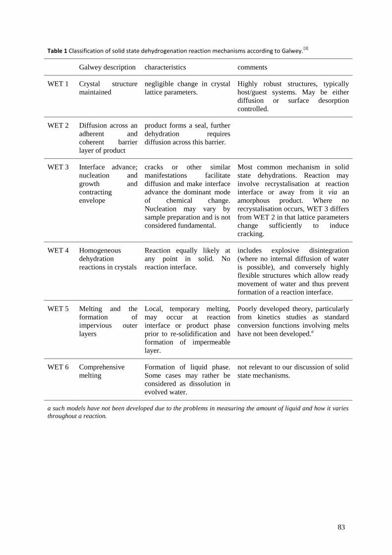
83
Table 1 Classification of solid state dehydrogenation reaction mechanisms according to Galwey.[3]
Galwey description characteristics comments
WET 1 Crystal structure
maintained
negligible change in crystal
lattice parameters.
Highly robust structures, typically
host/guest systems. May be either
diffusion or surface desorption
controlled.
WET 2 Diffusion across an
adherent and
coherent barrier
layer of product
product forms a seal, further
dehydration requires
diffusion across this barrier.
WET 3 Interface advance;
nucleation and
growth and
contracting
envelope
cracks or other similar
manifestations facilitate
diffusion and make interface
advance the dominant mode
of chemical change.
Nucleation may vary by
sample preparation and is not
considered fundamental.
Most common mechanism in solid
state dehydrations. Reaction may
involve recrystalisation at reaction
interface or away from it via an
amorphous product. Where no
recrystalisation occurs, WET 3 differs
from WET 2 in that lattice parameters
change sufficiently to induce
cracking.
WET 4 Homogeneous
dehydration
reactions in crystals
Reaction equally likely at
any point in solid. No
reaction interface.
includes explosive disintegration
(where no internal diffusion of water
is possible), and conversely highly
flexible structures which allow ready
movement of water and thus prevent
formation of a reaction interface.
WET 5 Melting and the
formation of
impervious outer
layers
Local, temporary melting,
may occur at reaction
interface or product phase
prior to re-solidification and
formation of impermeable
layer.
Poorly developed theory, particularly
from kinetics studies as standard
conversion functions involving melts
have not been developed.a
WET 6 Comprehensive
melting
Formation of liquid phase.
Some cases may rather be
considered as dissolution in
evolved water.
not relevant to our discussion of solid
state mechanisms.
a such models have not been developed due to the problems in measuring the amount of liquid and how it varies
throughout a reaction.

84
Petit and Coquerel proposed a „unified model for the dehydration mechanism of molecular crystals‟,
developed distinctly for organic and metal-organic compounds that lack extended networks of strong
bonds throughout the material.[25]
Two classes are identified, distinguished by whether or not the
product structure has a „filiation‟ with, (i.e., is derived from, or more literally, the child of), the
reactant structure, with Class I mechanisms showing no such relationship, and Class II mechanisms
possessing it. Four criteria are identified as necessary for maintaining the filiation:
C1, the material must be able to convey the water molecules to the surface with minimal
structural disruption, i.e., the hydrated structure should contain clear channels or planes of
water molecules, or be able to create them with minor, cooperative deformations
C2, the energy required to evolve the water should not also be able to disrupt the underlying
crystal lattice
C3, the loss of water must result in „domains‟ of sufficient size that cracks/grain boundaries
do not appear in sufficient number to raise the internal energy of the material and encourage
the nucleation and growth of a new phase (clearly, a higher degree of hydration in the starting
material is more likely to result in significant shrinkage of the domains)
C4, the loss of water must not introduce too many structural defects, i.e., the long range order
must remain sufficiently intact.
The first two are related to the mechanism of actual water loss, and the second to how the anhydrous
material rearranges itself after losing water. If any of them is not fulfilled, „structural information‟ will
not be transmitted from the reactants to the products.
The two classes are then sub-divided according to which criteria are met, and whether any final
reorganisation of the structure occurs. Class I is split according to whether the water release is
„cooperative‟ (C1 and C2 are met) or „destructive‟, and whether a nucleation and growth mechanism
reorders the structure („crystallised‟) or not („disorganised‟). Class II is split according to whether a
cooperative rearrangement of the structure occurs („reorganised‟) or not („topotactic‟). The latter is
considered to be on a sliding scale, and the degree of structural continuity between the reactant and
product is a function of the degree to which criteria 2 – 4 are met. Indeed, it seems that the two Class
II subcategories could be combined into one in this manner. A concise flow-chart was provided to aid
identification of mechanisms (see Figure 4). Unfortunately, the data required to classify according to
this scheme are often not available in the literature.
Thus, these theoretical and experimental complications noted, and frameworks for classifying
mechanisms considered, let us proceed with some examples.
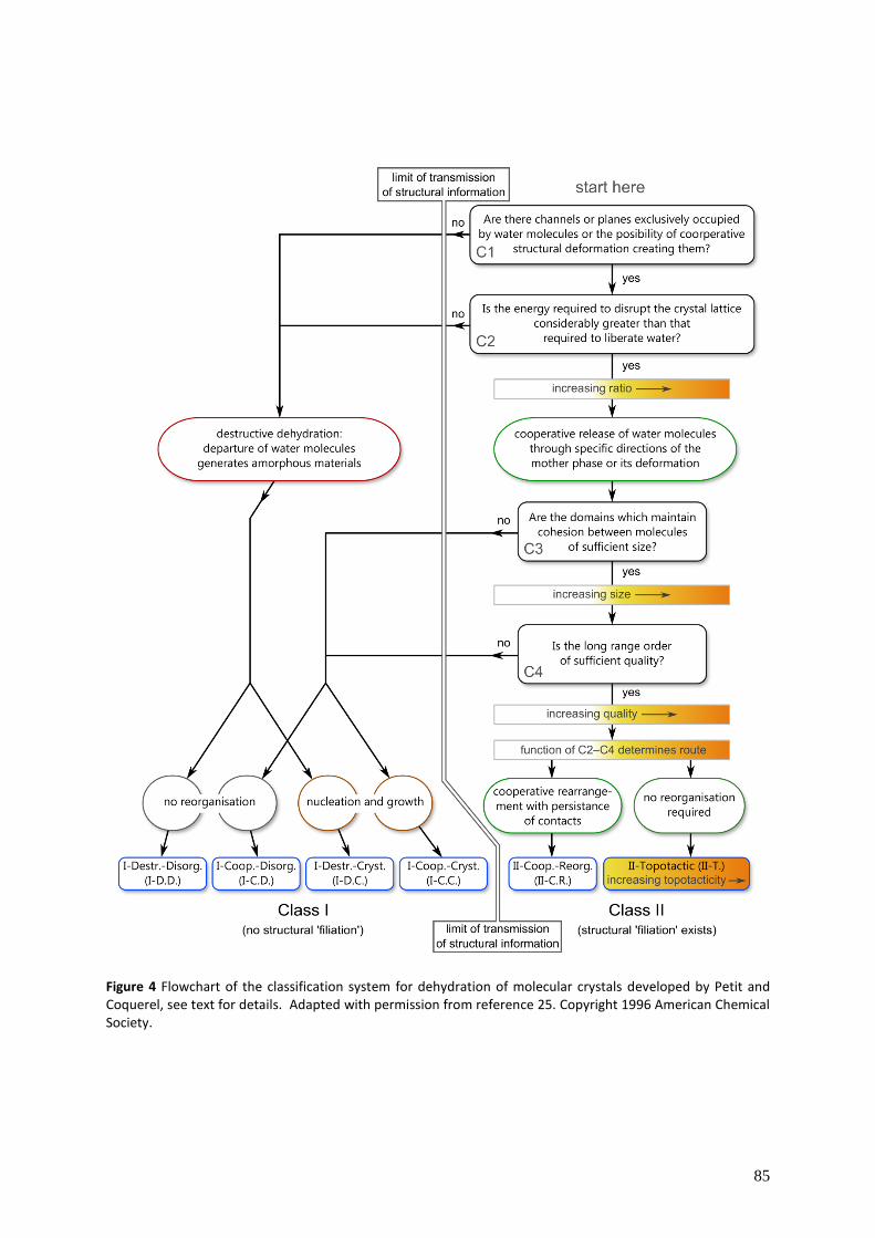
85
Figure 4 Flowchart of the classification system for dehydration of molecular crystals developed by Petit and Coquerel, see text for details. Adapted with permission from reference 25. Copyright 1996 American Chemical Society.

86
5.6. Examples of dehydration reactions involving nickel
5.6.1. Simple salts and complexes
The thermal dehydration of simple inorganic nickel salts has been investigated extensively. The most
recent studies on NiSO4·6H2O have shown that dehydration proceeds via a combination of nucleation
and growth mechanisms, releasing water first from surface layers.[26]
Furthermore, the initial
dehydration may form a relatively impermeable seal through which remaining water has difficulty
diffusing, to the extent that bubbles form under this layer which periodically burst allowing further
dehydration,[27]
a WET 2 mechanism according to Galwey‟s scheme. Ni(NO3)2·6H2O may lose two
waters in a step-wise fashion until the anhydrous salt is formed, but the reaction is very dependent on
pressure: at 5 × 10⁻⁵
bar dehydration to Ni(NO3)2 is possible; at 5 × 10⁻³
bar denitration occurs
simultaneously with dehydration, producing Ni(NO3)2·2Ni(OH)2;[28]
and at 0.1 bar and higher
pressures, a melt is formed from which only the oxides of nickel are isolatable.[28,29]
Dehydration of
NiCl2·6H2O is relatively straightforward as dehydrochlorination occurs at temperatures above which
the anhydrous salt is formed, though the number of steps appears to be highly dependent upon
measurement conditions[30–32]
and thus proposed mechanistic interpretations should be treated with
some scepticism. Similarly Ni3(PO4)2·7H2O may be dehydrated to Ni3(PO4)2 “or very close to it”.[33]
Thermal dehydration of Ni(BF4)2·6H2O is not possible (at ambient pressure), as the salt decomposes
releasing gaseous HxBOyFz compounds.[34]
Likewise, organic salts of Ni have also been the subject of much study, often driven by an interest in
using them as a precursor to high-surface area or nanoparticulate Ni or NiO. There is apparently
some dispute over whether nickel oxalate dihydrate, Ni(C2O4)·2H2O can be fully dehydrated without
further decomposition,[35,36]
though the majority of the literature evidence cited by Małecka et al.
points towards some remaining water, likely occluded in the highly porous dehydrated product.[36]
Anhydrous nickel acetate, Ni(CH3COO)2, may be formed from the tetrahydrate, but the conditions of
the thermal dehydration are important to prevent either hydrolysis of surface acetates (forming acetic
acid vapour) or further thermal decomposition to Ni(CH3COO)2·Ni(OH)2 and even NiO.[37,38]
Ni0
may also form and then catalyse side-reactions involving organic species, leading to a rich mixture of
organic gaseous products.[37]
Dehydration of nickel formate dihydrate, Ni(HCOO)2·2H2O, to the
anhydrous salt is apparently simpler,[39]
though details on kinetics and mechanisms are subject to
debate; even a detailed XAFS study was unable to reach definitive conclusions.[40]
The Lifschitz salts based on ethylene diamine (en) derivatives have been known for a long time,[41]
causing something of a mystery with their ability to form either blue paramagnetic or yellow
diamagnetic (or with anomalously low magnetic susceptibility) compounds.[42]
It was eventually
discovered that the origin of the colour change was caused by coordination of water, other solvent
molecules or anions (see Figure 5). The dehydration (or desolvation) is often accompanied by an
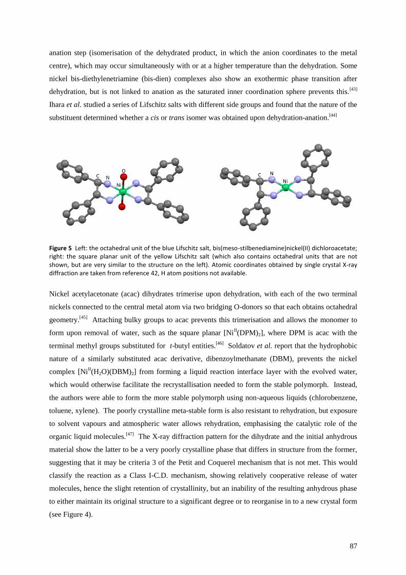
87
anation step (isomerisation of the dehydrated product, in which the anion coordinates to the metal
centre), which may occur simultaneously with or at a higher temperature than the dehydration. Some
nickel bis-diethylenetriamine (bis-dien) complexes also show an exothermic phase transition after
dehydration, but is not linked to anation as the saturated inner coordination sphere prevents this.[43]
Ihara et al. studied a series of Lifschitz salts with different side groups and found that the nature of the
substituent determined whether a cis or trans isomer was obtained upon dehydration-anation.[44]
Figure 5 Left: the octahedral unit of the blue Lifschitz salt, bis(meso-stilbenediamine)nickel(II) dichloroacetate; right: the square planar unit of the yellow Lifschitz salt (which also contains octahedral units that are not shown, but are very similar to the structure on the left). Atomic coordinates obtained by single crystal X-ray diffraction are taken from reference 42, H atom positions not available.
Nickel acetylacetonate (acac) dihydrates trimerise upon dehydration, with each of the two terminal
nickels connected to the central metal atom via two bridging O-donors so that each obtains octahedral
geometry.[45]
Attaching bulky groups to acac prevents this trimerisation and allows the monomer to
form upon removal of water, such as the square planar [NiII(DPM)2], where DPM is acac with the
terminal methyl groups substituted for t-butyl entities.[46]
Soldatov et al. report that the hydrophobic
nature of a similarly substituted acac derivative, dibenzoylmethanate (DBM), prevents the nickel
complex [NiII(H2O)(DBM)2] from forming a liquid reaction interface layer with the evolved water,
which would otherwise facilitate the recrystallisation needed to form the stable polymorph. Instead,
the authors were able to form the more stable polymorph using non-aqueous liquids (chlorobenzene,
toluene, xylene). The poorly crystalline meta-stable form is also resistant to rehydration, but exposure
to solvent vapours and atmospheric water allows rehydration, emphasising the catalytic role of the
organic liquid molecules.[47]
The X-ray diffraction pattern for the dihydrate and the initial anhydrous
material show the latter to be a very poorly crystalline phase that differs in structure from the former,
suggesting that it may be criteria 3 of the Petit and Coquerel mechanism that is not met. This would
classify the reaction as a Class I-C.D. mechanism, showing relatively cooperative release of water
molecules, hence the slight retention of crystallinity, but an inability of the resulting anhydrous phase
to either maintain its original structure to a significant degree or to reorganise in to a new crystal form
(see Figure 4).
88
Reports in the literature reflect nickel‟s affinity for N- and O-donors, and studies involving other
donors, such as S and P, are somewhat rarer. A dedicated investigation of the dehydration of a S-
donor complex has not been found, but brief information tangential to the main report can be
referenced. Burrows et al. report that coordinated water in a range of Ni–thiosemicarbazide
complexes (i.e., mixed-donor S/N chelates) may be removed at temperatures from 38 – 200°C, and in
one case that the dehydrated product is crystalline but different from the hydrated material. Some
complexes show no clear demarcation between dehydration and further decomposition in the TGA
experiments, but the authors do not provide further analysis.[48]
A search of the Cambridge Structural
Database for any nickel bound to a water molecule and a phosphorous atom of any type, allowing any
other connections, returned just nine results, none of which were investigated with respect to
dehydration.
5.6.2. Coordination polymers
Cycling between the different phases in a reversible solid state decomposition reaction involves a
change in crystal lattice parameters (or simply volume in the case of amorphous phases) that is likely
to cause strain in the solid, potentially leading to structural disintegration, via, for example the WET 3
(see Table 1) or Class I (see Figure 4) mechanisms. Coordination polymers, with their extended
arrays of strong bonds are often resistant to this effect, making them more prone to the WET 1
mechanism (though the crystal lattice may actually change quite substantially) or, to extend Petit and
Coquerel‟s model beyond molecular crystals, the Class II mechanism. This makes them attractive for
use in roles requiring materials capable of binding small molecules and thus responsive to their
environment, but also structural integrity, such as catalysis, storage, separation, sensing or switching.
For example the alteration of a physical property, such as electrical conductivity or magnetism, could
be the basis for a molecular switch.
The responses of coordination polymers to binding small molecules have been very well studied, and
there are a number of very good reviews. A few notable examples that contain nickel complexes will
now be discussed.
Nowicka et al. report the {[Ni(cyclam)]3[W(CN)8]2}n coordination polymer (see Figure 6), which
reversibly absorbs 16n molecules of water under atmospheric conditions, but swells by just 2.5%
compared with the volume of the anhydrous material.[49]
This very small increase in volume,
equivalent to just 3 Å3 per water molecule (one tenth of water‟s volume in its hexagonal ice structure),
suggests considerable latent porosity in the dehydrated polymer. The strong framework of bonds
maintains the crystal structure on loss of water, such that it may be considered a WET 1 mechanism,
though with more significant lattice parameter changes than in Galwey‟s original specification. The
{[Ni(bpe)2(N(CN)2)]2+
}n (bpe = 1,2–bis(4–pyridyl)ethane) framework contains two channels (Figure
6), the smaller of which holds additional charge balancing anions (which may be exchanged), whilst

89
the larger channels house 5n water molecules in the hydrated form which may be removed resulting in
only minor changes to the crystal structure.[50]
The material may also be rehydrated, though surface
defects introduced on water loss remain in the regenerated crystal (see Figure 7).
Ni2(dhtp)(H2O)2·8H2O (H4dhtp = 2,5-dihydroxyterephthalic acid) contains both coordinated and
„guest‟ water, both of which may be removed below 100°C, again with almost no change to the
underlying crystal structure (lattice parameters barely change (WET 1 mechanism) such that the
volume decreases by a mere 0.3%) leaving coordinatively unsaturated nickel and void spaces
accounting for 58%* of the total volume (Figure 6).
†,[51]
Figure 6 A few examples of coordination polymers capable of reversible hydration, oriented to show the channels in the structure a) {[Ni(cyclam)]3[W(CN)8]2}n, b) {[Ni(bpe)2(N(CN)2 )]
2+}n c) Ni2(dhtp)(H2O)2
Figure 7 Images of {[Ni(bpe)2(N(CN)2)](N(CN)2)2·xH2O}n crystals, a) hydrated b) dehydrated c) re-hydrated. Reproduced with permission from reference 50. Copyright 2007 Nature Publishing Group.
* The authors do not state on what basis this is calculated, but the specifics are not important here.
† The initial report of this material highlighted its potential as a hydrogen store due to these large voids and
coordinatively unsaturated nickel, though even at 77 K its gravimetric capacity was only 1.8%, and thus unlikely
to be suitable for practical applications.
90
The effects of hydration on magnetism can be significant, and again much research has been carried
out into using small molecules to change the properties of coordination polymers capable of binding
them.
The role of water in the development of molecular magnets has also been important. In one of the
first and seminal papers on the subject, Kahn et al. describe a Co/Cu mixed metal coordination
polymer system that moves from a hydrated molecular crystal state with non-magnetic properties, to
increasing dimensionality of coordination polymerisation, exhibiting different magnetic properties at
each stage of dehydration.[52]
Similarly, a Ni/Fe coordination polymer,
[Ni(dipn)]2[Ni(dipn)(H2O)][Fe(CN)6]2·11H2O, (dipn = N,N-di(3-aminopropyl)amine (a longer chain
variant of dien)) may reversibly eliminate 10 of the non-coordinated waters, forming an amorphous
phase that regains crystallinity on rehydration, whilst the conversion to a fully anhydrous material is
irreversible without dissolution and re-precipitation. Fully hydrated, the coordination polymer shows
ferromagnetic behaviour; removal of all but one of the non-coordinated water weakens the
ferromagnetic interaction and fragments the magnetic domains; whilst the anhydrous amorphous
material showed no ferromagnetic ordering at all.[53]
These changes in magnetism may be rationalised
by the significant disruption of bonding between magnetic centres brought about by the loss of
crystallinity and, upon complete dehydration, direct changes to the inner coordination sphere.
However, hydration of {[Ni(cyclam)]3[W(CN)8]2}n, mentioned above, also causes changes in the
magnetic behavior of the material, even though water is not directly bound to either Ni or W, nor do
they change their coordination environment to any great degree. Rather the slight swelling caused by
introduction of H2O subtly influences the structure, in particular some key bond angles, causing the
anti-ferromagnetic coupling between the 2-dimensional sheets to weaken and allowing a spin-flop
transition to occur at lower applied field.[49]
The magnetism in this system is somewhat complicated,
but is a useful example of how even slight changes caused by hydration/dehydration may cause non-
obvious effects in a material‟s characteristics such as magnetism.
This concludes the literature review. We will now look at the experimental work carried out for this
dissertation.

91
References
1 M. E. Brown, A. K. Galwey, G. G. T. Guarini, Journal of Thermal Analysis, 1997, 49, 1135.
2 A. K. Galwey, “Dehydration of crystalline hydrates” in Handbook of Thermal Analysis and Calorimetry Vol. 2
(Eds.: M. Brown, P. Gallagher), Elsevier, London, 2003, pp. 595-656.
3 A. K. Galwey, Thermochimica Acta, 2000, 355, 181.
4 M. E. Brown, Journal of Thermal Analysis, 1997, 49, 17.
5 For example, the new Hard X-ray Nanoprobe beamline at the Brookhaven based NSLS-II synchrotron is still
considered experimental and is not expected to be operating until 2015.
6 S. Vyazovkin, C. A. Wight, Annual Review of Physical Chemistry, 1997, 48, 125; A. K. Galwey,
Thermochimica Acta 2000, 355, 181; A. Khawam, D. R. Flanagan, Journal of Pharmaceutical Sciences, 2006,
95, 472.
7 M. Nic, J. Jirat, B. Kosatam updates A. Jenkins, IUPAC compendium on Chemical Technology 2nd ed. (the
‘Gold Book’), accessed online at http://goldbook.iupac.org/E02283.html.
8 P. D. Garn, Thermochimica Acta, 1990, 160, 135.
9 P. D. Garn, Journal of Thermal Analysis, 1978, 13, 581.
10 A. K. Galwey, M. E. Brown, Thermochimica Acta, 2002, 386, 91.
11 J. Flynn, Thermochimica Acta, 1997, 300, 83.
12 A. K. Galwey, Thermochimica Acta, 2003, 397, 249; A. K. Galwey, Journal of Thermal Analysis and
Calorimetry, 2006, 86, 267.
13 S. Vyazovkin, International Reviews in Physical Chemistry, 2000, 19, 45; S. Vyazovkin, Thermochimica Acta,
2003, 397, 269; G. Tan, Q. Wang, H. Zheng, W. Zhao, S. Zhang, Z. Liu, Journal of Physical Chemistry A, 2011,
115, 5517.
14 A. Khawam, D. R. Flanagan, Journal of Physical Chemistry B, 2006, 110, 17315.
15 A. K. Galwey, M. E. Brown, Thermal Decomposition of Ionic Solids, Elsevier, Amsterdam, 1999, p.163.
16 C. D. Doyle, Journal of Applied Polymer Science, 1962, 6, 639.
17 J. H. Flynn, Journal of Thermal Analysis, 1983, 27, 95.
18 H. E. Kissinger, Analytical Chemistry, 1957, 29, 1702.
19 J. P. Elder, Journal of Thermal Analysis, 1985, 30, 657.
20 P. Budrugeac, E. Segal, Journal of Thermal Analysis and Calorimetry, 2007, 88, 703.
21 a) B. Topley, M. L. Smith, Journal of the Chemical Society (Resumed) 1935, 321; b) A. K. Galwey, M. E.
Brown, Thermal Decomposition of Ionic Solids, Elsevier, Amsterdam, 1999, pp.224-227.
22 B. V. L’vov, Thermal Decomposition of Solids and Melts: New Thermochemical Approach to the Mechanism,
Kinetics and Methodology, Springer Netherlands, 2007, p.99.
23 M. E. Brown, D. Dollimore A. K. Galwey, Comprehensive Chemical Kinetics, Vol. 22, Elsevier, Amsterdam
1980, pp.125-130.
24 M. Nic, J. Jirat, B. Kosatam updates A. Jenkins, IUPAC compendium on Chemical Technology 2nd ed. (the
‘Gold Book’), accessed online at http://goldbook.iupac.org/M03804.html
25 S. Petit, G. Coquerel, Chemistry of Materials, 1996, 8, 2247.
26 S. G. Sinha, N. D. Deshpande, D. A. Deshpande, Thermochimica Acta, 1989, 144, 83-93; N. Koga, H. Tanaka,
Journal of Thermal Analysis, 1993, 40, 1165.
27 G. G. T. Guarini, Journal of Thermal Analysis, 1994, 41, 287.

92
28 P. L. Llewellyn, V. Chevrot, J. Ragai, O. Cerclier, J. Estienne, F. Rouquerol, Solid State Ionics, 1997, 101-103,
1293.
29 W. Brockner, C. Ehrhardt, M. Gjikaj, Thermochimica Acta, 2007, 456, 64.
30 S. K. Mishra, S. B. Kanungo, Journal of Thermal Analysis, 1992, 38, 2417.
31 M. A. Mohamed, S. A. Halawy, Journal of Thermal Analysis, 1994, 41, 147.
32 J. N. Charles, N. D. Deshpande, D. A. Deshpande, Thermochimica Acta, 2001, 375, 169.
33 L. Ben-Dor, I. Felner, Inorganica Chimica Acta, 1970, 4, 49.
34 A. Churchard, unpublished results.
35 D. Zhan, C. Cong, K. Diakite, Y. Tao, K. Zhang, Thermochimica Acta, 2005, 430, 101.
36 B. Małecka, A Małecki, E. Drożdż-Cieśla, L. Tortet, P. Llewellyn, F. Rouquerol, Thermochimica Acta, 2007,
466, 57.
37 G. A. M. Hussein, A. K. H. Nohman, K. M. A. Attyia, Journal of Thermal Analysis, 1994, 42, 1155 and
references cited therein.
38 J. Dejesus, I. Gonzalez, A Quevedo, T. Puerta, Journal of Molecular Catalysis A, 2005, 228, 283 and
references cited therein.
39 P. G. Fox, J. Ehretsmann, C. E. Brown, Journal of Catalysis, 1971, 20, 67; A. A. Vecher, S. V. Dalidovich, E. A.
Gusev, Thermochimica Acta, 1985, 89, 383.
40 A. B. Edwards, C. D. Garner, K. J. Roberts, Journal of Physical Chemistry B, 1997, 101, 20.
41 I. Lifschitz, J. G. Bos, K. M. Dijkema, Zeitschrift für Anorganische Allgemeine Chemie, 1939, 242, 97.
42 W. C. E. Higginson, S. C. Nyburg, J. S. Wood, Inorganic Chemistry, 1964, 3, 463; R. Janes, E. Moore, Metal-
Ligand Bonding, RSC, Cambridge, 2004, p.27.
43 S. Koner, A. Ghosh, N. R. Chaudhuri, Transition Metal Chemistry, 1988, 13, 291.
44 Y. Ihara, T. Sakino, M. Ishikawa, T. Koyata, Bulletin of the Chemical Society of Japan, 1997, 70, 3025; Y.
Ihara, K. Shinmura, K. Shibuya, H. Imai, K. Sone, Thermochimica Acta, 1995, 254, 219;
45 G. J. Bullen, R. Mason, P. Pauling, Nature, 1961, 189, 291.
46 F. A. Cotton, J. J. Wise, Inorganic Chemistry, 1966, 5, 1200.
47 D. V. Soldatov, A. T. Henegouwen, G. D. Enright, C. I. Ratcliffe, J. A. Ripmeester, Inorganic Chemistry, 2001,
40, 1626.
48 A. D. Burrows, R. W. Harrington, M. F. Mahon, S. J. Teat, Crystal Growth & Design, 2004, 4, 813.
49 B. Nowicka, M. Rams, K. Stadnicka, B. Sieklucka, Inorganic Chemistry, 2007, 46, 8123; B. Nowicka, M.
Bałanda, B. Gaweł, G. Dwiak, A. Budziak, W. Łasocha, B. Sieklucka, Dalton Transactions, 2011, 40, 3067.
50 T. K. Maji, R. Matsuda, S. Kitagawa, Nature Materials, 2007, 6, 142.
51 P. D. C. Dietzel, B. Panella, M. Hirscher, R. Blom, H. Fjellvåg, Chemical Communications, 2006, 1, 959.
52 O. Kahn, J. Larionova, J. V. Yakhmi, Chemistry - A European Journal, 1999, 5, 3443.
53 N. Yanai, W. Kaneko, K. Yoneda, M. Ohba, S. Kitagawa, Journal of the American Chemical Society, 2007,
129, 3496.

93
6 Characterisation of complexes and reactions with
borohydrides and alanates
6.1 Methodologies for synthesis and analysis .............................................................................. 94
6.1.1 Preparation of nickel precursor complexes .................................................................... 94
6.1.2 Reactions of nickel complexes with reducing agents ...................................................... 95
6.1.3 High–energy disc milling (mechanochemical reactions and doping) .............................. 97
6.1.4 Crystallisation and X–ray diffraction measurements ...................................................... 97
6.1.5 Powder neutron diffraction .......................................................................................... 100
6.1.6 Analysis of bond lengths and angles involving C and S in similar structures ................ 102
6.1.7 IR and Raman Spectroscopy .......................................................................................... 103
6.1.8 TGA/DSC with evolved gas analysis ............................................................................... 103
6.1.9 Scanning electron microscopy and energy dispersive X-ray spectroscopy ................... 104
Results and Discussion ...................................................................................................................... 105
6.2 Nickel cyclam complexes ....................................................................................................... 105
6.2.1 Synthesis of the complexes ........................................................................................... 105
6.2.2 Crystal structures .......................................................................................................... 106
6.2.3 IR Spectroscopy ............................................................................................................. 120
6.2.4 TGA/DSC and evolved gas analysis ................................................................................ 124
6.2.5 Reactions with alanates ................................................................................................ 131
6.3 Nickel thioether complexes ................................................................................................... 133
6.3.1 Synthesis of the complexes ........................................................................................... 133
6.3.2 Crystal structure ............................................................................................................ 133
6.3.3 IR Spectroscopy ............................................................................................................. 137
6.3.4 Reactions with borohydrides and alanates ................................................................... 138
6.4 Nickel phosphine complexes ................................................................................................. 138
6.4.1 Synthesis of the complexes ........................................................................................... 138
6.4.2 Crystal structures .......................................................................................................... 140
6.4.3 IR and Raman Spectroscopy .......................................................................................... 141
6.4.4 Reactions with borohydrides and alanates ................................................................... 143
6.4.5 TGA/DSC and evolved gas analysis ................................................................................ 143
6.5 Conclusions and assessment of potential of complexes as hydrogen store catalysts .......... 147
6.6 Summary ............................................................................................................................... 149
References ......................................................................................................................................... 150
94
6.1 Methodologies for synthesis and analysis
Reagents were used as received and not further purified, except dehydration of solvents where
stated. Where operations are specified as carried out in a glovebox, unless otherwise noted this was
done in an MBraun model with argon atmosphere and typical working values of O2 < 0.1 ppm and
H2O < 1 ppm.
6.1.1 Preparation of nickel precursor complexes
Preparation of nickel cyclam complexes
The nickel cyclam complexes were prepared with three salts of nickel(II) to form NiII(cyclam)Lx, Lx
= SO42−
, (BF4−)2, (ClO4
−)2. Typically, NiSO4·6H2O (Aldrich), Ni(BF4)2·6H2O (ABCR) or
Ni(ClO4)2·6H2O (ABCR) was dissolved in anhydrous methanol (Aldrich, abbreviated MeOH) with
approximately 5% by volume dimethoxypropane (ABCR, abbreviated DMP)) used as dehydrating
agent. A slight molar excess (5 – 10%) of cyclam (ABCR) was dissolved separately in anhydrous
MeOH with DMP, and the two solutions mixed. A coloured precipitate quickly formed
(Ni(cyclam)(SO4) – pink, Ni(cyclam)(ClO4)2 – yellow-orange, Ni(cyclam)(BF4)2 – orange) which
was separated, washed repeatedly with anhydrous MeOH and left to dry in the glovebox at room
temperature.
Attention! Use of perchlorate complexes of Ni(II) in this synthetic procedure is discouraged due to
risk of explosion.
Preparation of nickel 12aneS4 and 14aneS4 complexes
Ni(12aneS4)(BF4)2 was synthesised by refluxing a 1:1 mole ratio of Ni(BF4)2·6H2O with 12aneS4 in
acetone for 30 minutes and removing the solvent on a rotary evaporator to yield a dark purple solid.
No further purification was made. The product was found to be highly hygroscopic (see section 8)
and elemental combustion analysis for the anhydrous product was performed with particular care to
avoid absorption of atmospheric water: C 20.13% (calc. 20.32%), H 3.39% (3.41%).
A number of alternative solvents were investigated but acetone was preferred for reasons of safety
and ease of removal. The use of dimethoxypropane as a dehydrating agent was not found to confer
any particular advantage due to the ease with which water may be removed on the rotary evaporator.
It was also found that the hydrated complex, Ni(12aneS4)(BF4)2·2H2O, could be formed
mechanochemically by high-energy milling a 1:1 mole ratio mixture of 12aneS4 and Ni(BF4)2·6H2O
for 3 minutes.
A wet synthesis using the larger macrocycle, 14aneS4, was carried out in much the same way,
producing a characteristic bright red complex that quickly dulled to a light peach colour on exposure
to atmosphere. The red colour could be re-obtained by washing with THF, which the complex is not
soluble in. The infrared spectrum was consistent with the formation of Ni(14aneS4)(BF4)2.
95
Preparation of nickel phosphine complexes
[Ni(dppe)Cl2] is commercially available and relatively inexpensive, and so was bought ready
synthesised.
For the PP3 complexes, the nickel salt (NiSO4·6H2O, Ni(ClO4)2·6H2O or Ni(BF4)2·6H2O) was
dissolved in methanol and a slight molar excess of PP3 dissolved in dichloromethane before mixing
the solutions to obtain a dark purple solution. The solvent was removed on a rotary evaporator. In
one experiment using Ni(ClO4)2·6H2O a beige solid precipitated out of the solution and was
collected separately, but attempts to repeat this were unsuccessful. In most syntheses the mole ratio
of PP3 to Ni salt was about 1.05, but syntheses with ratios in the range of 0.8 – 1.2 were also carried
out. Where the product was purified this was achieved by dissolving the purple solid in
dichloromethane, filtering, and then removing the solvent on a rotary evaporator. Infrared spectra
often showed O–H stretching bands which would likely be detrimental in any reaction with
borohydrides or alanates, and much effort went into „drying‟ the complexes by heating or use of
dimethoxypropane, but with little and varying success.
6.1.2 Reactions of nickel complexes with reducing agents
Reactions of nickel cyclam precursor complexes with NaBH4, NaBD4 and (tBu)4NBH4
Reactions were carried out in a glovebox either with solutions of reactants or with pre–mixed solid
reactants ground in a mortar and pestle from which a slurry was formed. Solutions of approximately
0.1 M NaBH4 and NaBD4 in anhydrous acetonitrile (Aldrich, further dried over CaH2), and
approximately 0.02 M ligated [Ni(cyclam)Lx] complexes were prepared. Reactions were carried out
with both excess NaBH4/NaBD4 and stoichiometric quantities (i.e., 2:1 NaBH4: [Ni(cyclam)Lx]).
The resulting solid (trans-[Ni(cyclam)(BH4)2]) was separated and washed with dry THF and left in
the glovebox to dry.
We reacted [Ni(cyclam)SO4] with NaBH4 via mechanochemical metathesis (ligand exchange) by
milling the two compounds for 3 minutes but the yield was poor.
Reactions of nickel cyclam precursor complexes with LiBH4
Typically, approximately 80 mg of cyclam–ligated Ni complex was reacted with approximately 2 ml
of 0.1 M LiBH4 in tetrahydrofuran (THF, from a 2M solution (Aldrich) diluted with THF (Aldrich)
distilled over Na) in a glovebox, the solid-liquid reaction mixture being ground with an agate mortar
and pestle to ensure complete reaction. The resulting grey-green solid (trans–Ni(cyclam)(BH4)2) was
separated and washed with dry THF. If the IR spectrum showed any remaining solvent the product
was heated for 1 hour at 150°C in the glovebox to drive off the solvent residue.
The reaction of the BF4− precursor with LiBH4 was found to be the easiest and safest synthetic route
to trans-[Ni(cyclam)(BH4)2].
96
Conversion of trans–Ni(cyclam)(BH4)2 to cis–Ni(cyclam)(BH4)2
cis–Ni(cyclam)(BH4)2 readily forms during synthesis of the trans isomer, evident as a pink colour
that slowly develops in the solution above the trans solid. However, the solution of cis–
Ni(cyclam)(BH4)2 formed in this manner is contaminated with the excess metal–borohydride
reagent, purification of which is not simple. Rather, small amounts of the cis isomer were prepared
simply by taking a sample of the trans–isomer and mixing with acetonitrile (Aldrich, distilled over
CaH2), forming a pink solution of cis–Ni(cyclam)(BH4)2 over a period of several hours from which
the solvent could simply be evaporated.
Larger amounts of cis–Ni(cyclam)(BH4)2 for the neutron diffraction experiments were prepared in a
similar manner but using dimethyl sulfoxide (Aldrich, anhydrous and stored over molecular sieve,
abbreviated DMSO), which is a better solvent of the cis isomer than acetonitrile and requires smaller
quantities of solvent. DMSO was removed from the sample on a rotary evaporator at a pressure of
about 2 mbar and temperature of 60 – 70 °C and the pink solid washed with dry THF. The last step
was carried out as it was necessary to completely remove DMSO from the sample as even trace
amounts would slowly (ranging from days to weeks) catalyse the conversion back to the trans-
isomer.
Reactions of nickel cyclam precursor complexes with LiAlH4
In a similar manner to the LiBH4 reactions, THF solutions of LiAlH4 were reacted with solid
samples of Ni-cyclam precursors, resulting in a vigorous, gas-evolving reaction and a black
suspension that slowly settled (over a period of approximately 24 h) to give a black solid and brown
solution. The reaction mixture was centrifuged (typically at 1000 – 3000 g for 1 – 5 minutes) and
the supernatant decanted. The solid was washed with THF twice with centrifugation to separate the
washings. The supernatant was partially precipitated using non-polar organic solvents (hexane and
benzene) giving a brown solid that was separated by centrifugation. The solid was re-dissolved in
THF and re-precipitated with hexane or benzene twice to wash away unreacted LiAlH4, leaving a
brown powder.
In addition to reactions of the precursor complexes, cis-Ni(cyclam)(BH4)2 was reacted with 0.5 M
LiAlH4 in THF, giving a similar result: vigorous evolution of gas and brown/black solid with brown
solution.
Reactions of [Ni(12aneS4)](BF4)2 or [Ni(14aneS4)](BF4)2 with LiBH4 and NaBH4
All reactions of [Ni(12aneS4)](BF4)2 or [Ni(14aneS4)](BF4)2 with LiBH4 or NaBH4 in THF solution
were vigorous and gas-evolving, producing a black tarry product that was dried to a brown powder.
Initially, 15 μL aliquots of a 2 M solution of LiBH4 in THF were added to a suspension of the nickel
complex in 1.5 ml of THF until all signs of bubbling had finished. A later experiment reacted a 0.05
M solution of LiBH4 in THF with solid [Ni(12aneS4)](BF4)2 in a 1:1 mole ratio. NaBH4 was tested
97
as a milder reducing agent, using approximately 0.05 M solution in THF added portionwise until
bubbling ceased, which gave less vigorous gas evolution, but still rapid formation of a brown
product.
Additionally, an approximately 1:2 mole ratio mixture of [Ni(12aneS4)](BF4)2 and LiBH4 was milled
for 2 minutes.
Reaction of [Ni(dppe)Cl2] with LiBH4
Commercially available [Ni(dppe)Cl2] was reacted with LiBH4 by either addition of 0.2 ml of 2 M
solution of LiBH4 (representing a large excess of LiBH4) to 2 ml of THF over the solid
[Ni(dppe)Cl2] complex (the complex was only very slightly soluble in THF), or by slow addition of
0.05 M solution of LiBH4 in THF to solid [Ni(dppe)Cl2] in a 1:1 mole ratio of the reactants. In both
cases a vigorous, gas evolving reaction occurred and resulted in a black suspension.
Reactions of nickel PP3 complexes with LiBH4
Reactions of the nickel PP3 precursor complexes with LiBH4 were carried out in a similar way to
those above; solutions of LiBH4 in THF with concentrations ranging from approximately 0.01 – 2 M
were added to a solution of the nickel complex in THF, forming a yellow solution or suspension. In
some reactions a small amount of gas was seen to evolve, but this was not consistent nor was a
pattern established and is believed to have arisen from reaction of LiBH4 with uncharacterised
species coordinated to the complex (see discussion in section 6.4.2 on page 139 for more details of
these species) resulting in evolution of H2.
The BF4− form was milled for 3 minutes with LiBH4 in approximate mole ratios of 1:2.5 and 1:8.
Reactions of nickel PP3 complexes with LiAlH4 and NaAlH4
The beige ClO4− based and the purple BF4
− based nickel PP3 complexes were reacted with 0.025 M –
0.1 M solutions of LiAlH4 in THF, producing orange solutions with no evolution of gas. Further
portions of 2 M LiAlH4 in THF were added with no apparent effect. The solvent was removed
leaving a bright yellow powder.
The BF4− form was milled for 3 minutes with NaAlH4 in approximate mole ratios of 1:2.5 and 1:16.
6.1.3 High–energy disc milling (mechanochemical reactions and doping)
All milling was carried out in a vibrational disc mill (Testchem) using tungsten carbide mill pieces.
6.1.4 Crystallisation and X–ray diffraction measurements
Single crystal X-ray diffraction
Single crystals of trans–Ni(cyclam)(BH4)2 (green rods) were obtained directly from an alternative
synthetic pathway in acetonitrile followed by fast (1 hr) spontaneous crystallisation. Single crystals
98
of cis–Ni(cyclam)(BH4)2 were grown from a very dilute solution of the compound in dry THF by
slow evaporation inside the glovebox over a period of approximately 2 weeks.
Measurements of both crystals were performed by Dr. hab. Michał Cyrański, Faculty of Chemistry,
University of Warsaw, on a KM4CCD -axis diffractometer with graphite-monochromated Mo K
radiation at 100 K with the crystals positioned 62 mm from the CCD camera. The data were
corrected for Lorentz and polarisation effects and empirical corrections for absorption were
applied.[1]
Data reduction and analysis were carried out with the Oxford Diffraction programs.[2]
The structures were solved by Dr. hab. Michał Cyrański and Dr. Łukasz Dobrzycki, also of the
Faculty of Chemistry, University of Warsaw, by direct methods[3]
and refined using WinGX[4]
and
SHELXL.[5]
The refinements were based on F2. Scattering factors were taken from Tables 6.1.1.4
and 4.2.4.2 in reference 6.
For trans–Ni(cyclam)(BH4)2 the coordinates of all atoms were refined. The temperature factors of
all heavy atoms were refined anisotropically, whilst the temperature factors of hydrogen atoms were
not refined but set to be equal to either 1.2 or 1.8 times the value of Ueq of the corresponding heavy
atom. In the case of the heavily disordered cis–Ni(cyclam)(BH4)2, geometrical restraints for C–C and
C–N distances were applied with the goal set to be equal to 1.52 Å and 1.48 Å respectively
(instruction with esd = 0.02). All hydrogen atoms of the macrocycle were located geometrically and
their positions were not refined. The hydrogen atoms of both BH4– anions were constrained to form
tetrahedra with B–H distances fixed in range 1.06 – 1.19Å and only the rotation of BH4– moieties
was free to refine leading to a reasonable orientation. The temperature factors of all heavy atoms
were refined anisotropically whilst the temperature factors of hydrogen atoms were not refined but
set to be equal to either 1.2 or 1.5 times the value of Ueq of the corresponding heavy atom.
Crystallographic data for the structures were deposited with the Cambridge Crystallographic Data
Centre and allocated the deposition numbers: CCDC 773705 (cis), CCDC 773706 (trans).
A single crystal was grown from a solution of Ni(PP3)(BF4)2 in methanol and the structure again
solved by Dr. Łukasz Dobrzycki. In this case there were problems with achieving a neutral unit cell,
with it necessary to introduce unexpected F− and Cl
− ions as well as a less unusual solvent inclusion.
There was additionally some disorder in the position of the phenyl rings of PP3 and one remaining
BF4− group. The explanations for this will be discussed in section 6.4.2 on page 139.
Powder synchrotron X-ray diffraction
The powder synchrotron X-ray diffraction pattern of [Ni(12aneS4)](BF4)2 was recorded on the MS -
X04SA : Materials Science beamline of the Swiss Light Source, Paul Scherrer Institute, Switzerland,
using a 15.5 keV beam (the exact wavelength was determined by Rietveld refinement on a NIST
99
640C Si standard, and found to be 0.80035 Å). The sample was monitored for radiation damage,
with a minor effect visible after approximately 20 seconds in the X-ray beam. The data used for
structure solution were recorded in a 0.3 mm quartz glass capillary at 100 K and collected for 4
seconds. The complex was indexed using the nTreor algorithm implemented in the Expo2009[7]
software which also suggested the most likely space group to be Pbca.
An initial structure was found using the parallel tempering algorithm implemented in the Fox
program.[8]
Three „molecules‟ were introduced: two BF4 groups and one for the Ni–12aneS4 entity,
with starting structures optimized using a molecular dynamics algorithm in the Avogadro program.[9]
These were allowed to refine in Fox with the automatic flexibility mode and a small anti-bump
penalty. Additionally, the ring was restructured using molecular dynamics on average every 10
configurations to allow new conformations to be tested, which the ring structure‟s lack of torsional
freedom might otherwise have prevented. Soft restraints on the Ni–S distances were applied.
The initial structure was used for Rietveld refinement as implemented in the Jana2006 program.[10]
Soft restraints (derived from a survey of previously reported similar structures, described in the next
section) on most bond lengths and angles were needed to maintain a chemically viable model,
though very good agreement with experimental data was still achieved. These refined structures
were then used for DFT calculations performed by Dr. Mariana Derzsi and Prof. Wojciech Grochala,
ICM and Faculty of Chemistry, the University of Warsaw (the DFT calculations themselves will not
be discussed in this dissertation). The results of the DFT calculations were then used as starting
structures for another Rietveld refinement.
The changes to the structure after the DFT calculations were limited to adjusting B–F bond lengths
to be more chemically reasonable, then refining the BF4 groups and the Ni–12aneS4 group as rigid
bodies. The most important change during the Rietveld refinement of the DFT structure was the
lengthening of the shortest Ni–F distance from 2.547 Å to 2.813 Å (i.e., from a weak Ni–F bond to
essentially no bonding). The H positions were not refined, but were added to the methyl groups as
riding atoms with Jana2006‟s standard settings.
Crystallographic data for [Ni(12aneS4)](BF4)2 were deposited with the Cambridge Crystallographic
Data Centre and allocated the deposition number: CCDC 846504.
The powder synchrotron X-ray diffraction pattern of Ni(cyclam)(BF4)2 was recorded on the Swiss-
Norwegian beamline (BM01) at the European Synchrotron Radiation Facility, Grenoble, France.
The wavelength was determined to be 0.73791 Å from refinement against a NIST LaB6 standard.
The sample was measured in a 0.3 mm quartz glass capillary. Indexing was attempted using
Treor90, DICVOL and nTreor (in Expo2009[7]
) algorithms.
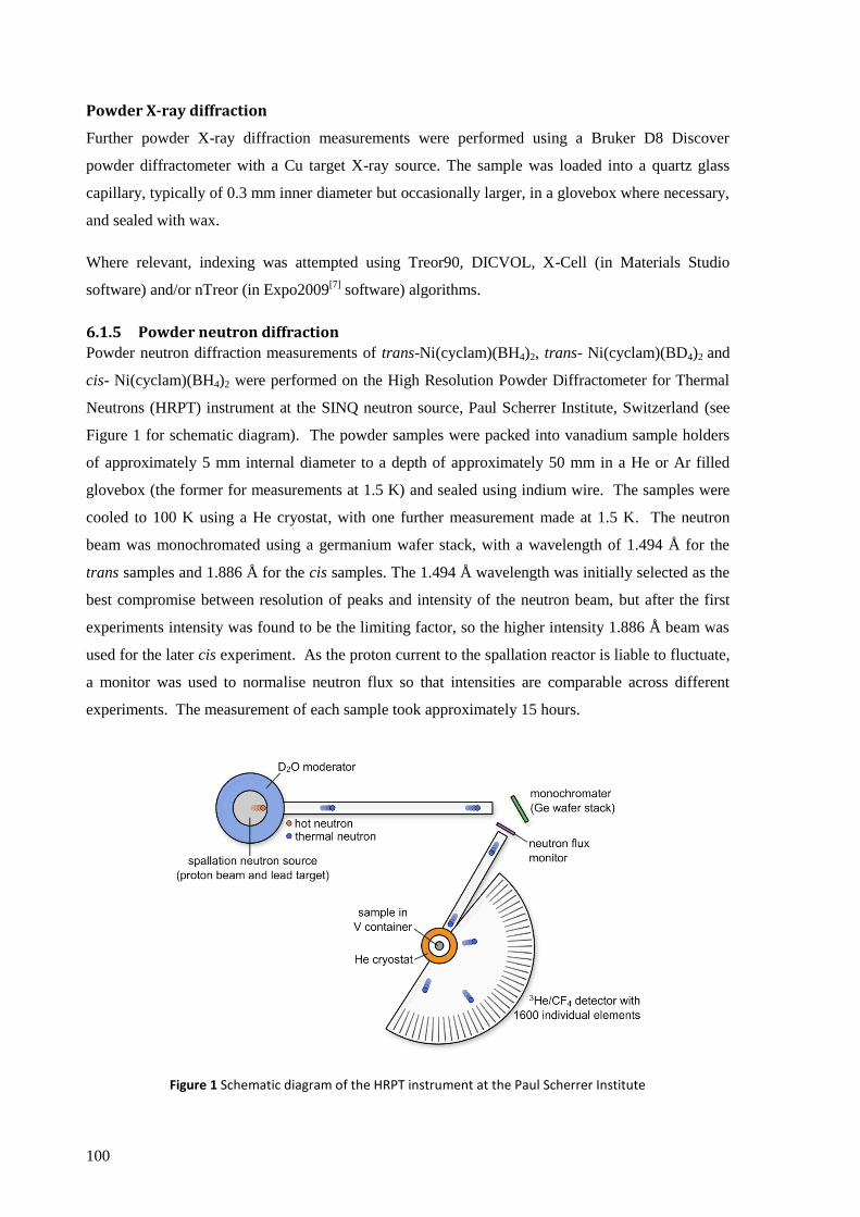
100
Powder X-ray diffraction
Further powder X-ray diffraction measurements were performed using a Bruker D8 Discover
powder diffractometer with a Cu target X-ray source. The sample was loaded into a quartz glass
capillary, typically of 0.3 mm inner diameter but occasionally larger, in a glovebox where necessary,
and sealed with wax.
Where relevant, indexing was attempted using Treor90, DICVOL, X-Cell (in Materials Studio
software) and/or nTreor (in Expo2009[7]
software) algorithms.
6.1.5 Powder neutron diffraction
Powder neutron diffraction measurements of trans-Ni(cyclam)(BH4)2, trans- Ni(cyclam)(BD4)2 and
cis- Ni(cyclam)(BH4)2 were performed on the High Resolution Powder Diffractometer for Thermal
Neutrons (HRPT) instrument at the SINQ neutron source, Paul Scherrer Institute, Switzerland (see
Figure 1 for schematic diagram). The powder samples were packed into vanadium sample holders
of approximately 5 mm internal diameter to a depth of approximately 50 mm in a He or Ar filled
glovebox (the former for measurements at 1.5 K) and sealed using indium wire. The samples were
cooled to 100 K using a He cryostat, with one further measurement made at 1.5 K. The neutron
beam was monochromated using a germanium wafer stack, with a wavelength of 1.494 Å for the
trans samples and 1.886 Å for the cis samples. The 1.494 Å wavelength was initially selected as the
best compromise between resolution of peaks and intensity of the neutron beam, but after the first
experiments intensity was found to be the limiting factor, so the higher intensity 1.886 Å beam was
used for the later cis experiment. As the proton current to the spallation reactor is liable to fluctuate,
a monitor was used to normalise neutron flux so that intensities are comparable across different
experiments. The measurement of each sample took approximately 15 hours.
Figure 1 Schematic diagram of the HRPT instrument at the Paul Scherrer Institute
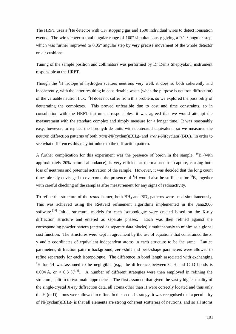
101
The HRPT uses a 3He detector with CF4 stopping gas and 1600 individual wires to detect ionisation
events. The wires cover a total angular range of 160° simultaneously giving a 0.1 ° angular step,
which was further improved to 0.05° angular step by very precise movement of the whole detector
on air cushions.
Tuning of the sample position and collimators was performed by Dr Denis Sheptyakov, instrument
responsible at the HRPT.
Though the 1H isotope of hydrogen scatters neutrons very well, it does so both coherently and
incoherently, with the latter resulting in considerable waste (when the purpose is neutron diffraction)
of the valuable neutron flux. 2H does not suffer from this problem, so we explored the possibility of
deuterating the complexes. This proved unfeasible due to cost and time constraints, so in
consultation with the HRPT instrument responsibles, it was agreed that we would attempt the
measurement with the standard complex and simply measure for a longer time. It was reasonably
easy, however, to replace the borohydride units with deuterated equivalents so we measured the
neutron diffraction patterns of both trans-Ni(cyclam)(BH4)2 and trans-Ni(cyclam)(BD4)2, in order to
see what differences this may introduce to the diffraction pattern.
A further complication for this experiment was the presence of boron in the sample. 10
B (with
approximately 20% natural abundance), is very efficient at thermal neutron capture, causing both
loss of neutrons and potential activation of the sample. However, it was decided that the long count
times already envisaged to overcome the presence of 1H would also be sufficient for
10B, together
with careful checking of the samples after measurement for any signs of radioactivity.
To refine the structure of the trans isomer, both BH4 and BD4 patterns were used simultaneously.
This was achieved using the Rietveld refinement algorithms implemented in the Jana2006
software.[10]
Initial structural models for each isotopologue were created based on the X-ray
diffraction structure and entered as separate phases. Each was then refined against the
corresponding powder pattern (entered as separate data blocks) simultaneously to minimise a global
cost function. The structures were kept in agreement by the use of equations that constrained the x,
y and z coordinates of equivalent independent atoms in each structure to be the same. Lattice
parameters, diffraction pattern background, zero-shift and peak-shape parameters were allowed to
refine separately for each isotopologue. The difference in bond length associated with exchanging
1H for
2H was assumed to be negligible (e.g., the difference between C–H and C–D bonds is
0.004 Å, or < 0.5 %[11]
). A number of different strategies were then employed in refining the
structure, split in to two main approaches. The first assumed that given the vastly higher quality of
the single-crystal X-ray diffraction data, all atoms other than H were correctly located and thus only
the H (or D) atoms were allowed to refine. In the second strategy, it was recognised that a peculiarity
of Ni(cyclam)(BH4)2 is that all elements are strong coherent scatterers of neutrons, and so all atoms
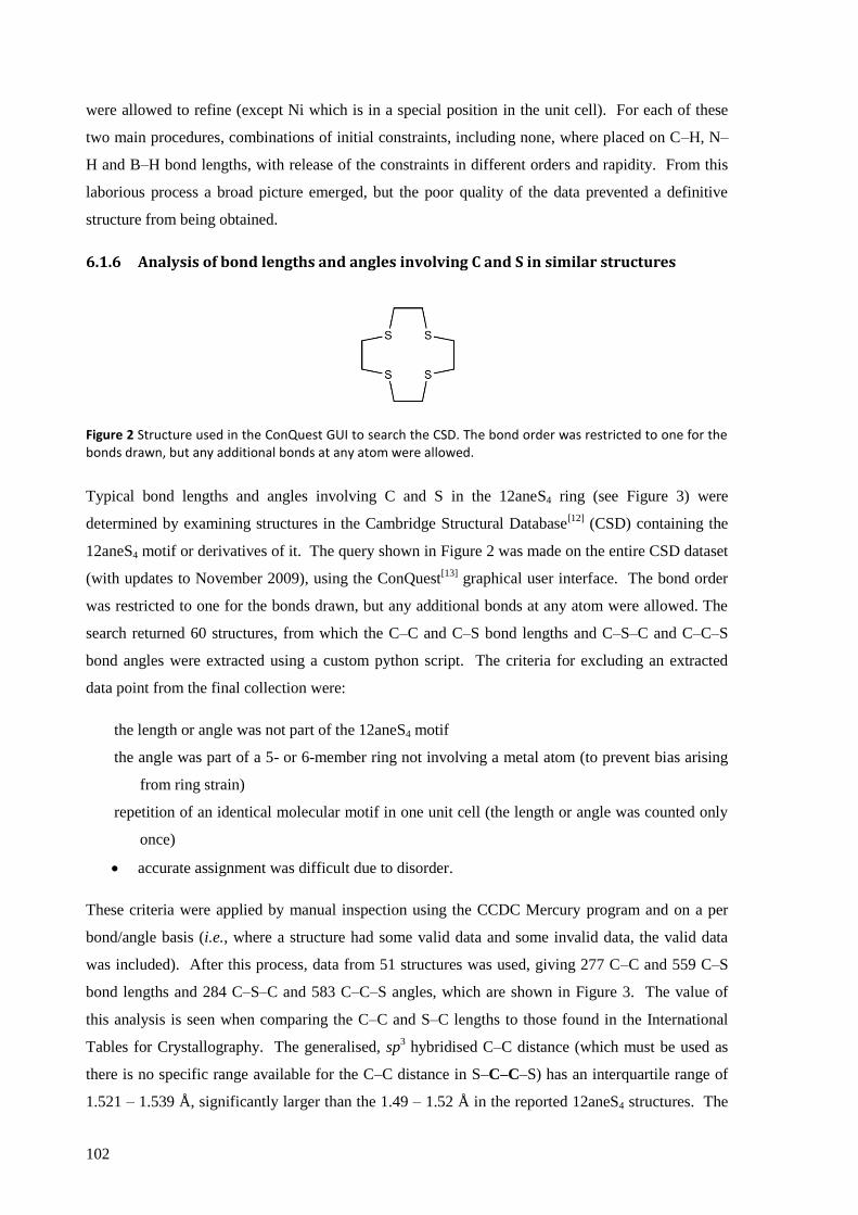
102
were allowed to refine (except Ni which is in a special position in the unit cell). For each of these
two main procedures, combinations of initial constraints, including none, where placed on C–H, N–
H and B–H bond lengths, with release of the constraints in different orders and rapidity. From this
laborious process a broad picture emerged, but the poor quality of the data prevented a definitive
structure from being obtained.
6.1.6 Analysis of bond lengths and angles involving C and S in similar structures
Figure 2 Structure used in the ConQuest GUI to search the CSD. The bond order was restricted to one for the bonds drawn, but any additional bonds at any atom were allowed.
Typical bond lengths and angles involving C and S in the 12aneS4 ring (see Figure 3) were
determined by examining structures in the Cambridge Structural Database[12]
(CSD) containing the
12aneS4 motif or derivatives of it. The query shown in Figure 2 was made on the entire CSD dataset
(with updates to November 2009), using the ConQuest[13]
graphical user interface. The bond order
was restricted to one for the bonds drawn, but any additional bonds at any atom were allowed. The
search returned 60 structures, from which the C–C and C–S bond lengths and C–S–C and C–C–S
bond angles were extracted using a custom python script. The criteria for excluding an extracted
data point from the final collection were:
the length or angle was not part of the 12aneS4 motif
the angle was part of a 5- or 6-member ring not involving a metal atom (to prevent bias arising
from ring strain)
repetition of an identical molecular motif in one unit cell (the length or angle was counted only
once)
accurate assignment was difficult due to disorder.
These criteria were applied by manual inspection using the CCDC Mercury program and on a per
bond/angle basis (i.e., where a structure had some valid data and some invalid data, the valid data
was included). After this process, data from 51 structures was used, giving 277 C–C and 559 C–S
bond lengths and 284 C–S–C and 583 C–C–S angles, which are shown in Figure 3. The value of
this analysis is seen when comparing the C–C and S–C lengths to those found in the International
Tables for Crystallography. The generalised, sp3 hybridised C–C distance (which must be used as
there is no specific range available for the C–C distance in S–C–C–S) has an interquartile range of
1.521 – 1.539 Å, significantly larger than the 1.49 – 1.52 Å in the reported 12aneS4 structures. The

103
bond lengths for C–S do match more closely, with the International Tables giving 1.808 – 1.824 and
this analysis suggesting 1.80 – 1.83 Å. The data on bond angles was also useful in defining the
structure solution restraints, particular that the C–S–C angle tended to significantly lower angles
(100 – 107 °) than an ideal tetrahedron, whilst the S–C–C angles spanned from 105 – 116 °, but with
a dip in occurrence around 109 °.
Figure 3 Analysis of bond lengths and angles in structures containing the 12aneS4 motif or derivatives of it in the CSD (a few outlying data points (< 2% of the total) are outside of the x-axis ranges shown above).
6.1.7 IR and Raman Spectroscopy
IR spectra were recorded on a Bruker Vertex 80v FTIR spectrometer in an evacuated chamber and in
most cases in KBr pellets. The pellets were formed inside the glovebox thus avoiding prolonged
exposure to atmosphere. The Ni(12aneS4)(BF4)2 complex was found to react with KBr so was
recorded using AgCl windows either directly on the surface or in a heavy oil mull. Raman spectra
were obtained using a dispersive T64000 Raman spectrometer (Jobin Yvonne-Spex, 647.1 nm
holographic grating) equipped with an optical microscope BX40 (Olympus, 50 mm lens).
6.1.8 TGA/DSC with evolved gas analysis
Typically, 7 mg of analyte was loaded into an alumina crucible and measured using a Netzsch STA
409 PG TGA/DSC coupled to a Bruker Vertex 80v FTIR spectrometer and Netzsch QMS 403 C
mass spectrometer via transfer lines and adapter heads heated to 200°C for evolved gas analysis
(EGA). Typical experiments were performed over the temperature range 25 – 300°C using a 1, 2 or
104
3 K min−1
scanning rate. 1 K min−1
was used to allow clearer separation of the decomposition steps
and 2 or 3 K min−1
as a compromise between separating the steps and achieving a reasonable
concentration of evolved gas in the flows to the analysing instruments.
Ice forming on the FTIR detector occasionally caused a wide band to form between 3060 and
3620 cm−1
which can be easily distinguished by its steady increase over the duration of the
experiment. When this occurred it was subtracted from the spectra using a separately obtained
spectrum for this ice band.
EGA-MS ion-currents for each m/z value were normalised such that the minimum ion current for
that m/z value over time is set to 1. This means that the values reported in this dissertation are a
multiple of the minimum signal for that m/z value over the whole experiment. The rationale for this
treatment was that, aside from situations where scavenging occurs, the lowest ion-current will
approximate to the background value. Signals that can be seen to be clearly different from
background using this method are lost when comparing isothermal relative intensity (i.e., across the
whole m/z spectrum at one point in time) due to the huge differences in background ion-current for
different m/z. This method allowed us to track changes in signals more easily, but with the effect that
isothermal values for different m/z should not necessarily be considered relative to one another as
one would in a typical mass spectrum.
The synchronisation of the EGA-MS and EGA-FTIR signals to the TGA was calibrated using
CuSO4·5H2O. Both were found to respond within 15 seconds, which for the 3 K min−1
measurements typically used in the analysis, corresponds to a discrepancy of < 0.75 K between TGA
and evolved gas detection.
6.1.9 Scanning electron microscopy and energy dispersive X-ray spectroscopy
Scanning electron microscopy (SEM) was performed on a LEO 435VP microscope coupled to
Roentec energy dispersive X-ray spectroscopy (EDS) equipment, which makes use of X-rays
emitted upon relaxation of the excited states formed by the electron beam, which are highly
characteristic to each element and thus provide crudely quantitative elemental analysis. The analysis
was performed with the help of Dr. Michał Grdeń, Department of Chemistry, University of Warsaw.
It was not possible to protect the samples from exposure to air, thus substantial oxidation of any
small metallic particles was expected.

105
Results and Discussion
6.2 Nickel cyclam complexes
The nickel cyclam precursor complexes, Ni(cyclam)Lx (Lx = SO42−
, (ClO4−)2, (BF4
−)2) are well
known and will only be discussed where of particular interest.
6.2.1 Synthesis of the complexes
Simple and reliable syntheses of both the trans and cis isomers of Ni(cyclam)(BH4)2 have been
developed. The reactions of similar* complexes were reported as long ago as 1965
[14] and the nature
of the products has been suggested,[14,15]
but definite identification and detailed information has not
been available.
The complexes Ni(cyclam)Lx, Lx = SO42−
, (ClO4−)2, (BF4
−)2, all react with solutions of NaBH4 or
LiBH4 to form Ni(cyclam)(BH4)2, which is stable in the presence of excess LiBH4 or NaBH4, even at
concentrations as high as 2 M. Mechanical milling of Ni(cyclam)SO4 and NaBH4 for three minutes
showed slight conversion to trans-Ni(cyclam)(BH4)2, as evidenced by broad peaks in the powder X–
ray diffraction pattern (marked with * in Figure 4). Milling trans-Ni(cyclam)(BH4)2 with NaBD4 for
three minutes resulted in some exchange of BH4− for BD4
− groups in the complex as evidenced in the
IR spectrum, showing that some lability of this group exists under the milling conditions.
Figure 4 Powder X-ray diffraction patterns of NaBH4, [Ni(cyclam)SO4], and a milled mixture of the two in a 4:1 mole ratio. In the latter, three poorly defined peaks (marked with an asterisk) belonging to Ni(cyclam)(BH4)2 are present, but primarily the pattern is a superposition of the two reagents.
* The cyclam ring was methyl substituted.
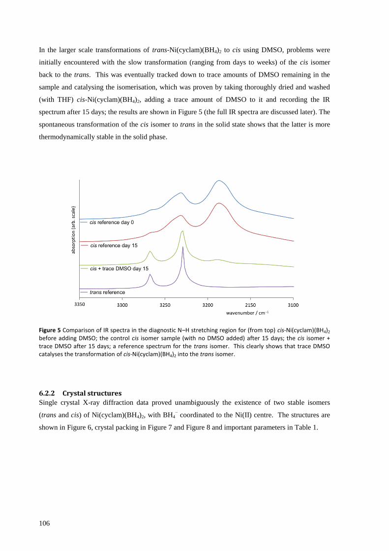
106
In the larger scale transformations of trans-Ni(cyclam)(BH4)2 to cis using DMSO, problems were
initially encountered with the slow transformation (ranging from days to weeks) of the cis isomer
back to the trans. This was eventually tracked down to trace amounts of DMSO remaining in the
sample and catalysing the isomerisation, which was proven by taking thoroughly dried and washed
(with THF) cis-Ni(cyclam)(BH4)2, adding a trace amount of DMSO to it and recording the IR
spectrum after 15 days; the results are shown in Figure 5 (the full IR spectra are discussed later). The
spontaneous transformation of the cis isomer to trans in the solid state shows that the latter is more
thermodynamically stable in the solid phase.
Figure 5 Comparison of IR spectra in the diagnostic N–H stretching region for (from top) cis-Ni(cyclam)(BH4)2 before adding DMSO; the control cis isomer sample (with no DMSO added) after 15 days; the cis isomer + trace DMSO after 15 days; a reference spectrum for the trans isomer. This clearly shows that trace DMSO catalyses the transformation of cis-Ni(cyclam)(BH4)2 into the trans isomer.
6.2.2 Crystal structures
Single crystal X-ray diffraction data proved unambiguously the existence of two stable isomers
(trans and cis) of Ni(cyclam)(BH4)2, with BH4− coordinated to the Ni(II) centre. The structures are
shown in Figure 6, crystal packing in Figure 7 and Figure 8 and important parameters in Table 1.
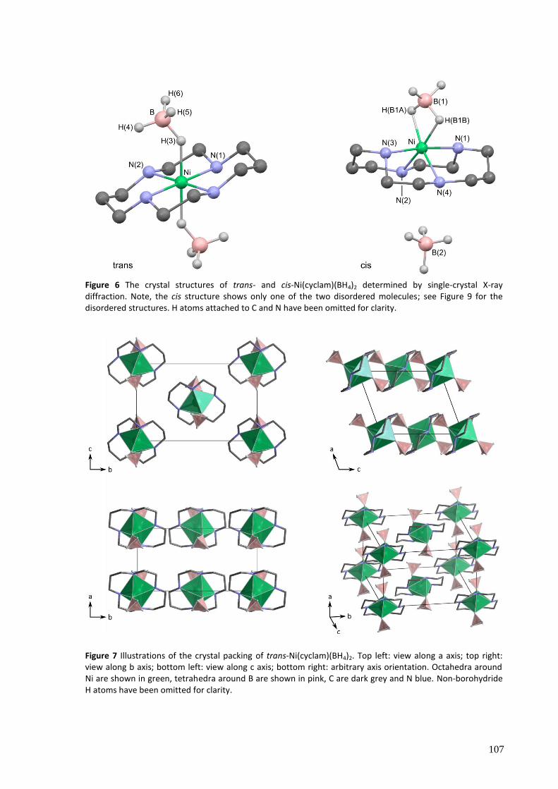
107
Figure 6 The crystal structures of trans- and cis-Ni(cyclam)(BH4)2 determined by single-crystal X-ray diffraction. Note, the cis structure shows only one of the two disordered molecules; see Figure 9 for the disordered structures. H atoms attached to C and N have been omitted for clarity.
Figure 7 Illustrations of the crystal packing of trans-Ni(cyclam)(BH4)2. Top left: view along a axis; top right: view along b axis; bottom left: view along c axis; bottom right: arbitrary axis orientation. Octahedra around Ni are shown in green, tetrahedra around B are shown in pink, C are dark grey and N blue. Non-borohydride H atoms have been omitted for clarity.

108
Figure 8 Illustrations of the crystal packing of cis-Ni(cyclam)(BH4)2. Top left: view along a axis; top right: view along b axis; bottom left: view along c axis; bottom right: arbitrary axis orientation.. Octahedra around Ni are shown in green, tetrahedra around B are shown in pink. C are dark grey and N blue. Non-borohydride H atoms have been omitted for clarity

109
Table 1 Selected parameters from the crystal structures of trans- and cis-Ni(cyclam)(BH4)2 determined by single-crystal X-ray diffraction.
trans cis
Empirical formula C10H32B2N4Ni C10H32B2N4Ni
Molar mass /g mol−1
288.73 288.73
T / K 100 (2) 100 (2)
λ / Å 0.71073 0.71073
Crystal system,
space group
Monoclinic
P21/c (No. 14)
Orthorhombic
Pnma (No. 62)
Unit cell dimensions / Å, º a = 7.1397 (5)
b = 12.8109 (7)
c = 8.7041 (5)
β = 109.948 (6)
a = 14.4512 (7)
b = 9.4625 (6)
c = 11.7824 (7)
V / Å3
748.36 (8) 1611.18 (16)
Cell formula units (Z) 2 4
Goodness of fit on F2 1.068 0.818
R [I > 2σ(I)] R1 = 0.0190
wR2 = 0.0501
R1 = 0.0363
wR2 = 0.0873
R (all data) R1 = 0.0251
wR2 = 0.0511
R1 = 0.0943
wR2 = 0.0951
For both isomers, octahedral geometry for Ni(II) is found (pointing to high-spin d8 Ni(II), in
agreement with DFT calculations and magnetic measurements). In the trans isomer, the Ni atom is
located at a centre of symmetry thus only half of the complex constitutes a symmetrically
independent part of the unit cell and the two BH4− groups are, by symmetry, in equivalent chemical
environments. Some selected geometrical parameters of the molecule are given in Table 2. The NiN4
unit is planar by symmetry, and the two independent Ni–N distances are all but identical at ca. 2.07
Å. The H(3)–B(1) bond, formed by the Ni···B bridging hydrogen atom, is considerably elongated
(1.184 Å) compared to the other B–H bonds (1.054 – 1.101 Å) and not perpendicular to the plane
made by the four N atoms, but slightly bent.
The shortest intermolecular contact at 2.31 Å can be observed between the amine H atom attached to
N(1) and the H(5) atom of the BH4− group, similar to but slightly shorter than the closest
intramolecular Hδ+
···Hδ−
contact between the same amine hydrogen but H(4) of the BH4− group.
These would represent only very weak dihydrogen bonding, however, and the orientation of the
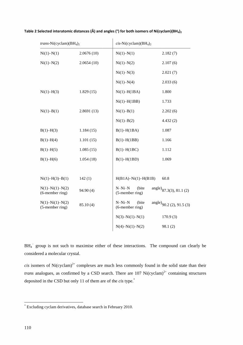
110
Table 2 Selected interatomic distances (Å) and angles (°) for both isomers of Ni(cyclam)(BH4)2
trans-Ni(cyclam)(BH4)2 cis-Ni(cyclam)(BH4)2
Ni(1)–N(1) 2.0676 (10) Ni(1)–N(1) 2.182 (7)
Ni(1)–N(2) 2.0654 (10) Ni(1)–N(2) 2.107 (6)
Ni(1)–N(3) 2.021 (7)
Ni(1)–N(4) 2.033 (6)
Ni(1)–H(3) 1.829 (15) Ni(1)–H(1BA) 1.800
Ni(1)–H(1BB) 1.733
Ni(1)–B(1) 2.8691 (13) Ni(1)–B(1) 2.202 (6)
Ni(1)–B(2) 4.432 (2)
B(1)–H(3) 1.184 (15) B(1)–H(1BA) 1.087
B(1)–H(4) 1.101 (15) B(1)–H(1BB) 1.166
B(1)–H(5) 1.085 (15) B(1)–H(1BC) 1.112
B(1)–H(6) 1.054 (18) B(1)–H(1BD) 1.069
Ni(1)–H(3)–B(1) 142 (1) H(B1A)–Ni(1)–H(B1B) 60.8
N(1)–Ni(1)–N(2)
(6-member ring) 94.90 (4)
N–Ni–N (bite angle)
(5-member ring) 87.3(3), 81.1 (2)
N(1)–Ni(1)–N(2)
(5-member ring) 85.10 (4)
N–Ni–N (bite angle)
(6-member ring) 90.2 (2), 91.5 (3)
N(3)–Ni(1)–N(1) 170.9 (3)
N(4)–Ni(1)–N(2) 98.1 (2)
BH4− group is not such to maximise either of these interactions. The compound can clearly be
considered a molecular crystal.
cis isomers of Ni(cyclam)2+
complexes are much less commonly found in the solid state than their
trans analogues, as confirmed by a CSD search. There are 107 Ni(cyclam)2+
containing structures
deposited in the CSD but only 11 of them are of the cis type.*
* Excluding cyclam derivatives, database search in February 2010.
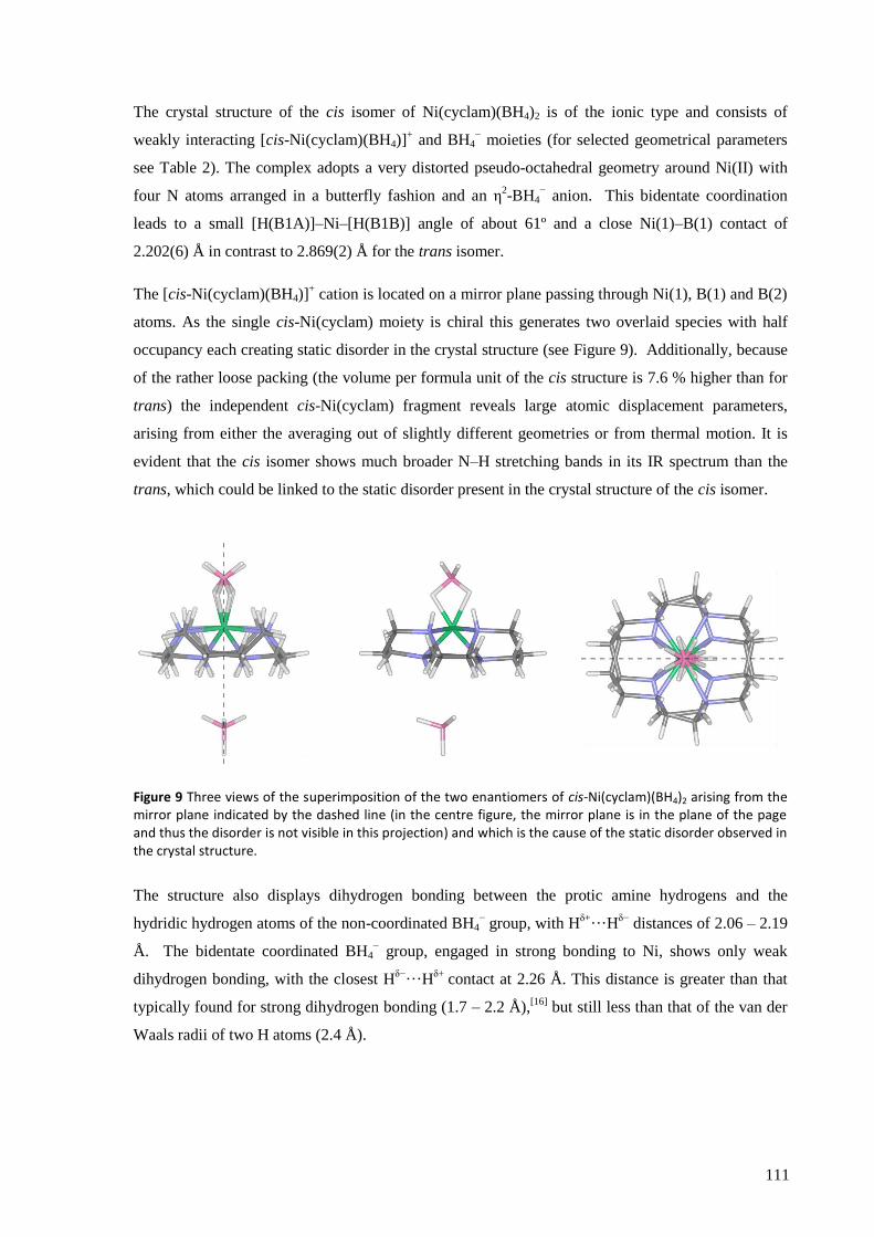
111
The crystal structure of the cis isomer of Ni(cyclam)(BH4)2 is of the ionic type and consists of
weakly interacting [cis-Ni(cyclam)(BH4)]+ and BH4
− moieties (for selected geometrical parameters
see Table 2). The complex adopts a very distorted pseudo-octahedral geometry around Ni(II) with
four N atoms arranged in a butterfly fashion and an η2-BH4
− anion. This bidentate coordination
leads to a small [H(B1A)]–Ni–[H(B1B)] angle of about 61º and a close Ni(1)–B(1) contact of
2.202(6) Å in contrast to 2.869(2) Å for the trans isomer.
The [cis-Ni(cyclam)(BH4)]+ cation is located on a mirror plane passing through Ni(1), B(1) and B(2)
atoms. As the single cis-Ni(cyclam) moiety is chiral this generates two overlaid species with half
occupancy each creating static disorder in the crystal structure (see Figure 9). Additionally, because
of the rather loose packing (the volume per formula unit of the cis structure is 7.6 % higher than for
trans) the independent cis-Ni(cyclam) fragment reveals large atomic displacement parameters,
arising from either the averaging out of slightly different geometries or from thermal motion. It is
evident that the cis isomer shows much broader N–H stretching bands in its IR spectrum than the
trans, which could be linked to the static disorder present in the crystal structure of the cis isomer.
Figure 9 Three views of the superimposition of the two enantiomers of cis-Ni(cyclam)(BH4)2 arising from the mirror plane indicated by the dashed line (in the centre figure, the mirror plane is in the plane of the page and thus the disorder is not visible in this projection) and which is the cause of the static disorder observed in the crystal structure.
The structure also displays dihydrogen bonding between the protic amine hydrogens and the
hydridic hydrogen atoms of the non-coordinated BH4− group, with H
δ+···H
δ− distances of 2.06 – 2.19
Å. The bidentate coordinated BH4− group, engaged in strong bonding to Ni, shows only weak
dihydrogen bonding, with the closest Hδ−
···Hδ+
contact at 2.26 Å. This distance is greater than that
typically found for strong dihydrogen bonding (1.7 – 2.2 Å),[16]
but still less than that of the van der
Waals radii of two H atoms (2.4 Å).
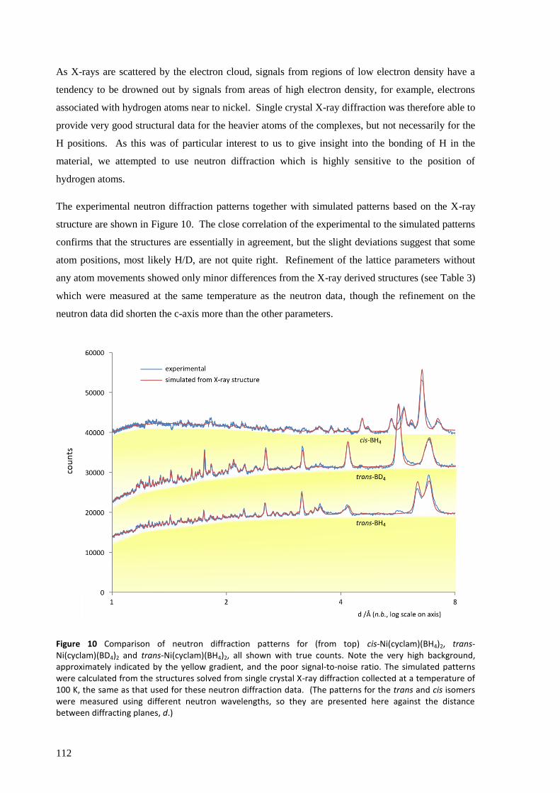
112
As X-rays are scattered by the electron cloud, signals from regions of low electron density have a
tendency to be drowned out by signals from areas of high electron density, for example, electrons
associated with hydrogen atoms near to nickel. Single crystal X-ray diffraction was therefore able to
provide very good structural data for the heavier atoms of the complexes, but not necessarily for the
H positions. As this was of particular interest to us to give insight into the bonding of H in the
material, we attempted to use neutron diffraction which is highly sensitive to the position of
hydrogen atoms.
The experimental neutron diffraction patterns together with simulated patterns based on the X-ray
structure are shown in Figure 10. The close correlation of the experimental to the simulated patterns
confirms that the structures are essentially in agreement, but the slight deviations suggest that some
atom positions, most likely H/D, are not quite right. Refinement of the lattice parameters without
any atom movements showed only minor differences from the X-ray derived structures (see Table 3)
which were measured at the same temperature as the neutron data, though the refinement on the
neutron data did shorten the c-axis more than the other parameters.
Figure 10 Comparison of neutron diffraction patterns for (from top) cis-Ni(cyclam)(BH4)2, trans-Ni(cyclam)(BD4)2 and trans-Ni(cyclam)(BH4)2, all shown with true counts. Note the very high background, approximately indicated by the yellow gradient, and the poor signal-to-noise ratio. The simulated patterns were calculated from the structures solved from single crystal X-ray diffraction collected at a temperature of 100 K, the same as that used for these neutron diffraction data. (The patterns for the trans and cis isomers were measured using different neutron wavelengths, so they are presented here against the distance between diffracting planes, d.)

113
Table 3 Comparison of the lattice parameters at 100 K for trans-Ni(cyclam)(BH4)2 obtained from single crystal X-ray diffraction and from neutron diffraction.
parameter single crystal X-ray neutron % difference
a 7.1397 (5) 7.1411 (9) 0.02%
b 12.8109 (7) 12.803 (2) 0.06 %
c 8.7401 (5) 8.6931 (9) 0.5 %
β 109.948 (6) 109.929 (9) 0.02 %
Unfortunately, despite the long counting times, the signal-to-noise ratio was too poor for direct
structure refinement. The poor quality of the patterns is entirely a result of the incoherent scattering
caused by the presence of large quantities of 1H in the sample, which unfortunately we were unable
to deuterate (see methodology section 6.1.5 on page 100). The incoherent scattering from 1H is the
cause of the high background, the size of which can give an idea of the number of „wasted‟ neutrons
(approximated by the yellow gradients in Figure 10) relative to the coherently scattered neutrons
which provide the diffraction pattern. A comparison of the integrals of the background and the
signal for the trans-Ni(cyclam)(BH4)2 measurement suggests less than 3% of the detected neutrons
contribute to the useful signal.
In the case of cis-Ni(cyclam)(BH4)2, it is clear that high angle peaks (low d in Figure 10) are of very
low intensity, exacerbating the signal-to-noise ratio problem. This is not due to attenuation of the
structure factor with increasing scattering angle as the neutron diffraction technique does not suffer
from this as X-ray interactions do, but rather must be an intrinsic property related to the structure of
the crystal. No further structure refinement was therefore possible. The trans isomer, however,
shows better definition of peaks at high angles, improving the prospects for meaningful results from
structure refinement. Furthermore, the diffraction patterns for the BH4 and BD4 isotopologues
contain complementary information on the structure due to the different scattering lengths of 1H and
2H, and it was therefore possible to improve the refinement of trans-Ni(cyclam)(BH4)2 structure by
requiring it to match both patterns simultaneously. As the X-ray diffraction data for the trans isomer
was of very high quality, it was expected that the newly refined structure would not differ greatly
from the original, and indeed the subtle nature of the changes in the diffraction patterns in Figure 11
reflect the only slight modifications made to the structures. This confirms that the hydrogen
positions determined from the X-ray data were broadly correct. As mentioned in the methodology
(section 6.1.5 on page 100), many different strategies for the structure refinement were carried out,
and unfortunately the results from different strategies were not in detailed agreement (e.g., with

114
respect to bond lengths). We report here qualitatively only those aspects that were consistent across
the large majority of refinements.
The clearest trends involved the BH4− group, which distorted significantly in every refinement. The
B–H bonds of H(4) and H(5) lengthened, which may be explained by their dihydrogen interaction
with the amine hydrogens (see below), whilst that of H(6), which shows no such contacts, shortened.
The B–H(3) bond length (involving the bridging H) took an intermediate value, which contrasts with
the X-ray structure in which it was the longest. Though an intermediate bond length for B–H(3)
may seem contrary to its participation in a 3-centre, 2-electron bond, similar behaviour was found in
the only other reported neutron diffraction experiment of a transition metal–η1-borohydride
structure: in the X-ray determination the bridging bond was significantly longer than the terminal B–
H bonds, but neutron diffraction revealed the bridging B–H distance to be similar to those of two
terminal B–H bonds, whilst the third terminal bond was significantly longer (1.330 (6) Å).[17]
The
authors of that study could not offer an explanation, except the suggestion of some disorder in the
position of the B atom.
Both independent N–H bonds consistently lengthened, which was expected given the rather short
distances found in the X-ray structure of 0.83 Å and 0.79 Å for N(1)–H and N(2)–H respectively,
compared to the commonly used „standard‟ N–H distance of 1.03 Å.[18]
This leads to stronger
dihydrogen bonding as the Hδ+
–Hδ−
distances are shortened by this process (the X-ray structure
showed only very weak dihydrogen bonding). The intramolecular dihydrogen bonding is further
strengthed by the tendency of the Ni–B–H angle to attain a greater „bent‟ character in the neutron
refinement.
The main problem that occurred in all the refinements was with the length of C–H bonds, which
tended to vary from 0.99 Å to 1.25 Å. The problem was ameliorated to some extent by very slowly
releasing the bond length constraint from the standard 1.09 Å, but even then the results were not
satisfactory. Some lengthening of the C–H bonds was expected as those in the X-ray structure (0.99
Å) were short, but in particular the hydrogens attached to C5 formed excessively long bonds.
Unfortunately it is impossible to draw firm conclusions from the neutron diffraction data, but the
confirmation that the position of hydrogen atoms in the X-ray structure are broadly correct, albeit
likely with stronger dihydrogen bonding, is valuable.
A brief measurement of trans-Ni(cyclam)(BH4)2 was also made at a temperature of 1.5 K to see if
any first-order phase transition occurred, which the diffraction pattern confirmed it did not (see
Figure 12), thus there are no phase changes from 1.5 K through to room temperature.
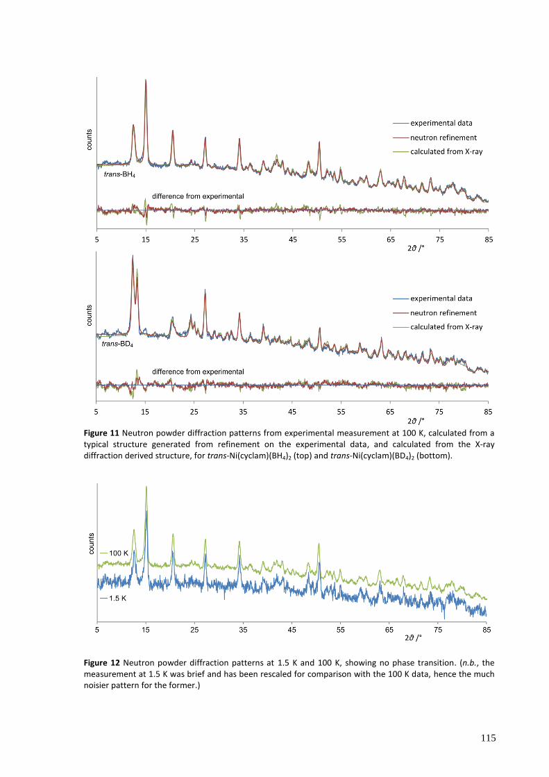
115
Figure 11 Neutron powder diffraction patterns from experimental measurement at 100 K, calculated from a typical structure generated from refinement on the experimental data, and calculated from the X-ray diffraction derived structure, for trans-Ni(cyclam)(BH4)2 (top) and trans-Ni(cyclam)(BD4)2 (bottom).
Figure 12 Neutron powder diffraction patterns at 1.5 K and 100 K, showing no phase transition. (n.b., the measurement at 1.5 K was brief and has been rescaled for comparison with the 100 K data, hence the much noisier pattern for the former.)
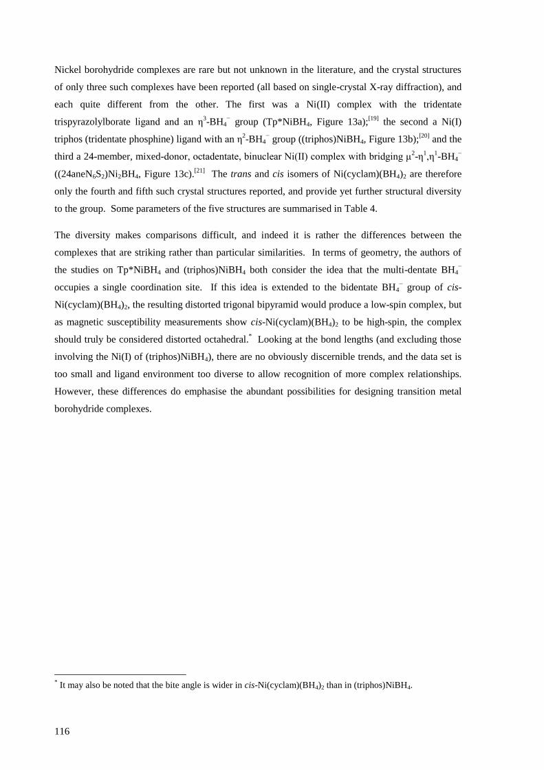
116
Nickel borohydride complexes are rare but not unknown in the literature, and the crystal structures
of only three such complexes have been reported (all based on single-crystal X-ray diffraction), and
each quite different from the other. The first was a Ni(II) complex with the tridentate
trispyrazolylborate ligand and an η3-BH4
− group (Tp*NiBH4, Figure 13a);
[19] the second a Ni(I)
triphos (tridentate phosphine) ligand with an η2-BH4
− group ((triphos)NiBH4, Figure 13b);
[20] and the
third a 24-member, mixed-donor, octadentate, binuclear Ni(II) complex with bridging μ2-η
1,η
1-BH4
−
((24aneN6S2)Ni2BH4, Figure 13c).[21]
The trans and cis isomers of Ni(cyclam)(BH4)2 are therefore
only the fourth and fifth such crystal structures reported, and provide yet further structural diversity
to the group. Some parameters of the five structures are summarised in Table 4.
The diversity makes comparisons difficult, and indeed it is rather the differences between the
complexes that are striking rather than particular similarities. In terms of geometry, the authors of
the studies on Tp*NiBH4 and (triphos)NiBH4 both consider the idea that the multi-dentate BH4−
occupies a single coordination site. If this idea is extended to the bidentate BH4− group of cis-
Ni(cyclam)(BH4)2, the resulting distorted trigonal bipyramid would produce a low-spin complex, but
as magnetic susceptibility measurements show cis-Ni(cyclam)(BH4)2 to be high-spin, the complex
should truly be considered distorted octahedral.* Looking at the bond lengths (and excluding those
involving the Ni(I) of (triphos)NiBH4), there are no obviously discernible trends, and the data set is
too small and ligand environment too diverse to allow recognition of more complex relationships.
However, these differences do emphasise the abundant possibilities for designing transition metal
borohydride complexes.
* It may also be noted that the bite angle is wider in cis-Ni(cyclam)(BH4)2 than in (triphos)NiBH4.
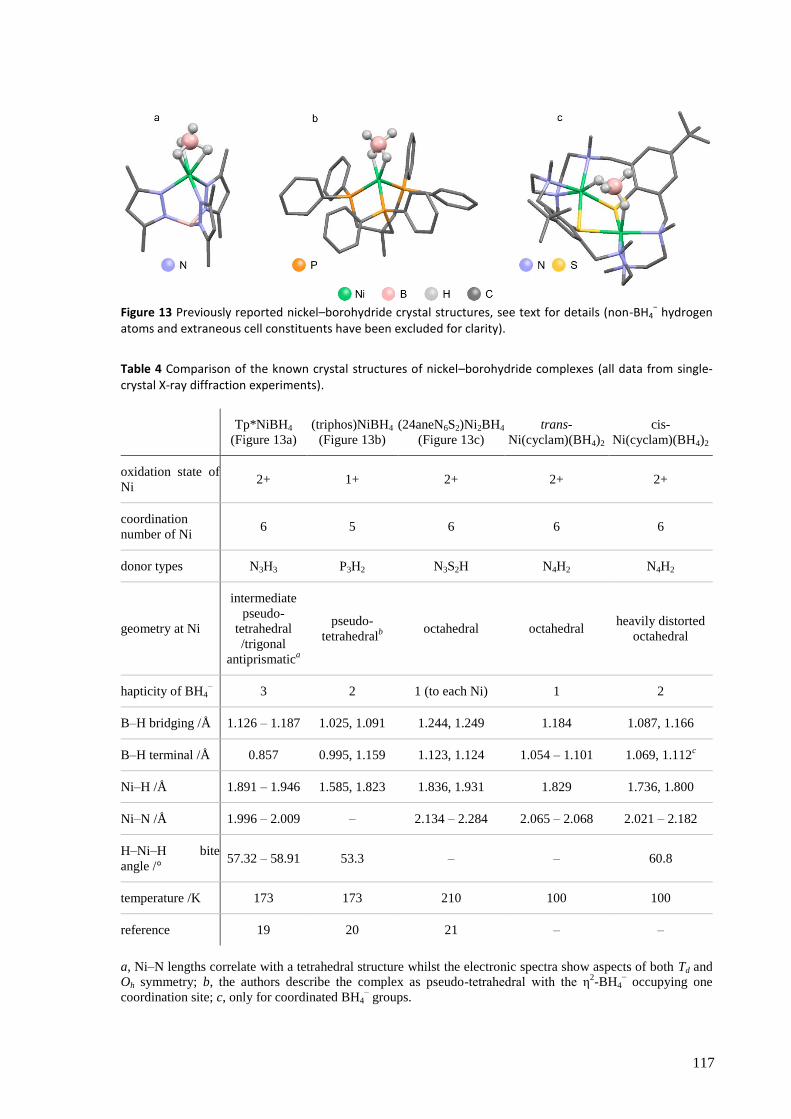
117
Figure 13 Previously reported nickel–borohydride crystal structures, see text for details (non-BH4− hydrogen
atoms and extraneous cell constituents have been excluded for clarity).
Table 4 Comparison of the known crystal structures of nickel–borohydride complexes (all data from single-crystal X-ray diffraction experiments).
Tp*NiBH4
(Figure 13a)
(triphos)NiBH4
(Figure 13b)
(24aneN6S2)Ni2BH4
(Figure 13c)
trans-
Ni(cyclam)(BH4)2
cis-
Ni(cyclam)(BH4)2
oxidation state of
Ni 2+ 1+ 2+ 2+ 2+
coordination
number of Ni 6 5 6 6 6
donor types N3H3 P3H2 N3S2H N4H2 N4H2
geometry at Ni
intermediate
pseudo-
tetrahedral
/trigonal
antiprismatica
pseudo-
tetrahedralb
octahedral octahedral heavily distorted
octahedral
hapticity of BH4− 3 2 1 (to each Ni) 1 2
B–H bridging /Å 1.126 – 1.187 1.025, 1.091 1.244, 1.249 1.184 1.087, 1.166
B–H terminal /Å 0.857 0.995, 1.159 1.123, 1.124 1.054 – 1.101 1.069, 1.112c
Ni–H /Å 1.891 – 1.946 1.585, 1.823 1.836, 1.931 1.829 1.736, 1.800
Ni–N /Å 1.996 – 2.009 – 2.134 – 2.284 2.065 – 2.068 2.021 – 2.182
H–Ni–H bite
angle /° 57.32 – 58.91 53.3 – – 60.8
temperature /K 173 173 210 100 100
reference 19 20 21 – –
a, Ni–N lengths correlate with a tetrahedral structure whilst the electronic spectra show aspects of both Td and
Oh symmetry; b, the authors describe the complex as pseudo-tetrahedral with the η2-BH4
− occupying one
coordination site; c, only for coordinated BH4− groups.
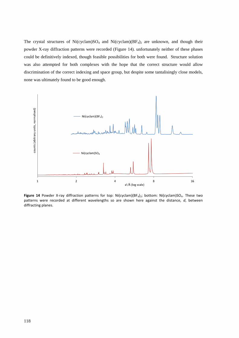
118
The crystal structures of Ni(cyclam)SO4 and Ni(cyclam)(BF4)2 are unknown, and though their
powder X-ray diffraction patterns were recorded (Figure 14). unfortunately neither of these phases
could be definitively indexed, though feasible possibilities for both were found. Structure solution
was also attempted for both complexes with the hope that the correct structure would allow
discrimination of the correct indexing and space group, but despite some tantalisingly close models,
none was ultimately found to be good enough.
Figure 14 Powder X-ray diffraction patterns for top: Ni(cyclam)(BF4)2; bottom: Ni(cyclam)SO4. These two patterns were recorded at different wavelengths so are shown here against the distance, d, between diffracting planes.

119
In order to improve the alignment of text, tables and figures, this page is not used

120
6.2.3 IR Spectroscopy
The IR spectra of the Ni(cyclam)Lx (Lx = SO42−
, (ClO4−)2, (BF4
−)2, (BH4
−)2) complexes, together with
the free cyclam ligand are shown in Figure 16.
N–H and C–H stretching and bending
Looking first at the N–H (3160 – 3280 cm−1
) and C–H (2800 – 3000 cm−1
) stretching regions, the
individual spectra can be set into three groups: the first shows broad and weak to medium peaks and
contains (ClO4−)2 and (BF4
−)2; the second sharp and medium to strong peaks and contains
trans-(BH4−)2 and SO4
2−; and the third strong and broad peaks with N–H stretching noticeably red-
shifted in frequency, containing cis-(BH4−)2 alone. We can associate these data with known and
expected structures, with the weakly coordinating ClO4− and BF4
− of the first grouping known and
expected (respectively) to give square-planar [Ni(cyclam)]2+
complexes, whilst in the second, trans-
(BH4−)2 and SO4
2− are relatively strongly coordinating anions, known and expected (respectively) to
form distorted octahedral geometries. To this second group we may also add [Ni(cyclam)Cl2], which
has a very similar spectrum (not shown) in the N–H and C–H stretching regions and is known to
form a distorted octahedral complex. The spectrum of the square planar [Ni(cyclam)]I2 is reported
to be similar to that of the (ClO4−)2 rather than the Cl2 derivative,
[22] and thus these IR bands may be
predictors of structural similarity. In the case of the trans-(BH4−)2 and SO4
2− complexes, the
different metal : ligand ratio may be accounted for by the latter forming 1D chains (see Figure 15).
Unfortunately, further literature data for the IR spectra of nickel cyclam complexes in these regions
is sparse and not detailed so it is not possible to determine whether this trend applies generally.
Figure 15 Schematic diagram of how sulphate could create octahedral geometry at Ni by forming 1D chains
The IR spectrum of the cis-(BH4−)2 complex is noticeably different from the others discussed here.
The dihydrogen bonding markedly red-shifts the bands corresponding to the N–H stretching modes,
an effect comparable to that caused by hydrogen bonding in the free cyclam ligand. The C–H
stretching modes show a significant increase in absorption (but are otherwise very similar).
The free cyclam ligand possesses bands extending below the normal C–H stretching region, down as
far as 2560 cm−1
, with some particularly strong. These are accounted for by the Bohlmann effect,[23]
whereby the lone pair of the secondary amine contributes some electron density to the σ* orbital of
the C–H bond trans to it, weakening the bond and resulting in lower energy vibrations. This then
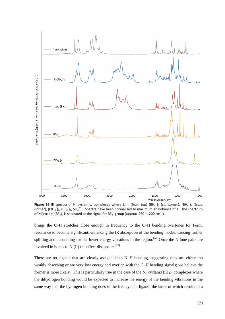
121
Figure 16 IR spectra of Ni(cyclam)Lx complexes where Lx = (from top) (BH4−)2 (cis isomer), (BH4
−)2 (trans
isomer), (ClO4−)2, (BF4
−)2, SO4
2− . Spectra have been normalised to maximum absorbance of 1. The spectrum
of Ni(cyclam)(BF4)2 is saturated at the signal for BF4– group (approx. 960 –1200 cm
−1).
brings the C–H stretches close enough in frequency to the C–H bending overtones for Fermi
resonance to become significant, enhancing the IR absorption of the bending modes, causing further
splitting and accounting for the lower energy vibrations in the region.[24]
Once the N lone-pairs are
involved in bonds to Ni(II) the effect disappears.[23]
There are no signals that are clearly assignable to N–H bending, suggesting they are either too
weakly absorbing or are very low energy and overlap with the C–H bending signals; we believe the
former is more likely. This is particularly true in the case of the Ni(cyclam)(BH4)2 complexes where
the dihydrogen bonding would be expected to increase the energy of the bending vibrations in the
same way that the hydrogen bonding does in the free cyclam ligand, the latter of which results in a
122
band at 1520 cm−1
. There are some differences in the C–H bending region (1410 – 1490 cm−1
) that
follow the same pattern as for the C–H stretching signals, i.e., relatively strongly coordinating anions
SO42−
and trans-BH4− (and Cl
−) result in sharp signals, weakly coordinating anions broader signal,
and the cis configuration broad and substantially stronger signals.
B–H stretching and bending
The B–H stretching region (1900 – 2500 cm−1
) is obviously only relevant to the trans and cis-
Ni(cyclam)(BH4)2 complexes, but in these two cases is clearly diagnostic of the structure (see Figure
17). The trans isomer shows at least 8 peaks/shoulders over the range 2025 – 2400 cm−1
, though the
overlapping nature of the fairly broad bands makes a definite count impossible. The cis isomer
shows a similar number (though possibly one or two more), but over a considerably wider range,
from 1900 – 2500 cm−1
. The shift to higher energy vibrations relative to the trans arrangement is
attributable to the non-coordinated BH4− group, whilst the lower energy vibrations arise from the
bidentate BH4−, whose B–H bonds suffer from the increased donation of electron density to the
nickel centre, particularly for the two bridging hydrogen atoms. Both isomers have lower energy B–
H stretches than NaBH4 and therefore weakened B–H bonding, a desirable trait for a lower thermal
decomposition temperature (which at more than 400 °C for NaBH4 is far too high*).
25
Deuteration of the BH4− groups shows the expected shift to lower frequencies (though not with the
ideal theoretical ratio of 1/1.37), such that the lowest frequency B–D stretch at 1490 cm−1
(and
possibly lower bands too) more clearly separates from the others and partially overlaps with the C–H
bending modes. The differences in the BH4−/BD4
− spectra of the trans complex also allow the peaks
at 1070, 1060 cm−1
(B–H) and 813, 803 cm−1
(B–D) to be assigned to bending modes. Such
assignment is not possible for the cis isomer.
* A wide range of decomposition temperatures have been reported in the literature for NaBH4,
[25] but even at
the lower bound of 400 °C this is clearly still too high.

123
Figure 17 IR spectra of deuterated Ni(cyclam)(BD4)2 complexes (middle two spectra) with their non-deuterated versions for reference. From top: cis-Ni(cyclam)(BH4)2, cis-Ni(cyclam)(BD4)2, trans-Ni(cyclam)(BD4)2, trans-Ni(cyclam)(BH4)2. Spectra have been normalised to maximum absorbance of 1. (The N–H and C–H stretches are not shown as they do not change on deuteration of BH4
− groups.)
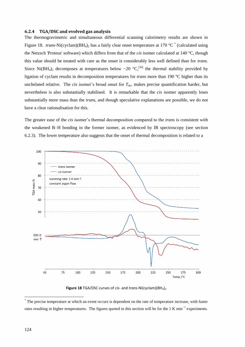
124
6.2.4 TGA/DSC and evolved gas analysis
The thermogravimetric and simultaneous differential scanning calorimetry results are shown in
Figure 18. trans-Ni(cyclam)(BH4)2 has a fairly clear onset temperature at 170 °C * (calculated using
the Netzsch 'Proteus' software) which differs from that of the cis isomer calculated at 140 °C, though
this value should be treated with care as the onset is considerably less well defined than for trans.
Since Ni(BH4)2 decomposes at temperatures below −20 °C,[26]
the thermal stability provided by
ligation of cyclam results in decomposition temperatures for trans more than 190 °C higher than its
unchelated relative. The cis isomer‟s broad onset for Tdec makes precise quantification harder, but
nevertheless is also substantially stabilised. It is remarkable that the cis isomer apparently loses
substantially more mass than the trans, and though speculative explanations are possible, we do not
have a clear rationalisation for this.
The greater ease of the cis isomer‟s thermal decomposition compared to the trans is consistent with
the weakened B–H bonding in the former isomer, as evidenced by IR spectroscopy (see section
6.2.3). The lower temperature also suggests that the onset of thermal decomposition is related to a
Figure 18 TGA/DSC curves of cis- and trans-Ni(cyclam)(BH4)2
* The precise temperature at which an event occurs is dependent on the rate of temperature increase, with faster
rates resulting in higher temperatures. The figures quoted in this section will be for the 1 K min−1
experiments.
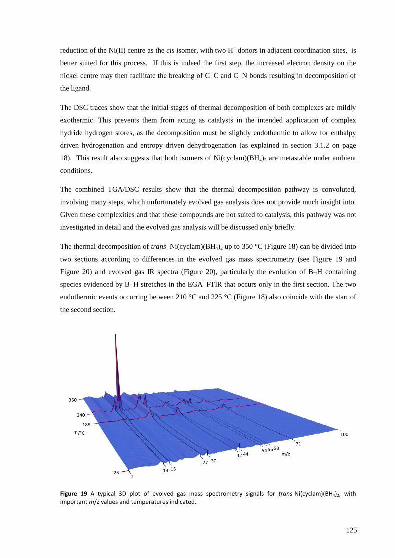
125
reduction of the Ni(II) centre as the cis isomer, with two H− donors in adjacent coordination sites, is
better suited for this process. If this is indeed the first step, the increased electron density on the
nickel centre may then facilitate the breaking of C–C and C–N bonds resulting in decomposition of
the ligand.
The DSC traces show that the initial stages of thermal decomposition of both complexes are mildly
exothermic. This prevents them from acting as catalysts in the intended application of complex
hydride hydrogen stores, as the decomposition must be slightly endothermic to allow for enthalpy
driven hydrogenation and entropy driven dehydrogenation (as explained in section 3.1.2 on page
18). This result also suggests that both isomers of Ni(cyclam)(BH4)2 are metastable under ambient
conditions.
The combined TGA/DSC results show that the thermal decomposition pathway is convoluted,
involving many steps, which unfortunately evolved gas analysis does not provide much insight into.
Given these complexities and that these compounds are not suited to catalysis, this pathway was not
investigated in detail and the evolved gas analysis will be discussed only briefly.
The thermal decomposition of trans–Ni(cyclam)(BH4)2 up to 350 °C (Figure 18) can be divided into
two sections according to differences in the evolved gas mass spectrometry (see Figure 19 and
Figure 20) and evolved gas IR spectra (Figure 20), particularly the evolution of B–H containing
species evidenced by B–H stretches in the EGA–FTIR that occurs only in the first section. The two
endothermic events occurring between 210 °C and 225 °C (Figure 18) also coincide with the start of
the second section.
Figure 19 A typical 3D plot of evolved gas mass spectrometry signals for trans-Ni(cyclam)(BH4)2, with important m/z values and temperatures indicated.
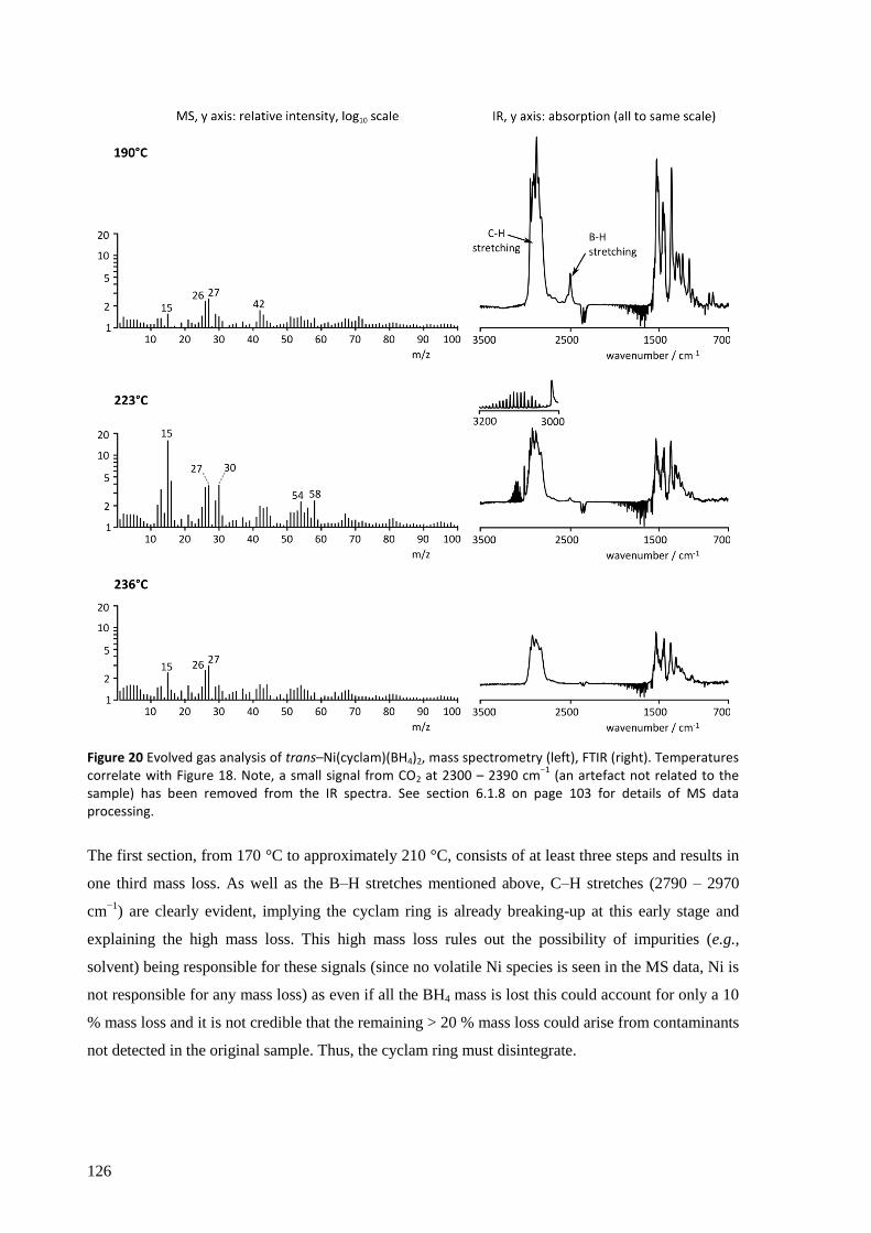
126
Figure 20 Evolved gas analysis of trans–Ni(cyclam)(BH4)2, mass spectrometry (left), FTIR (right). Temperatures correlate with Figure 18. Note, a small signal from CO2 at 2300 – 2390 cm
−1 (an artefact not related to the
sample) has been removed from the IR spectra. See section 6.1.8 on page 103 for details of MS data processing.
The first section, from 170 °C to approximately 210 °C, consists of at least three steps and results in
one third mass loss. As well as the B–H stretches mentioned above, C–H stretches (2790 – 2970
cm−1
) are clearly evident, implying the cyclam ring is already breaking-up at this early stage and
explaining the high mass loss. This high mass loss rules out the possibility of impurities (e.g.,
solvent) being responsible for these signals (since no volatile Ni species is seen in the MS data, Ni is
not responsible for any mass loss) as even if all the BH4 mass is lost this could account for only a 10
% mass loss and it is not credible that the remaining > 20 % mass loss could arise from contaminants
not detected in the original sample. Thus, the cyclam ring must disintegrate.

127
Table 5 Fragments of the cyclam ring that could produce the fragmentation patterns observed in the EGA-MS of trans–Ni(cyclam)(BH4)2.
m/z Fragments of [HN–(CH2)3–NH]+
15,16 [CH3]+, [NH]
+, [NH2]
+
26,27,30 [CN]+, [HCN]
+, [C2H2]
+, [C2H3]
+,
[CH3NH]+ (and possible contributions
from B2Hn species in section 1)
42,43 [(CH2)3]+, [(CH2)2NH]
+ and variants
56, 58 [HN−(CH2)2−NH]+ and variants
71,72 [HN–(CH2)3–NH]+ and variants
The MS data for section 1 show main signals at m/z = 15, 27, 42, 71 (the latter occurs at
temperatures below 190 °C and is not visible in Figure 20) whose ratios vary across the section.
Assignment of these m/z signals (see Table 5) fit the fragmentation pattern of the cyclam ring very
well (or rather a decomposition product of the cyclam ring). There is no evidence of N–H stretching
modes in the EGA-FTIR data, but this does not rule out evolution of amines as the N–H stretches
may simply be too weak to detect. The peaks in the MS would also fit fragmentation of THF and
could indicate trace contamination (the synthesis was carried out with LiBH4 dissolved in THF), but
the IR spectra are missing the strong, characteristic gas-phase THF absorption peaks at 918 and 1080
cm−1
which rules this out.
The second section of mass loss (above about 215 °C) starts with the two endothermic events
mentioned above. The second of these events results in the simultaneous detection of particularly
strong EGA-MS signals at m/z = 13, 15, 16, 30 and sharp EGA-FTIR signals over the range 3000 –
3200 cm−1
, reminiscent of rotational-vibrational spectra, unique to this point in the TGA/DSC
experiment (see Figure 20 inset for 223 °C). These FTIR signals do not easily fit either of the two
most obvious assignments: the frequency is lower than would typically be expected for N–H
stretches in the gas phase, and alkene C–H stretches are expected to be much broader. The MS
signals do not offer much guidance either as their presence could be explained by either of such
groups or indeed a molecule containing both. No B–H containing species are detected in the EGA-
FTIR of the second section of the TGA/DSC suggesting that no more boron is lost from the sample.
Processes which evolve similar gases continue until about 45 % of total mass has been lost, at which
point the rate of loss slows considerably but not completely. Considerable decomposition of the
cyclam ring must have occurred by this point: even assuming all mass associated with the BH4−
groups been lost, another 35 % must be accounted for, the equivalent of 100 atomic mass units per
128
molecule. Cyclam itself has a formula weight of 200 g mol−1
, suggesting that half of the ring has
been lost.
After cooling from 300 °C to room temperature in an Ar flow a fine black powder is left which is
amorphous (as determined by powder XRD). It glows red hot on exposure to air and readily sets
paper alight, probably caused by the presence of readily oxidisable nanoparticles of Ni0 and carbon
species.
cis-Ni(cyclam)(BH4)2 decomposes at lower temperature (with the nominal onset at 140 °C) than the
trans isomer (170 °C). This seems likely to be due to the two bridging H atoms being in close
proximity to each other which facilitates evolution of the H2 molecule. Evolved gases are essentially
identical to those for the trans isomer.
Further modifications to the metal centre and/or the chelating ligand are needed to achieve the
modest thermodynamic stability necessary for the transition metal complex to act as a hydrogenation
catalyst for complex hydride hydrogen stores. Nevertheless, these results clearly demonstrate that
manipulation of the coordination environment of Ni(II) does indeed allow it to be bound to a BH4−
moiety and survive to temperatures relevant for use in an on-board hydrogen store.
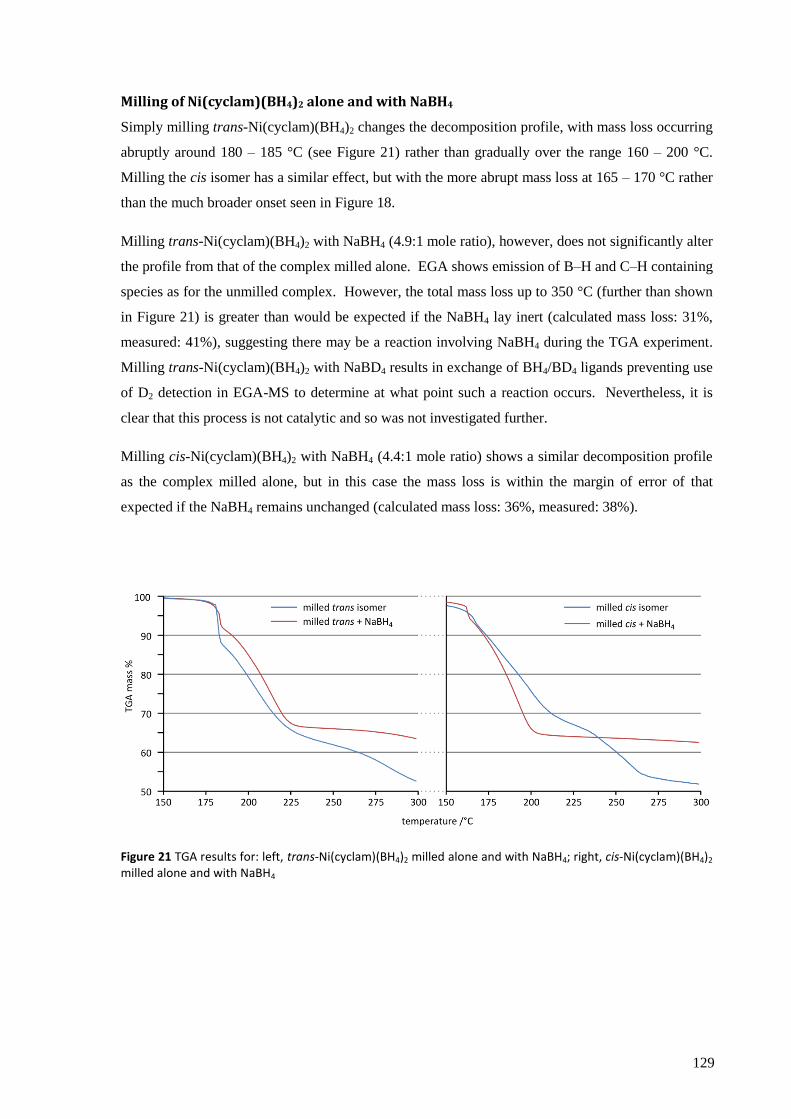
129
Milling of Ni(cyclam)(BH4)2 alone and with NaBH4
Simply milling trans-Ni(cyclam)(BH4)2 changes the decomposition profile, with mass loss occurring
abruptly around 180 – 185 °C (see Figure 21) rather than gradually over the range 160 – 200 °C.
Milling the cis isomer has a similar effect, but with the more abrupt mass loss at 165 – 170 °C rather
than the much broader onset seen in Figure 18.
Milling trans-Ni(cyclam)(BH4)2 with NaBH4 (4.9:1 mole ratio), however, does not significantly alter
the profile from that of the complex milled alone. EGA shows emission of B–H and C–H containing
species as for the unmilled complex. However, the total mass loss up to 350 °C (further than shown
in Figure 21) is greater than would be expected if the NaBH4 lay inert (calculated mass loss: 31%,
measured: 41%), suggesting there may be a reaction involving NaBH4 during the TGA experiment.
Milling trans-Ni(cyclam)(BH4)2 with NaBD4 results in exchange of BH4/BD4 ligands preventing use
of D2 detection in EGA-MS to determine at what point such a reaction occurs. Nevertheless, it is
clear that this process is not catalytic and so was not investigated further.
Milling cis-Ni(cyclam)(BH4)2 with NaBH4 (4.4:1 mole ratio) shows a similar decomposition profile
as the complex milled alone, but in this case the mass loss is within the margin of error of that
expected if the NaBH4 remains unchanged (calculated mass loss: 36%, measured: 38%).
Figure 21 TGA results for: left, trans-Ni(cyclam)(BH4)2 milled alone and with NaBH4; right, cis-Ni(cyclam)(BH4)2 milled alone and with NaBH4
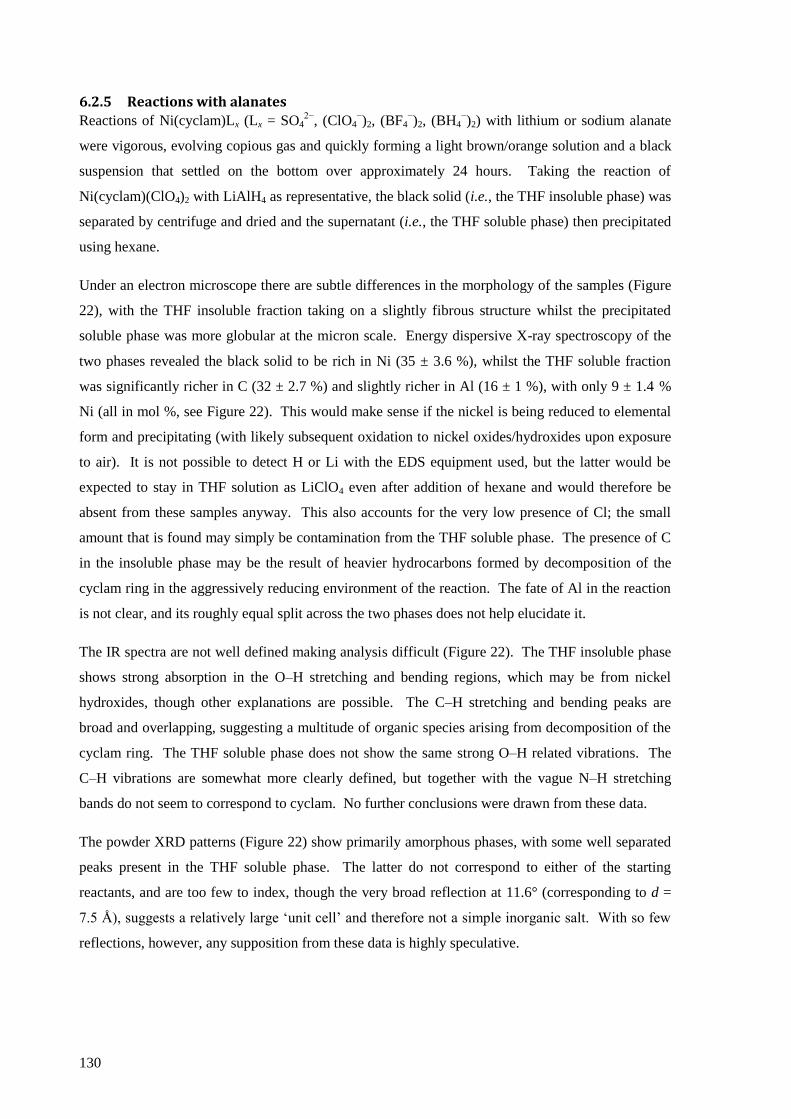
130
6.2.5 Reactions with alanates
Reactions of Ni(cyclam)Lx (Lx = SO42−
, (ClO4−)2, (BF4
−)2, (BH4
−)2) with lithium or sodium alanate
were vigorous, evolving copious gas and quickly forming a light brown/orange solution and a black
suspension that settled on the bottom over approximately 24 hours. Taking the reaction of
Ni(cyclam)(ClO4)2 with LiAlH4 as representative, the black solid (i.e., the THF insoluble phase) was
separated by centrifuge and dried and the supernatant (i.e., the THF soluble phase) then precipitated
using hexane.
Under an electron microscope there are subtle differences in the morphology of the samples (Figure
22), with the THF insoluble fraction taking on a slightly fibrous structure whilst the precipitated
soluble phase was more globular at the micron scale. Energy dispersive X-ray spectroscopy of the
two phases revealed the black solid to be rich in Ni (35 ± 3.6 %), whilst the THF soluble fraction
was significantly richer in C (32 ± 2.7 %) and slightly richer in Al (16 ± 1 %), with only 9 ± 1.4 %
Ni (all in mol %, see Figure 22). This would make sense if the nickel is being reduced to elemental
form and precipitating (with likely subsequent oxidation to nickel oxides/hydroxides upon exposure
to air). It is not possible to detect H or Li with the EDS equipment used, but the latter would be
expected to stay in THF solution as LiClO4 even after addition of hexane and would therefore be
absent from these samples anyway. This also accounts for the very low presence of Cl; the small
amount that is found may simply be contamination from the THF soluble phase. The presence of C
in the insoluble phase may be the result of heavier hydrocarbons formed by decomposition of the
cyclam ring in the aggressively reducing environment of the reaction. The fate of Al in the reaction
is not clear, and its roughly equal split across the two phases does not help elucidate it.
The IR spectra are not well defined making analysis difficult (Figure 22). The THF insoluble phase
shows strong absorption in the O–H stretching and bending regions, which may be from nickel
hydroxides, though other explanations are possible. The C–H stretching and bending peaks are
broad and overlapping, suggesting a multitude of organic species arising from decomposition of the
cyclam ring. The THF soluble phase does not show the same strong O–H related vibrations. The
C–H vibrations are somewhat more clearly defined, but together with the vague N–H stretching
bands do not seem to correspond to cyclam. No further conclusions were drawn from these data.
The powder XRD patterns (Figure 22) show primarily amorphous phases, with some well separated
peaks present in the THF soluble phase. The latter do not correspond to either of the starting
reactants, and are too few to index, though the very broad reflection at 11.6° (corresponding to d =
7.5 Å), suggests a relatively large „unit cell‟ and therefore not a simple inorganic salt. With so few
reflections, however, any supposition from these data is highly speculative.
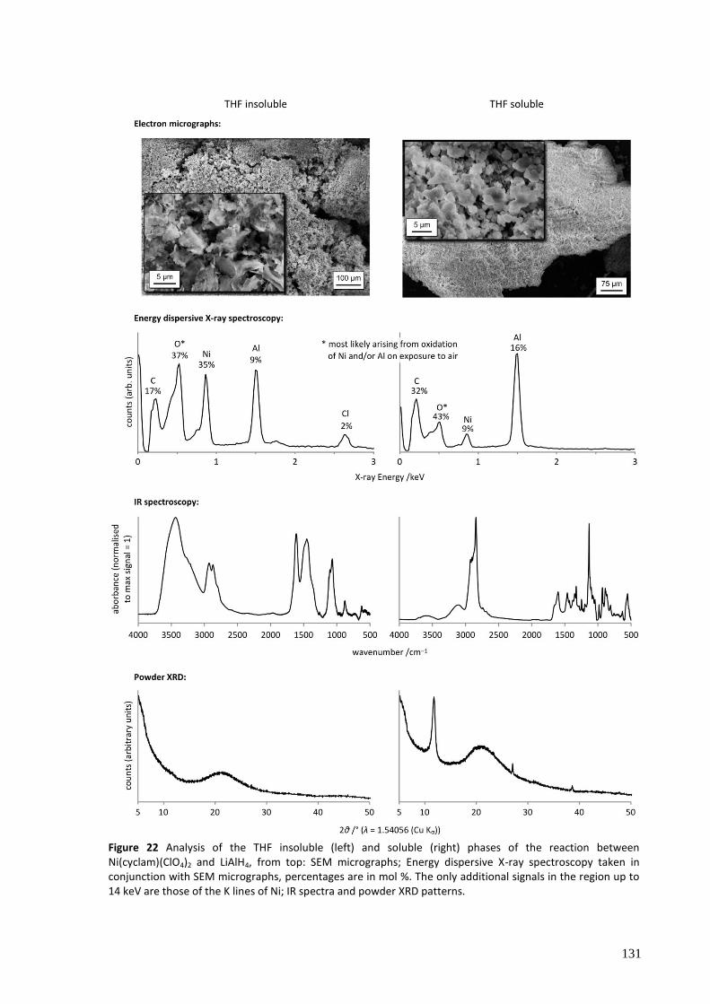
131
Figure 22 Analysis of the THF insoluble (left) and soluble (right) phases of the reaction between Ni(cyclam)(ClO4)2 and LiAlH4, from top: SEM micrographs; Energy dispersive X-ray spectroscopy taken in conjunction with SEM micrographs, percentages are in mol %. The only additional signals in the region up to 14 keV are those of the K lines of Ni; IR spectra and powder XRD patterns.

132
Attempts to moderate the reaction through dilute solutions and very slow addition of LiAlH4 were
unsuccessful, but low temperature reactions were not attempted and may be an interesting avenue to
investigate in the future.
[Ni(cyclam)Cl2], a complex that was not otherwise used in these studies, was also tested with
LiAlH4 to see if the more strongly coordinating anion had any effect, but gave the same result: a
vigorous reaction and a black solid product with poorly defined IR spectrum.
Despite considerable effort to more precisely characterise the reaction products, no further insight
into them was obtained. Given that the evidence available pointed to the reduction of Ni(II) and
decomposition of cyclam (quite possibly catalysed by nickel), it was decided that research efforts
would be better directed towards other complexes, and we will now consider the investigation of
nickel tetrathioether macrocycle complexes.
6.3 Nickel thioether complexes
6.3.1 Synthesis of the complexes
The lower affinity* of the 12aneS4 macrocycle for Ni(II) causes the synthesis of the complex to be
slightly less straightforward than for cyclam, though nevertheless it is still fairly simple. The main
difficulty arises from the ease of hydrolysis of the complex, such that the solvents must be kept
reasonably dry (standard commercial “anhydrous” solvents suffice), and exposure to particularly
humid air (e.g., on a humid summer day) may cause the product to revert to the reagents. These
conditions are, however, easily managed once they are recognised. The synthesis of
Ni(14aneS4)(BF4)2 (n.b., using the 14-member macrocycle) was achieved in a similar manner.
The solvent-free mechanochemical preparation of [Ni(12aneS4)(H2O)2](BF4)2 by milling the
hydrated nickel salt and the macrocycle ligand was extremely simple and fast (just three minutes
milling), requiring no work-up to obtain the product. This method of synthesis is still uncommon for
such transition metal complexes[27]
but shows promise for simpler and more environmentally
friendly reactions.
6.3.2 Crystal structure
The structure of [Ni(12aneS4)](BF4)2 solved from powder X-ray diffraction is shown in Figure 23.
The agreement between the high-quality experimental synchrotron X-ray diffraction pattern and that
calculated from the model was excellent (see Figure 24), giving very good confidence in the validity
of the structure. A selection of important parameter are shown in Table 6.
* The lack of „preorganisation‟ in the 12aneS4 ligand likely plays a significant role in this. See section 4.3 on
page 43 for more details.
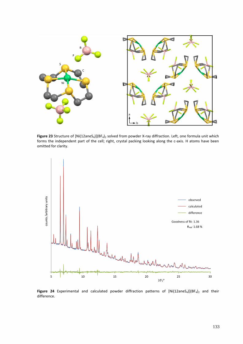
133
Figure 23 Structure of [Ni(12aneS4)](BF4)2 solved from powder X-ray diffraction. Left, one formula unit which forms the independent part of the cell; right, crystal packing looking along the c-axis. H atoms have been omitted for clarity.
Figure 24 Experimental and calculated powder diffraction patterns of [Ni(12aneS4)](BF4)2 and their difference.
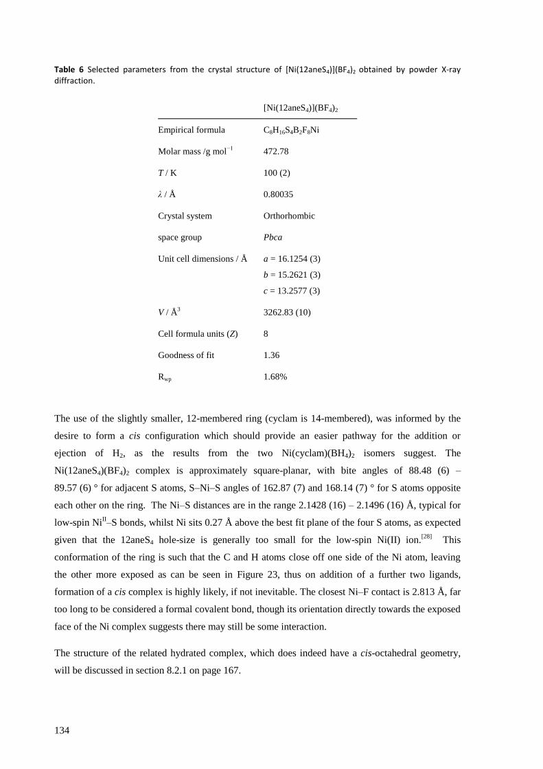
134
Table 6 Selected parameters from the crystal structure of [Ni(12aneS4)](BF4)2 obtained by powder X-ray diffraction.
[Ni(12aneS4)](BF4)2
Empirical formula C8H16S4B2F8Ni
Molar mass /g mol−1
472.78
T / K 100 (2)
λ / Å 0.80035
Crystal system Orthorhombic
space group Pbca
Unit cell dimensions / Å a = 16.1254 (3)
b = 15.2621 (3)
c = 13.2577 (3)
V / Å3
3262.83 (10)
Cell formula units (Z) 8
Goodness of fit 1.36
Rwp 1.68%
The use of the slightly smaller, 12-membered ring (cyclam is 14-membered), was informed by the
desire to form a cis configuration which should provide an easier pathway for the addition or
ejection of H2, as the results from the two Ni(cyclam)(BH4)2 isomers suggest. The
Ni(12aneS4)(BF4)2 complex is approximately square-planar, with bite angles of 88.48 (6) –
89.57 (6) ° for adjacent S atoms, S–Ni–S angles of 162.87 (7) and 168.14 (7) ° for S atoms opposite
each other on the ring. The Ni–S distances are in the range 2.1428 (16) – 2.1496 (16) Å, typical for
low-spin NiII–S bonds, whilst Ni sits 0.27 Å above the best fit plane of the four S atoms, as expected
given that the 12aneS4 hole-size is generally too small for the low-spin Ni(II) ion.[28]
This
conformation of the ring is such that the C and H atoms close off one side of the Ni atom, leaving
the other more exposed as can be seen in Figure 23, thus on addition of a further two ligands,
formation of a cis complex is highly likely, if not inevitable. The closest Ni–F contact is 2.813 Å, far
too long to be considered a formal covalent bond, though its orientation directly towards the exposed
face of the Ni complex suggests there may still be some interaction.
The structure of the related hydrated complex, which does indeed have a cis-octahedral geometry,
will be discussed in section 8.2.1 on page 167.

135
The powder X-ray diffraction pattern of Ni(14aneS4)(BF4)2 (with a larger 14-member macrocycle)
obtained for the sample prepared in this work did not match that calculated from a previously
reported structure (Figure 25).[29]
Given the different solvent system used and the powder versus
single crystal nature of the analytes, it is possible that a different polymorph was obtained, though
the possibility of decomposition of the complex should not be ruled out.
Figure 25 Powder X-ray diffraction patterns of Ni(14aneS4)(BF4)2 obtained in this work and calculated from a literature reported structure (reference 29).
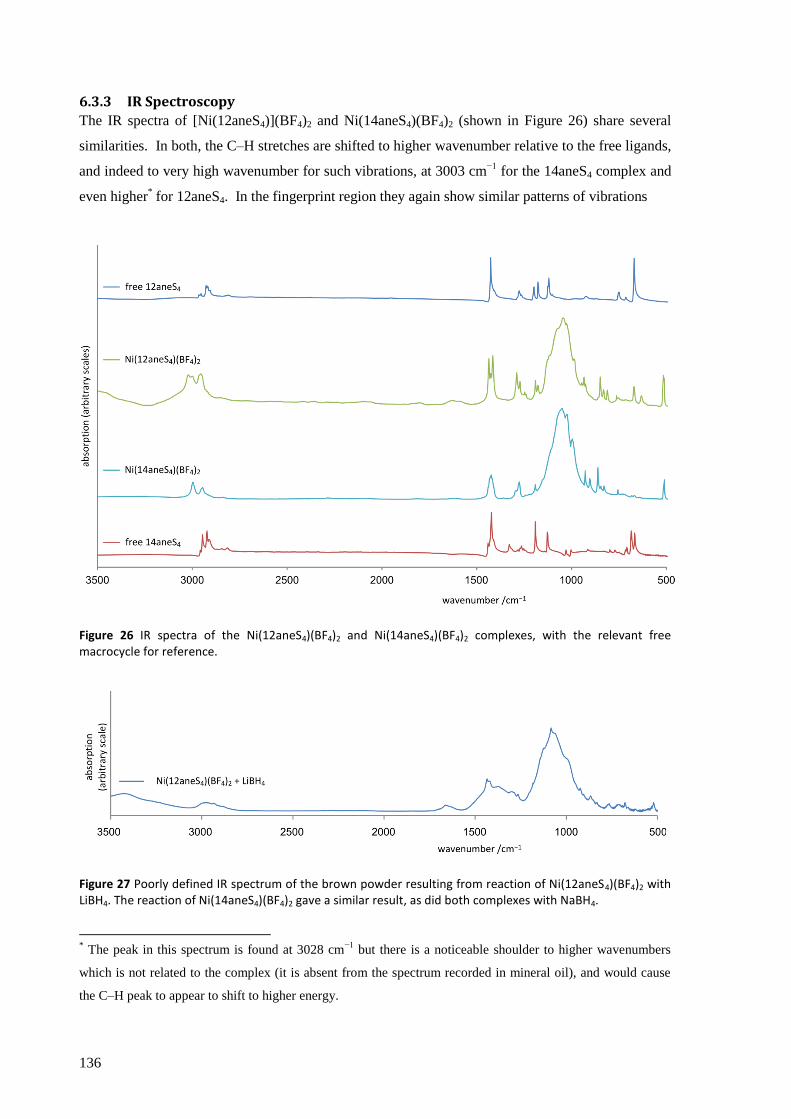
136
6.3.3 IR Spectroscopy
The IR spectra of [Ni(12aneS4)](BF4)2 and Ni(14aneS4)(BF4)2 (shown in Figure 26) share several
similarities. In both, the C–H stretches are shifted to higher wavenumber relative to the free ligands,
and indeed to very high wavenumber for such vibrations, at 3003 cm−1
for the 14aneS4 complex and
even higher* for 12aneS4. In the fingerprint region they again show similar patterns of vibrations
Figure 26 IR spectra of the Ni(12aneS4)(BF4)2 and Ni(14aneS4)(BF4)2 complexes, with the relevant free macrocycle for reference.
Figure 27 Poorly defined IR spectrum of the brown powder resulting from reaction of Ni(12aneS4)(BF4)2 with LiBH4. The reaction of Ni(14aneS4)(BF4)2 gave a similar result, as did both complexes with NaBH4.
* The peak in this spectrum is found at 3028 cm
−1 but there is a noticeable shoulder to higher wavenumbers
which is not related to the complex (it is absent from the spectrum recorded in mineral oil), and would cause
the C–H peak to appear to shift to higher energy.
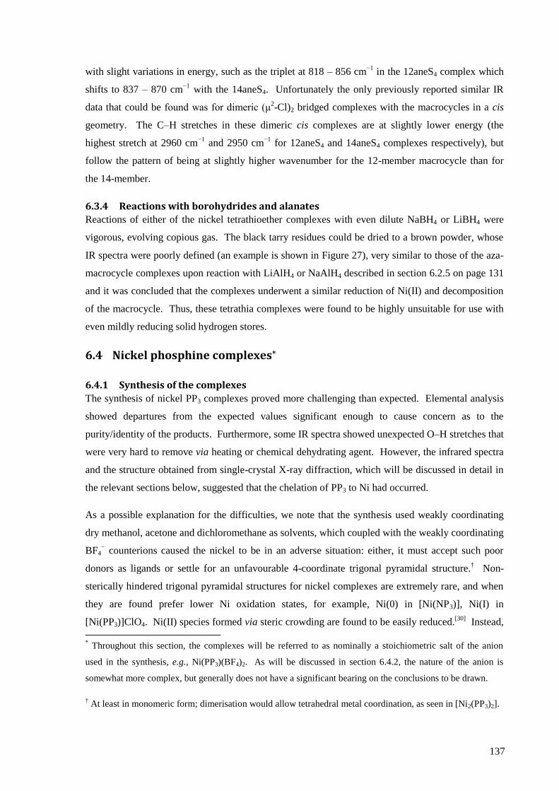
137
with slight variations in energy, such as the triplet at 818 – 856 cm−1
in the 12aneS4 complex which
shifts to 837 – 870 cm−1
with the 14aneS4. Unfortunately the only previously reported similar IR
data that could be found was for dimeric (μ2-Cl)2 bridged complexes with the macrocycles in a cis
geometry. The C–H stretches in these dimeric cis complexes are at slightly lower energy (the
highest stretch at 2960 cm−1
and 2950 cm−1
for 12aneS4 and 14aneS4 complexes respectively), but
follow the pattern of being at slightly higher wavenumber for the 12-member macrocycle than for
the 14-member.
6.3.4 Reactions with borohydrides and alanates
Reactions of either of the nickel tetrathioether complexes with even dilute NaBH4 or LiBH4 were
vigorous, evolving copious gas. The black tarry residues could be dried to a brown powder, whose
IR spectra were poorly defined (an example is shown in Figure 27), very similar to those of the aza-
macrocycle complexes upon reaction with LiAlH4 or NaAlH4 described in section 6.2.5 on page 131
and it was concluded that the complexes underwent a similar reduction of Ni(II) and decomposition
of the macrocycle. Thus, these tetrathia complexes were found to be highly unsuitable for use with
even mildly reducing solid hydrogen stores.
6.4 Nickel phosphine complexes*
6.4.1 Synthesis of the complexes
The synthesis of nickel PP3 complexes proved more challenging than expected. Elemental analysis
showed departures from the expected values significant enough to cause concern as to the
purity/identity of the products. Furthermore, some IR spectra showed unexpected O–H stretches that
were very hard to remove via heating or chemical dehydrating agent. However, the infrared spectra
and the structure obtained from single-crystal X-ray diffraction, which will be discussed in detail in
the relevant sections below, suggested that the chelation of PP3 to Ni had occurred.
As a possible explanation for the difficulties, we note that the synthesis used weakly coordinating
dry methanol, acetone and dichloromethane as solvents, which coupled with the weakly coordinating
BF4− counterions caused the nickel to be in an adverse situation: either, it must accept such poor
donors as ligands or settle for an unfavourable 4-coordinate trigonal pyramidal structure.† Non-
sterically hindered trigonal pyramidal structures for nickel complexes are extremely rare, and when
they are found prefer lower Ni oxidation states, for example, Ni(0) in [Ni(NP3)], Ni(I) in
[Ni(PP3)]ClO4. Ni(II) species formed via steric crowding are found to be easily reduced.[30]
Instead,
* Throughout this section, the complexes will be referred to as nominally a stoichiometric salt of the anion
used in the synthesis, e.g., Ni(PP3)(BF4)2. As will be discussed in section 6.4.2, the nature of the anion is
somewhat more complex, but generally does not have a significant bearing on the conclusions to be drawn.
† At least in monomeric form; dimerisation would allow tetrahedral metal coordination, as seen in [Ni2(PP3)2].
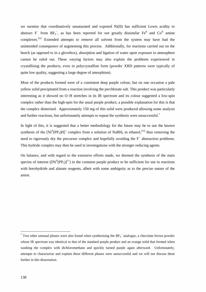
138
we surmise that coordinatively unsaturated and exposed Ni(II) has sufficient Lewis acidity to
abstract F− from BF4
−, as has been reported for not greatly dissimilar Fe
II and Co
II amine
complexes.[31]
Extended attempts to remove all solvent from the system may have had the
unintended consequence of augmenting this process. Additionally, for reactions carried out on the
bench (as opposed to in a glovebox), absorption and ligation of water upon exposure to atmosphere
cannot be ruled out. These varying factors may also explain the problems experienced in
crystallising the products, even in polycrystalline form (powder XRD patterns were typically of
quite low quality, suggesting a large degree of amorphism).
Most of the products formed were of a consistent deep purple colour, but on one occasion a pale
yellow solid precipitated from a reaction involving the perchlorate salt. This product was particularly
interesting as it showed no O–H stretches in its IR spectrum and its colour suggested a low-spin
complex rather than the high-spin for the usual purple product; a possible explanation for this is that
the complex dimerised. Approximately 150 mg of this solid were produced allowing some analysis
and further reactions, but unfortunately attempts to repeat the synthesis were unsuccessful.*
In light of this, it is suggested that a better methodology for the future may be to use the known
synthesis of the [NiII(PP3)H]
+ complex from a solution of NaBH4 in ethanol,
[33] thus removing the
need to rigorously dry the precursor complex and hopefully avoiding the F− abstraction problems.
This hydride complex may then be used in investigations with the stronger reducing agents.
On balance, and with regard to the extensive efforts made, we deemed the synthesis of the main
species of interest ([NiII(PP3)]
2+) in the common purple product to be sufficient for use in reactions
with borohydride and alanate reagents, albeit with some ambiguity as to the precise nature of the
anion.
* Two other unusual phases were also found when synthesising the BF4
− analogue, a chocolate brown powder
whose IR spectrum was identical to that of the standard purple product and an orange solid that formed when
washing the complex with dichloromethane and quickly turned purple again afterward. Unfortunately,
attempts to characterise and explain these different phases were unsuccessful and we will not discuss them
further in this dissertation.
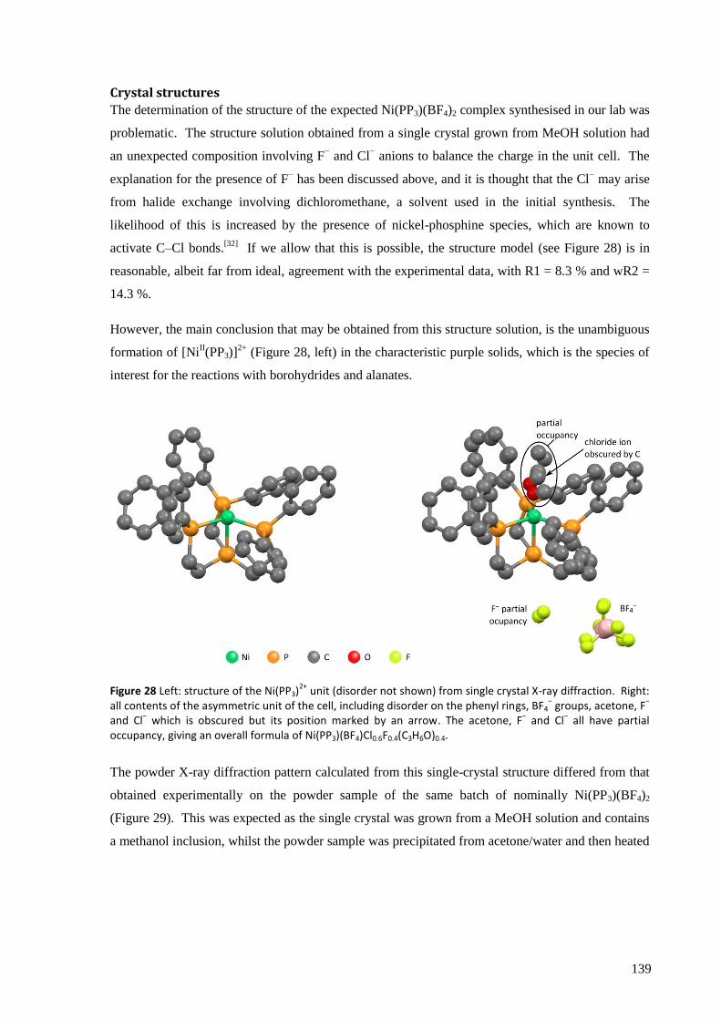
139
Crystal structures
The determination of the structure of the expected Ni(PP3)(BF4)2 complex synthesised in our lab was
problematic. The structure solution obtained from a single crystal grown from MeOH solution had
an unexpected composition involving F− and Cl
− anions to balance the charge in the unit cell. The
explanation for the presence of F− has been discussed above, and it is thought that the Cl
− may arise
from halide exchange involving dichloromethane, a solvent used in the initial synthesis. The
likelihood of this is increased by the presence of nickel-phosphine species, which are known to
activate C–Cl bonds.[32]
If we allow that this is possible, the structure model (see Figure 28) is in
reasonable, albeit far from ideal, agreement with the experimental data, with R1 = 8.3 % and wR2 =
14.3 %.
However, the main conclusion that may be obtained from this structure solution, is the unambiguous
formation of [NiII(PP3)]
2+ (Figure 28, left) in the characteristic purple solids, which is the species of
interest for the reactions with borohydrides and alanates.
Figure 28 Left: structure of the Ni(PP3)2+
unit (disorder not shown) from single crystal X-ray diffraction. Right: all contents of the asymmetric unit of the cell, including disorder on the phenyl rings, BF4
− groups, acetone, F
−
and Cl− which is obscured but its position marked by an arrow. The acetone, F
− and Cl
− all have partial
occupancy, giving an overall formula of Ni(PP3)(BF4)Cl0.6F0.4(C3H6O)0.4.
The powder X-ray diffraction pattern calculated from this single-crystal structure differed from that
obtained experimentally on the powder sample of the same batch of nominally Ni(PP3)(BF4)2
(Figure 29). This was expected as the single crystal was grown from a MeOH solution and contains
a methanol inclusion, whilst the powder sample was precipitated from acetone/water and then heated
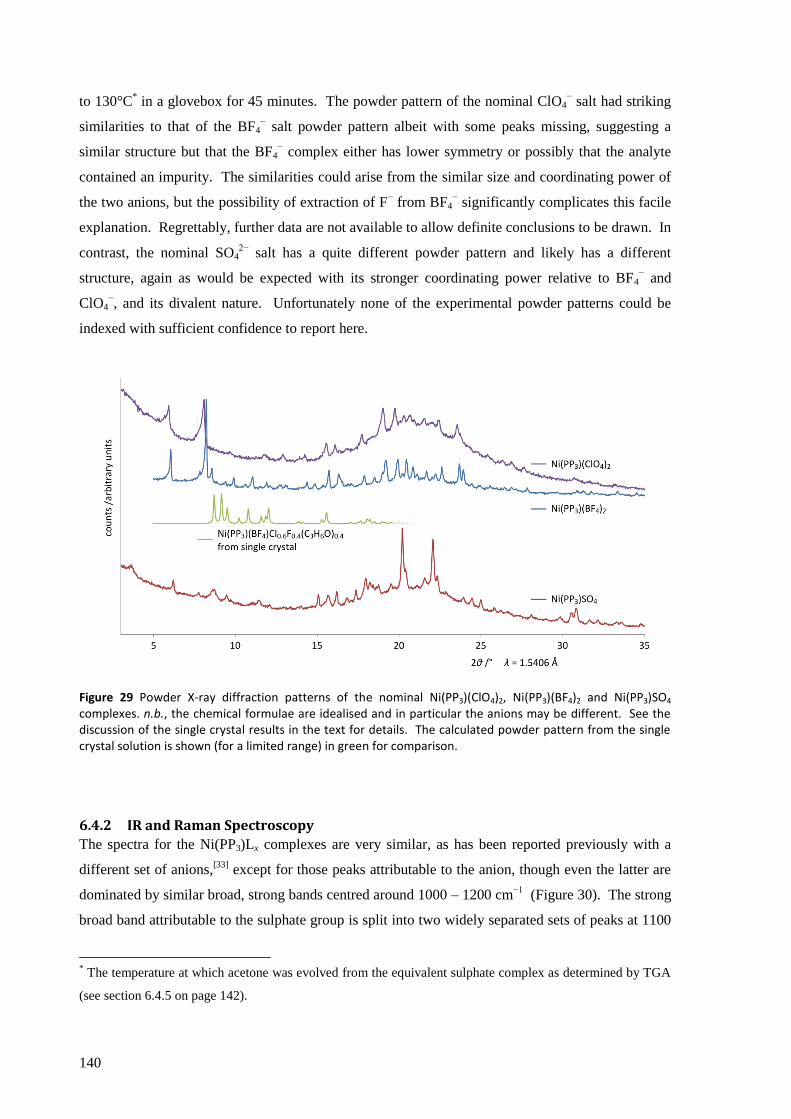
140
to 130°C* in a glovebox for 45 minutes. The powder pattern of the nominal ClO4
− salt had striking
similarities to that of the BF4− salt powder pattern albeit with some peaks missing, suggesting a
similar structure but that the BF4− complex either has lower symmetry or possibly that the analyte
contained an impurity. The similarities could arise from the similar size and coordinating power of
the two anions, but the possibility of extraction of F− from BF4
− significantly complicates this facile
explanation. Regrettably, further data are not available to allow definite conclusions to be drawn. In
contrast, the nominal SO42−
salt has a quite different powder pattern and likely has a different
structure, again as would be expected with its stronger coordinating power relative to BF4− and
ClO4−, and its divalent nature. Unfortunately none of the experimental powder patterns could be
indexed with sufficient confidence to report here.
Figure 29 Powder X-ray diffraction patterns of the nominal Ni(PP3)(ClO4)2, Ni(PP3)(BF4)2 and Ni(PP3)SO4 complexes. n.b., the chemical formulae are idealised and in particular the anions may be different. See the discussion of the single crystal results in the text for details. The calculated powder pattern from the single crystal solution is shown (for a limited range) in green for comparison.
6.4.2 IR and Raman Spectroscopy
The spectra for the Ni(PP3)Lx complexes are very similar, as has been reported previously with a
different set of anions,[33]
except for those peaks attributable to the anion, though even the latter are
dominated by similar broad, strong bands centred around 1000 – 1200 cm−1
(Figure 30). The strong
broad band attributable to the sulphate group is split into two widely separated sets of peaks at 1100
* The temperature at which acetone was evolved from the equivalent sulphate complex as determined by TGA
(see section 6.4.5 on page 142).
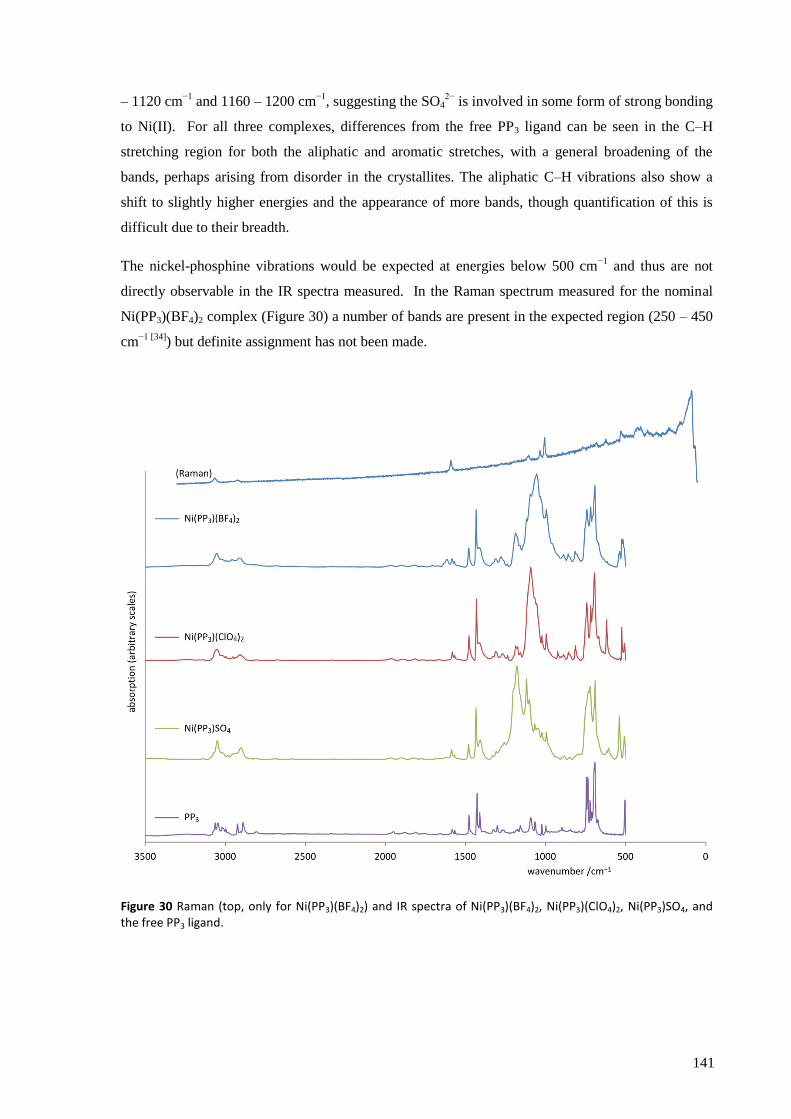
141
– 1120 cm−1
and 1160 – 1200 cm−1
, suggesting the SO42−
is involved in some form of strong bonding
to Ni(II). For all three complexes, differences from the free PP3 ligand can be seen in the C–H
stretching region for both the aliphatic and aromatic stretches, with a general broadening of the
bands, perhaps arising from disorder in the crystallites. The aliphatic C–H vibrations also show a
shift to slightly higher energies and the appearance of more bands, though quantification of this is
difficult due to their breadth.
The nickel-phosphine vibrations would be expected at energies below 500 cm−1
and thus are not
directly observable in the IR spectra measured. In the Raman spectrum measured for the nominal
Ni(PP3)(BF4)2 complex (Figure 30) a number of bands are present in the expected region (250 – 450
cm−1 [34]
) but definite assignment has not been made.
Figure 30 Raman (top, only for Ni(PP3)(BF4)2) and IR spectra of Ni(PP3)(BF4)2, Ni(PP3)(ClO4)2, Ni(PP3)SO4, and the free PP3 ligand.
142
6.4.3 Reactions with borohydrides and alanates
The complex [Ni(dppe)Cl2] was reacted with LiBH4. Unfortunately the vigorous evolution of gas
and solid black product with poorly defined IR spectrum was very similar to the reactions of the
tetrathioethers with borohydrides and the cyclam complexes with alanates, thus [Ni(dppe)Cl2] was
judged to be unpromising and no further investigations were carried out.
The reactions of [Ni(PP3)]2+
complexes with NaBH4 have been known for some time,[33]
resulting in
the formation of the air-sensitive and diamagnetic yellow solids, [NiII(PP3)(H)]L (L = I
−, NO3
−, BF4
−,
BPh4−). We were therefore interested in whether the complexes were stable in the more strongly
reducing environments of LiBH4, NaAlH4 and LiAlH4 THF solutions, and whether solid state
mechanochemical reactions were possible.
All three Ni(PP3)Lx complexes* were reacted with LiBH4 in THF, and reliably gave bright yellow
solids (or occasionally oils which were dried to a solid with some difficulty), in agreement with the
results of Ghilardi et al. with NaBH4.[33]
The IR spectra of the products also showed a small peak at
595 cm−1
which these authors attributed to Ni–H (an additional synthesis using borodeuteride would
help to confirm this assignment, but has not yet been carried out). The reactions with either NaAlH4
or LiAlH4 similarly produced yellow solids, generally with no visible evolution of gas; though
occasionally a few bubbles were seen to form, they were nothing like the vigorous evolution seen
when the other complexes were reacted with these alanates. Milling of (nominally) Ni(PP3)(BF4)2
with either LiBH4 or NaAlH4 resulted in yellow solids with IR spectra similar to those of the
reactions in THF including the peak at 595 cm−1
.
6.4.4 TGA/DSC and evolved gas analysis
Thermal analysis of the nominal Ni(PP3)SO4 showed a mass loss of about 7 %, which the EGA-MS
indicated was due to solvent loss (see Figure 31). Water was lost first, then DCM at a slightly
higher temperature, and acetone last, peaking at about 130 °C (though the latter did not account for
much mass loss), suggesting that acetone is bound to the nickel as in the structural model shown in
Figure 28. The Ni(PP3)SO4 complex only started to decompose above 180 °C, as evidenced by MS
signals attributable to the phenyl rings. This suggests that „drying‟ the complexes at 140 °C should
be acceptable and a TGA of Ni(PP3)(BF4)2 subjected to this treatment did not show any mass loss
until about 200 °C (temperature ramp: 3 K min−1
).
* The results discussed in the main text are from Ni(PP3)Lx complexes that did not show O–H stretching bands
in their IR spectra, indicating no water or methanol was present. Where these bands were present, reaction
with a reducing agent evolved copious gas, presumably from reaction with the O–H containing species, but a
similar yellow solid or oil was produced. Nevertheless, for simplicity, these reactions will not be discussed
beyond this brief note.
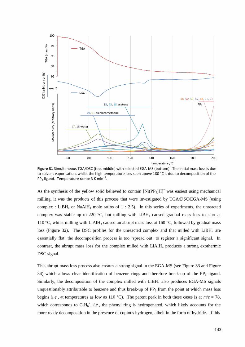
143
Figure 31 Simultaneous TGA/DSC (top, middle) with selected EGA-MS (bottom). The initial mass loss is due to solvent vaporisation, whilst the high temperature loss seen above 180 °C is due to decomposition of the PP3 ligand. Temperature ramp: 3 K min
−1.
As the synthesis of the yellow solid believed to contain [Ni(PP3)H]+ was easiest using mechanical
milling, it was the products of this process that were investigated by TGA/DSC/EGA-MS (using
complex : LiBH4 or NaAlH4 mole ratios of 1 : 2.5). In this series of experiments, the unreacted
complex was stable up to 220 °C, but milling with LiBH4 caused gradual mass loss to start at
110 °C, whilst milling with LiAlH4 caused an abrupt mass loss at 160 °C, followed by gradual mass
loss (Figure 32). The DSC profiles for the unreacted complex and that milled with LiBH4 are
essentially flat; the decomposition process is too „spread out‟ to register a significant signal. In
contrast, the abrupt mass loss for the complex milled with LiAlH4 produces a strong exothermic
DSC signal.
This abrupt mass loss process also creates a strong signal in the EGA-MS (see Figure 33 and Figure
34) which allows clear identification of benzene rings and therefore break-up of the PP3 ligand.
Similarly, the decomposition of the complex milled with LiBH4 also produces EGA-MS signals
unquestionably attributable to benzene and thus break-up of PP3 from the point at which mass loss
begins (i.e., at temperatures as low as 110 °C). The parent peak in both these cases is at m/z = 78,
which corresponds to C6H6+, i.e., the phenyl ring is hydrogenated, which likely accounts for the
more ready decomposition in the presence of copious hydrogen, albeit in the form of hydride. If this
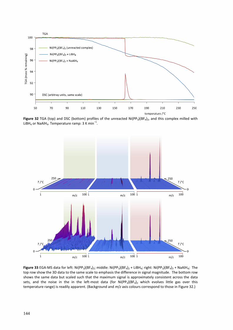
144
Figure 32 TGA (top) and DSC (bottom) profiles of the unreacted Ni(PP3)(BF4)2, and this complex milled with LiBH4 or NaAlH4. Temperature ramp: 3 K min
−1.
Figure 33 EGA-MS data for left: Ni(PP3)(BF4)2; middle: Ni(PP3)(BF4)2 + LiBH4; right: Ni(PP3)(BF4)2 + NaAlH4; The top row show the 3D data to the same scale to emphasis the difference in signal magnitude. The bottom row shows the same data but scaled such that the maximum signal is approximately consistent across the data sets, and the noise in the in the left-most data (for Ni(PP3)(BF4)2 which evolves little gas over this temperature range) is readily apparent. (Background and m/z axis colours correspond to those in Figure 32.)
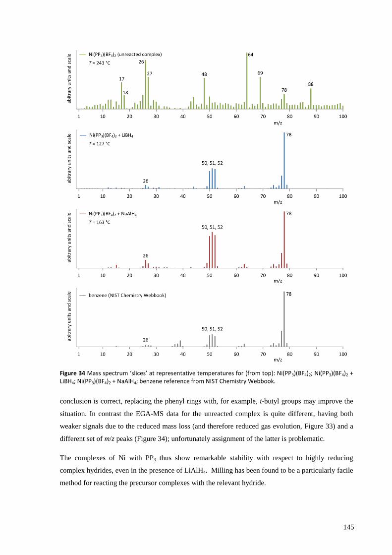
145
Figure 34 Mass spectrum ‘slices’ at representative temperatures for (from top): Ni(PP3)(BF4)2; Ni(PP3)(BF4)2 + LiBH4; Ni(PP3)(BF4)2 + NaAlH4; benzene reference from NIST Chemistry Webbook.
conclusion is correct, replacing the phenyl rings with, for example, t-butyl groups may improve the
situation. In contrast the EGA-MS data for the unreacted complex is quite different, having both
weaker signals due to the reduced mass loss (and therefore reduced gas evolution, Figure 33) and a
different set of m/z peaks (Figure 34); unfortunately assignment of the latter is problematic.
The complexes of Ni with PP3 thus show remarkable stability with respect to highly reducing
complex hydrides, even in the presence of LiAlH4. Milling has been found to be a particularly facile
method for reacting the precursor complexes with the relevant hydride.
146
6.5 Conclusions and assessment of potential of complexes as hydrogen
store catalysts
The use of ligands to stabilise Ni(II) sufficiently to withstand the highly reducing atmosphere of a
borohydride or alanate hydrogen store has been demonstrated. The nature of the ligand is of course
of vital importance: whilst success was achieved with both cyclam and PP3, neither the 12aneS4 nor
the 14aneS4 complexes with nickel were able to withstand even dilute solutions of NaBH4 in THF.
Work performed previously in our group has shown that crown ethers also provide no protection
from such relatively mild reducing agents.[35]
Similarly, whilst the PP3 ligand was very effective at
stabilising Ni(II) with respect to reduction, the bidentate dppe ligand was not (though a bis-dppe
complex may perform better).
The Ni(cyclam)(BH4)2 system has been extensively characterised and there is no doubt that the tetra-
amine functionality prevents reduction of Ni(II) by LiBH4, but fails with the more strongly reducing
alanates. Ni(PP3)2+
is more effective at protecting Ni(II) from reduction, even allowing binding of
the highly reducing H− ligand (a stronger reducing agent than BH4
−). Thus, the following series may
be proposed for tetra-dentate chelates/macrocycles with a single donor type, in order of increasing
protection against reduction afforded to Ni(II):
O, S < N < P
It is unfortunate that we were unable to test a macrocycle with phosphine donors as none was
commercially available, though as we would expect the macrocyclic effect to increase the stability
(see section 4.2 on page 41) it should enhance this relationship and is not a significant problem.
Confirmation that the above series is reasonable despite this slight inconsistency could be achieved
by testing equivalent tripodal ligands with N and P donors (this may be easier if the phenyl groups
are replaced with methyl or ethyl groups).
A clear example of the impact of the structure on the decomposition properties has also been
obtained in the form of the cis and trans isomers of Ni(cyclam)(BH4)2 where a lower decomposition
temperature is obtained when the H− donors are adjacent (cis) rather than spatially separated (trans).
It seems highly likely that the cis conformation is generally the more desirable for evolution of H2
where the reaction pathway involves H···H coupling. This could be imposed either by use of
macrocycles too small to fully encompass the metal atom, or perhaps more effectively, by using a
bridge across the ring that forces the ligand into such a geometry.
One aspect we have not considered until now is the mass of the catalysts, which is significantly
larger for the complexes considered here than for simple transition metal salts (for example,
Ni(cyclam)(BH4)2 has molecular mass of 288.7 g mol−1
, whilst NiCl2 has formula mass of 129.7 g
mol−1
). However, the requirement for lowering it can be thought of as inversely proportional to the

147
turn-over-frequency of the catalyst, that is, a particularly efficient catalyst can be heavier than a
lesser one and still meet the stringent gravimetric capacity requirements for on-board vehicular
hydrogen storage.
If we take a hypothetical storage material capable of reversibly storing 10 % hydrogen by mass but
showing poor kinetics, the revised DOE ultimate targets of 7.5 wt% hydrogen (see Table 1 on page
14) would still allow one quarter of the store by mass to be catalyst. For a catalyst of similar
molecular mass to Ni(cyclam)(BH4)2, this would require each nickel centre to „process‟ around 40–
50 molecules of H2 in each cycle. This scales proportionately with the mass of the catalyst, so one
based on Ni(PP3)2+
, which has about three times the molecular mass (depending on the anion), would
have to process about 120 – 150 molecules of H2 in each cycle. Whilst not underestimating the
challenges of mass transport in solids, this does not seem unreasonable, though masses more similar
to that of Ni(cyclam)(BH4)2 would certainly be preferred. In the case of PP3, the majority of the
mass is in the six phenyl rings, which could perhaps be substituted for lighter constituents.
It is important to be clear about the problems encountered so far, most notably that a catalytic
function has not been found, nor even the initial requirement of an endothermic decomposition
process. Furthermore, the complexes investigated here disintegrate rather than evolving (pure)
hydrogen and thus none would be suitable for use in complex hydride hydrogen stores. Therefore, a
more significant rethink of the approach may be advantageous. The use of a single metal centre in
the catalyst requires that it undergo two-electron reduction/oxidation in catalysing the H2 + 2e− →
2H− reaction or its reverse. As Ni(III) would be very hard (if not impossible) to achieve in these
reducing conditions, this would require Ni(II)/Ni(0) couple. Phosphines are capable of ligating this
oxidation state, and this provides a further reason to expand investigation of these ligands, but the
significant structural changes that may be required might still be a problem. Rather, the use of two
metal centres each providing or accepting a single electron may present a more promising avenue for
future research. This would require a more complex (and heavier) ligand to bring the two metal
centres into the correct position and orbital orientation, but would improve the prospects of using
donor atoms that are less able to bond to Ni(0).
The number of potential ligands is massive, and the resulting possibilities for tuning the environment
of the metal centre considerable. Use of different ring size and geometry, bridging groups to enforce
cis geometry, judicious positioning of different donor atoms, and of course the choice of metal
centre, are some of the methods available for altering the thermodynamic and thermal decomposition
properties of the final product.
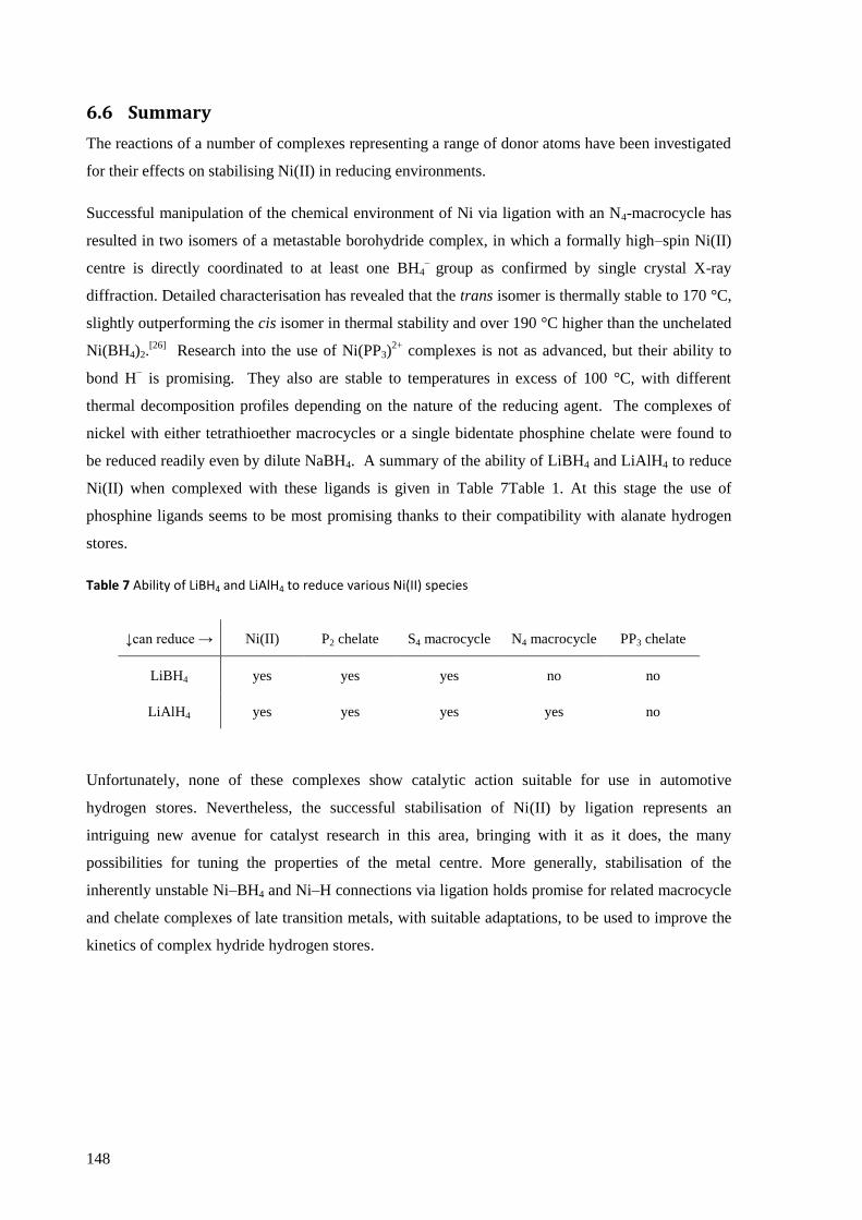
148
6.6 Summary
The reactions of a number of complexes representing a range of donor atoms have been investigated
for their effects on stabilising Ni(II) in reducing environments.
Successful manipulation of the chemical environment of Ni via ligation with an N4-macrocycle has
resulted in two isomers of a metastable borohydride complex, in which a formally high–spin Ni(II)
centre is directly coordinated to at least one BH4–
group as confirmed by single crystal X-ray
diffraction. Detailed characterisation has revealed that the trans isomer is thermally stable to 170 °C,
slightly outperforming the cis isomer in thermal stability and over 190 °C higher than the unchelated
Ni(BH4)2.[26]
Research into the use of Ni(PP3)2+
complexes is not as advanced, but their ability to
bond H− is promising. They also are stable to temperatures in excess of 100 °C, with different
thermal decomposition profiles depending on the nature of the reducing agent. The complexes of
nickel with either tetrathioether macrocycles or a single bidentate phosphine chelate were found to
be reduced readily even by dilute NaBH4. A summary of the ability of LiBH4 and LiAlH4 to reduce
Ni(II) when complexed with these ligands is given in Table 7Table 1. At this stage the use of
phosphine ligands seems to be most promising thanks to their compatibility with alanate hydrogen
stores.
Table 7 Ability of LiBH4 and LiAlH4 to reduce various Ni(II) species
↓can reduce → Ni(II) P2 chelate S4 macrocycle N4 macrocycle PP3 chelate
LiBH4 yes yes yes no no
LiAlH4 yes yes yes yes no
Unfortunately, none of these complexes show catalytic action suitable for use in automotive
hydrogen stores. Nevertheless, the successful stabilisation of Ni(II) by ligation represents an
intriguing new avenue for catalyst research in this area, bringing with it as it does, the many
possibilities for tuning the properties of the metal centre. More generally, stabilisation of the
inherently unstable Ni–BH4 and Ni–H connections via ligation holds promise for related macrocycle
and chelate complexes of late transition metals, with suitable adaptations, to be used to improve the
kinetics of complex hydride hydrogen stores.
149
References
1 CrysAlis RED, Oxford Diffraction Ltd., Version 1.171.33. Empirical absorption correction using spherical
harmonics, implemented in SCALE3 ABSPACK scaling algorithm.
2 CrysAlis CCD, Oxford Diffraction Ltd., Version 1.171.33, CrysAlis RED, Oxford Diffraction Ltd., Version
1.171.33.
3 G. M. Sheldrick, Acta Crystallographica Section A, 1990, 46, 467.
4 L. J. Farrugia, Journal of Applied Crystallography, 1999, 32, 837.
5 G. M. Sheldrick, SHELXL93. Program for the Refinement of Crystal Structures, University of Göttingen,
Germany.
6 A. J. C. Wilson, International Tables for Crystallography Vol. C, Kluwer, Dordrecht, 1992.
7 A. Altomare, M. Camalli, C. Cuocci, C. Giacovazzo, A. Moliterni, R. Rizzi, Journal of Applied
Crystallography, 2009, 42, 1197.
8 V. Favre-Nicolin, R. Cerny, Journal of Applied Crystallography, 2002, 35, 734.
9 Avogadro: an open-source molecular builder and visualization tool. Version 1.01.
http://avogadro.openmolecules.net/
10 V. Petricek, M. Dusek, L. Palatinus, Jana2006, crystallographic computing system, Institute of Physics,
Praha, (Czech Republic), 2006.
11 L. S. Bartell, E. a Roth, C. D. Hollowell, K. Kuchitsu, J. E. Young, The Journal of Chemical Physics, 1965, 42,
2683.
12 F. H. Allen, Acta Crystallographica Section B, 2002, 58, 380.
13 I. J. Bruno, J. C. Cole, P. R. Edgington, M. Kessler, C. F. Macrae, P. McCabe, J. Pearson, R. Taylor, Acta
Crystallographica Section B, 2002, 58, 389.
14 N. F. Curtis, Journal of the Chemical Society (Resumed), 1965, 1965, 924;
15 A. M. Stolzenberg, Z. Zhang, Inorganic Chemistry, 1997, 36, 593.
16 W. T. Klooster, T. F. Koetzle, P. E. Siegbahn, T. B. Richardson, R. H. Crabtree, Journal of the American
Chemical Society, 1999, 121, 6337; R. Custelcean, J. E. Jackson, Chemical Reviews, 2001, 101, 1963.
17 F. Takusagawa, A. Fumagalli, T. F. Koetzle, S. G. Shore, T. Schmitkons, A. V. Fratini, K. W. Morse, C.-yu
Wei, R. Bau, Journal of the American Chemical Society, 1981, 103, 5165.
18 R. Taylor, O. Kennard, Acta Crystallographica Section B, 1983, 39, 133.
19 P. J. Desrochers, S. LeLievre, R. J. Johnson, B. T. Lamb, A. L. Phelps, A. W. Cordes, W. Gu, S. P. Cramer,
Inorganic chemistry, 2003, 42, 7945.
20 M. Kandiah, G. S. McGrady, A. Decken, P. Sirsch, Inorganic Chemistry, 2005, 44, 8650.
21 Y. Journaux, V. Lozan, J. Klingele, B. Kersting, Chemical Communications, 2006, 219, 83.
22 B. Bosnich, M. L. Tobe, G. A. Webb, Inorganic Chemistry, 1965, 4, 1109.
23 H. Dodziuk, R. A. Kolinski, B. Korybut-Daszkiewicz, Spectrochimica Acta Part A: Molecular Spectroscopy,
1973, 29, 511.
24 E. E. Ernstbrunner, J. Hudec, Journal of Molecular Structure, 1973, 17, 249; S. Wolfe, H. B. Schlegel, M.-H.
Whangbo, F. Bernardi, Canadian Journal of Chemistry, 1974, 52, 3787; H. B. Schlegel, S. Wolfe, F.
Bernardi, Journal of Chemical Physics, 1977, 67, 4181.
25 P. Martelli, R. Caputo, A. Remhof, P. Mauron, A. Borgschulte, A. Züttel, Journal of Physical Chemistry C,
2010, 114, 7173.

150
26 J. Aubry, G. Monnier, Bulletin de la Societé Chimique France, 1955, 4, 482.
27 S. L. James, C. J. Adams, C. Bolm, D. Braga, P. Collier, T. Friščić, F. Grepioni, K. D. M. Harris, G. Hyett, W.
Jones, A. Krebs, J. Mack, L. Maini, A. G. Orpen, I. P. Parkin, W. C. Shearouse, J. W. Steed, D. C. Waddell,
Chemical Society Reviews, 2012, 41, 413.
28 A. J. Blake, M. A. Halcrow, M. Schröder, Journal of the Chemical Society Dalton Transactions, 1994, 1463.
29 P. H. Davis, L. K. White, R. L. Belford, Inorganic Chemistry, 1975, 14, 1753.
30 J. Cho, G. P. A. Yap, C. G. Riordan, Inorganic Chemistry, 2007, 46, 11308.
31 I. B. Gorrell, G. Parkin, Inorganic Chemistry, 1990, 29, 2452.
32 C. Malanga, S. Marmucci, L. Lardicci, Synthesis, 1998, 54, 1021.
33 C. A. Ghilardi, S. Midollini, L. Sacconi, Inorganic Chemistry, 1975, 14, 1790.
34 J. Podlahová, Collection of Czechoslovak Chemical Communications, 1978, 43, 64; P. L. Goggin, R. J.
Goodfellow, Journal of the Chemical Society A, 1966, 1462.
35 W. Grochala, personal communication.
151
7 The unusual structure of [Ni(H2O)6][Ni(SO4)2(cyclam)]·2H2O
7.1 Methodology for synthesis, analysis and database queries .................................................... 152
7.1.1 Synthesis and analysis by single crystal X-ray diffraction ................................................ 152
7.1.2 Cambridge Structural Database Queries .......................................................................... 152
7.2 Results and discussion .............................................................................................................. 153
7.2.1 Description of the structure ............................................................................................. 153
7.2.2 Comparison with other structures ................................................................................... 157
7.3 Summary .................................................................................................................................. 159
References ............................................................................................................................................ 160
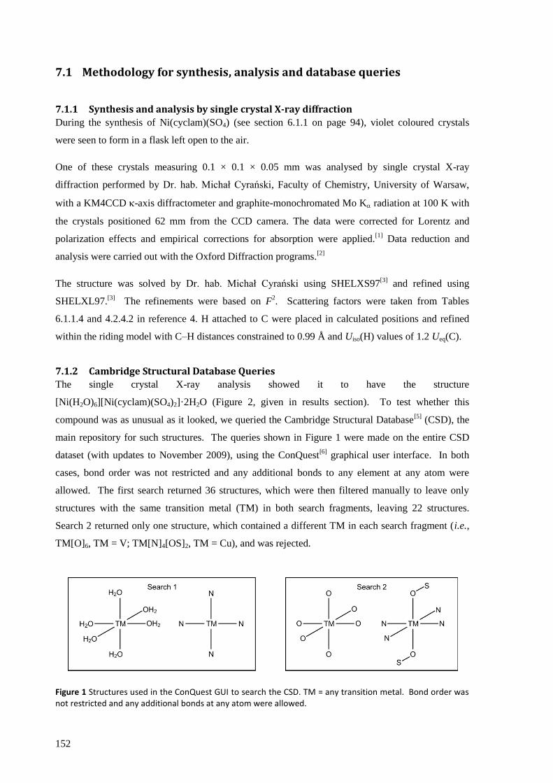
152
7.1 Methodology for synthesis, analysis and database queries
7.1.1 Synthesis and analysis by single crystal X-ray diffraction
During the synthesis of Ni(cyclam)(SO4) (see section 6.1.1 on page 94), violet coloured crystals
were seen to form in a flask left open to the air.
One of these crystals measuring 0.1 × 0.1 × 0.05 mm was analysed by single crystal X-ray
diffraction performed by Dr. hab. Michał Cyrański, Faculty of Chemistry, University of Warsaw,
with a KM4CCD -axis diffractometer and graphite-monochromated Mo K radiation at 100 K with
the crystals positioned 62 mm from the CCD camera. The data were corrected for Lorentz and
polarization effects and empirical corrections for absorption were applied.[1]
Data reduction and
analysis were carried out with the Oxford Diffraction programs.[2]
The structure was solved by Dr. hab. Michał Cyrański using SHELXS97[3]
and refined using
SHELXL97.[3]
The refinements were based on F2. Scattering factors were taken from Tables
6.1.1.4 and 4.2.4.2 in reference 4. H attached to C were placed in calculated positions and refined
within the riding model with C–H distances constrained to 0.99 Å and Uiso(H) values of 1.2 Ueq(C).
7.1.2 Cambridge Structural Database Queries
The single crystal X-ray analysis showed it to have the structure
[Ni(H2O)6][Ni(cyclam)(SO4)2]·2H2O (Figure 2, given in results section). To test whether this
compound was as unusual as it looked, we queried the Cambridge Structural Database[5]
(CSD), the
main repository for such structures. The queries shown in Figure 1 were made on the entire CSD
dataset (with updates to November 2009), using the ConQuest[6]
graphical user interface. In both
cases, bond order was not restricted and any additional bonds to any element at any atom were
allowed. The first search returned 36 structures, which were then filtered manually to leave only
structures with the same transition metal (TM) in both search fragments, leaving 22 structures.
Search 2 returned only one structure, which contained a different TM in each search fragment (i.e.,
TM[O]6, TM = V; TM[N]4[OS]2, TM = Cu), and was rejected.
Figure 1 Structures used in the ConQuest GUI to search the CSD. TM = any transition metal. Bond order was not restricted and any additional bonds at any atom were allowed.

153
7.2 Results and discussion
7.2.1 Description of the structure
Single crystal X-ray diffraction showed the structure of the violet crystals to contain two different
nickel complexes, one cationic and one anionic. The former consisted of a homoleptic hexaaqua
dication, [Ni(H2O)6]2+
, whilst the latter featured nickel bound to the cyclam ring and both sulphate
groups, [Ni(cyclam)(SO4)2]2−
. Two waters of crystallisation were also present. These structures are
shown in Figure 2, selected bond lengths and angles in Table 1, illustrations of crystal packing in
Figure 3 and other important parameters in Table 2. The experimental data was of high quality and
the structural model provided very good agreement with it.
Figure 2 Two representations of the molecular structure of [Ni(H2O)6][Ni(cyclam)(SO4)2]·2H2O obtained from single crystal X-ray diffraction. Left, ball and stick; right, corresponding ORTEP at 50% probability. Hydrogen atoms have been omitted for clarity. ORTEP diagram reproduced with permission of the International Union of Crystallography from the authors own work in reference 7.
Table 1 Selected bond length and angles of [Ni(H2O)6][Ni(cyclam)(SO4)2]·2H2O
bond lengths /Å bond angles /°
Ni1–N1 2.0691 (13) N1–Ni1–N2
(5-member ring) 85.74 (5)
Ni1–N2 2.0743 (13)
Ni1–O1 2.1522 (10) N1–Ni1–N2
(6-member ring) 94.26 (5)
Ni2–O5 2.0451 (11)
Ni2–O6 2.0701 (12) N1–Ni1–O1
Ni2–O7 2.0837 (12) N2–Ni1–O1
Ni2–O5
Ni2–O6
Ni2–O7
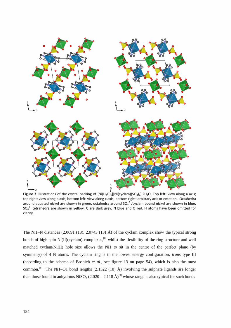
154
Figure 3 Illustrations of the crystal packing of [Ni(H2O)6][Ni(cyclam)(SO4)2]·2H2O. Top left: view along a axis; top right: view along b axis; bottom left: view along c axis; bottom right: arbitrary axis orientation. Octahedra around aquated nickel are shown in green, octahedra around SO4
2−/cyclam bound nickel are shown in blue,
SO42−
tetrahedra are shown in yellow. C are dark grey, N blue and O red. H atoms have been omitted for clarity.
The Ni1–N distances (2.0691 (13), 2.0743 (13) Å) of the cyclam complex show the typical strong
bonds of high-spin Ni(II)(cyclam) complexes,[8]
whilst the flexibility of the ring structure and well
matched cyclam/Ni(II) hole size allows the Ni1 to sit in the centre of the perfect plane (by
symmetry) of 4 N atoms. The cyclam ring is in the lowest energy configuration, trans type III
(according to the scheme of Bosnich et al., see figure 13 on page 54), which is also the most
common.[8]
The Ni1–O1 bond lengths (2.1522 (10) Å) involving the sulphate ligands are longer
than those found in anhydrous NiSO4 (2.020 – 2.118 Å)[9]
whose range is also typical for such bonds
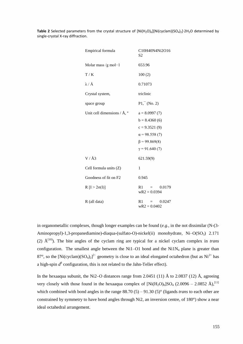
155
Table 2 Selected parameters from the crystal structure of [Ni(H2O)6][Ni(cyclam)(SO4)2]·2H2O determined by single-crystal X-ray diffraction.
Empirical formula C10H40N4Ni2O16
S2
Molar mass /g mol−1 653.96
T / K 100 (2)
λ / Å 0.71073
Crystal system, triclinic
space group P1,¯ (No. 2)
Unit cell dimensions / Å, º a = 8.0997 (7)
b = 8.4360 (6)
c = 9.3521 (9)
α = 98.558 (7)
β = 99.869(8)
γ = 91.640 (7)
V / Å3 621.59(9)
Cell formula units (Z) 1
Goodness of fit on F2 0.945
R [I > 2σ(I)] R1 = 0.0179
wR2 = 0.0394
R (all data) R1 = 0.0247
wR2 = 0.0402
in organometallic complexes, though longer examples can be found (e.g., in the not dissimilar (N-(3-
Aminopropyl)-1,3-propanediamine)-diaqua-(sulfato-O)-nickel(ii) monohydrate, Ni–O(SO3) 2.171
(2) Å[10]
). The bite angles of the cyclam ring are typical for a nickel cyclam complex in trans
configuration. The smallest angle between the Ni1–O1 bond and the Ni1N4 plane is greater than
87°, so the [Ni(cyclam)(SO4)2]2−
geometry is close to an ideal elongated octahedron (but as Ni2+
has
a high-spin d8 configuration, this is not related to the Jahn-Teller effect).
In the hexaaqua subunit, the Ni2–O distances range from 2.0451 (11) Å to 2.0837 (12) Å, agreeing
very closely with those found in the hexaaqua complex of [Ni(H2O)6]SO4 (2.0096 – 2.0852 Å),[11]
which combined with bond angles in the range 88.70 (5) – 91.30 (5)° (ligands trans to each other are
constrained by symmetry to have bond angles through Ni2, an inversion centre, of 180°) show a near
ideal octahedral arrangement.
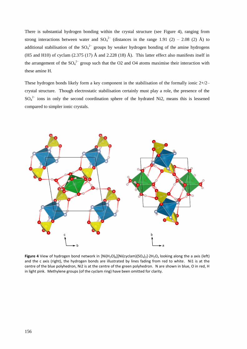
156
There is substantial hydrogen bonding within the crystal structure (see Figure 4), ranging from
strong interactions between water and SO42−
(distances in the range 1.91 (2) – 2.08 (2) Å) to
additional stabilisation of the SO42−
groups by weaker hydrogen bonding of the amine hydrogens
(H5 and H10) of cyclam (2.375 (17) Å and 2.228 (18) Å). This latter effect also manifests itself in
the arrangement of the SO42−
group such that the O2 and O4 atoms maximise their interaction with
these amine H.
These hydrogen bonds likely form a key component in the stabilisation of the formally ionic 2+/2–
crystal structure. Though electrostatic stabilisation certainly must play a role, the presence of the
SO42−
ions in only the second coordination sphere of the hydrated Ni2, means this is lessened
compared to simpler ionic crystals.
Figure 4 View of hydrogen bond network in [Ni(H2O)6][Ni(cyclam)(SO4)2]·2H2O, looking along the a axis (left) and the c axis (right), the hydrogen bonds are illustrated by lines fading from red to white. Ni1 is at the centre of the blue polyhedron, Ni2 is at the centre of the green polyhedron. N are shown in blue, O in red, H in light pink. Methylene groups (of the cyclam ring) have been omitted for clarity.
157
7.2.2 Comparison with other structures
The structural aspects of cyclam complexes have been very well studied: there were 374 cyclam
structures and 1694 cyclam derivatives (with a cyclam backbone, but additional groups (including
further cyclam units) attached at any point on the ring) in the Cambridge Structural Database with
updates to November 2009,[5]
and of these 514 contained nickel. Nevertheless, this common
macrocycle can still provide surprises, as demonstrated with our serendipitous discovery of a rather
unusual structure.
What distinguishes this compound from the plethora of reported structures is the presence of two
nickel centres in considerably different chemical environments: one (Ni1) is coordinated by cyclam
and two trans sulphate groups, and the second (Ni2) found in a homoleptic hexaaqua environment.
Furthermore, the latter attaches only weak field water ligands, while the former retains the
coordination of the higher field strength cyclam as well as both the dianionic SO42−
groups.
Examination of the proton affinity of the ligands (see Table 3), a useful proxy for sigma donor
ability[12]
allows a quantification of the situation and emphasises the curiosity of this arrangement.
Water has a proton affinity of 691 kJ mol−1
,[13]
and whilst we do not have an exact value for the
proton affinity of cyclam, related amine compounds all have values between 900 and 1000 kJ
mol−1
.[13]
The sulphate anion has a proton affinity above 1800 kJ mol−1
.[14]
It would seem reasonable
that a balanced distribution of the available ligand-donated electron density across each NiII centre
Table 3 Proton affinities (EPA) of water, compounds related to cyclam, and sulphate.
Compound EPA / kJ mol−1
reference
water 691 13
Ligands related to cyclam:
dimethylamine 930 13
N-methylethylamine 942 13
diethylamine 952 13
1,3-propyldiamine 987 13
N,N'-dimethyl-1,2-ethyldiamine 989 13
SO42−
>1800 14

158
would provide for stabilisation of both, but this is not what we see. Instead, the weaker σ-donor
ligands (the six water ligands) coordinate to one NiII while the more powerful donors congregate on
the other.
So just how unique is this coordination compound? Searching for structures containing any
transition metals where one metal atom is coordinated to 6 water molecules, while a second metal
atom (of the same element as the first) is attached at least to 4 N atoms, returns twenty-two
structures. Eleven of these are disregarded as they do not have a metal centre with the interesting
mixed donor functionality seen here (i.e., four N plus a different donor atom bound to the same
metal). Another five are simply aquated [M(phen)2] complexes together with an additional
hexaaqua complex of the same metal (i.e. [M(phen)2(H2O)2][M(H2O)6], M=Mn, Co, Ni, Zn; phen =
phenanthroline) and of little interest. Another structure is discounted here due to its complexity – its
unit cell contains 13 Co atoms, 12 of which are bound by a single mixed N / O donor
macromolecule. Four of the remaining five of the twenty-two structures have metal centres with
four N donors and two O donors, but all of the O donor ligands are chelates with N and O
functionality. The most interesting of these (hexaaqua-nickel(II) (1,4,7,10-
tetrakis(methylenephosphonic acid)-1,4,7,10-tetraazacyclododecane-N,N',N'',N''',O,O'')-nickel(II),
CSD refcode: SAHPOH)[15]
is discussed below, including why such chelates are not that alike to (I),
along with the final structure from this search (hexaaquacobalt(II) bis[dibromobis(ethanedial
dioximato)cobaltate(III)] acetone solvate (CSD refcode: BIYTUY),[16]
which bears some similarity
to the [Ni(H2O)6][Ni(cyclam)(SO4)2]·2H2O, but is still quite different.
SAHPOH (see Figure 5) is a bi-Ni compound with a striking superficial similarity to
[Ni(H2O)6][Ni(cyclam)(SO4)2]·2H2O. It has a directly analogous hexaaqua metal centre, and a
similar (albeit with cis rather than trans geometry) cyclen ring (12- rather 14-membered) derivatised
with N-pendant methylenephosphonate groups, where two phosphonate groups act as O donors
corresponding to the sulphate groups of [Ni(cyclam)(SO4)2]2−
. However, the crucial difference
between [Ni(H2O)6][Ni(cyclam)(SO4)2]·2H2O and SAHPOH is the hexadentate nature of the single,
mixed-donor ligand. This tethering of the phosphonates to the cyclen macrocycle gives them
Figure 5 Left: one formula unit from the crystal structure of SAHPOH; right: a schematic diagram of SAHPOH.

159
considerably greater tendency to coordinate to the same Ni as the cyclen ring than to another metal
centre by cause of the chelate effect. This is an important difference from the structure we
discovered, where the free sulphate groups may coordinate to a non-cyclam connected metal centre
but do not. A similar reasoning is used to differentiate the other mixed N/O chelates found in the
above search.
BIYTUY (see Figure 6) is a tri-Co compound akin to [Ni(H2O)6][Ni(cyclam)(SO4)2]·2H2O in having
two distinct metal environments: a hexaaqua metal complex, and a dibromo-bis(glyoximato)Co.
Besides the change in metal, there are, however, three significant differences from our compound.
The first is that each individual ligand bears a single negative charge, for a total ligand charge of 4−,
where the [Ni(cyclam)(SO4)2]2−
bears this 4− charge (formally) on just the two SO4
2− ligands. More
significantly, the ratio of the two different Co complexes is 1:2, requiring a CoIII
complex,
[Co(Br)2(gH−)2]
− (gH
− = glyoximato), to ensure charge neutrality. This triply charged metal centre is
naturally more attractive to Br− ligands than a doubly charged centre would be with the same bis-
glyoximato ligands. Finally, the C=N functionality of the glyoximato ligands are capable of much
stronger π-interactions than the secondary amines of [Ni(cyclam)(SO4)2]2−
. Thus, BIYTUY
represents a quite different compound from [Ni(H2O)6][Ni(cyclam)(SO4)2]·2H2O.
Figure 6 Left: one formula unit from the crystal structure of BIYTUY; right: a schematic diagram of BIYTUY.
A search of the type [TM(O)6][TM(N)4(SO)2] (search 2 in Figure 1), i.e., any transition metal (TM)
compound such that one TM is bound to six O and another TM of the same element is bound to four
N donors and two O-S groups (O donor, with S free to have any other connections), returned no
results.
7.3 Summary
The structure of [Ni(H2O)6][Ni(cyclam)(SO4)2]·2H2O, determined with high confidence from single
crystal X-ray diffraction, is unusual for having two distinct nickel complexes, one anionic and one
cationic, in which all the stronger σ-donors are located on the same Ni2+
centre. It is likely that this
unusual structure is stabilised by extensive hydrogen bonding. A search of the Cambridge Structural
Database confirms that the nature of this intriguing compound is exceedingly rare, even
unprecedented, for transition metal complexes.

160
References
1 CrysAlis RED, Oxford Diffraction Ltd., Version 1.171.33. Empirical absorption correction using spherical
harmonics, implemented in SCALE3 ABSPACK scaling algorithm.
2 CrysAlis CCD, Oxford Diffraction Ltd., Version 1.171.33, CrysAlis RED, Oxford Diffraction Ltd., Version
1.171.33.
3 G. M. Sheldrick, Acta Crystallographica Section A, 2008, 64, 112.
4 A. J. C. Wilson, International Tables for Crystallography Volume C, Kluwer, Dordrecht, 1992.
5 F. H. Allen, Acta Crystallographica Section B, 2002, 58, 380. Queries performed on dataset with update to
November 2009.
6 I. J. Bruno, J. C. Cole, P. R. Edgington, M. Kessler, C. F. Macrae, P. McCabe, J. Pearson, R. Taylor, Acta
Crystallographica Section B, 2002, 58, 389.
7 A. J. Churchard, M. K. Cyrański, W. Grochala, Acta crystallographica Section C, 2010, 66, m263.
8 M. A. Donnelly, M. Zimmer, Inorganic Chemistry, 1999, 38, 1650.
9 M. Wildner, Zeitschrif für Kristallographie, 1990, 191, 223.
10 M. Mukherjee, A. K. Mukherjee, C. Pariya, N. Ray Chaudhuri, Acta Crystallographica Section C, 1995, 51,
1543.
11 B. Rousseau, S. T. Maes, A. T. H. Lenstra, Acta Crystallographica Section A, 2000, 56, 300.
12 H. M. Senn, D. V. Deubel, P. E. Blochl, A. Togni, G. Frenking, Journal of Molecular Structure: THEOCHEM,
2000, 506, 233.
13 E. P. Hunter, S. G. Lias, Proton Affinity Evaluation in NIST Chemistry WebBook, (Eds: P. J. Linstrom, W. G.
Mallard), National Institute of Standards and Technology, Gaithersburg MD, 2010, (accessed online at
http://webbook.NIST.gov).
14 J. E. House, K. A. Kemper, Journal of Thermal Analysis, 1987, 32, 1855.
15 D. Kong, D. G. Medvedev, A. Clearfield, Inorganic chemistry, 2004, 43, 7308.
16 G. O. Egharevba, M. Mégnamisi-Bélombé, H. Endres, E. Rossato, Acta Crystallographica Section B, 1982, 38,
2901.

161
8 Facile reversible dehydration decomposition of
Ni(12aneS4)(BF4)2·2H2O
8.1 Methodology for synthesis and analysis ............................................................................... 162
8.1.1 Interconversion of anhydrous and hydrated Ni(12aneS4)(BF4)2 ................................... 162
8.1.2 Structure solution by powder X-ray diffraction ............................................................ 163
8.1.3 UV/vis, IR and Raman spectroscopy .............................................................................. 163
8.1.4 Gravimetric analysis ...................................................................................................... 165
8.1.5 Simultaneous thermogravimetric analysis and differential scanning calorimetry ....... 165
8.1.6 Magnetic susceptibility ................................................................................................. 166
8.2 Results and discussion ........................................................................................................... 167
8.2.1 Crystal structure ............................................................................................................ 167
8.2.2 UV/vis, IR and Raman spectroscopy .............................................................................. 172
8.2.3 Simultaneous thermogravimetric analysis and differential scanning calorimetry ....... 175
8.2.4 Magnetic susceptibility ................................................................................................. 184
8.3 Summary and future work .................................................................................................... 187
References ......................................................................................................................................... 188
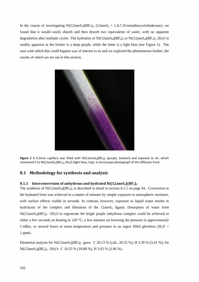
162
In the course of investigating Ni(12aneS4)(BF4)2, (12aneS4 = 1,4,7,10-tetrathiacyclododecane), we
found that it would easily absorb and then desorb two equivalents of water, with no apparent
degradation after multiple cycles. The hydration of Ni(12aneS4)(BF4)2 to Ni(12aneS4)(BF4)2·2H2O is
readily apparent as the former is a deep purple, while the latter is a light blue (see Figure 1). The
ease with which this could happen was of interest to us and we explored the phenomenon further, the
results of which are set out in this section.
Figure 1 A 0.3mm capillary was filled with Ni(12aneS4)(BF4)2 (purple, bottom) and exposed to air, which converted it to Ni(12aneS4)(BF4)2·2H2O (light blue, top): a microscope photograph of the diffusion front.
8.1 Methodology for synthesis and analysis
8.1.1 Interconversion of anhydrous and hydrated Ni(12aneS4)(BF4)2
The synthesis of Ni(12aneS4)(BF4)2 is described in detail in section 6.1.1 on page 94. Conversion to
the hydrated form was achieved in a matter of minutes by simple exposure to atmospheric moisture,
with surface effects visible in seconds. In contrast, however, exposure to liquid water results in
hydrolysis of the complex and liberation of the 12aneS4 ligand. Desorption of water from
Ni(12aneS4)(BF4)2 ·2H2O to regenerate the bright purple anhydrous complex could be achieved in
either a few seconds on heating to 120 °C, a few minutes on lowering the pressure to approximately
1 mBar, or several hours at room temperature and pressure in an argon filled glovebox (H2O <
1 ppm).
Elemental analysis for Ni(12aneS4)(BF4)2 gave: C 20.13 % (calc. 20.32 %), H 3.39 % (3.41 %); for
Ni(12aneS4)(BF4)2 ·2H2O: C 18.55 % (18.88 %), H 3.92 % (3.96 %).
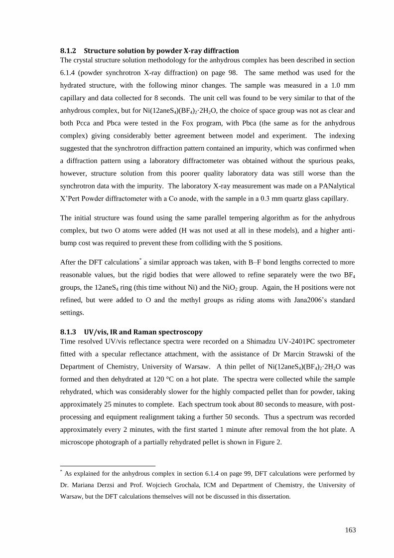
163
8.1.2 Structure solution by powder X-ray diffraction
The crystal structure solution methodology for the anhydrous complex has been described in section
6.1.4 (powder synchrotron X-ray diffraction) on page 98. The same method was used for the
hydrated structure, with the following minor changes. The sample was measured in a 1.0 mm
capillary and data collected for 8 seconds. The unit cell was found to be very similar to that of the
anhydrous complex, but for Ni(12aneS4)(BF4)2·2H2O, the choice of space group was not as clear and
both Pcca and Pbca were tested in the Fox program, with Pbca (the same as for the anhydrous
complex) giving considerably better agreement between model and experiment. The indexing
suggested that the synchrotron diffraction pattern contained an impurity, which was confirmed when
a diffraction pattern using a laboratory diffractometer was obtained without the spurious peaks,
however, structure solution from this poorer quality laboratory data was still worse than the
synchrotron data with the impurity. The laboratory X-ray measurement was made on a PANalytical
X’Pert Powder diffractometer with a Co anode, with the sample in a 0.3 mm quartz glass capillary.
The initial structure was found using the same parallel tempering algorithm as for the anhydrous
complex, but two O atoms were added (H was not used at all in these models), and a higher anti-
bump cost was required to prevent these from colliding with the S positions.
After the DFT calculations* a similar approach was taken, with B–F bond lengths corrected to more
reasonable values, but the rigid bodies that were allowed to refine separately were the two BF4
groups, the 12aneS4 ring (this time without Ni) and the NiO2 group. Again, the H positions were not
refined, but were added to O and the methyl groups as riding atoms with Jana2006’s standard
settings.
8.1.3 UV/vis, IR and Raman spectroscopy
Time resolved UV/vis reflectance spectra were recorded on a Shimadzu UV-2401PC spectrometer
fitted with a specular reflectance attachment, with the assistance of Dr Marcin Strawski of the
Department of Chemistry, University of Warsaw. A thin pellet of Ni(12aneS4)(BF4)2·2H2O was
formed and then dehydrated at 120 °C on a hot plate. The spectra were collected while the sample
rehydrated, which was considerably slower for the highly compacted pellet than for powder, taking
approximately 25 minutes to complete. Each spectrum took about 80 seconds to measure, with post-
processing and equipment realignment taking a further 50 seconds. Thus a spectrum was recorded
approximately every 2 minutes, with the first started 1 minute after removal from the hot plate. A
microscope photograph of a partially rehydrated pellet is shown in Figure 2.
* As explained for the anhydrous complex in section 6.1.4 on page 99, DFT calculations were performed by
Dr. Mariana Derzsi and Prof. Wojciech Grochala, ICM and Department of Chemistry, the University of
Warsaw, but the DFT calculations themselves will not be discussed in this dissertation.

164
The spectra were normalised by scaling each spectrum so that the signal at 290 nm (the most
consistent intensity in the ‘raw’ spectra, and unlikely to originate from d–d transitions) was equal
across all the spectra.
Figure 2 Partially converted pellet used for UV/vis spectroscopy as seen under a microscope.
Recording the infrared spectra of both Ni(12aneS4)(BF4)2 and Ni(12aneS4)(BF4)2·2H2O proved
surprisingly challenging. The complexes were found to react with KBr forming a green compound,
presumably through anion exchange to give Ni(12aneS4)Br2 or a similar complex. The answer for
the hydrated complex (a very soft material) was to record the spectrum by pressing a thin film on
AgCl windows and placing it in a sealed sample holder (to prevent dehydration in the evacuated
sample chamber). However, the anhydrous complex was too mechanically hard to form a suitable
layer and simply using a powder gave a very poor result. The spectrum recorded in light mineral oil
was of reasonable quality, but the particularly interesting C–H stretching region was obscured by the
oil. To investigate this region, a thin film of the hydrated form was prepared on AgCl windows and
dehydrated in situ by exposing the film to the evacuated sample chamber. The spectrum agreed well
with that recorded in mineral oil, though slight residual O–H vibrations remained. All IR spectra
were recorded on a Bruker Vertex 80v spectrometer with vacuum sample chamber.
Raman spectra were collected in backscattering configuration with a Labram HR800(Horiba Jobin–
Yvon) confocal microscope system equipped with a Peltier-cooled CCD detector (1024 x 256 pixel)
using a diode pumped Nd:YAG laser (1064nm and 532 nm (frequency doubled)) and a 20mW He-
Ne laser (633 nm). Calibration of the instrument was performed using the 520 cm−1
Raman signal of
a silicon wafer. Spectra were obtained using a 50x magnification Olympus objective, a confocal
pinhole size of 200 µm and a holographic grating with 600 grooves mm−1
. The complexes
165
decomposed quickly even on moderate laser illumination at 532 nm, 633 nm and 1064 nm
wavelengths, so heavy filters (100 × reduction) and short collection times were necessary, limiting
the signal-to-noise ratio achievable. All spectra were recorded with the assistance of Dr. Agata
Królikowska, Department of Chemistry, University of Warsaw.
8.1.4 Gravimetric analysis
The mass of approximately 300 mg of an anhydrous sample of Ni(12aneS4)(BF4)2 was measured on
an analytical balance with nominal accuracy of ±0.1 mg. The sample was hydrated in air and the
mass re-measured on the same balance, with the difference assumed to be the water uptake.
Gravimetric analysis showed a 7.3% mass increase on conversion to Ni(12aneS4)(BF4)2·2H2O
(calculated: 7.6%).
8.1.5 Simultaneous thermogravimetric analysis and differential scanning calorimetry
Thermogravimetric analysis (TGA) and differential scanning calorimetry (DSC) were carried out on
a Netzsch STA 409 PG instrument. Approximately 7 mg of sample was loaded in to an alumina
crucible (without a lid) and placed on the sample carrier. The experiments were conducted either in
a static air environment or with a flow of Ar gas. In the cycling experiments, the sample was heated
to 100 °C at a rate of 0.5 K min−1
held at 100 °C for 2 hours to dehydrate the sample, then cooled to
30 °C at a rate of 0.5 K min−1
and held at room temperature for 8 hours to allow the sample to
rehydrate. This procedure was repeated 4 times.
Thermodynamic data was obtained by performing TGA/DSC for a series of dehydration reactions.
Careful analysis of the profiles showed two overlapping events which were only sufficiently well
resolved to allow their clear separation when performed at very low scanning rates and in static air.
To allow the calculation of approximate values for the individual activation energies of the first and
second steps of dehydration, this was performed at scanning rates of 0.02, 0.03, 0.04, 0.05, 0.06 and
0.07 K min−1
. The activation energy was calculated using both Kissinger’s equation and the Ozawa-
Flynn-Wall method (see section 5.4.1 on page 76). The former used the peak DSC signal, as
specified by Kissinger, whilst the latter used mass to monitor the extent of reaction. However,
thermodynamic parameters are usually measured with a purging gas flow to prevent build up of
gaseous products from affecting the equilibrium too significantly, so experiments were also
performed with an Ar gas flow. In this setup the two dehydration steps could not be separated even
with a temperature ramp of 0.02 K min−1
; though a significant disadvantage, this did mean that a
larger range of scanning rates could be used, allowing a better spread of values once the logarithmic
transformation is applied in the analysis. In the Ar gas flow scanning rates of 0.02, 0.04, 0.08, 0.16,
0.32, 0.64 K min−1
were therefore used.
166
8.1.6 Magnetic susceptibility
Magnetic susceptibility was measured on a MPMS vibrating sample squid magnetometer made by
Quantum Design, Inc., by loading approximately 15 mg of sample into a polypropylene sample
holder. Samples of Ni(12aneS4)(BF4)2 were loaded in the glove box and exposure to air minimized,
but to completely exclude the possibility that the paramagnetism observed was due to remnant
hydrated species, the sample was fully dehydrated in the magnetometer before measurement by
heating to 100 °C for 4 hours at 10−5
Torr. Data were corrected for the diamagnetic contribution of
the sample holder by subtracting a ‘blank’ measurement and the core electrons of the sample using
Pascal’s constants,[1]
for which a value of −3.0 × 10⁻⁴
emu mol−1
was used for Ni(12aneS4)(BF4)2
and −3.3 × 10⁻⁴
emu mol−1
for Ni(12aneS4)(BF4)2·2H2O.

167
8.2 Results and discussion
The molecular crystal Ni(12aneS4)(BF4)2 displays the rare ability to retain its crystallinity on
reversible hydration/dehydration without polymeric bonding, despite the drastic structural changes
required, and shows clearly defined and detectable chromatic, structural and magnetic changes that
are both highly sensitive and easily reversed, of interest as an environmentally responsive material.
Furthermore, as a molecular crystal, Ni(12aneS4)(BF4)2 is different from the extensively reported
coordination polymers, using the flexibility of the macrocyclic 12aneS4 ligand rather than the brute
force of an extended network of coordination bonds to allow the transition metal complex to
reversibly undergo significant structural changes upon hydration/dehydration in the solid phase yet
remain crystalline. This makes such systems a complementary alternative to the bulk of research
made on their polymeric cousins.
8.2.1 Crystal structure
The structure of Ni(12aneS4)(BF4)2·2H2O (Figure 3) was solved from powder synchrotron X-ray
diffraction patterns collected at 100 K (further patterns collected over the temperature range 100 K
to room temperature showed no phase changes). A selection of important parameter are shown in
Table 1, together with those of Ni(12aneS4)(BF4)2 (also given in section 6.3.2) for comparison.
Figure 3 Structure of the molecular components extracted from the unit cells, showing the slightly distorted square planar arrangement of Ni(12aneS4)(BF4)2 (left) and the distorted octahedral arrangement of Ni(12aneS4)(BF4)2·2H2O (right). Hydrogen atoms omitted for clarity.

168
Table 1 Selected parameters from the crystal structures of [Ni(12aneS4)](BF4)2 and Ni(12aneS4)(BF4)2·2H2O obtained by powder X-ray diffraction.
Ni(12aneS4)(BF4)2 Ni(12aneS4)(BF4)2·2H2O
Empirical formula C8H16S4B2F8Ni B2C8F8H20NiO2S4
Molar mass /g mol−1
472.78 508.8
T / K 100 (2) 100 (2)
λ / Å 0.80035 0.80035
Crystal system Orthorhombic Orthorhombic
Space group Pbca Pbca
Unit cell dimensions / Å a = 16.1254 (3)
b = 15.2621 (3)
c = 13.2577 (3)
a = 18.5287 (5)
b = 15.2433 (4)
c = 13.3682 (3)
V / Å3
3262.83 (10) 3775.69 (17)
Cell formula units (Z) 8 8
Goodness of fit 1.36 4.35
Rwp 1.68 % 3.52 %
CCDC deposition number 846504 846503
The apparently poor fit (see Figure 4, top) that might be inferred from the fitting parameters of the
hydrated complex is due to an unidentified and unindexed impurity. It was possible to track a
number of peaks belonging to this phase using the temperature resolved patterns, (Figure 4, bottom)
and so to recognise where they cause problems, but it has not been possible to eliminate them. The
poor parameters also reflect the otherwise extremely high quality synchrotron data, that is, the
quality of the data is very unforgiving of even small ‘errors’ in the structure. Nevertheless, the
chemical and structural agreement with that found for the anhydrous complex (for which a very
good fit was found) makes us confident of its validity. Minor imperfections in the structure might
nevertheless be present due to the misallocation of electron density owing to the impurity.
169
Figure 4 Top: observed, calculated and difference powder diffraction patterns of Ni(12aneS4)(BF4)2·2H2O at 100 K. Note, the poorer fit compared to the anhydrous complex is due to an impurity which it was not possible to identify or index. Bottom: temperature resolved XRD patterns, with 2θ axis aligned with the 100 K spectrum, showing how the spacing between diffracting planes changes over the temperature range 120 K – 300 K resulting in different overlaps of peaks at different temperatures.
The structure of anhydrous Ni(12aneS4)(BF4)2 has been discussed in section 6.3.2 on page 133, and
will be mentioned here only in relation to the hydrated structure. Hydration results in two water
molecules attaching directly to the Ni(II) cation in a cis fashion to form a distorted octahedral
complex (see Figure 3), which would suggest a high-spin d8 complex. Bite angles (S–Ni–S for
adjacent S atoms) are 84.01 (9) – 86.81 (11) °, similar to but slightly smaller than the anhydrous
complex, and S–Ni–S angles for S atoms opposite each other on the ring are 92.07 (9) and 166.34
(10) °, the latter again similar to the anhydrous complex. The Ni–S distances are in the range 2.323
(3) – 2.369 (3) Å, typical for high-spin nickel(II),[2]
and about 0.2 Å longer than for the ‘low-spin’
square-planar Ni(12aneS4)(BF4)2. The O–Ni–O angle is slightly compressed at 83.66 (10) °,
possibly because of steric crowding from the 12aneS4 ligand, but the Ni–O distances at 2.055 (2) and
2.060 (3) Å lie within the interquartile range for aquated, 6-coordinate nickel complexes.
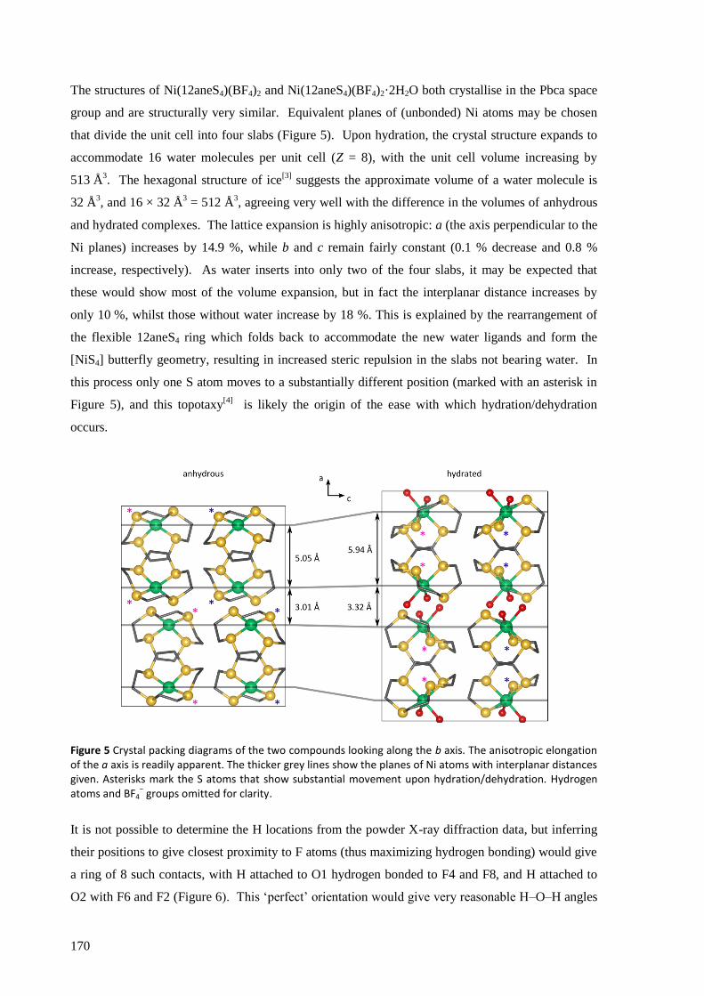
170
The structures of Ni(12aneS4)(BF4)2 and Ni(12aneS4)(BF4)2·2H2O both crystallise in the Pbca space
group and are structurally very similar. Equivalent planes of (unbonded) Ni atoms may be chosen
that divide the unit cell into four slabs (Figure 5). Upon hydration, the crystal structure expands to
accommodate 16 water molecules per unit cell (Z = 8), with the unit cell volume increasing by
513 Å3. The hexagonal structure of ice
[3] suggests the approximate volume of a water molecule is
32 Å3, and 16 × 32 Å
3 = 512 Å
3, agreeing very well with the difference in the volumes of anhydrous
and hydrated complexes. The lattice expansion is highly anisotropic: a (the axis perpendicular to the
Ni planes) increases by 14.9 %, while b and c remain fairly constant (0.1 % decrease and 0.8 %
increase, respectively). As water inserts into only two of the four slabs, it may be expected that
these would show most of the volume expansion, but in fact the interplanar distance increases by
only 10 %, whilst those without water increase by 18 %. This is explained by the rearrangement of
the flexible 12aneS4 ring which folds back to accommodate the new water ligands and form the
[NiS4] butterfly geometry, resulting in increased steric repulsion in the slabs not bearing water. In
this process only one S atom moves to a substantially different position (marked with an asterisk in
Figure 5), and this topotaxy[4]
is likely the origin of the ease with which hydration/dehydration
occurs.
Figure 5 Crystal packing diagrams of the two compounds looking along the b axis. The anisotropic elongation of the a axis is readily apparent. The thicker grey lines show the planes of Ni atoms with interplanar distances given. Asterisks mark the S atoms that show substantial movement upon hydration/dehydration. Hydrogen atoms and BF4
− groups omitted for clarity.
It is not possible to determine the H locations from the powder X-ray diffraction data, but inferring
their positions to give closest proximity to F atoms (thus maximizing hydrogen bonding) would give
a ring of 8 such contacts, with H attached to O1 hydrogen bonded to F4 and F8, and H attached to
O2 with F6 and F2 (Figure 6). This ‘perfect’ orientation would give very reasonable H–O–H angles
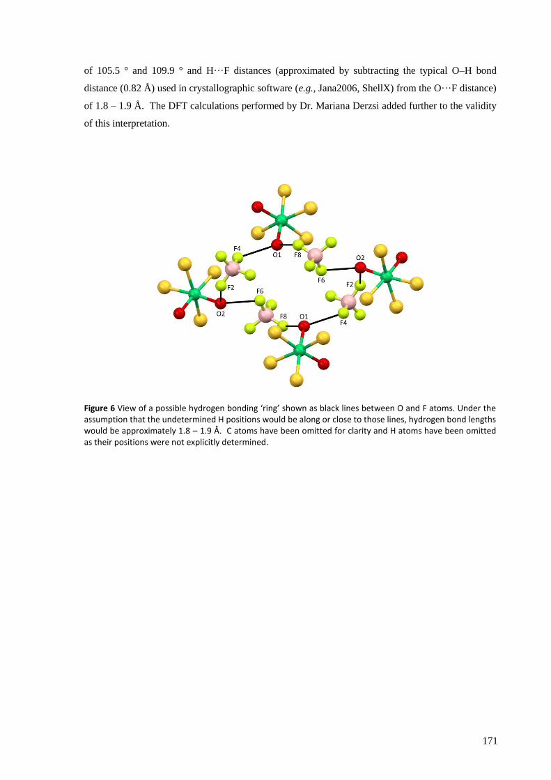
171
of 105.5 ° and 109.9 ° and H···F distances (approximated by subtracting the typical O–H bond
distance (0.82 Å) used in crystallographic software (e.g., Jana2006, ShellX) from the O···F distance)
of 1.8 – 1.9 Å. The DFT calculations performed by Dr. Mariana Derzsi added further to the validity
of this interpretation.
Figure 6 View of a possible hydrogen bonding ‘ring’ shown as black lines between O and F atoms. Under the assumption that the undetermined H positions would be along or close to those lines, hydrogen bond lengths would be approximately 1.8 – 1.9 Å. C atoms have been omitted for clarity and H atoms have been omitted as their positions were not explicitly determined.

172
8.2.2 UV/vis, IR and Raman spectroscopy
All spectroscopic analysis performed on these complexes was challenging. The requirement to use
solid state samples was the first challenge, particularly for reflectance UV/vis spectroscopy, whilst
the sensitivity of the compounds to laser irradiation was a distinct challenge in collecting Raman
spectra. Of the three methods, the IR spectra are of the highest quality, though even this ‘routine’
method required considerable effort to obtain reliable data.
Reflectance UV/vis spectroscopy
Despite the less than ideal quality of the reflectance UV/vis spectra obtained, the time-resolved
series for the hydration of Ni(12aneS4)(BF4)2 show clear differences between the two phases. Upon
hydration, the reflectance UV/vis spectrum Figure 7 shows reduced broad absorption features in the
460 nm and 630 nm regions and increased absorption in the 590 nm and 390 nm regions, explaining
the colour change from purple to blue. From the literature, the electronic spectrum of Ni(II) with the
18aneS4O2 macrocycle[5]
is similar to that of the hydrated spectrum here, leading us to follow the
assignment given in reference 5 so that the band at 590 nm arises from the 3T1g(F) ←
3A2g transition
and the upward slope visible above 800 nm from 3T2g ←
3A2g. They do not assign the
3T1g(P) ←
3A2g transition due to overlap with a charge transfer band (presumably sulphur to nickel), but it
would likely correspond to the band at 390 nm in Figure 7. In our case we may also see an overlap,
or the charge transfer may be the more intense band at 290 nm, but it is not really possible to
determine with certainty from the spectra recorded.
Figure 7 Series of reflectance UV/vis spectra recorded whilst a pellet of Ni(12aneS4)(BF4)2 was hydrated in air. The spectra are normalised at 290 nm. Arrows showing change in intensity (the thickness of the arrows roughly corresponds to clarity of the signal change).
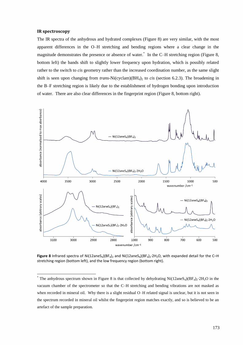
173
IR spectroscopy
The IR spectra of the anhydrous and hydrated complexes (Figure 8) are very similar, with the most
apparent differences in the O–H stretching and bending regions where a clear change in the
magnitude demonstrates the presence or absence of water.* In the C–H stretching region (Figure 8,
bottom left) the bands shift to slightly lower frequency upon hydration, which is possibly related
rather to the switch to cis geometry rather than the increased coordination number, as the same slight
shift is seen upon changing from trans-Ni(cyclam)(BH4)2 to cis (section 6.2.3). The broadening in
the B–F stretching region is likely due to the establishment of hydrogen bonding upon introduction
of water. There are also clear differences in the fingerprint region (Figure 8, bottom right).
Figure 8 Infrared spectra of Ni(12aneS4)(BF4)2 and Ni(12aneS4)(BF4)2·2H2O, with expanded detail for the C–H stretching region (bottom left), and the low frequency region (bottom right).
* The anhydrous spectrum shown in Figure 8 is that collected by dehydrating Ni(12aneS4)(BF4)2·2H2O in the
vacuum chamber of the spectrometer so that the C–H stretching and bending vibrations are not masked as
when recorded in mineral oil. Why there is a slight residual O–H related signal is unclear, but it is not seen in
the spectrum recorded in mineral oil whilst the fingerprint region matches exactly, and so is believed to be an
artefact of the sample preparation.

174
Raman Spectroscopy
The Raman spectra of the two complexes and the free ligand are shown in Figure 9. The spectrum
of the hydrated complex is apparently richer in bands than the anhydrous, though this may be due to
a pre-resonance enhancement, as suggested by the strong fluorescence of the hydrated sample. The
characteristic symmetric stretching mode of BF4− is typically found at around 770 cm
−1, and whilst a
small peak can be seen in the spectrum of the hydrated compound (where due to hydrogen bonding
its low intensity is more easily justified), its absence from the anhydrous sample is a little surprising
and a sign that this data should be treated with care. The free ligand did not suffer from
decomposition under the laser illumination and as such a much higher quality spectrum could be
obtained.
Figure 9 Raman spectra of Ni(12aneS4)(BF4)2, Ni(12aneS4)(BF4)2·2H2O, and the 12aneS4 reagent, collected with 633 nm wavelength laser irradiation.
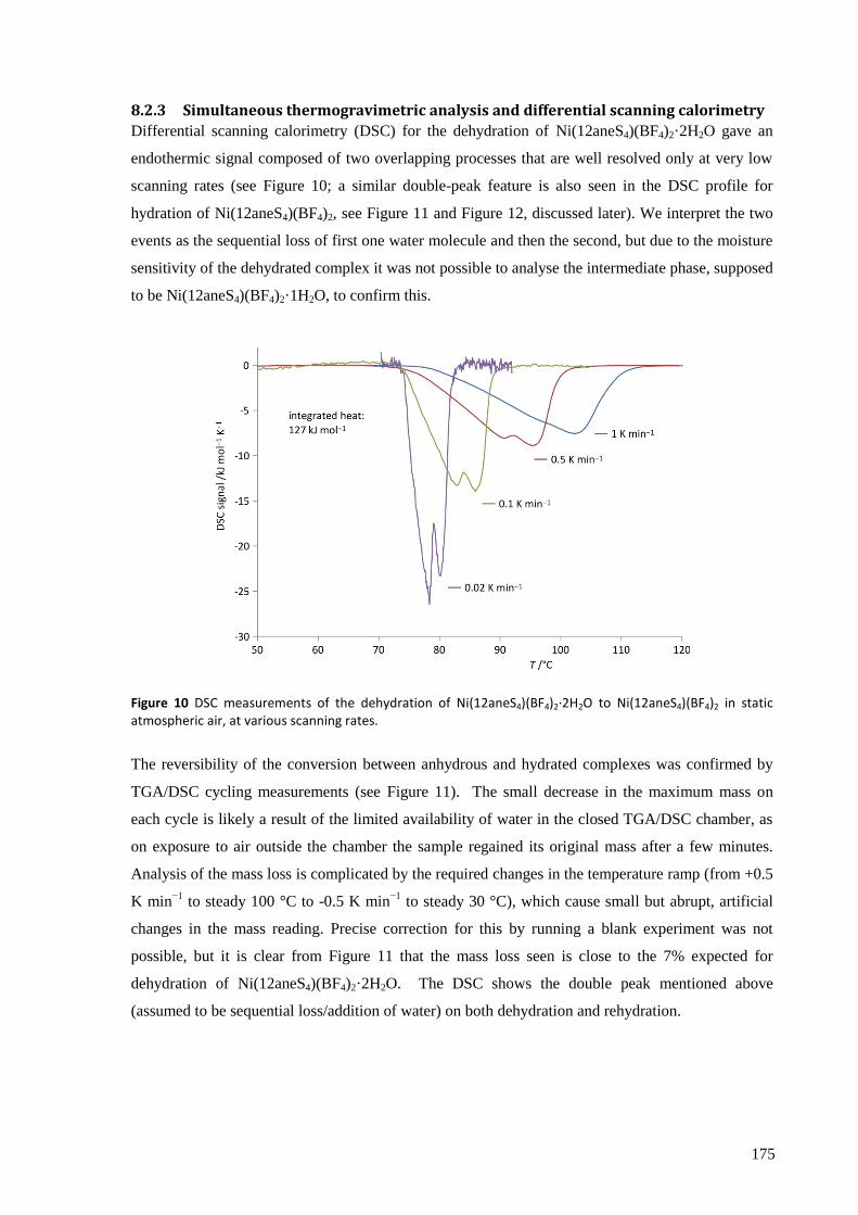
175
8.2.3 Simultaneous thermogravimetric analysis and differential scanning calorimetry
Differential scanning calorimetry (DSC) for the dehydration of Ni(12aneS4)(BF4)2·2H2O gave an
endothermic signal composed of two overlapping processes that are well resolved only at very low
scanning rates (see Figure 10; a similar double-peak feature is also seen in the DSC profile for
hydration of Ni(12aneS4)(BF4)2, see Figure 11 and Figure 12, discussed later). We interpret the two
events as the sequential loss of first one water molecule and then the second, but due to the moisture
sensitivity of the dehydrated complex it was not possible to analyse the intermediate phase, supposed
to be Ni(12aneS4)(BF4)2·1H2O, to confirm this.
Figure 10 DSC measurements of the dehydration of Ni(12aneS4)(BF4)2·2H2O to Ni(12aneS4)(BF4)2 in static atmospheric air, at various scanning rates.
The reversibility of the conversion between anhydrous and hydrated complexes was confirmed by
TGA/DSC cycling measurements (see Figure 11). The small decrease in the maximum mass on
each cycle is likely a result of the limited availability of water in the closed TGA/DSC chamber, as
on exposure to air outside the chamber the sample regained its original mass after a few minutes.
Analysis of the mass loss is complicated by the required changes in the temperature ramp (from +0.5
K min−1
to steady 100 °C to -0.5 K min−1
to steady 30 °C), which cause small but abrupt, artificial
changes in the mass reading. Precise correction for this by running a blank experiment was not
possible, but it is clear from Figure 11 that the mass loss seen is close to the 7% expected for
dehydration of Ni(12aneS4)(BF4)2·2H2O. The DSC shows the double peak mentioned above
(assumed to be sequential loss/addition of water) on both dehydration and rehydration.
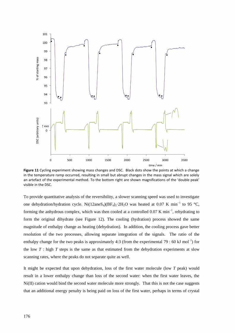
176
Figure 11 Cycling experiment showing mass changes and DSC. Black dots show the points at which a change in the temperature ramp occurred, resulting in small but abrupt changes in the mass signal which are solely an artefact of the experimental method. To the bottom right are shown magnifications of the ‘double peak’ visible in the DSC.
To provide quantitative analysis of the reversibility, a slower scanning speed was used to investigate
one dehydration/hydration cycle. Ni(12aneS4)(BF4)2·2H2O was heated at 0.07 K min−1
to 95 °C,
forming the anhydrous complex, which was then cooled at a controlled 0.07 K min−1
, rehydrating to
form the original dihydrate (see Figure 12). The cooling (hydration) process showed the same
magnitude of enthalpy change as heating (dehydration). In addition, the cooling process gave better
resolution of the two processes, allowing separate integration of the signals. The ratio of the
enthalpy change for the two peaks is approximately 4:3 (from the experimental 79 : 60 kJ mol–1
) for
the low T : high T steps is the same as that estimated from the dehydration experiments at slow
scanning rates, where the peaks do not separate quite as well.
It might be expected that upon dehydration, loss of the first water molecule (low T peak) would
result in a lower enthalpy change than loss of the second water: when the first water leaves, the
Ni(II) cation would bind the second water molecule more strongly. That this is not the case suggests
that an additional energy penalty is being paid on loss of the first water, perhaps in terms of crystal

177
packing, poorer hydrogen bonding or a less stable 5-coordinate complex. Hydration can be
interpreted in a similar manner but in reverse.
(n.b., the data in Figure 12 were recorded when conditions of atmospheric humidity were different
from previous measurements (we had no way to control the humidity inside the TGA/DSC chamber
during static air experiments and thus it reflected the weather on the day of measurement), which
causes the slight change in the onset temperature for dehydration from that shown in Figure 10.)
Figure 12 DSC measurement showing heating of Ni(12aneS4)(BF4)2·2H2O at 0.07 K min−1
followed by cooling of Ni(12aneS4)(BF4)2 (formed in situ) at 0.07 K min
−1, regenerating the hydrated complex. The magnitude of
the enthalpy change is the same (within experimental error) for both reactions. The cooling peaks are sufficiently well resolved to allow their separate integration, divided at the dotted line.
Integration of the combined peak gave an enthalpy change of 139 ± 3 kJ (mol complex)−1
, or 69 ± 2
kJ (mol H2O)−1
. The measured reaction heat is about 50% larger than the enthalpy change associated
with a hypothetical ice water vapour transformation (46.7 kJ mol−1
),[6]
and other reported values
for solids which reversibly absorb and desorb water at temperatures not exceeding 100 °C (32.0 kJ
(mol H2O)−1
and 44.7 kJ (mol H2O)−1
;[7a]
44 kJ (mol H2O)−1
;[7b]
55.5 kJ (mol H2O)−1 [7c]
).
An estimate of the entropy change on dehydration can be derived for each peak individually by
assuming that at the slowest scanning speeds the conditions approximate thermodynamic
equilibrium. Then,
ΔS = ΔH / T (1)
where ΔS and ΔH are change in entropy and change in enthalpy of reaction, respectively, while T is
the absolute temperature at which the reaction is deemed to occur judging by the DSC data.
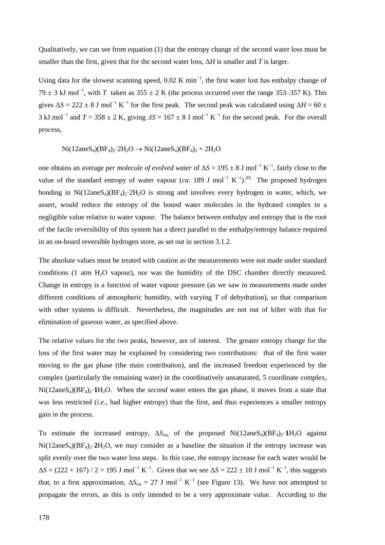
178
Qualitatively, we can see from equation (1) that the entropy change of the second water loss must be
smaller than the first, given that for the second water loss, ΔH is smaller and T is larger.
Using data for the slowest scanning speed, 0.02 K min−1
, the first water lost has enthalpy change of
79 ± 3 kJ mol−1
, with T taken as 355 ± 2 K (the process occurred over the range 353–357 K). This
gives ΔS = 222 ± 8 J mol−1
K−1
for the first peak. The second peak was calculated using ΔH = 60 ±
3 kJ mol−1
and T = 358 ± 2 K, giving ΔS = 167 ± 8 J mol−1
K−1
for the second peak. For the overall
process,
Ni(12aneS4)(BF4)2·2H2O Ni(12aneS4)(BF4)2 + 2H2O
one obtains an average per molecule of evolved water of ΔS = 195 ± 8 J mol−1
K−1
, fairly close to the
value of the standard entropy of water vapour (ca. 189 J mol−1
K−1
).[8]
The proposed hydrogen
bonding in Ni(12aneS4)(BF4)2·2H2O is strong and involves every hydrogen in water, which, we
assert, would reduce the entropy of the bound water molecules in the hydrated complex to a
negligible value relative to water vapour. The balance between enthalpy and entropy that is the root
of the facile reversibility of this system has a direct parallel to the enthalpy/entropy balance required
in an on-board reversible hydrogen store, as set out in section 3.1.2.
The absolute values must be treated with caution as the measurements were not made under standard
conditions (1 atm H2O vapour), nor was the humidity of the DSC chamber directly measured.
Change in entropy is a function of water vapour pressure (as we saw in measurements made under
different conditions of atmospheric humidity, with varying T of dehydration), so that comparison
with other systems is difficult. Nevertheless, the magnitudes are not out of kilter with that for
elimination of gaseous water, as specified above.
The relative values for the two peaks, however, are of interest. The greater entropy change for the
loss of the first water may be explained by considering two contributions: that of the first water
moving to the gas phase (the main contribution), and the increased freedom experienced by the
complex (particularly the remaining water) in the coordinatively unsaturated, 5 coordinate complex,
Ni(12aneS4)(BF4)2·1H2O. When the second water enters the gas phase, it moves from a state that
was less restricted (i.e., had higher entropy) than the first, and thus experiences a smaller entropy
gain in the process.
To estimate the increased entropy, ΔSint, of the proposed Ni(12aneS4)(BF4)2·1H2O against
Ni(12aneS4)(BF4)2·2H2O, we may consider as a baseline the situation if the entropy increase was
split evenly over the two water loss steps. In this case, the entropy increase for each water would be
ΔS = (222 + 167) / 2 = 195 J mol−1
K−1
. Given that we see ΔS = 222 ± 10 J mol−1
K−1
, this suggests
that, to a first approximation, ΔSint = 27 J mol−1
K−1
(see Figure 13). We have not attempted to
propagate the errors, as this is only intended to be a very approximate value. According to the
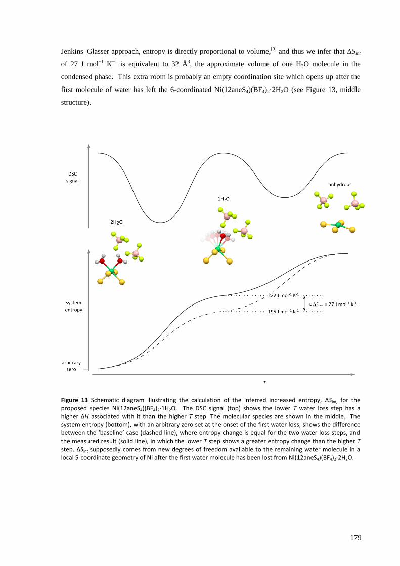
179
Jenkins–Glasser approach, entropy is directly proportional to volume,[9]
and thus we infer that ΔSint
of 27 J mol−1
K−1
is equivalent to 32 Å3, the approximate volume of one H2O molecule in the
condensed phase. This extra room is probably an empty coordination site which opens up after the
first molecule of water has left the 6-coordinated Ni(12aneS4)(BF4)2·2H2O (see Figure 13, middle
structure).
Figure 13 Schematic diagram illustrating the calculation of the inferred increased entropy, ΔSint, for the proposed species Ni(12aneS4)(BF4)2·1H2O. The DSC signal (top) shows the lower T water loss step has a higher ΔH associated with it than the higher T step. The molecular species are shown in the middle. The system entropy (bottom), with an arbitrary zero set at the onset of the first water loss, shows the difference between the ‘baseline’ case (dashed line), where entropy change is equal for the two water loss steps, and the measured result (solid line), in which the lower T step shows a greater entropy change than the higher T step. ΔSint supposedly comes from new degrees of freedom available to the remaining water molecule in a local 5-coordinate geometry of Ni after the first water molecule has been lost from Ni(12aneS4)(BF4)2·2H2O.
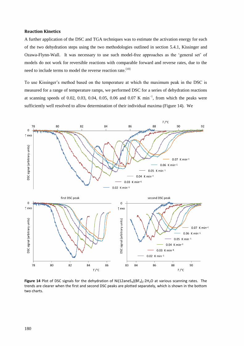
180
Reaction Kinetics
A further application of the DSC and TGA techniques was to estimate the activation energy for each
of the two dehydration steps using the two methodologies outlined in section 5.4.1, Kissinger and
Ozawa-Flynn-Wall. It was necessary to use such model-free approaches as the ‘general set’ of
models do not work for reversible reactions with comparable forward and reverse rates, due to the
need to include terms to model the reverse reaction rate.[10]
To use Kissinger’s method based on the temperature at which the maximum peak in the DSC is
measured for a range of temperature ramps, we performed DSC for a series of dehydration reactions
at scanning speeds of 0.02, 0.03, 0.04, 0.05, 0.06 and 0.07 K min−1
, from which the peaks were
sufficiently well resolved to allow determination of their individual maxima (Figure 14). We
Figure 14 Plot of DSC signals for the dehydration of Ni(12aneS4)(BF4)2·2H2O at various scanning rates. The trends are clearer when the first and second DSC peaks are plotted separately, which is shown in the bottom two charts.
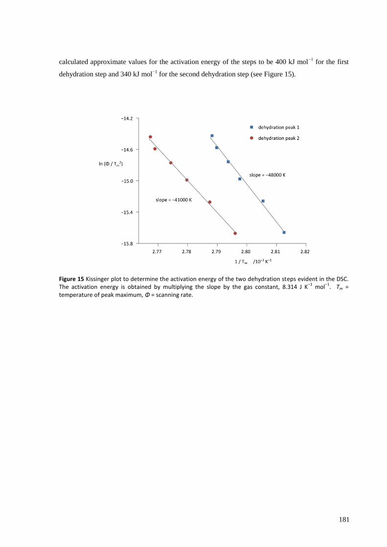
181
calculated approximate values for the activation energy of the steps to be 400 kJ mol−1
for the first
dehydration step and 340 kJ mol−1
for the second dehydration step (see Figure 15).
Figure 15 Kissinger plot to determine the activation energy of the two dehydration steps evident in the DSC. The activation energy is obtained by multiplying the slope by the gas constant, 8.314 J K
−1 mol
−1. Tm =
temperature of peak maximum, Φ = scanning rate.
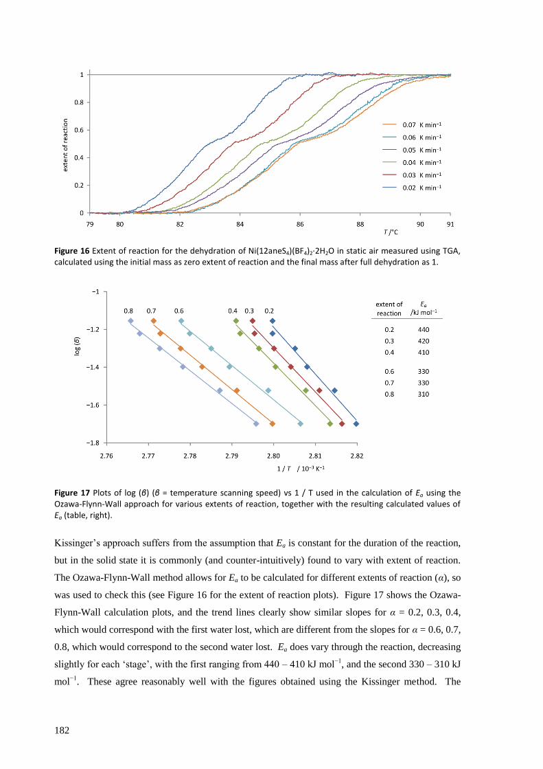
182
Figure 16 Extent of reaction for the dehydration of Ni(12aneS4)(BF4)2·2H2O in static air measured using TGA, calculated using the initial mass as zero extent of reaction and the final mass after full dehydration as 1.
Figure 17 Plots of log (β) (β = temperature scanning speed) vs 1 / T used in the calculation of Ea using the Ozawa-Flynn-Wall approach for various extents of reaction, together with the resulting calculated values of Ea (table, right).
Kissinger’s approach suffers from the assumption that Ea is constant for the duration of the reaction,
but in the solid state it is commonly (and counter-intuitively) found to vary with extent of reaction.
The Ozawa-Flynn-Wall method allows for Ea to be calculated for different extents of reaction (α), so
was used to check this (see Figure 16 for the extent of reaction plots). Figure 17 shows the Ozawa-
Flynn-Wall calculation plots, and the trend lines clearly show similar slopes for α = 0.2, 0.3, 0.4,
which would correspond with the first water lost, which are different from the slopes for α = 0.6, 0.7,
0.8, which would correspond to the second water lost. Ea does vary through the reaction, decreasing
slightly for each ‘stage’, with the first ranging from 440 – 410 kJ mol−1
, and the second 330 – 310 kJ
mol−1
. These agree reasonably well with the figures obtained using the Kissinger method. The
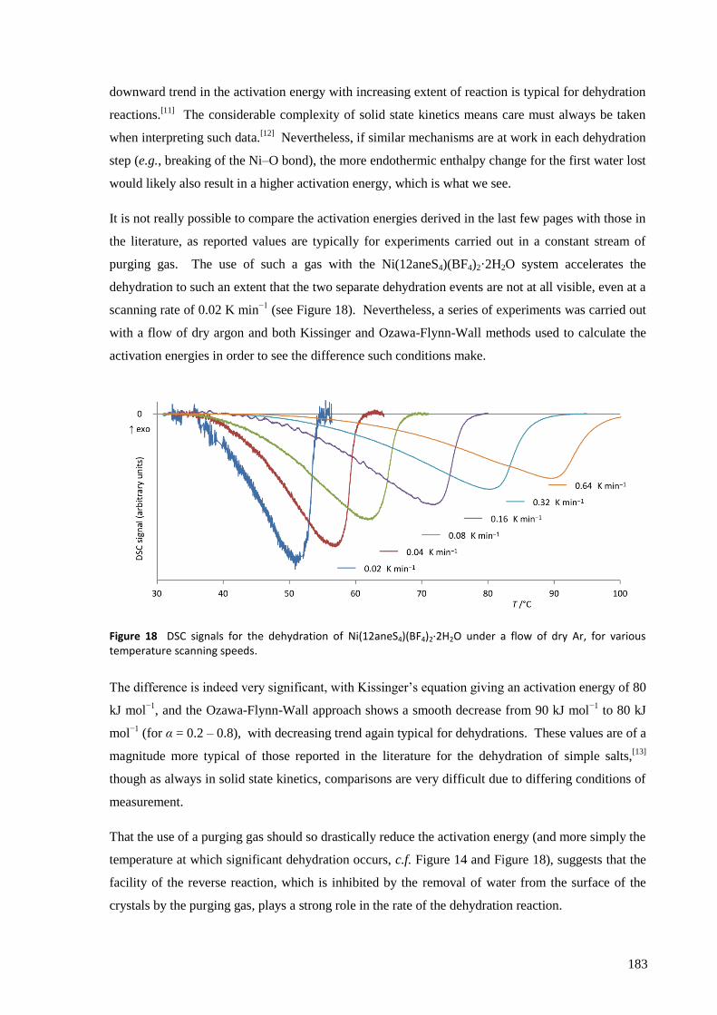
183
downward trend in the activation energy with increasing extent of reaction is typical for dehydration
reactions.[11]
The considerable complexity of solid state kinetics means care must always be taken
when interpreting such data.[12]
Nevertheless, if similar mechanisms are at work in each dehydration
step (e.g., breaking of the Ni–O bond), the more endothermic enthalpy change for the first water lost
would likely also result in a higher activation energy, which is what we see.
It is not really possible to compare the activation energies derived in the last few pages with those in
the literature, as reported values are typically for experiments carried out in a constant stream of
purging gas. The use of such a gas with the Ni(12aneS4)(BF4)2·2H2O system accelerates the
dehydration to such an extent that the two separate dehydration events are not at all visible, even at a
scanning rate of 0.02 K min−1
(see Figure 18). Nevertheless, a series of experiments was carried out
with a flow of dry argon and both Kissinger and Ozawa-Flynn-Wall methods used to calculate the
activation energies in order to see the difference such conditions make.
Figure 18 DSC signals for the dehydration of Ni(12aneS4)(BF4)2·2H2O under a flow of dry Ar, for various temperature scanning speeds.
The difference is indeed very significant, with Kissinger’s equation giving an activation energy of 80
kJ mol−1
, and the Ozawa-Flynn-Wall approach shows a smooth decrease from 90 kJ mol−1
to 80 kJ
mol−1
(for α = 0.2 – 0.8), with decreasing trend again typical for dehydrations. These values are of a
magnitude more typical of those reported in the literature for the dehydration of simple salts,[13]
though as always in solid state kinetics, comparisons are very difficult due to differing conditions of
measurement.
That the use of a purging gas should so drastically reduce the activation energy (and more simply the
temperature at which significant dehydration occurs, c.f. Figure 14 and Figure 18), suggests that the
facility of the reverse reaction, which is inhibited by the removal of water from the surface of the
crystals by the purging gas, plays a strong role in the rate of the dehydration reaction.
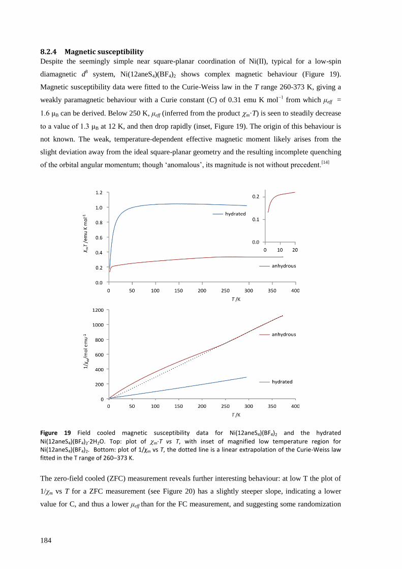
184
8.2.4 Magnetic susceptibility
Despite the seemingly simple near square-planar coordination of Ni(II), typical for a low-spin
diamagnetic d8 system, Ni(12aneS4)(BF4)2 shows complex magnetic behaviour (Figure 19).
Magnetic susceptibility data were fitted to the Curie-Weiss law in the T range 260-373 K, giving a
weakly paramagnetic behaviour with a Curie constant (C) of 0.31 emu K mol−1
from which μeff =
1.6 μB can be derived. Below 250 K, μeff (inferred from the product m·T) is seen to steadily decrease
to a value of 1.3 μB at 12 K, and then drop rapidly (inset, Figure 19). The origin of this behaviour is
not known. The weak, temperature-dependent effective magnetic moment likely arises from the
slight deviation away from the ideal square-planar geometry and the resulting incomplete quenching
of the orbital angular momentum; though ‘anomalous’, its magnitude is not without precedent.[14]
Figure 19 Field cooled magnetic susceptibility data for Ni(12aneS4)(BF4)2 and the hydrated
Ni(12aneS4)(BF4)2·2H2O. Top: plot of m·T vs T, with inset of magnified low temperature region for Ni(12aneS4)(BF4)2. Bottom: plot of 1/χm vs T, the dotted line is a linear extrapolation of the Curie-Weiss law fitted in the T range of 260–373 K.
The zero-field cooled (ZFC) measurement reveals further interesting behaviour: at low T the plot of
1/χm vs T for a ZFC measurement (see Figure 20) has a slightly steeper slope, indicating a lower
value for C, and thus a lower μeff than for the FC measurement, and suggesting some randomization
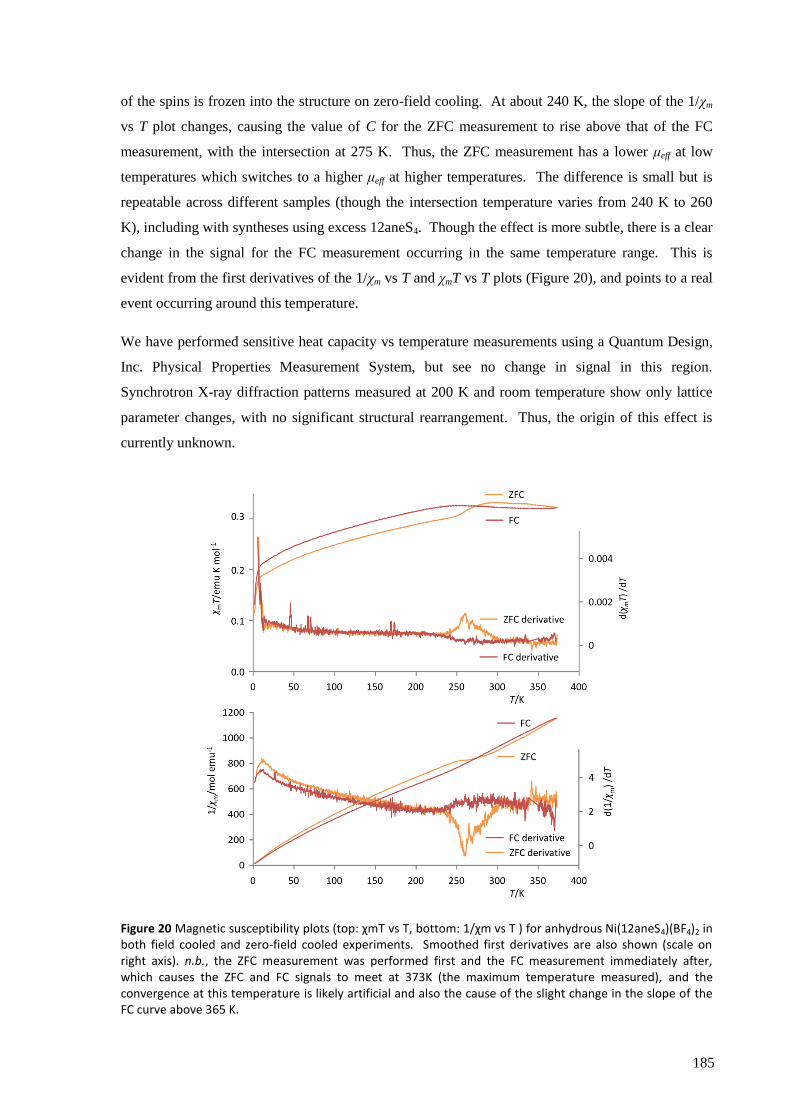
185
of the spins is frozen into the structure on zero-field cooling. At about 240 K, the slope of the 1/χm
vs T plot changes, causing the value of C for the ZFC measurement to rise above that of the FC
measurement, with the intersection at 275 K. Thus, the ZFC measurement has a lower μeff at low
temperatures which switches to a higher μeff at higher temperatures. The difference is small but is
repeatable across different samples (though the intersection temperature varies from 240 K to 260
K), including with syntheses using excess 12aneS4. Though the effect is more subtle, there is a clear
change in the signal for the FC measurement occurring in the same temperature range. This is
evident from the first derivatives of the 1/χm vs T and χmT vs T plots (Figure 20), and points to a real
event occurring around this temperature.
We have performed sensitive heat capacity vs temperature measurements using a Quantum Design,
Inc. Physical Properties Measurement System, but see no change in signal in this region.
Synchrotron X-ray diffraction patterns measured at 200 K and room temperature show only lattice
parameter changes, with no significant structural rearrangement. Thus, the origin of this effect is
currently unknown.
Figure 20 Magnetic susceptibility plots (top: χmT vs T, bottom: 1/χm vs T ) for anhydrous Ni(12aneS4)(BF4)2 in both field cooled and zero-field cooled experiments. Smoothed first derivatives are also shown (scale on right axis). n.b., the ZFC measurement was performed first and the FC measurement immediately after, which causes the ZFC and FC signals to meet at 373K (the maximum temperature measured), and the convergence at this temperature is likely artificial and also the cause of the slight change in the slope of the FC curve above 365 K.
186
In contrast, the magnetic susceptibility of the hydrated complex indicates the presence of high-spin
Ni(II), as expected for the octahedral geometry, with C = 1.3 emu K mol−1
, μeff = 3.2 μB, within the
normal range (3.0 – 3.3 μB) for such complexes.[14]
The 1/χm vs T plot in Figure 19b passes very
close to the origin, indicating no significant magnetic coupling, as expected for a molecular crystal
with no obvious pathway for through-bond intermolecular magnetic superexchange.* The zero-field
cooled case is essentially identical to that of the field cooled data (except for a very slight deviation
below 4 K). The low temperature fall in χmT could be due to either a spin-crossover event (possibly
linked to a phase transition), or simply due to zero-field splitting.
In the paramagnetic regime (T > 250 K), the magnetic susceptibility of the anhydrous complex is
less than 30% of that when hydrated, a readily detectable difference between the complexes even at
room temperature.
* The complex does show hydrogen bonding, but only providing very long (eight bond) paths between metal
centres.

187
8.3 Summary and future work
We have demonstrated extremely facile interconversion of a non-porous, molecularly crystalline
Ni(II) complex in the solid phase displaying clearly defined chromatic, structural and magnetic
changes upon reversible water vapour uptake and release. The clear topotactic structural
relationship between the anhydrous and hydrated complexes is the likely origin of this easy
reversibility. The ability of Ni(12aneS4)(BF4)2 to retain its crystallinity after undergoing such
significant structural changes is rare for a molecular crystal and provides an alternative approach to
the much studied coordination polymers.
TGA/DSC experiments clearly indicate the dehydration proceeds in two steps, in which the lower
temperature step involves greater heat transfer than the higher temperature step for both dehydration
and hydration. Kinetic studies suggest that the removal of water from the surface of the crystal is
important in controlling the rate of dehydration.
Ni(12aneS4)(BF4)2 has an ‘anomalous’ value for magnetic susceptibility, but this is actually well-
documented for nickel complexes and likely arises from the not quite square-planar structure.
Further investigation of the unusual behaviour of this complex in the temperature region 240 – 270
K could be of interest. A clearer understanding of the processes occurring in the hydrated complex
leading to the significant drop in magnetic susceptibility at temperatures below 50 K would be
useful, particularly if this can indeed be attributed to a spin-crossover event.
It also remains to be investigated whether Ni(12aneS4)(BF4)2 is similarly sensitive to other small
molecules and whether thin layers could be used as moisture sensors.[15]
188
References
1 G. A. Bain, J. F. Berry, Journal of Chemical Education, 2008, 85, 532.
2 G. Bergerhoff, K. Brandenburg, International Tables for Crystallography Volume C, Ed. E. Prince, Kluwer,
Dordrecht, 1992, pp. 778-789 (accessed online at http://it.iucr.org/Cb/ch9o4v0001/).
3 S. J. La Placa, B. Post, Acta Crystallographica, 1960, 13, 503.
4 R. D. Shannon, R. C. Rossi, Nature, 1964, 202, 1000.
5 G. J. Grant, M. W. Jones, K. D. Loveday, D. G. VanDerveer, W. T. Pennington, C. T. Eagle, L. F. Mehne,
Inorganica Chimica Acta, 2000, 300-302, 250.
6 J. G. Speight, Lange's Handbook of Chemistry (16th Edition), Section 1: Inorganic Chemistry, McGraw-Hill,
2005, p. 285.
7 a) complexes 1 and 4, respectively, in: M. Clemente-León, E. Coronado, M. C. Giménez-López, F. M.
Romero, Inorganic Chemistry, 2007, 46, 11266; b) complex 4 in: B. Sieklucka, R. Podgajny, D. Pinkowicz, B.
Nowicka, T. Korzeniak, M. Bałanda, T. Wasiutyoski, R. Pełka, M. Makarewicz, M. Czapla, M. Rams, B. Gaweł,
W. Łasocha, CrystEngComm, 2009, 11, 2032; c) L. Dobrzaoska, G. O. Lloyd, C. Esterhuysen, L. J. Barbour,
Angewandte Chemie (International ed. in English), 2006, 45, 5856.
8 P.W. Atkins, Physical Chemistry Sixth Edition, OUP, Oxford, 1999, p. 926.
9 H. D. B. Jenkins, L. Glasser, Inorganic Chemistry, 2003, 42, 8702.
10 A. K. Galwey, M. E. Brown, Thermal Decomposition of Ionic Solids, Elsevier, Amsterdam, 1999, p.163.
11 S. Vyazovkin, W. Linert, International Journal of Chemical Kinetics, 1995, 27, 73.
12 M. Maciejewski, Journal of Thermal Analyis, 1988, 33, 1269.
13 A. K. Galwey, M. E. Brown, Thermal Decomposition of Ionic Solids, Elsevier, Amsterdam, 1999, pp. 232.
14 E. K. Barefield, D. H. Busch, S. M. Nelson, Quarterly Reviews of the Chemical Society, 1968, 22, 457.
15 S. E. Angell, C. W. Rogers, Y. Zhang, M. O. Wolf, W. E. Jones, Coordination Chemistry Reviews, 2006, 250,
1829.
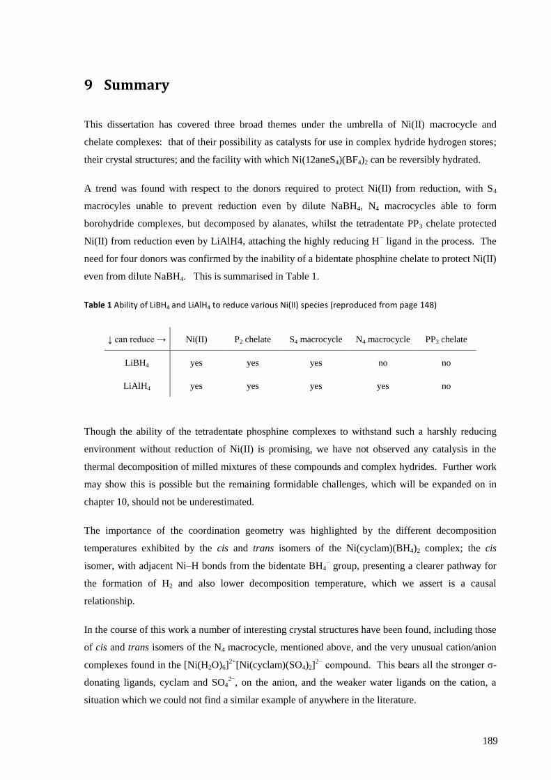
189
9 Summary
This dissertation has covered three broad themes under the umbrella of Ni(II) macrocycle and
chelate complexes: that of their possibility as catalysts for use in complex hydride hydrogen stores;
their crystal structures; and the facility with which Ni(12aneS4)(BF4)2 can be reversibly hydrated.
A trend was found with respect to the donors required to protect Ni(II) from reduction, with S4
macrocyles unable to prevent reduction even by dilute NaBH4, N4 macrocycles able to form
borohydride complexes, but decomposed by alanates, whilst the tetradentate PP3 chelate protected
Ni(II) from reduction even by LiAlH4, attaching the highly reducing H− ligand in the process. The
need for four donors was confirmed by the inability of a bidentate phosphine chelate to protect Ni(II)
even from dilute NaBH4. This is summarised in Table 1.
Table 1 Ability of LiBH4 and LiAlH4 to reduce various Ni(II) species (reproduced from page 148)
↓ can reduce → Ni(II) P2 chelate S4 macrocycle N4 macrocycle PP3 chelate
LiBH4 yes yes yes no no
LiAlH4 yes yes yes yes no
Though the ability of the tetradentate phosphine complexes to withstand such a harshly reducing
environment without reduction of Ni(II) is promising, we have not observed any catalysis in the
thermal decomposition of milled mixtures of these compounds and complex hydrides. Further work
may show this is possible but the remaining formidable challenges, which will be expanded on in
chapter 10, should not be underestimated.
The importance of the coordination geometry was highlighted by the different decomposition
temperatures exhibited by the cis and trans isomers of the Ni(cyclam)(BH4)2 complex; the cis
isomer, with adjacent Ni–H bonds from the bidentate BH4− group, presenting a clearer pathway for
the formation of H2 and also lower decomposition temperature, which we assert is a causal
relationship.
In the course of this work a number of interesting crystal structures have been found, including those
of cis and trans isomers of the N4 macrocycle, mentioned above, and the very unusual cation/anion
complexes found in the [Ni(H2O)6]2+
[Ni(cyclam)(SO4)2]2−
compound. This bears all the stronger σ-
donating ligands, cyclam and SO42−
, on the anion, and the weaker water ligands on the cation, a
situation which we could not find a similar example of anywhere in the literature.

190
The topotactic structures of Ni(12aneS4)(BF4)2 and Ni(12aneS4)(BF4)2·2H2O are also of interest for
the facile rearrangement of the 12aneS4 ligand that apparently plays a key role in the ease with
which the complexes are hydrated and dehydrated respectively. Though the kinetics and
mechanisms of solid state reactions are notoriously difficult to determine, we have seen that the
water molecules are lost and gained in two stages, with slightly different enthalpy and entropy for
each stage.
The crystal structures, properties and reactions of these Ni(II) complexes has therefore shown some
of the typical traits of Ni(II), along with some surprises, and we will now discuss what future work
might be built upon these results.

191
10 Outlook
10.1 Catalysis with complex hydrides The chief opportunity for future work lies in the main subject of this dissertation, designing catalysts
for use with complex hydrides. Due to the problems associated with evolution of boron hydrides
during the thermal decomposition of the borohydrides, the alanates are the more attractive stores, and
thus the use of phosphine complexes shows most promise. Phosphines are also particularly good at
stabilising Ni(0), providing the possibility for a two electron redox reaction, as required for the
reduction of H2 to 2H− on re-fuelling, or the reverse oxidation of 2H
− for hydrogen evolution. The
possibility of using two Ni(II) centres held in close proximity by a suitably designed complex so that
each need only donate/accept one electron to the reactions could also be considered, though the mass
of the ligands required to achieve this may prove prohibitive.
The catalyst needs to present an appropriately oriented orbital of the right phase to either donate two
electrons into the σ* orbital of H2, or accept them from the 2H−. The manipulation of the molecular
orbitals of the coordination complex to achieve this is not simple, and even slight changes can have a
significant impact on the efficacy of the catalyst. The use of mixed donor complexes may therefore
prove useful in achieving this demanding feat, and is another area worthy of attention.
Should a successful catalyst based on nickel be developed, the ability of the market to supply the
nickel must be considered. A hydrogen storage system with a capacity of 4 kg H2, and a mass ratio
for store : catalyst of 3 : 1 (approximately the case for the calculations used in section 6.5 on page
146), would require about 1.3 kg of catalyst. A catalyst with molecular weight of 300 g mol−1
(again
approximately the case for the calculations in section 6.5) and one nickel atom per complex would be
made up of about 20 wt% Ni, leading to about 0.25 kg of Ni in the store. If the technology were to
hit full production, it is not unlikely that during the conversion from fossil fuels (i.e., before
significant recycling efforts could be made), 10 – 100 million cars year−1
could require this amount of
nickel, a total for the fleet of 2.5 – 25 × 106 kg year
−1. As stated on page 4, current annual production
is only about 106 kg year
−1, with significant price spikes seen when demand rose. More efficient
catalysts would reduce the amount of nickel required, but the fundamental problem of mass transport
in solids is likely to be a limiting factor. Additional mining resources may be found to meet the
additional demand (nickel is not a particularly rare element), but the periods required for bringing
them into production are often long, with 10 – 15 years not untypical. Thus supply of nickel could
also prove to be a significant barrier to wide-scale implementation of any technology based on it or at
least significantly delay it.
192
Furthermore, even if the kinetic problems of the complex hydrides were to be overcome, further
significant challenges of a thermodynamic nature, and thus fundamental to the system, would still
exist. As shown in section 3.4 on page 23, about 40 kJ (mol H2)−1
of enthalpy stabilisation is required
on re-fuelling in order for entropy to drive the hydrogen evolution reaction by heating alone.
Assuming a requirement for 2000 mol of H2 (4 kg), approximately 80 MJ of energy must be
dissipated over the approximately 200 seconds allowed for re-fuelling, and therefore a cooling power
of 400 kW is required. For comparison, a high capacity commercial heat pump with dimensions of
1.8 m × 1.0 m × 0.8 m and weighing 260 kg has a cooling capacity of 34 kW.* Thus this problem
represents a possibly insurmountable challenge.
10.2 Reversible absorption of small molecules in Ni(12aneS4)(BF4)2 The other area for possible future research is to test the ability of Ni(12aneS4)(BF4)2 to reversibly
absorb other small molecules, such as methanol, acetone, dimethyl sulfoxide etc, and the effect this
has on the physical properties, including crystal structure and magnetic susceptibility. Their role as a
sensor for such small molecules might also be investigated, though given the myriad of effective,
existing solutions, it seems unlikely that a commercially viable new application would be found.
* Based on the Toshiba MAP1201HT8-E heat pump technical specifications.