CRYSTAL CITY, TEXAS - MAIN POST OFFICE - Zavala County
464
PROJECT MANUAL POSTAL PROJECT NUMBER: C32085 CRYSTAL CITY, TEXAS - MAIN POST OFFICE CRYSTAL CITY, TEXAS ARCHITECT’S PROJECT # 1921 A1 ISSUE FOR CONSTRUCTION August 7, 2020 915 S. St. Mary’s Street 210.299.1500 (P) San Antonio, TX 78205 (F) 210.299.1622
-
Upload
khangminh22 -
Category
Documents
-
view
0 -
download
0
Transcript of CRYSTAL CITY, TEXAS - MAIN POST OFFICE - Zavala County
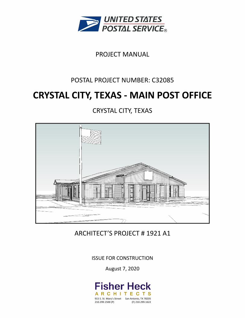
PROJECT MANUAL
POSTAL PROJECT NUMBER: C32085
CRYSTAL CITY, TEXAS - MAIN POST OFFICE
CRYSTAL CITY, TEXAS
ARCHITECT’S PROJECT # 1921 A1
ISSUE FOR CONSTRUCTION
August 7, 2020
915 S. St. Mary’s Street 210.299.1500 (P)
San Antonio, TX 78205 (F) 210.299.1622
00002 - 1 CRYSTAL CITY, TX – MAIN POST OFFICE Date: 8/7/2020 PROJECT DIRECTORY
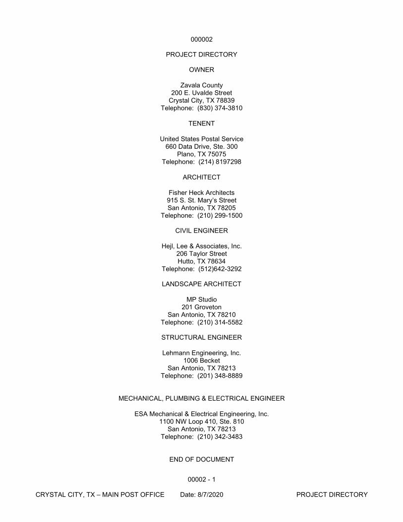
000002
PROJECT DIRECTORY
OWNER
Zavala County 200 E. Uvalde Street
Crystal City, TX 78839 Telephone: (830) 374-3810
TENENT
United States Postal Service 660 Data Drive, Ste. 300
Plano, TX 75075 Telephone: (214) 8197298
ARCHITECT
Fisher Heck Architects 915 S. St. Mary’s Street San Antonio, TX 78205
Telephone: (210) 299-1500
CIVIL ENGINEER
Hejl, Lee & Associates, Inc. 206 Taylor Street Hutto, TX 78634
Telephone: (512)642-3292
LANDSCAPE ARCHITECT
MP Studio 201 Groveton
San Antonio, TX 78210 Telephone: (210) 314-5582
STRUCTURAL ENGINEER
Lehmann Engineering, Inc. 1006 Becket
San Antonio, TX 78213 Telephone: (201) 348-8889
MECHANICAL, PLUMBING & ELECTRICAL ENGINEER
ESA Mechanical & Electrical Engineering, Inc. 1100 NW Loop 410, Ste. 810
San Antonio, TX 78213 Telephone: (210) 342-3483
END OF DOCUMENT
00007 - 1 CRYSTAL CITY, TX – MAIN POST OFFICE Date: 8/7/2020 SEALS PAGE
000007
SEALS PAGE
PROJECT
Name: Crystal City, TX – Main Post Office Location: Crystal City, TX 78839 FMS Project Number: C32085
ARCHITECT OF RECORD
915 S. St. Mary’s Street San Antonio, TX 78205
Architect of Record Date
CIVIL ENGINEER OF RECORD
206 Taylor Street Hutto, TX 78634
Civil Engineer of Record Date
8/7/2020
00007 - 2 CRYSTAL CITY, TX – MAIN POST OFFICE Date: 8/7/2020 SEALS PAGE
LANDSCAPE ARCHITECT OF RECORD
210 Groveton San Antonio, TX 78210
Landscape Architect of Record Date
STRUCTURAL ENGINEER OF RECORD
1006 Becket San Antonio, TX 78213
Structural Engineer of Record Date
MECHANICAL PLUMBING & ELECTRICAL ENGINEER OF RECORD
1100 NW Loop 410, Ste. 810 San Antonio, TX 78213
Mechanical Engineer of Record Date
END OF DOCUMENT
8/7/2020
000010 - 1 CRYSTAL CITY, TX – MAIN POST OFFICE Date: 8/7/2020 TABLE OF CONTENTS
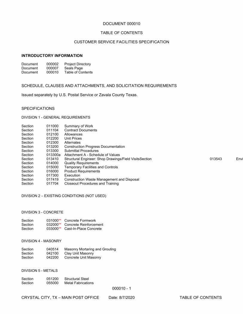
DOCUMENT 000010
TABLE OF CONTENTS
CUSTOMER SERVICE FACILITIES SPECIFICATION INTRODUCTORY INFORMATION Document 000002 Project Directory Document 000007 Seals Page Document 000010 Table of Contents SCHEDULE, CLAUSES AND ATTACHMENTS, AND SOLICITATION REQUIREMENTS Issued separately by U.S. Postal Service or Zavala County Texas. SPECIFICATIONS DIVISION 1 - GENERAL REQUIREMENTS Section 011000 Summary of Work Section 011104 Contract Documents Section 012100 Allowances Section 012200 Unit Prices Section 012300 Alternates Section 013200 Construction Progress Documentation Section 013300 Submittal Procedures Section 013300a Attachment A - Schedule of Values Section 013410 Structural Engineer: Shop Drawings/Field VisitsSection 013543 Envi Section 014000 Quality Requirements Section 015000 Temporary Facilities and Controls Section 016000 Product Requirements Section 017300 Execution Section 017419 Construction Waste Management and Disposal Section 017704 Closeout Procedures and Training DIVISION 2 – EXISTING CONDITIONS (NOT USED) DIVISION 3 - CONCRETE Section 031000** Concrete Formwork Section 032000** Concrete Reinforcement Section 033000** Cast-In-Place Concrete DIVISION 4 - MASONRY Section 040514 Masonry Mortaring and Grouting Section 042100 Clay Unit Masonry Section 042200 Concrete Unit Masonry DIVISION 5 - METALS Section 051200 Structural Steel Section 055000 Metal Fabrications
000010 - 2 CRYSTAL CITY, TX – MAIN POST OFFICE Date: 8/7/2020 TABLE OF CONTENTS
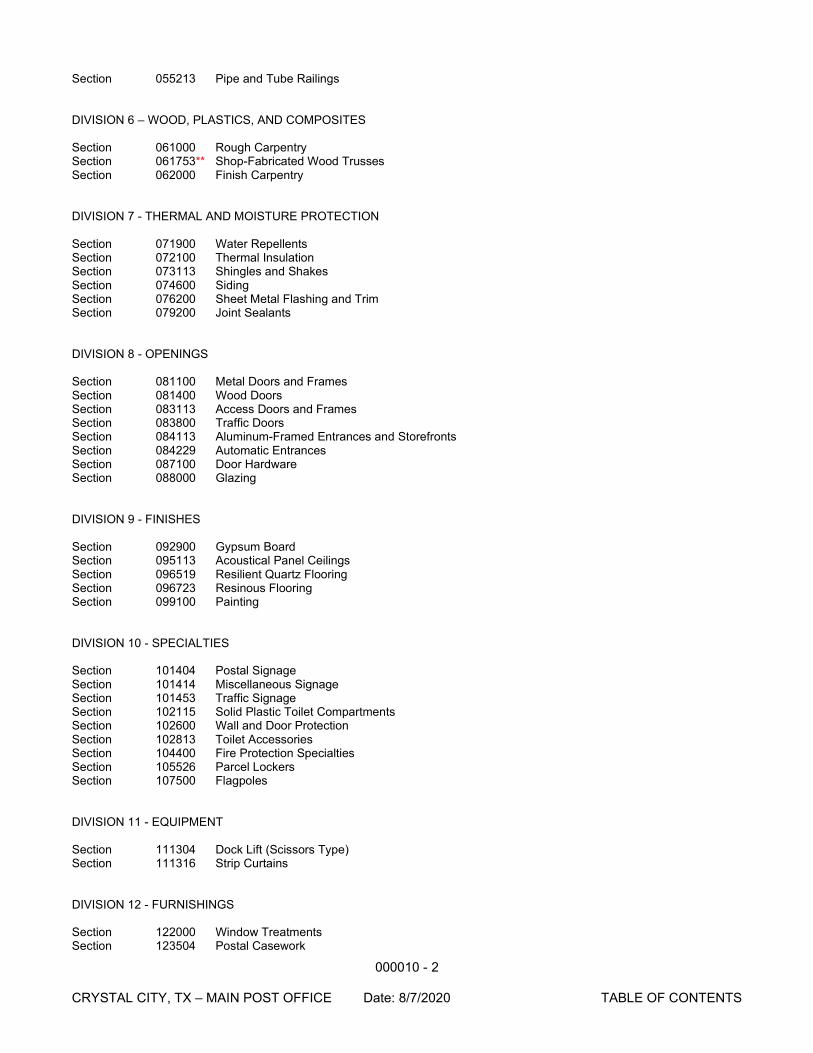
Section 055213 Pipe and Tube Railings DIVISION 6 – WOOD, PLASTICS, AND COMPOSITES Section 061000 Rough Carpentry Section 061753** Shop-Fabricated Wood Trusses Section 062000 Finish Carpentry DIVISION 7 - THERMAL AND MOISTURE PROTECTION Section 071900 Water Repellents Section 072100 Thermal Insulation Section 073113 Shingles and Shakes Section 074600 Siding Section 076200 Sheet Metal Flashing and Trim Section 079200 Joint Sealants DIVISION 8 - OPENINGS Section 081100 Metal Doors and Frames Section 081400 Wood Doors Section 083113 Access Doors and Frames Section 083800 Traffic Doors Section 084113 Aluminum-Framed Entrances and Storefronts Section 084229 Automatic Entrances Section 087100 Door Hardware Section 088000 Glazing DIVISION 9 - FINISHES Section 092900 Gypsum Board Section 095113 Acoustical Panel Ceilings Section 096519 Resilient Quartz Flooring Section 096723 Resinous Flooring Section 099100 Painting DIVISION 10 - SPECIALTIES Section 101404 Postal Signage Section 101414 Miscellaneous Signage Section 101453 Traffic Signage Section 102115 Solid Plastic Toilet Compartments Section 102600 Wall and Door Protection Section 102813 Toilet Accessories Section 104400 Fire Protection Specialties Section 105526 Parcel Lockers Section 107500 Flagpoles DIVISION 11 - EQUIPMENT Section 111304 Dock Lift (Scissors Type) Section 111316 Strip Curtains DIVISION 12 - FURNISHINGS Section 122000 Window Treatments Section 123504 Postal Casework
000010 - 3 CRYSTAL CITY, TX – MAIN POST OFFICE Date: 8/7/2020 TABLE OF CONTENTS
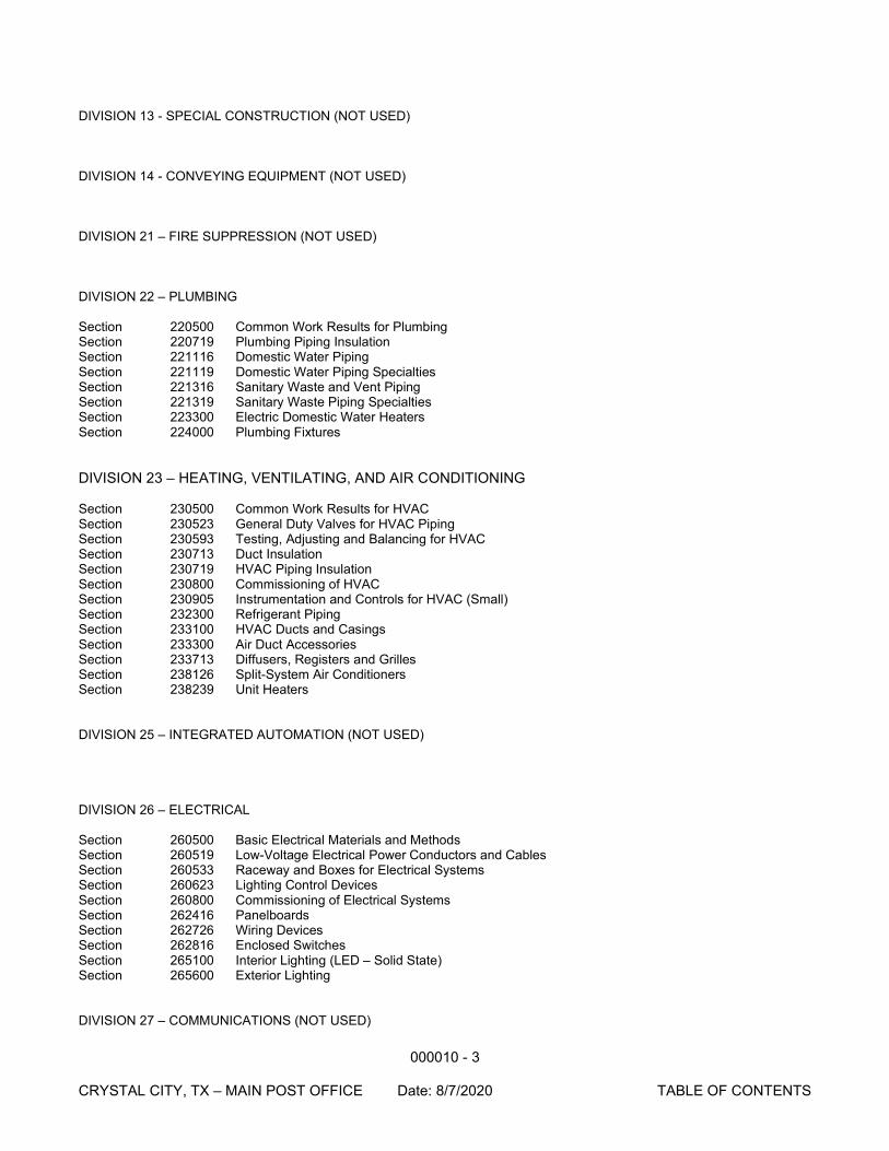
DIVISION 13 - SPECIAL CONSTRUCTION (NOT USED)
DIVISION 14 - CONVEYING EQUIPMENT (NOT USED) DIVISION 21 – FIRE SUPPRESSION (NOT USED) DIVISION 22 – PLUMBING Section 220500 Common Work Results for Plumbing Section 220719 Plumbing Piping Insulation Section 221116 Domestic Water Piping Section 221119 Domestic Water Piping Specialties Section 221316 Sanitary Waste and Vent Piping Section 221319 Sanitary Waste Piping Specialties Section 223300 Electric Domestic Water Heaters Section 224000 Plumbing Fixtures DIVISION 23 – HEATING, VENTILATING, AND AIR CONDITIONING Section 230500 Common Work Results for HVAC Section 230523 General Duty Valves for HVAC Piping Section 230593 Testing, Adjusting and Balancing for HVAC Section 230713 Duct Insulation Section 230719 HVAC Piping Insulation Section 230800 Commissioning of HVAC Section 230905 Instrumentation and Controls for HVAC (Small) Section 232300 Refrigerant Piping Section 233100 HVAC Ducts and Casings Section 233300 Air Duct Accessories Section 233713 Diffusers, Registers and Grilles Section 238126 Split-System Air Conditioners Section 238239 Unit Heaters DIVISION 25 – INTEGRATED AUTOMATION (NOT USED) DIVISION 26 – ELECTRICAL Section 260500 Basic Electrical Materials and Methods Section 260519 Low-Voltage Electrical Power Conductors and Cables Section 260533 Raceway and Boxes for Electrical Systems Section 260623 Lighting Control Devices Section 260800 Commissioning of Electrical Systems Section 262416 Panelboards Section 262726 Wiring Devices Section 262816 Enclosed Switches Section 265100 Interior Lighting (LED – Solid State) Section 265600 Exterior Lighting DIVISION 27 – COMMUNICATIONS (NOT USED)
000010 - 4 CRYSTAL CITY, TX – MAIN POST OFFICE Date: 8/7/2020 TABLE OF CONTENTS
DIVISION 28 – ELECTRONIC SAFETY AND SECURITY (NOT USED) DIVISION 31 – EARTHWORK Section 312010 Structural Earthwork for Building Foundations DIVISION 32 – EXTERIOR IMPROVEMENTS (NOT USED) DIVISION 33 – UTILITIES (NOT USED)
END OF DOCUMENT
011000–1 CRYSTAL CITY, TX – MAIN POST OFFICE Date: 8/7/2020 SUMMARY OF WORK
SECTION 011000
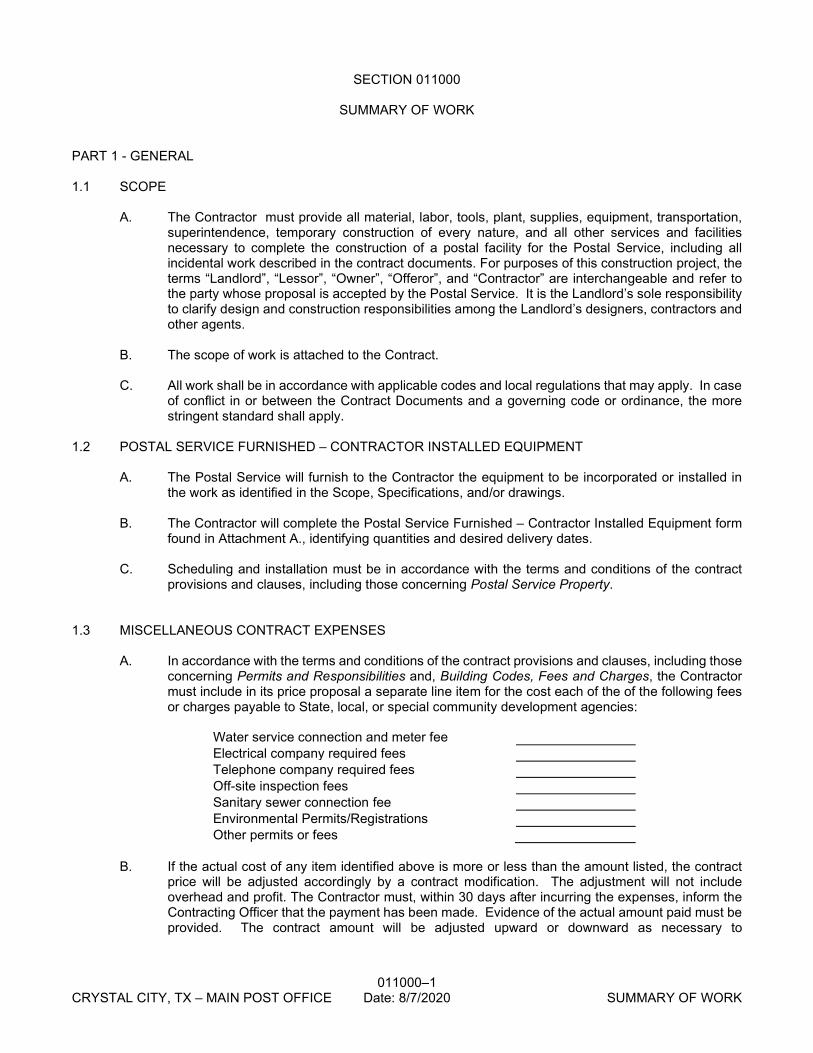
SUMMARY OF WORK PART 1 - GENERAL 1.1 SCOPE
A. The Contractor must provide all material, labor, tools, plant, supplies, equipment, transportation,
superintendence, temporary construction of every nature, and all other services and facilities necessary to complete the construction of a postal facility for the Postal Service, including all incidental work described in the contract documents. For purposes of this construction project, the terms “Landlord”, “Lessor”, “Owner”, “Offeror”, and “Contractor” are interchangeable and refer to the party whose proposal is accepted by the Postal Service. It is the Landlord’s sole responsibility to clarify design and construction responsibilities among the Landlord’s designers, contractors and other agents.
B. The scope of work is attached to the Contract. C. All work shall be in accordance with applicable codes and local regulations that may apply. In case
of conflict in or between the Contract Documents and a governing code or ordinance, the more stringent standard shall apply.
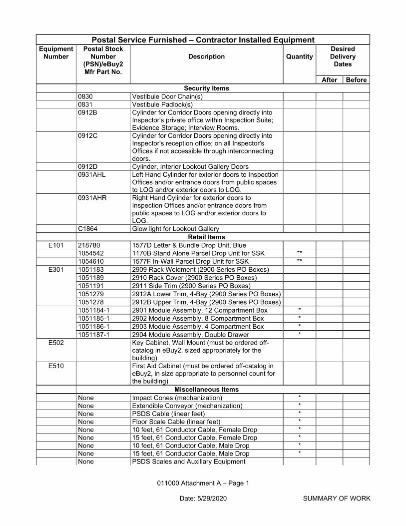
1.2 POSTAL SERVICE FURNISHED – CONTRACTOR INSTALLED EQUIPMENT
A. The Postal Service will furnish to the Contractor the equipment to be incorporated or installed in
the work as identified in the Scope, Specifications, and/or drawings. B. The Contractor will complete the Postal Service Furnished – Contractor Installed Equipment form
found in Attachment A., identifying quantities and desired delivery dates. C. Scheduling and installation must be in accordance with the terms and conditions of the contract
provisions and clauses, including those concerning Postal Service Property.
1.3 MISCELLANEOUS CONTRACT EXPENSES A. In accordance with the terms and conditions of the contract provisions and clauses, including those
concerning Permits and Responsibilities and, Building Codes, Fees and Charges, the Contractor must include in its price proposal a separate line item for the cost each of the of the following fees or charges payable to State, local, or special community development agencies:
Water service connection and meter fee Electrical company required fees Telephone company required fees Off-site inspection fees Sanitary sewer connection fee Environmental Permits/Registrations Other permits or fees
B. If the actual cost of any item identified above is more or less than the amount listed, the contract
price will be adjusted accordingly by a contract modification. The adjustment will not include overhead and profit. The Contractor must, within 30 days after incurring the expenses, inform the Contracting Officer that the payment has been made. Evidence of the actual amount paid must be provided. The contract amount will be adjusted upward or downward as necessary to
011000–2 CRYSTAL CITY, TX – MAIN POST OFFICE Date: 8/7/2020 SUMMARY OF WORK
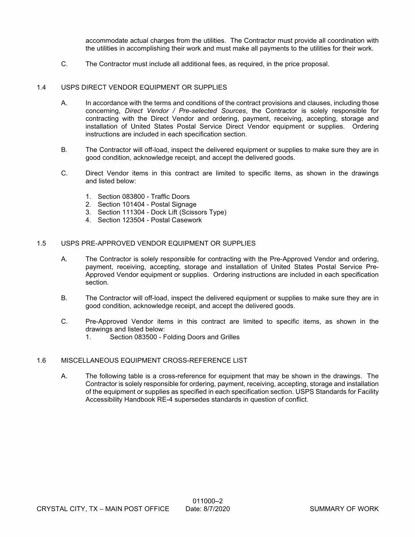
accommodate actual charges from the utilities. The Contractor must provide all coordination with the utilities in accomplishing their work and must make all payments to the utilities for their work.
C. The Contractor must include all additional fees, as required, in the price proposal.
1.4 USPS DIRECT VENDOR EQUIPMENT OR SUPPLIES A. In accordance with the terms and conditions of the contract provisions and clauses, including those
concerning, Direct Vendor / Pre-selected Sources, the Contractor is solely responsible for contracting with the Direct Vendor and ordering, payment, receiving, accepting, storage and installation of United States Postal Service Direct Vendor equipment or supplies. Ordering instructions are included in each specification section.
B. The Contractor will off-load, inspect the delivered equipment or supplies to make sure they are in
good condition, acknowledge receipt, and accept the delivered goods.
C. Direct Vendor items in this contract are limited to specific items, as shown in the drawings and listed below: 1. Section 083800 - Traffic Doors 2. Section 101404 - Postal Signage 3. Section 111304 - Dock Lift (Scissors Type) 4. Section 123504 - Postal Casework
1.5 USPS PRE-APPROVED VENDOR EQUIPMENT OR SUPPLIES
A. The Contractor is solely responsible for contracting with the Pre-Approved Vendor and ordering,
payment, receiving, accepting, storage and installation of United States Postal Service Pre-Approved Vendor equipment or supplies. Ordering instructions are included in each specification section.
B. The Contractor will off-load, inspect the delivered equipment or supplies to make sure they are in
good condition, acknowledge receipt, and accept the delivered goods.
C. Pre-Approved Vendor items in this contract are limited to specific items, as shown in the drawings and listed below: 1. Section 083500 - Folding Doors and Grilles
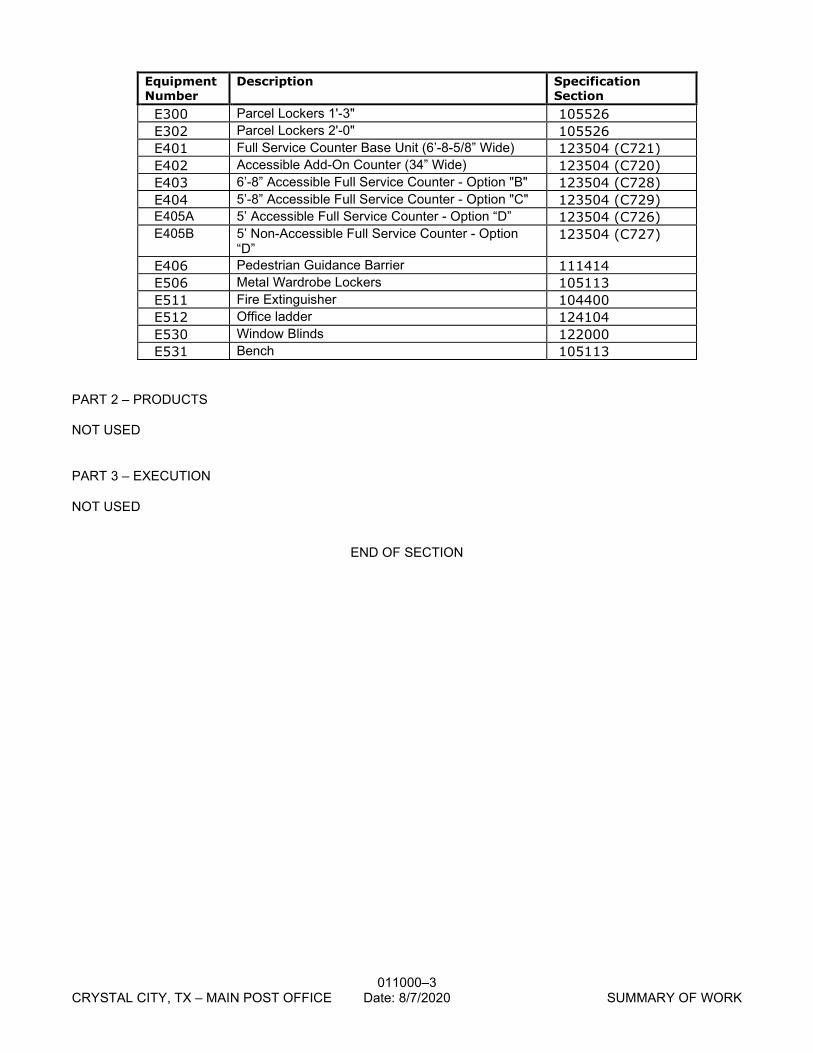
1.6 MISCELLANEOUS EQUIPMENT CROSS-REFERENCE LIST
A. The following table is a cross-reference for equipment that may be shown in the drawings. The
Contractor is solely responsible for ordering, payment, receiving, accepting, storage and installation of the equipment or supplies as specified in each specification section. USPS Standards for Facility Accessibility Handbook RE-4 supersedes standards in question of conflict.
011000–3 CRYSTAL CITY, TX – MAIN POST OFFICE Date: 8/7/2020 SUMMARY OF WORK
Equipment Number
Description Specification Section
E300 Parcel Lockers 1'-3" 105526 E302 Parcel Lockers 2'-0" 105526 E401 Full Service Counter Base Unit (6’-8-5/8” Wide) 123504 (C721) E402 Accessible Add-On Counter (34” Wide) 123504 (C720) E403 6’-8” Accessible Full Service Counter - Option "B" 123504 (C728) E404 5’-8” Accessible Full Service Counter - Option "C" 123504 (C729) E405A 5’ Accessible Full Service Counter - Option “D” 123504 (C726) E405B 5’ Non-Accessible Full Service Counter - Option
“D” 123504 (C727)
E406 Pedestrian Guidance Barrier 111414 E506 Metal Wardrobe Lockers 105113 E511 Fire Extinguisher 104400 E512 Office ladder 124104 E530 Window Blinds 122000 E531 Bench 105113
PART 2 – PRODUCTS NOT USED PART 3 – EXECUTION NOT USED
END OF SECTION
011000 Attachment A – Page 1
Date: 5/29/2020 SUMMARY OF WORK
Postal Service Furnished – Contractor Installed Equipment
Equipment Number
Postal Stock Number
(PSN)/eBuy2 Mfr Part No.
Description
Quantity
Desired Delivery
Dates
After Before Security Items 0830 Vestibule Door Chain(s) 0831 Vestibule Padlock(s) 0912B Cylinder for Corridor Doors opening directly into
Inspector's private office within Inspection Suite; Evidence Storage; Interview Rooms.
0912C Cylinder for Corridor Doors opening directly into Inspector's reception office; on all Inspector's Offices if not accessible through interconnecting doors.
0912D Cylinder, Interior Lookout Gallery Doors 0931AHL Left Hand Cylinder for exterior doors to Inspection
Offices and/or entrance doors from public spaces to LOG and/or exterior doors to LOG.
0931AHR Right Hand Cylinder for exterior doors to Inspection Offices and/or entrance doors from public spaces to LOG and/or exterior doors to LOG.
C1864 Glow light for Lookout Gallery Retail Items
E101 218780 1577D Letter & Bundle Drop Unit, Blue 1054542 1170B Stand Alone Parcel Drop Unit for SSK ** 1054610 1577F In-Wall Parcel Drop Unit for SSK **
E301 1051183 2909 Rack Weldment (2900 Series PO Boxes) 1051189 2910 Rack Cover (2900 Series PO Boxes) 1051191 2911 Side Trim (2900 Series PO Boxes) 1051279 2912A Lower Trim, 4-Bay (2900 Series PO Boxes) 1051278 2912B Upper Trim, 4-Bay (2900 Series PO Boxes) 1051184-1 2901 Module Assembly, 12 Compartment Box * 1051185-1 2902 Module Assembly, 8 Compartment Box * 1051186-1 2903 Module Assembly, 4 Compartment Box * 1051187-1 2904 Module Assembly, Double Drawer *
E502 Key Cabinet, Wall Mount (must be ordered off-catalog in eBuy2, sized appropriately for the building)
E510 First Aid Cabinet (must be ordered off-catalog in eBuy2, in size appropriate to personnel count for the building)
Miscellaneous Items None Impact Cones (mechanization) * None Extendible Conveyor (mechanization) * None PSDS Cable (linear feet) * None Floor Scale Cable (linear feet) * None 10 feet, 61 Conductor Cable, Female Drop * None 15 feet, 61 Conductor Cable, Female Drop * None 10 feet, 61 Conductor Cable, Male Drop * None 15 feet, 61 Conductor Cable, Male Drop * None PSDS Scales and Auxiliary Equipment
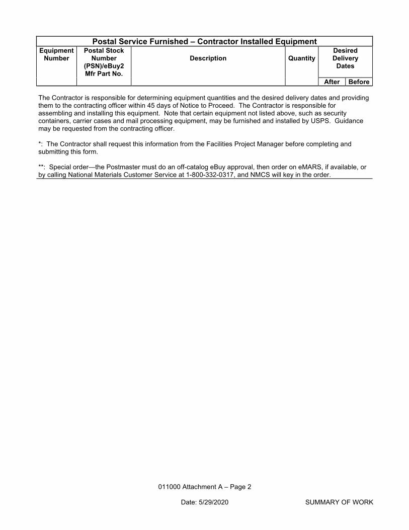
011000 Attachment A – Page 2
Date: 5/29/2020 SUMMARY OF WORK
Postal Service Furnished – Contractor Installed Equipment Equipment
Number Postal Stock
Number (PSN)/eBuy2 Mfr Part No.
Description
Quantity
Desired Delivery
Dates
After Before The Contractor is responsible for determining equipment quantities and the desired delivery dates and providing them to the contracting officer within 45 days of Notice to Proceed. The Contractor is responsible for assembling and installing this equipment. Note that certain equipment not listed above, such as security containers, carrier cases and mail processing equipment, may be furnished and installed by USPS. Guidance may be requested from the contracting officer. *: The Contractor shall request this information from the Facilities Project Manager before completing and submitting this form. **: Special order—the Postmaster must do an off-catalog eBuy approval, then order on eMARS, if available, or by calling National Materials Customer Service at 1-800-332-0317, and NMCS will key in the order.
011104 - 1
CRYSTAL CITY, TX – MAIN POST OFFICE Date: 8/7/2020 CONTRACT DOCUMENTS
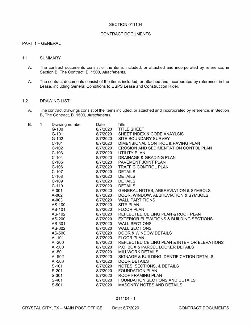
SECTION 011104
CONTRACT DOCUMENTS PART 1 – GENERAL
1.1 SUMMARY
A. The contract documents consist of the items included, or attached and incorporated by reference, in Section B, The Contract, B. 1500, Attachments.
A. The contract documents consist of the items included, or attached and incorporated by reference, in the
Lease, including General Conditions to USPS Lease and Construction Rider.
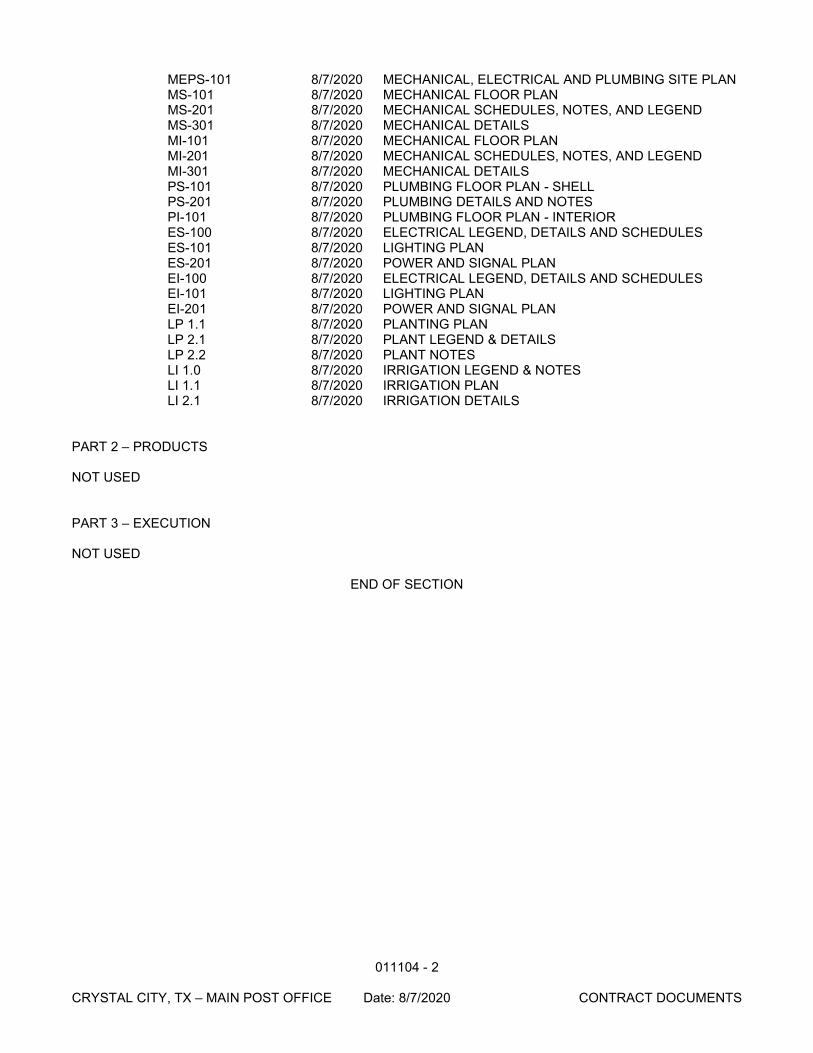
1.2 DRAWING LIST A. The contract drawings consist of the items included, or attached and incorporated by reference, in Section
B, The Contract, B. 1500, Attachments. B. 1 Drawing number Date Title
G-100 8/7/2020 TITLE SHEET G-101 8/7/2020 SHEET INDEX & CODE ANAYLSIS G-102 8/7/2020 SITE BOUNDARY SURVEY C-101 8/7/2020 DIMENSIONAL CONTROL & PAVING PLAN C-102 8/7/2020 EROSION AND SEDIMENTATION CONTOL PLAN C-103 8/7/2020 UTILITY PLAN C-104 8/7/2020 DRAINAGE & GRADING PLAN C-105 8/7/2020 PAVEMENT JOINT PLAN C-106 8/7/2020 TRAFFIC CONTROL PLAN C-107 8/7/2020 DETAILS C-108 8/7/2020 DETAILS C-109 8/7/2020 DETAILS C-110 8/7/2020 DETAILS A-001 8/7/2020 GENERAL NOTES, ABBREVIATION & SYMBOLS A-002 8/7/2020 DOOR, WINDOW, ABBREVIATION & SYMBOLS A-003 8/7/2020 WALL PARTITIONS AS-100 8/7/2020 SITE PLAN AS-101 8/7/2020 FLOOR PLAN AS-102 8/7/2020 REFLECTED CEILING PLAN & ROOF PLAN AS-200 8/7/2020 EXTERIOR ELEVATIONS & BUILDING SECTIONS AS-301 8/7/2020 WALL SECTIONS AS-302 8/7/2020 WALL SECTIONS AS-500 8/7/2020 DOOR & WINDOW DETAILS AI-101 8/7/2020 FLOOR PLAN AI-200 8/7/2020 REFLECTED CEILING PLAN & INTERIOR ELEVATIONS AI-500 8/7/2020 P.O. BOX & PARCEL LOCKER DETAILS AI-501 8/7/2020 MILLWORK DETAILS AI-502 8/7/2020 SIGNAGE & BUILDING IDENTIFICATION DETAILS AI-503 8/7/2020 DOOR DETAILS S-101 8/7/2020 NOTES, SECTIONS, & DETAILS S-201 8/7/2020 FOUNDATION PLAN S-301 8/7/2020 ROOF FRAMING PLAN S-401 8/7/2020 FOUNDATION SECTIONS AND DETAILS S-501 8/7/2020 MASONRY NOTES AND DETAILS
011104 - 2
CRYSTAL CITY, TX – MAIN POST OFFICE Date: 8/7/2020 CONTRACT DOCUMENTS
MEPS-101 8/7/2020 MECHANICAL, ELECTRICAL AND PLUMBING SITE PLAN MS-101 8/7/2020 MECHANICAL FLOOR PLAN MS-201 8/7/2020 MECHANICAL SCHEDULES, NOTES, AND LEGEND MS-301 8/7/2020 MECHANICAL DETAILS MI-101 8/7/2020 MECHANICAL FLOOR PLAN MI-201 8/7/2020 MECHANICAL SCHEDULES, NOTES, AND LEGEND MI-301 8/7/2020 MECHANICAL DETAILS PS-101 8/7/2020 PLUMBING FLOOR PLAN - SHELL PS-201 8/7/2020 PLUMBING DETAILS AND NOTES PI-101 8/7/2020 PLUMBING FLOOR PLAN - INTERIOR ES-100 8/7/2020 ELECTRICAL LEGEND, DETAILS AND SCHEDULES ES-101 8/7/2020 LIGHTING PLAN ES-201 8/7/2020 POWER AND SIGNAL PLAN EI-100 8/7/2020 ELECTRICAL LEGEND, DETAILS AND SCHEDULES EI-101 8/7/2020 LIGHTING PLAN EI-201 8/7/2020 POWER AND SIGNAL PLAN LP 1.1 8/7/2020 PLANTING PLAN LP 2.1 8/7/2020 PLANT LEGEND & DETAILS LP 2.2 8/7/2020 PLANT NOTES LI 1.0 8/7/2020 IRRIGATION LEGEND & NOTES LI 1.1 8/7/2020 IRRIGATION PLAN LI 2.1 8/7/2020 IRRIGATION DETAILS
PART 2 – PRODUCTS NOT USED PART 3 – EXECUTION NOT USED
END OF SECTION
013200 - 1 CONSTRUCTION PROGRESS CRYSTAL CITY, TX - MAIN POST OFFICE Date: 8/7/2020 DOCUMENTATION
SECTION 013200
CONSTRUCTION PROGRESS DOCUMENTATION PART 1 – GENERAL
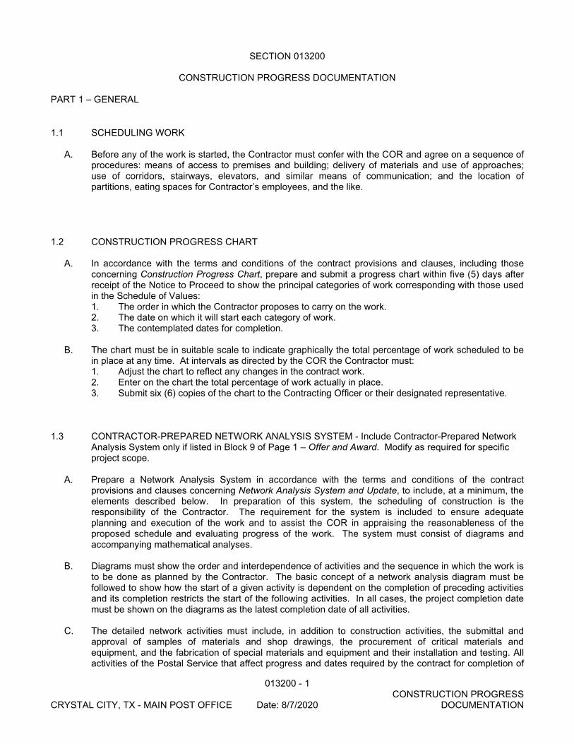
1.1 SCHEDULING WORK A. Before any of the work is started, the Contractor must confer with the COR and agree on a sequence of
procedures: means of access to premises and building; delivery of materials and use of approaches; use of corridors, stairways, elevators, and similar means of communication; and the location of partitions, eating spaces for Contractor’s employees, and the like.
1.2 CONSTRUCTION PROGRESS CHART A. In accordance with the terms and conditions of the contract provisions and clauses, including those
concerning Construction Progress Chart, prepare and submit a progress chart within five (5) days after receipt of the Notice to Proceed to show the principal categories of work corresponding with those used in the Schedule of Values: 1. The order in which the Contractor proposes to carry on the work. 2. The date on which it will start each category of work. 3. The contemplated dates for completion.
B. The chart must be in suitable scale to indicate graphically the total percentage of work scheduled to be
in place at any time. At intervals as directed by the COR the Contractor must: 1. Adjust the chart to reflect any changes in the contract work. 2. Enter on the chart the total percentage of work actually in place. 3. Submit six (6) copies of the chart to the Contracting Officer or their designated representative.
1.3 CONTRACTOR-PREPARED NETWORK ANALYSIS SYSTEM - Include Contractor-Prepared Network
Analysis System only if listed in Block 9 of Page 1 – Offer and Award. Modify as required for specific project scope.
A. Prepare a Network Analysis System in accordance with the terms and conditions of the contract
provisions and clauses concerning Network Analysis System and Update, to include, at a minimum, the elements described below. In preparation of this system, the scheduling of construction is the responsibility of the Contractor. The requirement for the system is included to ensure adequate planning and execution of the work and to assist the COR in appraising the reasonableness of the proposed schedule and evaluating progress of the work. The system must consist of diagrams and accompanying mathematical analyses.
B. Diagrams must show the order and interdependence of activities and the sequence in which the work is
to be done as planned by the Contractor. The basic concept of a network analysis diagram must be followed to show how the start of a given activity is dependent on the completion of preceding activities and its completion restricts the start of the following activities. In all cases, the project completion date must be shown on the diagrams as the latest completion date of all activities.
C. The detailed network activities must include, in addition to construction activities, the submittal and
approval of samples of materials and shop drawings, the procurement of critical materials and equipment, and the fabrication of special materials and equipment and their installation and testing. All activities of the Postal Service that affect progress and dates required by the contract for completion of
013200 - 2 CONSTRUCTION PROGRESS CRYSTAL CITY, TX - MAIN POST OFFICE Date: 8/7/2020 DOCUMENTATION
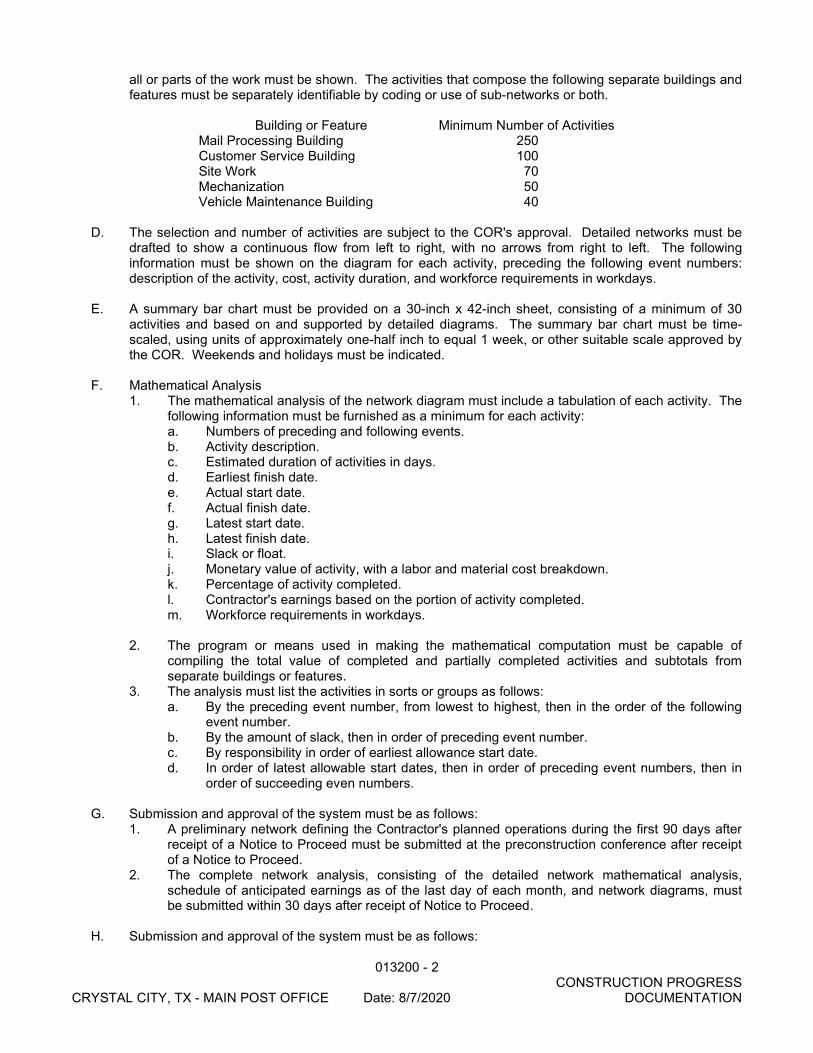
all or parts of the work must be shown. The activities that compose the following separate buildings and features must be separately identifiable by coding or use of sub-networks or both.
Building or Feature Minimum Number of Activities
Mail Processing Building 250 Customer Service Building 100 Site Work 70 Mechanization 50 Vehicle Maintenance Building 40
D. The selection and number of activities are subject to the COR's approval. Detailed networks must be
drafted to show a continuous flow from left to right, with no arrows from right to left. The following information must be shown on the diagram for each activity, preceding the following event numbers: description of the activity, cost, activity duration, and workforce requirements in workdays.
E. A summary bar chart must be provided on a 30-inch x 42-inch sheet, consisting of a minimum of 30
activities and based on and supported by detailed diagrams. The summary bar chart must be time-scaled, using units of approximately one-half inch to equal 1 week, or other suitable scale approved by the COR. Weekends and holidays must be indicated.
F. Mathematical Analysis
1. The mathematical analysis of the network diagram must include a tabulation of each activity. The following information must be furnished as a minimum for each activity: a. Numbers of preceding and following events. b. Activity description. c. Estimated duration of activities in days. d. Earliest finish date. e. Actual start date. f. Actual finish date. g. Latest start date. h. Latest finish date. i. Slack or float. j. Monetary value of activity, with a labor and material cost breakdown. k. Percentage of activity completed. l. Contractor's earnings based on the portion of activity completed. m. Workforce requirements in workdays.
2. The program or means used in making the mathematical computation must be capable of
compiling the total value of completed and partially completed activities and subtotals from separate buildings or features.
3. The analysis must list the activities in sorts or groups as follows: a. By the preceding event number, from lowest to highest, then in the order of the following
event number. b. By the amount of slack, then in order of preceding event number. c. By responsibility in order of earliest allowance start date. d. In order of latest allowable start dates, then in order of preceding event numbers, then in
order of succeeding even numbers.
G. Submission and approval of the system must be as follows: 1. A preliminary network defining the Contractor's planned operations during the first 90 days after
receipt of a Notice to Proceed must be submitted at the preconstruction conference after receipt of a Notice to Proceed.
2. The complete network analysis, consisting of the detailed network mathematical analysis, schedule of anticipated earnings as of the last day of each month, and network diagrams, must be submitted within 30 days after receipt of Notice to Proceed.
H. Submission and approval of the system must be as follows:
013200 - 3 CONSTRUCTION PROGRESS CRYSTAL CITY, TX - MAIN POST OFFICE Date: 8/7/2020 DOCUMENTATION
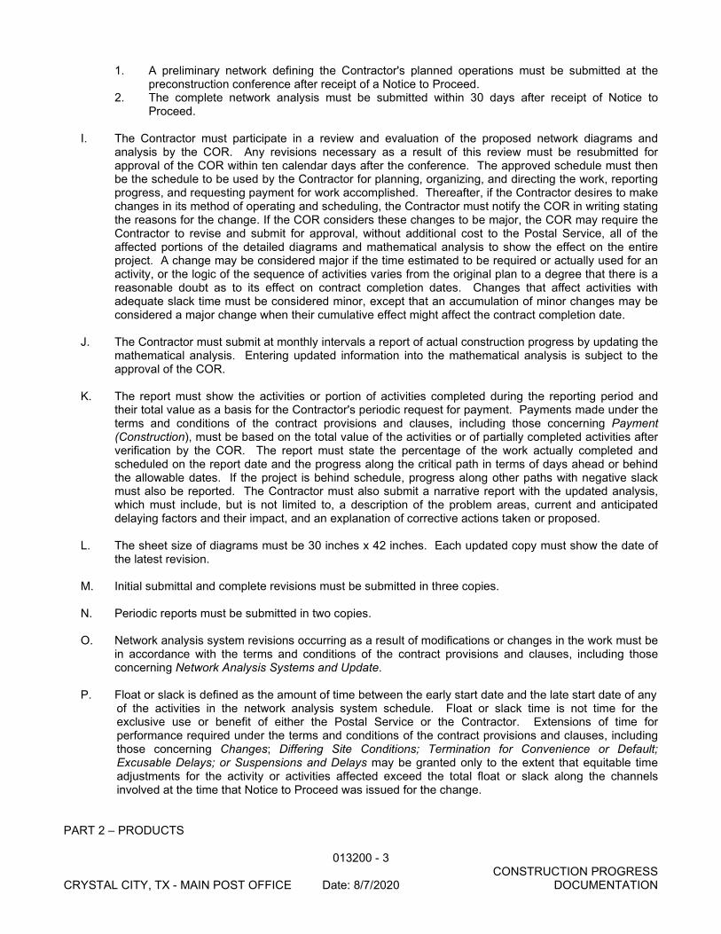
1. A preliminary network defining the Contractor's planned operations must be submitted at the preconstruction conference after receipt of a Notice to Proceed.
2. The complete network analysis must be submitted within 30 days after receipt of Notice to Proceed.
I. The Contractor must participate in a review and evaluation of the proposed network diagrams and
analysis by the COR. Any revisions necessary as a result of this review must be resubmitted for approval of the COR within ten calendar days after the conference. The approved schedule must then be the schedule to be used by the Contractor for planning, organizing, and directing the work, reporting progress, and requesting payment for work accomplished. Thereafter, if the Contractor desires to make changes in its method of operating and scheduling, the Contractor must notify the COR in writing stating the reasons for the change. If the COR considers these changes to be major, the COR may require the Contractor to revise and submit for approval, without additional cost to the Postal Service, all of the affected portions of the detailed diagrams and mathematical analysis to show the effect on the entire project. A change may be considered major if the time estimated to be required or actually used for an activity, or the logic of the sequence of activities varies from the original plan to a degree that there is a reasonable doubt as to its effect on contract completion dates. Changes that affect activities with adequate slack time must be considered minor, except that an accumulation of minor changes may be considered a major change when their cumulative effect might affect the contract completion date.
J. The Contractor must submit at monthly intervals a report of actual construction progress by updating the
mathematical analysis. Entering updated information into the mathematical analysis is subject to the approval of the COR.
K. The report must show the activities or portion of activities completed during the reporting period and
their total value as a basis for the Contractor's periodic request for payment. Payments made under the terms and conditions of the contract provisions and clauses, including those concerning Payment (Construction), must be based on the total value of the activities or of partially completed activities after verification by the COR. The report must state the percentage of the work actually completed and scheduled on the report date and the progress along the critical path in terms of days ahead or behind the allowable dates. If the project is behind schedule, progress along other paths with negative slack must also be reported. The Contractor must also submit a narrative report with the updated analysis, which must include, but is not limited to, a description of the problem areas, current and anticipated delaying factors and their impact, and an explanation of corrective actions taken or proposed.
L. The sheet size of diagrams must be 30 inches x 42 inches. Each updated copy must show the date of
the latest revision. M. Initial submittal and complete revisions must be submitted in three copies. N. Periodic reports must be submitted in two copies. O. Network analysis system revisions occurring as a result of modifications or changes in the work must be
in accordance with the terms and conditions of the contract provisions and clauses, including those concerning Network Analysis Systems and Update.
P. Float or slack is defined as the amount of time between the early start date and the late start date of any
of the activities in the network analysis system schedule. Float or slack time is not time for the exclusive use or benefit of either the Postal Service or the Contractor. Extensions of time for performance required under the terms and conditions of the contract provisions and clauses, including those concerning Changes; Differing Site Conditions; Termination for Convenience or Default; Excusable Delays; or Suspensions and Delays may be granted only to the extent that equitable time adjustments for the activity or activities affected exceed the total float or slack along the channels involved at the time that Notice to Proceed was issued for the change.
PART 2 – PRODUCTS
013200 - 4 CONSTRUCTION PROGRESS CRYSTAL CITY, TX - MAIN POST OFFICE Date: 8/7/2020 DOCUMENTATION
NOT USED PART 3 – EXECUTION NOT USED
END OF SECTION

013300 - 1
CRYSTAL CITY, TX - MAIN POST OFFICE Date: 8/7/2020 SUBMITTAL PROCEDURES
SECTION 013300
SUBMITTAL PROCEDURES PART 1 – GENERAL
1.1 SCHEDULE OF SUBMITTALS
A. In accordance with the terms and conditions of the contract provisions and clauses, including those concerning Shop Drawings, Coordination Drawings, Record “As Built” Drawings, and Schedules; within 30 days after receiving a Notice to Proceed, the Contractor must complete the Schedule of Submittals, in the format indicated below, in duplicate, listing all items that must be furnished for review and approval by the Postal Service. The schedule must indicate the type of items (such as sample, shop drawings, catalog cut, and so forth) and include the scheduled dates of submittal. In preparing the schedule, adequate time (10 business days or more, exclusive of time in the mails) must be allowed for review and approval and possible resubmittal. Also, the schedule must be coordinated with the approved construction progress chart. The Contractor must revise and/or update the schedule as directed. Such revised schedules must be made available to the COR for monitoring.
B. Within 30 days after receiving a Notice to Proceed, the Contractor must complete and submit to the
COR a listing of all subcontractors, including subcontractor name, address, telephone number, fax number and email address. Include an updated list with each progress payment request.
C. Schedule of Submittals Format
Project Contract No. Project Description
Spec. Section
Spec. Description
Paragraph Number
*Submittal Type
Date Action Taken
Assigned Number
Submittal Returned *Submittal Type: C – Certificate CD – Catalog Data S – Sample PL – Spare Parts List SD – Shop Drawing MM – Maintenance Manual
1.2 SHOP DRAWINGS AND RELATED DATA A. Submittal of shop drawings, samples and related data must conform to the requirements of the terms
and conditions of the contract provisions and clauses, including those concerning, Record “As Build” Drawings, and Samples. Prior to submittal, the Contractor must stamp the submittal to indicate that it has been reviewed and approved. The Contractor must make any corrections required by the COR. If the Contractor considers any correction indicated on the drawings to constitute a change to the contract drawings or specifications, notice, as required under the terms and conditions of the contract provisions and clauses, including those concerning Changes must be given to the COR. [Four] [ ] prints of all approved shop drawings must be given to the COR. The approval of the drawings by the COR must not
013300 - 2
CRYSTAL CITY, TX - MAIN POST OFFICE Date: 8/7/2020 SUBMITTAL PROCEDURES
be construed as a complete check but indicates only that the general method of construction and detailing is satisfactory. Approval of the shop drawings does not relieve the Contractor of responsibility for any error that may exist because the Contractor is responsible for the dimensions and design of adequate connections and details and for satisfactory construction of all work. The submission by the Contractor must be accompanied by a transmittal letter of a type approved by the COR. 1. Each shop drawing must have a blank area of 5 by 5 inches, located adjacent to the title block.
The title block must display: a. Number and title of drawing; b. Date of drawing or revision; c. Name of project building or facility; d. Name of Contractor and (if appropriate) of subcontractor submitting drawing; e. Clear identity of contents and location on the work; and f. Project title and contract number.
2. All drawings to be provided shall be clear and fully representative of the facility and fixed mechanization work.
3. Drawing files to be in .dwg and .pdf formats. .dwg files to be generated from Autocad revision 12 or other revision level concurred by USPS.
4. Documents other than drawings shall be provided in MicroSoft Word format. 5. Interim project documentation may be provide to USPS electronically 6. All final project documentation shall be provided to the USPS on a single CD or DVD media
1.3 EQUIPMENT ROOM LAYOUT DRAWINGS A. The Contractor must prepare and submit equipment room layout drawings as required by the technical
provisions as well as for areas where equipment proposed for use could present interface or space difficulties. Room layout drawings must be submitted within 40 days after receiving a Notice to Proceed and must conform to the specified requirements for shop drawings. Submittals describing the various mechanical and electrical equipment items that are to be installed in the areas represented by the layout drawings must be assembled and submitted concurrently and must be accompanied by the room layout drawings. Room layout drawings must be consolidated for all trades, to scale, and must show all pertinent structural and fenestration features and other items, such as cabinets, that are required for installation and that affect the available space. All mechanical and electrical equipment and accessories must be shown to scale in the plan and also in elevation or section in their installation positions. Ductwork and piping must be shown.
1.4 MATERIAL, EQUIPMENT, AND FIXTURE LISTS
A. When required by the technical provisions, lists of materials, equipment, and fixtures must be submitted by the Contractor in accordance with the requirements specified for shop drawings. The lists must be supported by sufficient descriptive material, such as catalogs, cuts, diagrams, and other data published by the manufacturer, as well as by evidence of compliance with safety and performance standards, to demonstrate conformance to the specification requirements. Catalog numbers alone are not acceptable. The data must include the name and address of the nearest service and maintenance organization that regularly stocks repair parts. No consideration will be given to partial lists submitted from time to time. Approval of materials and equipment is tentative, subject to submission of complete shop drawings indicating compliance with the contract documents.
1.5 CERTIFICATES OF COMPLIANCE
A. Any certificates required for demonstrating proof of compliance of materials with specification requirements, including mail certificates, statements of application, and extended guarantees, must be signed and submitted 4 copies to the COR at least 10 days before delivery. The Contractor must review
013300 - 3
CRYSTAL CITY, TX - MAIN POST OFFICE Date: 8/7/2020 SUBMITTAL PROCEDURES
all certificates before submissions are made to the COR, to ensure compliance with the contract specification requirements and to ensure that the affidavit is properly signed. Each certificate must be signed by an official authorized to certify on behalf of the manufacturing company and must contain the name and address of the Contractor, the project name and location, and the quantity and date or dates of shipment or delivery to which the certificates apply. Copies of laboratory test reports submitted with certificates must contain the name and address of the testing laboratory and the dates of tests to which the report applies. Certification must not be construed as relieving the Contractor from furnishing satisfactory material if, after tests are performed on selected samples, the material is found not to meet the specific requirements.
1.6 A-E'S REVIEW OF SUBMITTALS
A. When submittals are reviewed by the A-E on behalf of the COR, each submittal must be returned to the Contractor stamped or marked by the A-E in one of the following ways: 1. A Action: The Contractor is advised that "A Action" means that fabrication, manufacture, or
construction may proceed, provided the work complies with the contract documents. 2. B Action: The Contractor is advised that "B Action" means that fabrication, manufacture, or
construction may proceed, provided the work complies with the A-E's notations and the contract documents.
3. C Action: The Contractor is advised that "C Action" means that no work may be fabricated, manufactured, or constructed and that the Contractor must make a new submittal to the A-E. Any submission marked "C Action" is not permitted on the site.
B. The A-E must return reproducibles stamped "A Action" or "B Action" to the Contractor, who is
responsible for obtaining prints of them and for distributing them to the field and to subcontractors. C. In the case of shop drawings in the form of manufacturers' descriptive literature, catalog cuts, and
brochures stamped "A Action" or "B Action," the A-E must return the stamped copies to the Contractor, who is responsible for distributing them to the field and to the subcontractors. If the shop drawings are stamped "C Action," the A-E will return stamped copies to the Contractor, who must submit new shop drawings to the A-E.
D. In the case of samples stamped "A Action" or "B Action," the A-E must return one of the samples to the Contractor. In the case of samples stamped "C Action," the A-E must return all of the submitted samples.
1.7 SPARE PARTS DATA
A. Spare parts data must be submitted in quadruplicate in accordance with the terms and conditions of the contract provisions and clauses, including those concerning Spare Parts Data.
1.8 SCHEDULE OF VALUES
A. In accordance with the terms and conditions of the contract provisions and clauses concerning, Construction Cost Breakdown, the Contractor must submit a construction cost breakdown using the attached Schedule of Values. When applicable, a separate cost breakdown form must be submitted for each separate building. However, the total cost of site work for the facility must be included in the cost estimate breakdown for the main postal building. The number of items provided on the Systems Construction Cost Estimate Breakdown form are the minimum required. Additional subdivision of these items may be used by the Contractor.
B. Submit the construction cost breakdown after contract award to the COR. A Sample Schedule of
Values and Definitions is attached to this Section, as Attachment A.
013300 - 4
CRYSTAL CITY, TX - MAIN POST OFFICE Date: 8/7/2020 SUBMITTAL PROCEDURES
C. Do not delete items from the Schedule of Values form. However, expand the schedule “Description of Work” as necessary to allow evaluation of work or to make partial payments.
D. If the contract price changes, the Schedule of Values must be revised to reflect the change(s) and
forwarded to the COR.
E. A current Schedule of Values must accompany all Contractor Requests for Payment. PART 2 – PRODUCTS NOT USED PART 3 – EXECUTION NOT USED
END OF SECTION
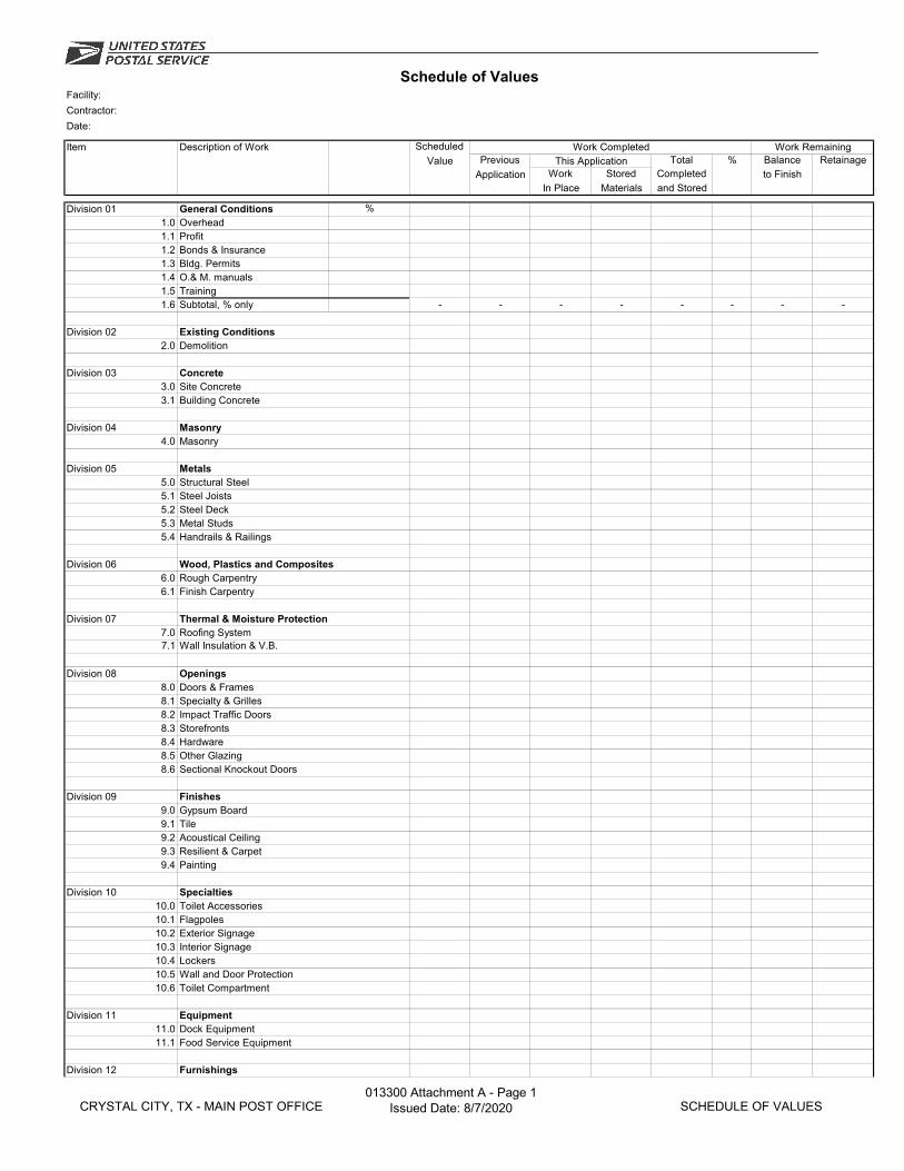
Schedule of ValuesFacility:Contractor:Date:
Item Description of Work Scheduled Work Completed Work RemainingValue Previous This Application Total % Balance Retainage
Application Work Stored Completed to FinishIn Place Materials and Stored
Division 01 General Conditions %1.0 Overhead1.1 Profit1.2 Bonds & Insurance1.3 Bldg. Permits1.4 O.& M. manuals1.5 Training1.6 Subtotal, % only - - - - - - - -
Division 02 Existing Conditions2.0 Demolition
Division 03 Concrete3.0 Site Concrete3.1 Building Concrete
Division 04 Masonry4.0 Masonry
Division 05 Metals5.0 Structural Steel5.1 Steel Joists5.2 Steel Deck5.3 Metal Studs5.4 Handrails & Railings
Division 06 Wood, Plastics and Composites6.0 Rough Carpentry6.1 Finish Carpentry
Division 07 Thermal & Moisture Protection7.0 Roofing System7.1 Wall Insulation & V.B.
Division 08 Openings8.0 Doors & Frames8.1 Specialty & Grilles8.2 Impact Traffic Doors8.3 Storefronts8.4 Hardware8.5 Other Glazing8.6 Sectional Knockout Doors
Division 09 Finishes9.0 Gypsum Board9.1 Tile9.2 Acoustical Ceiling9.3 Resilient & Carpet9.4 Painting
Division 10 Specialties10.0 Toilet Accessories10.1 Flagpoles10.2 Exterior Signage10.3 Interior Signage10.4 Lockers10.5 Wall and Door Protection10.6 Toilet Compartment
Division 11 Equipment11.0 Dock Equipment11.1 Food Service Equipment
Division 12 Furnishings
CRYSTAL CITY, TX - MAIN POST OFFICE013300 Attachment A - Page 1
Issued Date: 8/7/2020 SCHEDULE OF VALUES
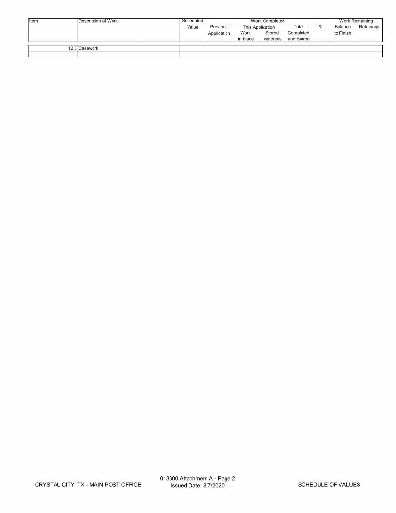
Item Description of Work Scheduled Work Completed Work RemainingValue Previous This Application Total % Balance Retainage
Application Work Stored Completed to FinishIn Place Materials and Stored
12.0 Casework
CRYSTAL CITY, TX - MAIN POST OFFICE013300 Attachment A - Page 2
Issued Date: 8/7/2020 SCHEDULE OF VALUES
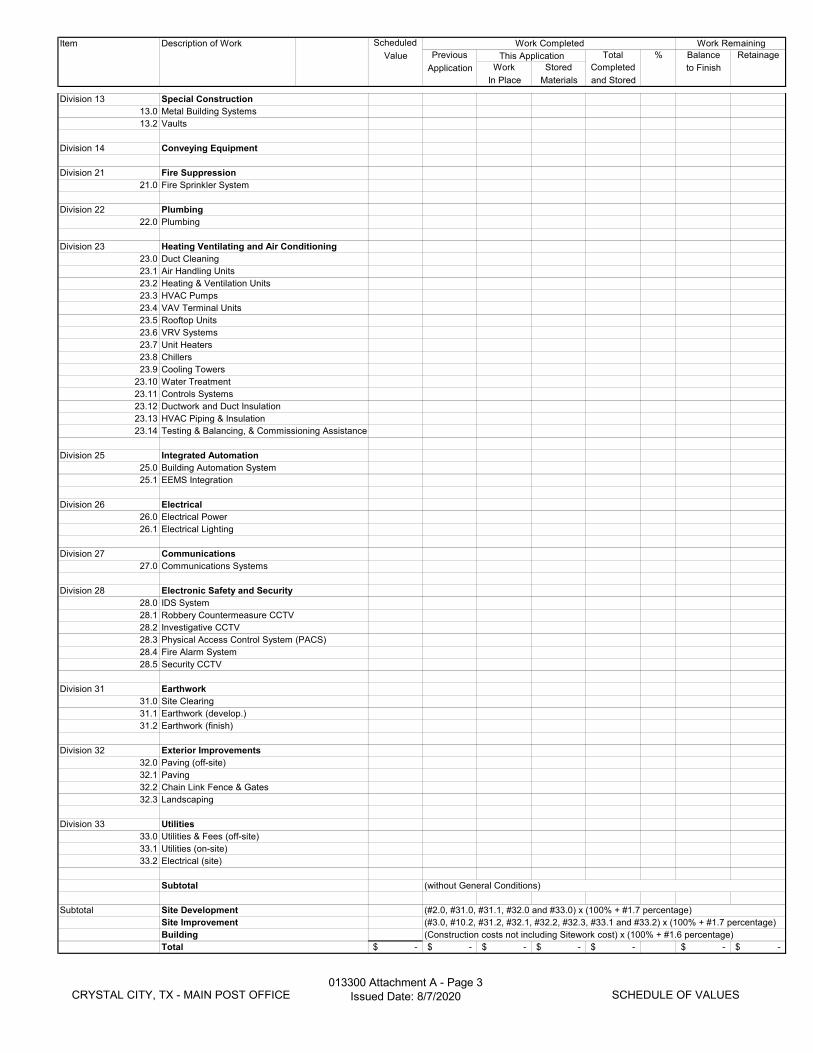
Item Description of Work Scheduled Work Completed Work RemainingValue Previous This Application Total % Balance Retainage
Application Work Stored Completed to FinishIn Place Materials and Stored
Division 13 Special Construction13.0 Metal Building Systems13.2 Vaults
Division 14 Conveying Equipment
Division 21 Fire Suppression21.0 Fire Sprinkler System
Division 22 Plumbing22.0 Plumbing
Division 23 Heating Ventilating and Air Conditioning23.0 Duct Cleaning23.1 Air Handling Units23.2 Heating & Ventilation Units23.3 HVAC Pumps23.4 VAV Terminal Units23.5 Rooftop Units23.6 VRV Systems23.7 Unit Heaters23.8 Chillers23.9 Cooling Towers
23.10 Water Treatment23.11 Controls Systems23.12 Ductwork and Duct Insulation23.13 HVAC Piping & Insulation23.14 Testing & Balancing, & Commissioning Assistance
Division 25 Integrated Automation25.0 Building Automation System25.1 EEMS Integration
Division 26 Electrical26.0 Electrical Power26.1 Electrical Lighting
Division 27 Communications27.0 Communications Systems
Division 28 Electronic Safety and Security28.0 IDS System28.1 Robbery Countermeasure CCTV28.2 Investigative CCTV28.3 Physical Access Control System (PACS)28.4 Fire Alarm System28.5 Security CCTV
Division 31 Earthwork31.0 Site Clearing31.1 Earthwork (develop.)31.2 Earthwork (finish)
Division 32 Exterior Improvements32.0 Paving (off-site)32.1 Paving32.2 Chain Link Fence & Gates32.3 Landscaping
Division 33 Utilities33.0 Utilities & Fees (off-site)33.1 Utilities (on-site)33.2 Electrical (site)
Subtotal (without General Conditions)
Subtotal Site Development (#2.0, #31.0, #31.1, #32.0 and #33.0) x (100% + #1.7 percentage)Site Improvement (#3.0, #10.2, #31.2, #32.1, #32.2, #32.3, #33.1 and #33.2) x (100% + #1.7 percentage)Building (Construction costs not including Sitework cost) x (100% + #1.6 percentage)Total -$ -$ -$ -$ -$ -$ -$
CRYSTAL CITY, TX - MAIN POST OFFICE013300 Attachment A - Page 3
Issued Date: 8/7/2020 SCHEDULE OF VALUES
013543–1
CRYSTAL CITY, TX - MAIN POST OFFICE Date: 8/7/2020 ENVIRONMENTAL PROCEDURES
SECTION 013543
ENVIRONMENTAL PROCEDURES PART 1 – GENERAL 1.1 SCOPE
A. This section is required in accordance with the terms and conditions of the contract provisions
and clauses, including those concerning Safety & Health Standards, Accident Prevention, Protection of the Environment, Existing Vegetation, Structures, Utilities and Improvements, and Handling Asbestos and other Hazardous Materials. The work covered by this section consists of furnishing all labor, material, and equipment and performing all work required for compliance with environmental regulations and preventing pollution during, and as a result of, construction operations under this contract, in addition to those measures set forth in other technical provisions of these specifications.
B. The Contractor and subcontractors must comply with all applicable federal, state and local laws
and regulations related to the environment, health and safety. 1.2 NOTIFICATION
A. The Contractor must, after receiving a notice of noncompliance with the foregoing provisions, immediately take corrective action. The notice, when delivered to its Contractor or its authorized representative at the site of the work, is deemed sufficient for this purpose. If the Contractor fails or refuses to comply promptly, the Contracting Officer may issue an order stopping all or part of the work until satisfactory corrective action has been taken. No part of the time lost because of any such stop orders may be made the subject of a claim for extension of time or for excess costs or damages by the Contractor unless it is subsequently determined that the Contractor was in compliance and the Contractor demonstrates that it is otherwise entitled to an extension of time, excess costs or damages, under the applicable terms and conditions of the contract provisions and clauses.
1.3 ENVIRONMENTAL REGULATORY COMPLIANCE
A. Within 30 days after receiving the notice to proceed or not less than 15 days prior to commencing on-site work, the Contractor must submit any environmental documents that are required by federal, state or local environmental regulations. Plans must be approved by the COR prior to commencing on-site work and must describe and include, but is not limited to, the following 1. Erosion Control and Stormwater Management Plan that describes erosion control
methods, surface drainage, storm water permitting requirements, and if applicable, protection of site wetlands and/or compliance with wetland permits. This must ensure any federal, state or local permitting requirements for site preparation, erosion control or surface drainage are met.
2. Landscape Management and Protection Plan that ensures any site-specific beneficial landscaping requirements are met. The plan shall describe the prevention and restoration of landscape damage, temporary roads and embankments, and post construction cleanup as prescribed in the terms and conditions of the contract provisions and clauses, including those concerning Protection of the Environment, Existing Vegetation, Structures, Utilities and Improvements.
3. Waste Minimization and Management Plan must describe how natural resources potentially impacted by construction will be protected or managed; construction wastes will be stored and disposed of or recycled; and pollutants associated with building materials will be controlled. The waste minimization and management section of the plan
013543–2
CRYSTAL CITY, TX - MAIN POST OFFICE Date: 8/7/2020 ENVIRONMENTAL PROCEDURES
must also list materials and construction debris to be recycled, and address the disposal of solid and hazardous wastes and materials, including asbestos and lead-based paint. It must also include tables applicable to the reclamation of chlorofluorocarbons (CFCs) and hydrochlorofluorocarbons (HCFCs) in accordance with 1.4 (B) below.
4. Environmental Compliance Plan must document NEPA compliance by describing mitigation measures to address environmental concerns/sensitive receptors identified in the National Environmental Policy Act (NEPA) document(s) in Section B. 1500, Attachments, of the contract.
5. The construction specifications in this contract must include mitigation measures to avoid or minimize potential environmental impacts identified in the NEPA document(s).
1.4 ENVIRONMENTAL SITE CONTROLS
A. Location of Hazardous Materials: The location of the Contractor’s temporary storage of any
hazardous materials and/or wastes must be appropriately marked and included in the health and Safety Plan (see Section 1.5 below).
B. Refrigerant Recovery, Recycling, and Disposal: Any work involving the replacement or repair of
equipment containing refrigerant shall meet the following requirements: 1. Recover and recycle or dispose of refrigerant from equipment according to 40 CFR 82
and local regulations. 2. The work shall be completed by a certified refrigerant recovery technician, per 40 CFR 82
and local regulations. 3. Provide a statement signed by the certified refrigerant recovery technician that the work
was completed per 40 CFR 82 and local regulations. Include the name and address of technician and date refrigerant was recovered.
C. Post-construction Cleanup or Obliteration: The Contractor must remove and properly dispose of
all signs of temporary construction facilities such as haul roads, work area, structures, foundations of temporary structures, excess or waste materials, or any other vestiges of construction as directed by the COR. No separate or direct payment may be made for post-construction cleanup and all associated costs must be considered included in the contract price.
D. Historical and Archeological: Monuments, markers, and works of art must be protected. Items
discovered that have potential historical or archeological interest must be preserved. The Contractor must leave the archeological find undisturbed and must immediately report the find to the COR so that the proper authority may be notified.
E. Dust Control: The Contractor must keep the site free from dust in accordance with applicable
federal, state and/or local regulations. F. Noise Minimization: The Contractor must perform demolition and construction operations to
minimize noise including conducting work during less sensitive hours of the day in accordance with applicable noise control regulations.
1.5 HEALTH AND SAFETY
A. Prior to commencing on-site work, the Contractor must submit an Occupational Safety and Health Administration (OSHA) Emergency Action Plan (EAP) to the Contracting Officer to demonstrate compliance by the Contractor and subcontractors with applicable OSHA regulations. If the Contractor is not required by OSHA to develop a written EAP, i.e. if 10 or fewer are employed for the construction project or any other specific regulations identified by OSHA, then the Contractor shall submit to the Contracting Officer a signed letter stating the Contractor shall meet OSHA's EAP requirements in a verbal communication to all employees.
013543–3
CRYSTAL CITY, TX - MAIN POST OFFICE Date: 8/7/2020 ENVIRONMENTAL PROCEDURES
B. The Postal Service has provided a Safety and Health Guide for Contractors, as Attachment A to this section. Prior to commencing on-site work, Contractor must read the Safety and Health Guide for Contractors and must sign the attached Certificate of Understanding acknowledging and accepting the requirements stated therein.
C. Prior to commencing on-site work, the Contractor must submit a project-specific Project Safety
Plan to the Contracting Officer. The plan must include, but is not limited to, hazard communication, labeling, emergency response and preparedness and training.
D. Copies of Material Safety Data Sheets (MSDSs) for any hazardous material(s), as defined by
OSHA's Hazard Communications Standard, must be included whenever such materials arrive on-site. MSDSs must be kept together and maintained centrally on-site through to project completion. Provide a copy of each MSDS in the Operating and Maintenance Manual. The use of asbestos containing materials, in excess of one percent as defined by US Environmental Protection Agency regulations, is prohibited in the construction of this project. Provide an executed copy of the “Certificate of Asbestos and Lead-Based Paint (New Work)” in the Operating and Maintenance Manual and include a copy with the final payment request.
E. The use of lead-based paint is prohibited in the construction of this project. F. The use of lead-containing solder for plumbing and plumbing fixtures is prohibited in the
construction of this project. G. In accordance with the terms and conditions of the contract provisions and clauses, including
those concerning Asbestos Free and Lead-Based Paint Free Certification, the Contractor must sign and submit to the Contracting Officer the attached “Certification of Asbestos and Lead-Based Paint” for this project. The signed certificate is required to be included in the final payment request.
H. Do not use any of the USPS targeted chemicals (see regulated and prohibited materials identified
under Safety and Health and related environmental requirements). PART 2 - PRODUCTS NOT USED PART 3 - EXECUTION NOT USED
END OF SECTION
013543 Attachment A ZAVALA COUNTY POST OFFICE Date: 12/03/202010/1/2019 ENVIRONMENTAL PROCEDURES
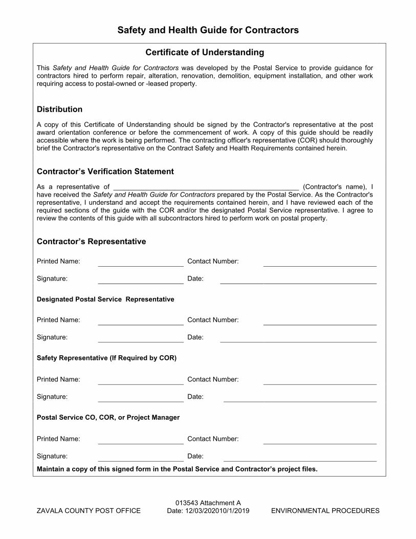
Safety and Health Guide for Contractors
Certificate of Understanding This Safety and Health Guide for Contractors was developed by the Postal Service to provide guidance for contractors hired to perform repair, alteration, renovation, demolition, equipment installation, and other work requiring access to postal-owned or -leased property.
Distribution
A copy of this Certificate of Understanding should be signed by the Contractor's representative at the post award orientation conference or before the commencement of work. A copy of this guide should be readily accessible where the work is being performed. The contracting officer's representative (COR) should thoroughly brief the Contractor's representative on the Contract Safety and Health Requirements contained herein.
Contractor’s Verification Statement
As a representative of _________________________________________________ (Contractor's name), I have received the Safety and Health Guide for Contractors prepared by the Postal Service. As the Contractor's representative, I understand and accept the requirements contained herein, and I have reviewed each of the required sections of the guide with the COR and/or the designated Postal Service representative. I agree to review the contents of this guide with all subcontractors hired to perform work on postal property.
Contractor’s Representative Printed Name:
Contact Number:
Signature:
Date:
Designated Postal Service Representative Printed Name:
Contact Number:
Signature:
Date:
Safety Representative (If Required by COR) Printed Name:
Contact Number:
Signature:
Date:
Postal Service CO, COR, or Project Manager Printed Name:
Contact Number:
Signature:
Date:
Maintain a copy of this signed form in the Postal Service and Contractor’s project files.

013543 Attachment A ZAVALA COUNTY POST OFFICE Date: 12/03/202010/1/2019 ENVIRONMENTAL PROCEDURES
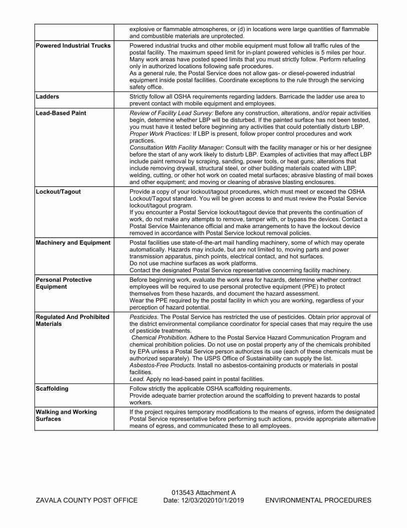
Safety and Health and Related Environmental Requirements The Contractor is required to meet all applicable OSHA, federal, state, and local safety, health, and related environmental requirements in addition to the US Postal Service requirement listed in this table. Issue Postal Requirements Asbestos Review of Facility Asbestos Survey: Before any building maintenance, equipment
installation, renovation, alteration, demolition, or other project begins, determine whether ACBM will be disturbed. Proper Work Practices: If ACBM is present, follow proper control procedures and work practices. Consultation With Facility Asbestos Coordinator: Consult with the facility manager or his or her designee before the start of any work likely to disturb ACBM. Disturbance means activities that crumble or pulverize ACBM or presumed asbestos-containing material (PACM) or generate visible debris. Operations may include drilling, abrading, cutting a hole, pulling cable, and crawling through tunnels or attics and spaces above the ceiling where asbestos is actively disturbed or asbestos-containing debris is actively disturbed. Asbestos Work Authorization: You must have an approved Form 8210, Work Authorization - Asbestos, before work begins within any building containing asbestos.
Barricades, Barriers, and Warnings
Your barricades must meet the OSHA requirements. In addition, you assume control of your work area during your activities unless otherwise specified in writing by the contracting officer (CO) or contracting officer's representative (COR).
Confined Spaces Confined space work must meet the OSHA requirements. You must have a comprehensive confined space program that includes a written program, employee training, entry and testing equipment, and rescue capabilities. If you require access to confined space requiring a permit, then the trained, designated Postal Service representative must review and approve the project and permit. Entry into other confined spaces must be in accordance with OSHA regulations.
Electrical Work Lock or rope off work areas involving exposed energized equipment or have an attendant present to prevent accidental contact by unqualified people. Refer to the Barricade section of this guideline for additional information.
Elevated Work and Fall Protection
Follow strictly the applicable OSHA fall protection requirements.
Excavation All excavations 4 feet or more in depth must be properly shored or sloped and meet all OSHA requirements. Before any digging or drilling commences, inform the Postal Service COR and call Dig Safe or its local equivalent to determine whether any underground utilities are located in the work area. Submit documentation that these notifications have been performed. You must not begin digging or drilling until you have verified that underground utilities have been identified and are properly marked so that work may be accomplished in a safe manner.
Fire Protection Do not block, remove, or otherwise prevent Postal Service fire extinguishers from being immediately accessible and usable. If a system must be impaired by a scheduled shutdown, notify the appropriate Postal Service representative and do not proceed without Postal Service authorization.
Hazard Communication Inform the Postal Service before any chemicals are used. Before materials are brought on site, provide material safety data sheets (MSDSs) and an inventory of materials. For projects that are anticipated to use substantial quantities of hazardous materials, you may be required to provide a routing, storage, and waste disposal plan. Upon request, the Postal Service will make available to you MSDSs for hazardous materials the Postal Service uses in the Contractor work area.
Hazardous Materials Follow all OSHA requirements regarding hazardous materials. Hazardous materials include, but are not limited to, flammable and combustible liquids, gasoline, diesel fuel, motor oil, lubricating oil, hydraulic oil, corrosive cleaners, and battery acid. Provide secondary containment for all containers of liquids that are over 5 gallons in capacity. Immediately report all hazardous material releases ("spills"), regardless of how small or where they occur, to the designated Postal Service representative. Releases include solids, liquids, and gases.
Hot Work Do not begin any hot work until a Postal Service qualified person has completed and signed a Postal Service Hot Work Permit. The permit will be valid for only a single work shift. You must display the permit at the work site. You are prohibited from performing hot work (a) when the Postal Service has not authorized it, (b) in locations in which fire protection systems have been impaired, (c) in the presence of
013543 Attachment A ZAVALA COUNTY POST OFFICE Date: 12/03/202010/1/2019 ENVIRONMENTAL PROCEDURES
explosive or flammable atmospheres, or (d) in locations were large quantities of flammable and combustible materials are unprotected.
Powered Industrial Trucks Powered industrial trucks and other mobile equipment must follow all traffic rules of the postal facility. The maximum speed limit for in-plant powered vehicles is 5 miles per hour. Many work areas have posted speed limits that you must strictly follow. Perform refueling only in authorized locations following safe procedures. As a general rule, the Postal Service does not allow gas- or diesel-powered industrial equipment inside postal facilities. Coordinate exceptions to the rule through the servicing safety office.
Ladders Strictly follow all OSHA requirements regarding ladders. Barricade the ladder use area to prevent contact with mobile equipment and employees.
Lead-Based Paint Review of Facility Lead Survey: Before any construction, alterations, and/or repair activities begin, determine whether LBP will be disturbed. If the painted surface has not been tested, you must have it tested before beginning any activities that could potentially disturb LBP. Proper Work Practices: If LBP is present, follow proper control procedures and work practices. Consultation With Facility Manager: Consult with the facility manager or his or her designee before the start of any work likely to disturb LBP. Examples of activities that may affect LBP include paint removal by scraping, sanding, power tools, or heat guns; alterations that include removing drywall, structural steel, or other building materials coated with LBP; welding, cutting, or other hot work on coated metal surfaces; abrasive blasting of mail boxes and other equipment; and moving or cleaning of abrasive blasting enclosures.
Lockout/Tagout Provide a copy of your lockout/tagout procedures, which must meet or exceed the OSHA Lockout/Tagout standard. You will be given access to and must review the Postal Service lockout/tagout program. If you encounter a Postal Service lockout/tagout device that prevents the continuation of work, do not make any attempts to remove, tamper with, or bypass the devices. Contact a Postal Service Maintenance official and make arrangements to have the lockout device removed in accordance with Postal Service lockout removal policies.
Machinery and Equipment Postal facilities use state-of-the-art mail handling machinery, some of which may operate automatically. Hazards may include, but are not limited to, moving parts and power transmission apparatus, pinch points, electrical contact, and hot surfaces. Do not use machine surfaces as work platforms. Contact the designated Postal Service representative concerning facility machinery.
Personal Protective Equipment
Before beginning work, evaluate the work area for hazards, determine whether contract employees will be required to use personal protective equipment (PPE) to protect themselves from these hazards, and document the hazard assessment. Wear the PPE required by the postal facility in which you are working, regardless of your perception of hazard potential.
Regulated And Prohibited Materials
Pesticides. The Postal Service has restricted the use of pesticides. Obtain prior approval of the district environmental compliance coordinator for special cases that may require the use of pesticide treatments. Chemical Prohibition. Adhere to the Postal Service Hazard Communication Program and chemical prohibition policies. Do not use on postal property any of the chemicals prohibited by EPA unless a Postal Service person authorizes its use (each of these chemicals must be authorized separately). The USPS Office of Sustainability can supply the list. Asbestos-Free Products. Install no asbestos-containing products or materials in postal facilities. Lead. Apply no lead-based paint in postal facilities.
Scaffolding Follow strictly the applicable OSHA scaffolding requirements. Provide adequate barrier protection around the scaffolding to prevent hazards to postal workers.
Walking and Working Surfaces
If the project requires temporary modifications to the means of egress, inform the designated Postal Service representative before performing such actions, provide appropriate alternative means of egress, and communicated these to all employees.
013543 Attachment A ZAVALA COUNTY POST OFFICE Date: 12/03/202010/1/2019 ENVIRONMENTAL PROCEDURES
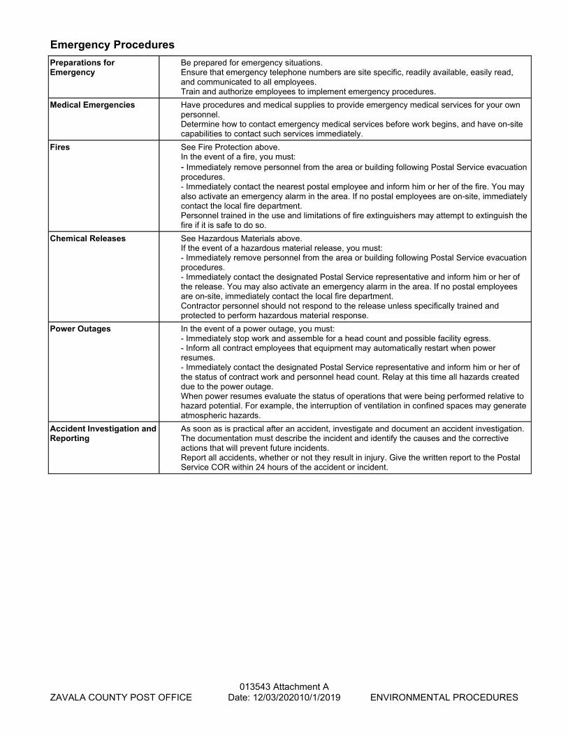
Emergency Procedures Preparations for Emergency
Be prepared for emergency situations. Ensure that emergency telephone numbers are site specific, readily available, easily read, and communicated to all employees. Train and authorize employees to implement emergency procedures.
Medical Emergencies Have procedures and medical supplies to provide emergency medical services for your own personnel. Determine how to contact emergency medical services before work begins, and have on-site capabilities to contact such services immediately.
Fires See Fire Protection above. In the event of a fire, you must: - Immediately remove personnel from the area or building following Postal Service evacuation procedures. - Immediately contact the nearest postal employee and inform him or her of the fire. You may also activate an emergency alarm in the area. If no postal employees are on-site, immediately contact the local fire department. Personnel trained in the use and limitations of fire extinguishers may attempt to extinguish the fire if it is safe to do so.
Chemical Releases See Hazardous Materials above. If the event of a hazardous material release, you must: - Immediately remove personnel from the area or building following Postal Service evacuation procedures. - Immediately contact the designated Postal Service representative and inform him or her of the release. You may also activate an emergency alarm in the area. If no postal employees are on-site, immediately contact the local fire department. Contractor personnel should not respond to the release unless specifically trained and protected to perform hazardous material response.
Power Outages In the event of a power outage, you must: - Immediately stop work and assemble for a head count and possible facility egress. - Inform all contract employees that equipment may automatically restart when power resumes. - Immediately contact the designated Postal Service representative and inform him or her of the status of contract work and personnel head count. Relay at this time all hazards created due to the power outage. When power resumes evaluate the status of operations that were being performed relative to hazard potential. For example, the interruption of ventilation in confined spaces may generate atmospheric hazards.
Accident Investigation and Reporting
As soon as is practical after an accident, investigate and document an accident investigation. The documentation must describe the incident and identify the causes and the corrective actions that will prevent future incidents. Report all accidents, whether or not they result in injury. Give the written report to the Postal Service COR within 24 hours of the accident or incident.

013543 Attachment B – Page 1
ZAVALA COUNTY POST OFFICE Date: 12/03/2020 ENVIRONMENTAL PROCEDURES
Certificate of Asbestos and Lead-Based Paint (New Work)
To: Contracting Officer, United States Postal Service Subject: Certification for new construction Postal facility name: Postal facility address: Certification for new construction: This Contractor/Owner hereby certifies that no asbestos-containing material in excess of 1 percent as defined by applicable US Environmental Protection Agency regulations, and no lead-based paint has been furnished or installed at the referenced project.
Contractor/Owner name:
Signature:
Address:
Telephone: Date executed:
The penalty for making a false statement is prescribed by 18 USC 1001.
014000 - 1
CRYSTAL CITY, TX - MAIN POST OFFICE Date: 8/7/2020 QUALITY REQUIREMENTS
SECTION 014000
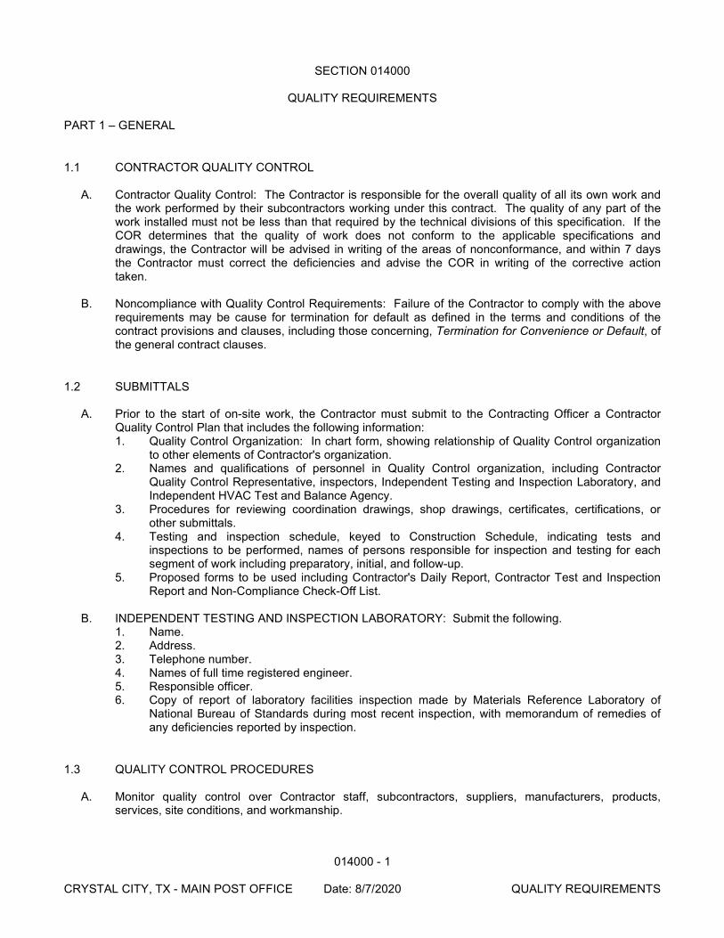
QUALITY REQUIREMENTS PART 1 – GENERAL
1.1 CONTRACTOR QUALITY CONTROL A. Contractor Quality Control: The Contractor is responsible for the overall quality of all its own work and
the work performed by their subcontractors working under this contract. The quality of any part of the work installed must not be less than that required by the technical divisions of this specification. If the COR determines that the quality of work does not conform to the applicable specifications and drawings, the Contractor will be advised in writing of the areas of nonconformance, and within 7 days the Contractor must correct the deficiencies and advise the COR in writing of the corrective action taken.
B. Noncompliance with Quality Control Requirements: Failure of the Contractor to comply with the above
requirements may be cause for termination for default as defined in the terms and conditions of the contract provisions and clauses, including those concerning, Termination for Convenience or Default, of the general contract clauses.
1.2 SUBMITTALS A. Prior to the start of on-site work, the Contractor must submit to the Contracting Officer a Contractor
Quality Control Plan that includes the following information: 1. Quality Control Organization: In chart form, showing relationship of Quality Control organization
to other elements of Contractor's organization. 2. Names and qualifications of personnel in Quality Control organization, including Contractor
Quality Control Representative, inspectors, Independent Testing and Inspection Laboratory, and Independent HVAC Test and Balance Agency.
3. Procedures for reviewing coordination drawings, shop drawings, certificates, certifications, or other submittals.
4. Testing and inspection schedule, keyed to Construction Schedule, indicating tests and inspections to be performed, names of persons responsible for inspection and testing for each segment of work including preparatory, initial, and follow-up.
5. Proposed forms to be used including Contractor's Daily Report, Contractor Test and Inspection Report and Non-Compliance Check-Off List.
B. INDEPENDENT TESTING AND INSPECTION LABORATORY: Submit the following.
1. Name. 2. Address. 3. Telephone number. 4. Names of full time registered engineer. 5. Responsible officer. 6. Copy of report of laboratory facilities inspection made by Materials Reference Laboratory of
National Bureau of Standards during most recent inspection, with memorandum of remedies of any deficiencies reported by inspection.
1.3 QUALITY CONTROL PROCEDURES
A. Monitor quality control over Contractor staff, subcontractors, suppliers, manufacturers, products, services, site conditions, and workmanship.
014000 - 2
CRYSTAL CITY, TX - MAIN POST OFFICE Date: 8/7/2020 QUALITY REQUIREMENTS
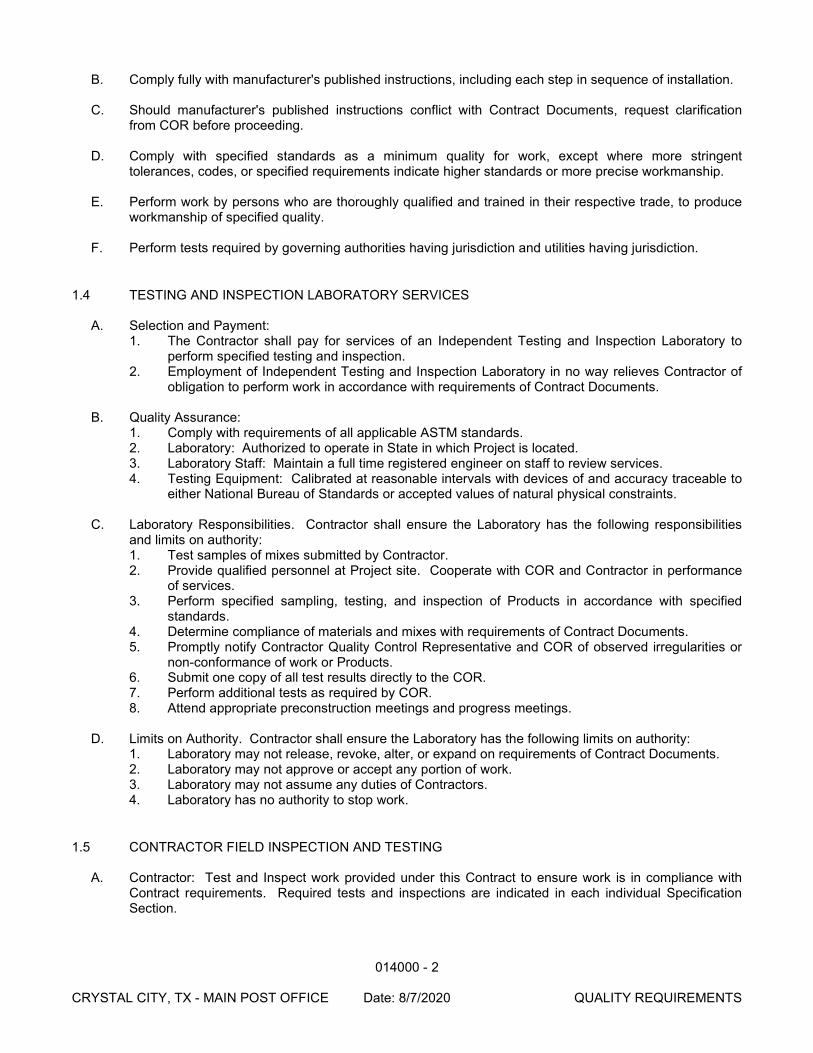
B. Comply fully with manufacturer's published instructions, including each step in sequence of installation.
C. Should manufacturer's published instructions conflict with Contract Documents, request clarification from COR before proceeding.
D. Comply with specified standards as a minimum quality for work, except where more stringent
tolerances, codes, or specified requirements indicate higher standards or more precise workmanship.
E. Perform work by persons who are thoroughly qualified and trained in their respective trade, to produce workmanship of specified quality.
F. Perform tests required by governing authorities having jurisdiction and utilities having jurisdiction.
1.4 TESTING AND INSPECTION LABORATORY SERVICES
A. Selection and Payment: 1. The Contractor shall pay for services of an Independent Testing and Inspection Laboratory to
perform specified testing and inspection. 2. Employment of Independent Testing and Inspection Laboratory in no way relieves Contractor of
obligation to perform work in accordance with requirements of Contract Documents.
B. Quality Assurance: 1. Comply with requirements of all applicable ASTM standards. 2. Laboratory: Authorized to operate in State in which Project is located. 3. Laboratory Staff: Maintain a full time registered engineer on staff to review services. 4. Testing Equipment: Calibrated at reasonable intervals with devices of and accuracy traceable to
either National Bureau of Standards or accepted values of natural physical constraints.
C. Laboratory Responsibilities. Contractor shall ensure the Laboratory has the following responsibilities and limits on authority: 1. Test samples of mixes submitted by Contractor. 2. Provide qualified personnel at Project site. Cooperate with COR and Contractor in performance
of services. 3. Perform specified sampling, testing, and inspection of Products in accordance with specified
standards. 4. Determine compliance of materials and mixes with requirements of Contract Documents. 5. Promptly notify Contractor Quality Control Representative and COR of observed irregularities or
non-conformance of work or Products. 6. Submit one copy of all test results directly to the COR. 7. Perform additional tests as required by COR. 8. Attend appropriate preconstruction meetings and progress meetings.
D. Limits on Authority. Contractor shall ensure the Laboratory has the following limits on authority:
1. Laboratory may not release, revoke, alter, or expand on requirements of Contract Documents. 2. Laboratory may not approve or accept any portion of work. 3. Laboratory may not assume any duties of Contractors. 4. Laboratory has no authority to stop work.
1.5 CONTRACTOR FIELD INSPECTION AND TESTING
A. Contractor: Test and Inspect work provided under this Contract to ensure work is in compliance with Contract requirements. Required tests and inspections are indicated in each individual Specification Section.
014000 - 3
CRYSTAL CITY, TX - MAIN POST OFFICE Date: 8/7/2020 QUALITY REQUIREMENTS
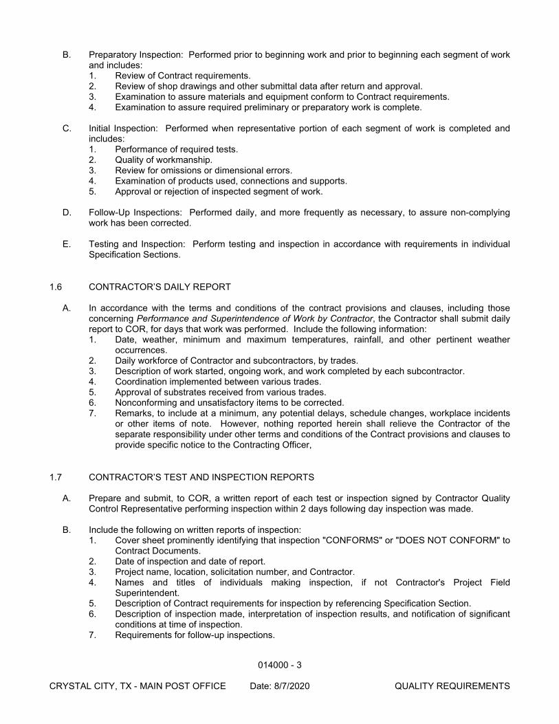
B. Preparatory Inspection: Performed prior to beginning work and prior to beginning each segment of work and includes: 1. Review of Contract requirements. 2. Review of shop drawings and other submittal data after return and approval. 3. Examination to assure materials and equipment conform to Contract requirements. 4. Examination to assure required preliminary or preparatory work is complete.
C. Initial Inspection: Performed when representative portion of each segment of work is completed and
includes: 1. Performance of required tests. 2. Quality of workmanship. 3. Review for omissions or dimensional errors. 4. Examination of products used, connections and supports. 5. Approval or rejection of inspected segment of work.
D. Follow-Up Inspections: Performed daily, and more frequently as necessary, to assure non-complying
work has been corrected.
E. Testing and Inspection: Perform testing and inspection in accordance with requirements in individual Specification Sections.
1.6 CONTRACTOR’S DAILY REPORT
A. In accordance with the terms and conditions of the contract provisions and clauses, including those concerning Performance and Superintendence of Work by Contractor, the Contractor shall submit daily report to COR, for days that work was performed. Include the following information: 1. Date, weather, minimum and maximum temperatures, rainfall, and other pertinent weather
occurrences. 2. Daily workforce of Contractor and subcontractors, by trades. 3. Description of work started, ongoing work, and work completed by each subcontractor. 4. Coordination implemented between various trades. 5. Approval of substrates received from various trades. 6. Nonconforming and unsatisfactory items to be corrected. 7. Remarks, to include at a minimum, any potential delays, schedule changes, workplace incidents
or other items of note. However, nothing reported herein shall relieve the Contractor of the separate responsibility under other terms and conditions of the Contract provisions and clauses to provide specific notice to the Contracting Officer,
1.7 CONTRACTOR’S TEST AND INSPECTION REPORTS
A. Prepare and submit, to COR, a written report of each test or inspection signed by Contractor Quality Control Representative performing inspection within 2 days following day inspection was made.
B. Include the following on written reports of inspection:
1. Cover sheet prominently identifying that inspection "CONFORMS" or "DOES NOT CONFORM" to Contract Documents.
2. Date of inspection and date of report. 3. Project name, location, solicitation number, and Contractor. 4. Names and titles of individuals making inspection, if not Contractor's Project Field
Superintendent. 5. Description of Contract requirements for inspection by referencing Specification Section. 6. Description of inspection made, interpretation of inspection results, and notification of significant
conditions at time of inspection. 7. Requirements for follow-up inspections.
014000 - 4
CRYSTAL CITY, TX - MAIN POST OFFICE Date: 8/7/2020 QUALITY REQUIREMENTS
1.8 NON-COMPLIANCE CHECK-OFF LIST
A. Maintain check-off list of work that does not comply with Contract Documents, stating specifically what is non-complying, date faulty work was originally discovered, and date work was corrected. No requirement to report deficiencies corrected same day it was discovered. Submit copy of Non-Compliance Check-Off List of non-complying work items to COR on a weekly basis.
1.9 COMPLETION AND INSPECTION OF WORK
A. Prior to final acceptance by Contracting Officer, submit a certification signed by Contractor to Contracting Officer stating that all work has been inspected and all work, except as specifically noted, is complete and in compliance with Contract Documents.
PART 2 – PRODUCTS NOT USED PART 3 – EXECUTION NOT USED
END OF SECTION
015000 - 1
CRYSTAL CITY, TX - MAIN POST OFFICE Date: 8/7/2020 TEMPORARY FACILITIES AND CONTROLS
SECTION 015000
TEMPORARY FACILITIES AND CONTROLS PART 1 – GENERAL
1.1 SUMMARY
A. The Contractor must provide all temporary facilities and services required to complete the work and to comply with OSHA and other applicable regulations.
B. The Contractor must maintain temporary facilities in a proper, safe, operating and sanitary condition for
the duration of this Contract. Upon completion of this Contract, all such temporary work and facilities shall be removed in their entirety and the premises will be restored to its prior condition.
1.2 PROJECT SIGN
A. The Contractor must provide and maintain a construction project sign at the location directed by the COR. The sign must conform to the Construction Sign as detailed in the Contract drawings. The information needed to complete the wording on the sign is provided by the COR and will be essentially as shown on the cover of the specification. The sign must be erected within 15 days after receiving a Notice to Proceed. The sign will remain the property of the Contractor and must be removed upon completion of the work and the premises will be restored to its prior condition.
B. Construction Site Sign: 1. Silk-screened, painted or pressure-sensitive vinyl letters applied to Medium Density Overlay
plywood sign. 2. Red: Match Benjamin Moore OP-67. 3. Blue: Match PPG 7062 Federal Blue. 4. White background.
C. The Contractor must construct and erect a minimum of two hard hat signs at locations designated by the
COR. The signs must be erected prior to the commencement of on-site work.
1.3 BULLETIN BOARD
A. A weatherproof bulletin board, not less than 36 inches wide and 30 inches high, with hinged glass door must be provided adjacent to, or mounted on, the Contractor's project office. If adjacent to the office, the bulletin board must be securely mounted on not less than two posts. The bulletin board and posts must be painted or have approved factory finish. The bulletin board must be easily accessible at all times and must contain wage rates, equal opportunity notice, and other items required to be posted.
B. The Contractor must maintain the bulletin board in good condition throughout the life of the project. The
bulletin board will remain the property of the Contractor and upon completion of the project must be removed from the site and the premises will be restored to its prior condition.
1.4 CONSTRUCTION-USE UTILITIES
A. The Contractor must arrange with the local utility companies for gas, water, and electricity required for construction under this project and must pay all costs in connection with them. The Contractor must, at its own expense, make all temporary connections and install distribution lines. All temporary lines must
015000 - 2
CRYSTAL CITY, TX - MAIN POST OFFICE Date: 8/7/2020 TEMPORARY FACILITIES AND CONTROLS
be maintained by the Contractor in a manner satisfactory to the COR and must be removed by the Contractor in like manner before final acceptance of the construction.
1.5 TEMPORARY ELECTRICITY
A. Costs: The Contractor must make arrangements with the serving utility for power, pay deposits, and install equipment, poles, wiring, switches, and outlets necessary to provide adequate supply for lighting and power for construction purposes. The Contractor must pay for power used during construction and for removal of all temporary equipment.
B. Service Required: The Contractor must provide temporary electric power throughout the construction
period so that power can be secured at any desired point with no more than a 100-foot extension cord; power centers for miscellaneous tools and equipment used in the construction work (not less than one per 2,000 square feet of floor space, consisting of a weatherproof distribution box with a minimum of four 20-amp, 120-volt grounded outlets with a circuit breaker protection for each outlet); lighting for safe and adequate working conditions throughout buildings and stairways (at least 1/4 watts of incandescent lighting per square foot, with a socket voltage of at least 110 volts and using 100 watt lamps minimum); power for construction site offices and other temporary storage and construction building; and power for testing and checking equipment welding units, and terrazzo grinders.
C. Safety: The Contractor must provide and maintain lights and signs to prevent damage or injury and
must illuminate all hazardous areas. Safety lights must be kept burning from dusk to dawn. D. Requirements of Regulatory Agencies: The Contractor must obtain permits as required by local
government authorities; obtain easements as required across private property other than that of the owner for temporary power service; and comply with the National Electrical Code, applicable local codes, and utility regulations.
E. Use of Permanent System: The Contractor must regulate any part of the permanent electrical system
that is used for construction purposes in order to prevent interference with safety and with the orderly progress of the work. The Contractor must leave permanent electrical services in a condition as good as new.
F. Materials: The materials may be new or used but must be adequate in capacity for the purposes
intended and must not create unsafe conditions or violate the requirements of applicable codes. At the Contractor's option, patented specialty materials may be used if UL-approved.
G. Conductors: The Contractor must use wire, cable, or busses of appropriate type, sized in accordance
with the National Electrical Code for the applied loads. Use only UL-approved wire. H. Equipment: In compliance with NEMA standards, the Contractor must provide an appropriate enclosure
for the environment in which the equipment is used. I. Installation: The Contractor must provide all required facilities, including transformers, conductors,
poles, conduits, raceways, fuses, switches, fixtures, and lamps, located so as to avoid interference with cranes and materials-handling equipment, storage areas, traffic areas, and work under other contracts. The Contractor must install all work to have a neat and orderly appearance and to make it structurally sound throughout. The Contractor must maintain it to give continuous service and to provide safe working conditions. The Contractor must modify the service as required by the progress of the job.
J. Removal: The Contractor must remove all temporary equipment and materials upon completion of
construction, repair all damage caused by the installation, and the premises will be restored to its prior condition.
015000 - 3
CRYSTAL CITY, TX - MAIN POST OFFICE Date: 8/7/2020 TEMPORARY FACILITIES AND CONTROLS
1.6 TEMPORARY HEATING AND VENTILATION
A. The Contractor must provide cold weather protection and temporary heat and fuel as required to carry on the work expeditiously during inclement weather, protect all work and materials against damage from dampness and cold, dry out the building, and provide suitable working conditions for the installation and curing of materials until final acceptance by the Contracting Officer. The Contractor must refer to requirements in detailed specifications for temperatures to be provided and maintained for installation and curing of work under the various trades.
B. The Contractor must provide temporary heat consisting of smokeless heating appliances satisfactory to
the COR. The Contractor must furnish and pay for all necessary fuel and attendants in any trade and must maintain temporary heat at temperatures adequate for the intended purpose.
C. When the permanent heating system is operable and the Contractor elects to use it, the Contractor must
provide all fuel, labor, materials, services, equipment, and attendants necessary to operate the permanent heating system for temporary heat and to maintain a minimum temperature as specified in the terms and conditions of the contract provisions and clauses, including those concerning Heat. If the permanent system is used to provide temporary heating and ventilation, the Contractor must replace all filters and restore the system to a condition satisfactory to the COR.
1.7 TEMPORARY WATER
A. The Contractor must provide and maintain a temporary water supply system for building purposes, extending branches to convenient points and terminating them with a proper stop and hose connection. Before any paving is laid, the temporary supply must be removed and the tap in the main supply properly capped.
1.8 SANITARY PROVISIONS A. The Contractor must provide and keep in neat and sanitary condition conveniences and
accommodations for the use of the construction personnel necessary to comply with the requirements and regulations of the local department of health and of other bodies having jurisdiction.
1.9 APPROACHES AND EXITS
A. The Contractor must provide all necessary approaches and exits required to properly execute the work. B. In connection with these, the Contractor must provide for temporary drainage to keep the site free from
standing water at all times.
1.10 POSTAL SERVICE FIELD OFFICE
A. Within 30 days after receiving a Notice to Proceed, the Contractor must furnish a building or trailer having a minimum of [ ___ ] square feet of floor space to serve as a USPS temporary field office. It must be located where directed and must be reserved for Postal Service use only. Drinking water facilities, adequate lighting, ventilation, heating, air-conditioning equipment, a copy machine, and a partition-enclosed chemical toilet must be furnished and maintained by the Contractor. The Contractor must provide hook-up to utility services and telephone services and must pay the cost of all services except long-distance phone calls. Used field office buildings and used furniture and equipment in good condition are acceptable. Entrance doors must be equipped with a substantial lock. Janitorial service must be furnished by the Contractor. If a building is provided, it must be constructed to be easily
015000 - 4
CRYSTAL CITY, TX - MAIN POST OFFICE Date: 8/7/2020 TEMPORARY FACILITIES AND CONTROLS
moved, and the Contractor must relocate the building twice during the contract, if directed to do so. All-weather vehicle and pedestrian access and all-weather parking areas for six cars must be provided at the field office location. The temporary field office, including furniture, with the exception of any office equipment including computers, printers, FAX machines, etc., will remain the property of the Contractor and must be removed from the site after the work is completed and the premises will be restored to its prior condition.
B. Detailed List of Furnishings and Equipment. See Attachment at the end of this section for a list of equipment to be included in the USPS field office.
1.11 PROJECT PHOTOS - Required on construction contracts that exceed $10,000.00. The number of
photographs, and their content, shall be appropriate to the Contract Scope of Work, with their intended purpose being to illustrate, generally, the work in place for which this payment application applies.
PART 2 – PRODUCTS NOT USED PART 3 – EXECUTION NOT USED
END OF SECTION
016000 - 1
CRYSTAL CITY, TX - MAIN POST OFFICE Date: 8/7/2020 PRODUCT REQUIREMENTS
SECTION 016000
PRODUCT REQUIREMENTS PART 1 – GENERAL
1.1 PRODUCT OPTIONS AND SUBSTITUTIONS
A. Refer to the terms and conditions of the contract provisions and clauses, including those concerning Optional Materials or Methods (Construction), Materials and Workmanship, Information On “Equal” Products and Brand Name or Equal.
B. Provide Products that comply with Contract Documents, which are undamaged and new at time of
installation.
C. Provide Products complete with accessories, trim, finish, safety guards, and other devices and details needed for complete installation and intended use and effect.
D. Substitutions may be considered when the Contractor:
1. Becomes aware of a product or procedure that is more environmentally sensitive or is otherwise
advantageous to the Postal Service; 2. Represents that he has personally investigated the proposed substitute product and determined
that it is equal or superior in all respects to that specified; 3. Will provide the same guarantee for the substitution that he would for that specified; and 4. Will coordinate the installation of the accepted substitute, making such changes as may be
required for the Work to be complete in all respects, at no additional cost to the Postal Service and at no extension of the Contract completion date.
1.2 PRODUCT DELIVERY REQUIREMENTS
A. Transport and handle Products in accordance with manufacturer's instructions, using means and methods that will prevent damage, deterioration and loss, including theft.
B. Schedule Product delivery to minimize long-term storage at Project site and prevent overcrowding of
construction spaces.
C. Coordinate Product delivery with installation schedule to assure minimum holding time for items that are flammable, hazardous, easily damaged, or sensitive to deterioration, theft, and other losses.
D. Deliver Products to Project site in undamaged condition in manufacturer's original sealed container or
other packaging system, complete with labels and instructions for handling, storing, unpacking, protecting, and installing.
E. Promptly inspect shipments to ensure that Products comply with project requirements, quantities are
correct, Products are undamaged, and properly protected.
F. Provide equipment and personnel to handle Products by methods to prevent soiling, disfigurement, or damage.
1.3 PRODUCT STORAGE AND HANDLING REQUIREMENTS
016000 - 2
CRYSTAL CITY, TX - MAIN POST OFFICE Date: 8/7/2020 PRODUCT REQUIREMENTS
A. Store and protect Products in accordance with manufacturers' published instructions, with seals and labels intact and legible.
B. Store Products subject to damage by elements above ground, under cover in weathertight enclosure,
with ventilation adequate to prevent condensation. Maintain temperature and humidity within range required by manufacturer's published instructions.
C. For exterior storage of fabricated Products, place on sloped supports, above ground.
D. Provide off-site storage and protection when Project site does not permit on-site storage or protection.
E. Cover Products subject to deterioration with impervious sheet covering. Provide ventilation to avoid
condensation or potential degradation of Products.
F. Store loose granular materials on solid flat surfaces in a well-drained area. Prevent mixing with foreign matter.
G. Provide equipment and personnel to store Products by methods to prevent soiling, disfigurement, or
damage.
H. Arrange storage of Products to permit access for inspection. Periodically inspect to verify Products are undamaged and are maintained in acceptable condition.
PART 2 – PRODUCTS NOT USED PART 3 – EXECUTION NOT USED
END OF SECTION
017300 - 1
CRYSTAL CITY, TX - MAIN POST OFFICE Date: 8/7/2020 EXECUTION
SECTION 017300
EXECUTION
PART 1 – GENERAL
1.1 LAYOUT OF WORK
A. The Contractor must lay out its work from Postal Service-established base lines and benchmarks indicated on the drawings and is responsible for all measurements based on them. The Contractor must furnish, at its own expense, all stakes, templates, platforms, equipment, tools, materials, and labor as may be required in laying out any part of the work from the base lines and benchmarks established by the Postal Service. The Contractor is responsible for the execution of the work to those lines and grades established or indicated by the COR.
1.2 CONTRACTOR'S TEMPORARY USE OF FACILITIES AND EQUIPMENT
A. No new facilities or equipment intended for the permanent installation, including materials-handling vehicles, may be used for temporary purposes unless specified in the Contract or unless the Contractor has the written permission of the COR.
1.3 FOR CONTRACT WORK PERFORMED IN AN EXISTING OCCUPIED POSTAL FACILITY
A. The Postal Service will continue to operate the facility during performance of the work. Accordingly, the Contractor must arrange and schedule contract work to facilitate such continued use of the site and building, with minimal disruption to Postal operations. Contract work that cannot be performed during normal Postal operating hours and must be performed after hours or during periods when the facility is normally closed, must be coordinated with the COR.
B. If contract work is being performed on the roof, or above or near electronic equipment or mail
processing equipment, Contractor must provide temporary interior protection above and/or around such equipment as appropriate or as indicated in construction documents. Interior protection shall be anti-static 6-mil poly. Remove temporary protection upon completion of the work. Coordinate interior protection with local management.
1.4 CLEANING A. Refer to the terms and conditions of the contract provisions and clauses, including those clauses Debris
and Clean Up.
B. Cleaning During Construction: 1. Maintain areas free of waste materials, debris, and rubbish. Maintain site in a clean and orderly
condition. 2. Remove debris and rubbish from pipe chases, plenums, attics, crawl spaces, and other closed or
remote spaces, prior to enclosing the space. 3. Broom and vacuum clean interior areas prior to start of surface finishing, and continue cleaning to
eliminate dust. 4. Collect and remove waste materials, debris, and rubbish from site as specified in the
Environmental Compliance and Management Plan as required in Section 013543 - Environmental Procedures.
C. Final Cleaning:
017300 - 2
CRYSTAL CITY, TX - MAIN POST OFFICE Date: 8/7/2020 EXECUTION
1. Use cleaning materials and agents recommended by manufacturer or fabricator of surface to be cleaned. Do not use cleaning agents that are potentially hazardous to health or property, or that might damage finished surfaces.
2. Employ experienced workers or professional cleaners for final cleaning. Clean each surface or unit of Work to condition expected from a commercial building cleaning and maintenance program. Comply with manufacturer's published instructions.
3. Complete following cleaning operations before requesting COR inspection for Substantial Completion. a. Clean Project Site, yard and grounds, in areas disturbed by construction activities,
including landscape development areas, of rubbish, waste materials, litter and foreign substances. Sweep paved areas broom clean. Remove petro-chemical spills, stains and other foreign deposits. Rake grounds that are neither planted nor paved, to a smooth even-textured surface.
b. Remove tools, construction equipment, machinery and surplus material from Project Site. c. Remove snow and ice to provide safe access to building. d. Clean exposed exterior and interior hard-surfaced finishes to a dirt-free condition, free of
stains, films and similar foreign substances. Avoid disturbing natural weathering of exterior surfaces. Restore reflective surfaces to their original condition.
e. Remove debris and surface dust from limited access spaces, including roofs, plenums, shafts, trenches, equipment vaults, manholes, attics and similar spaces.
f. Broom clean concrete floors in unoccupied spaces. g. Provide final cleaning, waxing, and buffing of resilient tile, in accordance with
manufacturer's requirements. h. Vacuum clean carpet and similar soft surfaces, removing debris and excess nap.
Shampoo if required. i. Clean transparent materials, including mirrors and glass in doors and windows. Remove
glazing compounds and other substances that are noticeable vision-obscuring materials. Replace chipped or broken glass and other damaged transparent materials. Polish mirrors and glass, taking care not to scratch surfaces.
j. Remove labels that are not permanent labels. k. Touch-up and otherwise repair and restore marred exposed finishes and surfaces.
Replace finishes and surfaces that can not be satisfactorily repaired or restored, or that show evidence of repair or restoration. Do not paint over "UL" and similar labels, including mechanical and electrical name plates.
l. Wipe surfaces of mechanical and electrical equipment, and other similar equipment. Remove excess lubrication, paint and mortar droppings and other foreign substances.
m. Clean plumbing fixtures to a sanitary condition, free of stains, including stains resulting from water exposure.
n. Replace air disposable filters and clean permanent air filters. Clean exposed surfaces of diffusers, registers, and grills. Clean ducts, blowers, and coils if units were operated without filters during construction.
o. Clean light fixtures, lamps, globes and reflectors to function with full efficiency. Replace burned out bulbs, and defective and noisy starters in fluorescent and mercury vapor fixtures.
p. Leave Project clean and ready for occupancy. 4. Engage an experienced licensed exterminator to make a final inspection, and rid Project of
rodents, insects, and other pests. Comply with regulations of local authorities having jurisdiction. 5. Remove temporary protection and facilities installed during construction to protect previously
completed installations during remainder of construction. 6. Comply with governing regulations and safety standards for cleaning operations. Remove waste
materials from Project Site and dispose of in accordance with requirements of local authorities having jurisdiction.
7. Where extra materials of value remain after completion of construction, they become Postal Service property and these materials should be stored as directed by COR.
PART 2 – PRODUCTS
017300 - 3
CRYSTAL CITY, TX - MAIN POST OFFICE Date: 8/7/2020 EXECUTION
NOT USED PART 3 – EXECUTION NOT USED
END OF SECTION
017419-1 CONSTRUCTION WASTE CRYSTAL CITY, TX - MAIN POST OFFICE Date: 8/7/2020 MANAGEMENT AND DISPOSAL
SECTION 017419
CONSTRUCTION WASTE MANAGEMENT AND DISPOSAL
PART 1 - GENERAL 1.1 SUMMARY
A. Section includes: Procedures for achieving the most environmentally conscious Work feasible within the limits of the Construction Schedule, Contract Sum, and available materials, equipment, and products. 1. Participate in promoting efforts of Postal Service to create an energy-efficient and
environmentally-sensitive structure. 2. Use recycled-content, toxic-free, and environmentally-sensitive materials and equipment. 3. Use environmentally-sensitive procedures.
a. Protect the environment, both on-site and off-site, during demolition and construction operations.
b. Prevent environmental pollution and damage. c. Effect optimum control of solid wastes.
B. Related Documents: The Contract Documents, as defined in Section 011000 - Summary of
Work, apply to the Work of this Section. Additional requirements and information necessary to complete the Work of this Section may be found in other documents.
C. Related Sections:
1. Section 013200 - Construction Progress Documentation. 2. Section 014000 - Quality Requirements: Contractor's Daily Report. 3. Section 015000 - Temporary Facilities And Controls: Temporary ventilation, progress
cleaning and waste removal. 4. Section 016000 - Product Requirements: Substitutions. 5. Section 017704 – Closeout Procedures and Training: Record submittals. 6. Section 024113 – Selective Site Demolition.
1.2 DEFINITIONS
A. Adequate ventilation: Ventilation, including air circulation and air changes, required to cure materials, dissipate humidity, and prevent accumulation of dust fumes, vapors, or gases.
B. Construction and demolition waste: Includes solid wastes, such as building materials, packaging,
rubbish, debris, and rubble resulting from construction, remodeling, repair, and demolition operations. 1. Rubbish: Includes both combustible and noncombustible wastes but excludes recyclable
materials such as paper, boxes, glass, metal, lumber scrap and metal cans. 2. Debris: Includes both combustible and noncombustible wastes, such as leaves and tree
trimmings, stumps and rubble that result from construction or maintenance and repair work.
C. Chemical waste: Includes petroleum products, bituminous materials, salts, acids, alkalis,
herbicides, pesticides, organic chemicals, and inorganic wastes. D. Diversion: Redirection of waste ordinarily deposited in a municipal landfill to a recycling facility or
to another destination for reuse. E. Environmental pollution and damage: The presence of chemical, physical, or biological elements
or agents, which adversely affect human health or welfare; unfavorably alter ecological balances; or degrade the utility of the environment for aesthetic, cultural, or historical purposes.
017419-2 CONSTRUCTION WASTE CRYSTAL CITY, TX - MAIN POST OFFICE Date: 8/7/2020 MANAGEMENT AND DISPOSAL
F. Hazardous materials: Includes pesticides, biocides, and carcinogens as listed by recognized
authorities, such as the Environmental Protection Agency (EPA) and the International Agency for Research on Cancer (IARC).
G. Interior final finishes: Materials and products that will be exposed at interior, occupied spaces;
including flooring, wallcovering, finish carpentry, and ceilings. H. Municipal Solid Waste Landfill: A permitted facility that accepts solid, non-hazardous waste such
as household, commercial, and industrial waste, including construction and demolition waste. I. Packaged dry products: Materials and products that are installed in dry form and are delivered to
the site in manufacturer's packaging; including carpets, resilient flooring, ceiling tiles, and insulation.
J. Sediment: Soil and other debris that has been eroded and transported by storm or well
production runoff water. K. Sanitary wastes:
1. Garbage: Refuse and scraps resulting from preparation, cooking, distribution, or consumption of food.
2. Sewage: Domestic sanitary sewage.
L. Wet products: Materials and products installed in wet form, including paints, sealants, adhesives, and special coatings.
1.3 SUBMITTALS
A. Solid Waste Management and Environmental Protection Plan: Prepare and submit at the Preconstruction Meeting a Solid Waste Management and Environmental Protection Plan including, but not limited to, the following: 1. Procedures for Recycling/Re-Use Program. 2. Schedule for application of interior finishes. 3. Revise and resubmit Solid Waste Management and Environmental Protection Plan as
required by Postal Service. a. Approval of the Contractor's Solid Waste Management and Environmental
Protection Plan, will not relieve the Contractor of responsibility for adequate and continuing control of pollutants and other environmental protection measures.
4. Any permits required by local, state or federal agencies.
B. With each Contractor's Report as specified in Section 014000 – Quality Requirements, submit an updated Summary Of Solid Waste Disposal And Diversion. Submit on form in Appendix A of this Section. Include manifests, weight tickets, receipts, and invoices specifically identifying the Project and waste material for: 1. Municipal Solid Waste Landfills. 2. Recycling/Reuse Facilities.
C. With Record Submittals as specified in Section 017704 - Closeout Procedures and Training,
submit the following: 1. Final Summary Of Solid Waste Disposal And Diversion. Submit on form in Appendix A of
this Section. 2. Resource Conservation and Recovery Act Project Summary. Submit on form in
Appendix B of this Section.
PART 2 – PRODUCTS
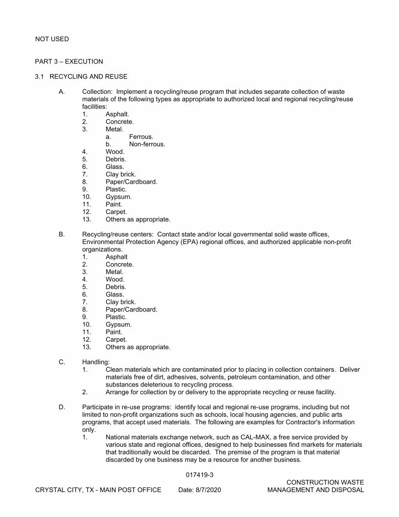
017419-3 CONSTRUCTION WASTE CRYSTAL CITY, TX - MAIN POST OFFICE Date: 8/7/2020 MANAGEMENT AND DISPOSAL
NOT USED PART 3 – EXECUTION 3.1 RECYCLING AND REUSE
A. Collection: Implement a recycling/reuse program that includes separate collection of waste materials of the following types as appropriate to authorized local and regional recycling/reuse facilities: 1. Asphalt. 2. Concrete. 3. Metal.
a. Ferrous. b. Non-ferrous.
4. Wood. 5. Debris. 6. Glass. 7. Clay brick. 8. Paper/Cardboard. 9. Plastic. 10. Gypsum. 11. Paint. 12. Carpet. 13. Others as appropriate.
B. Recycling/reuse centers: Contact state and/or local governmental solid waste offices,
Environmental Protection Agency (EPA) regional offices, and authorized applicable non-profit organizations. 1. Asphalt 2. Concrete. 3. Metal. 4. Wood. 5. Debris. 6. Glass. 7. Clay brick. 8. Paper/Cardboard. 9. Plastic. 10. Gypsum. 11. Paint. 12. Carpet. 13. Others as appropriate.
C. Handling: 1. Clean materials which are contaminated prior to placing in collection containers. Deliver
materials free of dirt, adhesives, solvents, petroleum contamination, and other substances deleterious to recycling process.
2. Arrange for collection by or delivery to the appropriate recycling or reuse facility. D. Participate in re-use programs: identify local and regional re-use programs, including but not
limited to non-profit organizations such as schools, local housing agencies, and public arts programs, that accept used materials. The following are examples for Contractor's information only. 1. National materials exchange network, such as CAL-MAX, a free service provided by
various state and regional offices, designed to help businesses find markets for materials that traditionally would be discarded. The premise of the program is that material discarded by one business may be a resource for another business.
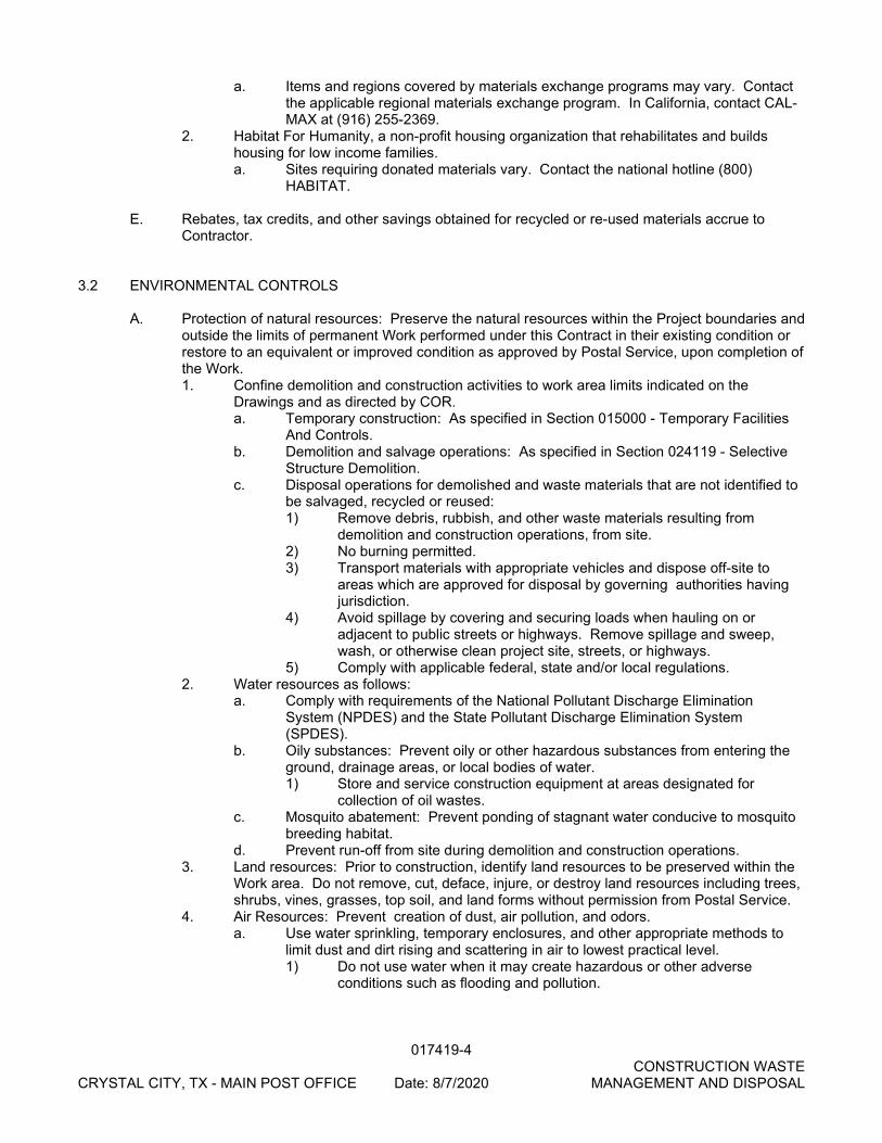
017419-4 CONSTRUCTION WASTE CRYSTAL CITY, TX - MAIN POST OFFICE Date: 8/7/2020 MANAGEMENT AND DISPOSAL
a. Items and regions covered by materials exchange programs may vary. Contact the applicable regional materials exchange program. In California, contact CAL-MAX at (916) 255-2369.
2. Habitat For Humanity, a non-profit housing organization that rehabilitates and builds housing for low income families. a. Sites requiring donated materials vary. Contact the national hotline (800)
HABITAT.
E. Rebates, tax credits, and other savings obtained for recycled or re-used materials accrue to Contractor.
3.2 ENVIRONMENTAL CONTROLS
A. Protection of natural resources: Preserve the natural resources within the Project boundaries and
outside the limits of permanent Work performed under this Contract in their existing condition or restore to an equivalent or improved condition as approved by Postal Service, upon completion of the Work. 1. Confine demolition and construction activities to work area limits indicated on the
Drawings and as directed by COR. a. Temporary construction: As specified in Section 015000 - Temporary Facilities
And Controls. b. Demolition and salvage operations: As specified in Section 024119 - Selective
Structure Demolition. c. Disposal operations for demolished and waste materials that are not identified to
be salvaged, recycled or reused: 1) Remove debris, rubbish, and other waste materials resulting from
demolition and construction operations, from site. 2) No burning permitted. 3) Transport materials with appropriate vehicles and dispose off-site to
areas which are approved for disposal by governing authorities having jurisdiction.
4) Avoid spillage by covering and securing loads when hauling on or adjacent to public streets or highways. Remove spillage and sweep, wash, or otherwise clean project site, streets, or highways.
5) Comply with applicable federal, state and/or local regulations. 2. Water resources as follows:
a. Comply with requirements of the National Pollutant Discharge Elimination System (NPDES) and the State Pollutant Discharge Elimination System (SPDES).
b. Oily substances: Prevent oily or other hazardous substances from entering the ground, drainage areas, or local bodies of water. 1) Store and service construction equipment at areas designated for
collection of oil wastes. c. Mosquito abatement: Prevent ponding of stagnant water conducive to mosquito
breeding habitat. d. Prevent run-off from site during demolition and construction operations.
3. Land resources: Prior to construction, identify land resources to be preserved within the Work area. Do not remove, cut, deface, injure, or destroy land resources including trees, shrubs, vines, grasses, top soil, and land forms without permission from Postal Service.
4. Air Resources: Prevent creation of dust, air pollution, and odors. a. Use water sprinkling, temporary enclosures, and other appropriate methods to
limit dust and dirt rising and scattering in air to lowest practical level. 1) Do not use water when it may create hazardous or other adverse
conditions such as flooding and pollution.
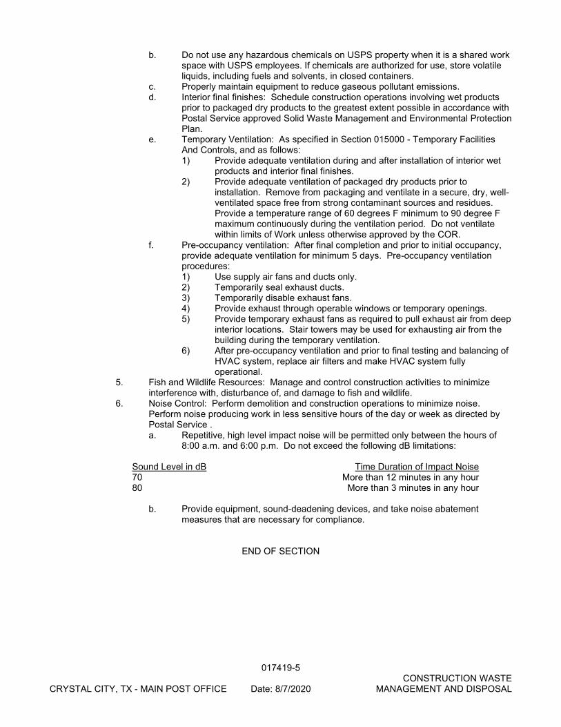
017419-5 CONSTRUCTION WASTE CRYSTAL CITY, TX - MAIN POST OFFICE Date: 8/7/2020 MANAGEMENT AND DISPOSAL
b. Do not use any hazardous chemicals on USPS property when it is a shared work space with USPS employees. If chemicals are authorized for use, store volatile liquids, including fuels and solvents, in closed containers.
c. Properly maintain equipment to reduce gaseous pollutant emissions. d. Interior final finishes: Schedule construction operations involving wet products
prior to packaged dry products to the greatest extent possible in accordance with Postal Service approved Solid Waste Management and Environmental Protection Plan.
e. Temporary Ventilation: As specified in Section 015000 - Temporary Facilities And Controls, and as follows: 1) Provide adequate ventilation during and after installation of interior wet
products and interior final finishes. 2) Provide adequate ventilation of packaged dry products prior to
installation. Remove from packaging and ventilate in a secure, dry, well-ventilated space free from strong contaminant sources and residues. Provide a temperature range of 60 degrees F minimum to 90 degree F maximum continuously during the ventilation period. Do not ventilate within limits of Work unless otherwise approved by the COR.
f. Pre-occupancy ventilation: After final completion and prior to initial occupancy, provide adequate ventilation for minimum 5 days. Pre-occupancy ventilation procedures: 1) Use supply air fans and ducts only. 2) Temporarily seal exhaust ducts. 3) Temporarily disable exhaust fans. 4) Provide exhaust through operable windows or temporary openings. 5) Provide temporary exhaust fans as required to pull exhaust air from deep
interior locations. Stair towers may be used for exhausting air from the building during the temporary ventilation.
6) After pre-occupancy ventilation and prior to final testing and balancing of HVAC system, replace air filters and make HVAC system fully operational.
5. Fish and Wildlife Resources: Manage and control construction activities to minimize interference with, disturbance of, and damage to fish and wildlife.
6. Noise Control: Perform demolition and construction operations to minimize noise. Perform noise producing work in less sensitive hours of the day or week as directed by Postal Service . a. Repetitive, high level impact noise will be permitted only between the hours of
8:00 a.m. and 6:00 p.m. Do not exceed the following dB limitations:
Sound Level in dB Time Duration of Impact Noise 70 More than 12 minutes in any hour 80 More than 3 minutes in any hour
b. Provide equipment, sound-deadening devices, and take noise abatement measures that are necessary for compliance.
END OF SECTION
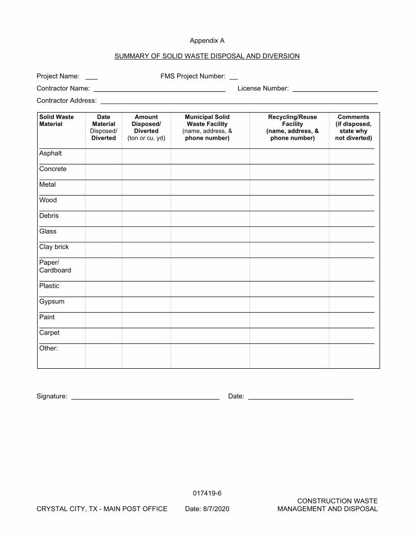
017419-6 CONSTRUCTION WASTE CRYSTAL CITY, TX - MAIN POST OFFICE Date: 8/7/2020 MANAGEMENT AND DISPOSAL
Appendix A
SUMMARY OF SOLID WASTE DISPOSAL AND DIVERSION
Project Name: FMS Project Number:
Contractor Name: License Number:
Contractor Address: Solid Waste Date Amount Municipal Solid Recycling/Reuse Comments Material Material Disposed/ Waste Facility Facility (if disposed, Disposed/ Diverted (name, address, & (name, address, & state why Diverted (ton or cu. yd) phone number) phone number) not diverted) Asphalt Concrete Metal Wood Debris Glass Clay brick Paper/ Cardboard Plastic Gypsum Paint Carpet Other:
Signature: Date:
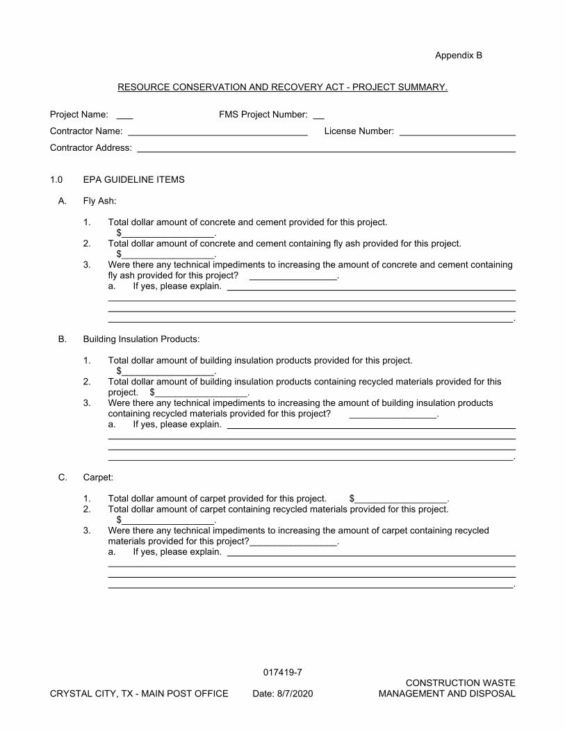
017419-7 CONSTRUCTION WASTE CRYSTAL CITY, TX - MAIN POST OFFICE Date: 8/7/2020 MANAGEMENT AND DISPOSAL
Appendix B
RESOURCE CONSERVATION AND RECOVERY ACT - PROJECT SUMMARY.
Project Name: FMS Project Number:
Contractor Name: License Number:
Contractor Address: 1.0 EPA GUIDELINE ITEMS
A. Fly Ash: 1. Total dollar amount of concrete and cement provided for this project.
$__________________. 2. Total dollar amount of concrete and cement containing fly ash provided for this project.
$__________________. 3. Were there any technical impediments to increasing the amount of concrete and cement containing
fly ash provided for this project? _________________. a. If yes, please explain. .
B. Building Insulation Products:
1. Total dollar amount of building insulation products provided for this project.
$__________________. 2. Total dollar amount of building insulation products containing recycled materials provided for this
project. $__________________. 3. Were there any technical impediments to increasing the amount of building insulation products
containing recycled materials provided for this project? _________________. a. If yes, please explain. .
C. Carpet:
1. Total dollar amount of carpet provided for this project. $__________________. 2. Total dollar amount of carpet containing recycled materials provided for this project.
$__________________. 3. Were there any technical impediments to increasing the amount of carpet containing recycled
materials provided for this project? _________________. a. If yes, please explain. .
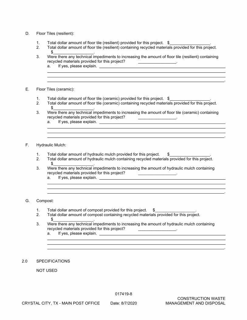
017419-8 CONSTRUCTION WASTE CRYSTAL CITY, TX - MAIN POST OFFICE Date: 8/7/2020 MANAGEMENT AND DISPOSAL
D. Floor Tiles (resilient):
1. Total dollar amount of floor tile (resilient) provided for this project. $__________________. 2. Total dollar amount of floor tile (resilient) containing recycled materials provided for this project.
$__________________. 3. Were there any technical impediments to increasing the amount of floor tile (resilient) containing
recycled materials provided for this project? _________________. a. If yes, please explain. .
E. Floor Tiles (ceramic):
1. Total dollar amount of floor tile (ceramic) provided for this project. $__________________. 2. Total dollar amount of floor tile (ceramic) containing recycled materials provided for this project.
$__________________. 3. Were there any technical impediments to increasing the amount of floor tile (ceramic) containing
recycled materials provided for this project? _________________. a. If yes, please explain. .
F. Hydraulic Mulch:
1. Total dollar amount of hydraulic mulch provided for this project. $__________________. 2. Total dollar amount of hydraulic mulch containing recycled materials provided for this project.
$__________________. 3. Were there any technical impediments to increasing the amount of hydraulic mulch containing
recycled materials provided for this project? _________________. a. If yes, please explain. .
G. Compost:
1. Total dollar amount of compost provided for this project. $__________________. 2. Total dollar amount of compost containing recycled materials provided for this project.
$__________________. 3. Were there any technical impediments to increasing the amount of hydraulic mulch containing
recycled materials provided for this project? _________________. a. If yes, please explain. .
2.0 SPECIFICATIONS NOT USED
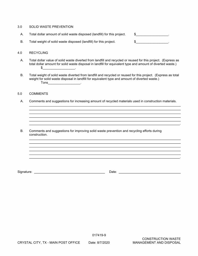
017419-9 CONSTRUCTION WASTE CRYSTAL CITY, TX - MAIN POST OFFICE Date: 8/7/2020 MANAGEMENT AND DISPOSAL
3.0 SOLID WASTE PREVENTION
A. Total dollar amount of solid waste disposed (landfill) for this project. $__________________. B. Total weight of solid waste disposed (landfill) for this project. $__________________.
4.0 RECYCLING
A. Total dollar value of solid waste diverted from landfill and recycled or reused for this project. (Express as
total dollar amount for solid waste disposal in landfill for equivalent type and amount of diverted waste.) $__________________.
B. Total weight of solid waste diverted from landfill and recycled or reused for this project. (Express as total
weight for solid waste disposal in landfill for equivalent type and amount of diverted waste.) Tons__________________.
5.0 COMMENTS
A. Comments and suggestions for increasing amount of recycled materials used in construction materials. .
B. Comments and suggestions for improving solid waste prevention and recycling efforts during
construction. .
Signature: Date:
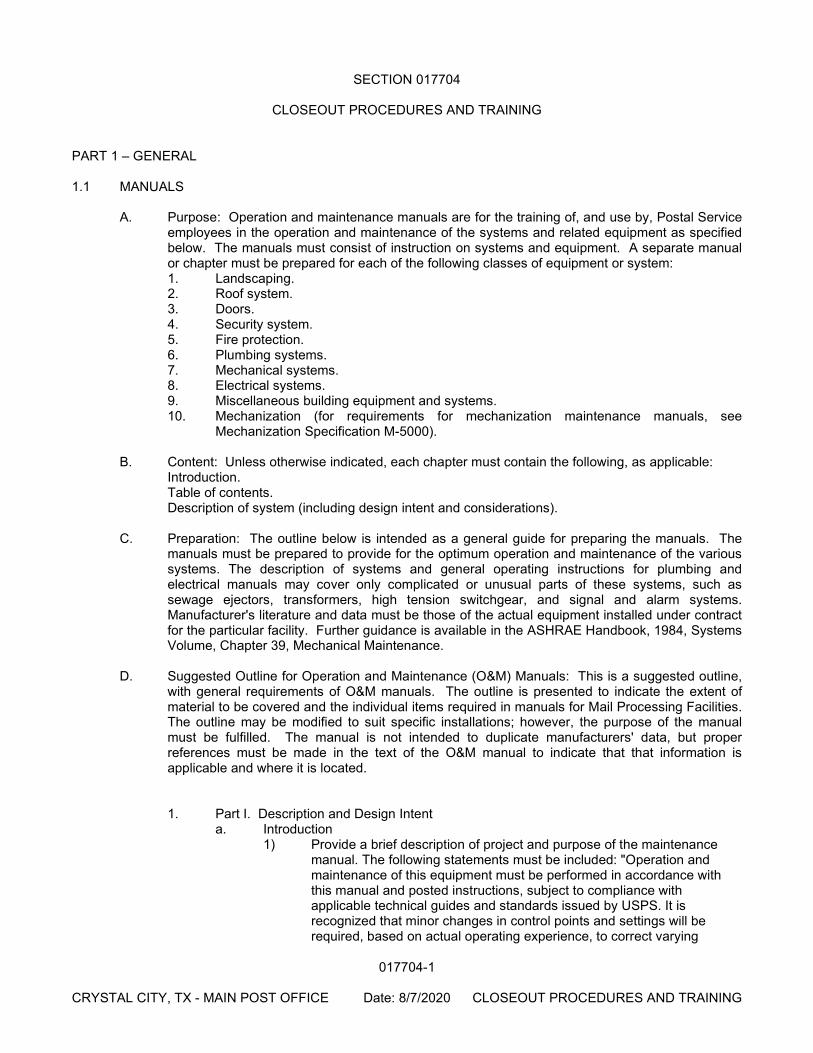
017704-1
CRYSTAL CITY, TX - MAIN POST OFFICE Date: 8/7/2020 CLOSEOUT PROCEDURES AND TRAINING
SECTION 017704
CLOSEOUT PROCEDURES AND TRAINING PART 1 – GENERAL 1.1 MANUALS
A. Purpose: Operation and maintenance manuals are for the training of, and use by, Postal Service employees in the operation and maintenance of the systems and related equipment as specified below. The manuals must consist of instruction on systems and equipment. A separate manual or chapter must be prepared for each of the following classes of equipment or system: 1. Landscaping. 2. Roof system. 3. Doors. 4. Security system. 5. Fire protection. 6. Plumbing systems. 7. Mechanical systems. 8. Electrical systems. 9. Miscellaneous building equipment and systems. 10. Mechanization (for requirements for mechanization maintenance manuals, see
Mechanization Specification M-5000).
B. Content: Unless otherwise indicated, each chapter must contain the following, as applicable: Introduction. Table of contents. Description of system (including design intent and considerations).
C. Preparation: The outline below is intended as a general guide for preparing the manuals. The
manuals must be prepared to provide for the optimum operation and maintenance of the various systems. The description of systems and general operating instructions for plumbing and electrical manuals may cover only complicated or unusual parts of these systems, such as sewage ejectors, transformers, high tension switchgear, and signal and alarm systems. Manufacturer's literature and data must be those of the actual equipment installed under contract for the particular facility. Further guidance is available in the ASHRAE Handbook, 1984, Systems Volume, Chapter 39, Mechanical Maintenance.
D. Suggested Outline for Operation and Maintenance (O&M) Manuals: This is a suggested outline,
with general requirements of O&M manuals. The outline is presented to indicate the extent of material to be covered and the individual items required in manuals for Mail Processing Facilities. The outline may be modified to suit specific installations; however, the purpose of the manual must be fulfilled. The manual is not intended to duplicate manufacturers' data, but proper references must be made in the text of the O&M manual to indicate that that information is applicable and where it is located.
1. Part I. Description and Design Intent a. Introduction
1) Provide a brief description of project and purpose of the maintenance manual. The following statements must be included: "Operation and maintenance of this equipment must be performed in accordance with this manual and posted instructions, subject to compliance with applicable technical guides and standards issued by USPS. It is recognized that minor changes in control points and settings will be required, based on actual operating experience, to correct varying
017704-2
CRYSTAL CITY, TX - MAIN POST OFFICE Date: 8/7/2020 CLOSEOUT PROCEDURES AND TRAINING
conditions and improve operation. When such changes appear necessary, they must be submitted to the maintenance manager for consideration. Upon approval of any changes, the applicable portions of all copies of the manual and proposed instructions must be revised and reissued, and any change in operating procedure brought to the attention of all operating personnel."
2) "This manual is specifically developed to assist the Postal official in charge at the facility to operate and maintain the building systems and equipment. Manufacturers' recommendations set forth for certain components must be followed during the complete warranty period for that equipment."
3) Contents of Manual. This portion of the introduction must explain that the manual is to contain complete operating, maintenance, and safety instructions for all equipment listed. It must also contain any other appropriate references as required to outline an explanation of the manuals and major categories of reference material required with the manuals.
b. Table of Contents 1) The table of contents must list numbers and titles of chapters, sections,
and main paragraphs, with their page numbers. Each volume in a set of manuals must contain its own table of contents. Publications containing 10 or more illustrations or tables must include a list of illustrations or tables, as applicable. These lists must show number, title, and page number of each illustration and table. Following is a typical table of contents: a. Landscaping
1.) Irrigation system 2.) Lawns and grasses 3.) Exterior plants 4.) Plant maintenance
b. Roof System 1.) Roof and flashing type 2.) Local inspection (frequency and what is included) 3.) Maintenance (when manufacturer performs, if USPS
performs what methods compatible materials, etc.) c. Doors
1.) Overhead coiling doors 2.) Folding closures 3.) Sectional overhead doors 4.) Impact traffic doors 5.) Automatic entrance doors 6.) Specialized hardware
d. Security Systems 1.) CCTV system 2.) Intrusion detection 3.) Electronic article surveillance 4.) Access control
e. Fire Protection System 1.) Water supply and distribution 2.) Exterior fire hydrants 3.) Sprinklers 4.) Fire Department connections 5.) Fire extinguishers 6.) Exit signs
f. Plumbing Systems 1.) Potable water 2.) Domestic hot water
017704-3
CRYSTAL CITY, TX - MAIN POST OFFICE Date: 8/7/2020 CLOSEOUT PROCEDURES AND TRAINING
3.) Roof and sanitary drains g. Mechanical Systems
1.) Space conditioning 2.) Heating 3.) Central chilled water and distribution 4.) HVAC instrumentation and controls
h. Electrical Systems 1.) Incoming Service 2.) Electrical power distribution 3.) Lighting and lighting controls 4.) Fire alarm 5.) Emergency lighting unit
i. Miscellaneous Building Equipment 1.) Postal Parcel Lockers 2.) Floor mats 3.) Dock equipment 4.) Window Treatments 5.) Elevators 6.) Scales 7.) Dust collectors 8.) Vehicle maintenance equipment
2. Part II. Operating Sequence and Procedures
a. Contents: Each chapter must describe the procedures necessary for Postal Service personnel to operate the system and equipment covered in that chapter.
b. Operating Procedures: The operating procedures must be divided into four subsections: Startup, Operation, Emergency Operation, and Shutdown. 1) Startup: Give complete instructions for energizing the equipment and
making initial settings and adjustments whenever applicable. If equipment is fully automatic, a statement to that effect is all that is required. If a specific sequence of steps must be performed, give step-by-step instructions in the proper sequence. If timing- (such as warm-up between power-on and adjustment) is important, clearly state the specific minimum time required at the proper point in the procedure. Refer to controls and indicators by panel; make references consistent with the nomenclature used in illustrations and tables of controls and indicators. If preliminary settings differ for different modes of operations, give procedures for each mode.
2) Operation: Give detailed instructions in proper sequence for each mode of operation. When, for a given action on the part of the operator, alternate equipment responses are possible, give the appropriate operation reaction to each.
3) Emergency Operation: If some functions of the equipment can be operated while other functions are disabled, give instructions for operations under these conditions. Include here only those alternate methods of operation (from normal) that the operator can follow when there is a partial failure or malfunctioning of components, or other unusual condition.
4) Shutdown: Include instructions for stopping and securing the equipment after operation. If a particular sequence is required, give step-by-step instructions in that order.
3. Part III. Maintenance Instructions and Requirements a. Contents: Each chapter must describe the procedures necessary for Postal
Service personnel to perform the maintenance on the systems and equipment covered in that chapter. Emphasis must be placed on the method of mechanical control of systems and equipment from a maintenance standpoint. References must be made, as appropriate, to drawings, schematics, and sequences of
017704-4
CRYSTAL CITY, TX - MAIN POST OFFICE Date: 8/7/2020 CLOSEOUT PROCEDURES AND TRAINING
operation included as part of the construction Contract drawings and specifications that show piping and equipment arrangements and items of control. Prints of these drawings must be reduced to 11 inches x 17 inches for insertion in the manuals. Drawings must represent the "as-built" condition.
b. Maintenance Procedures: The maintenance procedures must be divided into two categories: Preventive Maintenance and Corrective Maintenance. 1. Preventive Maintenance
a. Provide a schedule for preventive maintenance. State, preferably in tabular form, the recommended frequency of performance for each preventive maintenance task (cleaning, inspection, and scheduled overhauls).
b. Provide instruction and schedules for all routine maintenance cleaning and inspection, with recommended lubricants.
c. If periodic inspection of equipment is required for operation, cleaning, or other reasons, indicate the items to be inspected and give the inspection criteria for, but not limited to, the following: 1.) Motors 2.) Controls 3.) Filters 4.) Heat exchangers
2. Provide instruction for minor repairs or adjustments required for preventive maintenance routines. Minor repair and adjustment must be limited to repairs and adjustments that may be performed without special tools or test equipment and that require no special training or skills. Identify test points and give values for each.
c. Corrective Maintenance 1. Corrective Maintenance: Corrective maintenance instructions must be
predicated upon a logical effect-to-cause troubleshooting philosophy and a rapid replacement procedure to minimize equipment downtime. Instructions and data must appear in the normal sequence of corrective maintenance, for example, troubleshooting first, repair and replacement of parts second, and then the parts list.
2. Troubleshooting: This information must describe the general procedure for locating malfunctions and must give, in detail, any specific remedial procedures or techniques. The data shown are intended to isolate only the most common equipment deficiencies. Troubleshooting tables, charts, or diagrams may be used to present specific procedures. A guide to this type must be a three-column chart. The columns must be entitled Malfunction, Probable Cause, and Recommended Action. The information must be alphabetically arranged by component, and each component must, in turn, list deficiencies that may be expected. Each deficiency must contain one or more problems with a recommended correction.
3. Repair and Replacement: Indicate the repair and replacement procedures most likely to be required in the maintenance of the equipment. Information included here must consist of step-by-step instructions for repair and replacement of defective items. Include all information required to accomplish repair or replacement, including information such as torque values. Identify all tools, special equipment, and materials that may be required. Identify uses for maintenance equipment. The paragraphs must contain headings to identify the topics covered.
4. Safety Precautions: This subsection must comprise a listing of safety precautions and instructions to be followed before, during, and after repairs or adjustments are made or routine maintenance is performed.
017704-5
CRYSTAL CITY, TX - MAIN POST OFFICE Date: 8/7/2020 CLOSEOUT PROCEDURES AND TRAINING
d. Manufacturers' Brochures: Include manufacturers' descriptive literature covering devices used in the system, together with illustrations, exploded views, and renewal parts lists. This section must also include special devices manufactured by the Contractor.
e. Special Maintenance: Provide information of a maintenance nature covering warranty items that have not been discussed elsewhere.
f. Shop Drawings: Provide a copy of all approved shop drawings covering approval of equipment for the project with the manufacturers' brochures.
g. Spare Parts Lists: Include a recommended spare parts list for all equipment furnished for the project. The parts list must include a tabulation of descriptive data for all the electrical-electronic spare parts and all the mechanical spare parts proposed for each type of equipment or system. Each part must be properly identified by part number and manufacturer.
h. Warranty: Include a copy of the “special” or extended warranty in the operation and maintenance manual.
E. Submittal, In both “hard” and electronic DVD or CD-ROM format:
1. Preliminary Submittal: Two draft copies of the completed manuscript for items in this outline must be submitted to the COR for review within 30 days after approval of equipment to be provided. One copy will be returned to the Contractor within 15 days after submittal and, if required, must be revised and resubmitted within 15 days.
2. Final Submittal: four complete sets of manuals must be furnished to the COR not later than 30 days before completion of the project.
3. Final Submittal must be accepted by the COR before training can begin. 1.2 POSTED OPERATING INSTRUCTIONS
A. General. Operating instructions and diagrams must be prepared for posting near the equipment. Posted operating instructions must be photographic or equal non-fading reproductions framed under glass or encased in non-discoloring plastic and must be mounted in locations as directed. Copies of the posted operating instructions must also be used with the O&M manuals as a basis for training Postal Service personnel in the operation and maintenance of systems and related equipment installed under contract at the facility.
B. Posted operating instructions must consist of simplified, consolidated equipment, control, and
power diagrams graphically representing the entire system and actual equipment installed, including concise written instructions on how to start and stop systems, what settings and conditions are to be observed, and what control adjustments are to be made or maintained by the operation. Posted operating instructions must include, but are not limited to the following: 1. Boiler and burner controls. 2. Refrigeration controls. 3. Heating, ventilating, and air-conditioning controls for each system. 4. Controls for dust collection systems. 5. One-line schematic diagrams of water supply (plumbing). 6. One-line diagrams of steam distribution and hot water and chilled water systems,
including risers, main shutoff valves, balancing cocks, and the like. 7. One-line isometric diagrams of sanitary drainage.
1.3 TRAINING
A. The Contractor must train Postal Service personnel in the operation and maintenance of mechanical and electrical equipment. Coordination must be maintained with systems designers for developing the hours of instruction and scope of material to be covered. Training of Postal Service personnel must not begin until the COR has approved the final submittal copy of each O&M manual.
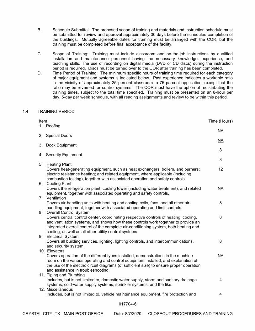
017704-6
CRYSTAL CITY, TX - MAIN POST OFFICE Date: 8/7/2020 CLOSEOUT PROCEDURES AND TRAINING
B. Schedule Submittal: The proposed scope of training and materials and instruction schedule must
be submitted for review and approval approximately 30 days before the scheduled completion of the buildings. Mutually agreeable dates for training must be arranged with the COR, but the training must be completed before final acceptance of the facility.
C. Scope of Training: Training must include classroom and on-the-job instructions by qualified
installation and maintenance personnel having the necessary knowledge, experience, and teaching skills. The use of recording on digital media (DVD or CD discs) during the instruction period is required. Discs must be turned over to the COR after training has been completed.
D. Time Period of Training: The minimum specific hours of training time required for each category of major equipment and systems is indicated below. Past experience indicates a workable ratio in the vicinity of approximately 25 percent classroom to 75 percent application, except that the ratio may be reversed for control systems. The COR must have the option of redistributing the training times, subject to the total time specified. Training must be presented on an 8-hour per day, 5-day per week schedule, with all reading assignments and review to be within this period.
1.4 TRAINING PERIOD
Item Time (Hours) 1. Roofing NA 2. Special Doors NA 3. Dock Equipment 8 4. Security Equipment 8 5. Heating Plant Covers heat-generating equipment, such as heat exchangers, boilers, and burners;
electric resistance heating; and related equipment, where applicable (including combustion testing), together with associated operation and safety controls.
12
6. Cooling Plant Covers the refrigeration plant, cooling tower (including water treatment), and related
equipment, together with associated operating and safety controls. NA
7. Ventilation Covers air-handling units with heating and cooling coils, fans, and all other air-
handling equipment, together with associated operating and limit controls. 8
8. Overall Control System Covers central control center, coordinating respective controls of heating, cooling,
and ventilation systems, and shows how these controls work together to provide an integrated overall control of the complete air-conditioning system, both heating and cooling, as well as all other utility control systems.
8
9. Electrical System Covers all building services, lighting, lighting controls, and intercommunications,
and security system. 8
10. Elevators Covers operation of the different types installed, demonstrations in the machine
room on the various operating and control equipment installed, and explanation of the use of the electric circuit diagrams (of sufficient size) to ensure proper operation and assistance in troubleshooting.
NA
11. Piping and Plumbing Includes, but is not limited to, domestic water supply, storm and sanitary drainage
systems, cold-water supply systems, sprinkler systems, and the like. 4
12. Miscellaneous Includes, but is not limited to, vehicle maintenance equipment, fire protection and 4
017704-7
CRYSTAL CITY, TX - MAIN POST OFFICE Date: 8/7/2020 CLOSEOUT PROCEDURES AND TRAINING
alarm equipment, dust collection systems, compressed air systems, automatic door operators, dock levelers, truck scales, data collection center, and all other equipment not specifically covered above.
13. Mechanization See Mechanization Specification M-5000.
1.5 TRAINING PARTICIPATION SHEETS
A. Submit to the COR sign-in sheets with the dates and names of all training participants. Training
sheets must be reviewed and certified by an authorized facility manager. 1.6 OTHER CLOSEOUT SUBMITTALS
A. Additional requirements for Systems Manuals, Operating Instructions, Training and other
deliverables are contained in individual Specification Sections. All closeout requirements must be provided to and accepted by the COR prior to requesting final payment. Examples of additional closeout requirements include, but are not limited to, the following 1. Final Punch-List with all items certified as complete. 2. In accordance with the terms and conditions of the contract provisions and clauses,
including those concerning Record “As Built” Drawings, the Contractor shall submit certified As-Built Record Drawings and Specifications in the quantities and media specified.
3. In accordance with the terms and conditions of the contract provisions and clauses, including those concerning Warranty, the Contractor shall submit all transferable guarantees and warranties for equipment, materials and installations furnished by any manufacturer, supplier, or installer.
4. Signed Asbestos and Lead-Based Paint Certificate. 5. RE-4 Certification of Accessibility (CoA) and Facility Accessibility Survey Report. 6. Material Safety Data Sheets. 7. Signed and sealed Contractor Release of Claims.
PART 2 – PRODUCTS NOT USED PART 3 – EXECUTION NOT USED
END OF SECTION
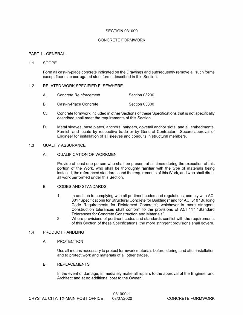
031000-1 CRYSTAL CITY, TX-MAIN POST OFFICE 08/07/2020 CONCRETE FORMWORK
SECTION 031000
CONCRETE FORMWORK PART 1 - GENERAL 1.1 SCOPE
Form all cast-in-place concrete indicated on the Drawings and subsequently remove all such forms except floor slab corrugated steel forms described in this Section.
1.2 RELATED WORK SPECIFIED ELSEWHERE
A. Concrete Reinforcement Section 03200
B. Cast-in-Place Concrete Section 03300 C. Concrete formwork included in other Sections of these Specifications that is not specifically
described shall meet the requirements of this Section. D. Metal sleeves, base plates, anchors, hangers, dovetail anchor slots, and all embedments:
Furnish and locate by respective trade or by General Contractor. Secure approval of Engineer for installation of all sleeves and conduits in structural members.
1.3 QUALITY ASSURANCE A. QUALIFICATION OF WORKMEN Provide at least one person who shall be present at all times during the execution of this
portion of the Work, who shall be thoroughly familiar with the type of materials being installed, the referenced standards, and the requirements of this Work, and who shall direct all work performed under this Section.
B. CODES AND STANDARDS 1. In addition to complying with all pertinent codes and regulations, comply with ACI
301 "Specifications for Structural Concrete for Buildings" and for ACI 318 "Building Code Requirements for Reinforced Concrete"; whichever is more stringent. Construction tolerances shall conform to the provisions of ACI 117 “Standard Tolerances for Concrete Construction and Materials”.
2. Where provisions of pertinent codes and standards conflict with the requirements of this Section of these Specifications, the more stringent provisions shall govern.
1.4 PRODUCT HANDLING A. PROTECTION Use all means necessary to protect formwork materials before, during, and after installation
and to protect work and materials of all other trades. B. REPLACEMENTS
In the event of damage, immediately make all repairs to the approval of the Engineer and Architect and at no additional cost to the Owner.

031000-2 CRYSTAL CITY, TX-MAIN POST OFFICE 08/07/2020 CONCRETE FORMWORK
PART 2 - PRODUCTS 2.1 FORM MATERIALS A. WOOD FORMS Capable of meeting all requirements described in FORM CONSTRUCTION paragraph in
this Section. B. UNEXPOSED SURFACES #2 common or better, plywood. C. EXPOSED SURFACES New or like-new moisture resistant fir form plywood. Surface must be smooth, completely
free from scratches, indentations, unsound surface knots, ripples, etching, prominent grain, depressions, warps or breaks. "Exposed surfaces" include concrete surfaces which are to be painted or dash coated.
2.2 MISCELLANEOUS MATERIALS A. EXPANSION JOINT FORMING MATERIAL Preformed asphaltic expansion joint material, thickness as indicated, as manufactured by
W. R. Grace & Company or W. R. Meadows, Inc. B. SEALED EXPANSION JOINT FORMING MATERIAL See CAST-IN-PLACE CONCRETE Section. C. ANCHOR SLOTS
“Beehive” dovetail type as manufactured by Gateway Erectors, Inc., or approved equal. Install anchor slots vertically at 32" c-c spacing in all exterior concrete floor or roof beams where masonry or anchored panels go past beams. Install vertically in columns where masonry abuts or is adjacent to columns.
D. VAPOR BARRIER
At fill supported slabs, unless detailed otherwise, install a vapor barrier having no more than 0.04 perms in accordance with ASTM E-96, meeting or exceeding the requirements of ASTM E-1745, Class C, and wherein the vapor barrier component (plastic) is no less than 10 mils thick in accordance with ACI 302.1R96. All joints/seams shall be overlapped six inches and sealed with manufacturer recommended tape. All penetrations shall be sealed with manufacturer recommended tape.
E. TIE AND SPREADERS
All form ties shall be a type which does not leave an opening through the concrete (regular snap ties) and which permits neat and solid patching of every hole.
PART 3 - EXECUTION 3.1 FORM CONSTRUCTION
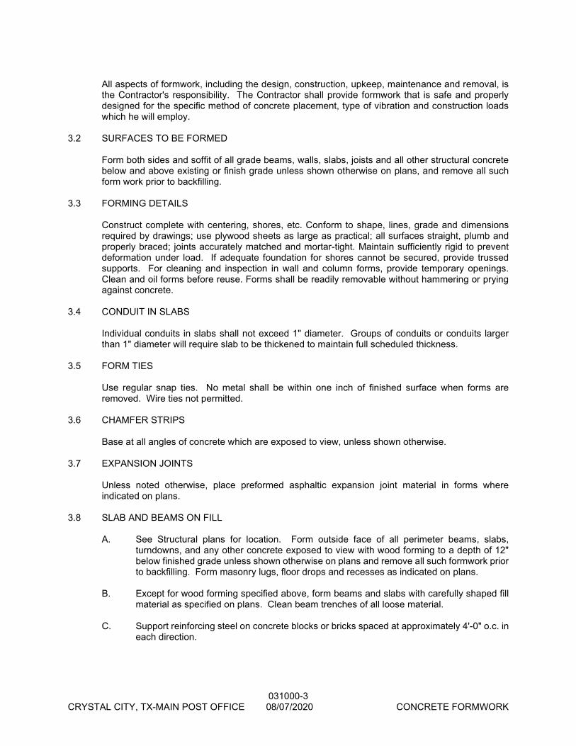
031000-3 CRYSTAL CITY, TX-MAIN POST OFFICE 08/07/2020 CONCRETE FORMWORK
All aspects of formwork, including the design, construction, upkeep, maintenance and removal, is the Contractor's responsibility. The Contractor shall provide formwork that is safe and properly designed for the specific method of concrete placement, type of vibration and construction loads which he will employ.
3.2 SURFACES TO BE FORMED
Form both sides and soffit of all grade beams, walls, slabs, joists and all other structural concrete below and above existing or finish grade unless shown otherwise on plans, and remove all such form work prior to backfilling.
3.3 FORMING DETAILS
Construct complete with centering, shores, etc. Conform to shape, lines, grade and dimensions required by drawings; use plywood sheets as large as practical; all surfaces straight, plumb and properly braced; joints accurately matched and mortar-tight. Maintain sufficiently rigid to prevent deformation under load. If adequate foundation for shores cannot be secured, provide trussed supports. For cleaning and inspection in wall and column forms, provide temporary openings. Clean and oil forms before reuse. Forms shall be readily removable without hammering or prying against concrete.
3.4 CONDUIT IN SLABS
Individual conduits in slabs shall not exceed 1" diameter. Groups of conduits or conduits larger than 1" diameter will require slab to be thickened to maintain full scheduled thickness.
3.5 FORM TIES
Use regular snap ties. No metal shall be within one inch of finished surface when forms are removed. Wire ties not permitted.
3.6 CHAMFER STRIPS
Base at all angles of concrete which are exposed to view, unless shown otherwise. 3.7 EXPANSION JOINTS
Unless noted otherwise, place preformed asphaltic expansion joint material in forms where indicated on plans.
3.8 SLAB AND BEAMS ON FILL A. See Structural plans for location. Form outside face of all perimeter beams, slabs,
turndowns, and any other concrete exposed to view with wood forming to a depth of 12" below finished grade unless shown otherwise on plans and remove all such formwork prior to backfilling. Form masonry lugs, floor drops and recesses as indicated on plans.
B. Except for wood forming specified above, form beams and slabs with carefully shaped fill
material as specified on plans. Clean beam trenches of all loose material. C. Support reinforcing steel on concrete blocks or bricks spaced at approximately 4'-0" o.c. in
each direction.
031000-4 CRYSTAL CITY, TX-MAIN POST OFFICE 08/07/2020 CONCRETE FORMWORK
D. Vapor barrier shall extend half way down sides of beams but not under beam soffits; prevent “bunching up” around reinforcing and at beam intersections by neatly folding and tacking against beam sides.
3.9 CONSTRUCTION JOINTS A. Provide and locate as necessary in Cast-In-Place Concrete. B. Form keyways as required in Cast-In-Place Concrete for transfer of shear and other forces
through the joint. 3.10 BEAM TO WALL CONNECTION Form key seat into wall full size of beam. 3.11 OILING OF FORMS A. Lightly coat with nonstaining form oil for exposed surfaces. Before placing reinforcing,
remove surplus oil. B. Forms for unexposed surfaces may be thoroughly wetted with water in lieu of oiling
immediately before placing concrete. 3.12 REMOVAL OF FORMS A. Side forms of beams, walls and columns may be removed after cumulatively curing at not
less than 50 degrees F (10 degrees C) for 24 hours after placing concrete, provided concrete is sufficiently hard to not be damaged by form removal operations, and provided curing and protection operations are maintained.
B. Wall, beam, joist and slab soffits may be removed when all of the following conditions are
satisfied: 1. Strength of concrete as shown by standard cylinder test has reached at least 2,500
psi and at least 75% of specified design strength. 2. Concrete has cured at least 7 days (4 days for type 3 cement) or additional time
as required if during cold weather. 3. Soffit forms shall not be removed from members that are supporting any load such
as construction materials or shoring for floor or roof above unless it can be determined that the member as sufficient strength to support such loading.
END OF SECTION
06195-1 CRYSTAL CITY, TX-MAIN POST OFFICE 08/07/2020 CONCRETE REINFORCEMENT
SECTION 032000
CONCRETE REINFORCEMENT PART 1 - GENERAL 1.1 SCOPE
Furnish and install all reinforcement and associated items required and/or indicated on the Drawings for all cast-in-place concrete.
1.2 RELATED WORK SPECIFIED ELSEWHERE A. Reinforcement of Masonry Section 04001 1.3 QUALITY ASSURANCE A. QUALIFICATIONS OF WORKMEN Provide at least one person who shall be present at all times during execution of this
portion of the work and who shall be thoroughly familiar with the type of materials being installed and the best methods for their installation and who shall direct all work performed under this section.
B. CODES AND STANDARDS 1. In addition to complying with all pertinent codes and regulations, concrete
reinforcement, unless otherwise noted, shall meet requirements of ACI 301 "Specifications for Structural Concrete for Buildings" and/or ACI 318 "Building Code Requirements for Reinforced Concrete", whichever is more stringent. Construction tolerances shall conform to the provisions of ACI 117 “Standard Tolerances for Concrete Construction and Materials”.
2. Where provisions of pertinent codes and standards conflict with this Specification, the more stringent provisions shall govern.
1.4 SUBMITTALS A. SHOP DRAWINGS 1. The Contractor shall obtain completely detailed shop drawings showing
placement plans, bar bending lists, etc. Include the specific location and size of all accessories, chairs and bar supports. The Contractor shall carefully check these drawings, then submit them to the Architect/Engineer. The Architect/Engineer may conduct limited spot checks aimed solely at determining general comprehension of the design intent, then return them to the Contractor. The Contractor shall then carefully recheck the shop drawings and approve them prior to fabrication.
2. NOTE: Regardless of the fabricators standard policy or other industry standards of practice, all straight and bent bars shall be tagged with the member mark. If the fabricator elects to use member marks other than those shown on the structural drawings, the members must also be labeled with the original engineer's member marks in addition to those of the fabricator.
3. The Engineer's spot check shall not relieve the Contractor from correcting, at his own expense, any items that may thereafter be found not to comply with the plans and specifications.
06195-2 CRYSTAL CITY, TX-MAIN POST OFFICE 08/07/2020 CONCRETE REINFORCEMENT
B. CERTIFICATES When requested by the Engineer, supplier of reinforcing steel and other embedded
materials shall furnish certified evidence that all materials delivered to the project meet the requirements of this Section of the Specification.
1.5 PRODUCT HANDLING A. PROTECTION 1. Use all means necessary to protect concrete reinforcement before, during, and
after installation and to protect the installed work and materials of all other trades. 2. Store in a manner to prevent excessive rusting and fouling with dirt, grease and
other bond-breaking coatings. 3. Use all necessary precautions to maintain identification after the bundles are
broken. 4. Concrete reinforcement included in other sections of these specifications that is
not specifically described shall meet the requirements of this section. 5. Mechanical and electrical equipment, ducts and conduit: Provide adequate
reinforcing as approved by Engineer for all required mechanical equipment and all required openings through beams, slabs, joists, walls, roof deck, etc., and for distribution of equipment loads to structural members. See EXECUTION paragraph in this section for conduit in slabs.
PART 2 - PRODUCTS 2.1 MATERIALS A. ALL REINFORCING Unless noted otherwise on plans, shall comply with ASTM A-615, Grade 60, except beam
stirrups and column ties may be Grade 40. B. WIRE MESH
Shall comply with ASTM A-185, flat sheets only. C. SPIRALS Unless noted otherwise on plans, shall be plain round, hot rolled bars conforming to the
strength and elongation requirements of ASTM A-615 Grade 40. D. METAL ACCESSORIES 1. According to latest revision of "Manual of Standard Practice for Detailing
Reinforced Concrete Structures" (ACI-SP66), except that beam reinforcing larger than #9 shall be supported on individual bar chairs spaced no greater than 2'-0" apart. Accessories resting on forms where underside is left exposed to view, or where plaster, paint, stucco, or dash coat is to be applied shall be galvanized or have plastic leg tips at all points of contact with forms.
2. Accessories fabricated completely from plastic will not be permitted. Accessories for use on cardboard carton forms shall have continuous bottom wire runners or metal sand plates.

06195-3 CRYSTAL CITY, TX-MAIN POST OFFICE 08/07/2020 CONCRETE REINFORCEMENT
3. In the event steel other than of domestic manufacture is contemplated to be used, furnish to Engineer laboratory tests made by a Testing Laboratory approved by the Engineer certifying that said steel meets all requirements.
PART 3 - EXECUTION 3.1 FABRICATION A. Reinforcing shall be fabricated in accordance with "Manual of Standard Building Code
Requirements for Reinforced Concrete" (ACI 318), latest edition. The Contractor shall be responsible for obtaining properly fabricated reinforcing and placing it properly.
B. Reinforcing steel, at the time concrete is placed, shall be free from excessive rust, scale,
dried concrete, or other coatings that will destroy or reduce bond, in the opinion of the Engineer.
C. Reinforcing steel shall be accurately shop bent and placed in position, securely tied or
supported to prevent movement during placing of concrete. Field bends will not be permitted without prior approval from Engineer. Authorized field bends shall be performed cold; no heating is permitted. Spacer bars, supports and accessories are not scheduled but are to be furnished and placed as described under MATERIALS paragraph in this Section. Raising of reinforcement (including welded wire fabric) during the pour will not be permitted.
3.2 CONCRETE COVER A. Unless detailed otherwise on plans, reinforcing bars shall have concrete cover as follows: 1. Beam Stirrups; top, bottom and sides, 1-1/2". 2. Column ties and spirals, 1-1/2". 3. Concrete joists and slabs, 3/4". 4. Spread or spot footings, 3". 3.3 SLAB AND BEAMS ON FILL A. See Structural Plans for Location.) Chair and/or block reinforcing securely in position with
concrete cover as follows: B. Beam stirrups; top, 1-1/2", bottom and sides 2-1/2". C. Slab bars; 1-1/2" from top. D. Support reinforcing steel on concrete blocks or bricks spaced at approximately 4'-0" o.c.
in each direction. 3.4 SPLICES
Necessary splices not shown on drawings or otherwise noted shall be in accordance with ACI specifications for bar sizes up to #11 size, but not less than 40 bar diameters. Splices in bars larger than #11 shall be made with approved thermal or mechanical coupling devices. Welded wire fabric shall be lapped 1-1/2 meshes, with a minimum lap of 8". All lap splices shall be contact type secured with annealed tie wire.
06195-4 CRYSTAL CITY, TX-MAIN POST OFFICE 08/07/2020 CONCRETE REINFORCEMENT
3.5 SLAB OPENINGS
Unless shown otherwise, at slab openings of 12" or less, spread main reinforcing around opening. At slab openings greater than 12", provide 2 #4x4'-0" bottom placed diagonally at each corner. At sides of openings, provide one full bar for each bar cut at opening. No main bars shall be cut without Engineer's approval.
3.6 CONDUITS IN SLABS
Electrical and mechanical conduit in slabs or joists shall run under upper layer of reinforcing or wire mesh; provide a minimum of 1-1/2" clear between conduits and between conduit and parallel reinforcing. Do not "bundle" conduits. See CONCRETE FORMWORK Section for thickened slab required at large conduits.
3.7 BEAM INTERSECTIONS Unless shown otherwise on plans, at corners, angle bends and at junction with other beams, provide four #7x6'-0" “corner bars” (3 ft. each leg) , 2 top and 2 bottom. For deep beams with scheduled intermediate bars, provide matching 80 diameter “corner bars” of the same size. At “T” intersection, place all “corner bars” so that one leg is in outside face of outside beam 3.8 WALL INTERSECTIONS
Unless shown otherwise, at corners, angle bends, and at junction with other walls, lap all horizontal bars in both faces 30 diameters or use matching 80 diameter “Corner Bars”.
3.9 BEAMS TO WALL CONNECTION
Unless shown otherwise, where beam abuts or frames into concrete wall, extend beam bars 30 diameters into wall, or use 60 diameter dowels or 60 diameter “corner bars” with 30 diameter embedment into both beam and wall; bar size and quantity shall match beam bars. See CONCRETE FORMWORK section for key seat at construction joint.
3.10 WALL ENDS
Unless shown otherwise, where walls stop, position two (2) of the wall vertical bars at the end of the wall; provided that vertical bars are #6 or larger. If wall vertical bars are smaller than #6, use 2 #6 at wall ends in lieu of wall vertical bars. Provide #4 U-bars (30 diameter laps) enclosing vertical bars at end faces, same spacing as horizontal bars.
3.11 OPENINGS IN CONCRETE WALLS
Unless shown otherwise, add 2 #6 bars in each face over opening, extending 30 diameters beyond limits of opening, and add 2#5x5'-0" placed diagonally at each corner of opening. Provide #4 U-bars (30 diameter laps) at end faces for each bar (horizontal or vertical) interrupted by opening. U-bars shall enclose horizontal or vertical bars at opening.
3.12 WALL DOWELS
Unless shown otherwise, provide 60 diameter wall dowels from beam or footing to match the size and spacing of all vertical bars in wall above; extend 30 diameters into wall. At construction joints, either continue all vertical bars or provide for 30 diameter laps of all vertical bars into wall above.
3.13 COLUMN DOWELS
06195-5 CRYSTAL CITY, TX-MAIN POST OFFICE 08/07/2020 CONCRETE REINFORCEMENT
Unless shown otherwise, provide dowels from bottom of beams, piers, footings or walls to match the size and quantity of bars scheduled in column above; extend 30 diameters into column. At construction joints, extend all vertical bars 30 diameters into column above; offset bars on 1 to 6 slope to provide proper lapping of bars in column above. If offset exceeds 3", stop lower column bars and provide separate 60 diameter dowels as described under “COLUMN DOWELS” above. Use contact lap splices as shown in details at column schedule.
3.14 COLUMN REINFORCEMENT
Unless shown otherwise, provide scheduled ties along full length of vertical bars and dowels except that at soffit down into column below and above construction joints, start first tie at one half of scheduled tie spacing. Also, unless shown otherwise, include scheduled ties in areas of floor or roof framing members unless width of framing members exceeds width of column above by at least 2" on all four faces. Columns built into concrete walls shall be reinforced same as scheduled column. Two-piece ties shall be deformed bars only and minimum laps shall be 12" for No.3 bars; 15" for No. 4 bars. Terminate column vertical bars at an elevation of 3" below top of upper roof beam unless otherwise detailed; bars shall lap into upper roof beam at least 30 diameters; provide 90 degree bend at bar ends as required to accomplish this.
3.15 COLUMN PIER CAPS
At columns carried directly by footing piers, and/or other places indicated on plans, construct a transitional pier cap extending from pier to column to allow accurate dowel or anchor bolt setting. Extend footing shaft reinforcing including hooping, to within 3" of top of plinth and make double wrap at top. Column dowels are as scheduled for column above. If column dowels occur outside of pier shaft hooping, provide “U” shaped ties (sizes, number, and spacing as scheduled for column above) for all such dowels.
3.16 TOPPING REINFORCEMENT
Reinforcement (including welded wire fabric) shall be chaired to proper depth as shown on plans and sections. Raising of reinforcement during pour is not acceptable.
3.17 CONSTRUCTION JOINTS A. Provide and locate as necessary in CAST-IN-PLACE CONCRETE Section. B. All reinforcing shall continue through the joint. C. Add extra reinforcing if so directed by Engineer.
END OF SECTION
033000-1 CRYSTAL CITY, TX-MAIN POST OFFICE 08/07/2020 FABRICATED WOOD TRUSSED RAFTERS
SECTION 033000
CAST-IN-PLACE CONCRETE PART 1 - GENERAL 1.1 WORK INCLUDED A. Cast-in-place concrete required for this work is indicated on the Drawings and includes
but is not limited to: 1. Drilled Footings. 2. Concrete Beams, Slabs and Joists. 3. Concrete Columns and Walls. 4. Slabs on grade. 5. Exterior flatwork. 1.2 RELATED WORK DESCRIBED ELSEWHERE
A. Shop Drawings/Field Visits Section 01341 B. Testing Laboratory Services Section 01410 C. Concrete Formwork Section 03100 D. Concrete Reinforcement Section 03200 E. Structural Precast Concrete Section 03400 F. Job Cast Concrete Wall Panels Section 03410 G. Architectural Precast Concrete Section 03450
1.3 QUALITY ASSURANCE A. QUALIFICATIONS OF WORKMEN Provide at least one person who shall be present at all times during execution of this
portion of the work who shall be thoroughly familiar and experienced in placing the types of concrete specified and who shall direct all work performed under this Section. For finishing of exposed surfaces of the concrete, use only thoroughly trained and experienced journeyman concrete finishers.
B. CODES AND STANDARDS In addition to complying with all pertinent codes and regulations, complying with all the
requirements of ACI 301, "Specifications for Structural Concrete for Buildings" and/or ACI 318, "Building Code Requirements for Reinforced Concrete". Refer to ACI 302 "Guide for Concrete Floor and Slab Construction." Construction tolerances shall conform to the provisions of ACI 117 “Standard Tolerances for Concrete Construction and Materials”.
C. EMBEDMENTS
033000-2 CRYSTAL CITY, TX-MAIN POST OFFICE 08/07/2020 FABRICATED WOOD TRUSSED RAFTERS
Metal sleeves, anchors, hangers, dovetail anchor slots, and all embedments; furnish and locate by respective trade or by General Contractor. Secure approval of Engineer for installation of sleeves and conduits in structural members.
D. FINISHES Refer to architectural drawings for all floor finishes, location and dimensions of slab drops
and depressions, floor checks, reglets, chamfers, reveals, rustications and special architectural concrete treatment.
E. MECHANICAL EQUIPMENT Mechanical and electrical equipment, ducts and conduit: provide adequate structural
framing and reinforcing as approved by Engineer for all required mechanical equipment and all required openings through beams, slabs, joists, walls, roof deck, etc., and for distribution of equipment loads to structural members.
F. CONCRETE QUALITY The Contractor shall be responsible for all aspects of concrete production, including
maintenance and control of the quality of the concrete through batching, mixing, placing and curing of the concrete. He shall take whatever measures he deems necessary to accomplish this. To assure the Owner of the quality of the work, an independent testing laboratory shall be employed by the Owner to perform certain services as described below. The performance of these services does not relieve the Contractor of his responsibility.
G. CONCRETE MIX DESIGN
An independent testing laboratory shall design the mix proportions for each type of concrete to be used on the project based on aggregate size and cement proportions specified in Part 2 - Products. Laboratory shall go to the designated concrete supplier’s batching plant and obtain samples of ingredients which shall be used in determination of compliance with ASTM C-33 and in the preparation of confirmatory test specimens.
H. CONFIRMATORY TEST SPECIMENS Using the proposed mix design, the laboratory shall make one set of four test cylinders
for each type of concrete. The results of two 7-day compression tests shall be submitted with the proposed mix design prior to placement of concrete on the job. Subsequently, results of two 28-day compression tests shall be submitted and the strength shall be at least 25% greater than the specified minimum strength for concrete placed on the job.
I. EXISTING MIX DESIGNS 1. The laboratory may submit data of previously prepared "standard" mix designs
provided: a. The mix design was prepared by the laboratory in strict accordance with
the provisions of this section of the project specifications. b. The mix design shall have been prepared within the preceding six
months. Documentation shall not reference any specific construction project.
c. The laboratory shall submit written certification that the materials used in the submitted mix designs are currently stocked at the batching plant.
033000-3 CRYSTAL CITY, TX-MAIN POST OFFICE 08/07/2020 FABRICATED WOOD TRUSSED RAFTERS
The use of a “standard” or “stock” mix design will not be permitted for this project. Submittals prepared by the concrete producer will not be accepted. It is mandatory that the general contractor include in his bid the cost to engage the services of an independent testing laboratory to prepare the necessary mix designs from scratch specifically for this project alone.
J. CONCRETE TESTING 1. Concrete tests shall be performed by a commercial testing laboratory approved
by the Structural Engineer. All charges for services as set out below shall be paid by the Owner.
2. The Laboratory shall take samples and perform slump and compression tests in accordance with ASTM C-39 on concrete placed each day at the rate of one set of four cylinders for each 80 cu. yds. or fraction thereof. When more than 80 cu. yds. is being continuously placed, the interval between test samples shall be at least 50 cu. yds. so as to be representative of the whole day's pour. Samples shall be taken at the point of deposit in the field and all cylinders shall be accurately marked and referenced to show date, time and exact location in the structure from which they came. Make 7-day test on two cylinders and 28-day test on two cylinders. Reports of tests shall be promptly sent as follows: two to the Architect, one to the Engineer, and one to the Contractor.
3. In addition to the testing described above, the Laboratory shall exercise complete "laboratory control", including plant inspection, field supervision, and observation of the concrete placing operation. Reports of such inspections shall be made as specified above.
K. BELOW STRENGTH CONCRETE If the 28-day cylinder strengths fall below the specified strength, the concrete represented
by such test cylinders shall be considered unacceptable and subject to removal. Consideration will be given to the acceptance of such concrete if it can be demonstrated to the satisfaction of the Engineer that the cylinder tests do not accurately represent the strength of the concrete in place, or that the structure is fully capable of carrying the loads for which it was designed. This data may be obtained by a series of non-destructive tests and core tests in accordance with ASTM C-42 of the concrete in place, and/or by load testing in accordance with applicable codes. All costs in connection with this additional testing and/or removal and replacement of defective concrete shall be paid by the Contractor.
1.4 SUBMITTALS A. MATERIALS LIST Within 35 days after award of Contract, and before any concrete is delivered to the job
site, submit to the Architect in accordance with Section 01300 of these Specifications a complete list of all materials proposed to be furnished and installed under this portion of the Work, showing manufacturer's name and catalog number of all items such as admixture and membrane, and the name and address of transit-mix concrete supplier.
B. TRANSIT-MIX DELIVERY SLIPS 1. Keep a record at the job site showing time and place of each pour of concrete
together with transit-mix delivery slip certifying contents of the pour. 2. Make the record available to the Architect/Engineer for his inspection upon
request.
033000-4 CRYSTAL CITY, TX-MAIN POST OFFICE 08/07/2020 FABRICATED WOOD TRUSSED RAFTERS
3. Upon completion of this portion of the Work, deliver the record and the delivery slips to the Architect.
1.5 PRODUCT HANDLING A. PROTECTION Use all means necessary to protect cast-in-place concrete materials before, during, and
after installation and to protect the installed work and materials of all other trades. B. REPLACEMENTS In the event of damage, immediately make all repairs and replacements necessary to the
approval of the Architect/Engineer and at no additional cost to the Owner. PART 2 - PRODUCTS 2.1 MATERIALS
When requested by Engineer, supplier of concrete materials shall furnish certified evidence that all materials delivered to the project meet the requirements of specifications.
2.2 PORTLAND CEMENT Comply with ASTM C-150, type 1 or type 3. 2.3 FLY ASH
Fly ash may be used as a pozzolan to replace a portion of the Portland Cement in a concrete mix, subject to the approval of the Structural Engineer. Fly ash, when used, shall conform to ASTM C-618. Concrete mixes using fly ash shall be proportioned to account for the properties of the specific fly ash used and to account for the specific properties of the fly ash concrete thus resulting. The ratio of the amount of the fly ash to the total amount of fly ash and cement in the mix shall not exceed 20 percent when calculated by weight.
2.4 CONCRETE AGGREGATES
Comply with ASTM C-33. Maximum aggregate size is 3/4" for columns and floor slabs; 1-1/2" elsewhere.
2.5 WATER
Clean and free from injurious amount of organic substances. 2.6 REINFORCING
See CONCRETE REINFORCEMENT Section. 2.7 EXPANSION JOINT FORMING MATERIAL
Preformed asphaltic expansion joint material, thickness as indicated, as manufactured by W. R. Grace & Company or W. R. Meadows, Inc.
2.8 SEALED EXPANSION JOINTS MATERIALS
033000-5 CRYSTAL CITY, TX-MAIN POST OFFICE 08/07/2020 FABRICATED WOOD TRUSSED RAFTERS
Sealant: Two-component polyurethane elastomeric sealant, "Daraseal-U, Traffic Grade" as manufactured by W. R. Grace & Company or equal.
2.9 JOINT FILLER
Resilient, preformed, non-extruding type such as cork, sponge rubber, or PVC foam, as manufactured by W. R. Grace & Company, or equal, and which is recommended by the Manufacturer to be used with sealant selected.
2.10 CURING MATERIAL A. For all slabs except those on which additional concrete or other toppings are to be
bonded, use a water-based acrylic membrane curing compound that has a maximum volatile organic compound (VOC) rating of 350 g/l (3 lbs/gal.) complying with ASTM C309, Type I, Class B. Available products include VOCOMP-20 (W. R. Meadows, Inc.), MasterKure 100W (Master Builders, Inc.), Dress and Seal WB (L & M Construction Chemicals, Inc.), or approved equal.
B. For slabs having bonded toppings, use "Sisalkraft" paper as manufactured by the
American Sisalkraft Company. 2.11 MIXING CONCRETE
Concrete shall be mixed and delivered in accordance with "Standard Specifications for Ready-Mixed Concrete", ASTM C-94.
2.12 ANCHOR SLOTS
"Beehive" dovetail type as manufactured by Gateway Erectors, Inc., or approved equal. Install anchor slots vertically at 32" spacing in all exterior concrete floor or roof beams where masonry or anchored panels go past beams. Install vertically in columns where masonry abuts or is adjacent to columns.
2.13 WATERSTOPS A. Wherever indicated on the drawings and where any construction joint occurs below grade
or is subject to moisture penetration, the contractor shall furnish and install polyvinylchloride (PVC) plastic waterstops as manufactured by W. R. Meadows, Inc., "Sealtight type 3332 3-3/4"X 3/32") or approved equal.
B. Care shall be taken to insure correct positioning of the waterstops during installation.
The center line of the waterstop shall coincide with the joint interface. Thoroughly work concrete all around waterstop to insure maximum density and complete tight embedment. Splices in waterstops shall be performed by heat sealing in accordance with the manufacturer's instructions.
2.14 CONCRETE A. PROPORTIONS 1. Proportions shall be as established by the Testing Laboratory for the various
strengths noted on the structural plans. Use the following cement content minimums:
Sacks of Cement/ B. 28 day strength Specified cu.yd. of Concrete
033000-6 CRYSTAL CITY, TX-MAIN POST OFFICE 08/07/2020 FABRICATED WOOD TRUSSED RAFTERS
1. 2500 psi, reg.wt., with admixture 4-1/2 2. 3000 psi, reg.wt., with admixture 5 3. 4000 psi, reg.wt., with admixture 5-1/2 4. 4000 psi, lightweight (114/cu.ft.) 6 5. 5000 psi, reg.wt., with admixture 6-1/2 C. GROUT For setting miscellaneous base plates and other metal items: Equal parts sand and
cement. See STRUCTURAL STEEL Section for special grouts. D. CONCRETE SLUMP Concrete shall be mixed and delivered in accordance with "Standard Specifications for
Ready-Mixed Concrete", ASTM C-94. Maximum slump: 5 inches. PART 3 - EXECUTION 3.1 PLACING CONCRETE A. Unless otherwise noted, concrete shall be mixed and placed in accordance with ACI
"Standard Building Code Requirements for reinforced Concrete" (ACI 318), latest edition. B. Before batching concrete for placement in a given section, the following items shall be
completed: C. All reinforcing, base plates, dowels, etc., shall be completely and securely tied in place
for the entire section to be concreted. Anchor bolts and embedded items requiring accurate location shall be positioned and leveled by the use of templates and instruments, and securely held in place so that no movement occurs during the placement of concrete.
D. All forming, bulkheads, construction joints, keyways, sleeves inserts, plates etc., and
embedded work of other trades shall be complete for the entire section to be concreted. E. All materials and equipment for curing and protecting concrete shall be at the job site. F. Runways shall be provided for wheeled equipment to protect reinforcing steel. Runways
and equipment used in mixing, conveying, lifting and depositing the concrete shall be in good condition, adequate to support all construction loads and suitable and safe for the workmen.
G. Water and debris shall be removed from space to be occupied by concrete. H. See CONCRETE FORMWORK Section for wetting of forms immediately before placing
concrete. 3.2 NOTIFICATION OF POURING SCHEDULE A. Before batching concrete for placement, the Contractor shall see that all applicable
provisions of the plans and specification have been complied with for the entire section to be concreted, and he shall notify the Architect/Engineer of this fact. This notification shall be given at least 24 hours prior to the time that the concrete placement is scheduled to begin and no concrete shall be placed until authorized by the Architect/Engineer. The
033000-7 CRYSTAL CITY, TX-MAIN POST OFFICE 08/07/2020 FABRICATED WOOD TRUSSED RAFTERS
Contractor shall inform himself of possibly unfavorable weather conditions prior to the placement of concrete and shall give due consideration to the weather in scheduling the placement of concrete.
B. Concrete shall not be deposited during rain unless adequately protected and in any case,
preparations shall be on hand to protect newly placed concrete from rain until it has hardened sufficiently so that it will not be damaged. In the event rain starts falling during the placement of concrete, the Contractor shall take such measures as are required to assure that the strength of the structure will not be impaired and the surface finishes will be as specified.
3.3 COLD WEATHER PLACING A. Concrete when deposited shall have a temperature not below 50 degrees F. and not
above 90 degrees F. B. When the temperature of the surrounding air is below 40 degrees F. suitable means shall
be provided for maintaining the concrete at a temperature not below 50 degrees F. for 5 days after placing; except when high early strength cement is used, the time may be reduced to 3 days.
C. Preparations for special protection shall be carefully planned and all materials,
equipment, etc., shall be at the job site prior to placing of any concrete. In general, these measures may include temporary heaters, coverings, and enclosures. The enclosures, coverings, etc., used in connection with this special protection shall remain in place and intact at least 24 hours after the artificial heating is discontinued so that the temperature change in the concrete will occur gradually.
D. In scheduling forming and shoring removal, Contractor shall take into account the fact
that at temperatures below 50 degrees F., concrete gains strength very slowly. E. Salt or chemicals shall not be mixed with the concrete to prevent freezing. 3.4 HOT WEATHER PLACING A. Concrete when deposited shall have a temperature not higher than 90 degrees F. B. Steps shall be taken to reduce concrete temperature and water evaporation by proper
attention to ingredients, production methods, handling, placing, protection and curing. 3.5 PLACING CONCRETE Convey continuously until the entire section to be concreted is completed. Partially hardened or
initially set concrete shall not be used. Compaction by mechanical vibrating equipment shall be required for all concrete. Place in layers not over 12" deep and compact each layer, supplemented by hand-spading, rodding and tamping.
3.6 CONVEYING
Concrete shall be conveyed from the mixer to the forms as rapidly as practicable by proper methods which will not cause segregation or loss of ingredients. It shall be deposited as nearly as practicable in its final position in the forms. At any point in the conveying, the free vertical drop of the concrete shall not exceed 3 feet. Chuting will be permitted only where the concrete is deposited into a hopper before it is placed in the forms. Chutes shall be constructed of metal or shall be metal lined. Conveying equipment shall be cleaned thoroughly before each run. All
033000-8 CRYSTAL CITY, TX-MAIN POST OFFICE 08/07/2020 FABRICATED WOOD TRUSSED RAFTERS
concrete shall be deposited as soon as practicable after the forms and the reinforcement have been observed by the Engineer. Concrete which has segregated in conveying shall be removed.
3.7 SURFACE DEFECTS
Patch honeycomb, tie rod holes, and minor defects with one part cement and two parts sand immediately after removing forms and before concrete is thoroughly dry. Remove fins and rough edges. Concrete exposed to view: refer to FINISHES paragraph in this Section.
3.8 BONDING NEW CONCRETE TO OLD
Clean, roughen, and wet old surface; then coat with neat cement grout. Place new concrete before grout sets.
3.9 CONSTRUCTION JOINTS A. Provide in monolithic concrete framing so that not more than 400 cubic yards is placed in
one day and no side dimension of the section being concreted is greater than 150 feet. Larger areas shall be approved by the Engineer.
B. Locate so as not to impair the strength of the structure and coordinate the location and
details with the Architect/Engineer. Location shall generally be near the middle of the spans of slabs and beams with wood or steel-formed soffits. When soffits are formed with cardboard cartons, locate construction joint on centerline of pier.
C. Provisions shall be made for transfer of shear and other forces through the joint.
Generally, this shall consist of forming horizontal keyways at mid-depth, 1-1/2" deep X 1/3 of beam or slab depth and allowing all reinforcing to continue through the joint. Add extra reinforcing if so directed by Engineer.
D. Follow procedure for "Bonding new concrete to old", as described herein. 3.10 EXPANSION JOINTS A. For flatwork, sidewalks, drives, approaches, form expansion joints with preformed
asphaltic expansion joint material. B. No part of the expansion joint material shall extend above the surface of the concrete.
Trim off any excess as required. 3.11 SEALED EXPANSION JOINTS
Provide unless otherwise indicated on the Drawings. Follow manufacturer's recommendations and instructions in all phases including filler installation, cleaning, bond breaking between filler and sealant, priming, mixing and application of sealant. Sealant shall be installed only by experienced personnel and shall have a thickness of one-half the width of the joints except the minimum thickness shall be 1/2".
3.12 FINISHES
Carefully work out all finishes to agree with other materials and finishes. Verify all elevations, levels and conditions. Carefully tool all exposed edges.
3.13 FLOORS
033000-9 CRYSTAL CITY, TX-MAIN POST OFFICE 08/07/2020 FABRICATED WOOD TRUSSED RAFTERS
Edge forms and intermediate screed strips shall be set accurately to produce the designated elevations and contours of the finished surface and shall be capable of supporting all screeding operations. Refer to Architectural Drawings for all floor and roof finishes, floor coverings, and dimensions and locations of slab drops, slopes, and depressions. Unless otherwise noted, concrete slab finishes and tolerances including consolidation, floating, troweling, brooming, etc., shall be as described in ACI 301, Chapter 11, for the type of surface indicated on Architectural Drawings.
3.14 FLOOR FLATNESS AND LEVELNESS A. Flatness and levelness tolerances for floors shall conform to the requirements set forth in
ACI 117, "Standard Tolerances for Concrete Construction and Materials", particularly section 4.5.6 and 4.5.7. Either of the following specifications is acceptable.
1. Face Floor Profile Numbers (F-Numbers): CONVENTIONAL, BULL-FLOATED; Flatness Ff = 15 Level Fl = 13 CONVENTIONAL STRAIGHTEDGED; Flatness Ff = 20 Level Fl = 15 FLAT; Flatness Ff = 30 Level Fl = 20 VERY FLAT; Flatness Ff = 50 Level Fl = 30 2. 10-ft. Straightedge Method: CONVENTIONAL, BULL-FLOATED; 1/2 in. CONVENTIONAL, STRAIGHTEDGED; 5/16 in. FLAT; 3/16 in. VERY FLAT; 1/8 in. B. Unless noted otherwise, slab surfaces shall conform to the following criteria: 1. Offices, classrooms, corridors, etc: FLAT. 2. Warehouses, storerooms, equipment rooms: STRAIGHTEDGED. 3. Sidewalks, plazas, pavement: BULL-FLOATED. 3.15 FINISHES OTHER THAN FLOORS AND SLABS
Concrete exposed to view, both interior and exterior, shall be rubbed with Carborundum bricks and water no sooner than 48 hours and not later than one week after pouring. Plastering such surfaces will not be permitted. Remove all form marks, bulges, and irregularities. Finished surfaces shall be true and uniform in texture.
3.16 CURING AND PROTECTION A. All concrete shall be protected from premature drying for at least the first 7 days after
placement. Curing compound shall be applied in strict accordance with manufacturer’s directions just as soon as concrete has taken it’s initial set and can receive compound without damaging the finish. All curing materials and equipment shall be on the jobsite before concrete is ordered.
B. At floor areas which are designated to have a permanently exposed concrete surface,
use a two-coat application of curing and sealing compound: apply one coat at the time of finishing and one coat immediately prior to "Substantial Completion" of project.
C. At floor areas scheduled to receive ordinary floor finishes (except bonded concrete or
cementitious materials) apply one coat of specified curing compound in accordance with manufacturer's directions.
033000-10 CRYSTAL CITY, TX-MAIN POST OFFICE 08/07/2020 FABRICATED WOOD TRUSSED RAFTERS
D. At floor areas scheduled to receive bonded concrete topping, ceramic tile, terrazzo or other cementitious floor finishes, DO NOT USE CURING COMPOUND. Such areas shall be cured with lapped and taped "Sisalkraft" paper or absorptive mats or fabric kept continuously wet during the entire curing process.
E. Vertical surfaces such as walls, columns, etc., may be cured by loosening the form and
allowing water to run down between the concrete and the form, or by keeping the forms continuously wet.
3.17 CONCRETE-FILLED MASONRY LINTELS
Furnish reinforcing and concrete. 3.18 TREADS AND RISERS
Equal for any one flight; lines straight and level, angles neatly rounded, or as otherwise detailed. 3.19 WALKS AND OTHER CEMENT WORK
See SITE WORK Section. 3.20 PRECAST CONCRETE EARTH RETAINERS A. Provide precast earth retainers per details on drawings. Install earth retainers against
beam faces on a 2:12 batter, lapping side of beam a minimum of 3", to provide a 12" minimum clear air space under beam soffit. Bottom edges of retainers shall be in firm undisturbed earth or heavily compacted backfill. Wipe all vertical joints and laps at beam or wall with cement grout.
B. All retainers shall be plant or job cast in carefully constructed casting bed, true and
square, with plywood bottom, properly oiled. C. Use 3,000 psi concrete with 3/4" aggregate, screed off, wood-float surface, cure with wet
burlap or equivalent. Earth retainers not manufactured and installed in accordance with these provisions shall be removed and replaced at Contractor's expense.
3.21 PRECAST CONCRETE AREAWALLS
Provide precast concrete area way walls as detailed in drawings. Depth varies; top is 2" above finished grade unless detailed otherwise, bottom is 18" below beam soffit. Recess concrete to receive hot-dip galvanized metal grating as shown on plans or specified. Excavate wide below grade beam for unobstructed vent area. See plans for location and details. Exposed edges neatly tooled. Provide 4 galvanized metal embedments so that grating can be welded in place.
3.22 FLOOR HATCH Install as located on plans. See MISCELLANEOUS METALS Section. 3.23 CLEANING
Clean all concrete work of mortar, plaster, paint, grease, oils, etc. Defective areas shall be replaced or repaired.
END OF SECTION
040514 - 1
CRYSTAL CITY, TX - MAIN POST OFFICE Date: 8/7/2020 MASONRY MORTARING AND GROUTING
SECTION 040514
MASONRY MORTARING AND GROUTING
PART 1 - GENERAL
1.1 SUMMARY
A. Section Includes: 1. Mortar and for unit masonry. 2. Grout for unit masonry.
1.2 SUBMITTALS
A. Section 013300 - Submittal Procedures: Procedures for submittals. 1. Assurance/Control Submittals:
a. Test Reports: Submit the following reports directly to Contracting Officer from Testing Laboratory, with copy to Contractor. Prepare reports in conformance with Section 014000 - Quality Requirements. 1) Conformance to Proportion specification of ASTM C 270. 2) Test and evaluation reports to ASTM C 780.
1.3 PROJECT CONDITIONS OR SITE CONDITIONS
A. Environmental Requirements: 1. Cold Weather Requirements: IMIAC - Recommended Practices and Guide Specifications for
Cold Weather Masonry Construction. 2. Specific Cold Weather Requirements: When the ambient air temperature is below 40 degrees F,
heat mixing water to maintain mortar temperature between 40 degrees F and 120 degrees F until placed. When the ambient air temperature is below 32 degrees F, heat the sand and water to maintain this mortar temperature.
PART 2 - PRODUCTS
2.1 MATERIALS
A. Portland Cement: ASTM C 150, normal-Type I or Type II; gray color. Fly ash, slag, and pozzolans not permitted as substitutes for Portland cement.
B. Mortar Aggregate: ASTM C 144, standard masonry type; clean, dry, protected against dampness,
freezing, and foreign matter.
C. Grout Aggregate: ASTM C 404; use of blast furnace slag is not permitted. Maximum coarse aggregate size, 3/8 inch.
D. Calcium chloride is not permitted in mortar or grout. Admixtures or other chemicals containing
Thyocyanates, Calcium Chloride or more than 0.1 percent chloride ions are not permitted.
E. Hydrated Lime: ASTM C 207, Type S.
040514 - 2
CRYSTAL CITY, TX - MAIN POST OFFICE Date: 8/7/2020 MASONRY MORTARING AND GROUTING
F. Water: Potable.
G. Admixtures: Not permitted unless approved by Contracting Officer prior to construction.
2.2 MIXES - MORTAR
A. Mortar: Type "N" or Type "S", as recommended by manufacturer, in accordance with the Proportion specification of ASTM C 270. 1. Mixing of components on-site is acceptable. 2. Mixing on-site water and packaged dry blended mix for mortar (ASTM C 387), that contains no
masonry cement, is acceptable.
B. Pointing Mortar: Duplicate original mortar proportions. Add aluminum tristearate, calcium stearate, or ammonium stearate equal to 2 Percent of Portland cement weight.
C. Mortar Color: to be selected by Architect from manufacturers full line of colors.
2.3 MIXING - MORTAR
A. Thoroughly mix mortar ingredients in accordance with ASTM C 270, in quantities needed for immediate use. 1. Maintain sand uniformly damp immediately before the mixing process. 2. Provide uniformity of mix and coloration. 3. Do not use anti-freeze compounds. 4. If water is lost by evaporation, retemper only within 2 hours of mixing. Do not retemper mortar
more than 2 hours after mixing.
2.4 MIXES - GROUT FILL
A. Grout fill is for concrete masonry unit bond beams, lintels, and reinforced cells with reinforcing bars and embedded plates. 1. Compressive Strength: 2000 psi minimum at 28 days, as determined in accordance with the
provisions of ASTM C 1019. 2. Slump: 8 inches, minimum; 10 inches, maximum, taken in accordance with ASTM C 143. 3. Use coarse grout when grout space is equal to or greater than 4 inches in both directions. 4. Use fine grout when grout space is smaller than 4 inches in either direction. 5. Do not use air-entrainment admixtures.
2.5 MIXING - GROUT
A. Grout: Batch and mix grout in accordance with ASTM C 94 or ASTM C476 for site batched and mixed grout. Do not use anti-freeze compounds to lower the freezing point of grout.
PART 3 - EXECUTION
3.1 EXAMINATION A. Section 017300 - Execution: Verification of existing conditions before starting work.
040514 - 3
CRYSTAL CITY, TX - MAIN POST OFFICE Date: 8/7/2020 MASONRY MORTARING AND GROUTING
B. Verification of Conditions: Verify that field measurements, surfaces, substrates and conditions are as required, and ready to receive Work.
C. Report in writing to Contracting Officer prevailing conditions that will adversely affect satisfactory
execution of the Work of this Section. Do not proceed with Work until unsatisfactory conditions have been corrected.
D. By beginning Work, Contractor accepts conditions and assumes responsibility for correcting unsuitable
conditions encountered at no additional cost to the United States Postal Service.
3.2 INSTALLATION
A. After reinforcing of masonry is securely tied in place, plug cleanout holes with masonry units. Brace against wet grout pressure.
B. Install mortar and grout under provisions of Section 042100 & 042200.
3.3 FIELD QUALITY CONTROL
A. Section 014000 - Quality Requirements: Procedures for testing.
B. Testing - Masonry Grout: Conduct strength tests in accordance with ASTM C 1019.
C. Testing - Masonry Mortar: Conduct strength tests in accordance with the following: 1. Spread mortar on the masonry units 1/2 inch to 5/8 inch thick, and allow to stand for one minute. 2. Remove mortar and place in a 2-inch by 4-inch cylinder in two layers, compressing the mortar
into the cylinder using a flat-end stick or fingers. Lightly tap mold on opposite sides, level off and immediately cover molds and keep them damp until taken to the laboratory.
3. After 48 hours' set, have the laboratory remove molds and place them in the fog room until tested in damp condition.
END OF SECTION

042100 - 1
CRYSTAL CITY, TX - MAIN POST OFFICE Date: 8/7/2020 CLAY UNIT MASONRY
SECTION 042100
CLAY UNIT MASONRY
PART 1 - GENERAL
1.1 SUMMARY
A. Section Includes: 1. Facing Brick Masonry. 2. Building Brick Masonry. 3. Anchors and Reinforcement. 4. Plastic Weep-Hole. 5. Embedded Flashing. 6. Cleaning of Brick.
B. Related Documents: The Contract Documents, as defined in Section 011000 - Summary of Work, apply
to the Work of this Section. Additional requirements and information necessary to complete the Work of this Section may be found in other Documents.
C. Related Sections:
1. Section 040514 - Masonry Mortaring and Grouting 2. Section 055000 - Metal Fabrications - Steel Lintels.
1.2 REFERENCES
A. American Society for Testing and Materials (ASTM): 1. ASTM A153, "Specification for Zinc Coating (Hot-Dip) on Iron and Steel Hardware." 2. ASTM C5, "Specification for Quicklime for Structural Purposes." 3. ASTM C144, "Specification for Aggregate for Masonry Mortar." 4. ASTM C150, "Specification for Portland Cement." 5. ASTM C207, "Specification for Hydrated Lime for Masonry Purposes."
1.3 SUBMITTALS A. Section 013300 - Submittal Procedures: Procedures for submittals.
1. Product Data: 2. Samples:
a. Submit samples of each specified type of brick masonry. b. Submit samples of proposed masonry for use in exposed work for preliminary approval by
the Contracting Officer before assembling mock-ups. c. Submit samples of mortar colors.
1.4 QUALITY ASSURANCE
1.5 Installer: Company specializing in performing the Work of this Section with minimum 5 years documented experience PROJECT CONDITIONS OR SITE CONDITIONS
A. Environmental Requirements:
1. No masonry work shall be installed in an atmosphere with temperature less than 40 degrees F. unless work is protected in a manner previously approved by the Contracting Officer.
042100 - 2
CRYSTAL CITY, TX - MAIN POST OFFICE Date: 8/7/2020 CLAY UNIT MASONRY
2. Hot Weather Construction - Protect masonry construction from direct exposure to wind and sun when erected in an ambient air temperature of 99 degrees F. in shade with relative humidity less than 50 percent.
3. Cover work at end of each day's work with non-staining waterproof material so as to prevent entrance of excess water at top of wall.
PART 2 - PRODUCTS
2.1 MATERIALS
A. General: Provide special shapes for applications where shapes produced by sawing would result in sawed surfaces being exposed to view.
B. Face Brick:
1. Manufacturer: Acme Brick 2. Size: Modular 3. Blend: DTP122 Ironstone
C. Colored Mortar: Mortar coloring shall be added and mixed into the brick mortar as directed by the
Contracting Officer.
D. Anchors and Ties: Anchors and ties shall be of zinc-coated steel or copper-coated steel. Except for steel wire, zinc coating shall conform to ASTM A153. Steel wire shall be zinc-coated in accordance with ASTM A116 for Class 2 coating. The extent and location of anchors and ties shall be as indicated on the drawings and as hereinafter specified under the laying requirements for the various items of masonry. 1. Anchor shall be DW-10 anchors as manufactured by Hohmann & Barnard, Inc., or approved
substitution. Anchors shall be constructed of 12 Ga. hot-dipped galvanized steel. Average tensile load of the anchor shall be 128 lb. Ties shall be 3/16-inch Vees with a hot-dipped finish. Length of ties depends on the location of the substrate.
E. Joint Reinforcement: Steel reinforcement for use in every sixth horizontal bed joint of brick 8-inch thick
masonry walls shall be prefabricated type formed of zinc-coated cold-drawn steel wire conforming to ASTM A116 for Class 2 coating. Side wires shall be formed of No. 9 gauge or larger and be deformed; cross rods shall be of No. 12 gauge or larger, smooth or deformed wire, butt welded to side wires in the same plane at contact points. Provide special formed pieces at corners and intersections of walls. Reinforcing shall be of proper widths for the partition and wall thicknesses shown. Reinforcing shall be Dur-O-Wall as manufactured by Southern Wire Mesh Company or approved substitution.
F. Embedded Flashing:
1. Copper-Fabric laminate: 5 oz./sq. ft. copper sheet bonded with asphalt between 2 layers of glass-fiber cloth, as manufactured by AFCO Products, Inc.
G. Cavity Drainage Protection Mesh: Recycled polyester/polyethylene trapezoidal-shaped 90% open
mesh. Thicknesses to fit wall in accordance with the manufacturer's recommendations. Height as recommended by manufacturer, but not to exceed height of the top of the flashing. Product as manufactured by Mortar Net USA, Limited.
H. Weep-holes: Plastic tube type 3/8 inch O.D. x 3-1/2 inch long (round in cross section). I. Weep-hole Vent Filler: Three dimensional, ultraviolet resistant, weave of polyester. Size matching full
head joint size of the masonry unit unless shown otherwise. Color selected by Contracting Officer to match mortar color. Product as manufactured by Mortar Net USA, Limited.
042100 - 3
CRYSTAL CITY, TX - MAIN POST OFFICE Date: 8/7/2020 CLAY UNIT MASONRY
J. Masonry Cleaner: All masonry work shall be thoroughly cleaned with Vana Trol Sure Klean as manufactured by the Process Solvent Co., Inc. or approved substitution.
K. Mortar Materials: See Section 040514.
L. Mortar for Masonry Units: See Section 040514.
M. Mixing Mortar: See Section 040514
N. Wire joint reinforcement for seismic zone design of brick veneer: ladder type, galvanized, 9 gauge wire.
PART 3 - EXECUTION
3.1 LAYING BRICK
A. Lay brick in accordance with detailed drawings, using continuous stretcher bond except where otherwise noted with veneer securely anchored to back-up masonry as described under anchors.
B. Lay all brick masonry straight, plumb and true to line with joints matching existing masonry.
C. Lay each brick in full joint of mortar on its bed and ends. Slush and fill each joint with mortar each
course of brick as work progresses.
D. Take precautions to prevent mortar droppings in cavity or air space between face brick and concrete block. Install weep-hole ventilators at all waterproofed edges.
E. Anchor brick veneer at a minimum of 16 inches horizontally and 16 inches vertically.
F. Protect all freshly constructed masonry from injury of any kind. Replace injured work in a manner
satisfactory to the Contracting Officer. Completely point and thoroughly wash all finished exposed masonry surfaces down with masonry cleaner in accordance with manufacturer's printed instructions.
3.2 JOINTS
A. Nominal thickness shall be 3/8 inch and uniform.
B. Shove vertical joints tight.
C. Strike joints flush in surfaces to be covered.
D. Tool joints slightly concave in surfaces to be exposed or painted.
3.3 BUILT-UP WORK
A. Cooperate with other trades in building in items in masonry work.
B. Grout solid around built-in items and in door frames.
3.4 LINTELS
042100 - 4
CRYSTAL CITY, TX - MAIN POST OFFICE Date: 8/7/2020 CLAY UNIT MASONRY
A. Install rebars and grout solid as indicated. Provide temporary shoring for openings wider than 36 inches.
B. Lintels shall extend into side walls at jambs, minimum of 8 inches.
C. Coordinate steel lintels with Section 055000.
3.5 FLASHING, WEEP HOLES, VENTS
A. General: Install embedded flashing and weepholes in masonry at shelf angles, lintels, ledges, other obstructions to the downward flow of water in the wall, and where indicated.
B. At masonry-veneer walls, extend flashing from exterior face of veneer, through the veneer, up face of
sheathing at least 8 inches and behind air-infiltration/building paper. 1. At lintels and shelf angles, extend flashing a minimum of 4 inches into masonry at each end. AT
head and sills, extend flashing 4 inches at ends and turn up not less than 2 inches to form a pan. 2. Cut off flashing flush with face of wall after masonry wall construction is completed.
C. Install weep holes in the head joints in exterior wythes of the first course of masonry immediately above
embedded flashing, and as follows: 1. Space weep holes 24 inches o.c. 2. In cavities, place pea gravel to a height equal to height of first course, but not less than 2 inches,
immediately above top of flashing embedded in the wall, as masonry construction progresses, to splatter mortar droppings and to maintain drainage.
3.6 POINTING AND CLEANING
A. Dry brush masonry surfaces after mortar has set, at end of each day's work and after final points.
B. Cut out and repoint defective joints.
C. At final completion of masonry work, fill holes in joints and tool to match adjacent work.
D. Leave work and surrounding surfaces clean and free of mortar spots and droppings.
END OF SECTION
042200 - 1
CRYSTAL CITY, TX – MAIN POST OFFICE Date: 8/7/2020 CONCRETE UNIT MASONRY
SECTION 042200
CONCRETE UNIT MASONRY
PART 1 - GENERAL
1.1 SUMMARY
A. Section Includes: 1. Concrete unit masonry veneer.
B. Related Documents: The Contract Documents, as defined in Section 011000 - Summary of Work, apply
to the Work of this Section. Additional requirements and information necessary to complete the Work of this Section may be found in other Documents.
C. Related Sections:
1. Section 040514 - Masonry Mortaring and Grouting: Mortar and grout.
1.2 SUBMITTALS
A. Section 013300 - Submittal Procedures: Procedures for submittals. 1. Product Data: Data for each masonry unit type, accessory, and other manufactured products
indicated. 2. Samples: Two samples of each masonry unit type to illustrate color, texture, and extremes of
color range.
1.3 DELIVERY, STORAGE, AND HANDLING A. Section 016000 - Product Requirements: Transport, handle, store, and protect Products. B. Materials shall be delivered and stored so as to avoid damage from breakage, moisture, staining or
damage of any kind.
1.4 PROJECT CONDITIONS OR SITE CONDITIONS A. Environmental Requirements:
1. Cold Weather Requirements: IMIAC - Recommended Practices and Guide Specifications for Cold Weather Masonry Construction.
2. Hot Weather Requirements: IMIAC - Recommended Practices and Guide Specifications for Hot Weather Masonry Construction.
PART 2 - PRODUCTS
2.1 CONCRETE MASONRY UNITS
A. Product:
1. Manufacturer: Capitol Products, Inc. 2. Size: 8”x8”x16” & 4”x8”x16”
042200 - 2
CRYSTAL CITY, TX – MAIN POST OFFICE Date: 8/7/2020 CONCRETE UNIT MASONRY
3. Finish: Burnish 4. Color: 2190 Buff Burnish
B. Lightweight units used for non-load bearing walls, meeting requirements of ASTM C129, Type I.
Provide units meeting fire resistance ratings. C. Lightweight units used for load bearing walls, meeting requirements of ASTM C90, Grade N, Type I.
Provide units meeting fire resistance ratings. D. Units to be high precision block or split face block. Sizes as designated on Drawings. Colors selected
from standard manufacturer’s colors. E. Special shaped units, U-blocks, etc., shall meet same specifications as adjacent units.
2.2 CONCRETE BUILDING BRICK
A. Concrete brick shall be solid units meeting ASTM C55, Type I, Grade N.
2.3 MORTAR
A. Specified in Section 040514.
2.4 REINFORCING
A. Horizontal reinforcing for concrete masonry units shall be mill galvanized, ladder type with 9 gauge parallel wires in each face and 9 gauge cross members a maximum of 24 inches on center, butt welded to side rods. Provide prefabricated corners and tees.
B. Reinforcing bars for lintels shall meet ASTM A615, Grade 60.
2.5 CONTROL JOINTS
A. Joint filler shall be preformed neoprene or poly-vinyl chloride. B. Control joint placement in non-reinforced masonry:
1. Vertical control joints shall be generally be located: a. At major changes in wall height. b. At changes in wall thickness. c. At control joints in foundations, in roof, and in floors. d. At chases and recesses for piping, columns, fixtures, etc. e. At one or both sides of wall openings. f. Near wall intersections. g. Near return angles in L, T, and U-shaped structures.
2. Maximum spacing of control joints shall be in no case exceed 24 feet.
2.6 CAVITY DRAINAGE PROTECTION MESH
A. Recycled polyester/polyethylene trapezoidal-shaped 90% open mesh. Thicknesses to fit wall in accordance with the manufacturer's recommendations. Height as recommended by manufacturer, but not to exceed height of the top of the flashing. Product as manufactured by Mortar Net USA, Limited or equal.
042200 - 3
CRYSTAL CITY, TX – MAIN POST OFFICE Date: 8/7/2020 CONCRETE UNIT MASONRY
2.7 WEEP-HOLE VENT FILLER
A. Three dimensional, ultraviolet resistant, weave of polyester. Size matching full head joint size of the masonry unit unless shown otherwise. [White] [Brown] [Tan] [Gray] [Red] [Almond] color. Product as manufactured by Mortar Net USA, Limited.
PART 3 - EXECUTION
3.1 INSTALLATION A. CMU Base Drainage Course: Lay base drainage course of CMU, consisting of 2 wythes separated by a
cavity sized to accommodate through-wall flashing and mesh. B. Weep-Vents: Set weep-hole vent filler in place, aligning front of weep vent with exterior face of CMU.
Apply adequate mortar to remainder of head joint, carefully removing excess mortar to prevent plugging of weep vent with mortar. 1. Install weep-hole vent filler at drainage courses at base of wall and at all lintels and bond beams
where through-wall flashing is required. 2. Install weep-hole vent filler at top of wall and below lintels and bond beams to provide continuous
air ventilation within wall. C. Mesh
1. Select correct thickness of mesh for size of single-wythe CMU wall and thickness of cavity formed by drainage course units.
2. Set mesh in cavity of drainage base course on either side of vertical reinforcing approximately 3 inches (7.5 cm) from the reinforcing on both sides. Set mesh against outside wythe units. No fasteners, adhesives are required, and mortar need not have set.
3. Construct single-wythe CMU wall above the drainage course. Web-bed and face shell-bed the vertical grout cell to prevent migration of grout to adjoining cells.
4. Grout reinforcing bar in place to within 1 inch (2.5 cm) of the top of the drainage course cavity. Install grout at reinforced cells in vertical lifts not to exceed 5 feet (1.5 m).
5. Set mesh in similarly constructed drainage course at lintels and bond beams. 6. Mesh may be compressed to allow insertion into cavities slightly smaller than its nominal
thickness without affecting mesh or wall performance. 7. When forcing mesh into a tight-fitting cavity, ensure that mortar has set sufficiently to allow
masonry units to resist outward pressure from product. 8. Protect installed product from damage during construction.
D. Mortar shall be thoroughly mixed and kept moist but shall not be retempered for use after initial set. E. Lay only dry masonry units. F. Use masonry saw for cutting exposed surfaces. Cut units to provide 1/8 inch clearance around
electrical boxes and similar items. G. Do not use chipped, cracked or broken units. H. Set units plumb, true to line, and level. I. Adjust units to final position while mortar is soft and plastic. If unit is displaced after mortar has
stiffened, remove unit, clean joints and unit of mortar and reset with fresh mortar. J. When joining fresh work to set or partially set masonry clean exposed surface and remove loose mortar
before laying fresh masonry.
042200 - 4
CRYSTAL CITY, TX – MAIN POST OFFICE Date: 8/7/2020 CONCRETE UNIT MASONRY
K. When necessary to stop a horizontal, run rack back one-half block length in each course, do not tooth. L. Unless indicated otherwise partitions shall extend from floor to bottom of floor or roof construction
above. M. Where rated partitions run perpendicular to deck, fill voids at deck with grout.
3.2 BOND
A. Lay units in running bond with vertical joints centered on unit in course below unless indicated otherwise on drawings.
3.3 MORTAR BEDS A. Lay hollow units with full mortar coverage on horizontal and vertical face shells. Provide full mortar
coverage on horizontal and vertical face shells and webs where adjacent to cells or cavities to be filled with grout and on starting courses.
B. Lay block with full horizontal and vertical joints.
3.4 WIRE REINFORCEMENT
A. Wire Reinforcements shall be placed as follows: 1. Four inch concrete block walls with ends adjoining other partitions.
a. Concrete block on slab on grade - continuous horizontal reinforcements 24 inches on center vertically (every third course).
b. Concrete block on slabs above grade - Continuous horizontal reinforcement 16 inches on center vertically (every other course).
2. Eight inch concrete block walls a. Concrete block walls on slab on grade - continuous horizontal reinforcement 16 inches on
center vertically (every other course). b. Concrete block walls on slabs above grade - continuous horizontal reinforcements 24
inches on center vertically (every third course). 3. Wire reinforcement shall be completely embedded in mortar or grout. Joints with wire
reinforcement shall be at least the thickness of the wire. 4. Wire reinforcement shall be lapped at least 8 inches at splices and shall contain at least one
cross wire of each piece of reinforcement in the lapped distance.
3.5 JOINTS A. Nominal thickness shall be 3/8 inch (9 mm) and uniform. B. Shove vertical joints tight. C. Strike joints flush in surfaces to be exposed or painted. D. Tool joints slightly concave in surfaces to be exposed or painted.
3.6 BUILT-UP WORK A. Cooperate with other trades in building in items in masonry work.
042200 - 5
CRYSTAL CITY, TX – MAIN POST OFFICE Date: 8/7/2020 CONCRETE UNIT MASONRY
B. Grout solid around built-in items and in door frames.
3.7 LINTELS A. Install rebars and grout solid as indicated. Provide temporary shoring for openings wider than 36
inches. B. Lintel blocks shall extend into side walls at jambs, minimum at 8 inches.
3.8 CLEANING AND POINTING
A. Dry brush masonry surfaces after mortar has set, at end of each day's work and after final points. B. Cut out and repaint defective joints. C. At final completion of masonry work fill holes in joints and tool to match adjacent work. D. Leave work and surrounding surfaces clean and free of mortar spots and droppings.
END OF SECTION
051200-1 CRYSTAL CITY, TX-MAIN POST OFFICE 08/07/2020 STRUCTURAL STEEL
SECTION 051200
STRUCTURAL STEEL PART 1 - GENERAL SCOPE Structural steel required for this work is indicated on the Drawings and includes, but is not limited to the following: 1. Columns and Beams. RELATED WORK SPECIFIED ELSEWHERE A. Testing Laboratory Services Section 01400
B. Concrete Reinforcement Section 03200 QUALITY ASSURANCE A. QUALIFICATIONS OF SUPPLIERS AND PERSONNEL 1. The steel fabricator shall nave not less than five years continuous experience in
the fabrication of structural steel. 2. The steel erector shall have not less than five years continuous experience in the
erection of structural steel. B. WELDER’S QUALIFICATIONS 1. Welds shall be made only by welders and welding operators who have been
qualified within the preceding 12 months by tests as prescribed in the “Code for Welding in Building Construction” of the American Welding Society, to perform the type of work required. All welders working on the project shall be assigned an identifying symbol or mark. Each welder will be required to mark his symbol on each weldment completed for identification. The Contractor shall maintain a record of welders employed, date of qualification and symbol or identification mark assigned to each. Full penetration shop or field welds shall be inspected by non-destructive testing methods and the results shall be submitted in writing to the Structural Engineer. Acceptable methods are as follows:
2. Liquid Penetrant Inspection: ASTM E-165. 3. Magnetic Particle Inspection: ASTM E-109; performed on root pass and on
finished weld. Cracks or zones of incomplete fusion or penetration not acceptable.
4. Radiographic Inspection: ASTM E-94 and ASTM E-142; minimum quality level “2-2T”.
5. Ultrasonic Inspection: ASTM E-164. 6. When requested by Engineer, supplier of structural steel shall furnish evidence
that all materials delivered to the project meet the requirements of the specifications.
C. CODES AND STANDARDS 1. In addition to complying with all pertinent codes and regulations, structural steel
shall comply with the following:
051200-2 CRYSTAL CITY, TX-MAIN POST OFFICE 08/07/2020 STRUCTURAL STEEL
a. Unless noted otherwise, shall meet the requirements of the “Manual of
Steel Construction, Specification for the Design, Fabrication and Erection of Structural Steel for Buildings” as amended to date and the “Code of Standard Practice” latest edition as adopted by the American Institute of Steel Construction.
b. “Code for Welding in Building Construction” of the American Welding Society.
c. “Specifications for Architecturally Exposed Structural Steel” of the American Institute of Steel Construction.
D. CONFLICTING REQUIREMENTS
In the event of conflict between pertinent codes and regulations and the requirements of the referenced standards or these Specifications, the provisions of the more stringent shall govern.
SUBMITTALS A. SHOP DRAWINGS
1. The Contractor shall obtain completely detailed shop drawings showing anchorage placing plans, member placing and erection plans, all member sizes, location, bridging, bracing, connections, methods of assembly, etc. The Contractor shall carefully check these drawings, then submit them to the Architects. The Architect/Engineer may conduct limited spot checks aimed solely at determining general comprehension of the design intent, then return them to the Contractor. The Contractor shall then carefully recheck the shop drawings and approve them prior to fabrication. The structural construction documents shall not be copied by the fabricator for use as erection drawings.
2. The contractor/fabricator shall check and verify the overall assembly of structural framing elements, including connection details, to ensure that proper erection is feasible. Adequate clearance shall be provided at connections to ensure correct fitting of connected elements, taking into account mill tolerance, weld clearance, etc.
3. The Architect’s spot check shall not relieve the Contractor from correcting, at his own expense, any items that may thereafter be found not to comply with the plans and specifications.
4. Show all shop and erection details including cuts, copes, connections, holes for threaded fasteners, rivets, and welds.
5. Show all welds, both shop and field, by the currently recommended symbols of the American Welding Society.
B. PROOF OF QUALIFICATION
Within five days after award of Contract, submit to the Architect satisfactory evidence that the steel fabricator and steel erector are qualified for the work in accordance with the requirements of this section of these Specifications.
PRODUCT HANDLING A. PROTECTION
Use all means necessary to protect structural steel before, during, and after installation and to protect the installed work and materials of all other trades.
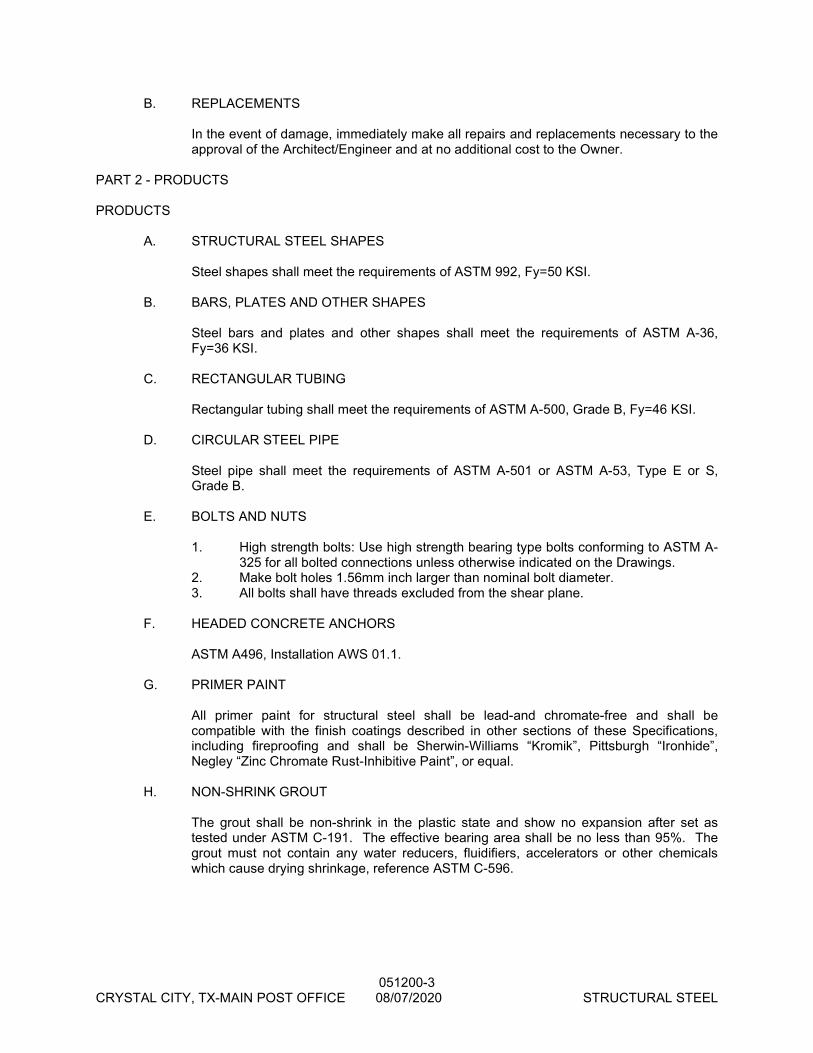
051200-3 CRYSTAL CITY, TX-MAIN POST OFFICE 08/07/2020 STRUCTURAL STEEL
B. REPLACEMENTS
In the event of damage, immediately make all repairs and replacements necessary to the approval of the Architect/Engineer and at no additional cost to the Owner.
PART 2 - PRODUCTS PRODUCTS
A. STRUCTURAL STEEL SHAPES Steel shapes shall meet the requirements of ASTM 992, Fy=50 KSI.
B. BARS, PLATES AND OTHER SHAPES
Steel bars and plates and other shapes shall meet the requirements of ASTM A-36, Fy=36 KSI.
C. RECTANGULAR TUBING
Rectangular tubing shall meet the requirements of ASTM A-500, Grade B, Fy=46 KSI. D. CIRCULAR STEEL PIPE
Steel pipe shall meet the requirements of ASTM A-501 or ASTM A-53, Type E or S, Grade B.
E. BOLTS AND NUTS
1. High strength bolts: Use high strength bearing type bolts conforming to ASTM A-325 for all bolted connections unless otherwise indicated on the Drawings.
2. Make bolt holes 1.56mm inch larger than nominal bolt diameter. 3. All bolts shall have threads excluded from the shear plane. F. HEADED CONCRETE ANCHORS ASTM A496, Installation AWS 01.1. G. PRIMER PAINT
All primer paint for structural steel shall be lead-and chromate-free and shall be compatible with the finish coatings described in other sections of these Specifications, including fireproofing and shall be Sherwin-Williams “Kromik”, Pittsburgh “Ironhide”, Negley “Zinc Chromate Rust-Inhibitive Paint”, or equal.
H. NON-SHRINK GROUT
The grout shall be non-shrink in the plastic state and show no expansion after set as tested under ASTM C-191. The effective bearing area shall be no less than 95%. The grout must not contain any water reducers, fluidifiers, accelerators or other chemicals which cause drying shrinkage, reference ASTM C-596.
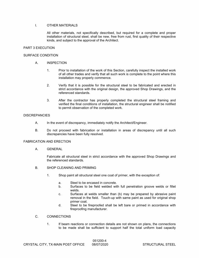
051200-4 CRYSTAL CITY, TX-MAIN POST OFFICE 08/07/2020 STRUCTURAL STEEL
I. OTHER MATERIALS
All other materials, not specifically described, but required for a complete and proper installation of structural steel, shall be new, free from rust, first quality of their respective kinds, and subject to the approval of the Architect.
PART 3 EXECUTION SURFACE CONDITION A. INSPECTION
1. Prior to installation of the work of this Section, carefully inspect the installed work of all other trades and verify that all such work is complete to the point where this installation may properly commence.
2. Verify that it is possible for the structural steel to be fabricated and erected in
strict accordance with the original design, the approved Shop Drawings, and the referenced standards.
3. After the contractor has properly completed the structural steel framing and
verified the final conditions of installation, the structural engineer shall be notified to permit observation of the completed work.
DISCREPANCIES A. In the event of discrepancy, immediately notify the Architect/Engineer.
B. Do not proceed with fabrication or installation in areas of discrepancy until all such discrepancies have been fully resolved.
FABRICATION AND ERECTION A. GENERAL
Fabricate all structural steel in strict accordance with the approved Shop Drawings and the referenced standards.
B. SHOP CLEANING AND PRIMING 1. Shop paint all structural steel one coat of primer, with the exception of: a. Steel to be encased in concrete. b. Surfaces to be field welded with full penetration groove welds or fillet
welds. c. Surfaces at welds smaller than (b) may be prepared by abrasive paint
removal in the field. Touch-up with same paint as used for original shop primer coat.
d. Steel to be fireproofed shall be left bare or primed in accordance with fireproofing manufacturer.
C. CONNECTIONS
1. If beam reactions or connection details are not shown on plans, the connections to be made shall be sufficient to support half the total uniform load capacity
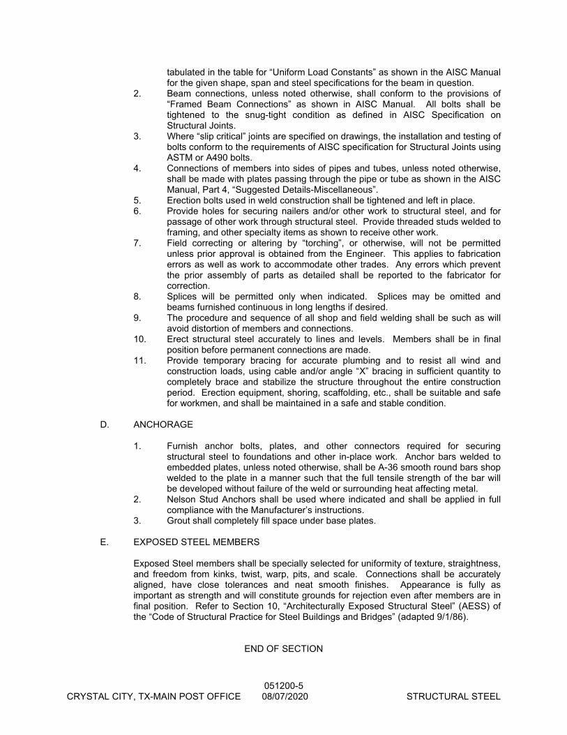
051200-5 CRYSTAL CITY, TX-MAIN POST OFFICE 08/07/2020 STRUCTURAL STEEL
tabulated in the table for “Uniform Load Constants” as shown in the AISC Manual for the given shape, span and steel specifications for the beam in question.
2. Beam connections, unless noted otherwise, shall conform to the provisions of “Framed Beam Connections” as shown in AISC Manual. All bolts shall be tightened to the snug-tight condition as defined in AISC Specification on Structural Joints.
3. Where “slip critical” joints are specified on drawings, the installation and testing of bolts conform to the requirements of AISC specification for Structural Joints using ASTM or A490 bolts.
4. Connections of members into sides of pipes and tubes, unless noted otherwise, shall be made with plates passing through the pipe or tube as shown in the AISC Manual, Part 4, “Suggested Details-Miscellaneous”.
5. Erection bolts used in weld construction shall be tightened and left in place. 6. Provide holes for securing nailers and/or other work to structural steel, and for
passage of other work through structural steel. Provide threaded studs welded to framing, and other specialty items as shown to receive other work.
7. Field correcting or altering by “torching”, or otherwise, will not be permitted unless prior approval is obtained from the Engineer. This applies to fabrication errors as well as work to accommodate other trades. Any errors which prevent the prior assembly of parts as detailed shall be reported to the fabricator for correction.
8. Splices will be permitted only when indicated. Splices may be omitted and beams furnished continuous in long lengths if desired.
9. The procedure and sequence of all shop and field welding shall be such as will avoid distortion of members and connections.
10. Erect structural steel accurately to lines and levels. Members shall be in final position before permanent connections are made.
11. Provide temporary bracing for accurate plumbing and to resist all wind and construction loads, using cable and/or angle “X” bracing in sufficient quantity to completely brace and stabilize the structure throughout the entire construction period. Erection equipment, shoring, scaffolding, etc., shall be suitable and safe for workmen, and shall be maintained in a safe and stable condition.
D. ANCHORAGE
1. Furnish anchor bolts, plates, and other connectors required for securing structural steel to foundations and other in-place work. Anchor bars welded to embedded plates, unless noted otherwise, shall be A-36 smooth round bars shop welded to the plate in a manner such that the full tensile strength of the bar will be developed without failure of the weld or surrounding heat affecting metal.
2. Nelson Stud Anchors shall be used where indicated and shall be applied in full compliance with the Manufacturer’s instructions.
3. Grout shall completely fill space under base plates. E. EXPOSED STEEL MEMBERS
Exposed Steel members shall be specially selected for uniformity of texture, straightness, and freedom from kinks, twist, warp, pits, and scale. Connections shall be accurately aligned, have close tolerances and neat smooth finishes. Appearance is fully as important as strength and will constitute grounds for rejection even after members are in final position. Refer to Section 10, “Architecturally Exposed Structural Steel” (AESS) of the “Code of Structural Practice for Steel Buildings and Bridges” (adapted 9/1/86).
END OF SECTION
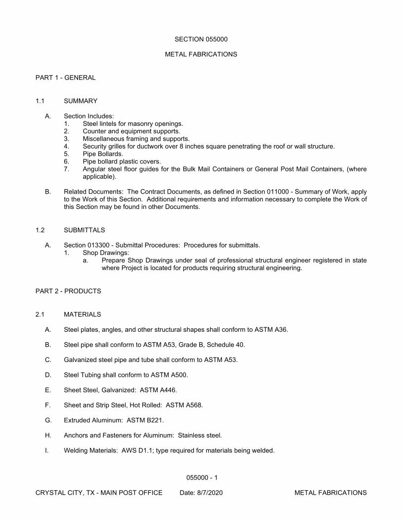
055000 - 1
CRYSTAL CITY, TX - MAIN POST OFFICE Date: 8/7/2020 METAL FABRICATIONS
SECTION 055000
METAL FABRICATIONS
PART 1 - GENERAL
1.1 SUMMARY
A. Section Includes: 1. Steel lintels for masonry openings. 2. Counter and equipment supports. 3. Miscellaneous framing and supports. 4. Security grilles for ductwork over 8 inches square penetrating the roof or wall structure. 5. Pipe Bollards. 6. Pipe bollard plastic covers. 7. Angular steel floor guides for the Bulk Mail Containers or General Post Mail Containers, (where
applicable).
B. Related Documents: The Contract Documents, as defined in Section 011000 - Summary of Work, apply to the Work of this Section. Additional requirements and information necessary to complete the Work of this Section may be found in other Documents.
1.2 SUBMITTALS
A. Section 013300 - Submittal Procedures: Procedures for submittals. 1. Shop Drawings:
a. Prepare Shop Drawings under seal of professional structural engineer registered in state where Project is located for products requiring structural engineering.
PART 2 - PRODUCTS
2.1 MATERIALS
A. Steel plates, angles, and other structural shapes shall conform to ASTM A36.
B. Steel pipe shall conform to ASTM A53, Grade B, Schedule 40.
C. Galvanized steel pipe and tube shall conform to ASTM A53.
D. Steel Tubing shall conform to ASTM A500.
E. Sheet Steel, Galvanized: ASTM A446.
F. Sheet and Strip Steel, Hot Rolled: ASTM A568.
G. Extruded Aluminum: ASTM B221.
H. Anchors and Fasteners for Aluminum: Stainless steel.
I. Welding Materials: AWS D1.1; type required for materials being welded.
055000 - 2
CRYSTAL CITY, TX - MAIN POST OFFICE Date: 8/7/2020 METAL FABRICATIONS
J. Anchors 1. Threaded Type Concrete Inserts: Galvanized malleable iron or cast steel capable of receiving
3/4 inch diameter machine bolts. 2. Slotted Type Concrete Inserts: Welded box type fabricated with minimum 1/8 inch thick
galvanized pressed steel plate with slot to receive 3/4 inch diameter square head bolt and knockout cover.
3. Expansion Shield for Masonry Anchorage: FS FF-2-325. 4. Toggle Bolts: FS FF-B-588.
K. Fasteners
1. Bolts, Nuts and Washers for Exterior Locations: ASTM A307, galvanized in accordance with ASTM A153.
2. Bolts, Nuts and Washers for Interior Locations: ASTM A307, Grade A, regular hexagon head. 3. Bolts, Round Head: ANSI B-18.5 4. Wood Screws, Flat Head Carbon Steel: ANSI B-18.6.1. 5. Plain Washers, Helical Spring Type Carbon Steel: FS FF-W-84.
L. Security Grilles:
1. All grilles are to be factory fabricated of 1/2 inch (1.25 cm) diameter tool-resistant, round steel bars spaced a maximum eight inches (20 cm) on center each direction. The bars are to be framed with a minimum 1/8 inch (0.625 cm) by 1 inch (2.5 cm) flat steel.
2. Grilles must be securely fastened to the structural framing around the opening with welded or non-removable fasteners at a maximum 6 inches (15.25 cm) on center.
M. Primers:
1. Primer for Painting: One of following: a. Tnemec, Kansas City, MO, (816) 474-3400: No. 99 red primer. b. Chessman-Elliot Company: Ceco No. 15 Primox. c. Rowe Products, Inc.: No. 7-C-19. d. Section 016000 – Product Substitutions. Substitutions: Permitted.
2. Touch-Up Primer for Galvanized Surfaces: FS TT-P-641.
2.2 FABRICATION
A. Fabricate steel items according to approved shop drawings and to applicable portions of AISC Specifications. Conceal welds where possible; grind exposed welds smooth and flush with adjacent finished surface. Ease exposed edges to small uniform radius.
B. Pre-assemble products in shop to greatest extent possible. Disassemble units to extent necessary for
shipping and handling. Clearly mark units for re-assemble and installation.
C. For exposed to view fabrications, use materials which are smooth and free of surface blemishes including pitting, seams marks, roller marks, roller trade names and roughness. Remove blemishes by grinding or by welding and grinding, prior to cleaning, treating and application of surface finishes including zinc coating.
D. Fabricate items with joints tightly fitted and secured.
E. Fit and shop assemble in largest practical sections for delivery to Project site.
F. Exposed Mechanical Fastenings: Flush countersunk screws or bolts; unobtrusively located; consistent
with design of structure, except where specifically noted otherwise.
G. Make exposed joints butt tight, flush and hairline.
055000 - 3
CRYSTAL CITY, TX - MAIN POST OFFICE Date: 8/7/2020 METAL FABRICATIONS
H. Fabricate anchorage and related components of same material and finish as metal fabrication, unless indicated otherwise.
2.3 ROUGH HARDWARE
A. Furnish bent or otherwise custom fabricated bolts, plates, anchors, hangers, dowels, and other miscellaneous steel and iron shapes as required for framing and supporting woodwork, and for anchoring or securing woodwork to concrete or other structures. Straight bolts and other stock rough hardware items are specified in Division 6 sections.
B. Fabricate items to sizes, shapes, and dimensions required. Furnish malleable-iron washers for heads
and nuts which bear on wood structural connections; elsewhere, furnish steel washers. 2.4 LOOSE STEEL LINTELS
C. Fabricate loose structural steel lintels from steel angles and shapes of size indicated for openings and recesses in masonry walls and partitions at locations indicated.
D. Weld adjoining members together to form a single unit where indicated.
E. Size loose lintels for equal bearing of one inch per foot of clear span but not less than 8 inches bearing
at each side of openings, unless otherwise indicated.
F. Galvanize all surfaces of loose steel lintels located in exterior walls.
2.4 MISCELLANEOUS FRAMING AND SUPPORTS
A. General: Provide steel framing and supports for applications indicated or which are not a part of structural steel framework, as required to complete work.
B. Fabricate units to sizes, shapes, and profiles indicated and required to receive adjacent other
construction retained by framing and supports. Fabricate from structural steel shapes, plates, and steel bars of welded construction using mitered joints for field connection. Cut, drill, and tap units to receive hardware, hangers, and similar items. 1. Equip units with integrally welded anchors for casting into concrete or building into masonry.
Furnish inserts if units must be installed after concrete is placed. a. Except as otherwise indicated, space anchors 24 inches on center and provide minimum
anchor units in the form of steel straps 1-1/4 inch x 8 inches long.
C. Fabricate support for suspended toilet partitions as follows: 1. Beams: Continuous steel shapes of size required to limit deflection to L/360 between hangers,
but use not less than C 8 x 11.5 channels or another shape with equivalent structural properties. 2. Hangers: Steel rods, 1/2 inch in diameter, spaced not more than 36 inches on center. Thread
rods to receive anchor and stop nuts. Fit hangers with wedge shape washers for full bearing on sloping flanges of support beam.
3. Braces and Angels: Steel angles of size required for rigid support of beam and for secure anchorage.
2.5 MISCELLANEOUS STEEL TRIM
A. Provide shapes and sizes indicated for profiles shown. Unless otherwise indicated, fabricate units from structural steel shapes, plates, and steel bars, with continuously welded joints and smooth exposed
055000 - 4
CRYSTAL CITY, TX - MAIN POST OFFICE Date: 8/7/2020 METAL FABRICATIONS
edges. Use concealed field splices wherever possible. Provide cutouts, fittings, and anchorages as required for coordination of assembly and installation with other work.
B. Galvanize miscellaneous framing and supports in the following locations:
1. Exterior locations.
2.6 SHELF AND RELIEVING ANGLES
A. Fabricate shelf and relieving angles from steel angles of sizes indicated and for attachment to concrete farming. Provide slotted holes to receive 3/4 inch bolts, spaced not more than 6 inches from ends and not more than 24 inches on center, unless otherwise indicated.
B. Galvanize shelf angles to be installed on exterior concrete framing.
2.7 PIPE BOLLARDS
A. Fabricate pipe bollards from Schedule 80 steel pipe. Exterior bollards to be galvanized. Fill bollards with concrete rounded off at top. Paint bollards per Section 099100.
B. Fabricate pipe bollards from Schedule 80 steel pipe. Exterior bollards are to be galvanized. Fill bollards
with concrete flush at top. Do not paint bollards. Install pipe bollard plastic cover.
C. Fabricate sleeves for bollard anchorage from steel pipe with 1/4 inch thick steel plate welded to bottom of sleeve. Exterior sleeves are to be galvanized.
2.8 PIPE BOLLARD PLASTIC COVERS
A. Exterior shell cover of low density polyethylene and interior steel sleeve. Covers are to be 1/4 inch nominal wall thickness with ultraviolet and anti-static additives and a dome top. Install over steel pipe posts as indicated on Drawings. Subject to compliance with project requirements, manufacturers offering Products which may be incorporated in the Work include the following: 1. Ideal Shield, L.L.C., Detroit, MI (313) 842-7290, (800) 731-1722. 2. Liberty Equipment Sales, Houston, TX (281) 987-8708, (888) 987-8708.
2.9 FINISHES, GENERAL
A. Comply with NAAMM “Metal Finishes Manual” for recommendations relative to application and designations of finishes.
B. Finish metal fabrications after assembly.
2.10 STEEL AND IRON FINISHES
A. Galvanizing: For those items indicated for galvanizing, apply zinc-coating by the hot-dip process compliance with the following requirements: 1. ASTM A153 for galvanizing iron and steel hardware. 2. ASTM A123 for galvanizing both fabricated and unfabricated iron and steel products made of
uncoated rolled, pressed, and forged shapes, plates, bars, and strip 0.0299 inch thick and heavier.

055000 - 5
CRYSTAL CITY, TX - MAIN POST OFFICE Date: 8/7/2020 METAL FABRICATIONS
B. Preparation for Shop Priming: Prepare uncoated ferrous metal surfaces to comply with minimum requirements indicated below for SSPC surface preparation specifications and environmental exposure conditions of installed metal fabrications: 1. Interiors (SSPC Zone 1A): SSPC-SP3 “Power Tool Cleaning”:
C. Apply shop primer to uncoated surfaces of metal fabrications, except those with galvanized finish or to
be embedded in concrete, sprayed-on fireproofing, or masonry, unless otherwise indicated. Comply with requirements of SSPC-PA1 “Paint Application Specification No. 1” for shop painting.
2.11 SHOP PAINTING AND PROTECTIVE COATING
A. Conform to Steel Structures Painting Council Specification 15-68T, Type 1, including preparation for painting.
B. Hot-Dip galvanizing and zinc coatings applied on products fabricated from rolled, pressed, and forged
steel shapes, plates, bars and strips shall comply with ASTM Specification A123. Galvanized surfaces for which a shop coat of paint is specified shall be chemically treated to provide a bond for the paint. Except for bolts and nuts, all galvanizing shall be done after fabrication.
C. Clean surfaces of rust, scale, grease and foreign matter in accordance with SSPC SP-1 solvent
cleaning, prior to finishing. Prepare surfaces for painting in accordance with SSPC-SP2 Hand Tool Cleaning, SSPC-SP3 Power Tool Cleaning or SSPC SP-7 Brush Off Blast Cleaning.
D. Do not prime surfaces in direct contact bond with concrete or where field welding is required.
E. Prime paint items scheduled with one coat.
F. Protect aluminum surfaces in contact with steel with zinc chromate primer.
PART 3 - EXECUTION
3.1 INSTALLATION
A. Fastening to In-Place Construction: Provide anchorage devices and fasteners where necessary for securing miscellaneous metal fabrications to in-place construction; include threaded fasteners for concrete and masonry inserts, toggle bolts, through-bolts, lag bolts, wood screws, and other connectors as required.
B. Cutting, Fitting, and Placement: Perform cutting, drilling, and fitting required for installation of
miscellaneous metal fabrications. Set metal fabrication accurately in location, alignment, and elevation; with edges and surfaces level, plumb, true, and free of rack; and measured from established lines and levels.
C. Provide temporary bracing or anchors in formwork for items that are to be built into concrete masonry or
similar construction.
D. Fit exposed connections accurately together to form hairline joints. Weld connections that are not to be left as exposed joints, but cannot be shop welded because of shipping size limitations. Do not weld, cut or abrade the surfaces of exterior units which have been hot-dip galvanized after fabrication, and are intended for bolted or screwed field connections.
E. Field Welding: Comply with AWS Code for procedures of manual shielded metal-arc welding,
appearance and quality of welds made, methods used in correcting welding work, and the following:
055000 - 6
CRYSTAL CITY, TX - MAIN POST OFFICE Date: 8/7/2020 METAL FABRICATIONS
1. Use materials and methods that minimize distortion and develop strength and corrosion resistance of base metals.
2. Obtain fusion without undercut or overlap. 3. Remove welding flux immediately. 4. At exposed connections, finish exposed welds and surfaces smooth and blended so that no
roughness shows after finishing and contour of welded surface matches those adjacent. 3.4 INSTALLATION - SECURITY GRILLES
A. Securely fasten to structural framing around opening with tamper-proof fasteners.
3.5 INSTALLATION - BOLLARDS
F. Anchor bollards in concrete by means of pipe sleeves preset and anchored into concrete. After bollards
have been inserted into sleeves, fill annular space between bollard and sleeve solid with nonshrink, nonmetallic grout, mixed and placed to comply with grout manufacturer’s directions.
G. Install pipe bollard plastic covers per manufacturer’s recommendation.
3.2 ADJUSTING AND CLEANING
A. Touch-Up Painting: Immediately after erection, clean field welds, bolted connections, and abraded areas of shop paint, and paint exposed areas with same material as used for shop painting to comply with SSPC-PA 1 requirements for touch-up of field painted surfaces. 1. Apply by brush or spray to provide a minimum dry film thickness of 2.0 mils.
B. For galvanized surfaces clean welds, bolted connections and abraded areas and apply galvanizing
repair paint to comply with ASTM A780.
END OF SECTION
055213 - 1
CRYSTAL CITY, TX - MAIN POST OFFICE Date: 8/7/2020 PIPE AND TUBE RAILINGS
SECTION 055213
PIPE AND TUBE RAILINGS
PART 1 - GENERAL
1.1 SUMMARY
A. Section Includes: 1. Steel pipe handrails.
B. Related Documents: The Contract Documents, as defined in Section 011000 - Summary of Work, apply to the Work of this Section. Additional requirements and information necessary to complete the Work of this Section may be found in other Documents.
1.2 SYSTEM DESCRIPTION
A. Design Requirements: 1. Design, engineer, fabricate and install handrails and railing systems to comply with requirements
of ASTM E 985 for structural performance based on testing performed in accordance with ASTM E 894 and E 935.
2. Railing assembly, wall rails, and attachments to comply with local code requirements and to resist minimum lateral force according to IBC or more stringent local building code at any point without damage or permanent set.
PART 2 - PRODUCTS
2.1 MATERIALS
A. Pipe: ASTM A 53, Grade B Schedule 80.
B. Rails and Posts: Steel pipe; with welded joints, of sizes and shapes as indicated on Drawings.
C. Fittings: Elbows, T-shapes, wall brackets, escutcheons; machined steel.
D. Mounting on Concrete Floor: Steel sleeves, sized to receive railing post with 1/4 inch clearance.
E. Mounting on Masonry or Concrete Walls: Brackets with anchors for building in masonry.
F. Mounting on Stud Walls: Brackets and anchor plates, predrilled to receive bolts.
G. Splice Connectors: Steel threaded collars.
2.2 FABRICATION
A. Fit and shop assemble sections in largest practical sizes, for delivery to site and installation.
B. Supply components required for secure anchorage of handrails and railings.
055213 - 2
CRYSTAL CITY, TX - MAIN POST OFFICE Date: 8/7/2020 PIPE AND TUBE RAILINGS
C. Fully weld joints. Grind exposed welds smooth and flush with adjacent surfaces.
D. Wake exposed joint butt tight, flush, and hairline.
E. Accurately form components required for anchorage of railings to each other and to building structure.
F. Prime railings which will be exposed.
2.3 FINISH
A. At Building Exterior: 1. Galvanizing: ASTM A123; provide minimum 2.0 ounces per square foot. 2. Touch-Up Primer for Galvanized Surfaces: SSPC 20 Type I Inorganic zinc rich.
B. At Building Interior: SSPC 15, Type 1, red oxide.
C. Field paint as specified in Section 099100.
PART 3 - EXECUTION
3.1 PREPARATION
A. Furnish items required to be cast into concrete, embedded in masonry, placed in partitions with setting templates, to appropriate Sections.
3.2 INSTALLATION
A. Install in accordance with manufacturer's published instructions.
B. Install components plumb and level, accurately fitted, free from distortion or defects.
C. Anchor railings to structure with anchors in conformance with ASTM E 985.
D. Field weld anchors as indicated on Drawings. Touch-up welds with primer. Grind welds smooth.
E. Insert railing posts in sleeves and pack sleeves with non-shrink grout.
END OF SECTION
06100 - 1 CRYSTAL CITY, TX-MAIN POST OFFICE 08/07/2020 ROUGH CARPENTRY
SECTION 06100
ROUGH CARPENTRY
PART 1 - GENERAL
1.1 RELATED DOCUMENTS
A. Drawings and general provisions of the Contract, including General and Supplementary Conditions and Division 1 Specification Sections, apply to this Section.
1.2 SUMMARY
A. This Section includes the following:
1. Framing with dimension lumber. 2. Framing with timber. 3. Framing with engineered wood products. 4. Rooftop equipment bases and support curbs. 5. Wood blocking[, cants,] and nailers. 6. Utility shelving. 7. Wood furring[ and grounds]. 8. Sheathing. 9. Subflooring and underlayment. 10. Plywood backing panels. 11. Building wrap.
B. Related Sections include the following:
1. Division 6 Section "Heavy Timber Construction." 2. Division 6 Section "Metal-Plate-Connected Wood Trusses." 3. Division 6 Section "Finish Carpentry" for nonstructural carpentry items exposed to view and
not specified in another Section.
1.3 DEFINITIONS
A. Rough Carpentry: Carpentry work not specified in other Sections and not exposed, unless otherwise indicated.
B. Exposed Framing: Dimension lumber not concealed by other construction.
C. Lumber grading agencies, and the abbreviations used to reference them, include the following:
1. NELMA - Northeastern Lumber Manufacturers Association. 2. NLGA - National Lumber Grades Authority. 3. RIS - Redwood Inspection Service. 4. SPIB - Southern Pine Inspection Bureau. 5. WCLIB - West Coast Lumber Inspection Bureau. 6. WWPA - Western Wood Products Association.
06100 - 2 CRYSTAL CITY, TX-MAIN POST OFFICE 08/07/2020 ROUGH CARPENTRY
1.4 SUBMITTALS
A. Product Data: For each type of process and factory-fabricated product. Indicate component materials and dimensions and include construction and application details.
1. Include data for wood-preservative treatment from chemical treatment manufacturer and certification by treating plant that treated materials comply with requirements. Indicate type of preservative used, net amount of preservative retained, and chemical treatment manufacturer's written instructions for handling, storing, installing, and finishing treated material.
2. Include data for fire-retardant treatment from chemical treatment manufacturer and certification by treating plant that treated materials comply with requirements. Include physical properties of treated materials, both before and after exposure to elevated temperatures when tested according to ASTM D 5516 and ASTM D 5664.
3. For products receiving a waterborne treatment, include statement that moisture content of treated materials was reduced to levels specified before shipment to Project site.
4. Include copies of warranties from chemical treatment manufacturers for each type of treatment.
B. Material Certificates: For dimension lumber specified to comply with minimum allowable unit stresses. Indicate species and grade selected for each use and design values approved by the American Lumber Standards Committee Board of Review.
C. Research/Evaluation Reports: For the following, showing compliance with building code in effect for Project:
1. Preservative-treated wood. 2. Fire-retardant-treated wood. 3. Engineered wood products. 4. Foam-plastic sheathing. 5. Power-driven fasteners. 6. Powder-actuated fasteners. 7. Expansion anchors. 8. Metal framing anchors. 9. Building wrap.
1.5 QUALITY ASSURANCE
A. Testing Agency Qualifications: An independent testing agency, acceptable to authorities having jurisdiction, with the experience and capability to conduct the testing indicated, as documented according to ASTM E 548.
B. Source Limitations for Engineered Wood Products: Obtain each type of engineered wood product through one source from a single manufacturer.
C. Source Limitations for Fire-Retardant-Treated Wood: Obtain each type of fire-retardant-treated wood product through one source from a single producer.
1.6 DELIVERY, STORAGE, AND HANDLING
A. Stack lumber, plywood, and other panels; place spacers between each bundle to provide air circulation. Provide for air circulation around stacks and under coverings.
06100 - 3 CRYSTAL CITY, TX-MAIN POST OFFICE 08/07/2020 ROUGH CARPENTRY
PART 2 - PRODUCTS
2.1 MANUFACTURERS
A. Available Manufacturers: Subject to compliance with requirements, manufacturers offering products that may be incorporated into the Work include, but are not limited to, the following:
B. Manufacturers: Subject to compliance with requirements, provide products by one of the following:
1. Laminated-Veneer Lumber:
a. Boise Cascade Corporation. b. Georgia-Pacific Corporation. c. Louisiana-Pacific Corporation. d. Pacific Woodtech Corp. e. Trus Joist MacMillan. f. Union Camp Corp.; Building Products Division. g. Willamette Industries, Inc.
2. Parallel-Strand Lumber:
a. Trus Joist MacMillan.
3. Gypsum Sheathing Board:
a. American Gypsum Co. b. G-P Gypsum Corporation. c. National Gypsum Company. d. United States Gypsum Co. e. <Insert manufacturer's name.>
4. Extruded-Polystyrene-Foam Wall Sheathing:
a. DiversiFoam Products. b. Dow Chemical Company (The). c. Owens Corning. d. Tenneco Building Products. e. <Insert manufacturer's name.>
5. Polyisocyanurate-Foam Wall Sheathing:
a. Apache Products Company. b. Celotex Corporation (The); Building Products Division. c. Rmax, Inc. d. <Insert manufacturer's name.>
6. Building Wrap:
a. Celotex Corporation (The); Building Products Division. b. DuPont (E. I. du Pont de Nemours and Company). c. Parsec, Inc. d. Raven Industries, Inc. e. Reemay, Inc.
06100 - 4 CRYSTAL CITY, TX-MAIN POST OFFICE 08/07/2020 ROUGH CARPENTRY
f. Simplex Products. g. Sto-Cote Products, Inc. h. Tenneco Building Products.
7. Metal Framing Anchors:
a. Alpine Engineered Products, Inc. b. Cleveland Steel Specialty Co. c. Harlen Metal Products, Inc. d. KC Metals Products, Inc. e. Silver Metal Products, Inc. f. Simpson Strong-Tie Company, Inc. g. Southeastern Metals Manufacturing Co., Inc. h. United Steel Products Company, Inc.
2.2 WOOD PRODUCTS, GENERAL
A. Lumber: DOC PS 20 and applicable rules of lumber grading agencies certified by the American Lumber Standards Committee Board of Review.
1. Factory mark each piece of lumber with grade stamp of grading agency. 2. For exposed lumber indicated to receive a stained or natural finish, mark grade stamp on
end or back of each piece[, or omit grade stamp and provide certificates of grade compliance issued by grading agency].
3. Where nominal sizes are indicated, provide actual sizes required by DOC PS 20 for moisture content specified. Where actual sizes are indicated, they are minimum dressed sizes for dry lumber.
4. Provide dressed lumber, S4S, unless otherwise indicated. 5. Provide dry lumber with 19 percent maximum moisture content at time of dressing for 2-
inch nominal (38-mm actual) thickness or less, unless otherwise indicated. 6. Provide dry lumber with 15 percent maximum moisture content at time of dressing for 2-
inch nominal (38-mm actual) thickness or less, unless otherwise indicated.
B. Engineered Wood Products: Provide engineered wood products acceptable to authorities having jurisdiction and for which current model code research or evaluation reports exist that show compliance with building code in effect for Project.
1. Allowable Design Stresses: Provide engineered wood products with allowable design stresses, as published by manufacturer, that meet or exceed those indicated. Manufacturer's published values shall be determined from empirical data or by rational engineering analysis and demonstrated by comprehensive testing performed by a qualified independent testing agency.
C. Wood Structural Panels:
1. Plywood: Either DOC PS 1 or DOC PS 2, unless otherwise indicated. 2. Oriented Strand Board: DOC PS 2. 3. Thickness: As needed to comply with requirements specified but not less than thickness
indicated. 4. Comply with "Code Plus" provisions in APA Form No. E30K, "APA Design/Construction
Guide: Residential & Commercial." 5. Factory mark panels according to indicated standard.
06100 - 5 CRYSTAL CITY, TX-MAIN POST OFFICE 08/07/2020 ROUGH CARPENTRY
2.3 WOOD-PRESERVATIVE-TREATED MATERIALS
A. Preservative Treatment by Pressure Process: AWPA C2 (lumber) and AWPA C9 (plywood), except that lumber that is not in contact with the ground and is continuously protected from liquid water may be treated according to AWPA C31 with inorganic boron (SBX).
1. Preservative Chemicals: Acceptable to authorities having jurisdiction and [one of] the following:
a. Chromated copper arsenate (CCA). b. Ammoniacal copper zinc arsenate (ACZA). c. Ammoniacal, or amine, copper quat (ACQ). d. Copper bis (dimethyldithiocarbamate) (CDDC). e. Ammoniacal copper citrate (CC). f. Copper azole, Type A (CBA-A). g. Oxine copper (copper-8-quinolinolate) in a light petroleum solvent.
2. For exposed items indicated to receive a stained or natural finish, use chemical formulations that do not require incising, contain colorants, bleed through, or otherwise adversely affect finishes.
B. Kiln-dry material after treatment to a maximum moisture content of 19 percent for lumber and 15 percent for plywood. Do not use material that is warped or does not comply with requirements for untreated material.
C. Mark each treated item with the treatment quality mark of an inspection agency approved by the American Lumber Standards Committee Board of Review.
1. For exposed lumber indicated to receive a stained or natural finish, mark end or back of each piece[, or omit marking and provide certificates of treatment compliance issued by inspection agency].
D. Application: Treat items indicated on Drawings, and the following:
1. Wood cants, nailers, curbs, equipment support bases, blocking, stripping, and similar members in connection with roofing, flashing, vapor barriers, and waterproofing.
2. Wood sills, sleepers, blocking, furring, stripping, and similar concealed members in contact with masonry or concrete.
3. Wood framing members less than 18 inches (460 mm) above grade. 4. Wood floor plates that are installed over concrete slabs directly in contact with earth.
2.4 FIRE-RETARDANT-TREATED MATERIALS
A. General: Where fire-retardant-treated materials are indicated, provide materials that comply with performance requirements in [AWPA C20 (lumber)] [and] [AWPA C27 (plywood)]. Identify fire-retardant-treated wood with appropriate classification marking of UL, U.S. Testing, Timber Products Inspection, or another testing and inspecting agency acceptable to authorities having jurisdiction.
1. Use treatment for which chemical manufacturer publishes physical properties of treated wood after exposure to elevated temperatures, when tested by a qualified independent testing agency according to [ASTM D 5664, for lumber] [and] [ASTM D 5516, for plywood].
2. Use treatment that does not promote corrosion of metal fasteners.
06100 - 6 CRYSTAL CITY, TX-MAIN POST OFFICE 08/07/2020 ROUGH CARPENTRY
3. Use Exterior type for exterior locations and where indicated. 4. Use Interior Type A High Temperature (HT), unless otherwise indicated.
B. For exposed items indicated to receive a stained or natural finish, use chemical formulations that do not bleed through, contain colorants, or otherwise adversely affect finishes.
2.5 DIMENSION LUMBER
A. General: Provide dimension lumber of grades indicated according to the American Lumber Standards Committee National Grading Rule provisions of the grading agency indicated.
B. Non-Load-Bearing Interior Partitions: [Construction, Stud, or No. 2] [Standard, Stud, or No. 3] grade and [any of] the following species:
1. Mixed southern pine; SPIB. 2. Hem-fir or Hem-fir (north); NLGA, WCLIB, or WWPA. 3. Spruce-pine-fir (south) or Spruce-pine-fir; NELMA, NLGA, WCLIB, or WWPA. 4. Eastern softwoods; NELMA. 5. Northern species; NLGA. 6. Western woods; WCLIB or WWPA.
C. Framing Other Than Non-Load-Bearing Partitions: No. 2 grade and any of the following species:
1. Douglas fir-larch; WCLIB or WWPA. 2. Douglas fir-south; WWPA. 3. Douglas fir-larch (north); NLGA. 4. Hem-fir; WCLIB or WWPA. 5. Hem-fir (north); NLGA. 6. Southern pine; SPIB. 7. Mixed southern pine; SPIB. 8. Spruce-pine-fir (south); NELMA, WCLIB, or WWPA. 9. Spruce-pine-fir; NLGA.
D. Framing Other Than Non-Load-Bearing Partitions: Any species of machine stress-rated dimension lumber with a grade of not less than 1650f-1.5E.
E. Ceiling Joists (Non-Load-Bearing): Construction the following species:
1. Douglas fir-larch; WCLIB or WWPA. 2. Douglas fir-south; WWPA. 3. Douglas fir-larch (north); NLGA. 4. Hem-fir; WCLIB or WWPA. 5. Hem-fir (north); NLGA. 6. Southern pine; SPIB. 7. Mixed southern pine; SPIB. 8. Spruce-pine-fir (south); NELMA, WCLIB, or WWPA. 9. Spruce-pine-fir; NLGA.
F. Joists, Rafters, and Other Framing Not Listed Above: No. 2 grade and any of the following species:
1. Douglas fir-larch; WCLIB or WWPA. 2. Douglas fir-south; WWPA.
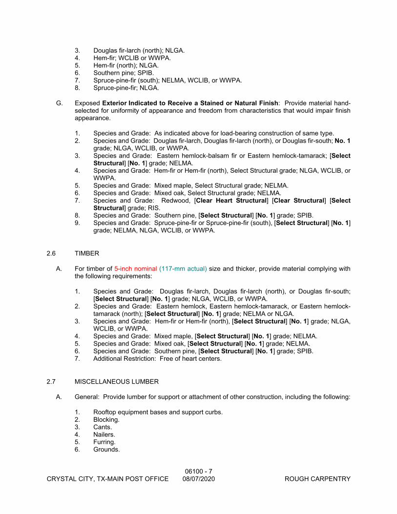
06100 - 7 CRYSTAL CITY, TX-MAIN POST OFFICE 08/07/2020 ROUGH CARPENTRY
3. Douglas fir-larch (north); NLGA. 4. Hem-fir; WCLIB or WWPA. 5. Hem-fir (north); NLGA. 6. Southern pine; SPIB. 7. Spruce-pine-fir (south); NELMA, WCLIB, or WWPA. 8. Spruce-pine-fir; NLGA.
G. Exposed Exterior Indicated to Receive a Stained or Natural Finish: Provide material hand-selected for uniformity of appearance and freedom from characteristics that would impair finish appearance.
1. Species and Grade: As indicated above for load-bearing construction of same type. 2. Species and Grade: Douglas fir-larch, Douglas fir-larch (north), or Douglas fir-south; No. 1
grade; NLGA, WCLIB, or WWPA. 3. Species and Grade: Eastern hemlock-balsam fir or Eastern hemlock-tamarack; [Select
Structural] [No. 1] grade; NELMA. 4. Species and Grade: Hem-fir or Hem-fir (north), Select Structural grade; NLGA, WCLIB, or
WWPA. 5. Species and Grade: Mixed maple, Select Structural grade; NELMA. 6. Species and Grade: Mixed oak, Select Structural grade; NELMA. 7. Species and Grade: Redwood, [Clear Heart Structural] [Clear Structural] [Select
Structural] grade; RIS. 8. Species and Grade: Southern pine, [Select Structural] [No. 1] grade; SPIB. 9. Species and Grade: Spruce-pine-fir or Spruce-pine-fir (south), [Select Structural] [No. 1]
grade; NELMA, NLGA, WCLIB, or WWPA.
2.6 TIMBER
A. For timber of 5-inch nominal (117-mm actual) size and thicker, provide material complying with the following requirements:
1. Species and Grade: Douglas fir-larch, Douglas fir-larch (north), or Douglas fir-south; [Select Structural] [No. 1] grade; NLGA, WCLIB, or WWPA.
2. Species and Grade: Eastern hemlock, Eastern hemlock-tamarack, or Eastern hemlock-tamarack (north); [Select Structural] [No. 1] grade; NELMA or NLGA.
3. Species and Grade: Hem-fir or Hem-fir (north), [Select Structural] [No. 1] grade; NLGA, WCLIB, or WWPA.
4. Species and Grade: Mixed maple, [Select Structural] [No. 1] grade; NELMA. 5. Species and Grade: Mixed oak, [Select Structural] [No. 1] grade; NELMA. 6. Species and Grade: Southern pine, [Select Structural] [No. 1] grade; SPIB. 7. Additional Restriction: Free of heart centers.
2.7 MISCELLANEOUS LUMBER
A. General: Provide lumber for support or attachment of other construction, including the following:
1. Rooftop equipment bases and support curbs. 2. Blocking. 3. Cants. 4. Nailers. 5. Furring. 6. Grounds.
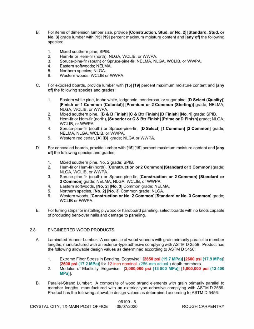
06100 - 8 CRYSTAL CITY, TX-MAIN POST OFFICE 08/07/2020 ROUGH CARPENTRY
B. For items of dimension lumber size, provide [Construction, Stud, or No. 2] [Standard, Stud, or No. 3] grade lumber with [15] [19] percent maximum moisture content and [any of] the following species:
1. Mixed southern pine; SPIB. 2. Hem-fir or Hem-fir (north); NLGA, WCLIB, or WWPA. 3. Spruce-pine-fir (south) or Spruce-pine-fir; NELMA, NLGA, WCLIB, or WWPA. 4. Eastern softwoods; NELMA. 5. Northern species; NLGA. 6. Western woods; WCLIB or WWPA.
C. For exposed boards, provide lumber with [15] [19] percent maximum moisture content and [any of] the following species and grades:
1. Eastern white pine, Idaho white, lodgepole, ponderosa, or sugar pine; [D Select (Quality)] [Finish or 1 Common (Colonial)] [Premium or 2 Common (Sterling)] grade; NELMA, NLGA, WCLIB, or WWPA.
2. Mixed southern pine, [B & B Finish] [C & Btr Finish] [D Finish] [No. 1] grade; SPIB. 3. Hem-fir or Hem-fir (north), [Superior or C & Btr Finish] [Prime or D Finish] grade; NLGA,
WCLIB, or WWPA. 4. Spruce-pine-fir (south) or Spruce-pine-fir, [D Select] [1 Common] [2 Common] grade;
NELMA, NLGA, WCLIB, or WWPA. 5. Western red cedar, [A] [B] grade; NLGA or WWPA.
D. For concealed boards, provide lumber with [15] [19] percent maximum moisture content and [any of] the following species and grades:
1. Mixed southern pine, No. 2 grade; SPIB. 2. Hem-fir or Hem-fir (north), [Construction or 2 Common] [Standard or 3 Common] grade;
NLGA, WCLIB, or WWPA. 3. Spruce-pine-fir (south) or Spruce-pine-fir, [Construction or 2 Common] [Standard or
3 Common] grade; NELMA, NLGA, WCLIB, or WWPA. 4. Eastern softwoods, [No. 2] [No. 3] Common grade; NELMA. 5. Northern species, [No. 2] [No. 3] Common grade; NLGA. 6. Western woods, [Construction or No. 2 Common] [Standard or No. 3 Common] grade;
WCLIB or WWPA.
E. For furring strips for installing plywood or hardboard paneling, select boards with no knots capable of producing bent-over nails and damage to paneling.
2.8 ENGINEERED WOOD PRODUCTS
A. Laminated-Veneer Lumber: A composite of wood veneers with grain primarily parallel to member lengths, manufactured with an exterior-type adhesive complying with ASTM D 2559. Product has the following allowable design values as determined according to ASTM D 5456:
1. Extreme Fiber Stress in Bending, Edgewise: [2850 psi (19.7 MPa)] [2600 psi (17.9 MPa)] [2500 psi (17.2 MPa)] for 12-inch nominal- (286-mm actual-) depth members.
2. Modulus of Elasticity, Edgewise: [2,000,000 psi (13 800 MPa)] [1,800,000 psi (12 400 MPa)].
B. Parallel-Strand Lumber: A composite of wood strand elements with grain primarily parallel to member lengths, manufactured with an exterior-type adhesive complying with ASTM D 2559. Product has the following allowable design values as determined according to ASTM D 5456:
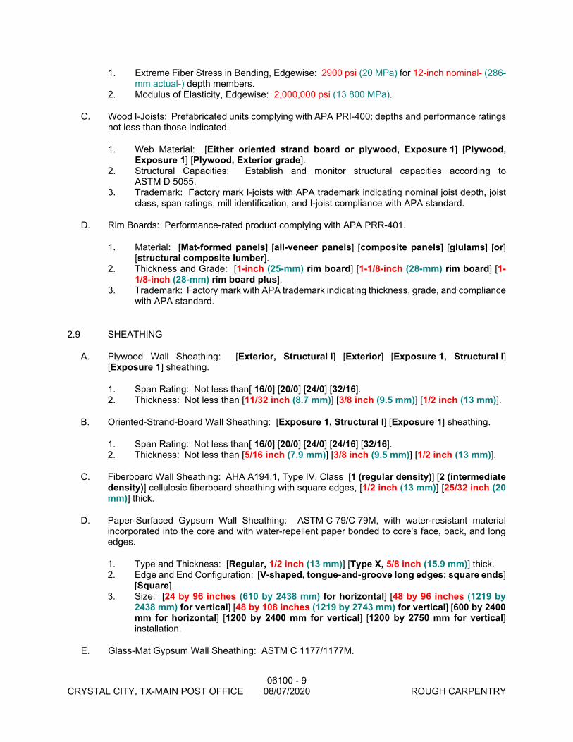
06100 - 9 CRYSTAL CITY, TX-MAIN POST OFFICE 08/07/2020 ROUGH CARPENTRY
1. Extreme Fiber Stress in Bending, Edgewise: 2900 psi (20 MPa) for 12-inch nominal- (286-mm actual-) depth members.
2. Modulus of Elasticity, Edgewise: 2,000,000 psi (13 800 MPa).
C. Wood I-Joists: Prefabricated units complying with APA PRI-400; depths and performance ratings not less than those indicated.
1. Web Material: [Either oriented strand board or plywood, Exposure 1] [Plywood, Exposure 1] [Plywood, Exterior grade].
2. Structural Capacities: Establish and monitor structural capacities according to ASTM D 5055.
3. Trademark: Factory mark I-joists with APA trademark indicating nominal joist depth, joist class, span ratings, mill identification, and I-joist compliance with APA standard.
D. Rim Boards: Performance-rated product complying with APA PRR-401.
1. Material: [Mat-formed panels] [all-veneer panels] [composite panels] [glulams] [or] [structural composite lumber].
2. Thickness and Grade: [1-inch (25-mm) rim board] [1-1/8-inch (28-mm) rim board] [1-1/8-inch (28-mm) rim board plus].
3. Trademark: Factory mark with APA trademark indicating thickness, grade, and compliance with APA standard.
2.9 SHEATHING
A. Plywood Wall Sheathing: [Exterior, Structural I] [Exterior] [Exposure 1, Structural I] [Exposure 1] sheathing.
1. Span Rating: Not less than[ 16/0] [20/0] [24/0] [32/16]. 2. Thickness: Not less than [11/32 inch (8.7 mm)] [3/8 inch (9.5 mm)] [1/2 inch (13 mm)].
B. Oriented-Strand-Board Wall Sheathing: [Exposure 1, Structural I] [Exposure 1] sheathing.
1. Span Rating: Not less than[ 16/0] [20/0] [24/0] [24/16] [32/16]. 2. Thickness: Not less than [5/16 inch (7.9 mm)] [3/8 inch (9.5 mm)] [1/2 inch (13 mm)].
C. Fiberboard Wall Sheathing: AHA A194.1, Type IV, Class [1 (regular density)] [2 (intermediate density)] cellulosic fiberboard sheathing with square edges, [1/2 inch (13 mm)] [25/32 inch (20 mm)] thick.
D. Paper-Surfaced Gypsum Wall Sheathing: ASTM C 79/C 79M, with water-resistant material incorporated into the core and with water-repellent paper bonded to core's face, back, and long edges.
1. Type and Thickness: [Regular, 1/2 inch (13 mm)] [Type X, 5/8 inch (15.9 mm)] thick. 2. Edge and End Configuration: [V-shaped, tongue-and-groove long edges; square ends]
[Square]. 3. Size: [24 by 96 inches (610 by 2438 mm) for horizontal] [48 by 96 inches (1219 by
2438 mm) for vertical] [48 by 108 inches (1219 by 2743 mm) for vertical] [600 by 2400 mm for horizontal] [1200 by 2400 mm for vertical] [1200 by 2750 mm for vertical] installation.
E. Glass-Mat Gypsum Wall Sheathing: ASTM C 1177/1177M.

06100 - 10 CRYSTAL CITY, TX-MAIN POST OFFICE 08/07/2020 ROUGH CARPENTRY
1. Product: Subject to compliance with requirements, provide "Dens-Glass Gold" by G-P Gypsum Corp.
2. Type and Thickness: [Regular, 1/2 inch (13 mm)] [Type X, 5/8 inch (15.9 mm)] thick. 3. Size: [48 by 96 inches (1219 by 2438 mm)] [48 by 108 inches (1219 by 2743 mm)] [48
by 120 inches (1219 by 3048 mm)] [1200 by 2400 mm] [1200 by 2750 mm] [1200 by 3050 mm] for vertical installation.
F. Extruded-Polystyrene-Foam Wall Sheathing: ASTM C 578, Type IV, in manufacturer's standard lengths and widths with tongue-and-groove or shiplap long edges as standard with manufacturer.
1. Thickness: [3/4 inch (19 mm)] [1 inch (25 mm)] [As indicated].
G. Polyisocyanurate-Foam Wall Sheathing: Aluminum-foil-faced, glass-fiber-reinforced, rigid, cellular, polyisocyanurate thermal insulation complying with ASTM C 1289, Type I, Class 2. Foam-plastic core and facings shall have a flame-spread index of 25 or less when tested individually.
1. Thickness: [7/16 inch (11.1 mm)] [1/2 inch (13 mm)] [5/8 inch (15.9 mm)] [3/4 inch (19 mm)] [1 inch (25 mm)] [As indicated].
H. Plywood Roof Sheathing: [Exterior, Structural I] [Exterior] [Exposure 1, Structural I] [Exposure 1] sheathing.
1. Span Rating: Not less than[ 16/0] [20/0] [24/0] [32/16] [40/20] [48/24]. 2. Thickness: Not less than [15/32 inch (11.9 mm)] [1/2 inch (13 mm)].
I. Oriented-Strand-Board Roof Sheathing: [Exposure 1, Structural I] [Exposure 1] sheathing.
1. Span Rating: Not less than[ 16/0] [20/0] [24/0] [24/16] [32/16] [40/20] [48/24]. 2. Thickness: Not less than [7/16 inch (11.1 mm)] [15/32 inch (11.9 mm)] [1/2 inch (13
mm)].
2.10 SUBFLOORING AND UNDERLAYMENT
A. Plywood Combination Subfloor-Underlayment: DOC PS 1, [Exterior, Structural I, C-C Plugged] [Exterior, C-C Plugged] [Exposure 1, Structural I, Underlayment] [Exposure 1, Underlayment] single-floor panels.
1. Span Rating: Not less than[ 16] [20] [24] [48] oc. 2. Thickness: Not less than [23/32 inch (18.3 mm)] [7/8 inch (22.2 mm)] [1 inch (25 mm)]. 3. Edge Detail: Square. 4. Edge Detail: Tongue and groove. 5. Surface Finish: Fully sanded face.
B. Oriented-Stand-Board, Combination Subfloor-Underlayment: Exposure 1 single-floor panels.
1. Span Rating: Not less than [16] [20] [24] [32] [48] oc. 2. Thickness: Not less than [23/32 inch (18.3 mm)] [7/8 inch (22.2 mm)] [1 inch (25 mm)]. 3. Edge Detail: Square. 4. Edge Detail: Tongue and groove. 5. Surface Finish: Fully sanded face.
C. Plywood Subflooring: [Exterior, Structural I] [Exterior] [Exposure 1, Structural I] [Exposure 1] single-floor panels or sheathing.
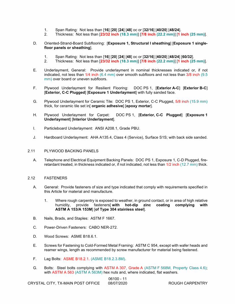
06100 - 11 CRYSTAL CITY, TX-MAIN POST OFFICE 08/07/2020 ROUGH CARPENTRY
1. Span Rating: Not less than [16] [20] [24] [48] oc or [32/16] [40/20] [48/24]. 2. Thickness: Not less than [23/32 inch (18.3 mm)] [7/8 inch (22.2 mm)] [1 inch (25 mm)].
D. Oriented-Strand-Board Subflooring: [Exposure 1, Structural I sheathing] [Exposure 1 single-floor panels or sheathing].
1. Span Rating: Not less than [16] [20] [24] [48] oc or [32/16] [40/20] [48/24] [60/32]. 2. Thickness: Not less than [23/32 inch (18.3 mm)] [7/8 inch (22.2 mm)] [1 inch (25 mm)].
E. Underlayment, General: Provide underlayment in nominal thicknesses indicated or, if not indicated, not less than 1/4 inch (6.4 mm) over smooth subfloors and not less than 3/8 inch (9.5 mm) over board or uneven subfloors.
F. Plywood Underlayment for Resilient Flooring: DOC PS 1, [Exterior A-C] [Exterior B-C] [Exterior, C-C Plugged] [Exposure 1 Underlayment] with fully sanded face.
G. Plywood Underlayment for Ceramic Tile: DOC PS 1, Exterior, C-C Plugged, 5/8 inch (15.9 mm) thick, for ceramic tile set in[ organic adhesive] [epoxy mortar].
H. Plywood Underlayment for Carpet: DOC PS 1, [Exterior, C-C Plugged] [Exposure 1 Underlayment] [Interior Underlayment].
I. Particleboard Underlayment: ANSI A208.1, Grade PBU.
J. Hardboard Underlayment: AHA A135.4, Class 4 (Service), Surface S1S; with back side sanded.
2.11 PLYWOOD BACKING PANELS
A. Telephone and Electrical Equipment Backing Panels: DOC PS 1, Exposure 1, C-D Plugged, fire-retardant treated, in thickness indicated or, if not indicated, not less than 1/2 inch (12.7 mm) thick.
2.12 FASTENERS
A. General: Provide fasteners of size and type indicated that comply with requirements specified in this Article for material and manufacture.
1. Where rough carpentry is exposed to weather, in ground contact, or in area of high relative humidity, provide fasteners[ with hot-dip zinc coating complying with ASTM A 153/A 153M] [of Type 304 stainless steel].
B. Nails, Brads, and Staples: ASTM F 1667.
C. Power-Driven Fasteners: CABO NER-272.
D. Wood Screws: ASME B18.6.1.
E. Screws for Fastening to Cold-Formed Metal Framing: ASTM C 954, except with wafer heads and reamer wings, length as recommended by screw manufacturer for material being fastened.
F. Lag Bolts: ASME B18.2.1. (ASME B18.2.3.8M).
G. Bolts: Steel bolts complying with ASTM A 307, Grade A (ASTM F 568M, Property Class 4.6); with ASTM A 563 (ASTM A 563M) hex nuts and, where indicated, flat washers.
06100 - 12 CRYSTAL CITY, TX-MAIN POST OFFICE 08/07/2020 ROUGH CARPENTRY
H. Expansion Anchors: Anchor bolt and sleeve assembly of material indicated below with capability to sustain, without failure, a load equal to 6 times the load imposed when installed in unit masonry assemblies and equal to 4 times the load imposed when installed in concrete as determined by testing per ASTM E 488 conducted by a qualified independent testing and inspecting agency.
1. Material: Carbon-steel components, zinc plated to comply with ASTM B 633, Class Fe/Zn 5.
2. Material: Stainless steel with bolts and nuts complying with ASTM F 593 and ASTM F 594, Alloy Group 1 or 2 (ASTM F 738M and ASTM F 836M, Grade A1 or A4).
2.13 METAL FRAMING ANCHORS
A. General: Provide framing anchors made from metal indicated, of structural capacity, type, and size indicated, and as follows:
1. Research/Evaluation Reports: Provide products acceptable to authorities having jurisdiction and for which model code research/evaluation reports exist that show compliance of metal framing anchors, for application indicated, with building code in effect for Project.
2. Allowable Design Loads: Provide products with allowable design loads, as published by manufacturer, that meet or exceed those indicated. Manufacturer's published values shall be determined from empirical data or by rational engineering analysis and demonstrated by comprehensive testing performed by a qualified independent testing agency.
B. Galvanized Steel Sheet: Hot-dip, zinc-coated steel sheet complying with ASTM A 653/A 653M, G60 (Z180) coating designation.
C. Stainless-Steel Sheet: ASTM A 666, Type [304] [316].
1. Use for exterior locations and where indicated.
D. Joist Hangers: U-shaped joist hangers with 2-inch- (50-mm-) long seat and 1-1/4-inch- (32-mm-) wide nailing flanges at least 85 percent of joist depth.
1. Thickness: [0.050 inch (1.3 mm)] [0.062 inch (1.6 mm)].
E. I-Joist Hangers: U-shaped joist hangers with 2-inch- (50-mm-) long seat and 1-1/4-inch- (32-mm-) wide nailing flanges full depth of joist. Nailing flanges provide lateral support at joist top chord.
1. Thickness: [0.050 inch (1.3 mm)] [0.062 inch (1.6 mm)].
F. Top Flange Hangers: U-shaped joist hangers, full depth of joist, formed from metal strap with tabs bent to extend over and be fastened to supporting member.
1. Strap Width: [1-1/2 inches (38 mm)] [2 inches (50 mm)]. 2. Thickness: [0.050 inch (1.3 mm)] [0.062 inch (1.6 mm)].
G. Bridging: Rigid, V-section, nailless type, 0.062 inch (1.6 mm) thick, length to suit joist size and spacing.
H. Post Bases: Adjustable-socket type for bolting in place with standoff plate to raise post 1 inch (25 mm) above base and with 2-inch- (50-mm-) minimum side cover, socket 0.062 inch (1.6 mm) thick, and standoff and adjustment plates 0.108 inch (2.8 mm) thick.
06100 - 13 CRYSTAL CITY, TX-MAIN POST OFFICE 08/07/2020 ROUGH CARPENTRY
I. Joist Ties: Flat straps, with holes for fasteners, for tying joists together over supports.
1. Width: [3/4 inch (19 mm)] [1-1/4 inches (32 mm)]. 2. Thickness: [0.050 inch (1.3 mm)] [0.062 inch (1.6 mm)]. 3. Length: [16 inches (400 mm)] [24 inches (600 mm)] [As indicated].
J. Rafter Tie-Downs: Bent strap tie for fastening rafters or roof trusses to wall studs below, 1-1/2 inches (38 mm) wide by 0.050 inch (1.3 mm) thick.[ Tie fastens to side of rafter or truss, face of top plates, and side of stud below.]
K. Rafter Tie-Downs (Hurricane or Seismic Ties): Bent strap tie for fastening rafters or roof trusses to wall studs below, 2-1/4 inches (57 mm) wide by 0.062 inch (1.6 mm) thick. Tie fits over top of rafter or truss and fastens to both sides of rafter or truss, face of top plates, and side of stud below.
L. Floor-to-Floor Ties: Flat straps, with holes for fasteners, for tying upper floor wall studs to band joists and lower floor studs, 1-1/4 inches (32 mm) wide by 0.050 inch (1.3 mm) thick by 36 inches (914 mm) long.
M. Hold-Downs: Brackets for bolting to wall studs and securing to foundation walls with anchor bolts or to other hold-downs with threaded rods and designed with first of two bolts placed seven bolt diameters from reinforced base.
1. Bolt Diameter: [5/8 inch (15.8 mm)] [3/4 inch (19 mm)]. 2. Width: [2-1/2 inches (64 mm)] [3-3/16 inches (81 mm)]. 3. Body Thickness: [0.108 inch (2.8 mm)] [0.138 inch (3.5 mm)]. 4. Base Reinforcement Thickness: [0.108 inch (2.8 mm)] [0.239 inch (6.1 mm)].
N. Wall Bracing: T-shaped bracing made for letting into studs in saw kerf, 1-1/8 inches (29 mm) wide by 9/16 inch (14 mm) deep by 0.034 inch (0.85 mm) thick with hemmed edges.
O. Wall Bracing: Angle bracing made for letting into studs in saw kerf, 15/16 by 15/16 by 0.040 inch (24 by 24 by 1 mm) thick with hemmed edges.
2.14 MISCELLANEOUS MATERIALS
A. Building Paper: Asphalt-saturated organic felt complying with ASTM D 226, Type I (No. 15 asphalt felt), unperforated.
B. Building Wrap: Air-retarder sheeting made from polyolefins; cross-laminated films, woven strands, or spun-bonded fibers; coated or uncoated; with or without perforations; and complying with ASTM E 1677, Type I.
1. Thickness: Not less than 3 mils (0.08 mm). 2. Permeance: Not less than 10 perms (575 ng/Pa x s x sq. m). 3. Flame-Spread Index: 25 or less per ASTM E 84. 4. Allowable Exposure Time: Not less than three months.
C. Building Wrap Tape: Pressure-sensitive plastic tape recommended by building wrap manufacturer for sealing joints and penetrations in building wrap.
D. Sheathing Tape: Pressure-sensitive plastic tape for sealing joints and penetrations in sheathing and recommended by sheathing manufacturer for use with type of sheathing required.
06100 - 14 CRYSTAL CITY, TX-MAIN POST OFFICE 08/07/2020 ROUGH CARPENTRY
E. Sill-Sealer Gaskets: Glass-fiber-resilient insulation, fabricated in strip form, for use as a sill sealer; 1-inch (25-mm) nominal thickness, compressible to 1/32 inch (0.8 mm); selected from manufacturer's standard widths to suit width of sill members indicated.
F. Sill-Sealer Gaskets: Closed-cell neoprene foam, 1/4 inch (6.4 mm) thick, selected from manufacturer's standard widths to suit width of sill members indicated.
G. Adhesives for Field Gluing Panels to Framing: Formulation complying with [APA AFG-01] [ASTM D 3498] that is approved for use with type of construction panel indicated by both adhesive and panel manufacturers.
H. Water-Repellent Preservative: NWWDA-tested and -accepted formulation containing 3-iodo-2-propynyl butyl carbamate, combined with an insecticide containing chloropyrifos as its active ingredient.
PART 3 - EXECUTION
3.1 INSTALLATION, GENERAL
A. Set rough carpentry to required levels and lines, with members plumb, true to line, cut, and fitted. Fit rough carpentry to other construction; scribe and cope as needed for accurate fit. Locate [furring,] nailers, blocking, [grounds,] and similar supports to comply with requirements for attaching other construction.
B. Do not use materials with defects that impair quality of rough carpentry or pieces that are too small to use with minimum number of joints or optimum joint arrangement.
C. Apply field treatment complying with AWPA M4 to cut surfaces of preservative-treated lumber and plywood.
D. Securely attach rough carpentry work to substrate by anchoring and fastening as indicated, complying with the following:
1. CABO NER-272 for power-driven fasteners. 2. Published requirements of metal framing anchor manufacturer. 3. Table 23-II-B-1, "Nailing Schedule," and Table 23-II-B-2, "Wood Structural Panel Roof
Sheathing Nailing Schedule," in the Uniform Building Code. 4. Table 2305.2, "Fastening Schedule," in the BOCA National Building Code. 5. Table 2306.1, "Fastening Schedule," in the Standard Building Code. 6. Table 602.3(1), "Fastener Schedule for Structural Members," and Table 602.3(2),
"Alternate Attachments," in the International One- and Two-Family Dwelling Code.
E. Use common wire nails, unless otherwise indicated. Select fasteners of size that will not fully penetrate members where opposite side will be exposed to view or will receive finish materials. Make tight connections between members. Install fasteners without splitting wood; predrill as required.
F. Use finishing nails for exposed work, unless otherwise indicated. Countersink nail heads and fill holes with wood filler.
3.2 WOOD [GROUND,] [SLEEPER,] BLOCKING, AND NAILER INSTALLATION
06100 - 15 CRYSTAL CITY, TX-MAIN POST OFFICE 08/07/2020 ROUGH CARPENTRY
A. Install where indicated and where required for [screeding or] attaching other work. Form to shapes indicated and cut as required for true line and level of attached work. Coordinate locations with other work involved.
B. Attach items to substrates to support applied loading. Recess bolts and nuts flush with surfaces, unless otherwise indicated. Build anchor bolts into masonry during installation of masonry work. Where possible, secure anchor bolts to formwork before concrete placement.
C. Provide permanent grounds of dressed, pressure-preservative-treated, key-beveled lumber not less than 1-1/2 inches (38 mm) wide and of thickness required to bring face of ground to exact thickness of finish material. Remove temporary grounds when no longer required.
3.3 WOOD FURRING INSTALLATION
A. Install level and plumb with closure strips at edges and openings. Shim with wood as required for tolerance of finish work.
1. Fire block furred spaces of walls, at each floor level and at ceiling, with wood blocking or noncombustible materials accurately fitted to close furred spaces.
B. Furring to Receive Plywood or Hardboard Paneling: Install 1-by-3-inch nominal- (19-by-63-mm actual-) size furring [horizontally] [and] [vertically] at 24 inches (610 mm) o.c.
C. Furring to Receive Plywood or Hardboard Paneling: Install 1-by-3-inch nominal- (19-by-63-mm actual-) size furring [horizontally] [and] [vertically] at 600 mm o.c.
D. Furring to Receive Gypsum Board: Install 1-by-2-inch nominal- (19-by-38-mm actual-) size furring vertically at 16 inches (406 mm) o.c.
E. Furring to Receive Gypsum Board: Install 1-by-2-inch nominal- (19-by-38-mm actual-) size furring vertically at 400 mm o.c.
F. Furring to Receive Plaster Lath: Install 1-by-2-inch nominal- (19-by-38-mm actual-) size furring vertically at 16 inches (406 mm) o.c.
G. Furring to Receive Plaster Lath: Install 1-by-2-inch nominal- (19-by-38-mm actual-) size furring vertically at 400 mm o.c.
3.4 WOOD FRAMING INSTALLATION, GENERAL
A. Framing Standard: Comply with AFPA's "Manual for Wood Frame Construction," unless otherwise indicated.
B. Framing with Engineered Wood Products: Install engineered wood products to comply with manufacturer's written instructions.
C. Do not splice structural members between supports.
D. Where built-up beams or girders of 2-inch nominal- (38-mm actual-) dimension lumber on edge are required, fasten together with 2 rows of 20d (100-mm) nails spaced not less than 32 inches (812 mm) o.c. Locate one row near top edge and other near bottom edge.
06100 - 16 CRYSTAL CITY, TX-MAIN POST OFFICE 08/07/2020 ROUGH CARPENTRY
1. For continuous members,[ stagger end joints at quarter points between supports] [locate end joints over supports].
3.5 WALL AND PARTITION FRAMING INSTALLATION
A. General: Arrange studs so wide face of stud is perpendicular to direction of wall or partition and narrow face is parallel. Provide single bottom plate and double top plates using members of 2-inch nominal (38-mm actual) thickness whose widths equal that of studs, except single top plate may be used for non-load-bearing partitions. Anchor [or nail] plates to supporting construction, unless otherwise indicated.
1. For exterior walls, provide [2-by-6-inch nominal- (38-by-140-mm actual-)] [2-by-4-inch nominal- (38-by-89-mm actual-)] size wood studs spaced [24 inches (610 mm)] [16 inches (406 mm)] [600 mm] [400 mm] o.c., unless otherwise indicated.
2. For interior partitions and walls, provide 2-by-4-inch nominal- (38-by-89-mm actual-) size wood studs spaced [16 inches (406 mm)] [400 mm] o.c., unless otherwise indicated.
B. Construct corners and intersections with three or more studs. Provide blocking and framing as indicated and as required to support facing materials, fixtures, specialty items, and trim.
1. Provide continuous horizontal blocking at midheight of partitions more than 96 inches (2438 mm) high, using members of 2-inch nominal (38-mm actual) thickness and of same width as wall or partitions.
C. Fire block concealed spaces of wood-framed walls and partitions at each floor level and at ceiling line of top story. Where fire blocking is not inherent in framing system used, provide closely fitted wood blocks of 2-inch nominal- (38-mm actual-) thick lumber of same width as framing members.
D. Frame openings with multiple studs and headers. Provide nailed header members of thickness equal to width of studs. Set headers on edge and support on jamb studs.
1. For non-load-bearing partitions, provide double-jamb studs with headers not less than 4-inch nominal (89-mm actual) depth for openings 48 inches (1200 mm) and less in width, 6-inch nominal (140-mm actual) depth for openings 48 to 72 inches (1200 to 1800 mm) in width, 8-inch nominal (184-mm actual) depth for openings 72 to 120 inches (1800 to 3000 mm) in width, and not less than 10-inch nominal (235-mm actual) depth for openings 10 to 12 feet (3 to 3.6 m) in width.
2. For load-bearing walls, provide double-jamb studs for openings 72 inches (1800 mm) and less in width, and triple-jamb studs for wider openings. Provide headers of depth indicated[ or, if not indicated, according to Table 602.7 in the International One- and Two-Family Dwelling Code].
E. Provide bracing in exterior walls, at both walls of each external corner, full-story height, unless otherwise indicated. Provide one of the following:
F. Provide bracing in walls, at locations indicated, full-story height, unless otherwise indicated. Provide one of the following:
1. Diagonal bracing at 45-degree angle using let-in 1-by-4-inch nominal- (19-by-89-mm actual-) size boards.
2. Diagonal bracing at 45-degree angle using metal bracing. 3. Plywood panels not less than 48 by 96 inches (1219 by 2438 mm) applied vertically. 4. Oriented-strand-board panels not less than 48 by 96 inches (1219 by 2438 mm) applied
vertically.
06100 - 17 CRYSTAL CITY, TX-MAIN POST OFFICE 08/07/2020 ROUGH CARPENTRY
5. Particleboard sheathing panels not less than 48 by 96 inches (1219 by 2438 mm) applied vertically.
6. In lieu of bracing at corners or at locations indicated, continuous gypsum sheathing may be provided in panels not less than 48 by 96 inches (1219 by 2438 mm) applied vertically.
7. In lieu of bracing at corners or at locations indicated, continuous fiberboard sheathing, intermediate type, may be provided in panels not less than 48 by 96 inches (1219 by 2438 mm) applied vertically.
3.6 CEILING JOIST AND RAFTER FRAMING INSTALLATION
A. Ceiling Joists: Install ceiling joists with crown edge up and complying with requirements specified above for floor joists. Face nail to ends of parallel rafters.
1. Where ceiling joists are at right angles to rafters, provide additional short joists parallel to rafters from wall plate to first joist; nail to ends of rafters and to top plate and nail to first joist or anchor with framing anchors or metal straps. Provide 1-by-8-inch nominal- (19-by-184-mm actual-) size or 2-by-4-inch nominal- (38-by-89-mm actual-) size stringers spaced 48 inches (1200 mm) o.c. crosswise over main ceiling joists.
B. Rafters: Notch to fit exterior wall plates and [toe nail or] use metal framing anchors. Double rafters to form headers and trimmers at openings in roof framing, if any, and support with metal hangers. Where rafters abut at ridge, place directly opposite each other and nail to ridge member or use metal ridge hangers.
1. At valleys, provide double-valley rafters of size indicated or, if not indicated, of same thickness as regular rafters and 2 inches (50 mm) deeper. Bevel ends of jack rafters for full bearing against valley rafters.
2. At hips, provide hip rafter of size indicated or, if not indicated, of same thickness as regular rafters and 2 inches (50 mm) deeper. Bevel ends of jack rafters for full bearing against hip rafter.
C. Provide collar beams (ties) as indicated or, if not indicated, provide 1-by-6-inch nominal- (19-by-140-mm actual-) size boards between every third pair of rafters, but not more than 48 inches (1219 mm) o.c. Locate below ridge member, at third point of rafter span. Cut ends to fit roof slope and nail to rafters.
D. Provide special framing as indicated for eaves, overhangs, dormers, and similar conditions, if any.
3.7 TIMBER FRAMING INSTALLATION
A. Install timber with crown edge up and provide not less than 4 inches (102 mm) of bearing on supports. Provide continuous members, unless otherwise indicated; tie together over supports if not continuous.
B. Where beams or girders are framed into pockets of exterior concrete or masonry walls, provide 1/2-inch (13-mm) air space at sides and ends of wood members.
C. Install wood posts using metal anchors indicated.
D. Treat ends of timber beams and posts exposed to weather by dipping in water-repellent preservative for 15 minutes.
06100 - 18 CRYSTAL CITY, TX-MAIN POST OFFICE 08/07/2020 ROUGH CARPENTRY
3.8 STAIR FRAMING INSTALLATION
A. Provide stair framing members of size, space, and configuration indicated or, if not indicated, to comply with the following requirements:
1. Stringer Size: 2-by-12-inch nominal- (38-by-286-mm actual-) size, minimum. 2. Notching: Notch stringers to receive treads, risers, and supports; leave at least 3-1/2
inches (89 mm) of effective depth. 3. Stringer Spacing: At least 3 stringers for each 36-inch (914-mm) clear width of stair.
B. Provide stair framing with no more than 3/16-inch (4.7-mm) variation between adjacent treads and risers and no more than 3/8-inch (9.5-mm) variation between largest and smallest treads and risers within each flight.
3.9 WOOD STRUCTURAL PANEL INSTALLATION
A. General: Comply with applicable recommendations contained in APA Form No. E30K, "APA Design/Construction Guide: Residential & Commercial," for types of structural-use panels and applications indicated.
1. Comply with "Code Plus" provisions in above-referenced guide.
B. Fastening Methods: Fasten panels as indicated below:
1. Sheathing:
a. Nail to wood framing. b. Screw to cold-formed metal framing. c. Space panels 1/8 inch (3 mm) apart at edges and ends.
2. Underlayment:
a. [Nail] [Nail or staple ]to subflooring. b. Space panels 1/32 inch (0.8 mm) apart at edges and ends. c. Fill and sand edge joints of underlayment receiving resilient flooring just before
installing flooring.
3. Plywood Backing Panels: Nail or screw to supports.
3.10 PARTICLEBOARD UNDERLAYMENT INSTALLATION
A. Comply with the National Particleboard Association's recommendations for type of subfloor indicated. Fill and sand gouges, gaps, and chipped edges. Sand uneven joints flush.
1. Fastening Method: [Glue and nail] [Nail] [Nail or staple ]underlayment to subflooring.
3.11 HARDBOARD UNDERLAYMENT
A. Comply with AHA's "Application Instructions for Basic Hardboard Products" and hardboard manufacturer's written instructions for preparing and applying hardboard underlayment.
1. Fastening Method: [Nail] [Nail or staple ]underlayment to subflooring.
06100 - 19 CRYSTAL CITY, TX-MAIN POST OFFICE 08/07/2020 ROUGH CARPENTRY
3.12 FOAM-PLASTIC SHEATHING INSTALLATION
A. Comply with manufacturer's written instructions for applying sheathing. Install vapor-relief strips or equivalent for permitting escape of moisture vapor that otherwise would be trapped in stud cavity behind sheathing.
3.13 GYPSUM SHEATHING
A. General: Fasten gypsum sheathing to supports with galvanized roofing nails [or divergent point galvanized staples]; comply with GA-253 and manufacturer's recommended spacing and referenced fastening schedule. Keep perimeter fasteners 3/8 inch (9.5 mm) from edges and ends of units.
B. Install 24-by-96-inch (609-by-2438-mm) sheathing horizontally with long edges at right angles to studs with V-grooved edge down and tongue edge up. Interlock tongue with groove to bring long edges in contact with edges of adjacent board without forcing. Abut ends of boards over centers of studs and stagger end joints of adjacent boards not less than one stud spacing, two where possible.
C. Install 48-by-96-inch (1219-by-2438-mm) and longer sheathing vertically with long edges parallel to, and centered over, studs. Install solid wood blocking where end joints do not occur over framing. Fit units tightly against each other.
3.14 FIBERBOARD SHEATHING INSTALLATION
A. Fasten fiberboard sheathing panels to intermediate supports and then at edges and ends. Use galvanized roofing nails [or galvanized staples]; comply with manufacturer's recommended spacing and referenced fastening schedule. Drive fasteners flush with surface of sheathing and locate perimeter fasteners at least 3/8 inch (9.5 mm) from edges and ends.
B. Install sheathing vertically with long edges parallel to, and centered over, studs. Install solid wood blocking where end joints do not occur over framing. Allow 1/8-inch (3-mm) open space between edges and ends of adjacent units. Stagger horizontal joints, if any.
C. Cover sheathing as soon as practical after installation to prevent deterioration from wetting.
3.15 BUILDING PAPER APPLICATION
A. Apply building paper horizontally with 2-inch (50-mm) overlap and 6-inch (150-mm) end lap; fasten to sheathing with galvanized staples or roofing nails. Cover upstanding flashing with 4-inch (102-mm) overlap.
3.16 BUILDING WRAP APPLICATION
A. Cover wall sheathing with building wrap as indicated.
1. Comply with manufacturer's written instructions. 2. Cover upstanding flashing with 4-inch (102-mm) overlap. 3. Seal seams, edges, and penetrations with tape. 4. Extend into jambs of openings and seal corners with tape.
06100 - 20 CRYSTAL CITY, TX-MAIN POST OFFICE 08/07/2020 ROUGH CARPENTRY
3.17 SHEATHING TAPE APPLICATION
A. Apply sheathing tape to joints between sheathing panels and at items penetrating sheathing. Apply at upstanding flashing to overlap both flashing and sheathing.
END OF SECTION
06195-1 CRYSTAL CITY, TX-MAIN POST OFFICE 08/07/2020 FABRICATED WOOD TRUSSED RAFTERS
SECTION 06195
FABRICATED WOOD TRUSSED RAFTERS PART 1 - GENERAL 1.1 SCOPE
Fabricate, supply and erect wood trusses as shown on the Drawings with steel connectors and gussets. Provide lateral support for trusses.
1.2 QUALITY ASSURANCE
Lumber used in the manufacture of trusses shall be clearly grade stamped indicating conformance with NFPA.
1.3 CODES AND STANDARDS
A. Design of Plate connected trusses shall conform to National Design Standards (NDS-Latest Edition), Truss Plate Institute criteria (ANSI/TPI-1-2007) and the International Building Code.
B. Truss fabrication shall comply with TPI quality control standard (QCM-77). Truss plant
shall be inspected by third party certified agency. 1.4 SHOP DRAWINGS AND PRODUCT DATA
Submit shop drawings prior to fabrication in accordance with Section 01340. Indicate truss framing plans and layout, species and grade of lumber used (see drawings), design loading and allowable stress increase; force analysis of each member; pitch, span and spacing of trusses; gauge thickness; nominal size and locations of connectors at joints; bearing and anchorage details; framed openings; permanent bracing and bridging. Shop drawings to bear seal of Professional Engineer registered in Texas. Submit manufacturer's instructions on lateral bracing.
PART 2 - PRODUCTS 2.1 STEEL GUSSET PLATES
Shall be a minimum of 20 gauge, ASTM A-446, Grade A, approved by the ICBO building code. 2.2 LUMBER
Lumber shall meet the following criteria:
A. Minimum Properties: Chord lumber Allowable bending stress 1,500 PSI Modulus of elasticity 1,600,000 PSI
B. Minimum Properties: Web Lumber Allowable bending stress 850 PSI Modulus of elasticity 1,400,000 PSI
C. Maximum moisture content 19% at time of fabrication.
06195-2 CRYSTAL CITY, TX-MAIN POST OFFICE 08/07/2020 FABRICATED WOOD TRUSSED RAFTERS
PART 3 - EXECUTION 3.1 Set and secure wood trusses level, plumb, and in correct locations. Provide temporary bracing
and anchorage to hold trusses in place until permanently secured. Ensure truss ends have sufficient bearing area. Install permanent bracing and bridging prior to application of loads. Cutting and altering of members is not permitted.
3.2 Trusses shall be erected, braced, and blocked in accordance with "Bracing Wood Trusses
(HIB-91)" by TPI.
END OF SECTION
062000- 1 CRYSTAL CITY, TX - MAIN POST OFFICE Date: 8/7/2020 FINISH CARPENTRY
SECTION 062000
FINISH CARPENTRY
PART 1 - GENERAL
1.1 SUMMARY
A. Section Includes: 1. Interior running and standing trim. 2. Adjustable shelving, shelf standards, and brackets.
B. Related Documents: The Contract Documents, as defined in Section 011000 - Summary of Work, apply
to the Work of this Section. Additional requirements and information necessary to complete the Work of this Section may be found in other documents.
C. Related Sections: 1. Section 102600 – Wall and Door Protection.
1.2 ENVIRONMENTAL REQUIREMENTS
A. Environmental Impact: 1. Formaldehyde: Products containing formaldehyde will not be permitted. 2. All wood products to be FSC Certified.
1.3 SITE ENVIRONMENTAL PROCEDURES
A. Indoor Air Quality: 1. Temporary ventilation: As specified in Section 013543 - Environmental Procedures.
PART 2 - PRODUCTS
2.1 ADJUSTABLE SHELVING
A. Standards: adjustable, flush mount shelf standards. B. Standards: Brackets. C. Sheathing for Shelves: 3/4 inch thick x 24 inches deep in maximum possible length. Formaldehyde
free board product sanded smooth and painted each side and each edge as specified in Section 099100 - Painting. 1. PrimeBoard, Incorporated, Wahpeton, ND (701) 642-1152. 2. Medite, Roseville, CA (800) 676-3339. 3. Naturall Fibre Board, Minneapolis, KS (785) 392-9922. 4. Section 016000 - Product Requirements: Product options and substitutions. Substitutions:
Permitted.
D. Fasteners: Size and type to suit application.
062000- 2 CRYSTAL CITY, TX - MAIN POST OFFICE Date: 8/7/2020 FINISH CARPENTRY
2.2 INTERIOR FINISH CARPENTRY
A. Trim and boards for transparent finish: Rift sawn oak.
B. Trim for painted finish: Softwood suitable for exposure and use.
C. Sheathing : Formaldehyde free board product sanded smooth and painted each exposed side and each exposed edge as specified in Section 099100 - Painting. 1. PrimeBoard, Incorporated, Wahpeton, ND (701) 642-1152. 2. Medite, Roseville, CA (800) 676-3339. 3. Naturall Fibre Board, Minneapolis, KS (785) 392-9922. 4. Section 016000 - Product Requirements: Product options and substitutions. Substitutions:
Permitted.
2.3 ACCESSORIES A. Adhesive: Type recommended by AWI to suit application. Low VOC
1. Titebond by Franklin International, Columbus, OH, (800) 877-4583. 2. Famowood/Famobond by Eclectic Products (800) 767-4667. 3. Almighty Adhesive by American Formulating & Manufacturing (619) 239-0321. 4. Section 016000 - Product Requirements: Product options and substitutions. Substitutions:
Permitted. B. Fasteners: Size and type to suit application.
PART 3 - EXECUTION
3.1 INSTALLATION
A. Install work in accordance with AWI AWQS, Section 1700 - Installation of Woodwork.
B. Install Work plumb, level, and straight without distortion; use concealed shims. Scribe and cut Work to fit adjoining work. Anchor Work items to nailers or blocking or directly to substrate using concealed fasteners.
C. Install shelving units, standards, and brackets at locations as indicated on Drawings.
3.2 SITE ENVIRONMENTAL PROCEDURES
A. Indoor Air Quality: 1. Temporary ventilation: As specified in Section 013543 - Environmental Procedures.
END OF SECTION

071900 - 1 CRYSTAL CITY, TX - MAIN POST OFFICE Date: 8/7/2020 WATER REPELLENTS
SECTION 071900
WATER REPELLENTS
PART 1 - GENERAL
1.1 SUMMARY
A. Section Includes: 1. Zero VOC water repellent coating applied to exterior masonry surfaces.
B. Related Sections:
1. Section 042200 - Concrete Unit Masonry: Substrate for application of water repellent.
1.2 SUBMITTALS
A. Section 013300 - Submittal Procedures: Procedures for submittals. 1. Product Data: Product description, tests performed, limitations to coating, and VOC content. 2. Assurance/Control Submittals:
a. Test Reports: Manufacturer's Material Safety Data Sheets (MSDS). b. Certificates: Manufacturer certificate that Products meet or exceed specified requirements. c. Manufacturer's Instructions: Indicate special procedures and conditions requiring special
attention; cautionary procedures required during application. d. Qualification Documentation: Submit manufacturer and applicator documentation of
experience indicating compliance with specified qualification requirements.
1.3 QUALITY ASSURANCE
A. Qualifications: 1. Manufacturer: Company specializing in manufacturing Products specified with minimum 5 years
documented experience. 2. Applicator: Company specializing in performing the work of this Section with minimum 5 years
documented experience.
B. Regulatory Requirements: Comply with applicable rules and regulations of Pollution-Control Regulatory Agency having jurisdiction regarding volatile organic compounds (VOC) and use of hydrocarbon solvents.
1.4 PROJECT CONDITIONS
A. Environmental Requirements: Do not apply Product during the following conditions; 1. Ambient temperature below 40 degrees F. 2. Substrate surfaces have cured less than 30 days. 3. Rain or temperatures below 40 degrees F are predicted for a period of 24 hours. 4. Surfaces not dry for minimum 24 hours. 5. Substrate frozen or surface temperature is below 40 degrees F.
1.5 WARRANTY
A. Section 017704 - Closeout Procedures and Training: Procedures for closeout submittals.
071900 - 2 CRYSTAL CITY, TX - MAIN POST OFFICE Date: 8/7/2020 WATER REPELLENTS
B. Warranty:
1. Submit written warranty signed by water repellent manufacturer and applicator agreeing to repair or reapply materials that fail to provide water repellency because of failure of Product or improper application.
2. Warranty Period: 3 years.
PART 2 - PRODUCTS
2.1 MANUFACTURERS
A. Subject to compliance with project requirements, manufacturers offering Products which may be incorporated in the Work include the following: 1. The Euclid Chemical Company, Cleveland, OH (216) 531-9222, (800) 321-7628 2. H&C Concrete Protection, Cleveland, OH, (800) 867-8246.
B. Section 016000 - Product Requirements: Product options and substitutions. Substitutions: Permitted.
2.2 MATERIALS
A. Siloxane: Clear penetrating water repellent. Alkylalkoxysiloxanes that are oligomerous with alcohol, ethanol, water, or other proprietary carrier.
B. Products:
1. Euclid: Loxon Siloxane. 2. H&C: SX-7.
PART 3 - EXECUTION
3.1 EXAMINATION
A. Section 017300 - Execution: Verification of existing conditions before starting work.
B. Verification of Conditions: Verify that field measurements, surfaces, substrates and conditions are as required, and ready to receive Work. 1. Verify joint sealants are installed and cured. 2. Verify surfaces to be coated are dry, clean, and free of efflorescence, oil, or other matter
detrimental to application of coating.
C. Report in writing to Contracting Officer prevailing conditions that will adversely affect satisfactory execution of the Work of this Section. Do not proceed with Work until unsatisfactory conditions have been corrected.
D. By beginning Work, Contractor accepts conditions and assumes responsibility for correcting unsuitable
conditions encountered at no additional cost to the United States Postal Service.
3.2 PREPARATION
A. Remove loose particles and foreign matter. Remove oil or foreign substance with a cleaning agent which will not affect coating.
071900 - 3 CRYSTAL CITY, TX - MAIN POST OFFICE Date: 8/7/2020 WATER REPELLENTS
B. Scrub and rinse surfaces with water, and let dry.
C. Protect adjacent surfaces not scheduled to receive coating. If applied on unscheduled surfaces,
remove immediately, by approved method.
D. Protect landscaping, property, and vehicles from over spray and drift.
3.3 APPLICATION
A. Delay work until masonry mortar is cured for seven days.
B. Apply coating in accordance with manufacturer's published instructions, using appropriate method and coverage rate.
END OF SECTION
072100 - 1 CRYSTAL CITY, TX - MAIN POST OFFICE Date: 8/7/2020 THERMAL INSULATION
SECTION 072100
THERMAL INSULATION
PART 1 - GENERAL
1.1 SUMMARY
A. Section Includes: 1. Batt Insulation in exterior wall roof construction. 2. Air infiltration seal.
B. Related Documents: The Contract Documents, as defined in Section 011000 - Summary of Work, apply
to the Work of this Section. Additional requirements and information necessary to complete the Work of this Section may be found in other Documents.
1.2 QUALITY ASSURANCE
A. Regulatory Requirements: Conform to insulation flame spread and smoke developed requirements of local authority having jurisdiction.
B. Certification: For projects California provide Products certified by manufacturer that meet California
Quality Standards for Insulating Materials.
1.3 ENVIRONMENTAL REQUIREMENTS A. Resource Management:
1. Recycled Content: Provide fiberglass insulation manufactured from minimum 30 percent recycled glass.
B. Environmental Impact:
1. Only Greenguard indoor air quality certified products will be permitted. 2. Chlorofluorocarbons (CFCs): Products and equipment requiring or using CFCs during the
manufacturing process will not be permitted.
PART 2 - PRODUCTS
2.1 BATT INSULATION
A. Manufacturers: 1. Johns Manville Corporation, Denver, Co (800) 654-3103. 2. Knauf Fiberglass, Shelbyville, IN (317) 398-4434, (800) 825-4434. 3. Owens-Corning Fiberglass Corporation, Toledo, OH (419) 248-8000, (800) 438-7465. 4. Section 016000 - Product Requirements: Product options and substitutions. Substitutions:
Permitted.
B. Materials: Fiberglass insulation manufactured from minimum 30 percent recycled glass. 1. Unfaced Glass Fiber: ASTM C 665, Type I, unfaced. Thermal resistance R-value as indicated on
Drawings.
072100 - 2 CRYSTAL CITY, TX - MAIN POST OFFICE Date: 8/7/2020 THERMAL INSULATION
2. Faced Glass Fiber: ASTM C 665, Type III, Class A, with reflective covering one side. Thermal resistance R-value as indicated on Drawings.
2.2 AIR INFILTRATION SEAL
A. Manufacturer: 1. Tenneco Building Products, Smyrna, GA (800) 241-4402. 2. DuPont, Wilmington, DE (800) 448-9835. 3. Section 016000 - Product Requirements: Product options and substitutions. Substitutions:
Permitted.
B. Materials: One of the following two types of materials: 1. 15 pound, type 1, grade D, 10 minute unperforated asphalt saturated organic felt in accordance
with ASTM D22. 2. Coated, cross-woven polyethylene or polypropylene fabric:
a. Tenneco: Amowrap Housewrap. b. DuPont: Tyvek Housewrap. c. Air Infiltration Seal Tape: Pressure sensitive of type recommended by vapor retardant
manufacturer for sealing joints and penetrations in air infiltration seal.
2.3 ACCESSORIES
A. Tape: Polyethylene or polyester self-adhering type; 2 inches (5.08 cm) wide.
B. Adhesive: Waterproof type, acceptable to manufacturer of insulation board.
C. Wire Mesh: Galvanized steel, hexagonal wire mesh.
PART 3 - EXECUTION
3.1 INSTALLATION - BATT INSULATION
A. Install batt insulation in accordance with manufacturer's instructions, without gaps or voids.
B. Trim insulation neatly to fit spaces. Use batts free of damage. Fit insulation tight in spaces and tight to exterior side of mechanical and electrical services within the plane of insulation.
C. Install insulation with factory applied membrane facing warm side of building spaces. Lap ends and
side flanges of membrane. Attach insulation in place to framing; tape seal butt ends and lapped side flanges. Tape seal tears or cuts in membrane.
3.2 INSTALLATION - AIR INFILTRATION SEAL
A. Install air infiltration seal over entire building exterior walls and adjacent surfaces
B. Seal vertical joints over framing by lapping minimum 2 stud spaces. Fasten to framing at top, end, and bottom edges; at perimeter of wall openings; and at lap joints.
C. Seal joints caused by pipes, conduits, electrical boxes, and similar items with manufacturer's sealing
tape. Seal penetrations air-tight.

072100 - 3 CRYSTAL CITY, TX - MAIN POST OFFICE Date: 8/7/2020 THERMAL INSULATION
END OF SECTION
073113- 1
CRYSTAL CITY, TX - MAIN POST OFFICE Date: 8/7/2020 SHINGLES AND SHAKES
SECTION 073113
SHINGLES AND SHAKES
PART 1 - GENERAL
1.1 SUMMARY
A. Section Includes: 1. Glass fiber reinforced shingles. 2. Underlayment, eave, valley, and ridge protection. 3. Associated flashings and accessories.
B. Related Documents: The Contract Documents, as defined in Section 011000 - Summary of Work, apply
to the Work of this Section. Additional requirements and information necessary to complete the Work of this Section may be found in other documents.
1.2 QUALITY ASSURANCE
A. Perform Work in accordance with NRCA Steep Roofing Manual.
1.3 ENVIROMENTAL REQUIREMENTS
A. Roof shingles supplied must be listed on the DOE’s ENERGY STAR Roof Products Qualified Products List.
PART 2 - PRODUCTS
2.1 MANUFACTURERS
A. Subject to compliance with Project requirements, manufacturers offering Products which may be incorporated in the Work include the following: 1. CertainTeed Corporation, Valley Forge, PA (800) 233-8990. 2. GAF Materials Corporation, Wayne, NJ (800) 766-3411. 3. Owens/Corning Fiberglass, Toledo, OH (800) 438-7465.
B. Section 016000 - Product Requirements: Product options and substitutions. Substitutions: Permitted.
2.2 MATERIALS
A. Shingles: 1. CertainTeed: Landmark. 2. GAF: Timberline HDZ. 3. Owens/Corning: Oakridge (base of design).
073113- 2
CRYSTAL CITY, TX - MAIN POST OFFICE Date: 8/7/2020 SHINGLES AND SHAKES
B. Description: ASTM D 3018 Class A with Type I - Self Sealing; UL Rating of A and Wind Resistance Label, glass fiber mat base, mineral granule surface dimensional type shingle; nominal 12 inch x 36 inch, 5 inch exposure; self sealing type; laminated overlay type.
C. Color:
1. CertainTeed: Weathered Wood. 2. GAF: Driftwood. 3. Owens/Corning: Driftwood.
2.3 ACCESSORIES
A. Sheet Metal Flashing: Specified in Section 076200.
B. Underlayment: ASTM D 226, No. 30 unperforated asphalt saturated felts.
C. Nails: Hot-dipped zinc-coated steel, type recommended for use with shingle type, length sufficient to penetrate roof deck.
D. Plastic Cement: ASTM D 2822, asphalt type with mineral fiber components.
E. Lap Cement: Fibrated cutback asphalt type.
F. Bituminous Paint: Acid and alkali resistant type; black color.
G. Eave, Ice Dam, Valley and Ridge Protection: Sheet barrier of rubberized asphalt bonded to sheet
polyethylene, 40 mil total thickness, with strippable treated release paper. H. Ridge Vent: Metal, specified in Section 076200.
PART 3 - EXECUTION
3.1 INSTALLATION
A. Install shingles in accordance with manufacturer's published instructions, NRCA Steep Roofing Manual, and to meet requirements of Underwriter's Laboratories class ratings indicated.
B. Coordinate roofing with installation of roof mounted components or work projecting through roof.
C. Install shingles square with building lines and parallel with roof slope.
D. Installation to provide weathertight service.
E. Underlayment:
1. Place one ply of underlayment perpendicular to slope of roof, over area not protected by eave membrane, with ends and edges weatherlapped a minimum of 4 inches. Nail protective underlayment in place.
2. Weather lap underlayment over eave membrane and seal items projecting through or mounted on roof with plastic cement.
F. Flashings:
1. Weather lap joints and seal weathertight with plastic cement. Nail in place. Conceal fastenings.
073113- 3
CRYSTAL CITY, TX - MAIN POST OFFICE Date: 8/7/2020 SHINGLES AND SHAKES
2. Flash and seal work projecting through or mounted on roofing, including ridge or slope vents, with plastic cement.
G. Glass Fiber Shingles:
1. Install shingles in straight coursing pattern over entire roof area starting with first course at bottom of slope as recommended by manufacturer.
2. Project first course of shingles 3/4 inch beyond roof decking. 3. Cap hips and nonvented section of ridge with individual shingles, maintaining recommended
weather exposure. 4. Place two daubs of plastic cement, one inch in diameter, under each shingle corner exposed to
weather on roof slopes less than 4 in 12.
H. Eave and Ice Dam Protection: 1. Place eave and ice dam edge flashing tight with fascia boards. Weather lap joints and seal with
plastic cement. Secure flange with nails. 2. Bond rubberized-asphalt protection sheet to roof sheathing by removing release paper; seal
seams with compatible sealant. Position lap seal over firm bearing. 3. Extend protection membrane up roof slope a minimum 4 feet beyond interior face of exterior
walls.
I. Ridge and Valley Protection: 1. Place one layer of roll roofing centered over valleys. Nail in place. 2. Apply lap cement along each edge of first layer and embed layer of roll roofing centered over first
layer. Place with mineral surface side up. 3. Install shingles on ridge vents in accordance with Section 076200.
END OF SECTION
074600 - 1
CRYSTAL CITY, TX – MAIN POST OFFICE Date: 8/7/2020 SIDING
SECTION 074600
SIDING
PART 1 - GENERAL
1.1 SUMMARY
A. Section Includes: 1. Vinyl soffit 2. Related trim, accessories, and fastenings.
B. Related Documents: The Contract Documents, as defined in Section 011000 - Summary of Work, apply
to the Work of this Section. Additional requirements and information necessary to complete the Work of this Section may be found in other Documents.
1.2 SUBMITTALS
A. Section 013300 - Submittal Procedures: Procedures for submittals. 1. Product Data:
a. Provide data indicating materials, component profiles, fastening methods, jointing details, sizes, surface texture, finishes, and accessories.
PART 2 - PRODUCTS
2.1 TRIM A. Wood trim: Flat grooved board wood siding shall be Clear Cedar boards. Locate cut boards over
bearing surfaces.
B. Vinyl trim: Size as indicated on drawings.
2.2 FLASHING A. Metal for wood siding, as per manufacturer for vinyl.
2.3 VINYL SIDING
A. Manufacturers 1. Alcoa Building Products, Sidney, OH, (800) 962-6973. 2. Alside, Inc, Akron, OH, (800) 922-6009. 3. CertainTeed Corp., Vinyl Building Products Group, Valley Forge, PA, (800) 233-8990. 4. Georgia-Pacific Corp, Atlanta, GA, (800) 284-5347. 5. Wolverine Technologies, Inc, Valley Forge, PA, (800) 838-8100. 6. Substitutions: Permitted.
B. Colors, Textures, and Patterns - Where manufacturer's standard products are indicated, provide siding with the following requirements:
074600 - 2
CRYSTAL CITY, TX – MAIN POST OFFICE Date: 8/7/2020 SIDING
1. Match Architect's samples 2. Match colors, textures, and patterns indicated by reference to manufacturer's standard
designations for these characteristics. 3. Provide selections made by Architect from manufacturer's full range of standard colors, textures,
and patterns for vinyl siding indicated.
C. Comply with siding manufacturer's installation instructions and recommendations. Center nails in elongated nailing slots without binding siding to allow for thermal movement. Install trim and accessories in accordance with manufacturer’s recommendations. Overlap butt joints to shed water away from direction of prevailing wind. Isolate dissimilar metals.
2.4 SOFFIT A. Vinyl Soffit: Solid vinyl soffit and accessories complying with ASTM D 4477.
1. Pattern: 12-inch exposure in double 6-inch style 2. Ventilation: Provide perforated soffit where indicated on drawings
2.5 ACCESSORIES
A. Siding Accessories: Provide starter strips, edge trim, window head flashing, corner cap, and other items as recommended by manufacturer for building configuration; match type of siding.
B. Decorative Accessories: Provide the following types of decorative accessories as indicated:
1. Fascia.
PART 3 - EXECUTION
3.1 INSTALLATION
A. Wood 1. Install siding horizontally with edges and ends over firm bearing. 2. Nail sheet siding 16 inches (400 mm) oc. Butt joints tight. Fasten siding in place, level and
plumb. Arrange for orderly nailing pattern. Blind nail except on cover trim. 3. Position cut ends over bearing surfaces. Sand cut edges smooth and clean. 4. Miter external and internal corners. Install corner strips, closures, and trim. 5. Install flashings at internal and external corners, sills and heads of wall openings.
B. Vinyl Siding
1. Install vinyl siding, soffit and accessories, according to ASTM D 4756
C. Aluminum 1. Install aluminum siding, soffit and accessories according to AAMA 1402
3.2 INSTALLATION TOLERANCES
A. Maximum Variation From Level: 1/4 inch per 10 feet (6 mm/3 m).
B. Maximum Offset From Joint Alignment: 1/16 inch (1.5 mm).

074600 - 3
CRYSTAL CITY, TX – MAIN POST OFFICE Date: 8/7/2020 SIDING
END OF SECTION
076200 - 1
CRYSTAL CITY, TX - MAIN POST OFFICE Date: 8/7/2020 SHEET METAL FLASHING AND TRIM
SECTION 076200
SHEET METAL FLASHING AND TRIM
PART 1 - GENERAL
1.1 SUMMARY
A. Section Includes: 1. Flashings and counterflashings, gutters and downspouts, and fabricated sheet metal items. 2. Sheet metal accessories.
B. Related Documents: The Contract Documents, as defined in Section 011000 - Summary of Work, apply
to the Work of this Section. Additional requirements and information necessary to complete the Work of this Section may be found in other Documents.
1.2 REFERENCES
A. American Society for Testing and Materials (ASTM): 1. ASTM B209 - Standard Specification for Aluminum and Aluminum-Alloy Sheet and Plate.
B. Federal Specifications (FS):
1. FS TT-C-494 - Coating Compound, Bituminous, Solvent Type, Acid Resistant.
1.3 SUBMITTALS
A. Section 013300 - Submittal Procedures: Procedures for submittals. a. Shop Drawings: Indicate material profile, jointing pattern, jointing details, fastening
methods, flashings, terminations, and installation details.
1.4 QUALITY ASSURANCE
A. Qualifications:
1. Fabricator: Company specializing in manufacturing Products specified with minimum 5 years documented experience.
2. Installer: Company specializing in performing the Work of this Section with minimum 5 years documented experience.
1.5 DELIVERY, STORAGE, AND HANDLING
A. Section 016000 - Product Requirements: Transport, handle, store, and protect Products.
B. Stack material to prevent twisting, bending, and abrasion, and to provide ventilation. Slope metal sheets to ensure drainage.
C. Prevent contact with materials which may cause discoloration or staining.
076200 - 2
CRYSTAL CITY, TX - MAIN POST OFFICE Date: 8/7/2020 SHEET METAL FLASHING AND TRIM
PART 2 - PRODUCTS
2.1 MATERIALS
A. Aluminum Sheet: ASTM B209, 3003 alloy, H14 temper; 0.025 inch minimum thickness; Class I clear anodized finish. Actual thickness as indicated on contract drawings or as needed to comply with code requirements and to prevent oil canning.
B. Pre-Finished Aluminum Sheet: ASTM B209, 3003 alloy, H14 temper; 0.025 inch minimum thickness;
finish shop pre-coated with PVDF (polyvinylidene fluoride)] coating; color as indicated on Drawings.
2.2 ACCESSORIES
A. Fasteners: Aluminum. B. Protective Backing Paint: FS TT-C-494, Bituminous. C. Sealant: Specified in Section 079200.
2.3 FABRICATION
A. Form sections true to shape, accurate in size, square, and free from distortion or defects. B. Fabricate cleats of same material as sheet, interlocking with sheet. C. Form pieces in longest possible lengths. D. Hem exposed edges on underside 1/2; miter and seam corners. E. Form material with flat lock seams, except where otherwise indicated. At moving joints, use sealed
lapped, bayonet-type or interlocking hooked seams. F. Tin edges of copper sheet to be soldered. Solder shop formed metal joints. After soldering, remove
flux. Wipe and wash solder joints clean. Weather seal joints. G. Fabricate gutters to profile and size indicated on Drawings. H. Fabricate downspouts to profile and size indicated on Drawings. I. Fabricate accessories in profile and size to suit gutters and downspouts.
1. Anchorage Devices: Type recommended by fabricator. 2. Gutter Supports: Brackets. 3. Downspout Supports: Straps.
J. Seal metal joints.
2.4 FACTORY FINISHING
A. PVDF (polyvinylidene fluoride) coating: Multiple coat, thermally cured, fluoropolymer system conforming to AAMA 605.2.

076200 - 3
CRYSTAL CITY, TX - MAIN POST OFFICE Date: 8/7/2020 SHEET METAL FLASHING AND TRIM
B. Primer Coat: Finish concealed side of metal sheets with primer compatible with finish system, as recommended by finish system manufacturer.
PART 3 - EXECUTION
3.1 EXAMINATION
A. Section 017300 - Execution: Verification of existing conditions before starting work.
B. Verification of Conditions: Verify that field measurements, surfaces, substrates and conditions are as required, and ready to receive Work. 1. Verify roof openings, curbs, pipes, sleeves, ducts, and vents through roof are solidly set, reglets
in place, and nailing strips located. 2. Verify roofing termination and base flashings are in place, sealed, and secure.
C. Report in writing to Contracting Officer prevailing conditions that will adversely affect satisfactory
execution of the Work of this Section. Do not proceed with Work until unsatisfactory conditions have been corrected.
D. By beginning Work, Contractor accepts conditions and assumes responsibility for correcting unsuitable
conditions encountered at no additional cost to the United States Postal Service.
3.2 PREPARATION
A. Install starter and edge strips, and cleats before starting installation. B. Install surface mounted reglets true to lines and levels. Seal top of reglets with sealant. C. Paint concealed metal surfaces with protective backing paint to a minimum dry film thickness of 15 mil .
3.3 INSTALLATION
A. Secure flashings in place using concealed fasteners. B. Apply plastic cement compound between metal flashings and felt flashings. C. Fit flashings tight in place. Make corners square, surfaces true and straight in planes, and lines
accurate to profiles. D. Seal metal joints watertight.
END OF SECTION
079200 - 1 CRYSTAL CITY, TX - MAIN POST OFFICE Date: 8/7/2020 JOINT SEALANTS
SECTION 079200
JOINT SEALANTS
PART 1 - GENERAL
1.1 SUMMARY
A. Section Includes: 1. Preparing sealant substrate surfaces. 2. Sealant and backing.
B. Related Documents: The Contract Documents, as defined in Section 011000 - Summary of Work, apply
to the Work of this Section. Additional requirements and information necessary to complete the Work of this Section may be found in other documents.
1.2 WARRANTY
A. Section 017704 - Closeout Procedures and Training: Procedures for closeout submittals.
B. Warranty: 1. Submit written warranty signed by sealant manufacturer agreeing to replace sealants and
accessories which fail because of loss of cohesion or adhesion or which do not cure. 2. Warranty Period: 5 years or longer per the manufacturers’ standard warranties.
PART 2 - PRODUCTS
2.1 MANUFACTURERS
A. Subject to compliance with project requirements, manufacturers offering specified items which may be incorporated into the work include the following: 1. Bostik, Inc, Huntingdon Valley, PA, (800) 523-2678, (125) 674-5600. 2. Dow Corning, Midland, MI (517) 496-4000. 3. GE Silicones, Waterford, NY (518) 233-3330. 4. Mameco International, Cleveland, OH, (800) 321-6412, (216) 752-4400. 5. W.R. Meadows, Inc, Elgin, IL (800) 342-5976, (847) 683-4500. 6. Nomaco, Inc., Zebulon, NC, (919) 269-6500. 7. Pecora Corporation, Harleysville, PA, (800) 523-6688, (215) 723-6051. 8. Sika Corporation, Lyndhurst, NJ, (800) 933-7452, (201) 933-8800. 9. Sonneborn Building Products Div. ChemRex, Inc., Shakopee, MN (800) 243-6739, (612) 496-
6000. 10. Tremco, Beachwood, OH, (800) 852-3821, (216) 292-5000. 11. USG Corp., Chicago, IL (800) 874-4968, (312) 606-4000. 12. Sherwin-Williams Co. (The), Cleveland, OH (800) 321-8194
2.2 BUILDING SEALANTS (See Sealant Schedule at the end of this Section for specific use of sealants.)
A. Urethanes: 1. Type 1: Two-Part Urethane: Self-Leveling, ASTM C920, Type M, Grade P, Class 25.
079200 - 2 CRYSTAL CITY, TX - MAIN POST OFFICE Date: 8/7/2020 JOINT SEALANTS
a. Chem-Calk CC-550, by Bostik. b. Vulkem 245, by Mameco. c. Vulkem 255, Wide-Joint, by Mameco. d. NR-200 Urexpan, by Pecora Corporation. e. Loxon 2K SL Multi-Comppnent Polyurethane Sealant, by Sherwin-Williams.
2. Type 2: Two-Part Urethane: Non-Sag, ASTM C920, Type M, Grade NS, Class 25. a. Chem-Calk 500, by Bostik. b. Vulkem 227, by Mameco. c. Sonolastic NP 2, by Sonneborn Building Products, ChemRex Inc. d. Loxon 2K NS Multi-Component Polyurethane Sealant, by Sherwin-Williams.
3. Type 3: One-Part Urethane: Self-Leveling, ASTM C920, Type S, Grade P, Class 25. a. Vulkem 45, by Mameco. b. Urexpan NR-201, by Pecora Corporation. c. Sonolastic SL1, by Sonneborn Building Products, ChemRex Inc. d. Sikaflex 1C-SL by Sika. e. Loxon 1K SL Polyurethane Sealant, by Sherwin-Williams.
4. Type 4: One-Part Urethane: Non-Sag, ASTM C920, Type S, Grade NS, Class 25. a. Chem-Calk 900, by Bostik. b. Vulkem 116, by Mameco. c. Sonolastic NP I, by Sonneborn Building Products, ChemRex Inc. d. Loxon 1K Smooth Polyurethane Sealant, by Sherwin-Williams.
B. Silicones:
1. Type 1: One-Part Silicones: ASTM C920, Type S, Grade NS, Class 50. a. 795 Silicone Building Sealant, by Dow Corning. b. 864 Architectural Silicone Sealant, by Pecora Corporation. c. White Lightning Silicone Ultra Sealant, by Sherwin-Williams.
2. Type 2: One-Part Silicones: ASTM C920, Type S, Grade NS, Class 25. a. 999-A Silicone Building & Glazing Sealant, Dow Corning. b. Construction 1200 Sealant, General Electric Company.
3. Type 3: One-Part Silicones: ASTM C920, Type S, Grade NS, Class 25. Vertical Surfaces Only. a. Construction 1200 Sealant, General Electric Company. b. 999-A, Dow Corning. c. 860 Glaziers and Contractors Silicone Sealant, by Pecora Corporation. (colors only)
4. Type 4: One-Part Silicones: ASTM C920, Type S, Grade NS, Class 25 or 50. a. 786 Mildew Resistant Silicone Sealant, Dow Corning. b. SCS 1700 Sanitary Sealant, General Electric. c. 898 Silicone Sanitary Sealant, Pecora Corporation.
C. Acrylics, Latex:
1. Type 1: One-Part Acrylic Latex, Non-Sag, ASTM-C-834-76. a. Chem-Calk 600, by Bostik. b. LC-130, by MACCO Adhesives, The Glidden Company. c. Easa-ply ALS, by W. R. Meadows, Inc. d. AC-20+Silicone Acrylic Latex, by Pecora Corporation. e. Sonolac, Sonneborn Building Products, ChemRex Inc f. 950A Siliconized Acrylic Latex Caulk, by Sherwin-Williams.
D. Acoustical Sealants:
1. Type 1: AC-20 FTR Acoustical and Insulation Sealant, by Pecora Corporation. 2. Type 2: 60+ Unicrylic, by Pecora Corporation. 3. Type 3: Sheetrock Acoustical Sealant, by United States Gypsum. 4. Power House Siliconized Latex Caulk, by Sherwin-Williams
E. Butyls:
1. Type 1: One-Part Butyl, Non-Sag, FS TT-S-1657. a. Chem-Calk 300, by Bostik.
079200 - 3 CRYSTAL CITY, TX - MAIN POST OFFICE Date: 8/7/2020 JOINT SEALANTS
b. BC-158 Butyl Rubber, by Pecora Corporation. (ASTM C1085) c. White Lightning Butyl Rubber Caulk, by Sherwin-Williams. (ASTM C1311)
F. Preformed Compressible & Non-Compressible Fillers:
1. Type 1: Backer Rod - Closed cell polyethylene foam: a. HBR Backer Rod, by Nomaco. b. #92 Greenrod, by Nomaco. c. Sonofoam Closed-Cell Backer Rod, Sonneborn Building Products, ChemRex Inc.
2. Type 2: Backer Rod - Open cell polyurethane foam: a. Denver Foam, by Backer Rod Mfg Inc. b. Foam Pack II, by Nomaco.
3. Type 3: Neoprene compression seals: a. WE, WF, and WG Series, by Watson Bowman & Acme Corp. b. Will-Seal 150 Precompressed Expanding Foam Sealants, by Will-Seal, a Division of
Illbruck. 4. Type 4: Butyl Rod: Kirkhill Rubber Co. (714)529-4901.
G. Bond Breaker Tape: Polyethylene tape of plastic as recommended by sealant manufacturer, to be
applied to sealant-contact surfaces where bond to substrate of joint filler must be avoided for proper performance of sealant
2.3 PAVING SEALANTS
A. Type 1: Two-Part Urethane: Self-Leveling, ASTM C920, Type M, Grade P, Class 25. 1. Vulkem 202, by Mameco. (Jet Fuel Resistant) (FS SS-S-200D, Type H only) 2. NR-300 Urexpan, by Pecora Corporation. (FS SS-S-200E) 3. Loxon 2K SL Polyurethane Sealant, by Sherwin-Williams.
B. Type 2: One-Part Urethane: Self-Leveling, ASTM C920, Type S, Grade P, Class 25.
1. Sonomeric 1 Sealant, by Sonneborn Building Products, ChemRex Inc. (FS SS-S-200E) 2. Vulkem 45, by Mameco. 3. Loxon 1K SL Polyurethane Sealant, by Sherwin-Williams
2.4 COLORS
A. Generally, use sealant colors matching color of material joint is located in.
B. Where a joint occurs between two materials of differing colors and Contractor cannot determine which material to match, contact Contracting Officer for selection.
2.5 ACCESSORIES
A. Joint Cleaner: Provide type of joint cleaning compound recommended by sealant manufacturer for joint surfaces to be cleaned.
B. Primer: As recommended by sealant manufacturer.
C. Masking tape and similar accessories to protect surfaces from damage.
079200 - 4 CRYSTAL CITY, TX - MAIN POST OFFICE Date: 8/7/2020 JOINT SEALANTS
PART 3 - EXECUTION
3.1 EXAMINATION
A. Section 017300 - Execution: Verification of existing conditions before starting work.
B. Verification of Conditions: Verify that field measurements, surfaces, substrates and conditions are as required, and ready to receive Work. 1. Verify that joint widths are in conformance with sealant manufacturer allowable limits. 2. Verify that contaminants capable of interfering with adhesion have been cleaned form joint and
joint properly prepared.
C. Report in writing to Contracting Officer prevailing conditions that will adversely affect satisfactory execution of the Work of this Section. Do not proceed with Work until unsatisfactory conditions have been corrected.
D. By beginning Work, Contractor accepts conditions and assumes responsibility for correcting unsuitable
conditions encountered at no additional cost to the United States Postal Service.
3.2 INSTALLATION
A. Install sealant in accordance with manufacturer's published instructions.
B. Prime or seal joint surfaces where recommended by sealant manufacturer. Do not allow primer or sealer to spill or migrate onto adjoining surfaces.
C. Install backer rod and bond breaker tape where required by manufacturer.
D. Install preformed compressible and non-compressible fillers in accordance with manufacturer's published instructions.
E. Install sealants to depths recommended by sealant manufacturer in uniform, continuous ribbons free of
air pockets, foreign embedded matter, ridges, and sags, "wetting" joint bond surfaces equally on both sides.
F. Tool joints concave unless shown otherwise. Where horizontal joints are between a horizontal surface
and a vertical surface, fill joint to form slight cove so that joint will not trap moisture and foreign matter. Dry tool joints. Do not use soap, water, or solvent to tool joints.
G. Epoxy Floor Joint Sealant: Install sealant at floor construction and control joints in accordance with
manufacturer's published instructions and initially under manufacturer's supervision.
3.3 CURING
A. Cure sealants in compliance with manufacturer's published instructions.
3.4 CLEANING
A. Remove excess and spillage of sealants promptly as the work progresses, using materials and methods as recommended by sealant and substrate manufacturers. Clean adjoining surfaces to eliminate evidence of spillage without damage to adjoining surfaces or finishes.
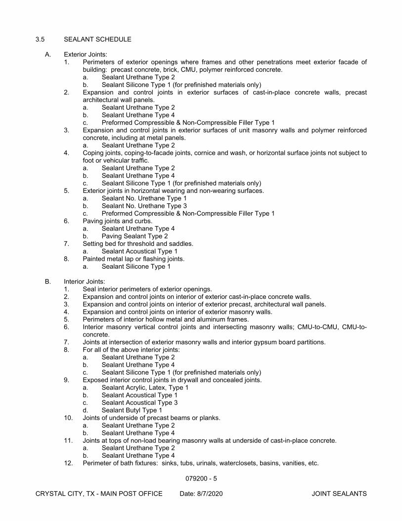
079200 - 5 CRYSTAL CITY, TX - MAIN POST OFFICE Date: 8/7/2020 JOINT SEALANTS
3.5 SEALANT SCHEDULE
A. Exterior Joints: 1. Perimeters of exterior openings where frames and other penetrations meet exterior facade of
building: precast concrete, brick, CMU, polymer reinforced concrete. a. Sealant Urethane Type 2 b. Sealant Silicone Type 1 (for prefinished materials only)
2. Expansion and control joints in exterior surfaces of cast-in-place concrete walls, precast architectural wall panels. a. Sealant Urethane Type 2 b. Sealant Urethane Type 4 c. Preformed Compressible & Non-Compressible Filler Type 1
3. Expansion and control joints in exterior surfaces of unit masonry walls and polymer reinforced concrete, including at metal panels. a. Sealant Urethane Type 2
4. Coping joints, coping-to-facade joints, cornice and wash, or horizontal surface joints not subject to foot or vehicular traffic. a. Sealant Urethane Type 2 b. Sealant Urethane Type 4 c. Sealant Silicone Type 1 (for prefinished materials only)
5. Exterior joints in horizontal wearing and non-wearing surfaces. a. Sealant No. Urethane Type 1 b. Sealant No. Urethane Type 3 c. Preformed Compressible & Non-Compressible Filler Type 1
6. Paving joints and curbs. a. Sealant Urethane Type 4 b. Paving Sealant Type 2
7. Setting bed for threshold and saddles. a. Sealant Acoustical Type 1
8. Painted metal lap or flashing joints. a. Sealant Silicone Type 1
B. Interior Joints:
1. Seal interior perimeters of exterior openings. 2. Expansion and control joints on interior of exterior cast-in-place concrete walls. 3. Expansion and control joints on interior of exterior precast, architectural wall panels. 4. Expansion and control joints on interior of exterior masonry walls. 5. Perimeters of interior hollow metal and aluminum frames. 6. Interior masonry vertical control joints and intersecting masonry walls; CMU-to-CMU, CMU-to-
concrete. 7. Joints at intersection of exterior masonry walls and interior gypsum board partitions. 8. For all of the above interior joints:
a. Sealant Urethane Type 2 b. Sealant Urethane Type 4 c. Sealant Silicone Type 1 (for prefinished materials only)
9. Exposed interior control joints in drywall and concealed joints. a. Sealant Acrylic, Latex, Type 1 b. Sealant Acoustical Type 1 c. Sealant Acoustical Type 3 d. Sealant Butyl Type 1
10. Joints of underside of precast beams or planks. a. Sealant Urethane Type 2 b. Sealant Urethane Type 4
11. Joints at tops of non-load bearing masonry walls at underside of cast-in-place concrete. a. Sealant Urethane Type 2 b. Sealant Urethane Type 4
12. Perimeter of bath fixtures: sinks, tubs, urinals, waterclosets, basins, vanities, etc.
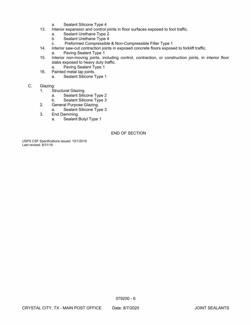
079200 - 6 CRYSTAL CITY, TX - MAIN POST OFFICE Date: 8/7/2020 JOINT SEALANTS
a. Sealant Silicone Type 4 13. Interior expansion and control joints in floor surfaces exposed to foot traffic.
a. Sealant Urethane Type 2 b. Sealant Urethane Type 4 c. Preformed Compressible & Non-Compressible Filler Type 1
14. Interior saw-cut contraction joints in exposed concrete floors exposed to forklift traffic. a. Paving Sealant Type 1
15. Interior non-moving joints, including control, contraction, or construction joints, in interior floor slabs exposed to heavy duty traffic. a. Paving Sealant Type 1
16. Painted metal lap joints. a. Sealant Silicone Type 1
C. Glazing:
1. Structural Glazing. a. Sealant Silicone Type 2 b. Sealant Silicone Type 3
2. General Purpose Glazing. a. Sealant Silicone Type 3
3. End Damming. a. Sealant Butyl Type 1
END OF SECTION USPS CSF Specifications issued: 10/1/2019 Last revised: 8/31/18
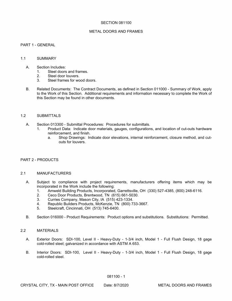
081100 - 1 CRYSTAL CITY, TX - MAIN POST OFFICE Date: 8/7/2020 METAL DOORS AND FRAMES
SECTION 081100
METAL DOORS AND FRAMES
PART 1 - GENERAL
1.1 SUMMARY
A. Section Includes: 1. Steel doors and frames. 2. Steel door louvers. 3. Steel frames for wood doors.
B. Related Documents: The Contract Documents, as defined in Section 011000 - Summary of Work, apply
to the Work of this Section. Additional requirements and information necessary to complete the Work of this Section may be found in other documents.
1.2 SUBMITTALS
A. Section 013300 - Submittal Procedures: Procedures for submittals. 1. Product Data: Indicate door materials, gauges, configurations, and location of cut-outs hardware
reinforcement, and finish. a. Shop Drawings: Indicate door elevations, internal reinforcement, closure method, and cut-
outs for louvers.
PART 2 - PRODUCTS
2.1 MANUFACTURERS
A. Subject to compliance with project requirements, manufacturers offering items which may be incorporated in the Work include the following: 1. Amweld Building Products, Incorporated, Garrettsville, OH (330) 527-4385, (800) 248-6116. 2. Ceco Door Products, Brentwood, TN (615) 661-5030. 3. Curries Company, Mason City, IA (515) 423-1334. 4. Republic Builders Products, McKenzie, TN (800) 733-3667. 5. Steelcraft, Cincinnati, OH (513) 745-6400.
B. Section 016000 - Product Requirements: Product options and substitutions. Substitutions: Permitted.
2.2 MATERIALS
A. Exterior Doors: SDI-100, Level II - Heavy-Duty - 1-3/4 inch, Model 1 - Full Flush Design, 18 gage cold-rolled steel; galvanized in accordance with ASTM A 653.
B. Interior Doors: SDI-100, Level II - Heavy-Duty - 1-3/4 inch, Model 1 - Full Flush Design, 18 gage
cold-rolled steel.
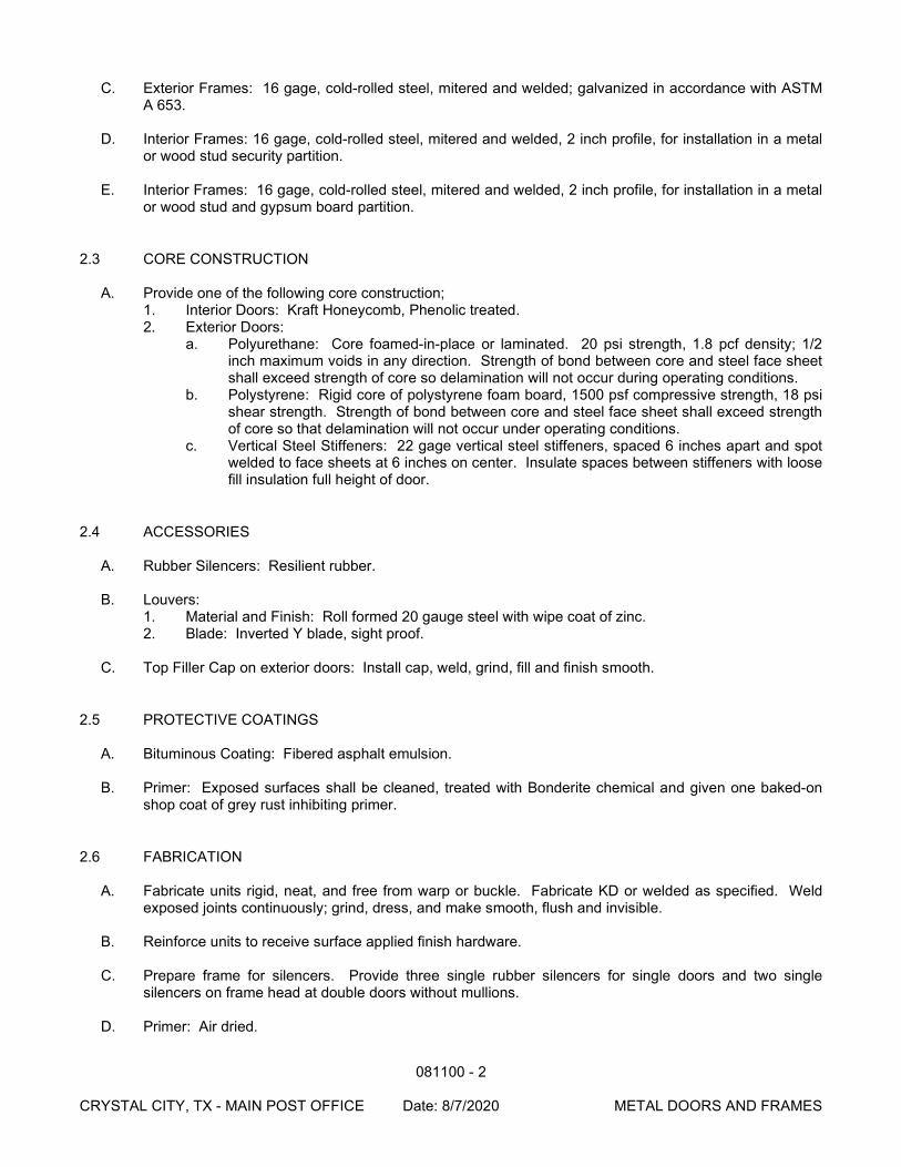
081100 - 2 CRYSTAL CITY, TX - MAIN POST OFFICE Date: 8/7/2020 METAL DOORS AND FRAMES
C. Exterior Frames: 16 gage, cold-rolled steel, mitered and welded; galvanized in accordance with ASTM A 653.
D. Interior Frames: 16 gage, cold-rolled steel, mitered and welded, 2 inch profile, for installation in a metal
or wood stud security partition.
E. Interior Frames: 16 gage, cold-rolled steel, mitered and welded, 2 inch profile, for installation in a metal or wood stud and gypsum board partition.
2.3 CORE CONSTRUCTION
A. Provide one of the following core construction; 1. Interior Doors: Kraft Honeycomb, Phenolic treated. 2. Exterior Doors:
a. Polyurethane: Core foamed-in-place or laminated. 20 psi strength, 1.8 pcf density; 1/2 inch maximum voids in any direction. Strength of bond between core and steel face sheet shall exceed strength of core so delamination will not occur during operating conditions.
b. Polystyrene: Rigid core of polystyrene foam board, 1500 psf compressive strength, 18 psi shear strength. Strength of bond between core and steel face sheet shall exceed strength of core so that delamination will not occur under operating conditions.
c. Vertical Steel Stiffeners: 22 gage vertical steel stiffeners, spaced 6 inches apart and spot welded to face sheets at 6 inches on center. Insulate spaces between stiffeners with loose fill insulation full height of door.
2.4 ACCESSORIES
A. Rubber Silencers: Resilient rubber.
B. Louvers: 1. Material and Finish: Roll formed 20 gauge steel with wipe coat of zinc. 2. Blade: Inverted Y blade, sight proof.
C. Top Filler Cap on exterior doors: Install cap, weld, grind, fill and finish smooth.
2.5 PROTECTIVE COATINGS
A. Bituminous Coating: Fibered asphalt emulsion.
B. Primer: Exposed surfaces shall be cleaned, treated with Bonderite chemical and given one baked-on shop coat of grey rust inhibiting primer.
2.6 FABRICATION
A. Fabricate units rigid, neat, and free from warp or buckle. Fabricate KD or welded as specified. Weld exposed joints continuously; grind, dress, and make smooth, flush and invisible.
B. Reinforce units to receive surface applied finish hardware.
C. Prepare frame for silencers. Provide three single rubber silencers for single doors and two single
silencers on frame head at double doors without mullions.
D. Primer: Air dried.
081100 - 3 CRYSTAL CITY, TX - MAIN POST OFFICE Date: 8/7/2020 METAL DOORS AND FRAMES
PART 3 - EXECUTION
3.1 INSTALLATION
A. Install frames in accordance with SDI-105.
B. Install doors in accordance with DHI.
C. Install doors in accordance with manufacturer's published instructions, of size, and at locations indicated.
D. Coordinate with adjacent wall construction for anchor placement.
E. Field paint doors and frames as specified in Section 099100. F. The frame is to be mounted to the studding in such a manner to prevent a spreading of the frame from
the studs of less than 1/2 inch.
END OF SECTION
081400 - 1 CRYSTAL CITY, TX - MAIN POST OFFICE Date: 8/7/2020 WOOD DOORS
SECTION 081400
WOOD DOORS
PART 1 - GENERAL
1.1 SUMMARY
A. Section Includes: 1. Flush wood doors. 2. Wood wicket doors.
B. Related Documents: The Contract Documents, as defined in Section 011000 - Summary of Work, apply
to the Work of this Section. Additional requirements and information necessary to complete the Work of this Section may be found in other documents.
1.2 SUBMITTALS
A. Section 013300 - Submittal Procedures: Procedures for submittals. 1. Shop Drawings: Illustrate door opening criteria, elevations, sizes, types, swings, special blocking
for hardware, and factory machining criteria. Indicate cutouts for door louvers. 2. Assurance/Control Submittals:
a. Certificates: Manufacturer's certificate that Products meet or exceed specified requirements.
b. Qualification Documentation: Submit documentation of experience indicating compliance with specified qualification requirements.
PART 2 - PRODUCTS
2.1 MANUFACTURERS
A. Subject to compliance with project requirements, manufacturers offering Products which may be incorporated in the Work include the following: 1. Algoma Hardwoods, Inc., Algoma, WI, (800) 678-8910. 2. Eggers Industries, Neena, WI, (920) 722-6444. 3. Mohawk Flush Doors, Inc., Northumberland, PA (717) 473-3557. 4. Marshfield DoorSystems, Incorporated, Marshfield, WI (800) 869-3667.
B. Section 016000 - Product Requirements: Product options and substitutions. Substitutions: Permitted.
2.2 MATERIALS
A. Solid Core Wood Doors (Interior Use): AWI 1300. 1. Thickness: Indicated on Drawings. 2. Veneer: AWI 1300-S-9 SLC-5 ME. 3. Face Veneer: AWI Custom quality rotary cut birch for paint finish. 4. Core Construction:
a. Non Fire-Rated: SLC solid stave lumber. b. Fire-Rated: Type FD 1-1/2 solid stave lumber.
081400 - 2 CRYSTAL CITY, TX - MAIN POST OFFICE Date: 8/7/2020 WOOD DOORS
5. Grade: AWI Custom.
B. Solid Core Wicket Doors (Interior Use): AWI 1300. 1. Thickness: Indicated on Drawings. 2. Face Veneer: AWI Custom quality rotary cut birch for paint finish. 3. Core Construction: SCL Structural Composite Lumber 4. Grade: AWI Custom.
C. Louvers: Roll formed steel, inverted V blade, sight proof, primed for paint finish, size as indicated on
Drawings. D. Provide fire-rated labeled doors where indicated on Drawings.
2.3 FABRICATION
A. Fabricate non fire-rated doors in accordance with AWI 1300.
B. Fabricate fire-rated doors to AWI 1300 and to Underwriters Laboratories Incorporated requirements. Attach fire rating label to doors.
C. Furnish and install lock blocks at lock edge, and top of door closer for hardware reinforcement.
D. Vertical Exposed Edge of Stiles:
1. Wicket Door: Paint same as door facing. 2. Other Wood Doors: Of same species as veneer facing.
E. Bond edge banding to cores.
F. Factory machine door for door hardware in accordance with hardware requirements and dimensions.
Do not machine for surface hardware.
G. Factory fit doors for frame opening dimensions identified on approved shop drawings.
H. Doors may be provided pre-hung set in frames and ready for installation in rough openings. Metal door frames specified in Section 081100.
PART 3 - EXECUTION
3.1 INSTALLATION
A. Install non fire-rated doors in accordance with AWI Quality Standards requirements.
B. Install fire-rated doors in accordance with AWI Quality Standard and NFPA 80 requirements.
C. Machine cut for hardware. Install door hardware specified in Section 087100.
D. Install door louvers plumb and level.
E. Field paint doors and door louvers as specified in Section 099100, color as indicated on Drawings.
END OF SECTION
083113 - 1
CRYSTAL CITY, TX - MAIN POST OFFICE Date: 8/7/2020 ACCESS DOORS AND FRAMES
SECTION 083113
ACCESS DOORS AND FRAMES
PART 1 - GENERAL
1.1 SUMMARY
A. Section Includes: 1. Fire-resistive rated access door and frame units. 2. Non fire-resistive rated access door and frame units. 3. Wall and ceiling locations.
B. Related Documents: The Contract Documents, as defined in Section 011000 - Summary of Work, apply
to the Work of this Section. Additional requirements and information necessary to complete the Work of this Section may be found in other Documents.
PART 2 - PRODUCTS
2.1 MANUFACTURERS
A. Subject to compliance with project requirements, manufacturer's offering Products which may be incorporated in the Work include the following: 1. J.L. Industries, Bloomington, MN (612) 835-6850. (800) 554-6077. 2. Karp, Maspeth, NY (800) 888-4212. 3. Larsen's Manufacturing Company, Minneapolis, MN (800) 527-7367. 4. Milcor, Holland, OH (800) 861-6452.
B. Section 016000 - Product Requirements: Product options and substitutions. Substitutions: Permitted.
2.2 ACCESS DOORS
A. Non Fire-Rated: 20 gauge recessed steel panel doors to accept field finish of drywall.
B. Fire-Rated Models: 14 gauge recessed steel panel doors to accept field finish of drywall.
2.3 FABRICATION A. Fabricate frames and flanges of 16 gauge (0.058 inch) steel. B. Fabricate door panels of 20 gauge (0.359 inch) single thickness steel sheet for non fire rated doors and
14 gauge (0.070 inch) single thickness steel sheet for fire rated doors. C. Weld, fill, and grind joints to ensure flush and square unit. D. Hardware:
1. Hinge: 175 degree stainless steel piano hinge concealed constant force closure spring type.[ 2. Lock: Screw driver slot for quarter turn cam lock unit.
083113 - 2
CRYSTAL CITY, TX - MAIN POST OFFICE Date: 8/7/2020 ACCESS DOORS AND FRAMES
2.4 FINISHES
A. Base Metal Protection: Prime coat units with alkyd primer.
PART 3 - EXECUTION
3.1 INSTALLATION A. Install units in accordance with manufacturer's published instructions where indicated on Drawings and
required for access. B. Install frames plumb and level in opening. Secure rigidly in place. C. Position unit to provide convenient access to concealed work requiring access.
END OF SECTION
083800 - 1
CRYSTAL CITY, TX - MAIN POST OFFICE Date: 8/7/2020 TRAFFIC DOORS
SECTION 083800
TRAFFIC DOORS
PART 1 - GENERAL
1.1 SUMMARY
A. Section Includes: 1. Double action impact resistant traffic doors, security type. 2. Door hardware. 3. Security features.
B. Related Documents: The Contract Documents, as defined in Section 011000 - Summary of Work, apply
to the Work of this Section. Additional requirements and information necessary to complete the Work of this Section may be found in other Documents.
C. Provide products complete with accessories, trim, finish, safety guards, and other pertinent devices and
details needed for a complete installation and intended use.
1.2 SUBMITTALS
A. Section 013300 - Submittal Procedures: Procedures for submittals. 1. Product Data: Indicate door materials, thickness, configuration, and hardware.
B. Section 017704 – Closeout Procedures and Training: Procedures for closeout submittals. 1. Operating and Maintenance Data: Operating and maintenance instruction and parts lists. 2. Submit written special warranty with forms completed in United States Postal Service name and
registered with manufacturer as specified in this section.
1.3 WARRANTY
A. Comply with Section 017704 - Closeout Procedures and Training: Procedures for closeout submittals.
B. Manufacturer warranty to cover all material and labor required to repair or replace doors and door components for a period of two years from time of acceptance by USPS, within a guaranteed maximum repair response time of ten (10) calendar days.
PART 2 - PRODUCTS
2.1 MANUFACTURERS
A. This Product must be manufactured by a USPS Direct Vendor and is subject to a USPS price and requirements purchasing agreement. The following vendor contact must be used: 1. Chase Industries/Senneca Holdings, 10021 Commerce Park Dr., Cincinnati, OH 45246.
Ordering POC: Sky Mathews, (800) 543-4455, ext. 3477, [email protected] B. Section 016000 - Product Requirements: Product options and substitutions. Substitutions: Not
Permitted.
083800 - 2
CRYSTAL CITY, TX - MAIN POST OFFICE Date: 8/7/2020 TRAFFIC DOORS
2.2 TRAFFIC DOORS
A. Model: 1. Chase Industries: Durulite Series 200 Security Doors, (or Series
ME-200, when a custom size is required).
B. Color: Selected by Contracting Officer from manufacturer's standard colors.
C. Door Body: 1. Per manufacturer’s USPS approved construction. 2. Panel skin rate of burning, ASTM D635: “HB” (horizontal burning), no combustion. 3. Panel skin flame spread index, ASTM E84: 275 maximum.
D. Hardware: The upper pivot shall consist of a V-cam capable of carrying a door weighing 200 pounds.
Lift shall be 1-3/8 inches with gravity self-closing action. Door shall be adjustable back and forth and/or up and down.
E. Gaskets: All gasket materials shall be factory applied and shall include wings to prevent accumulation
of dirt. Gaskets shall be on leading edge, back and bottom of each door panel.
F. Top and Hinge Seal Covers: Top seal shall be made of block reinforced nylon, with black anodized aluminum metal. Stainless steel screws shall be used for fastening to frame. Top and bottom hinge seal covers shall be field installed.
G. Viewing Area:
1. Per manufacturer’s USPS approved construction.
H. Fasteners: All fasteners and washers, including jamb fasteners shall be made of stainless steel.
I. Black Spring Polyethylene Bumper/Kick Plate. 1. At Carrier Vestibule: 38-inch-high bumpers on both sides of doors with no kickplate. 2. At Mail Vestibule: 38-inch-high bumpers on both sides of doors with no kickplate.
J. Steel Door Frames: Specified in Section 055000.
K. Directional Signs. USPS standard design:
1. Pictograph for enter. Apply to entry side of panels. 2. Pictograph and “NO EXIT”. Apply opposite to entry side of panels for doors providing entry to
building. 3. Pictograph and “NO ENTRY”. Apply opposite to entry side of panels for doors providing exit from
building.
2.3 SECURITY FEATURES
A. In addition to the items specified above, the following features shall be included in the door units: 1. Lower hinge guard. 2. Cane bolts, minimum 5/8-inch round steel, 12 inches long from tip to elbow (upper) and 36 inches
long from tip to elbow (lower). 3. 2-inch chain hole with grommet. 4. Dirt free retainer sleeves for each lower cane bolt, with a depth of at least 3 inches. 5. Double glazed polycarbonate security windows with three (3) 1” x ¼” vertical steel bars. The
vertical bars extend from the top of the door to within 33” of the bottom of the door panel, with a maximum horizontal spacing of 7”.
083800 - 3
CRYSTAL CITY, TX - MAIN POST OFFICE Date: 8/7/2020 TRAFFIC DOORS
2.4 DOOR STOPS
A. Overhead door stops, header mount with tabs and contact pads.
PART 3 - EXECUTION
3.1 INSTALLATION
A. Install door unit assembly to manufacturer's published instructions and final shop drawings.
B. Fit and align door assembly level and plumb.
C. Use anchorage devices to securely fasten door assembly to door frame construction without distortion or imposed stresses.
END OF SECTION
084113 - 1 CRYSTAL CITY, TX - MAIN POST OFFICE Date: 8/7/2020 ALUMINUM FRAMED ENTRANCES AND STOREFRONTS
SECTION 084113
ALUMINUM-FRAMED ENTRANCES AND STOREFRONTS
PART 1 - GENERAL
1.1 SUMMARY
A. Section Includes: 1. Aluminum entrance doors. 2. Aluminum storefronts 3. Aluminum windows (fixed and operable) 4. Vision glass and glass infill panels. 5. Door hardware for entrance doors. 6. Perimeter sealant.
B. Related Documents: The Contract Documents, as defined in Section 011000- Summary of Work, apply
to the Work of this Section. Additional requirements and information necessary to complete the Work of this Section may be found in other Documents.
1.2 SUBMITTALS
A. Section 013300 - Submittal Procedures: Procedures for submittals. 1. Product Data:
a. Product Data: Provide component dimensions, describe components within assembly, anchorage and fasteners, glass and infill, door hardware, and internal drainage details.
2. Shop Drawings: a. Shop Drawings: Indicate system dimensions, framed opening requirements and
tolerances, affected related Work and expansion and contraction joint location and details.
1.3 PROJECT CONDITIONS OR SITE CONDITIONS
A. Jobsite Requirements: 1. Install sealants and glazing only when temperature is 40 degrees F. or greater.
1.4 ENVIRONMENTAL REQUIREMENTS
A. Energy Efficiency: 1. Exterior framing system: Provide frame with thermal break for exterior framing systems; provide
weather-stripping for doors in exterior frame.
PART 2 - PRODUCTS
2.1 MANUFACTURERS
084113 - 2 CRYSTAL CITY, TX - MAIN POST OFFICE Date: 8/7/2020 ALUMINUM FRAMED ENTRANCES AND STOREFRONTS
A. Subject to compliance with project requirements, manufacturers offering Products which may be incorporated in the Work include the following: 1. Kawneer Company, Incorporated, Atlanta, GA (770) 449-5555. 2. Other acceptable manufacturers offering equivalent products.
a. Amarlite Architectural Aluminum and Glass Co., Tamarac, FL (800) 691-5750. b. EFCO Corporation; Monett, MO. (800) 221-4169. c. Tubelite, Inc., Reed City, MI. (800) 846-2227. d. U.S. Aluminum Corporation, Waxahachie, TX. (800) 627-6440. e. Vistawall Architectural Products, Terrell, TX. (800) 869-4567.
3. Section 016000 - Product Requirements: Product options and substitutions. Substitutions: Permitted.
2.2 MATERIALS
A. Extruded Aluminum: ASTM B221.
B. Sheet Aluminum: ASTM B209.
C. Steel Sections: ASTM A36/A36M; shaped to suit mullion sections.
D. Fasteners: Stainless steel.
2.3 COMPONENTS
A. Framing System: Trifab 451T, by Kawneer, 2 x 4-1/2 inch (50mm x 113mm) nominal dimension, minimum wall thickness of 0.080 inches, extruded aluminum flush glazed framing system with thermal break. 1. Operable window to include:
a. Limiters, allowing 4 inch (10 cm) maximum opening at leading edge of window. b. Insect screen installed with security fasteners. c. Locking devices installed with security fasteners. Awning type and hopper type windows
require two locking devices, one on each side of the window.
B. Column Covers: 0.040 inch aluminum, by Kawneer Company, Inc. Finish to match that of storefront system.
C. Receptor Channel: Model No. 450-038 and 65-025, by Kawneer Company, Inc. Finish to match that of
storefront system.
2.4 ENTRANCE DOORS
A. Doors: Series 350 swing door, medium stile, by Kawneer Company, Inc. Door sizes indicated on Drawings. 1. Vertical Stile: 3-1/2 inch (88mm), single piece. 2. Top Rail: 3-1/2 inch (88mm), single piece. 3. Bottom Rail: 10 inch (250mm), single piece. 4. Glazing: 1/4 inch (6mm) thick units per Section 088000, with standard bevel glass stops.
2.5 GLASS AND GLAZING MATERIALS
A. Glazing Materials: As specified in Section 088000.
084113 - 3 CRYSTAL CITY, TX - MAIN POST OFFICE Date: 8/7/2020 ALUMINUM FRAMED ENTRANCES AND STOREFRONTS
2.6 SEALANT MATERIALS
A. Sealant and Backing Materials: 1. Perimeter Sealant: Type as specified in Section 079200. 2. Sealant Used Within System (Not Used for Glazing): Type as specified in Section 079200.
2.7 HARDWARE
A. Verify hardware components specified in Section 087100.
B. Closers: See Section 087100.
C. Hinges: Door manufacturer’s standard three pairs of butt hinges with non-removable pins. Finish.
D. Locking Devices: See Section 087100.
E. Pulls: Type CO-9 pull, by Kawneer Company, Inc. Finish: #14 Clear Anodized.
F. Exit Devices: See Section 087100.
G. Weatherstripping, for Exterior Doors only: 1. Head and Jamb: Replaceable wool, polypropylene, or nylon wool pile with aluminum strip
backing, recessed in frame; AAMA 701.2. 2. Sill: Semi-rigid polymeric material on aluminum anodized to match door; EPDM sweep strip;
38-560 by Kawneer or similar by other named manufacturers.
H. Threshold: See Section 087100.
2.8 FINISHES
A. Exposed Aluminum Surfaces: Architectural Class I anodic coating, AA-M12 C22 A41, #14 Clear, unless otherwise indicated on Drawings.
B. Maintain same color range on doors, frames and other components. Do not mix light and dark shades.
C. Concealed Steel Items: Galvanized in accordance with ASTM A386 to 2.0 oz/sq. ft.
D. Apply two coats of bituminous paint to concealed aluminum and steel surfaces in contact with
cementitious or dissimilar materials.
PART 3 - EXECUTION
3.1 INSTALLATION
A. Install wall system in accordance with manufacturer's instructions.
B. Attach to structure to permit sufficient adjustment to accommodate construction tolerances and other irregularities.
C. Provide alignment attachments and shims to permanently fasten system to building structure.

084113 - 4 CRYSTAL CITY, TX - MAIN POST OFFICE Date: 8/7/2020 ALUMINUM FRAMED ENTRANCES AND STOREFRONTS
D. Align assembly plumb and level, free of warp or twist. Maintain assembly dimensional tolerances, aligning with adjacent work.
E. Provide thermal isolation where components penetrate or disrupt building insulation.
F. Install sill flashings. Turn up ends and edges; seal to adjacent work to form water tight dam.
G. Coordinate attachment and seal of perimeter air and vapor barrier materials.
H. Pack fibrous insulation in shim spaces at perimeter of assembly to maintain continuity of thermal barrier.
I. Set thresholds in bed of mastic and secure.
J. Install hardware using templates provided. Refer to Section 087100 for installation requirements.
K. Install glass in accordance with Section 088000. L. Install perimeter sealant, backing materials, and installation criteria in accordance with Section 079200. M. Install automatic door operators and actuators in accordance with Section 084229.
END OF SECTION
084229 - 1
CRYSTAL CITY, TX - MAIN POST OFFICE Date: 7/14/2020 AUTOMATIC ENTRANCES
SECTION 084229
AUTOMATIC ENTRANCES
PART 1 - GENERAL
1.1 SUMMARY
A. Section Includes: 1. Automatic sliding entrance doors with automatic actuators. 2. Entrance doors with low energy automatic operators and push plate actuators.
B. Related Documents: The Contract Documents, as defined in Section 011000 - Summary of Work, apply
to the Work of this Section. Additional requirements and information necessary to complete the Work of this Section may be found in other Documents.
C. Related Sections:
1. Section 084113, Aluminum-Framed Entrances and Storefronts 2. Section 087100, Door Hardware 3. Section 088000, Glazing 4. Division 16, Electrical: 115 volt AC, minimum 15 amp (for two operators), single-phase wiring in
conduit between operator enclosure and building power supply and low voltage wiring between enclosure and actuators. Wiring is to be concealed. Surface wiring is not permitted.
D. Automatic doors shall be installed by a factory representative and will include all accessories, trim, finish, safety guards, hardware and other pertinent devices and details needed for a complete installation and intended use.
1.2 REFERENCES
A. American National Standard Institute (ANSI): 1. ANSI/BHMA A156.19, American National Standard for Power Assist and Low Energy Power
Operated Doors. 2. ANSI/BHMA A156.10, American National Standard for Power Operated Pedestrian Doors..
1.3 SUBMITTALS
A. Section 013300 - Submittal Procedures: Procedures for submittals. 1. Product Data: Manufacturer’s catalog data, detail sheets, installation data and specifications.
B. Section 017704 - Closeout Procedures and Training: Procedures for closeout submittals.
1. Operating and Maintenance Data: Operating and maintenance instructions, parts lists and wiring diagrams.
2. Submit written special warranty with forms completed in United States Postal Service name and registered with manufacturer as specified in this Section.
1.4 QUALITY ASSURANCE
A. Qualifications: 1. Automatic doors will be manufactured and installed by the Factory Authorized Contractor.
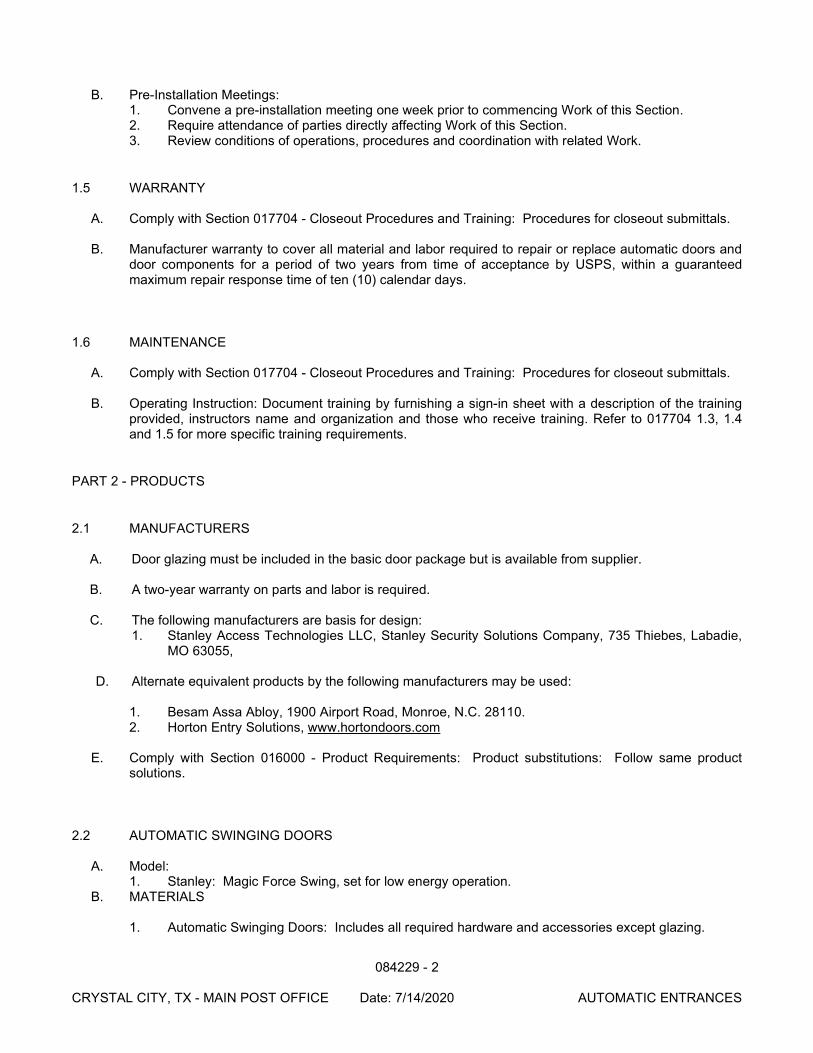
084229 - 2
CRYSTAL CITY, TX - MAIN POST OFFICE Date: 7/14/2020 AUTOMATIC ENTRANCES
B. Pre-Installation Meetings:
1. Convene a pre-installation meeting one week prior to commencing Work of this Section. 2. Require attendance of parties directly affecting Work of this Section. 3. Review conditions of operations, procedures and coordination with related Work.
1.5 WARRANTY
A. Comply with Section 017704 - Closeout Procedures and Training: Procedures for closeout submittals. B. Manufacturer warranty to cover all material and labor required to repair or replace automatic doors and
door components for a period of two years from time of acceptance by USPS, within a guaranteed maximum repair response time of ten (10) calendar days.
1.6 MAINTENANCE
A. Comply with Section 017704 - Closeout Procedures and Training: Procedures for closeout submittals.
B. Operating Instruction: Document training by furnishing a sign-in sheet with a description of the training provided, instructors name and organization and those who receive training. Refer to 017704 1.3, 1.4 and 1.5 for more specific training requirements.
PART 2 - PRODUCTS
2.1 MANUFACTURERS
A. Door glazing must be included in the basic door package but is available from supplier. B. A two-year warranty on parts and labor is required. C. The following manufacturers are basis for design:
1. Stanley Access Technologies LLC, Stanley Security Solutions Company, 735 Thiebes, Labadie, MO 63055,
D. Alternate equivalent products by the following manufacturers may be used:
1. Besam Assa Abloy, 1900 Airport Road, Monroe, N.C. 28110. 2. Horton Entry Solutions, www.hortondoors.com
E. Comply with Section 016000 - Product Requirements: Product substitutions: Follow same product
solutions.
2.2 AUTOMATIC SWINGING DOORS
A. Model: 1. Stanley: Magic Force Swing, set for low energy operation.
B. MATERIALS
1. Automatic Swinging Doors: Includes all required hardware and accessories except glazing.
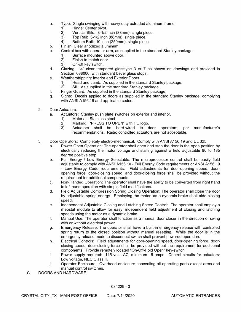
084229 - 3
CRYSTAL CITY, TX - MAIN POST OFFICE Date: 7/14/2020 AUTOMATIC ENTRANCES
a. Type: Single swinging with heavy duty extruded aluminum frame. 1) Hinge: Center pivot. 2) Vertical Stile: 3-1/2 inch (88mm), single piece. 3) Top Rail: 3-1/2 inch (88mm), single piece. 4) Bottom Rail: 10 inch (250mm), single piece.
b. Finish: Clear anodized aluminum. c. Control box with operator arm, as supplied in the standard Stanley package:
1) Surface mounted above door. 2) Finish to match door. 3) On-off key switch.
d. Glazing: ¼” clear tempered glasstype 3 or 7 as shown on drawings and provided in Section 088000, with standard bevel glass stops.
e. Weatherstripping: Interior and Exterior Doors 1) Head and Jamb: As supplied in the standard Stanley package. 2) Sill: As supplied in the standard Stanley package.
f. Finger Guard: As supplied in the standard Stanley package. g. Signs: Decals applied to doors as supplied in the standard Stanley package, complying
with ANSI A156.19 and applicable codes.
2. Door Actuators. a. Actuators: Stanley push plate switches on exterior and interior.
1) Material: Stainless steel. 2) Marking: “PRESS TO OPEN” with HC logo. 3) Actuators shall be hard-wired to door operators, per manufacturer’s
recommendations. Radio controlled actuators are not acceptable.
3. Door Operators: Completely electro-mechanical. Comply with ANSI A156.19 and UL 325. a. Power Open Operation: The operator shall open and stop the door in the open position by
electrically reducing the motor voltage and stalling against a field adjustable 80 to 135 degree positive stop.
b. Full Energy / Low Energy Selectable: The microprocessor control shall be easily field adjustable to comply with ANSI A156.10 - Full Energy Code requirements or ANSI A156.19 - Low Energy Code requirements. Field adjustments for door-opening speed, door-opening force, door-closing speed, and door-closing force shall be provided without the requirement for additional components.
c. Non-Handed Operation: The operator shall have the ability to be converted from right hand to left hand operation with simple field modifications.
d. Field Adjustable Compression Spring Closing Operation: The operator shall close the door by adjustable spring energy. Employing the motor, as a dynamic brake shall aide-closing speed.
e. Independent Adjustable Closing and Latching Speed Control: The operator shall employ a rheostat module to allow for easy, independent field adjustment of closing and latching speeds using the motor as a dynamic brake.
f. Manual Use: The operator shall function as a manual door closer in the direction of swing with or without electrical power.
g. Emergency Release: The operator shall have a built-in emergency release with controlled spring return to the closed position without manual resetting. While the door is in the emergency release mode, a disconnect switch shall prevent powered operation.
h. Electrical Controls: Field adjustments for door-opening speed, door-opening force, door-closing speed, door-closing force shall be provided without the requirement for additional components. Provide remotely located "On-Off-Hold Open" key-switch.
i. Power supply required: 115 volts AC, minimum 15 amps. Control circuits for actuators: Low voltage, NEC Class II.
j. Operator Enclosure: Overhead enclosure concealing all operating parts except arms and manual control switches.
C. DOORS AND HARDWARE
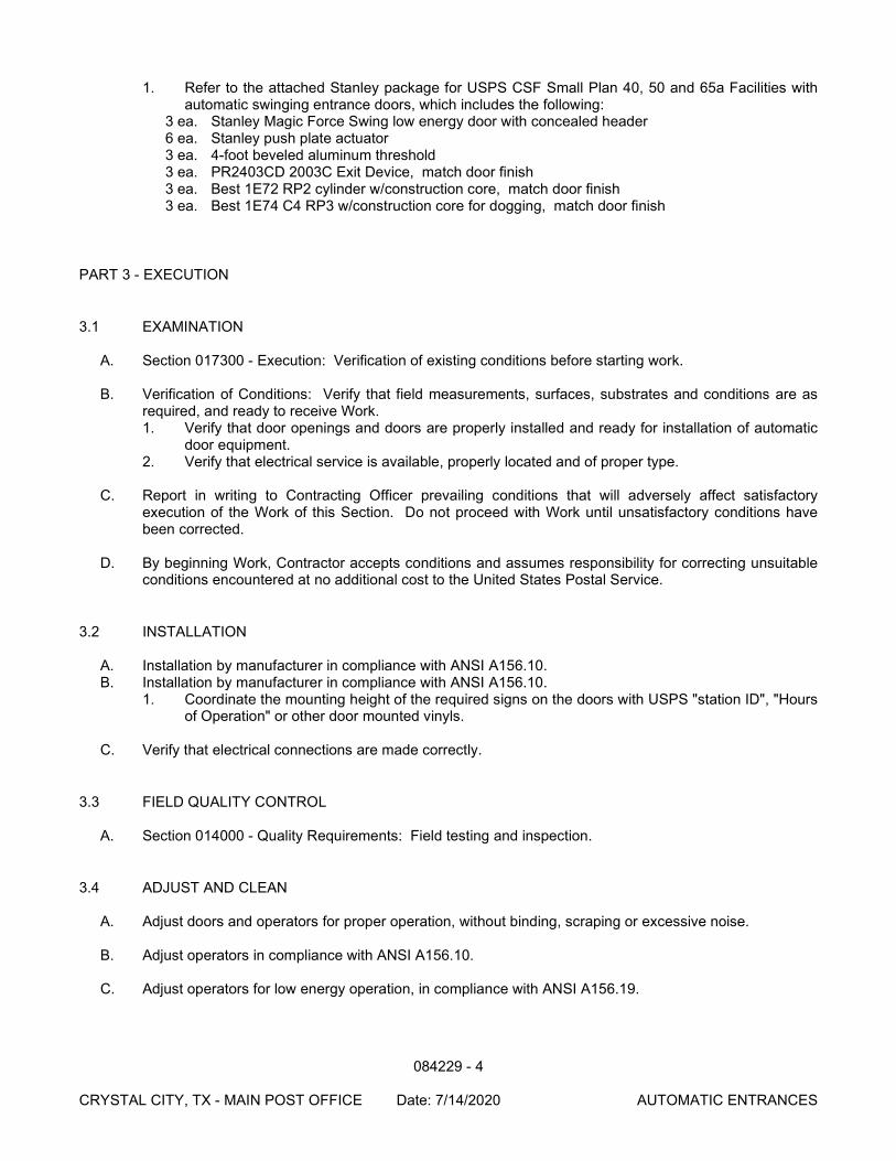
084229 - 4
CRYSTAL CITY, TX - MAIN POST OFFICE Date: 7/14/2020 AUTOMATIC ENTRANCES
1. Refer to the attached Stanley package for USPS CSF Small Plan 40, 50 and 65a Facilities with automatic swinging entrance doors, which includes the following:
3 ea. Stanley Magic Force Swing low energy door with concealed header 6 ea. Stanley push plate actuator 3 ea. 4-foot beveled aluminum threshold 3 ea. PR2403CD 2003C Exit Device, match door finish 3 ea. Best 1E72 RP2 cylinder w/construction core, match door finish 3 ea. Best 1E74 C4 RP3 w/construction core for dogging, match door finish
PART 3 - EXECUTION
3.1 EXAMINATION
A. Section 017300 - Execution: Verification of existing conditions before starting work.
B. Verification of Conditions: Verify that field measurements, surfaces, substrates and conditions are as required, and ready to receive Work. 1. Verify that door openings and doors are properly installed and ready for installation of automatic
door equipment. 2. Verify that electrical service is available, properly located and of proper type.
C. Report in writing to Contracting Officer prevailing conditions that will adversely affect satisfactory
execution of the Work of this Section. Do not proceed with Work until unsatisfactory conditions have been corrected.
D. By beginning Work, Contractor accepts conditions and assumes responsibility for correcting unsuitable
conditions encountered at no additional cost to the United States Postal Service.
3.2 INSTALLATION
A. Installation by manufacturer in compliance with ANSI A156.10. B. Installation by manufacturer in compliance with ANSI A156.10.
1. Coordinate the mounting height of the required signs on the doors with USPS "station ID", "Hours of Operation" or other door mounted vinyls.
C. Verify that electrical connections are made correctly.
3.3 FIELD QUALITY CONTROL
A. Section 014000 - Quality Requirements: Field testing and inspection.
3.4 ADJUST AND CLEAN
A. Adjust doors and operators for proper operation, without binding, scraping or excessive noise.
B. Adjust operators in compliance with ANSI A156.10.
C. Adjust operators for low energy operation, in compliance with ANSI A156.19.
084229 - 5
CRYSTAL CITY, TX - MAIN POST OFFICE Date: 7/14/2020 AUTOMATIC ENTRANCES
3.5 PROTECTION
A. Protect finishes until substantial completion. B. OPERATING INSTRUCTION
1. Provide on-site instruction to review the operation of the system and detail any common troubleshooting or maintenance that is required to ensure normal operation.
2. Provide one complete set of equipment operating, installation, and programming manuals that will remain at the installed location.
END OF SECTION
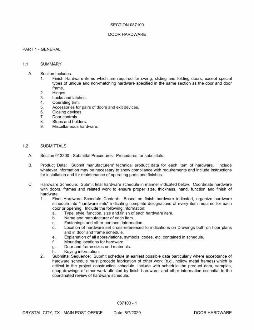
087100 - 1
CRYSTAL CITY, TX - MAIN POST OFFICE Date: 8/7/2020 DOOR HARDWARE
SECTION 087100
DOOR HARDWARE
PART 1 - GENERAL
1.1 SUMMARY
A. Section Includes: 1. Finish Hardware items which are required for swing, sliding and folding doors, except special
types of unique and non-matching hardware specified in the same section as the door and door frame.
2. Hinges. 3. Locks and latches. 4. Operating trim. 5. Accessories for pairs of doors and exit devices. 6. Closing devices. 7. Door controls. 8. Stops and holders. 9. Miscellaneous hardware.
1.2 SUBMITTALS
A. Section 013300 - Submittal Procedures: Procedures for submittals.
B. Product Data: Submit manufacturers' technical product data for each item of hardware. Include whatever information may be necessary to show compliance with requirements and include instructions for installation and for maintenance of operating parts and finishes.
C. Hardware Schedule: Submit final hardware schedule in manner indicated below. Coordinate hardware
with doors, frames and related work to ensure proper size, thickness, hand, function and finish of hardware. 1. Final Hardware Schedule Content: Based on finish hardware indicated, organize hardware
schedule into "hardware sets" indicating complete designations of every item required for each door or opening. Include the following information: a. Type, style, function, size and finish of each hardware item. b. Name and manufacturer of each item. c. Fastenings and other pertinent information. d. Location of hardware set cross-referenced to indications on Drawings both on floor plans
and in door and frame schedule. e. Explanation of all abbreviations, symbols, codes, etc. contained in schedule. f. Mounting locations for hardware. g. Door and frame sizes and materials. h. Keying information.
2. Submittal Sequence: Submit schedule at earliest possible date particularly where acceptance of hardware schedule must precede fabrication of other work (e.g., hollow metal frames) which is critical in the project construction schedule. Include with schedule the product data, samples, shop drawings of other work affected by finish hardware, and other information essential to the coordinated review of hardware schedule.
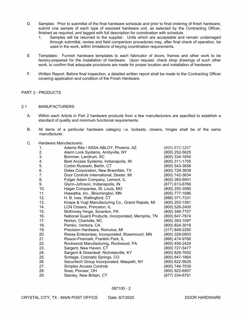
087100 - 2
CRYSTAL CITY, TX - MAIN POST OFFICE Date: 8/7/2020 DOOR HARDWARE
D. Samples: Prior to submittal of the final hardware schedule and prior to final ordering of finish hardware, submit one sample of each type of exposed hardware unit, as selected by the Contracting Officer, finished as required, and tagged with full description for coordination with schedule. 1. Samples will be returned to the supplier. Units which are acceptable and remain undamaged
through submittal, review and field comparison procedures may, after final check of operation, be used in the work, within limitations of keying coordination requirements.
E. Templates: Furnish hardware templates to each fabricator of doors, frames and other work to be
factory-prepared for the installation of hardware. Upon request, check shop drawings of such other work, to confirm that adequate provisions are made for proper location and installation of hardware.
F. Written Report: Before final inspection, a detailed written report shall be made to the Contracting Officer
covering application and condition of the Finish Hardware.
PART 2 - PRODUCTS
2.1 MANUFACTURERS
A. Within each Article in Part 2 hardware products from a few manufacturers are specified to establish a standard of quality and minimum functional requirements.
B. All items of a particular hardware category i.e. locksets, closers, hinges shall be of the same
manufacturer. C. Hardware Manufacturers:
1. Adams Rite / ASSA ABLOY, Phoenix, AZ (800) 872-3267 2. Alarm Lock Systems, Amityville, NY (800) 252-5625 3. Bommer, Landrum, SC (800) 334-1654 4. Best Access Systems, Indianapolis, IN (800) 311-1705 5. Corbin Russwin, Berlin, CT (800) 543-3658 6. Detex Corporation, New Brannfels, TX (800) 729-3839 7. Door Controls International, Dexter, MI (800) 742-3634 8. Folger Adam Company, Lemont, IL (800) 260-9001 9. Glynn-Johnson, Indianapolis, IN (877) 613-8766 10. Hager Companies, St. Louis, MO (800) 255-3590 11. Hiawatha, Inc., Bloomington, MN (800) 777-1686 12. H. B. Ives, Wallingford, CT (888) 371-7331 13. Knape & Vogt Manufacturing Co., Grand Rapids, MI (800) 253-1561 14. LCN Closers, Princeton, IL (800) 526-2400 15. McKinney Hinge, Scranton, PA (800) 346-7707 16. National Guard Products, Incorporated, Memphis, TN (800) 647-7874 17. Norton, Charlotte, NC (800) 393-1097 18. Pemko, Ventura, CA (800) 824-3018 19. Precision Hardware, Romulus, MI (317) 849-2250 20. Reese Enterprises, Incorporated, Rosemount, MN (800) 328-0953 21. Rixson-Firemark, Franklin Park, IL (866) 474-9766 22. Rockwood Manufacturing, Rockwood, PA (800) 458-2424 23. Sargent, New Haven, CT (800) 727-5477 24. Sargent & Greenleaf, Nicholasville, KY (800) 826-7652 25. Schlage, Colorado Springs, CO (800) 847-1864 26. Securitech Group Incorporated, Maspeth, NY (800) 622-5625 27. Simplex Access Controls (800) 746-7539 28. Soss, Pioneer, OH (800) 922-6957 29. Stanley, New Britain, CT (877) 334-6791
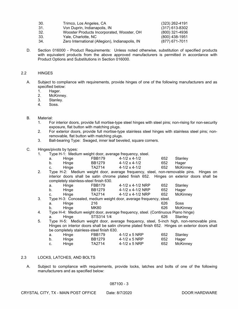
087100 - 3
CRYSTAL CITY, TX - MAIN POST OFFICE Date: 8/7/2020 DOOR HARDWARE
30. Trimco, Los Angeles, CA (323) 262-4191 31. Von Duprin, Indianapolis, IN (317) 613-8302 32. Wooster Products Incorporated, Wooster, OH (800) 321-4936 33. Yale, Charlotte, NC (800) 438-1951 34. Zero International (Allegion), Indianapolis, IN (877) 671-7011
D. Section 016000 - Product Requirements: Unless noted otherwise, substitution of specified products
with equivalent products from the above approved manufacturers is permitted in accordance with Product Options and Substitutions in Section 016000.
2.2 HINGES
A. Subject to compliance with requirements, provide hinges of one of the following manufacturers and as specified below: 1. Hager. 2. McKinney. 3. Stanley. 4. Soss.
B. Material: 1. For interior doors, provide full mortise-type steel hinges with steel pins; non-rising for non-security
exposure, flat button with matching plugs. 2. For exterior doors, provide full mortise-type stainless steel hinges with stainless steel pins; non-
removable, flat button with matching plugs. 3. Ball-bearing Type: Swaged, inner leaf beveled, square corners.
C. Hinges/pivots by types:
1. Type H-1: Medium weight door, average frequency, steel. a. Hinge FBB179 4-1/2 x 4-1/2 652 Stanley b. Hinge BB1279 4-1/2 x 4-1/2 652 Hager c. Hinge TA2714 4-1/2 x 4-1/2 652 McKinney
2. Type H-2: Medium weight door, average frequency, steel, non-removable pins. Hinges on interior doors shall be satin chrome plated finish 652. Hinges on exterior doors shall be completely stainless-steel finish 630. a. Hinge FBB179 4-1/2 x 4-1/2 NRP 652 Stanley b. Hinge BB1279 4-1/2 x 4-1/2 NRP 652 Hager c. Hinge TA2714 4-1/2 x 4-1/2 NRP 652 McKinney
3. Type H-3: Concealed, medium weight door, average frequency, steel. a. Hinge 216 626 Soss b. Hinge MK80 626 McKinney
4. Type H-4: Medium weight door, average frequency, steel. (Continuous Piano hinge) a. Hinge STS314 1/4 626 Stanley
5. Type H-5: Medium weight door, average frequency, steel, 5-inch high, non-removable pins. Hinges on interior doors shall be satin chrome plated finish 652. Hinges on exterior doors shall be completely stainless-steel finish 630. a. Hinge FBB179 4-1/2 x 5 NRP 652 Stanley b. Hinge BB1279 4-1/2 x 5 NRP 652 Hager c. Hinge TA2714 4-1/2 x 5 NRP 652 McKinney
2.3 LOCKS, LATCHES, AND BOLTS
A. Subject to compliance with requirements, provide locks, latches and bolts of one of the following manufacturers and as specified below:
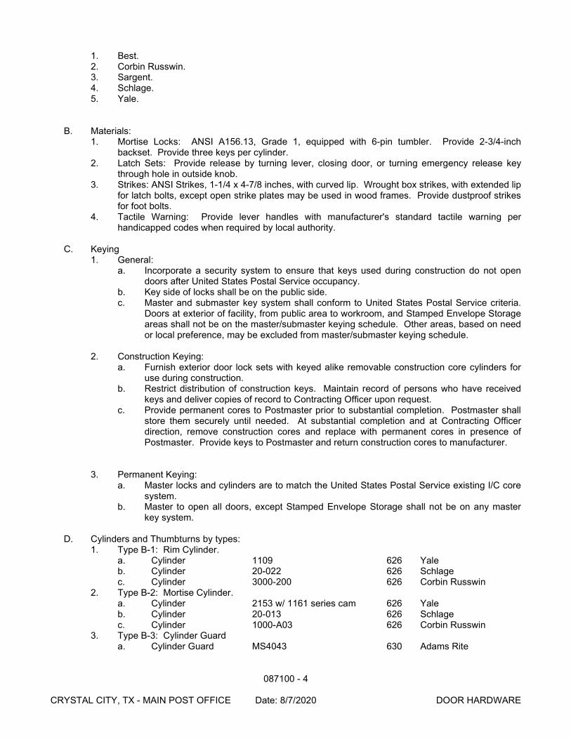
087100 - 4
CRYSTAL CITY, TX - MAIN POST OFFICE Date: 8/7/2020 DOOR HARDWARE
1. Best. 2. Corbin Russwin. 3. Sargent. 4. Schlage. 5. Yale.
B. Materials: 1. Mortise Locks: ANSI A156.13, Grade 1, equipped with 6-pin tumbler. Provide 2-3/4-inch
backset. Provide three keys per cylinder. 2. Latch Sets: Provide release by turning lever, closing door, or turning emergency release key
through hole in outside knob. 3. Strikes: ANSI Strikes, 1-1/4 x 4-7/8 inches, with curved lip. Wrought box strikes, with extended lip
for latch bolts, except open strike plates may be used in wood frames. Provide dustproof strikes for foot bolts.
4. Tactile Warning: Provide lever handles with manufacturer's standard tactile warning per handicapped codes when required by local authority.
C. Keying
1. General: a. Incorporate a security system to ensure that keys used during construction do not open
doors after United States Postal Service occupancy. b. Key side of locks shall be on the public side. c. Master and submaster key system shall conform to United States Postal Service criteria.
Doors at exterior of facility, from public area to workroom, and Stamped Envelope Storage areas shall not be on the master/submaster keying schedule. Other areas, based on need or local preference, may be excluded from master/submaster keying schedule.
2. Construction Keying:
a. Furnish exterior door lock sets with keyed alike removable construction core cylinders for use during construction.
b. Restrict distribution of construction keys. Maintain record of persons who have received keys and deliver copies of record to Contracting Officer upon request.
c. Provide permanent cores to Postmaster prior to substantial completion. Postmaster shall store them securely until needed. At substantial completion and at Contracting Officer direction, remove construction cores and replace with permanent cores in presence of Postmaster. Provide keys to Postmaster and return construction cores to manufacturer.
3. Permanent Keying: a. Master locks and cylinders are to match the United States Postal Service existing I/C core
system. b. Master to open all doors, except Stamped Envelope Storage shall not be on any master
key system.
D. Cylinders and Thumbturns by types: 1. Type B-1: Rim Cylinder.
a. Cylinder 1109 626 Yale b. Cylinder 20-022 626 Schlage c. Cylinder 3000-200 626 Corbin Russwin
2. Type B-2: Mortise Cylinder. a. Cylinder 2153 w/ 1161 series cam 626 Yale b. Cylinder 20-013 626 Schlage c. Cylinder 1000-A03 626 Corbin Russwin
3. Type B-3: Cylinder Guard a. Cylinder Guard MS4043 630 Adams Rite
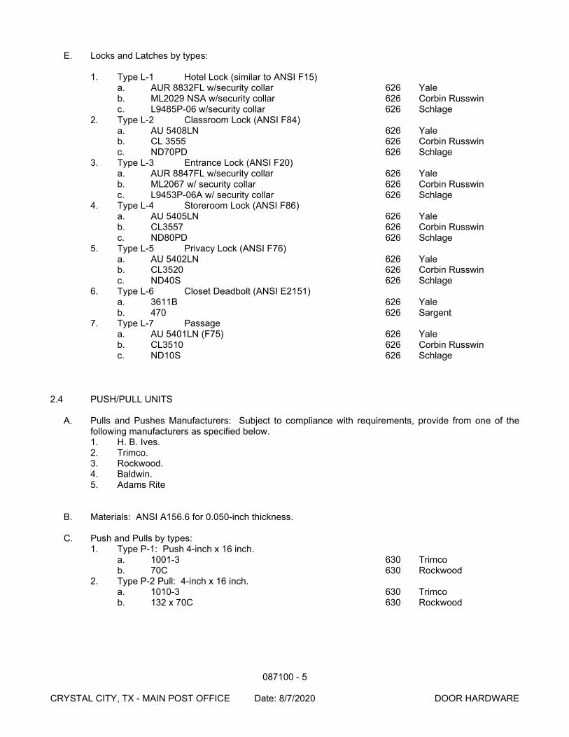
087100 - 5
CRYSTAL CITY, TX - MAIN POST OFFICE Date: 8/7/2020 DOOR HARDWARE
E. Locks and Latches by types:
1. Type L-1 Hotel Lock (similar to ANSI F15) a. AUR 8832FL w/security collar 626 Yale b. ML2029 NSA w/security collar 626 Corbin Russwin c. L9485P-06 w/security collar 626 Schlage
2. Type L-2 Classroom Lock (ANSI F84) a. AU 5408LN 626 Yale b. CL 3555 626 Corbin Russwin c. ND70PD 626 Schlage
3. Type L-3 Entrance Lock (ANSI F20) a. AUR 8847FL w/security collar 626 Yale b. ML2067 w/ security collar 626 Corbin Russwin c. L9453P-06A w/ security collar 626 Schlage
4. Type L-4 Storeroom Lock (ANSI F86) a. AU 5405LN 626 Yale b. CL3557 626 Corbin Russwin c. ND80PD 626 Schlage
5. Type L-5 Privacy Lock (ANSI F76) a. AU 5402LN 626 Yale b. CL3520 626 Corbin Russwin c. ND40S 626 Schlage
6. Type L-6 Closet Deadbolt (ANSI E2151) a. 3611B 626 Yale b. 470 626 Sargent
7. Type L-7 Passage a. AU 5401LN (F75) 626 Yale b. CL3510 626 Corbin Russwin c. ND10S 626 Schlage
2.4 PUSH/PULL UNITS
A. Pulls and Pushes Manufacturers: Subject to compliance with requirements, provide from one of the following manufacturers as specified below. 1. H. B. Ives. 2. Trimco. 3. Rockwood. 4. Baldwin. 5. Adams Rite
B. Materials: ANSI A156.6 for 0.050-inch thickness.
C. Push and Pulls by types: 1. Type P-1: Push 4-inch x 16 inch.
a. 1001-3 630 Trimco b. 70C 630 Rockwood
2. Type P-2 Pull: 4-inch x 16 inch. a. 1010-3 630 Trimco b. 132 x 70C 630 Rockwood
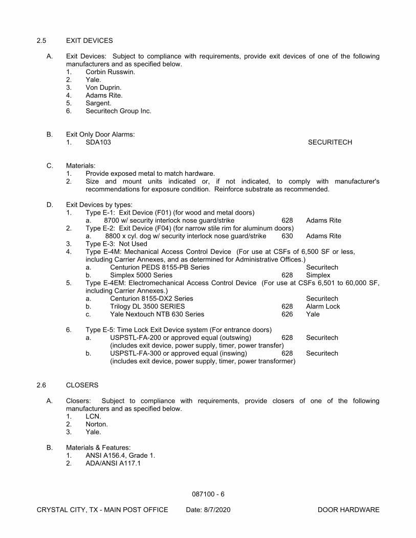
087100 - 6
CRYSTAL CITY, TX - MAIN POST OFFICE Date: 8/7/2020 DOOR HARDWARE
2.5 EXIT DEVICES
A. Exit Devices: Subject to compliance with requirements, provide exit devices of one of the following manufacturers and as specified below. 1. Corbin Russwin. 2. Yale. 3. Von Duprin. 4. Adams Rite. 5. Sargent. 6. Securitech Group Inc.
B. Exit Only Door Alarms: 1. SDA103 SECURITECH
C. Materials: 1. Provide exposed metal to match hardware. 2. Size and mount units indicated or, if not indicated, to comply with manufacturer's
recommendations for exposure condition. Reinforce substrate as recommended.
D. Exit Devices by types: 1. Type E-1: Exit Device (F01) (for wood and metal doors)
a. 8700 w/ security interlock nose guard/strike 628 Adams Rite 2. Type E-2: Exit Device (F04) (for narrow stile rim for aluminum doors)
a. 8800 x cyl. dog w/ security interlock nose guard/strike 630 Adams Rite 3. Type E-3: Not Used 4. Type E-4M: Mechanical Access Control Device (For use at CSFs of 6,500 SF or less,
including Carrier Annexes, and as determined for Administrative Offices.) a. Centurion PEDS 8155-PB Series Securitech b. Simplex 5000 Series 628 Simplex
5. Type E-4EM: Electromechanical Access Control Device (For use at CSFs 6,501 to 60,000 SF, including Carrier Annexes.) a. Centurion 8155-DX2 Series Securitech b. Trilogy DL 3500 SERIES 628 Alarm Lock c. Yale Nextouch NTB 630 Series 626 Yale
6. Type E-5: Time Lock Exit Device system (For entrance doors) a. USPSTL-FA-200 or approved equal (outswing) 628 Securitech (includes exit device, power supply, timer, power transfer) b. USPSTL-FA-300 or approved equal (inswing) 628 Securitech (includes exit device, power supply, timer, power transformer)
2.6 CLOSERS
A. Closers: Subject to compliance with requirements, provide closers of one of the following manufacturers and as specified below. 1. LCN. 2. Norton. 3. Yale.
B. Materials & Features:
1. ANSI A156.4, Grade 1. 2. ADA/ANSI A117.1
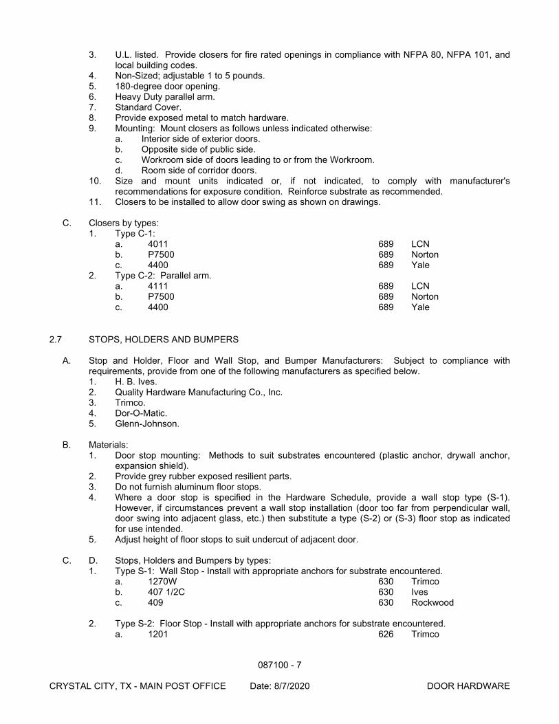
087100 - 7
CRYSTAL CITY, TX - MAIN POST OFFICE Date: 8/7/2020 DOOR HARDWARE
3. U.L. listed. Provide closers for fire rated openings in compliance with NFPA 80, NFPA 101, and local building codes.
4. Non-Sized; adjustable 1 to 5 pounds. 5. 180-degree door opening. 6. Heavy Duty parallel arm. 7. Standard Cover. 8. Provide exposed metal to match hardware. 9. Mounting: Mount closers as follows unless indicated otherwise:
a. Interior side of exterior doors. b. Opposite side of public side. c. Workroom side of doors leading to or from the Workroom. d. Room side of corridor doors.
10. Size and mount units indicated or, if not indicated, to comply with manufacturer's recommendations for exposure condition. Reinforce substrate as recommended.
11. Closers to be installed to allow door swing as shown on drawings.
C. Closers by types: 1. Type C-1:
a. 4011 689 LCN b. P7500 689 Norton c. 4400 689 Yale
2. Type C-2: Parallel arm. a. 4111 689 LCN b. P7500 689 Norton c. 4400 689 Yale
2.7 STOPS, HOLDERS AND BUMPERS
A. Stop and Holder, Floor and Wall Stop, and Bumper Manufacturers: Subject to compliance with requirements, provide from one of the following manufacturers as specified below. 1. H. B. Ives. 2. Quality Hardware Manufacturing Co., Inc. 3. Trimco. 4. Dor-O-Matic. 5. Glenn-Johnson.
B. Materials:
1. Door stop mounting: Methods to suit substrates encountered (plastic anchor, drywall anchor, expansion shield).
2. Provide grey rubber exposed resilient parts. 3. Do not furnish aluminum floor stops. 4. Where a door stop is specified in the Hardware Schedule, provide a wall stop type (S-1).
However, if circumstances prevent a wall stop installation (door too far from perpendicular wall, door swing into adjacent glass, etc.) then substitute a type (S-2) or (S-3) floor stop as indicated for use intended.
5. Adjust height of floor stops to suit undercut of adjacent door.
C. D. Stops, Holders and Bumpers by types: 1. Type S-1: Wall Stop - Install with appropriate anchors for substrate encountered.
a. 1270W 630 Trimco b. 407 1/2C 630 Ives c. 409 630 Rockwood
2. Type S-2: Floor Stop - Install with appropriate anchors for substrate encountered.
a. 1201 626 Trimco
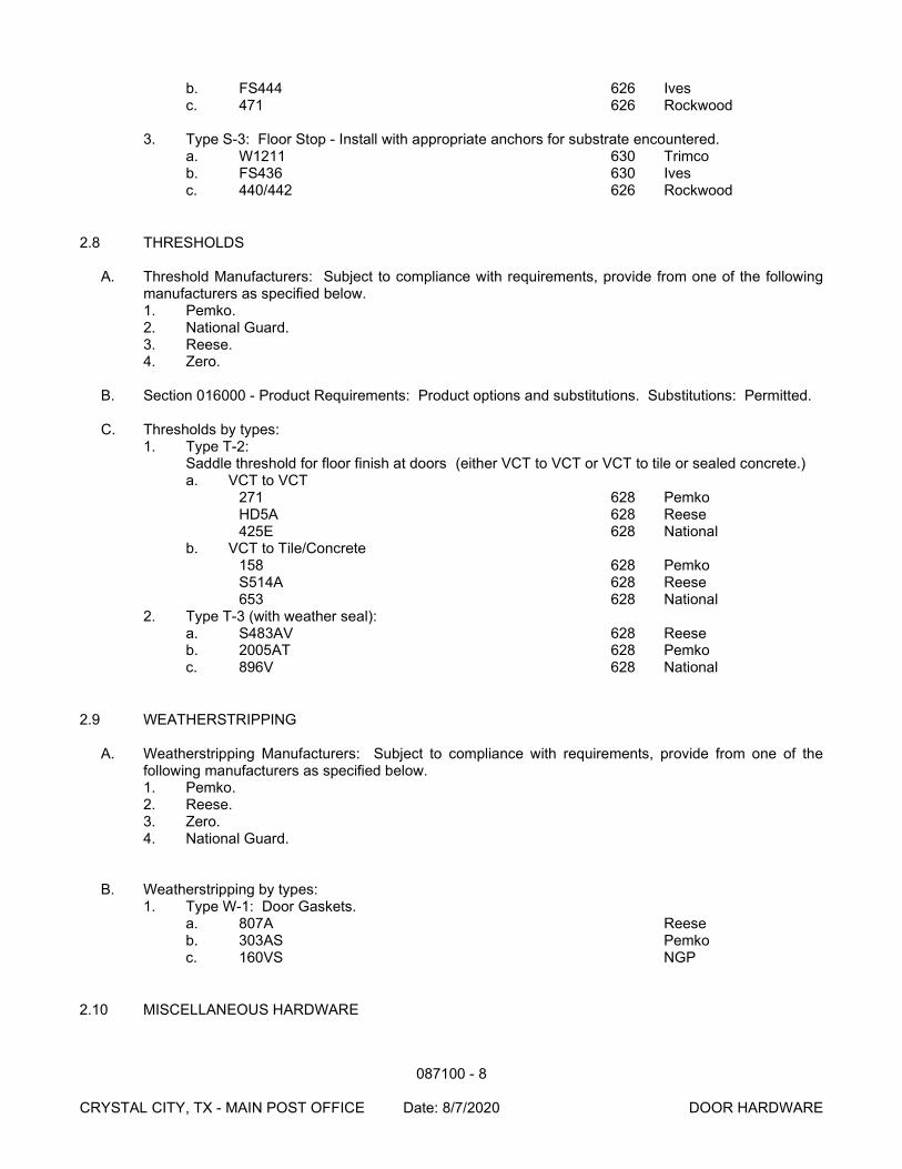
087100 - 8
CRYSTAL CITY, TX - MAIN POST OFFICE Date: 8/7/2020 DOOR HARDWARE
b. FS444 626 Ives c. 471 626 Rockwood
3. Type S-3: Floor Stop - Install with appropriate anchors for substrate encountered.
a. W1211 630 Trimco b. FS436 630 Ives c. 440/442 626 Rockwood
2.8 THRESHOLDS
A. Threshold Manufacturers: Subject to compliance with requirements, provide from one of the following manufacturers as specified below. 1. Pemko. 2. National Guard. 3. Reese. 4. Zero.
B. Section 016000 - Product Requirements: Product options and substitutions. Substitutions: Permitted.
C. Thresholds by types:
1. Type T-2: Saddle threshold for floor finish at doors (either VCT to VCT or VCT to tile or sealed concrete.) a. VCT to VCT
271 628 Pemko HD5A 628 Reese 425E 628 National
b. VCT to Tile/Concrete 158 628 Pemko S514A 628 Reese 653 628 National
2. Type T-3 (with weather seal): a. S483AV 628 Reese b. 2005AT 628 Pemko c. 896V 628 National
2.9 WEATHERSTRIPPING
A. Weatherstripping Manufacturers: Subject to compliance with requirements, provide from one of the following manufacturers as specified below. 1. Pemko. 2. Reese. 3. Zero. 4. National Guard.
B. Weatherstripping by types: 1. Type W-1: Door Gaskets.
a. 807A Reese b. 303AS Pemko c. 160VS NGP
2.10 MISCELLANEOUS HARDWARE
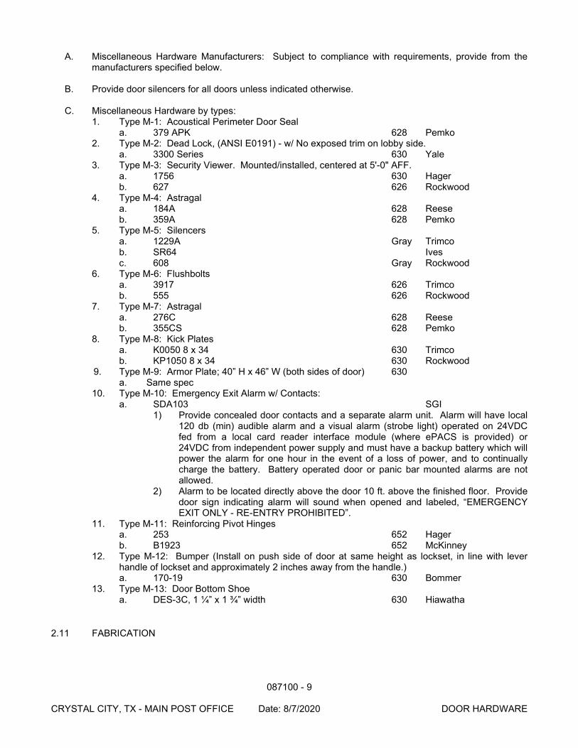
087100 - 9
CRYSTAL CITY, TX - MAIN POST OFFICE Date: 8/7/2020 DOOR HARDWARE
A. Miscellaneous Hardware Manufacturers: Subject to compliance with requirements, provide from the manufacturers specified below.
B. Provide door silencers for all doors unless indicated otherwise.
C. Miscellaneous Hardware by types:
1. Type M-1: Acoustical Perimeter Door Seal a. 379 APK 628 Pemko
2. Type M-2: Dead Lock, (ANSI E0191) - w/ No exposed trim on lobby side. a. 3300 Series 630 Yale
3. Type M-3: Security Viewer. Mounted/installed, centered at 5'-0" AFF. a. 1756 630 Hager b. 627 626 Rockwood
4. Type M-4: Astragal a. 184A 628 Reese b. 359A 628 Pemko
5. Type M-5: Silencers a. 1229A Gray Trimco b. SR64 Ives c. 608 Gray Rockwood
6. Type M-6: Flushbolts a. 3917 626 Trimco b. 555 626 Rockwood
7. Type M-7: Astragal a. 276C 628 Reese b. 355CS 628 Pemko
8. Type M-8: Kick Plates a. K0050 8 x 34 630 Trimco b. KP1050 8 x 34 630 Rockwood
9. Type M-9: Armor Plate; 40” H x 46” W (both sides of door) 630 a. Same spec
10. Type M-10: Emergency Exit Alarm w/ Contacts: a. SDA103 SGI
1) Provide concealed door contacts and a separate alarm unit. Alarm will have local 120 db (min) audible alarm and a visual alarm (strobe light) operated on 24VDC fed from a local card reader interface module (where ePACS is provided) or 24VDC from independent power supply and must have a backup battery which will power the alarm for one hour in the event of a loss of power, and to continually charge the battery. Battery operated door or panic bar mounted alarms are not allowed.
2) Alarm to be located directly above the door 10 ft. above the finished floor. Provide door sign indicating alarm will sound when opened and labeled, “EMERGENCY EXIT ONLY - RE-ENTRY PROHIBITED”.
11. Type M-11: Reinforcing Pivot Hinges a. 253 652 Hager b. B1923 652 McKinney
12. Type M-12: Bumper (Install on push side of door at same height as lockset, in line with lever handle of lockset and approximately 2 inches away from the handle.) a. 170-19 630 Bommer
13. Type M-13: Door Bottom Shoe a. DES-3C, 1 ¼” x 1 ¾” width 630 Hiawatha
2.11 FABRICATION
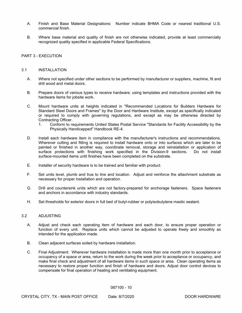
087100 - 10
CRYSTAL CITY, TX - MAIN POST OFFICE Date: 8/7/2020 DOOR HARDWARE
A. Finish and Base Material Designations: Number indicate BHMA Code or nearest traditional U.S. commercial finish.
B. Where base material and quality of finish are not otherwise indicated, provide at least commercially
recognized quality specified in applicable Federal Specifications.
PART 3 - EXECUTION
3.1 INSTALLATION
A. Where not specified under other sections to be performed by manufacturer or suppliers, machine, fit and drill wood and metal doors.
B. Prepare doors of various types to receive hardware, using templates and instructions provided with the
hardware items for jobsite work.
C. Mount hardware units at heights indicated in "Recommended Locations for Builders Hardware for Standard Steel Doors and Frames" by the Door and Hardware Institute, except as specifically indicated or required to comply with governing regulations, and except as may be otherwise directed by Contracting Officer. 1. Conform to requirements United States Postal Service "Standards for Facility Accessibility by the
Physically Handicapped" Handbook RE-4.
D. Install each hardware item in compliance with the manufacturer's instructions and recommendations. Wherever cutting and fitting is required to install hardware onto or into surfaces which are later to be painted or finished in another way, coordinate removal, storage and reinstallation or application of surface protections with finishing work specified in the Division-9 sections. Do not install surface-mounted items until finishes have been completed on the substrate.
E. Installer of security hardware is to be trained and familiar with product. F. Set units level, plumb and true to line and location. Adjust and reinforce the attachment substrate as
necessary for proper installation and operation.
G. Drill and countersink units which are not factory-prepared for anchorage fasteners. Space fasteners and anchors in accordance with industry standards.
H. Set thresholds for exterior doors in full bed of butyl-rubber or polyisobutylene mastic sealant.
3.2 ADJUSTING
A. Adjust and check each operating item of hardware and each door, to ensure proper operation or function of every unit. Replace units which cannot be adjusted to operate freely and smoothly as intended for the application made.
B. Clean adjacent surfaces soiled by hardware installation.
C. Final Adjustment: Wherever hardware installation is made more than one month prior to acceptance or
occupancy of a space or area, return to the work during the week prior to acceptance or occupancy, and make final check and adjustment of all hardware items in such space or area. Clean operating items as necessary to restore proper function and finish of hardware and doors. Adjust door control devices to compensate for final operation of heating and ventilating equipment.
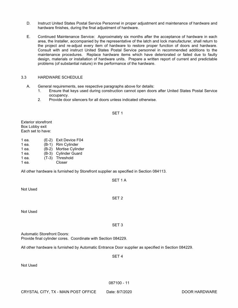
087100 - 11
CRYSTAL CITY, TX - MAIN POST OFFICE Date: 8/7/2020 DOOR HARDWARE
D. Instruct United States Postal Service Personnel in proper adjustment and maintenance of hardware and hardware finishes, during the final adjustment of hardware.
E. Continued Maintenance Service: Approximately six months after the acceptance of hardware in each
area, the Installer, accompanied by the representative of the latch and lock manufacturer, shall return to the project and re-adjust every item of hardware to restore proper function of doors and hardware. Consult with and instruct United States Postal Service personnel in recommended additions to the maintenance procedures. Replace hardware items which have deteriorated or failed due to faulty design, materials or installation of hardware units. Prepare a written report of current and predictable problems (of substantial nature) in the performance of the hardware.
3.3 HARDWARE SCHEDULE
A. General requirements, see respective paragraphs above for details: 1. Ensure that keys used during construction cannot open doors after United States Postal Service
occupancy. 2. Provide door silencers for all doors unless indicated otherwise.
SET 1 Exterior storefront Box Lobby exit Each set to have: 1 ea. (E-2) Exit Device F04 1 ea. (B-1) Rim Cylinder 1 ea. (B-2) Mortise Cylinder 1 ea. (B-3) Cylinder Guard 1 ea. (T-3) Threshold 1 ea. Closer All other hardware is furnished by Storefront supplier as specified in Section 084113.
SET 1 A Not Used SET 2 Not Used SET 3 Automatic Storefront Doors: Provide final cylinder cores. Coordinate with Section 084229. All other hardware is furnished by Automatic Entrance Door supplier as specified in Section 084229. SET 4 Not Used

087100 - 12
CRYSTAL CITY, TX - MAIN POST OFFICE Date: 8/7/2020 DOOR HARDWARE
SET 5 Not Used SET 6 Toilet - multiple occupancy Each set to have: 3 ea. (H-1) Hinges 1 ea. (P-1) Push 1 ea. (P-2) Pull 1 ea. (M-8) Kick Plate 1 ea. Door Stop 1 ea. Closer SET 7 Not Used SET 8 Mail Vestibule Personnel to Workroom and to Exterior (if <20 employees) Carrier Vestibule Personnel to Exterior Enclosed Platform: Carrier Vestibule Personnel to Exterior Building and Grounds Room (single door) Each set to have: 3 ea. (H-2) Hinges 1 ea. (L-3) Entrance Lock (ANSI F20) 1 ea. (T-2) Threshold 1 ea. (M-13) Door Bottom Shoe 1 ea. Door Stop (interior doors only) 1 ea. Closer SET 9 Not Used SET 10 Mail and Carrier Vestibule Impact Doors All hardware furnished by Impact Door supplier as specified in Section 083800. SET 11 SSDB 15-20: Mechanical Room to Mail Vestibule Office Door to Retail Lobby (public) Telephone Equipment Room to Workroom Stamped Envelopes to Workroom Each set to have: 3 ea. (H-2) Hinges 1 ea. (L-1) Hotel Lock (Similar to F15) 1 ea. (T-2) Threshold
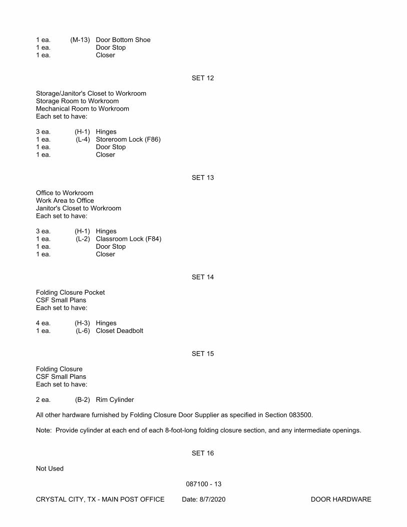
087100 - 13
CRYSTAL CITY, TX - MAIN POST OFFICE Date: 8/7/2020 DOOR HARDWARE
1 ea. (M-13) Door Bottom Shoe 1 ea. Door Stop 1 ea. Closer SET 12 Storage/Janitor's Closet to Workroom Storage Room to Workroom Mechanical Room to Workroom Each set to have: 3 ea. (H-1) Hinges 1 ea. (L-4) Storeroom Lock (F86) 1 ea. Door Stop 1 ea. Closer SET 13 Office to Workroom Work Area to Office Janitor's Closet to Workroom Each set to have: 3 ea. (H-1) Hinges 1 ea. (L-2) Classroom Lock (F84) 1 ea. Door Stop 1 ea. Closer SET 14 Folding Closure Pocket CSF Small Plans Each set to have: 4 ea. (H-3) Hinges 1 ea. (L-6) Closet Deadbolt SET 15 Folding Closure CSF Small Plans Each set to have: 2 ea. (B-2) Rim Cylinder All other hardware furnished by Folding Closure Door Supplier as specified in Section 083500. Note: Provide cylinder at each end of each 8-foot-long folding closure section, and any intermediate openings. SET 16 Not Used

087100 - 14
CRYSTAL CITY, TX - MAIN POST OFFICE Date: 8/7/2020 DOOR HARDWARE
SET 17 Wicket Door Each set to have: Door: 3 ea. (H-2) Hinges 1 ea. (L-1) Hotel Lock (Similar to F15) 1 ea. (T-2) Threshold 1 ea. (M-13) Door Bottom Shoe 1 ea. Door Stop 1 ea. Closer Wicket Panel: 1 ea. (H-4) Continuous Piano Hinge 1 ea. (M-2) Deadlock (ANSI E0191) 1 ea. (M-3) Security Viewer 1 ea. (M-4) Astragal SET 18 Not Used SET 19 Not Used SET 20 Not Used SET 21 Not Used SET 22 Not Used SET 23 Not Used
SET 29 Full Service to Workroom 3 ea. (H-1) Hinges 1 ea. (L-7) Passage Set 1 ea. Door Stop 1 ea. Closer
END OF SECTION
088000 - 1
CRYSTAL CITY, TX - MAIN POST OFFICE Date: 8/7/2020 GLAZING
SECTION 088000
GLAZING
PART 1 - GENERAL
1.1 SUMMARY
A. Section Includes: 1. Insulated glass units, low E. 2. Insulated tempered glass units, low E. 3. Clear tempered glass. 4. Wire glass. 5. One-way reflective mirror glass. 6. Insulated glass units with security film, low E.
B. Related Documents: The Contract Documents, as defined in Section 011000 - Summary of Work, apply
to the Work of this Section. Additional requirements and information necessary to complete the Work of this Section may be found in other Documents.
1.2 QUALITY ASSURANCE
A. Identification: Each unit of tempered glass and burglar resistant glazing shall be permanently identified by the manufacturer. The identification shall be etched or ceramic fired on the glass and be visible when the unit is glazed.
B. Provide Energy Star Label on glazing indicating compliance with DOE Energy Star requirements.
1.3 WARRANTY
A. Section 017704 - Closeout Procedures and Training: Procedures for closeout submittals.
B. Special Warranty: 1. Include coverage for cracking, breakage, and replacement of same.
a. Warranty Period: 1 year. 2. Include coverage for sealed glass units from seal failure, interpane dusting or misting, and
replacement of same. a. Warranty Period: 10 years.
3. Include coverage for delamination of laminated glass and replacement of same. a. Warranty Period: 5 years.
PART 2 - PRODUCTS
2.1 MANUFACTURERS
A. Subject to compliance with project requirements, manufacturers offering Products which may be incorporated in the Work include the following: 1. Pilkington, Toledo, OH (800)221-0444.
088000 - 2
CRYSTAL CITY, TX - MAIN POST OFFICE Date: 8/7/2020 GLAZING
2. PPG Industries, Pittsburgh, PA (412) 434-2858 (800) 377-5267. 3. Viracon, Owatonna, MN (800) 533-2080.
B. Subject to compliance with project requirements, manufacturers offering polycarbonate products which
may be incorporated in the Work include the following: 1. Sheffield Plastics, Incorporated Sheffield, MA (413) 229-8711 (800) 628-5084. 2. GE Plastics, Pittsfield, MA (800) 451-3147.
C. Subject to compliance with project requirements, manufacturers offering security film products which may be incorporated in the Work include the following: 1. 3M, St. Paul, MN (800) 480-1704.
D. Section 016000 - Product Requirements: Product options and substitutions. Substitutions: Permitted.
2.2 GLASS MATERIALS
A. Glass Type 1 - Insulated Glass Units, Low E: Double pane units with inner pane of clear annealed glass and outer pane of tinted annealed glass. Low E coating on #2 surface. 1. Where required by code, provide Glass Type 2 (tempered). 2. Glass Thickness, Inner: 1/4 inch (6 mm). 3. Glass Thickness, Outer: 1/4 inch (6 mm. 4. Tint Color: Selected by USPS Project Manager. 5. Visible Reflectance: Maximum 15 percent. 6. Visible Transmittance: Minimum 65 percent. 7. Unit Thickness: 1 inch (25 mm) thick units. 1/4 inch (6 mm) thick, clear inner pane. 1/4 inch (6
mm) thick, tinted outer pane. 1/2 inch (12 mm) air space between panes.
B. Glass Type 2 - Insulated Tempered Glass Units, Low E: Double pane units with inner pane of clear tempered glass and outer pane of tinted tempered glass. Low E coating on #2 surface. 1. Glass Thickness, Inner: 1/4 inch (6 mm). 2. Glass Thickness, Outer: 1/4 inch (6 mm. 3. Tint Color: Selected by USPS Project Manager. 4. Visible Reflectance: Maximum 15 percent. 5. Visible Transmittance: Minimum 65 percent. 6. Unit Thickness: 1 inch (25 mm) thick units. 1/4 inch (6 mm) thick, clear inner pane. 1/4 inch (6
mm) thick, tinted outer pane. 1/2 inch (12 mm) air space between panes.
C. Glass Type 3 - Clear Tempered Glass: ASTM C 1048, Kind FT (Fully Tempered), Condition A (Uncoated), Type I (Transparent Glass, Flat), Class 1 (Clear), Quality q3 (Glazing Select). Conform to ANSI Z97.1 and CPSC 16CFR Part 1201. 1. Thickness: 1/4 inch (6 mm), unless indicated otherwise.
D. Glass Type 4 - Wire Glass: (Fire Safety Glass) ASTM C 1036, Type II (Wired Glass Flat), Class 1 (Clear), Form 1 (Wired, Polished Both Sides), Quality q8 (Glazing), Mesh m2 (Square) woven stainless steel wire of 1/2 inch (12 mm) grid size. Wire glass is used for door vision panels. 1. Thickness: 1/4 inch (6 mm), unless indicated otherwise.
E. Glass Type 8 - Insulated Burglar Resistant Glass Units, Low E: Double pane units with inner pane of clear tempered glass and outer pane of tinted tempered or annealed laminated glass, conforming to: UL972 or ASTM F1233 Class Three Standard Test Method for Security Glazing and Systems. Low E coating on #2 surface. 1. Glass Thickness, Inner: 1/4 inch (6 mm).
088000 - 3
CRYSTAL CITY, TX - MAIN POST OFFICE Date: 8/7/2020 GLAZING
2. Glass Thickness, Outer: A laminated pane consisting of a 0.060-inch (60 mil)(1.5 mm) thick vinyl film between two layers of 1/8”-inch (3 mm) thick glass.
3. Tint Color: Selected by USPS Project Manager. 4. Visible Reflectance: Maximum 15 percent. 5. Visible Transmittance: Minimum 65 percent. 6. Unit Thickness: 1 inch (25 mm) thick units. 1/4 inch (6 mm) thick, clear inner pane. 5/16 inch (6
mm) thick, tinted outer pane. Nominal 1/2 inch (12 mm) air space between panes.
2.3 GLAZING COMPOUNDS
A. Polysulphide Sealant: Two component, chemical curing, non-sagging type; cured Shore A hardness of 15-25.
B. Silicone Sealant: Single component, chemical curing; capable of water immersion without loss of
properties; non-bleeding, non-staining; cured Shore A hardness of 15-25. 1. Color: Clear.
C. Acrylic terpolymer compounded especially for glazing; non-hardening, non-staining, and non-bleeding.
2.4 GLAZING ACCESSORIES
A. Setting Blocks: Resilient blocks of 70 to 90 Shore A durometer hardness; compatible with glazing sealant.
B. Spacers: Resilient blocks of 40 to 50 Shore A durometer hardness; self adhesive on one side;
compatible with glazing sealant.
C. Filler Rods: Closed cell or jacketed foam rods of polyethylene, butyl, neoprene, polyurethane, or vinyl; compatible with glazing sealant.
D. Joint Cleaners, Primers, and Sealers: As recommended by glazing sealant manufacturer.
E. Gaskets: ASTM D2000, SBC 415 to 3BC 620; extruded or molded neoprene or EPDM, black.
F. Mastic: Non-solvent type adhesive as recommended by mirrored glass manufacturer.
PART 3 - EXECUTION
3.1 GLAZING
A. Locate setting blocks at quarter points of sill; set in sealant if heel or toe bead is required.
B. Install spacers inside and out except where preshimmed tape or glazing gaskets are to be used.
C. Set each piece in a series to other pieces in pattern draw, bow, or other visually perceptible characteristics.
D. Provide glazing sealants and gaskets as required for particular glazing application. Coordinate with
other Sections for material compatibility.
088000 - 4
CRYSTAL CITY, TX - MAIN POST OFFICE Date: 8/7/2020 GLAZING
E. Gaskets: 1. Provide adequate anchorage, particularly for driven-in wedge gaskets. 2. Miter and weld ends of channel gaskets at corners to provide continuous gaskets. 3. Seal face gaskets at corners with sealant to close opening and prevent withdrawal of gaskets
from corners.
F. Do not leave voids in glazing channels except as specifically indicated or recommended by glass manufacturer. Force sealant into channel to eliminate voids. Tool exposed surfaces to slight wash away from joint. Trim and clean promptly.
G. Do not allow sealant to close weeps of aluminum framing.
H. Provide filler rod where sealants are used in the following locations:
1. Head and jamb channels. 2. Colored glass over 75 united inches in size. 3. Clear glass over 125 united inches in size.
END OF SECTION
092900 - 1
CRYSTAL CITY, TX - MAIN POST OFFICE Date: 8/7/2020 GYPSUM BOARD
SECTION 092900
GYPSUM BOARD
PART 1 - GENERAL
1.1 SUMMARY
A. Section Includes: 1. Gypsum board and joint treatment. 2. Gypsum sheathing. 3. Cementitious backer board. 4. Sound attenuation blankets. 5. Finishing.
B. Related Documents: The Contract Documents, as defined in Section 011000 - Summary of Work, apply
to the Work of this Section. Additional requirements and information necessary to complete the Work of this Section may be found in other Documents.
1.2 QUALITY ASSURANCE
A. Qualifications: 1. Manufacturer: Company specializing in manufacturing Products specified with minimum 5 years
documented experience. 2. Installer: Company specializing in performing the Work of this Section with minimum 5 years
documented experience.
1.3 DELIVERY, STORAGE, AND HANDLING
A. Section 016000 - Product Requirements: Transport, handle, store, and protect Products. B. Deliver materials in original packages, containers, or bundles bearing brand name and identification of
manufacturer or supplier. C. Stack gypsum board flat to prevent sagging.
1.4 PROJECT CONDITIONS OR SITE CONDITIONS
A. Jobsite Requirements: 1. Establish and maintain environmental conditions for applying and finishing gypsum board in
conformance with GA-216. 2. Maintain minimum 50 degrees F for 48 hours before application and finishing of gypsum board.
Maintain temperature continuously until dry. Do not exceed 95 degrees F when using temporary heat sources.
3. Ventilate building spaces as required to dry joint treatment materials. Prevent drafts during hot, dry weather to avoid finishing materials from drying too rapidly.
092900 - 2
CRYSTAL CITY, TX - MAIN POST OFFICE Date: 8/7/2020 GYPSUM BOARD
1.5 ENVIRONMENTAL REQUIREMENTS A. Resource Management:
1. Recycled Content: Provide gypsum board products with paper backing manufactured from 100 percent post-consumer recycled paper and gypsum core containing minimum 10 percent recycled gypsum. a. Soil amendment from recycled scrap gypsum: Coordinate with Section 329200 - Turf and
Grasses to identify requirements for gypsum soil amendment and to prepare scrap gypsum board for use as soil amendment.
PART 2 - PRODUCTS
2.1 MANUFACTURERS
A. Subject to compliance with project requirements, manufacturers offering Products which may be incorporated in the Work include the following: 1. Georgia-Pacific Gypsum Products, Atlanta, GA (800) 225-6119. 2. National Gypsum Company, Gold Bond Building Products, Charlotte, NC (800) 628-4662. 3. United States Gypsum Company, Chicago, IL (800) 874-4968. 4. Allied Stud Co., Phoenix, AZ, (800) 877-8823. 5. Consolidated Fabricators Corp., Paramount, CA, (800) 635-8335 6. Steeler, Inc., Seattle, WA (800) 275-2279 7. Western Metal Lath, Inc., Riverside, CA (909) 360-3500
B. Section 016000 - Product Requirements: Product options and substitutions. Substitutions: Permitted.
2.2 MATERIALS
A. Standard Gypsum Board: ASTM C 36; 1/2 inch and 5/8 inch thick 48 inch width, maximum permissible length; ends square cut, tapered edges.
B. Type X Gypsum Wallboard (Fire Resistant): ASTM C36; 1/2 inch and 5/8 inch thick, 48 inch width,
maximum permissible length; ends square cut, edges tapered, providing at least 1-hour fire-retardant rating for boards 5/8 inch thick or 3/4-hour fire-resistance classification for boards 1/2 inch thick, when tested in accordance with ASTM E119.
C. Water-Resistant Gypsum Backing Board: ASTM C630; 1/2 and 5/8 inch thick, 48 inch width, maximum
permissible length; ends and edges straight and solid, edges tapered. Board consisting of a noncombustible water-resistant gypsum core, surfaced on face and back with water-repellent paper bonded to the core.
D. Water-Resistant Glass Mat Embedded Gypsum Backing Board: ASTM C1178; 1/4 and 1/2 inch thick,
32 inch or 48 inch width, maximum permissible length; ends and edges straight and solid, edges square. Board consisting of a noncombustible water-resistant gypsum core, with glass mat embedded on front and back with the face surface with a heat cured copolymer water and vapor retardant coating. For janitor and toilet rooms where tile is the finish material.
E. Type X Water-Resistant Gypsum Backing Board (fire-resistant): ASTM C630; 1/2 and 5/8 inch thick, 48
inch width, maximum permissible length; ends and edges straight and solid, edges tapered. Board consisting of a noncombustible water-resistant gypsum core, surfaced on face and back with water-repellent paper bonded to the core. Providing at least 1-hour fire-retardant rating for boards 5/8 inch thick, or 3/4-hour fire-retardant rating for boards 1/2 inch thick, when tested in accordance with ASTM E119.
092900 - 3
CRYSTAL CITY, TX - MAIN POST OFFICE Date: 8/7/2020 GYPSUM BOARD
F. Type X Water-Resistant Glass Mat Embedded Gypsum Backing Board (fire-resistant): ASTM C1178;
5/8 inch thick, 48 inch width and 8 foot length; ends and edges straight and solid, edges squared. Board consisting of a noncombustible water-resistant gypsum core, embedded on face and back with water resistant fiberglass mat bonded into the core. Providing at least 1-hour fire-retardant rating for boards 5/8 inch thick, or 3/4-hour fire-retardant rating for boards 1/2 inch thick, when tested in accordance with ASTM E119.
G. Gypsum Sheathing Board: ASTM C79; moisture resistant type; 1/2 inch (13 mm) thick, maximum
available size in place; ends square cut, tongue and grooved edges; water repellent paper faces. Exterior wall sheathing where noted.
H. Gypsum Sheathing Glass Mat Embedded Board: ASTM C1177; moisture resistant type; 1/2 inch (13
mm) and 5/8 inch thick type X, maximum available size in place; ends and edges straight and solid, edges squared. Water resistant glass mat embossed both sides and edges, treated water resistant gypsum core with alkali resistant coating/primer. Flame spread: 0, smoke developed: 0 when tested in accordance with ASTM E84. Exterior wall sheathing where noted.
I. Cementitious Backing Board: High density, glass fiber reinforced, 1/2 inch (13 mm) thick x 26 inches or
48 inches x length as required; 2 inch (50 mm) wide, coated glass fiber tape for joints and corners; For janitor and toilet rooms where tile is the finish material.
J. Sound Attenuation Blankets: Semi-rigid, paperless spun mineral fiber blankets or uniform dimension
controlled density of 3 lb./cu. ft. Minimum thickness shall be 1-1/2 inch. K. Gypsum Board Fasteners:
1. Metal Framing: ASTM C 954 and C 1002, Type S-12 bugle head, corrosion-resistant self-drilling self-tapping steel screws. a. One Layer 1/2 Inch: 1 inch. b. One Layer 5/8 Inch: 1-1/8 inch.
L. Gypsum Board Accessories:
1. Corner Beads: 1 1/4 inch by 1 1/4 inch galvanized steel corner bead. 2. Edge Trim: Galvanized steel casing.
a. L bead for tight abutment at edges. b. J bead at other locations.
3. Control Joint: No. 093 roll-formed zinc. 4. Joint Materials:
a. Reinforcing Tape: Sheetrock Joint Tape. Paper; fiberglass joint tape not permitted. b. Joint Compound: Ready-Mixed All-Purpose Joint Compound. c. Adhesive: Commercial Adhesive complying with ASTM C 557.
PART 3 - EXECUTION
3.1 INSTALLATION
A. Install gypsum board in accordance with manufacturer's published instructions, GA-201 and GA-216. B. Where applicable, install ceiling panels before the installation of wall panels. C. Erect single layer gypsum board in most economical direction, with attachment to firm bearing surfaces
over framing members. Do not align panel joints with edges of openings.
092900 - 4
CRYSTAL CITY, TX - MAIN POST OFFICE Date: 8/7/2020 GYPSUM BOARD
D. Treat cut edges, holes, fastener heads and joints, including those at angle intersections, in water resistant gypsum board and exterior gypsum soffit board with specified joint compound. Treat cut edges, holes, fastener heads and joints in water resistant glass mat embedded backing board with mastic or mortar. Treat prior to tile installation.
E. Place gypsum panels over supporting framing members with panel ends aligning and parallel with
framing members. F. Install fasteners from center of field of panel toward ends and edges. Install fasteners 3/8 inch from
ends and edges of panels, and as follows: 1. Ceiling: 12 inches on center, perimeter and field. 2. Walls: 16 inches on center, perimeter and field.
3.2 GYPSUM SHEATHING INSTALLATION
A. Install gypsum board sheathing in accordance with manufacturer's published instructions, GA-216, GA-253 and GA-600, all latest editions. 1. Erect single layer gypsum board horizontally, with edges butted tight, tongue up with attachment
to firm bearing. Glass mat embedded board may be installed horizontally or vertically.
B. Provide construction control joints at maximum 30 feet on center, at inside corners, and at intersections. 1. Locate panel, allowing 1/4 inch space between edge of panel and adjacent walls, beams,
columns, and fascia construction.
C. Place edge trim where gypsum board abuts dissimilar materials. Use longest practical length. D. Using screws, secure panels in place at maximum 12 inches on center to supporting substrate. E. Protect all exposed gypsum core at perimeter edges, and penetrations by covering core with metal trim.
3.3 JOINT TREATMENT
A. Reinforce interior and exterior corners at ceiling and wall surfaces. Apply 3 inch wide initial coating of joint compound, pressing tape firmly into joint compound. Wipe off excess joint compound. Apply second coat of joint compound with tools of sufficient width to extend beyond joint center, approximately 4 inches. Draw joint compound down to a smooth even plane.
B. After drying or setting, sand or sponge joints, edges, and corners, eliminating high spots and excessive
joint compound to produce smooth finish surface. Prepare surfaces to receive subsequent finishes to height of 6 inches above finish ceiling. Feather coats onto adjoining surfaces resulting in maximum camber of 1/32-inch in 12.
C. Sand after second and third applications of joint compound. Do not to raise nap of paper when sanding. D. Install control joints full height of partition, consistent with lines of building spaces, with 1/2 inch between
boards. Apply sealant at base of joint and control joint accessory piece at face. E. Place corner beads at external corners. Use longest practical length. Place edge trim where gypsum
board abuts dissimilar materials.
3.4 FINISH
092900 - 5
CRYSTAL CITY, TX - MAIN POST OFFICE Date: 8/7/2020 GYPSUM BOARD
A. Apply gypsum board finish in accordance with manufacturer's published instructions and GA-214 Finish Levels. 1. Level 1: All joints and interior angles shall have tape embedded in joint compound. Surface shall
be free of excess joint compound. Tool marks and ridges are acceptable. a. Application: In plenum areas above ceilings, in attics, in mechanical rooms, in areas where
the assembly is generally concealed, and other areas not normally open to view. Accessories not required, unless shown or required by rating. Where a fire resistance rating is required for the gypsum board assembly, details of construction shall be in accordance with reports of fire tests of assemblies that have met the fire rating requirement.
2. Level 4: All joints and interior angles shall have tape embedded in joint compound and two separate coats of joint compound applied over all flat joints and one separate coat of joint compound applied over interior angles. Fastener heads and accessories shall be covered with three separate coats of joint compound. All joint compound shall be smooth and free of tool marks and ridges. Prepared surface shall be coated with a drywall primer/sealer prior to the application of finish paint. Refer to specification section 099100. a. Application: For use where gloss semi-gloss, enamel, or nontextured flat paints are
specified or where severe lighting conditions occur. Generally in all areas except where noted otherwise.
END OF SECTION
095113 - 1 CRYSTAL CITY, TX - MAIN POST OFFICE Date: 8/7/2020 ACOUSTICAL PANAL CEILINGS
SECTION 095113
ACOUSTICAL PANEL CEILINGS
PART 1 - GENERAL
1.1 SUMMARY
A. Section Includes: 1. Suspended metal grid ceiling system. 2. Acoustical panels. 3. Perimeter trim.
B. Related Documents: The Contract Documents, as defined in Section 011000 - Summary of Work, apply
to the Work of this Section. Additional requirements and information necessary to complete the Work of this Section may be found in other documents.
1.2 ENVIRONMENTAL REQUIREMENTS A. Resource Management:
1. Recycled Content: a. Acoustical panels type ACT-1: Manufactured from minimum 20 percent recycled
newsprint. b. Suspension system: Manufactured from minimum 20 percent recycled steel.
1.3 MAINTENANCE
A. Section 017704 - Closeout Procedures and Training: Procedures for closeout submittals.
B. Extra Materials: Provide 1 box of extra acoustical panels for each panel type, pattern, and color to Contracting Officer.
PART 2 - PRODUCTS
2.1 MANUFACTURERS
A. Suspension System: Subject to compliance with project requirements, manufacturers offering specified items which may be incorporated in the Work include the following: 1. Armstrong World Industries, Incorporated, Lancaster, PA (800) 448-1405. 2. Chicago Metallic Corporation, Chicago, IL (800) 323-7164. 3. USG Interiors, Chicago, IL (800) 950-3839. 4. Certainteed Ceilings (800) 346-7978
B. Acoustical Panels: Subject to compliance with project requirements, manufacturers offering specified
items which may be incorporated in the Work include the following: 1. Armstrong World Industries Incorporated, Lancaster, PA (800) 448-1405. 2. USG Interiors, Chicago, IL (800) 950-3839. 3. Certainteed Ceilings (800) 346-7978
C. Section 016000 - Product Requirements: Product options and substitutions. Substitutions: Permitted.
095113 - 2 CRYSTAL CITY, TX - MAIN POST OFFICE Date: 8/7/2020 ACOUSTICAL PANAL CEILINGS
2.2 SUSPENSION SYSTEM
A. Model: 1. Armstrong: Prelude 15/16 inch Exposed Tee System. 2. Chicago Metallic: 1200 System. 3. USG: Donn DX System. 4. Certainteed: Classic Stab CS12-12-15
B. Description:
1. Grid: ASTM C 635, intermediate duty, steel exposed T; nominal 1 inch width; stab-in connections.
2. Accessories: Stabilizer bars, clips, and splices. 3. Grid Finish: White. 4. Support System: Hot or cold rolled steel channels; galvanized hanger wire, minimum 12 gage. 5. Edge Moldings: Metal channel with exposed flange to match suspension system.
2.3 ACOUSTICAL PANELS
A. Type ACT-1: 1. Model:
a. Armstrong: Fine Fissured #1729. b. Certaineed : HHF – 157 c. USG: Auratone, Radar #2310.
2. Description: a. Size: 24 x 48 x 5/8 inches. b. Edge: Square lay-in. c. Weight: minimum 0.60 pounds per square foot. d. Surface Finish: Factory-applied vinyl latex paint, perforated, and scored. e. Color: White.
PART 3 - EXECUTION
3.1 INSTALLATION - SUSPENSION SYSTEM
A. Install system in accordance with ASTM C 636 and manufacturer's published instructions.
B. Provide metal hanger tabs and clips attached to metal deck where required for attachment of suspension wires.
C. Hang system independent of walls, columns, ducts, pipes and conduit. Where carrying members are
spliced, avoid visible displacement of face plane of adjacent members. Where ducts or other equipment prevent regular spacing of hangers, reinforce nearest affected hangers and related carrying channels to span extra distance.
D. Locate system on room axis according to Reflected Ceiling Plan, where indicated on Drawings, or locate
system to a balanced grid design with edge units no less than 50 percent of acoustical panel size where Reflected Ceiling Plan not shown on Drawings
E. Do not support components on main runners or cross runners if weight causes total dead load to
exceed deflection capability. Do not eccentrically load system, or produce rotation of runners.
095113 - 3 CRYSTAL CITY, TX - MAIN POST OFFICE Date: 8/7/2020 ACOUSTICAL PANAL CEILINGS
F. Install edge molding at intersection of ceiling and vertical surfaces using longest practical lengths. Miter corners. Provide edge moldings at junctions with other interruptions. Secure at 16 inches (41 cm) on center.
G. Install hold-down clips within five feet of doors.
3.2 INSTALLATION - ACOUSTICAL PANELS
A. Fit acoustic units in place free from damaged edges or other defects. Install acoustic units level, in uniform plane, and free from twist, warp, and dents.
3.3 SITE ENVIRONMENTAL PROCEDURES
A. Indoor Air Quality: 1. Temporary ventilation: As specified in Section 013543 - Environmental Procedures.
a. Ventilate products prior to installation. Remove from packaging and ventilate in a secure, dry, well-ventilated space free from strong contaminant sources and residues. Provide a temperature range of 60 degrees F minimum to 90 degree F maximum continuously for minimum 72 hours. Do not ventilate within limits of Work unless otherwise approved by USPS Contracting Officer.
END OF SECTION
096519 - 1 CRYSTAL CITY, TX - MAIN POST OFFICE Date: 8/7/2020 RESILIENT QUARTZ FLOORING
SECTION 096519
RESILIENT QUARTZ FLOORING
PART 1 - GENERAL
1.1 SUMMARY
A. Section Includes: 1. Resilient quartz tile flooring. 2. Resilient base.
B. Related Documents: The Contract Documents, as defined in Section 011000 - Summary of Work, apply
to the Work of this Section. Additional requirements and information necessary to complete the Work of this Section may be found in other documents.
C. Related Sections: Related work specified elsewhere includes but may not be limited to
1. Section 017704 - Closeout Procedures and Training. 2. Section 033000 - Cast-In-Place Concrete. 3. Section 123504 - Postal Casework.
1.2 REFERENCES
A. American Society for Testing and Materials (ASTM): 1. ASTM D2047 Standard Test Method for Static Coefficient of Friction of Polish-Coated Floor
Surfaces as Measured by the James Machine. 2. ASTM E648 Standard Test Method for Critical Radiant Flux of Floor-Covering Systems Using a
Radiant Heat Energy Source. 3. ASTM E662 Standard Test Method for Specific Optical Density of Smoke Generated by Solid
Materials. 4. ASTM F710 Standard Practice for Preparing Concrete Floors to Receive Resilient Flooring. 5. ASTM F970 Standard Test Method for Static Load Limit. 6. ASTM F1482 Standard Guide to Wood Underlayment Products Available for Use Under Resilient
Flooring. 7. ASTM F1066 Standard Specification for Vinyl Composition Floor Tile. 8. ASTM F2170 Standard Test Method for Determining Relative Humidity in Concrete Floor Slabs
Using in situ Probes.
B. Resilient Floor Covering Institute (RFCI) 1. RFCI
C. American Concrete Institute
1. ACI 302.1R 2. ACI 302.2R
1.3 SUBMITTALS
A. Section 013300 - Submittal Procedures: Procedures for submittals. 1. Product Data: Data describing physical and performance characteristics; including sizes,
patterns and colors including manufacturer's product sheet.
096519 - 2 CRYSTAL CITY, TX - MAIN POST OFFICE Date: 8/7/2020 RESILIENT QUARTZ FLOORING
a. Shop Drawings: Submit shop drawings showing layout, profiles, and product components, including anchorage, accessories, finish colors, patterns and textures.
b. Samples: Submit selection and verification samples for finishes, colors, and textures. c. Quality Assurance Submittals: Submit the following:
1) Test Reports: Certified test reports showing compliance with specified performance characteristics and physical properties.
2) Certificates: Product certificates signed by manufacturer certifying materials comply with specified performance characteristics and criteria, and physical requirements.
3) Manufacturer's Instructions: Manufacturer's installation instructions. 4) Manufacturer’s Field Reports: Manufacturer’s Field Reports Specified herein.
d. Closeout Submittals: Submit the following: 1) Operation and Maintenance Data: Operation and maintenance data for installed
products in accordance with Division 1 Closeout Submittals (Maintenance Data and Operation Data) Section. Include methods for maintaining installed products, and precautions against cleaning materials and methods detrimental to finishes and performance.
2) Warranty: Warranty documents specified herein.
1.4 QUALITY ASSURANCE
A. Installer Qualifications: Company specializing in performing work of this Section with minimum 5 years documented experience. 1. Training: Installer who has attended the manufacturer’s installation training clinic. 2. Certificate: When requested, submit certificate indicating qualification.
B. Regulatory Requirements:
1. Critical Radiant Flux in Accordance with ASTM E 648: More than 0.45 Watts per square centimeter.
2. Specific Optical Smoke Density in Accordance with ASTM E 662: Less than 450.
C. Pre-installation Meeting: If required by USPS Project Manager, conduct pre-installation meeting to verify project requirements, substrate conditions, manufacturer’s installation instructions and manufacturer’s warranty requirements.
1.5 DELIVERY, STORAGE, AND HANDLING
A. Section 016000 - Product Requirements: Transport, Handle, Store, and Protect Products. B. Ordering: Comply with manufacturer’s ordering instructions and lead time requirements to avoid
construction delays. C. Deliver tiles and installation accessories to site in original manufacturer's unopened cartons and
containers each bearing names of product and manufacturer, project identification, and shipping and handling instructions.
D. Storage and Protection: Store materials protected from exposure to harmful weather conditions and at temperature and humidity conditions recommended by manufacturer.
1.6 PROJECT CONDITIONS
A. Jobsite Requirements: 1. Environmental Requirements/Conditions: In accordance with manufacturer's recommendations,
areas where flooring is to be stored and areas to receive flooring shall be clean, fully enclosed, weather tight with the permanent HVAC set at a uniform temperature of at least 68 degrees F. The flooring material should be conditioned in the same manner. Maximum temperature should not exceed 80 degrees.
096519 - 3 CRYSTAL CITY, TX - MAIN POST OFFICE Date: 8/7/2020 RESILIENT QUARTZ FLOORING
2. Temperature Requirements: Maintain air temperature in spaces where products will be installed for time period before, during, and after installation as recommended by manufacturer. 1. Temperature Conditions: Between 68 degrees F (20 degrees C) and 80 degrees (26
degrees C) for 72 hours prior to, during and after installation. 3. Field Measurements: Verify actual measurements/openings by field measurements before
fabrication; show recorded measurements on shop drawings. Coordinate field measurements and fabrication schedule with construction progress to avoid construction delays.
1.7 SEQUENCING AND SCHEDULING
A. Finishing Operations: Install tile flooring after finishing operations, including painting and ceiling operations, have been completed.
B. Concrete Curing: Do not install tile flooring over concrete substrates until substrates have cured and are dry to bond with adhesive as determined by resilient flooring manufacturer's recommended bond, moisture test, and pH test.
1.8 WARRANTY
A. Manufacturer's Warranty: Submit, for USPS Project Manager's acceptance, manufacturer's standard warranty document executed by authorized company official. Manufacturer's warranty is in addition to, and not a limitation of, other rights USPS may have under Contract Documents. 1. Warranty Period: Minimum fifteen (15) year limited warranty commencing on Date of Substantial
Completion.
1.9 MAINTENANCE
A. Section 017704 - Closeout Procedures and Training: Procedures for closeout submittals.
B. Maintenance stock: 1. Provide 1 box of extra floor tiles for each tile type, panel, and color. 2. Deliver to USPS maintenance stock from same production run as products installed. Package
products with protective covering and identify with descriptive labels.
PART 2 - PRODUCTS
2.1 MANUFACTURERS
A. Tile: Subject to compliance with project requirements, manufacturers offering specified items which may be incorporated in the Work include the following: 1. For general use, as indicated in the Room Finish Schedule:
a. Altro USA, Inc., Wilmington, MA, 800.583.4244. b. Rikett America, City of Industry, CA, 855.745.3887. c. UPO Floor Americas, Inc., Altamonte Springs, FL., 800.800.5247.
2. For use only in conjunction with the NAFES asbestos containment system a. Procedo Flooring, Tuscumbia, AL, 866.955.8291.
B. Wall Base: Subject to compliance with project requirements, manufacturers offering specified items
which may be incorporated in the Work include the following: 1. Burke Mercer Flooring Products, San Jose, CA., 800.669.7010. 2. Johnsonite; A Tarkett Company, Solon, OH., 800.899.8916. 3. Roppe Corporation, USA, Fostoria, OH., 800.537.9527.
096519 - 4 CRYSTAL CITY, TX - MAIN POST OFFICE Date: 8/7/2020 RESILIENT QUARTZ FLOORING
C. Section 016000 - Product Requirements: Product options and substitutions. Substitutions: Permitted.
2.2 MATERIALS A. Floor Tile
1. Altro Quartz Tile a. Size: 24 inch x 24 inch (61 cm x 61 cm) b. Thickness: 0.08 inch (2 mm) c. Factory applied PUR coating d. Color:
1) RFT-1: #9306 - Charcoal CD 2) RFT-2: #9302 - Rock Salt CD
2. Rickett Quartz Tile a. Size: 24 inch x 24 inch (61 cm x 61 cm) b. Thickness: 0.08 inch (2 mm) c. Factory applied PUR coating d. Color:
1) RFT-1: #8806 - Fly Ash 2) RFT-2: #8804 - Tribeca
3. UPO Floor Quartz Mosaic Collection a. Size: 24 inch x 24 inch (61 cm x 61 cm) b. Thickness: 0.08 inch (2 mm) c. Factory applied PUR coating d. Color:
1) RFT-1: #619306 2) RFT-2: #619302
4. Procedo Flooring Versa Quartz Tile a. Size: 24 inch x 24 inch (61 cm x 61 cm) b. Thickness: 0.098 inch (2.5 mm) c. Color:
1) RFT-1: Norfolk - QNOR 2) RFT-2: Reno - QREN
B. Wall Base: 1. Material: Thermoplastic Vinyl 2. Height: 4 inches 3. Thickness: 1/8 inch. 4. Coved. 5. Length: Roll. 6. Color: Black
2.3 ACCESSORIES
A. Underlayment and Patching Compound: Refer to Section 033000 Cast-In-Place Concrete for Portland cement based underlayments and patching compounds; white gypsum materials are not acceptable.
B. Proprietary Accessory Products: Provide flooring manufacturer’s accessories for use with Quartz Tile:
Acrylic Adhesive: one part, water based, zero voc.
C. Base Accessories: Premolded end stops and internal, and external corners of same material, size, and color as base.
096519 - 5 CRYSTAL CITY, TX - MAIN POST OFFICE Date: 8/7/2020 RESILIENT QUARTZ FLOORING
D. Expansion Joint Covers: Refer to other specification section for expansion joint covers to be used with resilient flooring.
PART 3 - EXECUTION
3.1 MANUFACTURER’S INSTRUCTIONS
A. Compliance: Comply with manufacturer’s product data, including product technical bulletins, product catalog, installation instructions and product label instructions for installation.
3.2 EXAMINATION
A. Section 017300 - Execution: Verification of existing conditions before starting work.
B. Verification of Conditions: Verify that field measurements, surfaces, substrates and conditions are as required, and ready to receive Work and are acceptable for product installation in accordance with manufacturer’s instructions.
C. Report in writing to Contracting Officer prevailing conditions that will adversely affect satisfactory
execution of the Work of this Section. Do not proceed with Work until unsatisfactory conditions have been corrected.
D. By beginning Work, Contractor accepts conditions and assumes responsibility for correcting unsuitable
conditions encountered at no additional cost to the United States Postal Service.
E. Material Inspection: In accordance with manufacturer's installation requirements, visually inspect materials prior to installation. Material with visual defects shall not be installed and shall not be considered as a legitimate claim.
3.3 PREPARATION
A. Adjacent Surfaces Protection: Protect adjacent work areas and finish surfaces from damage during product installation.
B. Surface Preparation:
1. General: Prepare floor substrate in accordance with manufacturer's instructions. 2. Floor Substrate: Prepare floor substrate to be smooth, rigid, flat, level, permanently dry, clean and
free of foreign materials such as dust, paint, grease, oils, solvent, curing and hardening compounds, sealers, asphalt and old adhesive residue.
3. Concrete slabs must conform to ACI 302.1R and ACI 302.2R. 4. A vapor retarder of a minimum of 0.050 Perms or less must be placed directly under any on or
below grade concrete slabs, consult ACI 302.2R and ASTM E-1745. This barrier must be fully intact and retain its integrity. The water to cement ratio of the concrete should not exceed 0.45.
5. Concrete Floor Substrate: Concrete floor substrate shall have a minimum compressive strength of 3500 psi. Refer to Division 3 Concrete sections for patching and repairing crack materials, and leveling compounds with Portland cement based compounds. Do not use or install flooring over gypsum based leveling or patching materials
6. Reference Standard: Comply with ASTM F 710 Practice for Preparing Concrete Floors and Other Monolithic Floors to Receive Resilient Flooring.
C. Concrete Moisture Test:
096519 - 6 CRYSTAL CITY, TX - MAIN POST OFFICE Date: 8/7/2020 RESILIENT QUARTZ FLOORING
1. Perform moisture tests on concrete floors regardless of the age or grade level. Verify concrete substrate is dry in accordance with ASTM F 2170, in strict accordance with instructions.
2. ASTM F1869 Standard Test Method for Measuring Moisture Vapor Emission Rate of Concrete Sub floor Using Anhydrous Calcium Chloride: The moisture emission from the concrete shall not exceed 5.0 lbs. per 1000 sq. ft. in 24 hrs (verify using the calcium chloride test as per ASTM F 1869). A diagram of the area showing the location and results of each test shall be submitted to the Contracting Officer. If the test results exceed the limitations, the installation shall not proceed until the problem has been corrected.
3. ASTM F2170 Standard Test Method for Determining Relative Humidity in Concrete Floor Slabs Using in situ Probes. The relative humidity measured from the center of the concrete slab should not exceed 75%. If the test results exceed the limitations, the installation must not proceed until the problem has been corrected.
4. The test area shall be conditioned with the permanent HVAC system set at a uniform temperature of at least 68 degrees F (20 degrees C) for 72 hrs prior to and during testing.
D. Concrete pH Test: Perform pH tests on concrete floors regardless of the age or grade level. If the pH is
greater than 9.9, it must be neutralized prior to beginning the installation.
E. Do not proceed with work until results of moisture condition and/or pH tests are acceptable.
F. Meet and prepare concrete per ASTM F710 Standard for Concrete or other monolithic floors / ASTM F1482 Standard for Wood Subfloors. 1. Floor surfaces shall be clear, dry, and smooth, free of dust, solvent, paint, wax, oil, grease, or
other materials that might prevent a strong bond. 2. Use a probe test method to test for moisture and pH (alkalinity) per ASTM 2170. Do not proceed
with installation until moisture and pH levels are within acceptable ranges stated in the flooring manufacturers literature.
3. Floor surface flatness shall not vary more than +/- 3/16 inches across 10 linear feet.
G. Apply subfloor filler to low spots and cracks to achieve flatness to a tolerance of 3/16” over 10 feet
(and/or per architect’s specifications for slope and pitch), allow to cure. Never install flooring over gypsum-based toppings, underlayments, leveling or patching compounds, use only moisture tolerant patches in potential wet areas.
H. Wood subfloors shall not exceed 10% moisture content when measured with a Delmhorst Wood
Moisture Tester.
I. Prohibit traffic until filler is cured.
J. Vacuum clean substrate.
3.4 INSTALLATION - TILE FLOORING
A. Install resilient tile flooring in accordance with manufacturer's current published installation guide.
B. Prior to installation, confirm material installation pattern and direction per design specifications or work order. Inspect all tiles before installing or during installation to verify that there are no visible defects, damages, or excessive shading variations.
C. Do not blend materials from different cartons and avoid mixing cartons and pallets whenever possible.
Some flooring products, colors and textures have latent and acceptable color and shade variations. If there are concerns regarding shade or color variations, do not install material and consult a sales representative and manufacturer’s technical staff.
096519 - 7 CRYSTAL CITY, TX - MAIN POST OFFICE Date: 8/7/2020 RESILIENT QUARTZ FLOORING
D. A tile cutter shall be used for all standard cuts. For intricate or specialty cuts, use a tungsten-carbide blade and heat the back of the tile using a heat gun or equivalent to ease cutting. Pre-cut borders and other specialty pieces to fit snugly against or around walls, thresholds, transition strips, fixtures and other protrusions or accessories.
E. Lay flooring from center marks established parallel to building walls.
1. Allow minimum 1/2 full size tile width at room or area perimeter. 2. Adjust tile layout as required to avoid use of units less than 1/2 tile.
F. Terminate flooring at centerline of door openings where adjacent floor finish is dissimilar. Where
flooring continues through door opening, continue established pattern with no interruption.
G. Install edge strips at unprotected or exposed edges where flooring terminates.
H. Scribe flooring to walls, columns, cabinets, floor outlets, and other appurtenances to produce tight joints. I. Extend flooring into toe spaces, door reveals, closets, and similar openings.
J. Do not install resilient flooring over expansion joints. Use expansion joint covers manufactured for use
with resilient flooring. Refer to other specifications sections for expansion joint covers.
K. Adhere resilient flooring to flooring substrate without producing open cracks, voids, raising and puckering at joints, telegraphing of adhesive spreader marks, or other surface imperfections in completed flooring installation. 1. Ensure adhesive is approved for use with flooring materials and that proper trowel type and size
is used. 2. Use adhesive applied to substrate in compliance with flooring manufacturer’s recommendations,
including those for trowel notching, adhesive mixing, and adhesive open and working times. 3. Pay close attention to working time to avoid adhesion issues. This may require installing material
in smaller sections. Replace trowels at recommended intervals to maintain proper trowel ridge and spread rate.
L. Roll material with a 3 section, 100 lb. roller within 30 minutes of installation, crossing in a perpendicular
direction after initial roll. Use a hand roller in areas that cannot be reached with larger roller.
3.5 INSTALLATION - BASE
A. Install wall base in accordance with manufacturer's published instructions.
B. Fit joints tight and vertical. Maintain minimum measurement of 18 inches between joints.
C. Miter internal corners. At external corners, use premolded units. At exposed ends, use premolded units.
D. Install wall base on solid backing. Bond tight to wall and floor surfaces.
E. Apply the base to the cabinet toe kicks. If necessary, use a hot air gun to make the base pliable enough
to turn the corners of the toe kick. Minimize or eliminate base seams on the toe kick. If the cabinet butts into a wall, start the base where the wall and cabinet meet and continue around the exposed area of the toe kick.
096519 - 8 CRYSTAL CITY, TX - MAIN POST OFFICE Date: 8/7/2020 RESILIENT QUARTZ FLOORING
3.6 SITE ENVIRONMENTAL PROCEDURES
A. Indoor Air Quality: 1. Temporary ventilation: As specified in Section 013543 - Environmental Procedures.
1. Ventilate products prior to installation. Remove from packaging and ventilate in a secure, dry, well-ventilated space free from strong contaminant sources and residues for a minimum of 72 hours. Do not ventilate within limits of Work unless otherwise approved by USPS Contracting Officer.
3.7 FIELD QUALITY CONTROL
A. Section 014000 - Quality Requirements: Field inspection. 1. Manufacturer's Field Services: Upon USPS Project Manager's request and with at least 2-3 week
notice, provide manufacturer's field service consisting of product use recommendations and periodic site visit for inspection of product installation in accordance with manufacturer's instructions.
B. Inspect resilient flooring and base installation, pattern, layout, and attachment to substrate.
3.8 CLEANING
A. Section 017300 - Execution: Cleaning installed Work. B. Remove temporary coverings and protection of adjacent work areas. Repair or replace damaged
installed products. Clean installed products in accordance with manufacturer's instructions prior to USPS Project Manager's acceptance. Remove construction debris from project site and legally dispose of debris. 1. Remove visible adhesive and other surface blemishes using cleaning methods recommended by
tile floor manufacturer. 2. Sweep and vacuum floor after installation. 3. Do not wash floor until after time period recommended by tile flooring manufacturer. 4. Damp mop tile flooring to remove black marks and soil.
3.9 PROTECTION A. Protection: Protect installed product and finish surfaces from damage during construction. Remove and
legally dispose of protective covering at time of Substantial Completion. 1. Protect the newly installed flooring from foot traffic for 24 hours and heavy rolling traffic for 72
hours. 2. Protect installed product and finish surfaces from damage during construction.
B. Cover and protect finished installation from damage that may be caused by other trades using a plywood or non-staining temporary floor protection system, such as textured plastic sheeting.
Special Note: Do not use tapes on the surface of flooring as the adhesives in some tapes may cause permanent staining.
END OF SECTION
096723 - 1 CRYSTAL CITY, TX - MAIN POST OFFICE Date: 8/7/2020 RESINOUS FLOORING
SECTION 096723
RESINOUS FLOORING
PART 1 - GENERAL
1.1 SUMMARY
A. Epoxy coating with integral slip-resistant abrasive additive on Toilet Room floors.
1.2 REFERENCES A. Comply with the following American Society for Testing and Materials (ASTM) standards:
1. E-84: Test Method for Surface Burning Characteristics of Building Materials 2. D-4060: Test Method for Abrasion Resistance of Organic Coatings 3. D-714: Test Method for Evaluating degree of blistering of Paints 4. D-4585: Standard Practice for Testing Water Resistance of Coatings
1.3 SUBMITTALS A. Product Data: Required B. Samples: Required C. Color: Light Gray, to be selected from manufacturer’s standard colors and approved by the USPS
Project Manager.
1.4 QUALITY ASSURANCE A. Applicator to be certified and licensed by the flooring manufacturer. B. Field samples to be approved and serve as minimum acceptable standards for finished work.
PART 2 - PRODUCTS
2.1 MANUFACTURERS A. Basis of Design:
1. Manufacturer: Stonhard, Maple Shade, NJ (800) 257-7953
a. Floor Product: Stonclad GS.
B. Equal Products by one of the following Manufacturers may be substituted: 1. Crossfield Products, Dex-O-Tex, Rancho Dominiquez, CA (310) 886-9100 2. General Polymers, Cincinnati, OH (800) 543-7694 3. Florock, Chicago, IL (800) 356-7625 4. Dur-A-Flex, East Hartford, CT (800) 253-3539
2.2 SLIP RESISTANCE A. Provide a finished installation that provides a minimum wet SCOF value of 1.0 per ANSI/NFSI B101.3.
096723 - 2 CRYSTAL CITY, TX - MAIN POST OFFICE Date: 8/7/2020 RESINOUS FLOORING
PART 3 - EXECUTION
3.1 INSTALLATION
A. Apply coating system in strict accordance with manufacturer instructions for material and substrate involved.
B. Provide ample ventilation during application.
END OF SECTION
099100 - 1
CRYSTAL CITY, TX - MAIN POST OFFICE Date: 8/7/2020 PAINTING
SECTION 099100
PAINTING
PART 1 - GENERAL
1.1 SUMMARY
A. Section Includes: 1. Surface preparation and field application of paints and finishes for interior and exterior surfaces. 2. Schedule of Items to be painted. 3. Exterior painting and finishing schedule. 4. Interior painting and finishing schedule.
B. Related Documents: The Contract Documents, as defined in Section 011000 - Summary of Work,
apply to the Work of this Section. Additional requirements and information necessary to complete the Work of this Section may be found in other Documents.
C. Related Sections:
1. Section 055000 - Metal fabrications: 2. Section 081100 - Metal Doors and Frames: Shop priming. 3. Section 083323 - Overhead Coiling Doors: Shop priming.
1.2 REFERENCES
A. American Society for Testing and Materials (ASTM): 1. ASTM E 84 - Test Method for Surface Burning Characteristics of Building Materials.
1.3 SUBMITTALS
A. Section 013300 - Submittal Procedures: Procedures for submittals. 1. Product Data: Submit product data for each type of paint specified.
a. Technical data sheets indicating manufacturer's catalog number, paint type description, and VOC content.
b. Painting Schedule listing surfaces to be painted with cross reference to the specific painting and finishing system and application. Identify each paint material by manufacturer's catalog number and general classification.
2. Samples: Submit color brush-out sample for each paint color and sheen specified. a. Three samples on 8 1/2-inch x 11-inch card stock for color and sheen verification. b. Identify each sample by paint manufacturer, paint type, color, and sheen.
3. Assurance/Control Submittals: a. Test Reports: Submit manufacturer's Material Safety Data Sheets (MSDS) for each paint
type proposed.
1.4 QUALITY ASSURANCE
A. Applicator Qualifications: Company specializing in performing Work of this Section with minimum five years documented experience.
B. Regulatory Requirements:
1. Surface Burning Characteristics in Accordance with ASTM E-84 for Class I or A finish:
099100 - 2
CRYSTAL CITY, TX - MAIN POST OFFICE Date: 8/7/2020 PAINTING
a. Flame Spread (Non-Combustible Surfaces): Less than 25. b. Smoke Density (Non-Combustible Surfaces): Less than 450.
2. Provide paint and coating materials that conform to Federal, State, and Local restrictions for Volatile Organic Compounds (VOC) content.
1.5 DELIVERY, STORAGE AND HANDLING
A. Section 016000 - Product Requirements: Transport, handle, store, and protect products.
B. Deliver paint materials in sealed original labeled containers, bearing manufacturer's name, type of paint, brand name, lot number, brand code, coverage, surface preparation, drying time, cleanup requirements, color designation, and instructions for mixing and/or reducing.
C. Store paint materials at minimum ambient temperature of 45 degrees F and a maximum of 90 degrees
F, in ventilated area, and as required by manufacturer's published instructions.
D. Prevent fire hazards and spontaneous combustion.
1.6 PROJECT CONDITIONS OR SITE CONDITIONS
A. Environmental Requirements: 1. Apply paint finishes only when moisture content of surfaces is within manufacturer's acceptable
ranges for type of finish being applied. 2. Surface temperatures or surrounding air temperature to be above 40 degrees F before applying
alkyd finishes; above 45 degrees F for interior latex, and 50 degrees F for exterior latex work. Minimum for varnish and transparent finishes is 65 degrees F.
3. Provide continuous ventilation and heating facilities to maintain temperatures above 45 degrees F for 24 hours prior to, during and 48 hours after application of finishes.
4. Do not apply paint in areas where dust is being generated. 5. Provide lighting level in areas being painted of 80-foot candles measured mid-height at substrate
surface.
1.7 MAINTENANCE
A. Section 017704 - Closeout Procedures and Training: Procedures for closeout submittals.
B. Extra Materials: 1. Provide one gallon of each color, type and sheen to USPS Project Manager. 2. Label each container with color, type, texture, room locations, in addition to the manufacturer's
label.
PART 2 - PRODUCTS
2.1 MANUFACTURERS
A. Subject to compliance with project requirements, manufacturers offering specified items which may be incorporated in the work include the following: 1. Benjamin Moore and Company, Montvale, NJ (201) 573-9600. 2. Devoe (ICI), Cleveland, OH (888) 681-6353. 3. Glidden (ICI), Cleveland, OH (888) 681-6353. 4. Pittsburgh Paints, Pittsburgh, PA (800) 441-9695.
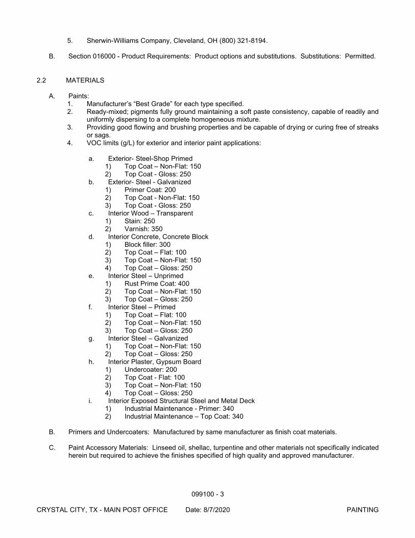
099100 - 3
CRYSTAL CITY, TX - MAIN POST OFFICE Date: 8/7/2020 PAINTING
5. Sherwin-Williams Company, Cleveland, OH (800) 321-8194.
B. Section 016000 - Product Requirements: Product options and substitutions. Substitutions: Permitted.
2.2 MATERIALS
A. Paints: 1. Manufacturer’s “Best Grade” for each type specified. 2. Ready-mixed; pigments fully ground maintaining a soft paste consistency, capable of readily and
uniformly dispersing to a complete homogeneous mixture. 3. Providing good flowing and brushing properties and be capable of drying or curing free of streaks
or sags. 4. VOC limits (g/L) for exterior and interior paint applications:
a. Exterior- Steel-Shop Primed 1) Top Coat – Non-Flat: 150 2) Top Coat - Gloss: 250
b. Exterior- Steel - Galvanized 1) Primer Coat: 200 2) Top Coat - Non-Flat: 150 3) Top Coat - Gloss: 250
c. Interior Wood – Transparent 1) Stain: 250 2) Varnish: 350
d. Interior Concrete, Concrete Block 1) Block filler: 300 2) Top Coat – Flat: 100 3) Top Coat – Non-Flat: 150 4) Top Coat – Gloss: 250
e. Interior Steel – Unprimed 1) Rust Prime Coat: 400 2) Top Coat – Non-Flat: 150 3) Top Coat – Gloss: 250
f. Interior Steel – Primed 1) Top Coat – Flat: 100 2) Top Coat – Non-Flat: 150 3) Top Coat – Gloss: 250
g. Interior Steel – Galvanized 1) Top Coat – Non-Flat: 150 2) Top Coat – Gloss: 250
h. Interior Plaster, Gypsum Board 1) Undercoater: 200 2) Top Coat - Flat: 100 3) Top Coat – Non-Flat: 150 4) Top Coat – Gloss: 250
i. Interior Exposed Structural Steel and Metal Deck 1) Industrial Maintenance - Primer: 340 2) Industrial Maintenance – Top Coat: 340
B. Primers and Undercoaters: Manufactured by same manufacturer as finish coat materials.
C. Paint Accessory Materials: Linseed oil, shellac, turpentine and other materials not specifically indicated
herein but required to achieve the finishes specified of high quality and approved manufacturer.
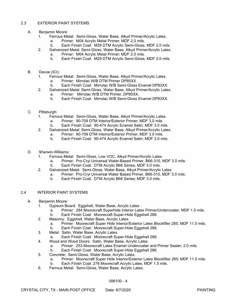
099100 - 4
CRYSTAL CITY, TX - MAIN POST OFFICE Date: 8/7/2020 PAINTING
2.3 EXTERIOR PAINT SYSTEMS
A. Benjamin Moore: 1. Ferrous Metal: Semi-Gloss, Water Base, Alkyd Primer/Acrylic Latex.
a. Primer: M04 Acrylic Metal Primer; MDF 2.0 mils. b. Each Finish Coat: M29 DTM Acrylic Semi-Gloss; MDF 2.0 mils.
2. Galvanized Metal: Semi-Gloss, Water Base, Alkyd Primer/Acrylic Latex. a. Primer: M04 Acrylic Metal Primer; MDF 2.0 mils. b. Each Finish Coat: M29 DTM Acrylic Semi-Gloss; MDF 2.0 mils.
B. Devoe (ICI): 1. Ferrous Metal: Semi-Gloss, Water Base, Alkyd Primer/Acrylic Latex.
a. Primer: Mirrolac W/B DTM Primer DP85XX. b. Each Finish Coat: Mirrolac W/B Semi-Gloss Enamel DP83XX.
2. Galvanized Metal: Semi-Gloss, Water Base, Alkyd Primer/Acrylic Latex. a. Primer: Mirrolac W/B DTM Primer, DP85XX. b. Each Finish Coat: Mirrolac W/B Semi-Gloss Enamel DP83XX.
C. Pittsburgh: 1. Ferrous Metal: Semi-Gloss, Water Base, Alkyd Primer/Acrylic Latex.
a. Primer: 90-709 DTM Interior/Exterior Primer; MDF 3.0 mils. b. Each Finish Coat: 90-474 Acrylic Enamel Satin; MDF 3.0 mils.
2. Galvanized Metal: Semi-Gloss, Water Base, Alkyd Primer/Acrylic Latex. a. Primer: 90-709 DTM Interior/Exterior Primer; MDF 3.0 mils. b. Each Finish Coat: 90-474 Acrylic Enamel Satin; MDF 3.0 mils.
D. Sherwin-Williams: 1. Ferrous Metal: Semi-Gloss, Low VOC, Alkyd Primer/Acrylic Latex.
a. Primer: Pro-Cryl Universal Water-Based Primer, B66-310, MDF 3.0 mils. b. Each Finish Coat: DTM Acrylic B66 Series; MDF 3.0 mils.
2. Galvanized Metal: Semi-Gloss, Water Base, Alkyd Primer/Acrylic Latex. a. Primer: Pro-Cryl Universal Water Based Primer, B66-310, MDF 3.0 mils. b. Each Finish Coat: DTM Acrylic B66 Series; MDF 3.0 mils.
2.4 INTERIOR PAINT SYSTEMS
A. Benjamin Moore: 1. Gypsum Board: Eggshell, Water Base, Acrylic Latex.
a. Primer: 284 Moorecraft Superhide Interior Latex Primer/Undercoater; MDF 1.5 mils. b. Each Finish Coat: Moorecraft Super-Hide Eggshell 286.
2. Masonry: Eggshell, Water Base, Acrylic Latex. a. Primer: Moorecraft Super Hide Interior/Exterior Latex Blockfiller 285; MDF 11.0 mils. b. Each Finish Coat: Moorecraft Super-Hide Eggshell 286.
3. Metal: Satin, Water Base, Acrylic Latex. a. Each Finish Coat: Moorecraft Super-Hide Eggshell 286.
4. Wood and Wood Doors: Satin, Water Base, Acrylic Latex. a. Primer: 253 Moorecraft Latex Enamel Undercoater and Primer Sealer; 2.0 mils. b. Each Finish Coat: Moorecraft Super-Hide Eggshell 286.
5. Concrete: Semi-Gloss, Water Base, Acrylic Latex. a. Primer: Moorecraft Super Hide Interior/Exterior Latex Blockfiller 285; MDF 11.0 mils. b. Each Finish Coat: 276 Moorecraft Acrylic Latex; MDF 1.5 mils.
6. Ferrous Metal: Semi-Gloss, Water Base, Acrylic Latex.
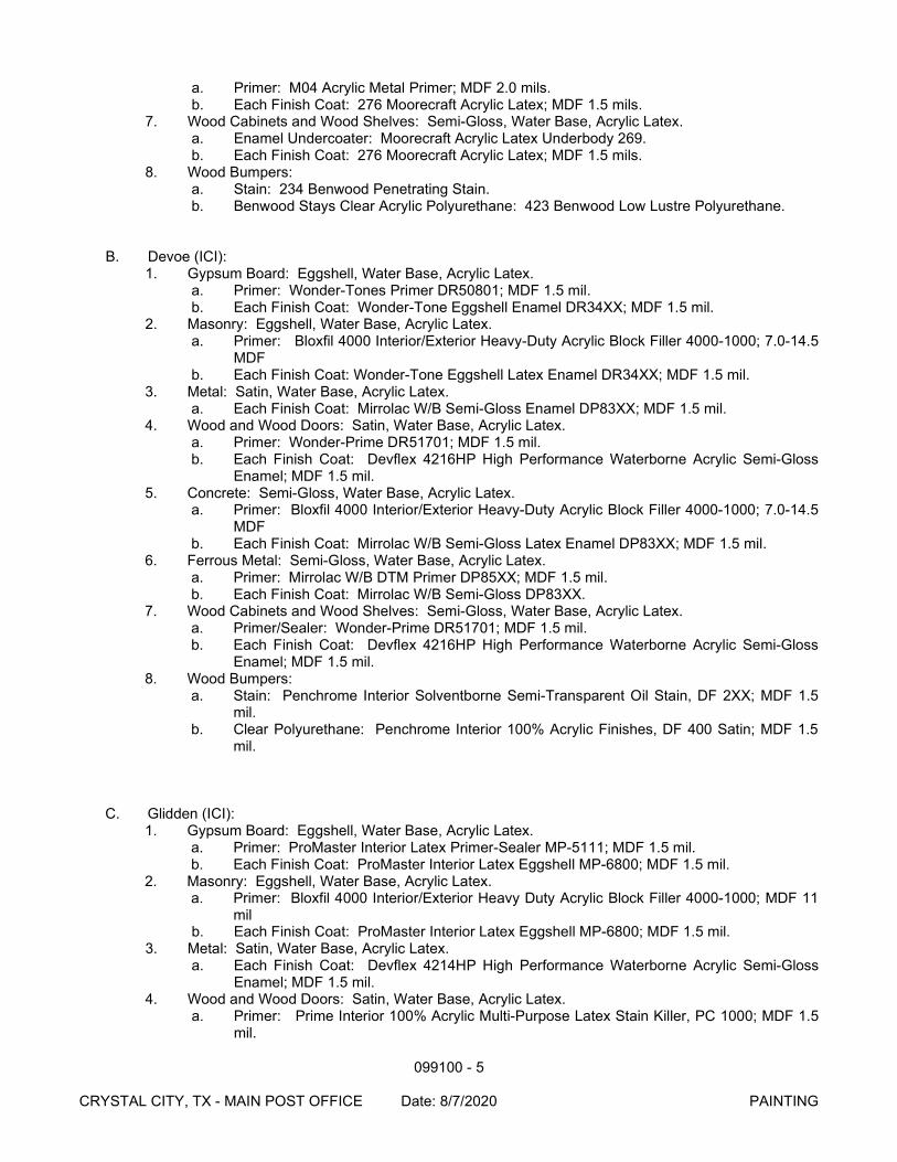
099100 - 5
CRYSTAL CITY, TX - MAIN POST OFFICE Date: 8/7/2020 PAINTING
a. Primer: M04 Acrylic Metal Primer; MDF 2.0 mils. b. Each Finish Coat: 276 Moorecraft Acrylic Latex; MDF 1.5 mils.
7. Wood Cabinets and Wood Shelves: Semi-Gloss, Water Base, Acrylic Latex. a. Enamel Undercoater: Moorecraft Acrylic Latex Underbody 269. b. Each Finish Coat: 276 Moorecraft Acrylic Latex; MDF 1.5 mils.
8. Wood Bumpers: a. Stain: 234 Benwood Penetrating Stain. b. Benwood Stays Clear Acrylic Polyurethane: 423 Benwood Low Lustre Polyurethane.
B. Devoe (ICI):
1. Gypsum Board: Eggshell, Water Base, Acrylic Latex. a. Primer: Wonder-Tones Primer DR50801; MDF 1.5 mil. b. Each Finish Coat: Wonder-Tone Eggshell Enamel DR34XX; MDF 1.5 mil.
2. Masonry: Eggshell, Water Base, Acrylic Latex. a. Primer: Bloxfil 4000 Interior/Exterior Heavy-Duty Acrylic Block Filler 4000-1000; 7.0-14.5
MDF b. Each Finish Coat: Wonder-Tone Eggshell Latex Enamel DR34XX; MDF 1.5 mil.
3. Metal: Satin, Water Base, Acrylic Latex. a. Each Finish Coat: Mirrolac W/B Semi-Gloss Enamel DP83XX; MDF 1.5 mil.
4. Wood and Wood Doors: Satin, Water Base, Acrylic Latex. a. Primer: Wonder-Prime DR51701; MDF 1.5 mil. b. Each Finish Coat: Devflex 4216HP High Performance Waterborne Acrylic Semi-Gloss
Enamel; MDF 1.5 mil. 5. Concrete: Semi-Gloss, Water Base, Acrylic Latex.
a. Primer: Bloxfil 4000 Interior/Exterior Heavy-Duty Acrylic Block Filler 4000-1000; 7.0-14.5 MDF
b. Each Finish Coat: Mirrolac W/B Semi-Gloss Latex Enamel DP83XX; MDF 1.5 mil. 6. Ferrous Metal: Semi-Gloss, Water Base, Acrylic Latex.
a. Primer: Mirrolac W/B DTM Primer DP85XX; MDF 1.5 mil. b. Each Finish Coat: Mirrolac W/B Semi-Gloss DP83XX.
7. Wood Cabinets and Wood Shelves: Semi-Gloss, Water Base, Acrylic Latex. a. Primer/Sealer: Wonder-Prime DR51701; MDF 1.5 mil. b. Each Finish Coat: Devflex 4216HP High Performance Waterborne Acrylic Semi-Gloss
Enamel; MDF 1.5 mil. 8. Wood Bumpers:
a. Stain: Penchrome Interior Solventborne Semi-Transparent Oil Stain, DF 2XX; MDF 1.5 mil.
b. Clear Polyurethane: Penchrome Interior 100% Acrylic Finishes, DF 400 Satin; MDF 1.5 mil.
C. Glidden (ICI):
1. Gypsum Board: Eggshell, Water Base, Acrylic Latex. a. Primer: ProMaster Interior Latex Primer-Sealer MP-5111; MDF 1.5 mil. b. Each Finish Coat: ProMaster Interior Latex Eggshell MP-6800; MDF 1.5 mil.
2. Masonry: Eggshell, Water Base, Acrylic Latex. a. Primer: Bloxfil 4000 Interior/Exterior Heavy Duty Acrylic Block Filler 4000-1000; MDF 11
mil b. Each Finish Coat: ProMaster Interior Latex Eggshell MP-6800; MDF 1.5 mil.
3. Metal: Satin, Water Base, Acrylic Latex. a. Each Finish Coat: Devflex 4214HP High Performance Waterborne Acrylic Semi-Gloss
Enamel; MDF 1.5 mil. 4. Wood and Wood Doors: Satin, Water Base, Acrylic Latex.
a. Primer: Prime Interior 100% Acrylic Multi-Purpose Latex Stain Killer, PC 1000; MDF 1.5 mil.

099100 - 6
CRYSTAL CITY, TX - MAIN POST OFFICE Date: 8/7/2020 PAINTING
b. Each Finish Coat: Devflex 4216 HP High Performance Waterborne Acrylic Semi-Gloss Enamel; MDF 1.5 mil.
5. Concrete: Semi-Gloss, Water Base, Acrylic Latex. a. Primer: Bloxfil 4000 Interior/Exterior Heavy Duty Acrylic Block Filler 4000-1000; MDF 11
mil b. Each Finish Coat: Devflex 4216 HP High Performance Waterborne Acrylic Semi-Gloss
Enamel; MDF 1.5 mil. 6. Ferrous Metal: Semi-Gloss, Water Base, Acrylic Latex.
a. Primer: Devflex 4020 PF Direct to Metal Primer & Flat Finish; MDF 1.5 mil. b. Each Finish Coat: Devflex 4216 HP High Performance Waterborne Acrylic Semi-Gloss
Enamel; MDF 1.5 mil. 7. Wood Cabinets and Wood Shelves: Semi-Gloss, Water Base, Acrylic Latex.
a. Primer/Sealer: Prime Interior 100% Acrylic Multi-Purpose Latex Stain Killer, PC 1000; MDF 1.5 mil.
b. Each Finish Coat: Devflex 4216 HP High Performance Waterborne Acrylic Semi-Gloss Enamel; MDF 1.5 mil.
8. Wood Bumpers: a. Stain: DF200 semi-transparent; MDF 1.5 mil. b. Clear Polyurethane: Penchrome Interior 100% Acrylic Finishes, DF 400 Satin; MDF 1.5
mil. D. Pittsburgh:
1. Gypsum Board: Eggshell, Water Base, Acrylic Latex. a. Primer: 6-2 Speedhide Latex Sealer; MDF 1.0 mils. b. Each Finish Coat: 6-411 Speedhide Eggshell Latex; MDF 1.5 mils.
2. Masonry: Eggshell, Water Base, Acrylic Latex. a. Primer: 6-2 Speedhide Latex Sealer; MDF 1.0 mils. b. Each Finish Coat: 6-411 Speedhide Eggshell Latex; MDF 1.5 mils.
3. Metal: Satin, Water Base, Acrylic Latex. a. Each Finish Coat: 90-474 DTM Acrylic Satin; MDF 1.5 mils.
4. Wood and Wood Doors: Satin, Water Base, Acrylic Latex. a. Primer: 6-855 Interior Water Base Undercoater; MDF 1.5 mils. b. Each Finish Coat: 90-474 DTM Acrylic Satin; MDF 1.5 mils.
5. Concrete: Semi-Gloss, Water Base, Acrylic Latex. a. Primer: 6-7 Speedhide Block Filler; MDF 6.0 - 12.0 mils. b. Each Finish Coat: 6-500 Speedhide Semi-Gloss Latex; MDF 1.2 mils.
6. Ferrous Metal: Semi-Gloss, Water Base, Acrylic Latex. a. Each Finish Coat: 90-474 DTM Acrylic Satin; MDF 1.5 mils.
7. Wood Cabinets and Wood Shelves: Semi-Gloss, Water Base, Acrylic Latex. a. Primer/Sealer: 6-855 Interior Water Base Undercoater; MDF 1.5 mils. b. Each Finish Coat: 90-474 DTM Acrylic Satin; MDF 1.5 mils.
8. Wood Bumpers: a. Stain: 77-560 Interior Oil Stain b. Clear Polyurethane: 77-89 Interior Oil Satin Polyurethane
E. Sherwin Williams:
1. Gypsum Board: Low VOC, Eg-shell, Water Base, Acrylic Latex. a. Primer: Harmony Latex Primer, MDF 1.6 mils. b. Each Finish Coat: Harmony Latex Eg-Shel, MDF 1.6 mils.
2. Masonry: Semi-Gloss, Water Base, Acrylic Latex. a. Primer: PrepRite Interior/Exterior Block Filler, B25W25; MDF 10.0 mils b. Each Finish Coat: ProMar 200 Zero VOC Interior Latex Egg Shell: MDF 1.5 mils.
3. Metal: Semi-Gloss, Water Base, Acrylic Latex. a. Each Finish Coat: Pro Industrial DTM Acrylic S-G, B66-1151 Series MDF 3.0 mils.
4. Wood and Wood Doors: Semi-Gloss, Water Base, Acrylic Latex. a. Primer: Wall & Wood Primer, B28W08111, MDF 1.6 mils.
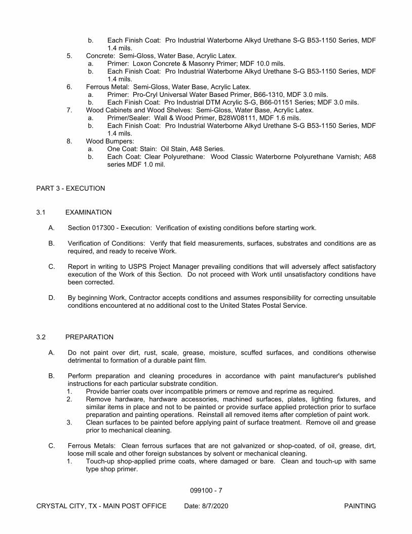
099100 - 7
CRYSTAL CITY, TX - MAIN POST OFFICE Date: 8/7/2020 PAINTING
b. Each Finish Coat: Pro Industrial Waterborne Alkyd Urethane S-G B53-1150 Series, MDF 1.4 mils.
5. Concrete: Semi-Gloss, Water Base, Acrylic Latex. a. Primer: Loxon Concrete & Masonry Primer; MDF 10.0 mils. b. Each Finish Coat: Pro Industrial Waterborne Alkyd Urethane S-G B53-1150 Series, MDF
1.4 mils. 6. Ferrous Metal: Semi-Gloss, Water Base, Acrylic Latex.
a. Primer: Pro-Cryl Universal Water Based Primer, B66-1310, MDF 3.0 mils. b. Each Finish Coat: Pro Industrial DTM Acrylic S-G, B66-01151 Series; MDF 3.0 mils.
7. Wood Cabinets and Wood Shelves: Semi-Gloss, Water Base, Acrylic Latex. a. Primer/Sealer: Wall & Wood Primer, B28W08111, MDF 1.6 mils. b. Each Finish Coat: Pro Industrial Waterborne Alkyd Urethane S-G B53-1150 Series, MDF
1.4 mils. 8. Wood Bumpers:
a. One Coat: Stain: Oil Stain, A48 Series. b. Each Coat: Clear Polyurethane: Wood Classic Waterborne Polyurethane Varnish; A68
series MDF 1.0 mil.
PART 3 - EXECUTION
3.1 EXAMINATION
A. Section 017300 - Execution: Verification of existing conditions before starting work.
B. Verification of Conditions: Verify that field measurements, surfaces, substrates and conditions are as required, and ready to receive Work.
C. Report in writing to USPS Project Manager prevailing conditions that will adversely affect satisfactory
execution of the Work of this Section. Do not proceed with Work until unsatisfactory conditions have been corrected.
D. By beginning Work, Contractor accepts conditions and assumes responsibility for correcting unsuitable
conditions encountered at no additional cost to the United States Postal Service.
3.2 PREPARATION
A. Do not paint over dirt, rust, scale, grease, moisture, scuffed surfaces, and conditions otherwise detrimental to formation of a durable paint film.
B. Perform preparation and cleaning procedures in accordance with paint manufacturer's published
instructions for each particular substrate condition. 1. Provide barrier coats over incompatible primers or remove and reprime as required. 2. Remove hardware, hardware accessories, machined surfaces, plates, lighting fixtures, and
similar items in place and not to be painted or provide surface applied protection prior to surface preparation and painting operations. Reinstall all removed items after completion of paint work.
3. Clean surfaces to be painted before applying paint of surface treatment. Remove oil and grease prior to mechanical cleaning.
C. Ferrous Metals: Clean ferrous surfaces that are not galvanized or shop-coated, of oil, grease, dirt,
loose mill scale and other foreign substances by solvent or mechanical cleaning. 1. Touch-up shop-applied prime coats, where damaged or bare. Clean and touch-up with same
type shop primer.
099100 - 8
CRYSTAL CITY, TX - MAIN POST OFFICE Date: 8/7/2020 PAINTING
D. Galvanized Surfaces: Clean free of oil and surface contaminants with non-petroleum-based solvent.
Apply coat of etching primer if required by paint manufacturer.
E. Cementitious Materials: Prepare cementitious surfaces to be painted by removing efflorescence, chalk, dust, dirt, grease, oils, and by roughening as required to remove glaze. 1. Determine alkalinity and moisture content of surfaces to be painted by performing appropriate
tests. a. If surfaces are found to be sufficiently alkaline to cause blistering and burning of finish
paint, correct condition before application of paint. 2. Do not paint over surfaces where moisture content exceeds that permitted in manufacturer's
printed instructions. 3. Clean floor surfaces scheduled to be painted with a commercial solution of muriatic acid, or other
etching cleaner. Flush floor with clean water to neutralize acid and allow to dry before painting.
F. Wood: Clean wood surfaces to be painted of dirt, oil, and other foreign substances with scrapers, mineral spirits, and sandpaper, as required. Sandpaper smooth those finished surfaces exposed to view and dust off. Scrape and clean small, dry, seasoned knots and apply a thin coat of white shellac or other recommended knot sealer, before application of priming coat. After priming, fill holes, and imperfections in finish surfaces with putty or plastic wood-filler. Sandpaper smooth when dried. 1. Prime, stain, or seal wood required to be job-painted immediately upon delivery to job. Prime
edges, ends faces, undersides, and backsides of such wood, including cabinets and counters. 2. Seal tops, bottoms, and cut-outs with a heavy coat of varnish or equivalent sealer immediately
upon delivery to job.
G. Gypsum Board: Fill minor defects with filler compound. Spot prime defects after repair.
3.3 APPLICATION
A. Apply paint products in accordance with manufacturer's published instructions using application procedures approved for the particular application and substrate to the specified Minimum Dry Film Thickness (MDF). Apply each coat to uniform finish.
B. Apply each coat slightly darker than preceding coat unless otherwise approved by USPS Project
Manager. Sand lightly between coats to achieve specified finish.
C. Do not apply finishes on surfaces that are not dry.
D. Number of coats and film thickness required is same regardless of application method. Do not apply succeeding coats until the previous coat has cured as recommended by the manufacturer.
E. Apply additional coats when undercoats, stains, or other conditions show through final coat until paint
film is of uniform finish, color, and appearance. Surfaces, including edges, corners, crevices, welds, and exposed fasteners to receive minimum dry film thickness equivalent to that of flat surfaces.
F. Minimum Coating Thickness: Apply materials at not less than manufacturer's recommended spreading
rate. Provide minimum dry film thickness (MDF) of the entire coating system as indicated in Painting and Finishing Schedule at end of this Section.
G. Block Fillers: Apply block fillers to concrete masonry units at rate to provide complete coverage with
pores filled.
H. Prime Coats: Before application of finish coats, apply a prime coat of material as recommended by manufacturer to material scheduled to be painted or finished that has not been shop primed. Recoat
099100 - 9
CRYSTAL CITY, TX - MAIN POST OFFICE Date: 8/7/2020 PAINTING
primed and sealed surfaces where evidence of suction spots or unsealed areas in first coat appears, to assure a finish coat with no burn through or other defects due to insufficient sealing.
I. Pigmented (Opaque) Finishes: Completely cover to provide an opaque, smooth surface of uniform
finish, color, appearance, and coverage. Cloudiness, spotting, laps, brush marks, runs, sags, or other surface imperfections will not be acceptable.
J. Hollow Metal Doors: Paint each door edge.
K. Completed Work: Match Contracting Officer approved field samples for color and sheen.
3.4 MECHANICAL AND ELECTRICAL EQUIPMENT
A. Clean or replace identification markings on mechanical or electrical equipment when painted over or spattered.
B. Paint both sides and edges of plywood backboards for electrical equipment before installing backboards and mounting equipment on them.
C. Prepaint Gas piping prior to installation. (Touch-up paint after installation.)
1. Color: a. Roof (Yellow): OSHA Standard "Safety Yellow." b. Other Areas: Match adjacent surfaces.
D. At Workroom locations, paint red background on wall behind fire extinguisher extending 6 inches on
both sides of the extinguisher and from floor to ceiling, or to 12 feet above floor, whichever is lower. Color is to be OSHA Standard "Safety Red” and in accordance with ANSI Z53.1.
3.5 FIELD QUALITY CONTROL
A. Section 014000 - Quality Requirements: Field testing and inspection.
B. Inspect painting and coating application for scheduled material, color, sheen, specified thickness (MDF), and coverage.
3.6 CLEANING
A. As work proceeds and upon completion, promptly remove paint where spilled, splashed, or spattered.
B. During progress of work keep premises free from any unnecessary accumulation of tools, equipment, surplus materials, and debris.
C. Collect waste, cloths, and material which may constitute a fire hazard, place in closed metal containers
and remove daily from site.
D. Upon completion of work leave premises neat and clean.
3.7 PROTECTION
A. Protect other surfaces from paint and damage. Repair damage as a result of inadequate or unsuitable protection.
099100 - 10
CRYSTAL CITY, TX - MAIN POST OFFICE Date: 8/7/2020 PAINTING
3.8 COLOR SCHEDULE
A. Any proposal to substitute a color is to include manufacturer’s certification that the color matches the specified Munsell notation. Similarly, paint colors proposed for P-4 and P-5 must include the manufacturer’s certification that the color matches the specified PMS number.
B. P-1 White (Munsell notation: #5Y 9.25/0.5NN)
1. Benjamin Moore: #968. 2. Glidden (ICI): #50YY 83/057. 3. Pittsburgh: #512-1, Winter Mood. 4. Sherwin-Williams (S-W): #SW 7636, Origami White.
C. P-2 Light Gray (Munsell notation: #N8.0)
1. Benjamin Moore: #1612, Pelican Gray. 2. Devoe (ICI): #1H51G, Catkin. 3. Glidden (ICI): #50BG 62/007. 4. Sherwin-Williams: #SW7662, Evening Shadow
D. P-3 (Not Used)
E. P-4 Red (Match PMS 485C “Postal Red”) Custom Match
F. P-5 Blue (Match PMS 301C “Postal Blue”) Custom Match
G. P-6 Medium Gray (Munsell notation: #10B7/1)
1. Sherwin Williams: SW#1232, Dublin Gray (custom mix)
H. P-7 Semi-gloss Black
3.9 SCHEDULE OF ITEMS TO BE PAINTED
A. Painted finishes shall be provided for, but not limited to, the following items. Refer to Drawings and Paint Color Schedule at end of this Section for designated finishes and colors of areas. 1. Exterior: All exterior surfaces including, but not limited to:
a. Hollow metal doors and frames. b. Metal opening frames and trim. c. Metal flashing (if exposed from ground level) and downspout. d. Metal gravelstops (vertical face). e. Pipe Bollards, if not to receive plastic covers specified in Section 055000. f. Metal railings. g. Roof hatch. h. Canopy supporting steel structure. i. Wall louvers.
2. Interior: All interior surfaces as scheduled on Drawings including, but not limited to: a. Hollow metal doors and frames. b. Hollow metal window frames. c. Metal opening frames and trim. d. Gypsum wallboard. e. Exposed concrete unit masonry. f. Pipe Bollards. g. Metal railings. h. Exposed structure columns. i. Metal stair stringers and handrails.
099100 - 11
CRYSTAL CITY, TX - MAIN POST OFFICE Date: 8/7/2020 PAINTING
j. Exposed wood trim.
B. Do not paint the following items:
1. Pre-finished items:
a. Aluminum, brass, bronze, stainless steel, and chrome plated steel. b. Pre-finished items, such as toilet compartments, acoustical ceiling materials, mechanical, and
electrical equipment. c. UL, FM, and other code-required labels. d. Equipment identification, performance rating, and name plates. e. Finish hardware. f. Factory finished metal wall panels, metal wall panel trim, and metal gravel stops.
2. Exposed items: a. Exposed mechanical ductwork, hangers, and supports. b. Exposed piping and conduit, hangers and supports. c. Exposed fire protection piping, hangers and supports. d. Exposed roof structure. e. Exposed roof deck.
3.10 PAINTING AND FINISHING SCHEDULE
A. Interior Paint Systems: 1. Interior Gypsum Wallboard:
a. 1 coat Latex Wall Primer. b. 1 coat Latex Eggshell Enamel
2. Interior Masonry:
a. 1 coat Latex Block Filler b. 1 coat Latex Eggshell Enamel
3. Interior Metal:
a. 2 coats Latex Satin
4. Interior Wood (painted): a. 1 coat Enamel Undercoat b. 2 coats Alkyd Semi-Satin Enamel
5. Cast-In-Place Concrete:
a. One coat of Latex Masonry Block Filler. b. Two tinted coats of Acrylic Latex Semi-Gloss Enamel.
6. Wood Doors - Painted.
a. One coat Enamel Undercoat. b. Two tinted coats of Latex Semi-Gloss Enamel.
7. Ferrous Metals
a. Touch up Prime Coat. b. Two tinted coats of Alkyd Enamel Semi-Gloss.
8. Wood Cabinets, Shelves, etc. - exposed surfaces.
a. One coat Primer-Sealer. b. One coat Enamel Undercoat. c. One coat Alkyd Enamel Semi-Gloss Enamel.
099100 - 12
CRYSTAL CITY, TX - MAIN POST OFFICE Date: 8/7/2020 PAINTING
9. Wood Bumpers.
a. Penetrating Oil Stain. b. Two Coats of Clear Polyurethane Semi-Gloss Finish.
B. Exterior Paint Systems:
1. Galvanized Metal: a. Touch up Prime Coat. b. Two tinted coats Exterior Alkyd Enamel Semi-Gloss Enamel.
2. Ferrous Metals:
a. Touch up Prime Coat. b. Two tinted coats Exterior Alkyd Enamel Semi-Gloss Enamel.
END OF SECTION
101404 - 1
CRYSTAL CITY, TX - MAIN POST OFFICE Date: 8/7/2020 POSTAL SIGNAGE
SECTION 101404
POSTAL SIGNAGE
PART 1 - GENERAL
1.1 SUMMARY
A. Section Includes: 1. Exterior signage - building identification, directional and parking regulatory signs. 2. Interior signage for retail spaces.
B. The USPS Direct Vendor for supplying the exterior signage - building identification, directional and parking regulatory signs listed in this specification through the contractor is Gable Signs. No substitutions allowed. 1. In the Offer, include the estimated exterior signage cost from the Exterior Signage Order Form at
the end of this section. This amount includes the exterior signage and shipping. It does not include installation which is part of the Work. Contractor may negotiate with the Direct Vendor for installation.
2. The contractor is to order the exterior signage from the Direct Vendor based on the Exterior Signage Order Form and Drawings in time to meet the schedule. Payment is to be received by the Direct Vendor from the contractor prior to shipment of the exterior signage.
C. The USPS Direct Vendor for supplying the interior signage listed in this specification through the contractor is Gable Signs. No substitutions allowed. 1. In the Offer, include the estimated interior signage cost from the Interior Signage Order Form at
the end of this section. This amount includes the interior signage and shipping. It does not include installation which is part of the Work.
2. The contractor is to order the interior signage from the Direct Vendor based on the Interior Signage Order Form and Drawings in time to meet the schedule. Payment is to be received by the Direct Vendor from the contractor prior to shipment of the interior signage.
D. Related Documents:
1. The Contract Documents, as defined in Section 011000 - Summary of Work, apply to the Work of this Section. Additional requirements and information necessary to complete the Work of this Section may be found in other Documents.
1.2 SUBMITTALS
A. Section 013300 - Submittal Procedures: Procedures for submittals. 1. USPS Exterior Signage vendor shop drawings have been approved by USPS Headquarters; no
additional submittals are required from this vendor. Signs included in this agreement are building identification, directional and parking regulatory signs. DOT signs are not included in this agreement.
2. USPS Interior Signage vendor shop drawings have been approved by USPS Headquarters; no additional submittals are required from this vendor.
PART 2 - PRODUCTS
2.1 MANUFACTURERS
101404 - 2
CRYSTAL CITY, TX - MAIN POST OFFICE Date: 8/7/2020 POSTAL SIGNAGE
A. Exterior Signage - building identification, directional and parking regulatory signs: Gable Signs, Eric Crowe, Director of Sales & Account Management, 7440 Fort Smallwood Road, Baltimore, MD 21226, Phone (443) 817-0303, [email protected]. USPS reserves the right to update these products through the Direct Vendor agreement.
B. Interior Signage: Gable Signs, Eric Crowe, Director of Sales & Account Management, 7440 Fort Smallwood Road, Baltimore, MD 21226, Phone (443) 817-0303, [email protected]. USPS reserves the right to update these products through the Direct Vendor agreements.
C. Section 016000 - Product Requirements:
1. Exterior Signage: Substitutions are not permitted. 2. Interior Signage: Substitutions are not permitted.
PART 3 - EXECUTION
3.1 EXAMINATION
A. Section 017300 - Execution: Verification of existing conditions before starting work.
B. Verification of Conditions by Contractor is required: Verify through field measurements that contract Documents are in accordance with actual site conditions. Verify that all sign site locations, wall surfaces, substrates and conditions are as required, and ready to receive Work. 1. Examine free standing sign placement locations, walls, doors, soffit and other areas scheduled to
receive signs for conditions that would affect quality and execution of work. 2. Check that electrical distribution for illuminated signs is complete and ready to receive signs. 3. Contractor is responsible for obtaining any required permits.
C. Contractor is to report in writing to Contracting Officer prevailing conditions that will adversely affect
satisfactory execution of the Work of this Section. Do not proceed with Work until unsatisfactory conditions have been corrected.
D. By beginning Work, Contractor accepts conditions and assumes responsibility for correcting unsuitable
conditions encountered at no additional cost to the United States Postal Service. E. Contractor is responsible for reviewing contract documents to provide required electrical service to sign
positions shown in the Drawings.
3.2 PREPARATION
A. Contractor is responsible for the removal of any existing signs in preparation to receive new sign elements. Contractor will patch affected surfaces to match existing materials. Contractor must dispose of all signs in accordance with all state and local codes and ordinances. Recycling and re-use of existing sign materials is greatly encouraged. Contractor must consider the salvage value of removed signs in the cost of work.
B. Contractor must verify that all signs ordered fit the as-built conditions of the facility.
3.3 INSTALLATION
A. Install sign units and components at the locations shown in Drawings, securely mount with fasteners appropriate to the substrate conditions.
101404 - 3
CRYSTAL CITY, TX - MAIN POST OFFICE Date: 8/7/2020 POSTAL SIGNAGE
B. Install signs on facility property clear of public right of ways and utilities. C. Install foundations for all free standing signs. D. Verify that all internal roadway, street and traffic conditions are in accordance with the signs selected
and shown on Contract Documents prior to purchase and installation of exterior signage. E. Connect signs to control devices and electrical service as required in the Drawings. Coordinate with the
USPS Sign Vendor time clock settings and power service required for checking lighting and operational status of all sign hardware.
F. Install interior sign units and components at the locations shown or scheduled, securely mount with concealed theft-resistant fasteners. Attach signs to substrates in accordance with the manufacturer's instructions.
G. Install level, plumb, and at the proper height and alignments. Cooperate with other trades for
installation of sign units to finish surfaces. 1. Coordinate the mounting height of the USPS "station ID", "Hours of Operation" or other door
mounted vinyls with any code-required signs for automatic doors.
H. Sign manufacturer to provide template for spacing of letters.
END OF SECTION
101414 - 1
CRYSTAL CITY, TX - MAIN POST OFFICE Date: 8/7/2020 MISC.SIGNAGE
SECTION 101414
MISCELLANEOUS SIGNAGE
PART 1 - GENERAL
1.1 SUMMARY
A. Section Includes: 1. Miscellaneous building signage.
B. Related Documents: The Contract Documents, as defined in Section 011000 - Summary of Work, apply
to the Work of this Section. Additional requirements and information necessary to complete the Work of this Section may be found in other Documents.
1.2 SUBMITTALS
A. Section 013300 - Submittal Procedures: Procedures for submittals. 1. Shop Drawings:
a. Indicate sign styles, lettering font, foreground and background colors, locations, and overall dimensions of each sign.
b. Setting details for installation in concrete footings.
PART 2 - PRODUCTS
2.1 MANUFACTURERS
A. Subject to compliance with project requirements, manufacturers offering Products which may be incorporated in the Work include the following: 1. APCO, Atlanta, GA (404) 688-9000. 2. ASI Sign Systems, Incorporated, Dallas, TX (800) 274 7732. 3. Gable Signs, Eric Crowe, Director of Sales & Account Management, 7440 Fort Smallwood Road,
Baltimore, MD 21226, Phone (443) 817-0303, [email protected] 4. Neokraft Signs, Incorporated, Lewiston, ME (800) 339-2258. 5. Vomar Products, Incorporated, Van Nuys, CA (800) 521-2737. 6. 2/90 Sign Systems, Grand Rapids, MI (800) 777-4310.
B. Section 016000 - Product Requirements: Product options and substitutions. Substitutions: Permitted.
2.2 SIGNAGE
A. Construction Site Sign: 1. Silk-screened, painted or pressure-sensitive vinyl letters applied to Medium Density Overlay
plywood sign. 2. Red: Match Benjamin Moore OP-67. 3. Blue: Match PPG 7062 Federal Blue. 4. White background.
B. Pictographs:
101414 - 2
CRYSTAL CITY, TX - MAIN POST OFFICE Date: 8/7/2020 MISC.SIGNAGE
1. AIGA Symbol Signs reproducible art developed for the U.S. Department of Transportation is to be used whenever possible. Room signs shall have 1/32 inch raised one inch high Helvetica Medium (upper and lower case) lettering and Braille.
2. Size: As indicated on drawings. 3. Material: Plastic. 4. Color: Use colors below, unless designated by AIGA.
a. Foreground (Characters and/or Graphics): White: Match P-1 in Section # 099100, Painting. b. Background: Blue: Match P-5 in Section # 099100, Painting.
C. Room and Directional Signage
1. Room signs shall have 1/32 inch raised one inch high Helvetica Medium (upper and lower case) lettering and Braille.
2. Size: 16 inches (40 cm). 3. Material: Plastic. 4. Color:
a. Foreground (Characters and/or Graphics): White: Match P-1 in Section # 099100, Painting. b. Background: Blue: Match P-5 in Section # 099100, Painting.
D. Egress Signage:
1. When required by public authority, provide signage in one inch high Helvetica Medium (upper and lower case) letters, in contrasting color to background to read: "This Door To Remain Unlocked During Business Hours." Doors requiring signage will be indicated on either the hardware schedule or door schedule.
2. For use above Impact/Traffic doors, which are not an approved means of emergency egress and must be so identified, signs reading "NOT AN EMERGENCY EXIT",
E. Exit Door Tactile Sign
1. Provide signage to read “Exit” at egress doors. In contrasting color to background, signs shall have 1/32 inch raised one inch high Helvetica Medium (upper and lower case) lettering and Braille.
2. Product: Same as Room and Directional signage. 3. Size: 6 inch (15 cm) 4. Color:
a. Foreground (Characters and/or Graphics): White: Match P-1 in Section # 099100, Painting. b. Background: Blue: Match P-5 in Section # 099100, Painting.
2.3 FASTENERS AND OTHER MATERIALS
A. Provide non-corrosive fasteners, hangers, and mounting devices which are compatible with sign material and finish.
B. Other materials, not specifically described, but required for a complete and proper installation of signs,
shall be as selected and subject to approval of the Contracting Officer.
PART 3 - EXECUTION
3.1 INSTALLATION
A. Install signage in accordance with manufacturer's published instructions.
101414 - 3
CRYSTAL CITY, TX - MAIN POST OFFICE Date: 8/7/2020 MISC.SIGNAGE
B. Install sign units and components at the locations shown or scheduled, securely mount with concealed theft-resistant fasteners. Attach signs to substrates in accordance with the manufacturer's instructions.
C. Install level, plumb, and at the proper height. Cooperate with other trades for installation of sign units to
finish surfaces.
D. Sign manufacturer to provide template for spacing of letters.
3.2 CONSTRUCTION
A. Interface with Other Work: 1. Furnish full-size spacing templates for individually bundled letters and numbers for coordination
with work of other trades.
3.3 MISCELLANEOUS INTERIOR SIGNAGE Item number Description 1. FIRST AID
2. FIRE EXTINGUISHER 3. NO SMOKING 4. ELECTRICAL HAZARD 5. TOILETS, MEN 6. TOILETS, WOMEN 9. EXIT (Tactile Sign)
END OF SECTION
101453 - 1
CRYSTAL CITY, TX - MAIN POST OFFICE Date: 8/7/2020 TRAFFIC SIGNAGE
SECTION 101453
TRAFFIC SIGNAGE
PART 1 - GENERAL
1.1 SUMMARY
A. Section Includes:
1. Department of Transportation (DOT) traffic control signs.
B. Related Documents:
1. The Contract Documents, as defined in Section 011000 - Summary of Work, apply to the Work of this Section. Additional requirements and information necessary to complete the Work of this Section may be found in other Documents.
1.2 SUBMITTALS
A. Section 013300 - Submittal Procedures: Procedures for submittals.
1. Signage Schedule: Submit signage selection schedule indicating quantity and location of each type of DOT sign required to Contracting Officer.
PART 2 - PRODUCTS
2.1 MANUFACTURERS
A. DOT (Department of Transportation) Traffic Control Signs. The Contractor is responsible to furnish and install (including foundations) all DOT Traffic Control Signs as indicated in the Drawings.
B. Section 016000 - Product Requirements:
1. DOT Traffic Control Signs. See Section 016000 - Product Requirements: Product options and substitutions. Substitutions: Permitted.
2.2 MATERIALS
A. Contractor is responsible to purchase and install all exterior DOT (Department of Transportation) traffic control signage as shown in the Drawings.
1. Traffic Signs: Sign post are to be steel tubes painted blue to match exterior signage by direct vendor. Size of posts and heights of signs are as indicated on the drawings. Sign face background is 0.063 inch aluminum plate, cut to size and attached to sign post with non-corrosive 3/8 inch machine bolts with washers, two per sign.

101453 - 2
CRYSTAL CITY, TX - MAIN POST OFFICE Date: 8/7/2020 TRAFFIC SIGNAGE
PART 3 - EXECUTION
3.1 EXAMINATION
A. Section 017300 - Execution: Verification of existing conditions before starting work.
B. Verification of Conditions by Contractor is required: Verify through field measurements that contract Documents are in accordance with actual site conditions. Verify that all sign site locations, wall surfaces, substrates and conditions are as required, and ready to receive Work.
1. Examine free standing sign placement locations, walls, doors, soffit and other areas scheduled to receive signs for conditions that would affect quality and execution of work.
2. Check that electrical distribution for illuminated signs is complete and ready to receive signs. 3. Contractor is responsible for obtaining any required permits.
C. Contractor is to report in writing to Contracting Officer prevailing conditions that will adversely affect
satisfactory execution of the Work of this Section. Do not proceed with Work until unsatisfactory conditions have been corrected.
D. By beginning Work, Contractor accepts conditions and assumes responsibility for correcting unsuitable
conditions encountered at no additional cost to the United States Postal Service. E. Contractor is responsible for reviewing contract documents to provide required electrical service to sign
positions shown in the Drawings.
3.2 PREPARATION
A. Contractor is responsible for the removal of any existing signs in preparation to receive new sign elements. Contractor will patch affected surfaces to match existing materials. Contractor must dispose of all signs in accordance with all state and local codes and ordinances. Recycling and re-use of existing sign materials is greatly encouraged. Contractor must consider the salvage value of removed signs in the cost of work.
B. Contractor must verify that all signs ordered fit the as-built conditions of the facility.
3.3 INSTALLATION
A. Install sign units and components at the locations shown in Drawings, securely mount with fasteners appropriate to the substrate conditions.
B. Install signs on facility property clear of public right of ways and utilities. C. Install foundations for all free standing signs. D. Verify that all Department of Transportation (DOT) traffic control signs shown in the Drawings are
accurate and in compliance with all state and local codes and ordinances. E. Verify that all internal roadway, street and traffic conditions are in accordance with the signs selected
and shown on Contract Documents prior to purchase and installation of DOT traffic control signs. F. Install level, plumb, and at the proper height. Cooperate with other trades for installation of sign units in
all locations and to all finished surfaces.
101453 - 3
CRYSTAL CITY, TX - MAIN POST OFFICE Date: 8/7/2020 TRAFFIC SIGNAGE
END OF SECTION
[This page intentionally left blank.]
102115 - 1 CRYSTAL CITY, TX - MAIN POST OFFICE Date: 8/7/2020 TOILET COMPARTMENTS
SECTION 102115
SOLID PLASTIC TOILET COMPARTMENTS
PART 1 - GENERAL
1.1 SUMMARY
A. Work Includes: 1. Solid plastic toilet compartments, floor mounted, head rail braced. 2. Solid plastic urinal screens, wall mounted. 3. Attachment hardware.
B. Related Documents: The Contract Documents, as defined in Section 011000 - Summary of Work, apply
to the Work of this Section. Additional requirements and information necessary to complete the Work of this Section may be found in other Documents.
1.2 SUBMITTALS A. Section 013300 - Submittal Procedures: Procedures for submittals.
1. Product Data: Panel construction, hardware, and accessories. 2. Samples: Two 2 inch x 3 inch samples of partition indicating finish and color.
1.3 ENVIRONMENTAL REQUIREMENTS A. Resource Management:
1. Recycled Content: Provide solid plastic compartments and screens with core manufactured from minimum 50 percent recycled plastic.
PART 2 - PRODUCTS
2.1 MANUFACTURERS
A. Subject to compliance with project requirements, manufacturers offering specified items which may be incorporated in the Work include the following: 1. Capitol Partitions, Incorporated, Columbia, MD (410) 740-8870. 2. Comtec Industries, Moosic, PA (717) 348-0997 or (800) 551-6993. 3. Metpar, Corporation, Westbury, NY (516) 333-2600. 4. Scranton Products, Scranton, PA (800) 368-5002 or (717) 343-7921.
B. Section 016000 - Product Requirements: Product options and substitutions. Substitutions: Permitted.
2.2 MATERIALS
A. Solid plastic compartments and screens: water resistant; graffiti resistant; non-absorbent; with plastic face sheets permanently fused to plastic core. 1. Panels: 1 inch thickness, manufacturer’s standard height except not less than 55 inches. 2. Doors: 1 inch thickness, manufacturer’s standard height except not less than 55 inches.
102115 - 2 CRYSTAL CITY, TX - MAIN POST OFFICE Date: 8/7/2020 TOILET COMPARTMENTS
3. Pilasters: 1 inch thickness. 4. Urinal screens: 1 inch thickness, 24 inches in depth, 42 inches in height, wall mounted.
B. Pilaster Shoes: 3 inches high and one of the following: 1. One piece molded polypropylene or high density polyethylene (HDPE). 2. 20 gage stainless steel.
C. Attachments:
1. Screws, and Bolts: Stainless steel; tamper proof type. 2. Wall Mounting Brackets: Continuous, full height heavy duty plastic or bight anodized aluminum
brackets in accordance with toilet compartment manufacturer's instructions.
D. Hardware: Chrome plated non-ferrous cast pivot hinges, gravity type, adjustable for door close positioning; nylon bearings; black anodized aluminum door latch; door strike and keeper with rubber bumper; cast alloy chrome plated coat hook and bumper.
2.3 FABRICATION
A. Solid Plastic: 1/4 inch radius beveled edges. B. Hardware and Attachments: Pre-drilled by manufacturer; provide for protection of dissimilar metals.
1. Floor Mounted Anchorage: Corrosion-resistant anchoring assemblies with threaded rods, lock washers, and leveling adjustment nuts at pilasters for structural connection to floor. Provide shoes at pilasters to conceal anchorage.
2.4 FINISHES
A. Compartments and Screens: 1. Capitol Partitions: Architect to select from full line of colors. 2. Comtec: Architect to select from full line of colors. 3. Metpar: Architect to select from full line of colors. 4. Santana: Architect to select from full line of colors.
B. Plastic Pilaster Shoes: Color to match core of solid plastic compartments and screens.
PART 3 - EXECUTION
3.1 INSTALLATION
A. Install partitions secure, rigid, plumb, level, and square in accordance with published manufacturer's instructions. 1. Provide for adjustment due to minor floor variations. 2. Install adjacent components for consistency of line and plane.
B. Maintain 1/2 inch space between wall and panels, and between wall and pilasters. Attach panel
brackets securely to walls using anchor devices.
C. Attach panels and pilasters to bracket with through sleeve tamperproof bolts and nuts. Locate head rail joints at pilaster center lines.
102115 - 3 CRYSTAL CITY, TX - MAIN POST OFFICE Date: 8/7/2020 TOILET COMPARTMENTS
D. Anchor urinal screen panels to walls and anchored to floor in accordance with manufacturer's instructions to suit supporting wall construction.
E. Conceal floor fastenings with pilaster shoes.
F. Equip each door with hinges, one door latch, and one coat hook and bumper. Align hardware to
uniform clearance at vertical edges of doors, not exceeding 1/4 inch. 1. Provide hardware at handicapped toilet with operating hardware complying with ANSI A117.1.
3.2 CONSTRUCTION
A. Interface with Other Work: 1. Coordinate placement of support framing and anchors in walls.
B. Site Tolerances:
1. Maximum Variation From True Position: 1/4 inch. 2. Maximum Variation From Plumb: 1/8 inch.
3.3 ADJUSTING
A. Adjust and align hardware to uniform clearance at vertical edge of doors, not exceeding 3/16 inch.
B. In Swinging Doors: Adjust hinges to locate doors in partial open position when unlatched.
C. Out Swinging Doors: Adjust hinges to gently return doors to closed position.
D. Adjust adjacent components for consistency of line or plane.
END OF SECTION
102600 - 1
CRYSTAL CITY, TX - MAIN POST OFFICE Date: 8/7/2020 WALL AND DOOR PROTECTION
SECTION 102600
WALL AND DOOR PROTECTION
PART 1 - GENERAL
1.1 SUMMARY
A. Section Includes: 1. FRP Wall Protection 2. Corner Guards 3. Plastic Laminate Wall Protection
B. Related Documents: The Contract Documents, as defined in Section 011000 - Summary of Work apply
to the work of this section. Additional requirements and information necessary to complete the work of this section may be found in other documents.
C. Regulatory Requirements: 1. Handbook RE-4 Requirements for the Physically Handicapped.
1.2 SUBMITTALS
A. Section 013300 - Submittal Procedures: Procedures for submittals: 1. Product Data: Indicate materials, construction, configuration, dimensions, and finishes.
PART 2 - PRODUCTS
2.1 FIBERGLASS REINFORCED PLASTIC (FRP) PANELS
A. Subject to compliance with project requirements, manufacturers offering plastic sheeting or fiberglass reinforced plastic (FRP) panels which may be incorporated in the Work include the following:
1. Crane Composites, Channahon,IL (800) 435-0080 2. Glasteel, Moscow, TN (800) 238-5546 3. Kalwall, Bow, NH (800) 526-1609
B. PRODUCT DESCRIPTION
1. Nominal 1/8” thick, white embossed finish, Class A Fire Rated panels. 2. Provide Manufacturer’s trim, joining and cap accessories.
3. Install panels in strict accordance with Manufacturer’s reccommendations.
C. Section 016000 - Product Requirements: Product options and substitutions. Substitutions: Permitted.
102600 - 2
CRYSTAL CITY, TX - MAIN POST OFFICE Date: 8/7/2020 WALL AND DOOR PROTECTION
2.2 CORNER GUARDS FOR RETAIL AND OFFICE SPACES
A. Subject to compliance with requirements, provide corner guards by one of the following manufacturers: 1. Construction Specialties: Acrovyn – SM-20. 2. Pawling: Pro-Tek Corner Guards surface mounted CG-10 with TC-10. 3. InPro Corporation: Type 150.
B. For retail space corner guard colors provide color most closely matching PMS 294 for blue walls and PMS 485 for red walls. For office space and other walls painted P-1, provide white.
C. Retail and office space corner guards: 4’-0” long snap-on covers of Calss 1 fire-rated resilient material, minimum 0.078 inch thick, free-floated over continuous aluminum retainer, 0.063 inch thick, surface mounted and anchored to wall at 20 inches on center maximum; moded end caps color matched to covers.
D. For non customer retail spaces, subject to compliance with requirements, provide ourner guards by one of the following manufacturers: 1. Construction Specialties: Acrovyn CO8 surface mounted stainless steel corner guard. 2. Pawling: GC-50 surface mounted corner guard. 3. InPro Corporation: Stainless steel surface mount corner guard.
E. Non-retail space corner guards: 4’-0” long surface mount screw attached, 3 ½ inch flanges, 16 gage, No. 304 stainless steel.
2.3 PLASTIC LAMINATE WALL PROTECTION A. Refer to Section 123216 Manufactured Plastic-Laminate Clad Casework for approved plastic laminate
manufacturers and colors. B. Install PL-2 plastic laminate to ¾” MDF Board as detailled for screen line.
PART 3 - EXECUTION
3.1 INSTALLATION
A. Provide for 1/8 inch gap at ends of pieces and parts of wood polymer lumber to wood polymer lumber
and wood polymer lumber to other materials.
B. No color is to be applied to the wood polymer lumber. Use standard color (neutral).
C. Install FRP panels and corner guards in accordance with manufacturers recommendations. 1. Install corner guards with tops at 5’-0” above finished floor.
D. Plastic Laminate wall protection: First install MDF panels over drywall to steel studs at 16” o.c.b.w.
Install Plastic Laminate to MDF with non-VOC type adhesive as recommended by laminate manufacturer.
END OF SECTION
102813 - 1 CRYSTAL CITY, TX - MAIN POST OFFICE Date: 8/7/2020 TOILET ACCESSORIES
SECTION 102813
TOILET ACCESSORIES
PART 1 - GENERAL
1.1 SUMMARY
A. Section Includes: 1. Toilet Accessories. 2. Attachment hardware.
B. Related Documents: The Contract Documents, as defined in the General Conditions, apply to the Work
of this Section. Additional requirements and information necessary to complete the Work of this Section may be found in other documents.
1.2 SUBMITTALS
A. Section 013300 - Submittal Procedures: Procedures for submittals. 1. Product Data: Data for each accessory describing size, finish, details of function, and attachment
methods.
1.3 QUALITY ASSURANCE
A. Regulatory Requirements: Conform to United States Postal Service "Standards for Facility Accessibility by the Physically Handicapped' Handbook RE-4 for mounting heights and locations of accessories.
PART 2 - PRODUCTS
2.1 MANUFACTURERS
A. Subject to compliance with project requirements, manufacturers offering specified items which may be incorporated in the Work include the following: 1. American Specialties Company, Incorporated, Yonkers, NY (914) 476-9000. 2. Bobrick Washroom Equipment, Incorporated, North Hollywood, CA (818) 764-1000. 3. Bradley Corporation, Milwaukee, WI (414) 251-6000. 4. McKinney Parker, Scranton, PA (570) 969-9770.
B. Section 016000 - Product Requirements: Product options and substitutions. Substitutions: Permitted.
2.2 MATERIALS
A. Sheet Steel: ASTM A 366.
B. Galvanized Sheet Steel: ASTM A 366, ASTM A 123 to 1.25 ounces per square yard.
C. Stainless Steel Sheet: ASTM A167, Type 304.
102813 - 2 CRYSTAL CITY, TX - MAIN POST OFFICE Date: 8/7/2020 TOILET ACCESSORIES
D. Fasteners, Screws, and Bolts: Hot dip galvanized, tamper-proof.
E. Expansion Shields: Fiber, lead, or rubber as recommended by accessory manufacturer for component and substrate.
2.3 MANUFACTURED UNITS
A. AC-1 - Surface Mounted Liquid Soap Dispenser, (install one dispenser per lavatory): 1. Model Numbers:
a. American Specialties: 0342. b. Bobrick: B-2112. c. Bradley: 6542. d. McKinney: 304-H
2. Description: Horizontal tank type for all-purpose liquid soap. Minimum 20 gage Type 304 stainless steel. Drawn one-piece construction. No. 4 satin finish. Concealed stainless steel wall plate. Clear plastic refill indicator window. Locked hinged stainless steel lid for top filling. Minimum 40 ounce capacity.
B. AC-4A - Mirror with Stainless Steel Channel Frame: 1. Model Numbers:
a. American Specialties: 0600. b. Bobrick: 165 series. c. Bradley: 780. d. McKinney:
2. Description: 18 inches wide x 36 inches high. Minimum 20 gage stainless steel , all joints mitered, welded and ground smooth. Type 430 bright polished finish. Galvanized steel back with slots for mounting screws and integral screw-head lock. Back protected by shock-absorbing water-resistant padding. Ten year warranty against silver spoilage.
C. AC-5 - Mop and Broom Holder:
1. Model Numbers: a. American Specialties: 8215B. b. Bobrick: B-223. c. Bradley: 9954. d. McKinney: 233.
2. Description: 36 inches long, 3 inch projection, 4 holders. Minimum 22 gage, Type 304 stainless steel hat channel. Spring loaded rubber cam-type mop holders. No. 4 Satin finish.
D. AC-6 - Surface-Mounted Multi-Roll Tissue Dispenser:
1. Model Numbers: a. American Specialties: 0030. b. Bobrick: B-2888. c. Bradley: 5402. d. McKinney: 615.
2. Description: Minimum 22 gage Type 304 stainless steel cabinet. Minimum 18 gage drawn one-piece Type 304 stainless steel unit front with pivot hinge and tumbler lockset. No. 4 satin finish. Holds 2 standard core 5 inch diameter tissue rolls. Reserve roll drops in-place by automatic release. Theft-resistant spindles.
E. AC-7 - Recessed Combination Paper Towel Dispenser and Waste Receptacle:
1. Model Numbers: a. American Specialties: 0469. b. Bobrick: B-3944.
102813 - 3 CRYSTAL CITY, TX - MAIN POST OFFICE Date: 8/7/2020 TOILET ACCESSORIES
c. Bradley: 234. d. McKinney: 80294.
2. Description: 4 inch wall depth. Minimum 22 gage Type 304 stainless steel. Drawn and beveled one-piece seamless flange. Full length stainless steel piano hinge and concealed tumbler lock at towel dispenser door. No. 4 satin finish. Capacity minimum 600 C-fold or 800 multi-fold paper towels. Waste receptacle with all edges with hemmed construction. Removable waste receptacle secured to cabinet with tumbler lock. Minimum 12 gallon capacity.
F. AC-8 - Grab Bar - 36 Inch:
1. Model Numbers: a. American Specialties: 3100 series. b. Bobrick: B-5806x36. c. Bradley: 832 series. d. McKinney: 9602.
2. Description: 1-1/4 inch minimum to 2 inch maximum diameter (1-1/2 inch diameter when required by local code) 36 inch long, horizontal, 1-1/2 inch wall clearance. Type 304 minimum 18 gage stainless steel. Concealed screw attached mounting and anchorage. No. 4 satin finish. Minimum 900 pound supporting capacity.
G. AC-9 - Grab Bar - 42 Inch:
1. Model Numbers: a. American Specialties: 3100 series. b. Bobrick: B5806x42. c. Bradley: 832 series. d. McKinney: 9602.
2. Description: 1-1/4 inch minimum to 2 inch maximum diameter (1-1/2 inch diameter when required by local code) 42 inch long, horizontal. 1-1/2 inch wall clearance. Type 304 minimum 18 gage stainless steel. Concealed screw attached mounting and anchorage. No. 4 satin finish. Minimum 900 pound supporting capacity.
H. AC-11 - Partition Mounted Dual-Access Sanitary Napkin Disposal: 1. Model Numbers:
a. American Specialties: 0472. b. Bobrick: B-354. c. Bradley: 4721-15. d. McKinney:
2. Description: Mounted in toilet compartment panel serving both sides of panel. Minimum 22 gage Type 304 stainless steel. Drawn and beveled one-piece seamless flange. Spring-loaded, self-closing door with full-length stainless steel piano hinge. No. 4 satin finish. Removable stainless steel receptacle with tumbler lock. International graphic symbol on door. Minimum 1.2 gallon capacity.
2.4 FABRICATION
A. Weld and grind smooth joints of fabricated components.
B. Form exposed surfaces from single sheet of stock, free of joints. Form surfaces flat without distortion. Maintain surfaces without scratches or dents.
C. Fabricate grab bars of tubing, free of visible joints, return to wall with end attachment flanges.
D. Shop assemble components and package complete with anchors and fittings.
102813 - 4 CRYSTAL CITY, TX - MAIN POST OFFICE Date: 8/7/2020 TOILET ACCESSORIES
E. Provide steel anchor plates, adapters, and anchor components for installation.
F. Back paint components where contact is made with building finishes to prevent electrolysis.
PART 3 - EXECUTION
3.1 EXAMINATION
A. Section 017300 - Execution: Verification of existing conditions before starting work.
B. Verification of Conditions: Verify that field measurements, surfaces, substrates and conditions are as required, and ready to receive Work. 1. Verify correct location of opening in wall for recessed accessories. 2. Verify that attachment blocking and backing plates are in place in the correct location for
accessory connections.
C. Report in writing to Contracting Officer prevailing conditions that will adversely affect satisfactory execution of the Work of this Section. Do not proceed with Work until unsatisfactory conditions have been corrected.
D. By beginning Work, Contractor accepts conditions and assumes responsibility for correcting unsuitable
conditions encountered at no additional cost to the United States Postal Service.
3.2 PREPARATION
A. Deliver inserts and rough-in frames to site for scheduled installation.
B. Provide and use templates and rough-in measurements as required.
3.3 INSTALLATION
A. Install fixtures, accessories, and items in accordance with manufacturer's instructions, US Postal Service handicapped requirements, and as indicated on Drawings. Use tamper-proof fasteners.
B. Install plumb and level, securely and rigidly anchored to substrate.
3.4 ADJUSTING AND CLEANING
A. Adjust accessories for proper operation and verify mechanisms function smoothly.
B. Remove temporary labels and protective coatings. Clean and polish exposed surfaces.
END OF SECTION
104400 - 1 CRYSTAL CITY, TX - MAIN POST OFFICE Date: 8/7/2020 FIRE PROTECTION SPECIALTIES
SECTION 104400
FIRE PROTECTION SPECIALTIES
PART 1 - GENERAL
1.1 SUMMARY
A. Section Includes. 1. Fire extinguishers. 2. Mounting brackets.
B. Related Documents: The Contract Documents, as defined in Section 011000 - Summary of Work, apply
to the Work of this Section. Additional requirements and information necessary to complete the Work of this Section may be found in other documents.
1.2 SUBMITTALS
A. Section 013300 - Submittal Procedures: Procedures for submittals. 1. Product Data:
a. Extinguisher type, operational features, color. b. Cabinet type, materials, construction, features, color, finish and attachment method.
PART 2 - PRODUCTS
2.1 MANUFACTURERS
A. Subject to compliance with project requirements, manufacturers offering Products that may be incorporated in the work include the following: 1. J.L. Industries, Bloomington, MN (800) 554-6077. 2. Larsen's Manufacturing Company, Minneapolis, MN (800) 527-7367. 3. Potter-Roemer, Incorporated, Cerritos, CA (800) 366-3473.
B. Section 016000 - Product Requirements: Product options and substitutions. Substitutions: Permitted.
2.2 MATERIALS
A. Extinguisher: Multipurpose dry chemical type, UL 299; UL-rated 4-A:60:B:C. 10 pound nominal capacity in enameled steel container.
B. Mounting Bracket: Metal designed to prevent accidentally dislodging extinguisher, of size required for
type and capacity of extinguisher specified, screw attached to wall. Brite chrome finish.
PART 3 - EXECUTION
3.1 INSTALLATION
104400 - 2 CRYSTAL CITY, TX - MAIN POST OFFICE Date: 8/7/2020 FIRE PROTECTION SPECIALTIES
A. Install extinguisher and bracket or cabinet in accordance with manufacturer's published instructions in locations required by authority having jurisdiction.
B. Secure rigidly in place.
C. Locate extinguishers where indicated on Drawings.
D. Mount brackets so top of extinguisher is maximum 60 inches above finish floor. E. At Workroom locations, paint red background on wall behind fire extinguisher extending 6 inches on
both sides of the extinguisher and from floor to ceiling, or to 12 feet above floor, whichever is lower. Color is to be “Safety Red” as specified in Section 099100, Painting.
END OF SECTION
105526 - 1
CRYSTAL CITY, TX - MAIN POST OFFICE Date: 8/7/2020 PARCEL LOCKERS
SECTION 105526
PARCEL LOCKERS
PART 1 - GENERAL
1.1 SUMMARY
A. Section Includes: 1. Parcel lockers. 2. Accessories.
B. Related Documents: The Contract Documents, as defined in Section 011000 - Summary of Work, apply
to the Work of this Section. Additional requirements and information necessary to complete the Work of this Section may be found in other Documents.
1.2 SUBMITTALS
A. Section 013300 - Submittal Procedures: Procedures for submittals. 1. Product Data: Data on locker types, sizes, and accessories. 2. Shop Drawings: Indicate layout, dimensions, details of fabrication and installation. Include plans,
elevations, sections, and attachments to other Work.
B. Section 017704 - Closeout Procedures and Training: Procedures for closeout submittals. 1. Operation and Maintenance Data: Include spare parts data, current unit prices, sources of
supply, and maintenance instructions.
PART 2 - PRODUCTS
2.1 MANUFACTURERS
A. Subject to compliance with project requirements, manufacturers offering Products which may be incorporated in the Work include the following: 1. HSS Industries, Incorporated, Traverse City, MI (800) 330-9701.
B. Section 016000 - Product Requirements: Product options and substitutions. Substitutions: Not Permitted.
2.2 PARCEL LOCKERS
A. Model: 1. HSS: PL series. PL-1, PL-2, PL-3, PL-DRD, PL-15, PL-SRD.
2.3 MATERIALS
A. Sheet Steel: Zinc-coated steel, nickel bearing, free from buckle, scale, and surface imperfections. Steel to be phosphate-treated, baked-on prime paint with baked enamel finish coat.
B. Finish: Custom finish and color.
1. Coating Type: Polyester/Acrylic.
105526 - 2
CRYSTAL CITY, TX - MAIN POST OFFICE Date: 8/7/2020 PARCEL LOCKERS
2. Color of Trim: Black, as delivered. 3. Color of Faceplate: Silver to match finish of P.O. Boxes. 4. Gloss: 35-Ultrahigh. 5. Edge Coverage: Good. 6. Specific Gravity: 1.20 + 1.80. 7. Average Particle Size: 24-40 Microns (per ASTM-D1921). 8. Chip Resistance: Minimum Rating of 5.
C. Fasteners: Cadmium, zinc, nickel plated steel; exposed both heads, slotless type; self-locking nuts or
locker washers for nuts on moving parts.
2.4 MANUFACTURED UNITS A. Select model and quantity of parcel lockers as directed by Contracting Officer from the following (based
on USPS approved parcel lockers, manufactured by HSS Industries). Post office box rack ladder system provided by the United States Postal Service. 1. Model PL-1 (1 compartment), size: 22.5 inches wide x 15.5 inches deep x 11.75 inches high. 2. Model PL-2 (2 compartment), size: 22.5 inches wide x 15.5 inches deep x 11.75 inches high. 3. Model PL-3 (1 compartment), size: 22.5 inches wide x 15.5 inches deep x 23.5 inches high. 4. Model PL-DRD (rear doors), size: 22” wide x 60 inches high (Required for all installations).
2.5 ACCESSORIES
A. Locking: Fabricate lockers to receive the following locking devices. 1. Locking Mechanism (Customer Side): Each parcel locker module shall be secured with a U.S.
Postal Service furnished 306 lock. (Manufacturers providing an installed lock equal to the 306 lock will be acceptable). Upon opening the compartment with a customer key to remove the contents, the customer key shall remain trapped. Three customer keys shall be provided for each compartment lock. The locks shall be so located to allow for easy replacement if they should be damaged or inoperable. Provide proper holes for USPS supplied and installed “Arrow” lock, above the 306 lock. The Arrow lock enables the Postal Service to unlock the trapped customer key with a master key.
2. Locking Mechanism (Postal Side): Full length door, minimum 16 GA., locked closed by a 12 gage, plated steel latch/strap that forms a three point latch (top, middle and bottom of door). The latch mechanism and cables shall be covered or enclosed to prevent tampering. The mechanism will be spring loaded to return to the locked position when handle is released or door is slammed shut. The door may be secured by turning the handle and closing the door or slamming the door shut so that the slam lock bolts engage.
B. Number Plates: Manufacturer's standard stainless steel metal number plates with numerals not less
than 3/8 inch (9 mm) high. Number lockers in sequence as directed by Contracting Officer. Attach plates to each locker above keyway with minimum 2 fasteners of same finish as number plate.
C. Trim: Provide black fillers and/or closure panel trim at jambs and head of recessed lockers, consisting
of minimum 18 gage cold-rolled steel, 3 inch (8 cm) and 6 inch (15 cm) wide factory-finish trim where indicated to match lockers. Secure trim to lockers with concealed fastening clips.
2.6 FABRICATION
A. Construction: Fabricate lockers square, and without warp, with metal faces flat and free of dents or distortion. Make all exposed metal edges safe to touch. Weld frame members together to form rigid, one-piece structure. Weld, bolt, or rivet other joints and connections as standard with manufacturer. Grind exposed welds flush. Do not expose bolts or rivet heads on fronts of locker doors and frames.
105526 - 3
CRYSTAL CITY, TX - MAIN POST OFFICE Date: 8/7/2020 PARCEL LOCKERS
B. Frames: Fabricate of 16 gage channels or 12 gage angles, minimum with continuous stop/strike formed on vertical members.
C. Interior: Side panels to be flush constructed to inside of frames for easy removal of customer packages.
Offset frame-to-side panel or protrusions into the opening are not permitted. From customer side, through compartment - postal floor shall not be visible with postal side door closed and latched. Provisions for attaching lockers together in at least two places front and back.
D. Body: Fabricate top, bottom and sides of minimum 24 gage steel, with double flanged connections
extending full height. E. Front Frame and Doors: One piece, minimum 16 gage sheet steel, without louvers, flanged at all
edges, constructed to prevent springing when opening or closing. Fabricate to swing minimum 90 degrees. 1. Reinforcing: Provide extra bracing or reinforcing on inside of doors over 15 inches (38 cm) wide. 2. Hinges: Heavy-duty, stainless steel, concealed full loop hinges. Weld to inside of frame and
secure to door with minimum 2 factory-installed fasteners which are completely concealed and tamperproof when door is closed. Front door shall have self-closing hinges.
F. Rear Doors: Provide doors without louvers on back of lockers for access by postal employees from
space behind public areas. The rear door shall be supported by a continuous hinge on one side. The rear door must be design and fabricated to preclude access from one compartment to another for the purpose of vandalism or unlawful removal of compartment contents and to prevent access to the workroom floor. Opening the rear door shall expose all compartments within a module for easy access and deposit of parcels.
PART 3 - EXECUTION
3.1 EXAMINATION
A. Section 017300 - Execution: Verification of existing conditions before starting work.
B. Verification of Conditions: Verify that field measurements, surfaces, substrates and conditions are as required, and ready to receive Work.
C. Report in writing to Contracting Officer prevailing conditions that will adversely affect satisfactory
execution of the Work of this Section. Do not proceed with Work until unsatisfactory conditions have been corrected.
D. By beginning Work, Contractor accepts conditions and assumes responsibility for correcting unsuitable
conditions encountered at no additional cost to the United States Postal Service.
3.2 PREPARATION
A. Field Measurements: Take field measurements prior to preparation of shop drawings and fabrication of special components, when possible, to ensure proper fitting of work. However, allow for adjustment and fitting of trim and filler panels whenever taking of field measurements before fabrication might delay Work.
3.3 INSTALLATION
105526 - 4
CRYSTAL CITY, TX - MAIN POST OFFICE Date: 8/7/2020 PARCEL LOCKERS
A. Install metal lockers at locations indicated on Drawings in accordance with manufacturer's published instructions.
B. Install lockers plumb, level, rigid, and flush.
C. Space fastenings about 48 inches (1.2 m) on center, unless otherwise recommended by manufacturer.
Install through back-up reinforcing plates where necessary to avoid metal distortion. Conceal fasteners.
D. Install trim where indicated, use concealed fasteners to provide flush, hairline joints with adjacent surfaces.
E. Provide door with flush fit at cross sill when in closed position to maximize intercompartment security.
Gaps not permitted.
3.4 FIELD QUALITY CONTROL
A. Section 014000 - Quality Requirements: Field testing and inspection.
B. Inspect installation of lockers, attachment, and alignment with adjacent finishes.
C. Operate locker doors and locking devices.
3.5 ADJUSTING AND CLEANING
A. Adjust doors and latches to operate easily without binding. Verify that integral locking devices are operating properly.
B. Touch-up marred finishes. Use only materials and procedures recommended or furnished by locker
manufacturer. Replace units which cannot be restored to factory-finished appearance.
END OF SECTION
107500 - 1 CRYSTAL CITY, TX - MAIN POST OFFICE Date: 8/7/2020 FLAGPOLES
SECTION 107500
FLAGPOLES
PART 1 - GENERAL
1.1 SUMMARY
A. Section Includes: 1. Aluminum ground mounted flagpole. 2. Truck, halyards, and accessories. 3. Concrete flagpole foundation base.
B. Related Documents: The Contract Documents, as defined in Section 011000 - Summary of Work, apply
to the Work of this Section. Additional requirements and information necessary to complete the Work of this Section may be found in other documents.
1.2 SYSTEM DESCRIPTION
A. Performance Requirements: 1. Pole With Flag Flying: Resistant without permanent deformation, 100 miles per hour wind
velocity, non-resonant, safety design factor of 1.0. 2. Flag Dimension: 4 foot x 6 foot. Coordinate recommended flag size with manufacturer.
1.3 SUBMITTALS
A. Section 013300 - Submittal Procedures: Procedures for submittals. 1. Product Data: Data on pole, accessories, and configurations. 2. Shop Drawings: Detailed dimensions, anchor requirements, imposed loads, and foundation
system.
1.4 DELIVERY, STORAGE AND HANDLING
A. Section 016000 - Product Requirements: Transport, handle, store, and protect products.
B. Spiral wrap flagpole with protective covering and pack in protective shipping tubes or containers.
C. Protect flagpole and accessories on site from damage or moisture.
PART 2 - PRODUCTS
2.1 MANUFACTURERS
A. Subject to compliance with project requirements, manufacturers offering specified items which may be incorporated in the Work include the following: 1. American Flagpole, Division of Kearney-National Incorporated, Abingdon, VA (800) 368-7171. 2. Concord Industries, Incorporated, Addison, TX (800) 527-3902.
107500 - 2 CRYSTAL CITY, TX - MAIN POST OFFICE Date: 8/7/2020 FLAGPOLES
3. Eder Flag Manufacturing Company, Incorporated, Oak Creek, WI (800) 558-6044. 4. Pole-Tech Company, Incorporated, East Setauket, NY (800) 633-6733.
B. Section 016000 - Product Requirements: Product options and substitutions. Substitutions: Permitted.
2.2 MATERIALS
A. Pole Type: Commercial external halyard cone tapered aluminum with ground sleeve.
B. Flagpole: ASTM B 241; 6063-T6 wrought alloy aluminum, cone tapered.
1. Outside Butt Diameter: 5-1/2 inches. 2. Outside Tip Diameter: 3-1/2 inches. 3. Nominal Wall Thickness: 0.188 inches. 4. Nominal Height: 25 foot 0 inches, measured from top of flagpole base. 5. Mounting: Ground mounted to concrete foundation and base.
C. Truck Assembly: Aluminum; stationary.
D. Halyard: Nylon halyard with four chrome plated bronze swivel snaphooks.
E. Cleat: 6” minimum, cast aluminum with stainless steel flat head fasteners for flush fit. F. Collar: Spun aluminum to match pole.
G. Foundation Sleeve: 16 gauge steel, galvanized corrugated tube with 3/16 inch thick steel base plate
and support plate, 3/4 inch diameter x 18 inch long ground spike, and steel centering wedges.
H. Concrete: Specified in Section 033000.
I. Flags: Furnished and installed by United States Postal Service.
2.3 FINISHES
A. Metal Surfaces in Contact with Concrete: Asphaltic paint.
B. Aluminum: AA M32-C22-A41 Clear anodized.
PART 3 - EXECUTION
3.1 PREPARATION
A. Coat metal sleeve surfaces below grade and surfaces in contact with dissimilar materials with asphaltic paint.
3.2 INSTALLATION
A. Install flagpole base assembly, and accessories in accordance with manufacturer's published instructions.
107500 - 3 CRYSTAL CITY, TX - MAIN POST OFFICE Date: 8/7/2020 FLAGPOLES
B. Electrically ground flagpole installation.
C. Install foundation plate and centering wedges for flagpole base set in concrete base and fasten. Fill
foundation tube sleeve with sand and compact.
END OF SECTION
111304 - 1
CRYSTAL CITY, TX - MAIN POST OFFICE Date: 8/7/2020 DOCK LIFT (SCISSORS TYPE)
SECTION 111304
DOCK LIFT (SCISSORS TYPE)
PART 1 - GENERAL
1.1 SUMMARY
A. Section Includes: 1. Pit mounted scissors type dock lift. 2. Rodent blocking seal – for enclosed platform locations. 3. Surface mounted scissors type dock lift. 4. Portable scissor type dock lifts 5. Structure and operating characteristics.
B. Related Documents: The Contract Documents, as defined in Section 011000 - Summary of Work, apply
to the Work of this Section. Additional requirements and information necessary to complete the Work of this Section may be found in other Documents.
C. Related Sections:
1. Section 055000, Metal Fabrications: for pipe bollards.
1.2 SUBMITTALS
A. Section 013300 - Submittal Procedures: Procedures for submittals. 1. Product Data: Indicate materials and finish, installation details, roughing-in measurements, and
operation of unit. 2. Shop Drawings: Indicate required opening dimensions, tolerances of opening dimensions,
perimeter conditions of construction, and electrical connections.
B. Section 017704 - Closeout Procedures and Training: Procedures for closeout submittals. 1. Operating and Maintenance Data:
a. Manufacturer's operating and maintenance instructions. b. Name, address, and telephone number of nearest authorized service representative. c. Complete parts list.
2. Operation Instruction: Document training by furnishing a sign-in sheet with a description of the training provided, instructors name and organization and those who received training. Refer to 017704 1.3, 1.4 and 1.5 for more specific training requirements.
1.3 QUALITY ASSURANCE
A. Conform to requirements of ANSI MH29.1.
B. Qualifications: 1. Installer: Company specializing in performing the Work of this Section with minimum 5 years
documented experience.
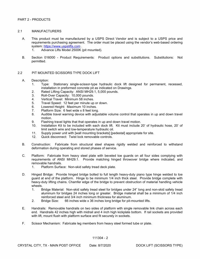
111304 - 2
CRYSTAL CITY, TX - MAIN POST OFFICE Date: 8/7/2020 DOCK LIFT (SCISSORS TYPE)
PART 2 - PRODUCTS
2.1 MANUFACTURERS
A. This product must be manufactured by a USPS Direct Vendor and is subject to a USPS price and requirements purchasing agreement. The order must be placed using the vendor’s web-based ordering system: https://www.uspslifts.com . 1. Advance Lifts Model 2500K (pit mounted).
B. Section 016000 - Product Requirements: Product options and substitutions. Substitutions: Not
permitted.
2.2 PIT MOUNTED SCISSORS TYPE DOCK LIFT A. Description:
1. Type: Stationary single-scissor-type hydraulic dock lift designed for permanent, recessed, installation in preformed concrete pit as indicated on Drawings.
2. Rated Lifting Capacity: ANSI MH29.1, 5,000 pounds. 3. Roll-Over Capacity: 10,000 pounds. 4. Vertical Travel: Minimum 58 inches. 5. Travel Speed: 12 feet per minute up or down. 6. Lowered Height: Maximum 10 inches. 7. Platform Size: 6 feet wide x 8 feet long. 8. Audible travel warning device with adjustable volume control that operates in up and down travel
motion. 9. Flashing travel lights that that operates in up and down travel motion. 10. Installation Kit to be included with each dock lift. Kit must include 20’ of hydraulic hose, 20’ of
limit switch wire and low-temperature hydraulic oil. 11. Supply power unit with [wall mounting brackets] [pedestal] appropriate for site. 12. Quick disconnect: Twist lock removable controls.
B. Construction: Fabricate from structural steel shapes rigidly welded and reinforced to withstand
deformation during operating and stored phases of service. C. Platform: Fabricate from heavy steel plate with beveled toe guards on all four sides complying with
requirements of ANSI MH29.1. Provide matching hinged throwover bridge where indicated, and removable handrails. 1. Platform Surface: Non-skid safety tread deck plate.
D. Hinged Bridge: Provide hinged bridge bolted to full length heavy-duty piano type hinge welded to toe
guard at end of the platform. Hinge to be minimum 1/4 inch thick steel. Provide bridge complete with heavy-duty lifting chains. Chamfer edge of the bridge to prevent obstruction of material handling vehicle wheels. 1. Bridge Material: Non-skid safety tread steel for bridges under 24” long and non-skid safety tread
aluminum for bridges 24 inches long or greater. Bridge material shall be a minimum of 1/4 inch reinforced steel and 3/4 inch minimum thickness for aluminum.
2. Bridge Size: 66 inches wide x 36 inches long bridge for pit-mounted lifts.
E. Handrails: Removable handrails on two sides of platform with single removable link chain across each end. Handrails 42 inches high with midrail and 4 inch high kickplate bottom. If rail sockets are provided with lift, mount flush with platform surface and fit securely in sockets.
F. Scissor Mechanism: Fabricate leg members from heavy steel formed tube or plate.
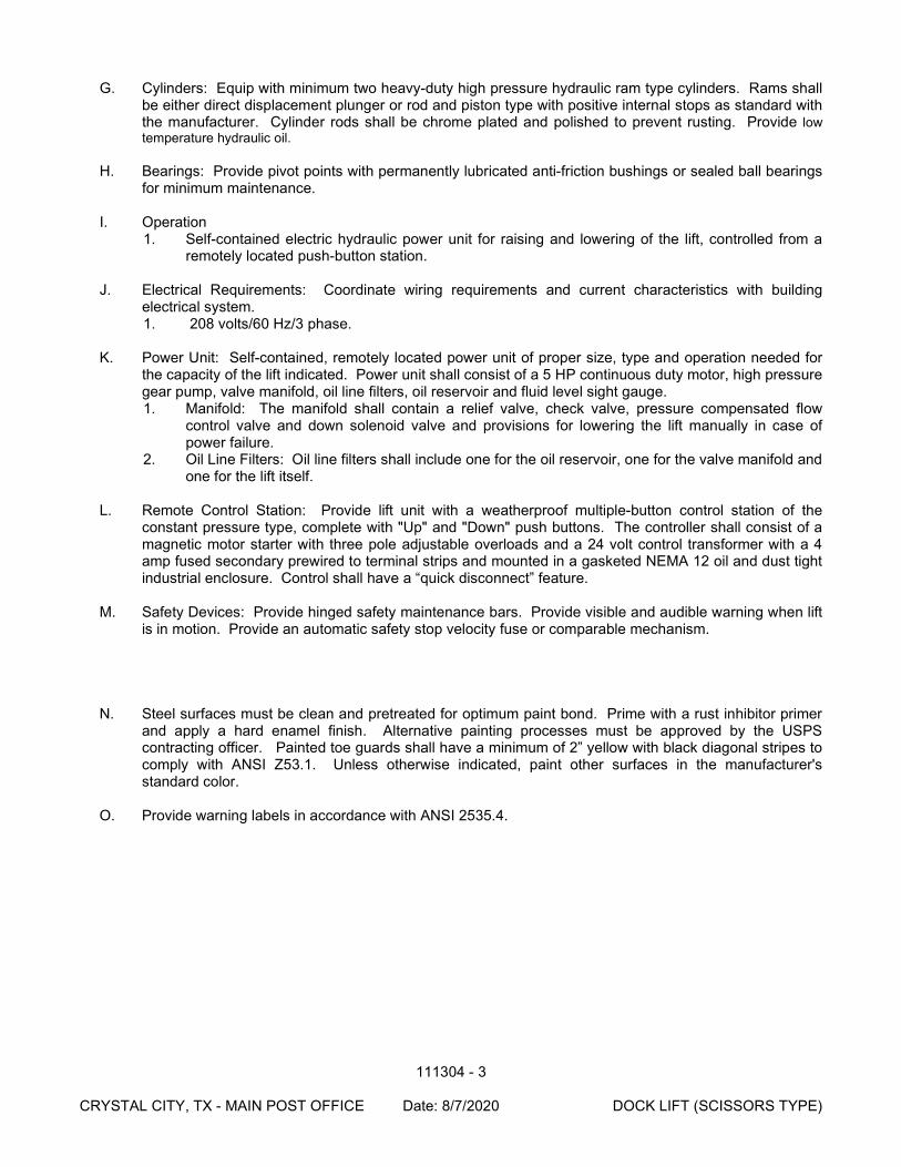
111304 - 3
CRYSTAL CITY, TX - MAIN POST OFFICE Date: 8/7/2020 DOCK LIFT (SCISSORS TYPE)
G. Cylinders: Equip with minimum two heavy-duty high pressure hydraulic ram type cylinders. Rams shall be either direct displacement plunger or rod and piston type with positive internal stops as standard with the manufacturer. Cylinder rods shall be chrome plated and polished to prevent rusting. Provide low temperature hydraulic oil.
H. Bearings: Provide pivot points with permanently lubricated anti-friction bushings or sealed ball bearings
for minimum maintenance.
I. Operation 1. Self-contained electric hydraulic power unit for raising and lowering of the lift, controlled from a
remotely located push-button station.
J. Electrical Requirements: Coordinate wiring requirements and current characteristics with building electrical system. 1. 208 volts/60 Hz/3 phase.
K. Power Unit: Self-contained, remotely located power unit of proper size, type and operation needed for
the capacity of the lift indicated. Power unit shall consist of a 5 HP continuous duty motor, high pressure gear pump, valve manifold, oil line filters, oil reservoir and fluid level sight gauge. 1. Manifold: The manifold shall contain a relief valve, check valve, pressure compensated flow
control valve and down solenoid valve and provisions for lowering the lift manually in case of power failure.
2. Oil Line Filters: Oil line filters shall include one for the oil reservoir, one for the valve manifold and one for the lift itself.
L. Remote Control Station: Provide lift unit with a weatherproof multiple-button control station of the
constant pressure type, complete with "Up" and "Down" push buttons. The controller shall consist of a magnetic motor starter with three pole adjustable overloads and a 24 volt control transformer with a 4 amp fused secondary prewired to terminal strips and mounted in a gasketed NEMA 12 oil and dust tight industrial enclosure. Control shall have a “quick disconnect” feature.
M. Safety Devices: Provide hinged safety maintenance bars. Provide visible and audible warning when lift
is in motion. Provide an automatic safety stop velocity fuse or comparable mechanism.
N. Steel surfaces must be clean and pretreated for optimum paint bond. Prime with a rust inhibitor primer and apply a hard enamel finish. Alternative painting processes must be approved by the USPS contracting officer. Painted toe guards shall have a minimum of 2” yellow with black diagonal stripes to comply with ANSI Z53.1. Unless otherwise indicated, paint other surfaces in the manufacturer's standard color.
O. Provide warning labels in accordance with ANSI 2535.4.
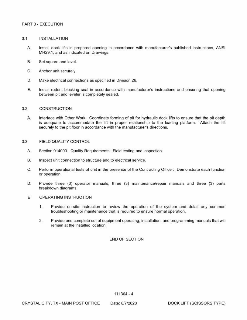
111304 - 4
CRYSTAL CITY, TX - MAIN POST OFFICE Date: 8/7/2020 DOCK LIFT (SCISSORS TYPE)
PART 3 - EXECUTION
3.1 INSTALLATION
A. Install dock lifts in prepared opening in accordance with manufacturer's published instructions, ANSI MH29.1, and as indicated on Drawings.
B. Set square and level.
C. Anchor unit securely.
D. Make electrical connections as specified in Division 26.
E. Install rodent blocking seal in accordance with manufacturer’s instructions and ensuring that opening between pit and leveler is completely sealed.
3.2 CONSTRUCTION
A. Interface with Other Work: Coordinate forming of pit for hydraulic dock lifts to ensure that the pit depth is adequate to accommodate the lift in proper relationship to the loading platform. Attach the lift securely to the pit floor in accordance with the manufacturer's directions.
3.3 FIELD QUALITY CONTROL
A. Section 014000 - Quality Requirements: Field testing and inspection.
B. Inspect unit connection to structure and to electrical service.
C. Perform operational tests of unit in the presence of the Contracting Officer. Demonstrate each function or operation.
D. Provide three (3) operator manuals, three (3) maintenance/repair manuals and three (3) parts
breakdown diagrams.
E. OPERATING INSTRUCTION
1. Provide on-site instruction to review the operation of the system and detail any common troubleshooting or maintenance that is required to ensure normal operation.
2. Provide one complete set of equipment operating, installation, and programming manuals that will
remain at the installed location.
END OF SECTION
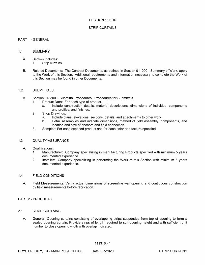
111316 - 1
CRYSTAL CITY, TX - MAIN POST OFFICE Date: 8/7/2020 STRIP CURTAINS
SECTION 111316
STRIP CURTAINS
PART 1 - GENERAL
1.1 SUMMARY
A. Section Includes: 1. Strip curtains.
B. Related Documents: The Contract Documents, as defined in Section 011000 - Summary of Work, apply
to the Work of this Section. Additional requirements and information necessary to complete the Work of this Section may be found in other Documents.
1.2 SUBMITTALS
A. Section 013300 – Submittal Procedures: Procedures for Submittals. 1. Product Data: For each type of product.
a. Include construction details, material descriptions, dimensions of individual components and profiles, and finishes.
2. Shop Drawings: a. Include plans, elevations, sections, details, and attachments to other work. b. Detail assemblies and indicate dimensions, method of field assembly, components, and
location and size of anchors and field connection. 3. Samples: For each exposed product and for each color and texture specified.
1.3 QUALITY ASSURANCE
A. Qualifications: 1. Manufacturer: Company specializing in manufacturing Products specified with minimum 5 years
documented experience. 2. Installer: Company specializing in performing the Work of this Section with minimum 5 years
documented experience.
1.4 FIELD CONDITIONS
A. Field Measurements: Verify actual dimensions of screenline wall opening and contiguous construction by field measurements before fabrication.
PART 2 - PRODUCTS
2.1 STRIP CURTAINS
A. General: Opening curtains consisting of overlapping strips suspended from top of opening to form a sealed opening curtain. Provide strips of length required to suit opening height and with sufficient unit number to close opening width with overlap indicated.
111316 - 2
CRYSTAL CITY, TX - MAIN POST OFFICE Date: 8/7/2020 STRIP CURTAINS
2.2 MANUFACTURERS
A. Manufacturers: Subject to compliance with requirements, available manufacturers offering products that may be incorporated into the Work include, but are not limited to the following: 1. Chase Doors. 2. Rotary Products Inc. 3. Verilon Vinyl.
B. Section 016000 – Product Requirements: Product options and substitutions. Substitutions: Permitted.
2.3 MATERIAL
A. Strip Material: Curved, opaque black, extruded PVC. Matte finish is preferred. Fabricate strips for manufacturer's standard method of attachment to overhead mounting system indicated. 1. Standard Grade 2. Strip Width and Thickness: 8 inches (203 mm) wide and 0.080 inch (2 mm) thick. 3. Overlap: 2 inches.
2.4 MOUNTING
A. Wall Surface Mounting: Consisting of a steel plate bolted to face of wall; equip plate with permanently attached, threaded, mounting pins and steel-angle or plate retaining strip attached to plate with wing nuts.
2.5 STEEL FINISH: Hot-dip galvanize components to comply with the following:
A. ASTM A 123/A 123M for iron and steel support mounting.
B. ASTM A 153/A 153M or ASTM F 2329 for iron and steel hardware and anchors.
PART 3 - EXECUTION
3.1 EXAMINATION
A. Section 017300 – Execution: Verification of existing conditions before starting work.
B. Verification of Conditions: Verify that field measurements, surfaces, substrates and conditions are as required, and ready to receive Work.
C. Report in writing to Contracting Officer prevailing conditions that will adversely affect satisfactory execution of the Work of this Section. Do not proceed with Work until unsatisfactory conditions have been corrected.
D. By beginning Work, Contractor accepts conditions and assumes responsibility for correcting unsuitable conditions encountered at no additional cost to the United States Postal Service.
3.2 INSTALLATION
A. Strip Curtains: Attach curtain mounting system to wall with screw anchors or toggle bolts. Mount curtain strips to overlap.
111316 - 3
CRYSTAL CITY, TX - MAIN POST OFFICE Date: 8/7/2020 STRIP CURTAINS
3.3 FIELD QUALITY CONTROL
A. Section 014000 – Quality Requirements – Field Testing and Inspection.
B. After completing installation, inspect exposed factory finishes and repair damaged finishes.
END OF SECTION
122000 - 1
CRYSTAL CITY, TX - MAIN POST OFFICE Date: 8/7/2020 WINDOW TREATMENTS
SECTION 122000
WINDOW TREATMENTS
PART 1 - GENERAL
1.1 SUMMARY
A. Section Includes: 1. Horizontal metal slat louver blinds. 2. Vertical blinds at Lobby/Self Service. 3. Mounting system. 4. Operating hardware.
B. Related Documents: The Contract Documents, as defined in Section 011000 - Summary of Work, apply
to the Work of this Section. Additional requirements and information necessary to complete the Work of this Section may be found in other Documents.
1.2 PROJECT CONDITIONS OR SITE CONDITIONS
A. Existing Conditions: Take field measurements of openings to determine exact sizes required for each opening.
1.3 WARRANTY
A. Section 017704 - Closeout Procedures and Training: Procedures for closeout submittals.
PART 2 - PRODUCTS
2.1 MANUFACTURERS
A. Subject to compliance with project requirements, manufacturers offering Products which may be incorporated in the Work include the following: 1. Blinds
a. Springs Window Fashions, LP, Montgomery, PA (800) 544-4749 b. Hunter Douglas Inc., Upper Saddle River, NJ (800) 727-8953 c. Levolor, Rockway, NJ (800) 826-8021
B. Section 016000 - Product Requirements: Product Options and Substitutions. Substitutions: Permitted.
2.2 HORIZONTAL BLINDS
A. Horizontal Blinds: Horizontal slat louvers hung from full-width headrail with full-width bottom rail; manual control of raising and lowering by cord with full range locking open and closed point locking; blade angle adjustable by control wand. 1. Springs Window Fashions, Bali: Classic 1 inch Mini Blinds, No. 042 "Matte White" color. 2. Hunter Douglas: Contract Flexalum Decor 1 inch Aluminum Blinds Model CD80, No. 127 "Linen
Flirt" color.
122000 - 2
CRYSTAL CITY, TX - MAIN POST OFFICE Date: 8/7/2020 WINDOW TREATMENTS
3. Levolor: Monaco 1 inch Contract Blind, No. 115 "Dover" color. a. Headrail Attachment: Wall brackets. b. Accessory Hardware: Type recommended by blind manufacturer.
2.3 VERTICAL BLINDS
A. Vertical, 3 ½” PVC Louver Vanes hung from full width headrail, manual wand contol for traversing and rotating louvers. 1. Springs Window Fashions: Graber G.85 Dura-Vue, #3353 “Alabaster”. 2. Levelor: Horizon #8091 “Dover”. 3. Hunter Douglas: Vertical Solutions, Color to match horizontal blinds.
a. Headrail Attachment: Wall Brackets.
2.4 FABRICATION
A. Fabricate blinds to cover window frames completely.
B. At openings requiring multiple blind units, provide separate blind assemblies with space of 1 inch between assemblies, occurring at window mullion centers.
PART 3 - EXECUTION
3.1 INSTALLATION
A. Install blinds in accordance with manufacturer's published instructions where indicated on Drawings.
B. Secure in place with concealed fasteners. C. Install curtain on a hospital-type curtain track mounted to the ceiling or to structure above. The curtain
must drape from minimum 7 feet above finished floor to the finished floor. The curtain is to be attached with Velcro or other mechanical device.
3.2 CONSTRUCTION
A. Interface with Other Work: Coordinate Work with window installation and placement of concealed blocking to support blinds.
B. Site Tolerances:
1. Maximum Variation of Gap at Window Opening Perimeter: 1/4 inch. 2. Maximum Offset From Level: 1/8 inch.
3.3 ADJUSTING AND CLEANING
A. Section 017300 - Execution: Requirements for adjusting and cleaning.
B. Adjust blinds for smooth operation.
C. Clean blind surfaces prior to Final Acceptance inspection.
122000 - 3
CRYSTAL CITY, TX - MAIN POST OFFICE Date: 8/7/2020 WINDOW TREATMENTS
END OF SECTION
123504 - 1
CRYSTAL CITY, TX - MAIN POST OFFICE Date: 8/7/2020 POSTAL CASEWORK
SECTION 123504
POSTAL CASEWORK
PART 1 - GENERAL
1.1 SUMMARY
A. Section Includes: 1. Fabricated custom cabinets and fixtures. 2. Countertops- including field installed custom solid surface tops on selected fixtures 3. Cabinet and fixture hardware. 4. Preparation for installing utilities. 5. Full Service Workstations.
B. The USPS Direct Vendor for supplying postal casework listed in this specification through the contractor
is 3C Store Fixtures, Inc. (formerly known as Carolina Cabinet Company). No substitutions allowed, for exceptions see Part 2 – Products. 1. In the Offer, include the casework cost from the selected Direct Vendor, including shipping. 2. Unloading and installation are also to be included as part of the Work. 3. The contractor is to order the casework from the USPS Direct Vendor based on the Casework
Drawings, in time to meet the schedule. 4. Payment may be required by the USPS Direct Vendor from the contractor prior to shipment of the
casework. C. Related Documents: The Contract Documents, as defined in Section 011000 - Summary of Work, apply
to the Work of this Section. Additional requirements and information necessary to complete the Work of this Section may be found in other Documents.
D. Related Sections:
1. Section 011000 - Summary of Work: Requirements for Postal Service furnished Products. 2. Section 096500 – Resilient Flooring.
1.2 REFERENCES
A. American National Standards Institute (ANSI): 1. ANSI A135.4 - Basic Hardboard. 2. ANSI A208.1 - Mat Formed Wood Particleboard.
B. Architectural Woodwork Institute (AWI):
1. AWI AWQS - Architectural Woodwork Quality Standards, 6th Edition Version 1.0.
C. National Electric Manufacturer's Association (NEMA): 1. NEMA LD3 - High Pressure Decorative Laminates.
D. United States Department of Commerce Product Standard (PS):
1. PS 1 - Construction and Industrial Plywood. 2. PS 20 - American Softwood Lumber Standard.
E. Direct Vendor Detailed Installation Instructions.
123504 - 2
CRYSTAL CITY, TX - MAIN POST OFFICE Date: 8/7/2020 POSTAL CASEWORK
1.3 SUBMITTALS
A. Section 013300 - Submittal Procedures: Procedures for submittals. 1. Assurance/Control Submittals:
a. Qualification Documentation: Custom cabinetwork and fixture installer documentation of experience indicating compliance with specified qualification requirements.
1.4 QUALITY ASSURANCE
A. Perform work in accordance with AWI AWQS Custom quality.
B. Qualifications: 1. Installer: Company specializing in performing work of this Section with a minimum of 5 years
documented experience
C. Pre-installation Meeting: 1. Convene a pre-installation meeting at Project Site, one week prior to commencing work of this
Section and after casework has been delivered. 2. Require attendance of parties directly affecting work of this Section. 3. Review preparation and installation procedures and coordinating and scheduling required with
related work. 4. Agenda:
a. Tour, inspect, and discuss condition of areas where custom cabinets and fixtures will be installed and other preparatory work performed by other trades.
b. Review custom cabinet and fixture requirements (drawings, specifications and other contract documents). Identify requirements for Postal Service furnished Products and Contractor furnished Products.
c. Review and finalize construction schedule related to custom cabinet and fixture work and verify availability of materials, installer's personnel, equipment and facilities needed to complete the Work and avoid delays.
d. Review requirements for inspections, installation certification, and material usage accounting procedures.
1.5 STORAGE AND HANDLING
A. Section 016000 - Product Requirements: Receive, handle, store, and protect products.
B. Protect fixtures from damage and excessive or inadequate relative humidity.
C. Maintain relative humidity between 25 percent and 55 percent. D. Contractor to carefully coordinate delivery scheduling with Direct Vendor to avoid premature delivery
and potential damage to casework on project site. Contractor will be responsible for inspection of casework upon receipt and shall report any damage to Direct Vendor, in writing, immediately.
E. Contractor will be responsible to take an inventory of casework hardware and accessories provided by
Direct Vendor and shall report any missing item to Direct Vendor, in writing, immediately.
F. Contractor shall be responsible to properly store the keys in a safe place and hand them over to Contracting Officer immediately upon completion of installation works and obtain a receipt. KEYS SHALL NOT BE DUPLICATED.
G. Certain casework items have been manufactured with additional weight installed (for safety reasons)
and may require special equipment and handling during unloading. Contractor shall contact Direct
123504 - 3
CRYSTAL CITY, TX - MAIN POST OFFICE Date: 8/7/2020 POSTAL CASEWORK
Vendor prior to receipt of shipment to insure adequate jobsite facilities for receiving and unloading casework.
PART 2 - PRODUCTS
2.1 MANUFACTURERS
A. The USPS Direct Vendor for supplying postal casework : 1. 3C Store Fixtures, Inc., Wilson, NC, Representative Contact: Chris Dill (252) 291-5181,
B. Section 016000 - Product Requirements: Product options and substitutions. Substitutions: Not permitted except for the following items, when they are not located in retail areas or otherwise visible to the public: USPS reserves the right to procure items C501; C502H; C503; C504; C505; C506; C507; C508; C510; C511; C512 from other vendors, in accordance with specification 123216 MANUFACTURED LAMINATE-CLAD CASEWORK when approved by the Contracting Officer.
C. USPS reserves the right to update these products through the Approved Vendor agreements.
2.2 CASEWORK DESCRIPTIONS
A. For casework descriptions and requirements refer to contract drawing. A list of all USPS casework is included in Appendix A of this section.
2.3 CASEWORK HARDWARE AND ACCESSORIES
A. Direct Vendor will supply all anchoring materials, glass, light fixtures, lamps, furring strips, trims, locks, keys (keyed independently) and any other materials and hardware shown on the details in contract drawings.
PART 3 - EXECUTION
3.1 EXAMINATION
A. Section 017300 - Execution: Verification of existing conditions before starting work.
B. Verification of Conditions: Verify that field measurements, surfaces, substrates and conditions are as required, and ready to receive Work. 1. Verify casework and fixture dimensions by field dimensions.
C. Report in writing to USPS Project Manager prevailing conditions that will adversely affect satisfactory
execution of the Work of this Section. Do not proceed with Work until unsatisfactory conditions have been corrected.
D. By beginning Work, Contractor accepts conditions and assumes responsibility for correcting unsuitable
conditions encountered at no additional cost to the United States Postal Service.
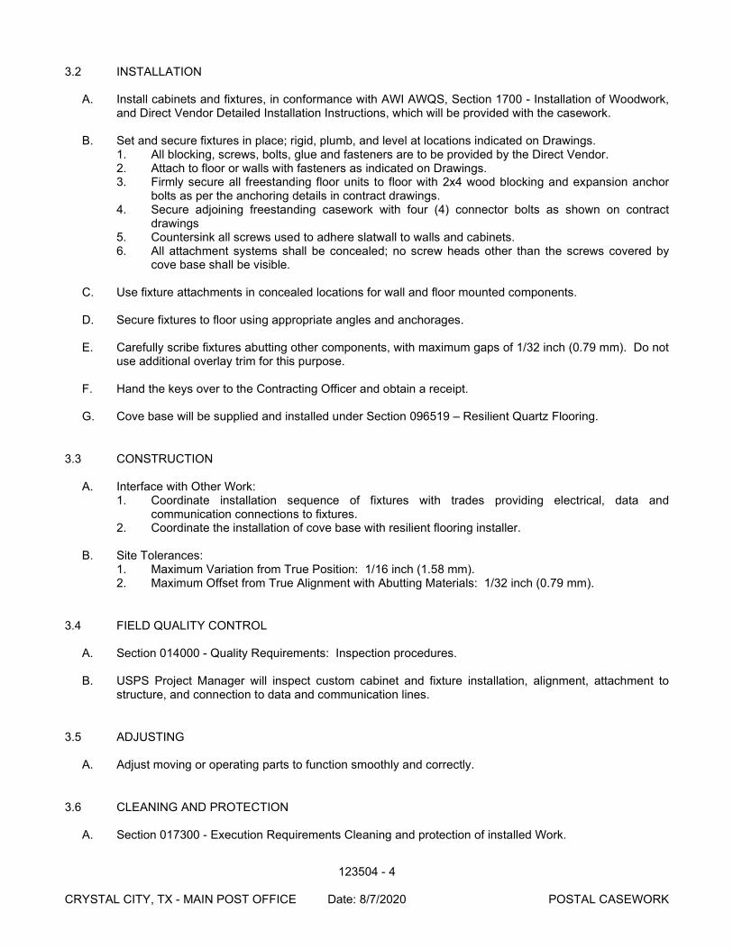
123504 - 4
CRYSTAL CITY, TX - MAIN POST OFFICE Date: 8/7/2020 POSTAL CASEWORK
3.2 INSTALLATION
A. Install cabinets and fixtures, in conformance with AWI AWQS, Section 1700 - Installation of Woodwork, and Direct Vendor Detailed Installation Instructions, which will be provided with the casework.
B. Set and secure fixtures in place; rigid, plumb, and level at locations indicated on Drawings.
1. All blocking, screws, bolts, glue and fasteners are to be provided by the Direct Vendor. 2. Attach to floor or walls with fasteners as indicated on Drawings. 3. Firmly secure all freestanding floor units to floor with 2x4 wood blocking and expansion anchor
bolts as per the anchoring details in contract drawings. 4. Secure adjoining freestanding casework with four (4) connector bolts as shown on contract
drawings 5. Countersink all screws used to adhere slatwall to walls and cabinets. 6. All attachment systems shall be concealed; no screw heads other than the screws covered by
cove base shall be visible.
C. Use fixture attachments in concealed locations for wall and floor mounted components. D. Secure fixtures to floor using appropriate angles and anchorages.
E. Carefully scribe fixtures abutting other components, with maximum gaps of 1/32 inch (0.79 mm). Do not
use additional overlay trim for this purpose.
F. Hand the keys over to the Contracting Officer and obtain a receipt.
G. Cove base will be supplied and installed under Section 096519 – Resilient Quartz Flooring.
3.3 CONSTRUCTION
A. Interface with Other Work: 1. Coordinate installation sequence of fixtures with trades providing electrical, data and
communication connections to fixtures. 2. Coordinate the installation of cove base with resilient flooring installer.
B. Site Tolerances:
1. Maximum Variation from True Position: 1/16 inch (1.58 mm). 2. Maximum Offset from True Alignment with Abutting Materials: 1/32 inch (0.79 mm).
3.4 FIELD QUALITY CONTROL
A. Section 014000 - Quality Requirements: Inspection procedures.
B. USPS Project Manager will inspect custom cabinet and fixture installation, alignment, attachment to structure, and connection to data and communication lines.
3.5 ADJUSTING
A. Adjust moving or operating parts to function smoothly and correctly.
3.6 CLEANING AND PROTECTION
A. Section 017300 - Execution Requirements Cleaning and protection of installed Work.
123504 - 5
CRYSTAL CITY, TX - MAIN POST OFFICE Date: 8/7/2020 POSTAL CASEWORK
B. Clean casework, counters, shelves, hardware, fittings, and fixtures.
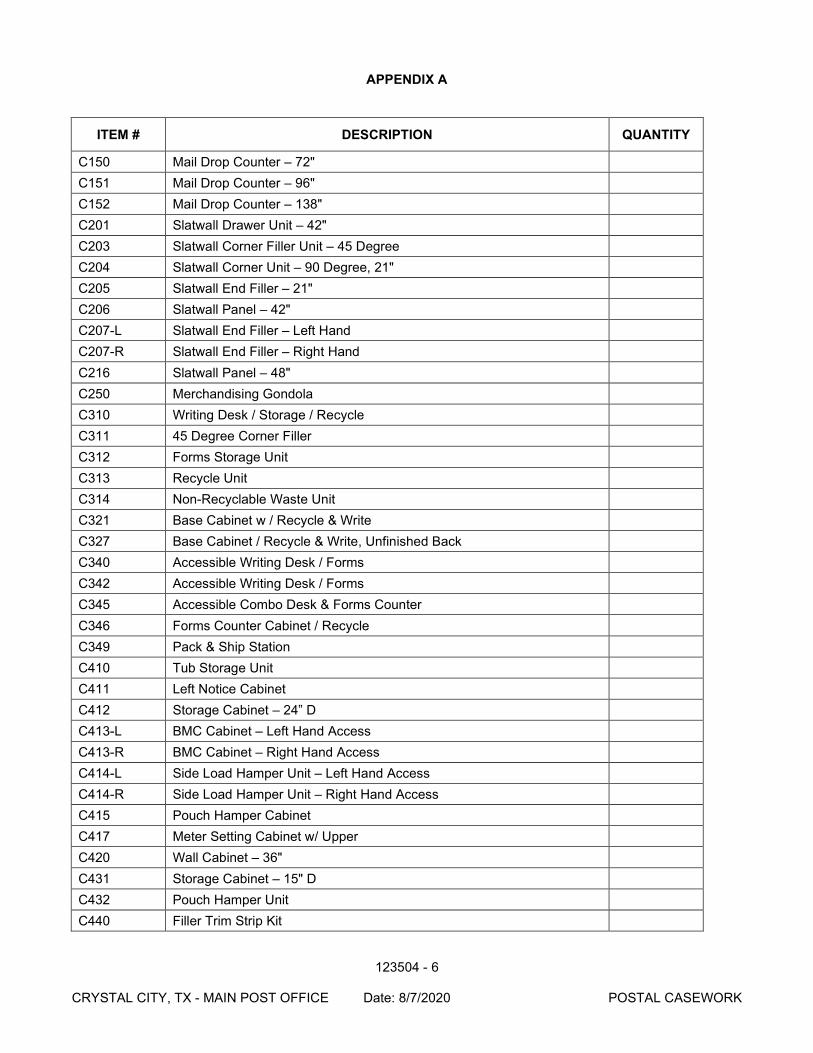
123504 - 6
CRYSTAL CITY, TX - MAIN POST OFFICE Date: 8/7/2020 POSTAL CASEWORK
APPENDIX A
ITEM # DESCRIPTION QUANTITY
C150 Mail Drop Counter – 72" C151 Mail Drop Counter – 96" C152 Mail Drop Counter – 138" C201 Slatwall Drawer Unit – 42" C203 Slatwall Corner Filler Unit – 45 Degree C204 Slatwall Corner Unit – 90 Degree, 21" C205 Slatwall End Filler – 21" C206 Slatwall Panel – 42" C207-L Slatwall End Filler – Left Hand C207-R Slatwall End Filler – Right Hand C216 Slatwall Panel – 48" C250 Merchandising Gondola C310 Writing Desk / Storage / Recycle C311 45 Degree Corner Filler C312 Forms Storage Unit C313 Recycle Unit C314 Non-Recyclable Waste Unit C321 Base Cabinet w / Recycle & Write C327 Base Cabinet / Recycle & Write, Unfinished Back C340 Accessible Writing Desk / Forms C342 Accessible Writing Desk / Forms C345 Accessible Combo Desk & Forms Counter C346 Forms Counter Cabinet / Recycle C349 Pack & Ship Station C410 Tub Storage Unit C411 Left Notice Cabinet C412 Storage Cabinet – 24” D C413-L BMC Cabinet – Left Hand Access C413-R BMC Cabinet – Right Hand Access C414-L Side Load Hamper Unit – Left Hand Access C414-R Side Load Hamper Unit – Right Hand Access C415 Pouch Hamper Cabinet C417 Meter Setting Cabinet w/ Upper C420 Wall Cabinet – 36" C431 Storage Cabinet – 15" D C432 Pouch Hamper Unit C440 Filler Trim Strip Kit
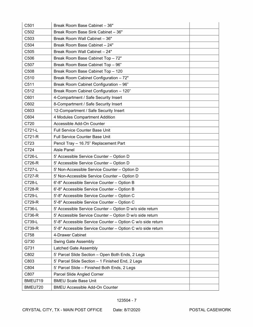
123504 - 7
CRYSTAL CITY, TX - MAIN POST OFFICE Date: 8/7/2020 POSTAL CASEWORK
C501 Break Room Base Cabinet – 36" C502 Break Room Base Sink Cabinet – 36" C503 Break Room Wall Cabinet – 36" C504 Break Room Base Cabinet – 24" C505 Break Room Wall Cabinet – 24" C506 Break Room Base Cabinet Top – 72" C507 Break Room Base Cabinet Top – 96” C508 Break Room Base Cabinet Top – 120 C510 Break Room Cabinet Configuration – 72" C511 Break Room Cabinet Configuration – 96” C512 Break Room Cabinet Configuration – 120” C601 4-Compartment / Safe Security Insert C602 8-Compartment / Safe Security Insert C603 12-Compartment / Safe Security Insert C604 4 Modules Compartment Addition C720 Accessible Add-On Counter C721-L Full Service Counter Base Unit C721-R Full Service Counter Base Unit C723 Pencil Tray – 16.75” Replacement Part C724 Aisle Panel C726-L 5' Accessible Service Counter – Option D C726-R 5' Accessible Service Counter – Option D C727-L 5' Non-Accessible Service Counter – Option D C727-R 5' Non-Accessible Service Counter – Option D C728-L 6'-8" Accessible Service Counter – Option B C728-R 6'-8" Accessible Service Counter – Option B C729-L 5'-8" Accessible Service Counter – Option C C729-R 5'-8" Accessible Service Counter – Option C C736-L 5' Accessible Service Counter – Option D w/o side return C736-R 5' Accessible Service Counter – Option D w/o side return C739-L 5'-8" Accessible Service Counter – Option C w/o side return C739-R 5'-8" Accessible Service Counter – Option C w/o side return C758 4-Drawer Cabinet G730 Swing Gate Assembly G731 Latched Gate Assembly C802 5’ Parcel Slide Section – Open Both Ends, 2 Legs C803 5’ Parcel Slide Section – 1 Finished End, 2 Legs C804 5’ Parcel Slide – Finished Both Ends, 2 Legs C807 Parcel Slide Angled Corner BMEU719 BMEU Scale Base Unit BMEU720 BMEU Accessible Add-On Counter
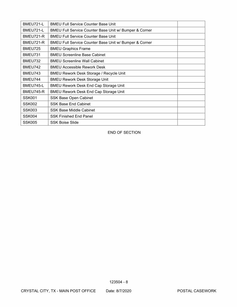
123504 - 8
CRYSTAL CITY, TX - MAIN POST OFFICE Date: 8/7/2020 POSTAL CASEWORK
BMEU721-L BMEU Full Service Counter Base Unit BMEU721-L BMEU Full Service Counter Base Unit w/ Bumper & Corner BMEU721-R BMEU Full Service Counter Base Unit BMEU721-R BMEU Full Service Counter Base Unit w/ Bumper & Corner BMEU725 BMEU Graphics Frame BMEU731 BMEU Screenline Base Cabinet BMEU732 BMEU Screenline Wall Cabinet BMEU742 BMEU Accessible Rework Desk BMEU743 BMEU Rework Desk Storage / Recycle Unit BMEU744 BMEU Rework Desk Storage Unit BMEU745-L BMEU Rework Desk End Cap Storage Unit BMEU745-R BMEU Rework Desk End Cap Storage Unit SSK001 SSK Base Open Cabinet SSK002 SSK Base End Cabinet SSK003 SSK Base Middle Cabinet SSK004 SSK Finished End Panel SSK005 SSK Boise Slide
END OF SECTION
013410-1 CRYSTAL CITY, TX-MAIN POST OFFICE 8/7/2020 STRUCTURAL ENGINEER: SHOP DRAWING/ FIELD VISITS
SECTION 013410
STRUCTURAL ENGINEER: SHOP DRAWINGS/FIELD VISITS PART 1 - GENERAL 1.1 SCOPE
This section defines and clarifies specific items of the Contract that are peculiar to the structural engineer's responsibilities. Refer to Article 4 for overall contractual agreements and to appropriate section of this specification for specifics on shop drawing, product data, and samples submitted.
PART 2 - GENERAL DEFINITIONS 2.1 STRUCTURAL ENGINEER OF RECORD
The engineer responsible for the design of the primary structural system and whose seal/signature appears on the contract structural drawings. Responsibility for any secondary structural and non-structural systems not shown on the structural drawings rests with the prime professional, the architect.
2.2 SPECIALTY ENGINEER
The engineer who is lawfully eligible to seal plans and designs for pre-engineered elements on systems which become part of the overall building.
2.3 SUBMITTALS
Items identified in the contract documents to be submitted by the contractor. Refer to individual sections of the specifications for specific items to be submitted.
2.4 FIELD OBSERVATIONS
Visits to the jobsite by the structural engineer-of-record or his authorized representative to ascertain whether the work is generally in accordance with the structural contract documents. These observations are not exhaustive nor continuous.
PART 3 - PROCEDURAL REQUIREMENTS 3.1 SHOP DRAWINGS
Refer to applicable section for specific requirements for number of copies to be submitted, time for review, etc. All submittals must come by way of the general contractor though the architect. Certain submittals, identified in specific sections of the specifications, generally regarding pre-engineered elements, will require a specialty engineer's seal and signature.
3.2 FIELD OBSERVATIONS
Structural engineer shall be notified at least 24 hours in advance of any concrete pour or other action that will cover up structural elements that have not been reviewed by the structural engineer. Structural Engineering site visits have been limited to three (3) visits, including a preconstruction conference. Owner shall employ an Independent Testing Lab and Special Inspectors to perform Construction Materials Testing and Special Inspections per the International Building Code.
013410-2 CRYSTAL CITY, TX-MAIN POST OFFICE 8/7/2020 STRUCTURAL ENGINEER: SHOP DRAWING/ FIELD VISITS
3.3 ENGINEER'S ACTIONS A. SHOP DRAWINGS As per General or Special Conditions, the structural engineer will review shop drawings for
the limited purpose of checking for conformance with information given and the design concept expressed in the contract documents.
The structural engineer-of-record shall review the submittals and return them to the
architect with one of the following statements checked off on the stamp: "NO exceptions Taken" informs the Architect that the structural engineer takes no
exception to the submittal being approved as per and in accordance with AIA Document 201,section 4.2.7.
"Make Corrections Noted" informs the Architect that the structural engineer has made
corrections on the submittals but otherwise takes no exception to the submittal being approved as per and in accordance with AIA Document 201, section 4.2.7.
"Revise and Resubmit" indicates important items must be corrected and resubmitted.
Marks on the submittal may not necessarily cover all of the defects of the submittal. This action expresses the structural engineer's concern and his recommendation to the Architect that the submittal be reviewed and resubmitted as per and in accordance with AIA Document 201, section 4.2.7.
"Return One Corrected Copy For File" informs the Architect that the submittal may be
approved as per AIA Document 201, section 4.2.7, but a corrected copy showing that corrections have been acknowledged must be returned for the structural engineer's file.
B. SHOP DRAWINGS WITH SPECIALTY ENGINEER'S SEAL AND SIGNATURE Certain shop drawings may be identified in specific sections of the specifications pertaining
to pre-engineered structural elements specified by the structural engineer-of-record and designed by specialty engineers. The structural engineer shall verify that submittals have received prior approvals as required by the contract documents. Submittals shall bear the signature and professional seal of the specialty engineer responsible for the design as required by the contract documents. The structural engineer shall review the submittal for type, position, and connection to other elements within the primary structural system, and for criteria and loads used for their design. Action on these submittals will be the same as for other shop drawings.
C. SHOP DRAWINGS FOR NON-STRUCTURAL ELEMENTS Submittal of shop drawings covering items not shown or specified on structural plans by
the Structural Engineer will be reviewed only to verify that the specialty engineer sealing the drawings/calculations has generally followed usual and customary application of code-mandated loads and design procedures. These submittals will be stamped “REVIEWED” indicating that the items listed interface with the primary structural framing without deleterious effect and no further action is taken.
3.4 SITE VISITS
A. The structural engineer-of-record ("SER"), Independent Testing Lab, and Special Inspectors will make site visits at intervals appropriate to the stage of construction and as defined by the contract to visually observe the quality and the progress of the construction work relative to the primary structural system. The general contractor is responsible to
013410-3 CRYSTAL CITY, TX-MAIN POST OFFICE 8/7/2020 STRUCTURAL ENGINEER: SHOP DRAWING/ FIELD VISITS
notify the SER, Independent Testing Lab, and the Special Inspectors when structural elements are ready for review and prior to their being covered up. Failure to do so may result in key observations not being made, preventing the engineer from recommending acceptance of the work.
B. The SER shall not have control over or charge of and shall not be responsible for
construction means, methods, techniques, sequences or procedures, or for safety precautions and programs in connection with the Work for This Part of the Project, since these are solely the Contractor's responsibility under the Contract for Construction. The SER shall not be responsible for the Contractor's or a Subcontractor's schedule or failure to carry out the Work in accordance with the Contract Documents. The SER shall not have control over or charge of acts or omissions of the Contractor, Subcontractors, their agents or employees or other persons performing portions of the Work.
END OF SECTION
220500 - 1 CRYSTAL CITY, TX - MAIN POST OFFICE Date: 08/07/2020 COMMON WORK RESULTS FOR PLUMBING
SECTION 220500
COMMON WORK RESULTS FOR PLUMBING
PART 1 - GENERAL
1.1 SUMMARY
A. This Section includes the following: 1. Piping materials and installation instructions common to most piping systems. 2. Dielectric fittings. 3. Mechanical sleeve seals. 4. Sleeves. 5. Escutcheons. 6. Grout. 7. Plumbing demolition. 8. Equipment installation requirements common to equipment sections. 9. Plumbing identification. 10. Concrete bases. 11. Supports and anchorages.
1.2 DEFINITIONS
A. Finished Spaces: Spaces other than plumbing and electrical equipment rooms, furred spaces, pipe chases, unheated spaces immediately below roof, spaces above ceilings, unexcavated spaces, crawlspaces, and tunnels.
B. Exposed, Interior Installations: Exposed to view indoors. Examples include finished occupied spaces and plumbing equipment rooms.
C. Exposed, Exterior Installations: Exposed to view outdoors or subject to outdoor ambient tem-peratures and weather conditions. Examples include rooftop locations.
D. Concealed, Interior Installations: Concealed from view and protected from physical contact by building occupants. Examples include above ceilings and in chases.
E. Concealed, Exterior Installations: Concealed from view and protected from weather conditions and physical contact by building occupants but subject to outdoor ambient temperatures. Exam-ples include installations within unheated shelters.
1.3 SUBMITTALS
A. Welding certificates.
1.4 QUALITY ASSURANCE
A. Steel Support Welding: Qualify processes and operators according to AWS D1.1, "Structural Welding Code--Steel."
B. Steel Pipe Welding: Qualify processes and operators according to ASME Boiler and Pressure Vessel Code: Section IX, "Welding and Brazing Qualifications." 1. Comply with provisions in ASME B31 Series, "Code for Pressure Piping." 2. Certify that each welder has passed AWS qualification tests for welding processes
involved and that certification is current.
220500 - 2 CRYSTAL CITY, TX - MAIN POST OFFICE Date: 08/07/2020 COMMON WORK RESULTS FOR PLUMBING
C. Electrical Characteristics for Plumbing Equipment: Equipment of higher electrical characteristics may be furnished provided such proposed equipment is approved in writing and connecting elec-trical services, circuit breakers, and conduit sizes are appropriately modified. If minimum energy ratings or efficiencies are specified, equipment shall comply with requirements.
PART 2 - PRODUCTS
2.1 PIPE, TUBE, AND FITTINGS
A. Refer to individual Division 22 piping Sections for pipe, tube, and fitting materials and joining methods.
B. Pipe Threads: ASME B1.20.1 for factory-threaded pipe and pipe fittings.
2.2 JOINING MATERIALS
A. Refer to individual Division 22 piping Sections for special joining materials not listed below.
B. Pipe-Flange Gasket Materials: ASME B16.21, nonmetallic, flat, asbestos-free, 1/8-inch maximum thickness unless thickness or specific material is indicated.
C. Plastic, Pipe-Flange Gasket, Bolts, and Nuts: Type and material recommended by piping system manufacturer, unless otherwise indicated.
D. Solder Filler Metals: ASTM B 32, lead-free alloys. Include water-flushable flux according to ASTM B 813.
E. Brazing Filler Metals: AWS A5.8, BCuP Series or BAg1, unless otherwise indicated.
F. Welding Filler Metals: Comply with AWS D10.12.
G. Solvent Cements for Joining Plastic Piping: 1. ABS Piping: ASTM D 2235. 2. CPVC Piping: ASTM F 493. 3. PVC Piping: ASTM D 2564. Include primer according to ASTM F 656. 4. PVC to ABS Piping Transition: ASTM D 3138.
2.3 DIELECTRIC FITTINGS
A. Description: Combination fitting of copper alloy and ferrous materials with threaded, solder-joint, plain, or weld-neck end connections that match piping system materials.
B. Insulating Material: Suitable for system fluid, pressure, and temperature.
C. Dielectric Unions: Factory-fabricated, union assembly, for 250-psig minimum working pressure at 180 deg F.
D. Dielectric Flanges: Factory-fabricated, companion-flange assembly, for 150- or 300-psig mini-mum working pressure as required to suit system pressures.
E. Dielectric Couplings: Galvanized-steel coupling with inert and noncorrosive, thermoplastic lining; threaded ends; and 300-psig minimum working pressure at 225 deg F.
F. Dielectric Nipples: Electroplated steel nipple with inert and noncorrosive, thermoplastic lining; plain, threaded, or grooved ends; and 300-psig minimum working pressure at 225 deg F.
220500 - 3 CRYSTAL CITY, TX - MAIN POST OFFICE Date: 08/07/2020 COMMON WORK RESULTS FOR PLUMBING
2.4 MECHANICAL SLEEVE SEALS
A. Description: Modular sealing element unit, designed for field assembly, to fill annular space be-tween pipe and sleeve.
B. Sealing Elements: EPDM interlocking links shaped to fit surface of pipe. Include type and num-ber required for pipe material and size of pipe.
C. Pressure Plates: Plastic. Include two for each sealing element.
D. Connecting Bolts and Nuts: Carbon steel with corrosion-resistant coating of length required to secure pressure plates to sealing elements. Include one for each sealing element.
2.5 SLEEVES
A. Galvanized-Steel Sheet: 0.0239-inch minimum thickness; round tube closed with welded longitu-dinal joint.
B. Steel Pipe: ASTM A 53, Type E, Grade B, Schedule 40, galvanized, plain ends.
C. Cast Iron: Cast or fabricated "wall pipe" equivalent to ductile-iron pressure pipe, with plain ends and integral waterstop, unless otherwise indicated.
D. Stack Sleeve Fittings: Manufactured, cast-iron sleeve with integral clamping flange. Include clamping ring and bolts and nuts for membrane flashing. 1. Underdeck Clamp: Clamping ring with set screws.
E. Molded PVC: Permanent, with nailing flange for attaching to wooden forms.
F. PVC Pipe: ASTM D 1785, Schedule 40.
G. Molded PE: Reusable, PE, tapered-cup shaped, and smooth-outer surface with nailing flange for attaching to wooden forms.
2.6 ESCUTCHEONS
A. Description: Manufactured wall and ceiling escutcheons and floor plates, with an ID to closely fit around pipe, tube, and insulation of insulated piping and an OD that completely covers opening.
B. One-Piece, Deep-Pattern Type: Deep-drawn, box-shaped brass with polished chrome-plated fin-ish.
C. One-Piece, Cast-Brass Type: With set screw. 1. Finish: Polished chrome-plated and rough brass.
D. Split-Casting, Cast-Brass Type: With concealed hinge and set screw. 1. Finish: Polished chrome-plated and rough brass.
2.7 GROUT
A. Description: ASTM C 1107, Grade B, nonshrink and nonmetallic, dry hydraulic-cement grout. 1. Characteristics: Post-hardening, volume-adjusting, nonstaining, noncorrosive,
nongaseous, and recommended for interior and exterior applications. 2. Design Mix: 5000-psi, 28-day compressive strength. 3. Packaging: Premixed and factory packaged.
220500 - 4 CRYSTAL CITY, TX - MAIN POST OFFICE Date: 08/07/2020 COMMON WORK RESULTS FOR PLUMBING
2.8 PLUMBING IDENTIFICATION
A. Equipment Nameplates: Laminated three-layer plastic with engraved black letters on light con-trasting background color.
B. Tags 1. Plastic Tags: Laminated three-layer plastic with engraved black letters on light
contrasting background color. Tag size minimum 1-1/2 inches (38 mm) diameter. 2. Metal Tags: Brass, Aluminum, or Stainless Steel with stamped letters; tag size minimum
1-1/2 inches (38 mm) diameter or square with smooth edges. 3. Information Tags: Clear plastic with printed "Danger," "Caution," or "Warning" and
message; size 3-1/4 x 5-5/8 inches (83 x 143 mm) with grommet and self-locking nylon ties.
4. Tag Chart: Typewritten letter size list in anodized aluminum frame and plastic laminated.
C. Pipe Markers 1. Color and Lettering: Conform to ASME A13.1. 2. Plastic Pipe Markers: Factory fabricated, flexible, semi-rigid plastic, preformed to fit
around pipe or pipe covering. Larger sizes may have maximum sheet size with spring fastener.
3. Plastic Tape Pipe Markers: Flexible, vinyl film tape with pressure sensitive adhesive backing and printed markings with flow direction.
4. Plastic Underground Pipe Markers: Bright colored continuously printed plastic ribbon tape, minimum 6 inches (150 mm) wide by 4 mil (0.10 mm) thick, manufactured for direct burial service.
PART 3 - EXECUTION
3.1 PLUMBING DEMOLITION
A. Refer to Division 01 Section "Cutting and Patching" and Division 02 Section "Selective Structure Demolition" for general demolition requirements and procedures.
B. Disconnect, demolish, and remove plumbing systems, equipment, and components indicated to be removed. 1. Piping to Be Removed: Remove portion of piping indicated to be removed and cap or
plug remaining piping with same or compatible piping material. 2. Piping to Be Abandoned in Place: Drain piping and cap or plug piping with same or
compatible piping material. 3. Equipment to Be Removed: Disconnect and cap services and remove equipment. 4. Equipment to Be Removed and Reinstalled: Disconnect and cap services and remove,
clean, and store equipment; when appropriate, reinstall, reconnect, and make equipment operational.
5. Equipment to Be Removed and Salvaged: Disconnect and cap services and remove equipment and deliver to Owner.
C. If pipe, insulation, or equipment to remain is damaged in appearance or is unserviceable, remove damaged or unserviceable portions and replace with new products of equal capacity and quality.
3.2 PIPING SYSTEMS - COMMON REQUIREMENTS
A. Install piping according to the following requirements and Division 22 Sections specifying piping systems.
B. Drawing plans, schematics, and diagrams indicate general location and arrangement of piping systems. Indicated locations and arrangements were used to size pipe and calculate friction loss,
220500 - 5 CRYSTAL CITY, TX - MAIN POST OFFICE Date: 08/07/2020 COMMON WORK RESULTS FOR PLUMBING
expansion, pump sizing, and other design considerations. Install piping as indicated unless devi-ations to layout are approved on Coordination Drawings.
C. Install piping in concealed locations, unless otherwise indicated and except in equipment rooms and service areas.
D. Install piping indicated to be exposed and piping in equipment rooms and service areas at right angles or parallel to building walls. Diagonal runs are prohibited unless specifically indicated oth-erwise.
E. Install piping above accessible ceilings to allow sufficient space for ceiling panel removal.
F. Install piping to permit valve servicing.
G. Install piping at indicated slopes.
H. Install piping free of sags and bends.
I. Install fittings for changes in direction and branch connections.
J. Install piping to allow application of insulation.
K. Select system components with pressure rating equal to or greater than system operating pres-sure.
L. Install escutcheons for penetrations of walls, ceilings, and floors.
M. Install sleeves for pipes passing through concrete and masonry walls, gypsum-board partitions, and concrete floor and roof slabs.
N. Aboveground, Exterior-Wall Pipe Penetrations: Seal penetrations using sleeves and mechanical sleeve seals. Select sleeve size to allow for 1-inch annular clear space between pipe and sleeve for installing mechanical sleeve seals. 1. Install steel pipe for sleeves smaller than 6 inches in diameter. 2. Install cast-iron "wall pipes" for sleeves 6 inches and larger in diameter. 3. Mechanical Sleeve Seal Installation: Select type and number of sealing elements
required for pipe material and size. Position pipe in center of sleeve. Assemble mechanical sleeve seals and install in annular space between pipe and sleeve. Tighten bolts against pressure plates that cause sealing elements to expand and make watertight seal.
O. Underground, Exterior-Wall Pipe Penetrations: Install cast-iron "wall pipes" for sleeves. Seal pipe penetrations using mechanical sleeve seals. Select sleeve size to allow for 1-inch annular clear space between pipe and sleeve for installing mechanical sleeve seals. 1. Mechanical Sleeve Seal Installation: Select type and number of sealing elements
required for pipe material and size. Position pipe in center of sleeve. Assemble mechanical sleeve seals and install in annular space between pipe and sleeve. Tighten bolts against pressure plates that cause sealing elements to expand and make watertight seal.
P. Fire-Barrier Penetrations: Maintain indicated fire rating of walls, partitions, ceilings, and floors at pipe penetrations. Seal pipe penetrations with firestop materials. Refer to Division 07 Section "Penetration Firestopping" for materials.
Q. Verify final equipment locations for roughing-in.
220500 - 6 CRYSTAL CITY, TX - MAIN POST OFFICE Date: 08/07/2020 COMMON WORK RESULTS FOR PLUMBING
R. Refer to equipment specifications in other Sections of these Specifications for roughing-in re-quirements.
3.3 PIPING JOINT CONSTRUCTION
A. Join pipe and fittings according to the following requirements and Division 22 Sections specifying piping systems.
B. Ream ends of pipes and tubes and remove burrs. Bevel plain ends of steel pipe.
C. Remove scale, slag, dirt, and debris from inside and outside of pipe and fittings before assembly.
D. Soldered Joints: Apply ASTM B 813, water-flushable flux, unless otherwise indicated, to tube end. Construct joints according to ASTM B 828 or CDA's "Copper Tube Handbook," using lead-free solder alloy complying with ASTM B 32.
E. Brazed Joints: Construct joints according to AWS's "Brazing Handbook," "Pipe and Tube" Chap-ter, using copper-phosphorus brazing filler metal complying with AWS A5.8.
F. Threaded Joints: Thread pipe with tapered pipe threads according to ASME B1.20.1. Cut threads full and clean using sharp dies. Ream threaded pipe ends to remove burrs and restore full ID. Join pipe fittings and valves as follows: 1. Apply appropriate tape or thread compound to external pipe threads unless dry seal
threading is specified. 2. Damaged Threads: Do not use pipe or pipe fittings with threads that are corroded or
damaged. Do not use pipe sections that have cracked or open welds.
G. Welded Joints: Construct joints according to AWS D10.12, using qualified processes and welding operators according to Part 1 "Quality Assurance" Article.
H. Flanged Joints: Select appropriate gasket material, size, type, and thickness for service applica-tion. Install gasket concentrically positioned. Use suitable lubricants on bolt threads.
I. Plastic Piping Solvent-Cement Joints: Clean and dry joining surfaces. Join pipe and fittings ac-cording to the following: 1. Comply with ASTM F 402, for safe-handling practice of cleaners, primers, and solvent
cements. 2. ABS Piping: Join according to ASTM D 2235 and ASTM D 2661 Appendixes. 3. CPVC Piping: Join according to ASTM D 2846/D 2846M Appendix. 4. PVC Pressure Piping: Join schedule number ASTM D 1785, PVC pipe and PVC socket
fittings according to ASTM D 2672. Join other-than-schedule-number PVC pipe and socket fittings according to ASTM D 2855.
5. PVC Nonpressure Piping: Join according to ASTM D 2855. 6. PVC to ABS Nonpressure Transition Fittings: Join according to ASTM D 3138 Appendix.
J. Plastic Pressure Piping Gasketed Joints: Join according to ASTM D 3139.
K. Plastic Nonpressure Piping Gasketed Joints: Join according to ASTM D 3212.
L. PE Piping Heat-Fusion Joints: Clean and dry joining surfaces by wiping with clean cloth or paper towels. Join according to ASTM D 2657. 1. Plain-End Pipe and Fittings: Use butt fusion. 2. Plain-End Pipe and Socket Fittings: Use socket fusion.
M. Fiberglass Bonded Joints: Prepare pipe ends and fittings, apply adhesive, and join according to pipe manufacturer's written instructions.

220500 - 7 CRYSTAL CITY, TX - MAIN POST OFFICE Date: 08/07/2020 COMMON WORK RESULTS FOR PLUMBING
3.4 PIPING CONNECTIONS
A. Make connections according to the following, unless otherwise indicated: 1. Install unions, in piping NPS 2 and smaller, adjacent to each valve and at final connection
to each piece of equipment. 2. Install flanges, in piping NPS 2-1/2 and larger, adjacent to flanged valves and at final
connection to each piece of equipment. 3. Dry Piping Systems: Install dielectric unions and flanges to connect piping materials of
dissimilar metals. 4. Wet Piping Systems: Install dielectric coupling and nipple fittings to connect piping
materials of dissimilar metals.
3.5 EQUIPMENT INSTALLATION - COMMON REQUIREMENTS
A. Install equipment to allow maximum possible headroom unless specific mounting heights are not indicated.
B. Install equipment level and plumb, parallel and perpendicular to other building systems and com-ponents in exposed interior spaces, unless otherwise indicated.
C. Install plumbing equipment to facilitate service, maintenance, and repair or replacement of com-ponents. Connect equipment for ease of disconnecting, with minimum interference to other in-stallations. Extend grease fittings to accessible locations.
D. Install equipment to allow right of way for piping installed at required slope.
3.6 INSTALLATION - PLUMBING IDENTIFICATION
A. Install identifying devices after completion of coverings and painting.
B. Install plastic nameplates with corrosive-resistant mechanical fasteners, or adhesive.
C. Install tags using corrosion resistant chain. Number tags consecutively by location.
D. Install underground plastic pipe markers 6 to 8 inches (150 to 200 mm) below finished grade, di-rectly above buried pipe.
E. Identify plumbing equipment with plastic nameplates. Locate equipment labels where accessible and visible.
F. Identify control panels and major control components outside panels with plastic nameplates.
G. Identify valves in main and branch piping with tags.
H. Identify piping, concealed or exposed, with plastic pipe markers and plastic tape pipe markers. Use tags on piping 3/4 inch (20 mm) diameter and smaller. Identify service, flow direction, and pressure. Install in clear view and align with axis of piping. Locate identification not to exceed 20 feet (6 m) on straight runs including risers and drops, adjacent to each valve and tee, at each side of penetration of structure or enclosure, and at each obstruction.
I. Locate pipe labels where piping is exposed or above accessible ceilings in finished spaces; ma-chine rooms; accessible maintenance spaces such as shafts, tunnels, and plenums; and exterior exposed locations as follows: 1. Near each valve and control device. 2. Near each branch connection, excluding short takeoffs for fixtures and terminal units.
Where flow pattern is not obvious, mark each pipe at branch.
220500 - 8 CRYSTAL CITY, TX - MAIN POST OFFICE Date: 08/07/2020 COMMON WORK RESULTS FOR PLUMBING
3. Near penetrations through walls, floors, ceilings, and inaccessible enclosures. 4. At access doors, manholes, and similar access points that permit view of concealed
piping. 5. Near major equipment items and other points of origination and termination. 6. Spaced at maximum intervals of 50 feet (15 m) along each run. Reduce intervals to [25
feet (7.6 m)] <Insert dimension> in areas of congested piping and equipment. 7. On piping above removable acoustical ceilings. Omit intermediately spaced labels. 8. Provide ceiling tacks to locate valves or dampers above T-bar type panel ceilings.
Locate in corner of panel closest to equipment.
3.7 CONCRETE BASES
A. Concrete Bases: Anchor equipment to concrete base according to equipment manufacturer's written instructions and according to seismic codes at Project. 1. Construct concrete bases of dimensions indicated, but not less than 4 inches larger in
both directions than supported unit. 2. Install dowel rods to connect concrete base to concrete floor. Unless otherwise
indicated, install dowel rods on 18-inch centers around the full perimeter of the base. 3. Install epoxy-coated anchor bolts for supported equipment that extend through concrete
base, and anchor into structural concrete floor. 4. Place and secure anchorage devices. Use supported equipment manufacturer's setting
drawings, templates, diagrams, instructions, and directions furnished with items to be embedded.
5. Install anchor bolts to elevations required for proper attachment to supported equipment. 6. Install anchor bolts according to anchor-bolt manufacturer's written instructions. 7. Use 3000-psi, 28-day compressive-strength concrete and reinforcement as specified in
Division 03 Section "Cast-in-Place Concrete."
3.8 ERECTION OF METAL SUPPORTS AND ANCHORAGES
A. Refer to Division 05 Section "Metal Fabrications" for structural steel.
B. Cut, fit, and place miscellaneous metal supports accurately in location, alignment, and elevation to support and anchor plumbing materials and equipment.
C. Field Welding: Comply with AWS D1.1.
3.9 ERECTION OF WOOD SUPPORTS AND ANCHORAGES
A. Cut, fit, and place wood grounds, nailers, blocking, and anchorages to support, and anchor plumbing materials and equipment.
B. Select fastener sizes that will not penetrate members if opposite side will be exposed to view or will receive finish materials. Tighten connections between members. Install fasteners without splitting wood members.
C. Attach to substrates as required to support applied loads.
3.10 GROUTING
A. Mix and install grout for plumbing equipment base bearing surfaces, pump and other equipment base plates, and anchors.
B. Clean surfaces that will come into contact with grout.
C. Provide forms as required for placement of grout.
220500 - 9 CRYSTAL CITY, TX - MAIN POST OFFICE Date: 08/07/2020 COMMON WORK RESULTS FOR PLUMBING
D. Avoid air entrapment during placement of grout.
E. Place grout, completely filling equipment bases.
F. Place grout on concrete bases and provide smooth bearing surface for equipment.
G. Place grout around anchors.
H. Cure placed grout.
END OF SECTION USPS CSF Specifications issued: 10/1/2019 Last revised: 4/16/2014
220500 - 10 CRYSTAL CITY, TX - MAIN POST OFFICE Date: 08/07/2020 COMMON WORK RESULTS FOR PLUMBING
[This page intentionally left blank.]
220719 - 1 CRYSTAL CITY, TX - MAIN POST OFFICE Date: 08/07/2020 PIPING INSULATION
SECTION 220719
PLUMBING PIPING INSULATION
PART 1 - GENERAL
1.1 SUMMARY
A. Section Includes: 1. Piping insulation. 2. Insulation jackets.
B. Related Documents: The Contract Documents, as defined in Section 011000 - Summary of Work, apply to the Work of this Section. Additional requirements and information necessary to complete the Work of this Section may be found in other Documents.
1.2 REFERENCES
A. American Society for Testing and Materials (ASTM): 1. ASTM B209 - Aluminum and Aluminum-Alloy Sheet and Plate. 2. ASTM C177 - Steady-State Heat Flux Measurements and Thermal Transmission
Properties by Means of the Guarded-Hot-Plate Apparatus. 3. ASTM C335 - Steady-State Heat Transfer Properties of Horizontal Pipe Insulation. 4. ASTM C518 - Steady-State Heat Flux Measurements and Thermal Transmission
Properties by Means of the Heat Flow Meter Apparatus. 5. ASTM C534 - Preformed Flexible Elastomeric Cellular Thermal Insulation in Sheet and
Tubular Form. 6. ASTM C547 - Mineral Fiber Pipe Insulation. 7. ASTM C553 - Mineral Fiber Blanket Thermal Insulation for Commercial and Industrial
Applications. 8. ASTM C921 - Properties of Jacketing Materials for Thermal Insulation. 9. ASTM D1056 - Flexible Cellular Materials - Sponge or Expanded Rubber. 10. ASTM E84 - Surface Burning Characteristics of Building Materials. 11. ASTM E96 - Water Vapor Transmission of Materials.
B. National Fire Protection Association (NFPA): 1. NFPA 255 - Standard Method of Test of Surface Burning Characteristics of Building
Materials.
C. Sheet Metal and Air Conditioning Contractors National Association (SMACNA): 1. SMACNA - HVAC Duct Construction Standards - Metal and Flexible.
D. Underwriters Laboratories, Inc. (UL): 1. UL 723 - Tests for Surface Burning Characteristics of Building Materials.
1.3 SUBMITTALS
A. Section 013300 - Submittal Procedures: Procedures for submittals. 1. Product Data:
a. Product Data: Provide product description, thermal characteristics, list of materials and thickness for each service, and locations.
1.4 QUALITY ASSURANCE
A. Qualifications:
220719 - 2 CRYSTAL CITY, TX - MAIN POST OFFICE Date: 08/07/2020 PIPING INSULATION
1. Manufacturer: Company specializing in manufacturing Products specified with minimum 3 years documented experience.
2. Installer: Company specializing in performing the Work of this Section with minimum 3 years documented experience.
B. Materials: 1. Flame spread/smoke developed rating of 25/50 or less in accordance with ASTM E84,
NFPA 255 and UL 723. 2. Insulation for duct, pipe and equipment for above grade exposed to weather outside
building shall be certified as being self-extinguishing for 1-inch thickness less than 53 seconds when tested in accordance with ASTM D1692.
1.5 DELIVERY, STORAGE, AND HANDLING
A. Section 016000 - Product Requirements: Transport, handle, store, and protect Products.
B. Deliver materials to site in original factory packaging, labeled with manufacturer's identification, including product density and thickness.
C. Store insulation in original wrapping and protect from weather and construction traffic.
D. Protect insulation against dirt, water, chemical, and mechanical damage.
1.6 PROJECT CONDITIONS OR SITE CONDITIONS
A. Jobsite Requirements 1. Maintain ambient temperatures and conditions required by manufacturers of adhesives,
mastics, and insulation cements. 2. Maintain temperature during and after installation for minimum period of 24 hours.
1.7 ENVIRONMENTAL REQUIREMENTS
A. Energy efficiency: 1. Insulation: Minimum thickness in accordance with ASHRAE 90.1. Provide additional
thickness to ensure surface temperatures are below 100 degrees and to prevent condensation on cold surfaces.
PART 2 - PRODUCTS
2.1 PIPING INSULATION
A. Glass Fiber 1. Manufacturers:
a. CertainTeed Insulation, Valley Forge, PA (800) 233-8990. b. Other acceptable manufacturers offering equivalent products.
1) Knauf Fiber Glass. 2) Manville Insulation, Inc. 3) Owens-Corning Fiberglass
2. Insulation: ASTM C547; rigid molded, noncombustible. a. 'K' ('ksi') value: ASTM C335, 0.24 at 75 degrees F. b. Minimum Service Temperature: -20 degrees F. c. Maximum Service Temperature: 300 degrees F. d. Maximum Moisture Absorption: 0.2 percent by volume.
3. Vapor Barrier Jacket a. ASTM C921, White kraft paper reinforced with glass fiber yarn and bonded to
aluminized film.
220719 - 3 CRYSTAL CITY, TX - MAIN POST OFFICE Date: 08/07/2020 PIPING INSULATION
b. Moisture Vapor Transmission: ASTM E96; 0.02 perm inches. c. Secure with self sealing longitudinal laps and butt strips. d. Secure with vapor barrier mastic.
4. Tie Wire: 18 gage stainless steel with twisted ends on maximum 12-inch centers. 5. For insulation outdoors, provide stainless steel jacket, bonded, overlapped, screwed with
pop rivets or screws, and sealant placed on joints as per manufacturers recommendation for a water-tight joint.
B. Cellular Foam 1. Manufacturers:
a. Armstrong World Industries, Inc, Lancaster, PA (800) 448-1405. b. Other acceptable manufacturers offering equivalent products.
1) Halstead Industries, Inc. 2) Rubatex Corporation, Armaflex II.
2. Insulation: ASTM C534; flexible, cellular elastomeric, molded or sheet. a. 'K' ('ksi') Value: ASTM C177 or C518; 0.27 at 75 degrees F, b. Minimum Service Temperature: -40 degrees F. c. Maximum Service Temperature: 220 degrees F. d. Maximum Moisture Absorption: ASTM D1056; 1.0 percent (pipe) by volume, 1.0
percent (sheet) by volume. e. Moisture Vapor Transmission: ASTM E96; 0.20 perm inches. f. Maximum Flame Spread: ASTM E84; 25. g. Maximum Smoke Developed: ASTM E84; 50. h. Connection: Waterproof vapor barrier adhesive.
3. Elastomeric Foam Adhesive a. Manufacturers:
1) Dow U.S.A. 2) H. B. Fuller Co. 3) Rubatex Corporation.
PART 3 - EXECUTION
3.1 EXAMINATION
A. Section 017300 - Execution: Verification of existing conditions before starting work.
B. Verification of Conditions: Verify that field measurements, surfaces, substrates and conditions are as required, and ready to receive Work. 1. Verify that piping has been tested before applying insulation materials. 2. Verify that ductwork has been tested before applying insulation materials. 3. Verify that surfaces are clean, foreign material removed, and dry.
C. Report in writing to Contracting Officer prevailing conditions that will adversely affect satisfactory execution of the Work of this Section. Do not proceed with Work until unsatisfactory conditions have been corrected.
D. By beginning Work, Contractor accepts conditions and assumes responsibility for correcting unsuitable conditions encountered at no additional cost to the United States Postal Service.
3.2 INSTALLATION - PIPING INSULATION
A. Install materials in accordance with manufacturer's instructions and ASHRAE 90.1.
B. On exposed piping, locate insulation and cover seams in least visible locations.
C. Insulated dual temperature pipes or cold pipes conveying fluids below ambient temperature:
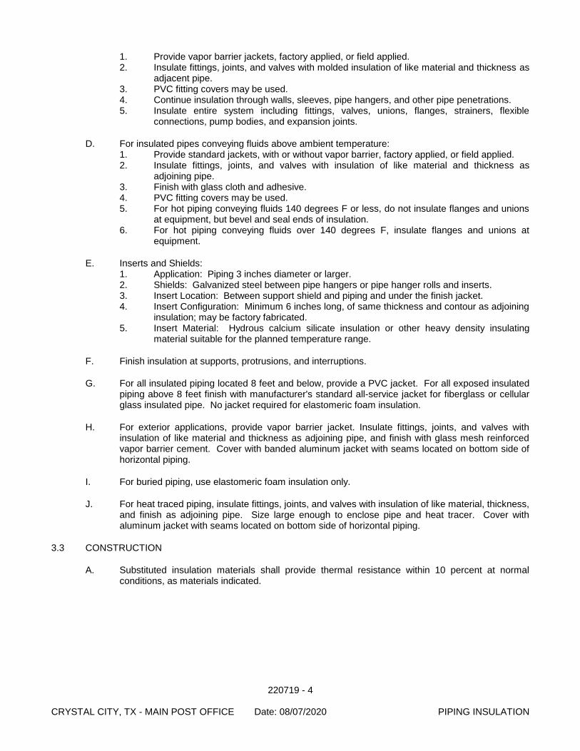
220719 - 4 CRYSTAL CITY, TX - MAIN POST OFFICE Date: 08/07/2020 PIPING INSULATION
1. Provide vapor barrier jackets, factory applied, or field applied. 2. Insulate fittings, joints, and valves with molded insulation of like material and thickness as
adjacent pipe. 3. PVC fitting covers may be used. 4. Continue insulation through walls, sleeves, pipe hangers, and other pipe penetrations. 5. Insulate entire system including fittings, valves, unions, flanges, strainers, flexible
connections, pump bodies, and expansion joints.
D. For insulated pipes conveying fluids above ambient temperature: 1. Provide standard jackets, with or without vapor barrier, factory applied, or field applied. 2. Insulate fittings, joints, and valves with insulation of like material and thickness as
adjoining pipe. 3. Finish with glass cloth and adhesive. 4. PVC fitting covers may be used. 5. For hot piping conveying fluids 140 degrees F or less, do not insulate flanges and unions
at equipment, but bevel and seal ends of insulation. 6. For hot piping conveying fluids over 140 degrees F, insulate flanges and unions at
equipment.
E. Inserts and Shields: 1. Application: Piping 3 inches diameter or larger. 2. Shields: Galvanized steel between pipe hangers or pipe hanger rolls and inserts. 3. Insert Location: Between support shield and piping and under the finish jacket. 4. Insert Configuration: Minimum 6 inches long, of same thickness and contour as adjoining
insulation; may be factory fabricated. 5. Insert Material: Hydrous calcium silicate insulation or other heavy density insulating
material suitable for the planned temperature range.
F. Finish insulation at supports, protrusions, and interruptions.
G. For all insulated piping located 8 feet and below, provide a PVC jacket. For all exposed insulated piping above 8 feet finish with manufacturer's standard all-service jacket for fiberglass or cellular glass insulated pipe. No jacket required for elastomeric foam insulation.
H. For exterior applications, provide vapor barrier jacket. Insulate fittings, joints, and valves with insulation of like material and thickness as adjoining pipe, and finish with glass mesh reinforced vapor barrier cement. Cover with banded aluminum jacket with seams located on bottom side of horizontal piping.
I. For buried piping, use elastomeric foam insulation only.
J. For heat traced piping, insulate fittings, joints, and valves with insulation of like material, thickness, and finish as adjoining pipe. Size large enough to enclose pipe and heat tracer. Cover with aluminum jacket with seams located on bottom side of horizontal piping.
3.3 CONSTRUCTION
A. Substituted insulation materials shall provide thermal resistance within 10 percent at normal conditions, as materials indicated.
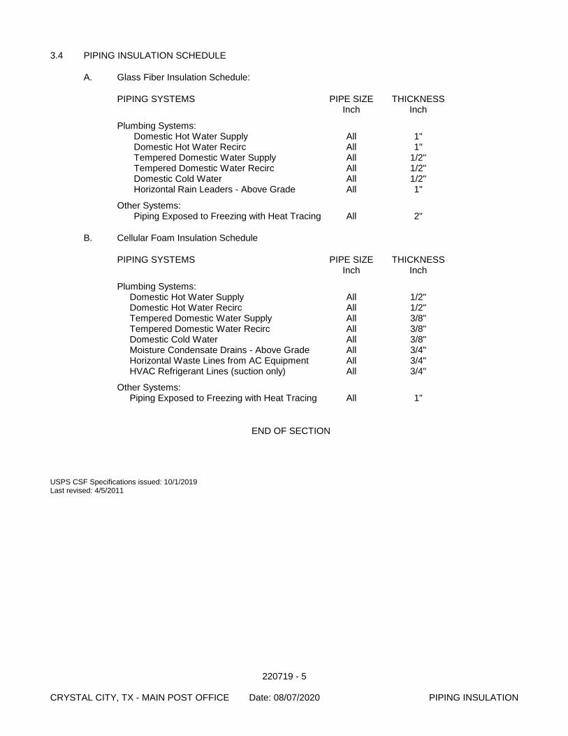
220719 - 5 CRYSTAL CITY, TX - MAIN POST OFFICE Date: 08/07/2020 PIPING INSULATION
3.4 PIPING INSULATION SCHEDULE
A. Glass Fiber Insulation Schedule:
PIPING SYSTEMS PIPE SIZE THICKNESS Inch Inch
Plumbing Systems: Domestic Hot Water Supply All 1" Domestic Hot Water Recirc All 1" Tempered Domestic Water Supply All 1/2" Tempered Domestic Water Recirc All 1/2" Domestic Cold Water All 1/2" Horizontal Rain Leaders - Above Grade All 1"
Other Systems: Piping Exposed to Freezing with Heat Tracing All 2"
B. Cellular Foam Insulation Schedule
PIPING SYSTEMS PIPE SIZE THICKNESS Inch Inch
Plumbing Systems: Domestic Hot Water Supply All 1/2" Domestic Hot Water Recirc All 1/2" Tempered Domestic Water Supply All 3/8" Tempered Domestic Water Recirc All 3/8" Domestic Cold Water All 3/8" Moisture Condensate Drains - Above Grade All 3/4" Horizontal Waste Lines from AC Equipment All 3/4" HVAC Refrigerant Lines (suction only) All 3/4"
Other Systems: Piping Exposed to Freezing with Heat Tracing All 1"
END OF SECTION
USPS CSF Specifications issued: 10/1/2019 Last revised: 4/5/2011

220719 - 6 CRYSTAL CITY, TX - MAIN POST OFFICE Date: 08/07/2020 PIPING INSULATION
[This page intentionally left blank.]
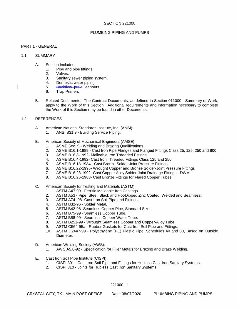
221000 - 1
CRYSTAL CITY, TX - MAIN POST OFFICE Date: 08/07/2020 PLUMBING PIPING AND PUMPS
SECTION 221000
PLUMBING PIPING AND PUMPS
PART 1 - GENERAL
1.1 SUMMARY
A. Section Includes: 1. Pipe and pipe fittings. 2. Valves. 3. Sanitary sewer piping system. 4. Domestic water piping. 5. Backflow prevCleanouts. 6. Trap Primers
B. Related Documents: The Contract Documents, as defined in Section 011000 - Summary of Work, apply to the Work of this Section. Additional requirements and information necessary to complete the Work of this Section may be found in other Documents.
1.2 REFERENCES
A. American National Standards Institute, Inc. (ANSI): 1. ANSI B31.9 - Building Service Piping.
B. American Society of Mechanical Engineers (AMSE): 1. ASME Sec. 9 - Welding and Brazing Qualifications. 2. ASME B16.1-1989 - Cast Iron Pipe Flanges and Flanged Fittings Class 25, 125, 250 and 800. 3. ASME B16.3-1992- Malleable Iron Threaded Fittings. 4. ASME B16.4-1992- Cast Iron Threaded Fittings Class 125 and 250. 5. ASME B16.18-1984 - Cast Bronze Solder-Joint Pressure Fittings. 6. ASME B16.22-1995- Wrought Copper and Bronze Solder-Joint Pressure Fittings 7. ASME B16.23-1992- Cast Copper Alloy Solder-Joint Drainage Fittings - DWV. 8. ASME B16.26-1988- Cast Bronze Fittings for Flared Copper Tubes.
C. American Society for Testing and Materials (ASTM): 1. ASTM A47-99 - Ferritic Malleable Iron Castings. 2. ASTM A53 - Pipe, Steel, Black and Hot-Dipped Zinc Coated, Welded and Seamless. 3. ASTM A74 -98- Cast Iron Soil Pipe and Fittings. 4. ASTM B32-96 - Solder Metal. 5. ASTM B42-98- Seamless Copper Pipe, Standard Sizes. 6. ASTM B75-99 - Seamless Copper Tube. 7. ASTM B88-99 - Seamless Copper Water Tube. 8. ASTM B251-99 - Wrought Seamless Copper and Copper-Alloy Tube. 9. ASTM C564-95a - Rubber Gaskets for Cast Iron Soil Pipe and Fittings. 10. ASTM D2447-99 - Polyethylene (PE) Plastic Pipe, Schedules 40 and 80, Based on Outside
Diameter.
D. American Welding Society (AWS): 1. AWS A5.8-92 - Specification for Filler Metals for Brazing and Braze Welding.
E. Cast Iron Soil Pipe Institute (CISPI): 1. CISPI 301 - Cast Iron Soil Pipe and Fittings for Hubless Cast Iron Sanitary Systems. 2. CISPI 310 - Joints for Hubless Cast Iron Sanitary Systems.
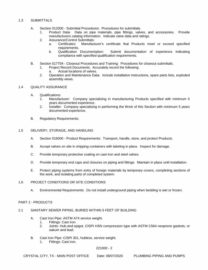
221000 - 2
CRYSTAL CITY, TX - MAIN POST OFFICE Date: 08/07/2020 PLUMBING PIPING AND PUMPS
1.3 SUBMITTALS
A. Section 013300 - Submittal Procedures: Procedures for submittals. 1. Product Data: Data on pipe materials, pipe fittings, valves, and accessories. Provide
manufacturers catalog information. Indicate valve data and ratings. 2. Assurance/Control Submittals:
a. Certificates: Manufacturer's certificate that Products meet or exceed specified requirements.
b. Qualification Documentation: Submit documentation of experience indicating compliance with specified qualification requirements.
B. Section 017704 - Closeout Procedures and Training: Procedures for closeout submittals. 1. Project Record Documents: Accurately record the following:
a. Actual locations of valves. 2. Operation and Maintenance Data: Include installation instructions, spare parts lists, exploded
assembly views.
1.4 QUALITY ASSURANCE
A. Qualifications: 1. Manufacturer: Company specializing in manufacturing Products specified with minimum 5
years documented experience. 2. Installer: Company specializing in performing the Work of this Section with minimum 5 years
documented experience.
B. Regulatory Requirements:
1.5 DELIVERY, STORAGE, AND HANDLING
A. Section 016000 - Product Requirements: Transport, handle, store, and protect Products.
B. Accept valves on site in shipping containers with labeling in place. Inspect for damage.
C. Provide temporary protective coating on cast iron and steel valves.
D. Provide temporary end caps and closures on piping and fittings. Maintain in place until installation.
E. Protect piping systems from entry of foreign materials by temporary covers, completing sections of the work, and isolating parts of completed system.
1.6 PROJECT CONDITIONS OR SITE CONDITIONS
A. Environmental Requirements: Do not install underground piping when bedding is wet or frozen.
PART 2 - PRODUCTS
2.1 SANITARY SEWER PIPING, BURIED WITHIN 5 FEET OF BUILDING
A. Cast Iron Pipe: ASTM A74 service weight. 1. Fittings: Cast iron. 2. Joints: Hub-and-spigot, CISPI HSN compression type with ASTM C564 neoprene gaskets, or
oakum and lead.
B. Cast Iron Pipe: CISPI 301, hubless, service weight. 1. Fittings: Cast iron.
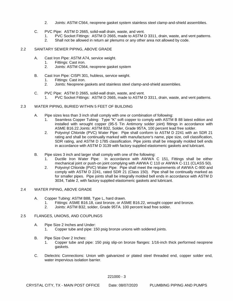
221000 - 3
CRYSTAL CITY, TX - MAIN POST OFFICE Date: 08/07/2020 PLUMBING PIPING AND PUMPS
2. Joints: ASTM C564, neoprene gasket system stainless steel clamp-and-shield assemblies.
C. PVC Pipe: ASTM D 2665, solid-wall drain, waste, and vent. 1. PVC Socket Fittings: ASTM D 2665, made to ASTM D 3311, drain, waste, and vent patterns. 2. Shall not be allowed in return air plenums or any other area not allowed by code.
2.2 SANITARY SEWER PIPING, ABOVE GRADE
A. Cast Iron Pipe: ASTM A74, service weight. 1. Fittings: Cast iron. 2. Joints: ASTM C564, neoprene gasket system
B. Cast Iron Pipe: CISPI 301, hubless, service weight. 1. Fittings: Cast iron. 2. Joints: Neoprene gaskets and stainless steel clamp-and-shield assemblies.
C. PVC Pipe: ASTM D 2665, solid-wall drain, waste, and vent. 1. PVC Socket Fittings: ASTM D 2665, made to ASTM D 3311, drain, waste, and vent patterns.
2.3 WATER PIPING, BURIED WITHIN 5 FEET OF BUILDING
A. Pipe sizes less than 3 inch shall comply with one or combination of following: 1. Seamless Copper Tubing: Type "K" soft copper to comply with ASTM B 88 latest edition and
installed with wrought copper (95-5 Tin Antimony solder joint) fittings in accordance with ASME B16.22.Joints: ASTM B32, Solder, Grade 95TA, 100 percent lead free solder.
2. Polyvinyl Chloride (PVC) Water Pipe: Pipe shall conform to ASTM D 2241 with an SDR 21 rating and shall be continually marked with manufacturer's name, pipe size, cell classification, SDR rating, and ASTM D 1785 classification. Pipe joints shall be integrally molded bell ends in accordance with ASTM D 3139 with factory supplied elastomeric gaskets and lubricant.
B. Pipe sizes 3 inch and larger shall comply with one of the following: 1. Ductile Iron Water Pipe: In accordance with AWWA C 151, Fittings shall be either
mechanical joint or push-on joint complying with AWWA C 110 or AWWA C-111 (CLASS 50). 2. Polyvinyl Chloride (PVC) Water Pipe: Pipe shall meet the requirements of AWWA C-900 and
comply with ASTM D 2241, rated SDR 21 (Class 150). Pipe shall be continually marked as for smaller pipes. Pipe joints shall be integrally molded bell ends in accordance with ASTM D 3034, Table 2, with factory supplied elastomeric gaskets and lubricant.
2.4 WATER PIPING, ABOVE GRADE
A. Copper Tubing: ASTM B88, Type L, hard drawn. 1. Fittings: ASME B16.18, cast bronze, or ASME B16.22, wrought copper and bronze. 2. Joints: ASTM B32, solder, Grade 95TA. 100 percent lead free solder.
2.5 FLANGES, UNIONS, AND COUPLINGS
A. Pipe Size 2 Inches and Under: 1. Copper tube and pipe: 150 psig bronze unions with soldered joints.
B. Pipe Size Over 2 Inches: 1. Copper tube and pipe: 150 psig slip-on bronze flanges: 1/16-inch thick performed neoprene
gaskets.
C. Dielectric Connections: Union with galvanized or plated steel threaded end, copper solder end, water impervious isolation barrier.
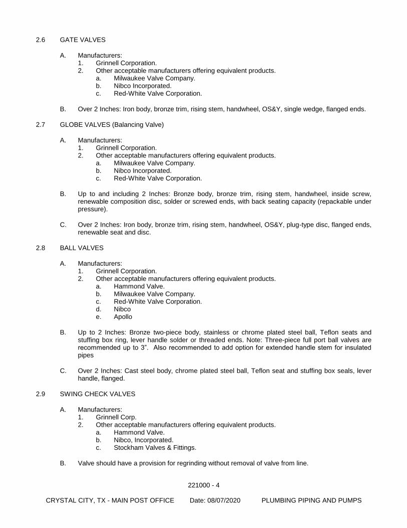
221000 - 4
CRYSTAL CITY, TX - MAIN POST OFFICE Date: 08/07/2020 PLUMBING PIPING AND PUMPS
2.6 GATE VALVES
A. Manufacturers: 1. Grinnell Corporation. 2. Other acceptable manufacturers offering equivalent products.
a. Milwaukee Valve Company. b. Nibco Incorporated. c. Red-White Valve Corporation.
B. Over 2 Inches: Iron body, bronze trim, rising stem, handwheel, OS&Y, single wedge, flanged ends.
2.7 GLOBE VALVES (Balancing Valve)
A. Manufacturers: 1. Grinnell Corporation. 2. Other acceptable manufacturers offering equivalent products.
a. Milwaukee Valve Company. b. Nibco Incorporated. c. Red-White Valve Corporation.
B. Up to and including 2 Inches: Bronze body, bronze trim, rising stem, handwheel, inside screw, renewable composition disc, solder or screwed ends, with back seating capacity (repackable under pressure).
C. Over 2 Inches: Iron body, bronze trim, rising stem, handwheel, OS&Y, plug-type disc, flanged ends, renewable seat and disc.
2.8 BALL VALVES
A. Manufacturers: 1. Grinnell Corporation. 2. Other acceptable manufacturers offering equivalent products.
a. Hammond Valve. b. Milwaukee Valve Company. c. Red-White Valve Corporation. d. Nibco e. Apollo
B. Up to 2 Inches: Bronze two-piece body, stainless or chrome plated steel ball, Teflon seats and stuffing box ring, lever handle solder or threaded ends. Note: Three-piece full port ball valves are recommended up to 3”. Also recommended to add option for extended handle stem for insulated pipes
C. Over 2 Inches: Cast steel body, chrome plated steel ball, Teflon seat and stuffing box seals, lever handle, flanged.
2.9 SWING CHECK VALVES
A. Manufacturers: 1. Grinnell Corp. 2. Other acceptable manufacturers offering equivalent products.
a. Hammond Valve. b. Nibco, Incorporated. c. Stockham Valves & Fittings.
B. Valve should have a provision for regrinding without removal of valve from line.
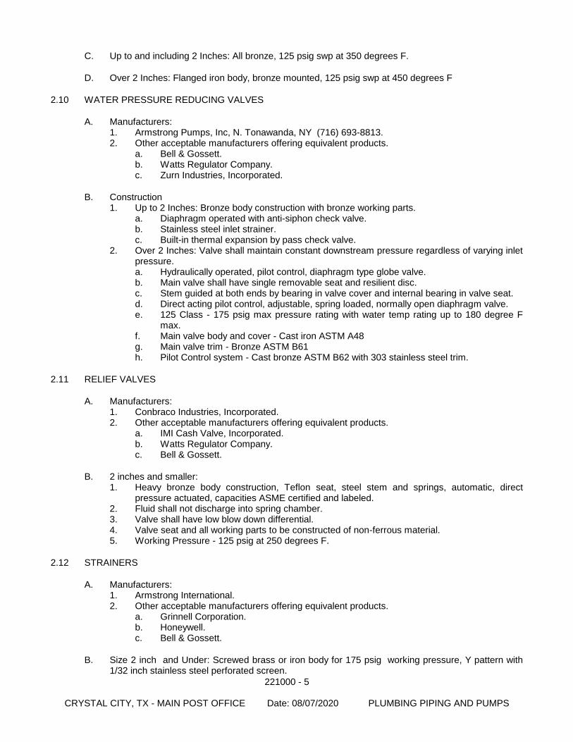
221000 - 5
CRYSTAL CITY, TX - MAIN POST OFFICE Date: 08/07/2020 PLUMBING PIPING AND PUMPS
C. Up to and including 2 Inches: All bronze, 125 psig swp at 350 degrees F.
D. Over 2 Inches: Flanged iron body, bronze mounted, 125 psig swp at 450 degrees F
2.10 WATER PRESSURE REDUCING VALVES
A. Manufacturers: 1. Armstrong Pumps, Inc, N. Tonawanda, NY (716) 693-8813. 2. Other acceptable manufacturers offering equivalent products.
a. Bell & Gossett. b. Watts Regulator Company. c. Zurn Industries, Incorporated.
B. Construction 1. Up to 2 Inches: Bronze body construction with bronze working parts.
a. Diaphragm operated with anti-siphon check valve. b. Stainless steel inlet strainer. c. Built-in thermal expansion by pass check valve.
2. Over 2 Inches: Valve shall maintain constant downstream pressure regardless of varying inlet pressure. a. Hydraulically operated, pilot control, diaphragm type globe valve. b. Main valve shall have single removable seat and resilient disc. c. Stem guided at both ends by bearing in valve cover and internal bearing in valve seat. d. Direct acting pilot control, adjustable, spring loaded, normally open diaphragm valve. e. 125 Class - 175 psig max pressure rating with water temp rating up to 180 degree F
max. f. Main valve body and cover - Cast iron ASTM A48 g. Main valve trim - Bronze ASTM B61 h. Pilot Control system - Cast bronze ASTM B62 with 303 stainless steel trim.
2.11 RELIEF VALVES
A. Manufacturers: 1. Conbraco Industries, Incorporated. 2. Other acceptable manufacturers offering equivalent products.
a. IMI Cash Valve, Incorporated. b. Watts Regulator Company. c. Bell & Gossett.
B. 2 inches and smaller: 1. Heavy bronze body construction, Teflon seat, steel stem and springs, automatic, direct
pressure actuated, capacities ASME certified and labeled. 2. Fluid shall not discharge into spring chamber. 3. Valve shall have low blow down differential. 4. Valve seat and all working parts to be constructed of non-ferrous material. 5. Working Pressure - 125 psig at 250 degrees F.
2.12 STRAINERS
A. Manufacturers: 1. Armstrong International. 2. Other acceptable manufacturers offering equivalent products.
a. Grinnell Corporation. b. Honeywell. c. Bell & Gossett.
B. Size 2 inch and Under: Screwed brass or iron body for 175 psig working pressure, Y pattern with 1/32 inch stainless steel perforated screen.
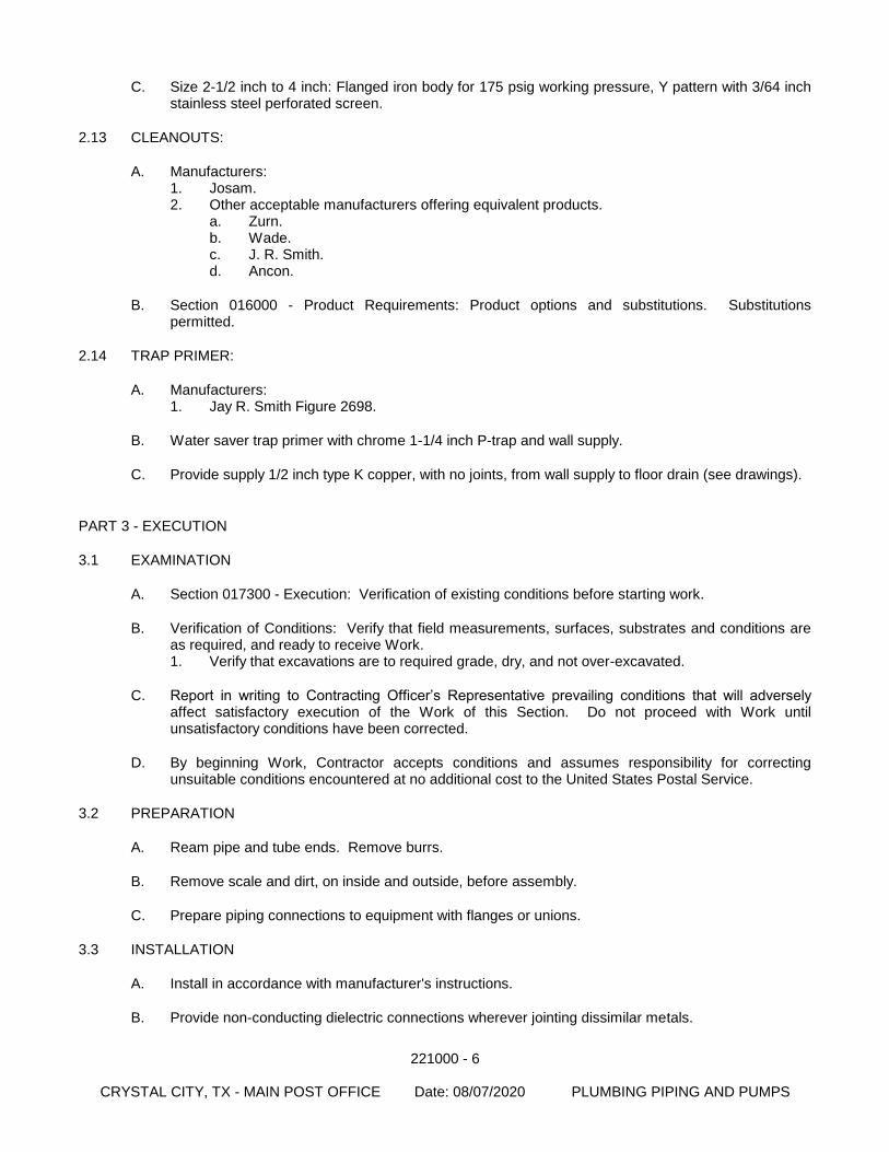
221000 - 6
CRYSTAL CITY, TX - MAIN POST OFFICE Date: 08/07/2020 PLUMBING PIPING AND PUMPS
C. Size 2-1/2 inch to 4 inch: Flanged iron body for 175 psig working pressure, Y pattern with 3/64 inch stainless steel perforated screen.
2.13 CLEANOUTS:
A. Manufacturers: 1. Josam. 2. Other acceptable manufacturers offering equivalent products.
a. Zurn. b. Wade. c. J. R. Smith. d. Ancon.
B. Section 016000 - Product Requirements: Product options and substitutions. Substitutions permitted.
2.14 TRAP PRIMER:
A. Manufacturers: 1. Jay R. Smith Figure 2698.
B. Water saver trap primer with chrome 1-1/4 inch P-trap and wall supply.
C. Provide supply 1/2 inch type K copper, with no joints, from wall supply to floor drain (see drawings).
PART 3 - EXECUTION
3.1 EXAMINATION
A. Section 017300 - Execution: Verification of existing conditions before starting work.
B. Verification of Conditions: Verify that field measurements, surfaces, substrates and conditions are as required, and ready to receive Work. 1. Verify that excavations are to required grade, dry, and not over-excavated.
C. Report in writing to Contracting Officer’s Representative prevailing conditions that will adversely affect satisfactory execution of the Work of this Section. Do not proceed with Work until unsatisfactory conditions have been corrected.
D. By beginning Work, Contractor accepts conditions and assumes responsibility for correcting unsuitable conditions encountered at no additional cost to the United States Postal Service.
3.2 PREPARATION
A. Ream pipe and tube ends. Remove burrs.
B. Remove scale and dirt, on inside and outside, before assembly.
C. Prepare piping connections to equipment with flanges or unions.
3.3 INSTALLATION
A. Install in accordance with manufacturer's instructions.
B. Provide non-conducting dielectric connections wherever jointing dissimilar metals.
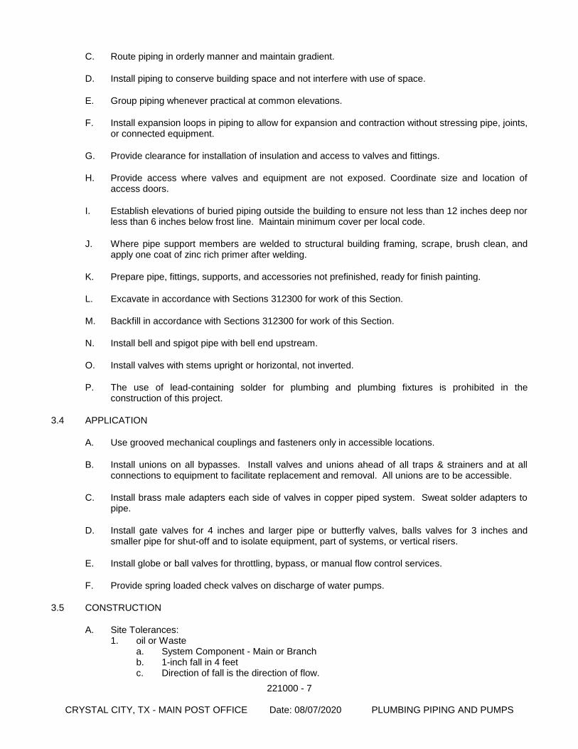
221000 - 7
CRYSTAL CITY, TX - MAIN POST OFFICE Date: 08/07/2020 PLUMBING PIPING AND PUMPS
C. Route piping in orderly manner and maintain gradient.
D. Install piping to conserve building space and not interfere with use of space.
E. Group piping whenever practical at common elevations.
F. Install expansion loops in piping to allow for expansion and contraction without stressing pipe, joints, or connected equipment.
G. Provide clearance for installation of insulation and access to valves and fittings.
H. Provide access where valves and equipment are not exposed. Coordinate size and location of access doors.
I. Establish elevations of buried piping outside the building to ensure not less than 12 inches deep nor less than 6 inches below frost line. Maintain minimum cover per local code.
J. Where pipe support members are welded to structural building framing, scrape, brush clean, and apply one coat of zinc rich primer after welding.
K. Prepare pipe, fittings, supports, and accessories not prefinished, ready for finish painting.
L. Excavate in accordance with Sections 312300 for work of this Section.
M. Backfill in accordance with Sections 312300 for work of this Section.
N. Install bell and spigot pipe with bell end upstream.
O. Install valves with stems upright or horizontal, not inverted.
P. The use of lead-containing solder for plumbing and plumbing fixtures is prohibited in the construction of this project.
3.4 APPLICATION
A. Use grooved mechanical couplings and fasteners only in accessible locations.
B. Install unions on all bypasses. Install valves and unions ahead of all traps & strainers and at all connections to equipment to facilitate replacement and removal. All unions are to be accessible.
C. Install brass male adapters each side of valves in copper piped system. Sweat solder adapters to pipe.
D. Install gate valves for 4 inches and larger pipe or butterfly valves, balls valves for 3 inches and smaller pipe for shut-off and to isolate equipment, part of systems, or vertical risers.
E. Install globe or ball valves for throttling, bypass, or manual flow control services.
F. Provide spring loaded check valves on discharge of water pumps.
3.5 CONSTRUCTION
A. Site Tolerances: 1. oil or Waste
a. System Component - Main or Branch b. 1-inch fall in 4 feet c. Direction of fall is the direction of flow.
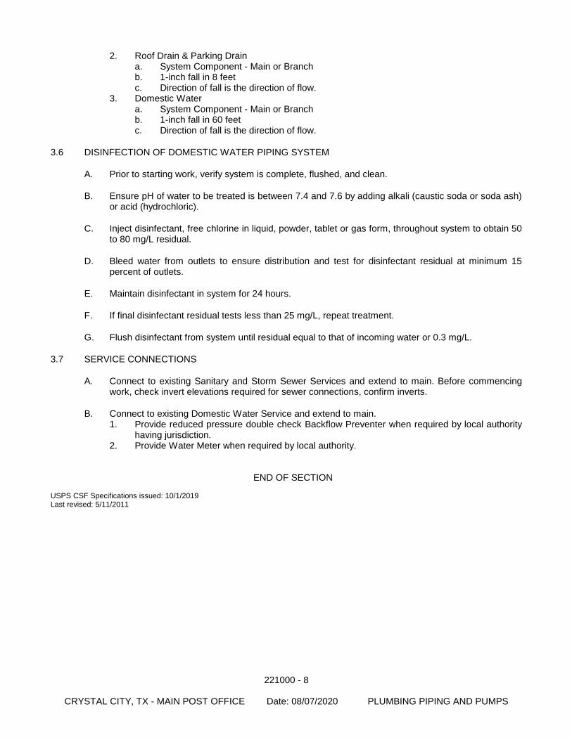
221000 - 8
CRYSTAL CITY, TX - MAIN POST OFFICE Date: 08/07/2020 PLUMBING PIPING AND PUMPS
2. Roof Drain & Parking Drain a. System Component - Main or Branch b. 1-inch fall in 8 feet c. Direction of fall is the direction of flow.
3. Domestic Water a. System Component - Main or Branch b. 1-inch fall in 60 feet c. Direction of fall is the direction of flow.
3.6 DISINFECTION OF DOMESTIC WATER PIPING SYSTEM
A. Prior to starting work, verify system is complete, flushed, and clean.
B. Ensure pH of water to be treated is between 7.4 and 7.6 by adding alkali (caustic soda or soda ash) or acid (hydrochloric).
C. Inject disinfectant, free chlorine in liquid, powder, tablet or gas form, throughout system to obtain 50 to 80 mg/L residual.
D. Bleed water from outlets to ensure distribution and test for disinfectant residual at minimum 15 percent of outlets.
E. Maintain disinfectant in system for 24 hours.
F. If final disinfectant residual tests less than 25 mg/L, repeat treatment.
G. Flush disinfectant from system until residual equal to that of incoming water or 0.3 mg/L.
3.7 SERVICE CONNECTIONS
A. Connect to existing Sanitary and Storm Sewer Services and extend to main. Before commencing work, check invert elevations required for sewer connections, confirm inverts.
B. Connect to existing Domestic Water Service and extend to main. 1. Provide reduced pressure double check Backflow Preventer when required by local authority
having jurisdiction. 2. Provide Water Meter when required by local authority.
END OF SECTION USPS CSF Specifications issued: 10/1/2019 Last revised: 5/11/2011
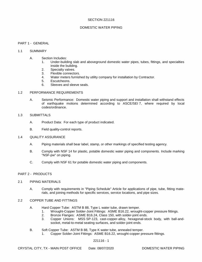
221116 - 1 CRYSTAL CITY, TX - MAIN POST OFFICE Date: 08/07/2020 DOMESTIC WATER PIPING
SECTION 221116
DOMESTIC WATER PIPING
PART 1 - GENERAL
1.1 SUMMARY
A. Section Includes: 1. Under-building slab and aboveground domestic water pipes, tubes, fittings, and specialties
inside the building. 2. Specialty valves. 3. Flexible connectors. 4. Water meters furnished by utility company for installation by Contractor. 5. Escutcheons. 6. Sleeves and sleeve seals.
1.2 PERFORMANCE REQUIREMENTS
A. Seismic Performance: Domestic water piping and support and installation shall withstand effects of earthquake motions determined according to ASCE/SEI 7, where required by local codes/ordinance.
1.3 SUBMITTALS
A. Product Data: For each type of product indicated.
B. Field quality-control reports.
1.4 QUALITY ASSURANCE
A. Piping materials shall bear label, stamp, or other markings of specified testing agency.
B. Comply with NSF 14 for plastic, potable domestic water piping and components. Include marking "NSF-pw" on piping.
C. Comply with NSF 61 for potable domestic water piping and components.
PART 2 - PRODUCTS
2.1 PIPING MATERIALS
A. Comply with requirements in "Piping Schedule" Article for applications of pipe, tube, fitting mate-rials, and joining methods for specific services, service locations, and pipe sizes.
2.2 COPPER TUBE AND FITTINGS
A. Hard Copper Tube: ASTM B 88, Type L water tube, drawn temper. 1. Wrought-Copper Solder-Joint Fittings: ASME B16.22, wrought-copper pressure fittings. 2. Bronze Flanges: ASME B16.24, Class 150, with solder-joint ends. 3. Copper Unions: MSS SP-123, cast-copper-alloy, hexagonal-stock body, with ball-and-
socket, metal-to-metal seating surfaces, and solder-joint ends.
B. Soft Copper Tube: ASTM B 88, Type K water tube, annealed temper. 1. Copper Solder-Joint Fittings: ASME B16.22, wrought-copper pressure fittings.
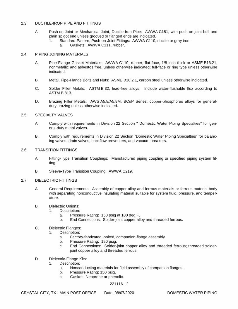
221116 - 2 CRYSTAL CITY, TX - MAIN POST OFFICE Date: 08/07/2020 DOMESTIC WATER PIPING
2.3 DUCTILE-IRON PIPE AND FITTINGS
A. Push-on-Joint or Mechanical Joint, Ductile-Iron Pipe: AWWA C151, with push-on-joint bell and plain spigot end unless grooved or flanged ends are indicated. 1. Standard-Pattern, Push-on-Joint Fittings: AWWA C110, ductile or gray iron.
a. Gaskets: AWWA C111, rubber.
2.4 PIPING JOINING MATERIALS
A. Pipe-Flange Gasket Materials: AWWA C110, rubber, flat face, 1/8 inch thick or ASME B16.21, nonmetallic and asbestos free, unless otherwise indicated; full-face or ring type unless otherwise indicated.
B. Metal, Pipe-Flange Bolts and Nuts: ASME B18.2.1, carbon steel unless otherwise indicated.
C. Solder Filler Metals: ASTM B 32, lead-free alloys. Include water-flushable flux according to ASTM B 813.
D. Brazing Filler Metals: AWS A5.8/A5.8M, BCuP Series, copper-phosphorus alloys for general-duty brazing unless otherwise indicated.
2.5 SPECIALTY VALVES
A. Comply with requirements in Division 22 Section " Domestic Water Piping Specialties" for gen-eral-duty metal valves.
B. Comply with requirements in Division 22 Section "Domestic Water Piping Specialties" for balanc-ing valves, drain valves, backflow preventers, and vacuum breakers.
2.6 TRANSITION FITTINGS
A. Fitting-Type Transition Couplings: Manufactured piping coupling or specified piping system fit-ting.
B. Sleeve-Type Transition Coupling: AWWA C219.
2.7 DIELECTRIC FITTINGS
A. General Requirements: Assembly of copper alloy and ferrous materials or ferrous material body with separating nonconductive insulating material suitable for system fluid, pressure, and temper-ature.
B. Dielectric Unions: 1. Description:
a. Pressure Rating: 150 psig at 180 deg F. b. End Connections: Solder-joint copper alloy and threaded ferrous.
C. Dielectric Flanges: 1. Description:
a. Factory-fabricated, bolted, companion-flange assembly. b. Pressure Rating: 150 psig. c. End Connections: Solder-joint copper alloy and threaded ferrous; threaded solder-
joint copper alloy and threaded ferrous.
D. Dielectric-Flange Kits: 1. Description:
a. Nonconducting materials for field assembly of companion flanges. b. Pressure Rating: 150 psig. c. Gasket: Neoprene or phenolic.
221116 - 3 CRYSTAL CITY, TX - MAIN POST OFFICE Date: 08/07/2020 DOMESTIC WATER PIPING
d. Bolt Sleeves: Phenolic or polyethylene. e. Washers: Phenolic with steel backing washers.
E. Dielectric Nipples: 1. Description:
a. Electroplated steel nipple complying with ASTM F 1545. b. Pressure Rating: 300 psig at 225 deg F. c. End Connections: Male threaded or grooved. d. Lining: Inert and noncorrosive, propylene.
2.8 FLEXIBLE CONNECTORS
A. Bronze-Hose Flexible Connectors: Corrugated-bronze tubing with bronze wire-braid covering and ends brazed to inner tubing. 1. Working-Pressure Rating: Minimum 200 psig. 2. End Connections NPS 2 and Smaller: Threaded copper pipe or plain-end copper tube. 3. End Connections NPS 2-1/2 and Larger: Flanged copper alloy.
B. Stainless-Steel-Hose Flexible Connectors: Corrugated-stainless-steel tubing with stainless-steel wire-braid covering and ends welded to inner tubing. 1. Working-Pressure Rating: Minimum 200 psig. 2. End Connections NPS 2 and Smaller: Threaded steel-pipe nipple. 3. End Connections NPS 2-1/2 and Larger: Flanged steel nipple.
2.9 ESCUTCHEONS
A. General: Manufactured ceiling, floor, and wall escutcheons and floor plates.
B. One Piece, Cast Brass: Polished, chrome-plated finish with setscrews.
C. Split Casting, Cast Brass: Polished, chrome-plated finish with concealed hinge and setscrew.
D. One-Piece Floor Plates: Cast-iron flange with holes for fasteners.
E. Split-Casting Floor Plates: Cast brass with concealed hinge.
2.10 SLEEVES
A. Cast-Iron Wall Pipes: Fabricated of cast iron, and equivalent to ductile-iron pressure pipe, with plain ends and integral waterstop unless otherwise indicated.
B. Galvanized-Steel-Sheet Sleeves: 0.0239-inch minimum thickness; round tube closed with weld-ed longitudinal joint.
C. PVC-Pipe Sleeves: ASTM D 1785, Schedule 40.
D. Galvanized-Steel-Pipe Sleeves: ASTM A 53/A 53M, Type E, Grade B, Schedule 40, zinc-coated, with plain ends.
E. Stack Sleeve Fittings: Manufactured, cast-iron sleeve with integral clamping flange. Include clamping ring and bolts and nuts for membrane flashing. 1. Underdeck Clamp: Clamping ring with setscrews.
2.11 SLEEVE SEALS
A. Description: Modular sealing element unit, designed for field assembly, used to fill annular space between pipe and sleeve. 1. Sealing Elements: EPDM-rubber interlocking links shaped to fit surface of pipe. Include
type and number required for pipe material and size of pipe.
221116 - 4 CRYSTAL CITY, TX - MAIN POST OFFICE Date: 08/07/2020 DOMESTIC WATER PIPING
2. Pressure Plates: Stainless steel. 3. Connecting Bolts and Nuts: Stainless steel of length required to secure pressure plates to
sealing elements.
2.12 GROUT
A. Standard: ASTM C 1107, Grade B, post-hardening and volume-adjusting, dry, hydraulic-cement grout.
B. Characteristics: Nonshrink; recommended for interior and exterior applications.
C. Design Mix: 5000-psi, 28-day compressive strength.
D. Packaging: Premixed and factory packaged.
PART 1 - EXECUTION
2.13 EARTHWORK
A. Comply with requirements in Division 31 Section "Earth Moving" for excavating, trenching, and backfilling.
2.14 PIPING INSTALLATION
A. Drawing plans, schematics, and diagrams indicate general location and arrangement of domestic water piping. Indicated locations and arrangements are used to size pipe and calculate friction loss, expansion, and other design considerations. Install piping as indicated unless deviations to layout are approved on Coordination Drawings.
B. Install copper tubing under building slab according to CDA's "Copper Tube Handbook."
C. Install ductile-iron piping under building slab with restrained joints according to AWWA C600 and AWWA M41.
D. Install shutoff valve, hose-end drain valve, strainer, pressure gage, and test tee with valve, inside the building at each domestic water service entrance. Comply with requirements in Division 22 Section " Domestic Water Piping Specialties" for pressure gages and Division 22 Section "Do-mestic Water Piping Specialties" for drain valves and strainers.
E. Install shutoff valve immediately upstream of each dielectric fitting.
F. Install water-pressure-reducing valves downstream from shutoff valves. Comply with require-ments in Division 22 Section "Domestic Water Piping Specialties" for pressure-reducing valves.
G. Install domestic water piping level and plumb.
H. Rough-in domestic water piping for water-meter installation according to utility company's re-quirements.
I. Install piping concealed from view and protected from physical contact by building occupants un-less otherwise indicated and except in equipment rooms and service areas.
J. Install piping indicated to be exposed and piping in equipment rooms and service areas at right angles or parallel to building walls. Diagonal runs are prohibited unless specifically indicated oth-erwise.
K. Install piping above accessible ceilings to allow sufficient space for ceiling panel removal and co-ordinate with other services occupying that space.
221116 - 5 CRYSTAL CITY, TX - MAIN POST OFFICE Date: 08/07/2020 DOMESTIC WATER PIPING
L. Install piping adjacent to equipment and specialties to allow service and maintenance.
M. Install piping to permit valve servicing.
N. Install nipples, unions, special fittings, and valves with pressure ratings the same as or higher than system pressure rating used in applications below unless otherwise indicated.
O. Install piping free of sags and bends.
P. Install fittings for changes in direction and branch connections.
Q. Install unions in copper tubing at final connection to each piece of equipment, machine, and spe-cialty.
R. Install pressure gages on suction and discharge piping from each plumbing pump and packaged booster pump.
S. Install thermostats in hot-water circulation piping.
2.15 JOINT CONSTRUCTION
A. Ream ends of pipes and tubes and remove burrs. Bevel plain ends of steel pipe.
B. Remove scale, slag, dirt, and debris from inside and outside of pipes, tubes, and fittings before assembly.
C. Brazed Joints: Join copper tube and fittings according to CDA's "Copper Tube Handbook," "Brazed Joints" Chapter.
D. Soldered Joints: Apply ASTM B 813, water-flushable flux to end of tube. Join copper tube and fittings according to ASTM B 828 or CDA's "Copper Tube Handbook."
E. Flanged Joints: Select appropriate asbestos-free, nonmetallic gasket material in size, type, and thickness suitable for domestic water service. Join flanges with gasket and bolts according to ASME B31.9.
F. Dissimilar-Material Piping Joints: Make joints using adapters compatible with materials of both piping systems.
2.16 VALVE INSTALLATION
A. General-Duty Valves: Comply with requirements in Division 22 Section " Domestic Water Piping Specialties" for valve installations.
B. Install shutoff valve close to water main on each branch and riser serving plumbing fixtures or equipment, on each water supply to equipment, and on each water supply to plumbing fixtures that do not have supply stops. Use ball or gate valves for piping NPS 2 and smaller. Use butter-fly or gate valves for piping NPS 2-1/2 and larger.
C. Install balancing valve in each hot-water circulation return branch and discharge side of each pump and circulator. Set balancing valves partly open to restrict but not stop flow. Use ball valves for piping NPS 2 and smaller and butterfly valves for piping NPS 2-1/2 and larger. Comply with requirements in Division 22 Section "Domestic Water Piping Specialties" for balancing valves.
2.17 TRANSITION FITTING INSTALLATION
A. Install transition couplings at joints of dissimilar piping.
B. Transition Fittings in Underground Domestic Water Piping:
221116 - 6 CRYSTAL CITY, TX - MAIN POST OFFICE Date: 08/07/2020 DOMESTIC WATER PIPING
1. NPS 1-1/2 and Smaller: Fitting-type coupling. 2. NPS 2 and Larger: Sleeve-type coupling.
C. Transition Fittings in Aboveground Domestic Water Piping NPS 2 and Smaller:
2.18 DIELECTRIC FITTING INSTALLATION
A. Install dielectric fittings in piping at connections of dissimilar metal piping and tubing.
B. Dielectric Fittings for NPS 2 and Smaller: Use dielectric unions.
C. Dielectric Fittings for NPS 2-1/2 to NPS 64: Use dielectric flanges or flange kits.
2.19 FLEXIBLE CONNECTOR INSTALLATION
A. Install flexible connectors in suction and discharge piping connections to each domestic water pump and in suction and discharge manifold connections to each domestic water booster pump.
B. Install bronze-hose flexible connectors in copper domestic water tubing.
C. Install stainless-steel-hose flexible connectors in steel domestic water piping.
2.20 HANGER AND SUPPORT INSTALLATION
A. Vertical Piping: MSS Type 8 or 42, clamps.
B. Individual, Straight, Horizontal Piping Runs: 1. 100 Feet and Less: MSS Type 1, adjustable, steel clevis hangers. 2. Longer Than 100 Feet: MSS Type 43, adjustable roller hangers.
C. Base of Vertical Piping: MSS Type 52, spring hangers.
D. Support vertical piping and tubing at base and at each floor.
E. Rod diameter may be reduced one size for double-rod hangers, to a minimum of 3/8 inch.
F. Install hangers for copper tubing with the following maximum horizontal spacing and minimum rod diameters: 1. NPS 3/4 and Smaller: 60 inches with 3/8-inch rod. 2. NPS 1 and NPS 1-1/4: 72 inches with 3/8-inch rod. 3. NPS 1-1/2 and NPS 2: 96 inches with 3/8-inch rod. 4. NPS 2-1/2: 108 inches with 1/2-inch rod. 5. NPS 3 to NPS 5: 10 feet with 1/2-inch rod. 6. NPS 6: 10 feet with 5/8-inch rod.
G. Install supports for vertical copper tubing every 10 feet.
H. Install hangers for steel piping with the following maximum horizontal spacing and minimum rod diameters: 1. NPS 1-1/4 and Smaller: 84 inches with 3/8-inch rod. 2. NPS 1-1/2: 108 inches with 3/8-inch rod. 3. NPS 2: 10 feet with 3/8-inch rod. 4. NPS 2-1/2: 11 feet with 1/2-inch rod. 5. NPS 3 and NPS 3-1/2: 12 feet with 1/2-inch rod. 6. NPS 4 and NPS 5: 12 feet with 5/8-inch rod. 7. NPS 6: 12 feet with 3/4-inch rod.
I. Install supports for vertical steel piping every 15 feet.
221116 - 7 CRYSTAL CITY, TX - MAIN POST OFFICE Date: 08/07/2020 DOMESTIC WATER PIPING
2.21 CONNECTIONS
A. Drawings indicate general arrangement of piping, fittings, and specialties.
B. Install piping adjacent to equipment and machines to allow service and maintenance.
C. Connect domestic water piping to exterior water-service piping. Use transition fitting to join dis-similar piping materials.
D. Connect domestic water piping to water-service piping with shutoff valve; extend and connect to the following: 1. Domestic Water Booster Pumps: Cold-water suction and discharge piping. 2. Water Heaters: Cold-water inlet and hot-water outlet piping in sizes indicated, but not
smaller than sizes of water heater connections. 3. Plumbing Fixtures: Cold- and hot-water supply piping in sizes indicated, but not smaller
than required by plumbing code. Comply with requirements in Division 22 plumbing fixture Sections for connection sizes.
4. Equipment: Cold- and hot-water supply piping as indicated, but not smaller than equipment connections. Provide shutoff valve and union for each connection. Use flanges instead of unions for NPS 2-1/2 and larger.
2.22 ESCUTCHEON INSTALLATION
A. Install escutcheons for penetrations of walls, ceilings, and floors.
B. Escutcheons for New Piping: 1. Piping with Fitting or Sleeve Protruding from Wall: One piece, deep pattern. 2. Bare Piping at Wall and Floor Penetrations in Finished Spaces: One piece, cast brass with
polished chrome-plated finish. 3. Bare Piping at Ceiling Penetrations in Finished Spaces: One piece, cast brass with pol-
ished chrome-plated finish. 4. Bare Piping in Unfinished Service Spaces: One piece, cast brass with polished chrome-
plated finish. 5. Bare Piping in Equipment Rooms: One piece, cast brass. 6. Bare Piping at Floor Penetrations in Equipment Rooms: One-piece floor plate.
C. Escutcheons for Existing Piping: 1. Chrome-Plated Piping: Split casting, cast brass with chrome-plated finish. 2. Insulated Piping: Split plate, stamped steel with concealed hinge and spring clips. 3. Bare Piping at Wall and Floor Penetrations in Finished Spaces: Split casting, cast brass
with chrome-plated finish. 4. Bare Piping at Ceiling Penetrations in Finished Spaces: Split casting, cast brass with
chrome-plated finish. 5. Bare Piping in Unfinished Service Spaces: Split casting, cast brass with polished chrome-
plated finish. 6. Bare Piping in Equipment Rooms: Split casting, cast brass. 7. Bare Piping at Floor Penetrations in Equipment Rooms: Split-casting floor plate.
2.23 SLEEVE INSTALLATION
A. General Requirements: Install sleeves for pipes and tubes passing through penetrations in floors, partitions, roofs, and walls.
B. Sleeves are not required for core-drilled holes.
C. Permanent sleeves are not required for holes formed by removable PE sleeves.
D. Cut sleeves to length for mounting flush with both surfaces unless otherwise indicated.
221116 - 8 CRYSTAL CITY, TX - MAIN POST OFFICE Date: 08/07/2020 DOMESTIC WATER PIPING
E. Install sleeves in new partitions, slabs, and walls as they are built.
F. For interior wall penetrations, seal annular space between sleeve and pipe or pipe insulation us-ing joint sealants appropriate for size, depth, and location of joint. Comply with requirements in Division 07 Section "Joint Sealants" for joint sealants.
G. For exterior wall penetrations above grade, seal annular space between sleeve and pipe using joint sealants appropriate for size, depth, and location of joint. Comply with requirements in Divi-sion 07 Section "Joint Sealants" for joint sealants.
H. For exterior wall penetrations below grade, seal annular space between sleeve and pipe using sleeve seals specified in this Section.
I. Seal space outside of sleeves in concrete slabs and walls with grout.
J. Install sleeves that are large enough to provide 1/4-inch annular clear space between sleeve and pipe or pipe insulation unless otherwise indicated.
K. Install sleeve materials according to the following applications: 1. Sleeves for Piping Passing through Concrete Floor Slabs: Steel pipe. 2. Sleeves for Piping Passing through Concrete Floor Slabs of Mechanical Equipment Areas
or Other Wet Areas: Stack sleeve fittings. a. Extend sleeves 2 inches above finished floor level. b. For pipes penetrating floors with membrane waterproofing, extend cast-iron sleeve
fittings below floor slab as required to secure clamping ring if ring is specified. Secure flashing between clamping flanges. Install section of cast-iron soil pipe to extend sleeve to 2 inches above finished floor level. Comply with requirements in Division 07 Section "Sheet Metal Flashing and Trim" for flashing.
3. Sleeves for Piping Passing through Gypsum-Board Partitions: a. Steel pipe sleeves for pipes smaller than NPS 6. b. Galvanized-steel sheet sleeves for pipes NPS 6 and larger. c. Exception: Sleeves are not required for water supply tubes and waste pipes for
individual plumbing fixtures if escutcheons will cover openings. 4. Sleeves for Piping Passing through Concrete Roof Slabs: Steel pipe. 5. Sleeves for Piping Passing through Exterior Concrete Walls:
a. Steel pipe sleeves for pipes smaller than NPS 6. b. Cast-iron wall pipe sleeves for pipes NPS 6 and larger. c. Install sleeves that are large enough to provide 1/2-inch annular clear space between
sleeve and pipe or pipe insulation when sleeve seals are used.
L. Fire-Barrier Penetrations: Maintain indicated fire rating of walls, partitions, ceilings, and floors at pipe penetrations. Seal pipe penetrations with firestop materials. Comply with requirements in Division 07 Section "Penetration Firestopping" for firestop materials and installations.
2.24 SLEEVE SEAL INSTALLATION
A. Install sleeve seals in sleeves in exterior concrete walls at water-service piping entries into build-ing.
B. Select type and number of sealing elements required for pipe material and size. Position pipe in center of sleeve. Assemble sleeve seal components and install in annular space between pipe and sleeve. Tighten bolts against pressure plates that cause sealing elements to expand and make watertight seal.
2.25 IDENTIFICATION
A. Identify system components. Comply with requirements in Division 22 Section "Identification for Plumbing Piping and Equipment" for identification materials and installation.
221116 - 9 CRYSTAL CITY, TX - MAIN POST OFFICE Date: 08/07/2020 DOMESTIC WATER PIPING
B. Label pressure piping with system operating pressure.
2.26 FIELD QUALITY CONTROL
A. Perform tests and inspections.
B. Piping Inspections: 1. Do not enclose, cover, or put piping into operation until it has been inspected and approved
by authorities having jurisdiction. 2. During installation, notify authorities having jurisdiction at least one day before inspection
must be made. Perform tests specified below in presence of authorities having jurisdiction: a. Roughing-in Inspection: Arrange for inspection of piping before concealing or
closing-in after roughing-in and before setting fixtures. b. Final Inspection: Arrange final inspection for authorities having jurisdiction to observe
tests specified below and to ensure compliance with requirements. 3. Reinspection: If authorities having jurisdiction find that piping will not pass tests or inspec-
tions, make required corrections and arrange for reinspection. 4. Reports: Prepare inspection reports and have them signed by authorities having jurisdic-
tion.
C. Piping Tests: 1. Fill domestic water piping. Check components to determine that they are not air bound and
that piping is full of water. 2. Test for leaks and defects in new piping and parts of existing piping that have been altered,
extended, or repaired. If testing is performed in segments, submit a separate report for each test, complete with diagram of portion of piping tested.
3. Leave new, altered, extended, or replaced domestic water piping uncovered and uncon-cealed until it has been tested and approved. Expose work that was covered or concealed before it was tested.
4. Cap and subject piping to static water pressure of 50 psig above operating pressure, with-out exceeding pressure rating of piping system materials. Isolate test source and allow to stand for four hours. Leaks and loss in test pressure constitute defects that must be re-paired.
5. Repair leaks and defects with new materials and retest piping or portion thereof until satis-factory results are obtained.
6. Prepare reports for tests and for corrective action required.
D. Domestic water piping will be considered defective if it does not pass tests and inspections.
E. Prepare test and inspection reports.
2.27 CLEANING
A. Clean and disinfect potable domestic water piping as follows: 1. Purge new piping and parts of existing piping that have been altered, extended, or repaired
before using. 2. Use purging and disinfecting procedures prescribed by authorities having jurisdiction; if
methods are not prescribed, use procedures described in either AWWA C651 or AWWA C652 or follow procedures described below: a. Flush piping system with clean, potable water until dirty water does not appear at
outlets. b. Fill and isolate system according to either of the following:
1) Fill system or part thereof with water/chlorine solution with at least 50 ppm of chlorine. Isolate with valves and allow to stand for 24 hours.
2) Fill system or part thereof with water/chlorine solution with at least 200 ppm of chlorine. Isolate and allow to stand for three hours.
c. Flush system with clean, potable water until no chlorine is in water coming from system after the standing time.
221116 - 10 CRYSTAL CITY, TX - MAIN POST OFFICE Date: 08/07/2020 DOMESTIC WATER PIPING
d. Submit water samples in sterile bottles to authorities having jurisdiction. Repeat procedures if biological examination shows contamination.
B. Prepare and submit reports of purging and disinfecting activities.
C. Clean interior of domestic water piping system. Remove dirt and debris as work progresses.
2.28 PIPING SCHEDULE
A. Transition and special fittings with pressure ratings at least equal to piping rating may be used in applications below unless otherwise indicated.
B. Flanges and unions may be used for aboveground piping joints unless otherwise indicated.
C. Under-building-slab, domestic water, building service piping, NPS 3 and smaller, shall be the fol-lowing: 1. Soft copper tube, ASTM B 88, Type K; wrought-copper solder-joint fittings; and brazed
joints.
D. Under-building-slab, domestic water, building-service piping, NPS 4 to NPS 6, shall be the follow-ing: 1. Push-on-join or mechanical joint, ductile-iron pipe; standard-pattern push-on-joint or me-
chanical fittings; and gasketed joints.
E. Aboveground domestic water piping, NPS 2 and smaller, shall be the following: 1. Hard copper tube, ASTM B 88, Type L; wrought-copper solder-joint fittings; and soldered
joints.
F. Aboveground domestic water piping, NPS 2-1/2 to NPS 4, shall be the following: 1. Hard copper tube, ASTM B 88, Type L; wrought-copper solder-joint fittings; and soldered
joints.
G. Aboveground domestic water piping, NPS 5 and NPS 6, shall be the following: 1. Hard copper tube, ASTM B 88, Type L; wrought-copper solder-joint fittings; and soldered
joints.
2.29 VALVE SCHEDULE
A. Drawings indicate valve types to be used. Where specific valve types are not indicated, the fol-lowing requirements apply: 1. Shutoff Duty: Use ball or gate valves for piping NPS 2 and smaller. Use butterfly, ball, or
gate valves with flanged ends for piping NPS 2-1/2 and larger. 2. Throttling Duty: Use ball or globe valves for piping NPS 2 and smaller. Use butterfly or ball
valves with flanged ends for piping NPS 2-1/2 and larger. 3. Hot-Water Circulation Piping, Balancing Duty: Memory-stop balancing valves. 4. Drain Duty: Hose-end drain valves.
B. Use check valves to maintain correct direction of domestic water flow to and from equipment.
C. Iron grooved-end valves may be used with grooved-end piping.
END OF SECTION
USPS Mail Processing Facility Specification issued: 10/1/2019 Last revised: 05/11/2012
221119 - 1 CRYSTAL CITY, TX - MAIN POST OFFICE Date: 08/07/2020 DOMESTIC WATER PIPING SPECIALTIES
SECTION 221119
DOMESTIC WATER PIPING SPECIALTIES
PART 1 - GENERAL
1.1 SUMMARY
A. This Section includes the following domestic water piping specialties: 1. Vacuum breakers. 2. Water pressure-reducing valves. 3. Balancing valves. 4. Temperature-actuated water mixing valves. 5. Strainers. 6. Hose bibbs. 7. Wall hydrants. 8. Drain valves. 9. Water hammer arresters. 10. Trap-seal primer valves.
1.2 PERFORMANCE REQUIREMENTS
A. Minimum Working Pressure for Domestic Water Piping Specialties: 125 psig, unless otherwise indicated.
1.3 SUBMITTALS
A. Product Data: For each type of product indicated.
B. Field quality-control test reports.
C. Operation and maintenance data.
1.4 QUALITY ASSURANCE
A. NSF Compliance: 1. Comply with NSF 14, "Plastics Piping Components and Related Materials," for plastic do-
mestic water piping components. 2. Comply with NSF 61, "Drinking Water System Components - Health Effects; Sections 1
through 9."
PART 2 - PRODUCTS
2.1 VACUUM BREAKERS
A. Pipe-Applied, Atmospheric-Type Vacuum Breakers: 1. Subject to compliance with requirements, manufacturers offering products that may be in-
corporated into the Work include, but are not limited to, the following: a. Ames Co. b. Cash Acme. c. Conbraco Industries, Inc. d. FEBCO; SPX Valves & Controls. e. Rain Bird Corporation. f. Toro Company (The); Irrigation Div. g. Watts Industries, Inc.; Water Products Div. h. Zurn Plumbing Products Group; Wilkins Div.
2. Standard: ASSE 1001.
221119 - 2 CRYSTAL CITY, TX - MAIN POST OFFICE Date: 08/07/2020 DOMESTIC WATER PIPING SPECIALTIES
3. Size: NPS 1/4 to NPS 3, as required to match connected piping. 4. Body: Bronze. 5. Inlet and Outlet Connections: Threaded. 6. Finish: Chrome plated.
2.2 WATER PRESSURE-REDUCING VALVES
A. Water Regulators: 1. Available Manufacturers: Subject to compliance with requirements, manufacturers offering
products that may be incorporated into the Work include, but are not limited to, the follow-ing: a. Cash Acme. b. Conbraco Industries, Inc. c. Honeywell Water Controls. d. Watts Industries, Inc.; Water Products Div. e. Zurn Plumbing Products Group; Wilkins Div.
2. Standard: ASSE 1003. 3. Pressure Rating: Initial working pressure of 150 psig. 4. Size: As indicated on drawings. 5. Body: Bronze with chrome-plated finish for NPS 2 and smaller; cast iron with interior lining
complying with AWWA C550 or that is FDA approved for NPS 2-1/2 and NPS 3. 6. Valves for Booster Heater Water Supply: Include integral bypass. 7. End Connections: Threaded for NPS 2 and smaller; flanged for NPS 2-1/2 and NPS 3.
2.3 BALANCING VALVES
A. Memory-Stop Balancing Valves: 1. Available Manufacturers: Subject to compliance with requirements, manufacturers offering
products that may be incorporated into the Work include, but are not limited to, the follow-ing: a. Conbraco Industries, Inc. b. Crane Co.; Crane Valve Group; Crane Valves. c. Crane Co.; Crane Valve Group; Jenkins Valves. d. Crane Co.; Crane Valve Group; Stockham Div. e. Hammond Valve. f. Milwaukee Valve Company. g. NIBCO INC. h. Red-White Valve Corp.
2. Standard: MSS SP-110 for two-piece, copper-alloy ball valves. 3. Pressure Rating: 400-psig minimum CWP. 4. Size: NPS 2 or smaller. 5. Body: Copper alloy. 6. Port: Standard or full port. 7. Ball: Chrome-plated brass. 8. Seats and Seals: Replaceable. 9. End Connections: Solder joint or threaded. 10. Handle: Vinyl-covered steel with memory-setting device.
B. Primary, Thermostatic, Water Mixing Valves: 1. Available Manufacturers: Subject to compliance with requirements, manufacturers offering
products that may be incorporated into the Work include, but are not limited to, the follow-ing: a. Armstrong International, Inc. b. Lawler Manufacturing Company, Inc. c. Leonard Valve Company. d. Powers; a Watts Industries Co. e. Symmons Industries, Inc.
2. Standard: ASSE 1017.
221119 - 3 CRYSTAL CITY, TX - MAIN POST OFFICE Date: 08/07/2020 DOMESTIC WATER PIPING SPECIALTIES
3. Pressure Rating: 125 psig. 4. Type: Cabinet-type, thermostatically controlled water mixing valve. 5. Material: Bronze body with corrosion-resistant interior components. 6. Connections: Threaded inlets and outlet. 7. Accessories: Manual temperature control, check stops on hot- and cold-water supplies,
and adjustable, temperature-control handle. 8. Valve Pressure Rating: 125 psig minimum, unless otherwise indicated. 9. Valve Finish: Chrome plated or rough bronze. 10. Piping Finish: Copper. 11. Cabinet: Factory-fabricated, stainless steel, for mounting and with hinged, stainless-steel
door.
2.4 STRAINERS FOR DOMESTIC WATER PIPING
A. Y-Pattern Strainers: 1. Pressure Rating: 125 psig minimum, unless otherwise indicated. 2. Body: Bronze for NPS 2 and smaller; cast iron with interior lining complying with
AWWA C550 or FDA-approved, epoxy coating and for NPS 2-1/2 and larger. 3. End Connections: Threaded for NPS 2 and smaller; flanged for NPS 2-1/2 and larger. 4. Screen: Stainless steel with round perforations, unless otherwise indicated. 5. Perforation Size: a. Strainers NPS 2 and Smaller0.033 inch. b. Strainers NPS 2-1/2 to NPS 4: 0.062 inch. c. Strainers NPS 5 and Larger: 0.125 inch. 6. Drain: Pipe plug or factory-installed, hose-end drain valve.
2.5 HOSE BIBBS
A. Hose Bibbs: 1. Standard: ASME A112.18.1 for sediment faucets. 2. Body Material: Bronze. 3. Seat: Bronze, replaceable. 4. Supply Connections: NPS 1/2 or NPS 3/4 threaded or solder-joint inlet. 5. Outlet Connection: Garden-hose thread complying with ASME B1.20.7. 6. Pressure Rating: 125 psig. 7. Vacuum Breaker: Integral nonremovable, drainable, hose-connection vacuum breaker
complying with ASSE 1011. 8. Finish for Equipment Rooms: Rough bronze, or chrome or nickel plated. 9. Finish for Service Areas: Chrome or nickel plated. 10. Finish for Finished Rooms: Chrome or nickel plated. 11. Operation for Equipment Rooms: Wheel handle or operating key. 12. Operation for Service Areas: Operating key. 13. Operation for Finished Rooms: Operating key. 14. Include operating key with each operating-key hose bibb. 15. Include integral wall flange with each chrome- or nickel-plated hose bibb.
2.6 WALL HYDRANTS
A. Nonfreeze Wall Hydrants where local climate conditions require: 1. Available Manufacturers: Subject to compliance with requirements, manufacturers offering
products that may be incorporated into the Work include, but are not limited to, the follow-ing: a. Josam Company. b. MIFAB, Inc. c. Prier Products, Inc. d. Smith, Jay R. Mfg. Co.; Division of Smith Industries, Inc. e. Tyler Pipe; Wade Div. f. Watts Drainage Products Inc. g. Woodford Manufacturing Company.
221119 - 4 CRYSTAL CITY, TX - MAIN POST OFFICE Date: 08/07/2020 DOMESTIC WATER PIPING SPECIALTIES
h. Zurn Plumbing Products Group; Light Commercial Operation. i. Zurn Plumbing Products Group; Specification Drainage Operation.
2. Standard: ASME A112.21.3M for concealed-outlet, self-draining wall hydrants. 3. Pressure Rating: 125 psig. 4. Operation: Loose key. 5. Casing and Operating Rod: Of length required to match wall thickness. Include wall
clamp. 6. Inlet: NPS 3/4. 7. Outlet: Concealed, with integral vacuum breaker or nonremovable hose-connection vacu-
um breaker complying with ASSE 1011; and garden-hose thread complying with ASME B1.20.7.Box: Deep, flush mounting with cover.
8. Box and Cover Finish: Polished nickel bronze. 9. Nozzle and Wall-Plate Finish: Polished nickel bronze. 10. Operating Keys(s): Two with each wall hydrant.
B. Moderate-Climate Wall Hydrants where local climate conditions allow: 1. Available Manufacturers: Subject to compliance with requirements, manufacturers offering
products that may be incorporated into the Work include, but are not limited to, the follow-ing: a. Josam Company. b. MIFAB, Inc. c. Prier Products, Inc. d. Smith, Jay R. Mfg. Co.; Division of Smith Industries, Inc. e. Tyler Pipe; Wade Div. f. Watts Drainage Products Inc. g. Woodford Manufacturing Company. h. Zurn Plumbing Products Group; Light Commercial Operation. i. Zurn Plumbing Products Group; Specification Drainage Operation.
2. Standard: ASME A112.21.3M for concealed-outlet, self-draining wall hydrants. 3. Pressure Rating: 125 psig. 4. Operation: Loose key. 5. Inlet: NPS 3/4. 6. Outlet: Concealed, with integral vacuum breaker or nonremovable hose-connection vacu-
um breaker complying with ASSE 1011; and garden-hose thread complying with ASME B1.20.7.
7. Box: Deep, flush mounting with cover. 8. Box and Cover Finish: Polished nickel bronze. 9. Nozzle and Wall-Plate Finish: Polished nickel bronze. 10. Operating Keys(s): Two with each wall hydrant.
2.7 DRAIN VALVES
A. Ball-Valve-Type, Hose-End Drain Valves: 1. Standard: MSS SP-110 for standard-port, two-piece ball valves. 2. Pressure Rating: 400-psig minimum CWP. 3. Size: NPS 3/4. 4. Body: Copper alloy. 5. Ball: Chrome-plated brass. 6. Seats and Seals: Replaceable. 7. Handle: Vinyl-covered steel. 8. Inlet: Threaded or solder joint. 9. Outlet: Threaded, short nipple with garden-hose thread complying with ASME B1.20.7 and
cap with brass chain.
2.8 WATER HAMMER ARRESTERS
A. Water Hammer Arresters:

221119 - 5 CRYSTAL CITY, TX - MAIN POST OFFICE Date: 08/07/2020 DOMESTIC WATER PIPING SPECIALTIES
1. Available Manufacturers: Subject to compliance with requirements, manufacturers offering products that may be incorporated into the Work include, but are not limited to, the follow-ing: a. AMTROL, Inc. b. Josam Company. c. MIFAB, Inc. d. PPP Inc. e. Sioux Chief Manufacturing Company, Inc. f. Smith, Jay R. Mfg. Co.; Division of Smith Industries, Inc. g. Tyler Pipe; Wade Div. h. Watts Drainage Products Inc. i. Zurn Plumbing Products Group; Specification Drainage Operation.
2. Standard: ASSE 1010 or PDI-WH 201. 3. Type: Metal bellows. 4. Size: ASSE 1010, Sizes AA and A through F or PDI-WH 201, Sizes A through F.
2.9 TRAP-SEAL PRIMER VALVES
A. Supply-Type, Trap-Seal Primer Valves: 1. Available Manufacturers: Subject to compliance with requirements, manufacturers offering
products that may be incorporated into the Work include, but are not limited to, the follow-ing: a. MIFAB, Inc. b. PPP Inc. c. Sioux Chief Manufacturing Company, Inc. d. Smith, Jay R. Mfg. Co.; Division of Smith Industries, Inc. e. Watts Industries, Inc.; Water Products Div.
2. Standard: ASSE 1018. 3. Pressure Rating: 125 psig minimum. 4. Body: Bronze. 5. Inlet and Outlet Connections: NPS 1/2 threaded, union, or solder joint. 6. Gravity Drain Outlet Connection: NPS 1/2 threaded or solder joint. 7. Finish: Chrome plated, or rough bronze for units used with pipe or tube that is not chrome
finished.
PART 3 - EXECUTION
3.1 INSTALLATION
A. Refer to Division 22 Section "Common Work Results for Plumbing" for piping joining materials, joint construction, and basic installation requirements.
B. Install water regulators with inlet and outlet shutoff valves. Install pressure gages on inlet and out-let.
C. Install balancing valves in locations where they can easily be adjusted.
D. Install Y-pattern strainers for water on supply side of each control valve, water pressure-reducing valve, solenoid valve, and pump.
E. Install water hammer arresters in water piping according to PDI-WH 201.
F. Install supply-type, trap-seal primer valves with outlet piping pitched down toward drain trap a minimum of 1 percent, and connect to floor-drain body, trap, or inlet fitting. Adjust valve for prop-er flow.
G. Piping installation requirements are specified in other Division 22 Sections. Drawings indicate general arrangement of piping and specialties.
221119 - 6 CRYSTAL CITY, TX - MAIN POST OFFICE Date: 08/07/2020 DOMESTIC WATER PIPING SPECIALTIES
H. Distinguish among multiple units, inform operator of operational requirements, indicate safety and emergency precautions, and warn of hazards and improper operations, in addition to identifying unit. Nameplates and signs are specified in Division 22 Section " Common Work Results for Plumbing".
3.2 FIELD QUALITY CONTROL
A. Perform the following tests and prepare test reports: 1. Test each reduced-pressure-principle backflow preventer and double-check backflow-
prevention assembly according to authorities having jurisdiction and the device's reference standard.
B. Remove and replace malfunctioning domestic water piping specialties and retest as specified above.
3.3 ADJUSTING
A. Set field-adjustable pressure set points of water pressure-reducing valves.
B. Set field-adjustable flow of balancing valves.
C. Set field-adjustable temperature set points of temperature-actuated water mixing valves.
END OF SECTION
USPS Mail Processing Facility Specification issued: 10/1/2019 Last revised: 05/11/2012
221316 - 1 CRYSTAL CITY, TX - MAIN POST OFFICE Date: 08/07/2020 SANITARY WASTE AND VENT PIPING
SECTION 221316
SANITARY WASTE AND VENT PIPING
PART 1 - GENERAL
1.1 SUMMARY
A. This Section includes the following soil and waste, sanitary drainage and vent piping inside the building: 1. Pipe, tube, and fittings. 2. Special pipe fittings.
1.2 PERFORMANCE REQUIREMENTS
A. Components and installation shall be capable of withstanding the following minimum working pressure, unless otherwise indicated: 1. Soil, Waste, and Vent Piping: 10-foot head of water.
1.3 SUBMITTALS
A. Product Data: For each type of product indicated.
B. Field quality-control inspection and test reports.
1.4 QUALITY ASSURANCE
A. Piping materials shall bear label, stamp, or other markings of specified testing agency.
B. Comply with NSF 14, "Plastics Piping Systems Components and Related Materials," for plastic piping components. Include marking with "NSF-dwv" for plastic drain, waste, and vent piping; and "NSF-drain" for plastic drain piping.
PART 2 - PRODUCTS
2.1 PIPING MATERIALS
A. Hub-and-Spigot, Cast-Iron Pipe and Fittings: ASTM A 74, Service class. 1. Gaskets: ASTM C 564, rubber.
B. Hubless Cast-Iron Pipe and Fittings: ASTM A 888 or CISPI 301. 1. Sovent Stack Fittings: ASME B16.45 or ASSE 1043, hubless, cast-iron aerator and deaer-
ator drainage fittings. 2. Shielded Couplings: ASTM C 1277 assembly of metal shield or housing, corrosion-
resistant fasteners, and rubber sleeve with integral, center pipe stop. a. Standard, Shielded, Stainless-Steel Couplings: CISPI 310, with stainless-steel cor-
rugated shield; stainless-steel bands and tightening devices; and ASTM C 564, rubber sleeve.
b. Heavy-Duty, Shielded, Stainless-Steel Couplings: With stainless-steel shield, stainless-steel bands and tightening devices, and ASTM C 564, rubber sleeve.
C. Steel Pipe: ASTM A 53/A 53M, Type E or S, Grade A or B, Schedule 40, galvanized. Include ends matching joining method. 1. Drainage Fittings: ASME B16.12, galvanized, threaded, cast-iron drainage pattern. 2. Pressure Fittings:
221316 - 2 CRYSTAL CITY, TX - MAIN POST OFFICE Date: 08/07/2020 SANITARY WASTE AND VENT PIPING
a. Steel Pipe Nipples: ASTM A 733, made of ASTM A 53/A 53M or ASTM A 106, Schedule 40, galvanized, seamless steel pipe. Include ends matching joining method.
b. Malleable-Iron Unions: ASME B16.39; Class 150; hexagonal-stock body with ball-and-socket, metal-to-metal, bronze seating surface; and female threaded ends.
c. Gray-Iron, Threaded Fittings: ASME B16.4, Class 125, galvanized, standard pattern.
d. Cast-Iron Flanges: ASME B16.1, Class 125. e. Cast-Iron, Flanged Fittings: ASME B16.1, Class 125, galvanized.
D. Copper DWV Tube: ASTM B 306, drainage tube, drawn temper. 1. Copper Drainage Fittings: ASME B16.23, cast copper or ASME B16.29, wrought-copper,
solder-joint fittings.
E. Solid-Wall ABS Pipe: ASTM D 2661, Schedule 40, solid wall. 1. ABS Socket Fittings: ASTM D 2661, made to ASTM D 3311, drain, waste, and vent pat-
terns. 2. Solvent Cement and Adhesive Primer:
a. Use ABS solvent cement that has a VOC content of 325 g/L or less when calculated according to 40 CFR 59, Subpart D (EPA Method 24).
b. Use adhesive primer that has a VOC content of 550 g/L or less when calculated according to 40 CFR 59, Subpart D (EPA Method 24).
F. Solid-Wall PVC Pipe: ASTM D 2665, solid-wall drain, waste, and vent. 1. PVC Socket Fittings: ASTM D 2665, socket type, made to ASTM D 3311, drain, waste,
and vent patterns. 2. Solvent Cement and Adhesive Primer:
a. Use PVC solvent cement that has a VOC content of 510 g/L or less when calculated according to 40 CFR 59, Subpart D (EPA Method 24).
b. Use adhesive primer that has a VOC content of 550 g/L or less when calculated according to 40 CFR 59, Subpart D (EPA Method 24).
PART 3 - EXECUTION
3.1 PIPING APPLICATIONS
A. Special pipe fittings with pressure ratings at least equal to piping pressure ratings may be used in applications below, unless otherwise indicated.
B. Flanges and unions may be used on aboveground pressure piping, unless otherwise indicated.
C. Aboveground, soil, waste, and vent piping NPS 4 and smaller shall be any of the following: 1. Hubless cast-iron soil pipe and fittings and heavy-duty shielded, stainless-steel couplings;
and hubless-coupling joints. 2. Copper DWV tube, copper drainage fittings, and soldered joints. 3. Solid-wall ABS pipe, ABS socket fittings, and solvent-cemented joints. Not to be used in
plenum spaces. 4. Solid-wall PVC pipe, PVC socket fittings, and solvent-cemented joints. Not to be used in
plenum spaces.
D. Aboveground, soil, waste, and vent piping NPS 5 and larger shall be any of the following: 1. Hubless cast-iron soil pipe and fittings and heavy-duty shielded, stainless-steel couplings;
and hubless-coupling joints. 2. Copper DWV tube, copper drainage fittings, and soldered joints. 3. Solid-wall ABS pipe, ABS socket fittings, and solvent-cemented joints. 4. Solid-wall PVC pipe, PVC socket fittings, and solvent-cemented joints.
221316 - 3 CRYSTAL CITY, TX - MAIN POST OFFICE Date: 08/07/2020 SANITARY WASTE AND VENT PIPING
E. Underground in building (to 5 feet outside building), soil, waste, and vent piping NPS 4 and smaller shall be any of the following: 1. Service class, hub-and-spigot, cast-iron soil pipe and fittings; gaskets; and compression
joints. 2. Solid-wall ABS pipe, ABS socket fittings, and solvent-cemented joints. Not to be used in
plenum spaces. 3. Solid-wall PVC pipe, PVC socket fittings, and solvent-cemented joints. Not to be used in
plenum spaces.
F. Underground in building (to 5 feet outside building), soil and waste Piping NPS 5 and larger shall be any of the following: 1. Service class, cast-iron soil pipe and fittings; gaskets; and compression joints. 2. Solid-wall ABS pipe, ABS socket fittings, and solvent-cemented joints. Not to be used in
plenum spaces. 3. Solid-wall PVC pipe, PVC socket fittings, and solvent-cemented joints. Not to be used in
plenum spaces.
3.2 PIPING INSTALLATION
A. Sanitary sewer piping outside the building is specified in Division 22 Section " Common Work Re-sults for Plumbing."
B. Basic piping installation requirements are specified in Division 22 Section "Common Work Re-sults for Plumbing."
C. Install cleanouts at grade and extend to where building sanitary drains connect to building sani-tary sewers.
D. Install cast-iron sleeve with water stop and mechanical sleeve seal at each service pipe penetra-tion through foundation wall. Select number of interlocking rubber links required to make installa-tion watertight. Sleeves and mechanical sleeve seals are specified in Division 22 Section "Com-mon Work Results for Plumbing."
E. Install wall penetration system at each service pipe penetration through foundation wall. Make installation watertight. Wall penetration systems are specified in Division 22 Section "Common Work Results for Plumbing."
F. Install cast-iron soil piping according to CISPI's "Cast Iron Soil Pipe and Fittings Handbook," Chapter IV, "Installation of Cast Iron Soil Pipe and Fittings."
G. Make changes in direction for soil and waste drainage and vent piping using appropriate branch-es, bends, and long-sweep bends. Sanitary tees and short-sweep 1/4 bends may be used on vertical stacks if change in direction of flow is from horizontal to vertical. Use long-turn, double Y-branch and 1/8-bend fittings if 2 fixtures are installed back to back or side by side with common drainpipe. Straight tees, elbows, and crosses may be used on vent lines. Do not change direc-tion of flow more than 90 degrees. Use proper size of standard increasers and reducers if pipes of different sizes are connected. Reducing size of drainage piping in direction of flow is prohibit-ed.
H. Lay buried building drainage piping beginning at low point of each system. Install true to grades and alignment indicated, with unbroken continuity of invert. Place hub ends of piping upstream. Install required gaskets according to manufacturer's written instructions for use of lubricants, ce-ments, and other installation requirements. Maintain swab in piping and pull past each joint as completed.
I. Install soil and waste drainage and vent piping at the following minimum slopes, unless otherwise indicated: 1. Building Sanitary Drain: 2 percent downward in direction of flow for piping NPS 3 and
smaller; 1 percent downward in direction of flow for piping NPS 4 and larger.
221316 - 4 CRYSTAL CITY, TX - MAIN POST OFFICE Date: 08/07/2020 SANITARY WASTE AND VENT PIPING
2. Horizontal Sanitary Drainage Piping: 2 percent downward in direction of flow. 3. Vent Piping: 1 percent down toward vertical fixture vent or toward vent stack.
J. Sleeves are not required for cast-iron soil piping passing through concrete slabs-on-grade if slab is without membrane waterproofing.
K. Install ABS soil and waste drainage and vent piping according to ASTM D 2661.
L. Install PVC soil and waste drainage and vent piping according to ASTM D 2665.
M. Do not enclose, cover, or put piping into operation until it is inspected and approved by authorities having jurisdiction.
3.3 JOINT CONSTRUCTION
A. Basic piping joint construction requirements are specified in Division 22 Section "Common Work Results for Plumbing."
B. Cast-Iron, Soil-Piping Joints: Make joints according to CISPI's "Cast Iron Soil Pipe and Fittings Handbook," Chapter IV, "Installation of Cast Iron Soil Pipe and Fittings." 1. Gasketed Joints: Make with rubber gasket matching class of pipe and fittings. 2. Hubless Joints: Make with rubber gasket and sleeve or clamp.
C. Soldered Joints: Use ASTM B 813, water-flushable, lead-free flux; ASTM B 32, lead-free-alloy solder; and ASTM B 828 procedure, unless otherwise indicated.
D. PVC Nonpressure Piping Joints: Join piping according to ASTM D 2665.
3.4 VALVE INSTALLATION
A. General-duty valves are specified in Division 22 Section "Domestic Water Piping Specialties".
B. Shutoff Valves: Install shutoff valve on each sewage pump discharge. 1. Use gate or full-port ball valve for piping NPS 2 and smaller. 2. Use gate valve for piping NPS 2-1/2 and larger.
C. Check Valves: Install swing check valve, downstream from shutoff valve, on each sewage pump discharge.
D. Backwater Valves: Install backwater valves in piping subject to sewage backflow. 1. Horizontal Piping: Horizontal backwater valves.[ Use normally closed type, unless other-
wise indicated.] 2. Floor Drains: Drain outlet backwater valves, unless drain has integral backwater valve. 3. Install backwater valves in accessible locations. 4. Backwater valves are specified in Division 22 Section "Sanitary Waste Piping Specialties."
3.5 HANGER AND SUPPORT INSTALLATION
A. Pipe hangers and supports are specified in Division 22 Section "Hangers and Supports for Plumbing Piping and Equipment." Install the following:
1. Vertical Piping: MSS Type 8 or Type 42, clamps. 2. Individual, Straight, Horizontal Piping Runs: According to the following: a. 100 Feet and Less: MSS Type 1, adjustable, steel clevis hangers. b. Longer Than 100 Feet: MSS Type 43, adjustable roller hangers. c. Longer Than 100 Feet, if Indicated: MSS Type 49, spring cushion rolls. 3. Multiple, Straight, Horizontal Piping Runs 100 Feet or Longer: MSS Type 44, pipe rolls.
Support pipe rolls on trapeze. 4. Base of Vertical Piping: MSS Type 52, spring hangers.
221316 - 5 CRYSTAL CITY, TX - MAIN POST OFFICE Date: 08/07/2020 SANITARY WASTE AND VENT PIPING
B. Support vertical piping and tubing at base and at each floor.
C. Rod diameter may be reduced 1 size for double-rod hangers, with 3/8-inch minimum rods.
D. Install hangers for cast-iron soil piping with the following maximum horizontal spacing and mini-mum rod diameters: 1. NPS 1-1/2 and NPS 2: 60 inches with 3/8-inch rod. 2. NPS 3: 60 inches with 1/2-inch rod. 3. NPS 4 and NPS 5: 60 inches with 5/8-inch rod. 4. NPS 6: 60 inches with 3/4-inch rod. 5. Spacing for 10-foot lengths may be increased to 10 feet. Spacing for fittings is limited to 60
inches.
E. Install supports for vertical cast-iron soil piping every 15 feet.
F. Install hangers for steel piping with the following maximum horizontal spacing and minimum rod diameters: 1. NPS 1-1/4: 84 inches with 3/8-inch rod. 2. NPS 1-1/2: 108 inches with 3/8-inch rod. 3. NPS 2: 10 feet with 3/8-inch rod. 4. NPS 2-1/2: 11 feet with 1/2-inch rod. 5. NPS 3: 12 feet with 1/2-inch rod. 6. NPS 4 and NPS 5: 12 feet with 5/8-inch rod. 7. NPS 6: 12 feet with 3/4-inch rod.
G. Install supports for vertical steel piping every 15 feet.
H. Install hangers for copper tubing with the following maximum horizontal spacing and minimum rod diameters: 1. NPS 1-1/4: 72 inches with 3/8-inch rod. 2. NPS 1-1/2 and NPS 2: 96 inches with 3/8-inch rod. 3. NPS 2-1/2: 108 inches with 1/2-inch rod. 4. NPS 3 to NPS 5: 10 feet with 1/2-inch rod. 5. NPS 6: 10 feet with 5/8-inch rod.
I. Install supports for vertical copper tubing every 10 feet.
J. Install hangers for ABS and PVC piping with the following maximum horizontal spacing and mini-mum rod diameters: 1. NPS 1-1/2 and NPS 2: 48 inches with 3/8-inch rod. 2. NPS 3: 48 inches with 1/2-inch rod. 3. NPS 4 and NPS 5: 48 inches with 5/8-inch rod. 4. NPS 6: 48 inches with 3/4-inch rod.
K. Install supports for vertical ABS and PVC piping every 48 inches.
L. Support piping and tubing not listed above according to MSS SP-69 and manufacturer's written instructions.
3.6 CONNECTIONS
A. Connect soil and waste piping to exterior sanitary sewerage piping. Use transition fitting to join dissimilar piping materials.
B. Connect drainage and vent piping to the following: 1. Plumbing Fixtures: Connect drainage piping in sizes indicated, but not smaller than re-
quired by plumbing code. 2. Plumbing Fixtures and Equipment: Connect atmospheric vent piping in sizes indicated, but
not smaller than required by authorities having jurisdiction.
221316 - 6 CRYSTAL CITY, TX - MAIN POST OFFICE Date: 08/07/2020 SANITARY WASTE AND VENT PIPING
3. Plumbing Specialties: Connect drainage and vent piping in sizes indicated, but not smaller than required by plumbing code.
4. Equipment: Connect drainage piping as indicated. Provide shutoff valve, if indicated, and union for each connection. Use flanges instead of unions for connections NPS 2-1/2 and larger.
3.7 FIELD QUALITY CONTROL
A. During installation, notify authorities having jurisdiction at least 24 hours before inspection must be made. Perform tests specified below in presence of authorities having jurisdiction. 1. Roughing-in Inspection: Arrange for inspection of piping before concealing or closing-in af-
ter roughing-in and before setting fixtures. 2. Final Inspection: Arrange for final inspection by authorities having jurisdiction to observe
tests specified below and to ensure compliance with requirements.
B. Reinspection: If authorities having jurisdiction find that piping will not pass test or inspection, make required corrections and arrange for reinspection.
C. Reports: Prepare inspection reports and have them signed by authorities having jurisdiction.
D. Test sanitary drainage and vent piping according to procedures of authorities having jurisdiction. 1. Repair leaks and defects with new materials and retest piping, or portion thereof, until sat-
isfactory results are obtained. 2. Prepare reports for tests and required corrective action.
3.8 CLEANING
A. Clean interior of piping. Remove dirt and debris as work progresses.
B. Protect drains during remainder of construction period to avoid clogging with dirt and debris and to prevent damage from traffic and construction work.
C. Place plugs in ends of uncompleted piping at end of day and when work stops.
3.9 PROTECTION
A. Exposed ABS and PVC Piping: Protect plumbing vents exposed to sunlight with two coats of wa-ter-based latex paint.
END OF SECTION
USPS Mail Processing Facility Specification issued: 10/1/2019 Last revised: 05/11/2012
221319 - 1 CRYSTAL CITY, TX - MAIN POST OFFICE Date: 08/07/2020 SANITARY WASTE PIPING SPECIALTIES
SECTION 221319
SANITARY WASTE PIPING SPECIALTIES
PART 1 - GENERAL
1.1 SUMMARY
A. This Section includes the following sanitary drainage piping specialties: 1. Cleanouts. 2. Floor drains. 3. Roof flashing assemblies. 4. Miscellaneous sanitary drainage piping specialties. 5. Flashing materials.
1.2 SUBMITTALS
A. Product Data: For each type of product indicated. Include rated capacities, operating character-istics, and accessories for grease interceptors.
1.3 QUALITY ASSURANCE
A. Drainage piping specialties shall bear label, stamp, or other markings of specified testing agency.
PART 2 - PRODUCTS
2.1 CLEANOUTS
A. Exposed Cast-Iron Cleanouts : 1. Available Manufacturers: Subject to compliance with requirements, manufacturers offering
products that may be incorporated into the Work include, but are not limited to, the follow-ing: a. Josam Company; Josam Div. b. MIFAB, Inc. c. Smith, Jay R. Mfg. Co.; Division of Smith Industries, Inc. d. Tyler Pipe; Wade Div. e. Watts Drainage Products Inc. f. Zurn Plumbing Products Group; Specification Drainage Operation.
2. Standard: ASME A112.36.2M for cast iron for cleanout test tee. 3. Size: Same as connected drainage piping 4. Body Material: As required to match connected piping. 5. Closure: Countersunk brass or cast-iron plug. 6. Closure Plug Size: Same as or not more than one size smaller than cleanout size.
B. Cast-Iron Floor Cleanouts: 1. Available Manufacturers: Subject to compliance with requirements, manufacturers offering
products that may be incorporated into the Work include, but are not limited to, the follow-ing: a. Josam Company; Josam Div. b. Oatey. c. Sioux Chief Manufacturing Company, Inc. d. Smith, Jay R. Mfg. Co.; Division of Smith Industries, Inc. e. Tyler Pipe; Wade Div. f. Watts Drainage Products Inc. g. Zurn Plumbing Products Group; Light Commercial Operation. h. Zurn Plumbing Products Group; Specification Drainage Operation.
221319 - 2 CRYSTAL CITY, TX - MAIN POST OFFICE Date: 08/07/2020 SANITARY WASTE PIPING SPECIALTIES
2. Standard: ASME A112.36.2M for adjustable housing cleanout. 3. Size: Same as connected branch. 4. Closure: Brass plug with straight threads and gasket OR cast-iron plug. 5. Top Loading Classification: Heavy Duty. 6. Riser: ASTM A 74, Service class, cast-iron drainage pipe fitting and riser to cleanout.
C. Cast-Iron Wall Cleanouts: 1. Available Manufacturers: Subject to compliance with requirements, manufacturers offering
products that may be incorporated into the Work include, but are not limited to, the follow-ing: a. Josam Company; Josam Div. b. MIFAB, Inc. c. Smith, Jay R. Mfg. Co.; Division of Smith Industries, Inc. d. Tyler Pipe; Wade Div. e. Watts Drainage Products Inc. f. Zurn Plumbing Products Group; Specification Drainage Operation.
2. Standard: ASME A112.36.2M. Include wall access. 3. Size: Same as connected drainage piping. 4. Closure Plug Size: Same as or not more than one size smaller than cleanout size. 5. Wall Access: Round, flat, chrome-plated brass or stainless-steel cover plate with screw.
2.2 FLOOR DRAINS
A. Cast-Iron Floor Drains : 1. Available Manufacturers: Subject to compliance with requirements, manufacturers offering
products that may be incorporated into the Work include, but are not limited to, the follow-ing: a. Commercial Enameling Co. b. Josam Company; Josam Div. c. MIFAB, Inc. d. Prier Products, Inc. e. Smith, Jay R. Mfg. Co.; Division of Smith Industries, Inc. f. Tyler Pipe; Wade Div. g. Watts Drainage Products Inc. h. Zurn Plumbing Products Group; Light Commercial Operation. i. Zurn Plumbing Products Group; Specification Drainage Operation.
2. Standard: ASME A112.6.3 with backwater valve, if required. 3. Body Material: Gray iron. 4. Backwater Valve: Integral, ASME A112.14.1, swing-check type, if required. 5. Coating on Interior and Exposed Exterior Surfaces: Acid-resistant enamel, where required.
. 6. Sediment Bucket: 7. Top or Strainer Material: Nickel bronze. 8. Top of Body and Strainer Finish: Nickel bronze. 9. Top Shape: Square. 10. Top Loading Classification: Heavy Duty.
2.3 ROOF FLASHING ASSEMBLIES
A. Roof Flashing Assemblies: 1. Available Manufacturers: Subject to compliance with requirements, manufacturers offering
products that may be incorporated into the Work include, but are not limited to, the follow-ing: a. Acorn Engineering Company; Elmdor/Stoneman Div. b. Thaler Metal Industries Ltd.
221319 - 3 CRYSTAL CITY, TX - MAIN POST OFFICE Date: 08/07/2020 SANITARY WASTE PIPING SPECIALTIES
B. Description: Manufactured assembly made of 6.0-lb/sq. ft., 0.0938-inch-thick, lead flashing collar and skirt extending at least 10 inches from pipe, with galvanized-steel boot reinforcement and counterflashing fitting. 1. Open-Top Vent Cap: Without cap. 2. Low-Silhouette Vent Cap: With vandal-proof vent cap. 3. Extended Vent Cap: With field-installed, vandal-proof vent cap.
2.4 MISCELLANEOUS SANITARY DRAINAGE PIPING SPECIALTIES
A. Open Drains: 1. Description: Shop or field fabricate from ASTM A 74, Service class, hub-and-spigot, cast-
iron, soil-pipe fittings. Include P-trap, hub-and-spigot riser section; and where required, in-creaser fitting joined with ASTM C 564, rubber gaskets.
2. Size: Same as connected waste piping.
B. Deep-Seal Traps: 1. Description: Cast-iron or bronze casting, with inlet and outlet matching connected piping
and cleanout trap-seal primer valve connection. 2. Size: Same as connected waste piping.
a. NPS 2: 4-inch- minimum water seal. b. NPS 2-1/2 and Larger: 5-inch- minimum water seal.
C. Floor-Drain, Trap-Seal Primer Fittings: 1. Description: Cast iron, with threaded inlet and threaded or spigot outlet, and trap-seal pri-
mer valve connection. 2. Size: Same as floor drain outlet with NPS 1/2 side inlet.
D. Air-Gap Fittings: 1. Standard: ASME A112.1.2, for fitting designed to ensure fixed, positive air gap between in-
stalled inlet and outlet piping. 2. Body: Bronze or cast iron. 3. Inlet: Opening in top of body. 4. Outlet: Larger than inlet. 5. Size: Same as connected waste piping and with inlet large enough for associated indirect
waste piping.
E. Sleeve Flashing Device : 1. Description: Manufactured, cast-iron fitting, with clamping device, that forms sleeve for
pipe floor penetrations of floor membrane. Include galvanized-steel pipe extension in top of fitting that will extend 2 inches above finished floor and galvanized-steel pipe extension in bottom of fitting that will extend through floor slab.
2. Size: As required for close fit to riser or stack piping.
F. Stack Flashing Fittings : 1. Description: Counterflashing-type, cast-iron fitting, with bottom recess for terminating roof
membrane, and with threaded or hub top for extending vent pipe. 2. Size: Same as connected stack vent or vent stack.
G. Vent Caps : 1. Description: Cast-iron body with threaded or hub inlet and vandal-proof design. Include
vented hood and setscrews to secure to vent pipe. 2. Size: Same as connected stack vent or vent stack.
2.5 FLASHING MATERIALS
A. Lead Sheet: ASTM B 749, Type L51121, copper bearing, with the following minimum weights and thicknesses, unless otherwise indicated: 1. General Use: 6-lb/sq. ft., 0.0938-inch thickness.
221319 - 4 CRYSTAL CITY, TX - MAIN POST OFFICE Date: 08/07/2020 SANITARY WASTE PIPING SPECIALTIES
B. Fasteners: Metal compatible with material and substrate being fastened.
C. Metal Accessories: Sheet metal strips, clamps, anchoring devices, and similar accessory units required for installation; matching or compatible with material being installed.
D. Solder: ASTM B 32, lead-free alloy.
E. Bituminous Coating: SSPC-Paint 12, solvent-type, bituminous mastic.
PART 3 - EXECUTION
3.1 INSTALLATION
A. Refer to Division 22 Section "Common Work Results for Plumbing" for piping joining materials, joint construction, and basic installation requirements.
B. Install cleanouts in aboveground piping and building drain piping according to the following, un-less otherwise indicated: 1. Size same as drainage piping up to NPS 4. Use NPS 4 for larger drainage piping unless
larger cleanout is indicated. 2. Locate at each change in direction of piping greater than 45 degrees. 3. Locate at minimum intervals of 50 feet for piping NPS 4 and smaller and 100 feet for larger
piping. 4. Locate at base of each vertical soil and waste stack.
C. For floor cleanouts for piping below floors, install cleanout deck plates with top flush with finished floor.
D. For cleanouts located in concealed piping, install cleanout wall access covers, of types indicated, with frame and cover flush with finished wall.
E. Install floor drains at low points of surface areas to be drained. Set grates of drains flush with fin-ished floor, unless otherwise indicated. 1. Position floor drains for easy access and maintenance. 2. Set floor drains below elevation of surrounding finished floor to allow floor drainage. Set
with grates depressed according to the following drainage area radii: a. Radius, 30 Inches or Less: Equivalent to 1 percent slope, but not less than 1/4-inch
total depression. b. Radius, 30 to 60 Inches: Equivalent to 1 percent slope. c. Radius, 60 Inches or Larger: Equivalent to 1 percent slope, but not greater than 1-
inch total depression. 3. Install floor-drain flashing collar or flange so no leakage occurs between drain and adjoining
flooring. Maintain integrity of waterproof membranes where penetrated. 4. Install individual traps for floor drains connected to sanitary building drain, unless otherwise
indicated.
F. Install roof flashing assemblies on sanitary stack vents and vent stacks that extend through roof.
G. Install flashing fittings on sanitary stack vents and vent stacks that extend through roof.
H. Assemble open drain fittings and install with top of hub 2 inches above floor.
I. Install deep-seal traps on floor drains and other waste outlets, if indicated.
J. Install floor-drain, trap-seal primer fittings on inlet to floor drains that require trap-seal primer con-nection. 1. Exception: Fitting may be omitted if trap has trap-seal primer connection. 2. Size: Same as floor drain inlet.
221319 - 5 CRYSTAL CITY, TX - MAIN POST OFFICE Date: 08/07/2020 SANITARY WASTE PIPING SPECIALTIES
K. Install sleeve flashing device with each riser and stack passing through floors with waterproof membrane.
L. Install vent caps on each vent pipe passing through roof.
M. Install grease interceptors, including trapping, venting, and flow-control fitting, according to au-thorities having jurisdiction and with clear space for servicing. 1. Above-Floor Installation: Set unit with bottom resting on floor, unless otherwise indicated. 2. Flush with Floor Installation: Set unit and extension, if required, with cover flush with fin-
ished floor. 3. Recessed Floor Installation: Set unit in receiver housing having bottom or cradle supports,
with receiver housing cover flush with finished floor. 4. Install cleanout immediately downstream from interceptors not having integral cleanout on
outlet.
N. Install traps on plumbing specialty drain outlets. Omit traps on indirect wastes unless trap is indi-cated.
O. Install escutcheons at wall, floor, and ceiling penetrations in exposed finished locations and within cabinets and millwork. Use deep-pattern escutcheons if required to conceal protruding pipe fit-tings.
3.2 CONNECTIONS
A. Piping installation requirements are specified in other Division 22 Sections. Drawings indicate general arrangement of piping, fittings, and specialties.
B. Install piping adjacent to equipment to allow service and maintenance.
3.3 FLASHING INSTALLATION
A. Fabricate flashing from single piece unless large pans, sumps, or other drainage shapes are re-quired. Join flashing according to the following if required: 1. Lead Sheets: 6.0-lb/sq. ft., 0.0938-inch thickness or thinner.
B. Install sheet flashing on pipes, sleeves, and specialties passing through or embedded in floors and roofs with waterproof membrane. 1. Pipe Flashing: Sleeve type, matching pipe size, with minimum length of 10 inches, and
skirt or flange extending at least 8 inches around pipe. 2. Sleeve Flashing: Flat sheet, with skirt or flange extending at least 8 inches around sleeve. 3. Embedded Specialty Flashing: Flat sheet, with skirt or flange extending at least 8 inches
around specialty.
C. Set flashing on floors and roofs in solid coating of bituminous cement.
D. Secure flashing into sleeve and specialty clamping ring or device.
E. Install flashing for piping passing through roofs with counterflashing or commercially made flash-ing fittings, according to Division 07 Section "Sheet Metal Flashing and Trim."
F. Extend flashing up vent pipe passing through roofs and turn down into pipe, or secure flashing in-to cast-iron sleeve having calking recess.
3.4 LABELING AND IDENTIFYING
A. Equipment Nameplates and Signs: Install engraved plastic-laminate equipment nameplate or sign on or near each grease interceptor.
221319 - 6 CRYSTAL CITY, TX - MAIN POST OFFICE Date: 08/07/2020 SANITARY WASTE PIPING SPECIALTIES
B. Distinguish among multiple units, inform operator of operational requirements, indicate safety and emergency precautions, and warn of hazards and improper operations, in addition to identifying unit. Nameplates and signs are specified in Division 22 Section "A. Common Work Results for Plumbing."
3.5 PROTECTION
A. Protect drains during remainder of construction period to avoid clogging with dirt or debris and to prevent damage from traffic or construction work.
B. Place plugs in ends of uncompleted piping at end of each day or when work stops.
END OF SECTION
USPS Mail Processing Facility Specification issued: 10/1/2019 Last revised: 05/11/2012
223300 - 1 CRYSTAL CITY, TX - MAIN POST OFFICE Date: 08/07/2020 ELECTRIC DOMESTIC WATER HEATERS
SECTION 223300
ELECTRIC DOMESTIC WATER HEATERS
PART 1 - GENERAL
1.1 SUMMARY
A. Section Includes: 1. Commercial electric water heaters. 2. Instantaneous point-of-use electric water heater.
B. Related Documents: The Contract Documents, as defined in Section 011000 - Summary of Work, apply
to the Work of this Section. Additional requirements and information necessary to complete the Work of this Section may be found in other Documents.
1.2 SUBMITTALS
A. Section 013300 - Submittal Procedures: Procedures for submittals. 1. Product Data: Indicate rated capacity, weight, specialties, accessories, dimensions,
required clearances, piping and wiring connections
B. Section 017704 - Closeout Procedures and Training: Procedures for closeout submittals. 1. Operation and Maintenance Data: Include operation, maintenance, and inspection data,
replacement part numbers and availability, and service location name, address, and telephone number.
1.3 REFERENCES
A. NFPA 70 - National Electric Code.
1.4 QUALITY ASSURANCE
A. Provide water heaters that are UL listed and labeled.
B. Provide water heaters listed with the California Energy Commission.
1.5 DELIVERY, STORAGE, AND HANDLING
A. Section 016000 - Product Requirements: Transport, handle, store, and protect Products.
B. Provide temporary inlet and outlet caps. Maintain caps in place until installation.
1.6 ENVIRONMENTAL REQUIREMENTS
A. Energy Efficiency: 1. Minimum energy efficiency: Comply with ASHRAE 90.1.
a. Electric water heaters: Provide instantaneous point-of-use electric water heaters for lavatories and hand sinks located away from the domestic hot water mains; use electric tank type water heaters, unless gas fired type is approved by USPS Contracting Officer.
PART 2 - PRODUCTS
2.1 MANUFACTURERS
223300 - 2 CRYSTAL CITY, TX - MAIN POST OFFICE Date: 08/07/2020 ELECTRIC DOMESTIC WATER HEATERS
A. Commercial Electric Water Heaters: Subject to compliance with project requirements, manufacturers offering Products which may be incorporated in the Work include the following: 1. A.O. Smith Water Products Company, Irving, TX (800) 527-1953. 2. Lochinvar Corporation, Nashville, TN (615) 889-8900. 3. Ruud Water Heater, Montgomery, AL (334) 260-1500. 4. State Industries Incorporated, Ashland City, TN (800) 365-8170.
B. Refer to Specification Section 016000 - Product Requirements: Product options and
substitutions. Substitutions: Permitted.
2.2 COMMERCIAL ELECTRIC WATER HEATERS
A. Model, Capacity, and Electrical Requirements: Indicated on Drawings.
B. Type: Factory-assembled and wired, electric, vertical storage, 150 psi working pressure.
C. Tank: Glass lined welded steel; 4-inch diameter inspection port, thermally insulated with minimum 2 inches glass fiber encased in corrosion-resistant steel jacket; baked-on enamel finish.
D. Controls: Automatic immersion water thermostat; externally adjustable temperature range from
60 to 180 degrees F, flanged or screw-in nichrome elements, high temperature limit thermostat.
E. Accessories: Brass water connections and dip tube, drain valve, high-density magnesium anode, and ASME rated temperature and pressure relief valve.
PART 3 - EXECUTION
3.1 EXAMINATION
A. Verification of Conditions: Verify that field measurements, surfaces, substrates and conditions are as required, and ready to receive Work.
B. Report in writing to Contracting Officer’s Representative prevailing conditions that will adversely
affect satisfactory execution of the Work of this Section. Do not proceed with Work until unsatisfactory conditions have been corrected.
C. By beginning Work, Contractor accepts conditions and assumes responsibility for correcting
unsuitable conditions encountered at no additional cost to the United States Postal Service.
3.2 INSTALLATION
A. Set and connect units in accordance with manufacturer's published instructions at locations indicated on Drawings.
B. C. Install units plumb and level, rigidly connected to adjacent construction.
D. Maintain manufacturer's recommended clearances. Orient unit for clear access to controls and
devices requiring servicing.
E. Install and connect units in conformance with NFPA 70.
F. Connect hot and cold-water piping to units with shutoff valve, check valve, and union. Extend relief valve to location indicated on Drawings.
G. The use of lead-containing solder for plumbing and plumbing fixtures is prohibited in the
construction of this project.
223300 - 3 CRYSTAL CITY, TX - MAIN POST OFFICE Date: 08/07/2020 ELECTRIC DOMESTIC WATER HEATERS
3.3 FIELD QUALITY CONTROL
A. Section 014000 - Quality Requirements: Field testing and inspection.
B. Test and adjust unit operation and adjust controls as specified in Section 230593.
END OF SECTION USPS CSF Specifications issued: 10/1/2019 Last revised: 09/22/2015
223300 - 4 CRYSTAL CITY, TX - MAIN POST OFFICE Date: 08/07/2020 ELECTRIC DOMESTIC WATER HEATERS
[This page intentionally left blank.]
224000 - 1 CRYSTAL CITY, TX - MAIN POST OFFICE Date: 08/07/2020 PLUMBING FIXTURES
SECTION 224000
PLUMBING FIXTURES
PART 1 - GENERAL
1.1 SUMMARY
A. Section Includes: 1. Water closets. 2. Urinals. 3. Lavatories. 4. Sinks. 5. Service sinks. 6. Electric water coolers. 7. Wall hydrants 8. Roof drains 9. Floor drains 10. Shock absorbers. 11. Protective shielding guards
B. Related Documents: The Contract Documents, as defined in Section 011000 - Summary of
Work, apply to the Work of this Section. Additional requirements and information necessary to complete the Work of this Section may be found in other Documents.
C. Related Sections:
1. Section 079200 - Joint Sealants: Seal fixtures to walls and floors. 2. Section 221000 - Plumbing Piping and Pumps
1.2 REFERENCES
A. American Society of Mechanical Engineers (ASME): 1. ASME A112.18.1 - Finished and Rough Brass Plumbing Fixture Fittings.
1.3 SUBMITTALS
A. Section 013300 - Submittal Procedures: Procedures for submittals. 1. Product Data:
a. Product Data: Provide catalogue illustrations of fixtures, sizes, rough-in dimensions, utility sizes, trim, and finishes.
B. Section 017704 - Closeout Procedures and Training: Procedures for closeout submittals.
1. Project Record Documents: Accurately record the following: a. Operation and Maintenance Data: Include fixture trim exploded view and
replacement parts lists.
1.4 DELIVERY, STORAGE, AND HANDLING
A. Section 016000 - Product Requirements: Transport, handle, store, and protect Products.
B. Accept fixtures on site in factory packaging. Inspect for damage.
C. Protect installed fixtures from damage by securing areas and by leaving factory packaging in place to protect fixtures and prevent use.
224000 - 2 CRYSTAL CITY, TX - MAIN POST OFFICE Date: 08/07/2020 PLUMBING FIXTURES
PART 2 - PRODUCTS
2.1 MANUFACTURERS
A. Subject to compliance with project requirements, manufacturers offering Products which may be incorporated in the Work include the following: 1. American Standard, Piscataway, NJ (800) 442-1902. 2. Beneke/Sanderson Plumbing Products, Columbus, MS (800) 647-1042. 3. Church Seat Co., Sheboygan Falls, WI (800) 233-7328. 4. Delta Faucet Company, Indianapolis, IN (317) 818-0396. 5. Eljer Plumbingware, Dallas, TX (800) 898-4048. 6. Fiat Products, Evanston, IL (847) 864-7600. 7. Gerber Plumbing Products, Woodbridge, IL (866) 538-5536 8. Josam, Michigan City, IN (219) 872-5531. 9. Just Manufacturing Company, Franklin Park, IL (847) 678-5150 (800) 456-4537. 10. Kohler Plumbing, Kohler, WI (920) 457-4441. 11. McGuire, Cheshire, CT (203) 699-1801. 12. Sloan Valve Company, Franklin Park, IL (800) 982-5839. 13. Jay R. Smith Manufacturing Company, Montgomery, AL (334) 277-8520. 14. Stern-Williams, Shawnee Mission, KS (913) 362-5635. 15. Woodford Manufacturing Company, Colorado Springs, CO (719) 574-1101 (800) 621-6031. 16. Zurn Hydromechanics, Inc., Erie, PA (814) 455-0921.
B. Furnish and install Products as indicated in Plumbing Fixture Schedule at the end of this Section.
C. Section 016000 - Product Requirements: Product options and substitutions. Substitutions:
Permitted.
PART 3 - EXECUTION
3.1 EXAMINATION
A. Section 017300 - Execution: Verification of existing conditions before starting work.
B. Verification of Conditions: Verify that field measurements, surfaces, substrates and conditions are as required, and ready to receive Work. 1. Verify that walls and floor finishes are prepared and ready for installation of fixtures. 2. Verify that electric power is available and of the correct characteristics.
C. Report in writing to Contracting Officer’s Representative prevailing conditions that will adversely
affect satisfactory execution of the Work of this Section. Do not proceed with Work until unsatisfactory conditions have been corrected.
D. By beginning Work, Contractor accepts conditions and assumes responsibility for correcting
unsuitable conditions encountered at no additional cost to the United States Postal Service.
3.2 PREPARATION
A. Rough-in fixture piping connections in accordance with minimum sizes indicated in fixture rough-in
schedule for particular fixtures.
3.3 INSTALLATION
A. Plumbing Fixtures: 1. Install in accordance with manufacturer's instructions. 2. Install each fixture with trap, easily removable for servicing and cleaning.
224000 - 3 CRYSTAL CITY, TX - MAIN POST OFFICE Date: 08/07/2020 PLUMBING FIXTURES
3. Provide chrome plated rigid or flexible supplies to fixtures with screwdriver stops, reducers, and escutcheons.
4. Install components level and plumb. 5. Install and secure fixtures in place with wall carriers and bolts. 6. Seal fixtures to wall and floor surfaces with sealant as specified in Section 079200, color to
match fixture. 7. Connect wall hung urinals to waste piping with red brass nipples. 8. Water Closets: Provide adjustable cast iron fixture supports for all wall hung water closets,
except where single vertical carriers in shallow walls occur. Secure carrier foot supports to floor with 1/2-inch anchor bolts and 1/2-inch Phillips expansion shields drilled into concrete slab. Rough in centerline of carrier inlet in accordance with fixture manufacturer's standard rough-in dimensions.
9. Urinals Supported on Steel Studding: To be securely attached to 1/4-inch-thick by 6-inch-wide steel wall plate extending at least one stud beyond fixture mounting point, welded to each stud it passes. Use 1/8-inch fillet weld across the full width of the steel stud flange, or bolt on by use of not less than two 1/4 inch "U" bolts per stud.
10. Lavatories Supported on Steel Studding: To be securely attached to 1/4-inch-thick by 4-inch-wide steel wall plate extending at least one stud beyond fixture mounting point, welded to each stud it passes. Use 1/8-inch fillet weld across the full width of the steel stud flange or bolt on by use of not less than two 1/4 inch "U" bolts per stud.
11. The use of lead-containing solder for plumbing and plumbing fixtures is prohibited in the construction of this project.
B. Trap Primers
1. Install primers under sinks and/or lavatories out of line of sight. 2. Trap primers to have approval of plumbing and drainage institute. 3. Install trap primers in accordance with manufacturer's recommendations.
C. Protective Shielding Guards
1. Manufactured, plastic enclosure for covering hot- and cold-water supplies, trap and drain piping, and complying with ADA requirements and meeting ANSI code for barrier-free design. Provide at all accessible sinks and lavatories.
3.4 ADJUSTING
A. Adjust stops or valves for intended water flow rate to fixtures without splashing, noise, or overflow.
3.5 CLEANING
A. At completion clean plumbing fixtures and equipment.
3.6 FIELD QUALITY CONTROL
A. Section 014000 - Quality Requirements: Field testing and inspection.
3.7 PLUMBING FIXTURE SCHEDULE
A. Water Closet (P-1) 1. Bowl:
a. Floor mounted, vitreous china closet bowl, with elongated rim. b. Manufacturer:
1) Refer to approved manufacturers in Part 2. 2. Flush Valve:
a. ASME A112.18.1; exposed chrome plated, diaphragm type with oscillating handle, escutcheon, seat bumper, integral screwdriver stop and vacuum breaker ; maximum 1.28 gallon flush volume.
b. Manufacturer: 1) Sloan: #111-1.5FYB.

224000 - 4 CRYSTAL CITY, TX - MAIN POST OFFICE Date: 08/07/2020 PLUMBING FIXTURES
2) Zurn: #Z 6000 WS 1 YB. 3. Seat:
a. Solid white plastic, open front, extended back, brass bolts, bolt caps, without cover. b. Manufacturer:
1) Beneke: #533. 2) Church: #5321.112. 3) Kohler: #K-4670-C.
4. Fixture Support: a. Manufacturer: Refer to approved manufacturers in Part 2.
B. Water Closet -Handicap (P-1A)
1. Bowl: a. Floor mounted, 18 inch high, vitreous china closet bowl, with elongated rim. b. Manufacturer:
1) Refer to approved manufacturers in Part 2. 2. Flush Valve:
a. ASME A112.18.1; exposed chrome plated, diaphragm type with oscillating handle, escutcheon, seat bumper, integral screwdriver stop and vacuum breaker ; maximum 1.28 gallon flush volume.
b. Manufacturer: 1) Sloan: #111-1.5FYB. 2) Zurn: #Z 6000 WS 1 YB.
3. Seat: a. Solid white plastic, open front, extended back, brass bolts, bolt caps, without cover. b. Manufacturer:
1) Beneke: #533. 2) Church: #5321.112. 3) Kohler: #K-4670-C.
4. Fixture Support: a. Manufacturer: J.R. Smith 100 or 200 series adjustable support. J.R. Smith compact
400 series for furred spaces not sufficient for the adjustable 200 series.
C. Lavatory - Single Lever Handicap (P-3A) 1. Bowl:
a. 20 x 18 inch vitreous china lavatory. b. Manufacturer:
1) American Standard: #0355.012, Lucerne. 2) Eljer: #051-2101, Signature. 3) Kohler: #K-2007, Kingston.
2. Faucet: a. Single lever faucet with aerator with 0.5 GPM flow restrictor. b. Manufacturer:
1) American Standard: # 2000.100. 2) Delta: #520.
3. Fittings: a. Manufacturer:
1) McGuire: #155-A grid drain with 1-1/4 inch tailpiece. 2) McGuire: #8872, 1-1/4 inch semi-cast brass P-trap. 3) McGuire: #2165 supplies to wall, chrome nipple with stop. 4) McGuire: #155-WC offset tailpiece. Provide insulation on drain and hot
water supply. 4. Mounting height of 32 inches from basin rim to finished floor. 5. Offset p-trap. 6. Concealed support arms in wall: Smith, Wade or Zurn.
D. Sink - One Compartment Handicap (P-5A)
1. Sink: a. Stainless steel sink with nominal I.D. of 12 inch by 16 inch by 6 1/2 inches deep.
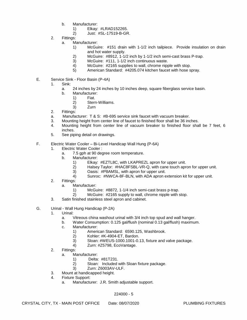
224000 - 5 CRYSTAL CITY, TX - MAIN POST OFFICE Date: 08/07/2020 PLUMBING FIXTURES
b. Manufacturer: 1) Elkay: #LRAD152265. 2) Just: #SL-17519-B-GR.
2. Fittings: a. Manufacturer:
1) McGuire: #151 drain with 1-1/2 inch tailpiece. Provide insulation on drain and hot water supply.
2) McGuire: #8912, 1-1/2 inch by 1-1/2 inch semi-cast brass P-trap. 3) McGuire: #111, 1-1/2 inch continuous waste. 4) McGuire: #2165 supplies to wall, chrome nipple with stop. 5) American Standard: #4205.074 kitchen faucet with hose spray.
E. Service Sink - Floor Basin (P-4A)
1. Sink: a. 24 inches by 24 inches by 10 inches deep, square fiberglass service basin. b. Manufacturer:
1) Fiat. 2) Stern-Williams. 3) Zurn
2. Fittings: a. Manufacturer: T & S: #B-695 service sink faucet with vacuum breaker. 3. Mounting height from center line of faucet to finished floor shall be 36 inches. 4. Mounting height from center line of vacuum breaker to finished floor shall be 7 feet, 6
inches. 5. See piping detail on drawings.
F. Electric Water Cooler – Bi-Level Handicap Wall Hung (P-6A)
1. Electric Water Cooler : a. 7.5 gph at 90 degree room temperature. b. Manufacturer:
1) Elkay: #EZTL8C, with LKAPREZL apron for upper unit. 2) Halsey Taylor: #HAC8FSBL-VR-Q, with cane touch apron for upper unit. 3) Oasis: #P8AMSL, with apron for upper unit. 4) Sunroc: #NWCA-8F-BLN, with ADA apron extension kit for upper unit.
2. Fittings: a. Manufactuer:
1) McGuire: #8872, 1-1/4 inch semi-cast brass p-trap. 2) McGuire: #2165 supply to wall, chrome nipple with stop.
3. Satin finished stainless steel apron and cabinet.
G. Urinal - Wall Hung Handicap (P-2A) 1. Urinal:
a. Vitreous china washout urinal with 3/4 inch top spud and wall hanger. b. Water Consumption: 0.125 gal/flush (nominal 0.13 gal/flush) maximum. c. Manufacturer:
1) American Standard: 6590.125, Washbrook. 2) Kohler: #K-4904-ET, Bardon. 3) Sloan: #WEUS-1000.1001-0.13, fixture and valve package. 4) Zurn: #Z5798, EcoVantage.
2. Fittings: a. Manufacturer:
1) Delta: #81T231. 2) Sloan: Included with Sloan fixture package. 3) Zurn: Z6003AV-ULF.
3. Mount at handicapped height. 4. Fixture Support:
a. Manufacturer: J.R. Smith adjustable support.
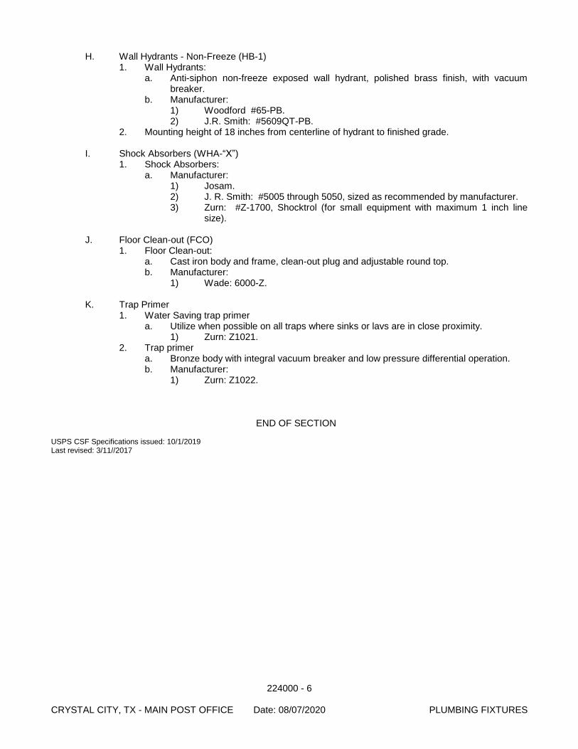
224000 - 6 CRYSTAL CITY, TX - MAIN POST OFFICE Date: 08/07/2020 PLUMBING FIXTURES
H. Wall Hydrants - Non-Freeze (HB-1) 1. Wall Hydrants:
a. Anti-siphon non-freeze exposed wall hydrant, polished brass finish, with vacuum breaker.
b. Manufacturer: 1) Woodford #65-PB. 2) J.R. Smith: #5609QT-PB.
2. Mounting height of 18 inches from centerline of hydrant to finished grade.
I. Shock Absorbers (WHA-“X”) 1. Shock Absorbers:
a. Manufacturer: 1) Josam. 2) J. R. Smith: #5005 through 5050, sized as recommended by manufacturer. 3) Zurn: #Z-1700, Shocktrol (for small equipment with maximum 1 inch line
size).
J. Floor Clean-out (FCO) 1. Floor Clean-out:
a. Cast iron body and frame, clean-out plug and adjustable round top. b. Manufacturer:
1) Wade: 6000-Z.
K. Trap Primer 1. Water Saving trap primer
a. Utilize when possible on all traps where sinks or lavs are in close proximity. 1) Zurn: Z1021.
2. Trap primer a. Bronze body with integral vacuum breaker and low pressure differential operation. b. Manufacturer:
1) Zurn: Z1022.
END OF SECTION USPS CSF Specifications issued: 10/1/2019 Last revised: 3/11//2017
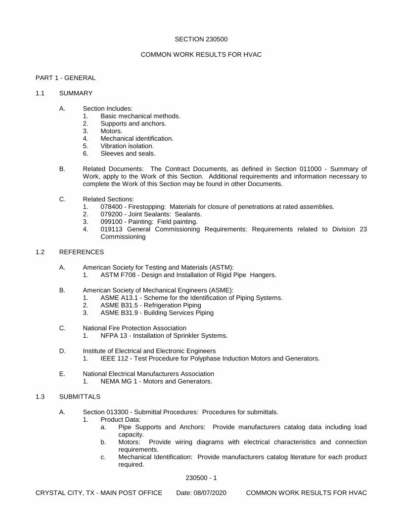
230500 - 1 CRYSTAL CITY, TX - MAIN POST OFFICE Date: 08/07/2020 COMMON WORK RESULTS FOR HVAC
SECTION 230500
COMMON WORK RESULTS FOR HVAC
PART 1 - GENERAL
1.1 SUMMARY
A. Section Includes: 1. Basic mechanical methods. 2. Supports and anchors. 3. Motors. 4. Mechanical identification. 5. Vibration isolation. 6. Sleeves and seals.
B. Related Documents: The Contract Documents, as defined in Section 011000 - Summary of Work, apply to the Work of this Section. Additional requirements and information necessary to complete the Work of this Section may be found in other Documents.
C. Related Sections: 1. 078400 - Firestopping: Materials for closure of penetrations at rated assemblies. 2. 079200 - Joint Sealants: Sealants. 3. 099100 - Painting: Field painting. 4. 019113 General Commissioning Requirements: Requirements related to Division 23
Commissioning
1.2 REFERENCES
A. American Society for Testing and Materials (ASTM): 1. ASTM F708 - Design and Installation of Rigid Pipe Hangers.
B. American Society of Mechanical Engineers (ASME): 1. ASME A13.1 - Scheme for the Identification of Piping Systems. 2. ASME B31.5 - Refrigeration Piping 3. ASME B31.9 - Building Services Piping
C. National Fire Protection Association 1. NFPA 13 - Installation of Sprinkler Systems.
D. Institute of Electrical and Electronic Engineers 1. IEEE 112 - Test Procedure for Polyphase Induction Motors and Generators.
E. National Electrical Manufacturers Association 1. NEMA MG 1 - Motors and Generators.
1.3 SUBMITTALS
A. Section 013300 - Submittal Procedures: Procedures for submittals. 1. Product Data:
a. Pipe Supports and Anchors: Provide manufacturers catalog data including load capacity.
b. Motors: Provide wiring diagrams with electrical characteristics and connection requirements.
c. Mechanical Identification: Provide manufacturers catalog literature for each product required.
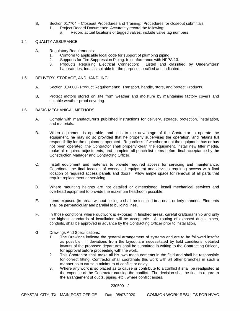
230500 - 2 CRYSTAL CITY, TX - MAIN POST OFFICE Date: 08/07/2020 COMMON WORK RESULTS FOR HVAC
B. Section 017704 – Closeout Procedures and Training: Procedures for closeout submittals. 1. Project Record Documents: Accurately record the following:
a. Record actual locations of tagged valves; include valve tag numbers.
1.4 QUALITY ASSURANCE
A. Regulatory Requirements: 1. Conform to applicable local code for support of plumbing piping. 2. Supports for Fire Suppression Piping: In conformance with NFPA 13. 3. Products Requiring Electrical Connection: Listed and classified by Underwriters'
Laboratories, Inc., as suitable for the purpose specified and indicated.
1.5 DELIVERY, STORAGE, AND HANDLING
A. Section 016000 - Product Requirements: Transport, handle, store, and protect Products.
B. Protect motors stored on site from weather and moisture by maintaining factory covers and suitable weather-proof covering.
1.6 BASIC MECHANICAL METHODS
A. Comply with manufacturer's published instructions for delivery, storage, protection, installation, and materials.
B. When equipment is operable, and it is to the advantage of the Contractor to operate the equipment, he may do so provided that he properly supervises the operation, and retains full responsibility for the equipment operated. Regardless of whether or not the equipment has or has not been operated, the Contractor shall properly clean the equipment, install new filter media, make all required adjustments, and complete all punch list items before final acceptance by the Construction Manager and Contracting Officer.
C. Install equipment and materials to provide required access for servicing and maintenance. Coordinate the final location of concealed equipment and devices requiring access with final location of required access panels and doors. Allow ample space for removal of all parts that require replacement or servicing.
D. Where mounting heights are not detailed or dimensioned, install mechanical services and overhead equipment to provide the maximum headroom possible.
E. Items exposed (in areas without ceilings) shall be installed in a neat, orderly manner. Elements shall be perpendicular and parallel to building lines.
F. In those conditions where ductwork is exposed in finished areas, careful craftsmanship and only the highest standards of installation will be acceptable. All routing of exposed ducts, pipes, conduits, shall be approved in advance by the Contracting Officer prior to installation.
G. Drawings And Specifications: 1. The Drawings indicate the general arrangement of systems and are to be followed insofar
as possible. If deviations from the layout are necessitated by field conditions, detailed layouts of the proposed departures shall be submitted in writing to the Contracting Officer , for approval before proceeding with the work.
2. This Contractor shall make all his own measurements in the field and shall be responsible for correct fitting. Contractor shall coordinate this work with all other branches in such a manner as to cause a minimum of conflict or delay.
3. Where any work is so placed as to cause or contribute to a conflict it shall be readjusted at the expense of the Contractor causing the conflict. The decision shall be final in regard to the arrangement of ducts, piping, etc., where conflict arises.
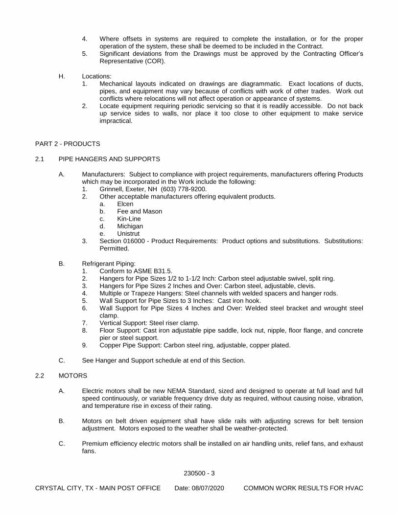
230500 - 3 CRYSTAL CITY, TX - MAIN POST OFFICE Date: 08/07/2020 COMMON WORK RESULTS FOR HVAC
4. Where offsets in systems are required to complete the installation, or for the proper operation of the system, these shall be deemed to be included in the Contract.
5. Significant deviations from the Drawings must be approved by the Contracting Officer’s Representative (COR).
H. Locations: 1. Mechanical layouts indicated on drawings are diagrammatic. Exact locations of ducts,
pipes, and equipment may vary because of conflicts with work of other trades. Work out conflicts where relocations will not affect operation or appearance of systems.
2. Locate equipment requiring periodic servicing so that it is readily accessible. Do not back up service sides to walls, nor place it too close to other equipment to make service impractical.
PART 2 - PRODUCTS
2.1 PIPE HANGERS AND SUPPORTS
A. Manufacturers: Subject to compliance with project requirements, manufacturers offering Products which may be incorporated in the Work include the following: 1. Grinnell, Exeter, NH (603) 778-9200. 2. Other acceptable manufacturers offering equivalent products.
a. Elcen b. Fee and Mason c. Kin-Line d. Michigan e. Unistrut
3. Section 016000 - Product Requirements: Product options and substitutions. Substitutions: Permitted.
B. Refrigerant Piping: 1. Conform to ASME B31.5. 2. Hangers for Pipe Sizes 1/2 to 1-1/2 Inch: Carbon steel adjustable swivel, split ring. 3. Hangers for Pipe Sizes 2 Inches and Over: Carbon steel, adjustable, clevis. 4. Multiple or Trapeze Hangers: Steel channels with welded spacers and hanger rods. 5. Wall Support for Pipe Sizes to 3 Inches: Cast iron hook. 6. Wall Support for Pipe Sizes 4 Inches and Over: Welded steel bracket and wrought steel
clamp. 7. Vertical Support: Steel riser clamp. 8. Floor Support: Cast iron adjustable pipe saddle, lock nut, nipple, floor flange, and concrete
pier or steel support. 9. Copper Pipe Support: Carbon steel ring, adjustable, copper plated.
C. See Hanger and Support schedule at end of this Section.
2.2 MOTORS
A. Electric motors shall be new NEMA Standard, sized and designed to operate at full load and full speed continuously, or variable frequency drive duty as required, without causing noise, vibration, and temperature rise in excess of their rating.
B. Motors on belt driven equipment shall have slide rails with adjusting screws for belt tension adjustment. Motors exposed to the weather shall be weather-protected.
C. Premium efficiency electric motors shall be installed on air handling units, relief fans, and exhaust fans.
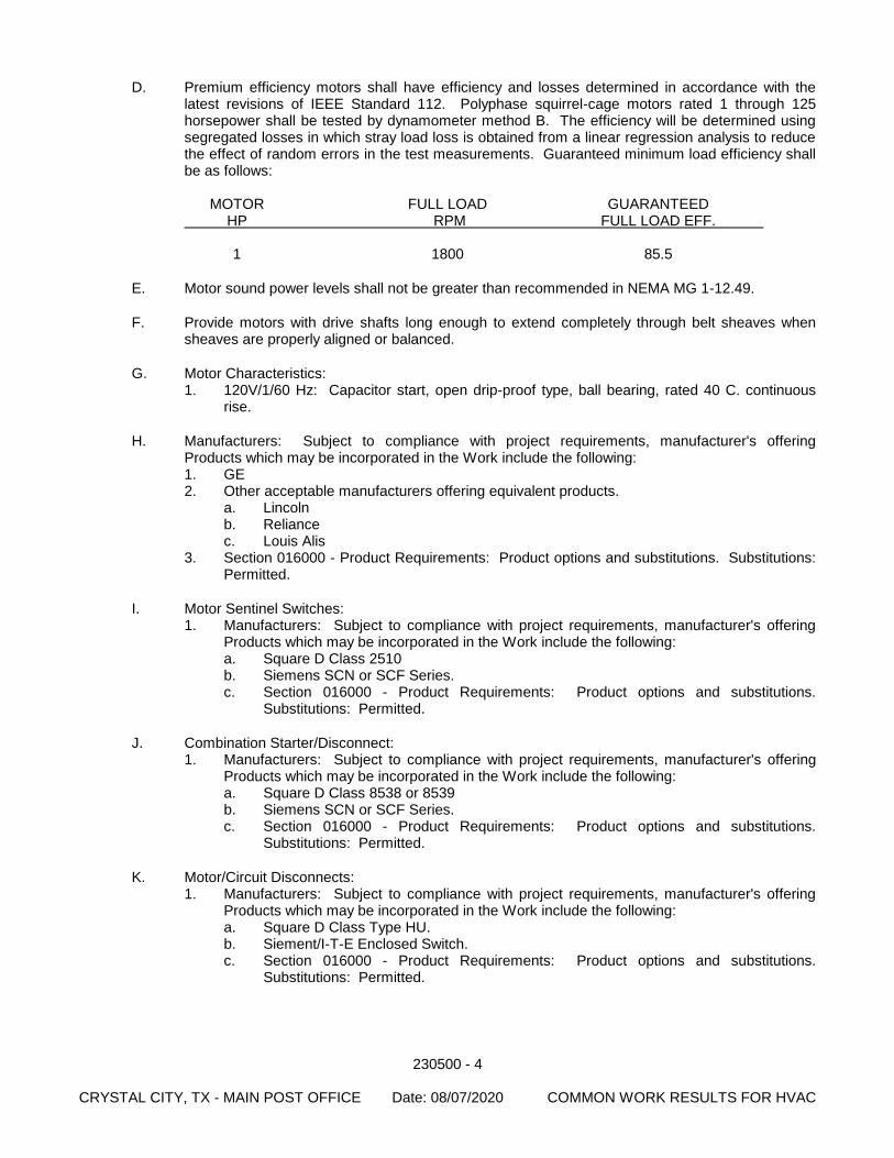
230500 - 4 CRYSTAL CITY, TX - MAIN POST OFFICE Date: 08/07/2020 COMMON WORK RESULTS FOR HVAC
D. Premium efficiency motors shall have efficiency and losses determined in accordance with the latest revisions of IEEE Standard 112. Polyphase squirrel-cage motors rated 1 through 125 horsepower shall be tested by dynamometer method B. The efficiency will be determined using segregated losses in which stray load loss is obtained from a linear regression analysis to reduce the effect of random errors in the test measurements. Guaranteed minimum load efficiency shall be as follows:
MOTOR FULL LOAD GUARANTEED HP RPM FULL LOAD EFF. 1 1800 85.5
E. Motor sound power levels shall not be greater than recommended in NEMA MG 1-12.49.
F. Provide motors with drive shafts long enough to extend completely through belt sheaves when sheaves are properly aligned or balanced.
G. Motor Characteristics: 1. 120V/1/60 Hz: Capacitor start, open drip-proof type, ball bearing, rated 40 C. continuous
rise.
H. Manufacturers: Subject to compliance with project requirements, manufacturer's offering Products which may be incorporated in the Work include the following: 1. GE 2. Other acceptable manufacturers offering equivalent products.
a. Lincoln b. Reliance c. Louis Alis
3. Section 016000 - Product Requirements: Product options and substitutions. Substitutions: Permitted.
I. Motor Sentinel Switches: 1. Manufacturers: Subject to compliance with project requirements, manufacturer's offering
Products which may be incorporated in the Work include the following: a. Square D Class 2510 b. Siemens SCN or SCF Series. c. Section 016000 - Product Requirements: Product options and substitutions.
Substitutions: Permitted.
J. Combination Starter/Disconnect: 1. Manufacturers: Subject to compliance with project requirements, manufacturer's offering
Products which may be incorporated in the Work include the following: a. Square D Class 8538 or 8539 b. Siemens SCN or SCF Series. c. Section 016000 - Product Requirements: Product options and substitutions.
Substitutions: Permitted.
K. Motor/Circuit Disconnects: 1. Manufacturers: Subject to compliance with project requirements, manufacturer's offering
Products which may be incorporated in the Work include the following: a. Square D Class Type HU. b. Siement/I-T-E Enclosed Switch. c. Section 016000 - Product Requirements: Product options and substitutions.
Substitutions: Permitted.
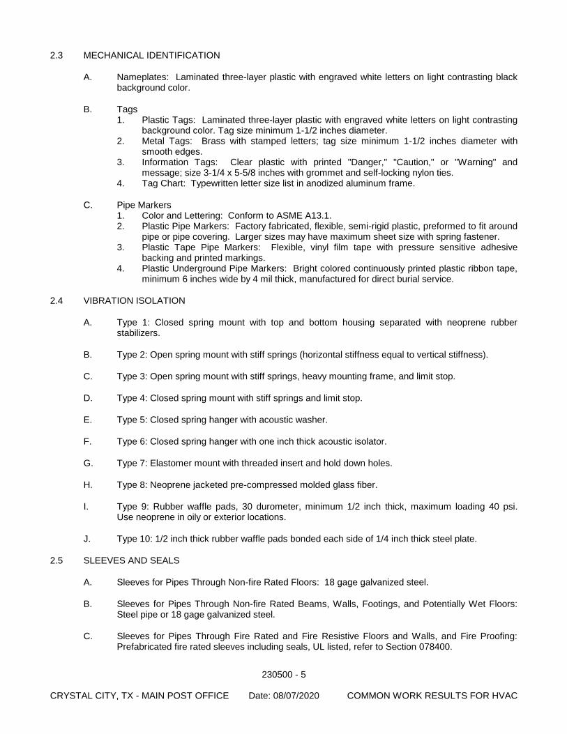
230500 - 5 CRYSTAL CITY, TX - MAIN POST OFFICE Date: 08/07/2020 COMMON WORK RESULTS FOR HVAC
2.3 MECHANICAL IDENTIFICATION
A. Nameplates: Laminated three-layer plastic with engraved white letters on light contrasting black background color.
B. Tags 1. Plastic Tags: Laminated three-layer plastic with engraved white letters on light contrasting
background color. Tag size minimum 1-1/2 inches diameter. 2. Metal Tags: Brass with stamped letters; tag size minimum 1-1/2 inches diameter with
smooth edges. 3. Information Tags: Clear plastic with printed "Danger," "Caution," or "Warning" and
message; size 3-1/4 x 5-5/8 inches with grommet and self-locking nylon ties. 4. Tag Chart: Typewritten letter size list in anodized aluminum frame.
C. Pipe Markers 1. Color and Lettering: Conform to ASME A13.1. 2. Plastic Pipe Markers: Factory fabricated, flexible, semi-rigid plastic, preformed to fit around
pipe or pipe covering. Larger sizes may have maximum sheet size with spring fastener. 3. Plastic Tape Pipe Markers: Flexible, vinyl film tape with pressure sensitive adhesive
backing and printed markings. 4. Plastic Underground Pipe Markers: Bright colored continuously printed plastic ribbon tape,
minimum 6 inches wide by 4 mil thick, manufactured for direct burial service.
2.4 VIBRATION ISOLATION
A. Type 1: Closed spring mount with top and bottom housing separated with neoprene rubber stabilizers.
B. Type 2: Open spring mount with stiff springs (horizontal stiffness equal to vertical stiffness).
C. Type 3: Open spring mount with stiff springs, heavy mounting frame, and limit stop.
D. Type 4: Closed spring mount with stiff springs and limit stop.
E. Type 5: Closed spring hanger with acoustic washer.
F. Type 6: Closed spring hanger with one inch thick acoustic isolator.
G. Type 7: Elastomer mount with threaded insert and hold down holes.
H. Type 8: Neoprene jacketed pre-compressed molded glass fiber.
I. Type 9: Rubber waffle pads, 30 durometer, minimum 1/2 inch thick, maximum loading 40 psi. Use neoprene in oily or exterior locations.
J. Type 10: 1/2 inch thick rubber waffle pads bonded each side of 1/4 inch thick steel plate.
2.5 SLEEVES AND SEALS
A. Sleeves for Pipes Through Non-fire Rated Floors: 18 gage galvanized steel.
B. Sleeves for Pipes Through Non-fire Rated Beams, Walls, Footings, and Potentially Wet Floors: Steel pipe or 18 gage galvanized steel.
C. Sleeves for Pipes Through Fire Rated and Fire Resistive Floors and Walls, and Fire Proofing: Prefabricated fire rated sleeves including seals, UL listed, refer to Section 078400.
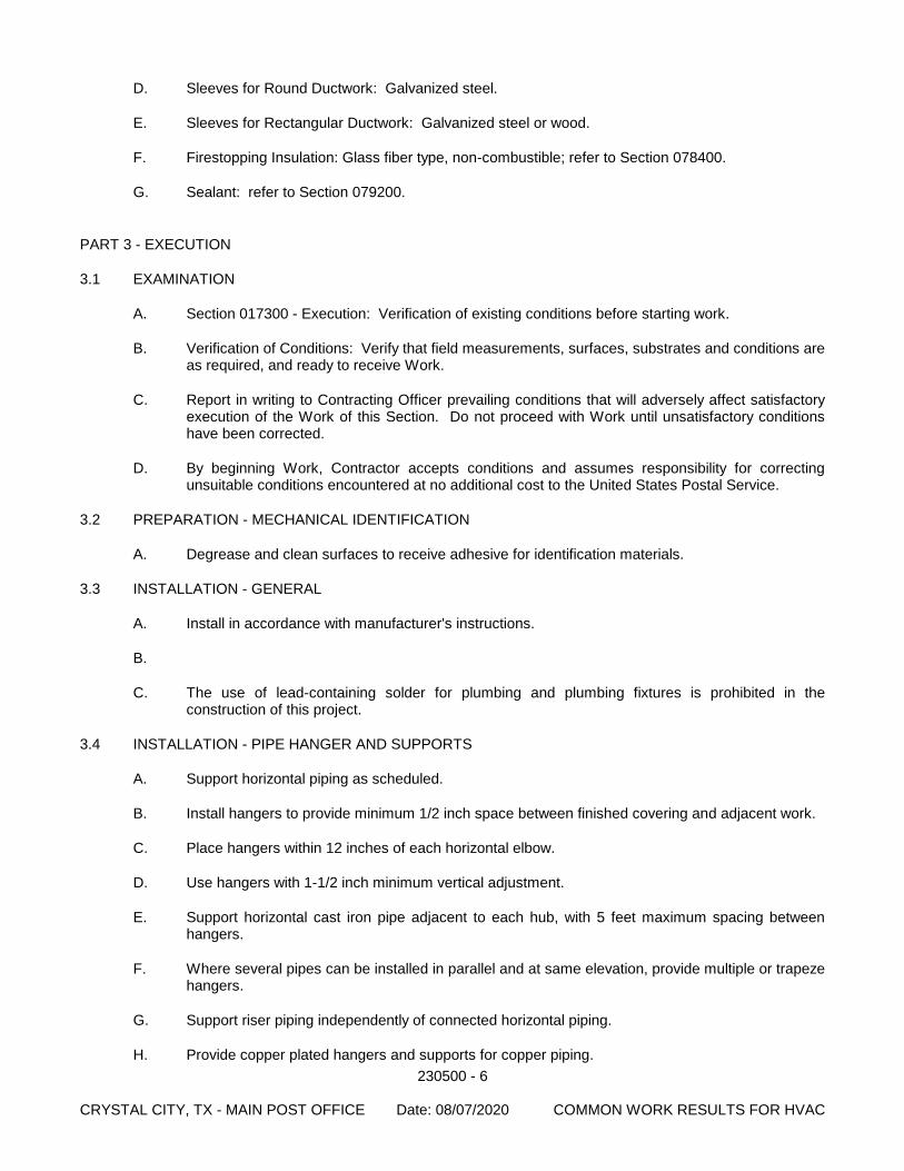
230500 - 6 CRYSTAL CITY, TX - MAIN POST OFFICE Date: 08/07/2020 COMMON WORK RESULTS FOR HVAC
D. Sleeves for Round Ductwork: Galvanized steel.
E. Sleeves for Rectangular Ductwork: Galvanized steel or wood.
F. Firestopping Insulation: Glass fiber type, non-combustible; refer to Section 078400.
G. Sealant: refer to Section 079200.
PART 3 - EXECUTION
3.1 EXAMINATION
A. Section 017300 - Execution: Verification of existing conditions before starting work.
B. Verification of Conditions: Verify that field measurements, surfaces, substrates and conditions are as required, and ready to receive Work.
C. Report in writing to Contracting Officer prevailing conditions that will adversely affect satisfactory execution of the Work of this Section. Do not proceed with Work until unsatisfactory conditions have been corrected.
D. By beginning Work, Contractor accepts conditions and assumes responsibility for correcting unsuitable conditions encountered at no additional cost to the United States Postal Service.
3.2 PREPARATION - MECHANICAL IDENTIFICATION
A. Degrease and clean surfaces to receive adhesive for identification materials.
3.3 INSTALLATION - GENERAL
A. Install in accordance with manufacturer's instructions.
B.
C. The use of lead-containing solder for plumbing and plumbing fixtures is prohibited in the construction of this project.
3.4 INSTALLATION - PIPE HANGER AND SUPPORTS
A. Support horizontal piping as scheduled.
B. Install hangers to provide minimum 1/2 inch space between finished covering and adjacent work.
C. Place hangers within 12 inches of each horizontal elbow.
D. Use hangers with 1-1/2 inch minimum vertical adjustment.
E. Support horizontal cast iron pipe adjacent to each hub, with 5 feet maximum spacing between hangers.
F. Where several pipes can be installed in parallel and at same elevation, provide multiple or trapeze hangers.
G. Support riser piping independently of connected horizontal piping.
H. Provide copper plated hangers and supports for copper piping.
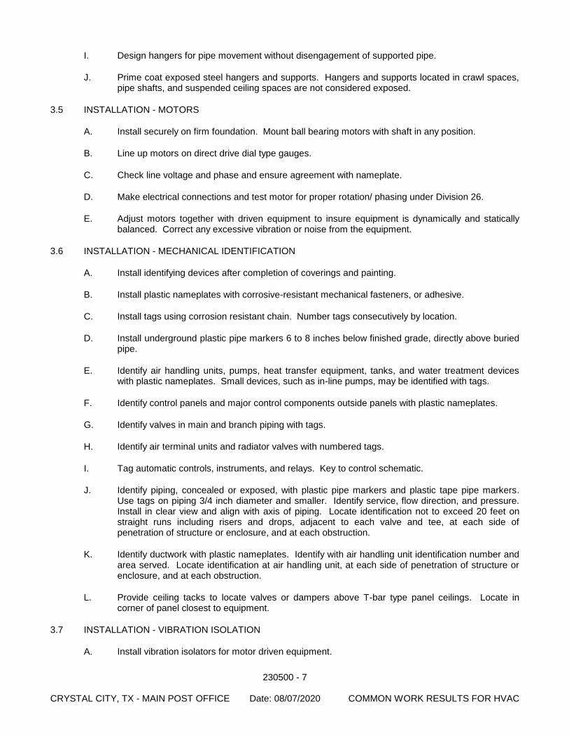
230500 - 7 CRYSTAL CITY, TX - MAIN POST OFFICE Date: 08/07/2020 COMMON WORK RESULTS FOR HVAC
I. Design hangers for pipe movement without disengagement of supported pipe.
J. Prime coat exposed steel hangers and supports. Hangers and supports located in crawl spaces, pipe shafts, and suspended ceiling spaces are not considered exposed.
3.5 INSTALLATION - MOTORS
A. Install securely on firm foundation. Mount ball bearing motors with shaft in any position.
B. Line up motors on direct drive dial type gauges.
C. Check line voltage and phase and ensure agreement with nameplate.
D. Make electrical connections and test motor for proper rotation/ phasing under Division 26.
E. Adjust motors together with driven equipment to insure equipment is dynamically and statically balanced. Correct any excessive vibration or noise from the equipment.
3.6 INSTALLATION - MECHANICAL IDENTIFICATION
A. Install identifying devices after completion of coverings and painting.
B. Install plastic nameplates with corrosive-resistant mechanical fasteners, or adhesive.
C. Install tags using corrosion resistant chain. Number tags consecutively by location.
D. Install underground plastic pipe markers 6 to 8 inches below finished grade, directly above buried pipe.
E. Identify air handling units, pumps, heat transfer equipment, tanks, and water treatment devices with plastic nameplates. Small devices, such as in-line pumps, may be identified with tags.
F. Identify control panels and major control components outside panels with plastic nameplates.
G. Identify valves in main and branch piping with tags.
H. Identify air terminal units and radiator valves with numbered tags.
I. Tag automatic controls, instruments, and relays. Key to control schematic.
J. Identify piping, concealed or exposed, with plastic pipe markers and plastic tape pipe markers. Use tags on piping 3/4 inch diameter and smaller. Identify service, flow direction, and pressure. Install in clear view and align with axis of piping. Locate identification not to exceed 20 feet on straight runs including risers and drops, adjacent to each valve and tee, at each side of penetration of structure or enclosure, and at each obstruction.
K. Identify ductwork with plastic nameplates. Identify with air handling unit identification number and area served. Locate identification at air handling unit, at each side of penetration of structure or enclosure, and at each obstruction.
L. Provide ceiling tacks to locate valves or dampers above T-bar type panel ceilings. Locate in corner of panel closest to equipment.
3.7 INSTALLATION - VIBRATION ISOLATION
A. Install vibration isolators for motor driven equipment.
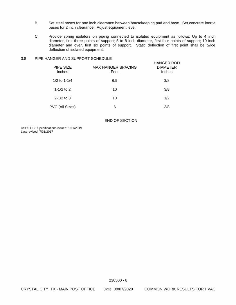
230500 - 8 CRYSTAL CITY, TX - MAIN POST OFFICE Date: 08/07/2020 COMMON WORK RESULTS FOR HVAC
B. Set steel bases for one inch clearance between housekeeping pad and base. Set concrete inertia bases for 2 inch clearance. Adjust equipment level.
C. Provide spring isolators on piping connected to isolated equipment as follows: Up to 4 inch diameter, first three points of support; 5 to 8 inch diameter, first four points of support; 10 inch diameter and over, first six points of support. Static deflection of first point shall be twice deflection of isolated equipment.
3.8 PIPE HANGER AND SUPPORT SCHEDULE HANGER ROD
PIPE SIZE MAX HANGER SPACING DIAMETER Inches Feet Inches 1/2 to 1-1/4 6.5 3/8 1-1/2 to 2 10 3/8 2-1/2 to 3 10 1/2 PVC (All Sizes) 6 3/8
END OF SECTION USPS CSF Specifications issued: 10/1/2019 Last revised: 7/31/2017
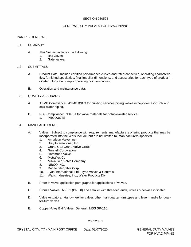
230523 - 1
CRYSTAL CITY, TX - MAIN POST OFFICE Date: 08/07/2020 GENERAL DUTY VALVES
FOR HVAC PIPING
SECTION 230523
GENERAL DUTY VALVES FOR HVAC PIPING
PART 1 - GENERAL
1.1 SUMMARY
A. This Section includes the following: 1. Ball valves. 2. Gate valves.
1.2 SUBMITTALS
A. Product Data: Include certified performance curves and rated capacities, operating characteris-tics, furnished specialties, final impeller dimensions, and accessories for each type of product in-dicated. Indicate pump's operating point on curves.
B. Operation and maintenance data.
1.3 QUALITY ASSURANCE
A. ASME Compliance: ASME B31.9 for building services piping valves except domestic hot- and cold-water piping.
B. NSF Compliance: NSF 61 for valve materials for potable-water service. 1. PRODUCTS
1.4 MANUFACTURERS:
A. Valves: Subject to compliance with requirements, manufacturers offering products that may be incorporated into the Work include, but are not limited to, manufacturers specified. 1. American Valve, Inc. 2. Bray International, Inc. 3. Crane Co.; Crane Valve Group; 4. Grinnell Corporation. 5. Hammond Valve. 6. Metraflex Co. 7. Milwaukee Valve Company. 8. NIBCO INC. 9. Red-White Valve Corp. 10. Tyco International, Ltd.; Tyco Valves & Controls. 11. Watts Industries, Inc.; Water Products Div.
B. Refer to valve application paragraphs for applications of valves.
C. Bronze Valves: NPS 2 (DN 50) and smaller with threaded ends, unless otherwise indicated.
D. Valve Actuators: Handwheel for valves other than quarter-turn types and lever handle for quar-ter-turn valves.
E. Copper-Alloy Ball Valves, General: MSS SP-110.
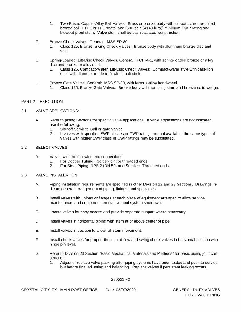
230523 - 2
CRYSTAL CITY, TX - MAIN POST OFFICE Date: 08/07/2020 GENERAL DUTY VALVES
FOR HVAC PIPING
1. Two-Piece, Copper-Alloy Ball Valves: Brass or bronze body with full-port, chrome-plated bronze ball; PTFE or TFE seats; and [600-psig (4140-kPa)] minimum CWP rating and blowout-proof stem. Valve stem shall be stainless steel construction.
F. Bronze Check Valves, General: MSS SP-80. 1. Class 125, Bronze, Swing Check Valves: Bronze body with aluminum bronze disc and
seat.
G. Spring-Loaded, Lift-Disc Check Valves, General: FCI 74-1, with spring-loaded bronze or alloy disc and bronze or alloy seat. 1. Class 125, Compact-Wafer, Lift-Disc Check Valves: Compact-wafer style with cast-iron
shell with diameter made to fit within bolt circle.
H. Bronze Gate Valves, General: MSS SP-80, with ferrous-alloy handwheel. 1. Class 125, Bronze Gate Valves: Bronze body with nonrising stem and bronze solid wedge.
PART 2 - EXECUTION
2.1 VALVE APPLICATIONS:
A. Refer to piping Sections for specific valve applications. If valve applications are not indicated, use the following: 1. Shutoff Service: Ball or gate valves. 2. If valves with specified SWP classes or CWP ratings are not available, the same types of
valves with higher SWP class or CWP ratings may be substituted.
2.2 SELECT VALVES
A. Valves with the following end connections: 1. For Copper Tubing: Solder-joint or threaded ends 2. For Steel Piping, NPS 2 (DN 50) and Smaller: Threaded ends.
2.3 VALVE INSTALLATION:
A. Piping installation requirements are specified in other Division 22 and 23 Sections. Drawings in-dicate general arrangement of piping, fittings, and specialties.
B. Install valves with unions or flanges at each piece of equipment arranged to allow service, maintenance, and equipment removal without system shutdown.
C. Locate valves for easy access and provide separate support where necessary.
D. Install valves in horizontal piping with stem at or above center of pipe.
E. Install valves in position to allow full stem movement.
F. Install check valves for proper direction of flow and swing check valves in horizontal position with hinge pin level.
G. Refer to Division 23 Section "Basic Mechanical Materials and Methods" for basic piping joint con-struction. 1. Adjust or replace valve packing after piping systems have been tested and put into service
but before final adjusting and balancing. Replace valves if persistent leaking occurs.
230523 - 3
CRYSTAL CITY, TX - MAIN POST OFFICE Date: 08/07/2020 GENERAL DUTY VALVES
FOR HVAC PIPING
END OF SECTION
USPS CSF Specification issued: 10/1/2019 Last revised: 5/11/2011

230523 - 4
CRYSTAL CITY, TX - MAIN POST OFFICE Date: 08/07/2020 GENERAL DUTY VALVES
FOR HVAC PIPING
[This page intentionally left blank.]
230593 - 1 CRYSTAL CITY, TX - MAIN POST OFFICE Date: 08/07/2020 TESTING, ADJUSTING AND BALANCING FOR HVAC
SECTION 230593
TESTING, ADJUSTING AND BALANCING FOR HVAC
PART 1 - GENERAL
1.1 SUMMARY
A. SECTION INCLUDES: 1. Testing, adjustment, and balancing of air systems. 2. Measurement of final operating condition of HVAC systems. 3. Sound measurement of equipment operating conditions. 4. Vibration measurement of equipment operating conditions.
B. RELATED DOCUMENTS: 1. The Contract Documents, as defined in Section 011000 - Summary of Work, apply to the
Work of this Section. Additional requirements and information necessary to complete the Work of this Section may be found in other Documents.
C. RELATED SECTIONS: 1. Section 013543 - Environmental Procedures: Pre-occupancy ventilation 2. Section 014000 - Quality Requirements: Employment of testing agency and payment for
services. 3. Section 017300 - Execution: Starting of systems.
1.2 REFERENCES
A. Associated Air Balance Council (AABC): 1. AABC - National Standards for Total System Balance.
B. National Environmental Balancing Bureau.
1.3 SUBMITTALS
A. Section 013300 - Submittal Procedures: Procedures for submittals. 1. Assurance/Control Submittals:
a. Test Reports: Submit the following reports directly to Contracting Officer from Testing Laboratory, with copy to Contractor. Prepare reports in conformance with Section 014000 - Quality Requirements: 1) Indicate deficiencies in systems that would prevent proper testing,
adjusting, and balancing of systems and equipment to achieve specified performance.
2) Submit draft copies of report for review prior to final acceptance of Project. Provide final copies for inclusion in operating and maintenance manuals.
3) Provide reports in binder manuals, complete with index page and indexing tabs, with cover identification at front and side. Include set of reduced drawings with air outlets and equipment identified to correspond with data sheets, and indicating thermostat locations.
4) Indicate data on AABC National Standards for Total System Balance forms.
b. Certificates: Manufacturer's certificate that Products meet or exceed specified requirements.
c. Qualification Documentation: Submit documentation of experience indicating compliance with specified qualification requirements.
230593 - 2 CRYSTAL CITY, TX - MAIN POST OFFICE Date: 08/07/2020 TESTING, ADJUSTING AND BALANCING FOR HVAC
B. Section 017704 - Closeout Procedures and Training: Procedures for closeout submittals. 1. Project Record Documents: Accurately record the following:
a. Actual locations of balancing valves and rough setting. 2. Submit written special warranty with forms completed in United States Postal Service
name and registered with manufacturer as specified in this Section.
1.4 QUALITY ASSURANCE
A. Qualifications: 1. Company specializing in testing, adjusting, and balancing of specified with minimum 5
years documented experience. Company to be certified by one of the following. a. AABC Certified Independent Testing and Balancing Agency. b. National Environmental Balancing Bureau Certified Independent Agency.
(NEBB).
B. Certification: Certify the testing, adjusting, and balancing field data reports.
C. Testing, Adjusting, and Balancing Reports: Use testing, adjusting, and balancing Agent’s standard forms.
PART 2 - PRODUCTS (Not Used.)
PART 3 - EXECUTION
3.1 EXAMINATION
A. Verify that systems are complete and operable before commencing work. Ensure the following conditions: 1. Systems are started and operating in a safe and normal condition. 2. Temperature control systems are installed complete and operable. 3. Proper thermal overload protection is in place for electrical equipment. 4. Final filters are clean and in place. If required, install temporary media in addition to final
filters. 5. Duct systems are clean of debris. 6. Fans are rotating correctly. 7. Fire and volume dampers are in place and open. 8. Air coil fins are cleaned and combed. 9. Access doors are closed and duct end caps are in place. 10. Air outlets are installed and connected. 11. Duct system leakage is minimized.
3.2 PREPARATION
A. Provide instruments required for testing, adjusting, and balancing operations. Make instruments available to Contracting Officer to facilitate spot checks during testing.
B. Provide additional balancing instruments as required.
3.3 INSTALLATION TOLERANCES
A. Air Handling Systems: Adjust to within plus or minus 5 percent of design for supply systems and plus or minus 10 percent of design for return and exhaust systems.
230593 - 3 CRYSTAL CITY, TX - MAIN POST OFFICE Date: 08/07/2020 TESTING, ADJUSTING AND BALANCING FOR HVAC
B. Air Outlets and Inlets: Adjust total to within plus 10 percent and minus 5 percent of design to space. Adjust outlets and inlets in space to within plus or minus 10 percent of design.
3.4 ADJUSTING
A. Ensure recorded data represents actual measured or observed conditions.
B. Permanently mark settings of valves, dampers, and other adjustment devices allowing settings to be restored. Set and lock memory stops.
C. After adjustment, take measurements to verify balance has not been disrupted or that such disruption has been rectified.
D. Leave systems in proper working order, replacing belt guards, closing access doors, closing doors to electrical switch boxes, and restoring thermostats to specified settings.
E. At final inspection, recheck random selections of data recorded in report. Recheck points or areas as selected and witnessed by Contracting Officer.
F. Check and adjust systems approximately six months after final acceptance and submit report.
3.5 AIR SYSTEM PROCEDURE
A. Adjust air handling and distribution systems to provide required or design supply, return, and exhaust air quantities. Perform this work with cooling system energized where applicable to obtain the extra resistance of wet coils.
B. Make air quantity measurements in ducts by Pitot tube traverse of entire cross sectional area of duct.
C. Measure air quantities at air inlets and outlets.
D. Adjust distribution system to obtain uniform space temperatures free from objectionable drafts and noise.
E. Use volume control devices to regulate air quantities only to extend that adjustments do not create objectionable air motion or sound levels. Effect volume control by duct internal devices.
F. Vary total system air quantities by adjustment of fan speeds. Provide drive changes required. Vary branch air quantities by damper regulation.
G. Provide system schematic with required and actual air quantities recorded at each outlet or inlet.
H. Measure static air pressure conditions on air supply units, including filter and coil pressure drops, and total pressure across the fan. Make allowances for 50 percent loading of filters.
I. Adjust outside air automatic dampers, outside air, return air, and exhaust dampers for design conditions.
J. Measure temperature conditions across outside air, return air, and exhaust dampers to check leakage.
K. Measure building static pressure and adjust supply, return, and exhaust air systems to provide required relationship between each to maintain approximately 0.05 inches (12.5 Pa) positive static pressure near the building entries.
230593 - 4 CRYSTAL CITY, TX - MAIN POST OFFICE Date: 08/07/2020 TESTING, ADJUSTING AND BALANCING FOR HVAC
3.6 SITE ENVIRONMENTAL PROCEDURES
A. Indoor Air Quality: 1. Pre-occupancy ventilation: Provide pre-occupancy ventilation as specified in Section
013543 - Environmental Procedures; provide prior to final testing, adjusting, and balancing of HVAC system.
END OF SECTION USPS CSF Specifications issued: 10/1/2019 Last revised: 5/11/2011
230713 - 1 CRYSTAL CITY, TX - MAIN POST OFFICE Date: 08/07/2020 DUCT INSULATION
SECTION 230713
DUCT INSULATION
PART 1 - GENERAL
1.1 SUMMARY
A. Section Includes: 1. Ductwork insulation. 2. Insulation jackets.
B. Related Documents: The Contract Documents, as defined in Section 011000 - Summary of Work, apply to the Work of this Section. Additional requirements and information necessary to complete the Work of this Section may be found in other Documents.
1.2 REFERENCES
A. American Society for Testing and Materials (ASTM): 1. ASTM B209 - Aluminum and Aluminum-Alloy Sheet and Plate. 2. ASTM C177 - Steady-State Heat Flux Measurements and Thermal Transmission
Properties by Means of the Guarded-Hot-Plate Apparatus. 3. ASTM C335 - Steady-State Heat Transfer Properties of Horizontal Pipe Insulation. 4. ASTM C518 - Steady-State Heat Flux Measurements and Thermal Transmission
Properties by Means of the Heat Flow Meter Apparatus. 5. ASTM C534 - Preformed Flexible Elastomeric Cellular Thermal Insulation in Sheet and
Tubular Form. 6. ASTM C547 - Mineral Fiber Pipe Insulation. 7. ASTM C553 - Mineral Fiber Blanket Thermal Insulation for Commercial and Industrial
Applications. 8. ASTM C921 - Properties of Jacketing Materials for Thermal Insulation. 9. ASTM D1056 - Flexible Cellular Materials - Sponge or Expanded Rubber. 10. ASTM E84 - Surface Burning Characteristics of Building Materials. 11. ASTM E96 - Water Vapor Transmission of Materials.
B. National Fire Protection Association (NFPA): 1. NFPA 255 - Standard Method of Test of Surface Burning Characteristics of Building
Materials.
C. Sheet Metal and Air Conditioning Contractors National Association (SMACNA): 1. SMACNA - HVAC Duct Construction Standards - Metal and Flexible.
D. Underwriters Laboratories, Inc. (UL): 1. UL 723 - Tests for Surface Burning Characteristics of Building Materials.
1.3 SUBMITTALS
A. Section 013300 - Submittal Procedures: Procedures for submittals. 1. Product Data:
a. Product Data: Provide product description, thermal characteristics, list of materials and thickness for each service, and locations.
1.4 QUALITY ASSURANCE
A. Qualifications:
230713 - 2 CRYSTAL CITY, TX - MAIN POST OFFICE Date: 08/07/2020 DUCT INSULATION
1. Manufacturer: Company specializing in manufacturing Products specified with minimum 3 years documented experience.
2. Installer: Company specializing in performing the Work of this Section with minimum 3 years documented experience.
B. Materials: 1. Flame spread/smoke developed rating of 25/50 or less in accordance with ASTM E84,
NFPA 255 and UL 723. 2. Insulation for duct, pipe and equipment for above grade exposed to weather outside
building shall be certified as being self-extinguishing for 1 inch thickness less than 53 seconds when tested in accordance with ASTM D1692.
1.5 DELIVERY, STORAGE, AND HANDLING
A. Section 016000 - Product Requirements: Transport, handle, store, and protect Products.
B. Deliver materials to site in original factory packaging, labeled with manufacturer's identification, including product density and thickness.
C. Store insulation in original wrapping and protect from weather and construction traffic.
D. Protect insulation against dirt, water, chemical, and mechanical damage.
1.6 PROJECT CONDITIONS OR SITE CONDITIONS
A. Jobsite Requirements 1. Maintain ambient temperatures and conditions required by manufacturers of adhesives,
mastics, and insulation cements. 2. Maintain temperature during and after installation for minimum period of 24 hours.
1.7 ENVIRONMENTAL REQUIREMENTS
A. Energy efficiency: 1. Insulation: Minimum thickness in accordance with ASHRAE 90.1. Provide additional
thickness to ensure surface temperatures are below 100 degrees and to prevent condensation on cold surfaces.
PART 2 - PRODUCTS
2.1 DUCTWORK INSULATION
A. Glass Fiber, Flexible Duct Wrap 1. Manufacturers:
a. Owens/Corning, Toledo, OH (800) 438-7465. b. Other acceptable manufacturers offering equivalent products.
1) CertainTeed. 2) Schuller (Manville). 3) Knauf.
2. Insulation: ASTM C553 flexible, noncombustible blanket. a. 'K' ('Ksi') value : ASTM C518, 0.30 at 75 degrees F. b. Maximum service temperature: 250 degrees F. c. Maximum moisture absorption: 0.20 percent by volume. d. Density: 0.75 lb./cu ft .
3. Vapor Barrier Jacket a. Kraft paper reinforced with glass fiber yarn and bonded to aluminized film. b. Moisture vapor transmission: ASTM E96; 0.02 perm.
230713 - 3 CRYSTAL CITY, TX - MAIN POST OFFICE Date: 08/07/2020 DUCT INSULATION
c. Secure with pressure sensitive tape. 4. Vapor Barrier Tape
a. Manufacturers: 1) Owens/Corning. 2) CertainTeed. 3) Schuller (Manville).
b. Kraft paper reinforced with glass fiber yarn and bonded to aluminized film, with pressure sensitive rubber based adhesive.
5. Tie Wire: Annealed steel, 16 gage.
B. Glass Fiber Duct Liner, Flexible 1. Manufacturers:
a. CertainTeed. b. Other acceptable manufacturers offering equivalent products.
1) Knauf. 2) Schuller (Manville). 3) Owens Corning.
2. Insulation: ASTM C553; flexible, noncombustible blanket. a. 'K' ('Ksi') value : ASTM C518, 0.28 at 75 degrees F. b. Maximum service temperature: 250 degrees F. c. Density: 1.5 lb./cu ft. d. Maximum Velocity on Coated Air Side: 4,000 ft./min.
3. Adhesive a. Waterproof fire-retardant type.
4. Liner Fasteners: Galvanized steel, impact applied with integral head.
PART 3 - EXECUTION
3.1 EXAMINATION
A. Section 017300 - Execution: Verification of existing conditions before starting work.
B. Verification of Conditions: Verify that field measurements, surfaces, substrates and conditions are as required, and ready to receive Work. 1. Verify that piping has been tested before applying insulation materials. 2. Verify that ductwork has been tested before applying insulation materials. 3. Verify that surfaces are clean, foreign material removed, and dry.
C. Report in writing to Contracting Officer prevailing conditions that will adversely affect satisfactory execution of the Work of this Section. Do not proceed with Work until unsatisfactory conditions have been corrected.
D. By beginning Work, Contractor accepts conditions and assumes responsibility for correcting unsuitable conditions encountered at no additional cost to the United States Postal Service.
3.2 INSTALLATION - DUCTWORK INSULATION
A. Install materials in accordance with manufacturer's instructions and ASHRAE 90.1.
B. Insulated ductwork conveying air below ambient temperature: 1. Provide insulation with vapor barrier jackets. 2. Finish with tape and vapor barrier jacket. 3. Continue insulation through walls, sleeves, hangers, and other duct penetrations. 4. Insulate entire system including fittings, joints, flanges, fire dampers, flexible connections,
and expansion joints.
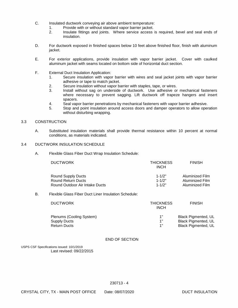
230713 - 4 CRYSTAL CITY, TX - MAIN POST OFFICE Date: 08/07/2020 DUCT INSULATION
C. Insulated ductwork conveying air above ambient temperature: 1. Provide with or without standard vapor barrier jacket. 2. Insulate fittings and joints. Where service access is required, bevel and seal ends of
insulation.
D. For ductwork exposed in finished spaces below 10 feet above finished floor, finish with aluminum jacket.
E. For exterior applications, provide insulation with vapor barrier jacket. Cover with caulked aluminum jacket with seams located on bottom side of horizontal duct section.
F. External Duct Insulation Application: 1. Secure insulation with vapor barrier with wires and seal jacket joints with vapor barrier
adhesive or tape to match jacket. 2. Secure insulation without vapor barrier with staples, tape, or wires. 3. Install without sag on underside of ductwork. Use adhesive or mechanical fasteners
where necessary to prevent sagging. Lift ductwork off trapeze hangers and insert spacers.
4. Seal vapor barrier penetrations by mechanical fasteners with vapor barrier adhesive. 5. Stop and point insulation around access doors and damper operators to allow operation
without disturbing wrapping.
3.3 CONSTRUCTION
A. Substituted insulation materials shall provide thermal resistance within 10 percent at normal conditions, as materials indicated.
3.4 DUCTWORK INSULATION SCHEDULE
A. Flexible Glass Fiber Duct Wrap Insulation Schedule:
DUCTWORK THICKNESS FINISH INCH
Round Supply Ducts 1-1/2" Aluminized Film Round Return Ducts 1-1/2" Aluminized Film Round Outdoor Air Intake Ducts 1-1/2" Aluminized Film
B. Flexible Glass Fiber Duct Liner Insulation Schedule:
DUCTWORK THICKNESS FINISH INCH
Plenums (Cooling System) 1" Black Pigmented, UL Supply Ducts 1" Black Pigmented, UL Return Ducts 1" Black Pigmented, UL
END OF SECTION USPS CSF Specifications issued: 10/1/2019
Last revised: 09/22/2015
230719 - 1 CRYSTAL CITY, TX - MAIN POST OFFICE Date: 08/07/2020 HVAC PIPING INSULATION
SECTION 230719
HVAC PIPING INSULATION
PART 1 - GENERAL
1.1 SUMMARY
A. Section Includes: 1. Piping insulation. 2. Insulation jackets.
B. Related Documents: The Contract Documents, as defined in Section 011000 - Summary of Work, apply to the Work of this Section. Additional requirements and information necessary to complete the Work of this Section may be found in other Documents.
1.2 REFERENCES
A. American Society for Testing and Materials (ASTM): 1. ASTM B209 - Aluminum and Aluminum-Alloy Sheet and Plate. 2. ASTM C177 - Steady-State Heat Flux Measurements and Thermal Transmission
Properties by Means of the Guarded-Hot-Plate Apparatus. 3. ASTM C335 - Steady-State Heat Transfer Properties of Horizontal Pipe Insulation. 4. ASTM C518 - Steady-State Heat Flux Measurements and Thermal Transmission
Properties by Means of the Heat Flow Meter Apparatus. 5. ASTM C534 - Preformed Flexible Elastomeric Cellular Thermal Insulation in Sheet and
Tubular Form. 6. ASTM C547 - Mineral Fiber Pipe Insulation. 7. ASTM C553 - Mineral Fiber Blanket Thermal Insulation for Commercial and Industrial
Applications. 8. ASTM C921 - Properties of Jacketing Materials for Thermal Insulation. 9. ASTM D1056 - Flexible Cellular Materials - Sponge or Expanded Rubber. 10. ASTM E84 - Surface Burning Characteristics of Building Materials. 11. ASTM E96 - Water Vapor Transmission of Materials.
B. National Fire Protection Association (NFPA): 1. NFPA 255 - Standard Method of Test of Surface Burning Characteristics of Building
Materials.
C. Sheet Metal and Air Conditioning Contractors National Association (SMACNA): 1. SMACNA - HVAC Duct Construction Standards - Metal and Flexible.
D. Underwriters Laboratories, Inc. (UL): 1. UL 723 - Tests for Surface Burning Characteristics of Building Materials.
1.3 SUBMITTALS A. Section 013300 - Submittal Procedures: Procedures for submittals.
1. Product Data: a. Product Data: Provide product description, thermal characteristics, list of
materials and thickness for each service, and locations.
1.4 QUALITY ASSURANCE
A. Qualifications: 1. Manufacturer: Company specializing in manufacturing Products specified with minimum
3 years documented experience.
230719 - 2 CRYSTAL CITY, TX - MAIN POST OFFICE Date: 08/07/2020 HVAC PIPING INSULATION
2. Installer: Company specializing in performing the Work of this Section with minimum 3 years documented experience.
B. Materials: 1. Flame spread/smoke developed rating of 25/50 or less in accordance with ASTM E84,
NFPA 255 and UL 723. 2. Insulation for pipe and equipment for above grade exposed to weather outside building
shall be certified as being self-extinguishing for 1 inch thickness less than 53 seconds when tested in accordance with ASTM D1692.
1.5 DELIVERY, STORAGE, AND HANDLING
A. Section 016000 - Product Requirements: Transport, handle, store, and protect Products.
B. Deliver materials to site in original factory packaging, labeled with manufacturer's identification, including product density and thickness.
C. Store insulation in original wrapping and protect from weather and construction traffic.
D. Protect insulation against dirt, water, chemical, and mechanical damage.
1.6 PROJECT CONDITIONS OR SITE CONDITIONS
A. Jobsite Requirements 1. Maintain ambient temperatures and conditions required by manufacturers of adhesives,
mastics, and insulation cements. 2. Maintain temperature during and after installation for minimum period of 24 hours.
1.7 ENVIRONMENTAL REQUIREMENTS
A. Energy efficiency: 1. Insulation: Minimum thickness in accordance with ASHRAE 90.1. Provide additional
thickness to ensure surface temperatures are below 100 degrees and to prevent condensation on cold surfaces.
PART 2 - PRODUCTS
2.1 PIPING INSULATION
A. Cellular Foam 1. Manufacturers:
a. Armstrong World Industries, Inc, Lancaster, PA (800) 448-1405. b. Other acceptable manufacturers offering equivalent products.
1) Halstead Industries, Inc. 2) Rubatex Corporation, Armaflex II.
2. Insulation: ASTM C534; flexible, cellular elastomeric, molded or sheet. a. 'K' ('ksi') Value: ASTM C177 or C518; 0.27 at 75 degrees F, b. Minimum Service Temperature: -40 degrees F. c. Maximum Service Temperature: 220 degrees F. d. Maximum Moisture Absorption: ASTM D1056; 1.0 percent (pipe) by volume, 1.0
percent (sheet) by volume. e. Moisture Vapor Transmission: ASTM E96; 0.20 perm inches. f. Maximum Flame Spread: ASTM E84; 25. g. Maximum Smoke Developed: ASTM E84; 50. h. Connection: Waterproof vapor barrier adhesive.
230719 - 3 CRYSTAL CITY, TX - MAIN POST OFFICE Date: 08/07/2020 HVAC PIPING INSULATION
3. Elastomeric Foam Adhesive a. Manufacturers:
1) Dow U.S.A. 2) H. B. Fuller Co. 3) Rubatex Corporation.
PART 3 - EXECUTION
3.1 EXAMINATION
A. Section 017300 - Execution: Verification of existing conditions before starting work.
B. Verification of Conditions: Verify that field measurements, surfaces, substrates and conditions are as required, and ready to receive Work. 1. Verify that piping has been tested before applying insulation materials. 2. Verify that surfaces are clean, foreign material removed, and dry.
C. Report in writing to Contracting Officer prevailing conditions that will adversely affect satisfactory execution of the Work of this Section. Do not proceed with Work until unsatisfactory conditions have been corrected.
D. By beginning Work, Contractor accepts conditions and assumes responsibility for correcting unsuitable conditions encountered at no additional cost to the United States Postal Service.
3.2 INSTALLATION - PIPING INSULATION
A. Install materials in accordance with manufacturer's instructions and ASHRAE 90.1.
B. On exposed piping, locate insulation and cover seams in least visible locations.
C. Insulated dual temperature pipes or cold pipes conveying fluids below ambient temperature: 1. Provide vapor barrier jackets, factory applied or field applied. 2. Insulate fittings, joints, and valves with molded insulation of like material and thickness as
adjacent pipe. 3. PVC fitting covers may be used. 4. Continue insulation through walls, sleeves, pipe hangers, and other pipe penetrations. 5. Insulate entire system including fittings, valves, unions, flanges, strainers, flexible
connections, pump bodies, and expansion joints.
D. For insulated pipes conveying fluids above ambient temperature: 1. Provide standard jackets, with or without vapor barrier, factory applied or field applied. 2. Insulate fittings, joints, and valves with insulation of like material and thickness as
adjoining pipe. 3. Finish with glass cloth and adhesive. 4. PVC fitting covers may be used. 5. For hot piping conveying fluids 140 degrees F or less, do not insulate flanges and unions
at equipment, but bevel and seal ends of insulation. 6. For hot piping conveying fluids over 140 degrees F, insulate flanges and unions at
equipment.
E. Inserts and Shields: 1. Application: Piping 3 inches diameter or larger. 2. Shields: Galvanized steel between pipe hangers or pipe hanger rolls and inserts. 3. Insert Location: Between support shield and piping and under the finish jacket. 4. Insert Configuration: Minimum 6 inches long, of same thickness and contour as adjoining
insulation; may be factory fabricated.
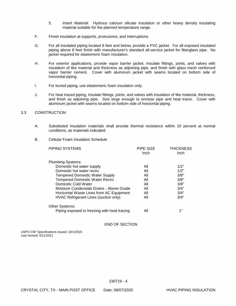
230719 - 4 CRYSTAL CITY, TX - MAIN POST OFFICE Date: 08/07/2020 HVAC PIPING INSULATION
5. Insert Material: Hydrous calcium silicate insulation or other heavy density insulating material suitable for the planned temperature range.
F. Finish insulation at supports, protrusions, and interruptions.
G. For all insulated piping located 8 feet and below, provide a PVC jacket. For all exposed insulated piping above 8 feet finish with manufacturer's standard all-service jacket for fiberglass pipe. No jacket required for elastomeric foam insulation.
H. For exterior applications, provide vapor barrier jacket. Insulate fittings, joints, and valves with insulation of like material and thickness as adjoining pipe, and finish with glass mesh reinforced vapor barrier cement. Cover with aluminum jacket with seams located on bottom side of horizontal piping.
I. For buried piping, use elastomeric foam insulation only.
J. For heat traced piping, insulate fittings, joints, and valves with insulation of like material, thickness, and finish as adjoining pipe. Size large enough to enclose pipe and heat tracer. Cover with aluminum jacket with seams located on bottom side of horizontal piping.
3.3 CONSTRUCTION
A. Substituted insulation materials shall provide thermal resistance within 10 percent at normal conditions, as materials indicated.
B. Cellular Foam Insulation Schedule
PIPING SYSTEMS PIPE SIZE THICKNESS Inch Inch
Plumbing Systems: Domestic hot water supply All 1/2" Domestic hot water recirc All 1/2" Tempered Domestic Water Supply All 3/8" Tempered Domestic Water Recirc All 3/8" Domestic Cold Water All 3/8" Moisture Condensate Drains - Above Grade All 3/4" Horizontal Waste Lines from AC Equipment All 3/4" HVAC Refrigerant Lines (suction only) All 3/4"
Other Systems: Piping exposed to freezing with heat tracing All 1"
END OF SECTION USPS CSF Specifications issued: 10/1/2019 Last revised: 5/11/2011
230800 - 1 CRYSTAL CITY, TX - MAIN POST OFFICE Date: 08/07/2020 COMMISSIONING OF HVAC
SECTION 230800
COMMISSIONING OF HVAC
PART 1 - GENERAL
1.1 WORK INCLUDED
A. Systems and equipment testing and start-up.
B. Validation of proper and thorough installation of Division 23 systems and equipment.
C. Systems balancing verification.
D. Pre-functional performance testing of equipment and systems.
E. Documentation of tests, procedures, and installations.
F. Coordination of Training Events.
G. Generic Start-Up Procedures for mechanical systems and equipment.
1.2 GENERAL DESCRIPTION
A. Commissioning (Cx) is the process of ensuring that all building systems are installed and perform interactively according to the design intent; that systems are efficient and cost effective and meet the owner’s operational needs; that the installation is adequately documented; and that the Operators are adequately trained. It serves as a tool to minimize post-occupancy operational problems. It establishes testing and communication protocols in an effort to advance the building systems from installation to full dynamic operation and optimization.
B. The USPS shall retain an independent Commissioning Authority (CxA) to provide Commissioning Services, or have Solicitation A/E for Design-Build Project or Design A/E for Design-Bid-Build Project hire the CxA.
C. This Section outlines the Cx procedures specific to the Division 23 Contractors. Requirements common to all work are described in Specifications 019113.
1.3 SCOPE
A. The following equipment and/or systems may be commissioned if in compliance with the guidelines provided in Specifications 019113, or with Contracting Officer approval: 1. Air Handling Units 2. Air Terminal Units 3. Unit Heaters
1.4 RELATED WORK AND DOCUMENTS
A. Drawings and general provisions of Contract, including General and Supplementary Conditions and Division-1 Specification sections, apply to work of this section
B. Commissioning Plan: The Cx Plan shall be available for reference as it outlines responsibilities outside of the Construction Contract. It provides the Contractor and the Owner an understanding of the planned commissioning activities for that project.
230800 - 2 CRYSTAL CITY, TX - MAIN POST OFFICE Date: 08/07/2020 COMMISSIONING OF HVAC
C. Section 013300 - Submittal Procedures: Stipulates additional copies of submittals to be submitted and refers to other sections for additional submittal requirements related to Cx.
D. Section 017704 - Closeout Procedures and Training: Defines the milestones in completion incorporating the Cx process.
E. Section 019113 – General Commissioning Requirements: Specifies the general facility commissioning procedures common across all Divisions and the Contractor’s responsibilities for the commissioning process.
F. Individual Specification Sections: Individual sections stipulate installation, start-up, warranty, O&M documentation, and training requirements for the system or device specified in the Section.
G. Section 250804 – Building Automation System Commissioning: Details the commissioning procedures specific to the BAS.
H. Section 220800 – Commissioning of Plumbing: Details the commissioning procedures specific to the Plumbing Systems.
I. Section 260800 – Commissioning of Electrical Systems: Details the commissioning procedures specific to Division 26 work.
1.5 REFERENCE STANDARDS
A. ASHRAE Guideline 0-2005, "Guideline for Commissioning HVAC Systems"
B. National Environmental Balancing Bureau (NEBB)
C. AABC Commissioning Group (ACG)
D. National Fire Protection Association (NFPA)
1.6 DOCUMENTATION
A. In addition to the documentation required in Section 019113, Contractor shall provide to the CxA the following per the procedures specified herein and in other Sections of the specification: 1. HVAC Balancing Plan 2. All referenced charts such as vibration severity chart and room noise criteria (NC) curves. 3. Vibration Severity Charts 4. Factory Test Reports: Contractor shall provide any factory testing documentation or
certified test reports required by the specifications. These shall be provided prior to Acceptance Phase. Factory Test Reports should be provided in PDF electronic format. These may include but are not limited to: a. Air Handling Units b. Variable Frequency Drives c. Fans Capacity d. Fan Sound Power Levels e. Pump Capacity
5. Field Testing Agency Reports (other than TAB): Provide all documentation of work of independent testing agencies required by the specification. These shall be provided prior to Acceptance Phase. Field Testing Agency Reports should be provided in PDF electronic format. These may include but are not limited to: a. Pipe Pressure Testing b. Duct Leakage Testing c. Vibration Testing d. Generated Noise and Resultant Noise Level e. Corrosion Protection
230800 - 3 CRYSTAL CITY, TX - MAIN POST OFFICE Date: 08/07/2020 COMMISSIONING OF HVAC
6. Completed Test and Balance Reports.
1.7 CONTRACTOR RESPONSIBILITIES
A. Refer to Section 019113: Detailed Contractor responsibilities common to all Divisions are specified in this Section. The following are additional responsibilities or notable responsibilities specific to Division 23.
B. Acceptance Phase 1. Assist CxA in functional performance testing. Assistance will generally include the
following: a. Manipulate systems and equipment to facilitate testing (as dictated in the
Commissioning Plan; in some cases this will entail only an initial sample); b. Provide any specialized instrumentation necessary for functional performance
testing; c. Manipulate BAS and other control systems to facilitate functional performance
testing (as dictated Specification 250804; in some cases this will entail only an initial sample).
2. Provide a TAB technician to work at the direction of CxA for up to 24 hours beyond assistance specified above.
3. Provide a BAS technician to work at the direction of CxA for additional hours as specified in Section 250804.
4. Maintain trends and monitor the facility throughout the Endurance Period as specified in Section 250804.
5. Respond to all Action Items which are assigned to the respective Division 23 Contractors. Response shall be via the Project Portal or by response to the original Action Item E-mail.
6. Resolve all deficiencies which are determined to be within the Division 23 scope of work.
C. Warranty Phase 1. Maintain record documentation of any configurations, set ups, parameters etc, that
change throughout the period. 2. Provide representative for off season testing as required by CxA. 3. Respond to Warranty issues as required by Division 1 and the General Conditions.
1.8 EQUIPMENT SUPPLIER RESPONSIBILITIES
A. Refer to Section 019113.
1.9 CONTRACTOR NOTIFICATION AND SCHEDULING
A. Refer to Section 019113.
1.10 START-UP PROCEDURES AND DOCUMENTATION
A. Refer to Section 019113 and as detailed in Section 3 below.
1.11 EQUIPMENT NAMEPLATE DATA
A. Refer to Division 1.
1.12 BAS TRENDING REQUIREMENTS
A. Trending requirements are specified in Section 250804..
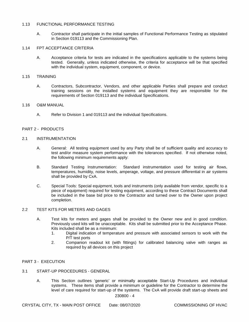
230800 - 4 CRYSTAL CITY, TX - MAIN POST OFFICE Date: 08/07/2020 COMMISSIONING OF HVAC
1.13 FUNCTIONAL PERFORMANCE TESTING
A. Contractor shall participate in the initial samples of Functional Performance Testing as stipulated in Section 019113 and the Commissioning Plan.
1.14 FPT ACCEPTANCE CRITERIA
A. Acceptance criteria for tests are indicated in the specifications applicable to the systems being tested. Generally, unless indicated otherwise, the criteria for acceptance will be that specified with the individual system, equipment, component, or device.
1.15 TRAINING
A. Contractors, Subcontractor, Vendors, and other applicable Parties shall prepare and conduct training sessions on the installed systems and equipment they are responsible for the requirements of Section 019113 and the individual Specifications.
1.16 O&M MANUAL
A. Refer to Division 1 and 019113 and the individual Specifications.
PART 2 - PRODUCTS
2.1 INSTRUMENTATION
A. General: All testing equipment used by any Party shall be of sufficient quality and accuracy to test and/or measure system performance with the tolerances specified. If not otherwise noted, the following minimum requirements apply:
B. Standard Testing Instrumentation: Standard instrumentation used for testing air flows, temperatures, humidity, noise levels, amperage, voltage, and pressure differential in air systems shall be provided by CxA.
C. Special Tools: Special equipment, tools and instruments (only available from vendor, specific to a piece of equipment) required for testing equipment, according to these Contract Documents shall be included in the base bid price to the Contractor and turned over to the Owner upon project completion.
2.2 TEST KITS FOR METERS AND GAGES
A. Test kits for meters and gages shall be provided to the Owner new and in good condition. Previously used kits will be unacceptable. Kits shall be submitted prior to the Acceptance Phase. Kits included shall be as a minimum: 1. Digital indication of temperature and pressure with associated sensors to work with the
P/T test ports 2. Companion readout kit (with fittings) for calibrated balancing valve with ranges as
required by all devices on this project
PART 3 - EXECUTION
3.1 START-UP PROCEDURES - GENERAL
A. This Section outlines ‘generic’ or minimally acceptable Start-Up Procedures and individual systems. These items shall provide a minimum or guideline for the Contractor to determine the level of care required for start-up of the systems. The CxA will provide draft start-up sheets and
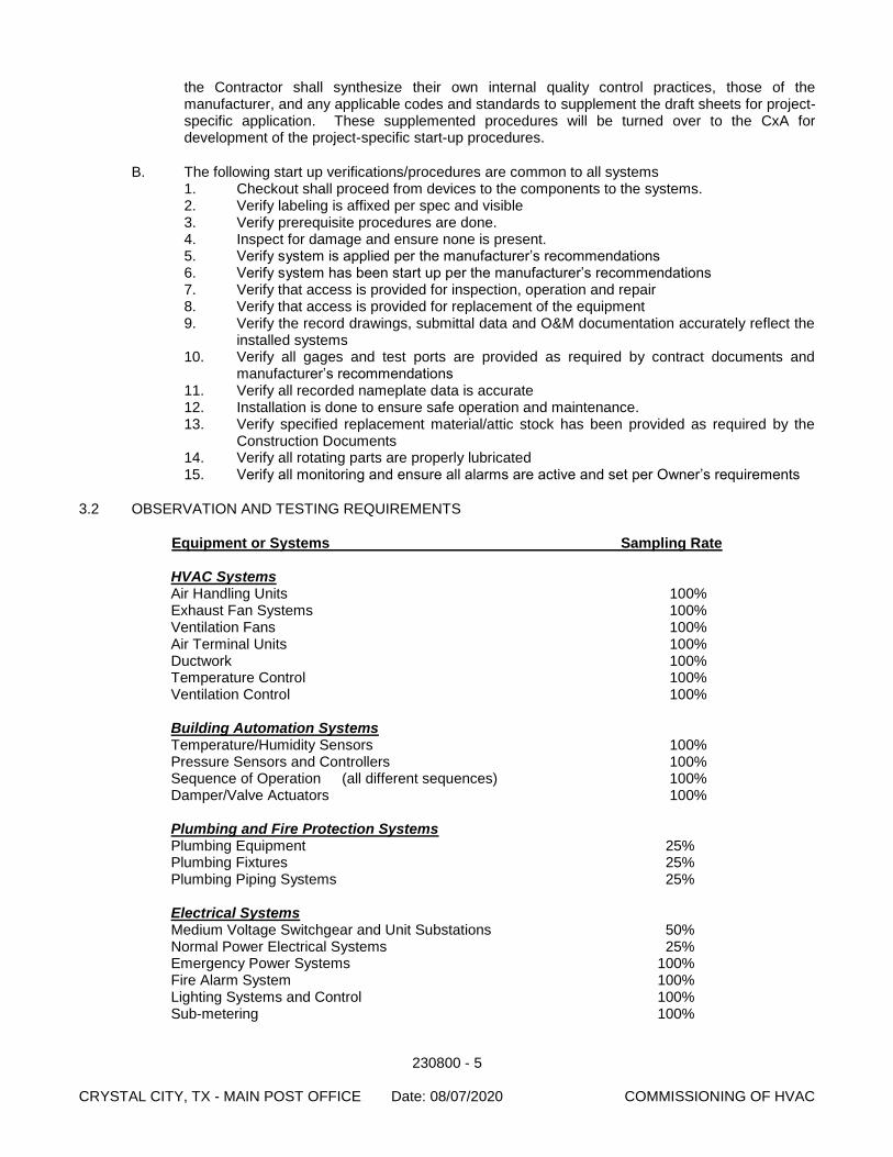
230800 - 5 CRYSTAL CITY, TX - MAIN POST OFFICE Date: 08/07/2020 COMMISSIONING OF HVAC
the Contractor shall synthesize their own internal quality control practices, those of the manufacturer, and any applicable codes and standards to supplement the draft sheets for project-specific application. These supplemented procedures will be turned over to the CxA for development of the project-specific start-up procedures.
B. The following start up verifications/procedures are common to all systems 1. Checkout shall proceed from devices to the components to the systems. 2. Verify labeling is affixed per spec and visible 3. Verify prerequisite procedures are done. 4. Inspect for damage and ensure none is present. 5. Verify system is applied per the manufacturer’s recommendations 6. Verify system has been start up per the manufacturer’s recommendations 7. Verify that access is provided for inspection, operation and repair 8. Verify that access is provided for replacement of the equipment 9. Verify the record drawings, submittal data and O&M documentation accurately reflect the
installed systems 10. Verify all gages and test ports are provided as required by contract documents and
manufacturer’s recommendations 11. Verify all recorded nameplate data is accurate 12. Installation is done to ensure safe operation and maintenance. 13. Verify specified replacement material/attic stock has been provided as required by the
Construction Documents 14. Verify all rotating parts are properly lubricated 15. Verify all monitoring and ensure all alarms are active and set per Owner’s requirements
3.2 OBSERVATION AND TESTING REQUIREMENTS
Equipment or Systems Sampling Rate
HVAC Systems Air Handling Units 100% Exhaust Fan Systems 100% Ventilation Fans 100% Air Terminal Units 100% Ductwork 100% Temperature Control 100% Ventilation Control 100%
Building Automation Systems Temperature/Humidity Sensors 100% Pressure Sensors and Controllers 100% Sequence of Operation (all different sequences) 100% Damper/Valve Actuators 100%
Plumbing and Fire Protection Systems Plumbing Equipment 25% Plumbing Fixtures 25% Plumbing Piping Systems 25%
Electrical Systems Medium Voltage Switchgear and Unit Substations 50% Normal Power Electrical Systems 25% Emergency Power Systems 100% Fire Alarm System 100% Lighting Systems and Control 100% Sub-metering 100%
230800 - 6 CRYSTAL CITY, TX - MAIN POST OFFICE Date: 08/07/2020 COMMISSIONING OF HVAC
END OF SECTION
USPS CSF Specification issued: 10/1/2019 Last revised: 8/31/2018
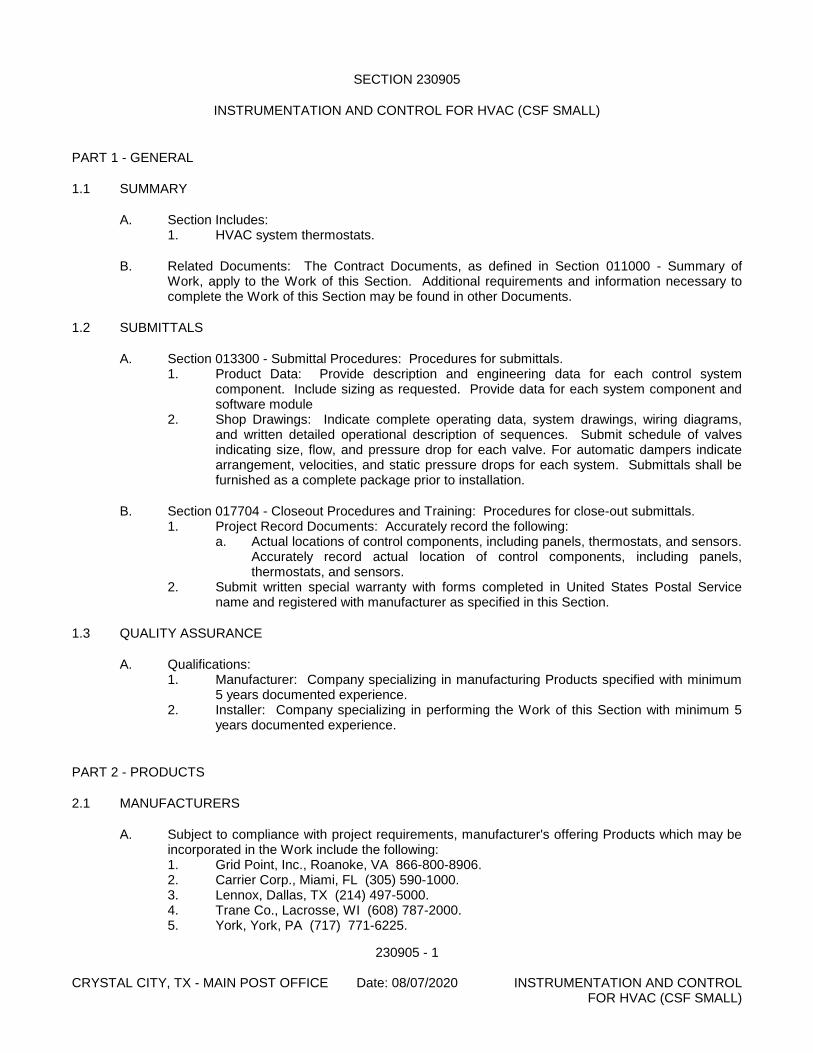
230905 - 1 CRYSTAL CITY, TX - MAIN POST OFFICE Date: 08/07/2020 INSTRUMENTATION AND CONTROL FOR HVAC (CSF SMALL)
SECTION 230905
INSTRUMENTATION AND CONTROL FOR HVAC (CSF SMALL)
PART 1 - GENERAL
1.1 SUMMARY
A. Section Includes: 1. HVAC system thermostats.
B. Related Documents: The Contract Documents, as defined in Section 011000 - Summary of Work, apply to the Work of this Section. Additional requirements and information necessary to complete the Work of this Section may be found in other Documents.
1.2 SUBMITTALS
A. Section 013300 - Submittal Procedures: Procedures for submittals. 1. Product Data: Provide description and engineering data for each control system
component. Include sizing as requested. Provide data for each system component and software module
2. Shop Drawings: Indicate complete operating data, system drawings, wiring diagrams, and written detailed operational description of sequences. Submit schedule of valves indicating size, flow, and pressure drop for each valve. For automatic dampers indicate arrangement, velocities, and static pressure drops for each system. Submittals shall be furnished as a complete package prior to installation.
B. Section 017704 - Closeout Procedures and Training: Procedures for close-out submittals. 1. Project Record Documents: Accurately record the following:
a. Actual locations of control components, including panels, thermostats, and sensors. Accurately record actual location of control components, including panels, thermostats, and sensors.
2. Submit written special warranty with forms completed in United States Postal Service name and registered with manufacturer as specified in this Section.
1.3 QUALITY ASSURANCE
A. Qualifications: 1. Manufacturer: Company specializing in manufacturing Products specified with minimum
5 years documented experience. 2. Installer: Company specializing in performing the Work of this Section with minimum 5
years documented experience.
PART 2 - PRODUCTS
2.1 MANUFACTURERS
A. Subject to compliance with project requirements, manufacturer's offering Products which may be incorporated in the Work include the following: 1. Grid Point, Inc., Roanoke, VA 866-800-8906. 2. Carrier Corp., Miami, FL (305) 590-1000. 3. Lennox, Dallas, TX (214) 497-5000. 4. Trane Co., Lacrosse, WI (608) 787-2000. 5. York, York, PA (717) 771-6225.
230905 - 2 CRYSTAL CITY, TX - MAIN POST OFFICE Date: 08/07/2020 INSTRUMENTATION AND CONTROL FOR HVAC (CSF SMALL)
6. Honeywell, Minneapolis, MN (800) 328-5111. 7. White Rodgers, St. Louis, MO (314) 577-1300.
B. Section 016000 - Product Requirements: Product options and substitutions. Substitutions: Permitted.
2.2 ROOM THERMOSTATS
A. Thermostats for controlled HVAC equipment shall be low voltage digital electronic type. See drawings for HVAC equipment type and number of stages.
B. Performance Requirements: 1. LCD Touch-Screen Display 2. Energy Star approved 3. Seven-day programmable schedule: Minimum of four separate scheduling periods per
day (with separate heating and cooling setpoints for each period). Each time period and temperature setpoint shall be individually programmable.
4. Automatic changeover between heating and cooling modes 5. Built in time delay between compressor starts 6. Fan operation: Fan operation shall be programmable by time period to either operate
continuously or automatically on a call for heating or cooling. 7. Adaptive Recovery Control: Thermostat shall have an adaptive recovery feature that
adjusts the start time, based on learned system performance, to reach setpoint at the desired occupancy time.
8. Battery Back-up to retain program and time through minimum 24 hour power outage. 9. Keypad Lock: Keypad shall be partially lockable (via programming) to allow only
temporary adjustment of temperature setpoints. Keypad shall also be fully lockable (via programming).
C. Model Selection: Provide the manufacturer’s recommended model for the HVAC equipment to be controlled (type and number of stages).
D. Provide heavy duty, locking, ventilated, hinged all - metal enclosure with locking guards for all thermostats located in workroom and customer accessible areas. Provide two keys.
2.3 ELECTRIC THERMOSTATS:
A. Electric Thermostats for unit heater control shall be low voltage, 24 volt, rated and suitable for the application, coiled bimetal element, switch with adjustable heat anticipator, that is non-mercury based, setting lever (55 degrees F to 95 degrees F. range), . Mounted in heavy ventilated metal enclosure at 78 inches above floor.
PART 3 - EXECUTION
3.1 INSTALLATION:
A. Provide new control wiring as required for proper operation. All control wires installed under this contract shall be color coded, numbered or otherwise labeled for easy identification. All control wiring exposed to damage in workrooms shall be installed in conduit painted to match the mounting surface. All control wiring exposed in offices or other public spaces shall be installed in wiremold painted to match the mounting surface. All concealed control wiring shall be plenum rated. Provide and install batteries as required for proper operation. New installation shall be in accordance with manufacturer’s recommendations.
230905 - 3 CRYSTAL CITY, TX - MAIN POST OFFICE Date: 08/07/2020 INSTRUMENTATION AND CONTROL FOR HVAC (CSF SMALL)
B. Provide all necessary transformers, relays, contactors and other options as required for proper operation.
C. Mount new thermostats at 78 inches above the floor in workroom spaces subject to damage from operations. Mount new thermostats at 54 inches above the floor in office and public areas.
3.2 SYSTEM PERFORMANCE
A. Thermostats including batteries, temperature controllers, relays, switches, and 24 volt wiring to be furnished and installed by the Heating Contractor, unless furnished with the equipment.
B. The temperature control system is to maintain space temperature settings, within plus or minus 1 degree F. of space thermostat settings.
3.3 TEMPERATURE CONTROL SYSTEM OPERATION
A. The temperature control system for split system air conditioning systems shall control the operation of the heating and ventilating and air conditioning system as follows:
B. Air handling fans shall run continuously in the "Occupied" position when the thermostat fan is in the “ON” position. Fans shall cycle as required to maintain setpoint when the thermostat fan is in the “Auto” position and during the "Unoccupied" cycle. Set blower speed at highest speed for cooling and next highest speed for heating. Where economizers are provided in air handlers without integral economizers, thermostat shall enable the economizer on a call for cooling when the outside air temperature is below 65 degrees F. Where outside air capability is provided, set minimum position to be at 5 percent when fan is ON.
END OF SECTION USPS CSF Specifications issued: 10/1/2019 Last revised: 9/16/2015

230905 - 4 CRYSTAL CITY, TX - MAIN POST OFFICE Date: 08/07/2020 INSTRUMENTATION AND CONTROL FOR HVAC (CSF SMALL)
[This page intentionally left blank.]
232300 - 1 CRYSTAL CITY, TX - MAIN POST OFFICE Date: 08/07/2020 REFRIGERANT PIPING
SECTION 232300
REFRIGERANT PIPING
PART 1 - GENERAL
1.1 SUBMITTALS:
A. Product Data: Include pressure drop, based on manufacturer's test data, for thermostatic expan-sion valves, solenoid valves, and pressure-regulating valves.
B. Shop Drawings: Show layout of refrigerant piping and specialties, including pipe, tube, and fitting sizes, flow capacities, valve arrangements and locations, slopes of horizontal runs, oil traps, dou-ble risers, wall and floor penetrations, and equipment connection details. Show interface and spatial relationship between piping and equipment. 1. Size piping and design the actual piping layout, including oil traps, double risers, special-
ties, and pipe and tube sizes, to ensure proper operation and compliance with warranties of connected equipment.
1.2 QUALITY ASSURANCE:
A. ASHRAE Standard: Comply with ASHRAE 15, "Safety Code for Mechanical Refrigeration."
B. ASME Standard: Comply with ASME B31.5, "Refrigeration Piping."
C. UL Standard: Provide products complying with UL 207, "Refrigerant-Containing Components and Accessories, Nonelectrical"; or UL 429, "Electrically Operated Valves."
PART 2 - PRODUCTS
2.1 COPPER TUBE AND FITTINGS:
A. Drawn-Temper Copper Tube: ASTM B 280, Type ACR.
B. Wrought-Copper Fittings: ASME B16.22.
C. Wrought-Copper Unions: ASME B16.22.
D. Bronze Filler Metals: AWS A5.8, Classification BAg-1 (silver)
2.2 REFRIGERANT PIPING SPECIALITIES:
A. Replaceable-Core Filter-Dryers: 500-psig maximum working pressure; heavy gage protected with corrosion-resistant-painted steel shell, flanged ring and spring, ductile-iron cover plate with steel cap screws; wrought-copper fittings for solder-end connections; with replaceable-core kit, including gaskets and the following: 1. Filter-Dryer Cartridge: Pleated media with solid-core sieve with activated alumina,
ARI 730 rated for capacity. 2. Service Valves: 500-psig (3450-kPa) pressure rating; forged-brass body with copper
stubs, brass caps, removable valve core, integral ball check valve, and with solder-end connections.
3. Pressure-Regulating Valves: Comply with ARI 770; direct acting, brass; with pilot opera-tor, stainless-steel diaphragm, standard coil, and solder-end connection; suitable for re-frigerant specified.
4. Pressure Relief Valves: Straight-through or angle pattern, brass body and disc, neo-prene seat, and factory sealed and ASME labeled for standard pressure setting.
232300 - 2 CRYSTAL CITY, TX - MAIN POST OFFICE Date: 08/07/2020 REFRIGERANT PIPING
5. Thermostatic Expansion Valves: Comply with ARI 750; brass body with stainless-steel parts; thermostatic-adjustable, modulating type; size and operating characteristics as recommended by manufacturer of evaporator, and factory set for superheat require-ments; solder-end connections; with sensing bulb, distributor having side connection for hot-gas bypass line, and external equalizer line.
6. Hot-Gas Bypass Valve: Pulsating-dampening design, stainless-steel bellows and polytet-rafluoroethylene valve seat; adjustable; sized for capacity equal to last step of compres-sor unloading; with solder-end connections.
7. Moisture/Liquid Indicators: 500-psig (3450-kPa) maximum working pressure and 200 deg F (93 deg C) operating temperature; all-brass body with replaceable, polished, opti-cal viewing window with color-coded moisture indicator; with solder-end connections.
PART 3 - EXECUTION
3.1 PIPING APPLICATIONS:
A. Aboveground, within Building: Type ACR drawn-copper tubing or Type L (Type B) drawn-copper tubing.
B. Belowground for NPS 2 (DN 50) and Smaller: Type K (Type A) annealed-copper tubing.
3.2 PIPING INSTALLATION:
A. Install refrigerant piping according to ASHRAE 15. Equipment manufacturer shall size refrigerant lines for Contractor.
B. Basic piping installation requirements are specified in Division 23 Section "Common Work for HVAC."
C. Install piping as short and direct as possible, with a minimum number of joints, elbows, and fit-tings.
D. Arrange piping to allow inspection and service of compressor and other equipment. Install valves and specialties in accessible locations to allow for service and inspection.
E. Install piping with adequate clearance between pipe and adjacent walls and hangers or between pipes for insulation installation. Use sleeves through floors, walls, or ceilings, sized to permit in-stallation of full-thickness insulation.
F. Install copper tubing in rigid or flexible conduit in locations where copper tubing will be exposed to mechanical injury.
G. Slope refrigerant piping as follows: 1. Install horizontal suction lines with a uniform slope downward to compressor. 2. Install traps and double risers to entrain oil in vertical runs. 3. Liquid lines may be installed level.
H. Hanger, support, and anchor products are specified in Division 23 Section "Hangers and Sup-ports."
I. Install the following pipe attachments: 1. Adjustable steel clevis hangers for individual horizontal runs less than 20 feet long.
J. Install hangers for copper tubing with the following maximum spacing and minimum rod sizes: 1. NPS 1/2: Maximum span, 60 inches; minimum rod size, 1/4 inch. 2. NPS 5/8: Maximum span, 60 inches; minimum rod size, 1/4 inch. 3. NPS 1: Maximum span, 72 inches; minimum rod size, 1/4 inch. 4. NPS 1-1/4: Maximum span, 96 inches; minimum rod size, 3/8 inch.
232300 - 3 CRYSTAL CITY, TX - MAIN POST OFFICE Date: 08/07/2020 REFRIGERANT PIPING
5. NPS 1-1/2: Maximum span, 96 inches; minimum rod size, 3/8 inch.
K. Support vertical runs at each floor.
L. Pipe Joint Construction: 1. Braze joints according to Division 23 Section "Common Work for HVAC." 2. Fill pipe and fittings with an inert gas (nitrogen or carbon dioxide) during brazing to pre-
vent scale formation.
M. Refrigerant Pipe Insulation: 1. Insulate refrigerant piping according to Division 23 Section "Pipe Insulation."
N. Test and inspect refrigerant piping according to ASME B31.5, Chapter VI. 1. Test refrigerant piping, specialties, and receivers. Isolate compressor, condenser, evap-
orator, and safety devices from test pressure. 2. Test high- and low-pressure side piping of each system at not less than the lower of the
design pressure or the setting of pressure relief device protecting high and low side of system. a. System shall maintain test pressure at the manifold gage throughout duration of
test. b. Test joints and fittings by brushing a small amount of soap and glycerine solution
over joint. c. Fill system with nitrogen to raise a test pressure of 150 psig or higher as required
by authorities having jurisdiction. d. Remake leaking joints using new materials, and retest until satisfactory results are
achieved.
O. Adjust set-point temperature of the conditioned air controllers to the system design temperature.
P. Before installing copper tubing other than Type ACR, clean tubing and fittings with trichloroeth-ylene.
Q. Replace core of filter-dryer after system has been adjusted and design flow rates and pressures are established.
R. Charge system using the following procedures: 1. Install core in filter-dryer after leak test but before evacuation. 2. Evacuate entire refrigerant system with a vacuum pump to a vacuum of 500 micrometers.
If vacuum holds for 12 hours, system is ready for charging. 3. Break vacuum with refrigerant gas, allowing pressure to build up to 2 psig. 4. Charge system with a new filter-dryer core in charging line. Provide full-operating
charge.
END OF SECTION
USPS CSF Specification issued: 10/1/2019 Last revised: 5/11/2011

232300 - 4 CRYSTAL CITY, TX - MAIN POST OFFICE Date: 08/07/2020 REFRIGERANT PIPING
[This page intentionally left blank.]
233100 - 1 CRYSTAL CITY, TX - MAIN POST OFFICE Date: 08/07/2020 HVAC DUCTS AND CASINGS
SECTION 233100
HVAC DUCTS AND CASINGS
PART 1 - GENERAL
1.1 SUMMARY
A. Section Includes: 1. Metal ductwork. 2. Air turning devices. 3. Duct access doors. 4. Duct test holes. 5. Flexible duct connections. 6. Volume control dampers. 7. Duct cleaning.
B. Related Documents: The Contract Documents, as defined in Section 011000 - Summary of Work, apply to the Work of this Section. Additional requirements and information necessary to complete the Work of this Section may be found in other Documents.
C. Related Sections: 1. Section 230500 - Common Work Results for HVAC: 2. Section 230719 - Duct Insulation: Duct Insulation. 3. Section 233713 - Diffusers Registers and Grilles: 4. Section 230593 - Testing, Adjusting and Balancing for HVAC:
1.2 REFERENCES
A. American Society for Testing and Materials (ASTM): 1. ASTM A 36 - Structural Steel. 2. ASTM A 90 - Weight of Coating on Zinc-Coated (Galvanized) Iron or Steel Articles. 3. ASTM A 167 - Stainless and Heat-Resisting Chromium-Nickel Steel Plate, Sheet and
Strip. 4. ASTM A 480 - General Requirements for Flat-Rolled Stainless and Heat-Resisting Steel
Plate, Sheet and Strip. 5. ASTM A 653 - Steel Sheet, Zinc-Coated (Galvanized) or Zinc-Iron Alloy Coated
(Galvanealed) by the Hot-Dip Process. 6. ASTM A 568 Steel, Sheet, Carbon, and High-Strength, Low-Alloy, Hot-Rolled and
Cold-Rolled.
B. American Welding Society (AWS): 1. AWS D9.1 - Welding of Sheet Metal.
C. National Fire Protection Association (NFPA): 1. NFPA 90A - Installation of Air Conditioning and Ventilating Systems. 2. NFPA 90B - Installation of Warm Air Heating and Air Conditioning Systems. 3. NFPA 91 - Installation of Blower and Exhaust Systems for Dust, Stock and Vapor
Removal or Conveying. 4. NFPA 96 - Installing of Equipment for the Removal of Smoke and Grease-Laden Vapors
from Commercial Cooking Equipment.
D. Sheet Metal and Air Conditioning Contractors National Association (SMACNA): 1. SMACNA - HVAC Air Duct Leakage Test Manual. 2. SMACNA - HVAC Duct Construction Standards - Metal and Flexible.
233100 - 2 CRYSTAL CITY, TX - MAIN POST OFFICE Date: 08/07/2020 HVAC DUCTS AND CASINGS
E. Underwriters Laboratories, Inc. (UL): 1. UL 181 - Factory-Made Air Ducts and Connectors.
1.3 SYSTEM DESCRIPTION
A. Performance Requirements: No variation of duct configuration or sizes permitted except by written permission. Size round ducts installed in place of rectangular ducts in accordance with ASHRAE table of equivalent rectangular and round ducts.
1.4 SUBMITTALS
A. Section 013300 - Submittal Procedures: Procedures for submittals. 1. Product Data:
a. Duct materials, duct liner, duct connectors, and flexible duct. b. Factory or shop manufactured assemblies including volume control dampers, duct
access doors, duct test holes, and hardware used. Include electrical characteristics and connection requirements.
B. Section 017704 - Closeout Procedures and Training: Procedures for closeout submittals. 1. Project Record Documents: Accurately record the following:
a. Actual locations of ducts and duct fittings. b. Record changes in fitting location and type. c. Show additional fittings used. d. Actual locations of access doors, test holes, and fire dampers.
1.5 QUALITY ASSURANCE
A. Perform Work in accordance with SMACNA - HVAC Duct Construction Standards - Metal and Flexible.
B. Qualifications: 1. Manufacturer: Company specializing in manufacturing Products specified with minimum
5 years documented experience. 2. Installer: Company specializing in performing the Work of this Section with minimum 5
years documented experience.
C. Regulatory Requirements: Construct ductwork to NFPA 90A. NFPA 90B, and NFPA 96 standards.
1.6 DELIVERY, STORAGE, AND HANDLING
A. Section 016000 - Product Requirements: Transport, handle, store, and protect Products.
B. Protect dampers from damage to operating linkages and blades.
1.7 PROJECT CONDITIONS OR SITE CONDITIONS
A. Jobsite Requirements: 1. Do not install duct sealants when temperatures are less than those recommended by
sealant manufacturers. 2. Maintain temperatures during and after installation of duct sealants.
1.8 ENVIRONMENTAL REQUIREMENTS
A. Environmental Impact: 1. Indoor Air Quality: Install insulation so that unfaced fiberglass and mineral fiber insulation
are not in the interior of the ductwork.
233100 - 3 CRYSTAL CITY, TX - MAIN POST OFFICE Date: 08/07/2020 HVAC DUCTS AND CASINGS
PART 2 - PRODUCTS
2.1 METAL DUCTWORK
A. Galvanized Steel Ducts: ASTM A653 having zinc coating in conformance with ASTM A90.
B. Steel Ducts: ASTM A569 and A568..
C. Flexible Ducts: 1. Manufacturers:
a. Anco Products Inc. b. Hart & Cooley. c. Tuttle & Bailey. d. Section 016000 - Product Requirements: Product options and substitutions.
Substitutions: Permitted. 2. UL Labeled, black polymer film supported by helically wound spring steel wire. 3. Pressure Rating: 4 inches WG positive and 0.5 inches WG negative. 4. Maximum Velocity: 4000 fpm. 5. Temperature Range: -20 degrees F to 175 degrees.
D. Insulated Flexible Ducts: 1. Manufacturers:
a. Anco Products Inc. b. Hart & Cooley. c. Tuttle & Bailey d. Section 016000 - Product Requirements: Product options and substitutions.
Substitutions: Permitted. 2. Black polymer film supported by helically wound spring steel wire; fiberglass insulation;
aluminized vapor barrier film. 3. Pressure Rating: 4 inches WG positive and 0.5 inches WG negative. 4. Maximum Velocity: 4000 fpm. 5. Temperature Range: -20 degrees F to 175 degrees F.
E. Stainless Steel Ducts: ASTM A 167, Type 304.
F. Fasteners: Rivets, bolts, or sheet metal screws.
G. Sealant: 1. Manufacturers:
a. Duro Dyne Corporation, Farmingdale, NY (800) 899-3876. b. H.B. Fuller Co, St. Paul, MN (888) 423-8553. c. Hardcast, Inc, Wylie, TX (800) 527-7092. d. Section 016000 - Product Requirements: Product options and substitutions.
Substitutions: Permitted. 2. Non-hardening, water resistant, fire resistive, compatible with mating materials; liquid
used alone or with tape, or heavy mastic.
H. Hanger Rod: ASTM A36; steel threaded both ends, threaded one end, or continuously threaded.
2.2 AIR TURNING DEVICES/EXTRACTORS
A. Manufacturers: 1. Semco, Inc, Columbia, MO (888) 473-6264. 2. Metal-Fab, Inc, Wichita, KS (800) 835-2830. 3. United McGill Corp, Groveport, OH (614) 836-9981. 4. Section 016000 - Product Requirements: Product options and substitutions.
Substitutions: Permitted.
233100 - 4 CRYSTAL CITY, TX - MAIN POST OFFICE Date: 08/07/2020 HVAC DUCTS AND CASINGS
B. Multi-blade device with blades aligned in short dimension; steel or aluminum construction; with individually adjustable blades, mounting straps.
2.3 DUCT ACCESS DOORS
A. Manufacturers: 1. Ductmate Industries, Inc, East Monongahela, PA (800) 245-3188. 2. Ruskin Manufacturing, Kansas City, MO (816) 761-7476. 3. Semco Inc, Columbia, MO (888) 473-6264. 4. Section 016000 - Product Requirements: Product options and substitutions.
Substitutions: Permitted.
B. Fabricate in accordance with SMACNA HVAC Duct Construction Standards - Metal and Flexible, and as indicated.
C. Fabrication: Rigid and close-fitting of galvanized steel with sealing gaskets and quick fastening locking devices. For insulated ductwork, install minimum one inch thick insulation with sheet metal cover. 1. Less Than 12 Inches Square: Secure with sash locks. 2. Up to 18 Inches Square: Provide two hinges and two sash locks. 3. Up to 24 x 48 Inches: Three hinges and two compression latches with outside and inside
handles. 4. Larger Sizes: Provide an additional hinge.
D. Access doors with sheet metal screw fasteners are not acceptable.
2.4 DUCT TEST HOLES
A. Temporary Test Holes: Cut or drill in ducts as required. Cap with neat patches, neoprene plugs, threaded plugs, or threaded or twist-on metal caps.
B. Permanent Test Holes: Factory fabricated, air tight flanged fittings with screw cap. Provide extended neck fittings to clear insulation.
2.5 FLEXIBLE DUCT CONNECTIONS
A. Manufacturers: 1. Ductmate Industries, Inc, East Monongahela, PA (800) 245-3188. 2. Ruskin Manufacturing, Kansas City, MO (816) 761-7476. 3. Semco Inc, Columbia, MO (888) 473-6264. 4. Section 016000 - Product Requirements: Product options and substitutions.
Substitutions: Permitted.
B. Fabricate in accordance with SMACNA HVAC Duct Construction Standards - Metal and Flexible, and as indicated.
C. Connector: Fabric crimped into metal edging strip. 1. Fabric: UL listed fire-retardant neoprene coated woven glass fiber fabric to NFPA 90A,
minimum density 30oz per sq yd. 2. Net Fabric Width: Approximately 3 inches wide. 3. Metal: 3 inches wide, 24 gage thick galvanized steel.
2.6 VOLUME CONTROL DAMPERS.
A. Manufacturers: 1. Louvers and Dampers, Inc, Florence, KY (606) 647-2299. 2. Prefco Products, Inc, Buckingham, PA (800) 437-6653.
233100 - 5 CRYSTAL CITY, TX - MAIN POST OFFICE Date: 08/07/2020 HVAC DUCTS AND CASINGS
3. Ruskin Manufacturing, Kansas City, MO (816) 761-7476. 4. Section 016000 - Product Requirements: Product options and substitutions.
Substitutions: Permitted.
B. Fabricate in accordance with SMACNA HVAC Duct Construction Standards - Metal and Flexible, and as indicated.
C. Splitter Dampers: 1. Material: Same gage as duct to 24 inches size in either direction, and two gages heavier
for sizes over 24 inches. 2. Blade: Fabricate of double thickness sheet metal to streamline shape, secured with
continuous hinge or rod. 3. Operator: Minimum 1/4 inch diameter rod in self aligning, universal joint action, flanged
bushing with set screw.
D. Single Blade Dampers: Fabricate for duct sizes up to 6 x 30 inch.
E. Multi-Blade Damper: Fabricate of opposed blade pattern with maximum blade sizes 8 x 72 inch. Assemble center and edge crimped blades in prime coated or galvanized channel frame with suitable hardware.
F. End Bearings: Except in round ductwork 12 inches and smaller, provide end bearings. On multiple blade dampers, provide oil-impregnated nylon or sintered bronze bearings.
G. Quadrants: 1. Provide locking, indicating quadrant regulators on single and multi-blade dampers. 2. On insulated ducts mount quadrant regulators on stand-off mounting brackets, bases, or
adapters. 3. Where rod lengths exceed 30 inches provide regulator at both ends.
2.7 DUCTWORK FABRICATION
A. Fabricate and support in accordance with SMACNA HVAC Duct Construction Standards - Metal and Flexible, and as indicated. Provide duct material, gages, reinforcing, and sealing for operating pressures indicated.
B. Construct T's, bends, and elbows with radius of not less than 1-1/2 times width of duct on centerline. Where not possible and where rectangular elbows are used, provide turning vanes.
C. Increase duct sizes gradually, not exceeding 15 degrees divergence wherever possible; maximum 30 degrees divergence upstream of equipment and 45 degrees convergence downstream.
PART 3 - EXECUTION
3.1 EXAMINATION
A. Section 017300 - Execution: Verification of existing conditions before starting work.
B. Verification of Conditions: Verify that field measurements, surfaces, substrates and conditions are as required, and ready to receive Work. 1. Verify that electric power is available and of the correct characteristics.
C. Report in writing to Contracting Officer prevailing conditions that will adversely affect satisfactory execution of the Work of this Section. Do not proceed with Work until unsatisfactory conditions have been corrected.
233100 - 6 CRYSTAL CITY, TX - MAIN POST OFFICE Date: 08/07/2020 HVAC DUCTS AND CASINGS
D. By beginning Work, Contractor accepts conditions and assumes responsibility for correcting unsuitable conditions encountered at no additional cost to the United States Postal Service.
3.2 INSTALLATION - DUCTWORK
A. Install in accordance with manufacturer's instructions.
B. Install and seal ducts in accordance with SMACNA HVAC Duct Construction Standards - Metal and Flexible.
C. Duct Sizes are inside clear dimensions. For lined ducts, maintain sizes inside lining.
D. Provide openings in ductwork where required to accommodate thermometers and controllers. Provide pilot tube openings where required for testing of systems, complete with metal can with spring device or screw to ensure against air leakage. Where openings are provided in insulated ductwork, install insulation material inside a metal ring.
E. Locate ducts with sufficient space around equipment to allow normal operating and maintenance activities.
F. Use crimp joints with or without bead for joining round duct sizes 8 inch and smaller with crimp in direction of air flow.
G. Use double nuts and lock washers on threaded rod supports.
H. Connect diffusers or light troffer boots to low pressure ducts directly or with 5 feet maximum length of flexible duct held in place with strap or clamp and tape.
I. Connect flexible ducts to metal ducts with draw bands plus tape.
J. Provide residue traps in kitchen hood exhaust ducts at base of vertical risers with provisions for clean out. Use stainless steel for ductwork exposed to view and stainless steel or carbon steel for ducts where concealed.
K. During construction provide temporary closures of metal or taped polyethylene on open ductwork to prevent construction dust from entering ductwork system.
L. Install so that unfaced fiberglass and mineral fiber insulation are not in the interior of the ductwork.
3.3 INSTALLATION - DUCTWORK ACCESSORIES
A. Install accessories in accordance with manufacturer's instructions, NFPA 90A, and follow SMACNA HVAC Duct Construction Standards - Metal and Flexible.
B. Provide backdraft dampers on exhaust fans or exhaust ducts nearest to outside and where indicated.
C. Provide duct access doors for inspection and cleaning before and after filters, coils, fans, automatic dampers, at fire dampers, and elsewhere as indicated. Provide for cleaning kitchen exhaust ductwork in accordance with NFPA 96. Provide minimum 8 x 8 inch size for hand access, 18 x 18 inch size for shoulder access, and as indicated. Review locations prior to fabrication.
D. Provide duct test holes where indicated and required for testing and balancing purposes.
E. Provide flexible connections immediately adjacent to equipment in ducts associated with fans and motorized equipment.
233100 - 7 CRYSTAL CITY, TX - MAIN POST OFFICE Date: 08/07/2020 HVAC DUCTS AND CASINGS
F. Provide balancing dampers at points on supply, return, and exhaust systems where branches are taken from larger ducts as required for air balancing. Install minimum 2 duct widths from duct take-off.
G. Use splitter dampers only where indicated.
H. Provide balancing dampers on duct take-off to diffusers, grilles, and registers, regardless of whether dampers are specified as part of the diffuser, grille, or register assembly.
3.4 CLEANING
A. Clean work under provisions of 017300.
B. Clean duct system and force air at high velocity through duct to remove accumulated dust. To obtain sufficient air, clean half the system at a time. Protect equipment which may be harmed by excessive dirt with temporary filters, or bypass during cleaning.
END OF SECTION USPS CSF Specifications issued: 10/1/2019 Last revised: 09/22/2015

233100 - 8 CRYSTAL CITY, TX - MAIN POST OFFICE Date: 08/07/2020 HVAC DUCTS AND CASINGS
[This page intentionally left blank.]
233300 - 1 CRYSTAL CITY, TX - MAIN POST OFFICE Date: 08/07/2020 AIR DUCT ACCESSORIES
SECTION 233300
AIR DUCT ACCESSORIES
PART 1 - GENERAL
1.1 SUMMARY
A. Section Includes: 1. Backdraft and pressure relief dampers. 2. Manual volume dampers. 3. Control dampers. 4. Flange connectors. 5. Turning vanes. 6. Flexible connectors. 7. Flexible ducts. 8. Duct accessory hardware.
1.2 SUBMITTALS
A. Product Data: For each type of product indicated.
B. Shop Drawings: For duct accessories. Include plans, elevations, sections, details and attach-ments to other work. 1. Detail duct accessories fabrication and installation in ducts and other construction. In-
clude dimensions, weights, loads, and required clearances; and method of field assembly into duct systems and other construction. Include the following: a. Special fittings. b. Manual volume damper installations. c. Control damper installations. d. Wiring Diagrams: For power, signal, and control wiring.
C. Operation and maintenance data.
1.3 QUALITY ASSURANCE
A. Comply with NFPA 90A, "Installation of Air Conditioning and Ventilating Systems," and with NFPA 90B, "Installation of Warm Air Heating and Air Conditioning Systems."
B. Comply with AMCA 500-D testing for damper rating.
PART 2 - PRODUCTS
2.1 MATERIALS
A. Comply with SMACNA's "HVAC Duct Construction Standards - Metal and Flexible" for acceptable materials, material thicknesses, and duct construction methods unless otherwise indicated. Sheet metal materials shall be free of pitting, seam marks, roller marks, stains, discolorations, and other imperfections.
B. Galvanized Sheet Steel: Comply with ASTM A 653/A 653M. 1. Galvanized Coating Designation: G90. 2. Exposed-Surface Finish: Mill phosphatized.
C. Stainless-Steel Sheets: Comply with ASTM A 480/A 480M, Type 304, and having a No. 2 finish for concealed ducts and finish for exposed ducts.
233300 - 2 CRYSTAL CITY, TX - MAIN POST OFFICE Date: 08/07/2020 AIR DUCT ACCESSORIES
D. Aluminum Sheets: Comply with ASTM B 209, Alloy 3003, Temper H14; with mill finish for con-cealed ducts and standard, 1-side bright finish for exposed ducts.
E. Extruded Aluminum: Comply with ASTM B 221, Alloy 6063, Temper T6.
F. Reinforcement Shapes and Plates: Galvanized-steel reinforcement where installed on galva-nized sheet metal ducts; compatible materials for aluminum and stainless-steel ducts.
G. Tie Rods: Galvanized steel, 1/4-inch minimum diameter for lengths 36 inches or less; 3/8-inch minimum diameter for lengths longer than 36 inches.
2.2 BACKDRAFT AND PRESSURE RELIEF DAMPERS
A. Manufacturers: Subject to compliance with requirements, provide products by one of the follow-ing: 1. Air Balance Inc.; a division of Mestek, Inc. 2. American Warming and Ventilating; a division of Mestek, Inc. 3. Cesco Products; a division of Mestek, Inc. 4. Duro Dyne Inc. 5. Greenheck Fan Corporation. 6. Lloyd Industries, Inc. 7. Nailor Industries Inc. 8. NCA Manufacturing, Inc. 9. Pottorff; a division of PCI Industries, Inc. 10. Ruskin Company. 11. SEMCO Incorporated. 12. Vent Products Company, Inc.
B. Description: Gravity balanced.
C. Frame: 0.052-inch- thick, galvanized sheet steel.
D. Blades: Multiple single-piece blades, [center-pivoted,] maximum 6-inch width, 0.025-inch- thick, roll-formed aluminum with sealed edges.
E. Blade Action: Parallel.
F. Blade Seals: Neoprene, mechanically locked.
G. Blade Axles: 1. Material: Stainless steel 2. Diameter: 0.20 inch.
H. Tie Bars and Brackets: Galvanized steel.
I. Return Spring: Adjustable tension.
J. Bearings: [Steel ball] [Synthetic pivot bushings] [Steel ball or synthetic pivot bushings].
K. Accessories: 1. Adjustment device to permit setting for varying differential static pressure. 2. Counterweights and spring-assist kits for vertical airflow installations. 3. Electric actuators. 4. Chain pulls. 5. Screen Mounting: Front mounted in sleeve.
a. Sleeve Thickness: 20-gage minimum. b. Sleeve Length: 6 inches minimum.
6. Screen Mounting: Rear mounted. 7. Screen Material: Aluminum.
233300 - 3 CRYSTAL CITY, TX - MAIN POST OFFICE Date: 08/07/2020 AIR DUCT ACCESSORIES
8. Screen Type: Bird. 9. 90-degree stops.
2.3 MANUAL VOLUME DAMPERS
A. Standard, Steel, Manual Volume Dampers: 1. Manufacturers: Subject to compliance with requirements, available manufacturers offer-
ing products that may be incorporated into the Work include, but are not limited to, the following: a. Air Balance Inc.; a division of Mestek, Inc. b. American Warming and Ventilating; a division of Mestek, Inc. c. Flexmaster U.S.A., Inc. d. McGill AirFlow LLC. e. METALAIRE, Inc. f. Nailor Industries Inc. g. Ruskin Company. h. Vent Products Company, Inc.
2. Standard leakage rating, with linkage outside airstream. 3. Suitable for horizontal or vertical applications. 4. Frames:
a. Hat-shaped, galvanized-steel channels, 0.064-inch minimum thickness. b. Mitered and welded corners. c. Flanges for attaching to walls and flangeless frames for installing in ducts.
5. Blades: a. Multiple or single blade. b. Parallel- or opposed-blade design. c. Stiffen damper blades for stability. d. Galvanized-steel, 0.064 inch thick.
6. Blade Axles: Stainless steel. 7. Bearings:
a. Molded synthetic. b. Dampers in ducts with pressure classes of 3-inch wg or less shall have axles full
length of damper blades and bearings at both ends of operating shaft. 8. Tie Bars and Brackets: Galvanized steel.
B. Jackshaft: 1. Size: 1-inch diameter. 2. Material: Galvanized-steel pipe rotating within pipe-bearing assembly mounted on sup-
ports at each mullion and at each end of multiple-damper assemblies. 3. Length and Number of Mountings: As required to connect linkage of each damper in
multiple-damper assembly.
C. Damper Hardware: 1. Zinc-plated, die-cast core with dial and handle made of 3/32-inch- thick zinc-plated steel,
and a 3/4-inch hexagon locking nut. 2. Include center hole to suit damper operating-rod size. 3. Include elevated platform for insulated duct mounting.
2.4 CONTROL DAMPERS
A. Manufacturers: Subject to compliance with requirements, available manufacturers offering prod-ucts that may be incorporated into the Work include, but are not limited to, the following: 1. American Warming and Ventilating; a division of Mestek, Inc. 2. Arrow United Industries; a division of Mestek, Inc. 3. Flexmaster U.S.A., Inc. 4. Greenheck Fan Corporation. 5. Lloyd Industries, Inc. 6. McGill AirFlow LLC.
233300 - 4 CRYSTAL CITY, TX - MAIN POST OFFICE Date: 08/07/2020 AIR DUCT ACCESSORIES
7. METALAIRE, Inc. 8. Nailor Industries Inc. 9. Ruskin Company. 10. Vent Products Company, Inc. 11. Young Regulator Company.
B. Frames: 1. Hat or U shaped. 2. Galvanized-steel channels, 0.064 inch thick. 3. Mitered and welded corners.
C. Blades: 1. Multiple blade with maximum blade width of 8 inches. 2. Parallel- and opposed-blade design. 3. Galvanized steel. 4. 0.064 inch thick. 5. Blade Edging: Closed-cell neoprene edging.
D. Blade Axles: 1/2-inch- diameter; stainless steel; blade-linkage hardware of zinc-plated steel and brass; ends sealed against blade bearings. 1. Operating Temperature Range: From minus 40 to plus 200 deg F.
E. Bearings: 1. Molded synthetic. 2. Dampers in ducts with pressure classes of 3-inch wg or less shall have axles full length of
damper blades and bearings at both ends of operating shaft. 3. Thrust bearings at each end of every blade.
2.5 FLANGE CONNECTORS
A. Manufacturers: Subject to compliance with requirements, available manufacturers offering prod-ucts that may be incorporated into the Work include, but are not limited to, the following: 1. Ductmate Industries, Inc. 2. Nexus PDQ; Division of Shilco Holdings Inc. 3. Ward Industries, Inc.; a division of Hart & Cooley, Inc.
B. Material: Galvanized steel.
C. Gage and Shape: Match connecting ductwork.
2.6 TURNING VANES
A. Manufacturers: Subject to compliance with requirements, [provide products by one of the follow-ing] [available manufacturers offering products that may be incorporated into the Work include, but are not limited to, the following]: 1. Ductmate Industries, Inc. 2. Duro Dyne Inc. 3. METALAIRE, Inc. 4. SEMCO Incorporated. 5. Ward Industries, Inc.; a division of Hart & Cooley, Inc.
B. Manufactured Turning Vanes for Metal Ducts: Curved blades of galvanized sheet steel; support with bars perpendicular to blades set; set into vane runners suitable for duct mounting. 1. Acoustic Turning Vanes: Fabricate airfoil-shaped aluminum extrusions with perforated
faces and fibrous-glass fill.
C. General Requirements: Comply with SMACNA's "HVAC Duct Construction Standards - Metal and Flexible"; Figures 2-3, "Vanes and Vane Runners," and 2-4, "Vane Support in Elbows."
233300 - 5 CRYSTAL CITY, TX - MAIN POST OFFICE Date: 08/07/2020 AIR DUCT ACCESSORIES
D. Vane Construction: Single wall for ducts up to 48 inches wide and double wall for larger dimen-sions.
2.7 FLEXIBLE CONNECTORS
A. Manufacturers: Subject to compliance with requirements, available manufacturers offering prod-ucts that may be incorporated into the Work include, but are not limited to, the following: 1. Ductmate Industries, Inc. 2. Duro Dyne Inc. 3. Ventfabrics, Inc. 4. Ward Industries, Inc.; a division of Hart & Cooley, Inc.
B. Materials: Flame-retardant or noncombustible fabrics.
C. Coatings and Adhesives: Comply with UL 181, Class 1.
D. Metal-Edged Connectors: Factory fabricated with a fabric strip 3-1/2 inches wide attached to 2 strips of 2-3/4-inch- wide, 0.028-inch- thick, galvanized sheet steel or 0.032-inch- thick aluminum sheets. Provide metal compatible with connected ducts.
E. Indoor System, Flexible Connector Fabric: Glass fabric double coated with neoprene. 1. Minimum Weight: 26 oz./sq. yd.. 2. Tensile Strength: 480 lbf/inch in the warp and 360 lbf/inch in the filling. 3. Service Temperature: Minus 40 to plus 200 deg F.
F. Outdoor System, Flexible Connector Fabric: Glass fabric double coated with weatherproof, syn-thetic rubber resistant to UV rays and ozone. 1. Minimum Weight: 24 oz./sq. yd.. 2. Tensile Strength: 530 lbf/inch in the warp and 440 lbf/inch in the filling. 3. Service Temperature: Minus 50 to plus 250 deg F.
2.8 FLEXIBLE DUCTS
A. Manufacturers: Subject to compliance with requirements, available manufacturers offering prod-ucts that may be incorporated into the Work include, but are not limited to, the following: 1. Flexmaster U.S.A., Inc. 2. McGill AirFlow LLC. 3. Ward Industries, Inc.; a division of Hart & Cooley, Inc.
B. Insulated, Flexible Duct: UL 181, Class 1, 2-ply vinyl film supported by helically wound, spring-steel wire; fibrous-glass insulation; aluminized vapor-barrier film. 1. Pressure Rating: 10-inch wg positive and 1.0-inch wg negative. 2. Maximum Air Velocity: 4000 fpm. 3. Temperature Range: Minus 10 to plus 160 deg F.
C. Flexible Duct Connectors: 1. Clamps: Stainless-steel band with cadmium-plated hex screw to tighten band with a
worm-gear action in sizes 3 through 18 inches, to suit duct size. 2. Non-Clamp Connectors: Adhesive plus sheet metal screws.
2.9 DUCT ACCESSORY HARDWARE
A. Instrument Test Holes: Cast iron or cast aluminum to suit duct material, including screw cap and gasket. Size to allow insertion of pitot tube and other testing instruments and of length to suit duct-insulation thickness.
B. Adhesives: High strength, quick setting, neoprene based, waterproof, and resistant to gasoline and grease.
233300 - 6 CRYSTAL CITY, TX - MAIN POST OFFICE Date: 08/07/2020 AIR DUCT ACCESSORIES
PART 3 - EXECUTION
3.1 INSTALLATION
A. Install duct accessories according to applicable details in SMACNA's "HVAC Duct Construction Standards - Metal and Flexible" for metal ducts and in NAIMA AH116, "Fibrous Glass Duct Con-struction Standards," for fibrous-glass ducts.
B. Install duct accessories of materials suited to duct materials; use galvanized-steel accessories in galvanized-steel and fibrous-glass ducts, stainless-steel accessories in stainless-steel ducts, and aluminum accessories in aluminum ducts.
C. Install backdraft and control dampers at inlet of exhaust fans or exhaust ducts as close as possi-ble to exhaust fan unless otherwise indicated.
D. Install volume dampers at points on supply, return, and exhaust systems where branches extend from larger ducts. Where dampers are installed in ducts having duct liner, install dampers with hat channels of same depth as liner, and terminate liner with nosing at hat channel. 1. Install steel volume dampers in steel ducts. 2. Install aluminum volume dampers in aluminum ducts.
E. Set dampers to fully open position before testing, adjusting, and balancing.
F. Install test holes at fan inlets and outlets and elsewhere as indicated.
G. Install flexible connectors to connect ducts to equipment.
H. For fans developing static pressures of 5-inch wg and more, cover flexible connectors with loaded vinyl sheet held in place with metal straps.
I. Connect flexible ducts to metal ducts with adhesive plus sheet metal screws.
J. Install duct test holes where required for testing and balancing purposes.
3.2 FIELD QUALITY CONTROL
A. Tests and Inspections: 1. Operate dampers to verify full range of movement. 2. Inspect locations of access doors and verify that purpose of access door can be per-
formed. 3. Inspect turning vanes for proper and secure installation.
END OF SECTION
USPS Mail Processing Facility Specification issued: 10/1/2019 Last revised: 6/25/2013
233713 - 1 CRYSTAL CITY, TX - MAIN POST OFFICE Date: 08/07/2020 DIFFUSERS, REGISTERS AND GRILLES
SECTION 233713
DIFFUSERS, REGISTERS AND GRILLES
PART 1 - GENERAL
1.1 SUMMARY
A. Section Includes: 1. Diffusers. 2. Registers/grilles.
B. Related Sections: 1. Section 099100 - Painting: Painting of ductwork visible behind outlets and inlets.
1.2 REFERENCES
A. Air Diffusion Council (ADC): 1. ADC 1062 - Certification, Rating and Test Manual.
B. Air Movement and Control Association (AMCA): 1. AMCA 500 - Test Method for Louvers, Dampers and Shutters.
C. Air Conditioning and Refrigeration Institute (ARI): 1. ARI 650 - Air Outlets and Inlets.
D. American Society of Heating, Refrigerating and Air Conditioning Engineers (ASHRAE): 1. ASHRAE 70 - Method of Testing for Rating the Air Flow Performance of Outlets and
Inlets.
E. Sheet Metal and Air Conditioning Contractors National Association (SMACNA): 1. SMACNA - HVAC Duct Construction Standard - Metal and Flexible.
F. National Fire Protection Association (NFPA): 1. NFPA 70 - National Electrical Code. 2. NFPA 90A - Installation of Air Conditioning and Ventilating Systems.
1.3 SUBMITTALS
A. Section 013300 - Submittals: Procedures for submittals. 1. Product Data: Provide data for equipment required for this project. Review outlets and
inlets as to size, finish, and type of mounting prior to submission. Submit schedule of outlets and inlets showing type, size, location, application, and noise level.
1.4 QUALITY ASSURANCE
A. Test and rate air outlet and inlet performance in accordance with ADC Equipment Test Code 1062 and ASHRAE 70.
B. Test and rate louver performance in accordance with AMCA 500.
C. Qualifications 1. Manufacturer: Company specializing in manufacturing the Products specified in this
section with minimum three years documented experience.
233713 - 2 CRYSTAL CITY, TX - MAIN POST OFFICE Date: 08/07/2020 DIFFUSERS, REGISTERS AND GRILLES
PART 2 - PRODUCTS
2.1 MANUFACTURERS
A. Subject to compliance with project requirements, manufacturers offering Products which may be incorporated in the Work include the following: 1. Titus, Richardson, TX (214) 899-1030. 2. Ruskin, Kansas City, MO (816) 761-7476. 3. Tuttle & Bailey, Holland, MI (800) 270-5686.
2.2 RECTANGULAR CEILING DIFFUSERS
A. Type: Square, stamped, multi-core diffuser to discharge air in four way pattern.
B. Frame: Surface mount, Snap-in, Inverted T-bar, or Spline type as scheduled on plans.
C. Fabrication: Steel or Aluminum with baked enamel, “off-white” finish.
D. Accessories: Radial opposed blade damper and multi-louvered equalizing grid with damper adjustable from diffuser face.
E. Insulation: Back plate covered with glass fiber insulation with an aluminum foil vapor barrier to prevent harmful effects of condensation.
2.3 CEILING EXHAUST AND RETURN REGISTERS/GRILLES
A. Type: Streamlined blades, 3/4 inch minimum depth, 3/4 inch maximum spacing, with blades set at 35 degrees, vertical or horizontal face as scheduled on Drawings.
B. Frame: 1-1/4 inch margin with concealed mounting.
C. Fabrication: Steel with 20 gage minimum frames and 22 gage minimum blades, steel and aluminum with 20 gage minimum frame, or aluminum extrusions, with factory baked enamel, “off-white” finish.
D. Damper: Integral, gang-operated, opposed blade type with removable key operator, operable from face where not individually connected to exhaust fans.
E. Insulation: Back plate covered with glass fiber insulation with an aluminum foil vapor barrier to prevent harmful effects of condensation.
PART 3 - EXECUTION
3.1 INSTALLATION
A. Install in accordance with manufacturer's instructions.
B. Coordinate location of outlets and inlets with Architectural reflected ceiling plan and make necessary adjustments in position to conform with architectural features, symmetry, and electrical lighting arrangement.
C. Install diffusers to ductwork with air tight connection.
D. Provide balancing dampers on duct take-off to diffusers, and grilles and registers, despite whether dampers are specified as part of the diffuser, or grille and register assembly.
233713 - 3 CRYSTAL CITY, TX - MAIN POST OFFICE Date: 08/07/2020 DIFFUSERS, REGISTERS AND GRILLES
E. Paint ductwork visible behind air outlets and inlets matte black. Refer to Section 099100.
END OF SECTION USPS CSF Specifications issued: 10/1/2019 Last revised: 4/24/2012

233713 - 4 CRYSTAL CITY, TX - MAIN POST OFFICE Date: 08/07/2020 DIFFUSERS, REGISTERS AND GRILLES
[This page intentionally left blank.]
238126 - 1 CRYSTAL CITY, TX - MAIN POST OFFICE Date: 08/07/2020 SPLIT-SYSTEM AIR CONDITIONERS
SECTION 238126
SPLIT-SYSTEM AIR CONDITIONERS
PART 1 - GENERAL
1.1 SUMMARY
A. Section Includes: 1. Air Handling Unit. 2. Condensing Unit. 3. Refrigerant piping. 4. Temperature Controls. 5. Refrigeration.
B. Related Documents: The Contract Documents, as defined in Section 011000 - Summary of Work, apply to the Work of this Section. Additional requirements and information necessary to complete the Work of this Section may be found in other Documents.
1.2 DEFINITIONS
A. Air Handling Unit: Packaged, self-contained, factory-assembled, pre-wired, indoor unit consisting of cabinet, evaporator fan, evaporator-coil, heater, controls and filters.
B. Condensing Unit: Packaged, self-contained, factory-assembled, pre-wired outdoor unit consisting of cabinet, condenser coil, condenser fan, compressor and controls.
1.3 SUBMITTALS
A. Section 013300 - Submittal Procedures: Procedures for submittals. 1. Product Data: Provide for Air Handling Units and Condensing Units. Indicate
performance capacities, energy-efficiency ratings, and electrical characteristics. 2. Shop Drawings: Provide for Air Handling Units and Condensing Units. Indicate
refrigerant pipe connections, ductwork connections, filter size and quantity, condensate drain connection, thermostatic valves, temperature controls connections and electrical rough-in connections with electrical characteristics and connection requirements.
B. Section 017704 - Closeout Procedures and Training: Procedures for closeout submittals. 1. Project Record Documents: Accurately record the following:
a. Plan view of installed location for Air Handling Units and Condensing Units. b. Elevation or section view of installed Air Handling Units and Condensing Units.
2. Special Warranty: Submit written special warranty with forms completed in United States Postal Service name and registered with manufacturer as specified in this Section.
3. Extra Products: Submit extra products as specified in this Section.
1.4 QUALITY ASSURANCE
A. Qualifications: 1. Manufacturer: Company specializing in manufacturing Products specified with minimum
five years documented experience. 2. Installer: Company specializing in performing the Work of this Section with minimum five
years documented experience.
B. Regulatory Requirements: 1. Products Requiring Electrical Connection: Listed and classified by Underwriters'
Laboratories, Inc., as suitable for the purpose specified and indicated.
238126 - 2 CRYSTAL CITY, TX - MAIN POST OFFICE Date: 08/07/2020 SPLIT-SYSTEM AIR CONDITIONERS
2. ASHRAE Standard 15-2016 for safety codes for mechanical refrigeration. 3. ASHRAE Standard 34-2016 for safety classifications of refrigerants based on toxicity and
flammability data. 4. ASHRAE Standard 147-2013 for refrigerant leaks, recovery, and handling and storage
requirements. 5. Comply with U.S. EPA Final Rule 21 (40 CFR Part 82 – 81 FR 86778) for acceptability
status of substitute refrigerants. 6. Comply with any state, fire marshal, building code or other local authority prohibitions or
regulations related to flammable refrigerants.
1.5 WARRANTY
A. Section 017704 - Closeout Procedures and Training.
B. Special Warranty: 1. Split-system units including refrigeration compressors. 2. Warranty Period: 5 years labor and materials on air conditioning unit compressors.
PART 2 - PRODUCTS
2.1 MANUFACTURERS
A. Subject to compliance with project requirements, manufacturers offering Products which may be incorporated in the Work include the following: 1. Carrier. 2. Lennox. 3. Trane. 4. YORK.
B. Section 016000 - Product Requirements: Product options and substitutions. Substitutions: Permitted.
2.2 AIR HANDLING UNITS
A. Unit Model: Indicated on Drawings.
B. Cabinet: 1. Frame and Panels: Minimum 22 gauge galvanized steel with baked enamel finish, easily
removed access doors or panels with quick fasteners. 2. Insulation: Minimum one half 1/2 inch thick acoustic duct liner with smooth, black
neoprene air-side surface for lining cabinet interior. 3. Drain Pan: Galvanized steel with corrosion-resistant coating, insulated, high-slope for
positive drainage per ASHRAE Standard 62-89. Drain pan shall extend under the complete coil section.
C. Evaporator Fan: 1. Fans: Permanently lubricated bearings, forward curved centrifugal fan, statically and
dynamically balanced, resiliently mounted. Minimum 3 -speed, direct drive blower to provide required CFM with minimum external static pressure of 0.5 inches wg. Normally set at high speed for cooling and medium speed for heating.
2. Motors: 1/3 and 3/4 hp, 208 volts, single phase, 60 Hz; variable speed ECM motor.
D. Evaporator Coil: 1. Direct expansion cooling coil shall be 1/2 inch outside diameter , 0.016 inch thick
seamless copper tubes expanded into aluminum fins. Maximum coil face velocity shall not exceed 500 feet per minute.
238126 - 3 CRYSTAL CITY, TX - MAIN POST OFFICE Date: 08/07/2020 SPLIT-SYSTEM AIR CONDITIONERS
2. Refrigeration circuit with externally equalized thermal expansion valve, filter-drier, and charging valves.
E. Heater: 1. Heat Pump: Condensing unit with refrigerant cycle reversing valve with auxiliary heater.
a. Auxiliary Electric-Resistance Heater: Helical nickel-chrome resistance wire coil heating elements with refractory ceramic support bushings, with automatic reset thermal cut-out, built-in magnetic contactors, manual reset thermal cut-out, airflow proving device, load fuses.
F. Air Filters: Easily removed 1 inch thick throw-away type with 25-30 percent ASHRAE Dust Spot Efficiency filter. Maximum filter face velocity shall not exceed 500 feet per minute.
G. Controls:
1. Factory wired, unit mounted terminal board and include 24 Volts control circuit transformer.
2. Controls – certified BacNet output directly from RTU to thermostats, sensors and other controllers, and to Building Automation System, if applicable.
3. Low Ambient Controller: Cycles condenser fan to permit operation down to low temperature observed in project location.
2.3 CONDENSING UNIT
A. Unit Model: Indicated on Drawings.
B. Cabinet: Minimum 14 gauge galvanized steel welded frame with minimum 16 gauge galvanized steel panels and access doors with weather resistant, phosphatized finish.
C. Condenser Fans: Direct-driven, with permanently lubricated bearings, thermal overload protection, weatherproofed, vertical discharge propeller type with fan guard, statically and dynamically balanced, resiliently mounted.
D. Condenser Coil: 1/2 inch outside diameter, 0.016 inch thick seamless copper tubes expanded into aluminum fins with sub-cooling circuits, tested for leaks up to 425 psig. Suction and Liquid line service gauge ports and full charge of refrigerant.
E. Compressor: Hermetically sealed, 3600 rpm maximum, resiliently mounted with positive lubrication internal motor protection and crankcase heater. Minimum SEER 15.
F. Reversing valve for heat-pump units.
G. Controls - Shall be factory wired and shall include contactors, high and low pressure cutouts, internal winding thermostat, 24 Volts control circuit transformer, non-cycling reset relay. Provide lockable disconnect switch at each new air handling unit/condensing unit. Provide low ambient controller to cycles condenser fan(s) to permit operation down to project area low temperature.
2.4 REFRIGERANT PIPING
A. Per section 232300.
2.5 TEMPERATURE CONTROLS
A. Per section 230905.
238126 - 4 CRYSTAL CITY, TX - MAIN POST OFFICE Date: 08/07/2020 SPLIT-SYSTEM AIR CONDITIONERS
2.6 COMBUSTION PRODUCTS/COMBUSTION AIR INLET VENT
A. Provide directed vented intake and combustion vent systems per the manufacturer’s installation requirements. Flue shall meet requirements of NFPA 211 and UL standards.
B. Size according to manufacturer’s recommendations. Insure that PVC combustion products vent does not drip on walking surfaces.
2.7 REFRIGERATION
A. Only R-407C and R-410A refrigerant is permitted. 1. Note: As of this update, EPA has not designated a schedule for phase out of R-407C or
R-410A in air conditioners. System must comply with U.S. EPA’s Significant New Alternatives Policy (SNAP) program for acceptable substitute refrigerants. If/when EPA deems R-407C and R-410A unacceptable and as that deadline approaches, new generation equipment utilizing lower Global Warming Potential (GWP) hydrofluoroolefin (HFO) refrigerants and blends should be considered.
2. Refrigerant Compatibility: Parts exposed to refrigerants shall be fully compatible with refrigerants, and pressure components shall be rated for refrigerant pressures.
PART 3 - EXECUTION
3.1 INSTALLATION
A. Install in accordance with manufacturer’s instructions.
B. Install refrigerant lines from Air Handling Unit Coil to Condensing Unit in accordance with manufacturer’s recommendations. Insulate new suction piping in accordance with manufacturer’s recommendations.
C. Install condensate drain pipes from Air Handling Unit drain pan to designated location shown on drawings. Provide minimum 1/8 inch per foot slope on all horizontal pipes.
D. On units over 2000 CFM capacity, provide smoke detector in supply air ductwork downstream of filters to shut down unit upon sensing smoke.
E. Connect units to electrical system. Provide fused disconnects. Connect to temperature control system. Test for proper operation.
F. Connect air handling supply and return to ductwork using flexible connectors. Install smoke detector in supply downstream of filters to deactivate fan on sensing smoke.
G. Check oil and refrigerant charge and superheat. Add additional refrigerant and oil as required. Comply with ASHRAE Standard 15-2016, “Safety Standard for Refrigeration Systems”.
H. Mechanical equipment, appliances, and supports that are exposed to wind shall be designed and installed to resist the wind pressures determined in accordance with the local Building Code.
END OF SECTION USPS CSF Specifications issued: 10/1/2019 Last revised: 7/31/2018
238239 - 1 CRYSTAL CITY, TX - MAIN POST OFFICE Date: 08/07/2020 UNIT HEATERS
SECTION 238239
UNIT HEATERS
PART 1 - GENERAL
1.1 SUMMARY
A. Section Includes: 1. Electric unit heater.
B. Related Documents: The Contract Documents, as defined in Section 011000 - Summary of Work, apply to the Work of this Section. Additional requirements and information necessary to complete the Work of this Section may be found in other Documents.
C. Related Sections: 1. Section 230500 - Common Work Results for HVAC:
1.2 SUBMITTALS
A. Section 013300 - Submittal Procedures: Procedures for submittals. 1. Product Data: Data indicating rated capacities, weights, accessories, electrical nameplate
data, and wiring diagrams. 2. Shop Drawings: Indicate assembly, required clearances, and locations and sizes of field
connections. 3. Assurance/Control Submittals:
a. Certificates: Manufacturer's certificate that Products meet or exceed specified requirements.
b. Qualification Documentation: Submit documentation of experience indicating compliance with specified qualification requirements.
B. Section 017704 - Closeout Procedures and Requirements: Procedures for closeout submittals. 1. Operation and Maintenance Data: Include manufacturer's descriptive literature, operating
instructions, maintenance and repair data, and parts listing.
1.3 QUALITY ASSURANCE
A. Qualifications: 1. Manufacturer: Company specializing in manufacturing Products specified with minimum
5 years documented experience. 2. Installer: Company specializing in performing the Work of this Section with minimum 5
years documented experience.
B. Regulatory Requirements: 1. Products Requiring Electrical Connection: Listed and classified by Underwriters
Laboratories, Incorporated as suitable for the purpose specified and indicated.
1.4 DELIVERY, STORAGE, AND HANDLING
A. Section 016000 - Product Requirements: Transport, handle, store, and protect Products.
238239 - 2 CRYSTAL CITY, TX - MAIN POST OFFICE Date: 08/07/2020 UNIT HEATERS
PART 2 - PRODUCTS
2.1 MANUFACTURERS
A. Electric Unit Heaters: Subject to compliance with project requirements, manufacturer's offering Products which may be incorporated in the Work include the following: 1. Berko, Bennettsville, SC (800) 452-4179. 2. Reznor, Memphis, TN (800) 695-1901. 3. Lennox Industries, Incorporated, Dallas, TX (972) 497-5000. 4. Trane Company, Lacrosse, WI (608) 787-2000. 5. Q Mark, Bennettsville, SC (843) 479-4006.
B. Section 016000 - Product Requirements: Product options and substitutions. Substitutions: Permitted.
2.2 ELECTRIC UNIT HEATERS
A. Description: Electric unit heater for suspended mounting, with fan forced air distribution over electric resistance heating coils and horizontal discharge.
B. Input Voltage: 208 volts, 60 Hz, three phase.
C. Output Rating: 2.5 kW, 440 cu ft/min.
D. Heating Element: Enclosed copper tube, aluminum finned element of coiled nickel-chrome resistance wire centered in tubes and embedded in refractory material.
E. Input Fuses: Provide integral fuses for units rated more than 48 amperes full load.
F. Provide line voltage disconnect switch for each input circuit.
G. Fabrication: Fabricate cabinet of heavy welded steel.
H. Provide hinged and latched panel for electrical connection and control compartment.
I. Provide internal shroud around heating elements to assure uniform air flow and delivery temperature across heater face.
J. Provide suitable fan blade protection using wire guard.
K. Cabinet Finish: Use corrosion-resisting primer and powder coated finish.
L. Contactor: Provide contactor control for unit.
M. Thermostat: Provide optional wall mounted low voltage room thermostat to directly control heater element.
N. Provide low voltage control transformer.
O. Operating Stages: One.
P. Provide terminal blocks for power and control wiring connections.
Q. Louver: Provide discharge louver with individually adjustable blades.
R. Room Thermostat: Wall mounted low voltage temperature control thermostat.
238239 - 3 CRYSTAL CITY, TX - MAIN POST OFFICE Date: 08/07/2020 UNIT HEATERS
S. Mounting Accessories: Wall/ceiling mount bracket, summer fan switch, and ceiling suspension kit.
PART 3 - EXECUTION
3.1 EXAMINATION
A. Section 017300 - Execution: Verification of existing conditions before starting work.
B. Verification of Conditions: Verify that field measurements, surfaces, substrates and conditions are as required, and ready to receive Work.
C. Verify that required utilities are available, in proper location, and ready for use.
D. Report in writing to Contracting Officer prevailing conditions that will adversely affect satisfactory execution of the Work of this Section. Do not proceed with Work until unsatisfactory conditions have been corrected.
E. By beginning Work, Contractor accepts conditions and assumes responsibility for correcting unsuitable conditions encountered at no additional cost to the United States Postal Service.
3.2 INSTALLATION - ELECTRIC UNIT HEATERS
A. Install in accordance with NFPA 90A and NFPA 90B.
B. Install unit heaters with vibration isolation.
C. Provide operating controls; refer to Section 230905.
D. Provide connection to electrical power systems; refer to Section 260500.
3.3 FIELD QUALITY CONTROL
A. Section 014000 - Quality Requirements: Field testing and inspection.
B. Verify operation of each electric heating unit by measuring input voltage and current simultaneously for period of ten minutes of continuous operation.
END OF SECTION USPS CSF Specifications issued: 10/1/2019 Last revised: 5/11/2011
260500 - 1
CRYSTAL CITY, TX - MAIN POST OFFICE Date: 07/14/2020 BASIC ELECTRICAL MATERIALS AND METHODS
SECTION 260500
COMMON WORK RESULTS FOR ELECTRICAL
PART 1 - GENERAL
1.1 SUMMARY
A. Section Includes: 1. Basic electrical methods. 2. Grounding and bonding. 3. Hangers and supports. 4. Electrical identification. 5. Motor Starters, controls, and connections to mechanical equipment. 6. Electrical system testing and inspection.
B. Related Documents: The Contract Documents, as defined in Section 011000 - Summary of Work, apply to the Work of this Section. Additional requirements and information necessary to complete the Work of this Section may be found in other documents.
C. Related Sections: 1. Section 019113 - General Commissioning Requirements 2. Section 078400 - Firestopping 3. Section 220500 - Common Work Results for Plumbing 4. Section 230500 - Common Work Results for HVAC 5. Section 260519 - Low-Voltage Electrical Power Conductors and Cables 6. Section 260533 - Raceway and Boxes for Electrical Systems 7. Section 260623 - Lighting Control Devices 8. Section 260800 - Commissioning of Electrical Systems 9. Section 262416 - Panelboards 10. Section 262726 - Wiring Devices 11. Section 262816 - Enclosed Switches and Circuit Breakers 12. Section 262923 - Variable Speed Drives 13. Section 264100 - Facility Lightning Protection 14. Section 264128 - Surge Protective Devices (SPD’s) 15. Section 265100 - Interior Lighting (LED-Solid State) 16. Section 265600 - Exterior Lighting 17. Section 270500 - Common Work Results for Communications 18. Section 271100 - Communications Equipment Room Fittings
1.2 REFERENCES
A. National Electrical Contractors Association (NECA): 1. NECA SI - Standard of Installation.
B. National Electrical Manufacturers Association (NEMA): 1. NEMA KS 1 - Enclosed Switches.
C. National Electrical Testing Association (NETA): 1. NETA ATS - Acceptance Testing Specifications for Electrical Power Distribution
Equipment and Systems.
D. National Fire Protection Association (NFPA): 1. NFPA 70 - National Electrical Code.
260500 - 2
CRYSTAL CITY, TX - MAIN POST OFFICE Date: 07/14/2020 BASIC ELECTRICAL MATERIALS AND METHODS
1.3 SUBMITTALS
A. Section 013300 - Submittal Procedures: Procedures for submittals. 1. Product Data:
a. Grounding electrodes and connections. b. Starter electrical characteristics and connection requirements.
2. Assurance/Control Submittals: a. Electrical System Test Reports: Submit report including the following directly to
USPS Project Manager from Testing Laboratory, with copy to Contractor. Prepare reports in conformance with Section 014000 - Quality Requirements. 1) Summary of project. 2) Description of equipment tested. 3) Description of test. 4) Test results. 5) Conclusions and recommendations. 6) Appendix, including appropriate test forms. 7) List of test equipment used and calibration date. 8) Signature of responsible Testing Laboratory Officer.
b. Certificates: Manufacturer's certificate that each Product specified meet or exceed specified requirements.
c. Qualification Documentation: Submit documentation of experience indication compliance with specified qualification requirements.
B. Section 017704 - Closeout Procedures and Training: Procedures for closeout submittals. 1. Project Record Documents: Accurately record the following.
a. Locations of components and grounding electrodes.
1.4 QUALITY ASSURANCE
A. Installer Qualifications: Company specializing in performing Work of this Section with minimum 5 years documented experience.
B. Regulatory Requirements: 1. Products: Listed and classified by Underwriters Laboratories, Incorporated as suitable for
the purpose specified and indicated. 2. Work herein shall conform to all applicable laws, ordinances and regulations in
accordance with the latest applicable requirements of: a. National Electrical Manufacturer’s Associates. b. Standards of National Fire Protection Association (NFPA 72, 90A and 101). c. Underwriter’s Laboratories. d. Occupational Safety and Health Agency Standards. e. Illuminating Engineering Society Handbook. f. The International Existing Building Code. g. The International Electrical Code. h. ASHRAE Standard 90.1. i. The International Energy Conservation Code.
1.5 BASIC ELECTRICAL METHODS
A. Drawings are schematic and diagrammatic. Use judgment and care to install electrical Work to function properly and fit within building construction and finishes. Electrical conductors, conduit, components, not shown or specified, which are required for any device or system to produce a complete and operative system are required to be furnished and installed.
260500 - 3
CRYSTAL CITY, TX - MAIN POST OFFICE Date: 07/14/2020 BASIC ELECTRICAL MATERIALS AND METHODS
B. Exact location of outlets are determined from dimension on Drawings, manufacturer's shop drawings, or as may be determined at Project Site. Do not scale Drawings for exact location of any item. Verify item mounting heights as required by project conditions prior to rough-in.
C. Route conduits and wiring associated with new equipment and systems above ceilings, in existing chases, and concealed within building structure.
D. Surface mounted raceways or conduit permitted only at locations indicated on Drawings.
E. Circuit grouping, conduit or cable runs and home runs are indicated with number of conductors shown in each raceway to clarify operation and function of various systems. Provide proper number of conductors and conduits or cables to provide operative system as indicated on Contract Documents. Do not regroup any feeder circuits, branch circuits, home runs, and zone alarms at any point, from that shown on Contract Documents. Each conduit run shall contain no more than (6) current carrying conductors.
F. Branch and home run circuits are indicated as 2, 3, or 4 wire circuits unless otherwise noted. Do not connect two ungrounded conductors to same circuit breaker/fused switch in any panel. Circuit runs consist of a maximum of five conductors; 3 phase conductors, 1 neutral conductor, and 1 equipment ground conductor, unless otherwise noted. Do not splice branch circuit conductors in any panels, safety switches, or circuit breakers in separate enclosures.
G. The sharing of neutral conductors for multiwire branch circuits is prohibited. All branch circuits shall contain individual neutrals.
H. Proposed equipment, switches or devices, shown mounted on and/or adjacent to equipment, which if installed, would impair proper operation of existing or new equipment, shall be removed and relocated by Contractor as required so equipment will function properly. Notify USPS Project Manager immediately if any such condition exists.
I. Seal and make permanently watertight penetrations by electrical raceways or equipment through ceilings, walls or floors. 1. Seal penetrations in non-fire rated ceilings, walls or floors material specified in Section
079200 – Joint Sealants. 2. Seal penetrations in fire rated walls with material specified in Section 078400 -
Firestopping.
J. Tighten electrical connectors and terminals, including screws and bolts, in accordance with equipment manufacturer's published torque tightening values for equipment connectors. Where manufacturer's torqueing requirements are not indicated, tighten connectors and terminals to comply with tightening torques specified in UL 486A, and NFPA 70.
K. Install equipment and materials to provide required maintenance and code working clearance for servicing and maintenance. Coordinate final location of concealed equipment and devices requiring access with final location of required access panels and doors. Allow required space for removal of parts that require replacement or servicing.
PART 2 - PRODUCTS
2.1 GROUNDING AND BONDING
A. Grounding System Resistance: Five ohm.
B. Rod Electrodes:

260500 - 4
CRYSTAL CITY, TX - MAIN POST OFFICE Date: 07/14/2020 BASIC ELECTRICAL MATERIALS AND METHODS
1. Material: Copper. 2. Diameter: 3/4 inch. 3. Length: 10 feet.
C. Mechanical Connectors: Bronze.
D. Electrode Conductor: 1. Material: Bare stranded copper. 2. Foundation Electrodes: 2/0 AWG. 3. Grounding Electrode Conductor: Size to meet NFPA 70 requirements.
2.2 HANGERS AND SUPPORTS
A. Product Requirements: Furnish and install approved materials, sizes, and types of anchors, fasteners, and supports to carry loads of equipment and conduit, including weight of wire in conduit plus 300 pounds.
B. Materials and Finishes: Corrosion resistive.
C. Anchors and Fasteners: 1. Steel Structural Elements: Beam clamps and welded fasteners. 2. Concrete Surfaces: Self-drilling anchors and expansion anchors. 3. Hollow Masonry, Plaster, and Gypsum Board Partitions: Toggle bolts and hollow wall
fasteners. 4. Solid Masonry Walls: Expansion anchors. 5. Sheet Metal: Sheet metal screws. 6. Wood: Wood screws.
2.3 ELECTRICAL IDENTIFICATION
A. Nameplates: 1. Engraved three-layer laminated phenolic plastic, white letters on black background. 2. Locations:
a. Each electrical distribution and control equipment enclosure. b. Communication cabinets. c. Terminal Cabinets. d. Individual motor starter. e. Separately enclosed circuit breakers. f. Panelboards g. Transformers. h. Pull boxes. i. Lighting contactor/control panel enclosure. j. Relays. k. Switches and disconnects.
3. Letter Size: a. Use 1/8 inch letters for identifying individual equipment and loads. b. Use 1/4 inch letters for identifying grouped equipment and loads.
B. Wire and Cable Markers: 1. Description: Cloth tape or tubing type wire markers. 2. Locations: Each conductor at panelboard gutters, pull boxes, outlet and junction boxes,
and each load connection. 3. Identification:
a. Power and Lighting Circuits: Branch circuit or feeder number indicated on Drawings.
260500 - 5
CRYSTAL CITY, TX - MAIN POST OFFICE Date: 07/14/2020 BASIC ELECTRICAL MATERIALS AND METHODS
b. Control Circuits: Control wire number indicated on schematic and interconnection diagrams on Drawings.
c. Communications Cable: Per section 270500.
C. Conduit Markers: 1. Underground conduit routings shall be marked utilizing magnetic marker tape set atop of
the entire conduit run. a. Underground-Type Plastic Line Marker: Manufacturer’s standard detectable
permanent, bright colored, continuous-printed plastic tape, intended for direct-burial service; not less than 6” wide by 4 mils thick. Provide tape with printing which most accurately indicates type of service of buried cable. Locate tape 12 inches above top of conduit.
D. Arc Flash warning Signs: Furnish signs in accordance with NEC Article 110.16, warning of potential arc flash hazard and requiring suitable Personal protective equipment. Locate and install signs per INSTALLATION Section of this specification.
E. Receptacles and Switches: All coverplates for receptacles and switches shall be labeled with the branch circuit number. Label shall be machine generated and permanently affixed to the outside of the cover plate.
2.4 MOTOR STARTERS, CONTROLS, AND CONNECTIONS TO MECHANICAL EQUIPMENT
A. Manufacturers: Subject to compliance with project requirements, manufacturers offering Products which may be incorporated in the Work include the following: 1. Allen-Bradley Company, Milwaukee, WI (414) 382-2000. 2. Cutler-Hammer Eaton Corp, Milwaukee, WI (800) 833-3927. 3. Square D Company, Palatine, IL (847) 397-2600. 4. General Electric Company, Plainville, CT (860) 747-7111. 5. Siemens Energy and Automation, Alpharetta, GA (800) 964-4114. 6. Section 016000 - Product Requirements: Product options and substitutions.
Substitutions: Permitted.
B. Motor Starters: 1. Provide manual, single phase, 120/277V, toggle type, motor rated switches with thermal
overload element (sized at 115 percent of full load current) for fractional horsepower motors not requiring automatic control interfaces.
2. Provide across-the-line, AC magnetic motor starters in applications where controls other than manual on and off are involved. Motor starters shall be UL labeled. Provide starters with the following features: a. Rating for the voltage and current imposed. b. Enclosure for the application usage: NEMA 1 for dry, indoors, NEMA 3R for
outdoors, etc. c. Control circuit voltage and amperage to match coil voltage and ratings of control
apparatus. d. Control transformers with primary and secondary fusing for control circuits, as
required. e. Overload elements for every conductor leg above ground. Elements are to be
“thermal alloy” type, resettable and properly sized to motor nameplate rating. Elements located near boilers, heat strips, duct heaters or other heat sources or where heating by conduction or radiation can occur, shall be ambient temperature compensated types.
f. Adjustable phase loss/phase reversal protection (0-15 seconds), factory set at 7 seconds and a minimum of two field convertible auxiliary contacts.
260500 - 6
CRYSTAL CITY, TX - MAIN POST OFFICE Date: 07/14/2020 BASIC ELECTRICAL MATERIALS AND METHODS
g. Cover-mounted control switch is to be a “start-stop” or “hand-off-auto” type with “running” and “auto” pilot lights, as required by the control sequence. A suitable reset device for manually resetting overcurrent trip shall be provided.
3. Magnetic starters for motors 10 hp or less shall be connected to automatically return the motor to service after a power interruption. Starters for motors over 10 hp shall be equipped with time delay relays so that after a power resumption and after a preset delay of 0-30 seconds, the motor shall automatically be returned to service.
4. Combination magnetic motor starter/fused disconnect unit shall be utilized wherever possible.
C. Furnish and Install the Following: 1. Conduit, wiring and electrical connections to motors, safety switches, starters, relays,
electrical interlock circuits, valves, unit heaters, fan coil units, air handling units, and other similar equipment, required for complete and ready for operation. Coordinate with and review other sections of the specifications describing electrical equipment in order to fully understand the wiring requirements.
2. Starters as indicated on Drawings except factory provided starters such as those physically mounted on the unit or any piece of equipment where starter is furnished as an integral part of the equipment.
3. Electrical line voltage control components and installation as specified in Division 26 Sections.
4. Furnish and install low voltage (below 50 volts) control wiring as indicated on Drawings using metallic conduit and No. 12 type THHN wire, minimum.
D. Refer to Drawings for quantity and size of motor starters.
E. Individual motor starters and those starters factory provided integral with the equipment shall be furnished in accordance with paragraph 2.4 B.
PART 3 - EXECUTION
3.1 EXAMINATION
A. Section 017300 - Execution: Verification of existing conditions before starting work.
B. Verification of Conditions: Verify that field measurements, surfaces, substrates and conditions are as required, and ready to receive Work.
C. Report in writing to USPS Project Manager prevailing conditions that will adversely affect satisfactory execution of the Work of this Section. Do not proceed with Work until unsatisfactory conditions have been corrected.
D. By beginning Work, Contractor accepts conditions and assumes responsibility for correcting unsuitable conditions encountered at no additional cost to the United States Postal Service.
3.2 INSTALLATION - GROUNDING AND BONDING
A. Install rod electrodes at locations indicated. Install additional rod electrodes as required to achieve specified resistance to ground.
B. Provide grounding well pipe with cover at each rod location. Install well pipe top flush with finished grade or surface.
260500 - 7
CRYSTAL CITY, TX - MAIN POST OFFICE Date: 07/14/2020 BASIC ELECTRICAL MATERIALS AND METHODS
C. Provide grounding electrode conductor and connect to reinforcing steel in foundation footing, building steel above grade and metallic cold water pipe.
D. Provide bonding and grounding in conformance with NFPA 70.
E. Equipment Grounding Conductor: Provide separate, insulated conductor within all lighting and power raceways. Terminate each end on suitable lug, bus, or bushing.
F. Testing and Inspection: 1. Inspect and test in accordance with NETA ATS, where applicable. 2. Perform inspections and tests listed in NETA ATS, Section 7.13. 3. Test ground resistance of system with clamp-on ground resistance tester. The resistance
of the grounding system shall not exceed 5 ohms. Where tests show resistance-to-ground is over 5 ohms, take appropriate action to reduce resistance to 5 ohms, or less, by driving additional ground rods; lengthening the rods or installing ground enhancing materials; then retest to demonstrate compliance. Install rods at least 8 feet apart.
3.3 INSTALLATION - HANGERS AND SUPPORTS
A. Install products in accordance with manufacturer's published instructions.
B. Furnish and install anchors, fasteners, and supports in accordance with NECA SI.
C. Do not fasten supports to pipes, ducts, mechanical equipment, and conduit.
D. Do not use spring steel clips and clamps.
E. Do not use powder-actuated anchors.
F. Obtain permission from structural engineer before drilling or cutting structural members.
G. Fabricate supports from structural steel angle or structural steel channel. Rigidly weld members or use hexagon head bolts to present neat appearance with adequate strength and rigidity. Use spring lock washers under all nuts.
H. Install surface-mounted cabinets and panelboards with minimum of four anchors.
I. In wet and damp locations use structural steel channel supports to stand cabinets and panelboards one inch off wall.
J. Use sheet metal channel to bridge studs above and below cabinets and panelboards recessed in hollow partitions.
3.4 INSTALLATION - ELECTRICAL IDENTIFICATION
A. Install nameplate parallel to equipment lines.
B. Secure nameplate to equipment front using stainless steel screws. Use minimum two screws at each end of nameplate.
C. Secure nameplate to outside surface of door on panelboards and switchboards.
D. Install Arc Flash Warning Signs on switchboards, panelboards, control panels, meter socket enclosures, and motor control centers likely to require examination, adjustment, servicing, or
260500 - 8
CRYSTAL CITY, TX - MAIN POST OFFICE Date: 07/14/2020 BASIC ELECTRICAL MATERIALS AND METHODS
maintenance while energized. Locate sign so as to be clearly visible to qualified persons before examination, adjustment, servicing, or maintenance of the equipment.
3.5 INSTALLATION – MOTOR STARTERS. CONTROLS, AND CONNECTIONS TO MECHANICAL EQUIPMENT
A. Verify and check equipment manufacturer's nameplate and installation instructions to obtain exact location of outlets for equipment before installation.
B. Wire and connect line voltage controls in accordance with approved wiring diagrams. Provide line voltage interlock and control wiring as indicated on Drawings using conduit and No. 12 type THHN wire.
3.6 FIELD QUALITY CONTROL - ELECTRICAL TESTING AND INSPECTION
A. Section 014000 - Quality Requirements: Field testing and inspection.
B. Section 260800 - Commissioning of Electrical Systems: Requirements related to Division 26 Commissioning.
C. Conduct testing to Determine that Electrical Equipment and Systems: 1. Are in conformance with Contract Documents and applicable reference standards. 2. Is properly installed without damage due either to installation or shipment. 3. Operate correctly, meet design intent, and are performing at optimum level, in safe
manner.
D. Provide a complete written record of operational values to be used as a baseline for future operational testing.
E. Instrumentation: 1. Provide calibration program that assures applicable test instrumentation is maintained
within rated accuracy and directly traceable to National Bureau of Standards. 2. Calibrate instruments in accordance with following frequency schedule:
a. Field Instruments: 1) Analog - 6 months maximum. 2) Digital - 12 months maximum.
b. Leased Specialty Equipment: 12 months. (Where accuracy is guaranteed by lessor.)
c. Dated Calibration Labels: Visible on test equipment. d. Keep records current; show date and result of instruments calibrated or tested. e. Maintain current instrument calibration instruction and procedure for each test
instrument. f. Calibrating Standard: Higher accuracy than that of instrument being calibrated.
F. Regulatory Requirements: 1. Safety Practices: Include, but not limited to, the following requirements:
a. Occupational Safety and Health Act of 1970 - OSHA. b. Accident Prevention Manual for Industrial Operations, Seventh Edition, National
Safety Council, Chapter 4. c. Applicable State and Local Safety Operating Procedures. d. NETA Safety/Accident Prevention Program. e. United States Postal Service Safety Practices. f. NFPA 70E - Electrical Safety Requirements for Employee Workplace. g. American National Standards for Personnel Protection, ANSI Z244.1.
2. Perform tests with apparatus de-energized except where otherwise specifically required herein.
260500 - 9
CRYSTAL CITY, TX - MAIN POST OFFICE Date: 07/14/2020 BASIC ELECTRICAL MATERIALS AND METHODS
3. Testing Laboratory: Provide a designated safety representative present at Project Site and supervise safety operations.
4. Power Circuits: Conductors shorted to ground by a hot line grounded device approved for the purpose.
5. Do not proceed until safety representative has determined that it is safe to do so. 6. Testing Laboratory: Provide sufficient protective barriers and warning signs to conduct
specified tests safely.
G. Tests and inspections include, but are not limited to the following: 1. Proper operation of lights and equipment. 2. Continuity of raceway system. 3. Insulation leakage and impedances. 4. Ground system resistance. 5. Elimination of reverse rotation and single-phasing of motors. 6. Sub-system tests indicated in other Sections.
H. Load balance all electrical phases, at device, and panels.
I. Perform electrical system testing and inspection as specified in each related Section and as specified in this Section.
END OF SECTION USPS CSF Specifications issued: 10/1/2019 Last revised: 9/5/2019

260500 - 10
CRYSTAL CITY, TX - MAIN POST OFFICE Date: 07/14/2020 BASIC ELECTRICAL MATERIALS AND METHODS
[This page intentionally left blank.]
260519 - 1 CRYSTAL CITY, TX - MAIN POST OFFICE Date: 07/14/2020 LOW-VOLTAGE ELECTRICAL POWER CONDUCTORS AND CABLES
SECTION 260519
LOW-VOLTAGE ELECTRICAL POWER CONDUCTORS AND CABLES
PART 1 - GENERAL
1.1 SUMMARY
A. Section Includes: 1. Building wire and cable. 2. Branch-circuit cable. 3. Wiring connectors and connections. 4. Drop cords.
B. Related Documents: The Contract Documents, as defined in Section 011000 - Summary of Work, apply to the Work of this Section. Additional requirements and information necessary to complete the Work of this Section may be found in other documents.
C. Related Sections 1. As specified in Section 260500 - Common Work Results for Electrical.
1.2 REFERENCES
A. As specified in Section 260500 - Common Work Results for Electrical.
1.3 SUBMITTALS
A. As specified in Section 260500 - Common Work Results for Electrical.
1.4 QUALITY ASSURANCE
A. As specified in Section 260500 - Common Work Results for Electrical.
1.5 DELIVERY, STORAGE, AND HANDLING
A. Section 016000 - Product Requirements: Transport, handle, store, and protect products.
B. Deliver in accordance with NEMA WC 26.
PART 2 - PRODUCTS
2.1 BUILDING WIRE AND CABLE
A. Manufacturers: Subject to compliance with project requirements, manufacturers offering Products which may be incorporated in the Work include the following: 1. Alcan Cable, Atlanta, GA (770) 392-2376. 2. Anixter, Inc., Skokie, IL (800) ANIXTER. 3. General Cable, Highland Heights, KY (800) 526-4391. 4. General Electric, Plainville, CT (860) 747-7111. 5. Okonite, Ramsey, NJ (201) 825-0300. 6. Southwire Company, Carrollton, GA (800) 444-1700. 7. Section 016000 - Product Requirements: Product options and substitutions.
Substitutions: Permitted.
260519 - 2 CRYSTAL CITY, TX - MAIN POST OFFICE Date: 07/14/2020 LOW-VOLTAGE ELECTRICAL POWER CONDUCTORS AND CABLES
B. Description: Single conductor insulated wire.
C. Conductor: Copper, except conductors #1/0 AWG and larger may be compact stranded aluminum if equipped with compression lugs and installed per manufacturer’s recommendations and the National Electrical Code.
D. Insulation Voltage Rating: 600 Volts.
E. Insulation: NFPA 70, Type THHN/THWN or Type XHHW-2
F. Multiconductor cable: Metal clad cable, Type MC with ground wire. 1. Type “MC” cable shall be permitted for use in exposed or accessible ceiling spaces only.
Type “MC” cable shall not be utilized above inaccessible hard ceilings or in damp locations. Cable shall be supported and secured where such support does not exceed 3 ft. intervals and shall be properly color coded to identify phase, neutral, ground and switch legs.
2.2 WIRING CONNECTORS
A. Manufacturers: Subject to compliance with project requirements, manufacturers offering Products which may be incorporated in the Work include the following: 1. Buchanan Construction Products, Hackettstown, NJ (800) 610-5201. 2. Thomas and Betts, Memphis, TN (800) 695-1901. 3. 3M, St. Paul, MN (800) 364-3577. 4. Section 016000 - Product Requirements: Product options and substitutions.
Substitutions: Permitted.
B. Compression Connectors; Conductor sizes #12 through #6 AWG: 1. Buchanan: 2006S or 2011S. 2. Thomas and Betts: . 3. 3M;.
2.3 DROP CORDS
A. Description: Continuous length of cable with 20 Amp, 120 Volt, locking blade type connector body at one end as indicated on Drawings. Secure cable at both ends with wire type stainless steel cable grips to prevent transmission of tension directly to conductors or terminal screws.
B. Junction Box: Furnished and installed flush with ceiling anchored to building structure for fastening of uppercord grip.
C. Cable: Type SO 600 volt flexible cord with three #12 stranded wires.
D. Connector Body: Single 20 Amp, 120 volt, grounding receptacle of twistlock type at one end and straight blade type at other end that grips on cable insulation and is manufactured for use with wire cable grips. Furnish and install drop cords in length required for a receptacle height of 6 feet 8 inches above finished floor.
PART 3 - EXECUTION
3.1 EXAMINATION
A. As specified in Section 260500 - Common Work Results for Electrical.
260519 - 3 CRYSTAL CITY, TX - MAIN POST OFFICE Date: 07/14/2020 LOW-VOLTAGE ELECTRICAL POWER CONDUCTORS AND CABLES
3.2 PREPARATION
A. Completely and thoroughly swab raceway before installing wire.
3.3 INSTALLATION
A. Wiring methods 1. Concealed Dry Interior Locations: Use building wire, Type THHN/THWN or Type XHHW-
2 insulation in metallic raceway or MC multiconductor cable. 2. Exposed Dry Interior Locations: Use building wire, Type THHN/THWN or Type XHHW-2
insulation in metallic raceway or MC multiconductor cable. 3. Above Accessible Ceilings: Use building wire, Type THHN/THWN or Type XHHW-2
insulation in metallic raceway or MC multiconductor cable. 4. Wet or Damp Interior/Exterior Locations: Use only building wire, Type THHN/THWN or
Type XHHW-2 insulation in raceway.
B. Install products in accordance with manufacturers published instructions and NECA SI.
C. Use solid conductor for feeders and branch circuits 10 AWG and smaller.
D. Use stranded conductors for control circuits and final connections to all vibration equipment.
E. Use conductor not smaller than 12 AWG for power and lighting circuits.
F. Use conductor not smaller than 14 AWG for control circuits.
G. Use 10 AWG conductors for 20 ampere, 120 volt branch circuits longer than 75 feet.
H. Use 10 AWG conductors for 20 ampere, 277 volt branch circuits longer than 200 feet.
I. Pull all conductors into raceway at same time.
J. Use approved wire pulling lubricant for all building wire.
K. Protect exposed cable from damage.
L. Neatly train and lace wiring inside boxes, equipment, and panelboards in accordance with NECA Standards.
M. Clean conductor surfaces before installing lugs and connectors.
N. Make splices, taps, and terminations to carry full ampacity of conductors with no perceptible temperature rise.
O. For splices and taps, use only compression connectors for copper conductors, 6 AWG and larger or aluminum conductors 1/0 and larger. Tape uninsulated conductors and connector with electrical tape to 150 percent of insulation rating of conductor.
P. Use solderless pressure compression connectors with insulating covers for copper conductor splices and taps, 8 AWG and smaller.
Q. Use conductors rated 90 degrees C, inside a ballast compartment or within 6 inches of any ballast.
R. Conductor Sizes #8 and Larger: Class B stranding.
260519 - 4 CRYSTAL CITY, TX - MAIN POST OFFICE Date: 07/14/2020 LOW-VOLTAGE ELECTRICAL POWER CONDUCTORS AND CABLES
S. Install Drop Cords to building structure at locations indicated on Drawings as indicated on Drawings.
T. The sharing of neutral conductors for multiwire branch circuits is prohibited. All branch circuits shall contain individual neutral conductors.
3.4 CONSTRUCTION
A. Interface with Other Work: 1. Identify wire and cable using Thomas and Betts type WM vinyl markers. 2. Identify each conductor with its circuit number or other designation indicated on Drawings
in all junction, pull, terminal boxes and cabinets. Identify neutrals with common circuit numbers in all junction, pull and terminal boxes, panels and cabinets.
3.5 WIRING COLOR CODE
A. Comply with the following color code for each voltage system.
B. 208Y/120 Volt System: 1. Phase A - Black 2. Phase A Switch Leg - Black with “S” tag. 3. Phase B - Red 4. Phase B Switch Leg - Red with “S” tag. 5. Phase C - Blue. 6. Phase C - Switch Leg - Blue with “S” tag. 7. Travelers - Yellow. 8. Neutral - White. 9. Equipment Ground - Green.
C. Use same color for same phase throughout. Use same colors for switch legs. Travelers shall be yellow. Phase rotation shall be same in all panels. Identify large cables with colored tape.
D. Provide identification tags on each conductor entering panel, switch, junction box and pull box to identify conductor.
3.6 FIELD QUALITY CONTROL
A. As specified in Section 260500 – Common Work Results for Electrical.
B. Cables, 600 Volt or less and size no. 3 or larger, shall be meggered using an industry-approved “megger with a minimum of 500 Volt internal generating voltage. All inspection, cleaning and testing procedures shall be in compliance with the recommendations and standards outlined in the “maintenance testing specifications for electrical power distribution equipment and systems”, latest edition, published by International Electrical Testing Association (NETA). Insulation resistance test values shall be no less than 250 megaohms. A typewritten report of all readings shall be prepared and submitted.
END OF SECTION USPS CSF Specifications issued: 10/1/2019 Last revised: 4/18/2011
260533 - 1 CRYSTAL CITY, TX - MAIN POST OFFICE Date: 07/14/2020 RACEWAY AND BOXES FOR ELECTRICAL SYSTEMS
SECTION 260533 RACEWAY AND BOXES FOR ELECTRICAL SYSTEMS
PART 1 - GENERAL
1.1 SUMMARY
A. Section Includes: 1. Metal conduit. 2. Flexible metal conduit. 3. Liquid tight metal conduit. 4. Electrical metallic tubing. 5. Fittings and conduit bodies. 6. Wall and ceiling outlet boxes. 7. Pull and junction boxes.
B. Related Documents: The Contract Documents, as defined in Section 011000 - Summary of Work, apply to the Work of this Section. Additional requirements and information necessary to complete the Work of this Section may be found in other documents.
C. Related Sections: 1. Section 230500 – Common Work Results for HVAC. 2. Section 260500 – Common Work Results for Electrical. 3. Section 262726 – Wiring Devices. 4. Section 270500 – Common Work Results for Communication.
1.2 REFERENCES
A. American Society for Testing and Materials (ASTM): 1. ASTM A 123 - Specification for Zinc (Hot-Galvanized) Coatings on Iron and Steel
Products.
B. American National Standards Institute (ANSI): 1. ANSI C80.1 - Rigid Steel Conduit, Zinc Coated. 2. ANSI C80.3 - Electrical Metallic Tubing, Zinc Coated. 3. ANSI C80.5 - Rigid Aluminum Conduit.
C. National Electrical Contractors Association (NECA): 1. NECA "Standard of Installation."
D. National Electrical Manufacturers Association (NEMA): 1. NEMA FB 1 - Fittings, Cast Metal Boxes, and Conduit Bodies for Conduit and Cable
Assemblies. 2. NEMA RN 1 - Polyvinyl Chloride (PVC) Externally Coated Galvanized Rigid Steel Conduit
and Intermediate Metal Conduit. 3. NEMA TC 2 - Electrical Plastic Tubing (EPT) and Conduit (EPC-40 and EPC-80). 4. NEMA TC 3 - PVC Fittings for Use with Rigid PVC Conduit and Tubing. 5. NEMA VE 1 - Metallic Cable Tray Systems.
E. National Fire Protection Association (NFPA): 1. NFPA 70 - National Electrical Code.
260533 - 2 CRYSTAL CITY, TX - MAIN POST OFFICE Date: 07/14/2020 RACEWAY AND BOXES FOR ELECTRICAL SYSTEMS
1.3 SYSTEM DESCRIPTION
A. Design Requirements 1. Conduit Size: NFPA 70, unless indicated otherwise on Drawings.
1.4 QUALITY ASSURANCE
A. Regulatory Requirements: 1. Conform to requirements of NFPA 70. 2. Provide products listed and classified by Underwriters Laboratories, Incorporated.
1.5 DELIVERY, STORAGE, AND HANDLING
A. Section 016000 - Product Requirements: Transport, handle, store, and protect products.
B. Accept conduit on site. Contractor inspect for damage prior to acceptance.
C. Protect conduit from corrosion and entrance of debris by storing above grade. Provide appropriate covering.
D. Protect PVC conduit from sunlight.
PART 2 - PRODUCTS
2.1 CONDUIT REQUIREMENTS
A. Where conduit is required by standards, codes, or required elsewhere, minimum size shall be as follows: 1. 1/2 inch for power and branch circuit wiring, unless indicated otherwise. All homerun
conduits shall be 3/4 inch, minimum. 2. 3/4 inch for communications cable, unless indicated otherwise. 3. 3/4 inch for low voltage, control, intercom, security and communications unless indicated
otherwise.
2.2 METAL CONDUIT
A. Manufacturers: Subject to compliance with project requirements, manufacturers offering specified items which may be incorporated in the Work include the following: 1. Allied Tube & Conduit, Harvey, IL (800) 882-5543. 2. Wheatland Tube Co., Collinswood, NJ (800) 257-8182. 3. Republic Wire & Cable, Rocky Mount, NC (800) 533-8198. 4. Section 016000 - Product Requirements: Product options and substitutions.
Substitutions: Permitted.
B. Rigid Galvanized Steel Conduit (GRC): ANSI C80.1, UL6.
C. Intermediate Metal Conduit (IMC): UL1242.
D. Fittings and Conduit Bodies: NEMA FB1 Material to match conduit.
2.3 FLEXIBLE METAL CONDUIT (FMC)
A. Manufacturers: Subject to compliance with project requirements, manufacturers offering specified items which may be incorporated in the Work include the following: 1. Hubbell, Millford, CT (203) 882-4800.
260533 - 3 CRYSTAL CITY, TX - MAIN POST OFFICE Date: 07/14/2020 RACEWAY AND BOXES FOR ELECTRICAL SYSTEMS
2. Electriflex, Roselle, IL (800) 323-6174. 3. 0-Z/Gedney, Farmington, CT (860) 677-5541. 4. Section 016000 - Product Requirements: Product options and substitutions.
Substitutions: Permitted.
B. Description: Interlocked steel and aluminum construction.
C. Fittings: NEMA FB 1.
2.4 LIQUIDTIGHT FLEXIBLE METAL CONDUIT
A. Manufacturers: Subject to compliance with project requirements, manufacturers offering specified items which may be incorporated in the Work include the following: 1. Hubbell, Millford, CT (203) 882-4800. 2. Electriflex, Roselle, IL (800) 323-6174. 3. Anixter, Inc., Skokie, IL (800) ANIXTER. 4. Section 016000 - Product Requirements: Product options and substitutions.
Substitutions: Permitted.
B. Description: Interlocked steel and aluminum construction with PVC jacket.
C. Fittings: NEMA FB 1.
2.5 ELECTRICAL METALLIC TUBING (EMT)
A. Manufacturers: Subject to compliance with project requirements, manufacturers offering specified items which may be incorporated in the Work include the following: 1. Allied Tube & Conduit, Harvey, IL (800) 882-5543. 2. Wheatland Tube Co., Collinswood, NJ (800) 257-8182. 3. Republic Wire & Cable, Rocky Mount, NC (800) 533-8198. 4. Section 016000 - Product Requirements: Product options and substitutions.
Substitutions: Permitted.
B. Description: ANSI C80.3; galvanized tubing.
C. Fittings and Conduit Bodies: NEMA FB 1; steel set-screw type. Die-cut Zinc not permitted.
2.6 NONMETALLIC CONDUIT
A. Manufacturers: Subject to compliance with project requirements, manufacturers offering specified items which may be incorporated in the Work include the following: 1. Carlon, Cleveland, OH (800) 322-7566. 2. Section 016000 - Product Requirements: Product options and substitutions.
Substitutions: Permitted.
B. Description: NEMA TC 2; Schedule 40 PVC.
C. Fittings and Conduit Bodies: NEMA TC 3.
2.7 FITTINGS
A. Manufacturer: Raco, Inc., South Bend, IN (219) 234-7151. 1. Subject to compliance with project requirements, one of the following manufacturers may
also be provided: a. Steel City. b. 0-Z/Gedney.
260533 - 4 CRYSTAL CITY, TX - MAIN POST OFFICE Date: 07/14/2020 RACEWAY AND BOXES FOR ELECTRICAL SYSTEMS
2. Section 016000 - Product Requirements: Product options and substitutions. Substitutions: Permitted.
B. Conduits 1/2 inch thru 1 inch enter junction boxes, pull boxes, panels, cabinets, and gutters, provide the following: 1. Rigid Conduit: Raco 1222, 1223, 1224. 2. Flexible Metal Conduit: Raco 3302, 3303, 3304, 3305, 3306, 3308. 3. Liquidtight Flexible Metal Conduit: Raco 3511, 3512, 3513, 3541, 3542, 3543.
C. Conduits 1-1/4 inch and larger entering junction boxes, pull boxes, panels, cabinets, and gutters, provide Insulated throat type bushings; Raco 1225, 1226, 1228, 1230, 1232, 1234, 1236.
D. Provide threaded joint connectors and malleable iron no thread compression box connectors on rigid conduit. Do not provide fittings requiring set screws or indentor type applications including BM connectors.
E. Provide only steel set-screw couplings and connectors on EMT conduit.
2.8 CONDUIT STRAPS AND HANGERS
A. Strap Manufacturer: Raco, Inc., South Bend, IN (219) 234-7151 1. Subject to compliance with project requirements, one of the following manufacturers may
also be provided: a. Steel City. b. Unistrut.
2. Section 016000 - Product Requirements: Product options and substitutions. Substitutions: Permitted.
B. Hanger Manufacturer: Steel City/Thomas & Betts, Memphis, TN (800) 888-0211. 1. Subject to compliance with project requirements, one of the following manufacturers may
also be provided: a. Unistrut. b. Raco.
2. Section 016000 - Product Requirements: Product options and substitutions. Substitutions: Permitted.
C. Straps: Two hole push on stamped steel straps on surface areas such as concrete, masonry, wide flange beams, columns, and wood. 1. Rigid Conduit: Raco 2232, 2233, 2234, 2235, 2336, 2238. 2. Electrical Metallic Tubing: Raco 2092, 2093, 2094.
D. Hangers: Lay-in pipe hanger. 1. Conduits 1-1/4 Inch and Larger: Steel-City C-149.
E. Trapeze Hangers for Conduits Grouped Together: Hangers consisting of all thread rods sized as required and Kingdorff channel. 1. Steel City B-909, 1/2 inch x 1-7/8 inch (12 gauge) with single bolt channel pipe straps. 2. Steel City C-105, C-105-AL, or C-106, (no wire permitted for anchoring conduit).
2.9 SEAL-OFF AND EXPANSION FITTINGS
A. Seal-Off Fitting Manufacturer: Crouse-Hinds, Syracuse, NY (315) 477-5531. 1. Subject to compliance with project requirements, one of the following manufacturers may
also be provided: a. Killark. b. Appleton.
260533 - 5 CRYSTAL CITY, TX - MAIN POST OFFICE Date: 07/14/2020 RACEWAY AND BOXES FOR ELECTRICAL SYSTEMS
c. O-Z/Gedney. 2. Section 016000 - Product Requirements: Product options and substitutions.
Substitutions: Permitted.
B. Expansion Fitting Manufacturer: OZ/Gedney, Farmington, CT (860) 677-5541 1. Subject to compliance with project requirements, one of the following manufacturers may
also be provided: a. Crouse-Hinds. b. Killark. c. Appleton.
2. Section 016000 - Product Requirements: Product options and substitutions. Substitutions: Permitted.
C. Provide seal-off fittings where required by governing authority, code, or as indicated on Drawings. 1. Vertical Runs: Crouse-Hinds Type EYS. 2. Horizontal and Vertical Runs: Crouse-Hinds Type EZS. 3. Elbows: Crouse-Hinds Type EYS. 4. Sealing Compound: "Chico X" fiber and "Chico A".
D. Provide expansion fittings in conduits where indicated on Drawings or where required to pass through expansion joints embedded in concrete. 1. O-Z/Gedney Type AX.
2.10 OUTLET BOXES
A. Sheet Metal Outlet Boxes: NEMA OS 1, galvanized steel. 1. Luminaire and Equipment Supporting Boxes: Rated for weight of equipment supported;
include 1/2 inch male fixture studs where required. 2. Receptacle and Device Boxes - 4 inch square x 2-1/8 inch deep with raised, single gang,
plaster ring unless indicated otherwise. 3. Switch Boxes: 2 inch x 4 inch x 2-1/8 inch deep, unless indicated otherwise. 4. Communication Boxes: 4 inch square x 3 inch deep with raised gang plaster ring unless
indicated otherwise.
B. Cast Boxes: NEMA FB 1, Type FD, aluminum. Provide gasketed cover by box manufacturer. Provide threaded hubs.
C. Wall Plates for Finished Areas: Specified in Section 262726.
2.11 PULL AND JUNCTION BOXES
A. Sheet Metal Boxes: NEMA OS 1, galvanized steel.
PART 3 - EXECUTION
3.1 EXAMINATION
A. Section 017300 - Execution: Verification of existing conditions before starting work.
B. Verification of Conditions: Verify that field measurements, surfaces, substrates and conditions are as required, and ready to receive Work. 1. Verify routing and termination locations of conduit prior to rough-in.
260533 - 6 CRYSTAL CITY, TX - MAIN POST OFFICE Date: 07/14/2020 RACEWAY AND BOXES FOR ELECTRICAL SYSTEMS
C. Report in writing to the USPS Project Manager prevailing conditions that will adversely affect satisfactory execution of the Work of this Section. Do not proceed with Work until unsatisfactory conditions have been corrected.
D. By beginning Work, Contractor accepts conditions and assumes responsibility for correcting unsuitable conditions encountered at no additional cost to the United States Postal Service.
3.2 INSTALLATION - RACEWAYS
A. Install in accordance with the following schedule, unless indicated otherwise on Drawings: Plastic flexible PVC conduit shall not be permitted. Flexible metal conduit shall be permitted for electrical power and security wiring only and not permitted for fire alarm cables. Intermediate grade rigid conduit permitted where indicated below. 1. Above suspended ceilings: Galvanized or sherardised thick wall rigid steel (GRC), or
intermediate grade rigid steel (IMC), or electrical metallic tubing (EMT). 2. Metal stud walls: Galvanized or sherardised thick wall rigid steel (GRC), intermediate
grade rigid steel (IMC), or electrical metallic tubing (EMT). 3. Exposed interior areas: Galvanized or sherardised thick wall rigid steel (GRC),
intermediate grade rigid steel (IMC), electrical metallic tubing (EMT). 4. Exposed exterior areas: Galvanized or sherardised thick wall rigid steel (GRC). 5. Underground or below slab areas: Rigid polyvinyl chloride conduit (PVC-Sched. 40).
B. Install conduit in accordance with NECA "Standard of Installation."
C. Install nonmetallic conduit in accordance with manufacturer's instructions. Nonmetallic conduit shall only be used under slabs or direct buried in earth. Conduit penetrations through slab including elbows shall be galvanized rigid conduit.
D. Conduit routing indicated on Drawings are approximate locations unless dimensioned. Route parallel and perpendicular to building construction for complete wiring system regardless whether exposed or concealed.
E. Arrange supports to prevent misalignment during wiring installation.
F. Support conduit using coated steel or malleable iron straps, lay-in adjustable hangers, clevis hangers, and split hangers.
G. Group related conduits; support using conduit rack. Construct rack using approved steel channel and provide space on each rack for 25 percent additional conduits.
H. Fasten conduit supports to building structure and surfaces under provisions of this section.
I. Do not support conduit with wire or perforated pipe straps in any type structure. Remove wire used for temporary supports. Steel tie wire may be used to anchor conduit down to reinforcing rods in concrete encasement only.
J. Do not attach conduit or boxes to ceiling support wires. Boxes shall be independently supported.
K. Arrange conduit to maintain headroom and present neat appearance. Maintain required clearance between conduit and piping.
L. Route all conduit, whether exposed or concealed, parallel and perpendicular to walls, ceilings, building structures, etc.
M. Maintain 12 inch clearance between conduit and surfaces with temperatures exceeding 104 degrees F.
260533 - 7 CRYSTAL CITY, TX - MAIN POST OFFICE Date: 07/14/2020 RACEWAY AND BOXES FOR ELECTRICAL SYSTEMS
N. Cut EMT conduit square using saw or pipe cutter; de-burr cut ends and ream. Bring conduit to shoulder of fittings; fasten securely.
O. Join nonmetallic conduit using cement as recommended by manufacturer. Wipe nonmetallic conduit dry and clean before joining. Apply full even coat of cement to entire area inserted in fitting. Allow joint to cure for 20 minutes, minimum.
P. Use conduit hubs or sealing locknuts to fasten conduit to sheet metal boxes in damp and wet locations and to cast boxes. Use Myers hub connectors on all conduit entering top or sides of all junction boxes, pull boxes, wiring gutters, exposed to weather.
Q. The number of conduit bends per box shall comply with NFPA 70, Article 360. Conduit bends for “SCS” installation shall not exceed two 90 degree bends or exceed a total of 180 degrees of bend between pull boxes or conduit ends. Pull boxes shall be sized per NEC codes per conduit installed. Use conduit bodies to make sharp changes in direction, as around beams. Use hydraulic one-shot bender to fabricate or use factory elbows for bends in metal conduit larger than 2 inch size.
R. Avoid moisture traps; provide junction box with drain fitting at low points in conduit system.
S. Provide suitable fittings to accommodate expansion and deflection where conduit crosses control and expansion joints.
T. Provide suitable nylon pull string or #14 AWG steel wire in each conduit excluding sleeves and nipples.
U. Ground and bond conduit per NFPA 70.
V. Coat all metallic conduit with "General Electric" RTV silicone sealer where conduit is installed in exterior areas or in contact with concrete or earth.
W. Conduits shall be sized as indicated on Drawings. Where sizes are not indicated, conduit shall be sized per NFPA 70.
X. Cap all upturned conduits during construction rough-in to prevent moisture or debris from entering. Pull through each and every conduit a dry swab of sufficient size to remove any and all moisture.
Y. Maximum length of flexible metal conduit (Greenfield), or flexible liquidtite shall be 5 feet.
Z. Assure ground continuity on all branch circuitry conduits with two locknuts, one inside and one outside of all boxes, cabinets and gutters for rigid conduit. One locknut inside of all boxes, cabinets, and gutters for EMT.
AA. Provide conduit supports as follows: 1. Galvanized rigid thick wall conduit (GRC), intermediate grade rigid conduit (IMC) and
electrical metallic conduit (EMT) within three feet of all outlet boxes, junction boxes, cabinets, gutters, or fittings. Horizontally anchored at 10 foot maximum intervals. Other spacings indicated on Drawings.
2. Flexible metal conduit (Greenfield) and liquid-tight flexible metal conduit (sealtite), within 12 inches of all outlet boxes, junction boxes, cabinets, gutters, or fittings and bends or turns. Horizontally anchored at 4-1/2 foot intervals. 1/2 inch minimum size permitted.
3.3 INSTALLATION - BOXES
A. Install boxes in accordance with NECA "Standard of Installation."
260533 - 8 CRYSTAL CITY, TX - MAIN POST OFFICE Date: 07/14/2020 RACEWAY AND BOXES FOR ELECTRICAL SYSTEMS
B. Install in locations as shown on Drawings, and as required for splices, taps, wire pulling, equipment connections and compliance with NFPA 70.
C. Set wall mounted boxes at elevations to accommodate mounting heights indicated or as required for specific project requirements. Orient boxes to accommodate wiring devices as specified in Section 262726.
D. Electrical boxes are indicated on Drawings in approximate locations unless dimensioned. Adjust box location up to 10 feet if required to accommodate intended purpose with no additional cost to contract. Coordinate mounting heights and locations of outlets mounted above counters, benches, and backsplashes.
E. Maintain headroom and present neat mechanical appearance.
F. Install pull boxes and junction boxes above accessible ceilings and in unfinished areas only. Install pull boxes in freezer and dock area above bottom chord of structural joist. Pullboxes sized in excess of 12 inches shall be equipped with hinged and hasped covers.
G. Install outlet and junction boxes within inaccessible ceiling areas, no more than 6 inches from ceiling access panel or from removable recessed luminaire.
H. Locate outlet boxes to allow luminaires positioned as indicated on Drawings.
I. Align adjacent wall mounted outlet boxes for switches, thermostats, and similar devices.
J. Locate flush mounted box in masonry wall to require cutting of masonry unit corner only. Coordinate masonry cutting to achieve neat opening. Use approved raised gang covers in masonry and stud walls.
K. Flush mounted boxes shall not be mounted back-to-back in walls; provide minimum 6 inches separation. Provide minimum 24 inches separation in acoustic rated walls.
L. Secure flush mounted box to interior wall and partition studs. Accurately position to allow for surface finish thickness. Use approved stamped steel bridges to fasten box between studs.
M. Install flush mounting box without damaging wall insulation or reducing its effectiveness.
N. Use approved adjustable steel channel fasteners spanning joist for hung ceiling outlet box.
O. Provide factory sectioned multi-gang boxes where more than one adjacent device is to be mounted. Sectional boxes shall not be permitted.
3.4 FIELD QUALITY CONTROL
A. Section 014000 - Quality Requirements: Field inspection.
B. Inspect conduit installation, types, sizes, fittings and attachment to structure.
C. Inspect box installation, locations, connection to conduit, and attachment to structure.
D. Inspect cable tray installation, locations, connection to conduit, and attachment to structure.
3.5 ADJUSTING
A. Adjust flush-mounting outlets to make front flush with finished wall material.
260533 - 9 CRYSTAL CITY, TX - MAIN POST OFFICE Date: 07/14/2020 RACEWAY AND BOXES FOR ELECTRICAL SYSTEMS
B. Install knockout closures in unused box openings.
3.6 CLEANING
A. Clean interior of boxes to remove dust, debris, and other material.
B. Clean exposed surfaces and restore finish like new.
END OF SECTION USPS CSF Specifications issued: 10/1/2019 Last revised: 9/5/2019

260533 - 10 CRYSTAL CITY, TX - MAIN POST OFFICE Date: 07/14/2020 RACEWAY AND BOXES FOR ELECTRICAL SYSTEMS
[This page intentionally left blank.]
260623 - 1 CRYSTAL CITY, TX - MAIN POST OFFICE Date: 07/14/2020 LIGHTING CONTROL DEVICES
SECTION 260623
LIGHTING CONTROL DEVICES
PART 1 - GENERAL
1.1 SUMMARY
A. Section Includes: 1. Lighting control system for Workroom. 2. Lighting control system for Box Lobby. 3. Control of Interior/Exterior Lighting. 4. Occupancy and Photo sensors.
B. Related Documents: The Contract Documents, as defined in Section 011000 - Summary of Work, apply to the work of this section. Additional requirements and information necessary to complete the work of this section may be found in other documents.
C. Related Sections: 1. Section 019113 - General Commissioning Requirements. 2. Section 260500 - Common Work Results for Electrical. 3. Section 260800 - Commissioning of Electrical Systems.
1.2 REFERENCES
A. National Electrical Manufacturers Association (NEMA): 1. NEMA ICS 1 - General Standards for Industrial Control and Systems.
B. National Fire Protection Association (NFPA): 1. NFPA 70 - National Electrical Code. 2. NFPA 101 - Life Safety Code
C. Codes and Standards: 1. International Building Code / National Electrical Code. 2. Occupational Safety and Health Agency Standards. 3. Illuminating Engineering Society Handbook. 4. ASHRAE Standard 90.1. 5. The International Energy Conservation Code.
D. U.L. Standards: 1. UL 916 Energy Management Equipment
1.3 SUBMITTALS
A. As specified in Section 260500 - Common Work Results for Electrical. 1. Product Data: Data for each component of the lighting control system indicating electrical
characteristics and connection requirements. a. Lighting Control Components. b. Digital Interval Timer. c. Digital Time Switch. d. Exterior Photo Sensor. e. Occupancy Sensors.
2. Shop Drawings: Indicate electrical characteristics and connection requirements, including layout of completed assemblies, interconnecting cabling, dimensions, and power requirements.
3. Assurance/Control Submittals:
260623 - 2 CRYSTAL CITY, TX - MAIN POST OFFICE Date: 07/14/2020 LIGHTING CONTROL DEVICES
a. Certificates: Manufacturer's certificate that Products and components meet or exceed specified requirements.
b. Qualification Documentation: Submit documentation of experience indicating compliance with specified qualification requirements.
B. Section 017704 - Closeout Procedures and Training: Procedures for closeout submittals. 1. Project Record Documents: Accurately record the actual locations of Products. 2. Operating Instruction: Document training by furnishing a sign-in sheet with a description
on the training provided, instructors name and organization and those who received training. Refer to 017704 1.3, 1.4 and 1.5 for more specific training.
1.4 SYSTEM DESCRIPTION
A. Each space enclosed by walls or floor-to-ceiling height partitions must be equipped with at least one automatic control device to independently control the general lighting within the space. This control device must automatically de-energize the space lighting within 30 minutes of all occupants leaving the space. Interior lighting for all spaces must utilize automatic occupancy sensors to turn off lighting in all spaces without occupant intervention.
B. The workroom and enclosed platform lighting systems shall be provided to achieve the required light levels for the lighting groups as shown on the drawings.
C. The functional characteristic of each luminaire within the workroom shall be as follows: 1. Lamp and ballast combinations within individual luminaires, groups of luminaires or at
every other luminaire must be controlled as zones to achieve the required illumination levels under different lighting conditions. Control solutions such as turning off every other luminaire or row of luminaires are acceptable.
2. All luminaires must be automatically controlled by ceiling or luminaire mounted occupancy sensors. The occupancy sensors selected must be appropriate for the ceiling height or luminaire mounting height within the workroom or platform. Ceiling mounted sensors shall be located to overlap their coverages and provide a seamless transition from one sensor zone to the next.
3. The occupancy sensors shall be dual-technology type and must turn the ambient lighting groups “off” within 20 minutes of the last detected presence in the workroom.
D. Limit lighting in the workroom area to an average maintained level of 25 footcandles and use bi-level AC switching. Average maintained high output level illumination is limited to 25 footcandles, low output level illumination to 12.5 footcandles. 1. “High output level illumination” condition. This condition must provide 25 fc for normal
workroom activities and must be both automatically and countdown timer controlled using countdown timers fed downstream of the occupancy sensors. The high output level illumination groups must only be energized upon detection of presence by the occupancy sensor(s) and activation of the countdown timer(s). When the override countdown timer is activated, high level lighting illumination must come on for a period of no more than four (4) hours. This must be the primary lighting system provided for the workroom.
2. “Low output level illumination” condition. This condition must provide 12.5 fc for the workroom area when less visual activity is needed and must be automatically controlled using occupancy sensors.
E. The lighting within exterior, open platform and carrier canopies must be provided with bi-level control (0%, 50% to 100%). The lower output illumination level of 12.5 footcandles shall be automatically controlled by photo-sensor(s) and the higher output level of 25 footcandles must be both automatically and countdown timer controlled utilizing photocells with countdown timers fed downstream of the photo-sensor(s).
F. Exterior lighting shall be energized by photo-sensor(s) and de-energized by time control functions. 1. The control of the exterior and building mounted signs shall operate similar to the exterior
lighting control scheme but shall utilize independent time schedules.
260623 - 3 CRYSTAL CITY, TX - MAIN POST OFFICE Date: 07/14/2020 LIGHTING CONTROL DEVICES
G. Box Lobby Control System Performance Requirements: 1. 24 hour Box Lobby lighting shall be automatically controlled utilizing occupancy sensors. 2. All other Box Lobby spaces shall have manual on/off controls wired downstream of the
area occupancy sensors.
1.5 QUALITY ASSURANCE
A. Single Source: Provide occupancy sensors, photocells, time switches, digital override timer switches, and other lighting control components from a single lighting control system supplier.
B. Qualifications: 1. Manufacturer: Company specializing in manufacturing Products specified with minimum
5 years documented experience. 2. Installer: Company specializing in performing the Work of this Section with minimum 5
years documented experience.
C. Regulatory Requirements: 1. Conform to requirements of NFPA 70 and NFPA 101. 2. Furnish products listed and classified by Underwriters Laboratories Inc. as suitable for
purpose specified and indicated. 3. Comply with NEC, NEMA and FCC Emission requirements for Class A applications. 4. UL Approvals: Lighting control components are to be UL listed under UL 916 Energy
Management Equipment.
D. Testing: 1. Component Pretesting: All component and assemblies are to be pretested and burned-in
prior to installation. 2. System Checkout: A factory trained technician shall test each component in the system
after installation to verify proper operation. Submit check-out memo from factory representative.
3. Functional testing of the lighting control system shall be provided by an independent commissioning authority in accordance with ASHRAE 90.1. Refer to Section 260800 - Commissioning of Electrical Systems.
1.6 DELIVERY, STORAGE, AND HANDLING
A. Section 016000 - Product Requirements: Transport, Handle, Store, and Protect Products.
B. Store products in clean, dry area; maintain temperature to NEMA ICS 1 requirements.
PART 2 - PRODUCTS
2.1 MANUFACTURERS
A. Subject to compliance with project requirements, manufacturers offering products which may be incorporated in the Work include the following: 1. Cooper Controls, Peachtree City, GA (800) 553-3879. 2. Encelium Technologies, Inc., Philadelphia, PA (267) 286-0336 3. General Electric Company, Plainville, CT (800) 626-2000. 4. Hubbell Building Automation, Inc, Austin, TX (888) 698-3242. 5. Intermatic, Inc., Spring Grove, IL (815) 675-7000. 6. Leviton, Little Neck, NY (800) 824-3005, 7. Lighting Control & Design, Glendale, CA (800) 345-4448 8. Lutron Electronics,Co. Coopersburg, PA (800) 523-9466 9. Novitas, Culver City, CA (310) 568-9600. 10. Sensor Switch, Wallingford, CT (800) 727-7583.
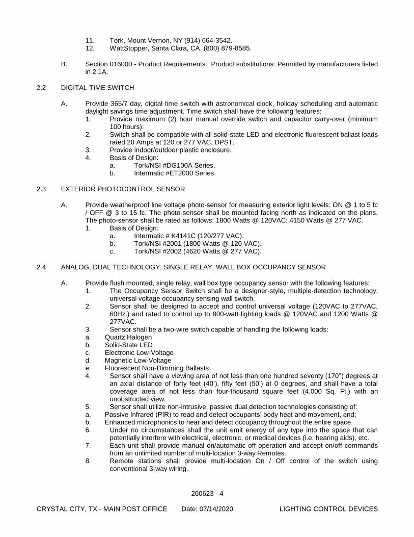
260623 - 4 CRYSTAL CITY, TX - MAIN POST OFFICE Date: 07/14/2020 LIGHTING CONTROL DEVICES
11. Tork, Mount Vernon, NY (914) 664-3542. 12. WattStopper, Santa Clara, CA (800) 879-8585.
B. Section 016000 - Product Requirements: Product substitutions: Permitted by manufacturers listed in 2.1A.
2.2 DIGITAL TIME SWITCH
A. Provide 365/7 day, digital time switch with astronomical clock, holiday scheduling and automatic daylight savings time adjustment. Time switch shall have the following features: 1. Provide maximum (2) hour manual override switch and capacitor carry-over (minimum
100 hours). 2. Switch shall be compatible with all solid-state LED and electronic fluorescent ballast loads
rated 20 Amps at 120 or 277 VAC, DPST. 3. Provide indoor/outdoor plastic enclosure. 4. Basis of Design:
a. Tork/NSI #DG100A Series. b. Intermatic #ET2000 Series.
2.3 EXTERIOR PHOTOCONTROL SENSOR
A. Provide weatherproof line voltage photo-sensor for measuring exterior light levels: ON @ 1 to 5 fc / OFF @ 3 to 15 fc. The photo-sensor shall be mounted facing north as indicated on the plans. The photo-sensor shall be rated as follows: 1800 Watts @ 120VAC; 4150 Watts @ 277 VAC. 1. Basis of Design:
a. Intermatic # K4141C (120/277 VAC). b. Tork/NSI #2001 (1800 Watts @ 120 VAC). c. Tork/NSI #2002 (4620 Watts @ 277 VAC).
2.4 ANALOG, DUAL TECHNOLOGY, SINGLE RELAY, WALL BOX OCCUPANCY SENSOR
A. Provide flush mounted, single relay, wall box type occupancy sensor with the following features: 1. The Occupancy Sensor Switch shall be a designer-style, multiple-detection technology,
universal voltage occupancy sensing wall switch. 2. Sensor shall be designed to accept and control universal voltage (120VAC to 277VAC,
60Hz.) and rated to control up to 800-watt lighting loads @ 120VAC and 1200 Watts @ 277VAC.
3. Sensor shall be a two-wire switch capable of handling the following loads: a. Quartz Halogen b. Solid-State LED c. Electronic Low-Voltage d. Magnetic Low-Voltage e. Fluorescent Non-Dimming Ballasts 4. Sensor shall have a viewing area of not less than one hundred seventy (170°) degrees at
an axial distance of forty feet (40’), fifty feet (50’) at 0 degrees, and shall have a total coverage area of not less than four-thousand square feet (4,000 Sq. Ft.) with an unobstructed view.
5. Sensor shall utilize non-intrusive, passive dual detection technologies consisting of: a. Passive Infrared (PIR) to read and detect occupants’ body heat and movement, and; b. Enhanced microphonics to hear and detect occupancy throughout the entire space. 6. Under no circumstances shall the unit emit energy of any type into the space that can
potentially interfere with electrical, electronic, or medical devices (i.e. hearing aids), etc. 7. Each unit shall provide manual on/automatic off operation and accept on/off commands
from an unlimited number of multi-location 3-way Remotes. 8. Remote stations shall provide multi-location On / Off control of the switch using
conventional 3-way wiring.
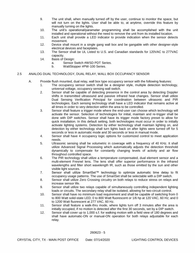
260623 - 5 CRYSTAL CITY, TX - MAIN POST OFFICE Date: 07/14/2020 LIGHTING CONTROL DEVICES
9. The unit shall, when manually turned off by the user, continue to monitor the space, but will not turn on the lights. User shall be able to, at anytime, override this feature by manually turning on the lights.
10. The unit’s operational/parameter programming shall be accomplished with the unit installed and operational without the need to remove the unit from its installed location.
11. Each unit shall provide a LED indicator to provide indication when the sensor detects movement.
12. Device shall mount in a single gang wall box and be gangable with other designer-style electrical devices and faceplates.
13. The Sensor shall be UL Listed to U.S. and Canadian standards for 120VAC to 277VAC capacity.
14. Basis of Design: a. Sensor Switch #WSD PDT Series. b. WattStopper #PW-100 Series.
2.5 ANALOG DUAL TECHNOLOGY, DUAL RELAY, WALL BOX OCCUPANCY SENSOR
A. Provide flush mounted, dual relay, wall box type occupancy sensor with the following features: 1. The occupancy sensor switch shall be a designer style, multiple detection technology,
universal voltage, occupancy sensing wall switch. 2. Sensor shall be capable of detecting presence in the control area by detecting Doppler
shifts in transmitted ultrasound and passive infrared heat changes. Sensor shall utilize Dual Sensing Verification Principal for coordination between ultrasonic and PIR technologies. Each sensing technology shall have a LED indicator that remains active at all times in order to very detection within the area to be controlled.
3. Sensor shall feature a trigger mode where the end-user can choose which technology will activate the sensor. Selection of technologies for initial, maintain and re-trigger shall be done with DIP switches. Sensor shall have its trigger mode factory preset to allow for quick installation. In this default setting, both technologies must occur in order to initially activate lighting systems. Detection by either technology shall maintain lighting on, and detection by either technology shall turn lights back on after lights were turned off for 5 seconds or less in automatic mode and 30 seconds or less in manual mode.
4. Sensor shall have 4 occupancy logic options for customized control to meet application needs.
5. Ultrasonic sensing shall be volumetric in coverage with a frequency of 40 KHz. It shall utilize Advanced Signal Processing which automatically adjusts the detection threshold dynamically to compensate for constantly changing levels of activity and air flow throughout controlled space.
6. The PIR technology shall utilize a temperature compensated, dual element sensor and a multi-element Fresnel lens. The lens shall offer superior performance in the infrared wavelengths and filter short wavelength IR, such as those emitted by the sun and other visible light sources.
7. Sensor shall utilize SmartSet™ technology to optimize automatic time delay to fit occupancy usage patterns. The use of SmartSet shall be selectable with a DIP switch.
8. Sensor shall utilize Zero Crossing circuitry on both relays to reduce stress on relays and increase sensor life.
9. Sensor shall utilize two relays capable of simultaneously controlling independent lighting loads or circuits. The secondary relay shall be isolated, allowing for two-circuit control.
10. Sensor shall have no minimum load requirement and shall be capable of switching from 0 to 800 Watt solid-state LED; 0 to 800 Watt fluorescent or 1/6 hp at 120 VAC, 60 Hz; and 0 to 1200 Watt fluorescent at 277 VAC, 60 Hz.
11. Sensor shall feature a walk-thru mode, where lights turn off 3 minutes after the area is initially occupied, if no motion is detected after the first 30 seconds, set by a DIP switch.
12. Sensor shall cover up to 1,000 s.f. for walking motion with a field view of 180 degrees and shall have automatic-ON or manual-ON operation for both relays adjustable for each relay.
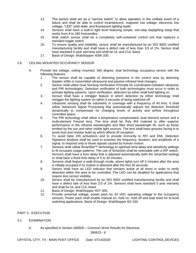
260623 - 6 CRYSTAL CITY, TX - MAIN POST OFFICE Date: 07/14/2020 LIGHTING CONTROL DEVICES
13. The sensor shall act as a “service switch” to allow operation in the unlikely event of a failure and shall be able to control incandescent, magnetic low voltage, electronic low voltage, “LED” solid state, and fluorescent lighting loads
14. Sensors shall have a built-in light level featuring simple, one-step daylighting setup that works from 8 to 180 footcandles.
15. Wall switch sensor shall be a completely self-contained control unit that replaces a standard toggle switch.
16. To ensure quality and reliability, sensor shall be manufactured by an ISO 9002 certified manufacturing facility and shall have a defect rate of less than 1/3 of 1%. Sensor shall have standard 5-year warranty and shall be UL and CUL listed.
17. Basis of Design: WattStopper #DW-200.
2.6 CEILING MOUNTED OCCUPANCY SENSOR
A. Provide low voltage, ceiling mounted, 360 degree, dual technology occupancy sensor with the following features. 1. The sensor shall be capable of detecting presence in the control area by detecting
doppler shifts in transmitted ultrasound and passive infrared heat changes. 2. Sensor shall utilize Dual Sensing Verification Principle for coordination between ultrasonic
and PIR technologies. Detection verification of both technologies must occur in order to activate lighting systems. Upon verification, detection by either shall hold lighting on.
3. Sensor shall have a retrigger feature in which detection by either technology shall retrigger the lighting system on within 5 seconds of being switched off.
4. Ultrasonic sensing shall be volumetric in coverage with a frequency of 40 KHz. It shall utilize Advanced Signal Processing that automatically adjusts the detection threshold dynamically to compensate for changing levels of activity and airflow throughout controlled space.
5. The PIR technology shall utilize a temperature compensated, dual element sensor and a multi-element Fresnel lens. The lens shall be Poly IR4 material to offer superior performance in the infrared wavelengths and filter short wavelength IR, such as those emitted by the sun and other visible light sources. The lens shall have grooves facing in to avoid dust and residue build up which affects IR reception.
6. To avoid false ON activations and to provide immunity to RFI and EMI, Detection Signature Analysis shall be used to examine the frequency, duration, and amplitude of a signal, to respond only to those signals caused by human motion.
7. Sensors shall utilize SmartSet™ technology to optimize time delay and sensitivity settings to fit occupant usage patterns. The use of SmartSet shall be selectable with a DIP switch. Sensors shall have a time delay that is adjusted automatically (with the SmartSet setting) or shall have a fixed time delay of 5 to 30 minutes.
8. Sensors shall feature a walk-through mode, where lights turn off 3 minutes after the area is initially occupied if no motion is detected after the first 30 seconds.
9. Sensor shall have an LED indicator that remains active at all times in order to verify detection within the area to be controlled. The LED can be disabled for applications that require less sensor visibility.
10. Sensor shall be manufactured by an ISO 9002 certified manufacturing facility and shall have a defect rate of less than 1/3 of 1%. Sensors shall have standard 5 year warranty and shall be UL and CUL listed.
11. Basis of Design: WattStopper #DT-305. 12. Provide universal voltage, power pack for 24 VDC operating voltage to the occupancy
sensors. Power pack shall enable manual on, hold on, hold off and load shed for bi-level switching applications. Basis of Design: WattStopper BZ-150.
PART 3 - EXECUTION
3.1 EXAMINATION
A. As specified in Section 260500 – Common Work Results for Electrical.
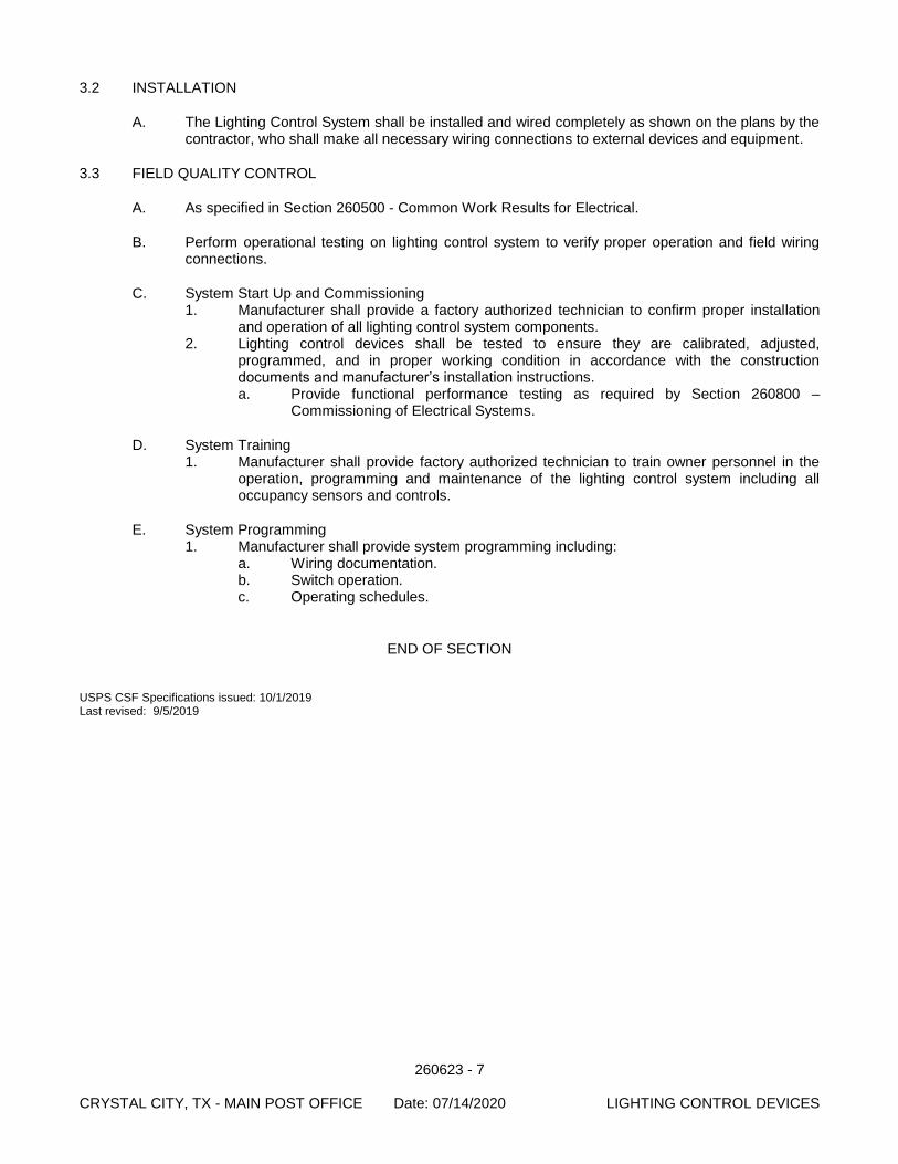
260623 - 7 CRYSTAL CITY, TX - MAIN POST OFFICE Date: 07/14/2020 LIGHTING CONTROL DEVICES
3.2 INSTALLATION
A. The Lighting Control System shall be installed and wired completely as shown on the plans by the contractor, who shall make all necessary wiring connections to external devices and equipment.
3.3 FIELD QUALITY CONTROL
A. As specified in Section 260500 - Common Work Results for Electrical.
B. Perform operational testing on lighting control system to verify proper operation and field wiring connections.
C. System Start Up and Commissioning 1. Manufacturer shall provide a factory authorized technician to confirm proper installation
and operation of all lighting control system components. 2. Lighting control devices shall be tested to ensure they are calibrated, adjusted,
programmed, and in proper working condition in accordance with the construction documents and manufacturer’s installation instructions. a. Provide functional performance testing as required by Section 260800 –
Commissioning of Electrical Systems.
D. System Training 1. Manufacturer shall provide factory authorized technician to train owner personnel in the
operation, programming and maintenance of the lighting control system including all occupancy sensors and controls.
E. System Programming 1. Manufacturer shall provide system programming including:
a. Wiring documentation. b. Switch operation. c. Operating schedules.
END OF SECTION USPS CSF Specifications issued: 10/1/2019 Last revised: 9/5/2019

260623 - 8 CRYSTAL CITY, TX - MAIN POST OFFICE Date: 07/14/2020 LIGHTING CONTROL DEVICES
[This page intentionally left blank.]
260800 - 1 CRYSTAL CITY, TX - MAIN POST OFFICE Date: 07/14/2020 COMMISSIONING OF ELECTRICAL SYSTEMS
SECTION 260800
COMMISSIONING OF ELECTRICAL SYSTEMS
PART 1 - GENERAL
1.1 WORK INCLUDED
A. Systems and equipment testing and start-up.
B. Validation of proper and thorough installation of Division 26 systems and equipment.
C. Functional performance testing of electrical systems.
D. Documentation of tests, procedures, and installations.
E. Coordination of Training Events.
F. Generic Start-Up Procedures for electrical systems and equipment.
1.2 SCOPE
A. The following electrical equipment and/or systems shall be commissioned if in compliance with the guidelines provided in Specification 019113, or with Contracting Officer approval: 1. Lighting and Lighting Control System – Per ASHRAE 90.1, Table 9.4.3.
1.3 GENERAL DESCRIPTION
A. Commissioning (Cx) is the process of ensuring that all building systems are installed and perform interactively according to the design intent; that systems are efficient and cost effective and meet the USPS’s operational needs; that the installation is adequately documented; and that the Operators are adequately trained. It serves as a tool to minimize post-occupancy operational problems. It establishes testing and communication protocols in an effort to advance the building systems from installation to full dynamic operation and optimization.
B. The USPS shall arrange to retain an independent Commissioning Authority (CxA) to provide Commissioning Services.
C. Commissioning Authority (CxA) shall work with the Contractor and Engineer to direct and oversee the Cx process and perform functional performance testing.
D. This Section outlines the Cx procedures specific to the Contractor’s electrical responsibilities. Requirements common to all work are described in Specification section 019113.
1.4 RELATED WORK AND DOCUMENTS
A. Drawings and general provisions of Contract, including General and Supplementary Conditions and Division-1 Specification sections, apply to work of this section
B. Commissioning Plan: The Cx Plan shall be available for reference as it outlines responsibilities outside of the Construction Contract. It provides the Contractor and the USPS an understanding of the planned commissioning activities for that project.
C. Section 013300 - Submittal Procedures: Stipulates additional copies of submittals to be submitted and refers to other sections for additional submittal requirements related to Cx.
260800 - 2 CRYSTAL CITY, TX - MAIN POST OFFICE Date: 07/14/2020 COMMISSIONING OF ELECTRICAL SYSTEMS
D. Section 017704 - Closeout Procedures and Training: Defines the milestones in completion incorporating the Cx process.
E. Section 019113 – General Commissioning Requirements: Specifies the general facility commissioning procedures common across all Divisions and the Contractor’s responsibilities for the commissioning process.
F. Individual Specification Sections: Individual sections stipulate installation, start-up, warranty, O&M documentation, and training requirements for the system or device specified in the Section.
G. Section 250804 – Building Automation System Commissioning: Details the commissioning procedures specific to the BAS.
1.5 REFERENCE STANDARDS
A. AABC Commissioning Group (ACG)
B. NEBB – Procedures for Building Systems Commissioning
C. National Electric Code (NEC)
D. American Society for Testing and Materials (ASTM)
E. Electronics Industry Association/Telecommunications Industry Association (EIA/TIA)
F. Illuminating Engineering Society (IES)
G. Institute of Electrical and Electronics Engineers (IEEE)
H. International Electrical Testing Association (NETA)
I. National Electrical Manufacturers Associates (NEMA)
J. National Fire Protection Association (NFPA)
K. Underwriters Laboratory, Inc. (UL)
1.6 DOCUMENTATION
A. As required in Specification 019113 and the following as they apply to the commissioning of equipment: 1. Factory Test Reports: Contractor shall provide any factory testing documentation or
certified test reports required by the specifications. These shall be provided prior to Acceptance Phase. Factory Test Reports should be provided in pdf electronic format. These include but are not limited to: a. Field Testing Agency Reports: Provide all documentation of work done by
independent testing agencies required by the contract documents. These shall be provided prior to Acceptance Phase. Field Testing Agency Reports should be provided in pdf electronic format.
1.7 COORDINATION MANAGEMENT PROTOCOLS
A. Coordination responsibilities and management protocols relative to Cx are initially defined in Section 019113 and the Commissioning Plan, but shall be refined and documented in the Construction Phase Cx Kick-Off meeting. Contractor shall have input in the protocols and all Parties will commit to scheduling obligations. The CxA will record and distribute.
260800 - 3 CRYSTAL CITY, TX - MAIN POST OFFICE Date: 07/14/2020 COMMISSIONING OF ELECTRICAL SYSTEMS
1.8 CONTRACTOR RESPONSIBILITIES
A. Refer to Section 019113: Detailed Contractor responsibilities common to all Divisions are specified in Section 019113. The following are additional responsibilities or notable responsibilities specific to the electrical systems.
B. Construction Phase 1. Coordinate the work of the Electrical Testing Agency and the Cx requirements, as
required. 2. Provide skilled technicians qualified to perform the work required. 3. Provide factory-trained and authorized technicians where required by the Contract
Documents. 4. Prepare and submit required draft Start-Up Procedures and submit along with the
manufacturer’s application, installation and start-up information. 5. Provide assistance to the CxA in preparation of the specific Functional Performance Test
(FPT) procedures. Contractors, subcontractors and vendors shall review FPT procedures to ensure feasibility, safety and equipment protection and provide necessary written alarm limits to be used during the tests.
6. Thoroughly complete and inspect installation of systems and equipment as detailed throughout Contract Documents, as required by reference or industry standards, and as specifically indicated elsewhere this Section.
7. Record Start-up Procedures on start-up procedure forms and certify that the systems and equipment have been started and or tested in accordance with the requirements specified above. Each task or item shall be indicated with the Party actually performing the task or procedure.
C. Acceptance Phase 1. Assist CxA in functional performance testing. Assistance will generally include the
following: a. Manipulate systems and equipment to facilitate testing (as dictated in Section
019110 and the Cx Plan; in some cases this will entail only an initial sample).
D. Warranty Phase 1. Maintain record documentation of any configurations, set ups, parameters etc, that
change throughout the period. a. Provide representative for off season testing as required by CxA. b. Respond to Warranty issues as required by Division 1 and the General
Conditions.
1.9 START-UP PROCEDURES AND DOCUMENTATION
A. Refer to Section 019113 and as detailed in PART 3 - EXECUTION below.
1.10 INDEPENDENT ELECTRICAL TESTING AGENCY
A. The Independent Electrical Testing Agency shall be provided under the construction specifications and therefore included with the bid. Many of the aspects of the start-up and functional performance testing indicated herein will be accomplished under the respective section and witnessed by the CxA at the indicated sample rate. CxA will include applicable test results in the functional performance testing record.
1.11 FUNCTIONAL PERFORMANCE TESTING
A. For applicable systems and equipment, Contractor shall participate in the initial samples of Functional Performance Testing as stipulated in Section 019113 and the Commissioning Plan.
260800 - 4 CRYSTAL CITY, TX - MAIN POST OFFICE Date: 07/14/2020 COMMISSIONING OF ELECTRICAL SYSTEMS
1.12 FPT ACCEPTANCE CRITERIA
A. Acceptance criteria for tests are indicated in the specification Sections applicable to the systems being tested. Generally, unless indicated otherwise, the criteria for acceptance will be that specified with the individual system, equipment, component, or device, which in general conform to NFPA 70B and International Electrical Testing Association (NETA) testing specifications NETA ATS-2003.
1.13 TRAINING
A. Contractors, subcontractor, vendors, and other applicable Parties shall prepare and conduct training sessions on the installed systems and equipment they are responsible for per the requirements of Section 019113 and the individual Specifications.
1.14 O&M MANUAL CONTENT - PREPARATION AND LOGISTICS
A. Refer to Section 019113 and the individual Specifications.
PART 2 - PRODUCTS
2.1 INSTRUMENTATION
A. All testing equipment used by any Party shall be of sufficient quality and accuracy to test and/or measure system performance with the tolerances specified. If not otherwise noted, the following minimum requirements apply: All equipment shall be calibrated according to the manufacturer’s recommended intervals. Calibration tags shall be affixed or certificates readily available.
B. Testing Instrumentation: Contractor shall provide all instrumentation necessary for tests for which they are responsible. CxA will provide standard instrumentation for measuring medium and low voltage electrical voltage, current, power factor, power, and THD. CxA will provide receptacle testers for normal and GFI receptacle tests. Contractor shall provide all other instrumentation required to accomplish the specified testing.
C. Contractor shall provide infrared scanning equipment when required by the contract documents. Infrared scanning equipment shall be an AGA (or approved equal) thermovision set capable of viewing an entire bus or equipment assembly at one time and have a sensitivity of 0.2°C with a liquid nitrogen reference.
D. Contractor shall provide Amprobe DM-III Multitest F power quality recorder/data logger or approved equal.
PART 3 - EXECUTION
3.1 START-UP PROCEDURES
A. This Section outlines ‘generic’ or minimally acceptable Start-Up Procedures. These items shall provide a minimum or guideline for required Contractor development of Start-Up Procedures. Contractor shall synthesize these minimum requirements along with their own internal quality control practices, those of the manufacturer, and any applicable codes and standards to develop specific and itemized Start-Up Procedures specific to the equipment and systems installed on this project.
B. Refer to NETA which is referenced in several Division 26 sections which outline electrical related testing required.

260800 - 5 CRYSTAL CITY, TX - MAIN POST OFFICE Date: 07/14/2020 COMMISSIONING OF ELECTRICAL SYSTEMS
C. The following start up verifications/procedures are common to all systems 1. Checkout shall proceed from devices to the components to the systems. 2. Verify labeling is affixed per spec and visible 3. Verify prerequisite procedures are done. 4. Inspect for damage and ensure none is present. 5. Verify system is applied per the manufacturer’s recommendations 6. Verify system has been started up per the manufacturer’s recommendations 7. Verify that access is provided for inspection, operation and repair 8. Verify that access is provided for replacement of the equipment 9. Verify the record drawings, submittal data and O&M documentation accurately reflect the
installed systems 10. Verify all gages and test reports are provided as required by contract documents and
manufacturer’s recommendations 11. Verify all recorded nameplate data is accurate 12. Installation is done to ensure safe operation and maintenance. 13. Verify specified replacement material/attic stock has been provided as required by the
Construction Documents
3.2 LIGHTING AND LIGHTING CONTROLS
A. General: Refer to the quality control requirements listed in section 019113 – General Commissioning Requirements for additional checks and tests. These shall be included in the tests used for this project.
B. Functional Testing. Lighting control devices and control systems shall be tested to ensure that control hardware and software are calibrated, adjusted, programmed, and in proper working condition in accordance with the construction documents and manufacturer’s installation instructions. When occupant sensors, time switches, programmable schedule controls, or photo sensors are installed, at a minimum, the following procedures shall be performed: 1. Confirm that the placement, sensitivity and time-out adjustments for occupant sensors
yield acceptable performance, lights turn off only after space is vacated and do not turn on unless space is occupied.
2. Confirm that the time switches and programmable schedule controls are programmed to turn the lights off.
3. Confirm that photosensor controls reduce electric light levels based on the amount of usable daylight in the space as specified.
4. Check the lighting systems and ensure that the all luminaries and lamps are operational and fixtures are clean.
5. Measure lighting levels after lamps have been ‘burned in’ for at least 100 hours. Check lighting levels to ensure compliance with the design requirements for the respective zones, if applicable.
6. Check operational and override switches to ensure the proper operation of timing circuits. 7. Measure the connected loads in current and watts on each controlled circuit. 8. Check full load current on all breakers serving controlled lighting to ensure that the
breaker is properly sized. 9. Verify the correct operation of all control devices (contactors, relays, time clocks, control
interface relays, etc.).
END OF SECTION
USPS CSF Specification issued: 10/1/2019 Last revised: 9/4/2018
260800 - 6 CRYSTAL CITY, TX - MAIN POST OFFICE Date: 07/14/2020 COMMISSIONING OF ELECTRICAL SYSTEMS
[This page intentionally left blank.]
262416 - 1 CRYSTAL CITY, TX - MAIN POST OFFICE Date: 07/14/2020 PANELBOARDS
SECTION 262416
PANELBOARDS
PART 1 - GENERAL
1.1 SUMMARY
A. Section Includes: 1. Panelboards.
B. Related Documents: The Contract Documents, as defined in Section 011000 - Summary of Work, apply to the Work of this Section. Additional requirements and information necessary to complete the Work of this Section may be found in other documents.
C. Related Sections: 1. As specified in Section 260500 - Common Work Results for Electrical.
1.2 REFERENCES
A. As specified in Section 260500 - Common Work Results for Electrical.
B. National Electrical Manufacturers Association (NEMA): 1. NEMA AB 1 – Molded Case Circuit Breakers. 2. NEMA ICS 2 – Industrial Control Devices, Controllers, and Assemblies. 3. NEMA KS 1 – Enclosed Switches. 4. NEMA PB 1 – Panelboards. 5. NEMA PB 1.1 – Instructions for Safe Installation, Operation and Maintenance of
Panelboards Rated 600 Volts or Less.
C. Underwriters Laboratories (UL): 1. UL 486 – Molded Case Circuit Breakers. 2. UL 67 – Heat Rise Test for Panelboards. 3. UL 50 – Steel Gauge Requirements for Cabinets and Enclosures. 4. UL 1449 4th Edition – Standard for Transient Voltage Surge Suppressors.
1.3 SUBMITTALS
A. As specified in Section 260500 – Common Work Results for Electrical. 1. Shop Drawings: Indicate outline and support point dimensions, voltage, main bus
ampacity, integrated short circuit ampere rating, circuit breaker and fusible switch arrangement and sizes.
2. Manufacturer’s Installation Instructions: Indicate application conditions and limitations of use stipulated by Product testing agency. Include instructions for storage, handling, protection, examination, preparation, installation, and starting of Product.
3. Shall include UL 1449 Listing documentation verifying the following: a. Short Circuit Current Rating (SCCR) b. Voltage Protection Ratings (VPRs) for all modes c. Maximum Continuous Operating Voltage Rating (MCOV) d. I-nominal rating (I-n)
B. Section 017704 – Closeout Procedures and Training: Procedures for closeout submittals: 1. Project Record Documents: Record actual locations of Products; indicate actual branch
circuit arrangement.
262416 - 2 CRYSTAL CITY, TX - MAIN POST OFFICE Date: 07/14/2020 PANELBOARDS
2. Operation and Maintenance Data: Include spare parts data listing; source and current prices of replacement parts and supplies; and recommended maintenance procedures and intervals.
3. Submit data showing compliance with UL 1449.
1.4 QUALITY ASSURANCE
A. As specified in Section 260500 – Common Work Results for Electrical.
B. Panelboards shall be UL Listed and labeled and shall be designed in accordance with the applicable standards of ANSI and NEMA.
C. Qualifications 1. Manufacturer: Company specializing in manufacturing the Products specified in this
section with minimum five years documented experience.
PART 2 - PRODUCTS
2.1 GENERAL CLASSIFICATION
A. Manufacturers: General Electric Company (G.E.) Catalog numbers are used to identify type of equipment specified. Equivalent products by the following manufacturers are acceptable: Alternate substitutions not permitted. 1. Siemens 2. Square-D 3. Eaton/Cutler Hammer
a. Branch Circuit Panels: 1) 120/208V: G.E. Type AQ
b. Distribution Panels: 1) Circuit breaker: G.E. Type CS or A
2.2 PANELBOARDS
A. Cabinet: Construct cabinet with code gauge galvanized steel. Provide minimum 20 inch wide cabinets, and extra wiring space where incoming feed-through or parallel lines are required.
B. Doors: Provide single door construction, made of cold-rolled steel. Door shall have concealed hinges, flush catch, and lock. (Tie bar handles not acceptable). Secure top and bottom of door to cabinet by slotted steel bolts. Release shall be by one-half turn with a screwdriver. All panels shall be keyed alike.
C. Panels located adjacent to each other shall have identically sized enclosures and trims.
D. Finish: Finish exposed parts with one coat of primer and one coat of light gray enamel suitable for overpainting in field if desired.
E. Phase, neutral and ground bus bars shall be tin plated copper.
F. Provide all hardware for future breakers, identified on drawings as SPACES, or for the full length of usable bus, whichever is longer.
G. Provide ground bus with full complement of terminals in addition to insulated neutral bus.
H. Circuit Breakers: 1. Provide multi-pole units with common trip elements. Handle ties are not acceptable.
262416 - 3 CRYSTAL CITY, TX - MAIN POST OFFICE Date: 07/14/2020 PANELBOARDS
2. Provide key-operated circuit breakers in the panelboards used for the Fire Alarm. Security and CCTV Systems. Circuit breakers shall be similar to square D type QO_K.
3. 120/208V branch circuit panelboards: Molded cast bolt-on type designed for 120/208V, three phase, four wire service with minimum 10,000 amperes rms short circuit rating.
I. Main circuit breakers shall be individually mounted. The panelboard interior assembly shall be dead front with panelboard front removed. Main lugs or main breakers shall have barriers on five sides. The barrier in front of the main lugs shall be hinged to a fixed part of the interior. The end of the bus structure opposite the main shall have barriers.
J. Provide all panelboards with lockout/tagout devices; Circuit-Safe type as manufactured by Stranco, Inc. or approved equal.
K. Nameplates: Provide screwed-on (no adhesives) engraved bakelite nameplate identification on outside of each panel showing panel designation, voltage and phase in minimum ¼ inch high letters.
L. Circuit directories: Provide a metal-framed typewritten circuit directory on inside of inner door, with plastic protector.
M. Provide 2-3/4 inches and 1-1 inch spare empty conduits routed above into accessible ceiling space from all flush mounted panelboards.
N. Panels serving electronic equipment and/or other harmonic producing loads shall be equipped with double neutral bus bars.
PART 3 - EXECUTION
3.1 EXAMINATION
A. As specified in Section 260500 – Common Work Results for Electrical.
3.2 CLEARANCES
A. Minimum code required clearances around panelboards must be maintained.
3.3 INSTALLATION
A. Install panelboards in accordance with NEMA PB 1.1.
B. Install panelboards plumb. Provide supports in accordance with Section 260500.
C. Provide filler plates for unused spaces in panelboards.
3.4 MOUNTING HEIGHT
A. Typically mount panel boards top at 6 ft. – 0 in. above finished floor but no more than 6 ft. – 6 in. above finished floor to top of circuit breaker handle.
3.5 MOUNTING HARDWARE
A. Provide all necessary blocking, channels and other hardware for securing panelboards to wall, column, or other parts of building structure.
262416 - 4 CRYSTAL CITY, TX - MAIN POST OFFICE Date: 07/14/2020 PANELBOARDS
3.6 FIELD QUALITY CONTROL
A. As specified in Section 260500 – Common Work Results for Electrical.
B. Inspect and test panelboard installation and torque connections.
C. Measure steady state load currents at each panelboard feeder; rearrange circuits in the panelboard to balance the phase loads to within 20 percent of each other. Maintain proper phasing for multi-wire branch circuits.
D. Inspect for physical damage, proper alignment, anchorage, and grounding. Check proper installation and tightness of connections for circuit breakers.
END OF SECTION USPS CSF Specifications issued: 10/1/2019 Last revised: 9/5/2019
262726 - 1 CRYSTAL CITY, TX - MAIN POST OFFICE Date: 07/14/2020 WIRING DEVICES
SECTION 262726
WIRING DEVICES
PART 1 - GENERAL
1.1 SUMMARY
A. Section Includes: 1. Wall switches. 2. Receptacles. 3. Device plates and box covers. 4. Multi-outlet surface raceway.
B. Related Documents: The Contract Documents, as defined in Section 011000 - Summary of Work, apply to the Work of this Section. Additional requirements and information necessary to complete the Work of this Section may be found in other documents.
C. Related Sections: 1. As specified in Section 260500 - Common Work Results for Electrical.
1.2 REFERENCES
A. As specified in Section 260500 - Common Work Results for Electrical.
B. National Electrical Manufacturers Association (NEMA): 1. NEMA WD 1 - General Requirements for Wiring Devices. 2. NEMA WD 6 - Wiring Device -- Dimensional Requirements.
1.3 SUBMITTALS
A. Product data required.
1.4 QUALITY ASSURANCE
A. Qualifications: 1. Manufacturer: Company specializing in manufacturing the Products specified in this
section with minimum 5 years documented experience.
B. Regulatory Requirements: 1. Conform to requirements of NFPA 70. 2. Provide Products listed and classified by Underwriters Laboratories, Incorporated.
PART 2 - PRODUCTS
2.1 WALL SWITCHES
A. Manufacturers: Subject to compliance with project requirements, manufacturers offering specified items which may be incorporated in the Work include the following: 1. Hubbell, Inc, Milford, CT (203) 882-4800. 2. Leviton Manufacturing, Company, Inc., Little Neck, NY (800) 824-3005. 3. Pass & Seymour, Syracuse, NY (800) 776-4035.
B. Section 016000 - Product Requirements: Product options and substitutions. Substitutions: Permitted.

262726 - 2 CRYSTAL CITY, TX - MAIN POST OFFICE Date: 07/14/2020 WIRING DEVICES
C. Provide 20 Amp, 120/277V, specification grade, flush, single pole toggle switches with side and back wired screw terminals. All switches shall be equipped with grounding screws.
D. Single Pole Switch: 1. Leviton Cat. No.1221-2. 2. P&S Cat. No. PS20AC1I. 3. Hubbell Cat. No. HBL1221.
E. Double Pole Switch: 1. Leviton Cat. No. 1222-2. 2. P&S Cat. No. PS20AC2. 3. Hubbell, Cat. No. HBL1222.
F. Three-way Switch: 1. Leviton, Cat. No. 1223-2. 2. P&S Cat. No. PS20AC-3. 3. Hubbell Cat. No. HBL1223.
G. Indicator Switch: 1. Leviton Cat. No. 1221-PLR (Red). 2. P&S Cat. No. PS20AC1-RPL (Red). 3. Hubbell Cat. No. HBL1221PL (Red).
H. Locator Switch: 1. Leviton Cat. No. 1221-LHC (Clear). 2. P&S Cat. No. PS20AC1-CSL (Clear). 3. Hubbell Cat. No. HBL1221IL (Clear).
I. Locking Switch: 1. Leviton Cat. No. 1221-2LW. 2. P&S Cat. No. PS20AC1-L. 3. Hubbell Cat. No. HBL1221L.
J. Color: Switches located within the Retail Area to be mounted in “blue” or “red” painted walls shall be black. All other switches shall be white unless indicated otherwise.
2.2 RECEPTACLES
A. Manufacturers: Subject to compliance with project requirements, manufacturers offering specified items which may be incorporated in the Work include the following: 1. Leviton Manufacturing, Company, Inc., Little Neck, NY (800) 824-3005. 2. Pass & Seymour, Syracuse, NY (800) 776-4035. 3. Hubbell, Inc, Milford, CT (203) 882-4800. 4. Section 016000 - Product Requirements: Product options and substitutions.
Substitutions: Permitted.
B. Provide duplex, specification grade, 20 Amp, 120 Volt, 2 pole, 3 wire receptacles with grounding screw.
C. Duplex Convenience Receptacle: 1. Leviton Cat. No. 5362. 2. P&S Cat. No. 5362. 3. Hubbell Cat. No. HBL5352.
D. Tamper and Weather Resistant GFCI Receptacle (Side Wired Feed-Thru): 1. Hubbell Cat. No. GFR5362SG.
262726 - 3 CRYSTAL CITY, TX - MAIN POST OFFICE Date: 07/14/2020 WIRING DEVICES
E. Color: Receptacles located within the Retail Area to be mounted in “blue” or “red” painted walls shall be black. All other receptacles shall be white unless indicated otherwise.
2.3 WALL PLATES
A. Manufacturers: Subject to compliance with project requirements, manufacturers offering specified items which may be incorporated in the Work include the following: 1. P&S Sierra. 2. Hubbell. 3. Leviton. 4. Section 016000 - Product Requirements: Product options and substitutions.
Substitutions: Permitted.
B. Coverplate: Coverplates to be installed within the Retail Areas on “blue” or “red” painted walls shall be black smooth thermoplastic. All other coverplates shall be white smooth thermoplastic unless otherwise noted. 1. Sierra TP8-W.
C. Weatherproof Coverplate: Gasketed cast metal with hinged gasketed device. 1. Sierra 4510 cast aluminum.
2.4 MULTI-OUTLET SURFACE RACEWAY
A. Manufacturers: Subject to compliance with project requirements, manufacturers offering specified items which may be incorporated in the Work include the following: 1. Legrand/Wiremold, West Hartford, CT (800) 621-0049. 2. Section 016000 - Product Requirements: Product options and substitutions.
Substitutions: Permitted.
B. Raceway Material: Anodized aluminum with manufacturer’s standard hardware and fittings. Length as indicated on drawings.
C. Wire: Factory pre-wired with No. 12 AWG minimum. Provide equipment grounding conductor.
D. Wiring Devices: NEMA5-20R duplex receptacles and/or telecommunication outlets. Quantity as indicated on drawings.
E. Provide single channel raceway for applications requiring power receptacles only. Provide dual channel raceway for applications requiring power receptacles and telecommunications outlets.
F. Single channel, single cover raceway. 1. Wiremold #AL3000 Series.
G. Dual channel, single cover raceway 1. Wiremold #AL4000 Series.
PART 3 - EXECUTION
3.1 EXAMINATION
A. Section 017300 - Execution: Verification of existing conditions before starting work.
B. Verification of Conditions: Verify that field measurements, surfaces, substrates and conditions are as required, and ready to receive Work. 1. Verify that outlet boxes are installed at proper height. 2. Verify that wall openings are neatly cut and will be completely covered by wall plates.
262726 - 4 CRYSTAL CITY, TX - MAIN POST OFFICE Date: 07/14/2020 WIRING DEVICES
3. Verify that branch circuit wiring installation is completed, tested, and ready for connection to wiring devices.
3.2 PREPARATION
A. Provide extension rings to bring outlet boxes flush with finished surface.
B. Clean debris from outlet boxes.
3.3 INSTALLATION
A. Install wiring devices as indicated, in accordance with manufacturer’s written instruction, applicable requirements of NEC and NECA "Standard of Installation" , and in accordance with recognized industry practices to fulfill project requirements
B. Install devices plumb and level.
C. Install switches with OFF position down.
D. Install receptacles with grounding pole on bottom.
E. Connect wiring device grounding terminal to branch circuit equipment grounding conductor.
F. Connect wiring devices by wrapping conductor 2/3 of screw diameter in clockwise direction around screw terminal. Tighten screw to 12 pound-inches. Do not use spring pressure devices for wire connections.
G. Install galvanized steel plates on outlet boxes and junction boxes in unfinished areas, above accessible ceilings, and on surface mounted outlets.
H. Provide coverplates on switch, receptacle, and blank outlets.
3.4 LABELING
A. All coverplates for receptacles and switches shall be labeled with the branch circuit number. Label shall be machine generated and permanently affixed to the outside of the coverplate.
3.5 CONSTRUCTION
A. Interface with other work: 1. Coordinate locations of outlet boxes provided under Section 260533 to obtain mounting
heights indicated on Drawings.
3.6 FIELD QUALITY CONTROL
A. Section 014000 – Quality Requirements: Field inspection.
B. Prior to energizing circuitry, test wiring for electrical continuity, and for short circuits. Ensure proper polarity of connections is maintained. Subsequent to energization, test wiring devices to demonstrate compliance with requirements.
C. Inspect each wiring device for defects.
D. Operate each wall switch with circuit energized and verify proper operation.
E. Verify that each receptacle device is energized.
262726 - 5 CRYSTAL CITY, TX - MAIN POST OFFICE Date: 07/14/2020 WIRING DEVICES
F. Test each receptacle device for proper polarity.
G. Test each GFCI receptacle device for proper operation.
3.7 ADJUSTING
A. Adjust devices and wall plates to be flush, level and plumb with wall.
3.8 CLEANING
A. Section 017300 Execution: Cleaning installed work.
B. Clean exposed surfaces to remove splatters and restore finish.
END OF SECTION USPS Master Specifications issued: 10/1/2019 Last revised: 9/5/2019

262726 - 6 CRYSTAL CITY, TX - MAIN POST OFFICE Date: 07/14/2020 WIRING DEVICES
[This page intentionally left blank.]
262816 - 1 CRYSTAL CITY, TX - MAIN POST OFFICE Date: 07/14/2020 ENCLOSED SWITCHES
SECTION 262816
ENCLOSED SWITCHES
PART 1 - GENERAL
1.1 SUMMARY
A. Section Includes: 1. Fusible switches. 2. Nonfusible switches. 3. Fuses.
B. Related Documents: The Contract Documents, as defined in Section 011000 - Summary of Work, apply to the Work of this Section. Additional requirements and information necessary to complete the Work of this Section may be found in other Documents.
C. Related Sections: 1. As specified in Section 260500 - Common Work Results for Electrical.
1.2 REFERENCES
A. National Electrical Testing Association (NETA): 1. NETA ATS - Acceptance Testing Specifications for Electrical Power Distribution Equipment
and Systems.
B. National Electrical Contractors Association (NECA): 1. NECA SI - Standard of Installation.
C. National Electrical Manufacturers Association (NEMA): 1. NEMA FU 1 - Low Voltage Cartridge Fuses. 2. NEMA KS 1 - Enclosed Switches.
D. National Fire Protection Association (NFPA): 1. NFPA 70 - National Electrical Code.
1.3 SUBMITTALS
A. Section 013300 - Submittal Procedures: Procedures for submittals. 1. Product Data:
a. Switch ratings and enclosure dimensions. b. Fuse data sheets showing electrical characteristics including time-current curves.
2. Assurance/Control Submittals: a. Certificates: Manufacturer's certificate that Products meet or exceed specified
requirements. b. Manufacturer's Instructions: Indicate application conditions and limitations of use
stipulated by Product testing agency. Include instructions for storage, handling, protection, examination, preparation, installation, and starting of Product.
B. Section 017704 - Closeout Procedures and Training: Procedures for closeout submittals. 1. Project Record Documents: Record actual locations of enclosed switches and actual fuse
sizes.
1.4 QUALITY ASSURANCE
A. Perform Work in accordance with NECA SI.
262816 - 2 CRYSTAL CITY, TX - MAIN POST OFFICE Date: 07/14/2020 ENCLOSED SWITCHES
B. Manufacturer Qualifications: Company specializing in manufacturing Products specified in this Section with minimum five years documented experience.
C. Regulatory Requirements: 1. Conform to requirements of NFPA 70. 2. Products: Listed and classified by Underwriters Laboratories, Incorporated as suitable for
purpose specified and indicated.
1.5 MAINTENANCE
A. Section 017704 - Closeout Procedures and Training: Procedures for closeout submittals.
B. Extra Products: At completion of installation, deliver to USPS Project Manager. 1. Three of each size and type fuse installed.
PART 2 - PRODUCTS
2.1 MANUFACTURERS
A. Switches: Subject to compliance with project requirements, manufacturer's offering Products which may be incorporated in the Work include the following: 1. Eaton/Cutler Hammer Corp., Pittsburg, PA (800) 525-2000. 2. General Electric Company (800) 626-2000. 3. Siemens Energy & Automation, Alpharetta, GA (800) 964-4114. 4. Square D Company, Palatine, IL (800) 392-8781.
B. Fuses: Subject to compliance with project requirements, manufacturers offering Products which may be incorporated in the Work include the following: 1. Cooper Industries Incorporated, Waukesha, WI (414) 524-3300. 2. General Electric Company (800) 626-2000. 3. Gould Shawmut, Newburyport, MA (508) 462-6662.
C. Section 016000 - Product Requirements: Product options and substitutions. Substitutions not permitted.
2.2 FUSIBLE ENCLOSED SWITCH ASSEMBLIES
A. NEMA KS 1, Type HD heavy duty, 100,000 AIC load interrupter enclosed knife switch with externally operable handle interlocked to prevent opening front cover with switch in ON position. Cover shall be equipped with a manual defeat to allow opening by authorized personnel while energized. Handle shall be lockable in ON or OFF position.
B. Rating: 250 volts AC or 600 volts AC as indicated on Drawings.
C. Fuse Clips: Designed to accommodate Class R fuses.
D. Enclosures: NEMA KS 1. 1. Interior Dry Locations: NEMA Type 1 or 12. 2. Exterior Locations: NEMA Type 3R or 12.
E. Provide factory grounding lug and neutral block if required.
2.3 NONFUSIBLE SWITCH ASSEMBLIES
A. NEMA KS 1, Type GD, general duty load interrupter enclosed knife switch with externally operable handle interlocked to prevent opening front cover with switch in ON position. Cover shall be
262816 - 3 CRYSTAL CITY, TX - MAIN POST OFFICE Date: 07/14/2020 ENCLOSED SWITCHES
equipped with a manual defeat to allow opening by authorized personnel while energized. Handle shall be lockable in ON or OFF position.
B. Rating: 250 volts AC or 600 volts AC as indicated on Drawings.
C. Enclosures: NEMA KS 1. 1. Interior Dry Locations: NEMA Type 1 or 12. 2. Exterior Locations: NEMA Type 3R or 12.
D. Provide factory grounding lug and neutral block if required.
2.4 FUSES
A. NEMA FU 1, Class RK5, dual element, current limiting, time delay, 250 volt AC or 600 volt AC as indicated on Drawings.
B. Interrupting Rating: 100,000 rms amperes.
PART 3 - EXECUTION
3.1 EXAMINATION
A. As specified in Section 260500 – Common Work Results for Electrical.
3.2 INSTALLATION
A. Switches: 1. Install in accordance with manufacturers published instructions and NECA SI. 2. Install where indicated on Drawings, where required by equipment, and where required by
NFPA 70. 3. Apply adhesive tag on inside door of each fused switch indicating NEMA fuse class and size
installed.
B. Fuses: 1. Install fuses in fusible switches in accordance with manufacturer's published instructions, as
indicated on Drawings, or as required by loading per NFPA 70. 2. Install fuse with label oriented with manufacturer, type, and size easily read.
3.3 FIELD QUALITY CONTROL
A. Section 014000 - Quality Requirements: Field testing and inspection.
B. Inspect and test in accordance with NETA ATS, except Section 4.
C. Perform inspections and tests listed in NETA ATS, Section 7.5.
END OF SECTION USPS CSF Specifications issued: 10/1/2019 Last revised: 9/5/2019 Last revised: 9/5/2019

262816 - 4 CRYSTAL CITY, TX - MAIN POST OFFICE Date: 07/14/2020 ENCLOSED SWITCHES
[This page intentionally left blank.]
265100 - 1 CRYSTAL CITY, TX - MAIN POST OFFICE Date: 07/14/2020 INTERIOR LIGHTING (LED-SOLID STATE)
SECTION 265100
INTERIOR LIGHTING (LED-SOLID STATE)
PART 1 - GENERAL
1.1 SUMMARY
A. Section Includes: 1. Interior luminaires and accessories. 2. Emergency lighting units. 3. Exit signs. 4. Ballast/Light emitting diode (LED) drivers. 5. Light Sources. 6. Luminaire accessories.
B. Substitutions: 1. Section 016000 - Product Requirements: Product substitutions permitted by
manufacturers listed in 2.1A.
C. Related Documents: The Contract Documents, as defined in Section 011000 - Summary of Work, apply to the work of this section. Additional requirements and information necessary to complete the work of this section may be found in other documents.
D. Related Sections: 1. Section 260500 - Common Work Results for Electrical. 2. Section 260623 – Lighting Controls.
1.2 REFERENCES
A. As specified in Section 260500 – Common Work Results for Electrical.
B. Illuminating Engineering Society (IES): 1. IES LM-79 - (2008) Electrical and Photometric Measurements of Solid-State Lighting
Products. 2. IES LM-80 - (2015) Measuring Lumen Maintenance of LED Light Sources. 3. IES TM-21 - (2011; Addendum B 2015) Projecting Long Term Lumen Maintenance of
LED Light Sources.
C. National Fire Protection Association (NFPA) 1. NFPA 101 – Life Safety Code. 2. NFPA 70 – National Electrical Code.
D. National Electrical Manufacturers Association (NEMA): 1. NEMA ANSILG C78.377 – (2017) Electric Lamps— Specifications for the Chromaticity of
Solid State Lighting Products. 2. NEMA SSL 1 – (2010) Electronic Drivers for Led Devices, Arrays, or Systems. 3. NEMA SSL 3 - (2011) High-Power White LED Binning for General Illumination.
E. Federal Communications Commission Parts 18.305, 18.307 (EMI RFI).
F. American Society of Heating, Refrigerating and Air Conditioning, Inc. 1. ANSI/ ASHRAE/ IES Standard 90.1.
G. Underwriters Laboratories (UL)
265100 - 2 CRYSTAL CITY, TX - MAIN POST OFFICE Date: 07/14/2020 INTERIOR LIGHTING (LED-SOLID STATE)
1. UL 1472 – (2015) UL Standard for Safety Solid-State Dimming Controls. 2. UL 1598 – (2008; Reprint Oct 2012) Luminaires. 3. UL 844 – (2012; Reprint Mar 2016) UL Standard for Safety Luminaires for Use in
Hazardous (Classified) Locations. 4. UL 8750 – (2015; Reprint Feb 2018) UL Standard for Safety Light Emitting Diode (LED)
Equipment for Use in Lighting Products. 5. UL 924 – (2016; Reprint Nov 2017) UL Standard for Safety Emergency Lighting and
Power Equipment.
1.3 SUBMITTALS
A. As specified in Section 260500 – Common Work Results for Electrical. 1. Product Data: Submit catalog cuts, drawings, descriptive matter and lighting
performance characteristics as required to completely define the materials and construction details employed, finishes applied, dimensions, hinging, latching and relamping provisions, and electrical characteristics.
2. Assurance/Control Submittals: a. Manufacturer's Instructions: Indicate application conditions and limitations of use
stipulated by product testing agency. Include instructions for storage, handling, protection, examination, preparation, and installation of Product.
B. Section 017704 - Closeout Procedures and Training: Procedures for closeout submittals: 1. Operation and Maintenance Data: Submit manufacturer's operation and maintenance
instructions for each type of luminaire.
1.4 DEFINITIONS
A. For LED luminaire light sources, “Useful Life” is the operating hours before reaching 70 percent of the initial rated lumen output (L70) with no catastrophic failures under normal operating conditions. This is also known as 70 percent “Rated Lumen Maintenance Life” as defined in IES LM-80.
B. For LED luminaires, “Luminaire Efficacy” (LE) is the appropriate measure of energy efficiency, measured in lumens/watt. This is gathered from LM-79 data for the luminaire, in which absolute photometry is used to measure the lumen output of the luminaire as one entity, not the source separately and then the source and housing together.
C. Total harmonic distortion (THD) is the root mean square (RMS) of all the harmonic components divided by the total fundamental current.
1.5 QUALITY ASSURANCE
A. As specified in Section 260500 - Common Work Results for Electrical.
B. Products shall be tested, approved and labeled/listed by Underwriters Laboratories, Inc., or by a nationally recognized testing laboratory (NRTL).
C. Electrical equipment and materials shall be new and within one year of manufacture, complying with the latest codes and standards. Re-built, refurbished and/or re-manufactured electrical equipment and materials shall not be furnished on this project.
1.6 MAINTENANCE
A. Section 017704 - Closeout Procedures and Training: Procedures for closeout submittals.
B. Extra Products: At completion of installation, deliver to the USPS Project Manager. 1. Two of each luminaire lens type.
265100 - 3 CRYSTAL CITY, TX - MAIN POST OFFICE Date: 07/14/2020 INTERIOR LIGHTING (LED-SOLID STATE)
2. Each component type: Provide quantity for each unique ballast/driver, relay, I/O module and lamp equal to 2 percent of luminaire total, but not less than two of each type.
PART 2 - PRODUCTS
2.1 LUMINAIRE MANUFACTURERS
A. Subject to compliance with project requirements, manufacturers offering Products which may be incorporated in the Work include the following: 1. Alphabet Lighting, Tustin, CA (714) 259-9959. 2. Beghelli, Miramar, FL (954) 442-6600. 3. Chloride Systems, Burgaw, NC (910) 259-1000. 4. Columbia Lighting, Greenville, SC (864) 678-1000. 5. Cooper Lighting (Halo, Invue, Lumark, Metalux, Portfolio, Sure-Lites), Peachtree City, GA
(770) 486-4800. 6. Compass Lighting Products, Greenville, SC (866) 313-3909. 7. Day-Brite, Tupelo, MS (662) 842-7212. 8. Dual-Lite, Cheshire, CT (203) 699-2000. 9. Edison-Price Lighting, Long Island City, NY (718) 685-0700. 10. Elcast Lighting, Addison, IL (630) 543-5390. 11. Gardco Lighting, San Leandro, CA (800) 227-0758. 12. GE Lighting Systems, Charlotte, NC (803)462-2016. 13. Gotham Lighting, Conyers, GA (800) 315-4982. 14. Guth Lighting, St. Louis, MO (314) 533-3200. 15. H.E.Williams, Carthage, MO (417) 358-4065. 16. Holophane, Newark, OH (740) 345-9631. 17. Hubbell Lighting, Inc., (Columbia, Spaulding, Sterner) Spartanburg, SC (864) 599-6000. 18. Intense Lighting LLC, Anaheim, CA (800) 961-5321. 19. Indy Lighting, Fishers, IN (817) 849-1233. 20. Kenall Manufacturing, Gurnee, IL (847) 360-8200. 21. Kirlin Lighting, Detroit, MI (313) 259-6400. 22. Kramer Lighting, Sturtevant, WI (800) 236-6800. 23. Kurt Versen Company, Westwood, NJ (201) 664-8200. 24. Kurtzon Lighting, Chicago, IL (773) 277-2121. 25. LaMar Lighting, Farming Dale, NY (631) 777-7700. 26. LightAlarms (Thomas & Betts) Montreal, ON (888) 552-6467. 27. Lithonia Lighting, Conyers, GA (770) 922-9000. 28. LSI Industries, Cincinnati, OH (513) 793-3200. 29. Lumax Industries, Altoona, PA (814) 944-2537.Omega Lighting, Tupelo, MS (800) 234-
1890. 30. Orion Energy Systems, Inc., Manitowoc, WI (800) 660-9340. 31. Phoenix Products, Milwaukee, WI (414) 438-1200. 32. Prescolite Lighting, Spartanburg, SC (864) 599-6000. 33. Prudential Lighting, Los Angeles, CA (213) 746-0360. 34. Vista Lighting, Tupelo, MS (662) 690-4105. 35. Zumtobel Staff, Highland, NY (800) 448-4131.
2.2 LUMINAIRE TYPES
A. Type A1: Lithonia #2BLT4-XXX-ADP-EZ1-LP840 Series. 1. Description: Recessed, 2 ft. W x 4 ft. L x 3 inch D LED type troffer with side reflectors
and dropped acrylic center lens, non-air handling. 2. Lens: High performance extruded acrylic diffuser with curved linear prisms. 3. Housing:
a. 22 gauge steel body, flush steel door with mitered corners. b. Frame and housing white baked enamel or powder coated finish.
265100 - 4 CRYSTAL CITY, TX - MAIN POST OFFICE Date: 07/14/2020 INTERIOR LIGHTING (LED-SOLID STATE)
4. Ballast/Driver: LED high efficiency – 30W at 3400 Lumen, 34W at 4000 Lumen, 45W at 5200 Lumen or 53W at 6300 Lumen. Wattage based on lumen package selected.
5. Mounting: a. Recessed in Inverted T suspended ceiling. b. Recessed in gypsum board ceiling; provide flanged frame-in kit. 6. Lamps: 3400 Lumen, 4000 Lumen, 5200 Lumen or 6300 Lumen LED array; 4000K rated
60,000 hours at LLD = 0.8. 7. Marking: luminaires are to be labeled on the interior side with lumen package used. 8. Alternate Manufacturers:
a. Columbia #LCAT24-40-XXXX-G-ED-U. b. Metalux #24RTC-XX-UNV-L840-CD-U. c. Substitutions permitted: As listed in paragraph 2.1A.
B. Type R2: Gotham #EVOWW-40/XX-4WR-MVOLT Series. 1. Description: Recessed 4.5 inch dia. aperture LED wall washer type downlight. 2. Reflector: Low brightness, white painted, self-flanged reflector. 3. Ballast/Driver: 10 Watt/750 Lumen, 13 Watt/1000 Lumen or 17 Watt/1500 Lumen LED
light engine with remote phosphor technology; Wattage based on lumen packaged selected; 5-year factory warranty.
4. Housing: a. Frame to be 18 gauge galvanized steel ring. b. Mounting ring shall be secured to ceiling bar hangers (supplied with luminaire). c. Luminaire frame to be supported from the structure by at least two opposing
corners 5. Junction Box:
a. Junction box to be code approved for through wiring. b. Junction box to be secured to the mounting ring and accessible from two sides. c. Junction box to be pre-wired and accessible per code through the ceiling trim
opening. 6. Mounting:
a. 24 inch grid ceiling bar hangers shall be supplied by manufacturer and securely fastened to grid.
b. Provide 28 inch "C" channel mounting bars and flange kit for drywall ceiling. 7. Voltage: 120. 8. Lamp: 750 Lumen, 1000 Lumen or 1500 Lumen, 4000K, remote phosphor enclosed LED
array; 60,000 hours at LLD = 0.7. 9. Marking: Luminaires are to be labeled on the interior side with lumen package used. 10. Alternate Manufacturers:
a. Portfolio #LD4BXXD010-EU4B-1020-80-40-4LBSW-XX-1-XX. b. Alphabet #NU4-RW-SW-XXLM-40K-80-WW-XXX-DM10-WH-WH. c. Substitutions permitted: As listed in paragraph 2.1A.
C. Type CL1: Lithonia #ZLIN-L48-XXXX-FST-40K Series. 1. Description; 4 ft. long, LED strip luminaire with protective lens/diffuser. 2. Lens: Snap on frosted, diffused lens. 3. Housing:
a. 20 gauge cold rolled steel housing with punched knockouts for mounting. b. End plates shall be die-formed heavy gauge rolled steel with punched knockouts
for through wiring. c. White baked enamel finish with a minimum 90 percent reflectance.
4. Ballast/Driver: LED high efficiency – 25W at 3000 Lumen, 34W. 5. Mounting:
a. Surface mounted to the underside of the ceiling. Attach luminaire to ceiling grid by means of a gripper hanger which attaches to any standard ceiling grid system.
b. For spaces without ceiling, suspend from structure with all-thread rods to required height.
c. Electrical Contractor to determine quantity of hangers required for either method.
265100 - 5 CRYSTAL CITY, TX - MAIN POST OFFICE Date: 07/14/2020 INTERIOR LIGHTING (LED-SOLID STATE)
6. Lamps: 3000 Lumen LED arrays, 4000K rated 60,000 hours at LLD=0.7. 7. Marking: Luminaires are to be labeled on the interior side with lumen package used. 8. Alternate Manufacturers:
a. Lumax Industries #CNLED-XXL-4K-48-9-FAF. b. Metalux #4SNLED-LD5-XXX-LW-UNV-L840-CD1-U. c. Orion (Harris) #SFHC1 Series with lens. d. Substitutions permitted: As listed in paragraph 2.1A.
D. Type W2: Lithonia #ZLID-L48SMR-5000-FST-40K Series. 1. Description: Surface Mounted, 4 ft. long, industrial LED, strip light luminaire providing 10
percent uplighting, with locking lampholders and protective wireguards. 2. Lens: Snap on frosted, diffused lens. 3. Reflector: 4 ft. long, symmetrical reflector with uplight #ZLR-L48-SYM-UPL-WH. 4. Housing:
a. Channel and end plates of formed steel, 20 gauge material thickness. b. Reflector and housing shall be white baked enamel with 90% minimum
reflectance. 5. Ballast/Driver: 41W at 5000 Lumen. Wattage based on lumen packages selected. 6. Mounting: Wire rope/chain from ceiling structure. 7. Lamps: 5500 Lumen LED array; 4000K, 50,000 hours at LLD=0.7. 8. Marking: Luminaires are to be labeled on the interior side with lumen package used. 9. Alternate Manufacturers:
a. Mercury #LW4-4-XXXX-40K-HTA-SRA. b. Lumax #CHLEDR-XXXL-4K-48-9. c. Substitutions permitted: As listed in paragraph 2.1A.
E. Type X1: Lithonia #LQM-S-W-3R-120/277-ELN-SD Series. 1. Description: Ceiling, end or wall mount, single face LED exit sign with canopy. Self
powered and with self diagnostics. 2. Features: Red Letters, White Stencil, White Housing (verify colors with local jurisdiction).
Injection molded UL94-5V rated polycarbonate frame and canopy. 3. Mounting: Ceiling, back or end mounted. 4. Battery: Maintenance free sealed Nickel Cadmium with long life, full recharge time of 24
hours max. 5. Voltage: 120. 6. Lamps: LED lamp module. 7. Alternate Manufacturers:
a. Sure-Lites #LPX7-X-SD. b. Compass #CERSD. c. Substitutions permitted: As listed in paragraph 2.1A.
2.3 LUMINAIRES
A. Provide luminaires as indicated in luminaire schedule and details on project plans. Provide luminaires complete with light sources of quantity, type and wattage indicated. Provide all luminaires of the same type by the same manufacturer. Luminaires must be specifically designed for use with the driver or ballast and light source provided.
B. LED Luminaires: 1. Install ballast/drivers, LED arrays and specified accessories at the factory. 2. Luminaires must have a minimum 5 year manufacturer's warranty. 3. Luminaires must have a minimum L70 lumen maintenance value of 50,000 hours as
calculated by IES TM-21, with data obtained per IES LM-80 requirements. 4. Luminaire drive current value must be identical to that provided by test data for luminaire
in question. 5. Luminaires must be listed with the DesignLights Consortium 'Qualified Products List'
when falling into category of "General Application" luminaires, i.e. Interior Directional,

265100 - 6 CRYSTAL CITY, TX - MAIN POST OFFICE Date: 07/14/2020 INTERIOR LIGHTING (LED-SOLID STATE)
Display Case, Troffer, Linear Ambient, or Low/High Bay. Requirements are shown in the Designlights Consortium "Technical Requirements Table" at https://data.energystar.gov/dataset/EPA-Recognized-Laboratories-For- Lighting-Products/jgwf-7qrr.
6. Provide Department of Energy 'Lighting Facts' label for each luminaire.
2.4 LED DRIVERS
A. NEMA SSL 1, UL 8750. LED drivers must be electronic, UL Class 1, constant-current type and comply with the following requirements: 1. Output power (watts)and luminous flux (lumens) as shown in luminaire schedule for each
luminaire type to meet minimum luminaire efficacy (LE) value provided. 2. Power Factor (PF) greater than or equal to 0.9 over the full dimming range when
provided. 3. Current draw Total Harmonic Distortion (THD) of less than 20 percent. 4. Class A sound rating. 5. Operable at input voltage of 120-277 volts at 60 hertz. 6. Minimum 5 year manufacturer's warranty. 7. RoHS compliant. 8. Integral thermal protection that reduces or eliminates the output power if case
temperature exceeds a value detrimental to the driver. 9. UL listed for dry or damp locations typical of interior installations. 10. LED driver shall tolerate sustained open circuit and short circuit output conditions without
damage. 11. LED driver shall comply with the requirements of the FCC rules and regulations, Title 47
CFR Part 15 Non-Consumer (Class A).
2.5 LIGHT SOURCES
A. NEMA ANSLG C78.377, NEMA SSL 3. Provide type and wattage as indicated in luminaire schedule on project plans.
B. LED arrays shall have a correlated color temperature (CCT) of 4000K; minimum color rendering index (CRI) value of 80.
C. High power, white light output utilizing phosphor conversion (PC) process or mixed system of colored LEDs, typically red, green and blue (RGB).
D. Provide light source color consistency by utilizing a binning tolerance within a 4 step McAdam ellipse.
E. Luminaire shall have door frame and lens compatible for use with LED arrays and integral airflow ventilation system.
2.6 LED EMERGENCY DRIVERS
A. Provide LED emergency driver with automatic power failure detection, test switch and LED indicator (or combination switch/indicator) located on luminaire exterior and provide self-diagnostic function integral to emergency driver. Integral nickel cadmium or lithium ion phosphate battery is required to supply a minimum of 90 minutes of emergency power at 700 Lumens. Driver must be RoHS compliant, rated for installation in plenum-rated spaces and damp locations, and be warranted for a minimum of five years.
2.7 LUMINAIRE SUPPORT HARDWARE
A. Wire:
265100 - 7 CRYSTAL CITY, TX - MAIN POST OFFICE Date: 07/14/2020 INTERIOR LIGHTING (LED-SOLID STATE)
1. ASTM A641/A641M; Galvanized, soft tempered steel, minimum 0.11 inches in diameter, or galvanized, braided steel, minimum 0.08 inches in diameter.
B. Threaded Rods: 1. Threaded steel rods, 3/16 inch diameter, zinc or cadmium coated.
C. Straps: 1. Galvanized steel, one inch by 3/16 inch, conforming to ASTM A653/A653M, with a light
commercial zinc coating or ASTM A1008/A1008M with an electrodeposited zinc coating conforming to ASTM B633, Type RS.
2.8 EQUIPMENT IDENTIFICATION
A. Each item of equipment must have a nameplate bearing the manufacturer's name, address, model number, and serial number securely affixed in a conspicuous place; the nameplate of the distributing agent will not be acceptable.
B. Provide labeled luminaires in accordance with UL 1598 requirements. All luminaires must be clearly marked for operation of specific light sources and ballasts or drivers. Note the following light source characteristics in the format "Use Only _____": 1. Correlated color temperature (CCT) and color rendering index (CRI) for all luminaires. 2. All markings related to light source type must be clear and located to be readily visible to
service personnel, but unseen from normal viewing angles when light sources are in place. Ballasts or drivers must have clear markings indicating multi-level outputs and indicate proper terminals for the various outputs.
2.9 FACTORY APPLIED FINISH
A. Provide all luminaires and lighting equipment with factory-applied painting system that as a minimum, meets requirements of NEMA 250 corrosion-resistance test.
2.10 RECESS- AND FLUSH-MOUNTED LUMINAIRES
A. Provide access to lamp and ballast from bottom of luminaire. Provide trim for the exposed surface of flush-mounted luminaires as indicated on project drawings and specifications.
2.11 SUSPENDED LUMINAIRES
A. Provide hangers capable of supporting twice the combined weight of luminaires supported by hangers. Provide with swivel hangers to ensure a plumb installation. Provide cadmium-plated steel with a swivel-ball tapped for the conduit size indicated. Hangers must allow fixtures to swing within an angle of 45 degrees. Brace pendants 4 feet or longer to limit swinging. Single-unit suspended luminaires must have twin-stem hangers. Multiple-unit or continuous row luminaires must have a tubing or stem for wiring at one point and a tubing or rod suspension provided for each unit length of chassis, including one at each end. Provide rods in minimum 0.25 inch diameter.
PART 3 - EXECUTION
3.1 EXAMINATION
A. As specified in Section 260500 – Common Work Results for Electrical.
3.2 INSTALLATION
265100 - 8 CRYSTAL CITY, TX - MAIN POST OFFICE Date: 07/14/2020 INTERIOR LIGHTING (LED-SOLID STATE)
A. Electrical installations must conform to IEEE C2, NFPA 70, and to the requirements specified herein. Install luminaires to meet the requirements of ASHRAE 90.1 and ASHRAE 189.1. To encourage consistency and uniformity, install luminaires of the same manufacture and model number when residing in the same facility or building.
B. Luminaires: 1. Set luminaires plumb, square, and level with ceiling and walls, in alignment with adjacent
luminaires and secure in accordance with manufacturers' directions and approved drawings. Installation must meet requirements of NFPA 70. Obtain approval of the exact mounting height on the job before commencing installation and, where applicable, after coordinating with the type, style, and pattern of the ceiling being installed.
2. Recessed and semi-recessed luminaires must be independently supported from the building structure by a minimum of four wires, straps or rods per luminaire and located near each corner of the luminaire. Ceiling grid clips are not allowed as an alternative to independently supported luminaires.
3. Round luminaires or luminaires smaller in size than the ceiling grid must be independently supported from the building structure by a minimum of two wires, straps or rods per luminaire, spaced approximately equidistant around. Do not support luminaires by acoustical tile ceiling panels. a. Where luminaires of sizes less than the ceiling grid are indicated to be centered
in the acoustical panel, support each independently and provide at least two 3/4 inch metal channels spanning, and secured to, the ceiling tees for centering and aligning the luminaire. Provide wires, straps, or rods for luminaire support in this section.
C. Suspended Luminaires 1. Provide suspended luminaires with swivel hangers so that they hang plumb and level.
The stem, canopy and luminaire must be capable of 45 degree swing. Pendants, rods, or chains, 4 feet or longer excluding luminaire, must be braced to prevent swaying using three cables at 120 degree separation.
2. Suspended luminaires in continuous rows must have internal wireway systems for end to end wiring and must be properly aligned to provide a straight and continuous row without bends, gaps, light leaks or filler pieces.
3. Match supporting pendants with supported luminaire. Aircraft cable must be stainless steel. Canopies must be finished to match the ceiling and must be low profile unless otherwise shown.
4. Maximum distance between suspension points must be 10 feet or as recommended by the manufacturer, whichever is less.
D. Locate recessed ceiling luminaires as indicated on reflected ceiling plan.
E. Install surface mounted luminaires and exit luminaire signs plumb and adjust to align with building lines and with each other. Secure to prevent movement. Mount exit signs to outlet box mounted flush in wall or ceilings. Outlet box for ceiling mounted exit signs: Connect to rigid conduit system.
F. Install recessed luminaires using accessories and firestopping materials to meet regulatory requirements for fire rating. In fire rated ceilings recessed luminaires must carry 1 hour UL fire rating classification.
G. Install earthquake clips to secure recessed grid-supported luminaires in place.
H. Install wall mounted luminaires, emergency lighting units and exit luminaire signs at height as scheduled.
I. Install accessories furnished with each luminaire.
265100 - 9 CRYSTAL CITY, TX - MAIN POST OFFICE Date: 07/14/2020 INTERIOR LIGHTING (LED-SOLID STATE)
J. Bond products and metal accessories to branch circuit equipment grounding conductor.
K. Install specified light sources in each emergency lighting unit, exit luminaire sign, and luminaire.
L. Wire exit signs and emergency lighting units ahead of the local switch, to the normal lighting circuit located in the same room or area.
M. Luminaire whips shall be steel or aluminum. M/C cable shall be permissible for luminaire whips/connections. Luminaire whips/connections shall be made with a minimum of #12 AWG copper conductors. Equipment grounding conductors shall be provided in all luminaire whips and/or connections. 1. All luminaire whips shall be supported to luminaire support wire/cable with an approved
fastener equal to an Erico “KX” flexible conduit hanger or other UL listed supports and fasteners.
N. Luminaires are not to be used as a raceway unless stamped for use as raceway by manufacturer. Single luminaire in lay-in ceilings shall not be used for raceway and shall be connected to an outlet box located within six feet (6’) of fixture with flexible conduit or luminaire whips.
3.3 FIELD QUALITY CONTROL
A. As specified in Section 260500 – Common Work Results for Electrical.
B. Operate each luminaire after installation and connection. Inspect for proper connection and operation.
C. Final acceptance will be based on measurement of initial lighting levels after required hours of burn in as specified in USPS Customer Service Facilities Design Criteria, not maintained lighting levels.
3.4 WARRANTY
A. Provide a written 5 year on-site replacement warranty for material, luminaire finish, and workmanship. On-site replacement includes transportation, removal, and installation of new products. 1. Include finish warranty to include failure and substantial deterioration such as blistering,
cracking, peeling, chalking, or fading. 2. Material warranty must include:
a. All drivers. b. Replacement when more than 10 percent of LED sources in any lightbar or
subassembly(s) are defective or non-starting.
B. Warranty period must begin on date of beneficial occupancy. Provide the USPS Project Manager with signed warranty certificates prior to final payment.
3.5 ADJUSTING
A. Aim and adjust luminaires as directed by the USPS Project Manager.
B. Position exit luminaire sign directional arrows as indicated.
3.6 CLEANING
A. Conform to Section 017300 - Execution: Cleaning installed work.
B. Clean electrical parts to remove conductive and deleterious materials.
265100 - 10 CRYSTAL CITY, TX - MAIN POST OFFICE Date: 07/14/2020 INTERIOR LIGHTING (LED-SOLID STATE)
C. Remove dirt and debris from enclosures.
D. Clean photometric control surfaces as recommended by manufacturer.
E. Clean finishes and touch up damage.
END OF SECTION USPS CSF Specifications issued: 10/1/2019 Last revised: 9/5/2019
265600 - 1 CRYSTAL CITY, TX - MAIN POST OFFICE Date: 07/14/2020 EXTERIOR LIGHTING
SECTION 265600
EXTERIOR LIGHTING
PART 1 - GENERAL
1.1 SUMMARY
A. Section Includes: 1. Exterior luminaires and accessories. 2. Poles. 3. Ballast/Drivers.
B. Substitutions: 1. Section 016000 – Product Requirements: Product substitutions permitted by
manufacturers listed in paragraph 2.1A.
C. Related Documents: The Contract Documents, as defined in Section 011000 - Summary of Work, apply to the work of this section. Additional requirements and information necessary to complete the work of this section may be found in other documents.
D. Related Sections 1. As specified in Section 260500 - Common Work Results for Electrical. 2. Section 033000 - Cast-in-Place Concrete. 3. Section 260623 - Lighting Controls.
1.2 REFERENCES
A. As specified in Section 260500 – Common Work Results for Electrical.
B. Illuminating Engineering Society North America (IESNA): 1. IESNA RP-8 - Recommended Practice for Roadway Lighting. 2. IESNA RP-20 - Recommended Practice for Lighting for Parking Facilities. 3. IESNA RP-33 - Recommended Practice for Lighting for Exterior Environments.
C. Federal Communications Commission Parts 18.305, 18.307 (EMI RFI).
D. American Society of Heating, Refrigerating and Air Conditioning, Inc. 1. ANSI/ ASHRAE/ IES Standard 90.1.
1.3 SUBMITTALS
A. As specified in Section 260500 – Common Work Results for Electrical. 1. Product Data:
a. Luminaire dimensions, ratings, and performance data. b. Complete computer data printout of illumination levels based on a 5 ft. by 5 ft. grid
pattern. 2. Shop Drawings:
a. Indicate dimensions and components for each luminaire which is not a standard Product of the manufacturer.
b. Indicate illumination levels in accordance with layout and scheduled luminaires indicated on Drawings.
1.4 QUALITY ASSURANCE
A. As specified in Section 260500 – Common Work Results for Electrical.
265600 - 2 CRYSTAL CITY, TX - MAIN POST OFFICE Date: 07/14/2020 EXTERIOR LIGHTING
1.5 DELIVERY, STORAGE, AND HANDLING
A. Section 016000 - Material and Equipment: Transport, Handle, Store, and Protect Products.
1.6 MAINTENANCE
A. Section 017704 – Closeout Procedures and Training. Procedures for closeout submittals.
B. Extra Products: At completion of installation, deliver to the USPS Project Manager. 1. Each component type: Provide quantity for each unique ballast/driver, surge protector and
LED array equal to two (2) percent of luminaire total, but not less than two of each type.
PART 2 - PRODUCTS
2.1 LUMINAIRE MANUFACTURERS
A. Subject to compliance with project requirements, manufacturers offering Products which may be incorporated in the Work include the following: 1. Alphabet Lighting, Tustin, CA (714) 259-9959. 2. Architectural Landscape Lighting, Santa Ana, CA 92704 (714) 668-1107. 3. Barron Lighting Group (Trace-Lite), Phoenix, AZ 85027 (888) 533-3948. 4. Bronzelite Commercial Landscape Lighting, (800) 273-1569. 5. CGF Design Inc., Morton Grove, IL (847) 815-5079. 6. Cooper Lighting (Halo, Invue, Lumark, Lumiere, McGraw-Edison, Portfolio), Peachtree
City, GA (770) 486-4800. 7. Deco Lighting, Commerce, CA (800) 613-3326. 8. Gardco/Philips Lighting, San Leandro, CA (800) 227-0758. 9. GE Lighting Systems, Charlotte, NC (803) 462-2016. 10. Gotham Lighting, Conyers, GA (800) 315-4982. 11. Hadco Lighting, Littlestown, PA (717) 359-7131. 12. H.E. Williams, Carthage, MO (417) 358-4065. 13. Holophane, Newark, OH (740) 345-9631. 14. Hubbell Lighting, Inc., (Kim, Spaulding, Sterner) Spartanburg, SC (864) 599-6000. 15. Hydrel Architectural and Landscape Products, Sylmar, CA 91342 (818) 362-9465. 16. Intense Lighting, Anaheim, CA (800) 961-5322. 17. Kenall Manufacturing, Gurnee, IL (847) 360-8200. 18. Kim Lighting, City of Industry, CA (626) 968-5666. 19. Kirlin Lighting, Detroit, MI (313) 259-6400. 20. Ligman Lighting USA, Hillsboro, OR (503) 645-0500. 21. Lithonia Lighting, Conyers, GA (770) 922-9000. 22. LSI Industries, Cincinnati, OH (513) 793-3200. 23. McPhilben Lighting, San Leandro, CA (510) 357-6900. 24. Pathway Lighting, Old Saybrook, CT (800) 342-0592. 25. Quality Lighting, Franklin Park, IL (847) 451-0090. 26. Visionaire Lighting, Rancho Dominguez, CA (310) 512-6480. 27. Wide-Lite, San Marcos, TX (512) 392-5821
2.2 LUMINAIRE TYPES
A. Type MH3 (exterior) Lithonia #MRWLED-XX-40K-SRX Series. 1. Description: 18 inch dia. half cylinder wall mounted full cut-off, solid state, LED luminaire.
Lens door is fully gasketed with one-piece solid silicone and UL listed for wet locations. 2. Lens: Precision molded acrylic. 3. Housing: Die-cast single piece aluminum housing. Finish by the USPS Project Manager. 4. Ballast/Driver: 20W at 2200 Lumen, 29W at 3000 Lumen, 40W at 4500 Lumen or 61W at
6000 Lumen. Wattage based on lumen packaged selected. 5. Mounting: Surface wall.
265600 - 3 CRYSTAL CITY, TX - MAIN POST OFFICE Date: 07/14/2020 EXTERIOR LIGHTING
6. Voltage: 120. 7. Lamp: 2200 Lumen, 3000 Lumen, 4500 Lumen or 6000 Lumen LED array; 4000K, 60,000
hours @ LLC = 0.9. 8. Label: UL listed for wet locations; IP65 rated. 9. Warranty: Full five (5) year factory replacement warranty (internal components). 10. Alternate Manufacturers:
a. Gardco/Philips #104L-XXL-XXX-NW-G1 Series. b. Hubbell #QSP-30L4K-XXX-X-U Series. c. Lithonia #WSRLED-XX-40K-SRX. d. McGraw Edison #ISS-EOX-LED-E1-BLX. e. Barron Trace-Lite #TLED111P Series. f. Deco Lighting #D440-LED-XX-40-UNV-D-XX Series. g. Substitutions permitted: As listed in paragraph 2.1A.
B. Type PL4 (exterior) #Kenall #MR13XL-PP-XXL40K-DV Series. 1. Description: 13 inch dia., low profile, round, wall mounted, full cut-off LED luminaire. 2. Reflector: High efficiency, semi-specular aluminum. 3. Lens: Pearlescent, U.V. stabilized, high impact resistant, virgin injection molded
polycarbonate. 4. Finish: Finish by the USPS Project Manager. 5. Recessed Housing: 18 gauge, cold rolled steel. 6. Ballast/Driver: 13W at 1100 Lumen or 24W at 2200 Lumen. Wattage based on lumen
package selected. 7. Mounting: Semi-recessed, wall mounted; A.D.A. compliant. 8. Voltage: 120. 9. Lamp: 1100 Lumen or 2200 Lumen LED array; 4000K,60,000 hours at LLD = 0.7. 10. Label: U.L. listed for wet locations; 5-year factory warranty. 11. Alternate manufacturers:
a. Cooper/Fail-Safe #TRX-15-LD4-XXW-40 Series. b. Kim #WF31X-X-XXL2KUV Series. c. CGF Design #GB-4-LEDXX-CT4-UNV-0-10D Series. d. Substitutions permitted: As listed in paragraph 2.1A.
C. Type PL5 Gotham EVOCYL-40/XX-6AR-MD-LD-MVOLT-EZ10 Series. 1. Description: Pendant 6 inch dia., aperture LED downlight. 2. Reflector: Low brightness, matte-diffused, clear specular alzak finish. 3. Housing: Heavy gauge aluminum cylinder, finished white. Pendant hung on a 24 inch
stem with a swivel canopy. 4. Ballast/Driver: 12W at 1100 Lumen thru 47W at 4500 Lumen. Wattage based on lumen
package selected. 5. Mounting: Pendant or surface mounted. 6. Voltage: 120. 7. Lamp: 1100 Lumen thru 4500 Lumen LED array; 4000K 60,000 hours at LLD = 0.7. 8. Label: U.L. listed for wet locations; 5-year factory warranty. 9. Alternate manufacturers:
a. Alphabet #608W-6-XTM19-XXLM-40K-83-DAXX-UNV-DIM10 Series. b. Pathway #C68LB79V-XX-4K Series. c. Kirlin #LSR-12484-XXXL Series. d. Portfolio #LSR6B Series. e. Substitutions permitted: As listed in paragraph 2.1A.
D. Type SP2 Lithonia #DSX1LED-60C-1000-40K-TXX-MVOLT Series. 1. Description: 13 inch W x 33 inch L x 3 ½ inch H, large, low profile, rectilinear architectural
arm-mounted full cut-off, solid state, LED luminaire. 2. Reflector: Anodized segmented reflectors. Beam distribution as required. 3. Housing: Rugged aluminum rectilinear housing with all seams continuously welded for
integrity. Corrosion-resistant polyester powder coat.
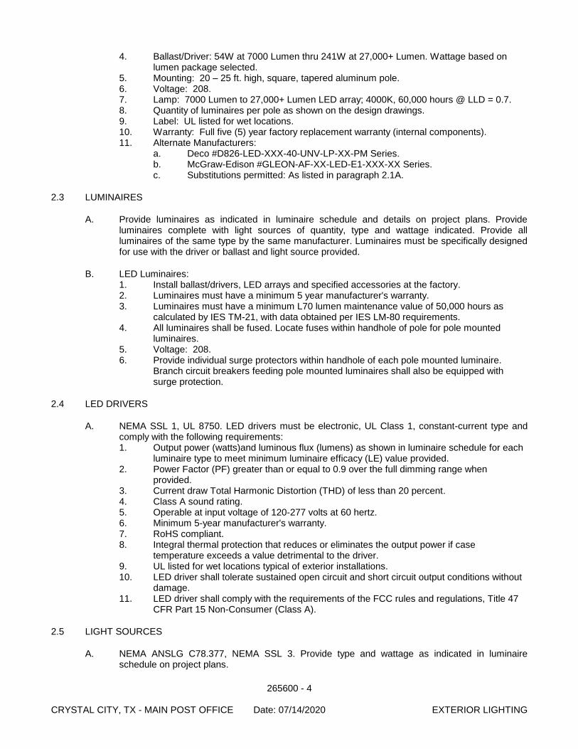
265600 - 4 CRYSTAL CITY, TX - MAIN POST OFFICE Date: 07/14/2020 EXTERIOR LIGHTING
4. Ballast/Driver: 54W at 7000 Lumen thru 241W at 27,000+ Lumen. Wattage based on lumen package selected.
5. Mounting: 20 – 25 ft. high, square, tapered aluminum pole. 6. Voltage: 208. 7. Lamp: 7000 Lumen to 27,000+ Lumen LED array; 4000K, 60,000 hours @ LLD = 0.7. 8. Quantity of luminaires per pole as shown on the design drawings. 9. Label: UL listed for wet locations. 10. Warranty: Full five (5) year factory replacement warranty (internal components). 11. Alternate Manufacturers:
a. Deco #D826-LED-XXX-40-UNV-LP-XX-PM Series. b. McGraw-Edison #GLEON-AF-XX-LED-E1-XXX-XX Series. c. Substitutions permitted: As listed in paragraph 2.1A.
2.3 LUMINAIRES
A. Provide luminaires as indicated in luminaire schedule and details on project plans. Provide luminaires complete with light sources of quantity, type and wattage indicated. Provide all luminaires of the same type by the same manufacturer. Luminaires must be specifically designed for use with the driver or ballast and light source provided.
B. LED Luminaires: 1. Install ballast/drivers, LED arrays and specified accessories at the factory. 2. Luminaires must have a minimum 5 year manufacturer's warranty. 3. Luminaires must have a minimum L70 lumen maintenance value of 50,000 hours as
calculated by IES TM-21, with data obtained per IES LM-80 requirements. 4. All luminaires shall be fused. Locate fuses within handhole of pole for pole mounted
luminaires. 5. Voltage: 208. 6. Provide individual surge protectors within handhole of each pole mounted luminaire.
Branch circuit breakers feeding pole mounted luminaires shall also be equipped with surge protection.
2.4 LED DRIVERS
A. NEMA SSL 1, UL 8750. LED drivers must be electronic, UL Class 1, constant-current type and comply with the following requirements: 1. Output power (watts)and luminous flux (lumens) as shown in luminaire schedule for each
luminaire type to meet minimum luminaire efficacy (LE) value provided. 2. Power Factor (PF) greater than or equal to 0.9 over the full dimming range when
provided. 3. Current draw Total Harmonic Distortion (THD) of less than 20 percent. 4. Class A sound rating. 5. Operable at input voltage of 120-277 volts at 60 hertz. 6. Minimum 5-year manufacturer's warranty. 7. RoHS compliant. 8. Integral thermal protection that reduces or eliminates the output power if case
temperature exceeds a value detrimental to the driver. 9. UL listed for wet locations typical of exterior installations. 10. LED driver shall tolerate sustained open circuit and short circuit output conditions without
damage. 11. LED driver shall comply with the requirements of the FCC rules and regulations, Title 47
CFR Part 15 Non-Consumer (Class A).
2.5 LIGHT SOURCES
A. NEMA ANSLG C78.377, NEMA SSL 3. Provide type and wattage as indicated in luminaire schedule on project plans.
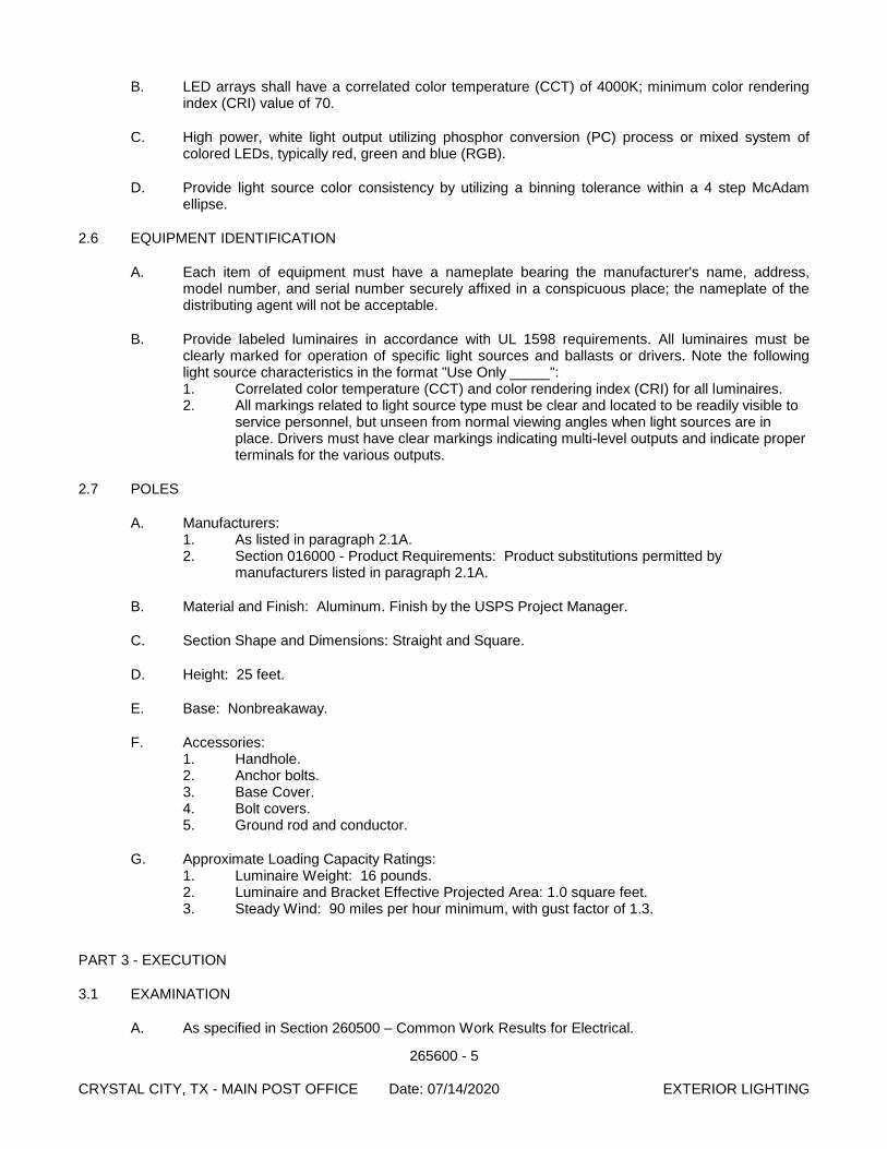
265600 - 5 CRYSTAL CITY, TX - MAIN POST OFFICE Date: 07/14/2020 EXTERIOR LIGHTING
B. LED arrays shall have a correlated color temperature (CCT) of 4000K; minimum color rendering index (CRI) value of 70.
C. High power, white light output utilizing phosphor conversion (PC) process or mixed system of colored LEDs, typically red, green and blue (RGB).
D. Provide light source color consistency by utilizing a binning tolerance within a 4 step McAdam ellipse.
2.6 EQUIPMENT IDENTIFICATION
A. Each item of equipment must have a nameplate bearing the manufacturer's name, address, model number, and serial number securely affixed in a conspicuous place; the nameplate of the distributing agent will not be acceptable.
B. Provide labeled luminaires in accordance with UL 1598 requirements. All luminaires must be clearly marked for operation of specific light sources and ballasts or drivers. Note the following light source characteristics in the format "Use Only _____": 1. Correlated color temperature (CCT) and color rendering index (CRI) for all luminaires. 2. All markings related to light source type must be clear and located to be readily visible to
service personnel, but unseen from normal viewing angles when light sources are in place. Drivers must have clear markings indicating multi-level outputs and indicate proper terminals for the various outputs.
2.7 POLES
A. Manufacturers: 1. As listed in paragraph 2.1A. 2. Section 016000 - Product Requirements: Product substitutions permitted by
manufacturers listed in paragraph 2.1A.
B. Material and Finish: Aluminum. Finish by the USPS Project Manager.
C. Section Shape and Dimensions: Straight and Square.
D. Height: 25 feet.
E. Base: Nonbreakaway.
F. Accessories: 1. Handhole. 2. Anchor bolts. 3. Base Cover. 4. Bolt covers. 5. Ground rod and conductor.
G. Approximate Loading Capacity Ratings: 1. Luminaire Weight: 16 pounds. 2. Luminaire and Bracket Effective Projected Area: 1.0 square feet. 3. Steady Wind: 90 miles per hour minimum, with gust factor of 1.3.
PART 3 - EXECUTION
3.1 EXAMINATION
A. As specified in Section 260500 – Common Work Results for Electrical.
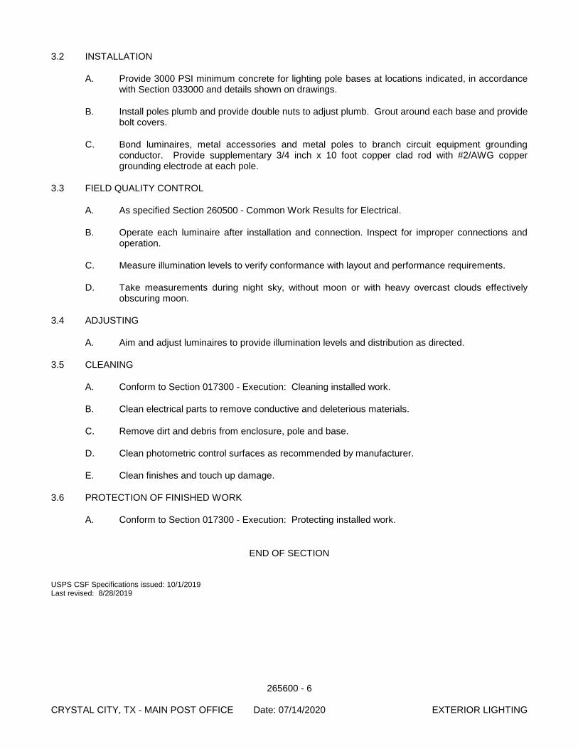
265600 - 6 CRYSTAL CITY, TX - MAIN POST OFFICE Date: 07/14/2020 EXTERIOR LIGHTING
3.2 INSTALLATION
A. Provide 3000 PSI minimum concrete for lighting pole bases at locations indicated, in accordance with Section 033000 and details shown on drawings.
B. Install poles plumb and provide double nuts to adjust plumb. Grout around each base and provide bolt covers.
C. Bond luminaires, metal accessories and metal poles to branch circuit equipment grounding conductor. Provide supplementary 3/4 inch x 10 foot copper clad rod with #2/AWG copper grounding electrode at each pole.
3.3 FIELD QUALITY CONTROL
A. As specified Section 260500 - Common Work Results for Electrical.
B. Operate each luminaire after installation and connection. Inspect for improper connections and operation.
C. Measure illumination levels to verify conformance with layout and performance requirements.
D. Take measurements during night sky, without moon or with heavy overcast clouds effectively obscuring moon.
3.4 ADJUSTING
A. Aim and adjust luminaires to provide illumination levels and distribution as directed.
3.5 CLEANING
A. Conform to Section 017300 - Execution: Cleaning installed work.
B. Clean electrical parts to remove conductive and deleterious materials.
C. Remove dirt and debris from enclosure, pole and base.
D. Clean photometric control surfaces as recommended by manufacturer.
E. Clean finishes and touch up damage.
3.6 PROTECTION OF FINISHED WORK
A. Conform to Section 017300 - Execution: Protecting installed work.
END OF SECTION USPS CSF Specifications issued: 10/1/2019 Last revised: 8/28/2019
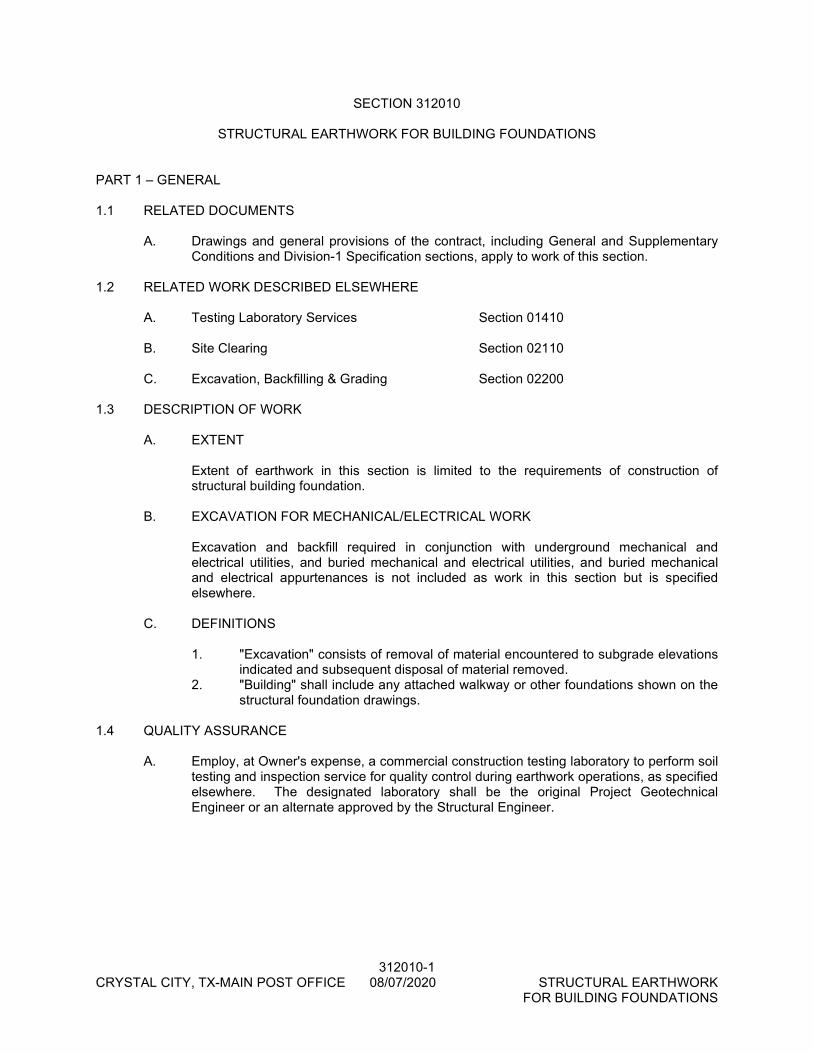
312010-1 CRYSTAL CITY, TX-MAIN POST OFFICE 08/07/2020 STRUCTURAL EARTHWORK FOR BUILDING FOUNDATIONS
SECTION 312010
STRUCTURAL EARTHWORK FOR BUILDING FOUNDATIONS PART 1 – GENERAL 1.1 RELATED DOCUMENTS
A. Drawings and general provisions of the contract, including General and Supplementary Conditions and Division-1 Specification sections, apply to work of this section.
1.2 RELATED WORK DESCRIBED ELSEWHERE
A. Testing Laboratory Services Section 01410 B. Site Clearing Section 02110
C. Excavation, Backfilling & Grading Section 02200
1.3 DESCRIPTION OF WORK
A. EXTENT
Extent of earthwork in this section is limited to the requirements of construction of structural building foundation.
B. EXCAVATION FOR MECHANICAL/ELECTRICAL WORK
Excavation and backfill required in conjunction with underground mechanical and electrical utilities, and buried mechanical and electrical utilities, and buried mechanical and electrical appurtenances is not included as work in this section but is specified elsewhere.
C. DEFINITIONS
1. "Excavation" consists of removal of material encountered to subgrade elevations
indicated and subsequent disposal of material removed. 2. "Building" shall include any attached walkway or other foundations shown on the
structural foundation drawings. 1.4 QUALITY ASSURANCE
A. Employ, at Owner's expense, a commercial construction testing laboratory to perform soil testing and inspection service for quality control during earthwork operations, as specified elsewhere. The designated laboratory shall be the original Project Geotechnical Engineer or an alternate approved by the Structural Engineer.
312010-2 CRYSTAL CITY, TX-MAIN POST OFFICE 08/07/2020 STRUCTURAL EARTHWORK FOR BUILDING FOUNDATIONS
1.5 SUBMITTALS
A. TEST REPORTS-EXCAVATING
1. Submit following reports directly to Architect/Engineer from the testing services, with copy to Contractor:
a. Verification of specified depth of excavation. b. Field density test reports, as follows:
1) One optimum moisture-maximum density curve for each type of soil encountered.
2) Report of actual unconfined compressive strength and/or results of bearing tests of each strata tested.
PART 2 - PRODUCTS 2.1 SELECT STRUCTURAL FILL
A. Structural fill under the building foundation shall be as noted on structural drawings. A minimum fill thickness of 1'-0" is required. No dirt fill shall be used under the building foundation (see plans for over-excavation where undesired expansive clays are to be removed).
PART 3 - EXECUTION 3.1 EXCAVATION
A. EXCAVATION IS UNCLASSIFIED
Excavation is unclassified, and includes excavation to subgrade elevations indicated, regardless of character of materials and obstructions encountered. Refer to plan notes.
B. UNAUTHORIZED EXCAVATION
1. Unauthorized excavation consists of removal of materials beyond indicated
subgrade elevations or dimensions without specific direction of Architect/Engineer. Unauthorized excavation, as well as remedial work directed by Architect, shall be at Contractor's expense.
2. Perform all earthwork described above before trenching for grade beams or mechanical lines.
C. EXCAVATION
In an area occupied by the building, plus a distance of 3 feet away all around, a minimum of 6" of surface soil and vegetation shall be excavated. Do not reuse this excavated soil for fill under the building. Additional surface soil shall be excavated to clear away roots, debris or organic soils, and to remove undesired expansive clays (see plans for over-excavation).
3.2 DE-WATERING
A. Prevent surface water and subsurface or ground water from flowing into excavations and from flooding project site and surrounding area.
B. Do not allow water to accumulate in excavations. Remove water to prevent softening of
foundation bottoms, undercutting footings, and soil changes detrimental to stability or
312010-3 CRYSTAL CITY, TX-MAIN POST OFFICE 08/07/2020 STRUCTURAL EARTHWORK FOR BUILDING FOUNDATIONS
subgrades and foundation. Provide and maintain pumps, well points, sumps, suction and discharge lines, and other de-watering system components necessary to convey water away from excavations.
C. Establish and maintain temporary drainage ditches and other diversions outside
excavation limits to convey rain water and water removed from excavations to collecting or run-off areas. Do not use trench excavations as temporary drainage ditches.
3.3 PROOF ROLLING
A. After initial excavation of surface soil, the exposed subgrade shall be proof rolled to locate and density weak and compressible zones utilizing a minimum of 10 passes of a 25 ton vibratory pneumatic roller. Any soft spots located shall be removed and replaced with similar soil, compacted as specified herein.
3.4 COMPACTION
A. The proof rolled subgrade shall be scarified just prior to fill placement to a minimum depth of 6" and then recompacted to a minimum of 95% of the maximum density as determined by compaction test specification ASTM D 698. Moisture content shall be maintained between -2 and +2 percentage points until permanently covered.
B. For a distance of 3'-0" outside of the building line, and beginning at the low end, build up
to the bottom of the slab with select structural fill. A minimum fill thickness of 1'-0" is required. No dirt fill shall be used under the building foundation.
C. All fill shall be placed in 8" loose horizontal lifts and compacted to a minimum of 95% of
the maximum density as determined by ASTM D 698 compaction test. Excess fill at the building perimeter shall be cut and graded to comply with finished grade requirements and shall be overlaid with a 6" layer of impervious clay for a distance of 5'-0" outside of the building line.
3.5 FIELD QUALITY CONTROL
A. Allow testing service to inspect and approve subgrades and fill layers before further construction work is performed.
B. Perform field density tests in accordance with ASTM D 698. 3.6 TESTING OF SUBGRADE AND COMPACTED FILL
A. Make at least one field density test of subgrade for every 3000 square feet of building slab, but in no case less than 3 tests. In each compacted fill layer, make one field density test for every 3000 square feet of overlaying building slab area, but in no case less than 3 tests.
B. If, in opinion of the testing laboratory and/or the Architect/Engineer, based on testing
service reports and inspection, subgrade or fills which have been placed are below specified density, the contractor shall perform additional compaction and testing at no additional expense.
3.7 MAINTENANCE
A. Protect newly graded areas from traffic and erosion.
B. Keep area free of trash and debris.

312010-4 CRYSTAL CITY, TX-MAIN POST OFFICE 08/07/2020 STRUCTURAL EARTHWORK FOR BUILDING FOUNDATIONS
3.8 RECONDITIONING COMPACTED AREAS
A. Where completed compacted areas are disturbed by subsequent construction operations or adverse weather, scarify the surface, re-shape, and compact to required density prior to further construction.
3.9 DISPOSAL OF EXCESS AND WASTE MATERIALS
A. Remove waste materials, including unacceptable excavated material, trash and debris, and dispose of it off Owner's property.
END OF SECTION