MAIN UNIT MANUAL - BNT
44
MADE IN ITALY ISO 9001 9105.BNT1 ISO 9001 IT-52587 ISO 14001 9191.BNT2 ISO 14001 IT-52588 OHSAS 18001 9192.BSEC OHSAS 18001 IT - 60983 MAIN UNIT MANUAL
-
Upload
khangminh22 -
Category
Documents
-
view
0 -
download
0
Transcript of MAIN UNIT MANUAL - BNT

MADEIN
ITALYISO 9001
9105.BNT1ISO 9001IT-52587
ISO 140019191.BNT2
ISO 14001IT-52588
OHSAS 180019192.BSEC
OHSAS 18001IT - 60983
MAIN UNIT MANUAL

BENTEL SECURITY srl reserves the right to modify the technical specifications of this product without prior notice.
IMPORTANT: The following information is for disassembled Control Panels ONLY.
Ensure that the Manual you are using corresponds to, or is higher than the one requestedon the “RELEASE ISSUES” label (see below).
M anua l Release
Firm ware Re lease
Software Re lease
RELEASE IS SUESOK32 1.01
Insta lla tio n M an ualU se r M an ualKeypa d P rog. M an .M ain U nit M anu alKyo Un it Softwa re
1.11.11.11.15.10
If the Manual/KYO Unit Software release does not correspond, DO NOT attempt to as-semble or install the Control Panel.
The Manual Release Number can be found at the bottom of the last page, between theCode and Date, as shown in the Fig. below.
T h is contro l un it su pports the fo llow ing keyp ads a nd ke y read ers :PR EM IUM , C LA SSIK A, M IA s eries , AL ISO N se ries , O M N IA /TAST-R, N C 2/TAST, IC O N/K P, E C LIP SE , EC L IPSE 2
To kee p th in gs s im ple, th is instruc tion m anual re fers onlyto the P R EM IUM and C LASS IK A k eyp ads a nd E C LIP SE 2 key rea ders .
If y ou require further in form ation re la ting to the o ther typ es of keypa d/K ey R ead er sup ported by th is contro l un it, the prev ious ve rsio n o f th is ins truc tion m an ual m a y be dow nlo aded from the w eb address ww w.ben te lsecu rity.c om
KYO 4 M – KYO 8 M – K YO 8W M – KY O 32 M – KY O 4 P – KY O 8 P – K YO 8W P – K YO 32 P
KYO 8G L-SW 1 – KYO 8G L-SW 2 – KY O 3 2G L -SW 1 – KYO 32G L -SW 2 KYO16 D
For all the Control Pane ls the pe rformance le vel is II (unless o the rw ise spec ified).The KYO 16D perform ance level is I
KYO 8GW P-SW 1 – KYO 8G W P-SW 2 – KYO 8G W L-SW 1 – KY O 8G W L-SW 2 KYO 8G P-S W1 – KYO 8G P-SW 2 – KY O 32G P-SW 1 – KY O 32G P-S W 2
Hereby, B entel Secu rity, dec lares the above m entioned C ontro l Pa nels to be in com plia nce w ith the essentia l requ irem e nts and other relevant prov is ions of 19 99/5/E C D irective .
The com plete R&TTE Declaration of Conform ity for ea ch Pane l can be found at w ww.bentelse curity.com /dc.htm l.
These Control P ane ls com ply w ith
Ins talla t ion of these system s m ust be ca rried out strictly in accordance w ith the instructionsdescribed in this m a nua l, and in com pliance w ith the loca l law s and bylaws in force .
The above m entioned C ontrol pane ls have been designed and m adeto the h ighe st s tandards of quality and p erform ance.
The m anufactu re r recom m ends that the ins ta lled system shou ld be com p le te ly tes ted a t least once a m onth .BE NTEL S ECU RIT Y S rl shall n ot assum e th e respons ib ility
for dam age aris ing from im p roper app lication o r use .The above m entioned C ontrol pane ls have no user-fr iend ly com po nents , the re fore,
CE I 79-2 2 ed. 1993a .
ISTPTB LE U NK YO 190503 P701.2
M a n u a lR e le a s eN u m b e r
D a teC o d e
3®®
Section 1 - Introduction .............................................................5Certification Formalities ......................................................................................... 5General Features .................................................................................................... 5About the System .................................................................................................... 7Control panel Versions ........................................................................................... 8Components and Accessories ................................................................................ 9Technical Specifications ...................................................................................... 10
Section 2 - Identification of Components ............................... 11KYO 4 M — KYO 8 M — KYO 8W M — KYO 32 M ................................................ 11KYO 4 P — KYO 8 P — KYO 8W P — KYO 32 P.................................................. 12KYO 8G P-SW1 — KYO 8GWP-SW1 — KYO 32G P-SW1 .................................... 13KYO 8G P-SW2 — KYO 8GWP-SW2 — KYO 32G P-SW2 .................................... 14KYO 8G L-SW1 — KYO 8GWL-SW1 — KYO 32G L-SW1 .................................... 15KYO 8G L-SW2 — KYO 8GWL-SW2 — KYO 32G L-SW2 .................................... 16KYO 16D ................................................................................................................ 17
Section 3 - Mounting the Components ...................................21Introduction ........................................................................................................... 21Boxes and Accessories ........................................................................................ 21Installing the Transformer and Mains Screw Terminal - Fused ......................... 22
Metal box (BOX-M) ............................................................................................. 22Plastic box (BOX PLUS) .................................................................................... 23
Mounting K4-K8-K8W-K16D-K32 PCBs ............................................................... 24Metal box (BOX-M) ............................................................................................. 24Plastic box (BOX PLUS) .................................................................................... 24
Installing ‘G’ series PCBs (K8G-K8GW-K32G) .................................................... 25Plastic box (BOX PLUS) .................................................................................... 25Metal box (BOX-L) .............................................................................................. 25
Installing the Switching Power Supply ................................................................ 26Installing BAQ15T12 Switching Power Supplies ................................................. 26Installing BAQ35T12 Switching Power Supplies ................................................. 27Replacing BAQ35T12 Fuse ............................................................................... 27
Earthing the PCB .................................................................................................. 28Marking Ticket ....................................................................................................... 28Connecting the KST Thermal Probe ................................................................... 28Connecting the NC2/VOX Voice Board ................................................................ 29
Metal box (BOX-M and BOX-L) ........................................................................... 29Plastic box (BOX PLUS) .................................................................................... 29
PCB Identification Label ...................................................................................... 30
TABLE OF CONTENTS

4 Multifunction Control Panel®®
Section 4 - Installing the Control Panel ..................................31Mounting the Control Panel ................................................................................. 31Opening and Closing the Control Panel ............................................................. 32
Section 5 - Installing the NC2/VOX..........................................34General Features .................................................................................................. 34Additional VOX-REM Modules .............................................................................. 34
Installing Additional VOX-REM Modules .............................................................. 34Record / Play Messages ....................................................................................... 35
Selecting Messages ........................................................................................... 36Recording Alarm Messages ............................................................................... 36Playing Messages .............................................................................................. 36
Programming ......................................................................................................... 37Activation ............................................................................................................... 37
Section 6 - Default Settings .....................................................38Restoring Factory Default .................................................................................... 38
Notes .........................................................................................42

5®®
Section 1 - Introduction
This Manual is designed for anyone using a Control panel from the KYO range.Most of the features described in this Manual are included on all KYO Controlpanels (refer to Table 1.1). However, some features are included on certainmodels only, in such cases, the Control panel will be specified.
� KYO4 - 4 fully-programmable input-zonesKYO8 - 8 fully-programmable input-zonesKYO16 - 6 fully-programmable input-zones (can be doubled to 12)
� Expandable to 32 Input Zones via optional M-IN/OUT Expanders (only forKYO 32 series Control panels)
� 1 Balanced 24h Tamper Zone (Not available for KYO16D)
� 1 Programmable Alarm Output: 1A relay (3A on ‘G’ models)
� Auxiliary Open-Collector Outputs (OC):2 x 150 mA for KYO 16D3 x 150 mA for KYO 4, KYO 8, KYO 8W and KYO 32 series5 x 500 mA for KYO 8 G, KYO 8 GW and KYO 32 G seriesExpandable to 14 (5x500 and 9x150 mA) Outputs for KYO 32 seriesExpandable to 16 (5x500 and 11x150 mA) Outputs for KYO 32 G series
� Metal box (Model M or L) or Plastic Box (Model P)
� Accepts Conventional Fire Detectors, and provides restoral facility
� Supports up to 8 Keypads (4 for KYO 16D)
� Supports up to 16 Readers (8 for KYO 16D)
� Accepts up to 128 SAT Keys and/or PROXI-CARDs
� Manages 4 independent Partitions (8 for KYO 32 and KYO 32 G)
� 3 Arming Modes (Global, A Mode and B Mode): A and B Mode can beprogrammed as: Away, Stay or Stay with no Entry delay
General Features
SECTION 1 - INTRODUCTION
Control Panel
Certification Formalities
The KYO-Unit series can be purchased as out-of-the-box Control pan-els, or as separate package components. Bentel Security S.r.l declaresthat KYO-Unit separate package components comply with the essen-tial requirements and other relevant provisions of Directive R&TTE1999/5/CE — only when they are assembled by a security professional,and are used as part of one of the Control panels provided for inSection 3, and indicated in Table 1.1. in this Manual. Bentel Secu-rity S.r.l. declares that CE Certification is not applicable when KYOseparate package components are improperly assembled or used.

6 Multifunction Control Panel®®
� Auto-Arming for each Partition on Daily or Weekly basis
� 24 Programmable Codes (4 to 6 digits)
� Partition Bypass for Patrol purposes with automatic or manual Rearming
� Can be programmed from an LCD or LED Keypad
� Can be programmed from a computer via RS232 link cable or via telephone
� Power Supplies:
Integrated 1A linear Power Supply in KYO 4, KYO 8, KYO 8W, KYO 32 andKYO 16D
1.5A Switching Power Supply in SW1 Models
3A Switching Power Supply in SW2 Models
� Touch-tone (MF) or Pulse dialling
� Manages 8 Telephone numbers for Teleservice and Central Station calls
� Supports the following Reporting Formats:ADEMCO / SILENT KNIGHT - Slow 10 baud - 3/1, 4/1, 4/2ADEMCO / SILENT KNIGHT - Fast 14 baud - 3/1, 4/1, 4/2FRANKLIN / SECOA / DCI-VERTEX - Fast 20 baud - 3/1, 4/1, 4/2RADIONICS - 40 baud - 3/1, 4/1, 4/2SCANTRONIC - 10 baud - 3/1, 4/1, 4/2CONTACT IDCESASIA (Only for KYO16D)
� Accepts commands from touch-tone phones (Arm, Disarm, Turn ON/OFFMain board Outputs; Remote Talk/Listen-in — requires optional NC2/VOXVoice Board. Not available for KYO 16D.
� Manages Voice Calls (requires optional NC2/VOX Voice Board). Not avail-able for KYO 16D.
� Remote Telephone Access via Dialler or Answer Mode. Not available forKYO 16D.
� Remote Talk/Listen-in (requires optional NC2/VOX Voice Board). Notavailable for KYO 16D.
� 128 event memory with date and time datails (256 events for KYO8W-16Dand 32 series).
� 3 function keys for immediate Alarm calls from Keypad
� Programmable Test Call
� Teleservice Management
� Double Call
� Line-sharing Management
Digital Dialler
7®®
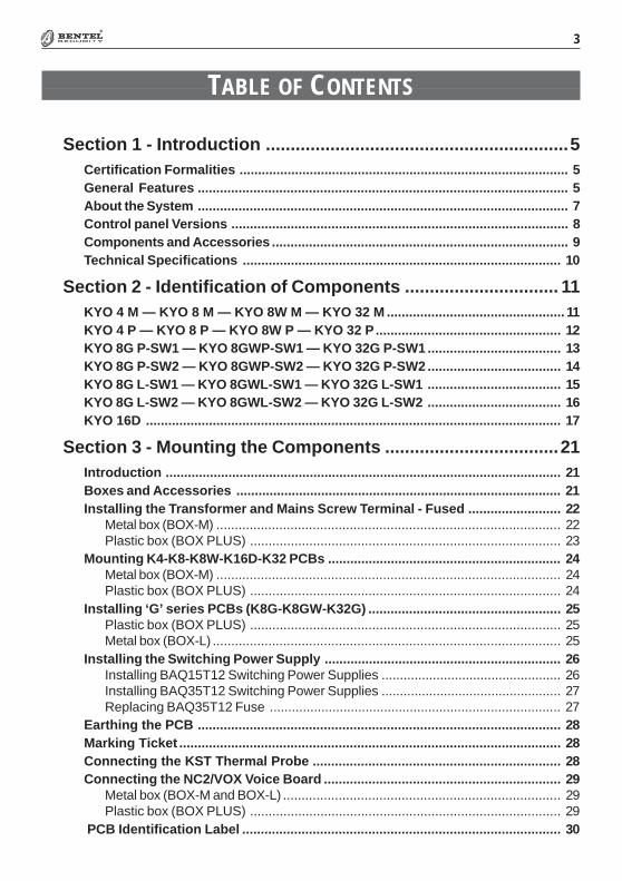
Section 1 - Introduction
The Control panel is made up of a Control Unit, Digital Communicator andModem. It can be controlled from remote Keypads and/or Digital Key/CardReaders.
The Digital Communicator can call up to 8 Telephone numbers for Teleserviceand communication to Central Stations. You can program the system to reportevents using any one of the supported formats.
The NC2/VOX Voice board (accessory item) will allow the Communicator tosend 8 Voice messages to up to 8 Telephone numbers. The NC2/VOX Voiceboard also provides the Talk/Listen-in feature.
The B-Mod2 Modem and Management software will allow you to program,control and Teleservice (provide remote maintenance) from a remote computer.
About the System
The Control panel
The DigitalCommunicator
Voice Messagesusing NC2/VOX
(Not for Kyo 16D)
�������������� ��
��� ��
���������
PCB Box Transf. TRFPower Supply
BAQ15T12Power Supply
BAQ35T12
������� �� ����� �
������� �� ����� �
�������� �� ����� �
�������� ��� ����� �
�������� � � ����� �
������� �� �������� �
������� �� �������� �
�������� �� �������� �
�������� � � �������� �
����� ��!�� ��� �������� �
����� ��!�� ��� �������� �
������ ��!�� � �� �������� �
����� ��!�� ��� �������� �
����� ��!�� ��� �������� �
������ ��!�� � �� �������� �
����� �"!�� ��� ����� �
����� �"!�� ��� ����� �
������ �"!�� � �� ����� �
����� �"!�� ��� ����� �
����� �"!�� ��� ����� �
������ �"!�� � �� ����� �
Teleservice

8 Multifunction Control Panel®®
Telemonitoring
Accessing the systemusing a remote
Touch-tone Telephone
Programming thesystem
The B-Mod2 Modem and the WinBCS software will allow you to program, con-trol, Teleservice and Monitor the system from a remote computer.
All Events, Alarms and Troubles, complete with Customer and Event details willbe logged on the Event Logger.
The User can access the system over the phone, in order to:
� Arm/Disarm the system
� Turn ON/OFF Reserved Outputs
� Activate Talk/Listen-in sessions (NC2/VOX required). Not managementfor KYO16D.
This Control panel can be programmed:
a) on-site, using an LCD or LED Keypad (accessory item);b) on-site, using an RS232 Computer link;c) from remote computer, using a modem and downloading software.
������������ ���� ���������� ���������� �������
�����Wireless
Management��������
�������� � ������� �� �����������
!��"�������� !��"�� �� � � ��������
!��#�������� !��#�� �� � � ��������
!��#$�������� !��#$�� �� � � ��������
!���%& �� ��
������������������������
!��'�������� !��'�� �� ��
����������� ����!��������
����������� �����!!
!��#(�)����� �� � � �������
!��#($�)����� �� � � �������
!��'(�)����� �� ��
����������� ����!�������
����������� �����!!
! The M-IN/OUT Expander Module manages 6 Inputs!! The M-IN/OUT Expander Module manages 6 OC Outputs — 150 mA (6 x 150 mA)
Control panel Versions
9®®
Section 1 - Introduction
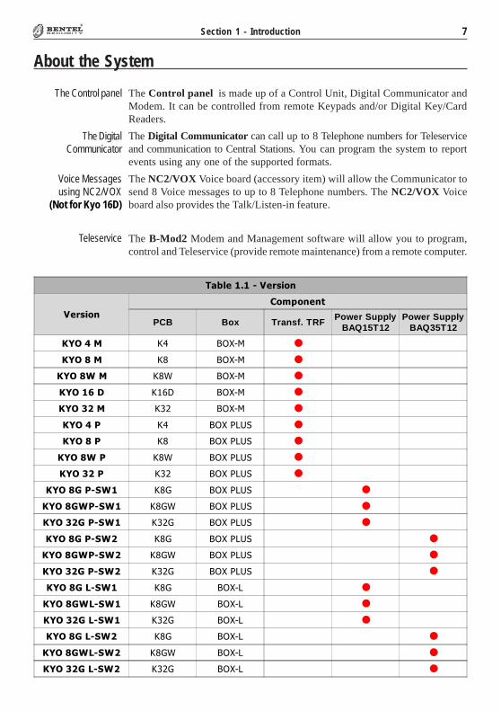
Components and Accessories������������������������#�$%%�����&�'����
��#� ���%� �� ��
���������������� ��������������������������������� �
�� ���� ������ ������������������������������ ���
���� �������������
(�)� ���� �!�"����������� #
(�)��"*! � �#�$%�!�"����������� #
(�)" ���� �!�"�����"����� #
�+, &�'�%���()�* ���+���,���#���-��
($-�.��� ()�* ��+$�%.$�/���+����011 2�����!������� #
($-�.��� �* ��+$�%.$�/���+����011 2�����!������� #
(��"/�(��"��
�34�5���6�2!����#7�����8�������9������4��8�����4�9
(�("/�(�("��
��* ��5�* �6�2!����#7�����8�������9������4��8�����4�9
�(��(�) : 0#.�-�0��$�/�6$��8�� 2������34�5��������4�������������9
/�"�*�+84��5��4�9
��$;��#� �3���������0 �������$/$�� �6�2��+$�.�0��%����%�#�������#$/���������%�##���$�#�� ��$��
/�"����;�������4������3���$;��#� �3���������0 ��8�����.�� $#������21�#��#��,�! ��( �$���.��5�#�� ��$������0� 9
�+�)' ���"$-$�2�3�����
!$� �$/$�� �6�2�����4��5��4������3��5�3�����#
�+�)'�$+� �3��5�����
0��1�) '�$%�������
�)+/� ,� 6<�$#����5��=����4"1���������0 ��8�$%��1.����>���0�#1��6��9
�'01�*� ��5�10�<�0�10��4"1���������0 �
��0'$1�+ ���� �2����0 �������0�10��4"1�����#
�'!*0'� ���0� ��$�
/���+1+)���1+)� $�� �##�3�%�$;��
$+��2 $�� �##���2�����'�%���<3������'�%���<3��
$���2 $�� �##�����5--0����53�����'�%���<3������'�%���<3��
$���2 $�� �##���/���$%������%������'�%���<3������'�%���<3��
$!��2 $�� �##��-�6������%��������'�%���<3������'�%���<3��
(��#� ,� �#��;$%������,� �-��$���$�/�����-
!/�*+'���!*'�/ ����/�-��������+���
�!/+13,3, ��-10�������$� ��$�6
$�!/+13��., * ��1���������'�43<?:?:� $�6�%�! �������)��� �����$� �����#�8����)9
�!� ,.��-� ����!��8���� ����� #��� 29
��" �4 �0�10��'� ��/�������� �+$����8���� ����� #��� 29
$!0� �$%��#+$�%.�1��;$��#�����%.<,�-1���1����%�$���������������
�'0'$!0� ����%.��$%��#+$�%.������3��5�34* �43#
�$)'$!0� ,�-1����$%��#+$�%.��������� �!�"�#�8���������������9
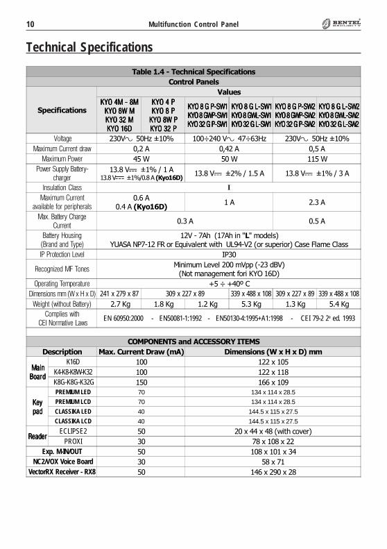
10 Multifunction Control Panel®®
Technical Specifications
��������"�����* �����)����������� �
�� ������� ���
)����������� �
+�����
��������������������������������������������������������������������������������������������������������� ������ ������ ������ �
����������������������������������������������������������������������������������������������������������������
��������������������������������������������������������������������������������������������������������������������������������������������
��������������������������������������������������������������������������������������������������������������������������������������������
��������������������������������������������������������������������������������������������������������������������������������������������
��������������������������������������������������������������������������������������������������������������������������������������������
�������� ��"����#$�%�& �'���"����('��#$ ��"����#$�%�&
������������� ��!��" )��� )���� )���
����������"�� ���* ��* ����*
��"�����##�$�%�����$�&'�����
��+��"���%�&�,�����������������������������
��+��"���%�&�,��+��� ��+��"���%�&�,����
( )������ ����)) I������������� �
�*����+���,���#���#'����)+���
+����� ,��%&���� �+���
���-�%�����$��'��������� �
+��� +���
%�����$�.��)� �/%�� !�� !�0$#�1
��"�-�(�.����(�.����/-/������� 0�1���2(-���34��5��6��7���� �8� .��09:�-"����5�����5��5��;����3����;����
(�������&��� ���*�� <2�
2�&�� �3�!��4�0� �)=�����9�7�����"����-����>"�
��� ����?��� ���5��@ A�����
�#����� ��0��#������� B��'�B�C�;
���� )�� )����/���.����1 241 x 279 x 87 309 x 227 x 89 339 x 488 x 108 309 x 227 x 89 339 x 488 x 108���'��/"��'����%�����$1 ��+(�@? �+��@? �+��@? �+��@? �+��@? �+��@?
���#���)�"��'��5(�6������*����")
EN 60950:2000 - EN50081-1:1992 - EN50130-4:1995+A1:1998 - CEI 79-2 2a ed. 1993
�����./.�)�� ��0��/))�1!���/�)
&��������� ��2������� ��&�����30� &�3� ��� ���$�2�4�2�&��33
��� ��� ��� ��� %���!%���!%���!%���!
K16D � ��������
K4-K8-K8W-K32 � ���������
K8G-K8G-K32G �� �������:
��$��$��$��$#�!#�!#�!#�!
PREMIUM LED 70 134 x 114 x 28.5
PREMIUM LCD 70 134 x 114 x 28.5
CLASSIKA LED 40 144.5 x 115 x 27.5
CLASSIKA LCD 40 144.5 x 115 x 27.5
2��!��2��!��2��!��2��!��ECLIPSE2 � �������������8� .�D�7�5�
PROXI � (�����������
Exp. M-IN/OUT � ������������
�NC2/VOX Voice Board � �����(�
VectorRX Receiver - RX8 � �������:�����
11®®
Section 2 - Identification of Components
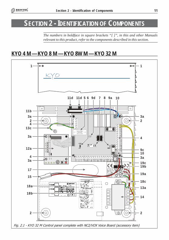
SECTION 2 - IDENTIFICATION OF COMPONENTS
The numbers in boldface in square brackets “[ ]”, in this and other Manualsrelevant to this product, refer to the components described in this section.
Fig. 2.1 - KYO 32 M Control panel complete with NC2/VOX Voice Board (accessory item)
KYO 4 M — KYO 8 M — KYO 8W M — KYO 32 M
19b
2
19a17
LELI
3332
3435
36
5 6 7 8 9a
AC3031
CO
MNC
0201
+B19
2022
2124
23G
RN
2526
RED
BLK
YEL
2729
2803 4
14
11d
15
2
4
12a
2 2
1 1
9c10
10
3a
3a
13c
13a18a
3a3a
3a
19c
4
11b
11d 9d
18b
K Y O 8
18c
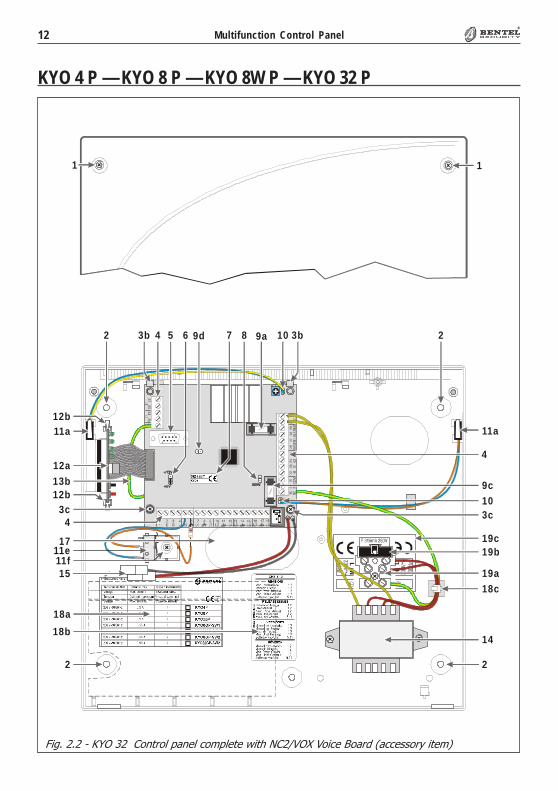
12 Multifunction Control Panel®®
Fig. 2.2 - KYO 32 Control panel complete with NC2/VOX Voice Board (accessory item)
KYO 4 P — KYO 8 P — KYO 8W P — KYO 32 P
�
�
�
�
51
96
K YO 8
9d 10 22 54 6 7 83b 3b9a
15
2
12a
3c4
19b
2
11a
19a
4
9c10
11a
13b
18a
17
3c
12b
12b
1418b
11f11e
18c
19c
11
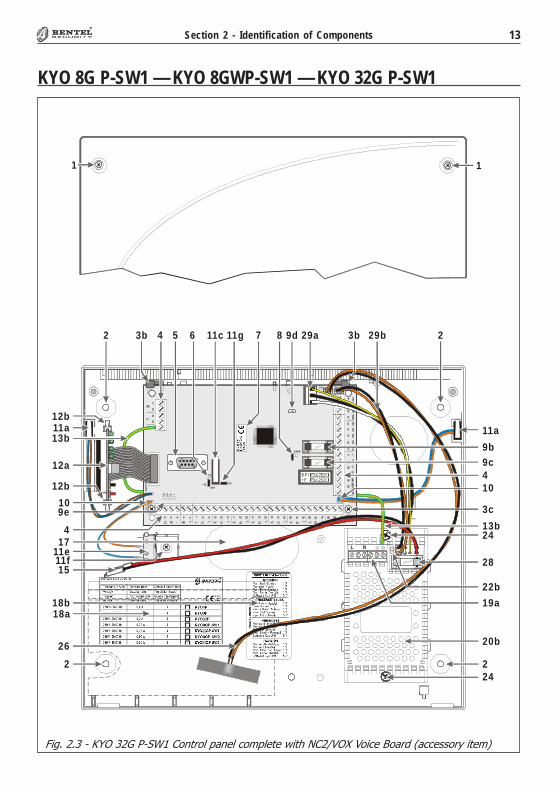
13®®
Section 2 - Identification of Components
Fig. 2.3 - KYO 32G P-SW1 Control panel complete with NC2/VOX Voice Board (accessory item)
KYO 8G P-SW1 — KYO 8GWP-SW1 — KYO 32G P-SW1
11
B P I+F
L N
22 54 6 83b 3b11g
15
2
12a
28
2
11a
9b9c
20b
11a
3c
12b
7 29a
24
22b
19a
104
174
12b
109e
29b
24
13b
26
9d
18a18b
11c
11f11e
13b
14 Multifunction Control Panel®®
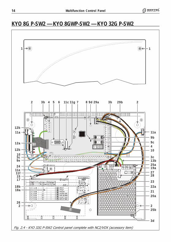
Fig. 2.4 - KYO 32G P-SW2 Control panel complete with NC2/VOX (accessory item)
KYO 8G P-SW2 — KYO 8GWP-SW2 — KYO 32G P-SW2
11
BP I+F
22 54 6 83b 3b
15
2
17
12a
9e
27
2
11a
28
9b
25a
9c
20a
11a
3c
12b
12b
7 29a
25b
19a
23
22a21
1010
26
3d
4
3c
29b
24
13b
9d
18a18b
11g11c
11f11e
15®®
Section 2 - Identification of Components
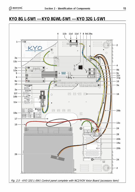
Fig. 2.5 - KYO 32G L-SW1 Control panel complete with NC2/VOX Voice Board (accessory item)
KYO 8G L-SW1 — KYO 8GWL-SW1 — KYO 32G L-SW1
B P I+ F
L N
17
11d
15
26
6
1
9e
13c
18b
3a
10
11e
11d
18a
3a
11b
11f
5
2
24
20b
28
22b
19a
24
13c
3a
10
9c9b
11g
29b
7 9d8 29a
12a
11c
4
4
2
3e
16

16 Multifunction Control Panel®®
Fig. 2.6 - KYO 32G L-SW2 Control panel complete with NC2/VOX Voice Board (accessory item)
KYO 8G L-SW2 — KYO 8GWL-SW2 — KYO 32G L-SW2
B P I+ F
17
11d
15
26
6
1
9e
13c
18b
3a
10
11e
11d
18a
3a
11b
11f
5
2
24
20a
28
22a
24
3a
10
9c9b
11g
29b
7 9d8 29a
12a
11c
4
4
2
27
21
23
19a25a
25b3d
3e
16
17®®
Section 2 - Identification of Components
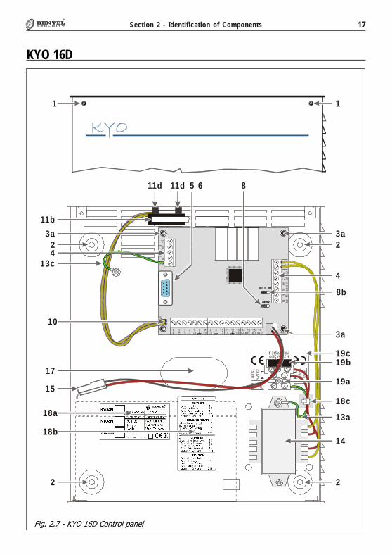
Fig. 2.7 - KYO 16D Control panel
KYO 16D
LELI
2627
2829
AC2425
CO
MN
CA
UX
1819
+V20
2322
25
G RN RE DBLKYE L
19b
2
19a17
5 6 8
4
14
11d
15
2
2 2
1 1
3a
13c
13a18a
3a
3a
19c
4
11b
11d
18b
18c
10
8b
18 Multifunction Control Panel®®
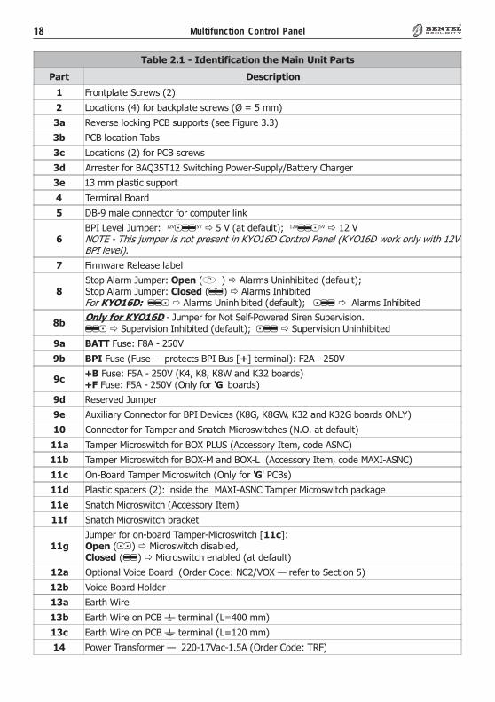
������������� ��������� ��*����� �5 ��������
���� &���������
� 35�� ��� ��1D5�8�����
9�D� �����������5���DE��� ���D5�8���F�G����
'� 4�7�5�����DE��?�2;>������5 �������3�?�5���+��
'� 2;>���D� ����H���
'� 9�D� �����������5�2;>��D5�8�
'� �55�� �5���5�>�I��H���18� D.��?�2�8�5-1����J,>� �5J�;.�5?�5
'� �������� �D������5
" H�5�����>��5�
6 �>-:�����D����D �5���5�D��� �5����E
%>2<�9�7���K���5L�������������"��� ������� �M��������������"/0123431567389:;<=3673>?@3;=<7<>@36>3AB0CDE3F?>@=?G3HI><G3JAB0CDE3K?=L3?>GM3K6@53CNOPHQ3G<R<GST
7 3�58�5��4������������
#1 ������5�K���5L���� ������������5��0���.��� ���������� �M�1 ������5�K���5L�����������������5��<�.��� ��U?=3����������������5��0���.��� ���������� �M�����������5��<�.��� ��
#����� ���������-�K���5���5��� �1���-2�8�5���1�5���1���57�����+����1���57������<�.��� ���������� �M������1���57������0���.��� ��
8� 90���3���L�3���-���"
8� 9���3�����3����N��5� �D ��>2<�>���O:P� �5�����L�3���-���"
8�:9�3���L�3���-���"��@�)�@�)�@�*�����@������5���:��3���L�3���-���"��A��J���5��(�����5���
8� 4���57���K���5
8� �������5J�;����D �5���5�>2<���7�D����@�Q)�@�Q*)�@�������@��Q����5���A�9 �
�; ;����D �5���5�H���5�����1�� D.�=�D5��8� D.�����+A+�� ������� �
��� H���5�=�D5��8� D.���5�>AR�2901���DD����5J�< �)�D�����1�;�
��� H���5�=�D5��8� D.���5�>AR-=�����>AR-9����DD����5J�< �)�D����=�R<-�1�;�
��� A�->��5��H���5�=�D5��8� D.��A��J���5��(��2;>��
��� 2��� �D����D�5�����L�������� .���=�R<-�1�;�H���5�=�D5��8� D.���DE�?�
��� 1�� D.�=�D5��8� D.���DD����5J�< ��
��� 1�� D.�=�D5��8� D.��5�DE�
��<K���5���5���-���5��H���5-=�D5��8� D.�O���PL��� �������=�D5��8� D.���������)�������������=�D5��8� D.����������� ������� �
�� A� ������"��D��>��5����A5��5�;���L��;�,"AR�N�5���5� ��1�D ������
�� "��D��>��5��#����5
�'� ��5 .�*�5�
�'� ��5 .�*�5�����2;>��� �5������9G���
�'� ��5 .�*�5�����2;>��� �5������9G����
�" 2�8�5�H5�����5�5�N����-�("�D-�+����A5��5�;���L�H43�

19®®
Section 2 - Identification of Components
������������ ��������� �����*����� �5 ���� ��)����*� <�������)����,����3�� � ��
���� &���������
�6 >� �5J�8�5��
�% ;����������5 �
�7 ;������� 5J
�#� =�5E��?� �DE�
�#� 4�������9����
�#� ;�����H���>����
�8� =�����1D5�8�H�5�����N���5�=�����������5 .
��8� Q���5����5� �D ����3���L��3���=��-���"
�8� ��.���7��9����
;� >�I��H���18� D.��?�2�8�5�1����J
;� >�I��H���18� D.��?�2�8�5�1����J
� =�����9�����.�G�=�����A@�
� 3�������S�� �� �H5��5
�@1H�K���5�N����,��������� ���� <��� )���*��3�������������*��������,=��*��>�3����3�������� �������
' �������5J�H�5��������5��J� ����5��.�5�����������G���+��"DD�
"1D5�8� ����D�5�� .��18� D.��?�2�8�5�1����J� �� .����DE��� �L����>�I��H���-�����>�I��H��
6� 1D5�8���5� .��18� D.��?�2�8�5�1����J
6� 1����4�7�
% H.�5����5����N� ������� ��� �� .���� �5J��A5��5�;���L��@1H�
7 3����N��5� �D ��18� D.��?�2�8�5�1����J���3��-��"�
# 3����N��5� �D ���?���� �>� �5J�����5� J���7�5������3�+��-��"�
8� ;����D �5���5� .��18� D.��?�2�8�5�1����J
8� A";-9��E�8�5���A� �� �"�� �?��;�� 5���
20 Multifunction Control Panel®®
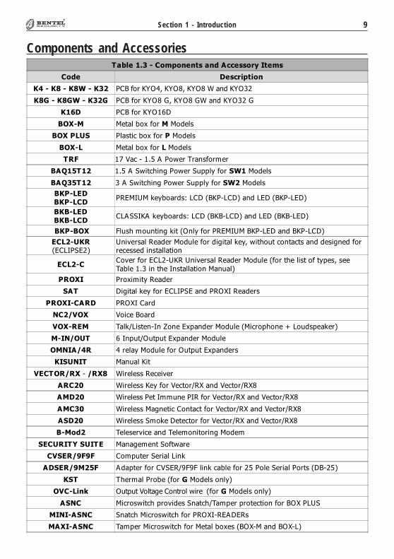
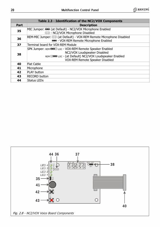
Fig. 2.8 - NC2/VOX Voice Board Components
�������'����� ��������� �����*��.�?+�@���3�� � ��
����� &���������
'6=<;�K���5L����� ������� ��-��;�,"AR�=�D5��.�����������=<;�K���5L���-��;�,"AR�=�D5��.������������
'%4�=-=<;�K���5L����� ������� ��-�"AR-4�=�4�� ��=�D5��.������������4�=-=<;�K���5L���-�"AR-4�=�4�� ��=�D5��.�����������
'7 H�5��������5����5�"AR-4�=�=�����
'#
12@�K���5L�����������-�"AR-4�=�4�� ��1���E�5��������12@�K���5L�����������-��;�,"AR�9�������E�5���������12@�K���5L�����������-��� ������� ���;�,"AR�9�������E�5��������12@�K���5L�����������-�"AR-4�=�4�� ��1���E�5���������
"; 3�� �;����
"� =�D5��.���
" 29� ��� ��
"' 4�;A4���� ��
"" 1 � ���9���
41
42
43
44 36 37
38
40
35

21®®
Section 3 - Mounting the Components
SECTION 3 - MOUNTING THE COMPONENTS
IntroductionPlease read this section to get an overall view of the steps involved in installingControl panels from the KYO Unit range.
The end of the stranded conductor must not be soft soldered in places where it issubject to contact pressure. The Mains wiring must comply with the rules fordouble or reinforced insulation. Use an adhesive cable grip to secure the wiresto the terminal boards.
Boxes and AccessoriesMetal and Plastic boxes are available.The Metal Box (BOX-M) kit includes the following parts:� 18 Balance Resistors — 10 Kohm� 4 plastic PCB supports� 1 x 12cm Earth wire (Yellow-Green) with eyelet [13c]� 4 hexagonal nuts — M3� 2 Parker screws — 2.9 x 7.5 to secure the FrontplateThe Plastic Box (BOX PLUS) kit includes the following parts:� 18 Balance Resistors — 10 Kohm� 1 x 40 cm Earth wire (Yellow-Green) without eyelet [13b]� 2 Parker screws — 2.9 x 7.5 to secure the PCB� 1 Parker screw — 2.9 x 9.5 to secure the BAQ35T12 Switching Power Supply� 2 Parker screws — 3.9 x 9.5 to secure the Frontplate� 1 Parker screw — 3 x 14.2 to secure the Mains Screw Terminal� 2 Parker screws — 3 x 8 to secure the Transformer or BAQ15T12.The Large Metal Box (BOX-L) kit includes the following parts:� 18 Balance Resistors — 10 Kohm� 1 x 13 mm plastic support for the PCB� 4 plastic supports for the PCB� 2 x 12 cm Earth wire (Yellow-Green) with eyelet [13c]� 1 hexagonal nut — M3� 1 plastic Snatch microswitch bracket [11e]� 2 x 3mm cogged metal washers� 2 screws 3x6� 2 screws 3x8� 2 Parker screws — 2.9 x 7.5 to secure the frontplate� 1 “Protected Enviroment” label
Metal boxBOX-M
Plastic boxBOX PLUS
Large Metal BoxBOX-L

22 Multifunction Control Panel®®
The Transformer (see Fig. 3.1) package includes the following parts:� 1 Mains Screw Terminal - Fused [19a] — 500 mA� 1 Adhesive Label [19c] for the Mains Screw Terminal
� 1 x 12 cm Earth wire (Yellow-Green) with eyelet [13a] for earthing theMetal box or Transformer
To install the Transformer (Order Code TRF), work carefully through the fol-lowing steps (refer to Fig. 3.1).
Metal box (BOX-M)1. Stick the label [19c] onto the backplate (one aperture must be positioned
over the fixed screw, and the other over the Mains Terminal [19a] screwlocation.
2. Fit the Mains Screw Terminal [19a] onto the fixed screw (as indicated onthe label) then, using the hexagonal nut, secure it to the backplate.
3. Mount the Transformer onto the 2 fixed screws (M3x10) on the backplateof the Metal box.
4. Fit the eyelet terminal [13a] to the fixed screw (as shown in Fig. 3.2a) then,using two hexagonal nuts, secure the transformer to the backplate.
5. Connect the Transformer primary (RED wires) to terminals [N] and [L].
6. Connect the free end of the Earth wire [13a] to the [QQQQQ] terminal on theMains Screw Terminal [19a] (as shown in Fig. 3.2a).
Use the cable tie bases (refer to [18c] in Fig. 2.1) to bunch the Red wires of theTransformer and the Earth wire [13a].
Installing the Transformer and Mains Screw Terminal - Fused
Fig. 3.1 - Installing the Transformer and Mains Terminal board
71.75 mm
Fixed screw sM 3x10 71.75 mm
Metal Box — BO X-M Plastic Box — BOX-PLUS
Screw Location Ø 2.5mm
[19c]
[19a]
[19c][19a]
M 3 N ut to secureM ains Terminal Screw to secure
Term inal board

23®®
Section 3 - Mounting the Components
Plastic box (BOX PLUS)1. Stick the label [19c] onto the backplate (as shown in Fig. 3.1). Ensure that the
2 label holes correspond to the 2 holes on the backplate.
2. Place the Mains Screw Terminal onto the screw location (Ø 2.5) then, usingthe Parker screw (3 x 14.2) secure it to the backplate.
3. Using the 2 holes on the backplate as reference, mount the Transformer[14] (as shown in Fig. 3.2b).
4. Using the two 3 x 8 parker screws, secure the Transformer to the backplate.
5. Connect the Transformer primary (RED wires) to terminals [N] and [L].
Fig. 3.2 - Connecting the Earth wire [13a]
Fig. 3.3 - Fitting the Reverse Locking PCB Supports
51
96
M e ta l B o x — B O X -M
[13a]
H e x a g o n a ln u t s M 3

24 Multifunction Control Panel®®
Please read this section to get an overall view of the steps involved in installingK4, K8, K8W, K16D and K32 PCBs in Metal and Plastic boxes.
Metal box (BOX-M)For the following procedure, see Fig. 2.1.
1. Insert the 4 reverse locking PCB supports [3a] into their locations on thebackplate, then attach the PCB. If you are installing an NC2/VOX VoiceBoard, insert the supports (LEDs to the bottom), then attach the NC2/VOX Voice board (see Fig. 3.3).
2. Using a hexagonal nut (M3), secure the Earth wire (Yellow-Green) eyelet[13c] to the screw (M3x10) on the backplate.
3. Connect the other end of the Earth wire (Yellow-Green) to terminal 36(-----) on the PCB.
4. Connect the Transformer secondary (YELLOW wires) to terminals 30-31(AC) on the PCB.
5. If you are fitting a Tamper microswitch [11b], insert the two spacers [11d]then, using the two hexagonal nuts( M3), secure it to its location (see Fig.3.3). Connect the wire to the connector [10].
Plastic box (BOX PLUS)For the following procedure, see Fig. 2.2.
1. Slide the PCB under the 2 tabs [3b].
2. Using the 2 (2.9 x 7.5) Parker screws (in screw locations [3c]), secure thePCB to the backplate.
3. Connect one end of the Earth wire (Yellow-Green) [13b] to the [-----]terminal (36) on the PCB, and the other to the [QQQQQ] terminal on the MainsScrew Terminal [19a].
Use the cable tie bases (refer to [18c] in Fig. 2.2) to bunch the Red wires of theTransformer and the Earth wire [13b].
4. Connect the Transformer secondary (YELLOW wires) to terminals 30-31(AC) on the PCB.
5. If you are fitting a Tamper microswitch [11a], insert it into its location, thenconnect the wire to one of the two connectors [10] on the PCB. The secondconnector [10] can be used for an external Tamper microswitch (on theoutside of the cabinet).
6. If you are fitting a Snatch microswitch [11e], insert it into its location, thenconnect the wire to terminals no. 5 and no. 6 (AS) and connect, in series, a10 Kohm EOL resistor.
NOTE: Cut off the Snatch microswitch connector before connecting the wire.
Mounting K4-K8-K8W-K16D-K32 PCBs

25®®
Section 3 - Mounting the Components
Installing ‘G’ series PCBs (K8G-K8GW-K32G)
Please read the following instructions, to get an overall view of the steps involvedin installing K8G, K8GW and K32G PCBs. “G” series PCBs can be installed inplastic boxes (BOX PLUS) and large metal boxes (BOX-L).
Plastic box (BOX PLUS)For the following procedure, refer to Fig. 2.3 and Fig. 2.4.
1. Slide the PCB under the 2 tabs [3b].
2. Using the 2 (2.9 x 7.5) Parker screws (in screw locations [3c]), secure thePCB to the backplate.
3. If you are fitting a Tamper microswitch [11a], insert it into its location, thenconnect the wire to one of the two connectors [10] on the PCB (see Fig. 2.3or 2.4). The second connector [10] can be used for an exterrnal Tampermicroswitch (on the outside of the cabinet).
4. If you are fitting a Snatch microswitch [11e], insert it into its location, thenconnect the wire to connector [10].
Metal box (BOX-L)For the following procedure, refer to Fig. 2.5 and Fig. 2.6.
1. Insert the plastic support [3e] into its location.
2. Insert the 4 reverse locking PCB supports [3a] into their locations on thebackplate, then attach the PCB (see Fig. 3.3). If you are installing an NC2/VOX Voice Board, insert the supports [3a], then attach the NC2/VOXVoice board (LEDs to the left).
3. Using a hexagonal nut (M3), secure the Earth wire (Yellow-Green) eyelet[13c] to the soldered screw on the backplate.
4. Connect the other end of the Earth wire (Yellow-Green) [13c] to terminal 51(-----) on the PCB.
5. If necessary, remove the Jumper [11g] in order to disable the Tamper micro-switch [11c].
6. If you are fitting a Tamper microswitch [11b], insert the two spacers [11d]then, using the two hexagonal nuts (M3), secure it to its location (see Fig.3.3). Connect the wire to the connector [10].
7. If you are fitting a Snatch microswitch [11e], position the bracket [11f]then, using the two hexagonal nuts (M3), secure the Snatch microswitch toits location. Connect the wire to the connector [10].
26 Multifunction Control Panel®®
Please read the following instructions to get an overall view of the steps in-volved in installing Switching Power Supplies in ‘G’ series Control panels (i.e.Control panels with K8G, K8GW and K32G PCBs). Two Switching PowerSupplies are available:
SW1) BAQ 15T12 (1,5 A)
SW2) BAQ 35T12 (3 A)
Installing BAQ15T12 Switching Power SuppliesTo install a BAQ15T12 in a plastic box, work carefully through the followingsteps (see Fig. 2.3 and 3.5).
1. Using the 2 holes on the backplate as reference, mount the BAQ15T12 tothe backplate.
2. Using the 2 Parker screws [24] (3 x 8), secure the BAQ15T12.
3. Connect one end of the Earth wire (Yellow-Green) [13b] to the Earthterminal 51 (-----) on the PCB, and the other to terminal [QQQQQ] on theBAQ15T12 Switching Power Supply.
4. Plug the Switching Power Supply into the connector [29a] on the PCB.
5. Connect one end of the OVC-Link wire [29b] to the OVC connector onthe PCB, and the other to the NTC connector on the BAQ15T12. Thisconnection will allow the system to monitor the battery status constantly.
To install a BAQ15T12 in a metal box, work carefully through the followingsteps (see Fig. 2.5 and 3.5).
1. Using the 2 holes on the backplate as reference, mount the BAQ15T12 tothe backplate.
2. Using the 2 screws [24] (3 x 8), secure the BAQ15T12.
3. Connect one end of the Earth wire (Yellow-Green) [13c] to the Earthterminal [QQQQQ] on the BAQ15T12 then, using the screw (3x6) and washer,secure the other end to its location on the backplate (see Fig. 2.5).
4. Plug the Switching Power Supply into the connector [29a] on the PCB.
5. Connect one end of the OVC-Link wire [29b] to the OVC connector onthe PCB, and the other to the NTC connector on the BAQ15T12. Thisconnection will allow the system to monitor the battery status constantly.
Installing the Switching Power Supply
BOX PLUSPlastic Box
BOX-LLarge Metal Box
27®®
Section 3 - Mounting the Components
Installing BAQ35T12 Switching Power SuppliesTo install a BAQ35T12 in a plastic box, work carefully through the followingsteps (see Fig. 2.4 and 3.5).
1. Locate the BAQ35T12 onto its supports on the backplate. Ensure that theSwitching Power Supply is secured firmly in place by the arrester [3d].
2. Using the Parker screw [24] (2.9 x 9.5), secure the BAQ35T12 in place.
3. Connect one end of the Earth wire (Yellow-Green) [13b] to terminal 51(-----) on the PCB, and the other to terminal [QQQQQ] on the BAQ35T12Switching Power Supply.
4. Insert the Switching Power Supply plug into the connector [29a] on thePCB.
5. Connect one end of the OVC-Link wire [29b] to the OVC connector onthe PCB, and the other to the NTC connector on the BAQ15T12. Thisconnection will allow the system to monitor the battery status constantly.
To install a BAQ35T12 in a metal box, work carefully through the followingsteps (see Fig. 2.6 and 3.5).
1. Locate the BAQ35T12 onto its supports on the backplate. Ensure that theSwitching Power Supply is secured firmly in place by its arrester [3d].
2. Using the washer and screw [24] (3 x 6), secure the BAQ35T12 in position.
3. Insert the Switching Power Supply plug into the connector [29a] on thePCB.
4. Connect one end of the OVC-Link wire [29b] to the OVC connector onthe PCB, and the other to the NTC connector on the BAQ35T12. Thisconnection will allow the system to monitor the battery status constantly.
Replacing BAQ35T12 FusePlease read the following instructions, to get an overall view of the stepsinvolved in replacing the Fuse [28] of the BAQ35T12 Switching Power Sup-ply (see Fig. 2.4).
1. Disconnect the Mains Power.
2. Remove the snap rivet [25b].
3. Remove the screws [25a].
4. Remove the cover, then replace the Fuse.
5. Replace the cover, snap rivet [25b] and screw [25a].
6. Restore the Mains Power.
IMPORTANT - If the Mains Fuse [27] blows, DO NOT replace it. Thiscondition indicates general malfunction and requires specialist intervention,Therefore, return the Switching Power Supply to your nearest Service Centrefor repair.
BOX PLUSPlastic Box
BOX-LLarge Metal Box

28 Multifunction Control Panel®®
Once you have assembled the components, specify the type of Control panelthat you have constructed.
Using an indelible pen, tick the relevant box on the Marking Ticket [18] (asshown in Fig. 3.4).
NOTE: SW1 indicates the presence of a BAQ15T12 Switching Power Supply (1.5A), and SW2 indicates the presence of a BAQ35T12 Switching Power Supply (3 A).
Fig. 3.4 - Marking Ticket
Marking Ticket
Earthing the PCBThe PCB must be earthed by means of the Earth wire ([13a], [13b] or [13c]), inorder to protect it from electrical surges from the Telephone Line, and complywith Safety Regulations.
Connecting the KST Thermal Probe‘G’ series PCBs have on-board connectors (PTC in Fig. 3.5.) for KST ThermalProbes [26]. Addition of a KST Thermal Probe will optimize the Battery Chargeprocess, by regulating the Battery Charge Voltage in accordance with the Batterytemperature. The probe must be attached to the Battery by means of adhesive tape.
The KST connection cannot be considered complete until the OVC-Link Wire[29b] (supplied with the Switching Power Supply) has been connected.
U s in g a n in d e l ib le p e n ,t ick th e b o x th a t
c orre s p on d s to the as s em b ledC o n tro l pa n e l
If the C o n tro l pa ne l is eq u ipp e dw ith a Tra n s fo rm e r(O rd er C o d e T R F ), t ic k th e b ox th a t c o rre s p on d s to the as s em b ledC o n tro l pa n e l
If the C o n tro l pa ne lis e q u ip p e d w ith aS w i tc h in g P ow e r S u pp ly, tick the bo x th a t co rres p on d sto th e a s se m ble d C on tro l p an e l(S W 1 = B A Q 1 5 T1 2, S W 2 = B A Q 35 T 1 2 )
Marking Ticket for BOX PLU S Plastic B ox
Marking Ticket for BOX-M and BOX-L Metal Box

29®®
Section 3 - Mounting the Components
Fig. 3.5 - Connecting the KST Thermal Probe to ‘G’ series PCBs
To install the NC2/VOX Voice Board, work carefully through the relevant steps(Metal box or Plastic box), and refer to Fig. 3.6.
NOTE - KYO16D Control Panel not management the NC2/VOX Board.
NOTE - If you are connecting an NC2/VOX Voice Board to a Control panelthat is already in service, ensure that the Mains and Battery have been DIS-CONNECTED before starting the connection procedure.
Metal box (BOX-M and BOX-L)1. Remove the paper from the self-adhesive rubber gasket, and position it in the
centre of the 4 board support locations on the backplate.2. Insert the reverse-locking board supports [3a], then attach the NC2/VOX
(refer to Fig. 3.3). If you are using a BOX-L, locate the boar as shown in Fig.2.5 or 2.6.
3. Connect the Flat cable to connector A on the NC2/VOX Voice board, and toConnector B on the PCB.
Plastic box (BOX PLUS)1. Slot the NC2/VOX board in the holder [12b] — LEDs to the top.2. Connect the Flat cable to connector A on the NC2/VOX Voice board, and to
Connector B on the PCB.
Connecting the NC2/VOX Voice Board
If you are connecting a KST thermal probe to a Control panel with a BAQ15T12Power Supply, ensure that the BAQ15T12 on-board Jumper [22b] is inserted.
For further information, refer to the Insert in the KST package.
SwitchingPower Supply
(BAQ35T12 or BAQ15T12)
Battery
KYO UNITControl Circuit (PCB)
PTC Connector OVC Connector
KST ThermalProbe NTC Connector
OVC-Link

30 Multifunction Control Panel®®
Fig. 3.6 - Installing the NC2/VOX Voice board in Metal box (Left) or Plastic box (Right)
Fig. 3.7 - Locating the PCB Label
PCB Identification LabelThe self-adhesive PCB Identification Label (supplied with the PCB) should belocated on the frontplate (attach the label to the container so that it can be easilyread); Fig. 37 shows two possible solutions.
Lo ca te the P C BIden tifica tion Labe l he re
Lo ca te the P C BIden tifica tion Labe l he re
K Y O 3 2K Y O 3 2 G
MSALGBL0BOXPLUS 0.0
CONTROLCIR CUIT
(PC B)BACKPLATE
[12]
A B
GASKET
[12]
BACKPLATE
CONTROLCIR CUIT
(PC B)
A B

31®®
Section 4 - Installing the Control Panel
The Control panel must be mounted in a safe, dry place, close to the placementof command devices (Keypads, Readers, etc.). Once you have selected amounting location and created a layout, ensure that you will be able to connectthe Mains and Telephone line.
The Main Unit must be at least 2 metres from GSM and radio relay systems.
To mount the backplate:
1. Remove the screws [1] and frontplate.
2. Pull the cables through the wire entry [17], then using 4 anchor screws forall the screw locations [2], secure the backplate to the wall.
3. Complete the connections on the Terminal board [4] (refer to Table 4.1).
GGGGG - In order to comply with safety regulations, the Mains powersupply must be fitted with a bipolar insulating device (e.g. Automaticisolating switch) for protection against overvoltage and short-circuit(see Fig. 4.1a).
4. Connect the Mains power supply to the Mains terminal [19a]: Neu-tral to terminal [N], Phase to terminal [L] and Earth to terminal [QQQQQ].
Mounting the Control Panel
SECTION 4 - INSTALLING THE CONTROL PANEL
Fig. 4.1 - Connecting the Insulating device
230 V50 Hz
a b
18c
Contro l Panel
Phase
Neutral
Earth

32 Multifunction Control Panel®®
Opening and Closing the Control Panel
Opening the Controlpanel
If the Tamper microswitches ([11a], [11b] or [11c]) are enabled, do not open theControl panel until you have disabled the Alarm output.
To open the Control panel:
1. Enter the Installer Code at any Keypad, then press ENTER.
2. Remove the screws [1] and Frontplate.
3. Insert the Stop Alarm Jumper [8].
To close the Control panel:
1. Remove the Stop Alarm Jumper [8].2. Replace the Frontplate and screws [1]3. Exit the Menu (as described in the PROGRAMMING FROM KEYPAD
Manual). The system will become operative when you exit the Menu.
NOTE: If you are using a LED Keypad, press the ESC key to exit Menu.
NOTE: In order to comply with the Safety Regulations in force,this device must be protected against electrical surges (e.g. from theTelephone Line), therefore, it must be properly connected to theMains Earth line. The warranty does not cover damage to the PCBcaused by non-connection, or improper connection to a faulty MainsEarth line.
Use the cable tie bases (refer to [18c] in Fig. 4.1b) to bunch the 220 V Mainswires and the Earth wire.
5. Disable the Alarm Output, as described in the following paragraph ‘Open-ing and Closing the Control panel’.
6. Connect the battery wires [15].
7. Program the Control panel, as described in the INSTALLATIONMANUAL.
8. Close the Control panel then, using the 2 screws [1], secure the Frontplate.
Closing the Controlpanel
33®®
Section 4 - Installing the Control Panel
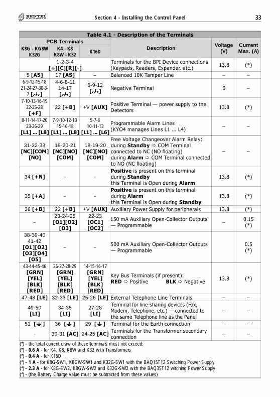
������������� ������������������������
PCB TerminalsDescription Voltage
(V)CurrentMax. (A)K8G - KG8W
K32GK4 - K8
K8W - K32 K16D
1-2-3-4�����������
����������� ����������������� ���������������������������� ���
!�" �#�
5���� 17���� – �������� $�������%��� & &
6-9-12-15-1821-24-27-30-3-
7������
4-6-8-1114-17������
6-9-12������
'�(� ����������� $ &
7-10-13-16-1922-25-28����
22 ���� +V �� !���� �����������)��*��+���� � ���� �� ��
!�" �#�
8-11-14-17-2023-26-29
�"�������"#�
7-9-10-12-1315-16-18
�"�������"#�
5-7-810-11-13
�"�������"$�
���(�����,��-����%�����./0����(�%���% ���%0�
& &
31-32-33�%����&'�
�%&�
19-20-21�%���%&���&'�
18-19-20�%���%&���&'�
1���2�� �(�3���(�����-���������4�+���(����(�)�3/5�������������� �� �'3�'/���� ��(��+���(������3/5�������������� �� �'/�'3���� ��(�
& &
34��%� – –*�����+�������� �� �� ��������+���(����(�) �����������/����+���(�����
!�" �#�
35���� – –*�����+�������� �� �� ��������+���(����� �����������/����+���(����(�)
!�" �#�
36���� 22���� +V �� !� -+���������*��6+����������������� !�" �#�
–23-24-25�&��&,��&-�
22-23�&���&�,�
7$�--+�������/���83����� ��/+ �+ )���(�����,��
&$� 7�#�
38-39-4041-42
�&��&,��&-��&���&.�
– – 7$$�--+�������/���83����� ��/+ �+ )���(�����,��
$�7�#�
43-44-45-46�/�%��01"���"2���1��
26-27-28-29�/�%��01"���"2���1��
14-15-16-17�/�%��01"���"2���1��
����+���������������� �4�1����� ����"2�'�(� ���
!�" �#�
47-48�"1� 32-33�"1� 25-26�"1� �� ��������������%����������� & &
49-50�"3�
34-35�"3�
27-28�"3�
���������������8�����(�������1���5���������������� ���)������ �� � ������������������� �������
& &
51������ 36������ 29������ ����������� ����� ������� ��� & &
– 30-31���� 24-25���� ����������� �������������������������� ���
& &
(*) - the total current draw of these terminals must not exceed:(*) - 0.6 A - for K4, K8, K8W and K32 with Transformers(*) - 0.4 A - for K16D(*) - 1 A - for K8G-SW1, K8GW-SW1 and K32G-SW1 with the BAQ15T12 Switching Power Supply(*) - 2.3 A - for K8G-SW2, K8GW-SW2 and K32G-SW2 with the BAQ35T12 witching Power Supply(*) - (the Battery Charge value must be subtracted from these values)

34 Multifunction Control Panel®®
SECTION 5 - INSTALLING THE NC2/VOX
� Voice synthesizer — Records/Plays Messages
� Records 8 Messages: 4 x 15 seconds and 4 x 7 seconds
� Repeats the Alarm Message up to 4 times
� Loudspeaker
� Talk Listen-in function (Telemergency)
General Features
NOTE: please, refer to the previous release of the Main Unit manual toinstall the Voice Board NC2/VOX old version BL233.
The NC2/VOX Voice Board (Accessory Item, not management for KYO16D)will allow you to record and send Voice messages to the programmed Telephonenumbers. For the installation instructions refer to Section 3 under ‘NC2/VOX’.
VOX-REM Jumpers
If the NC2/VOX Voice Board is unable to cover the entire premises (e.g. due tothe size of the building), you can extend cover by using additional VOX-REMModules (Microphone and Loudspeaker). The additional VOX-REM Mod-ules can be located as required (see Fig. 5.1).
GGGGG - For proper operation, the wire length between the additional VOX-REM Module and the NC2/VOX Voice Board should not exceed 50 metres.
Additional VOX-REM Modules must be connected in parallel to the NC2/VOXVoice Board (see Fig. 5.1).
Installing Additional VOX-REM ModulesThe VOX-REM must be mounted in 2 separate boxes (Minibox), as shown inFig. 5.1: one for the board and the other for the loudspeaker.
If you intend using the VOX-REM Microphone, you must insert the Jumpermarked EN LOC MIC.
If you intend using a remote Microphone, you must insert the Jumper markedEN REM MIC. The Microphone must be connected to the connector markedMIC on the VOX-REM Module.
NOTE: Use shielded cable for all connections. For proper operation, thewire length must not exceed 2 metres.
Additional VOX-REM Modules

35®®
Section 5 - Installing the NC2/VOX
Record / Play MessagesPut the system in SERVICE Mode (as per maintenance) by inserting theJumper [8] (as described in Section 4 under ‘Opening and Closing the Controlpanel’): the VVVVV LED on the Keypad will blink, and the 4 Green LEDs on theNC2/VOX will go through the 8 message configurations (refer to the ‘SelectMessage’).
Fig. 5.1 - Installing Additional VOX-REM Modules
The Loudspeaker must be connected to the bipolar connector (see Fig. 5.1).
NOTE: If you connect a VOX-REM Module, you must set the jumpers on theNC2/VOX as follows:
� MIC Open (oo)
� REM-MIC Closed (//)
� SPK Closed on REM (REM j LOC)
GGGGG - The NC2/VOX supports up to 4 additional VOX-REM Modules.
NC2/VOX JumperSettings
��������
��
�������
��
���
����
��
���
���
���
���
SP
–S
P–
VOX-REM
SP
+S
P+
MIC
MIC
M odu lo A gg iun tivo
NC2/VOXS cheda Voca le
C onnettore pe r A ltoparlan te
36 Multifunction Control Panel®®
��������������� ���� ����������
����������� � � � � � � �
���� � 15 sec 15 sec 15 sec 15 sec 7 sec 7 sec 7 sec 7 sec
���� ON OFF OFF OFF OFF ON ON ON
����� OFF ON OFF OFF ON OFF ON ON
����� OFF OFF ON OFF ON ON OFF ON
����� OFF OFF OFF ON ON ON ON OFF
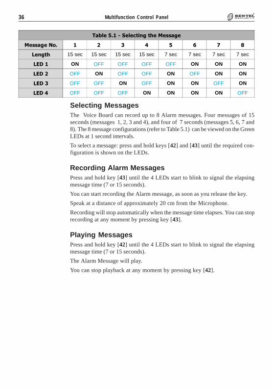
Selecting MessagesThe Voice Board can record up to 8 Alarm messages. Four messages of 15seconds (messages 1, 2, 3 and 4), and four of 7 seconds (messages 5, 6, 7 and8). The 8 message configurations (refer to Table 5.1) can be viewed on the GreenLEDs at 1 second intervals.
To select a message: press and hold keys [42] and [43] until the required con-figuration is shown on the LEDs.
Recording Alarm MessagesPress and hold key [43] until the 4 LEDs start to blink to signal the elapsingmessage time (7 or 15 seconds).
You can start recording the Alarm message, as soon as you release the key.
Speak at a distance of approximately 20 cm from the Microphone.
Recording will stop automatically when the message time elapses. You can stoprecording at any moment by pressing key [43].
Playing MessagesPress and hold key [42] until the 4 LEDs start to blink to signal the elapsingmessage time (7 or 15 seconds).
The Alarm Message will play.
You can stop playback at any moment by pressing key [42].
37®®
Section 5 - Installing the NC2/VOX
ProgrammingProper operation of the NC2/VOX Voice Board depends on Telephone andthe Events pages (refer to ‘Programming from PC’ in the ‘INSTALLATIONMANUAL’).
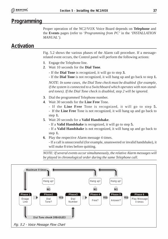
Fig. 5.2 - Voice Message Flow Chart
Fig. 5.2 shows the various phases of the Alarm call procedure. If a message-related event occurs, the Control panel will perform the following actions:
1. Engage the Telephone line.2. Wait 10 seconds for the Dial Tone.
- If the Dial Tone is recognized, it will go to step 3.- If the Dial Tone is not recognized, it will hang up and go back to step 1.
NOTE: In some cases, the Dial Tone check must be disabled (for example,if the system is connected to a Switchboard which operates with non-stand-ard tones). If the Dial Tone check is disabled, step 2 will be ignored.
3. Dial the programmed Telephone number.4. Wait 30 seconds for the Line Free Tone.
- If the Line Free Tone is recognized, it will go to step 5.- If the Line Free Tone is not recognized, it will hang up and go back tostep 1.
5. Wait 20 seconds for a Valid Handshake.- If a Valid Handshake is recognized, it will go to step 5.- If a Valid Handshake is not recognized, it will hang up and go back tostep 1.
6. Play the respective Alarm message 4 times.- If a call is unsuccessful (for example, unanswered or invalid handshake), itwill make 8 tries before quitting.
NOTE: If several events occur simultaneously, the relative Alarm messages willbe played in chronological order during the same Telephone call.
Activation
Answ er?Free?
Phase 5Phase 4
Hang up !Hang up !Hang up !
P lay M essage4 times
Dia lNum ber
Phase3
EnageLine
Phase 1
Dia lTone?
Phase2
Maximum 8 times
Phase 6
38 Multifunction Control Panel®®
SECTION 6 - DEFAULT SETTINGS
Restoring Factory Default
������ �� ����� ���������� ����
Address���������������� �� ������ ��!"���� ��
KeypadPartitionDefault Keypad
PartitionDefault Keypad
PartitionDefault
01 LCD 1, 2, 3, 4 LCD 1, 2, 3, 4 LCD 1, 2, 3, 45, 6, 7, 8
02 ALISO N/32LP 1, 2, 3, 4ALISO N/8LBKP-LEDBKB-LED
1, 2, 3, 4 — —
03
ICO N/KPALISO N/8LBKP-LEDBKB-LED
1, 2, 3, 4 — — — —
04 NC2/TAST 1, 2, 3, 4 — — — —
05...08 — — — — — —
���#����"���� ����������� ����
Address Readerin conf.
DescriptionRed Amber and Green
1 2 3 4 5 6 7 8 1 2 3 4 5 6 7 8
01 ... 16 No Reader 01 ... Reader 16 — — — — — — — — — — — — — — — —
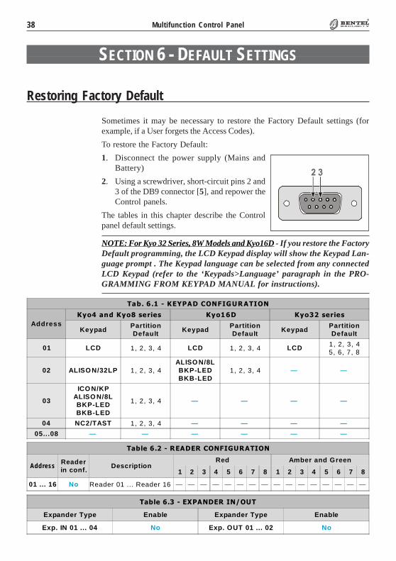
Sometimes it may be necessary to restore the Factory Default settings (forexample, if a User forgets the Access Codes).
To restore the Factory Default:
1. Disconnect the power supply (Mains andBattery)
2. Using a screwdriver, short-circuit pins 2 and3 of the DB9 connector [5], and repower theControl panels.
The tables in this chapter describe the Controlpanel default settings.
NOTE: For Kyo 32 Series, 8W Models and Kyo16D - If you restore the FactoryDefault programming, the LCD Keypad display will show the Keypad Lan-guage prompt . The Keypad language can be selected from any connectedLCD Keypad (refer to the ‘Keypads>Language’ paragraph in the PRO-GRAMMING FROM KEYPAD MANUAL for instructions).
������������ ������������
Expander Type Enable Expander Type Enable
Exp. IN 01 ... 04 No Exp. OUT 01 ... 02 No
39®®
Section 6 - Default Settings
������%�6���5��5�)
No. Place. Ter. Description Attributes SignalsPartitions
01 02 03 04 05 06 07 08
1 M.U. O1 Output 1 (*) N.O. — ���� ���� ���� ���� ���� ���� ���� ����
2 M.U. O2 Output 2 N.O. — ���� ���� ���� ���� ���� ���� ���� ����
3 M.U. O3 Output 3 N.O. — ���� ���� ���� ���� ���� ���� ���� ����
4 M.U. O4 Output 4 N.O. — ���� ���� ���� ���� ���� ���� ���� ����
5 M.U. O5 Output 5 N.O. — ���� ���� ���� ���� ���� ���� ���� ����
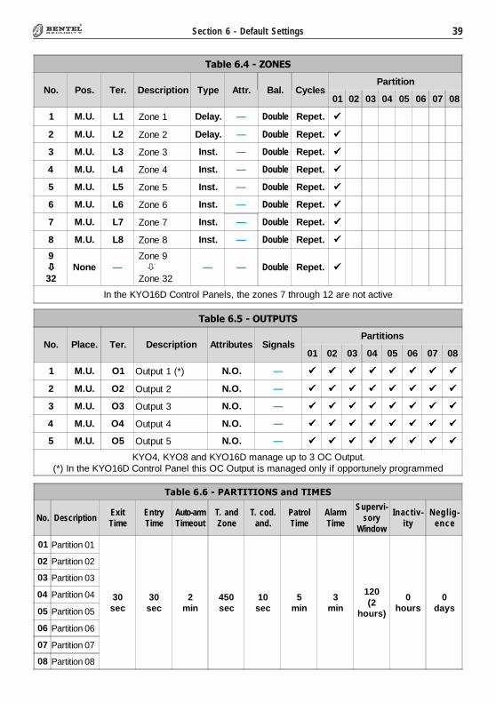
KYO4, KYO8 and KYO16D manage up to 3 OC Output.(*) In the KYO16D Control Panel this OC Output is managed only if opportunely programmed
������%�"����./)
No. Pos. Ter. Description Type Attr. Bal. CyclesPartition
01 02 03 04 05 06 07 08
1 M.U. L1 Zone 1 Delay. — Double Repet. ����
2 M.U. L2 Zone 2 Delay. — Double Repet. ����
3 M.U. L3 Zone 3 Inst. — Double Repet. ����
4 M.U. L4 Zone 4 Inst. — Double Repet. ����
5 M.U. L5 Zone 5 Inst. — Double Repet. ����
6 M.U. L6 Zone 6 Inst. — Double Repet. ����
7 M.U. L7 Zone 7 Inst. — Double Repet. ����
8 M.U. L8 Zone 8 Inst. — Double Repet. ����
9����
32None —
Zone 9�����
Zone 32— — Double Repet. ����
In the KYO16D Control Panels, the zones 7 through 12 are not active
������$�$��*���3�3&%����(��3'1�
No. DescriptionExitTime
EntryTime
Auto-armTimeout
T. andZone
T. cod.and.
PatrolTime
AlarmTime
Supervi-sory
Window
Inactiv-ity
Neg lig-ence
01 Partition 01
30sec
30sec
2min
450sec
10sec
5min
3min
120(2
hours)
0hours
0days
02 Partition 02
03 Partition 03
04 Partition 04
05 Partition 05
06 Partition 06
07 Partition 07
08 Partition 08

40 Multifunction Control Panel®®
������%�8����&/)
PIN DescriptionPartition
Type A and Type BArming Code Type
1 2 3 4 5 6 7 8 1 2 3 4 5 6 7 8
0001 Code 1 ���� ���� ���� ���� ���� ���� ���� ���� N N N N N N N NActive
(Main User)
0002����
0024
Code 2���������������������
Code 24— — — — — — — — Inactive
0025 Installer Code Active
����������� �!�
No. Description ServiceClear Call
QueuePartitions
1 2 3 4 5 6 7 8
1����
128
Key 1 � Key 128
No No No No No No No No No No
������%�#���/-/)/1+��/
Double Number of Rings Callback Test Event
No 3 No No
������%�7���/-/�4�./
No. DescriptionDisableTone
Check
DTMFDialling
Type ProtocolCustomer
Code
2-WayAudioAlert
Timeout
CallAttempts
01 Number 1 ���� None — — 3 min
8
02 Number 2 ���� None — — 3 min
03 Number 3 ���� None — — 3 min
04 Number 4 ���� None — — 3 min
05 Number 5 ���� None — — 3 min
06 Number 6 ���� None — — 3 min
07 Number 7 ���� None — — 3 min
08 Number 8 ���� None — — 3 min
41®®
Section 6 - Default Settings
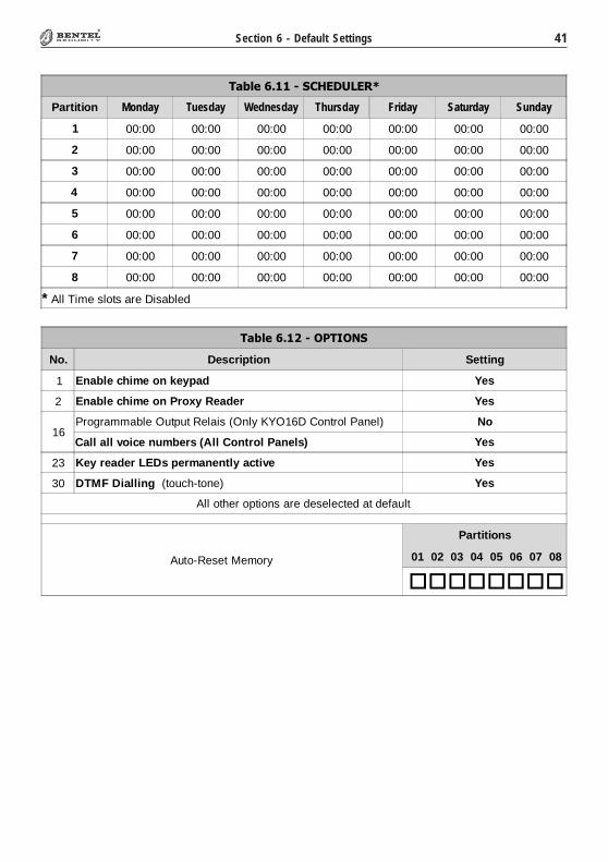
�����������"#�$"��
No. Description Setting
1 Enable chime on keypad Yes
2 Enable chime on Proxy Reader Yes
16Programmable Output Relais (Only KYO16D Control Panel) No
Call all voice numbers (All Control Panels) Yes
23 Key reader LEDs permanently active Yes
30 DTMF Dialling (touch-tone) Yes
All other options are deselected at default
Auto-Reset Memory
Partitions
01 02 03 04 05 06 07 08
��������
������%�����)�4/&5-/1A
Partition Monday Tuesday Wednesday Thursday Friday Saturday Sunday
1 00:00 00:00 00:00 00:00 00:00 00:00 00:00
2 00:00 00:00 00:00 00:00 00:00 00:00 00:00
3 00:00 00:00 00:00 00:00 00:00 00:00 00:00
4 00:00 00:00 00:00 00:00 00:00 00:00 00:00
5 00:00 00:00 00:00 00:00 00:00 00:00 00:00
6 00:00 00:00 00:00 00:00 00:00 00:00 00:00
7 00:00 00:00 00:00 00:00 00:00 00:00 00:00
8 00:00 00:00 00:00 00:00 00:00 00:00 00:00
* All Time slots are Disabled

42 Multifunction Control Panel®®
NOTES

43®®

ISTUCBLEUNKYO 5.0 061211 P70
BENTEL SECURITY S.r.l. - Tel.: +39 0861 839060 - Fax: +39 0861 839065
www.bentelsecurity.com - [email protected]
Via Gabbiano, 22 - Z.I. Santa Scolastica - 64013 CORROPOLI - TE - ITALY
Recycling informationBENTEL SECURITY recommends that customers dispose of their used equipments (panels, detectors,
sirens, and other devices) in an environmentally sound manner. Potential methods include reuse of parts or whole products and recycling of products, components, and/or materials.
For specific information see: http://www.bentelsecurity.com/index.php?o=environmental
Waste Electrical and Electronic Equipment (WEEE) Directive
It should be deposited at an appropriate facility to enable recovery and recycling.
For specific information see: http://www.bentelsecurity.com/index.php?o=environmental
In the European Union, this label indicates that this product should NOT be disposed of with household waste.