CRITICAL UTILITY SYSTEMS MANAGEMENT PLAN
222
CRITICAL UTILITY SYSTEMS MANAGEMENT PLAN prepared for VA Central Western Massachusetts – Northampton VA Medical Center PREPARED BY: EMG 10461 Mill Run Circle, Suite 1100 Owings Mills, Maryland 21117 800.733.0660 www.EMGcorp.com EMG CONTACT: John Young Senior Engineering Consultant 800.733.0660 x6505 [email protected] EMG PROJECT #: 122798.16R000-002.244 DATE OF REPORT: April 11, 2017 ON SITE DATE: N/A CRITICAL UTILITY SYSTEMS MANAGEMENT PLAN OF VACWM NORTHAMPTON VA MEDICAL CENTER 421 NORTH MAIN STREET LEEDS, MASSACHUSETTS 01053 EMG Corporate Headquarters 10461 Mill Run Circle, Suite 1100, Owings Mills, MD 21117 www.EMGcorp.com p 800.733.0660
-
Upload
khangminh22 -
Category
Documents
-
view
0 -
download
0
Transcript of CRITICAL UTILITY SYSTEMS MANAGEMENT PLAN

CRITICAL UTILITY SYSTEMS MANAGEMENT PLAN
prepared for
VA Central Western Massachusetts – Northampton VA Medical Center
PREPARED BY: EMG 10461 Mill Run Circle, Suite 1100 Owings Mills, Maryland 21117 800.733.0660
www.EMGcorp.com
EMG CONTACT: John Young Senior Engineering Consultant 800.733.0660 x6505
EMG PROJECT #: 122798.16R000-002.244
DATE OF REPORT: April 11, 2017
ON SITE DATE: N/A
CRITICAL UTILITY SYSTEMS MANAGEMENT PLAN
OF
VACWM NORTHAMPTON VA MEDICAL CENTER 421 NORTH MAIN STREET LEEDS, MASSACHUSETTS 01053
EMG Corporate Headquarters 10461 Mill Run Circle, Suite 1100, Owings Mills, MD 21117 www.EMGcorp.com p 800.733.0660

CRITICAL UTILITY SYSTEMS MANAGEMENT PLAN
VACWM NORTHAMPTON CRITICAL UTILITY MANAGEMENT PLAN 421 NORTH MAIN STREET
LEEDS, MASSACHUSETTS 01053 EMG PROJECT NO.: 122798.16R000-002.244
www.EMGcorp.com p 800.733.0660
TABLE OF CONTENTS 1 Executive Summary .............................................................................................................................. 1
1.1 Goal .............................................................................................................................................. 1 1.2 Methodology ................................................................................................................................. 1
2 Objectives ............................................................................................................................................... 2
3 Scope ...................................................................................................................................................... 3
4 Responsibilites ...................................................................................................................................... 4
5 Critical Utility Systems Elements of Performance ............................................................................. 5 5.1 Utility Systems Management Plan ................................................................................................ 5 5.2 Critical Utility Systems .................................................................................................................. 5 5.2.1 Utility Systems .............................................................................................................................. 5 5.2.2 Critical Facilities............................................................................................................................ 5 5.2.3 VACWM Critical Utilities ............................................................................................................... 5 5.3 RISK ASSESSMENTS ....................................................................................................................... 6 5.3.1 Equipment Risk Assessment ........................................................................................................ 6 5.3.2 Risk Assessment Methodology .................................................................................................... 6 5.4 Critical Utility System Equipment Inventory ................................................................................. 6 5.5 Preventive Maintenance Strategies.............................................................................................. 7 5.5.1 Alternative Equipment Maintenance (AEM) Program .................................................................. 7 5.5.2 Preventive Maintenance Schedules for VACWM ......................................................................... 7 5.6 Preventive Maintenance Frequencies .......................................................................................... 7 5.7 Inspections, Tests, and Maintenance ........................................................................................... 7 5.7.1 Inspection and Testing Prior to Initial Use .................................................................................... 8 5.8 Emergency Power Systems ......................................................................................................... 8 5.8.1 Emergency Power Systems Application ...................................................................................... 8 5.8.2 Emergency Power System Levels................................................................................................ 8 5.8.3 Battery Systems ........................................................................................................................... 9 5.9 Employee Training ....................................................................................................................... 9 5.9.1 Annual Plan Review ..................................................................................................................... 9
6 Implementation Plan ............................................................................................................................ 10 6.1 Step 1 – Implement Weekly and Monthly PM Inspections .......................................................... 10 6.2 Step 2 - Procure Maintenance Contracts on Selected Equipment .............................................. 11 6.3 Step 3 – Schedule Employee Performed Annual PM Tasks on Critical, Risk 1 Equipment ....... 11 6.4 Step 4 – Schedule Employee Performed Quarterly PM Tasks on Critical, Risk 2 Equipment ... 12 6.5 Step 5 – Set Up Critical Utility System Equipment Preventive Maintenance Program in Existing
CMMS .......................................................................................................................................... 13 7 Appendices ........................................................................................................................................... 14

CRITICAL UTILITY SYSTEMS MANAGEMENT PLAN
VACWM NORTHAMPTON CRITICAL UTILITY MANAGEMENT PLAN 421 NORTH MAIN STREET
LEEDS, MASSACHUSETTS 01053 EMG PROJECT NO.: 122798.16R000-002.244
1
www.EMGcorp.com p 800.733.0660
1 EX E C U TI VE SU M M A R Y
1.1 GOAL
This management plan describes the framework to manage risks associated with and to improve program performance for critical utility systems for the VA Central Western Mass Healthcare System (VACWM). The scope and objectives are consistent with the Veterans Administration’s values, vision, and mission to provide quality healthcare to our nation’s veterans.
1.2 METHODOLOGY
To develop this plan a survey was conducted of the facilities and systems at VACWM by professionals experienced in the maintenance and operations of critical utility systems. This survey was conducted over the course of a week and involved physical inspections of all facilities.
The building occupancy and functional activities conducted within each facility were reviewed with the engineering staff to determine which buildings were considered Critical as defined by the International Building Code. Three such facilities (Main Hospital (1), Psychiatric Ward (4) and Ward 8 / PTSD (8) were identified as being critical facilities.
The building systems and equipment within each facility and centralized systems on campus were inspected to develop an equipment inventory and to assess the Risk of each piece of equipment to patient health. Maintenance procedures for each piece of equipment were developed based on manufacturers’ recommendations, where available, or generally accepted standards of practice for healthcare facilities when manufacturers’ recommendations were not available.
An implementation plan was developed that prioritized the critical utility system equipment maintenance based on Criticality and Risk. The implementation plan established four steps of maintenance that should be phased in immediately to improve the reliability of the existing systems. The implementation plan also laid out the steps required to use the Equipment Inventory and PM Schedules developed as part of this Critical Utility System Management Plan to set up a preventive maintenance program using the existing CMMS.
CRITICAL UTILITY SYSTEMS MANAGEMENT PLAN
VACWM NORTHAMPTON CRITICAL UTILITY MANAGEMENT PLAN 421 NORTH MAIN STREET
LEEDS, MASSACHUSETTS 01053 EMG PROJECT NO.: 122798.16R000-002.244
2
www.EMGcorp.com p 800.733.0660
2 O BJ E C TI VE S
The following objectives will ensure the physical safety of patients, visitors, and staff and prevent the loss of property.
Effectively manage utility system risks by using best industry practices
Optimize resources by using efficient utility system processes and lifecycle management of equipment
Improve staff performance through effective utility system education and training
Improve staff and patient satisfaction by providing a safe physical environment

CRITICAL UTILITY SYSTEMS MANAGEMENT PLAN
VACWM NORTHAMPTON CRITICAL UTILITY MANAGEMENT PLAN 421 NORTH MAIN STREET
LEEDS, MASSACHUSETTS 01053 EMG PROJECT NO.: 122798.16R000-002.244
3
www.EMGcorp.com p 800.733.0660
3 S C OP E
The plan applies to all facilities and building systems that make up the VA Central Western Mass Healthcare System (VACWM).
The critical utility systems covered under this plan are defined in Section 5.2.
CRITICAL UTILITY SYSTEMS MANAGEMENT PLAN
VACWM NORTHAMPTON CRITICAL UTILITY MANAGEMENT PLAN 421 NORTH MAIN STREET
LEEDS, MASSACHUSETTS 01053 EMG PROJECT NO.: 122798.16R000-002.244
4
www.EMGcorp.com p 800.733.0660
4 R E SP O NSI B I L I T E S
The authority and responsibility for the Utility Systems Management Plan’s strategic design, execution and maintenance of this plan has been assigned to Chief of Facility (FMS).
Program implementation and day-to-day operational management is delegated to M & O Supervisor.
These individuals work in close cooperation with Safety, as well as various operating and safety committees.
All staff must be trained and competent in safe operation and use of utility systems and in emergency response and reporting procedures.
CRITICAL UTILITY SYSTEMS MANAGEMENT PLAN
VACWM NORTHAMPTON CRITICAL UTILITY MANAGEMENT PLAN 421 NORTH MAIN STREET
LEEDS, MASSACHUSETTS 01053 EMG PROJECT NO.: 122798.16R000-002.244
5
www.EMGcorp.com p 800.733.0660
5 C R I T I CA L U T I L I T Y S YS TE MS E LE ME N T S O F PE R F O RMA N C E
5.1 UTILITY SYSTEMS MANAGEMENT PLAN
This management plan addresses the essential process for making sure that critical utility systems are safe and functional.
5.2 CRITICAL UTILITY SYSTEMS
Critical Utility Systems are utility systems of the types listed in Section 5.2.1 that support critical facilities, as defined in section 5.2.2.
5.2.1 UTILITY SYSTEMS
This management plan applies to the following types of utility systems that are located in or serve Critical Facilities, as defined in Section 5.2.2:
Electrical distribution and emergency power;
Vertical and horizontal transport;
Heating, ventilating, and air conditioning (HVAC);
Plumbing, boiler, and steam;
Refrigeration; piped gases; vacuum systems;
Fire alarm and suppression systems;
Communication systems, including data exchange systems.
5.2.2 CRITICAL FACILITIES
Critical facilities are facilities that are classified as Risk Category IV facilities in the 2012 International Building Code (IBC) (Section 1604, General Design Requirements, Table 1604.5).
Risk Category IV facilities include buildings and other structures designated as essential facilities, including but not limited to Group I-2 occupancies having surgery or emergency treatment facilities.
IBC Use and Occupancy Classification Group I-2 includes buildings and structures used for medical, surgical, psychiatric, nursing or custodial care on a 24-hour basis of more than five persons who are not capable of self- preservation. This group shall include, but not be limited to the following: hospitals, nursing homes (both intermediate care facilities and skilled nursing facilities), mental hospitals and detoxification facilities. The following facilities at VACWM are considered critical facilities:
Main Hospital (Building 1)
Psychiatric Ward (Building 4)
Ward 8 / PTSD Unit (Building 8)
5.2.3 VACWM CRITICAL UTILITIES
Critical utilities at VACWM are the utility systems of the types listed in section 5.2.1 that are either:
In the facilities listed in section 5.2.2
Campus wide and serving the facilities listed in Section 5.2.2
All of the building systems of the types listed in Section 5.2.1 that are located in the facilities listed in Section 5.2.2 are considered Critical Utility Systems.
Because the emergency power system in Building 8 is fed from the emergency power system in Building 6, the Building 6 emergency power system is considered a Critical Utility System.
CRITICAL UTILITY SYSTEMS MANAGEMENT PLAN
VACWM NORTHAMPTON CRITICAL UTILITY MANAGEMENT PLAN 421 NORTH MAIN STREET
LEEDS, MASSACHUSETTS 01053 EMG PROJECT NO.: 122798.16R000-002.244
6
www.EMGcorp.com p 800.733.0660
The campus wide utility systems listed below support the critical facilities listed in Section 5.2.2 and are therefore considered Critical Utility Systems:
Electrical Distribution System, consisting of substation in Building 65 and numerous pad mounted switches and pad mountedtransformers located on the Grounds across the campus
Centralized steam production and distribution from Building 28
Refrigeration equipment located in Building 5
Domestic water and fire suppression water systems fed from Water Tank (29)
Communications systems (phone, radio and paging) located in Main Hospital (1) and Building 2
5.3 R ISK ASSESSMENTS
Utility system components are assessed for risk to patients and caregivers in the facilities. Each component is assigned a category based on Section 4.1 of the 2012 edition of NFPA® 99, Health Care Facilities Code. The four categories are described below.
Category 1: Systems are expected to work or be available at all times to support patient needs.
Category 2: Systems are expected to provide a high level of reliability; however, limited short durations of equipment downtime canbe tolerated without significant impact on patient care. Category 2 systems support patient needs but are not critical for life support.
Category 3: Normal building system reliabilities are expected. Such systems support patient needs, but failure of such equipmentwould not immediately affect patient care. Such equipment is not critical for life support.
Category 4: Such systems have no impact on patient care and would not be noticeable to patients in the event of failure.
5.3.1 EQUIPMENT RISK ASSESSMENT
Risk assessment for each equipment of the Critical Utility Systems is included in the Critical Utility System Equipment Inventory in Appendix A. Risk Assessments are summarized by Criticality, System, Classification and Type in Appendix D.
5.3.2 RISK ASSESSMENT METHODOLOGY
Risk assessment for a system component is based on the worst-outcome scenario of a failure’s impact, therefore is impacted by the criticality of system the component is part of:
Due to the geographic location of VACWM, heating system equipment was assessed a higher risk that air conditioning equipment
Since Switchgear and Main Distribution Panels typically feed multiple Electrical Panels, Switchgear and Main Distribution Panelswere assessed a higher risk than Electrical Panels
Unit Heaters and Damper Actuators that serve Emergency Power Systems are vital to the function of the Emergency Power Systemsand were assessed a higher risk than similar equipment in different applications
5.4 CRITICAL UTILITY SYSTEM EQUIPMENT INVENTORY
Critical utility systems are defined in Section 5.2.
Equipment that are components of critical utility systems are to be included in the critical utility system equipment inventory.
Equipment will be added to the inventory at the Functional-Unit Level. Equipment that is composed of several parts or modules shall be entered into the inventory as a single piece of equipment at the functional unit level. If the parts or modules always occur together and require each other to be functional, the entire system can be considered one piece of equipment on the inventory. Examples of this concept include:
A chiller is a system composed of a motor, a compressor, a condenser and valves. Since each of these components work together toperform the function of the chiller, only the chiller is included in the inventory. Any work that is performed on a component of thechiller shall be attributed to the chiller.
A medium voltage substation circuit breaker is composed of multiple relays, sensing devices and electro-mechanical opening andclosing devices. Each of these components work together to perform the function of the circuit breaker. Any work that is performedon a component of the breaker shall be attributed to the circuit breaker.
CRITICAL UTILITY SYSTEMS MANAGEMENT PLAN
VACWM NORTHAMPTON CRITICAL UTILITY MANAGEMENT PLAN 421 NORTH MAIN STREET
LEEDS, MASSACHUSETTS 01053 EMG PROJECT NO.: 122798.16R000-002.244
7
www.EMGcorp.com p 800.733.0660
All systems or components included in the Equipment Inventory are assigned a unique identifier, Equipment ID, and a corresponding record is created in the Work Order System. The identification numbers attach each component to specific preventive maintenance and corrective maintenance records.
All systems or components included in the Equipment Inventory are assigned an equipment classification and type. The equipment classifications correspond to the building system the item is a part of (electrical, plumbing, HVAC, etc.). The equipment types correspond to the functional type of equipment (pump, fan, chiller, etc.) and in some cases include the style and manufacturer of the equipment.
The Work Order System is used to maintain documentation for the following:
A current, accurate, and separate inventory of utility components included in the utility management plan
Performance and safety testing of each critical component identified in the plan before initial use
Critical components of life support utility systems/equipment consistent with maintenance strategies
Critical components of infection control utility systems/equipment for high-risk patients
Critical components of non-life support utility systems/equipment
A written inventory (Equipment Inventory) of all operating components of the critical utility systems is included in Appendix A of this plan.
5.5 PREVENTIVE MAINTENANCE STRATEGIES
Each combination of equipment classification and type, as described in Section 5.5 (3), have prescribed time based preventive maintenance schedules. Each preventive maintenance schedule details the specific tasks and associated frequencies required for that equipment. In general, preventive maintenance tasks and frequencies are based on:
Manufacturers’ recommendations
EC Standards
Applicable Codes referenced by the EC Standards
VHA Directive 1028 – Electrical Power Distribution Systems
5.5.1 ALTERNATIVE EQUIPMENT MAINTENANCE (AEM) PROGRAM
In instances where manufacturer recommended maintenance information is not available, strategies of an alternative equipment maintenance (AEM) program were used. This was the case for some older equipment. In these cases, the prescribed preventive maintenance tasks and frequencies are based on generally accepted standards of practice for healthcare facilities. ASHE 2014 document “Maintenance Management for Healthcare Facilities” was used as the source for equipment preventive maintenance tasks and frequencies for equipment covered by the Alternative Equipment Maintenance (AEM) Program.
5.5.2 PREVENTIVE MAINTENANCE SCHEDULES FOR VACWM
The Preventive Maintenance schedules for Critical Utility System equipment are included in Appendix B of this plan. These schedules include detailed recommended tasks and frequencies of equipment maintenance.
5.6 PREVENTIVE MAINTENANCE FREQUENCIES
The Work Order System serves as a tracking tool to document completion of required inspections, tests, and maintenance. Each month the Work Order System automatically generates scheduled services requirements based on the maintenance types described in Section 5.5.
5.7 INSPECTIONS, TESTS, AND MAINTENANCE
All systems and equipment are inspected, tested and maintained as described in Sections 5.4, 5.5 and 5.6.
Life Support. See Sections 5.4, 5.5, and 5.6.
CRITICAL UTILITY SYSTEMS MANAGEMENT PLAN
VACWM NORTHAMPTON CRITICAL UTILITY MANAGEMENT PLAN 421 NORTH MAIN STREET
LEEDS, MASSACHUSETTS 01053 EMG PROJECT NO.: 122798.16R000-002.244
8
www.EMGcorp.com p 800.733.0660
Infection Control. See Sections 5.4, 5.5, and 5.6.
Non-Life Support. See Sections 5.4, 5.5, and 5.6.
5.7.1 INSPECTION AND TESTING PRIOR TO INITIAL USE
Upon installation of new critical utility system equipment, sufficient testing and inspection shall be performed to verify that the equipment has been installed in a safe manner, operates as designed and performs its intended function. Prior to initial use, all critical utility systems and equipment receive pre-functional inspection and functional testing following checklists included in Appendix C.
5.8 EMERGENCY POWER SYSTEMS
Normal electric power on the campus is supplied by the Utility Power Company (UPC) to a VACWM owned substation in Building 65. Power is distributed to buildings on campus via an electrical distribution system owned and operated by VACWM. Emergency power systems provide electric power to specific buildings and circuits when there is an interruption of power from the UPC or the campus electrical distribution system.
Emergency power systems consist of an emergency power source (battery station or emergency generator) and a system of conductors, disconnecting means and overcurrent protective devices, transfer switches, and all control, supervisory, and support devices up to and including the load terminals of the transfer equipment needed for the system to operate as a safe and reliable source of electric power.
5.8.1 EMERGENCY POWER SYSTEMS APPLICATION
VACWM has installed emergency power systems to adequately provide for the following as required by the Life Safety Code:
Alarm systems
Exit route and exit sign illumination
Emergency communication systems
Elevators (at least one for non-ambulatory patients)
Equipment that could cause patient harm when it fails
Areas in which loss of power could result in patient harm
5.8.2 EMERGENCY POWER SYSTEM LEVELS
In accordance with NFPA 110 2010, emergency power systems are classified as either Level 1 or Level 2.
Level 1 systems are installed where failure of the equipment to perform could result in loss of human life or serious injuries. AtVACWM, emergency power systems that provide power for the following buildings where patients receive acute care, inpatient careor power for Kitchen Refrigeration are classified as Level 1:
Main Hospital (Building 1)
Psychiatric Ward (Building 4)
Ward 8 / PTSD Unit (Building 8)
Building 6A (Kitchen Refrigeration)
Building 12A (Kitchen Refrigeration)
All other emergency power systems are classified as Level 2.
Prescribed frequencies of preventive maintenance tasks are increased for Level 1 systems to ensure reliable operation of thesesystems.
CRITICAL UTILITY SYSTEMS MANAGEMENT PLAN
VACWM NORTHAMPTON CRITICAL UTILITY MANAGEMENT PLAN 421 NORTH MAIN STREET
LEEDS, MASSACHUSETTS 01053 EMG PROJECT NO.: 122798.16R000-002.244
9
www.EMGcorp.com p 800.733.0660
5.8.3 BATTERY SYSTEMS
The VACWM does not have battery-powered lights for egress purposes.
Inspections, tests and maintenance of substation battery stations and emergency generator batteries are as per Sections 5.4, 5.5, and 5.6.
All inspections, tests, and maintenance are documented in the Work Order System.
5.9 EMPLOYEE TRAINING
The orientation and education component pertaining to critical utility systems addresses the following criteria:
Maintenance workers.
Certification, license or information and skills necessary to perform assigned maintenance responsibilities
The utility system's capabilities, limitations, and special applications
Emergency procedures in the event of system failure
Location and instructions for use of emergency shutoff controls
Processes for reporting utility system management problems, failures, and user errors
Shop safety (Lockout/Tagout, confined spaces, tool and ladder safety, etc.)
Supervisors provide worksite-specific orientation and annual refresher training.
All training is documented in the staff training records.
5.9.1 ANNUAL PLAN REVIEW
The Facility Manager keeps the management plan current by reviewing the plan at least annually (i.e., one year from the date of the last review, plus or minus 30 days) and making modifications based on changes to policies, regulations, and standards. In performing the annual review, the Facility Manager uses a variety of sources such as inspection and audit results, accident/incident reports, employee reports of unsafe or unhealthy working conditions, customer satisfaction surveys, suggestion boxes, performance improvement committees, and other statistical information and tracking reports. The Facility Manager may also use other forms of review and input from relevant sources such as leadership, other EC/PE disciplines, management, staff, personnel, and volunteers.
The annual evaluation includes an assessment of the plan’s:
Scope. Based on the outcome of objectives assessment, the scope of the plan is expanded, reduced or maintained at its presentscope (buildings, equipment, people, operations, services)
Objectives. An annual assessment is made to determine if the objectives, as outlined in paragraphs 2.a through 2.d are current.
Performance. An acceptable level of performance is determined by the achievements related to the utility management processesnecessary for maintaining a successful Utility Management Program.
Effectiveness. An acceptable level of effectiveness is determined by attaining success in meeting objectives and producing asatisfactory level of performance.
The annual review is used as an opportunity to develop or modify programs, plans, and policies; identify and implement additional or more effective controls; and enhance the Employee Orientation and Annual Refresher Training Programs.
CRITICAL UTILITY SYSTEMS MANAGEMENT PLAN
VACWM NORTHAMPTON CRITICAL UTILITY MANAGEMENT PLAN 421 NORTH MAIN STREET
LEEDS, MASSACHUSETTS 01053 EMG PROJECT NO.: 122798.16R000-002.244
10
www.EMGcorp.com p 800.733.0660
6 I MP LE M E N TA TI ON P LA N
Ideally all recommended maintenance on all equipment would be performed on time and documented in a modern and fully functional Computerized Maintenance Management System (CMMS). At the time this Critical Utility Management Plan was being developed, VACWM was transitioning from an obsolete CMMS (VISTA), with plans to implement a new CMMS (Maximo) within the next 18-24 months. The following plan was developed to give VACWM a prioritized approach to allocate resources in a manner that has the greatest impact on critical utility system reliability.
Step 1 – Implement Weekly and Monthly PM Inspections
Step 2 - Procure Maintenance Contracts on Selected Equipment
Step 3 – Schedule Employee Performed Annual PM Tasks on Critical, Risk 1 Equipment
Step 4 – Schedule Employee Performed Quarterly PM Tasks on Critical, Risk 2 Equipment
Step 5 – Set Up Critical Utility System Equipment Preventive Maintenance Program in Existing CMMS
These steps are detailed in Sections 6.1 through Section 6.5.
6.1 STEP 1 – IMPLEMENT WEEKLY AND MONTHLY PM INSPECTIONS
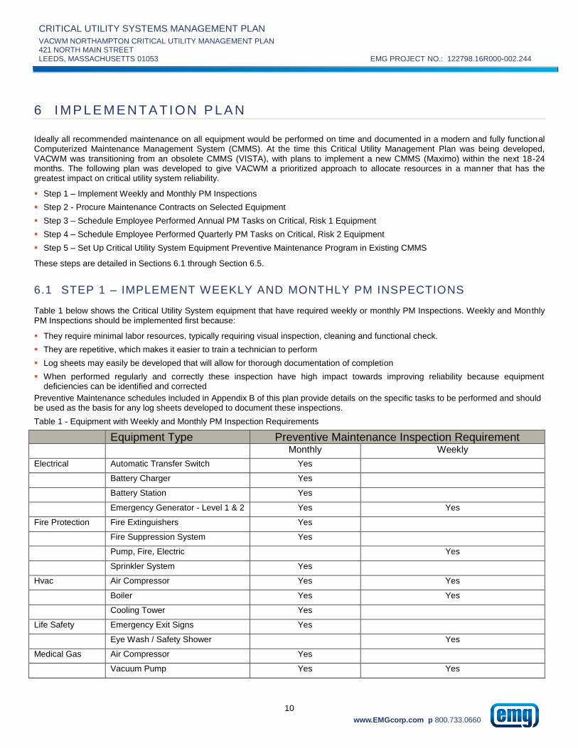
Table 1 below shows the Critical Utility System equipment that have required weekly or monthly PM Inspections. Weekly and Monthly PM Inspections should be implemented first because:
They require minimal labor resources, typically requiring visual inspection, cleaning and functional check.
They are repetitive, which makes it easier to train a technician to perform
Log sheets may easily be developed that will allow for thorough documentation of completion
When performed regularly and correctly these inspection have high impact towards improving reliability because equipmentdeficiencies can be identified and corrected
Preventive Maintenance schedules included in Appendix B of this plan provide details on the specific tasks to be performed and should be used as the basis for any log sheets developed to document these inspections.
Table 1 - Equipment with Weekly and Monthly PM Inspection Requirements
Equipment Type Preventive Maintenance Inspection Requirement Monthly Weekly
Electrical Automatic Transfer Switch Yes
Battery Charger Yes
Battery Station Yes
Emergency Generator - Level 1 & 2 Yes Yes
Fire Protection Fire Extinguishers Yes
Fire Suppression System Yes
Pump, Fire, Electric Yes
Sprinkler System Yes
Hvac Air Compressor Yes Yes
Boiler Yes Yes
Cooling Tower Yes
Life Safety Emergency Exit Signs Yes
Eye Wash / Safety Shower Yes
Medical Gas Air Compressor Yes
Vacuum Pump Yes Yes

CRITICAL UTILITY SYSTEMS MANAGEMENT PLAN
VACWM NORTHAMPTON CRITICAL UTILITY MANAGEMENT PLAN 421 NORTH MAIN STREET
LEEDS, MASSACHUSETTS 01053 EMG PROJECT NO.: 122798.16R000-002.244
11
www.EMGcorp.com p 800.733.0660
6.2 STEP 2 - PROCURE MAINTENANCE CONTRACTS ON SELECTED EQUIPMENT
Some equipment types customarily have at least some of their maintenance performed by qualified vendors due to the specialized training required to correctly maintain this equipment. Table 2 shows equipment types that have at least some of their PM Schedules customarily performed by qualified vendors. VACWM should procure maintenance contracts from qualified vendors to perform the PM schedules detailed in Table 2.
Preventive Maintenance schedules included in Appendix B of this plan provide details on the specific tasks to be included in each PM and should be used as a basis for scope of work for procured maintenance contracts.
Table 2 - Critical Utility System Equipment with PM Schedules Customarily Contracted
Equipment Type Customarily Contracted Maintenance
Q S Y 3Y 5Y
Conveying Elevator, Hydraulic Yes Yes Yes
Elevator, Traction Yes Yes Yes
Electrical Emergency Generator - Level 1 Yes Yes Yes
Emergency Generator - Level 2 Yes Yes Yes Yes
Fire Protection Fire Alarm System Yes
Fire Extinguishers Yes
Fire Suppression System Yes
Pump, Fire, Electric Yes
Sprinkler System Yes
Food Service Compressor, Refrigeration Yes Yes
Walk-In Cooler Yes
Walk-In Freezer Yes
Hvac Boiler Yes
Chiller, Air Cooled Yes Yes
Chiller, Water Cooled Yes Yes Yes
Condenser Yes Yes
Medical Gas Air Compressor Yes
Oxygen Tank Yes
Vacuum Pump Yes
Plumbing BackFlow Preventer Yes
Domestic Hot Water Yes
RO System Yes
Water Softener Yes
6.3 STEP 3 – SCHEDULE EMPLOYEE PERFORMED ANNUAL PM TASKS ON CRITICAL, RISK 1 EQUIPMENT
Prioritize the maintenance not completed in Step 1 and Step 2 based on Equipment Criticality, Equipment Risk assessment and PM Frequency. Limited resources should be allocated to perform maintenance on equipment in Critical Systems that have been assessed a Risk level of 1. Annual PM schedules include more thorough tasks and are closer to an equipment overhaul / renewal. For risk Level 1 equipment components of Critical Utility Systems, completion of Annual PM schedules should be prioritized. Many of these PM Schedules were covered by Step 2 – Procure Maintenance Contracts. The remaining Critical Utility System equipment with a Risk level of 1 and maintenance that is customarily performed by employees are listed in Table 3.

CRITICAL UTILITY SYSTEMS MANAGEMENT PLAN
VACWM NORTHAMPTON CRITICAL UTILITY MANAGEMENT PLAN 421 NORTH MAIN STREET
LEEDS, MASSACHUSETTS 01053 EMG PROJECT NO.: 122798.16R000-002.244
12
www.EMGcorp.com p 800.733.0660
Preventive Maintenance schedules included in Appendix B of this plan provide details on the specific tasks to be included in each PM work order assignment.
Table 3 - Critical Utility System Equipment Risk Level 1 with Employee Performed Annual Maintenance
Criticality Classification Type Risk
Critical Electrical Day Tank 1
Critical Electrical Tank, Fuel 1
Critical Hvac Damper Actuators 1
Critical Hvac Honeywell Actuators 1
Critical Hvac Lifeline Air Dryer 1
Critical Life Safety Emergency Exit Signs 1
Critical Medical Gas Lifeline Air Dryer 1
Critical Medical Gas Pressure Reducing Valve 1
6.4 STEP 4 – SCHEDULE EMPLOYEE PERFORMED QUARTERLY PM TASKS ON CRITICAL, RISK 2 EQUIPMENT
Prioritize the maintenance not completed in Steps 1, 2 and 3 based on Equipment Criticality, Equipment Risk assessment and PM Frequency. The next group of limited resources should be allocated to perform quarterly maintenance on equipment in Critical Systems that have been assessed a Risk level of 2. Quarterly PM schedules include more inspection tasks along with critical lubrication and wear part replacement. They require less time to complete than Annual PM but the inspections may identify equipment deficiencies that necessitate completion of Annual PM. Completion of quarterly PM for Risk Level 2 equipment components of Critical Utility Systems, completion of Annual PM schedules should be prioritized. Many of these PM Schedules were covered by Step 2 – Procure Maintenance Contracts. The remaining Critical Utility System equipment with a Risk level of 2 and maintenance that is customarily performed by employees are listed in Table 4.
Preventive Maintenance schedules included in Appendix B of this plan provide details on the specific tasks to be included in each PM work order assignment.
Table 4 - Critical Utility System Equipment Risk Level 2 with Employee Performed Quarterly Maintenance
Criticality Classification Base Type Risk Critical Fire Protection Fire Hydrant 2
Critical Fire Protection Pump, Fire, Electric 2
Critical Food Service_Dietary Freezer 2
Critical Food Service_Dietary Refrigerator 2
Critical Food Service_Dietary Walk-In Cooler 2
Critical Food Service_Dietary Walk-In Freezer 2
Critical Hvac Boiler 2
Critical Hvac Pump 2
Critical Plumbing Pump 2
Critical Plumbing RO System 2

CRITICAL UTILITY SYSTEMS MANAGEMENT PLAN
VACWM NORTHAMPTON CRITICAL UTILITY MANAGEMENT PLAN 421 NORTH MAIN STREET
LEEDS, MASSACHUSETTS 01053 EMG PROJECT NO.: 122798.16R000-002.244
13
www.EMGcorp.com p 800.733.0660
6.5 STEP 5 – SET UP CRITICAL UTILITY SYSTEM EQUIPMENT PREVENTIVE MAINTENANCE PROGRAM IN EXISTING CMMS
Setting up a preventive maintenance program in a CMMS is a time consuming but necessary activity. Steps 1-4 identified a prioritized approach to beginning preventive maintenance activities on the Critical Utility System equipment before or while the preventive maintenance program is set up in the current CMMS.
To set up the Preventive Maintenance program for the Critical Utility Systems in the existing CMMS (VISTA) the following must be done:
Input the Critical Utility System Equipment Inventory as listed in Appendix A
Input the Preventive Maintenance Schedules as listed in Appendix B. Each PM schedule should identify tasks to be completed for aspecific equipment classification and type for a specific frequency
Assign Critical Utility System Equipment to the Preventive Maintenance Schedules based on the equipment’s Classification and Type
Establish start dates for each PM schedule:
Annual PM’s should be scheduled during the time of year when shutdown of the equipment has least impact on the facility
served (ie perform boiler PM’s in summer)
Semi-Annual and Quarterly PMs should be staggered off of the Annual PM date
Annual, Semi-Annual and Quarterly PM’s should be spread out to distribute the work evenly across the months. For example,
if boiler annual PM’s are to be performed in the summer, consider spreading them out over the months of June, July and
August
Define technician or assignments for each PM Schedule.

CRITICAL UTILITY SYSTEMS MANAGEMENT PLAN
VACWM NORTHAMPTON CRITICAL UTILITY MANAGEMENT PLAN 421 NORTH MAIN STREET
LEEDS, MASSACHUSETTS 01053 EMG PROJECT NO.: 122798.16R000-002.244
14
www.EMGcorp.com p 800.733.0660
7 A PP E N DI CE S
APPENDIX A: EQUIPMENT INVENTORY
APPENDIX B: CRITICAL UTILITY SYSTEMS EQUIPMENT PM SCHEDULES
APPENDIX C: EQUIPMENT PRE-FUNCTIONAL CHECKLISTS
APPENDIX D: EQUIPMENT RISK ASSESSMENT
APPENDIX E: SUPPLEMENTAL INFORMATION

CRITICAL UTILITY SYSTEMS MANAGEMENT PLAN
VACWM NORTHAMPTON CRITICAL UTILITY MANAGEMENT PLAN 421 NORTH MAIN STREET
LEEDS, MASSACHUSETTS 01053 EMG PROJECT NO.: 122798.16R000-002.244
www.EMGcorp.com p 800.733.0660
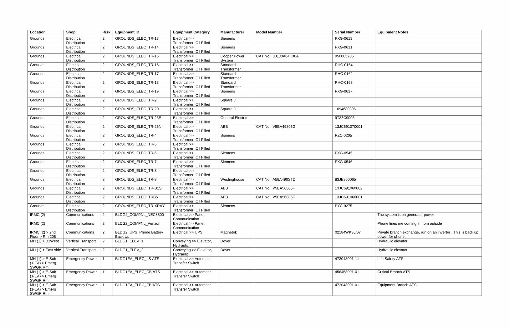
APPENDIX A: EQUIPMENT INVENTORY

Location Shop Risk Equipment ID Equipment Category Manufacturer Model Number Serial Number Equipment Notes
Building 65 Emergency Power 1 BLDG65_ATS_1 Electrical >> Automatic Transfer Switch
Westinghouse EMERGENCY FEEDER TRANSFER SWITCH
Generator in building 45 feeds main electrical building 65 and old boiler plant and garage and laundry
Building 65 Electrical Distribution
2 BLDG65_BATT_1 Electrical >> Battery Station
Sens ENER GENIUS IN Q120006TL511CR 291494 Delia avr unigy 1 12avr 40 10 batteries
Building 65 Electrical Distribution
2 BLDG65_BRKR_Feeder F1 Electrical >> Circuit Breaker
Westinghouse Breaker:13.8 kV Feeder; Phase over current relay co 6h1111n style 264c898a07; Phase A and C under voltage style 1875506a Feeder #2
Building 65 Electrical Distribution
2 BLDG65_BRKR_Feeder F2 Electrical >> Circuit Breaker
Westinghouse Breaker:13.8 kV Feeder; Phase over current relay co 6h1111n style 264c898a07; Phase A and C under voltage style 1875506a Feeder #2
Building 65 Electrical Distribution
2 BLDG65_BRKR_Incoming Utility Feeder 1
Electrical >> Circuit Breaker
Westinghouse Breaker: Incoming 13.8 kV Ground Over current relay cat co 6l1111n style 264c898a03 Phase over current relay co 6h1111n style 264c898a07 Incoming utility feeder 1
Building 65 Electrical Distribution
2 BLDG65_BRKR_Incoming Utility Feeder 2
Electrical >> Circuit Breaker
Westinghouse Breaker: Incoming 13.8 kV Ground Over current relay cat co 6l1111n style 264c898a03 Phase over current relay co 6h1111n style 264c898a07 Incoming utility feeder 2
Building 65 > ELC RM
Electrical Distribution
3 BLDG65_EPNL_65-100 Electrical >> Panel
Building 65 > ELC RM
Electrical Distribution
3 BLDG65_EPNL_65-101 Electrical >> Panel
Building 65 Air Conditioning 3 BLDG65_UH_1 HVAC >> Unit Heater, Electric
Federal Pacific In front of switchgear
Building 65 Air Conditioning 3 BLDG65_UH_2 HVAC >> Unit Heater, Electric
Federal Pacific Storage room in building 65
Building 65 Life Safety 2 BLDG65_EYEW_1 Life Safety >> Eye Wash
Grounds Electrical Distribution
2 GROUNDS_ELEC_SW-1 Electrical >> Switch, Pad Mounted
Federal Pacific CAT No.: PSI/11-9-44222 B1-B2-G1-G2-K3-S6
J9025-02
Grounds Electrical Distribution
2 GROUNDS_ELEC_SW-11 Electrical >> Switch, Pad Mounted
Electrical Equipment
CAT No.: PSI/11-9-44222 A9-B4-K2-K4-T5
Grounds Electrical Distribution
2 GROUNDS_ELEC_SW-12 Electrical >> Switch, Pad Mounted
Shallbetter CAT No.: SPD9-315PF-M20-62-GA-VAMC 12113
Grounds Electrical Distribution
2 GROUNDS_ELEC_SW-13 Electrical >> Switch, Pad Mounted
Shallbetter CAT No.: SPD9-315PF-M20-62-GA-VAMC 12112
Grounds Electrical Distribution
2 GROUNDS_ELEC_SW-14 Electrical >> Switch, Pad Mounted
S&C Electric CAT No.: 65152R1-C3F2 130151
Grounds Electrical Distribution
2 GROUNDS_ELEC_SW-15 Electrical >> Switch, Pad Mounted
S&C Electric CAT No.: 65152R1-C3F2M4 150230
Grounds Electrical Distribution
2 GROUNDS_ELEC_SW-2 Electrical >> Switch, Pad Mounted
Federal Pacific CAT No.: PSI/11-9-44222 A9-B1-B2-B4-G1-G2-K2-K3-T5
J6555
Grounds Electrical Distribution
2 GROUNDS_ELEC_SW-3 Electrical >> Switch, Pad Mounted
Electrical Equipment
CAT No.: PSI/11-9-44222 A7-B4-K2-K4-T5 46192-0337
Grounds Electrical Distribution
2 GROUNDS_ELEC_SW-4 Electrical >> Switch, Pad Mounted
Electrical Equipment
CAT No.: PSI/11-9-44222 A7-B4-K2-K4-T5 46192-0338
Grounds Electrical Distribution
2 GROUNDS_ELEC_SW-5 Electrical >> Switch, Pad Mounted
Electrical Equipment
CAT No.: PSI/11-9-44222 A7-B4-K2-K4-T5 46192-0336
Grounds Electrical Distribution
2 GROUNDS_ELEC_SW-6 Electrical >> Switch, Pad Mounted
Federal Pacific CAT No.: PSI/11-9-44222 B1-B2-G1-G2-K3-S6
J9025-01
Grounds Electrical Distribution
2 GROUNDS_ELEC_SW-7 Electrical >> Switch, Pad Mounted
Federal Pacific
Grounds Electrical Distribution
2 GROUNDS_ELEC_SW-8 Electrical >> Switch, Pad Mounted
Electrical Equipment
CAT No.: PSI/11-9-44222 A9-B4-K2-K4-T5 46192-0349
Grounds Electrical Distribution
2 GROUNDS_ELEC_SW-9 Electrical >> Switch, Pad Mounted
Electrical Equipment
CAT No.: PSI/11-9-44222 A9-B4-K2-K4-T5 46192-0348
Grounds Electrical Distribution
2 GROUNDS_ELEC_TR-1 Electrical >> Transformer, Oil Filled
General Electric 0246265TUJ
Grounds Electrical Distribution
2 GROUNDS_ELEC_TR-10 Electrical >> Transformer, Oil Filled
Square D 16935823-001-01
Grounds Electrical Distribution
2 GROUNDS_ELEC_TR-11 Electrical >> Transformer, Oil Filled
Square D 16935823-002-01
Location Shop Risk Equipment ID Equipment Category Manufacturer Model Number Serial Number Equipment Notes
Grounds Electrical Distribution
2 GROUNDS_ELEC_TR-13 Electrical >> Transformer, Oil Filled
Siemens PXG-0613
Grounds Electrical Distribution
2 GROUNDS_ELEC_TR-14 Electrical >> Transformer, Oil Filled
Siemens PXG-0611
Grounds Electrical Distribution
2 GROUNDS_ELEC_TR-15 Electrical >> Transformer, Oil Filled
Cooper Power System
CAT No.: 001J8A64K36A 950005705
Grounds Electrical Distribution
2 GROUNDS_ELEC_TR-16 Electrical >> Transformer, Oil Filled
Standard Transformer
RHC-0154
Grounds Electrical Distribution
2 GROUNDS_ELEC_TR-17 Electrical >> Transformer, Oil Filled
Standard Transformer
RHC-0162
Grounds Electrical Distribution
2 GROUNDS_ELEC_TR-18 Electrical >> Transformer, Oil Filled
Standard Transformer
RHC-0163
Grounds Electrical Distribution
2 GROUNDS_ELEC_TR-19 Electrical >> Transformer, Oil Filled
Siemens PXG-0617
Grounds Electrical Distribution
2 GROUNDS_ELEC_TR-2 Electrical >> Transformer, Oil Filled
Square D
Grounds Electrical Distribution
2 GROUNDS_ELEC_TR-20 Electrical >> Transformer, Oil Filled
Square D 1094680396
Grounds Electrical Distribution
2 GROUNDS_ELEC_TR-26E Electrical >> Transformer, Oil Filled
General Electric 9T83C9096
Grounds Electrical Distribution
2 GROUNDS_ELEC_TR-26N Electrical >> Transformer, Oil Filled
ABB CAT No.: V5EA49805G 13JC691070001
Grounds Electrical Distribution
2 GROUNDS_ELEC_TR-4 Electrical >> Transformer, Oil Filled
Siemens PZC-0205
Grounds Electrical Distribution
2 GROUNDS_ELEC_TR-5 Electrical >> Transformer, Oil Filled
Grounds Electrical Distribution
2 GROUNDS_ELEC_TR-6 Electrical >> Transformer, Oil Filled
Siemens PXG-0545
Grounds Electrical Distribution
2 GROUNDS_ELEC_TR-7 Electrical >> Transformer, Oil Filled
Siemens PXG-0546
Grounds Electrical Distribution
2 GROUNDS_ELEC_TR-8 Electrical >> Transformer, Oil Filled
Grounds Electrical Distribution
2 GROUNDS_ELEC_TR-9 Electrical >> Transformer, Oil Filled
Westinghouse CAT No.: A59A490STD 83JE950065
Grounds Electrical Distribution
2 GROUNDS_ELEC_TR-B1S Electrical >> Transformer, Oil Filled
ABB CAT No.: V5EA56805F 13JC691060002
Grounds Electrical Distribution
2 GROUNDS_ELEC_TRB5 Electrical >> Transformer, Oil Filled
ABB CAT No.: V5EA56805F 13JC691060001
Grounds Electrical Distribution
2 GROUNDS_ELEC_TR-XRAY Electrical >> Transformer, Oil Filled
Siemens PYC-0275
IRMC (2) Communications 2 BLDG2_COMPNL_NEC8500 Electrical >> Panel, Communication
The system is on generator power
IRMC (2) Communications 2 BLDG2_COMPNL_Verizon Electrical >> Panel, Communication
Phone lines me coming in from outside
IRMC (2) > 2nd Floor > Rm 208
Communications 2 BLDG2_UPS_Phone Battery Back Up
Electrical >> UPS Magnetek 02184WK36/07 Private branch exchange, run on an inverter . This is back up power for phone.
MH (1) > B1West Vertical Transport 2 BLDG1_ELEV_1 Conveying >> Elevator, Hydraulic
Dover Hydraulic elevator
MH (1) > East side Vertical Transport 2 BLDG1_ELEV_2 Conveying >> Elevator, Hydraulic
Dover Hydraulic elevator
MH (1) > E-Sub (1-EA) > Emerg SWGR Rm
Emergency Power 1 BLDG1EA_ELEC_LS ATS Electrical >> Automatic Transfer Switch
472048001-11 Life Safety ATS
MH (1) > E-Sub (1-EA) > Emerg SWGR Rm
Emergency Power 1 BLDG1EA_ELEC_CB ATS Electrical >> Automatic Transfer Switch
456458001-01 Critical Branch ATS
MH (1) > E-Sub (1-EA) > Emerg SWGR Rm
Emergency Power 1 BLDG1EA_ELEC_EB ATS Electrical >> Automatic Transfer Switch
472048001-01 Equipment Branch ATS

Location Shop Risk Equipment ID Equipment Category Manufacturer Model Number Serial Number Equipment Notes
MH (1) > E-Sub (1-WA) > Emerg SWGR Rm
Emergency Power 1 BLDG1WA_ELEC_EB ATS Electrical >> Automatic Transfer Switch
472048001-01 Equipment Branch ATS
MH (1) > E-Sub (1-WA) > Emerg SWGR Rm
Emergency Power 1 BLDG1WA_ELEC_LS ATS Electrical >> Automatic Transfer Switch
Life Safety ATS
MH (1) > E-Sub (1-WA) > Emerg SWGR Rm
Emergency Power 1 BLDG1WA_ELEC_CB ATS Electrical >> Automatic Transfer Switch
472048001-03 Critical Branch ATS
MH (1) > E-Sub (1-EA) > Gen Rm
Emergency Power 1 BLDG1EA_BCHRG_1 Electrical >> Battery Charger
Kohler C-292865 Charges generator batteries; Solar on 8g8d/t975 (2)
MH (1) > E-Sub (1-WA) > Gen Rm
Emergency Power 1 BLDG1WA_BCHRG_1 Electrical >> Battery Charger
Kohler C-292865 Charges generator batteries; Solar on 8g8d/t975 (2)
MH (1) > E-Sub (1-EA) > Gen Rm
Emergency Power 1 BLDG1EA_DTANK_1 Electrical >> Day Tank Kohler Fuel pump system day tank type thing
MH (1) > E-Sub (1-WA) > Gen Rm
Emergency Power 1 BLDG1WA_DTANK_1 Electrical >> Day Tank Kohler Fuel pump system day tank type thing
MH (1) > E-Sub (1-EA) > Gen Rm
Emergency Power 1 BLDG1EA_EGEN_1 Electrical >> Emergency Generator
Kohler 400R0Z81 304477 Same load bank fuel system fuel tank as 6 and 12
MH (1) > E-Sub (1-WA) > Gen Rm
Emergency Power 1 BLDG1WA_EGEN_1 Electrical >> Emergency Generator
Kohler 400R0Z81 304476 Engine 37144344 model kta19g2 so 61039. Manu 08/92; 600hp Cummins
MH (1) > E-Sub (1-EA) > Gen Rm
Emergency Power 2 BLDG1EA_FTPNL_1 Electrical >> Fuel Tank Monitoring Panel
Veeder-Root PLUS TONS 351 Fuel tank monitoring panel
MH (1) > E-Sub (1-WA) > Gen Rm
Emergency Power 2 BLDG1WA_FTPNL_1 Electrical >> Fuel Tank Monitoring Panel
Veeder-Root PLUS TONS 351 304476 Fuel tank monitoring panel
MH (1) > E-Sub (1-EA) > Gen Rm
Emergency Power 1 BLDG1EA_GENSGR_Gen main
Electrical >> Generator Control Switchgear
Kohler GENERATOR CONTROL
MH (1) > E-Sub (1-WA) > Gen Rm
Emergency Power 1 BLDG1WA_GENSGR_Gen main
Electrical >> Generator Control Switchgear
Kohler GENERATOR CONTROL
MH (1) > E-Sub (1-EA) > Gen Rm
Emergency Power 2 BLDG1EA_LDBNK_1 Electrical >> Load Bank Kohler
MH (1) > E-Sub (1-WA) > Gen Rm
Emergency Power 2 BLDG1WA_LDBNK_1 Electrical >> Load Bank Kohler
MH (1) > E-Sub (1-EA) > Gen Rm
Emergency Power 2 BLDG1EA_LBSGR_1 Electrical >> Loadbank Control Switchgear
Simplx LOADBANK CONTROL SWITCHGEAR Radiator airflow cooled resistive Loadbank lbd series
MH (1) > E-Sub (1-WA) > Gen Rm
Emergency Power 2 BLDG1WA_LBSGR_1 Electrical >> Loadbank Control Switchgear
Simplx LOADBANK CONTROL SWITCHGEAR Radiator airflow cooled resistive Loadbank lbd series
MH (1) > E-Sub (1-EA) > Normal SWGR Rm
Emergency Power 2 BLDG1EA_ELEC_1EA-MDP Electrical >> Main Distribution Panel
CAT ECI SO 18-50957-C01
MH (1) > E-Sub (1-EA) > Emerg SWGR Rm
Emergency Power 2 BLDG1EA_MDP_1 Electrical >> Main Distribution Panel
Siemens FC-I Adjacent to e12a map emergency mdp
MH (1) > E-Sub (1-WA) > Normal SWGR Rm
Emergency Power 2 BLDG1WA_ELEC_1WA-GEN Electrical >> Main Distribution Panel
Siemens FC-I Incoming fed from transformer outside
MH (1) > E-Sub (1-WA) > Emerg SWGR Rm
Emergency Power 2 BLDG1WA_ELEC_E1WA-MDP Electrical >> Main Distribution Panel
Emergency Power
MH (1) > BUILDING 1C
Electrical Distribution
2 BLDG1_ELEC_1C-MDP Electrical >> Main Distribution Panel
MH (1) > E-Sub (1-EA) > NORM. RM.
Electrical Distribution
3 BLDG1EA_EPNL_1EA-A/C Electrical >> Panel
MH (1) > E-Sub (1-EA) > Emerg SWGR Rm
Emergency Power 3 BLDG1EA_EPNL_E1EA-CB Electrical >> Panel Siemens TYPE S4 Emergency Panel

Location Shop Risk Equipment ID Equipment Category Manufacturer Model Number Serial Number Equipment Notes
MH (1) > E-Sub (1-EA) > Emerg SWGR Rm
Emergency Power 3 BLDG1EA_EPNL_E1EA-EB Electrical >> Panel CAT-54CG6ML460ATS Emergency Panel
MH (1) > E-Sub (1-EA) > Emerg SWGR Rm
Emergency Power 3 BLDG1EA_EPNL_E1EA-LESH Electrical >> Panel Siemens TYPE S1 Fed from LS Panel (E1WA-LS). Feeds Battery Charger, Dampers, Fire Alarm, and Generator
MH (1) > E-Sub (1-EA) > Emerg SWGR Rm
Emergency Power 3 BLDG1EA_EPNL_E1EA-LS Electrical >> Panel 120/208 - Emergency Panel
MH (1) > E-Sub (1-EA) > Normal SWGR Rm
Emergency Power 3 BLDG1EA_EPNL_1 Electrical >> Panel Siemens CAT FCI
MH (1) > E-Sub (1-EA) > Normal SWGR Rm
Emergency Power 3 BLDG1EA_EPNL_2 Electrical >> Panel Siemens CAT FCI
MH (1) > E-Sub (1-EA) > Normal SWGR Rm
Emergency Power 3 BLDG1EA_EPNL_3 Electrical >> Panel Siemens CAT FCI
MH (1) > E-Sub (1-EA) > Normal SWGR Rm
Emergency Power 3 BLDG1EA_EPNL_4 Electrical >> Panel Siemens CAT FCI
MH (1) > E-Sub (1-WA) > Emerg SWGR Rm
Emergency Power 3 BLDG1WA_EPNL_E1WA-CB Electrical >> Panel Panel for ATS-2
MH (1) > E-Sub (1-WA) > Emerg SWGR Rm
Emergency Power 3 BLDG1WA_EPNL_E1WA-EB Electrical >> Panel Panel for ATS-3
MH (1) > E-Sub (1-WA) > Emerg SWGR Rm
Emergency Power 3 BLDG1WA_EPNL_E1WA-LESH
Electrical >> Panel Siemens TYPE S1 S1C30ML125ABS Fed from LS Panel (E1WA-LS). Feeds Battery Charger, Dampers, Fire Alarm, and Generator
MH (1) > E-Sub (1-WA) > Emerg SWGR Rm
Emergency Power 3 BLDG1WA_EPNL_E1WA-LS Electrical >> Panel Panel for ATS-1
MH (1) > E-Sub (1-WA) > Normal SWGR Rm
Emergency Power 3 BLDG1WA_EPNL_1 Electrical >> Panel Siemens CAT FCI
MH (1) > E-Sub (1-WA) > Normal SWGR Rm
Emergency Power 3 BLDG1WA_EPNL_2 Electrical >> Panel Siemens CAT FCI
MH (1) > E-Sub (1-WA) > Normal SWGR Rm
Emergency Power 3 BLDG1WA_EPNL_3 Electrical >> Panel Siemens CAT FCI
MH (1) > E-Sub (1-WA) > Normal SWGR Rm
Emergency Power 3 BLDG1WA_EPNL_4 Electrical >> Panel Siemens CAT FCI
MH (1) > B129 Electrical Distribution
3 BLDG1_EPNL_01-E1S-EDP Electrical >> Panel
MH (1) > BUILDING 1C
Electrical Distribution
3 BLDG1_EPNL_1C-HP-1 Electrical >> Panel
MH (1) > BUILDING 1C
Electrical Distribution
3 BLDG1_EPNL_1C-PP-1 Electrical >> Panel
MH (1) > CORR BY 1280
Electrical Distribution
3 BLDG1_EPNL_1E-100 Electrical >> Panel
MH (1) > 1265D Electrical Distribution
3 BLDG1_EPNL_1E-101 Electrical >> Panel
MH (1) > 1-FC-2 Electrical Distribution
3 BLDG1_EPNL_1E-102 Electrical >> Panel
MH (1) > 1-FC-2 Electrical Distribution
3 BLDG1_EPNL_1E-103 Electrical >> Panel

Location Shop Risk Equipment ID Equipment Category Manufacturer Model Number Serial Number Equipment Notes
MH (1) > 1258HK Electrical Distribution
3 BLDG1_EPNL_1E-104 Electrical >> Panel
MH (1) > 1258HK Electrical Distribution
3 BLDG1_EPNL_1E-105 Electrical >> Panel
MH (1) > CORR BY 1236
Electrical Distribution
3 BLDG1_EPNL_1E-106 Electrical >> Panel
MH (1) > CORR BY ELEV
Electrical Distribution
3 BLDG1_EPNL_1E-107 Electrical >> Panel
MH (1) > CORR BY ELEV
Electrical Distribution
3 BLDG1_EPNL_1E-108 Electrical >> Panel
MH (1) > 1-EL-3 Electrical Distribution
3 BLDG1_EPNL_1E-109 Electrical >> Panel
MH (1) > CORR BY 2277
Electrical Distribution
3 BLDG1_EPNL_1E-200 Electrical >> Panel
MH (1) > 2-FL-3 Electrical Distribution
3 BLDG1_EPNL_1E-201 Electrical >> Panel
MH (1) > CORR BY STAIR
Electrical Distribution
3 BLDG1_EPNL_1E-204 Electrical >> Panel
MH (1) > 2112 Electrical Distribution
3 BLDG1_EPNL_1E-205 Electrical >> Panel
MH (1) > ATTIC E. Electrical Distribution
3 BLDG1_EPNL_1E-300 Electrical >> Panel
MH (1) > ATTIC E. Electrical Distribution
3 BLDG1_EPNL_1E-301 Electrical >> Panel
MH (1) > ATTIC E. Electrical Distribution
3 BLDG1_EPNL_1E-302 Electrical >> Panel
MH (1) > B280E Electrical Distribution
3 BLDG1_EPNL_1EB-1 Electrical >> Panel
MH (1) > B-FC-3 Electrical Distribution
3 BLDG1_EPNL_1EB-10 Electrical >> Panel
MH (1) > B-FC-3 BY B241
Electrical Distribution
3 BLDG1_EPNL_1EB-11 Electrical >> Panel
MH (1) > CORR BY B204
Electrical Distribution
3 BLDG1_EPNL_1EB-12 Electrical >> Panel
MH (1) > B223 Electrical Distribution
3 BLDG1_EPNL_1EB-13 Electrical >> Panel
MH (1) > B230 Electrical Distribution
3 BLDG1_EPNL_1EB-14 Electrical >> Panel
MH (1) > B244 Electrical Distribution
3 BLDG1_EPNL_1EB-15 Electrical >> Panel
MH (1) > B280 Electrical Distribution
3 BLDG1_EPNL_1EB-2 Electrical >> Panel
MH (1) > B280B Electrical Distribution
3 BLDG1_EPNL_1EB-3 Electrical >> Panel
MH (1) > B-FC-3 Electrical Distribution
3 BLDG1_EPNL_1EB-4 Electrical >> Panel
MH (1) > B-FC-3 Electrical Distribution
3 BLDG1_EPNL_1EB-5 Electrical >> Panel
MH (1) > B-FC-3 Electrical Distribution
3 BLDG1_EPNL_1EB-6 Electrical >> Panel
MH (1) > B260 CLOSET
Electrical Distribution
3 BLDG1_EPNL_1EB-7 Electrical >> Panel
MH (1) > B260 CLOSET
Electrical Distribution
3 BLDG1_EPNL_1EB-8 Electrical >> Panel
MH (1) > B-FC-3 Electrical Distribution
3 BLDG1_EPNL_1EB-9 Electrical >> Panel
MH (1) > B244 Electrical Distribution
3 BLDG1_EPNL_1E-MDP-1 Electrical >> Panel

Location Shop Risk Equipment ID Equipment Category Manufacturer Model Number Serial Number Equipment Notes
MH (1) > B244 Electrical Distribution
3 BLDG1_EPNL_1E-MDP-2 Electrical >> Panel
MH (1) > ATTIC S. Electrical Distribution
3 BLDG1_EPNL_1S-DP Electrical >> Panel
MH (1) > B129 Electrical Distribution
3 BLDG1_EPNL_1S-EDP Electrical >> Panel
MH (1) > 2154 Electrical Distribution
3 BLDG1_EPNL_1S-ELC Electrical >> Panel
MH (1) > ATTIC S. Electrical Distribution
3 BLDG1_EPNL_1S-ELP Electrical >> Panel
MH (1) > B141 Electrical Distribution
3 BLDG1_EPNL_1S-EPB Electrical >> Panel
MH (1) > ATTIC S. Electrical Distribution
3 BLDG1_EPNL_1S-EPP Electrical >> Panel
MH (1) > ATTIC S. Electrical Distribution
3 BLDG1_EPNL_1S-EPPA Electrical >> Panel
MH (1) > B129A Electrical Distribution
3 BLDG1_EPNL_1S-LB Electrical >> Panel
MH (1) > 1-EL-1 Electrical Distribution
3 BLDG1_EPNL_1S-LP1 Electrical >> Panel
MH (1) > 1-EL-2 Electrical Distribution
3 BLDG1_EPNL_1S-LP1A Electrical >> Panel
MH (1) > 2-EL-2 Electrical Distribution
3 BLDG1_EPNL_1S-LP2 Electrical >> Panel
MH (1) > 2-EL-2 Electrical Distribution
3 BLDG1_EPNL_1S-LP2A Electrical >> Panel
MH (1) > B129A Electrical Distribution
3 BLDG1_EPNL_1S-MDP Electrical >> Panel
MH (1) > B129A Electrical Distribution
3 BLDG1_EPNL_1S-OLP Electrical >> Panel
MH (1) > B141 Electrical Distribution
3 BLDG1_EPNL_1S-PPB Electrical >> Panel
MH (1) > 1-EL-1 Electrical Distribution
3 BLDG1_EPNL_1S-RP1 Electrical >> Panel
MH (1) > 1-EL-2 Electrical Distribution
3 BLDG1_EPNL_1S-RP1A Electrical >> Panel
MH (1) > 2-EL-2 Electrical Distribution
3 BLDG1_EPNL_1S-RP2 Electrical >> Panel
MH (1) > 2-EL-1 Electrical Distribution
3 BLDG1_EPNL_1S-RP2A Electrical >> Panel
MH (1) > B129 Electrical Distribution
3 BLDG1_EPNL_1S-SDP Electrical >> Panel
MH (1) > CORR BY 1062
Electrical Distribution
3 BLDG1_EPNL_1W-100 Electrical >> Panel
MH (1) > CORR BY 1062
Electrical Distribution
3 BLDG1_EPNL_1W-101 Electrical >> Panel
MH (1) > CORR BY ELEV
Electrical Distribution
3 BLDG1_EPNL_1W-102 Electrical >> Panel
MH (1) > CORR BY ELEV
Electrical Distribution
3 BLDG1_EPNL_1W-103 Electrical >> Panel
MH (1) > 1-EL-4 Electrical Distribution
3 BLDG1_EPNL_1W-105 Electrical >> Panel
MH (1) > CORR BY STAIR
Electrical Distribution
3 BLDG1_EPNL_1W-203 Electrical >> Panel
MH (1) > CORR BY STAIR
Electrical Distribution
3 BLDG1_EPNL_1W-204 Electrical >> Panel
MH (1) > ATTIC W.
Electrical Distribution
3 BLDG1_EPNL_1W-301 Electrical >> Panel

Location Shop Risk Equipment ID Equipment Category Manufacturer Model Number Serial Number Equipment Notes
MH (1) > B040 Electrical Distribution
3 BLDG1_EPNL_1WB-1 Electrical >> Panel
MH (1) > CORR BY B109
Electrical Distribution
3 BLDG1_EPNL_1WB-11 Electrical >> Panel
MH (1) > B015 Electrical Distribution
3 BLDG1_EPNL_1WB-13 Electrical >> Panel
MH (1) > B015 Electrical Distribution
3 BLDG1_EPNL_1WB-14 Electrical >> Panel
MH (1) > CORR BY B068
Electrical Distribution
3 BLDG1_EPNL_1WB-2 Electrical >> Panel
MH (1) > B-FC-2 Electrical Distribution
3 BLDG1_EPNL_1WB-4 Electrical >> Panel
MH (1) > B018 Electrical Distribution
3 BLDG1_EPNL_1WB-5 Electrical >> Panel
MH (1) > B015A Electrical Distribution
3 BLDG1_EPNL_1WB-6 Electrical >> Panel
MH (1) > CORR BY B014
Electrical Distribution
3 BLDG1_EPNL_1WB-8 Electrical >> Panel
MH (1) > CORR BY B014
Electrical Distribution
3 BLDG1_EPNL_1WB-9 Electrical >> Panel
MH (1) > B015 Electrical Distribution
3 BLDG1_EPNL_1WB-MDP Electrical >> Panel
MH (1) > 2WA-1 Electrical Distribution
3 BLDG1_EPNL_A-LS21 Electrical >> Panel
MH (1) > B129 Electrical Distribution
3 BLDG1_EPNL_ATS#1 Electrical >> Panel
MH (1) > B129 Electrical Distribution
3 BLDG1_EPNL_ATS#2 Electrical >> Panel
MH (1) > B242 Electrical Distribution
3 BLDG1_EPNL_ATS#3 Electrical >> Panel
MH (1) > B013 Electrical Distribution
3 BLDG1_EPNL_ATS#4 Electrical >> Panel
MH (1) > 2WA-2 Electrical Distribution
3 BLDG1_EPNL_B-1W-201 Electrical >> Panel
MH (1) > 2WA-2 Electrical Distribution
3 BLDG1_EPNL_C-1W-202 Electrical >> Panel
MH (1) > B102 Electrical Distribution
3 BLDG1_EPNL_CB1-WB Electrical >> Panel
MH (1) > B102 Electrical Distribution
3 BLDG1_EPNL_CB1-WB1 Electrical >> Panel
MH (1) > 2WA-1 Electrical Distribution
3 BLDG1_EPNL_D-1W-201 Electrical >> Panel
MH (1) > 2WA-1 Electrical Distribution
3 BLDG1_EPNL_D-1W-201A Electrical >> Panel
MH (1) > 1-FC-2 Electrical Distribution
3 BLDG1_EPNL_E1E-100 Electrical >> Panel
MH (1) > CORR BY ELEV
Electrical Distribution
3 BLDG1_EPNL_E1E-101 Electrical >> Panel
MH (1) > 2-FC-3 Electrical Distribution
3 BLDG1_EPNL_E1E-200 Electrical >> Panel
MH (1) > CORR BY STAIR
Electrical Distribution
3 BLDG1_EPNL_E1E-201 Electrical >> Panel
MH (1) > CORR BY 2216
Electrical Distribution
3 BLDG1_EPNL_E1E-202 Electrical >> Panel
MH (1) > CORR BY 2216
Electrical Distribution
3 BLDG1_EPNL_E1E-203 Electrical >> Panel
MH (1) > 2235A Electrical Distribution
3 BLDG1_EPNL_E1E-204 Electrical >> Panel

Location Shop Risk Equipment ID Equipment Category Manufacturer Model Number Serial Number Equipment Notes
MH (1) > 2254 Electrical Distribution
3 BLDG1_EPNL_E1E-206 Electrical >> Panel
MH (1) > ATTIC E. Electrical Distribution
3 BLDG1_EPNL_E1E-303 Electrical >> Panel
MH (1) > B-FC-3 Electrical Distribution
3 BLDG1_EPNL_E1EB-1 Electrical >> Panel
MH (1) > B113 Electrical Distribution
3 BLDG1_EPNL_E1EB-2 Electrical >> Panel
MH (1) > B242 Electrical Distribution
3 BLDG1_EPNL_E1E-CB Electrical >> Panel
MH (1) > B242 Electrical Distribution
3 BLDG1_EPNL_E1E-EB Electrical >> Panel
MH (1) > B242 Electrical Distribution
3 BLDG1_EPNL_E1E-LS Electrical >> Panel
MH (1) > CORR BY 1062
Electrical Distribution
3 BLDG1_EPNL_E1W-100 Electrical >> Panel
MH (1) > CORR BY STAIR
Electrical Distribution
3 BLDG1_EPNL_E1W-101 Electrical >> Panel
MH (1) > 1-EL-4 Electrical Distribution
3 BLDG1_EPNL_E1W-102 Electrical >> Panel
MH (1) > 1-ME-3 Electrical Distribution
3 BLDG1_EPNL_E1W-103 Electrical >> Panel
MH (1) > CORR BY STAIR
Electrical Distribution
3 BLDG1_EPNL_E1W-201 Electrical >> Panel
MH (1) > 2WB-56 Electrical Distribution
3 BLDG1_EPNL_E1W-202 Electrical >> Panel
MH (1) > B-EL-1 Electrical Distribution
3 BLDG1_EPNL_E1W-B1 Electrical >> Panel
MH (1) > B050 Electrical Distribution
3 BLDG1_EPNL_E1W-B12 Electrical >> Panel
MH (1) > B105 Electrical Distribution
3 BLDG1_EPNL_E1WB-2 Electrical >> Panel
MH (1) > B013 Electrical Distribution
3 BLDG1_EPNL_E1W-CB Electrical >> Panel
MH (1) > B013 Electrical Distribution
3 BLDG1_EPNL_E1W-EB Electrical >> Panel
MH (1) > B013 Electrical Distribution
3 BLDG1_EPNL_E1W-ETD Electrical >> Panel
MH (1) > B013 Electrical Distribution
3 BLDG1_EPNL_E1W-LS Electrical >> Panel
MH (1) > 2WB-56 Electrical Distribution
3 BLDG1_EPNL_F-1W-203 Electrical >> Panel
MH (1) > 2WB-57 Electrical Distribution
3 BLDG1_EPNL_G-E1W-202 Electrical >> Panel
MH (1) > 2WB-57 Electrical Distribution
3 BLDG1_EPNL_G-E1W-202A Electrical >> Panel
MH (1) > ATTIC W.
Electrical Distribution
3 BLDG1_EPNL_H-1W-301 Electrical >> Panel
MH (1) > ATTIC W.
Electrical Distribution
3 BLDG1_EPNL_I-1W-302 Electrical >> Panel
MH (1) > 2WA-2 Electrical Distribution
3 BLDG1_EPNL_K-1W-204 Electrical >> Panel
MH (1) > B018 Electrical Distribution
3 BLDG1_EPNL_L-HEP Electrical >> Panel
MH (1) > Attic Electrical Distribution
3 BLDG1_EPNL_1 Electrical >> Panel Surge suppressor and disconnect for room 2116- X-ray
MH (1) > Attic Communications 2 BLDG1_COMPNL_1 Electrical >> Panel, Communication
Millennium PT4000 Paging transmitter

Location Shop Risk Equipment ID Equipment Category Manufacturer Model Number Serial Number Equipment Notes
MH (1) > Attic Communications 2 BLDG1_COMPNL_2 Electrical >> Panel, Communication
Motorola Radio receivers
MH (1) > E-Sub (1-EA) > Gen Rm
Emergency Power 1 BLDG1EA_FTANK_1 Electrical >> Tank, Fuel In ground fuel tank 2500
MH (1) > E-Sub (1-WA) > Gen Rm
Emergency Power 1 BLDG1WA_FTANK_1 Electrical >> Tank, Fuel In ground fuel tank 2500
MH (1) > BUILDING 1C
Electrical Distribution
2 BLDG1_ELEC_1C-XFMR Electrical >> Transformer
MH (1) > Attic Communications 2 BLDG1_UPS_1 Electrical >> UPS Apc SMT1500 AS1032132615 There are two of these UPS backups to the radio receivers.
MH (1) > Basement > Sprinkler riser Rm
Fire Protection - Suppression
1 BLDG1_FCOMP_3 Fire Protection >> Compressor
631-EE18854 D10J160172 Serves ambulance bay
MH (1) > Attic Fire Protection - Suppression
1 BLDG1_FCOMP_1 Fire Protection >> Compressor
Jenny K F120209007 East End Attic
MH (1) > Attic Fire Protection - Suppression
1 BLDG1_FCOMP_2 Fire Protection >> Compressor
Jenny K F050710002 Serves west end dry system.
MH (1) > Throughout Building
Fire Protection - Alarm & Detection
1 BLDG1_FAS_1 Fire Protection >> Fire Alarm System
Horns, speaker, strobes, pull stations, smoke detector, heat detector, and duct detectors. Also, door releases for fire doors
MH (1) > Throughout Building
Fire Protection - Suppression
2 BLDG1_FEXT_1 Fire Protection >> Fire Extinguishers
MH (1) > 1st Floor > Outside
Fire Protection - Suppression
2 BLDG1_FHYD_1 Fire Protection >> Fire Hydrant
Fire department connection -qty. 2
MH (1) > Basement
Fire Protection - Alarm & Detection
1 BLDG1_FPNL_1 Fire Protection >> Fire Pump Controller
Firetrol FTA1500-AA40H-T-TS
MH (1) > Basement > Canteen
Fire Protection - Suppression
2 BLDG1_FSUPP_1 Fire Protection >> Fire Suppression System
Ansul Front line system
MH (1) > Basement > Canteen
Fire Protection - Suppression
2 BLDG1_FSUPP_2 Fire Protection >> Fire Suppression System
Kidde-Fenwal Back line
MH (1) > 1st Floor > Main Entrance
Fire Protection - Alarm & Detection
1 BLDG1_FPNL_2 Fire Protection >> Panel, Fire
Honeywell Computer and monitor set up in main office area and monitored around the clock. This computer can also be used to disable detectors if needed. Will have control room at police department that will monitor fire and security systems.
MH (1) > 1st Floor > Outside
Fire Protection - Suppression
2 BLDG1_PIV_1 Fire Protection >> Post Indicator Valve
Serves south side sprinkler
MH (1) > 1st Floor > Outside
Fire Protection - Suppression
2 BLDG1_PIV_2 Fire Protection >> Post Indicator Valve
Serves main building sprinkler system
MH (1) > Basement
Fire Protection - Suppression
2 BLDG1_FPUMP_1 Fire Protection >> Pump, Fire, Electric
Peerless Pumps 5PVF7 992704098-10-4 Electric - backed up by generator. Serves building 1
MH (1) > 1st Floor Fire Protection - Suppression
2 BLDG1_FRISR_1 Fire Protection >> Sprinkler Riser
Locates in each stairwell. Did not get each, just a sample.
MH (1) > Basement > Sprinkler riser Rm
Fire Protection - Suppression
2 BLDG1_FRISR_2 Fire Protection >> Sprinkler Riser
Serves south end
MH (1) > 1st Floor > Outside
Fire Protection - Suppression
1 BLDG1_SPRNK_2 Fire Protection >> Sprinkler System
Test headers
MH (1) > Throughout Building
Fire Protection - Suppression
1 BLDG1_SPRNK_1 Fire Protection >> Sprinkler System
Most of building is wet system.
MH (1) > Throughout Building
Fire Protection - Suppression
1 BLDG1_SPRNKDRY_1 Fire Protection >> Sprinkler System, Dry Pipe
Exist in attic and ambulance bay. 3 different systems.
MH (1) > 1st Floor > Pharmacy
Refrigeration 2 BLDG1_FRZR_1 Food Service_Dietary >> Freezer
So-Low MV30-6UCF 0506497 For vaccines.
MH (1) > 1st Floor > Pharmacy
Refrigeration 2 BLDG1_REFR_1 Food Service_Dietary >> Refrigerator
Pharmacy window

Location Shop Risk Equipment ID Equipment Category Manufacturer Model Number Serial Number Equipment Notes
MH (1) > 1st Floor > Pharmacy
Refrigeration 2 BLDG1_REFR_2 Food Service_Dietary >> Refrigerator
So-Low DHN4-55PTF-0 07050901 Main pharmacy refrigerator
MH (1) > 1st Floor > Pharmacy
Refrigeration 2 BLDG1_REFR_3 Food Service_Dietary >> Refrigerator
So-Low DHN4-24GD-0 09100640 Backup refrigerator and houses flu vaccine
MH (1) > 1st Floor > Pharmacy
Refrigeration 2 BLDG1_REFR_4 Food Service_Dietary >> Refrigerator
Mini ref
MH (1) > 1st Floor > Pharmacy
Refrigeration 2 BLDG1_REFR_5 Food Service_Dietary >> Refrigerator
Standard refrigerator freezer/freezer
MH (1) > 1st Floor > A&D
Refrigeration 2 BLDG1_REFR_6 Food Service_Dietary >> Refrigerator
Medicine Ref.
MH (1) > 1st Floor > Women's Clinic
Refrigeration 2 BLDG1_REFR_8 Food Service_Dietary >> Refrigerator
Medicine refrigerator
MH (1) > 1st Floor > Primary Care
Refrigeration 2 BLDG1_REFR_9 Food Service_Dietary >> Refrigerator
Medicine refrigerator
MH (1) > 2nd Floor > West
Refrigeration 2 BLDG1_REFR_7 Food Service_Dietary >> Refrigerator
Medicine refrigerator
MH (1) > 2nd Floor > West
Refrigeration 2 BLDG1_REFR_10 Food Service_Dietary >> Refrigerator
Medicine refrigerator
MH (1) > Building 1 South Attic
Air Conditioning 3 BLDG1_ACMP_1 HVAC >> Air Compressor
Johnson 5100-2 77521 Possibly used as backup for pneumatic controls
MH (1) > 1st Floor > Rm 1-ME-2
Air Conditioning 3 BLDG1_AHU_6 HVAC >> Air Handling Unit
Pure SX-4 SX1027 Not currently using but still connected
MH (1) > 2nd Floor > X-ray-2
Air Conditioning 3 BLDG1_AHU_2 HVAC >> Air Handling Unit
Condenser and AHU are in ceiling. Room was not accessible. Info given by tech.
MH (1) > Basement > B050
Air Conditioning 3 BLDG1_HVAC_AHU-1B HVAC >> Air Handling Unit
York XTI-042X081-NAKA017A CCCMXT0053 Serves pharmacy
MH (1) > Basement > West End
Air Conditioning 3 BLDG1_AHU_7 HVAC >> Air Handling Unit
Carrier 40RS012430 D798576 Serves occupational therapy
MH (1) > Basement > B060A
Air Conditioning 3 BLDG1_AHU_8 HVAC >> Air Handling Unit
Carrier 40RS008400 E795824 Serves physical therapy
MH (1) > Basement > B-MC-1
Air Conditioning 3 BLDG1_AHU_9 HVAC >> Air Handling Unit
Magic Aire 48-BVM/BVX-A 951043232 Serves optometry
MH (1) > Building 1 South Attic
Air Conditioning 3 BLDG1_HVAC_AHU-1 HVAC >> Air Handling Unit
York XTI-069X123-JANA117A CNAM-XT0177 Fed from main chiller.
MH (1) > Building 1 West Attic
Air Conditioning 3 BLDG1_HVAC_AHU1-1 HVAC >> Air Handling Unit
York XTI-039X051-KAJA017A CEYMXT0116 Serves 2nd floor west
MH (1) > Building 1 West Attic
Air Conditioning 3 BLDG1_HVAC_AHU-2 HVAC >> Air Handling Unit
York XTI-039X051-KAJA017A CEYMXT0117
MH (1) > Building 1 West Attic
Air Conditioning 3 BLDG1_HVAC_AHU-2A HVAC >> Air Handling Unit
York XTI-042X069-HAJA117A CNAMXT0178 Serves X-Ray hallway
MH (1) > Building 1 West Attic
Air Conditioning 3 BLDG1_HVAC_AHU-3 HVAC >> Air Handling Unit
York XTI-039X051-KAJA017A CEYMXT0118 Serves 2nd floor center
MH (1) > Building 1 West Attic
Air Conditioning 3 BLDG1_HVAC_AHU-4 HVAC >> Air Handling Unit
York XTI-039X051-KAJA017A CEYMXT0115
MH (1) > Building 1 West Attic
Air Conditioning 3 BLDG1_HVAC_AHU-5 HVAC >> Air Handling Unit
York XTI-039X051-KAJA017A CEYMXT0106
MH (1) > Building 1 West Attic
Air Conditioning 3 BLDG1_HVAC_AHU-6 HVAC >> Air Handling Unit
York XTI-039X051-KAJA017A CEYMXT0105
MH (1) > Building 1 West Attic
Air Conditioning 3 BLDG1_AHU_1 HVAC >> Air Handling Unit
Trane MCCA010GAY0ABA000F0CEA00C0A K00J45576A Feds primary care south.
MH (1) > Attic Air Conditioning 3 BLDG1_AHU_3 HVAC >> Air Handling Unit
Witt MHS08F 255061B98 Serves dental. Humidifier is installed but has not worked for years.
MH (1) > Attic Air Conditioning 3 BLDG1_AHU_4 HVAC >> Air Handling Unit
Witt LHS03F 288230I99 Serves TB room. Has humidifier but is taken out of service.
MH (1) > Rm 1-MC-3
Air Conditioning 3 BLDG1_AHU_5 HVAC >> Air Handling Unit
Witt MVL-08F 212934L95 Serves mental health clinic

Location Shop Risk Equipment ID Equipment Category Manufacturer Model Number Serial Number Equipment Notes
MH (1) > Mechanical Rm under canteen
Air Conditioning 3 BLDG1_AHU_10 HVAC >> Air Handling Unit
Carrier 40R008550 X489230 Serves canteen dining room
MH (1) > Basement > West Mechanical Rm
Heating 2 BLDG1_ASEP_1 HVAC >> Air Separator Armstrong VAS-6 315961 Air Separator
MH (1) > Roof > Main Chiller Building
Air Conditioning 3 BLDG1_HVAC_CT 1 HVAC >> BAC Cooling Tower
Baltimore Aircoil Company
3240C-JM-2 U094861707 Feed from HP-1 32, 34, 36
MH (1) > Roof > Main Chiller Building
Air Conditioning 3 BLDG1_HVAC_CT 2 HVAC >> BAC Cooling Tower
Baltimore Aircoil Company
3240C-JM-2 U094861707 HP-1, 26, 28, 30
MH (1) > Basement > B171-Mechanical Rm
Heating 2 BLDG1_BLR_1 HVAC >> Boiler Steris CH12-821-500 34651 Boiler used SPS to sterilize surgical tools and dental instruments.
MH (1) > 1st Floor > Outside
Air Conditioning 3 BLDG1_COND_1 HVAC >> Carrier 38AK Condenser
Carrier 38AK012500 4793G00019 Serves learning center. AHU is above ceiling and not easily assessable
MH (1) > 1st Floor > Outside
Air Conditioning 3 BLDG1_COND_2 HVAC >> Carrier 38BA Condenser
Carrier 38BA0C9550 2085G03-92 Serves canteen dining room
MH (1) > 1st Floor > Outside
Air Conditioning 3 BLDG1_COND_3 HVAC >> Carrier 38CKB Condenser
Carrier 38CKB060510 1895E17493 Serves canteen stock room. AHU is in ceiling of stock room
MH (1) > 1st Floor > Outside
Air Conditioning 3 BLDG1_COND_4 HVAC >> Carrier 38TK Condenser
Carrier 38TKB018310 2393E10175 Serves learning center A/v office. AHU is above ceiling
MH (1) > Main Chiller Building
Air Conditioning 3 BLDG1_CHLR_Chiller 1 HVAC >> Chiller, Water Cooled
York YKEQESQ4-CHGS SGMV-327720 WIRING DIAGRAM: 035-21476-000; 1718lbs, R134A; Compressor Model: YDHF-432DD; VSD: Model# VSD351 KFT-46; Serial# FRM-042; Part # 371-02767-706
MH (1) > Main Chiller Building
Air Conditioning 3 BLDG1_CHLR_Chiller 2 HVAC >> Chiller, Water Cooled
York YKEQESQ4-CHGS SGMV-327500 WIRING DIAGRAM: 035-21476-000; 1718lbs, R134A; Compressor Model: YDHF-432DD; VSD: Model# VSD351 KFT-46; Serial# FRM-041; Part # 371-02767-706
MH (1) > Main Chiller Building
Air Conditioning 3 BLDG1_CHLR_Chiller 3 HVAC >> Chiller, Water Cooled
York YKEQESQ4-CHGS SGMV-327940 WIRING DIAGRAM: 035-21476-000; 1718lbs, R134A; Compressor Model: YDHF-432DD; VSD: Model# VSD351 KFT-46; Serial# FRM-030; Part # 371-02767-706
MH (1) > 1st Floor > Outside
Air Conditioning 3 BLDG1_COND_5 HVAC >> Condenser Trane TTA048C300A0 J32203010 Serves optometry
MH (1) > 1st Floor > Outside
Air Conditioning 3 BLDG1_COND_6 HVAC >> Condenser Carrier 25HNA960A300 4708E01667 Serves retail store in basement. AHU is above ceiling
MH (1) > 1st Floor > Outside
Air Conditioning 3 BLDG1_ERU_HRU-1 HVAC >> Energy Recovery Unit
Annexair ERP-E09-HP-C-H-HM-AM46 1963-01-0912 Serves SPS.
MH (1) > Building 1 West Attic
Air Conditioning 3 BLDG1_HVAC_2-RF-2 HVAC >> Fan Greenheck AEI-12-G-10 12773332-1204
MH (1) > Attic Air Conditioning 3 BLDG1_HVAC_Fan-3 HVAC >> Fan Greenheck TCB-2-9-3 99G17275 Return air fan
MH (1) > Roof > Building 1 South
Ventilation 3 BLDG1_FAN_1 HVAC >> Fan, Exhaust Fantech SDDD10AA 858594-65074001 115V - 2.3Amps -60 ha - 1/6 hp -1625 rpm
MH (1) > Roof > Building 1 South
Ventilation 3 BLDG1_FAN_2 HVAC >> Fan, Exhaust Fantech SDDU10AA MH46842-1686786-65072001
1/6 hp -1625 rpm
MH (1) > Roof > Building 1 South
Ventilation 3 BLDG1_FAN_3 HVAC >> Fan, Exhaust Fantech SDDU10AA MH46842-1686786-65072001
1/6 hp -1625rpm
MH (1) > Building 1 South Attic
Ventilation 3 BLDG1_HVAC_EF-10 HVAC >> Fan, Exhaust Ilg Industries BOL-2700 194-127AB Lab hood exhaust. 1.5 hp, 590 rpm, class=A1101
MH (1) > Attic Ventilation 3 BLDG1_HVAC_EF-11 HVAC >> Fan, Exhaust NO TAG
MH (1) > Building 1 South Attic
Ventilation 3 BLDG1_HVAC_EF-7 HVAC >> Fan, Exhaust Ilg Industries MH1007 H29904 Sterilizer exhaust. 1/2 hp
MH (1) > Building 1 South Attic
Ventilation 3 BLDG1_HVAC_EF-8 HVAC >> Fan, Exhaust Ilg Industries FCB-1075 181-021GA Chemistry exhaust fan. Not hooked up. 1/4 hp
MH (1) > Building 1 South Attic
Ventilation 3 BLDG1_HVAC_EF-B HVAC >> Fan, Exhaust Cook 120FCB 3-169697-00 Backup for EF-10. 824 rpm, 3/4 hp
MH (1) > Attic Ventilation 3 BLDG1_HVAC_Fan-1 HVAC >> Fan, Exhaust Greenheck 7-IR0-SD-9 99G17278

Location Shop Risk Equipment ID Equipment Category Manufacturer Model Number Serial Number Equipment Notes
MH (1) > Building 1 South Attic
Ventilation 3 BLDG1_FAN_4 HVAC >> Fan, Exhaust Cook 120FCB B169697-00 11/84 Chemistry exhaust hood
MH (1) > Building 1 West Attic
Ventilation 3 BLDG1_FAN_5 HVAC >> Fan, Exhaust Trane FC S-5679
MH (1) > Building 1 West Attic
Ventilation 3 BLDG1_FAN_6 HVAC >> Fan, Exhaust Trane 21 T-4519
MH (1) > Attic Ventilation 3 BLDG1_FAN_7 HVAC >> Fan, Exhaust NO TAG
MH (1) > Attic Ventilation 3 BLDG1_FAN_8 HVAC >> Fan, Exhaust Greenheck 7-IP0-SD-9 99G17279
MH (1) > Attic Ventilation 3 BLDG1_FAN_9 HVAC >> Fan, Exhaust Herman Nelson BAZK1204-01 4140-1011 Out of service
MH (1) > Attic Ventilation 3 BLDG1_FAN_10 HVAC >> Fan, Exhaust Champion ILLEGIBLE
MH (1) > Attic Air Conditioning 3 BLDG1_FILT_1 HVAC >> Filter Rack Filter rack for TB isolation room. Room is not used for isolation any longer. Filters are changed on a regular schedule though. There are two of these units
MH (1) > Building 1 West Attic
Air Conditioning 3 BLDG1_HVAC_1-RF-1 HVAC >> Greenheck Fan
Greenheck QEI-2-11-10 12773331-1204
MH (1) > Building 1 West Attic
Air Conditioning 3 BLDG1_HVAC_3-RF-3 HVAC >> Greenheck Fan
Greenheck QEI-15-1-20-X 12773333-1204
MH (1) > Building 1 West Attic
Air Conditioning 3 BLDG1_HVAC_4-RF-4 HVAC >> Greenheck Fan
Greenheck QEI-15-1-15-X 12773334-1204
MH (1) > Building 1 West Attic
Air Conditioning 3 BLDG1_FAN_11 HVAC >> Greenheck Fan
Greenheck QEI-15-11-15-X 12773348-1204
MH (1) > Building 1 West Attic
Air Conditioning 3 BLDG1_FAN_12 HVAC >> Greenheck Fan
Greenheck QEI-12-11-10-X 12773347-1204
MH (1) > Building 1 West Attic
Ventilation 3 BLDG1_HVAC_10-EF-4 HVAC >> Greenheck SWB Fan, Exhaust
Greenheck SWB-242-7-CW-UB-X 12772370-1204 For B1 East Hallway. Has problem with condensation in the summer time.
MH (1) > Building 1 West Attic
Ventilation 3 BLDG1_HVAC_11-EF5-CLC HVAC >> Greenheck SWB Fan, Exhaust
Greenheck SWB-210-5-CW-UB-X 12772373-1204 For B1 East Hallway. Has problem with condensation in the summer time.
MH (1) > Building 1 West Attic
Ventilation 3 BLDG1_HVAC_13-EF-7 HVAC >> Greenheck SWB Fan, Exhaust
Greenheck SWB-212-10-CW-TAU-X 12772372-1204 For B1 East Hallway. Has problem with condensation in the summer time.
MH (1) > Building 1 West Attic
Ventilation 3 BLDG1_HVAC_EF-1 HVAC >> Greenheck SWB Fan, Exhaust
Greenheck SWB-213-20-CW-WB-X 12772375-1204 For B1 East Hallway. Has problem with condensation in the summer time.
MH (1) > Building 1 West Attic
Ventilation 3 BLDG1_HVAC_EF-2 HVAC >> Greenheck SWB Fan, Exhaust
Greenheck SWB-208-8-CW-BH-X 12772376-1204 For B1 East Hallway. Has problem with condensation in the summer time.
MH (1) > Building 1 West Attic
Ventilation 3 BLDG1_FAN_13 HVAC >> Greenheck SWB Fan, Exhaust
Greenheck SWB-210-7-CW-UB-X 12772377-1204 For B1 East Hallway. Has problem with condensation in the summer time.
MH (1) > Building 1 West Attic
Ventilation 3 BLDG1_FAN_14 HVAC >> Greenheck SWB Fan, Exhaust
Greenheck SWB-213-20-CCW-TH-X 12772374-1204 For B1 East Hallway. Has problem with condensation in the summer time.
MH (1) > Basement > West
Domestic Hot Water
3 BLDG1_HX_1 HVAC >> Heat Exchanger
Leslie E600L Illegible For domestic hot water. 1 in west, one in center and one in east
MH (1) > Basement > East
Domestic Hot Water
3 BLDG1_HX_2 HVAC >> Heat Exchanger
Leslie E600L Illegible For domestic hot water. 1 in west, one in center and one in east
MH (1) > Basement > Center
Domestic Hot Water
3 BLDG1_HX_3 HVAC >> Heat Exchanger
Leslie E600L Illegible For domestic hot water. 1 in west, one in center and one in east
MH (1) > Basement > Building 1 South
Heating 2 BLDG1_HX_4 HVAC >> Heat Exchanger
Taco AC2-1 X2549 Serves hot water loop for radiators and reheats
MH (1) > Basement > Building 1 South
Heating 2 BLDG1_HX_5 HVAC >> Heat Exchanger
Taco AC2:5-1 X2853 Serves radiators and reheats
MH (1) > E-Sub (1-EA) > Gen Rm
Emergency Power 1 BLDG1EA_DAMP_1 HVAC >> Honeywell Actuators
Honeywell MODUTROL V Exhaust louvre actuator 4 per generator 2 open inlet louvre on wall behind gen 2 close louvres next to gen fan. Actuated by signal from generator controls
MH (1) > E-Sub (1-WA) > Gen Rm
Emergency Power 1 BLDG1WA_DAMP_1 HVAC >> Honeywell Actuators
Honeywell MODUTROL V M9174D1007 Exhaust louvre actuator 4 per generator 2 open inlet louvre on wall behind gen 2 close louvres next to gen fan. Actuated by signal from generator controls

Location Shop Risk Equipment ID Equipment Category Manufacturer Model Number Serial Number Equipment Notes
MH (1) > Basement > B171-Mechanical Rm
Air Conditioning 3 BLDG1_HUM_4 HVAC >> Humidifier Dristeem STS-25DI 1205964-01-01 Unit serves HRU-1
MH (1) > Basement > B050
Air Conditioning 3 BLDG1_HUM_5 HVAC >> Humidifier Dristeem STS-100S 1028956-01-01 Serves AHU-1
MH (1) > Building 1 South Attic
Air Conditioning 3 BLDG1_HUM_1 HVAC >> Humidifier Dristeam STS-50DI 1218151-01-01 Steam humidifier for AHU-1. 120v, 1ph, 50/60 HX, 3.0amps, 15 psi, 104kpa, 240 lbs. per hour
MH (1) > Attic Air Conditioning 3 BLDG1_HUM_2 HVAC >> Humidifier Dristeem STS-50S 1071363-02-01 Not in service
MH (1) > Rm 1-MC-3
Air Conditioning 3 BLDG1_HUM_3 HVAC >> Humidifier Pure SX-4 SX1073 Currently not running but not disconnected
MH (1) > 3rd Floor Medical Gas 1 BLDG1_MADRY_Medical Air Dryer-1
HVAC >> Lifeline Air Dryer
No information, came as package unit
MH (1) > 1st Floor > Rm 1-ME-2
Air Conditioning 3 BLDG1_AHU_11 HVAC >> McQuay MSL Air Handling Unit
Mcquay MSL108CV 35D00770-06 Serves primary care north
MH (1) > Basement > Building 1 South
Heating 2 BLDG1_HVAC_Pump 4 HVAC >> Pump Taco NO TAG NO TAG For reheat
MH (1) > Basement > Building 1 South
Heating 2 BLDG1_HVAC_Pump-1 HVAC >> Pump Taco 1614C1N2 6.25 7/80 Hot water pumps for radiators
MH (1) > Basement > Building 1 South
Heating 2 BLDG1_HVAC_Pump-2 HVAC >> Pump Taco NO TAG NO TAG Radiator
MH (1) > Basement > Building 1 South
Heating 2 BLDG1_HVAC_Pump-3 HVAC >> Pump Taco 1633C1N3N 7.0 12/78 Hot water for reheats in van boxes. Makes one loop through all van. Uses steam to hot water heat exchanger to heat water
MH (1) > Building 1 South Attic
Air Conditioning 3 BLDG1_ACMP_2 HVAC >> Quincy Air Compressor
Quincy QRDS10 000099 Former used for medical air but now being used for pneumatic controls. 2 compressors feeding one tank. Size: 4.75x2.38
MH (1) > Basement > B171-Mechanical Rm
Air Conditioning 3 BLDG1_UH_9 HVAC >> Rittling Unit Heater
Sterling HS-108 D08837855002010 Hot water unit heater
MH (1) > Building 1 West Attic
Air Conditioning 3 BLDG1_UH_1 HVAC >> Rittling Unit Heater
Rittling RH033HOTSAC 111100023 Hot water unit heater
MH (1) > Building 1 West Attic
Air Conditioning 3 BLDG1_UH_2 HVAC >> Rittling Unit Heater
Rittling RH033HOTSAC 111100024
MH (1) > Building 1 West Attic
Air Conditioning 3 BLDG1_UH_3 HVAC >> Rittling Unit Heater
Rittling RH033H01SAC 111100010
MH (1) > Building 1 West Attic
Air Conditioning 3 BLDG1_UH_4 HVAC >> Rittling Unit Heater
Rittling RH033H01SAC 111100014
MH (1) > Building 1 West Attic
Air Conditioning 3 BLDG1_UH_5 HVAC >> Rittling Unit Heater
Rittling RH033H01SAC 111100002
MH (1) > Building 1 West Attic
Air Conditioning 3 BLDG1_UH_6 HVAC >> Rittling Unit Heater
Rittling RH033H01SAC 111100018
MH (1) > Building 1 West Attic
Air Conditioning 3 BLDG1_UH_7 HVAC >> Rittling Unit Heater
Rittling RH033H01SAC 111100008
MH (1) > Building 1 West Attic
Air Conditioning 3 BLDG1_UH_8 HVAC >> Rittling Unit Heater
Rittling RH033H01SAC 111100004
MH (1) > 1st Floor > Outside
Air Conditioning 3 BLDG1_SPLIT_2 HVAC >> Split System Liebert ILLEGIBLE D26415 Serves CAT Scan Room
MH (1) > 1st Floor > Outside
Air Conditioning 3 BLDG1_SPLIT_3 HVAC >> Split System Mitsubishi PU12EK 050048870 Serves IT Closet
MH (1) > 1st Floor > Outside
Air Conditioning 3 BLDG1_SPLIT_4 HVAC >> Split System Mitsubishi PU12EK 050008470 Serves IT Closet
MH (1) > 1st Floor > Outside
Air Conditioning 3 BLDG1_SPLIT_5 HVAC >> Split System Mitsubishi MU15TN 5001142 Serves optometry waiting room
MH (1) > Attic Air Conditioning 3 BLDG1_SPLIT_1 HVAC >> Split System Mitsubishi PU24EK 71E011088 Feds room 2112 -X-ray
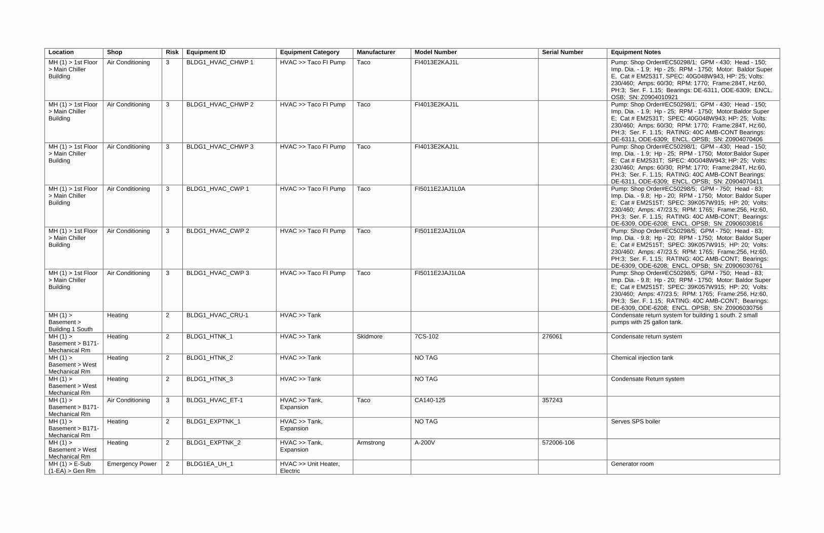
Location Shop Risk Equipment ID Equipment Category Manufacturer Model Number Serial Number Equipment Notes
MH (1) > 1st Floor > Main Chiller Building
Air Conditioning 3 BLDG1_HVAC_CHWP 1 HVAC >> Taco FI Pump Taco FI4013E2KAJ1L Pump: Shop Order#EC50298/1; GPM - 430; Head - 150; Imp. Dia. - 1.9; Hp - 25; RPM - 1750; Motor: Baldor Super E, Cat # EM2531T, SPEC: 40G048W943, HP: 25; Volts: 230/460; Amps: 60/30; RPM: 1770; Frame:284T, Hz:60, PH:3; Ser. F. 1.15; Bearings: DE-6311, ODE-6309; ENCL. OSB; SN: Z0904010921
MH (1) > 1st Floor > Main Chiller Building
Air Conditioning 3 BLDG1_HVAC_CHWP 2 HVAC >> Taco FI Pump Taco FI4013E2KAJ1L Pump: Shop Order#EC50298/1; GPM - 430; Head - 150; Imp. Dia. - 1.9; Hp - 25; RPM - 1750; Motor:Baldor Super E; Cat # EM2531T; SPEC: 40G048W943; HP: 25; Volts: 230/460; Amps: 60/30; RPM: 1770; Frame:284T, Hz:60, PH:3; Ser. F. 1.15; RATING: 40C AMB-CONT Bearings: DE-6311, ODE-6309; ENCL. OPSB; SN: Z0904070406
MH (1) > 1st Floor > Main Chiller Building
Air Conditioning 3 BLDG1_HVAC_CHWP 3 HVAC >> Taco FI Pump Taco FI4013E2KAJ1L Pump: Shop Order#EC50298/1; GPM - 430; Head - 150; Imp. Dia. - 1.9; Hp - 25; RPM - 1750; Motor:Baldor Super E; Cat # EM2531T; SPEC: 40G048W943; HP: 25; Volts: 230/460; Amps: 60/30; RPM: 1770; Frame:284T, Hz:60, PH:3; Ser. F. 1.15; RATING: 40C AMB-CONT Bearings: DE-6311, ODE-6309; ENCL. OPSB; SN: Z0904070411
MH (1) > 1st Floor > Main Chiller Building
Air Conditioning 3 BLDG1_HVAC_CWP 1 HVAC >> Taco FI Pump Taco FI5011E2JAJ1L0A Pump: Shop Order#EC50298/5; GPM - 750; Head - 83; Imp. Dia. - 9.8; Hp - 20; RPM - 1750; Motor: Baldor Super E; Cat # EM2515T; SPEC: 39K057W915; HP: 20; Volts: 230/460; Amps: 47/23.5; RPM: 1765; Frame:256, Hz:60, PH:3; Ser. F. 1.15; RATING: 40C AMB-CONT; Bearings: DE-6309, ODE-6208; ENCL. OPSB; SN: Z0906030816
MH (1) > 1st Floor > Main Chiller Building
Air Conditioning 3 BLDG1_HVAC_CWP 2 HVAC >> Taco FI Pump Taco FI5011E2JAJ1L0A Pump: Shop Order#EC50298/5; GPM - 750; Head - 83; Imp. Dia. - 9.8; Hp - 20; RPM - 1750; Motor: Baldor Super E; Cat # EM2515T; SPEC: 39K057W915; HP: 20; Volts: 230/460; Amps: 47/23.5; RPM: 1765; Frame:256, Hz:60, PH:3; Ser. F. 1.15; RATING: 40C AMB-CONT; Bearings: DE-6309, ODE-6208; ENCL. OPSB; SN: Z0906030761
MH (1) > 1st Floor > Main Chiller Building
Air Conditioning 3 BLDG1_HVAC_CWP 3 HVAC >> Taco FI Pump Taco FI5011E2JAJ1L0A Pump: Shop Order#EC50298/5; GPM - 750; Head - 83; Imp. Dia. - 9.8; Hp - 20; RPM - 1750; Motor: Baldor Super E; Cat # EM2515T; SPEC: 39K057W915; HP: 20; Volts: 230/460; Amps: 47/23.5; RPM: 1765; Frame:256, Hz:60, PH:3; Ser. F. 1.15; RATING: 40C AMB-CONT; Bearings: DE-6309, ODE-6208; ENCL. OPSB; SN: Z0906030756
MH (1) > Basement > Building 1 South
Heating 2 BLDG1_HVAC_CRU-1 HVAC >> Tank Condensate return system for building 1 south. 2 small pumps with 25 gallon tank.
MH (1) > Basement > B171-Mechanical Rm
Heating 2 BLDG1_HTNK_1 HVAC >> Tank Skidmore 7CS-102 276061 Condensate return system
MH (1) > Basement > West Mechanical Rm
Heating 2 BLDG1_HTNK_2 HVAC >> Tank NO TAG Chemical injection tank
MH (1) > Basement > West Mechanical Rm
Heating 2 BLDG1_HTNK_3 HVAC >> Tank NO TAG Condensate Return system
MH (1) > Basement > B171-Mechanical Rm
Air Conditioning 3 BLDG1_HVAC_ET-1 HVAC >> Tank, Expansion
Taco CA140-125 357243
MH (1) > Basement > B171-Mechanical Rm
Heating 2 BLDG1_EXPTNK_1 HVAC >> Tank, Expansion
NO TAG Serves SPS boiler
MH (1) > Basement > West Mechanical Rm
Heating 2 BLDG1_EXPTNK_2 HVAC >> Tank, Expansion
Armstrong A-200V 572006-106
MH (1) > E-Sub (1-EA) > Gen Rm
Emergency Power 2 BLDG1EA_UH_1 HVAC >> Unit Heater, Electric
Generator room

Location Shop Risk Equipment ID Equipment Category Manufacturer Model Number Serial Number Equipment Notes
MH (1) > E-Sub (1-WA) > Gen Rm
Emergency Power 2 BLDG1WA_UH_1 HVAC >> Unit Heater, Electric
Generator room
MH (1) > Building 1 South Attic
Life Safety 1 BLDG1_EXSN_1 Life Safety >> Emergency Exit Signs
MH (1) > Throughout Building
Life Safety 2 BLDG1_EYEW_1 Life Safety >> Eye Wash
MH (1) > 3rd Floor Medical Gas 1 BLDG1_MACMP_Medical Air Medical Gas >> Air Compressor
Beaconmedaes 4107005768 230814-2 LifeLine Medical Systems; 208V; 3PH; 60Hz; 3Hp; System FLA-31A; Main Motor Hp- 3; FLA9.95; Reference Drawing: DIA:02 702 025 A; LSP-3D-SD120-TAY-SPL; 1-800-463-3427
MH (1) > 3rd Floor Medical Gas 1 BLDG1_MGAS_Medical Air Comp-1
Medical Gas >> Air Compressor
Scroll Oil-Less Medical Air, no model or serial numbers.
MH (1) > 3rd Floor Medical Gas 1 BLDG1_MGAS_Medical Air Comp-2
Medical Gas >> Air Compressor
Scroll Oil-Less Medical Air, no model or serial numbers.
MH (1) > 3rd Floor Medical Gas 1 BLDG1_MADRY_Medical Air Dryer-2
Medical Gas >> Lifeline Air Dryer
Lifeline No information, came as package unit
MH (1) > 3rd Floor Medical Gas 1 BLDG1_MVAC_Medical Vac Medical Gas >> Lifeline Vacuum Pump
Lifeline 4107103691 230813-2 200V; 3PH; 60Hz; 3Hp; 31 SYSTEM FLA; 9.6 FLA; REFERENCE DRAWINGS: DIA 02 972 F; LVP-3DS-H120-TA-SPL; BeaconMedaes; 1-800-463-3427
MH (1) > 3rd Floor Medical Gas 1 BLDG1_MVAC_Medical Vac Pump-1
Medical Gas >> Lifeline Vacuum Pump
Beaconmedaes VAC03-002F 2855770 Motor HP- 3; RPM-3600
MH (1) > 3rd Floor Medical Gas 1 BLDG1_MVAC_Medical Vac Pump-2
Medical Gas >> Lifeline Vacuum Pump
Beaconmedaes VAC03-002F 2855771 Motor HP- 3; RPM-3600
MH (1) Medical Gas 1 BLDG1_MVAC_Medical Vac Silencer-1
Medical Gas >> Vacuum Pump Silencer
Universal Silencer US5 1 - 1/2 91886-08 P/N: 1-115-AA
MH (1) Medical Gas 1 BLDG1_MVAC_Medical Vac Silencer-2
Medical Gas >> Vacuum Pump Silencer
Universal Silencer US5 1 - 1/2 91886-08 P/N: 1-115-AA
MH (1) > Basement > West Mechanical Rm
Domestic Hot Water
3 BLDG1_PPMP_1 Plumbing >> Armstrong HWP Pump
Armstrong 3X2X10 C699210 Heating hot water pump
MH (1) > Basement > West Mechanical Rm
Domestic Hot Water
3 BLDG1_PPMP_2 Plumbing >> Armstrong HWP Pump
Armstrong 3X2X10 C689209 Heating hot water pump
MH (1) > Basement > West Mechanical Rm
Domestic Hot Water
3 BLDG1_PPMP_3 Plumbing >> Armstrong HWP Pump
Armstrong 3X2X10 C736040 Heating hot water pump
MH (1) > Basement
Potable Water 2 BLDG1_BFP_1 Plumbing >> BackFlow Preventer
Watts CJ0686 6"
MH (1) Domestic Hot Water
3 BLDG1_DWH_1 Plumbing >> Domestic Hot Water
MH (1) > Basement > West Mechanical Rm
Domestic Hot Water
3 BLDG1_DWH_2 Plumbing >> Water Heater
Constantemp C E6001 Heated by steam. No tank. This is really a heat exchanger but used for DHW.
MH (1) > 3rd Floor Heating 2 BLDG1_SOFT_Water Softener-1
Plumbing >> Water Softener
EF90MM H13-29Z
MH (1) > 3rd Floor > DI Skid
High Purity Water 2 BLDG1_PPMP_DI-P1 Plumbing >> Pump Grundfos A96083919P114470635 0635 Hp- .33; RPM- 3436
MH (1) > 3rd Floor > DI Skid
High Purity Water 2 BLDG1_PPMP_RO Booster P1 Plumbing >> Pump Grundfos 10GBS1515Q4 No other information
MH (1) > 3rd Floor High Purity Water 2 BLDG1_ROSYS_DI Water-1 Plumbing >> RO System Axeon CT-7000P 93838 Axeon; 220V; 3PH; 6.5AMPS; 60HZ; 1-800-320-4074; Pure Flow; Peterborough, NH; (603) 924-4008
MH (1) > 3rd Floor High Purity Water 2 BLDG1_SOFT_Water Softener Controlled 1
Plumbing >> Water Softener
Water Control EF90MM H13-29Z
MH (1) > 3rd Floor High Purity Water 2 BLDG1_SOFT_Water Softener-2
Plumbing >> Water Softener
New Boiler Building (28) > New boiler plant
Emergency Power 1 BLDG28_ATS_1 Electrical >> Automatic Transfer Switch
Asco 7000 POWER TRANSFER SWITCH 670989 Cat no. J7actbb30260n5xc; Life safety for boiler plant

Location Shop Risk Equipment ID Equipment Category Manufacturer Model Number Serial Number Equipment Notes
New Boiler Building (28) > New boiler plant
Emergency Power 1 BLDG28_ATS_2 Electrical >> Automatic Transfer Switch
Asco 7000 POWER TRANSFER SWITCH 670990-001 WE Feeds mcc pumps compressors
New Boiler Building (28) > New boiler plant
Emergency Power 1 BLDG28_ATS_3 Electrical >> Automatic Transfer Switch
Asco 7000 POWER TRANSFER SWITCH 670990-02 WE
New Boiler Building (28) > New boiler plant
Emergency Power 1 BLDG28_BCHRG_1 Electrical >> Battery Charger
Ener Genius By Sens
NRG24-20-RCLS 312657
New Boiler Building (28) > New boiler plant
Emergency Power 1 BLDG28_DTANK_1 Electrical >> Day Tank Preferred Utilities Fuel tank with pumps and containment
New Boiler Building (28) > New boiler plant
Emergency Power 1 BLDG28_EGEN_1 Electrical >> Emergency Generator
Caterpillar LC6 ARRANGEMENT 235-1211 G6B18738 Engine fte00646; Ar no. 286-4922; Has 3 disconnects feed 3 circuits inside building; Has no load bank; 500 kva; 400 kw
New Boiler Building (28) > New boiler plant
Electrical Distribution
2 BLDG28_ELEC_Msb-1 Electrical >> Main Distribution Panel
Square D QED POWER STYLE 28638041-003
New Boiler Building (28) > New Boiler Building
Electrical Distribution
2 BLDG28_MCC_1 Electrical >> Motor Control Center
Square D MODEL 6 28638041-002
New Boiler Building (28) > New Boiler Building
Emergency Power 3 BLDG28_EPNL_1 Electrical >> Panel Square D Distributed Generator AC Utility Disconnect -400amp - 600v switch
New Boiler Building (28) > New Boiler Building
Fire Protection - Alarm & Detection
1 BLDG28_FAS_1 Fire Protection >> Fire Alarm System
New Boiler Building (28) > New Boiler Building
Fire Protection - Suppression
2 BLDG28_FDC_1 Fire Protection >> Fire Department Connection
FDC
New Boiler Building (28) > New Boiler Building
Fire Protection - Suppression
2 BLDG28_FEXT_1 Fire Protection >> Fire Extinguishers
New Boiler Building (28) > New Boiler Building
Fire Protection - Alarm & Detection
1 BLDG28_FPNL_1 Fire Protection >> Panel, Fire
Honeywell NFS-320
New Boiler Building (28) > New Boiler Building
Fire Protection - Suppression
2 BLDG28_FRISR_1 Fire Protection >> Sprinkler Riser
New Boiler Building (28) > New Boiler Building
Air Conditioning 3 BLDG28_ACMP_1 HVAC >> AC Air Compressor
Atlas Copco KT10HD12034 H0P251197 2- 5hp compressor and tank. Provides compressed air to boiler building.
New Boiler Building (28) > New Boiler Building
Air Conditioning 3 BLDG28_ADRY_1 HVAC >> Air Dryer Atlas Copco FX3 CAI532642
New Boiler Building (28) > New boiler plant
Emergency Power 1 BLDG28_DAMP_1 HVAC >> Damper Actuators
Johnson Controls M9220-BAG-3G Damper actuators for 10 dampers when gen runs

Location Shop Risk Equipment ID Equipment Category Manufacturer Model Number Serial Number Equipment Notes
New Boiler Building (28) > 1st Floor > Building 28 (Boilers)
Heating 2 BLDG28_BLR_Boiler NO. 3 HVAC >> Johnston Boiler
Johnston Boiler Company
PFTA250-4LG200S 10892-01 Fire Tube; Main Power-460, PH-3,FREQ-60, AMPS-18.8; Blower Motor-460, PH-3, FREQ-60, AMPS-14, HP-10; Air Comp. Motor-Volts-460, PH-3, FREQ-60, AMPS-4.8, HP-3; Minimum Circuit Ampacity- 22.3 AMPS; Gas- Natural; 9.8M BTU; Fuel Oil- #2; Max Oil Firing Rate-70
New Boiler Building (28) > 1st Floor > Building 28 (Boilers)
Heating 2 BLDG28_BLR_Boiler NO.1 HVAC >> Johnston Boiler
Johnston Boiler Company
PFTA250-4LG200S 10892-03 Fire Tube; Main Power-460, PH-3,FREQ-60, AMPS-18.8; Blower Motor-460, PH-3, FREQ-60, AMPS-14, HP-10; Air Comp. Motor-Volts-460, PH-3, FREQ-60, AMPS-4.8, HP-3; Minimum Circuit Ampacity- 22.3 AMPS; Gas- Natural; 9.8M BTU; Fuel Oil- #2; Max Oil Firing Rate-70
New Boiler Building (28) > 1st Floor > Building 28 (Boilers)
Heating 2 BLDG28_BLR_Boiler NO.2 HVAC >> Johnston Boiler
Johnston Boiler Company
PFTA250-4LG200S 10892-02 Fire Tube; Main Power-460, PH-3,FREQ-60, AMPS-18.8; Blower Motor-460, PH-3, FREQ-60, AMPS-14, HP-10; Air Comp. Motor-Volts-460, PH-3, FREQ-60, AMPS-4.8, HP-3; Minimum Circuit Ampacity- 22.3 AMPS; Gas- Natural; 9.8M BTU; Fuel Oil- #2; Max Oil Firing Rate-70
New Boiler Building (28) > 1st Floor > Building 28
Heating 2 BLDG28_HVAC_Boiler NO.1 LWCO
HVAC >> Low Water Cut-Off
McDonnell & Miller
New Boiler Building (28) > 1st Floor > Building 28
Heating 2 BLDG28_HVAC_Boiler NO.2 LWCO
HVAC >> Low Water Cut-Off
McDonnell & Miller
New Boiler Building (28) > 1st Floor > Building 28
Heating 2 BLDG28_HVAC_Boiler NO.3 LWCO
HVAC >> Low Water Cut-Off
McDonnell & Miller
New Boiler Building (28) > 2nd Floor > Building 28
Air Conditioning 3 BLDG28_HVAC_MAU-1 HVAC >> Make Up Air Unit
York XTI-048X057-HAHA046A CKXMXT0295
New Boiler Building (28) > 2nd Floor > Building 28
Air Conditioning 3 BLDG28_HVAC_MAU-2 HVAC >> Make Up Air Unit
York XTI-048X057-HAHA046A CKXMXT0296
New Boiler Building (28) > 1st Floor > Building 28
Heating 2 BLDG28_HVAC_DA-P1 HVAC >> Pump Grunfos No nameplate data; Industrial Steam; Model#VC35-7L; 53 GPM @ 259 TDH
New Boiler Building (28) > 1st Floor > Building 28
Heating 2 BLDG28_HVAC_DA-P2 HVAC >> Pump Grunfos No nameplate data; Industrial Steam; Model#VC35-7L; 53 GPM @ 259 TDH
New Boiler Building (28) > 1st Floor > Building 28
Heating 2 BLDG28_HVAC_DA-P3 HVAC >> Pump Grunfos No nameplate data; Industrial Steam; Model#VC35-7L; 53 GPM @ 259 TDH
New Boiler Building (28) > Basement > Building 28
Heating 2 BLDG28_HVAC_Surge Tank - P1
HVAC >> Pump Grundfos No nameplate data; Industrial Steam (712) 243-5300; Model#VC70-2; Serial: 24276B; 60 GPM @ 83 TDH
New Boiler Building (28) > Basement > Building 28
Heating 2 BLDG28_HVAC_Surge Tank - P2
HVAC >> Pump Grundfos No nameplate data; Industrial Steam (712) 243-5300; Model#VC70-2; Serial: 24276B; 60 GPM @ 83 TDH
New Boiler Building (28) > New Boiler Building
Air Conditioning 3 BLDG28_SPLIT_1 HVAC >> Split System Daikin RXS36HVJU A001566 Cools electrical room
New Boiler Building (28) > New Boiler Building
Air Conditioning 3 BLDG28_SPLIT_2 HVAC >> Split System Daikin RXS18DVJU E007230 Serves office
New Boiler Building (28) > New boiler plant
Air Conditioning 3 BLDG28_UH_1 HVAC >> Sterling Unit Heater
Sterling HE-108 H1101089262001002 Steam unit heater

Location Shop Risk Equipment ID Equipment Category Manufacturer Model Number Serial Number Equipment Notes
New Boiler Building (28) > New boiler plant
Air Conditioning 3 BLDG28_UH_2 HVAC >> Sterling Unit Heater
Sterling HE-108 H1101089262001002
New Boiler Building (28) > New Boiler Building
Air Conditioning 3 BLDG28_UH_3 HVAC >> Sterling Unit Heater
Sterling HS-072 H1101089262002001 Steam/Hot Water Unit Heater
New Boiler Building (28) > 1st Floor > Building 28
Heating 2 BLDG28_HVAC_DA Tank HVAC >> Tank Wheeler Tank Mfg., Inc.
I1179 No model number; 30 PSIG at 300 deg F; Industrial Steam; Model#6JS5/M/ ; Serial# 24276 A
New Boiler Building (28) > Basement > Building 28
Heating 2 BLDG28_HVAC_Surge Tank HVAC >> Tank Wheeler Tank Mfg., Inc.
11750 Industrial Steam; Model: 6ST; Serial: 24276B
New Boiler Building (28) > 1st Floor > Building 28
Heating 2 BLDG28_VLV_DA-PSV1 HVAC >> Valve Kunkle 6021JHT01-LM Size- 2"; Set- 15 PSIG; Capacity- 2091 LB/HR, L11
New Boiler Building (28) > 1st Floor > Building 28
Heating 2 BLDG28_VLV_DA-PSV2 HVAC >> Valve Kunkle 6021JHT01-LM Size- 2"; Set- 15 PSIG; Capacity- 2091 LB/HR, L11
New Boiler Building (28) > 1st Floor > Building 28
Heating 2 BLDG28_VLV_LP-PSV-1 HVAC >> Valve Conbraco 119-QPDAM-30 12140 Size- 6Q8; Assembled by: Sevco Inc, Winslow, ME; Conbraco, A126 B (this is the number on the body of the PSV)
New Boiler Building (28) > 1st Floor > Building 28
Heating 2 BLDG28_VLV_Turbine - PSV - 2
HVAC >> Valve Kunkle 6010GFM01-AM No serial number; Size- 1-1/4; 794 LB/HR L11; Set- 15 PSIG
New Boiler Building (28) > 1st Floor > Building 28
Heating 2 BLDG28_VLV_Turbine - PSV -1
HVAC >> Valve Kunkle 6010GFM01-AM No serial number; Size- 1-1/4; 794 LB/HR L11; Set- 15 PSIG
New Boiler Building (28) > 2nd Floor > Building 28
Heating 2 BLDG28_VLV_Boiler NO.1 PSV 1
HVAC >> Valve Kunkle Valve 6030JHE01-AM Size 2"; CAP. 7525 lbs. per hour, K15; Set: 100 PSIG; ASME: V; Valve Closer to front of boiler
New Boiler Building (28) > 2nd Floor > Building 28
Heating 2 BLDG28_VLV_Boiler NO.1 PSV 2
HVAC >> Valve Kunkle Valve 6030JHE01-AM Size 2"; CAP. 7855 LB/HR. G16; Set: 105 PSIG; ASME: V; Valve Closer to back of boilers
New Boiler Building (28) > 2nd Floor > Building 28
Heating 2 BLDG28_VLV_Boiler NO.2 PSV 1
HVAC >> Valve Kunkle Valve 6030JHE01-AM Size 2"; CAP. 7525 lbs. per hour, K15; Set: 100 PSIG; ASME: V; Valve Closer to front of boiler
New Boiler Building (28) > 2nd Floor > Building 28
Heating 2 BLDG28_VLV_Boiler NO.2 PSV 2
HVAC >> Valve Kunkle Valve 6030JHE01-AM Size 2"; CAP. 7855 lbs. per hour, G16; Set: 105 PSIG; ASME:V; Valve Closer to back of boiler
New Boiler Building (28) > 2nd Floor > Building 28
Heating 2 BLDG28_VLV_Boiler NO.3 PSV 1
HVAC >> Valve Kunkle Valve 6030JHE01-AM Size 2"; CAP. 7525 lbs. per hour, K15; Set: 100 PSIG; ASME: V; Valve Closer to front of boiler
New Boiler Building (28) > 2nd Floor > Building 28
Heating 2 BLDG28_VLV_Boiler NO.3 SRD 2
HVAC >> Valve Kunkle Valve 6030JHE01-AM Size 2"; CAP. 7855 lbs. per hour, G16; Set: 105 PSIG; ASME:V; Valve Closer to back of boiler
New Boiler Building (28) > 2nd Floor > Building 28
Heating 2 BLDG28_VLV_Steam System PSV
HVAC >> Valve No name plate on pressure safety valve. 3" inlet; 4" outlet; Information (Mold on valve): KVCO; A120 GR A/B; C30804.003.129; HY28. P217

Location Shop Risk Equipment ID Equipment Category Manufacturer Model Number Serial Number Equipment Notes
New Boiler Building (28) > New Boiler Building
Life Safety 1 BLDG28_EXSN_1 Life Safety >> Emergency Exit Signs
New Boiler Building (28) > New Boiler Building
Life Safety 2 BLDG28_EWSS_1 Life Safety >> Eye Wash / Safety Shower
Guardian Located near restroom
New Boiler Building (28) > New Boiler Building
Potable Water 2 BLDG28_BFP_1 Plumbing >> BackFlow Preventer
Watts 312460 2" - For domestic water where enters the building
New Boiler Building (28) > New Boiler Building
Potable Water 2 BLDG28_BFP_2 Plumbing >> BackFlow Preventer
Apollo DC4A 25081 For sprinkler system
New Boiler Building (28) > New Boiler Building
Domestic Hot Water
3 BLDG28_DWH_1 Plumbing >> Water Heater, Electric
Rheem ES120-30-G RR0312E00212 Supplies DHW to new boiler building
New Boiler Building (28) > New Boiler Building
Heating 2 BLDG28_SOFT_1 Plumbing >> Water Softener
Nalco ULTRATREAT Provides a soft water outlet near sink near restroom
N&FS, Psychology Service (5)> Basement > Electrical Rm
Emergency Power 1 BLDG5_ATS_1 Electrical >> Automatic Transfer Switch
Asco 940 110518 Fed from building 12 generator feeds cafeteria
N&FS, Psychology Service (5)> Basement > Electrical Rm
Electrical Distribution
2 BLDG5_ELEC_05-e5-mdp-2 Electrical >> Main Distribution Panel
General Electric
N&FS, Psychology Service (5)> Basement > Electrical Rm
Electrical Distribution
2 BLDG5_ELEC_5mdp Electrical >> Main Distribution Panel
General Electric SPECTRA SERIES
N&FS, Psychology Service (5)> Basement
Refrigeration 2 BLDG5_RCOMP_2 Food Service_Dietary >> Compressor, Refrigeration
N&FS, Psychology Service (5)> Basement
Refrigeration 2 BLDG5_RCOMP_3 Food Service_Dietary >> Compressor, Refrigeration
Serves freezer-1
N&FS, Psychology Service (5)> Basement
Refrigeration 2 BLDG5_RCOMP_4 Food Service_Dietary >> Compressor, Refrigeration
Serves freezer-2
N&FS, Psychology Service (5)> Basement
Refrigeration 2 BLDG5_RCOMP_5 Food Service_Dietary >> Compressor, Refrigeration
Serves freezer-3
N&FS, Psychology Service (5)> Exterior
Refrigeration 2 BLDG5_RCOMP_1 Food Service_Dietary >> Compressor, Refrigeration
For blast cooler . No tag.
N&FS, Psychology Service (5)> Exterior
Refrigeration 2 BLDG5_RCOMP_6 Food Service_Dietary >> Compressor, Refrigeration
Serves freezer-24
N&FS, Psychology Service (5)> Exterior
Refrigeration 2 BLDG5_RCOMP_7 Food Service_Dietary >> Compressor, Refrigeration
Copeland Serves cooler in kitchen
N&FS, Psychology Service (5)> Exterior
Refrigeration 2 BLDG5_RCOMP_8 Food Service_Dietary >> Compressor, Refrigeration
Heatcraft LHT020X6CFM T13J13781 Serves cooler in kitchen

Location Shop Risk Equipment ID Equipment Category Manufacturer Model Number Serial Number Equipment Notes
N&FS, Psychology Service (5)> 1st Floor > Kitchen
Refrigeration 2 BLDG5_FRZR_1 Food Service_Dietary >> Freezer
Traulsen G22010 T36508D13
N&FS, Psychology Service (5)> 1st Floor > Kitchen
Refrigeration 2 BLDG5_RIC_1 Food Service_Dietary >> Reach-In Cooler
True TWT-72 6718110
N&FS, Psychology Service (5)> 1st Floor > Kitchen
Refrigeration 2 BLDG5_FRZR_2 Food Service_Dietary >> Reach-In Freezer
True TWT-27F 1253485
N&FS, Psychology Service (5)> 1st Floor > Kitchen
Refrigeration 2 BLDG5_REFR_REF-3 Food Service_Dietary >> Refrigerator
Aladdin
N&FS, Psychology Service (5)> 1st Floor > Kitchen
Refrigeration 2 BLDG5_REFR_REF-4 Food Service_Dietary >> Refrigerator
Aladdin
N&FS, Psychology Service (5)> 1st Floor > Kitchen
Refrigeration 2 BLDG5_REFR_1 Food Service_Dietary >> Refrigerator
True TG2RRI-2S 5284951
N&FS, Psychology Service (5)> 1st Floor > Kitchen
Refrigeration 2 BLDG5_REFR_2 Food Service_Dietary >> Refrigerator
Traulsen RR1232HUT-FHS T35806J06
N&FS, Psychology Service (5)> 1st Floor > Kitchen
Refrigeration 2 BLDG5_REFR_3 Food Service_Dietary >> Refrigerator
Aladdin Sandwich Unit
N&FS, Psychology Service (5)> 1st Floor > Kitchen
Refrigeration 2 BLDG5_REFR_4 Food Service_Dietary >> Refrigerator
Aladdin Milk Cooler
N&FS, Psychology Service (5)> 1st Floor > Kitchen
Refrigeration 2 BLDG5_REFR_5 Food Service_Dietary >> Refrigerator
Aladdin
N&FS, Psychology Service (5)> 1st Floor > Kitchen
Refrigeration 2 BLDG5_REFR_6 Food Service_Dietary >> Refrigerator
Traulsen RRI232HUT-FHS T45453H10
N&FS, Psychology Service (5)> 1st Floor > Kitchen
Refrigeration 2 BLDG5_REFR_7 Food Service_Dietary >> Refrigerator
Traulsen RRI232HUT-FHS T37891E13
N&FS, Psychology Service (5)> 1st Floor > Kitchen
Refrigeration 2 BLDG5_REFR_8 Food Service_Dietary >> Refrigerator
Traulsen RRI232HUT-FHS T37979E13
N&FS, Psychology Service (5)> 1st Floor > Dining Rm B
Refrigeration 2 BLDG5_REFR_9 Food Service_Dietary >> Refrigerator
True TM-24 5086456
N&FS, Psychology Service (5)> 1st Floor > Kitchen
Refrigeration 2 BLDG5_WIC_Cooler-131A Food Service_Dietary >> Walk-In Cooler
Hobart
N&FS, Psychology Service (5)> 1st Floor > Kitchen
Refrigeration 2 BLDG5_WIC_1 Food Service_Dietary >> Walk-In Cooler
Jamison Glass door cooler
N&FS, Psychology Service (5)> 1st Floor > Kitchen
Refrigeration 2 BLDG5_WIC_2 Food Service_Dietary >> Walk-In Cooler
Hobart Served by compressor 2 in basement
N&FS, Psychology Service (5)> Basement
Refrigeration 2 BLDG5_REFR_Freezer-1 Food Service_Dietary >> Walk-In Freezer
Bangor Cooler Company
N&FS, Psychology Service (5)> Basement
Refrigeration 2 BLDG5_REFR_Freezer-2 Food Service_Dietary >> Walk-In Freezer
Bangor Cooler Company

Location Shop Risk Equipment ID Equipment Category Manufacturer Model Number Serial Number Equipment Notes
N&FS, Psychology Service (5)> Basement
Refrigeration 2 BLDG5_REFR_Freezer-24 Food Service_Dietary >> Walk-In Freezer
Bangor Cooler Company
N&FS, Psychology Service (5)> Basement
Refrigeration 2 BLDG5_REFR_Freezer-3 Food Service_Dietary >> Walk-In Freezer
Bangor Cooler Company
20690
Oxygen Tank Area > Exterior > O2Pressure Reducing Station
Medical Gas 1 OX-TANK_OXY_CV-1 Medical Gas >> Check Valve
Circle Seal Controls
Check Valve; Pat: 2538364; 232B-8PP-.15; 3000 PSIG
Oxygen Tank Area > Exterior > O2Pressure Reducing Station
Medical Gas 1 OX-TANK_OXY_CV-2 Medical Gas >> Check Valve
Circle Seal Controls
Check Valve; Pat: 2538364; 232B-8PP-.15; 3000 psig
Oxygen Tank Area > Exterior > O2 PAD
Medical Gas 1 OX-TANK_OXY_LEVEL INDICATOR (LI-1)
Medical Gas >> Level Indicator
No information on gauge, 6" face; Information off of DP diaphragm that connect to level gauge: 288C-051846; 500 B; 0-200" WC
Oxygen Tank Area > Exterior > O2 Pad
Medical Gas 1 OX-TANK_OXY_Liquid Oxygen Medical Gas >> Oxygen Tank
Process 1625-6 C36378 Nat'l BD Serial#5137; 250 PSIG (MAWP); Year Built-1979; Head Rad-ELLIP.2; Min HD THK.-.343"; She'll THK. .435"
Oxygen Tank Area > Exterior > O2 PAD
Medical Gas 1 OX-TANK_OXY_O2 DP Transmitter-1
Medical Gas >> Oxygen Transmitter
Enders+Hauser 8EQ0039 Order Code-PMD235; Delta P- (-1200 to 1200) inH2O; Pmax-12000 inH2O; 4-4mA Hart; Material- Viton CRNI-STEEL
Oxygen Tank Area > Exterior > O2 PAD
Medical Gas 1 OX-TANK_OXY_O2 Vaporizer Medical Gas >> Oxygen Vaporizer
Cryoquip Inc. VAI-812-FSP 54168-1-9 Rating-1250 SCFH; P/N-4838901-1; Year-2005; BOC:2AH06-9; Fluid-NOA; MAWP-450 PSIG
Oxygen Tank Area > Exterior > O2 PAD
Medical Gas 1 OX-TANK_OXY_O2 Reserve PRV-1
Medical Gas >> Pressure Reducing Valve
Tescom 44-3414S24-626 Max In PSIG -3000; Max Out PSIG- 250; Range on Inlet gauge-0 to 3000 PSIG; Range on Outlet gauge-0 to 400 PSIG
Oxygen Tank Area > Exterior > O2 PAD Pressure Reducing Station
Medical Gas 1 OX-TANK_OXY_PCV-3A Medical Gas >> Pressure Reducing Valve
Generant Co., Inc. P/N: 2GDR-100B-EP-B; Max Inlet Pressure-40PSIG; Outlet Pressure: 50-135; Made in Bulter, NJ
Oxygen Tank Area > Exterior > O2 PAD Pressure Reducing Station
Medical Gas 1 OX-TANK_OXY_PCV-3B Medical Gas >> Pressure Reducing Valve
Generant Co,. Inc P/N: 2GDR-100B-EP-B; Max Inlet Pressure-40PSIG; Outlet Pressure: 50-135; Made in Bulter, NJ
Oxygen Tank Area > Exterior > O2 PAD Pressure Reducing Station
Medical Gas 1 OX-TANK_OXY_PCV-3C Medical Gas >> Pressure Reducing Valve
Generant Co., Inc. P/N: 2GDR-100B-EP-B; Max Inlet Pressure-40PSIG; Outlet Pressure: 50-135; Made in Bulter, NJ
Oxygen Tank Area > Exterior > O2 PAD Pressure Reducing Station
Medical Gas 1 OX-TANK_OXY_PCV-3D Medical Gas >> Pressure Reducing Valve
Generant Co,. Inc P/N: 2GDR-100B-EP-B; Max Inlet Pressure-40PSIG; Outlet Pressure: 50-135; Made in Bulter, NJ
Oxygen Tank Area > Exterior > O2 PAD Pressure Reducing Station
Medical Gas 1 OX-TANK_OXY_PI-3A Medical Gas >> Pressure Reducing Valve
Boc Range-0 to 200 PSIG; 2" face
Oxygen Tank Area > Exterior > O2 PAD Pressure Reducing Station
Medical Gas 1 OX-TANK_OXY_PI-3B Medical Gas >> Pressure Reducing Valve
Boc Range-0 to 100 PSIG; 2" face
Oxygen Tank Area > Exterior > O2 PAD Pressure Reducing Station
Medical Gas 1 OX-TANK_OXY_PI-3C Medical Gas >> Pressure Reducing Valve
Boc Range-0 to 100 PSIG; 2" face

Location Shop Risk Equipment ID Equipment Category Manufacturer Model Number Serial Number Equipment Notes
Oxygen Tank Area > Exterior > O2 PAD Pressure Reducing Station
Medical Gas 1 OX-TANK_OXY_PI-3D Medical Gas >> Pressure Reducing Valve
Boc Range-0 to 100 PSIG; 2" face
Oxygen Tank Area > Exterior > O2 PAD Pressure Reducing Station
Medical Gas 1 OX-TANK_OXY_PCV Medical Gas >> Safety Valve
Cash Valve 10673 GH Type-FRM2; MAWP: 40 PSIG; Range:75 to 150 PSIG; Set-125
Oxygen Tank Area > Exterior > O2 PAD Pressure Reducing Station
Medical Gas 1 OX-TANK_OXY_PSV-3 Medical Gas >> Safety Valve
Spence Eng Co. 710NDEG-A Rockwood Swendeman ; Size-1x1-1/2; Type-RXSO; SCFM-456; YR-TH; SET-75 PSIG; SEAT DIA.-1.5; CRN-0G0591.9C; Phone of manufacture:845-778-5566
Oxygen Tank Area > Exterior > O2 PAD Pressure Reducing Station
Medical Gas 1 OX-TANK_OXY_PSV-4 Medical Gas >> Safety Valve
Spence Eng Co. 710NDEG-A Rockwood Swendeman ; Size-1x1-1/2; Type-RXSO; SCFM-456; YR-TH; SET-75 PSIG; SEAT DIA.-1.5; CRN-0G0591.9C; Phone of manufacture:845-778-5566
Oxygen Tank Area > Exterior > O2 Pad
Medical Gas 1 OX-TANK_OXY_SV-1 (PSV-1) Medical Gas >> Safety Valve
Spence Eng. Co. 710NADE-A250 Size-3/4x1; Type-RXSO; SCFM-378; Set-250; Seat Dia.- .750; CRN-0G0591.9C; Both valves are named the same SV-1
Oxygen Tank Area > Exterior > O2 Pad
Medical Gas 1 OX-TANK_OXY_SV-2 (PSV-2) Medical Gas >> Safety Valve
Spence Eng. Co. 710NADE-A Size-3/4x1; Type-RXSO; SCFM-378; Set-250; Seat Dia.- .750; CRN-0G0591.9C; YR-8N; Both valves are named the same SV-1
Oxygen Tank Area > Exterior > O2 PAD Pressure Reducing Station
Medical Gas 1 OX-TANK_OXY_SWV-1 Medical Gas >> Safety Valve
Generant Co., Inc. CRV-500B-K-280-PSI; (2 safeties here)
Oxygen Tank Area > Exterior > O2 PAD Pressure Reducing Station
Medical Gas 1 OX-TANK_OXY_SWV-2 Medical Gas >> Safety Valve
Generant Co., Inc. CRV-500B-K-280-PSI; (2 safeties here)
Oxygen Tank Area > Exterior > O2 Reserve Station
Medical Gas 1 OX-TANK_OXY_SWV-Reserve Medical Gas >> Safety Valve
Generant Co., Inc. CRV-500B-K-280-PSI; (2 safeties here)
Oxygen Tank Area > Exterior > O2 PAD
Medical Gas 1 OX-TANK_OXY_Vaporizer Outlet Valve Actuator-1
Medical Gas >> Valve Actuator
Flowserve 1575 W 120A L788354 Stall Torque-325 in-lbs; Volts/AMPS/HZ- 120/.7/60; Speed Sec/90-5.0; Duty%-20%; Max Amb Temp-115F; No positioner model number
Psych Ward (4) > Front elevator
Vertical Transport 2 BLDG4_ELEV_1 Conveying >> Elevator, Hydraulic
Hydraulic elevator
Psych Ward (4) > Back elevator
Vertical Transport 2 BLDG4_ELEV_2 Conveying >> Elevator, Traction
Traction elevator
Psych Ward (4) > E-Sub (4A) > Emerg SWGR Rm
Emergency Power 1 BLDG4_ELEC_ATS-5 Electrical >> Automatic Transfer Switch
General Electric ZENITH ZTS Ats with built
Psych Ward (4) > E-Sub (4A) > Emerg SWGR Rm
Emergency Power 1 BLDG4_ELEC_CB ATS #2 Electrical >> Automatic Transfer Switch
Kohler 472048001-14
Psych Ward (4) > E-Sub (4A) > Emerg SWGR Rm
Emergency Power 1 BLDG4_ELEC_EB ATS #3 Electrical >> Automatic Transfer Switch
Kohler 472047001-04
Psych Ward (4) > E-Sub (4A) > Emerg SWGR Rm
Emergency Power 1 BLDG4_ELEC_LS ATS 1 Electrical >> Automatic Transfer Switch
Kohler 472048001-08
Psych Ward (4) > E-Sub (4A) > Gen Rm
Emergency Power 1 BLDG4_BCHRG_1 Electrical >> Battery Charger
Kohler C-292865 Charges generator batteries; Solar on 8g8d/t975 (2)
Psych Ward (4) > E-Sub (4A) > Gen Rm
Emergency Power 1 BLDG4_DTANK_1 Electrical >> Day Tank Kohler Fuel pump system day tank system

Location Shop Risk Equipment ID Equipment Category Manufacturer Model Number Serial Number Equipment Notes
Psych Ward (4) > E-Sub (4A) > Gen Rm
Emergency Power 1 BLDG4_EGEN_Bldg 4 gen Electrical >> Emergency Generator
Kohler 400R0Z81 304478 Same setup as 6 and 12, load bank, fuel system, fuel tank
Psych Ward (4) > E-Sub (4A) > Gen Rm
Emergency Power 2 BLDG4_FTPNL_1 Electrical >> Fuel Tank Monitoring Panel
Veeder-Root PLUS TONS 351 Fuel tank monitoring panel
Psych Ward (4) > E-Sub (4A) > Gen Rm
Emergency Power 1 BLDG4_GENSGR_1 Electrical >> Generator Control Switchgear
Kohler GENERATOR CONTROL SWITCHGEAR
Psych Ward (4) > E-Sub (4A) > Gen Rm
Emergency Power 2 BLDG4_LDBNK_1 Electrical >> Load Bank Kohler
Psych Ward (4) > E-Sub (4A) > Gen Rm
Emergency Power 2 BLDG4_LBSGR_1 Electrical >> Loadbank Control Switchgear
Simplx LOADBANK CONTROL SWITCHGEAR Radiator airflow cooled resistive Loadbank lbd series
Psych Ward (4) > E-Sub (4A) > Normal SWGR Rm
Emergency Power 2 BLDG4_ELEC_4A-MDP Electrical >> Main Distribution Panel
Siemens FC-I Incoming fed from transformer outside
Psych Ward (4) > E-Sub (4A) > Emerg SWGR Rm
Emergency Power 2 BLDG4_ELEC_E4A MDP Electrical >> Main Distribution Panel
Siemens FC-I Feeds 3 ats
Psych Ward (4) > SB-1
Electrical Distribution
2 BLDG4_ELEC_4-MDP Electrical >> Main Distribution Panel
Psych Ward (4) > E-Sub (4A) > Emerg SWGR Rm
Emergency Power 3 BLDG4_EPNL_E4A-CB Electrical >> Panel Siemens SO-17-15888-F00 CAT-S4C60ML400ATS
120/208-400A - Emergency Panel
Psych Ward (4) > E-Sub (4A) > Emerg SWGR Rm
Emergency Power 3 BLDG4_EPNL_E4A-EB Electrical >> Panel Siemens SO-17-15888-F00 CAT-S4C60ML400ATS
120/208-400A - Emergency Panel
Psych Ward (4) > E-Sub (4A) > Emerg SWGR Rm
Emergency Power 3 BLDG4_EPNL_E4A-LESH Electrical >> Panel Siemens TYPE S1 Fed from LS Panel (E1WA-LS). Feeds Battery Charger, Dampers, Fire Alarm, and Generator
Psych Ward (4) > E-Sub (4A) > Emerg SWGR Rm
Emergency Power 3 BLDG4_EPNL_E4A-LS Electrical >> Panel Siemens SO-17-15888-F00 CAT-S4C60ML400ATS
120/208-400A - Emergency Panel
Psych Ward (4) > E-Sub (4A) > Normal SWGR Rm
Emergency Power 3 BLDG4_EPNL_1 Electrical >> Panel Siemens CAT FCI
Psych Ward (4) > E-Sub (4A) > Normal SWGR Rm
Emergency Power 3 BLDG4_EPNL_2 Electrical >> Panel Siemens CAT FCI
Psych Ward (4) > E-Sub (4A) > Normal SWGR Rm
Emergency Power 3 BLDG4_EPNL_3 Electrical >> Panel Siemens CAT FCI
Psych Ward (4) > E-Sub (4A) > Normal SWGR Rm
Emergency Power 3 BLDG4_EPNL_4 Electrical >> Panel Siemens CAT FCI Picture of trip setting wheels
Psych Ward (4) > N106
Electrical Distribution
3 BLDG4_EPNL_4-100 Electrical >> Panel
Psych Ward (4) > CORRIDOR N101
Electrical Distribution
3 BLDG4_EPNL_4-101-LS Electrical >> Panel
Psych Ward (4) > S110A
Electrical Distribution
3 BLDG4_EPNL_4-102 Electrical >> Panel
Psych Ward (4) > S110A
Electrical Distribution
3 BLDG4_EPNL_4-103 Electrical >> Panel

Location Shop Risk Equipment ID Equipment Category Manufacturer Model Number Serial Number Equipment Notes
Psych Ward (4) > S110A
Electrical Distribution
3 BLDG4_EPNL_4-105 Electrical >> Panel
Psych Ward (4) > ATTIC
Electrical Distribution
3 BLDG4_EPNL_4-300 Electrical >> Panel
Psych Ward (4) > BN1
Electrical Distribution
3 BLDG4_EPNL_4-B1 Electrical >> Panel
Psych Ward (4) > N103
Electrical Distribution
3 BLDG4_EPNL_E4-100 Electrical >> Panel
Psych Ward (4) > 240A
Electrical Distribution
3 BLDG4_EPNL_E4-200 Electrical >> Panel
Psych Ward (4) > 240A
Electrical Distribution
3 BLDG4_EPNL_E4-205 Electrical >> Panel
Psych Ward (4) > E4-CB
Electrical Distribution
3 BLDG4_EPNL_E4-CB Electrical >> Panel
Psych Ward (4) > S110A
Electrical Distribution
3 BLDG4_EPNL_E4-CB1 Electrical >> Panel
Psych Ward (4) > SB-1
Electrical Distribution
3 BLDG4_EPNL_E4-EB Electrical >> Panel
Psych Ward (4) > BS4
Electrical Distribution
3 BLDG4_EPNL_E4-EB1 Electrical >> Panel
Psych Ward (4) > SB-1
Electrical Distribution
3 BLDG4_EPNL_E4-LS Electrical >> Panel
Psych Ward (4) > S110A
Electrical Distribution
3 BLDG4_EPNL_E4-LS1 Electrical >> Panel
Psych Ward (4) > 2ND FLOOR CORR.
Electrical Distribution
3 BLDG4_EPNL_ECB4-200 Electrical >> Panel
Psych Ward (4) > 2ND FLOOR CORR.
Electrical Distribution
3 BLDG4_EPNL_ECB4-201 Electrical >> Panel
Psych Ward (4) > 2ND FLOOR CORR.
Electrical Distribution
3 BLDG4_EPNL_ECB4-202 Electrical >> Panel
Psych Ward (4) > 2ND FLOOR CORR.
Electrical Distribution
3 BLDG4_EPNL_ECB4-203 Electrical >> Panel
Psych Ward (4) > CORR. ACROSS FROM 210
Electrical Distribution
3 BLDG4_EPNL_ECB4-204 Electrical >> Panel
Psych Ward (4) > E-Sub (4A) > Gen Rm
Emergency Power 1 BLDG4_FTANK_1 Electrical >> Tank, Fuel In ground fuel tank 2500
Psych Ward (4) > 2nd Floor > Rm 238
Fire Protection - Suppression
1 BLDG4_FCOMP_1 Fire Protection >> Compressor
Jenny K F020211010
Psych Ward (4) > Throughout Building
Fire Protection - Alarm & Detection
1 BLDG4_FAS_1 Fire Protection >> Fire Alarm System
Psych Ward (4) > Outside
Fire Protection - Suppression
2 BLDG4_FDC_1 Fire Protection >> Fire Department Connection
FDC
Psych Ward (4) > Throughout Building
Fire Protection - Suppression
2 BLDG4_FEXT_1 Fire Protection >> Fire Extinguishers
Psych Ward (4) > Outside
Fire Protection - Suppression
2 BLDG4_FHYD_1 Fire Protection >> Fire Hydrant
Psych Ward (4) > 1st Floor > Main Entrance
Fire Protection - Alarm & Detection
1 BLDG4_FPNL_1 Fire Protection >> Panel, Fire
Honeywell
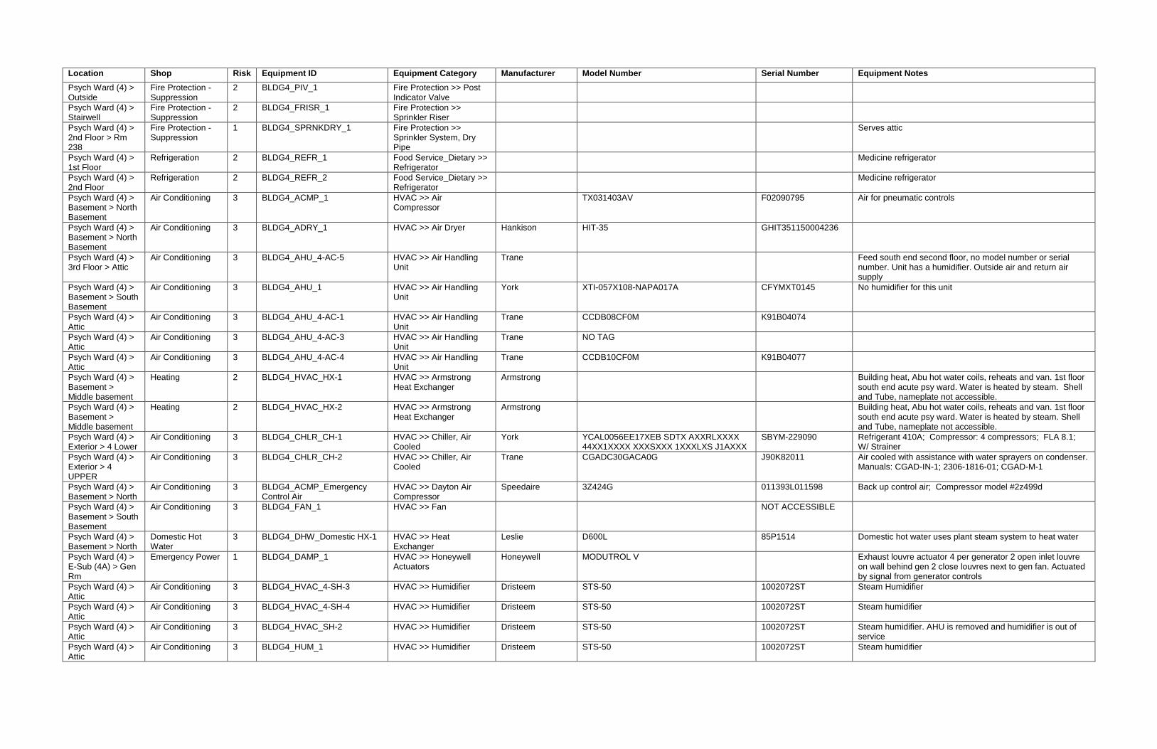
Location Shop Risk Equipment ID Equipment Category Manufacturer Model Number Serial Number Equipment Notes
Psych Ward (4) > Outside
Fire Protection - Suppression
2 BLDG4_PIV_1 Fire Protection >> Post Indicator Valve
Psych Ward (4) > Stairwell
Fire Protection - Suppression
2 BLDG4_FRISR_1 Fire Protection >> Sprinkler Riser
Psych Ward (4) > 2nd Floor > Rm 238
Fire Protection - Suppression
1 BLDG4_SPRNKDRY_1 Fire Protection >> Sprinkler System, Dry Pipe
Serves attic
Psych Ward (4) > 1st Floor
Refrigeration 2 BLDG4_REFR_1 Food Service_Dietary >> Refrigerator
Medicine refrigerator
Psych Ward (4) > 2nd Floor
Refrigeration 2 BLDG4_REFR_2 Food Service_Dietary >> Refrigerator
Medicine refrigerator
Psych Ward (4) > Basement > North Basement
Air Conditioning 3 BLDG4_ACMP_1 HVAC >> Air Compressor
TX031403AV F02090795 Air for pneumatic controls
Psych Ward (4) > Basement > North Basement
Air Conditioning 3 BLDG4_ADRY_1 HVAC >> Air Dryer Hankison HIT-35 GHIT351150004236
Psych Ward (4) > 3rd Floor > Attic
Air Conditioning 3 BLDG4_AHU_4-AC-5 HVAC >> Air Handling Unit
Trane Feed south end second floor, no model number or serial number. Unit has a humidifier. Outside air and return air supply
Psych Ward (4) > Basement > South Basement
Air Conditioning 3 BLDG4_AHU_1 HVAC >> Air Handling Unit
York XTI-057X108-NAPA017A CFYMXT0145 No humidifier for this unit
Psych Ward (4) > Attic
Air Conditioning 3 BLDG4_AHU_4-AC-1 HVAC >> Air Handling Unit
Trane CCDB08CF0M K91B04074
Psych Ward (4) > Attic
Air Conditioning 3 BLDG4_AHU_4-AC-3 HVAC >> Air Handling Unit
Trane NO TAG
Psych Ward (4) > Attic
Air Conditioning 3 BLDG4_AHU_4-AC-4 HVAC >> Air Handling Unit
Trane CCDB10CF0M K91B04077
Psych Ward (4) > Basement > Middle basement
Heating 2 BLDG4_HVAC_HX-1 HVAC >> Armstrong Heat Exchanger
Armstrong Building heat, Abu hot water coils, reheats and van. 1st floor south end acute psy ward. Water is heated by steam. Shell and Tube, nameplate not accessible.
Psych Ward (4) > Basement > Middle basement
Heating 2 BLDG4_HVAC_HX-2 HVAC >> Armstrong Heat Exchanger
Armstrong Building heat, Abu hot water coils, reheats and van. 1st floor south end acute psy ward. Water is heated by steam. Shell and Tube, nameplate not accessible.
Psych Ward (4) > Exterior > 4 Lower
Air Conditioning 3 BLDG4_CHLR_CH-1 HVAC >> Chiller, Air Cooled
York YCAL0056EE17XEB SDTX AXXRLXXXX 44XX1XXXX XXXSXXX 1XXXLXS J1AXXX
SBYM-229090 Refrigerant 410A; Compressor: 4 compressors; FLA 8.1; W/ Strainer
Psych Ward (4) > Exterior > 4 UPPER
Air Conditioning 3 BLDG4_CHLR_CH-2 HVAC >> Chiller, Air Cooled
Trane CGADC30GACA0G J90K82011 Air cooled with assistance with water sprayers on condenser. Manuals: CGAD-IN-1; 2306-1816-01; CGAD-M-1
Psych Ward (4) > Basement > North
Air Conditioning 3 BLDG4_ACMP_Emergency Control Air
HVAC >> Dayton Air Compressor
Speedaire 3Z424G 011393L011598 Back up control air; Compressor model #2z499d
Psych Ward (4) > Basement > South Basement
Air Conditioning 3 BLDG4_FAN_1 HVAC >> Fan NOT ACCESSIBLE
Psych Ward (4) > Basement > North
Domestic Hot Water
3 BLDG4_DHW_Domestic HX-1 HVAC >> Heat Exchanger
Leslie D600L 85P1514 Domestic hot water uses plant steam system to heat water
Psych Ward (4) > E-Sub (4A) > Gen Rm
Emergency Power 1 BLDG4_DAMP_1 HVAC >> Honeywell Actuators
Honeywell MODUTROL V Exhaust louvre actuator 4 per generator 2 open inlet louvre on wall behind gen 2 close louvres next to gen fan. Actuated by signal from generator controls
Psych Ward (4) > Attic
Air Conditioning 3 BLDG4_HVAC_4-SH-3 HVAC >> Humidifier Dristeem STS-50 1002072ST Steam Humidifier
Psych Ward (4) > Attic
Air Conditioning 3 BLDG4_HVAC_4-SH-4 HVAC >> Humidifier Dristeem STS-50 1002072ST Steam humidifier
Psych Ward (4) > Attic
Air Conditioning 3 BLDG4_HVAC_SH-2 HVAC >> Humidifier Dristeem STS-50 1002072ST Steam humidifier. AHU is removed and humidifier is out of service
Psych Ward (4) > Attic
Air Conditioning 3 BLDG4_HUM_1 HVAC >> Humidifier Dristeem STS-50 1002072ST Steam humidifier

Location Shop Risk Equipment ID Equipment Category Manufacturer Model Number Serial Number Equipment Notes
Psych Ward (4) > Basement > Middle Psych Ward (4)
Air Conditioning 3 BLDG4_HVAC_CHWP-1 HVAC >> Pump, Vertical Inline
Armstrong 2X2X10 4380 712220 Pump: 130 GPM; HEAD: 85 ft; Motor: HP: 7.5; RPM: 1800; Frame: 213JP; SF: 1.25; Volts: 239/460; Amps: 18.0/9.00; Hz: 60; Duty: CONT; ENCL: TEFC; Model# 00718ET3E213JP-W22; Serial# 28UN12Z000292526; Triple duty valve
Psych Ward (4) > Basement > Middle Psych Ward (4)
Air Conditioning 3 BLDG4_HVAC_CHWP-2 HVAC >> Pump, Vertical Inline
Armstrong 2X2X10 4380 712221 Pump: 130 GPM; HEAD: 85 ft; Motor: HP: 7.5; RPM: 1800; Frame: 213JP; SF: 1.25; Volts: 239/460; Amps: 18.0/9.00; Hz: 60; Duty: CONT; ENCL: TEFC; Model# 00718ET3E213JP-W22; Serial# 28UN12Z000292516; Triple duty valve
Psych Ward (4) > Basement > Middle Basement
Heating 2 BLDG4_HVAC_HWP-1 HVAC >> Pump, Vertical Inline
Taco For Building heat no model number or serial number.
Psych Ward (4) > Basement > Middle Basement
Heating 2 BLDG4_HVAC_HWP-2 HVAC >> Pump, Vertical Inline
Taco For Building heat no model number or serial number.
Psych Ward (4) > Basement > 4 UPPER
Heating 2 BLDG4_HVAC_CP 4-P-1 HVAC >> Taco FM Pump Taco FM1207 5.75 B2D1A1L0 Baldor SuperE Motor; Cat #EM3212T-8; SER: F290; Frame - 182T; HP - 5; Volts 200; RPM 3500; Hz 60, PH 3; SF 1.15; Rating: AMB-CONT; SPEC: 36F256W988; PU BRG: 6206; FR. BRG6205; Triple duty valve
Psych Ward (4) > Basement > 4 UPPER
Heating 2 BLDG4_HVAC_CP 4-P-2 HVAC >> Taco FM Pump Taco FM1207 5.75 B2D1A1L0 Baldor SuperE Motor; Cat #EM3212T-8; SER: F290; Frame - 182T; HP - 5; Volts 200; RPM 3500; Hz 60, PH 3; SF 1.15; Rating: AMB-CONT; SPEC: 36F256W988; PU BRG: 6206; FR. BRG6205; Triple duty valve
Psych Ward (4) > Basement > 4 UPPER
Heating 2 BLDG4_HVAC_CP 4-P-3 HVAC >> Taco FM Pump Taco FM1207 5.75 B2D1A1L0 Baldor SuperE Motor; Cat #EM3212T-8; SER: F290; Frame - 182T; HP - 5; Volts 200; RPM 3500; Hz 60, PH 3; SF 1.15; Rating: AMB-CONT; SPEC: 36F256W988; PU BRG: 6206; FR. BRG6205; Triple duty valve
Psych Ward (4) > Basement > North Basement
Heating 2 BLDG4_HVAC_Condensate Receiver Tank
HVAC >> Tank Quality Pump Equipment & Engineering
1282-190 No model number on unit, condensate return from steam system.
Psych Ward (4) > Basement > South Basement
Heating 2 BLDG4_HTNK_1 HVAC >> Tank Shipco Pumps 63ECCD 59020 Condensate Return Unit
Psych Ward (4) > E-Sub (4A) > Gen Rm
Emergency Power 2 BLDG4_UH_1 HVAC >> Unit Heater, Electric
Generator room
Psych Ward (4) Domestic Hot Water
3 BLDG4_DWH_1 Plumbing >> Domestic Hot Water
Psych Ward (4) > Basement
Domestic Hot Water
3 BLDG4_HWPMP_1 Plumbing >> Pump Bell & Gossett Series PR AB 102208LF DHW pumps
Psych Ward (4) > Basement
Domestic Hot Water
3 BLDG4_HWPMP_2 Plumbing >> Pump Bell & Gossett Series PR AB 102208LF DHW Pump
Psych Ward (4) > Basement > Middle basement
Domestic Hot Water
3 BLDG4_DWH_2 Plumbing >> Water Heater
Mixing valves for DHW
Soldier - On (6) Emergency Power 1 BLDG6_ELEC_CB ATS #2 Electrical >> Automatic Transfer Switch
Kohler
Soldier - On (6) Emergency Power 1 BLDG6_ELEC_EB ATS #3 Electrical >> Automatic Transfer Switch
Kohler
Soldier - On (6) Emergency Power 1 BLDG6_ELEC_LS ATS 1 Electrical >> Automatic Transfer Switch
Kohler
Soldier - On (6) Emergency Power 1 BLDG6_BCHRG_1 Electrical >> Battery Charger
Kohler C-292865 Charges generator batteries; Solar on 8g8d/t975 (2)
Soldier - On (6) Emergency Power 1 BLDG6_DTANK_1 Electrical >> Day Tank Kohler SYSTEM 2000 PLUS EXM
Fuel pump system day tank system
Soldier - On (6) Emergency Power 1 BLDG6_EGEN_Bldg 6a Electrical >> Emergency Generator
Kohler 400R0Z81 304479 300 kW 375 kva 1042 amp 120/208; Same load bank switchgear and fuel pump day tank as b 12
Soldier - On (6) Emergency Power 1 BLDG6_FTPNL_1 Electrical >> Fuel Tank Monitoring Panel
Veeder-Root PLUS TONS 351 304476 Fuel tank monitoring panel

Location Shop Risk Equipment ID Equipment Category Manufacturer Model Number Serial Number Equipment Notes
Soldier - On (6) Emergency Power 1 BLDG6_GENSGR_1 Electrical >> Generator Control Switchgear
Kohler GENERATOR CONTROL SWITCHGEAR
Soldier - On (6) Emergency Power 2 BLDG6_LDBNK_1 Electrical >> Load Bank Kohler
Soldier - On (6) Emergency Power 2 BLDG6_LBSGR_1 Electrical >> Loadbank Control Switchgear
Simplx LOADBANK CONTROL SWITCHGEAR 20417-95-42/4 Radiator airflow cooled resistive Loadbank lbd series
Soldier - On (6) Emergency Power 1 BLDG6_FTANK_1 Electrical >> Tank, Fuel In ground fuel tank 2500
Soldier - On (6) Emergency Power 1 BLDG6_DAMP_1 HVAC >> Honeywell Actuators
Honeywell MODUTROL V M9174D1007 Exhaust louvre actuator 4 per generator 2 open inlet louvre on wall behind gen 2 close louvres next to gen fan. Actuated by signal from generator controls
Soldier - On (6) Emergency Power 2 BLDG6_UH_1 HVAC >> Unit Heater, Electric
Generator room
Ward 8 / PTSD Unit (8) > E-Sub (8A) > Emerg SWGR Rm
Emergency Power 1 BLDG8_ELEC_CB ATS #2 Electrical >> Automatic Transfer Switch
Kohler Fed from Building 6 Generator
Ward 8 / PTSD Unit (8) > E-Sub (8A) > Emerg SWGR Rm
Emergency Power 1 BLDG8_ELEC_EB ATS #3 Electrical >> Automatic Transfer Switch
Kohler Fed from Building 6 Generator
Ward 8 / PTSD Unit (8) > E-Sub (8A) > Emerg SWGR Rm
Emergency Power 1 BLDG8_ELEC_LS ATS 1 Electrical >> Automatic Transfer Switch
Kohler Fed from Building 6 Generator
Ward 8 / PTSD Unit (8) > E-Sub (8A) > Normal SWGR Rm
Emergency Power 2 BLDG8_ELEC_8-MDP Electrical >> Main Distribution Panel
Siemens FC-I SO 18-50957-CO4
Ward 8 / PTSD Unit (8) > E-Sub (8A) > Emerg SWGR Rm
Emergency Power 3 BLDG8_EPNL_E8A-CB Electrical >> Panel Siemens CAT S4C60ML400ATS
Ward 8 / PTSD Unit (8) > E-Sub (8A) > Emerg SWGR Rm
Emergency Power 3 BLDG8_EPNL_E8A-EB Electrical >> Panel Siemens CAT S4C60ML400ATS
Ward 8 / PTSD Unit (8) > E-Sub (8A) > Emerg SWGR Rm
Emergency Power 3 BLDG8_EPNL_E8A-LS Electrical >> Panel Siemens CAT S4C60ML400ATS
Ward 8 / PTSD Unit (8) > PC 110
Electrical Distribution
3 BLDG8_EPNL_8-100 Electrical >> Panel
Ward 8 / PTSD Unit (8) > TC-109
Electrical Distribution
3 BLDG8_EPNL_8-101 Electrical >> Panel
Ward 8 / PTSD Unit (8) > STAIR
Electrical Distribution
3 BLDG8_EPNL_8-102 Electrical >> Panel
Ward 8 / PTSD Unit (8) > 208
Electrical Distribution
3 BLDG8_EPNL_8-200 Electrical >> Panel
Ward 8 / PTSD Unit (8) > CORR
Electrical Distribution
3 BLDG8_EPNL_8-201 Electrical >> Panel
Ward 8 / PTSD Unit (8) > 116
Electrical Distribution
3 BLDG8_EPNL_E8-100 Electrical >> Panel
Ward 8 / PTSD Unit (8) > 103
Electrical Distribution
3 BLDG8_EPNL_E8-101 Electrical >> Panel
Ward 8 / PTSD Unit (8) > 209
Electrical Distribution
3 BLDG8_EPNL_E8-200 Electrical >> Panel
Ward 8 / PTSD Unit (8) > EMER. RM.
Electrical Distribution
3 BLDG8_EPNL_E8A-LESH Electrical >> Panel

Location Shop Risk Equipment ID Equipment Category Manufacturer Model Number Serial Number Equipment Notes
Ward 8 / PTSD Unit (8) > B1C-8
Electrical Distribution
3 BLDG8_EPNL_E8-CB Electrical >> Panel
Ward 8 / PTSD Unit (8) > B1C-8
Electrical Distribution
3 BLDG8_EPNL_E8-EB Electrical >> Panel
Ward 8 / PTSD Unit (8) > B1C-8
Electrical Distribution
3 BLDG8_EPNL_E8-LS Electrical >> Panel
Ward 8 / PTSD Unit (8) > Outside
Fire Protection - Suppression
2 BLDG8_FDC_1 Fire Protection >> Fire Department Connection
FDC
Ward 8 / PTSD Unit (8) > Outside
Fire Protection - Suppression
2 BLDG8_FHYD_1 Fire Protection >> Fire Hydrant
Ward 8 / PTSD Unit (8) > Outside
Fire Protection - Suppression
2 BLDG8_PIV_1 Fire Protection >> Post Indicator Valve
Ward 8 / PTSD Unit (8)
Refrigeration 2 BLDG8_REFR_1 Food Service_Dietary >> Refrigerator
Medicine refrigerator
Ward 8 / PTSD Unit (8) > Basement
Domestic Hot Water
3 BLDG8_HX_1 HVAC >> Heat Exchanger
Leslie E-3001 LB For DHW
Ward 8 / PTSD Unit (8) > Basement
Heating 2 BLDG8_HTNK_1 HVAC >> Tank CRVD1525-2BCI Condensate return unit
Directors Office (12)
Emergency Power 1 BLDG12_ELEC_CB ATS #2 Electrical >> Automatic Transfer Switch
Kohler 472408001-02 Elec-0372
Directors Office (12)
Emergency Power 1 BLDG12_ELEC_EB ATS #3 Electrical >> Automatic Transfer Switch
Kohler 358564001-03 0373
Directors Office (12)
Emergency Power 1 BLDG12_ELEC_LS ATS 1 Electrical >> Automatic Transfer Switch
Kohler 47240800-01
Directors Office (12)
Emergency Power 1 BLDG12_BCHRG_1 Electrical >> Battery Charger
Kohler C-292865 Charges generator batteries; Solar on 8g8d/t975 (2)
Directors Office (12)
Emergency Power 1 BLDG12_DTANK_1 Electrical >> Day Tank Kohler SYSTEM 2000 PLUS EXM
Fuel pump system day tank system
Directors Office (12)
Emergency Power 1 BLDG12_EGEN_Building 12 Electrical >> Emergency Generator
Kohler 400R0Z81 304475
Directors Office (12)
Emergency Power 1 BLDG12_FTPNL_1 Electrical >> Fuel Tank Monitoring Panel
Veeder-Root PLUS TONS 351 304476 Fuel tank monitoring panel
Directors Office (12)
Emergency Power 1 BLDG12_GENSGR_1 Electrical >> Generator Control Switchgear
Kohler GENERATOR CONTROL SWITCHGEAR
Directors Office (12)
Emergency Power 2 BLDG12_LDBNK_1 Electrical >> Load Bank Kohler
Directors Office (12)
Emergency Power 2 BLDG12_LBSGR_1 Electrical >> Loadbank Control Switchgear
Simplex LOADBANK CONTROL SWITCHGEAR 20417-95-42/4 Radiator airflow cooled resistive Loadbank lbd series
Directors Office (12)
Emergency Power 1 BLDG12_FTANK_1 Electrical >> Tank, Fuel In ground fuel tank 2500
Directors Office (12)
Emergency Power 1 BLDG12_DAMP_1 HVAC >> Honeywell Actuators
Honeywell MODUTROL V M9174D1007 Exhaust louvre actuator 4 per generator 2 open inlet louvre on wall behind gen 2 close louvres next to gen fan. Actuated by signal from generator controls
Directors Office (12)
Emergency Power 2 BLDG12_UH_1 HVAC >> Unit Heater, Electric
Generator room
Water Tank (29) Emergency Power 1 BLDG29_ATS_1 Electrical >> Automatic Transfer Switch
Cummins POWER COMMAND Outside unit
Water Tank (29) Emergency Power 1 BLDG29_EGEN_1 Electrical >> Emergency Generator
Cummins DFEJ-8946811 L110279678 Sits on fuel tank 1700 gallon; Engine: 6CTA8.3-G2 sn 45939769 pn3408501; Sn 34075776; Qsx15
Water Tank (29) > 1st Floor > Pump Rm
Emergency Power 3 BLDG29_EPNL_1 Electrical >> Panel Eaton PRL4 6572C66G02 600 Amps 3ph 4w - 480/277v - Breakers for VFDs for pumps
Water Tank (29) > PUMP BLDG
Electrical Distribution
3 BLDG29_EPNL_29B-MDP Electrical >> Panel
Water Tank (29) > PUMP BLDG
Electrical Distribution
3 BLDG29_EPNL_29B-MPC Electrical >> Panel
Water Tank (29) Emergency Power 2 BLDG29_SGR_1 Electrical >> Switchgear General Electric NP1578002D Disconnect at generator

Location Shop Risk Equipment ID Equipment Category Manufacturer Model Number Serial Number Equipment Notes
Water Tank (29) > Beneath Generator
Emergency Power 1 BLDG29_FTANK_1 Electrical >> Tank, Fuel In ground fuel tank 2500
Water Tank (29) > 1st Floor > Outside
Fire Protection - Suppression
2 BLDG29_PIV_1 Fire Protection >> Post Indicator Valve
A240 2011
Water Tank (29) > 1st Floor > Pump Rm
Fire Protection - Suppression
2 BLDG29_FPUMP_1 Fire Protection >> Pump, Fire, Electric
Tigerflow 1595-5-8-0 315742 Provides potable water to all buildings. Also, provides water to sprinkler system. Most of the time, only one pump runs but as many as three could run at the same time if needed. Pumps are rotated to keep wear consistant.
Water Tank (29) > 1st Floor > Pump Rm
Fire Protection - Suppression
2 BLDG29_FPUMP_2 Fire Protection >> Pump, Fire, Electric
Tigerflow 2595-7-8-5 315742 Provides potable water to all buildings. Also, provides water to sprinkler system. Most of the time, only one pump runs but as many as three could run at the same time if needed. Pumps are rotated to keep wear consistant.
Water Tank (29) > 1st Floor > Pump Rm
Fire Protection - Suppression
2 BLDG29_FPUMP_3 Fire Protection >> Pump, Fire, Electric
Tigerflow 2595-7-8-5 315742 Provides potable water to all buildings. Also, provides water to sprinkler system. Most of the time, only one pump runs but as many as three could run at the same time if needed. Pumps are rotated to keep wear consistant.
Water Tank (29) > 1st Floor > Pump Rm
Fire Protection - Suppression
2 BLDG29_FPUMP_4 Fire Protection >> Pump, Fire, Electric
Paco 10-40959-1A0001-1931EE 1971066994-10B Provides potable water to all buildings. Also, provides water to sprinkler system. Most of the time, only one pump runs but as many as three could run at the same time if needed. Pumps are rotated to keep wear consistant.
Water Tank (29) Air Conditioning 3 BLDG29_ACU_1 HVAC >> Air Conditioner Marvair AVPA60ACD090NU-100 MA-F126335-0-1 Cooling for water tank pump room
Water Tank (29) > 1st Floor > Beside Pump Rm
Air Conditioning 3 BLDG29_UH_1 HVAC >> Unit Heater G&C Enclosures RH-4-C 14557-H2 1800 watts - 240V -7.5 amps
Water Tank (29) > 1st Floor > Beside Pump Rm
Air Conditioning 3 BLDG29_UH_2 HVAC >> Unit Heater G&C Enclosures RH-4-C 14557-H1 1800 watts - 240 volts - 7.5 amps
Water Tank (29) Potable Water 2 BLDG29_CLAVAL_1 Plumbing >> Valve Claval 8" 210-01BY 210-01-759F Between pumps and tank

CRITICAL UTILITY SYSTEMS MANAGEMENT PLAN
VACWM NORTHAMPTON CRITICAL UTILITY MANAGEMENT PLAN 421 NORTH MAIN STREET
LEEDS, MASSACHUSETTS 01053 EMG PROJECT NO.: 122798.16R000-002.244
www.EMGcorp.com p 800.733.0660
APPENDIX B:
CRITICAL UTILITY SYSTEMS EQUIPMENT PM SCHEDULES
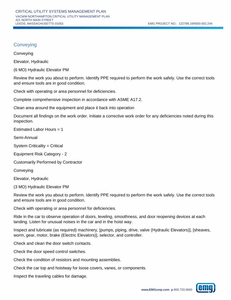
CRITICAL UTILITY SYSTEMS MANAGEMENT PLAN
VACWM NORTHAMPTON CRITICAL UTILITY MANAGEMENT PLAN 421 NORTH MAIN STREET
LEEDS, MASSACHUSETTS 01053 EMG PROJECT NO.: 122798.16R000-002.244
www.EMGcorp.com p 800.733.0660
Conveying
Conveying
Elevator, Hydraulic
(6 MO) Hydraulic Elevator PM
Review the work you about to perform. Identify PPE required to perform the work safely. Use the correct tools
and ensure tools are in good condition.
Check with operating or area personnel for deficiencies.
Complete comprehensive inspection in accordance with ASME A17.2.
Clean area around the equipment and place it back into operation
Document all findings on the work order. Initiate a corrective work order for any deficiencies noted during this
inspection.
Estimated Labor Hours = 1
Semi-Annual
System Criticality = Critical
Equipment Risk Category - 2
Customarily Performed by Contractor
Conveying
Elevator, Hydraulic
(3 MO) Hydraulic Elevator PM
Review the work you about to perform. Identify PPE required to perform the work safely. Use the correct tools
and ensure tools are in good condition.
Check with operating or area personnel for deficiencies.
Ride in the car to observe operation of doors, leveling, smoothness, and door reopening devices at each
landing. Listen for unusual noises in the car and in the hoist way.
Inspect and lubricate (as required) machinery, [pumps, piping, drive, valve (Hydraulic Elevators)], [sheaves,
worm, gear, motor, brake (Electric Elevators)], selector, and controller.
Check and clean the door switch contacts.
Check the door speed control switches.
Check the condition of resistors and mounting assemblies.
Check the car top and hoistway for loose covers, vanes, or components.
Inspect the traveling cables for damage.

CRITICAL UTILITY SYSTEMS MANAGEMENT PLAN
VACWM NORTHAMPTON CRITICAL UTILITY MANAGEMENT PLAN 421 NORTH MAIN STREET
LEEDS, MASSACHUSETTS 01053 EMG PROJECT NO.: 122798.16R000-002.244
www.EMGcorp.com p 800.733.0660
Inspect the counterweight rope for wear and lubrication (if equipped).
Clean area around the equipment and place it back into operation
Document all findings on the work order. Initiate a corrective work order for any deficiencies noted during this
inspection.
Estimated Labor Hours = 3
Quarterly
System Criticality = Critical
Equipment Risk Category - 2
Customarily Performed by Contractor
Conveying
Elevator, Hydraulic
(1 YR) Hydraulic Elevator PM
Review the work you about to perform. Identify PPE required to perform the work safely. Use the correct tools
and ensure tools are in good condition.
Check with operating or area personnel for deficiencies.
Conduct Category 1, Category 3, and Category 5 tests.
Inspect the condition of the flexible hoses and replace as needed. Pressure hoses are required to be tested,
inspected, and replaced according to the Code.
As required, test a sample of the hydraulic fluid for viscosity, color, contamination, foaming, and other pertinent
properties specified by the equipment manufacturer. Drain and replace the fluid if the tests show it does not
meet the requirements.
Clean the guide rails with solvent to remove dirt, debris, or excess lubricant.
Test the car emergency light for required illumination.
Test and adjust dispatching, scheduling, and emergency service of the group supervisory control system (if
equipped).
Clean the hoist way.
Vacuum the dust from controllers and relays.
Clean area around the equipment and place it back into operation
Document all findings on the work order. Initiate a corrective work order for any deficiencies noted during this
inspection.
Estimated Labor Hours = 8
Annual

CRITICAL UTILITY SYSTEMS MANAGEMENT PLAN
VACWM NORTHAMPTON CRITICAL UTILITY MANAGEMENT PLAN 421 NORTH MAIN STREET
LEEDS, MASSACHUSETTS 01053 EMG PROJECT NO.: 122798.16R000-002.244
www.EMGcorp.com p 800.733.0660
System Criticality = Critical
Equipment Risk Category - 2
Customarily Performed by Contractor
Conveying
Elevator, Traction
(1 YR) Traction Elevator PM
Review the work you about to perform. Identify PPE required to perform the work safely. Use the correct tools
and ensure tools are in good condition.
Check with operating or area personnel for deficiencies.
Conduct Category 1 and Category 5 test.
Remove, clean, and lubricate the brake cores. Inspect the brake linings for wear - clean or replace if
necessary. Adjust the brakes to wear evenly if necessary.
Inspect the armatures of hoist motor and motor-generator (if equipped). Check the electrical connections.
Drain, flush, and refill the oil reservoirs. Check the brushes for neutral settings and for proper quartering and
spacing.
Drain, flush, and refill the gearing lubricant.
Check the compensation rope tension.
Lubricate the sheave bearings and check for leaky seals.
Clean the guide rails with solvent to remove dirt, debris, or excess lubricant.
Test the car emergency light for required illumination.
Test and adjust dispatching, scheduling, and emergency service of the group supervisory control system (if
equipped).
Clean the hoist way.
Vacuum the dust from controllers and relays.
Clean area around the equipment and place it back into operation
Document all findings on the work order. Initiate a corrective work order for any deficiencies noted during this
inspection.
Estimated Labor Hours = 8
Annual
System Criticality = Critical
Equipment Risk Category - 2

CRITICAL UTILITY SYSTEMS MANAGEMENT PLAN
VACWM NORTHAMPTON CRITICAL UTILITY MANAGEMENT PLAN 421 NORTH MAIN STREET
LEEDS, MASSACHUSETTS 01053 EMG PROJECT NO.: 122798.16R000-002.244
www.EMGcorp.com p 800.733.0660
Customarily Performed by Contractor
Conveying
Elevator, Traction
(6 MO) Traction Elevator PM
Review the work you about to perform. Identify PPE required to perform the work safely. Use the correct tools
and ensure tools are in good condition.
Check with operating or area personnel for deficiencies.
Complete comprehensive inspection in accordance with ASME A17.2.
Check the clearances for governor tension sheave, counterweight-to-buffer (with car at top landing), and
compensation sheave to pit. Check governor sheave fastenings.
Check all of the timers in the system and reset if necessary.
Inspect guide rails, cams, fastenings, and counterweights in hoist ways.
Test all of the terminal limit switches. Lubricate the limit switch roller pins.
Inspect the sheaves to verify that they are tight on the shafts, and sound their spokes and hubs with a hammer
to inspect for cracks. Repair as necessary.
Lubricate the guide shoe stems.
Clean area around the equipment and place it back into operation
Document all findings on the work order. Initiate a corrective work order for any deficiencies noted during this
inspection.
Estimated Labor Hours = 6
Semi-Annual
System Criticality = Critical
Equipment Risk Category - 2
Customarily Performed by Contractor
Conveying
Elevator, Traction
(3 MO) Traction Elevator PM
Review the work you about to perform. Identify PPE required to perform the work safely. Use the correct tools
and ensure tools are in good condition.
Check with operating or area personnel for deficiencies.

CRITICAL UTILITY SYSTEMS MANAGEMENT PLAN
VACWM NORTHAMPTON CRITICAL UTILITY MANAGEMENT PLAN 421 NORTH MAIN STREET
LEEDS, MASSACHUSETTS 01053 EMG PROJECT NO.: 122798.16R000-002.244
www.EMGcorp.com p 800.733.0660
Ride in the car to observe operation of doors, leveling, smoothness, and door reopening devices at each
landing. Listen for unusual noises in the car and in the hoist way.
Inspect and lubricate (as required) machinery, [pumps, piping, drive, valve (Hydraulic Elevators)], [sheaves,
worm, gear, motor, brake (Electric Elevators)], selector, and controller.
Check and clean the door switch contacts.
Check the door speed control switches.
Check the condition of resistors and mounting assemblies.
Check the car top and hoistway for loose covers, vanes, or components.
Inspect the traveling cables for damage.
Inspect the counterweight rope for wear and lubrication (if equipped).
Inspect the brake linings (as required)
Inspect all ropes for wear and lubrication (do not lubricate the governor rope) - replace or lubricate the ropes if
required. Clean the governor and hoist ropes. Inspect the rope hitches, fastenings, and shackles - equalize
ropes if w
Check the car position sensor drive wheel.
Check decelerations, advances, and accelerations to ensure all cars are matched.
Inspect all parts of the safeties and adjust clearance between the safety jaws and guide rails.
Clean all parts and lubricate the pivot points.
Clean area around the equipment and place it back into operation
Document all findings on the work order. Initiate a corrective work order for any deficiencies noted during this
inspection.
Estimated Labor Hours = 3
Quarterly
System Criticality = Critical
Equipment Risk Category - 2
Customarily Performed by Contractor

CRITICAL UTILITY SYSTEMS MANAGEMENT PLAN
VACWM NORTHAMPTON CRITICAL UTILITY MANAGEMENT PLAN 421 NORTH MAIN STREET
LEEDS, MASSACHUSETTS 01053 EMG PROJECT NO.: 122798.16R000-002.244
www.EMGcorp.com p 800.733.0660
Electrical
Electrical
Automatic Transfer Switch
(3 MO) Automatic Transfer Switch PM
LOCK OUT – TAG OUT - Identify potential hazards (electrical, mechanical, etc.) before starting job. Prior to any task that exposes hazard, isolate hazard, release stored energy, LOCK OUT and TAG OUT, and verify hazard has been eliminated.
ELECTRICAL HAZARD - Work near live electrical parts should be avoided if possible, and should only be performed by trained personnel wearing PPE and using tools appropriate for the arc flash hazard.
1. Check with operating or area personnel for deficiencies.
2. Visually inspect the transfer switch control mechanism, control panel, harnesses, and cable
connections for signs of moisture, corrosion, or heating.
3. Measure and record the normal source voltage phase to phase, phase to ground, and phase to neutral
4. Measure and record the engine start time (from crank start to source available light or relay pickup)
5. Measure and record the emergency source voltage phase to phase, phase to ground, and phase to
neutral
6. Measure and record the load current each phase
7. Measure and record the momentary override normal deviation where provided
8. Measure and record the transfer time delay where provided
9. Measure and record the return to normal source time delay where provided
10. Measure and record the engine cool down where provided
11. If the connection is to a multiple-source EPS, verify the load priority of the ATS being tested and
confirm this is correct given the criticality of the connected load.
12. Verify proper operation of all indicator lights and meters and controls.
13. Inspect cabinets for proper sealing and appropriate gasketing. Seal all open conduit knockouts or other
penetrations.
14. Perform a load test using the test switch if permitted
15. If a required emergency power system test fails, the hospital shall implement measures to protect
patients, visitors, and staff until necessary repairs or corrections are completed.
16. If a required emergency power system test fails, the hospital shall perform a retest after making the
necessary repairs or corrections.
17. Clean area around unit.
18. Document all findings on the work order. Initiate a corrective work order for any deficiencies noted
during this inspection.
Estimated Labor Hours = 1 Quarterly System Criticality = Critical Equipment Risk Category - 1 Customarily Performed by Employee

CRITICAL UTILITY SYSTEMS MANAGEMENT PLAN
VACWM NORTHAMPTON CRITICAL UTILITY MANAGEMENT PLAN 421 NORTH MAIN STREET
LEEDS, MASSACHUSETTS 01053 EMG PROJECT NO.: 122798.16R000-002.244
www.EMGcorp.com p 800.733.0660
Electrical Automatic Transfer Switch
(1 MO) Automatic Transfer Switch PM
LOCK OUT – TAG OUT - Identify potential hazards (electrical, mechanical, etc.) before starting job. Prior to any task that exposes hazard, isolate hazard, release stored energy, LOCK OUT and TAG OUT, and verify hazard has been eliminated.
ELECTRICAL HAZARD - Work near live electrical parts should be avoided if possible, and should only be performed by trained personnel wearing PPE and using tools appropriate for the arc flash hazard.
1. Test automatic transfer switch by electrically operating the transfer switch from the standard position to
the alternate position and then return to the standard position.
2. If a required emergency power system test fails, the hospital shall implement measures to protect
patients, visitors, and staff until necessary repairs or corrections are completed.
3. If a required emergency power system test fails, the hospital shall perform a retest after making the
necessary repairs or corrections.
4. Clean area around unit.
5. Document all findings on the work order. Initiate a corrective work order for any deficiencies noted
during this inspection.
Estimated Labor Hours = 0.75 Monthly System Criticality = Critical Equipment Risk Category - 1 Customarily Performed by Employee
Electrical Automatic Transfer Switch
(1 YR) Automatic Transfer Switch PM
LOCK OUT – TAG OUT - Identify potential hazards (electrical, mechanical, etc.) before starting job. Prior to any task that exposes hazard, isolate hazard, release stored energy, LOCK OUT and TAG OUT, and verify hazard has been eliminated.
ELECTRICAL HAZARD - Work near live electrical parts should be avoided if possible, and should only be performed by trained personnel wearing PPE and using tools appropriate for the arc flash hazard.
1. Perform a thermographic scan of the ATS while the ATS is under normal (peak) load and again during
the generator load test. Carefully inspect any connections found to be hotter than adjacent connections
when the ATS is de-energized.
2. With power connected to the normal source, measure and record millivolt drop levels across each pole.
Any reading that is greater than 25 percent of the average of all poles should be carefully inspected
when the ATS is de-energized.
CRITICAL UTILITY SYSTEMS MANAGEMENT PLAN
VACWM NORTHAMPTON CRITICAL UTILITY MANAGEMENT PLAN 421 NORTH MAIN STREET
LEEDS, MASSACHUSETTS 01053 EMG PROJECT NO.: 122798.16R000-002.244
www.EMGcorp.com p 800.733.0660
3. With power connected to the emergency source, measure and record millivolt drop levels across each
pole. Any reading that is greater than 25 percent of the average of all poles should be carefully
inspected when the ATS is de-energized.
4. If the ATS is equipped with a bypass isolation feature, operate the bypass to the connected source
(emergency or normal) and repeat the thermographic scan and millivolt drop measurements.
5. With power secured and both the emergency and normal sources properly locked out and tagged out,
measure the micro-ohm resistance levels across the emergency source cabling lug to bus.
6. With power secured and both the emergency and normal sources properly locked out and tagged out,
measure the micro-ohm resistance levels across the normal source cabling lug to bus.
7. With power secured and both the emergency and normal sources properly locked out and tagged out,
measure the micro-ohm resistance levels across the load cabling lug to bus.
8. With power secured and both the emergency and normal sources properly locked out and tagged out,
measure the micro-ohm resistance levels across the neutral cabling lug to bus.
9. With power secured and both the emergency and normal sources properly locked out and tagged out,
measure the micro-ohm resistance levels across the load connected to normal across each pole.
10. With power secured and both the emergency and normal sources properly locked out and tagged out,
measure the micro-ohm resistance levels across the load connected to emergency across each pole.
11. With power from both sources secured and properly locked out and tagged out, remove all protective
pole covers and arc chutes.
12. Carefully inspect main contacts and other current carrying parts for signs of corrosion or overheating.
Observation should correlate with previous results (i.e., thermographic, abnormal millivolt drop
readings, or abnormal micro-ohm (DLRO) readings).
13. Carefully inspect insulating materials or standoff insulators for signs of contamination (i.e., dirt, grime,
oil, etc.). Clean contaminated surfaces with a solvent approved for this purpose.
14. Inspect control connection, plugs, and harnesses for signs of corrosion, heat, contamination, and so
forth.
15. Using a vacuum, remove all dust and debris from the ATS cabinet, transfer switch mechanism, bus,
and so forth.
16. Inspect cabinets for proper sealing and appropriate gasketing. Seal all open conduit knockouts or other
penetrations.
17. Replace and secure all protective pole covers and chutes. Remove lockout devices and resupply
normal power. If the ATS is of the bypass isolation type, reconnect the transfer switch mechanism.
Observe proper manufacturer’s procedures.
18. Measure and record the normal source voltage phase to phase, phase to ground, and phase to neutral
19. Measure and record the engine start time (from crank start to source available light or relay pickup)
20. Measure and record the emergency source voltage phase to phase, phase to ground, and phase to
neutral
21. Measure and record the load current each phase
22. Measure and record the momentary override normal deviation where provided
23. Measure and record the transfer time delay where provided
24. Measure and record the return to normal source time delay where provided
25. Measure and record the engine cool down where provided
26. If the connection is to a multiple-source EPS, verify the load priority of the ATS being tested and
confirm this is correct given the criticality of the connected load.
27. Verify proper operation of all indicator lights and meters and controls.
28. Return ATS to normal service.

CRITICAL UTILITY SYSTEMS MANAGEMENT PLAN
VACWM NORTHAMPTON CRITICAL UTILITY MANAGEMENT PLAN 421 NORTH MAIN STREET
LEEDS, MASSACHUSETTS 01053 EMG PROJECT NO.: 122798.16R000-002.244
www.EMGcorp.com p 800.733.0660
29. If a required emergency power system test fails, the hospital shall implement measures to protect
patients, visitors, and staff until necessary repairs or corrections are completed.
30. If a required emergency power system test fails, the hospital shall perform a retest after making the
necessary repairs or corrections.
31. Clean area around equipment.
32. Document all findings on the work order. Initiate a corrective work order for any deficiencies noted
during this inspection.
Estimated Labor Hours = 2 Annual System Criticality = Critical Equipment Risk Category - 1 Customarily Performed by Contractor
Electrical
Battery Charger
(1 MO) Battery Charger PM
LOCK OUT – TAG OUT - Identify potential hazards (electrical, mechanical, etc.) before starting job. Prior to any task that exposes hazard, isolate hazard, release stored energy, LOCK OUT and TAG OUT, and verify hazard has been eliminated.
ELECTRICAL HAZARD - Work near live electrical parts should be avoided if possible, and should only be performed by trained personnel wearing PPE and using tools appropriate for the arc flash hazard.
1. Check with operating or area personnel for deficiencies.
2. Inspect exterior for damage, missing covers, missing bolts or open holes.
3. Check room ventilation, and be sure charger is not exposed to moisture or water.
4. Inspect for physical and mechanical condition. Verify unit and immediate surroundings are clean and
free from trash.
5. Clean the unit.
6. Inspect electrical wiring and connections, for looseness or damage.
7. Record charger output voltage and output current.
8. Inspect and record if any warning lights are lit up.
9. Document all findings on the work order. Initiate a corrective work order for any deficiencies noted
during this inspection.
Estimated Labor Hours = 0.45 Monthly System Criticality = Critical Equipment Risk Category - 1 Customarily Performed by Employee
Electrical

CRITICAL UTILITY SYSTEMS MANAGEMENT PLAN
VACWM NORTHAMPTON CRITICAL UTILITY MANAGEMENT PLAN 421 NORTH MAIN STREET
LEEDS, MASSACHUSETTS 01053 EMG PROJECT NO.: 122798.16R000-002.244
www.EMGcorp.com p 800.733.0660
Fuel Tank Monitoring Panel
(1 YR) Fuel Tank Monit. PM
Review the work you about to perform. Identify PPE required to perform the work safely. Use the correct tools and ensure tools are in good condition.
1. Check with operating or area personnel for deficiencies.
2. Check printer for paper if equipped.
3. Print out or check system inventory and verify to actual inventory.
4. Print out or record system setup values, then verify if battery backup is working by powering the unit
down and then back up with the circuit breaker. If programming is lost, the battery is bad and the unit
needs service.
5. Verify in-tank tests are being performed as required by printing reports.
6. Press Alarm/Test button to verify power, warning and alarm indicators light and audible alarm sounds.
7. Verify line leak tests are being performed.
8. Inspect sensor probe cable for any cracking or damage.
9. Clean area around unit.
10. Document all findings on the work order. Initiate a corrective work order for any deficiencies noted
during this inspection.
Estimated Labor Hours = 1 Annual System Criticality = Critical Equipment Risk Category - 2 Customarily Performed by Employee
Electrical
Generator Control Switchgear
(1 YR) Emerg.Switchgear PM
ELECTRICAL HAZARD - Work near live electrical parts should be avoided if possible, and should only be performed by trained personnel wearing PPE and using tools appropriate for the arc flash hazard.
1. Check with operating or area personnel for deficiencies.
2. Inspect physical and mechanical condition.
3. Inspect anchorage, alignment, grounding, and required clearances.
4. Clean the unit.
5. Inspect electrical connections for high resistance using infra-red thermal detecting equipment. Tighten
problem connections to correct torque.
6. Check and calibrate voltage sensing relays / devices.
7. Verify correct operation of all indicating and control devices.
8. Clean area around unit.
9. Document all findings on the work order. Initiate a corrective work order for any deficiencies noted
during this inspection.

CRITICAL UTILITY SYSTEMS MANAGEMENT PLAN
VACWM NORTHAMPTON CRITICAL UTILITY MANAGEMENT PLAN 421 NORTH MAIN STREET
LEEDS, MASSACHUSETTS 01053 EMG PROJECT NO.: 122798.16R000-002.244
www.EMGcorp.com p 800.733.0660
Estimated Labor Hours = 2 Annual System Criticality = Critical Equipment Risk Category - 1 Customarily Performed by Contractor
Electrical
Loadbank Control Switchgear
(3 YR) Switchgear PM
ELECTRICAL HAZARD - Work near live electrical parts should be avoided if possible, and should only be performed by trained personnel wearing PPE and using tools appropriate for the arc flash hazard.
1. Check with operating or area personnel for deficiencies.
2. Inspect exterior for damage, missing covers, missing bolts or open holes.
3. Identify the loads fed from the Switchgear. Review these loads with Operations to determine if and
when the loads can be shut down so the Switchgear can be serviced.
4. De-energize, lockout and tagout Switchgear. While wearing PPE with the appropriate arc flash rating,
use a digital multimeter to verify that the voltage has been removed.
5. Remove covers from Switchgear. Visually inspect Switchgear internal parts for condition, alignment,
corrosion, evidence of tracking and dirt build up.
6. Clean any dust and dirt from Switchgear internal parts using lint free rags.
7. Remove lock and tags from Switchgear. Re-energize Switchgear.
8. Inspect electrical connections using a thermographic or infrared camera. For connections with
temperature difference of 4 C to 15C compared to similar components under similar loading, repair as
time permits. For connections with temperature > 15C schedule repair immediately.
9. Re-install covers on Switchgear.
10. Return unit to service.
11. Exercise each circuit breaker. Manually open and close each breaker. Verify that the contacts open and
close smoothly when manually tripped and restored.
12. Clean exterior with dry cloth.
13. Document all findings on the work order. Initiate a corrective work order for any deficiencies noted
during this inspection.
Estimated Labor Hours = 2 Annual System Criticality = Critical Equipment Risk Category - 2 Customarily Performed by Contractor
Electrical

CRITICAL UTILITY SYSTEMS MANAGEMENT PLAN
VACWM NORTHAMPTON CRITICAL UTILITY MANAGEMENT PLAN 421 NORTH MAIN STREET
LEEDS, MASSACHUSETTS 01053 EMG PROJECT NO.: 122798.16R000-002.244
www.EMGcorp.com p 800.733.0660
Main Distribution Panel
(1 YR) Panel PM
ELECTRICAL HAZARD - Work near live electrical parts should be avoided if possible, and should only be performed by trained personnel wearing PPE and using tools appropriate for the arc flash hazard.
1. Check with operating or area personnel for deficiencies.
2. Inspect exterior for damage, missing covers, missing bolts or open holes.
3. Identify the loads fed from the panel. Review these loads with Operations to determine if and when the
loads can be shut down so the panel can be serviced.
4. Exercise each circuit breaker. Manually open and close each breaker. Verify that the contacts open and
close smoothly when manually tripped and restored.
5. Clean exterior with dry cloth.
6. Document all findings on the work order. Initiate a corrective work order for any deficiencies noted
during this inspection.
Estimated Labor Hours = 1 Annual System Criticality = Critical Equipment Risk Category - 2 Customarily Performed by Employee
Electrical
Motor Control Center
(1 YR) Panel PM
ELECTRICAL HAZARD - Work near live electrical parts should be avoided if possible, and should only be performed by trained personnel wearing PPE and using tools appropriate for the arc flash hazard.
1. Check with operating or area personnel for deficiencies.
2. Inspect exterior for damage, missing covers, missing bolts or open holes.
3. Identify the loads fed from the panel. Review these loads with Operations to determine if and when the
loads can be shut down so the panel can be serviced.
4. Exercise each circuit breaker. Manually open and close each breaker. Verify that the contacts open and
close smoothly when manually tripped and restored.
5. Clean exterior with dry cloth.
6. Document all findings on the work order. Initiate a corrective work order for any deficiencies noted
during this inspection.
Estimated Labor Hours = 1 Annual System Criticality = Critical Equipment Risk Category - 2 Customarily Performed by Employee

CRITICAL UTILITY SYSTEMS MANAGEMENT PLAN
VACWM NORTHAMPTON CRITICAL UTILITY MANAGEMENT PLAN 421 NORTH MAIN STREET
LEEDS, MASSACHUSETTS 01053 EMG PROJECT NO.: 122798.16R000-002.244
www.EMGcorp.com p 800.733.0660
Electrical
Panel
(1 YR) Panel PM
ELECTRICAL HAZARD - Work near live electrical parts should be avoided if possible, and should only be performed by trained personnel wearing PPE and using tools appropriate for the arc flash hazard.
1. Check with operating or area personnel for deficiencies.
2. Inspect exterior for damage, missing covers, missing bolts or open holes.
3. Identify the loads fed from the panel. Review these loads with Operations to determine if and when the
loads can be shut down so the panel can be serviced.
4. Exercise each circuit breaker. Manually open and close each breaker. Verify that the contacts open and
close smoothly when manually tripped and restored.
5. Clean exterior with dry cloth.
6. Document all findings on the work order. Initiate a corrective work order for any deficiencies noted
during this inspection.
Estimated Labor Hours = 1 Annual System Criticality = Critical Equipment Risk Category - 3 Customarily Performed by Employee
Electrical
Panel, Communication
(1 YR) Panel PM
ELECTRICAL HAZARD - Work near live electrical parts should be avoided if possible, and should only be performed by trained personnel wearing PPE and using tools appropriate for the arc flash hazard.
1. Check with operating or area personnel for deficiencies.
2. Inspect exterior for damage, missing covers, missing bolts or open holes.
3. Identify the loads fed from the panel. Review these loads with Operations to determine if and when the
loads can be shut down so the panel can be serviced.
4. Exercise each circuit breaker. Manually open and close each breaker. Verify that the contacts open and
close smoothly when manually tripped and restored.
5. Clean exterior with dry cloth.
6. Document all findings on the work order. Initiate a corrective work order for any deficiencies noted
during this inspection.
Estimated Labor Hours = 1 Annual System Criticality = Critical Equipment Risk Category - 2 Customarily Performed by Employee

CRITICAL UTILITY SYSTEMS MANAGEMENT PLAN
VACWM NORTHAMPTON CRITICAL UTILITY MANAGEMENT PLAN 421 NORTH MAIN STREET
LEEDS, MASSACHUSETTS 01053 EMG PROJECT NO.: 122798.16R000-002.244
www.EMGcorp.com p 800.733.0660
Electrical
Switchgear
(3 YR) Switchgear PM
ELECTRICAL HAZARD - Work near live electrical parts should be avoided if possible, and should only be performed by trained personnel wearing PPE and using tools appropriate for the arc flash hazard.
1. Check with operating or area personnel for deficiencies.
2. Inspect exterior for damage, missing covers, missing bolts or open holes.
3. Identify the loads fed from the Switchgear. Review these loads with Operations to determine if and
when the loads can be shut down so the Switchgear can be serviced.
4. De-energize, lockout and tagout Switchgear. While wearing PPE with the appropriate arc flash rating,
use a digital multimeter to verify that the voltage has been removed.
5. Remove covers from Switchgear. Visually inspect Switchgear internal parts for condition, alignment,
corrosion, evidence of tracking and dirt build up.
6. Clean any dust and dirt from Switchgear internal parts using lint free rags.
7. Remove lock and tags from Switchgear. Re-energize Switchgear.
8. Inspect electrical connections using a thermographic or infrared camera. For connections with
temperature difference of 4 C to 15C compared to similar components under similar loading, repair as
time permits. For connections with temperature > 15C schedule repair immediately.
9. Re-install covers on Switchgear.
10. Return unit to service.
11. Exercise each circuit breaker. Manually open and close each breaker. Verify that the contacts open and
close smoothly when manually tripped and restored.
12. Clean exterior with dry cloth.
13. Document all findings on the work order. Initiate a corrective work order for any deficiencies noted
during this inspection.
Estimated Labor Hours = 2 Annual System Criticality = Critical Equipment Risk Category - 2 Customarily Performed by Contractor
Electrical
Tank, Fuel
(1 YR) Tank, Fuel PM
CHEMICAL HAZARD - Read Safety Data Sheet (SDS) for chemicals to be used. Review potential hazards and follow recommended precautions to protect.
1. Check with operating or area personnel for deficiencies.
2. Verify fuel tank vents and overflow piping are unobstructed.
3. Inspect fuel piping for damage, corrosion or leaks.
CRITICAL UTILITY SYSTEMS MANAGEMENT PLAN
VACWM NORTHAMPTON CRITICAL UTILITY MANAGEMENT PLAN 421 NORTH MAIN STREET
LEEDS, MASSACHUSETTS 01053 EMG PROJECT NO.: 122798.16R000-002.244
www.EMGcorp.com p 800.733.0660
4. Inspect for the accumulation of water in tank.
5. Using a test kit and following instructions from approved test lab, collect a sample of fuel from the
storage tank. Send fuel sample to lab for analysis following ASTM standards.
6. Check floats and level measuring devices in tank.
7. Clean area around unit.
8. Document all findings on the work order. Initiate a corrective work order for any deficiencies noted
during this inspection.
Estimated Labor Hours = 1 Annual System Criticality = Critical Equipment Risk Category - 1 Customarily Performed by Employee
Electrical
Transformer
(3 YR) Transformer PM
LOCK OUT – TAG OUT - Identify potential hazards (electrical, mechanical, etc.) before starting job. Prior to any task that exposes hazard, isolate hazard, release stored energy, LOCK OUT and TAG OUT, and verify hazard has been eliminated.
ELECTRICAL HAZARD - Work near live electrical parts should be avoided if possible, and should only be performed by trained personnel wearing PPE and using tools appropriate for the arc flash hazard.
1. Check with operating or area personnel for deficiencies.
2. Inspect exterior for damage, missing covers, missing bolts or open holes.
3. Identify the loads fed from the transformer. Review these loads with Operations to determine if and
when the loads can be shut down so the transformer can be serviced.
4. De-energize, lockout and tagout transformer. While wearing PPE with the appropriate arc flash rating,
use a digital multimeter to verify that the voltage has been removed.
5. Remove covers from transformer. Visually inspect transformer internal parts for condition, alignment,
corrosion, evidence of tracking and dirt build up.
6. Clean any dust and dirt from transformer internal parts.
7. Re-install covers on transformer.
8. Remove lock and tags from transformer. Re-energize transformer.
9. Check that transformer is operating with no abnormal noises, smells, vibration or heat.
10. Ensure that any cooling fans, temperature switches, and alarms are functioning properly.
11. Perform infrared inspection on transformer. If hot spots are identified, schedule an outage of the
transformer to perform corrective maintenance.
12. Clean exterior with dry cloth.
13. Document all findings on the work order. Initiate a corrective work order for any deficiencies noted
during this inspection.
Estimated Labor Hours = 2 3 Year

CRITICAL UTILITY SYSTEMS MANAGEMENT PLAN
VACWM NORTHAMPTON CRITICAL UTILITY MANAGEMENT PLAN 421 NORTH MAIN STREET
LEEDS, MASSACHUSETTS 01053 EMG PROJECT NO.: 122798.16R000-002.244
www.EMGcorp.com p 800.733.0660
System Criticality = Critical Equipment Risk Category - 2 Customarily Performed by Contractor
Electrical Electrical
Day Tank
(1 YR) Day Tank PM
CHEMICAL HAZARD - Read Safety Data Sheet (SDS) for chemicals to be used. Review potential hazards and follow recommended precautions to protect.
1. Check with operating or area personnel for deficiencies.
2. Verify fuel tank vents and overflow piping are unobstructed.
3. Inspect fuel piping for damage, corrosion or leaks.
4. Inspect for the accumulation of water in tank.
5. Check floats and level measuring devices in tank.
6. Clean area around unit.
7. Document all findings on the work order. Initiate a corrective work order for any deficiencies noted
during this inspection.
Estimated Labor Hours = 1 Annual System Criticality = Critical Equipment Risk Category - 1 Customarily Performed by Employee
Electrical
Load Bank
(1 YR) Load Bank PM
Review the work you about to perform. Identify PPE required to perform the work safely. Use the correct tools and ensure tools are in good condition.
1. Check with operating or area personnel for deficiencies.
2. Inspect the exterior for damage, missing covers, missing bolts, or open holes.
3. Visually inspect interior components for correct alignment, mechanical damage, or evidence of
overheating.
4. Inspect electrical wiring and connections; tighten loose connections.
5. Verify load controller is operating correctly.
6. Verify that voltage and current metering are functioning correctly.
7. Clean area around unit.
8. Document all findings on the work order. Initiate a corrective work order for any deficiencies noted
during this inspection.
Estimated Labor Hours = 1

CRITICAL UTILITY SYSTEMS MANAGEMENT PLAN
VACWM NORTHAMPTON CRITICAL UTILITY MANAGEMENT PLAN 421 NORTH MAIN STREET
LEEDS, MASSACHUSETTS 01053 EMG PROJECT NO.: 122798.16R000-002.244
www.EMGcorp.com p 800.733.0660
Annual System Criticality = Critical Equipment Risk Category - 2 Customarily Performed by Employee Electrical
Circuit Breaker
(1 YR) Circuit Breaker PM
ELECTRICAL HAZARD - Work near live electrical parts should be avoided if possible, and should only be performed by trained personnel wearing PPE and using tools appropriate for the arc flash hazard.
1. Check with operating or area personnel for deficiencies.
2. Inspect exterior for damage, missing covers, missing bolts or open holes.
3. Work with operations to verify that the loads served by the circuit breaker may be safely interrupted.
Notify any potentially impacted parties of the potential impact.
4. Mechanically exercise breaker. Verify that the breaker operates smoothly.
5. Visually inspect the breaker for correct alignment, mechanical damage or evidence of overheating.
6. Return equipment to service.
7. Document all findings on the work order. Initiate a corrective work order for any deficiencies noted
during this inspection.
Estimated Labor Hours = 2 Annual System Criticality = Critical Equipment Risk Category - 2 Customarily Performed by Employee Electrical
Emergency Generator - Level 1
(3 YR) Emergency Generator - Lev 1 PM
LOCK OUT – TAG OUT - Identify potential hazards (electrical, mechanical, etc.) before starting job. Prior to any task that exposes hazard, isolate hazard, release stored energy, LOCK OUT and TAG OUT, and verify hazard has been eliminated. CHEMICAL HAZARD - Read Safety Data Sheet (SDS) for chemicals to be used. Review potential hazards and follow recommended precautions to protect.
1. Check with operating or area personnel for deficiencies.
2. Test run emergency generator under load for at least 4 hours.
3. The load for the test shall be at least 30% of the nameplate rating of the generator, or meets the
manufacturer’s recommended prime mover’s exhaust gas temperature.
CRITICAL UTILITY SYSTEMS MANAGEMENT PLAN
VACWM NORTHAMPTON CRITICAL UTILITY MANAGEMENT PLAN 421 NORTH MAIN STREET
LEEDS, MASSACHUSETTS 01053 EMG PROJECT NO.: 122798.16R000-002.244
www.EMGcorp.com p 800.733.0660
4. This test should be coordinated with the local Utility Power Company (UPC). The test should initiated
by opening the main electrical switch, owned by the UPC, that serves the facility, to simulate a total
electrical power outage.
5. Exercise, test and maintain main substation tie breaker during this test.
6. This test has two objectives, a thorough test of the Essential Electrical System (EES) initiated by a loss
of utility normal power and a thorough test of the medical center staff's ability to operate while restricted
only to the EES.
7. This test should be coordinated with the medical center management. It may be incorporated into the
facility-wide disaster drills required by the Joint Commision. An unscheduled facility power outage of at
least 4 hours continuous duration may be document
8. If a required emergency power system test fails, the hospital shall implement measures to protect
patients, visitors, and staff until necessary repairs or corrections are completed.
9. If a required emergency power system test fails, the hospital shall perform a retest after making the
necessary repairs or corrections.
10. Clean area around unit.
11. Document all findings on the work order. Initiate a corrective work order for any deficiencies noted
during this inspection.
Estimated Labor Hours = 16 3 Year System Criticality = Critical Equipment Risk Category - 1 Customarily Performed by Contractor Electrical Emergency Generator - Level 1
(1 MO) Emergency Generator - Lev 1 PM
CHEMICAL HAZARD - Read Safety Data Sheet (SDS) for chemicals to be used. Review potential hazards and follow recommended precautions to protect.
1. Check with operating or area personnel for deficiencies.
2. Test run emergency generator under load for at least 30 minutes using a simulated cold start.
3. Diesel generators should be loaded using one of the following methods: (1) Loading that maintains the
minimum exhaust gas temperatures as recommended by the manufacturer. (2) Under operating
temperature conditions and at not less than 30% of nameplate kW
4. Inspect fan and alternator belt for wear or damage.
5. Inspect and clean exterior of batteries.
6. Test specific gravity or state of charge of batteries, verify within acceptable range.
7. Inspect battery charger, verify charge rate.
8. Equalize charge on batteries.
9. Inspect, clean and test circuit breakers and fuses. Replace as needed.
10. Check governor oil level. Inspect governor linkage.
11. If a required emergency power system test fails, the hospital shall implement measures to protect
patients, visitors, and staff until necessary repairs or corrections are completed.

CRITICAL UTILITY SYSTEMS MANAGEMENT PLAN
VACWM NORTHAMPTON CRITICAL UTILITY MANAGEMENT PLAN 421 NORTH MAIN STREET
LEEDS, MASSACHUSETTS 01053 EMG PROJECT NO.: 122798.16R000-002.244
www.EMGcorp.com p 800.733.0660
12. If a required emergency power system test fails, the hospital shall perform a retest after making the
necessary repairs or corrections.
13. Clean area around unit.
14. Document all findings on the work order. Initiate a corrective work order for any deficiencies noted
during this inspection.
Estimated Labor Hours = 1 Monthly System Criticality = Critical Equipment Risk Category - 1 Customarily Performed by Employee Electrical Emergency Generator - Level 1
(1 YR) Emergency Generator - Lev 1 PM
LOCK OUT – TAG OUT - Identify potential hazards (electrical, mechanical, etc.) before starting job. Prior to any task that exposes hazard, isolate hazard, release stored energy, LOCK OUT and TAG OUT, and verify hazard has been eliminated. ELECTRICAL HAZARD - Work near live electrical parts should be avoided if possible, and should only be performed by trained personnel wearing PPE and using tools appropriate for the arc flash hazard.
1. Check with operating or area personnel for deficiencies.
2. Diesel generators that are not tested under specified load during the monthly test shall be exercised
annually with supplemental load. Generates shall be exercised at no less than 50% nameplate load for
30 minutes and no less than 75% nameplate load for no less than 60 minutes, for a total test duration of
no less than 1.5 hours.
3. Have oil analysis performed on engine oil. Change engine oil and oil filters as determined necessary by
oil analysis.
4. Have coolant analysis performed on engine coolant. Change coolant as determined necessary by
coolant analysis.
5. Rod out heat exchanger.
6. Clean exterior of radiator.
7. Test exhaust backpressure, verify that it is not excessive.
8. Inspect exhaust system hangers and supports for condition and damage. Verify exhaust system is
adequately supported.
9. Tighten generator control and power wiring connections.
10. Replace governor oil, as needed.
11. Test injector pump and injectors for flow rate pressure and/ or spray pattern.
12. Inspect and clean commutator and slip rings.
13. Inspect and clean rotor and stators.
14. Inspect generator bearings.
15. Check generator bearing grease, replace if needed.
16. Inspect and clean exciter.
17. Inspect and clean voltage regulator.

CRITICAL UTILITY SYSTEMS MANAGEMENT PLAN
VACWM NORTHAMPTON CRITICAL UTILITY MANAGEMENT PLAN 421 NORTH MAIN STREET
LEEDS, MASSACHUSETTS 01053 EMG PROJECT NO.: 122798.16R000-002.244
www.EMGcorp.com p 800.733.0660
18. Measure and record resistance readings of windings with insulation tester.
19. If a required emergency power system test fails, the hospital shall implement measures to protect
patients, visitors, and staff until necessary repairs or corrections are completed.
20. If a required emergency power system test fails, the hospital shall perform a retest after making the
necessary repairs or corrections.
21. Clean area around unit.
22. Document all findings on the work order. Initiate a corrective work order for any deficiencies noted
during this inspection.
Estimated Labor Hours = 6 Annual System Criticality = Critical Equipment Risk Category - 1 Customarily Performed by Contractor Electrical Emergency Generator - Level 1
(3 MO) Emergency Generator - Lev 1 PM
CHEMICAL HAZARD - Read Safety Data Sheet (SDS) for chemicals to be used. Review potential hazards and follow recommended precautions to protect.
1. Check with operating or area personnel for deficiencies.
2. Perform a load test on emergency generator batteries.
3. Clean fuel strainer and/or dirt leg.
4. Inspect and clean crankcase breather. Replace if needed.
5. Inspect exhaust system insulation for evidence of burning, check area around exhaust system for fire
hazards.
6. Inspect battery terminals, verify tight.
7. Inspect for chafing any wiring subject to movement.
8. If a required emergency power system test fails, the hospital shall implement measures to protect
patients, visitors, and staff until necessary repairs or corrections are completed.
9. If a required emergency power system test fails, the hospital shall perform a retest after making the
necessary repairs or corrections.
Estimated Labor Hours = 1 Quarterly System Criticality = Critical Equipment Risk Category - 1 Customarily Performed by Employee Electrical Emergency Generator - Level 1
CRITICAL UTILITY SYSTEMS MANAGEMENT PLAN
VACWM NORTHAMPTON CRITICAL UTILITY MANAGEMENT PLAN 421 NORTH MAIN STREET
LEEDS, MASSACHUSETTS 01053 EMG PROJECT NO.: 122798.16R000-002.244
www.EMGcorp.com p 800.733.0660
(1 WK) Emergency Generator - Lev 1 PM
CHEMICAL HAZARD - Read Safety Data Sheet (SDS) for chemicals to be used. Review potential hazards and follow recommended precautions to protect.
1. Check with operating or area personnel for deficiencies.
2. Verify level in both the main fuel tank and the day tank is adequate.
3. Inspect condition and verify that the day tank float switch and transfer pump are operational.
4. Inspect condition and verify operation of fuel solenoid valve(s).
5. Inspect fuel water separator, drain any accumulated water.
6. Inspect condition of fuel system flexible hoses and connectors.
7. Check lube oil level.
8. Inspect condition and verify operation of lube oil heater.
9. Check coolant level.
10. Verify adequate cooling water to heat exchanger.
11. Verify adequate fresh air through radiator, no blockage.
12. Inspect condition of water pumps.
13. Inspect condition of jacket water heater.
14. Inspect exhaust system for evidence of leakage.
15. Inspect and drain exhaust system condensate trap.
16. Inspect physical condition of batteries and check electrolyte levels.
17. Inspect physical and mechanical condition of generator electrical system including emergency
switchgear.
18. Inspect physical and mechanical condition of engine.
19. Inspect general condition of emergency power system, including all related components, such as
Automatic Transfer Switches and generator.
20. Inspect generator and emergency switchgear rooms for leaks or housekeeping issues.
21. If a required emergency power system test fails, the hospital shall implement measures to protect
patients, visitors, and staff until necessary repairs or corrections are completed.
22. If a required emergency power system test fails, the hospital shall perform a retest after making the
necessary repairs or corrections.
23. Clean area around unit.
24. Document all findings on the work order. Initiate a corrective work order for any deficiencies noted
during this inspection.
Estimated Labor Hours = 0.5 Weekly System Criticality = Critical Equipment Risk Category - 1 Customarily Performed by Employee Electrical Emergency Generator - Level 1
(6 MO) Emergency Generator - Lev 1 PM
CHEMICAL HAZARD - Read Safety Data Sheet (SDS) for chemicals to be used. Review potential hazards and follow recommended precautions to protect.

CRITICAL UTILITY SYSTEMS MANAGEMENT PLAN
VACWM NORTHAMPTON CRITICAL UTILITY MANAGEMENT PLAN 421 NORTH MAIN STREET
LEEDS, MASSACHUSETTS 01053 EMG PROJECT NO.: 122798.16R000-002.244
www.EMGcorp.com p 800.733.0660
1. Check with operating or area personnel for deficiencies.
2. Test coolant to determine whether the protection level of the coolant is adequate.
3. Inspect flexible exhaust section for condition and damage.
4. Check and test operation of safeties and alarms.
5. Inspect and clean electrical boxes and cabinets.
6. Inspect and clean air cleaner. Replace if necessary
7. Check and clean generator brush. Verify length, appearance and free to move in holder.
8. If a required emergency power system test fails, the hospital shall implement measures to protect
patients, visitors, and staff until necessary repairs or corrections are completed.
9. If a required emergency power system test fails, the hospital shall perform a retest after making the
necessary repairs or corrections.
10. Clean area around unit.
11. Document all findings on the work order. Initiate a corrective work order for any deficiencies noted
during this inspection.
Estimated Labor Hours = 1 Semi-Annual System Criticality = Critical Equipment Risk Category - 1 Customarily Performed by Contractor Electrical
Emergency Generator - Level 2
(3 MO) Emergency Generator - Lev 2 PM
CHEMICAL HAZARD - Read Safety Data Sheet (SDS) for chemicals to be used. Review potential hazards and follow recommended precautions to protect.
1. Check with operating or area personnel for deficiencies.
2. Perform a load test on emergency generator batteries.
3. Clean fuel strainer and/or dirt leg.
4. Inspect condition and verify that the day tank float switch and transfer pump are operational.
5. Inspect condition and verify operation of fuel solenoid valve(s).
6. Inspect fuel water separator, drain any accumulated water.
7. Inspect condition of water pumps.
8. Inspect exhaust system insulation for evidence of burning, check area around exhaust system for fire
hazards.
9. Inspect battery terminals, verify tight.
10. If a required emergency power system test fails, the hospital shall implement measures to protect
patients, visitors, and staff until necessary repairs or corrections are completed.
11. If a required emergency power system test fails, the hospital shall perform a retest after making the
necessary repairs or corrections.
12. Clean area around unit.
CRITICAL UTILITY SYSTEMS MANAGEMENT PLAN
VACWM NORTHAMPTON CRITICAL UTILITY MANAGEMENT PLAN 421 NORTH MAIN STREET
LEEDS, MASSACHUSETTS 01053 EMG PROJECT NO.: 122798.16R000-002.244
www.EMGcorp.com p 800.733.0660
13. Document all findings on the work order. Initiate a corrective work order for any deficiencies noted
during this inspection.
Estimated Labor Hours = 1 Quarterly System Criticality = Critical Equipment Risk Category - 1 Customarily Performed by Contractor Electrical Emergency Generator - Level 2
(3 YR) Emergency Generator - Lev 2 PM
LOCK OUT – TAG OUT - Identify potential hazards (electrical, mechanical, etc.) before starting job. Prior to any task that exposes hazard, isolate hazard, release stored energy, LOCK OUT and TAG OUT, and verify hazard has been eliminated.CHEMICAL HAZARD - Read Safety Data Sheet (SDS) for chemicals to be used. Review potential hazards and follow recommended precautions to protect.
1. Test run emergency generator under load for at least 4 hours.
2. The load for the test shall be at least 30% of the nameplate rating of the generator, or meets the
manufacturer’s recommended prime mover’s exhaust gas temperature.
3. This test should be coordinated with the local Utility Power Company (UPC). The test should initiated
by opening the main electrical switch, owned by the UPC, that serves the facility, to simulate a total
electrical power outage.
4. Exercise, test and maintain main substation tie breaker during this test.
5. This test has two objectives, a thorough test of the Essential Electrical System (EES) initiated by a loss
of utility normal power and a thorough test of the medical center staff's ability to operate while restricted
only to the EES.
6. This test should be coordinated with the medical center management. It may be incorporated into the
facility-wide disaster drills required by the Joint Commision. An unscheduled facility power outage of at
least 4 hours continuous duration may be documented and considered the equivalent of this test.
7. If a required emergency power system test fails, the hospital shall implement measures to protect
patients, visitors, and staff until necessary repairs or corrections are completed.
8. If a required emergency power system test fails, the hospital shall perform a retest after making the
necessary repairs or corrections.
9. Clean area around unit.
10. Document all findings on the work order. Initiate a corrective work order for any deficiencies noted
during this inspection.
Estimated Labor Hours = 16 3 Year System Criticality = Critical Equipment Risk Category - 1 Customarily Performed by Contractor Electrical Emergency Generator - Level 2

CRITICAL UTILITY SYSTEMS MANAGEMENT PLAN
VACWM NORTHAMPTON CRITICAL UTILITY MANAGEMENT PLAN 421 NORTH MAIN STREET
LEEDS, MASSACHUSETTS 01053 EMG PROJECT NO.: 122798.16R000-002.244
www.EMGcorp.com p 800.733.0660
(1 YR) Emergency Generator - Lev 2 PM
LOCK OUT – TAG OUT - Identify potential hazards (electrical, mechanical, etc.) before starting job. Prior to any task that exposes hazard, isolate hazard, release stored energy, LOCK OUT and TAG OUT, and verify hazard has been eliminated. ELECTRICAL HAZARD - Work near live electrical parts should be avoided if possible, and should only be performed by trained personnel wearing PPE and using tools appropriate for the arc flash hazard.
1. Check with operating or area personnel for deficiencies.
2. Diesel generators that are not tested under specified load during the monthly test shall be exercised
annually with supplemental load. Generators shall be exercised at no less than 50% nameplate load for
30 minutes and no less than 75% nameplate load for no less than 60 minutes, for a total test duration of
no less than 1.5 hours.
3. Have oil analysis performed on engine oil. Change engine oil and oil filters as determined necessary by
oil analysis.
4. Have coolant analysis performed on engine coolant. Change coolant as determined necessary by
coolant analysis.
5. Rod out heat exchanger.
6. Clean exterior of radiator.
7. Test exhaust backpressure, verify that it is not excessive.
8. Inspect exhaust system hangers and supports for condition and damage. Verify exhaust system is
adequately supported.
9. Inspect, clean and test circuit breakers and fuses. Replace as needed.
10. Tighten generator control and power wiring connections.
11. Replace governor oil, as needed.
12. Test injector pump and injectors for flow rate pressure and/ or spray pattern.
13. Inspect and clean commutator and slip rings.
14. Inspect and clean rotor and stators.
15. Inspect generator bearings.
16. Check generator bearing grease, replace if needed.
17. Inspect and clean exciter.
18. Inspect and clean voltage regulator.
19. Measure and record resistance readings of windings with insulation tester.
20. If a required emergency power system test fails, the hospital shall implement measures to protect
patients, visitors, and staff until necessary repairs or corrections are completed.
21. If a required emergency power system test fails, the hospital shall perform a retest after making the
necessary repairs or corrections.
22. Clean area around unit.
23. Document all findings on the work order. Initiate a corrective work order for any deficiencies noted
during this inspection.
Estimated Labor Hours = 6 Annual System Criticality = Critical Equipment Risk Category - 1 Customarily Performed by Contractor

CRITICAL UTILITY SYSTEMS MANAGEMENT PLAN
VACWM NORTHAMPTON CRITICAL UTILITY MANAGEMENT PLAN 421 NORTH MAIN STREET
LEEDS, MASSACHUSETTS 01053 EMG PROJECT NO.: 122798.16R000-002.244
www.EMGcorp.com p 800.733.0660
Electrical Emergency Generator - Level 2
(1 MO) Emergency Generator - Lev 2 PM
CHEMICAL HAZARD - Read Safety Data Sheet (SDS) for chemicals to be used. Review potential hazards and follow recommended precautions to protect.
1. Check with operating or area personnel for deficiencies.
2. Test run emergency generator under load for at least 30 minutes using a simulated cold start.
3. Diesel generators should be loaded using one of the following methods: (1) Loading that maintains the
minimum exhaust gas temperatures as recommended by the manufacturer. (2) Under operating
temperature conditions and at not less than 30% of nameplate kW
4. Inspect and clean exterior of batteries.
5. Test specific gravity or state of charge of batteries, verify within acceptable range.
6. Inspect battery charger, verify charge rate.
7. Equalize charge on batteries.
8. Check governor oil level. Inspect governor linkage.
9. Verify level in both the main fuel tank and the day tank is adequate.
10. Inspect condition of fuel system flexible hoses and connectors.
11. Check lube oil level.
12. Inspect condition and verify operation of lube oil heater.
13. Check coolant level.
14. Verify adequate cooling water to heat exchanger.
15. Verify adequate fresh air through radiator, no blockage.
16. Inspect condition of jacket water heater.
17. Inspect exhaust system for evidence of leakage.
18. Inspect and drain exhaust system condensate trap.
19. Inspect physical condition of batteries and check electrolyte levels.
20. Inspect physical and mechanical condition of generator electrical system including emergency
switchgear.
21. Inspect generator and emergency switchgear rooms for leaks or housekeeping issues.
22. If a required emergency power system test fails, the hospital shall implement measures to protect
patients, visitors, and staff until necessary repairs or corrections are completed.
23. If a required emergency power system test fails, the hospital shall perform a retest after making the
necessary repairs or corrections.
24. Clean area around unit.
25. Document all findings on the work order. Initiate a corrective work order for any deficiencies noted
during this inspection.
Estimated Labor Hours = 1 Monthly System Criticality = Critical Equipment Risk Category - 1 Customarily Performed by Employee
CRITICAL UTILITY SYSTEMS MANAGEMENT PLAN
VACWM NORTHAMPTON CRITICAL UTILITY MANAGEMENT PLAN 421 NORTH MAIN STREET
LEEDS, MASSACHUSETTS 01053 EMG PROJECT NO.: 122798.16R000-002.244
www.EMGcorp.com p 800.733.0660
Electrical Emergency Generator - Level 2
(1 WK) Emergency Generator - Lev 2 PM
CHEMICAL HAZARD - Read Safety Data Sheet (SDS) for chemicals to be used. Review potential hazards and follow recommended precautions to protect.
1. Check with operating or area personnel for deficiencies.
2. Inspect physical and mechanical condition of generator electrical system including emergency
switchgear.
3. Inspect generator and emergency switchgear rooms for leaks or housekeeping issues.
4. If a required emergency power system test fails, the hospital shall implement measures to protect
patients, visitors, and staff until necessary repairs or corrections are completed.
5. If a required emergency power system test fails, the hospital shall perform a retest after making the
necessary repairs or corrections.
6. Clean area around unit.
7. Document all findings on the work order. Initiate a corrective work order for any deficiencies noted
during this inspection.
Estimated Labor Hours = 0.5 Weekly System Criticality = Critical Equipment Risk Category - 1 Customarily Performed by Employee Electrical Emergency Generator - Level 2
(6 MO) Emergency Generator - Lev 2 PM
CHEMICAL HAZARD - Read Safety Data Sheet (SDS) for chemicals to be used. Review potential hazards and follow recommended precautions to protect.
1. Check with operating or area personnel for deficiencies.
2. Inspect flexible exhaust section for condition and damage.
3. Check and test operation of safeties and alarms.
4. Inspect and clean electrical boxes and cabinets.
5. Inspect and clean crankcase breather. Replace if needed.
6. Inspect and clean air cleaner. Replace if necessary
7. Inspect for chafing any wiring subject to movement.
8. Check and clean generator brush. Verify length, appearance and free to move in holder.
9. If a required emergency power system test fails, the hospital shall implement measures to protect
patients, visitors, and staff until necessary repairs or corrections are completed.
10. If a required emergency power system test fails, the hospital shall perform a retest after making the
necessary repairs or corrections.
11. Clean area around unit.
12. Document all findings on the work order. Initiate a corrective work order for any deficiencies noted
during this inspection.

CRITICAL UTILITY SYSTEMS MANAGEMENT PLAN
VACWM NORTHAMPTON CRITICAL UTILITY MANAGEMENT PLAN 421 NORTH MAIN STREET
LEEDS, MASSACHUSETTS 01053 EMG PROJECT NO.: 122798.16R000-002.244
www.EMGcorp.com p 800.733.0660
Estimated Labor Hours = 1 Semi-Annual System Criticality = Critical Equipment Risk Category - 1 Customarily Performed by Contractor Electrical
Switch, Pad Mounted
(3 YR) Switch, Pad Mounted PM
LOCK OUT – TAG OUT - Identify potential hazards (electrical, mechanical, etc.) before starting job. Prior to any task that exposes hazard, isolate hazard, release stored energy, LOCK OUT and TAG OUT, and verify hazard has been eliminated. ELECTRICAL HAZARD - Work near live electrical parts should be avoided if possible, and should only be performed by trained personnel wearing PPE and using tools appropriate for the arc flash hazard.
1. Check with operating or area personnel for deficiencies.
2. Inspect exterior for damage, missing covers, missing bolts or open holes.
3. Identify the loads fed by switch. Review these loads with Operations to determine if and when the loads
can be shut down so the switch can be serviced.
4. De-energize, lockout and tagout switch While wearing PPE with the appropriate arc flash rating, use a
digital multimeter to verify that the voltage has been removed.
5. Visually inspect components for correct alignment, mechanical damage, or evidence of overheating.
6. Exercise switch. Verify smooth operation.
7. Clean any dust and dirt from switch external parts and connections.
8. Remove lock and tags. Re-energize and return to service.
9. Check that switch is operating with no abnormal noises, smells, vibration or heat.
10. Perform infrared inspection on switch. If hot spots are identified, schedule an outage of the switch to
perform corrective maintenance.
11. Clean exterior with dry cloth.
12. Document all findings on the work order. Initiate a corrective work order for any deficiencies noted
during this inspection.
Estimated Labor Hours = 2 3 Year System Criticality = Critical Equipment Risk Category - 2 Customarily Performed by Contractor
CRITICAL UTILITY SYSTEMS MANAGEMENT PLAN
VACWM NORTHAMPTON CRITICAL UTILITY MANAGEMENT PLAN 421 NORTH MAIN STREET
LEEDS, MASSACHUSETTS 01053 EMG PROJECT NO.: 122798.16R000-002.244
www.EMGcorp.com p 800.733.0660
Electrical
Transformer, Oil Filled
(3 YR) Transformer, Oil-Filled PM
LOCK OUT – TAG OUT - Identify potential hazards (electrical, mechanical, etc.) before starting job. Prior to any task that exposes hazard, isolate hazard, release stored energy, LOCK OUT and TAG OUT, and verify hazard has been eliminated. ELECTRICAL HAZARD - Work near live electrical parts should be avoided if possible, and should only be performed by trained personnel wearing PPE and using tools appropriate for the arc flash hazard.
1. Check with operating or area personnel for deficiencies.
2. Inspect exterior for damage, missing covers, missing bolts or open holes.
3. Identify the loads fed from the transformer. Review these loads with Operations to determine if and
when the loads can be shut down so the transformer can be serviced.
4. De-energize, lockout and tagout transformer. While wearing PPE with the appropriate arc flash rating,
use a digital multi-meter to verify that the voltage has been removed.
5. Remove covers from transformer. Visually inspect transformer internal parts for condition, alignment,
corrosion, evidence of tracking and dirt build up.
6. Clean any dust and dirt from transformer internal parts.
7. Re-install covers on transformer.
8. Remove lock and tags from transformer. Re-energize transformer.
9. Check that transformer is operating with no abnormal noises, smells, vibration or heat.
10. Ensure that any cooling fans, temperature switches, and alarms are functioning properly.
11. Perform infrared inspection on transformer. If hot spots are identified, schedule an outage of the
transformer to perform corrective maintenance.
12. Clean exterior with dry cloth.
13. Perform oil analysis on transformer oil.
14. Document all findings on the work order. Initiate a corrective work order for any deficiencies noted
during this inspection.
Estimated Labor Hours = 2 3 Year System Criticality = Critical Equipment Risk Category - 2 Customarily Performed by Contractor Electrical
Battery Station
(1 YR) Battery Station PM
LOCK OUT – TAG OUT - Identify potential hazards (electrical, mechanical, etc.) before starting job. Prior to any task that exposes hazard, isolate hazard, release stored energy, LOCK OUT and TAG OUT, and verify hazard has been eliminated.

CRITICAL UTILITY SYSTEMS MANAGEMENT PLAN
VACWM NORTHAMPTON CRITICAL UTILITY MANAGEMENT PLAN 421 NORTH MAIN STREET
LEEDS, MASSACHUSETTS 01053 EMG PROJECT NO.: 122798.16R000-002.244
www.EMGcorp.com p 800.733.0660
ELECTRICAL HAZARD - Work near live electrical parts should be avoided if possible, and should only be performed by trained personnel wearing PPE and using tools appropriate for the arc flash hazard.
1. Conduct a visual inspection of each battery.
2. Record the battery string voltage at battery terminal while battery is on float charge.
3. Record the charger voltage at charger panel meter
4. Record the individual battery voltages. The accuracy of the DMM (Digital Multimeter) must be 0.05%
(on dc scale) or better. The DMM must be calibrated to NIST traceable standards. Because float
readings are affected by discharge and recharges, these readings must be taken when battery string
has been on continuous, uninterrupted float for at least one month. Battery should be within ± 0.30 volts
of the average battery string float voltage.
5. Record the ambient temperatures.
6. Record the battery string temperature at the negative terminal
7. Record individual battery Ohmic readings.
8. Record all interbattery and terminal connection resistances. Micro-ohm readings should be taken during
this inspection. If any reading differs by more than 20% from initial readings taken, retorque the
connection. Re-torque value is equal to initial torque value. Recheck the micro-ohm reading. If the
reading remains high, clean the contact surface.
Estimated Labor Hours = 1 Annual System Criticality = Critical Equipment Risk Category - 2 Customarily Performed by Contractor Electrical Battery Station
(1 MO) Battery Station PM
LOCK OUT – TAG OUT - Identify potential hazards (electrical, mechanical, etc.) before starting job. Prior to any task that exposes hazard, isolate hazard, release stored energy, LOCK OUT and TAG OUT, and verify hazard has been eliminated. ELECTRICAL HAZARD - Work near live electrical parts should be avoided if possible, and should only be performed by trained personnel wearing PPE and using tools appropriate for the arc flash hazard.
1. Check with operating or area personnel for deficiencies.
2. Inspect exterior for damage, missing covers, missing bolts or open holes.
3. Check room ventilation, and be sure charger is not exposed to moisture or water.
4. Inspect for physical and mechanical condition. Verify unit and immediate surroundings are clean and
free from trash.
5. Clean the unit.
6. Inspect electrical wiring and connections, for looseness or damage.
7. Record charger output voltage and output current.
8. Inspect and record if any warning lights are lit up.
9. Document all findings on the work order. Initiate a corrective work order for any deficiencies noted
during this inspection.

CRITICAL UTILITY SYSTEMS MANAGEMENT PLAN
VACWM NORTHAMPTON CRITICAL UTILITY MANAGEMENT PLAN 421 NORTH MAIN STREET
LEEDS, MASSACHUSETTS 01053 EMG PROJECT NO.: 122798.16R000-002.244
www.EMGcorp.com p 800.733.0660
Estimated Labor Hours = 0.5 Monthly System Criticality = Critical Equipment Risk Category - 2 Customarily Performed by Employee
Fire Protection
Fire Protection
Compressor
(1 YR) Compressor PM
LOCK OUT – TAG OUT - Identify potential hazards (electrical, mechanical, etc.) before starting job. Prior to any task that exposes hazard, isolate hazard, release stored energy, LOCK OUT and TAG OUT, and verify hazard has been eliminated.
ELECTRICAL HAZARD - Work near live electrical parts should be avoided if possible, and should only be performed by trained personnel wearing PPE and using tools appropriate for the arc flash hazard.
1. Check with operating or area personnel for deficiencies.
2. Inspect electrical wiring and connections; tighten loose connections.
3. Inspect piping and valves for leaks, damage or deterioration.
4. Perform functional test of compressor to verify pressure switch starts and stops compressor at correct
pressures.
5. Lubricate compressor and motor as required.
6. Document all findings on the work order. Initiate a corrective work order for any deficiencies noted
during this inspection.
Estimated Labor Hours = 2 Annual System Criticality = Critical Equipment Risk Category - 1 Customarily Performed by Contractor
Fire Protection
Fire Alarm System
(1 YR) Panel, Fire PM
ELECTRICAL HAZARD - Work near live electrical parts should be avoided if possible, and should only be performed by trained personnel wearing PPE and using tools appropriate for the arc flash hazard.
1. Check with operating or area personnel for deficiencies.
2. Inspect the cabinet for damage (exterior and interior) including locks, door hinges, and plastic covers.
3. Check all lamps/LED's (including remote annunciators).
4. Check all fuses, verify proper rating.
5. Check power supply output voltage in normal and under load conditions for at least 5 minutes.
6. Check standby battery voltage under load for a minimum of five minutes (if required).
CRITICAL UTILITY SYSTEMS MANAGEMENT PLAN
VACWM NORTHAMPTON CRITICAL UTILITY MANAGEMENT PLAN 421 NORTH MAIN STREET
LEEDS, MASSACHUSETTS 01053 EMG PROJECT NO.: 122798.16R000-002.244
www.EMGcorp.com p 800.733.0660
7. Check battery charge current (be sure it is within manufacturer's limits).
8. Verify trouble signals by opening all alarm and supervision circuits one at a time.
9. Verify ring back feature for systems using a trouble silencing switch which requires resetting.
10. When panel has dis-connect and isolating switches, verify that each switch performs its intended
function and a trouble signal is received when a supervised function is disconnected.
11. Verify for proper alarm on all input circuits.
12. Verify return to normal operation after each alarm circuit input.
13. Verify for proper reset (either automatic or manual) of the trouble signal when the circuits are closed.
14. Verify for proper contact closure and signal transmission for all panel modes of operation (trouble,
alarm, ground, etc.).
15. When system has ground detection feature, verify that a ground fault indication is given whenever any
installation conductor is grounded.
16. Verify transmission of signals to a 24 hour manned control station or central station: (a) Actuate an
appropriate initiating device and verify that alarm signal is received at the off-premises location. (b)
Create a trouble condition and verify that a trouble signal is received at the off-premises location. (c)
Actuate a supervisory device and verify that a supervisory signal is received at the off-premises
location.
17. Verify for proper operation and confirm proper identification for all remote annunciators. When provided,
verify proper operation under a fault condition.
18. Test electrically operated release devices (control heads).
19. Inspect and test all initiating devices (smoke detectors, heat detectors, pull stations, etc.) as per
manufacturer’s recommendations.
20. Inspect and test all Alarm Notification Appliances (horns, strobes, etc.) as per manufacturer’s
recommendations.
21. Check modules in panel for signs of heat (discoloration) or deterioration. Check all meters in panel for
proper operation and deflection.
22. Check standby batteries (if located in the panel) for signs of overcharging, heat, and leakage.
23. Clean interior of panel.
24. Return all circuits and subsystems to normal. Leave panel in normal operating condition with door
locked.
25. Document all findings on the work order. Initiate a corrective work order for any deficiencies noted
during this inspection.
Estimated Labor Hours = 8 Annual System Criticality = Critical Equipment Risk Category - 1 Customarily Performed by Contractor Fire Protection
Fire Department Connection
(1 YR) FDC PM
Review the work you about to perform. Identify PPE required to perform the work safely. Use the correct tools and ensure tools are in good condition.
CRITICAL UTILITY SYSTEMS MANAGEMENT PLAN
VACWM NORTHAMPTON CRITICAL UTILITY MANAGEMENT PLAN 421 NORTH MAIN STREET
LEEDS, MASSACHUSETTS 01053 EMG PROJECT NO.: 122798.16R000-002.244
www.EMGcorp.com p 800.733.0660
1. Check with operating or area personnel for deficiencies.
2. Check the general condition of the unit.
3. Check the accessibility to ensure the path to connection is clear (including snow removal in winter).
4. Ensure that the couplings or swivels are not damaged and rotate smoothly.
5. Check the plugs and caps to ensure they are in place and undamaged.
6. Ensure that the gaskets are in place and in good condition.
7. Ensure that identification signs are in place.
8. If it is a pumper connection, endure the check valve is not leaking.
9. If it is a pumper connection, endure the automatic drain valve is in place and operating properly.
10. Ensure the clappers are in place and operating properly.
11. Clean area around unit.
12. Document all findings on the work order. Initiate a corrective work order for any deficiencies noted
during this inspection.
Estimated Labor Hours = 4 Annual System Criticality = Critical Equipment Risk Category - 2 Customarily Performed by Employee Fire Protection
Fire Extinguishers
(1 YR) Fire Extinguishers PM
Review the work you about to perform. Identify PPE required to perform the work safely. Use the correct tools and ensure tools are in good condition.
1. Inspect all fire extinguishers in building.
2. Annual inspection of fire extinguishers should be a detailed inspection completed by qualified fire
extinguisher service personnel.
3. Verify each fire extinguisher is up to date for hydrostatic testing.
4. Inspect for structural defects and verify mounting is secure.
5. Verify clear path is maintained to each fire extinguisher.
6. Document all findings on the work order. Initiate a corrective work order for any deficiencies noted
during this inspection.
Estimated Labor Hours = 16 Annual System Criticality = Critical Equipment Risk Category - 2 Customarily Performed by Contractor Fire Protection Fire Extinguishers

CRITICAL UTILITY SYSTEMS MANAGEMENT PLAN
VACWM NORTHAMPTON CRITICAL UTILITY MANAGEMENT PLAN 421 NORTH MAIN STREET
LEEDS, MASSACHUSETTS 01053 EMG PROJECT NO.: 122798.16R000-002.244
www.EMGcorp.com p 800.733.0660
(1 MO) Fire Extinguishers PM
Review the work you about to perform. Identify PPE required to perform the work safely. Use the correct tools and ensure tools are in good condition.
1. Inspect all fire extinguishers in building.
2. Inspect for structural defects and verify mounting is secure.
3. Verify clear path is maintained to each fire extinguisher.
4. Verify pressure gauge on each unit indicates pressure is in acceptable range.
5. Document all findings on the work order. Initiate a corrective work order for any deficiencies noted
during this inspection.
Estimated Labor Hours = 2 Monthly System Criticality = Critical Equipment Risk Category - 2 Customarily Performed by Employee Fire Protection
Fire Hydrant
(3 MO) Hydrant PM
Review the work you about to perform. Identify PPE required to perform the work safely. Use the correct tools and ensure tools are in good condition.
1. Check with operating or area personnel for deficiencies.
2. Check the general condition of the unit.
3. Check the accessibility to ensure the path to hydrant is clear (including snow removal in winter).
4. Ensure that the hydrant wrench is available and in good condition.
5. Check the hose, nozzles and related equipment, which should be stored dry.
6. Examine nozzle and cap threads and gasket. Lubricate and replace if needed.
7. Check dry-based type hydrant for proper drainage by removing the cap from one end of the discharge
outlets, determine if water or ice is present, and inspect for proper drainage.
8. Clean area around hydrant.
9. Document all findings on the work order. Initiate a corrective work order for any deficiencies noted
during this inspection.
Estimated Labor Hours = 0.75 Quarterly System Criticality = Critical Equipment Risk Category - 2 Customarily Performed by Employee Fire Protection Fire Hydrant

CRITICAL UTILITY SYSTEMS MANAGEMENT PLAN
VACWM NORTHAMPTON CRITICAL UTILITY MANAGEMENT PLAN 421 NORTH MAIN STREET
LEEDS, MASSACHUSETTS 01053 EMG PROJECT NO.: 122798.16R000-002.244
www.EMGcorp.com p 800.733.0660
(1 YR) Hydrant PM
Safety Note: Performing a hydrant flow test may pose a risk of injury to personnel and/or result in property damage. To minimize the likelihood of injury and/or property damage, such testing should only be performed under controlled conditions by qualified persons knowledgeable of the potential hazards.
1. Check with operating or area personnel for deficiencies.
2. Check the general condition of the unit.
3. Check the accessibility to ensure the path to hydrant is clear (including snow removal in winter).
4. Ensure that the hydrant wrench is available and in good condition.
5. Check the hose, nozzles and related equipment, which should be stored dry.
6. Examine nozzle and cap threads and gasket. Lubricate and replace if needed.
7. Check dry-based type hydrant for proper drainage by removing the cap from one end of the discharge
outlets, determine if water or ice is present, and inspect for proper drainage.
8. Open and flush each hydrant by removing caps and opening valves. Caution: Ensure the stream of
water from this test will not cause any damage.
9. Shut valve and check to ensure barrel is empty, or clear drain, and repair any leaks.
10. Lubricate threaded fittings, especially operating stem nut. Depending on the model, the threads of the
stem nut can be lubricated through grease fittings or by removing a nut on the weather cap or stem nut,
and pouring oil in the bolt hole.
11. Clean area around hydrant.
12. Document all findings on the work order. Initiate a corrective work order for any deficiencies noted
during this inspection.
Estimated Labor Hours = 3 Annual System Criticality = Critical Equipment Risk Category - 2 Customarily Performed by Employee Fire Protection
Fire Suppression System
(6 MO) Fire Suppression System PM
LOCK OUT – TAG OUT - Identify potential hazards (electrical, mechanical, etc.) before starting job. Prior to any task that exposes hazard, isolate hazard, release stored energy, LOCK OUT and TAG OUT, and verify hazard has been eliminated.
1. Check with operating or area personnel for deficiencies.
2. Six month inspection should be performed by technician trained and experienced in the servicing of
manufacturer’s equipment.
3. Check for signs of physical damage to all system components. Have damaged components checked
and replaced or repaired accordingly.
4. Check entire piping systems and cylinders for signs of leakage and adequate support.
5. Verify that each liquid fire suppressant tank is full. Inspect each tank nozzle and tank adapter for
damage.

CRITICAL UTILITY SYSTEMS MANAGEMENT PLAN
VACWM NORTHAMPTON CRITICAL UTILITY MANAGEMENT PLAN 421 NORTH MAIN STREET
LEEDS, MASSACHUSETTS 01053 EMG PROJECT NO.: 122798.16R000-002.244
www.EMGcorp.com p 800.733.0660
6. Remove blow off caps from nozzles. Inspect each blow off cap and replace if damaged.
7. Check for grease accumulation on each nozzles and apply clean silicone grease to nozzle orifice.
8. Follow manufacturer’s recommendations for testing pull station actuation and automatic actuation.
9. Replace metal fusible links.
10. Verify that any detection system(s) used to activate the extinguishing system is operational. Inspect
detector wiring.
11. Verify that there are no changes in the size or type of hazard being protected and that no alterations
have been made to the equipment or room being protected.
12. Initial and date inspection tag.
13. Clean area around unit.
14. Document all findings on the work order. Initiate a corrective work order for any deficiencies noted
during this inspection.
Estimated Labor Hours = 4 Semi-Annual System Criticality = Critical Equipment Risk Category - 2 Customarily Performed by Contractor Fire Protection Fire Suppression System
(1 MO) Fire Suppression System PM
Review the work you about to perform. Identify PPE required to perform the work safely. Use the correct tools and ensure tools are in good condition.
1. Check with operating or area personnel for deficiencies.
2. Check nozzles for damage, that nozzle caps (if installed) are in place, that nozzles are properly aligned
for the hazard being protected.
3. Check for signs of physical damage to all system components. Have damaged components checked
and replaced or repaired accordingly.
4. Check entire piping systems and cylinders for signs of leakage and adequate support.
5. Check cylinder pressures, if provided, for proper pressure. Service system if pressures are outside of
operable range.
6. Check for grease accumulation on the fusible links and nozzles on systems protecting cooking
equipment.
7. Check that manual system actuators are not obstructed.
8. Check that seals or tamper indicators are intact.
9. Verify that any detection system(s) used to activate the extinguishing system is operational.
10. Verify that there are no changes in the size or type of hazard being protected and that no alterations
have been made to the equipment or room being protected.
11. Where total flooding extinguishing systems protect space, verify that all doors are not blocked and will
be free to close with system activation.
12. Initial and date inspection tag.
13. Clean area around unit.

CRITICAL UTILITY SYSTEMS MANAGEMENT PLAN
VACWM NORTHAMPTON CRITICAL UTILITY MANAGEMENT PLAN 421 NORTH MAIN STREET
LEEDS, MASSACHUSETTS 01053 EMG PROJECT NO.: 122798.16R000-002.244
www.EMGcorp.com p 800.733.0660
14. Document all findings on the work order. Initiate a corrective work order for any deficiencies noted
during this inspection.
Estimated Labor Hours = 1 Monthly System Criticality = Critical Equipment Risk Category - 2 Customarily Performed by Employee Fire Protection
Panel, Fire
(1 YR) Panel, Fire PM
ELECTRICAL HAZARD - Work near live electrical parts should be avoided if possible, and should only be performed by trained personnel wearing PPE and using tools appropriate for the arc flash hazard.
1. Check with operating or area personnel for deficiencies.
2. Inspect the cabinet for damage (exterior and interior) including locks, door hinges, and plastic covers.
3. Check all lamps/LED's (including remote annunciators).
4. Check all fuses, verify proper rating.
5. Check power supply output voltage in normal and under load conditions for at least 5 minutes.
6. Check standby battery voltage under load for a minimum of five minutes (if required).
7. Check battery charge current (be sure it is within manufacturer's limits).
8. Verify trouble signals by opening all alarm and supervision circuits one at a time.
9. Verify ring back feature for systems using a trouble silencing switch which requires resetting.
10. When panel has disconnect and isolating switches, verify that each switch performs its intended
function and a trouble signal is received when a supervised function is disconnected.
11. Verify for proper alarm on all input circuits.
12. Verify return to normal operation after each alarm circuit input.
13. Verify for proper reset (either automatic or manual) of the trouble signal when the circuits are closed.
14. Verify for proper contact closure and signal transmission for all panel modes of operation (trouble,
alarm, ground, etc.).
15. When system has ground detection feature, verify that a ground fault indication is given whenever any
installation conductor is grounded.
16. Verify transmission of signals to a 24 hour manned control station or central station: (a) Actuate an
appropriate initiating device and verify that alarm signal is received at the off-premises location. (b)
Create a trouble condition and verify that a trouble signal is received at the off-premises location. (c)
Actuate a supervisory device and verify that a supervisory signal is received at the off-premises
location.
17. Verify for proper operation and confirm proper identification for all remote annunciators. When provided,
verify proper operation under a fault condition.
18. Test electrically operated release devices (control heads).
19. Inspect and test all initiating devices (smoke detectors, heat detectors, pull stations, etc.) as per
manufacturer recommendations.

CRITICAL UTILITY SYSTEMS MANAGEMENT PLAN
VACWM NORTHAMPTON CRITICAL UTILITY MANAGEMENT PLAN 421 NORTH MAIN STREET
LEEDS, MASSACHUSETTS 01053 EMG PROJECT NO.: 122798.16R000-002.244
www.EMGcorp.com p 800.733.0660
20. Inspect and test all Alarm Notification Appliances (horns, strobes, etc.) as per manufacturer
recommendations.
21. Check modules in panel for signs of heat (discoloration) or deterioration. Check all meters in panel for
proper operation and deflection.
22. Check standby batteries (if located in the panel) for signs of overcharging, heat, and leakage.
23. Clean interior of panel.
24. Return all circuits and subsystems to normal. Leave panel in normal operating condition with door
locked.
25. Document all findings on the work order. Initiate a corrective work order for any deficiencies noted
during this inspection.
Estimated Labor Hours = 8 Annual System Criticality = Critical Equipment Risk Category - 1 Customarily Performed by Contractor Fire Protection
Sprinkler System
(1 MO) Sprinkler System PM
Review the work you about to perform. Identify PPE required to perform the work safely. Use the correct tools and ensure tools are in good condition.
1. Check with operating or area personnel for deficiencies.
2. Fire Control Valves: Inspect each fire control valve for leaks, condition and accessibility. Lubricate
outside stems. Determine that each valve is in the proper operating position. If a valve is found closed
at the time of the inspection confirm with management on the proper normal valve position.
3. Alarm Check Valves: Verify that all gauges are in good condition and indicate that normal water supply
pressure is being maintained. Verify that the valve is free from physical damage and in the appropriate
open or closed position. Verify that there is no leakage from the retarding chamber or alarm drains.
4. Risers: Verify that the required number and type of spare sprinkler heads, as well as the proper
sprinkler wrench (es) are located in an accessible cabinet.
5. Dry Pipe Valves: Check system air pressure and add pressure as necessary. Verify accelerators and
exhauster air pressure and system air pressure are equalized. Verify automatic drain from the
intermediate chamber is free to move. Check the level of priming water above clapper and drain excess
water.
6. Clean area around equipment.
7. Document all findings on the work order. Initiate a corrective work order for any deficiencies noted
during this inspection.
Estimated Labor Hours = 1.5 Monthly System Criticality = Critical Equipment Risk Category - 1 Customarily Performed by Employee

CRITICAL UTILITY SYSTEMS MANAGEMENT PLAN
VACWM NORTHAMPTON CRITICAL UTILITY MANAGEMENT PLAN 421 NORTH MAIN STREET
LEEDS, MASSACHUSETTS 01053 EMG PROJECT NO.: 122798.16R000-002.244
www.EMGcorp.com p 800.733.0660
Fire Protection Sprinkler System
(1 YR) Sprinkler System PM
Review the work you about to perform. Identify PPE required to perform the work safely. Use the correct tools and ensure tools are in good condition.
1. Check with operating or area personnel for deficiencies.
2. Visually inspect from floor level the sprinkler piping and heads to verify that they are in good condition
and free from mechanical damage, leakage, corrosion, and alignment.
3. Identify and replace damaged, bent, corroded, weeping, or painted sprinkler heads.
4. Repair any observed sprinkler piping problems.
5. Remove any insect nests attached to sprinkler heads.
6. Replace broken pipe hangers and refasten any hangers that have become loose.
7. Verify that a minimum distance of 18 inches is maintained between the sprinkler head deflector and the
top of all storage, equipment, etc.
8. Verify that the required number and type of spare sprinkler heads and sprinkler wrenches are located in
an accessible cabinet.
9. Verify that all water is drained from low points in dry piping systems.
10. Replace sprinkler heads that have been in service for fifty years. The date of manufacture is stamped
on the sprinkler head deflector.
11. PIVs: Inspect each PIV for condition and accessibility. Lubricate threads. Close each PIV and verify that
a trouble signal was received. Return each PIV to the open position.
12. Fire Control Valves: Inspect each fire control valve for leaks, condition and accessibility. Lubricate
outside stems. Close each fire control valve. Check that water flow ceases and that a trouble signal
was received. Reopen each valve and check for leaks at stem and joints. Ensure valve is electronically
supervised or locked.
13. With supply valve open, check operation of alarm check valve, water motor gong and its drain, and all
other alarm or supervisory signals, such as water flow paddle alarms, pressure switches, etc., by
flowing water through inspector's test both at valve and at remote connection.
14. Document all findings on the work order. Initiate a corrective work order for any deficiencies noted
during this inspection.
Estimated Labor Hours = 16 Annual System Criticality = Critical Equipment Risk Category - 1 Customarily Performed by Contractor Fire Protection
Sprinkler System, Dry Pipe
(1 YR) Dry Pipe System PM
Review the work you about to perform. Identify PPE required to perform the work safely. Use the correct tools and ensure tools are in good condition.

CRITICAL UTILITY SYSTEMS MANAGEMENT PLAN
VACWM NORTHAMPTON CRITICAL UTILITY MANAGEMENT PLAN 421 NORTH MAIN STREET
LEEDS, MASSACHUSETTS 01053 EMG PROJECT NO.: 122798.16R000-002.244
www.EMGcorp.com p 800.733.0660
1. Check with operating or area personnel for deficiencies.
2. Visually inspect dry pipe valves and compressor to verify that they are in good condition and free from
mechanical damage, leakage, corrosion, and alignment.
3. Complete a main drain test.
4. Record air/nitrogen and water supply pressure.
5. If permitted, perform a partial flow trip test. Throttle sprinkler control valve to within 2 1/2 turns of being
closed. Open inspectors test connection to release air pressure. Record the time and air pressure at
which the system trips. Compare results with previous tests.
6. Drain system and inspect internal valve components. Repair or replace worn components.
7. Reset valves per manufacturer's instructions.
8. Check air supply system. Verify the air compressor, piping and valves are in good condition.
9. Verify that all water is drained from low points in dry piping systems.
10. Document all findings on the work order. Initiate a corrective work order for any deficiencies noted
during this inspection.
Estimated Labor Hours = 8 Annual System Criticality = Critical Equipment Risk Category - 1 Customarily Performed by Contractor Fire Protection
Pump, Fire, Electric
(1 YR) Pump, Fire PM
LOCK OUT – TAG OUT - Identify potential hazards (electrical, mechanical, etc.) before starting job. Prior to any task that exposes hazard, isolate hazard, release stored energy, LOCK OUT and TAG OUT, and verify hazard has been eliminated. ELECTRICAL HAZARD - Work near live electrical parts should be avoided if possible, and should only be performed by trained personnel wearing PPE and using tools appropriate for the arc flash hazard.
1. Check with operating or area personnel for deficiencies.
2. Check unit for proper operation, excessive noise or vibration.
3. Inspect piping and valves for leaks, damage or deterioration.
4. Using strobe scope, inspect coupling while pump is operating for looseness.
5. Measure and record motor amperage.
6. Check motor ventilation ports and cooling fan for soil accumulation, clean if necessary.
7. Clean exterior of motor surfaces of soil accumulation.
8. Grease motor bearings, as required. Remove filler and drain plugs. Free drain hole of any hard grease.
Add correct type and amount of grease. Run motor for 15 minutes, wipe off excess grease at drain
hole and reinstall drain plug.
9. Check motor windings for accumulation of dirt or excess grease.
10. Check hold down bolts and grounding straps for tightness.
11. Inspect electrical wiring and connections, for looseness or damage.
12. Meg motor and record findings

CRITICAL UTILITY SYSTEMS MANAGEMENT PLAN
VACWM NORTHAMPTON CRITICAL UTILITY MANAGEMENT PLAN 421 NORTH MAIN STREET
LEEDS, MASSACHUSETTS 01053 EMG PROJECT NO.: 122798.16R000-002.244
www.EMGcorp.com p 800.733.0660
13. Inspect coupling for wear, damage or looseness.
14. Clean and repaint any corroded surface.
15. Return unit to service.
16. Clean area around pump.
17. Document all findings on the work order. Initiate a corrective work order for any deficiencies noted
during this inspection.
Estimated Labor Hours = 1.5 Annual PM System Criticality = Critical Equipment Risk Category - 2 Customarily Performed by Contractor Fire Protection Pump, Fire, Electric
(1 YR) Pump, Fire Annual Test PM
Review the work you about to perform. Identify PPE required to perform the work safely. Use the correct tools and ensure tools are in good condition.
1. Test pump flow at churn, rated and peak flow (150% of rated capacity) and compare results with
original acceptance testing or manufacturer pump curves.
2. While testing at churn (no flow) conditions, check pressure relief valve operation and circulation relief
valve operation, as required. Continue test for 30 minutes.
3. At 100 % rated flow conditions record suction and discharge pressure readings, engine/pump speed in
rpm. Observe any visible abnormality or alarms.
4. At 150 % rated flow conditions record suction and discharge pressure readings, engine/pump speed in
rpm. Observe any visible abnormality or alarms.
5. Return unit to standby operation.
6. Clean area around unit.
7. Document all findings on the work order. Initiate a corrective work order for any deficiencies noted
during this inspection.
Estimated Labor Hours = 8 Annual Test System Criticality = Critical Equipment Risk Category - 2 Customarily Performed by Contractor Fire Protection Pump, Fire, Electric
(1 WK) Pump, Fire PM
Review the work you about to perform. Identify PPE required to perform the work safely. Use the correct tools and ensure tools are in good condition.
1. Check with operating or area personnel for deficiencies.

CRITICAL UTILITY SYSTEMS MANAGEMENT PLAN
VACWM NORTHAMPTON CRITICAL UTILITY MANAGEMENT PLAN 421 NORTH MAIN STREET
LEEDS, MASSACHUSETTS 01053 EMG PROJECT NO.: 122798.16R000-002.244
www.EMGcorp.com p 800.733.0660
2. Verify pump room temperature not less than 40°F and clean with no miscellaneous storage.
3. Verify ventilating louvers free to operate.
4. Inspect piping for leaks.
5. Verify suction reservoir full (if required).
6. Verify pump suction, discharge and bypass valves fully open.
7. Start motor.
8. Check pump packing glands for slight discharge and adjust gland nuts if necessary to attain slight
discharge.
9. Check packing boxes, bearings, and pump casing for overheating
10. Check for unusual noise or vibration.
11. Record pump starting pressure and time pump runs after starting (for automatic stop controllers).
12. Record motor running time meter reading.
13. Verify controller pilot light (power on) illuminated and selector switch in Auto position.
14. Verify all alarm pilot lights off.
15. Check for proper supervisory signals.
16. Inspect circulation pressure relief valve, verify that sufficient water flows through the valve when the fire
pump is at churn to prevent overheating.
17. Inspect pressure relief valve to ensure that the pressure downstream of the relief valve fittings in the fire
pump does not exceed the pressure for which the system components are rated.
18. Check bearing oil level as required.
19. Verify jockey pump starts at appropriate pressure, as required.
20. Return unit to standby operation.
21. Clean area around unit.
22. Document all findings on the work order. Initiate a corrective work order for any deficiencies noted
during this inspection.
Estimated Labor Hours = 0.5 Weekly System Criticality = Critical Equipment Risk Category - 2 Customarily Performed by Employee Fire Protection Pump, Fire, Electric
(3 MO) Pump, Fire PM
Review the work you about to perform. Identify PPE required to perform the work safely. Use the correct tools and ensure tools are in good condition.
1. Check with operating or area personnel for deficiencies.
2. Check unit for proper operation, excessive noise or vibration.
3. Inspect piping and valves for leaks, damage or deterioration.
4. Lubricate pump bearings, as required.
5. Clean pump motor exterior
6. Check general condition of the pump
7. Clean area around pump.

CRITICAL UTILITY SYSTEMS MANAGEMENT PLAN
VACWM NORTHAMPTON CRITICAL UTILITY MANAGEMENT PLAN 421 NORTH MAIN STREET
LEEDS, MASSACHUSETTS 01053 EMG PROJECT NO.: 122798.16R000-002.244
www.EMGcorp.com p 800.733.0660
8. Document all findings on the work order. Initiate a corrective work order for any deficiencies noted
during this inspection.
Estimated Labor Hours = 0.75 Quarterly System Criticality = Critical Equipment Risk Category - 2 Customarily Performed by Employee Fire Protection
Fire Pump Controller
(1 YR) Fire Pump Controller PM
ELECTRICAL HAZARD - Work near live electrical parts should be avoided if possible, and should only be performed by trained personnel wearing PPE and using tools appropriate for the arc flash hazard.
1. Check with operating or area personnel for deficiencies.
2. Inspect physical and mechanical condition.
3. Inspect anchorage, alignment, grounding, and required clearances.
4. Clean the unit.
5. Inspect electrical connections for high resistance using infra-red thermal detecting equipment. Tighten
problem connections to correct torque.
6. Check and calibrate pressure and voltage sensing relays / devices.
7. Verify correct operation of all indicating and control devices.
8. Verify that pump event and status logging is working correctly.
9. Perform functional testing of pump and controller. Verify that system is responding as intended, starting
at correct settings, with applicable delays and follows proper shut down sequence.
10. Clean area around unit.
11. Document all findings on the work order. Initiate a corrective work order for any deficiencies noted
during this inspection.
Estimated Labor Hours = 16 Annual System Criticality = Critical Equipment Risk Category - 1 Customarily Performed by Contractor
Food Service_Dietary
Food Service_Dietary
Compressor, Refrigeration
(3 MO) Compressor, Refrigeration PM
LOCK OUT – TAG OUT - Identify potential hazards (electrical, mechanical, etc.) before starting job. Prior to any task that exposes hazard, isolate hazard, release stored energy, LOCK OUT and TAG OUT, and verify hazard has been eliminated.
CRITICAL UTILITY SYSTEMS MANAGEMENT PLAN
VACWM NORTHAMPTON CRITICAL UTILITY MANAGEMENT PLAN 421 NORTH MAIN STREET
LEEDS, MASSACHUSETTS 01053 EMG PROJECT NO.: 122798.16R000-002.244
www.EMGcorp.com p 800.733.0660
1. Check unit for proper operation, excessive noise or vibration.
2. Check oil level in sight glass of compressor.
3. Clean intake side of condenser coils, fans and intake screens.
4. Inspect fan(s) or blower(s) for bent blades of imbalance.
5. Inspect plumbing, valves, and piping for leaks, adjust as necessary.
6. Clean unit and surrounding area.
7. Document all findings on the work order. Initiate a corrective work order for any deficiencies noted
during this inspection.
Estimated Labor Hours = 0.75 Quarterly System Criticality = Critical Equipment Risk Category - 2 Customarily Performed by Contractor Food Service_Dietary Compressor, Refrigeration
(1 YR) Compressor, Refrigeration PM
LOCK OUT – TAG OUT - Identify potential hazards (electrical, mechanical, etc.) before starting job. Prior to any task that exposes hazard, isolate hazard, release stored energy, LOCK OUT and TAG OUT, and verify hazard has been eliminated. ELECTRICAL HAZARD - Work near live electrical parts should be avoided if possible, and should only be performed by trained personnel wearing PPE and using tools appropriate for the arc flash hazard. CHEMICAL HAZARD - Read Safety Data Sheet (SDS) for chemicals to be used. Review potential hazards and follow recommended precautions to protect.
1. Check unit for proper operation, excessive noise or vibration.
2. Check oil level in sight glass of compressor.
3. Check suction pressure and discharge pressure.
4. Check superheat and sub-cooling temperatures.
5. Check liquid line sight glass, oil and refrigerant pressures.
6. Inspect control and compressor contactors.
7. Check expansion valve sensing bulbs, sensors and mechanical safety limits
8. Inspect electrical wiring and connections; tighten loose connections.
9. Clean intake side of condenser coils, fans and intake screens.
10. Wash condenser coils.
11. Inspect fan(s) or blower(s) for bent blades of imbalance.
12. Lubricate shaft bearings and motor bearings as required.
13. Inspect plumbing, valves, and piping for leaks, adjust as necessary.
14. Check condenser for corrosion.
15. Clean and repaint any corroded surface.
16. Clean unit and surrounding area.

CRITICAL UTILITY SYSTEMS MANAGEMENT PLAN
VACWM NORTHAMPTON CRITICAL UTILITY MANAGEMENT PLAN 421 NORTH MAIN STREET
LEEDS, MASSACHUSETTS 01053 EMG PROJECT NO.: 122798.16R000-002.244
www.EMGcorp.com p 800.733.0660
17. Document all findings on the work order. Initiate a corrective work order for any deficiencies noted
during this inspection.
Estimated Labor Hours = 4 Annual System Criticality = Critical Equipment Risk Category - 2 Customarily Performed by Contractor Food Service_Dietary
Freezer
(3 MO) Refrigerator PM
Review the work you about to perform. Identify PPE required to perform the work safely. Use the correct tools and ensure tools are in good condition.
1. Check with operating or area personnel for deficiencies.
2. Clean and inspect door gaskets for damage. Replace as required
3. Inspect drain tube for damage and make sure it is fitted correctly
4. Remove drawers and clean them. Clean inside the interior of the Refrigerator
5. Check the condenser fins and clear dust and debris as required.
6. Check door hinges for loose screws and lubricate if required
7. Clean area around the equipment and place it back into operation
8. Document all findings on the work order. Initiate a corrective work order for any deficiencies noted
during this inspection.
Estimated Labor Hours = Quarterly System Criticality = Critical Equipment Risk Category - 2 Customarily Performed by Employee Food Service_Dietary
Reach-In Cooler
(3 MO) Refrigerator PM
Review the work you about to perform. Identify PPE required to perform the work safely. Use the correct tools and ensure tools are in good condition.
1. Check with operating or area personnel for deficiencies.
2. Clean and inspect door gaskets for damage. Replace as required
3. Inspect drain tube for damage and make sure it is fitted correctly
4. Remove drawers and clean them. Clean inside the interior of the Refrigerator
5. Check the condenser fins and clear dust and debris as required.
6. Check door hinges for loose screws and lubricate if required

CRITICAL UTILITY SYSTEMS MANAGEMENT PLAN
VACWM NORTHAMPTON CRITICAL UTILITY MANAGEMENT PLAN 421 NORTH MAIN STREET
LEEDS, MASSACHUSETTS 01053 EMG PROJECT NO.: 122798.16R000-002.244
www.EMGcorp.com p 800.733.0660
7. Clean area around the equipment and place it back into operation
8. Document all findings on the work order. Initiate a corrective work order for any deficiencies noted
during this inspection.
Estimated Labor Hours = 0.5 Quarterly System Criticality = Critical Equipment Risk Category - 2 Customarily Performed by Employee
Food Service_Dietary
Reach-In Freezer
(3 MO) Refrigerator PM
Review the work you about to perform. Identify PPE required to perform the work safely. Use the correct tools and ensure tools are in good condition.
1. Check with operating or area personnel for deficiencies.
2. Clean and inspect door gaskets for damage. Replace as required
3. Inspect drain tube for damage and make sure it is fitted correctly
4. Remove drawers and clean them. Clean inside the interior of the Refrigerator
5. Check the condenser fins and clear dust and debris as required.
6. Check door hinges for loose screws and lubricate if required
7. Clean area around the equipment and place it back into operation
8. Document all findings on the work order. Initiate a corrective work order for any deficiencies noted
during this inspection.
Estimated Labor Hours = 0.5 Quarterly System Criticality = Critical Equipment Risk Category - 2 Customarily Performed by Employee Food Service_Dietary
Refrigerator
(3 MO) Refrigerator PM
Review the work you about to perform. Identify PPE required to perform the work safely. Use the correct tools and ensure tools are in good condition.
1. Check with operating or area personnel for deficiencies.
2. Clean and inspect door gaskets for damage. Replace as required
3. Inspect drain tube for damage and make sure it is fitted correctly
4. Remove drawers and clean them. Clean inside the interior of the Refrigerator
5. Check the condenser fins and clear dust and debris as required.

CRITICAL UTILITY SYSTEMS MANAGEMENT PLAN
VACWM NORTHAMPTON CRITICAL UTILITY MANAGEMENT PLAN 421 NORTH MAIN STREET
LEEDS, MASSACHUSETTS 01053 EMG PROJECT NO.: 122798.16R000-002.244
www.EMGcorp.com p 800.733.0660
6. Check door hinges for loose screws and lubricate if required
7. Clean area around the equipment and place it back into operation
8. Document all findings on the work order. Initiate a corrective work order for any deficiencies noted
during this inspection.
Estimated Labor Hours = 0.5 Quarterly System Criticality = Critical Equipment Risk Category - 2 Customarily Performed by Employee Food Service_Dietary
Walk-In Cooler
(6 MO) Walk-In Cooler PM
Review the work you about to perform. Identify PPE required to perform the work safely. Use the correct tools and ensure tools are in good condition.
1. Check with operating or area personnel for deficiencies.
2. Verify indicator light on; check compartment temperature.
3. Examine handles, hinges and tightness of door closure.
4. Inspect door gaskets for damage and proper fit; adjust gaskets as required and lubricate hinges with
food grade oil.
5. Verify defrost cycle and timer operation.
6. Clean fan, condenser fins/plates/blower coils, and intake screens; lubricate motor.
7. Check starter panels and controls for proper operation, burned or loose contacts, and loose
connections.
8. Clean coils, evaporator drain pan, blowers, fans, motors, and drain piping as required; lubricate
motor(s).
9. During operation of unit, check refrigerant pressures and compressor oil level, add refrigerant and oil as
required.
10. Inspect defrost systems for proper operation, including timer; adjust as required. Have automatic
defrosters adjusted as required so freezer will defrost during "Off Peak" hours
11. Check operation of thermostats; calibrated as required.
12. Inspect and service all electric motors.
13. Clean area around the equipment and place it back into operation
14. Document all findings on the work order. Initiate a corrective work order for any deficiencies noted
during this inspection.
Estimated Labor Hours = 1.5 Semi-Annual System Criticality = Critical Equipment Risk Category - 2 Customarily Performed by Contractor Food Service_Dietary

CRITICAL UTILITY SYSTEMS MANAGEMENT PLAN
VACWM NORTHAMPTON CRITICAL UTILITY MANAGEMENT PLAN 421 NORTH MAIN STREET
LEEDS, MASSACHUSETTS 01053 EMG PROJECT NO.: 122798.16R000-002.244
www.EMGcorp.com p 800.733.0660
Walk-In Cooler
(3 MO) Walk-In Cooler PM
Review the work you about to perform. Identify PPE required to perform the work safely. Use the correct tools and ensure tools are in good condition.
1. Check with operating or area personnel for deficiencies.
2. Check anti-skid strips for wear and damage and replace strips as required.
3. Check the area for spills and food and clean area as necessary
4. Clean area around the equipment and place it back into operation
5. Document all findings on the work order. Initiate a corrective work order for any deficiencies noted
during this inspection.
Estimated Labor Hours = 0.75 Quarterly System Criticality = Critical Equipment Risk Category - 2 Customarily Performed by Employee Food Service_Dietary
Walk-In Freezer
(6 MO) Walk-In Cooler PM
Review the work you about to perform. Identify PPE required to perform the work safely. Use the correct tools and ensure tools are in good condition.
1. Check with operating or area personnel for deficiencies.
2. Verify indicator light on; check compartment temperature.
3. Examine handles, hinges and tightness of door closure.
4. Inspect door gaskets for damage and proper fit; adjust gaskets as required and lubricate hinges with
food grade oil.
5. Verify defrost cycle and timer operation.
6. Clean fan, condenser fins/plates/blower coils, and intake screens; lubricate motor.
7. Check starter panels and controls for proper operation, burned or loose contacts, and loose
connections.
8. Clean coils, evaporator drain pan, blowers, fans, motors, and drain piping as required; lubricate
motor(s).
9. During operation of unit, check refrigerant pressures and compressor oil level, add refrigerant and oil as
required.
10. Inspect defrost systems for proper operation, including timer; adjust as required. Have automatic
defrosters adjusted as required so freezer will defrost during "Off Peak" hours
11. Check operation of thermostats; calibrated as required.
12. Inspect and service all electric motors.
13. Clean area around the equipment and place it back into operation
14. Document all findings on the work order. Initiate a corrective work order for any deficiencies noted
during this inspection.
CRITICAL UTILITY SYSTEMS MANAGEMENT PLAN
VACWM NORTHAMPTON CRITICAL UTILITY MANAGEMENT PLAN 421 NORTH MAIN STREET
LEEDS, MASSACHUSETTS 01053 EMG PROJECT NO.: 122798.16R000-002.244
www.EMGcorp.com p 800.733.0660
Estimated Labor Hours = 1.5 Semi-Annual System Criticality = Critical Equipment Risk Category - 2 Customarily Performed by Contractor Food Service_Dietary Walk-In Freezer
(3 MO) Walk-In Cooler PM
Review the work you about to perform. Identify PPE required to perform the work safely. Use the correct tools and ensure tools are in good condition.
1. Check with operating or area personnel for deficiencies.
2. Check anti-skid strips for wear and damage and replace strips as required.
3. Check the area for spills and food and clean area as necessary
4. Clean area around the equipment and place it back into operation
5. Document all findings on the work order. Initiate a corrective work order for any deficiencies noted
during this inspection.
Estimated Labor Hours = 0.75 Quarterly System Criticality = Critical Equipment Risk Category - 2 Customarily Performed by Employee
HVAC
HVAC
Air Compressor (Atlas Copco)
(3 MO) Air Compressor PM
LOCK OUT – TAG OUT - Identify potential hazards (electrical, mechanical, etc.) before starting job. Prior to any task that exposes hazard, isolate hazard, release stored energy, LOCK OUT and TAG OUT, and verify hazard has been eliminated. ELECTRICAL HAZARD - Work near live electrical parts should be avoided if possible, and should only be performed by trained personnel wearing PPE and using tools appropriate for the arc flash hazard.
1. Check with operating or area personnel for deficiencies.
2. Check unit for proper operation, excessive noise or vibration.
3. Perform functional test of compressor to verify pressure switch starts and stops compressor at correct
pressures.
4. Inspect piping and valves for leaks, damage or deterioration.
5. Check oil and coolant level. Change oil on reciprocating compressor.
6. Check separator element and air filter pressure differentials, as required.
CRITICAL UTILITY SYSTEMS MANAGEMENT PLAN
VACWM NORTHAMPTON CRITICAL UTILITY MANAGEMENT PLAN 421 NORTH MAIN STREET
LEEDS, MASSACHUSETTS 01053 EMG PROJECT NO.: 122798.16R000-002.244
www.EMGcorp.com p 800.733.0660
7. Inspect automatic blowdowns for condition and proper operation.
8. Clean area around the equipment and place it back into operation.
9. Document all findings on the work order. Initiate a corrective work order for any deficiencies noted
during this inspection.
Estimated Labor Hours = 0.5 Quarterly System Criticality = Critical Equipment Risk Category - 3 Customarily Performed by Employee HVAC Air Compressor (Atlas Copco)
(1 YR) Air Compressor PM
LOCK OUT – TAG OUT - Identify potential hazards (electrical, mechanical, etc.) before starting job. Prior to any task that exposes hazard, isolate hazard, release stored energy, LOCK OUT and TAG OUT, and verify hazard has been eliminated. ELECTRICAL HAZARD - Work near live electrical parts should be avoided if possible, and should only be performed by trained personnel wearing PPE and using tools appropriate for the arc flash hazard.
1. Check with operating or area personnel for deficiencies.
2. Check unit for proper operation, excessive noise or vibration.
3. Perform functional test of compressor to verify pressure switch starts and stops compressor at correct
pressures.
4. Lubricate motor as required.
5. For screw or centrifugal compressors, change oil based on oil analysis results or manufacturer
recommended run hours.
6. Inspect electrical wiring and connections; tighten loose connections.
7. Inspect piping and valves for leaks, damage or deterioration.
8. Change air filter and separator element.
9. Inspect starter contactors.
10. Inspect hoses and V belts, replace as required.
11. Inspect automatic blowdowns for condition and proper operation.
12. Clean cooler cores.
13. Clean area around the equipment and place it back into operation.
14. Document all findings on the work order. Initiate a corrective work order for any deficiencies noted
during this inspection.
Estimated Labor Hours = 4 Annual System Criticality = Critical Equipment Risk Category - 3 Customarily Performed by Employee

CRITICAL UTILITY SYSTEMS MANAGEMENT PLAN
VACWM NORTHAMPTON CRITICAL UTILITY MANAGEMENT PLAN 421 NORTH MAIN STREET
LEEDS, MASSACHUSETTS 01053 EMG PROJECT NO.: 122798.16R000-002.244
www.EMGcorp.com p 800.733.0660
HVAC
Actuators (Honeywell)
(1 YR) Honeywell Actuators PM
Review the work you about to perform. Identify PPE required to perform the work safely. Use the correct tools and ensure tools are in good condition.
1. Check with operating or area personnel for deficiencies.
2. Check motor for proper operation
3. Ensure that the motor responds properly as the input is varied
4. If used, check the auxiliary switch operates at the desired point of motor rotation
5. Inspect the motor, linkage, and valve or damper to see that all mechanical connections are correct and
secure
6. Inspect the pushrods to ensure that they are not extended more than a few inches past the ball joints.
7. Clean unit and surrounding area.
8. Document all findings on the work order. Initiate a corrective work order for any deficiencies noted
during this inspection.
9. Lubricate motor bearings.
Estimated Labor Hours = 1 Annual System Criticality = Critical Equipment Risk Category - 1 Customarily Performed by Employee HVAC
Air Compressor
(1 YR) Air Compressor PM
LOCK OUT – TAG OUT - Identify potential hazards (electrical, mechanical, etc.) before starting job. Prior to any task that exposes hazard, isolate hazard, release stored energy, LOCK OUT and TAG OUT, and verify hazard has been eliminated. ELECTRICAL HAZARD - Work near live electrical parts should be avoided if possible, and should only be performed by trained personnel wearing PPE and using tools appropriate for the arc flash hazard.
1. Check with operating or area personnel for deficiencies.
2. Check unit for proper operation, excessive noise or vibration.
3. Perform functional test of compressor to verify pressure switch starts and stops compressor at correct
pressures.
4. Lubricate motor as required.
5. For screw or centrifugal compressors, change oil based on oil analysis results or manufacturer
recommended run hours.
6. Inspect electrical wiring and connections; tighten loose connections.
7. Inspect piping and valves for leaks, damage or deterioration.

CRITICAL UTILITY SYSTEMS MANAGEMENT PLAN
VACWM NORTHAMPTON CRITICAL UTILITY MANAGEMENT PLAN 421 NORTH MAIN STREET
LEEDS, MASSACHUSETTS 01053 EMG PROJECT NO.: 122798.16R000-002.244
www.EMGcorp.com p 800.733.0660
8. Change air filter and separator element.
9. Inspect starter contactors.
10. Inspect hoses and V belts, replace as required.
11. Inspect automatic blowdowns for condition and proper operation.
12. Clean cooler cores.
13. Clean area around the equipment and place it back into operation.
14. Document all findings on the work order. Initiate a corrective work order for any deficiencies noted
during this inspection.
Estimated Labor Hours = 4 Annual System Criticality = Critical Equipment Risk Category - 3 Customarily Performed by Employee HVAC Air Compressor
(3 MO) Air Compressor PM
LOCK OUT – TAG OUT - Identify potential hazards (electrical, mechanical, etc.) before starting job. Prior to any task that exposes hazard, isolate hazard, release stored energy, LOCK OUT and TAG OUT, and verify hazard has been eliminated. ELECTRICAL HAZARD - Work near live electrical parts should be avoided if possible, and should only be performed by trained personnel wearing PPE and using tools appropriate for the arc flash hazard.
1. Check with operating or area personnel for deficiencies.
2. Check unit for proper operation, excessive noise or vibration.
3. Perform functional test of compressor to verify pressure switch starts and stops compressor at correct
pressures.
4. Inspect piping and valves for leaks, damage or deterioration.
5. Check oil and coolant level. Change oil on reciprocating compressor.
6. Check separator element and air filter pressure differentials, as required.
7. Inspect automatic blowdowns for condition and proper operation.
8. Clean area around the equipment and place it back into operation.
9. Document all findings on the work order. Initiate a corrective work order for any deficiencies noted
during this inspection.
Estimated Labor Hours = 0.5 Quarterly System Criticality = Critical Equipment Risk Category - 3 Customarily Performed by Employee HVAC

CRITICAL UTILITY SYSTEMS MANAGEMENT PLAN
VACWM NORTHAMPTON CRITICAL UTILITY MANAGEMENT PLAN 421 NORTH MAIN STREET
LEEDS, MASSACHUSETTS 01053 EMG PROJECT NO.: 122798.16R000-002.244
www.EMGcorp.com p 800.733.0660
Air Compressor (Dayton)
(1 WK) Dayton Air Compressor PM
LOCK OUT – TAG OUT - Identify potential hazards (electrical, mechanical, etc.) before starting job. Prior to any task that exposes hazard, isolate hazard, release stored energy, LOCK OUT and TAG OUT, and verify hazard has been eliminated. ELECTRICAL HAZARD - Work near live electrical parts should be avoided if possible, and should only be performed by trained personnel wearing PPE and using tools appropriate for the arc flash hazard.
1. Check with operating or area personnel for deficiencies.
2. Check unit for proper operation, excessive noise or vibration.
3. Check oil level.
4. Drain tank.
5. Check air filter.
6. Check safety valve.
7. Clean area around the equipment and place it back into operation.
8. Document all findings on the work order. Initiate a corrective work order for any deficiencies noted
during this inspection.
Estimated Labor Hours = 0.5 Weekly System Criticality = Critical Equipment Risk Category - 3 Customarily Performed by Employee HVAC Air Compressor (Dayton)
(1 MO) Dayton Air Compressor PM
LOCK OUT – TAG OUT - Identify potential hazards (electrical, mechanical, etc.) before starting job. Prior to any task that exposes hazard, isolate hazard, release stored energy, LOCK OUT and TAG OUT, and verify hazard has been eliminated. ELECTRICAL HAZARD - Work near live electrical parts should be avoided if possible, and should only be performed by trained personnel wearing PPE and using tools appropriate for the arc flash hazard.
1. Check with operating or area personnel for deficiencies.
2. Check unit for proper operation, excessive noise or vibration.
3. Check belt for proper tension. Adjust as needed.
4. Inspect piping and valves for leaks, damage or deterioration.
5. Clean area around the equipment and place it back into operation.
6. Document all findings on the work order. Initiate a corrective work order for any deficiencies noted
during this inspection.
Estimated Labor Hours = 0.75 Monthly

CRITICAL UTILITY SYSTEMS MANAGEMENT PLAN
VACWM NORTHAMPTON CRITICAL UTILITY MANAGEMENT PLAN 421 NORTH MAIN STREET
LEEDS, MASSACHUSETTS 01053 EMG PROJECT NO.: 122798.16R000-002.244
www.EMGcorp.com p 800.733.0660
System Criticality = Critical Equipment Risk Category - 3 Customarily Performed by Employee HVAC Air Compressor (Dayton)
(3 MO) Dayton Air Compressor PM
LOCK OUT – TAG OUT - Identify potential hazards (electrical, mechanical, etc.) before starting job. Prior to any task that exposes hazard, isolate hazard, release stored energy, LOCK OUT and TAG OUT, and verify hazard has been eliminated. ELECTRICAL HAZARD - Work near live electrical parts should be avoided if possible, and should only be performed by trained personnel wearing PPE and using tools appropriate for the arc flash hazard.
1. Check with operating or area personnel for deficiencies.
2. Check unit for proper operation, excessive noise or vibration.
3. Perform functional test of compressor to verify pressure switch starts and stops compressor at correct
pressures.
4. Lubricate motor as required.
5. Change oil.
6. Inspect electrical wiring and connections; tighten loose connections.
7. Inspect piping and valves for leaks, damage or deterioration.
8. Change air filter and separator element.
9. Inspect starter contactors.
10. Inspect hoses and V belts, replace as required.
11. Inspect automatic blowdowns for condition and proper operation.
12. Clean cooler cores.
13. Clean area around the equipment and place it back into operation.
14. Document all findings on the work order. Initiate a corrective work order for any deficiencies noted
during this inspection.
Estimated Labor Hours = 1.5 Quarterly System Criticality = Critical Equipment Risk Category - 3 Customarily Performed by Employee HVAC
Air Compressor (Quincy)
(1 MO) Quincy Air Compressor PM
LOCK OUT – TAG OUT - Identify potential hazards (electrical, mechanical, etc.) before starting job. Prior to any task that exposes hazard, isolate hazard, release stored energy, LOCK OUT and TAG OUT, and verify hazard has been eliminated.
CRITICAL UTILITY SYSTEMS MANAGEMENT PLAN
VACWM NORTHAMPTON CRITICAL UTILITY MANAGEMENT PLAN 421 NORTH MAIN STREET
LEEDS, MASSACHUSETTS 01053 EMG PROJECT NO.: 122798.16R000-002.244
www.EMGcorp.com p 800.733.0660
ELECTRICAL HAZARD - Work near live electrical parts should be avoided if possible, and should only be performed by trained personnel wearing PPE and using tools appropriate for the arc flash hazard.
1. Check with operating or area personnel for deficiencies.
2. Check unit for proper operation, excessive noise or vibration.
3. Check belt for proper tension. Adjust as needed.
4. Inspect piping and valves for leaks, damage or deterioration.
5. Check oil and coolant level.
6. Check separator element and air filter pressure differentials, as required.
7. Check the torque sheave fastners.
8. Clean area around the equipment and place it back into operation.
9. Document all findings on the work order. Initiate a corrective work order for any deficiencies noted
during this inspection.
Estimated Labor Hours = 0.75 Monthly System Criticality = Critical Equipment Risk Category - 3 Customarily Performed by Employee HVAC Air Compressor (Quincy)
(1 WK) Quincy Air Compressor PM
LOCK OUT – TAG OUT - Identify potential hazards (electrical, mechanical, etc.) before starting job. Prior to any task that exposes hazard, isolate hazard, release stored energy, LOCK OUT and TAG OUT, and verify hazard has been eliminated. ELECTRICAL HAZARD - Work near live electrical parts should be avoided if possible, and should only be performed by trained personnel wearing PPE and using tools appropriate for the arc flash hazard.
1. Check with operating or area personnel for deficiencies.
2. Check unit for proper operation, excessive noise or vibration.
3. Manually test pressure relief valves.
4. Inspect piping and valves for leaks, damage or deterioration.
5. Clean surfaces of intercooler.
6. Check distribution system for leaks.
7. Check for contaminated lubricant.
8. Clean area around the equipment and place it back into operation.
9. Document all findings on the work order. Initiate a corrective work order for any deficiencies noted
during this inspection.
Estimated Labor Hours = 0.5 Weekly System Criticality = Critical Equipment Risk Category - 3 Customarily Performed by Employee

CRITICAL UTILITY SYSTEMS MANAGEMENT PLAN
VACWM NORTHAMPTON CRITICAL UTILITY MANAGEMENT PLAN 421 NORTH MAIN STREET
LEEDS, MASSACHUSETTS 01053 EMG PROJECT NO.: 122798.16R000-002.244
www.EMGcorp.com p 800.733.0660
HVAC Air Compressor (Quincy)
(3 MO) Quincy Air Compressor PM
LOCK OUT – TAG OUT - Identify potential hazards (electrical, mechanical, etc.) before starting job. Prior to any task that exposes hazard, isolate hazard, release stored energy, LOCK OUT and TAG OUT, and verify hazard has been eliminated. ELECTRICAL HAZARD - Work near live electrical parts should be avoided if possible, and should only be performed by trained personnel wearing PPE and using tools appropriate for the arc flash hazard.
1. Check with operating or area personnel for deficiencies.
2. Check unit for proper operation, excessive noise or vibration.
3. Check belt for proper tension. Adjust as needed.
4. Inspect piping and valves for leaks, damage or deterioration.
5. Change oil and filter.
6. Torque pulley clamp screws or jamnut.
7. Clean area around the equipment and place it back into operation.
8. Document all findings on the work order. Initiate a corrective work order for any deficiencies noted
during this inspection.
Estimated Labor Hours = 0.75 Quarterly System Criticality = Critical Equipment Risk Category - 3 Customarily Performed by Employee HVAC Air Compressor (Quincy)
(1 YR) Quincy Air Compressor PM
LOCK OUT – TAG OUT - Identify potential hazards (electrical, mechanical, etc.) before starting job. Prior to any task that exposes hazard, isolate hazard, release stored energy, LOCK OUT and TAG OUT, and verify hazard has been eliminated. ELECTRICAL HAZARD - Work near live electrical parts should be avoided if possible, and should only be performed by trained personnel wearing PPE and using tools appropriate for the arc flash hazard.
1. Check unit for proper operation, excessive noise or vibration.
2. Perform functional test of compressor to verify pressure switch starts and stops compressor at correct
pressures. Inspect the pressure switch diaphram, contacts, and contact points in the motor/starter.
3. Lubricate motor as required.
4. Change oil and filter.
5. Inspect electrical wiring and connections; tighten loose connections.
6. Inspect piping and valves for leaks, damage or deterioration.

CRITICAL UTILITY SYSTEMS MANAGEMENT PLAN
VACWM NORTHAMPTON CRITICAL UTILITY MANAGEMENT PLAN 421 NORTH MAIN STREET
LEEDS, MASSACHUSETTS 01053 EMG PROJECT NO.: 122798.16R000-002.244
www.EMGcorp.com p 800.733.0660
7. Change air filter and separator element.
8. Inspect starter contactors.
9. Inspect hoses, sheaves and V belts, replace as required.
10. Inspect automatic blowdowns for condition and proper operation.
11. Clean cooler cores.
12. Clean area around the equipment and place it back into operation.
13. Document all findings on the work order. Initiate a corrective work order for any deficiencies noted
during this inspection.
Estimated Labor Hours = 4 Annual System Criticality = Critical Equipment Risk Category - 3 Customarily Performed by Employee HVAC Air Compressor (Quincy)
(6 MO) Quincy Air Compressor PM
LOCK OUT – TAG OUT - Identify potential hazards (electrical, mechanical, etc.) before starting job. Prior to any task that exposes hazard, isolate hazard, release stored energy, LOCK OUT and TAG OUT, and verify hazard has been eliminated. ELECTRICAL HAZARD - Work near live electrical parts should be avoided if possible, and should only be performed by trained personnel wearing PPE and using tools appropriate for the arc flash hazard.
1. Check unit for proper operation, excessive noise or vibration.
2. Check belt for proper tension. Adjust as needed.
3. Inspect piping and valves for leaks, damage or deterioration.
4. Change oil and filter.
5. Torque pulley clamp screws or jamnut.
6. Check the crankcase for excessive sludge build-up. Clean if needed.
7. Clean area around the equipment and place it back into operation.
8. Document all findings on the work order. Initiate a corrective work order for any deficiencies noted
during this inspection.
Estimated Labor Hours = 1 Semi-Annual System Criticality = Critical Equipment Risk Category - 3 Customarily Performed by Employee HVAC

CRITICAL UTILITY SYSTEMS MANAGEMENT PLAN
VACWM NORTHAMPTON CRITICAL UTILITY MANAGEMENT PLAN 421 NORTH MAIN STREET
LEEDS, MASSACHUSETTS 01053 EMG PROJECT NO.: 122798.16R000-002.244
www.EMGcorp.com p 800.733.0660
Air Conditioner
(3 MO) Air Conditioner PM
LOCK OUT – TAG OUT - Identify potential hazards (electrical, mechanical, etc.) before starting job. Prior to any task that exposes hazard, isolate hazard, release stored energy, LOCK OUT and TAG OUT, and verify hazard has been eliminated. CHEMICAL HAZARD - Read Safety Data Sheet (SDS) for chemicals to be used. Review potential hazards and follow recommended precautions to protect.
1. Check operating unit for excessive noise, vibration or icing.
2. Inspect condenser fan for looseness, damage or dirt.
3. Change air filters.
4. Inspect evaporator drain pan and piping. Clean as required.
5. Perform operational check of unit; make adjustments on controls and other components as required.
6. Clean area around unit.
7. Document all findings on the work order. Initiate a corrective work order for any deficiencies noted
during this inspection.
Estimated Labor Hours = 0.75 Quarterly System Criticality = Critical Equipment Risk Category - 3 Customarily Performed by Employee HVAC Air Conditioner
(1 YR) Air Conditioner PM
LOCK OUT – TAG OUT - Identify potential hazards (electrical, mechanical, etc.) before starting job. Prior to any task that exposes hazard, isolate hazard, release stored energy, LOCK OUT and TAG OUT, and verify hazard has been eliminated. ELECTRICAL HAZARD - Work near live electrical parts should be avoided if possible, and should only be performed by trained personnel wearing PPE and using tools appropriate for the arc flash hazard. CHEMICAL HAZARD - Read Safety Data Sheet (SDS) for chemicals to be used. Review potential hazards and follow recommended precautions to protect.
1. Check operating unit for excessive noise, vibration or icing.
2. Inspect condenser fan for looseness, damage or dirt.
3. Replace air filters.
4. Inspect electrical wiring and connections; tighten loose connections.
5. Clean condenser and evaporator coils, evaporator drain pan, blowers, fans, motors and drain piping as
required.
6. Perform operational check of unit; make adjustments on controls and other components as required.
7. During operation of unit, check refrigerant pressure; add refrigerant as necessary.

CRITICAL UTILITY SYSTEMS MANAGEMENT PLAN
VACWM NORTHAMPTON CRITICAL UTILITY MANAGEMENT PLAN 421 NORTH MAIN STREET
LEEDS, MASSACHUSETTS 01053 EMG PROJECT NO.: 122798.16R000-002.244
www.EMGcorp.com p 800.733.0660
8. Clean area around unit.
9. Document all findings on the work order. Initiate a corrective work order for any deficiencies noted
during this inspection.
Estimated Labor Hours = 2 Annual System Criticality = Critical Equipment Risk Category - 3 Customarily Performed by Employee HVAC
Air Dryer
(3 MO) Air Dryer PM
LOCK OUT – TAG OUT - Identify potential hazards (electrical, mechanical, etc.) before starting job. Prior to any task that exposes hazard, isolate hazard, release stored energy, LOCK OUT and TAG OUT, and verify hazard has been eliminated. ELECTRICAL HAZARD - Work near live electrical parts should be avoided if possible, and should only be performed by trained personnel wearing PPE and using tools appropriate for the arc flash hazard.
1. Check unit for proper operation, excessive noise or vibration.
2. Verify air dryer is drying air sufficiently and supplying air with the required dewpoint.
3. Inspect piping and valves for leaks, damage or deterioration.
4. Inspect refrigeration circuit for icing or blockage of coils.
5. Check separator element and air filter pressure differentials, as required.
6. Inspect automatic blowdowns for condition and proper operation.
7. Clean area around the equipment and place it back into operation.
8. Document all findings on the work order. Initiate a corrective work order for any deficiencies noted
during this inspection.
Estimated Labor Hours = 0.5 Quarterly System Criticality = Critical Equipment Risk Category - 3 Customarily Performed by Employee HVAC Air Dryer
(1 YR) Air Dryer PM
LOCK OUT – TAG OUT - Identify potential hazards (electrical, mechanical, etc.) before starting job. Prior to any task that exposes hazard, isolate hazard, release stored energy, LOCK OUT and TAG OUT, and verify hazard has been eliminated.
CRITICAL UTILITY SYSTEMS MANAGEMENT PLAN
VACWM NORTHAMPTON CRITICAL UTILITY MANAGEMENT PLAN 421 NORTH MAIN STREET
LEEDS, MASSACHUSETTS 01053 EMG PROJECT NO.: 122798.16R000-002.244
www.EMGcorp.com p 800.733.0660
ELECTRICAL HAZARD - Work near live electrical parts should be avoided if possible, and should only be performed by trained personnel wearing PPE and using tools appropriate for the arc flash hazard.
1. Check unit for proper operation, excessive noise or vibration.
2. Verify air dryer is drying air sufficiently and supplying air with the required dew-point.
3. Inspect refrigeration circuit for icing or blockage of coils.
4. Clean condenser coils.
5. Inspect electrical wiring and connections; tighten loose connections.
6. Inspect piping and valves for leaks, damage or deterioration.
7. Change air filter and separator element.
8. Inspect automatic blowdowns for condition and proper operation.
9. Clean area around the equipment and place it back into operation.
10. Document all findings on the work order. Initiate a corrective work order for any deficiencies noted
during this inspection.
Estimated Labor Hours = 4 Annual System Criticality = Critical Equipment Risk Category - 3 Customarily Performed by Employee HVAC
Air Dryer (Lifeline)
(1 YR) Air Dryer PM
LOCK OUT – TAG OUT - Identify potential hazards (electrical, mechanical, etc.) before starting job. Prior to any task that exposes hazard, isolate hazard, release stored energy, LOCK OUT and TAG OUT, and verify hazard has been eliminated. ELECTRICAL HAZARD - Work near live electrical parts should be avoided if possible, and should only be performed by trained personnel wearing PPE and using tools appropriate for the arc flash hazard.
1. Check unit for proper operation, excessive noise or vibration.
2. Verify air dryer is drying air sufficiently and supplying air with the required dew-point.
3. Inspect refrigeration circuit for icing or blockage of coils.
4. Clean condenser coils.
5. Inspect electrical wiring and connections; tighten loose connections.
6. Inspect piping and valves for leaks, damage or deterioration.
7. Change air filter and separator element.
8. Inspect automatic blowdowns for condition and proper operation.
9. Clean area around the equipment and place it back into operation.
10. Document all findings on the work order. Initiate a corrective work order for any deficiencies noted
during this inspection.
Estimated Labor Hours = 4 Annual
CRITICAL UTILITY SYSTEMS MANAGEMENT PLAN
VACWM NORTHAMPTON CRITICAL UTILITY MANAGEMENT PLAN 421 NORTH MAIN STREET
LEEDS, MASSACHUSETTS 01053 EMG PROJECT NO.: 122798.16R000-002.244
www.EMGcorp.com p 800.733.0660
System Criticality = Critical Equipment Risk Category - 1 Customarily Performed by Employee HVAC Air Dryer (Lifeline)
(3 MO) Air Dryer PM
LOCK OUT – TAG OUT - Identify potential hazards (electrical, mechanical, etc.) before starting job. Prior to any task that exposes hazard, isolate hazard, release stored energy, LOCK OUT and TAG OUT, and verify hazard has been eliminated. ELECTRICAL HAZARD - Work near live electrical parts should be avoided if possible, and should only be performed by trained personnel wearing PPE and using tools appropriate for the arc flash hazard.
1. Check unit for proper operation, excessive noise or vibration.
2. Verify air dryer is drying air sufficiently and supplying air with the required dewpoint.
3. Inspect piping and valves for leaks, damage or deterioration.
4. Inspect refrigeration circuit for icing or blockage of coils.
5. Check separator element and air filter pressure differentials, as required.
6. Inspect automatic blowdowns for condition and proper operation.
7. Clean area around the equipment and place it back into operation.
8. Document all findings on the work order. Initiate a corrective work order for any deficiencies noted
during this inspection.
Estimated Labor Hours = 0.5 Quarterly System Criticality = Critical Equipment Risk Category - 1 Customarily Performed by Employee HVAC
Air Handling Unit
(3 MO) Air Handling Unit PM
LOCK OUT – TAG OUT - Identify potential hazards (electrical, mechanical, etc.) before starting job. Prior to any task that exposes hazard, isolate hazard, release stored energy, LOCK OUT and TAG OUT, and verify hazard has been eliminated.
1. Check controls and unit for proper operation.
2. Check for unusual noise or vibration.
3. Lubricate fan bearings.
4. Inspect belts for proper tension and alignment.
5. Inspect exterior piping and valves for leaks; tighten connections as required.
6. Check operation of freeze-stat if required.
7. Inspect air filters and change as needed.
CRITICAL UTILITY SYSTEMS MANAGEMENT PLAN
VACWM NORTHAMPTON CRITICAL UTILITY MANAGEMENT PLAN 421 NORTH MAIN STREET
LEEDS, MASSACHUSETTS 01053 EMG PROJECT NO.: 122798.16R000-002.244
www.EMGcorp.com p 800.733.0660
8. Clean area around equipment.
9. Document all findings on the work order. Initiate a corrective work order for any deficiencies noted
during this inspection.
Estimated Labor Hours = 1 Quarterly System Criticality = Critical Equipment Risk Category - 3 Customarily Performed by Employee HVAC Air Handling Unit
(1 YR) Air Handling Unit PM
LOCK OUT – TAG OUT - Identify potential hazards (electrical, mechanical, etc.) before starting job. Prior to any task that exposes hazard, isolate hazard, release stored energy, LOCK OUT and TAG OUT, and verify hazard has been eliminated. CHEMICAL HAZARD - Read Safety Data Sheet (SDS) for chemicals to be used. Review potential hazards and follow recommended precautions to protect. ELECTRICAL HAZARD - Work near live electrical parts should be avoided if possible, and should only be performed by trained personnel wearing PPE and using tools appropriate for the arc flash hazard. CONFINED SPACE - All potential hazards should be locked out and tagged out before any body part enters the space. Review with supervision if hazards can’t be locked our prior to entry or if new hazards may be introduced as a result of the work to be done.
1. Check controls and unit for proper operation.
2. Check for unusual noise or vibration.
3. Clean coils, evaporator drain pan, blower, motor and condensate drain piping, as required.
4. Lubricate shaft and motor bearings.
5. Replace belts and ensure proper tension and alignment; adjust as necessary.
6. Inspect exterior piping and valves for leaks; tighten connections as required.
7. Check operation and clean dampers, louvers and shutters; lubricate all pivot points and linkages
8. Check temperature and pressure gauges for proper operation.
9. Check operation of freeze-stat if required.
10. Record motor amperage readings.
11. Clean electrical wiring and connections; tighten loose connections.
12. Inspect condition of contacts and motor starters.
13. Inspect air filters and change as needed.
14. Clean area around equipment.
15. Document all findings on the work order. Initiate a corrective work order for any deficiencies noted
during this inspection.
Estimated Labor Hours = 4 Annual

CRITICAL UTILITY SYSTEMS MANAGEMENT PLAN
VACWM NORTHAMPTON CRITICAL UTILITY MANAGEMENT PLAN 421 NORTH MAIN STREET
LEEDS, MASSACHUSETTS 01053 EMG PROJECT NO.: 122798.16R000-002.244
www.EMGcorp.com p 800.733.0660
System Criticality = Critical Equipment Risk Category - 3 Customarily Performed by Employee HVAC
Air Handling Unit (McQuay MSL)
(1 YR) McQuay MSL AHU PM
LOCK OUT – TAG OUT - Identify potential hazards (electrical, mechanical, etc.) before starting job. Prior to any task that exposes hazard, isolate hazard, release stored energy, LOCK OUT and TAG OUT, and verify hazard has been eliminated. ELECTRICAL HAZARD - Work near live electrical parts should be avoided if possible, and should only be performed by trained personnel wearing PPE and using tools appropriate for the arc flash hazard.
1. Check controls and unit for proper operation.
2. Check for unusual noise or vibration.
3. Clean coils, evaporator drain pan, blower, motor and condensate drain piping, as required.
4. Lubricate shaft and motor bearings.
5. Replace belts and ensure proper tension and alignment; adjust as necessary.
6. Inspect exterior piping and valves for leaks; tighten connections as required.
7. Check operation and clean dampers, louvers and shutters; lubricate all pivot points and linkages
8. Check temperature and pressure gauges for proper operation.
9. Check operation of freeze-stat if required.
10. Record motor amperage readings.
11. Clean electrical wiring and connections; tighten loose connections.
12. Inspect condition of contacts and motor starters.
13. Inspect air filters and change as needed.
14. Clean area around equipment.
15. Document all findings on the work order. Initiate a corrective work order for any deficiencies noted
during this inspection.
Estimated Labor Hours = 4 Annual System Criticality = Critical Equipment Risk Category - 3 Customarily Performed by Employee HVAC Air Handling Unit (McQuay MSL)
(3 MO) McQuay MSL AHU PM
LOCK OUT – TAG OUT - Identify potential hazards (electrical, mechanical, etc.) before starting job. Prior to any task that exposes hazard, isolate hazard, release stored energy, LOCK OUT and TAG OUT, and verify hazard has been eliminated.

CRITICAL UTILITY SYSTEMS MANAGEMENT PLAN
VACWM NORTHAMPTON CRITICAL UTILITY MANAGEMENT PLAN 421 NORTH MAIN STREET
LEEDS, MASSACHUSETTS 01053 EMG PROJECT NO.: 122798.16R000-002.244
www.EMGcorp.com p 800.733.0660
1. Check controls and unit for proper operation.
2. Check for unusual noise or vibration.
3. Lubricate fan bearings.
4. Inspect belts for proper tension and alignment.
5. Inspect exterior piping and valves for leaks; tighten connections as required.
6. Check operation of freeze-stat if required.
7. Inspect air filters and change as needed.
8. Clean area around equipment.
9. Document all findings on the work order. Initiate a corrective work order for any deficiencies noted
during this inspection.
Estimated Labor Hours = 1 Quarterly System Criticality = Critical Equipment Risk Category - 3 Customarily Performed by Employee HVAC
Air Separator
(1 YR) Plumbing PM
Review the work you about to perform. Identify PPE required to perform the work safely. Use the correct tools and ensure tools are in good condition.
1. Check unit for proper operation, excessive noise or vibration.
2. Inspect piping for leaks, damage or deterioration, as required.
3. Check general condition of unit
4. Clean unit
5. If appropriate and conditions allow, operate unit through its entire operating range, verify smooth
operation.
6. Return unit to service.
7. Clean area around unit.
8. Document all findings on the work order. Initiate a corrective work order for any deficiencies noted
during this inspection.
Estimated Labor Hours = 1 Annual System Criticality = Critical Equipment Risk Category - 2 Customarily Performed by Employee HVAC

CRITICAL UTILITY SYSTEMS MANAGEMENT PLAN
VACWM NORTHAMPTON CRITICAL UTILITY MANAGEMENT PLAN 421 NORTH MAIN STREET
LEEDS, MASSACHUSETTS 01053 EMG PROJECT NO.: 122798.16R000-002.244
www.EMGcorp.com p 800.733.0660
Boiler
(1 MO) Boiler PM
Review the work you about to perform. Identify PPE required to perform the work safely. Use the correct tools and ensure tools are in good condition.
1. Verify that daily bottom blowdown is being performed.
2. Inspect all piping for leaks or damage; repair as necessary.
3. Inspect condition of safety pressure relief valve.
4. Test safety valve by lifting the safety valve try lever, with the boiler pressure at a minimum of 75% of
the safety valve set pressure. Discharge steam for 5 sec to 10 sec.
5. Clean area around boiler.
6. Document all findings on the work order. Initiate a corrective work order for any deficiencies noted
during this inspection.
Estimated Labor Hours = 1 Monthly System Criticality = Critical Equipment Risk Category - 2 Customarily Performed by Employee HVAC Boiler
(3 MO) Boiler PM
Review the work you about to perform. Identify PPE required to perform the work safely. Use the correct tools and ensure tools are in good condition.
1. Inspect all piping for leaks or damage; repair as necessary.
2. Inspect condition of safety pressure relief valve.
3. Check condition of flue pipe, damper and exhaust stack.
4. Test safety valve by lifting the safety valve try lever, with the boiler pressure at a minimum of 75% of
the safety valve set pressure. Discharge steam for 5 sec to 10 sec.
5. Check boiler operation through complete cycle, up to 30 minutes.
6. Check fuel level with gauge pole for oil burning boilers.
7. Clean area around boiler.
8. Document all findings on the work order. Initiate a corrective work order for any deficiencies noted
during this inspection.
Estimated Labor Hours = 0.75 Quarterly System Criticality = Critical Equipment Risk Category - 2 Customarily Performed by Employee HVAC

CRITICAL UTILITY SYSTEMS MANAGEMENT PLAN
VACWM NORTHAMPTON CRITICAL UTILITY MANAGEMENT PLAN 421 NORTH MAIN STREET
LEEDS, MASSACHUSETTS 01053 EMG PROJECT NO.: 122798.16R000-002.244
www.EMGcorp.com p 800.733.0660
Boiler
(1 YR) Boiler PM
LOCK OUT – TAG OUT - Identify potential hazards (electrical, mechanical, etc.) before starting job. Prior to any task that exposes hazard, isolate hazard, release stored energy, LOCK OUT and TAG OUT, and verify hazard has been eliminated. ELECTRICAL HAZARD - Work near live electrical parts should be avoided if possible, and should only be performed by trained personnel wearing PPE and using tools appropriate for the arc flash hazard. CONFINED SPACE - All potential hazards should be locked out and tagged out before any body part enters the space. Review with supervision if hazards can’t be locked our prior to entry or if new hazards may be introduced as a result of the work to be done.
1. Inspect fuel system for leaks or damage.
2. Change fuel filter element and clean strainers; repair leaks, where applicable.
3. Check main flame failure protection, positive fuel shutoff and main flame detection scanner on boiler
equipped with spark ignition (oil burner). Clean oil burner gun and ignition assembly where applicable.
4. Check for proper operation of control switches (i.e. steam pressure, hot water temperature limit, low
water cut off, atomizing or combustion air proving, etc.).
5. Inspect all piping for leaks or damage; repair as necessary.
6. Check feedwater system and feedwater makeup control and pump.
7. Remove low water cut off. Clean and inspect and reinstall.
8. Check and lubricate burner, blowers and motors as required.
9. Check operation and condition of safety pressure relief valve.
10. Check combustion controls, combustion blower and damper modulation control.
11. Test combustion, tune combustion controls to ensure efficient combustion at low, medium and high fire.
12. Check all indicator lamps and water/steam pressure gauges.
13. Check electrical panels and wiring to burner, blower and other components.
14. Clean blower air-intake dampers, if required.
15. Check condition of flue pipe, damper and exhaust stack.
16. Check boiler operation through complete cycle, up to 30 minutes.
17. Check water column sight glass and water level system; clean or replace sight glass, clean fire side of
water jacket, if required.
18. Clean soot and ash from tubes and firebox.
19. Check fuel level with gauge pole for oil burning boilers.
20. Inspect and clean oil burner gun and ignition assembly where applicable.
21. Have boiler internally inspected by Water Treatment Professional.
22. Have required pressure vessel internal and external inspections performed by boiler inspector.
23. Clean area around boiler.
24. Document all findings on the work order. Initiate a corrective work order for any deficiencies noted
during this inspection.
Estimated Labor Hours = 8 Annual System Criticality = Critical Equipment Risk Category - 2
CRITICAL UTILITY SYSTEMS MANAGEMENT PLAN
VACWM NORTHAMPTON CRITICAL UTILITY MANAGEMENT PLAN 421 NORTH MAIN STREET
LEEDS, MASSACHUSETTS 01053 EMG PROJECT NO.: 122798.16R000-002.244
www.EMGcorp.com p 800.733.0660
Customarily Performed by Contractor HVAC
Boiler (Johnston)
(1 YR) Johnston Boiler PM
LOCK OUT – TAG OUT - Identify potential hazards (electrical, mechanical, etc.) before starting job. Prior to any task that exposes hazard, isolate hazard, release stored energy, LOCK OUT and TAG OUT, and verify hazard has been eliminated. ELECTRICAL HAZARD - Work near live electrical parts should be avoided if possible, and should only be performed by trained personnel wearing PPE and using tools appropriate for the arc flash hazard.
1. Inspect fuel system for leaks or damage.
2. Change fuel filter element and clean strainers; repair leaks, where applicable.
3. Check main flame failure protection, positive fuel shutoff and main flame detection scanner on boiler
equipped with spark ignition (oil burner). Clean oil burner gun and ignition assembly where applicable.
4. Check for proper operation of control switches (i.e. steam pressure, hot water temperature limit, low
water cut off, atomizing or combustion air proving, etc.).
5. Inspect all piping for leaks or damage; repair as necessary.
6. Check feedwater system and feedwater makeup control and pump.
7. Check the condition of the burner internals, including the swirlers, main gas ring, oil gun assembly and
burner refractory.
8. Check and lubricate blowers and motors as required.
9. Check gauges and thermometers for proper calibration.
10. Check combustion controls, combustion blower and damper modulation control.
11. Test combustion, tune combustion controls to ensure efficient combustion at low, medium and high fire.
12. Open, clean (flush) and inspect the boiler waterside, including all water level controls, piping and
fittings.
13. Check electrical panels and wiring to burner, blower and other components.
14. Clean blower air-intake dampers, if required.
15. Check condition of flue pipe, damper and exhaust stack.
16. Check boiler operation through complete cycle, up to 30 minutes.
17. Check water column sight glass and water level system; clean or replace sight glass, clean fire side of
water jacket, if required.
18. Clean soot and ash from tubes and firebox.
19. Check fuel level with gauge pole for oil burning boilers.
20. Open, clean and inspect the boiler fireside. Inspect the condition of the boiler refractory, including the
refractory in the burner, near combustion chamber access door and fluebox doors. Hairline cracking in
the refractory is normal. Loose or missing pi
21. Check the condition of the fireside gasketing. Check for hardness and/or cracking. Replace fireside
gasketing as needed, but not less than every three years. Also, check the waterside gasketing no less
than once a year. Handhole and manway gaskets may be r
22. Have required pressure vessel internal and external inspections performed by boiler inspector.
23. Clean area around boiler.

CRITICAL UTILITY SYSTEMS MANAGEMENT PLAN
VACWM NORTHAMPTON CRITICAL UTILITY MANAGEMENT PLAN 421 NORTH MAIN STREET
LEEDS, MASSACHUSETTS 01053 EMG PROJECT NO.: 122798.16R000-002.244
www.EMGcorp.com p 800.733.0660
24. Document all findings on the work order. Initiate a corrective work order for any deficiencies noted
during this inspection.
Estimated Labor Hours = 8 Annual System Criticality = Critical Equipment Risk Category - 2 Customarily Performed by Contractor HVAC Boiler (Johnston)
(1 WK) Johnston Boiler PM
Review the work you about to perform. Identify PPE required to perform the work safely. Use the correct tools and ensure tools are in good condition.
1. Check the burner linkage joints, arms, and roots for tightness
2. Check the linkage firing rate motor (MOD motor), shafts, bearings, and flow control fuel valves for
proper and smooth operation.
3. If a heavy oil burner, clean the oil gun assembly. In cleaning the oil nozzle, disassemble and clean with
solvent and compressed air.
4. Grease the burner blower shaft bearings sparingly (only while in operation). See the manufacturer's
recommendations for lubricating the blower motor.
5. If installed, check the boiler outlet flue gas damper for proper and smooth operation. Check the linkage
joints, arms and rods for tightness.
6. Check the peepsite and sightports for cracks in the lens.
7. Clean area around boiler.
8. Document all findings on the work order. Initiate a corrective work order for any deficiencies noted
during this inspection.
Estimated Labor Hours = 0.5 Weekly System Criticality = Critical Equipment Risk Category - 2 Customarily Performed by Employee HVAC Boiler (Johnston)
(1 MO) Johnston Boiler PM
Review the work you about to perform. Identify PPE required to perform the work safely. Use the correct tools and ensure tools are in good condition.
1. Check the burner pilot assembly for cleanliness and proper condition
2. Check the electrode for cracks in the porcelain and proper adjustment.

CRITICAL UTILITY SYSTEMS MANAGEMENT PLAN
VACWM NORTHAMPTON CRITICAL UTILITY MANAGEMENT PLAN 421 NORTH MAIN STREET
LEEDS, MASSACHUSETTS 01053 EMG PROJECT NO.: 122798.16R000-002.244
www.EMGcorp.com p 800.733.0660
3. Check the condition of the lead wire, and its connectors. Standard electrode setting is a 1/8" to 3/16"
gap.
4. Check the flame scanner for cleanliness. Check the condition of its connecting cable.
5. If a light oil fixed burner, check the oil gun assembly for cleanliness and condition. Clean as required. In
cleaning of the nozzle, disassemble and clean with solvent and compressed air.
6. Check the blower assembly condition, cleanliness and proper operation, including the motor, blower
wheel, air, damper, and linkages.
7. If a heavy oil fined burner, check the operation of the steam trap for the oil preheater.
8. If a gas fired burner, check the main gas valves for proper, smooth operation.
9. If a combination fuel burner, check the fuel selector shifter mechanism for tightness and proper
operation.
10. Check operation of the surface or continuous blow-off valve.
11. Change oil in air compressor after 500 hours of operation.
12. Clean area around boiler.
13. Document all findings on the work order. Initiate a corrective work order for any deficiencies noted
during this inspection.
Estimated Labor Hours = 1 Monthly System Criticality = Critical Equipment Risk Category - 2 Customarily Performed by Employee HVAC
Chiller, Air Cooled
(3 MO) Chiller PM
LOCK OUT – TAG OUT - Identify potential hazards (electrical, mechanical, etc.) before starting job. Prior to any task that exposes hazard, isolate hazard, release stored energy, LOCK OUT and TAG OUT, and verify hazard has been eliminated.
1. Check unit for proper operation, excessive noise or vibration.
2. Check oil level in sight glass of compressor.
3. Clean intake side of condenser coils, fans and intake screens.
4. Inspect fan(s) or blower(s) for bent blades of imbalance.
5. Inspect plumbing, valves, and piping for leaks, adjust as necessary.
6. Clean chiller and surrounding area.
7. Document all findings on the work order. Initiate a corrective work order for any deficiencies noted
during this inspection.
Estimated Labor Hours = 0.75 Quarterly System Criticality = Critical Equipment Risk Category - 3 Customarily Performed by Contractor

CRITICAL UTILITY SYSTEMS MANAGEMENT PLAN
VACWM NORTHAMPTON CRITICAL UTILITY MANAGEMENT PLAN 421 NORTH MAIN STREET
LEEDS, MASSACHUSETTS 01053 EMG PROJECT NO.: 122798.16R000-002.244
www.EMGcorp.com p 800.733.0660
HVAC Chiller, Air Cooled
(1 YR) Chiller PM
LOCK OUT – TAG OUT - Identify potential hazards (electrical, mechanical, etc.) before starting job. Prior to any task that exposes hazard, isolate hazard, release stored energy, LOCK OUT and TAG OUT, and verify hazard has been eliminated. ELECTRICAL HAZARD - Work near live electrical parts should be avoided if possible, and should only be performed by trained personnel wearing PPE and using tools appropriate for the arc flash hazard. CHEMICAL HAZARD - Read Safety Data Sheet (SDS) for chemicals to be used. Review potential hazards and follow recommended precautions to protect.
1. Check unit for proper operation, excessive noise or vibration.
2. Check oil level in sight glass of compressor.
3. Check suction pressure and discharge pressure.
4. Check super-heat and sub-cooling temperatures.
5. Check liquid line sight glass, oil and refrigerant pressures.
6. Inspect control and compressor contactors.
7. Check expansion valve sensing bulbs, sensors, flow switches and mechanical safety limits
8. Inspect electrical wiring and connections; tighten loose connections.
9. Clean intake side of condenser coils, fans and intake screens.
10. Wash condenser coils.
11. Inspect fan for bent blades or looseness.
12. Lubricate shaft bearings and motor bearings as required.
13. Inspect plumbing, valves, and piping for leaks, adjust as necessary.
14. Check evaporator and condenser for corrosion.
15. Clean and repaint any corroded surface.
16. Clean chiller and surrounding area.
17. Document all findings on the work order. Initiate a corrective work order for any deficiencies noted
during this inspection.
Estimated Labor Hours = 8 Annual System Criticality = Critical Equipment Risk Category - 3 Customarily Performed by Contractor HVAC
Chiller, Water Cooled
(6 MO) Chiller, Water Cooled PM
CHEMICAL HAZARD - Read Safety Data Sheet (SDS) for chemicals to be used. Review potential hazards and follow recommended precautions to protect.
CRITICAL UTILITY SYSTEMS MANAGEMENT PLAN
VACWM NORTHAMPTON CRITICAL UTILITY MANAGEMENT PLAN 421 NORTH MAIN STREET
LEEDS, MASSACHUSETTS 01053 EMG PROJECT NO.: 122798.16R000-002.244
www.EMGcorp.com p 800.733.0660
1. Check unit for proper operation, excessive noise or vibration.
2. Clean all water strainers in the water piping system.
3. Lubricate the vane control linkage bearings, ball joints, and pivot points. Lubricate vane operator tang
O-rings. Operate the tang operators manually and check for any abnormalities.
4. Lubricate the oil filter shutoff valve O-rings.
5. Drain contents of the rupture disk and purge discharge ventline dripleg into an evacuated waste
container.
6. Inspect the purge air-cooled condenser coil and clean as needed. Clean the coil from the fan side using
compressed air or coil cleaner. A dirty coil will reduce purge efficiency and capacity.
7. Inspect the purge tank and carbon tank insulation for any damage or degradation. Make any needed
repairs to the insulation.
8. Apply oil to any exposed metal parts to prevent rust.
9. Clean chiller and surrounding area.
10. Document all findings on the work order. Initiate a corrective work order for any deficiencies noted
during this inspection.
Estimated Labor Hours = 2 Semi-Annual System Criticality = Critical Equipment Risk Category - 3 Customarily Performed by Contractor HVAC Chiller, Water Cooled
(5 YR) Chiller, Water Cooled PM
LOCK OUT – TAG OUT - Identify potential hazards (electrical, mechanical, etc.) before starting job. Prior to any task that exposes hazard, isolate hazard, release stored energy, LOCK OUT and TAG OUT, and verify hazard has been eliminated.
1. Remove chiller from service. Remove evaporator and condenser end bells.
2. Clean evaporator and condenser tubes.
3. Have eddy current testing performed on evaporator and condenser tubes by qualified testing personnel.
4. Return unit to service.
5. Document all findings on the work order. Initiate a corrective work order for any deficiencies noted
during this inspection.
Estimated Labor Hours = 24 5 Year System Criticality = Critical Equipment Risk Category - 3 Customarily Performed by Contractor HVAC Chiller, Water Cooled

CRITICAL UTILITY SYSTEMS MANAGEMENT PLAN
VACWM NORTHAMPTON CRITICAL UTILITY MANAGEMENT PLAN 421 NORTH MAIN STREET
LEEDS, MASSACHUSETTS 01053 EMG PROJECT NO.: 122798.16R000-002.244
www.EMGcorp.com p 800.733.0660
(1 YR) Chiller, Water Cooled PM
LOCK OUT – TAG OUT - Identify potential hazards (electrical, mechanical, etc.) before starting job. Prior to any task that exposes hazard, isolate hazard, release stored energy, LOCK OUT and TAG OUT, and verify hazard has been eliminated. ELECTRICAL HAZARD - Work near live electrical parts should be avoided if possible, and should only be performed by trained personnel wearing PPE and using tools appropriate for the arc flash hazard. CHEMICAL HAZARD - Read Safety Data Sheet (SDS) for chemicals to be used. Review potential hazards and follow recommended precautions to protect.
1. Check unit for proper operation, excessive noise or vibration.
2. Clean all water strainers in the water piping system.
3. Calibrate the evaporator refrigerant temperature sensor using an ice water bath or precision calibrator.
4. Verify control parameters. Test appropriate sensors for accuracy. Ensure sensors are properly seated
in wells with thermopaste installed. Check evaporator leaving water temperature low temperature
cutout set point. Condenser high pressure -switch check-out. Check adjustment and operation of the
inlet guide vane actuator.
5. Inspect and clean the condenser tubes. Have tubes internally inspected by Water Treatment
Professional prior to cleaning.
6. Check operation of evaporator and condenser water flow sensing devices. Inspect and clean devices.
7. Submit a sample of the compressor oil to a qualified laboratory for comprehensive analysis. Change
compressor oil as recommended by oil analysis
8. Clean and lubricate oil system as required. Perform electrical inspection and continuity check of oil
pump motor. Run oil pump and check differential oil pressure.
9. Perform motor continuity and meg test. Check motor terminals. Inspect motor terminal board.
10. Inspect starter contacts. Check all connections per manufacturer specifications. Follow all manufacturer
recommendations for starter or AFD maintenance.
11. Clean and touch-up painted surfaces as needed. Repair deteriorated, torn, or missing insulation.
12. Inspect the purge air-cooled condenser coil and clean as needed. Clean the coil from the fan side using
compressed air or coil cleaner. A dirty coil will reduce purge efficiency and capacity.
13. Inspect the purge tank and carbon tank insulation for any damage or degradation. Make any needed
repairs to the insulation.
14. Perform the purge system control check.
15. Open the purge control panel and check all internal components for such problems as corrosion,
terminal tightness, or signs of overheating.
16. Change the purge filter-drier assembly.
17. Clean chiller and surrounding area.
18. Document all findings on the work order. Initiate a corrective work order for any deficiencies noted
during this inspection.
Estimated Labor Hours = 16 Annual System Criticality = Critical Equipment Risk Category - 3 Customarily Performed by Contractor

CRITICAL UTILITY SYSTEMS MANAGEMENT PLAN
VACWM NORTHAMPTON CRITICAL UTILITY MANAGEMENT PLAN 421 NORTH MAIN STREET
LEEDS, MASSACHUSETTS 01053 EMG PROJECT NO.: 122798.16R000-002.244
www.EMGcorp.com p 800.733.0660
HVAC
Condenser
(3 MO) Compressor, Refrigeration PM
LOCK OUT – TAG OUT - Identify potential hazards (electrical, mechanical, etc.) before starting job. Prior to any task that exposes hazard, isolate hazard, release stored energy, LOCK OUT and TAG OUT, and verify hazard has been eliminated.
1. Check unit for proper operation, excessive noise or vibration.
2. Check oil level in sight glass of compressor.
3. Clean intake side of condenser coils, fans and intake screens.
4. Inspect fan(s) or blower(s) for bent blades of imbalance.
5. Inspect plumbing, valves, and piping for leaks, adjust as necessary.
6. Clean unit and surrounding area.
7. Document all findings on the work order. Initiate a corrective work order for any deficiencies noted
during this inspection.
Estimated Labor Hours = 0.75 Quarterly System Criticality = Critical Equipment Risk Category - 3 Customarily Performed by Contractor HVAC Condenser
(1 YR) Compressor, Refrigeration PM
LOCK OUT – TAG OUT - Identify potential hazards (electrical, mechanical, etc.) before starting job. Prior to any task that exposes hazard, isolate hazard, release stored energy, LOCK OUT and TAG OUT, and verify hazard has been eliminated. ELECTRICAL HAZARD - Work near live electrical parts should be avoided if possible, and should only be performed by trained personnel wearing PPE and using tools appropriate for the arc flash hazard. CHEMICAL HAZARD - Read Safety Data Sheet (SDS) for chemicals to be used. Review potential hazards and follow recommended precautions to protect.
1. Check unit for proper operation, excessive noise or vibration.
2. Check oil level in sight glass of compressor.
3. Check suction pressure and discharge pressure.
4. Check superheat and sub-cooling temperatures.
5. Check liquid line sight glass, oil and refrigerant pressures.
6. Inspect control and compressor contactors.
7. Check expansion valve sensing bulbs, sensors and mechanical safety limits
8. Inspect electrical wiring and connections; tighten loose connections.
9. Clean intake side of condenser coils, fans and intake screens.
10. Wash condenser coils.

CRITICAL UTILITY SYSTEMS MANAGEMENT PLAN
VACWM NORTHAMPTON CRITICAL UTILITY MANAGEMENT PLAN 421 NORTH MAIN STREET
LEEDS, MASSACHUSETTS 01053 EMG PROJECT NO.: 122798.16R000-002.244
www.EMGcorp.com p 800.733.0660
11. Inspect fan(s) or blower(s) for bent blades of imbalance.
12. Lubricate shaft bearings and motor bearings as required.
13. Inspect plumbing, valves, and piping for leaks, adjust as necessary.
14. Check condenser for corrosion.
15. Clean and repaint any corroded surface.
16. Clean unit and surrounding area.
17. Document all findings on the work order. Initiate a corrective work order for any deficiencies noted
during this inspection.
Estimated Labor Hours = 4 Annual System Criticality = Critical Equipment Risk Category - 3 Customarily Performed by Contractor HVAC
Condenser (Carrier 38AK)
(1 YR) Carrier-AK Condenser PM
LOCK OUT – TAG OUT - Identify potential hazards (electrical, mechanical, etc.) before starting job. Prior to any task that exposes hazard, isolate hazard, release stored energy, LOCK OUT and TAG OUT, and verify hazard has been eliminated. ELECTRICAL HAZARD - Work near live electrical parts should be avoided if possible, and should only be performed by trained personnel wearing PPE and using tools appropriate for the arc flash hazard.
1. Check unit for proper operation, excessive noise or vibration.
2. Check oil level in sight glass of compressor.
3. Check suction pressure and discharge pressure.
4. Check superheat and sub-cooling temperatures.
5. Check liquid line sight glass, oil and refrigerant pressures.
6. Inspect control and compressor contactors.
7. Check expansion valve sensing bulbs, sensors and mechanical safety limits
8. Inspect electrical wiring and connections; tighten loose connections.
9. Clean intake side of condenser coils, fans and intake screens.
10. Wash condenser coils.
11. Inspect fan(s) or blower(s) for bent blades of imbalance.
12. Lubricate shaft bearings and motor bearings as required.
13. Inspect plumbing, valves, and piping for leaks, adjust as necessary.
14. Check condenser for corrosion.
15. Clean and repaint any corroded surface.
16. Clean unit and surrounding area.
17. Document all findings on the work order. Initiate a corrective work order for any deficiencies noted
during this inspection.
Estimated Labor Hours = 4

CRITICAL UTILITY SYSTEMS MANAGEMENT PLAN
VACWM NORTHAMPTON CRITICAL UTILITY MANAGEMENT PLAN 421 NORTH MAIN STREET
LEEDS, MASSACHUSETTS 01053 EMG PROJECT NO.: 122798.16R000-002.244
www.EMGcorp.com p 800.733.0660
Annual System Criticality = Critical Equipment Risk Category - 3 Customarily Performed by Employee HVAC Condenser (Carrier 38AK)
(3 MO) Carrier-AK Condenser PM
LOCK OUT – TAG OUT - Identify potential hazards (electrical, mechanical, etc.) before starting job. Prior to any task that exposes hazard, isolate hazard, release stored energy, LOCK OUT and TAG OUT, and verify hazard has been eliminated.
1. Check unit for proper operation, excessive noise or vibration.
2. Check oil level in sight glass of compressor.
3. Clean intake side of condenser coils, fans and intake screens.
4. Inspect fan(s) or blower(s) for bent blades of imbalance.
5. Inspect plumbing, valves, and piping for leaks, adjust as necessary.
6. Clean unit and surrounding area.
7. Document all findings on the work order. Initiate a corrective work order for any deficiencies noted
during this inspection.
Estimated Labor Hours = 0.75 Quarterly System Criticality = Critical Equipment Risk Category - 3 Customarily Performed by Employee HVAC
Condenser (Carrier 38BA)
(3 MO) Carrier-BA Condenser PM
LOCK OUT – TAG OUT - Identify potential hazards (electrical, mechanical, etc.) before starting job. Prior to any task that exposes hazard, isolate hazard, release stored energy, LOCK OUT and TAG OUT, and verify hazard has been eliminated.
1. Check unit for proper operation, excessive noise or vibration.
2. Check oil level in sight glass of compressor.
3. Clean intake side of condenser coils, fans and intake screens.
4. Inspect fan(s) or blower(s) for bent blades of imbalance.
5. Inspect plumbing, valves, and piping for leaks, adjust as necessary.
6. Clean unit and surrounding area.
7. Document all findings on the work order. Initiate a corrective work order for any deficiencies noted
during this inspection.
Estimated Labor Hours = 0.75

CRITICAL UTILITY SYSTEMS MANAGEMENT PLAN
VACWM NORTHAMPTON CRITICAL UTILITY MANAGEMENT PLAN 421 NORTH MAIN STREET
LEEDS, MASSACHUSETTS 01053 EMG PROJECT NO.: 122798.16R000-002.244
www.EMGcorp.com p 800.733.0660
Quarterly System Criticality = Critical Equipment Risk Category - 3 Customarily Performed by Employee HVAC Condenser (Carrier 38BA)
(1 YR) Carrier-BA Condenser PM
LOCK OUT – TAG OUT - Identify potential hazards (electrical, mechanical, etc.) before starting job. Prior to any task that exposes hazard, isolate hazard, release stored energy, LOCK OUT and TAG OUT, and verify hazard has been eliminated. ELECTRICAL HAZARD - Work near live electrical parts should be avoided if possible, and should only be performed by trained personnel wearing PPE and using tools appropriate for the arc flash hazard.
1. Check unit for proper operation, excessive noise or vibration.
2. Check oil level in sight glass of compressor.
3. Check suction pressure and discharge pressure.
4. Check super-heat and sub-cooling temperatures.
5. Check liquid line sight glass, oil and refrigerant pressures.
6. Inspect control and compressor contactors.
7. Check expansion valve sensing bulbs, sensors and mechanical safety limits
8. Inspect electrical wiring and connections; tighten loose connections.
9. Clean intake side of condenser coils, fans and intake screens.
10. Wash condenser coils.
11. Inspect fan(s) or blower(s) for bent blades of imbalance.
12. Lubricate shaft bearings and motor bearings as required.
13. Inspect plumbing, valves, and piping for leaks, adjust as necessary.
14. Check condenser for corrosion.
15. Clean and repaint any corroded surface.
16. Clean unit and surrounding area.
17. Document all findings on the work order. Initiate a corrective work order for any deficiencies noted
during this inspection.
Estimated Labor Hours = 4 Annual System Criticality = Critical Equipment Risk Category - 3 Customarily Performed by Employee HVAC

CRITICAL UTILITY SYSTEMS MANAGEMENT PLAN
VACWM NORTHAMPTON CRITICAL UTILITY MANAGEMENT PLAN 421 NORTH MAIN STREET
LEEDS, MASSACHUSETTS 01053 EMG PROJECT NO.: 122798.16R000-002.244
www.EMGcorp.com p 800.733.0660
Condenser (Carrier 38CKB)
(1 YR) Carrier-CKB Condenser PM
LOCK OUT – TAG OUT - Identify potential hazards (electrical, mechanical, etc.) before starting job. Prior to any task that exposes hazard, isolate hazard, release stored energy, LOCK OUT and TAG OUT, and verify hazard has been eliminated. ELECTRICAL HAZARD - Work near live electrical parts should be avoided if possible, and should only be performed by trained personnel wearing PPE and using tools appropriate for the arc flash hazard.
1. Check unit for proper operation, excessive noise or vibration.
2. Check oil level in sight glass of compressor.
3. Check suction pressure and discharge pressure.
4. Check super-heat and sub-cooling temperatures.
5. Check liquid line sight glass, oil and refrigerant pressures.
6. Inspect control and compressor contactors.
7. Check expansion valve sensing bulbs, sensors and mechanical safety limits
8. Inspect electrical wiring and connections; tighten loose connections.
9. Clean intake side of condenser coils, fans and intake screens.
10. Wash condenser coils.
11. Inspect fan(s) or blower(s) for bent blades of imbalance.
12. Lubricate shaft bearings and motor bearings as required.
13. Inspect plumbing, valves, and piping for leaks, adjust as necessary.
14. Check condenser for corrosion.
15. Clean and repaint any corroded surface.
16. Clean unit and surrounding area.
17. Document all findings on the work order. Initiate a corrective work order for any deficiencies noted
during this inspection.
Estimated Labor Hours = 4 Annual System Criticality = Critical Equipment Risk Category - 3 Customarily Performed by Employee HVAC Condenser (Carrier 38CKB)
(3 MO) Carrier-CKB Condenser PM
LOCK OUT – TAG OUT - Identify potential hazards (electrical, mechanical, etc.) before starting job. Prior to any task that exposes hazard, isolate hazard, release stored energy, LOCK OUT and TAG OUT, and verify hazard has been eliminated.
1. Check unit for proper operation, excessive noise or vibration.
2. Check oil level in sight glass of compressor.
3. Clean intake side of condenser coils, fans and intake screens.
4. Inspect fan(s) or blower(s) for bent blades of imbalance.

CRITICAL UTILITY SYSTEMS MANAGEMENT PLAN
VACWM NORTHAMPTON CRITICAL UTILITY MANAGEMENT PLAN 421 NORTH MAIN STREET
LEEDS, MASSACHUSETTS 01053 EMG PROJECT NO.: 122798.16R000-002.244
www.EMGcorp.com p 800.733.0660
5. Inspect plumbing, valves, and piping for leaks, adjust as necessary.
6. Clean unit and surrounding area.
7. Document all findings on the work order. Initiate a corrective work order for any deficiencies noted
during this inspection.
Estimated Labor Hours = 0.75 Quarterly System Criticality = Critical Equipment Risk Category - 3 Customarily Performed by Employee HVAC
Condenser (Carrier 38TK)
(3 MO) Carrier-TK Condenser PM
LOCK OUT – TAG OUT - Identify potential hazards (electrical, mechanical, etc.) before starting job. Prior to any task that exposes hazard, isolate hazard, release stored energy, LOCK OUT and TAG OUT, and verify hazard has been eliminated.
1. Check unit for proper operation, excessive noise or vibration.
2. Check oil level in sight glass of compressor.
3. Clean intake side of condenser coils, fans and intake screens.
4. Inspect fan(s) or blower(s) for bent blades of imbalance.
5. Inspect plumbing, valves, and piping for leaks, adjust as necessary.
6. Clean unit and surrounding area.
7. Document all findings on the work order. Initiate a corrective work order for any deficiencies noted
during this inspection.
Estimated Labor Hours = 0.75 Quarterly System Criticality = Critical Equipment Risk Category - 3 Customarily Performed by Employee HVAC Condenser (Carrier 38TK)
(1 YR) Carrier-TK Condenser PM
LOCK OUT – TAG OUT - Identify potential hazards (electrical, mechanical, etc.) before starting job. Prior to any task that exposes hazard, isolate hazard, release stored energy, LOCK OUT and TAG OUT, and verify hazard has been eliminated. ELECTRICAL HAZARD - Work near live electrical parts should be avoided if possible, and should only be performed by trained personnel wearing PPE and using tools appropriate for the arc flash hazard.
1. Check unit for proper operation, excessive noise or vibration.

CRITICAL UTILITY SYSTEMS MANAGEMENT PLAN
VACWM NORTHAMPTON CRITICAL UTILITY MANAGEMENT PLAN 421 NORTH MAIN STREET
LEEDS, MASSACHUSETTS 01053 EMG PROJECT NO.: 122798.16R000-002.244
www.EMGcorp.com p 800.733.0660
2. Check oil level in sight glass of compressor.
3. Check suction pressure and discharge pressure.
4. Check superheat and sub-cooling temperatures.
5. Check liquid line sight glass, oil and refrigerant pressures.
6. Inspect control and compressor contactors.
7. Check expansion valve sensing bulbs, sensors and mechanical safety limits
8. Inspect electrical wiring and connections; tighten loose connections.
9. Clean intake side of condenser coils, fans and intake screens.
10. Wash condenser coils.
11. Inspect fan(s) or blower(s) for bent blades of imbalance.
12. Lubricate shaft bearings and motor bearings as required.
13. Inspect plumbing, valves, and piping for leaks, adjust as necessary.
14. Check condenser for corrosion.
15. Clean and repaint any corroded surface.
16. Clean unit and surrounding area.
17. Document all findings on the work order. Initiate a corrective work order for any deficiencies noted
during this inspection.
Estimated Labor Hours = 4 Annual System Criticality = Critical Equipment Risk Category - 3 Customarily Performed by Employee HVAC
Cooling Tower (BAC)
(1 YR) BAC Cooling Tower PM
LOCK OUT – TAG OUT - Identify potential hazards (electrical, mechanical, etc.) before starting job. Prior to any task that exposes hazard, isolate hazard, release stored energy, LOCK OUT and TAG OUT, and verify hazard has been eliminated. ELECTRICAL HAZARD - Work near live electrical parts should be avoided if possible, and should only be performed by trained personnel wearing PPE and using tools appropriate for the arc flash hazard.
1. Check unit for proper operation, excessive noise or vibration.
2. Inspect cold water basin/Spray nozzles
3. Have tower internally inspected by Water Treatment Professional.
4. Drain basin and piping
5. Inspect air inlet louvers
6. Check and adjust water level in basins
7. Check operation of make-up valve
8. Check and adjust bleed rate
9. Inspect unit finish
10. Check and lubricate gear drive as required
11. Check drive alignment

CRITICAL UTILITY SYSTEMS MANAGEMENT PLAN
VACWM NORTHAMPTON CRITICAL UTILITY MANAGEMENT PLAN 421 NORTH MAIN STREET
LEEDS, MASSACHUSETTS 01053 EMG PROJECT NO.: 122798.16R000-002.244
www.EMGcorp.com p 800.733.0660
12. Inspect electrical wiring and connections, for looseness or damage.
13. Lubricate fan motor as required
14. Check and unplug fan drain holes (hollow blade fans)
15. Check fan for uniform pitch
16. Check fan for rotation without obstruction
17. Inspect unit finish. Clean and repaint any corroded surface.
18. If applicable, check optional basin heater and standalone BAC heater control panel.
19. If applicable, check optional vibration cutout switch.
20. Clean area around tower.
21. Document all findings on the work order. Initiate a corrective work order for any deficiencies noted
during this inspection.
Estimated Labor Hours = 16 Annual System Criticality = Critical Equipment Risk Category - 3 Customarily Performed by Employee HVAC Cooling Tower (BAC)
(3 MO) BAC Cooling Tower PM
LOCK OUT – TAG OUT - Identify potential hazards (electrical, mechanical, etc.) before starting job. Prior to any task that exposes hazard, isolate hazard, release stored energy, LOCK OUT and TAG OUT, and verify hazard has been eliminated. CONFINED SPACE
1. Check unit for proper operation, excessive noise or vibration.
2. Inspect cold and hot water basin/Spray nozzles
3. Flush water distribution system
4. Inspect unit finish
5. Adjust belt tension
6. Lubricate fan shaft bearings
7. Lubricate motor base adjusting screw
8. Check motor voltage and current
9. Clean fan motor exterior
10. Check general condition of the fan
11. Verify fan blade drain holes are not obstructed (hollow blade fans)
12. Check fan for uniform pitch
13. Check fan for rotation without obstruction
14. Check and recoat steel shafts with RUST VETO
15. Clean area around tower.
16. Document all findings on the work order. Initiate a corrective work order for any deficiencies noted
during this inspection.

CRITICAL UTILITY SYSTEMS MANAGEMENT PLAN
VACWM NORTHAMPTON CRITICAL UTILITY MANAGEMENT PLAN 421 NORTH MAIN STREET
LEEDS, MASSACHUSETTS 01053 EMG PROJECT NO.: 122798.16R000-002.244
www.EMGcorp.com p 800.733.0660
Estimated Labor Hours = 1.5 Quarterly System Criticality = Critical Equipment Risk Category - 3 Customarily Performed by Employee HVAC Cooling Tower (BAC)
(1 MO) BAC Cooling Tower PM
LOCK OUT – TAG OUT - Identify potential hazards (electrical, mechanical, etc.) before starting job. Prior to any task that exposes hazard, isolate hazard, release stored energy, LOCK OUT and TAG OUT, and verify hazard has been eliminated.
1. Check unit for proper operation, excessive noise or vibration.
2. Inspect air inlet louvers/Combined inlet shields
3. Check and adjust water level in cold water basins
4. Check operation of make-up valve
5. Verify that water treatment testing being completed and chemical levels being maintained as per water
treatment program.
6. Check operation of make-up valve
7. Check and adjust bleed rate
8. Check belt condition, as required.
9. Clean area around tower.
10. Document all findings on the work order. Initiate a corrective work order for any deficiencies noted
during this inspection.
Estimated Labor Hours = 0.75 Monthly System Criticality = Critical Equipment Risk Category - 3 Customarily Performed by Employee HVAC
Damper Actuators
(1 YR) Honeywell Actuators PM
Review the work you about to perform. Identify PPE required to perform the work safely. Use the correct tools and ensure tools are in good condition.
1. Check motor for proper operation
2. Ensure that the motor responds properly as the input is varied
3. If used, check the auxiliary switch operates at the desired point of motor rotation
4. Inspect the motor, linkage, and valve or damper to see that all mechanical connections are correct and
secure

CRITICAL UTILITY SYSTEMS MANAGEMENT PLAN
VACWM NORTHAMPTON CRITICAL UTILITY MANAGEMENT PLAN 421 NORTH MAIN STREET
LEEDS, MASSACHUSETTS 01053 EMG PROJECT NO.: 122798.16R000-002.244
www.EMGcorp.com p 800.733.0660
5. Inspect the pushrods to ensure that they are not extended more than a few inches past the ball joints.
6. Clean unit and surrounding area.
7. Document all findings on the work order. Initiate a corrective work order for any deficiencies noted
during this inspection.
8. Lubricate motor bearings.
Estimated Labor Hours = 1 Annual System Criticality = Critical Equipment Risk Category - 1 Customarily Performed by Employee HVAC
Energy Recovery Unit
(3MO) Energy Recovery Unit PM
LOCK OUT – TAG OUT - Identify potential hazards (electrical, mechanical, etc.) before starting job. Prior to any task that exposes hazard, isolate hazard, release stored energy, LOCK OUT and TAG OUT, and verify hazard has been eliminated. CHEMICAL HAZARD - Read Safety Data Sheet (SDS) for chemicals to be used. Review potential hazards and follow recommended precautions to protect. ELECTRICAL HAZARD - Work near live electrical parts should be avoided if possible, and should only be performed by trained personnel wearing PPE and using tools appropriate for the arc flash hazard. CONFINED SPACE - All potential hazards should be locked out and tagged out before any body part enters the space. Review with supervision if hazards can’t be locked our prior to entry or if new hazards may be introduced as a result of the work to be done.
1. Check controls and unit for proper operation.
2. Check for unusual noise or vibration.
3. Lubricate fan bearings.
4. Inspect belts for proper tension and alignment
5. Inspect exterior piping and valves for leaks; tighten connections as required.
6. For units ventilating spaces with heavy dirt loading, inspect heat recovery. If the wheel appears
excessively dirty, it should be cleaned using a household cleaner to ensure maximum operating
efficiency.
7. Check operation of freeze-stat if required.
8. Inspect air filters and change as needed.
9. Inspect door seals for leakage. Verify seals are intact and pliable.
10. Clean area around equipment.
11. Document all findings on the work order. Initiate a corrective work order for any deficiencies noted
during this inspection.
Estimated Labor Hours = 4
CRITICAL UTILITY SYSTEMS MANAGEMENT PLAN
VACWM NORTHAMPTON CRITICAL UTILITY MANAGEMENT PLAN 421 NORTH MAIN STREET
LEEDS, MASSACHUSETTS 01053 EMG PROJECT NO.: 122798.16R000-002.244
www.EMGcorp.com p 800.733.0660
Annual System Criticality = Critical Equipment Risk Category - 3 Customarily Performed by Employee HVAC Energy Recovery Unit
(1 YR) Energy Recovery Unit PM
LOCK OUT – TAG OUT - Identify potential hazards (electrical, mechanical, etc.) before starting job. Prior to any task that exposes hazard, isolate hazard, release stored energy, LOCK OUT and TAG OUT, and verify hazard has been eliminated. CHEMICAL HAZARD - Read Safety Data Sheet (SDS) for chemicals to be used. Review potential hazards and follow recommended precautions to protect. ELECTRICAL HAZARD - Work near live electrical parts should be avoided if possible, and should only be performed by trained personnel wearing PPE and using tools appropriate for the arc flash hazard. CONFINED SPACE - All potential hazards should be locked out and tagged out before any body part enters the space. Review with supervision if hazards can’t be locked our prior to entry or if new hazards may be introduced as a result of the work to be done.
1. Check controls and unit for proper operation.
2. Check for unusual noise or vibration.
3. Clean coils, evaporator drain pan, blower, motor and condensate drain piping, as required.
4. Lubricate shaft and motor bearings.
5. Replace belts and ensure proper tension and alignment; adjust as necessary.
6. Inspect exterior piping and valves for leaks; tighten connections as required.
7. Check operation and clean dampers, louvers and shutters; lubricate all pivot points and linkages
8. Check temperature and pressure gauges for proper operation.
9. Check operation of freeze-stat if required.
10. Record motor amperage readings.
11. Clean electrical wiring and connections; tighten loose connections.
12. Inspect condition of contacts and motor starters.
13. Inspect air filters and change as needed.
14. Inspect heat recovery wheel. If the wheel appears excessively dirty, it should be cleaned using a
household cleaner to ensure maximum operating efficiency.
15. Inspect heat recovery wheel motor, belts and bearings for alignment, wear or damage.
16. Inspect door seals for leakage. Verify seals are intact and pliable.
17. Clean area around equipment.
18. Document all findings on the work order. Initiate a corrective work order for any deficiencies noted
during this inspection.
Estimated Labor Hours = 4 Annual System Criticality = Critical Equipment Risk Category - 3
CRITICAL UTILITY SYSTEMS MANAGEMENT PLAN
VACWM NORTHAMPTON CRITICAL UTILITY MANAGEMENT PLAN 421 NORTH MAIN STREET
LEEDS, MASSACHUSETTS 01053 EMG PROJECT NO.: 122798.16R000-002.244
www.EMGcorp.com p 800.733.0660
Customarily Performed by Employee HVAC
Fan
(1 YR) Fan, Exhaust PM
LOCK OUT – TAG OUT - Identify potential hazards (electrical, mechanical, etc.) before starting job. Prior to any task that exposes hazard, isolate hazard, release stored energy, LOCK OUT and TAG OUT, and verify hazard has been eliminated. ELECTRICAL HAZARD - Work near live electrical parts should be avoided if possible, and should only be performed by trained personnel wearing PPE and using tools appropriate for the arc flash hazard.
1. Check motor and fan shaft bearings for noise, vibration, overheating.
2. Replace belt(s), properly tension and align; adjust as required.
3. Check fan and motor sheaves and wear and replace if needed.
4. Check blower intake dampers, lubricate; if required.
5. Inspect electrical wiring and connections, for looseness or damage.
6. Record motor amperage readings.
7. Inspect condition of flex connections.
8. Clean fan and surrounding area.
9. Document all findings on the work order. Initiate a corrective work order for any deficiencies noted
during this inspection.
10. Lubricate fan shaft bearings if required.
11. Lubricate motor bearings.
Estimated Labor Hours = 3 Annual System Criticality = Critical Equipment Risk Category - 3 Customarily Performed by Employee HVAC Fan
(6 MO) Fan, Exhaust PM
LOCK OUT – TAG OUT - Identify potential hazards (electrical, mechanical, etc.) before starting job. Prior to any task that exposes hazard, isolate hazard, release stored energy, LOCK OUT and TAG OUT, and verify hazard has been eliminated.
1. Check motor and fan shaft bearings for noise, vibration, overheating.
2. Inspect belt tension and alignment.
3. Lubricate fan shaft bearings if required.
4. Clean fan and surrounding area.
5. Document all findings on the work order. Initiate a corrective work order for any deficiencies noted
during this inspection.
CRITICAL UTILITY SYSTEMS MANAGEMENT PLAN
VACWM NORTHAMPTON CRITICAL UTILITY MANAGEMENT PLAN 421 NORTH MAIN STREET
LEEDS, MASSACHUSETTS 01053 EMG PROJECT NO.: 122798.16R000-002.244
www.EMGcorp.com p 800.733.0660
Estimated Labor Hours = 0.75 Semi-Annual System Criticality = Critical Equipment Risk Category - 3 Customarily Performed by Employee HVAC
Fan (Greenheck)
(1 YR) Greenheck Fan PM
LOCK OUT – TAG OUT - Identify potential hazards (electrical, mechanical, etc.) before starting job. Prior to any task that exposes hazard, isolate hazard, release stored energy, LOCK OUT and TAG OUT, and verify hazard has been eliminated. ELECTRICAL HAZARD - Work near live electrical parts should be avoided if possible, and should only be performed by trained personnel wearing PPE and using tools appropriate for the arc flash hazard.
1. Check motor and fan shaft bearings for noise, vibration, overheating.
2. Replace belt(s), properly tension and align; adjust as required.
3. Check fan and motor sheaves and wear and replace if needed.
4. Check blower intake dampers, lubricate; if required.
5. Inspect electrical wiring and connections, for looseness or damage.
6. Record motor amperage readings.
7. Inspect condition of flex connections.
8. Check the set screws in the bearing collars for tightness. Tighten, if needed.
9. Lubricate fan shaft bearings if required.
10. Lubricate motor bearings.
11. Variable inlet vanes should be checked for freedom of operation and wear.
12. Wheel, housing, bolts and set screws on entire fan should be checked for tightness
13. Any dirt accumulation on the wheel or in the housing should be removed to prevent unbalance and
possible damage
14. Isolation bases should be checked for freedom of movement and the bolts for tightness
15. Inspect fan impeller and housing looking for fatigue, corrosion or wear
16. Clean fan and surrounding area.
17. Document all findings on the work order. Initiate a corrective work order for any deficiencies noted
during this inspection.
Estimated Labor Hours = 3 Annual System Criticality = Critical Equipment Risk Category - 3 Customarily Performed by Employee HVAC

CRITICAL UTILITY SYSTEMS MANAGEMENT PLAN
VACWM NORTHAMPTON CRITICAL UTILITY MANAGEMENT PLAN 421 NORTH MAIN STREET
LEEDS, MASSACHUSETTS 01053 EMG PROJECT NO.: 122798.16R000-002.244
www.EMGcorp.com p 800.733.0660
Fan (Greenheck)
(6 MO) Greenheck Fan PM
LOCK OUT – TAG OUT - Identify potential hazards (electrical, mechanical, etc.) before starting job. Prior to any task that exposes hazard, isolate hazard, release stored energy, LOCK OUT and TAG OUT, and verify hazard has been eliminated.
1. Check motor and fan shaft bearings for noise, vibration, overheating.
2. Inspect belt tension and alignment.
3. Clean and lubricate fan shaft bearings if required.
4. Check the set screws in the bearing collars for tightness. Tighten, if needed.
5. Variable inlet vanes should be checked for freedom of operation and wear.
6. Wheel, housing, bolts and set screws on entire fan should be checked for tightness
7. Any dirt accumulation on the wheel or in the housing should be removed to prevent unbalance and
possible damage
8. Isolation bases should be checked for freedom of movement and the bolts for tightness
9. Inspect fan impeller and housing looking for fatigue, corrosion or wear
10. Clean fan and surrounding area.
11. Document all findings on the work order. Initiate a corrective work order for any deficiencies noted
during this inspection.
Estimated Labor Hours = 0.75 Semi-Annual System Criticality = Critical Equipment Risk Category - 3 Customarily Performed by Employee HVAC
Fan, Exhaust
(6 MO) Fan, Exhaust PM
LOCK OUT – TAG OUT - Identify potential hazards (electrical, mechanical, etc.) before starting job. Prior to any task that exposes hazard, isolate hazard, release stored energy, LOCK OUT and TAG OUT, and verify hazard has been eliminated.
1. Check motor and fan shaft bearings for noise, vibration, overheating.
2. Inspect belt tension and alignment.
3. Lubricate fan shaft bearings if required.
4. Clean fan and surrounding area.
5. Document all findings on the work order. Initiate a corrective work order for any deficiencies noted
during this inspection.
Estimated Labor Hours = 0.75 Semi-Annual System Criticality = Critical Equipment Risk Category - 3

CRITICAL UTILITY SYSTEMS MANAGEMENT PLAN
VACWM NORTHAMPTON CRITICAL UTILITY MANAGEMENT PLAN 421 NORTH MAIN STREET
LEEDS, MASSACHUSETTS 01053 EMG PROJECT NO.: 122798.16R000-002.244
www.EMGcorp.com p 800.733.0660
Customarily Performed by Employee HVAC Fan, Exhaust
(1 YR) Fan, Exhaust PM
LOCK OUT – TAG OUT - Identify potential hazards (electrical, mechanical, etc.) before starting job. Prior to any task that exposes hazard, isolate hazard, release stored energy, LOCK OUT and TAG OUT, and verify hazard has been eliminated. ELECTRICAL HAZARD - Work near live electrical parts should be avoided if possible, and should only be performed by trained personnel wearing PPE and using tools appropriate for the arc flash hazard.
1. Check motor and fan shaft bearings for noise, vibration, overheating.
2. Replace belt(s), properly tension and align; adjust as required.
3. Check fan and motor sheaves and wear and replace if needed.
4. Check blower intake dampers, lubricate; if required.
5. Inspect electrical wiring and connections, for looseness or damage.
6. Record motor amperage readings.
7. Inspect condition of flex connections.
8. Clean fan and surrounding area.
9. Document all findings on the work order. Initiate a corrective work order for any deficiencies noted
during this inspection.
10. Lubricate fan shaft bearings if required.
11. Lubricate motor bearings.
Estimated Labor Hours = 3 Annual System Criticality = Critical Equipment Risk Category - 3 Customarily Performed by Employee HVAC
Fan, Exhaust (Greenheck SWB)
(1 YR) Greenheck-SWB Fan, Exhaust PM
LOCK OUT – TAG OUT - Identify potential hazards (electrical, mechanical, etc.) before starting job. Prior to any task that exposes hazard, isolate hazard, release stored energy, LOCK OUT and TAG OUT, and verify hazard has been eliminated. ELECTRICAL HAZARD - Work near live electrical parts should be avoided if possible, and should only be performed by trained personnel wearing PPE and using tools appropriate for the arc flash hazard.
1. Check motor and fan shaft bearings for noise, vibration, overheating.
2. Replace belt(s), properly tension and align; adjust as required.
3. Check fan and motor sheaves and wear and replace if needed.

CRITICAL UTILITY SYSTEMS MANAGEMENT PLAN
VACWM NORTHAMPTON CRITICAL UTILITY MANAGEMENT PLAN 421 NORTH MAIN STREET
LEEDS, MASSACHUSETTS 01053 EMG PROJECT NO.: 122798.16R000-002.244
www.EMGcorp.com p 800.733.0660
4. Check blower intake dampers, lubricate; if required.
5. Inspect electrical wiring and connections, for looseness or damage.
6. Record motor amperage readings.
7. Inspect condition of flex connections.
8. Check the set screws in the bearing collars for tightness. Tighten, if needed.
9. Lubricate fan shaft bearings if required.
10. Lubricate motor bearings.
11. Clean fan and surrounding area.
12. Document all findings on the work order. Initiate a corrective work order for any deficiencies noted
during this inspection.
Estimated Labor Hours = 3 Annual System Criticality = Critical Equipment Risk Category - 3 Customarily Performed by Employee HVAC Fan, Exhaust (Greenheck SWB)
(6 MO) Greenheck-SWB Fan, Exhaust PM
LOCK OUT – TAG OUT - Identify potential hazards (electrical, mechanical, etc.) before starting job. Prior to any task that exposes hazard, isolate hazard, release stored energy, LOCK OUT and TAG OUT, and verify hazard has been eliminated.
1. Check motor and fan shaft bearings for noise, vibration, overheating.
2. Inspect belt tension and alignment.
3. Clean and lubricate fan shaft bearings if required.
4. Check the set screws in the bearing collars for tightness. Tighten, if needed.
5. Clean fan and surrounding area.
6. Document all findings on the work order. Initiate a corrective work order for any deficiencies noted
during this inspection.
Estimated Labor Hours = 0.75 Semi-Annual System Criticality = Critical Equipment Risk Category - 3 Customarily Performed by Employee HVAC
Filter Rack
(1 YR) Filter Rack PM
LOCK OUT – TAG OUT - Identify potential hazards (electrical, mechanical, etc.) before starting job. Prior to any task that exposes hazard, isolate hazard, release stored energy, LOCK OUT and TAG OUT, and verify hazard has been eliminated.
CRITICAL UTILITY SYSTEMS MANAGEMENT PLAN
VACWM NORTHAMPTON CRITICAL UTILITY MANAGEMENT PLAN 421 NORTH MAIN STREET
LEEDS, MASSACHUSETTS 01053 EMG PROJECT NO.: 122798.16R000-002.244
www.EMGcorp.com p 800.733.0660
ELECTRICAL HAZARD - Work near live electrical parts should be avoided if possible, and should only be performed by trained personnel wearing PPE and using tools appropriate for the arc flash hazard. CHEMICAL HAZARD - Read Safety Data Sheet (SDS) for chemicals to be used. Review potential hazards and follow recommended precautions to protect.
1. Check unit for proper operation, excessive noise or vibration.
2. Inspect ductwork for leaks, damage or deterioration, as required.
3. Check general condition of unit
4. Clean unit
5. Change filters in unit.
6. Return unit to service.
7. Clean area around unit.
8. Document all findings on the work order. Initiate a corrective work order for any deficiencies noted
during this inspection.
Estimated Labor Hours = 1 Annual System Criticality = Critical Equipment Risk Category - 3 Customarily Performed by Employee HVAC
Heat Exchanger
(1 YR) Heat Exchanger PM
Review the work you about to perform. Identify PPE required to perform the work safely. Use the correct tools and ensure tools are in good condition.
1. Check unit for proper operation. Verify unit flow, pressure drop and heat transfer meet design
expectations.
2. Clean inlet strainer, as required.
3. Inspect piping, sight glass and valves for leaks, damage or deterioration.
4. Clean area around unit.
5. Document all findings on the work order. Initiate a corrective work order for any deficiencies noted
during this inspection.
Estimated Labor Hours = 1 Annual System Criticality = Critical Equipment Risk Category - 2 Customarily Performed by Employee HVAC Heat Exchanger

CRITICAL UTILITY SYSTEMS MANAGEMENT PLAN
VACWM NORTHAMPTON CRITICAL UTILITY MANAGEMENT PLAN 421 NORTH MAIN STREET
LEEDS, MASSACHUSETTS 01053 EMG PROJECT NO.: 122798.16R000-002.244
www.EMGcorp.com p 800.733.0660
(1 YR) Heat Exchanger PM
Review the work you about to perform. Identify PPE required to perform the work safely. Use the correct tools and ensure tools are in good condition.
1. Check unit for proper operation. Verify unit flow, pressure drop and heat transfer meet design
expectations.
2. Clean inlet strainer, as required.
3. Inspect piping, sight glass and valves for leaks, damage or deterioration.
4. Clean area around unit.
5. Document all findings on the work order. Initiate a corrective work order for any deficiencies noted
during this inspection.
Estimated Labor Hours = 1 Annual System Criticality = Critical Equipment Risk Category - 3 Customarily Performed by Employee HVAC
Heat Exchanger (Armstrong)
(1 YR) Armstrong Heat Exchanger PM
Review the work you about to perform. Identify PPE required to perform the work safely. Use the correct tools and ensure tools are in good condition.
1. Check unit for proper operation. Verify unit flow, pressure drop and heat transfer meet design
expectations.
2. Clean inlet strainer, as required.
3. Inspect piping, sight glass and valves for leaks, damage or deterioration.
4. Observe the interior and exterior of all tubes. Ensure that they are clean and free of debris. Blockage of
the tubes will cause them to overheat and result in expansion strains and leaking tube joints.
5. When removing the tube bundles from the exchanger for inspection or cleaning, care should be taken
to see that improper handling does not damage tubes. Do not handle bundles with hooks or other tools
which may damage them.
6. Clean heat exhanger by circulating hot wash oil or light distilate through the tubes or shell at high
velocity. This will remove sludge or other soft deposits.
7. Remove any scale build-up or foreign matter from the heat exchanger or tubes.
8. Clean area around unit.
9. Document all findings on the work order. Initiate a corrective work order for any deficiencies noted
during this inspection.
Estimated Labor Hours = 1 Annual System Criticality = Critical Equipment Risk Category - 2

CRITICAL UTILITY SYSTEMS MANAGEMENT PLAN
VACWM NORTHAMPTON CRITICAL UTILITY MANAGEMENT PLAN 421 NORTH MAIN STREET
LEEDS, MASSACHUSETTS 01053 EMG PROJECT NO.: 122798.16R000-002.244
www.EMGcorp.com p 800.733.0660
Customarily Performed by Employee HVAC
Humidifier
(1 YR) HVAC PM
LOCK OUT – TAG OUT - Identify potential hazards (electrical, mechanical, etc.) before starting job. Prior to any task that exposes hazard, isolate hazard, release stored energy, LOCK OUT and TAG OUT, and verify hazard has been eliminated. ELECTRICAL HAZARD - Work near live electrical parts should be avoided if possible, and should only be performed by trained personnel wearing PPE and using tools appropriate for the arc flash hazard. CHEMICAL HAZARD - Read Safety Data Sheet (SDS) for chemicals to be used. Review potential hazards and follow recommended precautions to protect.
1. Check unit for proper operation, excessive noise or vibration.
2. Inspect piping for leaks, damage or deterioration, as required.
3. Check general condition of unit
4. Clean unit
5. Inspect electrical wiring and connections; tighten loose connections.
6. Return unit to service.
7. Clean area around unit.
8. Document all findings on the work order. Initiate a corrective work order for any deficiencies noted
during this inspection.
Estimated Labor Hours = 0.5 Annual System Criticality = Critical Equipment Risk Category - 3 Customarily Performed by Employee HVAC
Low Water Cut-Off
(1 YR) Low Water Cutoff PM
Review the work you about to perform. Identify PPE required to perform the work safely. Use the correct tools and ensure tools are in good condition.
1. Remove the head assembly and inspect the water side components. Replace head assembly if any of
the internal components are worn, corroded, or damaged or if the control no longer operates properly.
2. Inspect the float chamber and equalizing piping. Remove all sediment and debris.
3. Clean area around boiler.
4. Document all findings on the work order. Initiate a corrective work order for any deficiencies noted
during this inspection.

CRITICAL UTILITY SYSTEMS MANAGEMENT PLAN
VACWM NORTHAMPTON CRITICAL UTILITY MANAGEMENT PLAN 421 NORTH MAIN STREET
LEEDS, MASSACHUSETTS 01053 EMG PROJECT NO.: 122798.16R000-002.244
www.EMGcorp.com p 800.733.0660
Estimated Labor Hours = 1 Annual System Criticality = Critical Equipment Risk Category - 2 Customarily Performed by Employee HVAC Low Water Cut-Off
(5 YR) Low Water Cutoff PM
Review the work you about to perform. Identify PPE required to perform the work safely. Use the correct tools and ensure tools are in good condition.
1. Replace the head mechanism.
2. Clean area around boiler.
3. Document all findings on the work order. Initiate a corrective work order for any deficiencies noted
during this inspection.
Estimated Labor Hours = 2 5 Year System Criticality = Critical Equipment Risk Category - 2 Customarily Performed by Employee HVAC Low Water Cut-Off
(1 WK) Low-Water Cutoff PM
Review the work you about to perform. Identify PPE required to perform the work safely. Use the correct tools and ensure tools are in good condition.
1. Blow down each control by opening the valve slowly to prevent water hammer. The piping needs to be
warmed up and stagnant water in the drain piping needs to be pushed out.
2. Review PM frequency. If blowdown needs to happen more often, adjust the PM frequency in CMMS.
3. Clean area around boiler.
4. Document all findings on the work order. Initiate a corrective work order for any deficiencies noted
during this inspection.
Estimated Labor Hours = 0.25 Weekly System Criticality = Critical Equipment Risk Category - 2 Customarily Performed by Employee HVAC
CRITICAL UTILITY SYSTEMS MANAGEMENT PLAN
VACWM NORTHAMPTON CRITICAL UTILITY MANAGEMENT PLAN 421 NORTH MAIN STREET
LEEDS, MASSACHUSETTS 01053 EMG PROJECT NO.: 122798.16R000-002.244
www.EMGcorp.com p 800.733.0660
Make Up Air Unit
(3 MO) Make-Up Air Unit PM
LOCK OUT – TAG OUT - Identify potential hazards (electrical, mechanical, etc.) before starting job. Prior to any task that exposes hazard, isolate hazard, release stored energy, LOCK OUT and TAG OUT, and verify hazard has been eliminated.
1. Check operating unit for excessive noise or vibration.
2. If in heating season, operate unit and verify complete combustion and stable flame and clear stack.
3. Check motor and fan shaft bearings for noise, vibration, overheating.
4. Inspect belt tension and alignment.
5. Lubricate fan shaft bearings if required.
6. Wash re-usable screens or filters. Replace disposable filters.
7. Return unit to service. Verify smooth operation, stable flame and clear stack.
8. Clean unit and surrounding area.
9. Document all findings on the work order. Initiate a corrective work order for any deficiencies noted
during this inspection.
Estimated Labor Hours = 0.75 Quarterly System Criticality = Critical Equipment Risk Category - 3 Customarily Performed by Employee HVAC Make Up Air Unit
(1 YR) Make-Up Air Unit PM
LOCK OUT – TAG OUT - Identify potential hazards (electrical, mechanical, etc.) before starting job. Prior to any task that exposes hazard, isolate hazard, release stored energy, LOCK OUT and TAG OUT, and verify hazard has been eliminated. ELECTRICAL HAZARD - Work near live electrical parts should be avoided if possible, and should only be performed by trained personnel wearing PPE and using tools appropriate for the arc flash hazard.
1. Check operating unit for excessive noise or vibration.
2. Operate heating unit and verify stable flame and clear stack.
3. Check motor and fan shaft bearings for noise, vibration, overheating.
4. Inspect electrical wiring and connections, for looseness or damage.
5. Inspect condition of flex connections.
6. Replace belt(s), properly tension and align; adjust as required.
7. Lubricate fan shaft bearings as required.
8. Lubricate motor bearings as required.
9. Wash re-usable screens or filters. Replace disposable filters.
10. Inspect and clean burner and mixing plates.
11. Inspect and clean flame and spark rod and UV sensor as required.

CRITICAL UTILITY SYSTEMS MANAGEMENT PLAN
VACWM NORTHAMPTON CRITICAL UTILITY MANAGEMENT PLAN 421 NORTH MAIN STREET
LEEDS, MASSACHUSETTS 01053 EMG PROJECT NO.: 122798.16R000-002.244
www.EMGcorp.com p 800.733.0660
12. Check high limit switch, reset if necessary.
13. Return unit to service. Verify smooth operation, stable flame and clear stack.
14. Clean unit and surrounding area.
15. Document all findings on the work order. Initiate a corrective work order for any deficiencies noted
during this inspection.
Estimated Labor Hours = 3 Annual System Criticality = Critical Equipment Risk Category - 3 Customarily Performed by Employee HVAC
Pump
(3 MO) Pump PM
Review the work you about to perform. Identify PPE required to perform the work safely. Use the correct tools and ensure tools are in good condition.
1. Check unit for proper operation, excessive noise or vibration.
2. Inspect piping and valves for leaks, damage or deterioration.
3. Lubricate pump bearings, as required.
4. Clean pump motor exterior
5. Check general condition of the pump
6. Clean area around pump.
7. Document all findings on the work order. Initiate a corrective work order for any deficiencies noted
during this inspection.
Estimated Labor Hours = 0.75 Quarterly System Criticality = Critical Equipment Risk Category - 2 Customarily Performed by Employee HVAC Pump
(1 YR) Pump PM
LOCK OUT – TAG OUT - Identify potential hazards (electrical, mechanical, etc.) before starting job. Prior to any task that exposes hazard, isolate hazard, release stored energy, LOCK OUT and TAG OUT, and verify hazard has been eliminated. ELECTRICAL HAZARD - Work near live electrical parts should be avoided if possible, and should only be performed by trained personnel wearing PPE and using tools appropriate for the arc flash hazard.
1. Check unit for proper operation, excessive noise or vibration.

CRITICAL UTILITY SYSTEMS MANAGEMENT PLAN
VACWM NORTHAMPTON CRITICAL UTILITY MANAGEMENT PLAN 421 NORTH MAIN STREET
LEEDS, MASSACHUSETTS 01053 EMG PROJECT NO.: 122798.16R000-002.244
www.EMGcorp.com p 800.733.0660
2. Inspect piping and valves for leaks, damage or deterioration.
3. Using strobe scope, inspect coupling while pump is operating for looseness.
4. Measure and record motor amperage.
5. Check motor ventilation ports and cooling fan for soil accumulation, clean if necessary.
6. Clean exterior of motor surfaces of soil accumulation.
7. Grease motor bearings, as required. Remove filler and drain plugs. Free drain hole of any hard grease.
Add correct type and amount of grease. Run motor for 15 minutes, wipe off excess grease at drain
hole and reinstall drain plug.
8. Check motor windings for accumulation of dirt or excess grease.
9. Check hold down bolts and grounding straps for tightness.
10. Inspect electrical wiring and connections, for looseness or damage.
11. Meg motor and record findings
12. Inspect coupling for wear, damage or looseness.
13. Clean and repaint any corroded surface.
14. Return unit to service.
15. Clean area around pump.
16. Document all findings on the work order. Initiate a corrective work order for any deficiencies noted
during this inspection.
Estimated Labor Hours = 1.5 Annual System Criticality = Critical Equipment Risk Category - 2 Customarily Performed by Employee HVAC
Pump (Taco FI )
(3 MO) Taco-FI Pump PM
Review the work you about to perform. Identify PPE required to perform the work safely. Use the correct tools and ensure tools are in good condition.
1. Check unit for proper operation, excessive noise or vibration.
2. Inspect piping and valves for leaks, damage or deterioration.
3. Lubricate pump bearings, if required.
4. Clean pump motor exterior
5. Check general condition of the pump
6. Clean area around pump.
7. Document all findings on the work order. Initiate a corrective work order for any deficiencies noted
during this inspection.
Estimated Labor Hours = 0.75 Quarterly System Criticality = Critical Equipment Risk Category - 3 Customarily Performed by Employee
CRITICAL UTILITY SYSTEMS MANAGEMENT PLAN
VACWM NORTHAMPTON CRITICAL UTILITY MANAGEMENT PLAN 421 NORTH MAIN STREET
LEEDS, MASSACHUSETTS 01053 EMG PROJECT NO.: 122798.16R000-002.244
www.EMGcorp.com p 800.733.0660
HVAC Pump (Taco FI )
(1 YR) Taco-FI Pump PM
LOCK OUT – TAG OUT - Identify potential hazards (electrical, mechanical, etc.) before starting job. Prior to any task that exposes hazard, isolate hazard, release stored energy, LOCK OUT and TAG OUT, and verify hazard has been eliminated. ELECTRICAL HAZARD - Work near live electrical parts should be avoided if possible, and should only be performed by trained personnel wearing PPE and using tools appropriate for the arc flash hazard.
1. Check unit for proper operation, excessive noise or vibration.
2. Inspect piping and valves for leaks, damage or deterioration.
3. Using strobe scope, inspect coupling while pump is operating for looseness.
4. Measure and record motor amperage.
5. Check motor ventilation ports and cooling fan for soil accumulation, clean if necessary.
6. Clean exterior of motor surfaces of soil accumulation.
7. Grease motor bearings, as required. Remove filler and drain plugs. Free drain hole of any hard grease.
Add correct type and amount of grease. Run motor for 15 minutes, wipe off excess grease at drain
hole and reinstall drain plug.
8. Check motor windings for accumulation of dirt or excess grease.
9. Check hold down bolts and grounding straps for tightness.
10. Inspect electrical wiring and connections, for looseness or damage.
11. Meg motor and record findings
12. Inspect coupling for wear, damage or looseness.
13. Clean and repaint any corroded surface.
14. Return unit to service.
15. Clean area around pump.
16. Document all findings on the work order. Initiate a corrective work order for any deficiencies noted
during this inspection.
Estimated Labor Hours = 1.5 Annual System Criticality = Critical Equipment Risk Category - 3 Customarily Performed by Employee HVAC
Pump (Taco FM)
(1 YR) Taco-FM Pump PM
LOCK OUT – TAG OUT - Identify potential hazards (electrical, mechanical, etc.) before starting job. Prior to any task that exposes hazard, isolate hazard, release stored energy, LOCK OUT and TAG OUT, and verify hazard has been eliminated.
CRITICAL UTILITY SYSTEMS MANAGEMENT PLAN
VACWM NORTHAMPTON CRITICAL UTILITY MANAGEMENT PLAN 421 NORTH MAIN STREET
LEEDS, MASSACHUSETTS 01053 EMG PROJECT NO.: 122798.16R000-002.244
www.EMGcorp.com p 800.733.0660
ELECTRICAL HAZARD - Work near live electrical parts should be avoided if possible, and should only be performed by trained personnel wearing PPE and using tools appropriate for the arc flash hazard.
1. Check unit for proper operation, excessive noise or vibration.
2. Inspect piping and valves for leaks, damage or deterioration.
3. Using strobe scope, inspect coupling while pump is operating for looseness.
4. Measure and record motor amperage.
5. Check motor ventilation ports and cooling fan for soil accumulation, clean if necessary.
6. Clean exterior of motor surfaces of soil accumulation.
7. Grease motor bearings, as required. Remove filler and drain plugs. Free drain hole of any hard grease.
Add correct type and amount of grease. Run motor for 15 minutes, wipe off excess grease at drain hole
and reinstall drain plug.
8. Check motor windings for accumulation of dirt or excess grease.
9. Check hold down bolts and grounding straps for tightness.
10. Inspect electrical wiring and connections, for looseness or damage.
11. Meg motor and record findings
12. Inspect coupling for wear, damage or looseness.
13. Clean and repaint any corroded surface.
14. Return unit to service.
15. Clean area around pump.
16. Document all findings on the work order. Initiate a corrective work order for any deficiencies noted
during this inspection.
Estimated Labor Hours = 1.5 Annual System Criticality = Critical Equipment Risk Category - 2 Customarily Performed by Employee HVAC Pump (Taco FM)
(3 MO) Taco-FM Pump PM
Review the work you about to perform. Identify PPE required to perform the work safely. Use the correct tools and ensure tools are in good condition.
1. Check unit for proper operation, excessive noise or vibration.
2. Inspect piping and valves for leaks, damage or deterioration.
3. Lubricate pump bearings, as required.
4. Clean pump motor exterior
5. Check general condition of the pump
6. Clean area around pump.
7. Document all findings on the work order. Initiate a corrective work order for any deficiencies noted
during this inspection.
Estimated Labor Hours = 0.75

CRITICAL UTILITY SYSTEMS MANAGEMENT PLAN
VACWM NORTHAMPTON CRITICAL UTILITY MANAGEMENT PLAN 421 NORTH MAIN STREET
LEEDS, MASSACHUSETTS 01053 EMG PROJECT NO.: 122798.16R000-002.244
www.EMGcorp.com p 800.733.0660
Quarterly System Criticality = Critical Equipment Risk Category - 2 Customarily Performed by Employee HVAC
Pump, Vertical Inline
(3 MO) Pump PM
Review the work you about to perform. Identify PPE required to perform the work safely. Use the correct tools and ensure tools are in good condition.
1. Check unit for proper operation, excessive noise or vibration.
2. Inspect piping and valves for leaks, damage or deterioration.
3. Lubricate pump bearings, as required.
4. Clean pump motor exterior
5. Check general condition of the pump
6. Clean area around pump.
7. Document all findings on the work order. Initiate a corrective work order for any deficiencies noted
during this inspection.
Estimated Labor Hours = 0.75 Quarterly System Criticality = Critical Equipment Risk Category - 2 Customarily Performed by Employee HVAC Pump, Vertical Inline
(1 YR) Pump PM
LOCK OUT – TAG OUT - Identify potential hazards (electrical, mechanical, etc.) before starting job. Prior to any task that exposes hazard, isolate hazard, release stored energy, LOCK OUT and TAG OUT, and verify hazard has been eliminated. ELECTRICAL HAZARD - Work near live electrical parts should be avoided if possible, and should only be performed by trained personnel wearing PPE and using tools appropriate for the arc flash hazard.
1. Check unit for proper operation, excessive noise or vibration.
2. Inspect piping and valves for leaks, damage or deterioration.
3. Using strobe scope, inspect coupling while pump is operating for looseness.
4. Measure and record motor amperage.
5. Check motor ventilation ports and cooling fan for soil accumulation, clean if necessary.
6. Clean exterior of motor surfaces of soil accumulation.

CRITICAL UTILITY SYSTEMS MANAGEMENT PLAN
VACWM NORTHAMPTON CRITICAL UTILITY MANAGEMENT PLAN 421 NORTH MAIN STREET
LEEDS, MASSACHUSETTS 01053 EMG PROJECT NO.: 122798.16R000-002.244
www.EMGcorp.com p 800.733.0660
7. Grease motor bearings, as required. Remove filler and drain plugs. Free drain hole of any hard grease.
Add correct type and amount of grease. Run motor for 15 minutes, wipe off excess grease at drain
hole and reinstall drain plug.
8. Check motor windings for accumulation of dirt or excess grease.
9. Check hold down bolts and grounding straps for tightness.
10. Inspect electrical wiring and connections, for looseness or damage.
11. Meg motor and record findings
12. Inspect coupling for wear, damage or looseness.
13. Clean and repaint any corroded surface.
14. Return unit to service.
15. Clean area around pump.
16. Document all findings on the work order. Initiate a corrective work order for any deficiencies noted
during this inspection.
Estimated Labor Hours = 1.5 Annual System Criticality = Critical Equipment Risk Category - 2 Customarily Performed by Employee HVAC Pump, Vertical Inline
(3 MO) Pump PM
Review the work you about to perform. Identify PPE required to perform the work safely. Use the correct tools and ensure tools are in good condition.
1. Check unit for proper operation, excessive noise or vibration.
2. Inspect piping and valves for leaks, damage or deterioration.
3. Lubricate pump bearings, as required.
4. Clean pump motor exterior
5. Check general condition of the pump
6. Clean area around pump.
7. Document all findings on the work order. Initiate a corrective work order for any deficiencies noted
during this inspection.
Estimated Labor Hours = 0.75 Quarterly System Criticality = Critical Equipment Risk Category - 3 Customarily Performed by Employee HVAC Pump, Vertical Inline

CRITICAL UTILITY SYSTEMS MANAGEMENT PLAN
VACWM NORTHAMPTON CRITICAL UTILITY MANAGEMENT PLAN 421 NORTH MAIN STREET
LEEDS, MASSACHUSETTS 01053 EMG PROJECT NO.: 122798.16R000-002.244
www.EMGcorp.com p 800.733.0660
(1 YR) Pump PM
LOCK OUT – TAG OUT - Identify potential hazards (electrical, mechanical, etc.) before starting job. Prior to any task that exposes hazard, isolate hazard, release stored energy, LOCK OUT and TAG OUT, and verify hazard has been eliminated. ELECTRICAL HAZARD - Work near live electrical parts should be avoided if possible, and should only be performed by trained personnel wearing PPE and using tools appropriate for the arc flash hazard.
1. Check unit for proper operation, excessive noise or vibration.
2. Inspect piping and valves for leaks, damage or deterioration.
3. Using strobe scope, inspect coupling while pump is operating for looseness.
4. Measure and record motor amperage.
5. Check motor ventilation ports and cooling fan for soil accumulation, clean if necessary.
6. Clean exterior of motor surfaces of soil accumulation.
7. Grease motor bearings, as required. Remove filler and drain plugs. Free drain hole of any hard grease.
Add correct type and amount of grease. Run motor for 15 minutes, wipe off excess grease at drain
hole and reinstall drain plug.
8. Check motor windings for accumulation of dirt or excess grease.
9. Check hold down bolts and grounding straps for tightness.
10. Inspect electrical wiring and connections, for looseness or damage.
11. Meg motor and record findings
12. Inspect coupling for wear, damage or looseness.
13. Clean and repaint any corroded surface.
14. Return unit to service.
15. Clean area around pump.
16. Document all findings on the work order. Initiate a corrective work order for any deficiencies noted
during this inspection.
Estimated Labor Hours = 1.5 Annual System Criticality = Critical Equipment Risk Category - 3 Customarily Performed by Employee HVAC
Split System
(3 MO) Split System PM
LOCK OUT – TAG OUT - Identify potential hazards (electrical, mechanical, etc.) before starting job. Prior to any task that exposes hazard, isolate hazard, release stored energy, LOCK OUT and TAG OUT, and verify hazard has been eliminated.
1. Check operating unit for excessive noise, vibration or icing.
2. Inspect condenser fan for looseness, damage or dirt.
3. Wash re-usable screens or filters. Replace disposable filters.
CRITICAL UTILITY SYSTEMS MANAGEMENT PLAN
VACWM NORTHAMPTON CRITICAL UTILITY MANAGEMENT PLAN 421 NORTH MAIN STREET
LEEDS, MASSACHUSETTS 01053 EMG PROJECT NO.: 122798.16R000-002.244
www.EMGcorp.com p 800.733.0660
4. Inspect evaporator drain pan and piping. Clean as required.
5. Perform operational check of unit; make adjustments on controls and other components as required.
6. Clean area around unit.
7. Document all findings on the work order. Initiate a corrective work order for any deficiencies noted
during this inspection.
Estimated Labor Hours = 0.75 Quarterly System Criticality = Critical Equipment Risk Category - 3 Customarily Performed by Employee HVAC Split System
(1 YR) Split System PM
LOCK OUT – TAG OUT - Identify potential hazards (electrical, mechanical, etc.) before starting job. Prior to any task that exposes hazard, isolate hazard, release stored energy, LOCK OUT and TAG OUT, and verify hazard has been eliminated. ELECTRICAL HAZARD - Work near live electrical parts should be avoided if possible, and should only be performed by trained personnel wearing PPE and using tools appropriate for the arc flash hazard. CHEMICAL HAZARD - Read Safety Data Sheet (SDS) for chemicals to be used. Review potential hazards and follow recommended precautions to protect.
1. Check operating unit for excessive noise, vibration or icing.
2. Inspect condenser fan for looseness, damage or dirt.
3. Wash re-usable screens or filters. Replace disposable filters.
4. Inspect electrical wiring and connections, for looseness or damage.
5. Clean condenser and evaporator coils, evaporator drain pan, blowers, fans, motors and drain piping as
required.
6. Perform operational check of unit; make adjustments on controls and other components as required.
7. Clean area around unit.
8. Document all findings on the work order. Initiate a corrective work order for any deficiencies noted
during this inspection.
Estimated Labor Hours = 3 Annual System Criticality = Critical Equipment Risk Category - 3 Customarily Performed by Employee HVAC
CRITICAL UTILITY SYSTEMS MANAGEMENT PLAN
VACWM NORTHAMPTON CRITICAL UTILITY MANAGEMENT PLAN 421 NORTH MAIN STREET
LEEDS, MASSACHUSETTS 01053 EMG PROJECT NO.: 122798.16R000-002.244
www.EMGcorp.com p 800.733.0660
Tank
(1 YR) Tank PM
Review the work you about to perform. Identify PPE required to perform the work safely. Use the correct tools and ensure tools are in good condition.
1. Examine exterior of tank including fittings, manholes, and handholes for leaks and signs of corrosion.
2. Inspect structural supports and insulation for damage or deterioration.
3. Inspect and clean any related sight glasses, valves, fittings, drains, and controls.
4. Clean area around unit.
5. Document all findings on the work order. Initiate a corrective work order for any deficiencies noted
during this inspection.
Estimated Labor Hours = 1 Annual System Criticality = Critical Equipment Risk Category - 2 Customarily Performed by Employee HVAC
Tank, Expansion
(1 YR) Tank PM
Review the work you about to perform. Identify PPE required to perform the work safely. Use the correct tools and ensure tools are in good condition.
1. Examine exterior of tank including fittings, manholes, and handholes for leaks and signs of corrosion.
2. Inspect structural supports and insulation for damage or deterioration.
3. Inspect and clean any related sight glasses, valves, fittings, drains, and controls.
4. Clean area around unit.
5. Document all findings on the work order. Initiate a corrective work order for any deficiencies noted
during this inspection.
Estimated Labor Hours = 1 Annual System Criticality = Critical Equipment Risk Category - 2 Customarily Performed by Employee HVAC Tank, Expansion
(1 YR) Tank PM
Review the work you about to perform. Identify PPE required to perform the work safely. Use the correct tools and ensure tools are in good condition.

CRITICAL UTILITY SYSTEMS MANAGEMENT PLAN
VACWM NORTHAMPTON CRITICAL UTILITY MANAGEMENT PLAN 421 NORTH MAIN STREET
LEEDS, MASSACHUSETTS 01053 EMG PROJECT NO.: 122798.16R000-002.244
www.EMGcorp.com p 800.733.0660
1. Examine exterior of tank including fittings, manholes, and handholes for leaks and signs of corrosion.
2. Inspect structural supports and insulation for damage or deterioration.
3. Inspect and clean any related sight glasses, valves, fittings, drains, and controls.
4. Clean area around unit.
5. Document all findings on the work order. Initiate a corrective work order for any deficiencies noted
during this inspection.
Estimated Labor Hours = 1 Annual System Criticality = Critical Equipment Risk Category - 3 Customarily Performed by Employee HVAC
Unit Heater
(1 YR) Unit Heater PM
LOCK OUT – TAG OUT - Identify potential hazards (electrical, mechanical, etc.) before starting job. Prior to any task that exposes hazard, isolate hazard, release stored energy, LOCK OUT and TAG OUT, and verify hazard has been eliminated. ELECTRICAL HAZARD - Work near live electrical parts should be avoided if possible, and should only be performed by trained personnel wearing PPE and using tools appropriate for the arc flash hazard.
1. Check operating unit for excessive noise or vibration.
2. Inspect piping for leaks, damage or deterioration.
3. Clean fan and inspect for looseness. Lubricate motor as required.
4. Inspect electrical wiring and connections, for looseness or damage.
5. Clean area around unit.
6. Document all findings on the work order. Initiate a corrective work order for any deficiencies noted
during this inspection.
Estimated Labor Hours = 2 Annual System Criticality = Critical Equipment Risk Category - 3 Customarily Performed by Employee HVAC
Unit Heater (Rittling)
(1 YR) Rittling Unit Heater PM
LOCK OUT – TAG OUT - Identify potential hazards (electrical, mechanical, etc.) before starting job. Prior to any task that exposes hazard, isolate hazard, release stored energy, LOCK OUT and TAG OUT, and verify

CRITICAL UTILITY SYSTEMS MANAGEMENT PLAN
VACWM NORTHAMPTON CRITICAL UTILITY MANAGEMENT PLAN 421 NORTH MAIN STREET
LEEDS, MASSACHUSETTS 01053 EMG PROJECT NO.: 122798.16R000-002.244
www.EMGcorp.com p 800.733.0660
hazard has been eliminated. ELECTRICAL HAZARD - Work near live electrical parts should be avoided if possible, and should only be performed by trained personnel wearing PPE and using tools appropriate for the arc flash hazard.
1. Check operating unit for excessive noise or vibration.
2. Inspect piping for leaks, damage or deterioration.
3. Check unit for dirty, clogged coils. Coils may be cleaned by removing the motor/fan assembly which
provides access to the air entry side of the coil. Brush the entire finned surface with a soft bristled
brush, brushing parallel to the fins, taking care n
4. Tighten fan guard and motor bracket. Check fan for proper clearance, free rotation, and firm
connection.
5. Clean fan and inspect for looseness.
6. Inspect electrical wiring and connections, for looseness or damage.
7. Clean casing to remove dirt, grease, and corrosive substances that may injure finish.
8. Clean area around unit.
9. Document all findings on the work order. Initiate a corrective work order for any deficiencies noted
during this inspection.
Estimated Labor Hours = 2 Annual System Criticality = Critical Equipment Risk Category - 3 Customarily Performed by Employee HVAC
Unit Heater (Sterling)
(1 YR) Sterling Unit Heater PM
LOCK OUT – TAG OUT - Identify potential hazards (electrical, mechanical, etc.) before starting job. Prior to any task that exposes hazard, isolate hazard, release stored energy, LOCK OUT and TAG OUT, and verify hazard has been eliminated. ELECTRICAL HAZARD - Work near live electrical parts should be avoided if possible, and should only be performed by trained personnel wearing PPE and using tools appropriate for the arc flash hazard.
1. Check operating unit for excessive noise or vibration.
2. Inspect piping for leaks, damage or deterioration.
3. Check unit for dirty, clogged coils. Coils may be cleaned by removing the motor/fan assembly which
provides access to the air entry side of the coil. Brush the entire finned surface with a soft bristled
brush, brushing parallel to the fins, taking care n
4. Tighten fan guard and motor bracket. Check fan for proper clearance, free rotation, and firm
connection.
5. Clean fan and inspect for looseness.
6. Inspect electrical wiring and connections, for looseness or damage.
7. Clean casing to remove dirt, grease, and corrosive substances that may injure finish.

CRITICAL UTILITY SYSTEMS MANAGEMENT PLAN
VACWM NORTHAMPTON CRITICAL UTILITY MANAGEMENT PLAN 421 NORTH MAIN STREET
LEEDS, MASSACHUSETTS 01053 EMG PROJECT NO.: 122798.16R000-002.244
www.EMGcorp.com p 800.733.0660
8. Clean area around unit.
9. Document all findings on the work order. Initiate a corrective work order for any deficiencies noted
during this inspection.
Estimated Labor Hours = 2 Annual System Criticality = Critical Equipment Risk Category - 3 Customarily Performed by Employee HVAC
Unit Heater, Electric
(1 YR) Unit Heater PM
LOCK OUT – TAG OUT - Identify potential hazards (electrical, mechanical, etc.) before starting job. Prior to any task that exposes hazard, isolate hazard, release stored energy, LOCK OUT and TAG OUT, and verify hazard has been eliminated. ELECTRICAL HAZARD - Work near live electrical parts should be avoided if possible, and should only be performed by trained personnel wearing PPE and using tools appropriate for the arc flash hazard.
1. Check operating unit for excessive noise or vibration.
2. Inspect piping for leaks, damage or deterioration.
3. Clean fan and inspect for looseness. Lubricate motor as required.
4. Inspect electrical wiring and connections, for looseness or damage.
5. Clean area around unit.
6. Document all findings on the work order. Initiate a corrective work order for any deficiencies noted
during this inspection.
Estimated Labor Hours = 2 Annual System Criticality = Critical Equipment Risk Category - 2 Customarily Performed by Employee HVAC Unit Heater, Electric
(1 YR) Unit Heater PM
LOCK OUT – TAG OUT - Identify potential hazards (electrical, mechanical, etc.) before starting job. Prior to any task that exposes hazard, isolate hazard, release stored energy, LOCK OUT and TAG OUT, and verify hazard has been eliminated. ELECTRICAL HAZARD - Work near live electrical parts should be avoided if possible, and should only be performed by trained personnel wearing PPE and using tools appropriate for the arc flash hazard.

CRITICAL UTILITY SYSTEMS MANAGEMENT PLAN
VACWM NORTHAMPTON CRITICAL UTILITY MANAGEMENT PLAN 421 NORTH MAIN STREET
LEEDS, MASSACHUSETTS 01053 EMG PROJECT NO.: 122798.16R000-002.244
www.EMGcorp.com p 800.733.0660
1. Check operating unit for excessive noise or vibration.
2. Inspect piping for leaks, damage or deterioration.
3. Clean fan and inspect for looseness. Lubricate motor as required.
4. Inspect electrical wiring and connections, for looseness or damage.
5. Clean area around unit.
6. Document all findings on the work order. Initiate a corrective work order for any deficiencies noted
during this inspection.
Estimated Labor Hours = 2 Annual System Criticality = Critical Equipment Risk Category - 3 Customarily Performed by Employee HVAC
Valve
(1 YR) Valve PM
Review the work you about to perform. Identify PPE required to perform the work safely. Use the correct tools and ensure tools are in good condition.
1. Operate valve open and closed and return to as found position.
2. Inspect leaks, damage or deterioration.
3. Clean area around unit.
4. Document all findings on the work order. Initiate a corrective work order for any deficiencies noted
during this inspection.
Estimated Labor Hours = 1 Annual System Criticality = Critical Equipment Risk Category - 2 Customarily Performed by Employee
Life Safety
Life Safety
Emergency Exit Signs
(1 MO) Emergency Exit Signs PM
Review the work you about to perform. Identify PPE required to perform the work safely. Use the correct tools and ensure tools are in good condition.
1. Inspect for structural defects and verify mounting is secure.
2. Push test button and observe light operation for a minimum of 30 seconds.
3. Clean exterior with dry cloth.

CRITICAL UTILITY SYSTEMS MANAGEMENT PLAN
VACWM NORTHAMPTON CRITICAL UTILITY MANAGEMENT PLAN 421 NORTH MAIN STREET
LEEDS, MASSACHUSETTS 01053 EMG PROJECT NO.: 122798.16R000-002.244
www.EMGcorp.com p 800.733.0660
4. Document all findings on the work order. Initiate a corrective work order for any deficiencies noted
during this inspection.
Estimated Labor Hours = 2 Monthly System Criticality = Critical Equipment Risk Category - 1 Customarily Performed by Employee Life Safety Emergency Exit Signs
(1 YR) Emergency Exit Signs PM
Review the work you about to perform. Identify PPE required to perform the work safely. Use the correct tools and ensure tools are in good condition.
1. Inspect for structural defects and verify mounting is secure.
2. Turn off power to light and verify unit can run on battery for 90 minutes.
3. Inspect electrical wiring and connections; tighten loose connections.
4. Ensure there are no decorations, furnishings, or equipment that impair visibility of an exit sign.
5. Clean exterior with dry cloth.
6. Document all findings on the work order. Initiate a corrective work order for any deficiencies noted
during this inspection.
Estimated Labor Hours = 0.5 Annual System Criticality = Critical Equipment Risk Category - 1 Customarily Performed by Employee Life Safety
Eye Wash
(1 WK) Eye Wash / Safety Shower PM
Review the work you about to perform. Identify PPE required to perform the work safely. Use the correct tools and ensure tools are in good condition.
1. Verify access to eyewash is clear and not obstructed,
2. Inspect condition of emergency eyewash / shower.
3. Plumbed emergency eyewash / showers must be activated for weekly to verify correct operation
4. Self-contained eyewash / showers must be visually checked weekly to determine if the flushing fluid
needs to be changed or supplemented
5. Clean area around unit.
6. Document all findings on the work order. Initiate a corrective work order for any deficiencies noted
during this inspection.
Estimated Labor Hours = 0.25 Weekly

CRITICAL UTILITY SYSTEMS MANAGEMENT PLAN
VACWM NORTHAMPTON CRITICAL UTILITY MANAGEMENT PLAN 421 NORTH MAIN STREET
LEEDS, MASSACHUSETTS 01053 EMG PROJECT NO.: 122798.16R000-002.244
www.EMGcorp.com p 800.733.0660
System Criticality = Critical Equipment Risk Category - 2 Customarily Performed by Employee Life Safety
Eye Wash / Safety Shower
(1 WK) Eye Wash / Safety Shower PM
Review the work you about to perform. Identify PPE required to perform the work safely. Use the correct tools and ensure tools are in good condition.
1. Verify access to eyewash is clear and not obstructed,
2. Inspect condition of emergency eyewash / shower.
3. Plumbed emergency eyewash / showers must be activated for weekly to verify correct operation
4. Self-contained eyewash / showers must be visually checked weekly to determine if the flushing fluid
needs to be changed or supplemented
5. Clean area around unit.
6. Document all findings on the work order. Initiate a corrective work order for any deficiencies noted
during this inspection.
Estimated Labor Hours = 0.25 Weekly System Criticality = Critical Equipment Risk Category - 2 Customarily Performed by Employee
Medical Gas
Medical Gas
Air Compressor
(1 YR) Medical Air PM
LOCK OUT – TAG OUT - Identify potential hazards (electrical, mechanical, etc.) before starting job. Prior to any task that exposes hazard, isolate hazard, release stored energy, LOCK OUT and TAG OUT, and verify hazard has been eliminated. ELECTRICAL HAZARD - Work near live electrical parts should be avoided if possible, and should only be performed by trained personnel wearing PPE and using tools appropriate for the arc flash hazard.
1. Check unit for proper operation, excessive noise or vibration.
2. Perform functional test of compressor to verify pressure switch starts and stops compressor at correct
pressures.
3. Lubricate motor as required.
4. For screw or centrifugal compressors, change oil based on oil analysis results or manufacturer
recommended run hours.
5. Inspect electrical wiring and connections; tighten loose connections.

CRITICAL UTILITY SYSTEMS MANAGEMENT PLAN
VACWM NORTHAMPTON CRITICAL UTILITY MANAGEMENT PLAN 421 NORTH MAIN STREET
LEEDS, MASSACHUSETTS 01053 EMG PROJECT NO.: 122798.16R000-002.244
www.EMGcorp.com p 800.733.0660
6. Inspect piping and valves for leaks, damage or deterioration.
7. Change air filter and separator element.
8. Inspect starter contactors.
9. Inspect hoses and V belts, replace as required. V-Belts should be replaced every 8000 hours of
operation.
10. Inspect automatic blowdowns for condition and proper operation.
11. Clean cooler cores.
12. Clean area around the equipment and place it back into operation.
13. Document all findings on the work order. Initiate a corrective work order for any deficiencies noted
during this inspection.
Estimated Labor Hours = 4 Annual System Criticality = Critical Equipment Risk Category - 1 Customarily Performed by Contractor Medical Gas Air Compressor
(1 MO) Medical Air PM
LOCK OUT – TAG OUT - Identify potential hazards (electrical, mechanical, etc.) before starting job. Prior to any task that exposes hazard, isolate hazard, release stored energy, LOCK OUT and TAG OUT, and verify hazard has been eliminated. ELECTRICAL HAZARD - Work near live electrical parts should be avoided if possible, and should only be performed by trained personnel wearing PPE and using tools appropriate for the arc flash hazard.
1. Check unit for proper operation, excessive noise or vibration.
2. Check the belt tension by disconnecting the power and removing the beltguard. Ensure that the belt
tension is within manufacturer's specifications for this unit.
3. Clean area around the equipment and place it back into operation.
4. Document all findings on the work order. Initiate a corrective work order for any deficiencies noted
during this inspection.
Estimated Labor Hours = 0.5 Monthly System Criticality = Critical Equipment Risk Category - 1 Customarily Performed by Employee Medical Gas Air Compressor
(3 MO) Medical Air PM
LOCK OUT – TAG OUT - Identify potential hazards (electrical, mechanical, etc.) before starting job. Prior to any task that exposes hazard, isolate hazard, release stored energy, LOCK OUT and TAG OUT, and verify

CRITICAL UTILITY SYSTEMS MANAGEMENT PLAN
VACWM NORTHAMPTON CRITICAL UTILITY MANAGEMENT PLAN 421 NORTH MAIN STREET
LEEDS, MASSACHUSETTS 01053 EMG PROJECT NO.: 122798.16R000-002.244
www.EMGcorp.com p 800.733.0660
hazard has been eliminated. ELECTRICAL HAZARD - Work near live electrical parts should be avoided if possible, and should only be performed by trained personnel wearing PPE and using tools appropriate for the arc flash hazard.
1. Check unit for proper operation, excessive noise or vibration.
2. Perform functional test of compressor to verify pressure switch starts and stops compressor at correct
pressures.
3. Inspect piping and valves for leaks, damage or deterioration.
4. Check oil and coolant level. Change oil on reciprocating compressor.
5. Check separator element and air filter pressure differentials, as required. Air intake filter should be
replaced every 4000 hours of operation.
6. Inspect automatic blowdowns for condition and proper operation.
7. Clean area around the equipment and place it back into operation.
8. Document all findings on the work order. Initiate a corrective work order for any deficiencies noted
during this inspection.
Estimated Labor Hours = 0.75 Quarterly System Criticality = Critical Equipment Risk Category - 1 Customarily Performed by Employee Medical Gas
Air Dryer (Lifeline)
(3 MO) Air Dryer PM
LOCK OUT – TAG OUT - Identify potential hazards (electrical, mechanical, etc.) before starting job. Prior to any task that exposes hazard, isolate hazard, release stored energy, LOCK OUT and TAG OUT, and verify hazard has been eliminated. ELECTRICAL HAZARD - Work near live electrical parts should be avoided if possible, and should only be performed by trained personnel wearing PPE and using tools appropriate for the arc flash hazard.
1. Check unit for proper operation, excessive noise or vibration.
2. Verify air dryer is drying air sufficiently and supplying air with the required dewpoint.
3. Inspect piping and valves for leaks, damage or deterioration.
4. Inspect refrigeration circuit for icing or blockage of coils.
5. Check separator element and air filter pressure differentials, as required.
6. Inspect automatic blowdowns for condition and proper operation.
7. Clean area around the equipment and place it back into operation.
8. Document all findings on the work order. Initiate a corrective work order for any deficiencies noted
during this inspection.
Estimated Labor Hours = 0.5 Quarterly
CRITICAL UTILITY SYSTEMS MANAGEMENT PLAN
VACWM NORTHAMPTON CRITICAL UTILITY MANAGEMENT PLAN 421 NORTH MAIN STREET
LEEDS, MASSACHUSETTS 01053 EMG PROJECT NO.: 122798.16R000-002.244
www.EMGcorp.com p 800.733.0660
System Criticality = Critical Equipment Risk Category - 1 Customarily Performed by Employee Medical Gas Air Dryer (Lifeline)
(1 YR) Air Dryer PM
LOCK OUT – TAG OUT - Identify potential hazards (electrical, mechanical, etc.) before starting job. Prior to any task that exposes hazard, isolate hazard, release stored energy, LOCK OUT and TAG OUT, and verify hazard has been eliminated. ELECTRICAL HAZARD - Work near live electrical parts should be avoided if possible, and should only be performed by trained personnel wearing PPE and using tools appropriate for the arc flash hazard.
1. Check unit for proper operation, excessive noise or vibration.
2. Verify air dryer is drying air sufficiently and supplying air with the required dewpoint.
3. Inspect refrigeration circuit for icing or blockage of coils.
4. Clean condenser coils.
5. Inspect electrical wiring and connections; tighten loose connections.
6. Inspect piping and valves for leaks, damage or deterioration.
7. Change air filter and separator element.
8. Inspect automatic blowdowns for condition and proper operation.
9. Clean area around the equipment and place it back into operation.
10. Document all findings on the work order. Initiate a corrective work order for any deficiencies noted
during this inspection.
Estimated Labor Hours = 4 Annual System Criticality = Critical Equipment Risk Category - 1 Customarily Performed by Employee Medical Gas
Oxygen Tank
(1 YR) Oxygen System PM
Review the work you about to perform. Identify PPE required to perform the work safely. Use the correct tools and ensure tools are in good condition.
1. Check the general condition of the system.
2. Verify that the size of the system is still sufficient for the needed uses.
3. Inspect the piping, flexible connection, and valves for leaks, damage, or corrosion. Replace any
component that is not functioning properly.
4. Perform a check of the system’s alarm system to ensure it is working properly. Correct any issues.
5. Calibrate and inspect the carbon monoxide monitor.

CRITICAL UTILITY SYSTEMS MANAGEMENT PLAN
VACWM NORTHAMPTON CRITICAL UTILITY MANAGEMENT PLAN 421 NORTH MAIN STREET
LEEDS, MASSACHUSETTS 01053 EMG PROJECT NO.: 122798.16R000-002.244
www.EMGcorp.com p 800.733.0660
6. Calibrate and inspect all pressure switches, level indicators, and oxygen transmitters.
7. Inspect the tank for corrosion or defects. Repair/Replace as needed.
8. Inspect the vaporizer to ensure they are functioning properly. Correct any issues.
9. Inspect the manifold for any leaks or defects. Correct any issues that are discovered.
10. Clean area around the system.
11. Document all findings on the work order. Initiate a corrective work order for any deficiencies noted
during this inspection.
Estimated Labor Hours = 4 Annual System Criticality = Critical Equipment Risk Category - 1 Customarily Performed by Contractor Medical Gas Oxygen Tank Medical Gas
Pressure Reducing Valve
(1 YR) PR Valve PM
Review the work you about to perform. Identify PPE required to perform the work safely. Use the correct tools and ensure tools are in good condition.
1. Operate all hand valves.
2. Check for leaks.
3. Check operation of steam traps.
4. Clean steam strainers.
5. Check that all bypass valves are closed.
6. Check pressure setting and operation of pressure reducing valve.
7. Manually operate pressure reducing valve.
8. Check pressure gauge calibration.
9. Clean area around equipment.
10. Document all findings on the work order. Initiate a corrective work order for any deficiencies noted
during this inspection.
Estimated Labor Hours = 1 Annual System Criticality = Critical Equipment Risk Category - 1 Customarily Performed by Employee Medical Gas
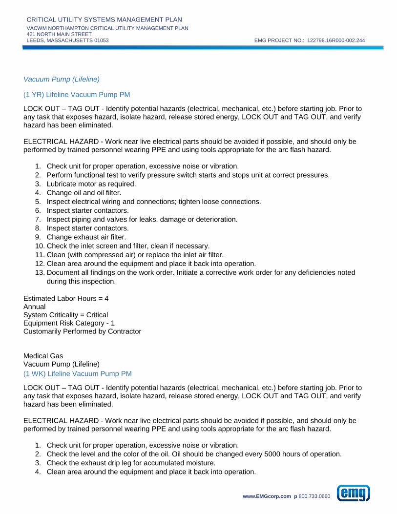
CRITICAL UTILITY SYSTEMS MANAGEMENT PLAN
VACWM NORTHAMPTON CRITICAL UTILITY MANAGEMENT PLAN 421 NORTH MAIN STREET
LEEDS, MASSACHUSETTS 01053 EMG PROJECT NO.: 122798.16R000-002.244
www.EMGcorp.com p 800.733.0660
Vacuum Pump (Lifeline)
(1 YR) Lifeline Vacuum Pump PM
LOCK OUT – TAG OUT - Identify potential hazards (electrical, mechanical, etc.) before starting job. Prior to any task that exposes hazard, isolate hazard, release stored energy, LOCK OUT and TAG OUT, and verify hazard has been eliminated. ELECTRICAL HAZARD - Work near live electrical parts should be avoided if possible, and should only be performed by trained personnel wearing PPE and using tools appropriate for the arc flash hazard.
1. Check unit for proper operation, excessive noise or vibration.
2. Perform functional test to verify pressure switch starts and stops unit at correct pressures.
3. Lubricate motor as required.
4. Change oil and oil filter.
5. Inspect electrical wiring and connections; tighten loose connections.
6. Inspect starter contactors.
7. Inspect piping and valves for leaks, damage or deterioration.
8. Inspect starter contactors.
9. Change exhaust air filter.
10. Check the inlet screen and filter, clean if necessary.
11. Clean (with compressed air) or replace the inlet air filter.
12. Clean area around the equipment and place it back into operation.
13. Document all findings on the work order. Initiate a corrective work order for any deficiencies noted
during this inspection.
Estimated Labor Hours = 4 Annual System Criticality = Critical Equipment Risk Category - 1 Customarily Performed by Contractor Medical Gas Vacuum Pump (Lifeline)
(1 WK) Lifeline Vacuum Pump PM
LOCK OUT – TAG OUT - Identify potential hazards (electrical, mechanical, etc.) before starting job. Prior to any task that exposes hazard, isolate hazard, release stored energy, LOCK OUT and TAG OUT, and verify hazard has been eliminated. ELECTRICAL HAZARD - Work near live electrical parts should be avoided if possible, and should only be performed by trained personnel wearing PPE and using tools appropriate for the arc flash hazard.
1. Check unit for proper operation, excessive noise or vibration.
2. Check the level and the color of the oil. Oil should be changed every 5000 hours of operation.
3. Check the exhaust drip leg for accumulated moisture.
4. Clean area around the equipment and place it back into operation.

CRITICAL UTILITY SYSTEMS MANAGEMENT PLAN
VACWM NORTHAMPTON CRITICAL UTILITY MANAGEMENT PLAN 421 NORTH MAIN STREET
LEEDS, MASSACHUSETTS 01053 EMG PROJECT NO.: 122798.16R000-002.244
www.EMGcorp.com p 800.733.0660
5. Document all findings on the work order. Initiate a corrective work order for any deficiencies noted
during this inspection.
Estimated Labor Hours = 0.25 Weekly System Criticality = Critical Equipment Risk Category - 1 Customarily Performed by Employee Medical Gas Vacuum Pump (Lifeline)
(1 MO) Lifeline Vacuum Pump PM
LOCK OUT – TAG OUT - Identify potential hazards (electrical, mechanical, etc.) before starting job. Prior to any task that exposes hazard, isolate hazard, release stored energy, LOCK OUT and TAG OUT, and verify hazard has been eliminated. ELECTRICAL HAZARD - Work near live electrical parts should be avoided if possible, and should only be performed by trained personnel wearing PPE and using tools appropriate for the arc flash hazard.
1. Check unit for proper operation, excessive noise or vibration.
2. Check the level and the color of the oil. Oil should be changed every 5000 hours of operation.
3. Inspect vacuum pump, piping and valves for leaks, damage or deterioration.
4. Check the function of the exhaust filters.
5. Check the inlet air filter, if necessary clean (with compressed air) or replace.
6. Inspect housing for dust and dirt, clean if necessary.
7. Clean area around the equipment and place it back into operation.
8. Document all findings on the work order. Initiate a corrective work order for any deficiencies noted
during this inspection.
Estimated Labor Hours = 0.5 Monthly System Criticality = Critical Equipment Risk Category - 1 Customarily Performed by Employee Medical Gas Vacuum Pump (Lifeline)
(3 MO) Lifeline Vacuum Pump PM
LOCK OUT – TAG OUT - Identify potential hazards (electrical, mechanical, etc.) before starting job. Prior to any task that exposes hazard, isolate hazard, release stored energy, LOCK OUT and TAG OUT, and verify hazard has been eliminated. ELECTRICAL HAZARD - Work near live electrical parts should be avoided if possible, and should only be performed by trained personnel wearing PPE and using tools appropriate for the arc flash hazard.
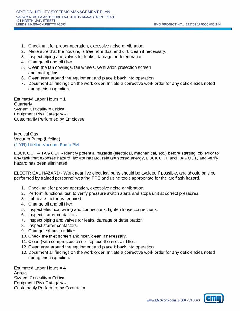
CRITICAL UTILITY SYSTEMS MANAGEMENT PLAN
VACWM NORTHAMPTON CRITICAL UTILITY MANAGEMENT PLAN 421 NORTH MAIN STREET
LEEDS, MASSACHUSETTS 01053 EMG PROJECT NO.: 122798.16R000-002.244
www.EMGcorp.com p 800.733.0660
1. Check unit for proper operation, excessive noise or vibration.
2. Make sure that the housing is free from dust and dirt, clean if necessary.
3. Inspect piping and valves for leaks, damage or deterioration.
4. Change oil and oil filter.
5. Clean the fan cowlings, fan wheels, ventilation protection screen
and cooling fins.
6. Clean area around the equipment and place it back into operation.
7. Document all findings on the work order. Initiate a corrective work order for any deficiencies noted
during this inspection.
Estimated Labor Hours = 1 Quarterly System Criticality = Critical Equipment Risk Category - 1 Customarily Performed by Employee Medical Gas Vacuum Pump (Lifeline)
(1 YR) Lifeline Vacuum Pump PM
LOCK OUT – TAG OUT - Identify potential hazards (electrical, mechanical, etc.) before starting job. Prior to any task that exposes hazard, isolate hazard, release stored energy, LOCK OUT and TAG OUT, and verify hazard has been eliminated. ELECTRICAL HAZARD - Work near live electrical parts should be avoided if possible, and should only be performed by trained personnel wearing PPE and using tools appropriate for the arc flash hazard.
1. Check unit for proper operation, excessive noise or vibration.
2. Perform functional test to verify pressure switch starts and stops unit at correct pressures.
3. Lubricate motor as required.
4. Change oil and oil filter.
5. Inspect electrical wiring and connections; tighten loose connections.
6. Inspect starter contactors.
7. Inspect piping and valves for leaks, damage or deterioration.
8. Inspect starter contactors.
9. Change exhaust air filter.
10. Check the inlet screen and filter, clean if necessary.
11. Clean (with compressed air) or replace the inlet air filter.
12. Clean area around the equipment and place it back into operation.
13. Document all findings on the work order. Initiate a corrective work order for any deficiencies noted
during this inspection.
Estimated Labor Hours = 4 Annual System Criticality = Critical Equipment Risk Category - 1 Customarily Performed by Contractor

CRITICAL UTILITY SYSTEMS MANAGEMENT PLAN
VACWM NORTHAMPTON CRITICAL UTILITY MANAGEMENT PLAN 421 NORTH MAIN STREET
LEEDS, MASSACHUSETTS 01053 EMG PROJECT NO.: 122798.16R000-002.244
www.EMGcorp.com p 800.733.0660
Plumbing
Plumbing
BackFlow Preventer
(1 YR) Backflow Preventer PM
LOCK OUT – TAG OUT - Identify potential hazards (electrical, mechanical, etc.) before starting job. Prior to any task that exposes hazard, isolate hazard, release stored energy, LOCK OUT and TAG OUT, and verify hazard has been eliminated.
1. Backflow preventer should be tested annually by a certified tester and completed test form submitted to
city.
2. Check unit for proper operation, leaks or damage.
3. Secure the incoming potable water line(s).
4. On reduced pressure zone backflow preventers, perform the following tests in accordance with the
manufacturer's specifications, using the appropriate test kit: (a) Test check valve number 2 for tightness
against reverse flow. (b) Test gate valve number 2 for tightness.(c) Test check valve number 1 for
tightness.(d) Test operation of pressure differential relief valve.
5. Service the first and second checks. CAUTION: If the check valve is spring loaded, do not remove the
spring retainers. Consult the manufacturer's instructions for proper servicing. (a) Carefully remove
screws, cover, and check. (b) Disengage the disc and spring assembly into individual components in
accordance with manufacturer's instructions. Remove any embedded foreign objects, and inspect for
corrosion, worn seals, etc. Clean or replace the assembly as required.(c) Clean or replace seals as
necessary. Apply a light coating of manufacturer's specified and FDA approved lubrication prior to
installation of seals. (d)Reassemble the check valve module in reverse order. (e) Repeat for second
check.
6. Service the relief valve. CAUTION: Springs may be loaded. Strictly comply with manufacturer's
instructions.(a) Remove bolts, cover, diaphragm, and relief valve piston assembly per manufacturer's
instructions.(b) Clean or replace wiper seal, piston "O" ring, and relief valve disc as required. Apply
appropriate lubricant to "O" ring per manufacturer's specifications prior to reinstallation. (c) Inspect
bottom spring assembly. If defective, replace entire unit. Do not attempt to remove the spring.
7. Following the manufacturer's procedures, test and calibrate the device.
8. Clean area and remove all debris.
9. Document all findings on the work order. Initiate a corrective work order for any deficiencies noted
during this inspection.
Estimated Labor Hours = 4 Annual System Criticality = Critical Equipment Risk Category - 2 Customarily Performed by Contractor Plumbing

CRITICAL UTILITY SYSTEMS MANAGEMENT PLAN
VACWM NORTHAMPTON CRITICAL UTILITY MANAGEMENT PLAN 421 NORTH MAIN STREET
LEEDS, MASSACHUSETTS 01053 EMG PROJECT NO.: 122798.16R000-002.244
www.EMGcorp.com p 800.733.0660
Domestic Hot Water
(1 YR) Legionella Testing
Review the work you about to perform. Identify PPE required to perform the work safely. Use the correct tools and ensure tools are in good condition.
1. Order Legionella Testing kit for each sample area. (All closed loop systems).
2. Once kit arrives, read and follow procedures supplied with the test kit.
3. Take sample of closed loop domestic hot water.
4. Make sure sample is clearly marked with sample location.
5. Send test sample to lab.
6. Document all findings on the work order. Initiate a corrective work order for any deficiencies noted
during this test.
Estimated Labor Hours = 1 Annual System Criticality = Critical Equipment Risk Category - 3 Customarily Performed by Contractor Plumbing
Pump
(3 MO) Pump PM
Review the work you about to perform. Identify PPE required to perform the work safely. Use the correct tools and ensure tools are in good condition.
1. Check unit for proper operation, excessive noise or vibration.
2. Inspect piping and valves for leaks, damage or deterioration.
3. Lubricate pump bearings, as required.
4. Clean pump motor exterior
5. Check general condition of the pump
6. Clean area around pump.
7. Document all findings on the work order. Initiate a corrective work order for any deficiencies noted
during this inspection.
Estimated Labor Hours = 0.75 Quarterly System Criticality = Critical Equipment Risk Category - 3 Customarily Performed by Employee Plumbing Pump
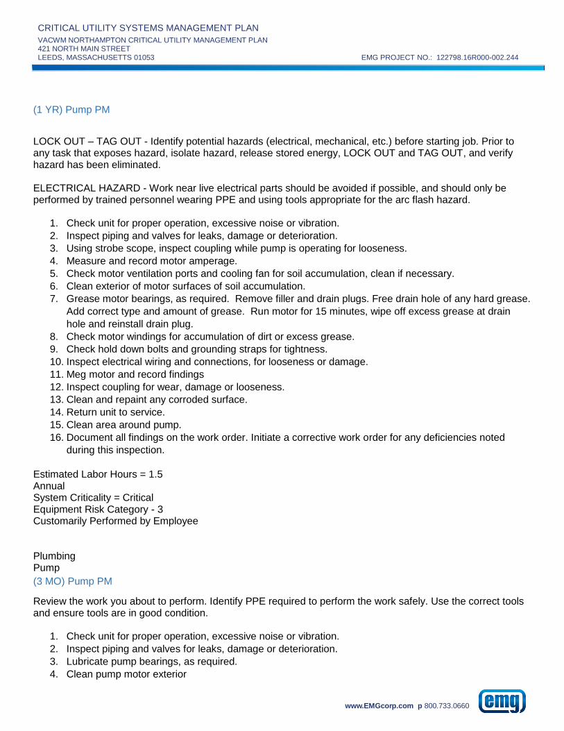
CRITICAL UTILITY SYSTEMS MANAGEMENT PLAN
VACWM NORTHAMPTON CRITICAL UTILITY MANAGEMENT PLAN 421 NORTH MAIN STREET
LEEDS, MASSACHUSETTS 01053 EMG PROJECT NO.: 122798.16R000-002.244
www.EMGcorp.com p 800.733.0660
(1 YR) Pump PM
LOCK OUT – TAG OUT - Identify potential hazards (electrical, mechanical, etc.) before starting job. Prior to any task that exposes hazard, isolate hazard, release stored energy, LOCK OUT and TAG OUT, and verify hazard has been eliminated. ELECTRICAL HAZARD - Work near live electrical parts should be avoided if possible, and should only be performed by trained personnel wearing PPE and using tools appropriate for the arc flash hazard.
1. Check unit for proper operation, excessive noise or vibration.
2. Inspect piping and valves for leaks, damage or deterioration.
3. Using strobe scope, inspect coupling while pump is operating for looseness.
4. Measure and record motor amperage.
5. Check motor ventilation ports and cooling fan for soil accumulation, clean if necessary.
6. Clean exterior of motor surfaces of soil accumulation.
7. Grease motor bearings, as required. Remove filler and drain plugs. Free drain hole of any hard grease.
Add correct type and amount of grease. Run motor for 15 minutes, wipe off excess grease at drain
hole and reinstall drain plug.
8. Check motor windings for accumulation of dirt or excess grease.
9. Check hold down bolts and grounding straps for tightness.
10. Inspect electrical wiring and connections, for looseness or damage.
11. Meg motor and record findings
12. Inspect coupling for wear, damage or looseness.
13. Clean and repaint any corroded surface.
14. Return unit to service.
15. Clean area around pump.
16. Document all findings on the work order. Initiate a corrective work order for any deficiencies noted
during this inspection.
Estimated Labor Hours = 1.5 Annual System Criticality = Critical Equipment Risk Category - 3 Customarily Performed by Employee Plumbing Pump
(3 MO) Pump PM
Review the work you about to perform. Identify PPE required to perform the work safely. Use the correct tools and ensure tools are in good condition.
1. Check unit for proper operation, excessive noise or vibration.
2. Inspect piping and valves for leaks, damage or deterioration.
3. Lubricate pump bearings, as required.
4. Clean pump motor exterior

CRITICAL UTILITY SYSTEMS MANAGEMENT PLAN
VACWM NORTHAMPTON CRITICAL UTILITY MANAGEMENT PLAN 421 NORTH MAIN STREET
LEEDS, MASSACHUSETTS 01053 EMG PROJECT NO.: 122798.16R000-002.244
www.EMGcorp.com p 800.733.0660
5. Check general condition of the pump
6. Clean area around pump.
7. Document all findings on the work order. Initiate a corrective work order for any deficiencies noted
during this inspection.
Estimated Labor Hours = 0.75 Quarterly System Criticality = Critical Equipment Risk Category - 2 Customarily Performed by Employee Plumbing Pump
(1 YR) Pump PM
LOCK OUT – TAG OUT - Identify potential hazards (electrical, mechanical, etc.) before starting job. Prior to any task that exposes hazard, isolate hazard, release stored energy, LOCK OUT and TAG OUT, and verify hazard has been eliminated. ELECTRICAL HAZARD - Work near live electrical parts should be avoided if possible, and should only be performed by trained personnel wearing PPE and using tools appropriate for the arc flash hazard.
1. Check unit for proper operation, excessive noise or vibration.
2. Inspect piping and valves for leaks, damage or deterioration.
3. Using strobe scope, inspect coupling while pump is operating for looseness.
4. Measure and record motor amperage.
5. Check motor ventilation ports and cooling fan for soil accumulation, clean if necessary.
6. Clean exterior of motor surfaces of soil accumulation.
7. Grease motor bearings, as required. Remove filler and drain plugs. Free drain hole of any hard grease.
Add correct type and amount of grease. Run motor for 15 minutes, wipe off excess grease at drain
hole and reinstall drain plug.
8. Check motor windings for accumulation of dirt or excess grease.
9. Check hold down bolts and grounding straps for tightness.
10. Inspect electrical wiring and connections, for looseness or damage.
11. Meg motor and record findings
12. Inspect coupling for wear, damage or looseness.
13. Clean and repaint any corroded surface.
14. Return unit to service.
15. Clean area around pump.
16. Document all findings on the work order. Initiate a corrective work order for any deficiencies noted
during this inspection.
Estimated Labor Hours = 1.5 Annual System Criticality = Critical Equipment Risk Category - 2 Customarily Performed by Employee

CRITICAL UTILITY SYSTEMS MANAGEMENT PLAN
VACWM NORTHAMPTON CRITICAL UTILITY MANAGEMENT PLAN 421 NORTH MAIN STREET
LEEDS, MASSACHUSETTS 01053 EMG PROJECT NO.: 122798.16R000-002.244
www.EMGcorp.com p 800.733.0660
Plumbing
Pump (HWP Armstrong)
(3 MO) Armstrong Pump PM
Review the work you about to perform. Identify PPE required to perform the work safely. Use the correct tools and ensure tools are in good condition.
1. Check unit for proper operation, excessive noise or vibration.
2. Inspect piping and valves for leaks, damage or deterioration.
3. Inspect the entire hydronic system. Repair or replace as needed.
4. Inspect the ARMflo E Series circulator. Repair or replace as needed.
5. Clean pump motor exterior
6. Check general condition of the pump
7. Clean area around pump.
8. Document all findings on the work order. Initiate a corrective work order for any deficiencies noted
during this inspection.
Estimated Labor Hours = 0.75 Quarterly System Criticality = Critical Equipment Risk Category - 3 Customarily Performed by Employee Plumbing Pump (HWP Armstrong)
(1 YR) Armstrong Pump PM
LOCK OUT – TAG OUT - Identify potential hazards (electrical, mechanical, etc.) before starting job. Prior to any task that exposes hazard, isolate hazard, release stored energy, LOCK OUT and TAG OUT, and verify hazard has been eliminated. ELECTRICAL HAZARD - Work near live electrical parts should be avoided if possible, and should only be performed by trained personnel wearing PPE and using tools appropriate for the arc flash hazard.
1. Check unit for proper operation, excessive noise or vibration.
2. Inspect piping and valves for leaks, damage or deterioration.
3. Inspect the entire hydronic system. Repair or replace as needed.
4. Inspect the ARMflo E Series circulator. Repair or replace as needed.
5. Using strobe scope, inspect coupling while pump is operating for looseness.
6. Measure and record motor amperage.
7. Check motor ventilation ports and cooling fan for soil accumulation, clean if necessary.
8. Clean exterior of motor surfaces of soil accumulation.

CRITICAL UTILITY SYSTEMS MANAGEMENT PLAN
VACWM NORTHAMPTON CRITICAL UTILITY MANAGEMENT PLAN 421 NORTH MAIN STREET
LEEDS, MASSACHUSETTS 01053 EMG PROJECT NO.: 122798.16R000-002.244
www.EMGcorp.com p 800.733.0660
9. Grease motor bearings, as required. Remove filler and drain plugs. Free drain hole of any hard grease.
Add correct type and amount of grease. Run motor for 15 minutes, wipe off excess grease at drain
hole and reinstall drain plug.
10. Check motor windings for accumulation of dirt or excess grease.
11. Check hold down bolts and grounding straps for tightness.
12. Inspect electrical wiring and connections, for looseness or damage.
13. Meg motor and record findings
14. Inspect coupling for wear, damage or looseness.
15. Clean and repaint any corroded surface.
16. Return unit to service.
17. Clean area around pump.
18. Document all findings on the work order. Initiate a corrective work order for any deficiencies noted
during this inspection.
Estimated Labor Hours = 1.5 Annual System Criticality = Critical Equipment Risk Category - 3 Customarily Performed by Employee Plumbing
RO System
(3 MO) RO System PM
Review the work you about to perform. Identify PPE required to perform the work safely. Use the correct tools and ensure tools are in good condition.
1. Inspect unit for water leaks and tight fitting connections. Clean all connections. Verify that drain lines
are unobstructed.
2. Inspect all electrical wiring, switches, accessory connections, and insulation. Check interior of control
panel.
3. Inspect water distribution pump drive motor, mounts and electrical connections. Clean motor air
passage.
4. Inspect water pump, mounts, housing, seals, connections, water lines, valves, and gauges. Check
pump/motor coupling and alignment.
5. Check holding tank pure water temperature control valve operation.
6. Check low water and high water level control operation.
7. Perform chemical water test to verify acceptable water quality.
8. If chlorine content exceeds 0.1 ppm, replace activated charcoal filters.
9. Check chemical feed system pump and piping for leaks. Verify that the chemical supply level is
maintained.
10. Clean area around equipment.
11. Document all findings on the work order. Initiate a corrective work order for any deficiencies noted
during this inspection.

CRITICAL UTILITY SYSTEMS MANAGEMENT PLAN
VACWM NORTHAMPTON CRITICAL UTILITY MANAGEMENT PLAN 421 NORTH MAIN STREET
LEEDS, MASSACHUSETTS 01053 EMG PROJECT NO.: 122798.16R000-002.244
www.EMGcorp.com p 800.733.0660
Estimated Labor Hours = 1 Quarterly System Criticality = Critical Equipment Risk Category - 2 Customarily Performed by Employee Plumbing RO System
(1 YR) RO System PM
Review the work you about to perform. Identify PPE required to perform the work safely. Use the correct tools and ensure tools are in good condition.
1. Inspect unit for water leaks and tight fitting connections. Clean all connections. Verify that drain lines
are unobstructed.
2. Inspect all electrical wiring, switches, accessory connections, and insulation. Check interior of control
panel.
3. Inspect water distribution pump drive motor, mounts and electrical connections. Clean motor air
passage.
4. Inspect water pump, mounts, housing, seals, connections, water lines, valves, and gauges. Check
pump/motor coupling and alignment.
5. Check holding tank pure water temperature control valve operation.
6. Check low water and high water level control operation.
7. Perform chemical water test to verify acceptable water quality.
8. If chlorine content exceeds 0.1 ppm, replace activated charcoal filters.
9. Check chemical feed system pump and piping for leaks. Verify that the chemical supply level is
maintained.
10. Inspect pre-filter assemblies. Clean or replace filters as needed (Max. pressure drop: 10 psi).
11. Drain and open tank and inspect interior.
12. Check chemical pump, mixer motor cords and electrical ground.
13. Check reservoir and piping for algae or slime contamination. If contaminated, purge system and
perform chemical cleanup.
14. Clean area around equipment.
15. Document all findings on the work order. Initiate a corrective work order for any deficiencies noted
during this inspection.
Estimated Labor Hours = 3 Annual System Criticality = Critical Equipment Risk Category - 2 Customarily Performed by Contractor Plumbing

CRITICAL UTILITY SYSTEMS MANAGEMENT PLAN
VACWM NORTHAMPTON CRITICAL UTILITY MANAGEMENT PLAN 421 NORTH MAIN STREET
LEEDS, MASSACHUSETTS 01053 EMG PROJECT NO.: 122798.16R000-002.244
www.EMGcorp.com p 800.733.0660
Valve
(1 YR) Valve PM
Review the work you about to perform. Identify PPE required to perform the work safely. Use the correct tools and ensure tools are in good condition.
1. Operate valve open and closed and return to as found position.
2. Inspect leaks, damage or deterioration.
3. Clean area around unit.
4. Document all findings on the work order. Initiate a corrective work order for any deficiencies noted
during this inspection.
Estimated Labor Hours = 1 Annual System Criticality = Critical Equipment Risk Category - 2 Customarily Performed by Employee Plumbing
Water Heater
(1 YR) Water Heater PM
LOCK OUT – TAG OUT - Identify potential hazards (electrical, mechanical, etc.) before starting job. Prior to any task that exposes hazard, isolate hazard, release stored energy, LOCK OUT and TAG OUT, and verify hazard has been eliminated. ELECTRICAL HAZARD - Work near live electrical parts should be avoided if possible, and should only be performed by trained personnel wearing PPE and using tools appropriate for the arc flash hazard.
1. Drain several gallons from tank to remove sediment.
2. Manually check operation of safety valve. Check for corrosion.
3. Inspect electrical wiring and connections, for looseness or damage.
4. Inspect piping and valves for leaks, damage or deterioration.
5. Check operation and setting of aquastat. Check hot water temperature with dial thermometer, and set
aquastat at minimum value.
6. Check amperage draw of upper and lower elements and compare to name plate data.
7. Clean area and remove all debris.
8. Document all findings on the work order. Initiate a corrective work order for any deficiencies noted
during this inspection.
Estimated Labor Hours = 1 Annual System Criticality = Critical Equipment Risk Category - 3 Customarily Performed by Employee

CRITICAL UTILITY SYSTEMS MANAGEMENT PLAN
VACWM NORTHAMPTON CRITICAL UTILITY MANAGEMENT PLAN 421 NORTH MAIN STREET
LEEDS, MASSACHUSETTS 01053 EMG PROJECT NO.: 122798.16R000-002.244
www.EMGcorp.com p 800.733.0660
Plumbing
Water Heater, Electric
(1 YR) Water Heater, Electric PM
LOCK OUT – TAG OUT - Identify potential hazards (electrical, mechanical, etc.) before starting job. Prior to any task that exposes hazard, isolate hazard, release stored energy, LOCK OUT and TAG OUT, and verify hazard has been eliminated. ELECTRICAL HAZARD - Work near live electrical parts should be avoided if possible, and should only be performed by trained personnel wearing PPE and using tools appropriate for the arc flash hazard.
1. Drain several gallons from tank to remove sediment.
2. Manually check operation of safety valve. Check for corrosion.
3. Inspect electrical wiring and connections, for looseness or damage.
4. Inspect piping and valves for leaks, damage or deterioration.
5. Check operation and setting of aquastat. Check hot water temperature with dial thermometer, and set
aquastat at minimum value.
6. Check amperage draw of upper and lower elements and compare to name plate data.
7. Clean area and remove all debris.
8. Document all findings on the work order. Initiate a corrective work order for any deficiencies noted
during this inspection.
Estimated Labor Hours = 1 Annual System Criticality = Critical Equipment Risk Category - 3 Customarily Performed by Employee Plumbing
Water Softener
(1 YR) Water Softener PM
LOCK OUT – TAG OUT - Identify potential hazards (electrical, mechanical, etc.) before starting job. Prior to any task that exposes hazard, isolate hazard, release stored energy, LOCK OUT and TAG OUT, and verify hazard has been eliminated. ELECTRICAL HAZARD - Work near live electrical parts should be avoided if possible, and should only be performed by trained personnel wearing PPE and using tools appropriate for the arc flash hazard.
1. Inspect electrical wiring and connections, for looseness or damage.
2. Inspect piping and valves for leaks, damage or deterioration. Operate manual valves through their full
range.
3. Perform functional test of controls, control valves and regeneration sequence. Verify smooth operation
of controls.

CRITICAL UTILITY SYSTEMS MANAGEMENT PLAN
VACWM NORTHAMPTON CRITICAL UTILITY MANAGEMENT PLAN 421 NORTH MAIN STREET
LEEDS, MASSACHUSETTS 01053 EMG PROJECT NO.: 122798.16R000-002.244
www.EMGcorp.com p 800.733.0660
4. Have elution study performed to determine the effectiveness of the softener.
5. Clean area around unit.
6. Document all findings on the work order. Initiate a corrective work order for any deficiencies noted
during this inspection.
Estimated Labor Hours = 1 Annual System Criticality = Critical Equipment Risk Category - 2 Customarily Performed by Contractor Plumbing Water Softener
(1 YR) Water Softener PM
LOCK OUT – TAG OUT - Identify potential hazards (electrical, mechanical, etc.) before starting job. Prior to any task that exposes hazard, isolate hazard, release stored energy, LOCK OUT and TAG OUT, and verify hazard has been eliminated. ELECTRICAL HAZARD - Work near live electrical parts should be avoided if possible, and should only be performed by trained personnel wearing PPE and using tools appropriate for the arc flash hazard.
1. Inspect electrical wiring and connections, for looseness or damage.
2. Inspect piping and valves for leaks, damage or deterioration. Operate manual valves through their full
range.
3. Perform functional test of controls, control valves and regeneration sequence. Verify smooth operation
of controls.
4. Have elution study performed to determine the effectiveness of the softener.
5. Clean area around unit.
6. Document all findings on the work order. Initiate a corrective work order for any deficiencies noted
during this inspection.
Estimated Labor Hours = 1 Annual System Criticality = Critical Equipment Risk Category - 2 Customarily Performed by Contractor

CRITICAL UTILITY SYSTEMS MANAGEMENT PLAN
VACWM NORTHAMPTON CRITICAL UTILITY MANAGEMENT PLAN 421 NORTH MAIN STREET
LEEDS, MASSACHUSETTS 01053 EMG PROJECT NO.: 122798.16R000-002.244
www.EMGcorp.com p 800.733.0660
APPENDIX C:
EQUIPMENT PRE-FUNCTIONAL CHECKLISTS

CRITICAL UTILITY SYSTEMS MANAGEMENT PLAN
VACWM NORTHAMPTON CRITICAL UTILITY MANAGEMENT PLAN 421 NORTH MAIN STREET
LEEDS, MASSACHUSETTS 01053 EMG PROJECT NO.: 122798.16R000-002.244
www.EMGcorp.com p 800.733.0660
PREFUNCTIONAL CHECKLIST - Switchgear, Panelboards, Motor Control Centers, Transformers Project: _____________________________________ Project #:_____________________ Identification of Equipment or System: _________________________________________ Location of Equipment or System: _______________________________________________ Specification Section: ____________________ Detail/Drawing Number: _______________ Manufacturer / Supplier: ________________________________________________________ This Date: __________________ Inspection Requested for (Date): __________________ ════════════════════════════════════════════════════════════ Prefunctional Checklist Number: __________________ Components Included: ____Disconnects ____Fuses ____Meters ____Other __________________________________________________ Associated Prefunctional Checklists: __________________ __________________ General: The above systems and components integral to this equipment are complete and ready for Functional Performance Tests. The Prefunctional Checklist items are complete and have been checked off only by parties having direct knowledge of the event, as indicted below, respective to each responsible contractor. This Prefunctional Checklist is submitted for approval and is subject to the attached list of outstanding items not completed successfully. Submit a Deficiency Form upon completion of any outstanding or deficient items. None of the outstanding items preclude safe and reliable functional tests being performed. ___ Deficiency Form attached. This Prefunctional Checklist does not take the place of the manufacturer’s recommended checkout and Start-up procedures or report. Contractors assigned responsibility for sections of the Prefunctional Checklist shall be responsible to ensure that their subcontractors complete and check off their Checklist items. Prefunctional Checklist items shall be completed as part of Start-up and initial checkout, preparatory to functional testing.

CRITICAL UTILITY SYSTEMS MANAGEMENT PLAN
VACWM NORTHAMPTON CRITICAL UTILITY MANAGEMENT PLAN 421 NORTH MAIN STREET
LEEDS, MASSACHUSETTS 01053 EMG PROJECT NO.: 122798.16R000-002.244
www.EMGcorp.com p 800.733.0660
Contractor/Entity Company Abbreviation
VACWM Staff VACWM
Architect/Engineer A/E
General Contractor / Construction Manager
GC
Mechanical Contractor MC
Electrical Contractor EC
Building Automation System Provider BAS
Test, Adjust, and Balance Firm TAB
Commissioning Consultant CA
Requested Documentation Submitted:
Specified Requirement Yes No Date to be Submitted
a) Manufacturer’s Product Data including Performance Data and Shop Drawings, as approved by Architect/Engineer
b) Required Test Reports and/or Certifications
c) Installation and Start-up Manual and Plan
d) Wiring Diagrams, Control Schematics and Sequences
e) Operating and Maintenance Manual Content for Applicable System
f) Equipment Matrix
Equipment Verification:
Item Specified Submitted Installed
Manufacturer
Model Number
Serial Number
Service
Equipment Rating (amps)
Voltage/Phase
Installation Checks:
a) Unit and General Installation Yes No Comments
1. Permanent labels affixed
2. Physical condition acceptable, no visible damage, cabinets in place
3. Properly mounted on equipment pad and anchored
4. Maintenance access acceptable
5. Interior clean and dry
6. Meter(s) installed per Contract Documents
7. Disconnects installed and labeled
8. Disconnects are pad lockable in open position
9. Circuit breakers installed and labeled
10. Fuses installed
11. Conduits installed and connected
12. Cable/conduit routing does not obstruct access
13. Equipment room properly ventilated, air-conditioned, heated, fire/smoke wall separated, fire/smoke dampered, fire sprinklered, fire alarmed and illuminated (normal, emergency and battery

CRITICAL UTILITY SYSTEMS MANAGEMENT PLAN
VACWM NORTHAMPTON CRITICAL UTILITY MANAGEMENT PLAN 421 NORTH MAIN STREET
LEEDS, MASSACHUSETTS 01053 EMG PROJECT NO.: 122798.16R000-002.244
www.EMGcorp.com p 800.733.0660
a) Unit and General Installation Yes No Comments
backed-up fixtures)
14. Record Drawings updated
b) Switchgear (service entrance 1500kVA and above) and Switchboards (service entrance less than 1500 kVA)
Yes No Comments
1. Free standing metal enclosure
2. Cobber buses
3. Penetration to utility service area and equipment per code
c) Distribution Panelboards and other Panelboards Yes No Comments
1. Tin plated copper buses
2. Each circuit identified and labeled
3. Space for additional circuits exist
d) Motor Control Centers Yes No Comments
1. Tin plated copper buses
2. Main breakers installed and labeled
3. Each circuit identified and labeled
e) Transformers Yes No Comments
1. Dry type installed
2. Unit properly labeled and identified
f) Electrical and Controls Yes No Comments
1. Panel devices labeled and wiring tagged per Contract Documents
2. I/O devices labeled and wiring tagged per Contract Documents
3. Digital inputs and outputs operational
4. All electrical connections tight
5. Proper grounding installed for the electrical system, equipment, components, and unit
6. Safeties in place and operable
7. Sensors, transmitters, gages, etc., installed
8. Sensors calibrated (see below)
9. Control system interlocks hooked up and functional
10. All control devices and wiring complete
11. Lightning protection installed
12. Surge protection installed
g) Final Yes No Comments
1. Start-up report completed and attached with this Prefunctional Checklist
2. Safeties and safe operating ranges for this equipment have been reviewed and accepted
3. System is ready for Functional Performance Test

CRITICAL UTILITY SYSTEMS MANAGEMENT PLAN
VACWM NORTHAMPTON CRITICAL UTILITY MANAGEMENT PLAN 421 NORTH MAIN STREET
LEEDS, MASSACHUSETTS 01053 EMG PROJECT NO.: 122798.16R000-002.244
www.EMGcorp.com p 800.733.0660
Operational Checks: These checks supplement the manufacturer’s list. This is not the Functional Performance Test.
Operational Checks Yes No Comments
1. Associated Prefunctional Checklists are complete and accepted
2. Fuses are good
3. Resistance check(s) complete with results attached
4. Disconnect switch operates smoothly with full contact
5. Specified point-to-point checks have been completed and documentation record submitted for this system
Sensor and/or Actuator Calibration: All field-installed temperature sensors, pressure sensors, meters, and gages, and all actuators and valves on this piece of equipment shall be calibrated. Sensors installed in the unit at the factory with calibration certification provided are not required to be field calibrated. All test instruments have had a certified calibration within the last 12-months: Y / N Sensor/Actuator Verification Table
Sensor or Actuator Correct Location (Y/N) (1)
Thermometer or Gage Value
BAS Value (2)
Instrument Measured Value (3)
Pass (Y/N)
1) Thermometer/Gage reading is the reading of the permanently mounted instrument on the equipment. 2) BAS is the Building Automation System. Instrument = testing instrument. 3) All sensors are calibrated within required tolerances ___ YES ___ NO
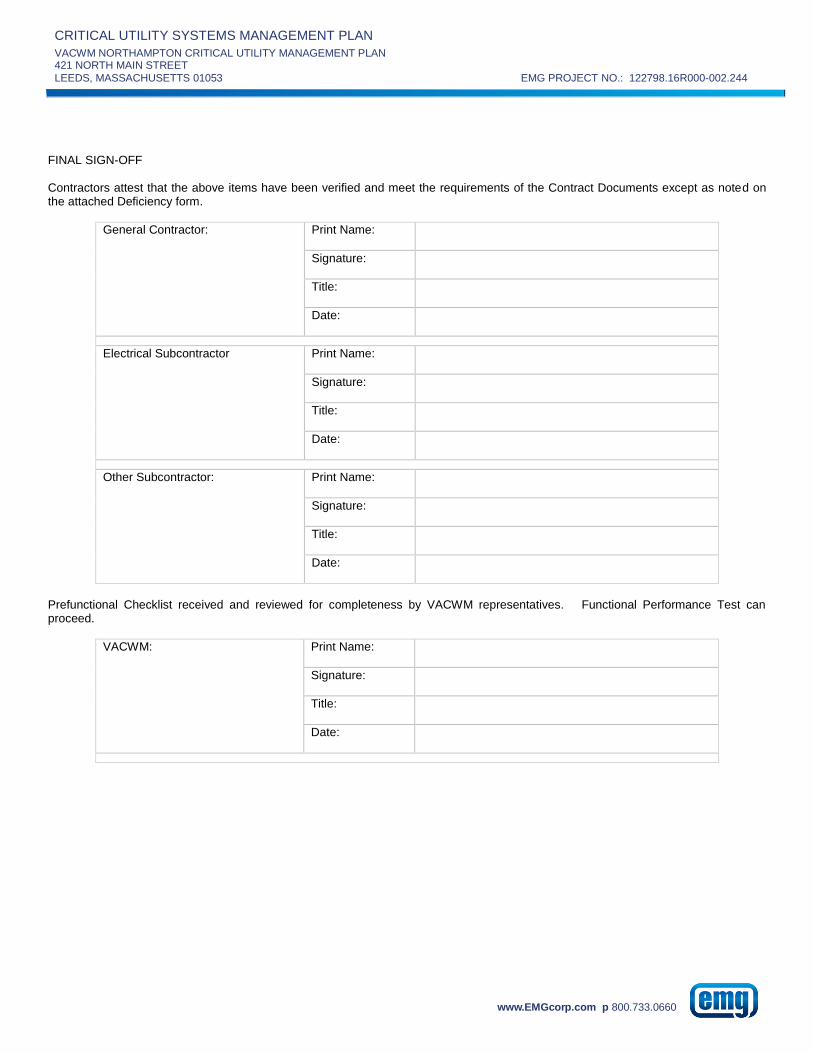
CRITICAL UTILITY SYSTEMS MANAGEMENT PLAN
VACWM NORTHAMPTON CRITICAL UTILITY MANAGEMENT PLAN 421 NORTH MAIN STREET
LEEDS, MASSACHUSETTS 01053 EMG PROJECT NO.: 122798.16R000-002.244
www.EMGcorp.com p 800.733.0660
FINAL SIGN-OFF Contractors attest that the above items have been verified and meet the requirements of the Contract Documents except as noted on the attached Deficiency form.
General Contractor: Print Name:
Signature:
Title:
Date:
Electrical Subcontractor Print Name:
Signature:
Title:
Date:
Other Subcontractor: Print Name:
Signature:
Title:
Date:
Prefunctional Checklist received and reviewed for completeness by VACWM representatives. Functional Performance Test can proceed.
VACWM: Print Name:
Signature:
Title:
Date:

CRITICAL UTILITY SYSTEMS MANAGEMENT PLAN
VACWM NORTHAMPTON CRITICAL UTILITY MANAGEMENT PLAN 421 NORTH MAIN STREET
LEEDS, MASSACHUSETTS 01053 EMG PROJECT NO.: 122798.16R000-002.244
www.EMGcorp.com p 800.733.0660
PREFUNCTIONAL CHECKLIST Emergency Power System Project: _____________________________________ Project #:_____________________
Identification of Equipment or System: _________________________________________ Location of Equipment or System: _______________________________________________ Specification Section: ____________________ Detail/Drawing Number: _______________ Manufacturer / Supplier: ________________________________________________________ This Date: __________________ Inspection Requested for (Date): __________________ ════════════════════════════════════════════════════════════
PREFUNCTIONAL CHECKLIST NUMBER: ___________ Components Included: ___ Prime Mover, ___ Generator, ___ Fuel System, ___Cooling System, ___Battery System, ___ Exhaust System, ___ ATS, ___ UPS Associated Prefunctional Checklists: ___Mechanical Equipment ___ Electrical Equipment General: The above systems and components integral to this equipment are complete and ready for Functional Performance Tests. The Prefunctional Checklist items are complete and have been checked off only by parties having direct knowledge of the event, as indicted below, respective to each responsible contractor. This Prefunctional Checklist is submitted for approval and is subject to the attached list of outstanding items not completed successfully. Submit a Deficiency Form upon completion of any outstanding or deficient items. None of the outstanding items preclude safe and reliable functional tests being performed. ___ Deficiency Form attached. This Prefunctional Checklist does not take the place of the manufacturer’s recommended checkout and Start-up procedures or report. Contractors assigned responsibility for sections of the Prefunctional Checklist shall be responsible to ensure that their subcontractors complete and check off their Checklist items. Prefunctional Checklist items shall be completed as part of start-up and initial checkout, preparatory to functional testing.

CRITICAL UTILITY SYSTEMS MANAGEMENT PLAN
VACWM NORTHAMPTON CRITICAL UTILITY MANAGEMENT PLAN 421 NORTH MAIN STREET
LEEDS, MASSACHUSETTS 01053 EMG PROJECT NO.: 122798.16R000-002.244
www.EMGcorp.com p 800.733.0660
Contractor/Entity Company Abbreviation
Staff VACWM
Architect/Engineer A/E
General Contractor / Construction Manager
GC
Mechanical Contractor MC
Electrical Contractor EC
Building Automation System Provider BAS
Test, Adjust, and Balance Firm TAB
Commissioning Consultant CA
Requested Documentation Submitted:
Specified Requirement Yes No Date to be Submitted
a) Manufacturer’s Product Data including Performance Data and Shop Drawings, as approved by Architect/Engineer
b) Required Test Reports and/or Certifications
c) Installation and Start-up Manual and Plan
d) Wiring Diagrams, Control Schematics and Sequences
e) Operating and Maintenance Manual Content for Applicable System
f) Equipment Matrix
Equipment Verification:
Item Specified Submitted Installed
Manufacturer
Model Number
Serial Number
Service
Size/Rating (kW / continuous or standby)
Fuel Type
Voltage/Phase
Installation Checks:
a) Unit and General Installation Yes No Comments
1. Permanent labels affixed
2. Physical condition acceptable
3. Properly mounted with vibration isolators
4. Factory alignment appears correct
5. Field alignment complete
6. Maintenance access acceptable
7. Fuel piping and/or prime mover exhaust system are properly supported (independent of prime mover and/or generator)
8. Record Drawings updated
9. Equipment clean
10. Equipment room properly ventilated, air-conditioned, heated, fire/smoke wall separated, fire/smoke dampered, fire sprinklered, fire alarmed and illuminated (normal, emergency and battery backed-up fixtures)

CRITICAL UTILITY SYSTEMS MANAGEMENT PLAN
VACWM NORTHAMPTON CRITICAL UTILITY MANAGEMENT PLAN 421 NORTH MAIN STREET
LEEDS, MASSACHUSETTS 01053 EMG PROJECT NO.: 122798.16R000-002.244
www.EMGcorp.com p 800.733.0660
a) Unit and General Installation Yes No Comments
11. All equipment properly identified and labeled
b) Prime Mover Yes No Comments
1. Unit able to run on diesel fuel or a combination of natural gas and diesel fuel
2. Air cleaner and oil filter(s) installed
3. Vibration isolators active
4. Proper oil type used, with level correct
5. Exhaust duct installed with proper insulation and silencer/muffler
6. Exhaust system discharges to outside
7. Condensables able to be removed from exhaust system and discharged properly
8. Combustion and/or ventilation air louvers installed correctly
9. Cooling water radiator ducted to inlet louver
c) Generator Yes No Comments
1. Bearings lubricated
2. Rotor and stator in proper condition
3. Voltage regulator installed
4. Main breaker installed, rated at full load capacity
5. Instrument panel is mounted on unit
6. Remote annunciator panel installed
7. Generator auxiliary panel (dedicated to generator room equipment/lighting) is installed
d) Fuel System Yes No Comments
1. Piping Prefunctional Checklist complete and accepted
2. Day tank installed, with electric pump, hand pump, and bypass piping/valves
3. Above ground fuel tank installed, with pump(s)
4. Monitoring system installed
5. VACWM Environmental reviews complete and accepted
e) Battery Charger and Batteries Yes No Comments
1. Batteries installed in a nonmetallic rack (wall mounted) adjacent to the prime mover
2. Battery electrolyte level is correct
3. Automatic trickle battery charger is installed (wall mounted) adjacent to battery bank
4. Battery cable connections are tight, terminals are clean
f) Automatic Transfer Switch Yes No Comments
1. ATS rated for operation at the same output as the emergency generator, capacity is greater than total system transferred load
2. Transferred loads identified at panel, agrees with listed loads
3. ATS installation is complete
g) Electrical and Controls Yes No Comments
1. Panel devices labeled and wiring tagged per Contract Documents
2. Unit mounted instrument panel includes:
AC voltmeter

CRITICAL UTILITY SYSTEMS MANAGEMENT PLAN
VACWM NORTHAMPTON CRITICAL UTILITY MANAGEMENT PLAN 421 NORTH MAIN STREET
LEEDS, MASSACHUSETTS 01053 EMG PROJECT NO.: 122798.16R000-002.244
www.EMGcorp.com p 800.733.0660
g) Electrical and Controls Yes No Comments
Ammeter
V-a selector switch
Frequency meter
Running time meter
Voltage adjusting rheostat
Exciter overload protection
Warning lights and alarms
3. Batteries provided with electronic sensing device for remote notification of battery conditions
4. I/O devices labeled and wiring tagged per Contract Documents
5. Digital inputs and outputs operational
6. All electrical connections tight
7. Proper grounding installed for the electrical system, equipment, components, and unit
8. Safeties in place and operable
9. Sensors, transmitters, gages, etc., installed
10. Sensors calibrated (see below)
11. Control system interlocks hooked up and functional
12. All control devices and wiring complete
13. Lightning protection installed
h) Final Yes No Comments
1. Start-up report completed and attached with this Prefunctional Checklist
2. List of items/systems served by the emergency power system is attached
3. Fuel tank(s) full
4. Safeties and safe operating ranges for this equipment have been reviewed and accepted
5. Sequence of operation adequately indicates all information
6. System is ready for Functional Performance Test
Operational Checks: These checks supplement the manufacturer’s list. This is not the Functional Performance Test.
Operational Checks Yes No Comments
1. Associated Prefunctional Checklists are complete and accepted
2. ATS operates correctly
3. Resistance check(s) complete with results attached
4. Fuel system operates correctly
5. Ignition and battery systems operate correctly
6. Cooling system operates correctly
7. Specified point-to-point checks have been completed and documentation record submitted for this system
Sensor and/or Actuator Calibration: All field-installed temperature sensors, pressure sensors, meters, and gages, and all actuators and valves on this piece of equipment shall be calibrated. Sensors installed in the unit at the factory with calibration certification provided are not required to be field calibrated. All test instruments have had a certified calibration within the last 12-months: Y / N

CRITICAL UTILITY SYSTEMS MANAGEMENT PLAN
VACWM NORTHAMPTON CRITICAL UTILITY MANAGEMENT PLAN 421 NORTH MAIN STREET
LEEDS, MASSACHUSETTS 01053 EMG PROJECT NO.: 122798.16R000-002.244
www.EMGcorp.com p 800.733.0660
Sensor/Actuator Verification Table
Sensor or Actuator Correct Location (Y/N) (1)
Thermometer or Gage Value
BAS Value (2)
Instrument Measured Value (3)
Pass (Y/N)
1. Thermometer/Gage reading is the reading of the permanently mounted instrument on the equipment. 2. BAS is the Building Automation System. Instrument = testing instrument. 3. All sensors are calibrated within required tolerances ___ YES ___ NO

CRITICAL UTILITY SYSTEMS MANAGEMENT PLAN
VACWM NORTHAMPTON CRITICAL UTILITY MANAGEMENT PLAN 421 NORTH MAIN STREET
LEEDS, MASSACHUSETTS 01053 EMG PROJECT NO.: 122798.16R000-002.244
www.EMGcorp.com p 800.733.0660
FINAL SIGN-OFF Contractors attest that the above items have been verified and meet the requirements of the Contract Documents except as noted on the attached Deficiency form.
General Contractor: Print Name:
Signature:
Title:
Date:
Electrical Subcontractor Print Name:
Signature:
Title:
Date:
Other Subcontractor: Print Name:
Signature:
Title:
Date:
Prefunctional Checklist received and reviewed for completeness by VACWM representatives. Functional Performance Test can proceed.
VACWM: Print Name:
Signature:
Title:
Date:
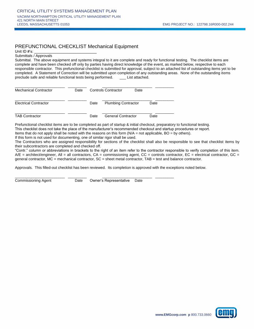
CRITICAL UTILITY SYSTEMS MANAGEMENT PLAN
VACWM NORTHAMPTON CRITICAL UTILITY MANAGEMENT PLAN 421 NORTH MAIN STREET
LEEDS, MASSACHUSETTS 01053 EMG PROJECT NO.: 122798.16R000-002.244
www.EMGcorp.com p 800.733.0660
PREFUNCTIONAL CHECKLIST Mechanical Equipment Unit ID #’s: ______________________________ Submittals / Approvals Submittal. The above equipment and systems integral to it are complete and ready for functional testing. The checklist items are complete and have been checked off only by parties having direct knowledge of the event, as marked below, respective to each responsible contractor. This prefunctional checklist is submitted for approval, subject to an attached list of outstanding items yet to be completed. A Statement of Correction will be submitted upon completion of any outstanding areas. None of the outstanding items preclude safe and reliable functional tests being performed. ___ List attached. ________________________ _________ ________________________ _________ Mechanical Contractor Date Controls Contractor Date ________________________ _________ ________________________ _________ Electrical Contractor Date Plumbing Contractor Date ________________________ _________ ________________________ _________ TAB Contractor Date General Contractor Date Prefunctional checklist items are to be completed as part of startup & initial checkout, preparatory to functional testing. This checklist does not take the place of the manufacturer’s recommended checkout and startup procedures or report. Items that do not apply shall be noted with the reasons on this form (N/A = not applicable, BO = by others). If this form is not used for documenting, one of similar rigor shall be used. The Contractors who are assigned responsibility for sections of the checklist shall also be responsible to see that checklist items by their subcontractors are completed and checked off. “Contr.” column or abbreviations in brackets to the right of an item refer to the contractor responsible to verify completion of this item. A/E = architect/engineer, All = all contractors, CA = commissioning agent, CC = controls contractor, EC = electrical contractor, GC = general contractor, MC = mechanical contractor, SC = sheet metal contractor, TAB = test and balance contractor. Approvals. This filled-out checklist has been reviewed. Its completion is approved with the exceptions noted below. ________________________ _________ ________________________ _________ Commissioning Agent Date Owner’s Representative Date

CRITICAL UTILITY SYSTEMS MANAGEMENT PLAN
VACWM NORTHAMPTON CRITICAL UTILITY MANAGEMENT PLAN 421 NORTH MAIN STREET
LEEDS, MASSACHUSETTS 01053 EMG PROJECT NO.: 122798.16R000-002.244
www.EMGcorp.com p 800.733.0660
Installation Checks Check if Okay. Enter N/A if not applicable. Enter Note number if deficient.
Check Equip Tag Contr.
General Installation
Label permanently affixed
Equipment installed in place and properly grouted, bases filled (as required)
Vibration isolation devices installed and functional
Factory alignment checked and appears correct
Field alignment, if required, completed
Seismic anchoring installed
Temperature and pressure gauges and sensors installed
Equipment and motor bearings lubricated
Piping (as required)
Pipe fittings completed and piping properly supported
No leaks in pipe fittings and accessories.
Piping and equipment properly insulated
Strainers in place and cleaned out
Piping system properly flushed
Valves properly tagged
Mechanical (as required)
Mountings checked and shipping bolts removed
Vibration isolators installed
Equipment guards installed
Pulleys aligned
Belt tension correct
Plenums clear of debris
Fans rotate freely
Dampers installed per drawings and operate freely
Electrical and Controls
Disconnect switches in place and labeled
Electrical connections tight
Proper grounding installed for components and unit
Motor overloads calibrated
Control system interlocks hooked up and functional
Control devices, tubing and wiring complete
VFD (as required)
VFD powered up and wired to controlled equipment
VFD interlocked to control system
Controlling sensors properly located and per drawings and calibrated
Controller location not subject to excessive temperatures
Controller location not subject to excessive moisture or dirt
Controller size matches motor size
Internal settings designating the application are correct
Input of motor FLA represents 105% to 115% of motor FLA rating
Appropriate Volts vs Hz curve is being used; energy saver on?
Accel and decel times are around 10-50 seconds, except for special applications. Actual decel = Actual accel =
Upper frequency limit set at 100%, unless explained otherwise
Unit is programmed with written programming record available
VFD kW demand at panel matches BAS readout
TAB
Installation of system and balancing devices permits balancing to be completed following specified NEBB or AABC procedures and contract documents
Final
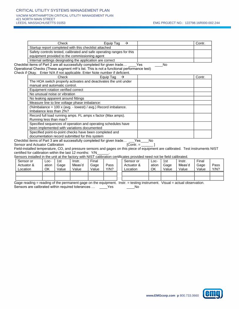
CRITICAL UTILITY SYSTEMS MANAGEMENT PLAN
VACWM NORTHAMPTON CRITICAL UTILITY MANAGEMENT PLAN 421 NORTH MAIN STREET
LEEDS, MASSACHUSETTS 01053 EMG PROJECT NO.: 122798.16R000-002.244
www.EMGcorp.com p 800.733.0660
Check Equip Tag Contr.
Startup report completed with this checklist attached
Safety controls tested, calibrated and safe operating ranges for this equipment provided to the commissioning agent
Internal settings designating the application are correct
Checklist items of Part 2 are all successfully completed for given trade… ____Yes ____No Operational Checks (These augment mfr’s list. This is not a functional performance test) Check if Okay. Enter N/A if not applicable. Enter Note number if deficient.
Check Equip Tag Contr.
The HOA switch properly activates and deactivates the unit under manual and automatic control.
Equipment rotation verified correct
No unusual noise or vibration
No leaking apparent around fittings
Measure line to line voltage phase imbalance:
(%lmbalance = 100 x (avg. - lowest) / avg.) Record imbalance. Imbalance less than 2%?
Record full load running amps. FL amps x factor (Max amps). Running less than max?
Specified sequences of operation and operating schedules have been implemented with variations documented
Specified point-to-point checks have been completed and documentation record submitted for this system
Checklist items of Part 3 are all successfully completed for given trade… ___Yes ____No Sensor and Actuator Calibration [Contr. = ______ ] Field-installed temperature, CO, and pressure sensors and gages on this piece of equipment are calibrated. Test instruments NIST certified for calibration within the last 12 months: Y/N______. Sensors installed in the unit at the factory with NIST calibration certificates provided need not be field calibrated.
Sensor or Actuator & Location
Loc-ation OK
1st Gage Value
Instr. Meas’d Value
Final Gage Value
Pass Y/N?
Sensor or Actuator & Location
Loc-ation OK
1st Gage Value
Instr. Meas’d Value
Final Gage Value
Pass Y/N?
Gage reading = reading of the permanent gage on the equipment. Instr. = testing instrument. Visual = actual observation. Sensors are calibrated within required tolerances … ____Yes ____No

CRITICAL UTILITY SYSTEMS MANAGEMENT PLAN
VACWM NORTHAMPTON CRITICAL UTILITY MANAGEMENT PLAN 421 NORTH MAIN STREET
LEEDS, MASSACHUSETTS 01053 EMG PROJECT NO.: 122798.16R000-002.244
www.EMGcorp.com p 800.733.0660
APPENDIX D:
EQUIPMENT RISK ASSESSMENT

CRITICAL UTILITY SYSTEMS MANAGEMENT PLAN
VACWM NORTHAMPTON CRITICAL UTILITY MANAGEMENT PLAN 421 NORTH MAIN STREET
LEEDS, MASSACHUSETTS 01053 EMG PROJECT NO.: 122798.16R000-002.244
www.EMGcorp.com p 800.733.0660
Criticality System Classification Type Risk
Critical Air Conditioning HVAC Air Compressor 3
Critical Air Conditioning HVAC Air Conditioner 3
Critical Air Conditioning HVAC Air Dryer 3
Critical Air Conditioning HVAC Air Handling Unit 3
Critical Air Conditioning HVAC Chiller, Air Cooled 3
Critical Air Conditioning HVAC Chiller, Water Cooled 3
Critical Air Conditioning HVAC Condenser 3
Critical Air Conditioning HVAC Energy Recovery Unit 3
Critical Air Conditioning HVAC Fan 3
Critical Air Conditioning HVAC Filter Rack 3
Critical Air Conditioning HVAC Humidifier 3
Critical Air Conditioning HVAC Make Up Air Unit 3
Critical Air Conditioning HVAC Pump 3
Critical Air Conditioning HVAC Split System 3
Critical Air Conditioning HVAC Tank, Expansion 3
Critical Air Conditioning HVAC Unit Heater 3
Critical Air Conditioning HVAC Cooling Tower 3
Critical Communications Electrical Panel, Communication 2
Critical Communications Electrical UPS 2
Critical Domestic Hot Water HVAC Heat Exchanger 3
Critical Domestic Hot Water Plumbing Pump 3
Critical Domestic Hot Water Plumbing Water Heater 3
Critical Electrical Distribution Electrical Main Distribution Panel 2
Critical Electrical Distribution Electrical Motor Control Center 2
Critical Electrical Distribution Electrical Panel 3
Critical Electrical Distribution Electrical Transformer 2
Critical Electrical Distribution Electrical Circuit Breaker 2
Critical Electrical Distribution Electrical Switch, Pad Mounted 2
Critical Electrical Distribution Electrical Transformer, Oil Filled 2
Critical Electrical Distribution Electrical Battery Station 2
Critical Emergency Power Electrical Automatic Transfer Switch 1
Critical Emergency Power Electrical Battery Charger 1
Critical Emergency Power Electrical Fuel Tank Monitoring Panel 2
Critical Emergency Power Electrical Generator Control Switchgear 1
Critical Emergency Power Electrical Loadbank Control Switchgear 2
Critical Emergency Power Electrical Main Distribution Panel 2
Critical Emergency Power Electrical Panel 3
Critical Emergency Power Electrical Switchgear 2
Critical Emergency Power Electrical Tank, Fuel 1
Critical Emergency Power Electrical Day Tank 1
Critical Emergency Power Electrical Load Bank 2
Critical Emergency Power Electrical Emergency Generator - Level 2 1
Critical Emergency Power Electrical Emergency Generator - Level 1 1
Critical Emergency Power HVAC Damper Actuators 1

CRITICAL UTILITY SYSTEMS MANAGEMENT PLAN
VACWM NORTHAMPTON CRITICAL UTILITY MANAGEMENT PLAN 421 NORTH MAIN STREET
LEEDS, MASSACHUSETTS 01053 EMG PROJECT NO.: 122798.16R000-002.244
www.EMGcorp.com p 800.733.0660
Criticality System Classification Type Risk
Critical Emergency Power HVAC Unit Heater, Electric 2
Critical Fire Protection - Alarm & Detection Fire Protection Fire Alarm System 1
Critical Fire Protection - Alarm & Detection Fire Protection Panel, Fire 1
Critical Fire Protection - Alarm & Detection Fire Protection Fire Pump Controller 1
Critical Fire Protection - Suppression Fire Protection Compressor 1
Critical Fire Protection - Suppression Fire Protection Fire Department Connection 2
Critical Fire Protection - Suppression Fire Protection Fire Extinguishers 2
Critical Fire Protection - Suppression Fire Protection Fire Hydrant 2
Critical Fire Protection - Suppression Fire Protection Fire Suppression System 2
Critical Fire Protection - Suppression Fire Protection Post Indicator Valve 2
Critical Fire Protection - Suppression Fire Protection Sprinkler Riser 2
Critical Fire Protection - Suppression Fire Protection Sprinkler System 1
Critical Fire Protection - Suppression Fire Protection Sprinkler System, Dry Pipe 1
Critical Fire Protection - Suppression Fire Protection Pump, Fire, Electric 2
Critical Heating HVAC Boiler 2
Critical Heating HVAC Heat Exchanger 2
Critical Heating HVAC Low Water Cut-Off 2
Critical Heating HVAC Pump 2
Critical Heating HVAC Tank 2
Critical Heating HVAC Tank, Expansion 2
Critical Heating HVAC Valve 2
Critical Heating HVAC Air Separator 2
Critical Heating Plumbing Water Softener 2
Critical High Purity Water Plumbing Pump 2
Critical High Purity Water Plumbing RO System 2
Critical High Purity Water Plumbing Water Softener 2
Critical Life Safety Life Safety Emergency Exit Signs 1
Critical Life Safety Life Safety Eye Wash / Safety Shower 2
Critical Medical Gas Medical Gas Air Compressor 1
Critical Medical Gas Medical Gas Check Valve 1
Critical Medical Gas Medical Gas Level Indicator 1
Critical Medical Gas Medical Gas Oxygen Tank 1
Critical Medical Gas Medical Gas Oxygen Transmitter 1
Critical Medical Gas Medical Gas Oxygen Vaporizer 1
Critical Medical Gas Medical Gas Pressure Reducing Valve 1
Critical Medical Gas Medical Gas Safety Valve 1
Critical Medical Gas Medical Gas Vacuum Pump Silencer 1
Critical Medical Gas Medical Gas Valve Actuator 1
Critical Medical Gas Medical Gas Air Dryer 1
Critical Medical Gas Medical Gas Vacuum Pump 1
Critical Potable Water Plumbing BackFlow Preventer 2
Critical Potable Water Plumbing Valve 2
Critical Refrigeration Food Service_Dietary Compressor, Refrigeration 2
Critical Refrigeration Food Service_Dietary Walk-In Freezer 2
Critical Refrigeration Food Service_Dietary Walk-In Cooler 2
Critical Refrigeration Food Service_Dietary Refrigerator 2
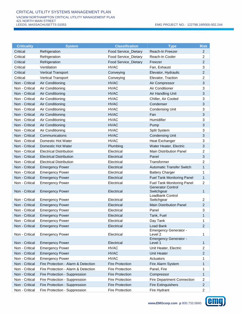
CRITICAL UTILITY SYSTEMS MANAGEMENT PLAN
VACWM NORTHAMPTON CRITICAL UTILITY MANAGEMENT PLAN 421 NORTH MAIN STREET
LEEDS, MASSACHUSETTS 01053 EMG PROJECT NO.: 122798.16R000-002.244
www.EMGcorp.com p 800.733.0660
Criticality System Classification Type Risk
Critical Refrigeration Food Service_Dietary Reach-In Freezer 2
Critical Refrigeration Food Service_Dietary Reach-In Cooler 2
Critical Refrigeration Food Service_Dietary Freezer 2
Critical Ventilation HVAC Fan, Exhaust 3
Critical Vertical Transport Conveying Elevator, Hydraulic 2
Critical Vertical Transport Conveying Elevator, Traction 2
Non - Critical Air Conditioning HVAC Air Compressor 3
Non - Critical Air Conditioning HVAC Air Conditioner 3
Non - Critical Air Conditioning HVAC Air Handling Unit 3
Non - Critical Air Conditioning HVAC Chiller, Air Cooled 3
Non - Critical Air Conditioning HVAC Condenser 3
Non - Critical Air Conditioning HVAC Condensing Unit 3
Non - Critical Air Conditioning HVAC Fan 3
Non - Critical Air Conditioning HVAC Humidifier 3
Non - Critical Air Conditioning HVAC Pump 3
Non - Critical Air Conditioning HVAC Split System 3
Non - Critical Communications HVAC Condensing Unit 3
Non - Critical Domestic Hot Water HVAC Heat Exchanger 3
Non - Critical Domestic Hot Water Plumbing Water Heater, Electric 3
Non - Critical Electrical Distribution Electrical Main Distribution Panel 2
Non - Critical Electrical Distribution Electrical Panel 3
Non - Critical Electrical Distribution Electrical Transformer 2
Non - Critical Emergency Power Electrical Automatic Transfer Switch 1
Non - Critical Emergency Power Electrical Battery Charger 1
Non - Critical Emergency Power Electrical Fuel Tank Monitoring Panel 1
Non - Critical Emergency Power Electrical Fuel Tank Monitoring Panel 2
Non - Critical Emergency Power Electrical Generator Control Switchgear 1
Non - Critical Emergency Power Electrical Loadbank Control Switchgear 2
Non - Critical Emergency Power Electrical Main Distribution Panel 2
Non - Critical Emergency Power Electrical Panel 3
Non - Critical Emergency Power Electrical Tank, Fuel 1
Non - Critical Emergency Power Electrical Day Tank 1
Non - Critical Emergency Power Electrical Load Bank 2
Non - Critical Emergency Power Electrical Emergency Generator - Level 2 1
Non - Critical Emergency Power Electrical Emergency Generator - Level 1 1
Non - Critical Emergency Power HVAC Unit Heater, Electric 2
Non - Critical Emergency Power HVAC Unit Heater 2
Non - Critical Emergency Power HVAC Actuators 1
Non - Critical Fire Protection - Alarm & Detection Fire Protection Fire Alarm System 1
Non - Critical Fire Protection - Alarm & Detection Fire Protection Panel, Fire 1
Non - Critical Fire Protection - Suppression Fire Protection Compressor 1
Non - Critical Fire Protection - Suppression Fire Protection Fire Department Connection 2
Non - Critical Fire Protection - Suppression Fire Protection Fire Extinguishers 2
Non - Critical Fire Protection - Suppression Fire Protection Fire Hydrant 2
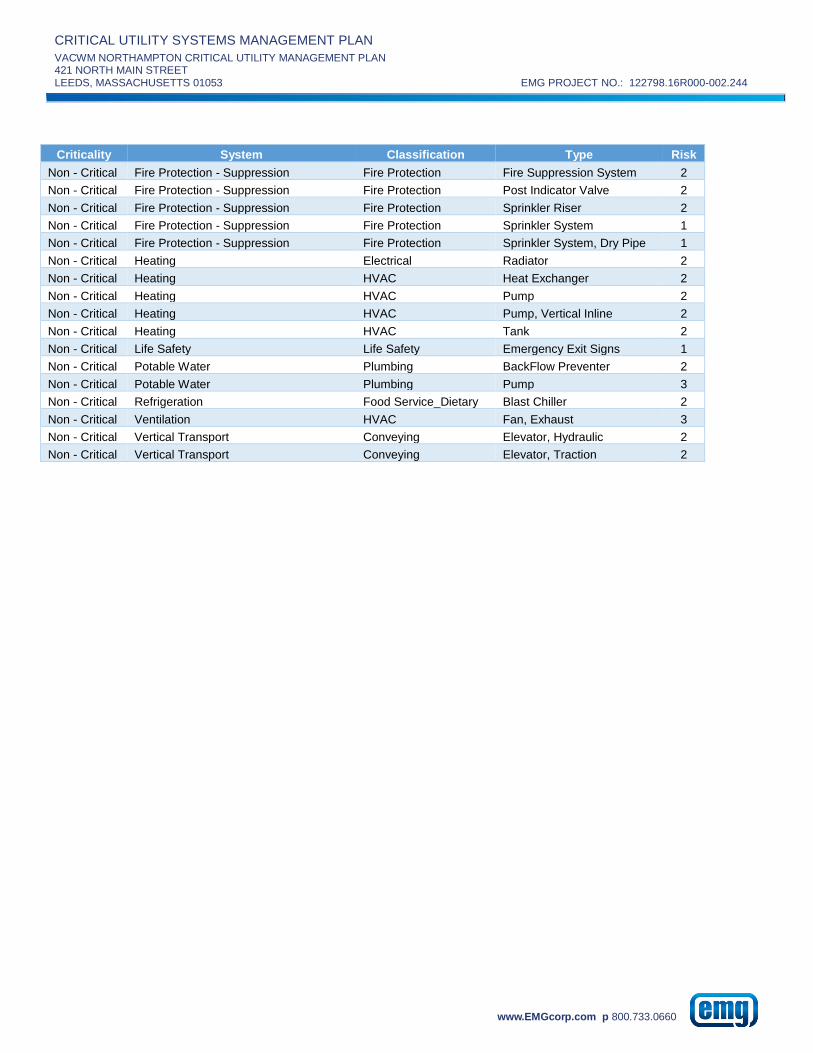
CRITICAL UTILITY SYSTEMS MANAGEMENT PLAN
VACWM NORTHAMPTON CRITICAL UTILITY MANAGEMENT PLAN 421 NORTH MAIN STREET
LEEDS, MASSACHUSETTS 01053 EMG PROJECT NO.: 122798.16R000-002.244
www.EMGcorp.com p 800.733.0660
Criticality System Classification Type Risk
Non - Critical Fire Protection - Suppression Fire Protection Fire Suppression System 2
Non - Critical Fire Protection - Suppression Fire Protection Post Indicator Valve 2
Non - Critical Fire Protection - Suppression Fire Protection Sprinkler Riser 2
Non - Critical Fire Protection - Suppression Fire Protection Sprinkler System 1
Non - Critical Fire Protection - Suppression Fire Protection Sprinkler System, Dry Pipe 1
Non - Critical Heating Electrical Radiator 2
Non - Critical Heating HVAC Heat Exchanger 2
Non - Critical Heating HVAC Pump 2
Non - Critical Heating HVAC Pump, Vertical Inline 2
Non - Critical Heating HVAC Tank 2
Non - Critical Life Safety Life Safety Emergency Exit Signs 1
Non - Critical Potable Water Plumbing BackFlow Preventer 2
Non - Critical Potable Water Plumbing Pump 3
Non - Critical Refrigeration Food Service_Dietary Blast Chiller 2
Non - Critical Ventilation HVAC Fan, Exhaust 3
Non - Critical Vertical Transport Conveying Elevator, Hydraulic 2
Non - Critical Vertical Transport Conveying Elevator, Traction 2
CRITICAL UTILITY SYSTEMS MANAGEMENT PLAN
VACWM NORTHAMPTON CRITICAL UTILITY MANAGEMENT PLAN 421 NORTH MAIN STREET
LEEDS, MASSACHUSETTS 01053 EMG PROJECT NO.: 122798.16R000-002.244
www.EMGcorp.com p 800.733.0660
APPENDIX E:
SUPPLEMENTAL INFORMATION

CRITICAL UTILITY SYSTEMS MANAGEMENT PLAN
VACWM NORTHAMPTON CRITICAL UTILITY MANAGEMENT PLAN 421 NORTH MAIN STREET
LEEDS, MASSACHUSETTS 01053 EMG PROJECT NO.: 122798.16R000-002.244
www.EMGcorp.com p 800.733.0660
Non Critical Utility System Equipment Inventory During the survey of critical utility systems, information was gathered on non-critical utility systems. This information is included in this section.
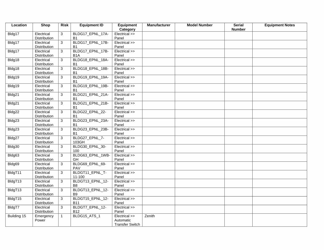
Location Shop Risk Equipment ID Equipment Category
Manufacturer Model Number Serial Number
Equipment Notes
Bldg17 Electrical Distribution
3 BLDG17_EPNL_17A-B1
Electrical >> Panel
Bldg17 Electrical Distribution
3 BLDG17_EPNL_17B-B1
Electrical >> Panel
Bldg17 Electrical Distribution
3 BLDG17_EPNL_17B-B1A
Electrical >> Panel
Bldg18 Electrical Distribution
3 BLDG18_EPNL_18A-B1
Electrical >> Panel
Bldg18 Electrical Distribution
3 BLDG18_EPNL_18B-B1
Electrical >> Panel
Bldg19 Electrical Distribution
3 BLDG19_EPNL_19A-B1
Electrical >> Panel
Bldg19 Electrical Distribution
3 BLDG19_EPNL_19B-B1
Electrical >> Panel
Bldg21 Electrical Distribution
3 BLDG21_EPNL_21A-B1
Electrical >> Panel
Bldg21 Electrical Distribution
3 BLDG21_EPNL_21B-B1
Electrical >> Panel
Bldg22 Electrical Distribution
3 BLDG22_EPNL_22-B1
Electrical >> Panel
Bldg23 Electrical Distribution
3 BLDG23_EPNL_23A-B1
Electrical >> Panel
Bldg23 Electrical Distribution
3 BLDG23_EPNL_23B-B1
Electrical >> Panel
Bldg27 Electrical Distribution
3 BLDG27_EPNL_7-103GH
Electrical >> Panel
Bldg30 Electrical Distribution
3 BLDG30_EPNL_30-100
Electrical >> Panel
Bldg63 Electrical Distribution
3 BLDG63_EPNL_1WB-GH
Electrical >> Panel
Bldg69 Electrical Distribution
3 BLDG69_EPNL_69-PAV
Electrical >> Panel
BldgT11 Electrical Distribution
3 BLDGT11_EPNL_T-11-100
Electrical >> Panel
BldgT13 Electrical Distribution
3 BLDGT13_EPNL_12-B8
Electrical >> Panel
BldgT13 Electrical Distribution
3 BLDGT13_EPNL_12-B9
Electrical >> Panel
BldgT15 Electrical Distribution
3 BLDGT15_EPNL_12-B11
Electrical >> Panel
BldgT7 Electrical Distribution
3 BLDGT7_EPNL_12-B12
Electrical >> Panel
Building 15 Emergency Power
1 BLDG15_ATS_1 Electrical >> Automatic Transfer Switch
Zenith

Location Shop Risk Equipment ID Equipment Category
Manufacturer Model Number Serial Number
Equipment Notes
Building 15 Emergency Power
2 BLDG15_FTPNL_1 Electrical >> Fuel Tank Monitoring Panel
Veeder-Root 2 - 25,000 gallon tanks that fed new boiler plant including generator. This is vendor root for that system located in B15 basement
Building 15 Emergency Power
2 BLDG15_ELEC_E15-MDP
Electrical >> Main Distribution Panel
General Electric 970X035IL01 J-4CC640
Building 15 Electrical Distribution
3 BLDG15_EPNL_E15-B1
Electrical >> Panel
Building 15 Electrical Distribution
3 BLDG15_EPNL_E15-B2
Electrical >> Panel
Building 15 Electrical Distribution
3 BLDG15_EPNL_E15-BDP
Electrical >> Panel
Building 15 Emergency Power
1 BLDG15_FTANK_1 Electrical >> Tank, Fuel
25,000 gallon tanks that fed new boiler plant including generator. Located in ground outside of B15.
Building 15 Emergency Power
1 BLDG15_FTANK_2 Electrical >> Tank, Fuel
25,000 gallon tanks that fed new boiler plant including generator. Located in ground outside of B15.
Building 15 Heating 2 BLDG15_HVAC_#1 Oil Pump
HVAC >> Pump
Roper S5652 Figure NO. 6115; These are pump that send #2 fuel oil up to new boiler plant (building 28); These are located in old boiler plant building 15
Building 15 Heating 2 BLDG15_HVAC_#2 Oil Pump
HVAC >> Pump
Roper S4844 Figure NO. 6115; These are pump that send #2 fuel oil up to new boiler plant (building 28); This pump is located in a the old boiler plant building 15
Building 45 Emergency Power
1 BLDG45_BCHRG_1 Electrical >> Battery Charger
Battery charger on top of control panel
Building 45 Emergency Power
1 BLDG45_DTANK_1 Electrical >> Day Tank
275 gallons
Building 45 Emergency Power
1 BLDG45_DTANK_2 Electrical >> Day Tank
275 Gallons
Building 45 Emergency Power
1 BLDG45_EGEN_1 Electrical >> Emergency Generator
Onan DGFA-3388204 B000055706 Serves building 16, building 65, and motor pool (13).
Building 45 Emergency Power
2 BLDG45_LDBNK_1 Electrical >> Load Bank
Suitcase Load bank for B45 generator
Building 45 Electrical Distribution
3 BLDG45_EPNL_E45-B1
Electrical >> Panel

Location Shop Risk Equipment ID Equipment Category
Manufacturer Model Number Serial Number
Equipment Notes
Building 45 Heating 2 BLDG45_GENRAD_1 Electrical >> Radiator
Modine Radiator for generator. Motor info - 5hp 1170 rpm frame 215T
Building 45 Electrical Distribution
2 BLDG45_ELEC_65 XFMR
Electrical >> Transformer
Building 45 Emergency Power
2 BLDG45_UH_1 HVAC >> Modine Unit Heater
Modine HS86501 05010889 Steam or hot water unit heater
Chapel (60) Electrical Distribution
2 BLDG60_ELEC_60-MDP
Electrical >> Main Distribution Panel
Chapel (60) Electrical Distribution
3 BLDG60_EPNL_60-100
Electrical >> Panel
Chapel (60) Electrical Distribution
3 BLDG60_EPNL_60-101
Electrical >> Panel
Chapel (60) Electrical Distribution
3 BLDG60_EPNL_60-102
Electrical >> Panel
Chapel (60) Electrical Distribution
3 BLDG60_EPNL_60-103
Electrical >> Panel
Chapel (60) Electrical Distribution
3 BLDG60_EPNL_60-200
Electrical >> Panel
Chapel (60) Electrical Distribution
3 BLDG60_EPNL_60-B2
Electrical >> Panel
Chapel (60) Electrical Distribution
3 BLDG60_EPNL_E60-CB
Electrical >> Panel
Chapel (60) Fire Protection - Alarm & Detection
1 BLDG60_FAS_1 Fire Protection >> Fire Alarm System
All components like main building
Chapel (60) Fire Protection - Suppression
2 BLDG60_FDC_1 Fire Protection >> Fire Department Connection
FDC
Chapel (60) Fire Protection - Alarm & Detection
1 BLDG60_FPNL_1 Fire Protection >> Panel, Fire
Honeywell
Chapel (60) Fire Protection - Suppression
2 BLDG60_PIV_1 Fire Protection >> Post Indicator Valve
Chapel (60) Fire Protection - Suppression
2 BLDG60_FRISR_1 Fire Protection >> Sprinkler Riser
Chapel (60) Fire Protection - Suppression
1 BLDG60_SPRNK_1 Fire Protection >> Sprinkler System

Location Shop Risk Equipment ID Equipment Category
Manufacturer Model Number Serial Number
Equipment Notes
Chapel (60) Air Conditioning
3 BLDG60_ACMP_1 HVAC >> Air Compressor
The Johnson System
For pneumatic controls in chapel
Chapel (60) Air Conditioning
3 BLDG60_AHU_1 HVAC >> Air Handling Unit
NO TAG Installed in 1959
Chapel (60) Domestic Hot Water
3 BLDG60_DWH_1 Plumbing >> Water Heater, Electric
Bradford White M112UT6SS-1NAL EH10928723 DHW for chapel
Directors Office (12)
Vertical Transport
2 BLDG12_ELEV_1 Conveying >> Elevator, Hydraulic
Hydraulic elevator
Directors Office (12)
Emergency Power
2 BLDG12_ELEC_12a-mdp
Electrical >> Main Distribution Panel
Siemens FC-I SO 18-50957-CO4
Incoming fed from transformer outside
Directors Office (12)
Emergency Power
2 BLDG12_ELEC_E12a mdp
Electrical >> Main Distribution Panel
Siemens FC-I SO 18-50957-DO2
Feeds 3 ats
Directors Office (12)
Electrical Distribution
2 BLDG12_ELEC_12-MDP
Electrical >> Main Distribution Panel
Directors Office (12)
Emergency Power
3 BLDG12_EPNL_E12a-cb
Electrical >> Panel
Siemens CAT S4C60ML400ATS SO 17-15888-F00
Directors Office (12)
Emergency Power
3 BLDG12_EPNL_E12a-eb
Electrical >> Panel
Siemens CAT S4C60ML400ATS SO 17-15888-F00
Directors Office (12)
Emergency Power
3 BLDG12_EPNL_E12a-ls
Electrical >> Panel
Siemens CAT S4C60ML400ATS SO 17-15888-F00
Directors Office (12)
Emergency Power
3 BLDG12_EPNL_E12-LESH
Electrical >> Panel
Siemens TYPE S1 S1C30ML125ABS
Fed from LS Panel (E1WA-LS). Feeds Battery Charger, Dampers, Fire Alarm, and Generator
Directors Office (12)
Emergency Power
3 BLDG12_EPNL_1 Electrical >> Panel
Siemens CAT FCI SO 18-50957-CO4
Directors Office (12)
Emergency Power
3 BLDG12_EPNL_2 Electrical >> Panel
Siemens CAT FCI SO 18-50957-CO4
Directors Office (12)
Emergency Power
3 BLDG12_EPNL_3 Electrical >> Panel
Siemens CAT FCI SO 18-50957-CO4
Directors Office (12)
Emergency Power
3 BLDG12_EPNL_4 Electrical >> Panel
Siemens CAT FCI SO 18-50957-CO4
Directors Office (12)
Electrical Distribution
3 BLDG12_EPNL_12-101
Electrical >> Panel
Directors Office (12)
Electrical Distribution
3 BLDG12_EPNL_12-103
Electrical >> Panel
Directors Office (12)
Electrical Distribution
3 BLDG12_EPNL_12-104
Electrical >> Panel
Directors Office (12)
Electrical Distribution
3 BLDG12_EPNL_12-200
Electrical >> Panel

Location Shop Risk Equipment ID Equipment Category
Manufacturer Model Number Serial Number
Equipment Notes
Directors Office (12)
Electrical Distribution
3 BLDG12_EPNL_12-201
Electrical >> Panel
Directors Office (12)
Electrical Distribution
3 BLDG12_EPNL_12-202
Electrical >> Panel
Directors Office (12)
Electrical Distribution
3 BLDG12_EPNL_12-203
Electrical >> Panel
Directors Office (12)
Electrical Distribution
3 BLDG12_EPNL_12-204
Electrical >> Panel
Directors Office (12)
Electrical Distribution
3 BLDG12_EPNL_12-B1
Electrical >> Panel
Directors Office (12)
Electrical Distribution
3 BLDG12_EPNL_12-B3
Electrical >> Panel
Directors Office (12)
Electrical Distribution
3 BLDG12_EPNL_12-B4
Electrical >> Panel
Directors Office (12)
Electrical Distribution
3 BLDG12_EPNL_12-B5
Electrical >> Panel
Directors Office (12)
Electrical Distribution
3 BLDG12_EPNL_12-B6
Electrical >> Panel
Directors Office (12)
Electrical Distribution
3 BLDG12_EPNL_12-B7
Electrical >> Panel
Directors Office (12)
Electrical Distribution
3 BLDG12_EPNL_E12-100
Electrical >> Panel
Directors Office (12)
Electrical Distribution
3 BLDG12_EPNL_E12-100N
Electrical >> Panel
Directors Office (12)
Electrical Distribution
3 BLDG12_EPNL_E12-101
Electrical >> Panel
Directors Office (12)
Electrical Distribution
3 BLDG12_EPNL_E12-102
Electrical >> Panel
Directors Office (12)
Electrical Distribution
3 BLDG12_EPNL_E12-102C
Electrical >> Panel
Directors Office (12)
Electrical Distribution
3 BLDG12_EPNL_E12-200
Electrical >> Panel
Directors Office (12)
Electrical Distribution
3 BLDG12_EPNL_E12-201
Electrical >> Panel
Directors Office (12)
Electrical Distribution
3 BLDG12_EPNL_E12-CB
Electrical >> Panel
Directors Office (12)
Electrical Distribution
3 BLDG12_EPNL_E12-EB
Electrical >> Panel
Directors Office (12)
Electrical Distribution
3 BLDG12_EPNL_E12-LS
Electrical >> Panel
Directors Office (12)
Fire Protection - Suppression
1 BLDG12_FCOMP_1 Fire Protection >> Compressor
Jenny K G081915005
Directors Office (12)
Fire Protection - Alarm & Detection
1 BLDG12_FAS_1 Fire Protection >> Fire Alarm System
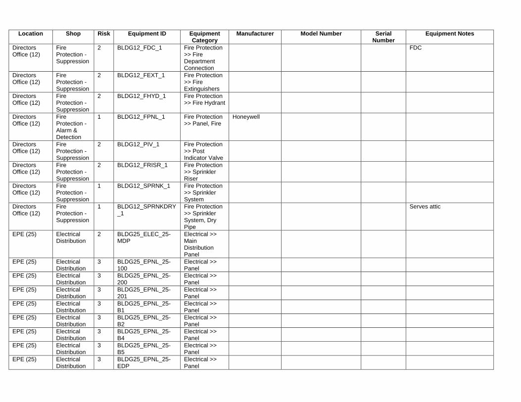
Location Shop Risk Equipment ID Equipment Category
Manufacturer Model Number Serial Number
Equipment Notes
Directors Office (12)
Fire Protection - Suppression
2 BLDG12_FDC_1 Fire Protection >> Fire Department Connection
FDC
Directors Office (12)
Fire Protection - Suppression
2 BLDG12_FEXT_1 Fire Protection >> Fire Extinguishers
Directors Office (12)
Fire Protection - Suppression
2 BLDG12_FHYD_1 Fire Protection >> Fire Hydrant
Directors Office (12)
Fire Protection - Alarm & Detection
1 BLDG12_FPNL_1 Fire Protection >> Panel, Fire
Honeywell
Directors Office (12)
Fire Protection - Suppression
2 BLDG12_PIV_1 Fire Protection >> Post Indicator Valve
Directors Office (12)
Fire Protection - Suppression
2 BLDG12_FRISR_1 Fire Protection >> Sprinkler Riser
Directors Office (12)
Fire Protection - Suppression
1 BLDG12_SPRNK_1 Fire Protection >> Sprinkler System
Directors Office (12)
Fire Protection - Suppression
1 BLDG12_SPRNKDRY_1
Fire Protection >> Sprinkler System, Dry Pipe
Serves attic
EPE (25) Electrical Distribution
2 BLDG25_ELEC_25-MDP
Electrical >> Main Distribution Panel
EPE (25) Electrical Distribution
3 BLDG25_EPNL_25-100
Electrical >> Panel
EPE (25) Electrical Distribution
3 BLDG25_EPNL_25-200
Electrical >> Panel
EPE (25) Electrical Distribution
3 BLDG25_EPNL_25-201
Electrical >> Panel
EPE (25) Electrical Distribution
3 BLDG25_EPNL_25-B1
Electrical >> Panel
EPE (25) Electrical Distribution
3 BLDG25_EPNL_25-B2
Electrical >> Panel
EPE (25) Electrical Distribution
3 BLDG25_EPNL_25-B4
Electrical >> Panel
EPE (25) Electrical Distribution
3 BLDG25_EPNL_25-B5
Electrical >> Panel
EPE (25) Electrical Distribution
3 BLDG25_EPNL_25-EDP
Electrical >> Panel
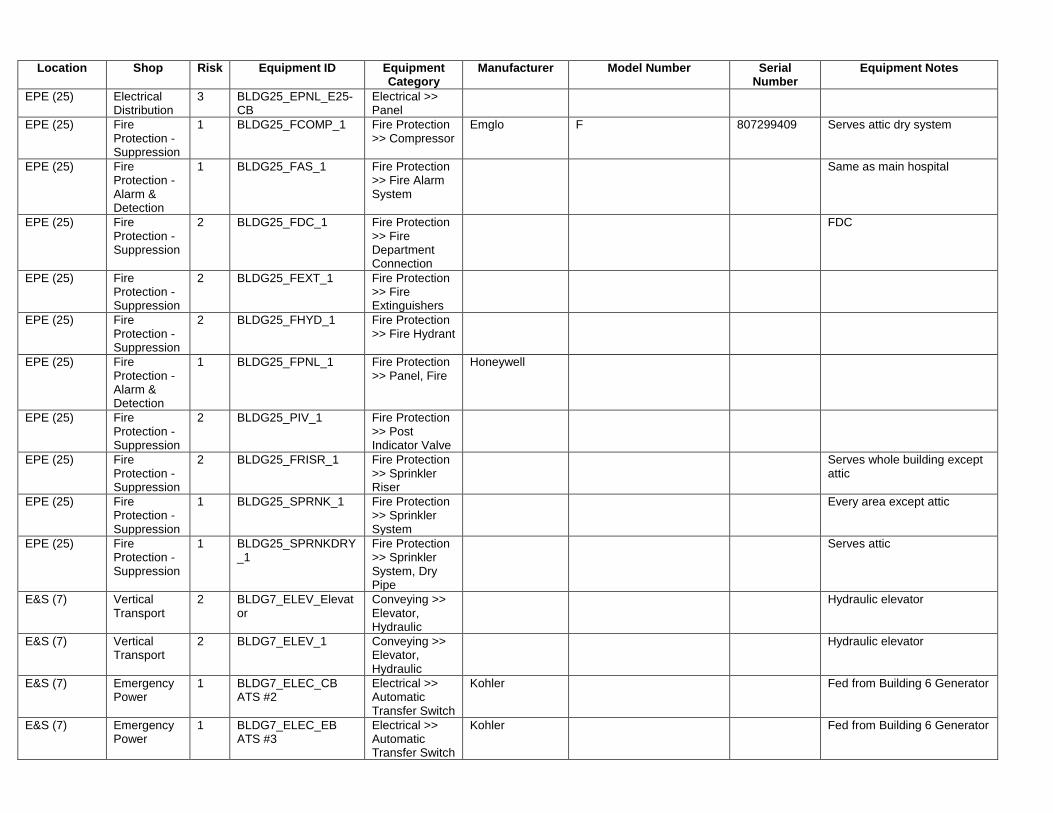
Location Shop Risk Equipment ID Equipment Category
Manufacturer Model Number Serial Number
Equipment Notes
EPE (25) Electrical Distribution
3 BLDG25_EPNL_E25-CB
Electrical >> Panel
EPE (25) Fire Protection - Suppression
1 BLDG25_FCOMP_1 Fire Protection >> Compressor
Emglo F 807299409 Serves attic dry system
EPE (25) Fire Protection - Alarm & Detection
1 BLDG25_FAS_1 Fire Protection >> Fire Alarm System
Same as main hospital
EPE (25) Fire Protection - Suppression
2 BLDG25_FDC_1 Fire Protection >> Fire Department Connection
FDC
EPE (25) Fire Protection - Suppression
2 BLDG25_FEXT_1 Fire Protection >> Fire Extinguishers
EPE (25) Fire Protection - Suppression
2 BLDG25_FHYD_1 Fire Protection >> Fire Hydrant
EPE (25) Fire Protection - Alarm & Detection
1 BLDG25_FPNL_1 Fire Protection >> Panel, Fire
Honeywell
EPE (25) Fire Protection - Suppression
2 BLDG25_PIV_1 Fire Protection >> Post Indicator Valve
EPE (25) Fire Protection - Suppression
2 BLDG25_FRISR_1 Fire Protection >> Sprinkler Riser
Serves whole building except attic
EPE (25) Fire Protection - Suppression
1 BLDG25_SPRNK_1 Fire Protection >> Sprinkler System
Every area except attic
EPE (25) Fire Protection - Suppression
1 BLDG25_SPRNKDRY_1
Fire Protection >> Sprinkler System, Dry Pipe
Serves attic
E&S (7) Vertical Transport
2 BLDG7_ELEV_Elevator
Conveying >> Elevator, Hydraulic
Hydraulic elevator
E&S (7) Vertical Transport
2 BLDG7_ELEV_1 Conveying >> Elevator, Hydraulic
Hydraulic elevator
E&S (7) Emergency Power
1 BLDG7_ELEC_CB ATS #2
Electrical >> Automatic Transfer Switch
Kohler Fed from Building 6 Generator
E&S (7) Emergency Power
1 BLDG7_ELEC_EB ATS #3
Electrical >> Automatic Transfer Switch
Kohler Fed from Building 6 Generator

Location Shop Risk Equipment ID Equipment Category
Manufacturer Model Number Serial Number
Equipment Notes
E&S (7) Emergency Power
1 BLDG7_ELEC_LS ATS 1
Electrical >> Automatic Transfer Switch
Kohler Fed from Building 6 Generator
E&S (7) Emergency Power
2 BLDG7_ELEC_7-MDP
Electrical >> Main Distribution Panel
Siemens FC-I SO 18-50957-CO4
E&S (7) Emergency Power
3 BLDG7_EPNL_E7A-CB
Electrical >> Panel
Siemens CAT S4C60ML400ATS
E&S (7) Emergency Power
3 BLDG7_EPNL_E7A-EB
Electrical >> Panel
Siemens CAT S4C60ML400ATS
E&S (7) Emergency Power
3 BLDG7_EPNL_E7A-LS
Electrical >> Panel
Siemens CAT S4C60ML400ATS
E&S (7) Electrical Distribution
3 BLDG7_EPNL_7-100 Electrical >> Panel
E&S (7) Electrical Distribution
3 BLDG7_EPNL_7-101 Electrical >> Panel
E&S (7) Electrical Distribution
3 BLDG7_EPNL_7-102 Electrical >> Panel
E&S (7) Electrical Distribution
3 BLDG7_EPNL_7-200 Electrical >> Panel
E&S (7) Electrical Distribution
3 BLDG7_EPNL_7-201 Electrical >> Panel
E&S (7) Electrical Distribution
3 BLDG7_EPNL_E-102 Electrical >> Panel
E&S (7) Electrical Distribution
3 BLDG7_EPNL_E7-100
Electrical >> Panel
E&S (7) Electrical Distribution
3 BLDG7_EPNL_E7-101
Electrical >> Panel
E&S (7) Electrical Distribution
3 BLDG7_EPNL_E7-200
Electrical >> Panel
E&S (7) Electrical Distribution
3 BLDG7_EPNL_E7A-LESH
Electrical >> Panel
E&S (7) Electrical Distribution
3 BLDG7_EPNL_E7-CB Electrical >> Panel
E&S (7) Electrical Distribution
3 BLDG7_EPNL_E7-EB Electrical >> Panel
E&S (7) Electrical Distribution
3 BLDG7_EPNL_E7-LS Electrical >> Panel
E&S (7) Fire Protection - Suppression
1 BLDG7_FCOMP_1 Fire Protection >> Compressor
Jenny K G032515042 Serves attic
E&S (7) Fire Protection - Alarm & Detection
1 BLDG7_FAS_1 Fire Protection >> Fire Alarm System

Location Shop Risk Equipment ID Equipment Category
Manufacturer Model Number Serial Number
Equipment Notes
E&S (7) Fire Protection - Suppression
2 BLDG7_FDC_1 Fire Protection >> Fire Department Connection
FDC
E&S (7) Fire Protection - Suppression
2 BLDG7_FEXT_1 Fire Protection >> Fire Extinguishers
E&S (7) Fire Protection - Alarm & Detection
1 BLDG7_FPNL_1 Fire Protection >> Panel, Fire
Honeywell
E&S (7) Fire Protection - Suppression
2 BLDG7_PIV_1 Fire Protection >> Post Indicator Valve
E&S (7) Fire Protection - Suppression
2 BLDG7_FRISR_1 Fire Protection >> Sprinkler Riser
E&S (7) Fire Protection - Suppression
1 BLDG7_SPRNK_1 Fire Protection >> Sprinkler System
E&S (7) Fire Protection - Suppression
1 BLDG7_SPRNKDRY_1
Fire Protection >> Sprinkler System, Dry Pipe
Serves attic
E&S (7) Air Conditioning
3 BLDG7_CHLR_Building 7 Chiller
HVAC >> Chiller, Air Cooled
Mcquay AGZ060BS29-ER11 STNU060300255
Refrigerant R22; Total Charge 98 lbs; Compressors: 4 (1.5hp each); Volts: 230; Hz: 60; PH: 3; FLA: 5.8
E&S (7) Air Conditioning
3 BLDG7_HVAC_AHU-1 RTN FAN
HVAC >> Fan Cook 270 CAS 270CA-SWSI 140S897088-00/0000701
Loren Cook Company Tag:RAF 1 VA HOSPITAL BLDG7
E&S (7) Ventilation 3 BLDG7_HVAC_EX Fan-1
HVAC >> Fantech Fan, Exhaust
Fantech FSD 18 295492 Item# 40035; UL: KDS18; Building exhaust
E&S (7) Domestic Hot Water
3 BLDG7_HVAC_HX-3 HVAC >> Heat Exchanger
Lislie E300L For Domestic hot water; Constantemp heat exchanger
E&S (7) Heating 2 BLDG7_HVAC_HX-1 HVAC >> Heat Exchanger
Manufacturer not know, covered with insulation; For building heat; Has safety relief valve on it
E&S (7) Heating 2 BLDG7_HVAC_HX-2 HVAC >> Heat Exchanger
Manufacturer not know, covered with insulation; For building heat; Has safety relief valve on it
E&S (7) Air Conditioning
3 BLDG7_HVAC_HU-1 HVAC >> Humidifier
Dristeam STS-200S 1143593-01-01

Location Shop Risk Equipment ID Equipment Category
Manufacturer Model Number Serial Number
Equipment Notes
E&S (7) Air Conditioning
3 BLDG7_HVAC_AHU-1
HVAC >> McQuay Air Handling Unit
Mcquay CAH030GDAC FB0U060301490
Part#E793449010 4 sections to unit Supplies entire building
E&S (7) Air Conditioning
3 BLDG7_HVAC_CHWP-1
HVAC >> Pump
Taco Pump: No information, pump completely enclosed; Motor: Baldor; Cat No. EM3311T-8; Spec. 37F614Y724G1; HP: 7.5; Volts: 200; Amps: 22.5; RPM: 1760; Frame: 213T; SF: 1.15; Rating: 40C AMB-CONT; Bearings: DE:6307; ODE:6209; SeRial #F0508135505
E&S (7) Air Conditioning
3 BLDG7_HVAC_CHWP-2
HVAC >> Pump
Taco Pump: No information, pump completely enclosed; Motor: Baldor; Cat No. EM3311T-8; Spec. 37F614Y724G1; HP: 7.5; Volts: 200; Amps: 22.5; RPM: 1760; Frame: 213T; SF: 1.15; Rating: 40C AMB-CONT; Bearings: DE:6307; ODE:6209; Serial #F0508135506
E&S (7) Heating 2 BLDG7_HVAC_HWP-1
HVAC >> Pump, Vertical Inline
Taco KV1507 For building heat; Shop Order # 9301712; No serial Number; Hp-2
E&S (7) Heating 2 BLDG7_HVAC_HWP-2
HVAC >> Pump, Vertical Inline
Taco KV1507 For building heat; Shop Order # 9301712; No serial Number; Hp-2
E&S (7) Heating 2 BLDG7_HVAC_Condensate Receiver1
HVAC >> Tank VNS 103 157229 Gets condensate only from humidifier
E&S (7) Potable Water
3 BLDG7_DHW_Leslie HW P1
Plumbing >> Pump
Taco Only pump information is 1/25 hp; No model #; No serial #
HR & P (3) Vertical Transport
2 BLDG3_ELEV_1 Conveying >> Elevator, Hydraulic
Hydraulic elevator
HR & P (3) Electrical Distribution
2 BLDG3_ELEC_3-MDP
Electrical >> Main Distribution Panel
HR & P (3) Electrical Distribution
3 BLDG3_EPNL_3-100 Electrical >> Panel
HR & P (3) Electrical Distribution
3 BLDG3_EPNL_3-101 Electrical >> Panel
HR & P (3) Electrical Distribution
3 BLDG3_EPNL_3-102 Electrical >> Panel
HR & P (3) Electrical Distribution
3 BLDG3_EPNL_3-200 Electrical >> Panel
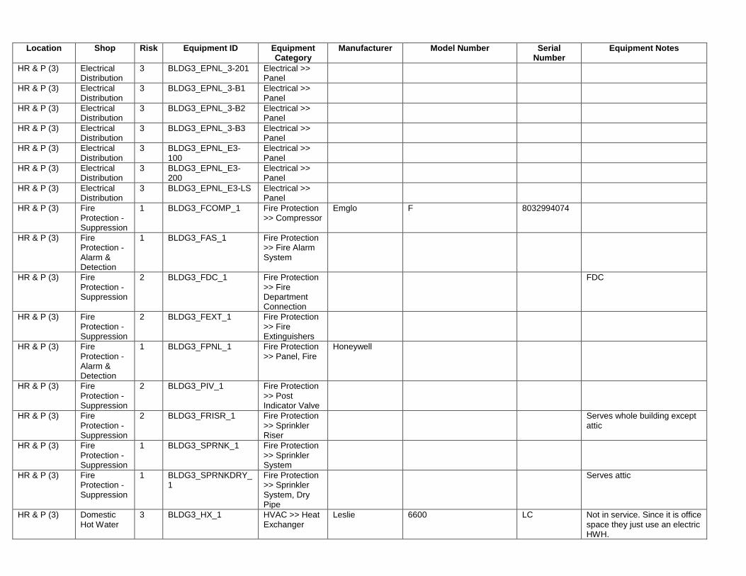
Location Shop Risk Equipment ID Equipment Category
Manufacturer Model Number Serial Number
Equipment Notes
HR & P (3) Electrical Distribution
3 BLDG3_EPNL_3-201 Electrical >> Panel
HR & P (3) Electrical Distribution
3 BLDG3_EPNL_3-B1 Electrical >> Panel
HR & P (3) Electrical Distribution
3 BLDG3_EPNL_3-B2 Electrical >> Panel
HR & P (3) Electrical Distribution
3 BLDG3_EPNL_3-B3 Electrical >> Panel
HR & P (3) Electrical Distribution
3 BLDG3_EPNL_E3-100
Electrical >> Panel
HR & P (3) Electrical Distribution
3 BLDG3_EPNL_E3-200
Electrical >> Panel
HR & P (3) Electrical Distribution
3 BLDG3_EPNL_E3-LS Electrical >> Panel
HR & P (3) Fire Protection - Suppression
1 BLDG3_FCOMP_1 Fire Protection >> Compressor
Emglo F 8032994074
HR & P (3) Fire Protection - Alarm & Detection
1 BLDG3_FAS_1 Fire Protection >> Fire Alarm System
HR & P (3) Fire Protection - Suppression
2 BLDG3_FDC_1 Fire Protection >> Fire Department Connection
FDC
HR & P (3) Fire Protection - Suppression
2 BLDG3_FEXT_1 Fire Protection >> Fire Extinguishers
HR & P (3) Fire Protection - Alarm & Detection
1 BLDG3_FPNL_1 Fire Protection >> Panel, Fire
Honeywell
HR & P (3) Fire Protection - Suppression
2 BLDG3_PIV_1 Fire Protection >> Post Indicator Valve
HR & P (3) Fire Protection - Suppression
2 BLDG3_FRISR_1 Fire Protection >> Sprinkler Riser
Serves whole building except attic
HR & P (3) Fire Protection - Suppression
1 BLDG3_SPRNK_1 Fire Protection >> Sprinkler System
HR & P (3) Fire Protection - Suppression
1 BLDG3_SPRNKDRY_1
Fire Protection >> Sprinkler System, Dry Pipe
Serves attic
HR & P (3) Domestic Hot Water
3 BLDG3_HX_1 HVAC >> Heat Exchanger
Leslie 6600 LC Not in service. Since it is office space they just use an electric HWH.

Location Shop Risk Equipment ID Equipment Category
Manufacturer Model Number Serial Number
Equipment Notes
HR & P (3) Heating 2 BLDG3_HX_2 HVAC >> Heat Exchanger
Has two small circulator pumps and circulates hot water for baseboard heat
HR & P (3) Domestic Hot Water
3 BLDG3_DWH_1 Plumbing >> Water Heater, Electric
Bradford White M250S6DS-1NCWW FD11870667
IT/H (9) Electrical Distribution
2 BLDG9_ELEC_9-MDP
Electrical >> Main Distribution Panel
IT/H (9) Electrical Distribution
3 BLDG9_EPNL_9-100 Electrical >> Panel
IT/H (9) Electrical Distribution
3 BLDG9_EPNL_9-101 Electrical >> Panel
IT/H (9) Electrical Distribution
3 BLDG9_EPNL_9-B1 Electrical >> Panel
IT/H (9) Electrical Distribution
3 BLDG9_EPNL_9-B2 Electrical >> Panel
IT/H (9) Electrical Distribution
3 BLDG9_EPNL_9-BDP1
Electrical >> Panel
IT/H (9) Electrical Distribution
3 BLDG9_EPNL_9-BDP2
Electrical >> Panel
IT/H (9) Electrical Distribution
3 BLDG9_EPNL_9-BDP3
Electrical >> Panel
IT/H (9) Electrical Distribution
3 BLDG9_EPNL_9-EQPMT
Electrical >> Panel
IT/H (9) Electrical Distribution
3 BLDG9_EPNL_E9-100
Electrical >> Panel
IT/H (9) Electrical Distribution
3 BLDG9_EPNL_E9-EB Electrical >> Panel
IT/H (9) Fire Protection - Suppression
1 BLDG9_FCOMP_1 Fire Protection >> Compressor
Jenny K F020211012
IT/H (9) Fire Protection - Alarm & Detection
1 BLDG9_FAS_1 Fire Protection >> Fire Alarm System
IT/H (9) Fire Protection - Suppression
2 BLDG9_FDC_1 Fire Protection >> Fire Department Connection
FDC
IT/H (9) Fire Protection - Suppression
2 BLDG9_FEXT_1 Fire Protection >> Fire Extinguishers
IT/H (9) Fire Protection - Suppression
2 BLDG9_FHYD_1 Fire Protection >> Fire Hydrant

Location Shop Risk Equipment ID Equipment Category
Manufacturer Model Number Serial Number
Equipment Notes
IT/H (9) Fire Protection - Alarm & Detection
1 BLDG9_FPNL_1 Fire Protection >> Panel, Fire
Honeywell
IT/H (9) Fire Protection - Suppression
2 BLDG9_PIV_1 Fire Protection >> Post Indicator Valve
IT/H (9) Fire Protection - Suppression
2 BLDG9_FRISR_1 Fire Protection >> Sprinkler Riser
IT/H (9) Fire Protection - Suppression
1 BLDG9_SPRNK_1 Fire Protection >> Sprinkler System
Serves building except attic
IT/H (9) Fire Protection - Suppression
1 BLDG9_SPRNKDRY_1
Fire Protection >> Sprinkler System, Dry Pipe
Serves attic
IT/H (9) Air Conditioning
3 BLDG9_COND_1 HVAC >> Condenser
Trane 4TTA3060D300CA 16162AWG5F
IT/H (9) Ventilation 3 BLDG9_HVAC_EF-3 HVAC >> Greenheck Fan, Exhaust
Greenheck CSP-A710-QD 14580800
IT/H (9) Ventilation 3 BLDG9_FAN_1 HVAC >> Greenheck Fan, Exhaust
Greenheck CSP-A510-QD 14556040
IT/H (9) Heating 2 BLDG9_HX_1 HVAC >> Heat Exchanger
ILLEGIBLE
IT/H (9) Heating 2 BLDG9_HVAC_P-1A HVAC >> Pump
Fia 60 16-41-92 1.5x6.25, 26-30 gpm
IT/H (9) Heating 2 BLDG9_HVAC_P-1B HVAC >> Pump
Fia 60 16-41-92 1.5x6.25, 26-30 gpm
IT/H (9) Heating 2 BLDG9_HTNK_1 HVAC >> Tank Neptune DBF-5HP Bypass feeder tank -5 gallons, 300 psi, working temp 200 degrees
IT/H (9) Heating 2 BLDG9_HTNK_2 HVAC >> Tank Condensate return unit
IT/H (9) Air Conditioning
3 BLDG9_AHU_1 HVAC >> Trane Air Handling Unit
Trane BCHD072E2G0A1105Z00000BC100000
T16E21495
IT/H (9) Air Conditioning
3 BLDG9_AHU_2 HVAC >> Trane Air Handling Unit
Trane BCDH090E2G0A1107Z00000BC1000
T16E21497
IT/H (9) Air Conditioning
3 BLDG9_AHU_3 HVAC >> Trane Air Handling Unit
Trane BCDH072E2G0A1405Z00000BC100000
T16E21496
IT/H (9) Air Conditioning
3 BLDG9_AHU_4 HVAC >> Trane Air Handling Unit
Trane BCDH072E2G0A1405Z00000BC100000
T16E21494

Location Shop Risk Equipment ID Equipment Category
Manufacturer Model Number Serial Number
Equipment Notes
IT/H (9) Air Conditioning
3 BLDG9_AHU_5 HVAC >> Trane Air Handling Unit
Trane BCDH072E2G0A1405Z00000BC100000
T16E21493
IT/H (9) Air Conditioning
3 BLDG9_COND_2 HVAC >> Trane Condenser
Trane TTA073G300AA 16195TT8YA
IT/H (9) Air Conditioning
3 BLDG9_COND_3 HVAC >> Trane Condenser
Trane TTA073G300AA 16195TUFYA
IT/H (9) Air Conditioning
3 BLDG9_COND_4 HVAC >> Trane Condenser
Trane TTA073G300AA 16195TUHYA
IT/H (9) Air Conditioning
3 BLDG9_COND_5 HVAC >> Trane Condenser
Trane TTA090G300AA 161851PDYA
IT/H (9) Life Safety 1 BLDG9_EXSN_1 Life Safety >> Emergency Exit Signs
IT/H (9) Domestic Hot Water
3 BLDG9_DWH_1 Plumbing >> Water Heater, Electric
Bradford White M250S6DS5 BM7061142 50 gallon
IRMC (2) Vertical Transport
2 BLDG2_ELEV_1 Conveying >> Elevator, Hydraulic
Hydraulic elevator
IRMC (2) Emergency Power
1 BLDG2_ATS_1 Electrical >> Automatic Transfer Switch
Asco 1187040-2 Fed from building 4 generator
IRMC (2) Electrical Distribution
2 BLDG2_MDP_1 Electrical >> Main Distribution Panel
General Electric AV LINE SWITCHBOARD Main breaker has over current trip indication 120/208
IRMC (2) Electrical Distribution
3 BLDG2_EPNL_2-100 Electrical >> Panel
IRMC (2) Electrical Distribution
3 BLDG2_EPNL_2-101 Electrical >> Panel
IRMC (2) Electrical Distribution
3 BLDG2_EPNL_2-200 Electrical >> Panel
IRMC (2) Electrical Distribution
3 BLDG2_EPNL_2-B1 Electrical >> Panel
IRMC (2) Electrical Distribution
3 BLDG2_EPNL_2-B2 Electrical >> Panel
IRMC (2) Electrical Distribution
3 BLDG2_EPNL_2-E2B-EQ1
Electrical >> Panel
IRMC (2) Electrical Distribution
3 BLDG2_EPNL_2SH-1 Electrical >> Panel
IRMC (2) Electrical Distribution
3 BLDG2_EPNL_CBE2-201
Electrical >> Panel

Location Shop Risk Equipment ID Equipment Category
Manufacturer Model Number Serial Number
Equipment Notes
IRMC (2) Electrical Distribution
3 BLDG2_EPNL_CBE2-202
Electrical >> Panel
IRMC (2) Electrical Distribution
3 BLDG2_EPNL_E2B-EQ1
Electrical >> Panel
IRMC (2) Electrical Distribution
3 BLDG2_EPNL_E2B-LS
Electrical >> Panel
IRMC (2) Electrical Distribution
3 BLDG2_EPNL_E2-LS-100
Electrical >> Panel
IRMC (2) Electrical Distribution
3 BLDG2_EPNL_E2-LS-200
Electrical >> Panel
IRMC (2) Electrical Distribution
3 BLDG2_EPNL_UPS-2 Electrical >> Panel
IRMC (2) Electrical Distribution
3 BLDG2_EPNL_UPS-2A
Electrical >> Panel
IRMC (2) Fire Protection - Suppression
1 BLDG2_FCOMP_1 Fire Protection >> Compressor
Jenny F F111141010
IRMC (2) Fire Protection - Alarm & Detection
1 BLDG2_FAS_1 Fire Protection >> Fire Alarm System
IRMC (2) Fire Protection - Suppression
2 BLDG2_FDC_1 Fire Protection >> Fire Department Connection
FDC
IRMC (2) Fire Protection - Suppression
2 BLDG2_FEXT_1 Fire Protection >> Fire Extinguishers
IRMC (2) Fire Protection - Alarm & Detection
1 BLDG2_FPNL_1 Fire Protection >> Panel, Fire
Honeywell
IRMC (2) Fire Protection - Suppression
2 BLDG2_PIV_1 Fire Protection >> Post Indicator Valve
IRMC (2) Fire Protection - Suppression
2 BLDG2_FRISR_1 Fire Protection >> Sprinkler Riser
IRMC (2) Fire Protection - Suppression
1 BLDG2_SPRNK_1 Fire Protection >> Sprinkler System
IRMC (2) Fire Protection - Suppression
1 BLDG2_SPRNKDRY_1
Fire Protection >> Sprinkler System, Dry Pipe
Serves attic

Location Shop Risk Equipment ID Equipment Category
Manufacturer Model Number Serial Number
Equipment Notes
IRMC (2) Air Conditioning
3 BLDG2_ACU_1 HVAC >> Air Conditioner
Liebert Uses the glycol condensing unit to take heat to outside. Refrigeration located in this unit.
IRMC (2) Air Conditioning
3 BLDG2_AHU_1 HVAC >> Air Handling Unit
York Matches with outside condenser. Cools telephone switchgear room.
IRMC (2) Air Conditioning
3 BLDG2_AHU_2 HVAC >> Air Handling Unit
Matches to condenser in back. Cools office area.
IRMC (2) Air Conditioning
3 BLDG2_AHU_3 HVAC >> Air Handling Unit
Evap coils for units out back (2 units). Backup cooling for server room.
IRMC (2) Air Conditioning
3 BLDG2_COND_AC-2 HVAC >> Condenser
York ILLEGIBLE ILLEGIBLE Serves office area
IRMC (2) Air Conditioning
3 BLDG2_COND_1 HVAC >> Condenser
Cac/Bdp PA13NR048 3612X71636 Supplemental cooling for server room
IRMC (2) Air Conditioning
3 BLDG2_COND_2 HVAC >> Condenser
Bryant 561CJ048-G 1305E14066 Supplemental cooling for server room
IRMC (2) Air Conditioning
3 BLDG2_COND_3 HVAC >> Condensing Unit
Liebert ILLEGIBLE 3053654 Circulates glycol through condensers to carry heat outside. Typically used in IT situations. Serves server room
IRMC (2) Communications
3 BLDG2_COND_AC-1 HVAC >> Condensing Unit
York ILLEGIBLE Serves telephone switchgear room
IRMC (2) Air Conditioning
3 BLDG2_HPMP_1 HVAC >> Pump
Ingersoll Rand SMP-2000-P-2061 1287-1203 Glycol pump
IRMC (2) Air Conditioning
3 BLDG2_HPMP_2 HVAC >> Pump
Ingersoll Rand SMP-2000-P-2964 1287-1207 Glycol pump
L & S (14) Electrical Distribution
3 BLDG14_EPNL_14-100
Electrical >> Panel
L & S (14) Electrical Distribution
3 BLDG14_EPNL_14-101
Electrical >> Panel
L & S (14) Electrical Distribution
3 BLDG14_EPNL_14-102
Electrical >> Panel
L & S (14) Electrical Distribution
3 BLDG14_EPNL_14-103
Electrical >> Panel
L & S (14) Electrical Distribution
3 BLDG14_EPNL_14-104
Electrical >> Panel
L & S (14) Electrical Distribution
3 BLDG14_EPNL_14-MDP
Electrical >> Panel
L & S (14) Electrical Distribution
3 BLDG14_EPNL_14-SHOP
Electrical >> Panel
L & S (14) Fire Protection - Alarm & Detection
1 BLDG14_FAS_1 Fire Protection >> Fire Alarm System

Location Shop Risk Equipment ID Equipment Category
Manufacturer Model Number Serial Number
Equipment Notes
L & S (14) Fire Protection - Suppression
2 BLDG14_FDC_1 Fire Protection >> Fire Department Connection
FDC
L & S (14) Fire Protection - Suppression
2 BLDG14_FEXT_1 Fire Protection >> Fire Extinguishers
L & S (14) Fire Protection - Alarm & Detection
1 BLDG14_FPNL_1 Fire Protection >> Panel, Fire
Honeywell
L & S (14) Fire Protection - Suppression
2 BLDG14_PIV_1 Fire Protection >> Post Indicator Valve
L & S (14) Fire Protection - Suppression
2 BLDG14_FRISR_1 Fire Protection >> Sprinkler Riser
L & S (14) Fire Protection - Suppression
1 BLDG14_SPRNK_1 Fire Protection >> Sprinkler System
No dry system in this building
MP & G (13) Electrical Distribution
2 BLDG13_ELEC_13-MDP
Electrical >> Main Distribution Panel
MP & G (13) Electrical Distribution
3 BLDG13_EPNL_13-100
Electrical >> Panel
MP & G (13) Electrical Distribution
3 BLDG13_EPNL_13-101
Electrical >> Panel
MP & G (13) Electrical Distribution
3 BLDG13_EPNL_13-102
Electrical >> Panel
MP & G (13) Electrical Distribution
3 BLDG13_EPNL_E13-LS1
Electrical >> Panel
MP & G (13) Electrical Distribution
3 BLDG13_EPNL_E13-LS2
Electrical >> Panel
MP & G (13) Electrical Distribution
2 BLDG13_ELEC_E13-LS1-TR
Electrical >> Transformer
MP & G (13) Electrical Distribution
2 BLDG13_ELEC_E13-LS2-TR
Electrical >> Transformer
MP & G (13) Electrical Distribution
2 BLDG13_ELEC_TRB13
Electrical >> Transformer
MP & G (13) Fire Protection - Alarm & Detection
1 BLDG13_FAS_1 Fire Protection >> Fire Alarm System
MP & G (13) Fire Protection - Suppression
2 BLDG13_FDC_1 Fire Protection >> Fire Department Connection
FDC

Location Shop Risk Equipment ID Equipment Category
Manufacturer Model Number Serial Number
Equipment Notes
MP & G (13) Fire Protection - Suppression
2 BLDG13_FEXT_1 Fire Protection >> Fire Extinguishers
MP & G (13) Fire Protection - Suppression
2 BLDG13_FHYD_1 Fire Protection >> Fire Hydrant
MP & G (13) Fire Protection - Alarm & Detection
1 BLDG13_FPNL_1 Fire Protection >> Panel, Fire
MP & G (13) Fire Protection - Suppression
2 BLDG13_PIV_1 Fire Protection >> Post Indicator Valve
MP & G (13) Fire Protection - Suppression
2 BLDG13_FRISR_1 Fire Protection >> Sprinkler Riser
MP & G (13) Fire Protection - Suppression
1 BLDG13_SPRNK_1 Fire Protection >> Sprinkler System
N&FS, PSYCH SERVICE (5)
Vertical Transport
2 BLDG5_ELEV_1 Conveying >> Elevator, Traction
4000 lbs. - traction elevator
N&FS, PSYCH SERVICE (5)
Electrical Distribution
3 BLDG5_EPNL_5-101 Electrical >> Panel
N&FS, PSYCH SERVICE (5)
Electrical Distribution
3 BLDG5_EPNL_5-106 Electrical >> Panel
N&FS, PSYCH SERVICE (5)
Electrical Distribution
3 BLDG5_EPNL_5-B1 Electrical >> Panel
N&FS, PSYCH SERVICE (5)
Electrical Distribution
3 BLDG5_EPNL_5-B10 Electrical >> Panel
N&FS, PSYCH SERVICE (5)
Electrical Distribution
3 BLDG5_EPNL_5-B11 Electrical >> Panel
N&FS, PSYCH SERVICE (5)
Electrical Distribution
3 BLDG5_EPNL_5-B2 Electrical >> Panel
N&FS, PSYCH SERVICE (5)
Electrical Distribution
3 BLDG5_EPNL_5-B3 Electrical >> Panel
N&FS, PSYCHOLOGY SERVICE (5)
Electrical Distribution
3 BLDG5_EPNL_5-B4 Electrical >> Panel

Location Shop Risk Equipment ID Equipment Category
Manufacturer Model Number Serial Number
Equipment Notes
N&FS, PSYCH SERVICE (5)
Electrical Distribution
3 BLDG5_EPNL_5-B5 Electrical >> Panel
N&FS, PSYCH SERVICE (5)
Electrical Distribution
3 BLDG5_EPNL_5-B6 Electrical >> Panel
N&FS, PSYCH SERVICE (5)
Electrical Distribution
3 BLDG5_EPNL_5-B7 Electrical >> Panel
N&FS, PSYCH SERVICE (5)
Electrical Distribution
3 BLDG5_EPNL_5-B8 Electrical >> Panel
N&FS, PSYCH SERVICE (5)
Electrical Distribution
3 BLDG5_EPNL_5-B9 Electrical >> Panel
N&FS, PSYCH SERVICE (5)
Electrical Distribution
3 BLDG5_EPNL_5-EDP Electrical >> Panel
N&FS, PSYCH SERVICE (5)
Electrical Distribution
3 BLDG5_EPNL_E5-102
Electrical >> Panel
N&FS, PSYCH SERVICE (5)
Electrical Distribution
3 BLDG5_EPNL_E5-103
Electrical >> Panel
N&FS, PSYCH SERVICE (5)
Electrical Distribution
3 BLDG5_EPNL_E5-104
Electrical >> Panel
N&FS, PSYCH SERVICE (5)
Electrical Distribution
3 BLDG5_EPNL_E5-104A
Electrical >> Panel
N&FS, PSYCH SERVICE (5)
Electrical Distribution
3 BLDG5_EPNL_E5B1LS
Electrical >> Panel
N&FS, PSYCH SERVICE (5)
Electrical Distribution
3 BLDG5_EPNL_E5-B2 Electrical >> Panel
N&FS, PSYCH SERVICE (5)
Electrical Distribution
3 BLDG5_EPNL_E5-B2LS
Electrical >> Panel
N&FS, PSYCH SERVICE (5)
Electrical Distribution
3 BLDG5_EPNL_E5-LS Electrical >> Panel
N&FS, PSYCH SERVICE (5)
Fire Protection - Alarm & Detection
1 BLDG5_FAS_1 Fire Protection >> Fire Alarm System

Location Shop Risk Equipment ID Equipment Category
Manufacturer Model Number Serial Number
Equipment Notes
N&FS, PSYCH SERVICE (5)
Fire Protection - Suppression
2 BLDG5_FDC_1 Fire Protection >> Fire Department Connection
FDC
N&FS, PSYCH SERVICE (5)
Fire Protection - Suppression
2 BLDG5_FEXT_1 Fire Protection >> Fire Extinguishers
N&FS, PSYCH SERVICE (5)
Fire Protection - Suppression
2 BLDG5_FSUPP_1 Fire Protection >> Fire Suppression System
Kidde Fire System
N&FS, PSYCH SERVICE (5)
Fire Protection - Alarm & Detection
1 BLDG5_FPNL_1 Fire Protection >> Panel, Fire
Honeywell
N&FS, PSYCH SERVICE (5)
Fire Protection - Suppression
2 BLDG5_PIV_1 Fire Protection >> Post Indicator Valve
N&FS, PSYCH SERVICE (5)
Fire Protection - Suppression
1 BLDG5_SPRNK_1 Fire Protection >> Sprinkler System
1 - regular sprinkler for the building and 1- glycol system for the tunnels on each side of building
N&FS, PSYCH SERVICE (5)
Refrigeration 2 BLDG5_BLAST_1 Food Service_Dietary >> Blast Chiller
Traulsen RBC200-20 T28811K09
N&FS, PSYCH SERVICE (5)
Air Conditioning
3 BLDG5_AHU_1 HVAC >> Air Handling Unit
American Blower Serves both DRA and DRB via two evaporators, HP steam heating coils, and utilizes two carrier condensing units (located on the east exterior of DRA). This unit has been heavily modified to incorporate three independent Dayton centrifugal blowers.
N&FS, PSYCH SERVICE (5)
Air Conditioning
3 BLDG5_AHU_2 HVAC >> Air Handling Unit
American Blower Serves as Makeup Air handler to the North side of the main Kitchen area. It has been non-operational and beyond economic repair for years.
N&FS, PSYCH SERVICE (5)
Air Conditioning
3 BLDG5_AHU_3 HVAC >> Air Handling Unit
American Blower Serves as Makeup Air Handler to the south side of the Kitchen area. It has a blown heating coil from winter of 2015. Steam coil turned off at that time.

Location Shop Risk Equipment ID Equipment Category
Manufacturer Model Number Serial Number
Equipment Notes
N&FS, PSYCH SERVICE (5)
Air Conditioning
3 BLDG5_AHU_4 HVAC >> Air Handling Unit
Carrier Serves Dietetics Services offices. W Condenser on pad outside widget shop.
N&FS, PSYCH SERVICE (5)
Air Conditioning
3 BLDG5_AHU_5 HVAC >> Air Handling Unit
Goodman Serves Psychology service offices on first floor. Note this AHU was made redundant and obsolete by the installation of window AC units and the removal of the bi-parting doors that served to isolate the air conditioned wing from the adjacent non-Air conditioned space and hall. It has not functioned since 2012. Condenser is on pad outside widget shop.
N&FS, PSYCH SERVICE (5)
Air Conditioning
3 BLDG5_AHU_6 HVAC >> Air Handling Unit
Serves widget shop (factory floor area). Condensing unit on pad outside of widget shop.
N&FS, PSYCH SERVICE (5)
Air Conditioning
3 BLDG5_COND_1 HVAC >> Condenser
Carrier 38EN048520 2987E45189 Serves conference room
N&FS, PSYCH SERVICE (5)
Air Conditioning
3 BLDG5_COND_2 HVAC >> Condenser
Carrier 38EN015310SM 4086E06998 Serves VA office
N&FS, PSYCH SERVICE (5)
Air Conditioning
3 BLDG5_COND_3 HVAC >> Condenser
Goodman GSC130241FA 1307289312 Serves office
N&FS, PSYCH SERVICE (5)
Air Conditioning
3 BLDG5_COND_4 HVAC >> Condenser
Carrier Serves dining room
N&FS, PSYCH SERVICE (5)
Air Conditioning
3 BLDG5_COND_5 HVAC >> Condenser
Carrier Serves meal prep area
N&FS, PSYCH SERVICE (5)
Domestic Hot Water
3 BLDG5_DHW_Domestic HX-1
HVAC >> Heat Exchanger
Leslie E 600L LC Leslie Pilot Constant-temp
model E600L. This is the only
building domestic hot water
heater.
N&FS, PSYCH SERVICE (5)
Air Conditioning
3 BDLG5_HRU_001 HVAC >> Heat Recovery Unit
LectraSaver B11-5-VA. This unit recover heat and pre-heat domestic water for hot water generation.
N&FS, PSYCH SERVICE (5)
Air Conditioning
3 BDLG5_HRU_002 HVAC >> Heat Recovery Unit
LectraSaver B11-5-VA. This unit recover heat and pre-heat domestic water for hot water generation.

Location Shop Risk Equipment ID Equipment Category
Manufacturer Model Number Serial Number
Equipment Notes
N&FS, PSYCH SERVICE (5)
Air Conditioning
3 BDLG5_HRU_003 HVAC >> Heat Recovery Unit
LectraSaver B11-5-VA. This unit recover heat and pre-heat domestic water for hot water generation.
N&FS, PSYCH SERVICE (5)
Air Conditioning
3 BDLG5_HRU_004 HVAC >> Heat Recovery Unit
LectraSaver B11-5-VA. This unit recover heat and pre-heat domestic water for hot water generation.
N&FS, PSYCH SERVICE (5)
Air Conditioning
3 BDLG5_HRU_005 HVAC >> Heat Recovery Unit
LectraSaver B11-5-VA. This unit recover heat and pre-heat domestic water for hot water generation.
N&FS, PSYCH SERVICE (5)
Air Conditioning
3 BDLG5_HRU_006 HVAC >> Heat Recovery Unit
LectraSaver B21-5-VA. This unit recover heat and pre-heat domestic water for hot water generation.
N&FS, PSYCH SERVICE (5)
Air Conditioning
3 BDLG5_HRU_007 HVAC >> Heat Recovery Unit
LectraSaver B21-5-VA. This unit recover heat and pre-heat domestic water for hot water generation.
N&FS, PSYCH SERVICE (5)
Air Conditioning
3 BDLG5_HRU_008 HVAC >> Heat Recovery Unit
LectraSaver B21-5-VA. This unit recover heat and pre-heat domestic water for hot water generation.
N&FS, PSYCH SERVICE (5)
Air Conditioning
3 BDLG5_HRU_009 HVAC >> Heat Recovery Unit
Roof top heat recovery unit (HRU) from the kitchen exhaust fan.
N&FS, PSYCH SERVICE (5)
Air Conditioning
3 BLDG5_SPLIT_1 HVAC >> Split System
Tadiran Serves an interior space (B19-5-VA) that is used for dry storage. By VA standards and VA Dietetics guide specifications – this area is required to be Air Conditioned. It is serviced by a mini-split. The condensing unit is wall mounted on the south exterior next to N&FS loading dock. The unit has remained in bad repair and non-operational since 2011.
N&FS, PSYCH SERVICE (5)
Air Conditioning
3 BLDG5_SPLIT_2 HVAC >> Split System
Mitsubishi Serves Joyce Fredrick’s Office area (133-5-VA). The condensing unit is mounted on the exterior west wall of her office, above the Building 5 locker room roof.
N&FS, PSYCH SERVICE (5)
Potable Water
2 BLDG5_BFP_1 Plumbing >> BackFlow Preventer
Ames LA-1028 2.5"
PTSD Patient Clinic (9A)
Electrical Distribution
3 BLDG9A_EPNL_PP1 Electrical >> Panel
PTSD Patient Clinic (9A)
Electrical Distribution
3 BLDG9A_EPNL_PP1A
Electrical >> Panel

Location Shop Risk Equipment ID Equipment Category
Manufacturer Model Number Serial Number
Equipment Notes
PTSD Patient Clinic (9A)
Electrical Distribution
3 BLDG9A_EPNL_SP2 Electrical >> Panel
PTSD Patient Clinic (9A)
Fire Protection - Suppression
1 BLDG9A_FCOMP_1 Fire Protection >> Compressor
PTSD Patient Clinic (9A)
Fire Protection - Alarm & Detection
1 BLDG9A_FAS_1 Fire Protection >> Fire Alarm System
Tied into panel at building 26
PTSD Patient Clinic (9A)
Fire Protection - Suppression
2 BLDG9A_FDC_1 Fire Protection >> Fire Department Connection
FDC
PTSD Patient Clinic (9A)
Fire Protection - Suppression
2 BLDG9A_FEXT_1 Fire Protection >> Fire Extinguishers
PTSD Patient Clinic (9A)
Fire Protection - Alarm & Detection
1 BLDG9A_FPNL_1 Fire Protection >> Panel, Fire
Shares fire panel and PIV with building 26
PTSD Patient Clinic (9A)
Fire Protection - Suppression
1 BLDG9A_SPRNK_1 Fire Protection >> Sprinkler System
Serves most of building except attic
PTSD Patient Clinic (9A)
Fire Protection - Suppression
1 BLDG9A_SPRNKDRY_1
Fire Protection >> Sprinkler System, Dry Pipe
Serves attic
PTSD Patient Clinic (9A)
Air Conditioning
3 BLDG9A_HTPMP_1 HVAC >> York Heat Pump
York YHJD48S41S4A W1H1240080 AHU in ceiling and not easily accessible
PTSD Patient Clinic (9A)
Air Conditioning
3 BLDG9A_HTPMP_2 HVAC >> York Heat Pump
York YHJD48S41S4A W1F110528 AHU in ceiling and not easily accessible. Filters replaced in ceiling return air vents so AHUs are not normally accessed
PTSD Patient Clinic (9A)
Fire Protection - Suppression
2 BLDG9A_BFP_1 Plumbing >> BackFlow Preventer
Ames JJ-1060
Rec Auditorium (11)
Electrical Distribution
3 BLDG11_EPNL_11-100
Electrical >> Panel
Rec Auditorium (11)
Electrical Distribution
3 BLDG11_EPNL_11-101
Electrical >> Panel
Rec Auditorium (11)
Electrical Distribution
3 BLDG11_EPNL_11-200
Electrical >> Panel

Location Shop Risk Equipment ID Equipment Category
Manufacturer Model Number Serial Number
Equipment Notes
Rec Auditorium (11)
Electrical Distribution
3 BLDG11_EPNL_11-B1
Electrical >> Panel
Rec Auditorium (11)
Electrical Distribution
3 BLDG11_EPNL_11-B2
Electrical >> Panel
Rec Auditorium (11)
Electrical Distribution
3 BLDG11_EPNL_11-B3
Electrical >> Panel
Rec Auditorium (11)
Electrical Distribution
3 BLDG11_EPNL_11-BDP
Electrical >> Panel
Rec Auditorium (11)
Electrical Distribution
3 BLDG11_EPNL_11-MDP
Electrical >> Panel
Rec Auditorium (11)
Electrical Distribution
3 BLDG11_EPNL_E11-200EB
Electrical >> Panel
Rec Auditorium (11)
Electrical Distribution
3 BLDG11_EPNL_E11-EB
Electrical >> Panel
Rec Auditorium (11)
Fire Protection - Suppression
1 BLDG11_FCOMP_1 Fire Protection >> Compressor
Rec Auditorium (11)
Fire Protection - Alarm & Detection
1 BLDG11_FAS_1 Fire Protection >> Fire Alarm System
Rec Auditorium (11)
Fire Protection - Suppression
2 BLDG11_FEXT_1 Fire Protection >> Fire Extinguishers
Rec Auditorium (11)
Fire Protection - Alarm & Detection
1 BLDG11_FPNL_1 Fire Protection >> Panel, Fire
Honeywell
Rec Auditorium (11)
Fire Protection - Alarm & Detection
1 BLDG11_FPNL_2 Fire Protection >> Panel, Fire
Honeywell
Rec Auditorium (11)
Fire Protection - Alarm & Detection
1 BLDG11_FPNL_3 Fire Protection >> Panel, Fire
Honeywell
Rec Auditorium (11)
Fire Protection - Suppression
2 BLDG11_PIV_1 Fire Protection >> Post Indicator Valve

Location Shop Risk Equipment ID Equipment Category
Manufacturer Model Number Serial Number
Equipment Notes
Rec Auditorium (11)
Fire Protection - Suppression
2 BLDG11_PIV_2 Fire Protection >> Post Indicator Valve
Rec Auditorium (11)
Fire Protection - Suppression
2 BLDG11_PIV_3 Fire Protection >> Post Indicator Valve
Rec Auditorium (11)
Fire Protection - Suppression
1 BLDG11_SPRNK_1 Fire Protection >> Sprinkler System
Everything except attic
Rec Auditorium (11)
Fire Protection - Suppression
1 BLDG11_SPRNKDRY_1
Fire Protection >> Sprinkler System, Dry Pipe
Serves attic
Soldier - On (26)
Vertical Transport
2 BLDG26_ELEV_1 Conveying >> Elevator, Hydraulic
Hydraulic elevator
Soldier - On (26)
Electrical Distribution
2 BLDG26_ELEC_26-MDP
Electrical >> Main Distribution Panel
Soldier - On (26)
Electrical Distribution
3 BLDG26_EPNL_26-100
Electrical >> Panel
Soldier - On (26)
Electrical Distribution
3 BLDG26_EPNL_26-101
Electrical >> Panel
Soldier - On (26)
Electrical Distribution
3 BLDG26_EPNL_26-200
Electrical >> Panel
Soldier - On (26)
Electrical Distribution
3 BLDG26_EPNL_26-201
Electrical >> Panel
Soldier - On (26)
Electrical Distribution
3 BLDG26_EPNL_26-300
Electrical >> Panel
Soldier - On (26)
Electrical Distribution
3 BLDG26_EPNL_26-B1
Electrical >> Panel
Soldier - On (26)
Electrical Distribution
3 BLDG26_EPNL_26-B2
Electrical >> Panel
Soldier - On (26)
Electrical Distribution
3 BLDG26_EPNL_26-B3
Electrical >> Panel
Soldier - On (26)
Electrical Distribution
3 BLDG26_EPNL_26-DP
Electrical >> Panel
Soldier - On (26)
Electrical Distribution
3 BLDG26_EPNL_26-EDP
Electrical >> Panel
Soldier - On (26)
Electrical Distribution
3 BLDG26_EPNL_26-SDP
Electrical >> Panel
Soldier - On (26)
Electrical Distribution
3 BLDG26_EPNL_E26-100
Electrical >> Panel
Soldier - On (26)
Electrical Distribution
3 BLDG26_EPNL_E26-101
Electrical >> Panel
Soldier - On (26)
Electrical Distribution
3 BLDG26_EPNL_E26-200
Electrical >> Panel

Location Shop Risk Equipment ID Equipment Category
Manufacturer Model Number Serial Number
Equipment Notes
Soldier - On (26)
Electrical Distribution
3 BLDG26_EPNL_E26-201
Electrical >> Panel
Soldier - On (26)
Electrical Distribution
3 BLDG26_EPNL_E26-300
Electrical >> Panel
Soldier - On (26)
Electrical Distribution
3 BLDG26_EPNL_E26-LS
Electrical >> Panel
Soldier - On (26)
Fire Protection - Suppression
1 BLDG26_FCOMP_1 Fire Protection >> Compressor
Jenny K F02061203
Soldier - On (26)
Fire Protection - Alarm & Detection
1 BLDG26_FAS_1 Fire Protection >> Fire Alarm System
Soldier - On (26)
Fire Protection - Suppression
2 BLDG26_FDC_1 Fire Protection >> Fire Department Connection
FDC
Soldier - On (26)
Fire Protection - Suppression
2 BLDG26_FEXT_1 Fire Protection >> Fire Extinguishers
Soldier - On (26)
Fire Protection - Alarm & Detection
1 BLDG26_FPNL_1 Fire Protection >> Panel, Fire
Honeywell
Soldier - On (26)
Fire Protection - Suppression
2 BLDG26_PIV_1 Fire Protection >> Post Indicator Valve
Soldier - On (26)
Fire Protection - Suppression
2 BLDG26_FRISR_1 Fire Protection >> Sprinkler Riser
Soldier - On (26)
Fire Protection - Suppression
1 BLDG26_SPRNK_1 Fire Protection >> Sprinkler System
Soldier - On (26)
Fire Protection - Suppression
1 BLDG26_SPRNKDRY_1
Fire Protection >> Sprinkler System, Dry Pipe
Serves attic
Soldier - On (6)
Vertical Transport
2 BLDG6_ELEV_1 Conveying >> Elevator, Hydraulic
Hydraulic elevator
Soldier - On (6)
Emergency Power
2 BLDG6_ELEC_12a-mdp
Electrical >> Main Distribution Panel
Siemens FC-I SO 18-50957-CO4
Incoming fed from transformer outside
Soldier - On (6)
Emergency Power
2 BLDG6_ELEC_E6A MDP
Electrical >> Main Distribution Panel
Siemens FC-I SO 18-50957-DO2
Feeds 3 ats
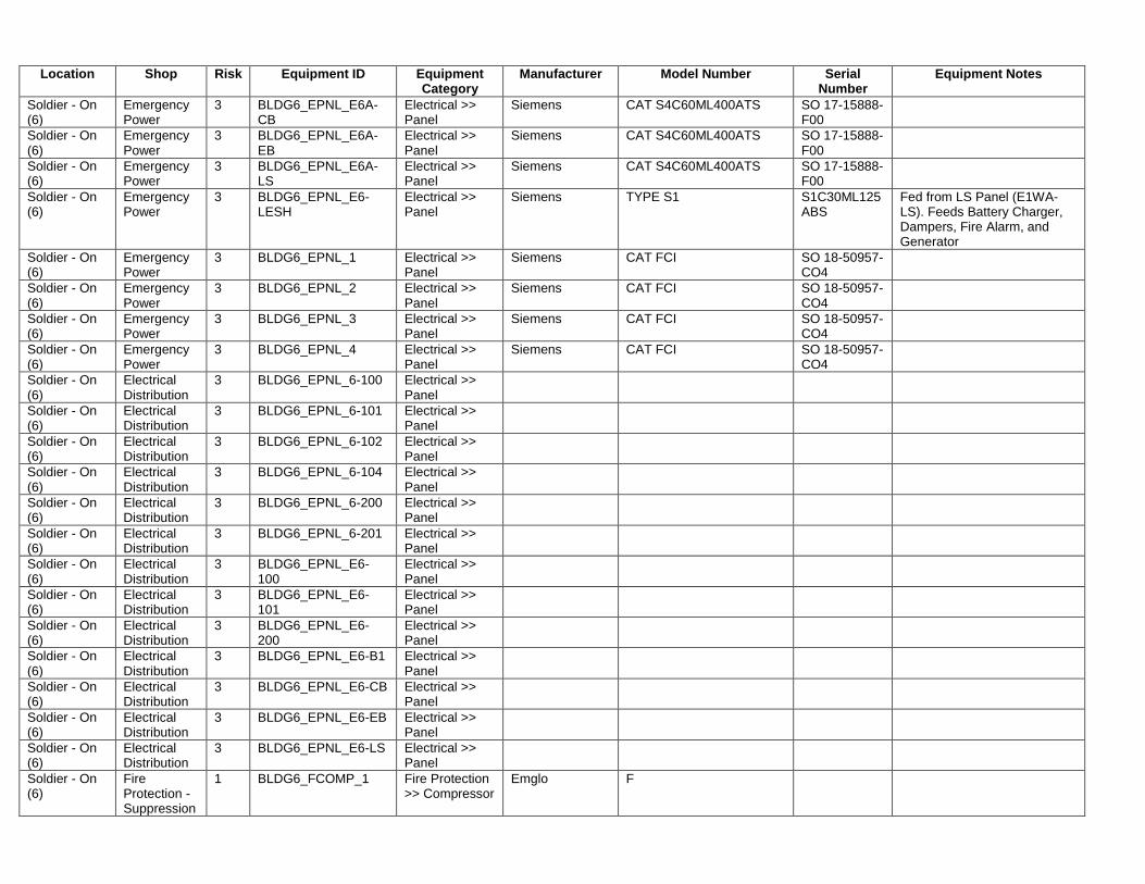
Location Shop Risk Equipment ID Equipment Category
Manufacturer Model Number Serial Number
Equipment Notes
Soldier - On (6)
Emergency Power
3 BLDG6_EPNL_E6A-CB
Electrical >> Panel
Siemens CAT S4C60ML400ATS SO 17-15888-F00
Soldier - On (6)
Emergency Power
3 BLDG6_EPNL_E6A-EB
Electrical >> Panel
Siemens CAT S4C60ML400ATS SO 17-15888-F00
Soldier - On (6)
Emergency Power
3 BLDG6_EPNL_E6A-LS
Electrical >> Panel
Siemens CAT S4C60ML400ATS SO 17-15888-F00
Soldier - On (6)
Emergency Power
3 BLDG6_EPNL_E6-LESH
Electrical >> Panel
Siemens TYPE S1 S1C30ML125ABS
Fed from LS Panel (E1WA-LS). Feeds Battery Charger, Dampers, Fire Alarm, and Generator
Soldier - On (6)
Emergency Power
3 BLDG6_EPNL_1 Electrical >> Panel
Siemens CAT FCI SO 18-50957-CO4
Soldier - On (6)
Emergency Power
3 BLDG6_EPNL_2 Electrical >> Panel
Siemens CAT FCI SO 18-50957-CO4
Soldier - On (6)
Emergency Power
3 BLDG6_EPNL_3 Electrical >> Panel
Siemens CAT FCI SO 18-50957-CO4
Soldier - On (6)
Emergency Power
3 BLDG6_EPNL_4 Electrical >> Panel
Siemens CAT FCI SO 18-50957-CO4
Soldier - On (6)
Electrical Distribution
3 BLDG6_EPNL_6-100 Electrical >> Panel
Soldier - On (6)
Electrical Distribution
3 BLDG6_EPNL_6-101 Electrical >> Panel
Soldier - On (6)
Electrical Distribution
3 BLDG6_EPNL_6-102 Electrical >> Panel
Soldier - On (6)
Electrical Distribution
3 BLDG6_EPNL_6-104 Electrical >> Panel
Soldier - On (6)
Electrical Distribution
3 BLDG6_EPNL_6-200 Electrical >> Panel
Soldier - On (6)
Electrical Distribution
3 BLDG6_EPNL_6-201 Electrical >> Panel
Soldier - On (6)
Electrical Distribution
3 BLDG6_EPNL_E6-100
Electrical >> Panel
Soldier - On (6)
Electrical Distribution
3 BLDG6_EPNL_E6-101
Electrical >> Panel
Soldier - On (6)
Electrical Distribution
3 BLDG6_EPNL_E6-200
Electrical >> Panel
Soldier - On (6)
Electrical Distribution
3 BLDG6_EPNL_E6-B1 Electrical >> Panel
Soldier - On (6)
Electrical Distribution
3 BLDG6_EPNL_E6-CB Electrical >> Panel
Soldier - On (6)
Electrical Distribution
3 BLDG6_EPNL_E6-EB Electrical >> Panel
Soldier - On (6)
Electrical Distribution
3 BLDG6_EPNL_E6-LS Electrical >> Panel
Soldier - On (6)
Fire Protection - Suppression
1 BLDG6_FCOMP_1 Fire Protection >> Compressor
Emglo F
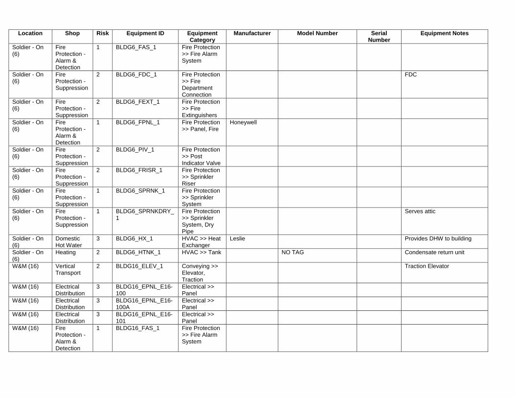
Location Shop Risk Equipment ID Equipment Category
Manufacturer Model Number Serial Number
Equipment Notes
Soldier - On (6)
Fire Protection - Alarm & Detection
1 BLDG6_FAS_1 Fire Protection >> Fire Alarm System
Soldier - On (6)
Fire Protection - Suppression
2 BLDG6_FDC_1 Fire Protection >> Fire Department Connection
FDC
Soldier - On (6)
Fire Protection - Suppression
2 BLDG6_FEXT_1 Fire Protection >> Fire Extinguishers
Soldier - On (6)
Fire Protection - Alarm & Detection
1 BLDG6_FPNL_1 Fire Protection >> Panel, Fire
Honeywell
Soldier - On (6)
Fire Protection - Suppression
2 BLDG6_PIV_1 Fire Protection >> Post Indicator Valve
Soldier - On (6)
Fire Protection - Suppression
2 BLDG6_FRISR_1 Fire Protection >> Sprinkler Riser
Soldier - On (6)
Fire Protection - Suppression
1 BLDG6_SPRNK_1 Fire Protection >> Sprinkler System
Soldier - On (6)
Fire Protection - Suppression
1 BLDG6_SPRNKDRY_1
Fire Protection >> Sprinkler System, Dry Pipe
Serves attic
Soldier - On (6)
Domestic Hot Water
3 BLDG6_HX_1 HVAC >> Heat Exchanger
Leslie Provides DHW to building
Soldier - On (6)
Heating 2 BLDG6_HTNK_1 HVAC >> Tank NO TAG Condensate return unit
W&M (16) Vertical Transport
2 BLDG16_ELEV_1 Conveying >> Elevator, Traction
Traction Elevator
W&M (16) Electrical Distribution
3 BLDG16_EPNL_E16-100
Electrical >> Panel
W&M (16) Electrical Distribution
3 BLDG16_EPNL_E16-100A
Electrical >> Panel
W&M (16) Electrical Distribution
3 BLDG16_EPNL_E16-101
Electrical >> Panel
W&M (16) Fire Protection - Alarm & Detection
1 BLDG16_FAS_1 Fire Protection >> Fire Alarm System
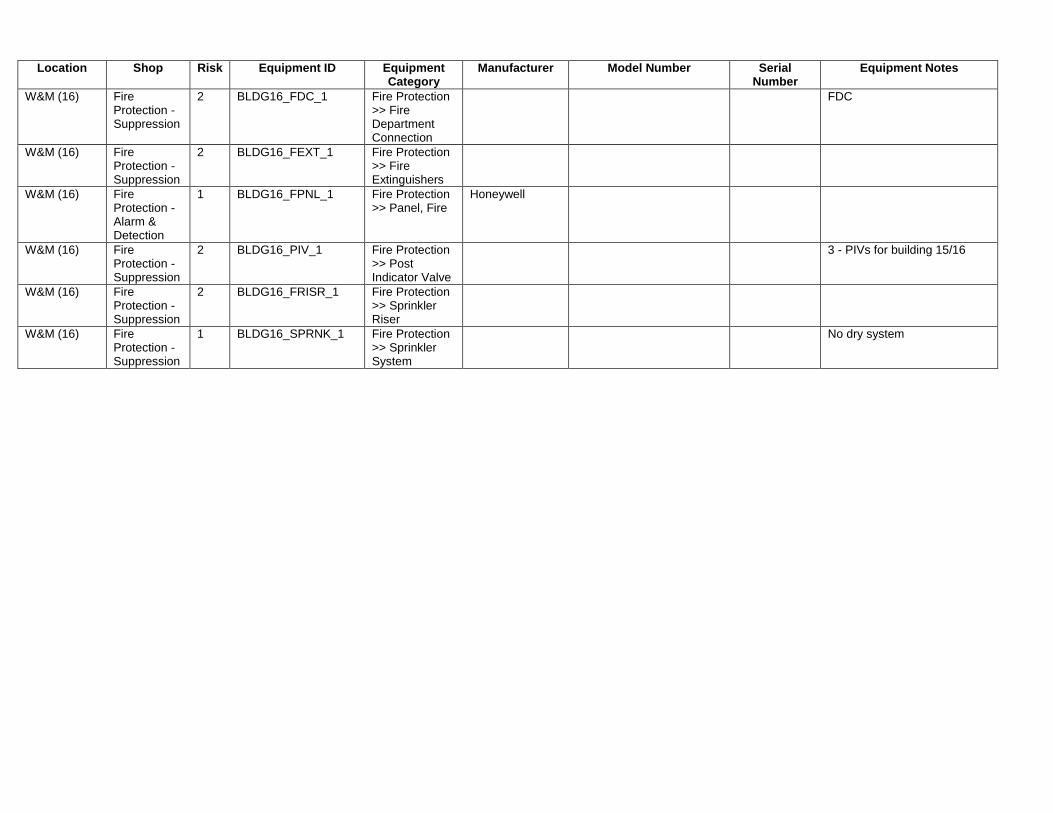
Location Shop Risk Equipment ID Equipment Category
Manufacturer Model Number Serial Number
Equipment Notes
W&M (16) Fire Protection - Suppression
2 BLDG16_FDC_1 Fire Protection >> Fire Department Connection
FDC
W&M (16) Fire Protection - Suppression
2 BLDG16_FEXT_1 Fire Protection >> Fire Extinguishers
W&M (16) Fire Protection - Alarm & Detection
1 BLDG16_FPNL_1 Fire Protection >> Panel, Fire
Honeywell
W&M (16) Fire Protection - Suppression
2 BLDG16_PIV_1 Fire Protection >> Post Indicator Valve
3 - PIVs for building 15/16
W&M (16) Fire Protection - Suppression
2 BLDG16_FRISR_1 Fire Protection >> Sprinkler Riser
W&M (16) Fire Protection - Suppression
1 BLDG16_SPRNK_1 Fire Protection >> Sprinkler System
No dry system