CRCM2176.pdf - Oracle Help Center
196
. . . . . . . . . . . . . . . . . . . . . . . . . . . . . . . . . . . . . . . . . . . Viper 200 . . . . . . . . . . . . . . . . . . . . . . . . . . . . . . . . . . . . . . . . . . . LTO Tape Drive . . . . . . . . . . . . . . . . . . . . . . . . . . . . . . . . . . . . . . . . . . . . . . . . . . . . . . . . . . . . . . . . . . . . . . . . . . . . . . . . . . . . . . . . . . . . . . . . . . . . . . . . . . . . . . . . . . . . . . . . . . . . . . . . . SCSI / Fibre Channel Interface Manual . . . . . . . . . . . . . . . . . . . . . . . . . . . . . . . . . . . . . . .
-
Upload
khangminh22 -
Category
Documents
-
view
1 -
download
0
Transcript of CRCM2176.pdf - Oracle Help Center

. . . . . . . . . . . . . . . . . . . . . . . . . . . . . . . . . .. . . . . . . . .Viper 200. . . . . . . . . . . . . . . . . . . . . . . . . . . . . . . . . .. . . . . . . . .LTO Tape Drive. . . . . . . . . . . . . . . . . . . . . . . . . . . . . . . . . .. . . . . . . . .
. . . . . . . . . . . . . . . . . . . . . . . . . . . . . . . . . .. . . . . . . . .
. . . . . . . . . . . . . . . . . . . . . . . . . . . . . . . . . .. . . . . . . . .SCSI / Fibre Channel Interface Manual. . . . . . . . . . . . . . . . . . . . . . . . . . . . . . . . . .. . . . .


. . . . . . . . . . . . . . . . . . . . . . . . . . . . . . . . . .. . . . . . . . .Viper 200. . . . . . . . . . . . . . . . . . . . . . . . . . . . . . . . . .. . . . . . . . .LTO Tape Drive. . . . . . . . . . . . . . . . . . . . . . . . . . . . . . . . . .. . . . . . . . .
. . . . . . . . . . . . . . . . . . . . . . . . . . . . . . . . . .. . . . . . . . .
. . . . . . . . . . . . . . . . . . . . . . . . . . . . . . . . . .. . . . . . . . .SCSI / Fibre Channel Interface Manual. . . . . . . . . . . . . . . . . . . . . . . . . . . . . . . . . .. . . . . . . . .

© 2000-2002 Seagate Removable Storage Solutions, LLC. All rights reservedManufacturing Part Number: 100109647, Rev. C
Seagate and the Seagate logo are trademarks of Seagate Technology, LLC. Viper is a trademark of SeagateRemovable Storage Systems, LLC. Other product names are trademarks or registered trademarks of theirowners.
Seagate reserves the right to change, without notice, product offerings or specifications. No part of this publi-cation may be reproduced in any form without written permission from Seagate Technology, LLC.
Publication Number T001, Rev. D, July 9, 2002
Important Information About This Manual
All information contained in or disclosed by this document is proprietary to SeagateTechnology. By accepting this material, the recipient agrees that this material andthe information contained therein are held in confidence and in trust and will not beused, reproduced in whole or in part, nor its contents revealed to others, except tomeet the purpose for which it was delivered. It is understood that no right isconveyed to reproduce or translate any item herein disclosed without express writtenpermission from Seagate Technology.
Seagate Technology provides this manual "as is," without warranty of any kind, eitherexpressed or implied, including, but not limited to, the implied warranties ofmerchantability and fitness for a particular purpose. Seagate Technology reservesthe right to change, without notification, the specifications contained in this manual.
Seagate Technology assumes no responsibility for the accuracy, completeness,sufficiency, or usefulness of this manual, nor for any problem that might arise fromthe use of the information in this manual.

Page iv LTO SCSI/Fibre Channel Interface Manual
Contents
Introduction 1About This Manual ...................................................................................................... 1
Interface Overview 2ANSI Interconnect Standards ............................................................................... 2Cabling and Connectors ....................................................................................... 2General features ................................................................................................... 2
Parallel SCSI Interface ................................................................................................ 2General features ................................................................................................... 3Disconnect/Reconnect Function ........................................................................... 3SCSI Messages .................................................................................................... 3Inbound messages ............................................................................................... 4Outbound messages............................................................................................. 4Extended messages ............................................................................................. 6Parity errors .......................................................................................................... 6Message exception handling ................................................................................ 8
Fibre Channel Interface Overview............................................................................... 9General features ................................................................................................... 9Link Services....................................................................................................... 10Name Server Requests ...................................................................................... 11
Standards Conformance ........................................................................................... 11LTO Conformance..................................................................................................... 12General Behaviors..................................................................................................... 12
Reset Condition .................................................................................................. 12Unit Attention Condition ...................................................................................... 12Contingent Allegiance Condition......................................................................... 13Buffered Mode .................................................................................................... 13Immediate Function ............................................................................................ 13Residual Length Function ................................................................................... 13Early Warning Function ...................................................................................... 14Error Reporting ................................................................................................... 14Variable and Fixed Mode Recording................................................................... 14Library Features.................................................................................................. 15
Contents Page v
SCSI Commands 18Command Set ........................................................................................................... 18
Conventions........................................................................................................ 19Command Descriptor Blocks .................................................................................... 19
Command Descriptor Block Formats ................................................................. 19Operation Code Format...................................................................................... 20Control Byte Format............................................................................................ 20
Command Status ...................................................................................................... 21Status Byte Format ............................................................................................. 21Status Codes ...................................................................................................... 21
ERASE ...................................................................................................................... 22Command Descriptor Block................................................................................ 22Completion Status .............................................................................................. 22
INQUIRY ................................................................................................................... 24Command Descriptor Block................................................................................ 24Standard Inquiry Data Page ............................................................................... 25Supported Vital Product Data (VPD) Page (00h)................................................ 26Unit Serial Number Page (80h) .......................................................................... 27Device Identification Page (83h)......................................................................... 28Drive Component Revision Levels Pages (C0h, C1h)........................................ 29Drive Component Serial Number Page (C2,C3,C4,C5,C6h).............................. 30Drive Status Page (DFh)..................................................................................... 31Completion Status .............................................................................................. 34
LOAD UNLOAD ........................................................................................................ 35Command Descriptor Block................................................................................ 35Completion Status .............................................................................................. 37
LOCATE.................................................................................................................... 38Command Descriptor Block................................................................................ 38Completion Status .............................................................................................. 39
LOG SELECT............................................................................................................ 40Command Descriptor Block................................................................................ 40Log Pages........................................................................................................... 41Completion Status .............................................................................................. 43
LOG SENSE ............................................................................................................. 44Command Descriptor Block................................................................................ 44The Parameter Pointer Field .............................................................................. 45Log Pages........................................................................................................... 45Supported Log Pages Log (00h)......................................................................... 47Write Error Counters Log (02h) .......................................................................... 48Read Error Counters Log (03h) .......................................................................... 49
Page vi LTO SCSI/Fibre Channel Interface Manual
Sequential Access Device Log (0Ch) ................................................................. 49Tape Alert Log (2Eh)........................................................................................... 50Tape Usage Log (30h)........................................................................................ 50Tape Capacity Log (31h) .................................................................................... 51Data Compression Log (32h).............................................................................. 52Completion Status............................................................................................... 52
MODE SELECT......................................................................................................... 53Command Descriptor Block................................................................................ 53Mode Select Parameters .................................................................................... 54Mode Parameter Header .................................................................................... 55Block Descriptor.................................................................................................. 56Mode Parameter Pages...................................................................................... 57Disconnect/Reconnect Page .............................................................................. 58Control Mode Page ............................................................................................. 59Data Compression Control Page ........................................................................ 60Sequential Access Device Configuration Page................................................... 61Fibre Channel Logical Unit Control Mode Page (Fibre Channel drives only) ..... 62Fibre Channel Port Control Mode Page (Fibre Channel drives only).................. 63Information Exceptions Mode Page.................................................................... 64Drive Capabilities Control Mode Page ................................................................ 65Interface Control Mode Page.............................................................................. 66Completion Status............................................................................................... 68
MODE SENSE........................................................................................................... 69Command Descriptor Block................................................................................ 70Mode Sense Data ............................................................................................... 72Mode Parameter Header .................................................................................... 72Block Descriptor.................................................................................................. 73Mode Parameter Pages...................................................................................... 74Completion Status............................................................................................... 74
PARK UNPARK......................................................................................................... 75Command Descriptor Block................................................................................ 75Completion Status............................................................................................... 75
PERSISTENT RESERVE IN (Fibre Channel drive only)........................................... 76Command Descriptor Block................................................................................ 76Completion Status............................................................................................... 78
PERSISTENT RESERVE OUT (Fibre Channel drive only)....................................... 79Command Descriptor Block................................................................................ 79Completion Status............................................................................................... 81
PREVENT ALLOW MEDIA REMOVAL..................................................................... 82Command Descriptor Block................................................................................ 82
Contents Page vii
Completion Status .............................................................................................. 83READ ........................................................................................................................ 84
Command Descriptor Block................................................................................ 84Read Command Operation................................................................................. 86Completion Status .............................................................................................. 89
READ BLOCK LIMITS .............................................................................................. 90Command Descriptor Block................................................................................ 90Block Limit Data.................................................................................................. 90Completion Status .............................................................................................. 91
READ BUFFER......................................................................................................... 92Command Descriptor Block................................................................................ 92Read Buffer Descriptor ....................................................................................... 93MAM Page Definitions ........................................................................................ 93Completion Status .............................................................................................. 94
READ POSITION...................................................................................................... 95Command Descriptor Block................................................................................ 95Read Position Data............................................................................................. 95Completion Status .............................................................................................. 98
RECEIVE DIAGNOSTIC RESULTS ......................................................................... 99Command Descriptor Block................................................................................ 99Returned Data .................................................................................................... 99Completion Status ............................................................................................ 100
RELEASE UNIT ...................................................................................................... 101Command Descriptor Blocks............................................................................ 101Completion Status ............................................................................................ 102
REPORT DENSITY SUPPORT .............................................................................. 103Command Descriptor Block.............................................................................. 103Report Density Support Data............................................................................ 103Completion Status ............................................................................................ 105
REPORT LUNS....................................................................................................... 106Command Descriptor Block.............................................................................. 106Report LUNS Data............................................................................................ 106Completion Status ............................................................................................ 107
REQUEST SENSE.................................................................................................. 108Sense Data Management................................................................................. 108Command Descriptor Block.............................................................................. 108Sense Data Format .......................................................................................... 109Completion Status ............................................................................................ 117
RESERVE UNIT...................................................................................................... 118Command Descriptor Block.............................................................................. 118
Page viii LTO SCSI/Fibre Channel Interface Manual
Completion Status............................................................................................. 119REWIND.................................................................................................................. 120
Command Descriptor Block.............................................................................. 120Rewind Completion Status................................................................................ 120
SEND DIAGNOSTIC ............................................................................................... 121Command Descriptor Block.............................................................................. 121Send Diagnostic Completion Status ................................................................. 122
SET CAPACITY ...................................................................................................... 122Command Descriptor Block.............................................................................. 122Completion Status............................................................................................. 123
SPACE .................................................................................................................... 124Command Descriptor Block.............................................................................. 124Space-by-Count Functions ............................................................................... 125Space to EOD................................................................................................... 126Completion Status............................................................................................. 126
TEST UNIT READY ................................................................................................ 127Command Descriptor Block.............................................................................. 127Completion Status............................................................................................. 127
VERIFY.................................................................................................................... 128Command Descriptor Block.............................................................................. 128Verify Command Operation .............................................................................. 128Completion Status............................................................................................. 129
WRITE..................................................................................................................... 130Command Descriptor Block.............................................................................. 130Completion Status............................................................................................. 131
WRITE BUFFER ..................................................................................................... 132Command Descriptor Block.............................................................................. 132Write Buffer Data Header ................................................................................. 134Completion Status............................................................................................. 134
WRITE FILE MARKS .............................................................................................. 135Command Descriptor Block.............................................................................. 135Completion Status............................................................................................. 136
Appendix A: Message Codes 137

Introduction Page 1
Introduction
The Seagate LTO drives are designed for computer environments requiring highperformance, ultra-high capacity data storage. The drives are available in 5.25-inchinternal configurations or as an external subsystem.
Seagate LTO drives contain an embedded Small Computer Systems Interface(SCSI) or Fibre Channel controller. Parallel SCSI drives provide synchronous orasynchronous SCSI and a high speed burst synchronous data transfer rate of 80megabytes/second. Drives with Fibre Channel connections provide a burst transferrate of 106.25 megabytes/second. The internal drives are tailored for easyinstallation in today's computers and the full-featured embedded controller facilitateseasy integration into a variety of systems.
About This Manual
The information in this manual applies to the Viper 200 drive. For drive-specificinstallation and operational information, including connector information, refer to theInstallation Guide or Product Description Manual for the specific model of your drive.
Page 2 LTO SCSI/Fibre Channel Interface Manual
Interface Overview
The Seagate LTO drives are designed to operate with either the Small ComputerSystem Interface (SCSI) bus or the Fibre Channel (FC) interface. This chapterdiscusses interface operation as it pertains to drive functions.
ANSI Interconnect Standards
In addition to the information presented in this manual, we recommend that youreview the applicable SCSI-3 and Fibre Channel standards before writing hostsoftware drivers. Also, see the conformance statements, which are given in theProduct Description Manual for each model of LTO drive.
SCSI is a set of standard interfaces established to support peripheral equipmentsuch as printers, tape drives, magnetic disks, optical disks for microcomputers andother computer systems. The Parallel SCSI bus can support up to sixteen devicesconsisting of any multiple of host adapters and peripheral devices. The FibreChannel interface can support up to 126 devices on an Arbitrated Loop and up to 16million devices in a Fabric.
The Seagate LTO drives comply with SCSI-2 and SCSI-3 specifications. In a fewcases, vendor unique features are available. These features are compatible with theSCSI standards.
LTO drives support LUN 0 in stand-alone mode and can support LUN 1 wheninstalled in a media changer (tape autoloader or library).
Cabling and Connectors
The cabling requirements and pin assignments for the SCSI and Fibre Channelconnectors for the internal drive models are given in the respective installation guideand Product Description Manual for each model of LTO drive.
General features
The Viper 200 supports the following:
• Operation in both single and multi-initiator systems• Fixed and variable block transfer lengths• Space blocks, filemarks, and EOD• Log Sense and Log Select for managing soft error reporting
Parallel SCSI Interface
The interface is a sixteen-port daisy-chained bus using twenty-seven signal lines:eighteen data-bit signal lines and nine control lines. The eighteen data-bit lines are

SCSI Interface Overview Page 3
made up of two pairs of eight data signal lines and one parity bit line. The remainingnine lines provide control and status signals to coordinate data transfer operationsbetween the host controller and the selected drive.
The drives have an internal SCSI controller integrated into the drive electronics.
General features
The Viper 200 supports the following:
• Disconnect/reconnect, arbitration (required in SCSI-2 and SCSI-3)• LVD and single-ended drivers• Hard reset• Synchronous data transfers• Parity implemented (switch option)
Disconnect/Reconnect Function
When the drive is performing a task not requiring communication with the Initiator orwhen the tape drive determines that a relatively long time has passed with no busactivity, it disconnects from the SCSI bus. Examples are:
• When rewinding the tape.• When writing to the tape and the buffer is full.• When reading from the tape and the buffer is empty.• When spacing, locating, or generally performing any tape motion when data
cannot be transferred on the SCSI bus.
During the time the Target is disconnected for one of these functions, the bus is freefor use by other devices. Both disconnect and reconnect are initiated by the Target.
If the tape drive is selected while disconnected, it only allows the following actions:
• If the command is from a different initiator or is from the same initiator but to adifferent LUN, the tape drive accepts the command and immediately disconnectsif the command is a media-access command. If the new command is a RequestSense, Inquiry or Test Unit Ready, then the new command is executedimmediately.
• Immediately following the selection, the Initiator may send the Identify, No Op,Abort, or Bus Device Reset messages to the drive.
• If the command is from the same initiator to the same LUN, the currentcommand terminates with a Check Condition and an Abort Sense Key.
SCSI Messages
The SCSI message codes, descriptions, and directions are given in the followingtable. Each of these SCSI messages are supported by the Seagate LTO drive.
Code Description Direction00h Command Complete In01h Extended Message* In/Out02h Save Data Pointers In
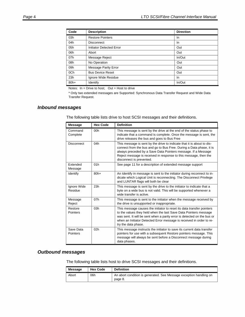
Page 4 LTO SCSI/Fibre Channel Interface Manual
Code Description Direction03h Restore Pointers In04h Disconnect In05h Initiator Detected Error Out06h Abort Out07h Message Reject In/Out08h No Operation Out09h Message Parity Error Out0Ch Bus Device Reset Out23h Ignore Wide Residue In80h+ Identify In/Out
Notes: In = Drive to host; Out = Host to drive* Only two extended messages are Supported: Synchronous Data Transfer Request and Wide DataTransfer Request.
Inbound messages
The following table lists drive to host SCSI messages and their definitions.
Message Hex Code DefinitionCommandComplete
00h This message is sent by the drive at the end of the status phase toindicate that a command is complete. Once the message is sent, thedrive releases the bus and goes to Bus Free
Disconnect 04h This message is sent by the drive to indicate that it is about to dis-connect from the bus and go to Bus Free. During a Data phase, it isalways preceded by a Save Data Pointers message. If a MessageReject message is received in response to this message, then thedisconnect is prevented.
ExtendedMessage
01h See page 11 for a description of extended message support
Identify 80h+ An Identify in message is sent to the initiator during reconnect to in-dicate which Logical Unit is reconnecting. The Disconnect Privilegeand LUNTAR flags will both be clear
Ignore WideResidue
23h This message is sent by the drive to the initiator to indicate that abyte on a wide bus is not valid. This will be supported whenever awide transfer is active.
MessageReject
07h This message is sent to the initiator when the message received bythe drive is unsupported or inappropriate.
RestorePointers
03h This message causes the initiator to reset its data transfer pointersto the values they held when the last Save Data Pointers messagewas sent. It will be sent when a parity error is detected on the bus orwhen an Initiator Detected Error message is received in order to re-try the data phase.
Save DataPointers
02h This message instructs the initiator to save its current data transferpointers for use with a subsequent Restore pointers message. Thismessage will always be sent before a Disconnect message duringdata phases.
Outbound messages
The following table lists host to drive SCSI messages and their definitions.
Message Hex Code DefinitionAbort 06h An abort condition is generated. See Message exception handling on
page 8.

SCSI Interface Overview Page 5
Message Hex Code DefinitionBus DeviceReset
0Ch A reset condition is generated. . See Message exception handling onpage 8.
ExtendedMessage
01h See Extended messages on the following page for a description ofextended message support
Identify 80h+ The Identify Out message is sent by the initiator to identify the LogicalUnit to be accessed and to set Disconnect Privilege. The LUNTAR flagmust be zero.The Identify Out message must be sent as the first thing after selec-tion. If it is sent at any other time, the drive will respond with a mes-sage reject message and go to Bus Free.
InitiatorDetectedError
05h The initiator has detected an error in the data being sent in a MessageCommand, Data or Status phase. The drive will retry the data burst ormessage.If the message is received immediately after an Identify message orafter the Command Complete message has been sent, the drive willgo Bus Free.
MessageParity Error
09h The initiator has detected a parity error in a message. The drive willretry the message.If the message is received during a Command, Data or Status phase,immediately after an Identify message or after the Command Com-plete message has been sent, the drive will go Bus Free.
MessageReject
07h This message is sent when the initiator does not support a messagesent by the drive or considers the message inappropriate. If the mes-sage being rejected is Disconnect, Synchronous Data Transfer Re-quest or Wide Data Transfer Request, the operation continues withoutthose features. For all other messages except Restore Pointers, themessage is treated as an Abort message.If the message is received during a Command, Data or Status phase,immediately after an Identify message or after the command completemessage has been sent, the drive will go Bus Free.
NoOperation
08h This message has no effect and is ignored.

Page 6 LTO SCSI/Fibre Channel Interface Manual
Extended messages
The following table lists extended SCSI messages and their definitions.
Hex Code Message DefinitionSynchronousData TransferRequest
01h The drive will never initiate a Synchronous data transfer negotiation,but will expect the initiator to do so.If the message is received after selection and before commandphase, it will then go to Message In phase and respond with a validresponse to complete the negotiation.If the message is received at any other time, a Message Reject issent in response.
Wide DataTransferRequest
03h The drive will never initiate a Wide Data Transfer negotiation, butwill expect the initiator to do so.If the message is received after selection and before Commandphase, it will then go to Message In phase and respond with a validresponse to complete the negotiation.If the message is received at any other time, a Message Reject issent in response.
Parity errors
The following table describes the operation for each of the possible cases of parityerror.
State or Phase DescriptionBus Free State The drive does not detect nor react to parity errors on the SCSI bus while
the drive is in a bus free state.Arbitration Phase The drive does not detect nor react to parity errors on the SCSI bus while
arbitration is being performed.Selection Phase The drive does not detect nor react to parity errors on the SCSI bus while
the drive is being selected.Selection, Message OutPhase (Identify Message)
If the drive detects a parity error while the host is sending an Identifymessage, the drive retries forever.
Reselection, Message InPhase (Identify Message)
If the drive is attempting to reconnect to the host and the host assertsATN because it detected an error, the drive:♦ Switches the host to the Message Out Phase.♦ Waits for the host to send a 09 (Parity Error Message)♦ The drive then performs the retry option by:♦ Switching the host to the Message In Phase.♦ Resending the Identify Message
Command Phase If the drive detects a parity error while the host is transferring a CDB, thedrive:♦ Switches the host to Message In phase♦ Sends Restore Data Pointers (03h) message♦ Switches the host to Command phase to retry the command.♦ If a parity error occurs on the retry the host:♦ Terminates the transfer.♦ Switches the host to the Status Phase and sends a Check Condition.♦ Switches the host to the Message In Phase and sends a Command
Complete.♦ Sets the Sense Key = B and ASC/ASCQ = 47-00 (SCSI-2 only).

SCSI Interface Overview Page 7
State or Phase DescriptionData In Phase If the host detects a parity error while data is being transferred from the
drive and asserts ATN, the drive:♦ Terminates the transfer of data.♦ Switches the host to the Message Out Phase.♦ Waits for the host to send a 05 (Host Detected Error).♦ Switches the host to the Status Phase and sends a Check Condition.♦ Switches the host to the Message In Phase and sends a Command
Complete.♦ Sets the Sense Key = B and ASC/ASCQ = 48-00 (SCSI-2 only).
Data Out Phase If the drive detects a parity error while the host is transferring data, thedrive:♦ Terminates the transfer of data.♦ Switches the host to the Status Phase and sends a Check Condition.♦ Switches the host to the Message In Phase and sends Command
Complete.♦ Sets the Sense Key = B and ASC/ASCQ = 47-00 (SCSI-2 only).
Status Phase If the host is in the Status phase and detects an error in the status byteand asserts ATN, the drive:♦ Switches the host to the Message Out Phase and waits for the host to
send 05 (Initiator Detected Error).♦ Switches the host to the Status Phase and sends a Check Condition.♦ Target sends restore pointers and resends Status.
Message In Phase If the host is in the Message In Phase and detects an error on a messagebytes an asserts ATN, the drive:♦ Switches the host to the Message Out Phase.♦ Waits for the host to send 09 (Parity Error Message).♦ Switches the host to the Message In Phase and resends the message.
Message Out Phase ♦ If the host is in the Message Out Phase and sends a message bytesand the drive detects a parity error, the drive retries forever.
An Initiator that accommodates disconnect/reconnect can indicate this capability tothe tape drive during the Selection phase by asserting both its own Initiator SCSI IDbit as well as the tape drive’s SCSI ID bit (allows the tape drive to know with whichInitiator to reconnect). The Initiator must also assert ATN before exiting the Selectionphase (prior to releasing SEL) and send an Identify message out of C0h to the tapedrive. This sequence causes the drive to enter the Message-Out phase when theSelection phase completes.
The first message sent by the host after the Selection phase is an Identify message.Under normal conditions, the first message sent by the tape drive after a Reselectionphase is also Identify. Under certain exceptional conditions, the host may send theAbort message or the Bus Device Reset message instead of Identify as the firstmessage.

Page 8 LTO SCSI/Fibre Channel Interface Manual
Message exception handling
Message exceptions are handled as described in the following tables. The numbersin the tables identify the actions that the drive takes when an exception under theidentified conditions occurs. The action are described following the tables.
Phase During Which ATN is RaisedMessage Selection Ident. Cmd Data in Data out Status sdtr/wdtrAbort (06h) 2 2 2 2 2 2 2BDR (0Ch) 2 2 2 2 2 2 2Identify(80h/C0h)
12 7, 11 7, 11 7, 11 7, 11 7, 11 7, 11
IDE (05h) 5 2 If Retry, 8,else 5
If Retry, 8,else 5
If Retry, 8,else 5
If Retry, 8, ifStatus, 2, ifNo Status,5
If Retry, 4,else 5
Reject (07h) 5 2 2 2 2 2 1Parity (09h) 5 2 11 11 11 11 If Retry, 4,
else 5NOP (08h) 5 9 9 9 9 9 If EOM, 9,
else 4SDTR 5 10 7, 11 7, 11 7, 11 7, 11 10WDTR 5 10 7, 11 7, 11 7, 11 7, 11 10Unrecognizedor illegal
5 6 6 6 6 6 If EOM, 6,else 4
Message-In Byte During Which ATN is Raised
MessageSDP(02h)
RestorePointers(03h)
Disconnect(04h)
Reject(07h)
Identify(80h)
CC(00h)
IgnoreWide Resi-due(23h)
Abort (06h) 2 2 2 2 2 2 2BDR (0Ch) 2 2 2 2 2 2 2Identify(80h/C0h)
7, 11 7, 11 7, 11 7, 11 7, 11 2 7, 11
IDE (05h) If Retry, 4else 5
If Status, 2,if No Status,5
If Retry, 4,else 5
If Retry, 4,else 13
If retry, 4,else 5
2 If retry, 4,else 5
Reject (07h) 2 If Status, 2,if No Status,5
1 2 2 2 2
Parity (09h) If Retry, 4else 5
If Status, 2,if No Status,5
If Retry, 4,else 5
If Retry, 4,else 13
If Retry, 4,else 5
2 If Retry, 4,else 5
NOP (08h) 9 9 9 9 9 2 If EOM, 9,else 4
SDTR 7, 11 7, 11 7, 11 7,11 7, 11 2 7, 11WDTR 7, 11 7, 11 7, 11 7,11 7, 11 2 7, 11Unrecognizedor illegal
6 6 6 6 6 2 If EOM, 6,else 4
Retry Retry has not been exhaustedEOM End of the message
Status Status has been reportedNo Status Status has not been reported

SCSI Interface Overview Page 9
Action codes used in previous tables1. The Message Out Reject disables the feature and continues. In case of
Message In Disconnect, the drive disables further “Disconnects” on the currentcommand. In case of Message In SDTR, both the initiator and the drive go toasynchronous mode. In case of Message In WDTR, the drive goes to 8-bit datatransfer mode.
2. The drive goes Bus Free by releasing BSY without sense data set up.
3. The Message Out Abort or Bus Device Reset will result in the drive going BusFree and therefore abnormally terminating the command.
4. The drive re-sends the message.
5. The drive posts Check Condition status indicating an Aborted command.
6. The drive rejects the message by Message In Reject and continues its operation.
7. The drive rejects the message by Message In Reject.
8. The drive sends Message In Restore Pointers and retries if retry is notexhausted.
9. The drive ignores the message and continues.
10. The wide data transfer agreement is negotiated prior to negotiating thesynchronous data transfer agreement.
11. The drive goes Bus Free by releasing BSY with sense data set up.
12. The drive continues the normal process.
13. If the drive is continuing an operation after sending a Message in Reject, thedrive will post Check Condition status indicating an Aborted command (Action 5),if not, The drive will go Bus Free by releasing BSY without sense data set up(Action 2).
Fibre Channel Interface Overview
The interface is a bi-directional serial connection. By connecting devices to a hub, aloop of up to 126 devices can be constructed. Up to 16 million devices can beconnected via a switch.
The Viper 200 FC drives have an internal FC controller integrated into the driveelectronics.
General features
Viper 200 FC supports the following:
• Connection in point-to-point, arbitrated loop, and fabric topologies as an NL_Port• Command queuing

Page 10 LTO SCSI/Fibre Channel Interface Manual
• Both single and multi-initiator systems• Dual ports• Reset via Target Reset and Logical Unit Reset task management requests as
well as by selective and broadcast Reset LIP• Auto Contingent Allegience. For details, see the SCSI Architectural Model–2
(SAM-2) standard.
Link Services
The following basic link services, extended link services, and FC-4 link services aresupported by Viper 200 FC:
• Abort Sequence (ABTS)• Accept (ACC)• Basic Accept (BA_ACC)• Basic Reject (BA_RJT)• Discover Address (ADISC)• Discover N_Port Parameters (PDISC) – Obsolete, but supported for legacy
compatibility• Fabric Login (FLOGI)• Fabric Address Notification (FAN)• Logout (LOGO)• Link Service Reject (LS_RJT)• N_Port Login (PLOGI)• Process Login (PRLI)• Process Logout (PRLO)• Read Exchange Concise (REC)• Read Link Error Status Block (RLS)• Registered State Change Notification (RSCN)• Report Node Capabilities Information (RNC)• Report Node FC-4 Types (RNFT)• Report Port Speed Capabilities (RPSC)• Request Node Identification Data (RNID)• Read Port List (RPL)• Read Port Status Block (RPS)• Reinstate Recovery Qualifier (RRQ)• Request Sequence Initiative (RSI)• Read Sequence Status Block (RSS)• Sequence Retransmission Request (SRR)• State Change Registration (SCR)• Third Party Process Logout (TPRLO)
SCSI Interface Overview Page 11
Name Server Requests
When attached to a fabric, the drive will issue the following name server requests:
• Register FC–4 TYPEs (RFT_ID)• Register FC–4 Features (RFF_ID)
Task Management Requests
The Fibre Channel drives support the following SCSI-3 Task Management Requests:
• Abort Task• Abort Task Set• Clear ACA• Clear Task Set• Logical Unit Reset• Target Reset
Standards Conformance
The Small Computer System Interface and Fibre Channel interface are described instandards including several versions and a number of individual documents. Theoriginal Small Computer System Interface Standard, X3.131-1986, is referred toherein as SCSI-1. SCSI-1 was revised resulting in the Small Computer SystemInterface – 2 (X3.131-1994), referred to herein as SCSI-2. The set of SCSI-3standards are collectively referred to as SCSI-3. The applicable standards are asfollows:SCSI-3 Architecture Model (SAM) ANSI/NCITS X3.270: 1996
SCSI Architecture Model – 2 (SAM-2) in development
SCSI-3 Primary Commands (SPC) Status: ANSI/NCITS X3.301: 1997
SCSI Primary Commands – 2 (SPC-2) ANSI/INCITS 351-2001: 2001
SCSI Primary Commands – 3 (SPC-3) in development
SCSI-3 Medium Changer Commands (SMC) ANSI/NCITS.314: 1998
SCSI-3 Medium Changer Commands – 2 (SMC-2) in development
SCSI-3 Stream Commands (SSC) ANSI/NCITS 335: 2000
SCSI-3 Stream Commands – 2 (SSC-2) in development
Fibre Channel Protocol (FCP) ANSI/NCITS X3.269-1996: 1996
Fibre Channel Protocol – 2 (FCP-2) in development
Fibre Channel Arbitrated Loop – 2 Amendment (FC-AL-2) NCITS 332-1999: 1999
Fibre Channel – Fabric Loop Attach - Direct Attach (FC-FLA) NCITS TR-20-1998
Fibre Channel – Tape and Tape Medium Changers (FC-TAPE) ANSI/NCITS TR-24-1999
Page 12 LTO SCSI/Fibre Channel Interface Manual
Fibre Channel – Private Loop SCSI Direct Attach (FC-PLDA) ANSI/NCITS TR19-1997
Fibre Channel – Methodologies for Interconnects (FC-MI) in development
Fibre Channel Physical Interface (FC-PI) in development
Fibre Channel Framing and Signalling (FC-FS) in development
Note: The term SCSI is used wherever it is not necessary to distinguish betweenthe versions of SCSI.
LTO Conformance
Seagate LTO drives conform to the requirements of the Generation 1 SCSI CommonCommand Set Advisory Document (AU1-SCSI) for Ultrium format devices.
General Behaviors
Reset Condition
When a reset is issued to the tape drive, the drive clears all uncompletedcommands, releases all SCSI device reservations, sets the tape drive to defaultmodes. The Parallel SCSI drive returns to the Bus Free phase.
Unit Attention Condition
The Unit Attention condition in the tape drive typically results from the followingconditions:
• A Reset was previously issued to the drive.• The drive has just been powered on.• A cartridge has been inserted.• A log exception condition occurred.• The mode pages have been changed.• The cartridge has been loaded or unloaded to the Hold position, and the Medium
Auxiliary Memory (MAM) is accessible.
The Unit Attention Condition persists for each Initiator until that Initiator issues acommand other than Inquiry for which the tape drive returns with a Check ConditionStatus. If the next command from that Initiator following the Check Condition Statusis Request Sense, then the unit attention sense key is returned. Because FibreChannel drives support autosense, the sense data is returned in the FCP_RSPinformation unit in which the Check Condition Status is reported, and a RequestSense command is not necessary.
If the Inquiry Command is received from an Initiator with a pending Unit AttentionCondition before the tape drive reports Check Condition Status, the tape driveperforms the Inquiry Command and does not clear the Unit Attention Condition.
If the Request Sense Command is received from an Initiator with a pending UnitAttention Condition before the tape drive reports Check Condition Status, the tape
SCSI Interface Overview Page 13
drive reports unit attention sense key and clears the Unit Attention Condition for thatInitiator.
Contingent Allegiance Condition
The Contingent Allegiance condition shall exist following the return of CheckCondition and may exist following an unexpected disconnect. The contingentallegiance condition shall be preserved for the I T x nexus until it is cleared. Thecontingent allegiance condition shall be cleared upon the generation of a hard resetcondition or by an Abort message, a Bus Device Reset message, or any subsequentcommand for the I T x nexus. While the contingent allegiance condition exists thedrive shall preserve the sense data for the initiator.
While the contingent allegiance condition exists, the drive shall respond to any otherrequests for access to the logical unit from another initiator with a Busy status.Execution of queued commands shall be suspended until the Contingent Allegiancecondition is cleared.
Buffered Mode
Buffered Mode allows the most efficient operation of a tape drive. The drive defaultsto Buffered mode. In this mode, the drive signals Command Complete when allrequested data for a Write command has been transferred from the host to the tapedrive buffer. This mode provides data to maintain operation while the host readies anew Write Command.
If an error occurs in writing data to the tape after the tape drive signals CommandComplete, an error status is sent on the next Command issued.
Immediate Function
For Initiators that do not support the disconnect feature, the Immediate bit provides ameans of releasing the bus while the drive is busy completing a function such asrepositioning the tape. If a command is sent by the Initiator after a previousImmediate Command was accepted, the drive continues the Immediate Function it iscurrently performing and may disconnect, execute, or reject the new commanddepending on the new command.
An immediate bit of zero means that the status is returned to the Initiator when theoperation is completed. (For example, the status is returned when the tape has beenrepositioned.) An Immediate bit of one means that the status is returned to theInitiator as soon as the function is started.
Residual Length Function
When performing a Write command, the drive returns a Good Status and CommandCompletion Message when the last byte requested by the command is placed in theData Buffer, rather than when it is written onto tape. If an error occurs while data isbeing written onto tape, the drive calculates the Residual Length and places thisvalue in the information bytes of the Sense Data Block. Also, the Residual Lengthfunctions for other commands, such as Read.
Residual Length is calculated by: RL = TL - AL

Page 14 LTO SCSI/Fibre Channel Interface Manual
Where:
AL (Actual Length) = Blocks transferred from the host to the tape drive acrossthe SCSI bus.
TL (Transfer Length) = The Transfer Length from bytes 2-4 of the Write com-mand (Request Transfer Length).
RL (Residual Length) = The amount of blocks or bytes not written to tape.
Early Warning Function
Early Warning on the Viper drive is a logical warning given when 64 megabytes ofstorage space remain on the tape. The position is calculated by the drive. When thisphysical position is reached on a tape, the following occurs.
1. The command completes with a Check Condition and a 40h Sense data mean-ing EOM and no Sense Key.
2. Subsequent WRITE commands write data and complete with check conditionwith EOM Status and No Sense Key until the physical tape end is encountered.
Error Reporting
Soft errors are generally tape-quality related and occur more frequently during writeoperations than during read operations. Soft errors indicate repeated attempts by thedrive to read or write data on the tape. Some soft errors are normal, but an increasein the usual count can indicate deteriorating tape quality. If the soft error countremains higher than normal, use a cleaning cartridge to clean the read/write heads. Ifthis procedure does not clear the problem, change to a new tape cartridge.
If a hard error (unrecoverable error) occurs during operation, the drive terminatesoperation immediately and returns a Check Condition. The Initiator should cease anyfurther read or write functions and issue a Request Sense Command to determinethe type of error.
When the drive detects a write error, it attempts to rewrite the data up to 128 times.
After the 128th attempt, the error is considered unrecoverable and the operationterminates. When a hard error is encountered, replace the tape with a new cartridgeand repeat the function or clean the heads with a cleaning cartridge.
Variable and Fixed Mode Recording
The Viper drive can write either fixed or variable block sizes. The recording mode isdetermined by the Fixed bit in the SCSI Write and Read commands.
If the Fixed bit is set, the Mode Select command sets the size of the next block ormultiple blocks to be written with the next Write command. When a Write commandis issued with the Fixed bit set, the current block size is implemented. The transferlength specifies the number of blocks to be written with this size. If a Write commandis issued with the Fixed bit set and the current block size set to 0, the Viper drivereturns a Check Condition with Illegal Request Sense Key. When writing with the

SCSI Interface Overview Page 15
Fixed bit set, each Write command specifies the number of contiguous blocks to bewritten of a fixed size, resulting in fixed-mode blocks. If the Fixed bit is reset, thenonly one block can be written on the tape per SCSI Write command CDB. In thatcase, the Write command CDB transfer length specifies the size of the block to bewritten in bytes. With the Fixed bit reset, the current block size specified with the lastMode Select command is ignored.
Setting the block size to 0 in the Mode Select page descriptor is not required.Therefore, with the Fixed bit reset, each SCSI Write command may specify adifferent byte count, resulting in variable-mode blocks.
The host may switch between fixed and variable mode recording. By issuing theMode Select command to specify different block sizes, blocks can be written to thetape with different block sizes in the fixed mode. Also, the host may change the blocksize after BOM, allowing on-the-fly block-size changes.
The Read command Fixed bit also specifies fixed or variable mode. When reading invariable mode, the host must know the size of the block to be read from the tape inadvance in order to avoid causing the Viper drive to return a Check Condition withIncorrect Length indicated in the Sense data (ILI). Also, the data transfer may betruncated (cut off) when the recorded block does not match the transfer length invariable mode or the current block size in fixed mode.
The Read command includes a SILI bit to Suppress ILI Check conditions.
When the SILI bit is set, the host usually specifies the maximum block size beforereading so that the data blocks are not truncated, and no Check Conditions aregenerated.
The SCSI Read Block Limits command returns the minimum and maximum blocksizes that the Viper drive can support. The Block Limits data is not modified to reflectthe current mode of writing—fixed or variable. The Block Limits returned data is notmodified to reflect the current block size for the next fixed-mode Write. The ModeSense command is used for that purpose.
Library Features
Auto Unload ModeThe Viper drive has an Auto Unload Mode that may be accessed via a Modecommand to Mode Page 21h. The purpose of the Auto Unload mode is to allow thedrive to be configured to work in Library systems or as a Stand Alone drive. The AutoUnload mode allows the drive to control how the tape is unloaded in “automatic” typesituations. There are four Auto Unload modes that are possible.
• Do Nothing – Stay threaded at BOT.
• Unthread Only
• Unthread and unload
• Unthread and unload non data cartridges, data cartridges go to BOT.
Here are the possible “automatic” situations where the ejection process will becontrolled using the Auto Unload mode. As shown in the list below, this covers not

Page 16 LTO SCSI/Fibre Channel Interface Manual
only power on situations, but also how cleaning tapes, incompatible tapes andfirmware tapes are handled.
• Powering on or power cycling while the tape is inside the drive.
• Cleaning tape has finished the cleaning cycle.
• Unsupported data tape has been loaded.
• Unsupported cleaning tape has been loaded.
• Microcode download from a firmware tape.
• Microcode download via the SCSI Write Buffer command while a tape is loaded.
Host Unload OverrideThe Viper drive has a Host Unload Override mode that may be accessed via a Modecommand to Mode Page 21h. The purpose of the Host Unload Override mode is toallow the Library system to set the drive into a mode where the drive will not eject thecartridge should the host issue a SCSI Unload command. A SCSI Unload commandfrom the host will cause the tape to be unthreaded but the cartridge will remain in thedrive. The Library Unload command will cause the cartridge to be ejected.
ID ModificationTape libraries require the ability to change the SCSI ID of installed tape driveswithout opening the library and changing address jumpers. To change the SCSI ID(Parallel SCSI Interface) or Assigned Loop Identifier (Fibre Channel Interface) of theViper drive, issue a Mode Select command to Mode Page 22h to change the NextSelection ID field to the desired ID. Then reset or power cycle the drive, and it willbegin responding to the new ID. This new ID will persist through additional resetsand power cycles.
If the address jumpers are changed and the drive’s power is cycled, the drive willrespond to the new address on the jumpers. The value in the Next Selection ID fieldwill be that on the jumpers, even though the field may have been changedimmediately before the power cycle.
For the mapping between the Fibre Channel Assigned Loop Identifier and theArbitrated Loop Physical Address (AL-PA), see the FCP-2 standard.
LUN 1 Command ForwardingA tape library or autoloader containing a Viper can receive its SCSI commands viathe Viper. This function is called “Command Forwarding” and is enabled via the“CmdFwd” field in the Interface Control mode page (22h). When enabled,commands received via the SCSI bus and addressed to LUN 1 are immediatelytransmitted to the library via the RS-422 interface. Viper acts as a bridge, passingcommands, data, and status between the initiator and the library, as specified in theLibrary Interface Encapsulated SCSI Protocol Manual.
In SCSI Medium Changer terminology, the library or autoloader appears as an“independent medium changer,” because the tape drive and medium changer are atdifferent LUNs. Medium changer commands addressed to LUN 0 are rejected with

SCSI Interface Overview Page 17
Check Condition and sense data of Illegal Request / Invalid Command OperationCode (05/20/00).
Because of the relatively slow communication on the RS-422 interface, Viper willdisconnect from the SCSI bus after receiving a command, after receiving data-out,and after sending status. Data-in and status are sent to the initiator withoutdisconnecting between them.
If the link fails between the Viper and the library, a command will receive a status ofCheck Condition and sense data of Aborted Command / Logical Unit CommunicationFailure (0B/08/00).
If a SCSI bus reset is received, a target reset task management request istransmitted to the library.
When command forwarding is disabled in mode page 22h, commands addressed toLUN 1 will receive a status of Check Condition and sense data of Illegal Request /Logical Unit Not Supported (05/25/00).
After Command Forwarding is enabled or disabled, the drive will respond to the nextcommand with a Check Condition and sense data of Unit Attention / Reported LUNsData Has Changed (06/3F/0E).
Page 18 LTO SCSI/Fibre Channel Interface Manual
SCSI Commands
This chapter describes the SCSI commands for the LTO tape drive.
Command Set
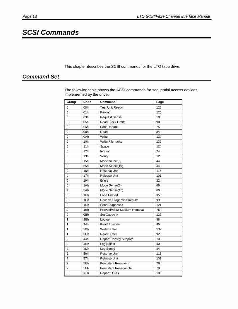
The following table shows the SCSI commands for sequential access devicesimplemented by the drive.
Group Code Command Page0 00h Test Unit Ready 1260 01h Rewind 1200 03h Request Sense 1080 05h Read Block Limits 900 06h Park Unpark 750 08h Read 840 0Ah Write 1300 10h Write Filemarks 1350 11h Space 1240 12h Inquiry 240 13h Verify 1280 15h Mode Select(6) 442 55h Mode Select(10) 440 16h Reserve Unit 1180 17h Release Unit 1010 19h Erase 220 1Ah Mode Sense(6) 692 5Ah Mode Sense(10) 690 1Bh Load Unload 350 1Ch Receive Diagnostic Results 990 1Dh Send Diagnostic 1210 1Eh Prevent/Allow Medium Removal 750 0Bh Set Capacity 1221 2Bh Locate 381 34h Read Position 951 3Bh Write Buffer 1321 3Ch Read Buffer 922 44h Report Density Support 1032 4Ch Log Select 402 4Dh Log Sense 442 56h Reserve Unit 1182 57h Release Unit 1012 5Eh Persistent Reserve In 762 5Fh Persistent Reserve Out 793 A0h Report LUNS 106

SCSI Commands: Command Descriptor Blocks Page 19
Conventions
The commands in this chapter are listed in alphabetical order. Each command isdescribed, its Command Descriptor Block (CDB) illustrated, and the CompletionStatus is given. Bits and fields defined in the ANSI SCSI documents that are notused by the drive are not described in this document. Bits and fields that aresupported by the drive are described.
Command Descriptor Blocks
A host makes request of the tape drive by sending a Command Descriptor Block(CDB). Some commands also require a parameter list. If the CDB or the parameterlist contains an invalid parameter, the drive terminates the command, returning aSense Key of Illegal Request, without altering the medium.
Command Descriptor Block Formats
SCSI six-byte Command Descriptor Blocks are arranged in the format shown in thefollowing table.
ByteBits
7 6 5 4 3 2 1 00 Operation Code1 Ignored LUN Command Dependent2 Command Dependent
3 Command Dependent4 Command Dependent5 Control
SCSI ten-byte Command Descriptor Blocks are arranged in the format shown in thefollowing table.
ByteBits
7 6 5 4 3 2 1 00 Operation Code1 Ignored LUN Command Dependent2 Command Dependent3 Command Dependent4 Command Dependent5 Command Dependent6 Command Dependent7 Command Dependent8 Command Dependent9 Control
Field names that are centered represent fields that are at least one byte long. Fieldnames that are left-aligned with a bit number are one or more bits long. The length isindicated by the beginning of the following field name, and by the Bits column in theField Descriptions table on the following page.

Page 20 LTO SCSI/Fibre Channel Interface Manual
Field DescriptionsField Byte Bits DescriptionOperationCode
0 The Operation Code is made up of the Group Code and the Com-mand Code. See Operation Code Format, below.
IgnoredLogicalUnit
1 5-7 The LUN field is vestigal from the SCSI-1 standard and is ignored.
CommandDependent
12-42-8
0-4 See the specific command.
Reserved All reserved bits must be 0.Control Last The Control byte is made up of the Vendor Unique, Flag and Link
bits. See Control Format, below.
Fields that are one byte or longer have no entry in the Bits column.
Operation Code Format
ByteBits
7 6 5 4 3 2 1 0
0 Group Code Command Code
Field DescriptionsField Byte Bits DescriptionGroupCode
0 5-7 The SCSI command group.
CommandCode *
0 0-4 The SCSI command code.
NOTE: The Group Code and Command Code together make the Operation Code.
Control Byte Format
ByteBits
7 6 5 4 3 2 1 0
Last Vendor Unique Reserved NACA Flag Link
Field DescriptionsField Byte Bits DescriptionVendorUnique
Last 6-7 Not used, always 0.
Reserved Last 3-5 All reserved bits must be 0.NACA Last 2 Parallel SCSI Interface: Not supported; reserved.
Fibre Channel Interface: Supported.Flag andLink bits
Last 0-1 These bits are not supported by the Viper drive.

SCSI Commands: Command Status Page 21
Command Status
When the tape drive competes a command it responds with a status byte. Theformat of the status byte is shown below.
Status Byte Format
ByteBits
7 6 5 4 3 2 1 00 Reserved Status Code
Field DescriptionsField Byte Bits DescriptionReserved 0 6-7 Always 0StatusCode
0 0-5 The command status, as shown below.
Status Codes
Status codes for the Viper drives are shown in the following table.
Description Value When returnedGood Status 00h The command completed without problemsCheck Condition 02h A problem occurred during command execution. The sense data
should be examined to determine the nature of the problem.Busy 08h The drive is unable to accept the command at this time. This is
only returned during the power on sequence or if there are com-mands from too many initiators outstanding.
Reservation Conflict 18h This is returned if the drive is reserved for an initiator other thanthe one sending the command

Page 22 LTO SCSI/Fibre Channel Interface Manual
ERASE
The Erase command marks the tape, from the current position to the end of tape, aserased.
Command Descriptor Block
ByteBits
7 6 5 4 3 2 1 0
0 Operation Code (19h)1 Ignored LUN Reserved Immed Long2 Reserved3 Reserved4 Reserved5 Control
Field DescriptionsField Bytes Bits DescriptionOperationCode
0 The Operation Code for Erase is 19h.
IgnoredLogicalUnit
1 5-7 The LUN field is vestigal from the SCSI-1 standard and is ignored.
Immed 1 1 0 = Status is not returned until the tape is erased.1 = Status is returned as soon as the operation is initiated.
Long 1 0 0 = Short Erase is performed and EOD is recorded at the currenttape position.
1 = Long data-security Erase is performed, and EOD is recordedfrom the current tape position to the end of the tape.
Reserved All reserved bits must be 0.Control See Control Byte Format on page 20.
If the Immediate (Immed) flag is set to 1, then the drive validates the command andwaits for any previous command from any host to complete including any immediatecommands currently being processed and for any buffered data to be flushed totape. It will then report a deferred error for any preceding command or buffered dataif appropriate. If there is no deferred error, the drive reports good status and initiatesthe command. If the Immediate (Immed) flag is set to 0, status is not returned untilafter the command has completed.
If the Long bit is set, EOD is written at the current position. Data Set Separators arethen written from EOD to the end of the medium to overwrite any data currently onthe tape. If the Long bit is clear, then an EOD is written at the current positionmarking it as end of data.
Completion StatusCode Message Description
00h Good Status • The drive remains in any previously set modes.• The drive is ready to perform any appropriate command.Note: If Immed is 1, then Good Status only indicates that the command isvalid.

SCSI Commands: ERASE Page 23
Code Message Description
02h CheckCondition
Use the Request Sense command to retrieve status information. PossibleSense Keys are:Code Message Description02h Not Ready No cartridge is in the drive.03h Media Error Unrecoverable data error encountered.04h Hardware Error Parity error on the SCSI bus or drive hard-
ware failure detected.05h Illegal Request Both the Immed bit and the Link bits are 1, or
the Command Descriptor Block is invalid.06h Unit Attention The cartridge was changed or the drive was
reset prior to this command.07h Write Protect The cartridge is write protected.
Page 24 LTO SCSI/Fibre Channel Interface Manual
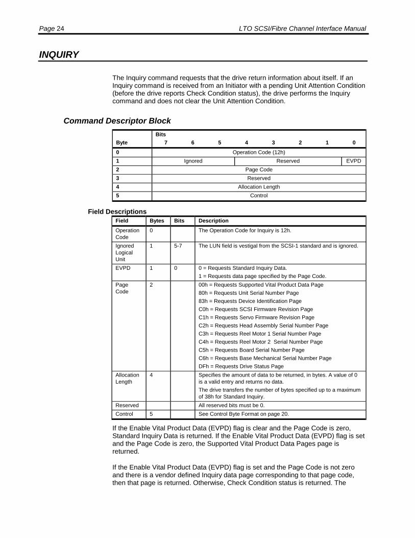
INQUIRY
The Inquiry command requests that the drive return information about itself. If anInquiry command is received from an Initiator with a pending Unit Attention Condition(before the drive reports Check Condition status), the drive performs the Inquirycommand and does not clear the Unit Attention Condition.
Command Descriptor Block
ByteBits
7 6 5 4 3 2 1 00 Operation Code (12h)1 Ignored Reserved EVPD2 Page Code3 Reserved4 Allocation Length5 Control
Field DescriptionsField Bytes Bits DescriptionOperationCode
0 The Operation Code for Inquiry is 12h.
IgnoredLogicalUnit
1 5-7 The LUN field is vestigal from the SCSI-1 standard and is ignored.
EVPD 1 0 0 = Requests Standard Inquiry Data.1 = Requests data page specified by the Page Code.
PageCode
2 00h = Requests Supported Vital Product Data Page80h = Requests Unit Serial Number Page83h = Requests Device Identification PageC0h = Requests SCSI Firmware Revision PageC1h = Requests Servo Firmware Revision PageC2h = Requests Head Assembly Serial Number PageC3h = Requests Reel Motor 1 Serial Number PageC4h = Requests Reel Motor 2 Serial Number PageC5h = Requests Board Serial Number PageC6h = Requests Base Mechanical Serial Number PageDFh = Requests Drive Status Page
AllocationLength
4 Specifies the amount of data to be returned, in bytes. A value of 0is a valid entry and returns no data.The drive transfers the number of bytes specified up to a maximumof 38h for Standard Inquiry.
Reserved All reserved bits must be 0.Control 5 See Control Byte Format on page 20.
If the Enable Vital Product Data (EVPD) flag is clear and the Page Code is zero,Standard Inquiry Data is returned. If the Enable Vital Product Data (EVPD) flag is setand the Page Code is zero, the Supported Vital Product Data Pages page isreturned.
If the Enable Vital Product Data (EVPD) flag is set and the Page Code is not zeroand there is a vendor defined Inquiry data page corresponding to that page code,then that page is returned. Otherwise, Check Condition status is returned. The

SCSI Commands: INQUIRY Page 25
Sense Key is set to Invalid Request (5) and the additional Sense to Invalid Field inCDB (2400).
Standard Inquiry Data Page
ByteBits
7 6 5 4 3 2 1 00 Peripheral Qualifier Peripheral Device Type1 RMB Reserved2 Version3 AENC Obso-
leteNACA HiSup Response Data Format
4 Additional Length5 Reserved6 BQue EncSrv VS MuiltiP MChgr Obso-
leteObso-lete
Adr16
7 RelAdr Obso-lete
WBus16
Sync Linked Trans-Dis
CMdQ VS
8 – 15 Vendor Identification16 – 31 Product Identification32 – 35 Product Revision Level36 – 55 Vendor Specific
Field DescriptionsField Bytes Bits DescriptionPeripheralQualifier
0 5-7 Always 000b.
PeripheralDeviceType
0 0-4 Normally 01h to indicate a sequential access device.7Fh indicates that a logical unit is not present. This value is re-turned when an invalid LUN was in the last Identify message.
RMB 1 7 Always 1, indicating Removable Media.
Version 2 Always 3AENC 3 7 Always 0, indicating Asynchronous Event Notification Capability is
not supported.NACA 3 5 0 = Normal ACA (NACA) is not supported (Parallel SCSI drives)
1 = Normal ACA (NACA) is supported (Fibre Channel drives)HiSup 3 4 Always 0, indicating Hierarchical Support is not supported.ResponseData For-mat
3 0-3 Always 2, indicating support of the SCSI-2 standard.
AdditionalLength
4 Always 33h, indicating that 51 bytes of additional Inquiry commandparameters follow, beginning in Byte 5. This value does not changeif the Allocation Length in the CDB is too small or too large to ac-commodate the entire response.
BQue 6 7 0 = Basic Queuing not supported (Parallel SCSI drives)1 = Basic Queuing supported (Fibre Channel drives)
EncSrv 6 6 Always 0, indicating Enclosure Services is not supported.VS 6 5 Always 0, indicating this feature is not supported.MuiltiP 6 4 0 = Multiple Interface Ports not available (SCSI drives)
1 = Multiple Interface Ports are available (Fibre Channel drives).
MChgr 6 3 Always 0, indicating Medium Changer is not supported.
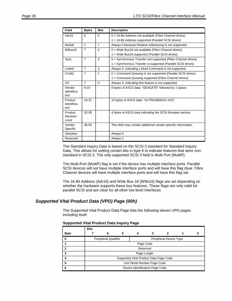
Page 26 LTO SCSI/Fibre Channel Interface Manual
Field Bytes Bits DescriptionAdr16 6 0 0 = 16 Bit Address not available (Fibre Channel drives)
1 = 16 Bit Address supported (Parallel SCSI drives)RelAdr 7 7 Always 0 because Relative Addressing is not supported.WBus16 7 5 0 = Wide Bus16 not available (Fibre Channel drives)
1 = Wide Bus16 supported (Parallel SCSI drives)Sync 7 4 0 = Synchronous Transfer not supported (Fibre Channel drives)
1 = Synchronous Transfer is supported (Parallel SCSI drives)Linked 7 3 Always 0, indicating Linked Command is not supported.CmdQ 7 1 0 = Command Queuing is not supported (Parallel SCSI drives)
1 = Command Queuing supported (Fibre Channel drives)VS 7 0 Always 0, indicating this feature is not supported.VendorIdentifica-tion
8-15 8 bytes of ASCII data: “SEAGATE” followed by 1 space.
ProductIdentifica-tion
16-31 16 bytes of ASCII data: “ULTRIUM06242-XXX“.
ProductRevisionLevel
32-35 4 bytes of ASCII data indicating the SCSI firmware version.
VendorSpecific
36-55 This field may contain additional vendor specific information.
Obsolete Always 0Reserved Always 0
The Standard Inquiry Data is based on the SCSI 3 standard for Standard InquiryData. This allows for setting certain bits in byte 6 to indicate features that were non-standard in SCSI 2. The only supported SCSI 3 field is Multi Port (MultiP).
The Multi-Port (MultiP) flag is set if the device has multiple interface ports. ParallelSCSI devices will not have multiple interface ports and will have this flag clear. FibreChannel devices will have multiple interface ports and will have this flag set.
The 16 Bit Address (Adr16) and Wide Bus 16 (WBs16) flags are set depending onwhether the hardware supports these bus features. These flags are only valid forparallel SCSI and are clear for all other low level interfaces.
Supported Vital Product Data (VPD) Page (00h)
The Supported Vital Product Data Page lists the following eleven VPD pagesincluding itself.
Supported Vital Product Data Inquiry Page
ByteBits
7 6 5 4 3 2 1 0
0 Peripheral Qualifier Peripheral Device Type1 Page Code2 Reserved3 Page Length4 Supported Vital Product Data Page Code5 Unit Serial Number Page Code6 Device Identification Page Code

SCSI Commands: INQUIRY Page 27
ByteBits
7 6 5 4 3 2 1 0
7 SCSI Firmware Revision Page Code8 Servo Firmware Revision Page Code9 Head Assembly Serial Number Page Code10 Reel Motor 1 Serial Number Page Code11 Reel Motor 2 Serial Number Page Code12 Board Serial Number Page Code13 Base Mechanical Serial Number Page Code14 Drive Status Page Code
Field DescriptionsField Bytes Bits DescriptionPeripheral Qualifier 0 5-7 Always 000b.Peripheral DeviceType
0 0-4 Normally 01h to indicate a sequential access device.7Fh indicates that a logical unit is not present. This value isreturned when an invalid LUN was in the last Identify mes-sage, or the LUN field of the Identify CDB.
Page Code 1 Always 0, indicating the Supported Vital Product Data InquiryPage
Reserved 2 Always 0Page Length 3 Always 0Bh to indicate 11 listed pages.Supported VitalProduct Data PageCode
4 Always 00h, the page code of the Supported Vital ProductData Inquiry Page
Unit Serial NumberPage Code
5 Always 80h, the page code of the Unit Serial Number Page
Device IdentificationPage Code
6 Always 83h, the page code of the Device Identification Page
SCSI Firmware Re-vision Page Code
7 Always C0h, the page code of the SCSI Firmware RevisionPage
Servo Firmware Re-vision Page Code
8 Always C1h, the page code of the Servo Firmware RevisionPage
Head Assembly Se-rial Number Page
9 Always C2h, the page code of the Head Assembly SerialNumber Page.
Reel Motor 1 SerialNumber Page
10 Always C3h, the page code of the Reel Motor 1 Serial Num-ber Page.
Reel Motor 2 SerialNumber Page
11 Always C4h, the page code of the Reel Motor 2 Serial Num-ber Page.
Board Serial Num-ber Page
12 Always C5h, the page code of the Board Serial NumberPage.
Base MechanicalSerial Number Page
13 Always C6h, the page code of the Base Mechanical SerialNumber Page.
Drive Status Page 14 Always DFh, the page code of the current drive and cartridgestate.
Unit Serial Number Page (80h)
The Unit Serial Number Page contains a single value, which is a 12 byte ASCIIstring. The string, with the Vendor Identification and Product Identification fields inthe standard Inquiry data, uniquely identifies the drive.

Page 28 LTO SCSI/Fibre Channel Interface Manual
ByteBits
7 6 5 4 3 2 1 00 Peripheral Qualifier Peripheral Device Type1 Page Code2 Reserved3 Page Length4-15 Drive Serial Number
Field DescriptionsField Bytes Bits DescriptionPeripheralQualifier
0 5-7 Always 000b.
PeripheralDeviceType
0 0-4 Normally 01h to indicate a sequential access device.7Fh in byte 0 indicates that a logical unit is not present. This value isreturned when an invalid LUN is specified.
PageCode
1 Always 80h, indicating the Unit Serial Number Page
Reserved 2 Always 0PageLength
3 Always 0Ch to indicate 12 additional bytes of data.
DriveSerialNumber
4-15 12 bytes of ASCII data giving the unit serial number.
Device Identification Page (83h)
The Device Identification Page contains one or more device identification descriptorsthat uniquely identify the particular device. Viper FC returns four identifiers: Vendor,Node Name, Relative Port, and Port Name.
ByteBits
7 6 5 4 3 2 1 0
0 Peripheral Qualifier Peripheral Device Type1 Page code2 Reserved3 Page Length4-… Identification Descriptor…-… ……-… Identification Descriptor
Field DescriptionsField Bytes Bits DescriptionPeripheralQualifier
0 5-7 Always 000b.
PeripheralDeviceType
0 0-4 Normally 01h to indicate a sequential access device.7Fh indicates that a logical unit is not present. This value is returnedwhen an invalid LUN is specified.
PageCode
1 Always 83h, indicating the Device Identification Page
Reserved 2 Always 0PageLength
3 n-3, indicating the total length of all Identification Descriptors follow-ing.
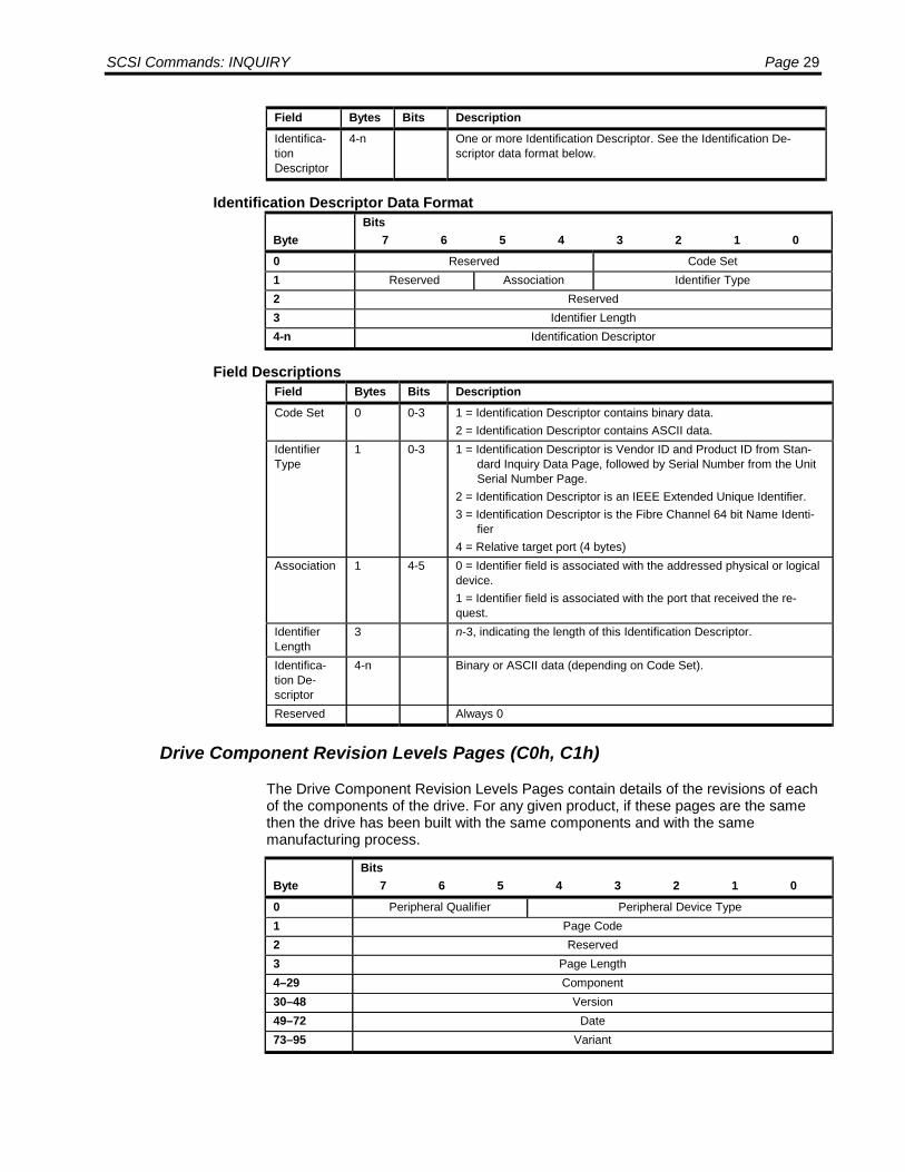
SCSI Commands: INQUIRY Page 29
Field Bytes Bits DescriptionIdentifica-tionDescriptor
4-n One or more Identification Descriptor. See the Identification De-scriptor data format below.
Identification Descriptor Data Format
ByteBits
7 6 5 4 3 2 1 00 Reserved Code Set1 Reserved Association Identifier Type2 Reserved3 Identifier Length4-n Identification Descriptor
Field DescriptionsField Bytes Bits DescriptionCode Set 0 0-3 1 = Identification Descriptor contains binary data.
2 = Identification Descriptor contains ASCII data.IdentifierType
1 0-3 1 = Identification Descriptor is Vendor ID and Product ID from Stan-dard Inquiry Data Page, followed by Serial Number from the UnitSerial Number Page.
2 = Identification Descriptor is an IEEE Extended Unique Identifier.3 = Identification Descriptor is the Fibre Channel 64 bit Name Identi-
fier4 = Relative target port (4 bytes)
Association 1 4-5 0 = Identifier field is associated with the addressed physical or logicaldevice.1 = Identifier field is associated with the port that received the re-quest.
IdentifierLength
3 n-3, indicating the length of this Identification Descriptor.
Identifica-tion De-scriptor
4-n Binary or ASCII data (depending on Code Set).
Reserved Always 0
Drive Component Revision Levels Pages (C0h, C1h)
The Drive Component Revision Levels Pages contain details of the revisions of eachof the components of the drive. For any given product, if these pages are the samethen the drive has been built with the same components and with the samemanufacturing process.
ByteBits
7 6 5 4 3 2 1 0
0 Peripheral Qualifier Peripheral Device Type1 Page Code2 Reserved3 Page Length4–29 Component30–48 Version49–72 Date73–95 Variant
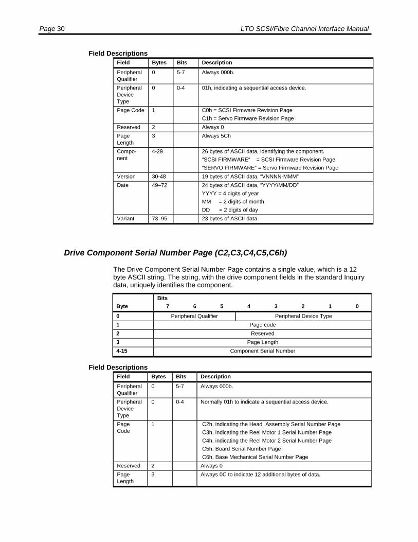
Page 30 LTO SCSI/Fibre Channel Interface Manual
Field DescriptionsField Bytes Bits DescriptionPeripheralQualifier
0 5-7 Always 000b.
PeripheralDeviceType
0 0-4 01h, indicating a sequential access device.
Page Code 1 C0h = SCSI Firmware Revision PageC1h = Servo Firmware Revision Page
Reserved 2 Always 0PageLength
3 Always 5Ch
Compo-nent
4-29 26 bytes of ASCII data, identifying the component.“SCSI FIRMWARE“ = SCSI Firmware Revision Page“SERVO FIRMWARE“ = Servo Firmware Revision Page
Version 30-48 19 bytes of ASCII data, “VNNNN-MMM”Date 49–72 24 bytes of ASCII data, “YYYY/MM/DD”
YYYY = 4 digits of yearMM = 2 digits of monthDD = 2 digits of day
Variant 73–95 23 bytes of ASCII data
Drive Component Serial Number Page (C2,C3,C4,C5,C6h)
The Drive Component Serial Number Page contains a single value, which is a 12byte ASCII string. The string, with the drive component fields in the standard Inquirydata, uniquely identifies the component.
ByteBits
7 6 5 4 3 2 1 00 Peripheral Qualifier Peripheral Device Type1 Page code2 Reserved3 Page Length4-15 Component Serial Number
Field DescriptionsField Bytes Bits DescriptionPeripheralQualifier
0 5-7 Always 000b.
PeripheralDeviceType
0 0-4 Normally 01h to indicate a sequential access device.
PageCode
1 C2h, indicating the Head Assembly Serial Number Page C3h, indicating the Reel Motor 1 Serial Number Page C4h, indicating the Reel Motor 2 Serial Number Page C5h, Board Serial Number Page C6h, Base Mechanical Serial Number Page
Reserved 2 Always 0PageLength
3 Always 0C to indicate 12 additional bytes of data.
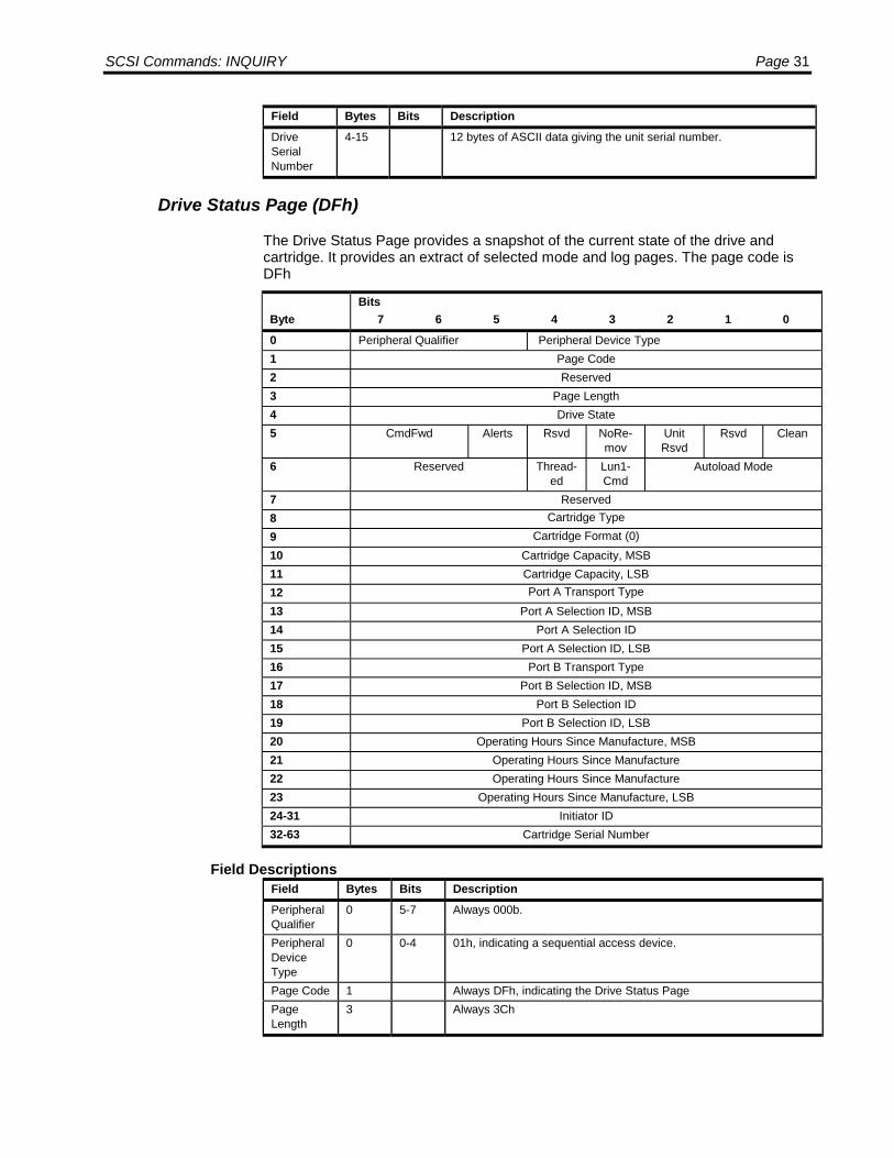
SCSI Commands: INQUIRY Page 31
Field Bytes Bits DescriptionDriveSerialNumber
4-15 12 bytes of ASCII data giving the unit serial number.
Drive Status Page (DFh)
The Drive Status Page provides a snapshot of the current state of the drive andcartridge. It provides an extract of selected mode and log pages. The page code isDFh
ByteBits
7 6 5 4 3 2 1 00 Peripheral Qualifier Peripheral Device Type1 Page Code2 Reserved3 Page Length4 Drive State5 CmdFwd Alerts Rsvd NoRe-
movUnitRsvd
Rsvd Clean
6 Reserved Thread-ed
Lun1-Cmd
Autoload Mode
7 Reserved8 Cartridge Type9 Cartridge Format (0)10 Cartridge Capacity, MSB11 Cartridge Capacity, LSB12 Port A Transport Type13 Port A Selection ID, MSB14 Port A Selection ID15 Port A Selection ID, LSB16 Port B Transport Type17 Port B Selection ID, MSB18 Port B Selection ID19 Port B Selection ID, LSB20 Operating Hours Since Manufacture, MSB21 Operating Hours Since Manufacture22 Operating Hours Since Manufacture23 Operating Hours Since Manufacture, LSB24-31 Initiator ID32-63 Cartridge Serial Number
Field DescriptionsField Bytes Bits DescriptionPeripheralQualifier
0 5-7 Always 000b.
PeripheralDeviceType
0 0-4 01h, indicating a sequential access device.
Page Code 1 Always DFh, indicating the Drive Status PagePageLength
3 Always 3Ch
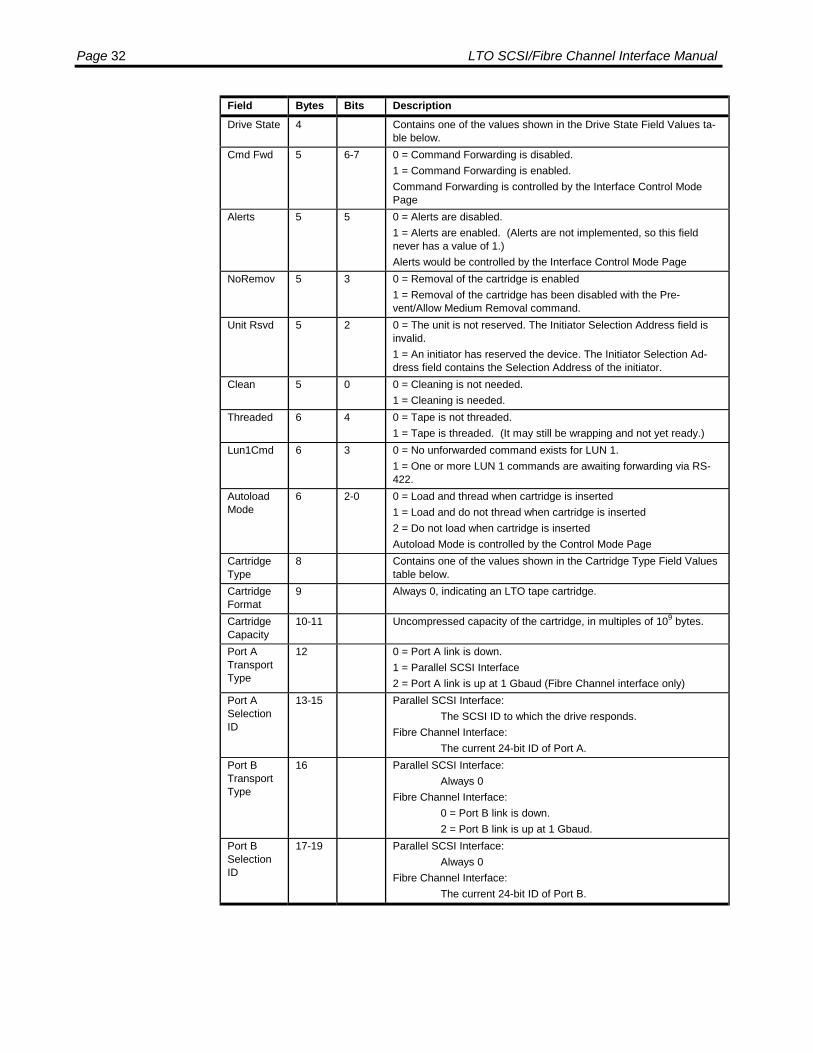
Page 32 LTO SCSI/Fibre Channel Interface Manual
Field Bytes Bits DescriptionDrive State 4 Contains one of the values shown in the Drive State Field Values ta-
ble below.Cmd Fwd 5 6-7 0 = Command Forwarding is disabled.
1 = Command Forwarding is enabled.Command Forwarding is controlled by the Interface Control ModePage
Alerts 5 5 0 = Alerts are disabled.1 = Alerts are enabled. (Alerts are not implemented, so this fieldnever has a value of 1.)Alerts would be controlled by the Interface Control Mode Page
NoRemov 5 3 0 = Removal of the cartridge is enabled1 = Removal of the cartridge has been disabled with the Pre-vent/Allow Medium Removal command.
Unit Rsvd 5 2 0 = The unit is not reserved. The Initiator Selection Address field isinvalid.1 = An initiator has reserved the device. The Initiator Selection Ad-dress field contains the Selection Address of the initiator.
Clean 5 0 0 = Cleaning is not needed.1 = Cleaning is needed.
Threaded 6 4 0 = Tape is not threaded.1 = Tape is threaded. (It may still be wrapping and not yet ready.)
Lun1Cmd 6 3 0 = No unforwarded command exists for LUN 1.1 = One or more LUN 1 commands are awaiting forwarding via RS-422.
AutoloadMode
6 2-0 0 = Load and thread when cartridge is inserted1 = Load and do not thread when cartridge is inserted2 = Do not load when cartridge is insertedAutoload Mode is controlled by the Control Mode Page
CartridgeType
8 Contains one of the values shown in the Cartridge Type Field Valuestable below.
CartridgeFormat
9 Always 0, indicating an LTO tape cartridge.
CartridgeCapacity
10-11 Uncompressed capacity of the cartridge, in multiples of 109 bytes.
Port ATransportType
12 0 = Port A link is down.1 = Parallel SCSI Interface2 = Port A link is up at 1 Gbaud (Fibre Channel interface only)
Port ASelectionID
13-15 Parallel SCSI Interface:The SCSI ID to which the drive responds.
Fibre Channel Interface:The current 24-bit ID of Port A.
Port BTransportType
16 Parallel SCSI Interface:Always 0
Fibre Channel Interface:0 = Port B link is down.2 = Port B link is up at 1 Gbaud.
Port BSelectionID
17-19 Parallel SCSI Interface:Always 0
Fibre Channel Interface:The current 24-bit ID of Port B.

SCSI Commands: INQUIRY Page 33
Field Bytes Bits DescriptionOperatingHoursSinceManufac-ture
20-23 Total number of hours of head-tape contact time.
Initiator ID 24-31 Identification of the initiator holding a reservation on the drive, whenthe Unit Rsvd field is one. If the interface is Parallel SCSI, then theleast-significant byte contains the initiator’s SCSI ID; if the interfaceis Fibre Channel, then the field contains the initiator’s 64-bit world-wide ID. If Unit Rsvd is zero, then this field is zero.
CartridgeSerialNumber
32-6332 bytes of ASCII data, right-filled with blanks. This is the cartridgeserial number as defined by attribute number 0201h of the SPC-2Read Attribute command. [The SPC-2 Read Attribute command hasnot been implemented.]
Reserved Always 0
As there is only one LTO format defined at this time, the Cartridge Format value isalways zero. During insertion, the type of a data cartridge is unknown between thetime the cartridge is seated and the drive completes winding to BOT; the lengthcalculation takes place during winding.
Drive State Field ValuesThe Medium Auxiliary Memory (MAM) can be accessed only in the states indicated.
Value
State DescriptionMAMAcces-sible
0 DRIVE NOT READY No commands may be issued and cartridgemay not be inserted.
N
1 DRIVE EMPTY READY No cartridge in drive. Commands will be ac-cepted and a cartridge may be inserted.
N
2 DRIVE MEDIA LOADABLE Cartridge is in carrier and loading may beinitiated by issuing a SCSI Load or a libraryLOAD CARTRIDGE command.
N
3 DRIVE LOADING Drive is loading and threading the cartridge. N4 DRIVE LOADED HOLD Drive is loaded to Hold point. Y5 DRIVE LOADED READY Drive can accept non-status commands. Y6 DRIVE WRITING Drive cannot accept non-status commands. Y7 DRIVE READING Drive cannot accept non-status commands. Y8 DRIVE BUSY Drive cannot accept non-status commands. Y9 DRIVE UNLOADING Tape is being unthreaded and ejected. Y10 DRIVE MEDIA REMOVABLE Cartridge has been ejected and is ready for
extraction by the library.N
11 DRIVE LOAD FAILED EJECTED Loading failed and the cartridge was re-turned to the loadable/removable position.
N
12 DRIVE LOAD FAILED JAMMED Loading failed. N13 DRIVE LOAD FAILED HOLD Loading failed and the cartridge is in the
drive at the Hold position.Y
14 DRIVE EJECT FAILED JAMMED Ejection failed. N15 DRIVE EJECT FAILED HOLD Ejection failed and the cartridge is in the
drive at the Hold position.Y
16 DRIVE STATE UNKNOWN. N17 DRIVE CLEANING FAILED Cleaning cartridge expired or cleaning failed
for another reason. Tape may be threaded.Y
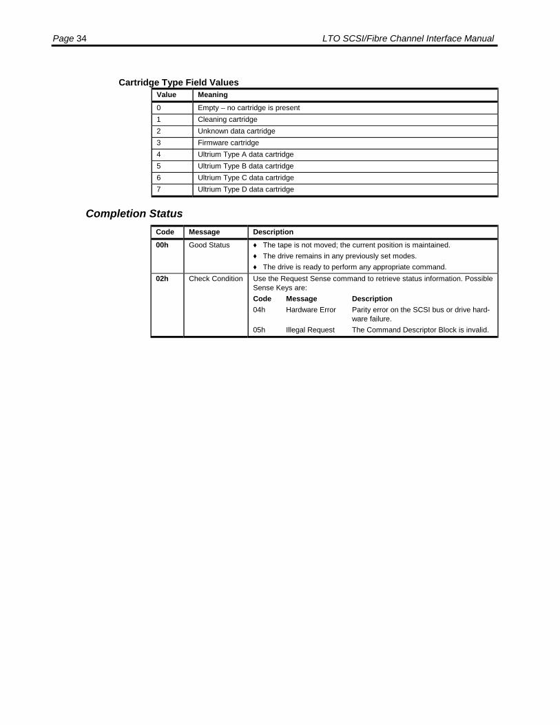
Page 34 LTO SCSI/Fibre Channel Interface Manual
Cartridge Type Field ValuesValue Meaning0 Empty – no cartridge is present1 Cleaning cartridge2 Unknown data cartridge3 Firmware cartridge4 Ultrium Type A data cartridge5 Ultrium Type B data cartridge6 Ultrium Type C data cartridge7 Ultrium Type D data cartridge
Completion StatusCode Message Description00h Good Status ♦ The tape is not moved; the current position is maintained.
♦ The drive remains in any previously set modes.♦ The drive is ready to perform any appropriate command.
02h Check Condition Use the Request Sense command to retrieve status information. PossibleSense Keys are:Code Message Description04h Hardware Error Parity error on the SCSI bus or drive hard-
ware failure.05h Illegal Request The Command Descriptor Block is invalid.

SCSI Commands: LOAD UNLOAD Page 35
LOAD UNLOAD
The Load Unload command may be used to load or unload a cartridge. Thiscommand may also be used to request that the retension function be performed.
Command Descriptor Block
ByteBits
7 6 5 4 3 2 1 0
0 Operation Code (1Bh)1 Ignored LUN Reserved Immed2 Reserved3 Reserved4 Reserved Hold EOT Reten Load5 Control
Field DescriptionsField Bytes Bits DescriptionOperationCode
0 The Operation Code for the Load Unload command is 1Bh.
IgnoredLogicalUnit
1 5-7 The LUN field is vestigal from the SCSI-1 standard and is ignored.
Immed 1 0 0 = Status is not returned until the operation has completed.1 = Status is returned as soon as buffered data and filemarks are
written to the medium and the CDB has been validated.Hold 4 3 1 = Requests that the medium be positioned to the Medium Auxil-
iary Memory Accessible position where the medium is seatedinto the drive but the tape is not threaded to BOT.
EOT 4 2 Not supported. Must be set to 0.Reten 4 1 1 = Requests that the retension function be performed on medium.Load 4 0 0 = requests that the medium be unloaded.
1 = requests that the medium be loaded.Reserved All reserved bits must be 0.Control 5 See Control Byte Format on page 20.
The drive has three possible states where the medium may be positioned. Thelocations are:
• The Medium Loadable Position where the medium is inserted into the drive buthas not been seated into the drive and the tape has not been threaded to BOT.
• The Medium Auxiliary Memory Accessible Position where the medium has beenseated into the drive but the tape has not been threaded to BOT.
• The Medium Loaded And Ready Position where the medium has been seatedinto the drive and the tape has been threaded to BOT. The medium is ready touse.

Page 36 LTO SCSI/Fibre Channel Interface Manual
Medium Loadable PositionHold Reten Load Description
0 0 0 No action taken, Good Status is returned.0 0 1 Load the medium to the Loaded position. The medium will be ready at
BOT.0 1 0 Check condition, sense data 02/3A/03.0 1 1 Load the medium to the Loaded position and perform the retension op-
eration. The medium will be ready at BOT.1 0 0 Load the medium to the Medium Auxiliary Memory Accessible position.1 0 1 Load the medium to the Medium Auxiliary Memory Accessible position.1 1 0 Check condition, sense data 02/3A/03.1 1 1 Check condition, sense data 02/3A/03.
Medium Auxiliary Memory Accessible PositionHold Reten Load Description
0 0 0 Unload the medium to the Loadable position.0 0 1 Load the medium to the Loaded position. The medium will be ready at
BOT.0 1 0 Check condition, sense data 02/3A/04.0 1 1 Load the medium to the Loaded position and perform the retension op-
eration. The medium will be ready at BOT.1 0 0 No action taken, Good Status is returned.1 0 1 No action taken, Good Status is returned.1 1 0 Check condition, sense data 02/3A/04.1 1 1 Check condition, sense data 02/3A/04.
Medium Loaded And Ready PositionHold Reten Load Description
0 0 0 Unload the medium to the Loadable position.0 0 1 Rewind the medium to the Loaded position. The medium will be ready
at BOT.0 1 0 Perform the retension operation and unload the medium to the Load-
able position.0 1 1 Perform the retension operation. The medium will remain at the Loaded
position ready at BOT.1 0 0 Unload the medium to the Medium Auxiliary Memory Accessible posi-
tion.1 0 1 Unload the medium to the Medium Auxiliary Memory Accessible posi-
tion.1 1 0 Perform the retension operation and unload the medium to the Medium
Auxiliary Memory Accessible position.1 1 1 Perform the retension operation and unload the medium to the Medium
Auxiliary Memory Accessible position.
If the Prevent Medium Removal state has been set using the Prevent Allow MediumRemoval command and a Load Unload command is issued that requests themedium be unloaded to the Medium Loadable position, then a check condition statuswill be returned. The sense key will be set to Illegal Request(05) and the additionalsense data will be set to Medium Removal Prevented (5302).
If the Immediate (Immed) flag is 1, then the drive validates the command and waitsfor any previous command from any host to complete, including any immediatecommands currently being processed, and for any buffered data to be flushed to
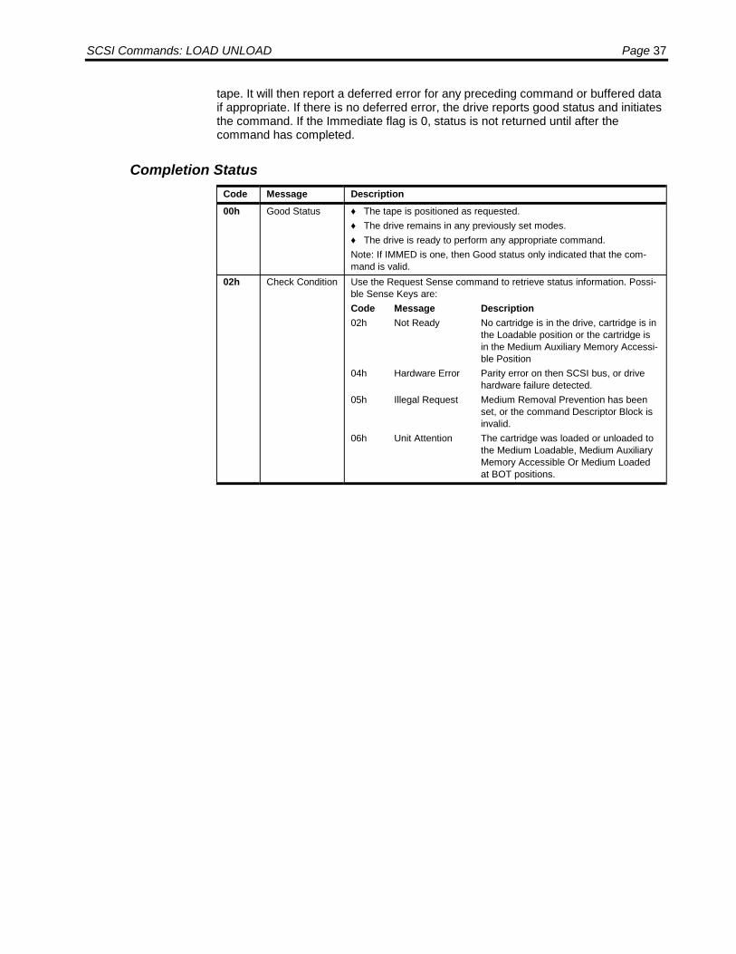
SCSI Commands: LOAD UNLOAD Page 37
tape. It will then report a deferred error for any preceding command or buffered dataif appropriate. If there is no deferred error, the drive reports good status and initiatesthe command. If the Immediate flag is 0, status is not returned until after thecommand has completed.
Completion StatusCode Message Description00h Good Status ♦ The tape is positioned as requested.
♦ The drive remains in any previously set modes.♦ The drive is ready to perform any appropriate command.Note: If IMMED is one, then Good status only indicated that the com-mand is valid.
02h Check Condition Use the Request Sense command to retrieve status information. Possi-ble Sense Keys are:Code Message Description02h Not Ready No cartridge is in the drive, cartridge is in
the Loadable position or the cartridge isin the Medium Auxiliary Memory Accessi-ble Position
04h Hardware Error Parity error on then SCSI bus, or drivehardware failure detected.
05h Illegal Request Medium Removal Prevention has beenset, or the command Descriptor Block isinvalid.
06h Unit Attention The cartridge was loaded or unloaded tothe Medium Loadable, Medium AuxiliaryMemory Accessible Or Medium Loadedat BOT positions.
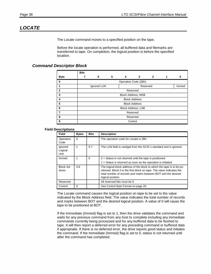
Page 38 LTO SCSI/Fibre Channel Interface Manual
LOCATE
The Locate command moves to a specified position on the tape.
Before the locate operation is performed, all buffered data and filemarks aretransferred to tape. On completion, the logical position is before the specifiedlocation.
Command Descriptor Block
ByteBits
7 6 5 4 3 2 1 00 Operation Code (2Bh)1 Ignored LUN Reserved Immed2 Reserved3 Block Address, MSB4 Block Address5 Block Address6 Block Address, LSB7 Reserved8 Reserved9 Control
Field DescriptionsField Bytes Bits DescriptionOperationCode
0 The operation code for Locate is 2Bh
IgnoredLogicalUnit
1 5-7 The LUN field is vestigal from the SCSI-1 standard and is ignored.
Immed 1 0 0 = Status is not returned until the tape is positioned.1 = Status is returned as soon as the operation is initiated.
Block Ad-dress
3-6 The logical block address of the block to which the tape is to be po-sitioned. Block 0 is the first block on tape. The value indicates thetotal number of records and marks between BOT and the desiredlogical position.
Reserved All reserved bits must be 0.Control 9 See Control Byte Format on page 20.
The Locate command causes the logical position on tape to be set to the valueindicated by the Block Address field. The value indicates the total number of recordsand marks between BOT and the desired logical position. A value of 0 will cause thetape to be positioned at BOT.
If the Immediate (Immed) flag is set to 1, then the drive validates the command andwaits for any previous command from any host to complete including any immediatecommands currently being processed and for any buffered data to be flushed totape. It will then report a deferred error for any preceding command or buffered dataif appropriate. If there is no deferred error, the drive reports good status and initiatesthe command. If the Immediate (Immed) flag is set to 0, status is not returned untilafter the command has completed.

SCSI Commands: LOCATE Page 39
Completion StatusCode Message Description00h Good
Status♦ The tape is positioned to the logical block address specified.♦ The drive remains in any previously set mode.♦ The drive is ready to perform any appropriate command.Note: If Immed is 1, then Good Status only indicates that the command isvalid.
02h CheckCondition
Use the Request Sense command to retrieve status information. PossibleSense Keys are:Code Message Description02h Not Ready No cartridge is in the drive.03h Media Error Unrecoverable data error encountered.04h Hardware Error Parity error on SCSI bus or drive hardware fail-
ure detected.05h Illegal Request The Command Descriptor Block is invalid.06h Unit Attention The cartridge was changed, or the drive was
reset prior to this command.08h Blank Check The drive encountered EOD.
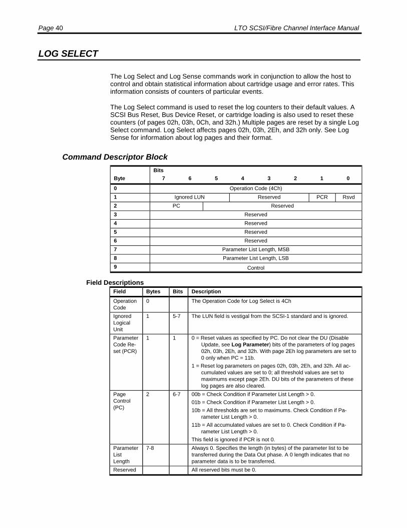
Page 40 LTO SCSI/Fibre Channel Interface Manual
LOG SELECT
The Log Select and Log Sense commands work in conjunction to allow the host tocontrol and obtain statistical information about cartridge usage and error rates. Thisinformation consists of counters of particular events.
The Log Select command is used to reset the log counters to their default values. ASCSI Bus Reset, Bus Device Reset, or cartridge loading is also used to reset thesecounters (of pages 02h, 03h, 0Ch, and 32h.) Multiple pages are reset by a single LogSelect command. Log Select affects pages 02h, 03h, 2Eh, and 32h only. See LogSense for information about log pages and their format.
Command Descriptor Block
ByteBits
7 6 5 4 3 2 1 0
0 Operation Code (4Ch)1 Ignored LUN Reserved PCR Rsvd2 PC Reserved3 Reserved4 Reserved5 Reserved6 Reserved7 Parameter List Length, MSB8 Parameter List Length, LSB9 Control
Field DescriptionsField Bytes Bits DescriptionOperationCode
0 The Operation Code for Log Select is 4Ch
IgnoredLogicalUnit
1 5-7 The LUN field is vestigal from the SCSI-1 standard and is ignored.
ParameterCode Re-set (PCR)
1 1 0 = Reset values as specified by PC. Do not clear the DU (DisableUpdate, see Log Parameter) bits of the parameters of log pages02h, 03h, 2Eh, and 32h. With page 2Eh log parameters are set to0 only when PC = 11b.
1 = Reset log parameters on pages 02h, 03h, 2Eh, and 32h. All ac-cumulated values are set to 0; all threshold values are set tomaximums except page 2Eh. DU bits of the parameters of theselog pages are also cleared.
PageControl(PC)
2 6-7 00b = Check Condition if Parameter List Length > 0.01b = Check Condition if Parameter List Length > 0.10b = All thresholds are set to maximums. Check Condition if Pa-
rameter List Length > 0.11b = All accumulated values are set to 0. Check Condition if Pa-
rameter List Length > 0.This field is ignored if PCR is not 0.
ParameterListLength
7-8 Always 0. Specifies the length (in bytes) of the parameter list to betransferred during the Data Out phase. A 0 length indicates that noparameter data is to be transferred.
Reserved All reserved bits must be 0.
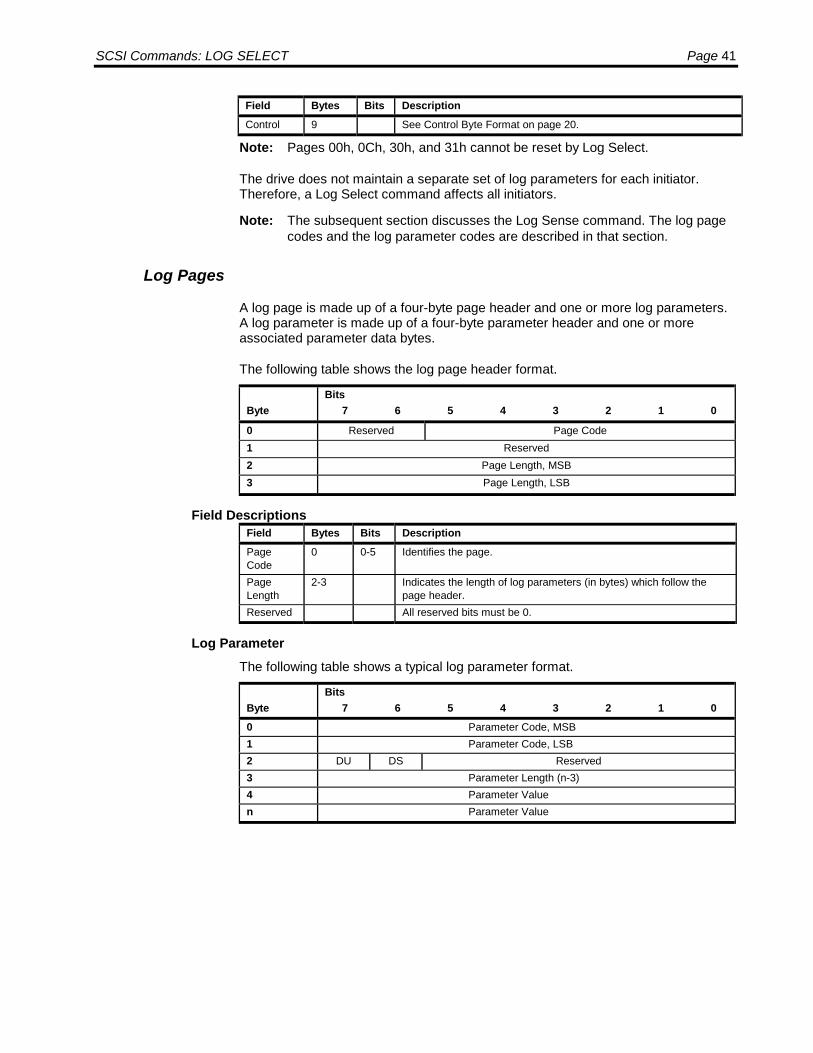
SCSI Commands: LOG SELECT Page 41
Field Bytes Bits DescriptionControl 9 See Control Byte Format on page 20.
Note: Pages 00h, 0Ch, 30h, and 31h cannot be reset by Log Select.
The drive does not maintain a separate set of log parameters for each initiator.Therefore, a Log Select command affects all initiators.
Note: The subsequent section discusses the Log Sense command. The log pagecodes and the log parameter codes are described in that section.
Log Pages
A log page is made up of a four-byte page header and one or more log parameters.A log parameter is made up of a four-byte parameter header and one or moreassociated parameter data bytes.
The following table shows the log page header format.
ByteBits
7 6 5 4 3 2 1 0
0 Reserved Page Code1 Reserved2 Page Length, MSB3 Page Length, LSB
Field DescriptionsField Bytes Bits DescriptionPageCode
0 0-5 Identifies the page.
PageLength
2-3 Indicates the length of log parameters (in bytes) which follow thepage header.
Reserved All reserved bits must be 0.
Log ParameterThe following table shows a typical log parameter format.
ByteBits
7 6 5 4 3 2 1 00 Parameter Code, MSB1 Parameter Code, LSB2 DU DS Reserved3 Parameter Length (n-3)4 Parameter Valuen Parameter Value
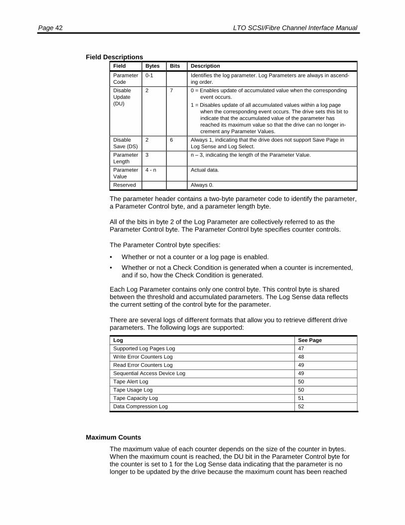
Page 42 LTO SCSI/Fibre Channel Interface Manual
Field DescriptionsField Bytes Bits DescriptionParameterCode
0-1 Identifies the log parameter. Log Parameters are always in ascend-ing order.
DisableUpdate(DU)
2 7 0 = Enables update of accumulated value when the correspondingevent occurs.
1 = Disables update of all accumulated values within a log pagewhen the corresponding event occurs. The drive sets this bit toindicate that the accumulated value of the parameter hasreached its maximum value so that the drive can no longer in-crement any Parameter Values.
DisableSave (DS)
2 6 Always 1, indicating that the drive does not support Save Page inLog Sense and Log Select.
ParameterLength
3 n – 3, indicating the length of the Parameter Value.
ParameterValue
4 - n Actual data.
Reserved Always 0.
The parameter header contains a two-byte parameter code to identify the parameter,a Parameter Control byte, and a parameter length byte.
All of the bits in byte 2 of the Log Parameter are collectively referred to as theParameter Control byte. The Parameter Control byte specifies counter controls.
The Parameter Control byte specifies:
• Whether or not a counter or a log page is enabled.• Whether or not a Check Condition is generated when a counter is incremented,
and if so, how the Check Condition is generated.
Each Log Parameter contains only one control byte. This control byte is sharedbetween the threshold and accumulated parameters. The Log Sense data reflectsthe current setting of the control byte for the parameter.
There are several logs of different formats that allow you to retrieve different driveparameters. The following logs are supported:
Log See PageSupported Log Pages Log 47Write Error Counters Log 48Read Error Counters Log 49Sequential Access Device Log 49Tape Alert Log 50Tape Usage Log 50Tape Capacity Log 51Data Compression Log 52
Maximum CountsThe maximum value of each counter depends on the size of the counter in bytes.When the maximum count is reached, the DU bit in the Parameter Control byte forthe counter is set to 1 for the Log Sense data indicating that the parameter is nolonger to be updated by the drive because the maximum count has been reached

SCSI Commands: LOG SELECT Page 43
and if RLEC (Report Log Exception Condition) bit in Mode Page 0Ah (Control Modepage) is set to 1, Recovered Error/Log Counter at Maximum (01/5B/02) is returned tohost to inform of the log exception. Bytes 15-17 of the Request Sense data specifythe page, MSB and LSB of the Parameter Code respectively, which caused the LogException.
When a counter reaches the maximum, the counter is no longer incremented. If amaximum value for the parameter size is reached, the count does NOT roll over andcontinue counting. When any counter of a page reaches maximum, all counters ofthat page are no longer incremented. A Log Select command can be issued forpages 02h, 03h, and 32h with the PCR bit set to reset the accumulated values and toallow counters to continue as normal. The DU bit of the affected parameter is alsoreset to zero. The same effect can be achieved by a SCSI Bus Reset, Bus DeviceReset, or cartridge loading.
Completion StatusCode Message Description00h Good Status • The drive is ready to perform any appropriate command.
• The affected log parameters are reset.• The tape position is not changed.
02h Check Condi-tion
Use the Request Sense command to retrieve status information. Possi-ble Sense Keys are:Code Message Description04h Hardware Error Parity error on the SCSI bus or drive
hardware failure.05h Illegal Request The Reserved bits are set or the Pa-
rameter List Length is not 0 in the Com-mand Descriptor Block.
06h Unit Attention The cartridge was changed, or the drivewas reset prior to this command.

Page 44 LTO SCSI/Fibre Channel Interface Manual
LOG SENSE
The Log Select and Log Sense commands work in conjunction to allow the host tocontrol and obtain statistical information about cartridge usage and error rates. Thisinformation consists of counters of particular events.
Log Sense data is obtained by specifying a log page in the Page Code field of theLog Sense CDB. The host can request only one page of data with each Log Sensecommand. The available pages are found by reading the Supported Log Pages Log(00h).
Command Descriptor Block
ByteBits
7 6 5 4 3 2 1 00 Operation Code (4Dh)1 Ignored LUN Reserved2 PC Page Code3 Reserved4 Reserved5 Parameter Pointer, MSB6 Parameter Pointer, LSB7 Allocation Length, MSB8 Allocation Length, LSB9 Control
Field DescriptionsField Bytes Bits DescriptionOperationCode
0 The Operation Code for Log Sense is 4Dh.
IgnoredLogicalUnit
1 5-7 The LUN field is vestigal from the SCSI-1 standard and is ignored.
PageControl(PC)
2 6-7 00b = Requests Threshold values (always returns maximum possiblevalues).
01b = Requests Accumulated values10b = Requests Default threshold values (always returns maximum
possible values).11b = Requests Default accumulated values (always returns 0s).
PageCode
2 0-5 00h = Requests Supported Log Pages Log02h = Requests Write Error Counters Log03h = Requests Read Error Counters Log0Ch = Requests Sequential Access Device Log2Eh = Requests Tape Alert Log30h = Requests Tape Usage Log31h = Requests Tape Capacity Log32h = Requests Data Compression Log
ParameterPointer
5-6 7-0 Specifies the beginning parameter code to be returned to the initia-tor. All remaining parameter codes are returned in ascending order.This field is ignored for page code 00h.

SCSI Commands: LOG SENSE Page 45
Field Bytes Bits DescriptionAllocationLength
7-8 7-0 The Allocation Length field specifies the maximum amount of mem-ory space (in bytes), which the initiator has reserved for Log Sensedata.The drive returns the number of bytes contained in the requestedpage, or the requested Allocation Length, whichever is less. If theAllocation Length is less than the actual page length, the transfer istruncated.
Reserved All reserved bits must be 0.Control 9 See Control Byte Format on page 20.
The Page Control (PC) field specifies the type of counters that the initiator isrequesting. The value 01b is the most common page control setting. This requeststhe accumulated counts for the page to be returned. These counts reflect the currentcount of events since the last power-on cycle, SCSI bus Reset, Bus Device Reset,cartridge loading, or the last Log Select command that cleared the parameter values.
Accumulated values are incremented by the drive as an event occurs. For pages02h, 03h, and 32h, these values can be cleared with all the above methods. Forpage 0Ch these values can be cleared with all the above methods except with LogSelect. Because the drive maintains the accumulated values in volatile memory, thevalues may be lost if a power cycle occurs.
The PC field is ignored for pages 00h, 0Ch, 2Eh, 30h, and 31h and the accumulatedvalues are always returned except page 00h which has no accumulated values.
The Parameter Pointer Field
The Parameter Pointer field specifies the starting page that is to be transferred. Forexample, if the page uses parameter codes 2 through 6 and the parameter pointerfield is set to 3, then the drive returns parameters 3 through 6. Likewise, if theparameter pointer is set to 1, parameters 2 through 6 are returned.
If the Parameter Pointer field is set to 0, all parameters for that particular page arereturned up to the maximum number of bytes specified in the allocation length.
Regardless of the starting parameter code specified in the Parameter Pointer field,the page header is always returned.
Log Pages
There are several logs of different formats that allow you to retrieve different driveparameters. The following logs are supported:
Log See PageSupported Log Pages Log 47Write Error Counters Log 48Read Error Counters Log 49Sequential Access Device Log 49Tape Alert Log 50Tape Usage Log 50Tape Capacity Log 51Data Compression Log 52

Page 46 LTO SCSI/Fibre Channel Interface Manual
Only one log page is transferred to the host with each Log Sense command. ThePage Code field (Byte 2) of the CDB specifies the page to be transferred.
A four-byte page header precedes the parameter data for each page. The pageheader specifies the page code returned and the length of that page in bytes.
Following the page header are the log parameters. Each log parameter is a datastructure that contains several description bytes followed by the parameter valueitself.
Log Page Header Log Page Header is always returned.
First Log Parameter
…Multiple Log Parameters are returned in each logpage. The log parameters are returned inascending order.
Last Log Parameter
Log Page Header
ByteBits
7 6 5 4 3 2 1 00 Reserved Page Code1 Reserved2 Page Length, MSB3 Page Length, LSB
Field DescriptionsField Bytes Bits DescriptionPageCode
0 0-5 Identifies the page being returned.
PageLength
2-3 Indicates the length of the page in bytes that follow the page header.If the allocation length specified in the CDB is too small to transfer theentire requested page, this value is not adjusted to reflect the trunca-tion. However, if the Parameter Pointer field specifies a starting pa-rameter code other than zero, the page length is adjusted to indicatethe number of bytes that follow the page header.
Reserved All reserved bits must be 0.
Log Parameter
ByteBits
7 6 5 4 3 2 1 00 Parameter Code, MSB1 Parameter Code, LSB2 DU DS TSD ETC TMC LBIN LP3 Parameter Length4 – n Parameter Value

SCSI Commands: LOG SENSE Page 47
Field DescriptionsField Bytes Bits DescriptionParameterCode
0-1 Identifies the log parameter returned. Log Parameters are always re-turned in ascending order.
DisableUpdate(DU)
2 7 0 = Enables update of accumulated value when the correspondingevent occurs.
1 = Disables update of all accumulated values within a log page whenthe corresponding event occurs. The drive sets this bit to indicatethat the accumulated value of the parameter has reached itsmaximum value so that the drive can no longer increment any Pa-rameter Values.
DisableSave (DS)
2 6 Always 1, indicating that the drive does not support Save Page in LogSense and Log Select.
TSD 2 5 Always 0, indicating that Target Save Disable (TSD) is not supported.ETC 2 4 Always 0, indicating that Enable Threshold Comparison (ETC) is not
supported.TMC 2 2-3 Always 0, indicating that Threshold Met Criteria (TMC) is not sup-
ported.List Binary(LBIN)
2 1 Always 0, indicating that all log parameters are data counters.
ListParameter(LP)
2 0 Always 0, indicating that all log parameters are data counters.
ParameterLength
3 n – 3, indicating the length of the Parameter Value.
ParameterValue
4 – n The Parameter Value is the actual data requested.
Reserved Always 0.
Supported Log Pages Log (00h)
Page 00h indicates the log pages used by the drive. To determine the size of eachpage and of each parameter in the page, the individual page must be requested.Page 00h is unique in that the log parameters returned do not contain log parameterheaders. All other pages return a log parameter header for each log parameter.Page 00h is valid only for the Log Sense command. When page 00h is requested,the four-byte page header is returned followed by the list of log pages—one byte foreach log page. The list of log pages is returned in ascending order.
ByteBits
7 6 5 4 3 2 1 00 Reserved Page Code (00h)1 Reserved2 Page Length, MSB3 Page Length, LSB (0Ah)4 Supported Log Pages Log (00h)5 Write Error Counters Log (02h)6 Read Error Counters Log (03h)7 Sequential Access Device Log (0Ch)8 Tape Alert Log (2Eh)9 Tape Usage Log (30h)10 Tape Capacity Log (31h)11 Data Compression Log (32h)

Page 48 LTO SCSI/Fibre Channel Interface Manual
Field DescriptionsField Bytes Bits DescriptionPageCode
0 0-5
PageLength
2-3 Always 0Ah, indicating the page length.
SupportedLog PagesLog
4 Always 00h, the page code of the Supported Log Pages Log
Write ErrorCountersLog
5 Always 02h, the page code of the Write Error Counters Log
Read ErrorCountersLog
6 Always 03h, the page code of the Read Error Counters Log
SequentialAccessDeviceLog
7 Always 0Ch, the page code of the Sequential Access Device Log
Tape AlertLog
8 Always 2Eh, the page code of the Tape Alert Log
Tape Us-age Log
9 Always 30h, the page code of the Tape Usage Log
Tape Ca-pacity Log
10 Always 31h, the page code of the Tape Capacity Log
DataCompres-sion Log
11 Always 32h, the page code of the Data Compression Log
Reserved Always 0.
Write Error Counters Log (02h)
The Write Error Counters Log records write errors. The parameters on this page canbe reset to 0 with the Log Select command.
Page Code Page Length02h 38h
Parameter Description Length0 Errors corrected without substantial delay 41 Errors corrected with possible delay. 42 Total rewrites. (sum of Parameter 0003 and Parameter 0006) 43 Total errors corrected. This is total write retries less total unrecoverable write
errors. (Parameter 0004 minus Parameter 0006, this is also the sum of Pa-rameter 0000 and Parameter 0001)
4
4 Total times error correction processed. This is the total number of write re-tries.
4
5 Total bytes processed. The is the total data sets written. 46 Total uncorrected errors. This is the total unrecoverable write errors. 4

SCSI Commands: LOG SENSE Page 49
Read Error Counters Log (03h)
The Read Error Counters Log records read errors. The parameters on this page canbe reset to 0 with the Log Select command.
Page Code Page Length03h 38h
Parameter Description Length0 Errors corrected without substantial delay 41 Errors corrected with possible delay. 42 Total rereads. (sum of Parameter 0003 and Parameter 0006) 43 Total errors corrected. This is total read retries less total unrecoverable er-
rors. (Parameter 0004 minus Parameter 0006, this is also the sum of Pa-rameter 0000 and Parameter 0001)
4
4 Total times error correction processed. This is the total number of read re-tries.
4
5 Total bytes processed. The is the total data sets read. 46 Total uncorrected errors. This is the total unrecoverable read errors. 4
Sequential Access Device Log (0Ch)
The Sequential Access Device Log tracks the flow of data to and from the drive. Italso signals when drive cleaning is necessary.
Page Code Page Length0Ch 3Ch
Parameter Description Length0000h Number of data bytes received from application clients during Write Com-
mand operations. This is the number of bytes transferred over the SCSI in-terface before compression.
8
0001h Number of data bytes written to the media as a result of Write Command op-erations, not counting ECC and formatting overhead. This is the number ofdata bytes transferred to media after compression.
8
0002h Number of data bytes read from the media during Read command Opera-tions, not counting ECC and formatting overhead. This is the number of databytes transferred from media with compression.
8
0003h Number of data bytes transferred to the initiator(s) during Read Commandoperations. This is the number of bytes transferred over the SCSI interface,after decompression.
8
0100h Cleaning required. A non-zero value of the cleaning required parameter indi-cates that a condition requiring cleaning has been detected and a subsequentcleaning cycle has not been completed. The cleaning required parameter ispersistent across hard resets and power cycles.
8

Page 50 LTO SCSI/Fibre Channel Interface Manual
Tape Alert Log (2Eh)
The Tape Alert Log Page provides information about errors and the status of thedrive and media.
Page Code Page Length2Eh 140h
All parameters are one byte long. Each parameter is either zero to indicate thecorresponding condition has not occurred or one to indicate that the correspondingcondition has occurred. The log page is used in conjunction with InformationExceptions Mode Page (1Ch) that controls the action taken by the drive when a flagis set and sets various other control mechanisms of the Tape Alert system. A flag isset whenever the condition for setting the flag exists. There are three types of flags,Informational, Warning, and Critical. The type of flag depends upon the severity ofthe condition that sets the flag. Flags are cleared on the following conditions:
• At drive power on• When the TapeAlert Log page is read• When specified corrective action has been taken (such as using a cleaning
cartridge)• On a SCSI bus reset or bus device reset message• On Log Select reset (note that the recommended action on receiving Log Select
for the TapeAlert Log page is to reject the command with an error).
Additional information regarding the Tape Alert system is found in the SCSI-3Stream Commands (SSC) Standard and Tape Alert specification. The following isthe list of flags (parameters) supported by the drive.
Parameter Description Type Length3 Hard Error Warning 19 Write Protect Critical 111 Cleaning media in drive Informational 114 Unrecoverable snapped tape Critical 115 Memory in Cartridge Failure Warning 116 Forced Eject Critical 117 Read Only Format Warning 118 Tape Directory Corrupted on Load Warning 120 Clean now Critical 122 Expired cleaning media Critical 123 Invalid cleaning tape Critical 130 Hardware A Critical 131 Hardware B Critical 132 Interface Warning 134 Download Fault Warning 151 Tape Directory Invalid at Unload Warning 1
Tape Usage Log (30h)
The Tape Usage Log Page returns information about the current tape cartridge.These values are all read directly from the tape log. The Page Control, PC, field isignored and accumulated values are always returned.
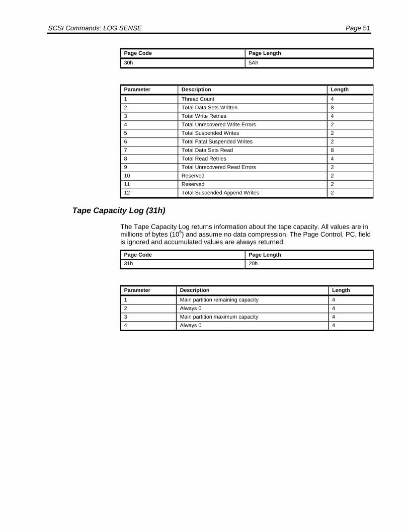
SCSI Commands: LOG SENSE Page 51
Page Code Page Length30h 5Ah
Parameter Description Length1 Thread Count 42 Total Data Sets Written 83 Total Write Retries 44 Total Unrecovered Write Errors 25 Total Suspended Writes 26 Total Fatal Suspended Writes 27 Total Data Sets Read 88 Total Read Retries 49 Total Unrecovered Read Errors 210 Reserved 211 Reserved 212 Total Suspended Append Writes 2
Tape Capacity Log (31h)
The Tape Capacity Log returns information about the tape capacity. All values are inmillions of bytes (106) and assume no data compression. The Page Control, PC, fieldis ignored and accumulated values are always returned.
Page Code Page Length31h 20h
Parameter Description Length1 Main partition remaining capacity 42 Always 0 43 Main partition maximum capacity 44 Always 0 4

Page 52 LTO SCSI/Fibre Channel Interface Manual
Data Compression Log (32h)
The Data Compression Log records compression information. The parameters onthis page can be reset to 0 with the Log Select command
Page Code Page Length32h 4Ch
Parameter Description Length0 Read compression ratio in percent 21 Write compression ratio in percent 22 Millions of total bytes transferred to host 43 Remaining bytes of total bytes transferred to host 44 Millions of total bytes read from tape 45 Remaining bytes of total bytes read from tape 46 Millions of total bytes transferred from host 47 Remaining bytes of total bytes transferred from host 48 Millions of total bytes written to tape 49 Remaining bytes of total bytes written to tape 4
Parameters 2 through 9 occur as pairs each of which represents a total number ofbytes (i.e., total number of bytes transferred to host as with Parameter 2 and 3 pair.)The first four-byte parameter of a pair represents millions of bytes (106.) The secondfour-byte parameter of a pair represents the difference between the millions of bytesand the total number of bytes as a positive number in the range of 0 to 999,999.Thus the total number of bytes is the first four-byte parameter in bytes plus thesecond four-byte parameter. Parameters 0 and 1are in percent, i.e. 200 represents200% compression. Compression ratios will be most accurate after 108 bytes havebeen read or written.
Completion Status
Code Message Description
00h Good Status • The drive is ready to perform any appropriate command.• The requested log page is returned.• The tape position is not changed.
02h Check Condi-tion
Use the Request Sense command to retrieve status information. Possi-ble Sense Keys are:Code Message Description04h Hardware Error Parity error on the SCSI bus or drive
hardware failure.05h Illegal Request The Command Descriptor Block is invalid.06h Unit Attention The cartridge was changed, or the drive
was reset prior to this command.
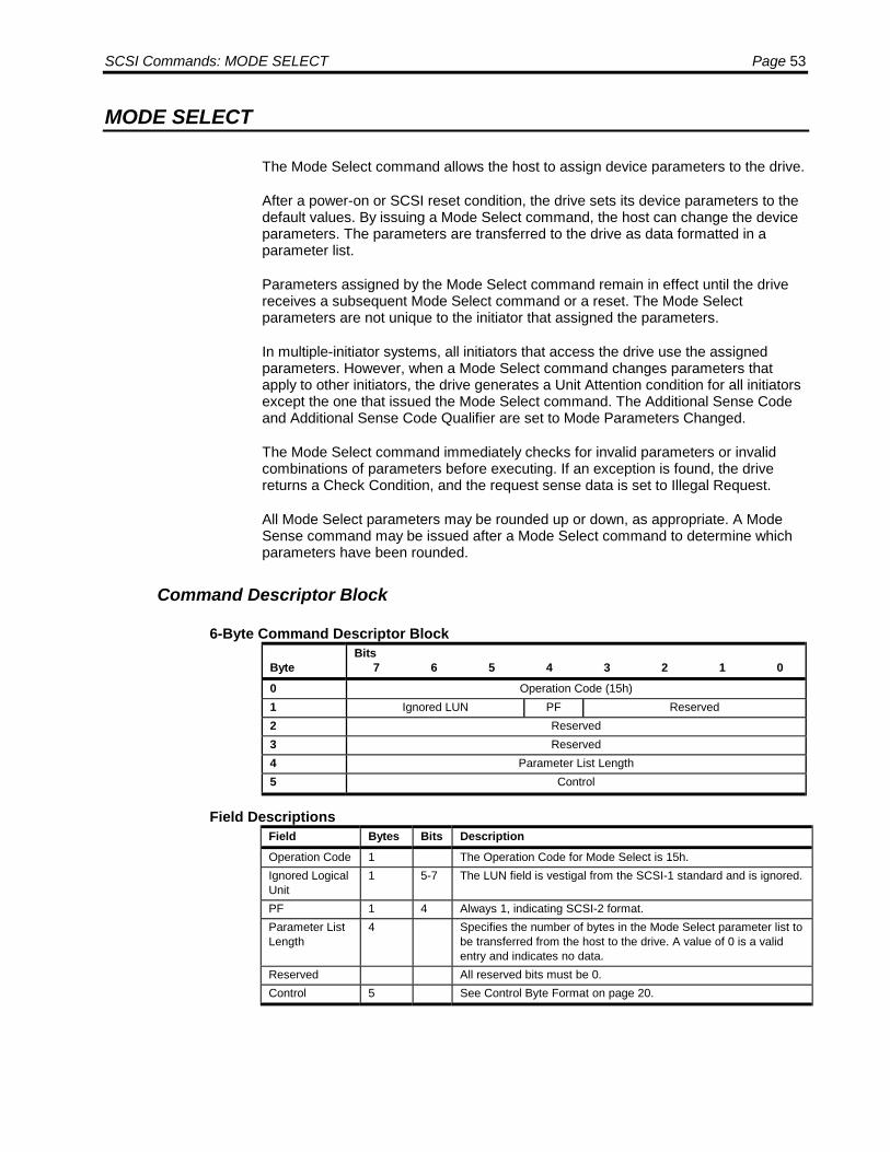
SCSI Commands: MODE SELECT Page 53
MODE SELECT
The Mode Select command allows the host to assign device parameters to the drive.
After a power-on or SCSI reset condition, the drive sets its device parameters to thedefault values. By issuing a Mode Select command, the host can change the deviceparameters. The parameters are transferred to the drive as data formatted in aparameter list.
Parameters assigned by the Mode Select command remain in effect until the drivereceives a subsequent Mode Select command or a reset. The Mode Selectparameters are not unique to the initiator that assigned the parameters.
In multiple-initiator systems, all initiators that access the drive use the assignedparameters. However, when a Mode Select command changes parameters thatapply to other initiators, the drive generates a Unit Attention condition for all initiatorsexcept the one that issued the Mode Select command. The Additional Sense Codeand Additional Sense Code Qualifier are set to Mode Parameters Changed.
The Mode Select command immediately checks for invalid parameters or invalidcombinations of parameters before executing. If an exception is found, the drivereturns a Check Condition, and the request sense data is set to Illegal Request.
All Mode Select parameters may be rounded up or down, as appropriate. A ModeSense command may be issued after a Mode Select command to determine whichparameters have been rounded.
Command Descriptor Block
6-Byte Command Descriptor Block
ByteBits
7 6 5 4 3 2 1 00 Operation Code (15h)1 Ignored LUN PF Reserved2 Reserved3 Reserved4 Parameter List Length5 Control
Field DescriptionsField Bytes Bits DescriptionOperation Code 1 The Operation Code for Mode Select is 15h.Ignored LogicalUnit
1 5-7 The LUN field is vestigal from the SCSI-1 standard and is ignored.
PF 1 4 Always 1, indicating SCSI-2 format.Parameter ListLength
4 Specifies the number of bytes in the Mode Select parameter list tobe transferred from the host to the drive. A value of 0 is a validentry and indicates no data.
Reserved All reserved bits must be 0.Control 5 See Control Byte Format on page 20.
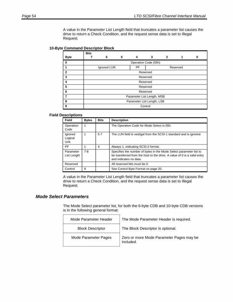
Page 54 LTO SCSI/Fibre Channel Interface Manual
A value in the Parameter List Length field that truncates a parameter list causes thedrive to return a Check Condition, and the request sense data is set to IllegalRequest.
10-Byte Command Descriptor Block
ByteBits
7 6 5 4 3 2 1 00 Operation Code (55h)1 Ignored LUN PF Reserved2 Reserved3 Reserved4 Reserved5 Reserved6 Reserved7 Parameter List Length, MSB8 Parameter List Length, LSB9 Control
Field DescriptionsField Bytes Bits DescriptionOperationCode
1 The Operation Code for Mode Select is 55h.
IgnoredLogicalUnit
1 5-7 The LUN field is vestigal from the SCSI-1 standard and is ignored.
PF 1 4 Always 1, indicating SCSI-2 format.ParameterList Length
7-8 Specifies the number of bytes in the Mode Select parameter list tobe transferred from the host to the drive. A value of 0 is a valid entryand indicates no data.
Reserved All reserved bits must be 0.Control 9 See Control Byte Format on page 20.
A value in the Parameter List Length field that truncates a parameter list causes thedrive to return a Check Condition, and the request sense data is set to IllegalRequest.
Mode Select Parameters
The Mode Select parameter list, for both the 6-byte CDB and 10-byte CDB versionsis in the following general format:
Mode Parameter Header The Mode Parameter Header is required.
Block Descriptor The Block Descriptor is optional.
Mode Parameter Pages Zero or more Mode Parameter Pages may beincluded.

SCSI Commands: MODE SELECT Page 55
Mode Parameter Header
6-Byte CDB Mode Parameter Header
ByteBits
7 6 5 4 3 2 1 00 Mode Data Length1 Reserved2 WP Buffered Mode Speed3 Block Descriptor Length
Field DescriptionsField Bytes Bits DescriptionMode DataLength
0 Mode Select: Always 0.Mode Sense: The number of bytes of data available.
WP 2 7 Mode Select: Ignored.Mode Sense: 0 = The cartridge is not write protected.
1 = the cartridge is write protected.BufferedMode
2 4-6 0 = Unbuffered mode.1 = Buffered mode (default).
Speed 2 0-3 This field indicates the tape speed.0 = Default3 = 2.077 m/sec (meter/second)4 = 2.576 m/sec5 = 3.097 m/sec6 = 3.643 m/sec7 = 4.153 m/sec
BlockDescriptorLength
3 0 = No Block Descriptor follows.8 = 8-byte Block Descriptor follows.
Reserved All reserved bits must be 0.
When Buffered Mode is 1, a Write command is terminated when the data istransferred to the internal buffer of the drive. When Buffered Mode is 0 a Writecommand is not terminated until all data has been transferred to tape.
10-Byte CDB Mode Parameter Header
ByteBits
7 6 5 4 3 2 1 00 Mode Data Length, MSB1 Mode Data Length, LSB2 Reserved3 WP Buffered Mode Speed4 Reserved5 Reserved6 Block Descriptor Length, MSB7 Block Descriptor Length, LSB
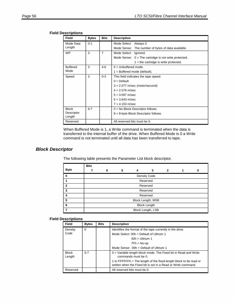
Page 56 LTO SCSI/Fibre Channel Interface Manual
Field DescriptionsField Bytes Bits DescriptionMode DataLength
0-1 Mode Select: Always 0.Mode Sense: The number of bytes of data available.
WP 3 7 Mode Select: Ignored.Mode Sense: 0 = The cartridge is not write protected.
1 = the cartridge is write protected.BufferedMode
3 4-6 0 = Unbuffered mode.1 = Buffered mode (default).
Speed 3 0-3 This field indicates the tape speed.0 = Default3 = 2.077 m/sec (meter/second)4 = 2.576 m/sec5 = 3.097 m/sec6 = 3.643 m/sec7 = 4.153 m/sec
BlockDescriptorLength
6-7 0 = No Block Descriptor follows.8 = 8-byte Block Descriptor follows.
Reserved All reserved bits must be 0.
When Buffered Mode is 1, a Write command is terminated when the data istransferred to the internal buffer of the drive. When Buffered Mode is 0 a Writecommand is not terminated until all data has been transferred to tape.
Block Descriptor
The following table presents the Parameter List block descriptor.
ByteBits
7 6 5 4 3 2 1 00 Density Code1 Reserved2 Reserved3 Reserved4 Reserved5 Block Length, MSB6 Block Length7 Block Length, LSB
Field DescriptionsField Bytes Bits DescriptionDensityCode
0 Identifies the format of the tape currently in the drive.Mode Select: 00h = Default of Ultrium 1 40h = Ultrium 1 7Fh = No-opMode Sense: 00h = Default of Ultrium 1
BlockLength
5-7 0 = Variable length block mode. The Fixed bit in Read and Writecommands must be 0.
1 to FFFFFFh = The length of the fixed-length block to be read orwritten when the Fixed bit is set in a Read or Write command.
Reserved All reserved bits must be 0.

SCSI Commands: MODE SELECT Page 57
Mode Parameter Pages
There are several mode parameter pages of different formats that allow you to setdifferent drive parameters. The following mode parameter pages are supported:
Mode Parameter Page See PageDisconnect/Reconnect Page (02h) 58Control Mode Page (0Ah) 59Data Compression Control Page (0Fh) 60Sequential Access Device Configuration Page (10h) 61Information Exceptions Mode Page (1Ch) 62Drive Capabilities Control Mode Page (21h) 65Interface Control Mode Page (22h) 65
The following table shows the general format of a Mode Parameter Page.
ByteBits
7 6 5 4 3 2 1 00 Reserved Page Code1 Additional Page Length2 - n Mode Parameters
Field DescriptionsField Bytes Bits DescriptionPageCode
0 0-5 02h = Disconnect/Reconnect Page0Ah = Control Mode Page0Fh = Data Compression Control Page10h = Device Configuration Page1Ch = Information Exceptions Page21h = Drive Capabilities Control Mode Page22h = Interface Control Page
AdditionalPageLength
1 Specifies the length (in bytes) of the Mode Parameters.
Mode Pa-rameters
2-n The mode parameters are specific to each mode parameter pageand are described in the following sections.
Reserved All reserved bits must be o.
If the initiator does not set the Additional Page Length field of the Mode Page to thevalue indicated in the Mode Page definition (for example, 10h for the DeviceConfiguration Page), the drive terminates the Mode Select command and returnsCheck Condition status bytes with an Illegal Request sense key. The AdditionalSense Code and Additional Sense Code Qualifier are set to Invalid Field inParameter List.
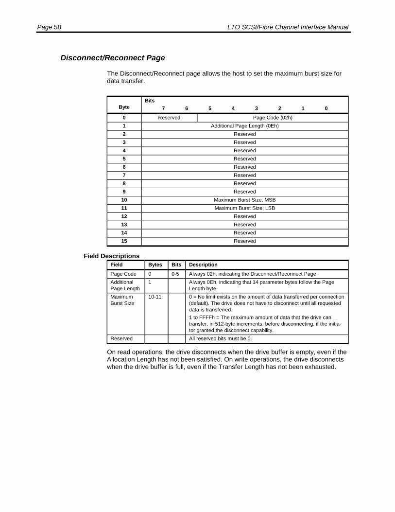
Page 58 LTO SCSI/Fibre Channel Interface Manual
Disconnect/Reconnect Page
The Disconnect/Reconnect page allows the host to set the maximum burst size fordata transfer.
ByteBits
7 6 5 4 3 2 1 00 Reserved Page Code (02h)1 Additional Page Length (0Eh)2 Reserved3 Reserved4 Reserved5 Reserved6 Reserved7 Reserved8 Reserved9 Reserved
10 Maximum Burst Size, MSB11 Maximum Burst Size, LSB12 Reserved13 Reserved14 Reserved15 Reserved
Field DescriptionsField Bytes Bits DescriptionPage Code 0 0-5 Always 02h, indicating the Disconnect/Reconnect PageAdditionalPage Length
1 Always 0Eh, indicating that 14 parameter bytes follow the PageLength byte.
MaximumBurst Size
10-11 0 = No limit exists on the amount of data transferred per connection(default). The drive does not have to disconnect until all requesteddata is transferred.1 to FFFFh = The maximum amount of data that the drive cantransfer, in 512-byte increments, before disconnecting, if the initia-tor granted the disconnect capability.
Reserved All reserved bits must be 0.
On read operations, the drive disconnects when the drive buffer is empty, even if theAllocation Length has not been satisfied. On write operations, the drive disconnectswhen the drive buffer is full, even if the Transfer Length has not been exhausted.
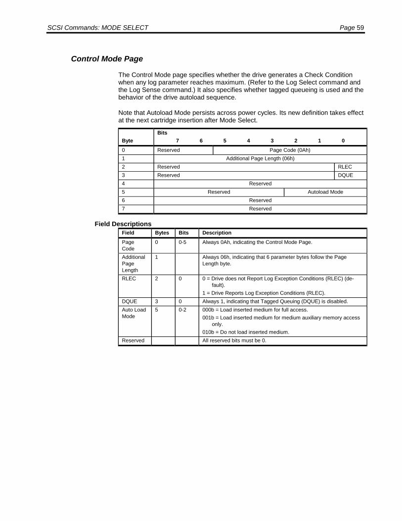
SCSI Commands: MODE SELECT Page 59
Control Mode Page
The Control Mode page specifies whether the drive generates a Check Conditionwhen any log parameter reaches maximum. (Refer to the Log Select command andthe Log Sense command.) It also specifies whether tagged queueing is used and thebehavior of the drive autoload sequence.
Note that Autoload Mode persists across power cycles. Its new definition takes effectat the next cartridge insertion after Mode Select.
ByteBits
7 6 5 4 3 2 1 00 Reserved Page Code (0Ah)1 Additional Page Length (06h)2 Reserved RLEC3 Reserved DQUE4 Reserved5 Reserved Autoload Mode6 Reserved7 Reserved
Field DescriptionsField Bytes Bits DescriptionPageCode
0 0-5 Always 0Ah, indicating the Control Mode Page.
AdditionalPageLength
1 Always 06h, indicating that 6 parameter bytes follow the PageLength byte.
RLEC 2 0 0 = Drive does not Report Log Exception Conditions (RLEC) (de-fault).
1 = Drive Reports Log Exception Conditions (RLEC).DQUE 3 0 Always 1, indicating that Tagged Queuing (DQUE) is disabled.Auto LoadMode
5 0-2 000b = Load inserted medium for full access.001b = Load inserted medium for medium auxiliary memory access
only.010b = Do not load inserted medium.
Reserved All reserved bits must be 0.
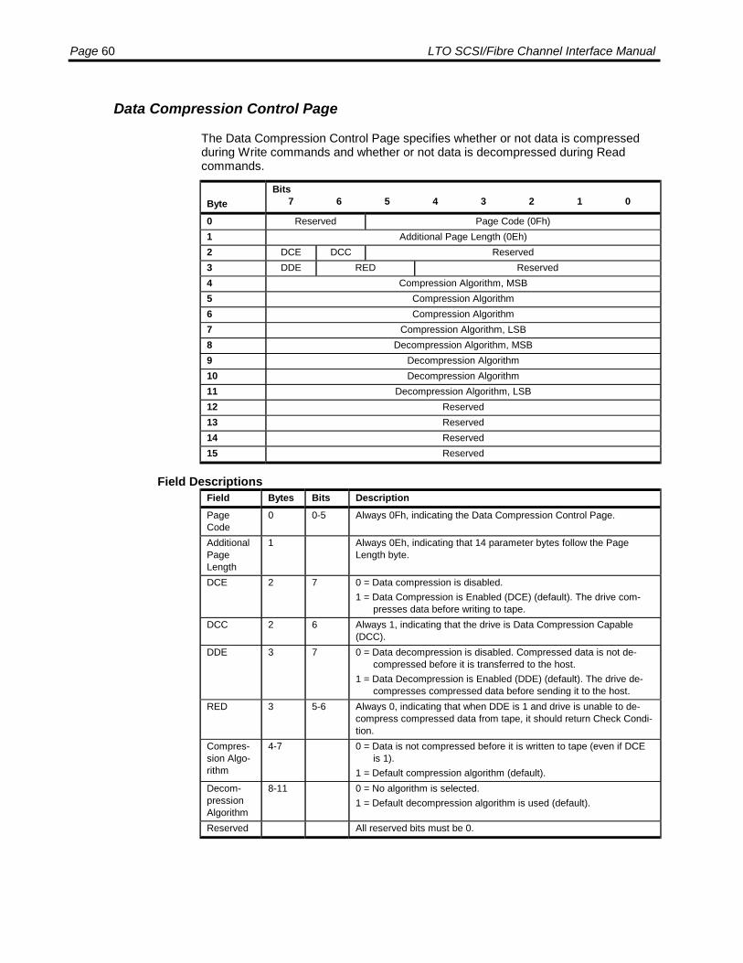
Page 60 LTO SCSI/Fibre Channel Interface Manual
Data Compression Control Page
The Data Compression Control Page specifies whether or not data is compressedduring Write commands and whether or not data is decompressed during Readcommands.
ByteBits
7 6 5 4 3 2 1 0
0 Reserved Page Code (0Fh)1 Additional Page Length (0Eh)2 DCE DCC Reserved3 DDE RED Reserved4 Compression Algorithm, MSB5 Compression Algorithm6 Compression Algorithm7 Compression Algorithm, LSB8 Decompression Algorithm, MSB9 Decompression Algorithm10 Decompression Algorithm11 Decompression Algorithm, LSB12 Reserved13 Reserved14 Reserved15 Reserved
Field DescriptionsField Bytes Bits DescriptionPageCode
0 0-5 Always 0Fh, indicating the Data Compression Control Page.
AdditionalPageLength
1 Always 0Eh, indicating that 14 parameter bytes follow the PageLength byte.
DCE 2 7 0 = Data compression is disabled.1 = Data Compression is Enabled (DCE) (default). The drive com-
presses data before writing to tape.DCC 2 6 Always 1, indicating that the drive is Data Compression Capable
(DCC).DDE 3 7 0 = Data decompression is disabled. Compressed data is not de-
compressed before it is transferred to the host.1 = Data Decompression is Enabled (DDE) (default). The drive de-
compresses compressed data before sending it to the host.RED 3 5-6 Always 0, indicating that when DDE is 1 and drive is unable to de-
compress compressed data from tape, it should return Check Condi-tion.
Compres-sion Algo-rithm
4-7 0 = Data is not compressed before it is written to tape (even if DCEis 1).
1 = Default compression algorithm (default).Decom-pressionAlgorithm
8-11 0 = No algorithm is selected.1 = Default decompression algorithm is used (default).
Reserved All reserved bits must be 0.
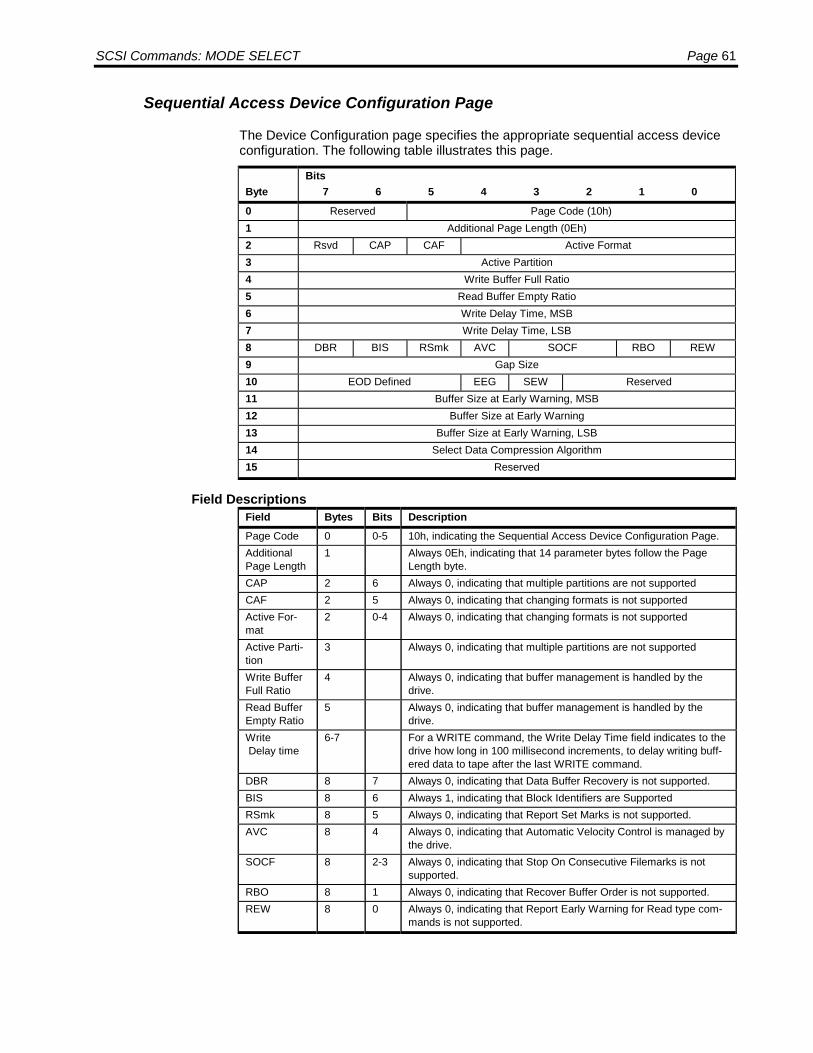
SCSI Commands: MODE SELECT Page 61
Sequential Access Device Configuration Page
The Device Configuration page specifies the appropriate sequential access deviceconfiguration. The following table illustrates this page.
ByteBits
7 6 5 4 3 2 1 0
0 Reserved Page Code (10h)1 Additional Page Length (0Eh)2 Rsvd CAP CAF Active Format3 Active Partition4 Write Buffer Full Ratio5 Read Buffer Empty Ratio6 Write Delay Time, MSB7 Write Delay Time, LSB8 DBR BIS RSmk AVC SOCF RBO REW9 Gap Size10 EOD Defined EEG SEW Reserved11 Buffer Size at Early Warning, MSB12 Buffer Size at Early Warning13 Buffer Size at Early Warning, LSB14 Select Data Compression Algorithm15 Reserved
Field DescriptionsField Bytes Bits DescriptionPage Code 0 0-5 10h, indicating the Sequential Access Device Configuration Page.AdditionalPage Length
1 Always 0Eh, indicating that 14 parameter bytes follow the PageLength byte.
CAP 2 6 Always 0, indicating that multiple partitions are not supportedCAF 2 5 Always 0, indicating that changing formats is not supportedActive For-mat
2 0-4 Always 0, indicating that changing formats is not supported
Active Parti-tion
3 Always 0, indicating that multiple partitions are not supported
Write BufferFull Ratio
4 Always 0, indicating that buffer management is handled by thedrive.
Read BufferEmpty Ratio
5 Always 0, indicating that buffer management is handled by thedrive.
Write Delay time
6-7 For a WRITE command, the Write Delay Time field indicates to thedrive how long in 100 millisecond increments, to delay writing buff-ered data to tape after the last WRITE command.
DBR 8 7 Always 0, indicating that Data Buffer Recovery is not supported.BIS 8 6 Always 1, indicating that Block Identifiers are SupportedRSmk 8 5 Always 0, indicating that Report Set Marks is not supported.AVC 8 4 Always 0, indicating that Automatic Velocity Control is managed by
the drive.SOCF 8 2-3 Always 0, indicating that Stop On Consecutive Filemarks is not
supported.RBO 8 1 Always 0, indicating that Recover Buffer Order is not supported.REW 8 0 Always 0, indicating that Report Early Warning for Read type com-
mands is not supported.

Page 62 LTO SCSI/Fibre Channel Interface Manual
Field Bytes Bits DescriptionGap Size 9 Always 0, indicating that there is no concept of inter-block gaps in
the LTO format.EOD Defined 10 5-7 Always 0, indicating the logical unit's default EOD defi-
nition.EEG 10 4 Always 1, indicating that EOD generation is always enabled.SEW 10 3 Always 0, The Buffered Mode set in the Mode Select Parameter
Header controls drive buffering.Buffer Size atEarly Warn-ing
11-13 Always 0, indicating that this cannot be set.
Select DataCompressionAlgorithm
14 0 = Use pass through mode; do not compress data (not recom-mended).
1 = Use default auto-compression scheme (recommended default)Reserved All reserved bits must be 0.
Fibre Channel Logical Unit Control Mode Page (Fibre Channel drives only)
The Fibre Channel Logical Unit Control mode page contains those parameters that selectFCP logical unit operation options, which only includes the enabling and disabling ofprecise delivery checking.
ByteBits
7 6 5 4 3 2 1 00 PS Rsvd Page Code (18h)1 Page Length 06h)2 Reserved Protocol Identifier (FCP = 0h)3 Reserved EPDC4 Reserved5 Reserved6 Reserved7 Reserved
Field DescriptionsField Bytes Bits DescriptionPage Code 0 0-5 18h, indicating the Fibre Channel Logical Unit Control Mode Page.PageLength
1 06h, indicating that six parameter bytes follow the Page Lengthbyte.
ProtocolIdentifier
2 0-4 0 = Fibre Channel Protocol for SCSI (FCP)
EPDC 3 0 0 = Disable Precise Delivery Checking1 = Enable Precise Delivery Checking
Reserved All reserved bits must be 0.

SCSI Commands: MODE SELECT Page 63
Fibre Channel Port Control Mode Page (Fibre Channel drives only)
The Fibre Channel Port Control mode page contains those parameters that selectFCP_Port operation options. The page is implemented by LUN 0 of the drive. Someof the bits defined by the Fibre Channel Port Control page require the FCP_Port to violateone or more of the Fibre Channel standards. The non-standard behaviors have beenidentified as useful for certain specialized operating environments. For this reason, all ofthe fields in bytes 3 – 7 are zero and cannot be changed.
ByteBits
7 6 5 4 3 2 1 00 PS Rsvd Page Code (19h)1 Page Length 06h)2 Reserved Protocol Identifier (FCP = 0h)3 DTFD PLPB DDIS DLM RHA ALWI DTIPE DTOLI4 Reserved5 Reserved6 Reserved RR_TOV Units7 Resource Recovery Time-Out Value (RR_TOV)
Field DescriptionsField Bytes Bits DescriptionPage Code 0 0-5 19h, indicating the Fibre Channel Logical Unit Control Mode Page.Page Length 1 06h, indicating that six parameter bytes follow the Page Length
byte.ProtocolIdentifier
2 0-4 0 = Fibre Channel Protocol for SCSI (FCP)
DTOLI 3 0 Always 0, indicating that the drive can initiate LIP.DTIPE 3 1 Always 0, indicating that the drive will insert itself in the loop waiting
for LPE.ALWI 3 2 Always 0, indicating that the drive will accept login without LIP.RHA 3 3 Always 0, indicating that the drive will attempt to obtain an address
during the LISA phase of LIP.DLM 3 4 Always 0, indicating that the drive will not attempt to become loop
masterDDIS 3 5 Always 0, indicating that address discovery is required following LIPPLPB 3 6 Always 0, indicating that the drive will response to Loop Port By-
pass (LPB) and Loop Port Enable (LPE) primitive sequencesDTFD 3 7 Always 0, indicating that the drive will always recognize a fabric
loop port and will perform the public loop functions required by FC-FLA.
RR_TOVUnits
6 0-3 000b = No timer is specified. Field is not changeable. The drive im-plements the FCP-2 default values.
RR_TOV 7 Resource Recovery Timeout Value (RR_TOV) in the units specifiedby the preceding field. Value is reported as 0 and is non-changeable.
Reserved All reserved bits must be 0.
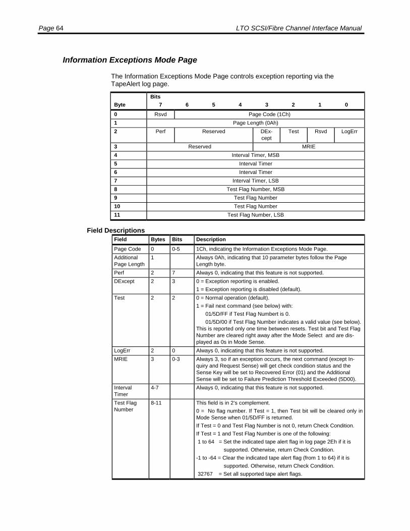
Page 64 LTO SCSI/Fibre Channel Interface Manual
Information Exceptions Mode Page
The Information Exceptions Mode Page controls exception reporting via theTapeAlert log page.
ByteBits
7 6 5 4 3 2 1 00 Rsvd Page Code (1Ch)1 Page Length (0Ah)2 Perf Reserved DEx-
ceptTest Rsvd LogErr
3 Reserved MRIE4 Interval Timer, MSB5 Interval Timer6 Interval Timer7 Interval Timer, LSB8 Test Flag Number, MSB9 Test Flag Number10 Test Flag Number11 Test Flag Number, LSB
Field DescriptionsField Bytes Bits DescriptionPage Code 0 0-5 1Ch, indicating the Information Exceptions Mode Page.AdditionalPage Length
1 Always 0Ah, indicating that 10 parameter bytes follow the PageLength byte.
Perf 2 7 Always 0, indicating that this feature is not supported.DExcept 2 3 0 = Exception reporting is enabled.
1 = Exception reporting is disabled (default).Test 2 2 0 = Normal operation (default).
1 = Fail next command (see below) with: 01/5D/FF if Test Flag Numbert is 0. 01/5D/00 if Test Flag Number indicates a valid value (see below).This is reported only one time between resets. Test bit and Test FlagNumber are cleared right away after the Mode Select and are dis-played as 0s in Mode Sense.
LogErr 2 0 Always 0, indicating that this feature is not supported.MRIE 3 0-3 Always 3, so if an exception occurs, the next command (except In-
quiry and Request Sense) will get check condition status and theSense Key will be set to Recovered Error (01) and the AdditionalSense will be set to Failure Prediction Threshold Exceeded (5D00).
IntervalTimer
4-7 Always 0, indicating that this feature is not supported.
Test FlagNumber
8-11 This field is in 2’s complement.0 = No flag number. If Test = 1, then Test bit will be cleared only inMode Sense when 01/5D/FF is returned.If Test = 0 and Test Flag Number is not 0, return Check Condition.If Test = 1 and Test Flag Number is one of the following: 1 to 64 = Set the indicated tape alert flag in log page 2Eh if it is supported. Otherwise, return Check Condition.-1 to -64 = Clear the indicated tape alert flag (from 1 to 64) if it is supported. Otherwise, return Check Condition. 32767 = Set all supported tape alert flags.

SCSI Commands: MODE SELECT Page 65
Field Bytes Bits DescriptionRsvd All reserved bits must be 0.
Drive Capabilities Control Mode Page
The Drive Capabilities Control mode page controls the capabilities of the Viper drive.A single copy of this page is maintained for all initiators. New Inquiry String Control,Firmware Test Control, and Data Compression Control will be in effect immediatelyafter Mode Select. New Operating Systems Support, Extended POST Mode, andAuto Unload Mode will be in effect the next power cycle, after Mode Select. Thispage persists across power cycles.
ByteBits
7 6 5 4 3 2 1 00 Reserved Page Code (21h)1 Page Length (07h)2 Operating Systems Support3 Firmware Test Control-24 Extended POST Mode5 Inquiry String Control6 Firmware Test Control7 Data Compression Control8 Host
UnloadOver-ride
Auto Unload Mode
Field DescriptionsField Bytes Bits DescriptionPage Code 0 0-5 21h, indicating the Drive Capabilities Control Mode Page.AdditionalPage Length
1 07h, indicating that seven parameter bytes follow the Page Lengthbyte.
OperatingSystemsSupport
2 0 = Standard LTO (default AU1-SCSI and ISV)
FirmwareTest Control-2
3 0 = disable Factory test mode code (default)1 = enable Factory test code 12 = enable Factory test code 2
POST Mode 4 0 = Enable POST (default)1 = Disable POST
Inquiry StringControl
5 0 = Standard Seagate Viper Inquiry string (default)1 = Factory test only Inquiry string 12 = Factory test only Inquiry string 2
FirmwareTest Control
6 0 = disable Factory test mode code (default)1 = enable Factory test code 12 = enable Factory test code 2
Data Com-pressionControl
7 0 = Full Mode Page 0Fh & 10h Control of Compression (default)1 = Auto compression with No SCSI Mode control2 = Compression Disabled with No SCSI Mode control
Host UnloadOverride
8 7 The Host Unload Override when set will place the drive into a modewhere SCSI Unload commands from the host will not eject the car-tridge. Library systems that do not want the host to eject the car-tridge should set this bit.
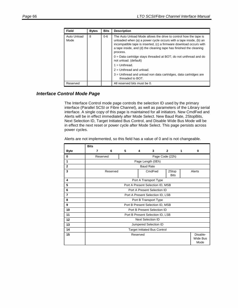
Page 66 LTO SCSI/Fibre Channel Interface Manual
Field Bytes Bits DescriptionAuto UnloadMode
8 0-6 The Auto Unload Mode allows the drive to control how the tape isunloaded when (a) a power cycle occurs with a tape inside, (b) anincompatible tape is inserted, (c) a firmware download occurs witha tape inside, and (d) the cleaning tape has finished the cleaningprocess.0 = Data cartridge stays threaded at BOT; do not unthread and donot unload. (default)1 = Unthread.2 = Unthread and unload.3 = Unthread and unload non data cartridges, data cartridges are
threaded to BOT.Reserved All reserved bits must be 0.
Interface Control Mode Page
The Interface Control mode page controls the selection ID used by the primaryinterface (Parallel SCSI or Fibre Channel), as well as parameters of the Library serialinterface. A single copy of this page is maintained for all initiators. New CmdFwd andAlerts will be in effect immediately after Mode Select. New Baud Rate, 2StopBits,Next Selection ID, Target Initiated Bus Control, and Disable Wide Bus Mode will bein effect the next reset or power cycle after Mode Select. This page persists acrosspower cycles.
Alerts are not implemented, so this field has a value of 0 and is not changeable.
ByteBits
7 6 5 4 3 2 1 00 Reserved Page Code (22h)1 Page Length (0Eh)2 Baud Rate3 Reserved CmdFwd 2Stop
BitsAlerts
4 Port A Transport Type5 Port A Present Selection ID, MSB6 Port A Present Selection ID7 Port A Present Selection ID, LSB8 Port B Transport Type9 Port B Present Selection ID, MSB10 Port B Present Selection ID11 Port B Present Selection ID, LSB12 Next Selection ID13 Jumpered Selection ID14 Target Initiated Bus Control15 Reserved Disable-
Wide BusMode
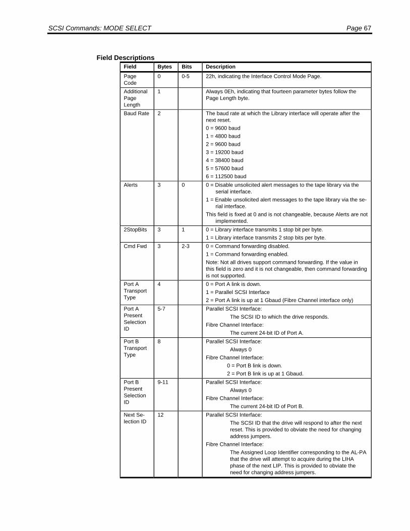
SCSI Commands: MODE SELECT Page 67
Field DescriptionsField Bytes Bits DescriptionPageCode
0 0-5 22h, indicating the Interface Control Mode Page.
AdditionalPageLength
1 Always 0Eh, indicating that fourteen parameter bytes follow thePage Length byte.
Baud Rate 2 The baud rate at which the Library interface will operate after thenext reset.0 = 9600 baud1 = 4800 baud2 = 9600 baud3 = 19200 baud4 = 38400 baud5 = 57600 baud6 = 112500 baud
Alerts 3 0 0 = Disable unsolicited alert messages to the tape library via theserial interface.
1 = Enable unsolicited alert messages to the tape library via the se-rial interface.
This field is fixed at 0 and is not changeable, because Alerts are notimplemented.
2StopBits 3 1 0 = Library interface transmits 1 stop bit per byte.1 = Library interface transmits 2 stop bits per byte.
Cmd Fwd 3 2-3 0 = Command forwarding disabled.1 = Command forwarding enabled.Note: Not all drives support command forwarding. If the value inthis field is zero and it is not changeable, then command forwardingis not supported.
Port ATransportType
4 0 = Port A link is down.1 = Parallel SCSI Interface2 = Port A link is up at 1 Gbaud (Fibre Channel interface only)
Port APresentSelectionID
5-7 Parallel SCSI Interface:The SCSI ID to which the drive responds.
Fibre Channel Interface:The current 24-bit ID of Port A.
Port BTransportType
8 Parallel SCSI Interface:Always 0
Fibre Channel Interface:0 = Port B link is down.2 = Port B link is up at 1 Gbaud.
Port BPresentSelectionID
9-11 Parallel SCSI Interface:Always 0
Fibre Channel Interface:The current 24-bit ID of Port B.
Next Se-lection ID
12 Parallel SCSI Interface:The SCSI ID that the drive will respond to after the nextreset. This is provided to obviate the need for changingaddress jumpers.
Fibre Channel Interface:The Assigned Loop Identifier corresponding to the AL-PAthat the drive will attempt to acquire during the LIHAphase of the next LIP. This is provided to obviate theneed for changing address jumpers.
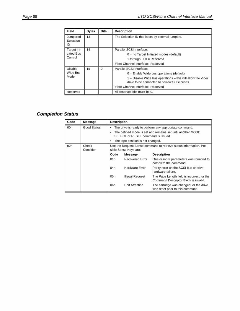
Page 68 LTO SCSI/Fibre Channel Interface Manual
Field Bytes Bits DescriptionJumperedSelectionID
13 The Selection ID that is set by external jumpers.
Target Ini-tiated BusControl
14 Parallel SCSI Interface:0 = no Target Initiated modes (default)1 through FFh = Reserved
Fibre Channel Interface: ReservedDisableWide BusMode
15 0 Parallel SCSI Interface:0 = Enable Wide bus operations (default)1 = Disable Wide bus operations – this will allow the Viperdrive to be connected to narrow SCSI buses.
Fibre Channel Interface: ReservedReserved All reserved bits must be 0.
Completion StatusCode Message Description00h Good Status • The drive is ready to perform any appropriate command.
• The defined mode is set and remains set until another MODESELECT or RESET command is issued.
• The tape position is not changed.02h Check
ConditionUse the Request Sense command to retrieve status information. Pos-sible Sense Keys are:Code Message Description01h Recovered Error One or more parameters was rounded to
complete the command.04h Hardware Error Parity error on the SCSI bus or drive
hardware failure.05h Illegal Request The Page Length field is incorrect, or the
Command Descriptor Block is invalid.06h Unit Attention The cartridge was changed, or the drive
was reset prior to this command.
SCSI Commands: MODE SENSE Page 69
MODE SENSE
The MODE SENSE command allows the host to determine various driveparameters. These parameters are sent from the drive to the host as data formattedin a parameter list. This command is complementary to the Mode Select commandthat sets device parameters.
The drive terminates execution of the Mode Sense command:
• When the number of bytes specified in the Allocation Length field have beensent to the host, or
• When all available Mode Sense data has been sent to the host.
If a Mode Select command has not been performed since power-on or SCSI Reset,the default mode parameters are in effect.
All Mode Select parameters may be rounded up or down, as appropriate. A ModeSense command may be issued after a Mode Select command to determine whichparameters have been rounded.
Block and page descriptions for this command are shown on subsequent pages.

Page 70 LTO SCSI/Fibre Channel Interface Manual
Command Descriptor Block
6-Byte Command Descriptor Block
ByteBits
7 6 5 4 3 2 1 00 Operation Code (1Ah)1 Ignored LUN Rsvd DBD Reserved2 PC Page Code3 Reserved4 Allocation Length5 Control
Field DescriptionsField Bytes Bits DescriptionOperationCode
0 The Operation Code for the 6-byte version of Mode Sense is 1Ah.
IgnoredLogicalUnit
1 5-7 The LUN field is vestigal from the SCSI-1 standard and is ignored.
DBD 1 3 0 = Return the block descriptor in the Mode Sense data.1 = Disable Block Descriptors (DBD).NOTE: When the DBD is 1, the Block Descriptor Length in the pa-rameter header is 0.
PC 2 6-7 Page Control specifies the type of values to be returned.00b = Report current values.01b = Report changeable values. Any bit that can be changed by
Mode Select is set to 1; otherwise, the bits are set to 0.10b = Report default values. Returns the power-up, or reset, values.11b = Report saved values. Returns the power-up, or reset, values.
PageCode
2 0-5 The Page Code selects the page or pages to be returned by thedrive.00h = Return only the Parameter List Header/Block Descriptor02h = Return the Disconnect/Reconnect Page0Ah = Return the Control Mode Page0Fh = Return the Data Compression Control Page10h = Return the Device Configuration Page1Ch = Return the Information Exceptions Page21h = Return the Drive Capabilities Page22h = Return the Interface Control Page3Fh = Return all available pages in ascending order starting from
page 02hAllocationLength
4 Specifies the number of bytes the host has allocated for returnedMode Sense data. The drive will not return more than this amount ofdata. A value of 0 is a valid entry and indicates no data.
Reserved All reserved bits must be 0.Control 5 See Control Byte Format on page 20.

SCSI Commands: MODE SENSE Page 71
10-Byte Command Descriptor Block
ByteBits
7 6 5 4 3 2 1 00 Operation Code (5Ah)1 Ignored LUN Rsvd DBD Reserved2 PC Page Code3 Reserved4 Reserved5 Reserved6 Reserved7 Allocation Length, MSB8 Allocation Length, LSB9 Control
Field DescriptionsField Bytes Bits DescriptionOperationCode
0 The Operation Code for the 6-byte version of Mode Sense is 1Ah.
IgnoredLogicalUnit
1 5-7 The LUN field is vestigal from the SCSI-1 standard and is ignored.
DBD 1 3 0 = Return the block descriptor in the Mode Sense data.1 = Disable Block Descriptors (DBD).NOTE: When the DBD is 1, the Block Descriptor Length in the pa-rameter header is 0.
PC 2 6-7 Page Control specifies the type of values to be returned.00b = Report current values.01b = Report changeable values. Any bit that can be changed by
Mode Select is set to 1; otherwise, the bits are set to 0.10b = Report default values. Returns the power-up, or reset, values.11b = Report saved values. Returns the power-up, or reset, values.76b = Unit
PageCode
2 0-5 The Page Code selects the page or pages to be returned by thedrive.00h = Return only the Parameter List Header/Block Descriptor02h = Return the Disconnect/Reconnect Page0Ah = Return the Control Mode Page0Fh = Return the Data Compression Control Page10h = Return the Device Configuration Page1Ch = Return the Information Exceptions Page21h = Return the Drive Capabilities Page22h = Return the Interface Control Page3Fh = Return all available pages in ascending order starting from
page 02hAllocationLength
7-8 Specifies the number of bytes the host has allocated for returnedMode Sense data. The drive will not return more than this amount ofdata. A value of 0 is a valid entry and indicates no data.
Reserved All reserved bits must be 0.Control See Control Byte Format on page 20.

Page 72 LTO SCSI/Fibre Channel Interface Manual
Mode Sense Data
The Mode Sense data list, for both the 6-byte CDB and 10-byte CDB versions is inthe following general format:
Mode Parameter Header The Mode Parameter Header is always returned.
Block Descriptor The Block Descriptor is returned if DBD is 0 inthe Mode Sense CDB.
Mode Parameter Pages One or all Mode Parameter Pages may bereturned depending on the value of Page Code inthe Mode Sense CDB.
Mode Parameter Header
6-Byte CDB Mode Parameter Header
ByteBits
7 6 5 4 3 2 1 00 Mode Data Length1 Medium Type2 WP Buffered Mode Speed3 Block Descriptor Length
Field DescriptionsField Bytes Bits DescriptionMode DataLength
0 Mode Select: Always 0.Mode Sense: The number of bytes of data available.
MediumType
1 Identifies the type of media currently in the drive.0 = Data Cartridge1 = Cleaning Cartridge
WP 2 7 Mode Select: Ignored.Mode Sense: 0 = The cartridge is not write protected.
1 = the cartridge is write protected.BufferedMode
2 4-6 0 = Unbuffered mode.1 = Buffered mode (default).
Speed 2 0-3 This field indicates the tape speed.0 = Default3 = 2.077 m/sec (meter/second)4 = 2.576 m/sec5 = 3.097 m/sec6 = 3.643 m/sec7 = 4.153 m/sec
BlockDescriptorLength
3 0 = No Block Descriptor follows.8 = 8-byte Block Descriptor follows.
Reserved All reserved bits must be 0.
When Buffered Mode is 1, a Write command is terminated when the data istransferred to the internal buffer of the drive. When Buffered Mode is 0 a Writecommand is not terminated until all data has been transferred to tape.
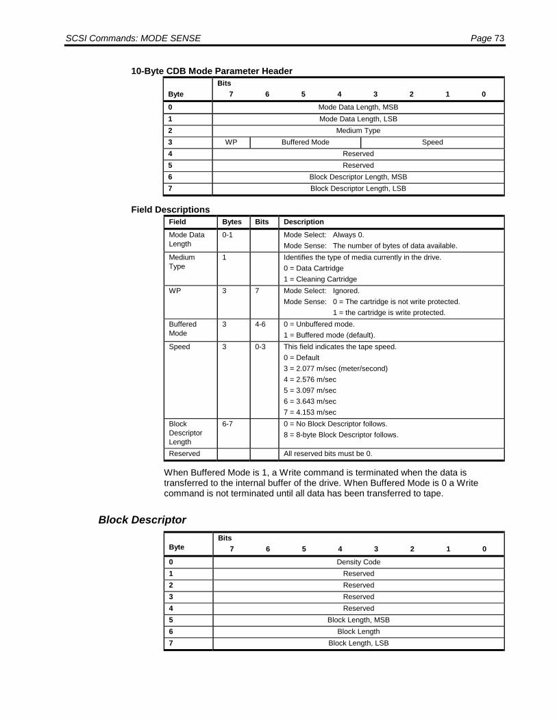
SCSI Commands: MODE SENSE Page 73
10-Byte CDB Mode Parameter Header
ByteBits
7 6 5 4 3 2 1 00 Mode Data Length, MSB1 Mode Data Length, LSB2 Medium Type3 WP Buffered Mode Speed4 Reserved5 Reserved6 Block Descriptor Length, MSB7 Block Descriptor Length, LSB
Field DescriptionsField Bytes Bits DescriptionMode DataLength
0-1 Mode Select: Always 0.Mode Sense: The number of bytes of data available.
MediumType
1 Identifies the type of media currently in the drive.0 = Data Cartridge1 = Cleaning Cartridge
WP 3 7 Mode Select: Ignored.Mode Sense: 0 = The cartridge is not write protected.
1 = the cartridge is write protected.BufferedMode
3 4-6 0 = Unbuffered mode.1 = Buffered mode (default).
Speed 3 0-3 This field indicates the tape speed.0 = Default3 = 2.077 m/sec (meter/second)4 = 2.576 m/sec5 = 3.097 m/sec6 = 3.643 m/sec7 = 4.153 m/sec
BlockDescriptorLength
6-7 0 = No Block Descriptor follows.8 = 8-byte Block Descriptor follows.
Reserved All reserved bits must be 0.
When Buffered Mode is 1, a Write command is terminated when the data istransferred to the internal buffer of the drive. When Buffered Mode is 0 a Writecommand is not terminated until all data has been transferred to tape.
Block Descriptor
ByteBits
7 6 5 4 3 2 1 00 Density Code1 Reserved2 Reserved3 Reserved4 Reserved5 Block Length, MSB6 Block Length7 Block Length, LSB

Page 74 LTO SCSI/Fibre Channel Interface Manual
Field DescriptionsField Bytes Bits DescriptionDensityCode
0 Identifies the format of the tape currently in the drive.Mode Select: 00h = Default of Ultrium 1 40h = Ultrium 1 7Fh = No-opMode Sense: 00h = Default of Ultrium 1
BlockLength
5-7 0 = Variable length block mode. The Fixed bit in Read and Writecommands must be 0.
1 to FFFFFFh = The length of the fixed-length block to be read orwritten when the Fixed bit is set in a Read or Write command.
Reserved All reserved bits must be 0.
Mode Parameter Pages
There are several mode parameter pages that allow you to retrieve different driveparameters. The format of these pages is described in the Mode Select command,starting on page 44. The following mode parameter pages are supported:
Mode Parameter Page See PageDisconnect/Reconnect Page 58Control Mode Page 59Data Compression Control Page 60Sequential Access Device Configuration Page 61Information Exceptions Mode Page 62Drive Capabilities Control Mode Page 65Interface Control Mode Page 66
Completion StatusCode Message Description00h Good Status • The drive is ready to perform any appropriate command.
• The drive remains in any previously set mode. MODE SENSE doesnot set or change any modes.
• The tape position is not changed. It remains at the previous position.02h Check Condition Use the Request Sense command to retrieve status information. Possi-
ble Sense Keys are:Code Message Description04h Hardware Error Parity error on the SCSI bus or drive
hardware failure.05h Illegal Request The Command Descriptor Block is invalid.06h Unit Attention The cartridge was changed, or the drive
was reset prior to this command.

SCSI Commands: PARK UNPARK Page 75
PARK UNPARK
The Park Unpark command with the park bit set requests that the drive park the loadarm in preparation for transport.
The Park Unpark command with the park bit not set requests that the drive load armbe unparked. This is not usually necessary as the drive automatically unparks onpower up.
In either case, attempting to issue this command while the medium is present willresult in a vendor specific check condition of MEDIUM_IS_PRESENT (09/80/80).
The Park Unpark command is a vendor unique command.
Command Descriptor Block
ByteBits
7 6 5 4 3 2 1 00 Operation Code (06h)1 Ignored LUN Reserved2 Reserved3 Reserved4 Reserved Park5 Control
Field DescriptionsField Bytes Bits DescriptionOperationCode
0 The Operation Code for Park Unpark is 06h.
IgnoredLogicalUnit
1 5-7 The LUN field is vestigal from the SCSI-1 standard and is ig-nored.
Park 4 0 0b = Requests the drive to be unparked.1b = Requests the drive to be parked.
Reserved All reserved bits must be 0.Control 5 See Control Byte Format on page 20.
Completion StatusCode Message Description00h Good Status • The drive is ready to perform any appropriate command.
• The drive remains in any previously set mode.• The tape position is not changed.
02h Check Condition Use the Request Sense command to retrieve status information. PossibleSense Keys are:Code Message Description04h Hardware Error Drive hardware failure.05h Illegal Request The Command Descriptor Block is invalid.06h Unit Attention The cartridge was changed, or the drive
was reset prior to this command.09h Medium Present Cannot park drive with medium present.
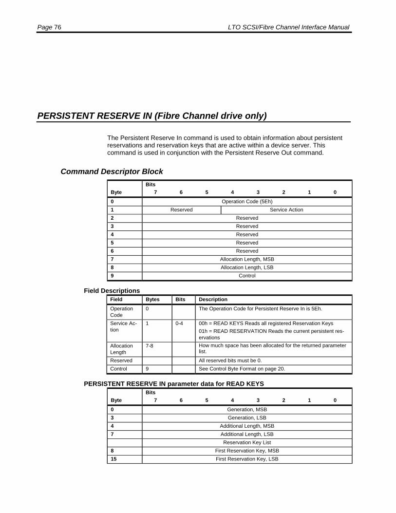
Page 76 LTO SCSI/Fibre Channel Interface Manual
PERSISTENT RESERVE IN (Fibre Channel drive only)
The Persistent Reserve In command is used to obtain information about persistentreservations and reservation keys that are active within a device server. Thiscommand is used in conjunction with the Persistent Reserve Out command.
Command Descriptor Block
ByteBits
7 6 5 4 3 2 1 00 Operation Code (5Eh)1 Reserved Service Action2 Reserved3 Reserved4 Reserved5 Reserved6 Reserved7 Allocation Length, MSB8 Allocation Length, LSB9 Control
Field DescriptionsField Bytes Bits DescriptionOperationCode
0 The Operation Code for Persistent Reserve In is 5Eh.
Service Ac-tion
1 0-4 00h = READ KEYS Reads all registered Reservation Keys01h = READ RESERVATION Reads the current persistent res-ervations
AllocationLength
7-8 How much space has been allocated for the returned parameterlist.
Reserved All reserved bits must be 0.Control 9 See Control Byte Format on page 20.
PERSISTENT RESERVE IN parameter data for READ KEYS
ByteBits
7 6 5 4 3 2 1 00 Generation, MSB3 Generation, LSB4 Additional Length, MSB7 Additional Length, LSB
Reservation Key List8 First Reservation Key, MSB15 First Reservation Key, LSB
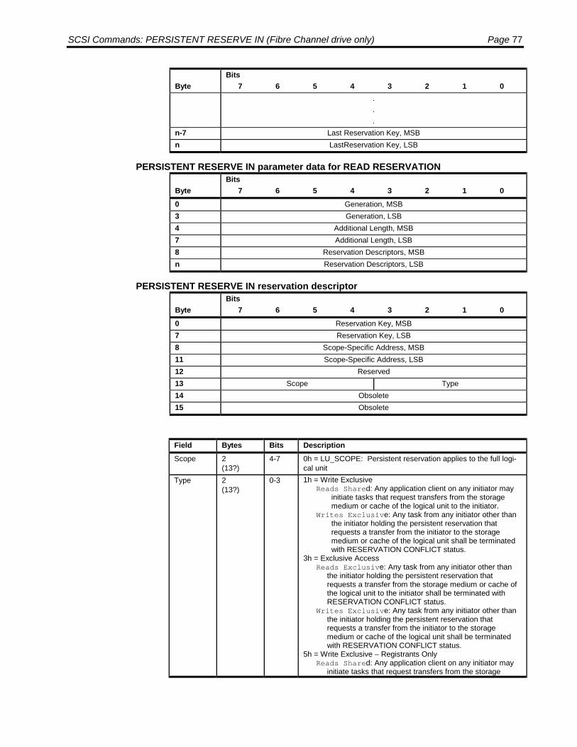
SCSI Commands: PERSISTENT RESERVE IN (Fibre Channel drive only) Page 77
ByteBits
7 6 5 4 3 2 1 0...
n-7 Last Reservation Key, MSBn LastReservation Key, LSB
PERSISTENT RESERVE IN parameter data for READ RESERVATION
ByteBits
7 6 5 4 3 2 1 00 Generation, MSB3 Generation, LSB4 Additional Length, MSB7 Additional Length, LSB8 Reservation Descriptors, MSBn Reservation Descriptors, LSB
PERSISTENT RESERVE IN reservation descriptor
ByteBits
7 6 5 4 3 2 1 00 Reservation Key, MSB7 Reservation Key, LSB8 Scope-Specific Address, MSB11 Scope-Specific Address, LSB12 Reserved13 Scope Type14 Obsolete15 Obsolete
Field Bytes Bits DescriptionScope 2
(13?)4-7 0h = LU_SCOPE: Persistent reservation applies to the full logi-
cal unitType 2
(13?)0-3 1h = Write Exclusive
Reads Shared: Any application client on any initiator mayinitiate tasks that request transfers from the storagemedium or cache of the logical unit to the initiator.
Writes Exclusive: Any task from any initiator other thanthe initiator holding the persistent reservation thatrequests a transfer from the initiator to the storagemedium or cache of the logical unit shall be terminatedwith RESERVATION CONFLICT status.
3h = Exclusive AccessReads Exclusive: Any task from any initiator other than
the initiator holding the persistent reservation thatrequests a transfer from the storage medium or cache ofthe logical unit to the initiator shall be terminated withRESERVATION CONFLICT status.
Writes Exclusive: Any task from any initiator other thanthe initiator holding the persistent reservation thatrequests a transfer from the initiator to the storagemedium or cache of the logical unit shall be terminatedwith RESERVATION CONFLICT status.
5h = Write Exclusive – Registrants OnlyReads Shared: Any application client on any initiator may
initiate tasks that request transfers from the storage

Page 78 LTO SCSI/Fibre Channel Interface Manual
Field Bytes Bits Descriptionmedium or cache of the logical unit to the initiator.
Writes Exclusive: A task that requests a transfer to thestorage medium or cache of the logical unit from aninitiator that is not currently registered with the deviceserver shall be terminated with RESERVATIONCONFLICT status.
6h = Exclusive Access – Registrants OnlyReads Exclusive: A task that requests a transfer from the
storage medium or cache of the logical unit to an initiatorthat is not currently registered with the device server shallbe terminated with RESERVATION CONFLICT status.
Writes Exclusive: A task that requests a transfer to thestorage medium or cache of the logical unit from an ini-tiator that is not currently registered with the device servershall be terminated with RESERVATION CONFLICTstatus.
Completion StatusCode Message Description00h Good Status • The drive is ready to perform any appropriate command.02h Check Condition Use the Request Sense command to retrieve status information. Possi-
ble Sense Keys are:Code Message Description05h Illegal Request The Command Descriptor Block is invalid.

SCSI Commands: PERSISTENT RESERVE OUT (Fibre Channel drive only) Page 79
PERSISTENT RESERVE OUT (Fibre Channel drive only)
The PERSISTENT RESERVE OUT command (see table 78) is used to requestservice actions that reserve a logical unit or element for the exclusive or shared useof a particular initiator. The command uses other service actions to manage andremove such reservations. The command shall be used in conjunction with thePERSISTENT RESERVE IN command and shall not be used with the RESERVEand RELEASE commands. Initiators performing PERSISTENT RESERVE OUTservice actions are identified by a reservation key provided by the application client.An application client may use the PERSISTENT RESERVE IN command to obtainthe reservation key for the initiator holding a persistent reservation and may use thePERSISTENT RESERVE OUT command to preempt that reservation.
Command Descriptor Block
ByteBits
7 6 5 4 3 2 1 00 Operation Code (5Fh)1 Reserved Service Action2 Scope Type3 Reserved4 Reserved5 Reserved6 Reserved7 Parameter Length, MSB (00h)8 Parameter Length, LSB (18h)9 Control
Field DescriptionsField Bytes Bits DescriptionOperationCode
0 The Operation Code for Persistent Reserve Out is 5Fh.
ServiceAction
1 0-4 See following table.
Scope 2 4-7 0h = LU_SCOPE: Persistent reservation applies to the full logi-cal unit
Type 2 0-3 See Type field for the PERSISTENT RESERVE IN reservationdescriptor.
Reserved All reserved bits must be 0.Control 9 See Control Byte Format on page 20.

Page 80 LTO SCSI/Fibre Channel Interface Manual
PERSISTENT RESERVE OUT service action codesCode Name Description GENERATION field
incremented00h REGISTER Register a reservation key with the device
server.Yes
01h RESERVE Creates a persistent reservation having aspecified SCOPE and TYPE.
No
02h RELEASE Releases the selected reservation for therequesting initiator.
No
03h CLEAR Clears all reservation keys and all persis-tent reservations.
Yes
04 PREEMPT Preempts persistent reservations from an-other initiator.
Yes
05h PREEMPT ANDABORT
Preempts persistent reservations fromanother initiator and aborts all tasks for allinitiators registered with the specifiedreservation key.
Yes
06h REGISTER ANDIGNOREEXISTING KEY
Register a reservation key with the deviceserver or unregister a reservation key.
Yes
PERSISTENT RESERVE OUT parameter list
ByteBits
7 6 5 4 3 2 1 00 Reservation Key, MSB7 Reservation Key, LSB8 Service Action Reservation Key, MSB15 Service Action Reservation Key, LSB16 Scope-Specific Address, MSB19 Scope-Specific Address, LSB20 Reserved ATPTL21 Reserved22 Obsolete23 Obsolete
Field Bytes Bits DescriptionAPTPL 20 0 If the last valid APTPL bit value received by the device server is
zero, the loss of power in the target shall release the persistentreservation for all logical units and remove all reservation keys.If the last valid APTPL bit value received by the device server isone, the logical unit shall retain any persistent reservation(s)that may be present and all reservation keys for all initiatorseven if power is lost and later returned.
Obsolete All obsolete fields must be 0.
PERSISTENT RESERVE OUT service actions and valid parametersParametersService Action Allowed
SCOPE TYPE RESERVATIONKEY
SERVICEACTION
RESERVATIONKEY
SCOPE-SPECIFICADDRESS
REGISTER ignored ignored valid valid ignored

SCSI Commands: PERSISTENT RESERVE OUT (Fibre Channel drive only) Page 81
ParametersService Action AllowedSCOPE TYPE RESERVATION
KEYSERVICEACTION
RESERVATIONKEY
SCOPE-SPECIFICADDRESS
REGISTER ANDIGNOREEXISTING KEY
ignored ignored ignored valid ignored
RESERVE LU_SCOPE valid valid ignored ignoredRELEASE LU_SCOPE valid valid ignored ignoredCLEAR ignored ignored valid valid ignoredPREEMPT LU_SCOPE valid valid valid ignoredPREEMPT &ABORT
LU_SCOPE valid valid valid ignored
Completion StatusCode Message Description00h Good Status • The drive is ready to perform any appropriate command.02h Check Condition Use the Request Sense command to retrieve status information. Possi-
ble Sense Keys are:Code Message Description05h Illegal Request The Command Descriptor Block is inva-
lid.

Page 82 LTO SCSI/Fibre Channel Interface Manual
PREVENT ALLOW MEDIA REMOVAL
The Prevent Allow Medium Removal command requests that the target enable ordisable the removal of the medium from the drive. The drive will not allow mediumremoval if any initiator currently has medium removal prevented.
If medium removal is prevented and the medium is in the loaded position, then:
• Pressing the eject button on the front panel will be ignored.
• The Load Unload command with the LOAD bit set to zero will result in a CheckCondition status. The sense code is set to Illegal Request and the AdditionalSense to Medium Removal Prevented (5302).
All initiators that have prevented medium removal must enable it before the mediumcan be removed from the drive.
A bus reset, BDR message or power cycle will clear any previous medium removalprevented setting and allow medium removal.
Command Descriptor Block
ByteBits
7 6 5 4 3 2 1 00 Operation Code (1Eh)1 Ignored LUN Reserved2 Reserved3 Reserved4 Reserved Prevent5 Control
Field DescriptionsField Bytes Bits DescriptionOperationCode
0 The Operation Code for Prevent/Allow Medium Removal is 1Eh.
IgnoredLogicalUnit
1 5-7 The LUN field is vestigal from the SCSI-1 standard and is ig-nored.
Prevent 4 0-1 00b = Medium removal allowed.01b = Medium removal prevented.10b = Not supported, no medium changer.11b = Not supported, no medium changer.
Reserved All reserved bits must be 0.Control 5 See Control Byte Format on page 20.

SCSI Commands: PREVENT ALLOW MEDIA REMOVAL Page 83
Completion StatusCode Message Description00h Good Status • The drive is ready to perform any appropriate command.
• The drive remains in any previously set mode.• The tape position is not changed.
02h Check Condition Use the Request Sense command to retrieve status information. Possi-ble Sense Keys are:Code Message Description04h Hardware Error Parity error on the SCSI bus or drive
hardware failure.05h Illegal Request The Command Descriptor Block is invalid.06h Unit Attention The cartridge was changed, or the drive
was reset prior to this command.

Page 84 LTO SCSI/Fibre Channel Interface Manual
READ
The READ command transfers one or more bytes or blocks from the drive to theInitiator beginning with the next block on tape.
If the Fixed flag is clear and Transfer Length is not zero, then a single block of thelength in Transfer Length is transferred. If the next block on tape is of this length orshorter then it is transferred to the initiator. If the next block is longer than this length,then only the length requested is returned and the logical position is set to after therecord. If the length of the block was the same as the Transfer Length field, thengood status is returned. If the length of the block was not the same as in TransferLength and the Suppress Illegal Length Indicator (SILI) flag was clear, then CheckCondition Status is returned. If the length of the block was not the same as inTransfer Length and the Suppress Illegal Length Indicator (SILI) flag was set, thenGood status is returned.
If the fixed flag is set and the Transfer Length field is not zero and the SuppressIllegal Length Indicator (SILI) flag is clear, then a sequence of blocks of the currentlyconfigured block length is to be returned, the number of blocks being indicated in theTransfer Length field. If there is a sequence of blocks of this length on the tape, theyare returned to the initiator with good status. If a block that is longer than theconfigured length is encountered before the sequence is complete, the blocks up tothat block are returned followed by the configured length from the record that was toolong and Check Condition status. If a block that is shorter than the configured lengthis encountered before the sequence is complete, the blocks up to that block arereturned followed by all of that block and Check Condition status. The currentposition is set after the last block that was returned or partially returned.
If the Transfer Length field is zero and the Suppress Illegal Length Indicator and theFixed bit are not both set, then no action is taken.
If Suppress Illegal Length Indicator (SILI) flag is set and the Fixed bit is set, thenCheck Condition status is returned. The sense key is set to Illegal Request and theAdditional Sense to Invalid Field in CDB (2400).
Command Descriptor Block
The following table shows the layout of the CDB.
ByteBits
7 6 5 4 3 2 1 00 Operation Code (08h)1 Ignored LUN Reserved SILI Fixed2 Transfer Length, MSB3 Transfer Length4 Transfer Length, LSB5 Control
fultonk
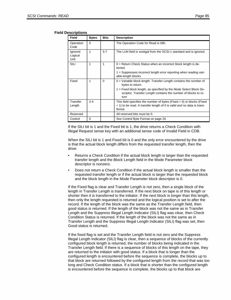
SCSI Commands: READ Page 85
Field DescriptionsField Bytes Bits DescriptionOperationCode
0 The Operation Code for Read is 08h.
IgnoredLogicalUnit
1 5-7 The LUN field is vestigal from the SCSI-1 standard and is ignored.
SILI 1 1 0 = Return Check Status when an incorrect block length is de-tected.1 = Suppresses incorrect length error reporting when reading vari-able-length blocks
Fixed 1 0 0 = Variable block length. Transfer Length contains the number ofbytes to return.
1 = Fixed block length, as specified by the Mode Select Block De-scriptor. Transfer Length contains the number of blocks to re-turn
TransferLength
2-4 This field specifies the number of bytes (Fixed = 0) or blocks (Fixed= 1) to be read. A transfer length of 0 is valid and no data is trans-ferred.
Reserved All reserved bits must be 0.Control 5 See Control Byte Format on page 20.
If the SILI bit is 1 and the Fixed bit is 1, the drive returns a Check Condition withIllegal Request sense key with an additional sense code of Invalid Field in CDB.
When the SILI bit is 1 and Fixed bit is 0 and the only error encountered by the driveis that the actual block length differs from the requested transfer length, then thedrive:
• Returns a Check Condition if the actual block length is larger than the requestedtransfer length and the Block Length field in the Mode Parameter blockdescriptor is nonzero.
• Does not return a Check Condition if the actual block length is smaller than therequested transfer length or if the actual block is larger than the requested blockand the block length in the Mode Parameter block descriptor is 0.
If the Fixed flag is clear and Transfer Length is not zero, then a single block of thelength in Transfer Length is transferred. If the next block on tape is of this length orshorter then it is transferred to the initiator. If the next block is longer than this length,then only the length requested is returned and the logical position is set to after therecord. If the length of the block was the same as the Transfer Length field, thengood status is returned. If the length of the block was not the same as in TransferLength and the Suppress Illegal Length Indicator (SILI) flag was clear, then CheckCondition Status is returned. If the length of the block was not the same as inTransfer Length and the Suppress Illegal Length Indicator (SILI) flag was set, thenGood status is returned.
If the fixed flag is set and the Transfer Length field is not zero and the SuppressIllegal Length Indicator (SILI) flag is clear, then a sequence of blocks of the currentlyconfigured block length is returned, the number of blocks being indicated in theTransfer Length field. If there is a sequence of blocks of this length on the tape, theyare returned to the initiator with good status. If a block that is longer than theconfigured length is encountered before the sequence is complete, the blocks up tothat block are returned followed by the configured length from the record that was toolong and Check Condition status. If a block that is shorter than the configured lengthis encountered before the sequence is complete, the blocks up to that block are

Page 86 LTO SCSI/Fibre Channel Interface Manual
returned followed by all of that block and Check Condition status. The currentposition is set after the last block that was returned or partially returned.
If the Transfer Length field is zero and the Suppress Illegal Length Indicator and theFixed bit are not both set, then no action is taken.
If Suppress Illegal Length Indicator (SILI) flag is set and the Fixed bit is set, thenCheck Condition status is returned. The sense key is set to Illegal Request and theAdditional Sense to Invalid Field in CDB (2400).
Read Command Operation
The Read command is complete when one of the following conditions is met. Theseconditions are described in the following paragraphs.
• End-of-Data (EOD) is reached.• A filemark (FM) is read.• Transfer length is satisfied• End-of-Tape (EOT) or end-of-partition (EOP) is reached.• Unrecoverable data error occurs.• Detection of incorrect block length.
End-of-DataIf EOD is encountered, the command terminates with a Check Condition status anda Sense Key of 08h. If the Valid bit (byte 0, bit 7) is set indicating a residual count,the Residual length field is determined as follows:
• If the Fixed bit is 1, it equals the difference between the CDB transfer length andthe number of actual blocks read.
• If the Fixed bit is 0, it equals the CDB transfer length.
The tape is then positioned to allow an Append Data operation.
FilemarkIf a filemark is encountered, the command terminates with a Check Condition, andthe filemark bit (byte 2, bit 7) of the sense data is set to 1. If the Valid bit (byte 0, bit7) is set indicating a residual count, the Residual length field is determined asfollows:
• If the Fixed bit is 1, it equals the difference between the CDB transfer length andthe number of actual blocks read.
• If the Fixed bit is 0, it equals the CDB transfer length.
On termination, the tape is positioned after the filemark on the EOT side of tape.
Transfer Length SatisfiedIf the CDB Transfer Length is satisfied, the command completes successfully with aGood Status, and the tape is positioned on the EOT side of the last block read.

SCSI Commands: READ Page 87
End of Tape (EOT) or End-of-Partition (EOP)When the end-of-tape or end-of-partition position is encountered, the commandterminates with a Check Condition and Medium Error (03h) sense key. The Valid bit(byte 0, bit 7) and the EOM bit (byte 2, bit 6) are set.
The Residual Length field is then set as follows:
• If the Fixed bit is 1, it equals the difference between the CDB transfer length andthe number of actual blocks read.
• If the Fixed bit is 0, it equals the CDB transfer length.
The logical position after encountering an end-of-tape or end-of-partition error isundetermined.
Recoverable Data ErrorIf an error is encountered while reading the drive applies its retry algorithm. If thealgorithm process cannot recover the error is reported as an unrecoverable readerror.
Unrecoverable Data ErrorIf an Unrecoverable Data Error is encountered, the READ command terminates withCheck Condition and a Medium Error (03h) sense key.
If the Valid bit (byte 0, bit 7) is set, Residual Length field equals the differencebetween the requested Transfer Length and the actual number of blocks or bytestransferred. On termination, the tape is positioned after the error block on the EOTside of tape.
Incorrect LengthWriting fixed- and variable-length blocks varies according to the setting of the Fixedbit.
When the Fixed bit is set (1), one or more tape blocks can be read. The CDBTransfer Length field specifies the block count to read. The block size is the currentblock size of the drive, which is set to 512 at power-up or after a SCSI Bus Reset.
The host can change the current block size by issuing a MODE SELECT commandwith a new block descriptor parameter that specifies a new block size. If the currentblock size differs from the actual block size of the block being read, the drive reportsan Incorrect Length error.
When the Fixed bit is reset (0), the CDB Transfer Length field indicates the numberof bytes to be read. When the actual block size found on tape differs from the CDBTransfer Length, an Incorrect Length error is reported.

Page 88 LTO SCSI/Fibre Channel Interface Manual
The drive reports the Incorrect Length error based on the Suppress Incorrect LengthIndicator (SILI) bit as follows:
• If the actual block length exceeds the CDB Transfer Length, the Incorrect Lengtherror is reported.
• If the actual block length is smaller than the CDB Transfer Length and the SILIbit is 1, the drive ignores (that is, suppresses) the Incorrect Length error.
• If the actual block length is different than the CDB Transfer Length and the SILIbit is 0, the drive reports the Incorrect Length error.
The drive reports the Incorrect Length error by returning a Check Condition. TheIncorrect Length Indicator bit (byte 2, bit 5) of the Request Sense data is set (1)indicating the Incorrect Length error. The Valid bit (byte 0, bit 7) of the RequestSense data is also set (1) indicating that the residual data (bytes 3 through 6) is valid.The meaning of the residual data depends on the setting of the Fixed bit.
For reading both fixed- and variable-length blocks, the logical position afterencountering an Incorrect Length error in block N is always at the end of block N.The following figure illustrates this position.
Current Block Size = 512 bytes/block
Block N-1 Block N Block N N+1
512 bytes 514 bytes 512 bytes↑↑↑↑ ↑↑↑↑
Encounter ILI Logical Positionerror reading after ILI errorblock N
Fixed Mode Residual DataWhen the Fixed bit is set (1), the residual data is set to the CDB Transfer Lengthminus the actual number of blocks correctly read without encountering an ILI error.
For example, assume the following:
• The current block size is 512 bytes/block.• The drive is currently positioned before block N.• Block N contains 514 bytes.
If the host issues a READ command with a CDB Transfer Length of one, indicatingone 512-byte block is to be read, the drive transfers the first 512 bytes of block N;then skips the last two bytes (513 and 514) and reports a Check Condition (causedby an Incorrect Length error). The residual is set to one. This residual is determinedas follows:
CDB Transfer Length = Number of blocks correctly read without encountering an ILIerror (1 - 0 = 1).
The logical position after the error is after byte 514 of block N.
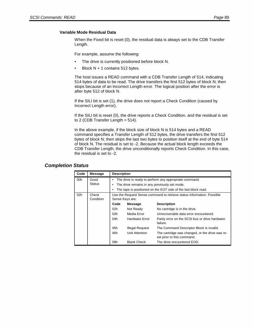
SCSI Commands: READ Page 89
Variable Mode Residual DataWhen the Fixed bit is reset (0), the residual data is always set to the CDB TransferLength.
For example, assume the following:
• The drive is currently positioned before block N.• Block N + 1 contains 512 bytes.
The host issues a READ command with a CDB Transfer Length of 514, indicating514 bytes of data to be read. The drive transfers the first 512 bytes of block N; thenstops because of an Incorrect Length error. The logical position after the error isafter byte 512 of block N.
If the SILI bit is set (1), the drive does not report a Check Condition (caused byIncorrect Length error).
If the SILI bit is reset (0), the drive reports a Check Condition, and the residual is setto 2 (CDB Transfer Length = 514).
In the above example, if the block size of block N is 514 bytes and a READcommand specifies a Transfer Length of 512 bytes, the drive transfers the first 512bytes of block N; then skips the last two bytes to position itself at the end of byte 514of block N. The residual is set to -2. Because the actual block length exceeds theCDB Transfer Length, the drive unconditionally reports Check Condition. In this case,the residual is set to -2.
Completion StatusCode Message Description00h Good
Status• The drive is ready to perform any appropriate command.• The drive remains in any previously set mode.• The tape is positioned on the EOT side of the last block read.
02h CheckCondition
Use the Request Sense command to retrieve status information. PossibleSense Keys are:Code Message Description02h Not Ready No cartridge is in the drive.03h Media Error Unrecoverable data error encountered.04h Hardware Error Parity error on the SCSI bus or drive hardware
failure.05h Illegal Request The Command Descriptor Block is invalid.06h Unit Attention The cartridge was changed, or the drive was re-
set prior to this command.08h Blank Check The drive encountered EOD.

Page 90 LTO SCSI/Fibre Channel Interface Manual
READ BLOCK LIMITS
The Read Block Limits command requests that the drive return the maximum andminimum block sizes that it supports. The minimum block length is always reportedas 1 byte, the maximum as 224-1 bytes.
Command Descriptor Block
ByteBits
7 6 5 4 3 2 1 00 Operation Code (05h)1 Ignored LUN Reserved2 Reserved3 Reserved4 Reserved5 Control
Field DescriptionsField Bytes Bits DescriptionOperationCode
0 The Operation Code for Read Block Limits is 05h
IgnoredLogical Unit
1 5-7 The LUN field is vestigal from the SCSI-1 standard and is ignored.
Reserved All reserved bits must be 0.Control 5 See Control Byte Format on page 20.
The host specifies the actual block size in fixed mode with the Mode Selectcommand and in variable mode with the transfer/allocation length of Read and Writecommands. The use of the Mode Sense command determines the current blocksize. The Read Block Limits command indicates the minimum and maximum blocksize that the drive can support.
Block Limit Data
The Read Block Limits command returns data in the following format.
ByteBits
7 6 5 4 3 2 1 00 Reserved1 Maximum Block Length, MSB2 Maximum Block Length3 Maximum Block Length, LSB4 Minimum Block Length, MSB5 Minimum Block Length, LSB

SCSI Commands: READ BLOCK LIMITS Page 91
Field DescriptionsField Bytes Bits DescriptionReserved All reserved bits must be 0.MaximumBlockLength
1-3 Always FFFFFFh, indicating a maximum block length of 224-1bytes.
MinimumBlockLength
4-5 Always 0001h, indicating a minimum block length of 1.
Completion StatusCode Message Description00h Good
Status• The drive is ready to perform any appropriate command.• The drive remains in any previously set mode.• The tape position is not changed.
02h CheckCondition
Use the Request Sense command to retrieve status information. PossibleSense Keys are:Code Message Description04h Hardware Error Parity error on the SCSI bus or drive hardware
failure.05h Illegal Request The Command Descriptor Block is invalid.06h Unit Attention The cartridge was changed, or the drive was re-
set prior to this command.

Page 92 LTO SCSI/Fibre Channel Interface Manual
READ BUFFER
The Read Buffer command reads data from the memory on the drive and sends it tothe initiator. This command is used in conjunction with the Write Buffer command asa diagnostic function for testing the drive buffer memory and confirming the SCSIbus integrity. The tape is not accessed during execution of this command.
Command Descriptor Block
ByteBits
7 6 5 4 3 2 1 00 Operation Code (3Ch)1 Ignored LUN Rsvd Mode2 Buffer ID3 Buffer Offset (MSB)4 Buffer Offset5 Buffer Offset (LSB)6 Allocation Length (MSB)7 Allocation Length8 Allocation Length (LSB)9 Control
Field DescriptionsField Bytes Bits DescriptionOperationCode
0 The operation code for Read Buffer is 3Ch.
Ignored Logi-cal Unit
1 5-7 The LUN field is vestigal from the SCSI-1 standard and is ignored.
Mode 1 0-3 0000b = Return descriptor and data.0001b = Return Medium Auxiliary Memory(MAM) or EEPROM
data.0010b = Return data only.0011b = Return descriptor only.0100b = Return Trace Buffer data.
Buffer ID 2 00h = normal access (default)54h = specifies access to MAM
Buffer Offset 3-5 For Mode not equal 0001b: The offset from the beginning of thespecified buffer in bytes.For Mode equal 0001b: Set to the MAM page code as described inthe tables or FFFFFFh to specify the entire 4KB MAM.
Allocationlength
6-8 Specifies the amount of data bytes to be returned. A value of 0 isa valid entry and returns no data.The drive stops sending data when the number of bytes specifiedhas been transferred or when all available data has been sent.
Reserved All reserved bits must be 0.Control 9 See Control Byte Format on page 20.
A Mode of 0000b requests that the data returned consist of a 4-byte descriptorheader followed by the data from the buffer. The 4-byte header is included in thenumber of bytes specified by the Allocation Length. The Buffer ID and Buffer Offsetfields are reserved.
A Mode of 0001b requests that data from the Medium Auxiliary Memory is returned.

SCSI Commands: READ BUFFER Page 93
A Mode of 0010b requests that only the data from the buffer is returned.
A Mode of 0011b requests that only the 4-byte descriptor header is returned. ABuffer ID value for which there is no buffer associated will result in an all zeroheader. The Buffer Offset field is reserved.
The Buffer ID field indicates which buffer is to be read. All drives support buffer 0.Other buffers may be available in the drive.
The Buffer Offset field may be used to specify the offset within the specified bufferfrom which the data will be transferred.
The Allocation Length is used to specify the number of bytes that the initiator hasallocated for the returned data.
Read Buffer Descriptor
If the Mode field is set to 0000b or 0011b, then the data returned includes a 4 byteRead Buffer Descriptor. The following table shows the fields in the Read BufferDescriptor.
ByteBits
7 6 5 4 3 2 1 00 Reserved (0)1 Buffer capacity, MSB2 Buffer capacity3 Buffer capacity, LSB
Field DescriptionsField Bytes Bits DescriptionReserved 0 All bits are 0.Buffer Capacity 1-3 The capacity of the drive’s data buffer.
MAM Page Definitions
The following sections details the pages available in the MAM. Always refer toUltrium Generation 1 8-Channel Format Specification Document for the latest up-to-date MAM data.
MAM PagesThe table below shows the Page ID used to identify each page within the MAM.Note that a Page ID of 0xFFFFFF is used when reading the entire MAM.
An optional page will not exist unless the drive has preformed an operation thatrequires information be stored to that optional page. A Read Buffer command to anoptional page that has not been created will result in a check condition LUN NOTREADY AUXILIARY MEMORY NOT ACCESSIBLE.
Page ID Access DescriptionFFFFFFh RO All pages.000001h RO Cartridge Manufacturer’s Information
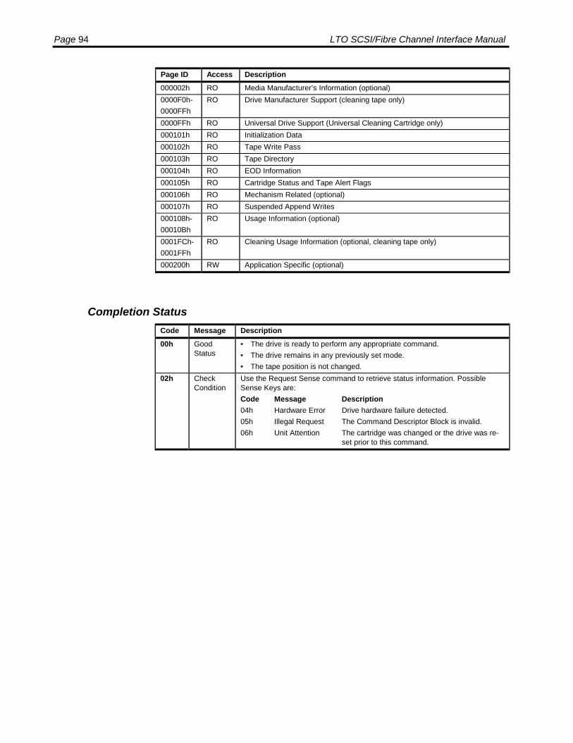
Page 94 LTO SCSI/Fibre Channel Interface Manual
Page ID Access Description000002h RO Media Manufacturer’s Information (optional)0000F0h-0000FFh
RO Drive Manufacturer Support (cleaning tape only)
0000FFh RO Universal Drive Support (Universal Cleaning Cartridge only)000101h RO Initialization Data000102h RO Tape Write Pass000103h RO Tape Directory000104h RO EOD Information000105h RO Cartridge Status and Tape Alert Flags000106h RO Mechanism Related (optional)000107h RO Suspended Append Writes000108h-00010Bh
RO Usage Information (optional)
0001FCh-0001FFh
RO Cleaning Usage Information (optional, cleaning tape only)
000200h RW Application Specific (optional)
Completion StatusCode Message Description00h Good
Status• The drive is ready to perform any appropriate command.• The drive remains in any previously set mode.• The tape position is not changed.
02h CheckCondition
Use the Request Sense command to retrieve status information. PossibleSense Keys are:Code Message Description04h Hardware Error Drive hardware failure detected.05h Illegal Request The Command Descriptor Block is invalid.06h Unit Attention The cartridge was changed or the drive was re-
set prior to this command.
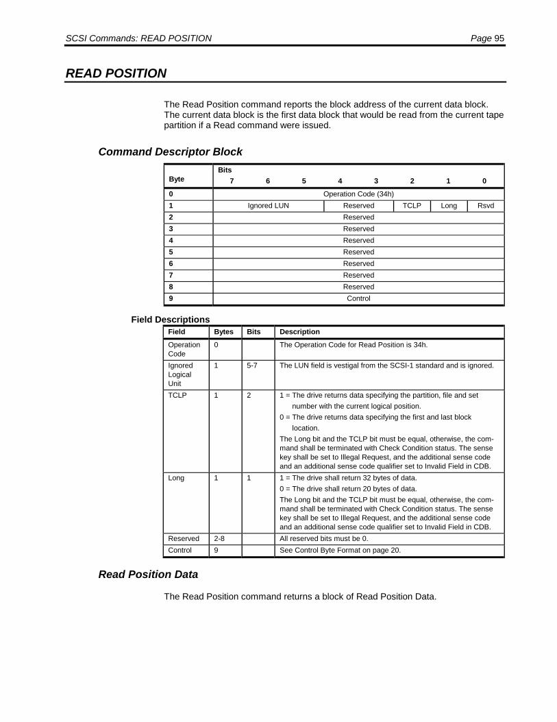
SCSI Commands: READ POSITION Page 95
READ POSITION
The Read Position command reports the block address of the current data block.The current data block is the first data block that would be read from the current tapepartition if a Read command were issued.
Command Descriptor Block
ByteBits
7 6 5 4 3 2 1 00 Operation Code (34h)1 Ignored LUN Reserved TCLP Long Rsvd2 Reserved3 Reserved4 Reserved5 Reserved6 Reserved7 Reserved8 Reserved9 Control
Field DescriptionsField Bytes Bits DescriptionOperationCode
0 The Operation Code for Read Position is 34h.
IgnoredLogicalUnit
1 5-7 The LUN field is vestigal from the SCSI-1 standard and is ignored.
TCLP 1 2 1 = The drive returns data specifying the partition, file and set number with the current logical position.0 = The drive returns data specifying the first and last block location.The Long bit and the TCLP bit must be equal, otherwise, the com-mand shall be terminated with Check Condition status. The sensekey shall be set to Illegal Request, and the additional sense codeand an additional sense code qualifier set to Invalid Field in CDB.
Long 1 1 1 = The drive shall return 32 bytes of data.0 = The drive shall return 20 bytes of data.The Long bit and the TCLP bit must be equal, otherwise, the com-mand shall be terminated with Check Condition status. The sensekey shall be set to Illegal Request, and the additional sense codeand an additional sense code qualifier set to Invalid Field in CDB.
Reserved 2-8 All reserved bits must be 0.Control 9 See Control Byte Format on page 20.
Read Position Data
The Read Position command returns a block of Read Position Data.

Page 96 LTO SCSI/Fibre Channel Interface Manual
The following table shows the fields in the Read Position Data when the Long andTCLP bits are set to 0.
ByteBits
7 6 5 4 3 2 1 00 BOP EOP Reserved BPU Reserved1 Partition Number (0)2 Reserved3 Reserved4 First Block Location, MSB5 First Block Location6 First Block Location7 First Block Location, LSB8 Last Block Location, MSB9 Last Block Location10 Last Block Location11 Last Block Location, LSB12 Reserved13 Number of blocks in buffer, MSB14 Number of blocks in buffer15 Number of blocks in buffer, LSB16 Number of bytes in buffer, MSB17 Number of bytes in buffer18 Number of bytes in buffer19 Number of bytes in buffer, LSB
Field DescriptionsField Bytes Bits DescriptionBOP 0 7 0 = The current logical position is not at BOT.
1 = The current logical position is at Beginning-of-Partition (BOT).EOP 0 6 0 = The current logical position is not between early-warning and
end-of-tape.1 = The current logical position is between early-warning and end-of-tape.
BPU 0 2 0 = First Block Location and Last Block Location fields are valid.1 = First Block Location and Last Block Location fields are invalid.
PartitionNumber
1 This field is always 0.
First BlockLocation
4-7 The block address of the current logical position.
Last BlockLocation
8-11 The block address of the current logical position. Always the sameas First Block Location.
Number ofblocks inbuffer
13-15 This field is not supported and is always 0.
Number ofbytes inbuffer
16-19 This field is not supported and is always 0.
Reserved All bits are 0.
The First Block Location and the Last Block Location are both set to the number ofblocks and file marks between BOT and current logical position. If the tape is atBOT, 0 is returned in these fields. The Beginning of Partition (BOP) flag is set if theBlock Location fields are zero.

SCSI Commands: READ POSITION Page 97
The following table shows the fields in the Read Position Data when Long and TCLPbits are set to 1.
ByteBits
7 6 5 4 3 2 1 00 BOP EOP Reserved MPU BPU Reserved1 Reserved2 Reserved3 Reserved4 Partition Number, MSB (0)5 Partition Number (0)6 Partition Number (0)7 Partition Number, LSB (0)8 Block Number, MSB9 Block Number10 Block Number11 Block Number12 Block Number13 Block Number14 Block Number15 Block Number, LSB16 File Number, MSB17 File Number18 File Number19 File Number20 File Number21 File Number22 File Number23 File Number, LSB24 Set Number, MSB (0)25 Set Number (0)26 Set Number (0)27 Set Number (0)28 Set Number (0)29 Set Number (0)30 Set Number (0)31 Set Number, LSB (0)
Field DescriptionsField Bytes Bits DescriptionBOP 0 7 0 = The current logical position is not at BOT.
1 = The current logical position is at Beginning-of-Partition (BOT).EOP 0 6 0 = The current logical position is not between early-warning and
end-of-tape.1 = The current logical position is between early-warning and end-of-tape.
MPU 0 3 0 = File Number field is valid.1 = File Number field is invalid.
BPU 0 2 0 = Block Number field is valid.1 = Block Number field is invalid.
PartitionNumber
4-7 This field is always 0.
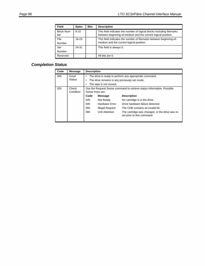
Page 98 LTO SCSI/Fibre Channel Interface Manual
Field Bytes Bits DescriptionBlock Num-ber
8-15 This field indicates the number of logical blocks including filemarksbetween beginning-of-medium and the current logical position.
FileNumber
16-23 This field indicates the number of filemarks between beginning-of-medium and the current logical position.
SetNumber
24-31 This field is always 0.
Reserved All bits are 0.
Completion StatusCode Message Description00h Good
Status• The drive is ready to perform any appropriate command.• The drive remains in any previously set mode.• The tape is not moved.
02h CheckCondition
Use the Request Sense command to retrieve status information. PossibleSense Keys are:Code Message Description02h Not Ready No cartridge is in the drive.04h Hardware Error Drive hardware failure detected.05h Illegal Request The CDB contains an invalid bit.06h Unit Attention The cartridge was changed, or the drive was re-
set prior to this command.

SCSI Commands: RECEIVE DIAGNOSTIC RESULTS Page 99
RECEIVE DIAGNOSTIC RESULTS
The Receive Diagnostic Results command requests that the results of a previouslyexecuted Send Diagnostics command be sent to the initiator.
Command Descriptor Block
ByteBits
7 6 5 4 3 2 1 00 Operation Code (1C)1 Ignored LUN Reserved PCV2 Page Code3 Allocation Length (MSB)4 Allocation Length (LSB)5 Control
Field DescriptionsField Bytes Bits DescriptionOperationCode
0 The Operation Code for Receive Diagnostic Results is 1Ch.
Ignored Logi-cal Unit
1 5-7 The LUN field is vestigal from the SCSI-1 standard and is ignored.
Reserved 1 1-4 All reserved bits must be 0.PCV 1 0 Page Code Valid bit. Not supported, should be set to 0.Page Code 2 Valid only when PCV bit is set.Allocationlength
3-4 Specifies the amount of data to be returned. An ALLOCATIONLENGTH of 0 is valid and shall not be considered an error.
Control 5 See Control Byte Format on page 20.
Returned Data
The Receive Diagnostic Results command returns a diagnostic page that reports theresults of the previous Send Diagnostics command.
Returned Data Format
ByteBits
7 6 5 4 3 2 1 00 Page Code1 Reserved2 Page Length (MSB)3 Page Length (LSB)4 Diagnostic Parameter (MSB)5 Diagnostic Parameter6 Diagnostic Parameter7 Diagnostic Parameter (LSB)

Page 100 LTO SCSI/Fibre Channel Interface Manual
Field DescriptionsField Bytes DescriptionPageCode
0 Identifies the type of diagnostic page being returned.
Reserved 1 All reserved bits must be 0.PageLength
2-3 Indicates the number of bytes of data to be returned after this block.
DiagnosticParameter
4-7 The results of the Send Diagnostics command test. A code of zero indicatesthat the drive passed the test. A non zero code indicates that the drive hasfailed the test. The value returned corresponds to the Message Code de-scribed in Appendix A.
Completion StatusStatus Message Description00h Good
Status♦ The drive is ready to perform any appropriate command.♦ The drive remains in any previously set mode.♦ The tape position is not changed.
02h CheckCondition
Use the Request Sense command to retrieve status information. PossibleSense Keys are:Code Message Description04h Hardware Error Drive hardware failure detected.05h Illegal Request The CDB contains an invalid bit.06h Unit Attention The cartridge was changed, or the drive was re-
set prior to this command.
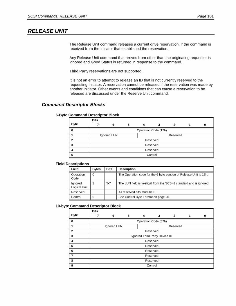
SCSI Commands: RELEASE UNIT Page 101
RELEASE UNIT
The Release Unit command releases a current drive reservation, if the command isreceived from the Initiator that established the reservation.
Any Release Unit command that arrives from other than the originating requester isignored and Good Status is returned in response to the command.
Third Party reservations are not supported.
It is not an error to attempt to release an ID that is not currently reserved to therequesting Initiator. A reservation cannot be released if the reservation was made byanother Initiator. Other events and conditions that can cause a reservation to bereleased are discussed under the Reserve Unit command.
Command Descriptor Blocks
6-Byte Command Descriptor Block
ByteBits
7 6 5 4 3 2 1 00 Operation Code (17h)1 Ignored LUN Reserved2 Reserved3 Reserved4 Reserved5 Control
Field DescriptionsField Bytes Bits DescriptionOperationCode
0 The Operation code for the 6-byte version of Release Unit is 17h.
IgnoredLogical Unit
1 5-7 The LUN field is vestigal from the SCSI-1 standard and is ignored.
Reserved All reserved bits must be 0.Control 5 See Control Byte Format on page 20.
10-byte Command Descriptor Block
ByteBits
7 6 5 4 3 2 1 00 Operation Code (57h)1 Ignored LUN Reserved2 Reserved3 Ignored Third Party Device ID4 Reserved5 Reserved6 Reserved7 Reserved8 Reserved9 Control
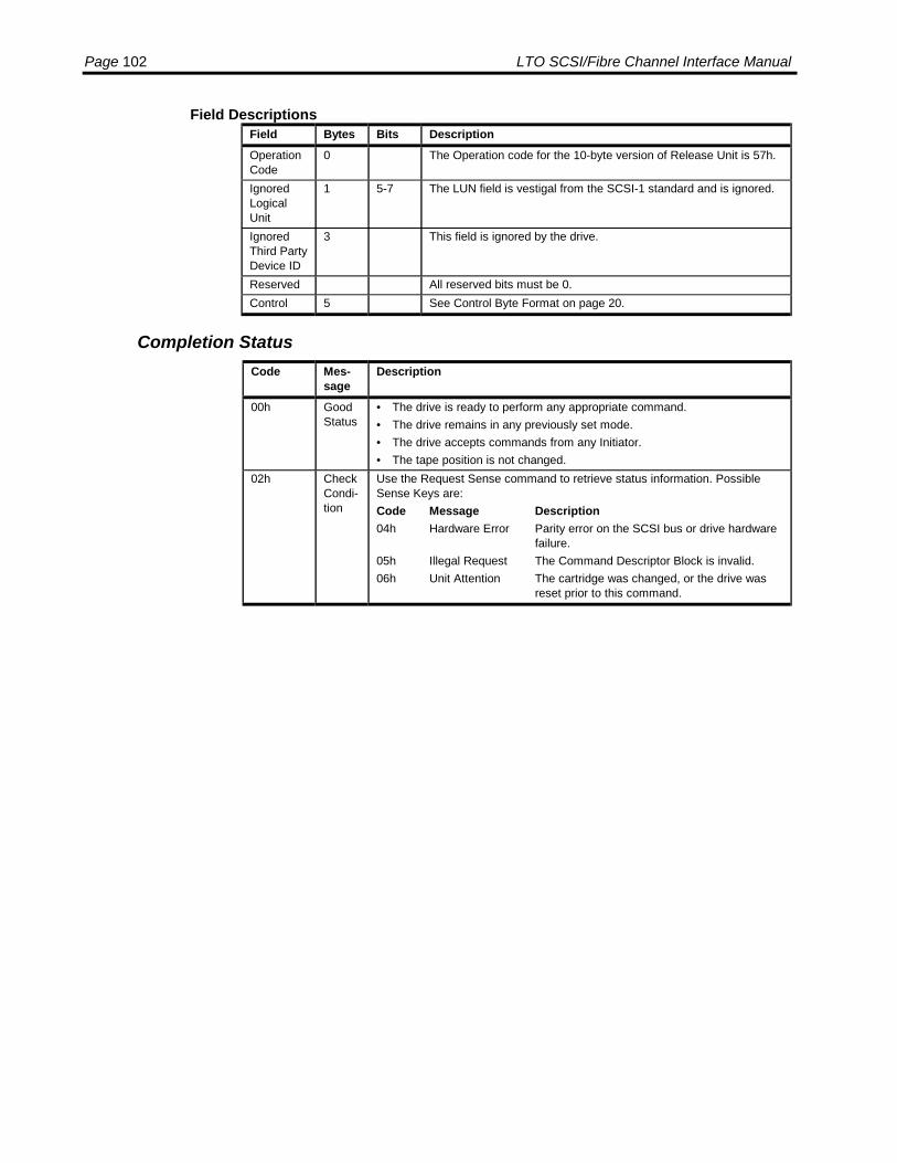
Page 102 LTO SCSI/Fibre Channel Interface Manual
Field DescriptionsField Bytes Bits DescriptionOperationCode
0 The Operation code for the 10-byte version of Release Unit is 57h.
IgnoredLogicalUnit
1 5-7 The LUN field is vestigal from the SCSI-1 standard and is ignored.
IgnoredThird PartyDevice ID
3 This field is ignored by the drive.
Reserved All reserved bits must be 0.Control 5 See Control Byte Format on page 20.
Completion StatusCode Mes-
sageDescription
00h GoodStatus
• The drive is ready to perform any appropriate command.• The drive remains in any previously set mode.• The drive accepts commands from any Initiator.• The tape position is not changed.
02h CheckCondi-tion
Use the Request Sense command to retrieve status information. PossibleSense Keys are:Code Message Description04h Hardware Error Parity error on the SCSI bus or drive hardware
failure.05h Illegal Request The Command Descriptor Block is invalid.06h Unit Attention The cartridge was changed, or the drive was
reset prior to this command.

SCSI Commands: REPORT DENSITY SUPPORT Page 103
REPORT DENSITY SUPPORT
The Report Density Support command returns details about the tape formatssupported by the drive. The data is returned as a header and a series of descriptorblocks. If the Media flag is set, then one descriptor block is returned with the data forthe currently loaded tape. If the Media bit is clear, then one descriptor block isreturned for each format supported by the drive.
Command Descriptor Block
ByteBits
7 6 5 4 3 2 1 00 Operation Code (44h)1 Ignored LUN Reserved Media2 Reserved3 Reserved4 Reserved5 Reserved6 Reserved7 Allocation Length, MSB8 Allocation Length, LSB9 Control
Field DescriptionsField Bytes Bits DescriptionOperationCode
0 The Operation code for Report Density is 44h.
IgnoredLogicalUnit
1 5-7 The LUN field is vestigal from the SCSI-1 standard and is ignored.
Media 1 0 0 = Report all densities supported by drive.1 = Report current media density.
AllocationLength
7-8 Specifies the amount of data to be returned, in bytes.
Reserved All reserved bits must be 0.Control 9 See Control Byte Format on page 20.
Report Density Support Data
The Report Density Support returns a header followed by one or more pages of data.
Report Density Support Header
ByteBits
7 6 5 4 3 2 1 00 Available Density Descriptor Length, MSB1 Available Density Descriptor Length, LSB2 Reserved3 Reserved

Page 104 LTO SCSI/Fibre Channel Interface Manual
Field DescriptionsField Bytes Bits DescriptionAvailableDensityDescriptorLength
0-1 The total amount of data that is available to be returned excludingthis field.
Reserved 2-3 All reserved bits are 0.
One or more Report Density Support pages in the format shown below follow theheader.
Report Density Support Data Block Descriptor
ByteBits
7 6 5 4 3 2 1 00 Primary Density Code1 Secondary Density Code2 WRTO
KDUP DEFLT Reserved
3 Reserved4 Reserved5 Bits per mm, MSB6 Bits per mm7 Bits per mm, LSB8 Media Width, MSB9 Media Width, LSB10 Tracks, MSB11 Tracks, LSB12 Capacity, MSB13 Capacity14 Capacity15 Capacity, LSB16-23 Assigning Organization24-31 Density Name32-51 Description
Field DescriptionsField Bytes Bits DescriptionPrimary DensityCode
0 40h, indicating Ultrium 1
SecondaryDensity Code
1 40h, indicating Ultrium 1
WRTOK 2 7 0 = This format can only be read.1 = This format can be read and written.
DUP 2 6 Always 0, indicating that each density is only reported once.DEFLT 2 5 0 = Not the density of the current medium.
1 = This is the density of the current medium.This is always 1 for first generation drives since all media is thesame format.
Bits per mm 5-7 4880Media Width 8-9 127Tracks 10-11 384

SCSI Commands: REPORT DENSITY SUPPORT Page 105
Field Bytes Bits DescriptionCapacity 12-15 Can be one of the following nominal values:
100,000 MB 50,000 MB 30,000 MB 10,000 MB
Assigning Or-ganization
16-23 8 bytes of ASCII data, “LTO-CVE ”
Density Name 24-31 8 bytes of ASCII data. Can be one of the following:“U-18-100”“U-18-50 ““U-18-30 ““U-18-10 “
Description 32-51 20 bytes of ASCII data. Can be one of the following:“Ultrium 1/8T 100GB ”“Ultrium 1/8T 50GB ”“Ultrium 1/8T 30GB ”“Ultrium 1/8T 10GB ”
Reserved All reserved bits are 0.
Completion StatusCode Message Description00h Good
Status• The drive is ready to perform any appropriate command.• The drive remains in any previously set mode.• The drive accepts commands from any Initiator.• The tape position is not changed.
02h CheckCondition
Use the Request Sense command to retrieve status information. PossibleSense Keys are:Code Message Description04h Hardware Error Parity error on the SCSI bus or drive hardware
failure.05h Illegal Request The Command Descriptor Block is invalid.06h Unit Attention The cartridge was changed, or the drive was re-
set prior to this command.

Page 106 LTO SCSI/Fibre Channel Interface Manual
REPORT LUNS
The host uses this command to retrieve information about which Logical Units thedrive supports. The allocation length shall be at least 16 bytes. If this is not the case,drive will return Check Condition status and provide a sense key of Illegal Requestand additional sense of INVALID FIELD IN CDB.
Command Descriptor Block
The following table shows the layout of the CDB.
ByteBits
7 6 5 4 3 2 1 00 Operation Code (A0h)1 Ignored LUN Reserved2 Reserved3 Reserved4 Reserved5 Reserved6 Allocation Length, MSB7 Allocation Length8 Allocation Length9 Allocation Length, LSB10 Reserved11 Control
Field DescriptionsField Bytes Bits DescriptionOperationCode
0 The Operation code for Report LUNS is A0h.
IgnoredLogical Unit
1 5-7 The LUN field is vestigal from the SCSI-1 standard and is ig-nored.
AllocationLength
6-9 Specifies the amount of data to be returned, in bytes. Must beat least 16 bytes or the drive will return Check Condition.
Reserved All reserved bits must be 0.Control 11 See Control Byte Format on page 20.
Report LUNS Data
The following header is returned by the Report LUNS command.
ByteBits
7 6 5 4 3 2 1 00 LUN List Length, MSB1 LUN List Length2 LUN List Length3 LUN List Length, LSB4 Reserved5 Reserved6 Reserved7 Reserved8-15 LUN 0
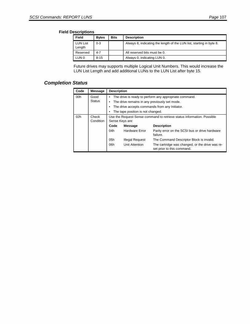
SCSI Commands: REPORT LUNS Page 107
Field DescriptionsField Bytes Bits DescriptionLUN ListLength
0-3 Always 8, indicating the length of the LUN list, starting in byte 8.
Reserved 4-7 All reserved bits must be 0.LUN 0 8-15 Always 0, indicating LUN 0.
Future drives may supports multiple Logical Unit Numbers. This would increase theLUN List Length and add additional LUNs to the LUN List after byte 15.
Completion StatusCode Message Description00h Good
Status• The drive is ready to perform any appropriate command.• The drive remains in any previously set mode.• The drive accepts commands from any Initiator.• The tape position is not changed.
02h CheckCondition
Use the Request Sense command to retrieve status information. PossibleSense Keys are:Code Message Description04h Hardware Error Parity error on the SCSI bus or drive hardware
failure.05h Illegal Request The Command Descriptor Block is invalid.06h Unit Attention The cartridge was changed, or the drive was re-
set prior to this command.

Page 108 LTO SCSI/Fibre Channel Interface Manual
REQUEST SENSE
The Request Sense command returns the status of the last command.
Sense Data is updated with each command; therefore, the sense data only reportsthe status of the immediately previous command. If a Check Condition status results,a Request Sense command should be issued to recover the information form theSense Data.
The Request Sense command returns Check Condition status only if a fatal erroroccurs during execution of the Request Sense command. If nonfatal errors occurduring the Request Sense execution, Good Status is returned. Sense Data may beinvalid following a fatal error on a Request Sense command.
Sense Data Management
The drive maintains three types of sense data.
♦ Current Sense is sense data associated with the last command received fromthe initiator.
♦ Deferred Sense is sense data from a command that has been reported as good,but has generated sense data after being reported. This may be a commandwith the Immediate flag set or may be a buffered write. A command with theImmediate flag set will generate sense for the host that sent the command. Abuffered write will generate sense for all hosts.
♦ Unit Attention Sense is sense data generated by a Unit Attention condition. Thisis generated for all hosts.
Any command other than a Request Sense command or an Inquiry command willgenerate Check Condition status if there is Deferred Sense data or Unit Attentiondata available. All commands will generate Check Condition status if the commanditself generates sense data. If the next command after the Check Condition status isnot a Request Sense command, then all the sense data for that initiator is cleared.
When a Request Sense command is received, the Current Sense is returned. Ifthere is no Current Sense, the Deferred Sense is returned. If there is no DeferredSense, the Unit Attention Sense is returned. If there is no Unit Attention Sense,default sense data is returned. Once a particular set of sense data has beenreturned, that sense data is cleared. Any other sense data that is still pending maystill cause Check Condition status for subsequent commands.
Command Descriptor Block
ByteBits
7 6 5 4 3 2 1 00 Operation Code (03h)1 Ignored LUN Reserved2 Reserved3 Reserved4 Allocation Length5 Control

SCSI Commands: REQUEST SENSE Page 109
Field DescriptionsField Bytes Bits DescriptionOperationCode
0 The Operation code for Request Sense is 03h.
IgnoredLogicalUnit
1 5-7 The LUN field is vestigal from the SCSI-1 standard and is ignored.
AllocationLength
4 Specifies the amount of data to be returned, in bytes.
Reserved All reserved bits must be 0.Control 5 See Control Byte Format on page 20.
Sense Data Format
The Request Sense command returns sense data in the following format.
ByteBits
7 6 5 4 3 2 1 00 Valid Error Code1 Segment Number2 FM EOM ILI Rsvd Sense Key3 Information, MSB4 Information5 Information6 Information, LSB7 Additional Sense Length8 Command-specific Information, MSB9 Command-specific Information10 Command-specific Information11 Command-specific Information, LSB12 Additional Sense Code13 Additional Sense Code Qualifier14 Field-Replaceable Unit Code15 SKSV C/D Reserved BPV Bit Pointer16 Field Pointer, MSB17 Field Pointer, LSB18 Reserved19 Reserved20 Reserved21 Reserved CLN Reserved22-29 Vendor Unique1 (Reserved)30-33 Vendor Unique2 (Reserved)34-37 Vendor Unique3 (Reserved)
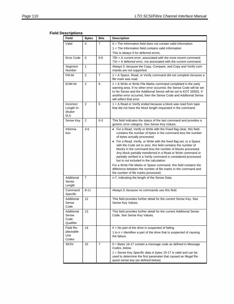
Page 110 LTO SCSI/Fibre Channel Interface Manual
Field DescriptionsField Bytes Bits DescriptionValid 0 7 0 = The Information field does not contain valid information
1 = The Information field contains valid informationThis is always 0 for deferred errors.
Error Code 0 0-6 70h = A current error, associated with the most recent command.71h = A deferred error, not associated with the current command.
SegmentNumber
1 Always 0, because the Copy, Compare, and Copy and Verify com-mands are not supported.
FM bit 2 7 1 = A Space, Read, or Verify command did not complete because afile mark was read.
EOM bit 2 6 1 = A Write or Write File Marks command completed in the earlywarning area. If no other error occurred, the Sense Code will be setto No Sense and the Additional Sense will be set to EOT (0002). Ifanother error occurred, then the Sense Code and Additional Sensewill reflect that error.
IncorrectLength In-dicator(ILI)
2 5 1 = A Read or Verify ended because a block was read from tapethat did not have the block length requested in the command.
Sense Key 2 0-3 This field indicates the status of the last command and provides ageneric error category. See Sense Key Values.
Informa-tion
3-6 ♦ For a Read, Verify or Write with the Fixed flag clear, this fieldcontains the number of bytes in the command less the numberof bytes actually processed.
♦ For a Read, Verify, or Write with the fixed flag set, or a Spacewith the Code set to zero, this field contains the number ofblocks in the command less the number of blocks processed.Any block partially transferred in a Read or Write command orpartially verified in a Verify command is considered processedbut is not included in the calculation.
For a Write File Marks or Space command, this field contains thedifference between the number of file marks in the command andthe number of file marks processed.
AdditionalSenseLength
7 n-7, indicating the length of the Sense Data.
CommandSpecific
8-11 Always 0, because no commands use this field.
AdditionalSenseCode
12 This field provides further detail for the current Sense Key. SeeSense Key Values.
AdditionalSenseCodeQualifier
13 This field provides further detail for the current Additional SenseCode. See Sense Key Values.
Field Re-placeableUnitCodes
14 0 = No part of the drive is suspected of failing1 to n = Identifies a part of the drive that is suspected of causingthe failure.
SKSV 15 7 0 = Bytes 16-17 contain a message code as defined in MessageCodes, below.1 = Sense Key Specific data in bytes 15-17 is valid and can beused to determine the first parameter that caused an Illegal Re-quest sense key (as defined below).
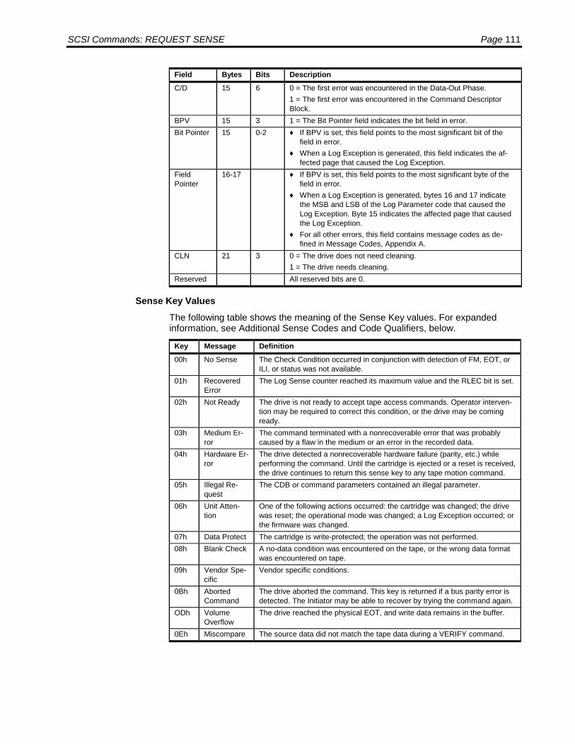
SCSI Commands: REQUEST SENSE Page 111
Field Bytes Bits DescriptionC/D 15 6 0 = The first error was encountered in the Data-Out Phase.
1 = The first error was encountered in the Command DescriptorBlock.
BPV 15 3 1 = The Bit Pointer field indicates the bit field in error.Bit Pointer 15 0-2 ♦ If BPV is set, this field points to the most significant bit of the
field in error.♦ When a Log Exception is generated, this field indicates the af-
fected page that caused the Log Exception.FieldPointer
16-17 ♦ If BPV is set, this field points to the most significant byte of thefield in error.
♦ When a Log Exception is generated, bytes 16 and 17 indicatethe MSB and LSB of the Log Parameter code that caused theLog Exception. Byte 15 indicates the affected page that causedthe Log Exception.
♦ For all other errors, this field contains message codes as de-fined in Message Codes, Appendix A.
CLN 21 3 0 = The drive does not need cleaning.1 = The drive needs cleaning.
Reserved All reserved bits are 0.
Sense Key ValuesThe following table shows the meaning of the Sense Key values. For expandedinformation, see Additional Sense Codes and Code Qualifiers, below.
Key Message Definition00h No Sense The Check Condition occurred in conjunction with detection of FM, EOT, or
ILI, or status was not available.01h Recovered
ErrorThe Log Sense counter reached its maximum value and the RLEC bit is set.
02h Not Ready The drive is not ready to accept tape access commands. Operator interven-tion may be required to correct this condition, or the drive may be comingready.
03h Medium Er-ror
The command terminated with a nonrecoverable error that was probablycaused by a flaw in the medium or an error in the recorded data.
04h Hardware Er-ror
The drive detected a nonrecoverable hardware failure (parity, etc.) whileperforming the command. Until the cartridge is ejected or a reset is received,the drive continues to return this sense key to any tape motion command.
05h Illegal Re-quest
The CDB or command parameters contained an illegal parameter.
06h Unit Atten-tion
One of the following actions occurred: the cartridge was changed; the drivewas reset; the operational mode was changed; a Log Exception occurred; orthe firmware was changed.
07h Data Protect The cartridge is write-protected; the operation was not performed.08h Blank Check A no-data condition was encountered on the tape, or the wrong data format
was encountered on tape.09h Vendor Spe-
cificVendor specific conditions.
0Bh AbortedCommand
The drive aborted the command. This key is returned if a bus parity error isdetected. The Initiator may be able to recover by trying the command again.
ODh VolumeOverflow
The drive reached the physical EOT, and write data remains in the buffer.
0Eh Miscompare The source data did not match the tape data during a VERIFY command.

Page 112 LTO SCSI/Fibre Channel Interface Manual
Additional Sense Codes and Code QualifiersAdditional Sense Codes and Additional Sense Codes Qualifiers are returned in theRequest Sense data in bytes 12 and 13. These codes are loaded whenever a CheckCondition is returned for a SCSI command. The purpose of the codes is to providemore specific error information.
SenseKeyByte 2
ASCByte 12
ASCQByte 13 Message Explanation
00h No Sense00h 00h 00h No additional sense in-
formationThe flags in the sense data indicatethe reason for command failure
00h 00h 01h Filemark detected A Read or a Space command hasterminated early because a filemark has been encountered. TheFile Mark flag will be set.
00h 00h 02h EOM detected A Write or a Write File Marks com-mand ended in the early warningarea. The EOM flag will be set.
00h 00h 04h BOM detected00h 00h 17h Cleaning requested00h 5Dh 00h Failure prediction thresh-
old exceeded00h 5Dh FFh Failure prediction thresh-
old exceeded false00h 70h 00h Decompression exception
short algorithm id of nn
01h Recovered Error01h 00h 17h Cleaning requested01h 18h 01h Recovered data with error
correction and retries01h 37h 00h Rounded parameter A Mode Select command parame-
ter has been rounded because thedrive cannot store it with the accu-racy of the command
01h 3Fh 00h Target operation condi-tions have changed.
CM inquiry failure detected
01h 5Bh 01h Threshold condition met01h 5Bh 02h Log counter at maximum01h 5Dh 00h Failure prediction thresh-
old exceededFailure Prediction thresholds havebeen exceeded indicating that afailure may occur soon.
01h 5Dh FFh Failure prediction thresh-old exceeded false
01h 70h 00h Decompression exceptionshort algorithm id of nn
02h Not Ready02h 04h 00h LUN not ready CNR Cause Not Reportable -
A tape is present in the drive, but itis in the process of being unloaded.
02h 04h 01h LUN not ready POBR Process of Becoming Ready -A medium access command hasbeen received during a front panelinitiated load or an immediate re-ported load command

SCSI Commands: REQUEST SENSE Page 113
SenseKeyByte 2
ASCByte 12
ASCQByte 13 Message Explanation
02h 04h 02h LUN not ready ICR Initializing Command Required -A tape is present in the drive, but itis not logically loaded. A Loadcommand is required.
02h 04h 03h LUN not ready MIR Manual Intervention Required02h 04h 10h LUN not ready AMNA Auxiliary Memory Not Accessible02h 30h 00h Incompatible medium in-
stalled02h 30h 03h Cleaning cartridge in-
stalledAn operation could not be carriedout because the tape in the drive isa cleaning cartridge.
02h 30h 04h Cannot write medium un-known format
02h 30h 07h Cleaning failure A cleaning operation was at-tempted, but could not be com-pleted for some reason
02h 3Ah 00h Medium not present A media access command hasbeen received when there is notape loaded
02h 3Ah 03h Medium not present, butloadable
A media access command hasbeen received when the is tape isloadable.
02h 3Ah 04h Medium not present, Me-dium Auxiliary MemoryAccessible
A media access command hasbeen received when the tapeseated but not loaded. The MAM isaccessible.
02h 3Eh 00h Logical unit has not selfconfigured yet
The drive has just powered on andhas not completed its self-test se-quence and cannot process com-mands.
02h 3Eh 02h Timeout on logical unit02h 4Ch 00h LUN failed self configura-
tion02h 53h 00h Media load or eject failed02h 5Ah 01h Operator medium removal
request
03h Medium Error03h 00h 02h EOM detected A Read or a Space command ter-
minated early because End of Tapewas encountered. The EOM flagwill be set.
03h 00h 04h BOM detected A Space command terminated earlybecause beginning of tape was en-countered. The EOM flag will be set
03h 03h 02h Excessive write errors03h 09h 00h Track following error03h 0Ch 00h Write error A Write operation has failed. This is
probably due to bad media, butmay be hardware related.
03h 0Ch 0Bh Auxiliary memory write er-ror
03h 11h 00h Unrecovered read error A Read operation failed. This isprobably due to bad media, butmay be hardware related.
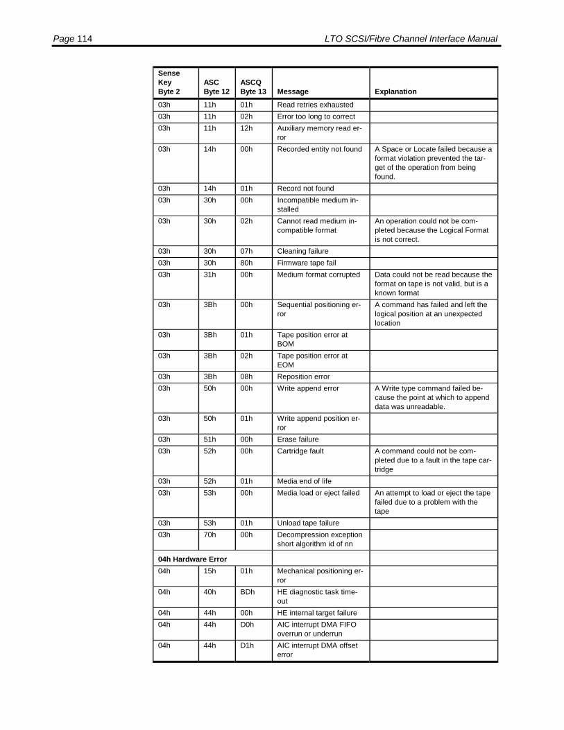
Page 114 LTO SCSI/Fibre Channel Interface Manual
SenseKeyByte 2
ASCByte 12
ASCQByte 13 Message Explanation
03h 11h 01h Read retries exhausted03h 11h 02h Error too long to correct03h 11h 12h Auxiliary memory read er-
ror03h 14h 00h Recorded entity not found A Space or Locate failed because a
format violation prevented the tar-get of the operation from beingfound.
03h 14h 01h Record not found03h 30h 00h Incompatible medium in-
stalled03h 30h 02h Cannot read medium in-
compatible formatAn operation could not be com-pleted because the Logical Formatis not correct.
03h 30h 07h Cleaning failure03h 30h 80h Firmware tape fail03h 31h 00h Medium format corrupted Data could not be read because the
format on tape is not valid, but is aknown format
03h 3Bh 00h Sequential positioning er-ror
A command has failed and left thelogical position at an unexpectedlocation
03h 3Bh 01h Tape position error atBOM
03h 3Bh 02h Tape position error atEOM
03h 3Bh 08h Reposition error03h 50h 00h Write append error A Write type command failed be-
cause the point at which to appenddata was unreadable.
03h 50h 01h Write append position er-ror
03h 51h 00h Erase failure03h 52h 00h Cartridge fault A command could not be com-
pleted due to a fault in the tape car-tridge
03h 52h 01h Media end of life03h 53h 00h Media load or eject failed An attempt to load or eject the tape
failed due to a problem with thetape
03h 53h 01h Unload tape failure03h 70h 00h Decompression exception
short algorithm id of nn
04h Hardware Error04h 15h 01h Mechanical positioning er-
ror04h 40h BDh HE diagnostic task time-
out04h 44h 00h HE internal target failure04h 44h D0h AIC interrupt DMA FIFO
overrun or underrun04h 44h D1h AIC interrupt DMA offset
error

SCSI Commands: REQUEST SENSE Page 115
SenseKeyByte 2
ASCByte 12
ASCQByte 13 Message Explanation
04h 44h D2h AIC interrupt DMA parityerror
04h 44h D3h AIC interrupt read parityerror
04h 44h D4h Diagnostic cache testfailed
04h 51h 00h Erase failure An Erase command failed to erasethe required area on the medium.
04h 52h 00h Cartridge fault The tape is snapped04h 53h 00h Media load or eject failed An attempt to load or eject the tape
failed due to a problem with thedrive
05h Illegal Request05h 1Ah 00h Parameter list length error The amount of data sent in a Mode
Select or Log Select command isincorrect
05h 20h 00h Invalid command opera-tion code
The Operation Code in the com-mand was not a valid OperationCode
05h 21h 01h Invalid element address05h 24h 00h Invalid field in CDB An invalid field has been detected
in a Command Descriptor Block.05h 25h 00h LUN not supported The command was addressed to a
non-existent logical unit number.05h 26h 00h Invalid field in parameter
listAn invalid field has been detectedin the data sent during the dataphase
05h 26h 02h Parameter value invalid Firmware download flash failure.05h 26h 04h Invalid release of persis-
tent reservation05h 26h 098h Invalid field parameter
checksumMicrocode image invalid, badchecksum or CRC.
05h 3Bh 0Ch Position past beginning ofmedium
05h 53h 02h Medium removal pre-vented
An Unload command has failed toeject the tape because mediumremoval has been prevented.
05h 55h 04h Insufficient registration re-source
06h Unit Attention06h 04h 10h Auxiliary Memory not ac-
cessibleAn access attempt was made to theMedium Auxiliary Memory or theEEPROM that was not successful.
06h 28h 00h Not ready to ready transi-tion
A tape has been loaded success-fully into the drive and is now readyto be accessed.
06h 29h 00h Power on reset or bus de-vice reset occurred
The drive has powered on, receiveda reset signal or a bus device resetmessage since the initiator last ac-cessed it
06h 2Ah 01h Mode parameterschanged
An initiator other than the one is-suing the command has changedthe Mode parameters for the drive.

Page 116 LTO SCSI/Fibre Channel Interface Manual
SenseKeyByte 2
ASCByte 12
ASCQByte 13 Message Explanation
06h 2Ah 02h Log parameters changed06h 2Ah 04h Reservations released06h 2Ah 05h Registration preempted06h 3Fh 01h Microcode has been
changedThe firmware in the drive has justbeen changed by a Write Buffercommand or firmware tape.
06h 3Fh 0Eh Reported LUNs Data HasChanged
Command Forwarding has beenchanged from disabled to enabledor vice-versa.
06h 3Fh 10h Media Loadable Medium has transistioned to aloadable state.
06h 3Fh 11h Auxiliary Cartridge Mem-ory accessible.
Medium has transistioned to MAMaccessible state from a MAM inac-cessible state.
06h 5Bh 01h Threshold condition met06h 5Dh 00h Failure prediction thresh-
old exceeded06h 5Dh FFh Failure prediction thresh-
old exceeded falseA Mode Select command has beenused to test for Failure Predictionsystem.
06h 67h 00h Power on reset or bus de-vice soft reset occurred
07h Data Protect07h 27h 00h Write protected A Write type operation has been
requested on a tape that has beenwrite protected.
07h 30h 00h Incompatible medium in-stalled
A Write type operation could not beexecuted because it is not sup-ported on the tape type that isloaded
08h Blank Check08h 00h 05h EOD detected A Read or a Space command ter-
minated early because End of Datawas encountered.
08h 14h 03h EOD not found A Read type operation failed be-cause a format violation related to amissing EOD data set
08h 30h 01h Cannot read medium un-known format
08h 30h 02h Cannot read medium in-compatible format
09h Vendor Unique09h 00 05 VS EOD detected Raw reader09h 80 80 VS Medium is present Park Unpark command
0Bh Aborted Command0Bh 08h 01h LUN communication time
out0Bh 1Bh 00h Synchronous data transfer
error0Bh 3Dh 00h Invalid bits in identify
messageAn illegal Identify message hasbeen received by the drive at thestart of a command.

SCSI Commands: REQUEST SENSE Page 117
SenseKeyByte 2
ASCByte 12
ASCQByte 13 Message Explanation
0Bh 43h 00h Message error A message could not be sent or re-ceived due to excessive trans-mission errors.
0Bh 45h 00h Select or reselect failure An attempt to reselect an initiator inorder to complete the commandhas failed.
0Bh 47h 00h SCSI parity error0Bh 48h 00h Initiator detected error
message receivedA command failed because an Ini-tiator Detected Error message wasreceived.
0Bh 49h 00h Invalid message error The command failed because aninvalid message was received bythe drive.
0Bh 4Ah 00h Command phase error A command could not be executedbecause too many parity errors oc-curred in the Command phase
0Bh 4Bh 00h Data phase error A command could not be com-pleted because too many errors oc-curred during the Data phase.
0Bh 4Eh 00h Overlapped commandsattempted
An initiator selected the drive eventhough it already had a commandoutstanding in the drive.
0Bh 5Ah 01h Operator medium removalrequest
The command was aborted be-cause the eject button waspressed.
0Dh Volume Overflow0Dh 00h 02h EOM detected A Write or Write File Marks com-
mand failed because the physicalend of tape was encountered. TheEOM flag will be set.
Message CodesThe table in Appendix A: Message Codes, beginning on page 137, lists the vendorunique message codes that are returned in the Field Pointer field (bytes 16-17) whenthe SKSV bit is 0.
Completion StatusCode Message Description00h Good
Status• The drive is ready to perform any appropriate command.• The drive remains in any previously set mode.• The tape position is not changed.
02h CheckCondition
Use the Request Sense command to retrieve status information. PossibleSense Keys are:Code Message Description05h Illegal Request The Command Descriptor Block is invalid.

Page 118 LTO SCSI/Fibre Channel Interface Manual
RESERVE UNIT
The Reserve Unit command reserves the drive for exclusive use of the requestingInitiator.
The drive reservation once established, remains in effect until one of the followingoccurs:
• Another Reserve Unit command arrives from the same Initiator that requestedthe current reservation. The new reservation supersedes the current one andmay be the same as the current one. Redundant use of the command is notconsidered an error.
• A Release Unit command arrives from the same Initiator that requested thecurrent reservation. The drive returns to unreserved mode.
• A Bus Device Reset Message arrives from any Initiator.• A Reset condition occurs.• Firmware is updated.
When the drive is reserved, it returns Reservation Conflict Status in response tomost commands received from excluded Initiators. Inquiry, Request Sense, PreventMedium Removal (with a prevent bit of zero), and Release Unit commands areaccepted from any initiator.
Command Descriptor Block
6-Byte Command Descriptor Block
ByteBits
7 6 5 4 3 2 1 00 Operation Code (16h)1 Ignored LUN Reserved2 Reserved3 Reserved4 Reserved5 Control
Field Descriptions for 6-Byte CommandField Bytes Bits DescriptionOperationCode
0 The Operation code for the 6-byte version of Reserve Unit is 16h.
IgnoredLogicalUnit
1 5-7 The LUN field is vestigal from the SCSI-1 standard and is ignored.
Reserved All reserved bits must be 0.Control 5 See Control Byte Format on page 20.
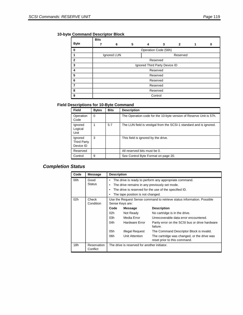
SCSI Commands: RESERVE UNIT Page 119
10-byte Command Descriptor Block
ByteBits
7 6 5 4 3 2 1 00 Operation Code (56h)1 Ignored LUN Reserved2 Reserved3 Ignored Third Party Device ID4 Reserved5 Reserved6 Reserved7 Reserved8 Reserved9 Control
Field Descriptions for 10-Byte CommandField Bytes Bits DescriptionOperationCode
0 The Operation code for the 10-byte version of Reserve Unit is 57h.
IgnoredLogicalUnit
1 5-7 The LUN field is vestigal from the SCSI-1 standard and is ignored.
IgnoredThird PartyDevice ID
3 This field is ignored by the drive.
Reserved All reserved bits must be 0.Control 9 See Control Byte Format on page 20.
Completion StatusCode Message Description00h Good
Status• The drive is ready to perform any appropriate command.• The drive remains in any previously set mode.• The drive is reserved for the use of the specified ID.• The tape position is not changed.
02h CheckCondition
Use the Request Sense command to retrieve status information. PossibleSense Keys are:Code Message Description02h Not Ready No cartridge is in the drive.03h Media Error Unrecoverable data error encountered.04h Hardware Error Parity error on the SCSI bus or drive hardware
failure.05h Illegal Request The Command Descriptor Block is invalid.06h Unit Attention The cartridge was changed, or the drive was
reset prior to this command.18h Reservation
ConflictThe drive is reserved for another initiator.
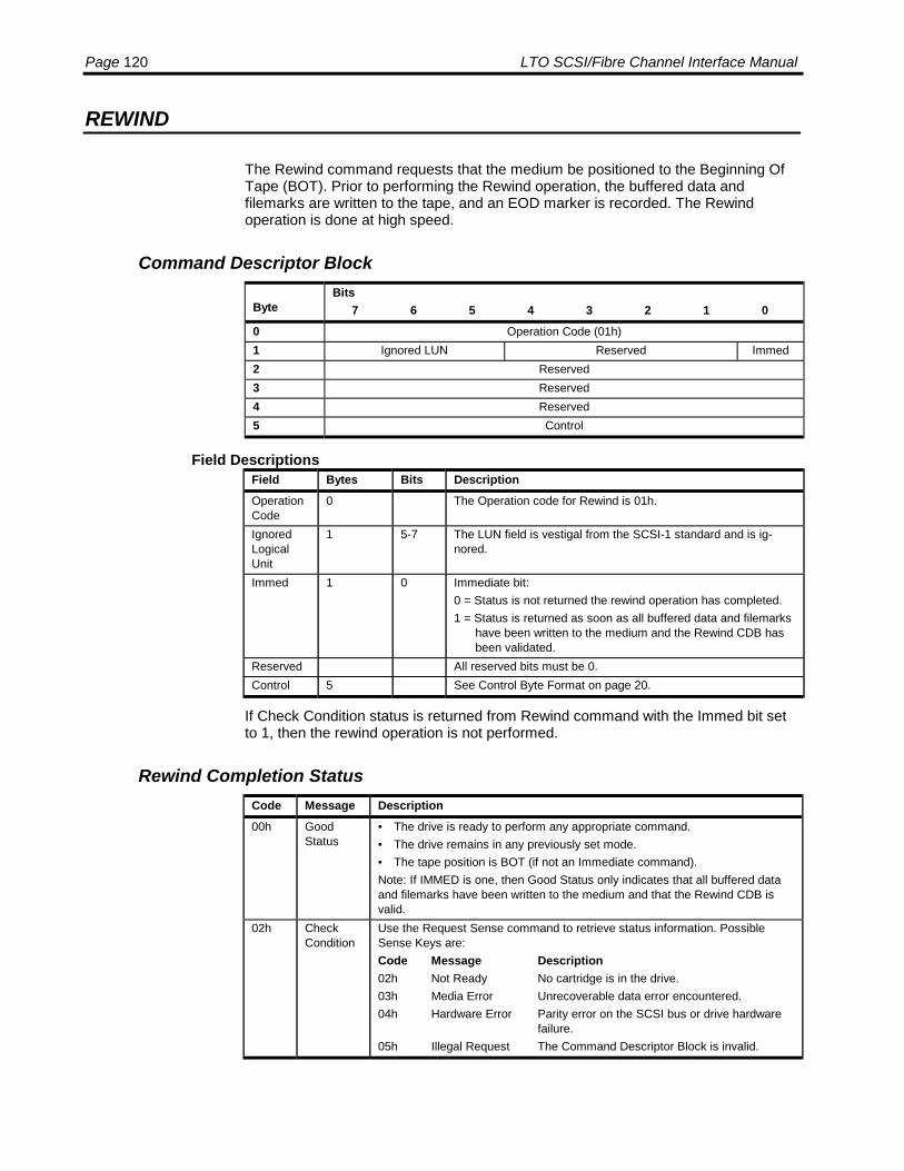
Page 120 LTO SCSI/Fibre Channel Interface Manual
REWIND
The Rewind command requests that the medium be positioned to the Beginning OfTape (BOT). Prior to performing the Rewind operation, the buffered data andfilemarks are written to the tape, and an EOD marker is recorded. The Rewindoperation is done at high speed.
Command Descriptor Block
ByteBits
7 6 5 4 3 2 1 00 Operation Code (01h)1 Ignored LUN Reserved Immed2 Reserved3 Reserved4 Reserved5 Control
Field DescriptionsField Bytes Bits DescriptionOperationCode
0 The Operation code for Rewind is 01h.
IgnoredLogicalUnit
1 5-7 The LUN field is vestigal from the SCSI-1 standard and is ig-nored.
Immed 1 0 Immediate bit:0 = Status is not returned the rewind operation has completed.1 = Status is returned as soon as all buffered data and filemarks
have been written to the medium and the Rewind CDB hasbeen validated.
Reserved All reserved bits must be 0.Control 5 See Control Byte Format on page 20.
If Check Condition status is returned from Rewind command with the Immed bit setto 1, then the rewind operation is not performed.
Rewind Completion StatusCode Message Description00h Good
Status• The drive is ready to perform any appropriate command.• The drive remains in any previously set mode.• The tape position is BOT (if not an Immediate command).Note: If IMMED is one, then Good Status only indicates that all buffered dataand filemarks have been written to the medium and that the Rewind CDB isvalid.
02h CheckCondition
Use the Request Sense command to retrieve status information. PossibleSense Keys are:Code Message Description02h Not Ready No cartridge is in the drive.03h Media Error Unrecoverable data error encountered.04h Hardware Error Parity error on the SCSI bus or drive hardware
failure.05h Illegal Request The Command Descriptor Block is invalid.

SCSI Commands: SEND DIAGNOSTIC Page 121
SEND DIAGNOSTIC
The Send Diagnostic command requests the drive to perform diagnostic operationson itself. The diagnostic tests are part of the drive’s resident firmware.
The Receive Diagnostic Results command may be used to retrieve the result of thediagnostic operations.
A Self Test bit of one requests the drive to perform its self test diagnostic.
Command Descriptor Block
ByteBits
7 6 5 4 3 2 1 00 Operation Code (1Dh)1 Self-Test Code PF Rsvd Selftest Devoffl UnitOffl2 Reserved3 Parameter List Length (MSB)4 Parameter List Length (LSB)5 Control
Field DescriptionsField Bytes Bits DescriptionOperationcode
0 The Operation Code for Send Diagnostic is 1Dh.
Self-test code 1 5-7 This bit field is not supported and must be set to 0.Pf 1 4 This bit is not supported and must be set to 0.Selftest 1 2 Self test diagnostics.Devoffl 1 1 Device off-line.UnitOffl 1 0 Unit off-line.
Mode 0: supportedMode 4: Perform self test diagnostics;Mode 5: Write with incrementing pattern;Mode 6: Verify with incrementing pattern;Mode 7: Write and verify with increment-ing pattern
Mode 0: Selftest = 0 Devoffl = 0 UnitOffl = 0Mode 4: Selftest = 1 Devoffl = 0 UnitOffl = 0Mode 5: Selftest = 1 Devoffl = 0 UnitOffl = 1Mode 6: Selftest = 1 Devoffl = 1 UnitOffl = 0Mode 7: Selftest = 1 Devoffl = 1 UnitOffl = 1
Parameter listlength
3-4 This field is not supported and must be to 0.
Reserved All reserved bits must be 0.Control 5 The control field must be 0.

Page 122 LTO SCSI/Fibre Channel Interface Manual
Send Diagnostic Completion StatusCode Message Description00h Good
Status• The drive is ready to perform any appropriate command.• The drive remains in any previously set mode.• The tape position is not changed.
02h CheckCondition
Use the Request Sense command to retrieve status information. PossibleSense Keys are:Code Message Description02h Not Ready No cartridge is inserted in the drive.04h Hardware Error Drive hardware failure detected.05h Illegal Request The CDB contains an invalid bit.06h Unit Attention The cartridge was changed, or the drive was
reset prior to this command.
SET CAPACITY
The Set Capacity command sets the available medium for a volume to a proportionof the total capacity of that volume. Any excess space is unavailable on the volumeafter successful completion of this command until reset by a new Set Capacitycommand.
The Set Capacity command is valid only when the medium is at beginning-of-medium. If the medium is logically at any other position, the command is rejectedwith Check Condition status. The sense key is Illegal Request with the additionalsense code and an additional sense code qualifier set to position past beginning ofmedium.
If the medium is write protected, the command is rejected with Check Conditionstatus. The sense key is Data Protect with the additional sense code and anadditional sense code qualifier set to Write Protected.
If the Set Capacity command specifies the portion of the total volume capacity to bemade available for use less than 10 gigabytes, the device will round up the capacityto 10 gigabytes. The command is terminated with Check Condition status. The sensekey is Recovered Error with the additional sense code and an additional sense codequalifier set to Rounded Parameter.
A valid Set Capacity command causes all data on the tape to be lost.
Command Descriptor Block
ByteBits
7 6 5 4 3 2 1 00 Operation Code (0Bh)1 Ignored LUN Reserved Immed2 Reserved3 Capacity Proportion Value, MSB4 Capacity Proportion Value, LSB5 Control
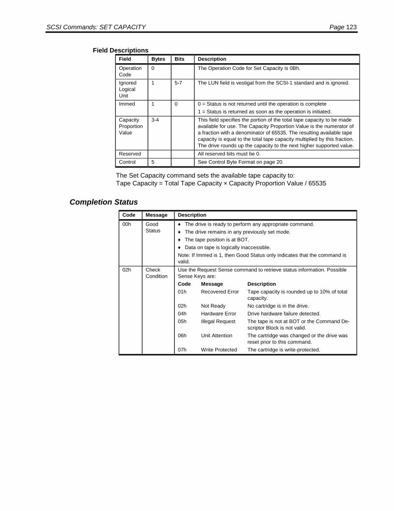
SCSI Commands: SET CAPACITY Page 123
Field DescriptionsField Bytes Bits DescriptionOperationCode
0 The Operation Code for Set Capacity is 0Bh.
IgnoredLogicalUnit
1 5-7 The LUN field is vestigal from the SCSI-1 standard and is ignored.
Immed 1 0 0 = Status is not returned until the operation is complete1 = Status is returned as soon as the operation is initiated.
CapacityProportionValue
3-4 This field specifies the portion of the total tape capacity to be madeavailable for use. The Capacity Proportion Value is the numerator ofa fraction with a denominator of 65535. The resulting available tapecapacity is equal to the total tape capacity multiplied by this fraction.The drive rounds up the capacity to the next higher supported value.
Reserved All reserved bits must be 0.Control 5 See Control Byte Format on page 20.
The Set Capacity command sets the available tape capacity to:Tape Capacity = Total Tape Capacity × Capacity Proportion Value / 65535
Completion StatusCode Message Description00h Good
Status♦ The drive is ready to perform any appropriate command.♦ The drive remains in any previously set mode.♦ The tape position is at BOT.♦ Data on tape is logically inaccessible.Note: If Immed is 1, then Good Status only indicates that the command isvalid.
02h CheckCondition
Use the Request Sense command to retrieve status information. PossibleSense Keys are:Code Message Description01h Recovered Error Tape capacity is rounded up to 10% of total
capacity.02h Not Ready No cartridge is in the drive.04h Hardware Error Drive hardware failure detected.05h Illegal Request The tape is not at BOT or the Command De-
scriptor Block is not valid.06h Unit Attention The cartridge was changed or the drive was
reset prior to this command.07h Write Protected The cartridge is write-protected.

Page 124 LTO SCSI/Fibre Channel Interface Manual
SPACE
The Space command uses three methods to move the tape. This command movesthe position:
• Forward or backward a specified number of blocks.• Forward or backward a specified number of filemarks.• Forward to the end of recorded data (EOD).
If the target block or filemark is in the buffer of the drive, no tape motion results,otherwise, spacing is done at high search speed.
Command Descriptor Block
ByteBits
7 6 5 4 3 2 1 00 Operation Code (11h)1 Ignored LUN Reserved Code2 Count, MSB3 Count4 Count, LSB5 Control
Field DescriptionsField Bytes Bits DescriptionOperationCode
0 The Operation Code for Space is 11h.
IgnoredLogicalUnit
1 5-7 The LUN field is vestigal from the SCSI-1 standard and is ignored.
Code 1 0-2 000b = Move Count blocks001b = Move Count filemarks011 = Move to end of recorded data (EOD)
Count 2-4 This field specifies the number of blocks or filemarks to space over.A positive Count moves the tape forward. A negative (2's comple-ment) Count moves the tape backward. A zero Count causes nomedia movement and is not an error. For Space to EOD operation,this field is ignored.
Reserved All reserved bits must be 0.Control 5 See Control Byte Format on page 20.
The Space command instructs the drive to set a new logical position relative to thecurrent logical position. How this is done is dependent on the value of the Code fieldand the Count field. The Count field is a signed value indicating the distance tomove, negative indicating movement towards BOT and positive indicating movementtowards EOT.
If the Code field is 000b, then the logical position is moved the number of blocksindicated by the Count field. If a file mark is detected between the current logicalposition and the requested logical position, the new logical position is set toimmediately after the file mark in the direction of the space operation. If BOT or EODis detected before the requested logical position, then the logical position is set tothat position.

SCSI Commands: SPACE Page 125
If the Code field is 001b, then the logical position is moved the number of file marksindicated by the Count field. If BOT or EOD is detected before the requested logicalposition, then the logical position is set to that position.
If the Code field is 011b, then the logical position is set to after the last valid block ontape. In this case the count field is ignored.
Any other value of the Code field will cause Check Condition status to be returned.Spacing to sequential file marks is not supported. Set marks are not supported. TheSense Key is set to Illegal Request and the Additional Sense is set to Invalid field inCDB (2400).
Space-by-Count Functions
The Count field indicates both direction and number of blocks or filemarks to spaceover from the current logical position. A positive value N in the Count field moves thetape forward over N blocks or filemarks. A negative value -N (2's complement) in theCount field moves the tape backward over N blocks or filemarks. Zero in the countfield causes no tape movement and is not considered an error.
When there are no exception conditions during space functions, forward tape motionends on the EOT side of the last block or filemark and reverse motion ends on theBOT side of the last block or filemark.
• If a filemark is encountered while spacing over blocks, a Check Condition Statusis returned. The Sense FM bit is set and the Sense Valid bit is set, indicatingResidual Length is non-zero.
The Residual Length equals the difference in the requested count and the actualnumber of blocks spaced over not including the filemark. The tape is positionedon the logical EOT side of the filemark if movement was forward or on the logicalBOT side of the filemark if movement was reverse.
• If EOD is encountered while spacing forward, Check Condition is returned with08h Sense Key. Extended Sense Valid bit is set, indicating Residual Length isnonzero.
• If BOT is encountered while spacing in reverse, Check Condition is returned with40h Sense Key. Extended sense Valid bit is set, indicating a nonzero ResidualLength.
• If EOT is encountered while spacing forward, Check Condition is returned with40h or 43h Sense Key. Extended Sense Valid bit is set, indicating a nonzeroResidual Length.
• If an unrecoverable data error is encountered, Check Condition is returned,Extended Sense Key is set to Medium Error, and Extended Sense Valid bit isset, indicating Residual Length is nonzero.
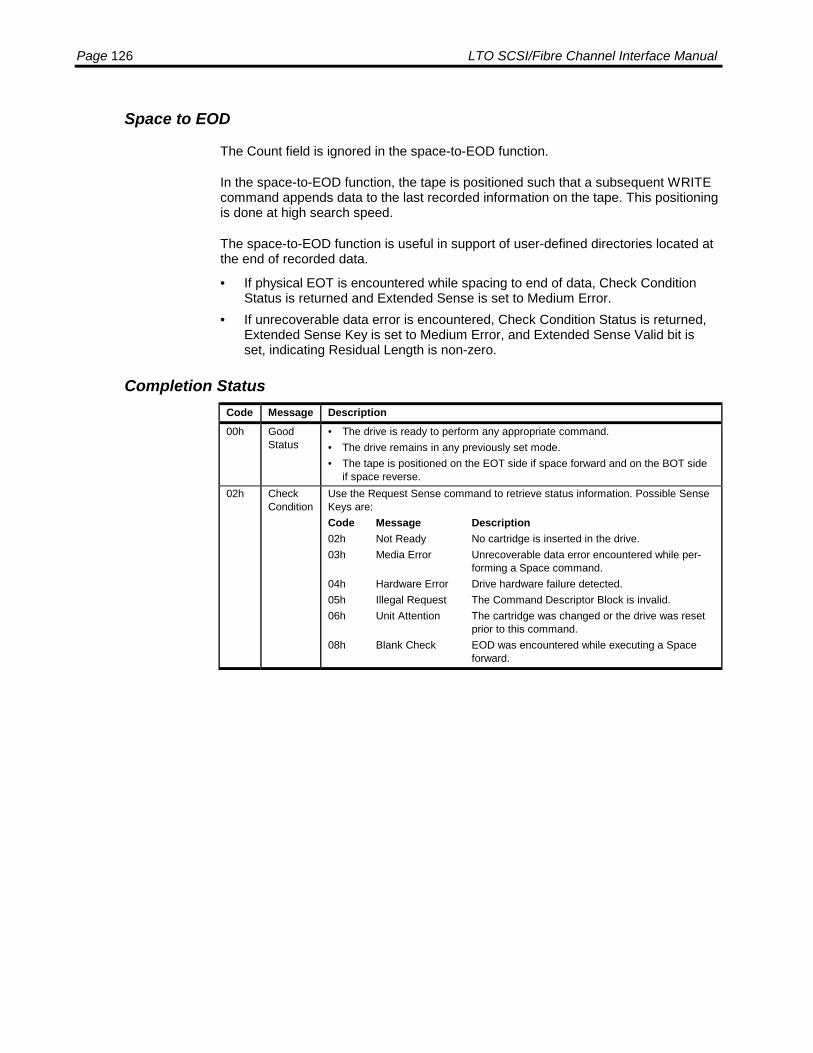
Page 126 LTO SCSI/Fibre Channel Interface Manual
Space to EOD
The Count field is ignored in the space-to-EOD function.
In the space-to-EOD function, the tape is positioned such that a subsequent WRITEcommand appends data to the last recorded information on the tape. This positioningis done at high search speed.
The space-to-EOD function is useful in support of user-defined directories located atthe end of recorded data.
• If physical EOT is encountered while spacing to end of data, Check ConditionStatus is returned and Extended Sense is set to Medium Error.
• If unrecoverable data error is encountered, Check Condition Status is returned,Extended Sense Key is set to Medium Error, and Extended Sense Valid bit isset, indicating Residual Length is non-zero.
Completion StatusCode Message Description00h Good
Status• The drive is ready to perform any appropriate command.• The drive remains in any previously set mode.• The tape is positioned on the EOT side if space forward and on the BOT side
if space reverse.02h Check
ConditionUse the Request Sense command to retrieve status information. Possible SenseKeys are:Code Message Description02h Not Ready No cartridge is inserted in the drive.03h Media Error Unrecoverable data error encountered while per-
forming a Space command.04h Hardware Error Drive hardware failure detected.05h Illegal Request The Command Descriptor Block is invalid.06h Unit Attention The cartridge was changed or the drive was reset
prior to this command.08h Blank Check EOD was encountered while executing a Space
forward.
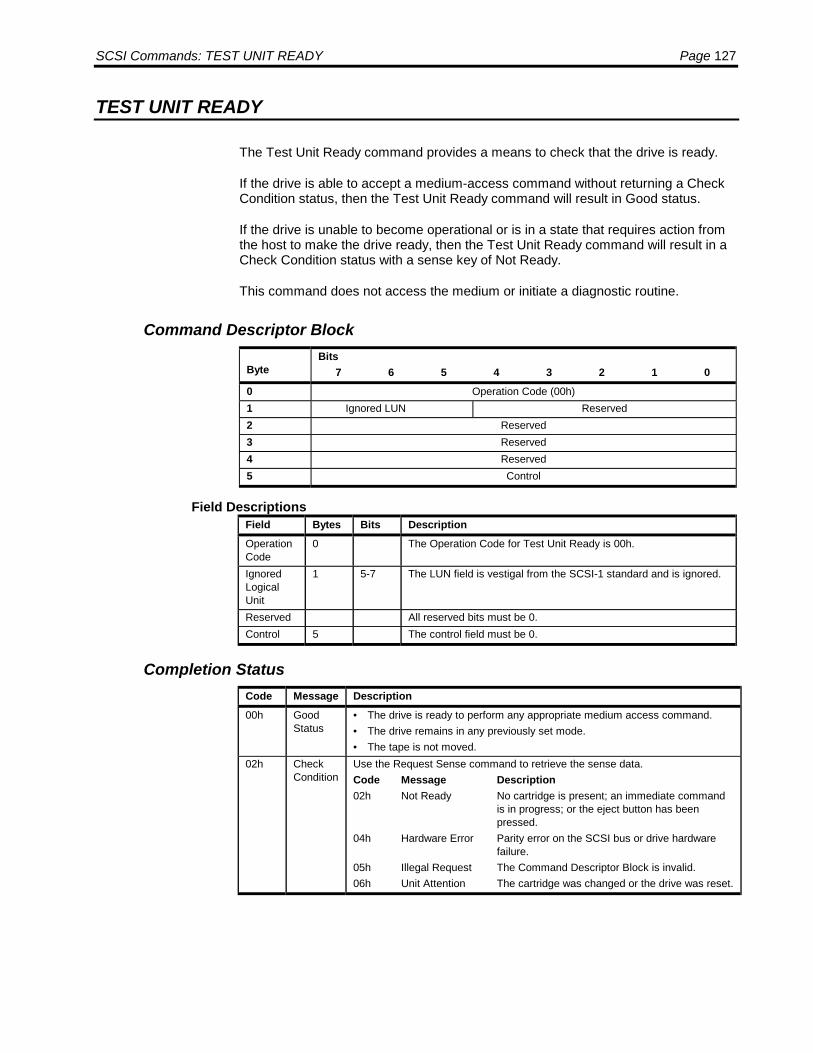
SCSI Commands: TEST UNIT READY Page 127
TEST UNIT READY
The Test Unit Ready command provides a means to check that the drive is ready.
If the drive is able to accept a medium-access command without returning a CheckCondition status, then the Test Unit Ready command will result in Good status.
If the drive is unable to become operational or is in a state that requires action fromthe host to make the drive ready, then the Test Unit Ready command will result in aCheck Condition status with a sense key of Not Ready.
This command does not access the medium or initiate a diagnostic routine.
Command Descriptor Block
ByteBits
7 6 5 4 3 2 1 00 Operation Code (00h)1 Ignored LUN Reserved2 Reserved3 Reserved4 Reserved5 Control
Field DescriptionsField Bytes Bits DescriptionOperationCode
0 The Operation Code for Test Unit Ready is 00h.
IgnoredLogicalUnit
1 5-7 The LUN field is vestigal from the SCSI-1 standard and is ignored.
Reserved All reserved bits must be 0.Control 5 The control field must be 0.
Completion StatusCode Message Description00h Good
Status• The drive is ready to perform any appropriate medium access command.• The drive remains in any previously set mode.• The tape is not moved.
02h CheckCondition
Use the Request Sense command to retrieve the sense data.Code Message Description02h Not Ready No cartridge is present; an immediate command
is in progress; or the eject button has beenpressed.
04h Hardware Error Parity error on the SCSI bus or drive hardwarefailure.
05h Illegal Request The Command Descriptor Block is invalid.06h Unit Attention The cartridge was changed or the drive was reset.
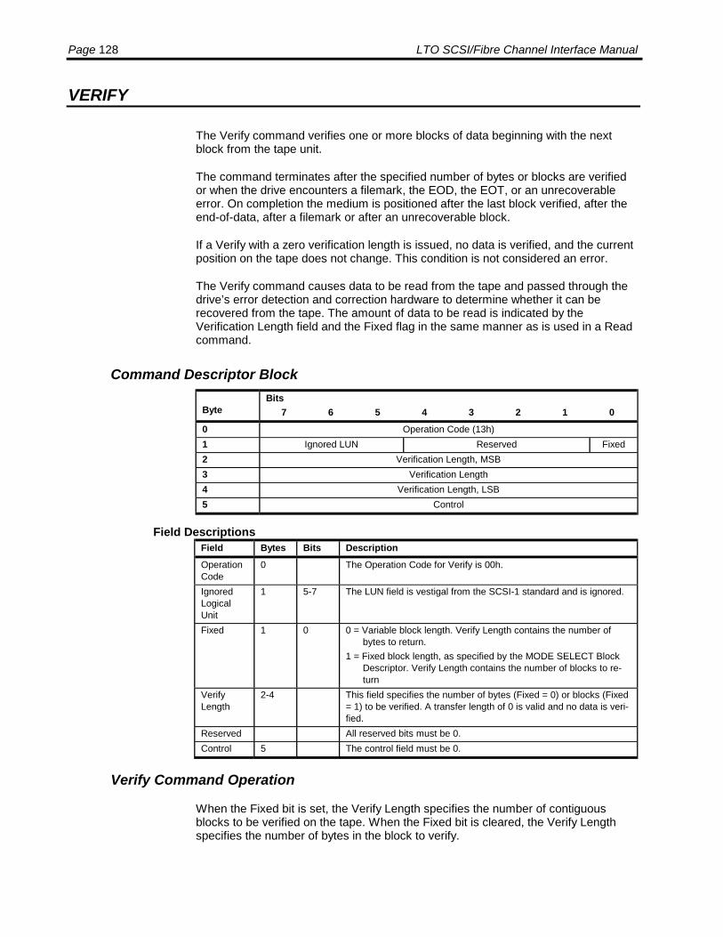
Page 128 LTO SCSI/Fibre Channel Interface Manual
VERIFY
The Verify command verifies one or more blocks of data beginning with the nextblock from the tape unit.
The command terminates after the specified number of bytes or blocks are verifiedor when the drive encounters a filemark, the EOD, the EOT, or an unrecoverableerror. On completion the medium is positioned after the last block verified, after theend-of-data, after a filemark or after an unrecoverable block.
If a Verify with a zero verification length is issued, no data is verified, and the currentposition on the tape does not change. This condition is not considered an error.
The Verify command causes data to be read from the tape and passed through thedrive’s error detection and correction hardware to determine whether it can berecovered from the tape. The amount of data to be read is indicated by theVerification Length field and the Fixed flag in the same manner as is used in a Readcommand.
Command Descriptor Block
ByteBits
7 6 5 4 3 2 1 00 Operation Code (13h)1 Ignored LUN Reserved Fixed2 Verification Length, MSB3 Verification Length4 Verification Length, LSB5 Control
Field DescriptionsField Bytes Bits DescriptionOperationCode
0 The Operation Code for Verify is 00h.
IgnoredLogicalUnit
1 5-7 The LUN field is vestigal from the SCSI-1 standard and is ignored.
Fixed 1 0 0 = Variable block length. Verify Length contains the number ofbytes to return.
1 = Fixed block length, as specified by the MODE SELECT BlockDescriptor. Verify Length contains the number of blocks to re-turn
VerifyLength
2-4 This field specifies the number of bytes (Fixed = 0) or blocks (Fixed= 1) to be verified. A transfer length of 0 is valid and no data is veri-fied.
Reserved All reserved bits must be 0.Control 5 The control field must be 0.
Verify Command Operation
When the Fixed bit is set, the Verify Length specifies the number of contiguousblocks to be verified on the tape. When the Fixed bit is cleared, the Verify Lengthspecifies the number of bytes in the block to verify.

SCSI Commands: VERIFY Page 129
The byte compare starts on a block boundary starting at the current tape blockposition.
Completion StatusCode Message Description00h Good
Status• The drive is ready to perform any appropriate command.• The drive remains in any previously set mode.• The tape is positioned on the EOT side of the last block verified.
02h CheckCondition
Use the Request Sense command to retrieve status information. PossibleSense Keys are:Code Message Description02h Not Ready No cartridge is in the drive.03h Media Error Unrecoverable data error encountered.04h Hardware Error Parity error on the SCSI bus or drive hardware
failure.05h Illegal Request The Command Descriptor Block is invalid.06h Unit Attention The cartridge was changed, or the drive was reset
prior to this command.08h Blank Check EOD was encountered..

Page 130 LTO SCSI/Fibre Channel Interface Manual
WRITE
The Write command transfers one or more data blocks from the Initiator to the drive.If the Transfer Length is zero, no data is transferred, and the current position of thetape is not changed. This condition is not considered an error.
Command Descriptor Block
ByteBits
7 6 5 4 3 2 1 00 Operation Code (0Ah)1 Ignored LUN Reserved Fixed2 Transfer Length, MSB3 Transfer Length4 Transfer Length, LSB5 Control
Field DescriptionsField Bytes Bits DescriptionOperationCode
0 The Operation Code for Write is 0Ah.
IgnoredLogicalUnit
1 5-7 The LUN field is vestigal from the SCSI-1 standard and is ignored.
Fixed 1 0 0 = Variable block length. Transfer Length contains the number ofbytes to write.
1 = Fixed block length, as specified by the MODE SELECT BlockDescriptor. Transfer Length contains the number of blocks towrite.
TransferLength
2-4 This field specifies the number of bytes (Fixed = 0) or blocks (Fixed= 1) to be written. A transfer length of 0 is valid and no data is writ-ten.
Reserved All reserved bits must be 0.Control 5 The control field must be 0.
If the Fixed flag is clear, the initiator will transfer a single block of the length indicatedin Transfer Length.
If the Fixed flag is set, the initiator will transfer a sequence of blocks. The TransferLength field gives the number of blocks. The current fixed block length gives thelength of the blocks.
At Early Warning, the drive completes the current block transfer and terminates thecommand with a Check Condition, EOM bit set, and Sense Key equal to 0.
Subsequent Write commands complete with a Check Condition and the EOM bit set.
If writing the buffer to tape is unsuccessful because of EOT, a Volume Overflow isreported. The Residual count field in the Request Sense data reports the amount ofdata not transferred. Writing can continue in the Early Warning region until EOT isencountered. Any Write command issued within Early Warning and successfullycompleted, finishes with a Check Condition and the EOM bit set.

SCSI Commands: WRITE Page 131
Completion StatusCode Message Description00h Good
Status• The SCSI data has been transferred to the data buffer.• The drive remains in any previously set mode.
02h CheckCondition
Use the Request Sense command to retrieve status information. PossibleSense Keys are:Code Message Description02h Not Ready No cartridge is in the drive.03h Media Error Unrecoverable data error encountered.04h Hardware Error Parity error on the SCSI bus or drive hardware
failure.05h Illegal Request The Command Descriptor Block is invalid.06h Unit Attention The cartridge was changed, or the drive was reset
prior to this command.07h Write Protect The tape is write-protected; check the cartridge
before continuing.0Dh Volume Overflow The Write command completed with data in the
buffer because the end-of-partition was encoun-tered.

Page 132 LTO SCSI/Fibre Channel Interface Manual
WRITE BUFFER
The Write Buffer command is used in conjunction with the Read Buffer command asa diagnostic function for testing the data buffer memory of the drive and confirmingthe SCSI bus integrity. The medium is not accessed during the execution of thiscommand.
The Write Buffer command is also used to download microcode to the drive.
Command Descriptor Block
ByteBits
7 6 5 4 3 2 1 00 Operation Code (3B)1 Ignored LUN Rsvd Mode2 Buffer ID3 Buffer Offset, MSB4 Buffer Offset5 Buffer Offset, LSB6 Parameter List Length, MSB7 Parameter List Length8 Parameter List Length, LSB9 Control
Field DescriptionsField Bytes Bits DescriptionOperationCode
0 The operation code for Write Buffer is 3Bh.
IgnoredLogicalUnit
1 5-7 The LUN field is vestigal from the SCSI-1 standard and is ignored.
Reserved 1 4 All Reserved bits must be 0.MODE 1 0-3 0000b = Write header and data.
0001b = Write Medium Auxiliary Memory(MAM).0010b = Write data only.0100b = Microcode download. Do not write to flash memory.0101b = Microcode download. Write to flash memory.0110b = Microcode download. Do not write to flash memory.0111b = Microcode download. Write to flash memory.
Buffer ID 00h = normal access (default)54h = specifies access to Medium Auxiliary Memory
BUFFEROFFSET
3-5 For Mode not equal to 0001b: The offset from the beginning of thespecified buffer in bytes.For Mode equal 0001b: Set to the Medium Auxiliary Memory as de-scribed in the tables.
PARAMETER LISTLENGTH
6-8 Specifies the amount of data to be sent. A value of 0 is a valid entryand shall not be considered an error.This value must be smaller than the difference between the BufferOffset and the size of the buffer.
CONTROL 9 See Control Byte Format on page 20.
SCSI Commands: WRITE BUFFER Page 133
A Mode field of 0000b indicates that the data to be written will be preceded with afour-byte header. This Write Buffer Data Header is reserved and must be set to allzeros. The header will not be placed into buffer memory.
A Mode field of 0001b indicates that data to be written to the Medium AuxiliaryMemory will be sent. If the optional Application Specific page does not exist in theMAM then a Write Buffer command to this page will create it prior to writing data.
A Mode field of 0010b indicates that only data to be written to the buffer will be sent.
A Mode field of 0100b or 0110b indicates download microcode.
A Mode field of 0101b or 0111b indicates download microcode and save.
The Buffer ID field indicates which buffer is to be written. All drives support buffer 0.Other buffers may be available in the drive.
The Buffer Offset is used to specify the byte location within the specified bufferwhere data is to be written.
The Parameter List Length field indicated the amount of data to be transferred. Careneeds to be taken so that the Buffer Offset plus the Parameter List Length does notexceed the buffer capacity. If the buffer capacity is exceeded, no data is written andCheck Condition status is generated.
Soft Microcode DownloadA soft microcode download will load the microcode image and reboot the drivewithout flashing the image into memory.
Use Mode field of 0100b or 0110b to download the microcode image into memorywithout saving (flashing). Buffer Offsets may be used in either of these Modes.
After the downloaded microcode image is in memory, it may be booted (withoutflashing) by issuing a Write Buffer command with Mode 0100b or 0110b and aParameter List Length of zero. The downloaded code will then run on the drive untilthe drive is power cycled. Upon power cycling the drive, the original firmware revisionwill be restored.
Hard Microcode DownloadA hard microcode download will load the microcode image, flash it into memory andreboot the drive.
Use Mode field of 0100b or 0110b to download the microcode image into memorywithout saving (flashing). Buffer Offsets may be used in either of these Modes.
After the downloaded microcode image is in memory, it may be flashed and bootedby issuing a Write Buffer command with Mode 0101b or 0111b and a Parameter ListLength of zero. The downloaded code will then run on the drive and remain inmemory until a subsequent hard microcode download is done.
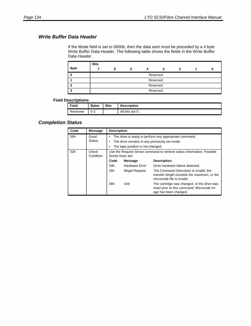
Page 134 LTO SCSI/Fibre Channel Interface Manual
Write Buffer Data Header
If the Mode field is set to 0000b, then the data sent must be preceded by a 4 byteWrite Buffer Data Header. The following table shows the fields in the Write BufferData Header.
ByteBits
7 6 5 4 3 2 1 00 Reserved1 Reserved2 Reserved3 Reserved
Field DescriptionsField Bytes Bits DescriptionReserved 0-3 All bits are 0.
Completion StatusCode Message Description00h Good
Status• The drive is ready to perform any appropriate command.• The drive remains in any previously set mode.• The tape position is not changed.
02h CheckCondition
Use the Request Sense command to retrieve status information. PossibleSense Keys are:Code Message Description04h Hardware Error Drive hardware failure detected.05h Illegal Request The Command Descriptor is invalid, the
transfer length exceeds the maximum, or themicrocode file is invalid.
06h Unit The cartridge was changed, or the drive wasreset prior to this command. Microcode im-age has been changed.

SCSI Commands: WRITE FILE MARKS Page 135
WRITE FILE MARKS
The Write Filemarks command causes the specified number of filemarks to bewritten to tape.
This command can be used to force all remaining buffered data blocks to be writtento tape without appending filemarks by specifying zero filemarks. When zerofilemarks are specified, the command does not return Good Status to the Initiatoruntil all buffered data blocks and filemarks are written correctly on the tape.Otherwise, status is returned immediately.
Command Descriptor Block
ByteBits
7 6 5 4 3 2 1 00 Operation Code (10h)1 Reserved Immed2 Count, MSB3 Count4 Count, LSB5 Control
Field DescriptionsFieldName
Bytes Bits Description
OperationCode
0 The Operation Code for Write Filemarks is 10h.
Immed 1 0 0 = Status is not returned until the tape is positioned.1 = Status is returned as soon as the operation is initiated.
Count 2-4 The number of filemarks to record.Reserved All Reserved bits must be 0.Control 5 See Control Byte Format on page 20.
The Write File Marks command causes a sequence of file marks to be written at thecurrent logical position. The number of file marks to be written is indicated in theCount field.
If the Immed flag is set, status is returned immediately, before the file marks arewritten to tape. If the Immed flag is clear, the file marks and any buffered data iswritten to tape before status is returned. If the Immed flag is clear and the Count fieldis 0, then all buffered data is flushed to tape before the command is reported.

Page 136 LTO SCSI/Fibre Channel Interface Manual
Completion StatusCode Message Description00h Good
Status• The filemarks have been sent to the buffer.• The drive remains in any previously set mode.Note: If Immed is 1, then Good Status only indicates that the command isvalid.
02h CheckCondition
Use the Request Sense command to retrieve status information. PossibleSense Keys are:Code Message Description02h Not Ready No cartridge is in the drive.03h Media Error Unrecoverable data error encountered.04h Hardware Error Parity error on the SCSI bus or drive hardware
failure.05h Illegal Request The Command Descriptor Block is invalid.06h Unit Attention The cartridge was changed, or the drive was
reset prior to this command.07h Write Protect The tape is write-protected; check the cartridge
before continuing.0Dh Volume The command completed with Overflow data in
the buffer because EOT was encountered.

Appendix A: Message Codes Page 137
Appendix A: Message Codes
This table lists the vendor unique message codes that are returned by the Request Sense command in theField Pointer field (bytes 16-17) when the SKSV bit is 0.
Message VSCQ Type DefinitionGOOD_STATUS 00h General Good statusBUSY_STATUS 01h General Busy statusILLEGAL_COMMAND_STATUS 02h General Illegal command statusCOMMAND_ABORTED_STATUS 03h General Command aborted statusBAD_STATUS 04h General Bad statusFAILED_STATUS 08h General Failed statusILLEGAL_MESSAGE 09h General Illegal messageLOGICAL_EW_STATUS 0Bh General Logical EW statusBOP_STATUS 0Ch General BOP statusREWRITE_RECOVERED_STATUS 0Dh GeneralSCSI_BOR_ERR 40h SCSI Additional Vendor Specific ASCQ
BOR errorSCSI_CRC_ERR 41h SCSI CRC errorSCSI_INDETERMINATE_IRQ 42h SCSI Unknown IRQSCSI_SAPI_FAILED 43h SCSI SAPI routine failedSCSI_KERNEL_MSG_FAILED 44h SCSI Receiving kernel message failedSCSI_UNKNOWN_BE_STATE 45h SCSI Unknown BE stateSCSI_UNKNOWN_FE_STATE 46h SCSI Unknown FE stateSCSI_UNKNOWN_SCSI_INT 47h SCSI Kernel Message: Unknown SCSI
interrupt (unknown SCSI kernelmessage type)
SCSI_UNKNOWN_KERNEL_MSG_TYPE 48h SCSI Kernel Message: Unknown kernelmessage type
SCSI_UNKNOWN_SENDER 49h SCSI Kernel Message: Unknown kernelmessage sender
SCSI_UNKNOWN_SCSI_MSG 4Ah SCSI Kernel Message: Unknown SCSImessage
SCSI_UNKNOWN_SVA_MSG 4Bh SCSI Kernel Message: Unknown SERVOALERT message
SCSI_UNKNOWN_DMA_MSG 4Ch SCSI Kernel Message: Unknown DMAmessage
SCSI_TIMER_FAILED 4Dh SCSI Timer failedSCSI_ZERO_TRANSFER 4Eh SCSI SAPI transfer with zero lengthSCSI_UNEXP_CCSTARTED 4Fh SCSI Unexpected COMMAND
COMPLETE startedSCSI_UNEXP_CCNOTSTARTED 50h SCSI Unexpected COMMAND
COMPLETE not startedSCSI_FE_STATE_NOT_MATCHED 51h SCSI Unexpected FE stateSCSI_UNEXP_SELFTEST_MODE 52h SCSI Unexpected Self Test modeSCSI_ABORT_BIT_SET 53h SCSI Unexpected ABORT bit setSCSI_NON_DSM_PRIMITIVE 54h SCSI Unexpected DSM primitive

Page 138 LTO SCSI/Fibre Channel Interface Manual
Message VSCQ Type DefinitionSCSI_CMD_REFS_EXHAUSTED 55h SCSI Exhausted all command refer-
ences.SCSI_UNKNOWN_INQ_PAGE 56h SCSI Unknown Inquiry pageSCSI_UNKNOWN_IID 57h SCSI Unknown initiator IDSCSI_UNKNOWN_SENSE_TYPE 58h SCSI Unknown sense typeSCSI_DMA_FIFO_ERR 59h SCSI DMA OVERRUN/UNDERRUNSCSI_DMA_OFFSET_ERR 5Ah SCSI DMA offset error.SCSI_DMA_PARITY_ERR 5Bh SCSI DMA parity errorSCSI_READ_PARITY_ERR 5Ch SCSI Read parity errorSCSI_OFFSET_ERR 5Dh SCSI SCSI offset errorSCSI_UNKNOWN_MODE_PAGE 5Eh SCSI Unknown Mode pageSCSI_EJECT_FAILED 5Fh SCSI EJECT failedSCSI_ILLEGAL_MSG_SEQ 60h SCSI Illegal SCSI bus message se-
quenceSCSI_ILLEGAL_DSM_CMD 61h SCSI Illegal command returned from
DSM.SCSI_BUSY_STATUS_FAILED 62h SCSI Command should have return busy
statusSCSI_UNEXP_CMD_REF 63h SCSI Unexpected Command reference
foundSCSI_ILLEGAL_MON_CMD 64h SCSI Illegal command returned from
MON TaskSCSI_DSM_TIMEOUT 65h SCSI DSM timeout.SCSI_KERNEL_MSG_TIMEOUT 66h SCSI Receiving kernel message timeoutSCSI_FW_DOWNLOAD_FAILED 67h SCSI Microcode download failureSCSI_UNKN_CMD_REF_TYPE 68h SCSI Unknown Command Reference
TypeSCSI_RB_NO_ROOM 69h SCSI Ring Buffer should have enough
roomSCSI_MAIN_NOT_FOUND 6Ah SCSI pMainRoutine not foundSCSI_XFERDONE_NOT_FOUND 6Bh SCSI pXferDoneRoutine not foundSCSI_COMPDONE_NOT_FOUND 6Ch SCSI pCompDoneRoutine not foundSCSI_PDETECT_NOT_FOUND 6Dh SCSI pDetect routine not foundSCSI_PCMD_LOSTINFEHEAD 6Eh SCSI pCmd lost in the FE headSCSI_PCMD_LOSTINBEHEAD 6Fh SCSI pCmd lost in the BE headSCSI_PACTIVE_CMD_LOST 70h SCSI pActive_Cmd lostSCSI_CR_POOL_UNINIT 71h SCSI Command Reference Pool
sc_Command uninitializedSCSI_QE_POOL_UNINIT 72h SCSI Queue Element Pool
sc_Queue_Element uninitializedSCSI_FAIL_TO_GET_FREE_ELEMENT 73h SCSI Fail to get free element from queueSCSI_FAIL_TO_FREE_ELEMENT 74h SCSI Fail to free element during dequeueSCSI_RB_BUSY 75h SCSI RB busySCSI_INVALID_CDB_LENGTH 76h SCSI (CDB Length != 6) and
(CDB_Length != 10)SCSI_UA_POWER_ON_OCCURRED 77h SCSI UA power on occurredSCSI_UA_SCSI_BUS_RESET_OCCURRED 78h SCSI UA SCSI bus reset occurredSCSI_UA_BUS_DEVICE_RESET_FUNCTION_OCCURRED
79h SCSI UA bus device reset function oc-curred
SCSI_UA_INTERNAL_FW_REBOOT 7Ah SCSI UA internal FW rebootSCSI_UA_TRANSCEIVERS_CHANGED_TO_SE 7Bh SCSI UA transceivers changed to se
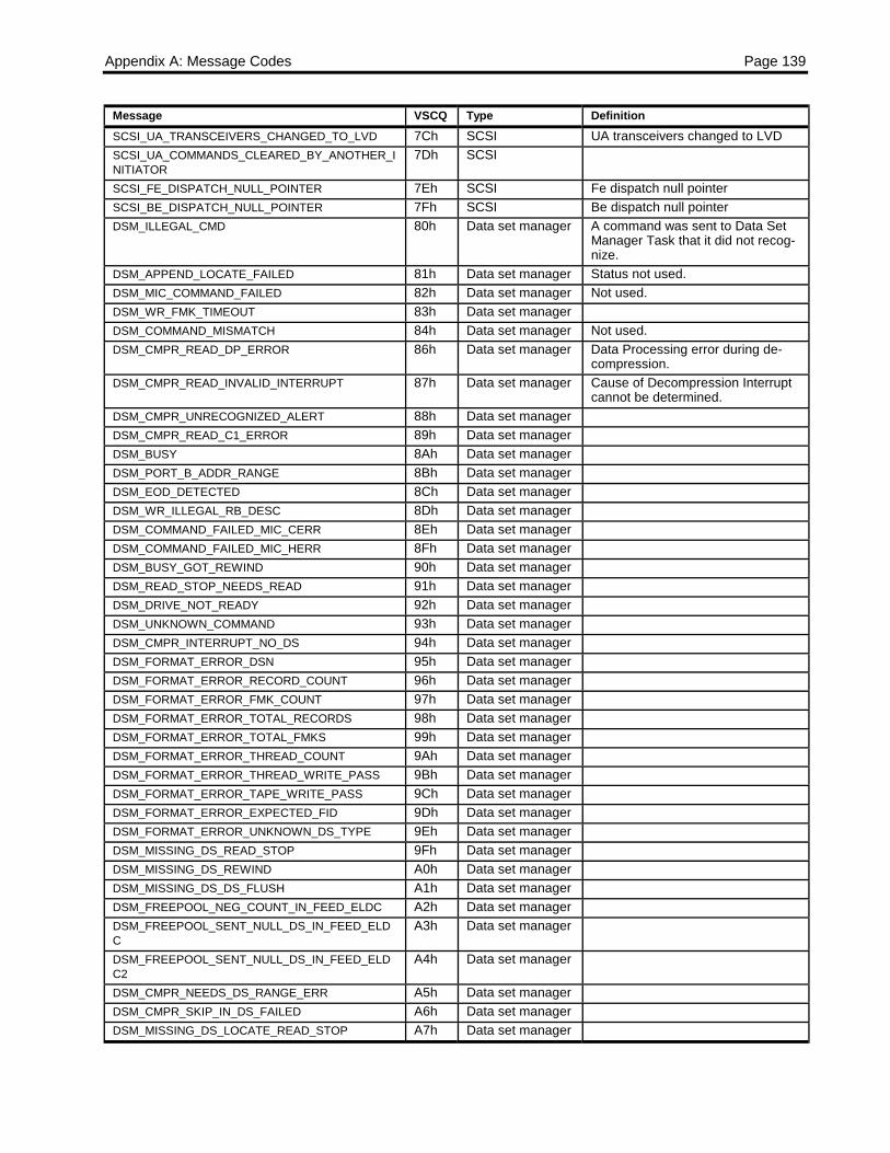
Appendix A: Message Codes Page 139
Message VSCQ Type DefinitionSCSI_UA_TRANSCEIVERS_CHANGED_TO_LVD 7Ch SCSI UA transceivers changed to LVDSCSI_UA_COMMANDS_CLEARED_BY_ANOTHER_INITIATOR
7Dh SCSI
SCSI_FE_DISPATCH_NULL_POINTER 7Eh SCSI Fe dispatch null pointerSCSI_BE_DISPATCH_NULL_POINTER 7Fh SCSI Be dispatch null pointerDSM_ILLEGAL_CMD 80h Data set manager A command was sent to Data Set
Manager Task that it did not recog-nize.
DSM_APPEND_LOCATE_FAILED 81h Data set manager Status not used.DSM_MIC_COMMAND_FAILED 82h Data set manager Not used.DSM_WR_FMK_TIMEOUT 83h Data set managerDSM_COMMAND_MISMATCH 84h Data set manager Not used.DSM_CMPR_READ_DP_ERROR 86h Data set manager Data Processing error during de-
compression.DSM_CMPR_READ_INVALID_INTERRUPT 87h Data set manager Cause of Decompression Interrupt
cannot be determined.DSM_CMPR_UNRECOGNIZED_ALERT 88h Data set managerDSM_CMPR_READ_C1_ERROR 89h Data set managerDSM_BUSY 8Ah Data set managerDSM_PORT_B_ADDR_RANGE 8Bh Data set managerDSM_EOD_DETECTED 8Ch Data set managerDSM_WR_ILLEGAL_RB_DESC 8Dh Data set managerDSM_COMMAND_FAILED_MIC_CERR 8Eh Data set managerDSM_COMMAND_FAILED_MIC_HERR 8Fh Data set managerDSM_BUSY_GOT_REWIND 90h Data set managerDSM_READ_STOP_NEEDS_READ 91h Data set managerDSM_DRIVE_NOT_READY 92h Data set managerDSM_UNKNOWN_COMMAND 93h Data set managerDSM_CMPR_INTERRUPT_NO_DS 94h Data set managerDSM_FORMAT_ERROR_DSN 95h Data set managerDSM_FORMAT_ERROR_RECORD_COUNT 96h Data set managerDSM_FORMAT_ERROR_FMK_COUNT 97h Data set managerDSM_FORMAT_ERROR_TOTAL_RECORDS 98h Data set managerDSM_FORMAT_ERROR_TOTAL_FMKS 99h Data set managerDSM_FORMAT_ERROR_THREAD_COUNT 9Ah Data set managerDSM_FORMAT_ERROR_THREAD_WRITE_PASS 9Bh Data set managerDSM_FORMAT_ERROR_TAPE_WRITE_PASS 9Ch Data set managerDSM_FORMAT_ERROR_EXPECTED_FID 9Dh Data set managerDSM_FORMAT_ERROR_UNKNOWN_DS_TYPE 9Eh Data set managerDSM_MISSING_DS_READ_STOP 9Fh Data set managerDSM_MISSING_DS_REWIND A0h Data set managerDSM_MISSING_DS_DS_FLUSH A1h Data set managerDSM_FREEPOOL_NEG_COUNT_IN_FEED_ELDC A2h Data set managerDSM_FREEPOOL_SENT_NULL_DS_IN_FEED_ELDC
A3h Data set manager
DSM_FREEPOOL_SENT_NULL_DS_IN_FEED_ELDC2
A4h Data set manager
DSM_CMPR_NEEDS_DS_RANGE_ERR A5h Data set managerDSM_CMPR_SKIP_IN_DS_FAILED A6h Data set managerDSM_MISSING_DS_LOCATE_READ_STOP A7h Data set manager
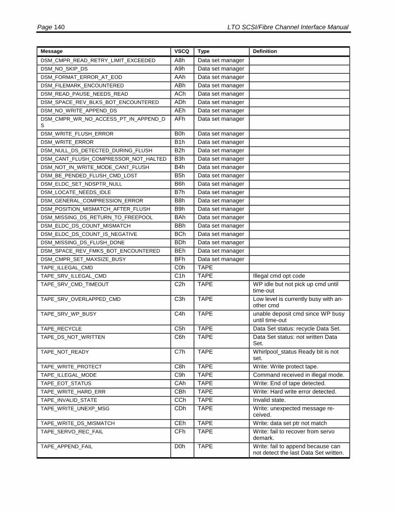
Page 140 LTO SCSI/Fibre Channel Interface Manual
Message VSCQ Type DefinitionDSM_CMPR_READ_RETRY_LIMIT_EXCEEDED A8h Data set managerDSM_NO_SKIP_DS A9h Data set managerDSM_FORMAT_ERROR_AT_EOD AAh Data set managerDSM_FILEMARK_ENCOUNTERED ABh Data set managerDSM_READ_PAUSE_NEEDS_READ ACh Data set managerDSM_SPACE_REV_BLKS_BOT_ENCOUNTERED ADh Data set managerDSM_NO_WRITE_APPEND_DS AEh Data set managerDSM_CMPR_WR_NO_ACCESS_PT_IN_APPEND_DS
AFh Data set manager
DSM_WRITE_FLUSH_ERROR B0h Data set managerDSM_WRITE_ERROR B1h Data set managerDSM_NULL_DS_DETECTED_DURING_FLUSH B2h Data set managerDSM_CANT_FLUSH_COMPRESSOR_NOT_HALTED B3h Data set managerDSM_NOT_IN_WRITE_MODE_CANT_FLUSH B4h Data set managerDSM_BE_PENDED_FLUSH_CMD_LOST B5h Data set managerDSM_ELDC_SET_NDSPTR_NULL B6h Data set managerDSM_LOCATE_NEEDS_IDLE B7h Data set managerDSM_GENERAL_COMPRESSION_ERROR B8h Data set managerDSM_POSITION_MISMATCH_AFTER_FLUSH B9h Data set managerDSM_MISSING_DS_RETURN_TO_FREEPOOL BAh Data set managerDSM_ELDC_DS_COUNT_MISMATCH BBh Data set managerDSM_ELDC_DS_COUNT_IS_NEGATIVE BCh Data set managerDSM_MISSING_DS_FLUSH_DONE BDh Data set managerDSM_SPACE_REV_FMKS_BOT_ENCOUNTERED BEh Data set managerDSM_CMPR_SET_MAXSIZE_BUSY BFh Data set managerTAPE_ILLEGAL_CMD C0h TAPETAPE_SRV_ILLEGAL_CMD C1h TAPE Illegal cmd opt codeTAPE_SRV_CMD_TIMEOUT C2h TAPE WP idle but not pick up cmd until
time-outTAPE_SRV_OVERLAPPED_CMD C3h TAPE Low level is currently busy with an-
other cmdTAPE_SRV_WP_BUSY C4h TAPE unable deposit cmd since WP busy
until time-outTAPE_RECYCLE C5h TAPE Data Set status: recycle Data Set.TAPE_DS_NOT_WRITTEN C6h TAPE Data Set status: not written Data
Set.TAPE_NOT_READY C7h TAPE Whirlpool_status Ready bit is not
set.TAPE_WRITE_PROTECT C8h TAPE Write: Write protect tape.TAPE_ILLEGAL_MODE C9h TAPE Command received in illegal mode.TAPE_EOT_STATUS CAh TAPE Write: End of tape detected.TAPE_WRITE_HARD_ERR CBh TAPE Write: Hard write error detected.TAPE_INVALID_STATE CCh TAPE Invalid state.TAPE_WRITE_UNEXP_MSG CDh TAPE Write: unexpected message re-
ceived.TAPE_WRITE_DS_MISMATCH CEh TAPE Write: data set ptr not matchTAPE_SERVO_REC_FAIL CFh TAPE Write: fail to recover from servo
demark.TAPE_APPEND_FAIL D0h TAPE Write: fail to append because can
not detect the last Data Set written.

Appendix A: Message Codes Page 141
Message VSCQ Type DefinitionTAPE_C1_ERR D1h TAPE Write: C1 ECC error detected by
formatter.TAPE_WRITE_UNKNOWN_ERR D2h TAPE Write: Unknown error.TAPE_HARD_READ_ERROR D3h TAPE Read: Hard Read Error.TAPE_READ_EOT D4h TAPE Read: End of TapeTAPE_READ_AT_EOD D5h TAPE Read: EOD encounterTAPE_READ_FIFO_OVRRUN D6h TAPE Read: FIFO Overrrun ( HW error)TAPE_TARGET_NOT_FOUND D7h TAPE Seek: target not found errorTAPE_ILLEGAL_SRV_ALERT D8h TAPE Task: illegal SERVO_ALERT mes-
sage received.TAPE_ILLEGAL_MSG_TYPE D9h TAPE Task: illegal message type re-
ceived.TAPE_BUSY_STATUS DAh TAPE Task: Busy.TAPE_ILLEGAL_ABORT_CMD DBh TAPE Task: illegal ABORT_COMMMAND
received.TAPE_DS_IN_OUT_SEQUENCE DCh TAPE Write: Data Set in out of sequence.TAPE_DS_DN_OUT_SEQUENCE DDh TAPE Write: Data Set done out of se-
quence.TAPE_READ_BLANK_TAPE DEh TAPE Read: Blank TapeTAPE_ILLEGAL_SPEED DFh TAPE tp_set_vco(): illegal speed.TAPE_VCO_LOCK_ERR E0h TAPE tp_set_vco(): VCO_LOCK error.TAPE_VCO_PHASE_ERR E1h TAPE tp_set_vco(): VCO is not running in
correct phase.TAPE_RECYCLING_DATA_SETS E2h TAPE Write: FLUSH/FLUSH_ERASE
command is received when recycleis in process.
TAPE_CHAN_ILLEGAL_EQ_REG E3h TAPE Not a valid equalizer register (>20during read)
TAPE_CHAN_ILLEGAL_PA_REG E4h TAPE Not a valid preamp register (> 53)TAPE_DS_NOT_AVAILABLE E5h TAPE Data Set not availableTAPE_UNEXP_SERVO_ALERT E6h TAPE Write: Unexpected SERVO_ALERT
Message is received.TAPE_CHAN_SET_CALIB_ID_ERROR E7h TAPETAPE_CHAN_SET_CALIB_MODE_ERROR E8h TAPETAPE_CHAN_ILLEGAL_MODE E9h TAPETAPE_SERVO_ERROR EAh TAPE Seek: Unrecoverable Hard Servo
ErrorTAPE_CHAN_READ_CALIB_ID_ERROR EBh TAPETAPE_CHAN_READ_CALIB_MODE_ERROR ECh TAPETAPE_READ_END_OF_WRAP EEh TAPE Read: RAW read end-of-wrapTAPE_RAW_READ_UNDERRUN EFh TAPE Read: RAW underrun errorTAPE_CHAN_EQ1_COMM_ERROR F0h TAPETAPE_CHAN_EQ2_COMM_ERROR F1h TAPETAPE_CHAN_EQ1_AND_EQ2_COMM_ERROR F2h TAPETAPE_BAD_MIC_PAGE F3h TAPE Task: Bad MIC page errorTAPE_UNEXP_MSG_REC F4h TAPE Task: Unexpected Message Re-
ceivedTAPE_SRV_RAMP_UP_TO_LP1 F5h TAPE Write: Append ramp up, Whirlpool
report lp1 before returnSERVO_CMD_DONE.

Page 142 LTO SCSI/Fibre Channel Interface Manual
Message VSCQ Type DefinitionTAPE_SRV_RAMP_UP_TO_LP6 F6h TAPE Write: Append ramp up, Whirlpool
reportTAPE_WRITE_LOOP_BACK_FAIL F7h TAPE Write: WRITE_LOOP_BACK error
detected.TAPE_WRITE_ISB_SVO_FAIL F8h TAPE Write: LOOP_BACK, LOOP_EXT,
or VAST, servo fail reported whenwriting Data Set by ISB_SVO_FAIL.
TAPE_WRITE_DSS_SERVO_FAULT F9h TAPE Write: LOOP_BACK, LOOP_EXT,or VAST, servo
TAPE_FIRST_DS_SERVO_REC_FAIL FAh TAPE Write: Fail to handle the Servo de-mark when writing the firstDSS/Data Set after fail reportedwhen the first DSS/Data Set after
TAPE_UNEXP_SVA_LP1_UNDERRUN FBh TAPE Write: unexpected lp1 received.TAPE_UNEXP_SVA_LP6_OVERRUN FCh TAPE Write: unexpected lp6 received.TAPE_AUTO_LOAD_CM_FAILED FDh TAPE CM failure during auto_load se-
quenceTAPE_READ_ILLEGAL_OLD_DATA FEh TAPE Read: Reader detects old data
which has higher WPC than newdata WPC
TAPE_FIRST_DS_APPEND_FAIL FFh TAPE Write: Fail to detect the last DataSet after enter write mode.
SRV_STATUS_100=0X100 100h ServoSRV_CMD_REJECT 101h Servo Command rejectedSRV_CMD_ERROR 102h Servo Command errorSRV_CMD_ABORTED 103h Servo Command abortedSRV_ALERT 104h Servo Servo AlertSRV_REJ_INV_STATE 105h Servo Invalid State For This CommandSRV_REJ_CMD 106h Servo Unrecognized CommandSRV_REJ_PARM 107h Servo Invalid Parameter ReceivedSRV_REJ_FORMAT 108h Servo Invalid Message FormatSRV_REJ_NO_LP1 109h Servo LP1 Not SetSRV_REJ_NO_CARTRIDGE 10Ah Servo No cartridge presentSRV_REJ_NOT_THREADED 10Bh Servo Cartridge not threaded yetSRV_REJ_AT_BOT 10Ch Servo Cmd rejected,position already at
BOT.SRV_REJ_REWINDING 10Dh Servo Cmd rejected,tape already rewind-
ingSRV_REJ_CLEANING 10Eh Servo Cleaning tape inserted, cleaning in
progress.SRV_LPOS_TABLE_FULL 10Fh Servo LPOS table is full.SRV_UNKNOWN_REASON 110h Servo Unknown reason code in cmd re-
sponse memory.SRV_DIVIDER_ERROR 111h Servo Hardware divider detected a divi-
sion errorSRV_DIVIDER_TIMEOUT 112h Servo FW timed out waiting for hardware
dividerSRV_SERVO_TIMEOUT 113h Servo Servo firmware time outSRV_FIND_INDEX_FAILED 114h Servo Find drive motor index failedSRV_CAL_SLOT_FAILED 115h Servo Calibrate slot command failedSRV_GOTO_POINT_INVALID 116h Servo target point to close to ramp to or
already pastSRV_SERVO_POWEROFF_FAILED 117h Servo servo did not acknowledge power

Appendix A: Message Codes Page 143
Message VSCQ Type Definitionoff
SRV_REWIND_NOT_NECESSARY 118h Servo current tape position is at or beforewrap point
SRV_NOT_USED_8 119h ServoSRV_DIVIDER_OVERFLOW 11Ah Servo division overflow when using hard-
ware divider.SRV_MULTIPLY_ERROR 11Bh Servo overflow error in scaled int multiply
routine.SRV_WRONG_REEL_SELECT 11Ch Servo Wrong reel selected in rotate reel
or stop reel command.SRV_CMDPROC_UNDEFINED_SCRAMBLER_COMMAND
11Dh Servo Command sent from scrambler isnot defined.
SRV_INVALID_MONITOR_MSG 11Eh Servo internal RTOS message unknown.SRV_SELF_MONITOR_BUF_OVERFLOW 11Fh Servo fiq monitor to irq buffer overflow.SRV_SELF_EVENT_BUF_OVERFLOW 120h Servo fiq event to irq buffer overflow.SRV_RTOS_UNKNOWN 121h Servo unknown rtos error.SRV_SEQ_TABLE_LOOKUP 122h Servo sequencer table look up error.SRV_SEQ_NULL_FUNCTION_CALLED 123h Servo sequencer table function is null.SRV_SEQ_UNEXPECTED_MESSAGE_RESPONSE 124h Servo response not expected for com-
mand.SRV_SELF_ERROR_BUF_OVERFLOW 125h Servo fiq error buf to irq buffer overflow.SRV_SEQ_NON_MECHANICAL_SCRAMBLER_COMMAND
126h Servo non mechanical command receivedby sequencer.
SRV_SEQ_OUT_OF_RANGE_SCRAMBLER_COMMAND
127h Servo out of range command received bysequencer.
SRV_SELF_RTOS_BUF_OVERFLOW 128h Servo fiq rtos buffer to irq buffer overflow.SRV_CMDPROC_UNDEFINED_TASK_FOR_COMMAND_IN_BYPASS_MODE
129h Servo undefined task specified.
SRV_CMDTYPE_TABLE_INTEGRITY 12Ah Servo table integrity for command type orparameter table look up not con-sistent with command enumerated.
SRV_REEL_NO_TASK_SPECIFIED 12Bh Servo reel task received a message with-out a valid sender specified.
SRV_STACK_OVERFLOW 12Ch Servo stack overflow.SRV_NO_SINECAL_DATA 12Dh Servo Sine calibration failed to find 0-
xings.SRV_BAD_SINECAL_DATA 12Eh Servo Sine calibration found invalid 0-
xings.SRV_NO_SINECAL_INDEX 12Fh Servo Sine calibration couldn't find index.SRV_NO_LOADRCA_INDEX 130h Servo Sine RCA/RCB load couldn't find
index.SRV_PARAM_TABLE_INTEGRITY 131h Servo Table lookup not consistent with
COMMAND_ENUM definitions.SRV_PARPORT_SCRAMBLER_NOT_READY_IN_SEND_RESPONSE
132h Servo Scrambler not ready to acceptcommand.
SRV_PARPORT_UNDEFINED_CONDENSED_FORMAT
133h Servo Undefined scrambler condensedformat.
SRV_CMDPROC_NO_TAPE_TO_EJECT 134h Servo Eject attempt rejected becausethere was no tape.
SRV_CMDPROC_REJECT_EJECT_INVALID_STATE 135h Servo Reject eject button due to invalidmechanical state.
SRV_PARPORT_SCRAMBLER_NOT_READY_IN_PASS_THRU
136h Servo Scrambler not ready to acceptcommand for passthru mode.

Page 144 LTO SCSI/Fibre Channel Interface Manual
Message VSCQ Type DefinitionSRV_MOVETAPE_REVERSE_PHYSICAL_LIMIT_UNDERRUN_DURING_CRUISE_CONTROL
137h Servo Physical limit exceeded in reversedirection.
SRV_CMDPROC_SET_TAPE_SPEED_REJ_INVALID_STATE
138h Servo Reject set tape speed command
SRV_CMDPROC_SET_TAPE_SPEED_REJ_NOT_INCREASING
139h Servo Reject set tape speed command
SRV_MOVETAPE_FORWARD_PHYSICAL_LIMIT_OVERRUN_DURING_RAMP_UP
13Ah Servo Physical limit in forward directionexceeded in ramp up state.
SRV_MOVETAPE_ERROR_EOT_OVERRUN_DURING_CRUISE_CONTROL
13Bh Servo Tape has gone past eot duringcruise control state
SRV_MOVETAPE_ERROR_BOT_UNDERRUN_DURING_CRUISE_CONTROL
13Ch Servo Tape has gone past bot duringcruise control state or emergencyshut down.
SRV_MOVETAPE_ERROR_EOT_OVERRUN_DURING_RAMP_UP
13Dh Servo Tape has gone past eot duringramp up state
SRV_MOVETAPE_ERROR_BOT_UNDERRUN_DURING_RAMP_UP
13Eh Servo Tape has gone past bot duringramp up state
SRV_INVALID_MARK_SELECT 13Fh Servo Invalid mode select in mark.c.ECC_C2_ERROR 140h ECCMIC_NO_STATUS 180h Medium Auxiliary
MemoryFill Info.Word with this if there is nostatus to send.
MIC_PAGE_ID_BAD 181h Medium AuxiliaryMemory
the PAGE ID value received is outof RANGE.
MIC_PAGE_DOES_NOT_EXIST 182h Medium AuxiliaryMemory
the PAGE ID requested does notexist in the PAGE descriptor table.
MIC_PAGE_CRC_BAD 183h Medium AuxiliaryMemory
the CRC calculated on the PAGE isnot valid.
MIC_PAGE_LOCKED_60SEC 184h Medium AuxiliaryMemory
a lock is on the PAGE for morethan 60 seconds.
MIC_RELOCKING_PAGE_ERR 185h Medium AuxiliaryMemory
a Task is trying to lock a PAGE thatit has already locked.
MIC_BAD_STATUS_REQUEST 186h Medium AuxiliaryMemory
the status word requested was outof RANGE.
MIC_UNLOCKING_TWICE 187h Medium AuxiliaryMemory
a Task is trying to unlock a PAGEthat is not locked.
MIC_TAPE_DIR_RANGE 188h Medium AuxiliaryMemory
the Tape Directory index valuegiven is out of range or too big.
MIC_INVALID_MSG_TYPE 189h Medium AuxiliaryMemory
an illegal message type was sent tothe MIC Task.
MIC_INVALID_TASK_VALUE 18Ah Medium AuxiliaryMemory
the Task number in the messagereceived was out of range.
MIC_RESET_MSG_BAD 18Bh Medium AuxiliaryMemory
there was an error in the RESETmessage sent to the MIC Task.
MIC_PAGE_WR_PROT 18Ch Medium AuxiliaryMemory
the PAGE is write protected and aread modify lock is requested.
MIC_CART_NOT_SEATED 18Dh Medium AuxiliaryMemory
the Cartridge was not seated whena request for a lock was received.
MIC_FLUSHING_RAM 18Eh Medium AuxiliaryMemory
the RAM is being flushed toEEPROM and read modify locksare not allowed.
MIC_WRITE_PASS_INVALID 18Fh Medium AuxiliaryMemory
the write pass value stored in theEEPROM is not correctly stored.
MIC_DELAYED_Q_FULL 190h Medium AuxiliaryMemory
there is no more room on the de-layed Q when a message needs tobe delayed.

Appendix A: Message Codes Page 145
Message VSCQ Type DefinitionMIC_CREATE_TWICE 191h Medium Auxiliary
Memorycreate_lock message received on aPage that is already created.
MIC_SPI_FAILED 192h Medium AuxiliaryMemory
Serial Port Interface failed
MIC_READ_FAILED 193h Medium AuxiliaryMemory
Read CM/EEPROM failed
MIC_WRITE_FAILED 194h Medium AuxiliaryMemory
Write CM/EEPROM failed
MIC_VERIFY_FAILED 195h Medium AuxiliaryMemory
Read after Write failed
MIC_BAD_PG_TBL 196h Medium AuxiliaryMemory
Page table corrupted
MIC_BAD_PG_ID 197h Medium AuxiliaryMemory
Page ID incorrect
MIC_BAD_PG_LEN 198h Medium AuxiliaryMemory
Page length incorrect
MIC_INVALID_COPIES 199h Medium AuxiliaryMemory
Too many/little copies of a page
MIC_MALT_INIT_FAILED 1A0h Medium AuxiliaryMemory
Cannot init MALT reader chip
MIC_CM_NOT_DETECTED 1A1h Medium AuxiliaryMemory
Cannot find Cartridge Memory chip
MIC_BAD_CM_INFO 1A2h Medium AuxiliaryMemory
CM Manufacturer Info isblank/invalid
MIC_NO_CART_INFO 1A3h Medium AuxiliaryMemory
Cart Manufacturer Info does notexist
MIC_BAD_CART_INFO 1A4h Medium AuxiliaryMemory
Cart Manufacturer Info isblank/invalid
MIC_NO_MEDIA_INFO 1A5h Medium AuxiliaryMemory
Media Manufacturer Info does notexist
MIC_BAD_MEDIA_INFO 1A6h Medium AuxiliaryMemory
Media Manufacturer Info isblank/invalid
MIC_NO_INIT_DATA 1A7h Medium AuxiliaryMemory
Initialisation Data does not exist
MIC_PARTIAL_INIT 1A8h Medium AuxiliaryMemory
data CM is partially init or corrupted
Tape shall send CM_INIT_PG & init some pagesMIC_CLEAN_CART_BAD 1A9h Medium Auxiliary
Memoryclean CM is partially init or cor-rupted
SCSI shall report error, blink led, eject cartMIC_CLEAN_CART_NEW 1AAh Medium Auxiliary
Memoryclean cart is uninit but supportSeagate
Tape shall send CM_INIT_PG & init some pages
MIC_CLEAN_CART_OTHER 1ABh Medium AuxiliaryMemory
clean cart was init by other drive
SCSI shall report error, blink led, eject cartMIC_CLEAN_CART_SEAGATE 1ACh Medium Auxiliary
Memoryclean cart was init by Seagate drive
Tape shall clean head, update cm, eject cartMIC_CLEAN_CART_INCOMPAT 1ADh Medium Auxiliary
Memoryclean cart does not support Sea-gate
SCSI shall report error, blink led, eject cart
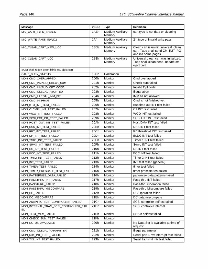
Page 146 LTO SCSI/Fibre Channel Interface Manual
Message VSCQ Type DefinitionMIC_CART_TYPE_INVALID 1AEh Medium Auxiliary
Memorycart type is not data or cleaning
MIC_WRITE_PASS_INVLD2 1Afh Medium AuxiliaryMemory
2nd type of invalid write pass
MIC_CLEAN_CART_NEW_UCC 1B0h Medium AuxiliaryMemory
Clean cart is uninit universal cleancart. Tape shall send CM_INIT_PGand init some pages
MIC_CLEAN_CART_UCC 1B1h Medium AuxiliaryMemory
Universal clean cart was initialized.Tape shall clean head, update cm,eject cart
SCSI shall report error, blink led, eject cartCALIB_BUSY_STATUS 1C0h CalibrationMON_CMD_OVERLAPPED 200h Monitor Cmd overlappedMON_CMD_INVALID_CHECK_SUM 201h Monitor Check sum failedMON_CMD_INVALID_OPT_CODE 202h Monitor Invalid Opt codeMON_CMD_ILLEGAL_ABORTED 203h Monitor Illegal abortMON_CMD_ILLEGAL_IMM_BIT 204h Monitor IMM bit not allowedMON_CMD_IN_PROG 205h Monitor Cmd is not finished yetMON_BTO_INT_TEST_FAILED 206h Monitor Bus time-out INT test failedMON_C1CMPL_INT_TEST_FAILED 207h Monitor C1 INT test failedMON_WCQ_INT_TEST_FAILED 208h Monitor WCQ INT test failedMON_SCSI_EXT_INT_TEST_FAILED 209h Monitor SCSI EXT INT test failedMON_HOST_DMA_INT_TEST_FAILED 20Ah Monitor Host DMA INT test failedMON_DSS_INT_TEST_FAILED 20Bh Monitor DSS INT test failedMON_RBT_INT_TEST_FAILED 20Ch Monitor RB threshold INT test failedMON_DP_INT_TEST_FAILED 20Dh Monitor ELDC INT test failedMON_TMR1_INT_TEST_FAILED 20Eh Monitor Timer 1 INT test failedMON_SRVO_INT_TEST_FAILED 20Fh Monitor Servo INT test failedMON_DS_INT_TEST_FAILED 210h Monitor DS INT test failedMON_ECC_INT_TEST_FAILED 211h Monitor ECC INT test failedMON_TMR2_INT_TEST_FAILED 212h Monitor Timer 2 INT test failedMON_INT_TEST_FAILED 213h Monitor INT test failed (general)MON_TIMER_TEST_FAILED 214h Monitor timer test failedMON_TIMER_PRESCALE_TEST_FAILED 215h Monitor timer prescale test failedMON_PATTERNIZE_DATA_FAILED 216h Monitor patternize data patterns failedMON_PASSTHRU_INT_FAILED 217h Monitor Pass-thru INT failedMON_PASSTHRU_FAILED 218h Monitor Pass-thru Operation failedMON_PASSTHRU_MISCOMPARE 219h Monitor Pass-thru Miscompare failedMON_DC_FAILED 21Ah Monitor DC Operation failedMON_DC_MISCOMPARE 21Bh Monitor DC data miscompareMON_ADAPTEC_SCSI_CONTROLLER_FAILED 21Ch Monitor SCSI controller selftest failedMON_INTERNAL_SRAM_SCSI_CONTROLLER_FAILED
21Dh Monitor SCSI controller internal
MON_TEST_MEM_FAILED 21Eh Monitor SRAM selftest failedMON_CHECK_SUM_TEST_FAILED 21Fh MonitorMON_NO_DS_AVAILABLE 220h Monitor No Data Set is available at time of
requestMON_CMD_ILLEGAL_PARAMETER 221h Monitor Illegal parameterMON_RX1_INT_TEST_FAILED 222h Monitor Serial port 1 rcv interrupt test failedMON_TX1_INT_TEST_FAILED 223h Monitor Serial transmit intr test failed

Appendix A: Message Codes Page 147
Message VSCQ Type DefinitionMON_RX2_INT_TEST_FAILED 224h Monitor Timer 1 intr test failedMON_TIMER1_INT_TEST_FAILED 225h Monitor Serial port 2 rcv intr test failedMON_TX2_INT_TEST_FAILED 226h Monitor Serial port 2 transmit intr test failedMON_RTC_INT_TEST_FAILED 227h Monitor Real time clock intr test failedMON_SC_EXTERNAL_SRAM_TEST_FAILED 228h Monitor Scrambler External SRAM test
failedMON_SC_INTERNAL_SRAM_TEST_FAILED 229h Monitor Scrambler Internal SRAM test failedMON_SC_SDRAM_TEST_FAILED 22Ah Monitor Scrambler Data Set SDRAM test
failedMON_WP_INTERNAL_SRAM_TEST_FAILED 22Bh Monitor Servo Internal RAM test failedMON_WP_EXTERNAL_SRAM_TEST_FAILED 22Ch Monitor Servo External RAM test failedMON_DS_INTERNAL_SRAM_TEST_FAILED 22Dh Monitor Data Set Internal SRAM test failedMON_NEXT_STEP_READY 22Eh Monitor Command ready for next step,
waiting for no responseMON_COMPRESSION_SCHEME_1_FAILED 22Fh Monitor Compression Scheme 1 failureMON_COMPRESSION_SCHEME_2_FAILED 230h Monitor Compression Scheme 2 failureMON_COMPRESSION_AUTO_SCHEME_FAILED 231h Monitor Auto Scheme Compression failureMON_DECOMPRESSION_SCHEME_1_FAILED 232h Monitor Decompression Scheme 1 failureMON_DECOMPRESSION_SCHEME_2_FAILED 233h Monitor Decompression Scheme 2 failureMON_DECOMPRESSION_AUTO_SCHEME_FAILED 234h Monitor Auto Scheme Decompression fail-
ureMON_DESC_ERRORS 235h Monitor Despcriptor Errors detectedMON_CRC_ERROR 236h Monitor CRC checking errorMON_INVALID_PARAMETERS 237h Monitor Invalid parameters field in cmd
packetMON_NO_CARTRIDGE_INSERTED 238h Monitor No Cartridge insertedMON_SERVO_MARGIN_DATA_IS_NOT_AVAILABLE 239h MonitorSRV_LPOS_NOTIFICATION_NOT_FOUND 240h Servo Delete lpos failed because it was
not in the notify table.SRV_LPOS_UNRECOGNIZED_LPOS_DELETE_MODE
241h Servo Delete mode not recognized as avalid enum.
SRV_LPOS_READ_DIR_INVALID 242h Servo Invalid direction in lpos notificationcheck
SRV_MOVETAPE_REVERSE_PHYSICAL_LIMIT_UNDERRUN_DURING_RAMP_UP
243h Servo Physical limit in reverse directionexceeded in ramp up state.
SRV_MOVETAPE_RAMP_DOWN_FAILED_AT_LPOS_NOTIFICATION
244h Servo A ramp down attempt was rejectedby the fiq servo code during thecruise control state when the tapewas already at the lpos location.
SRV_MOVETAPE_RAMP_DOWN_FAILED_WHEN_REVERSING_DIR
245h Servo A ramp down attempt was rejectedby the fiq servo code during thecruise control state when the taperequired a reverse of direction.
SRV_MOVETAPE_RAMP_DOWN_FAILED_WHEN_SPEED_CHANGE_REQUIRED
246h Servo A ramp down attempt was rejectedby the fiq servo code during thecruise control state when a speedchange was required.
SRV_MOVETAPE_TAPE_ACTIVE_CMD_NOT_VALID_FOR_THIS_STATE
247h Servo In tape state machine - activecommand not valid for this state.
SRV_MOVETAPE_TAPE_RAMP_UP_FAILED_FROM_IDLE_STATE
248h Servo Ramp up failed insrv_skip_to_lpos_in_idle transitionfunction.
SRV_MOVETAPE_UNEXPECTED_MESSAGE_RES 249h Servo An unexpected message was re-

Page 148 LTO SCSI/Fibre Channel Interface Manual
Message VSCQ Type DefinitionPONSE_IN_CRUISE_CONTROL ceived in the cruise control.SRV_LPOS_REJECT_LPOS_SET_LPOS_NOTIFICATION_BECAUSE_TABLE_IN_USE
24Ah Servo Notification table being updated byother task - access denied.
SRV_MOVETAPE_RAMPDOWN_FAILED_DURING_LPOS_UNDERRUN_IN_CRUISE_CONTROL
24Bh Servo Tape lpos underrun error duringcruise control state.
SRV_MOVETAPE_RAMPDOWN_FAILED_DURING_LPOS_OVERRUN_IN_CRUISE_CONTROL
24Ch Servo Tape lpos overrun error duringcruise control state.
SRV_MOVETAPE_FORWARD_PHYSICAL_LIMIT_OVERRUN_DURING_CRUISE_CONTROL
24Dh Servo Physical limit exceeded in forwarddirection.
SRV_SEQ_TABLE_LOOKUP_ERROR 24Eh Servo Sequencer table incorrectly definedat compile time.
SRV_SEQ_MAXIMUM_STATE_EXCEEDED 24Fh Servo Sequencer index exceeded maxi-mum number of functions in table.
SRV_REEL_MAXIMUM_STATE_EXCEEDED 250h Servo Reel task state variable exceedednumber of defined states.
SRV_CMDPROC_NOT_ENOUGH_TAPE_TO_RAMP 251h Servo Not enough tape is available toramp up before a PBOT or PEOTcondition ramps down.
SRV_CMDPROC_PAST_LP1_REJ_INV_STATE 252h Servo Command rejected since we are al-ready past lp1.
SRV_CMDPROC_PAST_LP6_REJ_INV_STATE 253h Servo Command rejected since we are al-ready past lp6.
SRV_CMDPROC_REJ_NO_LP1 254h Servo Command rejected since tape pa-rameters were not set.
SRV_CMDPROC_REJ_PARM 255h Servo Command rejected in commandprocessor because of invalid pa-rameter value.
SRV_CMDPROC_REJ_INV_DIR 256h Servo Command rejectedSRV_CMDPROC_REJ_CMD_NOT_ENOUGH_TAPE_TO_RAMP
257h Servo Command rejected - not enoughtape to ramp before lpos.
SRV_CMDPROC_REJ_CMD_TAPE_PAST_TARGET_LPOS
258h Servo Command rejected - tape past tar-get lpos already.
SRV_CMDPROC_TAPE_NOT_STOPPED 259h Servo Command rejected - tape in mo-tion.
SRV_REEL_UNKNOWN_TAPE_MOVE_COMMAND 25Ah Servo Reel task recieved a command notrecognized as a tape movementcommand
SRV_MOVETAPE_RAMPDOWNTAPE_API_BUSY_REJECT
25Bh Servo Servo API function RampDown-Tape() returned busy status.
SRV_MOVETAPE_MOVETAPETRACK_API_BUSY_REJECT
25Ch Servo Servo API function MoveTape-Track() returned busy status.
SRV_MOVETAPE_MOVETAPE_API_BUSY_REJECT 25Dh Servo Servo API function MoveTape() re-turned busy status.
SRV_REEL_INVALID_MESSAGE_RECEIVED 25Eh Servo An invalid message was recievedby the reel task.
SRV_REEL_DRIVEMOTOR_ON_API_BUSY_REJECT
25Fh Servo API call DriverMotor failed.
SRV_REEL_DRIVEMOTOR_OFF_API_BUSY_REJECT
260h Servo API call DriverMotor failed.
SRV_REEL_MOTORPOWEROFF_API_BUSY_REJECT
261h Servo API call MotorPowerOff failed.
SRV_REEL_TIMEOUT_USER_ABORT_STATE 262h Servo Timeout message recieved inUSER_ABORT_STATE.
SRV_REEL_TIMEOUT_USER_ABORT_TAPE_STATE
263h Servo Timeout message recieved inUSER_ABORT_TAPE_STATE.
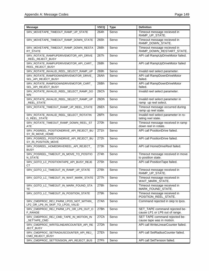
Appendix A: Message Codes Page 149
Message VSCQ Type DefinitionSRV_MOVETAPE_TIMEOUT_RAMP_UP_STATE 264h Servo Timeout message recieved in
RAMP_UP_STATE.SRV_MOVETAPE_TIMEOUT_RAMP_DOWN_STATE 265h Servo Timeout message recieved in
RAMP_DOWN_STATE.SRV_MOVETAPE_TIMEOUT_RAMP_DOWN_RESTART_STATE
266h Servo Timeout message recieved inRAMP_DOWN_RESTART_STATE.
SRV_ROTATE_RAMPUPDRIVEMOTOR_API_DRIVE_REEL_REJECT_BUSY
267h Servo API call RampUpDriveMotor failed.
SRV_ROTATE_RAMPUPDRIVEMOTOR_API_CART_REEL_REJECT_BUSY
268h Servo API call RampUpDriveMotor failed
SRV_ROTATE_INVALID_REEL_SELECT_RAMP_UP 269h Servo Invalid reel select parameter.SRV_ROTATE_RAMPDOWNDRIVEMOTOR_DRIVE_SEL_API_REJECT_BUSY
26Ah Servo API call RampDownDriveMotorfailed.
SRV_ROTATE_RAMPDOWNDRIVEMOTOR_CART_SEL_API_REJECT_BUSY
26Bh Servo API call RampDownDriveMotorfailed.
SRV_ROTATE_INVALID_REEL_SELECT_RAMP_DOWN
26Ch Servo Invalid reel select parameter.
SRV_ROTATE_INVALID_REEL_SELECT_RAMP_UP_REEL_STATE
26Dh Servo Invalid reel select parameter inramp up reel select.
SRV_ROTATE_TIMEOUT_RAMP_UP_REEL_STATE 26Eh Servo Timeout message occurred duringramp up reel state.
SRV_ROTATE_INVALID_REEL_SELECT_ROTATING_REEL_STATE
26Fh Servo Invalid reel select parameter in ro-tating reel state.
SRV_ROTATE_TIMEOUT_RAMP_DOWN_REEL_STATE
270h Servo Timeout message received in rampdown reel in rotate.
SRV_POSREEL_POSITIONDRIVE_API_REJECT_BUSY_IN_MOVE_HOME
271h Servo API call PositionDrive failed.
SRV_POSREEL_POSITIONDRIVE_API_REJECT_BUSY_IN_POSITION_MOVE
272h Servo API call PositionDrive failed.
SRV_POSREEL_HOMEDRIVEREEL_API_REJECT_BUSY
273h Servo API call HomeDriveReel failed.
SRV_POSREEL_TIMEOUT_IN_MOVE_TO_POSITION_STATE
274h Servo Timeout message received in moveto position state.
SRV_GOTO_LC_POSITIONTAPE_API_BUSY_REJECT
275h Servo API call PositionTape failed.
SRV_GOTO_LC_TIMEOUT_IN_RAMP_UP_STATE 276h Servo Timeout message received inRAMP_UP_STATE.
SRV_GOTO_LC_TIMEOUT_IN_WAIT_MARK_STATE 277h Servo Timeout message received inWAIT_MARK_STATE.
SRV_GOTO_LC_TIMEOUT_IN_MARK_FOUND_STATE
278h Servo Timeout message received inMARK_FOUND_STATE.
SRV_GOTO_LC_TIMEOUT_IN_POSITION_STATE 279h Servo Timeout message received inPOSITION_REEL_STATE.
SRV_CMDPROC_REJ_PARM_LPOS_NOT_WITHIN_LP2_OR_LP6_IN_SKIP_TO_LPOS_VALID
27Ah Servo Command rejected in skip to lpos.
SRV_CMDPROC_REJ_PARM_LP1_OR_LP6_OUT_OF_RANGE
27Bh Servo SET_TAPE command rejected be-cause LP1 or LP6 out of range.
SRV_CMDPROC_REJ_CMD_TAPE_IN_MOTION_IN_SETTAPE_CMD
27Ch Servo SET TAPE command rejected be-cause tape was in motion.
SRV_CMDPROC_WRITELINEARCOUNTER_API_REJECT_BUSY
27Dh Servo API call WriteLinearCounter failed.
SRV_CMDPROC_SETRADIUSCOUNTER_API_REJ_CMD_REJECT_BUSY
27Eh Servo API call SetRadiusCounter failed.
SRV_CMDPROC_SETTENSION_API_REJECT_BUS 27Fh Servo API call SetTension failed.
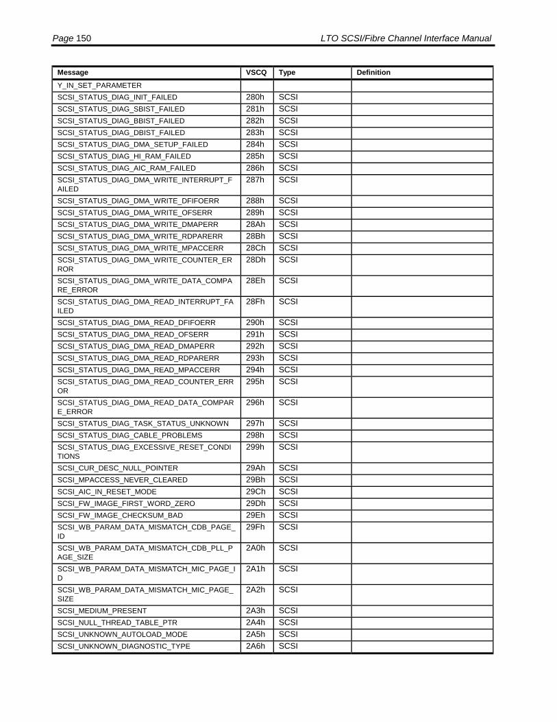
Page 150 LTO SCSI/Fibre Channel Interface Manual
Message VSCQ Type DefinitionY_IN_SET_PARAMETERSCSI_STATUS_DIAG_INIT_FAILED 280h SCSISCSI_STATUS_DIAG_SBIST_FAILED 281h SCSISCSI_STATUS_DIAG_BBIST_FAILED 282h SCSISCSI_STATUS_DIAG_DBIST_FAILED 283h SCSISCSI_STATUS_DIAG_DMA_SETUP_FAILED 284h SCSISCSI_STATUS_DIAG_HI_RAM_FAILED 285h SCSISCSI_STATUS_DIAG_AIC_RAM_FAILED 286h SCSISCSI_STATUS_DIAG_DMA_WRITE_INTERRUPT_FAILED
287h SCSI
SCSI_STATUS_DIAG_DMA_WRITE_DFIFOERR 288h SCSISCSI_STATUS_DIAG_DMA_WRITE_OFSERR 289h SCSISCSI_STATUS_DIAG_DMA_WRITE_DMAPERR 28Ah SCSISCSI_STATUS_DIAG_DMA_WRITE_RDPARERR 28Bh SCSISCSI_STATUS_DIAG_DMA_WRITE_MPACCERR 28Ch SCSISCSI_STATUS_DIAG_DMA_WRITE_COUNTER_ERROR
28Dh SCSI
SCSI_STATUS_DIAG_DMA_WRITE_DATA_COMPARE_ERROR
28Eh SCSI
SCSI_STATUS_DIAG_DMA_READ_INTERRUPT_FAILED
28Fh SCSI
SCSI_STATUS_DIAG_DMA_READ_DFIFOERR 290h SCSISCSI_STATUS_DIAG_DMA_READ_OFSERR 291h SCSISCSI_STATUS_DIAG_DMA_READ_DMAPERR 292h SCSISCSI_STATUS_DIAG_DMA_READ_RDPARERR 293h SCSISCSI_STATUS_DIAG_DMA_READ_MPACCERR 294h SCSISCSI_STATUS_DIAG_DMA_READ_COUNTER_ERROR
295h SCSI
SCSI_STATUS_DIAG_DMA_READ_DATA_COMPARE_ERROR
296h SCSI
SCSI_STATUS_DIAG_TASK_STATUS_UNKNOWN 297h SCSISCSI_STATUS_DIAG_CABLE_PROBLEMS 298h SCSISCSI_STATUS_DIAG_EXCESSIVE_RESET_CONDITIONS
299h SCSI
SCSI_CUR_DESC_NULL_POINTER 29Ah SCSISCSI_MPACCESS_NEVER_CLEARED 29Bh SCSISCSI_AIC_IN_RESET_MODE 29Ch SCSISCSI_FW_IMAGE_FIRST_WORD_ZERO 29Dh SCSISCSI_FW_IMAGE_CHECKSUM_BAD 29Eh SCSISCSI_WB_PARAM_DATA_MISMATCH_CDB_PAGE_ID
29Fh SCSI
SCSI_WB_PARAM_DATA_MISMATCH_CDB_PLL_PAGE_SIZE
2A0h SCSI
SCSI_WB_PARAM_DATA_MISMATCH_MIC_PAGE_ID
2A1h SCSI
SCSI_WB_PARAM_DATA_MISMATCH_MIC_PAGE_SIZE
2A2h SCSI
SCSI_MEDIUM_PRESENT 2A3h SCSISCSI_NULL_THREAD_TABLE_PTR 2A4h SCSISCSI_UNKNOWN_AUTOLOAD_MODE 2A5h SCSISCSI_UNKNOWN_DIAGNOSTIC_TYPE 2A6h SCSI
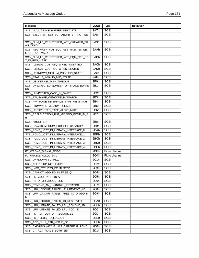
Appendix A: Message Codes Page 151
Message VSCQ Type DefinitionSCSI_NULL_TRACE_BUFFER_NEXT_PTR 2A7h SCSISCSI_EJECT_BIT_SET_BUT_ABORT_BIT_NOT_SET
2A8h SCSI
SCSI_NUM_IID_REGISTERED_NOT_GREATER_THAN_ZERO
2A9h SCSI
SCSI_REG_MASK_NOT_EQU_RES_MASK_BITWISE_OR_REG_MASK
2AAh SCSI
SCSI_NUM_IID_REGISTERED_NOT_EQU_BITS_SET_IN_REG_MASK
2ABh SCSI
SCSI_ILLEGAL_CDB_REQ_WHEN_INSERTED 2ACh SCSISCSI_ILLEGAL_CDB_REQ_WHEN_SEATED 2ADh SCSISCSI_UNKNOWN_MEDIUM_POSITION_STATE 2Aeh SCSISCSI_STATUS_INVALID_MIC_STATE 2Afh SCSISCSI_LIB_KERNEL_MSG_TIMEOUT 2B0h SCSISCSI_UNEXPECTED_NUMBER_OF_TRACE_BUFFERS
2B1h SCSI
SCSI_UNXPECTED_CASE_IN_SWITCH 2B2h SCSISCSI_FW_IMAGE_OEMCODE_MISMATCH 2B3h SCSISCSI_FW_IMAGE_INTERFACE_TYPE_MISMATCH 2B4h SCSISCSI_FIRMWARE_MEDIUM_PRESENT 2B5h SCSISCSI_UNEXPECTED_TAPE_ALERT_MRIE 2B6h SCSISCSI_RESLELECTION_BUT_MISSING_PCMD_IN_FE
2B7h SCSI
SCSI_HTEST_ERR 2B8h SCSISCSI_INVALID_MEDIUM_FOR_SET_CAPACITY 2B9h SCSISCSI_PCMD_LOST_IN_LIBRARY_INTERFACE_0 2BAh SCSISCSI_PCMD_LOST_IN_LIBRARY_INTERFACE_1 2BBh SCSISCSI_PCMD_LOST_IN_LIBRARY_INTERFACE_2 2BCh SCSISCSI_PCMD_LOST_IN_LIBRARY_INTERFACE_3 2BDh SCSISCSI_PCMD_LOST_IN_LIBRARY_INTERFACE_4 2BEh SCSIFC_WRONG_SIGNAL_NODE 2BFh Fibre channelFC_UNABLE_ALLOC_DTD 2C0h Fibre channelSCSI_UNKNOWN_FC_MSG 2C1h SCSISCSI_XFERSTOP_NOT_FOUND 2C2h SCSISCSI_INFO_STRUCTS_EXHAUSTED 2C3h SCSISCSI_CANNOT_ADD_IID_IN_FREE_Q 2C4h SCSISCSI_IID_LOST_IN_FREE_Q 2C5h SCSISCSI_INITIATOR_ADDED_LOST 2C6h SCSISCSI_REMOVE_AN_UNKNOWN_INITIATOR 2C7h SCSISCSI_LRU_LOGOUT_FAILED_LRU_REMOVE_IID 2C8h SCSISCSI_LRU_LOGOUT_FAILED_FREE_IID_Q_ADD_IID
2C9h SCSI
SCSI_LRU_LOGOUT_FAILED_IID_RESERVED 2CAh SCSISCSI_LRU_UPDATE_FAILED_LRU_REMOVE_IID 2CBh SCSISCSI_LRU_UPDATE_FAILED_LRU_ADD_IID 2CCh SCSISCSI_IID_RUN_OUT_OF_RESOURCES 2CDh SCSISCSI_IID_NEEDS_TO_LOGOUT 2CEh SCSISCSI_ADD_NULL_PTR_NEXUS_DB 2CFh SCSISCSI_EXISTING_NEXUS_HAS_DIFFERENT_PCMD 2D0h SCSISCSI_CA_ACA_FLAGS_BOTH_SET 2D1h SCSI

Page 152 LTO SCSI/Fibre Channel Interface Manual
Message VSCQ Type DefinitionSCSI_HAPI_UNEXPECTED_RECORD_TYPE 2D2h SCSISCSI_UNKNOWN_SIGNAL_NODE 2D3h SCSISCSI_INVALID_COMMAND_DONE_SIGNAL_NODE 2D4h SCSISCSI_UNKNOWN_TASK_MANAGEMENT_SIGNAL_NODE
2D5h SCSI
SCSI_UNKNOWN_THRESHOLD_INTERRUPT 2D6h SCSISCSI_NULL_PSCSIINFO_FROM_DMA 2D7h SCSISCSI_STREAMOP_BUT_VALID_PACTIVE_CMD 2D8h SCSISCSI_FCP_INVALID_PORT_NUMBER_GET_WWN 2D9h SCSISCSI_FCP_INVALID_PORT_NUMBER_ID_CHANGE 2DAh SCSISCSI_FCP_PORT_DB_ENTRY_NOT_FOUND 2DBh SCSISCSI_FCP_INVALID_PORT_NUMBER_ATTACH_CHANGE
2DCh SCSI
SCSI_STDF_RESTART_DUE_TO_FAILURE 2DDh SCSISCSI_STDF_UNKNOWN_FAILURE 2DEh SCSISCSI_STDF_ASSERTION_FAILURE 2DFh SCSISCSI_STDF_COMPONENT_VERSION_MISMATCH 2E0h SCSISCSI_STDF_STARTUP_FAILURE 2E1h SCSISCSI_STDF_DYNAMIC_CONFIGURATION_FAILURE
2E2h SCSI
SCSI_STDF_UNEXPECTED_OS_BEHAVIOR 2E3h SCSISCSI_STDF_INTERNAL_GENERAL_FAILURE 2E4h SCSISCSI_STDF_INTERNAL_INIT_FAILURE 2E5h SCSISCSI_STDF_LOGICAL_UNIT_INIT_FAILURE 2E6h SCSISCSI_STDF_SD_CONTROLLER_HARDWARE_FAILURE
2E7h SCSI
SCSI_STDF_TRANSPORT_PROTOCOL_FAILURE 2E8h SCSISCSI_STDF_CONFIGURATION_PARAMETER_ERROR
2E9h SCSI
SCSI_STDF_INTERRUPT_NESTING_OVERFLOW 2EAh SCSISCSI_STDF_INSUFFICIENT_DYNAMIC_MEMORY 2EBh SCSISCSI_STDF_MEMORY_POOL_MISMANAGEMENT 2ECh SCSISCSI_STDF_DYNAMIC_MEMORY_CORRUPTION 2EDh SCSISCSI_STDF_BAD_DATA_STRUCTURE_FORMAT 2EEh SCSISCSI_SET_THRESHOLD_NOT_SIZE_ERR 2F4h SCSISCSI_SAPI_GET_CMD_REF_NULL 2F5h SCSISCSI_INVALID_MICROCODE_UPDATE_TYPE 2F6h SCSISCSI_CREATE_SENSE_FAILED 2F7h SCSISCSI_INITIALIZE_SENSE_FAILED 2F8h SCSISCSI_UNKNOWN_CM_EEPROM_STATE 2F9h SCSISCSI_INVALID_LOG_PARAMETER 2Fah SCSISCSI_INVALID_LOG_PAGE 2FBh SCSISCSI_INVALID_LOG_PAGE_CONTROL 2FCh SCSISCSI_PAGE_OUT_OF_RANGE 2FDh SCSI Log page out of rangeSCSI_UNKNOWN_LOG_INFO_RESPONSE 2FEh SCSI Unknown log information responseSCSI_UNKNOWN_LOG_INFO_RESPONSE_DATA_POINTER
2FFh SCSI Unknown log information responsedata pointer
SRV_CMDPROC_CMD_REJECT_ABORT_IN_PROGRESS
300h Servo Abort command rejected since al-ready aborting.
SRV_CMDPROC_CMD_REJECT_SEQUENCER_BU 301h Servo Mechanical command rejected
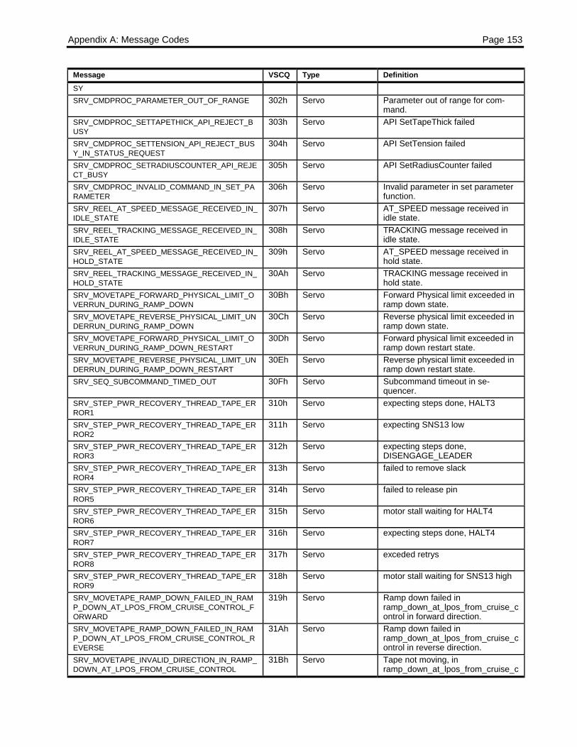
Appendix A: Message Codes Page 153
Message VSCQ Type DefinitionSYSRV_CMDPROC_PARAMETER_OUT_OF_RANGE 302h Servo Parameter out of range for com-
mand.SRV_CMDPROC_SETTAPETHICK_API_REJECT_BUSY
303h Servo API SetTapeThick failed
SRV_CMDPROC_SETTENSION_API_REJECT_BUSY_IN_STATUS_REQUEST
304h Servo API SetTension failed
SRV_CMDPROC_SETRADIUSCOUNTER_API_REJECT_BUSY
305h Servo API SetRadiusCounter failed
SRV_CMDPROC_INVALID_COMMAND_IN_SET_PARAMETER
306h Servo Invalid parameter in set parameterfunction.
SRV_REEL_AT_SPEED_MESSAGE_RECEIVED_IN_IDLE_STATE
307h Servo AT_SPEED message received inidle state.
SRV_REEL_TRACKING_MESSAGE_RECEIVED_IN_IDLE_STATE
308h Servo TRACKING message received inidle state.
SRV_REEL_AT_SPEED_MESSAGE_RECEIVED_IN_HOLD_STATE
309h Servo AT_SPEED message received inhold state.
SRV_REEL_TRACKING_MESSAGE_RECEIVED_IN_HOLD_STATE
30Ah Servo TRACKING message received inhold state.
SRV_MOVETAPE_FORWARD_PHYSICAL_LIMIT_OVERRUN_DURING_RAMP_DOWN
30Bh Servo Forward Physical limit exceeded inramp down state.
SRV_MOVETAPE_REVERSE_PHYSICAL_LIMIT_UNDERRUN_DURING_RAMP_DOWN
30Ch Servo Reverse physical limit exceeded inramp down state.
SRV_MOVETAPE_FORWARD_PHYSICAL_LIMIT_OVERRUN_DURING_RAMP_DOWN_RESTART
30Dh Servo Forward physical limit exceeded inramp down restart state.
SRV_MOVETAPE_REVERSE_PHYSICAL_LIMIT_UNDERRUN_DURING_RAMP_DOWN_RESTART
30Eh Servo Reverse physical limit exceeded inramp down restart state.
SRV_SEQ_SUBCOMMAND_TIMED_OUT 30Fh Servo Subcommand timeout in se-quencer.
SRV_STEP_PWR_RECOVERY_THREAD_TAPE_ERROR1
310h Servo expecting steps done, HALT3
SRV_STEP_PWR_RECOVERY_THREAD_TAPE_ERROR2
311h Servo expecting SNS13 low
SRV_STEP_PWR_RECOVERY_THREAD_TAPE_ERROR3
312h Servo expecting steps done,DISENGAGE_LEADER
SRV_STEP_PWR_RECOVERY_THREAD_TAPE_ERROR4
313h Servo failed to remove slack
SRV_STEP_PWR_RECOVERY_THREAD_TAPE_ERROR5
314h Servo failed to release pin
SRV_STEP_PWR_RECOVERY_THREAD_TAPE_ERROR6
315h Servo motor stall waiting for HALT4
SRV_STEP_PWR_RECOVERY_THREAD_TAPE_ERROR7
316h Servo expecting steps done, HALT4
SRV_STEP_PWR_RECOVERY_THREAD_TAPE_ERROR8
317h Servo exceded retrys
SRV_STEP_PWR_RECOVERY_THREAD_TAPE_ERROR9
318h Servo motor stall waiting for SNS13 high
SRV_MOVETAPE_RAMP_DOWN_FAILED_IN_RAMP_DOWN_AT_LPOS_FROM_CRUISE_CONTROL_FORWARD
319h Servo Ramp down failed inramp_down_at_lpos_from_cruise_control in forward direction.
SRV_MOVETAPE_RAMP_DOWN_FAILED_IN_RAMP_DOWN_AT_LPOS_FROM_CRUISE_CONTROL_REVERSE
31Ah Servo Ramp down failed inramp_down_at_lpos_from_cruise_control in reverse direction.
SRV_MOVETAPE_INVALID_DIRECTION_IN_RAMP_DOWN_AT_LPOS_FROM_CRUISE_CONTROL
31Bh Servo Tape not moving, inramp_down_at_lpos_from_cruise_c
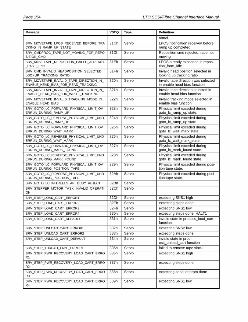
Page 154 LTO SCSI/Fibre Channel Interface Manual
Message VSCQ Type Definitionontrol.
SRV_MOVETAPE_LPOS_RECEIVED_BEFORE_TRACKING_IN_RAMP_UP_STATE
31Ch Servo LPOS notification received beforeramp up completed.
SRV_CMDPROC_TAPE_NOT_MOVING_FOR_REPOSITION_CMD
31Dh Servo Reposition cmd rejected, tape notmoving
SRV_MOVETAPE_REPOSITION_FAILED_ALREADY_PAST_LPOS
31Eh Servo LPOS already exceeded in reposi-tion_from_idle
SRV_CMD_INVALID_HEADPOSITION_SELECTED_LOOKUP_TRACKING_RATIO
31Fh Servo Invalid head position selected inlooking up tracking ratio
SRV_MOVETAPE_INVALID_TAPE_DIRECTION_IN_ENABLE_HEAD_BIAS_FOR_READ_TRACKING
320h Servo Invalid tape direction was selectedin enable head bias function
SRV_MOVETAPE_INVALID_TAPE_DIRECTION_IN_ENABLE_HEAD_BIAS_FOR_WRITE_TRACKING
321h Servo Invalid tape direction selected inenable head bias function
SRV_MOVETAPE_INVALID_TRACKING_MODE_IN_ENABLE_HEAD_BIAS
322h Servo Invalid tracking mode selected inenable bias function
SRV_GOTO_LC_FORWARD_PHYSICAL_LIMIT_OVERRUN_DURING_RAMP_UP
323h Servo Physical limit exceded duringgoto_lc_ramp_up state.
SRV_GOTO_LC_REVERSE_PHYSICAL_LIMIT_UNDERRUN_DURING_RAMP_UP
324h Servo Physical limit exceded duringgoto_lc_ramp_up state.
SRV_GOTO_LC_FORWARD_PHYSICAL_LIMIT_OVERRUN_DURING_WAIT_MARK
325h Servo Physical limit exceded duringgoto_lc_wait_mark state.
SRV_GOTO_LC_REVERSE_PHYSICAL_LIMIT_UNDERRUN_DURING_WAIT_MARK
326h Servo Physical limit exceded duringgoto_lc_wait_mark_state.
SRV_GOTO_LC_FORWARD_PHYSICAL_LIMIT_OVERRUN_DURING_MARK_FOUND
327h Servo Physical limit exceded duringgoto_lc_mark_found state.
SRV_GOTO_LC_REVERSE_PHYSICAL_LIMIT_UNDERRUN_DURING_MARK_FOUND
328h Servo Physical limit exceded duringgoto_lc_mark_found state.
SRV_GOTO_LC_FORWARD_PHYSICAL_LIMIT_OVERRUN_DURING_POSITION_TAPE
329h Servo Physical limit exceded during posi-tion tape state.
SRV_GOTO_LC_REVERSE_PHYSICAL_LIMIT_UNDERRUN_DURING_POSITION_TAPE
32Ah Servo Physical limit exceded during posi-tion tape state.
SRV_GOTO_LC_INITREELS_API_BUSY_REJECT 32Bh ServoSRV_STEPPER_MOTOR_TASK_INVALID_OPERATION
32Ch Servo
SRV_STEP_LOAD_CART_ERROR1 32Dh Servo expecting SNS1 highSRV_STEP_LOAD_CART_ERROR2 32Eh Servo expecting steps doneSRV_STEP_LOAD_CART_ERROR3 32Fh Servo expecting SNS1 lowSRV_STEP_LOAD_CART_ERROR4 330h Servo expecting steps done, HALT1SRV_STEP_LOAD_CART_DEFAULT 331h Servo invalid state in process_load_cart
functionSRV_STEP_UNLOAD_CART_ERROR1 332h Servo expecting SNS2 lowSRV_STEP_UNLOAD_CART_ERROR2 333h Servo expecting steps doneSRV_STEP_UNLOAD_CART_DEFAULT 334h Servo invalid state in proc-
ess_unload_cart functionSRV_STEP_THREAD_TAPE_ERROR1 335h Servo failed to remove tape slackSRV_STEP_PWR_RECOVERY_LOAD_CART_ERROR1
336h Servo expecting SNS1 high
SRV_STEP_PWR_RECOVERY_LOAD_CART_ERROR2
337h Servo expecting steps done
SRV_STEP_PWR_RECOVERY_LOAD_CART_ERROR3
338h Servo expecting serial eeprom done
SRV_STEP_PWR_RECOVERY_LOAD_CART_ERROR4
339h Servo expecting SNS1 low
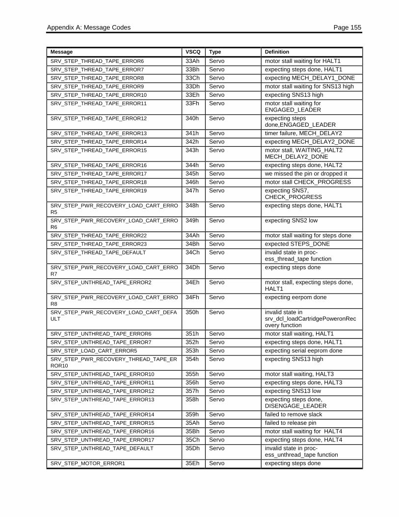
Appendix A: Message Codes Page 155
Message VSCQ Type DefinitionSRV_STEP_THREAD_TAPE_ERROR6 33Ah Servo motor stall waiting for HALT1SRV_STEP_THREAD_TAPE_ERROR7 33Bh Servo expecting steps done, HALT1SRV_STEP_THREAD_TAPE_ERROR8 33Ch Servo expecting MECH_DELAY1_DONESRV_STEP_THREAD_TAPE_ERROR9 33Dh Servo motor stall waiting for SNS13 highSRV_STEP_THREAD_TAPE_ERROR10 33Eh Servo expecting SNS13 highSRV_STEP_THREAD_TAPE_ERROR11 33Fh Servo motor stall waiting for
ENGAGED_LEADERSRV_STEP_THREAD_TAPE_ERROR12 340h Servo expecting steps
done,ENGAGED_LEADERSRV_STEP_THREAD_TAPE_ERROR13 341h Servo timer failure, MECH_DELAY2SRV_STEP_THREAD_TAPE_ERROR14 342h Servo expecting MECH_DELAY2_DONESRV_STEP_THREAD_TAPE_ERROR15 343h Servo motor stall, WAITING_HALT2
MECH_DELAY2_DONESRV_STEP_THREAD_TAPE_ERROR16 344h Servo expecting steps done, HALT2SRV_STEP_THREAD_TAPE_ERROR17 345h Servo we missed the pin or dropped itSRV_STEP_THREAD_TAPE_ERROR18 346h Servo motor stall CHECK_PROGRESSSRV_STEP_THREAD_TAPE_ERROR19 347h Servo expecting SNS7,
CHECK_PROGRESSSRV_STEP_PWR_RECOVERY_LOAD_CART_ERROR5
348h Servo expecting steps done, HALT1
SRV_STEP_PWR_RECOVERY_LOAD_CART_ERROR6
349h Servo expecting SNS2 low
SRV_STEP_THREAD_TAPE_ERROR22 34Ah Servo motor stall waiting for steps doneSRV_STEP_THREAD_TAPE_ERROR23 34Bh Servo expected STEPS_DONESRV_STEP_THREAD_TAPE_DEFAULT 34Ch Servo invalid state in proc-
ess_thread_tape functionSRV_STEP_PWR_RECOVERY_LOAD_CART_ERROR7
34Dh Servo expecting steps done
SRV_STEP_UNTHREAD_TAPE_ERROR2 34Eh Servo motor stall, expecting steps done,HALT1
SRV_STEP_PWR_RECOVERY_LOAD_CART_ERROR8
34Fh Servo expecting eerpom done
SRV_STEP_PWR_RECOVERY_LOAD_CART_DEFAULT
350h Servo invalid state insrv_dcl_loadCartridgePoweronRecovery function
SRV_STEP_UNTHREAD_TAPE_ERROR6 351h Servo motor stall waiting, HALT1SRV_STEP_UNTHREAD_TAPE_ERROR7 352h Servo expecting steps done, HALT1SRV_STEP_LOAD_CART_ERROR5 353h Servo expecting serial eeprom doneSRV_STEP_PWR_RECOVERY_THREAD_TAPE_ERROR10
354h Servo expecting SNS13 high
SRV_STEP_UNTHREAD_TAPE_ERROR10 355h Servo motor stall waiting, HALT3SRV_STEP_UNTHREAD_TAPE_ERROR11 356h Servo expecting steps done, HALT3SRV_STEP_UNTHREAD_TAPE_ERROR12 357h Servo expecting SNS13 lowSRV_STEP_UNTHREAD_TAPE_ERROR13 358h Servo expecting steps done,
DISENGAGE_LEADERSRV_STEP_UNTHREAD_TAPE_ERROR14 359h Servo failed to remove slackSRV_STEP_UNTHREAD_TAPE_ERROR15 35Ah Servo failed to release pinSRV_STEP_UNTHREAD_TAPE_ERROR16 35Bh Servo motor stall waiting for HALT4SRV_STEP_UNTHREAD_TAPE_ERROR17 35Ch Servo expecting steps done, HALT4SRV_STEP_UNTHREAD_TAPE_DEFAULT 35Dh Servo invalid state in proc-
ess_unthread_tape functionSRV_STEP_MOTOR_ERROR1 35Eh Servo expecting steps done
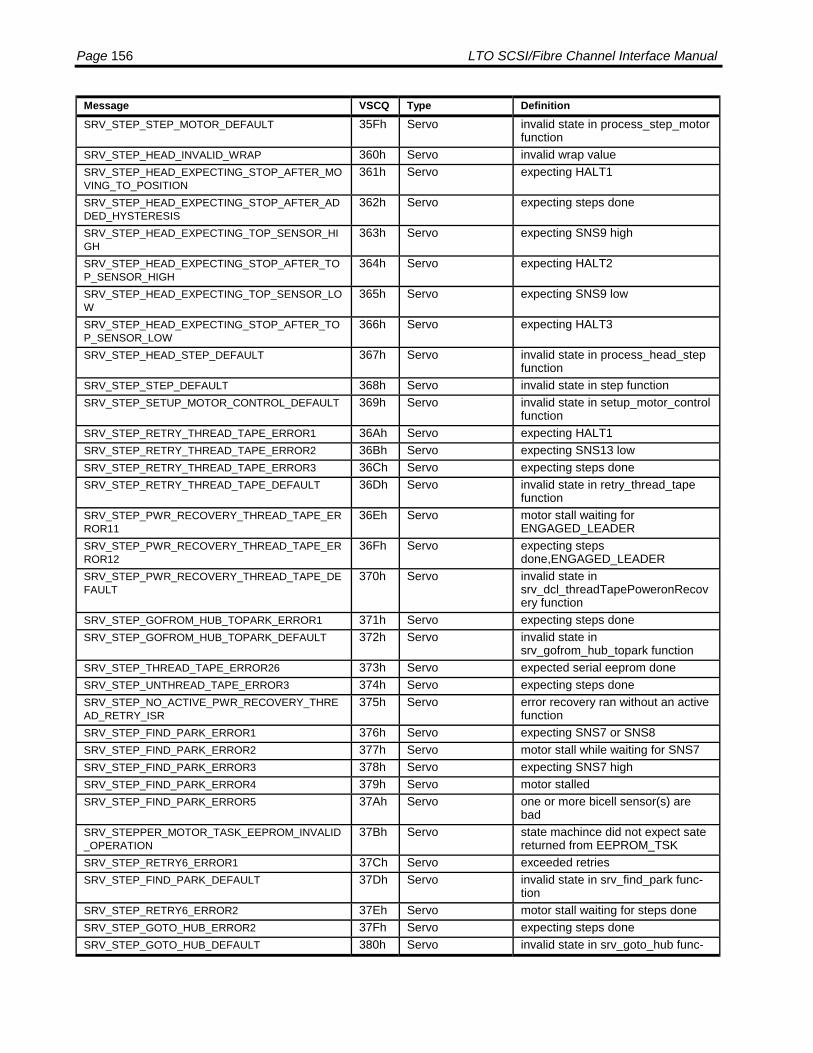
Page 156 LTO SCSI/Fibre Channel Interface Manual
Message VSCQ Type DefinitionSRV_STEP_STEP_MOTOR_DEFAULT 35Fh Servo invalid state in process_step_motor
functionSRV_STEP_HEAD_INVALID_WRAP 360h Servo invalid wrap valueSRV_STEP_HEAD_EXPECTING_STOP_AFTER_MOVING_TO_POSITION
361h Servo expecting HALT1
SRV_STEP_HEAD_EXPECTING_STOP_AFTER_ADDED_HYSTERESIS
362h Servo expecting steps done
SRV_STEP_HEAD_EXPECTING_TOP_SENSOR_HIGH
363h Servo expecting SNS9 high
SRV_STEP_HEAD_EXPECTING_STOP_AFTER_TOP_SENSOR_HIGH
364h Servo expecting HALT2
SRV_STEP_HEAD_EXPECTING_TOP_SENSOR_LOW
365h Servo expecting SNS9 low
SRV_STEP_HEAD_EXPECTING_STOP_AFTER_TOP_SENSOR_LOW
366h Servo expecting HALT3
SRV_STEP_HEAD_STEP_DEFAULT 367h Servo invalid state in process_head_stepfunction
SRV_STEP_STEP_DEFAULT 368h Servo invalid state in step functionSRV_STEP_SETUP_MOTOR_CONTROL_DEFAULT 369h Servo invalid state in setup_motor_control
functionSRV_STEP_RETRY_THREAD_TAPE_ERROR1 36Ah Servo expecting HALT1SRV_STEP_RETRY_THREAD_TAPE_ERROR2 36Bh Servo expecting SNS13 lowSRV_STEP_RETRY_THREAD_TAPE_ERROR3 36Ch Servo expecting steps doneSRV_STEP_RETRY_THREAD_TAPE_DEFAULT 36Dh Servo invalid state in retry_thread_tape
functionSRV_STEP_PWR_RECOVERY_THREAD_TAPE_ERROR11
36Eh Servo motor stall waiting forENGAGED_LEADER
SRV_STEP_PWR_RECOVERY_THREAD_TAPE_ERROR12
36Fh Servo expecting stepsdone,ENGAGED_LEADER
SRV_STEP_PWR_RECOVERY_THREAD_TAPE_DEFAULT
370h Servo invalid state insrv_dcl_threadTapePoweronRecovery function
SRV_STEP_GOFROM_HUB_TOPARK_ERROR1 371h Servo expecting steps doneSRV_STEP_GOFROM_HUB_TOPARK_DEFAULT 372h Servo invalid state in
srv_gofrom_hub_topark functionSRV_STEP_THREAD_TAPE_ERROR26 373h Servo expected serial eeprom doneSRV_STEP_UNTHREAD_TAPE_ERROR3 374h Servo expecting steps doneSRV_STEP_NO_ACTIVE_PWR_RECOVERY_THREAD_RETRY_ISR
375h Servo error recovery ran without an activefunction
SRV_STEP_FIND_PARK_ERROR1 376h Servo expecting SNS7 or SNS8SRV_STEP_FIND_PARK_ERROR2 377h Servo motor stall while waiting for SNS7SRV_STEP_FIND_PARK_ERROR3 378h Servo expecting SNS7 highSRV_STEP_FIND_PARK_ERROR4 379h Servo motor stalledSRV_STEP_FIND_PARK_ERROR5 37Ah Servo one or more bicell sensor(s) are
badSRV_STEPPER_MOTOR_TASK_EEPROM_INVALID_OPERATION
37Bh Servo state machince did not expect satereturned from EEPROM_TSK
SRV_STEP_RETRY6_ERROR1 37Ch Servo exceeded retriesSRV_STEP_FIND_PARK_DEFAULT 37Dh Servo invalid state in srv_find_park func-
tionSRV_STEP_RETRY6_ERROR2 37Eh Servo motor stall waiting for steps doneSRV_STEP_GOTO_HUB_ERROR2 37Fh Servo expecting steps doneSRV_STEP_GOTO_HUB_DEFAULT 380h Servo invalid state in srv_goto_hub func-
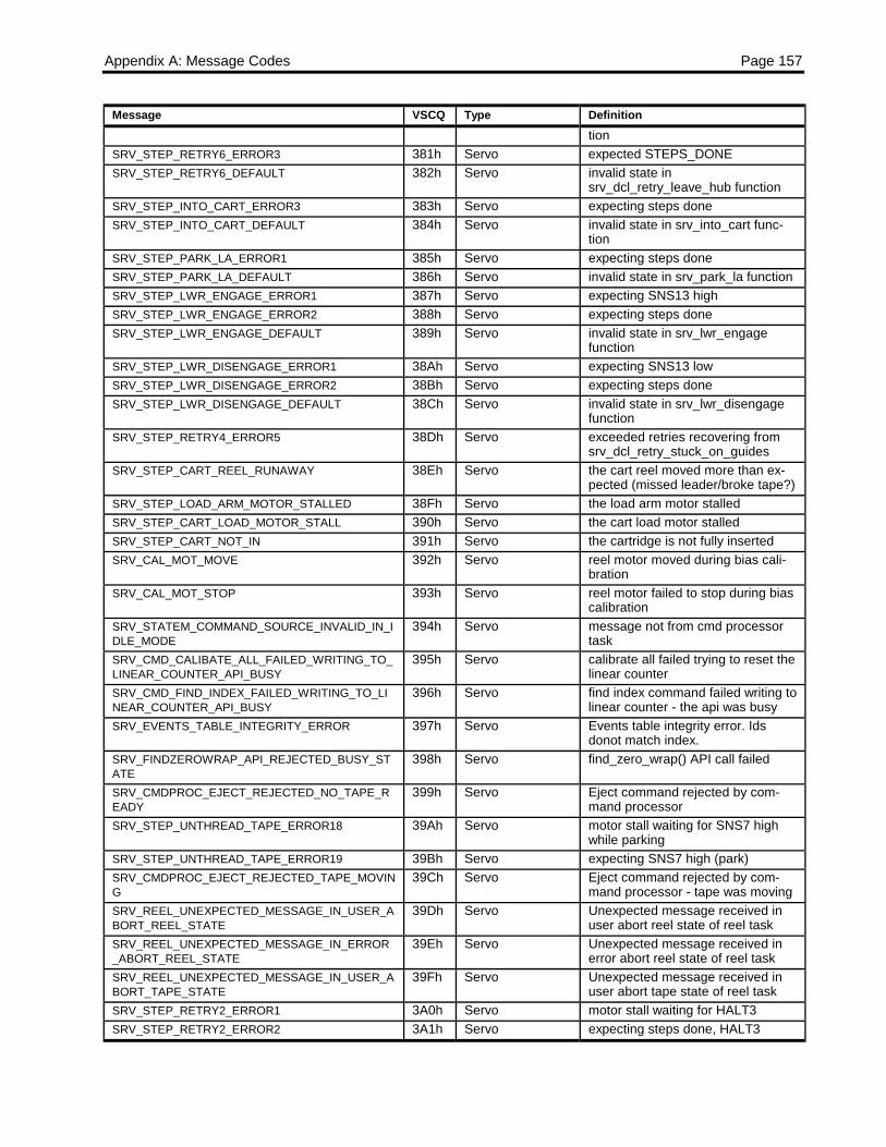
Appendix A: Message Codes Page 157
Message VSCQ Type Definitiontion
SRV_STEP_RETRY6_ERROR3 381h Servo expected STEPS_DONESRV_STEP_RETRY6_DEFAULT 382h Servo invalid state in
srv_dcl_retry_leave_hub functionSRV_STEP_INTO_CART_ERROR3 383h Servo expecting steps doneSRV_STEP_INTO_CART_DEFAULT 384h Servo invalid state in srv_into_cart func-
tionSRV_STEP_PARK_LA_ERROR1 385h Servo expecting steps doneSRV_STEP_PARK_LA_DEFAULT 386h Servo invalid state in srv_park_la functionSRV_STEP_LWR_ENGAGE_ERROR1 387h Servo expecting SNS13 highSRV_STEP_LWR_ENGAGE_ERROR2 388h Servo expecting steps doneSRV_STEP_LWR_ENGAGE_DEFAULT 389h Servo invalid state in srv_lwr_engage
functionSRV_STEP_LWR_DISENGAGE_ERROR1 38Ah Servo expecting SNS13 lowSRV_STEP_LWR_DISENGAGE_ERROR2 38Bh Servo expecting steps doneSRV_STEP_LWR_DISENGAGE_DEFAULT 38Ch Servo invalid state in srv_lwr_disengage
functionSRV_STEP_RETRY4_ERROR5 38Dh Servo exceeded retries recovering from
srv_dcl_retry_stuck_on_guidesSRV_STEP_CART_REEL_RUNAWAY 38Eh Servo the cart reel moved more than ex-
pected (missed leader/broke tape?)SRV_STEP_LOAD_ARM_MOTOR_STALLED 38Fh Servo the load arm motor stalledSRV_STEP_CART_LOAD_MOTOR_STALL 390h Servo the cart load motor stalledSRV_STEP_CART_NOT_IN 391h Servo the cartridge is not fully insertedSRV_CAL_MOT_MOVE 392h Servo reel motor moved during bias cali-
brationSRV_CAL_MOT_STOP 393h Servo reel motor failed to stop during bias
calibrationSRV_STATEM_COMMAND_SOURCE_INVALID_IN_IDLE_MODE
394h Servo message not from cmd processortask
SRV_CMD_CALIBATE_ALL_FAILED_WRITING_TO_LINEAR_COUNTER_API_BUSY
395h Servo calibrate all failed trying to reset thelinear counter
SRV_CMD_FIND_INDEX_FAILED_WRITING_TO_LINEAR_COUNTER_API_BUSY
396h Servo find index command failed writing tolinear counter - the api was busy
SRV_EVENTS_TABLE_INTEGRITY_ERROR 397h Servo Events table integrity error. Idsdonot match index.
SRV_FINDZEROWRAP_API_REJECTED_BUSY_STATE
398h Servo find_zero_wrap() API call failed
SRV_CMDPROC_EJECT_REJECTED_NO_TAPE_READY
399h Servo Eject command rejected by com-mand processor
SRV_STEP_UNTHREAD_TAPE_ERROR18 39Ah Servo motor stall waiting for SNS7 highwhile parking
SRV_STEP_UNTHREAD_TAPE_ERROR19 39Bh Servo expecting SNS7 high (park)SRV_CMDPROC_EJECT_REJECTED_TAPE_MOVING
39Ch Servo Eject command rejected by com-mand processor - tape was moving
SRV_REEL_UNEXPECTED_MESSAGE_IN_USER_ABORT_REEL_STATE
39Dh Servo Unexpected message received inuser abort reel state of reel task
SRV_REEL_UNEXPECTED_MESSAGE_IN_ERROR_ABORT_REEL_STATE
39Eh Servo Unexpected message received inerror abort reel state of reel task
SRV_REEL_UNEXPECTED_MESSAGE_IN_USER_ABORT_TAPE_STATE
39Fh Servo Unexpected message received inuser abort tape state of reel task
SRV_STEP_RETRY2_ERROR1 3A0h Servo motor stall waiting for HALT3SRV_STEP_RETRY2_ERROR2 3A1h Servo expecting steps done, HALT3

Page 158 LTO SCSI/Fibre Channel Interface Manual
Message VSCQ Type DefinitionSRV_STEP_RETRY2_ERROR3 3A2h Servo expecting SNS13 lowSRV_STEP_RETRY2_ERROR4 3A3h Servo expecting steps done,
DISENGAGE_LEADERSRV_STEP_RETRY2_ERROR5 3A4h Servo failed to remove slackSRV_STEP_RETRY2_ERROR6 3A5h Servo failed to release pinSRV_STEP_RETRY2_ERROR7 3A6h Servo motor stall waiting for HALT4SRV_STEP_RETRY2_ERROR8 3A7h Servo expecting steps done, HALT4SRV_STEP_RETRY2_ERROR9 3A8h Servo motor stall waiting for HALT4SRV_STEP_RETRY2_ERROR10 3A9h Servo expecting steps done, HALT4SRV_STEP_RETRY2_ERROR11 3AAh Servo motor stall waiting for HALT4SRV_STEP_RETRY2_ERROR12 3ABh Servo expecting steps done, HALT4SRV_STEP_RETRY2_DEFAULT 3ACh Servo invalid state in process_head_step
functionSRV_STEP_RETRY3_ERROR1 3ADh Servo expecting SNS13 lowSRV_STEP_RETRY3_ERROR2 3AEh Servo expecting SNS13 highSRV_STEP_RETRY3_ERROR3 3AFh Servo expecting steps doneSRV_STEP_RETRY3_DEFAULT 3B0h Servo invalid state in retry_unthread_tape
functionSRV_STEP_RETRY4_ERROR1 3B1h Servo motor stall waiting for steps doneSRV_STEP_RETRY4_ERROR2 3B2h Servo expected STEPS_DONESRV_STEP_RETRY4_DEFAULT 3B3h Servo invalid state in re-
try_stuck_on_guides functionSRV_STEP_RETRY4_ERROR3 3B4h Servo motor stall waiting for steps doneSRV_STEP_RETRY4_ERROR4 3B5h Servo expected STEPS_DONESRV_STEP_GOFROM_HUB_GRABER_ERROR1 3B6h Servo expecting steps doneSRV_STEP_GOFROM_HUB_GRABER_ERROR2 3B7h Servo motor stallSRV_STEP_GOFROM_HUB_GRABER_ERROR3 3B8h Servo expecting steps doneSRV_STEP_GOFROM_HUB_GRABER_DEFAULT 3B9h Servo invalid state in
srv_gofrom_hub_graber functionSRV_STEP_LA_INTO_CART_ERROR1 3BAh Servo expecting SNS13 lowSRV_STEP_LA_INTO_CART_ERROR2 3BBh Servo expecting steps done,
DISENGAGE_LEADERSRV_STEP_LA_INTO_CART_ERROR3 3BCh Servo expecting steps doneSRV_STEP_LA_INTO_CART_DEFAULT 3BDh Servo invalid state in
srv_move_loadarm_into_cart func-tion
SRV_STEP_LOAD_ARM_MOTOR_STALLED1 3BEh Servo the load arm motor stalledSRV_STEP_MOTOR_ERROR2 3BFh Servo expecting steps doneSRV_STEP_PARK_LA_CMD_ERROR1 3C0h Servo expecting steps doneSRV_STEP_PARK_LA_CMD_DEFAULT 3C1h Servo invalid state in srv_park_loadarm
functionSRV_STEP_RETRY_FAILED1 3C2h Servo exceded retrysSRV_STEP_RETRY_FAILED2 3C3h Servo exceded retrysSRV_STEP_UNTHREAD_TAPE_ERROR20 3C4h Servo motor stall waiting for SNS13 highSRV_STEP_UNTHREAD_TAPE_ERROR21 3C5h Servo expecting SNS13 highSRV_STEP_UNTHREAD_TAPE_ERROR22 3C6h Servo motor stall waiting for
ENGAGED_LEADERSRV_STEP_UNTHREAD_TAPE_ERROR23 3C7h Servo expecting steps
done,ENGAGED_LEADERSRV_STEP_THREAD_TAPE_ERROR24 3C8h Servo expecting SNS13 lowSRV_STEP_THREAD_TAPE_ERROR25 3C9h Servo expecting steps done,
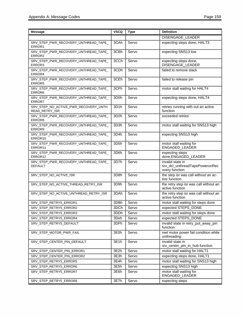
Appendix A: Message Codes Page 159
Message VSCQ Type DefinitionDISENGAGE_LEADER
SRV_STEP_PWR_RECOVERY_UNTHREAD_TAPE_ERROR1
3CAh Servo expecting steps done, HALT3
SRV_STEP_PWR_RECOVERY_UNTHREAD_TAPE_ERROR2
3CBh Servo expecting SNS13 low
SRV_STEP_PWR_RECOVERY_UNTHREAD_TAPE_ERROR3
3CCh Servo expecting steps done,DISENGAGE_LEADER
SRV_STEP_PWR_RECOVERY_UNTHREAD_TAPE_ERROR4
3CDh Servo failed to remove slack
SRV_STEP_PWR_RECOVERY_UNTHREAD_TAPE_ERROR5
3CEh Servo failed to release pin
SRV_STEP_PWR_RECOVERY_UNTHREAD_TAPE_ERROR6
3CFh Servo motor stall waiting for HALT4
SRV_STEP_PWR_RECOVERY_UNTHREAD_TAPE_ERROR7
3D0h Servo expecting steps done, HALT4
SRV_STEP_NO_ACTIVE_PWR_RECOVERY_UNTHREAD_RETRY_ISR
3D1h Servo retries running with out an activefunction
SRV_STEP_PWR_RECOVERY_UNTHREAD_TAPE_ERROR8
3D2h Servo exceeded retries
SRV_STEP_PWR_RECOVERY_UNTHREAD_TAPE_ERROR9
3D3h Servo motor stall waiting for SNS13 high
SRV_STEP_PWR_RECOVERY_UNTHREAD_TAPE_ERROR10
3D4h Servo expecting SNS13 high
SRV_STEP_PWR_RECOVERY_UNTHREAD_TAPE_ERROR11
3D5h Servo motor stall waiting forENGAGED_LEADER
SRV_STEP_PWR_RECOVERY_UNTHREAD_TAPE_ERROR12
3D6h Servo expecting stepsdone,ENGAGED_LEADER
SRV_STEP_PWR_RECOVERY_UNTHREAD_TAPE_DEFAULT
3D7h Servo invalid state insrv_dcl_unthreadTapePoweronRecovery function
SRV_STEP_NO_ACTIVE_ISR 3D8h Servo the step isr was call without an ac-tive function
SRV_STEP_NO_ACTIVE_THREAD_RETRY_ISR 3D9h Servo the retry step isr was call without anactive function
SRV_STEP_NO_ACTIVE_UNTHREAD_RETRY_ISR 3DAh Servo the retry step isr was call without anactive function
SRV_STEP_RETRY5_ERROR1 3DBh Servo motor stall waiting for steps doneSRV_STEP_RETRY5_ERROR2 3DCh Servo expected STEPS_DONESRV_STEP_RETRY5_ERROR3 3DDh Servo motor stall waiting for steps doneSRV_STEP_RETRY5_ERROR4 3Deh Servo expected STEPS_DONESRV_STEP_RETRY5_DEFAULT 3DFh Servo invalid state in retry_put_away_pin
functionSRV_STEP_MOTOR_PWR_FAIL 3E0h Servo reel motor power fail condition while
unthreadingSRV_STEP_CENTER_PIN_DEFAULT 3E1h Servo invalid state in
srv_center_pin_in_hub functionSRV_STEP_CENTER_PIN_ERROR1 3E2h Servo motor stall waiting for HALT1SRV_STEP_CENTER_PIN_ERROR2 3E3h Servo expecting steps done, HALT1SRV_STEP_RETRY5_ERROR5 3E4h Servo motor stall waiting for SNS13 highSRV_STEP_RETRY5_ERROR6 3E5h Servo expecting SNS13 highSRV_STEP_RETRY5_ERROR7 3E6h Servo motor stall waiting for
ENGAGED_LEADERSRV_STEP_RETRY5_ERROR8 3E7h Servo expecting steps

Page 160 LTO SCSI/Fibre Channel Interface Manual
Message VSCQ Type Definitiondone,ENGAGED_LEADER
SRV_STEP_RETRY5_ERROR9 3E8h Servo motor stall waiting for steps doneSRV_STEP_RETRY5_ERROR10 3E9h Servo expected STEPS_DONESRV_STEP_UNLOAD_CART_ERROR3 3Eah Servo expecting eerpom doneSRV_RECOVER_BIN_ERROR 3Ebh Servo an unspecified error occurred while
accessing the serial EEPROMSRV_RECOVER_EEPROM_DEFAULT 3Ech Servo invalid state in the re-
cover_drive_state functionSRV_TEST_SEEP_DEFAULT 3Edh Servo invalid state in the test_seep func-
tionSRV_STEP_NO_ACTIVE_FUNCTION_FOR_EEPROM_TASK
3Eeh Servo no command handler was installedto handle completion froEEPROM_TSK
SRV_SERIAL_EEPROM_ERROR 3Efh Servo expect good status fro serial eer-pom task
SRV_STEP_THREAD_TAPE_ERROR27 3F0h Servo expecting eeprom doneSRV_STEP_RETRY2_ERROR13 3F1h Servo motor stall waiting for HALT4SRV_STEP_RETRY2_ERROR14 3F2h Servo expecting steps done, HALT4SRV_STEP_RETRY7_ERROR1 3F3h Servo motor stall waiting for steps doneSRV_STEP_RETRY7_ERROR2 3F4h Servo expected STEPS_DONESRV_STEP_RETRY7_DEFAULT 3F5h Servo invalid state in
srv_dcl_retry_failed_park functionSRV_STEP_THREAD_TAPE_ERROR28 3F6h Servo reel motor stalled adding slackSRV_STEP_THREAD_TAPE_ERROR29 3F7h Servo unexpected error adding slackSRV_STEP_THREAD_TAPE_ERROR30 3F8h Servo reel motor stalled removing added
slackSRV_STEP_THREAD_TAPE_ERROR31 3F9h Servo unexpected error removing added
slackSRV_STEP_GOTO_HUB_ERROR1 3Fah Servo expecting SNS2 lowSRV_STEP_GOTO_HUB_ERROR3 3FBh Servo expecting steps doneSRV_STEP_REEL_TASK_RETURNED_MISCHUCKED_CARTRIDGE
3FCh Servo Reel motor task indicated that theteeth on the hub did not line up withthe cartridge
SRV_UNTHREAD_DELAY_ERROR_BEFORE_MOVING_TO_PARK
3FDh Servo Error occurred during unthreadmoving from dropping off the pin-reel motor task indicated that theteeth on the hub did not line up withthe cartridge
SRV_UNTHREAD_ERROR_MOVING_TO_PARK 3FEh Servo Load arm failed to make it back topark while unthreading
SRV_UNTHREAD_FAILED_TO_PUT_PIN_AWAY 3FFh Servo Unthread exhausted retries trying topark pin in cartridge
RTOS_STATUS_TASK_ID_ERROR 400h RTOSRTOS_STATUS_NO_MEMORY_AVAILABLE 401h RTOSRTOS_STATUS_MAILBOX_IN_USE 402h RTOSRTOS_STATUS_ZERO_MESSAGE 403h RTOSRTOS_STATUS_INVALID_SYSTEM_CALL 404h RTOSRTOS_STATUS_TIMEOUT 405h RTOSRTOS_STATUS_NO_MESSAGE_PRESENT 406h RTOSRTOS_STATUS_QUEUE_ID_ERROR 407h RTOSRTOS_STATUS_QUEUE_FULL 408h RTOSRTOS_STATUS_PARTITION_ID_ERROR 409h RTOS
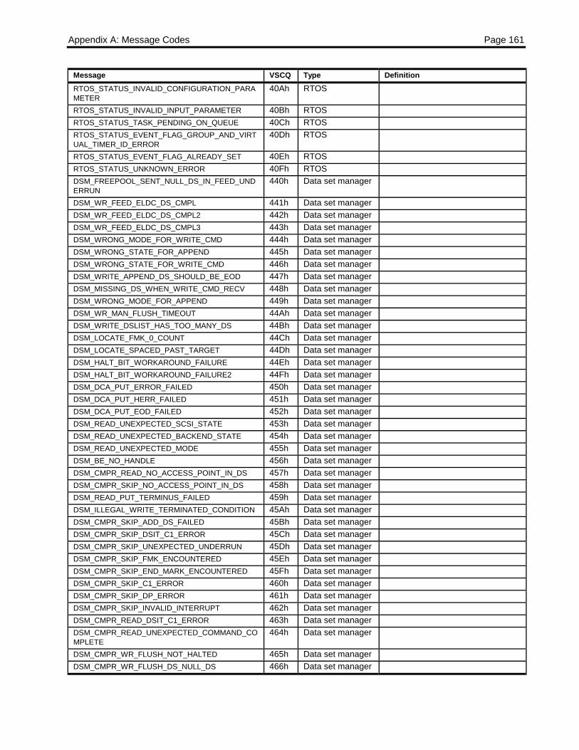
Appendix A: Message Codes Page 161
Message VSCQ Type DefinitionRTOS_STATUS_INVALID_CONFIGURATION_PARAMETER
40Ah RTOS
RTOS_STATUS_INVALID_INPUT_PARAMETER 40Bh RTOSRTOS_STATUS_TASK_PENDING_ON_QUEUE 40Ch RTOSRTOS_STATUS_EVENT_FLAG_GROUP_AND_VIRTUAL_TIMER_ID_ERROR
40Dh RTOS
RTOS_STATUS_EVENT_FLAG_ALREADY_SET 40Eh RTOSRTOS_STATUS_UNKNOWN_ERROR 40Fh RTOSDSM_FREEPOOL_SENT_NULL_DS_IN_FEED_UNDERRUN
440h Data set manager
DSM_WR_FEED_ELDC_DS_CMPL 441h Data set managerDSM_WR_FEED_ELDC_DS_CMPL2 442h Data set managerDSM_WR_FEED_ELDC_DS_CMPL3 443h Data set managerDSM_WRONG_MODE_FOR_WRITE_CMD 444h Data set managerDSM_WRONG_STATE_FOR_APPEND 445h Data set managerDSM_WRONG_STATE_FOR_WRITE_CMD 446h Data set managerDSM_WRITE_APPEND_DS_SHOULD_BE_EOD 447h Data set managerDSM_MISSING_DS_WHEN_WRITE_CMD_RECV 448h Data set managerDSM_WRONG_MODE_FOR_APPEND 449h Data set managerDSM_WR_MAN_FLUSH_TIMEOUT 44Ah Data set managerDSM_WRITE_DSLIST_HAS_TOO_MANY_DS 44Bh Data set managerDSM_LOCATE_FMK_0_COUNT 44Ch Data set managerDSM_LOCATE_SPACED_PAST_TARGET 44Dh Data set managerDSM_HALT_BIT_WORKAROUND_FAILURE 44Eh Data set managerDSM_HALT_BIT_WORKAROUND_FAILURE2 44Fh Data set managerDSM_DCA_PUT_ERROR_FAILED 450h Data set managerDSM_DCA_PUT_HERR_FAILED 451h Data set managerDSM_DCA_PUT_EOD_FAILED 452h Data set managerDSM_READ_UNEXPECTED_SCSI_STATE 453h Data set managerDSM_READ_UNEXPECTED_BACKEND_STATE 454h Data set managerDSM_READ_UNEXPECTED_MODE 455h Data set managerDSM_BE_NO_HANDLE 456h Data set managerDSM_CMPR_READ_NO_ACCESS_POINT_IN_DS 457h Data set managerDSM_CMPR_SKIP_NO_ACCESS_POINT_IN_DS 458h Data set managerDSM_READ_PUT_TERMINUS_FAILED 459h Data set managerDSM_ILLEGAL_WRITE_TERMINATED_CONDITION 45Ah Data set managerDSM_CMPR_SKIP_ADD_DS_FAILED 45Bh Data set managerDSM_CMPR_SKIP_DSIT_C1_ERROR 45Ch Data set managerDSM_CMPR_SKIP_UNEXPECTED_UNDERRUN 45Dh Data set managerDSM_CMPR_SKIP_FMK_ENCOUNTERED 45Eh Data set managerDSM_CMPR_SKIP_END_MARK_ENCOUNTERED 45Fh Data set managerDSM_CMPR_SKIP_C1_ERROR 460h Data set managerDSM_CMPR_SKIP_DP_ERROR 461h Data set managerDSM_CMPR_SKIP_INVALID_INTERRUPT 462h Data set managerDSM_CMPR_READ_DSIT_C1_ERROR 463h Data set managerDSM_CMPR_READ_UNEXPECTED_COMMAND_COMPLETE
464h Data set manager
DSM_CMPR_WR_FLUSH_NOT_HALTED 465h Data set managerDSM_CMPR_WR_FLUSH_DS_NULL_DS 466h Data set manager
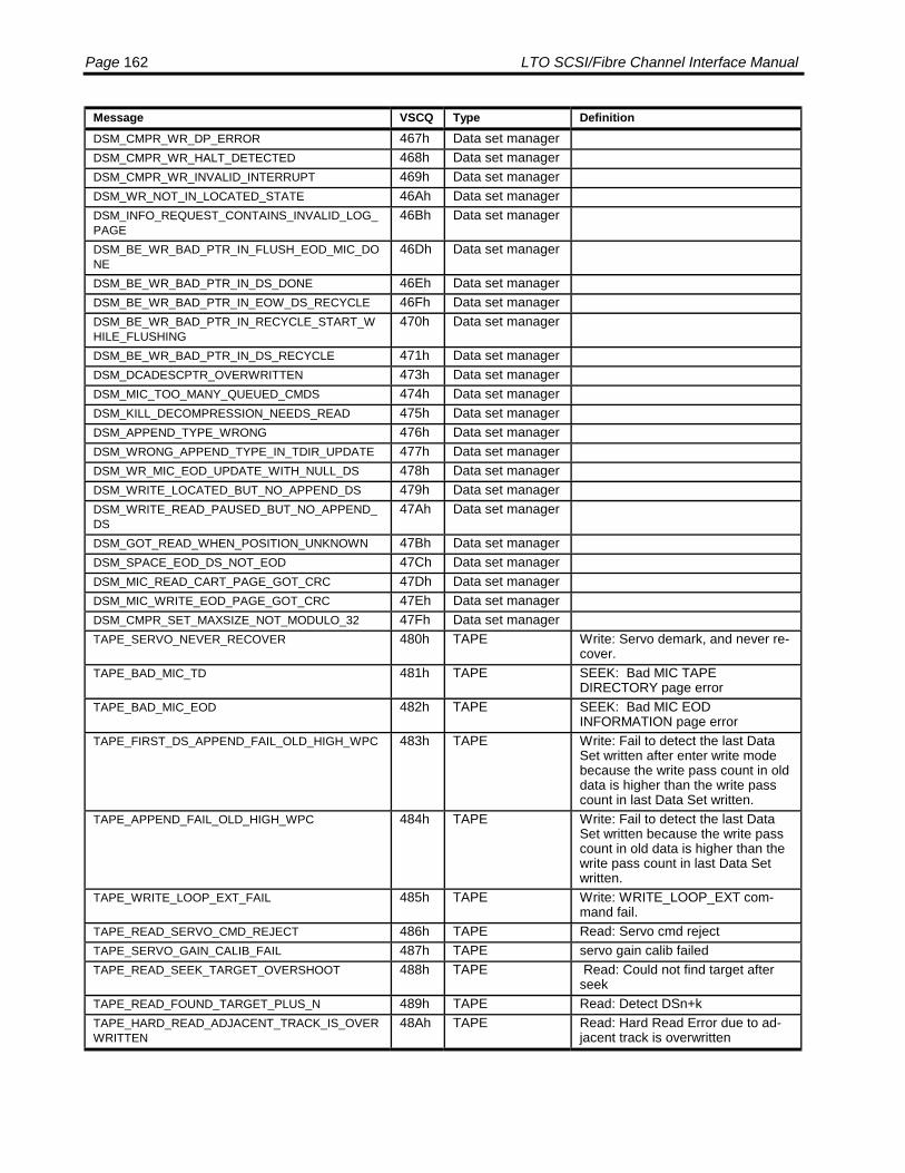
Page 162 LTO SCSI/Fibre Channel Interface Manual
Message VSCQ Type DefinitionDSM_CMPR_WR_DP_ERROR 467h Data set managerDSM_CMPR_WR_HALT_DETECTED 468h Data set managerDSM_CMPR_WR_INVALID_INTERRUPT 469h Data set managerDSM_WR_NOT_IN_LOCATED_STATE 46Ah Data set managerDSM_INFO_REQUEST_CONTAINS_INVALID_LOG_PAGE
46Bh Data set manager
DSM_BE_WR_BAD_PTR_IN_FLUSH_EOD_MIC_DONE
46Dh Data set manager
DSM_BE_WR_BAD_PTR_IN_DS_DONE 46Eh Data set managerDSM_BE_WR_BAD_PTR_IN_EOW_DS_RECYCLE 46Fh Data set managerDSM_BE_WR_BAD_PTR_IN_RECYCLE_START_WHILE_FLUSHING
470h Data set manager
DSM_BE_WR_BAD_PTR_IN_DS_RECYCLE 471h Data set managerDSM_DCADESCPTR_OVERWRITTEN 473h Data set managerDSM_MIC_TOO_MANY_QUEUED_CMDS 474h Data set managerDSM_KILL_DECOMPRESSION_NEEDS_READ 475h Data set managerDSM_APPEND_TYPE_WRONG 476h Data set managerDSM_WRONG_APPEND_TYPE_IN_TDIR_UPDATE 477h Data set managerDSM_WR_MIC_EOD_UPDATE_WITH_NULL_DS 478h Data set managerDSM_WRITE_LOCATED_BUT_NO_APPEND_DS 479h Data set managerDSM_WRITE_READ_PAUSED_BUT_NO_APPEND_DS
47Ah Data set manager
DSM_GOT_READ_WHEN_POSITION_UNKNOWN 47Bh Data set managerDSM_SPACE_EOD_DS_NOT_EOD 47Ch Data set managerDSM_MIC_READ_CART_PAGE_GOT_CRC 47Dh Data set managerDSM_MIC_WRITE_EOD_PAGE_GOT_CRC 47Eh Data set managerDSM_CMPR_SET_MAXSIZE_NOT_MODULO_32 47Fh Data set managerTAPE_SERVO_NEVER_RECOVER 480h TAPE Write: Servo demark, and never re-
cover.TAPE_BAD_MIC_TD 481h TAPE SEEK: Bad MIC TAPE
DIRECTORY page errorTAPE_BAD_MIC_EOD 482h TAPE SEEK: Bad MIC EOD
INFORMATION page errorTAPE_FIRST_DS_APPEND_FAIL_OLD_HIGH_WPC 483h TAPE Write: Fail to detect the last Data
Set written after enter write modebecause the write pass count in olddata is higher than the write passcount in last Data Set written.
TAPE_APPEND_FAIL_OLD_HIGH_WPC 484h TAPE Write: Fail to detect the last DataSet written because the write passcount in old data is higher than thewrite pass count in last Data Setwritten.
TAPE_WRITE_LOOP_EXT_FAIL 485h TAPE Write: WRITE_LOOP_EXT com-mand fail.
TAPE_READ_SERVO_CMD_REJECT 486h TAPE Read: Servo cmd rejectTAPE_SERVO_GAIN_CALIB_FAIL 487h TAPE servo gain calib failedTAPE_READ_SEEK_TARGET_OVERSHOOT 488h TAPE Read: Could not find target after
seekTAPE_READ_FOUND_TARGET_PLUS_N 489h TAPE Read: Detect DSn+kTAPE_HARD_READ_ADJACENT_TRACK_IS_OVERWRITTEN
48Ah TAPE Read: Hard Read Error due to ad-jacent track is overwritten

Appendix A: Message Codes Page 163
Message VSCQ Type DefinitionTAPE_READ_4METERS_TIMEOUT 48Bh TAPE Read: Has no Data Set Interrupt for
more than 4 metersTAPE_READ_TIMEOUT_NO_SERVO_RESPONSE 48Ch TAPE Read: 20 seconds timeout wait for
Servo responseTAPE_READ_BOW_DS_NOT_FOUND 48Dh TAPE Read: Could not find BOW data SetTAPE_READ_LAST_WRAP_DS_NOT_FOUND 48Eh TAPE Read: Could not find the last Data
Set at end-of-wrapTAPE_READ_BAD_CM_AND_BAD_FID 48Fh TAPE Read: Could not read FIDTAPE_SEEK_ISB_UNDERRUN 490h TAPE Seek: Hardware reports isb under-
run errorTAPE_SEEK_ISB_SVO_FAIL 491h TAPE Seek: Hardware reports isb svo fail
errorTAPE_SEEK_ISB_EOWRAP 492h TAPE Seek: Hardware reports isb eowrap
errorTAPE_SEEK_ISB_UNKNOWN 493h TAPE Seek: Hardware reports isb un-
known errorTAPE_READ_SERVO_OVERSHOOT 494h TAPE Read: Servo overshoot, past targetTAPE_BAD_CLEAN_CARTRIDGE 495h TAPE Tape: Bad cleaning cartridgeTAPE_OUT_OF_CLEAN_TAPE 496h TAPE Tape: Out of cleaning tapeTAPE_SEEKER_MISSING_DS 497h TAPE Read: Seeker missed data set
bufferTAPE_CHAN_HOC_GAIN_CALIB_FAILED 498h TAPE head offset gain calibration failedTAPE_NULL_PTR_TP_LIST 499h TAPE Read: Detect Null pointer in
tp_ds_listTAPE_INVALID_PHYS_LP6 49Ah TAPE Tape: auto_load sequence for de-
tecting invalid phys lp6TAPE_ABORT_STATUS 49Bh TAPE Tape: abort status for command
that has just been abortedTAPE_HARD_READ_ERROR_RETRY_EXHAUSTED 49Ch TAPE Tape: could not recover dataTAPE_CHAN_BOTH_SERVO_HEADS_BAD 49Dh TAPE Tape: per tape servo gain calib:
both channels failedTAPE_CHAN_UPPER_SERVO_HEAD_BAD 49Eh TAPE Tape: per tape servo gain calib:
upper channel failedTAPE_CHAN_LOWER_SERVO_HEAD_BAD 49Fh TAPE Tape: per tape servo gain calib:
lower channel failedTAPE_SRV_FAIL_REPORT_EW 4A0h TAPE Write: WP fail to report early warn-
ing at end of wrap.TAPE_RED_ZONE_ERR_RETRY_EXHAUSTED 4A1h TAPE Tape: Red Zone Error retry ex-
haustedTAPE_APPEND_ON_TRACK_FAIL 4A2h TAPE Write: On track signal fail when try
to detect the last DS for appendTAPE_SERVO_GAIN_CALIB_RETRY_FAIL 4A3h TAPE servo gain calib retry failedTAPE_SERVO_GAIN_CALIB_RETRY_GOOD 4A4h TAPE servo gain calib retry goodTAPE_ON_TRACK_NEVER_ON 4A5h TAPE Read: On_Track signal is not ONTAPE_WRITE_BOW_ON_TRACK_FAIL 4A6h TAPE Write: On track signal fail when try
to start to write at BOWTAPE_READ_SWITCH_WRONG_WRAP 4A7h TAPE Read: DSM commands to switch to
opposite directionTAPE_HARD_READ_ERROR_CORNER_RETRY_FAILED
4A8h TAPE Read: Failed to reread at corner
TAPE_READ_ILLEGAL_SWITCH_WRAP_IDLE_STATE
4A9h TAPE Read: Idle state, cannot switchwrap on the fly
TAPE_READ_ILLEGAL_SWITCH_WRAP_UNDERRU 4AAh TAPE Read: Underrrun state, cannot

Page 164 LTO SCSI/Fibre Channel Interface Manual
Message VSCQ Type DefinitionN_STATE switch wrap on the flyTAPE_READ_SWITCH_WRAP_BAD_EOD_PAGE 4ABh TAPE Read: EOD must be validTAPE_READ_ILLEGAL_SWITCH_WRAP_BACKWARD_MODE
4ACh TAPE Read: Must be in forward mode
TAPE_CM_SUSPENDED_APPEND_WRITES_PAGE_FULL
4ADh TAPE
TAPE_READ_WRT_SUSPEND_MORE_THAN_4METERS
4Aeh TAPE
TAPE_READ_OVERSHOOT_RETRY_EXHAUSTED 4Afh TAPETAPE_READ_SEEK_LOST_POSITION 4B0h TAPETAPE_READ_NO_DATA_DETECTED 4B1h TAPE Cannot read any cwpSRV_REEL_UNEXPECTED_MESSAGE_IN_ERROR_ABORT_TAPE_STATE
500h Servo Unexpected message received inerror abort tape state
SRV_MOVETAPE_UNEXPECTED_MESSAGE_IN_RAMP_UP_STATE
501h Servo Unexpected message in ramp upstate
SRV_MOVETAPE_UNEXPECTED_MESSAGE_IN_RAMP_DOWN_STATE
502h Servo Unexpected message in rampdown state
SRV_MOVETAPE_UNEXPECTED_MESSAGE_IN_RAMP_RESTART_STATE
503h Servo Unexpected message in rampdown restart state
SRV_MOVETAPE_UNEXPECTED_MESSAGE_IN_CRUISE_CONTROL_STATE
504h Servo Unexpected message received incruise control state
SRV_ROTATE_UNEXPECTED_MESSAGE_IN_RAMP_UP_REEL_STATE
505h Servo Unexpected message received inramp up reel state
SRV_ROTATE_UNEXPECTED_MESSAGE_IN_ROTATING_REEL_STATE
506h Servo Unexpected message received inrotating reel state
SRV_ROTATE_UNEXPECTED_MESSAGE_IN_RAMP_DOWN_REEL_STATE
507h Servo Unexpected message received inramp down reel state
SRV_POSREEL_UNEXPECTED_MESSAGE_IN_MOVE_TO_POSITION_STATE
508h Servo
SRV_GOTO_LC_UNEXPECTED_MESSAGE_IN_RAMP_UP_STATE
509h Servo Unexpected message received ingoto lc module in ramp up state
SRV_GOTO_LC_UNEXPECTED_MESSAGE_IN_WAIT_MARK_STATE
50Ah Servo Unexpected message received ingoto lc module in wait mark state
SRV_GOTO_LC_UNEXPECTED_MESSAGE_IN_MARK_FOUND_STATE
50Bh Servo Unexpected message received ingoto lc module in mark found state
SRV_GOTO_LC_UNEXPECTED_MESSAGE_IN_POSITION_STATE
50Ch Servo Unexpected message received ingoto lc module in position tapestate
SRV_REEL_UNEXPECTED_MESSAGE_IN_HOLD_STATE
50Dh Servo Unexpected message received inhold state.
SRV_REEL_UNEXPECTED_MESSAGE_IN_IDLE_STATE
50Eh Servo Unexpected message received inidle state
SRV_CMDPROC_REJ_PARM_LPOS_NOT_WITHIN_LP2_OR_LP6_IN_GOTO_TO_LPOS_VALID
50Fh Servo The LPOS selected for theGOTO_LPOS command is beyondthe limits
SRV_CMDPROC_REJ_PARM_NOT_ENOUGH_TAPE_TO_RAMP_TO_LPOS_IN_GOTO_LPOS_PARAM_VALID
510h Servo The distance between the currentposition and the target LPOS is toshort
SRV_CMDPROC_GOTO_LPOS_REJECTED_TAPE_NOT_STOPPED
511h Servo The tape was not stopped whenthis command was received
SRV_CMDPROC_GOTO_LPOS_REJECTED_LP1_LP6_NOT_SET
512h Servo The tape parameters were not setbefore issuing the GOTO_LPOScommand.
SRV_MOVETAPE_TIMEOUT_CALCULATION_ERRO 513h Servo The calculation of a time out time inthe movetape module calculated an

Appendix A: Message Codes Page 165
Message VSCQ Type DefinitionR erroneous intermediate resultSRV_CALMEM_SET_TENSION_REJ_INVALID_STATE
514h Servo Set tension api call failed duringstartup
SRV_CALMEM_SET_TAPE_SPEED_REJ_INVALID_STATE
515h Servo Set tape speeds api call failed dur-ing startup
SRV_INDEX_MOTOR_INTERRUPT_NOT_DETECTED_AFTER_ROTATING_DRIVE_MOTOR
516h Servo Motor interrupt not detected afterrotating drive motor
SRV_MOVETAPE_RAMPDOWN_API_FAILED_IN_TIMEOUT_HANDLER_IN_RAMP_UP_STATE
517h Servo An attempt to ramp down the tapefailed after a timeout occured dur-ing ramp up
SRV_OFF_TRACK 518h Servo tracking servo detected off trackevent
SRV_NO_PES_FOUND 519h Servo no valid PES eventSRV_VCM_SHOCK_ERROR 51Ah Servo tracking servo detected shock vi-
bration errorSRV_TRACKING_TARGET_OUTRANGE 51Bh Servo tracking servo detected unreach-
able track errorSRV_TRACKING_SAMPLE_ERROR 51Ch Servo tracking servo detected asic sam-
ple errorSRV_TRACKING_COARSE_MOVE_ERROR 51Dh Servo tracking servo detected coarse
stepper is out of positionSRV_TRACKING_UPDATE_MEM_ERROR 51Eh Servo tracking servo detected PES mem-
ory failureSRV_MOVETAPE_RAMPDOWN_API_FAILED_IN_TRACKING_CMD_FAILED_HANDLER_IN_RAMP_UP_STATE
51Fh Servo Rampdown api call failed/rejectedwhen called from tracking com-mand failed handler in the ramp upstate
SRV_MOVETAPE_TRACKING_CMD_FAILED_IN_RAMP_UP_STATE
520h Servo Tracking command failed in rampup state
SRV_CMDPROC_ROTATE_REEL_REJECTED_BECAUSE_CART_LOADED
521h Servo Rotate reel command rejected be-cause cartridge is loaded andcommand is trying to rotate thecartridge reel
SRV_CMDPROC_ROTATE_REEL_REJECTED_BECAUSE_DRIVE_REEL_IS_OBSTRUCTED
522h Servo Rotate reel command rejected be-cause reels are obstructed by tapeor a cartridge.
SRV_CMDPROC_ROTATE_REEL_REJECTED_INVALID_REEL_SELECT
523h Servo Rotate reel command rejected be-cause an invalid reel select wasgiven
SRV_CMDPROC_SET_DRIVE_STATE_COMMAND_REJECTED_STATE_OUT_OF_RANGE
524h Servo Set drive state command rejectedbecause the drive state is out ofrange.
SRV_STATEM_RECOVERY_COMMAND_REJECTED_DRIVE_IN_UNKNOWN_STATE
525h Servo Recovery command rejected, drivein unknown state.
SRV_TRKCNVT_MULTIPLY_ERROR_IN_TRACKING_CONVERT_FUNCTION
526h Servo Multiply error in tracking conversionfunction from ratio to dac
SRV_TRKCNVT_DIVIDE_ERROR_IN_TRACKING_CONVERT_FUNCTION
527h Servo Divide error in tracking conversionfunction from dac to ratio.
SRV_STATEM_AUTOLOAD_COMMAND_REJECTED_INVALID_STATE
528h Servo Command rejected since the drivestate was invalid (out of range).
SRV_NOT_USED_OBSOLETE_2 529h Servo N/ASRV_STATEM_PRE_EJECT_COMMAND_REJECTED_INVALID_STATE
52Ah Servo Command rejected since the drivestate was invalid in pre-eject se-quence
SRV_STATEM_PRE_EJECT_COMMAND_REJECTE 52Bh Servo Command rejected - drive in un-
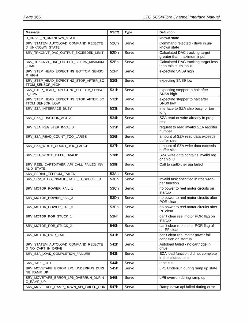
Page 166 LTO SCSI/Fibre Channel Interface Manual
Message VSCQ Type DefinitionD_DRIVE_IN_UNKNOWN_STATE known stateSRV_STATEM_AUTOLOAD_COMMAND_REJECTED_UNKNOWN_STATE
52Ch Servo Command rejected - drive in un-known state
SRV_TRKCNVT_DAC_OUTPUT_EXCEEDED_LIMIT 52Dh Servo Calculated DAC tracking targetgreater than maximum input
SRV_TRKCNVT_DAC_OUTPUT_BELOW_MINIMUM_LIMIT
52Eh Servo Calculated DAC tracking target lessthan minimum input
SRV_STEP_HEAD_EXPECTING_BOTTOM_SENSOR_HIGH
52Fh Servo expecting SNS9 high
SRV_STEP_HEAD_EXPECTING_STOP_AFTER_BOTTOM_SENSOR_HIGH
530h Servo expecting SNS9 low
SRV_STEP_HEAD_EXPECTING_BOTTOM_SENSOR_LOW
531h Servo expecting stepper to halt afterSNS9 high
SRV_STEP_HEAD_EXPECTING_STOP_AFTER_BOTTOM_SENSOR_LOW
532h Servo expecting stepper to halt afterSNS9 low
SRV_SZA_INTERFACE_BUSY 533h Servo interface to SZA chip busy for toolong
SRV_SZA_FUNCTION_ACTIVE 534h Servo SZA read or write already in prog-ress
SRV_SZA_REGISTER_INVALID 535h Servo request to read invalid SZA registernumber
SRV_SZA_READ_COUNT_TOO_LARGE 536h Servo amount of SZA read data exceedsbuffer size
SRV_SZA_WRITE_COUNT_TOO_LARGE 537h Servo amount of SZA write data exceedsbuffer size
SRV_SZA_WRITE_DATA_INVALID 538h Servo SZA write data contains invalid regor chip ID
SRV_REEL_CARTDITHER_API_CALL_FAILED_INVALID_STATE
539h Servo Call to cartDither api failed
SRV_SERIAL_EEPROM_FAILED 53Ah ServoSRV_SRV_RTOS_INVALID_TASK_ID_SPECIFIED 53Bh Servo invalid task specified in rtos wrap-
per function.SRV_MOTOR_POWER_FAIL_1 53Ch Servo no power to reel motor circuits on
startupSRV_MOTOR_POWER_FAIL_2 53Dh Servo no power to reel motor circuits after
POR clearSRV_MOTOR_POWER_FAIL_3 53Eh Servo no power to reel motor circuits after
PF clearSRV_MOTOR_POR_STUCK_1 53Fh Servo can't clear reel motor POR flag on
startupSRV_MOTOR_POR_STUCK_2 540h Servo can't clear reel motor POR flag af-
ter PF clearSRV_MOTOR_PWR_FAIL 541h Servo can't clear reel motor power fail
condition on startupSRV_STATEM_AUTOLOAD_COMMAND_REJECTED_NO_CART_IN_DRIVE
542h Servo Autoload failed - no cartridge indrive.
SRV_SZA_LOAD_COMPLETION_FAILURE 543h Servo SZA load function did not completein the allotted time
SRV_TAPE_CUT 544h Servo tape cutSRV_MOVETAPE_ERROR_LP1_UNDERRUN_DURING_RAMP_UP
545h Servo LP1 Underrun during ramp up state
SRV_MOVETAPE_ERROR_LP6_OVERRUN_DURING_RAMP_UP
546h Servo LP6 overrun during ramp up
SRV_MOVETAPE_RAMP_DOWN_API_FAILED_DUR 547h Servo Ramp down api failed during error
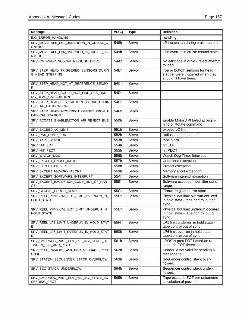
Appendix A: Message Codes Page 167
Message VSCQ Type DefinitionING_ERROR_HANDLING handlingSRV_MOVETAPE_LP1_UNDERRUN_IN_CRUISE_CONTROL
548h Servo LP1 underrun during cruise controlstate.
SRV_MOVETAPE_LP6_OVERRUN_IN_CRUISE_CONTROL
549h Servo LP6 overrun in cruise control state.
SRV_CMDPROC_NO_CARTRIDGE_IN_DRIVE 54Ah Servo No cartridge in drive - reject attemptto load
SRV_STEP_HEAD_TRIGGERED_SENSORS_DURING_HEAD_STEPPING
54Bh Servo Top or bottom sensors for headstepper were triggered when theyshouldn't have been.
SRV_STEP_HEAD_NOT_AT_REFERENCE_SENSOR
54Ch Servo
SRV_STEP_HEAD_COULD_NOT_FIND_PES_DURING_HEAD_CALIBRATION
54Dh Servo
SRV_STEP_HEAD_PES_CAPTURE_IS_BAD_DURING_HEAD_CALIBRATION
54Eh Servo
SRV_STEP_HEAD_INCORRECT_OFFSET_FROM_HEAD_CALIBRATION
54Fh Servo
SRV_ROTATE_ENABLEMOTOR_API_REJECT_BUSY
550h Servo Enable Motor API failed at begin-ning of Rotate command
SRV_EXCEED_LC_LIMIT 551h Servo exceed LC limitSRV_RAD_COMP_ERR 552h Servo radius computation offSRV_TAPE_SLACK 553h Servo tape slackSRV_HIT_EOT 554h Servo hit EOTSRV_HIT_PEOT 555h Servo hit PEOTSRV_WATCH_DOG 556h Servo Watch Dog Timer InterruptSRV_EXCEPT_UNDEF_INSTR 557h Servo Undefined exceptionSRV_EXCEPT_PREFECT 558h Servo Prefect exceptionSRV_EXCEPT_MEMORY_ABORT 559h Servo Memory abort exceptionSRV_EXCEPT_SOFTWARE_INTERRUPT 55Ah Servo Software interrupt exceptionSRV_EXCEPT_EXCEPTION_CODE_OUT_OF_RANGE
55Bh Servo Software exception identifier out ofrange
SRV_GLOBAL_ERROR_STATE 55Ch Servo Firmware global error stateSRV_REEL_PHYSICAL_EOT_LIMIT_OVERRUN_IN_HOLD_STATE
55Dh Servo Physical eot limit overrun occuredin hold state - tape control out ofsync
SRV_REEL_PHYSICAL_BOT_LIMIT_UNDERUN_IN_HOLD_STATE
55Eh Servo Physical bot limit underrun occuredin hold state - tape control out ofsync
SRV_REEL_LP1_LIMIT_UNDERUN_IN_HOLD_STATE
55Fh Servo LP1 limit underrun in hold state -tape control out of sync
SRV_REEL_LP6_LIMIT_OVERRUN_IN_HOLD_STATE
560h Servo LP6 limit overrun in hold state -tape control out of sync
SRV_CMDPROC_PAST_EOT_REJ_INV_STATE_BETWEEN_EOT_AND_PEOT
561h Servo LPOS is past EOT based on ra-tiometric EOT detection
SRV_REEL_INVALID_TASK_FOR_MESSAGE_RESPONSE
562h Servo Sender id not valid for sending amessage to
SRV_STATEM_SEQUENCER_STACK_OVERFLOW 563h Servo Sequencer control stack over-flowed.
SRV_SEQ_STACK_UNDERFLOW 564h Servo Sequencer control stack under-flowed.
SRV_CMDPROC_PAST_EOT_REJ_INV_STATE_EXCEEDING_PEOT
565h Servo Tape exceeds EOT per ratiometriccalculation of position
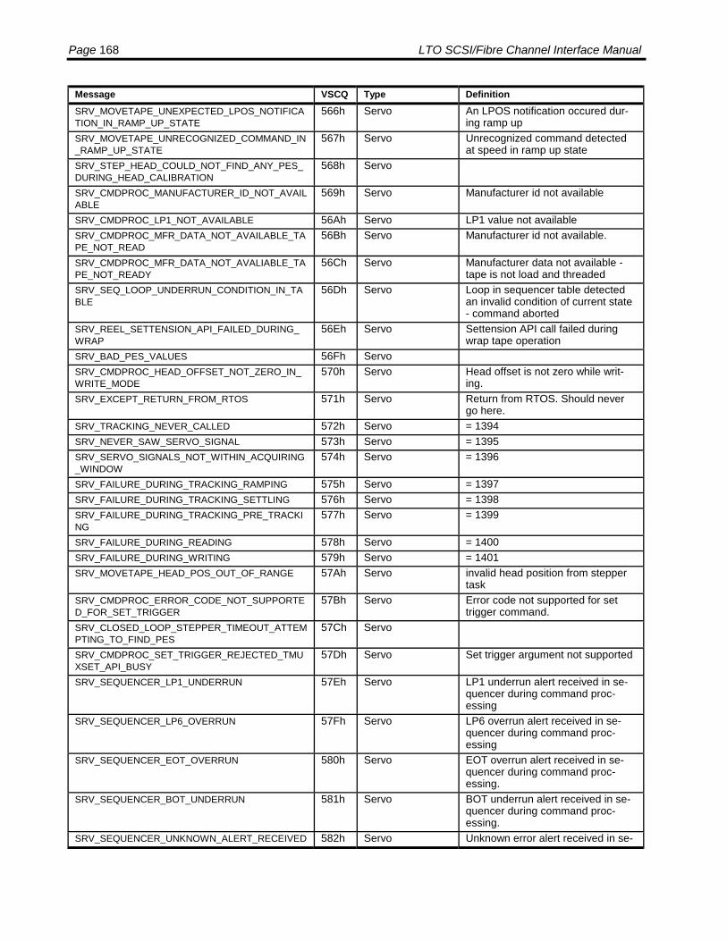
Page 168 LTO SCSI/Fibre Channel Interface Manual
Message VSCQ Type DefinitionSRV_MOVETAPE_UNEXPECTED_LPOS_NOTIFICATION_IN_RAMP_UP_STATE
566h Servo An LPOS notification occured dur-ing ramp up
SRV_MOVETAPE_UNRECOGNIZED_COMMAND_IN_RAMP_UP_STATE
567h Servo Unrecognized command detectedat speed in ramp up state
SRV_STEP_HEAD_COULD_NOT_FIND_ANY_PES_DURING_HEAD_CALIBRATION
568h Servo
SRV_CMDPROC_MANUFACTURER_ID_NOT_AVAILABLE
569h Servo Manufacturer id not available
SRV_CMDPROC_LP1_NOT_AVAILABLE 56Ah Servo LP1 value not availableSRV_CMDPROC_MFR_DATA_NOT_AVAILABLE_TAPE_NOT_READ
56Bh Servo Manufacturer id not available.
SRV_CMDPROC_MFR_DATA_NOT_AVALIABLE_TAPE_NOT_READY
56Ch Servo Manufacturer data not available -tape is not load and threaded
SRV_SEQ_LOOP_UNDERRUN_CONDITION_IN_TABLE
56Dh Servo Loop in sequencer table detectedan invalid condition of current state- command aborted
SRV_REEL_SETTENSION_API_FAILED_DURING_WRAP
56Eh Servo Settension API call failed duringwrap tape operation
SRV_BAD_PES_VALUES 56Fh ServoSRV_CMDPROC_HEAD_OFFSET_NOT_ZERO_IN_WRITE_MODE
570h Servo Head offset is not zero while writ-ing.
SRV_EXCEPT_RETURN_FROM_RTOS 571h Servo Return from RTOS. Should nevergo here.
SRV_TRACKING_NEVER_CALLED 572h Servo = 1394SRV_NEVER_SAW_SERVO_SIGNAL 573h Servo = 1395SRV_SERVO_SIGNALS_NOT_WITHIN_ACQUIRING_WINDOW
574h Servo = 1396
SRV_FAILURE_DURING_TRACKING_RAMPING 575h Servo = 1397SRV_FAILURE_DURING_TRACKING_SETTLING 576h Servo = 1398SRV_FAILURE_DURING_TRACKING_PRE_TRACKING
577h Servo = 1399
SRV_FAILURE_DURING_READING 578h Servo = 1400SRV_FAILURE_DURING_WRITING 579h Servo = 1401SRV_MOVETAPE_HEAD_POS_OUT_OF_RANGE 57Ah Servo invalid head position from stepper
taskSRV_CMDPROC_ERROR_CODE_NOT_SUPPORTED_FOR_SET_TRIGGER
57Bh Servo Error code not supported for settrigger command.
SRV_CLOSED_LOOP_STEPPER_TIMEOUT_ATTEMPTING_TO_FIND_PES
57Ch Servo
SRV_CMDPROC_SET_TRIGGER_REJECTED_TMUXSET_API_BUSY
57Dh Servo Set trigger argument not supported
SRV_SEQUENCER_LP1_UNDERRUN 57Eh Servo LP1 underrun alert received in se-quencer during command proc-essing
SRV_SEQUENCER_LP6_OVERRUN 57Fh Servo LP6 overrun alert received in se-quencer during command proc-essing
SRV_SEQUENCER_EOT_OVERRUN 580h Servo EOT overrun alert received in se-quencer during command proc-essing.
SRV_SEQUENCER_BOT_UNDERRUN 581h Servo BOT underrun alert received in se-quencer during command proc-essing.
SRV_SEQUENCER_UNKNOWN_ALERT_RECEIVED 582h Servo Unknown error alert received in se-

Appendix A: Message Codes Page 169
Message VSCQ Type Definitionquencer during command proc-essing.
SRV_SZA_SIFT_COUNT_TOO_LARGE 583h Servo Sift values in READ SZA commandexceed the number of samples
SRV_RTOS_TASK_ID_ERROR 584h Servo RTOS error - task id invalidSRV_RTOS_NO_MEMORY_AVAILABLE 585h Servo RTOS error - no memory availableSRV_RTOS_MAILBOX_IN_USE 586h Servo RTOS error - mailbox in useSRV_RTOS_ZERO_MESSAGE 587h Servo RTOS error - Zero messageSRV_RTOS_INVALID_SYSTEM_CALL 588h Servo RTOS error - Invalid system callSRV_RTOS_NO_MESSAGE_PRESENT 589h Servo RTOS error - No message presentSRV_RTOS_QUEUE_ID_ERROR 58Ah Servo RTOS error, Queue id errorSRV_RTOS_QUEUE_FULL 58Bh Servo RTOS error, Queue fullSRV_STATEM_COMMAND_ABORTED_BY_EMERGENCY_EJECT
58Ch Servo Command aborted by emergencyeject
SRV_EMERGENCY_EJECT_ABORT 58Dh Servo Command aborted by emergencyabort
SRV_STEP_THREAD_TEST18_ERROR1 58Eh Servo slack couldn't be taken upSRV_FINDZERO_INIT_API_REJECT 58Fh Servo findzero init servo findzero api re-
jectSRV_FINDZERO_ROUGH_RADIUS_API_REJECT 590h Servo findzero: rough radius servo api
rejectSRV_FINDZERO_PRECISE_RADIUS 591h Servo findzero: precise radius servo api
rejectedSRV_FINDZERO_COARSE_MOTION_API_REJECT 592h Servo findzero: coarse motion servo api
rejectedSRV_MOVETAPE_RAMPDOWNTAPE_API_BUSY_REJECT_DURING_FINDZERO
593h Servo findzero rampdown api rejectedduring findzero operation
SRV_FINDZERO_NULL_FUNCTION_IN_TABLE 594h Servo null function pointer in table lookupSRV_FINDZERO_INVALID_MESSAGE_RECEIVED 595h Servo invalid message received by reel
task during findzero operationSRV_CMDPROC_INVALID_DRIVE_STATE_ON_UNLOAD_CMD
596h Servo invalid drive state on unload com-mand
SRV_CMDPROC_OUT_OF_RANGE_DRIVE_STATE_ON_UNLOAD_CMD
597h Servo Drive state is out of range.
SRV_CMDPROC_INVALID_DRIVE_STATE_ON_EJECT_CMD
598h Servo Eject command rejected, drive notin valid state.
SRV_CMDPROC_OUT_OF_RANGE_DRIVE_STATE_ON_EJECT_CMD
599h Servo Eject command rejected, drivestate out of range.
SRV_FINDZERO_MOVETAPE_API_BUSY_REJECT 59Ah Servo Servo API function MoveTape() re-turned busy status when calledfrom findzero
SRV_FINDZERO_POSITIONTAPE_API_FWD_BUSY_REJECT
59Bh Servo API call PositionTape forward failedwhen called from findzero
SRV_FINDZERO_POSITIONTAPE_API_REV_BUSY_REJECT
59Ch Servo API call PositionTape reverse failedwhen called from findzero
SRV_CMDPROC_CMD_REJECTED_DURING_INITIALIZATION
59Dh Servo Mechanical command receivedfrom scrambler while still initializing
SRV_CMDPROC_INVALID_DRIVE_STATE_ON_PARK_CMD
59Eh Servo Park command rejected, invalidstate
SRV_CMDPROC_OUT_OF_RANGE_DRIVE_STATE_ON_PARK_CMD
59Fh Servo Park command rejected, out ofrange state
SRV_CMDPROC_INVALID_DRIVE_STATE_ON_UNPARK_CMD
5A0h Servo Unpark command rejected, invalidstate
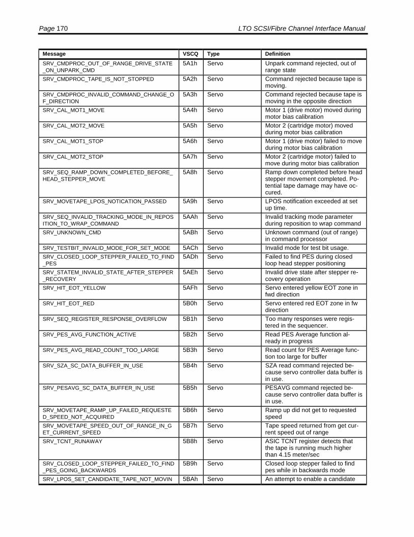
Page 170 LTO SCSI/Fibre Channel Interface Manual
Message VSCQ Type DefinitionSRV_CMDPROC_OUT_OF_RANGE_DRIVE_STATE_ON_UNPARK_CMD
5A1h Servo Unpark command rejected, out ofrange state
SRV_CMDPROC_TAPE_IS_NOT_STOPPED 5A2h Servo Command rejected because tape ismoving.
SRV_CMDPROC_INVALID_COMMAND_CHANGE_OF_DIRECTION
5A3h Servo Command rejected because tape ismoving in the opposite direction
SRV_CAL_MOT1_MOVE 5A4h Servo Motor 1 (drive motor) moved duringmotor bias calibration
SRV_CAL_MOT2_MOVE 5A5h Servo Motor 2 (cartridge motor) movedduring motor bias calibration
SRV_CAL_MOT1_STOP 5A6h Servo Motor 1 (drive motor) failed to moveduring motor bias calibration
SRV_CAL_MOT2_STOP 5A7h Servo Motor 2 (cartridge motor) failed tomove during motor bias calibration
SRV_SEQ_RAMP_DOWN_COMPLETED_BEFORE_HEAD_STEPPER_MOVE
5A8h Servo Ramp down completed before headstepper movement completed. Po-tential tape damage may have oc-cured.
SRV_MOVETAPE_LPOS_NOTICATION_PASSED 5A9h Servo LPOS notification exceeded at setup time.
SRV_SEQ_INVALID_TRACKING_MODE_IN_REPOSITION_TO_WRAP_COMMAND
5AAh Servo Invalid tracking mode parameterduring reposition to wrap command
SRV_UNKNOWN_CMD 5ABh Servo Unknown command (out of range)in command processor
SRV_TESTBIT_INVALID_MODE_FOR_SET_MODE 5ACh Servo Invalid mode for test bit usage.SRV_CLOSED_LOOP_STEPPER_FAILED_TO_FIND_PES
5ADh Servo Failed to find PES during closedloop head stepper positioning
SRV_STATEM_INVALID_STATE_AFTER_STEPPER_RECOVERY
5AEh Servo Invalid drive state after stepper re-covery operation
SRV_HIT_EOT_YELLOW 5AFh Servo Servo entered yellow EOT zone infwd direction
SRV_HIT_EOT_RED 5B0h Servo Servo entered red EOT zone in fwdirection
SRV_SEQ_REGISTER_RESPONSE_OVERFLOW 5B1h Servo Too many responses were regis-tered in the sequencer.
SRV_PES_AVG_FUNCTION_ACTIVE 5B2h Servo Read PES Average function al-ready in progress
SRV_PES_AVG_READ_COUNT_TOO_LARGE 5B3h Servo Read count for PES Average func-tion too large for buffer
SRV_SZA_SC_DATA_BUFFER_IN_USE 5B4h Servo SZA read command rejected be-cause servo controller data buffer isin use.
SRV_PESAVG_SC_DATA_BUFFER_IN_USE 5B5h Servo PESAVG command rejected be-cause servo controller data buffer isin use.
SRV_MOVETAPE_RAMP_UP_FAILED_REQUESTED_SPEED_NOT_ACQUIRED
5B6h Servo Ramp up did not get to requestedspeed
SRV_MOVETAPE_SPEED_OUT_OF_RANGE_IN_GET_CURRENT_SPEED
5B7h Servo Tape speed returned from get cur-rent speed out of range
SRV_TCNT_RUNAWAY 5B8h Servo ASIC TCNT register detects thatthe tape is running much higherthan 4.15 meter/sec
SRV_CLOSED_LOOP_STEPPER_FAILED_TO_FIND_PES_GOING_BACKWARDS
5B9h Servo Closed loop stepper failed to findpes while in backwards mode
SRV_LPOS_SET_CANDIDATE_TAPE_NOT_MOVIN 5BAh Servo An attempt to enable a candidate
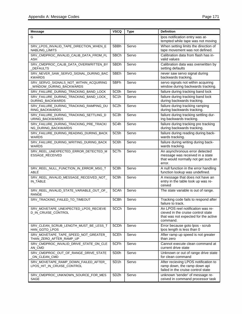
Appendix A: Message Codes Page 171
Message VSCQ Type DefinitionG lpos notification entry was at-
tempted while tape was not movingSRV_LPOS_INVALID_TAPE_DIRECTION_WHEN_ENABLING_LIMITS
5BBh Servo When setting limits the direction oftape movement was not defined.
SRV_CMDPROC_INVALID_CALIB_DATA_FROM_FLASH
5BCh Servo Calibration data from flash has in-valid values
SRV_CMDPROC_CALIB_DATA_OVERWRITTEN_BY_DEFAULTS
5BDh Servo Calibration data was overwritten bysetting defaults
SRV_NEVER_SAW_SERVO_SIGNAL_DURING_BACKWARDS
5BEh Servo never saw servo signal duringbackwards tracking.
SRV_SERVO_SIGNALS_NOT_WITHIN_ACQUIRING_WINDOW_DURING_BACKWARDS
5BFh Servo servo signals not within acquiringwindow during backwards tracking.
SRV_FAILURE_DURING_TRACKING_BAND_LOCK 5C0h Servo failure during tracking band lockSRV_FAILURE_DURING_TRACKING_BAND_LOCK_DURING_BACKWARDS
5C1h Servo failure during tracking band lockduring backwards tracking.
SRV_FAILURE_DURING_TRACKING_RAMPING_DURING_BACKWARDS
5C2h Servo failure during tracking rampingduring backwards tracking.
SRV_FAILURE_DURING_TRACKING_SETTLING_DURING_BACKWARDS
5C3h Servo failure during tracking settling dur-ing backwards tracking.
SRV_FAILURE_DURING_TRACKING_PRE_TRACKING_DURING_BACKWARDS
5C4h Servo failure during tracking pre trackingduring backwards tracking.
SRV_FAILURE_DURING_READING_DURING_BACKWARDS
5C5h Servo failure during reading during back-wards tracking.
SRV_FAILURE_DURING_WRITING_DURING_BACKWARDS
5C6h Servo failure during writing during back-wards tracking.
SRV_REEL_UNEXPECTED_ERROR_DETECTED_MESSAGE_RECEIVED
5C7h Servo An asynchronous error detectedmessage was received in a statethat would normally not get such anerror.
SRV_REEL_NULL_FUNCTION_IN_ERROR_MSG_TABLE
5C8h Servo A null function in the error handlingfunction lookup was undefined.
SRV_REEL_INVALID_MESSAGE_RECEIVED_NOT_IN_TABLE
5C9h Servo A message that does not have anentry in the table look up was re-ceived
SRV_REEL_INVALID_STATE_VARIABLE_OUT_OF_RANGE
5CAh Servo The state variable is out of range.
SRV_TRACKING_FAILED_TO_TIMEOUT 5CBh Servo Tracking code fails to respond afterfailure to track.
SRV_MOVETAPE_UNEXPECTED_LPOS_RECIEVED_IN_CRUISE_CONTROL
5CCh Servo An LPOS reel notification was re-cieved in the cruise control statethat was not expected for the activecommand.
SRV_CLEAN_SCRUB_LENGTH_MUST_BE_LESS_THAN_GOTO_LPOS
5CDh Servo Error because goto lpos - scrublpos length is less than 0
SRV_MOVETAPE_TAPE_SPEED_NOT_GREATER_THAN_ZERO_AFTER_RAMP_UP
5CEh Servo After ramp up speed is not greaterthan zero
SRV_CMDPROC_INVALID_DRIVE_STATE_ON_CLEAN_CMD
5CFh Servo Cannot execute clean command atcurrent drive state
SRV_CMDPROC_OUT_OF_RANGE_DRIVE_STATE_ON_CLEAN_CMD
5D0h Servo Unknown or out of range drive statefor clean command
SRV_MOVETAPE_RAMP_DOWN_FAILED_AFTER_LPOS_HIT_IN_CRUISE_CONTROL
5D1h Servo After recieving LPOS notification toramp down, the ramp down apifailed in the cruise control state
SRV_CMDPROC_UNKNOWN_SOURCE_FOR_MESSAGE
5D2h Servo unknown 'sender' of message re-ceived in command processor task
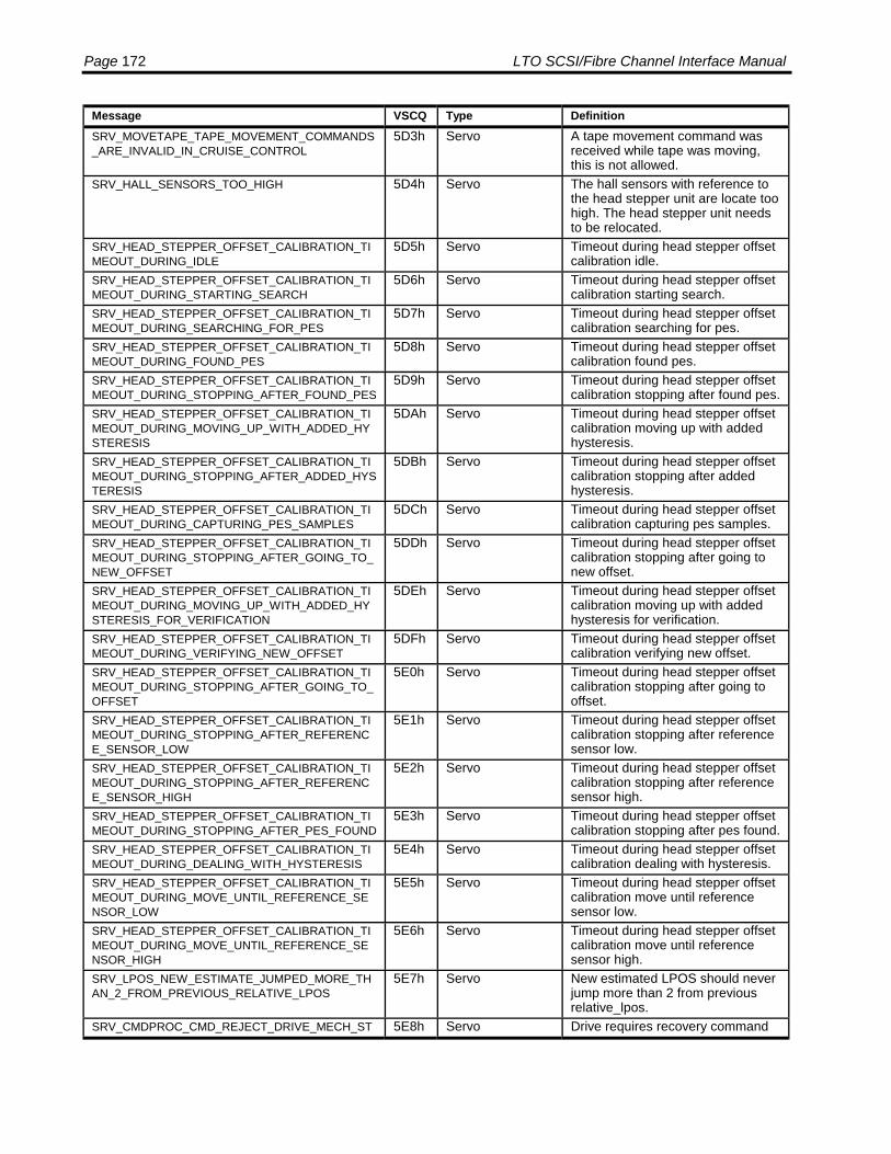
Page 172 LTO SCSI/Fibre Channel Interface Manual
Message VSCQ Type DefinitionSRV_MOVETAPE_TAPE_MOVEMENT_COMMANDS_ARE_INVALID_IN_CRUISE_CONTROL
5D3h Servo A tape movement command wasreceived while tape was moving,this is not allowed.
SRV_HALL_SENSORS_TOO_HIGH 5D4h Servo The hall sensors with reference tothe head stepper unit are locate toohigh. The head stepper unit needsto be relocated.
SRV_HEAD_STEPPER_OFFSET_CALIBRATION_TIMEOUT_DURING_IDLE
5D5h Servo Timeout during head stepper offsetcalibration idle.
SRV_HEAD_STEPPER_OFFSET_CALIBRATION_TIMEOUT_DURING_STARTING_SEARCH
5D6h Servo Timeout during head stepper offsetcalibration starting search.
SRV_HEAD_STEPPER_OFFSET_CALIBRATION_TIMEOUT_DURING_SEARCHING_FOR_PES
5D7h Servo Timeout during head stepper offsetcalibration searching for pes.
SRV_HEAD_STEPPER_OFFSET_CALIBRATION_TIMEOUT_DURING_FOUND_PES
5D8h Servo Timeout during head stepper offsetcalibration found pes.
SRV_HEAD_STEPPER_OFFSET_CALIBRATION_TIMEOUT_DURING_STOPPING_AFTER_FOUND_PES
5D9h Servo Timeout during head stepper offsetcalibration stopping after found pes.
SRV_HEAD_STEPPER_OFFSET_CALIBRATION_TIMEOUT_DURING_MOVING_UP_WITH_ADDED_HYSTERESIS
5DAh Servo Timeout during head stepper offsetcalibration moving up with addedhysteresis.
SRV_HEAD_STEPPER_OFFSET_CALIBRATION_TIMEOUT_DURING_STOPPING_AFTER_ADDED_HYSTERESIS
5DBh Servo Timeout during head stepper offsetcalibration stopping after addedhysteresis.
SRV_HEAD_STEPPER_OFFSET_CALIBRATION_TIMEOUT_DURING_CAPTURING_PES_SAMPLES
5DCh Servo Timeout during head stepper offsetcalibration capturing pes samples.
SRV_HEAD_STEPPER_OFFSET_CALIBRATION_TIMEOUT_DURING_STOPPING_AFTER_GOING_TO_NEW_OFFSET
5DDh Servo Timeout during head stepper offsetcalibration stopping after going tonew offset.
SRV_HEAD_STEPPER_OFFSET_CALIBRATION_TIMEOUT_DURING_MOVING_UP_WITH_ADDED_HYSTERESIS_FOR_VERIFICATION
5DEh Servo Timeout during head stepper offsetcalibration moving up with addedhysteresis for verification.
SRV_HEAD_STEPPER_OFFSET_CALIBRATION_TIMEOUT_DURING_VERIFYING_NEW_OFFSET
5DFh Servo Timeout during head stepper offsetcalibration verifying new offset.
SRV_HEAD_STEPPER_OFFSET_CALIBRATION_TIMEOUT_DURING_STOPPING_AFTER_GOING_TO_OFFSET
5E0h Servo Timeout during head stepper offsetcalibration stopping after going tooffset.
SRV_HEAD_STEPPER_OFFSET_CALIBRATION_TIMEOUT_DURING_STOPPING_AFTER_REFERENCE_SENSOR_LOW
5E1h Servo Timeout during head stepper offsetcalibration stopping after referencesensor low.
SRV_HEAD_STEPPER_OFFSET_CALIBRATION_TIMEOUT_DURING_STOPPING_AFTER_REFERENCE_SENSOR_HIGH
5E2h Servo Timeout during head stepper offsetcalibration stopping after referencesensor high.
SRV_HEAD_STEPPER_OFFSET_CALIBRATION_TIMEOUT_DURING_STOPPING_AFTER_PES_FOUND
5E3h Servo Timeout during head stepper offsetcalibration stopping after pes found.
SRV_HEAD_STEPPER_OFFSET_CALIBRATION_TIMEOUT_DURING_DEALING_WITH_HYSTERESIS
5E4h Servo Timeout during head stepper offsetcalibration dealing with hysteresis.
SRV_HEAD_STEPPER_OFFSET_CALIBRATION_TIMEOUT_DURING_MOVE_UNTIL_REFERENCE_SENSOR_LOW
5E5h Servo Timeout during head stepper offsetcalibration move until referencesensor low.
SRV_HEAD_STEPPER_OFFSET_CALIBRATION_TIMEOUT_DURING_MOVE_UNTIL_REFERENCE_SENSOR_HIGH
5E6h Servo Timeout during head stepper offsetcalibration move until referencesensor high.
SRV_LPOS_NEW_ESTIMATE_JUMPED_MORE_THAN_2_FROM_PREVIOUS_RELATIVE_LPOS
5E7h Servo New estimated LPOS should neverjump more than 2 from previousrelative_lpos.
SRV_CMDPROC_CMD_REJECT_DRIVE_MECH_ST 5E8h Servo Drive requires recovery command
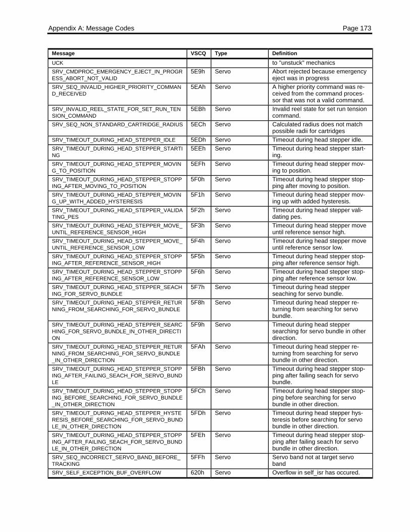
Appendix A: Message Codes Page 173
Message VSCQ Type DefinitionUCK to "unstuck" mechanicsSRV_CMDPROC_EMERGENCY_EJECT_IN_PROGRESS_ABORT_NOT_VALID
5E9h Servo Abort rejected because emergencyeject was in progress
SRV_SEQ_INVALID_HIGHER_PRIORITY_COMMAND_RECEIVED
5EAh Servo A higher priority command was re-ceived from the command proces-sor that was not a valid command.
SRV_INVALID_REEL_STATE_FOR_SET_RUN_TENSION_COMMAND
5EBh Servo Invalid reel state for set run tensioncommand.
SRV_SEQ_NON_STANDARD_CARTRIDGE_RADIUS 5ECh Servo Calculated radius does not matchpossible radii for cartridges
SRV_TIMEOUT_DURING_HEAD_STEPPER_IDLE 5EDh Servo Timeout during head stepper idle.SRV_TIMEOUT_DURING_HEAD_STEPPER_STARTING
5EEh Servo Timeout during head stepper start-ing.
SRV_TIMEOUT_DURING_HEAD_STEPPER_MOVING_TO_POSITION
5EFh Servo Timeout during head stepper mov-ing to position.
SRV_TIMEOUT_DURING_HEAD_STEPPER_STOPPING_AFTER_MOVING_TO_POSITION
5F0h Servo Timeout during head stepper stop-ping after moving to position.
SRV_TIMEOUT_DURING_HEAD_STEPPER_MOVING_UP_WITH_ADDED_HYSTERESIS
5F1h Servo Timeout during head stepper mov-ing up with added hysteresis.
SRV_TIMEOUT_DURING_HEAD_STEPPER_VALIDATING_PES
5F2h Servo Timeout during head stepper vali-dating pes.
SRV_TIMEOUT_DURING_HEAD_STEPPER_MOVE_UNTIL_REFERENCE_SENSOR_HIGH
5F3h Servo Timeout during head stepper moveuntil reference sensor high.
SRV_TIMEOUT_DURING_HEAD_STEPPER_MOVE_UNTIL_REFERENCE_SENSOR_LOW
5F4h Servo Timeout during head stepper moveuntil reference sensor low.
SRV_TIMEOUT_DURING_HEAD_STEPPER_STOPPING_AFTER_REFERENCE_SENSOR_HIGH
5F5h Servo Timeout during head stepper stop-ping after reference sensor high.
SRV_TIMEOUT_DURING_HEAD_STEPPER_STOPPING_AFTER_REFERENCE_SENSOR_LOW
5F6h Servo Timeout during head stepper stop-ping after reference sensor low.
SRV_TIMEOUT_DURING_HEAD_STEPPER_SEACHING_FOR_SERVO_BUNDLE
5F7h Servo Timeout during head stepperseaching for servo bundle.
SRV_TIMEOUT_DURING_HEAD_STEPPER_RETURNING_FROM_SEARCHING_FOR_SERVO_BUNDLE
5F8h Servo Timeout during head stepper re-turning from searching for servobundle.
SRV_TIMEOUT_DURING_HEAD_STEPPER_SEARCHING_FOR_SERVO_BUNDLE_IN_OTHER_DIRECTION
5F9h Servo Timeout during head steppersearching for servo bundle in otherdirection.
SRV_TIMEOUT_DURING_HEAD_STEPPER_RETURNING_FROM_SEARCHING_FOR_SERVO_BUNDLE_IN_OTHER_DIRECTION
5FAh Servo Timeout during head stepper re-turning from searching for servobundle in other direction.
SRV_TIMEOUT_DURING_HEAD_STEPPER_STOPPING_AFTER_FAILING_SEACH_FOR_SERVO_BUNDLE
5FBh Servo Timeout during head stepper stop-ping after failing seach for servobundle.
SRV_TIMEOUT_DURING_HEAD_STEPPER_STOPPING_BEFORE_SEARCHING_FOR_SERVO_BUNDLE_IN_OTHER_DIRECTION
5FCh Servo Timeout during head stepper stop-ping before searching for servobundle in other direction.
SRV_TIMEOUT_DURING_HEAD_STEPPER_HYSTERESIS_BEFORE_SEARCHING_FOR_SERVO_BUNDLE_IN_OTHER_DIRECTION
5FDh Servo Timeout during head stepper hys-teresis before searching for servobundle in other direction.
SRV_TIMEOUT_DURING_HEAD_STEPPER_STOPPING_AFTER_FAILING_SEACH_FOR_SERVO_BUNDLE_IN_OTHER_DIRECTION
5FEh Servo Timeout during head stepper stop-ping after failing seach for servobundle in other direction.
SRV_SEQ_INCORRECT_SERVO_BAND_BEFORE_TRACKING
5FFh Servo Servo band not at target servoband
SRV_SELF_EXCEPTION_BUF_OVERFLOW 620h Servo Overflow in self_isr has occured.
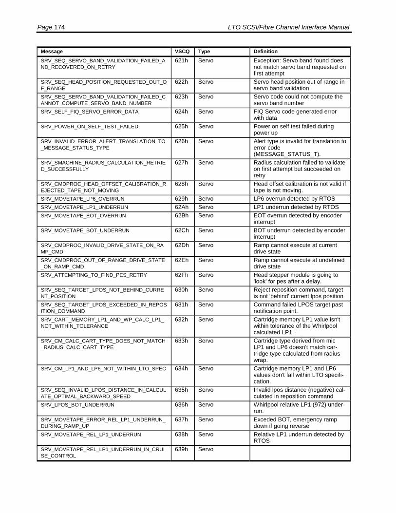
Page 174 LTO SCSI/Fibre Channel Interface Manual
Message VSCQ Type DefinitionSRV_SEQ_SERVO_BAND_VALIDATION_FAILED_AND_RECOVERED_ON_RETRY
621h Servo Exception: Servo band found doesnot match servo band requested onfirst attempt
SRV_SEQ_HEAD_POSITION_REQUESTED_OUT_OF_RANGE
622h Servo Servo head position out of range inservo band validation
SRV_SEQ_SERVO_BAND_VALIDATION_FAILED_CANNOT_COMPUTE_SERVO_BAND_NUMBER
623h Servo Servo code could not compute theservo band number
SRV_SELF_FIQ_SERVO_ERROR_DATA 624h Servo FIQ Servo code generated errorwith data
SRV_POWER_ON_SELF_TEST_FAILED 625h Servo Power on self test failed duringpower up
SRV_INVALID_ERROR_ALERT_TRANSLATION_TO_MESSAGE_STATUS_TYPE
626h Servo Alert type is invalid for translation toerror code(MESSAGE_STATUS_T).
SRV_SMACHINE_RADIUS_CALCULATION_RETRIED_SUCCESSFULLY
627h Servo Radius calculation failed to validateon first attempt but succeeded onretry
SRV_CMDPROC_HEAD_OFFSET_CALIBRATION_REJECTED_TAPE_NOT_MOVING
628h Servo Head offset calibration is not valid iftape is not moving.
SRV_MOVETAPE_LP6_OVERRUN 629h Servo LP6 overrun detected by RTOSSRV_MOVETAPE_LP1_UNDERRUN 62Ah Servo LP1 underrun detected by RTOSSRV_MOVETAPE_EOT_OVERRUN 62Bh Servo EOT overrun detected by encoder
interruptSRV_MOVETAPE_BOT_UNDERRUN 62Ch Servo BOT underrun detected by encoder
interruptSRV_CMDPROC_INVALID_DRIVE_STATE_ON_RAMP_CMD
62Dh Servo Ramp cannot execute at currentdrive state
SRV_CMDPROC_OUT_OF_RANGE_DRIVE_STATE_ON_RAMP_CMD
62Eh Servo Ramp cannot execute at undefineddrive state
SRV_ATTEMPTING_TO_FIND_PES_RETRY 62Fh Servo Head stepper module is going to'look' for pes after a delay.
SRV_SEQ_TARGET_LPOS_NOT_BEHIND_CURRENT_POSITION
630h Servo Reject reposition command, targetis not 'behind' current lpos position
SRV_SEQ_TARGET_LPOS_EXCEEDED_IN_REPOSITION_COMMAND
631h Servo Command failed LPOS target pastnotification point.
SRV_CART_MEMORY_LP1_AND_WP_CALC_LP1_NOT_WITHIN_TOLERANCE
632h Servo Cartridge memory LP1 value isn'twithin tolerance of the Whirlpoolcalculated LP1.
SRV_CM_CALC_CART_TYPE_DOES_NOT_MATCH_RADIUS_CALC_CART_TYPE
633h Servo Cartridge type derived from micLP1 and LP6 doesn't match car-tridge type calculated from radiuswrap.
SRV_CM_LP1_AND_LP6_NOT_WITHIN_LTO_SPEC 634h Servo Cartridge memory LP1 and LP6values don't fall within LTO specifi-cation.
SRV_SEQ_INVALID_LPOS_DISTANCE_IN_CALCULATE_OPTIMAL_BACKWARD_SPEED
635h Servo Invalid lpos distance (negative) cal-culated in reposition command
SRV_LPOS_BOT_UNDERRUN 636h Servo Whirlpool relative LP1 (972) under-run.
SRV_MOVETAPE_ERROR_REL_LP1_UNDERRUN_DURING_RAMP_UP
637h Servo Exceded BOT, emergency rampdown if going reverse
SRV_MOVETAPE_REL_LP1_UNDERRUN 638h Servo Relative LP1 underrun detected byRTOS
SRV_MOVETAPE_REL_LP1_UNDERRUN_IN_CRUISE_CONTROL
639h Servo

Appendix A: Message Codes Page 175
Message VSCQ Type DefinitionSRV_REEL_REL_LP1_LIMIT_UNDERRUN_IN_HOLD_STATE
63Ah Servo Relative LP1 limit underrun in holdstate, tape control out of sync
SRV_CMDPROC_COMMAND_INVALID_SEQUENCE 63Bh Servo Recovery commands are for inter-nal use only and should not beexecuted from the scrambler
SRV_SEQ_UNEXPECTED_COMMAND_RECEIVED_DURING_ACTIVE_MECHANICAL_COMMAND
63Ch Servo A command was received from thecommand processor during proc-essing of a mechanical commmand
SRV_SEQ_COMMAND_RECEIVED_DURING_ERROR_HANDLING
63Dh Servo A command was received from thecommand processor during errorrecovery. This may have occurred ifan asynchronous error occurredsimultaneous to a new commandfrom the Controller.
SRV_POST_REGISTER_FAILED 63Eh Servo POST register test failedSRV_NOT_USED 63Fh Servo End of this SRV seriesSCSI_SAPI_REQUEST_TIMEOUT 640h SCSICM_BAD_APP_SPEC 700h Medium Auxiliary
MemoryApplication Specific
CM_BAD_CM_MANUF_INFO 701h Medium AuxiliaryMemory
CM Manufacturer's Information
CM_BAD_WRITE_PROTECT 702h Medium AuxiliaryMemory
CM Write Protect
CM_BAD_PROT_PAGE_TBL 703h Medium AuxiliaryMemory
CM Protected Page Table
CM_BAD_CART_MANUF_INFO 704h Medium AuxiliaryMemory
Cartridge Manufacturer's Informa-tion
CM_BAD_MEDIA_MANUF_INFO 705h Medium AuxiliaryMemory
Media Manufacturer's Information
CM_BAD_DRIVE_MANUF_SUPPORT 706h Medium AuxiliaryMemory
Drive Manufacturer's Support
CM_BAD_UNPROT_PAGE_TBL 710h Medium AuxiliaryMemory
CM Unprotected Page Table
CM_BAD_INITIALIZATION 711h Medium AuxiliaryMemory
Initialisation Data
CM_BAD_WRITE_PASS 712h Medium AuxiliaryMemory
Tape Write Pass
CM_BAD_TAPE_DIR 713h Medium AuxiliaryMemory
Tape Directory
CM_BAD_EOD_INFO 714h Medium AuxiliaryMemory
EOD Information
CM_BAD_CART_STATUS 715h Medium AuxiliaryMemory
Cartridge Status & Tape Alert Flags
CM_BAD_MECHANISM_RELATED 716h Medium AuxiliaryMemory
Mechanism Related
CM_BAD_SUSPEND_APPEND 717h Medium AuxiliaryMemory
Suspended Append Writes
CM_BAD_USAGE_INFO_0 718h Medium AuxiliaryMemory
Usage Information 0
CM_BAD_USAGE_INFO_1 719h Medium AuxiliaryMemory
Usage Information 1
CM_BAD_USAGE_INFO_2 71Ah Medium AuxiliaryMemory
Usage Information 2
CM_BAD_USAGE_INFO_3 71Bh Medium AuxiliaryMemory
Usage Information 3
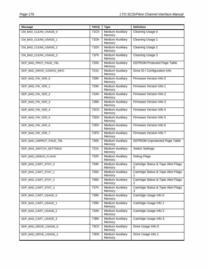
Page 176 LTO SCSI/Fibre Channel Interface Manual
Message VSCQ Type DefinitionCM_BAD_CLEAN_USAGE_0 71Ch Medium Auxiliary
MemoryCleaning Usage 0
CM_BAD_CLEAN_USAGE_1 71Dh Medium AuxiliaryMemory
Cleaning Usage 1
CM_BAD_CLEAN_USAGE_2 71Eh Medium AuxiliaryMemory
Cleaning Usage 2
CM_BAD_CLEAN_USAGE_3 71Fh Medium AuxiliaryMemory
Cleaning Usage 3
EEP_BAD_PROT_PAGE_TBL 720h Medium AuxiliaryMemory
EEPROM Protected Page Table
EEP_BAD_DRIVE_CONFIG_INFO 721h Medium AuxiliaryMemory
Drive ID / Configuration Info
EEP_BAD_FW_VER_0 728h Medium AuxiliaryMemory
Firmware Version Info 0
EEP_BAD_FW_VER_1 729h Medium AuxiliaryMemory
Firmware Version Info 1
EEP_BAD_FW_VER_2 72Ah Medium AuxiliaryMemory
Firmware Version Info 2
EEP_BAD_FW_VER_3 72Bh Medium AuxiliaryMemory
Firmware Version Info 3
EEP_BAD_FW_VER_4 72Ch Medium AuxiliaryMemory
Firmware Version Info 4
EEP_BAD_FW_VER_5 72Dh Medium AuxiliaryMemory
Firmware Version Info 5
EEP_BAD_FW_VER_6 72Eh Medium AuxiliaryMemory
Firmware Version Info 6
EEP_BAD_FW_VER_7 72Fh Medium AuxiliaryMemory
Firmware Version Info 7
EEP_BAD_UNPROT_PAGE_TBL 730h Medium AuxiliaryMemory
EEPROM Unprotected Page Table
EEP_BAD_SWITCH_SETTINGS 731h Medium AuxiliaryMemory
Switch Settings
EEP_BAD_DEBUG_FLAGS 732h Medium AuxiliaryMemory
Debug Flags
EEP_BAD_CART_STAT_0 734h Medium AuxiliaryMemory
Cartridge Status & Tape Alert Flags0
EEP_BAD_CART_STAT_1 735h Medium AuxiliaryMemory
Cartridge Status & Tape Alert Flags1
EEP_BAD_CART_STAT_2 736h Medium AuxiliaryMemory
Cartridge Status & Tape Alert Flags2
EEP_BAD_CART_STAT_3 737h Medium AuxiliaryMemory
Cartridge Status & Tape Alert Flags3
EEP_BAD_CART_USAGE_0 738h Medium AuxiliaryMemory
Cartridge Usage Info 0
EEP_BAD_CART_USAGE_1 739h Medium AuxiliaryMemory
Cartridge Usage Info 1
EEP_BAD_CART_USAGE_2 73Ah Medium AuxiliaryMemory
Cartridge Usage Info 2
EEP_BAD_CART_USAGE_3 73Bh Medium AuxiliaryMemory
Cartridge Usage Info 3
EEP_BAD_DRIVE_USAGE_0 73Ch Medium AuxiliaryMemory
Drive Usage Info 0
EEP_BAD_DRIVE_USAGE_1 73Dh Medium AuxiliaryMemory
Drive Usage Info 1
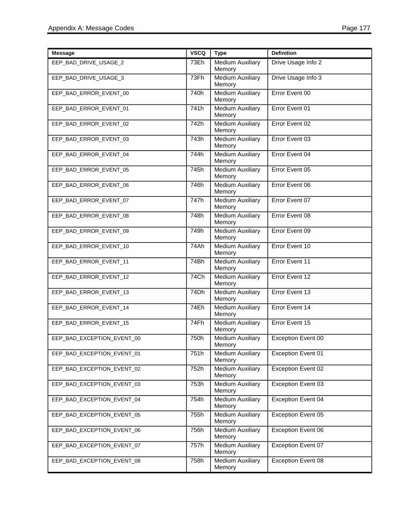
Appendix A: Message Codes Page 177
Message VSCQ Type DefinitionEEP_BAD_DRIVE_USAGE_2 73Eh Medium Auxiliary
MemoryDrive Usage Info 2
EEP_BAD_DRIVE_USAGE_3 73Fh Medium AuxiliaryMemory
Drive Usage Info 3
EEP_BAD_ERROR_EVENT_00 740h Medium AuxiliaryMemory
Error Event 00
EEP_BAD_ERROR_EVENT_01 741h Medium AuxiliaryMemory
Error Event 01
EEP_BAD_ERROR_EVENT_02 742h Medium AuxiliaryMemory
Error Event 02
EEP_BAD_ERROR_EVENT_03 743h Medium AuxiliaryMemory
Error Event 03
EEP_BAD_ERROR_EVENT_04 744h Medium AuxiliaryMemory
Error Event 04
EEP_BAD_ERROR_EVENT_05 745h Medium AuxiliaryMemory
Error Event 05
EEP_BAD_ERROR_EVENT_06 746h Medium AuxiliaryMemory
Error Event 06
EEP_BAD_ERROR_EVENT_07 747h Medium AuxiliaryMemory
Error Event 07
EEP_BAD_ERROR_EVENT_08 748h Medium AuxiliaryMemory
Error Event 08
EEP_BAD_ERROR_EVENT_09 749h Medium AuxiliaryMemory
Error Event 09
EEP_BAD_ERROR_EVENT_10 74Ah Medium AuxiliaryMemory
Error Event 10
EEP_BAD_ERROR_EVENT_11 74Bh Medium AuxiliaryMemory
Error Event 11
EEP_BAD_ERROR_EVENT_12 74Ch Medium AuxiliaryMemory
Error Event 12
EEP_BAD_ERROR_EVENT_13 74Dh Medium AuxiliaryMemory
Error Event 13
EEP_BAD_ERROR_EVENT_14 74Eh Medium AuxiliaryMemory
Error Event 14
EEP_BAD_ERROR_EVENT_15 74Fh Medium AuxiliaryMemory
Error Event 15
EEP_BAD_EXCEPTION_EVENT_00 750h Medium AuxiliaryMemory
Exception Event 00
EEP_BAD_EXCEPTION_EVENT_01 751h Medium AuxiliaryMemory
Exception Event 01
EEP_BAD_EXCEPTION_EVENT_02 752h Medium AuxiliaryMemory
Exception Event 02
EEP_BAD_EXCEPTION_EVENT_03 753h Medium AuxiliaryMemory
Exception Event 03
EEP_BAD_EXCEPTION_EVENT_04 754h Medium AuxiliaryMemory
Exception Event 04
EEP_BAD_EXCEPTION_EVENT_05 755h Medium AuxiliaryMemory
Exception Event 05
EEP_BAD_EXCEPTION_EVENT_06 756h Medium AuxiliaryMemory
Exception Event 06
EEP_BAD_EXCEPTION_EVENT_07 757h Medium AuxiliaryMemory
Exception Event 07
EEP_BAD_EXCEPTION_EVENT_08 758h Medium AuxiliaryMemory
Exception Event 08

Page 178 LTO SCSI/Fibre Channel Interface Manual
Message VSCQ Type DefinitionEEP_BAD_EXCEPTION_EVENT_09 759h Medium Auxiliary
MemoryException Event 09
EEP_BAD_EXCEPTION_EVENT_10 75Ah Medium AuxiliaryMemory
Exception Event 10
EEP_BAD_EXCEPTION_EVENT_11 75Bh Medium AuxiliaryMemory
Exception Event 11
EEP_BAD_EXCEPTION_EVENT_12 75Ch Medium AuxiliaryMemory
Exception Event 12
EEP_BAD_EXCEPTION_EVENT_13 75Dh Medium AuxiliaryMemory
Exception Event 13
EEP_BAD_EXCEPTION_EVENT_14 75Eh Medium AuxiliaryMemory
Exception Event 14
EEP_BAD_EXCEPTION_EVENT_15 75Fh Medium AuxiliaryMemory
Exception Event 15
EEP_BAD_POR_COUNT 760h Medium AuxiliaryMemory
Power On Reset Count
EEP_BAD_RETRY_HISTORY 761h Medium AuxiliaryMemory
Retry History
EEP_BAD_APP_SPEC 76Ah Medium AuxiliaryMemory
Application Specific
SCSI_SC_TRANSFER_DONE_NO_PCMD 780h SCSI SCSI receivedSC_TRANSFER_DONE but pCmdis NULL
SCSI_SC_COMPLETE_DONE_NO_PCMD 781h SCSI SCSI receivedSC_COMPLETE_DONE but pCmdis NULL
SCSI_FE_QUEUE_TOO_MANY_PCMDS 782h SCSI SCSI FE traps excessive number ofpCmds in the queue
SCSI_NULL_SDPORT_DB_CHANGED 783h SCSI Database change – NULLSUPPORT pointer
SCSI_HAPI_INVOKE_CALLBACK_FAILED 784h SCSI HAPI DMA failed to invoke FC call-back
SCSI_FAILED_TO_REMOVE_IID 785h SCSI Failed to remove/log out the initiator.SCSI_FE_RETRY_FUNCTION_POINTER_IS_NULL 786h SCSI FE Retry dispatch has a null pointerSCSI_WP_VERSION_NOT_AVAILABLE 787h SCSI Whirpool Version Number Not AvailableSCSI_WP_DATE_NOT_AVAILABLE 788h SCSI Whirpool Build Date Not AvailableSCSI_EARLY_EXIT_FAILED 789h SCSISCSI_EARLY_EXIT_FAILED_SIZE 78Ah SCSISCSI_EARLY_EXIT_FAILED_BOR 78Bh SCSISCSI_STS_BUSY_TRANS_ID_ALLOCATION_FAILURE
78Ch SCSI
SCSI_STS_BUSY_CA_ACTIVE 78Dh SCSISCSI_STS_BUSY_CA_OR_ACA_ACTIVE 78Eh SCSISCSI_STS_BUSY_NO_DISC_PRIV_AND_NEED_TO_RUN_NOW
78Fh SCSI
SCSI_STS_BUSY_IMMED_NEED_TO_RUN_NOW_AND_BE_BUSY
790h SCSI
SCSI_STS_BUSY_LIB_SVC_RESP_INVALID_ID 791h SCSISCSI_CANNOT_APPEND_LIB_IID_FREE_Q 792h SCSISCSI_CANNOT_REMOVE_LIB_IID_FREE_Q 793h SCSISCSI_CANNOT_ADD_LIB_IID_LRU_Q 794h SCSISCSI_CANNOT_REMOVE_LIB_IID_LRU_Q 795h SCSISCSI_CANNOT_UPDATE_LIB_IID_LRU_Q 796h SCSI

Appendix A: Message Codes Page 179
Message VSCQ Type DefinitionSCSI_STS_BUSY_IMMED_LIB_CMD_AND_BE_BSY 797h SCSISCSI_INVALID_TRANSPORT_COUNT 798h SCSISCSI_STATUS_DIAG_DMA_CONTROLLER_TIMEOUT
799h SCSI
SCSI_STATUS_DIAG_FPGA_VERSION_ERROR 79Ah SCSISCSI_STATUS_DIAG_FC_SDRAM_PARAMETER_MISMATCH
79Bh SCSI
SCSI_STATUS_DIAG_RB_PARAMETER_MISMATCH
79Ch SCSI
SCSI_INVALID_COMMAND_REFERENCE_NUMBER 79Dh SCSISCSI_UA_INITIATOR_LOGGED_OUT 79Eh SCSISCSI_FCP_INVALID_PORT_NUMBER_ENABLE_PORT
79Fh SCSI
SCSI_FCP_INVALID_PORT_NUMBER_ID_CHANGE_REQUEST
7A0h SCSI
SCSI_FCP_INVALID_PORT_NUMBER_DISABLE_PORT
7A1h SCSI
DSM_READ_DSN_OUT_OF_SEQUENCE 8C0h Data set managerDSM_SCSI_COMMAND_ABORTED 8C1h Data set managerDSM_BE_WR_EOWS_IN_ODD_SECTION 8C2h Data set managerDSM_LOCATE_DONE_BUT_NOT_AT_TARGET 8C3h Data set managerDSM_MIC_UPDATE_TAPE_DIR_BUILD_FAILED 8C4h Data set managerDSM_BE_WR_OUTSTANDING_DS_COUNT_CANT_GO_NEGATIVE
8C5h Data set manager
DSM_BE_READ_STOP_MISSING_DS 8C6h Data set managerDSM_FAILURE_OCCURRED_WITH_GOOD_STATUS
8C7h Data set manager
DSM_LOCATE_TERMINATED_WITH_GOOD_STATUS
8C8h Data set manager
DSM_DEGRADED_SPACE_LOCATE 8C9h Data set managerDSM_CANT_CORRECT_INIT_PAGE_AWAY_FROM_BOT
8CAh Data set manager
DSM_DCA_PUT_REREAD_RECOVERED_FAILED 8CBh Data set managerDSM_RECEIVED_INVALID_DS_DATA 8CCh Data set managerDSM RECEIVED_INVALID_DS_DONE 8CDh Data set managerDSM_RECEIVED_INVALID_DS_EMPTY 8CEh Data set managerDSM_CMD_LIST_RECVD_DONE_WHILE_PREVENTED
8CFh Data set manager
DSM_MIC_Q_CANT_PREVENT_LIST_NOT_EMPTY 8D0h Data set managerDSM_RB_NOT_EMPTY_AFTER_FLUSH 8D1h Data set managerDSM_CMPR_NO_DS_TO_FLUSH 8D2h Data set managerSRV_POST_MEMORY_FAILED 900h Servo Post memory test failedSRV_POST_DIVIDER_FAILED 901h Servo POST hardware divider test failedSRV_POST_TIMESTAMP_FAILED 902h Servo Post timestamp incrementing test
failedSRV_SEQ_INVALID_DRIVE_STATE_AT_UNLOAD 903h Servo Sequencer received a load com-
mand when drive was parked. Thisshould never happen.
SRV_CMDPROC_INVALID_STATE_FOR_LOAD 904h Servo Command processor rejects loadcommand because drive is inparked
SRV_POST_INTERRUPT_FAILED_TIMER1_INTERR 905h Servo Unexpected timer1 interrupt oc-
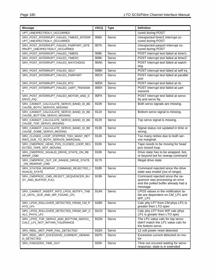
Page 180 LTO SCSI/Fibre Channel Interface Manual
Message VSCQ Type DefinitionUPT_UNEXPECTEDLY_OCCURRED cured during POSTSRV_POST_INTERRUPT_FAILED_TIMER2_INTERRUPT_UNEXPECTEDLY_OCCURRED
906h Servo Unexpected timer2 interrupt oc-cured during POST
SRV_POST_INTERRUPT_FAILED_PARPORT_INTERRUPT_UNEXPECTEDLY_OCCURRED
907h Servo Unexpected parport interrupt oc-cured during POST
SRV_POST_INTERRUPT_FAILED_TIMER1 908h Servo POST interrupt test failed at timer1SRV_POST_INTERRUPT_FAILED_TIMER2 909h Servo POST interrupt test failed at timer2SRV_POST_INTERRUPT_FAILED_WATCHDOG 90Ah Servo POST interrupt test failed at watch-
dogSRV_POST_INTERRUPT_FAILED_SELF 90Bh Servo POST interrupt test failed at self irqSRV_POST_INTERRUPT_FAILED_PARPORT 90Ch Servo POST interrupt test failed at parallel
portSRV_POST_INTERRUPT_FAILED_RTC 90Dh Servo POST interrupt test failed at rtcSRV_POST_INTERRUPT_FAILED_UART_TRANSMIT
90Eh Servo POST interrupt test failed at uarttransmit
SRV_POST_INTERRUPT_FAILED_MOTOR_AND_SERVO_FIQ
90Fh Servo POST interrupt test failed at servofiq and servo fiq
SRV_CANNOT_CALCULATE_SERVO_BAND_ID_BECAUSE_BOTH_SERVOS_MISSING
910h Servo Both servo signals are missing.
SRV_CANNOT_CALCULATE_SERVO_BAND_ID_BECAUSE_BOTTOM_SERVO_MISSING
911h Servo Bottom servo signal is missing.
SRV_CANNOT_CALCULATE_SERVO_BAND_ID_BECAUSE_TOP_SERVO_MISSING
912h Servo Top servo signal is missing.
SRV_CANNOT_CALCULATE_SERVO_BAND_ID_BECAUSE_SOME_SERVO_MISSING
913h Servo Signal status not updated in time orwrong.
SRV_CLOSED_LOOP_STEPPER_TOO_MANY_RETRIES_DUE_TO_BOTH_SERVOS_MARGINAL
914h Servo Too many retries due to both ser-vos marginal.
SRV_CMDPROC_HEAD_POS_CLOSED_LOOP_REJECTED_TAPE_NOT_MOVING
915h Servo Tape needs to be moving for headpos closed loop.
SRV_CMDPROC_INVALID_DRIVE_STATE_ON_REWRAP_CMD
916h Servo Drive state has to be wrapped, bot,or beyond bot for rewrap command
SRV_CMDPROC_OUT_OF_RANGE_DRIVE_STATE_ON_REWRAP_CMD
917h Illegal drive state
SRV_STATEM_REWRAP_COMMAND_REJECTED_INVALID_STATE
918h Servo Command rejected since the drivestate was invalid (out of range).
SRV_CMDPROC_CMD_REJECT_SEQUENCER_BUSY_AND_BUFFER_FULL
919h Servo Command rejected since the se-quencer was processing an errorand the polled buffer already had amessage
SRV_CANNOT_INSERT_INTO_LPOS_NOTIFY_TABLE_UNTIL_SCR_AND_WP_FOUND_LP1
91Ah Servo LPOS values in the notification ta-ble are dependent on CM_LP1 andWP_LP1
SRV_LPOS_ROLLOVER_DETECTED_FROM_CM_PHYS_LP1
91Bh Servo Calc phy LP7 from CM phys LP1 isgreater then LTO spec
SRV_LPOS_ROLLOVER_DETECTED_FROM_WP_CALC_PHYS_LP1
91Ch Servo Calc phy LP7 from WP calc physLP1 is greater then LTO spec
SRV_LPOS_TOP_SERVO_AND_BOTTOM_SERVO_CALC_LP1_NOT_WITHIN_TOLERANCE
91Dh Servo The LP1 value calc for top servodidn't match the LP1 value calc forthe bottom servo
SRV_REEL_MOT_PWR_FAIL_DETECTED 91Eh Servo 12 volt power reset detectedSRV_REEL_MOT_EXCESSIVE_CURRENT_DEMAND_DETECTED
91Fh Servo Excessive current detected on mo-tor
SRV_FINDZERO_TIME_OUT 920h Servo Time out occured waiting for servoresponse, state is in extended
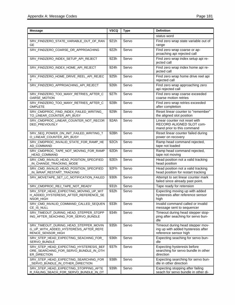
Appendix A: Message Codes Page 181
Message VSCQ Type Definitionstatus word
SRV_FINDZERO_STATE_VARIABLE_OUT_OF_RANGE
921h Servo Find zero wrap state variable out ofrange
SRV_FINDZERO_COARSE_OR_APPROACHING 922h Servo Find zero wrap coarse or ap-proaching api rejected call
SRV_FINDZERO_INDEX_SETUP_API_REJECT 923h Servo Find zero wrap index setup api re-jected call
SRV_FINDZERO_INDEX_HOME_API_REJECT 924h Servo Find zero wrap index home api re-jected call
SRV_FINDZERO_HOME_DRIVE_REEL_API_REJECT
925h Servo Find zero wrap home drive reel apirejected call
SRV_FINDZERO_APPROACHING_API_REJECT 926h Servo Find zero wrap approaching zeroapi rejected call
SRV_FINDZERO_TOO_MANY_RETRIES_AFTER_COARSE_MOTION
927h Servo Find zero wrap coarse exceededcoarse motion retries
SRV_FINDZERO_TOO_MANY_RETRIES_AFTER_COMPLETE
928h Servo Find zero wrap retries exceededafter completion
SRV_CMDPROC_FIND_INDEX_FAILED_WRITING_TO_LINEAR_COUNTER_API_BUSY
929h Servo Reset linear counter to "remember"the aligned slot position
SRV_CMDPROC_LINEAR_COUNTER_NOT_RECORDED_PREVIOUSLY
92Ah Servo Linear counter not reset withRECORD ALIGNED SLOT com-mand prior to this command
SRV_SEQ_POWER_ON_INIT_FAILED_WRITING_TO_LINEAR_COUNTER_API_BUSY
92Bh Servo Reset linear counter failed duringpower on recovery
SRV_CMDPROC_INVALID_STATE_FOR_RAMP_HEAD_COMMAND
92Ch Servo Ramp head command rejected,tape not loaded
SRV_CMDPROC_TAPE_NOT_MOVING_FOR_RAMP_HEAD_COMMAND
92Dh Servo Ramp head command rejected,tape not moving
SRV_CMD_INVALID_HEAD_POSITION_SPECIFIED_IN_CHANGE_TRACKING_MODE
92Eh Servo Head position not a valid trackinghead position
SRV_CMD_INVALID_HEAD_POSITION_SPECIFIED_IN_WRAP_RESTART_TRACKING
92Fh Servo Head position not a valid trackinghead position for restart tracking
SRV_MOVETAPE_SET_LC_NOTIFICATION_FAILED 930h Servo Attempt to set linear counter markfailed since already past point.
SRV_CMDPROC_REJ_TAPE_NOT_READY 931h Servo Tape ready for retensionSRV_STEP_HEAD_EXPECTING_MOVING_UP_WITH_ADDED_HYSTERESIS_AFTER_REFERENCE_SENSOR_HIGH
932h Servo Expecting moving up with addedhysteresis after reference sensorhigh
SRV_CMD_INVALID_COMMAND_CALLED_SEQUENCE_IS_NULL
933h Servo Invalid command called or invalidmessage sent to sequencer
SRV_TIMEOUT_DURING_HEAD_STEPPER_STOPPING_AFTER_SEACHING_FOR_SERVO_BUNDLE
934h Servo Timeout during head stepper stop-ping after seaching for servo bun-dle
SRV_TIMEOUT_DURING_HEAD_STEPPER_MOVING_UP_WITH_ADDED_HYSTERESIS_AFTER_REFERENCE_SENSOR_HIGH
935h Servo Timeout during head stepper mov-ing up with added hysteresis afterreference sensor high
SRV_STEP_HEAD_EXPECTING_SEACHING_FOR_SERVO_BUNDLE
936h Servo Expecting seaching for servo bun-dle
SRV_STEP_HEAD_EXPECTING_HYSTERESIS_BEFORE_SEARCHING_FOR_SERVO_BUNDLE_IN_OTHER_DIRECTION
937h Servo Expecting hysteresis beforesearching for servo bundle in otherdirection
SRV_STEP_HEAD_EXPECTING_SEARCHING_FOR_SERVO_BUNDLE_IN_OTHER_DIRECTION
938h Servo Expecting searching for servo bun-dle in other direction
SRV_STEP_HEAD_EXPECTING_STOPPING_AFTER_FAILING_SEACH_FOR_SERVO_BUNDLE_IN_OT
939h Servo Expecting stopping after failingseach for servo bundle in other di-

Page 182 LTO SCSI/Fibre Channel Interface Manual
Message VSCQ Type DefinitionHER_DIRECTION rectionSRV_STEP_HEAD_EXPECTING_STOPPING_AFTER_SEACHING_FOR_SERVO_BUNDLE
93Ah Servo Expecting stopping after seachingfor servo bundle
SRV_STEP_HEAD_EXPECTING_STOPPING_AFTER_FAILING_SEACH_FOR_SERVO_BUNDLE
93Bh Servo Expecting stopping after failingseach for servo bundle
SRV_STEP_HEAD_EXPECTING_STOPPING_BEFORE_SEARCHING_FOR_SERVO_BUNDLE_IN_OTHER_DIRECTION
93Ch Servo Expecting stopping before search-ing for servo bundle in other direc-tion
SRV_HEAD_STEPPER_MOVE_HEAD_TO_HEAD_POSITION_STATE_MACHINE_DEFAULT_ENCOUNTERED
93Dh Servo Head stepper move head to headposition state machine default en-countered
SRV_HEAD_STEPPER_OFFSET_CALIBRATION_EXPECTING_SEARCHING_FOR_PES
93Eh Servo Head stepper offset calibration ex-pecting searching for pes
SRV_HEAD_STEPPER_OFFSET_CALIBRATION_EXPECTING_STOPPING_AFTER_PES_FOUND
93Fh Servo Head stepper offset calibration ex-pecting stopping after pes found
SRV_HEAD_STEPPER_OFFSET_CALIBRATION_EXPECTING_DEALING_WITH_HYSTERESIS
940h Servo Head stepper offset calibration ex-pecting dealing with hysteresis
SRV_HEAD_STEPPER_OFFSET_CALIBRATION_EXPECTING_STOPPING_AFTER_GOING_TO_NEW_OFFSET
941h Servo Head stepper offset calibration ex-pecting stopping after going to newoffset
SRV_FAILURE_TO_FIND_PES_DURING_HEAD_STEPPER_OFFSET_CALIBRATION
942h Servo Failure to find pes during headstepper offset calibration
SRV_HEAD_STEPPER_OFFSET_CALIBRATION_STATE_MACHINE_DEFAULT_ENCOUNTERED
943h Servo Head stepper offset calibrationstate machine default encountered
SRV_INCORRECT_DATA_BAND_ID 944h Servo Query for data band returned incor-rect band ID
SRV_CALCULATED_LP1_VALUES_NOT_CONSISTENT
945h Servo Calculated LP1 sample array valuesvary too much. Cannot calculate LP1from this set of samples
SRV_HEAD_STEPPER_PROCESS_STEP_MOTOR_STATE_MACHINE_DEFAULT_ENCOUNTERED
946h Servo unknown state encountered while headstepper process_step_motor function
SRV_MOVETAPE_TIMEOUT_IN_CRUISE_CONTROL
947h Servo
SRV_NEVER_SAW_SERVO_SIGNAL_DUE_TO_MECHANICAL_ISSUES
948h Servo
SRV_SERVO_SIGNALS_NOT_WITHIN_ACQUIRING_WINDOW_DUE_TO _MECHANICAL_ISSUES
949h Servo
SRV_FAILURE_DURING_TRACKING_BAND_LOCK_ DUE_TO_MECHANICAL_ISSUES
94Ah Servo
SRV_FAILURE_DURING_TRACKING_RAMPING_DUE_TO_MECHANICAL_ISSUES
94Bh Servo
SRV_FAILURE_DURING_TRACKING_SETTLING_DUE TO_MECHANICAL_ISSUES
94Ch Servo
SRV_FAILURE_DURING_TRACKING_PRE_TRACKING_ DUE_TO_MECHANICAL_ISSUES
94Dh Servo
SRV_FAILURE_DURING_TRACKING_UNKNOWN_STATE_DUE_ TO_MECHANICAL_ISSUES
94Eh Servo
SRV_NEVER_SAW_SERVO_SIGNAL_DURING_BACKWARDS_DUE_TO_MECHANICAL_ISSUES
94Fh Servo
SRV_SERVO_SIGNALS_NOT_WITHIN_ACQUIRING_WINDOW_DURING_BACKWARDS_DUE_TO_MECHANICAL_ISSUES
950h Servo
SRV_FAILURE_DURING_TRACKING_BAND_LOCK_DURING_BACKWARDS_DUE_TO_MECHANICAL_ISSUES
951h Servo
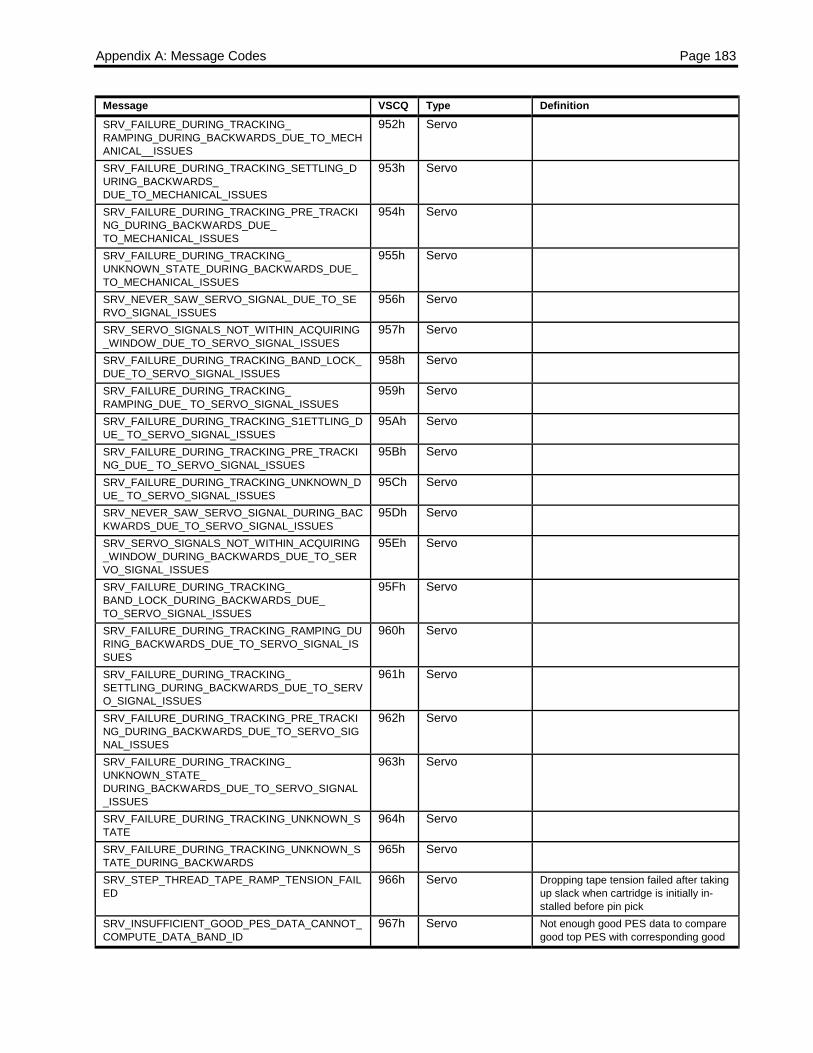
Appendix A: Message Codes Page 183
Message VSCQ Type DefinitionSRV_FAILURE_DURING_TRACKING_RAMPING_DURING_BACKWARDS_DUE_TO_MECHANICAL__ISSUES
952h Servo
SRV_FAILURE_DURING_TRACKING_SETTLING_DURING_BACKWARDS_DUE_TO_MECHANICAL_ISSUES
953h Servo
SRV_FAILURE_DURING_TRACKING_PRE_TRACKING_DURING_BACKWARDS_DUE_TO_MECHANICAL_ISSUES
954h Servo
SRV_FAILURE_DURING_TRACKING_UNKNOWN_STATE_DURING_BACKWARDS_DUE_TO_MECHANICAL_ISSUES
955h Servo
SRV_NEVER_SAW_SERVO_SIGNAL_DUE_TO_SERVO_SIGNAL_ISSUES
956h Servo
SRV_SERVO_SIGNALS_NOT_WITHIN_ACQUIRING_WINDOW_DUE_TO_SERVO_SIGNAL_ISSUES
957h Servo
SRV_FAILURE_DURING_TRACKING_BAND_LOCK_DUE_TO_SERVO_SIGNAL_ISSUES
958h Servo
SRV_FAILURE_DURING_TRACKING_RAMPING_DUE_ TO_SERVO_SIGNAL_ISSUES
959h Servo
SRV_FAILURE_DURING_TRACKING_S1ETTLING_DUE_ TO_SERVO_SIGNAL_ISSUES
95Ah Servo
SRV_FAILURE_DURING_TRACKING_PRE_TRACKING_DUE_ TO_SERVO_SIGNAL_ISSUES
95Bh Servo
SRV_FAILURE_DURING_TRACKING_UNKNOWN_DUE_ TO_SERVO_SIGNAL_ISSUES
95Ch Servo
SRV_NEVER_SAW_SERVO_SIGNAL_DURING_BACKWARDS_DUE_TO_SERVO_SIGNAL_ISSUES
95Dh Servo
SRV_SERVO_SIGNALS_NOT_WITHIN_ACQUIRING_WINDOW_DURING_BACKWARDS_DUE_TO_SERVO_SIGNAL_ISSUES
95Eh Servo
SRV_FAILURE_DURING_TRACKING_BAND_LOCK_DURING_BACKWARDS_DUE_TO_SERVO_SIGNAL_ISSUES
95Fh Servo
SRV_FAILURE_DURING_TRACKING_RAMPING_DURING_BACKWARDS_DUE_TO_SERVO_SIGNAL_ISSUES
960h Servo
SRV_FAILURE_DURING_TRACKING_SETTLING_DURING_BACKWARDS_DUE_TO_SERVO_SIGNAL_ISSUES
961h Servo
SRV_FAILURE_DURING_TRACKING_PRE_TRACKING_DURING_BACKWARDS_DUE_TO_SERVO_SIGNAL_ISSUES
962h Servo
SRV_FAILURE_DURING_TRACKING_UNKNOWN_STATE_DURING_BACKWARDS_DUE_TO_SERVO_SIGNAL_ISSUES
963h Servo
SRV_FAILURE_DURING_TRACKING_UNKNOWN_STATE
964h Servo
SRV_FAILURE_DURING_TRACKING_UNKNOWN_STATE_DURING_BACKWARDS
965h Servo
SRV_STEP_THREAD_TAPE_RAMP_TENSION_FAILED
966h Servo Dropping tape tension failed after takingup slack when cartridge is initially in-stalled before pin pick
SRV_INSUFFICIENT_GOOD_PES_DATA_CANNOT_COMPUTE_DATA_BAND_ID
967h Servo Not enough good PES data to comparegood top PES with corresponding good
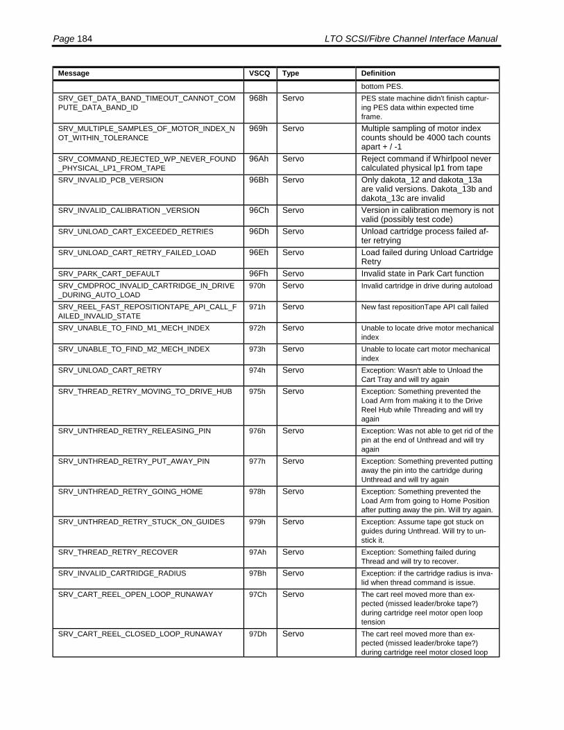
Page 184 LTO SCSI/Fibre Channel Interface Manual
Message VSCQ Type Definitionbottom PES.
SRV_GET_DATA_BAND_TIMEOUT_CANNOT_COMPUTE_DATA_BAND_ID
968h Servo PES state machine didn't finish captur-ing PES data within expected timeframe.
SRV_MULTIPLE_SAMPLES_OF_MOTOR_INDEX_NOT_WITHIN_TOLERANCE
969h Servo Multiple sampling of motor indexcounts should be 4000 tach countsapart + / -1
SRV_COMMAND_REJECTED_WP_NEVER_FOUND_PHYSICAL_LP1_FROM_TAPE
96Ah Servo Reject command if Whirlpool nevercalculated physical lp1 from tape
SRV_INVALID_PCB_VERSION 96Bh Servo Only dakota_12 and dakota_13aare valid versions. Dakota_13b anddakota_13c are invalid
SRV_INVALID_CALIBRATION _VERSION 96Ch Servo Version in calibration memory is notvalid (possibly test code)
SRV_UNLOAD_CART_EXCEEDED_RETRIES 96Dh Servo Unload cartridge process failed af-ter retrying
SRV_UNLOAD_CART_RETRY_FAILED_LOAD 96Eh Servo Load failed during Unload CartridgeRetry
SRV_PARK_CART_DEFAULT 96Fh Servo Invalid state in Park Cart functionSRV_CMDPROC_INVALID_CARTRIDGE_IN_DRIVE_DURING_AUTO_LOAD
970h Servo Invalid cartridge in drive during autoload
SRV_REEL_FAST_REPOSITIONTAPE_API_CALL_FAILED_INVALID_STATE
971h Servo New fast repositionTape API call failed
SRV_UNABLE_TO_FIND_M1_MECH_INDEX 972h Servo Unable to locate drive motor mechanicalindex
SRV_UNABLE_TO_FIND_M2_MECH_INDEX 973h Servo Unable to locate cart motor mechanicalindex
SRV_UNLOAD_CART_RETRY 974h Servo Exception: Wasn't able to Unload theCart Tray and will try again
SRV_THREAD_RETRY_MOVING_TO_DRIVE_HUB 975h Servo Exception: Something prevented theLoad Arm from making it to the DriveReel Hub while Threading and will tryagain
SRV_UNTHREAD_RETRY_RELEASING_PIN 976h Servo Exception: Was not able to get rid of thepin at the end of Unthread and will tryagain
SRV_UNTHREAD_RETRY_PUT_AWAY_PIN 977h Servo Exception: Something prevented puttingaway the pin into the cartridge duringUnthread and will try again
SRV_UNTHREAD_RETRY_GOING_HOME 978h Servo Exception: Something prevented theLoad Arm from going to Home Positionafter putting away the pin. Will try again.
SRV_UNTHREAD_RETRY_STUCK_ON_GUIDES 979h Servo Exception: Assume tape got stuck onguides during Unthread. Will try to un-stick it.
SRV_THREAD_RETRY_RECOVER 97Ah Servo Exception: Something failed duringThread and will try to recover.
SRV_INVALID_CARTRIDGE_RADIUS 97Bh Servo Exception: if the cartridge radius is inva-lid when thread command is issue.
SRV_CART_REEL_OPEN_LOOP_RUNAWAY 97Ch Servo The cart reel moved more than ex-pected (missed leader/broke tape?)during cartridge reel motor open looptension
SRV_CART_REEL_CLOSED_LOOP_RUNAWAY 97Dh Servo The cart reel moved more than ex-pected (missed leader/broke tape?)during cartridge reel motor closed loop

Appendix A: Message Codes Page 185
Message VSCQ Type Definitionmotion
SRV_THREAD_RETRY_RECHUCKING_CARTRIDGE
97Eh Servo Exception: Wasn't able to pick pin fromCartridge. Cartridge was rechucked andwill attempt Thread again.
SRV_LAST_MESSAGE 9FFh Servo

Seagate Removable Storage Solutions1650 Sunflower Avenue, Costa Mesa, California 92626, USA
Publication Number: T-001, Rev. D, Printed in USA