
e66657.pdf - Oracle Help Center
196
[1]Oracle® Communications Network Intelligence User’s Guide Release 7.3.1 E66657-01 October 2018
-
Upload
khangminh22 -
Category
Documents
-
view
1 -
download
0
Transcript of e66657.pdf - Oracle Help Center

[1] Oracle® Communications Network IntelligenceUser’s Guide
Release 7.3.1
E66657-01
October 2018

Oracle Communications Network Intelligence User’s Guide, Release 7.3.1
E66657-01
Copyright © 2010, 2018, Oracle and/or its affiliates. All rights reserved.
This software and related documentation are provided under a license agreement containing restrictions on use and disclosure and are protected by intellectual property laws. Except as expressly permitted in your license agreement or allowed by law, you may not use, copy, reproduce, translate, broadcast, modify, license, transmit, distribute, exhibit, perform, publish, or display any part, in any form, or by any means. Reverse engineering, disassembly, or decompilation of this software, unless required by law for interoperability, is prohibited.
The information contained herein is subject to change without notice and is not warranted to be error-free. If you find any errors, please report them to us in writing.
If this is software or related documentation that is delivered to the U.S. Government or anyone licensing it on behalf of the U.S. Government, then the following notice is applicable:
U.S. GOVERNMENT END USERS: Oracle programs, including any operating system, integrated software, any programs installed on the hardware, and/or documentation, delivered to U.S. Government end users are "commercial computer software" pursuant to the applicable Federal Acquisition Regulation and agency-specific supplemental regulations. As such, use, duplication, disclosure, modification, and adaptation of the programs, including any operating system, integrated software, any programs installed on the hardware, and/or documentation, shall be subject to license terms and license restrictions applicable to the programs. No other rights are granted to the U.S. Government.
This software or hardware is developed for general use in a variety of information management applications. It is not developed or intended for use in any inherently dangerous applications, including applications that may create a risk of personal injury. If you use this software or hardware in dangerous applications, then you shall be responsible to take all appropriate fail-safe, backup, redundancy, and other measures to ensure its safe use. Oracle Corporation and its affiliates disclaim any liability for any damages caused by use of this software or hardware in dangerous applications.
Oracle and Java are registered trademarks of Oracle and/or its affiliates. Other names may be trademarks of their respective owners.
Intel and Intel Xeon are trademarks or registered trademarks of Intel Corporation. All SPARC trademarks are used under license and are trademarks or registered trademarks of SPARC International, Inc. AMD, Opteron, the AMD logo, and the AMD Opteron logo are trademarks or registered trademarks of Advanced Micro Devices. UNIX is a registered trademark of The Open Group.
This software or hardware and documentation may provide access to or information about content, products, and services from third parties. Oracle Corporation and its affiliates are not responsible for and expressly disclaim all warranties of any kind with respect to third-party content, products, and services unless otherwise set forth in an applicable agreement between you and Oracle. Oracle Corporation and its affiliates will not be responsible for any loss, costs, or damages incurred due to your access to or use of third-party content, products, or services, except as set forth in an applicable agreement between you and Oracle.

iii
Contents
Preface ............................................................................................................................................................... xv
Audience..................................................................................................................................................... xvRelated Documents ................................................................................................................................... xvDocumentation Accessibility ................................................................................................................... xvDocument Revision History .................................................................................................................... xvi
1 Using Network Intelligence
Getting Started with Network Intelligence ........................................................................................ 1-1Accessing Network Intelligence....................................................................................................... 1-1
Managing your Network Intelligence User Profile and Password ..................................... 1-2Understanding Network Intelligence and Network Intelligence Terminology ....................... 1-2Working with the Network Intelligence User Interface ............................................................... 1-3
Using the Menu........................................................................................................................... 1-3Using the Toolbar........................................................................................................................ 1-5Using the Context Toolbar......................................................................................................... 1-5Using the Tree Browser.............................................................................................................. 1-7
Working with Object Views.............................................................................................................. 1-8Displaying Object Definitions ................................................................................................... 1-9Displaying Object Group Views ............................................................................................... 1-9
Working with Data Views ................................................................................................................ 1-9Related Topics .......................................................................................................................... 1-10Using Table Views ................................................................................................................... 1-10Using Mesh Views ................................................................................................................... 1-10Using Modeled Views ............................................................................................................. 1-12Using Geographic Map Views ............................................................................................... 1-13Filtering View Data.................................................................................................................. 1-16Displaying a Legend................................................................................................................ 1-20Saving the View in Spreadsheet Format............................................................................... 1-20
Managing Windows ....................................................................................................................... 1-20Searching .......................................................................................................................................... 1-20
Performing Actions on Search Results.................................................................................. 1-21
2 Displaying Network Data
About Displaying Network Data .......................................................................................................... 2-1Using Object Type Trail Views ............................................................................................................. 2-1
iv
Working with the Terminating Child Trails View ........................................................................ 2-2About the Terminating Child Trails View Data ..................................................................... 2-2Editing a Terminating Child Trail ............................................................................................ 2-2
Working with the All Child Trails View......................................................................................... 2-3Filtering Data ............................................................................................................................... 2-3Using the Traffic Type Filter ..................................................................................................... 2-3
Using Object Link Mesh Views ............................................................................................................ 2-4Running the Inter Site Trail Mesh Report....................................................................................... 2-4
Setting the Protection Type ....................................................................................................... 2-4Selecting Link Utilization Thresholds...................................................................................... 2-4Applying the Settings................................................................................................................. 2-5
Running the Inter Site Pair Trail Mesh View ................................................................................. 2-6Filtering Data ............................................................................................................................... 2-7Setting the Protection Type ....................................................................................................... 2-7Applying the Settings................................................................................................................. 2-7
Running the Inter Equipment Trail Mesh Report ......................................................................... 2-7Running the Inter Equipment Pair Trail Mesh View.................................................................... 2-8
3 Using Networks
Using the Network Tree Browser.......................................................................................................... 3-1Creating a Network .................................................................................................................................. 3-1Working with Network Views .............................................................................................................. 3-2
Using the Network Node View........................................................................................................ 3-2Using the Equipment Search View for a Network........................................................................ 3-2Using the Child Trails View for a Network ................................................................................... 3-3Using the Customer Bandwidth View ............................................................................................ 3-3
4 Using Sites
Using the Site Tree Browser ................................................................................................................... 4-1Creating a Site ........................................................................................................................................... 4-1
Related Topics..................................................................................................................................... 4-2Creating a Location ............................................................................................................................ 4-2Creating an Address .......................................................................................................................... 4-2
Working with Site Object Views .......................................................................................................... 4-3Using the External Links View......................................................................................................... 4-3Using the Internal Links View ........................................................................................................ 4-3Using the Resource Topology List View......................................................................................... 4-3Using the Equipment Search View.................................................................................................. 4-3Using the Port Availability View..................................................................................................... 4-4Using the Trail Views ........................................................................................................................ 4-4
Working with the Site Group Object Views....................................................................................... 4-4Related Topics..................................................................................................................................... 4-4
5 Using Topologies
Using the Topology Tree Browser ........................................................................................................ 5-1Creating a Resource Topology ............................................................................................................... 5-2
v
Working with Topology Object Views ................................................................................................ 5-3Working with Resource Topology Object Views .......................................................................... 5-3Working with Service Topology Object Views.............................................................................. 5-3Using the Utilization View ............................................................................................................... 5-3
Saving the Utilization View....................................................................................................... 5-4Using the Link View .......................................................................................................................... 5-4
Path Core Links ........................................................................................................................... 5-4Path Edge Links........................................................................................................................... 5-4Displaying Trails in a Link ........................................................................................................ 5-4Hiding the Link or Node Layer ................................................................................................ 5-5Adding a Main Node to a Topology ........................................................................................ 5-5Removing a Main Node from a Topology .............................................................................. 5-5Adding a Link to a Topology .................................................................................................... 5-5Removing a Link from a Topology .......................................................................................... 5-6Saving a Topology View ............................................................................................................ 5-6Loading a Topology View ......................................................................................................... 5-6
Using the Path View .......................................................................................................................... 5-6Removing Links .......................................................................................................................... 5-7Removing Nodes......................................................................................................................... 5-7
Using the To Other Resource Topologies Network View............................................................ 5-7Using the To Other Resource Topology Nodes Network View.................................................. 5-7Using the Trail Views ........................................................................................................................ 5-8
6 Using Trails
Creating a Trail Definition ..................................................................................................................... 6-1Assigning Trail Definitions to Enabling Trail Holder Definitions ............................................... 6-2
Related Topics..................................................................................................................................... 6-2Working with the Trails Tree Browser ................................................................................................ 6-2Working with Trail Views ...................................................................................................................... 6-3
Using the Core (Trail) View ............................................................................................................. 6-3Related Topics ............................................................................................................................. 6-4Editing the Trail Definition........................................................................................................ 6-4Deleting a Trail ............................................................................................................................ 6-4
Viewing the Protection and Protected Trail ................................................................................... 6-5Using the Payload View ................................................................................................................... 6-5
Viewing a Trail ............................................................................................................................ 6-5Using the Trail Holder View ........................................................................................................... 6-5Editing Object Relationships in the Payload View........................................................................ 6-5
Adding a Trail to a Structured Trail......................................................................................... 6-6Adding a Trail to an Unstructured Trail ................................................................................. 6-6Removing a Trail from a Trail Holder ..................................................................................... 6-6Moving a Trail between Trail Holders..................................................................................... 6-6Removing a Trail Holder from an Unstructured Trail .......................................................... 6-7
About the Traversal View................................................................................................................. 6-7About the Parent Hierarchy View ................................................................................................... 6-7
About the Graphical View......................................................................................................... 6-7About the Textual View ............................................................................................................. 6-8

vi
Adding a Trail Holder and Parent Trail to a Trail ................................................................. 6-9Removing a Trail from a Trail Holder ..................................................................................... 6-9Removing the Parent Trail Holder of an Unstructured Trail ............................................... 6-9Moving a Trail between Trail Holders..................................................................................... 6-9
About the Equipment Traversal View ......................................................................................... 6-10About the Graphical View...................................................................................................... 6-10About the Text View................................................................................................................ 6-11
About the Geographical Map View.............................................................................................. 6-11Viewing Link Layers ............................................................................................................... 6-11
About the Hop by Hop Routing View ......................................................................................... 6-12Viewing an Equipment................................................................................................................... 6-12Viewing a Trail ................................................................................................................................ 6-12Generating a Trail Name................................................................................................................ 6-12About the Trail View ...................................................................................................................... 6-13About the Customer Trails View .................................................................................................. 6-13
About the Trail Group Object Views ................................................................................................ 6-13About the Trail Channel Utilization View .................................................................................. 6-13About the Trail Cumulative Channel Utilization View ............................................................ 6-14About the Trail Media Breakdown View .................................................................................... 6-14About the Long Trails View .......................................................................................................... 6-14About the Customer Group View................................................................................................. 6-15About the Trail Hop Optimization View..................................................................................... 6-15About the Site Trail Utilization View........................................................................................... 6-15
Displaying Trail Models ...................................................................................................................... 6-16Creating a New Trail............................................................................................................................. 6-16
Adding a Signal Structure.............................................................................................................. 6-17Adding a Default Trail on the Signal Structure................................................................... 6-18
Creating Multiple Trails ...................................................................................................................... 6-18Cloning a Trail ....................................................................................................................................... 6-19Routing an Unrouted Trail .................................................................................................................. 6-20Deleting an Existing Trail.................................................................................................................... 6-21Upgrading an Existing Trail ................................................................................................................ 6-21
Bulk Updating Trails ...................................................................................................................... 6-24Protecting an Existing Trail ................................................................................................................. 6-24Creating a Trail Holder Definition .................................................................................................... 6-25
7 Using Equipment
Using the Equipment Tree Browser ..................................................................................................... 7-1Creating an Equipment ........................................................................................................................... 7-1Displaying Equipment Models ............................................................................................................. 7-2
Creating an Equipment Definition .................................................................................................. 7-2Adding Sub-Rack Definitions ................................................................................................... 7-3Configuring a Sub-Rack ............................................................................................................. 7-4Configuring a Shelf..................................................................................................................... 7-4Adding Slots to a Shelf ............................................................................................................... 7-4
Updating the Equipment Definition ............................................................................................... 7-5Using the Elevation View .......................................................................................................... 7-5

vii
Configuring Default or Allowed Cards................................................................................... 7-5Creating a Card Definition ............................................................................................................... 7-6
Viewing a Card Definition......................................................................................................... 7-7Editing a Card Definition........................................................................................................... 7-7Adding a Sub-Card to a Card Definition................................................................................. 7-7Deleting a Card Definition......................................................................................................... 7-8
Creating a Port Definition................................................................................................................. 7-8Viewing a Port Definition .......................................................................................................... 7-8Editing a Port Definition............................................................................................................ 7-9Deleting a Port Definition.......................................................................................................... 7-9
Working with Equipment Views .......................................................................................................... 7-9Working with Equipment Views in Monitoring Report Manager .......................................... 7-10Using the Equipment Details View .............................................................................................. 7-10
Related Topics .......................................................................................................................... 7-10Editing an Equipment ............................................................................................................. 7-11Deleting an Equipment ........................................................................................................... 7-11Generating an Equipment Name........................................................................................... 7-11
Using the Elevation View............................................................................................................... 7-12Related Topics .......................................................................................................................... 7-13Displaying a Card View.......................................................................................................... 7-13Accessing Circuit Trails or Bearer Trails from the Ports View.......................................... 7-14Changing a Card Name .......................................................................................................... 7-14Adding a Planned Card Object .............................................................................................. 7-14Adding a Sub-Card to a Card ................................................................................................ 7-14Deleting a Card ........................................................................................................................ 7-15
Using the Hierarchy View ............................................................................................................. 7-15Carrying out Actions Using the Hierarchy View................................................................ 7-15Viewing Card and Trail Details ............................................................................................. 7-16Displaying a Card View.......................................................................................................... 7-16Adding a Planned Card Object .............................................................................................. 7-16Adding a Port to an Equipment............................................................................................. 7-16Adding a Card to a Slot........................................................................................................... 7-16Cutting and Pasting a Card to a Slot ..................................................................................... 7-17Deleting a Card ........................................................................................................................ 7-17Deleting a Port from an Equipment ...................................................................................... 7-17Removing a Trail from a Port................................................................................................. 7-18Moving a Trail from One Port to Another Port ................................................................... 7-18Moving a Trail with Child Trails to a Port ........................................................................... 7-18Moving a Trail to an Equipment............................................................................................ 7-18Creating a Logical Port Template .......................................................................................... 7-19Adding Logical Ports to a Physical Port ............................................................................... 7-19Deleting a Logical Port from a Physical Port ....................................................................... 7-20Saving Configuration Results ................................................................................................ 7-20
Logical View .................................................................................................................................... 7-21Viewing a Trail ......................................................................................................................... 7-22Viewing the Originating or Terminating Node................................................................... 7-22
Using the Utilization View ............................................................................................................ 7-22
viii
Using the External Links View...................................................................................................... 7-22Using the Internal Links View ...................................................................................................... 7-22Using the Cross Connect View...................................................................................................... 7-22Using the Port Availability View.................................................................................................. 7-23Using the Port Trail Routing View ............................................................................................... 7-23Working with Trail Views ............................................................................................................. 7-24Creating a Customer Trails View.................................................................................................. 7-24
Working with Equipment Group Views .......................................................................................... 7-24Using the Port Availability (Group) View................................................................................... 7-25Using the Inter Equipment Trail Geographic (Group) Report ................................................. 7-25Using the Inter Equipment Trail Mesh (Group) Report ............................................................ 7-25Using the Inter Equipment Pair Trail Mesh (Group) View ...................................................... 7-25Using the Cross Connect Report (Group) View ......................................................................... 7-25
Deleting an Equipment ........................................................................................................................ 7-26
8 Using Routes
About the Routes Tree Browser............................................................................................................. 8-1Creating a Route ....................................................................................................................................... 8-1Working with Route Views.................................................................................................................... 8-2
Using the Route Diversity View ...................................................................................................... 8-2Related Topics ............................................................................................................................. 8-2Viewing Trail Entities Routed Over Selected Route Path..................................................... 8-2Viewing a Trail ............................................................................................................................ 8-2
Using the Route Diversity Logical View ........................................................................................ 8-2Using the Customer Bandwidth Report ......................................................................................... 8-2
Related Topics ............................................................................................................................. 8-2Viewing Customer Details......................................................................................................... 8-3
Using Trail Views............................................................................................................................... 8-3Using the Service View...................................................................................................................... 8-3
Working with Route Object Group Views.......................................................................................... 8-3Using the Major Route Traffic Report ............................................................................................. 8-3
Related Topics ............................................................................................................................. 8-3Viewing Trails of a Particular Route ........................................................................................ 8-3
Using the A And Z Site Selection Route Reports .......................................................................... 8-3
9 Using Services, Policies, and Rules
Using the Services Tree Browser........................................................................................................... 9-1Creating a Service..................................................................................................................................... 9-1Creating a Policy for a Service ............................................................................................................... 9-2Assigning a Policy to a Service .............................................................................................................. 9-3
Adding a Rule to a Policy ................................................................................................................. 9-3Adding a Policy to a Policy............................................................................................................... 9-4
Designing and Assigning a Service Demand ..................................................................................... 9-4Creating Trails to Define the Network Connectivity of a Service............................................... 9-4Using Trail Routing Manager to Determine Path Routing .......................................................... 9-5Applying Policies and Rules to a Service ....................................................................................... 9-5Selecting a Solution Displayed by Trail Routing Manager.......................................................... 9-5
ix
Creating and Saving the New Service Trail ................................................................................... 9-5Working with Service Views ................................................................................................................. 9-5
Using the Customer Bandwidth View ............................................................................................ 9-5Displaying a Customer View .................................................................................................... 9-6
Using the Child Trails View ............................................................................................................. 9-6Using the Network Mesh View........................................................................................................ 9-6Using the Service Definition View................................................................................................... 9-6Using the Service Topology List ...................................................................................................... 9-6
Working with Service Object Group Views ....................................................................................... 9-6Using the Service Network Mesh Report ....................................................................................... 9-6
Using Routing Rules................................................................................................................................ 9-6Assigning Precedence to Rules ..................................................................................................... 9-10
Using Weightings .................................................................................................................................. 9-10Creating a Weighting...................................................................................................................... 9-10
Using Associations ................................................................................................................................ 9-11Viewing an Association.................................................................................................................. 9-11
10 Using Customers
Using the Customer Tree Browser ..................................................................................................... 10-1Creating a Customer ............................................................................................................................. 10-1Working with Customer Object Views............................................................................................. 10-2
Using the Network Site Mesh View ............................................................................................. 10-2Related Topics .......................................................................................................................... 10-2Viewing the Trails Making Up The Route ........................................................................... 10-2
Using the Sites List View................................................................................................................ 10-2Using the Equipment View............................................................................................................ 10-2Using the Trail Views ..................................................................................................................... 10-3
Working Customer Object Group Views ......................................................................................... 10-3Using the Major Customer Bandwidth View.............................................................................. 10-3Using the Customer Network Mesh Report ............................................................................... 10-3
Using Customer Contacts .................................................................................................................... 10-3Adding a Contact ............................................................................................................................ 10-3Editing a Contact............................................................................................................................. 10-3Deleting a Contact........................................................................................................................... 10-4
11 Using Capacities
Using the Capacity Tree Browser ....................................................................................................... 11-1Creating a Capacity......................................................................................................................... 11-1
12 Routing Trails
Using Trail Routing Manager ............................................................................................................. 12-1Using the Trail Routing Manager GUI......................................................................................... 12-1
Defining Service Demands ................................................................................................................. 12-2Using the Service Policy....................................................................................................................... 12-3Routing a Service Demand .................................................................................................................. 12-3
Viewing a Routing Solution........................................................................................................... 12-4
x
Related Topics .......................................................................................................................... 12-5Viewing Elements of the Routing Solution .......................................................................... 12-5Displaying the Textual View of the Routing Solution........................................................ 12-5
Choosing the Routing Method...................................................................................................... 12-5Applying Costs Using Trail Routing Manager ............................................................................... 12-6
Creating Tasks and Costs for Each Object................................................................................... 12-6Routing the Service Demand......................................................................................................... 12-7Inspecting the Routing Solutions.................................................................................................. 12-7Saving the Routing Solution View as an Image.......................................................................... 12-7Saving the Routing Solution Data in Other Formats ................................................................. 12-7Viewing a Legend of the Routing Solution ................................................................................. 12-8
13 Using Configuration Plans
Creating a Configuration Plan ............................................................................................................ 13-1Using the Configuration Plan Details View ................................................................................ 13-2Creating a Sample Configuration Plan ........................................................................................ 13-2
Configuring the Sample Configuration Plan ....................................................................... 13-2Recording Data for the Configuration Plan ................................................................................ 13-3Viewing the Configuration Change Report ................................................................................ 13-3
14 Forecasting Service Demands
Using the Plans Tree Browser ............................................................................................................. 14-1Using the My Plans Folder ............................................................................................................ 14-2
Related Topics .......................................................................................................................... 14-2Using the Other Plans Folder ........................................................................................................ 14-2
Related Topics .......................................................................................................................... 14-2Creating a Plan ....................................................................................................................................... 14-2
Creating a Plan By Selecting Routes............................................................................................. 14-3Creating a Plan by Selecting Network Objects and Applying Growth Criteria .................... 14-3Creating a Plan from an External File Source ............................................................................. 14-5
Using Service Demands .......................................................................................................... 14-5Creating a Plan by Importing Service Demands ................................................................. 14-7Using Bulk Service-Bandwidth Input Files .......................................................................... 14-8Creating a Plan by Importing Bulk Service Bandwidths ................................................... 14-8
Working with Plan Object Views ...................................................................................................... 14-9Using the Plan Details View .......................................................................................................... 14-9Using the Service Demands View............................................................................................... 14-10
Carrying out Actions on the Service Demands View....................................................... 14-10Using the Studies View ................................................................................................................ 14-11
Comparing Forecast Reports................................................................................................ 14-11Using the Planned Entities View ................................................................................................ 14-11Using the Planned Trails View.................................................................................................... 14-11Using the Planned Equipment View.......................................................................................... 14-11Using the Planned Cards View ................................................................................................... 14-12Using the Planned Sites View...................................................................................................... 14-12Using the Planned Topologies View .......................................................................................... 14-12
Editing Plans ........................................................................................................................................ 14-13
xi
Maintaining Plans ............................................................................................................................... 14-13Carrying Out Plan Date Tasks..................................................................................................... 14-13
Extending a Plan .................................................................................................................... 14-13Truncating a Plan ................................................................................................................... 14-14Archiving a Plan..................................................................................................................... 14-14Cloning a Plan ........................................................................................................................ 14-14Deleting a Plan ....................................................................................................................... 14-15
Adding Routes to a Plan .............................................................................................................. 14-15Tracking the Accuracy of Plans................................................................................................... 14-16Carrying out Plan Growth Scenario Tasks ................................................................................ 14-16Applying a Growth Scenario....................................................................................................... 14-16Carrying out Plan Tasks............................................................................................................... 14-17
Planning a New Site .............................................................................................................. 14-17Planning a New Topology.................................................................................................... 14-17
Using the Plan Routing Manager .................................................................................................... 14-18Analyzing Service Demands from a Plan.................................................................................. 14-18Using the Analysis Summary View............................................................................................ 14-19Using the Service Demand Summary View.............................................................................. 14-20Using the Configuration Suggestions View .............................................................................. 14-20
Suggesting New Links .......................................................................................................... 14-20Suggesting Existing Link Upgrades .................................................................................... 14-20Suggesting Existing Equipment Upgrades ........................................................................ 14-20Suggesting New Equipment................................................................................................. 14-21
Using the Planned Build View .................................................................................................... 14-21Using the Network Plan Impact Report .................................................................................... 14-21Using the Network Impact Trail Summary Report.................................................................. 14-21Using the Network Impact Equipment Summary Report ...................................................... 14-22Using the Network Trail Impact Report .................................................................................... 14-22Using the Network Equipment Impact Report......................................................................... 14-23Using the Network Site Impact Report...................................................................................... 14-23Using the Cost Estimation Reports............................................................................................. 14-24
Routing Solution Acceptance Costs .................................................................................... 14-24Viewing Task Details............................................................................................................. 14-25Viewing Equipment Cost Details ........................................................................................ 14-25Viewing Labor Cost Details.................................................................................................. 14-25Viewing Trail Cost Details.................................................................................................... 14-25Viewing Cost by Service Details .......................................................................................... 14-25Viewing Planned Entity Cost Details.................................................................................. 14-25Viewing OLO Cost Details ................................................................................................... 14-25
Saving Plan Run Results .............................................................................................................. 14-26Rerunning a Plan Run .................................................................................................................. 14-26Analyzing the Routing Solution and Result.............................................................................. 14-26Publishing a Plan........................................................................................................................... 14-27
15 Managing Outages
Generating an Outage Report ............................................................................................................. 15-1Viewing Outage Reports...................................................................................................................... 15-3
xii
Viewing Service Demands............................................................................................................. 15-3Viewing Studies............................................................................................................................... 15-4Viewing the Original Outage Entities .......................................................................................... 15-4Viewing Impacted Trails ................................................................................................................ 15-4Viewing Impacted Entities............................................................................................................. 15-5
Related Topics .......................................................................................................................... 15-5Viewing Impacted Equipment ............................................................................................... 15-5Viewing Impacted Customers................................................................................................ 15-5Viewing Impacted Services .................................................................................................... 15-5Viewing Impacted Locations.................................................................................................. 15-5Viewing Impacted Sites........................................................................................................... 15-5
Viewing Planned Trails .................................................................................................................. 15-5Viewing Planned Equipment ........................................................................................................ 15-6Viewing Planned Cards.................................................................................................................. 15-6Viewing Planned Sites.................................................................................................................... 15-6Viewing Planned Topologies ........................................................................................................ 15-6
16 Migrating Network Entities
Creating a Migration Plan ................................................................................................................... 16-1Viewing Migration Plans ............................................................................................................... 16-5Making Changes to a Migration Plan .......................................................................................... 16-5
Related Topics .......................................................................................................................... 16-5Sharing the Plan ....................................................................................................................... 16-5Changing the Name of the Plan............................................................................................. 16-6Deleting the Plan...................................................................................................................... 16-6
Migrating Cards .............................................................................................................................. 16-6
17 Monitoring Network Data
Starting Monitor Report Manager ..................................................................................................... 17-1Starting Monitor Report Manager from Within Network Intelligence................................... 17-1Starting Monitor Report Manager Using a Web Browser......................................................... 17-1Using Email Notification................................................................................................................ 17-2
Configuring Email and SMTP Settings................................................................................. 17-2Modifying the Scheduled Task Settings .............................................................................. 17-2
Selecting Reports of Interest .......................................................................................................... 17-3Viewing Your Reports .................................................................................................................... 17-3
Adding a Report....................................................................................................................... 17-3Deleting a Report ..................................................................................................................... 17-3
Viewing a Full Report..................................................................................................................... 17-3Setting Conditions on a Report ..................................................................................................... 17-4
Related Topics .......................................................................................................................... 17-4Setting a User Report Condition............................................................................................ 17-4Adding a User Report Condition .......................................................................................... 17-4
Viewing a Conditional Report ...................................................................................................... 17-5Monitor Reports .............................................................................................................................. 17-5
Related Topics .......................................................................................................................... 17-6Using the Spare Card Report ................................................................................................. 17-6

xiii
Using the Leased Trail Detail Costs by Vendor Report ..................................................... 17-7Using the Leased Trail Total Costs by Vendor Report ....................................................... 17-7Using the Topology Entity Utilization Report..................................................................... 17-7

xiv

xv
Preface
The Oracle Communications Network Intelligence Help is loaded into the Network Intelligence software and is available in the Network Intelligence UI.
AudienceThe Network Intelligence Help is intended for users of Network Intelligence.
Related DocumentsNetwork Intelligence User’s Guide is one book in the documentation set for Network Intelligence. For more information, refer to the following documents:
■ Network Intelligence Release Notes: Describes new features, fixes, and enhancements to existing features, known issues, troubleshooting tips, and required third party products and licensing.
■ Network Intelligence Installation Guide: Provides instructions for installing Network Intelligence.
■ Network Intelligence System Administrator’s Guide: Describes administrative tasks such as starting and stopping Network Intelligence, managing security, and managing Network Intelligence.
■ Network Intelligence Concepts: Provides an overview of important concepts and an introduction to using Network Intelligence.
■ Network Intelligence Developer’s Guide: Describes the architecture of Network Intelligence and explains how to customize reports and maps, extend the user interface, configure extensible attributes, configure security, populate the staging database, and load the database.
■ Network Intelligence Security Guide: Provides guidelines and recommendations for setting up Network Intelligence in a secure configuration.
Documentation AccessibilityFor information about Oracle's commitment to accessibility, visit the Oracle Accessibility Program website at http://www.oracle.com/pls/topic/lookup?ctx=acc&id=docacc.
Access to Oracle SupportOracle customers that have purchased support have access to electronic support through My Oracle Support. For information, visit http://www.oracle.com/pls/topic/lookup?ctx=acc&id=info or visit
xvi
http://www.oracle.com/pls/topic/lookup?ctx=acc&id=trs if you are hearing impaired.
Document Revision HistoryThe following table lists the revision history for this guide:
Version Date Description
E66657-01 October 2018 Initial release.

1
Using Network Intelligence 1-1
1Using Network Intelligence
This section describes how to use Oracle Communications Network Intelligence.
Getting Started with Network IntelligenceNetwork Intelligence enables network planning and optimization. It reads data from your network inventory systems or other network data sources and processes that data to create useful views of your network data.
Network Intelligence is a capacity planning system used by Communication Service Providers (CSPs) for communications networks. It reads data from your network inventory systems or other network data sources and processes that data to create useful views of your network data. After loading inventory data in Network Intelligence, you manage your network assets, forecast traffic demand, plan network capacity, and optimize network traffic.
Network Intelligence allows network planners to view network reports and maps, plan network build, and identify potential capacity stress points within the network in advance.
It can be used for assessing network capacity, and for carrying out network cost reduction and consolidation. It can also be used as an inventory system that offers capacity planning and reporting.
When getting started with Network Intelligence, see the following topics:
■ Accessing Network Intelligence
■ Understanding Network Intelligence and Network Intelligence Terminology
■ Working with the Network Intelligence User Interface
■ Working with Object Views
■ Working with Data Views
■ Managing Windows
■ Searching
Accessing Network IntelligenceYou log onto Network Intelligence using a user name and password provided to you by the Network Intelligence administrator.
To access Network Intelligence:
1. In a supported Internet browser, enter the following URL:

Getting Started with Network Intelligence
1-2 Network Intelligence User's Guide
http://host_name:port/netintel-client/
where host_name is either the name or IP address of the host of the application server in which Network Intelligence is installed, and port is the port number for the server.
Ask the Network Intelligence administrator for the host name or IP address and port number.
2. Click on the graphic on the Web page.
A Java network launching protocol (JNLP) file downloads to your computer.
Your browser might block the file or ask you to confirm the download. If this occurs, confirm the download.
3. Double-click the JNLP file.
The Network Intelligence Java client launches.
Your computer might ask you to confirm that you want to run the application. If this occurs, confirm that you want to run the application.
The Network Intelligence Login dialog box appears.
4. Enter your user name and password and click Login.
Managing your Network Intelligence User Profile and PasswordYou can manage your user profile and change your password:
1. In a supported Internet browser, enter the following URL:
http://host_name:port/netintel-server/
where host_name is either the name or IP address of the host of the application server in which Network Intelligence is installed, and port is the port number for the server.
Ask the Network Intelligence administrator for the host name or IP address and port number.
2. Enter your user name and password and click Login.
The Network Intelligence administration Welcome page appears.
3. Do any of the following:
■ To modify your user profile, from the My Profile menu, select My Profile.
The User Profile page appears.
■ To change your password, from the My Profile menu, select Change Password.
The Change Password page appears.
4. Make any changes and click Save.
Understanding Network Intelligence and Network Intelligence TerminologyYou should read Network Intelligence Concepts for full explanations of the concepts and background needed to work in Network Intelligence.
Network Intelligence Concepts also provides a full glossary of key Network Intelligence terms.

Getting Started with Network Intelligence
Using Network Intelligence 1-3
Working with the Network Intelligence User InterfaceNetwork Intelligence has a Web-based interface with simple navigation and interface controls. The main window is divided into several regions and has a menu in the upper left corner. The region to the left contains the tree browser panel listing network entities, which you use to open work areas of various kinds. The region to the right is populated with the work areas that you open, such as object views.
When working in the Network Intelligence user interface, see the following topics:
■ Using the Menu
■ Using the Toolbar
■ Using the Context Toolbar
■ Using the Tree Browser
■ Displaying Object Definitions
■ Working with Object Views
■ Managing Windows
■ Searching
Using the MenuFigure 1–1 displays the Network Intelligence menu.
Figure 1–1 Network Intelligence GUI: Menu
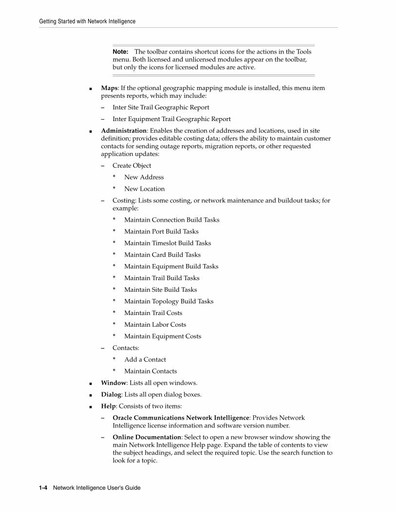
The menu contains the following menus:
■ File:
– Select Exit to exit the Network Intelligence GUI.
■ Tools: Provides access to Network Intelligence modules that have been licensed and installed, which may include:
– Trail Routing Manager. See "Routing Trails".
– Monitor Report Manager. See "Monitoring Network Data".
– Outage Manager. See "Generating an Outage Report".
– Migration Manager. See "Migrating Network Entities".
– Trail Configuration Wizard. See "Creating a New Trail".
– Bulk Update Status. See "Bulk Updating Trails".
Note: The menu displays Route because the Route entity is selected in the context toolbar, as shown in Figure 1–3, "Network Intelligence GUI: Context Toolbar".
See "Using the Context Toolbar" for more information on the context toolbar.
Getting Started with Network Intelligence
1-4 Network Intelligence User's Guide
■ Maps: If the optional geographic mapping module is installed, this menu item presents reports, which may include:
– Inter Site Trail Geographic Report
– Inter Equipment Trail Geographic Report
■ Administration: Enables the creation of addresses and locations, used in site definition; provides editable costing data; offers the ability to maintain customer contacts for sending outage reports, migration reports, or other requested application updates:
– Create Object
* New Address
* New Location
– Costing: Lists some costing, or network maintenance and buildout tasks; for example:
* Maintain Connection Build Tasks
* Maintain Port Build Tasks
* Maintain Timeslot Build Tasks
* Maintain Card Build Tasks
* Maintain Equipment Build Tasks
* Maintain Trail Build Tasks
* Maintain Site Build Tasks
* Maintain Topology Build Tasks
* Maintain Trail Costs
* Maintain Labor Costs
* Maintain Equipment Costs
– Contacts:
* Add a Contact
* Maintain Contacts
■ Window: Lists all open windows.
■ Dialog: Lists all open dialog boxes.
■ Help: Consists of two items:
– Oracle Communications Network Intelligence: Provides Network Intelligence license information and software version number.
– Online Documentation: Select to open a new browser window showing the main Network Intelligence Help page. Expand the table of contents to view the subject headings, and select the required topic. Use the search function to look for a topic.
Note: The toolbar contains shortcut icons for the actions in the Tools menu. Both licensed and unlicensed modules appear on the toolbar, but only the icons for licensed modules are active.

Getting Started with Network Intelligence
Using Network Intelligence 1-5
Using the ToolbarFigure 1–2 displays the Network Intelligence toolbar.
Figure 1–2 Network Intelligence GUI: Toolbar
Table 1–1 displays the toolbar icons.
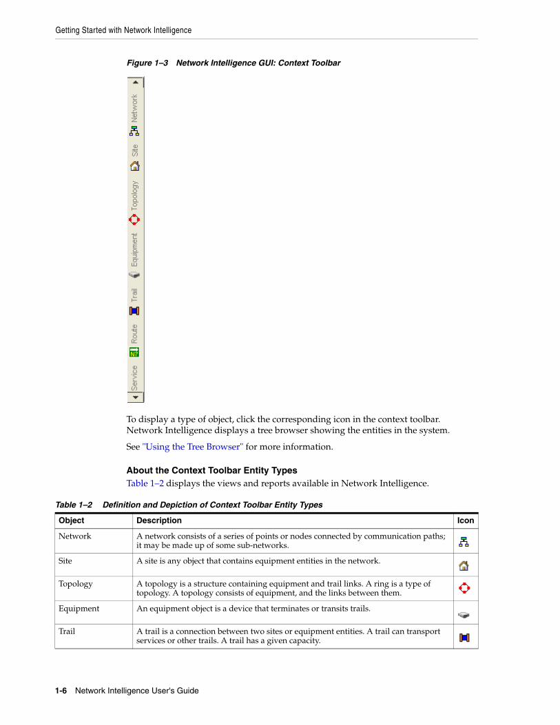
Using the Context ToolbarTo display network inventory data, use the context toolbar to select which type of data you want to see; for example, a network, site, or topology.
Figure 1–3 shows part of the context toolbar running vertically on the left of the GUI:
Table 1–1 Using the Toolbar Icons
Icon Description
Display Trail Routing Manager.
Trail Routing Manager is used to route end to end trails.
Run Monitor Report Manager.
Monitor Report Manager is a web-based online analysis and reporting tool used to provide a set of specific key performance indicator (KPI) reports for technical management.
Run the plan creation wizard.
The plan creation wizard is used to create a forecast, defined as a collection of service demands with expected future trail growth counts for one, or more, future time periods.
Create a configuration plan.
Configuration plans are used to perform and record actions such as creating, editing, or deleting network resources; for example: creating sites, or deleting equipment.
Display Outage Manager.
Outage Manager is used to create an outage report for a network entity, or a group of network entities.
Display Migration Manager.
Migration Manager is used to create a migration plan to generate network requirements changes to your network.
Search for a configuration plan. You can perform a quick search in the Associated Plan field.
Enter any part of the search tern, click Enter, and the field autocompletes.
The search icon is disabled if Network Modeling is selected.
Record configuration actions against the configuration plan selected in the Associated Plan field.
There are two modes available in the Mode field:
■ Network Modeling
■ Configuration Planning
Stop recording configuration actions against the configuration plan selected in the Associated Plan field.
Getting Started with Network Intelligence
1-6 Network Intelligence User's Guide
Figure 1–3 Network Intelligence GUI: Context Toolbar
To display a type of object, click the corresponding icon in the context toolbar. Network Intelligence displays a tree browser showing the entities in the system.
See "Using the Tree Browser" for more information.
About the Context Toolbar Entity TypesTable 1–2 displays the views and reports available in Network Intelligence.
Table 1–2 Definition and Depiction of Context Toolbar Entity Types
Object Description Icon
Network A network consists of a series of points or nodes connected by communication paths; it may be made up of some sub-networks.
Site A site is any object that contains equipment entities in the network.
Topology A topology is a structure containing equipment and trail links. A ring is a type of topology. A topology consists of equipment, and the links between them.
Equipment An equipment object is a device that terminates or transits trails.
Trail A trail is a connection between two sites or equipment entities. A trail can transport services or other trails. A trail has a given capacity.
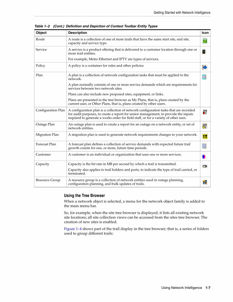
Getting Started with Network Intelligence
Using Network Intelligence 1-7
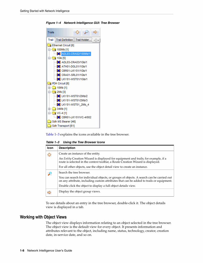
Using the Tree BrowserWhen a network object is selected, a menu for the network object family is added to the main menu bar.
So, for example, when the site tree browser is displayed, it lists all existing network site locations; all site collection views can be accessed from the sites tree browser. The creation of new sites is enabled.
Figure 1–4 shows part of the trail display in the tree browser; that is, a series of folders used to group different trails:
Route A route is a collection of one of more trails that have the same start site, end site, capacity and service type.
Service A service is a product offering that is delivered to a customer location through one or more trail entities.
For example, Metro Ethernet and IPTV are types of services.
Policy A policy is a container for rules and other policies.
Plan A plan is a collection of network configuration tasks that must be applied to the network.
A plan normally consists of one or more service demands which are requirements for services between two network sites.
Plans can also include new proposed sites, equipment, or links.
Plans are presented in the tree browser as My Plans, that is, plans created by the current user, or Other Plans, that is, plans created by other users.
Configuration Plan A configuration plan is a collection of network configuration tasks that are recorded for audit purposes, to create a report for senior management, to provide the inputs required to generate a works order for field staff, or for a variety of other uses.
Outage Plan An outage plan is used to create a report for an outage on a network entity, or set of network entities.
Migration Plan A migration plan is used to generate network requirements changes to your network.
Forecast Plan A forecast plan defines a collection of service demands with expected future trail growth counts for one, or more, future time periods.
Customer A customer is an individual or organization that uses one or more services.
Capacity Capacity is the bit rate in MB per second by which a trail is transmitted.
Capacity also applies to trail holders and ports, to indicate the type of trail carried, or terminated.
Resource Group A resource group is a collection of network entities used in outage planning, configuration planning, and bulk updates of trails.
Table 1–2 (Cont.) Definition and Depiction of Context Toolbar Entity Types
Object Description Icon
Getting Started with Network Intelligence
1-8 Network Intelligence User's Guide
Figure 1–4 Network Intelligence GUI: Tree Browser
Table 1–3 explains the icons available in the tree browser.
To see details about an entry in the tree browser, double-click it. The object details view is displayed in a tab.
Working with Object ViewsThe object view displays information relating to an object selected in the tree browser. The object view is the default view for every object. It presents information and attributes relevant to the object, including name, status, technology, creator, creation date, in-service date, and so on.
Table 1–3 Using the Tree Browser Icons
Icon Description
Create an instance of the entity.
An Entity Creation Wizard is displayed for equipment and trails; for example, if a route is selected in the context toolbar, a Route Creation Wizard is displayed.
For all other objects, use the object detail view to create an instance.
Search the tree browser.
You can search for individual objects, or groups of objects. A search can be carried out on any attribute, including custom attributes that can be added to trails or equipment.
Double click the object to display a full object details view.
Display the object group views.
Getting Started with Network Intelligence
Using Network Intelligence 1-9
On the right side of the screen, the View tab displays the views available for the network object.
To display a view, click the view name in the View tab.
Displaying Object DefinitionsYou can display definition details for trails and equipment; for example, the name, manufacturer, and number of ports for an equipment.
To display object definitions for an equipment:
1. Click Equipment on the context toolbar.
2. Click the Definitions tab to display the object types.
3. Expand the Equipment folder.
4. Expand the individual equipment folder required; for example, Card.
5. Double-click an object type to display the definition details.
Displaying Object Group ViewsYou can get views about all objects of a given type in the network, for example, views about all trails.
To display the object group views for a type of object:
1. From the context toolbar, open the tree browser of the object type selected.
2. Click the object group views icon:
The list of group views for that type of object is displayed. You can open the object group view only for the type of object currently in the tree browser. You can also open object group views from the menu bar.
3. Select a view.
Working with Data ViewsNetwork Intelligence displays data in views. A view is a set of data that has been processed to show a usable set of information; for example:
■ The trails handled by a specific piece of equipment.
■ Links between nodes in a topology.
Each type of inventory data has its own set of views; for example:
■ A network includes views for nodes, equipment, trails, and customer bandwidth.
■ A customer includes views for sites, equipment, and trails.
Views are displayed in various formats, depending on the data:
■ Using Table Views
■ Using Mesh Views
■ Using Modeled Views
■ Using Geographic Map Views
In some cases, there are multiple types of views for the same data; for example, a table view and a chart view.
Getting Started with Network Intelligence
1-10 Network Intelligence User's Guide
Related TopicsSee "Filtering View Data".
Using Table ViewsTable views display data in tables. You can perform the following tasks with table views:
■ Open detail views about entities referenced in the view. For example, if a view lists trails, double-click a trail to display its details.
■ Sort the data by any column.
■ Select which columns to display.
■ Save the data as HTML, save it as CSV, copy it to the clipboard, or open it in Microsoft Excel.
To sort data by column:
1. Click the column title.
The table is sorted by that title.
To select columns to display:
1. Right-click a column title to display a list of table columns.
2. Deselect the check box for any column name not to show.
To export data:
1. Right-click anywhere in the table to display data export options.
2. Select from:
■ Save As HTML
■ Save As CSV
■ Copy
■ Open in Excel
Using Mesh ViewsMesh views display data as graphical links, as shown in Figure 1–5.
Note: The first click in a column title sorts in A-Z, ascending order. The second click in a column title sorts in Z-A, descending order. The third click resets the table to its original order.
Note: To save data in PDF format, copy the data to Microsoft Excel, or to a word processing application, such as Microsoft Word, and publish the data in PDF format.
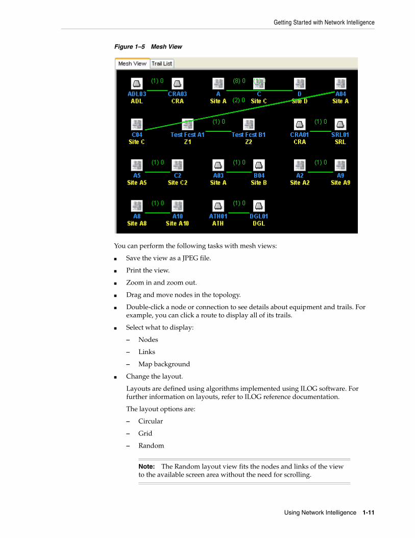
Getting Started with Network Intelligence
Using Network Intelligence 1-11
Figure 1–5 Mesh View
You can perform the following tasks with mesh views:
■ Save the view as a JPEG file.
■ Print the view.
■ Zoom in and zoom out.
■ Drag and move nodes in the topology.
■ Double-click a node or connection to see details about equipment and trails. For example, you can click a route to display all of its trails.
■ Select what to display:
– Nodes
– Links
– Map background
■ Change the layout.
Layouts are defined using algorithms implemented using ILOG software. For further information on layouts, refer to ILOG reference documentation.
The layout options are:
– Circular
– Grid
– Random
Note: The Random layout view fits the nodes and links of the view to the available screen area without the need for scrolling.
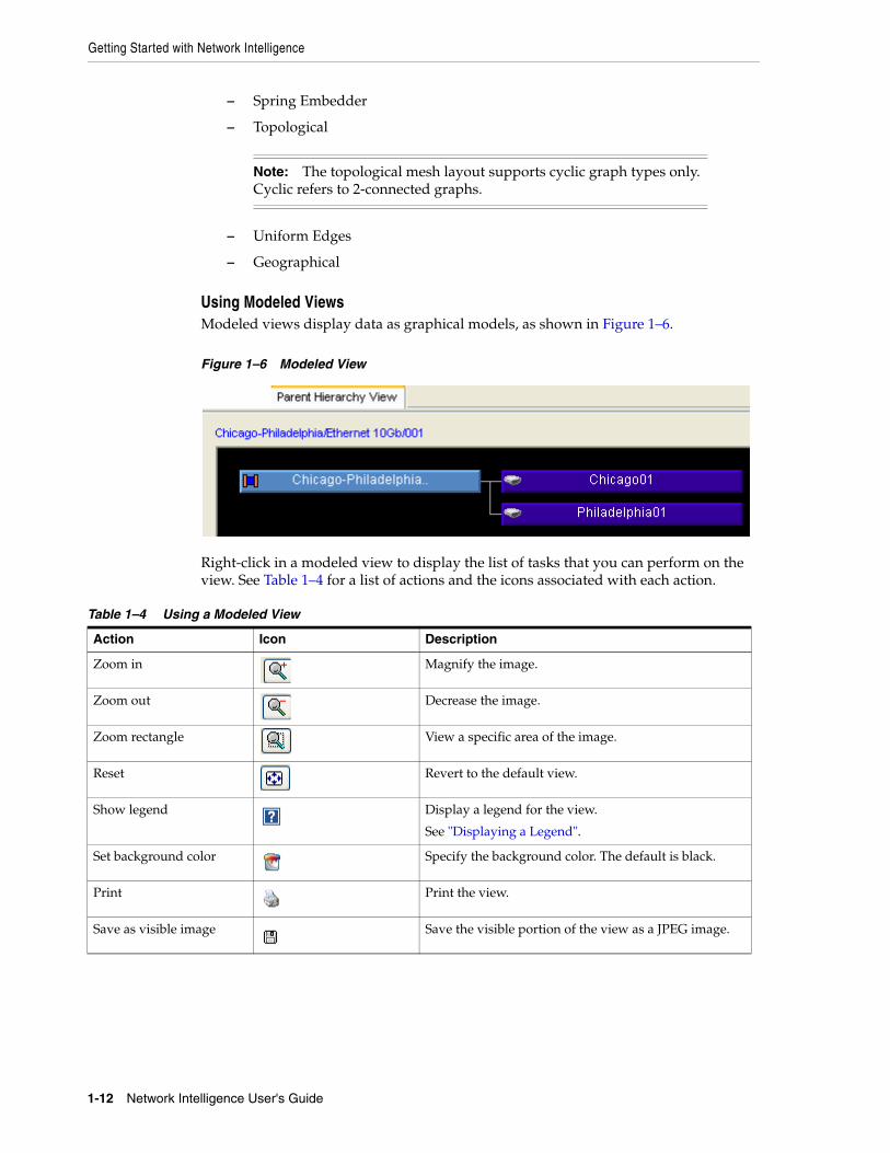
Getting Started with Network Intelligence
1-12 Network Intelligence User's Guide
– Spring Embedder
– Topological
– Uniform Edges
– Geographical
Using Modeled ViewsModeled views display data as graphical models, as shown in Figure 1–6.
Figure 1–6 Modeled View
Right-click in a modeled view to display the list of tasks that you can perform on the view. See Table 1–4 for a list of actions and the icons associated with each action.
Note: The topological mesh layout supports cyclic graph types only. Cyclic refers to 2-connected graphs.
Table 1–4 Using a Modeled View
Action Icon Description
Zoom in Magnify the image.
Zoom out Decrease the image.
Zoom rectangle View a specific area of the image.
Reset Revert to the default view.
Show legend Display a legend for the view.
See "Displaying a Legend".
Set background color Specify the background color. The default is black.
Print Print the view.
Save as visible image Save the visible portion of the view as a JPEG image.
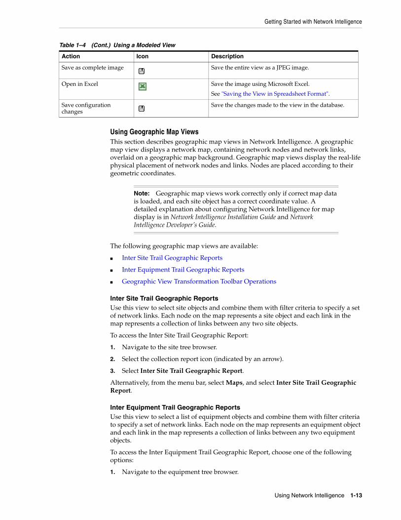
Getting Started with Network Intelligence
Using Network Intelligence 1-13
Using Geographic Map ViewsThis section describes geographic map views in Network Intelligence. A geographic map view displays a network map, containing network nodes and network links, overlaid on a geographic map background. Geographic map views display the real-life physical placement of network nodes and links. Nodes are placed according to their geometric coordinates.
The following geographic map views are available:
■ Inter Site Trail Geographic Reports
■ Inter Equipment Trail Geographic Reports
■ Geographic View Transformation Toolbar Operations
Inter Site Trail Geographic ReportsUse this view to select site objects and combine them with filter criteria to specify a set of network links. Each node on the map represents a site object and each link in the map represents a collection of links between any two site objects.
To access the Inter Site Trail Geographic Report:
1. Navigate to the site tree browser.
2. Select the collection report icon (indicated by an arrow).
3. Select Inter Site Trail Geographic Report.
Alternatively, from the menu bar, select Maps, and select Inter Site Trail Geographic Report.
Inter Equipment Trail Geographic ReportsUse this view to select a list of equipment objects and combine them with filter criteria to specify a set of network links. Each node on the map represents an equipment object and each link in the map represents a collection of links between any two equipment objects.
To access the Inter Equipment Trail Geographic Report, choose one of the following options:
1. Navigate to the equipment tree browser.
Save as complete image Save the entire view as a JPEG image.
Open in Excel Save the image using Microsoft Excel.
See "Saving the View in Spreadsheet Format".
Save configuration changes
Save the changes made to the view in the database.
Note: Geographic map views work correctly only if correct map data is loaded, and each site object has a correct coordinate value. A detailed explanation about configuring Network Intelligence for map display is in Network Intelligence Installation Guide and Network Intelligence Developer’s Guide.
Table 1–4 (Cont.) Using a Modeled View
Action Icon Description
Getting Started with Network Intelligence
1-14 Network Intelligence User's Guide
2. Select the collection report icon (indicated by an arrow).
3. Select Inter Equipment Trail Geographic Report.
Alternatively, from the menu bar, select Maps, and select Inter Equipment Trail Geographic Report.
Trail Traversal Geographic Map ViewsUse this view to see the routed path of a trail in a geographic map. The path of a trail from start node to end node is drawn with all intermediate hub nodes.
To access the Trail Traversal Geographic Map View:
1. Select a trail of interest from the trail tree browser, or trail search window.
2. In the view panel, on the right-hand side under Traversal, click Geographic Map View.
About Common Behaviors in Map ViewThe behaviors described in this section are common to all map views.
Fixed Placement of Node and Link Objects
Nodes and links are not movable: they are rendered according to geographical coordinates.
Logical graphical views, which exist elsewhere in the application, place nodes and links in a graphical view, in a non-geographical format. The nodes and views can be moved around in these views. Use the logical type views to lay out nodes and links in a custom format
Label Interactor Shows More Detail
When you move over a node or link with the mouse, more details about the node or link object appear at the top of the map panel, in the label interactor.
Object Drilldown
When you double-click a node object, the detail view of the object is displayed. For site-based nodes, double-click to display the detail view of the selected site object in the main application workbench. For equipment-based nodes, double-click to display the detail view of the selected equipment object in the main application workbench.
When you double-click a link object, its child trails are displayed in a table. Double-click a trail in the table to display the detail view of the selected link object in the main application workbench.
Map View Menu Options
The map view displays these menu options:
■ Show Legend: Displays a legend explaining the nodes and links in the current view.
■ Print: Prints the current geographic view.
■ Save As Visible Image: Saves the current geographical image as a JPEG.
■ Link Layers: Select separate layers for paths (bearers) and trails (transports.) See "Viewing Link Layers".
Geographic View Transformation Toolbar OperationsAt the top right-hand corner of the graphic screen, a toolbar displays the following buttons:
Getting Started with Network Intelligence
Using Network Intelligence 1-15
■ Reset
■ Zoom in
■ Zoom out
■ Zoom rectangle
■ Pan
Resetting the Geographic Map
Resetting the geographic map returns the map view to the initial display setting. If you zoom in or out too far, the reset button returns the map to full view.
To reset the geographic map:
1. Click Reset.
After a few seconds the map resets to its default size.
Zooming and Panning
Zooming increases or decreases the scale of a map view. Panning selects a specific click point as the center of a map view.
To zoom in:
1. Click Zoom in.
2. Click a point on the map required to be the centre of the zoom.
After a few seconds the map is rendered on a larger scale, centered on the click point.
To zoom out:
1. Click Zoom out.
2. Click a point on the map required to be the centre of the zoom out.
After a few seconds the map is rendered on a smaller scale, centered on the click point.
To use zoom rectangle:
1. Click Zoom rectangle.
2. Click a starting point in the map.
Note: Clicking a button in this group defines the mouse pointer behavior until you click a different button.

Getting Started with Network Intelligence
1-16 Network Intelligence User's Guide
This is the start of the zoomed rectangle area.
3. Drag the mouse until you have the rectangle required to zoom in on.
After a few seconds, the map is rendered on a larger scale, bound by the selected rectangle.
To pan in:
1. Click Pan.
2. Click a point in the map required to be the centre of the pan.
After a few seconds the map is re-rendered, centered at the click point. There is no increase or decrease to the scale of the map.
About Route LinksThe Inter Site Trail Geographic Report and Inter Equipment Trail Geographic Report each contain a Route Links tab. This tab displays the route objects between each node pair. Double-click a row to display a window containing a list of all the trails that comprise each route link.
About the Trail ListThe Inter Site Trail Geographic Report and Inter Equipment Trail Geographic Report each contain a Trail List tab. This tab displays the trail objects that compose the link objects in the geographic view. Double-click a row to display the trail detail view of the trail referenced in the selected row.
Filtering View DataSome views can be filtered to display only part of the available data. For example, when displaying trails, you can select to display link or path trails, or you can display trails for a specific capacity. If you do not select any filter criteria, all data is displayed. However, in some cases, you cannot open a view without filtering.
Table 1–5 Route Links Definitions
Attribute Description
Utilization The total cumulative bandwidth utilization of all the trails that comprise the route link.
Total Slots The total number of aggregated slots of all the trails that comprise the route link.
Free Slots The total number of aggregated free slots of all the trails that comprise the route link. A free slot is a path or timeslot that does not have a reference to a child trail.
Monthly Update The monthly uptake in megabytes of the route object referenced by the route link. This value is the rate of growth per month in carried traffic on this route link. It is an average value of the individual growths of each trail making up the route link.
Exhaustion Date This is the calculated exhaustion date of the Route object and is based on the current monthly uptake based on past time periods.
Note: Filter criteria change depending on the view.

Getting Started with Network Intelligence
Using Network Intelligence 1-17
To filter view data:
1. Click a view in the View tab. If the view allows filtering, the Filter Criteria tab is displayed, as shown in Figure 1–7.
Figure 1–7 Filtering Options
2. Use the tabs to display the type of data you want to filter from. For example, to display a specific type of trail, click Group Type.
3. Select the properties you want to include in the view. For example, to include links, select Link.
To select multiple properties, use the Shift and Ctrl keys. Selected properties remain selected when you click other tabs.
Properties in tabs are dependent on each other. For example, the type of trail you select in the Group Type tab determines the available capacities in the Capacity tab.; for example: the filter is prepopulated with all available traffic types for the selected equipment based on the known list of trails that reference the equipment.
4. Click Apply to display the view.
Using Standard Trail View Filter OptionsLinks, or link trails, generally, are point-to-point links at the highest level of the logical network. Parents of links are normally cable fiber pairs. From a planning point of view, a link trail is considered a link with a capacity to be managed between two network nodes. Link trails transport child trails of group type Path.
Getting Started with Network Intelligence
1-18 Network Intelligence User's Guide
Path trails normally refer to path trails that logically carry customer trails between two points in the network. Path trails have link trails as parents and child trails of group type Trail as children.
Circuit trails are circuits that deliver services to customer nodes. A circuit with a group type of Circuit normally has trails of group type Path as parents.
The standard filter options for trail views are:
■ Group Type:
– Link
– Circuit
– Path
■ Group: Defines a set of trails that are of a common type within a group type. For example, you can define a Group with the name “IP Link” that is a child of Group Type “Link,” which enables the classification of all IP Link trails as part of the same group.
■ Service
■ Capacity
■ Date Range:
– Creation date
– In service date
Using Standard Link View Filter OptionsThe standard filter options for link views are:
■ Group Type:
– Link
– Circuit
– Path
■ Group
■ Service
■ Capacity
■ Protection types:
– Protected
– Protection
– Unprotected
Using Standard Equipment View Filter OptionsThe standard filter options for equipment views are:
Note: The names Link, Path, and Trail can be changed by an administrative user using the administrative web portal. For example: in the US, a link is commonly called a facility, and a path is usually known as a rider.
Getting Started with Network Intelligence
Using Network Intelligence 1-19
■ Equipment Platform: Denotes what type of technology an equipment belongs to. Examples include IP, DWDM, SDH, Metro Ethernet.
■ Equipment Type: Sub-categorizes equipment within an equipment platform. For example, there might be an equipment platform called “IP” that has two equipment types called “IP Router” and “IP Switch.”
■ Equipment Template: Defines the equipment model. For example, “Cisco 8600" is the model type that identifies what model of equipment the equipment instance is.
Active FilteringIn Network intelligence, most reports use active filtering, where the items in the filter panel reflect the data related to the object being reported on.
For example, in a report detailing trails terminating on an equipment, the filter options offered (trail groups, capacities, and so on) are those that apply to trails that terminate on the equipment.
Some reports, for performance reasons, do not use active filtering:
■ Network Node View
■ Network All Child Trails View
■ Site All Child Trails View
■ Topology All Child Trails View
■ Equipment All Child Trails View
Saving the Data in a ViewIn most cases, you can save a view to its appropriate format. For example, you can save graphs as image (JPEG) files, and you can save table views in spreadsheet format or as HTML.
To save view data:
1. Right-click anywhere in the view data display.
2. Select to save or copy the data.
3. Specify a file name and location, and save the file.
Editing Object Detail DataTo change object attributes in the object details view:
1. Display the object details view.
2. Click Edit.
3. Make the changes.
4. Click Save.
Changes are saved to the Network Intelligence database.
Note: If Network Intelligence is deployed as a slave data system to a master data source whereby object attributes are updated by the master source and changes loaded into Network Intelligence, then use of this update functionality should be reviewed.

Getting Started with Network Intelligence
1-20 Network Intelligence User's Guide
Displaying a LegendA legend outlines the assignment of colors to entities, and the hierarchical structure of the view.
To display a legend that describes the modeled view:
1. Right-click the background of the image.
2. Click Show Legend.
Saving the View in Spreadsheet FormatTo save the view as a Microsoft Excel spreadsheet:
1. Right-click the background of the image.
2. Click Open in Excel.
3. Select a location to save the file.
Managing WindowsTo manage tabs, windows, and dialog boxes, use these features:
■ To close a tab, right-click it and select Close.
■ To close multiple tabs, right-click any tab and select from:
– Close All But This
– Close All Tabs
To display currently open tabs, windows, and dialog boxes:
■ Click a tab to display it.
■ Use the Window menu to display a tab. This menu shows only those windows that are currently open.
■ Use the Dialog menu to display a dialog box. This menu shows only those dialog boxes that are currently open.
SearchingIn addition to using the tree browser, you can search for network entities. Each type of data has its own search criteria.
To search for data:
1. From the context toolbar, open the browser of the object type you want to search for.
2. Click the Search icon:
3. The object’s search window is displayed.
■ Searching is based on any main attribute, such as name, platform, in service date, or object status.
■ Check the Advanced Search box, if applicable, to use extensible attributes in the search.
See Network Intelligence Developer’s Guide for further information on creating and configuring extensible attributes.
Getting Started with Network Intelligence
Using Network Intelligence 1-21
■ Check the Case Sensitive box to render the search case sensitive.
■ Click the Ellipsis icon to open a search window for an entity; for example, service or customer:
■ Click the Clear icon to clear a text field:
Performing Actions on Search ResultsWhen the object has been found, it is displayed under the Result tab. Double-click an object to display a full object details view.
■ Click Edit to configure object details.
■ Click Save to commit the object information.
■ Click Delete to remove the object.
■ Select a view to display further information about an object.

Getting Started with Network Intelligence
1-22 Network Intelligence User's Guide
2
Displaying Network Data 2-1
2Displaying Network Data
This section describes how data is displayed in Oracle Communications Network Intelligence.
About Displaying Network DataNetwork Intelligence contains an application platform and data modeling database that provides visualization, utilization, and trending reporting on all network object types from topologies, networks, equipment, equipment holders, and links, down to individual cards and trails.
By measuring and reporting the utilization of all network entities, and examining existing capacity utilization black spots, Network Intelligence suggests the re-routing of inefficient trails, and generates comprehensive outage information. Optimal aggregation of all lower-order traffic to minimum higher-order links is provided with optimal routing of all higher-order and lower-order trail paths. You can map path to service resources and perform trail route analysis to check protection, physical separation, and resilience.
The network can be viewed from any of the following perspectives:
■ Topology
■ Network
■ Location
■ Equipment
■ Trail
■ Service
■ Customer
All tabular reports generated can be saved to spreadsheet, or HTML, format. All graphical views can be displayed as image files.
Using Object Type Trail ViewsCertain views are common to some, or all, object types.
There are two standard trail sub-views available for each object type:
■ Working with the Terminating Child Trails View
■ Working with the All Child Trails View
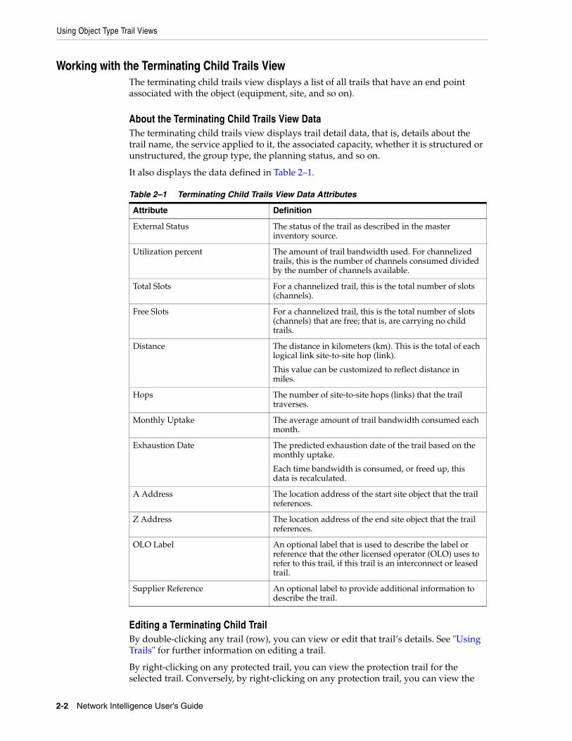
Using Object Type Trail Views
2-2 Network Intelligence User's Guide
Working with the Terminating Child Trails ViewThe terminating child trails view displays a list of all trails that have an end point associated with the object (equipment, site, and so on).
About the Terminating Child Trails View DataThe terminating child trails view displays trail detail data, that is, details about the trail name, the service applied to it, the associated capacity, whether it is structured or unstructured, the group type, the planning status, and so on.
It also displays the data defined in Table 2–1.
Editing a Terminating Child TrailBy double-clicking any trail (row), you can view or edit that trail’s details. See "Using Trails" for further information on editing a trail.
By right-clicking on any protected trail, you can view the protection trail for the selected trail. Conversely, by right-clicking on any protection trail, you can view the
Table 2–1 Terminating Child Trails View Data Attributes
Attribute Definition
External Status The status of the trail as described in the master inventory source.
Utilization percent The amount of trail bandwidth used. For channelized trails, this is the number of channels consumed divided by the number of channels available.
Total Slots For a channelized trail, this is the total number of slots (channels).
Free Slots For a channelized trail, this is the total number of slots (channels) that are free; that is, are carrying no child trails.
Distance The distance in kilometers (km). This is the total of each logical link site-to-site hop (link).
This value can be customized to reflect distance in miles.
Hops The number of site-to-site hops (links) that the trail traverses.
Monthly Uptake The average amount of trail bandwidth consumed each month.
Exhaustion Date The predicted exhaustion date of the trail based on the monthly uptake.
Each time bandwidth is consumed, or freed up, this data is recalculated.
A Address The location address of the start site object that the trail references.
Z Address The location address of the end site object that the trail references.
OLO Label An optional label that is used to describe the label or reference that the other licensed operator (OLO) uses to refer to this trail, if this trail is an interconnect or leased trail.
Supplier Reference An optional label to provide additional information to describe the trail.
Using Object Type Trail Views
Displaying Network Data 2-3
protected trail for the selected trail. See "Viewing the Protection and Protected Trail" for more information.
By right-clicking on any unprotected trail, you can create a protection trail for the selected trail. See "Protecting an Existing Trail" for more information.
Working with the All Child Trails ViewThe all child trails view displays a list of all trails that have an association with the selected entity. This includes all terminating trails and all transiting trails. The standard trail search filter is available for this trails view.
To display this view, use the filter. See "Filtering View Data".
Filtering DataTo filter data:
1. Click the search icon.
The Site Search window is displayed.
2. Enter the search criteria for the site.
3. Click the Result tab to view the results of the search.
4. Select the sites.
5. Click Select.
The Site Search tab of the filter is populated with the highlighted sites. This site search function can be repeated as often as required to select all necessary sites.
Using the Traffic Type FilterIn addition to the filters described in "Filtering View Data", the traffic type filter enables the selection of one, or both of, the following:
■ Terminating traffic only
■ Transiting traffic only
Terminating traffic means that the trail traffic has a start, or an end point associated with the selected object (the object is normally a equipment or site).
Transiting traffic means that the trail is passing through the selected object and is not terminating at the selected object.
Note: This report does not use active filtering. See "Active Filtering" for more information.
Note: If you do not select any sites using the Add button, all sites are selected by default. If you do this, keep in mind that, in some cases, the returned number of trails can be very large and can cause memory problems.
Tip: If you know in advance that there are not too many trails, you can filter on a service or capacity without selecting site objects. This saves the trouble of selecting individual sites.
Using Object Link Mesh Views
2-4 Network Intelligence User's Guide
If no filter options are selected, the filter returns a list of all trails that have any association with the object.
Double-click any trail (row) to display that trail’s details page.
Using Object Link Mesh ViewsA mesh view is a graphical view showing either network site locations or network equipment connected using links.
Running the Inter Site Trail Mesh ReportAn inter site trail mesh report is a graphical view displaying all the links between selected network sites.
An inter site trail mesh report can be filtered using the standard trail filter criteria (trail type, bandwidth, and so on). Filtering the selection of data generates a more meaningful report.
To run the site mesh report:
1. Navigate to the site tree browser.
2. Click the object group view icon and select Inter Site Trail Mesh Report.
3. Filter the selection of data by doing any of the following:
■ Filtering Data
■ Setting the Protection Type
■ Selecting Link Utilization Thresholds
■ Applying the Settings
Setting the Protection TypeThe protection type filter screens any protection trails that are not of interest.
To set the protection type:
1. Click the Protection Type tab at the base of the Filter Criteria.
2. Select the protection types to filter out.
3. Continue by selecting thresholds, or click Apply to generate the report.
Selecting Link Utilization ThresholdsTo select the link utilization thresholds:
1. Click Set Thresholds below the filter selection criteria.
The Set Thresholds window is displayed.
2. Click Add to set one or more link threshold values.
3. Click Add to display the threshold values to the Set Thresholds window.
For example, if you set a link threshold of color red for any link greater than or equal to 70 percent, any link on the map between two site entities that has a cumulative utilization of 70 percent or more is drawn in red on the mesh view.
Any link with utilization less than the lowest set threshold is displayed in green. If no thresholds are set, all links are displayed in green.
Using Object Link Mesh Views
Displaying Network Data 2-5
Any link can be selected by placing the mouse over that link. If the mouse is over a link then the link color changes to blue and a label interactor is displayed at the top of the mesh view depicting the following data:
■ A Site Name-Z Site Name
■ Number of links
■ Cumulative utilization
Applying the SettingsClick Apply after all filter criteria have been selected to display the following views:
■ Network View
■ Route Links view
The Route Links view displays in tabular format the data that is shown in the graphical view. Drill down on any row of this tabular view to display a list of trails that comprise the cumulative data in the row.
The Route Links view consists of the following columns:
– A Site
– Z Site
– Capacity
– Service
– Utilization %.
– Total Slots
– Used Slots
– Monthly Uptake: The average amount of trail bandwidth consumed each month, this percentage is calculated for the list of trails that comprise the Route Links view.
– Exhaustion Date: The predicted exhaustion date of the trail based on the monthly uptake. Each time bandwidth is consumed, or freed up, this data is recalculated. This value is calculated for the list of trails that comprise the Route Links view.
■ Trail List view
This report provides a tabular view of the trails between the sites. Double-click a trail to view it.
The Trail List view consists of the following columns:
– Name
– Service
– Capacity
– Structured (that is, whether the trail is structured)
– Group
– Status
– External Status
– Customer
Using Object Link Mesh Views
2-6 Network Intelligence User's Guide
– A Site
– Z Site
– A Node
– Z Node
– A Port
– Z Port
– Protection
– Utilization %.
– Total Slots
– Free Slots
– Distance (km)
– Hops
– In Service Date
– Out Service Date
– Monthly Uptake: The average amount of trail bandwidth consumed each month, this percentage is calculated for the list of trails that comprise the Trail List view.
– Exhaustion Date: The predicted exhaustion date of the trail based on the monthly uptake. Each time bandwidth is consumed, or freed up, this data is recalculated. This value is calculated for the list of trails that comprise the Trail List view.
– A Address
– Z Address
– Presentation
– OLO Label
– External Source
– Supplier Reference
See Table 2–1, " Terminating Child Trails View Data Attributes" for a list of column definitions.
Running the Inter Site Pair Trail Mesh ViewAn Inter Site Pair Trail Mesh View is very similar to an Inter Site Trail Mesh Report, except that you select site pairs in the network, rather than single sites.
For example, if a network has four sites A, B, C, D, choosing site pairs A-B and B-C displays traffic on the two chosen links. In a site mesh view, you select A, B, C, D, and all connecting links (if any) are displayed:
■ A-B
■ A-C
■ B-C
■ A-D, and so on.
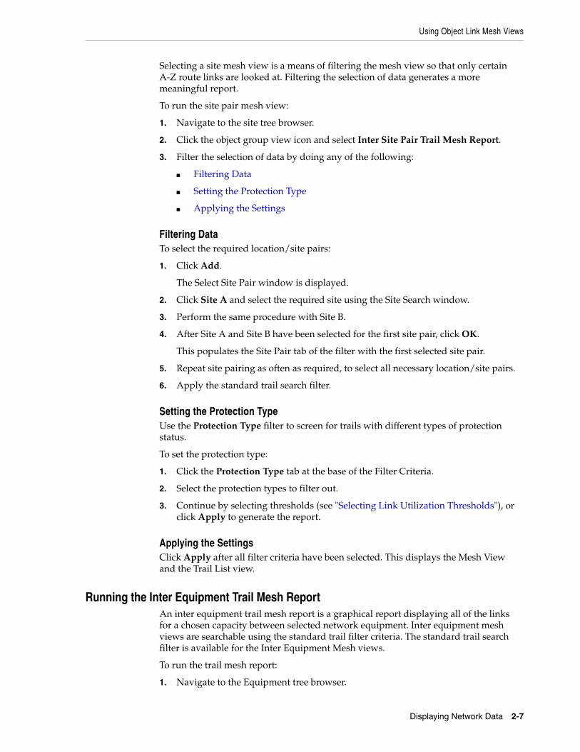
Using Object Link Mesh Views
Displaying Network Data 2-7
Selecting a site mesh view is a means of filtering the mesh view so that only certain A-Z route links are looked at. Filtering the selection of data generates a more meaningful report.
To run the site pair mesh view:
1. Navigate to the site tree browser.
2. Click the object group view icon and select Inter Site Pair Trail Mesh Report.
3. Filter the selection of data by doing any of the following:
■ Filtering Data
■ Setting the Protection Type
■ Applying the Settings
Filtering DataTo select the required location/site pairs:
1. Click Add.
The Select Site Pair window is displayed.
2. Click Site A and select the required site using the Site Search window.
3. Perform the same procedure with Site B.
4. After Site A and Site B have been selected for the first site pair, click OK.
This populates the Site Pair tab of the filter with the first selected site pair.
5. Repeat site pairing as often as required, to select all necessary location/site pairs.
6. Apply the standard trail search filter.
Setting the Protection TypeUse the Protection Type filter to screen for trails with different types of protection status.
To set the protection type:
1. Click the Protection Type tab at the base of the Filter Criteria.
2. Select the protection types to filter out.
3. Continue by selecting thresholds (see "Selecting Link Utilization Thresholds"), or click Apply to generate the report.
Applying the SettingsClick Apply after all filter criteria have been selected. This displays the Mesh View and the Trail List view.
Running the Inter Equipment Trail Mesh ReportAn inter equipment trail mesh report is a graphical report displaying all of the links for a chosen capacity between selected network equipment. Inter equipment mesh views are searchable using the standard trail filter criteria. The standard trail search filter is available for the Inter Equipment Mesh views.
To run the trail mesh report:
1. Navigate to the Equipment tree browser.
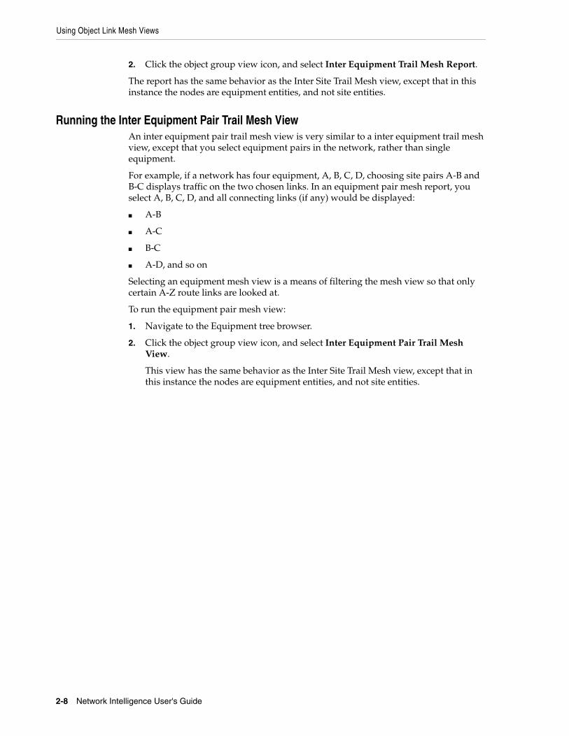
Using Object Link Mesh Views
2-8 Network Intelligence User's Guide
2. Click the object group view icon, and select Inter Equipment Trail Mesh Report.
The report has the same behavior as the Inter Site Trail Mesh view, except that in this instance the nodes are equipment entities, and not site entities.
Running the Inter Equipment Pair Trail Mesh ViewAn inter equipment pair trail mesh view is very similar to a inter equipment trail mesh view, except that you select equipment pairs in the network, rather than single equipment.
For example, if a network has four equipment, A, B, C, D, choosing site pairs A-B and B-C displays traffic on the two chosen links. In an equipment pair mesh report, you select A, B, C, D, and all connecting links (if any) would be displayed:
■ A-B
■ A-C
■ B-C
■ A-D, and so on
Selecting an equipment mesh view is a means of filtering the mesh view so that only certain A-Z route links are looked at.
To run the equipment pair mesh view:
1. Navigate to the Equipment tree browser.
2. Click the object group view icon, and select Inter Equipment Pair Trail Mesh View.
This view has the same behavior as the Inter Site Trail Mesh view, except that in this instance the nodes are equipment entities, and not site entities.
3
Using Networks 3-1
3Using Networks
This section describes networks in Oracle Communications Network Intelligence. A network consists of a series of points or nodes connected by communication paths.
Using the Network Tree BrowserThe network tree browser contains a list of all defined networks in the Network Intelligence database. Networks in Network Intelligence are generated in one of the following ways:
■ Networks are created in the Network Intelligence GUI. See "Creating a Network".
■ Networks are loaded from the inventory management system (IMS) in which they are modeled. See Network Intelligence Concepts for further information on data loading.
Creating a NetworkYou can create every type of object required for use in planning use cases using the Network Intelligence user interface.
The Create icon is used to create new network entities. All entities that are created in Network Intelligence have a default status of Planned (signifying that it is a Network Intelligence planned object). After the new object is created, it may be used in Forecast Manager for network simulations and planning.
To create a network:
1. Click Network on the context toolbar.
2. Click the Create icon:
The New Network window is displayed.
3. Configure the network using the following values:
■ Name: The name of the new network. The name must be unique.
■ Parent Network: Select from the list of available networks.
■ InService Date: Select the date on which the network comes into service.
■ OutService Date: Select the date on which the network goes out of service.
■ Status: The status of the network. The status is ONI Planned (where ONI signifies Oracle Communications Network Intelligence) by default, but may be
Working with Network Views
3-2 Network Intelligence User's Guide
changed to another status; for example: Planned Cease, Reserved in Service, Reserved Reprovide, Testing, and so on.
■ Policy: Setting a policy for a network allows specific routing constraints to be applied for the network when path routing.
4. Click Save.
Working with Network ViewsThe network object offers the following views:
■ Network Node View
■ Equipment Search
■ Child Trails
■ Customer Bandwidth View
Using the Network Node ViewThe network node view displays a logical view of the network’s equipment nodes and their connecting trails. A network has nodes associated with it when a topology is assigned to reference a network.
In the network node view, you can filter trails to decide what trail connectivity is required between network nodes.
This view has the same behavior as that described in "Running the Inter Equipment Trail Mesh Report".
Using the Equipment Search View for a NetworkThe equipment search view displays a table view of the network’s equipment.
You can filter the equipment as follows:
1. Select from the labels corresponding to the equipment filters:
■ Equipment platform
■ Equipment type
■ Equipment definition
■ Manufacturer
■ Status: The status of the equipment. By default, the status is planned, but may be changed to another status; for example: Planned Cease, Reserved in Service, Reserved Reprovide, Testing, and so on.
■ Date range: Select the in service date for the equipment.
2. Click to select the required equipment.
3. Click Apply to generate the view.
Note: This report does not use active filtering. See "Active Filtering" for more information.
Working with Network Views
Using Networks 3-3
Using the Child Trails View for a NetworkThe child trails view displays a filterable list of trails that reference nodes of the network.
The child trails view for the network is common to many supported entities. See "Using Object Type Trail Views" for a description of the view.
Using the Customer Bandwidth ViewThe customer bandwidth view provides a list of every customer subscribing to a service carried on the network.
The customer bandwidth can be filtered by both customer and capacity. You can extract and save the customer bandwidth data.
To view the customer bandwidth view for the network:
1. Click Select to search for the customer, or select the customer from the list in the Network Customer Bandwidth Report table.
2. Select the capacity.
The default is all available capacities on the network.
3. Click Retrieve to view the customer bandwidth for the network.
Customer bandwidth is defined by customer name, capacity name, the number of trails of that type allocated to the customer, and bandwidth (in Mbps).

Working with Network Views
3-4 Network Intelligence User's Guide
4
Using Sites 4-1
4Using Sites
This section describes sites in Oracle Communications Network Intelligence. A site is the part of the network that contains equipment. A site uses a location to group one, or more sites. A location, in turn, uses an address to configure the geographical placement of sites; for example:
Address: Location: Site: Equipment
Boston: Fenway Park: My_Company_Office: Cisco 3745 Router.
Using the Site Tree BrowserThe site tree browser displays all sites in the database. Sites are grouped by location. Sites in Network Intelligence are generated in one of the following ways:
■ Sites are created in the Network Intelligence GUI. See "Creating a Site".
■ Sites are loaded from the inventory management system (IMS) in which they are modeled. See Network Intelligence Developer’s Guide for further information on data loading.
Creating a SiteYou can create every type of object required for use in planning use cases using the Network Intelligence user interface.
The Create icon is used to create new network entities. All entities that are created in Network Intelligence have a default status of Planned (signifying that it is a Network Intelligence planned object). After the new object is created, it may be used in Forecast Manager for network simulations and planning.
To create a site:
1. Click Site on the context toolbar.
2. Click the Create icon:
The New Site window is displayed.
3. Configure the site using the following values:
■ Name: The name of the site. The name must be unique.
■ Description: Add other information about the site.
Creating a Site
4-2 Network Intelligence User's Guide
■ Parent Location: Select from the list of available locations, or create a location. To create a location, see "Creating a Location".
■ Address: Select from the list of available addresses.
■ Site Type: Select from the list of available site types.
■ Customer Type: Select from the list of available customer types.
■ X-Coordinate: Specify the geographical X coordinate of the site.
■ Y-Coordinate: Specify the geographical Y coordinate of the site.
■ InService Date: Select the date on which the site comes into service.
■ OutService Date: Select the date on which the site goes out of service.
■ Status: The status of the site. The default is ONI Planned (where ONI signifies Oracle Communications Network Intelligence), but may be changed to another status; for example: Planned Cease, Reserved in Service, Reserved Reprovide, Testing, and so on.
■ State: Select the state in which the site is to be created.
■ Area: Select the state in which the site is to be created.
■ Incumbent: Select the incumbent associated with the site.
■ OLO: Select the other licensed operator associated with the site.
4. Click Save.
Related TopicsCreating a Location
Creating an Address
Creating a LocationA location is used to group one or more sites.
To create a location:
1. From the top-level menu, select Administration, then select Create Object and select New Location to display the New Location window.
2. Configure the location using the following values:
■ Name: The name of the new location. The name must be unique.
■ Address: Select from the list of available addresses, or create an address. To create an address, see "Creating an Address".
■ Parent Location: Select from the list of available locations.
3. Click Save.
Creating an AddressAn address is used to define a location.
To create an address:
Note: Sites are grouped by parent location in the site tree browser.
Working with Site Object Views
Using Sites 4-3
1. From the top-level menu, select Administration, then select Create Object and select New Address to display the New Address window.
2. Configure the address using the following values:
■ Address: The name of the address. The name must be unique.
■ City: Enter the name of the city.
■ Province: Enter the name of the province.
■ Country: Enter the name of the country.
■ Postal Code: Enter the name of the postal code.
3. Click Save.
Working with Site Object ViewsThe site object offers the following views:
■ External Links View
■ Internal Links View
■ Resource Topology List View
■ Equipment Search View
■ Port Availability View
■ Terminating Child Trails View
■ All Child Trails View
Using the External Links ViewThe External Links View displays a graphical view of all of the external links from this site to other sites, and a tabular view of the trails.
This view has the same behavior as that described in the "Running the Inter Site Trail Mesh Report".
Using the Internal Links View The Internal Links View displays a graphical view of all of the internal links at this site. An internal link in this case means any link whose start site and end site are the same as the selected site.
This view has the same behavior as that described in the "Running the Inter Site Trail Mesh Report".
Using the Resource Topology List ViewThe Topology List View is a list of all topologies that contain equipment located at the selected site; that is, the topologies whose trails either transit; terminate; transit and terminate; transit or terminate, at the selected site.
Using the Equipment Search ViewThe Equipment Search View displays a table showing the equipment at the site. The equipment can be filtered in the normal manner. See "Filtering View Data".
Working with the Site Group Object Views
4-4 Network Intelligence User's Guide
This view has the same behavior as that described in "Using the Equipment Search View for a Network".
Using the Port Availability ViewThe Port Availability View displays a list of the current status and availability of all ports belonging to the equipment instances of the selected site. The status options for a port are:
■ In Service: The port has one or more trail associated with it.
■ Planned: The port is in a planned state and so may not physically be created yet in the real network; use it for planning purposes.
■ Free: The port exists in the real network and is not carrying any trails, and therefore it is available to use for carrying a trail.
The Port Availability View can be filtered in the normal manner. See "Filtering View Data".
To generate the port availability view for the site:
1. Select from the labels corresponding to the filters selected using the Filter Criteria tab:
■ Equipment platform
■ Equipment type
■ Equipment definition
■ Port definition
2. Click to select the required criteria.
3. Click Apply to generate the report.
Using the Trail ViewsThe trail views for the site are made up of the following views:
■ Terminating Child Trails View
■ All Child Trails View
These views are common to many supported entities in Network Intelligence, and are described in "Using Object Type Trail Views".
Working with the Site Group Object ViewsTo display the group object views for a site:
1. Click the object group view icon.
2. Select from the view options:
■ Using Geographic Map Views
■ Running the Inter Site Trail Mesh Report
■ Running the Inter Site Pair Trail Mesh View
Related TopicsDisplaying Object Group Views.

5
Using Topologies 5-1
5Using Topologies
This section describes topologies in Oracle Communications Network Intelligence.
Using the Topology Tree BrowserThe topology tree browser displays all topologies modeled in Network Intelligence, and is divided into subfolders for service topologies and resource topologies, with topologies listed alphabetically.
A service topology is used to model multipoint services in Network Intelligence; it is made up of the interconnection of the links and nodes of one of the following:
■ A point-to-point service;
■ A multipoint-to-multipoint service;
■ A rooted-multipoint service.
A resource topology is typically used to divide a network into logical groupings; for example: to partition a network into nodes and edges.
Each individual topology has two subfolders, as shown in Figure 5–1:
■ Links (containing the associated trails of all the topology links)
■ Nodes (containing the associated equipment of all the topology nodes)
Figure 5–1 Topology Tree Browser
Creating a Resource Topology
5-2 Network Intelligence User's Guide
Topologies are either created in Network Intelligence, or loaded from the inventory management system:
■ Resource topologies are created in the Network Intelligence GUI. See "Creating a Resource Topology".
■ Service topologies are loaded from the inventory management system (IMS) in which they are modeled. See Network Intelligence Concepts for further information on data loading.
Creating a Resource TopologyYou can create a resource topology using the Network Intelligence GUI.
To create a topology:
1. Click Topology on the context toolbar.
2. Click the Create icon:
The New Resource Topology window is displayed.
3. Configure the topology using the following values:
■ Topology Name: The name of the topology. The name must be unique.
■ Usage: Specifies the required usage; that is, whether the topology is of type Resource or Service. You may not edit this field.
■ Alias: (Optional) Provide another name for the topology.
■ Topology Pattern: Select the pattern to represent the topology:
– Ring
– Mesh
■ Topology Behavior: Select the topology behavior, that is, whether this is a routable topology, or is used for reporting and visualization purposes.
■ Network: Select the network associated with the topology.
■ Protection Type: Filter out protection trails that are not required in this topology by selecting from:
– Protected
– Protection
– Unprotected
■ Type: (Optional): Specify the type.
■ Supplier: (Optional) Specify the supplier.
■ No of Main Nodes: (Optional) Specify the number of main nodes in the topology.
■ InService Date: (Optional) Select the date on which the topology comes into service.
■ OutService Date: (Optional) Select the date on which the topology goes out of service.
Working with Topology Object Views
Using Topologies 5-3
■ Status: The status of the topology. The status is ONI Planned (where ONI signifies Oracle Communications Network Intelligence) by default.
4. Click Save.
To perform actions on a resource topology; for example: adding a link, or deleting a main node, and so on, see "Using the Link View".
Working with Topology Object ViewsTopology object views vary depending on topology type; that is, whether the topology object is a resource topology or a service topology. See the following topics:
■ Working with Resource Topology Object Views
■ Working with Service Topology Object Views
Working with Resource Topology Object ViewsThe topology object offers the following views for resource topologies:
■ Utilization View
■ Link View
■ Path View
■ To Other Resource Topologies Network View
■ To Other Resource Topology Nodes Network View
■ Terminating Child Trails View
■ All Child Trails View
Working with Service Topology Object ViewsThe topology object offers the following views for service topologies:
■ Utilization View
■ Terminating Child Trails View
■ All Child Trails View
Using the Utilization ViewThis view displays the utilization of the selected topology in terms of path, link, and equipment utilization.
■ Link utilization:
Each link is defined by name and equipment pair. Utilization is described by carrying traffic, utilization percentage, the number of used channels, the number of free channels, the monthly utilization growth measured in megabytes, the date at which the link entered service, and the date of exhaustion for the link.
For further information on path and link definitions, see "Using Standard Trail View Filter Options".
■ Path utilization:
Each path is defined by name and equipment pair. Utilization is described by carrying traffic, utilization percentage, the number of used channels, the number
Working with Topology Object Views
5-4 Network Intelligence User's Guide
of free channels, the monthly utilization growth measured in megabytes, the date at which the path entered service, and the date of exhaustion for the path.
For further information on path and link definitions, see "Using Standard Trail View Filter Options".
■ Equipment access slot utilization:
Each equipment is defined by name and capacity. Utilization is described by the number of free slots, and the total number of slots.
■ Equipment access port utilization:
Each equipment is defined by name, supported card type, and port definition. Utilization is described by the total number of ports, the number of in-service ports, the number of planned ports, and the number of free ports.
Saving the Utilization ViewTo save a utilization view in CSV (comma-delimited value) format:
1. Click Save As.
2. Select a location to save the file.
Using the Link ViewThe Link View displays the topology nodes and their trail connections of type link in logical view format. The view displays all topology equipment (both main and access) and all of the links that connect them.
Path Core LinksPath core links are all path circuits that exist between a selected main node and all other main nodes in a topology.
Path Edge LinksPath edge links are all path circuits that exist between a selected main node and all other nodes that are not main nodes in this topology; for example: the other node may be an access node in this topology.
To configure the topology using the Link View, see the following sections:
■ Displaying Trails in a Link
■ Hiding the Link or Node Layer
■ Adding a Main Node to a Topology
■ Removing a Main Node from a Topology
■ Adding a Link to a Topology
■ Removing a Link from a Topology
■ Saving a Topology View
■ Loading a Topology View
Displaying Trails in a LinkTo display the trails that comprise a link view:
■ Use the mouse to hover over a link in the Link View.
Working with Topology Object Views
Using Topologies 5-5
The color of the link changes. A tooltip displays information about the link, in terms of name, associated service, capacity, total slots, free slots, and utilization.
■ Double-click a a link in the Link View.
A table describing the trail in terms of name, associated service, capacity, group, status, protection, total slots, free slots, utilization, and so on, is displayed.
Double-click a trail entry in the table to:
– Display a detailed view of the trail.
– Edit the trail.
– Delete the trail.
Hiding the Link or Node LayerBy default, the Link View displays both the node layer and the link layer. You can turn off a layer so that only the other layer is visible.
To turn off the link layer, for example:
1. Right-click in the background of the view, and click Layers.
2. Uncheck Display Link Layer.
Adding a Main Node to a TopologyYou can add a main node, that is, any equipment in the Network Intelligence GUI, to a topology in the Link View.
To add a main node:
1. Right-click in the background of the view, and click Add Main Node to display the Add Main Node to Resource Topology window.
2. Select a node (equipment) from the tree browser by dragging and dropping it on the window.
3. Click Apply.
Removing a Main Node from a TopologyIn the link view, if a main node is removed, this removes all links to this node, both main links and path links. It also removes any access node on the other end of the link.
You can remove a main node, that is, any equipment in the Network Intelligence GUI, from a topology in the Link View.
To remove a main node:
1. Right-click a node in the topology, and select Remove Node.
2. Click OK to confirm the removal of the node, and its associated links and edge nodes, from the topology.
Adding a Link to a TopologyYou can add a link to a topology from a main node.You cannot add a link from an access node.
Note: You can select nodes from either the Topology tree browser, or the Equipment tree browser. You can add multiple nodes.
Working with Topology Object Views
5-6 Network Intelligence User's Guide
To add a link to a topology:
1. Right-click a main node, and click Add Link to display the Add Link to Topology window.
2. Select a link (edge or core) from the list of available links by double-clicking it, and click Add Core Link or Add Edge Link to add it to the topology.
Removing a Link from a TopologyIf all links between a main node and an access node are removed in the link view of a topology, this in turn deletes all access links and transport links to this node, and deletes the access node.
If all links between a main node and another main node are removed, this removes all links (both main links and path links).
To remove a link from a topology:
1. Right-click a link, and click Remove Link(s).
2. A warning dialog box may be displayed; for example: The selected access link and its associated edge node will be removed from the topology.
3. Click OK to accept the removal of the link and its associated entities, if any, or click Cancel to close the window without making any modifications.
Saving a Topology ViewYou can configure the topology in the Link View by moving nodes using the left mouse key. You can then save individual topology link views for each topology and load them at a later point.
To save the currently displayed view:
1. Click Save Topology Layout.
2. Name the report.
3. Save the report.
Loading a Topology ViewTo load a saved topology layout:
1. Click Load Topology Layout.
2. Select the report to display.
Using the Path ViewThe path view displays a logical view of all trails of type “path”, and depicts the start and end nodes of all trails that appear on that topology.
The main links on the path view are the path circuits that exist between the selected node and all other main nodes in this topology, where an existing topology link exists between this node and the other main node in the topology.
The access links on the path view are the path circuits that exist between a selected main node and all other nodes that are not main nodes in this topology, where an existing path topology link exists between a selected main node and the other node; for example: the other node may be an access node in this topology.
The path view has the same behavior as the link view except that the trail selection criteria are based on transport path trails rather than link trails.
Working with Topology Object Views
Using Topologies 5-7
To configure the topology using the path view, see "Using the Link View".
Removing LinksIn the path view, if all links between a main node and an access node are removed, then this deletes all path links.
Removing NodesIn the path view, if a main node is removed, this removes all links to this node, both main links and path links. It also removes any access node on other end of link.
If an access node is removed, this removes all links to this node, both main links and path links. It also removes any access node on the other end of the link.
Using the To Other Resource Topologies Network ViewThe To Other Resource Topologies Network View displays how the topology is connected to other network topologies. The To Other Resource Topologies Network View allows filtering using the standard trail search filter.
To filter the view:
1. Select resource topologies of the required capacity.
2. Click Apply to generate the views.
■ The mesh view displays all connected topologies in mesh format. The main customer topology is colored differently to the other topologies.
■ The trail list shows all trails defined by name, service, capacity, group, status, and so on.
■ The route list shows all routes defined by defined by resource topology, other resource topology, capacity, utilization, and so on.
■ (Optional) Save the views. See Table 1–4, " Using a Modeled View" for information about save options.
Using the To Other Resource Topology Nodes Network ViewThe To Other Resource Topology Nodes Network View displays how the topology is connected to other network topology nodes.
The To Other Resource Topology Nodes Network View allows filtering using the standard trail search filter.
To filter the view:
1. Select from the labels corresponding to the equipment filters:
■ Group type
■ Group
■ Service
■ Capacity
■ Protection type
2. Click to select the required topology nodes.
3. Set the thresholds. See "Running the Inter Site Trail Mesh Report".
4. Click Apply to generate the views:
Working with Topology Object Views
5-8 Network Intelligence User's Guide
■ The mesh view displays all connected topology nodes in mesh format.
■ The trail list shows all trails defined by name, service, capacity, group, status, and so on.
■ The route list shows all routes defined by defined by resource topology node, other resource topology node, capacity, utilization, and so on.
5. (Optional) Save the views. See Table 1–4, " Using a Modeled View" for information about save options.
Using the Trail ViewsThe trail views for the topology are made up of the following views:
■ Terminating Child Trails View
■ All Child Trails View
These views are common to many supported entities in Network Intelligence and are described in "Using Object Type Trail Views".
6
Using Trails 6-1
6Using Trails
This section describes trails in Oracle Communications Network Intelligence, and other entities associated with trails; that is: trail groups, trail definitions, trail holders, and trail holder definitions.
Creating a Trail DefinitionBefore creating a trail, you must first create a trail definition, which is a blueprint for creating a trail.
To create a trail definition:
1. Click Trail on the context toolbar.
2. Click the Create icon to display the following options:
■ Trail Configuration Wizard
■ New Trail Definition
■ New Trail Holder Definition
3. Select New Trail Definition to display the New Trail Definition window.
4. Configure the trail definition using the following values:
■ Name: The name of the new trail definition. The name must be unique.
■ Structure: Select whether to create a structured, or an unstructured trail. A structured trail has child channels or timeslots that carry other trails, and an unstructured trail does not.
If you select an unstructured trail, you must add enabled trail definitions in a later step.
The default is unstructured.
■ Capacity Required: Select the capacity required from the list of available capacity objects. This field determines the capacity that is demanded during forecasting of service demands that use this trail definition, and the capacity that is consumed when a trail is created based on this trail definition. This is a mandatory field for all trail definitions.
■ Capacity Enabled: This field is only available for unstructured trail definitions. It determines the capacity that may be consumed by child trails during forecasting of service demands. This is a mandatory field for unstructured trail definitions.
■ Technology: Select the type of technology associated with this trail definition.
Assigning Trail Definitions to Enabling Trail Holder Definitions
6-2 Network Intelligence User's Guide
■ Trail Group: Select the group to which the trail associated with this trail definition belongs.
■ Trail Definition Group: Select the group to which this trail definition belongs. This step is optional.
■ Position: Select the position which this trail definition occupies. This field applies only to unstructured trails.
■ Consumption Threshold %: Set the threshold for the capacity that is consumed when a trail is created based on this trail definition.
■ Use Parent Term. Ports: Select to use parent termination ports.
5. To select enabled trail definitions for an unstructured trail, click Add to display the Enabled Trail Definition Search window.
6. Click Save.
Assigning Trail Definitions to Enabling Trail Holder DefinitionsHaving created a trail definition, you must specify what trail holder definitions can carry it. This ensures that higher bandwidth trail definitions with trail holder definition children are made available for path analysis routing.
To assign a trail definition to enabling trail holder definitions, select the relevant trail holder definitions, and edit them.
To assign a trail definition:
1. Click Trail on the context toolbar.
2. Click Trail Holder Definition on the top of the Trails panel.
3. Select the required trail holder definition to display the Trail Holder Definition window.
4. Click Edit.
5. In the Enabled Trail Definitions section, click Add to display a list of available trail definitions.
6. Select the required trail definitions, and click Save.
Having assigned the trail definitions to an enabling trail holder definition, any parent trail definition that has a signal structure containing this trail holder definition is now available to carry circuits of the type defined in the trail holder definition.
Related TopicsRouting Trails
Working with the Trails Tree BrowserThe trails tree browser displays:
■ All trails in Network Intelligence ordered in hierarchical folders by trail type, trail sub-type, and trail bandwidth.
■ All trail definitions in Network Intelligence, ordered alphabetically.
■ All trail holder definitions in Network Intelligence, ordered alphabetically.

Working with Trail Views
Using Trails 6-3
Working with Trail ViewsTrail views are a series of different sub-views of a network trail.
A trail offers the following views:
■ Payload View
■ Parent Hierarchy View
■ Equipment Traversal View
■ Geographical Map View
■ Hop by Hop Routing Report
■ Child Trails
■ Customer Trails View
■ Trail Costs
In addition, there is a Trail Holder View that lists the trail holders associated with the trail. See "Using the Trail Holder View".
Using the Core (Trail) View Double-click the trail to display the core view. This view defines the trail in terms of the following:
■ Name: The name of the trail.
■ Service: The supported service; for example: ATM, IP Business, Path.
■ Trail Group: The supported trail group; for example: PDH Trail, SDH Path.
■ Trail Definitions: The supported trail definition; for example: 2MB, E1.
■ Capacity: The supported capacity; for example: 10 MB, 1 GB.
■ Customer: The supported customer.
■ A Site: The name of the originating site.
■ Z Site: The name of the terminating site.
■ A Equipment: The name of the originating equipment.
■ Z Equipment: The name of the terminating equipment.
■ A Physical Port: The A physical port.
■ Z Physical Port: The Z physical port.
■ A Logical Port: The A logical port (if logical ports are created in the model; not all trails require logical ports).
■ Z Logical Port: The Z logical port (if logical ports are created in the model; not all trails require logical ports).
■ Status: The trail status; for example: Ceased, Faulty, Free, In Service, ONI Planned (where ONI signifies Oracle Network Intelligence).
■ Direction: The trail direction; for example: BothWays, Incoming, Outgoing.
■ Protection: The protection status for the trail; for example: Protected, Protection, Unprotected.
■ Protecting Trail: The protecting trail for this trail.
Working with Trail Views
6-4 Network Intelligence User's Guide
■ Presentation: The presentation type for the service demand: for example: CHS, CSH, ISH, ISI, or Normal.
■ Route: The name of the route.
■ Routed Status: The routed status; for example: Routed, Partially Routed, Unrouted.
■ SequenceNo: The sequence number of the trail.
■ Supplier: The supported supplier; for example: Alcatel, Ericsson.
■ Media Type: The supported media type; for example: Coax, Dark Fibre, Fibre.
■ External Source: The inventory source.
■ InService Date: The date on which the trail came into service.
■ OutService Date: The date on which the trail is due to be exhausted.
To further refine the trail search, use the Searchable Site Fields, or the external attribute (EA) fields.
Extensible attributes exist only if they have been created as custom attributes as part of a telecom domain, or during implementation, as for example, when creating an equipment. See "Creating an Equipment".
See Network Intelligence Developer’s Guide for further information on creating and configuring extensible attributes.
Click Search to return the required entities, or click Reset to clear all the search fields.
Related TopicsEditing the Trail Definition
Editing the Trail Definition
Deleting a Trail
Editing the Trail DefinitionTo edit the trail definition:
1. Click Edit to modify the trail details in the core view.
2. Modify the details, as outlined in "Using the Core (Trail) View".
3. Click Save.
Deleting a TrailTo delete a trail:
1. Click Delete in the core view.
2. Confirm the deletion.
Note: In Edit mode, using the enabled search buttons '...', you can edit the start and end (A and Z) Site, Equipment, Port, and Logical Port values. Do not do this if the trail has been loaded from a master inventory source.
Tip: Leaving all search fields blank returns all network entities of that particular type.

Working with Trail Views
Using Trails 6-5
The trail is no longer displayed in the GUI.
Viewing the Protection and Protected TrailFrom the Trail Search Results view, you can view the protection or protected trail for the selected trail:
■ If the protection status for a trail is Protected, you can right-click the row and select View Protection to view the protection trail for the selected trail.
■ If the protection status for a trail is Protection, you can right-click the row and select View Protected to view the protected trail for the selected trail.
See Network Intelligence Concepts for more information about trail protection.
See "Protecting an Existing Trail" for more information about protecting existing trails.
Using the Payload View This view presents the trail’s payload timeslots/channels graphically. This view only applies to trails that are structured, that is, they have child channels or timeslots that carry other trails. The view displays both timeslot and trail entities. Timeslot entities are colored mustard and trail entities are colored blue.
Viewing a TrailDouble-click any trail to see a full trail view.
All trails are represented graphically depicting the service that the trail is carrying.
Using the Trail Holder View This view lists the trail holders and trail holder definitions associated with the trail. it also specifies the sequence number of the trail, the trail status; for example: Ceased, Faulty, Free, In Service, ONI Planned (where ONI signifies Oracle Network Intelligence), as well as child trails.
The Trail Holder view also lists termination (A Termination and Z Termination) attributes for cable and fiber modeling, for example. You can use these termination attributes to model cable as trails. Each of the constituent fibers in the cable can in turn be defined as a trail channel. By using this strategy to model cable, you reduce the total number of trails, thereby increasing performance when performing routing tasks using Trail Routing Manager.
Editing Object Relationships in the Payload ViewThe payload view has object relationship editing capabilities to repair incorrect objects relationships, or to capture missing relationships when Network Intelligence is being used as a master data source.
In most cases, the trail hierarchical object model is maintained in an inventory system and is loaded into Network Intelligence in a correct state, so there is no need for object relationship editing. However, to edit the object relationships, you can do the following:
■ Add a trail to a trail holder
■ Remove a trail from a trail holder
■ Move a trail from one trail holder to another trail holder
Working with Trail Views
6-6 Network Intelligence User's Guide
Adding a Trail to a Structured TrailTo add a trail to a structured trail, you must add it to an existing trail holder of that structured trail:
1. Open the Hierarchy View for a structured trail.
2. Right-click the required trail holder.
3. Select Add.
The Trail Search window is displayed. Use this to find the trail you want to add.
4. Select the trail and close the window.
The trail is displayed as a child of the trail holder.
5. To commit the changes to the database, see "Saving Configuration Results".
Adding a Trail to an Unstructured TrailTo add a trail to an unstructured parent trail, you must add it directly to the trail itself. This results in a trail holder and child trail being added to the parent:
1. Open the Payload View for a trail.
2. Right-click the trail.
3. Select Add.
The Trail Search window is displayed. Use this to find the trail.
4. Select the trail.
A trail holder and child trail are added to the unstructured trail and are modeled in the payload view.
The capacity required for parent trail holders is the child trail capacity reduced by the service overbooking rate specified by the service demand policy. This capacity is of type Trail Holder Capacity. If this capacity does not exist within Network Intelligence, it is created dynamically, and added as a trail holder capacity type with a prefix of UC- (for unstructured capacity). All such trail holder capacity types are grouped under the trail holder folder in the capacity tree browser.
See "Using Capacities" for more information.
5. To commit the changes to the database, see "Saving Configuration Results".
Removing a Trail from a Trail HolderTo remove a trail from a trail holder on a structured trail:
1. Open the Payload View for a trail.
2. Right-click the trail to remove from a trail holder.
3. Select Cut to remove the trail.
After a few moments, the color of the trail changes to orange, and the object icon changes to the scissors icon.
4. To commit the changes to the database, see "Saving Configuration Results".
Moving a Trail between Trail HoldersTo move a trail from one trail holder on a structured trail to another:
1. Open the Payload View for a trail.
Working with Trail Views
Using Trails 6-7
2. Right-click the trail to move.
3. Select Cut to remove the trail.
After a few moments, the color of the trail changes to orange, and the object icon changes to the scissors icon.
4. Select Paste to add the trail to another trail holder. The trail reverts to its normal color.
5. To commit the changes to the database, see "Saving Configuration Results".
Removing a Trail Holder from an Unstructured TrailTo remove a trail holder from an unstructured trail:
1. Open the Payload View for a trail.
2. Right-click the trail holder to remove.
3. Select Delete to remove the trail.
After a few moments, the color of the trail holder changes to red, and the object icon changes to a trashcan.
4. To commit the changes to the database, see "Saving Configuration Results".
About the Traversal ViewThe traversal views display a trail’s routed path across the network in terms of the equipment used, and the different trails that transport it.
About the Parent Hierarchy ViewThis view displays both graphical and textual parent-child hierarchical representations of the trail’s equipment linked by a parent trail.
About the Graphical ViewClick the Graphic tab to display the graphical view. The graphical view displays the parent equipment nodes for the trail, and parent links and timeslots of the parent's links (if the trails are channelized). The graphical view contains powerful editing capability to allow the removal or insertion of trail parents. You can add a parent link to a trail. The color-coding of trails in the parent hierarchy view is the same as that used in the equipment traversal view. See "About the Equipment Traversal View" for more information.
Sometimes parent links timeslots for a trail are loaded into Network Intelligence in the wrong order, such that the end-to-end trail does not align correctly as it proceeds from site to site. To fix this problem, the parent links must be correctly ordered 1, 2, and so on. You can change the sequence number of a trail’s timeslot.
To add a parent link to a trail:
1. Right-click the trail to which you want to add a parent link.
2. Select Add.
The Add Parent Trail window is displayed.
3. Click Select Parent Trail to search for the parent trail to add.
Note: After deleting the trail holder, it is removed from the database.
Working with Trail Views
6-8 Network Intelligence User's Guide
4. Select a parent trail.
5. Click Timeslot and select a timeslot. If the selected parent trail is unstructured, then the timeslot selection is disabled as a dynamic trail holder is created.
6. Click Apply.
The parent link is added to the trail.
7. Right-click anywhere in the view panel and select Save Configuration Changes.
8. Click OK to confirm the changes.
To change the sequence number of a trail timeslot:
1. Select the timeslot object.
2. Right-click the timeslot object and select Update.
The Update Timeslot window is displayed. The window displays the current timeslot sequence number and enables a new sequence number to be entered.
3. Enter the new sequence number.
4. Click Apply.
5. Right-click anywhere in the view panel and select Save Configuration Changes.
6. Click OK to confirm the changes.
To remove a parent trail holder from a trail:
1. Select the timeslot object.
2. Right-click the timeslot object and select Cut.
After a few moments, the color of the timeslot and its tree changes to orange, and the object icon for the timeslot and its tree changes to the scissors icon.
3. Right-click anywhere in the view panel and select Save Configuration Changes.
4. Click OK to confirm the changes.
About the Textual ViewClick the Text tab to display the textual view, defined in terms of:
■ Trail: the name of the parent trail.
■ Site: the name of the site on which the node carrying the trail originates.
■ Node: the name of the node on which the trail originates.
■ Platform: the trail technology; for example: SDH.
■ Node Type: the type of the node.
■ Node Definition: the definition of the node.
■ Shelf Name: the name of the shelf bearing the slot on which the card is located.
■ Slot Name: the name of the slot on the shelf.
■ Card Name: the name of the card on the slot.
■ Port Name: the name of the port on the card.
■ Port Number: the sequence number of the port on card.
Working with Trail Views
Using Trails 6-9
Adding a Trail Holder and Parent Trail to a TrailTo add a trail holder and parent trail to a trail:
1. Open the parent hierarchy view for a trail.
2. Right-click the trail, and select Add to display the Add Parent Circuit dialog box.
3. Select a parent trail and timeslot to apply to the parent circuit.
For unstructured trails, timeslot selection is grayed out.
4. Click Apply to model the new entities in the parent hierarchy view.
Removing a Trail from a Trail HolderTo remove a trail from a trail holder:
1. Open the Hierarchy View for a trail.
2. Right-click the trail to remove from a trail holder.
3. Select Cut to remove the trail.
After a few moments, the color of the trail changes to orange, and the object icon changes to the scissors icon.
4. To commit the changes to the database, see "Saving Configuration Results".
Removing the Parent Trail Holder of an Unstructured TrailTo remove the parent trail holder of an unstructured trail:
1. Open the Hierarchy View for a trail.
2. Right-click the trail to remove the parent trail holder.
3. Select Delete to remove the trail holder.
After a few moments, the color of the trail holder changes to red, and the object icon changes to a trashcan.
4. To commit the changes to the database, see "Saving Configuration Results".
Moving a Trail between Trail HoldersTo move a trail from one trail holder to another:
1. Open the Hierarchy View for a trail.
2. Right-click the trail to move.
3. Select Cut to remove the trail.
After a few moments, the color of the trail changes to orange, and the object icon changes to the scissors icon.
4. Select Paste to add the trail to another trail holder. The trail reverts to its normal color.
5. To commit the changes to the database, see "Saving Configuration Results".
Note: After deleting the trail holder, it is removed from the database.
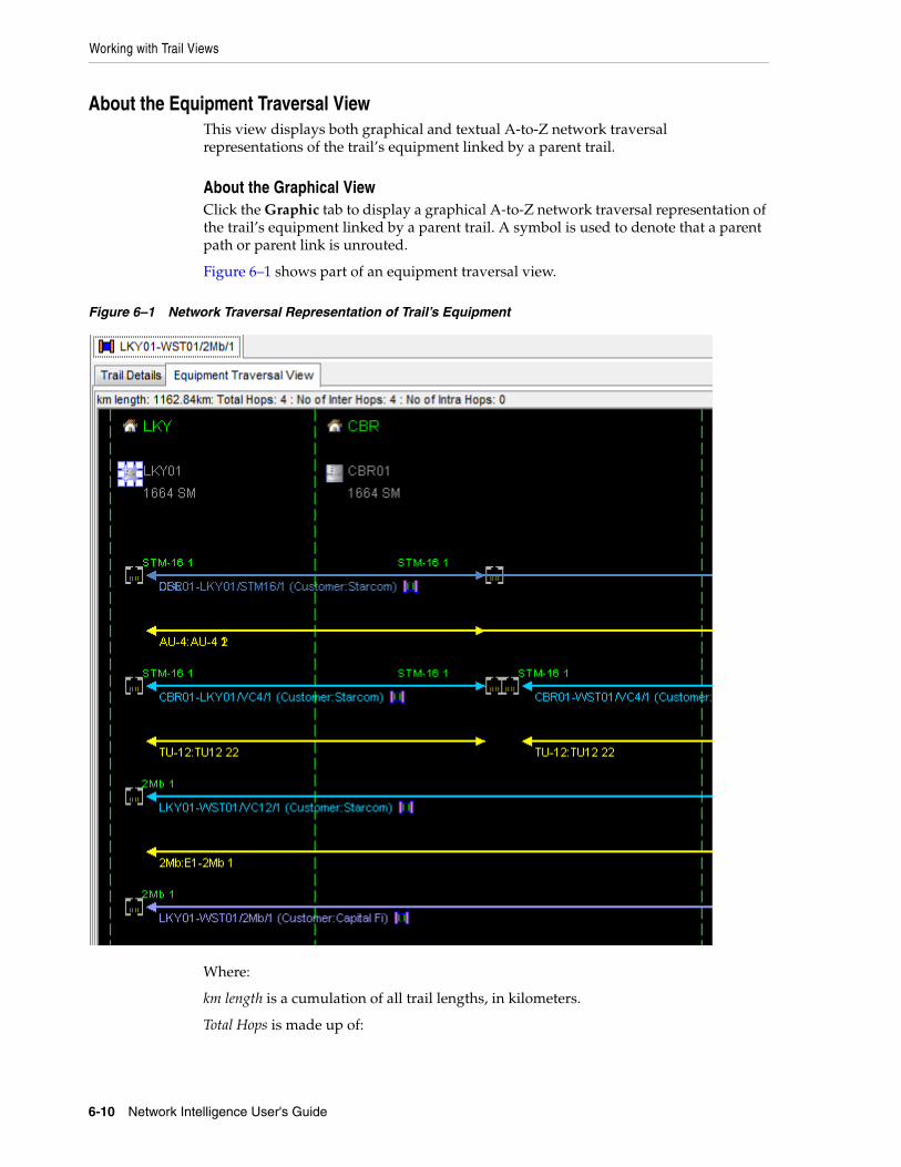
Working with Trail Views
6-10 Network Intelligence User's Guide
About the Equipment Traversal ViewThis view displays both graphical and textual A-to-Z network traversal representations of the trail’s equipment linked by a parent trail.
About the Graphical ViewClick the Graphic tab to display a graphical A-to-Z network traversal representation of the trail’s equipment linked by a parent trail. A symbol is used to denote that a parent path or parent link is unrouted.
Figure 6–1 shows part of an equipment traversal view.
Figure 6–1 Network Traversal Representation of Trail’s Equipment
Where:
km length is a cumulation of all trail lengths, in kilometers.
Total Hops is made up of:
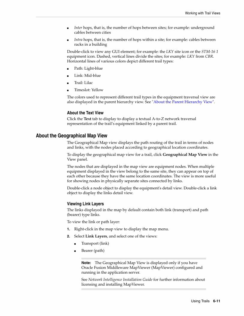
Working with Trail Views
Using Trails 6-11
■ Inter hops, that is, the number of hops between sites; for example: underground cables between cities
■ Intra hops, that is, the number of hops within a site; for example: cables between racks in a building
Double-click to view any GUI element; for example: the LKY site icon or the STM-16 1 equipment icon. Dashed, vertical lines divide the sites; for example: LKY from CBR. Horizontal lines of various colors depict different trail types:
■ Path: Light-blue
■ Link: Mid-blue
■ Trail: Lilac
■ Timeslot: Yellow
The colors used to represent different trail types in the equipment traversal view are also displayed in the parent hierarchy view. See "About the Parent Hierarchy View".
About the Text ViewClick the Text tab to display to display a textual A-to-Z network traversal representation of the trail’s equipment linked by a parent trail.
About the Geographical Map ViewThe Geographical Map view displays the path routing of the trail in terms of nodes and links, with the nodes placed according to geographical location coordinates.
To display the geographical map view for a trail, click Geographical Map View in the View panel.
The nodes that are displayed in the map view are equipment nodes. When multiple equipment displayed in the view belong to the same site, they can appear on top of each other because they have the same location coordinates. The view is more useful for showing nodes in physically separate sites connected by links.
Double-click a node object to display the equipment's detail view. Double-click a link object to display the links detail view.
Viewing Link LayersThe links displayed in the map by default contain both link (transport) and path (bearer) type links.
To view the link or path layer:
1. Right-click in the map view to display the map menu.
2. Select Link Layers, and select one of the views:
■ Transport (link)
■ Bearer (path)
Note: The Geographical Map View is displayed only if you have Oracle Fusion Middleware MapViewer (MapViewer) configured and running in the application server.
See Network Intelligence Installation Guide for further information about licensing and installing MapViewer.
Working with Trail Views
6-12 Network Intelligence User's Guide
About the Hop by Hop Routing ViewThe Hop by Hop Routing view depicts, in tabular format, all individual hops on the trail for an end to end circuit. The hops displayed can be inter hops, that is, hops between sites; for example: underground cables between cities, or intra hops, that is, hops within a site; for example: cables between racks in a building.
So, for example, on a VC-12 circuit consisting of six individual trails, the Hop by Hop Routing view displays a table listing each hop defined by:
■ Ingress Equipment: The originating equipment for the trail making up the hop.
■ Ingress Port: The originating port for the trail making up the hop.
■ Ingress Logical Port: The originating logical port for the trail making up the hop.
■ Trail Name: The name of the trail making up the hop; for more information on trail naming conventions, see "Generating a Trail Name".
■ Channel Position: The sequence number of the timeslot or channel, position held by the trail.
■ Egress Equipment: The terminating equipment for the trail making up the hop.
■ Egress Port: The terminating port for the trail making up the hop.
■ Egress Logical Port: The terminating logical port for the trail making up the hop.
Double-click a trail to display its details. Save the data in the table in a variety of formats: HTML, CSV, or Microsoft Excel. Select which columns to display. However, unlike most table views, you cannot sort the trails by column, or otherwise alter the fixed trail sequence shown, in the Hop by Hop Report view.
Viewing an EquipmentDouble-click any equipment icon or name to see a full equipment view.
Double-click any site icon or name to see a full site view.
Viewing a TrailDouble-click any trail to see a full trail view.
Generating a Trail NameOn a trail view, you can automatically generate a name for the trail as follows:
1. Click Edit on the trail view to enable configuration of the trail.
2. Click Generate Name beside the Name field to create a name for the trail. There are two possible results, depending on the type of trail:
■ If the trail is between sites, Network Intelligence concatenates the names of the A Site and Z Site, the trail capacity, and the next available sequence number for the trail, to create a name of the form: ASite-ZSite/Capacity/001.
■ If the trail is between equipment, Network Intelligence concatenates the names of the A Equipment and Z Equipment, the trail capacity, and the next available sequence number for the trail, to create a name of the form: AEquipment-ZEquipment/Capacity/001.
The sequence number allocated in this name is the next available to a trail, and does not match the sequence number listed in the SequenceNo field in the trail view.

About the Trail Group Object Views
Using Trails 6-13
If you modify any of the elements that comprise the trail name, for example, you change the A Site, Z Site, or capacity, click Generate Name again to update the name to include the new element.
You can update the database function create_trail_name to change the implementation of trail naming in Network Intelligence.
See Network Intelligence Developer’s Guide for further information on configuring database functions.
When you have configured the trail, click Next to proceed to the final wizard step.
3. Click Save to commit the changes to the database, and to display the new trail name in the GUI.
About the Trail ViewThe trail view for the trail is made up of the following view:
■ Child Trails View
These views are common to many supported entities in Network Intelligence, and are described in "Using Object Type Trail Views".
About the Customer Trails ViewThe customer trails view displays a detailed list of all customer traffic the trail is carrying. The list view uses the trail search filter.
About the Trail Group Object ViewsThere are several trail object collection views. These views display data for a related group of trails.
To display the trail group object views:
1. Click the object group view icon. See "Displaying Object Group Views".
2. Select from the view options:
■ Trail Channel Utilization View
■ Trail Cumulative Channel Utilization View
■ Trail Node to Node Utilization View
■ Trail Media Breakdown View
■ Long Trails View
■ Trail Hop Optimization View
■ Site Trail Utilization View
■ Leased Line Utilization Report
About the Trail Channel Utilization ViewThe Trail Channel Utilization View is a tabular view that shows the payload utilization of link and path trails.
The list view uses the trail search filter (see "Filtering View Data"). You can filter on:
About the Trail Group Object Views
6-14 Network Intelligence User's Guide
■ Trail Group: Select from the trail group type; for example: link, trail, path, undefined.
■ Capacity: Filter on the capacity of the trail.
■ Fill percentage: Select trails with utilization greater than, or equal to, the fill setting. The percentage values are 0, 10, 20, 30, 40, 50, 60, 70, 80, 90, or 100.
■ Trail Definition: Filter on the trail definition; for example: 100Mb Ethernet Bearer.
■ A Node, or Z Node, Platform: The platform of the originating and terminating nodes; for example: SDH.
■ A Node, or Z Node, Definition: The definition of the originating and terminating nodes; for example: 1664 SM.
After the utilization percentage is set, the view returns only trails with utilization greater than, or equal to, the fill setting.
You can also include full and protected trails.
About the Trail Cumulative Channel Utilization ViewThe Trail Cumulative Channel Utilization View is a tabular view that shows the channel utilization of link and path trails. This is the same view as the trail channel utilization view, except that the utilization is cumulatively summed for all trails that share the same start and end equipment.
The Trail Cumulative Channel Utilization View also displays cumulative utilization for all equipment that share the same start- and end location (these are known as inter-site trails).
See "About the Trail Channel Utilization View".
About the Trail Media Breakdown ViewThe Trail Media Breakdown View is a detailed list report for each trail level in the network. It provides a complete breakdown of the number of hops per media type used by a particular trail group and capacity.
The trail media breakdown view uses the trail search filter. See "Filtering View Data".
To create a trail media breakdown report:
1. Open the filter.
2. Select the desired trail levels for:
■ Group type
■ Group
■ Service
■ Capacity
■ Date range
3. Click Apply.
About the Long Trails ViewThe Long Trails View finds trails for the chosen filter settings that have the greatest number of physical hops in the network. These trails may then be considered candidates for rerouting more efficiently using the Trail Routing Manager module to
About the Trail Group Object Views
Using Trails 6-15
free up potentially very useful capacity. See "Routing Trails".
The Long Trails View uses the trail search filter. See "Filtering View Data".
To create a long trails view:
1. Open the filter.
2. Select the trail capacity and the minimum number of parent hops to display:
■ Group type
■ Group
■ Service
■ Capacity
■ Date range
■ Minimum Hops
3. Click Apply.
About the Customer Group ViewUse the Customer Group View to group several customers to analyze their accumulated trails and utilizations. The list view uses the trail search filter. See "Filtering View Data".
About the Trail Hop Optimization ViewThe Trail Hop Optimization View finds trails at the chosen capacity that have been inefficiently routed, and presents more optimal solution links for suggested reroutes of these trails. The optimization algorithm is based on considering the least number of physical hops.
About the Site Trail Utilization ViewThe Site Trail Utilization View is specific to the Z Site, as the Z Site functions as an interconnect site in some configurations. There is no A site filter for this view.
You can filter on:
■ Z Site Search: Find the required site.
■ Incumbent: Select the incumbent.
■ State: Select the state in which the site is located.
■ Area: Select the specific area in which the site is located.
■ Capacity: Select the capacity of the trail.
■ Service Group: Select the service group that applies to the trail.
■ Legacy Company: Select the legacy company that applies to the trail.
■ Trail Group: Select the trail group that applies to the trail.
■ Fill percentage: Select trails with utilization greater than, or equal to, the fill setting. The percentage values are from 0 to 100, in 5 percent increments.
After the utilization percentage is set, the view returns only trails with utilization greater than, or equal to, the fill setting.
Displaying Trail Models
6-16 Network Intelligence User's Guide
Displaying Trail ModelsAll modeled trail definitions can be viewed in the trail tree browser by clicking the Trail Definition tab.
Double-click the trail definition to open the trail definition details view.
You can modify or update the trail definition attributes and physical dimensions.
1. Click Edit to make changes.
2. Perform one of the following:
■ Click Save to create the new definition in the database. The trail definition must not be the same as an existing definition name. A warning dialog box is displayed if the user attempts to create a definition with the same name as an existing definition.
The trail definition tree browser is refreshed to show the new definition in the definition list.
■ Click Cancel to close the panel without making any modifications.
Creating a New TrailYou create new trails using the Trail Configuration wizard.
To create a new trail:
1. Open the Trails tree browser.
2. Select Trail Configuration Wizard from the Tools menu, or by clicking the Create icon while browsing trails.
The Trail Configuration wizard appears.
3. Select Create New Trail, and click Next.
4. Enter the trail details.
The policy is set when you select the service, assuming the service has a policy. The trail definition and capacity are set if you have created a service trail definitions rule as part of the policy.
5. Click Next to display the trail values. The trail has not yet been routed.
6. (Optional) Click Find Trail Routing to find a route.
Trail Routing Manager starts. The service demand and policy details are automatically set. Select Analyze to view the suggested solutions (if any), and choose the required option by right-clicking the Select icon, and selecting Default Configuration as Main Path or Manual Configuration as Main Path.
The A and Z Equipment (and A and Z Port, if any are accepted) are filled in automatically for all newly created circuits in the next page of the Circuit Creation Wizard.
See "Routing Trails".
7. Click Next and add more details about the trail.
8. (Optional) Click Generate Name beside the Name field to create a name for the trail. There are two possible results, depending on the type of trail:
Creating a New Trail
Using Trails 6-17
■ If the trail is between sites, Network Intelligence concatenates the names of the A Site and Z Site, the trail capacity, and the next available sequence number for the trail, to create a name of the form: ASite-ZSite/Capacity/001.
■ If the trail is between equipment, Network Intelligence concatenates the names of the A Equipment and Z Equipment, the trail capacity, and the next available sequence number for the trail, to create a name of the form: AEquipment-ZEquipment/Capacity/001.
The sequence number allocated in this name is the next available to a trail, and matches the sequence number listed in the SequenceNo field in the trail view.
If you modify any of the elements that comprise the trail name, for example, you change the A Site, Z Site, or capacity, click Generate Name again to update the name to include the new element.
You can update the database function create_trail_name to change the implementation of trail naming in Network Intelligence.
See Network Intelligence Developer’s Guide for further information on configuring database functions.
When you have configured the trail, click Next to proceed to the final wizard step.
9. You are prompted whether you want to display the new trail on saving it. Accept the default to display the trail, or deselect the check box.
10. Click Finish to save the trail. The trail is saved in the database, and displayed in the appropriate folder in the Trails tree browser.
If a child trail is added to a parent trail on the last remaining channel or timeslot, then this parent trail should no longer be considered for routing.
Adding a Signal StructureA structured trail definition has a signal structure that defines the set of child trail holders that the trail payload supports.
To add a signal structure:
1. Open the Trails tree browser.
2. Click the Trail Definition tab to display the existing trail definitions, or create a trail definition. See "Creating a Trail Definition".
3. Select the View tab to display the associated reports.
4. Click Signal Structure to display the modeled trail definition.
5. Right-click the trail definition, and select Add to display the Add Signal Structure dialog box.
6. Complete the details of the signal structure:
■ Select the trail holder definition.
■ Enter the number of trail holders or timeslots.
■ (Optional) Add a prefix to all of the trail holders in the Stub Label field.
■ Enter the base channels group size.
■ (Optional) Edit the names of the trail holders or timeslots in the Label fields.
7. Click Apply to display the signal structure hierarchy in the GUI.
Creating Multiple Trails
6-18 Network Intelligence User's Guide
You can remove, or rename, trail holders, or add a trail definition by right-clicking any of the modeled trail holders.
You can add a default trail on the signal structure.
Adding a Default Trail on the Signal StructureYou can add a trail on the signal structure of a trail definition so that every time an instance of a trail based on this trail definition is created, a trail is added on one, or more, of its constituent trail holders.
To add a default trail on the signal structure:
1. Open the Trails tree browser.
2. Create a trail definition. See "Creating a Trail Definition".
You must:
■ Select to create a structured trail.
■ Add a signal structure. See "Adding a Signal Structure".
3. Select the View tab to display the associated reports.
4. Click Signal Structure to display the modeled trail definition.
5. Right-click one of the trail holders on the trail definition, and select Add to display the Add a Default Trail Definition dialog box.
6. Complete the details of the trail by selecting its associated service, policy, and trail definition.
7. (Optional) Add default trails to the other trail holders.
8. Click Apply to display the trail in the signal structure view.
9. Click Save to commit the changes.
Creating Multiple TrailsYou can also use the trail configuration wizard to create multiple trails at the same time. This is useful to create a group of trails that have similar properties.
To create multiple trails:
1. Open the Trails tree browser.
2. Select Trail Configuration Wizard from the Tools menu, or by clicking the Create icon while browsing trails.
3. Select Create New Trail and click Next.
4. Enter the trail details, entering the Total Trails value for the number of trails required.
5. Click Next to display the trail values. The trails have not yet been routed.
6. (Optional) Click Find Trail Routing to find route paths for each trail.
Trail Routing Manager starts. See "Routing Trails".
Note: You can create multiple trails only if the start and end sites are the same for each trail demand.
Cloning a Trail
Using Trails 6-19
7. Click Next and add more details about the trail.
8. Enter all the first trail details.
9. (Optional) Click Generate Name beside the Name field to create a name for the trail.
10. To autopopulate the remaining trail forms, click Replicate Values for all Trails, which is displayed last in the selected Trail detail view.
This button uses all the values entered in this form (except name and start and end ports) to auto-populate the remaining trail forms. This saves a lot of time, however, the user must still generate the trail name for each trail. Selected ports and logical ports are not replicated for other trails, so if the trails require port selection, these must be selected for each individual trail.
11. After you configure the trail, click Next.
12. You are prompted whether you want to display the first new trail on saving it. Accept the default to display the trail, or deselect the check box.
13. Click Finish to save the trails. The trails are saved in the database, and displayed in the appropriate folder in the Trails tree browser.
Cloning a TrailCloning a trail means creating an exact copy of an existing trail. Only the trail details and the service demand list entities are copied. Any reports or editing details are not copied in a clone task.
You clone a trail using the Trail Configuration wizard.
To clone a trail:
1. Open the Trails tree browser.
2. Select Trail Configuration Wizard from the Tools menu, or by clicking the Create icon while browsing trails.
The Trail Configuration wizard appears.
3. Select Clone Trail, and click Next.
4. Enter the trail details.
5. Click Next to display the service demands. Enter the service demands, or accept the existing service demand list entities. The trail has not yet been routed.
6. (Optional) Click Find Trail Routing to find a route.
Trail Routing Manager starts. The service demand and policy details are automatically set. Select Analyze to view the suggested solutions (if any), and choose the required option by right-clicking the Select icon, and selecting Default Configuration as Main Path or Manual Configuration as Main Path.
The A and Z Equipment (and A and Z Port, if any are accepted) are filled in automatically for all newly created circuits in the next page of the Circuit Creation Wizard.
Note: Only the first trail is automatically loaded and displayed in the main workbench on bulk trail save. To see the other trails, look for them in the appropriate folder in the trail tree browser or use the trail search window.
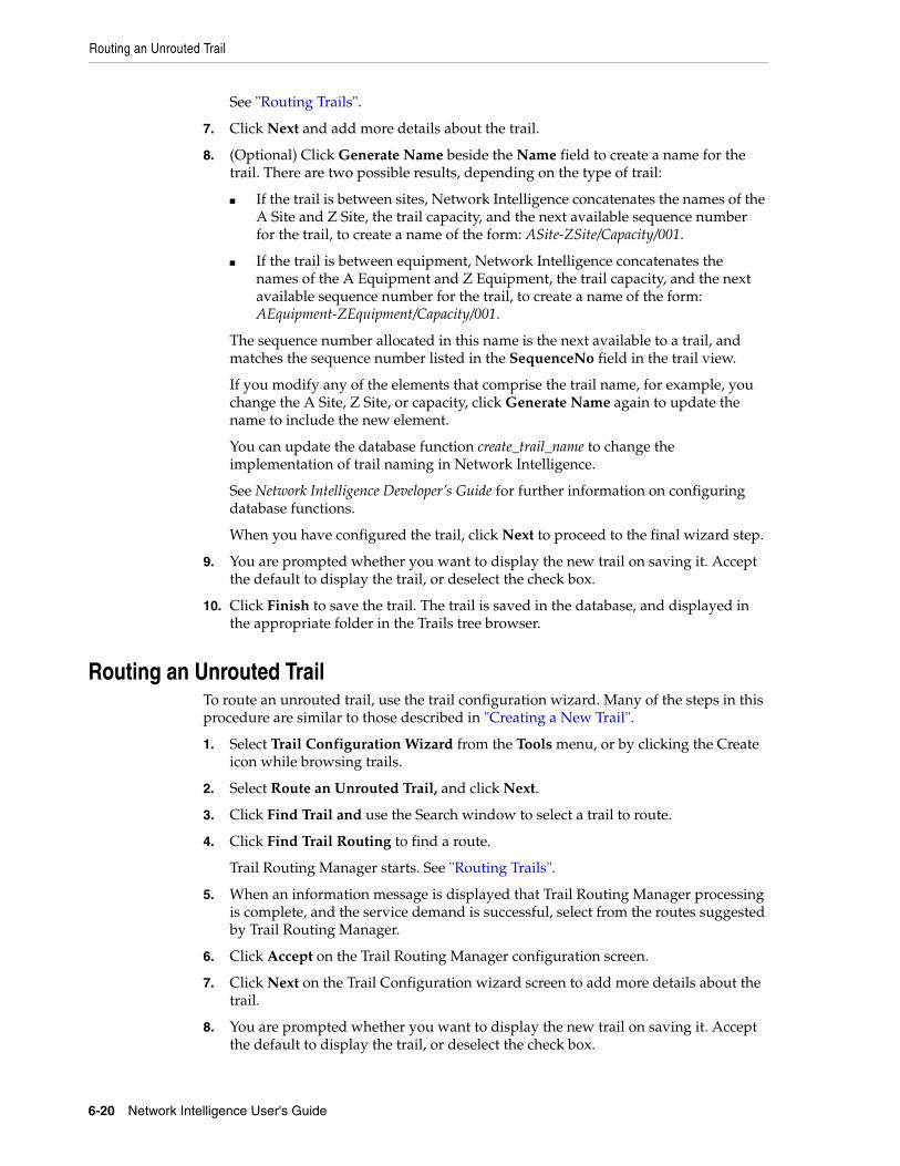
Routing an Unrouted Trail
6-20 Network Intelligence User's Guide
See "Routing Trails".
7. Click Next and add more details about the trail.
8. (Optional) Click Generate Name beside the Name field to create a name for the trail. There are two possible results, depending on the type of trail:
■ If the trail is between sites, Network Intelligence concatenates the names of the A Site and Z Site, the trail capacity, and the next available sequence number for the trail, to create a name of the form: ASite-ZSite/Capacity/001.
■ If the trail is between equipment, Network Intelligence concatenates the names of the A Equipment and Z Equipment, the trail capacity, and the next available sequence number for the trail, to create a name of the form: AEquipment-ZEquipment/Capacity/001.
The sequence number allocated in this name is the next available to a trail, and matches the sequence number listed in the SequenceNo field in the trail view.
If you modify any of the elements that comprise the trail name, for example, you change the A Site, Z Site, or capacity, click Generate Name again to update the name to include the new element.
You can update the database function create_trail_name to change the implementation of trail naming in Network Intelligence.
See Network Intelligence Developer’s Guide for further information on configuring database functions.
When you have configured the trail, click Next to proceed to the final wizard step.
9. You are prompted whether you want to display the new trail on saving it. Accept the default to display the trail, or deselect the check box.
10. Click Finish to save the trail. The trail is saved in the database, and displayed in the appropriate folder in the Trails tree browser.
Routing an Unrouted TrailTo route an unrouted trail, use the trail configuration wizard. Many of the steps in this procedure are similar to those described in "Creating a New Trail".
1. Select Trail Configuration Wizard from the Tools menu, or by clicking the Create icon while browsing trails.
2. Select Route an Unrouted Trail, and click Next.
3. Click Find Trail and use the Search window to select a trail to route.
4. Click Find Trail Routing to find a route.
Trail Routing Manager starts. See "Routing Trails".
5. When an information message is displayed that Trail Routing Manager processing is complete, and the service demand is successful, select from the routes suggested by Trail Routing Manager.
6. Click Accept on the Trail Routing Manager configuration screen.
7. Click Next on the Trail Configuration wizard screen to add more details about the trail.
8. You are prompted whether you want to display the new trail on saving it. Accept the default to display the trail, or deselect the check box.
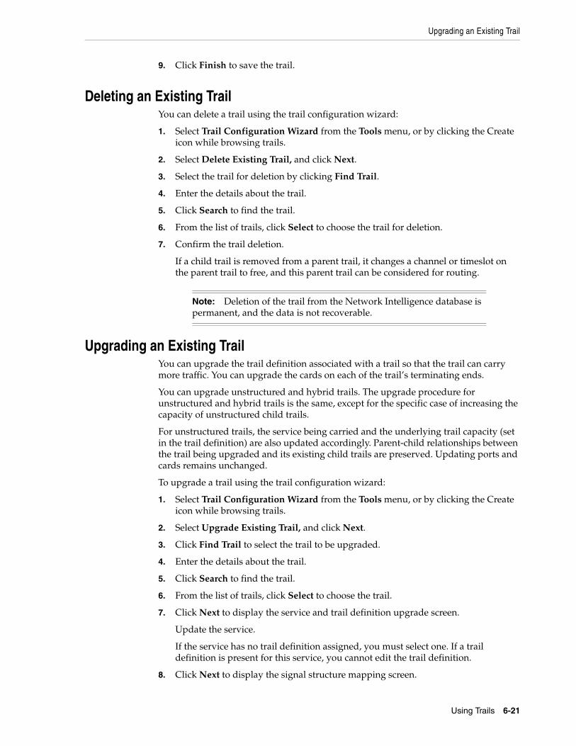
Upgrading an Existing Trail
Using Trails 6-21
9. Click Finish to save the trail.
Deleting an Existing TrailYou can delete a trail using the trail configuration wizard:
1. Select Trail Configuration Wizard from the Tools menu, or by clicking the Create icon while browsing trails.
2. Select Delete Existing Trail, and click Next.
3. Select the trail for deletion by clicking Find Trail.
4. Enter the details about the trail.
5. Click Search to find the trail.
6. From the list of trails, click Select to choose the trail for deletion.
7. Confirm the trail deletion.
If a child trail is removed from a parent trail, it changes a channel or timeslot on the parent trail to free, and this parent trail can be considered for routing.
Upgrading an Existing TrailYou can upgrade the trail definition associated with a trail so that the trail can carry more traffic. You can upgrade the cards on each of the trail’s terminating ends.
You can upgrade unstructured and hybrid trails. The upgrade procedure for unstructured and hybrid trails is the same, except for the specific case of increasing the capacity of unstructured child trails.
For unstructured trails, the service being carried and the underlying trail capacity (set in the trail definition) are also updated accordingly. Parent-child relationships between the trail being upgraded and its existing child trails are preserved. Updating ports and cards remains unchanged.
To upgrade a trail using the trail configuration wizard:
1. Select Trail Configuration Wizard from the Tools menu, or by clicking the Create icon while browsing trails.
2. Select Upgrade Existing Trail, and click Next.
3. Click Find Trail to select the trail to be upgraded.
4. Enter the details about the trail.
5. Click Search to find the trail.
6. From the list of trails, click Select to choose the trail.
7. Click Next to display the service and trail definition upgrade screen.
Update the service.
If the service has no trail definition assigned, you must select one. If a trail definition is present for this service, you cannot edit the trail definition.
8. Click Next to display the signal structure mapping screen.
Note: Deletion of the trail from the Network Intelligence database is permanent, and the data is not recoverable.
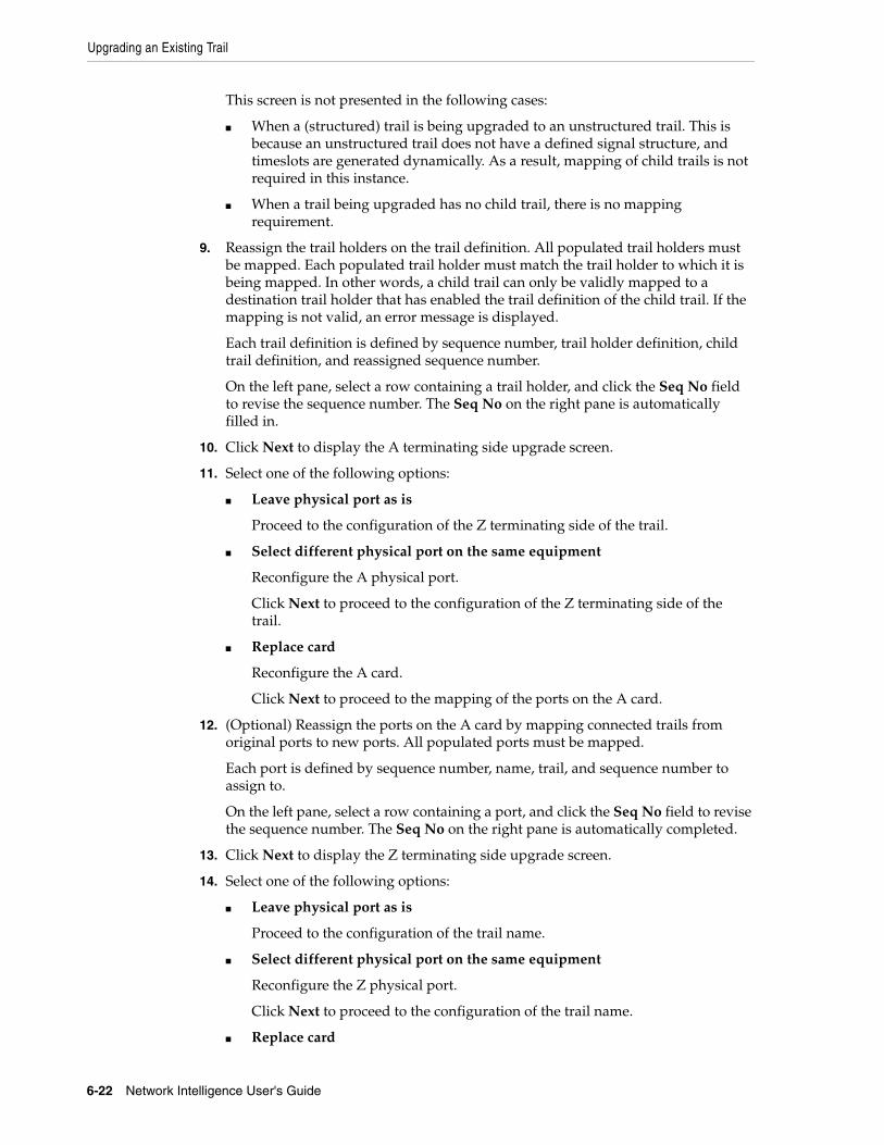
Upgrading an Existing Trail
6-22 Network Intelligence User's Guide
This screen is not presented in the following cases:
■ When a (structured) trail is being upgraded to an unstructured trail. This is because an unstructured trail does not have a defined signal structure, and timeslots are generated dynamically. As a result, mapping of child trails is not required in this instance.
■ When a trail being upgraded has no child trail, there is no mapping requirement.
9. Reassign the trail holders on the trail definition. All populated trail holders must be mapped. Each populated trail holder must match the trail holder to which it is being mapped. In other words, a child trail can only be validly mapped to a destination trail holder that has enabled the trail definition of the child trail. If the mapping is not valid, an error message is displayed.
Each trail definition is defined by sequence number, trail holder definition, child trail definition, and reassigned sequence number.
On the left pane, select a row containing a trail holder, and click the Seq No field to revise the sequence number. The Seq No on the right pane is automatically filled in.
10. Click Next to display the A terminating side upgrade screen.
11. Select one of the following options:
■ Leave physical port as is
Proceed to the configuration of the Z terminating side of the trail.
■ Select different physical port on the same equipment
Reconfigure the A physical port.
Click Next to proceed to the configuration of the Z terminating side of the trail.
■ Replace card
Reconfigure the A card.
Click Next to proceed to the mapping of the ports on the A card.
12. (Optional) Reassign the ports on the A card by mapping connected trails from original ports to new ports. All populated ports must be mapped.
Each port is defined by sequence number, name, trail, and sequence number to assign to.
On the left pane, select a row containing a port, and click the Seq No field to revise the sequence number. The Seq No on the right pane is automatically completed.
13. Click Next to display the Z terminating side upgrade screen.
14. Select one of the following options:
■ Leave physical port as is
Proceed to the configuration of the trail name.
■ Select different physical port on the same equipment
Reconfigure the Z physical port.
Click Next to proceed to the configuration of the trail name.
■ Replace card
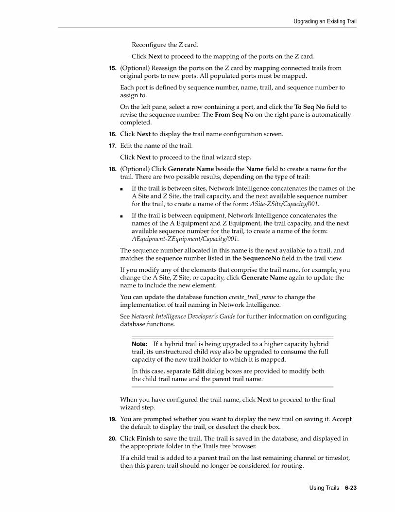
Upgrading an Existing Trail
Using Trails 6-23
Reconfigure the Z card.
Click Next to proceed to the mapping of the ports on the Z card.
15. (Optional) Reassign the ports on the Z card by mapping connected trails from original ports to new ports. All populated ports must be mapped.
Each port is defined by sequence number, name, trail, and sequence number to assign to.
On the left pane, select a row containing a port, and click the To Seq No field to revise the sequence number. The From Seq No on the right pane is automatically completed.
16. Click Next to display the trail name configuration screen.
17. Edit the name of the trail.
Click Next to proceed to the final wizard step.
18. (Optional) Click Generate Name beside the Name field to create a name for the trail. There are two possible results, depending on the type of trail:
■ If the trail is between sites, Network Intelligence concatenates the names of the A Site and Z Site, the trail capacity, and the next available sequence number for the trail, to create a name of the form: ASite-ZSite/Capacity/001.
■ If the trail is between equipment, Network Intelligence concatenates the names of the A Equipment and Z Equipment, the trail capacity, and the next available sequence number for the trail, to create a name of the form: AEquipment-ZEquipment/Capacity/001.
The sequence number allocated in this name is the next available to a trail, and matches the sequence number listed in the SequenceNo field in the trail view.
If you modify any of the elements that comprise the trail name, for example, you change the A Site, Z Site, or capacity, click Generate Name again to update the name to include the new element.
You can update the database function create_trail_name to change the implementation of trail naming in Network Intelligence.
See Network Intelligence Developer’s Guide for further information on configuring database functions.
When you have configured the trail name, click Next to proceed to the final wizard step.
19. You are prompted whether you want to display the new trail on saving it. Accept the default to display the trail, or deselect the check box.
20. Click Finish to save the trail. The trail is saved in the database, and displayed in the appropriate folder in the Trails tree browser.
If a child trail is added to a parent trail on the last remaining channel or timeslot, then this parent trail should no longer be considered for routing.
Note: If a hybrid trail is being upgraded to a higher capacity hybrid trail, its unstructured child may also be upgraded to consume the full capacity of the new trail holder to which it is mapped.
In this case, separate Edit dialog boxes are provided to modify both the child trail name and the parent trail name.
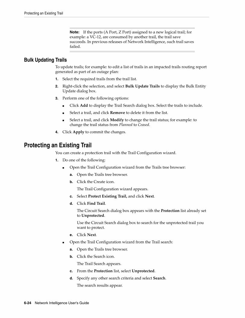
Protecting an Existing Trail
6-24 Network Intelligence User's Guide
Bulk Updating TrailsTo update trails; for example: to edit a list of trails in an impacted trails routing report generated as part of an outage plan:
1. Select the required trails from the trail list.
2. Right-click the selection, and select Bulk Update Trails to display the Bulk Entity Update dialog box.
3. Perform one of the following options:
■ Click Add to display the Trail Search dialog box. Select the trails to include.
■ Select a trail, and click Remove to delete it from the list.
■ Select a trail, and click Modify to change the trail status; for example: to change the trail status from Planned to Ceased.
4. Click Apply to commit the changes.
Protecting an Existing TrailYou can create a protection trail with the Trail Configuration wizard.
1. Do one of the following:
■ Open the Trail Configuration wizard from the Trails tree browser:
a. Open the Trails tree browser.
b. Click the Create icon.
The Trail Configuration wizard appears.
c. Select Protect Existing Trail, and click Next.
d. Click Find Trail.
The Circuit Search dialog box appears with the Protection list already set to Unprotected.
Use the Circuit Search dialog box to search for the unprotected trail you want to protect.
e. Click Next.
■ Open the Trail Configuration wizard from the Trail search:
a. Open the Trails tree browser.
b. Click the Search icon.
The Trail Search appears.
c. From the Protection list, select Unprotected.
d. Specify any other search criteria and select Search.
The search results appear.
Note: If the ports (A Port, Z Port) assigned to a new logical trail; for example: a VC-12, are consumed by another trail, the trail save succeeds. In previous releases of Network Intelligence, such trail saves failed.
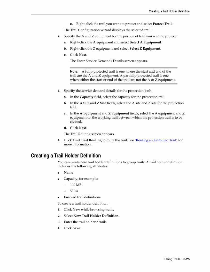
Creating a Trail Holder Definition
Using Trails 6-25
e. Right-click the trail you want to protect and select Protect Trail.
The Trail Configuration wizard displays the selected trail.
2. Specify the A and Z equipment for the portion of trail you want to protect:
a. Right-click the A equipment and select Select A Equipment.
b. Right-click the Z equipment and select Select Z Equipment.
c. Click Next.
The Enter Service Demands Details screen appears.
3. Specify the service demand details for the protection path:
a. In the Capacity field, select the capacity for the protection trail.
b. In the A Site and Z Site fields, select the A site and Z site for the protection trail.
c. In the A Equipment and Z Equipment fields, select the A equipment and Z equipment on the working trail between which the protection trail is to be created.
d. Click Next.
The Trail Routing screen appears.
4. Click Find Trail Routing to route the trail. See "Routing an Unrouted Trail" for more information.
Creating a Trail Holder DefinitionYou can create new trail holder definitions to group trails. A trail holder definition includes the following attributes:
■ Name
■ Capacity; for example:
– 100 MB
– VC-4
■ Enabled trail definitions
To create a trail holder definition:
1. Click New while browsing trails.
2. Select New Trail Holder Definition.
3. Enter the trail holder details.
4. Click Save.
Note: A fully-protected trail is one where the start and end of the trail are the A and Z equipment. A partially-protected trail is one where either the start or end of the trail are not the A or Z equipment.

Creating a Trail Holder Definition
6-26 Network Intelligence User's Guide
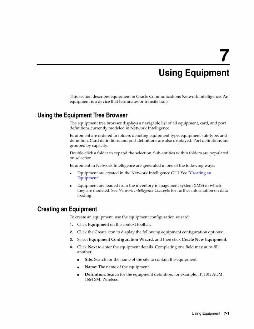
7
Using Equipment 7-1
7Using Equipment
This section describes equipment in Oracle Communications Network Intelligence. An equipment is a device that terminates or transits trails.
Using the Equipment Tree BrowserThe equipment tree browser displays a navigable list of all equipment, card, and port definitions currently modeled in Network Intelligence.
Equipment are ordered in folders denoting equipment type, equipment sub-type, and definition. Card definitions and port definitions are also displayed. Port definitions are grouped by capacity.
Double-click a folder to expand the selection. Sub-entities within folders are populated on selection.
Equipment in Network Intelligence are generated in one of the following ways:
■ Equipment are created in the Network Intelligence GUI. See "Creating an Equipment".
■ Equipment are loaded from the inventory management system (IMS) in which they are modeled. See Network Intelligence Concepts for further information on data loading.
Creating an EquipmentTo create an equipment, use the equipment configuration wizard:
1. Click Equipment on the context toolbar.
2. Click the Create icon to display the following equipment configuration options:
3. Select Equipment Configuration Wizard, and then click Create New Equipment.
4. Click Next to enter the equipment details. Completing one field may auto-fill another:
■ Site: Search for the name of the site to contain the equipment.
■ Name: The name of the equipment.
■ Definition: Search for the equipment definition; for example: IP, 10G ADM, 1664 SM, Wireless.
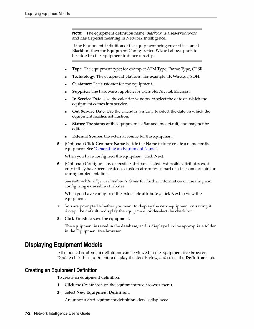
Displaying Equipment Models
7-2 Network Intelligence User's Guide
■ Type: The equipment type; for example: ATM Type, Frame Type, CESR.
■ Technology: The equipment platform; for example: IP, Wireless, SDH.
■ Customer: The customer for the equipment.
■ Supplier: The hardware supplier; for example: Alcatel, Ericsson.
■ In Service Date: Use the calendar window to select the date on which the equipment comes into service.
■ Out Service Date: Use the calendar window to select the date on which the equipment reaches exhaustion.
■ Status: The status of the equipment is Planned, by default, and may not be edited.
■ External Source: the external source for the equipment.
5. (Optional) Click Generate Name beside the Name field to create a name for the equipment. See "Generating an Equipment Name".
When you have configured the equipment, click Next.
6. (Optional) Configure any extensible attributes listed. Extensible attributes exist only if they have been created as custom attributes as part of a telecom domain, or during implementation.
See Network Intelligence Developer’s Guide for further information on creating and configuring extensible attributes.
When you have configured the extensible attributes, click Next to view the equipment.
7. You are prompted whether you want to display the new equipment on saving it. Accept the default to display the equipment, or deselect the check box.
8. Click Finish to save the equipment.
The equipment is saved in the database, and is displayed in the appropriate folder in the Equipment tree browser.
Displaying Equipment ModelsAll modeled equipment definitions can be viewed in the equipment tree browser. Double-click the equipment to display the details view, and select the Definitions tab.
Creating an Equipment DefinitionTo create an equipment definition:
1. Click the Create icon on the equipment tree browser menu.
2. Select New Equipment Definition.
An unpopulated equipment definition view is displayed.
Note: The equipment definition name, Blackbox, is a reserved word and has a special meaning in Network Intelligence.
If the Equipment Definition of the equipment being created is named Blackbox, then the Equipment Configuration Wizard allows ports to be added to the equipment instance directly.
Displaying Equipment Models
Using Equipment 7-3
3. Complete the required fields. The Name, Technology, and Type fields are mandatory.
4. Select the Requires Cross Connect for Traversal check box to specify that the routing manager consider the internal connectivity (cross connects within an equipment) while finding a routing path. In other words, if this check box is selected, this equipment must have cross connects to be a part of a route solution.
See "Using the Cross Connect View" for further information.
Clear the check box to ignore the internal connectivity while finding a routing path. In other words, if this check box is not selected, these equipment still form part of the route solution irrespective of whether they have cross connects or not.
This option enables flexible routing where certain equipment within a route solution must always have cross connects, but others may, or may not, have cross connects present, but should still form part of a valid route solution.
Requires Cross Connect for Traversal is only used by Trail Routing Manager when the Require Cross Connects Routing rule is enabled for the service being routed. For further information on rules and services, see "Using Services, Policies, and Rules"
If cross connects exist at an equipment for which its equipment definition has Require Cross Connect for Traversal disabled, they are ignored by Trail Routing Manager, and are not consumed when a trail is created using Trail Configuration Wizard. For more information about Trail Configuration Wizard, see "Creating a New Trail".
Irrespective of whether cross connects exist at an equipment for which its equipment definition has Require Cross Connect for Traversal disabled, Trail Routing Manager treats this equipment as not requiring cross connects.
If cross connects do not exist at an equipment for which its equipment definition has Require Cross Connect for Traversal enabled, Trail Routing Manager cannot use this equipment as part of a route solution.
5. Perform one of the following:
■ Click Save to create the new definition in the database. The equipment definition must not be the same as an existing definition name. A warning window is displayed if a new definition has the same name as an existing definition.
The equipment definition tree browser is refreshed to show the new definition in the definition list.
■ Click Cancel to close the panel without making any modifications.
Adding Sub-Rack DefinitionsWhen a new equipment definition is created, a sub-rack definition window is automatically displayed.
To create a sub-rack definition:
1. Open the Elevation View for the equipment.
2. Right-click the background of the equipment, in the area outside the existing sub-racks.
3. Select Add Sub-Rack to display the Sub-Rack Definition window.
4. Enter the number of sub-racks contained in the new equipment definition.

Displaying Equipment Models
7-4 Network Intelligence User's Guide
When you enter the number, a list of the sub-rack name text entry fields is provided.
These sub-racks are appended to the list of sub-racks. By default, new sub-racks are named in terms of existing sub-racks; for example, if you have two sub-racks in the definition, adding two more would give you Sub-Rack 3 Name and Sub-Rack 4 Name.
Edit the sub-rack names as required.
5. Click Apply to display and populate the Elevation View with the sub-racks and shelves.
6. Close the window.
Configuring a Sub-RackTo configure a sub-rack:
1. Right-click the sub-rack and select from the available options:
■ Add Shelves
■ Remove Sub-Rack
2. Select Add Shelves to open the shelf definition window, and add shelves as required.
This window has the same behavior as that described in the sub-rack definition window. See "Adding Sub-Rack Definitions".
3. Select Remove Sub-Rack to delete the sub-rack selected from the equipment definition.
Configuring a ShelfTo configure a shelf:
1. Right-click the shelf and select from the available options:
■ Add Slots
■ Remove Shelf
2. Select Add Slots to display the Design Slots window, and add slots as required. See "Adding Slots to a Shelf".
3. Select Remove Shelf to delete the shelf.
Adding Slots to a ShelfTo add slots to a shelf:
1. Right-click the shelf and select Add Slots to display the Design Slots window.
2. Enter the number of slots required.
Each slot created requires a default slot card or allowed card, defined by card label, description, size, and type.
3. To add cards to each slot, click Cards to display the Slot Card Rules window.
Note: You cannot rename a sub-rack directly. To rename a sub-rack, you must remove it, and then add a new sub-rack.
Displaying Equipment Models
Using Equipment 7-5
4. In the Default Card section of the window, click Cards to view the list of available cards.
5. Select a card as the default.
6. In the Allowed Cards section of the window, click Cards to view the list of available cards.
7. Select the allowable cards. The default card is automatically added to the list of allowable cards.
8. Click Apply on the Slot Card Rules window to add the cards to the Design Slots window.
9. Click Apply on the Design Slots window to display and populate the Elevation View with the new slots.
Updating the Equipment DefinitionTo update the definition attributes, physical dimensions, and capacities for an equipment:
1. Click Edit to enable the equipment details to be modified.
2. Complete the required fields. The Name, Technology, and Type fields are mandatory.
3. Perform one of the following:
■ Click Save to create the new definition in the database. The equipment definition must not be the same as an existing definition name. A warning window is displayed if an updated definition has the same name as an existing definition.
The equipment definition tree browser is refreshed to show the new definition in the definition list.
■ Click Cancel to close the panel without making any modifications.
Using the Elevation ViewThe Elevation View displays the current default layout of the equipment definition. See "Using the Elevation View".
Configuring Default or Allowed CardsYou can use the Elevation View for an equipment definition to change the cards in the equipment definition.
To configure the cards in an equipment definition:
1. From the Elevation View for an equipment definition, right-click a card.
2. Select Configure Default or Allowed Cards to display the Slot Card Rules window.
3. In the Default Card section of the window, click Cards to view the list of available cards.
Note: It is not possible to configure cards in the Elevation View for an equipment.
Displaying Equipment Models
7-6 Network Intelligence User's Guide
4. Select a card as the default.
5. In the Allowed Cards section of the window, click Cards to view the list of available cards.
6. Select the allowable cards. The default card is automatically added to the list of allowable cards.
(Optional) Click Remove to delete a card from the list of allowed cards.
7. Click Apply on the Slot Card Rules window to add the cards to the Design Slots window.
8. Click Apply on the Design Slots window to display and populate the Elevation View with the new cards.
Creating a Card DefinitionTo create a card definition:
1. Click the Create icon on the equipment tree browser menu.
2. Select New Card Definition.
An unpopulated card definition view is displayed.
3. Complete the required fields. The Name, Card Group, Manufacturer, Internal/External, and Port Definition fields are mandatory.
Use the Internal/External field to determine whether the ports on a particular card can terminate a trail:
■ Select Internal to specify that the ports on this card cannot be used to terminate a trail; Trail Routing Manager cannot offer solutions which terminate on these ports.
■ Select External to specify that the ports on this card can terminate a trail; Trail Routing Manager only offers solutions which terminate on ports within an external card.
When a route solution is being configured, only those ports on external cards are presented at the Select Start/End Terminating Ports stages.
See "Routing Trails" for more information.
4. Select the Ports Always Cross Connected check box to define all of the ports within the card as cross-connected.
A network equipment may have internal connectivity, specifically cross connects, from the ingress port through internal cards, to the egress port. A cross connect is a connection between two logical or physical ports within an equipment. To say that one port is cross connected to another port means that these ports are somehow “wired” (either physically, or by using software).
If a card is created from a card definition on which Ports Always Cross Connected is enabled, when there is a cross connect to a port on this card, any other port on this card which is cross connected to a port outside this card is a valid path through the card.
Although this field can be set for both internal and external cards, it is typically used for switching fabric cards, that is, internal cards where the fabric can be configured to interconnect any of its ports.
5. Configure ports on the card definition. For each type of port on the card:
Displaying Equipment Models
Using Equipment 7-7
a. In the Ports section, click Add.
The Select Port Definition dialog box appears.
b. In the Port Definition field, specify the port definition.
Click the Ellipsis icon to search for a port definition.
c. In the Quantity field, specify the number of ports on the card for the port definition.
d. Click Apply.
6. Perform one of the following:
■ Click Save to create the new definition in the database. The card definition must not be the same as an existing definition name. A warning window is displayed if a new definition has the same name as an existing definition.
The card definition tree browser is refreshed to show the new definition in the definition list.
■ Click Cancel to close the panel without making any modifications.
Viewing a Card DefinitionTo view a card definition:
1. Open the Equipment tree browser.
2. Click the Definitions tab, and from the ports folder, double-click the required port to display the port object.
3. From the views on the right, select Card Definitions List to display all card definitions.
4. Double-click a card definition to view it.
Editing a Card DefinitionTo edit a card definition:
1. Open the Equipment tree browser.
2. Click the Definitions tab, and from the ports folder, double-click the required port to display the port object.
3. From the views on the right, select Card Definitions List to display all card definitions.
4. Double-click a card definition to view it.
5. Click Edit to modify the definition.
6. Perform one of the following:
■ Click Save to edit the definition in the database.
The card definition tree browser is refreshed to show the revised definition in the definition list.
■ Click Cancel to close the panel without making any modifications.
Adding a Sub-Card to a Card DefinitionTo add a sub-card to a card definition:
1. Open the Elevation View for a card definition.
Displaying Equipment Models
7-8 Network Intelligence User's Guide
2. Right-click on the shelf in the Elevation View and select Add Slots.
The Design Slots dialog box appears.
3. In the Quantity field, specify the number of additional slots on the shelf.
The Slot Definition section displays a row for each slot you specified.
4. For each slot:
a. Click the Cards button.
The Slot Card Rules dialog box appears.
b. To specify a default card, click Cards in the Default Card section and select a card from the Card Definitions list.
c. To specify allowed cards, click Cards in the Allowed Cards section and select a card from the Card Definition list.
5. Click Apply.
The additional slots are added to the card definition in the Elevation View.
Deleting a Card DefinitionTo delete a card definition:
1. Open the Equipment tree browser.
2. Click the Definitions tab, and from the ports folder, double-click the required port to display the port object.
3. From the views on the right, select Card Definitions List to display all card definitions.
4. Double-click a card definition to view it.
5. Click Delete to delete the definition. Confirm the deletion.
Creating a Port DefinitionTo create a port definition:
1. Click the Create icon on the equipment tree browser menu.
2. Select New Port Definition.
An unpopulated port definition view is displayed.
3. Complete the required fields. The Name, Capacity, and Interface fields are mandatory.
4. Perform one of the following:
■ Click Save to create the new definition in the database. The port definition must not be the same as an existing definition name. A warning window is displayed if a new definition has the same name as an existing definition.
The port definition tree browser is refreshed to show the new definition in the definition list.
■ Click Cancel to close the panel without making any modifications.
Viewing a Port DefinitionTo view a port definition:
Working with Equipment Views
Using Equipment 7-9
1. Open the Equipment tree browser.
2. Click the Definitions tab, and from the ports folder, double-click the required port to display the port object.
3. Click the Details tab to display the port definition.
Editing a Port DefinitionTo edit a port definition:
1. Open the Equipment tree browser.
2. Click the Definitions tab, and from the ports folder, double-click the required port to display the port object.
3. Click the Details tab to display the port definition.
4. Click Edit to configure the definition.
5. Perform one of the following:
■ Click Save to edit the definition in the database.
The card definition tree browser is refreshed to show the revised definition in the definition list.
■ Click Cancel to close the panel without making any modifications.
Deleting a Port DefinitionA port definition being used by a card definition cannot be deleted. If you attempt to delete a port definition that is being used in this way, an error message is displayed.
To delete a port definition:
1. Open the Equipment tree browser.
2. Click the Definitions tab, and from the ports folder, double-click the required port to display the port object.
3. Click the Details tab to display the port definition.
4. Click Delete to delete the definition. Confirm the deletion.
Working with Equipment ViewsThe equipment object offers the following views:
■ Equipment Details View
■ Elevation View
■ Hierarchy View
■ Logical View
■ Utilization View
■ External Links View
■ Internal Links View
■ Cross Connect View
■ Port Availability View
■ Port Trail Routing View
Working with Equipment Views
7-10 Network Intelligence User's Guide
■ Terminating Child Trails View
■ All Child Trails View
■ Customer Trails View
Working with Equipment Views in Monitoring Report ManagerThe equipment object also offers some reports available in Monitor Report Manager.
Select Equipment on the menu bar to view the following reports:
■ Platform Port Utilization Report
■ Card In Slot Audit Report
■ Filtered Platform Port Utilization Report
■ Filtered Equipment Port Utilization Report
■ Equipment Count Report
■ Equipment Port Utilization Report
■ Spare Card Report
■ Equipment Card Utilization Report
See Table 17–1, " Monitor Reports" for further information about these reports.
Using the Equipment Details ViewThe details view is available when you double-click any equipment in the Equipment tree browser, and displays all information relating to the equipment:
■ Site: The name of the site that contains the equipment.
■ Name: The name of the equipment. See "Generating an Equipment Name" to create a name for the equipment.
■ Technology: The equipment platform; for example: IP, Wireless, SDH.
■ Type: The equipment type; for example: ATM Type, Frame Type.
■ Definition: The equipment definition; for example: 10G ADM, 1664 SM, Access Node, Aggregation Node, Core Node.
■ Customer: The customer for the equipment.
■ Supplier: The hardware supplier; for example: Alcatel, Ericsson.
■ Network: The network to which the equipment belongs.
■ External Source: The source of the equipment, for example, Company A.
■ Status: The status of the equipment. The status is Planned by default, but may be changed to another status; for example: Planned Cease, Reserved in Service, Reserved Reprovide, Testing, and so on.
■ In Service Date: The date on which the equipment came into service.
■ Out Service Date: The date on which the equipment reaches exhaustion.
Related TopicsEditing an Equipment
Deleting an Equipment
Working with Equipment Views
Using Equipment 7-11
Generating an Equipment Name
Editing an EquipmentTo edit the equipment:
1. Click Edit to modify the equipment details in the details view.
2. Modify the details, as outlined in "Using the Equipment Details View".
3. Click Save.
Deleting an EquipmentTo delete an equipment:
1. Click Delete in the details view.
2. Confirm the deletion.
The equipment is no longer displayed in the GUI.
Generating an Equipment NameOn an equipment details view, you can automatically generate a name for the equipment as follows:
1. Click Edit to enable configuration of the equipment.
2. Click Generate Name beside the Name field to create a name for the equipment.
The default equipment name is created by concatenating the site name and the next node number for the site in the following format: EQUIPMENT_NAMENEXT_NODE_NO. For example, consider a node in a site called San Francisco. The San Francisco site has 10 equipment in it, therefore the default new equipment name generated is SanFrancisco11.
If you modify any of the elements that comprise the equipment name; for example, you change the site, click Generate Name again to update the name to include the new element.
You can update the database function create_equipment_name to change the implementation of equipment naming in Network Intelligence.
See Network Intelligence Developer’s Guide for further information on configuring database functions.
When you have configured the equipment, click Next to view the equipment.
3. You are prompted whether you want to display the new equipment on saving it. Accept the default to display the equipment, or deselect the check box.
4. Click Finish to save the equipment. The equipment is saved in the database, and is displayed in the appropriate folder in the Equipment tree browser.
Note: Equipment can be deleted only if they do not reference any trail, topology, or network objects. To delete an equipment with references you must first delete the references to that equipment object.
Working with Equipment Views
7-12 Network Intelligence User's Guide
Using the Elevation ViewThe Elevation View displays the physical layout of the equipment in terms of sub-rack, shelf, slot, card and sub-card entities. This view is normally modeled according to the equipment vendor’s specifications.
Figure 7–1 shows part of the elevation view for an equipment called ADL03. It depicts several slots on a shelf within the sub-rack:
■ Slots 2 to 5 contain cards all of the same type “ALC 2M1.”
■ The card label on the left in green comes from the Card Definition name and can be edited in the Equipment Definition tree browser by selecting the relevant card definition.
■ The card label on the right in blue is the actual card instance label, which can be edited by double-clicking the card. Card operations are described in detail later in this section.
■ Slots 6, 19, 20, and 23 are empty and do not currently contain cards.
■ The numbers at the base of each card refer to the total number of ports. For example, on the card in slot 2, the number of ports available is 21 (in red) and the number of ports free is 21 (in green). Therefore the card in slot 2 does not carry any traffic trails.
■ The card in slot 18 has a small icon showing a stack of three rectangles in the bottom-left corner. This icon indicates that the card in slot 18 has sub-cards. Some equipment can have nested card hierarchy such that a card can have another card as a child (sub-card) and this nesting of cards can be present multiple times.
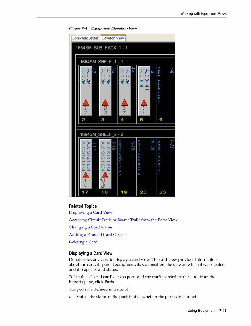
Working with Equipment Views
Using Equipment 7-13
Figure 7–1 Equipment Elevation View
Related TopicsDisplaying a Card View
Accessing Circuit Trails or Bearer Trails from the Ports View
Changing a Card Name
Adding a Planned Card Object
Deleting a Card
Displaying a Card ViewDouble-click any card to display a card view. The card view provides information about the card, its parent equipment, its slot position, the date on which it was created, and its capacity and status.
To list the selected card's access ports and the traffic carried by the card, from the Reports pane, click Ports.
The ports are defined in terms of:
■ Status: the status of the port; that is, whether the port is free or not.
Working with Equipment Views
7-14 Network Intelligence User's Guide
■ Port Number: the number of the port
■ Port Name: the name of the port
■ Port Type: the type of the port; this may be undefined
■ Capacity: the capacity of the port
■ Circuit trail: the name of the first circuit trail serving the port, if present
■ Bearer Trail: the name of the bearer trail serving the port, if present
■ Service(s): the services being carried on the trail, if any
■ Customer(s): the customers using the services, if any.
Accessing Circuit Trails or Bearer Trails from the Ports ViewSelect the Ports view, as outlined in "Displaying a Card View".
Double-click any row in the table to display the trail detail:
■ If the port contains neither a circuit trail, nor a bearer trail, then a message is displayed: “No Related Circuit for this Port”.
■ If the port contains a circuit trail, but does not contain a bearer trail, then the detail for the circuit trail is shown.
■ If the port does not contain a circuit trail, but contains a bearer trail, then the detail for the bearer trail is shown.
■ If both trails - circuit trail and bearer trail - are present for the port, double-click the port to display the circuit trail detail.
Changing a Card NameTo modify the name of a card:
1. Click Edit on the Card Details view.
2. Edit the card name.
3. Click Save.
The new card name is displayed in any relevant view; for example: in the Elevation View of the equipment on which the card is contained. The revised card name is also shown on the tab in the GUI.
Adding a Planned Card ObjectTo add a planned card object:
1. Right-click any empty slot object.
2. Click Add Card.
3. Select one of the available cards and click Add.
The card is displayed in the slot.
Adding a Sub-Card to a CardYou can add a card as a child (sub-card) to an existing supported card.
To add a sub-card to a supported card:
1. In the Elevation view, select the card to which you want to add sub-cards.
2. In the Views panel, click Child Card.
Working with Equipment Views
Using Equipment 7-15
The existing child cards (if any) are displayed. Otherwise, empty slots are displayed.
3. Right-click an empty slot to which you want to add a sub-card and select Add Card.
The Cards dialog box is displayed. The Cards dialog box displays a list of all supported cards.
4. Select the card that you want to add as a sub-card and click Add.
The card is added as a sub-card.
Deleting a CardTo delete a card from a slot:
1. Right-click any slot object containing a card.
2. Click Remove Card.
The card is no longer displayed in the slot.
Using the Hierarchy ViewThe hierarchy view displays the equipment entities as a hierarchical view of parents and children, from left to right.
Carrying out Actions Using the Hierarchy ViewAmong the actions that can be carried out on the hierarchy view are:
■ Viewing Card and Trail Details
■ Displaying a Card View
■ Changing a Card Name
■ Saving Configuration Results
■ Adding a Planned Card Object
■ Adding a Port to an Equipment
■ Adding a Card to a Slot
■ Cutting and Pasting a Card to a Slot
■ Deleting a Card
■ Deleting a Port from an Equipment
■ Removing a Trail from a Port
■ Moving a Trail from One Port to Another Port
■ Moving a Trail with Child Trails to a Port
■ Adding Logical Ports to a Physical Port
■ Deleting a Logical Port from a Physical Port
Note: If the card that you deleted contains sub-cards, all the sub-cards will also be deleted along with the parent card.
Working with Equipment Views
7-16 Network Intelligence User's Guide
Viewing Card and Trail DetailsYou can drill down to an individual card or trail by double-clicking the object in the Hierarchy View. For example, if you double-click the trail ADL1-KNL01/2Mb/001 in Figure 7–2, "Equipment Logical View", the object view for the child object is displayed if applicable; for example: a trail on a port.
Displaying a Card ViewDouble-click any card to display a card view. The card view provides information about the card, its parent equipment, its slot position, the date on which it was created, and its capacity and status.
To list the card's access ports, and the traffic carried by the card, click Reports - Ports.
Adding a Planned Card ObjectTo add a planned card object:
1. Right-click any empty slot object.
2. Click Add Card.
3. Select one of the available cards and click Add.
The card is displayed in the slot.
Adding a Port to an EquipmentTo add a port to an equipment:
1. Open the Hierarchy View for the equipment.
2. Right-click any equipment in the view. An equipment is denoted by the following icon:
3. Select Add to display the Add Ports to Equipment window.
4. Click Select Port Definition, and from the resulting dialog box, choose the required ports, based on Name, Capacity and Manufacturer.
5. Enter the number of ports in the Quantity field.
6. In the Start Number field, enter the initial port number.
7. Click Apply to populate the Hierarchy View with the ports. A port is denoted by the following icon:
8. To commit the changes to the database, see "Saving Configuration Results".
Adding a Card to a SlotTo add a card to a slot:
1. Open the Hierarchy View for the equipment.
2. Right-click any slot in the view. A slot is denoted by the following icon:
3. Select Add to display the Cards window.
Working with Equipment Views
Using Equipment 7-17
4. Select from the available card definitions.
Edit the card name, as required.
5. Click Add to populate the Hierarchy View with the new card. A card is denoted by the following icon:
6. To commit the changes to the database, see "Saving Configuration Results".
Cutting and Pasting a Card to a SlotTo cut and paste a card to a slot:
1. Open the Hierarchy View for the equipment.
2. Right-click any card in the view.
3. Select Cut. The color of the card, and of all of its siblings, changes to orange until the next action is carried out.
4. Click Paste to add the card to an available slot, and to populate the Hierarchy View with the new card.
5. To commit the changes to the database, see "Saving Configuration Results".
Deleting a CardTo delete a card:
Only cards that do not have ports in use may be deleted.
1. Open the Hierarchy View for the equipment.
2. Right-click any card in the view.
3. Click Delete. The card is denoted by the following icon:
4. To commit the changes to the database, see "Saving Configuration Results".
Deleting a Port from an EquipmentOnly ports on an equipment may be deleted. Ports on a card may not be deleted, although the parent card may be deleted if the card does not have ports in use.
To delete a port from an equipment:
1. Open the Hierarchy View for the equipment.
2. Right-click any port that has been added directly to an equipment in the view.
3. Click Delete. The port is denoted by the following icon:
4. To commit the changes to the database, see "Saving Configuration Results".
Note: All deleted objects are displayed on a black background.
Working with Equipment Views
7-18 Network Intelligence User's Guide
Removing a Trail from a PortTo remove a trail from a port:
1. Open the Hierarchy View for the equipment.
2. Right-click the trail to remove from a port.
3. Select Cut.
After a few seconds the trail object color changes to orange, and the object icon changes to the scissors icon.
4. To commit the changes to the database, see "Saving Configuration Results".
Moving a Trail from One Port to Another PortTo move a trail from one port to another port:
1. Open the Hierarchy View for the equipment.
2. Right-click the trail to move from a port.
3. Select Cut.
After a few seconds the trail object changes to orange, and the object icon changes to the scissors icon.
4. Right-click the port object to move the trail to.
5. Select Paste.
After a few seconds the trail object is displayed on the new port.
6. To commit the changes to the database, see "Saving Configuration Results".
Moving a Trail with Child Trails to a PortTo move a trail with child trails to a port:
1. Open the Hierarchy View for the equipment.
2. Right-click the trail in the view.
3. Select Cut.
The color of the trail, and of all its child trails on
the same port, changes until the next action is completed.
4. Click Paste to add the trail and all its child trails to another port.
5. To commit the changes to the database, see "Saving Configuration Results".
Moving a Trail to an EquipmentTo move a trail to an equipment:
1. Open the Hierarchy View for the equipment.
2. Right-click a trail in the view.
Note: All deleted objects are displayed on a black background.
Note: If both termination ports of a trail are on the same equipment, it is displayed on both of these ports.

Working with Equipment Views
Using Equipment 7-19
3. Select Cut.
The color of the trail, and the color of all of its child trails on the same port, change until the next action is completed.
4. Right-click the Equipment icon in the Hierarchy View.
5. Click Paste to add the trail and all its child trails to the equipment.
6. To commit the changes to the database, see "Saving Configuration Results".
Creating a Logical Port TemplateYou can use one, or more, templates to create logical ports associated with a particular port definition.
To create a logical port template to use to generate logical ports to add to a physical port:
1. Open the Equipment tree browser.
2. Click the Definitions tab, and from the ports folder, double-click the required port definition to display the port object.
3. From the views on the right, select Logical Port Templates View.
4. Click Add to display the Logical Port Template Details dialog box.
5. Complete the details of the logical port template:
■ Select the name of the logical port template.
■ Enter the number of ports.
■ (Optional) Add a prefix to all of the ports in the Stub Label field.
■ Select the capacity to apply to the ports.
■ (Optional) Edit the names of the ports in the Label fields.
6. Click Save to display the logical port template in the Logical Port Templates View.
This logical port template can now be used when creating adding logical ports to a a physical port through the Network Intelligence user interface. See "Adding Logical Ports to a Physical Port".
7. To commit the changes to the database, see "Saving Configuration Results".
Adding Logical Ports to a Physical PortYou can add a logical port to a physical port. You can use one, or more, templates to create logical ports associated with a particular port definition.
To create a logical port template, see "Creating a Logical Port Template".
Note: If no logical port templates exist for the chosen port, only the Create New Logical Port option is enabled in the wizard.
A tool tip is displayed on the disabled Create Logical Ports From Template option, stating that no logical port templates are available for the selected physical port.

Working with Equipment Views
7-20 Network Intelligence User's Guide
To add logical ports to a physical port:
1. Open the Hierarchy View for the equipment.
2. Navigate to the physical port to which you want to add a logical port. A port is denoted by the following icon:
3. Right-click the port, and select Add to display the Logical Port Creation wizard.
4. Select one of the following:
■ Create New Logical Port
■ Create Logical Ports using a Template. This option is enabled only if a template exists for the port definition associated with this port.
5. (Optional) To create a new logical port, enter the name, capacity, and sequence number of the port, and click Next.
Click Finish to display the modeled logical port in the hierarchy view.
6. (Optional) To create logical ports using a template, select the logical port template based on the port definition, and click Next.
Click Finish to display the modeled logical ports in the hierarchy view. The ports are numbered sequentially.
7. To commit the changes to the database, see "Saving Configuration Results".
Deleting a Logical Port from a Physical PortOnly a logical port that does not have any trails on it may be deleted, although the parent card may be deleted if the card does not have ports in use.
To delete a logical port from a physical port:
1. Open the Hierarchy View for the equipment.
2. Right-click any logical port that has been added directly to a physical port in the view.
3. Click Delete.
4. To commit the changes to the database, see "Saving Configuration Results".
Saving Configuration ResultsTo save the configuration results:
1. Perform an action on any of the elements in the Hierarchy View for the equipment.
Note: If no logical port templates exist for the chosen port, only the Create New Logical Port option is enabled in the wizard.
A tool tip is displayed on the disabled Create Logical Ports From Template option, stating that no logical port templates are available for the selected physical port.
Note: All deleted objects are displayed on a black background.
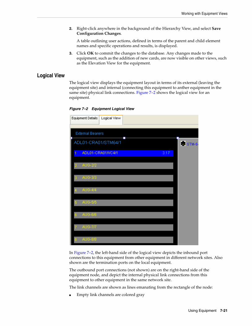
Working with Equipment Views
Using Equipment 7-21
2. Right-click anywhere in the background of the Hierarchy View, and select Save Configuration Changes.
A table outlining user actions, defined in terms of the parent and child element names and specific operations and results, is displayed.
3. Click OK to commit the changes to the database. Any changes made to the equipment, such as the addition of new cards, are now visible on other views, such as the Elevation View for the equipment.
Logical ViewThe logical view displays the equipment layout in terms of its external (leaving the equipment site) and internal (connecting this equipment to anther equipment in the same site) physical link connections. Figure 7–2 shows the logical view for an equipment.
Figure 7–2 Equipment Logical View
In Figure 7–2, the left-hand side of the logical view depicts the inbound port connections to this equipment from other equipment in different network sites. Also shown are the termination ports on the local equipment.
The outbound port connections (not shown) are on the right-hand side of the equipment node, and depict the internal physical link connections from this equipment to other equipment in the same network site.
The link channels are shown as lines emanating from the rectangle of the node:
■ Empty link channels are colored gray
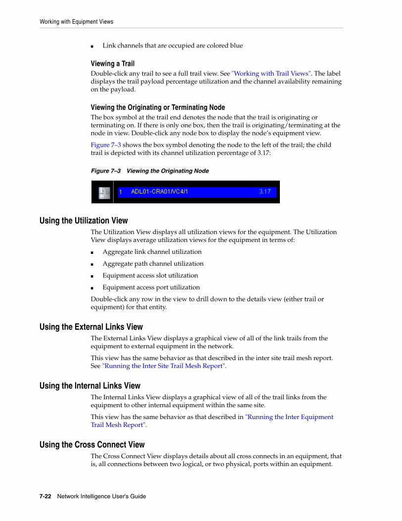
Working with Equipment Views
7-22 Network Intelligence User's Guide
■ Link channels that are occupied are colored blue
Viewing a TrailDouble-click any trail to see a full trail view. See "Working with Trail Views". The label displays the trail payload percentage utilization and the channel availability remaining on the payload.
Viewing the Originating or Terminating NodeThe box symbol at the trail end denotes the node that the trail is originating or terminating on. If there is only one box, then the trail is originating/terminating at the node in view. Double-click any node box to display the node’s equipment view.
Figure 7–3 shows the box symbol denoting the node to the left of the trail; the child trail is depicted with its channel utilization percentage of 3.17:
Figure 7–3 Viewing the Originating Node
Using the Utilization ViewThe Utilization View displays all utilization views for the equipment. The Utilization View displays average utilization views for the equipment in terms of:
■ Aggregate link channel utilization
■ Aggregate path channel utilization
■ Equipment access slot utilization
■ Equipment access port utilization
Double-click any row in the view to drill down to the details view (either trail or equipment) for that entity.
Using the External Links ViewThe External Links View displays a graphical view of all of the link trails from the equipment to external equipment in the network.
This view has the same behavior as that described in the inter site trail mesh report. See "Running the Inter Site Trail Mesh Report".
Using the Internal Links ViewThe Internal Links View displays a graphical view of all of the trail links from the equipment to other internal equipment within the same site.
This view has the same behavior as that described in "Running the Inter Equipment Trail Mesh Report".
Using the Cross Connect ViewThe Cross Connect View displays details about all cross connects in an equipment, that is, all connections between two logical, or two physical, ports within an equipment.
Working with Equipment Views
Using Equipment 7-23
Each cross connect is defined by values such as the site in which the equipment resides, originating and terminating cards, originating and terminating physical ports, protection status, originating and terminating logical ports (if they exist), and by cross connect utilization percentage, capacity, and status. The Cross Connect View also lists the capacity enabled for the cross connect, and the number of free and used ports.
Cross connects can originate or terminate a protection trail. Cross connects can have one of the following protection statuses:
■ Protected: the cross connect is on the working path and originates or terminates a protection trail. It is protected by the protection cross connect on the protection trail.
■ Protection: the cross connection is on the protection trail, protecting the protected cross connect on the working trail.
■ Unprotected: the cross connect is not protected.
You can right-click a protected cross-connect and select View Protection to see the cross connect for the protection trail.
Details about the originating cards and ports, that is, A Card, A Physical Port, and so on, are presented together, as are the corresponding data about terminating entities such as Z Card, Z Logical Port, and so on.
Using the Port Availability ViewThe Port Availability View displays a list view of the current status and availability of all ports on the equipment. This view can be filtered by port capacity and port status.
The ports are defined in terms of:
■ Location: the site location of the equipment.
■ Equipment: the equipment to which the port availability applies.
■ Resource Topology: the resource topology to which the equipment belongs; for example: national, south-east, central.
■ Platform: the platform type; for example: Carrier Ethernet, SDH.
■ Type: the equipment type; for example: SDH Type.
■ Definition: the equipment definition: for example: 10G ADM.
■ Card Type: the card type; for example: AXD S 16.S1, AXD S64.2.
■ Port Definition: the port definition: for example: SRTM-16, STM-64.
■ Total: the total number of ports on the equipment.
■ In Service: the number of ports on the equipment that are in use.
■ Planned: the number of ports on the equipment that have a status of planned.
■ Free: the number of ports on the equipment that are available for use.
Using the Port Trail Routing ViewThe Port Trail Routing View presents a list view of the complete network traversal of every presented trail on the equipment’s ports. The traversal information includes all
Note: You cannot create, edit, or delete cross connects using Network Intelligence.
Working with Equipment Group Views
7-24 Network Intelligence User's Guide
logical network routing information (trail names) and all physical network routing information (link trails and traversed equipment names, slots, and port numbers).
The logical and physical routing information is also presented for the trail’s protection path, if available, or modeled. This information includes:
■ Main path trail equipment
■ Standby path trail equipment
■ Main path trail routing
■ Standby path trail routing.
Working with Trail ViewsThe trail views for the equipment are made up of the following views:
■ Terminating Child Trails View
■ All Child Trails View
These views are common to many supported entities in Network Intelligence, and are described in "Using Object Type Trail Views".
If you use the Child Trails view to search for circuits, the search returns not only direct children of the circuit, but if the selected circuit is a protecting circuit, then the view shows children of the protected circuit as well.
Creating a Customer Trails ViewThe Customer Trails View displays all customer traffic carried by the node.
To create a customer trails view:
1. Open the filter.
2. Select the desired trail levels for:
■ Trail type
■ Trail capacity
■ Service
■ Date range
3. Click Apply.
If no filter options are selected, then the filter returns a list of all trails that have an association with this equipment.
Working with Equipment Group ViewsEquipment group views are views about all entities of the equipment type in the network. Equipment group views are available only when the equipment object is selected in the tree browser.
Display equipment group views by:
■ Clicking the object group views icon, or
■ Selecting Equipment on the menu bar
See "Displaying Object Group Views" for further information about the properties of group views.

Working with Equipment Group Views
Using Equipment 7-25
The equipment group views are:
■ Port Availability View
■ Inter Equipment Trail Geographic Report
■ Inter Equipment Trail Mesh Report
■ Inter Equipment Pair Trail Mesh View
■ Cross Connect View
Using the Port Availability (Group) ViewUse the Port Availability View to view the current status and availability of all ports on all equipment in the network. You can filter the view by equipment type, equipment platform, and port definition.
See "Using the Port Availability View", which applies to an equipment instance in the network, for further information about the fields used to define ports in the table.
Using the Inter Equipment Trail Geographic (Group) ReportUse this view to select equipment objects and combine them with filter criteria to specify a set of network links. Each node on the map represents an equipment object and each link in the map represents a collection of links between two equipment objects.
See "Inter Equipment Trail Geographic Reports", which applies to an equipment instance in the network, for further information about this report type.
Using the Inter Equipment Trail Mesh (Group) ReportUse this view to display the links for a chosen capacity between selected network equipment. Search for inter equipment mesh views using trail filters.
See "Running the Inter Equipment Trail Mesh Report", which applies to an equipment instance in the network, for further information about this report.
Using the Inter Equipment Pair Trail Mesh (Group) View Use this view to select equipment pairs in the network, rather than single equipment. The behavior of this view is similar to the "Using the Inter Equipment Trail Mesh (Group) Report".
See "Running the Inter Equipment Pair Trail Mesh View", which applies to an equipment instance in the network, for further information about this report.
Using the Cross Connect Report (Group) ViewUse this view to display details about cross connects, that is, connections between two logical, or physical, ports within the equipment in the network. If you run this report with using filter options, it may take some time to complete.
See "Using the Cross Connect View", which applies to an equipment instance in the network, for further information about this view.
Note: The view does not reflect the current capacity utilization, number of available ports, and so on until the view is refreshed.

Deleting an Equipment
7-26 Network Intelligence User's Guide
Deleting an EquipmentYou can delete an equipment using the equipment configuration wizard:
1. Open the Equipment tree browser.
2. From the list of equipment, select the equipment for deletion.
3. From the equipment details view, click Delete.
4. Confirm the equipment deletion.
Note: Deletion of the equipment from the Network Intelligence database is permanent, and the data is not recoverable. Equipment cannot be deleted if they are referenced in other objects. Object types that can reference an equipment are networks, topologies, and trails. Remove all references to the equipment in such a case before actually deleting the equipment itself.

8
Using Routes 8-1
8Using Routes
This section describes routes in Oracle Communications Network Intelligence. A route is defined as a set of connections with a defined capacity and a carried service between two site entities. Route entities are derived from collections of trail entities that share the same start site, end site, service, and capacity.
About the Routes Tree BrowserThe routes tree browser consists of a series of folders that contain the main types of routes in the network. The routes tree browser displays all routes in Network Intelligence ordered by route type in hierarchical folders.
Creating a RouteTo create a route:
1. Click Route on the context toolbar.
2. Click the Create icon:
The New Route window is displayed.
3. Configure the route using the following values:
■ Name: Enter the name of the route.
■ A Site: Enter the name of the A site, or click the ellipsis button to open a Site Search window to find the originating site.
■ Z Site: Enter the name of the Z site, or click the ellipsis button to open a Site Search window to find the terminating site.
■ Service: Select from the list of supported services.
■ Capacity: Select from the list of supported capacities.
■ Planned Total: Specify the expected bandwidth for the route.
■ Current Total: Specify the current bandwidth for the route.
■ Priority: Set the route priority.
■ InService Date: Use the calendar window to select the date on which the selected route comes into service.
■ OutService Date: Use the calendar window to select the date on which the selected route is due to go out of service.
Working with Route Views
8-2 Network Intelligence User's Guide
■ Status: Select from the list of statuses; for example: Ceased, Faulty, Free, In Service, ONI Planned (where ONI signifies Oracle Network Intelligence).
■ Monthly Mbps Growth: Define the bandwidth increase for the route.
4. Click Save.
Working with Route ViewsThe route object offers the following views:
■ Route Diversity View
■ Route Diversity Logical View
■ Customer Bandwidth Report
■ Child Trails
■ Service View
Using the Route Diversity ViewThe Route Diversity View displays, in detail, the diversity of a selected route. Full data is shown for equipment, link, and location diversity. The different network routes are also depicted with a list of all of the trails that belong to this route.
Related TopicsViewing Trail Entities Routed Over Selected Route Path
Viewing a Trail
Viewing Trail Entities Routed Over Selected Route PathClick a route path row to highlight in the trail list those trail entities that are routed over the selected route path.
Viewing a TrailDouble-click any trail object in the trail list to display the standard trail object view.
Using the Route Diversity Logical ViewThe Route Diversity Logical View displays a graphical diversity view of the route. Each route path can be selected, and for each selection the route path is displayed graphically in terms of the equipment and connecting trail links of the route path.
This view is an equipment mesh view and behaves identically to other equipment mesh views. See "Running the Inter Equipment Trail Mesh Report".
Using the Customer Bandwidth ReportThe Customer Bandwidth Report displays all of the customers carried on the network A-Z route ordered alphabetically, including their capacity/bandwidth utilization on the route.
Related TopicsViewing Customer Details
Working with Route Object Group Views
Using Routes 8-3
Viewing Customer DetailsDouble-click a row to open the customer details view.
Using Trail ViewsThe trail view for the route is the following view:
■ Child Trails
This view is common to many supported entities in Network Intelligence, which are described in "Using Object Type Trail Views".
Using the Service ViewThe service view displays the service associated with this route.
Working with Route Object Group ViewsTo display the route object group views:
1. Click the object group view icon.
A menu is displayed.
2. Select one of the following view options:
■ Major Route Traffic Report
■ A and Z Site Selection Route Reports
Using the Major Route Traffic ReportThe Major Route Traffic Report displays the trail growth on all links between any two sites in the network over a specified interval of time. By default, the link with the most growth is at the top.
The list view uses the trail search filter. See "Filtering View Data".
Related TopicsViewing Trails of a Particular Route
Viewing Trails of a Particular RouteDouble-click a row of the report to open a list view of trails of the particular route.
Using the A And Z Site Selection Route ReportsYou can use the A and Z Site Selection Route reports to:
■ Select an A Site and Z Site pair.
■ Specify a capacity level between the two sites (the default is for all capacities to be selected).
■ Select a customer for the service.
■ Apply a service to the route.
■ Set the creation date, and the in-service date.
The following reports are generated:
Working with Route Object Group Views
8-4 Network Intelligence User's Guide
■ Route Utilization: Outlines the utilization for each link.
■ Summary: Provides a summary of the bandwidth total and the bandwidth used, and lists all trails between the two sites.
■ Carried Customers: Details the customer bandwidth, associated capacity, number of trails per capacity, and the total bandwidth.
For information on setting thresholds, see "Running the Inter Site Trail Mesh Report".
9
Using Services, Policies, and Rules 9-1
9Using Services, Policies, and Rules
This section describes services, policies, and rules in Oracle Communications Network Intelligence. A service is defined as a product or service that is carried by one or more trails in the network to supply one or more customers, or an internal network service such as a transport path or link (a trail must reference a service).
A policy defines a set of routing constraints, or rules, that are applied when looking for a path between two points in the network. So, for example, policies specify class of service, or quality of service constraints when looking for suitable network resources to satisfy service demand requirements on a service level agreement (SLA).
Using the Services Tree BrowserThe services tree browser displays all services and service definitions currently modeled in Network Intelligence.
Services are separated into predefined folders or groups for ease of navigation. Double-click the folder to expand the selection.
The following sections describe how to use services in Network Intelligence:
■ Creating a Service
■ Creating a Policy for a Service
■ Assigning a Policy to a Service
■ Designing and Assigning a Service Demand
■ Working with Service Views
■ Working with Service Object Group Views
■ Using Routing Rules
■ Using Weightings
■ Using Associations
Creating a ServiceEach service requires a service definition, so before creating a service, you must first create a service definition.
To create a service definition:
1. Click Service on the context toolbar.
2. Click the Create icon to display the following options:
Creating a Policy for a Service
9-2 Network Intelligence User's Guide
■ New Service
■ New Service Definition
3. Select New Service Definition to display the New Service Definition window.
4. Configure the service definition using the following values:
■ Name: The name of the new service definition. The name must be unique.
■ Policy: Select from the list of available policies. This step is optional.
■ Description: Add a description of the service definition. This step is optional.
■ Connectivity Type: Select from the list of available connectivity types; for example: point to point, multipoint to multipoint.
5. Click Save.
Having created a service definition, you can create the service.
To create a service:
1. Click Service on the context toolbar.
2. Click the Create icon to display the following options:
■ New Service
■ New Service Definition
3. Select New Service to display the New Service window.
4. Configure the service using the following values:
■ Name: The name of the new service. The name must be unique.
■ Status: Select a status.
■ Service Definition: Select a service definition.
■ Group: Select a group to which the service belongs.
■ Description: Add a description of the service. This step is optional.
5. Click Save.
Creating a Policy for a ServiceIf a service requires a trail path connection that must be routed over carrying trails, you must assign a policy to the service definition to define routing constraint rules.
A policy holds one or more rules that define the pathfinding criteria used to discover end to end trail connections when fulfilling a service.
To create a policy:
1. Click Policy on the context toolbar.
2. Click the Create icon to display the New Policy window:
3. Configure the policy definition using the following values:
■ Name: The name of the new policy. The name must be unique.
■ Description: Add a description of the policy. This step is optional.
■ Type: Policy types are used for reporting and filtering, and for sorting policies in the Policy tree browser.

Assigning a Policy to a Service
Using Services, Policies, and Rules 9-3
Select from the list of available policy types:
– Service: Used to create a policy for a service.
– Network: Used to create a policy to be used by a specific network.
– Service Demand: Used if a policy is created by a plan.
– Exploratory: Used if a policy is intended for study purposes.
4. Click Save.
Assigning a Policy to a ServiceHaving created a policy, you can assign the policy to a service by editing the service definition, and selecting the required policy.
To assign a policy to a service:
1. Click Services on the context toolbar.
2. Click the Definitions tab on the top of the Services panel.
3. Select the required service definition to display a Service Definition window.
4. Click Edit.
5. Select the policy to assign to the service definition.
6. Click Save.
Adding a Rule to a PolicyA policy holds rules, or other policies. You can add rules to a policy by selecting one of the views associated with the policy.
To add a rule to a policy:
1. Click Policy on the context toolbar.
2. Select the required policy to display a Policy window.
3. From the Views section, select Policy and Rule List.
4. Click Add Rule to display the Rule Configuration Wizard window.
5. Select the rule type associated with the rule, and click Next.
6. Complete the rule details by specifying a rule name and at least one service trail definition, and by adding enabling trail definitions, or routing trails for aggregation purposes, if required.
Enabling trail definitions are trail definitions available for routing this service. All instance trails that match the trail definitions in the Enabling trail definitions list are candidates for pathfinding unless they are ruled out by other policy rules.
Aggregation is used to set concatenation rules for aggregated service demands.
Click Next.
7. Check the Display new Rule box to list the rule in the policy and rule list view, or deselect the check box if you do not want to display it.
Designing and Assigning a Service Demand
9-4 Network Intelligence User's Guide
8. Click Save.
Adding a Policy to a PolicyAdding a policy to another policy is useful for grouping common rules for routing use.
To add a policy to a policy:
1. Click Policy on the context toolbar.
2. Select the required policy to display a Policy window.
3. From the Views section, select Policy and Rule List.
4. Click Add Policy to display the Policy window.
5. Search for and select the required policy, and click Select to list the rule in the policy and rule list view.
Designing and Assigning a Service DemandA service demand is a request from a customer for a particular service over a particular route; for example: Customer A requires a business data service between Site A4 and Site A5.
To design a service demand, you perform the following tasks:
■ Use the Trail Configuration Wizard to create a service trail. See "Creating Trails to Define the Network Connectivity of a Service".
■ Use the Trail Routing Manager to determine path routing between Site A4 and Site A5. See "Using Trail Routing Manager to Determine Path Routing".
■ Apply the required policies and rules to the service. See "Applying Policies and Rules to a Service".
■ Select a valid routing solution. See "Selecting a Solution Displayed by Trail Routing Manager".
■ Create and save the new service trail.
Creating Trails to Define the Network Connectivity of a ServiceA service requires one or more trails to define its network connectivity. As with services and service definitions, each trail also requires a trail definition to define the type of trail to be built, principally whether the trail is structured or unstructured. If it is structured, a signal structure hierarchy can be defined.
To create trails, use the Trail Configuration Wizard. See "Creating a New Trail".
Note: The order in which rules and policies appear in the table in the policy and rule list view defines the precedence of the rules; that is, the order in which they are implemented.
Note: The order in which rules and policies appear in the table in the policy and rule list view defines the precedence of the rules; that is, the order in which they are implemented.
Working with Service Views
Using Services, Policies, and Rules 9-5
Using Trail Routing Manager to Determine Path RoutingWhen using the Trail Configuration Wizard, use the trail routing step to find a path routing for the service between the specified sites.
This invokes the Trail Routing Manager. See "Routing Trails" for information on trail routing.
Applying Policies and Rules to a ServiceWhen using the Trail Routing Manager, note the following options used to apply policies and rules to the service:
■ Click View Policy to view, or edit the policy that is set for the service.
■ Click Analyze to search for routed path solutions. The Trail Routing Manager takes the service demand and applies its policy to look for available solution paths between Site A4 and Site A5.
The Trail Routing Manager displays valid solutions for inspection.
Selecting a Solution Displayed by Trail Routing ManagerFrom the list of valid solutions displayed by Trail Routing Manager, you can choose one of the valid path routing options for the service trail.
See "Choosing the Routing Method" for information on selecting a routing solution.
Creating and Saving the New Service TrailTo create and save the new service trail, complete the trail details in the final step of the Trail Configuration Wizard.
Select Parent Hierarchy View to check that the trail was created with the correct parent trails. The parent trails have trail definitions that match the policy rule that was set.
Working with Service ViewsThe service object offers the following views:
■ Customer Bandwidth View
■ Child Trails
■ Network Mesh View
■ Service Definition
■ Service Topology List
Using the Customer Bandwidth ViewThe Customer Bandwidth View lists each customer of this service, and the amount and type of bandwidth being used by each customer.
To generate the Customer Bandwidth View:
1. Click the Date Range tab.
2. Enter the dates for which the bandwidth view applies.
3. Click Apply to generate the report.
Working with Service Object Group Views
9-6 Network Intelligence User's Guide
Displaying a Customer ViewDouble-click any customer in the generated report to display a customer view.
Using the Child Trails ViewThe Child Trails view is common to many supported objects in Network Intelligence. See "Using Object Type Trail Views" for information about this view.
Using the Network Mesh ViewThe Network Mesh View displays a logical topology view of all of the trails of the service with node connectivity.
There are two parts to this view, the mesh view and the trail list. The trail search filter is used by the Network Mesh View. See "Filtering View Data".
Using the Service Definition ViewUse this view to see what service definition this service references.
You can use the service definition to view the policy and the set of rules constraints for the service.
Using the Service Topology ListThe Service Topology List view displays a table of all topologies associated with this service.
Working with Service Object Group ViewsTo display the service object group view:
1. Click the object group view icon.
A menu is displayed.
2. Select Service Network Mesh Report.
Using the Service Network Mesh ReportThe Service Network Mesh Report displays a mesh view of the service network.
There are two parts to this view, the mesh view and the trail list. The trail search filter is used by the Network Mesh Report. See "Filtering View Data".
Using Routing RulesA service policy is made up of one or more routing rules. A routing rule is a conditional constraint applied to Trail Routing Manager when looking for route solutions for a service demand.
Rules may be used; for example:
■ To limit the scope of a search to specific network entities, such as a particular network equipment provider, or particular topology
■ To define requirements such as the maximum number of hops a solution completes, or the use of physical strapping to build out the network
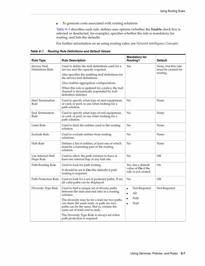
Using Routing Rules
Using Services, Policies, and Rules 9-7
■ To generate costs associated with routing solutions
Table 9–1 describes each rule, defines user options (whether the Enable check box is selected or deselected, for example), specifies whether the rule is mandatory for routing, and lists the defaults.
For further information on an using routing rules, see Network Intelligence Concepts.
Table 9–1 Routing Rule Definitions and Default Values
Rule Type Rule DescriptionMandatory for Routing? Default
Service Trail Definitions Rule
Used to define the trail definitions used for a service and the capacity required.
Also specifies the enabling trail definitions for the service trail definitions.
Also enables aggregation configurations.
When this rule is updated for a policy, the trail channel is dynamically populated by trail definition statistics
Yes None, but this rule must be created for routing.
Start Termination Rule
Used to specify what type of start equipment, or card, or port, to use when looking for a path solution.
No None
End Termination Rule
Used to specify what type of end equipment, or card, or port, to use when looking for a path solution.
No None
Limit Rule Used to limit the entities used in the routing solution.
No None
Exclude Rule Used to exclude entities from routing solutions.
No None
Hub Rule Defines a list of entities, at least one of which must be a transiting part of the routing solution.
No None
Use Internal Hub Hops Rule
Used to allow the path solution to have at least one internal hop at any hub site.
No Off
Path Routing Rule Used to look for path routing.
It should be set to On (the default) if path routing is required.
Yes, has a default value of On if the rule is not created.
On
Path Protection Rule Used to look for a set of protected paths. If set, all valid paths can be displayed.
No Off
Diversity Type Rule Used to find a unique set of diverse paths between the start and end sites in a routing solution.
The diversity may be for a trail (no two paths can share the same trail), or path (no two paths can be the same, that is, contain the same set of trails end to end).
The Diversity Type Rule is always set when path protection is required.
■ Not Required
■ All
■ Path
■ Trail
Not Required
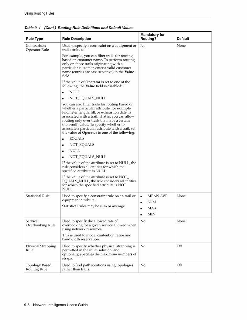
Using Routing Rules
9-8 Network Intelligence User's Guide
Comparison Operator Rule
Used to specify a constraint on a equipment or trail attribute.
For example, you can filter trails for routing based on customer name. To perform routing only on those trails originating with a particular customer, enter a valid customer name (entries are case sensitive) in the Value field.
If the value of Operator is set to one of the following, the Value field is disabled:
■ NULL
■ NOT_EQUALS_NULL
You can also filter trails for routing based on whether a particular attribute, for example, kilometer length, fill, or exhaustion date, is associated with a trail. That is, you can allow routing only over trails that have a certain (non-null) value. To specify whether to associate a particular attribute with a trail, set the value of Operator to one of the following:
■ EQUALS
■ NOT_EQUALS
■ NULL
■ NOT_EQUALS_NULL
If the value of the attribute is set to NULL, the rule considers all entities for which the specified attribute is NULL.
If the value of the attribute is set to NOT_EQUALS_NULL, the rule considers all entities for which the specified attribute is NOT NULL.
No None
Statistical Rule Used to specify a constraint rule on an trail or equipment attribute.
Statistical rules may be sum or average.
■ MEAN AVE
■ SUM
■ MAX
■ MIN
None
Service Overbooking Rule
Used to specify the allowed rate of overbooking for a given service allowed when using network resources.
This is used to model contention ratios and bandwidth reservation.
No None
Physical Strapping Rule
Used to specify whether physical strapping is permitted in the route solution, and optionally, specifies the maximum numbers of straps.
No Off
Topology Based Routing Rule
Used to find path solutions using topologies rather than trails.
No Off
Table 9–1 (Cont.) Routing Rule Definitions and Default Values
Rule Type Rule DescriptionMandatory for Routing? Default
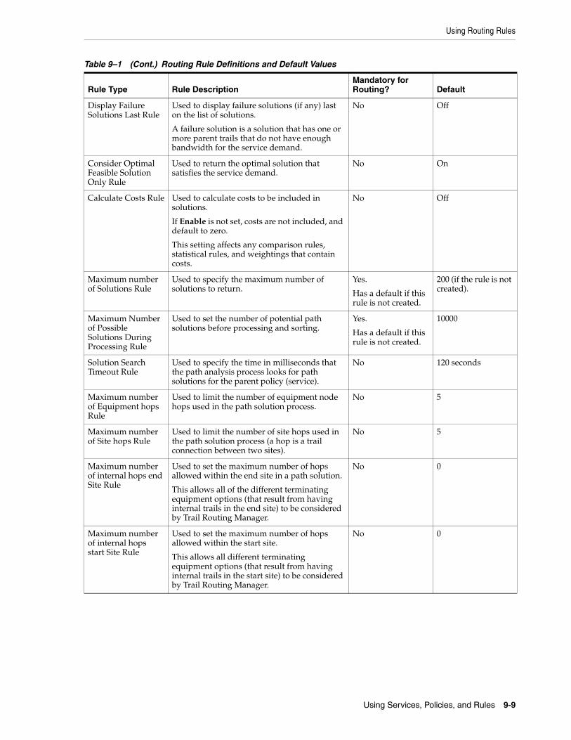
Using Routing Rules
Using Services, Policies, and Rules 9-9
Display Failure Solutions Last Rule
Used to display failure solutions (if any) last on the list of solutions.
A failure solution is a solution that has one or more parent trails that do not have enough bandwidth for the service demand.
No Off
Consider Optimal Feasible Solution Only Rule
Used to return the optimal solution that satisfies the service demand.
No On
Calculate Costs Rule Used to calculate costs to be included in solutions.
If Enable is not set, costs are not included, and default to zero.
This setting affects any comparison rules, statistical rules, and weightings that contain costs.
No Off
Maximum number of Solutions Rule
Used to specify the maximum number of solutions to return.
Yes.
Has a default if this rule is not created.
200 (if the rule is not created).
Maximum Number of Possible Solutions During Processing Rule
Used to set the number of potential path solutions before processing and sorting.
Yes.
Has a default if this rule is not created.
10000
Solution Search Timeout Rule
Used to specify the time in milliseconds that the path analysis process looks for path solutions for the parent policy (service).
No 120 seconds
Maximum number of Equipment hops Rule
Used to limit the number of equipment node hops used in the path solution process.
No 5
Maximum number of Site hops Rule
Used to limit the number of site hops used in the path solution process (a hop is a trail connection between two sites).
No 5
Maximum number of internal hops end Site Rule
Used to set the maximum number of hops allowed within the end site in a path solution.
This allows all of the different terminating equipment options (that result from having internal trails in the end site) to be considered by Trail Routing Manager.
No 0
Maximum number of internal hops start Site Rule
Used to set the maximum number of hops allowed within the start site.
This allows all different terminating equipment options (that result from having internal trails in the start site) to be considered by Trail Routing Manager.
No 0
Table 9–1 (Cont.) Routing Rule Definitions and Default Values
Rule Type Rule DescriptionMandatory for Routing? Default
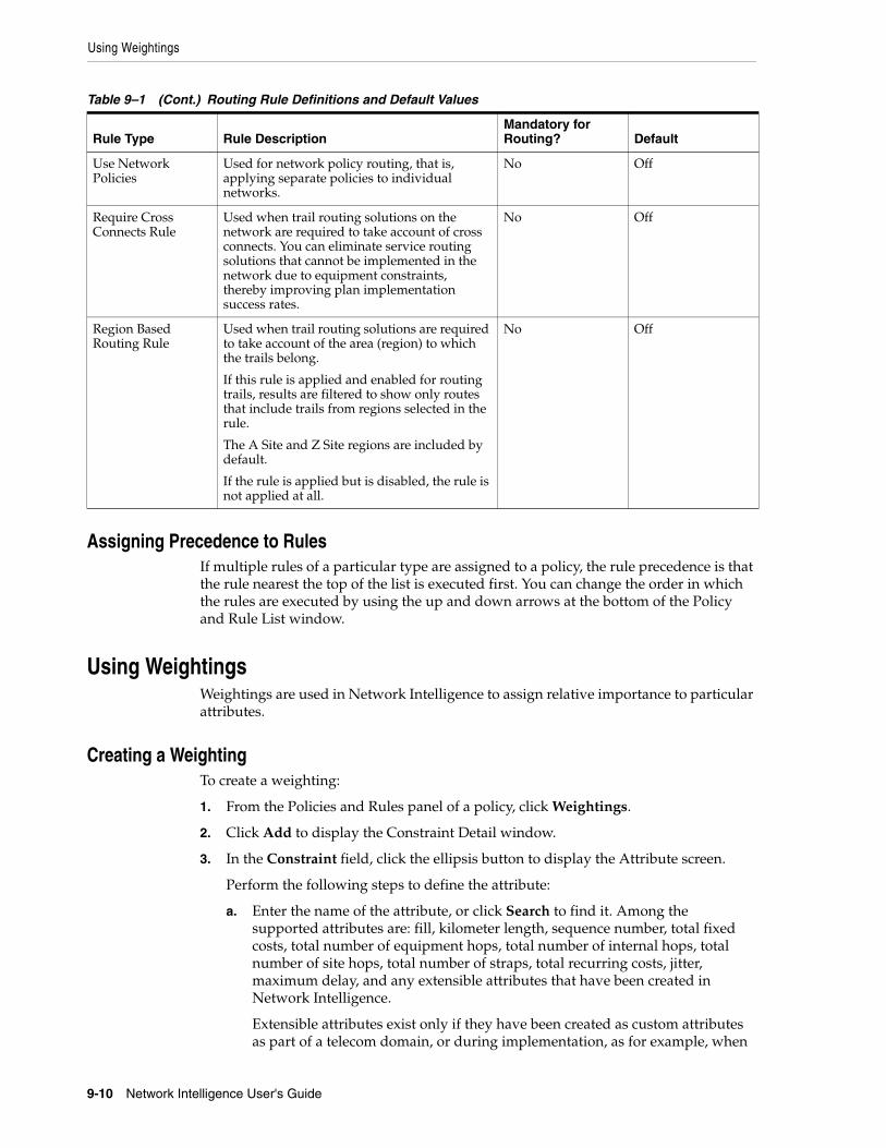
Using Weightings
9-10 Network Intelligence User's Guide
Assigning Precedence to RulesIf multiple rules of a particular type are assigned to a policy, the rule precedence is that the rule nearest the top of the list is executed first. You can change the order in which the rules are executed by using the up and down arrows at the bottom of the Policy and Rule List window.
Using WeightingsWeightings are used in Network Intelligence to assign relative importance to particular attributes.
Creating a WeightingTo create a weighting:
1. From the Policies and Rules panel of a policy, click Weightings.
2. Click Add to display the Constraint Detail window.
3. In the Constraint field, click the ellipsis button to display the Attribute screen.
Perform the following steps to define the attribute:
a. Enter the name of the attribute, or click Search to find it. Among the supported attributes are: fill, kilometer length, sequence number, total fixed costs, total number of equipment hops, total number of internal hops, total number of site hops, total number of straps, total recurring costs, jitter, maximum delay, and any extensible attributes that have been created in Network Intelligence.
Extensible attributes exist only if they have been created as custom attributes as part of a telecom domain, or during implementation, as for example, when
Use Network Policies
Used for network policy routing, that is, applying separate policies to individual networks.
No Off
Require Cross Connects Rule
Used when trail routing solutions on the network are required to take account of cross connects. You can eliminate service routing solutions that cannot be implemented in the network due to equipment constraints, thereby improving plan implementation success rates.
No Off
Region Based Routing Rule
Used when trail routing solutions are required to take account of the area (region) to which the trails belong.
If this rule is applied and enabled for routing trails, results are filtered to show only routes that include trails from regions selected in the rule.
The A Site and Z Site regions are included by default.
If the rule is applied but is disabled, the rule is not applied at all.
No Off
Table 9–1 (Cont.) Routing Rule Definitions and Default Values
Rule Type Rule DescriptionMandatory for Routing? Default
Using Associations
Using Services, Policies, and Rules 9-11
creating an equipment. See "Creating an Equipment".
See Network Intelligence Developer’s Guide for further information on creating and configuring extensible attributes.
b. Select the attribute type: double, or integer.
c. Choose from the associated entities: EQUIPMENT; EQUIPMENT and TRAIL; ROUTE_SOLUTION, or TRAIL.
4. Assign best and worst values to the constraint.
5. Select SUM or AVERAGE to determine how the weighting is calculated.
6. Use the slider to set the relative weight.
7. Click Save.
The weighting is added to the Weightings table. Double-click the weighting to edit it.
Using AssociationsFrom the policy, you can view and select the following entities:
■ Associated Service Definitions
■ Associated Service Demands
■ Associated Networks
Viewing an AssociationTo view an association; for example: an associated service definition:
1. From the Policies and Rules panel of a policy, click Associated Service Definitions to display the service definitions associated with the policy.
Service definitions, service demands, and networks are defined by name and association type.
2. Double-click the associated entity to display its details.
Click Edit to configure the entity, or click Delete to remove it from the application.

Using Associations
9-12 Network Intelligence User's Guide
10
Using Customers 10-1
10Using Customers
This section describes customers in Oracle Communications Network Intelligence. A customer is defined as a company or individual who currently subscribes, or previously subscribed to, one or more services. This includes all corporate, other licensed operator (OLO), and internal (core) customers.
You can add customer contacts to send email alerts if certain conditions, such as utilization threshold alerts, are set in Monitor Report Manager, or to inform company personnel of a network outage.
Using the Customer Tree BrowserThe customer tree browser displays all customers currently contained in the database.
Creating a CustomerTo create a customer:
1. Click Customer on the context toolbar.
2. Click the Create icon:
The New Customer window is displayed.
3. Configure the customer using the following values:
■ Name: Enter the name of the customer.
■ Customer Type: Select the customer type.
■ Account Manager: Select the name of the account manager.
■ Contact: Select the contact name for the customer.
■ InService Date: Use the calendar dialog box to select the date on which the selected customer comes into service.
■ OutService Date: Use the calendar dialog box to select the date on which the selected customer is due to go out of service.
■ Status: Select from the list of statuses; for example: Ceased, Faulty, Free, In Service, ONI Planned (where ONI signifies Oracle Network Intelligence).
4. Click Save.
Working with Customer Object Views
10-2 Network Intelligence User's Guide
Working with Customer Object ViewsThe customer object offers the following views:
■ Network Site Mesh View
■ Sites List View
■ Equipment View
■ Child Trails
Using the Network Site Mesh ViewThe Network Site Mesh View for a customer displays the customer’s network trails and sites.
There are two parts to this view, the mesh view and the trail list. The trail search filter is used by this view. See "Filtering View Data".
The mesh view takes the collection of trails returned by the filter and displays the customer network in a graphical mesh representation. The nodes displayed are the equipment referenced by the trails.
The trail list view provides a table of all the trail links found in the customer network matching the filtered criteria.
Related TopicsViewing the Trails Making Up The Route
Viewing the Trails Making Up The RouteDouble-click a route (row) in the mesh view to display a list of trails making up the route.
Using the Sites List ViewThe Sites List View displays a list of all of the sites in the network transiting or terminating the selected customer’s trails. The sites are defined by name, address, type, country, and Easting and Northing coordinates.
Using the Equipment ViewThe Equipment View for a customer displays a list of all of the equipment referenced to the selected customer.
The equipment can be filtered as follows:
1. Select from the labels corresponding to the equipment filters:
■ Equipment platform
■ Equipment type
■ Equipment template
■ Port capacity
2. Click to select the required equipment.
3. Click Apply to generate the view.
Using Customer Contacts
Using Customers 10-3
Using the Trail ViewsThe Child Trails view is common to many supported entities in Network Intelligence. See "Using Object Type Trail Views" for information about this view.
Working Customer Object Group ViewsTo display the customer object group views:
1. Click the object group view icon.
A menu is displayed.
2. Select one of the following view options:
■ Major Customer Bandwidth Report
■ Customer Network Mesh Report
Using the Major Customer Bandwidth ViewThe Major Customer Bandwidth Report displays customer bandwidth usage over a configurable time period, ordered by highest bandwidth usage (in megabits per second).
Using the Customer Network Mesh ReportThe Customer Network Mesh Report displays a mesh view of the customer network.
There are two parts to this view, the mesh view and the trail list. The trail search filter is used by this view. See "Filtering View Data".
Using Customer ContactsContacts are used in Network Intelligence to notify customers of service outages by email, or to enable reports to be sent to specified users when a user report condition is met.
You can add, edit, or delete contact details in Network Intelligence:
■ Adding a Contact
■ Editing a Contact
■ Deleting a Contact
Adding a ContactTo add a customer contact:
1. From the Administration menu on the menu bar, select Contacts.
2. Select Add a Contact.
3. Complete the personal details of the user. The First Name, Last Name, and Email fields are mandatory.
4. Click Save to add the contact details to the database.
Editing a ContactTo edit a contact:
Using Customer Contacts
10-4 Network Intelligence User's Guide
1. From the Administration menu on the menu bar, select Contacts.
2. Select Maintain Contacts to display the contact list.
3. Select a row, and click Edit Contact to revise the user’s contact details.
4. Update the contact details.
5. Click Save to commit the contact details to the database.
Deleting a ContactTo delete a contact:
1. From the Administration menu on the menu bar, select Contacts.
2. Select Maintain Contacts to display the contact list.
3. Select a row, and click Delete Contact to remove the user’s contact details.
4. Confirm the deletion.
Tip: You may be required to close and reopen the Contact Details tab to view the deletion.
11
Using Capacities 11-1
11Using Capacities
This section describes capacities in Oracle Communications Network Intelligence. A capacity is the bit rate in MB per second by which a trail is transmitted.
Using the Capacity Tree BrowserThe capacity tree browser displays all capacities currently contained in the database, in separate folders for trail capacities and trail holder capacities.
Capacities are listed singly, in alphabetical order, in each folder. Double-click any capacity to view it.
Creating a CapacityTo create a capacity:
1. Click Capacity on the context toolbar.
2. Click the Create icon:
The New Capacity window is displayed.
3. Configure the capacity using the following values:
■ Name: The name of the new capacity. The name must be unique.
■ Technology: Select from the list of available technologies.
■ Capacity Type: Select trail capacity, or trail holder capacity.
■ Description: Enter a description of the capacity.
■ Mbps: Specify the number of MB per second by which a trail is transmitted.
■ Abbreviation: Enter a shortened version of the capacity name.
■ Standard Name: Enter the standard name used to identify this capacity.
4. Click Save.

Using the Capacity Tree Browser
11-2 Network Intelligence User's Guide

12
Routing Trails 12-1
12Routing Trails
This section describes the Trail Routing Manager in Oracle Communications Network Intelligence. You can use the Trail Routing Manager to find the lowest-cost trail routing solution between two sites in the network. The suggested solutions offer optimal end-to-end trail paths to assist with network planning, service fulfillment, and service assurance.
Using Trail Routing ManagerTo run Trail Routing Manager, perform one of the following:
■ Select Tools, then Trail Routing Manager
■ Click the Trail Routing Manager icon under the main menu on the Network Intelligence GUI:
Using the Trail Routing Manager GUIThere are three main parts to the Trail Routing Manager GUI:
■ Service demand details area, where you complete the inputs required for the service demand.
If used with the Trail Configuration Wizard, these details are automatically filled in using the values taken from the service demand input form in the Trail Configuration Wizard.
■ Service fulfilment analysis area, which lets you see what policy is set to determine path solutions. You can edit the policy, or select another policy here.
■ Routing solutions area, where you can examine suggested solutions that are suitable for the set of rules specified in the selected policy.
Figure 12–1 shows the three main parts of the Trail Routing Manager GUI.
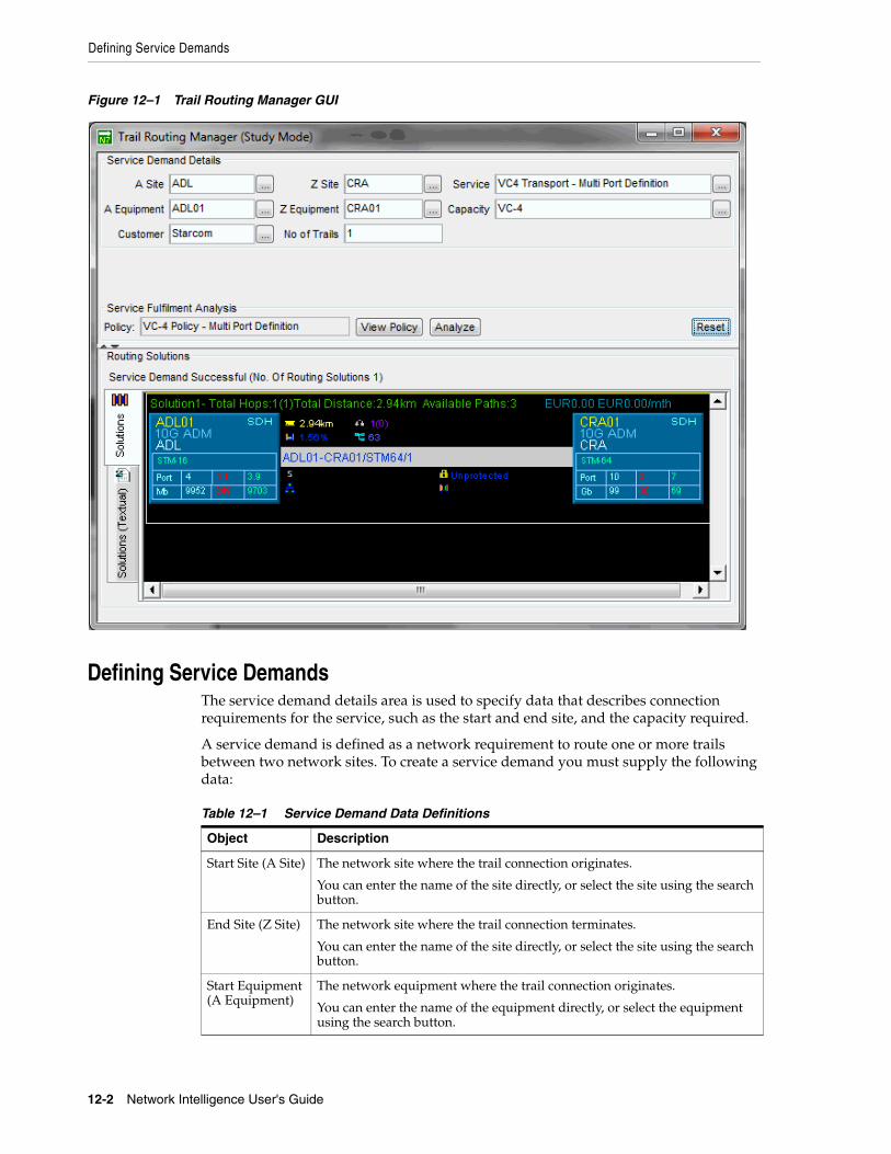
Defining Service Demands
12-2 Network Intelligence User's Guide
Figure 12–1 Trail Routing Manager GUI
Defining Service DemandsThe service demand details area is used to specify data that describes connection requirements for the service, such as the start and end site, and the capacity required.
A service demand is defined as a network requirement to route one or more trails between two network sites. To create a service demand you must supply the following data:
Table 12–1 Service Demand Data Definitions
Object Description
Start Site (A Site) The network site where the trail connection originates.
You can enter the name of the site directly, or select the site using the search button.
End Site (Z Site) The network site where the trail connection terminates.
You can enter the name of the site directly, or select the site using the search button.
Start Equipment (A Equipment)
The network equipment where the trail connection originates.
You can enter the name of the equipment directly, or select the equipment using the search button.
Routing a Service Demand
Routing Trails 12-3
Using the Service PolicyIn Network Intelligence, service objects can have policy objects associated with them. Policies contain one or more constraint rules to apply conditions to the Trail Routing Manager's path analysis process when looking for path solutions for service demands.
Policies are not supplied with Network Intelligence. You create your own policies. Policies can only be created for service objects.
See "Using Services, Policies, and Rules" for a full explanation of service policies and rules.
Routing a Service DemandTo route a service demand, perform the following tasks:
1. Do one of the following:
■ Select Tools, then Trail Routing Manager
■ Click the Trail Routing Manager icon:
Trail Routing Manager enables you to determine routes in “study” mode, that is, to investigate routing possibilities for a particular service demand.
2. Enter your service demand by specifying the start and end sites for the service demand, the start and end equipments for the service demand, the required service and capacity, the customer to whom the circuit applies, and the number of circuits needed.
End Equipment (Z Equipment)
The network equipment where the trail connection terminates.
You can enter the name of the equipment directly, or select the equipment using the search button.
Service The service that the trail connection is transporting.
Capacity The capacity or bandwidth required for the trail connection.
Customer The customer that the service is required for.
No. of Trails The total number of trail connections required.
Note: When invoking the Trail Routing Manager without a client like this, you are said to be in “study” mode because in this mode you can see any available routing solutions but you cannot fulfil the service demand by creating actual trail objects.
To create routed trail objects, use the Trail Configuration Wizard available in the Tools menu. The Trail Configuration Wizard takes you through a full set of simple tasks, including using the Trail Routing Manager to find a path.
Table 12–1 (Cont.) Service Demand Data Definitions
Object Description

Routing a Service Demand
12-4 Network Intelligence User's Guide
3. If a policy has been set for the service object, then the name of the policy is set in the policy field. If you have not set a policy for the service required, a No Policy set for Service message is displayed when you try to find path solutions.
You must set a policy with some constraint rules for a service to find path solutions. The policy may be edited at any time by clicking View Policy and editing the policy.
See "Using Services, Policies, and Rules" for a full explanation of service policies and rules.
4. Click Analyze to start the path finding process. At this point, the service demand and its corresponding policy are sent to the Trail Routing Manager path analysis service to look for path solutions according to the constraint criteria defined in the rule set in the policy.
Trail Routing Manager displays two separate views of the routing solution in the routing solutions view: one in graphical format, and the other in textual format.
Viewing a Routing SolutionTo view a routing solution:
1. Click one of the following tabs:
■ Solutions: displays a graphical view of the routing solution.
■ Solutions (Textual): displays a list of the solutions in spreadsheet format. See "Displaying the Textual View of the Routing Solution".
2. To view any element in the solution, double-click that component of the routing solution in the Routing Solutions pane of Trail Routing Manager to view it in the Network Intelligence GUI. See "Viewing Elements of the Routing Solution".
3. Modify the trail as required by clicking Edit, or select from the views associated with the trail by clicking the required view. See "Working with Trail Views".
Figure 12–2 displays a graphical view of a routing solution.
Figure 12–2 Trail Routing Manager: Routing Solution
Note: The Trail Routing Manager is contained in a separate window to the main application. When you click View Policy, the policy object is displayed in a new tab in the workbench of the main application. You must switch context to select the main application to view the policy for editing.

Routing a Service Demand
Routing Trails 12-5
Related TopicsViewing Elements of the Routing Solution
Displaying the Textual View of the Routing Solution
Viewing Elements of the Routing SolutionYou can also view any individual element from the route solution view; for example, drill down on the trail associated with the top solution by double-clicking it. This displays the trail object view that enables you to configure the trail or investigate the views associated with it.
Displaying the Textual View of the Routing SolutionFigure 12–3 displays a textual view of the same routing solution shown in Figure 12–2, outlining equipment and trails, the utilization percentage of each, and the number of channels and bandwidth available.
Figure 12–3 Routing Solution: Textual View
Choosing the Routing MethodThe suggested routing solution may offer options on how to perform the routing. This is denoted by the fact that the service demand is successful, but is marked by Select, as shown in Figure 12–4. In addition, the Accept button is disabled.
Figure 12–4 Selecting the Required Routing Method
To choose the routing method:
1. Right-click Select to list the routing methods.
2. Select from the suggested options:
■ Default configuration as main path
■ Manual configuration as main path

Applying Costs Using Trail Routing Manager
12-6 Network Intelligence User's Guide
■ Default configuration as standby path
■ Manual configuration as standby path
Manual configuration for routing over unstructured parent trails is different from that for structured parent trails:
■ When routing over unstructured trails, you do not need to select trail holders, so the trail holder selection dialog box is view only.
■ When routing over structured parent trails, you need to select parent timeslots.
3. The Select label changes to Configured, and the Accept button at the base of the configuration screen is enabled.
4. Click Accept to accept the path route solution, and write back the data to the Trail Configuration Wizard.
5. Ensure the Routing Found check box is enabled when using the Trail Configuration Wizard. See "Creating a New Trail".
Applying Costs Using Trail Routing ManagerAfter you have generated a routing solution, you can use Trail Routing Manager to calculate the costs associated with this solution. The costing component of Trail Routing Manager enables you to set fixed and recurring total costs for the solution.
This section outlines the process of costing a solution by providing sample data:
■ Creating Tasks and Costs for Each Object
■ Routing the Service Demand
■ Inspecting the Routing Solutions
Creating Tasks and Costs for Each ObjectTo generate costs for objects such as trails, connection, and port tasks, create individual tasks for each network build element in the routing solution. These tasks are referred to in Network Intelligence as build tasks,
For example, to create an equipment build task with the cost name 2Mb Unit Port, perform the following:
1. From the top-level menu of the Network Intelligence GUI, select Administration, then select Costing, then select Maintain Equipment Build Tasks.
2. Complete the task information:
a. Enter the task name and the equipment supplier, and select the equipment definition. Any user-defined equipment definitions created are displayed in the list of available definitions.
b. Select Add Equipment Costs to display the Equipment Cost List.
c. Click Add Cost and enter the details for the task; for example: for Name, enter 2Mb Unit Port; for Expenditure Type, select CapEx; select Fixed Cost in the Fixed/Recurring field, and enter the required monetary amount under Amount.
3. Click Save. The cost is displayed in the Equipment Cost List.
4. Repeat for each equipment build cost.

Applying Costs Using Trail Routing Manager
Routing Trails 12-7
5. From the Equipment Cost List, select the costs required for the build, and click Select to transfer them to the equipment build task form. The total cost is automatically updated as each cost is added.
6. Click Save. The cost is displayed in the Equipment Build Task List.
7. Complete the task information outlined in the table for:
■ Trails
■ Connections.
Routing the Service DemandTo route the service demand, perform the following:
1. In the Service Policy panel, click Route. The routing process may take some time, depending on the complexity of the demand.
2. When Trail Routing Manager Status window returns the message Trail Routing Manager Processing Complete, click OK.
Inspecting the Routing SolutionsTo inspect the routing solutions:
1. In the Routing Solutions panel, click Solutions to view a graphical outline of the successful routing solution:
The routing solution contains a series of tasks, quantities, and descriptions.
2. Click Solutions (Textual) to view the tabular outline of the routing solution:
3. (Optional) Save data in a spreadsheet to analyze it. See "Saving the Routing Solution Data in Other Formats".
4. (Optional) View a legend of the solution. See "Viewing a Legend of the Routing Solution".
Saving the Routing Solution View as an ImageTo save the view as a JPEG file:
1. Right-click the background of the graphical solution.
2. Click one of the following:
■ Save As Visible Image.
■ Save As Complete Image.
3. Select a location to save the file to.
Saving the Routing Solution Data in Other FormatsTo save the view as a Microsoft Excel spreadsheet, a comma-delimited file, or as HTML:
1. Right-click the textual solution.
Note: The total cost for the solution (taking all hops into account) should include the trail, connection, and timeslot costs.

Applying Costs Using Trail Routing Manager
12-8 Network Intelligence User's Guide
2. Click one of the following:
■ Open in Excel.
■ Save as CSV.
■ Save as HTML.
3. Select a location to save the file to.
Viewing a Legend of the Routing SolutionTo view a legend of the routing solution:
1. Right-click the background of the graphical solution.
2. Click Show Legend.
13
Using Configuration Plans 13-1
13Using Configuration Plans
This section describes configuration planning in Oracle Communications Network Intelligence. You can capture live configuration changes to network resources in Network Intelligence; for example: site creation, equipment modification, or trail deletion, and view these actions - and interactions with other supported entities - in a configuration plan. The contents of the configuration plan can be exported in various formats, or viewed in a report.
Configuration plans apply to the following entities:
■ Sites
■ Equipment, and the associated equipment hierarchy, that is, cards, ports, logical ports, and so on
■ Trails, and the associated trail hierarchy
Creating a Configuration PlanYou can create a configuration plan without enabling Configuration Planning mode. If you are in Network Modeling mode and create a new configuration plan, it automatically enables Configuration Planning mode, and populates the planning toolbar with the details of the newly created plan.
See "Using the Toolbar" for further information about the modes offered on the toolbar.
To create a configuration plan:
1. Select one of the following:
■ From the context toolbar, click Plans, and from the Plans tree browser, click the create icon:
Select Create New Configuration Plan.
■ From the Network Intelligence toolbar, click the Create Configuration Plan icon:
2. Complete the details of the plan, such as the name and planning type. See "Using the Configuration Plan Details View" for definitions of the fields.
3. Click Save to create the plan.
The toolbar is automatically updated with the details of the plan.
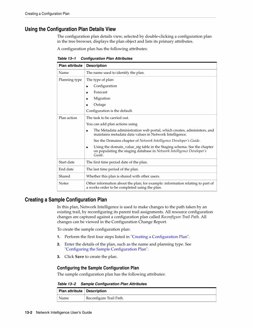
Creating a Configuration Plan
13-2 Network Intelligence User's Guide
Using the Configuration Plan Details ViewThe configuration plan details view, selected by double-clicking a configuration plan in the tree browser, displays the plan object and lists its primary attributes.
A configuration plan has the following attributes:
Creating a Sample Configuration PlanIn this plan, Network Intelligence is used to make changes to the path taken by an existing trail, by reconfiguring its parent trail assignments. All resource configuration changes are captured against a configuration plan called Reconfigure Trail Path. All changes can be viewed in the Configuration Change Report.
To create the sample configuration plan:
1. Perform the first four steps listed in "Creating a Configuration Plan".
2. Enter the details of the plan, such as the name and planning type. See "Configuring the Sample Configuration Plan".
3. Click Save to create the plan.
Configuring the Sample Configuration PlanThe sample configuration plan has the following attributes:
Table 13–1 Configuration Plan Attributes
Plan attribute Description
Name The name used to identify the plan.
Planning type The type of plan:
■ Configuration
■ Forecast
■ Migration
■ Outage
Configuration is the default.
Plan action The task to be carried out.
You can add plan actions using
■ The Metadata administration web portal, which creates, administers, and maintains metadata data values in Network Intelligence.
See the Domains chapter of Network Intelligence Developer’s Guide.
■ Using the domain_value_stg table in the Staging schema. See the chapter on populating the staging database in Network Intelligence Developer’s Guide.
Start date The first time period date of the plan.
End date The last time period of the plan.
Shared Whether this plan is shared with other users.
Notes Other information about the plan; for example: information relating to part of a works order to be completed using the plan.
Table 13–2 Sample Configuration Plan Attributes
Plan attribute Description
Name Reconfigure Trail Path.

Creating a Configuration Plan
Using Configuration Plans 13-3
Recording Data for the Configuration PlanAfter creating the configuration plan, you can use it to record configuration actions.
To record data:
1. Click the record icon on the Network Intelligence toolbar. See Figure 13–1.
Figure 13–1 Configuration Plan: Recording Icon
2. Click OK to accept the message that all changes are being captured against the selected plan:
Recording configuration actions against Configuration Plan: Plan Name.
3. Perform the required configuration.
4. Click the stop recording icon on the Network Intelligence toolbar. See Figure 13–2.
Figure 13–2 Configuration Plan: Stop Recording Icon
5. Click OK to accept the message that no subsequent changes are captured against the selected plan:
Recording stopped. No longer capturing configuration actions against Configuration Plan: Plan Name.
6. Examine the data in the configuration report. See "Viewing the Configuration Change Report".
Viewing the Configuration Change ReportThe configuration change report is a table listing all configuration actions recorded against the configuration plan. The most recent actions are listed first. Actions are defined by:
■ Configuration: The action type; for example: Add, Remove, Modify, Create, Delete, and so on.
Planning type The type of plan:
■ Configuration
This field cannot be edited.
Plan action Trail path upgrade.
Start date August 4, 2012.
End date August 7, 2012.
Shared Yes.
Notes This plan forms the basis for a Trail Path Rearrange works order for a trail called Intersite 1GB Ethernet Trail. The works order must be completed before 31st October, 2012.
Table 13–2 (Cont.) Sample Configuration Plan Attributes
Plan attribute Description
Creating a Configuration Plan
13-4 Network Intelligence User's Guide
■ Entity: The entity created, modified, or deleted.
■ Name: The name of the entity.
■ Description: Further information about the configuration action.
■ Field Name: The name of the field modified; for example: Status, Service, Name, and so on.
■ Old Value: The value of the field before the modification; for example, for a trail currently in use, but planned for decommissioning, In Service.
■ New Value: The value of the field after the modification; for example, for a trail that has been taken out of commission, Ceased.
■ Child Entity: The type of the child of the entity; for example: ports and cards are children of an equipment entity.
■ Child Name: The name of the child of the entity.
■ Child Description: A full description of the child entity; for example, for a port: Site/Equipment/Sub Rack/Shelf/Slot/Card/Port.
■ Changed By: The user who carried out the configuration action.
■ Time: When the configuration action took place.
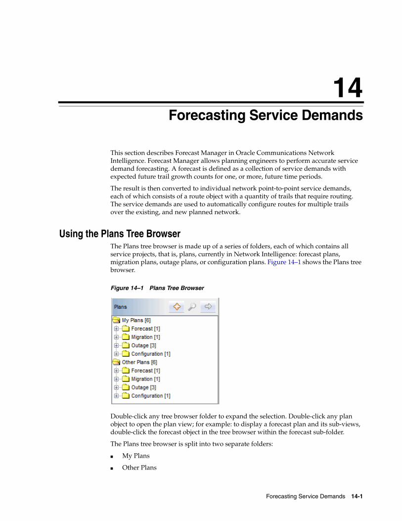
14
Forecasting Service Demands 14-1
14Forecasting Service Demands
This section describes Forecast Manager in Oracle Communications Network Intelligence. Forecast Manager allows planning engineers to perform accurate service demand forecasting. A forecast is defined as a collection of service demands with expected future trail growth counts for one, or more, future time periods.
The result is then converted to individual network point-to-point service demands, each of which consists of a route object with a quantity of trails that require routing. The service demands are used to automatically configure routes for multiple trails over the existing, and new planned network.
Using the Plans Tree BrowserThe Plans tree browser is made up of a series of folders, each of which contains all service projects, that is, plans, currently in Network Intelligence: forecast plans, migration plans, outage plans, or configuration plans. Figure 14–1 shows the Plans tree browser.
Figure 14–1 Plans Tree Browser
Double-click any tree browser folder to expand the selection. Double-click any plan object to open the plan view; for example: to display a forecast plan and its sub-views, double-click the forecast object in the tree browser within the forecast sub-folder.
The Plans tree browser is split into two separate folders:
■ My Plans
■ Other Plans
Creating a Plan
14-2 Network Intelligence User's Guide
Using the My Plans FolderThe My Plans folder consists of all service projects within Network Intelligence created by the current user. These plans are always visible on a Network Intelligence GUI opened by this user.
These plans may, or may not be, shared with other users. When you create a plan, there is an option to set the Shared option to make this plan sharable (and visible) to other users. If a plan is not shared, it is not visible to other users in the Plans tree browser.
Related TopicsUsing the Other Plans Folder
Using the Other Plans FolderThe Other Plans folder consists of all service projects within Network Intelligence created by other users. These plans are visible on a Network Intelligence GUI opened by this user (that is, the owner of the My Plans folder) if they have been shared by the other users.
Related TopicsUsing the My Plans Folder
Creating a PlanThe plan creation manager uses a wizard to enable you to create new plans in different ways. The steps taken depend on the creation method chosen.
To create a plan
1. Click Plans on the context toolbar.
2. Click the Create icon to display the plan creation manager wizard.
3. Choose which type of plan to create:
■ A plan that uses the route filter to select a route object, and then applies forecast values to future time periods.
See "Creating a Plan By Selecting Routes".
■ A plan that generates forecast scenarios that apply to particular network objects.
See "Creating a Plan by Selecting Network Objects and Applying Growth Criteria".
■ A plan that imports data from a file, and generates a forecast based on the data.
See "Creating a Plan from an External File Source".
Note: Migration and outage plans are created using the migration and outage managers respectively. See "Migrating Network Entities" and "Managing Outages".

Creating a Plan
Forecasting Service Demands 14-3
Creating a Plan By Selecting RoutesTo create a plan by selecting a route object using the route filter, and applying plan values to future periods, perform the following steps:
1. Select Create Plan by Selecting Routes in the plan creation manager window.
2. Complete the details of the plan, such as the name and planning type. See "Using the Plan Details View" for definitions of the fields.
3. Use the Route Filter to select routes for the new plan.
a. Click Select From Routes to display the Route Search window.
b. Select any required filter criteria, and click Search. For example, select the required customer and capacity to display all routes of that type.
c. Select the required routes by clicking the rows associated with them, and click Select to display the routes.
d. Click Next to select the start dates and end dates for the plan and the period type.
4. Enter the start dates and end dates for the plan, and the period type. The period type is measured in months, quarters, or years.
When the number of periods field is filled, the end date is automatically completed.
5. Fill in the service demand values for the future plan dates. Click Next to save the plan.
6. Select one of the following options:
■ Save and Display Plan
■ Save and Close Plan
7. Click Finish to complete the plan.
Creating a Plan by Selecting Network Objects and Applying Growth CriteriaTo create plan scenarios by selecting any network object in the tree browser, perform the following steps:
1. Select Create Forecast by Selecting Network Objects and Applying Growth Criteria in the plan creation manager window.
The following network entities may be selected for this type of plan creation:
■ Topology
■ Equipment
■ Site
■ Trail
■ Service
■ Route
■ Customer
2. Select the required entities:
a. To display the required network inventory data, use the context toolbar to select which type of data you want to see; for example, trails or equipment.
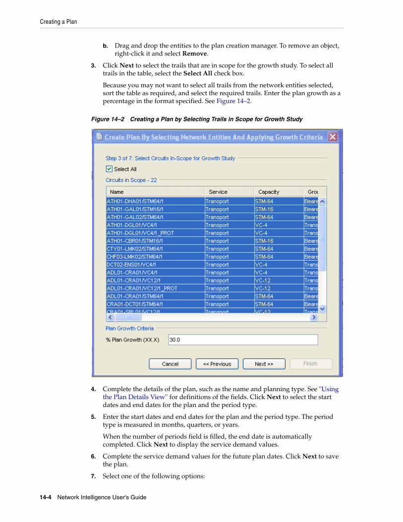
Creating a Plan
14-4 Network Intelligence User's Guide
b. Drag and drop the entities to the plan creation manager. To remove an object, right-click it and select Remove.
3. Click Next to select the trails that are in scope for the growth study. To select all trails in the table, select the Select All check box.
Because you may not want to select all trails from the network entities selected, sort the table as required, and select the required trails. Enter the plan growth as a percentage in the format specified. See Figure 14–2.
Figure 14–2 Creating a Plan by Selecting Trails in Scope for Growth Study
4. Complete the details of the plan, such as the name and planning type. See "Using the Plan Details View" for definitions of the fields. Click Next to select the start dates and end dates for the plan and the period type.
5. Enter the start dates and end dates for the plan and the period type. The period type is measured in months, quarters, or years.
When the number of periods field is filled, the end date is automatically completed. Click Next to display the service demand values.
6. Complete the service demand values for the future plan dates. Click Next to save the plan.
7. Select one of the following options:
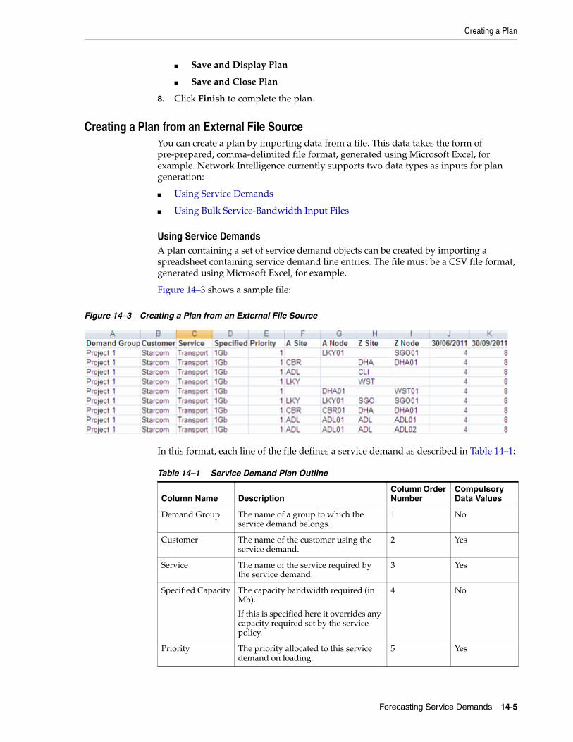
Creating a Plan
Forecasting Service Demands 14-5
■ Save and Display Plan
■ Save and Close Plan
8. Click Finish to complete the plan.
Creating a Plan from an External File SourceYou can create a plan by importing data from a file. This data takes the form of pre-prepared, comma-delimited file format, generated using Microsoft Excel, for example. Network Intelligence currently supports two data types as inputs for plan generation:
■ Using Service Demands
■ Using Bulk Service-Bandwidth Input Files
Using Service DemandsA plan containing a set of service demand objects can be created by importing a spreadsheet containing service demand line entries. The file must be a CSV file format, generated using Microsoft Excel, for example.
Figure 14–3 shows a sample file:
Figure 14–3 Creating a Plan from an External File Source
In this format, each line of the file defines a service demand as described in Table 14–1:
Table 14–1 Service Demand Plan Outline
Column Name DescriptionColumn Order Number
Compulsory Data Values
Demand Group The name of a group to which the service demand belongs.
1 No
Customer The name of the customer using the service demand.
2 Yes
Service The name of the service required by the service demand.
3 Yes
Specified Capacity The capacity bandwidth required (in Mb).
If this is specified here it overrides any capacity required set by the service policy.
4 No
Priority The priority allocated to this service demand on loading.
5 Yes
Creating a Plan
14-6 Network Intelligence User's Guide
Validating Data
This section describes the validation carried out on imported data.
■ All dates must be in the required format: for example: DD/MM/YYYY for Europe; MM/DD/YYYY for the US. The date format depends on setting of the JAVA_LOCALE variable.
■ Demand Order is optional and if entered can be any string value.
■ Customer names are mandatory, and must exist in Network Intelligence as customer objects with the same name specified in the file.
■ Service names are mandatory, and must exist in Network Intelligence as service objects with the same name specified in the file.
■ Capacity levels are mandatory, and must exist in Network Intelligence as capacity objects with the same name specified in the file.
■ A Site and Z Site are mandatory, and must exist in Network Intelligence as site objects with the same name specified in the file.
■ A Node and Z Node are optional, but if entered must exist in Network Intelligence as equipment objects with the same name specified in the file.
If the validation fails, a data error is displayed.
Understanding Data Errors
Table 14–2 lists the possible data errors if validation of the external file source fails.
A Site The start site name of the service demand connectivity requirement.
6 Yes
A Node The start equipment node name of the service demand connectivity requirement.
7 No
Z Site The end site of the service demand connectivity requirement.
8 Yes
Z Node The end equipment node name of the service demand connectivity requirement.
9 No
30/06/2011
30/09/2011
The number of trail connections forecast for the service demand for a specified period.
There is no limit to the number of periods in a forecast.
The dates in the heading column correspond to each forecast period.
To be valid, dates must be entered in the format shown.
10 Yes
Table 14–2 Forecast Manager Plan Data Errors
Data Error Description
Invalid A Site The service demand row contains a site name that does not exist in Network Intelligence.
Table 14–1 (Cont.) Service Demand Plan Outline
Column Name DescriptionColumn Order Number
Compulsory Data Values

Creating a Plan
Forecasting Service Demands 14-7
Creating a Plan by Importing Service DemandsTo create a plan by importing service demands, perform the following steps:
1. Select Create Plan From An External File Source in the plan creation manager window.
2. Click Next to select the file type to be used as the data input for the plan.
3. Select the file type for the plan. Click Create a plan from a Route A-Z spreadsheet file, and browse to the location of the file.
4. Click Next to load and validate the service demand input file.
5. Complete the plan attributes. Setting the Shared option makes this plan sharable to others. If a plan is not shared, it is not visible to other users in the Plans tree browser.
6. View the plan service demands. This step enables you to inspect the plan service demands before the plan is saved.
7. Select one of the following options:
■ Save and Display Plan
■ Save and Close Plan
8. The plan is displayed in the Network Intelligence GUI as shown in Figure 14–4.
Invalid A Node The service demand row contains an equipment node name that does not exist in Network Intelligence.
Same Location Both sites in the service demand are at the same location, so the service demand does not require any routing.
Duplicated Route The file contains two or more rows that reference the same service demand as described by A Site, Z Site, and Service.
You can merge these into one new service demand, or keep them separate. If merged, the forecast values are added.
Invalid Z Site The service demand row contains a site name that does not exist in Network Intelligence.
Invalid Z Node The service demand row contains an equipment node name that does not exist in Network Intelligence.
New Routes One or more service demand rows in the file describe connectivity between the A and Z site which does not currently exist.
As a result, a new route object is created on importing the plan.
These are not necessarily errors unless incorrect A and Z Site names have been input. You can create the new routes on importation.
No user privilege The user attempting to upload the file has included routes that they do not have permission to use to create the plan.
To change user privileges, see Network Intelligence System Administrator’s Guide.
Table 14–2 (Cont.) Forecast Manager Plan Data Errors
Data Error Description

Creating a Plan
14-8 Network Intelligence User's Guide
Figure 14–4 Creating a Plan by Importing Service Demands
Using Bulk Service-Bandwidth Input FilesThe bulk service demands are defined in CSV format, typically using Microsoft Excel. Figure 14–5 shows a sample CSV file.
Figure 14–5 Creating a Plan Using Bulk Service-Bandwidth Input Files
In this format, each line of the file describes a service followed by bulk capacity demands for future plan periods. The file contains no information about the A and Z connection details. Network Intelligence attempts to determine these details for the services in the file by using historical capacity growth on existing service routes.
The imported files are validated before import and must have the correct data headings. If the data titles are not exactly as described, the plan is not imported correctly and errors are returned.
Validating Data
This section describes the validation carried out on imported data.
■ Demand Order is optional, and if entered can be any string value.
■ Customer, if entered, must be a valid customer name that exists in Network Intelligence.
■ Service name is mandatory, and must exist in Network Intelligence.
■ Capacity name is mandatory, and must exist in Network Intelligence.
If the validation fails, a data error is displayed. See "Using Service Demands".
Creating a Plan by Importing Bulk Service BandwidthsTo create a plan by importing bulk service bandwidths, perform the following steps:
Working with Plan Object Views
Forecasting Service Demands 14-9
1. Select Create Plan From An External File Source in the plan creation manager window.
2. Click Next to select the file type to be used as the data input for the plan.
3. Select the file type for the plan. Click Create a plan from a Bulk Service-Bandwidth spreadsheet file, and browse to the location of the file.
4. Click Next to load the bulk data. Network Intelligence derives the required service demands. It does this by finding the full set of route objects that exist for the referenced service objects in the bulk import file.
Each route object has a monthly growth value in bandwidth units (Mbps). Network Intelligence takes the bulk bandwidth required (capacity) and apportions it by percentage to all routes belonging to the service that have monthly growth values greater than zero.
A route with higher monthly growth value is apportioned more of the bulk service capacity forecast that one with lower growth.
5. Complete the plan attributes. Setting the Shared option makes this plan sharable to others. If a plan is not shared, it is not visible to other users in the Plans tree browser.
6. View the plan service demands. This step enables you to inspect the plan routing service before the plan is saved.
7. Select one of the following options:
■ Save and Display Plan
■ Save and Close Plan
For further information about plan object views, see Network Intelligence Concepts.
Working with Plan Object ViewsThe plan object offers the following views:
■ Service Demands
■ Studies
■ Planned Entities
■ Planned Trails
■ Planned Equipment
■ Planned Cards
■ Planned Sites
■ Planned Topologies
Using the Plan Details ViewThe plan details view displays the plan object and lists its primary attributes.
Each plan has the attributes outlined in Table 14–3.
Table 14–3 Plan Details View Attributes
Plan attribute Description
Name The name used to identify the plan.
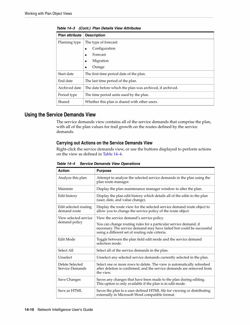
Working with Plan Object Views
14-10 Network Intelligence User's Guide
Using the Service Demands ViewThe service demands view contains all of the service demands that comprise the plan, with all of the plan values for trail growth on the routes defined by the service demands.
Carrying out Actions on the Service Demands ViewRight-click the service demands view, or use the buttons displayed to perform actions on the view as defined in Table 14–4.
Planning type The type of forecast:
■ Configuration
■ Forecast
■ Migration
■ Outage
Start date The first time period date of the plan.
End date The last time period of the plan.
Archived date The date before which the plan was archived, if archived.
Period type The time period units used by the plan.
Shared Whether this plan is shared with other users.
Table 14–4 Service Demands View Operations
Action Purpose
Analyze this plan Attempt to analyze the selected service demands in the plan using the plan route manager.
Maintain Display the plan maintenance manager window to alter the plan.
Edit history Display the plan edit history which details all of the edits to the plan (user, date, and value change).
Edit selected routing demand route
Display the route view for the selected service demand route object to allow you to change the service policy of the route object.
View selected service demand policy
View the service demand’s service policy.
You can change routing rules for a particular service demand, if necessary. The service demand may have failed but could be successful using a different set of routing rule criteria.
Edit Mode Toggle between the plan field edit mode and the service demand selection mode.
Select All Select all of the service demands in the plan.
Unselect Unselect any selected service demands currently selected in the plan.
Delete Selected Service Demands
Select one or more rows to delete. The view is automatically refreshed after deletion is confirmed, and the service demands are removed from the view.
Save Changes Saves any changes that have been made to the plan during editing. This option is only available if the plan is in edit mode.
Save as HTML Saves the plan to a user defined HTML file for viewing or distributing externally in Microsoft Word compatible format.
Table 14–3 (Cont.) Plan Details View Attributes
Plan attribute Description
Working with Plan Object Views
Forecasting Service Demands 14-11
Using the Studies ViewEach time a plan is routed it may be saved with the route solutions as a plan report. The studies view displays a list of plan reports for the selected plan.
Double-click the report in the list to select it.
Comparing Forecast ReportsTo compare forecast reports:
1. From the Studies view, select two, or more, reports.
2. Right-click the reports, and select Forecast Comparison Report.
3. Select one of the tabs to compare the route solutions:
■ Click the Summary tab to view the relative numbers of route demands, paths, and circuits, and the relative success rates for services and customers.
■ Click the Impact Summary tab to view the tasks resulting from the routing forecast; for example: a suggested circuit route build.
Using the Planned Entities ViewThe planned entities view displays a list of all entities that are planned for this plan.
To display an entity view for a planned entity, double-click an entity in the list.
Using the Planned Trails ViewThe planned trails view displays a list of all trails that are planned for this plan.
To display a trail view for a planned trail, double-click a trail in the list.
Using the Planned Equipment ViewThe planned equipment view displays a list of all equipment that are planned for this plan.
Save as CSV Saves the plan to a user defined CSV file for viewing or distributing externally in spreadsheet format.
Copy to Clipboard Saves the plan for pasting it elsewhere.
Open in Excel Saves the plan to a user defined XLS file and displays it directly in Microsoft Excel.
Note: These entities are only in scope within this plan and are not available to other plans.
Note: These trails are only in scope within this plan and are not available to other plans.
Table 14–4 (Cont.) Service Demands View Operations
Action Purpose
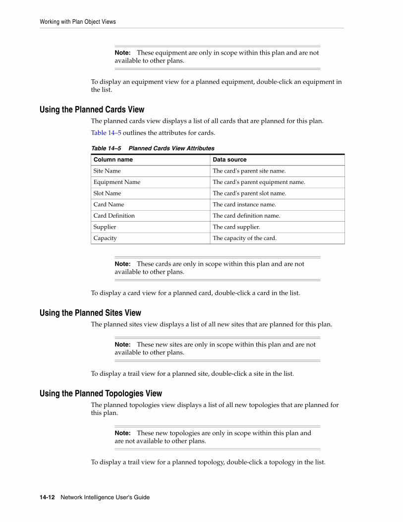
Working with Plan Object Views
14-12 Network Intelligence User's Guide
To display an equipment view for a planned equipment, double-click an equipment in the list.
Using the Planned Cards ViewThe planned cards view displays a list of all cards that are planned for this plan.
Table 14–5 outlines the attributes for cards.
To display a card view for a planned card, double-click a card in the list.
Using the Planned Sites ViewThe planned sites view displays a list of all new sites that are planned for this plan.
To display a trail view for a planned site, double-click a site in the list.
Using the Planned Topologies ViewThe planned topologies view displays a list of all new topologies that are planned for this plan.
To display a trail view for a planned topology, double-click a topology in the list.
Note: These equipment are only in scope within this plan and are not available to other plans.
Table 14–5 Planned Cards View Attributes
Column name Data source
Site Name The card's parent site name.
Equipment Name The card's parent equipment name.
Slot Name The card's parent slot name.
Card Name The card instance name.
Card Definition The card definition name.
Supplier The card supplier.
Capacity The capacity of the card.
Note: These cards are only in scope within this plan and are not available to other plans.
Note: These new sites are only in scope within this plan and are not available to other plans.
Note: These new topologies are only in scope within this plan and are not available to other plans.
Maintaining Plans
Forecasting Service Demands 14-13
Editing PlansAfter a plan has been created, it can be edited or maintained. The plan maintenance manager enables changes to the plan set of service demands, such as extending the plan future periods, or archiving historic periods.
You can also edit values in an existing plan.
To edit a plan:
1. Select the plan to be edited from the Plans tree browser.
2. Select the service demands view.
3. When the view is displayed, right-click it to invoke a popup menu. The Edit Mode option switches on the edit mode.
In edit mode, the following fields can be edited:
■ Any plan demand total for a future date period.
■ The demand order number.
■ Priority.
Any fields that cannot be edited are displayed with a light gray foreground color.
Any fields that have been edited are displayed with a yellow background color until saved. Edits are not saved until Save Changes is selected. To revert without saving, close the plan view.
Maintaining PlansPlan maintenance involves performing several tasks on a plan using the plan maintenance manager.
Carrying Out Plan Date TasksThere are three tasks associated with plan dates:
■ Extending a plan
■ Truncating a plan
■ Archiving a plan
Extending a PlanExtending a plan means adding extra time periods to the plan, with extra service demand values.
To extend a plan:
1. Select the plan from the Plans tree browser.
2. Select the service demands list view.
3. Right-click the list to invoke the popup menu.
4. Select Maintain to display the plan maintenance manager.
5. Click the Date Tasks tab.
6. Select Extend Plan, and click Next to display the extend plan window.
7. Extend the plan. The new end date is calculated automatically.
Maintaining Plans
14-14 Network Intelligence User's Guide
Select whether to populate new entries with current end date values by selecting, or deselecting, the check box.
8. Click Finish to complete the plan.
Truncating a PlanTruncating a plan means removing future time periods from the plan, with their service demand values. Only future plan periods can be truncated from the plan.
To truncate a plan:
1. Select the plan from the Plans tree browser.
2. Select the service demands list view.
3. Right-click the list to invoke the popup menu.
4. Select Maintain to display the plan maintenance manager.
5. Click the Date Tasks tab.
6. Select Truncate Plan to display the truncate plan window.
7. Shorten the plan by a selecting a new end date.
8. Click Finish to complete the plan.
Archiving a PlanArchiving a plan means removing past time periods from the plan, with their service demand values.
To archive a plan:
1. Select the plan from the Plans tree browser.
2. Select the plan’s service demands list view.
3. Right-click the list to invoke the popup menu.
4. Select Maintain to display the plan maintenance manager.
5. Click the Date Tasks tab.
6. Select Archive Plan to display the archive plan window.
7. Archive the plan up to a past date.
8. Click Finish to complete the plan.
Cloning a PlanCloning a plan means creating an exact copy of an existing plan. Only the plan details and the service demand list entities are copied. Any reports or editing details are not copied in a clone task.
To clone a plan:
1. Select the plan from the Plans tree browser.
2. Select the service demands list view.
3. Right-click the list to invoke the popup menu.
4. Select Maintain to display the plan maintenance manager.
5. Click the Copy/Delete Tasks tab.
6. Select Clone Plan to display the clone plan window.

Maintaining Plans
Forecasting Service Demands 14-15
7. Enter the name of the new cloned plan.
8. Click Finish to complete the plan.
Deleting a PlanDeleting a plan means deleting the plan object and all related entities associated with the plan. This includes:
■ Plan service demands
■ Plan routing run reports
■ Planned entities associated with the plan
■ Editing history
■ Red line conditions
To delete a plan:
1. Select the plan from the Plans tree browser.
2. Select the service demands list view.
3. Right-click the list to invoke the popup menu.
4. Select Maintain to display the plan maintenance manager.
5. Click the Copy/Delete Tasks tab.
6. Select Delete Plan.
7. Click Finish to complete the deletion.
8. Confirm the deletion.
Adding Routes to a PlanA plan may have routes (service demands) added to it after the plan has been created. You may have forgotten to include service demands on creation, or the plan may have changed, necessitating additional service demand requirements.
To add routes to a plan:
1. Select the plan from the Plans tree browser.
2. Select the service demands list view.
3. Right-click the list to invoke the popup menu.
4. Select Maintain to display the plan maintenance manager.
5. Click the Route Tasks tab.
6. Click Add Routes.
7. Click Select Routes and select the routes required.
8. Click Finish to complete the route addition which creates new service demands.
Note: After a plan has been deleted, it is removed from Network Intelligence. No back-up of deletions is maintained.
Maintaining Plans
14-16 Network Intelligence User's Guide
Tracking the Accuracy of PlansPlan accuracy can be tracked. Tracking plan accuracy is the process of checking (previously) planned service demand quantities against known inventory route quantities. After the network has been developed to meet a service demand for a particular period, it is then possible to track the degree to which the plan was accurate.
You can set “redline” colors to check the following:
■ Forecast totals against planned totals.
■ Planned totals against actual live totals.
Differences in values are displayed as colored cells in the service demand list view. You can quickly check a forecast for accuracy, and make adjustments for future forecast periods.
To set up redline tolerance values for a plan:
1. Select the plan from the Plans tree browser.
2. Select the service demands list view.
3. Right-click the list to invoke the popup menu.
4. Select Maintain to display the plan maintenance manager.
5. Click the Tracking Tasks tab.
6. Click Configure Redline Colors to display the Configure Redline Colors window.
7. Configure the colors for both the Forecast-Planned and Planned-Live tabs.
Set the colors for both the upper threshold and lower threshold in each case.
8. Click Finish to complete the configuration.
Carrying out Plan Growth Scenario TasksThe plan maintenance manager enables you to perform different growth scenarios on the plan. Applying growth scenarios entails the selection of one, or more, service demands within the plan, and setting traffic growths in the XX.X percent format for a particular future period (that is, you expect traffic to grow on the selected service demands by XX.X percent by the selected future plan period).
To apply growth criteria to the plan, choose from the following options:
■ Select one or more demand orders, and set the growth for a future period date. The plan is altered to include the new demand orders and the expected growth.
■ Select one or more services, capacities, customers, or routes, and set the growth for a future period date. The plan is altered to include the new periods and the expected growth.
Applying a Growth ScenarioTo apply a growth scenario to a plan:
1. Select the plan from the Plans tree browser.
2. Select the service demands list view.
3. Right-click the list to invoke the popup menu.
4. Select Maintain to display the plan maintenance manager.
5. Click the Growth Scenario tab.

Maintaining Plans
Forecasting Service Demands 14-17
6. Select the plan type group object to apply the growth criteria to.
7. Enter the growth criteria values against the select forecast group entities.
Click Next.
8. Select the period range that the growth criteria is applied against. If the growth criteria is for one period only, then the start and end dates should be equal.
Click Next.
9. Click Finish to complete the configuration.
Carrying out Plan TasksUse the plan maintenance manager to plan network entities that are associated with a plan. The following new network entities may be planned within a forecast:
■ Trail
■ Equipment
■ Site
■ Topology
If a network object is planned within a plan, it is only applicable within that plan. If a new planned network object is planned outside of the plan, it is available for all plans.
To plan a new network object within a plan:
1. Select the plan from the Plans tree browser.
2. Select the service demands list view.
3. Right-click the list to invoke the popup menu.
4. Select Maintain to display the plan maintenance manager.
5. Click the Plan Tasks tab.
6. Select the object type:
■ Plan new trail. See "Creating a New Trail".
■ Plan new equipment. See "Creating an Equipment Definition".
■ Plan new site. See "Planning a New Site".
■ Plan new topology. See "Planning a New Topology".
7. Follow the object creation steps.
8. Click Finish to complete the configuration.
Planning a New SiteTo plan a new site, follow the steps in "Carrying out Plan Tasks".
1. Select the object type:
■ Plan new site
2. Complete the details of the site object:
3. Click Finish to complete the configuration.
Planning a New TopologyTo plan a new topology, follow the steps in "Carrying out Plan Tasks".
Using the Plan Routing Manager
14-18 Network Intelligence User's Guide
1. Select the object type:
■ Plan new topology
2. Complete the details of the topology object.
3. Click Finish to complete the configuration.
Using the Plan Routing Manager The plan routing manager is used to design routes based on the service demands contained in a plan. You can select one or all service demands in a plan, and invoke Trail Routing Manager. When processing is complete, the path analysis results are displayed. You can save results, edit policies, edit rules for service demands, and rerun the service demand set.
To display the plan routing manager window:
1. Select and display the plan that is of interest.
2. Select the service demands view.
3. Select one or more service demands for routing.
To select all service demands, click Select All.
4. Click Analyze this Plan.
5. The plan routing manager window is displayed. See "Analyzing Service Demands from a Plan".
Analyzing Service Demands from a PlanTo analyze a selection of service demands from a plan:
1. Select the plan period and service demands that are in scope. Select the future period of the plan that is of interest for routing.
Only service demands that have a demand quantity greater than zero are displayed in the list. The demand quantity is calculated automatically by Network Intelligence as follows:
■ Select the Aggregate Approach check box to set the service demand total as the demand quantity less the total number of trails found in the database that belong to the route of the service demand; for example: if ten trails are forecast for a route defined by Site A, Site Z, Service B, and Capacity C, and eight trails in the database match this route, then the service demand is 10 - 8 = 2.
■ Deselect the Aggregate Approach check box to set the demand to equal the full demand value specified in each period column, that is, no existing route trail total is deducted.
2. Set prioritization for the service demands.
You can set service demand priority individually by editing the service demand list. However, when analyzing a plan, you can also set priorities by group selection. Priorities can be set by:
■ Demand Group
■ Capacity
■ Customer
■ Service

Using the Plan Routing Manager
Forecasting Service Demands 14-19
■ No priority
The lower the priority number, the higher is the routing priority. Service demands with a priority number of 1 are analyzed ahead of service demands with a priority number of 2, and so on. The order of prioritization can be altered before each analysis process.
You do not have to set any priorities in this step (the default is no priority). If ignored, the original priorities are kept, and the service demands routed in that order.
3. Process the forecast service demand set.
After setting priorities, the plan routing manager passes the list of in-scope service demands to Trail Routing Manager for routing. Each service demand is processed in turn, and the policy for each service demand is used to determine the path analysis rule criteria.
Routing progress is displayed using a progress bar that updates after each service demand has been processed by Trail Routing Manager.
4. Examine the routing results.
When all of the selected service demands have been processed by Trail Routing Manager, the service demand routing results are displayed. The routing results consist of several sub-views.
You can inspect the routing results by:
■ Viewing individual service demand results.
■ Making policy edits including rule changes.
■ Accepting routing solutions.
■ Rejecting routing solutions.
■ Rerunning the plan processing.
■ Saving the plan process run as a report known as a study.
The routing result view displays the following views:
■ Using the Analysis Summary View
■ Using the Service Demand Summary View
■ Using the Configuration Suggestions View
■ Using the Planned Build View
■ Using the Network Plan Impact Report
■ Using the Cost Estimation Reports
Using the Analysis Summary ViewThe analysis summary view gives an overall view of the routing success of the plan run.
Within the analysis summary view, the summary panel itemizes the quantity of service demands, the individual trails successfully routed, and the percentage success factor.
It also displays the number of service demands carried out during the last routing run, and the number of individual trails successfully routed. This detail is important to note, and it enables you to monitor the number of successful routing solutions carried out during successive processing runs. The Number of Service Demands This Run

Using the Plan Routing Manager
14-20 Network Intelligence User's Guide
figure should reduce with each successive processing run, as failed service demands are corrected, rerun, and successfully routed.
The failures displayed in the summary panel include:
■ Number of A ports.
■ Number of paths found.
■ Number of A terminating links.
Individual service and customer successes are also classified.
Using the Service Demand Summary ViewThe service demand summary view displays all of the individual service demands, and displays whether the routing was successful. Double-clicking any service demand displays the individual routing solution or failure view.
The service demands are color-coded as follows:
■ Red: The service demand is not routable; this is a failure.
■ White: The service demand is routable; this is a success.
■ Green: When you accept a routable service demand, the service demand changes to green after a short time.
■ Blue: When you select any service demand, it changes to blue.
Using the Configuration Suggestions ViewThe configuration suggestions view details proposed changes to the build:
■ Suggesting New Links
■ Suggesting Existing Link Upgrades
■ Suggesting Existing Equipment Upgrades
■ Suggesting New Equipment.
Suggesting New LinksWhere no link exists previously, Trail Routing Manager suggests an entirely new link or path trail to be added to the network. This occurs only if the cumulative bandwidth demand between the two locations exceeds a pre-defined threshold.
Suggesting Existing Link UpgradesThis report applies where a route has one or more direct link or path trails, and further bandwidth is required between the A and Z sites of the route.
If the nodes are known, a new trail build is suggested between two particular nodes in the network.
You can select the new trail suggested in the report and create it.
Suggesting Existing Equipment UpgradesIf a service demand requires port terminations, and there are none at a particular equipment node, but the node could be upgraded with a card insertion, then the type of card and node slot is itemized here for each site.
Using the Plan Routing Manager
Forecasting Service Demands 14-21
Suggesting New EquipmentIf a service demand requires port terminations, and there are no nodes at the site where the ports are required, then a new equipment build is suggested. Select the required equipment and use the Equipment Configuration Wizard to create the new equipment.
Using the Planned Build ViewWhen planned entities have been built as suggested, the entities subsequently appear in the Planned Build View.
The Planned Build View lists the following object types:
■ Using the Planned Trails View
■ Using the Planned Equipment View
■ Using the Planned Cards View
■ Using the Planned Sites View
■ Using the Planned Topologies View
If the service demand fails due to lack of capacity (port or trail bandwidth), you can build planned entities using the plan maintenance manager, or the plan routing manager suggested build. After building the planned entities, rerun the service demand plan for the failed solutions.
Some previous routing failures should now be routed successfully.
Using the Network Plan Impact ReportThe network plan impact report details the bandwidth utilization for all link and path trail levels of the network before the plan has been run, after the plan has been run, and after the network trail resources have been consumed.
The network plan impact report sub-views define the plan in terms of the following reports:
■ Network impact trail summary
■ Network impact equipment summary
■ Network trail impact
■ Network equipment impact
■ Network site impact.
Using the Network Impact Trail Summary ReportThe network impact trail summary report provides a summary of all trails consumed grouped by service and capacity, and lists the available capacity before and after the forecast (all values are in Mbps). Table 14–6 lists the report details:
Note: The impact reports are generated only if you have accepted solutions in the Service Demand Summary view.

Using the Plan Routing Manager
14-22 Network Intelligence User's Guide
Using the Network Impact Equipment Summary ReportThe network impact equipment summary report provides a summary of all equipment nodes consumed by the forecast run, grouped by platform, type, and entity. Table 14–7 lists the report details:
Using the Network Trail Impact ReportThe network trail impact report gives you a summary of all trail capacity nodes consumed by the forecast run, but listed for each individual trail. Table 14–8 lists the report details:
Table 14–6 Network Impact Trail Summary
Column Name Description
Service The name of the service.
Trail Capacity The capacity of the trail.
Trail Definition The name of the trail definition associated with the trail.
Total Capacity (Mbps) The capacity of all trails of this service, and of this capacity.
Used Capacity Pre (Mbps) The amount of capacity that was used for all the trails before the forecast run.
% Utilization Pre The percentage utilization of all trails before the forecast was run.
Take Up (Mbps) The amount of bandwidth consumed by the forecast run.
% Change The percentage change in bandwidth usage between post and pre forecast run.
% Utilization Post The percentage utilization after the forecast was run.
Table 14–7 Network Equipment Impact Summary
Column Name Description
Platform The name of the equipment platform family.
Type The platform type.
Equipment Definition The name of the equipment definition associated with the equipment.
Port Definition The name of the port definition associated with the port.
Total The percentage utilization of all the trails before the forecast was run.
Free Total Pre The total number of ports of the stated capacity that were free before the forecast run.
Free Total Post The total number of ports of the stated capacity that are free after the forecast run.
Take Up The number of ports of the stated capacity consumed by the forecast.
% Used Pre The percentage of ports of the stated capacity that were used before the forecast run.
% Used Post The percentage of ports of the stated capacity that are used after the forecast run.
Table 14–8 Network Trail Impact
Column Name Description
Trail The name of the trail.
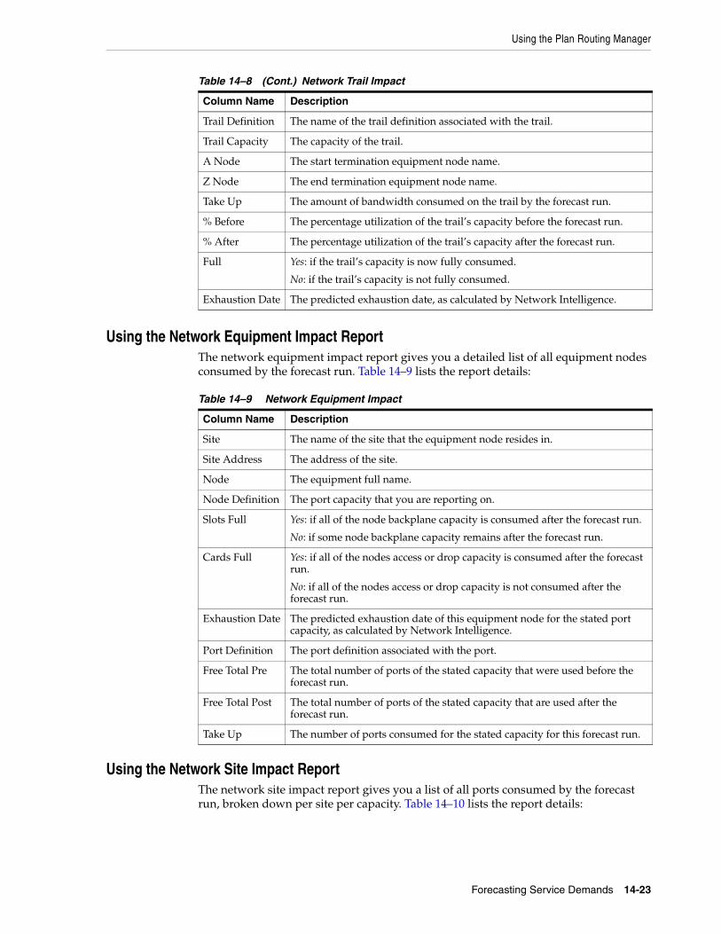
Using the Plan Routing Manager
Forecasting Service Demands 14-23
Using the Network Equipment Impact ReportThe network equipment impact report gives you a detailed list of all equipment nodes consumed by the forecast run. Table 14–9 lists the report details:
Using the Network Site Impact ReportThe network site impact report gives you a list of all ports consumed by the forecast run, broken down per site per capacity. Table 14–10 lists the report details:
Trail Definition The name of the trail definition associated with the trail.
Trail Capacity The capacity of the trail.
A Node The start termination equipment node name.
Z Node The end termination equipment node name.
Take Up The amount of bandwidth consumed on the trail by the forecast run.
% Before The percentage utilization of the trail’s capacity before the forecast run.
% After The percentage utilization of the trail’s capacity after the forecast run.
Full Yes: if the trail’s capacity is now fully consumed.
No: if the trail’s capacity is not fully consumed.
Exhaustion Date The predicted exhaustion date, as calculated by Network Intelligence.
Table 14–9 Network Equipment Impact
Column Name Description
Site The name of the site that the equipment node resides in.
Site Address The address of the site.
Node The equipment full name.
Node Definition The port capacity that you are reporting on.
Slots Full Yes: if all of the node backplane capacity is consumed after the forecast run.
No: if some node backplane capacity remains after the forecast run.
Cards Full Yes: if all of the nodes access or drop capacity is consumed after the forecast run.
No: if all of the nodes access or drop capacity is not consumed after the forecast run.
Exhaustion Date The predicted exhaustion date of this equipment node for the stated port capacity, as calculated by Network Intelligence.
Port Definition The port definition associated with the port.
Free Total Pre The total number of ports of the stated capacity that were used before the forecast run.
Free Total Post The total number of ports of the stated capacity that are used after the forecast run.
Take Up The number of ports consumed for the stated capacity for this forecast run.
Table 14–8 (Cont.) Network Trail Impact
Column Name Description

Using the Plan Routing Manager
14-24 Network Intelligence User's Guide
Using the Cost Estimation ReportsIf you create a planned object within a plan (using the plan maintenance manager), all the tasks (and related costs) associated with this new planned object are included in the cost report each time the plan routing manager is run.
You can create the following entities within a plan:
■ Site
■ Equipment
■ Trail
■ Topology.
The Cost Estimation Report details the estimated cost of carrying out the network build to satisfy the plan network demand.
The Cost Estimation Report sub-views define the plan in terms of:
■ Task details
■ Equipment cost details
■ Labor cost details
■ Trail cost details. See "Viewing Task Details".
■ Cost by service details
■ Planned entity costs. See "Viewing Planned Entity Cost Details".
■ OLO cost details.
The summary provides a list of associated costs, defined in terms of:
■ Capital expenditure
■ Operating expenditure
■ Network expenditure
■ Total expenditure.
Routing Solution Acceptance CostsThese costs are the cost of using successful routing solutions. When a route solution is accepted the system finds any tasks that are associated with the route solution
Table 14–10 Network Site Impact
Column Name Description
Site The name of the site that the ports reside in.
Site Address The address of the site.
Port Definition The port definition associated with the port.
Free Total Pre The total number of ports of the stated capacity that were used before the forecast run.
Free Total Post The total number of ports of the stated capacity that are used after the forecast run.
Take Up The number of ports consumed for the stated capacity for this forecast run.
Exhaustion Date The predicted exhaustion date of this equipment node for the stated port capacity, as calculated by Network Intelligence.
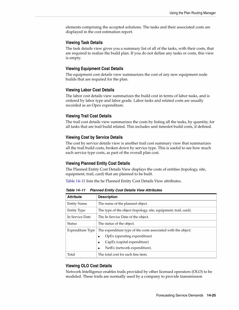
Using the Plan Routing Manager
Forecasting Service Demands 14-25
elements comprising the accepted solutions. The tasks and their associated costs are displayed in the cost estimation report.
Viewing Task DetailsThe task details view gives you a summary list of all of the tasks, with their costs, that are required to realize the build plan. If you do not define any tasks or costs, this view is empty.
Viewing Equipment Cost DetailsThe equipment cost details view summarizes the cost of any new equipment node builds that are required for the plan.
Viewing Labor Cost DetailsThe labor cost details view summarizes the build cost in terms of labor tasks, and is ordered by labor type and labor grade. Labor tasks and related costs are usually recorded as an Opex expenditure.
Viewing Trail Cost DetailsThe trail cost details view summarizes the costs by listing all the tasks, by quantity, for all tasks that are trail build related. This includes unit timeslot build costs, if defined.
Viewing Cost by Service DetailsThe cost by service details view is another trail cost summary view that summarizes all the trail build costs, broken down by service type. This is useful to see how much each service type costs, as part of the overall plan cost.
Viewing Planned Entity Cost DetailsThe Planned Entity Cost Details View displays the costs of entities (topology, site, equipment, trail, card) that are planned to be built.
Table 14–11 lists the he Planned Entity Cost Details View attributes.
Viewing OLO Cost DetailsNetwork Intelligence enables trails provided by other licensed operators (OLO) to be modeled. These trails are normally used by a company to provide transmission
Table 14–11 Planned Entity Cost Details View Attributes
Attribute Description
Entity Name The name of the planned object.
Entity Type The type of the object (topology, site, equipment, trail, card).
In Service Date The In Service Date of the object.
Status The status of the object.
Expenditure Type The expenditure type of the costs associated with the object:
■ OpEx (operating expenditure)
■ CapEx (capital expenditure)
■ NetEx (network expenditure).
Total The total cost for each line item.
Using the Plan Routing Manager
14-26 Network Intelligence User's Guide
coverage in areas where a company does not have any network. These trails have a leased cost associated with them, which is recorded as a monthly recurring cost.
The data loader process loads these costs into Network Intelligence from an outside source, and associates the cost with each leased trail. If you subsequently use these trails to path services in a forecast plan, the cost of each service consumption on the leased trails is listed in the cost summary report.
Saving Plan Run ResultsTo save a plan, click Save Report, and enter a name for the report. Each report must use a unique name. If you create a report name that is in use, a warning dialog box is displayed.
When a plan routing run is saved, all of the routing results are saved. This includes the status of a routing result, that is, whether the result has been accepted. All of the resources that each routing result consumes are also saved. You can easily reload a report at any time, and perform further plan routing with subsequent routing runs.
Rerunning a Plan RunYou can rerun a plan run at any time. For example, you might create a plan and route it for a particular period. You inspect the initial routing results, and accept service demand route solutions. For other service demands, you may make changes to the service policies to change the routing offered, or for failures, may alter the service policy to look for a routing solution on a rerun.
Suggested trails, cards, or equipment may be built, or new topologies or sites planned, and the plan rerun.
After each rerun, you can save the plan run as a report. After some iterations, during which changes were made, the plan is satisfactory. This normally occurs when the overall plan routing success percentage is sufficiently high. In certain cases, it may be 100 percent, which means that all of the service demands must be successfully routed.
Analyzing the Routing Solution and ResultA loaded report or a finished routing run can be rerun as many times as required. The most important view for routing solution analysis is the routing results view, which contains a list of all of the service demands that required routing.
The routing results view displays the success or failure status of each service demand, and whether the service demand result has been accepted. The popup menu associated with this view displays the options shown in Table 14–12.
Note: It may take a few moments for a plan routing run to save as a report, or reload as a report. The time taken depends on the number of service demands contained in the plan routing run.
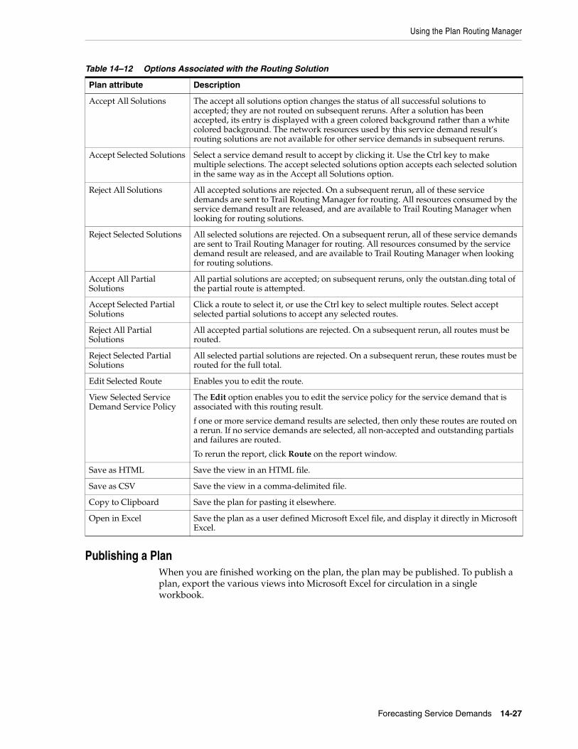
Using the Plan Routing Manager
Forecasting Service Demands 14-27
Publishing a PlanWhen you are finished working on the plan, the plan may be published. To publish a plan, export the various views into Microsoft Excel for circulation in a single workbook.
Table 14–12 Options Associated with the Routing Solution
Plan attribute Description
Accept All Solutions The accept all solutions option changes the status of all successful solutions to accepted; they are not routed on subsequent reruns. After a solution has been accepted, its entry is displayed with a green colored background rather than a white colored background. The network resources used by this service demand result’s routing solutions are not available for other service demands in subsequent reruns.
Accept Selected Solutions Select a service demand result to accept by clicking it. Use the Ctrl key to make multiple selections. The accept selected solutions option accepts each selected solution in the same way as in the Accept all Solutions option.
Reject All Solutions All accepted solutions are rejected. On a subsequent rerun, all of these service demands are sent to Trail Routing Manager for routing. All resources consumed by the service demand result are released, and are available to Trail Routing Manager when looking for routing solutions.
Reject Selected Solutions All selected solutions are rejected. On a subsequent rerun, all of these service demands are sent to Trail Routing Manager for routing. All resources consumed by the service demand result are released, and are available to Trail Routing Manager when looking for routing solutions.
Accept All Partial Solutions
All partial solutions are accepted; on subsequent reruns, only the outstan.ding total of the partial route is attempted.
Accept Selected Partial Solutions
Click a route to select it, or use the Ctrl key to select multiple routes. Select accept selected partial solutions to accept any selected routes.
Reject All Partial Solutions
All accepted partial solutions are rejected. On a subsequent rerun, all routes must be routed.
Reject Selected Partial Solutions
All selected partial solutions are rejected. On a subsequent rerun, these routes must be routed for the full total.
Edit Selected Route Enables you to edit the route.
View Selected Service Demand Service Policy
The Edit option enables you to edit the service policy for the service demand that is associated with this routing result.
f one or more service demand results are selected, then only these routes are routed on a rerun. If no service demands are selected, all non-accepted and outstanding partials and failures are routed.
To rerun the report, click Route on the report window.
Save as HTML Save the view in an HTML file.
Save as CSV Save the view in a comma-delimited file.
Copy to Clipboard Save the plan for pasting it elsewhere.
Open in Excel Save the plan as a user defined Microsoft Excel file, and display it directly in Microsoft Excel.

Using the Plan Routing Manager
14-28 Network Intelligence User's Guide

15
Managing Outages 15-1
15Managing Outages
This section describes the Outage Manager in Oracle Communications Network Intelligence. The Outage Manager is used to identify the impact of an outage on a network.
Generating an Outage ReportTo create an outage report using Outage Manager:
1. Perform one of the following:
■ Click Tools, and then select Outage Manager.
■ Click the Outage Manager icon on the toolbar:
■ Open the Plans tree browser, click the Create icon, and select Create New Outage Plan.
The opening page of the Outage Report Manager wizard is displayed.
2. Enter the plan details.
■ Name: The name of the planned outage. All plans must be unique.
■ Outage Owner: The person who generates the outage report.
■ Outage Type: Select Planned or Unplanned.
■ Start Date Time: The time and date on which the outage starts.
■ End Date Time: The time and date on which the outage ends.
■ Notes: Further description of the outage; for example: a reference number known by the customer, or order management system.
3. Click Next to display the Select Outage Resources dialog box.
4. Select the entities associated with the outage by selecting the required entity type from the Entity Type list; for example: click Add to include a resource group that includes some network entities in the application, specify a particular customer, or select an affected site (and all of its associated trails, which are retrieved automatically).
Click Import, and select a file of comma separated variable (CSV) format containing the entities to be associated with the outage; this can be generated using Microsoft Excel, for example. The file must be defined by columns called Entity Type and Entity Name.
Generating an Outage Report
15-2 Network Intelligence User's Guide
If several cards are associated with an outage, for example, carrying out a bulk import is a useful mechanism, rather than entering each card singly.
You can create an Outage Manager plan with multiple entities, and with entities of different types; for example: site and equipment. The supported entity types are:
■ Card
■ Customer
■ Equipment
■ Resource Group
■ Route
■ Service
■ Site
■ Topology
■ Trail
5. Click Add to display a search screen for entities of that type.
6. In the search window, enter an identifier for the entity in one of the search fields, if required, and click Search to select objects, or click Reset to clear all the search fields.
7. From the resulting entity types, choose the rows corresponding to the required entities, and click Select to add the objects to Outage Manager.
To add further entities, click the Add tab for that particular entity type, and perform the search.
To remove an entity from the list, click the required row, and click Remove.
8. Click Next to display all impacted entities. Click a tab to display a list of affected entities:
■ Impacted Customers
■ Impacted Services
■ Impacted Equipment
■ Impacted Sites
■ Impacted Trails for Notification
9. To select the trails to be displayed in the Impacted Trails for Notification report that is sent by email to mandated customer contacts, click the tabs for the other impacted entities, and select the required rows.
10. Click Next to select customer contacts to be notified of the outage by email.
If no contacts are selected, no emails are sent.
Note: If you use Outage Manager to search for trails, the search returns not only children of the trail, but where the selected trail is a protecting trail, the search also returns children of the protected trail.
Tip: Leaving all search fields in the window blank returns all network entities of that particular type.
Viewing Outage Reports
Managing Outages 15-3
See "Using Customer Contacts" for further information on contacts.
■ To notify a contact, click the corresponding row in the Contacts to Notify section. You cannot edit the contact information in this window.
To edit contact information, see "Editing a Contact".
■ To notify all listed customer contacts, select the Notify All Contacts check box.
■ To modify the subject title of the outage mail, edit the text in the Subject field.
■ Add more detail to the outage email in the Additional information to be added to email body field.
11. Click Next to save the outage plan.
12. Select one of the following:
■ Save and Display Plan
■ Save and Close Plan
Click Finish to complete the outage report. Selected contacts are notified of the outage by email. The outage plan is saved.
Viewing Outage ReportsOutage Manager creates reports listing all outage and impacted entities, and planned entities, and generates a set of service demands to find restoration paths for impacted services:
■ Viewing Service Demands
■ Viewing Studies
■ Viewing the Original Outage Entities
■ Viewing Impacted Trails
■ Viewing Impacted Equipment
■ Viewing Impacted Customers
■ Viewing Impacted Services
■ Viewing Impacted Locations
■ Viewing Impacted Sites
■ Viewing Planned Trails
■ Viewing Planned Equipment
■ Viewing Planned Cards
■ Viewing Planned Sites
■ Viewing Planned Topologies
Viewing Service DemandsTo view the service demands created by Outage Manager to find restoration paths for impacted services:
1. Create an outage plan as outlined in "Generating an Outage Report".
2. Select the View pane in the main GUI, and click Service Demands under the Plan heading.
Viewing Outage Reports
15-4 Network Intelligence User's Guide
3. To perform further actions on the service demands, see "Carrying out Actions on the Service Demands View".
Viewing StudiesTo analyze and compare forecast plans based on the generated restoration paths:
1. Select the View pane in the main GUI, and click Studies under the Plan heading.
2. To perform further actions on the listed plans, including comparing forecast plans, see "Using the Studies View".
Viewing the Original Outage EntitiesTo view the original outage entities:
1. Select the View pane in the main GUI, and click Original Outage Entities under the Original Outage Entities heading.
The Loaded From column is populated using the resource group to which the entities belong, or the spreadsheet from which the entities were loaded.
2. (Optional) Perform further actions on the entities:
■ To display an entity, double-click it.
■ To save the entity list, right-click to extract the table in HTML or CSV format, copy it to the clipboard, or open it in Microsoft Excel.
Viewing Impacted TrailsThere are two types of impacted trails supported in Outage Manager:
■ Service affecting trails: when impacted resources are not protected (or are protected by resources that are also affected), this is a service-affecting impact
■ Non-service affecting trails: when impacted resources are protected (or are themselves protecting other resources), this is a non-service-affecting impact
You can also view a routing report listing all impacted trails.
To view impacted trails:
1. Create an outage plan as outlined in "Generating an Outage Report", using the impacted services.
2. Select the View pane in the main GUI, and select one of the trail options under the Impact heading.
■ Impacted Trails (Service Affecting)
■ Impacted Trails (Non Service Affecting)
■ Impacted Trails Routing Report
3. (Optional) Perform further actions on the trails:
■ To perform a bulk update of trails:
In the routing report, select a trail, or a group of trails, right-click, and select Bulk Update Trails. See "Bulk Updating Trails".
■ To display a trail:
Double-click a trail in any of the impacted trail views.
Viewing Outage Reports
Managing Outages 15-5
■ To view a report of interest in summary or in detail:
Select a trail, or a group of trails, and right-click to extract the report in HTML or CSV format, copy it to the clipboard, or open it in Microsoft Excel.
Viewing Impacted EntitiesTo see a list of affected entities, click Impacted [Entities] to display a list of entities.
(Optional) Perform actions on the entities as follows:
■ To display an entity, double-click the entity in the view.
■ To view a report of interest in summary or in detail:
Select an entity, or a group of entities, and right-click to extract the report in HTML or CSV format, copy it to the clipboard, or open it in Microsoft Excel.
Related TopicsViewing Impacted Equipment
Viewing Impacted Customers
Viewing Impacted Services
Viewing Impacted Locations
Viewing Impacted Sites
Viewing Impacted EquipmentTo see a list of affected nodes, click Impacted Equipment to display the equipment listed by name, number of impacted trails, site, customer, and so on.
Viewing Impacted CustomersTo see a list of affected customers, click Impacted Customers to display the customers listed by name, type, and number of impacted entities per customer.
Viewing Impacted ServicesTo see a list of affected services, click Impacted Services to display the services listed by name, trail capacity, and number of impacted trails per service.
Viewing Impacted LocationsTo see a list of affected locations, click Impacted Locations to display the locations listed by name, number of impacted trails per location, address, and parent location.
Viewing Impacted SitesTo see a list of affected sites, click Impacted Sites to display the sites listed by name, number of impacted trails per site, address, geographical coordinates, site type, and so on.
Viewing Planned TrailsTo see a list of planned trails, click Planned Trails to display the trails listed by trail definition, A and Z site, service, and so on.
See "Using the Planned Trails View".
Viewing Outage Reports
15-6 Network Intelligence User's Guide
Viewing Planned EquipmentTo see a list of planned equipment, click Planned Equipment to display the equipment listed by definition, platform, type, and so on.
See "Using the Planned Equipment View".
Viewing Planned CardsTo see a list of planned cards, click Planned Cards to display the cards listed by site name, equipment name, slot name, card name, card definition, port definition, and supplier.
See "Using the Planned Cards View".
Viewing Planned SitesTo see a list of planned sites, click Planned Sites to display the sites listed by site name, address, type, location, and geographical coordinates.
See "Using the Planned Sites View".
Viewing Planned TopologiesTo see a list of planned topologies, click Planned Topologies to display the topologies listed by name, pattern, usage, network, supplier, status, and in service date.
See "Using the Planned Topologies View".
16
Migrating Network Entities 16-1
16Migrating Network Entities
This section describes the Migration Manager in Oracle Communications Network Intelligence. The Migration Manager is used to create a migration plan to generate network requirements changes to your network.
Creating a Migration PlanTo create a migration plan:
1. Perform one of the following to display the Migration Manager wizard:
■ Select Tools - Migration Manager from the main menu on the Network Intelligence GUI.
■ Click the Migration Manager icon under the main menu on the Network Intelligence GUI:
2. Enter a date on which the migration takes place in the Migration Project Date field. The date must be in the future.
Enter a name for the migration in the Migration Project Name field. The name must be unique within Network Intelligence.
Click Next to display the Select Network Entities window.
3. Find the network entity type to migrate. Selecting this type enables you to perform a search on network entities of this type in Network Intelligence.
From the Entity Type list, select the required network entity type:
■ Card
■ Trail
■ Customer
■ Equipment
■ Route
■ Service
■ Shelf
Tip: See "Migrating Cards" for further information on card migration using Migration Manager.
Creating a Migration Plan
16-2 Network Intelligence User's Guide
■ Site
■ Topology.
Click Search to display the (Entity Type) Search window; for example: Trail Search.
4. Click the Search tab to display a list of identifiers to help you to find the entities for the migration.
Select the Case Sensitive check box to enforce case sensitivity in the search fields.
For example: in the Trail Search window, the following identifiers are provided:
■ Name: Enter the name of the trail.
■ Trail Group: Select from the list of supported trail groups.
■ Trail Definitions: Select from the list of supported trail definitions.
■ Service: Select from the list of supported services.
■ Capacity: Select from the list of supported capacities.
■ A Site: Enter the name of the A site, or click the ellipsis button to open a Site Search window to find the originating site.
■ Z Site: Enter the name of the Z site, or click the ellipsis button to open a Site Search window to find the terminating site.
■ A Equipment: Enter the name of the A equipment, or click the ellipsis button to open an Equipment Search window to find the originating equipment. The equipment values in the window are disabled by default until a site is selected.
■ Z Equipment: Enter the name of the Z equipment, or click the ellipsis button to open an Equipment Search window to find the terminating equipment. The equipment values in the window are disabled by default until a site is selected.
■ A Port: Enter the name of the A port.
■ Z Port: Enter the name of the Z port.
■ Customer: Select from the list of supported customers.
■ Protection: Select the protection status for the service demand: Protected, Protection, Unprotected.
■ Presentation: Select the presentation type for the service demand: CHS, CSH, ISH, ISI, or Normal.
■ Route: Select the name of the route.
■ SequenceNo: Select the sequence number of the trail.
■ Supplier: Select from the list of supported suppliers; for example: Alcatel, Ericsson.
■ Media Type: Select from the list of supported media types; for example: Coax, Dark Fibre, Fibre.
■ Status: Select from the list of statuses; for example: Ceased, Faulty, Free, In Service, ONI Planned (where ONI signifies Oracle Network Intelligence).
■ Routed Status: Select from the list of routed statuses; for example: Routed, Partially Routed, Unrouted.
Creating a Migration Plan
Migrating Network Entities 16-3
■ Direction: Select from the list of directions; for example: BothWays, Incoming, Outgoing.
■ InService Date: Use the calendar window to select the date on which the selected trail came into service.
■ OutService Date: Use the calendar window to select the date on which the selected trail is due to be exhausted.
To further refine the trail search, use the Searchable Site Fields, or the Custom Fields.
Click Search to return the required entities, or click Reset to clear all the search fields.
5. Verify the entities to be migrated, and click Next.
Migration Manager processes each selected entity in turn to find both terminating and transiting trails relating to each migration object. It can take some time to complete.
To change the list, click Previous.
To remove entities from the table, right-click the selection and select Remove Selections.
6. Inspect the list of services, customers, and trails that are affected by the entities to be migrated.
The Services tab groups the trails referenced by the service. Selecting a service selects all of the trails that reference the service.
The Customers tab groups the trails by customer. Selecting a customer selects all of the trails belonging to that customer.
The Trails tab presents the full list of the trails for selection.
To migrate all trails, select the Select All check box and click Next.
To migrate a specific customer, or a particular service, click the Services tab, or the Customers tab, and select the required entity.
To change this selection, click Previous.
To remove entities from the table, right-click the selection and select Remove Selections.
7. Generate the migration rules for the new service demand by clicking Add.
Tip: Leaving all search fields blank returns all network entities of that particular type.
Note: The Next button is disabled until at least one trail has been selected for migration.
Note: Selecting a row under either the Services or Customers tab automatically selects the trails related to those services or customers in the Trails tab.
Creating a Migration Plan
16-4 Network Intelligence User's Guide
Create a migration rule by entering the current attributes, and the planned attributes. For example, to migrate a capacity, enter the capacity you want to migrate, and the capacity you want to migrate to. You can select from the following network attributes:
■ Customer
■ Service
■ Capacity
■ Quantity. The Quantity values in the window are disabled by default until a capacity is selected.
■ Start site (A Site)
■ End site (Z Site)
■ Start node (A Node). The node values in the window are disabled by default until a site is selected.
■ End node (Z Node). The node values in the window are disabled by default until a site is selected.
When you specify a new value, it is applied to all service demands that currently have that value. For example, if you change capacity from VC-12 to VC-4, all service demands that use VC-12 are changed to VC-4.
Click Create to generate the new rule, or click Close to exit the window without committing the new rule.
Click Add to create further migration rules, or click Remove to delete the selected rule.
Click Next to display the service demands that are used for the new trail routing plan.
8. Verify the service demands. Service demands are used by Forecast Manager to find rerouting path solutions for the migration traffic. To know, for example, only the customers and circuits affected by the migration, the service demands may not be of interest. Service demands do not include links.
The suggested path solutions exclude the entity being migrated; for example: if you migrate a site, RemoteOffice, the service demands listed in the Plan view display RemoteOffice as an excluded site.
To verify that an entity has been excluded after a migration plan has been completed for that entity, right-click a service demand, and select View Selected Service Demand Policy. In the Consolidated Rules Overview section, RemoteOffice is listed as an excluded site.
If the service demands are incorrect, click Previous to change the migration input.
9. Click Next to generate reports on:
■ Affected services
Note: The From and To values must not be the same.
Tip: When migrating from a site or node, you should set migration rules for both the start and end site, or node, because in some cases the traffic may be ingress or egress at that site or node.
Creating a Migration Plan
Migrating Network Entities 16-5
■ Affected customers
■ Affected trails
■ Trail decommissioning
■ Equipment hardware migration.
All reports are selected by default.
Click Next to save, and display, the migration plan.
10. Select one of the following:
■ Save and Display Plan
■ Save and Close Plan
Click Finish to complete the migration.
11. If you chose to display the migration plan, it is opened in a tab with the name of the plan. Use the Plan, Impact, Migration, and Planned Entities views to display the migration requirements.
Viewing Migration PlansTo view a migration plan:
1. Click the Plans tab in the context tool bar to view all plans within Network Intelligence: forecast plans, migration plans, and outage plans.
2. Expand the Migration folder to view the migration plans.
3. Double-click the required plan to view it.
Making Changes to a Migration PlanYou can share plans, modify the name of a plan, or delete the plan from Network Intelligence.
Related TopicsSharing the Plan
Changing the Name of the Plan
Deleting the Plan
Sharing the PlanBy sharing a plan, multiple Network Intelligence users can modify a plan. This feature might be useful where network planners are working on different elements of the same plan, or working at different locations.
To share a plan with other users of Network Intelligence:
1. Open the plan as outlined in "Viewing Migration Plans".
2. Click Edit to enable changes to the plan.
3. In the Shared field, select Yes.
4. Click Save.
The plan is visible to other users, who can edit and re-commit the plan as required.
Creating a Migration Plan
16-6 Network Intelligence User's Guide
Changing the Name of the PlanTo modify the name of a plan:
1. Open the plan as outlined in "Viewing Migration Plans".
2. Click Edit, and change the name of the plan.
3. Click Save.
Deleting the PlanTo delete a plan:
1. Open the plan as outlined in "Viewing Migration Plans".
2. Click Delete, and confirm the deletion.
The plan is deleted from the list of plans.
Migrating CardsThe requirements for migrating a significant number of cards using Migration Manager are significant, and must be taken into account before attempting any such migration.
For example, attempting to migrate all of the cards in a network may take some time, and the performance and memory requirements may also be significant. As a result, Migration Manager is not generally suitable for migrating all the cards in the network in one go.
Typically, card migration on this scale should be carried out on a site by site basis, using several migration plans.
17
Monitoring Network Data 17-1
17Monitoring Network Data
This section describes Monitor Report Manager in Oracle Communications Network Intelligence. Monitor Report Manager is a web-based analysis and reporting tool.
Starting Monitor Report ManagerYou start Monitor Report Manager in one of the following ways:
■ From within Network Intelligence.
■ Directly using a web browser.
Starting Monitor Report Manager from Within Network IntelligenceTo start Monitor Report Manager from within the Network Intelligence GUI:
1. Perform one of the following:
■ Click the Monitor icon on the main toolbar.
■ From the Tools menu, select Oracle Communications Network Intelligence Monitor Report Manager.
2. Log on using your user name and password.
3. From the main menu, select Monitor.
4. Select from:
■ My Reports: To see the list of reports in your user profile. You can use these reports to set report conditions.
■ Choose New Reports: To view all available reports. Select reports that are of interest.
Starting Monitor Report Manager Using a Web BrowserTo start Monitor Report Manager using a web browser:
1. Enter a URL in the following format:
http://host_name:port/netintel-server/
where host_name is the listen address configured during domain creation and port is the listen port for the domain.
2. Log on using your user name and password.
3. From the main menu, select Monitor.
Starting Monitor Report Manager
17-2 Network Intelligence User's Guide
4. Select from:
■ My Reports: To see the list of reports in your user profile. You can use these reports to set report conditions.
■ Choose New Reports: To view all available reports. Select reports that are of interest.
Using Email NotificationYou can configure Network Intelligence to email reports from Monitor Report Manager when a user report condition is met. The email contains a link to the report or reports where these conditions have been met.
See "Setting Conditions on a Report".
Configuring Email and SMTP SettingsFor the email feature of Monitor Report Manager to work correctly, ensure that:
1. The SMTP details requested during the installation of Network Intelligence are correctly configured.
If the SMTP details need to be modified after installation of Network Intelligence, see the troubleshooting chapter of Network Intelligence Installation Guide, which describes the steps involved in modifying the mail.properties file.
2. The current user has a valid email address configured. This can be configured using the My Profile link in the Network Intelligence user interface. See "Viewing Your Reports".
After these prerequisites have been met, email notifications should arrive for each of the report conditions that are met when the report monitor scheduled task is executed. To configure the interval at which the report monitor scheduled task runs, see "Modifying the Scheduled Task Settings".
Modifying the Scheduled Task Settings To modify the scheduled task settings:
1. Stop Network Intelligence using Oracle WebLogic.
See Network Intelligence System Administrator’s Guide for further information on stopping Network Intelligence.
2. Navigate to the directory containing the EAR, network-intelligence.ear. Open the file.
For further information on unpacking and repacking an EAR file, see the chapter on extracting the Network Intelligence EAR file in Network Intelligence Developer’s Guide.
3. Open the netintel-server.war file, and from the WEB-INF/lib directory, open the netsure_business.jar file.
Tip: To verify that your email address and SMTP settings are correctly configured, click Have your password hint e-mailed to you on the main Network Intelligence login page.
If you receive an email containing the password hint, all settings are configured correctly.
Starting Monitor Report Manager
Monitoring Network Data 17-3
4. Extract the applicationContext-scheduling.xml file, and open it for editing using a text editor such as VI, or Notepad.
5. Find the reportMonitorScheduledTask section of the file.
The scheduled task is configured by default to run every day. To run the scheduled task at a different frequency, calculate the number of milliseconds; for example: 60000 ms to run the scheduled task every minute.
6. After making the required changes, save and close all open files.
7. Repackage the WAR and EAR files using the information in Network Intelligence Developer’s Guide, as required.
8. Restart Network Intelligence using WebLogic to put these changes into effect.
Selecting Reports of InterestUse the Choose New Reports page to select reports that are of interest. To view all reports, check the Select All check box in the top column. To select or deselect an individual report, use the check box on the top row of the report table.
Viewing Your ReportsThe My Reports page lists all of the reports you have stored in your user profile, thus allowing you to set report conditions. You can view a full report or a conditional report, or edit any conditions attached to a particular report.
Adding a ReportTo add a report to the My Reports page:
1. From the My Reports page, click Add & Remove Report(s).
2. From the Choose Reports page, select the Select All check box associated with the report to be added.
3. Click Save.
The report is added to the My Reports page.
Deleting a ReportTo delete a report from the My Reports page:
1. From the My Reports page, click Add & Remove Report(s).
2. From the Choose Reports page, deselect the Select All check box associated with the report to be added.
3. Click Save.
The report is removed from the My Reports page.
Viewing a Full ReportTo display an individual report:
Note: Use the delay property to configure the time taken before the scheduled task runs again.
Starting Monitor Report Manager
17-4 Network Intelligence User's Guide
1. Open the My Reports page.
2. Click the icon corresponding to the required report.
3. The report is rendered in HTML, but may also be extracted in the following formats:
■ CSV
■ Microsoft Excel
Exporting to Microsoft Excel automatically starts Microsoft Excel (if it is available on the computer on which the web browser accesses the report), and displays the report in a new worksheet.
■ XML
Setting Conditions on a ReportYou may set one or more conditions on a report. Conditions are set on report statistics, that is, elements in the report. The available conditions depend on the report element data type (whether it is a date element, or a number element, and so on). You can also remove conditions from any report.
All conditions are checked at a scheduled time; For example, every day at 9 AM, and if a condition occurs, the user is notified by an email alert.
To set a condition on a report:
1. Open the My Reports page.
2. Click the Conditions icon on the required report.
The user conditions for the report are displayed.
3. Edit the user report condition by clicking the condition name. See "Setting a User Report Condition".
Related TopicsSetting a User Report Condition
Adding a User Report Condition
Setting a User Report ConditionTo set a condition, select the report statistic, and apply the condition. Conditions require a description. After the condition is set to active, it is saved to the monitor condition table in the database.
Adding a User Report ConditionTo add a condition:
1. Click Add on the report conditions page.
2. From the Statistic list, select the required report statistic.
3. Select from the list of operators.
4. Enter a value, or select a date and time to apply to the condition, using the DD/MM/YYYY format.
5. Save the condition to the monitor condition table in the database by checking the Active box. The default is unchecked.
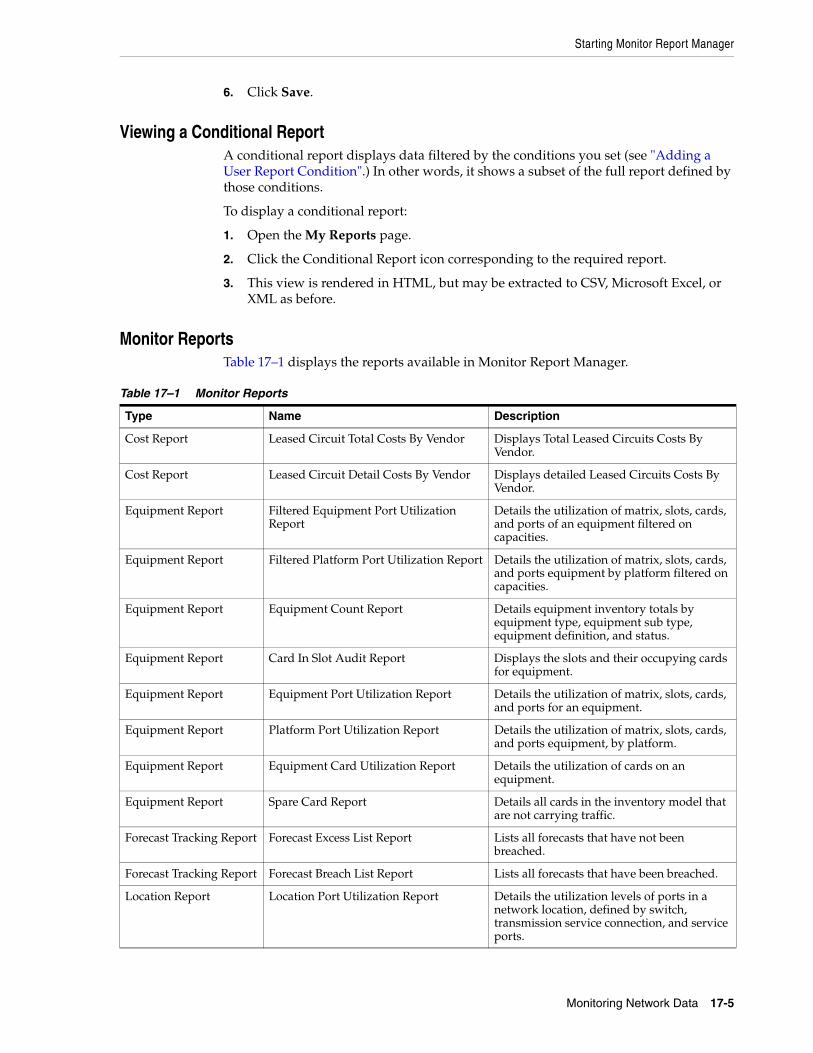
Starting Monitor Report Manager
Monitoring Network Data 17-5
6. Click Save.
Viewing a Conditional ReportA conditional report displays data filtered by the conditions you set (see "Adding a User Report Condition".) In other words, it shows a subset of the full report defined by those conditions.
To display a conditional report:
1. Open the My Reports page.
2. Click the Conditional Report icon corresponding to the required report.
3. This view is rendered in HTML, but may be extracted to CSV, Microsoft Excel, or XML as before.
Monitor ReportsTable 17–1 displays the reports available in Monitor Report Manager.
Table 17–1 Monitor Reports
Type Name Description
Cost Report Leased Circuit Total Costs By Vendor Displays Total Leased Circuits Costs By Vendor.
Cost Report Leased Circuit Detail Costs By Vendor Displays detailed Leased Circuits Costs By Vendor.
Equipment Report Filtered Equipment Port Utilization Report
Details the utilization of matrix, slots, cards, and ports of an equipment filtered on capacities.
Equipment Report Filtered Platform Port Utilization Report Details the utilization of matrix, slots, cards, and ports equipment by platform filtered on capacities.
Equipment Report Equipment Count Report Details equipment inventory totals by equipment type, equipment sub type, equipment definition, and status.
Equipment Report Card In Slot Audit Report Displays the slots and their occupying cards for equipment.
Equipment Report Equipment Port Utilization Report Details the utilization of matrix, slots, cards, and ports for an equipment.
Equipment Report Platform Port Utilization Report Details the utilization of matrix, slots, cards, and ports equipment, by platform.
Equipment Report Equipment Card Utilization Report Details the utilization of cards on an equipment.
Equipment Report Spare Card Report Details all cards in the inventory model that are not carrying traffic.
Forecast Tracking Report Forecast Excess List Report Lists all forecasts that have not been breached.
Forecast Tracking Report Forecast Breach List Report Lists all forecasts that have been breached.
Location Report Location Port Utilization Report Details the utilization levels of ports in a network location, defined by switch, transmission service connection, and service ports.
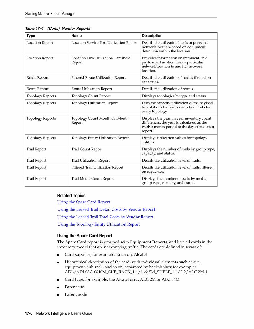
Starting Monitor Report Manager
17-6 Network Intelligence User's Guide
Related TopicsUsing the Spare Card Report
Using the Leased Trail Detail Costs by Vendor Report
Using the Leased Trail Total Costs by Vendor Report
Using the Topology Entity Utilization Report
Using the Spare Card ReportThe Spare Card report is grouped with Equipment Reports, and lists all cards in the inventory model that are not carrying traffic. The cards are defined in terms of:
■ Card supplier; for example: Ericsson, Alcatel
■ Hierarchical description of the card, with individual elements such as site, equipment, sub-rack, and so on, separated by backslashes; for example: ADL/ADL03/1664SM_SUB_RACK_1-1/1664SM_SHELF_1-1/2-2/ALC 2M-1
■ Card type; for example: the Alcatel card, ALC 2M or ALC 34M
■ Parent site
■ Parent node
Location Report Location Service Port Utilization Report Details the utilization levels of ports in a network location, based on equipment definition within the location.
Location Report Location Link Utilization Threshold Report
Provides information on imminent link payload exhaustion from a particular network location to another network location.
Route Report Filtered Route Utilization Report Details the utilization of routes filtered on capacities.
Route Report Route Utilization Report Details the utilization of routes.
Topology Reports Topology Count Report Displays topologies by type and status.
Topology Reports Topology Utilization Report Lists the capacity utilization of the payload timeslots and service connection ports for every topology.
Topology Reports Topology Count Month On Month Report
Displays the year on year inventory count differences; the year is calculated as the twelve month period to the day of the latest report.
Topology Reports Topology Entity Utilization Report Displays utilization values for topology entities.
Trail Report Trail Count Report Displays the number of trails by group type, capacity, and status.
Trail Report Trail Utilization Report Details the utilization level of trails.
Trail Report Filtered Trail Utilization Report Details the utilization level of trails, filtered on capacities.
Trail Report Trail Media Count Report Displays the number of trails by media, group type, capacity, and status.
Table 17–1 (Cont.) Monitor Reports
Type Name Description
Starting Monitor Report Manager
Monitoring Network Data 17-7
■ Unoccupied slot
Using the Leased Trail Detail Costs by Vendor ReportThe Leased Trail Detail Costs by Vendor report is grouped with Cost Reports, and lists, by vendor, all of the leased trails that have costs assigned to them.
The trails are defined in terms of:
■ Vendor: The company that has leased the line.
■ Trail: The trail name.
■ Bandwidth: The transmission capacity of the leased trail.
■ Service: The service that applies to the leased trail; for example: ATM, IP Business, Transport.
■ Total Cost: The accumulated costs associated with the leased trail.
■ Trail Reference: External reference data prefilled by a loader, and taken from the Trail table.
For further information on data loading in Network Intelligence, see Network Intelligence Developer’s Guide.
■ A Site: The originating site for the trail.
■ Z Site: The terminating site for the trail.
■ A Node: The originating node for the trail.
■ Z Node: The terminating node for the trail.
Using the Leased Trail Total Costs by Vendor ReportThe Leased Trail Total Costs by Vendor report is also grouped with Cost Reports, and contains a summary of the total costs of all of the trails that have costs assigned to them.
The trails are defined in terms of:
■ Vendor: The company that has leased the line.
■ Bandwidth: The transmission capacity of the leased trail.
■ Service: The service that applies to the leased trail; for example: ATM, IP Business, Transport.
■ Total Cost: The accumulated costs associated with the leased trail.
Using the Topology Entity Utilization ReportThe Topology Entity Utilization report is grouped with the Topology Reports, and provides a table listing the average utilization for each topology object. This report enables you to view utilization metrics for your topologies. You can also set thresholds at the topology level to monitor growth trends.
The topology objects are defined in terms of:
■ Topology name: The topology on which the utilization is being measured.
■ Topology pattern: The topology pattern.
■ Capacity name: The name of the capacity associated with the topology.
■ Entity Type: for example: Path, Link, Slot, or Port.

Starting Monitor Report Manager
17-8 Network Intelligence User's Guide
■ Average Utilization percentage: The average utilization value across the entities selected in the topology.
■ Total: The total number of the particular entity type in the topology.
■ Used: The number of the particular entity type in the topology in use.
■ Free: The number of the particular entity type in the topology that are free.