E72209_rev_1.pdf - Oracle Help Center
232
Oracle ® Communications EAGLE Maintenance Guide Release 46.3 E72209 Revision 1 June 2016
-
Upload
khangminh22 -
Category
Documents
-
view
1 -
download
0
Transcript of E72209_rev_1.pdf - Oracle Help Center

Oracle® CommunicationsEAGLEMaintenance Guide
Release 46.3
E72209 Revision 1
June 2016

Oracle Communications EAGLE Maintenance Guide, Release 46.3Copyright © 1993, 2016, Oracle and/or its affiliates. All rights reserved.
This software and related documentation are provided under a license agreement containing restrictionson use and disclosure and are protected by intellectual property laws. Except as expressly permitted in yourlicense agreement or allowed by law, you may not use, copy, reproduce, translate, broadcast, modify, license,transmit, distribute, exhibit, perform, publish, or display any part, in any form, or by any means. Reverseengineering, disassembly, or decompilation of this software, unless required by law for interoperability, isprohibited.
The information contained herein is subject to change without notice and is not warranted to be error-free.If you find any errors, please report them to us in writing.
If this is software or related documentation that is delivered to the U.S. Government or anyone licensing iton behalf of the U.S. Government, then the following notice is applicable:
U.S. GOVERNMENT END USERS: Oracle programs, including any operating system, integrated software,any programs installed on the hardware, and/or documentation, delivered to U.S. Government end usersare "commercial computer software" pursuant to the applicable Federal Acquisition Regulation andagency-specific supplemental regulations. As such, use, duplication, disclosure, modification, and adaptationof the programs, including any operating system, integrated software, any programs installed on thehardware, and/or documentation, shall be subject to license terms and license restrictions applicable to theprograms. No other rights are granted to the U.S. Government.
This software or hardware is developed for general use in a variety of information management applications.It is not developed or intended for use in any inherently dangerous applications, including applicationsthat may create a risk of personal injury. If you use this software or hardware in dangerous applications,then you shall be responsible to take all appropriate fail-safe, backup, redundancy, and other measures toensure its safe use. Oracle Corporation and its affiliates disclaim any liability for any damages caused byuse of this software or hardware in dangerous applications.
Oracle and Java are registered trademarks of Oracle and/or its affiliates. Other names may be trademarksof their respective owners.
Intel and Intel Xeon are trademarks or registered trademarks of Intel Corporation. All SPARC trademarksare used under license and are trademarks or registered trademarks of SPARC International, Inc. AMD,Opteron, the AMD logo, and the AMD Opteron logo are trademarks or registered trademarks of AdvancedMicro Devices. UNIX is a registered trademark of The Open Group.
This software or hardware and documentation may provide access to or information about content, products,and services from third parties. Oracle Corporation and its affiliates are not responsible for and expresslydisclaim all warranties of any kind with respect to third-party content, products, and services unless otherwiseset forth in an applicable agreement between you and Oracle. Oracle Corporation and its affiliates will notbe responsible for any loss, costs, or damages incurred due to your access to or use of third-party content,products, or services, except as set forth in an applicable agreement between you and Oracle.
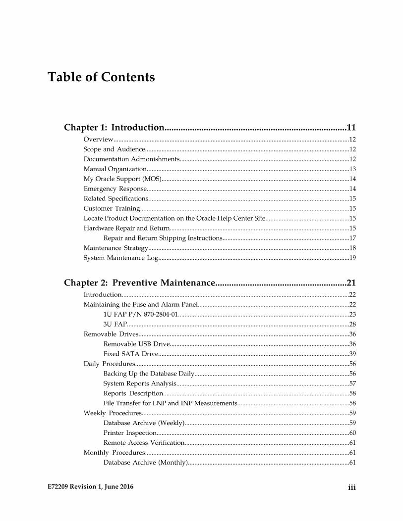
Table of Contents
Chapter 1: Introduction...............................................................................11Overview...............................................................................................................................................12Scope and Audience............................................................................................................................12Documentation Admonishments.......................................................................................................12Manual Organization...........................................................................................................................13My Oracle Support (MOS)..................................................................................................................14Emergency Response...........................................................................................................................14Related Specifications..........................................................................................................................15Customer Training...............................................................................................................................15Locate Product Documentation on the Oracle Help Center Site...................................................15Hardware Repair and Return.............................................................................................................15
Repair and Return Shipping Instructions.............................................................................17Maintenance Strategy..........................................................................................................................18System Maintenance Log....................................................................................................................19
Chapter 2: Preventive Maintenance.........................................................21Introduction..........................................................................................................................................22Maintaining the Fuse and Alarm Panel............................................................................................22
1U FAP P/N 870-2804-01........................................................................................................233U FAP.......................................................................................................................................28
Removable Drives................................................................................................................................36Removable USB Drive.............................................................................................................36Fixed SATA Drive....................................................................................................................39
Daily Procedures..................................................................................................................................56Backing Up the Database Daily..............................................................................................56System Reports Analysis.........................................................................................................57Reports Description.................................................................................................................58File Transfer for LNP and INP Measurements....................................................................58
Weekly Procedures..............................................................................................................................59Database Archive (Weekly)....................................................................................................59Printer Inspection.....................................................................................................................60Remote Access Verification....................................................................................................61
Monthly Procedures............................................................................................................................61Database Archive (Monthly)..................................................................................................61
iiiE72209 Revision 1, June 2016
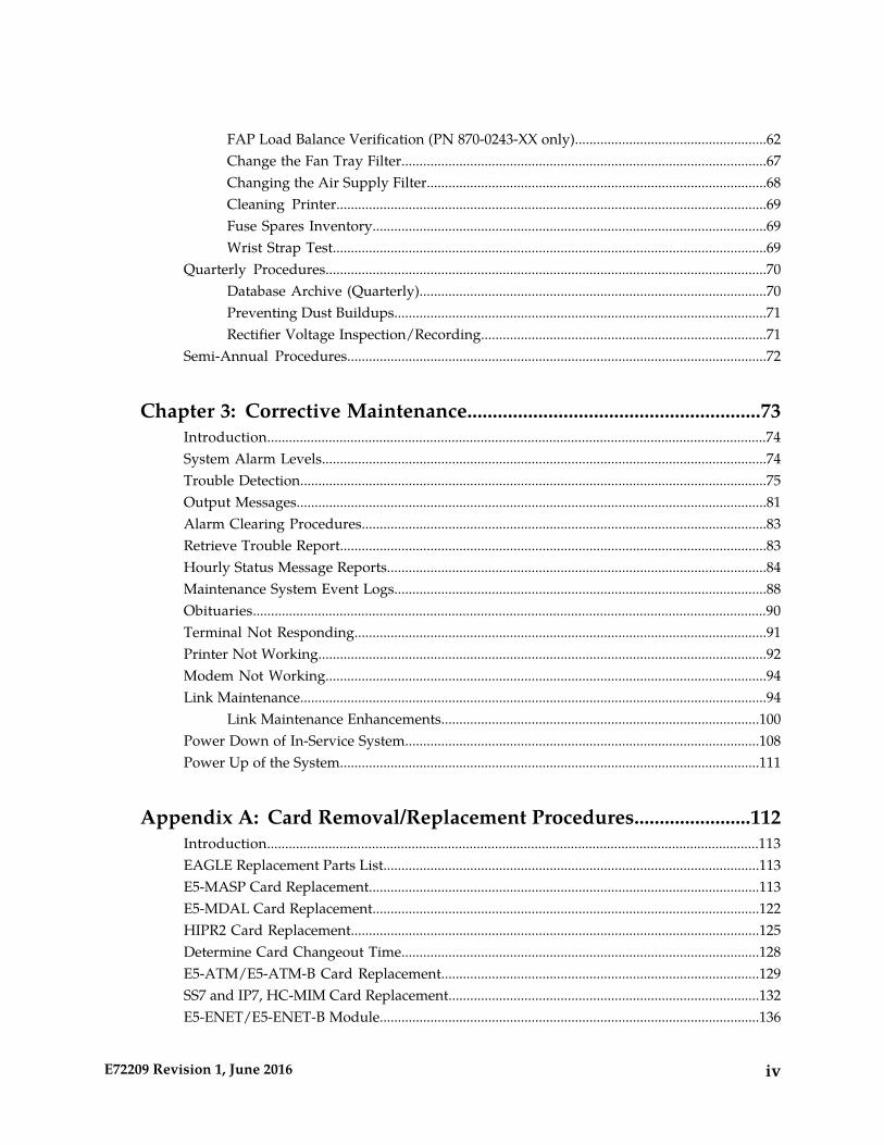
FAP Load Balance Verification (PN 870-0243-XX only).....................................................62Change the Fan Tray Filter.....................................................................................................67Changing the Air Supply Filter..............................................................................................68Cleaning Printer.......................................................................................................................69Fuse Spares Inventory.............................................................................................................69Wrist Strap Test........................................................................................................................69
Quarterly Procedures..........................................................................................................................70Database Archive (Quarterly)................................................................................................70Preventing Dust Buildups.......................................................................................................71Rectifier Voltage Inspection/Recording...............................................................................71
Semi-Annual Procedures....................................................................................................................72
Chapter 3: Corrective Maintenance..........................................................73Introduction..........................................................................................................................................74System Alarm Levels...........................................................................................................................74Trouble Detection.................................................................................................................................75Output Messages..................................................................................................................................81Alarm Clearing Procedures................................................................................................................83Retrieve Trouble Report......................................................................................................................83Hourly Status Message Reports.........................................................................................................84Maintenance System Event Logs.......................................................................................................88Obituaries..............................................................................................................................................90Terminal Not Responding..................................................................................................................91Printer Not Working............................................................................................................................92Modem Not Working..........................................................................................................................94Link Maintenance.................................................................................................................................94
Link Maintenance Enhancements........................................................................................100Power Down of In-Service System..................................................................................................108Power Up of the System....................................................................................................................111
Appendix A: Card Removal/Replacement Procedures.......................112Introduction........................................................................................................................................113EAGLE Replacement Parts List........................................................................................................113E5-MASP Card Replacement............................................................................................................113E5-MDAL Card Replacement...........................................................................................................122HIPR2 Card Replacement.................................................................................................................125Determine Card Changeout Time...................................................................................................128E5-ATM/E5-ATM-B Card Replacement........................................................................................129SS7 and IP7, HC-MIM Card Replacement......................................................................................132E5-ENET/E5-ENET-B Module.........................................................................................................136
ivE72209 Revision 1, June 2016
IP SIGTRAN on E5-ENET/E5-ENET-B..............................................................................138STPLAN/EROUTE on E5-ENET/E5-ENET-B ..................................................................141
E5-TSM Card Replacement...............................................................................................................145Database Services Module (DSM)....................................................................................................147E5-SM4G/E5-SM8G-B Card Replacement.....................................................................................149E5-IPSM Card Replacement.............................................................................................................152Database Communications Module (DCM)...................................................................................157Measurement Collection and Polling Module (E5-MCPM).........................................................159Replacing a Card in the EAGLE.......................................................................................................160Replacing Cards in the Holdover Clock.........................................................................................162
Non-Failed Clock Input (CI) Card Replacement...............................................................163ST3 Card Replacement..........................................................................................................164MIS Card Replacement..........................................................................................................165TOCA Card Replacement.....................................................................................................166
Fan Assembly P/N 890-0001-xx.......................................................................................................168Replace the Fan Unit..............................................................................................................169Replace Fan Controller Card................................................................................................169Replace Fan Assembly...........................................................................................................170
Appendix B: Holdover Clock Troubleshooting Procedures..............179Introduction........................................................................................................................................180Interpreting System Alarms, Lamps And Trouble Isolation.......................................................180
Appendix C: Part Numbers......................................................................190Overview.............................................................................................................................................191Cables, Adapters................................................................................................................................191Components........................................................................................................................................196Frames, Backplanes, FAPs, and Fans..............................................................................................198Labels...................................................................................................................................................200Miscellaneous Parts............................................................................................................................201Power Cords for Peripherals............................................................................................................203
Glossary.............................................................................................................................205
vE72209 Revision 1, June 2016
List of Figures
Figure 1: FAP High-Level Block Diagram....................................................................................................23
Figure 2: Shorting Board Faceplate, Normal Mode.....................................................................................26
Figure 3: Shorting Board Faceplate, Maintenance Mode...........................................................................26
Figure 4: Diode Board Faceplate....................................................................................................................27
Figure 5: Diode Board Edge Connector J1....................................................................................................27
Figure 6: Shorting Board Faceplate, Maintenance Mode...........................................................................28
Figure 7: Shorting Board Faceplate, Normal Mode.....................................................................................28
Figure 8: Location of FAP Components........................................................................................................29
Figure 9: FAP Component Functions............................................................................................................30
Figure 10: Removable USB Drive LOCKED.................................................................................................37
Figure 11: Removable USB Drive UNLOCKED..........................................................................................38
Figure 12: SATA Drive Locked......................................................................................................................43
Figure 13: SATA Drive UNLOCKED............................................................................................................44
Figure 14: Open Diode Example....................................................................................................................65
Figure 15: Steady State Example....................................................................................................................65
Figure 16: Fan Assembly.................................................................................................................................67
Figure 17: Fan Filter Replacement.................................................................................................................68
Figure 18: GMT Fuse........................................................................................................................................76
Figure 19: Fuse and Alarm Panel Front Layout (870-2804-01)..................................................................77
Figure 20: Fuse and Alarm Panel Front Layout (870-0243-xx)..................................................................78
Figure 21: Fuse and Alarm Panel Front Layout (870-1606-xx/870-2320-xx)...........................................79
Figure 22: Output Message Format...............................................................................................................81
viE72209 Revision 1, June 2016

Figure 23: Format of Hourly Status Message Output.................................................................................86
Figure 24: Signaling Link Network Connections......................................................................................101
Figure 25: E5-MASP Card Inject/Eject Hardware Switch, UNLOCKED..............................................116
Figure 26: E5-MASP Card Inject/Eject Hardware Switch, LOCKED.....................................................117
Figure 27: E5-MASP LEDs............................................................................................................................122
Figure 28: E5-MDAL LEDs...........................................................................................................................124
Figure 29: HIPR2 LEDs..................................................................................................................................128
Figure 30: E5-ATM/E5-ATM-B LEDs.........................................................................................................132
Figure 31: HC MIM LEDs.............................................................................................................................136
Figure 32: E5-ENET LEDs.............................................................................................................................137
Figure 33: E5-SM4G/E5-SM8G-B LEDs......................................................................................................152
Figure 34: DCM LEDs....................................................................................................................................159
Figure 35: Push Inject/Eject Clamps Outward..........................................................................................161
Figure 36: Push in Inject/Eject Clamps.......................................................................................................162
Figure 37: Holdover Clock CI Card LEDs..................................................................................................163
Figure 38: Holdover clock ST3 card LEDs..................................................................................................165
Figure 39: Holdover Clock MIS Card LEDs...............................................................................................166
Figure 40: Holdover Clock TOCA Card LEDs...........................................................................................167
Figure 41: Holdover Clock MCA Card LEDs.............................................................................................168
Figure 42: Fan Unit Mounting Screws.........................................................................................................169
Figure 43: Fan card with LEDs on front of fan assembly unit.................................................................171
Figure 44: Fan Assembly Rear Bracket Screws..........................................................................................172
Figure 45: Fan Assembly...............................................................................................................................172
Figure 46: Fan tray inserted into fan tray bracket in the frame - front view.........................................173
Figure 47: Tighten rear fan tray screws.......................................................................................................174
viiE72209 Revision 1, June 2016

Figure 48: Tighten fan side bracket screws.................................................................................................175
Figure 49: Fan card with LEDs on front of fan assembly.........................................................................176
viiiE72209 Revision 1, June 2016
List of Tables
Table 1: Admonishments................................................................................................................................13
Table 2: Basic RMA Types...............................................................................................................................16
Table 3: RMA Reasons for Return..................................................................................................................16
Table 4: System Maintenance Log.................................................................................................................20
Table 5: FAP Component Replacement........................................................................................................23
Table 6: FAP Alarm Conditions.....................................................................................................................24
Table 7: Additional Alarm Indicators...........................................................................................................25
Table 8: Power Diode Test Points..................................................................................................................27
Table 9: FAP Component Replacement........................................................................................................30
Table 10: FAP Alarm Conditions...................................................................................................................32
Table 11: Additional Alarm Indicators.........................................................................................................32
Table 12: FAP Part Numbers and Corresponding Procedures..................................................................33
Table 13: Oracle Method of Procedure Test Record....................................................................................66
Table 14: Fuse and Alarm Panel Front Items (870-2804-01).......................................................................77
Table 15: Fuse and Alarm Panel Front Items (870-0243-xx).......................................................................77
Table 16: Fuse and Alarm Panel Front Items (870-1606-xx/870-2320-xx)................................................78
Table 17: IMT Bus Alarm Levels....................................................................................................................81
Table 18: Remote Link Element types...........................................................................................................94
Table 19: Link Fault Sectionalization Test Types.........................................................................................95
Table 20: Link Fault Sectionalization Test Patterns.....................................................................................96
Table 21: Hardware/Card/APPL LFS Support...........................................................................................96
Table 22: Link Fault Sectionalization Data Entry Parameters...................................................................98
ixE72209 Revision 1, June 2016

Table 23: Link Fault Sectionalization Test Parameters...............................................................................99
Table 24: Command Driven Loopback Support........................................................................................101
Table 25: tst-slk Support................................................................................................................................102
Table 26: tst-e1/tst-t1 Support......................................................................................................................102
Table 27: Loopback AST Field Display.......................................................................................................108
Table 28: Card Locations...............................................................................................................................114
Table 29: DCM Card Locations....................................................................................................................157
Table 30: Input and ST3 Alarm Conditions................................................................................................180
Table 31: Input and ST3 Corrective Actions...............................................................................................182
Table 32: Shelf and Output Alarm Conditions - Not Related to Input and ST Conditions.................184
Table 33: Shelf and Output Corrective Actions - Not Related to Input and ST Conditions...............187
Table 34: EAGLE 5 Cables, Connectors, and Power Cords......................................................................191
Table 35: EAGLE Components.....................................................................................................................196
Table 36: EAGLE Frames, Backplanes, FAPs, and Fans...........................................................................198
Table 37: EAGLE Labels................................................................................................................................200
Table 38: EAGLE Miscellaneous Part Numbers........................................................................................201
Table 39: Power Cords for Peripherals........................................................................................................203
xE72209 Revision 1, June 2016

Chapter
1Introduction
This chapter contains an overview of the manual,describes how to obtain help, where to find related
Topics:
• Overview.....12 documentation, and provides other generalinformation.• Scope and Audience.....12
• Documentation Admonishments.....12• Manual Organization.....13• My Oracle Support (MOS).....14• Emergency Response.....14• Related Specifications.....15• Customer Training.....15• Locate Product Documentation on the Oracle Help
Center Site.....15• Hardware Repair and Return.....15• Maintenance Strategy.....18• System Maintenance Log.....19
11E72209 Revision 1, June 2016
Overview
Maintenance Guide provides preventive and corrective maintenance procedures used in maintainingthe Oracle Communications EAGLE and the Multi-Purpose Server (MPS) systems.
Attention: Be sure to wear a wrist strap connected to the wrist strap grounding point of the EAGLEbefore performing any installation procedures on the EAGLE.
The manual is organized as follows:
• Introduction provides general information about the organization of this manual, a description ofthe EAGLE maintenance strategy, and a list of acronyms and abbreviations.
• Preventive Maintenance provides recommended scheduled routines for the EAGLE.
• Corrective Maintenance provides procedures to use in response to all system alarms by the EAGLE.
In addition, these appendices of this manual provide useful reference material for maintenance,diagnostic, and troubleshooting activities.
• Card Removal/Replacement Procedures
• Holdover Clock Troubleshooting Procedures
• Part Numbers
Scope and Audience
This manual is intended for maintenance personnel who must maintain the EAGLE. The technicianshould be familiar with SS7 protocols. The manual provides preventive and corrective proceduresthat will aid maintenance personnel in maintaining the EAGLE.
Preventive maintenance procedures are routines to be carried out on a scheduled basis to help preventsystem failures. These routines are industry-standard recommendations and may be adopted to fitany company maintenance plan.
The corrective maintenance procedures are those used in response to a system alarm or output message.These procedures are EAGLE-specific and aid in the detection, isolation, and repair of faults.
Documentation Admonishments
Admonishments are icons and text throughout this manual that alert the reader to assure personalsafety, to minimize possible service interruptions, and to warn of the potential for equipment damage.
12E72209 Revision 1, June 2016
IntroductionMaintenance

Table 1: Admonishments
DescriptionIcon
Danger:
(This icon and text indicate the possibility ofpersonal injury.)
Warning:
(This icon and text indicate the possibility ofequipment damage.)
Caution:
(This icon and text indicate the possibility ofservice interruption.)
Topple:
(This icon and text indicate the possibility ofpersonal injury and equipment damage.)
Manual Organization
Maintenance Guide is organized into the following chapters:
• Introduction — Contains general information about manual organization, the scope of this manual,its targeted audience, brief explanations of the various systems, typical content of a DocumentationSuite delivered with each system, how to handle hardware repairs and returns, and how to gettechnical assistance.
• Preventive Maintenance — Contains recommended routine maintenance procedures to be performedon a scheduled basis.
• Corrective Maintenance — Contains corrective maintenance and alarm clearing procedures used tocorrect issues.
• Card Removal/Replacement Procedures — Contains card removal and replacement procedures,including administrative commands required to take a card out of service and place it back intoservice.
• Holdover Clock Troubleshooting Procedures — Describes holdover clock alarm conditions and offerstroubleshooting procedures.
• Part Numbers — Contains the part numbers of Oracle equipment, components, cables, andmiscellaneous parts described in this guide.
13E72209 Revision 1, June 2016
IntroductionMaintenance
My Oracle Support (MOS)
MOS (https://support.oracle.com) is your initial point of contact for all product support and trainingneeds. A representative at Customer Access Support (CAS) can assist you with MOS registration.
Call the CAS main number at 1-800-223-1711 (toll-free in the US), or call the Oracle Support hotlinefor your local country from the list at http://www.oracle.com/us/support/contact/index.html. When calling,make the selections in the sequence shown below on the Support telephone menu:
1. Select 2 for New Service Request2. Select 3 for Hardware, Networking and Solaris Operating System Support3. Select one of the following options:
• For Technical issues such as creating a new Service Request (SR), Select 1• For Non-technical issues such as registration or assistance with MOS, Select 2
You will be connected to a live agent who can assist you with MOS registration and opening a supportticket.
MOS is available 24 hours a day, 7 days a week, 365 days a year.
Emergency Response
In the event of a critical service situation, emergency response is offered by the Customer AccessSupport (CAS) main number at 1-800-223-1711 (toll-free in the US), or by calling the Oracle Supporthotline for your local country from the list at http://www.oracle.com/us/support/contact/index.html. Theemergency response provides immediate coverage, automatic escalation, and other features to ensurethat the critical situation is resolved as rapidly as possible.
A critical situation is defined as a problem with the installed equipment that severely affects service,traffic, or maintenance capabilities, and requires immediate corrective action. Critical situations affectservice and/or system operation resulting in one or several of these situations:
• A total system failure that results in loss of all transaction processing capability• Significant reduction in system capacity or traffic handling capability• Loss of the system’s ability to perform automatic system reconfiguration• Inability to restart a processor or the system• Corruption of system databases that requires service affecting corrective actions• Loss of access for maintenance or recovery operations• Loss of the system ability to provide any required critical or major trouble notification
Any other problem severely affecting service, capacity/traffic, billing, and maintenance capabilitiesmay be defined as critical by prior discussion and agreement with Oracle.
14E72209 Revision 1, June 2016
IntroductionMaintenance

Related Specifications
For information about additional publications that are related to this document, refer to the OracleHelp Center site. See Locate Product Documentation on the Oracle Help Center Site for more informationon related product publications.
Customer Training
Oracle University offers training for service providers and enterprises. Visit our web site to view, andregister for, Oracle Communications training:
http://education.oracle.com/communication
To obtain contact phone numbers for countries or regions, visit the Oracle University Education website:
www.oracle.com/education/contacts
Locate Product Documentation on the Oracle Help Center Site
Oracle Communications customer documentation is available on the web at the Oracle Help Center(OHC) site, http://docs.oracle.com. You do not have to register to access these documents. Viewing thesefiles requires Adobe Acrobat Reader, which can be downloaded at http://www.adobe.com.
1. Access the Oracle Help Center site at http://docs.oracle.com.2. Click Industries.3. Under the Oracle Communications subheading, click the Oracle Communications
documentation link.The Communications Documentation page appears. Most products covered by these documentationsets will appear under the headings “Network Session Delivery and Control Infrastructure” or“Platforms.”
4. Click on your Product and then the Release Number.A list of the entire documentation set for the selected product and release appears.
5. To download a file to your location, right-click the PDF link, select Save target as (or similarcommand based on your browser), and save to a local folder.
Hardware Repair and Return
Any system components being returned for repair or replacement must be processed through theOracle Return Material Authorization (RMA) procedures. A hardware repair is defined as an itemreturned to Oracle due to a failure, with the returned item being repaired and returned to the customer.It is essential that serial numbers are recorded correctly. RMAs cannot be created without a valid serial
15E72209 Revision 1, June 2016
IntroductionMaintenance

number. All repair and quality information is tracked by serial number. Table 2: Basic RMA Types liststhe basic RMA types. Table 3: RMA Reasons for Return lists the RMA return reasons.
Table 2: Basic RMA Types
TurnaroundDescriptionReplacement Type
Same Day ShipmentCustomer requests the URGENTreplacement of a damagedproduct
Priority Advance Replacement
Shipment Within 3 BusinessDays
Customer request thereplacement of a damagedproduct
Advance Replacement
Shipment Within 5 Days AfterReceipt
Customer will return a damagedproduct for repair
Repair / Return
Depends on Urgency - ShipmentWithin 3 Business Days
A damaged part, such as a cable,is replaced, but the Customerdoes not return the damagedproduct
Expendable
Table 3: RMA Reasons for Return
DescriptionReason for Return
Product damaged by environmental phenomenasuch as water damage or earthquake.
Damaged by Environment
Damaged between shipment from Oracle andreceipt at the Customer’s installation site.
Damaged in Shipment
Product is not functional when it is first installedat the Customer’s location.
DOA – Dead on Arrival
Products returned from lab sites.Lab Return
Defect to be captured by Quality or Engineering(not Product Recall).
Product Capture
Anything wrong with the part that doesn’t fallinto another category.
Product Deficiency
Products recalled by divisions for the repair of adefect or replacement of defective products.
Product Recall
Anything returned without the product beingdefective.
Return – No Product Deficiency
16E72209 Revision 1, June 2016
IntroductionMaintenance

Repair and Return Shipping Instructions
All returned equipment, assemblies, or subassemblies must be shipped to the Oracle Repair and ReturnFacility specified by the My Oracle Support (MOS). The item being returned must be shipped in theoriginal carton or in an equivalent container assuring proper static handling procedures and with thefreight charges prepaid.
The assigned RMA number must be clearly printed on the “RMA#:” line of the shipping label on theoutside of the shipping package. If the RMA number is not placed on the label, the return could bedelayed.
Procedure - RMA
1. Obtain and confirm the following information before contacting the My Oracle Support (MOS):
• Your name:
• Company name:
• Call-back number:
• Email address:
• Which product you are calling about?
• Site location:
• CLEI number
• System serial number (NT, CE, LM, DS, etc.):
• Complete software release (e.g., 28.0.1-41.53.0):
• Upgrade forms
WI005153
WI005154
WI005218
WI005219
WI005220
• Oracle card type: (e.g., E5-APP-B, E5-ENET, etc.):
• Oracle card part number (870-####-##):
• Associated serial number (102########):
• Reason for return or replacement (isolated from system):
• Full name of person the replacement card is being shipped to:
• Shipping address:
Note: If possible, include associated alarms (UAMs) and a copy of the associated output (capturefile).
2. Contact the My Oracle Support (MOS) and request a Return of Material Authorization (RMA).
17E72209 Revision 1, June 2016
IntroductionMaintenance
3. If the item is a like-for-like advance replacement, the My Oracle Support (MOS) arranges for shipmentof the replacement item to the customer.a) Wait for the replacement component to arrive.b) Package the defective component in the box of materials you received with your replacement.
Use proper static handling procedures.c) Label the outside and inside of the box with your RMA number clearly visible. Place the packing
slip from the received replacements on the inside of your box.d) Ship the defective component to the return address listed on the packing slip.
4. If the item is a repair/return, the My Oracle Support (MOS) arranges for shipment of the replacementitem to the customer.a) Package the defective component in a suitable package for shipping. Use proper static handling
procedures.b) Label the outside and inside of the box with your RMA number clearly visible. Include a packing
slip with all the information from Step 1 along with the RMA number.c) Ship the defective component to the following address:
ORACLE
Attn: RMA Department
5200 Paramount Parkway
Morrisville, NC 27560
RMA#: <assigned by Oracle>
d) Wait for the repaired component to arrive.
Maintenance Strategy
The EAGLE is equipped with an automated surveillance system, which allows many failures to bedetected and repaired autonomously. When trouble is detected, and its cause determined, the systemsoftware attempts to isolate the trouble and recover itself through reinitialization. Because of the useof distributed processing throughout the system, the reinitialization can be localized with little or noimpact on the rest of the system or network.
If the system software is unable to correct the problem, an output message is generated and maintenancepersonnel are provided with equipment location, nature of the trouble, and alarm severity.
There are three levels of recovery in the EAGLE:
• Application self recovery
• System maintenance software intervention
• Maintenance personnel intervention.
Application Self Recovery
This is the most desirable method of recovery, as it is nearly transparent to the network, and does notrequire any system resources. Examples of applications capable of self recovery:
18E72209 Revision 1, June 2016
IntroductionMaintenance
• Link failure
• Link set failure
• Route failure
• Interprocessor message transport (IMT) bus failure.
Failure of a link relies on SS7 maintenance to correct the trouble. This usually entails placing the linkout of service (OS), re-aligning the link, then placing the link back in service.
Route failures also rely on SS7 maintenance. Transfer restricted (TFR) and transfer prohibited (TFP)are commonly used to reroute messages around a node.
System Maintenance Software Intervention
The system maintenance software operates at two levels, maintenance and administration subsystem(MAS) and application subsystem (SS7, GLS, DTA, and STPLAN). All troubles detected at theapplication level are reported to the maintenance and administration subsystem (MAS), which isresponsible for generating system alarms and output messages.
Maintenance Personnel Intervention
Maintenance personnel intervention is required when hardware fails, or when software is unable torecover. There are few occurrences of maintenance that would require maintenance personnelintervention. Examples include:
• Blown fuses
• Loss of power
Note:
Maintenance personnel intervention is required to restore the power. Once power is restored, theEAGLE recovers automatically.
• Card failure
System Maintenance Log
The purpose of the System Maintenance Log is to provide both maintenance personnel and My OracleSupport (MOS) with a complete trouble history for a specific site. This history aids in spotting troubletrends, which, if left unrecorded, would be impossible to detect. Record all maintenance regardlessof nature.
On the following page is an example of a system maintenance log. Use this page to generate copiesfor your site. Oracle recommends this log be completed after every preventive and correctivemaintenance procedure.
This is a troubleshooting aid, and should be filled out completely. Printouts or any other supportivematerial should be referenced whenever possible. My Oracle Support (MOS) may ask for some of thisinformation at a later time, if a particular trend begins to develop.
19E72209 Revision 1, June 2016
IntroductionMaintenance
The trouble code field in the log is for recording EAGLE trouble messages. All maintenance (regardlessof nature) should be recorded on this log for reference when troubleshooting.
Table 4: System Maintenance Log
System Maintenance Log
20E72209 Revision 1, June 2016
IntroductionMaintenance

Chapter
2Preventive Maintenance
Topics:
• Introduction.....22• Maintaining the Fuse and Alarm Panel.....22• Removable Drives.....36• Daily Procedures.....56• Weekly Procedures.....59• Monthly Procedures.....61• Quarterly Procedures.....70• Semi-Annual Procedures.....72
21E72209 Revision 1, June 2016

Introduction
The procedures on the following pages are routine maintenance procedures to be performed on ascheduled basis. These procedures are recommendations that if followed will aid in maintainingsystem performance and data integrity.
These routines aid in detecting trouble trends and intermittent troubles. As with any maintenanceactivity, personnel should be encouraged to maintain a log of all routines performed. This aids themaintenance technician as well as My Oracle Support (MOS) in determining the source of systemtroubles and ways to prevent certain troubles from occurring again.
Instructions for performing required maintenance routines are provided. In the event another documentmay be required for a specific task, that document is referenced.
Maintaining the Fuse and Alarm Panel
The Fuse and Alarm Panel (FAP) serves as a central location for identifying a variety of potentialproblem conditions. However, you may have to occasionally perform corrective maintenance on theFAP, itself.
The FAP consist of five major functions:
• Input connections
• Diodes
• Fuse Arrays
• Alarm circuitry
• Output connections
22E72209 Revision 1, June 2016
Preventive MaintenanceMaintenance
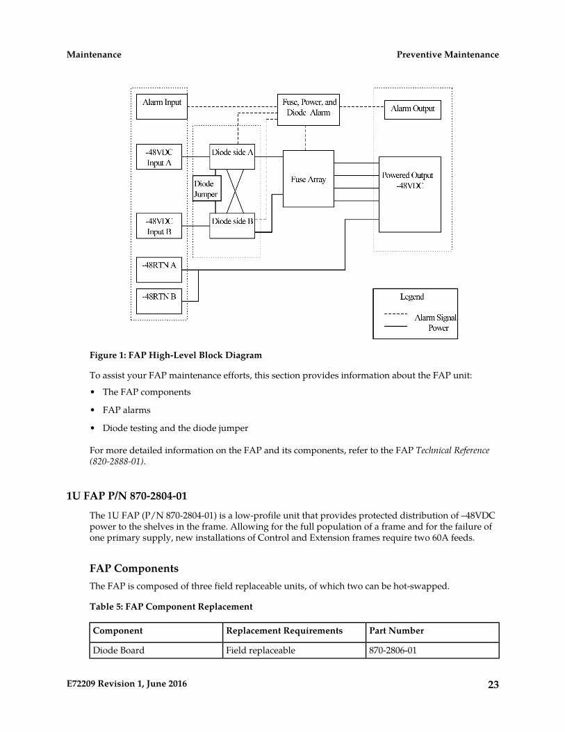
Figure 1: FAP High-Level Block Diagram
To assist your FAP maintenance efforts, this section provides information about the FAP unit:
• The FAP components
• FAP alarms
• Diode testing and the diode jumper
For more detailed information on the FAP and its components, refer to the FAP Technical Reference(820-2888-01).
1U FAP P/N 870-2804-01
The 1U FAP (P/N 870-2804-01) is a low-profile unit that provides protected distribution of –48VDCpower to the shelves in the frame. Allowing for the full population of a frame and for the failure ofone primary supply, new installations of Control and Extension frames require two 60A feeds.
FAP ComponentsThe FAP is composed of three field replaceable units, of which two can be hot-swapped.
Table 5: FAP Component Replacement
Part NumberReplacement RequirementsComponent
870-2806-01Field replaceableDiode Board
23E72209 Revision 1, June 2016
Preventive MaintenanceMaintenance
Part NumberReplacement RequirementsComponent
870-2805-01Field replaceableShorting Board
870-2804-01Field replaceable1U FAP
(includes Diode and ShortingBoards)
(with service interruption)
Diode Board
The diode board in the FAP contains power diodes and circuitry which allow one bus to pick up theentire load when there is a loss of input power on the other bus.
Shorting Board
The Shorting board allows the removal of the diode board without taking down the system. Thispermits periodic maintenance of the diodes without having to power down or remove the unit fromthe shelf. In the bypass position, both A and B power is connected to the fuse blocks so the diode boardcan be safely removed. The Shorting board has an LED which is off when the board is in normaloperational mode and is green when in the bypass mode of operation.
AlarmsThe FAP provides visual alarms, by means of a lit LED, for a variety of status alarms.
Table 6: FAP Alarm Conditions
Remote IndicationsAlarm ConditionAlarm
Dependent on EAGLE software• EAGLE command through E5-TDMCritical LED
• E5-MDAL not present and E5-MDAL_Pjumper off
Dependent on EAGLE softwareEAGLE command through E5-TDMMajor LED
Dependent on EAGLE softwareEAGLE command through E5-TDMMinor LED
Fuse alarm to EAGLE throughE5-TDM
• Distribution fuse blown
• Alarm circuit board removed (no LEDindication)
Fuse LED
• Jumper on the jumper circuit board is on
• Power feed failure
Fuse alarm to EAGLE throughE5-TDM
Power feed A is off, but power is availableto B.
PWR A LED
Fuse alarm to EAGLE throughE5-TDM
Power feed B is off, but power is availableto A.
PWR B LED
24E72209 Revision 1, June 2016
Preventive MaintenanceMaintenance
Remote IndicationsAlarm ConditionAlarm
Fuse alarm to EAGLE throughE5-TDM
Shorting board in maintenance mode.Shorting Board LED
A fuse alarm identifies the following problems or conditions within the FAP:
• blown fuse(s)
• power loss for side A or B
• alarm card removed
• maintenance mode
Use the following indicators to determine the nature of the problem:
Table 7: Additional Alarm Indicators
Alarm ConditionIndicator
Blown fuseFuse alarm and fuse flag down
Input power loss on AFuse alarm and PWR A LED
Input power loss on BFuse alarm and PWR B LED
Shorting Board in maintenance mode(by-passing diodes)
Fuse alarm red and Shorting Board LED is green
Shorting Board in normal mode, blown fuseFuse alarm red and Shorting Board LED is off
Diode Testing and the Shorting BoardThe Diode Board must be tested periodically. To test the Diode Board without powering down theentire EAGLE, peform the following procedures.
Maintenance ModeThis section describes how to place the Shorting Board into maintenance (bypass) mode. Maintenancemode allows the removal of the Diode Board without taking down the system.
Procedure — Shorting Board Maintenance Mode
1. Check to verify the Shorting Board LED is not on, indicating the FAP is in normal mode.2.
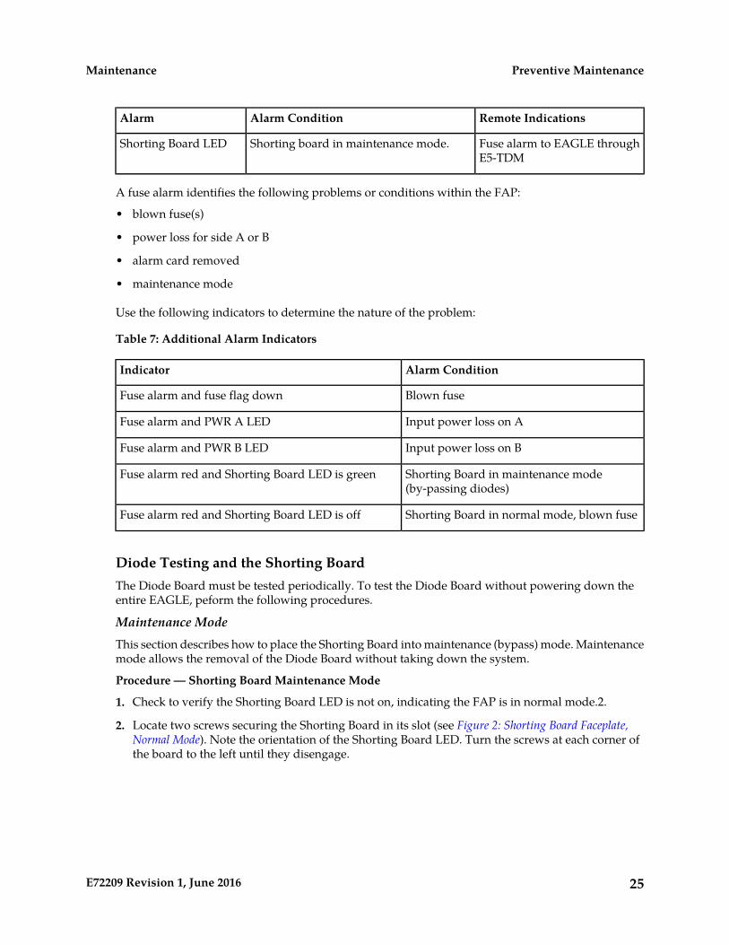
2. Locate two screws securing the Shorting Board in its slot (see Figure 2: Shorting Board Faceplate,Normal Mode). Note the orientation of the Shorting Board LED. Turn the screws at each corner ofthe board to the left until they disengage.
25E72209 Revision 1, June 2016
Preventive MaintenanceMaintenance
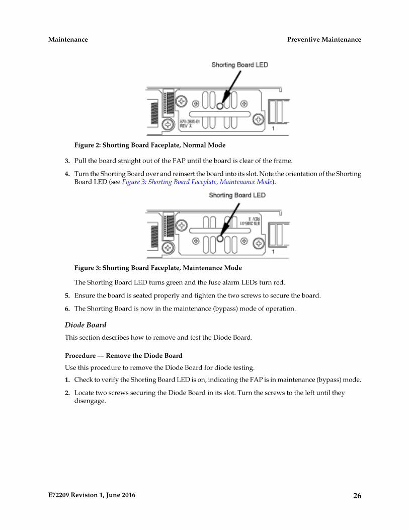
Figure 2: Shorting Board Faceplate, Normal Mode
3. Pull the board straight out of the FAP until the board is clear of the frame.
4. Turn the Shorting Board over and reinsert the board into its slot. Note the orientation of the ShortingBoard LED (see Figure 3: Shorting Board Faceplate, Maintenance Mode).
Figure 3: Shorting Board Faceplate, Maintenance Mode
The Shorting Board LED turns green and the fuse alarm LEDs turn red.
5. Ensure the board is seated properly and tighten the two screws to secure the board.
6. The Shorting Board is now in the maintenance (bypass) mode of operation.
Diode BoardThis section describes how to remove and test the Diode Board.
Procedure — Remove the Diode Board
Use this procedure to remove the Diode Board for diode testing.
1. Check to verify the Shorting Board LED is on, indicating the FAP is in maintenance (bypass) mode.
2. Locate two screws securing the Diode Board in its slot. Turn the screws to the left until theydisengage.
26E72209 Revision 1, June 2016
Preventive MaintenanceMaintenance
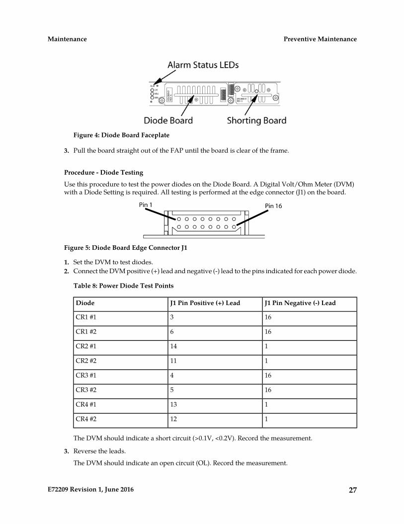
Figure 4: Diode Board Faceplate
3. Pull the board straight out of the FAP until the board is clear of the frame.
Procedure - Diode Testing
Use this procedure to test the power diodes on the Diode Board. A Digital Volt/Ohm Meter (DVM)with a Diode Setting is required. All testing is performed at the edge connector (J1) on the board.
Figure 5: Diode Board Edge Connector J1
1. Set the DVM to test diodes.2. Connect the DVM positive (+) lead and negative (-) lead to the pins indicated for each power diode.
Table 8: Power Diode Test Points
J1 Pin Negative (-) LeadJ1 Pin Positive (+) LeadDiode
163CR1 #1
166CR1 #2
114CR2 #1
111CR2 #2
164CR3 #1
165CR3 #2
113CR4 #1
112CR4 #2
The DVM should indicate a short circuit (>0.1V, <0.2V). Record the measurement.
3. Reverse the leads.
The DVM should indicate an open circuit (OL). Record the measurement.
27E72209 Revision 1, June 2016
Preventive MaintenanceMaintenance
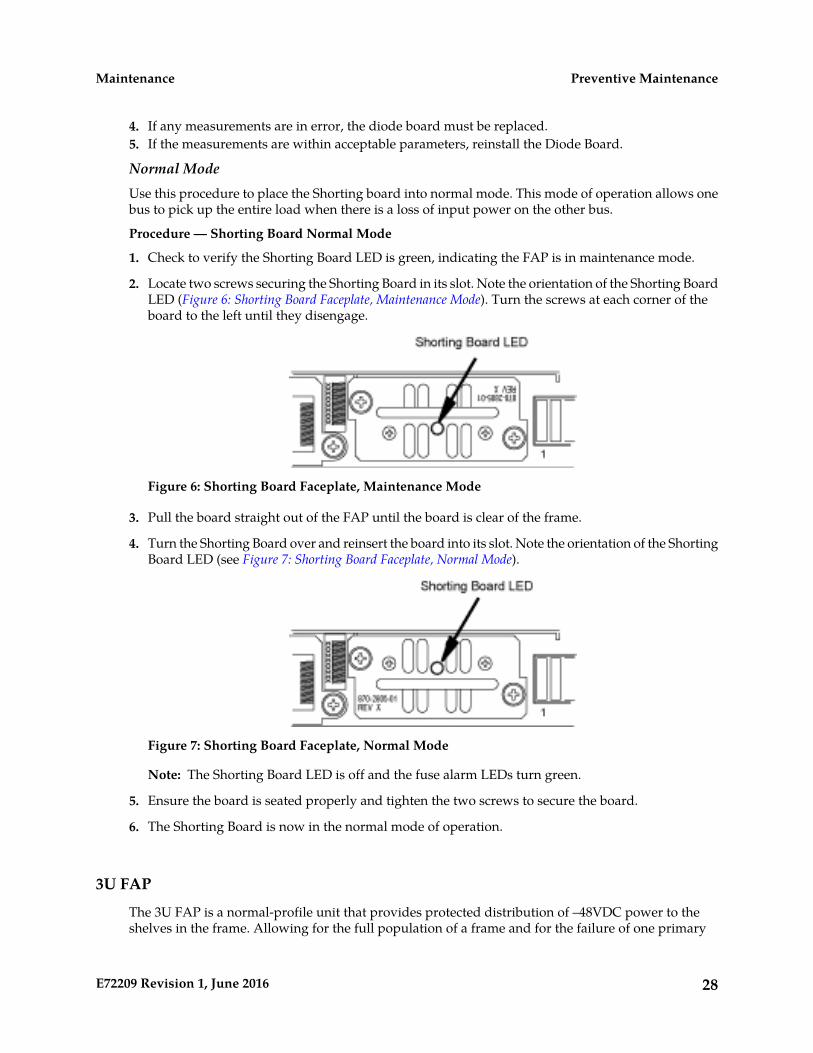
4. If any measurements are in error, the diode board must be replaced.5. If the measurements are within acceptable parameters, reinstall the Diode Board.
Normal ModeUse this procedure to place the Shorting board into normal mode. This mode of operation allows onebus to pick up the entire load when there is a loss of input power on the other bus.
Procedure — Shorting Board Normal Mode
1. Check to verify the Shorting Board LED is green, indicating the FAP is in maintenance mode.
2. Locate two screws securing the Shorting Board in its slot. Note the orientation of the Shorting BoardLED (Figure 6: Shorting Board Faceplate, Maintenance Mode). Turn the screws at each corner of theboard to the left until they disengage.
Figure 6: Shorting Board Faceplate, Maintenance Mode
3. Pull the board straight out of the FAP until the board is clear of the frame.
4. Turn the Shorting Board over and reinsert the board into its slot. Note the orientation of the ShortingBoard LED (see Figure 7: Shorting Board Faceplate, Normal Mode).
Figure 7: Shorting Board Faceplate, Normal Mode
Note: The Shorting Board LED is off and the fuse alarm LEDs turn green.
5. Ensure the board is seated properly and tighten the two screws to secure the board.
6. The Shorting Board is now in the normal mode of operation.
3U FAP
The 3U FAP is a normal-profile unit that provides protected distribution of –48VDC power to theshelves in the frame. Allowing for the full population of a frame and for the failure of one primary
28E72209 Revision 1, June 2016
Preventive MaintenanceMaintenance
supply, new installations of Control and Extension frames require two 60A feeds. The 3U FAP maybe one of the following:
• 870-1606-01 (all revisions)• 870-1616-02 with a revision G or lower• 870-2320-01 with a revision B or lower
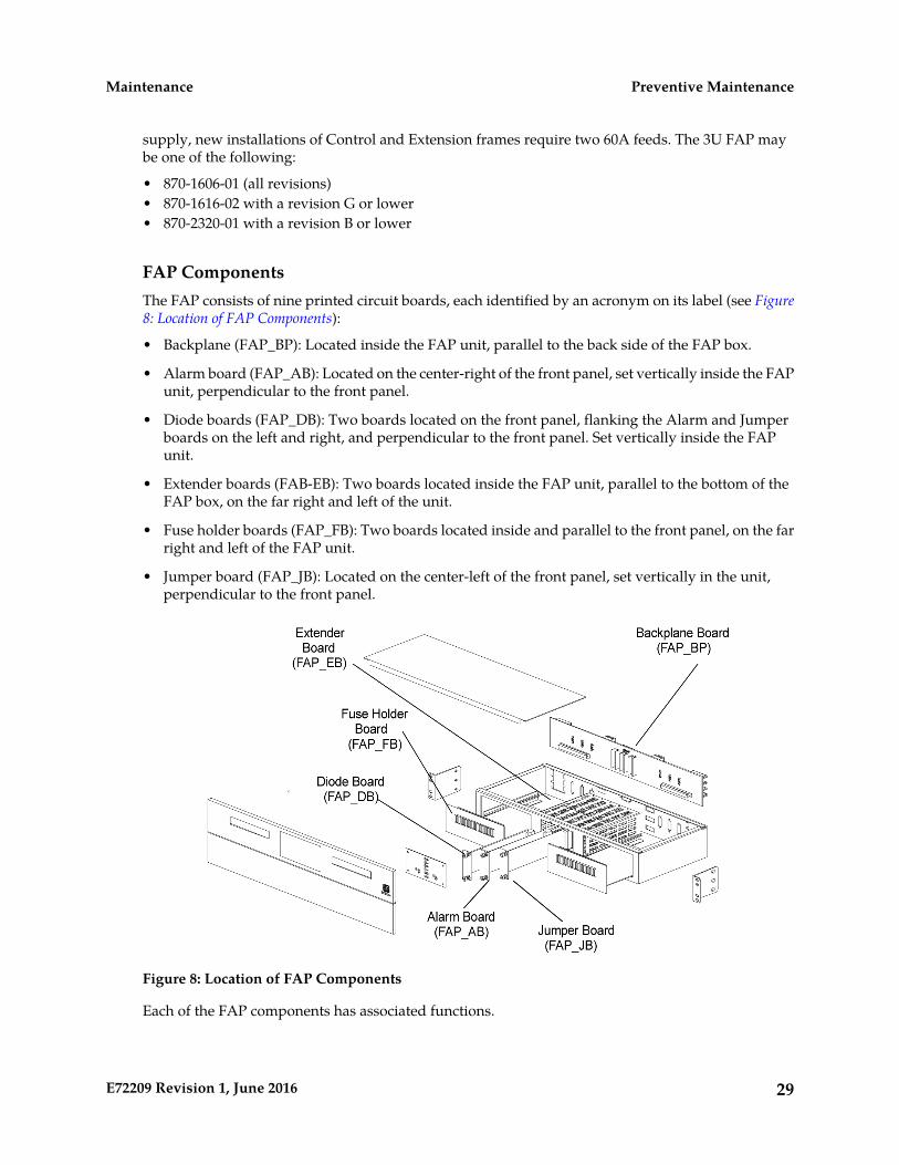
FAP ComponentsThe FAP consists of nine printed circuit boards, each identified by an acronym on its label (see Figure8: Location of FAP Components):
• Backplane (FAP_BP): Located inside the FAP unit, parallel to the back side of the FAP box.
• Alarm board (FAP_AB): Located on the center-right of the front panel, set vertically inside the FAPunit, perpendicular to the front panel.
• Diode boards (FAP_DB): Two boards located on the front panel, flanking the Alarm and Jumperboards on the left and right, and perpendicular to the front panel. Set vertically inside the FAPunit.
• Extender boards (FAB-EB): Two boards located inside the FAP unit, parallel to the bottom of theFAP box, on the far right and left of the unit.
• Fuse holder boards (FAP_FB): Two boards located inside and parallel to the front panel, on the farright and left of the FAP unit.
• Jumper board (FAP_JB): Located on the center-left of the front panel, set vertically in the unit,perpendicular to the front panel.
Figure 8: Location of FAP Components
Each of the FAP components has associated functions.
29E72209 Revision 1, June 2016
Preventive MaintenanceMaintenance
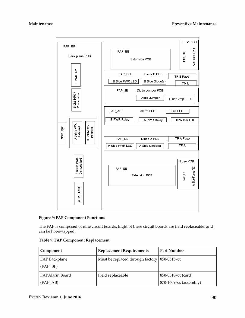
Figure 9: FAP Component Functions
The FAP is composed of nine circuit boards. Eight of these circuit boards are field replaceable, andcan be hot-swapped.
Table 9: FAP Component Replacement
Part NumberReplacement RequirementsComponent
850-0515-xxMust be replaced through factoryFAP Backplane
(FAP_BP)
850-0518-xx (card)Field replaceableFAPAlarm Board
(FAP_AB) 870-1609-xx (assembly)
30E72209 Revision 1, June 2016
Preventive MaintenanceMaintenance

Part NumberReplacement RequirementsComponent
850-0517-xx (card)Field replaceableFAP Diode Boards
870-1608-xx (assembly)(one at a time)(FAP_DB_A and
FAP_DB_B)
850-0519-xxField replaceableFAP Extender Boards
(one at a time(FAP_EB)
with service interruption)
850-0516-xxField replaceableFAP Fuse Holder Boards
(one at a time(FAP_FB)
with service interruption)
850-0523-xx (card)Field replaceableFAP Jumper Board
(FAP_JB) 870-1641-xx (assembly)
The following sections describe each type of circuit board:
Backplane Board (FAP_BP)
The backplane circuit board provides all of the external connections for the FAP. It consists primarilyof circuit routing and connectors, but also has one pull-down resistor, which provides a default alarmsignal for the Fuse Alarm in the event the alarm board is removed from the FAP.
Alarm Board (FAP_AB)
The alarm circuit board provides indicators and relays for the EAGLE status and fuse alarms. Thisboard includes a jumper (JMP50) for future use. This jumper is installed for all existing configurations.
Diode Boards (FAP_DB)
The diode circuit boards provide power diodes and power input test points. Four diode footprintsare included: two for Assembly A and two for Assembly B. Only one of the four positions is intendedto be populated; the second footprint is provided for future part rating changes or additionalheat-dissipation capabilities.
Extender Boards (FAP_EB)
The extender board provides connection between the backpanel board and the fuse holder boards.
Fuse Holder Boards (FAP_FB)
The fuse holder boards provide 20 fuses with a common alarm.
Jumper Board (FAP_JB)
The jumper board provides the capability to by-pass the diode boards with a fuse. Use this board onlyfor maintenance operations.
31E72209 Revision 1, June 2016
Preventive MaintenanceMaintenance

AlarmsThe FAP provides visual alarms, by means of a lit LED, for a variety of status alarms (see Table 10:FAP Alarm Conditions).
Table 10: FAP Alarm Conditions
Remote IndicationsAlarm ConditionAlarm
Dependent on EAGLE software• EAGLE command through E5-MCAPCritical LED
• E5-MDAL not present and E5-MDAL_Pjumper off
Dependent on EAGLE softwareEAGLE command through E5-MCAPMajor LED
Dependent on EAGLE softwareEAGLE command through E5-MCAPMinor LED
Fuse alarm to EAGLE throughE5-MCAP
• Distribution fuse blown
• Alarm circuit board removed (no LEDindication)
Fuse LED
• Jumper on the jumper circuit board is on
• Power feed failure
Fuse alarm to EAGLE throughE5-MCAP
Power feed A is off, but power is availableto B.
PWR A LED
Fuse alarm to EAGLE throughE5-MCAP
Power feed B is off, but power is availableto A.
PWR B LED
Fuse alarm to EAGLE throughE5-MCAP
Jumper on the jumper circuit board is on.OP/MAINTLED
A fuse alarm identifies the following problems or conditions within the FAP:
• blown fuse(s)
• power loss for side A or B
• alarm card removed
• maintenance mode
Use the following indicators to determine the nature of the problem:
Table 11: Additional Alarm Indicators
Alarm ConditionIndicator
Blown fuseFuse alarm and fuse flag down
Input power loss on AFuse alarm and PWR A LED
32E72209 Revision 1, June 2016
Preventive MaintenanceMaintenance

Alarm ConditionIndicator
Input power loss on BFuse alarm and PWR B LED
Diode jumper is installed (by-passing diodes)Fuse alarm and OP/MAINT LED is red
Diode Testing and the Diode JumperThe diode board must be tested periodically. To test a diode circuit board without powering downthe entire EAGLE, perform the procedure listed in Table 12: FAP Part Numbers and CorrespondingProcedures for the corresponding FAP part number.
Table 12: FAP Part Numbers and Corresponding Procedures
FAP ProcedurePart Number
Procedure 1870-1606-01 (all revisions)
Procedure 1870-1616-02 revision G or lower
Procedure 2870-1606-02 revision H or higher
Procedure 1870-2320-01 revision B or lower
Procedure 2870-2320-01 revision C or higher
(or 870-2320-03)
Procedure 1.
This procedure to test a diode circuit board without powering down the entire EAGLE applies to thefollowing FAPs:
• 870-1606-01 (all revisions)
• 870-1616-02 with a revision G or lower
• 870-2320-01 with a revision B or lower
1. Check to verify the OP/MAINT LED is green, indicating the FAP is not in maintenance mode.
2. Unscrew the two thumbscrews securing the FAP jumper board and remove the board.
3. On the jumper circuit board, move the jumper (the DB-26 male connector) from P71 to P72. Tightenthe thumbscrews connecting the jumper to its mate, to ensure a good connection. This repositioningoverrides the diodes, establishing a direct connection between input and fuse panels.
Warning: If fuses are blown, DONOT continue with this procedure. Instead, contactMy Oracle Support (MOS) at the appropriate number.
4. Make sure the glass fuses are installed and verify they are “good” by using the multimeter to checkfor continuity across each of the glass fuses.
33E72209 Revision 1, June 2016
Preventive MaintenanceMaintenance
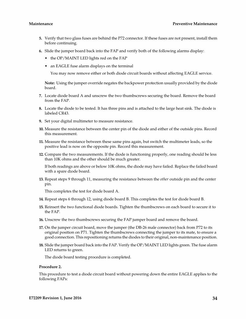
5. Verify that two glass fuses are behind the P72 connector. If these fuses are not present, install thembefore continuing.
6. Slide the jumper board back into the FAP and verify both of the following alarms display:
• the OP/MAINT LED lights red on the FAP
• an EAGLE fuse alarm displays on the terminal
You may now remove either or both diode circuit boards without affecting EAGLE service.
Note: Using the jumper override negates the backpower protection usually provided by the diodeboard.
7. Locate diode board A and unscrew the two thumbscrews securing the board. Remove the boardfrom the FAP.
8. Locate the diode to be tested. It has three pins and is attached to the large heat sink. The diode islabeled CR43.
9. Set your digital multimeter to measure resistance.
10. Measure the resistance between the center pin of the diode and either of the outside pins. Recordthis measurement.
11. Measure the resistance between these same pins again, but switch the multimeter leads, so thepositive lead is now on the opposite pin. Record this measurement.
12. Compare the two measurements. If the diode is functioning properly, one reading should be lessthan 10K ohms and the other should be much greater.
If both readings are above or below 10K ohms, the diode may have failed. Replace the failed boardwith a spare diode board.
13. Repeat steps 9 through 11, measuring the resistance between the other outside pin and the centerpin.
This completes the test for diode board A.
14. Repeat steps 6 through 12, using diode board B. This completes the test for diode board B.
15. Reinsert the two functional diode boards. Tighten the thumbscrews on each board to secure it tothe FAP.
16. Unscrew the two thumbscrews securing the FAP jumper board and remove the board.
17. On the jumper circuit board, move the jumper (the DB-26 male connector) back from P72 to itsoriginal position on P71. Tighten the thumbscrews connecting the jumper to its mate, to ensure agood connection. This repositioning returns the diodes to their original, non-maintenance position.
18. Slide the jumper board back into the FAP. Verify the OP/MAINT LED lights green. The fuse alarmLED returns to green.
The diode board testing procedure is completed.
Procedure 2.
This procedure to test a diode circuit board without powering down the entire EAGLE applies to thefollowing FAPs:
34E72209 Revision 1, June 2016
Preventive MaintenanceMaintenance
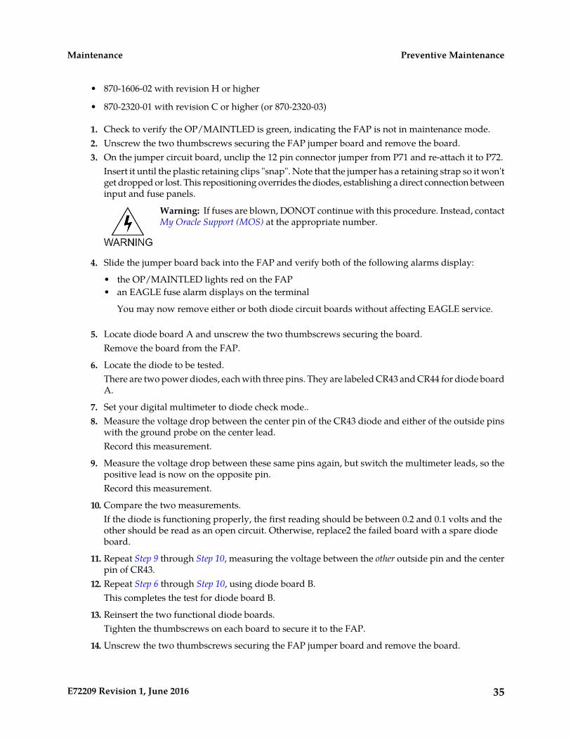
• 870-1606-02 with revision H or higher
• 870-2320-01 with revision C or higher (or 870-2320-03)
1. Check to verify the OP/MAINTLED is green, indicating the FAP is not in maintenance mode.2. Unscrew the two thumbscrews securing the FAP jumper board and remove the board.3. On the jumper circuit board, unclip the 12 pin connector jumper from P71 and re-attach it to P72.
Insert it until the plastic retaining clips "snap". Note that the jumper has a retaining strap so it won'tget dropped or lost. This repositioning overrides the diodes, establishing a direct connection betweeninput and fuse panels.
Warning: If fuses are blown, DONOT continue with this procedure. Instead, contactMy Oracle Support (MOS) at the appropriate number.
4. Slide the jumper board back into the FAP and verify both of the following alarms display:
• the OP/MAINTLED lights red on the FAP• an EAGLE fuse alarm displays on the terminal
You may now remove either or both diode circuit boards without affecting EAGLE service.
5. Locate diode board A and unscrew the two thumbscrews securing the board.Remove the board from the FAP.
6. Locate the diode to be tested.There are two power diodes, each with three pins. They are labeled CR43 and CR44 for diode boardA.
7. Set your digital multimeter to diode check mode..8. Measure the voltage drop between the center pin of the CR43 diode and either of the outside pins
with the ground probe on the center lead.Record this measurement.
9. Measure the voltage drop between these same pins again, but switch the multimeter leads, so thepositive lead is now on the opposite pin.Record this measurement.
10. Compare the two measurements.If the diode is functioning properly, the first reading should be between 0.2 and 0.1 volts and theother should be read as an open circuit. Otherwise, replace2 the failed board with a spare diodeboard.
11. Repeat Step 9 through Step 10, measuring the voltage between the other outside pin and the centerpin of CR43.
12. Repeat Step 6 through Step 10, using diode board B.This completes the test for diode board B.
13. Reinsert the two functional diode boards.Tighten the thumbscrews on each board to secure it to the FAP.
14. Unscrew the two thumbscrews securing the FAP jumper board and remove the board.
35E72209 Revision 1, June 2016
Preventive MaintenanceMaintenance

15. On the jumper circuit board, unclip the 12 pin connector jumper back from P72 to its originalposition on P71.Insert it until the plastic retaining clips “snap.” This repositioning returns the diodes to their original,non-maintenance position.
16. Slide the jumper board back into the FAP.Verify the OP/MAINTLED lights green. The fuse alarm LED returns to green. The diode boardtesting procedure is completed.
Removable Drives
This section provides information about the removable drives associated with the EAGLE MaintenanceAdministration Subsystem Processor (MASP).
A removable drive is used for two purposes:
• To hold an off-line, backup copy of the administered data and system GPLs
• To hold a copy of the measurement tables
To use a removable drive to hold the system data, it must be formatted for system data. To use aremovable drive to hold measurements data, it must be formatted for measurements data. The EAGLEprovides the user the ability to format a removable drive for either of these purposes. A removabledrive can be formatted on the EAGLE by using the format-disk command. For more informationon the format-disk command refer to Commands User's Guide.
Removable drives described in this section include:
• Removable USB Drive
• Fixed SATA Drive
Removable USB Drive
This section is referenced in this manual by many procedures requiring theuse of the removable USB thumb disk in the E5-MASP card. The procedures
Purpose:
found in this section are recommended procedures for handling the removableUSB drive in the E5-MASP card.
NoneRequirements:
Procedure - Remove USB Drive
1. Verify that the removable USB drive is locked in position and in use.
The removable drive latch (SW1) is in the LOCKED position and the Removable Media Status LEDon the E5-MASP is Off. Refer to Figure 10: Removable USB Drive LOCKED.
36E72209 Revision 1, June 2016
Preventive MaintenanceMaintenance
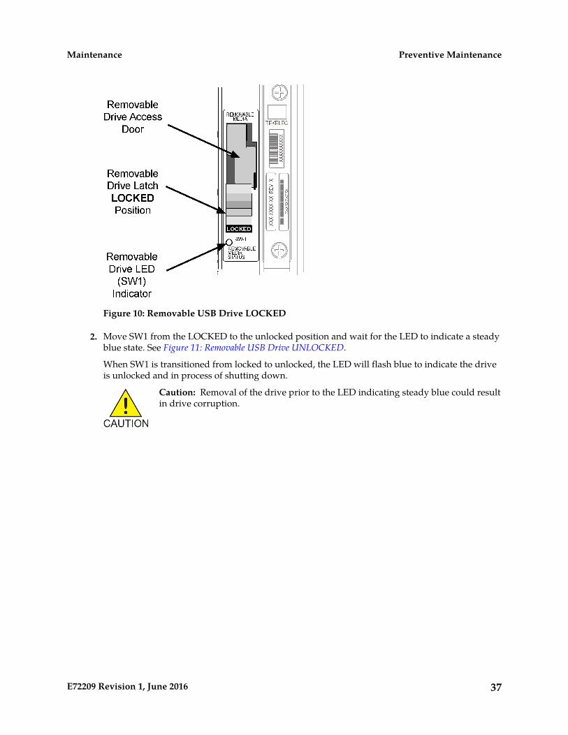
Figure 10: Removable USB Drive LOCKED
2. Move SW1 from the LOCKED to the unlocked position and wait for the LED to indicate a steadyblue state. See Figure 11: Removable USB Drive UNLOCKED.
When SW1 is transitioned from locked to unlocked, the LED will flash blue to indicate the driveis unlocked and in process of shutting down.
Caution: Removal of the drive prior to the LED indicating steady blue could resultin drive corruption.
37E72209 Revision 1, June 2016
Preventive MaintenanceMaintenance

Figure 11: Removable USB Drive UNLOCKED
3. When the LED indicates a steady blue state, the removable USB drive can be safely removed. TheLED is off when the USB drive is fully ejected from the drive media.The USB drive can now be removed from the drive media.
4. Lift the access door up, swing it past the detent position so that the door remains open on its own.5. Grasp the pull tab of the slide and pull the slide out slowly until it stops (it travels about a half
inch).
Caution: The full travel of the slide is less than an inch, do not try to pull the assemblyto expose the full length of the thumb drive as this is beyond the slide’s designedtravel.
6. The USB drive is disengaged and can be taken from the inject eject assembly.7. Insert a USB drive into the inject-eject assembly.8. Grasp the pull tab of the slide and push the slide in slowly until you feel the USB drive is seated
in its slot (it travels about a half inch).9. Close the access door.10. Move SW1 from the unlocked to the LOCKED position.
When SW1 is transitioned from unlocked to locked, the LED will flash blue to indicate the driveis locked and in process of coming online.
11. When the LED turns Off, the removable USB drive is ready for use.
38E72209 Revision 1, June 2016
Preventive MaintenanceMaintenance
Fixed SATA Drive
This section is referenced in this manual by many procedures requiring the use ofthe fixed SATA drive in the E5-MASP card. The procedures found in this section arerecommended procedures for handling the fixed drive in the E5-MASP card.
Purpose:
Requirements • The new SATA Drives to be installed should be at the current system release.• Before beginning this procedure, make sure there is a copy of the current release
GPLs on a removable USB drive on-hand.• System backups should be performed prior to the start of this procedure. Refer
to Daily Procedures.• You must be logged in to the EAGLE prior to performing this procedure.
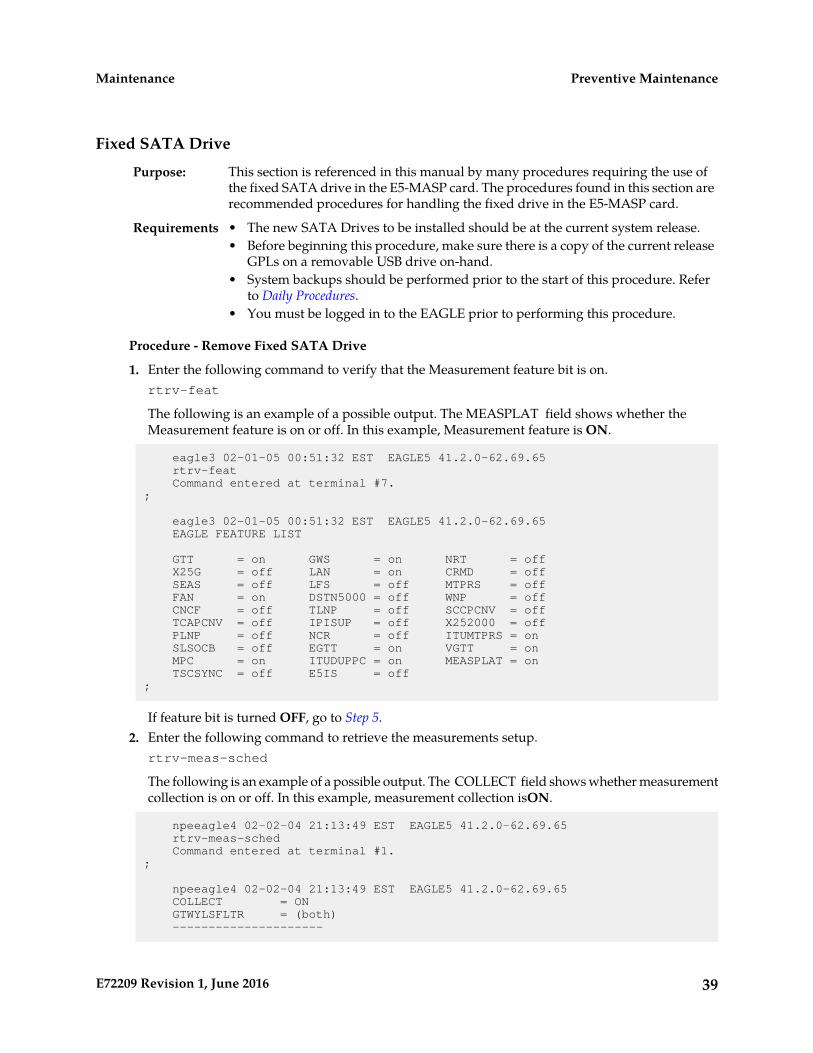
Procedure - Remove Fixed SATA Drive
1. Enter the following command to verify that the Measurement feature bit is on.rtrv-feat
The following is an example of a possible output. The MEASPLAT field shows whether theMeasurement feature is on or off. In this example, Measurement feature is ON.
eagle3 02-01-05 00:51:32 EST EAGLE5 41.2.0-62.69.65 rtrv-feat Command entered at terminal #7.;
eagle3 02-01-05 00:51:32 EST EAGLE5 41.2.0-62.69.65 EAGLE FEATURE LIST
GTT = on GWS = on NRT = off X25G = off LAN = on CRMD = off SEAS = off LFS = off MTPRS = off FAN = on DSTN5000 = off WNP = off CNCF = off TLNP = off SCCPCNV = off TCAPCNV = off IPISUP = off X252000 = off PLNP = off NCR = off ITUMTPRS = on SLSOCB = off EGTT = on VGTT = on MPC = on ITUDUPPC = on MEASPLAT = on TSCSYNC = off E5IS = off;
If feature bit is turned OFF, go to Step 5.2. Enter the following command to retrieve the measurements setup.
rtrv-meas-sched
The following is an example of a possible output. The COLLECT field shows whether measurementcollection is on or off. In this example, measurement collection isON.
npeeagle4 02-02-04 21:13:49 EST EAGLE5 41.2.0-62.69.65 rtrv-meas-sched Command entered at terminal #1.;
npeeagle4 02-02-04 21:13:49 EST EAGLE5 41.2.0-62.69.65 COLLECT = ON GTWYLSFLTR = (both) ---------------------
39E72209 Revision 1, June 2016
Preventive MaintenanceMaintenance

SYSTOT-STP = (off) SYSTOT-TT = (off) SYSTOT-STPLAN = (off) COMP-LNKSET = (off) COMP-LINK = (off) GTWY-STP = (off) GTWY-LNKSET = (off) MTCD-STP = (on) MTCD-LINK = (on) MTCD-STPLAN = (on) MTCD-LNKSET = (on)
;
If measurement collection is OFF, go to Step 5.3. Issue the following command to turn OFF measurement collection.
chg-meas:collect=off
The following is an example of a possible output.
tekelecstp YY-MM-DD hh:mm:ss TTTT PPP XX.x.x-YY.y.y chg-meas:collect=off Command entered at terminal #10.; tekelecstp YY-MM-DD hh:mm:ss TTTT PPP XX.x.x-YY.y.y CHG-MEAS: MASP A – COMPLTD;
4. Enter the following command to verify measurements collection is OFF.rtrv-meas-sched
The following is an example of a possible output. The COLLECT field shows whether measurementcollection is on or off. In this example, measurement collection is OFF.
npeeagle4 02-02-04 21:13:49 EST EAGLE5 41.2.0-62.69.65 rtrv-meas-sched Command entered at terminal #1.;
npeeagle4 02-02-04 21:13:49 EST EAGLE5 41.2.0-62.69.65 COLLECT = OFF GTWYLSFLTR = (both) --------------------- SYSTOT-STP = (off) SYSTOT-TT = (off) SYSTOT-STPLAN = (off) COMP-LNKSET = (off) COMP-LINK = (off) GTWY-STP = (off) GTWY-LNKSET = (off) MTCD-STP = (on) MTCD-LINK = (on) MTCD-STPLAN = (on) MTCD-LNKSET = (on)
;
5. Enter the following command to display the card status:rept-stat-card:appl=oam
40E72209 Revision 1, June 2016
Preventive MaintenanceMaintenance

The following is an example of a possible output.
Command Accepted - Processing
tekelecstp YY-MM-DD hh:mm:ss TTTT PPP XX.x.x-YY.y.y rept-stat-card:appl=oam Command entered at terminal #14.;
tekelecstp 10-04-19 16:47:51 EDT EAGLE5 41.1.0-62.64.1 CARD VERSION TYPE GPL PST SST AST 1113 132-064-000 E5MCAP OAMHC IS-NR Standby ----- 1115 132-064-000 E5MCAP OAMHC IS-NR Active -----
Command Completed.;
6. Enter the following command to display the card status:this rept-stat-card
The following is an example of a possible output.
e5oam 08-12-01 15:38:32 EST EAGLE 46.0.0 CARD VERSION TYPE GPL PST SST AST 1108 ----------- MCPM MCP OOS-MT-DSBLD Manual ----- 1109 030-009-000 HIPR2 HIPR2 IS-NR Active ----- 1110 030-009-000 HIPR2 HIPR2 IS-NR Active ----- 1111 030-010-000 IPSM IPS IS-NR Active ----- 1113 030-010-008 E5MCAP OAMHC IS-NR Standby ----- 1114 ----------- E5TDM IS-NR Active ----- 1115 030-010-008 E5MCAP OAMHC IS-NR Active ----- 1116 ----------- E5TDM IS-NR Active ----- 1117 ----------- E5MDAL OOS-MT Isolated -----
Command Completed.
In this sample output, 1113/1114 are standby and 1115/1116 are active.
Verify the E5-MASP card containing the fixed SATA drive to be replaced is in the Standby positionbefore continuing.
• If it is Standby, go to Step 10.• If it is not Standby, go to Step 7.
7. Enter the following command to force the Active E5-MASP card to become Standbyinit-card:loc=xxxx
where xxxx is the card location (1113 or 1115).
Note: User will need to login after executing this command.
8. Enter the following command to re-login:login:uid=eagle
9. Enter the password to complete login:Enter Password : xxxxx
41E72209 Revision 1, June 2016
Preventive MaintenanceMaintenance
Note: This document does not provide the passwords required in the procedures. Passwordsshould be acquired from the customer.
The following is an example of a possible output.
Command Accepted - Processing
tekelecstp YY-MM-DD hh:mm:ss TTTT PPP XX.x.x-YY.y.y Command entered at terminal #13.; tekelecstp YY-MM-DD hh:mm:ss TTTT PPP XX.x.x-YY.y.y NOTICE: This is a private computer system. Unauthorized access or use may lead to prosecution. 0 LOGIN failures since last successful LOGIN Last successful LOGIN was on port 13 on 09-03-04 @ 14:18:21
;
10. Inhibit the Standby card location from service by entering the following command:inh-card:loc=xxxx
wherexxxx is the Standby card location.
The following is an example of a possible output.
Command Accepted - Processing
eagle3 02-01-18 18:00:06 EST EAGLE 41.2.0-62.69.65 inh-card:loc=1113 Command entered at terminal #1.;
eagle3 02-01-18 18:00:06 EST EAGLE 41.2.0-62.69.65 Card has been inhibited.;
eagle3 02-01-18 18:00:06 EST EAGLE 41.2.0-62.69.65 Command Completed.;
11. Verify that the SATA drive is locked in position and in use. Refer to Figure 12: SATA Drive Locked.
The SATA drive latch (SW2) is in the LOCKED position and the SATA Media Status LED on theE5-MASP is Off.
42E72209 Revision 1, June 2016
Preventive MaintenanceMaintenance
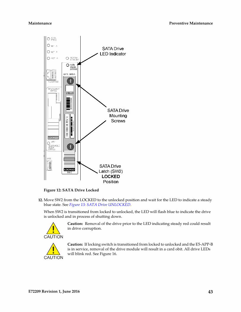
Figure 12: SATA Drive Locked
12. Move SW2 from the LOCKED to the unlocked position and wait for the LED to indicate a steadyblue state. See Figure 13: SATA Drive UNLOCKED.
When SW2 is transitioned from locked to unlocked, the LED will flash blue to indicate the driveis unlocked and in process of shutting down.
Caution: Removal of the drive prior to the LED indicating steady red could resultin drive corruption.
Caution: If locking switch is transitioned from locked to unlocked and the E5-APP-Bis in service, removal of the drive module will result in a card obit. All drive LEDswill blink red. See Figure 16.
43E72209 Revision 1, June 2016
Preventive MaintenanceMaintenance
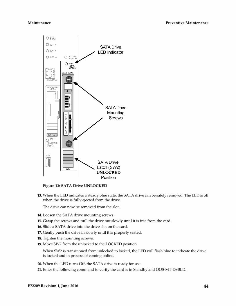
Figure 13: SATA Drive UNLOCKED
13. When the LED indicates a steady blue state, the SATA drive can be safely removed. The LED is offwhen the drive is fully ejected from the drive.
The drive can now be removed from the slot.
14. Loosen the SATA drive mounting screws.15. Grasp the screws and pull the drive out slowly until it is free from the card.16. Slide a SATA drive into the drive slot on the card.17. Gently push the drive in slowly until it is properly seated.18. Tighten the mounting screws.19. Move SW2 from the unlocked to the LOCKED position.
When SW2 is transitioned from unlocked to locked, the LED will flash blue to indicate the driveis locked and in process of coming online.
20. When the LED turns Off, the SATA drive is ready for use.21. Enter the following command to verify the card is in Standby and OOS-MT-DSBLD.
44E72209 Revision 1, June 2016
Preventive MaintenanceMaintenance
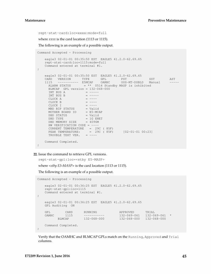
rept-stat-card:loc=xxxx:mode=full
where xxxx is the card location (1113 or 1115).
The following is an example of a possible output.
Command Accepted - Processing
eagle3 02-01-01 00:35:50 EST EAGLE5 41.2.0-62.69.65 rept-stat-card:loc=1115:mode=full Command entered at terminal #1.;
eagle3 02-01-01 00:35:50 EST EAGLE5 41.2.0-62.69.65 CARD VERSION TYPE GPL PST SST AST 1115 ----------- E5MCAP OAMHC OOS-MT-DSBLD Manual ----- ALARM STATUS = ** 0514 Standby MASP is inhibited BLMCAP GPL version = 132-068-000 IMT BUS A = ----- IMT BUS B = ----- CLOCK A = ---- CLOCK B = ---- CLOCK I = ---- MBD BIP STATUS = Valid MOTHER BOARD ID = E5-MCAP DBD STATUS = Valid DBD TYPE = 1G ENET DBD MEMORY SIZE = 4096M HW VERIFICATION CODE = ---- CURRENT TEMPERATURE = 29C ( 85F) PEAK TEMPERATURE: = 29C ( 85F) [02-01-01 00:23] TROUBLE TEXT VER. = ----
Command Completed.;
22. Issue the command to retrieve GPL versions.rept-stat-gpl:loc=<stby E5-MASP>
where <stby E5-MASP> is the card location (1113 or 1115).
The following is an example of a possible output.
Command Accepted - Processing
eagle3 02-01-01 00:36:25 EST EAGLE5 41.2.0-62.69.65 rept-stat-gpl:loc=1115 Command entered at terminal #1.;
eagle3 02-01-01 00:36:25 EST EAGLE5 41.2.0-62.69.65 GPL Auditing ON
GPL CARD RUNNING APPROVED TRIAL OAMHC 1115 ----------- 132-069-061 132-069-061 * BLMCAP 132-068-000 132-068-000 132-068-000
Command Completed.;
Verify that the OAMHC and BLMCAP GPLs match on the Running, Approved and Trialcolumns.
45E72209 Revision 1, June 2016
Preventive MaintenanceMaintenance

Note: If GPL are in alarm contact theMy Oracle Support (MOS) and have system USB drives availablefor corrections
23. Enter the following command to put the card that was inhibited in back into service.alw-card:loc=xxxx
wherexxxx is the card location used in Step 6.
Following is an example of a possible output.
Command Accepted - Processing
eagle3 02-01-18 18:02:20 EST EAGLE5 41.2.0-62.69.65 alw-card:loc=1113 Command entered at terminal #1.;
eagle3 02-01-18 18:02:20 EST EAGLE5 41.2.0-62.69.65 Card has been allowed.;
eagle3 02-01-18 18:02:20 EST EAGLE5 41.2.0-62.69.65 Command Completed.;
Note: Allow the card to run for 5 minutes before continuing.
24. Enter the following command to verify the database is not consistent (different level as the othercards in the system).rept-stat-db:display=version
The following is an example of a possible output.
Command Accepted - Processing
eagle3 02-01-10 21:52:58 EST EAGLE5 41.2.0-62.69.65 rept-stat-db:display=version Command entered at terminal #1.;
eagle3 02-01-10 21:52:59 EST EAGLE5 41.2.0-62.69.65 DATABASE STATUS: >> OK << E5TDM 1114 ( ACTV ) E5TDM 1116 ( STDBY) C LEVEL TIME LAST BACKUP C LEVEL TIME LAST BACKUP - -------- ---------------------- - -------- ----------------------
FD BKUP Y 79 02-01-05 18:06:16 EST Y 1 02-01-05 00:06:16 EST FD CRNT Y 79 Y 1 MCAP 1113 MCAP 1115 - -------- - -------- RD BKUP - - - - - - - - USB BKP - - - - - - - -
CARD/APPL LOC C T LEVEL TIME LAST UPDATE VERSION STATUS --------- ---- - - ---------- ----------------- ------------------- OAMHC-RMV 1113 - - - - - - OAMHC-USB 1113 - - - - - - E5TDM-CRNT 1114 Y N 79 02-01-04 23:46:18 132-013-000 NORMAL
E5TDM-BKUP 1114 Y - 79 02-01-04 23:46:18 132-013-000 NORMAL
46E72209 Revision 1, June 2016
Preventive MaintenanceMaintenance

OAMHC-RMV 1115 - - - - - - E5TDM-CRNT 1116 Y N 1 02-01-04 00:06:16 132-013-000 NORMAL
E5TDM-BKUP 1116 Y - 1 02-01-04 00:06:16 132-013-000 NORMAL
EPAP A (NOACCS) C BIRTHDATE LEVEL EXCEPTION - ----------------- ---------- -------------- PDB - - - - RTDB - - - - RTDB-EAGLE - - - - -
EPAP B (NOACCS) C BIRTHDATE LEVEL EXCEPTION - ----------------- ---------- -------------- PDB - - - - RTDB - - - - RTDB-EAGLE - - - - -
;
Compare the VERSION STATUS of the E5-MASP cards. The DB Level in the new drive is expectedto be different.
If the database VERSION on the new disk is not the same as the active disk, stop the procedureand contact theMy Oracle Support (MOS).
25. Enter the following command to show the version numbers of the GPLs stored on each fixed disk(E5-MASP).rtrv-gpl
The following is an example of a possible output.
e5oam 08-12-01 12:24:57 EST EAGLE 40.1.0 GPL Auditing ON
GPL CARD RELEASE APPROVED TRIAL REMOVE TRIAL OAMHC 1114 030-010-000 030-010-000 030-010-000 030-010-000 OAMHC 1116 030-010-000 030-010-000 030-010-000 030-010-000 OAMHC 1115 ----------- ----------- ----------- 030-010-000 SS7ANSI 1114 030-010-000 030-010-000 030-010-000 030-010-000 SS7ANSI 1116 030-010-000 030-010-000 030-010-000 030-010-000 SS7ANSI 1115 ----------- ----------- ----------- 030-010-000 SCCP 1114 030-010-000 030-010-000 030-010-000 030-010-000 SCCP 1116 030-010-000 030-010-000 030-010-000 030-010-000 SCCP 1115 ----------- ----------- ----------- 030-010-000 GLS 1114 030-010-000 030-010-000 030-010-000 030-010-000 GLS 1116 030-010-000 030-010-000 030-010-000 030-010-000 GLS 1115 ----------- ----------- ----------- 030-010-000 ... IPSG 1114 030-010-000 030-010-000 030-010-000 030-010-000 IPSG 1116 030-010-000 030-010-000 030-010-000 030-010-000 IPSG 1115 ----------- ----------- ----------- 030-010-000 BLROM1 1114 030-010-000 030-010-000 030-010-000 030-010-000 BLROM1 1116 030-010-000 030-010-000 030-010-000 030-010-000 BLROM1 1115 ----------- ----------- ----------- 030-010-000
If the new SATA drive shows alarmed GPLs, contact the My Oracle Support (MOS).
47E72209 Revision 1, June 2016
Preventive MaintenanceMaintenance
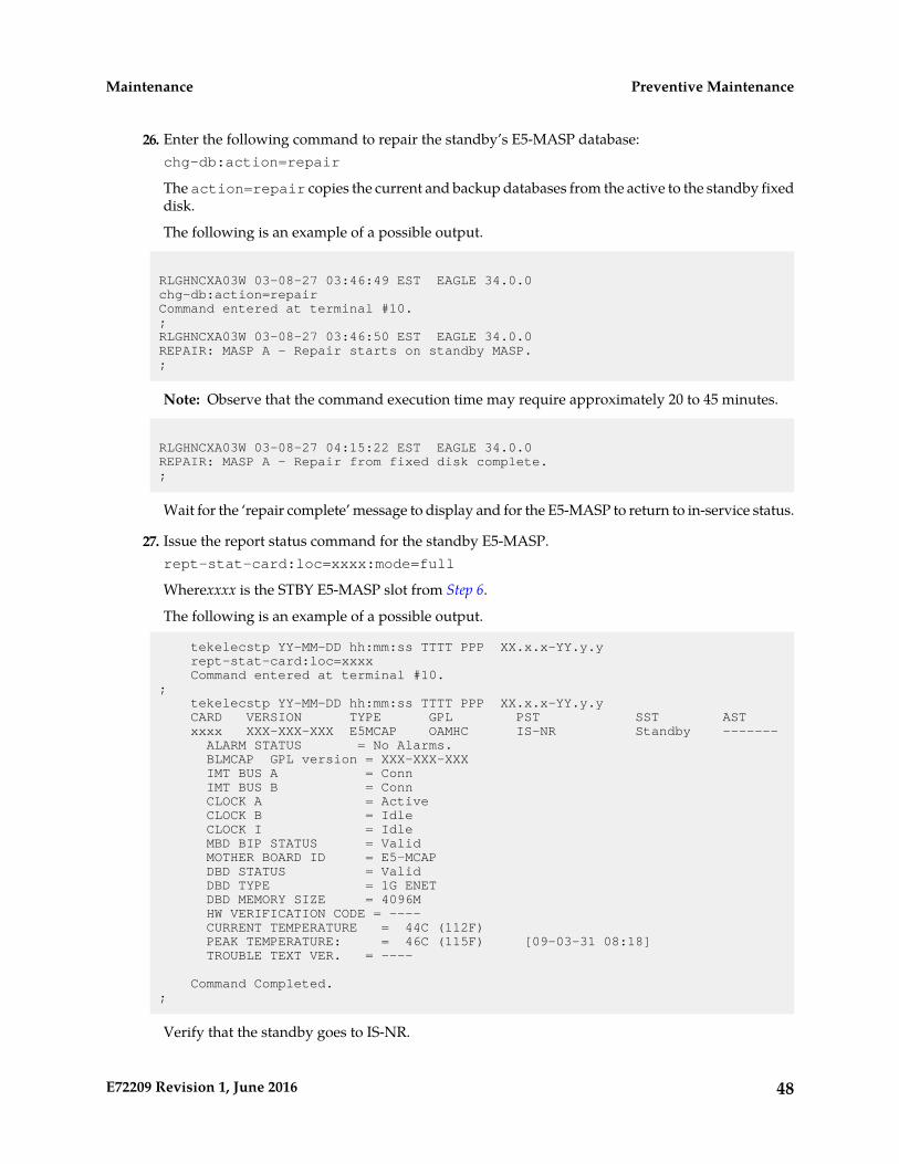
26. Enter the following command to repair the standby’s E5-MASP database:chg-db:action=repair
The action=repair copies the current and backup databases from the active to the standby fixeddisk.
The following is an example of a possible output.
RLGHNCXA03W 03-08-27 03:46:49 EST EAGLE 34.0.0chg-db:action=repairCommand entered at terminal #10.;RLGHNCXA03W 03-08-27 03:46:50 EST EAGLE 34.0.0REPAIR: MASP A - Repair starts on standby MASP.;
Note: Observe that the command execution time may require approximately 20 to 45 minutes.
RLGHNCXA03W 03-08-27 04:15:22 EST EAGLE 34.0.0REPAIR: MASP A - Repair from fixed disk complete.;
Wait for the ‘repair complete’ message to display and for the E5-MASP to return to in-service status.
27. Issue the report status command for the standby E5-MASP.rept-stat-card:loc=xxxx:mode=full
Wherexxxx is the STBY E5-MASP slot from Step 6.
The following is an example of a possible output.
tekelecstp YY-MM-DD hh:mm:ss TTTT PPP XX.x.x-YY.y.y rept-stat-card:loc=xxxx Command entered at terminal #10.; tekelecstp YY-MM-DD hh:mm:ss TTTT PPP XX.x.x-YY.y.y CARD VERSION TYPE GPL PST SST AST xxxx XXX-XXX-XXX E5MCAP OAMHC IS-NR Standby ------- ALARM STATUS = No Alarms. BLMCAP GPL version = XXX-XXX-XXX IMT BUS A = Conn IMT BUS B = Conn CLOCK A = Active CLOCK B = Idle CLOCK I = Idle MBD BIP STATUS = Valid MOTHER BOARD ID = E5-MCAP DBD STATUS = Valid DBD TYPE = 1G ENET DBD MEMORY SIZE = 4096M HW VERIFICATION CODE = ---- CURRENT TEMPERATURE = 44C (112F) PEAK TEMPERATURE: = 46C (115F) [09-03-31 08:18] TROUBLE TEXT VER. = ----
Command Completed.;
Verify that the standby goes to IS-NR.
48E72209 Revision 1, June 2016
Preventive MaintenanceMaintenance

28. Enter the following command to verify that the database counts of both MASPs.rept-stat-db:display=all
The following is an example of the possible output for a good database.
eagle3 02-01-11 16:11:25 EST EAGLE5 41.2.0-62.69.65 rept-stat-db:display=version Command entered at terminal #1.;
eagle3 02-01-11 16:11:26 EST EAGLE5 41.2.0-62.69.65 DATABASE STATUS: >> OK << E5TDM 1114 ( ACTV ) E5TDM 1116 ( STDBY) C LEVEL TIME LAST BACKUP C LEVEL TIME LAST BACKUP - -------- ---------------------- - -------- ----------------------
FD BKUP Y 79 02-01-05 18:06:16 EST Y 79 02-01-05 18:06:16 EST FD CRNT Y 79 Y 79 MCAP 1113 MCAP 1115 - -------- - -------- RD BKUP Y 79 02-01-05 11:15:16 EST - - - - USB BKP - - - - - - - -
CARD/APPL LOC C T LEVEL TIME LAST UPDATE VERSION STATUS --------- ---- - - ---------- ----------------- ------------------- OAMHC-RMV 1113 - - - - - - OAMHC-USB 1113 - - - - - - E5TDM-CRNT 1114 Y N 79 02-01-04 23:46:18 132-013-000 NORMAL E5TDM-BKUP 1114 Y - 79 02-01-04 23:46:18 132-013-000 NORMAL OAMHC-RMV 1115 - - - - - - E5TDM-CRNT 1116 Y N 79 02-01-04 23:46:18 132-013-000 NORMAL E5TDM-BKUP 1116 Y - 79 02-01-04 23:46:18 132-013-000 NORMAL
EPAP A (NOACCS) C BIRTHDATE LEVEL EXCEPTION - ----------------- ---------- -------------- PDB - - - - RTDB - - - - RTDB-EAGLE - - - - -
EPAP B (NOACCS) C BIRTHDATE LEVEL EXCEPTION - ----------------- ---------- -------------- PDB - - - - RTDB - - - - RTDB-EAGLE - - - - -
;
29. Repeat Step 5 - Step 28 on all remaining SATA Drives identified for replacement.30. If Step 3 was executed, issue the command to turn the measurements collection on.
chg-meas:collect=on
Execute this command only if measurement feature bit is turned on from Step 1.
The following is an example of a possible output.
tekelecstp YY-MM-DD hh:mm:ss TTTT PPP XX.x.x-YY.y.y chg-meas:collect=on Command entered at terminal #10.;
49E72209 Revision 1, June 2016
Preventive MaintenanceMaintenance
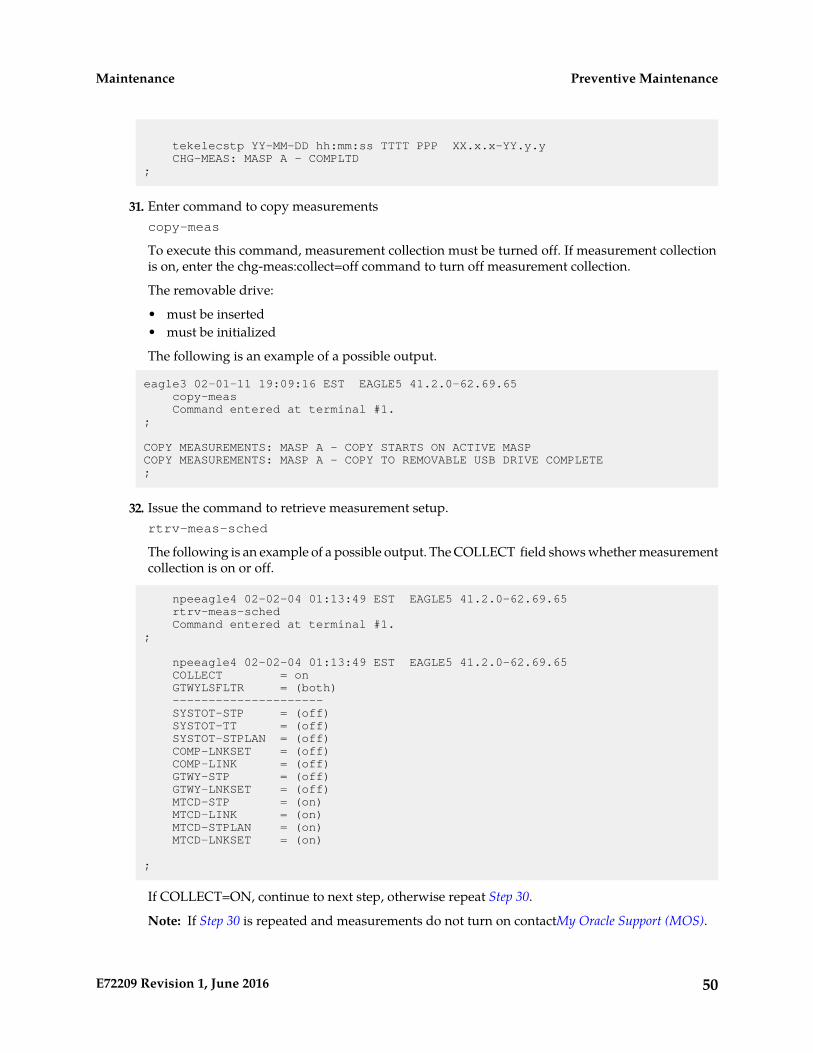
tekelecstp YY-MM-DD hh:mm:ss TTTT PPP XX.x.x-YY.y.y CHG-MEAS: MASP A - COMPLTD;
31. Enter command to copy measurementscopy-meas
To execute this command, measurement collection must be turned off. If measurement collectionis on, enter the chg-meas:collect=off command to turn off measurement collection.
The removable drive:
• must be inserted• must be initialized
The following is an example of a possible output.
eagle3 02-01-11 19:09:16 EST EAGLE5 41.2.0-62.69.65 copy-meas Command entered at terminal #1.;
COPY MEASUREMENTS: MASP A - COPY STARTS ON ACTIVE MASPCOPY MEASUREMENTS: MASP A - COPY TO REMOVABLE USB DRIVE COMPLETE;
32. Issue the command to retrieve measurement setup.rtrv-meas-sched
The following is an example of a possible output. The COLLECT field shows whether measurementcollection is on or off.
npeeagle4 02-02-04 01:13:49 EST EAGLE5 41.2.0-62.69.65 rtrv-meas-sched Command entered at terminal #1.;
npeeagle4 02-02-04 01:13:49 EST EAGLE5 41.2.0-62.69.65 COLLECT = on GTWYLSFLTR = (both) --------------------- SYSTOT-STP = (off) SYSTOT-TT = (off) SYSTOT-STPLAN = (off) COMP-LNKSET = (off) COMP-LINK = (off) GTWY-STP = (off) GTWY-LNKSET = (off) MTCD-STP = (on) MTCD-LINK = (on) MTCD-STPLAN = (on) MTCD-LNKSET = (on)
;
If COLLECT=ON, continue to next step, otherwise repeat Step 30.
Note: If Step 30 is repeated and measurements do not turn on contactMy Oracle Support (MOS).
50E72209 Revision 1, June 2016
Preventive MaintenanceMaintenance

33. Issue the report card status command.rept-stat-card:appl=oam
The following is an example of a possible output.
Command Accepted - Processing
eagle3 02-01-01 00:29:24 EST EAGLE5 41.2.0-62.69.65 rept-stat-card:appl=oam Command entered at terminal #1.;
eagle3 02-01-01 00:29:24 EST EAGLE5 41.2.0-62.69.65 CARD VERSION TYPE GPL PST SST AST 1113 132-069-061 E5MCAP OAMHC IS-NR Active ----- 1115 132-069-061 E5MCAP OAMHC IS-NR Standby -----
Command Completed.;
34. Issue the command to display database status.rept-stat-db:display=all
The following is an example of a possible output.
eagle3 02-01-11 16:11:25 EST EAGLE5 41.2.0-62.69.65 rept-stat-db:display=version Command entered at terminal #1.;
eagle3 02-01-11 16:11:26 EST EAGLE5 41.2.0-62.69.65 DATABASE STATUS: >> OK << E5TDM 1114 ( ACTV ) E5TDM 1116 ( STDBY) C LEVEL TIME LAST BACKUP C LEVEL TIME LAST BACKUP - -------- ---------------------- - -------- ----------------------
FD BKUP Y 79 02-01-05 18:06:16 EST Y 79 02-01-05 18:06:16 EST FD CRNT Y 79 Y 79 MCAP 1113 MCAP 1115 - -------- - -------- RD BKUP Y 79 02-01-05 11:15:16 EST - - - - USB BKP - - - - - - - -
CARD/APPL LOC C T LEVEL TIME LAST UPDATE VERSION STATUS --------- ---- - - ---------- ----------------- ------------------- OAMHC-RMV 1113 - - - - - - OAMHC-USB 1113 - - - - - - E5TDM-CRNT 1114 Y N 79 02-01-04 23:46:18 132-013-000 NORMAL E5TDM-BKUP 1114 Y - 79 02-01-04 23:46:18 132-013-000 NORMAL OAMHC-RMV 1115 - - - - - - E5TDM-CRNT 1116 Y N 79 02-01-04 23:46:18 132-013-000 NORMAL E5TDM-BKUP 1116 Y - 79 02-01-04 23:46:18 132-013-000 NORMAL
EPAP A (NOACCS) C BIRTHDATE LEVEL EXCEPTION - ----------------- ---------- -------------- PDB - - - - RTDB - - - - RTDB-EAGLE - - - - -
EPAP B (NOACCS) C BIRTHDATE LEVEL EXCEPTION
51E72209 Revision 1, June 2016
Preventive MaintenanceMaintenance
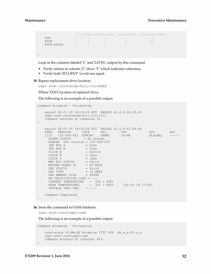
- ----------------- ---------- -------------- PDB - - - - RTDB - - - - RTDB-EAGLE - - - - -
;
Look in the columns labeled 'C' and 'LEVEL' output by this command.
• Verify entries in column ‘C’ show ‘Y’ which indicates coherence.• Verify both ‘FD CRNT’ Levels are equal.
35. Report replacement drive location.rept-stat-card:mode=full:loc=XXXX
Where XXXX location of replaced drive.
The following is an example of a possible output.
Command Accepted - Processing
eagle3 02-01-18 18:10:28 EST EAGLE5 41.2.0-62.69.65 rept-stat-card:mode=full:loc=1113 Command entered at terminal #1.;
eagle3 02-01-18 18:10:28 EST EAGLE5 41.2.0-62.69.65 CARD VERSION TYPE GPL PST SST AST 1113 132-069-061 E5MCAP OAMHC IS-NR Standby ----- ALARM STATUS = No Alarms. BLMCAP GPL version = 132-068-000 IMT BUS A = Conn IMT BUS B = Conn CLOCK A = Active CLOCK B = Idle CLOCK I = Idle MBD BIP STATUS = Valid MOTHER BOARD ID = E5-MCAP DBD STATUS = Valid DBD TYPE = 1G ENET DBD MEMORY SIZE = 4096M HW VERIFICATION CODE = ---- CURRENT TEMPERATURE = 30C ( 86F) PEAK TEMPERATURE: = 30C ( 86F) [02-01-18 17:58] TROUBLE TEXT VER. = ----
Command Completed.;
36. Issue the command to OAM database.rept-stat-card:appl=oam
The following is an example of a possible output.
Command Accepted - Processing
tekelecstp YY-MM-DD hh:mm:ss TTTT PPP XX.x.x-YY.y.y rept-stat-card:appl=oam Command entered at terminal #14.;
52E72209 Revision 1, June 2016
Preventive MaintenanceMaintenance
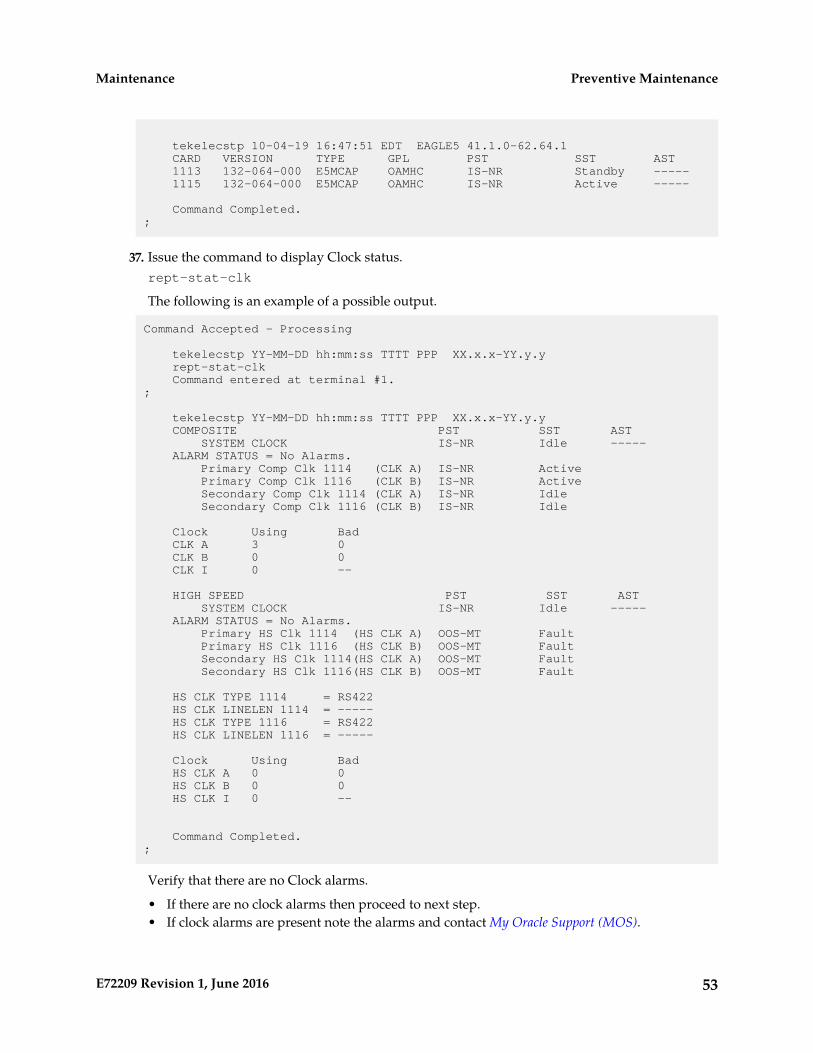
tekelecstp 10-04-19 16:47:51 EDT EAGLE5 41.1.0-62.64.1 CARD VERSION TYPE GPL PST SST AST 1113 132-064-000 E5MCAP OAMHC IS-NR Standby ----- 1115 132-064-000 E5MCAP OAMHC IS-NR Active -----
Command Completed.;
37. Issue the command to display Clock status.rept-stat-clk
The following is an example of a possible output.
Command Accepted - Processing
tekelecstp YY-MM-DD hh:mm:ss TTTT PPP XX.x.x-YY.y.y rept-stat-clk Command entered at terminal #1.;
tekelecstp YY-MM-DD hh:mm:ss TTTT PPP XX.x.x-YY.y.y COMPOSITE PST SST AST SYSTEM CLOCK IS-NR Idle ----- ALARM STATUS = No Alarms. Primary Comp Clk 1114 (CLK A) IS-NR Active Primary Comp Clk 1116 (CLK B) IS-NR Active Secondary Comp Clk 1114 (CLK A) IS-NR Idle Secondary Comp Clk 1116 (CLK B) IS-NR Idle
Clock Using Bad CLK A 3 0 CLK B 0 0 CLK I 0 --
HIGH SPEED PST SST AST SYSTEM CLOCK IS-NR Idle ----- ALARM STATUS = No Alarms. Primary HS Clk 1114 (HS CLK A) OOS-MT Fault Primary HS Clk 1116 (HS CLK B) OOS-MT Fault Secondary HS Clk 1114(HS CLK A) OOS-MT Fault Secondary HS Clk 1116(HS CLK B) OOS-MT Fault
HS CLK TYPE 1114 = RS422 HS CLK LINELEN 1114 = ----- HS CLK TYPE 1116 = RS422 HS CLK LINELEN 1116 = -----
Clock Using Bad HS CLK A 0 0 HS CLK B 0 0 HS CLK I 0 --
Command Completed.;
Verify that there are no Clock alarms.
• If there are no clock alarms then proceed to next step.• If clock alarms are present note the alarms and contact My Oracle Support (MOS).
53E72209 Revision 1, June 2016
Preventive MaintenanceMaintenance
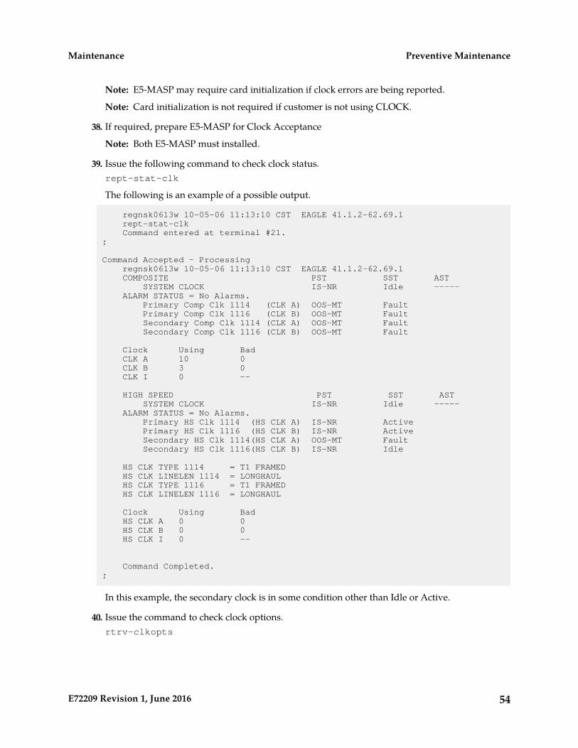
Note: E5-MASP may require card initialization if clock errors are being reported.
Note: Card initialization is not required if customer is not using CLOCK.
38. If required, prepare E5-MASP for Clock Acceptance
Note: Both E5-MASP must installed.
39. Issue the following command to check clock status.rept-stat-clk
The following is an example of a possible output.
regnsk0613w 10-05-06 11:13:10 CST EAGLE 41.1.2-62.69.1 rept-stat-clk Command entered at terminal #21.;
Command Accepted - Processing regnsk0613w 10-05-06 11:13:10 CST EAGLE 41.1.2-62.69.1 COMPOSITE PST SST AST SYSTEM CLOCK IS-NR Idle ----- ALARM STATUS = No Alarms. Primary Comp Clk 1114 (CLK A) OOS-MT Fault Primary Comp Clk 1116 (CLK B) OOS-MT Fault Secondary Comp Clk 1114 (CLK A) OOS-MT Fault Secondary Comp Clk 1116 (CLK B) OOS-MT Fault
Clock Using Bad CLK A 10 0 CLK B 3 0 CLK I 0 --
HIGH SPEED PST SST AST SYSTEM CLOCK IS-NR Idle ----- ALARM STATUS = No Alarms. Primary HS Clk 1114 (HS CLK A) IS-NR Active Primary HS Clk 1116 (HS CLK B) IS-NR Active Secondary HS Clk 1114(HS CLK A) OOS-MT Fault Secondary HS Clk 1116(HS CLK B) IS-NR Idle
HS CLK TYPE 1114 = T1 FRAMED HS CLK LINELEN 1114 = LONGHAUL HS CLK TYPE 1116 = T1 FRAMED HS CLK LINELEN 1116 = LONGHAUL
Clock Using Bad HS CLK A 0 0 HS CLK B 0 0 HS CLK I 0 --
Command Completed. ;
In this example, the secondary clock is in some condition other than Idle or Active.
40. Issue the command to check clock options.rtrv-clkopts
54E72209 Revision 1, June 2016
Preventive MaintenanceMaintenance
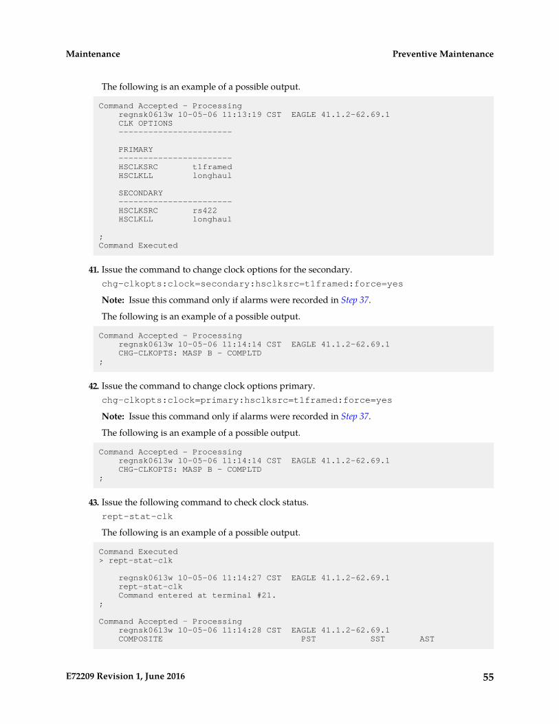
The following is an example of a possible output.
Command Accepted - Processing regnsk0613w 10-05-06 11:13:19 CST EAGLE 41.1.2-62.69.1 CLK OPTIONS -----------------------
PRIMARY ----------------------- HSCLKSRC t1framed HSCLKLL longhaul
SECONDARY ----------------------- HSCLKSRC rs422 HSCLKLL longhaul
;Command Executed
41. Issue the command to change clock options for the secondary.chg-clkopts:clock=secondary:hsclksrc=t1framed:force=yes
Note: Issue this command only if alarms were recorded in Step 37.
The following is an example of a possible output.
Command Accepted - Processing regnsk0613w 10-05-06 11:14:14 CST EAGLE 41.1.2-62.69.1 CHG-CLKOPTS: MASP B - COMPLTD;
42. Issue the command to change clock options primary.chg-clkopts:clock=primary:hsclksrc=t1framed:force=yes
Note: Issue this command only if alarms were recorded in Step 37.
The following is an example of a possible output.
Command Accepted - Processing regnsk0613w 10-05-06 11:14:14 CST EAGLE 41.1.2-62.69.1 CHG-CLKOPTS: MASP B - COMPLTD;
43. Issue the following command to check clock status.rept-stat-clk
The following is an example of a possible output.
Command Executed> rept-stat-clk
regnsk0613w 10-05-06 11:14:27 CST EAGLE 41.1.2-62.69.1 rept-stat-clk Command entered at terminal #21.;
Command Accepted - Processing regnsk0613w 10-05-06 11:14:28 CST EAGLE 41.1.2-62.69.1 COMPOSITE PST SST AST
55E72209 Revision 1, June 2016
Preventive MaintenanceMaintenance
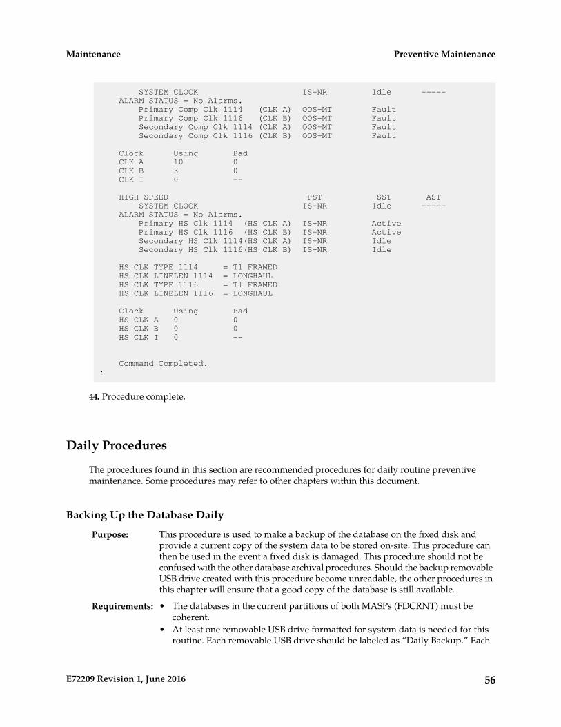
SYSTEM CLOCK IS-NR Idle ----- ALARM STATUS = No Alarms. Primary Comp Clk 1114 (CLK A) OOS-MT Fault Primary Comp Clk 1116 (CLK B) OOS-MT Fault Secondary Comp Clk 1114 (CLK A) OOS-MT Fault Secondary Comp Clk 1116 (CLK B) OOS-MT Fault
Clock Using Bad CLK A 10 0 CLK B 3 0 CLK I 0 --
HIGH SPEED PST SST AST SYSTEM CLOCK IS-NR Idle ----- ALARM STATUS = No Alarms. Primary HS Clk 1114 (HS CLK A) IS-NR Active Primary HS Clk 1116 (HS CLK B) IS-NR Active Secondary HS Clk 1114(HS CLK A) IS-NR Idle Secondary HS Clk 1116(HS CLK B) IS-NR Idle
HS CLK TYPE 1114 = T1 FRAMED HS CLK LINELEN 1114 = LONGHAUL HS CLK TYPE 1116 = T1 FRAMED HS CLK LINELEN 1116 = LONGHAUL
Clock Using Bad HS CLK A 0 0 HS CLK B 0 0 HS CLK I 0 --
Command Completed. ;
44. Procedure complete.
Daily Procedures
The procedures found in this section are recommended procedures for daily routine preventivemaintenance. Some procedures may refer to other chapters within this document.
Backing Up the Database Daily
This procedure is used to make a backup of the database on the fixed disk andprovide a current copy of the system data to be stored on-site. This procedure can
Purpose:
then be used in the event a fixed disk is damaged. This procedure should not beconfused with the other database archival procedures. Should the backup removableUSB drive created with this procedure become unreadable, the other procedures inthis chapter will ensure that a good copy of the database is still available.
Requirements: • The databases in the current partitions of both MASPs (FDCRNT) must becoherent.
• At least one removable USB drive formatted for system data is needed for thisroutine. Each removable USB drive should be labeled as “Daily Backup.” Each
56E72209 Revision 1, June 2016
Preventive MaintenanceMaintenance

day, select the removable USB drive with this label and perform the backupprocedure.
DailyInterval:
Procedure - Backing Up the Database
1. Enter the following command to check the operational status of the database:rept-stat-db
If necessary, refer to Commands User's Guide to interpret the output.
2. Enter the following command to create a backup of the database on the fixed disk:chg-db:action=backup
This command should take no longer than 30 minutes to execute. It could take longer dependingon other system activity that is in progress when this command is entered. During commandexecution, these messages appear (the active MASP is displayed first):
BACKUP (FIXED) : MASP A - Backup starts on active MASP.BACKUP (FIXED) : MASP A - Backup on active MASP to fixed disk complete.BACKUP (FIXED) : MASP B - Backup starts on standby MASP.BACKUP (FIXED) : MASP B - Backup on standby MASP to fixed disk complete.
3. Insert the removable USB drive labeled “Daily Backup” into the removable USB media slot.Reference: Removable Drives
4. Enter the following command to create a backup of the database on the removable USB drive:chg-db:action=backup:dest=remove
During command execution, these messages should appear.
BACKUP (REMOVABLE) : MASP A - Backup starts on active MASP.BACKUP (REMOVABLE) : MASP A - Backup to removable USB drive complete.
5. Verify that the databases on the removable USB drive (RDBKUP) and the current partition of theactive MASP (FDCRNT) are coherent by entering the following command:rept-stat-dbIf necessary, refer to Commands User's Guide to interpret the output.
6. Remove the removable USB drive from the removable USB media slot.Reference: Removable Drives
7. Make an entry in the site maintenance log that a backup was performed.Place the removable USB drive in a safe place, easily accessible in the event of a catastrophic failure.
System Reports AnalysisThe purpose of this routine is to inspect the printer outputs for possible troublemessages and routinely check the status of the STP through traffic measurements.
Purpose:
By inspecting printouts and measurements on a daily basis, system trends can bedetected and resolved.
Printer must be configured to receive traffic reports. Measurements collection mustbe activated before reports containing current data can be printed. Enter the
Requirements:
57E72209 Revision 1, June 2016
Preventive MaintenanceMaintenance
following command to activate measurements collection, ifnecessary:chg-meas:collect=on
Refer to Commands User's Guide for more information. If measurements are already allowed, an errormessage indicates this.
Reports Description
This includes a system terminal and printer output system related messagesas well as network protocol messages. Any abnormal activity (this is network
Purpose:
dependent) should be highlighted and saved for later retrieval. Refer toCorrective Maintenance for a description of system related messages andprocedures for recovery.
NoneRequirements:
DailyInterval:
hh = The end half-hour interval (0 - 2330) for requested intervalVariables:
Procedure - Print Report
1. Enter the following command to print a measurements report for the STP entitytype:rept-meas:type=systot:enttype=stp
2. Enter the following command to print a measurements report for the link entity type (this commandrequires either the loc and port parameters or the lsn parameter):rept-meas:type=comp:enttype=link
3. Review the STP report and compare with the link report.If excessive errors exist on any one particular link, enter the following command to print a reportfor the time period the errors occurred:rept-meas:enttype=link:period=specific:hh
Refer to Commands User's Guide for more information on using the rept-meas command.
4. From this report, determine what events may have occurred during the 30 minute measurementscollection period.
File Transfer for LNP and INP Measurements
The purpose of this procedure is to output LNP/INP measurements to the filetransfer area (FTA) so the measurements can be collected.
Purpose:
A computer with a VT320 or KSR connection to the EAGLE. A communicationprogram that both emulates VT terminals and supports Kermit file transfer.
Requirements:
Previous LNP/INP measurement files must have been successfully transferredand deleted (dlt-fta) before the start of this procedure. A spreadsheet programthat can import Comma Separated Value (CSV) text files. A PC running ProComm©
for Windows and Microsoft Excel© can also be used.
Daily and/or weekly.Interval:
Procedure - File Transfer
58E72209 Revision 1, June 2016
Preventive MaintenanceMaintenance
1. From the EAGLEVT320 or KSR terminal, enter the following command to display the contents ofthe FTA:disp-fta-dir:loc=xxxxWhere xxxx = the active E5-TDM (1114 or 1116).
2. From the EAGLEVT320 or KSR terminal, enter the following command to delete any existing filesfrom the FTA:dlt-fta:loc=xxxx:all=yesWhere xxxx = the active E5-TDM (1114 or 1116)
3. In this example, from the EAGLEVT320 or KSR terminal, enter the following command to sendLNP daily measurements to the FTA:rept-meas:enttype=lnp:type=mtcd
4. Enter the following command to acquire a list of the files transferred to the FTA in step4:disp-fta-dir:loc=xxxxWhere xxxx = the active E5-TDM (1114 or 1116).
5. Enter the following command to activate the file transfer:act-file-trns:loc=xxxxWherexxxx= the active E5-TDM (1114 or 1116).
6. Transfer the desired files (with .csv suffixes) to the PC by using the get command from within thecommunications program configured to run Kermit in ASCII mode.An example of the Kermit commands to extract the previous day’s records are as follows:> getmon_lnp.csv > get tues_ssp.csv > get thu_lrn.csv > get sat_npa.csv >finish
7. Run a spreadsheet program and open each of the files collected to view the LNP/INP measurementdata.
8. Once all the files are successfully transferred and confirmed, enter the following command toremove the files from the FTA:dlt-fta:loc=xxxx:all=yesWhere xxxx = the active E5-TDM (1114 or 1116)
Weekly Procedures
The procedures found in this section are recommended for weekly routine preventive maintenance.Some procedures may refer to other chapters within this document.
Database Archive (Weekly)
The purpose of this procedure is to create a copy of the database on a weekly basisover a period of four weeks to be stored in an archive. The copies can then be used
Purpose:
in the event a removable USB drive is damaged, and a new copy is required. Thisroutine will generate four copies of the database, all taken at weekly intervals.
Each tape in this cycle should be designated as Week 1, Week 2, Week 3, or Week 4.When all four removable USB drives have been used, repeat the process startingwith the Week 1 USB drive.
Four removable USB drives formatted for system data are required for this routine.The removable USB drive should be labeled “Week 1” through “Week 4.” Once each
Requirements:
week, select the removable USB drive with the appropriate label and perform the
59E72209 Revision 1, June 2016
Preventive MaintenanceMaintenance
backup procedure. Each week, select the removable USB drive with the next sequentialnumber and perform this procedure.
WeeklyInterval:
Procedure - Archive Database (Weekly)
1. Enter the following command to check the operational status of the database:rept-stat-db
If necessary, refer to Commands User's Guide to interpret the output.
2. Insert the removable USB drive labeled “Week x” into the removable USB drive media slot.Reference: Removable Drives.
3. Enter the following command to create a backup of the database on the removable USB drive:chg-db:action=backup:dest=remove
During command execution, these messages should appear.
BACKUP (REMOVABLE) : MASP A - Backup starts on active MASP.BACKUP (REMOVABLE) : MASP A - Backup to removable USB drive complete.
4. Verify that the databases on the removable USB drive backup partition (RD BKUP) and the currentpartition of the active maintenance and administration subprocessor system (MASP) fixed diskcurrent partition (FD CRNT) are coherent by entering the following command:rept-stat-db
If necessary, refer to Commands User's Guide to interpret the output.
5. Remove the removable USB drive from the removable USB drive media slot.Reference: Removable Drives
6. Make an entry in the site maintenance log that a backup was performed for the appropriate week(Week 1, Week 2, Week 3, or Week 4).Place the removable USB drive in a safe place, easily accessible in the event of a catastrophic failure.
Printer Inspection
This procedure verifies the printer is operational and the ribbon does not needreplacement. Should the printer cease operation, system reports and trouble
Purpose:
reports would not be printed at the system printer. Use the following procedureto verify the operation of the printer.
A printer connected through an RS232 to a serial port on the EAGLE controlshelf backplane. Refer to the printer user manual (provided by the printermanufacturer) for detailed specifics on maintaining the printer.
Requirements:
WeeklyInterval:
x = TDM serial port number (1-16)Variables:
Procedure -Printer Inspection
1. Verify the carriage assembly is free of any debris.
60E72209 Revision 1, June 2016
Preventive MaintenanceMaintenance

Remove the top of the printer if necessary.
2. Check that the power indicator is illuminated (on).If not, verify the power cord is plugged in.
3. Check the online indicator.If off, press the select button. Verify the indicator is illuminated.
4. Verify the presence of on-line indicators using the printer Users Manual.5. Enter the following command to send output to the printer: act-echo:trm=x.6. Type the following command at a terminal to verify the printer is operating: rept-stat-trm
If the printer does not print any messages, check the printer cable and verify it is connected to asystem terminal. If not, reconnect the printer cable (refer to the Installation Guide for cable pinouts).
7. Look at the printout.If the ink is faded and difficult to read, replace the ribbon. Refer to the Users Manual provided bythe manufacturer for ribbon replacement procedures.
Remote Access Verification
The purpose of this routine is to verify proper operation of the modemused for remote access of the EAGLE system.
Purpose:
Remote terminal and modem.Requirements:
WeeklyInterval
Procedure - Remote Access Verification
1. From a remote PC or terminal, dial the telephone number of the modem connected to the Eagle.2. When connected, verify you are able to log in to the EAGLE system and enter commands.3. Once you have verified the operation of the modem, logoff from the EAGLE and terminate your
connection.
Monthly Procedures
The procedures found in this section are recommended procedures for monthly routine preventivemaintenance. Some procedures may refer to other chapters within this document.
Database Archive (Monthly)
The purpose of this procedure is to create a copy of the database on a monthly basisover a period of four months to be stored in an archive. The copies can then be used
Purpose:
in the event a removable USB drive is damaged, and a new copy is required. Thisroutine will generate four copies of the database, all taken at monthly intervals.
Each tape in this cycle should be designated as Month 1, Month 2, Month 3, or Month4. When all four removable USB drives have been used, repeat the process startingwith the Month 1 USB drive.
61E72209 Revision 1, June 2016
Preventive MaintenanceMaintenance
Four removable USB drives formatted for system data are required for this routine.The removable USB drive should be labeled “Month 1” through “Month 4.” Once
Requirements:
each month, select the removable USB drive with the appropriate label and performthe backup procedure. Each month, select the removable USB drive with the nextsequential number and perform this procedure.
MonthlyInterval
Procedure - Database Archive (Monthly)
1. Enter the following command to check the operational status of the database:rept-stat-db
If necessary, refer to Commands User's Guide to interpret the output.
2. Insert the removable USB drive labeled “Month x” into the removable USB drive media slot.Reference:Removable Drives
3. Enter the following command to create a backup of the database on the removable USB drive:chg-db:action=backup:dest=remove
BACKUP (REMOVABLE) : MASP A - Backup starts on active MASP.BACKUP (REMOVABLE) : MASP A - Backup to removable USB drive complete.
4. Verify that the databases on the removable USB drive (RDBKUP) and the current partition of theactive MASP (FDCRNT) are coherent by entering the following command:rept-stat-db
If necessary, refer to Commands User's Guide to interpret the output.
5. Remove the removable USB drive from the removable USB drive media.Reference: Removable Drives
6. Make an entry in the site maintenance log that a backup was performed for the appropriate month(Month 1, Month 2, Month 3, or Month 4).Place the removable USB drive in a safe place, easily accessible in the event of a catastrophic failure.
FAP Load Balance Verification (PN 870-0243-XX only)
This procedure is used to verify the Load Balance Factor (LBF) for the A and B powersupplied to each Fuse and Alarm Panel (FAP) in the EAGLE. This procedure appliesONLY to installed FAPs with P/N 870-0243-XX.
Purpose:
The LBF is an empirically derived number that provides an indication if a Oracle STPSystem Frame has an open power distribution diode. The difference in amperagebetween the “A” versus “B” battery leads should be within a “typical” range. Valuesoutside of this range should be an indication of a potential problem and requiresfurther investigation.
Oracle recommends that the verification be performed using a Clamping TypeMultimeter (Clamp Amp Meter). If the Clamp Meter has different settings or functions
Requirements:
than the ones described in this procedure, consult the instruction manual for thismeter and determine substitute settings or functions. Results of this verification should
62E72209 Revision 1, June 2016
Preventive MaintenanceMaintenance

be recorded on the form provided with this procedure and filed with the STP Systemmaintenance records.
Caution: This procedure must be performed with the utmost Caution.All safety precautions associated with in service equipment and powermust be strictly followed. Any equipment that is below the shelf thatis being worked on must be protected from falling tools or debris. Alljewelry, rings, watches must be removed before this procedure isstarted. Read this procedure completely before proceeding.
MonthlyInterval:
Procedure - FAP Load Balance
1. Login to system via a dedicated terminal or connect a PC to an EAGLE terminal port.Open a capture log via ProComm Plus or other PC communications program.
2. Enter the following command to determine the status of all the cards in the system.rept-stat-card
If necessary, refer to Commands User's Guide to interpret the output. Save the results to comparewith the outputs at the conclusion of this procedure.
3. Enter the following command to verify the status of the signaling links.rept-stat-slk
If necessary, refer to Commands User's Guide to interpret the output. Save the results to comparewith the outputs at the conclusion of this procedure.
4. Enter the following command to get a report of all the device trouble notifications that are currentlylogged in the OAMRAM storage area.rept-stat-trbl
If necessary, refer to Commands User's Guide to interpret the output. Save the results to comparewith the outputs at the conclusion of this procedure.
5. Enter the following command to check the status of the IMT.rept-stat-imt
If necessary, refer to Commands User's Guide to interpret the output. Save the results to comparewith the outputs at the conclusion of this procedure.
6. Enter the following command to check the status of the SCCP subsystem.rept-stat-sccp
If necessary, refer to Commands User's Guide to interpret the output. Save the results to comparewith the outputs at the conclusion of this procedure.
7. Enter the following command to check the operational status of the database.rept-stat-db
If necessary, refer to Commands User's Guide to interpret the output. Save the results to comparewith the outputs at the conclusion of this procedure. Verify that FDCRNT and FDBKUP for E5-TDM1114 and E5-TDM 1116 match. If they do not match, perform Daily Procedures before continuing.
63E72209 Revision 1, June 2016
Preventive MaintenanceMaintenance

Warning: Do not proceed to the next step if the backup fails.
8. Set the Clamp Amp Meter to measure DC amps.Set the dial to the DC 400A setting and zero out/adjust the meter by turning the 0 ADJ control.The meter must read 00.0.
Note: On the inside of the Clamp Amp Meter there should be an arrow. The arrow must alwaysbe pointing towards the frame when clamped around the cable. If the meter cannot be directlyobserved, the DATAHOLD function can be utilized, if the meter is so equipped, and the readingwill hold. The jaws of the meter must be around the cable for the DATAHOLD function to operate.
Values of less than 1.0 Amp on BOTH the “A” and “B” sides are not applicable. Ignore plus (+) orminus (-) in the meter reading.
9. Measure the current on the A side of the EAGLE Frame FAP selected for verification.Clamp the meter around the -48VDC A battery cable on the FAP. Record the reading on the Table13: Oracle Method of Procedure Test Record.
10. Depress the DATAHOLD function again, if this option was utilized in Step 9 Verify the ClampAmp Meter reading is 00.0.The meter must read 00.0 before proceeding with Step 11.
11. Measure the current on the B side of the EAGLE Frame FAP selected in Step 9.Clamp the meter around the -48VDC B battery cable on the FAP. Record the reading on the Table13: Oracle Method of Procedure Test Record.
12. Calculate the Load Balance Factor (LBF) and record on the Table 13: Oracle Method of Procedure TestRecord.a) Compute the difference between A and B sides (A-B) or (B-A).b) The difference is divided by the lower of the two (2) measured values (A or B) and expressed
as a percentage.This percentage is the LBF.
c) Enter the LBF in the appropriate space on the Test Record form.Refer to Figure 14: Open Diode Example and Figure 15: Steady State Example for examples of thisformula. Data indicates that the acceptable range can be between 0% and 125%. The 125% pointis a Flag that indicates further investigation is warranted. It indicates the potential for at leastone open diode.
64E72209 Revision 1, June 2016
Preventive MaintenanceMaintenance
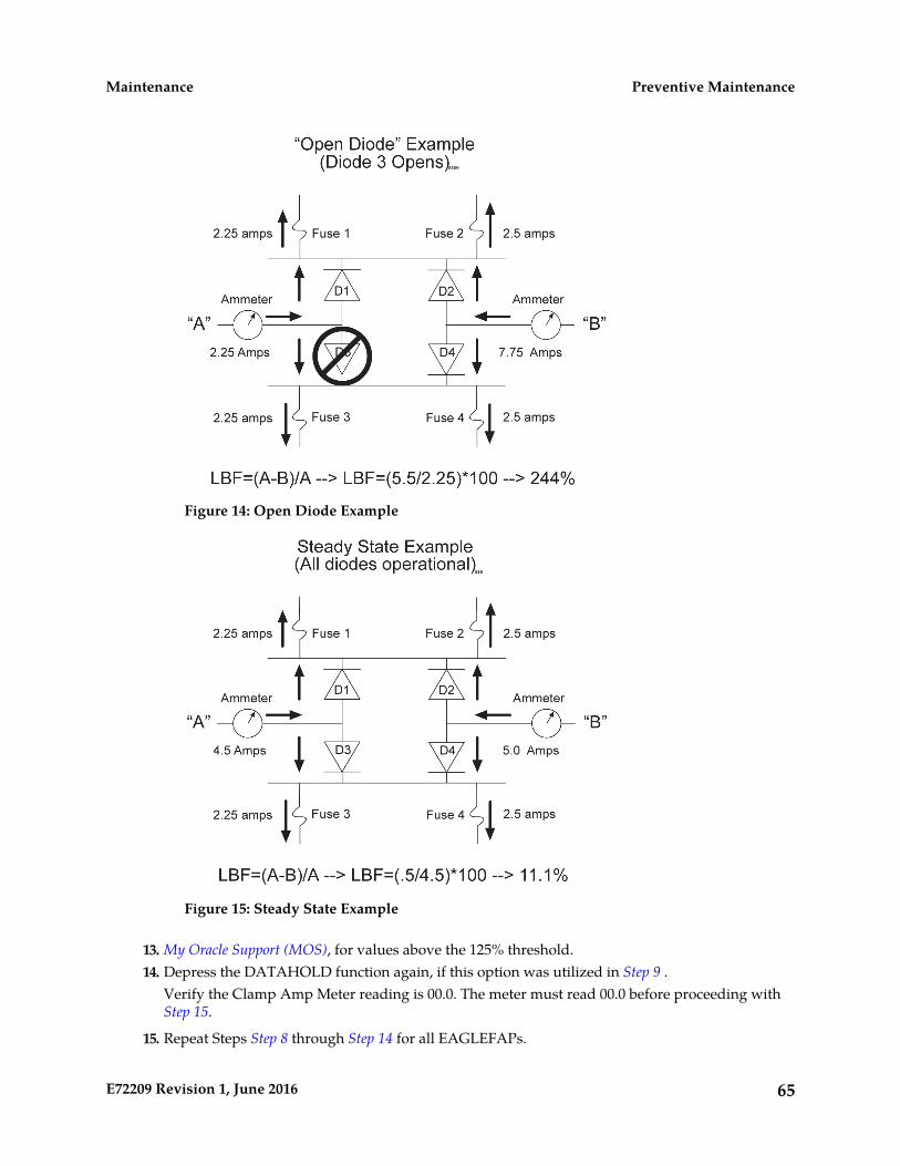
Figure 14: Open Diode Example
Figure 15: Steady State Example
13. My Oracle Support (MOS), for values above the 125% threshold.14. Depress the DATAHOLD function again, if this option was utilized in Step 9 .
Verify the Clamp Amp Meter reading is 00.0. The meter must read 00.0 before proceeding withStep 15.
15. Repeat Steps Step 8 through Step 14 for all EAGLEFAPs.
65E72209 Revision 1, June 2016
Preventive MaintenanceMaintenance
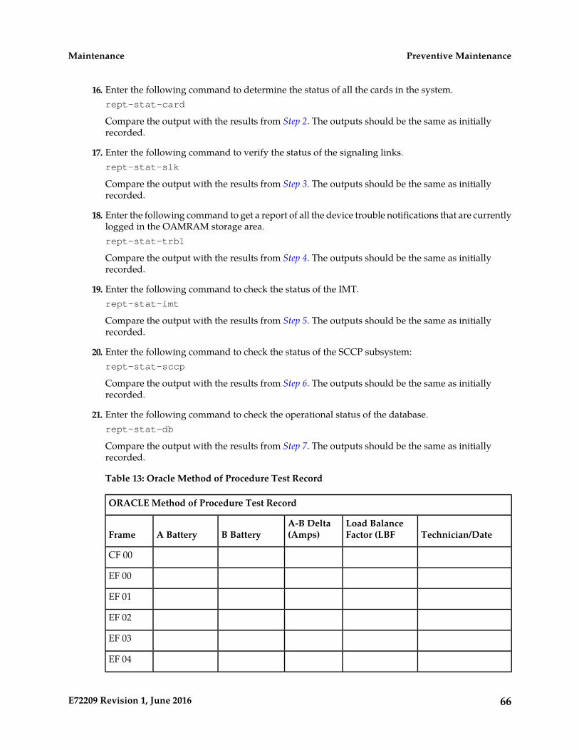
16. Enter the following command to determine the status of all the cards in the system.rept-stat-card
Compare the output with the results from Step 2. The outputs should be the same as initiallyrecorded.
17. Enter the following command to verify the status of the signaling links.rept-stat-slk
Compare the output with the results from Step 3. The outputs should be the same as initiallyrecorded.
18. Enter the following command to get a report of all the device trouble notifications that are currentlylogged in the OAMRAM storage area.rept-stat-trbl
Compare the output with the results from Step 4. The outputs should be the same as initiallyrecorded.
19. Enter the following command to check the status of the IMT.rept-stat-imt
Compare the output with the results from Step 5. The outputs should be the same as initiallyrecorded.
20. Enter the following command to check the status of the SCCP subsystem:rept-stat-sccp
Compare the output with the results from Step 6. The outputs should be the same as initiallyrecorded.
21. Enter the following command to check the operational status of the database.rept-stat-db
Compare the output with the results from Step 7. The outputs should be the same as initiallyrecorded.
Table 13: Oracle Method of Procedure Test Record
ORACLE Method of Procedure Test Record
Technician/DateLoad BalanceFactor (LBF
A-B Delta(Amps)B BatteryA BatteryFrame
CF 00
EF 00
EF 01
EF 02
EF 03
EF 04
66E72209 Revision 1, June 2016
Preventive MaintenanceMaintenance
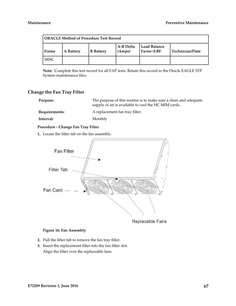
ORACLE Method of Procedure Test Record
Technician/DateLoad BalanceFactor (LBF
A-B Delta(Amps)B BatteryA BatteryFrame
MISC
Note: Complete this test record for all FAP tests. Retain this record in the Oracle EAGLE STPSystem maintenance files.
Change the Fan Tray Filter
The purpose of this routine is to make sure a clean and adequatesupply of air is available to cool the HC MIM cards.
Purpose:
A replacement fan tray filter.Requirements:
MonthlyInterval:
Procedure - Change Fan Tray Filter
1. Locate the filter tab on the fan assembly.
Figure 16: Fan Assembly
2. Pull the filter tab to remove the fan tray filter.3. Insert the replacement filter into the fan filter slot.
Align the filter over the replaceable fans.
67E72209 Revision 1, June 2016
Preventive MaintenanceMaintenance
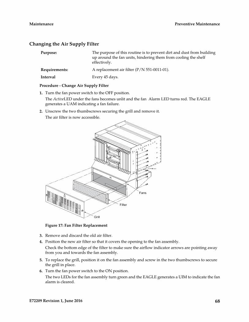
Changing the Air Supply Filter
The purpose of this routine is to prevent dirt and dust from buildingup around the fan units, hindering them from cooling the shelfeffectively.
Purpose:
A replacement air filter (P/N 551-0011-01).Requirements:
Every 45 days.Interval
Procedure - Change Air Supply Filter
1. Turn the fan power switch to the OFF position.The ActiveLED under the fans becomes unlit and the fan Alarm LED turns red. The EAGLEgenerates a UAM indicating a fan failure.
2. Unscrew the two thumbscrews securing the grill and remove it.The air filter is now accessible.
Figure 17: Fan Filter Replacement
3. Remove and discard the old air filter.4. Position the new air filter so that it covers the opening to the fan assembly.
Check the bottom edge of the filter to make sure the airflow indicator arrows are pointing awayfrom you and towards the fan assembly.
5. To replace the grill, position it on the fan assembly and screw in the two thumbscrews to securethe grill in place.
6. Turn the fan power switch to the ON position.The two LEDs for the fan assembly turn green and the EAGLE generates a UIM to indicate the fanalarm is cleared.
68E72209 Revision 1, June 2016
Preventive MaintenanceMaintenance

Cleaning Printer
The purpose of this routine is to prevent the system printer from buildingup dirt and dust around the print heads and carriage assemblies,preventing it from operating.
Purpose:
Printer cleaning kit, or cleaning solvent. Cotton swabs and damp cloth.Requirements:
MonthlyInterval
Procedure - Clean Printer
Follow the manufacturer’s procedures for cleaning the print head and carriage assembly.
Fuse Spares Inventory
This routine verifies ample spare fuses are available. Fuses areused in the fuse and alarm panel (FAP).
Purpose:
NoneRequirements
MonthlyInterval
Procedure - Fuse Inventory
Two types of fuses are used in the EAGLE:
1. Industry standard GMT fuse 1 amp2. Industry standard GMT fuse 3 amp
Spare fuses are stored in a fuse tray located on the side of each frame. Check that both types ofGMT fuses are in this tray. Oracle recommends no fewer than five of each fuse type be readilyaccessible. If the EAGLE is not located at the end of a bay, check your facility’s spare fuse storage.GMT fuses are industry standard fuses and are provided by Oracle during installation of the system.Additional inventory of these fuses should be purchased through Oracle.
Wrist Strap Test
The purpose of this routine is to verify the integrity of the anti-staticwrist strap and ground cord used when handling cards from the EAGLE.
Purpose:
Ohmmeter, wrist strap (equipped with the EAGLE).Requirements:
MonthlyInterval:
Procedure - Wrist Strap Test
1. Detach the grounding cord from the wrist strap.
Danger: If the resistance measured is less than 800 Kohms, you may be electrocutedif the equipment short circuits while you are wearing the wrist strap. If the resistancemeasured is greater than 1200 Kohms, you may damage your equipment.
2. Using an ohmmeter, measure the resistance between the two ends of the ground cord.
69E72209 Revision 1, June 2016
Preventive MaintenanceMaintenance

3. If you measure a resistance between 800 Kohms and 1200 Kohms, the ground cord is safe to continueusing.
4. If you measure a resistance that is not between 800 Kohms and 1200 Kohms, discard the groundcord and wrist strap.They are no longer safe to use.
Quarterly Procedures
The procedures found in this section are recommended procedures for quarterly routine preventivemaintenance. Some procedures may refer to other chapters within this document.
Database Archive (Quarterly)
The purpose of this routine is to create an archive copy of the EAGLE database.This archive copy should be stored off-site and saved for emergency recovery
Purpose:
when all other procedures have failed. This routine will reuse the sameremovable USB drive each quarter.
This procedure requires a removable USB drive formatted for system data.Requirements
QuarterlyInterval
Procedure _Database Archive (Quarterly)
1. Enter the following command to check the operational status of the database:rept-stat-db
If necessary, refer to Commands User's Guide to interpret the output.
2. Insert the removable USB drive labeled “Archive” into the removable USB drive media slot.Reference:Removable Drives
3. Enter the following command to create a backup of the database on the removable USB drive:chg-db:action=backup:dest=remove
BACKUP (REMOVABLE) : MASP A - Backup starts on active MASP.BACKUP (REMOVABLE) : MASP A - Backup to removable USB drive complete.
4. Verify that the databases on the removable USB drive (RDBKUP) and the current partition of theactive MASP (FDCRNT) are coherent by entering the following command:rept-stat-db
If necessary, refer to Commands User's Guide to interpret the output.
5. Remove the removable USB drive from the removable USB drive media slot.Reference: Removable Drives
6. Make an entry in the site maintenance log that a backup was performed on the “Archive” removableUSB drive.
70E72209 Revision 1, June 2016
Preventive MaintenanceMaintenance

Place the removable USB drive in a safe place off-premise. This copy is for emergency recovery inthe event all other methods of database recovery failed.
Preventing Dust Buildups
The purpose of this routine is to prevent dust build-up in and around thecabinet. Collection of dust within the EAGLE can allow electrostatic
Purpose:
charges to build around circuit cards, possibly damaging cards installedin the system.
Damp clothRequirements:
QuarterlyInterval:
Procedure - Prevent Dust Buildup
1. Open the cabinet doors on the front of the cabinet(s).
Note:
Do not use compressed air. Do not remove the plexiglass panels from the rear of the frame. Thisprocedure is to be used for removing dust from the front of the system and from around the cardcages only.
Using a damp cloth, wipe the dust from the doors and from the front of the card cages.
2. Using the same cloth, wipe the dust from the air intakes and around the exterior of the systemframes.
Rectifier Voltage Inspection/Recording
The purpose of this routine is to verify that the rectifier is providing adequatevoltages and has not become a marginal supply. By identifying power supplyproblems early, the possibility of failure can be circumvented.
Purpose:
Volt meter capable of measuring DC voltages in the range of -20VDC to-60VDC.
Requirements:
QuarterlyInterval
Procedure - Rectifier Voltage Inspection
1. Locate the power source for the EAGLE.2. Using a VOM, measure the -48VDC supply.3. Verify voltages are between -46VDC and -52VDC.
(If voltages are higher or lower, refer to the manufacturers maintenance procedures for appropriateaction).
71E72209 Revision 1, June 2016
Preventive MaintenanceMaintenance

Semi-Annual Procedures
The procedure found in this section is recommended for semi-annual (every 6 months) routinepreventive maintenance. Some procedures may refer to other chapters within this document.
Spare Inventory RotationThe purpose of this routine is to verify the integrity of spare cards. Byrotating spares on a regular basis, their operation can be verified beforethey are needed as replacements.
Purpose:
NoneRequirements
Semi-annually (every 6 months)Interval
Procedure - Semi-annual Procedures
1. Identify the spare cards in your inventory.
Warning: This procedure may interrupt service. Verify the type of card and serviceit provides, and only use this routine during the maintenance window.
2. Locate the card in service that matches the configuration of your spare card.3. Verify the part numbers and revision numbers of the cards are compatible.4. Refer to Card Removal/Replacement Procedures for the proper procedure for each card type.5. Place the card from your spares inventory into the now empty slot.
Perform any administrative commands described in Card Removal/Replacement Procedures.
6. Make an entry in the site maintenance log and place the card removed from the system into yourspares inventory.
72E72209 Revision 1, June 2016
Preventive MaintenanceMaintenance
Chapter
3Corrective Maintenance
Topics:
• Introduction.....74• System Alarm Levels.....74• Trouble Detection.....75• Output Messages.....81• Alarm Clearing Procedures.....83• Retrieve Trouble Report.....83• Hourly Status Message Reports.....84• Maintenance System Event Logs.....88• Obituaries.....90• Terminal Not Responding.....91• Printer Not Working.....92• Modem Not Working.....94• Link Maintenance.....94• Power Down of In-Service System.....108• Power Up of the System.....111
73E72209 Revision 1, June 2016

Introduction
The EAGLE trouble detection is distributed throughout the system. Each processor continually monitorsits internal subsystems and certain external subsystems. Whenever a trouble condition changes state,the processor analyzes the change and stores the analysis for reporting to the active E5-MASP. Thetrouble detection software does not affect the service quality of the system.
Each E5-MASP is made up of two cards, the E5-MCAP card and the E5-TDM (terminal disk module).
The E5-MCAP card is equipped with 4 GB of physical application processor memory. The primarydata interface to the E5-MCAP is RS-232 interfaces (i.e.: terminals) through the E5-TDM.
The E5-MCAP card contains one latched USB port for use with removable flash media (“thumb drive”),and one flush-mounted USB port for use with a plug-in flash drive. The removable media drive isused to install and back up customer data. The flush-mounted USB port is used for upgrade and couldbe used for disaster recovery. The removable flash media is used as a replacement for the legacyMagneto-Optic (MO) Drive. The E5-MCAP card is a replacement for the obsoleted legacy GPSM-IIcard used for the MCAP function.
Note: The E5-MCAP card can not be used for the other functions for which the GPSM-II class (e.g.:MCP, IPS, DCM) card is used.
The E5-TDM card contains four major subsystems: the Terminal Processor Subsystem, the SystemClock/Control Subsystem, the SATA Subsystem, and a Power Subsystem. These subsystems providethe EAGLE with 16 user-accessible terminals, distributes Composite Clocks and High Speed Masterclocks throughout the EAGLE, distributes Shelf ID to the EAGLE, and disk storage for an E5-MCAPcard. The E5-TDM card provides an interface to the E5-MDAL card for system alarms.
The E5-TDM card contains one fixed solid-state SATA drive that is removable and used to storeprimary and backup system databases, measurements, and Generic Program Loads (GPLs).
To determine which MASP is active either enter the rept-stat-db command, or enter therept-stat-card command, or examine the LEDs on both E5-TDM cards. If the LED on the E5-TDMcard is green, the associated E5-MASP is active. (If the LED on the E5-TDM card toggles between greenand amber, the associated E5-MASP is standby.)
The output of the rept-stat-db command shows which E5-MASP is active with the indicator(ACTV) following the E5-TDM card location. The indicator (STDBY) following the E5-TDM cardlocation shows which E5-MASP is standby.
The output of the rept-stat-card command shows which E5-MASP is active with the entry ACTIVEin the SST field for the E5-MCAP card. The entry STANDBY in the SST field for the E5-MCAP cardshows which E5-MASP is standby.
The database commands, such as rept-stat-db, refer to the E5-TDM because the E5-TDM containsthe fixed disk drive and the removable USB media for the E5-MASP.
System Alarm Levels
There are three levels of alarms in the EAGLE system. They are:
74E72209 Revision 1, June 2016
Corrective MaintenanceMaintenance

A critical alarm is an indication of a severe service affecting problem that can be relatedto traffic, billing, and maintenance capabilities and requires immediate maintenanceattention, regardless of time of day.
Critical
A major alarm is an indication of a problem that seriously affects system operation,maintenance and administration, etc. and requires immediate attention. The urgency
Major
is less than in critical situations because of a lesser immediate or impending effect onsystem performance, customers, and operating company operations and revenue.
A minor alarm is an indication of a problem that does not have a serious impact onservice, and does not require immediate maintenance attention.
Minor
Note: Some UAMs are considered informational if they satisfy the following conditions in the SNMPV2 traps generated by EAGLE E5OAM:
1. The Alarm Level is stated as "No alarm condition" in this user's guide.2. The alarm is not intended to clear any higher severity UAM as per the corresponding UAM Balancing
Matrix.
These UAMs are informational only and neither contribute to the total number of alarms in the systemnor change the alarm state of the device on EAGLE.
Trouble Detection
The first step in analyzing a system trouble is to know when a trouble exists. The EAGLE handles thistask through:
• Audible alarms
• Visual alarms
• Event/error messages
Audible Alarms
The EAGLE has three types of audible alarms: critical, major and minor. Audible alarms are generatedby the E5-maintenance disk and alarm card (E5-MDAL), and can be heard through the electronicsonalert device installed on the card. Each alarm has its own distinct cadence as described in thefollowing:
• Critical - Two tones 0.5 seconds apart, separated by 1.5 seconds of silence.
• Major - Single tone, separated by 1.5 seconds of silence.
• Minor - Single tone of 5 seconds or continuous tone for power plant alarm.
Visual Alarms
The EAGLE has several types of visual alarms. They are:
• AlarmLEDs on the Fuse and Alarm Panel (FAP)
• Alarms displayed on the system terminal
75E72209 Revision 1, June 2016
Corrective MaintenanceMaintenance

• LEDs on application cards
• End cabinet alarm indicators
Maintenance personnel usually see the alarm LEDs on the fuse and alarm panel (FAP) and the alarmsdisplayed on the system terminal screen to alert them that a system problem exists. The LEDs on acard help maintenance personnel diagnose where a problem exists.
Alarm LEDs on the Fuse and Alarm Panel (FAP)
There are six alarm LEDs on the FAP that indicate:
• Power alarm LEDs (A and B)
• A critical alarm
• A major alarm
• A minor alarm
• A fuse alarm
The FAP provides protected distribution of power to the system. Protection is provided by the fusesplaced in the GMT fuse holders used in the panel. The FAP contains a fuse fail alarm circuit thatoperates when one or more of the panel’s fuses fail. An LED changes from green to red when a fusehas failed. The LED remains red until the fuse has been replaced.
The fuse and alarm panel uses GMT fuses for individual circuit protection (see Figure 18: GMT Fuse).The EAGLE uses 3A and 1A fuses, depending on the application. When a fuse fails due to an overloadcondition, a small colored flag on the fuse shows the position of the fuse that has failed. The flag isgray on 1A fuses, blue on 3A fuses, black/white on 7.5A fuses, and red on 10A fuses.
Figure 18: GMT Fuse
The panel contains two separate circuits, A and B. Current flows from the input terminals to the fusebus. When a fuse is installed in a fuse holder, the circuit is completed to the output connector. TheFuse Fail Alarm LED on the front panel indicates the condition of the panel. Green is indicated ifpower is applied to the panel and there are no failed fuses. The green LED changes to red when a fusefails. An unlit LED indicates a failed LED or no power to the fuse and alarm panel.
The fuse and alarm panel is also equipped with frame alarm LEDs that display the critical, major, andminor alarms generated by the EAGLE system.
The fuse and alarm panels have the A and B buses connected through diodes to allow one bus to pickup the entire load when the other bus loses power.
76E72209 Revision 1, June 2016
Corrective MaintenanceMaintenance

Table 14: Fuse and Alarm Panel Front Items (870-2804-01), Table 15: Fuse and Alarm Panel Front Items(870-0243-xx) and Table 16: Fuse and Alarm Panel Front Items (870-1606-xx/870-2320-xx) describe thefront panel configuration of the fuse and alarm panels.
Table 14: Fuse and Alarm Panel Front Items (870-2804-01)
DescriptionFuse Panel Item
2 groups of 20 GMT fusesFuse Positions
LED indicator for A or B diode board input powerPWR ALM
• Green - input power applied• Red - no input power to board
LED indicator for fuse fail alarmFUSE ALM
• Green - normal• Red - blown fuse
LED indicator for frame critical alarmCR
LED indicator for frame major alarmMAJ
LED indicator for frame minor alarmMIN
LED indicator for mode of operationShorting Board
• Off - normal• Green - maintenance
Figure 19: Fuse and Alarm Panel Front Layout (870-2804-01)
Table 15: Fuse and Alarm Panel Front Items (870-0243-xx)
DescriptionFuse Panel Item
2 groups of 20 GMT fusesFuse Positions
slide-card holder with 2 designation cards for 20 fuse positions eachCard Holder
LED indicator for fuse fail alarmFuse Alarm
LED indicator for critical alarmCritical Alarm
77E72209 Revision 1, June 2016
Corrective MaintenanceMaintenance
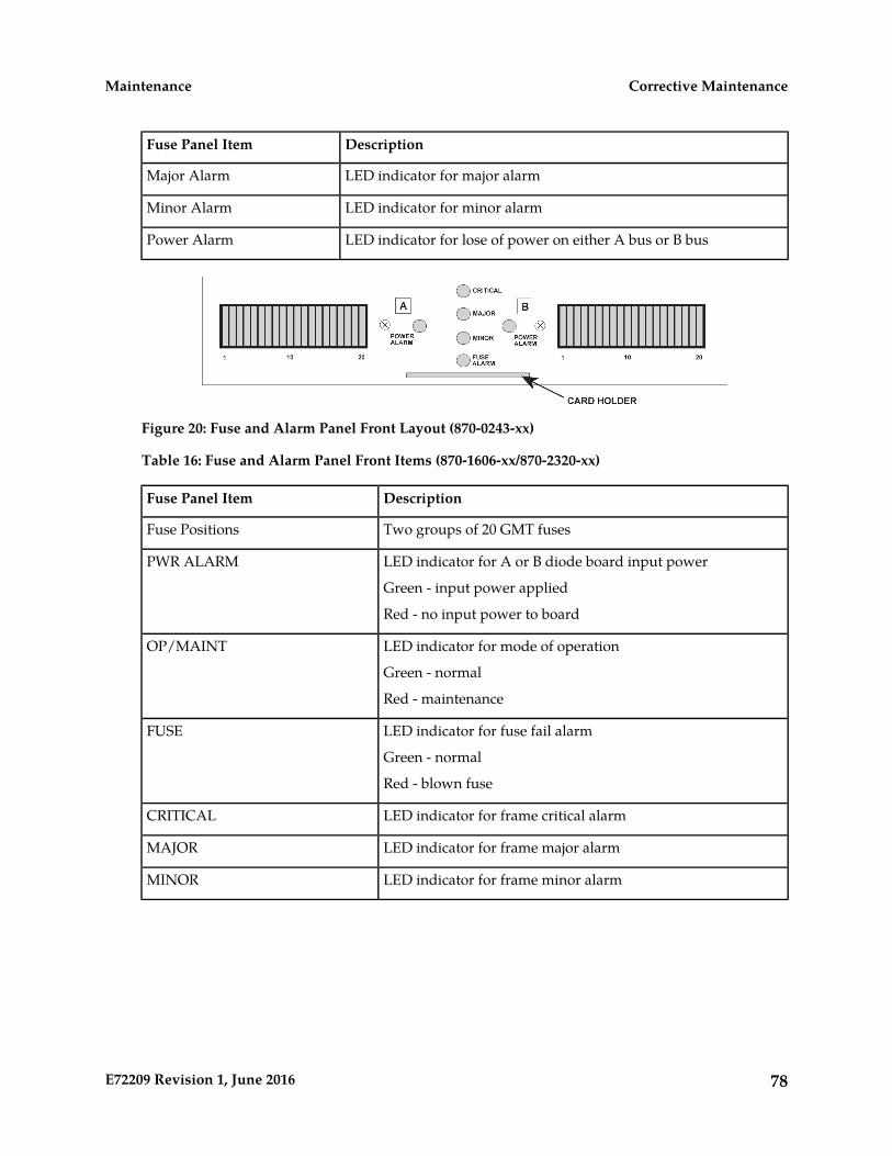
DescriptionFuse Panel Item
LED indicator for major alarmMajor Alarm
LED indicator for minor alarmMinor Alarm
LED indicator for lose of power on either A bus or B busPower Alarm
Figure 20: Fuse and Alarm Panel Front Layout (870-0243-xx)
Table 16: Fuse and Alarm Panel Front Items (870-1606-xx/870-2320-xx)
DescriptionFuse Panel Item
Two groups of 20 GMT fusesFuse Positions
LED indicator for A or B diode board input powerPWR ALARM
Green - input power applied
Red - no input power to board
LED indicator for mode of operationOP/MAINT
Green - normal
Red - maintenance
LED indicator for fuse fail alarmFUSE
Green - normal
Red - blown fuse
LED indicator for frame critical alarmCRITICAL
LED indicator for frame major alarmMAJOR
LED indicator for frame minor alarmMINOR
78E72209 Revision 1, June 2016
Corrective MaintenanceMaintenance

Figure 21: Fuse and Alarm Panel Front Layout (870-1606-xx/870-2320-xx)
Alarms appearing on a terminal screen
Three types of alarms may be displayed on a system terminal screen:
• CRIT - Indicates a critical alarm
• MAJR - Indicates a major alarm
• MINR - Indicates a minor alarm
These appear as three highlighted boxes in the top left corner of a terminal. If an alarm condition exists,it is displayed in one of the highlighted boxes. There is a fourth box next to the three alarm boxes thatis not used. To obtain information about the alarm, use the rept-stat-alm command at the systemterminal, followed by a carriage return.
This command provides all current alarm status. Refer to Commands User's Guide for more informationabout the rept-stat-alm command.
Alarms on Application Cards
Each application card has LEDs that indicate the condition of the card. Alarm conditions appear onthe card if the card has a fault. Refer to Installation Guide for the location and description of the cardLEDs.
End Cabinet Alarm Indicators
There are three alarm LEDs on the end cabinet:
• A critical alarm LED
• A major alarm LED
• A minor alarm LED
When an alarm condition is present, one or more of these LEDs illuminate in the signifying the overallsystem alarm level. Refer to Installation Guide for alarm indicators.
Event/Error Messages
Unsolicited messages are used in the EAGLE for trouble notification and to communicate the statusof the system to Operations Services (OS). The EAGLE outputs two types of unsolicited messages.
79E72209 Revision 1, June 2016
Corrective MaintenanceMaintenance
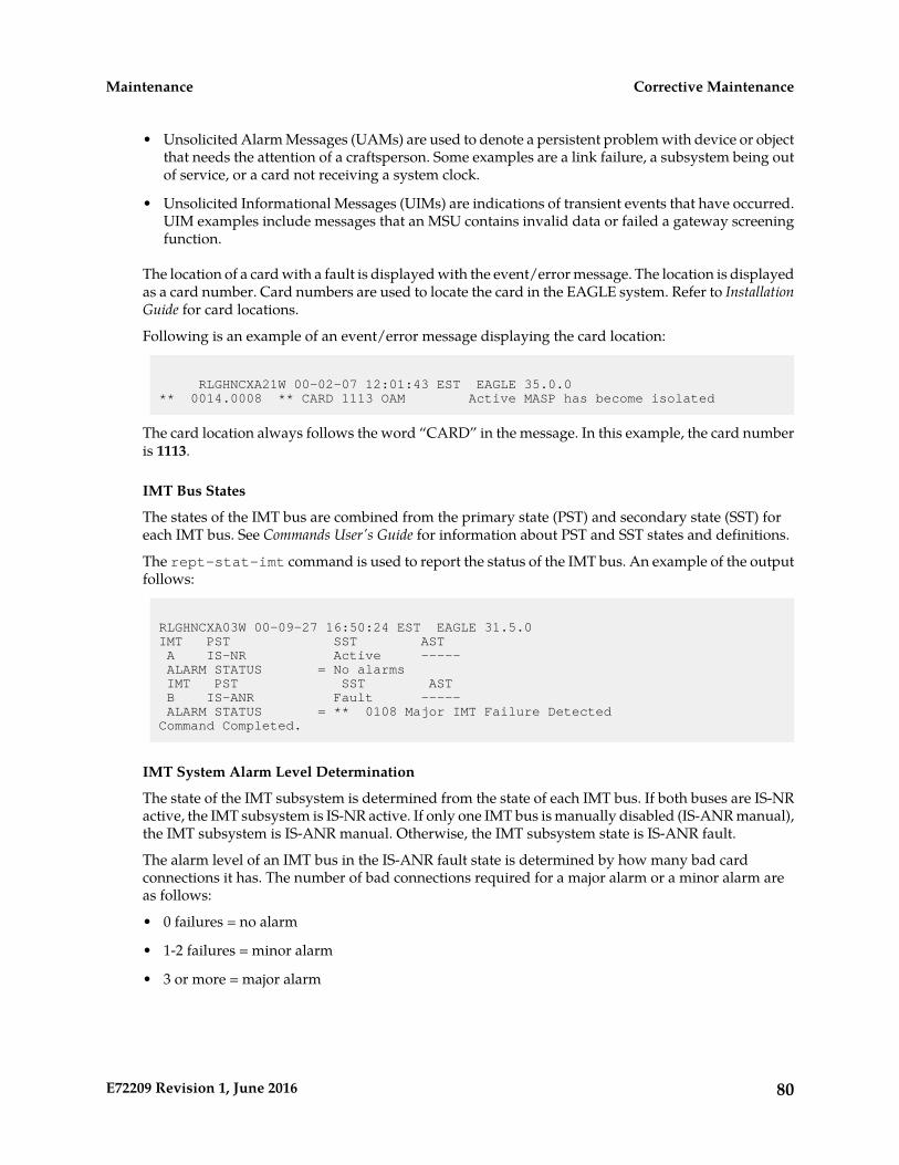
• Unsolicited Alarm Messages (UAMs) are used to denote a persistent problem with device or objectthat needs the attention of a craftsperson. Some examples are a link failure, a subsystem being outof service, or a card not receiving a system clock.
• Unsolicited Informational Messages (UIMs) are indications of transient events that have occurred.UIM examples include messages that an MSU contains invalid data or failed a gateway screeningfunction.
The location of a card with a fault is displayed with the event/error message. The location is displayedas a card number. Card numbers are used to locate the card in the EAGLE system. Refer to InstallationGuide for card locations.
Following is an example of an event/error message displaying the card location:
RLGHNCXA21W 00-02-07 12:01:43 EST EAGLE 35.0.0** 0014.0008 ** CARD 1113 OAM Active MASP has become isolated
The card location always follows the word “CARD” in the message. In this example, the card numberis 1113.
IMT Bus States
The states of the IMT bus are combined from the primary state (PST) and secondary state (SST) foreach IMT bus. See Commands User's Guide for information about PST and SST states and definitions.
The rept-stat-imt command is used to report the status of the IMT bus. An example of the outputfollows:
RLGHNCXA03W 00-09-27 16:50:24 EST EAGLE 31.5.0IMT PST SST AST A IS-NR Active ----- ALARM STATUS = No alarms IMT PST SST AST B IS-ANR Fault ----- ALARM STATUS = ** 0108 Major IMT Failure DetectedCommand Completed.
IMT System Alarm Level Determination
The state of the IMT subsystem is determined from the state of each IMT bus. If both buses are IS-NRactive, the IMT subsystem is IS-NR active. If only one IMT bus is manually disabled (IS-ANR manual),the IMT subsystem is IS-ANR manual. Otherwise, the IMT subsystem state is IS-ANR fault.
The alarm level of an IMT bus in the IS-ANR fault state is determined by how many bad cardconnections it has. The number of bad connections required for a major alarm or a minor alarm areas follows:
• 0 failures = no alarm
• 1-2 failures = minor alarm
• 3 or more = major alarm
80E72209 Revision 1, June 2016
Corrective MaintenanceMaintenance
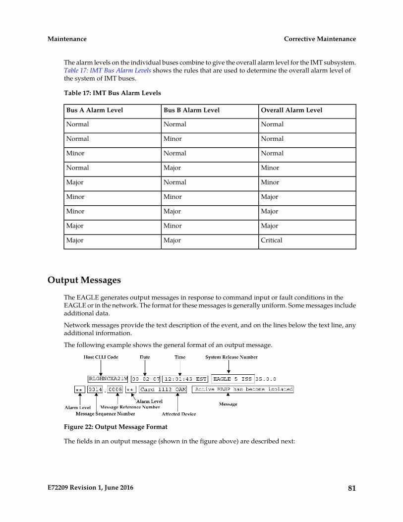
The alarm levels on the individual buses combine to give the overall alarm level for the IMT subsystem.Table 17: IMT Bus Alarm Levels shows the rules that are used to determine the overall alarm level ofthe system of IMT buses.
Table 17: IMT Bus Alarm Levels
Overall Alarm LevelBus B Alarm LevelBus A Alarm Level
NormalNormalNormal
NormalMinorNormal
NormalNormalMinor
MinorMajorNormal
MinorNormalMajor
MajorMinorMinor
MajorMajorMinor
MajorMinorMajor
CriticalMajorMajor
Output Messages
The EAGLE generates output messages in response to command input or fault conditions in theEAGLE or in the network. The format for these messages is generally uniform. Some messages includeadditional data.
Network messages provide the text description of the event, and on the lines below the text line, anyadditional information.
The following example shows the general format of an output message.
Figure 22: Output Message Format
The fields in an output message (shown in the figure above) are described next:
81E72209 Revision 1, June 2016
Corrective MaintenanceMaintenance

• Host CLLI code - a maximum of one alpha character and ten alphanumeric characters. The CLLIcode uniquely identifies the system in terms of its physical location. The CLLI code must be uniqueamong all elements in the system.
The CLLI code consists of the following:
• City = 4 characters
• State = 2 characters
• Building = 2 characters
• Equipment type = 3 characters
• Date - The date the message was generated, in the format year-month-day.
• Time - The time the message was generated with time zone, in the format hour: minutes: second timezone.
• System Release Number - contains a system identifier and the version ID number. The systemidentifier, can be EAGLE or EAGLE5 depending on the product key enabled on the system. Theversion ID number has the software release specific GPL set that is expected to be installed on thesystem as approved loads. The format of the version ID number is in the form of maj.min.maint,defined as follows:
• maj - the major release ID
• min - the minor release ID
• maint - the maintenance release ID
• Alarm Level - a one or two character indicator of the alarm level, defined as follows:
• *C = Critical Alarm
• ** = Major Alarm
• * = Minor Alarm
• blank = No Alarm
• Message Sequence Number - This number is an index for all output messages. The numberincrements sequentially for every message. The output messages originating from the card inlocation 1113 has a range from 0001 through 4999. The range for location 1115 is 5000 through 9999.
• Message Reference Number - Messages that are associated with a specific action are numberedfor reference. These messages are defined in this chapter, along with a corrective action.
• Affected Device - The device that caused the message to be generated. This generally describesthe card type.
Network messages with additional data display the additional lines below the text string and messagereference number (MRN). See individual messages for examples of output.
All network messages are non-alarm and are used to notify the user of network events. There may ormay not be a procedure associated with these messages.
82E72209 Revision 1, June 2016
Corrective MaintenanceMaintenance
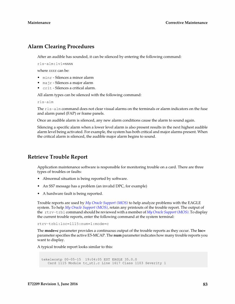
Alarm Clearing Procedures
After an audible has sounded, it can be silenced by entering the following command:
rls-alm:lvl=xxxx
where xxxx can be:
• minr - Silences a minor alarm• majr - Silences a major alarm• crit - Silences a critical alarm.
All alarm types can be silenced with the following command:
rls-alm
The rls-alm command does not clear visual alarms on the terminals or alarm indicators on the fuseand alarm panel (FAP) or frame panels.
Once an audible alarm is silenced, any new alarm conditions cause the alarm to sound again.
Silencing a specific alarm when a lower level alarm is also present results in the next highest audiblealarm level being activated. For example, the system has both critical and major alarms present. Whenthe critical alarm is silenced, the audible major alarm begins to sound.
Retrieve Trouble Report
Application maintenance software is responsible for monitoring trouble on a card. There are threetypes of troubles or faults:
• Abnormal situation is being reported by software.
• An SS7 message has a problem (an invalid DPC, for example)
• A hardware fault is being reported.
Trouble reports are used by My Oracle Support (MOS) to help analyze problems with the EAGLEsystem. To help My Oracle Support (MOS), retain any printouts of the trouble report. The output ofthe rtrv-trbl command should be reviewed with a member of My Oracle Support (MOS). To displaythe current trouble reports, enter the following command at the system terminal:
rtrv-trbl:loc=1115:num=1:mode=c
The mode=c parameter provides a continuous output of the trouble reports as they occur. The loc=parameter specifies the active E5-MCAP. The num parameter indicates how many trouble reports youwant to display.
A typical trouble report looks similar to this:
tekelecstp 00-05-15 19:04:05 EST EAGLE 35.0.0 Card 1115 Module tc_utl.c Line 1617 Class 1103 Severity 1
83E72209 Revision 1, June 2016
Corrective MaintenanceMaintenance
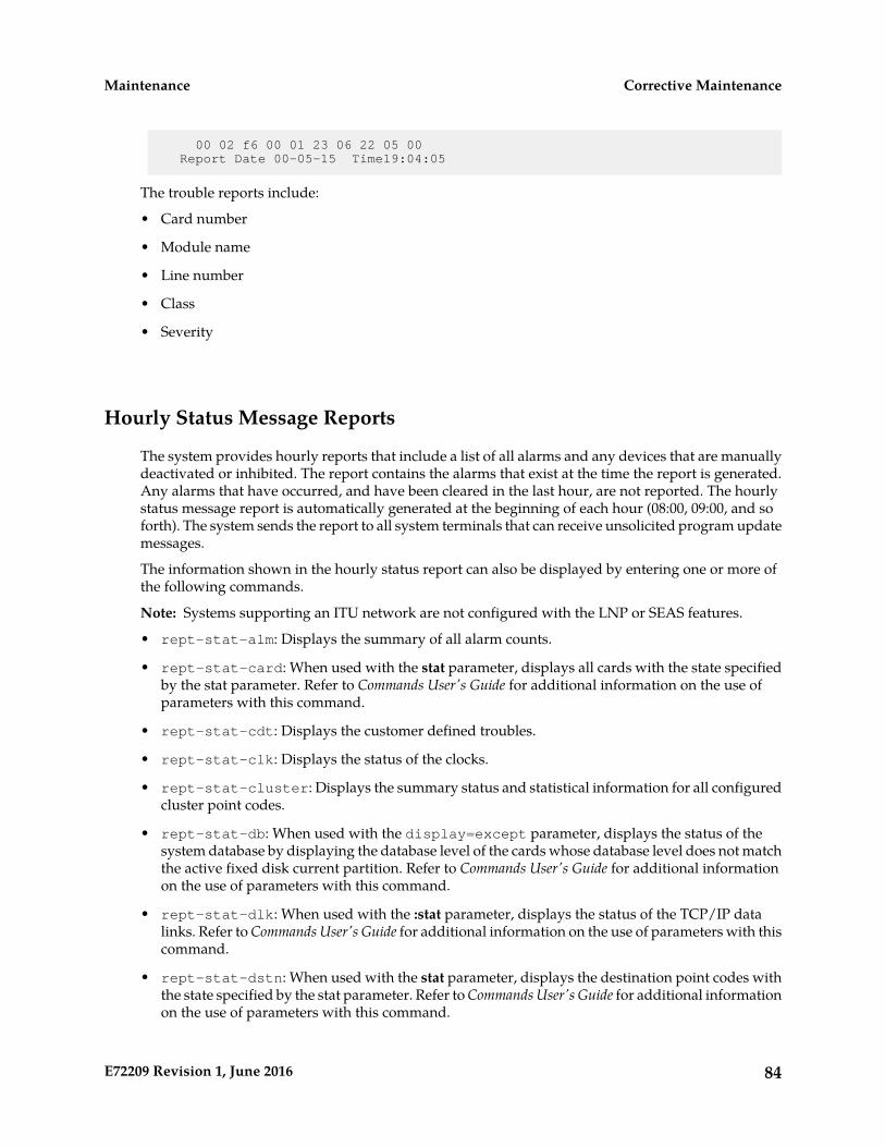
00 02 f6 00 01 23 06 22 05 00 Report Date 00-05-15 Time19:04:05
The trouble reports include:
• Card number
• Module name
• Line number
• Class
• Severity
Hourly Status Message Reports
The system provides hourly reports that include a list of all alarms and any devices that are manuallydeactivated or inhibited. The report contains the alarms that exist at the time the report is generated.Any alarms that have occurred, and have been cleared in the last hour, are not reported. The hourlystatus message report is automatically generated at the beginning of each hour (08:00, 09:00, and soforth). The system sends the report to all system terminals that can receive unsolicited program updatemessages.
The information shown in the hourly status report can also be displayed by entering one or more ofthe following commands.
Note: Systems supporting an ITU network are not configured with the LNP or SEAS features.
• rept-stat-alm: Displays the summary of all alarm counts.
• rept-stat-card: When used with the stat parameter, displays all cards with the state specifiedby the stat parameter. Refer to Commands User's Guide for additional information on the use ofparameters with this command.
• rept-stat-cdt: Displays the customer defined troubles.
• rept-stat-clk: Displays the status of the clocks.
• rept-stat-cluster: Displays the summary status and statistical information for all configuredcluster point codes.
• rept-stat-db: When used with the display=except parameter, displays the status of thesystem database by displaying the database level of the cards whose database level does not matchthe active fixed disk current partition. Refer to Commands User's Guide for additional informationon the use of parameters with this command.
• rept-stat-dlk: When used with the :stat parameter, displays the status of the TCP/IP datalinks. Refer to Commands User's Guide for additional information on the use of parameters with thiscommand.
• rept-stat-dstn: When used with the stat parameter, displays the destination point codes withthe state specified by the stat parameter. Refer to Commands User's Guide for additional informationon the use of parameters with this command.
84E72209 Revision 1, June 2016
Corrective MaintenanceMaintenance

• rept-stat-dstn: When used with the mode=full parameter, displays the subsystem status.Refer to Commands User's Guide for additional information on the use of parameters with thiscommand.
• rept-stat-mps: Displays in a single report, the overall status of the EPAP (EAGLE ProvisioningApplication Processor) subsystem.
• rept-stat-gpl: Displays the version of the GPL currently being used by an application andwhich versions of the GPL are the trial and approved versions of that GPL.
• rept-stat-imt: Displays the primary, secondary, and associated maintenance states of the IMTbuses.
• rept-stat-lnp: Displays the status and statistics related to LNP.
• rept-stat-ls: When used with the stat parameter, displays the linksets that have the statespecified by the stat parameter. Refer to Commands User's Guide for additional information on theuse of parameters with this command.
• rept-stat-sccp: Displays the status of the TSMs running the SCCP application.
• rept-stat-seas: Displays the status of the SEAS subsystem.
• rept-stat-slan: Displays the status of the cards that make up the STPLAN subsystem.
• rept-stat-slk: When used with the stat parameter, displays the signaling links that have thestate specified by the stat parameter. Refer to Commands User's Guide for additional informationon the use of parameters with this command.
• rept-stat-sys: Displays the status of these items: alarms, IMT buses, SS7 signaling links, linksets,destination point codes (DPCs), the maintenance and administration subsystem (MAS), clocks,TSMs loaded with the SCCP or GLS application, security subsystem, and the SEAS subsystem.
• rept-stat-trbl: Displays a report of all the device trouble notifications that are currently loggedin the OAMRAM storage area. The severity of each alarm is also identified in the report.
• rept-stat-trm: Displays the status of the terminal serial ports.
• rept-stat-xlist: Displays the statistics related to the storage of exception list (x-list) entries.
If the message reference number (MRN) field has a null value (no field entry), the device has beenmanually removed from service (through inh-card, canc-slk, and so forth). There is no alarmfor the device and the condition type is SCMMA (state change due to manual action). The date andtime in the report refer to the date and time of the alarm or when the device was removed from service.The format of the output is in Figure 23: Format of Hourly Status Message Output.
85E72209 Revision 1, June 2016
Corrective MaintenanceMaintenance

Figure 23: Format of Hourly Status Message Output
The following is a list of the device types and subsystems (with the ID of the affected device orsubsystem) that the hourly status message report displays reports for. For example, if the device typebeing reported on is CARD, then card locations are displayed. Only those device types and subsystemsthat have disabled devices or alarm conditions are displayed in the hourly status message report. Ifthere is more than one device type or subsystem to display, they are displayed in the following order.
1. CARD - the card location
2. IMT - the IMT bus A or IMT bus B
3. BITS - the BITS clock
4. TRM - the terminal port
5. SLK - the linkset name and the signaling link code (SLC)
6. DLK - the data links
7. LS - the linkset name
8. DPC - the destination point code
9. CDT - the customer defined trouble number
10. FUSEPNL - the frame ID of the system
11. SYSTEM - system
12. ALM - alarms
13. SYSCLK - system clock
14. SYSIMT - system IMT
15. SCCPSS - SCCP subsystem
16. GLSSS - GLS subsystem
17. GPL_SS - the name of the GPL
18. SLANSS - STP/LAN subsystem
19. XLISTSS - XLIST subsystem
20. SEASSS - SEAS subsystem
86E72209 Revision 1, June 2016
Corrective MaintenanceMaintenance

21. SECULOG - Security log
22. LNPSS - LNP subsystem
23. LSMS Q.3 Association - Local Services Management System Association
24. LSMSSS - Local Services Management System subsystem
25. HS System CLK - High-Speed system clock
26. EMDC Links - Element Measurement & Data Collection Application Links
27. NDCSS - Network Data Collection subsystem
28. NDC Q.3 Association - Network Data Collection Q.3 association
29. GSMSS - GSM subsystem
30. MPS (ELAP/EPAP) - Multi-Purpose Server
31. DSM Links - Database Services Module
32. INPSS - INP subsystem
33. SECURITYSS - Security subsystem
Within each device type or subsystem being reported, the subsets of the report are displayed in thefollowing order.
1. Disabled Devices
2. Minor Alarms
3. Major Alarms
4. Critical Alarms
The cond type field supports five values for this release:
• SCMMA: The device has been disabled due to manual maintenance action. This condition appliesregardless of a previous alarm state.
• MTCEINT-0: The reported device is off normal (ANR), but there is no alarm associated with thisdevice. An alarmed condition for another device typically affects the state of this device. Forexample, out-of-service (OOS) links affect the condition of the linksets.
• MAN: The reported device is off-normal (OOS-MT), but there is no alarm associated with thisdevice. The off-normal condition was caused by manual intervention (by entering the ent-dstncommand, for example).
• NULL: No specific cond type is supported. There is sufficient information to ascertain the devicecondition from the report. You should use a rept-stat command for further information.
• INAUDB: The use has manually inhibited alarms for this device. The time when the device wasinhibited is recorded and displayed during the hourly report.
87E72209 Revision 1, June 2016
Corrective MaintenanceMaintenance
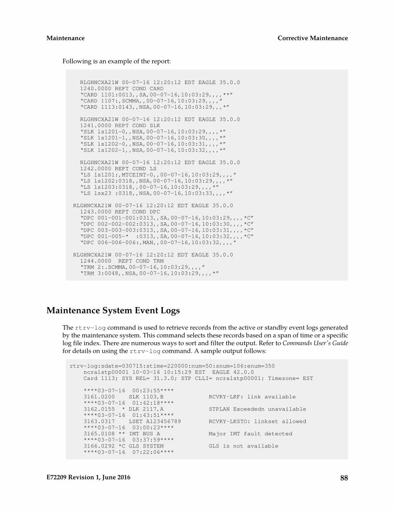
Following is an example of the report:
RLGHNCXA21W 00-07-16 12:20:12 EDT EAGLE 35.0.0 1240.0000 REPT COND CARD “CARD 1101:0013,,SA,00-07-16,10:03:29,,,,**” “CARD 1107:,SCMMA,,00-07-16,10:03:29,,,,” “CARD 1113:0143,,NSA,00-07-16,10:03:29,,,*”
RLGHNCXA21W 00-07-16 12:20:12 EDT EAGLE 35.0.0 1241.0000 REPT COND SLK “SLK ls1201-0,,NSA,00-07-16,10:03:29,,,,*” “SLK ls1201-1,,NSA,00-07-16,10:03:30,,,,*” “SLK ls1202-0,,NSA,00-07-16,10:03:31,,,,*” “SLK ls1202-1,,NSA,00-07-16,10:03:32,,,,*”
RLGHNCXA21W 00-07-16 12:20:12 EDT EAGLE 35.0.0 1242.0000 REPT COND LS “LS ls1201:,MTCEINT-0,,00-07-16,10:03:29,,,,” “LS ls1202:0318,,NSA,00-07-16,10:03:29,,,,*” “LS ls1203:0318,,00-07-16,10:03:29,,,,*” “LS lsx23 :0318,,NSA,00-07-16,10:03:33,,,,*”
RLGHNCXA21W 00-07-16 12:20:12 EDT EAGLE 35.0.0 1243.0000 REPT COND DPC “DPC 001-001-001:0313,,SA,00-07-16,10:03:29,,,,*C” “DPC 002-002-002:0313,,SA,00-07-16,10:03:30,,,,*C” “DPC 003-003-003:0313,,SA,00-07-16,10:03:31,,,,*C” “DPC 001-005-* :0313,,SA,00-07-16,10:03:32,,,,*C” “DPC 006-006-006:,MAN,,00-07-16,10:03:32,,,,”
RLGHNCXA21W 00-07-16 12:20:12 EDT EAGLE 35.0.0 1244.0000 REPT COND TRM “TRM 2:.SCMMA,00-07-16,10:03:29,,,,” “TRM 3:0048,,NSA,00-07-16,10:03:29,,,,*”
Maintenance System Event Logs
The rtrv-log command is used to retrieve records from the active or standby event logs generatedby the maintenance system. This command selects these records based on a span of time or a specificlog file index. There are numerous ways to sort and filter the output. Refer to Commands User's Guidefor details on using the rtrv-log command. A sample output follows:
rtrv-log:sdate=030715:stime=220000:num=50:snum=106:enum=350 ncralstp00001 10-03-16 10:15:29 EST EAGLE 42.0.0 Card 1113; SYS REL= 31.3.0; STP CLLI= ncralstp00001; Timezone= EST
****03-07-16 00:23:55**** 3161.0200 SLK 1103,B RCVRY-LKF: link available ****03-07-16 01:42:18**** 3162.0155 * DLK 2117,A STPLAN Exceededn unavailable ****03-07-16 01:43:51**** 3163.0317 LSET A123456789 RCVRY-LKSTO: linkset allowed ****03-07-16 03:00:23**** 3165.0108 ** IMT BUS A Major IMT fault detected ****03-07-16 03:37:59**** 3166.0292 *C GLS SYSTEM GLS is not available ****03-07-16 07:22:06****
88E72209 Revision 1, June 2016
Corrective MaintenanceMaintenance
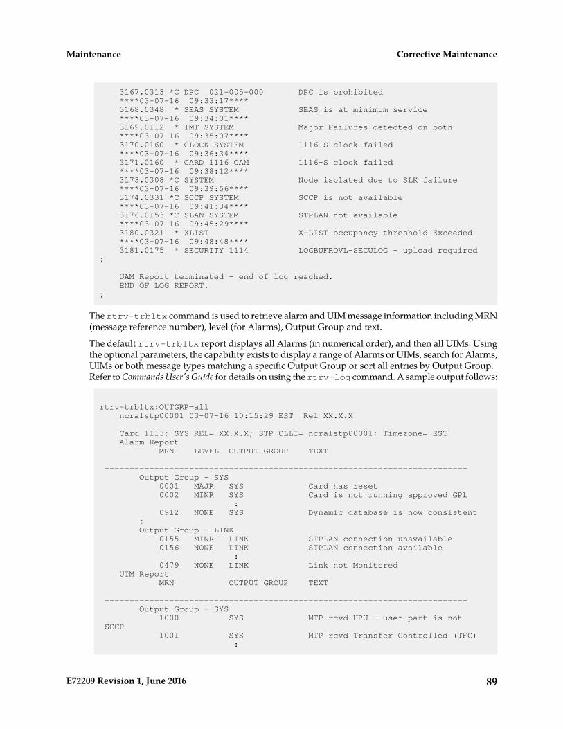
3167.0313 *C DPC 021-005-000 DPC is prohibited ****03-07-16 09:33:17**** 3168.0348 * SEAS SYSTEM SEAS is at minimum service ****03-07-16 09:34:01**** 3169.0112 * IMT SYSTEM Major Failures detected on both ****03-07-16 09:35:07**** 3170.0160 * CLOCK SYSTEM 1116-S clock failed ****03-07-16 09:36:34**** 3171.0160 * CARD 1116 OAM 1116-S clock failed ****03-07-16 09:38:12**** 3173.0308 *C SYSTEM Node isolated due to SLK failure ****03-07-16 09:39:56**** 3174.0331 *C SCCP SYSTEM SCCP is not available ****03-07-16 09:41:34**** 3176.0153 *C SLAN SYSTEM STPLAN not available ****03-07-16 09:45:29**** 3180.0321 * XLIST X-LIST occupancy threshold Exceeded ****03-07-16 09:48:48**** 3181.0175 * SECURITY 1114 LOGBUFROVL-SECULOG - upload required;
UAM Report terminated - end of log reached. END OF LOG REPORT.;
The rtrv-trbltx command is used to retrieve alarm and UIM message information including MRN(message reference number), level (for Alarms), Output Group and text.
The default rtrv-trbltx report displays all Alarms (in numerical order), and then all UIMs. Usingthe optional parameters, the capability exists to display a range of Alarms or UIMs, search for Alarms,UIMs or both message types matching a specific Output Group or sort all entries by Output Group.Refer to Commands User's Guide for details on using the rtrv-log command. A sample output follows:
rtrv-trbltx:OUTGRP=all ncralstp00001 03-07-16 10:15:29 EST Rel XX.X.X
Card 1113; SYS REL= XX.X.X; STP CLLI= ncralstp00001; Timezone= EST Alarm Report MRN LEVEL OUTPUT GROUP TEXT
------------------------------------------------------------------------- Output Group - SYS 0001 MAJR SYS Card has reset 0002 MINR SYS Card is not running approved GPL : 0912 NONE SYS Dynamic database is now consistent : Output Group - LINK 0155 MINR LINK STPLAN connection unavailable 0156 NONE LINK STPLAN connection available : 0479 NONE LINK Link not Monitored UIM Report MRN OUTPUT GROUP TEXT
------------------------------------------------------------------------- Output Group - SYS 1000 SYS MTP rcvd UPU - user part is not SCCP 1001 SYS MTP rcvd Transfer Controlled (TFC) :
89E72209 Revision 1, June 2016
Corrective MaintenanceMaintenance
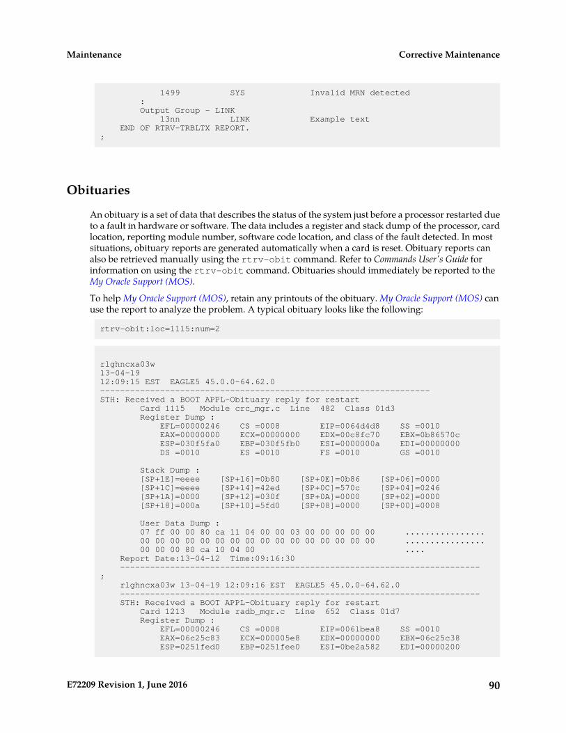
1499 SYS Invalid MRN detected : Output Group - LINK 13nn LINK Example text END OF RTRV-TRBLTX REPORT.;
Obituaries
An obituary is a set of data that describes the status of the system just before a processor restarted dueto a fault in hardware or software. The data includes a register and stack dump of the processor, cardlocation, reporting module number, software code location, and class of the fault detected. In mostsituations, obituary reports are generated automatically when a card is reset. Obituary reports canalso be retrieved manually using the rtrv-obit command. Refer to Commands User's Guide forinformation on using the rtrv-obit command. Obituaries should immediately be reported to theMy Oracle Support (MOS).
To help My Oracle Support (MOS), retain any printouts of the obituary. My Oracle Support (MOS) canuse the report to analyze the problem. A typical obituary looks like the following:
rtrv-obit:loc=1115:num=2
rlghncxa03w 13-04-19 12:09:15 EST EAGLE5 45.0.0-64.62.0------------------------------------------------------------------STH: Received a BOOT APPL-Obituary reply for restart Card 1115 Module crc_mgr.c Line 482 Class 01d3 Register Dump : EFL=00000246 CS =0008 EIP=0064d4d8 SS =0010 EAX=00000000 ECX=00000000 EDX=00c8fc70 EBX=0b86570c ESP=030f5fa0 EBP=030f5fb0 ESI=0000000a EDI=00000000 DS =0010 ES =0010 FS =0010 GS =0010
Stack Dump : [SP+1E]=eeee [SP+16]=0b80 [SP+0E]=0b86 [SP+06]=0000 [SP+1C]=eeee [SP+14]=42ed [SP+0C]=570c [SP+04]=0246 [SP+1A]=0000 [SP+12]=030f [SP+0A]=0000 [SP+02]=0000 [SP+18]=000a [SP+10]=5fd0 [SP+08]=0000 [SP+00]=0008
User Data Dump : 07 ff 00 00 80 ca 11 04 00 00 03 00 00 00 00 00 ................ 00 00 00 00 00 00 00 00 00 00 00 00 00 00 00 00 ................ 00 00 00 80 ca 10 04 00 .... Report Date:13-04-12 Time:09:16:30 ------------------------------------------------------------------------; rlghncxa03w 13-04-19 12:09:16 EST EAGLE5 45.0.0-64.62.0 ------------------------------------------------------------------------ STH: Received a BOOT APPL-Obituary reply for restart Card 1213 Module radb_mgr.c Line 652 Class 01d7 Register Dump : EFL=00000246 CS =0008 EIP=0061bea8 SS =0010 EAX=06c25c83 ECX=000005e8 EDX=00000000 EBX=06c25c38 ESP=0251fed0 EBP=0251fee0 ESI=0be2a582 EDI=00000200
90E72209 Revision 1, June 2016
Corrective MaintenanceMaintenance

DS =0010 ES =0010 FS =0010 GS =0010
Stack Dump : [SP+1E]=0000 [SP+16]=0b97 [SP+0E]=06c2 [SP+06]=0b97 [SP+1C]=00d4 [SP+14]=a454 [SP+0C]=5c38 [SP+04]=c429 [SP+1A]=06c2 [SP+12]=0251 [SP+0A]=0250 [SP+02]=0251 [SP+18]=5c38 [SP+10]=ff10 [SP+08]=0f14 [SP+00]=fee0
User Data Dump : 8f 82 fb ed 01 01 5a 01 5a 0b 00 86 00 00 00 99 ......Z.Z....... 54 8c 1a 87 00 00 00 f0 54 8c 1a 77 00 08 00 00 T.......T..w.... 00 00 00 00 00 00 00 00 .... Report Date:13-04-12 Time:10:40:36 ------------------------------------------------------------------------;
Terminal Not Responding
When a terminal is not responding, perform the following procedure:
1. Verify the terminal is connected to the MMI port on the back of the control shelf.2. Verify the terminal is set up for 7-E-1.3. From a working terminal, enter the following command to determine the port connected to the
faulty terminal:rtrv-trm
Note the port number. From the output message, verify the settings are correct. If no workingterminal is available, contact the My Oracle Support (MOS).
4. Enter the following command to inhibit the terminal failing to respond:inh-trm:trm=x
where x is the terminal that is not responding.
5. Enter the following command to re-activate the terminal failing to respond:alw-trm:trm=x
where x is the terminal that is not responding. If the terminal fails to respond, go to Step 6.
6. Enter the following command to ensure that the other terminal devices are functioning:rept-stat-trm
Following is an example of the output:
RLGHNCXA03W 00-02-07 09:50:17 EST EAGLE 35.0.0TRM PST SST AST1 IS-NR Active -----2 IS-NR Active -----3 IS-NR Active -----4 OOS-MT-DSBLD MANUAL -----5 IS-NR Active -----6 IS-NR Active -----7 IS-NR Active -----
91E72209 Revision 1, June 2016
Corrective MaintenanceMaintenance
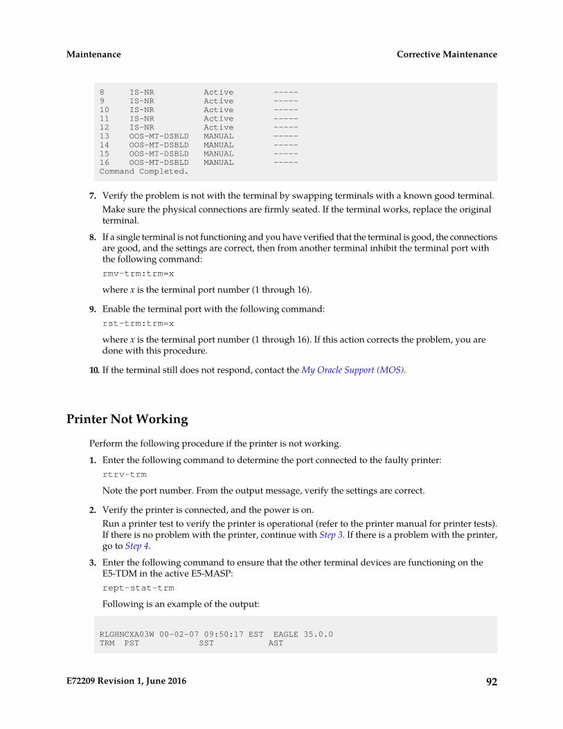
8 IS-NR Active -----9 IS-NR Active -----10 IS-NR Active -----11 IS-NR Active -----12 IS-NR Active -----13 OOS-MT-DSBLD MANUAL -----14 OOS-MT-DSBLD MANUAL -----15 OOS-MT-DSBLD MANUAL -----16 OOS-MT-DSBLD MANUAL -----Command Completed.
7. Verify the problem is not with the terminal by swapping terminals with a known good terminal.Make sure the physical connections are firmly seated. If the terminal works, replace the originalterminal.
8. If a single terminal is not functioning and you have verified that the terminal is good, the connectionsare good, and the settings are correct, then from another terminal inhibit the terminal port withthe following command:rmv-trm:trm=x
where x is the terminal port number (1 through 16).
9. Enable the terminal port with the following command:rst-trm:trm=x
where x is the terminal port number (1 through 16). If this action corrects the problem, you aredone with this procedure.
10. If the terminal still does not respond, contact the My Oracle Support (MOS).
Printer Not Working
Perform the following procedure if the printer is not working.
1. Enter the following command to determine the port connected to the faulty printer:rtrv-trm
Note the port number. From the output message, verify the settings are correct.
2. Verify the printer is connected, and the power is on.Run a printer test to verify the printer is operational (refer to the printer manual for printer tests).If there is no problem with the printer, continue with Step 3. If there is a problem with the printer,go to Step 4.
3. Enter the following command to ensure that the other terminal devices are functioning on theE5-TDM in the active E5-MASP:rept-stat-trm
Following is an example of the output:
RLGHNCXA03W 00-02-07 09:50:17 EST EAGLE 35.0.0TRM PST SST AST
92E72209 Revision 1, June 2016
Corrective MaintenanceMaintenance
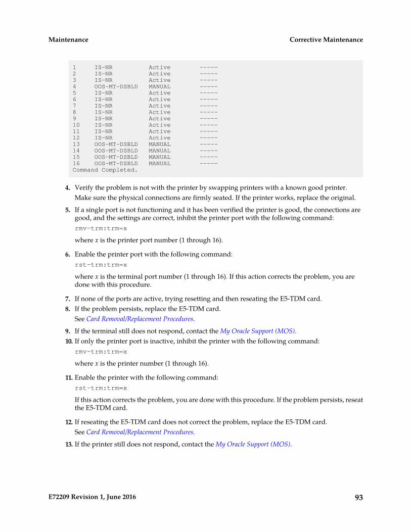
1 IS-NR Active -----2 IS-NR Active -----3 IS-NR Active -----4 OOS-MT-DSBLD MANUAL -----5 IS-NR Active -----6 IS-NR Active -----7 IS-NR Active -----8 IS-NR Active -----9 IS-NR Active -----10 IS-NR Active -----11 IS-NR Active -----12 IS-NR Active -----13 OOS-MT-DSBLD MANUAL -----14 OOS-MT-DSBLD MANUAL -----15 OOS-MT-DSBLD MANUAL -----16 OOS-MT-DSBLD MANUAL -----Command Completed.
4. Verify the problem is not with the printer by swapping printers with a known good printer.Make sure the physical connections are firmly seated. If the printer works, replace the original.
5. If a single port is not functioning and it has been verified the printer is good, the connections aregood, and the settings are correct, inhibit the printer port with the following command:rmv-trm:trm=x
where x is the printer port number (1 through 16).
6. Enable the printer port with the following command:rst-trm:trm=x
where x is the terminal port number (1 through 16). If this action corrects the problem, you aredone with this procedure.
7. If none of the ports are active, trying resetting and then reseating the E5-TDM card.8. If the problem persists, replace the E5-TDM card.
See Card Removal/Replacement Procedures.
9. If the terminal still does not respond, contact the My Oracle Support (MOS).10. If only the printer port is inactive, inhibit the printer with the following command:
rmv-trm:trm=x
where x is the printer number (1 through 16).
11. Enable the printer with the following command:rst-trm:trm=x
If this action corrects the problem, you are done with this procedure. If the problem persists, reseatthe E5-TDM card.
12. If reseating the E5-TDM card does not correct the problem, replace the E5-TDM card.See Card Removal/Replacement Procedures.
13. If the printer still does not respond, contact the My Oracle Support (MOS).
93E72209 Revision 1, June 2016
Corrective MaintenanceMaintenance
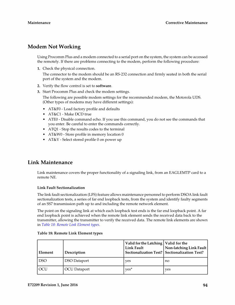
Modem Not Working
Using Procomm Plus and a modem connected to a serial port on the system, the system can be accessedthe remotely. If there are problems connecting to the modem, perform the following procedure:
1. Check the physical connection.The connector to the modem should be an RS-232 connection and firmly seated in both the serialport of the system and the modem.
2. Verify the flow control is set to software.3. Start Procomm Plus and check the modem settings.
The following are possible modem settings for the recommended modem, the Motorola UDS.(Other types of modems may have different settings):
• AT&F0 - Load factory profile and defaults• AT&C1 - Make DCD true• ATE0 - Disable command echo. If you use this command, you do not see the commands that
you enter. Be careful to enter the commands correctly.• ATQ1 - Stop the results codes to the terminal• AT&W0 - Store profile in memory location 0• AT&Y - Select stored profile 0 on power up
Link Maintenance
Link maintenance covers the proper functionality of a signaling link, from an EAGLEMTP card to aremote NE.
Link Fault Sectionalization
The link fault sectionalization (LFS) feature allows maintenance personnel to perform DSOA link faultsectionalization tests, a series of far end loopback tests, from the system and identify faulty segmentsof an SS7 transmission path up to and including the remote network element.
The point on the signaling link at which each loopback test ends is the far end loopback point. A farend loopback point is achieved when the remote link element sends the received data back to thetransmitter, allowing the transmitter to verify the received data. The remote link elements are shownin Table 18: Remote Link Element types.
Table 18: Remote Link Element types
Valid for theNon-latching Link FaultSectionalization Test?
Valid for the LatchingLink FaultSectionalization Test?DescriptionElement
noyesDSO DataportDSO
yesyes*OCU DataportOCU
94E72209 Revision 1, June 2016
Corrective MaintenanceMaintenance
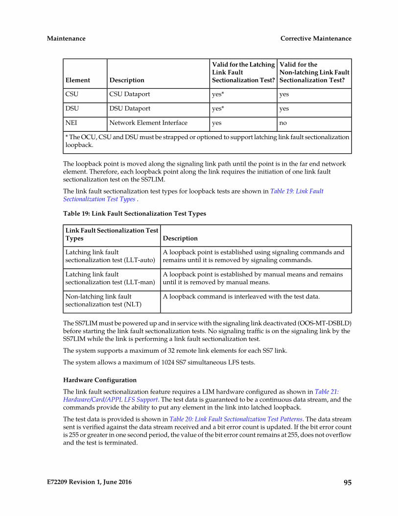
Valid for theNon-latching Link FaultSectionalization Test?
Valid for the LatchingLink FaultSectionalization Test?DescriptionElement
yesyes*CSU DataportCSU
yesyes*DSU DataportDSU
noyesNetwork Element InterfaceNEI
* The OCU, CSU and DSU must be strapped or optioned to support latching link fault sectionalizationloopback.
The loopback point is moved along the signaling link path until the point is in the far end networkelement. Therefore, each loopback point along the link requires the initiation of one link faultsectionalization test on the SS7LIM.
The link fault sectionalization test types for loopback tests are shown in Table 19: Link FaultSectionalization Test Types .
Table 19: Link Fault Sectionalization Test Types
DescriptionLink Fault Sectionalization TestTypes
A loopback point is established using signaling commands andremains until it is removed by signaling commands.
Latching link faultsectionalization test (LLT-auto)
A loopback point is established by manual means and remainsuntil it is removed by manual means.
Latching link faultsectionalization test (LLT-man)
A loopback command is interleaved with the test data.Non-latching link faultsectionalization test (NLT)
The SS7LIM must be powered up and in service with the signaling link deactivated (OOS-MT-DSBLD)before starting the link fault sectionalization tests. No signaling traffic is on the signaling link by theSS7LIM while the link is performing a link fault sectionalization test.
The system supports a maximum of 32 remote link elements for each SS7 link.
The system allows a maximum of 1024 SS7 simultaneous LFS tests.
Hardware Configuration
The link fault sectionalization feature requires a LIM hardware configured as shown in Table 21:Hardware/Card/APPL LFS Support. The test data is guaranteed to be a continuous data stream, and thecommands provide the ability to put any element in the link into latched loopback.
The test data is provided is shown in Table 20: Link Fault Sectionalization Test Patterns. The data streamsent is verified against the data stream received and a bit error count is updated. If the bit error countis 255 or greater in one second period, the value of the bit error count remains at 255, does not overflowand the test is terminated.
95E72209 Revision 1, June 2016
Corrective MaintenanceMaintenance
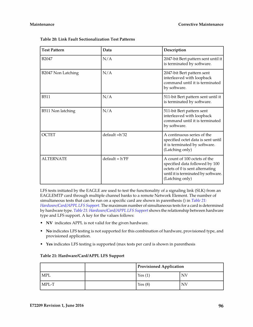
Table 20: Link Fault Sectionalization Test Patterns
DescriptionDataTest Pattern
2047-bit Bert pattern sent until itis terminated by software.
N/AB2047
2047-bit Bert pattern sentinterleaved with loopback
N/AB2047 Non Latching
command until it is terminatedby software.
511-bit Bert pattern sent until itis terminated by software.
N/AB511
511-bit Bert pattern sentinterleaved with loopback
N/AB511 Non latching
command until it is terminatedby software.
A continuous series of thespecified octet data is sent until
default =h’32OCTET
it is terminated by software.(Latching only)
A count of 100 octets of thespecified data followed by 100
default = h’FFALTERNATE
octets of 0 is sent alternatinguntil it is terminated by software.(Latching only)
LFS tests initiated by the EAGLE are used to test the functionality of a signaling link (SLK) from anEAGLEMTP card through multiple channel banks to a remote Network Element. The number ofsimultaneous tests that can be run on a specific card are shown in parenthesis () in Table 21:Hardware/Card/APPL LFS Support. The maximum number of simultaneous tests for a card is determinedby hardware type. Table 21: Hardware/Card/APPL LFS Support shows the relationship between hardwaretype and LFS support. A key for the values follows:
• NV indicates APPL is not valid for the given hardware.
• No indicates LFS testing is not supported for this combination of hardware, provisioned type, andprovisioned application.
• Yes indicates LFS testing is supported (max tests per card is shown in parenthesis
Table 21: Hardware/Card/APPL LFS Support
Provisioned Application
NVYes (1)MPL
NVYes (8)MPL-T
96E72209 Revision 1, June 2016
Corrective MaintenanceMaintenance
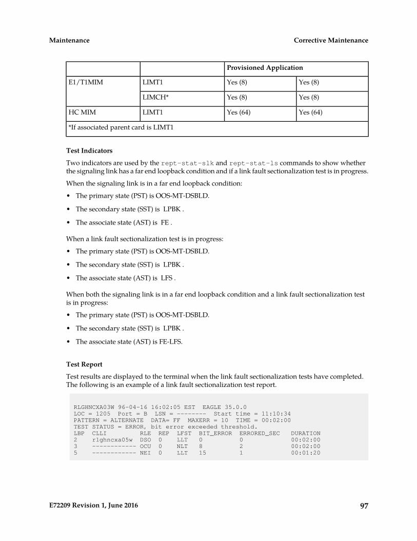
Provisioned Application
Yes (8)Yes (8)LIMT1E1/T1MIM
Yes (8)Yes (8)LIMCH*
Yes (64)Yes (64)LIMT1HC MIM
*If associated parent card is LIMT1
Test Indicators
Two indicators are used by the rept-stat-slk and rept-stat-ls commands to show whetherthe signaling link has a far end loopback condition and if a link fault sectionalization test is in progress.
When the signaling link is in a far end loopback condition:
• The primary state (PST) is OOS-MT-DSBLD.
• The secondary state (SST) is LPBK .
• The associate state (AST) is FE .
When a link fault sectionalization test is in progress:
• The primary state (PST) is OOS-MT-DSBLD.
• The secondary state (SST) is LPBK .
• The associate state (AST) is LFS .
When both the signaling link is in a far end loopback condition and a link fault sectionalization testis in progress:
• The primary state (PST) is OOS-MT-DSBLD.
• The secondary state (SST) is LPBK .
• The associate state (AST) is FE-LFS.
Test Report
Test results are displayed to the terminal when the link fault sectionalization tests have completed.The following is an example of a link fault sectionalization test report.
RLGHNCXA03W 96-04-16 16:02:05 EST EAGLE 35.0.0 LOC = 1205 Port = B LSN = -------- Start time = 11:10:34PATTERN = ALTERNATE DATA= FF MAXERR = 10 TIME = 00:02:00TEST STATUS = ERROR, bit error exceeded threshold.LBP CLLI RLE REP LFST BIT_ERROR ERRORED_SEC DURATION2 rlghncxa05w DSO 0 LLT 0 0 00:02:003 ------------ OCU 0 NLT 8 2 00:02:005 ------------ NEI 0 LLT 15 1 00:01:20
97E72209 Revision 1, June 2016
Corrective MaintenanceMaintenance
LFS Test Details
• EAGLE Initiated LFS Loopback Test Details
Loopback Test Type: EAGLE initiated Level 1 DS0LFS test
Link State: Link is down.
Equipment tested: Level 1 element(s) in a signaling path.
Purpose: Test the error rates of a signaling path.
Description: Sends loopback code to establish loopback and then performs BERT test for a specifiedperiod of time.
Typical use: To validate signaling path has acceptable error rate.
Testing Limits: 1024 concurrent link tests per system.
• Remote Initiated LFS Loopback Test Details
Loopback Test Type: Remote Loopback FAREND initiated DS0LFS test.
Link State: Link can be up or down.
Equipment tested: Near end H/W up to level 2 (LXVR) and far end H/W level 1 interface.
Purpose: Auto-loopback a BERT test to the far end.
Description: When receiving a loopback code, deactivate the link and go into loopback.
Typical use: Used to remotely test the far end with standard DS0BERT tests.
Testing Limits: No limit on number of cards.
Link Fault Test Commands
The link fault sectionalization feature uses the following commands:
• ent-lbp — add link fault sectionalization test data to the database.
• chg-lbp — change existing link fault sectionalization test data in the database.
• dlt-lbp — remove link fault sectionalization test data from the database.
• rtrv-lbp — display link fault sectionalization test data in the database.
• act-lbp — start a link fault sectionalization test.
• dact-lbp — stop a link fault sectionalization test.
• rept-stat-lfs — generates a report of all links that are under test.
The link fault sectionalization data is configured in the database using the parameters shown in Table22: Link Fault Sectionalization Data Entry Parameters.
Table 22: Link Fault Sectionalization Data Entry Parameters
DescriptionLink Fault SectionalizationData Entry Parameters
SS7LIM card locationCard Location
98E72209 Revision 1, June 2016
Corrective MaintenanceMaintenance

DescriptionLink Fault SectionalizationData Entry Parameters
Port a or b, and a1, a2, a3, b1, b2, b3 on the MPLPort Number
Identifies the remote link element for setting the loopback point. Valueis from 1 to 32.
Loopback Point Number
Description of the remote link elementCLLI
The remote element type from Table 18: Remote Link Element types.Remote Link Element Type
A repetition of the same element type in the link path. This is neededfor configuring the link element as a latched loopback point. The valueis from 0 to 31.
Repetition Count
Link fault sectionalization test type from Table 19: Link FaultSectionalization Test Types (LFS-man not supported for the database)
Link Fault SectionalizationTest Type
Use the act-lbp command to start one or a sequence of link fault sectionalization tests. The datastream sent is verified against the data stream received and the bit error counts and block error countsare displayed when the test completes.
The link fault sectionalization test parameters are described in Table 20: Link Fault Sectionalization TestPatterns. If either the remote link element type, repetition count, or link fault sectionalization test typeare specified with the act-lbp command, they must all be specified and the loopback point numberparameter is ignored. Otherwise the values for remote link element type, repetition count, or link faultsectionalization test type are read from the data entered with the ent-lbp command using theloopback point number parameter value. The test data parameter is only valid for test patterns OCTETand ALTERNATE.
If all LBPs are selected for the loopback point number parameter, a sequential test of the LBPs, asentered in the database with the ent-lbp command for that signaling link, is performed until theentire signaling link has been tested. When performing a test with all LBPs, the test is aborted withthe first failed test.
The test is stopped either because the amount of time for the test has expired or if the bit error thresholdhas been exceeded. The time duration parameter specifies the maximum time duration for one linkfault sectionalization loopback point test. The default value is one second (00:00:01) and the maximumvalue that can be entered is 24 hours (24:00:00). The bit error threshold parameter specifies the maximumnumber of bit errors allowed for one link fault sectionalization loopback point test. The default valueis 56 errors and the maximum value that can be entered is 4,838,400 (24 hours x 56 errors per second).
Table 23: Link Fault Sectionalization Test Parameters
DescriptionParameters
SS7LIM card locationCard Location
Signaling link id a to a31 and b to b31Port /Link Number
The remote link element for setting the loopback point. Value is from1 to 32, or if this parameter is not specified, all LBPs are selected.
Loopback Point Number
99E72209 Revision 1, June 2016
Corrective MaintenanceMaintenance

DescriptionParameters
The remote element type from Table 18: Remote Link Element types.Remote Link Element Type
A repetition of the same element type in the link path. The value isfrom 0 to 31.
Repetition Count
Link fault sectionalization test type from Table 19: Link FaultSectionalization Test Types.
Link Fault Sectionalization
Test Type
Time for one loopback point in hours, minutes, and seconds (hh:mm:ss).The value is from 00:00:01 to 24:00:00. The default value is 1 second(00:00:01).
Time duration
Bit error threshold. The value is from 0 to 4838400. The default valueis 56.
Error threshold
The test pattern from Table 20: Link Fault Sectionalization Test Patterns.The default value is B2047.
Test pattern
The octet to be used for test pattern OCTET or ALTERNATE only.Test data
The dact-lbp command stops the link fault sectionalization test in progress and cancels any pendinglink fault sectionalization tests for the SS7 link. The pending tests are the next sequential LBPs for theSS7 signaling link when an entire link test was initiated.
Link Maintenance Enhancements
The Link Maintenance Enhancements feature covers the following areas:
• Allows the operator to force a card into loopback. Without this enhancement, a card will go in andout of loopback as determined by loopback codes sent by the far end.
• tst-slk enhancements for ATM customers. The loopback parameters for ATM cards in thetst-slk command act in a similar fashion as the act-lbp command for standard DS0 loopbacks.Other tst-slk enhancements not specifically related to ATM are also provided.
Command Driven Loopback
Command Driven Loopback (CDL) is the ability to locally drive a signaling link into a manual lineloopback. The data received on the signaling link is echoed (transmitted) back. Commands are usedto provide this capability on an individual signaling link basis. CDL allows loopback testing of asignaling link when either far-end initiated loopbacks are prevented or when a constant loopbackstate is desired. This command driven setting of loopback is similar in functionality to a remote initiatedloopback. Table 24: Command Driven Loopback Support shows a breakdown of support for CommandDriven Loopback based on the MTP card type. Figure 24: Signaling Link Network Connections shows aconceptual view of a signaling links network connections. Local transceiver (LXVR) is a tst-slkinitiated test in which the line transmit is looped back to the line receive internal to the card. CDL is"LXVR in reverse", the line receive is looped back to the line transmit.
100E72209 Revision 1, June 2016
Corrective MaintenanceMaintenance

Table 24: Command Driven Loopback Support
SupportedMTPCard TypeSupportedMTPCard Type
YesT1-ATMYesMPL (DSO)
YesT1MIM (Channel)YesE1-ATM
NoIPLIMYesE1MIM (Channel)
NoIPGTWY
Test Indicators
If an MTP card boots, then all links on this card, by default, are not in CDL. A link in CDL is persistentacross an OAM switchover. Signaling links must be inhibited (OOS-MT-DSBLD) to perform commanddriven loopback. Signaling links in CDL have the following conditions:
• The primary state (PST) isOOS-MT-DSBLD.
• The secondary state (SST) is LPBK .
• The associate state (AST) is CDL .
Figure 24: Signaling Link Network Connections
Test Signaling Link
The tst-slk command is used to flush out intermittent link problems that are not captured with the oneshot testing. The tst-slk command allows for duration tests up to 24 hours, stopping of an in-progresstest, and forcing the execution of a test. The tst-slk command is grouped into two categories, messagebased tests and hardware-based tests.
The SLTC and OAM tests are message based. These tests involve sending a message to the far endand expecting an appropriate reply. The LXVR, LINE, and PAYLOAD tests are hardware-based. Thesetests involve setting hardware registers and after an appropriate duration resetting hardware registers.To prevent overloading of a signaling link, message based tests are delayed 1 to 10 seconds between
101E72209 Revision 1, June 2016
Corrective MaintenanceMaintenance
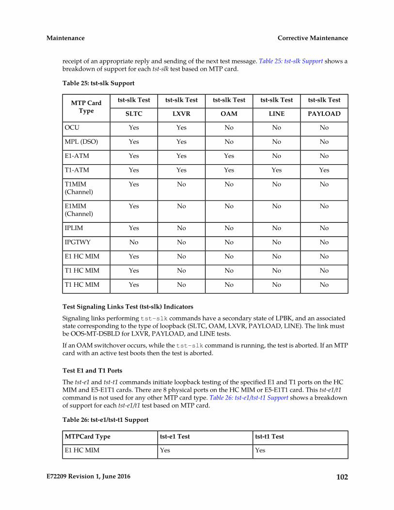
receipt of an appropriate reply and sending of the next test message. Table 25: tst-slk Support shows abreakdown of support for each tst-slk test based on MTP card.
Table 25: tst-slk Support
tst-slk Testtst-slk Testtst-slk Testtst-slk Testtst-slk TestMTP CardType PAYLOADLINEOAMLXVRSLTC
NoNoNoYesYesOCU
NoNoNoYesYesMPL (DSO)
NoNoYesYesYesE1-ATM
YesYesYesYesYesT1-ATM
NoNoNoNoYesT1MIM(Channel)
NoNoNoNoYesE1MIM(Channel)
NoNoNoNoYesIPLIM
NoNoNoNoNoIPGTWY
NoNoNoNoYesE1 HC MIM
NoNoNoNoYesT1 HC MIM
NoNoNoNoYesT1 HC MIM
Test Signaling Links Test (tst-slk) Indicators
Signaling links performing tst-slk commands have a secondary state of LPBK, and an associatedstate corresponding to the type of loopback (SLTC, OAM, LXVR, PAYLOAD, LINE). The link mustbe OOS-MT-DSBLD for LXVR, PAYLOAD, and LINE tests.
If an OAM switchover occurs, while the tst-slk command is running, the test is aborted. If an MTPcard with an active test boots then the test is aborted.
Test E1 and T1 Ports
The tst-e1 and tst-t1 commands initiate loopback testing of the specified E1 and T1 ports on the HCMIM and E5-E1T1 cards. There are 8 physical ports on the HC MIM or E5-E1T1 card. This tst-e1/t1command is not used for any other MTP card type. Table 26: tst-e1/tst-t1 Support shows a breakdownof support for each tst-e1/t1 test based on MTP card.
Table 26: tst-e1/tst-t1 Support
tst-t1 Testtst-e1 TestMTPCard Type
YesYesE1 HC MIM
102E72209 Revision 1, June 2016
Corrective MaintenanceMaintenance
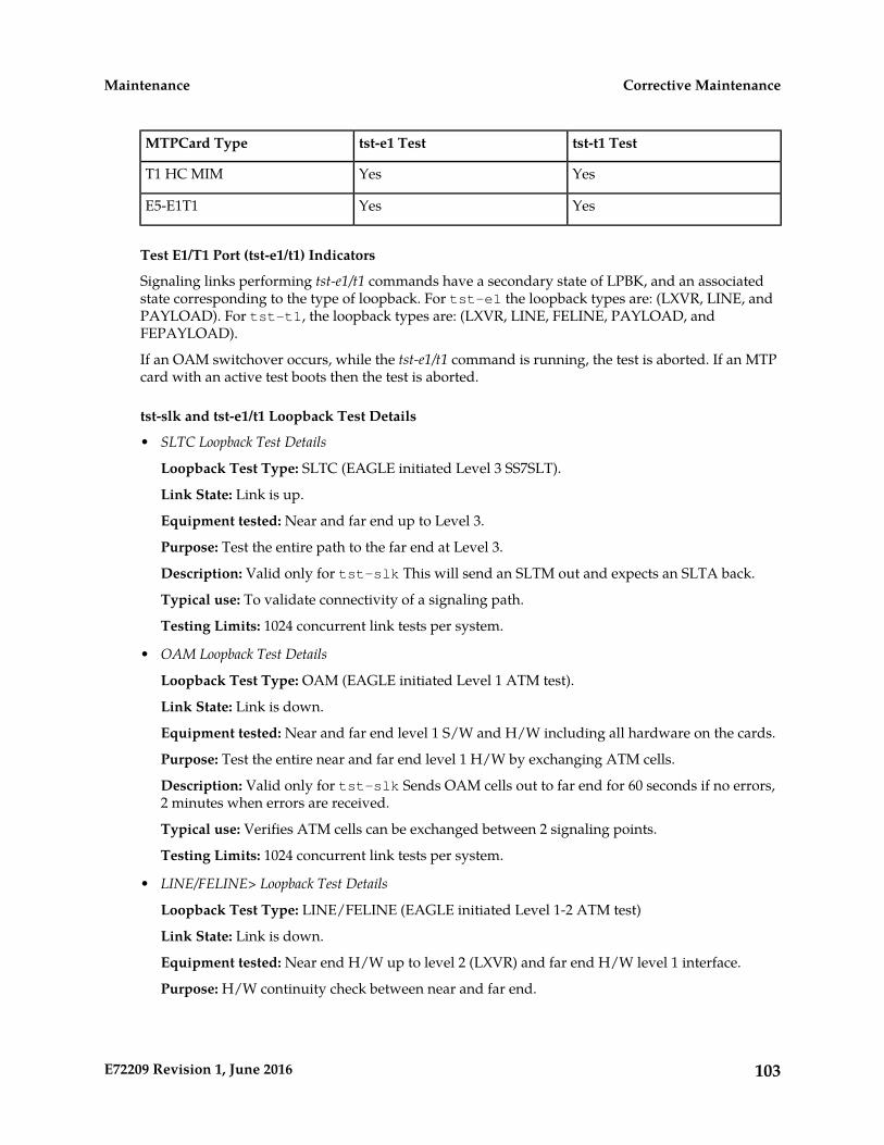
tst-t1 Testtst-e1 TestMTPCard Type
YesYesT1 HC MIM
YesYesE5-E1T1
Test E1/T1 Port (tst-e1/t1) Indicators
Signaling links performing tst-e1/t1 commands have a secondary state of LPBK, and an associatedstate corresponding to the type of loopback. For tst-e1 the loopback types are: (LXVR, LINE, andPAYLOAD). For tst-t1, the loopback types are: (LXVR, LINE, FELINE, PAYLOAD, andFEPAYLOAD).
If an OAM switchover occurs, while the tst-e1/t1 command is running, the test is aborted. If an MTPcard with an active test boots then the test is aborted.
tst-slk and tst-e1/t1 Loopback Test Details
• SLTC Loopback Test Details
Loopback Test Type: SLTC (EAGLE initiated Level 3 SS7SLT).
Link State: Link is up.
Equipment tested: Near and far end up to Level 3.
Purpose: Test the entire path to the far end at Level 3.
Description: Valid only for tst-slk This will send an SLTM out and expects an SLTA back.
Typical use: To validate connectivity of a signaling path.
Testing Limits: 1024 concurrent link tests per system.
• OAM Loopback Test Details
Loopback Test Type: OAM (EAGLE initiated Level 1 ATM test).
Link State: Link is down.
Equipment tested: Near and far end level 1 S/W and H/W including all hardware on the cards.
Purpose: Test the entire near and far end level 1 H/W by exchanging ATM cells.
Description: Valid only for tst-slk Sends OAM cells out to far end for 60 seconds if no errors,2 minutes when errors are received.
Typical use: Verifies ATM cells can be exchanged between 2 signaling points.
Testing Limits: 1024 concurrent link tests per system.
• LINE/FELINE> Loopback Test Details
Loopback Test Type: LINE/FELINE (EAGLE initiated Level 1-2 ATM test)
Link State: Link is down.
Equipment tested: Near end H/W up to level 2 (LXVR) and far end H/W level 1 interface.
Purpose: H/W continuity check between near and far end.
103E72209 Revision 1, June 2016
Corrective MaintenanceMaintenance

Description: This detail sequence is valid for tst-slk:loopback=line andtst-t1:loopback=feline.
tst-t1:loopback=line installs the local line loopback (receive to transmit) similar to anact-cdl:loopback=line.
The following steps occur:
1. Device under test (DUT) sends T1 bit oriented code (BOC) to remote device.
2. Remote device receives BOC and programs hardware.
3. DUT attempts level 2 alignment.
4. If link aligns (level 2), test passes, else test fails.
5. DUT sends BOC to remote device to remove loopback.
6. Remote device receives BOC and re-programs hardware.
Note: If the DUT boots in the middle of the sequence, the remote device needs to have the linkactivated/de-activated and it will return to the original programming.
Typical use: Used for a link in line timing to check continuity from the near end level 2 H/W tothe level 1 interface at the far end.
Testing Limits: 1024 concurrent link tests per system.
• PAYLOAD/FEPAYLOAD Loopback Test Details
Loopback Test Type: PAYLOADFEPAYLOAD (EAGLE initiated Level 1-2 ATM test)
Link State: Link is down.
Equipment tested: Near end H/W up to level 2 (LXVR) and far end H/W level 1 interface.
Purpose: H/W continuity check between near and far end.
Description: This detail sequence is valid for tst-slk:loopback=payload andtst-t1:loopback=fepayload.
tst-t1:loopback=payload installs the local payload loopback (receive to transmit) similar toan act-cdl:loopback=payload.
The following steps occur:
1. Device under test (DUT) sends T1 bit oriented code (BOC) to remote device.
2. Remote device receives BOC and programs hardware.
3. DUT attempts level 2 alignment.
4. If link aligns (level 2), test passes, else test fails.
5. DUT sends BOC to remote device to remove loopback.
6. remote device receives BOC and re-programs hardware.
Note: If the DUT boots in the middle of sequence, the remote device needs to have the linkactivated/de-activated and it will return to the original programming
104E72209 Revision 1, June 2016
Corrective MaintenanceMaintenance
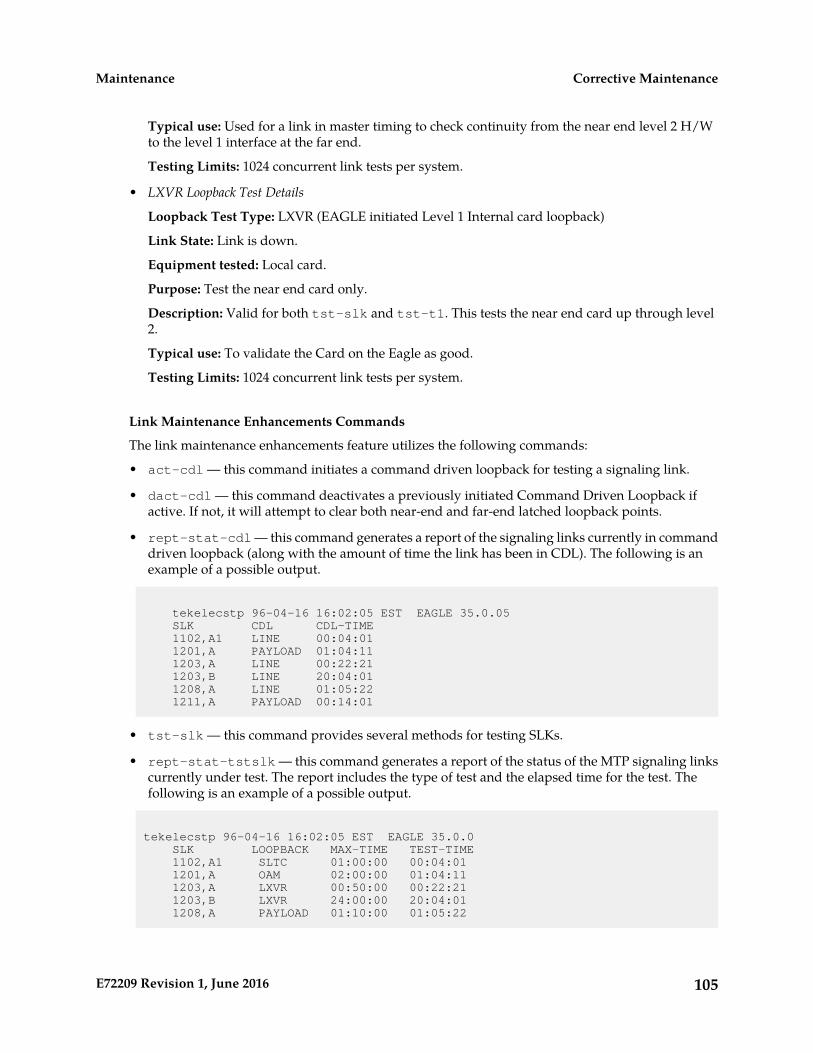
Typical use: Used for a link in master timing to check continuity from the near end level 2 H/Wto the level 1 interface at the far end.
Testing Limits: 1024 concurrent link tests per system.
• LXVR Loopback Test Details
Loopback Test Type: LXVR (EAGLE initiated Level 1 Internal card loopback)
Link State: Link is down.
Equipment tested: Local card.
Purpose: Test the near end card only.
Description: Valid for both tst-slk and tst-t1. This tests the near end card up through level2.
Typical use: To validate the Card on the Eagle as good.
Testing Limits: 1024 concurrent link tests per system.
Link Maintenance Enhancements Commands
The link maintenance enhancements feature utilizes the following commands:
• act-cdl — this command initiates a command driven loopback for testing a signaling link.
• dact-cdl — this command deactivates a previously initiated Command Driven Loopback ifactive. If not, it will attempt to clear both near-end and far-end latched loopback points.
• rept-stat-cdl — this command generates a report of the signaling links currently in commanddriven loopback (along with the amount of time the link has been in CDL). The following is anexample of a possible output.
tekelecstp 96-04-16 16:02:05 EST EAGLE 35.0.05 SLK CDL CDL-TIME 1102,A1 LINE 00:04:01 1201,A PAYLOAD 01:04:11 1203,A LINE 00:22:21 1203,B LINE 20:04:01 1208,A LINE 01:05:22 1211,A PAYLOAD 00:14:01
• tst-slk — this command provides several methods for testing SLKs.
• rept-stat-tstslk — this command generates a report of the status of the MTP signaling linkscurrently under test. The report includes the type of test and the elapsed time for the test. Thefollowing is an example of a possible output.
tekelecstp 96-04-16 16:02:05 EST EAGLE 35.0.0 SLK LOOPBACK MAX-TIME TEST-TIME 1102,A1 SLTC 01:00:00 00:04:01 1201,A OAM 02:00:00 01:04:11 1203,A LXVR 00:50:00 00:22:21 1203,B LXVR 24:00:00 20:04:01 1208,A PAYLOAD 01:10:00 01:05:22
105E72209 Revision 1, June 2016
Corrective MaintenanceMaintenance
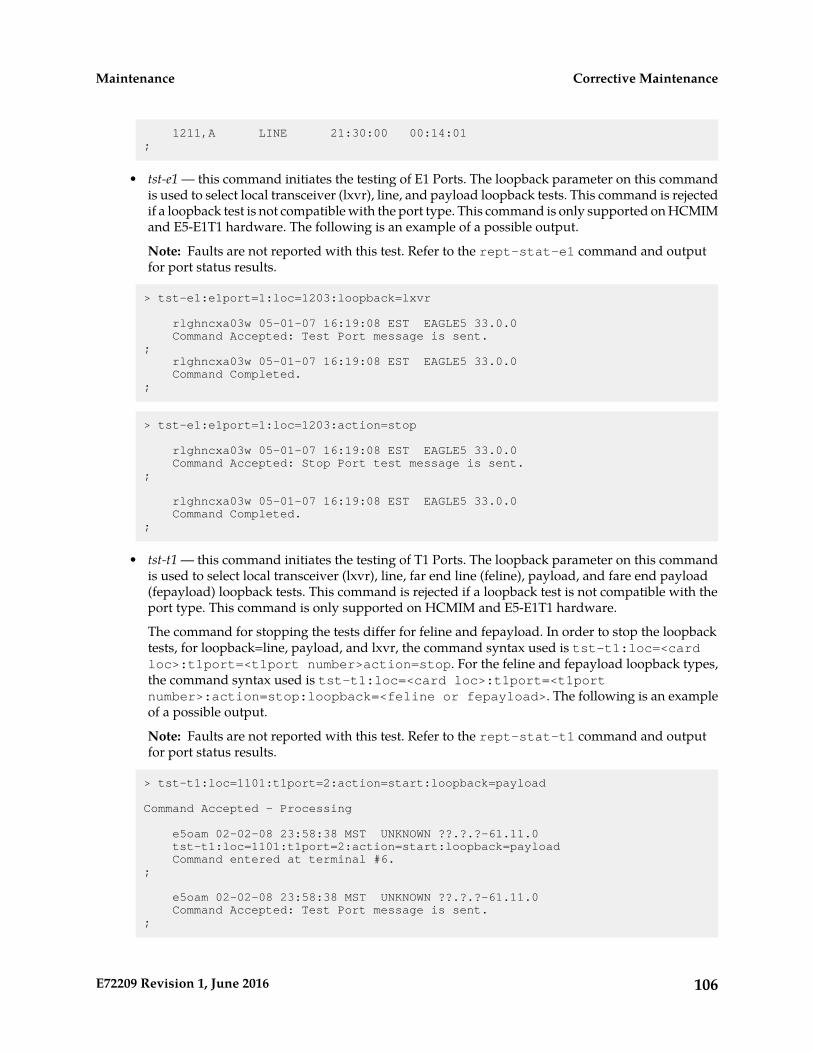
1211,A LINE 21:30:00 00:14:01 ;
• tst-e1 — this command initiates the testing of E1 Ports. The loopback parameter on this commandis used to select local transceiver (lxvr), line, and payload loopback tests. This command is rejectedif a loopback test is not compatible with the port type. This command is only supported on HCMIMand E5-E1T1 hardware. The following is an example of a possible output.
Note: Faults are not reported with this test. Refer to the rept-stat-e1 command and outputfor port status results.
> tst-e1:e1port=1:loc=1203:loopback=lxvr
rlghncxa03w 05-01-07 16:19:08 EST EAGLE5 33.0.0 Command Accepted: Test Port message is sent.; rlghncxa03w 05-01-07 16:19:08 EST EAGLE5 33.0.0 Command Completed.;
> tst-e1:e1port=1:loc=1203:action=stop
rlghncxa03w 05-01-07 16:19:08 EST EAGLE5 33.0.0 Command Accepted: Stop Port test message is sent.;
rlghncxa03w 05-01-07 16:19:08 EST EAGLE5 33.0.0 Command Completed.;
• tst-t1 — this command initiates the testing of T1 Ports. The loopback parameter on this commandis used to select local transceiver (lxvr), line, far end line (feline), payload, and fare end payload(fepayload) loopback tests. This command is rejected if a loopback test is not compatible with theport type. This command is only supported on HCMIM and E5-E1T1 hardware.
The command for stopping the tests differ for feline and fepayload. In order to stop the loopbacktests, for loopback=line, payload, and lxvr, the command syntax used is tst-t1:loc=<cardloc>:t1port=<t1port number>action=stop. For the feline and fepayload loopback types,the command syntax used is tst-t1:loc=<card loc>:t1port=<t1portnumber>:action=stop:loopback=<feline or fepayload>. The following is an exampleof a possible output.
Note: Faults are not reported with this test. Refer to the rept-stat-t1 command and outputfor port status results.
> tst-t1:loc=1101:t1port=2:action=start:loopback=payload
Command Accepted - Processing
e5oam 02-02-08 23:58:38 MST UNKNOWN ??.?.?-61.11.0 tst-t1:loc=1101:t1port=2:action=start:loopback=payload Command entered at terminal #6.;
e5oam 02-02-08 23:58:38 MST UNKNOWN ??.?.?-61.11.0 Command Accepted: Test Port message is sent.;
106E72209 Revision 1, June 2016
Corrective MaintenanceMaintenance
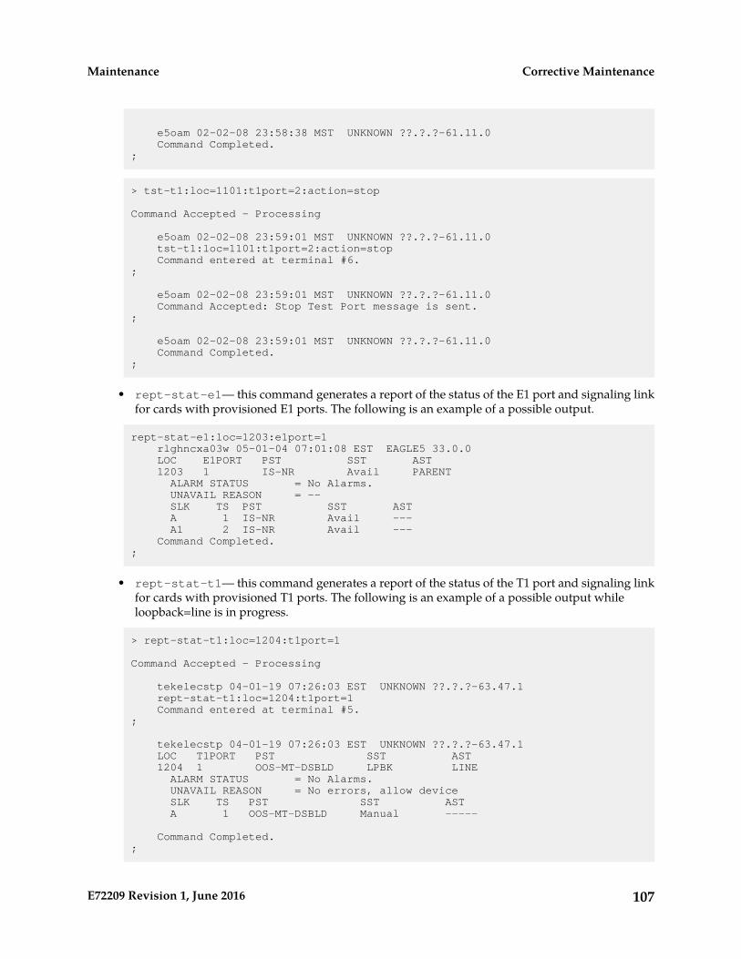
e5oam 02-02-08 23:58:38 MST UNKNOWN ??.?.?-61.11.0 Command Completed.;
> tst-t1:loc=1101:t1port=2:action=stop
Command Accepted - Processing
e5oam 02-02-08 23:59:01 MST UNKNOWN ??.?.?-61.11.0 tst-t1:loc=1101:t1port=2:action=stop Command entered at terminal #6.;
e5oam 02-02-08 23:59:01 MST UNKNOWN ??.?.?-61.11.0 Command Accepted: Stop Test Port message is sent.;
e5oam 02-02-08 23:59:01 MST UNKNOWN ??.?.?-61.11.0 Command Completed.;
• rept-stat-e1— this command generates a report of the status of the E1 port and signaling linkfor cards with provisioned E1 ports. The following is an example of a possible output.
rept-stat-e1:loc=1203:e1port=1 rlghncxa03w 05-01-04 07:01:08 EST EAGLE5 33.0.0 LOC E1PORT PST SST AST 1203 1 IS-NR Avail PARENT ALARM STATUS = No Alarms. UNAVAIL REASON = -- SLK TS PST SST AST A 1 IS-NR Avail --- A1 2 IS-NR Avail --- Command Completed.;
• rept-stat-t1— this command generates a report of the status of the T1 port and signaling linkfor cards with provisioned T1 ports. The following is an example of a possible output whileloopback=line is in progress.
> rept-stat-t1:loc=1204:t1port=1
Command Accepted - Processing
tekelecstp 04-01-19 07:26:03 EST UNKNOWN ??.?.?-63.47.1 rept-stat-t1:loc=1204:t1port=1 Command entered at terminal #5.;
tekelecstp 04-01-19 07:26:03 EST UNKNOWN ??.?.?-63.47.1 LOC T1PORT PST SST AST 1204 1 OOS-MT-DSBLD LPBK LINE ALARM STATUS = No Alarms. UNAVAIL REASON = No errors, allow device SLK TS PST SST AST A 1 OOS-MT-DSBLD Manual -----
Command Completed.;
107E72209 Revision 1, June 2016
Corrective MaintenanceMaintenance
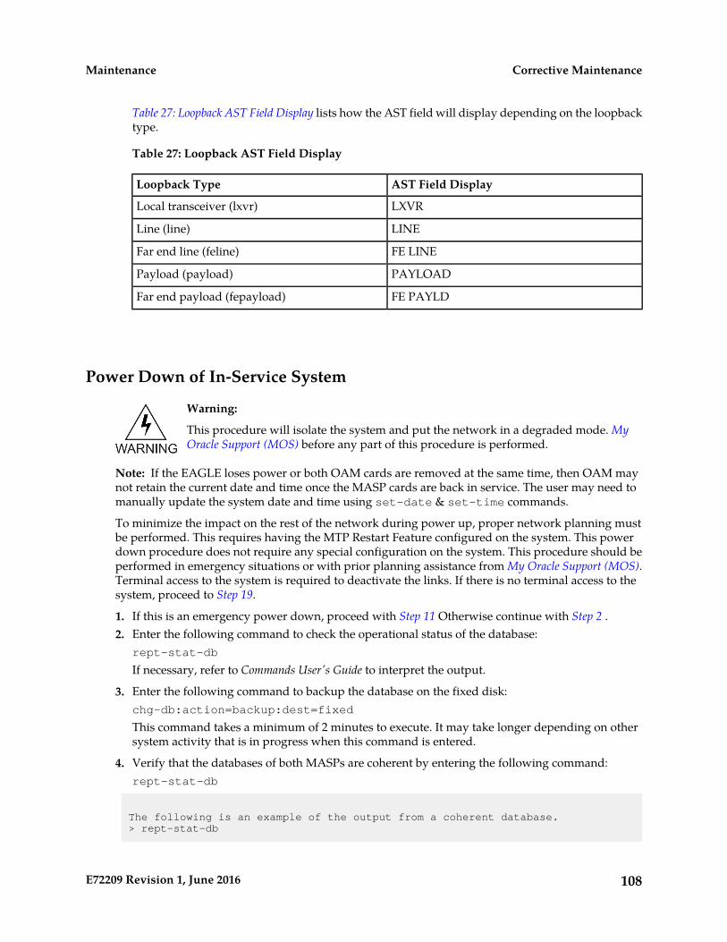
Table 27: Loopback AST Field Display lists how the AST field will display depending on the loopbacktype.
Table 27: Loopback AST Field Display
AST Field DisplayLoopback Type
LXVRLocal transceiver (lxvr)
LINELine (line)
FE LINEFar end line (feline)
PAYLOADPayload (payload)
FE PAYLDFar end payload (fepayload)
Power Down of In-Service System
Warning:
This procedure will isolate the system and put the network in a degraded mode. MyOracle Support (MOS) before any part of this procedure is performed.
Note: If the EAGLE loses power or both OAM cards are removed at the same time, then OAM maynot retain the current date and time once the MASP cards are back in service. The user may need tomanually update the system date and time using set-date & set-time commands.
To minimize the impact on the rest of the network during power up, proper network planning mustbe performed. This requires having the MTP Restart Feature configured on the system. This powerdown procedure does not require any special configuration on the system. This procedure should beperformed in emergency situations or with prior planning assistance from My Oracle Support (MOS).Terminal access to the system is required to deactivate the links. If there is no terminal access to thesystem, proceed to Step 19.
1. If this is an emergency power down, proceed with Step 11 Otherwise continue with Step 2 .2. Enter the following command to check the operational status of the database:
rept-stat-db
If necessary, refer to Commands User's Guide to interpret the output.
3. Enter the following command to backup the database on the fixed disk:chg-db:action=backup:dest=fixed
This command takes a minimum of 2 minutes to execute. It may take longer depending on othersystem activity that is in progress when this command is entered.
4. Verify that the databases of both MASPs are coherent by entering the following command:rept-stat-db
The following is an example of the output from a coherent database.> rept-stat-db
108E72209 Revision 1, June 2016
Corrective MaintenanceMaintenance

Command Accepted - Processing oflnmoxa11w 00-10-08 15:56:40 CDT EAGLE 35.0.0 rept-stat-db Command entered at terminal #4.; oflnmoxa11w 00-10-08 15:56:40 CDT EAGLE 35.0.0 DATABASE STATUS: >> OK << TDM 1114 ( STDBY) TDM 1116 ( ACTV ) C LEVEL TIME LAST BACKUP C LEVEL TIME LAST BACKUP - -------- --------------------- - -------- ---------------------
FD BKUP Y 342256 00-10-07 00:40:29 CDT Y 342256 00-10-07 00:40:29 CDT
FD CRNT N 342374 Y 342375 E5-MDAL 1117 ---------
If necessary, refer to Commands User's Guide to interpret the output.
5. Insert a pre-formatted (for system data) removable USB drive into the removable USB drive mediaslot.Refer to Removable Drives. Continue with Step 6.
6. Enter the following command to create a backup of the database on the removable USB drive:chg-db:action=backup:dest=remove
7. Verify that the databases on the removable USB drive (RDBKUP) and the current partition of theactive MASP (FDCRNT) are coherent by entering the following command:rept-stat-db
The following is an example of the output from a coherent database.
> rept-stat-dbCommand Accepted - Processing oflnmoxa11w 00-10-08 15:56:40 CDT EAGLE 35.0.0 rept-stat-db Command entered at terminal #4.; oflnmoxa11w 00-10-08 15:56:40 CDT EAGLE 35.0.0 DATABASE STATUS: >> OK << TDM 1114 (STDBY) TDM 1116 ( ACTV ) C LEVEL TIME LAST BACKUP C LEVEL TIME LAST BACKUP - -------- --------------------- - ------- ------------------- FD BKUP Y 32256 00-10-07 00:40:29 CDT Y 32256 00-10-07 00:40:29 CDT FD CRNT N 32374 Y 32375 E5-MDAL 1117 - --------
If necessary, refer to the Commands User's Guide to interpret the output.
8. Remove the removable USB drive from the removable USB drive media slot.Refer to Removable Drives.
9. Make an entry in the site maintenance log that a backup was performed.10. Enter the following command to verify the status of the mate EAGLE:
rept-stat-trbl
If there is any trouble or abnormal condition, My Oracle Support (MOS).
109E72209 Revision 1, June 2016
Corrective MaintenanceMaintenance

11. Enter the following command to retrieve the linksets.rtrv-ls
12. Enter the following command to retrieve the links.rtrv-slk
13. Enter the following command to deactivate all E-links.Use the outputs from Step 11 and Step 12.dact-slk:loc=xxxx:port=y
where xxxx is the card location stenciled on the shelf of the system and y is the port number on thecard specified in the loc parameter.
14. Enter the following command to deactivate all A-links.Use the outputs from Step 11 and Step 12..dact-slk:loc=xxxx:port=y
where xxxx is the card location stenciled on the shelf of the system and y is the port number on thecard specified in the loc parameter.
15. Enter the following command to deactivate all B-links.Use the outputs from Step 11 and Step 12.dact-slk:loc=xxxx:port=y
where xxxx is the card location stenciled on the shelf of the system and y is the port number on thecard specified in the loc parameter.
16. Enter the following command to deactivate all D-links.
Use the outputs from Step 11 and Step 12.
.dact-slk:loc=xxxx:port=y
where xxxx is the card location stenciled on the shelf of the system and y is the port number on thecard specified in the loc parameter.
17. Enter the following command to deactivate all C-links.Use the outputs from Step 11 and Step 12..dact-slk:loc=xxxx:port=y
where xxxx is the card location stenciled on the shelf of the system and y is the port number on thecard specified in the loc parameter.
18. Enter the following command to verify all links on the system are OOS-MT.rept-stat-slk
Repeat Step 13 through Step 17 for any links not having the proper status.
19. Pull the fuses or open the breaker at the customer power distribution frame to turn off power tothe system.
110E72209 Revision 1, June 2016
Corrective MaintenanceMaintenance

Power Up of the System
Warning: If the reason for the EAGLE Power Off is unknown or if damage to the EAGLEis suspected, do not perform this procedure. contact the My Oracle Support (MOS).
1. Verify that there is no USB drive in the E5-MDAL card.If there is a USB drive in the E5-MDAL, replace the E5-MDAL card with a spare E5-MDAL cardwithout a USB drive. If the spare E5-MDAL card has a USB drive installed, remove the E5-MDALcard. This power up will take place without a E5-MDAL card installed.
2. At the power distribution frame, insert fuses or close the breaker to restore power to the system.All frames with the EAGLE shelves must be powered up. Links that were deactivated during thepower down are automatically activated during the power up.
3. Enter the following commands to monitor the system during the power-up:rept-stat-card
rept-stat-slk
rept-stat-trbl
Contact My Oracle Support (MOS) if there is any trouble or abnormal condition during systemrecovery.
4. Install E5-MDAL card and remove removable USB drive, if necessary.
111E72209 Revision 1, June 2016
Corrective MaintenanceMaintenance

Appendix
ACard Removal/Replacement Procedures
Topics:
• Introduction.....113• EAGLE Replacement Parts List.....113• E5-MASP Card Replacement.....113• E5-MDAL Card Replacement.....122• HIPR2 Card Replacement.....125• Determine Card Changeout Time.....128• E5-ATM/E5-ATM-B Card Replacement.....129• SS7 and IP7, HC-MIM Card Replacement.....132• E5-ENET/E5-ENET-B Module.....136• E5-TSM Card Replacement.....145• Database Services Module (DSM).....147• E5-SM4G/E5-SM8G-B Card Replacement.....149• E5-IPSM Card Replacement.....152• Database Communications Module (DCM).....157• Measurement Collection and Polling Module
(E5-MCPM).....159• Replacing a Card in the EAGLE.....160• Replacing Cards in the Holdover Clock.....162• Fan Assembly P/N 890-0001-xx.....168
112E72209 Revision 1, June 2016
Introduction
This appendix explains how to remove a card from the EAGLE. The procedures include theadministrative commands required to take a card out of service and place it back into service.
In the event a numbered event message is encountered, refer to the appropriate procedure in UnsolicitedAlarm and Information Messages Reference.
Additional information about each command can be found in Commands User's Guide.
Caution: Always wear a wrist strap or other electrostatic protection when handlingEAGLE cards.
Caution: Always place removed cards into an electrostatic protection bag before sendingto Oracle, or storing in inventory (unless the card is being stored in the optional sparecard storage shelf).
EAGLE Replacement Parts List
For a listing of field replaceable parts and cables used in the EAGLE and their part numbers, refer tothe tables in Part Numbers.
All parts must be replaced through the Return Material Authorization (RMA) process. Contact theMy Oracle Support (MOS), before replacing any parts.
E5-MASP Card Replacement
This procedure is to replace an E5-MASP card. Before the E5-MASP is replaced, it must be verifiedthat it is the standby MASP.
The E5-MASP (made up of the E5-MCAP and E5-TDM cards) contains the removable USB drive, thefixed disk drive, the terminal processor for the 16 serial I/O ports, and an interface to the maintenancedisk and alarm (E5-MDAL) card.
1. Before beginning this procedure, make sure there is a copy of the current release GPLs on aremovable USB drive on-hand.
2. If the active E5-MASP card fails, the EAGLE automatically switches activity to the standby MASP.3. Enter the following command to display the card status:
rept-stat-card
The following is an example of a possible output.
e5oam 08-12-01 15:38:32 EST EAGLE 40.1.0
113E72209 Revision 1, June 2016
Card Removal/Replacement ProceduresMaintenance
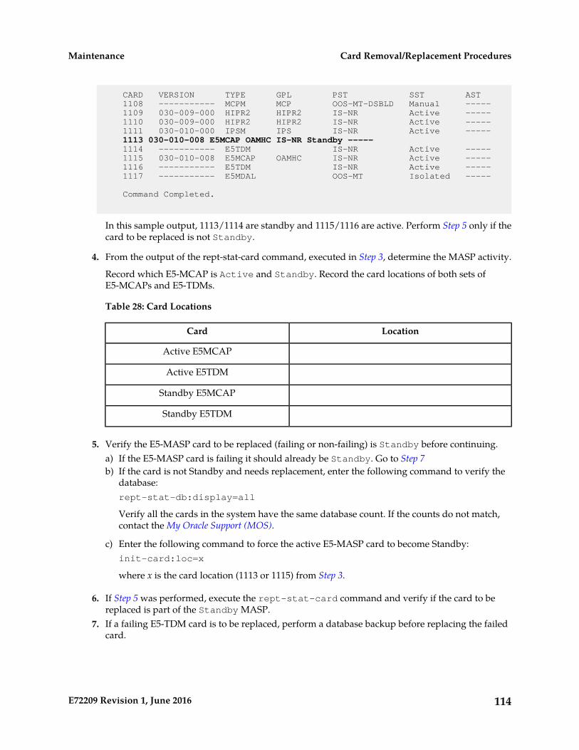
CARD VERSION TYPE GPL PST SST AST 1108 ----------- MCPM MCP OOS-MT-DSBLD Manual ----- 1109 030-009-000 HIPR2 HIPR2 IS-NR Active ----- 1110 030-009-000 HIPR2 HIPR2 IS-NR Active ----- 1111 030-010-000 IPSM IPS IS-NR Active -----
1113 030-010-008 E5MCAP OAMHC IS-NR Standby ----- 1114 ----------- E5TDM IS-NR Active ----- 1115 030-010-008 E5MCAP OAMHC IS-NR Active ----- 1116 ----------- E5TDM IS-NR Active ----- 1117 ----------- E5MDAL OOS-MT Isolated -----
Command Completed.
In this sample output, 1113/1114 are standby and 1115/1116 are active. Perform Step 5 only if thecard to be replaced is not Standby.
4. From the output of the rept-stat-card command, executed in Step 3, determine the MASP activity.
Record which E5-MCAP is Active and Standby. Record the card locations of both sets ofE5-MCAPs and E5-TDMs.
Table 28: Card Locations
LocationCard
Active E5MCAP
Active E5TDM
Standby E5MCAP
Standby E5TDM
5. Verify the E5-MASP card to be replaced (failing or non-failing) is Standby before continuing.a) If the E5-MASP card is failing it should already be Standby. Go to Step 7b) If the card is not Standby and needs replacement, enter the following command to verify the
database:rept-stat-db:display=all
Verify all the cards in the system have the same database count. If the counts do not match,contact the My Oracle Support (MOS).
c) Enter the following command to force the active E5-MASP card to become Standby:init-card:loc=x
where x is the card location (1113 or 1115) from Step 3.
6. If Step 5 was performed, execute the rept-stat-card command and verify if the card to bereplaced is part of the Standby MASP.
7. If a failing E5-TDM card is to be replaced, perform a database backup before replacing the failedcard.
114E72209 Revision 1, June 2016
Card Removal/Replacement ProceduresMaintenance
Insert the removable USB drive with the current release GPLs into the Active E5-MASP removableUSB port. Using Daily Procedures, create a backup of the database on the Active removable USBdrive. Then go to Step 9.
Warning: Do not proceed to Step 9 if the backup fails. Contact the My Oracle Support(MOS).
8. If a non-failing E5-TDM card is to be replaced, insert the removable USB drive containing the copyof the current release GPLs into the Active E5-MASP.
9. Enter the following command to verify that the security log on the standby MASP contains noentries that must be copied to the FTA area of the fixed disk:rept-stat-seculog
The following is an example of a possible output.
RLGHNCXA03W 96-10-04 15:59:06 EDT EAGLE 34.0.0 -- SINCE LAST UPLOAD -- OLDEST NEWEST LASTLOC ROLE ENTRIES %FULL OFLO FAIL RECORD RECORD UPLOAD1114 Active 8312 84 No No 95-08-12 96-01-04 96-12-16 11:23:56 15:59:06 14:02:22 1116 Standby 693 7 No No 95-09-12 95-09-30 95-09-30 11:24:12 14:00:06 14:02:13
• If the number shown in the ENTRIES field for the standby MASP (shown with the entry Standbyin the ROLE field) is 0, go to Step 12.
• If the number shown in the ENTRIES field for the standby MASP is greater than 0, these entriesmust be copied to the FTA area of the fixed disk.
To copy these entries, go to the next step.
10. Copy the security log entries on the standby MASP to the FTA area on the fixed disk using thefollowing command:copy-seculog:slog=stb:dloc=act
The following is a possible output of the message that should appear (thecopy-seculog:slog=stb command was used).
RLGHNCXA03W 96-10-04 15:59:06 EDT EAGLE 34.0.0Security log on E5TDM 1116 copied to file 961004s.log on E5TDM 1114
11. Remove the card from service by entering the following command:rmv-card:loc=xxxx
where xxxx is the card location.
12. Replace the Standby E5-MASP. Refer to Figure 27: E5-MASP LEDs for description ofthe E5-MASPLEDs.a) On the standby E5-MASP card determined in Step 6 , slide the MASP H/S switch (SW3) up to
the UNLOCKED position (see Figure 25: E5-MASP Card Inject/Eject Hardware Switch, UNLOCKED).
115E72209 Revision 1, June 2016
Card Removal/Replacement ProceduresMaintenance

Caution: When the Ejector switch goes from locked to unlocked and the E5-APP-Bcard is in service, the card will halt.
Figure 25: E5-MASP Card Inject/Eject Hardware Switch, UNLOCKED
b) WAIT for the MASP H/S LED to go from blinking blue to a steady blue.c) Grasp the upper and lower card Inject/Eject (I/E) lever release interlock, located just underneath
the I/E lever, and press it to meet the I/E lever. This is the mechanical interlock for the card.d) While holding the I/E interlock and lever, pull the levers away from the shelf until they are
parallel to the floor.e) Remove the standby E5-MASP card. Gently pull the card towards you until the card clears the
shelf.
Note: UAMs are generated during this step. An audible alarm is generated.
f) Place the card you have removed in an electrostatic discharge (ESD) protective container, orplace the card in the spare card storage shelf.
g) Be sure that the replacement card has the same Oracle part number and revision number as thecard you have just removed.
h) Open the ejector levers on the replacement card. Insert the spare E5-MASP card.
Carefully align the card’s edges with the top and bottom card guides. Then push the card alongthe length of the card guides until the rear connectors on the card engage the mating connectorson the target shelf backplane.
Note: UAMs are generated during this step. An audible alarm is generated. Wait for theE5-MASP card to come up to standby mode.
i) Push in the top and bottom inject/eject clamps.
This locks the card in place and ensures a strong connection with the pins on the target shelfbackplane.
116E72209 Revision 1, June 2016
Card Removal/Replacement ProceduresMaintenance
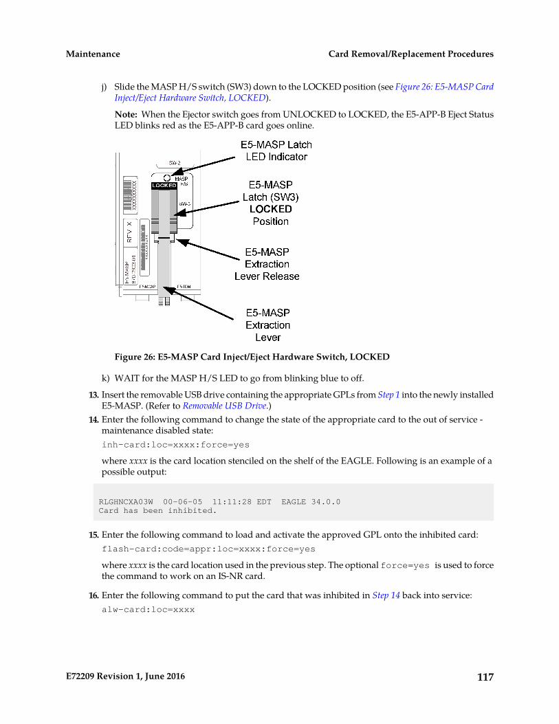
j) Slide the MASP H/S switch (SW3) down to the LOCKED position (see Figure 26: E5-MASP CardInject/Eject Hardware Switch, LOCKED).
Note: When the Ejector switch goes from UNLOCKED to LOCKED, the E5-APP-B Eject StatusLED blinks red as the E5-APP-B card goes online.
Figure 26: E5-MASP Card Inject/Eject Hardware Switch, LOCKED
k) WAIT for the MASP H/S LED to go from blinking blue to off.
13. Insert the removable USB drive containing the appropriate GPLs from Step 1 into the newly installedE5-MASP. (Refer to Removable USB Drive.)
14. Enter the following command to change the state of the appropriate card to the out of service -maintenance disabled state:inh-card:loc=xxxx:force=yes
where xxxx is the card location stenciled on the shelf of the EAGLE. Following is an example of apossible output:
RLGHNCXA03W 00-06-05 11:11:28 EDT EAGLE 34.0.0Card has been inhibited.
15. Enter the following command to load and activate the approved GPL onto the inhibited card:flash-card:code=appr:loc=xxxx:force=yes
where xxxx is the card location used in the previous step. The optional force=yes is used to forcethe command to work on an IS-NR card.
16. Enter the following command to put the card that was inhibited in Step 14 back into service:alw-card:loc=xxxx
117E72209 Revision 1, June 2016
Card Removal/Replacement ProceduresMaintenance
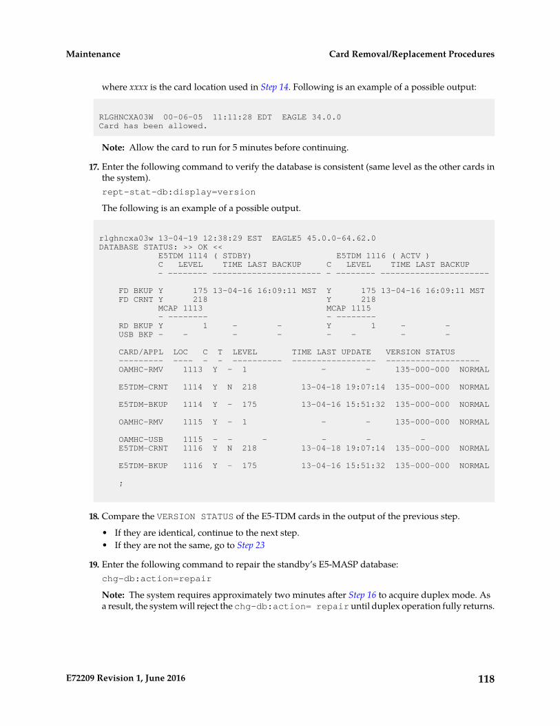
where xxxx is the card location used in Step 14. Following is an example of a possible output:
RLGHNCXA03W 00-06-05 11:11:28 EDT EAGLE 34.0.0Card has been allowed.
Note: Allow the card to run for 5 minutes before continuing.
17. Enter the following command to verify the database is consistent (same level as the other cards inthe system).rept-stat-db:display=version
The following is an example of a possible output.
rlghncxa03w 13-04-19 12:38:29 EST EAGLE5 45.0.0-64.62.0DATABASE STATUS: >> OK << E5TDM 1114 ( STDBY) E5TDM 1116 ( ACTV ) C LEVEL TIME LAST BACKUP C LEVEL TIME LAST BACKUP - -------- ---------------------- - -------- ----------------------
FD BKUP Y 175 13-04-16 16:09:11 MST Y 175 13-04-16 16:09:11 MST FD CRNT Y 218 Y 218 MCAP 1113 MCAP 1115 - -------- - -------- RD BKUP Y 1 - - Y 1 - - USB BKP - - - - - - - -
CARD/APPL LOC C T LEVEL TIME LAST UPDATE VERSION STATUS --------- ---- - - ---------- ----------------- ------------------- OAMHC-RMV 1113 Y - 1 - - 135-000-000 NORMAL
E5TDM-CRNT 1114 Y N 218 13-04-18 19:07:14 135-000-000 NORMAL
E5TDM-BKUP 1114 Y - 175 13-04-16 15:51:32 135-000-000 NORMAL
OAMHC-RMV 1115 Y - 1 - - 135-000-000 NORMAL
OAMHC-USB 1115 - - - - - - E5TDM-CRNT 1116 Y N 218 13-04-18 19:07:14 135-000-000 NORMAL
E5TDM-BKUP 1116 Y - 175 13-04-16 15:51:32 135-000-000 NORMAL
;
18. Compare the VERSION STATUS of the E5-TDM cards in the output of the previous step.
• If they are identical, continue to the next step.• If they are not the same, go to Step 23
19. Enter the following command to repair the standby’s E5-MASP database:chg-db:action=repair
Note: The system requires approximately two minutes after Step 16 to acquire duplex mode. Asa result, the system will reject the chg-db:action= repair until duplex operation fully returns.
118E72209 Revision 1, June 2016
Card Removal/Replacement ProceduresMaintenance
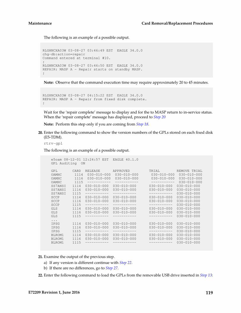
The following is an example of a possible output.
RLGHNCXA03W 03-08-27 03:46:49 EST EAGLE 34.0.0chg-db:action=repairCommand entered at terminal #10.;RLGHNCXA03W 03-08-27 03:46:50 EST EAGLE 34.0.0REPAIR: MASP A - Repair starts on standby MASP.;
Note: Observe that the command execution time may require approximately 20 to 45 minutes.
RLGHNCXA03W 03-08-27 04:15:22 EST EAGLE 34.0.0REPAIR: MASP A - Repair from fixed disk complete.;
Wait for the ‘repair complete’ message to display and for the to MASP return to in-service status.When the ‘repair complete’ message has displayed, proceed to Step 20
Note: Perform this step only if you are coming from Step 18.
20. Enter the following command to show the version numbers of the GPLs stored on each fixed disk(E5-TDM).rtrv-gpl
The following is an example of a possible output.
e5oam 08-12-01 12:24:57 EST EAGLE 40.1.0 GPL Auditing ON
GPL CARD RELEASE APPROVED TRIAL REMOVE TRIAL OAMHC 1114 030-010-000 030-010-000 030-010-000 030-010-000 OAMHC 1116 030-010-000 030-010-000 030-010-000 030-010-000 OAMHC 1115 ----------- ----------- ----------- 030-010-000 SS7ANSI 1114 030-010-000 030-010-000 030-010-000 030-010-000 SS7ANSI 1116 030-010-000 030-010-000 030-010-000 030-010-000 SS7ANSI 1115 ----------- ----------- ----------- 030-010-000 SCCP 1114 030-010-000 030-010-000 030-010-000 030-010-000 SCCP 1116 030-010-000 030-010-000 030-010-000 030-010-000 SCCP 1115 ----------- ----------- ----------- 030-010-000 GLS 1114 030-010-000 030-010-000 030-010-000 030-010-000 GLS 1116 030-010-000 030-010-000 030-010-000 030-010-000 GLS 1115 ----------- ----------- ----------- 030-010-000 ... IPSG 1114 030-010-000 030-010-000 030-010-000 030-010-000 IPSG 1116 030-010-000 030-010-000 030-010-000 030-010-000 IPSG 1115 ----------- ----------- ----------- 030-010-000 BLROM1 1114 030-010-000 030-010-000 030-010-000 030-010-000 BLROM1 1116 030-010-000 030-010-000 030-010-000 030-010-000 BLROM1 1115 ----------- ----------- ----------- 030-010-000
21. Examine the output of the previous step.a) If any version is different continue with Step 22.b) If there are no differences, go to Step 27.
22. Enter the following command to load the GPLs from the removable USB drive inserted in Step 13:
119E72209 Revision 1, June 2016
Card Removal/Replacement ProceduresMaintenance
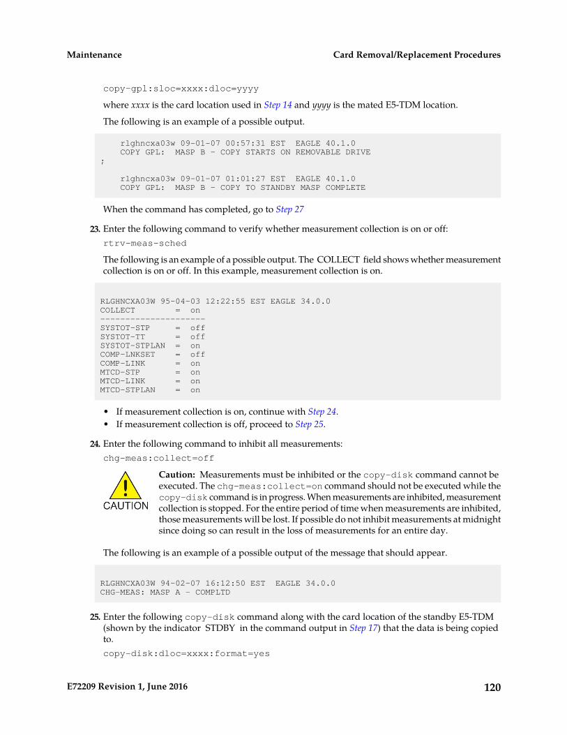
copy-gpl:sloc=xxxx:dloc=yyyy
where xxxx is the card location used in Step 14 and yyyy is the mated E5-TDM location.
The following is an example of a possible output.
rlghncxa03w 09-01-07 00:57:31 EST EAGLE 40.1.0 COPY GPL: MASP B - COPY STARTS ON REMOVABLE DRIVE;
rlghncxa03w 09-01-07 01:01:27 EST EAGLE 40.1.0 COPY GPL: MASP B - COPY TO STANDBY MASP COMPLETE
When the command has completed, go to Step 27
23. Enter the following command to verify whether measurement collection is on or off:rtrv-meas-sched
The following is an example of a possible output. The COLLECT field shows whether measurementcollection is on or off. In this example, measurement collection is on.
RLGHNCXA03W 95-04-03 12:22:55 EST EAGLE 34.0.0COLLECT = on---------------------SYSTOT-STP = offSYSTOT-TT = offSYSTOT-STPLAN = onCOMP-LNKSET = offCOMP-LINK = onMTCD-STP = onMTCD-LINK = onMTCD-STPLAN = on
• If measurement collection is on, continue with Step 24.• If measurement collection is off, proceed to Step 25.
24. Enter the following command to inhibit all measurements:chg-meas:collect=off
Caution: Measurements must be inhibited or the copy-disk command cannot beexecuted. The chg-meas:collect=on command should not be executed while thecopy-disk command is in progress. When measurements are inhibited, measurementcollection is stopped. For the entire period of time when measurements are inhibited,those measurements will be lost. If possible do not inhibit measurements at midnightsince doing so can result in the loss of measurements for an entire day.
The following is an example of a possible output of the message that should appear.
RLGHNCXA03W 94-02-07 16:12:50 EST EAGLE 34.0.0CHG-MEAS: MASP A - COMPLTD
25. Enter the following copy-disk command along with the card location of the standby E5-TDM(shown by the indicator STDBY in the command output in Step 17) that the data is being copiedto.copy-disk:dloc=xxxx:format=yes
120E72209 Revision 1, June 2016
Card Removal/Replacement ProceduresMaintenance
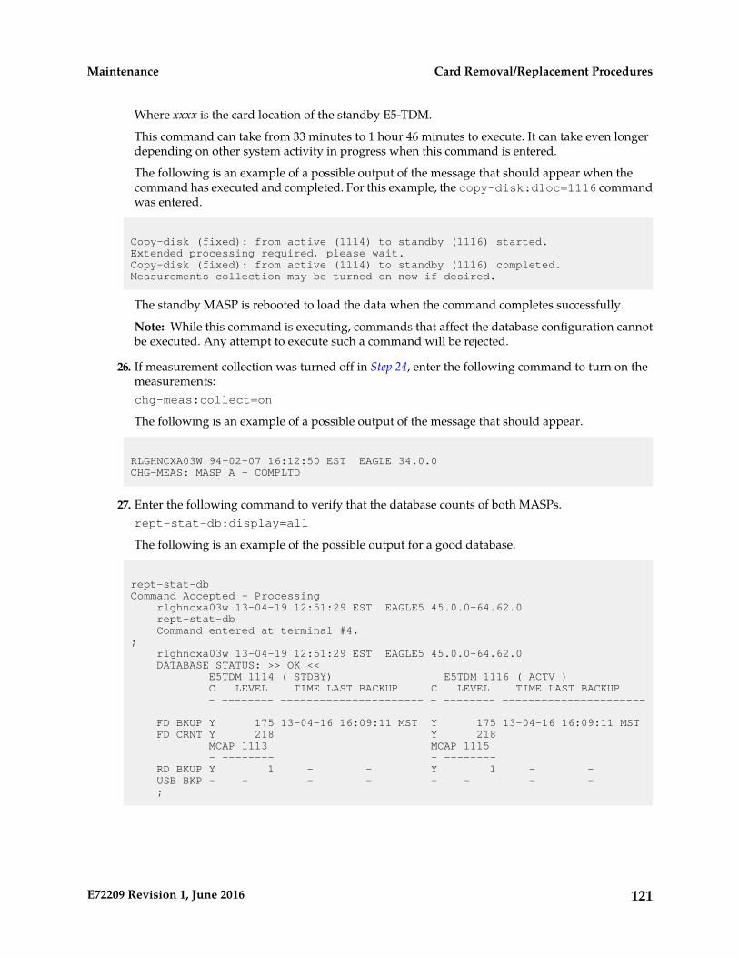
Where xxxx is the card location of the standby E5-TDM.
This command can take from 33 minutes to 1 hour 46 minutes to execute. It can take even longerdepending on other system activity in progress when this command is entered.
The following is an example of a possible output of the message that should appear when thecommand has executed and completed. For this example, the copy-disk:dloc=1116 commandwas entered.
Copy-disk (fixed): from active (1114) to standby (1116) started.Extended processing required, please wait.Copy-disk (fixed): from active (1114) to standby (1116) completed.Measurements collection may be turned on now if desired.
The standby MASP is rebooted to load the data when the command completes successfully.
Note: While this command is executing, commands that affect the database configuration cannotbe executed. Any attempt to execute such a command will be rejected.
26. If measurement collection was turned off in Step 24, enter the following command to turn on themeasurements:chg-meas:collect=on
The following is an example of a possible output of the message that should appear.
RLGHNCXA03W 94-02-07 16:12:50 EST EAGLE 34.0.0CHG-MEAS: MASP A - COMPLTD
27. Enter the following command to verify that the database counts of both MASPs.rept-stat-db:display=all
The following is an example of the possible output for a good database.
rept-stat-dbCommand Accepted - Processing rlghncxa03w 13-04-19 12:51:29 EST EAGLE5 45.0.0-64.62.0 rept-stat-db Command entered at terminal #4.; rlghncxa03w 13-04-19 12:51:29 EST EAGLE5 45.0.0-64.62.0 DATABASE STATUS: >> OK << E5TDM 1114 ( STDBY) E5TDM 1116 ( ACTV ) C LEVEL TIME LAST BACKUP C LEVEL TIME LAST BACKUP - -------- ---------------------- - -------- ----------------------
FD BKUP Y 175 13-04-16 16:09:11 MST Y 175 13-04-16 16:09:11 MST FD CRNT Y 218 Y 218 MCAP 1113 MCAP 1115 - -------- - -------- RD BKUP Y 1 - - Y 1 - - USB BKP - - - - - - - - ;
121E72209 Revision 1, June 2016
Card Removal/Replacement ProceduresMaintenance

Figure 27: E5-MASP LEDs
E5-MDAL Card Replacement
Description
The E5-MDAL (Figure 28: E5-MDAL LEDs) provides for external alarm indicators, such as bells, hornsand lamp indicators.
122E72209 Revision 1, June 2016
Card Removal/Replacement ProceduresMaintenance

Remove the card from service as described in the section titled, Replacing a Card in the EAGLE.
Note: Removing the E5-MDAL creates a critical alarm at the Remote Maintenance Center (RMC)as well as the local office.
123E72209 Revision 1, June 2016
Card Removal/Replacement ProceduresMaintenance
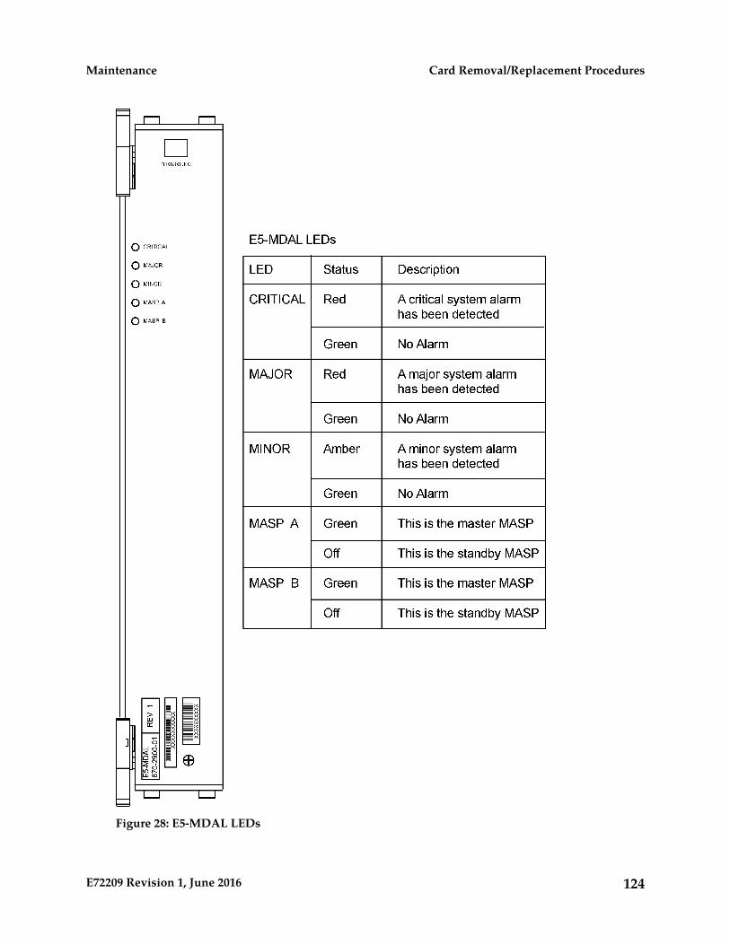
Figure 28: E5-MDAL LEDs
124E72209 Revision 1, June 2016
Card Removal/Replacement ProceduresMaintenance

HIPR2 Card Replacement
Use this procedure to remove a High-Speed Inter-processor Message Transport Packet Router 2 (HIPR2)card.
Each shelf contains two HIPR2 cards, one for each IMT bus, that provide continuity of the IMT bussignals even with failed or missing circuit modules. LEDs on the HIPR2 (Figure 29: HIPR2 LEDs)indicate connectivity to the IMT
1. Enter the following command to verify the status of the IMT buses.rept-stat-imt
Warning: Be sure to inhibit the correct IMT bus. If you inhibit the wrong IMT busand then remove the HIPR2, total nodal isolation will occur. Wait until the IMT hasreturned to IS-NR before replacing the other HIPR2.
The following is an example of the possible output.
RLGHNCXA03W 98-09-27 16:50:24 EST EAGLE 34.0.0 IMT PST SST AST A IS-NR Active ----- ALARM STATUS = No alarms IMT PST SST AST B IS-ANR Fault ----- ALARM STATUS = ** 0108 Major IMT Failure DetectedCommand Completed.
2. Enter the following command to inhibit the IMT bus associated with the HIPR2 being removed(top HIPR2 accesses bus A, bottom HIPR2 accesses bus B).rmv-imt:bus=x
where x is the IMT bus to be inhibited.
3. Remove the HIPR2, per the card replacement procedure described in the section titled Replacing aCard in the EAGLE.Place the new HIPR2 into its place. Be sure the revision numbers are compatible (if in doubt, contactthe My Oracle Support (MOS)).
4. Enter the following command to restore the IMT bus.alw-imt:bus=x
where x is the IMT bus inhibited.
Note: If UAM 0002 is output, the newly installed HIPR2 card needs to be flashed.
5. Enter the following command to determine if the newly replaced card's memory needs to be flashed:rept-stat-gpl:gpl=xxxxxx
where xxxxxx is hipr2.Following is an example of a HIPR2 output:
tekelecstp 09-07-09 16:53:23 EST EAGLE5 41.1Output:
125E72209 Revision 1, June 2016
Card Removal/Replacement ProceduresMaintenance
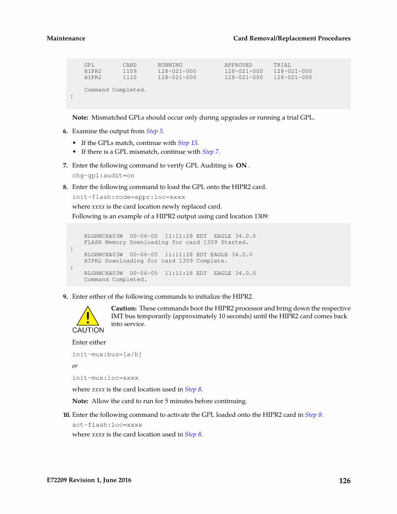
GPL CARD RUNNING APPROVED TRIAL HIPR2 1109 128-021-000 128-021-000 128-021-000 HIPR2 1110 128-021-000 128-021-000 128-021-000
Command Completed.;
Note: Mismatched GPLs should occur only during upgrades or running a trial GPL.
6. Examine the output from Step 5.
• If the GPLs match, continue with Step 15.• If there is a GPL mismatch, continue with Step 7.
7. Enter the following command to verify GPL Auditing is ON .chg-gpl:audit=on
8. Enter the following command to load the GPL onto the HIPR2 card.init-flash:code=appr:loc=xxxx
where xxxx is the card location newly replaced card.Following is an example of a HIPR2 output using card location 1309:
RLGHNCXA03W 00-06-05 11:11:28 EDT EAGLE 34.0.0 FLASH Memory Downloading for card 1309 Started.; RLGHNCXA03W 00-06-05 11:11:28 EDT EAGLE 34.0.0 HIPR2 Downloading for card 1309 Complete.; RLGHNCXA03W 00-06-05 11:11:28 EDT EAGLE 34.0.0 Command Completed.
9. Enter either of the following commands to initialize the HIPR2.
Caution: These commands boot the HIPR2 processor and bring down the respectiveIMT bus temporarily (approximately 10 seconds) until the HIPR2 card comes backinto service.
Enter either
init-mux:bus=[a/b]
or
init-mux:loc=xxxx
where xxxx is the card location used in Step 8.
Note: Allow the card to run for 5 minutes before continuing.
10. Enter the following command to activate the GPL loaded onto the HIPR2 card in Step 8:act-flash:loc=xxxx
where xxxx is the card location used in Step 8.
126E72209 Revision 1, June 2016
Card Removal/Replacement ProceduresMaintenance

Following is an example of the output using card location 1309:
RLGHNCXA03W 00-06-05 11:11:28 EDT EAGLE 34.0.0 FLASH Memory Activation for card 1309 Completed.; RLGHNCXA03W 00-06-05 11:11:28 EDT EAGLE 34.0.0 Command Completed.
11. Enter the following command to verify the approved GPLs match the running GPLs:rept-stat-gpl:gpl=hipr2
12. If the GPLs match, continue with Step 15.If the GPLs do not match, continue with Step 13.
13. Enter the following command determine which cards are in alarm condition (indicated by theacronym ALM in the rept-stat-gpl display):rept-stat-gpl
14. Note which cards are in an alarm condition and, if in doubt, My Oracle Support (MOS).15. Enter the following command to verify that the HIPR2 card is in service and the IMT bus has been
restored.rept-stat-imt
RLGHNCXA03W 98-09-27 16:50:24 EST EAGLE 34.0.0 IMT PST SST AST A IS-NR Active ----- ALARM STATUS = No alarms IMT PST SST AST B IS-NR Active ----- ALARM STATUS = No alarmsCommand Completed.
127E72209 Revision 1, June 2016
Card Removal/Replacement ProceduresMaintenance

Figure 29: HIPR2 LEDs
Determine Card Changeout Time
Description
This procedure assists the customer in deciding if the card should be changed immediately or duringthe Maintenance Window.
1. Replace the card immediately if any of the following conditions exist:
• If there is only one link on the card• If there is no other in-service link on this card
128E72209 Revision 1, June 2016
Card Removal/Replacement ProceduresMaintenance
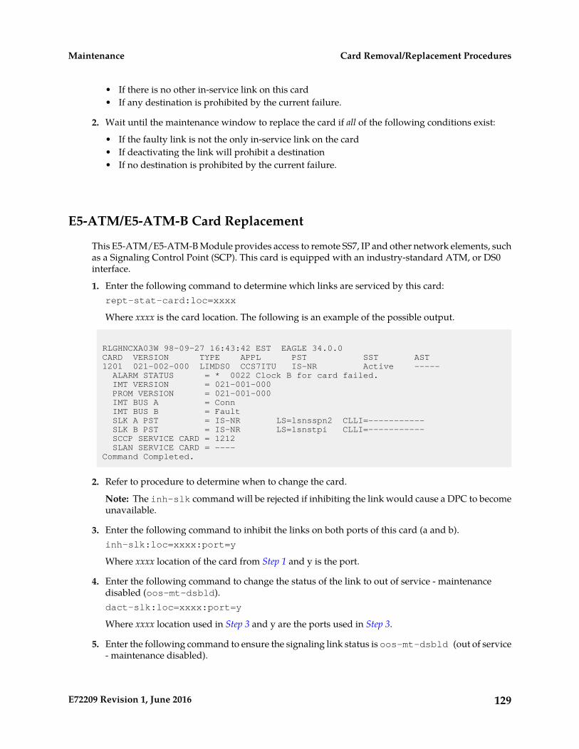
• If there is no other in-service link on this card• If any destination is prohibited by the current failure.
2. Wait until the maintenance window to replace the card if all of the following conditions exist:
• If the faulty link is not the only in-service link on the card• If deactivating the link will prohibit a destination• If no destination is prohibited by the current failure.
E5-ATM/E5-ATM-B Card Replacement
This E5-ATM/E5-ATM-B Module provides access to remote SS7, IP and other network elements, suchas a Signaling Control Point (SCP). This card is equipped with an industry-standard ATM, or DS0interface.
1. Enter the following command to determine which links are serviced by this card:rept-stat-card:loc=xxxx
Where xxxx is the card location. The following is an example of the possible output.
RLGHNCXA03W 98-09-27 16:43:42 EST EAGLE 34.0.0CARD VERSION TYPE APPL PST SST AST1201 021-002-000 LIMDS0 CCS7ITU IS-NR Active ----- ALARM STATUS = * 0022 Clock B for card failed. IMT VERSION = 021-001-000 PROM VERSION = 021-001-000 IMT BUS A = Conn IMT BUS B = Fault SLK A PST = IS-NR LS=lsnsspn2 CLLI=----------- SLK B PST = IS-NR LS=lsnstpi CLLI=----------- SCCP SERVICE CARD = 1212 SLAN SERVICE CARD = ----Command Completed.
2. Refer to procedure to determine when to change the card.
Note: The inh-slk command will be rejected if inhibiting the link would cause a DPC to becomeunavailable.
3. Enter the following command to inhibit the links on both ports of this card (a and b).inh-slk:loc=xxxx:port=y
Where xxxx location of the card from Step 1 and y is the port.
4. Enter the following command to change the status of the link to out of service - maintenancedisabled (oos-mt-dsbld).dact-slk:loc=xxxx:port=y
Where xxxx location used in Step 3 and y are the ports used in Step 3.
5. Enter the following command to ensure the signaling link status is oos-mt-dsbld (out of service- maintenance disabled).
129E72209 Revision 1, June 2016
Card Removal/Replacement ProceduresMaintenance

rept-stat-slk
The following is an example of the possible output.
RLGHNCXA03W 98-09-27 17:00:36 EST EAGLE 34.0.0rept-stat-slkSLK LSN CLLI PST SST AST1201,A lsnsspn2 ----------- OOS-MT-DSBLD Unava ----1201,B lsnstpi ----------- OOS-MT-DSBLD Unava ----1202,A lsnstpn ----------- IS-NR Avail ----1202,B lsnstpi ----------- IS-NR Avail ----1203,A lsnstpa ----------- IS-NR Avail ----1203,B lsnscpa ----------- IS-NR Avail ----1205,A lsnscpi ----------- IS-NR Avail ----1205,B lsnsspi1 ----------- IS-NR Avail ----1207,A lsnstpa ----------- IS-NR Avail ----1207,B lsnsspa1 ----------- IS-NR Avail ----1211,A lsnstpn ----------- IS-NR Avail ----1211,B lsnsspn1 ----------- IS-NR Avail ----Command Completed.
6. Enter the following command to inhibit the card and disconnect it from the IMT bus.rmv-card:loc=xxxx
Where xxxx location used in Step 3 and Step 4.
7. Remove the card, per the card replacement procedure described in the section titled Replacing aCard in the EAGLE..Place the new card into its place. Be sure the revision numbers are compatible (if in doubt, contactthe My Oracle Support (MOS)).
8. Enter the following command to download generic program loads and database information:rst-card:loc=xxxx
Where xxxx location used in Step 6.
9. Enter the following command to determine which links are serviced by this card:rept-stat-card:loc=xxxx
Where xxxx is the location of the replaced card.
Note: The signaling link alarms will be present until the links are restored in Step 11.
10. Examine the output from Step 9.Refer to Corrective Maintenance to clear any GPL related alarms on the newly replaced card beforecontinuing.
11. Enter the following command to return the links to service.Make sure this is done on all links:act-slk:loc=xxxx:port=y
Where xxxx location used in 3 and 4 and y are the ports used in Step 3 and Step 4.
12. Enter the following command to change the link status to IS-NR.Make sure this is done on both ports, a and b.unhb-slk:loc=xxxx:port=y
130E72209 Revision 1, June 2016
Card Removal/Replacement ProceduresMaintenance

Where xxxx location used in Step 3 and Step 4 and y are the ports used in Step 3 and Step 4.
13. Enter the following command to verify the status of the card and its associated links:rept-stat-card:loc=xxxx
Where xxxx is the card location. The following is an example of the possible output.
RLGHNCXA03W 98-09-27 16:43:42 EST EAGLE 34.0.0CARD VERSION TYPE APPL PST SST AST1201 024-002-000 LIMDS0 SS7ANSI IS-NR Active ----- ALARM STATUS = No Alarms. IMT VERSION = 024-001-000 PROM VERSION = 024-001-000 IMT BUS A = Conn IMT BUS B = Conn SLK A PST = IS-NR LS=lsnsspn2 CLLI=----------- SLK B PST = IS-NR LS=lsnstpi CLLI=----------- SCCP SERVICE CARD = 1212 SLAN SERVICE CARD = ----Command Completed.
14. Enter the following command to verify the links are properly aligned and are returned to fullservice:rept-stat-slk
The following is an example of the possible output.
RLGHNCXA03W 98-09-27 17:00:36 EST EAGLE 34.0.0rept-stat-slkSLK LSN CLLI PST SST AST1201,A lsnsspn2 ----------- IS-NR Avail ----1201,B lsnstpi ----------- IS-NR Avail ----1202,A lsnstpn ----------- IS-NR Avail ----1202,B lsnstpi ----------- IS-NR Avail ----1203,A lsnstpa ----------- IS-NR Avail ----1203,B lsnscpa ----------- IS-NR Avail ----1205,A lsnscpi ----------- IS-NR Avail ----1205,B lsnsspi1 ----------- IS-NR Avail ----1207,A lsnstpa ----------- IS-NR Avail ----1207,B lsnsspa1 ----------- IS-NR Avail ----1211,A lsnstpn ----------- IS-NR Avail ----1211,B lsnsspn1 ----------- IS-NR Avail ----Command Completed.
131E72209 Revision 1, June 2016
Card Removal/Replacement ProceduresMaintenance
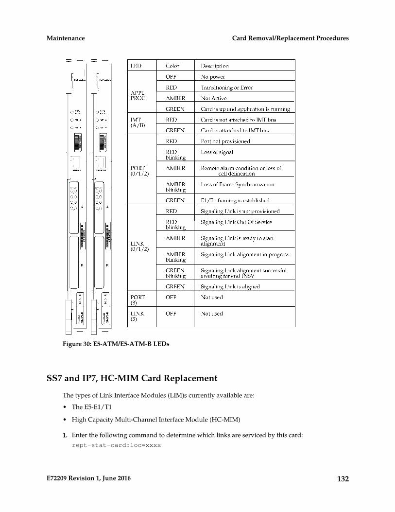
Figure 30: E5-ATM/E5-ATM-B LEDs
SS7 and IP7, HC-MIM Card Replacement
The types of Link Interface Modules (LIM)s currently available are:
• The E5-E1/T1
• High Capacity Multi-Channel Interface Module (HC-MIM)
1. Enter the following command to determine which links are serviced by this card:rept-stat-card:loc=xxxx
132E72209 Revision 1, June 2016
Card Removal/Replacement ProceduresMaintenance
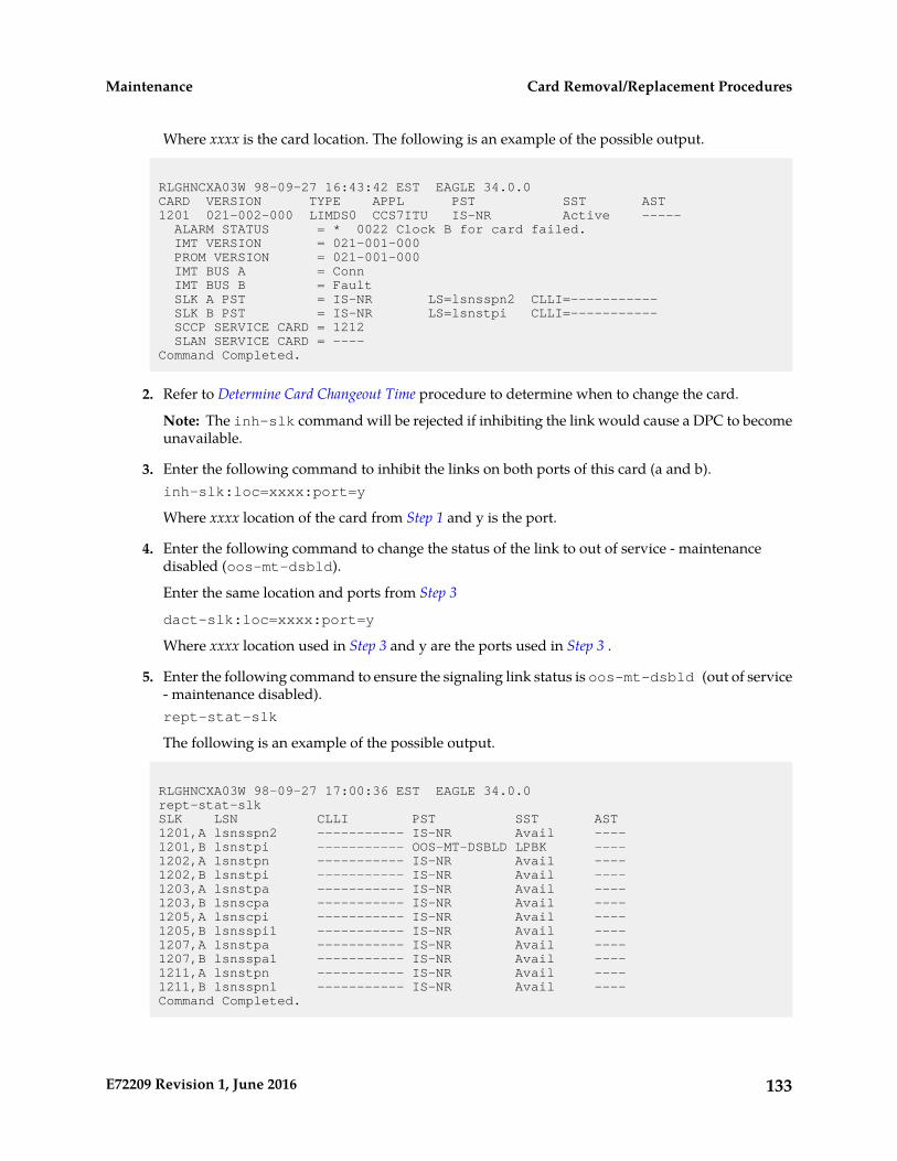
Where xxxx is the card location. The following is an example of the possible output.
RLGHNCXA03W 98-09-27 16:43:42 EST EAGLE 34.0.0CARD VERSION TYPE APPL PST SST AST1201 021-002-000 LIMDS0 CCS7ITU IS-NR Active ----- ALARM STATUS = * 0022 Clock B for card failed. IMT VERSION = 021-001-000 PROM VERSION = 021-001-000 IMT BUS A = Conn IMT BUS B = Fault SLK A PST = IS-NR LS=lsnsspn2 CLLI=----------- SLK B PST = IS-NR LS=lsnstpi CLLI=----------- SCCP SERVICE CARD = 1212 SLAN SERVICE CARD = ----Command Completed.
2. Refer to Determine Card Changeout Time procedure to determine when to change the card.
Note: The inh-slk command will be rejected if inhibiting the link would cause a DPC to becomeunavailable.
3. Enter the following command to inhibit the links on both ports of this card (a and b).inh-slk:loc=xxxx:port=y
Where xxxx location of the card from Step 1 and y is the port.
4. Enter the following command to change the status of the link to out of service - maintenancedisabled (oos-mt-dsbld).
Enter the same location and ports from Step 3
dact-slk:loc=xxxx:port=y
Where xxxx location used in Step 3 and y are the ports used in Step 3 .
5. Enter the following command to ensure the signaling link status is oos-mt-dsbld (out of service- maintenance disabled).rept-stat-slk
The following is an example of the possible output.
RLGHNCXA03W 98-09-27 17:00:36 EST EAGLE 34.0.0rept-stat-slkSLK LSN CLLI PST SST AST1201,A lsnsspn2 ----------- IS-NR Avail ----1201,B lsnstpi ----------- OOS-MT-DSBLD LPBK ----1202,A lsnstpn ----------- IS-NR Avail ----1202,B lsnstpi ----------- IS-NR Avail ----1203,A lsnstpa ----------- IS-NR Avail ----1203,B lsnscpa ----------- IS-NR Avail ----1205,A lsnscpi ----------- IS-NR Avail ----1205,B lsnsspi1 ----------- IS-NR Avail ----1207,A lsnstpa ----------- IS-NR Avail ----1207,B lsnsspa1 ----------- IS-NR Avail ----1211,A lsnstpn ----------- IS-NR Avail ----1211,B lsnsspn1 ----------- IS-NR Avail ----Command Completed.
133E72209 Revision 1, June 2016
Card Removal/Replacement ProceduresMaintenance
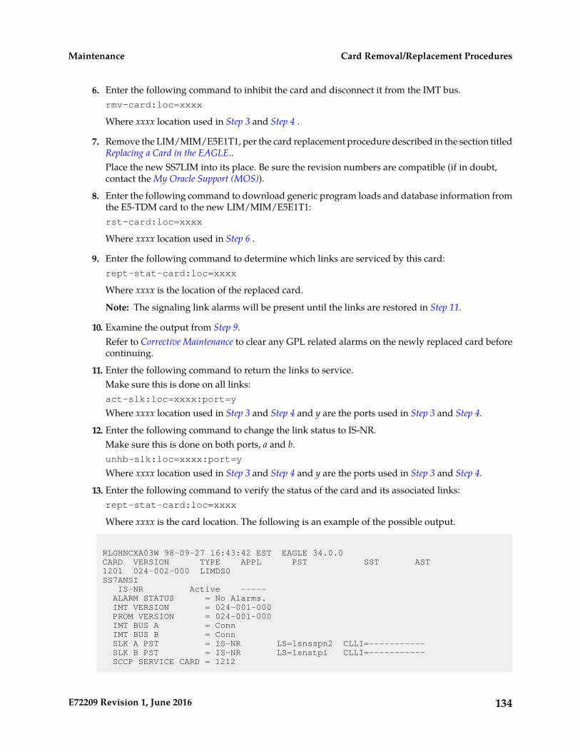
6. Enter the following command to inhibit the card and disconnect it from the IMT bus.rmv-card:loc=xxxx
Where xxxx location used in Step 3 and Step 4 .
7. Remove the LIM/MIM/E5E1T1, per the card replacement procedure described in the section titledReplacing a Card in the EAGLE..Place the new SS7LIM into its place. Be sure the revision numbers are compatible (if in doubt,contact the My Oracle Support (MOS)).
8. Enter the following command to download generic program loads and database information fromthe E5-TDM card to the new LIM/MIM/E5E1T1:rst-card:loc=xxxx
Where xxxx location used in Step 6 .
9. Enter the following command to determine which links are serviced by this card:rept-stat-card:loc=xxxx
Where xxxx is the location of the replaced card.
Note: The signaling link alarms will be present until the links are restored in Step 11.
10. Examine the output from Step 9.Refer to Corrective Maintenance to clear any GPL related alarms on the newly replaced card beforecontinuing.
11. Enter the following command to return the links to service.Make sure this is done on all links:act-slk:loc=xxxx:port=y
Where xxxx location used in Step 3 and Step 4 and y are the ports used in Step 3 and Step 4.
12. Enter the following command to change the link status to IS-NR.Make sure this is done on both ports, a and b.unhb-slk:loc=xxxx:port=y
Where xxxx location used in Step 3 and Step 4 and y are the ports used in Step 3 and Step 4.
13. Enter the following command to verify the status of the card and its associated links:rept-stat-card:loc=xxxx
Where xxxx is the card location. The following is an example of the possible output.
RLGHNCXA03W 98-09-27 16:43:42 EST EAGLE 34.0.0CARD VERSION TYPE APPL PST SST AST1201 024-002-000 LIMDS0 SS7ANSI IS-NR Active ----- ALARM STATUS = No Alarms. IMT VERSION = 024-001-000 PROM VERSION = 024-001-000 IMT BUS A = Conn IMT BUS B = Conn SLK A PST = IS-NR LS=lsnsspn2 CLLI=----------- SLK B PST = IS-NR LS=lsnstpi CLLI=----------- SCCP SERVICE CARD = 1212
134E72209 Revision 1, June 2016
Card Removal/Replacement ProceduresMaintenance

SLAN SERVICE CARD = ----Command Completed.
14. Enter the following command to verify the links are properly aligned and are returned to fullservice:rept-stat-slk
The following is an example of the possible output.
RLGHNCXA03W 98-09-27 17:00:36 EST EAGLE 34.0.0rept-stat-slkSLK LSN CLLI PST SST AST1201,A lsnsspn2 ----------- IS-NR Avail ----1201,B lsnstpi ----------- OOS-MT-DSBLD LPBK ----1202,A lsnstpn ----------- IS-NR Avail ----1202,B lsnstpi ----------- IS-NR Avail ----1203,A lsnstpa ----------- IS-NR Avail ----1203,B lsnscpa ----------- IS-NR Avail ----1205,A lsnscpi ----------- IS-NR Avail ----1205,B lsnsspi1 ----------- IS-NR Avail ----1207,A lsnstpa ----------- IS-NR Avail ----1207,B lsnsspa1 ----------- IS-NR Avail ----1211,A lsnstpn ----------- IS-NR Avail ----1211,B lsnsspn1 ----------- IS-NR Avail ----Command Completed.
135E72209 Revision 1, June 2016
Card Removal/Replacement ProceduresMaintenance

Figure 31: HC MIM LEDs
E5-ENET/E5-ENET-B Module
The term E5-ENET refers to either the E5-ENET (P/N 870-2212-xx) or to the E5-ENET-B (P/N870-2971-xx).
The E5-ENET module (refer to Figure 32: E5-ENET LEDs) can run different applications. Removal andreplacement procedures differ depending on the application.
Note: If this card is removed, the link supported by this card becomes out of service.
For removal and replacement procedures for a like-for-like card:
• If the E5-ENET card is operating with signaling interfaces such as IPLIM, IPGW, or IPSG, refer toIP SIGTRAN on E5-ENET/E5-ENET-B.
• If the E5-ENET card is operating with signaling interfaces such as SLAN or EROUTE, refer toSTPLAN/EROUTE on E5-ENET/E5-ENET-B .
136E72209 Revision 1, June 2016
Card Removal/Replacement ProceduresMaintenance

Figure 32: E5-ENET LEDs
137E72209 Revision 1, June 2016
Card Removal/Replacement ProceduresMaintenance
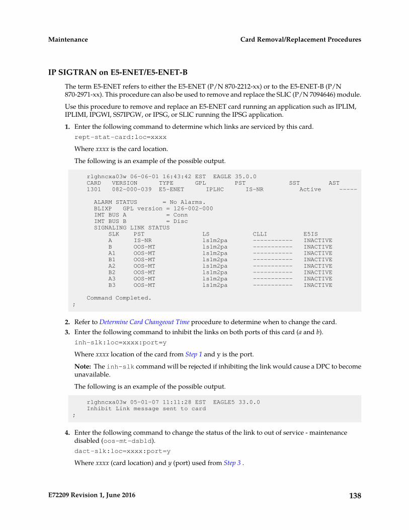
IP SIGTRAN on E5-ENET/E5-ENET-B
The term E5-ENET refers to either the E5-ENET (P/N 870-2212-xx) or to the E5-ENET-B (P/N870-2971-xx). This procedure can also be used to remove and replace the SLIC (P/N 7094646) module.
Use this procedure to remove and replace an E5-ENET card running an application such as IPLIM,IPLIMI, IPGWI, SS7IPGW, or IPSG, or SLIC running the IPSG application.
1. Enter the following command to determine which links are serviced by this card.rept-stat-card:loc=xxxx
Where xxxx is the card location.
The following is an example of the possible output.
rlghncxa03w 06-06-01 16:43:42 EST EAGLE 35.0.0 CARD VERSION TYPE GPL PST SST AST 1301 082-000-039 E5-ENET IPLHC IS-NR Active -----
ALARM STATUS = No Alarms. BLIXP GPL version = 126-002-000 IMT BUS A = Conn IMT BUS B = Disc SIGNALING LINK STATUS SLK PST LS CLLI E5IS A IS-NR ls1m2pa ----------- INACTIVE B OOS-MT ls1m2pa ----------- INACTIVE A1 OOS-MT ls1m2pa ----------- INACTIVE B1 OOS-MT ls1m2pa ----------- INACTIVE A2 OOS-MT ls1m2pa ----------- INACTIVE B2 OOS-MT ls1m2pa ----------- INACTIVE A3 OOS-MT ls1m2pa ----------- INACTIVE B3 OOS-MT ls1m2pa ----------- INACTIVE
Command Completed.;
2. Refer to Determine Card Changeout Time procedure to determine when to change the card.3. Enter the following command to inhibit the links on both ports of this card (a and b).
inh-slk:loc=xxxx:port=y
Where xxxx location of the card from Step 1 and y is the port.
Note: The inh-slk command will be rejected if inhibiting the link would cause a DPC to becomeunavailable.
The following is an example of the possible output.
rlghncxa03w 05-01-07 11:11:28 EST EAGLE5 33.0.0 Inhibit Link message sent to card;
4. Enter the following command to change the status of the link to out of service - maintenancedisabled (oos-mt-dsbld).dact-slk:loc=xxxx:port=y
Where xxxx (card location) and y (port) used from Step 3 .
138E72209 Revision 1, June 2016
Card Removal/Replacement ProceduresMaintenance
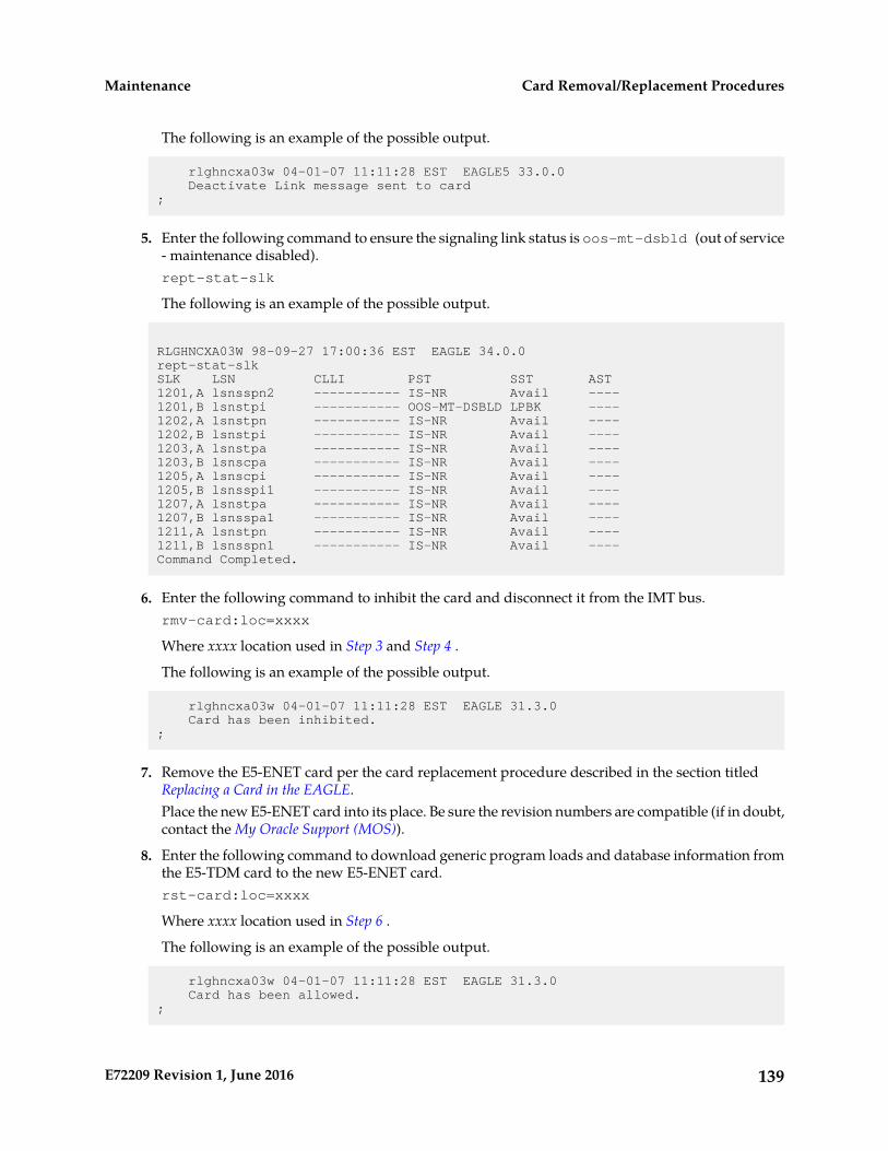
The following is an example of the possible output.
rlghncxa03w 04-01-07 11:11:28 EST EAGLE5 33.0.0 Deactivate Link message sent to card;
5. Enter the following command to ensure the signaling link status is oos-mt-dsbld (out of service- maintenance disabled).rept-stat-slk
The following is an example of the possible output.
RLGHNCXA03W 98-09-27 17:00:36 EST EAGLE 34.0.0rept-stat-slkSLK LSN CLLI PST SST AST1201,A lsnsspn2 ----------- IS-NR Avail ----1201,B lsnstpi ----------- OOS-MT-DSBLD LPBK ----1202,A lsnstpn ----------- IS-NR Avail ----1202,B lsnstpi ----------- IS-NR Avail ----1203,A lsnstpa ----------- IS-NR Avail ----1203,B lsnscpa ----------- IS-NR Avail ----1205,A lsnscpi ----------- IS-NR Avail ----1205,B lsnsspi1 ----------- IS-NR Avail ----1207,A lsnstpa ----------- IS-NR Avail ----1207,B lsnsspa1 ----------- IS-NR Avail ----1211,A lsnstpn ----------- IS-NR Avail ----1211,B lsnsspn1 ----------- IS-NR Avail ----Command Completed.
6. Enter the following command to inhibit the card and disconnect it from the IMT bus.rmv-card:loc=xxxx
Where xxxx location used in Step 3 and Step 4 .
The following is an example of the possible output.
rlghncxa03w 04-01-07 11:11:28 EST EAGLE 31.3.0 Card has been inhibited.;
7. Remove the E5-ENET card per the card replacement procedure described in the section titledReplacing a Card in the EAGLE.Place the new E5-ENET card into its place. Be sure the revision numbers are compatible (if in doubt,contact the My Oracle Support (MOS)).
8. Enter the following command to download generic program loads and database information fromthe E5-TDM card to the new E5-ENET card.rst-card:loc=xxxx
Where xxxx location used in Step 6 .
The following is an example of the possible output.
rlghncxa03w 04-01-07 11:11:28 EST EAGLE 31.3.0 Card has been allowed.;
139E72209 Revision 1, June 2016
Card Removal/Replacement ProceduresMaintenance

9. Enter the following command to determine which links are serviced by this card.rept-stat-card:loc=xxxx
Where xxxx is the location of the replaced card.
Note: The signaling link alarms will be present until the links are restored inStep 11.
rlghncxa03w 06-06-01 16:43:42 EST EAGLE 35.0.0 CARD VERSION TYPE GPL PST SST AST 1301 082-000-039 E5-ENET IPLHC IS-NR Active -----
ALARM STATUS = No Alarms. BLIXP GPL version = 126-002-000 IMT BUS A = Conn IMT BUS B = Disc SIGNALING LINK STATUS SLK PST LS CLLI E5IS A IS-NR ls1m2pa ----------- INACTIVE B OOS-MT ls1m2pa ----------- INACTIVE A1 OOS-MT ls1m2pa ----------- INACTIVE B1 OOS-MT ls1m2pa ----------- INACTIVE A2 OOS-MT ls1m2pa ----------- INACTIVE B2 OOS-MT ls1m2pa ----------- INACTIVE A3 OOS-MT ls1m2pa ----------- INACTIVE B3 OOS-MT ls1m2pa ----------- INACTIVE
Command Completed.;
10. Examine the output from Step 9.Refer to Corrective Maintenance to clear any GPL related alarms on the newly replaced card beforecontinuing.
11. Enter the following command to return the links to service.act-slk:loc=xxxx:port=y
Where xxxx location and y ports are those used in Step 3 and Step 4.
Make sure this is done on all links.
The following is an example of the possible output.
tekelecstp 05-01-21 17:00:36 EST EAGLE5 33.0.0 Activate Link message sent to card;
12. Enter the following command to change the link status to IS-NR.unhb-slk:loc=xxxx:port=y
Make sure this is done on both ports, a and b.
Where xxxx location used in Step 3 and Step 4 and y are the ports used in Step 3 and Step 4.
The following is an example of the possible output.
rlghncxa03w 03-03-23 13:20:59 EST EAGLE 31.3.0 Allow Link message sent to card;
140E72209 Revision 1, June 2016
Card Removal/Replacement ProceduresMaintenance

13. Enter the following command to verify the status of the card and its associated links.rept-stat-card:loc=xxxx
Where xxxx is the card location.
The following is an example of the possible output.
rlghncxa03w 06-06-01 16:43:42 EST EAGLE 35.0.0 CARD VERSION TYPE GPL PST SST AST 1301 082-000-039 E5-ENET IPLHC IS-NR Active -----
ALARM STATUS = No Alarms. BLIXP GPL version = 126-002-000 IMT BUS A = Conn IMT BUS B = Disc SIGNALING LINK STATUS SLK PST LS CLLI E5IS A IS-NR ls1m2pa ----------- INACTIVE B OOS-MT ls1m2pa ----------- INACTIVE A1 OOS-MT ls1m2pa ----------- INACTIVE B1 OOS-MT ls1m2pa ----------- INACTIVE A2 OOS-MT ls1m2pa ----------- INACTIVE B2 OOS-MT ls1m2pa ----------- INACTIVE A3 OOS-MT ls1m2pa ----------- INACTIVE B3 OOS-MT ls1m2pa ----------- INACTIVE
Command Completed.;
14. Enter the following command to verify the links are properly aligned and are returned to fullservice.rept-stat-slk
The following is an example of the possible output.
RLGHNCXA03W 98-09-27 17:00:36 EST EAGLE 34.0.0rept-stat-slkSLK LSN CLLI PST SST AST1201,A lsnsspn2 ----------- IS-NR Avail ----1201,B lsnstpi ----------- OOS-MT-DSBLD LPBK ----1202,A lsnstpn ----------- IS-NR Avail ----1202,B lsnstpi ----------- IS-NR Avail ----1203,A lsnstpa ----------- IS-NR Avail ----1203,B lsnscpa ----------- IS-NR Avail ----1205,A lsnscpi ----------- IS-NR Avail ----1205,B lsnsspi1 ----------- IS-NR Avail ----1207,A lsnstpa ----------- IS-NR Avail ----1207,B lsnsspa1 ----------- IS-NR Avail ----1211,A lsnstpn ----------- IS-NR Avail ----1211,B lsnsspn1 ----------- IS-NR Avail ----Command Completed.
15. Procedure complete.
STPLAN/EROUTE on E5-ENET/E5-ENET-B
The term E5-ENET refers to either the E5-ENET (P/N 870-2212-xx) or to the E5-ENET-B (P/N870-2971-xx).
141E72209 Revision 1, June 2016
Card Removal/Replacement ProceduresMaintenance
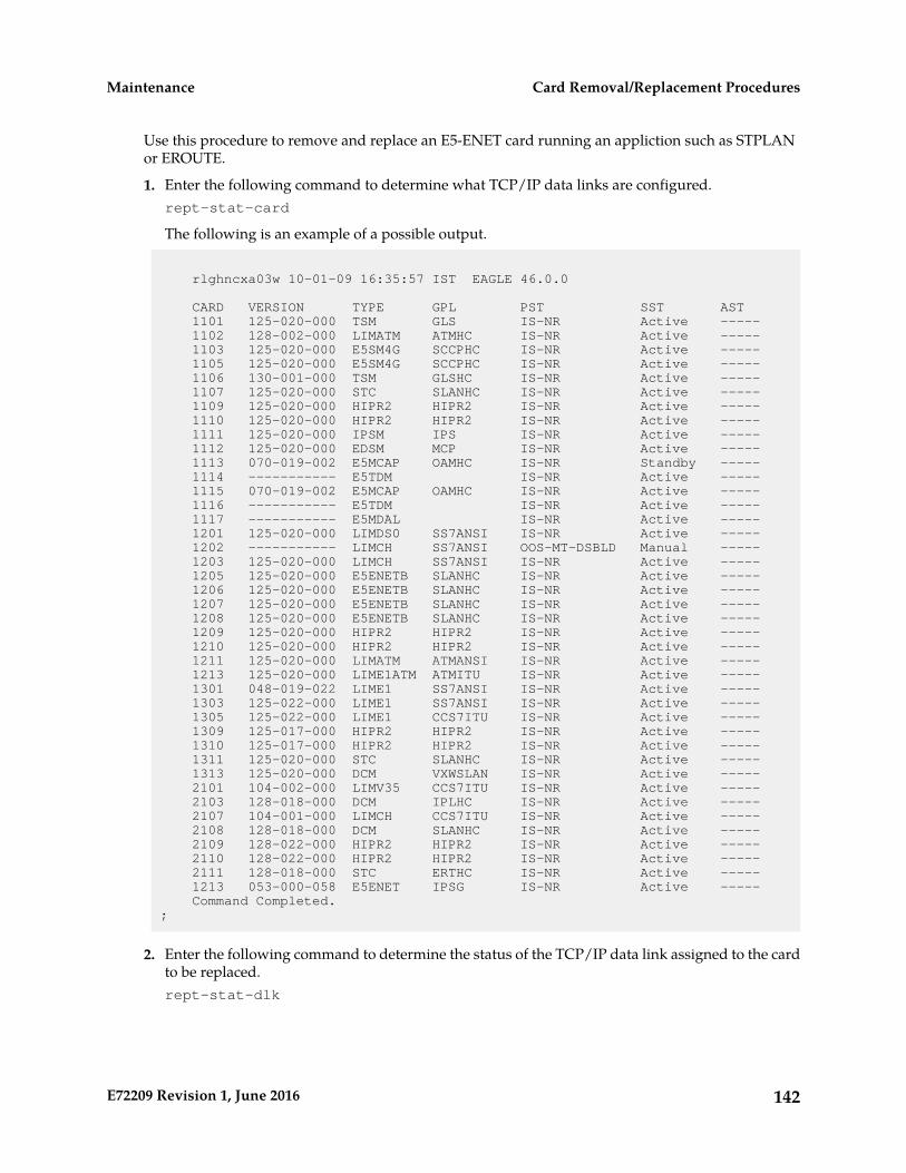
Use this procedure to remove and replace an E5-ENET card running an appliction such as STPLANor EROUTE.
1. Enter the following command to determine what TCP/IP data links are configured.rept-stat-card
The following is an example of a possible output.
rlghncxa03w 10-01-09 16:35:57 IST EAGLE 46.0.0
CARD VERSION TYPE GPL PST SST AST 1101 125-020-000 TSM GLS IS-NR Active ----- 1102 128-002-000 LIMATM ATMHC IS-NR Active ----- 1103 125-020-000 E5SM4G SCCPHC IS-NR Active ----- 1105 125-020-000 E5SM4G SCCPHC IS-NR Active ----- 1106 130-001-000 TSM GLSHC IS-NR Active ----- 1107 125-020-000 STC SLANHC IS-NR Active ----- 1109 125-020-000 HIPR2 HIPR2 IS-NR Active ----- 1110 125-020-000 HIPR2 HIPR2 IS-NR Active ----- 1111 125-020-000 IPSM IPS IS-NR Active ----- 1112 125-020-000 EDSM MCP IS-NR Active ----- 1113 070-019-002 E5MCAP OAMHC IS-NR Standby ----- 1114 ----------- E5TDM IS-NR Active ----- 1115 070-019-002 E5MCAP OAMHC IS-NR Active ----- 1116 ----------- E5TDM IS-NR Active ----- 1117 ----------- E5MDAL IS-NR Active ----- 1201 125-020-000 LIMDS0 SS7ANSI IS-NR Active ----- 1202 ----------- LIMCH SS7ANSI OOS-MT-DSBLD Manual ----- 1203 125-020-000 LIMCH SS7ANSI IS-NR Active ----- 1205 125-020-000 E5ENETB SLANHC IS-NR Active ----- 1206 125-020-000 E5ENETB SLANHC IS-NR Active ----- 1207 125-020-000 E5ENETB SLANHC IS-NR Active ----- 1208 125-020-000 E5ENETB SLANHC IS-NR Active ----- 1209 125-020-000 HIPR2 HIPR2 IS-NR Active ----- 1210 125-020-000 HIPR2 HIPR2 IS-NR Active ----- 1211 125-020-000 LIMATM ATMANSI IS-NR Active ----- 1213 125-020-000 LIME1ATM ATMITU IS-NR Active ----- 1301 048-019-022 LIME1 SS7ANSI IS-NR Active ----- 1303 125-022-000 LIME1 SS7ANSI IS-NR Active ----- 1305 125-022-000 LIME1 CCS7ITU IS-NR Active ----- 1309 125-017-000 HIPR2 HIPR2 IS-NR Active ----- 1310 125-017-000 HIPR2 HIPR2 IS-NR Active ----- 1311 125-020-000 STC SLANHC IS-NR Active ----- 1313 125-020-000 DCM VXWSLAN IS-NR Active ----- 2101 104-002-000 LIMV35 CCS7ITU IS-NR Active ----- 2103 128-018-000 DCM IPLHC IS-NR Active ----- 2107 104-001-000 LIMCH CCS7ITU IS-NR Active ----- 2108 128-018-000 DCM SLANHC IS-NR Active ----- 2109 128-022-000 HIPR2 HIPR2 IS-NR Active ----- 2110 128-022-000 HIPR2 HIPR2 IS-NR Active ----- 2111 128-018-000 STC ERTHC IS-NR Active ----- 1213 053-000-058 E5ENET IPSG IS-NR Active ----- Command Completed.;
2. Enter the following command to determine the status of the TCP/IP data link assigned to the cardto be replaced.rept-stat-dlk
142E72209 Revision 1, June 2016
Card Removal/Replacement ProceduresMaintenance
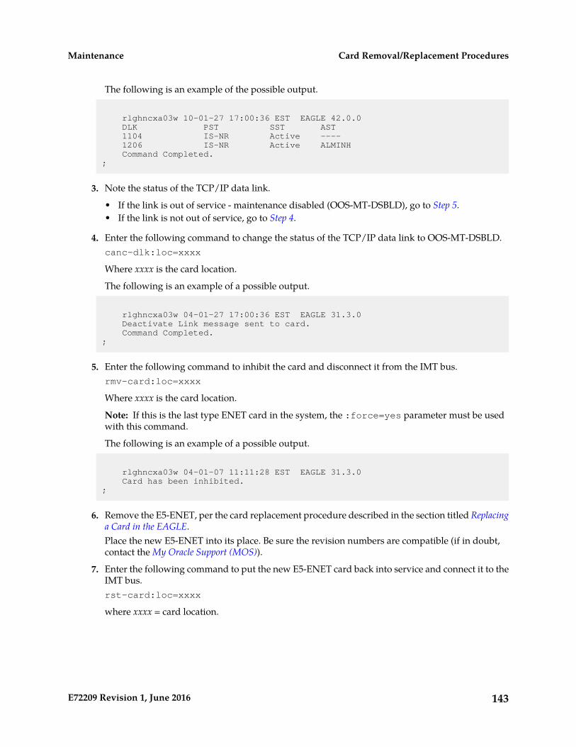
The following is an example of the possible output.
rlghncxa03w 10-01-27 17:00:36 EST EAGLE 42.0.0 DLK PST SST AST 1104 IS-NR Active ---- 1206 IS-NR Active ALMINH Command Completed.;
3. Note the status of the TCP/IP data link.
• If the link is out of service - maintenance disabled (OOS-MT-DSBLD), go to Step 5.• If the link is not out of service, go to Step 4.
4. Enter the following command to change the status of the TCP/IP data link to OOS-MT-DSBLD.canc-dlk:loc=xxxx
Where xxxx is the card location.
The following is an example of a possible output.
rlghncxa03w 04-01-27 17:00:36 EST EAGLE 31.3.0 Deactivate Link message sent to card. Command Completed.;
5. Enter the following command to inhibit the card and disconnect it from the IMT bus.rmv-card:loc=xxxx
Where xxxx is the card location.
Note: If this is the last type ENET card in the system, the :force=yes parameter must be usedwith this command.
The following is an example of a possible output.
rlghncxa03w 04-01-07 11:11:28 EST EAGLE 31.3.0 Card has been inhibited.;
6. Remove the E5-ENET, per the card replacement procedure described in the section titled Replacinga Card in the EAGLE.Place the new E5-ENET into its place. Be sure the revision numbers are compatible (if in doubt,contact the My Oracle Support (MOS)).
7. Enter the following command to put the new E5-ENET card back into service and connect it to theIMT bus.rst-card:loc=xxxx
where xxxx = card location.
143E72209 Revision 1, June 2016
Card Removal/Replacement ProceduresMaintenance
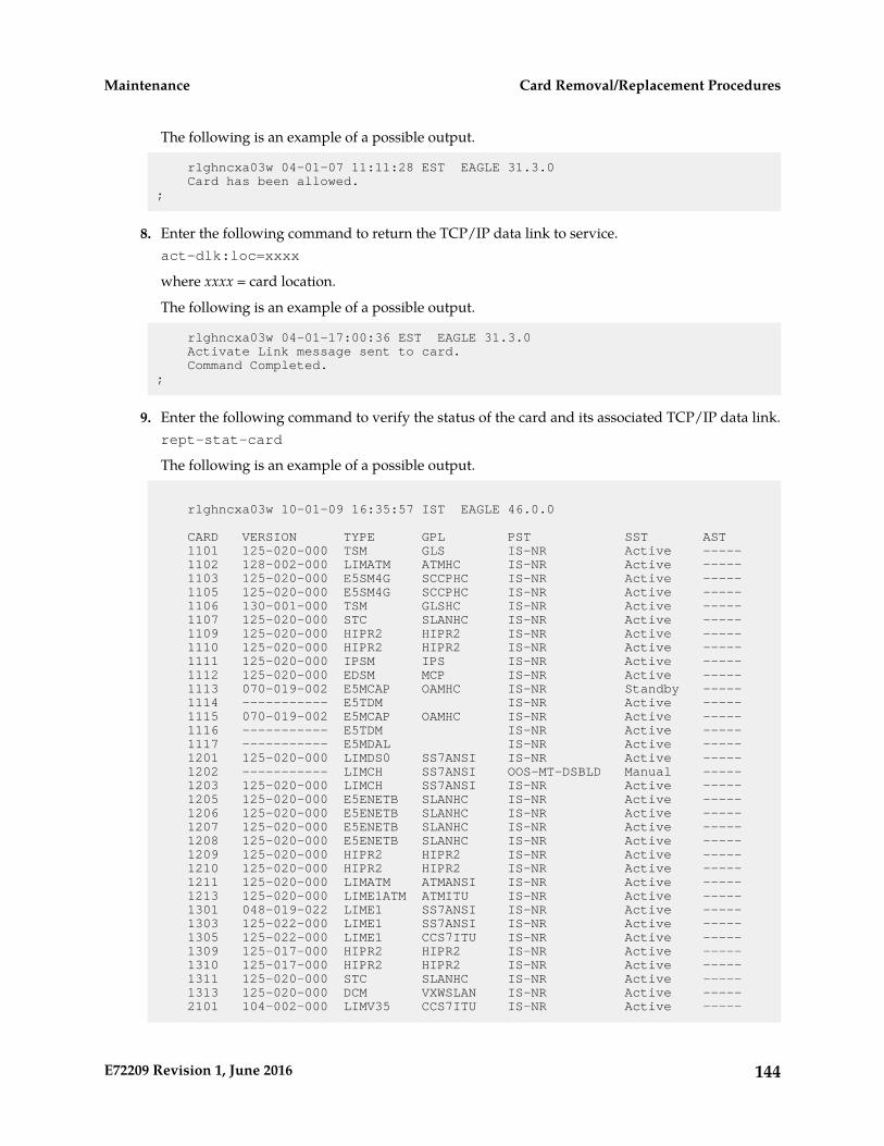
The following is an example of a possible output.
rlghncxa03w 04-01-07 11:11:28 EST EAGLE 31.3.0 Card has been allowed.;
8. Enter the following command to return the TCP/IP data link to service.act-dlk:loc=xxxx
where xxxx = card location.
The following is an example of a possible output.
rlghncxa03w 04-01-17:00:36 EST EAGLE 31.3.0 Activate Link message sent to card. Command Completed.;
9. Enter the following command to verify the status of the card and its associated TCP/IP data link.rept-stat-card
The following is an example of a possible output.
rlghncxa03w 10-01-09 16:35:57 IST EAGLE 46.0.0
CARD VERSION TYPE GPL PST SST AST 1101 125-020-000 TSM GLS IS-NR Active ----- 1102 128-002-000 LIMATM ATMHC IS-NR Active ----- 1103 125-020-000 E5SM4G SCCPHC IS-NR Active ----- 1105 125-020-000 E5SM4G SCCPHC IS-NR Active ----- 1106 130-001-000 TSM GLSHC IS-NR Active ----- 1107 125-020-000 STC SLANHC IS-NR Active ----- 1109 125-020-000 HIPR2 HIPR2 IS-NR Active ----- 1110 125-020-000 HIPR2 HIPR2 IS-NR Active ----- 1111 125-020-000 IPSM IPS IS-NR Active ----- 1112 125-020-000 EDSM MCP IS-NR Active ----- 1113 070-019-002 E5MCAP OAMHC IS-NR Standby ----- 1114 ----------- E5TDM IS-NR Active ----- 1115 070-019-002 E5MCAP OAMHC IS-NR Active ----- 1116 ----------- E5TDM IS-NR Active ----- 1117 ----------- E5MDAL IS-NR Active ----- 1201 125-020-000 LIMDS0 SS7ANSI IS-NR Active ----- 1202 ----------- LIMCH SS7ANSI OOS-MT-DSBLD Manual ----- 1203 125-020-000 LIMCH SS7ANSI IS-NR Active ----- 1205 125-020-000 E5ENETB SLANHC IS-NR Active ----- 1206 125-020-000 E5ENETB SLANHC IS-NR Active ----- 1207 125-020-000 E5ENETB SLANHC IS-NR Active ----- 1208 125-020-000 E5ENETB SLANHC IS-NR Active ----- 1209 125-020-000 HIPR2 HIPR2 IS-NR Active ----- 1210 125-020-000 HIPR2 HIPR2 IS-NR Active ----- 1211 125-020-000 LIMATM ATMANSI IS-NR Active ----- 1213 125-020-000 LIME1ATM ATMITU IS-NR Active ----- 1301 048-019-022 LIME1 SS7ANSI IS-NR Active ----- 1303 125-022-000 LIME1 SS7ANSI IS-NR Active ----- 1305 125-022-000 LIME1 CCS7ITU IS-NR Active ----- 1309 125-017-000 HIPR2 HIPR2 IS-NR Active ----- 1310 125-017-000 HIPR2 HIPR2 IS-NR Active ----- 1311 125-020-000 STC SLANHC IS-NR Active ----- 1313 125-020-000 DCM VXWSLAN IS-NR Active ----- 2101 104-002-000 LIMV35 CCS7ITU IS-NR Active -----
144E72209 Revision 1, June 2016
Card Removal/Replacement ProceduresMaintenance
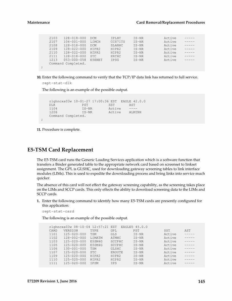
2103 128-018-000 DCM IPLHC IS-NR Active ----- 2107 104-001-000 LIMCH CCS7ITU IS-NR Active ----- 2108 128-018-000 DCM SLANHC IS-NR Active ----- 2109 128-022-000 HIPR2 HIPR2 IS-NR Active ----- 2110 128-022-000 HIPR2 HIPR2 IS-NR Active ----- 2111 128-018-000 STC ERTHC IS-NR Active ----- 1213 053-000-058 E5ENET IPSG IS-NR Active ----- Command Completed.;
10. Enter the following command to verify that the TCP/IP data link has returned to full service.rept-stat-dlk
The following is an example of the possible output.
rlghncxa03w 10-01-27 17:00:36 EST EAGLE 42.0.0 DLK PST SST AST 1104 IS-NR Active ---- 1206 IS-NR Active ALMINH Command Completed.;
11. Procedure is complete.
E5-TSM Card Replacement
The E5-TSM card runs the Generic Loading Services application which is a software function thattransfers a Binder generated table to the appropriate network card based on screenset to linksetassignment. The GPL is GLSHC, used for downloading gateway screening tables to link interfacemodules (LIMs). This is used to expedite the downloading process and bring links into service muchquicker.
The absence of this card will not effect the gateway screening capability, as the screening takes placeon the LIMs and SCCP cards. This only effects the ability to download screening data to the LIMs andSCCP cards.
1. Enter the following command to identify how many E5-TSM cards are presently configured forthis application:rept-stat-card
The following is an example of the possible output.
rlghncxa03w 08-10-04 12:57:21 EST EAGLE5 45.0.0 CARD VERSION TYPE GPL PST SST AST 1101 125-020-000 TSM GLS IS-NR Active ----- 1102 128-002-000 LIMATM ATMHC IS-NR Active ----- 1103 125-020-000 E5SM4G SCCPHC IS-NR Active ----- 1105 125-020-000 E5SM4G SCCPHC IS-NR Active ----- 1106 130-001-000 TSM GLSHC IS-NR Active ----- 1107 125-020-000 STC EROUTE IS-NR Active ----- 1109 125-020-000 HIPR2 HIPR2 IS-NR Active ----- 1110 125-020-000 HIPR2 HIPR2 IS-NR Active ----- 1111 125-020-000 IPSM IPS IS-NR Active -----
145E72209 Revision 1, June 2016
Card Removal/Replacement ProceduresMaintenance
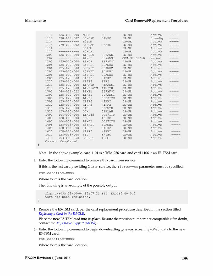
1112 125-020-000 MCPM MCP IS-NR Active ----- 1113 070-019-002 E5MCAP OAMHC IS-NR Standby ----- 1114 ----------- E5TDM IS-NR Active ----- 1115 070-019-002 E5MCAP OAMHC IS-NR Active ----- 1116 ----------- E5TDM IS-NR Active ----- 1117 ----------- E5MDAL IS-NR Active ----- 1201 125-020-000 LIMDS0 SS7ANSI IS-NR Active ----- 1202 ----------- LIMCH SS7ANSI OOS-MT-DSBLD Manual ----- 1203 125-020-000 LIMCH SS7ANSI IS-NR Active ----- 1205 125-020-000 E5ENET SLANHC IS-NR Active ----- 1206 125-020-000 E5ENET SLANHC IS-NR Active ----- 1207 125-020-000 E5ENET SLANHC IS-NR Active ----- 1208 125-020-000 E5ENET SLANHC IS-NR Active ----- 1209 125-020-000 HIPR2 HIPR2 IS-NR Active ----- 1210 125-020-000 HIPR2 IPR2 IS-NR Active ----- 1211 125-020-000 LIMATM ATMANSI IS-NR Active ----- 1213 125-020-000 LIME1ATM ATMITU IS-NR Active ----- 1301 048-019-022 LIME1 SS7ANSI IS-NR Active ----- 1303 125-022-000 LIME1 SS7ANSI IS-NR Active ----- 1305 125-022-000 LIME1 CCS7ITU IS-NR Active ----- 1309 125-017-000 HIPR2 HIPR2 IS-NR Active ----- 1310 125-017-000 HIPR2 HIPR2 IS-NR Active ----- 1311 125-020-000 STC EROUTE IS-NR Active ----- 1313 125-020-000 DCM STPLAN IS-NR Active ----- 1401 104-002-000 LIMV35 CCS7ITU IS-NR Active ----- 1403 128-018-000 DCM IPLHC IS-NR Active ----- 1407 104-001-000 LIMCH CCS7ITU IS-NR Active ----- 1408 128-018-000 E5ENET SLANHC IS-NR Active ----- 1409 128-016-000 HIPR2 HIPR2 IS-NR Active ----- 1410 128-016-000 HIPR2 HIPR2 IS-NR Active ----- 1411 128-018-000 STC ERTHC IS-NR Active ----- 1413 053-000-058 E5ENET IPSG IS-NR Active ----- Command Completed.;
Note: In the above example, card 1101 is a TSM-256 card and card 1106 is an E5-TSM card.
2. Enter the following command to remove this card from service.
If this is the last card providing GLS in service, the :force=yes parameter must be specified.
rmv-card:loc=xxxx
Where xxxx is the card location.
The following is an example of the possible output.
rlghncxa03w 08-10-04 13:07:21 EST EAGLE5 40.0.0 Card has been inhibited.;
3. Remove the E5-TSM card, per the card replacement procedure described in the section titledReplacing a Card in the EAGLE.Place the new E5-TSM card into its place. Be sure the revision numbers are compatible (if in doubt,contact the My Oracle Support (MOS)).
4. Enter the following command to begin downloading gateway screening (GWS) data to the newE5-TSM card:rst-card:loc=xxxx
Where xxxx is the card location.
146E72209 Revision 1, June 2016
Card Removal/Replacement ProceduresMaintenance
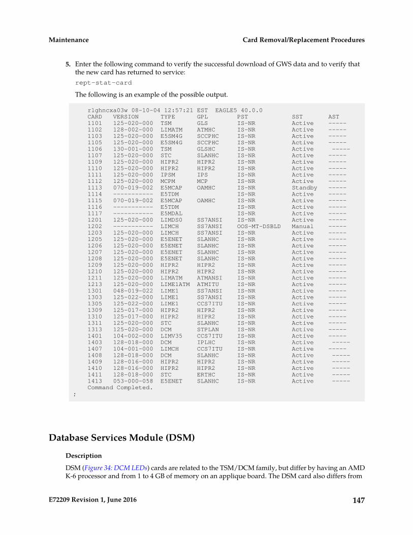
5. Enter the following command to verify the successful download of GWS data and to verify thatthe new card has returned to service:rept-stat-card
The following is an example of the possible output.
rlghncxa03w 08-10-04 12:57:21 EST EAGLE5 40.0.0 CARD VERSION TYPE GPL PST SST AST 1101 125-020-000 TSM GLS IS-NR Active ----- 1102 128-002-000 LIMATM ATMHC IS-NR Active ----- 1103 125-020-000 E5SM4G SCCPHC IS-NR Active ----- 1105 125-020-000 E5SM4G SCCPHC IS-NR Active ----- 1106 130-001-000 TSM GLSHC IS-NR Active ----- 1107 125-020-000 STC SLANHC IS-NR Active ----- 1109 125-020-000 HIPR2 HIPR2 IS-NR Active ----- 1110 125-020-000 HIPR2 HIPR2 IS-NR Active ----- 1111 125-020-000 IPSM IPS IS-NR Active ----- 1112 125-020-000 MCPM MCP IS-NR Active ----- 1113 070-019-002 E5MCAP OAMHC IS-NR Standby ----- 1114 ----------- E5TDM IS-NR Active ----- 1115 070-019-002 E5MCAP OAMHC IS-NR Active ----- 1116 ----------- E5TDM IS-NR Active ----- 1117 ----------- E5MDAL IS-NR Active ----- 1201 125-020-000 LIMDS0 SS7ANSI IS-NR Active ----- 1202 ----------- LIMCH SS7ANSI OOS-MT-DSBLD Manual ----- 1203 125-020-000 LIMCH SS7ANSI IS-NR Active ----- 1205 125-020-000 E5ENET SLANHC IS-NR Active ----- 1206 125-020-000 E5ENET SLANHC IS-NR Active ----- 1207 125-020-000 E5ENET SLANHC IS-NR Active ----- 1208 125-020-000 E5ENET SLANHC IS-NR Active ----- 1209 125-020-000 HIPR2 HIPR2 IS-NR Active ----- 1210 125-020-000 HIPR2 HIPR2 IS-NR Active ----- 1211 125-020-000 LIMATM ATMANSI IS-NR Active ----- 1213 125-020-000 LIME1ATM ATMITU IS-NR Active ----- 1301 048-019-022 LIME1 SS7ANSI IS-NR Active ----- 1303 125-022-000 LIME1 SS7ANSI IS-NR Active ----- 1305 125-022-000 LIME1 CCS7ITU IS-NR Active ----- 1309 125-017-000 HIPR2 HIPR2 IS-NR Active ----- 1310 125-017-000 HIPR2 HIPR2 IS-NR Active ----- 1311 125-020-000 STC SLANHC IS-NR Active ----- 1313 125-020-000 DCM STPLAN IS-NR Active ----- 1401 104-002-000 LIMV35 CCS7ITU IS-NR Active ----- 1403 128-018-000 DCM IPLHC IS-NR Active ----- 1407 104-001-000 LIMCH CCS7ITU IS-NR Active ----- 1408 128-018-000 DCM SLANHC IS-NR Active ----- 1409 128-016-000 HIPR2 HIPR2 IS-NR Active ----- 1410 128-016-000 HIPR2 HIPR2 IS-NR Active ----- 1411 128-018-000 STC ERTHC IS-NR Active ----- 1413 053-000-058 E5ENET SLANHC IS-NR Active ----- Command Completed.;
Database Services Module (DSM)
Description
DSM (Figure 34: DCM LEDs) cards are related to the TSM/DCM family, but differ by having an AMDK-6 processor and from 1 to 4 GB of memory on an applique board. The DSM card also differs from
147E72209 Revision 1, June 2016
Card Removal/Replacement ProceduresMaintenance

the TSM cards by having ethernet ports. The DSMs run a version of the SCCP application that hasbeen ported to the VxWorks OS. To differentiate the DSM-VxWorks-SCCP from the SCCP that runson the TSM cards, the DSM version has been named VSCCP. The extra memory is required to hold acopy of the RTDB. Ethernet ports are required to connect to the EPAP to download the RTDB. MultipleDSMs are used to provide a means of load balancing in high-traffic situations. Each DSM contains anidentical database. Furthermore, the DSM RTDBs need to be identical to the one maintained by theEPAPs.
Note: If there are provisioning scripts, such as LARG data, the DSM replacement activity should becoordinated with the DB/Admin operations to avoid extended provision otherwise RADB resets mayoccur.
1. Enter the following command to determine which cards are in service.rept-stat-card:loc=xxxx
Where xxxx is the DSM card location.
This will indicate which link interface modules (LIMs) will be affected by removal of the DSM card.2. Enter the following command to determine the number of DSM cards in service providing GTT.
rept-stat-sccp
The following is an example of the possible output.
RLGHNCXA03W 98-02-04 15:10:19 EST EAGLE 34.0.0SCCP SUBSYSTEM REPORT IS-NR Active -----GSM SUBSYSTEM REPORT IS-NR Active -----INP SUBSYSTEM REPORT IS-ANR Restricted ----- ASSUMING MATE'S LOAD INPQS: SSN STATUS = Allowed MATE SSN STATUS = Prohibited
SCCP Cards Configured= 4 Cards IS-NR= 2 Capacity Threshold = 100%CARD VERSION PST SST AST MSU USAGE CPU USAGE ------------------------------------------------------------------------------1212 103-001-000 IS-NR Active ALMINH 45% 30%1301 P 103-001-000 IS-NR Active ------ 35% 40%1305 ----------- OOS-MT Isolated ------ 0% 0%2112 ----------- OOS-MT-DSBLD Manual ------ 0% 0% ------------------------------------------------------------------------------SCCP Service Average MSU Capacity = 40% Average CPU Capacity = 35%AVERAGE CPU USAGE PER SERVICE: GTT = 15% GFLEX = 5% GPORT = 10% INPMR = 2% INPQS = 3% TOTAL SERVICE STATISTICS: SERVICE SUCCESS ERRORS WARNINGS FORWARD TO GTT TOTAL GTT: 1995 5 - - 2000 GFLEX: 500 1 4 10 515 GPORT: 800 0 2 3 805 INPMR: 50 5 0 15 70 INPQS: 499 1 - - 500Command Completed.
CAUTION: Inhibiting/removing all DSM cards at one time will cause an SCCP nodal outage.
3. Enter the following command to remove the DSM card from service.
CAUTION: Removing/inhibiting the last IS-NR DSM card will cause an SCCP outage on theaffected node. Before removing the last IS-NR DSMP card from service, ensure the mated STP DSMcards are IS-NR and capable of supporting the rerouted SCCP traffic.
148E72209 Revision 1, June 2016
Card Removal/Replacement ProceduresMaintenance

rmv-card:loc=xxxx
Where xxxx is the DSM card location.
If this is the last DSM card in service, the:force=yes parameter must be specified.
4. Remove the DSM card, per the card replacement procedure described in the section titled Replacinga Card in the EAGLE.Place the new DSM card into its place. Be sure the revision numbers are compatible (if in doubt,My Oracle Support (MOS)).
5. Enter the following command to return the DSM card into service.rst-card:loc=xxxx
Where xxxx is the DSM card location.
This causes the MASP to begin downloading tables to the new DSM card. When the card has beensuccessfully loaded (there will be a response on the terminal that downloading is complete). Thiscan take up to 4 hours.
6. Enter the following command to verify the card is operational and providing SCCP services.rept-stat-sccp
The following is an example of the possible output.
RLGHNCXA03W 98-02-04 15:10:19 EST EAGLE 34.0.0SCCP SUBSYSTEM REPORT IS-NR Active -----GSM SUBSYSTEM REPORT IS-NR Active -----INP SUBSYSTEM REPORT IS-ANR Restricted ----- ASSUMING MATE'S LOAD INPQS: SSN STATUS = Allowed MATE SSN STATUS = Prohibited
SCCP Cards Configured= 4 Cards IS-NR= 2 Capacity Threshold = 100%CARD VERSION PST SST AST MSU USAGE CPU USAGE ------------------------------------------------------------------------------1212 103-001-000 IS-NR Active ALMINH 45% 30%1301 P 103-001-000 IS-NR Active ------ 35% 40%1305 ----------- OOS-MT Isolated ------ 0% 0%2112 ----------- OOS-MT-DSBLD Manual ------ 0% 0% ------------------------------------------------------------------------------SCCP Service Average MSU Capacity = 40% Average CPU Capacity = 35%AVERAGE CPU USAGE PER SERVICE: GTT = 15% GFLEX = 5% GPORT = 10% INPMR = 2% INPQS = 3% TOTAL SERVICE STATISTICS: SERVICE SUCCESS ERRORS WARNINGS FORWARD TO GTT TOTAL GTT: 1995 5 - - 2000 GFLEX: 500 1 4 10 515 GPORT: 800 0 2 3 805 INPMR: 50 5 0 15 70 INPQS: 499 1 - - 500Command Completed.
E5-SM4G/E5-SM8G-B Card Replacement
The term E5-SM4G refers to either the E5-SM4G (P/N 870-2860-02) or the E5-SM8G-B (P/N 870-2990-01).
149E72209 Revision 1, June 2016
Card Removal/Replacement ProceduresMaintenance
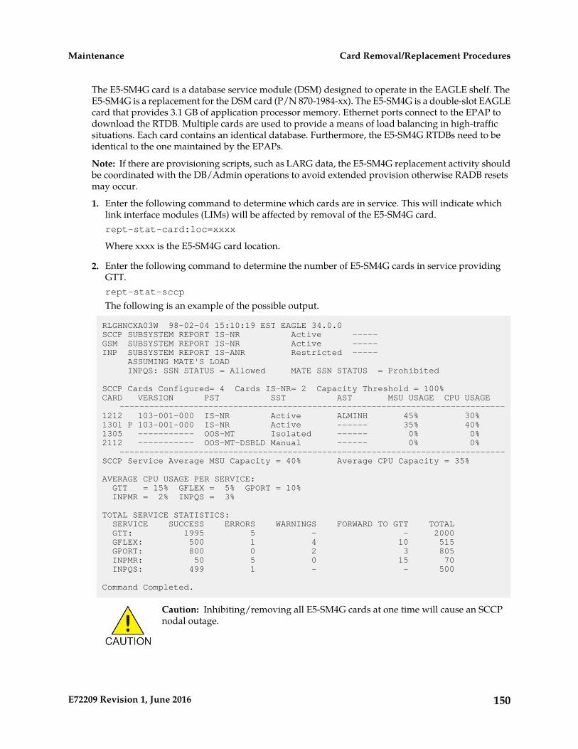
The E5-SM4G card is a database service module (DSM) designed to operate in the EAGLE shelf. TheE5-SM4G is a replacement for the DSM card (P/N 870-1984-xx). The E5-SM4G is a double-slot EAGLEcard that provides 3.1 GB of application processor memory. Ethernet ports connect to the EPAP todownload the RTDB. Multiple cards are used to provide a means of load balancing in high-trafficsituations. Each card contains an identical database. Furthermore, the E5-SM4G RTDBs need to beidentical to the one maintained by the EPAPs.
Note: If there are provisioning scripts, such as LARG data, the E5-SM4G replacement activity shouldbe coordinated with the DB/Admin operations to avoid extended provision otherwise RADB resetsmay occur.
1. Enter the following command to determine which cards are in service. This will indicate whichlink interface modules (LIMs) will be affected by removal of the E5-SM4G card.rept-stat-card:loc=xxxx
Where xxxx is the E5-SM4G card location.
2. Enter the following command to determine the number of E5-SM4G cards in service providingGTT.rept-stat-sccp
The following is an example of the possible output.
RLGHNCXA03W 98-02-04 15:10:19 EST EAGLE 34.0.0SCCP SUBSYSTEM REPORT IS-NR Active -----GSM SUBSYSTEM REPORT IS-NR Active -----INP SUBSYSTEM REPORT IS-ANR Restricted ----- ASSUMING MATE'S LOAD INPQS: SSN STATUS = Allowed MATE SSN STATUS = Prohibited
SCCP Cards Configured= 4 Cards IS-NR= 2 Capacity Threshold = 100%CARD VERSION PST SST AST MSU USAGE CPU USAGE ------------------------------------------------------------------------------1212 103-001-000 IS-NR Active ALMINH 45% 30%1301 P 103-001-000 IS-NR Active ------ 35% 40%1305 ----------- OOS-MT Isolated ------ 0% 0%2112 ----------- OOS-MT-DSBLD Manual ------ 0% 0% ------------------------------------------------------------------------------SCCP Service Average MSU Capacity = 40% Average CPU Capacity = 35%
AVERAGE CPU USAGE PER SERVICE: GTT = 15% GFLEX = 5% GPORT = 10% INPMR = 2% INPQS = 3%
TOTAL SERVICE STATISTICS: SERVICE SUCCESS ERRORS WARNINGS FORWARD TO GTT TOTAL GTT: 1995 5 - - 2000 GFLEX: 500 1 4 10 515 GPORT: 800 0 2 3 805 INPMR: 50 5 0 15 70 INPQS: 499 1 - - 500
Command Completed.
Caution: Inhibiting/removing all E5-SM4G cards at one time will cause an SCCPnodal outage.
150E72209 Revision 1, June 2016
Card Removal/Replacement ProceduresMaintenance
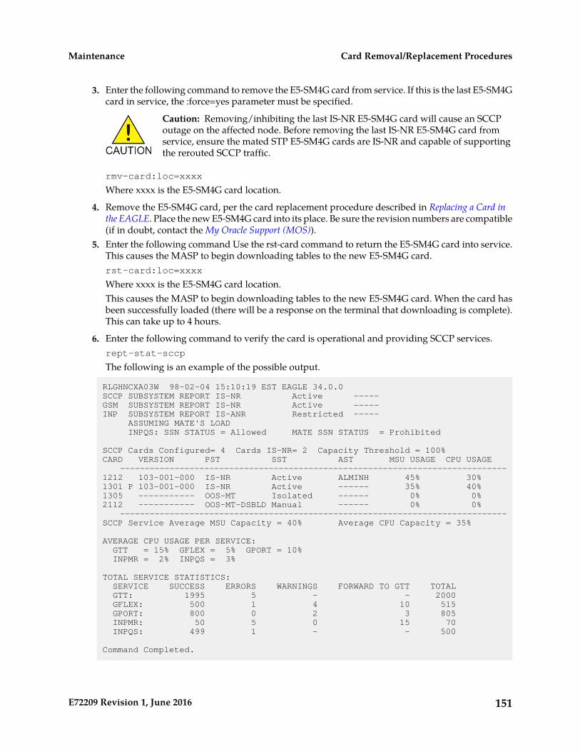
3. Enter the following command to remove the E5-SM4G card from service. If this is the last E5-SM4Gcard in service, the :force=yes parameter must be specified.
Caution: Removing/inhibiting the last IS-NR E5-SM4G card will cause an SCCPoutage on the affected node. Before removing the last IS-NR E5-SM4G card fromservice, ensure the mated STP E5-SM4G cards are IS-NR and capable of supportingthe rerouted SCCP traffic.
rmv-card:loc=xxxx
Where xxxx is the E5-SM4G card location.
4. Remove the E5-SM4G card, per the card replacement procedure described in Replacing a Card inthe EAGLE. Place the new E5-SM4G card into its place. Be sure the revision numbers are compatible(if in doubt, contact the My Oracle Support (MOS)).
5. Enter the following command Use the rst-card command to return the E5-SM4G card into service.This causes the MASP to begin downloading tables to the new E5-SM4G card.rst-card:loc=xxxx
Where xxxx is the E5-SM4G card location.This causes the MASP to begin downloading tables to the new E5-SM4G card. When the card hasbeen successfully loaded (there will be a response on the terminal that downloading is complete).This can take up to 4 hours.
6. Enter the following command to verify the card is operational and providing SCCP services.rept-stat-sccp
The following is an example of the possible output.
RLGHNCXA03W 98-02-04 15:10:19 EST EAGLE 34.0.0SCCP SUBSYSTEM REPORT IS-NR Active -----GSM SUBSYSTEM REPORT IS-NR Active -----INP SUBSYSTEM REPORT IS-ANR Restricted ----- ASSUMING MATE'S LOAD INPQS: SSN STATUS = Allowed MATE SSN STATUS = Prohibited
SCCP Cards Configured= 4 Cards IS-NR= 2 Capacity Threshold = 100%CARD VERSION PST SST AST MSU USAGE CPU USAGE ------------------------------------------------------------------------------1212 103-001-000 IS-NR Active ALMINH 45% 30%1301 P 103-001-000 IS-NR Active ------ 35% 40%1305 ----------- OOS-MT Isolated ------ 0% 0%2112 ----------- OOS-MT-DSBLD Manual ------ 0% 0% ------------------------------------------------------------------------------SCCP Service Average MSU Capacity = 40% Average CPU Capacity = 35%
AVERAGE CPU USAGE PER SERVICE: GTT = 15% GFLEX = 5% GPORT = 10% INPMR = 2% INPQS = 3%
TOTAL SERVICE STATISTICS: SERVICE SUCCESS ERRORS WARNINGS FORWARD TO GTT TOTAL GTT: 1995 5 - - 2000 GFLEX: 500 1 4 10 515 GPORT: 800 0 2 3 805 INPMR: 50 5 0 15 70 INPQS: 499 1 - - 500
Command Completed.
151E72209 Revision 1, June 2016
Card Removal/Replacement ProceduresMaintenance
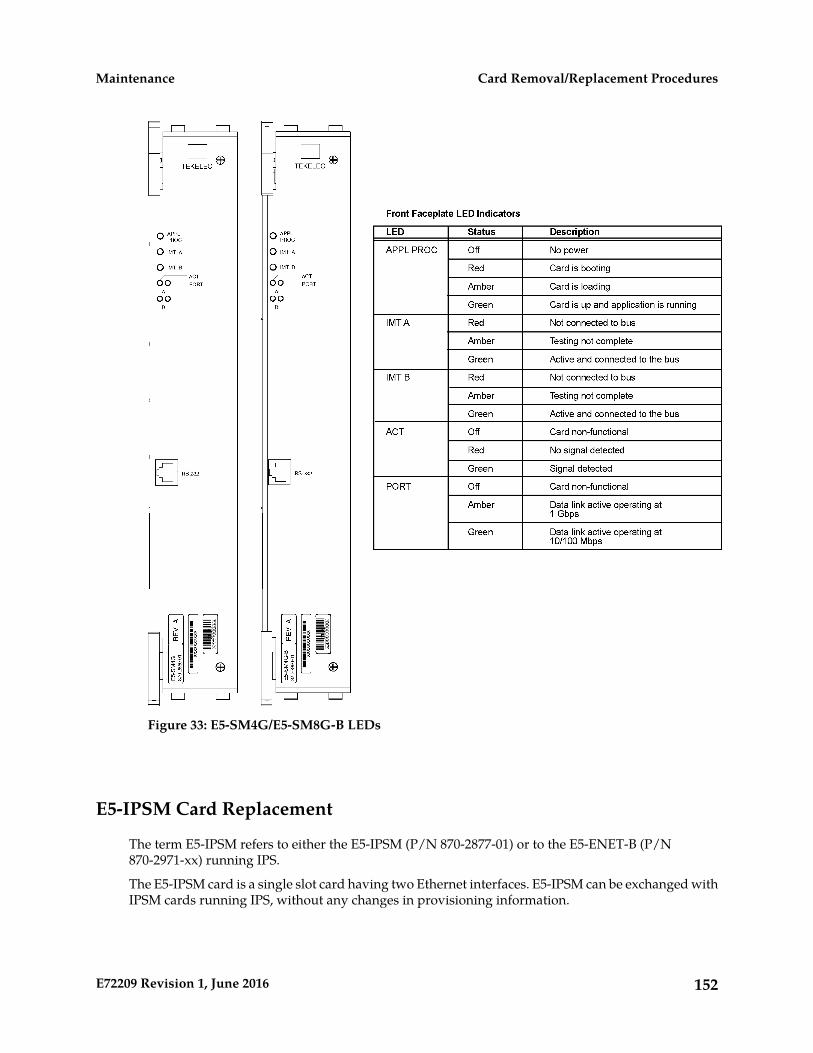
Figure 33: E5-SM4G/E5-SM8G-B LEDs
E5-IPSM Card Replacement
The term E5-IPSM refers to either the E5-IPSM (P/N 870-2877-01) or to the E5-ENET-B (P/N870-2971-xx) running IPS.
The E5-IPSM card is a single slot card having two Ethernet interfaces. E5-IPSM can be exchanged withIPSM cards running IPS, without any changes in provisioning information.
152E72209 Revision 1, June 2016
Card Removal/Replacement ProceduresMaintenance
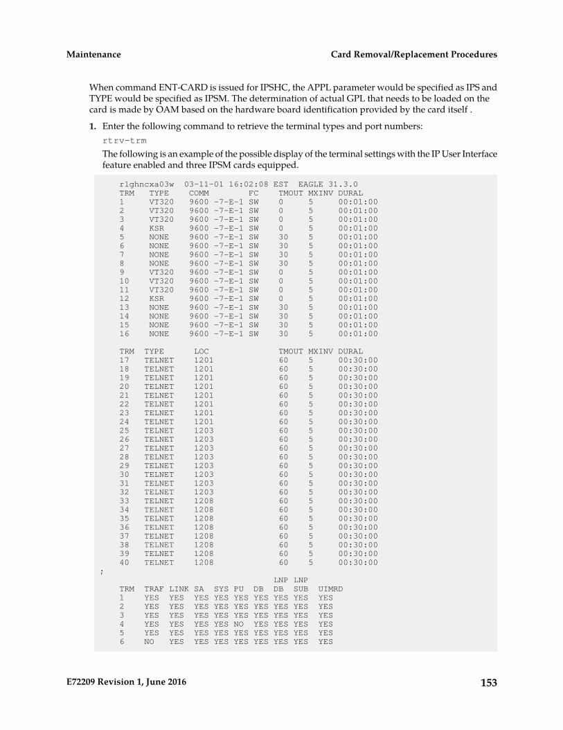
When command ENT-CARD is issued for IPSHC, the APPL parameter would be specified as IPS andTYPE would be specified as IPSM. The determination of actual GPL that needs to be loaded on thecard is made by OAM based on the hardware board identification provided by the card itself .
1. Enter the following command to retrieve the terminal types and port numbers:rtrv-trm
The following is an example of the possible display of the terminal settings with the IP User Interfacefeature enabled and three IPSM cards equipped.
rlghncxa03w 03-11-01 16:02:08 EST EAGLE 31.3.0 TRM TYPE COMM FC TMOUT MXINV DURAL 1 VT320 9600 -7-E-1 SW 0 5 00:01:00 2 VT320 9600 -7-E-1 SW 0 5 00:01:00 3 VT320 9600 -7-E-1 SW 0 5 00:01:00 4 KSR 9600 -7-E-1 SW 0 5 00:01:00 5 NONE 9600 -7-E-1 SW 30 5 00:01:00 6 NONE 9600 -7-E-1 SW 30 5 00:01:00 7 NONE 9600 -7-E-1 SW 30 5 00:01:00 8 NONE 9600 -7-E-1 SW 30 5 00:01:00 9 VT320 9600 -7-E-1 SW 0 5 00:01:00 10 VT320 9600 -7-E-1 SW 0 5 00:01:00 11 VT320 9600 -7-E-1 SW 0 5 00:01:00 12 KSR 9600 -7-E-1 SW 0 5 00:01:00 13 NONE 9600 -7-E-1 SW 30 5 00:01:00 14 NONE 9600 -7-E-1 SW 30 5 00:01:00 15 NONE 9600 -7-E-1 SW 30 5 00:01:00 16 NONE 9600 -7-E-1 SW 30 5 00:01:00
TRM TYPE LOC TMOUT MXINV DURAL 17 TELNET 1201 60 5 00:30:00 18 TELNET 1201 60 5 00:30:00 19 TELNET 1201 60 5 00:30:00 20 TELNET 1201 60 5 00:30:00 21 TELNET 1201 60 5 00:30:00 22 TELNET 1201 60 5 00:30:00 23 TELNET 1201 60 5 00:30:00 24 TELNET 1201 60 5 00:30:00 25 TELNET 1203 60 5 00:30:00 26 TELNET 1203 60 5 00:30:00 27 TELNET 1203 60 5 00:30:00 28 TELNET 1203 60 5 00:30:00 29 TELNET 1203 60 5 00:30:00 30 TELNET 1203 60 5 00:30:00 31 TELNET 1203 60 5 00:30:00 32 TELNET 1203 60 5 00:30:00 33 TELNET 1208 60 5 00:30:00 34 TELNET 1208 60 5 00:30:00 35 TELNET 1208 60 5 00:30:00 36 TELNET 1208 60 5 00:30:00 37 TELNET 1208 60 5 00:30:00 38 TELNET 1208 60 5 00:30:00 39 TELNET 1208 60 5 00:30:00 40 TELNET 1208 60 5 00:30:00; LNP LNP TRM TRAF LINK SA SYS PU DB DB SUB UIMRD 1 YES YES YES YES YES YES YES YES YES 2 YES YES YES YES YES YES YES YES YES 3 YES YES YES YES YES YES YES YES YES 4 YES YES YES YES NO YES YES YES YES 5 YES YES YES YES YES YES YES YES YES 6 NO YES YES YES YES YES YES YES YES
153E72209 Revision 1, June 2016
Card Removal/Replacement ProceduresMaintenance

7 NO YES YES YES YES YES YES YES YES 8 YES YES YES YES YES YES YES YES YES 9 YES YES YES YES YES YES YES YES YES 10 NO NO NO NO NO NO NO NO NO 11 NO NO NO NO NO NO NO NO NO 12 NO NO NO NO NO NO NO NO NO 13 NO NO NO NO NO NO NO NO NO 14 NO NO NO NO NO NO NO NO NO 15 NO NO NO NO NO NO NO NO NO 16 NO NO NO NO NO NO NO NO NO 17 NO NO NO NO NO NO NO NO NO 18 NO NO NO NO NO NO NO NO NO 19 NO NO NO NO NO NO NO NO NO 20 NO NO NO NO NO NO NO NO NO 21 NO NO NO NO NO NO NO NO NO 22 NO NO NO NO NO NO NO NO NO 23 NO NO NO NO NO NO NO NO NO 24 NO NO NO NO NO NO NO NO NO 25 NO NO NO NO NO NO NO NO NO 26 NO NO NO NO NO NO NO NO NO 27 NO NO NO NO NO NO NO NO NO 28 NO NO NO NO NO NO NO NO NO 29 NO NO NO NO NO NO NO NO NO 30 NO NO NO NO NO NO NO NO NO 31 NO NO NO NO NO NO NO NO NO 32 NO NO NO NO NO NO NO NO NO 33 NO NO NO NO NO NO NO NO NO 34 NO NO NO NO NO NO NO NO NO 35 NO NO NO NO NO NO NO NO NO 36 NO NO NO NO NO NO NO NO NO 37 NO NO NO NO NO NO NO NO NO 38 NO NO NO NO NO NO NO NO NO 39 NO NO NO NO NO NO NO NO NO 40 NO NO NO NO NO NO NO NO NO
APP APP TRM SERV SS CARD CLK DBG GTT GWS MEAS MON MPS SEAS SLAN 1 YES YES YES YES YES YES YES YES YES YES NO NO 2 YES YES YES YES YES YES YES YES YES YES NO NO 3 YES YES YES YES YES YES YES YES YES YES NO NO 4 YES YES YES YES YES NO YES YES YES YES NO NO 5 YES YES YES YES YES YES YES YES YES YES NO NO 6 YES YES YES YES YES YES YES YES YES YES NO NO 7 NO YES YES YES YES YES YES YES YES YES NO NO 8 YES YES YES YES YES YES YES YES YES YES YES YES 9 YES YES YES YES YES YES YES YES YES YES YES YES 10 NO NO NO NO NO NO NO NO NO NO NO NO 11 NO NO NO NO NO NO NO NO NO NO NO NO 12 NO NO NO NO NO NO NO NO NO NO NO NO 13 NO NO NO NO NO NO NO NO NO NO NO NO 14 NO NO NO NO NO NO NO NO NO NO NO NO 15 NO NO NO NO NO NO NO NO NO NO NO NO 16 NO NO NO NO NO NO NO NO NO NO NO NO 17 NO NO NO NO NO NO NO NO NO NO NO NO 18 NO NO NO NO NO NO NO NO NO NO NO NO 19 NO NO NO NO NO NO NO NO NO NO NO NO 20 NO NO NO NO NO NO NO NO NO NO NO NO 21 NO NO NO NO NO NO NO NO NO NO NO NO 22 NO NO NO NO NO NO NO NO NO NO NO NO 23 NO NO NO NO NO NO NO NO NO NO NO NO 24 NO NO NO NO NO NO NO NO NO NO NO NO 25 NO NO NO NO NO NO NO NO NO NO NO NO 26 NO NO NO NO NO NO NO NO NO NO NO NO 27 NO NO NO NO NO NO NO NO NO NO NO NO
154E72209 Revision 1, June 2016
Card Removal/Replacement ProceduresMaintenance

28 NO NO NO NO NO NO NO NO NO NO NO NO 29 NO NO NO NO NO NO NO NO NO NO NO NO 30 NO NO NO NO NO NO NO NO NO NO NO NO 31 NO NO NO NO NO NO NO NO NO NO NO NO 32 NO NO NO NO NO NO NO NO NO NO NO NO 33 NO NO NO NO NO NO NO NO NO NO NO NO 34 NO NO NO NO NO NO NO NO NO NO NO NO 35 NO NO NO NO NO NO NO NO NO NO NO NO 36 NO NO NO NO NO NO NO NO NO NO NO NO 37 NO NO NO NO NO NO NO NO NO NO NO NO 38 NO NO NO NO NO NO NO NO NO NO NO NO 39 NO NO NO NO NO NO NO NO NO NO NO NO 40 NO NO NO NO NO NO NO NO NO NO NO NO;
2. Enter the following command to change the state of the appropriate card to the out of service -maintenance disabled state:inh-card:loc=xxxx:force=yes
where xxxx is the card location stenciled on the shelf of the EAGLE. Following is an example ofthe output:
RLGHNCXA03W 00-06-05 11:11:28 EDT EAGLE 34.0.0Card has been inhibited.
3. Remove and replace the card as described in the section titled, Replacing a Card in the EAGLE.4. Enter the following command to load and activate the approved GPL onto the inhibited card:
flash-card:code=appr:loc=xxxx:force=yes
where xxxx is the card location used in the previous step. The optional force=yes is used to forcethe command to work on an IS-NR card. Links provisioned on the card are inhibited duringcommand execution. The card and inhibited links are restored to their previous state when thecommand is completed
Following is an example of the possible output using card location 1201:
tekelecstp 05-04-11 01:52:11 EST EAGLE5 34.0.0 Flash Card: Downloading BLDIAG on card 1201.; tekelecstp 05-04-11 01:52:11 EST EAGLE5 34.0.0 Flash Card: Card 1201 download BLDIAG complete.; tekelecstp 05-04-11 01:52:11 EST EAGLE5 34.0.0 Flash Card: Downloading IMTPCI on card 1201.; tekelecstp 05-04-11 01:52:11 EST EAGLE5 34.0.0 Flash Card: Card 1201 download IMTPCI complete.; tekelecstp 05-04-11 01:52:11 EST EAGLE5 34.0.0 Flash Card: Downloading BLVXW on card 1201.; tekelecstp 05-04-11 01:52:11 EST EAGLE5 34.0.0 Flash Card: Card 1201 download BLVXW complete.; tekelecstp 05-04-11 01:52:11 EST EAGLE5 34.0.0 Flash Card: Activating BLDIAG on card 1201.;
155E72209 Revision 1, June 2016
Card Removal/Replacement ProceduresMaintenance

tekelecstp 05-04-11 01:52:11 EST EAGLE5 34.0.0 Flash Card: Card 1201 activation BLDIAG complete.
tekelecstp 05-04-11 01:52:11 EST EAGLE5 34.0.0 Flash Card: Activating IMTPCI on card 1201.; tekelecstp 05-04-11 01:52:11 EST EAGLE5 34.0.0 Flash Card: Card 1201 activation IMTPCI complete.; tekelecstp 05-04-11 01:52:11 EST EAGLE5 34.0.0 Flash Card: Activating BLVXW on card 1201.; tekelecstp 05-04-11 01:52:11 EST EAGLE5 34.0.0 Flash Card: Card 1201 activation BLVXW complete.; tekelecstp 05-04-11 01:52:11 EST EAGLE5 34.0.0 Flash Card: Downloading BLCPLD on card 1201.; tekelecstp 05-04-11 01:52:11 EST EAGLE5 34.0.0 Flash Card: Card 1201 download BLCPLD complete.; tekelecstp 05-04-11 01:52:11 EST EAGLE5 34.0.0 Flash Card: Activating BLCPLD on card 1201.; tekelecstp 05-04-11 01:52:11 EST EAGLE5 34.0.0 Flash Card: Card 12015 activation BLCPLD complete.; tekelecstp 05-04-11 01:52:11 EST EAGLE5 34.0.0 Command Completed.; tekelecstp 05-04-11 01:52:11 EST EAGLE5 34.0.0 Flash Card: Canceling links on card 1201.; tekelecstp 05-04-11 01:52:11 EST EAGLE5 34.0.0 Flash Card: Inhibiting card 1201.; tekelecstp 05-04-11 01:52:11 EST EAGLE5 Rel 34.0.0 Flash Card: Downloading BLBEPM on card 1201.; tekelecstp 05-04-11 01:52:11 EST EAGLE5 34.0.0 Flash Card: Card 1201 download BLBEPM complete.; tekelecstp 05-04-11 01:52:11 EST EAGLE5 34.0.0 Flash Card: Allowing card 1201.; tekelecstp 05-04-11 01:52:11 EST EAGLE5 34.0.0 Flash Card: Activating BLBEPM on card 1201.; tekelecstp 05-04-11 01:52:11 EST EAGLE5 34.0.0 Flash Card: Card 1201 activation BLBEPM complete.; tekelecstp 05-04-11 01:52:11 EST EAGLE5 34.0.0 Flash Card: Activating links on card 1201.; tekelecstp 05-04-11 01:52:11 EST EAGLE5 34.0.0 Command Completed.;
5. After the card has been reloaded (a message appears to confirm completion of the load), enter thefollowing command to verify the database is consistent (same level as the other cards in the system).rept-stat-card
156E72209 Revision 1, June 2016
Card Removal/Replacement ProceduresMaintenance
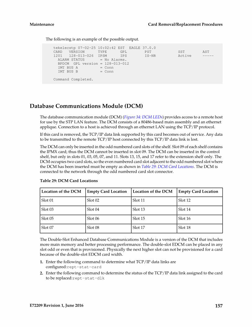
The following is an example of the possible output.
tekelecstp 07-02-25 10:02:42 EST EAGLE 37.0.0 CARD VERSION TYPE GPL PST SST AST 1201 128-013-026 IPSM IPS IS-NR Active ----- ALARM STATUS = No Alarms. BPDCM GPL version = 128-013-012 IMT BUS A = Conn IMT BUS B = Conn
Command Completed.
Database Communications Module (DCM)
The database communication module (DCM) (Figure 34: DCM LEDs) provides access to a remote hostfor use by the STP LAN feature. The DCM consists of a 80486-based main assembly and an ethernetapplique. Connection to a host is achieved through an ethernet LAN using the TCP/IP protocol.
If this card is removed, the TCP/IP data link supported by this card becomes out of service. Any datato be transmitted to the remote TCP/IP host connected by this TCP/IP data link is lost.
The DCM can only be inserted in the odd numbered card slots of the shelf. Slot 09 of each shelf containsthe IPMX card; thus the DCM cannot be inserted in slot 09. The DCM can be inserted in the controlshelf, but only in slots 01, 03, 05, 07, and 11. Slots 13, 15, and 17 refer to the extension shelf only. TheDCM occupies two card slots, so the even numbered card slot adjacent to the odd numbered slot wherethe DCM has been inserted must be empty as shown in Table 29: DCM Card Locations. The DCM isconnected to the network through the odd numbered card slot connector.
Table 29: DCM Card Locations
Empty Card LocationLocation of the DCMEmpty Card LocationLocation of the DCM
Slot 12Slot 11Slot 02Slot 01
Slot 14Slot 13Slot 04Slot 03
Slot 16Slot 15Slot 06Slot 05
Slot 18Slot 17Slot 08Slot 07
The Double-Slot Enhanced Database Communications Module is a version of the DCM that includesmore main memory and better processing performance. The double-slot EDCM can be placed in anyslot odd or even that is provisioned. Physically the next higher slot can not be provisioned for a cardbecause of the double-slot EDCM card width.
1. Enter the following command to determine what TCP/IP data links areconfigured:rept-stat-card
2. Enter the following command to determine the status of the TCP/IP data link assigned to the cardto be replaced:rept-stat-dlk
157E72209 Revision 1, June 2016
Card Removal/Replacement ProceduresMaintenance

The following is an example of the possible output.
RLGHNCXA03W 97-09-27 17:00:36 EST EAGLE 34.0.0DLK PST SST AST1104 IS-NR Avail ----1206 IS-NR Avail ALMINHCommand Completed.
3. If the status of the TCP/IP data link is not out of service - maintenance disabled (OOS-MT-DSBLD),use the canc-dlk command to change the status of the TCP/IP data link toOOS-MT-DSBLD.canc-dlk:loc=xxxxWhere xxxx is the card location.
4. Enter the following command to inhibit the card and disconnect it from the IMT bus.If this is the last DCM in the system, the :force=yes parameter must be used with thiscommand.rmv-card:loc=xxxxWhere xxxx is the card location.
5. Remove the DCM, per the card replacement procedure described in the section titled Replacing aCard in the EAGLE.Place the new DCM into its place. Be sure the revision numbers are compatible (if in doubt, contactthe My Oracle Support (MOS)).
6. Enter the following command to put the new DCM card back into service and connect it to the IMTbus:rst-card:loc=xxxxwhere xxxx = card location.
7. Enter the following command to return the TCP/IP data link to service:act-dlk:loc=xxxxwhere xxxx = card location.
8. Enter the following command to verify the status of the card and its associated TCP/IP datalink:rept-stat-card
9. Enter the following command to verify that the TCP/IP data link has returned to fullservice:rept-stat-dlkThe following is an example of the possible output.
RLGHNCXA03W 97-09-27 17:00:36 EST EAGLE 34.0.0DLK PST SST AST1104 IS-NR Avail ----1206 IS-NR Avail ALMINHCommand Completed.
158E72209 Revision 1, June 2016
Card Removal/Replacement ProceduresMaintenance

Figure 34: DCM LEDs
Measurement Collection and Polling Module (E5-MCPM)
Note: Throughout this document, the term MCPM refers to the E5-MCPM-B (P/N 870-3089-xx) cardunless specifically noted otherwise.
The primary MCPM card performs all measurements collection and reporting functions and provideson-card RAM storage for collected data and scheduled reports. The Secondary MCPM provides aredundant backup for the Primary card, and assumes collection and reporting responsibilities on theloss of the Primary. TCP/IP connections are used to deliver measurement reports from the PrimaryMCPM card to the customer via an FTP client. The FTP configuration can be customized to supportautomatic transfer of scheduled reports from the client to the server.
1. Enter the following command to determine the status of the MCPM cards.rept-stat-meas
2. Enter the following command to remove the faulty MCPM card from service.If this is the last MCPM card in service, the :force=yes parameter must be specified:rmv-card:loc=xxxx
where xxxx is the MCPM card location.
159E72209 Revision 1, June 2016
Card Removal/Replacement ProceduresMaintenance
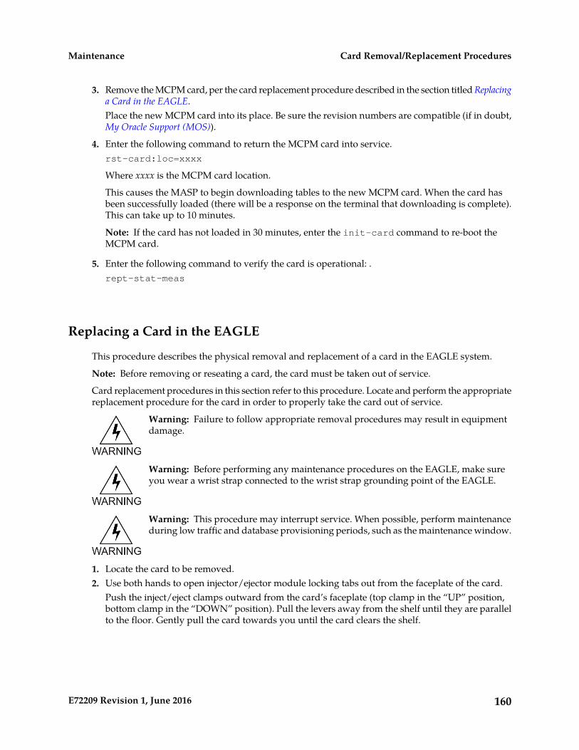
3. Remove the MCPM card, per the card replacement procedure described in the section titled Replacinga Card in the EAGLE.Place the new MCPM card into its place. Be sure the revision numbers are compatible (if in doubt,My Oracle Support (MOS)).
4. Enter the following command to return the MCPM card into service.rst-card:loc=xxxx
Where xxxx is the MCPM card location.
This causes the MASP to begin downloading tables to the new MCPM card. When the card hasbeen successfully loaded (there will be a response on the terminal that downloading is complete).This can take up to 10 minutes.
Note: If the card has not loaded in 30 minutes, enter the init-card command to re-boot theMCPM card.
5. Enter the following command to verify the card is operational: .rept-stat-meas
Replacing a Card in the EAGLE
This procedure describes the physical removal and replacement of a card in the EAGLE system.
Note: Before removing or reseating a card, the card must be taken out of service.
Card replacement procedures in this section refer to this procedure. Locate and perform the appropriatereplacement procedure for the card in order to properly take the card out of service.
Warning: Failure to follow appropriate removal procedures may result in equipmentdamage.
Warning: Before performing any maintenance procedures on the EAGLE, make sureyou wear a wrist strap connected to the wrist strap grounding point of the EAGLE.
Warning: This procedure may interrupt service. When possible, perform maintenanceduring low traffic and database provisioning periods, such as the maintenance window.
1. Locate the card to be removed.2. Use both hands to open injector/ejector module locking tabs out from the faceplate of the card.
Push the inject/eject clamps outward from the card’s faceplate (top clamp in the “UP” position,bottom clamp in the “DOWN” position). Pull the levers away from the shelf until they are parallelto the floor. Gently pull the card towards you until the card clears the shelf.
160E72209 Revision 1, June 2016
Card Removal/Replacement ProceduresMaintenance

Figure 35: Push Inject/Eject Clamps Outward
3. Place the card you have removed in an electrostatic discharge (ESD) protective container, or placethe card in the spare card storage shelf.
4. Be sure that the replacement card has the same part number and revision number as the card youhave just removed (unless this is an upgrade).
5. Open the ejector levers on the replacement card.Carefully align the card’s edges with the top and bottom card guides. Then push the card alongthe length of the card guides until the rear connectors on the card engage the mating connectorson the target shelf backplane.
6. Press the left edge of the card’s faceplate using constant pressure until you feel the card’s progresscease.To ensure proper seating, the tabs must be held in the release position until the locking tabs canengage with the upper and lower flange on the shelf.
Warning: Do not impact the faceplate in order to mate the connectors. Any impactto the card’s faceplate can damage the faceplate, the pins, or the connectors.
7. Push in the top and bottom inject/eject clamps.This locks the card in place and ensures a strong connection with the pins on the target shelfbackplane.
161E72209 Revision 1, June 2016
Card Removal/Replacement ProceduresMaintenance

Figure 36: Push in Inject/Eject Clamps
8. Verify that both IMT bus LEDs are green.9. Record the activity in the site maintenance log.10. Return to the appropriate card removal/replacement procedure to return the card to service (such
as initializing, flashing, and allowing).
Note: If any UAMs are generated in the system after the card comes into service, refer to MaintenanceGuide to find the recommended steps in diagnosing and clearing the UAM.
Replacing Cards in the Holdover Clock
Failed Clock Input (CI) Card Replacement
Description
Use this procedure to replace a failed clock input (CI) card in shelves equipped with ST3 clock cards.The input card FAIL lamp should be lit.
1. If the shelf is equipped with ST3 cards and the input card FAIL lamp is not lit, check the status ofthe SRCACT/SRCACTIVE lamp.If lit, press the transfer (XFR) button on either input card. If the input card FAIL lamp is lit, go toStep 2. The SRCACT/SRCACTIVE lamp on the other input card lights and the lamp goes off.
2. Remove the failed card or the card to be removed from the shelf.3. Set the option switches on the replacement card to the correct settings.
(See Installation Guide.) Wait for the input card to acquire the input reference signal (about 40seconds). Then, press the XFR button to make the new input card active.
CI, Clock Interface Card, Holdover Clock
162E72209 Revision 1, June 2016
Card Removal/Replacement ProceduresMaintenance
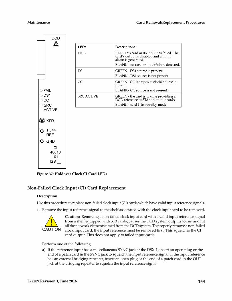
Figure 37: Holdover Clock CI Card LEDs
Non-Failed Clock Input (CI) Card Replacement
Description
Use this procedure to replace non-failed clock input (CI) cards which have valid input reference signals.
1. Remove the input reference signal to the shelf associated with the clock input card to be removed.
Caution: Removing a non-failed clock input card with a valid input reference signalfrom a shelf equipped with ST3 cards, causes the DCD system outputs to run and hitall the network elements timed from the DCD system. To properly remove a non-failedclock input card, the input reference must be removed first. This squelches the CIcard output. This does not apply to failed input cards.
Perform one of the following:a) If the reference input has a miscellaneous SYNC jack at the DSX-1, insert an open plug or the
end of a patch card in the SYNC jack to squelch the input reference signal. If the input referencehas an external bridging repeater, insert an open plug or the end of a patch cord in the OUTjack at the bridging repeater to squelch the input reference signal.
163E72209 Revision 1, June 2016
Card Removal/Replacement ProceduresMaintenance

b) If the input reference signal is directly cabled from the source to the DCD shelf, either lift theleads of the TB12 or TB13 wire-wrap terminals on the backplane of the DCD shelf, or short thetip (T) and ring (R) together at TB12 or TB13 on the backplane.
Caution: Use a clip cord that is no longer than two inches. A longer clip cord maynot appear as a short to the CI card and the input reference may continue to driveit.
The DS1 lamp should be off and the FAIL lamp lit on the CI card. If this is not true, do notproceed. This indicates the input reference has not been removed.
2. Remove the CI card.This has no effect on the outputs.
3. Set the option switches on the replacement card to the correct settings.(See Installation Guide.) The DS1 lamp should be off and the FAIL lamp lit on the CI card.
4. Restore the input reference by removing the open plug, clip cord, or reconnecting the leads to TB12or TB13 wire-wrap terminals on the DCD shelf backplane.
5. Wait for the input card to acquire the input reference signal (about 40 seconds).If you want the new CI card to be active, press the XFR button.
ST3 Card Replacement
Description
Use this procedure to replace ST3 cards. The only time an ST3 card should be replaced is if the FAILlamp is lit, or if it is in the ST A slot and the LOCK or LOCK and FAIL lamps are not lit and the networkelements receiving timing from the shelf are reporting slips. (However, the second condition is morelikely a timing loop rather than a bad ST3 card.)
Note: The ST3 card in slot B (ST B) in shelves equipped with ST3 clock cards may be removed fromthe shelf without any negative effect to the output, regardless if the ST3 has failed. If an ST3 is installedand not failed in slot A (ST A), it is the preferred source for the output cards. If you remove the cardfrom the shelf, it may cause a hit to the outputs.
1. Remove the ST3 card from the shelf.If it is in slot A and has not failed, the ST B clock card automatically become the preferred sourcefor the outputs. The TO cards ST and INPUT lamps should remain green.
Note: There may be a one-time phase hit to the outputs. If ST A has failed, the ST B clock card isalready the preferred source for the outputs. If ST B is being replaced, it is in standby and may beremoved without negative effect to the outputs.
2. Insert the replacement card in the shelf.Lock it into place by rotating the locking lever downward. The FAIL lamp should remain lit untilit has acquired the frequency and phase of the input reference signal and then go off (about oneminute). If ST A is being replaced, it automatically becomes the preferred source for the outputwhen the FAIL and LOCK lamps go off. The TO cards ST and INPUT lamps should remain lit.
Note: If you are replacing both ST3 cards, allow five minutes for the first card to stabilize beforereplacing the other.
164E72209 Revision 1, June 2016
Card Removal/Replacement ProceduresMaintenance

Figure 38: Holdover clock ST3 card LEDs
Note: If the FAIL and LOCKLEDs are both illuminated, the ST3 is in holdover mode and the card hasnot failed.
MIS Card Replacement
Description
The Maintenance Interface System (MIS) card may be removed or inserted into the shelf at any timewithout a negative effect to the operation of the shelf. The office alarms and shelf status (except forthe battery alarm) do not function while the MIS card is removed from the shelf.
1. Remove the MIS card from the shelf.2. Insert the replacement card.
165E72209 Revision 1, June 2016
Card Removal/Replacement ProceduresMaintenance
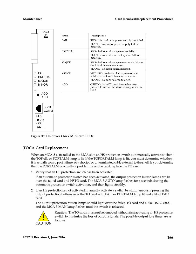
Figure 39: Holdover Clock MIS Card LEDs
TOCA Card Replacement
When an MCA-5 is installed in the MCA slot, an HS protection switch automatically activates whenthe TOFAIL or PORTALM lamp is lit. If the TOPORTALM lamp is lit, you must determine whetherit is actually a card port failure, or a shorted or unterminated cable external to the shelf. If you determinethat the PORTALM is actually a port failure on the card, replace the TO card.
1. Verify that an HS protection switch has been activated.If an automatic protection switch has been activated, the output protection button lamps are litover the failed card and HSTO card. The MCA-5 AUTO lamp flashes for 6 seconds during theautomatic protection switch activation, and then lights steadily.
2. If an HS protection is not activated, manually activate a switch by simultaneously pressing theoutput protection buttons over the TO card with FAIL or PORTALM lamp lit and a like HSTOcard.The output protection button lamps should light over the failed TO card and a like HSTO card,and the MCA-5 MAN lamp flashes until the switch is released.
Caution: The TO cards must not be removed without first activating an HS protectionswitch to minimize the loss of output signals. The possible output loss times are asfollows:
166E72209 Revision 1, June 2016
Card Removal/Replacement ProceduresMaintenance

a) TO card removal: up to 6 secondsb) Port or card failure: up to 3 secondsc) Manual switch activation/deactivation: approximately one ms.
3. Remove the TO card from the shelf.Set the option switches on the replacement card to the correct settings. Insert the replacement card.The FAIL lamp on the replacement card should remain off and the INPUT lamp should light. TheST lamp should also light if the system is equipped with clock cards.
4. Wait 10 seconds after all the lamps normalize to allow the card to warm-up and generate outputs.5. Press the lit output protection button for the HSTO card slot until the lamp goes out.
The lamp over the output protection button should go off. This releases the HS protection switchand puts the replacement card online.
Figure 40: Holdover Clock TOCA Card LEDs
167E72209 Revision 1, June 2016
Card Removal/Replacement ProceduresMaintenance

Figure 41: Holdover Clock MCA Card LEDs
Fan Assembly P/N 890-0001-xx
The Fan Assembly P/N 890-0001-xx is used for cooling shelves in the EAGLE frame. The assemblyincludes 3 fan units and a controller card.
Caution: Do not perform procedures to Replace Fan Assembly if the Fan Assembly is usedto cool shelves with HCMIM or HIPR2 cards. contact the My Oracle Support (MOS).
Refer to the following procedures to:
• Replace the Fan Unit
• Replace Fan Controller Card
• Replace Fan Assembly
168E72209 Revision 1, June 2016
Card Removal/Replacement ProceduresMaintenance
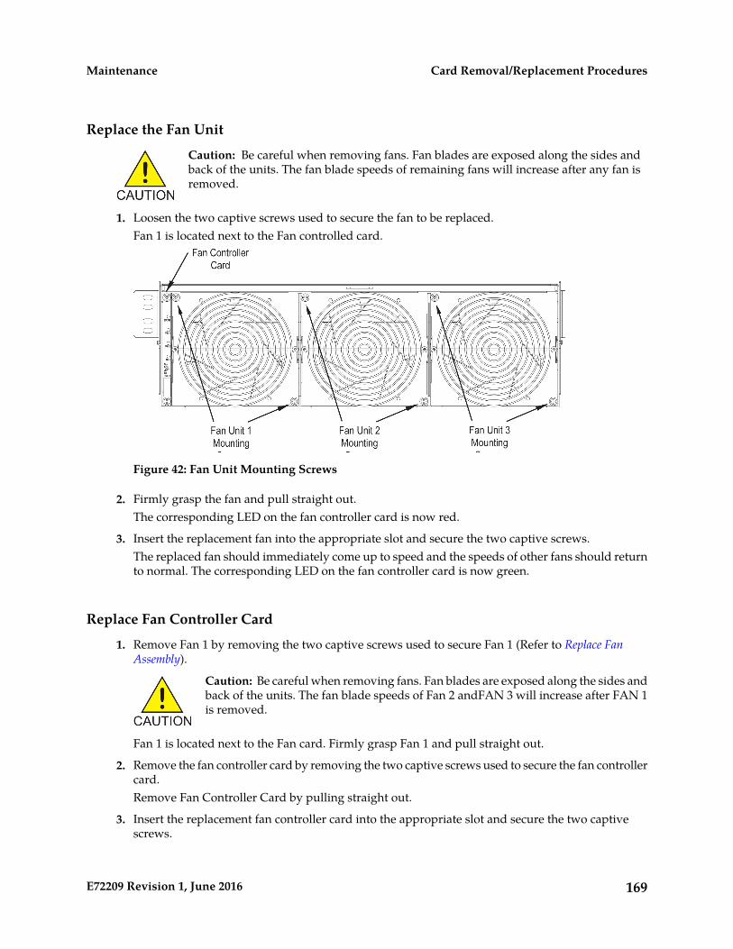
Replace the Fan Unit
Caution: Be careful when removing fans. Fan blades are exposed along the sides andback of the units. The fan blade speeds of remaining fans will increase after any fan isremoved.
1. Loosen the two captive screws used to secure the fan to be replaced.Fan 1 is located next to the Fan controlled card.
Figure 42: Fan Unit Mounting Screws
2. Firmly grasp the fan and pull straight out.The corresponding LED on the fan controller card is now red.
3. Insert the replacement fan into the appropriate slot and secure the two captive screws.The replaced fan should immediately come up to speed and the speeds of other fans should returnto normal. The corresponding LED on the fan controller card is now green.
Replace Fan Controller Card
1. Remove Fan 1 by removing the two captive screws used to secure Fan 1 (Refer to Replace FanAssembly).
Caution: Be careful when removing fans. Fan blades are exposed along the sides andback of the units. The fan blade speeds of Fan 2 andFAN 3 will increase after FAN 1is removed.
Fan 1 is located next to the Fan card. Firmly grasp Fan 1 and pull straight out.
2. Remove the fan controller card by removing the two captive screws used to secure the fan controllercard.Remove Fan Controller Card by pulling straight out.
3. Insert the replacement fan controller card into the appropriate slot and secure the two captivescrews.
169E72209 Revision 1, June 2016
Card Removal/Replacement ProceduresMaintenance

4. Insert Fan 1 back into the space next to the fan controller card and secure (finger tighten) using thetwo captive screws.Fan 1 should immediately come up to speed and the speeds of Fans 2 and 3 should return to normal.
Replace Fan Assembly
Caution: Do not perform this procedures if the Fan Assembly is used to cool shelveswith HCMIM or HIPR2 cards. contact the Customer Care Center.
The following procedures are used to replace Fan Assembly P/N 890-0001-xx when it is used to coolshelves not populated with HCMIM or HIPR2 cards.
• Procedure - Power Down the Fan Assembly
• Procedure - Remove Fan Cables and Fan Assembly
• Procedure - Install the Fan Assembly
• Procedure - Power Up the Fan Assembly
Procedure - Power Down the Fan AssemblyUse the following procedure to power down the fan assembly.
1. The fuse card located on the Fuse and Alarm Panel is marked FAN A and FAN B. Fuse positions6, 12, and 18 are the correct locations on the FAP faceplate. The fans are fused at 3As, with blueflags per feed. Remove the appropriate fuse for the fan assembly being replaced according to thefollowing:
• Fuse position 6 is for the fan unit directly below the x100 shelf.
• Fuse position 12 is for the fan directly below the x200 shelf.
• Fuse position 18 is for the fan directly below the x300 shelf.
2. When both the A side and B side power is removed from the fan unit, all of the LEDs on the fancontroller card (located on the left side of the front of the fan unit) are no longer illuminated andthe all fan motors are off.
170E72209 Revision 1, June 2016
Card Removal/Replacement ProceduresMaintenance

Figure 43: Fan card with LEDs on front of fan assembly unit
Procedure - Remove Fan Cables and Fan AssemblyUse the following procedure to remove fan cables and fan assembly.
1. At the fan assembly, place fiber paper on the shelf below where the fan is to be replaced. Thisensures that nothing drops into the area or equipment below.
2. From the front of the frame remove the fan filter from the fan assembly.3. From the rear of the fan unit, loosen the screws on the fan unit connector marked FAN A POWER.
Remove the connector from the fan unit.4. From the rear of the fan unit, loosen the screws on the fan unit connector marked FAN B POWER.
Remove the connector from the fan unit.
171E72209 Revision 1, June 2016
Card Removal/Replacement ProceduresMaintenance
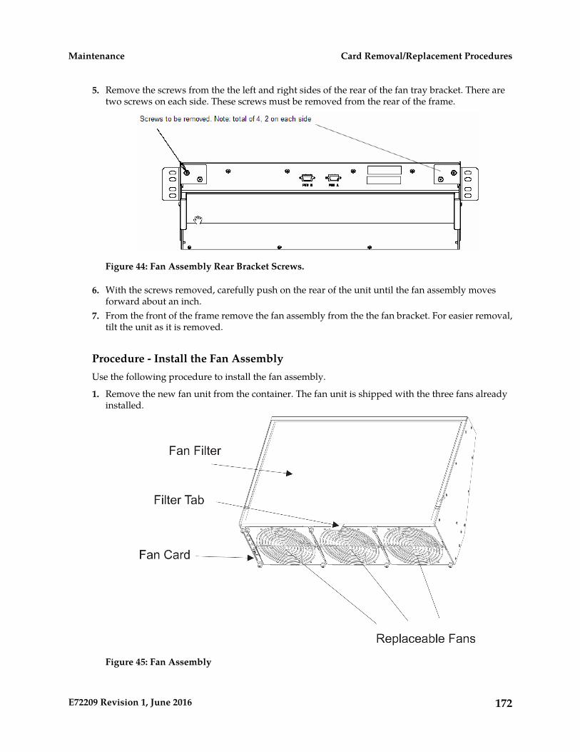
5. Remove the screws from the the left and right sides of the rear of the fan tray bracket. There aretwo screws on each side. These screws must be removed from the rear of the frame.
Figure 44: Fan Assembly Rear Bracket Screws.
6. With the screws removed, carefully push on the rear of the unit until the fan assembly movesforward about an inch.
7. From the front of the frame remove the fan assembly from the the fan bracket. For easier removal,tilt the unit as it is removed.
Procedure - Install the Fan AssemblyUse the following procedure to install the fan assembly.
1. Remove the new fan unit from the container. The fan unit is shipped with the three fans alreadyinstalled.
Figure 45: Fan Assembly
172E72209 Revision 1, June 2016
Card Removal/Replacement ProceduresMaintenance

2. Insert the fan unit into the fan bracket. Tilt the unit up as it is pushed in and completely insertedinto the bracket. After insertion, be sure the front of the fan unit is recessed about 1/2 inch fromthe front frame rails to allow the door to close.
Figure 46: Fan tray inserted into fan tray bracket in the frame - front view
3. When the fan unit is aligned and in place, attach the fan unit to the fan tray bracket by tighteningthe screws on the left and right sides of the rear of the fan tray bracket. There are two screws oneach side. These screws must be tightened from the rear of the frame.
173E72209 Revision 1, June 2016
Card Removal/Replacement ProceduresMaintenance
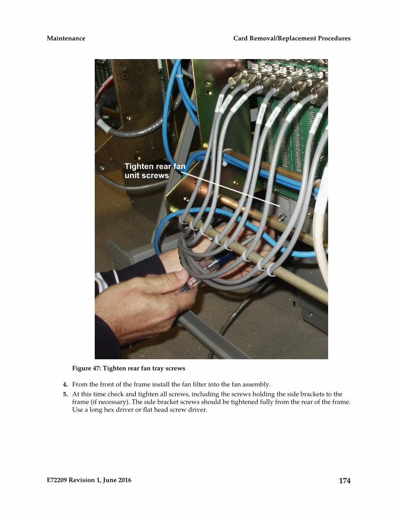
Figure 47: Tighten rear fan tray screws
4. From the front of the frame install the fan filter into the fan assembly.5. At this time check and tighten all screws, including the screws holding the side brackets to the
frame (if necessary). The side bracket screws should be tightened fully from the rear of the frame.Use a long hex driver or flat head screw driver.
174E72209 Revision 1, June 2016
Card Removal/Replacement ProceduresMaintenance
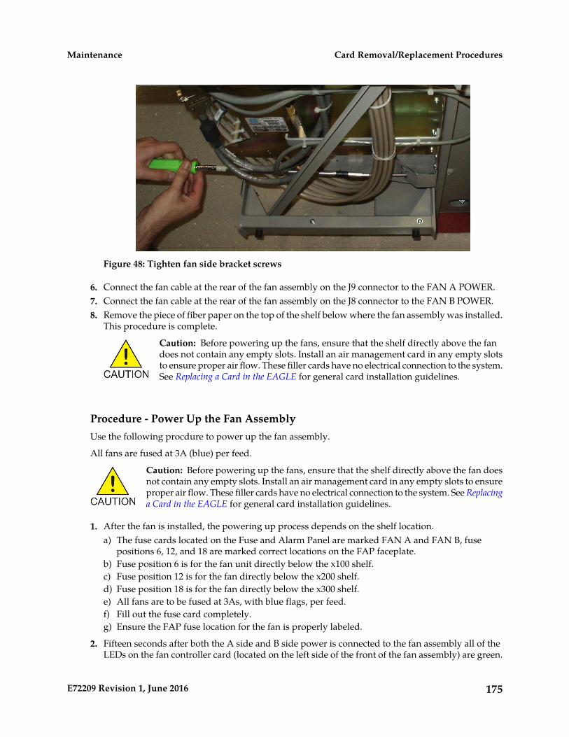
Figure 48: Tighten fan side bracket screws
6. Connect the fan cable at the rear of the fan assembly on the J9 connector to the FAN A POWER.7. Connect the fan cable at the rear of the fan assembly on the J8 connector to the FAN B POWER.8. Remove the piece of fiber paper on the top of the shelf below where the fan assembly was installed.
This procedure is complete.
Caution: Before powering up the fans, ensure that the shelf directly above the fandoes not contain any empty slots. Install an air management card in any empty slotsto ensure proper air flow. These filler cards have no electrical connection to the system.See Replacing a Card in the EAGLE for general card installation guidelines.
Procedure - Power Up the Fan AssemblyUse the following procdure to power up the fan assembly.
All fans are fused at 3A (blue) per feed.
Caution: Before powering up the fans, ensure that the shelf directly above the fan doesnot contain any empty slots. Install an air management card in any empty slots to ensureproper air flow. These filler cards have no electrical connection to the system. See Replacinga Card in the EAGLE for general card installation guidelines.
1. After the fan is installed, the powering up process depends on the shelf location.a) The fuse cards located on the Fuse and Alarm Panel are marked FAN A and FAN B, fuse
positions 6, 12, and 18 are marked correct locations on the FAP faceplate.b) Fuse position 6 is for the fan unit directly below the x100 shelf.c) Fuse position 12 is for the fan directly below the x200 shelf.d) Fuse position 18 is for the fan directly below the x300 shelf.e) All fans are to be fused at 3As, with blue flags, per feed.f) Fill out the fuse card completely.g) Ensure the FAP fuse location for the fan is properly labeled.
2. Fifteen seconds after both the A side and B side power is connected to the fan assembly all of theLEDs on the fan controller card (located on the left side of the front of the fan assembly) are green.
175E72209 Revision 1, June 2016
Card Removal/Replacement ProceduresMaintenance
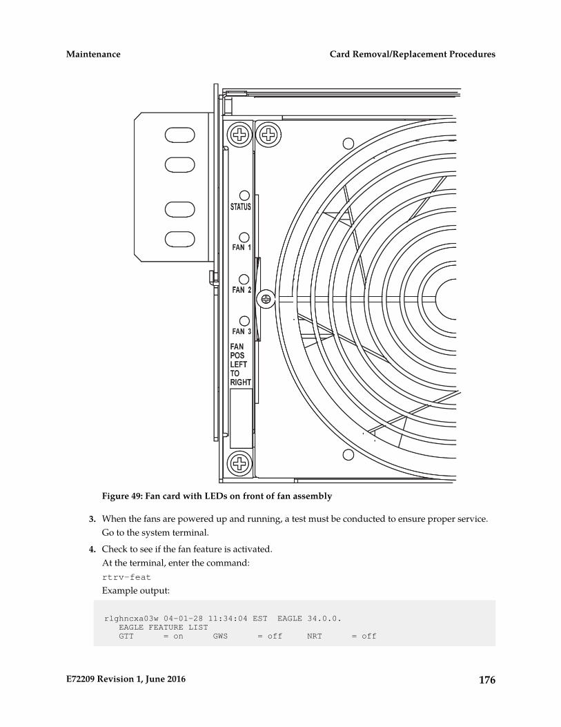
Figure 49: Fan card with LEDs on front of fan assembly
3. When the fans are powered up and running, a test must be conducted to ensure proper service.Go to the system terminal.
4. Check to see if the fan feature is activated.At the terminal, enter the command:rtrv-feat
Example output:
rlghncxa03w 04-01-28 11:34:04 EST EAGLE 34.0.0. EAGLE FEATURE LIST GTT = on GWS = off NRT = off
176E72209 Revision 1, June 2016
Card Removal/Replacement ProceduresMaintenance

X25G = off LAN = off CRMD = off SEAS = off LFS = off MTPRS = off FAN = off DSTN5000 = off WNP = off CNCF = off TLNP = off SCCPCNV = off TCAPCNV = off IPISUP = off DYNRTK = off X252000 = off INP = off PLNP = off NCR = off ITUMTPRS = off SLSOCB = off EGTT = off VGTT = off MGTT = off MPC = off ITUDUPPC = off GFLEX = off GPORT = off MEASPLAT = off TSCSYNC = off E5IS = off;
If the fan feature is off (illustrated in the example), go to Step 5. Otherwise, go to Step 6.
5. At the terminal, enter the command:chg-feat:fan=onWith this command the user will perform the tests beginning with Step 7.
6. At the terminal, enter the command: rept-stat-trblCheck to see that there are no fan errors. Specifically, check that there are no “#302 Cooling FanFailure” errors. Next, perform the tests beginning with Step 7.
7. Fan Verification (perform Step 7 through Step 12 for each fan assembly).Move to the rear of the frame and remove the A POWER cable from the FAN unit. Result: Fan 2and Fan 3 LEDs will blink as the fans speed up to maximum speed. This may take up to 15 seconds.Once maximum speed has been reached Fan 2 and Fan 3 LEDs on the Fan Controller card will besolid green. Fan 1 LED should be red. The controller LED should be blinking green. Fan 1 shouldstop running and the MINORLED should be lit.
8. At the system terminal enter the command:rept-stat-trblTest each fan to ensure that the alarm and the units are working correctly. The terminal reports:
# 302 Cooling Fan Failure
9. Replace the A POWER cable on the back of the FAN unit and secure the connector.Result: All fans are running and the MINORLED is not lit. The terminal reports:
# 303 Cooling Fans Normal
10. Remove the B POWER cable from the FAN unit.Result: Fan 1 and Fan 2 LEDs will blink as the fans speed up to maximum speed. This may takeup to 15 seconds. Once maximum speed has been reached Fan 1 and Fan 2 LEDs will be solid green.Fan 3 LEDshould be red. The fan controller LED should be blinking. Fan 3 should stop runningand the MINORLEDshould be lit.
11. At the system terminal enter the command: rept-stat-trblTest each fan to ensure that the alarm and the units are working correctly. The terminal reports:
# 302 Cooling Fan Failure
12. Replace the B POWER cable on the back of the FAN unit and secure the connector.
177E72209 Revision 1, June 2016
Card Removal/Replacement ProceduresMaintenance
Result: The fans are running and the MINORLED is not lit. The terminal reports:
# 303 Cooling Fans Normal
13. Repeat Step 7 through Step 12 for each fan unit installed.This procedure is complete.
178E72209 Revision 1, June 2016
Card Removal/Replacement ProceduresMaintenance

Appendix
BHoldover Clock Troubleshooting Procedures
Topics:
• Introduction.....180• Interpreting System Alarms, Lamps And Trouble
Isolation.....180
179E72209 Revision 1, June 2016

Introduction
Most alarm conditions in the holdover clock are not out-of service or service-affecting conditions. Thesystem is designed with redundant power, reference inputs, clock input cards, stratum clock cardsand output card protection switching.
The only true out-of-service condition is when all power is lost to a shelf, or all reference inputs andboth stratum clock cards fail. Before taking any action on the system, such as removing cards, firstconsider the following troubleshooting guidelines:
• Do not touch the shelf until you have analyzed the condition and know the possible result of anyplanned corrective actions.
• Do not touch the shelf until you have been properly grounded.
• Both major and minor alarms in the shelf require immediate attention. But, very few alarms in theholdover clock system are service affecting. Improper corrective actions could be service affecting.
• Do not remove an ST3 clock card from the shelf, unless you are certain it is the cause of the condition.This is especially true if the ST clock card(s) is (are) in the holdover mode (theHOLD OV/HOLDOVER lamp is lit, or the HOLD OV/HOLDOVER and INP TOL lamps are lit).Removing both ST clock cards in this condition causes total loss of all outputs from the shelf and/orsystem.
• Write down any alarm and normal lamp conditions in the shelf. These will help you to determinewhere to look for the cause of the condition.
Interpreting System Alarms, Lamps And Trouble Isolation
Alarms generated by the holdover clock are reported through the Eagle. All alarm conditions aredefined in Corrective Maintenance.
When troubleshooting, write down all abnormal and normal lamp conditions for the shelf with thealarm lamp lit on the SAI card. This will assist in analyzing and isolating the cause of the condition.Do not start removing or replacing cards to attempt to clear alarms, as it could lead to crashing EAGLE.
Tables to aid in troubleshooting are listed in the following sections. Once the basic trouble has beenisolated and it has been determined that an individual card is defective, perform the appropriate cardreplacement procedure in Card Removal/Replacement Procedures.
Table 30: Input and ST3 Alarm Conditions
CONDITION TYPE# (NOTE)
ACTIVATEDCLOCK STATUS AAND B
ACTIVATED OFFICEALARMS AND SHELFSTATUS
ABNORMALCARD LAMPSSAI/MISLAMPS
1NoneVisual = MAJOR andMINOR
ST3 A and B =FAIL, LOCK,and REF B lit
MAJOR andMINOR lit
180E72209 Revision 1, June 2016
Holdover Clock Troubleshooting ProceduresMaintenance

CONDITION TYPE# (NOTE)
ACTIVATEDCLOCK STATUS AAND B
ACTIVATED OFFICEALARMS AND SHELFSTATUS
ABNORMALCARD LAMPSSAI/MISLAMPS
Shelf Status = MAJSI,MINSI, and CLKL.(HOLDOVERALARMswitch SW3 onbackplane is set to MAJor MIN)
2NoneVisual = MAJOR andMINOR
Input cards Aand B = FAIL
MAJOR andMINOR lit
lit, Shelf Status = MAJSI,MINSI, and CLKL.frequency/bit
rate lamp off, (HOLDOVERALARMSRFL lit (ACIonly) switch SW3 on
backplane is set to MAJor MIN)ST3 A and B =
FAIL, LOCK,and REF B lit
3NoneVisual = MINORInput card A orB = FAIL lit,
MINOR lit
Shelf Status = MINSI,and CLKLfrequency/bit
rate lamp off or (HOLDOVERALARMlit, SRFL lit(ACI only) switch SW3 on
backplane is set to MAJor MIN)ST3 A and B =
REF (A or B)lamp lit(associatedwith input cardwith FAIL lampoff)
4NoneVisual = MINORST3 A and B =LOCK lit
MINOR lit
Shelf Status = MINSI(HOLDOVERALARMswitch SW3 onbackplane is set to MAJor MIN)
5NoneVisual = PeriodicMINOR
Input card Aand/or B =
MINORperiodically
FAILlights, then goesoff Shelf Status = Periodic
MINSI and CLKL (periodicallygoes on and off. HOLDOVERALARMFirst occurrence switch SW3 ononly the
181E72209 Revision 1, June 2016
Holdover Clock Troubleshooting ProceduresMaintenance
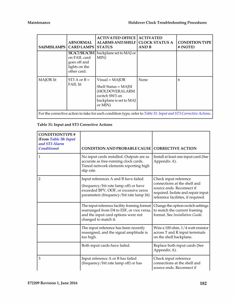
CONDITION TYPE# (NOTE)
ACTIVATEDCLOCK STATUS AAND B
ACTIVATED OFFICEALARMS AND SHELFSTATUS
ABNORMALCARD LAMPSSAI/MISLAMPSSRCACT/SRCACTIVEon FAIL card
backplane set to MAJ orMIN)
goes off andlights on theother card.
6NoneVisual = MAJORST3 A or B =FAIL lit
MAJOR lit
Shelf Status = MAJSI(HOLDOVERALARMswitch SW3 onbackplane is set to MAJor MIN)
For the corrective action to take for each condition type, refer to Table 31: Input and ST3 Corrective Actions.
Table 31: Input and ST3 Corrective Actions
CORRECTIVE ACTIONCONDITION AND PROBABLE CAUSE
CONDITIONTYPE #(From Table 30: Inputand ST3 AlarmConditions)
Install at least one input card.(SeeAppendix A).
No input cards installed. Outputs are asaccurate as free-running clock cards.Timed network elements reporting highslip rate.
1
Check input referenceconnections at the shelf and
Input references A and B have failed
(frequency/bit rate lamp off) or haveexceeded BPV, OOF, or excessive zerosparameters (frequency/bit rate lamp lit).
2
source ends. Reconnect ifrequired. Isolate and repair inputreference facilities, if required.
Change the option switch settingsto match the current framingformat. See Installation Guide.
The input reference facility framing formatrearranged from D4 to ESF, or vice versa,and the input card options were notchanged to match it.
Wire a 100 ohm, 1/4 watt resistoracross T and R input terminalson the shelf backplane.
The input reference has been recentlyreassigned, and the signal amplitude istoo high.
Replace both input cards (SeeAppendix A).
Both input cards have failed.
Check input referenceconnections at the shelf and
Input reference A or B has failed(frequency/bit rate lamp off) or has
3
source ends. Reconnect if
182E72209 Revision 1, June 2016
Holdover Clock Troubleshooting ProceduresMaintenance
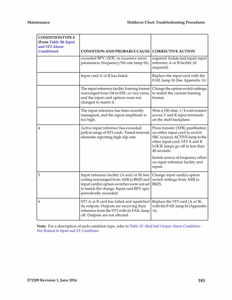
CORRECTIVE ACTIONCONDITION AND PROBABLE CAUSE
CONDITIONTYPE #(From Table 30: Inputand ST3 AlarmConditions)
required. Isolate and repair inputreference A or B facility (ifrequired).
exceeded BPV, OOF, or excessive zerosparameters (frequency/bit rate lamp lit).
Replace the input card with theFAIL lamp lit (See Appendix A).
Input card A or B has failed.
Change the option switch settingsto match the current framingformat.
The input reference facility framing formatrearranged from D4 to ESF, or vice versa,and the input card options were notchanged to match it.
Wire a 100 ohm, 1/4 watt resistoracross T and R input terminalson the shelf backplane.
The input reference has been recentlyreassigned, and the signal amplitude istoo high.
Press transfer (XFR) pushbuttonon either input card to switch
Active input reference has exceededpull-in range of ST3 cards. Timed networkelements reporting high slip rate.
4
SRC (source) ACTIVE lamp to theother input card. ST3 A and BLOCK lamps go off in less than40 seconds.
Isolate source of frequency offseton input reference facility andrepair.
Change input card(s) optionswitch settings from AMI toB8ZS.
Input reference facility (A and/or B) linecoding rearranged from AMI to B8ZS andinput card(s) option switches were not setto match the change. Input card BPV specperiodically exceeded.
5
Replace the ST3 card (A or B)with the FAIL lamp lit (AppendixA).
ST3 A or B card has failed and squelchedits outputs. Outputs are receiving theirreference from the ST3 with its FAIL lampoff. Outputs are not affected.
6
Note: For a description of each condition type, refer to Table 32: Shelf and Output Alarm Conditions -Not Related to Input and ST Conditions.
183E72209 Revision 1, June 2016
Holdover Clock Troubleshooting ProceduresMaintenance
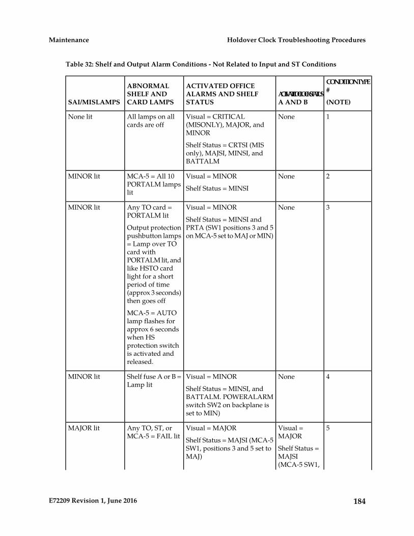
Table 32: Shelf and Output Alarm Conditions - Not Related to Input and ST Conditions
CONDITIONTYPE#
(NOTE)ACTIVATEDCLOCKSTATUSA AND B
ACTIVATED OFFICEALARMS AND SHELFSTATUS
ABNORMALSHELF ANDCARD LAMPSSAI/MISLAMPS
1NoneVisual = CRITICAL(MISONLY), MAJOR, andMINOR
All lamps on allcards are off
None lit
Shelf Status = CRTSI (MISonly), MAJSI, MINSI, andBATTALM
2NoneVisual = MINORMCA-5 = All 10PORTALM lampslit
MINOR lit
Shelf Status = MINSI
3NoneVisual = MINORAny TO card =PORTALM lit
MINOR lit
Shelf Status = MINSI andPRTA (SW1 positions 3 and 5on MCA-5 set to MAJ or MIN)
Output protectionpushbutton lamps= Lamp over TOcard withPORTALM lit, andlike HSTO cardlight for a shortperiod of time(approx 3 seconds)then goes off
MCA-5 = AUTOlamp flashes forapprox 6 secondswhen HSprotection switchis activated andreleased.
4NoneVisual = MINORShelf fuse A or B =Lamp lit
MINOR lit
Shelf Status = MINSI, andBATTALM. POWERALARMswitch SW2 on backplane isset to MIN)
5Visual =MAJOR
Visual = MAJOR
Shelf Status = MAJSI (MCA-5SW1, positions 3 and 5 set toMAJ)
Any TO, ST, orMCA-5 = FAIL lit
MAJOR lit
Shelf Status =MAJSI(MCA-5 SW1,
184E72209 Revision 1, June 2016
Holdover Clock Troubleshooting ProceduresMaintenance
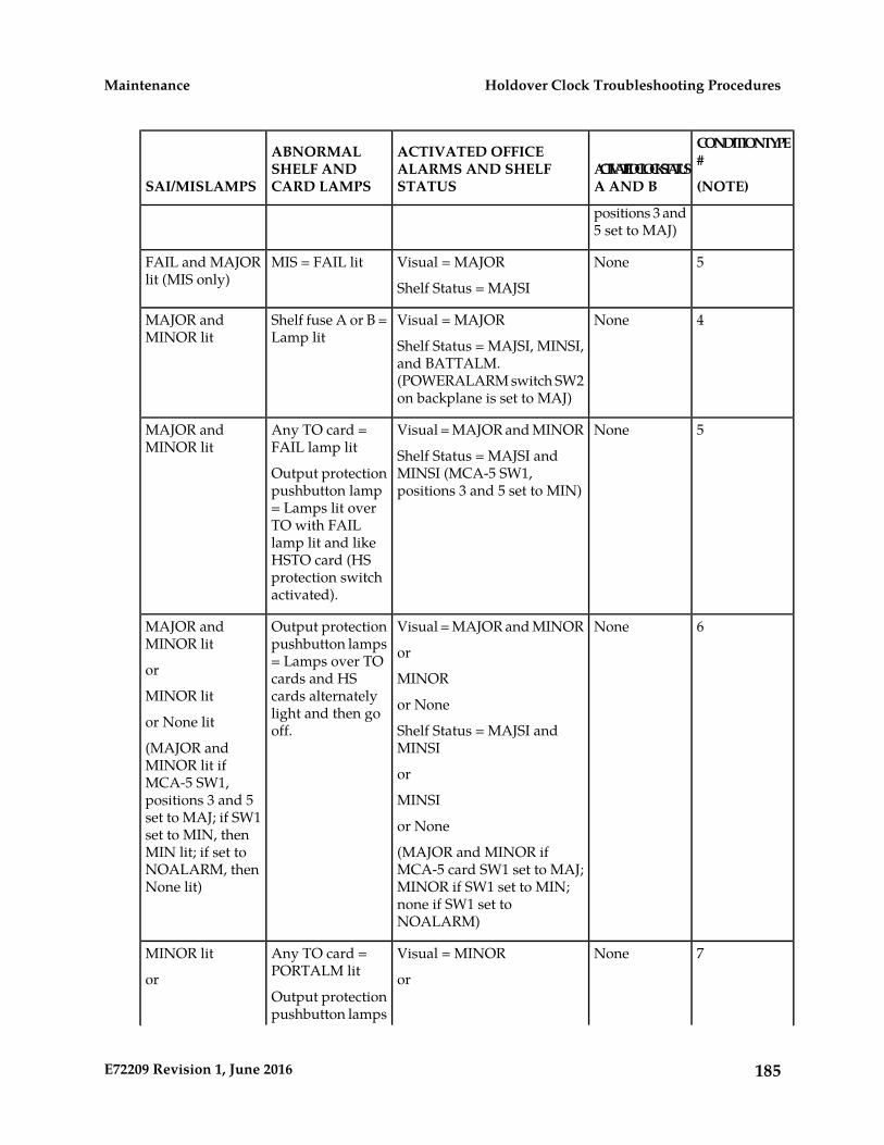
CONDITIONTYPE#
(NOTE)ACTIVATEDCLOCKSTATUSA AND B
ACTIVATED OFFICEALARMS AND SHELFSTATUS
ABNORMALSHELF ANDCARD LAMPSSAI/MISLAMPS
positions 3 and5 set to MAJ)
5NoneVisual = MAJORMIS = FAIL litFAIL and MAJORlit (MIS only) Shelf Status = MAJSI
4NoneVisual = MAJORShelf fuse A or B =Lamp lit
MAJOR andMINOR lit Shelf Status = MAJSI, MINSI,
and BATTALM.(POWERALARM switch SW2on backplane is set to MAJ)
5NoneVisual = MAJOR and MINORAny TO card =FAIL lamp lit
MAJOR andMINOR lit Shelf Status = MAJSI and
MINSI (MCA-5 SW1,positions 3 and 5 set to MIN)
Output protectionpushbutton lamp= Lamps lit overTO with FAILlamp lit and likeHSTO card (HSprotection switchactivated).
6NoneVisual = MAJOR and MINOROutput protectionpushbutton lamps
MAJOR andMINOR lit or= Lamps over TOor MINORcards and HS
cards alternatelyMINOR lit or Nonelight and then gooff.or None lit
(MAJOR andMINOR lit if
Shelf Status = MAJSI andMINSI
orMCA-5 SW1,positions 3 and 5 MINSIset to MAJ; if SW1 or Noneset to MIN, thenMIN lit; if set to (MAJOR and MINOR if
MCA-5 card SW1 set to MAJ;NOALARM, thenNone lit) MINOR if SW1 set to MIN;
none if SW1 set toNOALARM)
7NoneVisual = MINORAny TO card =PORTALM lit
MINOR lit
or orOutput protectionpushbutton lamps
185E72209 Revision 1, June 2016
Holdover Clock Troubleshooting ProceduresMaintenance
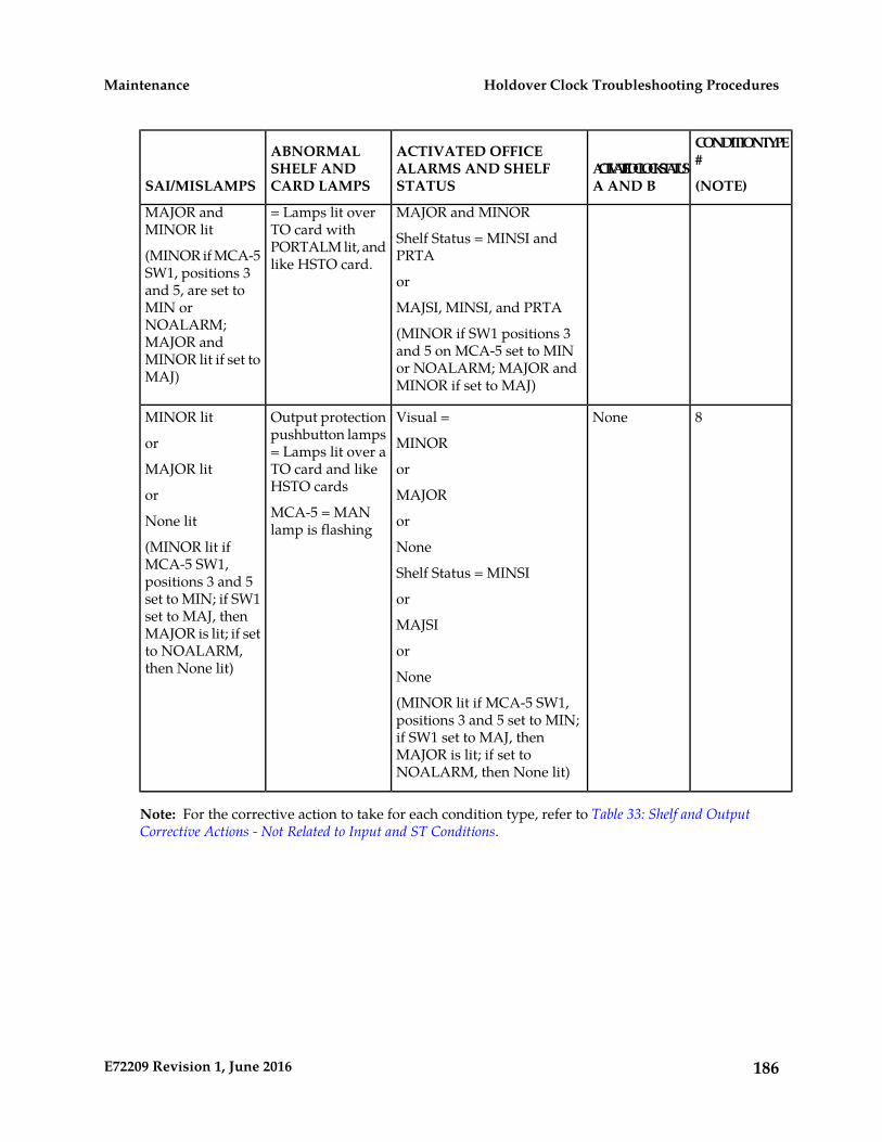
CONDITIONTYPE#
(NOTE)ACTIVATEDCLOCKSTATUSA AND B
ACTIVATED OFFICEALARMS AND SHELFSTATUS
ABNORMALSHELF ANDCARD LAMPSSAI/MISLAMPS
MAJOR andMINOR lit
MAJOR and MINOR
Shelf Status = MINSI andPRTA
= Lamps lit overTO card withPORTALM lit, andlike HSTO card.(MINOR if MCA-5
SW1, positions 3 orand 5, are set toMIN or MAJSI, MINSI, and PRTANOALARM; (MINOR if SW1 positions 3
and 5 on MCA-5 set to MINMAJOR andMINOR lit if set toMAJ) or NOALARM; MAJOR and
MINOR if set to MAJ)
8NoneVisual =Output protectionpushbutton lamps
MINOR lit
or MINOR= Lamps lit over aTO card and likeHSTO cards
MAJOR lit
or
or
MAJORMCA-5 = MANlamp is flashingNone lit
(MINOR lit ifMCA-5 SW1,
or
None
Shelf Status = MINSIpositions 3 and 5set to MIN; if SW1 orset to MAJ, then MAJSIMAJOR is lit; if setto NOALARM,then None lit)
or
None
(MINOR lit if MCA-5 SW1,positions 3 and 5 set to MIN;if SW1 set to MAJ, thenMAJOR is lit; if set toNOALARM, then None lit)
Note: For the corrective action to take for each condition type, refer to Table 33: Shelf and OutputCorrective Actions - Not Related to Input and ST Conditions.
186E72209 Revision 1, June 2016
Holdover Clock Troubleshooting ProceduresMaintenance
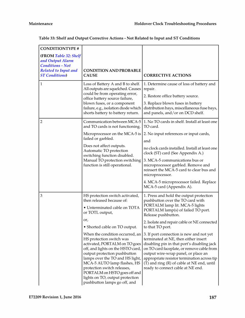
Table 33: Shelf and Output Corrective Actions - Not Related to Input and ST Conditions
CORRECTIVE ACTIONSCONDITION AND PROBABLECAUSE
CONDITIONTYPE #
(FROM Table 32: Shelfand Output AlarmConditions - NotRelated to Input andST Conditions)
1. Determine cause of loss of battery andrepair.
Loss of Battery A and B to shelf.All outputs are squelched. Causes
1
could be from operating error, 2. Restore office battery source.office battery source failure,blown fuses, or a component 3. Replace blown fuses in battery
distribution bays, miscellaneous fuse bays,and panels, and/or on DCD shelf.
failure, e.g., isolation diode whichshorts battery to battery return.
1. No TO cards in shelf. Install at least oneTO card.
Communication between MCA-5and TO cards is not functioning.
2
2. No input references or input cards,Microprocessor on the MCA-5 isfailed or garbled. andDoes not affect outputs.Automatic TO protection no clock cards installed. Install at least one
clock (ST) card (See Appendix A.)switching function disabled.Manual TO protection switchingfunction is still operational.
3. MCA-5 communications bus ormicroprocessor garbled. Remove andreinsert the MCA-5 card to clear bus andmicroprocessor.
4. MCA-5 microprocessor failed. ReplaceMCA-5 card (Appendix A).
1. Press and hold the output protectionpushbutton over the TO card with
HS protection switch activated,then released because of:
3
PORTALM lamp lit. MCA-5 lights• Unterminated cable on TOTAor TOTL output, PORTALM lamp(s) of failed TO port.
Release pushbutton.or, 2. Isolate and repair cable or NE connected
to that TO port.• Shorted cable on TO output.
3. If port connection is new and not yetterminated at NE, then either insert
When the condition occurred, anHS protection switch was
disabling pin in that port’s disabling jackactivated, PORTALM on TO goeson TO card faceplate, or remove cable fromoff, and lights on the HSTO card,output wire-wrap panel, or place anoutput protection pushbuttonappropriate resistor termination across tiplamps over the TO and HS light,(T) and ring (R) of cable at NE end, untilready to connect cable at NE end.
MCA-5 AUTO lamp flashes, HSprotection switch releases,PORTALM on HSTO goes off andlights on TO, output protectionpushbutton lamps go off, and
187E72209 Revision 1, June 2016
Holdover Clock Troubleshooting ProceduresMaintenance
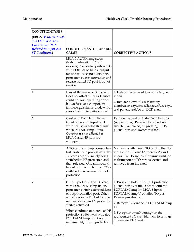
CORRECTIVE ACTIONSCONDITION AND PROBABLECAUSE
CONDITIONTYPE #
(FROM Table 32: Shelfand Output AlarmConditions - NotRelated to Input andST Conditions)
MCA-5 AUTO lamp stopsflashing (duration = 3 to 6seconds). Non-failed ports on TOwith PORTALM lit lost outputfor one millisecond during HSprotection switch activation andrelease. Failed TO port is out ofservice.
1. Determine cause of loss of battery andrepair.
Loss of Battery A or B to shelf.Does not affect outputs. Causes
4
could be from operating error, 2. Replace blown fuses in batterydistribution bays, miscellaneous fuse bays,and panels, and/or on DCD shelf.
blown fuse, or a componentfailure, e.g., isolation diode whichshorts battery to battery return.
Replace the card with the FAIL lamp lit(Appendix A). Release HS protection
Card with FAIL lamp lit hasfailed, except for input card
5
switch, if activated, by pressing lit HSpushbutton until switch releases.
which causes a MINOR alarmwhen its FAIL lamp lights.Outputs are not affected ifMCA-5 and HS slots areequipped.
Manually switch each TO card to the HS,replace the TO card (Appendix A) and
A TO card’s microprocessor haslost its ability to process data. The
6
release the HS switch. Continue until theTO cards are alternately beingmalfunctioning TO card is located andremoved from the shelf.
switched to HS protection andthen released. One millisecondloss of outputs each time a TO isswitched to or released from HSprotection.
1. Press and hold the output protectionpushbutton over the TO card with the
Output port failed on TO cardwith PORTALM lamp lit. HS
7
PORTALM lamp lit. MCA-5 lightsprotection switch activated. LossPORTALM lamp(s) of failed TO port.Release pushbutton.
of output on failed port. Otheroutput on same TO lost for onemillisecond when HS protectionswitch activated. 2. Remove TO card with PORTALM lamp
lit.When condition occurred, an HSprotection switch was activated, 3. Set option switch settings on the
replacement TO card identical to settingson removed TO card.PORTALM lamp on TO card
remained lit, output protection
188E72209 Revision 1, June 2016
Holdover Clock Troubleshooting ProceduresMaintenance

CORRECTIVE ACTIONSCONDITION AND PROBABLECAUSE
CONDITIONTYPE #
(FROM Table 32: Shelfand Output AlarmConditions - NotRelated to Input andST Conditions)
pushbutton lamps over TO andHS slots lit, and MCA-5 card’s
4. Insert replacement TO card in shelf slotand wait 10 seconds for TO to warm-up.
AUTO lamp flashes for 6 secondsand then lights steady.
Verify ST, INPUT and OPTION lamps arelit and PORTALM and/or FAIL lamps arenot lit.
5. Press output protection pushbutton overHSTO until pushbutton lamps go out(releases HS switch). MCA-5 card’s AUTOlamp flashes for 6 seconds and then lightssteady.
Release the manual HS switch by pressingthe lit pushbutton over the HSTO card for3 seconds.
TO card manually switched toHSTO card
8
Note: For a description of each condition type, refer to Table 32: Shelf and Output Alarm Conditions -Not Related to Input and ST Conditions.
189E72209 Revision 1, June 2016
Holdover Clock Troubleshooting ProceduresMaintenance

Appendix
CPart Numbers
Topics:
• Overview.....191• Cables, Adapters.....191• Components.....196• Frames, Backplanes, FAPs, and Fans.....198• Labels.....200• Miscellaneous Parts.....201• Power Cords for Peripherals.....203
190E72209 Revision 1, June 2016

Overview
This chapter lists the part numbers of Oracle equipment, components, cables, and miscellaneous partsdescribed in this manual.
Each table provides the item name, part number, and related notes. Items are listed by their name (asdescribed in this manual) in alphabetical order. Shaded part numbers indicate that the item is obsoleteor no longer shipped. Unless the item is indicated as obsolete, the item is still supported in the field.
Note: Oracle reserves the right to ship compatible part numbers or revisions for new installations andreplacements. Always check the latest Hardware Baseline for your release. The latest hardware baselinecan be found in the Feature Notice of your release.
RoHS 5/6 - As of July 1, 2006, all products that comprise new installations shipped to European Unionmember countries will comply with the EU Directive 2002/95/EC "RoHS" (Restriction of HazardousSubstances). The exemption for lead-based solder described in the Annex will be exercised. RoHS 5/6compliant components will have unique part numbers and are identified as the International partnumber in this manual.
Note: International part numbers will eventually replace North American part numbers to make allpart numbers RoHS compliant. The items of either part number are of equivalent function or qualityotherwise.
WEEE - All products shipped to European Union member countries comply with the EUDirective 2002/96/EC, Waste Electronic and Electrical Equipment. All components that are WEEEcompliant will be appropriately marked. For more information regarding Oracle's WEEE program,contact your sales representative.
Cables, Adapters
Table 34: EAGLE 5 Cables, Connectors, and Power Cords
Note
Part Numbers
Name InternationalNorth America
---830-0425-01Adapter, 15-Pin to 26-Pin
backplanes -03 and-04 for master timing
830-1183-01830-0846-01Adapter cables
and HS clock cable830-0873-xx
Holdover Clock---830-0543-01Alarm cable
191E72209 Revision 1, June 2016
Part NumbersMaintenance
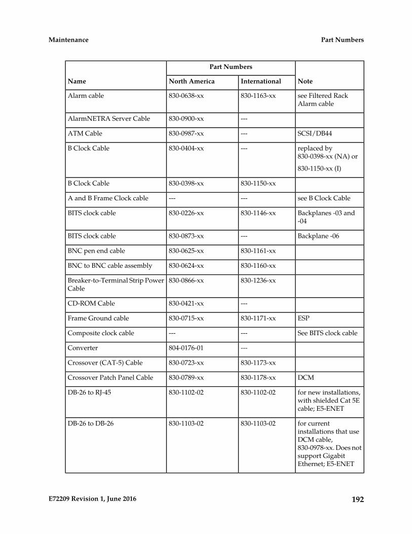
Note
Part Numbers
Name InternationalNorth America
see Filtered RackAlarm cable
830-1163-xx830-0638-xxAlarm cable
---830-0900-xxAlarmNETRA Server Cable
SCSI/DB44---830-0987-xxATM Cable
replaced by830-0398-xx (NA) or
---830-0404-xxB Clock Cable
830-1150-xx (I)
830-1150-xx830-0398-xxB Clock Cable
see B Clock Cable------A and B Frame Clock cable
Backplanes -03 and-04
830-1146-xx830-0226-xxBITS clock cable
Backplane -06---830-0873-xxBITS clock cable
830-1161-xx830-0625-xxBNC pen end cable
830-1160-xx830-0624-xxBNC to BNC cable assembly
830-1236-xx830-0866-xxBreaker-to-Terminal Strip PowerCable
---830-0421-xxCD-ROM Cable
ESP830-1171-xx830-0715-xxFrame Ground cable
See BITS clock cable------Composite clock cable
---804-0176-01Converter
830-1173-xx830-0723-xxCrossover (CAT-5) Cable
DCM830-1178-xx830-0789-xxCrossover Patch Panel Cable
for new installations,with shielded Cat 5Ecable; E5-ENET
830-1102-02830-1102-02DB-26 to RJ-45
for currentinstallations that use
830-1103-02830-1103-02DB-26 to DB-26
DCM cable,830-0978-xx. Does notsupport GigabitEthernet; E5-ENET
192E72209 Revision 1, June 2016
Part NumbersMaintenance
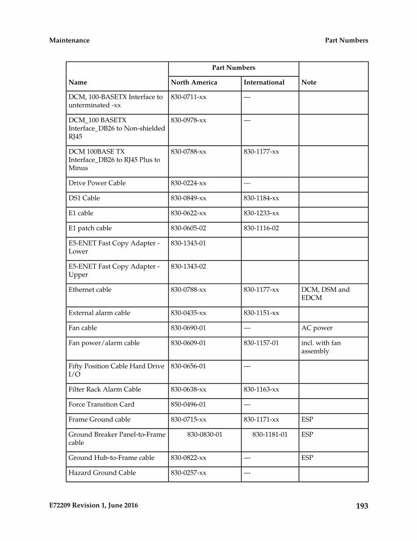
Note
Part Numbers
Name InternationalNorth America
---830-0711-xxDCM, 100-BASETX Interface tounterminated -xx
---830-0978-xxDCM_100 BASETXInterface_DB26 to Non-shieldedRJ45
830-1177-xx830-0788-xxDCM 100BASE TXInterface_DB26 to RJ45 Plus toMinus
---830-0224-xxDrive Power Cable
830-1184-xx830-0849-xxDS1 Cable
830-1233-xx830-0622-xxE1 cable
830-1116-02830-0605-02E1 patch cable
830-1343-01E5-ENET Fast Copy Adapter -Lower
830-1343-02E5-ENET Fast Copy Adapter -Upper
DCM, DSM andEDCM
830-1177-xx830-0788-xxEthernet cable
830-1151-xx830-0435-xxExternal alarm cable
AC power---830-0690-01Fan cable
incl. with fanassembly
830-1157-01830-0609-01Fan power/alarm cable
---830-0656-01Fifty Position Cable Hard DriveI/O
830-1163-xx830-0638-xxFilter Rack Alarm Cable
---850-0496-01Force Transition Card
ESP830-1171-xx830-0715-xxFrame Ground cable
ESP830-1181-01830-0830-01Ground Breaker Panel-to-Framecable
ESP---830-0822-xxGround Hub-to-Frame cable
---830-0257-xxHazard Ground Cable
193E72209 Revision 1, June 2016
Part NumbersMaintenance
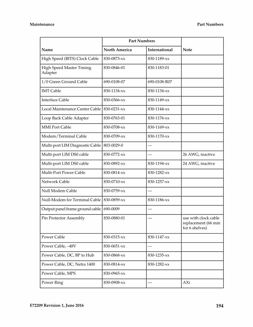
Note
Part Numbers
Name InternationalNorth America
830-1189-xx830-0873-xxHigh Speed (BITS) Clock Cable
830-1183-01830-0846-01High Speed Master TimingAdapter
690-0108-R07690-0108-071/0 Green Ground Cable
830-1134-xx830-1134-xxIMT Cable
830-1149-xx830-0366-xxInterface Cable
830-1144-xx830-0231-xxLocal Maintenance Center Cable
830-1176-xx830-0763-01Loop Back Cable Adapter
830-1169-xx830-0708-xxMMI Port Cable
830-1170-xx830-0709-xxModem/Terminal Cable
---803-0029-0Multi-port LIM Diagnostic Cable
26 AWG, inactive---830-0772-xxMulti-port LIM DS0 cable
24 AWG, inactive830-1194-xx830-0892-xxMulti-port LIM DS0 cable
830-1282-xx830-0814-xxMulti-Port Power Cable
830-1257-xx830-0710-xxNetwork Cable
---830-0759-xxNull Modem Cable
830-1186-xx830-0859-xxNull-Modem for Terminal Cable
---690-0009Output panel frame ground cable
use with clock cablereplacement (66 minfor 6 shelves)
---830-0880-01Pin Protector Assembly
830-1147-xx830-0315-xxPower Cable
---830-0651-xxPower Cable, –48V
830-1235-xx830-0868-xxPower Cable, DC, BP to Hub
830-1282-xx830-0814-xxPower Cable, DC, Netra 1400
830-0965-xxPower Cable, MPS
AXi---830-0908-xxPower Ring
194E72209 Revision 1, June 2016
Part NumbersMaintenance

Note
Part Numbers
Name InternationalNorth America
see Filtered RackAlarm cable
------Rack Alarm Cable
DC---830-0872-xxRAID Power Cable
830-1146-xx830-0233-xxRemote Maintenance CenterCable
---830-0888-xxRJ45/RJ45 Cable (CAT-5)(Yellow)
830-1192-xx830-0889-xxRJ45/RJ45 Cable (CAT-5) (Blue)
---830-0917-01RJ45 to 9 Pin Adapter
830-1145-xx830-0232-xxRow Alarm Cable
DC830-1188-xx830-0869-xxRouter Power Cable
830-1152-xx830-0527-xxRS232 Cable
SCSI/DB44---830-0987-xxATM Cable
---850-0514-01Serial I/O Transition Card
inactive---830-0531-01Serial Interface Converter Cable
use with 830-0394-xx830-1153-03830-0531-03Serial Interface/Modem Adapter
use with 830-0535-xx830-1153-04830-0531-04Serial Interface/Modem Adapter
36-inch T1x00 AS830-1231-01830-0972-01Serial DB44 to DB9 (X4) cable
use with 830-0394-xx830-1153-02830-0531-02Serial Interface, Terminal, PrinterAdapter
RJ-45 CAT-5E---830-0724-xxStraight Through Cable (CAT-5)
see DCM 100BASE TXInterface_DB26 toRJ45 Plus to Minus
------Straight Through Cable (PatchPanel)
---830-0884-01Switch-to-Frame Ground Cable
---830-0528-01Terminal/Converter Cable
830-1154-xx830-0535-xxTerminal/Printer Cable
DB9F/DB15M Serialw/Flow Control
830-1201-xx---Terminal/Server Serial Cable
195E72209 Revision 1, June 2016
Part NumbersMaintenance
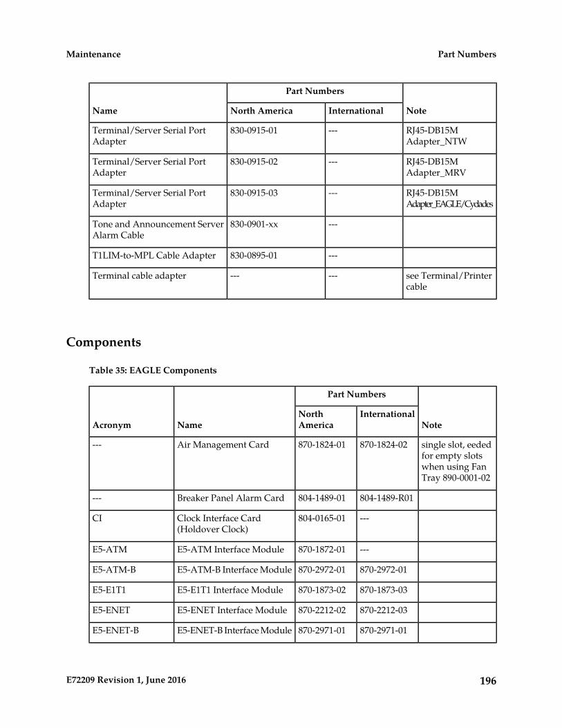
Note
Part Numbers
Name InternationalNorth America
RJ45-DB15MAdapter_NTW
---830-0915-01Terminal/Server Serial PortAdapter
RJ45-DB15MAdapter_MRV
---830-0915-02Terminal/Server Serial PortAdapter
RJ45-DB15MAdapter_EAGLE/Cyclades
---830-0915-03Terminal/Server Serial PortAdapter
---830-0901-xxTone and Announcement ServerAlarm Cable
---830-0895-01T1LIM-to-MPL Cable Adapter
see Terminal/Printercable
------Terminal cable adapter
Components
Table 35: EAGLE Components
Note
Part Numbers
NameAcronymInternationalNorth
America
single slot, eededfor empty slots
870-1824-02870-1824-01Air Management Card---
when using FanTray 890-0001-02
804-1489-R01804-1489-01Breaker Panel Alarm Card---
---804-0165-01Clock Interface Card(Holdover Clock)
CI
---870-1872-01E5-ATM Interface ModuleE5-ATM
870-2972-01870-2972-01E5-ATM-B Interface ModuleE5-ATM-B
870-1873-03870-1873-02E5-E1T1 Interface ModuleE5-E1T1
870-2212-03870-2212-02E5-ENET Interface ModuleE5-ENET
870-2971-01870-2971-01E5-ENET-B Interface ModuleE5-ENET-B
196E72209 Revision 1, June 2016
Part NumbersMaintenance

Note
Part Numbers
NameAcronymInternationalNorth
America
---870-2877-01IPSM ModuleE5-IPSM
870-2903-01E5 MaintenanceAdministration SubsystemProcessor Card
E5-MASP
870-3089-01870-3089-01E5-MCPM-B MeasurementsCollection and PollingModule
E5-MCPM-B
870-2900-01E5 Maintenance Disk andAlarm Card
E5-MDAL
---870-2860-02E5-SM4G DSM ModuleE5-SM4G
870-2990-01870-2990-01E5-SM8G-B DSM ModuleE5-SM8G-B
Replaces TSM-256as of 40.0
---870-2943-03E5-TSM (Translation ServiceModule running GLS)
E5-TSM
double-slot---870-2197-01Enhanced DatabaseCommunications Module
EDCM
Pre-IP7 SG 4.0
Replaces IPMX870-2574-02870-2671-01High Capacity Multi-channelInterface Module
HC MIM
Replaces IPMX,HMUX, HIPR
870-2872-01870-2872-01High-Speed IMT PacketRouter 2 Module
HIPR2
replaced byHMUX
---870-1171-01Interprocessor MessageTransport Power andMultiplexer
IPMX
---000-0028-xxMatrix Controller Automatic(Holdover Clock)
MCA
Replaced byGPSM-II as of 30.0
---870-1013-xx
870-1307-xx
Maintenance AdministrationSubsystem (MAS)CommunicationsApplications Processor
MCAP
---804-0175-xxMaintenance InterfaceSystem Card (HoldoverClock)
MIS
OEM OpenSystem
---
---
890-1287-xx
890-1374-xx
Multi-purpose ServerMPS
197E72209 Revision 1, June 2016
Part NumbersMaintenance
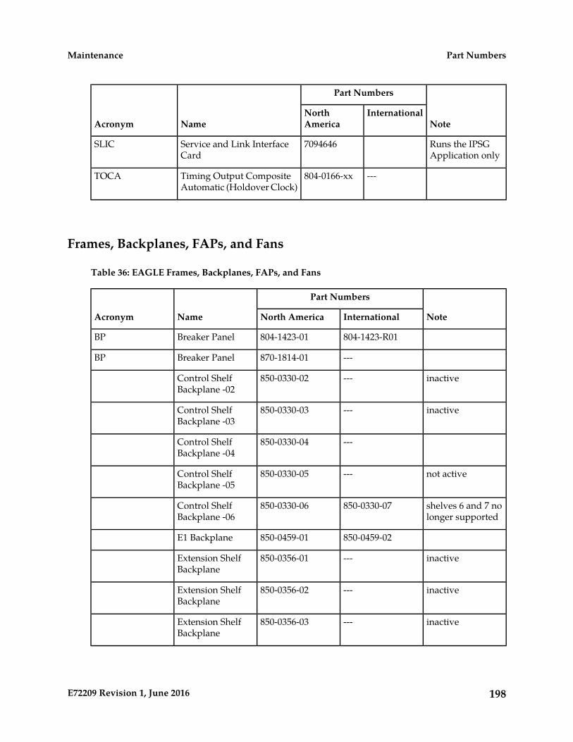
Note
Part Numbers
NameAcronymInternationalNorth
America
Runs the IPSGApplication only
7094646Service and Link InterfaceCard
SLIC
---804-0166-xxTiming Output CompositeAutomatic (Holdover Clock)
TOCA
Frames, Backplanes, FAPs, and Fans
Table 36: EAGLE Frames, Backplanes, FAPs, and Fans
Note
Part Numbers
NameAcronym InternationalNorth America
804-1423-R01804-1423-01Breaker PanelBP
---870-1814-01Breaker PanelBP
inactive---850-0330-02Control ShelfBackplane -02
inactive---850-0330-03Control ShelfBackplane -03
---850-0330-04Control ShelfBackplane -04
not active---850-0330-05Control ShelfBackplane -05
shelves 6 and 7 nolonger supported
850-0330-07850-0330-06Control ShelfBackplane -06
850-0459-02850-0459-01E1 Backplane
inactive---850-0356-01Extension ShelfBackplane
inactive---850-0356-02Extension ShelfBackplane
inactive---850-0356-03Extension ShelfBackplane
198E72209 Revision 1, June 2016
Part NumbersMaintenance
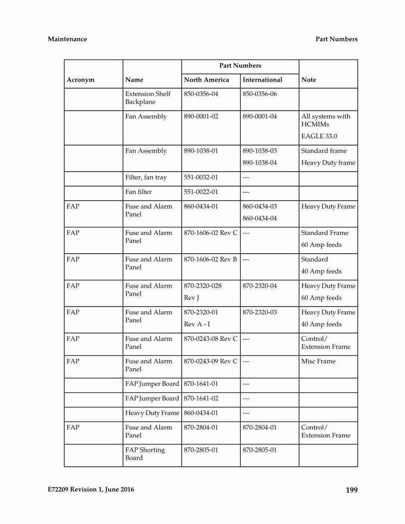
Note
Part Numbers
NameAcronym InternationalNorth America
850-0356-06850-0356-04Extension ShelfBackplane
All systems withHCMIMs
890-0001-04890-0001-02Fan Assembly
EAGLE 33.0
Standard frame890-1038-03890-1038-01Fan Assembly
Heavy Duty frame890-1038-04
---551-0032-01Filter, fan tray
---551-0022-01Fan filter
Heavy Duty Frame860-0434-03860-0434-01Fuse and AlarmPanel
FAP
860-0434-04
Standard Frame---870-1606-02 Rev CFuse and AlarmPanel
FAP
60 Amp feeds
Standard---870-1606-02 Rev BFuse and AlarmPanel
FAP
40 Amp feeds
Heavy Duty Frame870-2320-04870-2320-028Fuse and AlarmPanel
FAP
60 Amp feedsRev J
Heavy Duty Frame870-2320-03870-2320-01Fuse and AlarmPanel
FAP
40 Amp feedsRev A - I
Control/Extension Frame
---870-0243-08 Rev CFuse and AlarmPanel
FAP
Misc Frame---870-0243-09 Rev CFuse and AlarmPanel
FAP
---870-1641-01FAP Jumper Board
---870-1641-02FAP Jumper Board
---860-0434-01Heavy Duty Frame
Control/Extension Frame
870-2804-01870-2804-01Fuse and AlarmPanel
FAP
870-2805-01870-2805-01FAP ShortingBoard
199E72209 Revision 1, June 2016
Part NumbersMaintenance
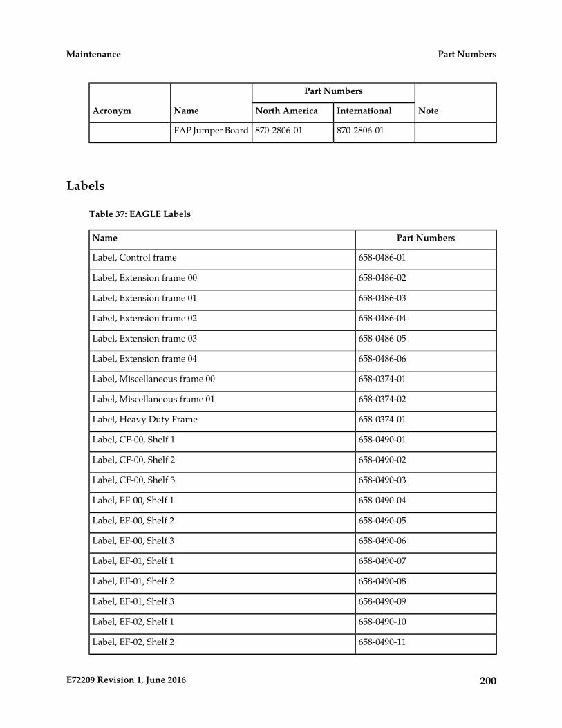
Note
Part Numbers
NameAcronym InternationalNorth America
870-2806-01870-2806-01FAP Jumper Board
Labels
Table 37: EAGLE Labels
Part NumbersName
658-0486-01Label, Control frame
658-0486-02Label, Extension frame 00
658-0486-03Label, Extension frame 01
658-0486-04Label, Extension frame 02
658-0486-05Label, Extension frame 03
658-0486-06Label, Extension frame 04
658-0374-01Label, Miscellaneous frame 00
658-0374-02Label, Miscellaneous frame 01
658-0374-01Label, Heavy Duty Frame
658-0490-01Label, CF-00, Shelf 1
658-0490-02Label, CF-00, Shelf 2
658-0490-03Label, CF-00, Shelf 3
658-0490-04Label, EF-00, Shelf 1
658-0490-05Label, EF-00, Shelf 2
658-0490-06Label, EF-00, Shelf 3
658-0490-07Label, EF-01, Shelf 1
658-0490-08Label, EF-01, Shelf 2
658-0490-09Label, EF-01, Shelf 3
658-0490-10Label, EF-02, Shelf 1
658-0490-11Label, EF-02, Shelf 2
200E72209 Revision 1, June 2016
Part NumbersMaintenance
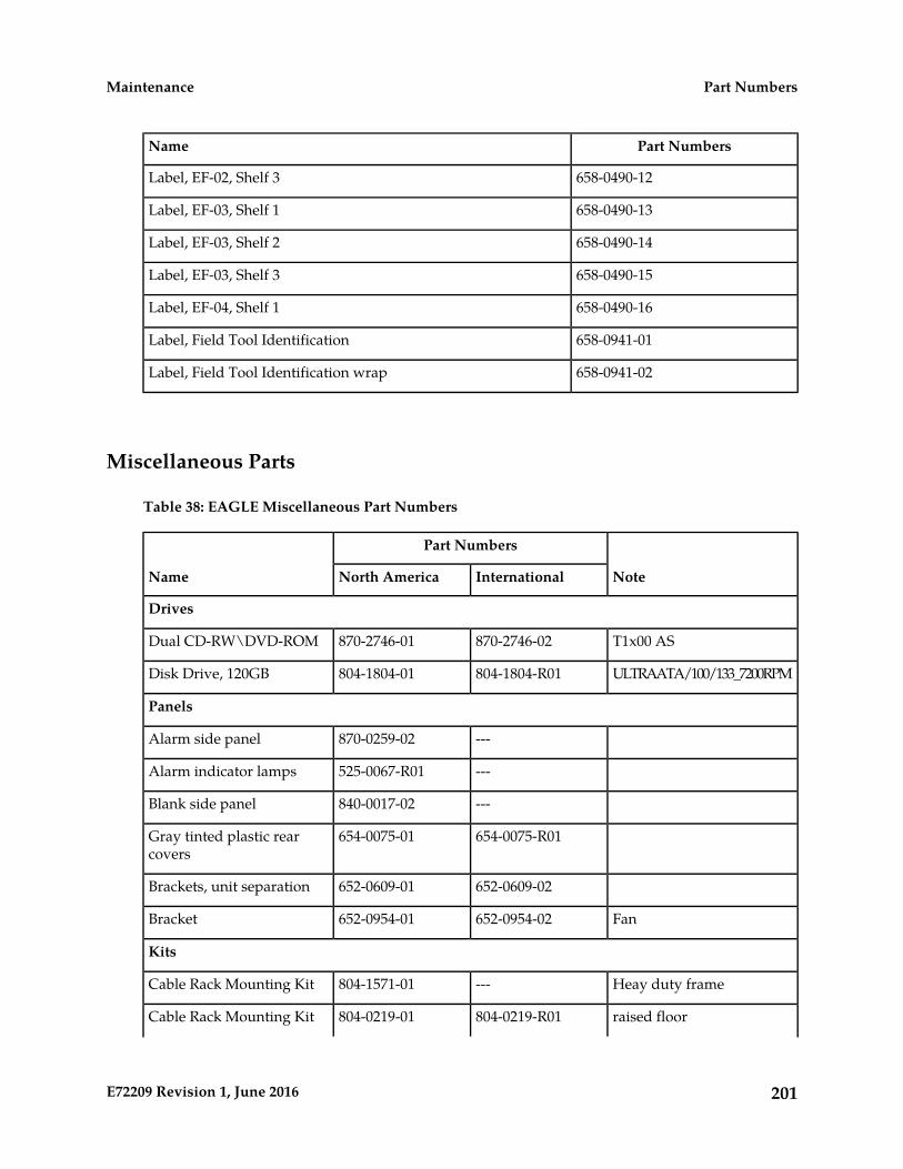
Part NumbersName
658-0490-12Label, EF-02, Shelf 3
658-0490-13Label, EF-03, Shelf 1
658-0490-14Label, EF-03, Shelf 2
658-0490-15Label, EF-03, Shelf 3
658-0490-16Label, EF-04, Shelf 1
658-0941-01Label, Field Tool Identification
658-0941-02Label, Field Tool Identification wrap
Miscellaneous Parts
Table 38: EAGLE Miscellaneous Part Numbers
Note
Part Numbers
Name InternationalNorth America
Drives
T1x00 AS870-2746-02870-2746-01Dual CD-RW\DVD-ROM
ULTRAATA/100/133_7200RPM804-1804-R01804-1804-01Disk Drive, 120GB
Panels
---870-0259-02Alarm side panel
---525-0067-R01Alarm indicator lamps
---840-0017-02Blank side panel
654-0075-R01654-0075-01Gray tinted plastic rearcovers
652-0609-02652-0609-01Brackets, unit separation
Fan652-0954-02652-0954-01Bracket
Kits
Heay duty frame---804-1571-01Cable Rack Mounting Kit
raised floor804-0219-R01804-0219-01Cable Rack Mounting Kit
201E72209 Revision 1, June 2016
Part NumbersMaintenance
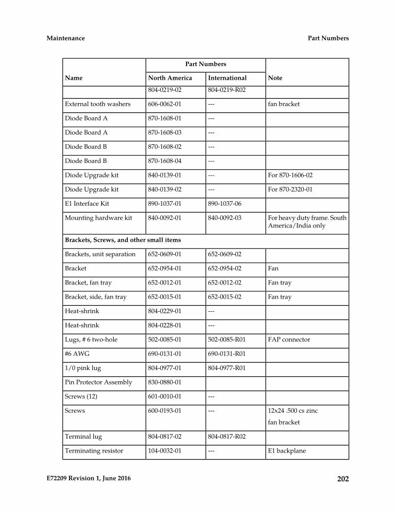
Note
Part Numbers
Name InternationalNorth America
804-0219-R02804-0219-02
fan bracket---606-0062-01External tooth washers
---870-1608-01Diode Board A
---870-1608-03Diode Board A
---870-1608-02Diode Board B
---870-1608-04Diode Board B
For 870-1606-02---840-0139-01Diode Upgrade kit
For 870-2320-01---840-0139-02Diode Upgrade kit
890-1037-06890-1037-01E1 Interface Kit
For heavy duty frame. SouthAmerica/India only
840-0092-03840-0092-01Mounting hardware kit
Brackets, Screws, and other small items
652-0609-02652-0609-01Brackets, unit separation
Fan652-0954-02652-0954-01Bracket
Fan tray652-0012-02652-0012-01Bracket, fan tray
Fan tray652-0015-02652-0015-01Bracket, side, fan tray
---804-0229-01Heat-shrink
---804-0228-01Heat-shrink
FAP connector502-0085-R01502-0085-01Lugs, # 6 two-hole
690-0131-R01690-0131-01#6 AWG
804-0977-R01804-0977-011/0 pink lug
830-0880-01Pin Protector Assembly
---601-0010-01Screws (12)
12x24 .500 cs zinc---600-0193-01Screws
fan bracket
804-0817-R02804-0817-02Terminal lug
E1 backplane---104-0032-01Terminating resistor
202E72209 Revision 1, June 2016
Part NumbersMaintenance
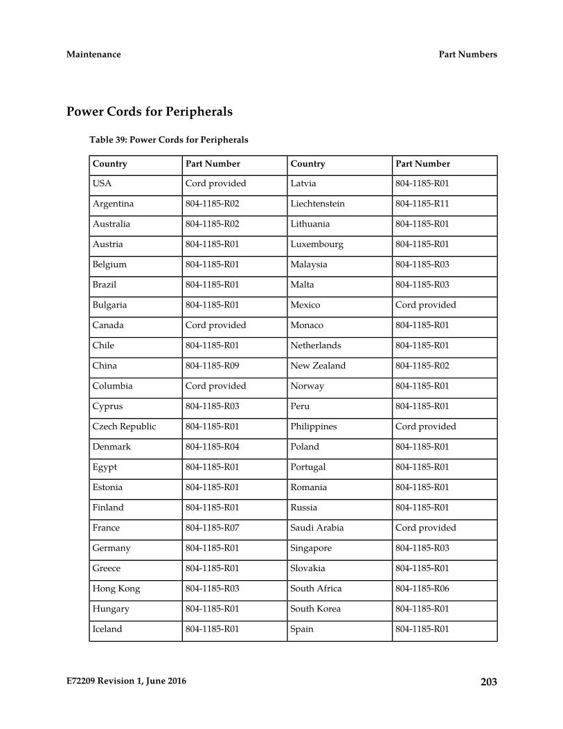
Power Cords for Peripherals
Table 39: Power Cords for Peripherals
Part NumberCountryPart NumberCountry
804-1185-R01LatviaCord providedUSA
804-1185-R11Liechtenstein804-1185-R02Argentina
804-1185-R01Lithuania804-1185-R02Australia
804-1185-R01Luxembourg804-1185-R01Austria
804-1185-R03Malaysia804-1185-R01Belgium
804-1185-R03Malta804-1185-R01Brazil
Cord providedMexico804-1185-R01Bulgaria
804-1185-R01MonacoCord providedCanada
804-1185-R01Netherlands804-1185-R01Chile
804-1185-R02New Zealand804-1185-R09China
804-1185-R01NorwayCord providedColumbia
804-1185-R01Peru804-1185-R03Cyprus
Cord providedPhilippines804-1185-R01Czech Republic
804-1185-R01Poland804-1185-R04Denmark
804-1185-R01Portugal804-1185-R01Egypt
804-1185-R01Romania804-1185-R01Estonia
804-1185-R01Russia804-1185-R01Finland
Cord providedSaudi Arabia804-1185-R07France
804-1185-R03Singapore804-1185-R01Germany
804-1185-R01Slovakia804-1185-R01Greece
804-1185-R06South Africa804-1185-R03Hong Kong
804-1185-R01South Korea804-1185-R01Hungary
804-1185-R01Spain804-1185-R01Iceland
203E72209 Revision 1, June 2016
Part NumbersMaintenance

Part NumberCountryPart NumberCountry
804-1185-R01Sweden804-1185-R06India
804-1185-R11Switzerland804-1185-R03Ireland
Cord providedTaiwan804-1185-R12Israel
804-1185-R01Turkey804-1185-R07Italy
804-1185-R03United Kingdom804-1185-R01Ivory Coast
804-1185-R03United Arab804-1185-R10Japan
204E72209 Revision 1, June 2016
Part NumbersMaintenance
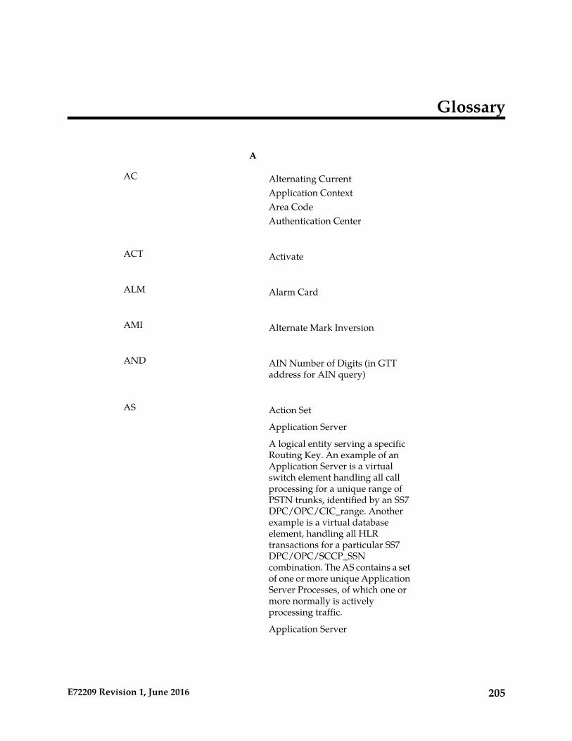
Glossary
A
Alternating CurrentAC
Application ContextArea CodeAuthentication Center
ActivateACT
Alarm CardALM
Alternate Mark InversionAMI
AIN Number of Digits (in GTTaddress for AIN query)
AND
Action SetAS
Application Server
A logical entity serving a specificRouting Key. An example of anApplication Server is a virtualswitch element handling all callprocessing for a unique range ofPSTN trunks, identified by an SS7DPC/OPC/CIC_range. Anotherexample is a virtual databaseelement, handling all HLRtransactions for a particular SS7DPC/OPC/SCCP_SSNcombination. The AS contains a setof one or more unique ApplicationServer Processes, of which one ormore normally is activelyprocessing traffic.
Application Server
205E72209 Revision 1, June 2016
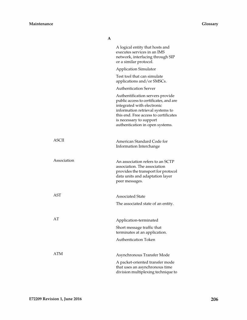
A
A logical entity that hosts andexecutes services in an IMSnetwork, interfacing through SIPor a similar protocol.
Application Simulator
Test tool that can simulateapplications and/or SMSCs.
Authentication Server
Authentification servers providepublic access to certificates, and areintegrated with electronicinformation retrieval systems tothis end. Free access to certificatesis necessary to supportauthentication in open systems.
American Standard Code forInformation Interchange
ASCII
An association refers to an SCTPassociation. The association
Association
provides the transport for protocoldata units and adaptation layerpeer messages.
Associated StateAST
The associated state of an entity.
Application-terminatedAT
Short message traffic thatterminates at an application.
Authentication Token
Asynchronous Transfer ModeATM
A packet-oriented transfer modethat uses an asynchronous timedivision multiplexing technique to
206E72209 Revision 1, June 2016
GlossaryMaintenance

A
multiplex information flow in fixedblocks, called cells.
A high-bandwidth, low-delayswitching, and multiplexingtechnology to support applicationsthat include high-speed data, localarea network interconnection,multimedia application andimaging, and residentialapplications such as videotelephony and otherinformation-based services.
B
Bit Error Rate TestBERT
Building Integrated Timing SystemBITS
The Building Integrated TimingSystem (BITS) clocks come directlyfrom the central office BITS clocksource or indirectly from anoptional holdover clock installedin the system.
Board PromBP
C
Cell Attribute TableCAT
Carrier DetectCD
Compact DiskCall Deflection
Control FrameCF
A singleTime-Division-Multiplexed (TDM)
Channel
timeslot within a channelizedE1/T1 port. Generically, channels
207E72209 Revision 1, June 2016
GlossaryMaintenance
C
can be used for transportingsignaling, digitized voice, or datainformation. Unused channelstypically are filled with defined idlecodes designed to maintainsufficient ones density to ensureframe-level synchronization.
Cell IdentityCI
Clock Interface CardCritical Status Indicator
Common Language LocationIdentifier
CLLI
The CLLI uniquely identifies theSTP in terms of its physicallocation. It is usually comprised ofa combination of identifiers for theSTP’s city (or locality), state (orprovince), building, and traffic unitidentity. The format of the CLLI is:
• The first four characters identifythe city, town, or locality
• The first character of the CLLImust be an alphabeticalcharacter
• The fifth and sixth charactersidentify state or province
• The seventh and eighthcharacters identify the building
• The last three charactersidentify the traffic unit
The shelf in the EAGLE thatcontains the Maintenance and
Control Shelf
Administration Subsystem. TheMaintenance and AdministrationSubsystem contains 5 cards: 2 CAMcards, 2 TDMs (Terminal DiskModules), and 1 MDAL(Maintenance Disk and Alarm)card. This shelf is designated as
208E72209 Revision 1, June 2016
GlossaryMaintenance
C
Shelf 1100 and cannot be added orremoved from the database.
Channel Service UnitCSU
Comma-Separated ValuesCSV
The comma-separated value fileformat is a delimited data formatthat has fields separated by thecomma character and recordsseparated by newlines (a newlineis a special character or sequenceof characters signifying the end ofa line of text).
D
All data that can be administeredby the user, including cards,
Database
destination point codes, gatewayscreening tables, global titletranslation tables, links, LNPservices, LNP service providers,location routing numbers, routes,shelves, subsystem applications,and 10-digit telephone numbers.
DatabaseDB
Daughter BoardDocumentation BulletinData bus
Direct CurrentDC
Data Collection
Database Communication ModuleDCM
The DCM provides IP connectivityfor applications. Connection to ahost is achieved through an
209E72209 Revision 1, June 2016
GlossaryMaintenance
D
ethernet LAN using the TCP/IPprotocol.
Data LinkDLK
TCP/IP Data Link.
Derived ObjectDO
Destination Point Code - DPCrefers to the scheme in SS7
DPC
signaling to identify the receivingsignaling point. In the SS7 network,the point codes are numericaddresses which uniquely identifyeach signaling point. This pointcode can be adjacent to the EAGLE,but does not have to be.
Digital Signal Level-0 (64 Kbits/secor 56 Kbits/sec)
DS0
A basic digital signaling rate of 64Kbits/sec corresponding to thecapacity of onevoice-frequency-equivalentchannel.
Digital Signal Level-1(1.544Mbits/sec)
DS1
A widely used standard intelecommunications in NorthAmerica and Japan to transmitvoice and data between devices.The data transmitted over aphysical T1 line.
Database Service Module.DSM
The DSM provides large capacitySCCP/database functionality. TheDSM is an application card that
210E72209 Revision 1, June 2016
GlossaryMaintenance
D
supports network specific functionssuch as EAGLE ApplicationProcessor (EPAP), Global Systemfor Mobile Communications(GSM), EAGLE Local NumberPortability (ELAP), and interfaceto Local Service ManagementSystem (LSMS).
Fault sectionalization tests, a seriesof far-end loopback tests to identify
DSO
faulty segments of an SS7transmission path up to andincluding the remote networkelement.
Data Service UnitDSU
Database Transport Access - Afeature in the EAGLE that
DTA
encapsulates specific MSUs into thedata portion of SCCP within a newSS7 MSU and sends the new MSUto the destination using global titletranslation. The EAGLE usesgateway screening to determinewhich MSUs are used by the DTAfeature.
Design Under TestDUT
Digital Versatile DiskDVD
E
The European equivalent of T1 thattransmits digital data over atelephone network at 2.048 Mbps.
E1
EPM-based E1/T1 Multi-ChannelInterface Module
E5-E1T1
211E72209 Revision 1, June 2016
GlossaryMaintenance
E
An EPM-based card that providesE1 and T1 connectivity. E1T1 is anabbreviation for the ITU E1 andANSI T1 interfaces. Thus thenomenclature defines the shelveswhere the card can be used and thephysical interface that it provides.
EPM-based Ethernet cardE5-ENET
A high capacity single-slot IPsignaling card (EPM card plus GigEthernet PMC cards).
External ConditionEC
Condition that is passed on theexternal condition interface.
Enhanced DCMEDCM
Enhanced DatabaseCommunication Module
Extension FrameEF
EAGLE Local Number PortabilityApplication Processor
ELAP
The EAGLE LNP ApplicationProcessor (ELAP) platformprovides capacity and performancerequired to support the portednumber database.
Element Measurement and DataCollection Application
EMDC
This application is used by theDCM card for CMIP/OSImeasurement collection interfaceas defined by Telcordia GR-376.
212E72209 Revision 1, June 2016
GlossaryMaintenance
E
EthernetENET
Can refer to a generic hardwaretype that supports one or moreEthernet interfaces.
EAGLE Application ProcessorEPAP
Extended Super FrameESF
Expanded Services PlatformESP
The Sentinel system with thehardware and software platformthat provides the interface to theIntegrated EAGLE and Sentinelmonitoring system. The ESPhardware and software platformruns on the model 120 server.
See ES.Extension Shelf
F
Cooling fan feature. The EAGLEwill report on the alarm conditions
FAN
of the fan assemblies. Once youhave turned on the feature, youcannot turn it off. The featureapplies to any and all fans installedwithin the system. When replacinga fan assembly, the feature shouldalready be turned on.
Fuse and Alarm PanelFAP
Feature DescriptionFD
File DescriptorFile DuplicatorFixed Disk
213E72209 Revision 1, June 2016
GlossaryMaintenance
F
Feature EngineerFE
Front End
Used in Provisioning Front EndApplications
File Transfer AreaFTA
A special area that exists on eachOAM hard disk, used as a stagingarea to copy files to and from theEAGLE using the Kermitfile-transfer protocol.
File Transfer ProtocolFTP
A client-server protocol that allowsa user on one computer to transferfiles to and from another computerover a TCP/IP network.
Feature Test Plan
G
GigabyteGB
1,073,741,824 bytes
Generic Loading ServicesGLS
An application that is used by theTSM cards for downloadinggateway screening to LIM cards.
Greenwich Mean TimeGMT
Generic Program LoadGPL
Software that allows the variousfeatures in the system to work.GPLs and applications are not thesame software.
214E72209 Revision 1, June 2016
GlossaryMaintenance

G
Global System for MobileCommunications
GSM
A second generation digital PCSmobile phone standard used inmany parts of the world.
Global Title TranslationGTT
A feature of the signalingconnection control part (SCCP) ofthe SS7 protocol that the EAGLEuses to determine which servicedatabase to send the query messagewhen an MSU enters the EAGLEand more information is needed toroute the MSU. These servicedatabases also verify calling cardnumbers and credit card numbers.The service databases are identifiedin the SS7 network by a point codeand a subsystem number.
Gateway ScreeningGWS
Used at gateway STPs to limitaccess into the network toauthorized users. A gateway STPperforms inter-network routingand gateway screening functions.GWS controls access to nonhomeSS7 networks. Only an MSU thatmatches predefined criteria in theEAGLE database is allowed toenter the EAGLE.
H
High Capacity Multi-ChannelInterface Module
HC-MIM
A card that provides access to eightE1/T1 ports residing on backplaneconnectors A and B. Each datastream consists of 24 T1 or 31 E1DS0 signaling links assigned in atime-division multiplex (TDM)
215E72209 Revision 1, June 2016
GlossaryMaintenance

H
manner. Each channel occupies aunique timeslot in the data streamand can be selected as a localsignaling link on the interface card.Each card has 8 E1 or 8 T1 portinterfaces with a maximum of 64signaling links provisioned amongthe 8 E1/T1 ports.
High-Speed IMT Packet Router 2HIPR2
A card that provides increasedsystem throughput and trafficcapacity on the existingFibre-Channel ring. A high rateFibre-Channel option of 2.5 Gbpsis available when an EAGLE isprovisioned with all HIPR2 cards.In a mixed topology where aHIPR2 is used in an EAGLE alongwith HMUX and HIPR, theFibre-Channel ring runs at thelower rate of 1.0625 Gbps.
High-Speed MultiplexerHMUX
A card that supports therequirements for up to 1500 links,allowing communication on IMTbuses between cards, shelves andframes. HMUX cards interface to16 serial links, creating a ring froma series of point to point links. EachHMUX card provides a bypassmultiplexer to maintain the ring’sintegrity as cards are removed andinserted into an operational shelf.
High-Speed IMT Multiplexer
A replacement card for the IPMX.
High SpeedHS
I
216E72209 Revision 1, June 2016
GlossaryMaintenance

I
IdentityID
Identifier
INAP-based Number PortabilityINP
INP can be deployed as astand-alone or an integrated signaltransfer point/number portabilitysolution. With a stand-alone NPserver, no network reconfigurationis required to implement numberportability. The NP server deliversa much greater signaling capabilitythan the conventional SCP-basedapproach.
Intelligent Network (IN) Portability
The application used by theSSEDCM/E5-ENET card for IP
IPLIM
point-to-point connectivity forANSI point codes.
IMT Power and Multiplexer cardIPMX
In Service - AbnormalIS-ANR
The entity is in service but onlyable to perform a limited subset ofits normal service functions.
In Service - NormalIS-NR
International TelecommunicationsUnion
ITU
An organization that operatesworldwide to allow governmentsand the privatetelecommunications sector tocoordinate the deployment andoperating of telecommunicationsnetworks and services. The ITU is
217E72209 Revision 1, June 2016
GlossaryMaintenance
I
responsible for regulating,coordinating and developinginternational telecommunications,and for harmonizing nationalpolitical interests.
K
Keyboard Send/Receive ModeKSR
L
Local Area NetworkLAN
A private data network in whichserial transmission is used fordirect data communication amongdata stations located in the sameproximate location. LAN uses coaxcable, twisted pair, or multimodefiber.See also STP LAN.
On the E5-MCAP card, a USB portwith a lockable latch. Used with
latched USB port
removable media (flash memory”thumb” drives) to install and backup customer data.
Light Emitting DiodeLED
An electrical device that glows aparticular color when a specifiedvoltage is applied to it.
Link Fault SectionalizationLFS
A feature in the EAGLE that allowsthe maintenance personnel toperform a series of far endloopback tests, from the EAGLEand identify faulty segments of anSS7 transmission path up to andincluding the remote networkelement.
218E72209 Revision 1, June 2016
GlossaryMaintenance
L
Link Interface ModuleLIM
Provides access to remote SS7, IP,and other network elements suchas a Signaling Control Point (SCP)through a variety of signalinginterfaces (DS0, MPL, E1/T1 MIM,LIM-ATM, E1-ATM, IPLIMx,IPGWx). The LIMs consist of amain assembly and possibly, aninterface appliqué board. Theseappliqués provide level one andsome level two functionality on SS7signaling links.
Signaling LinkLink
Carries signaling within a Link Setusing a specific Association. A Linkcan belong to only one Link Set andone Association. There is generallyone Link per Association in a LinkSet.
Latching LFS TestLLT
Local Number PortabilityLNP
The ability of subscribers to switchlocal or wireless carriers and stillretain the same phone number.
Link SetLS
A group of signaling links carryingtraffic to the same signaling point.
Represents a logical signalingconnection from one HLR Routerpoint code to one adjacent pointcode.
Local Service Management SystemLSMS
219E72209 Revision 1, June 2016
GlossaryMaintenance

L
An interface between the NumberPortability Administration Center(NPAC) and the LNP servicedatabases. The LSMS receives LNPdata from the NPAC anddownloads that data to the servicedatabases. LNP data can be enteredinto the LSMS database. The datacan then be downloaded to theLNP service databases and to theNPAC.
M
Metropolitan Area NetworkMAN
Manual
Maintenance and AdministrationSubsystem
MAS
A set of cards located in the ControlShelf, used to provide a centralmanagement point for the EAGLE.The MAS provides user interface,maintenance communication,peripheral services, alarmprocessing, system disk interface,and measurements using thefollowing three subassemblies:GPSM-II, TDM, and MDAL.
Maintenance and AdministrationSubsystem Processor
MASP
The Maintenance andAdministration SubsystemProcessor (MASP) function is alogical pairing of the GPSM-II cardand the TDM card. The GPSM-IIcard is connected to the TDM cardby means of an Extended BusInterface (EBI) local bus.
The MDAL card contains theremovable cartridge drive andalarm logic. There is only oneMDAL card in the Maintenance
220E72209 Revision 1, June 2016
GlossaryMaintenance

M
and Administration Subsystem(MAS) and it is shared between thetwo MASPs.
Matrix Controller AssemblyMCA
Maintenance Communications andApplications Processor
MCAP
Measurement Collection andPolling Module
MCPM
Provides comma delimited coreSTP measurement data to a remoteserver for processing. The MCPMis either an EDSM with 2 GB ofmemory or an E5-MCPM-B cardrunning the MCP application.
Measurements PlatformMEASPLAT
Multi-Channel Interface ModuleMIM
Mobile Identification NumberMIN
Man-Machine InterfaceMMI
Multi-port LIMMPL
Multi-Purpose ServerMPS
The Multi-Purpose Server providesdatabase/reload functionality anda variety of high capacity/highspeed offboard database functionsfor applications. The MPS residesin the General Purpose Frame.
Messages Per Second
221E72209 Revision 1, June 2016
GlossaryMaintenance
M
A measure of a message processor’sperformance capacity. A messageis any Diameter message (Requestor Answer) which is received andprocessed by a message processor.
Message Reference NumberMRN
An unsolicited numbered message(alarm or information) that isdisplayed in response to an alarmcondition detected by the systemor in response to an event that hasoccurred in the system.
Mated Relay Node
A mated relay node (MRN) groupis provisioned in the database toidentify the nodes that the traffic isload shared with, and the type ofrouting, either dominant, loadsharing, or combineddominant/load sharing.
Message Signal UnitMSU
The SS7 message that is sentbetween signaling points in the SS7network with the necessaryinformation to get the message toits destination and allow thesignaling points in the network toset up either a voice or dataconnection between themselves.The message contains the followinginformation:
• The forward and backwardsequence numbers assigned tothe message which indicate theposition of the message in thetraffic stream in relation to theother messages.
• The length indicator whichindicates the number of bytesthe message contains.
222E72209 Revision 1, June 2016
GlossaryMaintenance

M
• The type of message and thepriority of the message in thesignaling information octet ofthe message.
• The routing information for themessage, shown in the routinglabel of the message, with theidentification of the node thatsent message (originating pointcode), the identification of thenode receiving the message(destination point code), and thesignaling link selector which theEAGLE uses to pick which linkset and signaling link to use toroute the message.
Message Transfer PartMTP
The levels 1, 2, and 3 of the SS7protocol that control all thefunctions necessary to route an SS7MSU through the network
Module Test Plan
N
North AmericaNA
Not ApplicableNature of Address
Network Data CollectionNDC
Network Data Collection
Network ElementNE
An independent and identifiablepiece of equipment closelyassociated with at least oneprocessor, and within a singlelocation.
In a 2-Tiered DSR OAM system,this includes the NOAM and allMPs underneath it. In a 3-Tiered
223E72209 Revision 1, June 2016
GlossaryMaintenance
N
DSR OAM system, this includes theNOAM, the SOAM, and all MPsassociated with the SOAM.
The devices, servers, or functionswithin a wireless network withwhich Policy Management systemsinteract.
Network Entity
Network Element InterfaceNEI
See NENetwork Element
Nonlatching LFS TestNLT
Network OAMNO
A server that manages a collectionof SOs and their correspondingMPs. NO servers are deployed inactive/standby pairs.
O
Operations, Administration, andMaintenance. These functions are
OAM
generally managed by individualapplications and not managed bya platform managementapplication, such as PM&C.
Operations – Monitoring theenvironment, detecting anddetermining faults, and alertingadministrators.
Administration – Typicallyinvolves collecting performancestatistics, accounting data for thepurpose of billing, capacityplanning, using usage data, andmaintaining system reliability.
Maintenance – Provides suchfunctions as upgrades, fixes, new
224E72209 Revision 1, June 2016
GlossaryMaintenance
O
feature enablement, backup andrestore tasks, and monitoringmedia health (for example,diagnostics).
When the Active OAM gives upcontrol (for example, Init, Isolated,
OAM switchover
Obit) and either the Standby OAMbecomes the Active or the oldActive becomes a newly reinitialized Active. This is a timewhen existing maintenance andstatus information is lost and mustbe relearned.
Office Channel UnitOCU
The interface used with theLIMOCU card.
Original Equipment ManufacturerOEM
Out of ServiceOOS
Out of Service - MaintenanceOOS-MT
The entity is out of service and isnot available to perform its normalservice function. The maintenancesystem is actively working torestore the entity to service.
OperationOP
Operating SystemOS
Operations Systems
P
Point CodePC
225E72209 Revision 1, June 2016
GlossaryMaintenance
P
The identifier of a signaling pointor service control point in anetwork. The format of the pointcode can be one of the followingtypes:
• ANSI point codes in the formatnetwork indicator-networkcluster-network cluster member(ni-nc-ncm).
• Non-ANSI domestic point codesin the format networkindicator-networkcluster-network cluster member(ni-nc-ncm).
• Cluster point codes in theformat networkindicator-network cluster-* ornetwork indicator-*-*.
• ITU international point codesin the format zone-area-id.
• ITU national point codes in theformat of a 5-digit number(nnnnn), or 2, 3, or 4 numbers(members) separated by dashes(m1-m2-m3-m4) as defined bythe Flexible Point Code systemoption. A group code isrequired (m1-m2-m3-m4-gc)when the ITUDUPPC feature isturned on.
• 24-bit ITU national point codesin the format main signalingarea-subsignaling area-servicepoint (msa-ssa-sp).
Primary StatePST
A field in the rept-statcommand outputs showing theprimary state of the specifiedentity.
R
Redundant Array of IndependentDisks
RAID
226E72209 Revision 1, June 2016
GlossaryMaintenance

R
A group of disks presented toclients as one or more large virtualdisks, with accesses coordinatedamong multiple disks concurrentlyto increase performance, reliability,or both.
Random Access MemoryRAM
A type of computer memory thatcan be accessed randomly; that is,any byte of memory can beaccessed without touching thepreceding bytes.
Receive DataRD
Removable Disk
Registered JackRJ
Return Material AuthorizationRMA
Read Only MemoryROM
A signaling path from an LSP to anRSP using a specified Link Set.
Route
Requirement SpecificationRS
Redirect Server
Real Time DatabaseRTDB
S
Signaling Connection Control PartSCCP
The signaling connection controlpart with additional functions forthe Message Transfer Part (MTP)
227E72209 Revision 1, June 2016
GlossaryMaintenance
S
in SS7 signaling. Messages can betransmitted between arbitrarynodes in the signaling networkusing a connection-oriented orconnectionless approach.
Small Computer System InterfaceSCSI
There are two independent SmallComputer System Interface (SCSI)buses, one to the fixed disks onTDM cards and the other to theshared administration SCSI busthat runs on the backplane betweenTDMs and the MDAL card. EachSCSI bus has a block of memorythat allows transfers from memoryto occur without delaying theapplication processor.
Signaling Engineering andAdministration System
SEAS
An interface defined by Bellcoreand used by the Regional BellOperating Companies (RBOCs), aswell as other Bellcore ClientCompanies (BCCs), to remotelyadminister and monitor thesignaling points in their networkfrom a central location.
Signaling Transfer Point Local AreaNetwork
SLAN
A feature in the EAGLE that copiesMSUs selected through thegateway screening process andsends these MSUs over theEthernet to an external hostcomputer for further processing.
Signaling Link CodeSLC
228E72209 Revision 1, June 2016
GlossaryMaintenance

S
Service and Link Interface CardSLIC
A single-slot, multi-use card withthe same functionality as theE5-ENET-B card running the IPSGapplication.
Signaling Link TestAcknowledgment
SLTA
Signaling Link Test ControllerSLTC
Signal Link Test MessageSLTM
Screening ReferenceSR
SubsystemSS
Supplementary Services
Signaling System #7SS7
A communications protocol thatallows signaling points in anetwork to send messages to eachother so that voice and dataconnections can be set up betweenthese signaling points. Thesemessages are sent over its ownnetwork and not over the revenueproducing voice and data paths.The EAGLE is an STP, which is adevice that routes these messagesthrough the network.
Secondary StateSST
The secondary state of the specifiedentity.
Subsystem Status Test
229E72209 Revision 1, June 2016
GlossaryMaintenance
S
Subsystem Status Test networkmanagement message.
Subsystem Status Test SCCP(SCMG) management message.(CER)
Signal Transfer PointSTP
The STP is a special high-speedswitch for signaling messages inSS7 networks. The STP routes coreINAP communication between theService Switching Point (SSP) andthe Service Control Point (SCP)over the network.
Spanning Tree Protocol
Signaling Transfer Point Local AreaNetwork.
STP LAN
A feature in the EAGLE that copiesMSUs selected through thegateway screening process andsends these MSUs over theEthernet to an external hostcomputer for further processing.
Signaling Transfer Point Local AreaNetwork
STPLAN
The application used by the SLANcard and E5-SLAN card to supportthe STP LAN feature. Thisapplication does not support 24-bitITU-N point codes.
T
Transmission Level 1T1
A T1 interface terminates ordistributes T1 facility signals forthe purpose of processing the SS7signaling links carried by the E1carrier.
230E72209 Revision 1, June 2016
GlossaryMaintenance

T
A leased-line connection capableof carrying data at 1,544,000bits-per-second.
Transmission ControlProtocol/Internet Protocol
TCP/IP
Terminal Disk ModuleTDM
Time Division Multiplexing
Data transmissions withinindividual connections follow apre-defined multiplex schemewhere a fixed time slot is availablefor each channel.
TransFer Prohibited (Msg)TFP
A procedure included in thesignaling route management(functionality) used to inform asignaling point of the unavailabilityof a signaling route.
Transfer RestrictedTFR
Timing OutputTO
Timing Output CompositeAutomatic
TOCA
Termination Response ModeTRM
Translation Services ModuleTSM
Provides translation capability andGlobal Title Translation (GTT)implementation for the LocalNumber Portability (LNP) functionand is used for downloading
231E72209 Revision 1, June 2016
GlossaryMaintenance

T
gateway screening tables to linkinterface modules (LIMs).
TransmitTX
U
Unsolicited Alarm MessageUAM
A message sent to a user interfacewhenever there is a fault that isservice-affecting or when aprevious problem is corrected. Eachmessage has a trouble code and textassociated with the troublecondition.
Unsolicited Information MessageUIM
A message sent to a user interfacewhenever there is a fault that is notservice-affecting or when aprevious problem is corrected. Eachmessage has a trouble code and textassociated with the troublecondition.
Unified Inventory Management
V
Volt Ohm MeterVOM
VxWorks Signaling ConnectionControl Part
VSCCP
The application used by the ServiceModule card to supportEPAP-related features and LNPfeatures. If an EPAP-related or LNPfeature is not turned on, and aService Module card is present, theVSCCP application processesnormal GTT traffic.
232E72209 Revision 1, June 2016
GlossaryMaintenance