CPI KVM Switch User Manual - Chatsworth Products
36
CPI KVM Switch User Manual Version 1.0 12/2016 800-834-4969 [email protected] www.chatsworth.com ©2016 Chatsworth Products, Inc. All rights reserved. CPI, CPI Passive Cooling, MegaFrame, Saf-T-Grip, Seismic Frame, SlimFrame, TeraFrame, GlobalFrame, Cube-iT Plus, Evolution, OnTrac, QuadraRack and Velocity are federally registered trademarks of Chatsworth Products, Inc. Simply Efficient is a trademark of Chatsworth Products, Inc. All other trademarks belong to their respective companies. Rev.2 12/16 MKT-60020-530
-
Upload
khangminh22 -
Category
Documents
-
view
1 -
download
0
Transcript of CPI KVM Switch User Manual - Chatsworth Products
CPI KVM Switch User Manual
Version 1.0 12/2016
www.chatsworth.com
©2016 Chatsworth Products, Inc. All rights reserved. CPI, CPI Passive Cooling, MegaFrame, Saf-T-Grip, Seismic Frame, SlimFrame, TeraFrame, GlobalFrame, Cube-iT Plus, Evolution,
OnTrac, QuadraRack and Velocity are federally registered trademarks of Chatsworth Products, Inc. Simply Efficient is a trademark of Chatsworth Products, Inc.
All other trademarks belong to their respective companies. Rev.2 12/16 MKT-60020-530
2
Table of Contents
Legal Information .............................................................................................................................. 3 Warranty ........................................................................................................................................... 3
Introduction ............................................................................................................ 4 Product Features – IP KVM Switch with DB15 Ports (P/N 37212-260) ........................................... 5 Product Features – Analog KVM Switch with DB15 Ports (P/N 37202-160) ................................... 6 Product Features – IP KVM Switch with Cat5/6 Ports (P/N 37207-360, 37207-420) ...................... 7 Product Features – Analog KVM Switch with Cat5/6 Ports (P/N 37210-260, 37210-220) ............ 10
Important Safeguards .......................................................................................... 13 Safety Instructions .......................................................................................................................... 13 Federal Communications Commission (FCC) Regulatory Notices ................................................ 14
Installation ............................................................................................................ 15 Unpacking – Package Contents ..................................................................................................... 15 Rack/Cabinet Installation ................................................................................................................ 16 Cable Diagram for KVM Switches with DB15 Ports ....................................................................... 17 Cable Diagram for KVM Switches with Cat5/6 Ports ..................................................................... 18 Server Connections for KVM Switches with Cat 5/6 Ports ............................................................ 19 VGA-USB Dongle (P/N 37208-103, 37208-803, 37208-603) ........................................................ 19 VGA-PS/2 Dongle (P/N 37208-104, 37208-804, 37208-604) ........................................................ 19 Remote Console Connection for KVM Switches with Cat5/6 Ports ............................................... 20 Cascade – Expansion for KVM Switches with DB15 Ports ............................................................ 21 Cascade – Expansion for KVM Switches with Cat5/6 Ports .......................................................... 22
Use – KVM Switch ................................................................................................ 23 Power On ........................................................................................................................................ 23 Password Configuration for the Local/Remote Console ................................................................ 24 The On-Screen Display (OSD) Menu ............................................................................................. 25 The F1 Main Menu ......................................................................................................................... 26 Local Console Hotkeys ................................................................................................................... 27 Remote Console Hotkeys............................................................................................................... 27
Set-Up – IP Console ............................................................................................. 28
Troubleshooting Guide – KVM Switch .............................................................. 30
Appendices ........................................................................................................... 31 Factory Default Setting ................................................................................................................... 31 FAQ ................................................................................................................................................ 31 Specifications – KVM Switch with DB15 Ports ............................................................................... 33 Specifications – KVM Switches with Cat5/6 Ports ......................................................................... 34 Accessories for KVM Switches with DB15 Ports ........................................................................... 35 Accessories for KVM Switches with Cat5/6 Ports .......................................................................... 36
3
Chatsworth Products, Inc. 29899 Agoura Road, Suite 120 Agoura Hills, CA 91301 800-834-4969
CPI KVM Switch User Manual ©2011 Chatsworth Products, Inc. All rights reserved.
Legal Information The information contained in this guide is subject to change without notice. Chatsworth Products, Inc. shall not be liable for technical or editorial errors or omissions contained herein; nor is it liable for any injury, loss, or incidental or consequential damages resulting from the furnishing, performance, or use of this material and equipment.
Warranty To review Chatsworth Products, Inc. (CPI’s) Standard Limited Warranty, click here.
4
Introduction
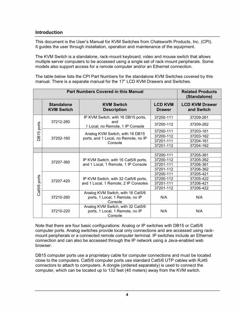
This document is the User’s Manual for KVM Switches from Chatsworth Products, Inc. (CPI). It guides the user through installation, operation and maintenance of the equipment. The KVM Switch is a standalone, rack-mount keyboard, video and mouse switch that allows multiple server computers to be accessed using a single set of rack-mount peripherals. Some models also support access for a remote computer and/or an Ethernet connection. The table below lists the CPI Part Numbers for the standalone KVM Switches covered by this manual. There is a separate manual for the 17” LCD KVM Drawers and Switches.
Part Numbers Covered in this Manual Related Products (Standalone)
Standalone KVM Switch
KVM Switch Description
LCD KVM Drawer
LCD KVM Drawer and Switch
DB
15 p
orts
37212-260 IP KVM Switch, with 16 DB15 ports,
and 1 Local, no Remote, 1 IP Console
37200-111 37209-261
37200-112 37209-262
37202-160 Analog KVM Switch, with 16 DB15
ports, and 1 Local, no Remote, no IP Console
37200-111 37203-161 37200-112 37203-162 37201-111 37204-161 37201-112 37204-162
Cat
5/6
ports
37207-360 IP KVM Switch, with 16 Cat5/6 ports, and 1 Local, 1 Remote, 1 IP Console
37200-111 37205-361 37200-112 37205-362 37201-111 37206-361 37201-112 37206-362
37207-420 IP KVM Switch, with 32 Cat5/6 ports, and 1 Local, 1 Remote, 2 IP Consoles
37200-111 37205-421 37200-112 37205-422 37201-111 37206-421 37201-112 37206-422
37210-260 Analog KVM Switch, with 16 Cat5/6
ports, 1 Local, 1 Remote, no IP Console
N/A N/A
37210-220 Analog KVM Switch, with 32 Cat5/6
ports, 1 Local, 1 Remote, no IP Console
N/A N/A
Note that there are four basic configurations: Analog or IP switches with DB15 or Cat5/6 computer ports. Analog switches provide local only connections and are accessed using rack-mount peripherals or a connected remote computer terminal. IP switches include an Ethernet connection and can also be accessed through the IP network using a Java-enabled web browser. DB15 computer ports use a proprietary cable for computer connections and must be located close to the computers. Cat5/6 computer ports use standard Cat5/6 UTP cables with RJ45 connectors to attach to computers. A dongle (ordered separately) is used to connect the computer, which can be located up to 132 feet (40 meters) away from the KVM switch.
5
Product Features – IP KVM Switch with DB15 ports (P/N 37212-260) 16 DB15 KVM switch device ports which provide low-level keyboard, video and mouse
connectivity to equipment within a rack. KVM Switches with DB15 ports use a proprietary 6 feet (1.8 meters) or 10 feet (3.0 meters) long breakout cable to connect computers. Cables are purchased separately (P/N 37203-161 or 37208-111).
Buttons on the front panel allows easy switching between computer ports. LED indicators on
the front panel to show if the computers are connected and powered on and which port is selected. Users can also switch between ports using an intuitive on-screen display menu or using keyboard hot keys.
A local console to connect external peripherals, like the 17” LCD KVM Drawer (P/N 37200-
11X or 37201-11X). Access to the switch can be password protected for eight user accounts.
An IP console that provides remote management capability for one user over a 10/100
TCP/IP network. Users access equipment through a Java-compatible web browser, like Microsoft Windows Internet Explorer, using a password protected logon and switch between computers using an intuitive on-screen menu. Supports fifteen user accounts.
An expansion connection that allows up to eight switches to be connected together
(cascade) providing access to 128 computers from the Local Console or IP Console on the first switch. KVM Switches with DB15 ports use a proprietary cascade cable to connect together (P/N 37208-162). No device ports are used. KVM Switches with DB15 ports will not connect to KVM Switches with Cat5/6 ports.
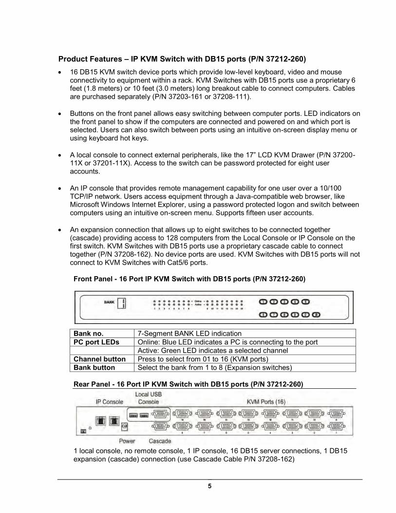
Front Panel - 16 Port IP KVM Switch with DB15 ports (P/N 37212-260)
Bank no. 7-Segment BANK LED indication PC port LEDs Online: Blue LED indicates a PC is connecting to the port Active: Green LED indicates a selected channel Channel button Press to select from 01 to 16 (KVM ports) Bank button Select the bank from 1 to 8 (Expansion switches)
Rear Panel - 16 Port IP KVM Switch with DB15 ports (P/N 37212-260)
1 local console, no remote console, 1 IP console, 16 DB15 server connections, 1 DB15 expansion (cascade) connection (use Cascade Cable P/N 37208-162)
6
Product Features – Analog KVM Switch with DB15 ports (P/N 37202-160) Used primarily as expansion switches for other KVM Switches with DB15 ports and 17” LCD
KVM Drawer and Switches with DB15 ports. 16 DB15 KVM switch device ports which provide low-level keyboard, video and mouse
connectivity to equipment within a rack. KVM Switches with DB15 ports use a proprietary 6 feet (1.8 meters) or 10 feet (3.0 meters) long breakout cable to connect computers. Cables are purchased separately (P/N 37208-161 or 37208-111).
Buttons on the front panel allows easy switching between computer ports. LED indicators on
the front panel to show if the computers are connected and powered on and which port is selected. Users can also switch between ports using an intuitive on screen display menu or using keyboard hot keys.
A local console to connect external peripherals, like the 17” LCD KVM Drawer
(P/N 37200-11X or 37201-11X). Access to the switch can be password protected for eight user accounts.
An expansion connection that allows up to eight switches to be connected together
(cascade) providing access to 128 computers from the Local Console on the first switch. KVM Switches with DB15 ports use a proprietary cascade cable to connect together (P/N 37208-162). No device ports are used. KVM Switches with DB15 ports will not connect to KVM Switches with Cat5/6 ports.
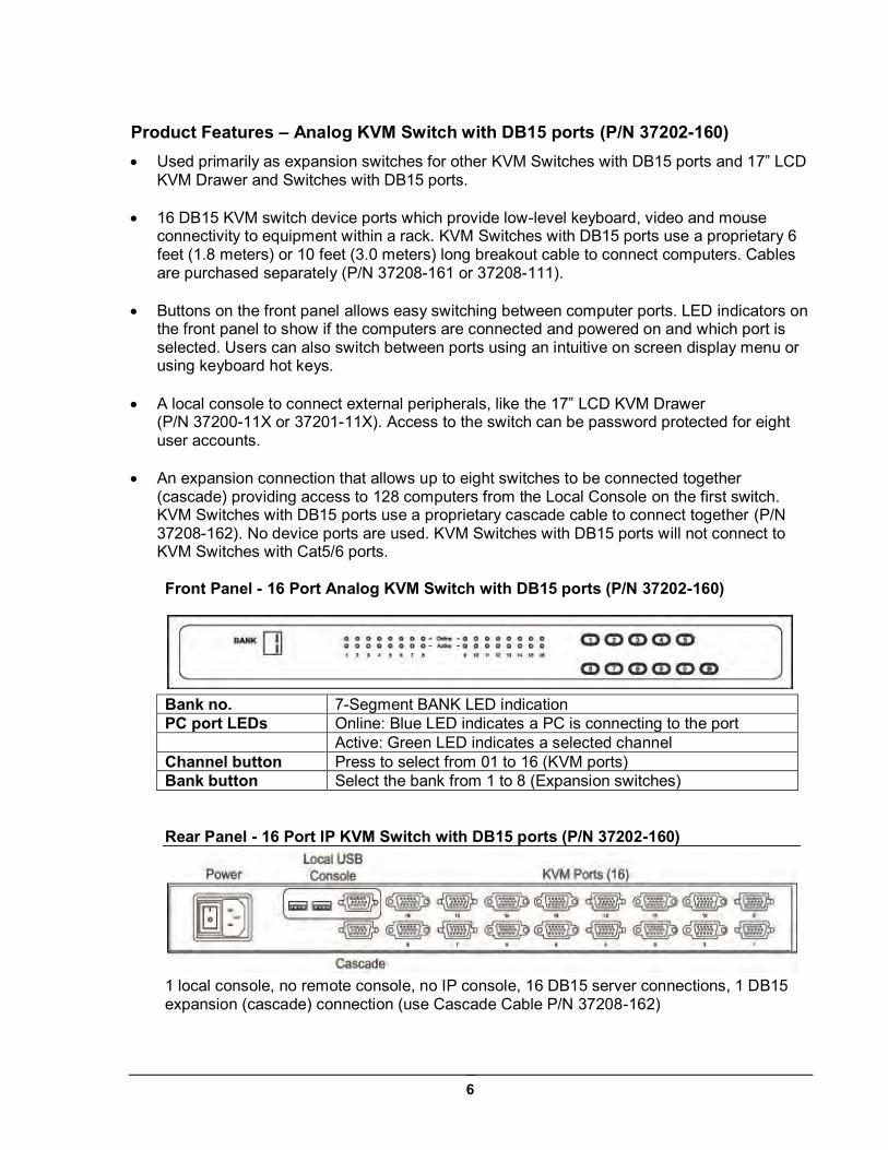
Front Panel - 16 Port Analog KVM Switch with DB15 ports (P/N 37202-160)
Bank no. 7-Segment BANK LED indication PC port LEDs Online: Blue LED indicates a PC is connecting to the port Active: Green LED indicates a selected channel Channel button Press to select from 01 to 16 (KVM ports) Bank button Select the bank from 1 to 8 (Expansion switches)
Rear Panel - 16 Port IP KVM Switch with DB15 ports (P/N 37202-160)
1 local console, no remote console, no IP console, 16 DB15 server connections, 1 DB15 expansion (cascade) connection (use Cascade Cable P/N 37208-162)
7
Product Features – IP KVM Switch with Cat5/6 ports (P/Ns 37207-360, 37207-420) 16 or 32 Cat5/6 RJ45 KVM switch device ports which provide low-level keyboard, video and
mouse connectivity to equipment within a rack. KVM Switches with Cat5/6 ports use standard Cat5/6 UTP cabling with RJ45 connectors and dongles to connect computers, which allow computers to be located much farther from the switch, up to 132 feet (40 meters) away. Dongles (P/N 37208-103 or 37208-104) are purchased separately.
Buttons on the front panel that allow easy switching between computer ports. LED indicators
on the front panel to show if the computers are connected and powered on and which port is selected. Users can also switch between ports using an intuitive on screen display menu or using keyboard hot keys.
A local console to connect external peripherals, like the 17” LCD KVM Drawer
(P/N 37200-11X or 37201-11X). Access to the switch can be password protected for eight accounts.
A remote console connection that provides access from a separate computer located
nearby. The remote console attaches to the switch using standard Cat5/6 UTP cabling with RJ45 connectors which allows the computer to be located up to 500 feet (150 meters) away from the switch.
An IP connection that provides remote management capability for one user over a 10/100
TCP/IP network. Users access equipment through a Java-compatible web browser, like Microsoft Windows Internet Explorer, using a password protected logon and switch between computers using an intuitive on screen menu. Supports fifteen user accounts.
An expansion connection that allows up to eight switches to be connected together
(cascade) providing access to 128 or 256 computers from the local, remote or IP consoles on the first switch. KVM Switches with Cat5/6 ports use a proprietary cascade cable (P/N 37208-165) to connect together. No device ports are used. KVM Switches with Cat5/6 ports will not connect to KVM Switches with DB15 ports.
See the next two pages for product diagrams.
8
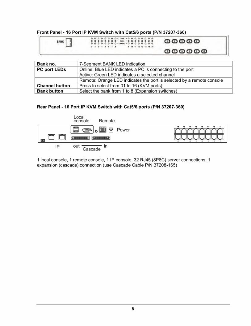
Front Panel - 16 Port IP KVM Switch with Cat5/6 ports (P/N 37207-360)
Bank no. 7-Segment BANK LED indication PC port LEDs Online: Blue LED indicates a PC is connecting to the port Active: Green LED indicates a selected channel Remote: Orange LED indicates the port is selected by a remote console Channel button Press to select from 01 to 16 (KVM ports) Bank button Select the bank from 1 to 8 (Expansion switches) Rear Panel - 16 Port IP KVM Switch with Cat5/6 ports (P/N 37207-360)
1 local console, 1 remote console, 1 IP console, 32 RJ45 (8P8C) server connections, 1 expansion (cascade) connection (use Cascade Cable P/N 37208-165)
Remote
Power
Local console
out Cascade
inIP

9
Front Panel - 32 Port IP KVM Switch with Cat5/6 ports (P/N 37207-420)
Bank no. 7-Segment BANK LED indication PC port LEDs Online: Blue LED indicates a PC is connecting to the port Active: Green LED indicates a selected channel Remote: Orange LED indicates the port is selected by a remote console Channel button Press to select channel from 01 to 32 Bank button Select the bank from 1 to 8 Rear Panel - 32 Port IP KVM Switch with Cat5/6 ports (P/N 37207-420)
1 local console, 1 remote console, 2 IP consoles, 32 RJ45 (8P8C) server connections, 1 expansion (cascade) connection (use Cascade Cable P/N 37208-165)
RemoteLocal
consoleIP 2
IP 1 out Cascade
in
10
Product Features – Analog KVM Switch with Cat5/6 ports (P/Ns 37210-260, 37210-220)
Used primarily as expansion switches for other IP KVM Switches with Cat5/6 ports and 17” LCD KVM Drawer and IP Switches with Cat5/6 ports.
16 or 32 Cat5/6 RJ45 KVM switch device ports which provide low-level keyboard, video and
mouse connectivity to equipment within a rack. KVM Switches with Cat5/6 ports use standard Cat5/6 UTP cabling with RJ45 connectors and dongles to connect computers, which allow computers to be located much farther from the switch, up to 132 feet (40 meters) away. Dongles (P/N 37208-103 or 37208-104) are purchased separately.
Buttons on the front panel that allow easy switching between computer ports. LED indicators
on the front panel to show if the computers are connected and powered on and which port is selected. Users can also switch between ports using an intuitive on screen display menu or using keyboard hot keys.
A local console to connect external peripherals, like the 17” LCD KVM Drawer (P/N 37200-
11X or 37201-11X). Access to the switch can be password protected for eight user accounts.
A remote console connection that provides access from a separate computer located
nearby. The remote console attaches to the switch using standard Cat5/6 UTP cabling with RJ45 connectors which allows the computer to be located up to 500 feet (150 meters) away from the switch.
An expansion connection that allows up to eight switches to be connected together
(cascade) providing access to 128 or 256 computers from the local, remote or IP consoles on the first switch. KVM Switches with Cat5/6 ports use a proprietary cascade cable (P/N 37208-165) to connect together. No device ports are used. KVM Switches with Cat5/6 ports will not connect to KVM Switches with DB15 ports.
See the next two pages for product diagrams.
11
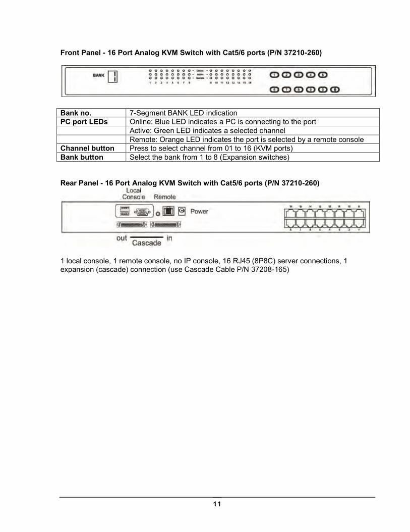
Front Panel - 16 Port Analog KVM Switch with Cat5/6 ports (P/N 37210-260)
Bank no. 7-Segment BANK LED indication PC port LEDs Online: Blue LED indicates a PC is connecting to the port Active: Green LED indicates a selected channel Remote: Orange LED indicates the port is selected by a remote console Channel button Press to select channel from 01 to 16 (KVM ports) Bank button Select the bank from 1 to 8 (Expansion switches) Rear Panel - 16 Port Analog KVM Switch with Cat5/6 ports (P/N 37210-260)
1 local console, 1 remote console, no IP console, 16 RJ45 (8P8C) server connections, 1 expansion (cascade) connection (use Cascade Cable P/N 37208-165)
12
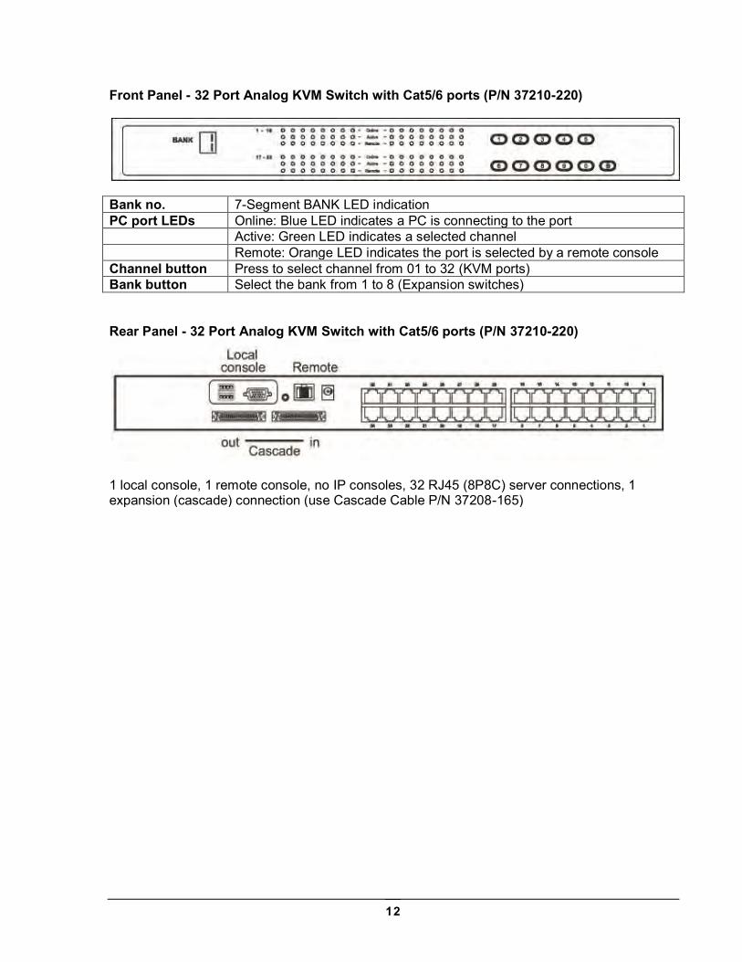
Front Panel - 32 Port Analog KVM Switch with Cat5/6 ports (P/N 37210-220)
Bank no. 7-Segment BANK LED indication PC port LEDs Online: Blue LED indicates a PC is connecting to the port Active: Green LED indicates a selected channel Remote: Orange LED indicates the port is selected by a remote console Channel button Press to select channel from 01 to 32 (KVM ports) Bank button Select the bank from 1 to 8 (Expansion switches) Rear Panel - 32 Port Analog KVM Switch with Cat5/6 ports (P/N 37210-220)
1 local console, 1 remote console, no IP consoles, 32 RJ45 (8P8C) server connections, 1 expansion (cascade) connection (use Cascade Cable P/N 37208-165)
13
Important Safeguards
Please read all of these instructions carefully before you use the device. Save this manual for future reference.
Safety Instructions
Unplug equipment before cleaning. Don’t use liquid or spray detergent; use a moist cloth.
Keep equipment away from excessive humidity and heat. Preferably, keep it in an air-conditioned environment with temperatures not exceeding 40º Celsius (104º Fahrenheit).
When installing, place the equipment on a sturdy, level surface to
prevent it from accidentally falling and causing damage to other equipment or injury to persons nearby.
When the equipment is in an open position, do not cover, block or in
any way obstruct the gap between it and the power supply. Proper air convection is necessary to keep it from overheating.
Arrange the equipment’s power cord in such a way that others won’t trip
or fall over it. If you are using a power cord that didn’t ship with the equipment, ensure
that it is rated for the voltage and current labeled on the equipment’s electrical ratings label. The voltage rating on the cord should be higher than the one listed on the equipment’s ratings label.
Observe all precautions and warnings attached to the equipment.
If you don’t intend on using the equipment for a long time, disconnect it
from the power outlet to prevent being damaged by transient over-voltage.
Keep all liquids away from the equipment to minimize the risk of
accidental spillage. Liquid spilled onto the power supply or on other hardware may cause damage, fire or electrical shock.
Only qualified service personnel should open the chassis. Opening it
yourself could damage the equipment and invalidate its warranty. If any part of the equipment becomes damaged or stops functioning,
have it checked by qualified service personnel. Slide rail mounted equipment is not to be used as a shelf or a
workspace.
14
Federal Communications Commission (FCC) Regulatory Notices This equipment has been tested and found to comply with the limits for a Class B digital device, pursuant to Part 15 of the FCC rules. These limits are designed to provide reasonable protection against harmful interference in a residential installation. Any changes or modifications made to this equipment may void the user’s authority to operate this equipment. This equipment generates, uses, and can radiate radio frequency energy and, if not installed and used in accordance with the instructions, may cause harmful interference to radio communications. However, there is no guarantee that interference will not occur in a particular installation. If this equipment does cause harmful interference to radio or television reception, which can be determined by turning the equipment off and on, the user is encouraged to try to correct the interference by one or more of the following measures: Re-position or relocate the receiving antenna. Increase the separation between the equipment and receiver. Connect the equipment into an outlet on a circuit different from that to which the receiver is
connected.
15
Installation
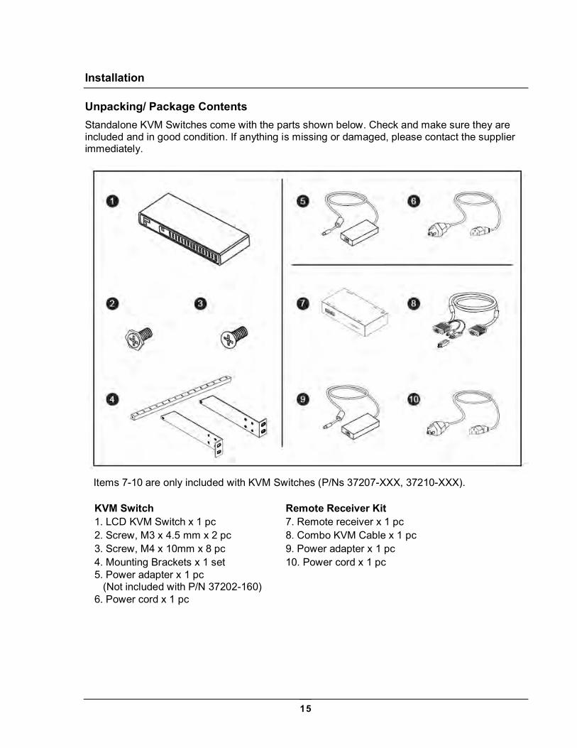
Unpacking/ Package Contents Standalone KVM Switches come with the parts shown below. Check and make sure they are included and in good condition. If anything is missing or damaged, please contact the supplier immediately.
Items 7-10 are only included with KVM Switches (P/Ns 37207-XXX, 37210-XXX).
KVM Switch Remote Receiver Kit 1. LCD KVM Switch x 1 pc 7. Remote receiver x 1 pc 2. Screw, M3 x 4.5 mm x 2 pc 8. Combo KVM Cable x 1 pc 3. Screw, M4 x 10mm x 8 pc 9. Power adapter x 1 pc 4. Mounting Brackets x 1 set 10. Power cord x 1 pc 5. Power adapter x 1 pc (Not included with P/N 37202-160)
6. Power cord x 1 pc
16
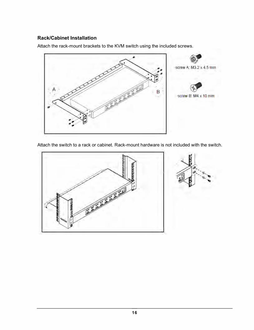
Rack/Cabinet Installation Attach the rack-mount brackets to the KVM switch using the included screws.
Attach the switch to a rack or cabinet. Rack-mount hardware is not included with the switch.
17
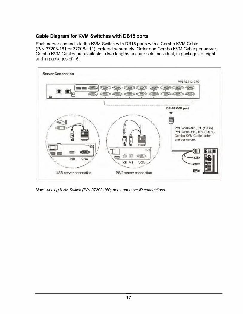
Cable Diagram for KVM Switches with DB15 ports Each server connects to the KVM Switch with DB15 ports with a Combo KVM Cable (P/N 37208-161 or 37208-111), ordered separately. Order one Combo KVM Cable per server. Combo KVM Cables are available in two lengths and are sold individual, in packages of eight and in packages of 16.
Note: Analog KVM Switch (P/N 37202-160) does not have IP connections.
18
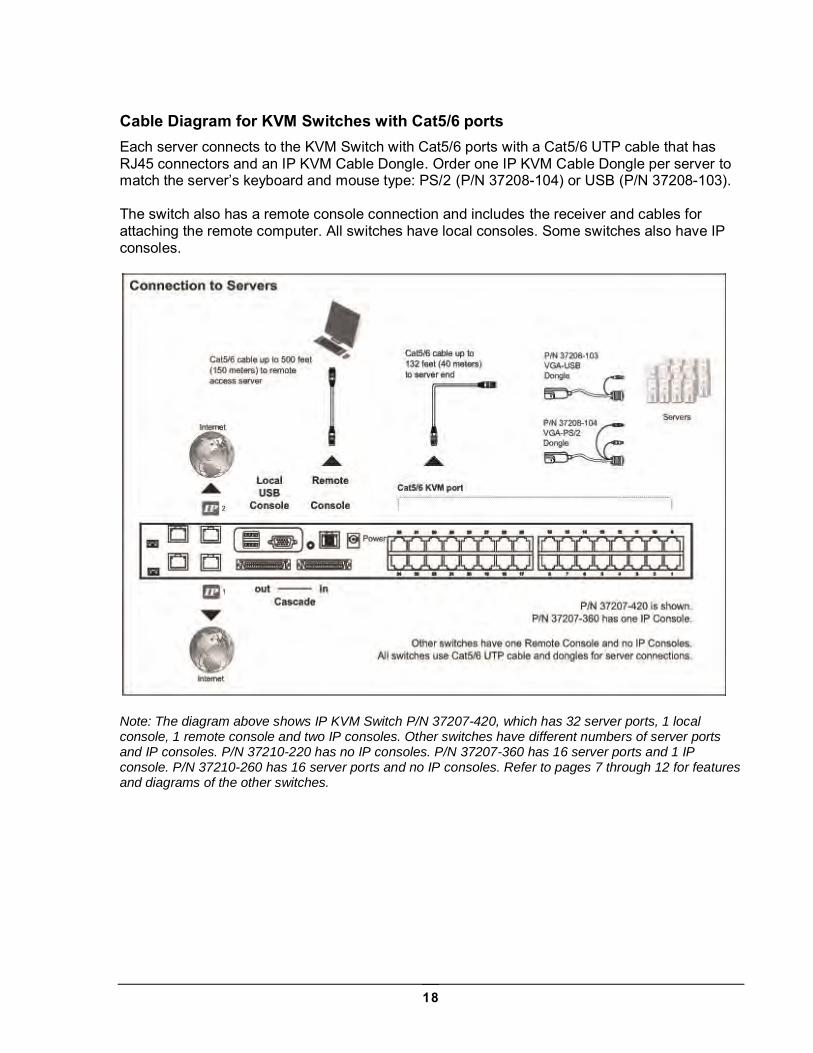
Cable Diagram for KVM Switches with Cat5/6 ports Each server connects to the KVM Switch with Cat5/6 ports with a Cat5/6 UTP cable that has RJ45 connectors and an IP KVM Cable Dongle. Order one IP KVM Cable Dongle per server to match the server’s keyboard and mouse type: PS/2 (P/N 37208-104) or USB (P/N 37208-103). The switch also has a remote console connection and includes the receiver and cables for attaching the remote computer. All switches have local consoles. Some switches also have IP consoles.
Note: The diagram above shows IP KVM Switch P/N 37207-420, which has 32 server ports, 1 local console, 1 remote console and two IP consoles. Other switches have different numbers of server ports and IP consoles. P/N 37210-220 has no IP consoles. P/N 37207-360 has 16 server ports and 1 IP console. P/N 37210-260 has 16 server ports and no IP consoles. Refer to pages 7 through 12 for features and diagrams of the other switches.
19
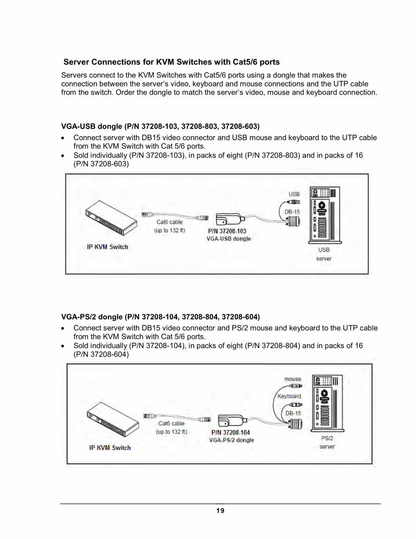
Server Connections for KVM Switches with Cat5/6 ports Servers connect to the KVM Switches with Cat5/6 ports using a dongle that makes the connection between the server’s video, keyboard and mouse connections and the UTP cable from the switch. Order the dongle to match the server’s video, mouse and keyboard connection.
VGA-USB dongle (P/N 37208-103, 37208-803, 37208-603) Connect server with DB15 video connector and USB mouse and keyboard to the UTP cable
from the KVM Switch with Cat 5/6 ports. Sold individually (P/N 37208-103), in packs of eight (P/N 37208-803) and in packs of 16
(P/N 37208-603)
VGA-PS/2 dongle (P/N 37208-104, 37208-804, 37208-604) Connect server with DB15 video connector and PS/2 mouse and keyboard to the UTP cable
from the KVM Switch with Cat 5/6 ports. Sold individually (P/N 37208-104), in packs of eight (P/N 37208-804) and in packs of 16
(P/N 37208-604)
20
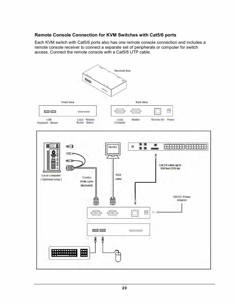
Remote Console Connection for KVM Switches with Cat5/6 ports Each KVM switch with Cat5/6 ports also has one remote console connection and includes a remote console receiver to connect a separate set of peripherals or computer for switch access. Connect the remote console with a Cat5/6 UTP cable.
21
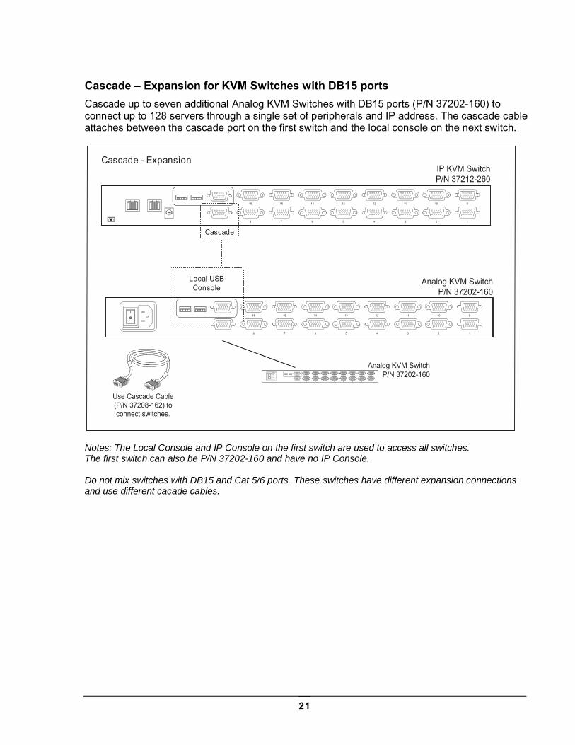
Cascade – Expansion for KVM Switches with DB15 ports Cascade up to seven additional Analog KVM Switches with DB15 ports (P/N 37202-160) to connect up to 128 servers through a single set of peripherals and IP address. The cascade cable attaches between the cascade port on the first switch and the local console on the next switch.
Notes: The Local Console and IP Console on the first switch are used to access all switches. The first switch can also be P/N 37202-160 and have no IP Console. Do not mix switches with DB15 and Cat 5/6 ports. These switches have different expansion connections and use different cacade cables.
Analog KVM SwitchP/N 37202-160
Cascade
Local USBConsole
Cascade - Expansion IP KVM SwitchP/N 37212-260
Analog KVM SwitchP/N 37202-160
Use Cascade Cable(P/N 37208-162) toconnect switches.
22
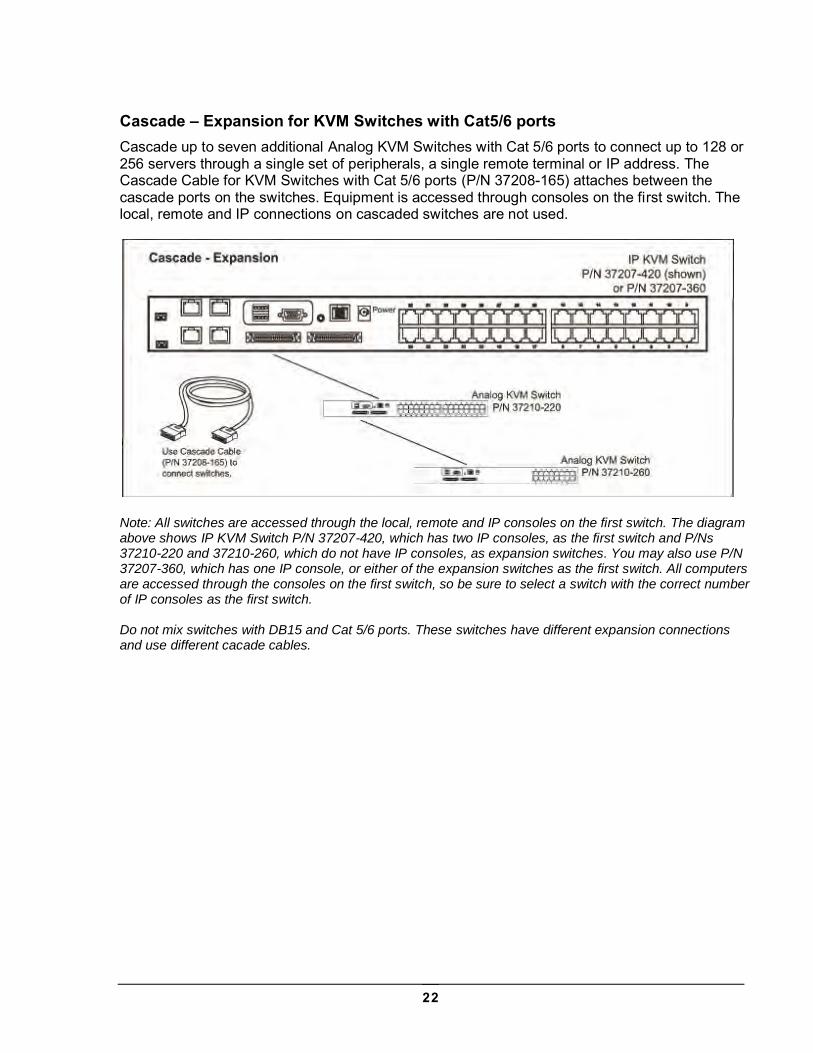
Cascade – Expansion for KVM Switches with Cat5/6 ports Cascade up to seven additional Analog KVM Switches with Cat 5/6 ports to connect up to 128 or 256 servers through a single set of peripherals, a single remote terminal or IP address. The Cascade Cable for KVM Switches with Cat 5/6 ports (P/N 37208-165) attaches between the cascade ports on the switches. Equipment is accessed through consoles on the first switch. The local, remote and IP connections on cascaded switches are not used.
Note: All switches are accessed through the local, remote and IP consoles on the first switch. The diagram above shows IP KVM Switch P/N 37207-420, which has two IP consoles, as the first switch and P/Ns 37210-220 and 37210-260, which do not have IP consoles, as expansion switches. You may also use P/N 37207-360, which has one IP console, or either of the expansion switches as the first switch. All computers are accessed through the consoles on the first switch, so be sure to select a switch with the correct number of IP consoles as the first switch. Do not mix switches with DB15 and Cat 5/6 ports. These switches have different expansion connections and use different cacade cables.
23
Use – KVM Switch
Power ON Turn off all servers and KVM switches Make sure all cables / connectors are properly connected Recommend Power ON sequence is monitor, KVM switch finally computer
24
Password Configuration for the Local/Remote Console The password is disabled by default. Enable password
1. Press the KVM hotkey Scroll Lock + Scroll Lock + U (you must press hotkey within 2 seconds, you will hear a beep when successful)
2. Logout the KVM by pressing the hotkey Scroll Lock + Scroll Lock + P (the unit will automatically log out after 10 minutes of inactivity)
3. In SUPERVISOR level, enter “00000000” eight zeros in user name & password field (Do not use “0” on number pad)
4. In USER level, press Space bar + Enter in user name & password field Set your own user name & password
1. Login the KVM in SUPERVISOR level by pressing “00000000” eight zeros in user name & password field
2. Call KVM OSD menu by pressing the KVM hotkey Scroll Lock + Scroll Lock + Space Bar 3. Press F1 to the MAIN MENU 4. Select “USER SECURITY” 5. Set password in SUPERVISOR & USER level
a. In the left-top row “S” (SUPERVISOR), press Enter to set your own user name & password
b. In the row 1 to 8 (USER), press Enter to set your own user name & password 6. Press Enter to save the setting or press Esc to cancel the editing without any change
a. Blank has underscore, while SPACE does not. b. Press any alphanumeric key to move to next input item. SPACE is treated as a
valid character Change your password
1. Login the KVM in SUPERVISOR level by pressing your own user name & password 2. Call KVM OSD menu by pressing the KVM hotkey Scroll Lock + Scroll Lock + Space Bar 3. Press F1 to the MAIN MENU 4. Select “USER SECURITY” 5. Change password in SUPERVISOR & USER level
a. In the left-top row “S” (SUPERVISOR), press Enter to change your user name & password
b. In the row 1 to 8 (USER), press Enter to change your user name & password 6. Press Enter to save the setting or press Esc to cancel the editing without any change
a. Blank has underscore, while SPACE does not. b. Press any alphanumeric key to move to next input item. SPACE is treated as a
valid character Disable your password
1. Press the KVM hotkey Scroll Lock + Scroll Lock + U 2. Logout the KVM by pressing the KVM hotkey Scroll Lock + Scroll Lock + P 3. You don’t need user name & password to access the KVM OSD menu
25
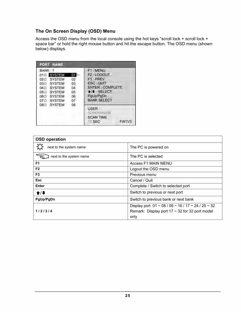
The On Screen Display (OSD) Menu Access the OSD menu from the local console using the hot keys “scroll lock + scroll lock + space bar” or hold the right mouse button and hit the escape button. The OSD menu (shown below) displays.
OSD operation
next to the system name The PC is powered on
next to the system name The PC is selected
F1 Access F1 MAIN MENU F2 Logout the OSD menu F3 Previous menu Esc Cancel / Quit Enter Complete / Switch to selected port
Switch to previous or next port
PgUp/PgDn Switch to previous bank or next bank
1 / 2 / 3 / 4 Display port 01 ~ 08 / 09 ~ 16 / 17 ~ 24 / 25 ~ 32 Remark: Display port 17 ~ 32 for 32 port model only
26
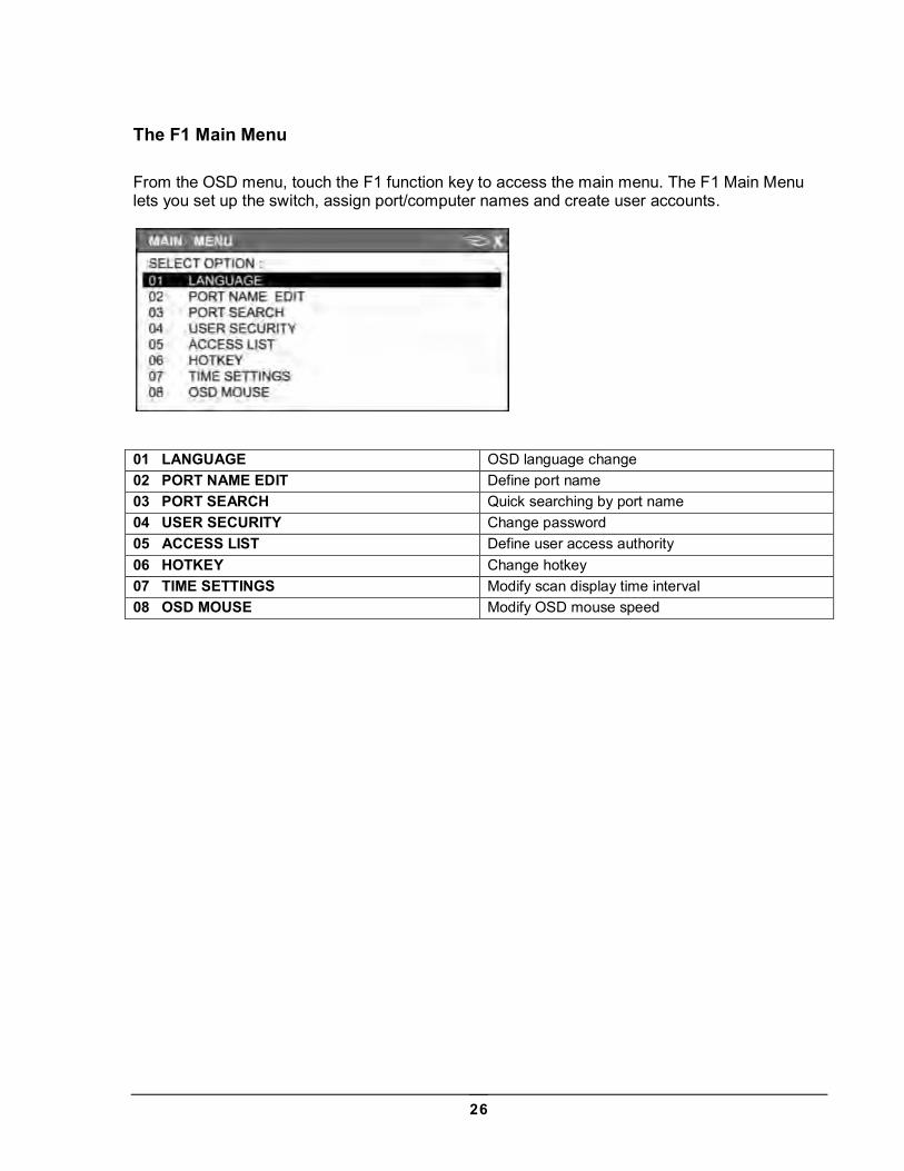
The F1 Main Menu From the OSD menu, touch the F1 function key to access the main menu. The F1 Main Menu lets you set up the switch, assign port/computer names and create user accounts.
01 LANGUAGE OSD language change 02 PORT NAME EDIT Define port name 03 PORT SEARCH Quick searching by port name 04 USER SECURITY Change password 05 ACCESS LIST Define user access authority 06 HOTKEY Change hotkey 07 TIME SETTINGS Modify scan display time interval 08 OSD MOUSE Modify OSD mouse speed
27
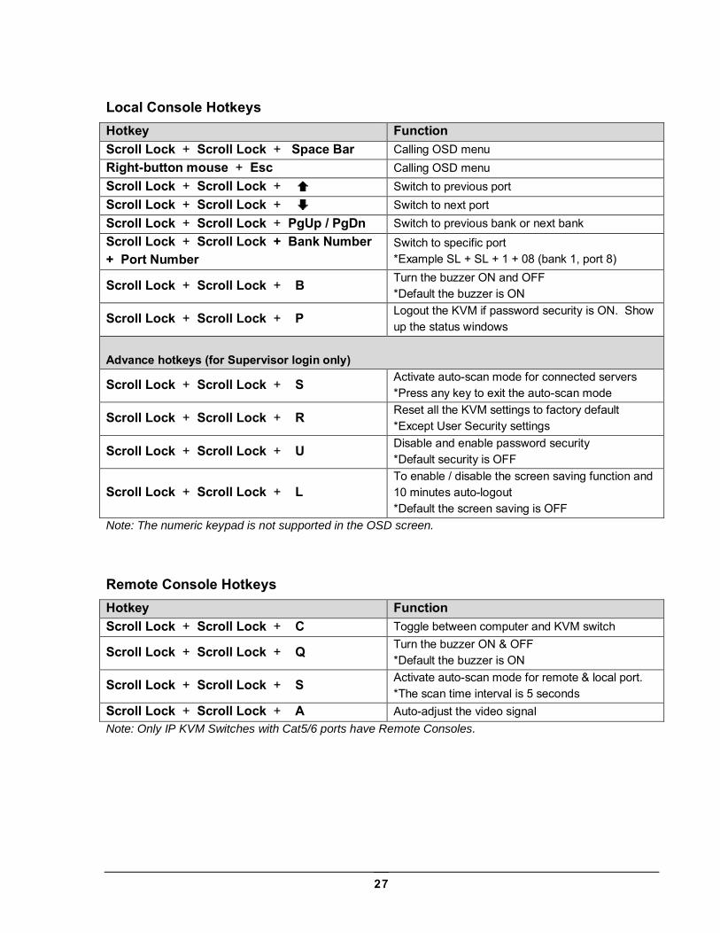
Local Console Hotkeys Hotkey Function Scroll Lock + Scroll Lock + Space Bar Calling OSD menu Right-button mouse + Esc Calling OSD menu Scroll Lock + Scroll Lock + Switch to previous port Scroll Lock + Scroll Lock + Switch to next port Scroll Lock + Scroll Lock + PgUp / PgDn Switch to previous bank or next bank Scroll Lock + Scroll Lock + Bank Number + Port Number
Switch to specific port *Example SL + SL + 1 + 08 (bank 1, port 8)
Scroll Lock + Scroll Lock + B Turn the buzzer ON and OFF *Default the buzzer is ON
Scroll Lock + Scroll Lock + P Logout the KVM if password security is ON. Show up the status windows
Advance hotkeys (for Supervisor login only)
Scroll Lock + Scroll Lock + S Activate auto-scan mode for connected servers *Press any key to exit the auto-scan mode
Scroll Lock + Scroll Lock + R Reset all the KVM settings to factory default *Except User Security settings
Scroll Lock + Scroll Lock + U Disable and enable password security *Default security is OFF
Scroll Lock + Scroll Lock + L To enable / disable the screen saving function and 10 minutes auto-logout *Default the screen saving is OFF
Note: The numeric keypad is not supported in the OSD screen.
Remote Console Hotkeys Hotkey Function Scroll Lock + Scroll Lock + C Toggle between computer and KVM switch
Scroll Lock + Scroll Lock + Q Turn the buzzer ON & OFF *Default the buzzer is ON
Scroll Lock + Scroll Lock + S Activate auto-scan mode for remote & local port. *The scan time interval is 5 seconds
Scroll Lock + Scroll Lock + A Auto-adjust the video signal Note: Only IP KVM Switches with Cat5/6 ports have Remote Consoles.
28
Set up – IP Console
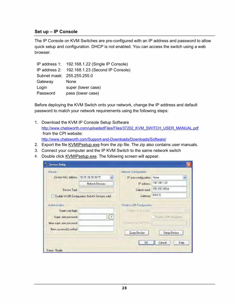
The IP Console on KVM Switches are pre-configured with an IP address and password to allow quick setup and configuration. DHCP is not enabled. You can access the switch using a web browser. IP address 1: 192.168.1.22 (Single IP Console) IP address 2: 192.168.1.23 (Second IP Console) Subnet mask: 255.255.255.0 Gateway None Login super (lower case) Password pass (lower case)
Before deploying the KVM Switch onto your network, change the IP address and default password to match your network requirements using the following steps: 1. Download the KVM IP Console Setup Software
http://www.chatsworth.com/uploadedFiles/Files/37202_KVM_SWITCH_USER_MANUAL.pdf from the CPI website: http://www.chatsworth.com/Support-and-Downloads/Downloads/Software/
2. Export the file KVMIPsetup.exe from the zip file. The zip also contains user manuals. 3. Connect your computer and the IP KVM Switch to the same network switch 4. Double click KVMIPsetup.exe. The following screen will appear.
29
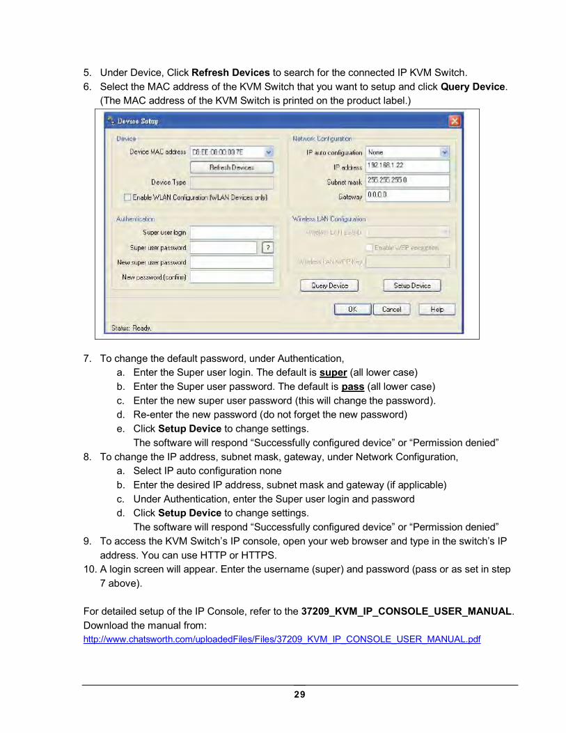
5. Under Device, Click Refresh Devices to search for the connected IP KVM Switch. 6. Select the MAC address of the KVM Switch that you want to setup and click Query Device.
(The MAC address of the KVM Switch is printed on the product label.)
7. To change the default password, under Authentication,
a. Enter the Super user login. The default is super (all lower case) b. Enter the Super user password. The default is pass (all lower case) c. Enter the new super user password (this will change the password). d. Re-enter the new password (do not forget the new password) e. Click Setup Device to change settings.
The software will respond “Successfully configured device” or “Permission denied” 8. To change the IP address, subnet mask, gateway, under Network Configuration,
a. Select IP auto configuration none b. Enter the desired IP address, subnet mask and gateway (if applicable) c. Under Authentication, enter the Super user login and password d. Click Setup Device to change settings.
The software will respond “Successfully configured device” or “Permission denied” 9. To access the KVM Switch’s IP console, open your web browser and type in the switch’s IP
address. You can use HTTP or HTTPS. 10. A login screen will appear. Enter the username (super) and password (pass or as set in step
7 above). For detailed setup of the IP Console, refer to the 37209_KVM_IP_CONSOLE_USER_MANUAL. Download the manual from: http://www.chatsworth.com/uploadedFiles/Files/37209_KVM_IP_CONSOLE_USER_MANUAL.pdf
30
Troubleshooting guide – KVM Switch
1. There is no LED display on KVM membrane switch.
Make sure the power adapter is plugged into the KVM Switch. If the LED is still off, perform soft reset to KVM switch. If that does not work, power cycle the KVM switch.
2. I can power on the KVM, but I am not getting any picture.
Switch to another port and check if this port has the same problem If the second port is working, check that the screen resolution is the same for both ports. Check that the OSD menu is available on the hot keys Scroll lock + Scroll lock + space
bar. Make sure the cables are inserted properly and reboot the system.
3. The screen is on but the keyboard and mouse don’t work.
Check the server by using a different keyboard and mouse. For PS/2 servers, the keyboard and mouse are not hot pluggable. For USB servers, unplug and plug allowing a few seconds for the bus emulation process
to complete. Do not press any keys on the keyboard while the server is booting up. This can cause a
keyboard error or cause the keyboard not to detect the KVM switch. Try a different keyboard, but use only 101/102/104-key keyboard. Avoid moving the mouse while switching the KVM ports.
4. There is no LED display on the dongle.
The LED on the dongle will flash when plugged into the USB or PS/2 server. The light will then become steady when the KVM switch has connected. If the LED light is on and not flashing when plugged into the server, please unplug the
USB or PS/2 and try again. Or try another good dongle to verify if problem still appears. If the problem persists,
please contact your supplier.
31
Appendices
Factory Default Setting Local/Remote Console Login User name = 00000000 (eight zeros) Local/Remote Console Login Password = 00000000 (eight zeros) Menu Access key = Scroll Lock + Scroll Lock + Space Bar or Right Mouse Button + Escape IP Login User name = super (all lowercase) IP Login Password = user (all lowercase) Default IP address = 192.168.1.22 Default IP2 address = 192.168.1.23
FAQ Q. How do the KVM switches allow the user to switch ports? A. There are three ways to switch ports: the membrane buttons on the front panel or keyboard
tray, with keyboard hot-key commands or using the OSD menu. Q. What operating systems do the KVMs support? A. The KVM switches support multi-platform operating systems including but not limited to DOS,
Windows 95/98/ME/NT/2000/XP, Linux, Solaris and Mac OS. Q. Do I have to power down the KVMs to add a new server? A. The KVMs are hot-pluggable and allow servers or devices to be added or removed without
powering down the switch, but components of connected devices, such as the servers, may not be hot pluggable. We suggest that you turn off power to all devices before connecting them.
Q. Why I can’t login with the default password on KVM switch? A. The default username and password for the Local/Remote KVM switch is eight zeros -
“00000000”. The numeric (number) keys on the number pad are not accepted by the KVM, only the main number keys. Be sure that the “Num lock” is not turned on for a notebook type keyboard.
Q. Can I disable the Local/Remote KVM password? A. Yes, you can disable and enable the KVM password by hotkey. Q. How many levels of KVM cascade are supported? A. Eight levels are supported. Q. Can I cascade the different types KVM switches together? A. No, only same type of KVM Switches can cascade together. KVM Switches with DB15 ports
P/N 37202-160 and 37212-260 will cascade. Likewise, KVM Switches with Cat5/6 ports P/N 37207-360 and 37210-260 and P/N 37207-420 and 37210-220 will cascade.
32
Q. Why am I getting ghosting images or shadowing? A. The signal cable may be loose or the video card configuration may not match the switch.
Check that all video cables are inserted properly. Check whether the KVM supports the resolution and refresh-rate on your servers. Check whether the graphics card you are using supports the resolution and refresh rate on your server or not. Connect the monitor directly into the servers you are having trouble with to see if problem still appears.
Q. The server VGA resolution does not match the resolution of monitor? A. The KVM supports DDC function which will dynamically detect the DDC data. The problem
may come from the power on sequence. For KVM switch, the recommended power on sequence is – monitor, KVM switch and then servers. For the remote console receiver, which supports the DDC function but does not support hot-plug, the recommend power on sequence is – monitor, remote console receiver and then servers.
Q. Can I use the touch screen with KVM switches? A. No, the KVM switches do not support the touch screen driver Q. What is the resolution support on the remote console? A. The remote console can support up to 1,000 feet (300 meters) at 1024 x 768, and up to 500 feet (150 meters) at 1600 x 1200. Q. Why am I getting ghosting images or shadowing on remote console? A. Press Scroll lock + Scroll lock + A on the keyboard connected to remote console box to force auto-adjusting the video signal to optimize. Q. Can I use standard Cat5/6 UTP cable for server connections through the dongle? A. The dongle can support Cat5/5e/6 straight cable. To maximize performance and stability, we
strongly recommend using factory made and tested cable assemblies in fixed lengths. Using this type of cable assembly will provide excellent link connections and data communication. As poorly made field cable assemblies can cause damage to the KVMs and dongles and result in a poor or intermittent link. The warranties do not apply to damage resulting from user-supplied cable.
33
Specifications – KVM Switches with DB15 ports KVM Ports: Number of Ports, Connector: 16, DB15 Connectivity: Combo KVM Cable up to 10 feet (3.0 meters) long, one per server;
P/N 37208-161 for 6 feet (1.8 meters) long, P/N 37208-111 for 10 feet (3.0 meters) long Local Console: Graphic connector, resolution: 1 x DB15 VGA, up to 1600 x 1200 Input Device: 2 x USB type A for keyboard and mouse IP Console (P/N 37212-260 only): Connector: 1 x RJ-45 (8P8C) User management: 15-user accounts, 1 active user Browser: Internet Explorer, Firefox, Safari (must be Java-compatible) Security: SSL v3, RSA, AES, HTTP/HTTPs, CSR Expansion: Up to 128 servers by eight-level cascade Requires DB15 Cascade Cable P/N 37208-162 Compatibility: Multi-platform: Mix PCs, SUNs, IBMs, HPs, Dells Servers Plug and Play DDC: EDID 1.3 Power: 100 or 240 VAC, 50/60 Hz via IEC power cord or adapter Consumption: Maximum 48 Watt, standby 5 Watt (P/N 37202-160 only) Consumption: Maximum 24 Watt, standby 5 Watt (P/N 37212-260 only) Regulatory: FCC, CE Environmental: Operating: 32 to 122°F (0 to 50°C) Storage: 23 to 140°F (-5 to 60°C) Relative humidity: 90%, non-condensing Shock: 50G peak acceleration (11ms, half-sine wave) Vibration: 58-100 Hz per 0.98G (11ms per cycle) Dimensions, Weight: Chassis: 1U x 19”EIA, 1.73” x 17.6” x 7.1” (44 mm x 447 mm x 180 mm), 9 lb (4.0 kg) Carton: 3.0” x 20.1” x 15.7” (76 mm x 511 mm x 399 mm), 10 lb (4.5 kg)
34
Specifications – KVM Switches with Cat5/6 ports KVM Ports: Number of Ports, Connector: 16 or 32, RJ-45 (8P8C) Connectivity: VGA connector dongle up to 132 feet (40 meters) over Cat6/Cat 5 UTP cable;
order dongles separately, one per server, P/N 37208-103 for USB, P/N 37208-104 for PS/2 Local Console: Graphic connector, resolution: 1 x DB15 VGA, up to 1600 x 1200 Input Device: 2 x USB type A for keyboard and mouse Remote Console: Connector: 1 x RJ45 (8P8C), up to 500 feet (150 meters) over Cat6/Cat 5 UTP Graphic connector, resolution: 1 x DB15 VGA, up to 1024 x 768 at 1,000 feet (300 meters);
1600 x 1200 at 500 feet (150 meters) Input Device: 2 x USB type A for keyboard and mouse IP Console (P/N 37207-420 and 37207-360 only): Connector: 1 x RJ-45 (8P8C) User management: 15-user accounts, 1 active user Browser: Internet Explorer, Firefox, Safari (must be Java-compatible) Security: SSL v3, RSA, AES, HTTP/HTTPs, CSR Expansion: Up to 128 or 256 servers by eight-level cascade; requires Cascade Cable P/N 37208-165 Compatibility: Multi-platform: Mix PCs, SUNs, IBMs, HPs, Dells Servers Plug and Play DDC: EDID 1.3 Power: 100 or 240 VAC, 50/60 Hz via IEC power cord Consumption: Maximum 24 Watt, standby 5 Watt Regulatory: FCC, CE Environmental: Operating: 32 to 122°F (0 to 50°C) Storage: 23 to 140°F (-5 to 60°C) Relative humidity: 90%, non-condensing Shock: 50G peak acceleration (11ms, half-sine wave) Vibration: 58-100 Hz per 0.98G (11ms per cycle) Dimensions, Weight: Chassis: 1U x 19”EIA, 1.73” x 17.6” x 7.4” (44 mm x 447 mm x 188 mm), 6 lb (2.7 kg) Carton: 6.1” x 22” x 18” (155 mm x 564 mm x 450 mm), 12 lb (5.5 kg)
35
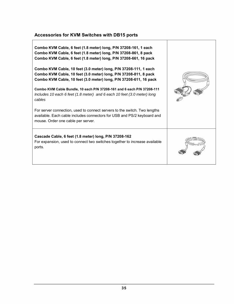
Accessories for KVM Switches with DB15 ports Combo KVM Cable, 6 feet (1.8 meter) long, P/N 37208-161, 1 each Combo KVM Cable, 6 feet (1.8 meter) long, P/N 37208-861, 8 pack Combo KVM Cable, 6 feet (1.8 meter) long, P/N 37208-661, 16 pack Combo KVM Cable, 10 feet (3.0 meter) long, P/N 37208-111, 1 each Combo KVM Cable, 10 feet (3.0 meter) long, P/N 37208-811, 8 pack Combo KVM Cable, 10 feet (3.0 meter) long, P/N 37208-611, 16 pack Combo KVM Cable Bundle, 10 each P/N 37208-161 and 6 each P/N 37208-111 Includes 10 each 6 feet (1.8 meter) and 6 each 10 feet (3.0 meter) long
cables
For server connection, used to connect servers to the switch. Two lengths available. Each cable includes connectors for USB and PS/2 keyboard and mouse. Order one cable per server.
Cascade Cable, 6 feet (1.8 meter) long, P/N 37208-162 For expansion, used to connect two switches together to increase available ports.
36
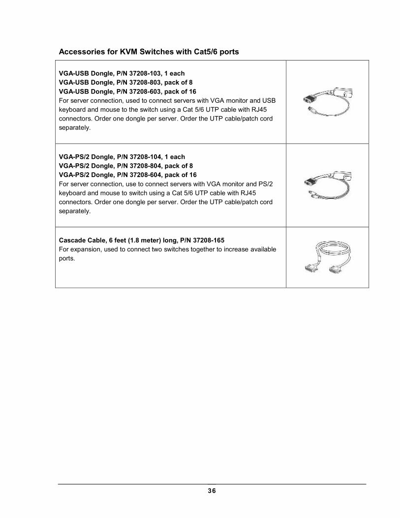
Accessories for KVM Switches with Cat5/6 ports VGA-USB Dongle, P/N 37208-103, 1 each VGA-USB Dongle, P/N 37208-803, pack of 8 VGA-USB Dongle, P/N 37208-603, pack of 16 For server connection, used to connect servers with VGA monitor and USB keyboard and mouse to the switch using a Cat 5/6 UTP cable with RJ45 connectors. Order one dongle per server. Order the UTP cable/patch cord separately.
VGA-PS/2 Dongle, P/N 37208-104, 1 each VGA-PS/2 Dongle, P/N 37208-804, pack of 8 VGA-PS/2 Dongle, P/N 37208-604, pack of 16 For server connection, use to connect servers with VGA monitor and PS/2 keyboard and mouse to switch using a Cat 5/6 UTP cable with RJ45 connectors. Order one dongle per server. Order the UTP cable/patch cord separately.
Cascade Cable, 6 feet (1.8 meter) long, P/N 37208-165 For expansion, used to connect two switches together to increase available ports.