
Electrically Addressed Dual Resonator Sensing Platform for Biochemical Detection

Coupling of Waveguide and Resonator by Inductive andCapacitive Irises for EPR Spectroscopy
R.R. Mett1,2, J.W. Sidabras1, and J.S. Hyde1
1Department of Biophysics, Medical College of Wisconsin, Milwaukee, Wisconsin, USA
2Milwaukee School of Engineering, Milwaukee, Wisconsin, USA
AbstractAn analytic circuit model for slot coupling from a waveguide to a loop-gap resonator (LGR) in acontext of electron paramagnetic resonance (EPR) spectroscopy is presented. The physicaldimensions of the waveguide, iris, LGR, and aqueous sample are transformed into circuit values ofinductance, capacitance, and resistance. These values are used in a solution of circuit equations thatresults in a prediction of the rf currents, magnitude and phase, frequency, and magnetic and electricstored energies near critical coupling. The circuit geometry reflects magnetic flux conservationbetween the iris and LGR as well as modification of the outer loop LGR currents by the iris. Unlikeconventional models, coupling is not explicitly based on a mutual inductance between the iris andLGR. Instead, the conducting wall high frequency rf boundary condition is used to define surfacecurrents, regions, and circuit topology with lumped-circuit values of self-inductance, capacitance,and resistance. Match is produced by a combination of self-inductive and capacitive circuit coupling.Two conditions must be met to achieve match. First, the equivalent resistance of the LGR as seenby the iris must be transformed into the waveguide characteristic impedance. This transformation ismet at a particular frequency relative to the natural LGR resonance frequency. The frequency shiftmagnitude is largely determined by the LGR properties, weakly dependent on iris length andplacement, and independent of other iris dimensions. The second condition for match is that the irisreactance at this frequency shift must cancel the residual reactance of the LGR. This second conditionis sensitive to the iris dimensions. If both conditions are not simultaneously satisfied, overcouplingor undercoupling results. A slotted iris of equal length to the size of the large dimension of thewaveguide is found to have many properties opposite to a conventional iris of shorter length. Notably,the magnetic field near the iris tends to reinforce rather than oppose the magnetic field in the resonator.The long iris improves the LGR EPR performance by providing increased rf magnetic fieldhomogeneity at the sample, higher signal, and reduced total frequency shift since the shifts due tosample and iris tend to cancel. Investigations reveal that the first match condition can be adjusted byLGR dimensional changes and such adjustment can eliminate the frequency shift. Results areconsistent with Ansoft High Frequency Structure Simulator (Version 10.1, Ansoft Corporation,Pittsburgh, PA) simulations and can be extended to cavity resonators.
Keywordsiris; EPR; loop-gap resonator
Author to whom correspondence should be addressed: James S. Hyde Department of Biophysics Medical College of Wisconsin 8701Watertown Plank Road Milwaukee, WI 53226-0509 Phone: (414) 456-4005 Fax: (414) 456-6512 E-mail: E-mail: [email protected].
NIH Public AccessAuthor ManuscriptAppl Magn Reson. Author manuscript; available in PMC 2009 June 3.
Published in final edited form as:Appl Magn Reson. 2009 ; 35(2): 285–318. doi:10.1007/s00723-008-0162-0.
NIH
-PA Author Manuscript
NIH
-PA Author Manuscript
NIH
-PA Author Manuscript
1 IntroductionMett and Hyde [1] have studied the influence of round and slotted irises on microwave leakagefrom magnetic field modulation slots cut perpendicular to the axis of TE011 cavities at Q-band.They found that a thin slotted iris has significantly less leakage than a round iris because theslotted iris makes a smaller perturbation on the TE011 mode than the round iris. A similarobservation was made using the finite element computer program Ansoft High FrequencyStructure Simulator (HFSS) (Version 10.1, Ansoft Corporation, Pittsburgh, PA) in loop-gapresonators (LGRs) of significant length. The authors were surprised at the level of modeperturbation, even at the sample, caused by round and slotted irises in a 10-mm-long 3-loop-2-gap resonator at Q-band (Fig. 1), despite the expected shielding effects of the gaps. The ratioof this LGR length to free space wavelength is 114% and other dimensions are given in Table1. Radio frequency magnetic field energy density uniformity was diminished by 8-15%compared to eigenmode by these couplers, Fig. 2(a). Uniform magnetic field at the sample isrequired to achieve uniform spin saturation. In an attempt to lower the level of modeperturbation caused by the iris, narrower and longer irises were tried. It was found possible toextend the iris length across the full WR-28 waveguide width as shown in Fig. 1 with irisdimensions given in Table 2. This long iris was observed to have many properties opposite ordual to those of a conventional slotted iris of length less than half the long waveguide dimensionand those of a round iris. These properties include the phases of the rf fields and currents inthe resonator relative to those near the iris, the stored energy type in the iris, the frequency atmatch relative to the resonator natural resonance frequency (frequency shift), and the sign ofthe iris reactance (inductive vs. capacitive). In addition, the rf magnetic energy densityuniformity at the sample was improved by the long iris compared to the eigenmode solution,Fig. 2(a). This paper presents an analysis and circuit model of iris coupling of a waveguide toan LGR. Although the analysis is done specifically for an LGR, treatment of a cavity resonatorfollows with little modification. The model was developed in close conjunction with AnsoftHFSS.
The LGR was introduced for use in EPR spectroscopy in the simplest possible cross-sectionalgeometry, Fig. 3(a), [2] and later extended to numerous other cross-sections including thoseshown in Figs. 3(b)-(d). The literature has been reviewed by Hyde and Froncisz [3] and byRinard and Eaton [4]. Iris coupling between a waveguide and a 3-loop-2-gap LGR of 1-mmlength has been done at Q-band, but there is no rationale given for the design [5, 6].
Iris coupling between waveguide and cavity is typically modeled by a mutual inductance Mbetween the iris and the cavity inductance [1,7-9]. After extensive investigation using AnsoftHFSS, models with mutual inductance were found to be inadequate to explain the iris couplingbehavior between waveguide and 3-loop-2-gap LGR for irises of different sizes at Q-band. Asimple mutual inductance model following ref. 1 was found to mimic some of the observations,including phases of rf currents and the input impedance, but not others such as frequency shift.The addition of the distributed nature of the iris into the model, Sect. 2.2, including mutualinductance between iris and LGR outer loop, was found to increase disparities between themodel and HFSS observations, and a rationale for choosing the sign and value of M remainedunsatisfactory.
In the present work, the metallic wall high frequency rf boundary condition, which relatessurface current to magnetic field [8], was used to define surface currents, distinct regions, andcircuit topology of the coupled iris-LGR with lumped-circuit values of capacitance, resistance,and self-inductance with no mutual inductance. That it is possible to obtain a complete circuitmodel of the coupled iris-LGR without mutual inductance is perhaps surprising. However, weshow in Appendix A that the equivalent self-inductance of a coil in the presence of a metallicrf shield is equivalently expressible in terms of mutual inductance or self-inductance. The effect
Mett et al. Page 2
Appl Magn Reson. Author manuscript; available in PMC 2009 June 3.
NIH
-PA Author Manuscript
NIH
-PA Author Manuscript
NIH
-PA Author Manuscript
of the mutual inductance of the shield on the coil in the high frequency rf limit is to induce anrf current on the outside surface of the coil. The separation of the total current on the coil intoan inner current and an outer current leads to the ability to treat the coil as two self-inductancesin parallel with no mutual inductance between them. The mutual and self inductance modelsdiffer in the definition of the coil currents. The results are consistent with a statement by Grover[10]: “Self-inductance is merely a special case of mutual inductance.”
In the present work, the circuit model geometry reflects flux conservation between iris andLGR, includes capacitive and inductive circuit coupling, and accounts for the influence of theiris on the LGR outer loop currents. In this model, the geometrical dimensions of the LGR,iris, and waveguide are used to calculate circuit values of self-inductance, capacitance, andresistance, including the effects of sample. These circuit values then determine the solution tothe circuit equations and predict the input impedance, rf currents, frequency shift, and magneticand electric stored energies. The circuit is a pi network with the bridge element an inductanceformed by the part of the LGR outer loop cut by the iris. The circuit can be cast into an equivalentform having an effective mutual coupling between two resonant circuits described by Terman[9]. The effective mutual coupling represents combined capacitive and self-inductive(complex) coupling between primary (waveguide/iris) and secondary (LGR), although withno mutual inductance.
Two conditions must be met to achieve critical coupling (match). First, the equivalentresistance of the LGR as seen by the iris must be transformed into the waveguide characteristicimpedance. Due to the behavior of the LGR resistance with frequency, this transformationtypically occurs at a particular frequency relative to the natural LGR resonance frequency. Thisfrequency shift magnitude is strongly dependent on the LGR and sample dimensions, weaklydependent on the iris length and placement, and independent of other iris dimensions. Thesecond condition for match is that the iris reactance at this frequency shift must cancel theresidual reactance of the LGR. This second condition is sensitive to the iris dimensions. If bothconditions are not simultaneously satisfied, overcoupling or undercoupling results. The firstmatch condition completely determines the frequency shift magnitude, and so LGR and irisdesign can reduce or eliminate this frequency shift, or tailor it for example to the needs of theEPR spectroscopist, who prefers no difference between the frequencies at match with andwithout sample.
2 TheoryA mechanical drawing of the 3-loop-2-gap 10-mm-long Q-band LGR introduced by Mett,Sidabras, and Hyde [11] with iris coupling to a WR-28 waveguide is shown in Fig. 1. The LGRand sample dimensions are shown in Table 1. The lumped circuit model that reflects theinteraction between LGR, iris, and waveguide is developed in stages below. For simplicity, weassume that the symmetry planes of the waveguide, iris, and LGR coincide so that two half-circuits in parallel describe the whole. With further analysis, this symmetry can be removed.At points in the development of the theory, predictions of the circuit model calculated withMathematica (Version 6, Wolfram Research, Inc., Champaign, IL) were compared with AnsoftHFSS simulations. A Dell Precision 690 workstation with dual dual-core 3.0 GHz processorsand 16 GB of RAM with Windows XP 64-bit was used to run the program. Both eigenmodeand driven solution methods were used.
2.1 Circuit Model of LGRSince the iris intercepts one of the outer loops of the LGR (Fig. 1), we take as a firstapproximation the LGR circuit seen by the iris, Fig. 4. Accordingly, the LGR input impedanceis given by Eq. (1) assuming ejωt time dependence:
Mett et al. Page 3
Appl Magn Reson. Author manuscript; available in PMC 2009 June 3.
NIH
-PA Author Manuscript
NIH
-PA Author Manuscript
NIH
-PA Author Manuscript
(1)
The lumped circuit values of self-inductance, capacitance, and resistance are expressed in termsof the LGR dimensions and conductivity as shown in Appendix B. The derivation follows fromMett et al. [11] and corresponds to the LGR at cutoff. At cutoff, the rf currents are perpendicularto the LGR axis and the rf fields are axially uniform (except within one radius of the LGRends). Reference [11] also shows how an rf impedance at the ends of the LGR causes a shiftin the resonance frequency from cutoff and a corresponding rf field axial non-uniformity. Thataxial full-wave analysis is shown to account for a majority of resonance frequency deviationfrom cutoff and field non-uniformity. The LGR ends can be designed to have an infinite rfimpedance and the LGR then resonates with uniform fields at cutoff. Since the present workis about the influence of a coupling iris on the LGR, for simplicity we do not include the axialfull-wave analysis, although such effects could be included with further analysis. Thefrequency shifts due to coupling predicted by the circuit model are relative to cutoff. These arecompared to the frequency shifts predicted by finite element modeling of driven mode withthe iris relative to eigenmode without.
Near resonance, the magnetic flux in the inner LGR loop is shared between the outer loops.This conservation of flux can be combined with the expression for the peak magnetic energyof the system to derive the equivalent inductance,
(2)
and with the expression for the dissipated power to obtain the equivalent resistance,
(3)
looking into the outer loop, Fig. 4. These equations were written for m gaps and m outer loops;although in Fig. 4, m = 2. It can be shown that Eq. (3) reduces to Eq. (2) with the replacementR → L. These equations, which can also be derived from Eq. (1), reflect how flux conservationin the LGR magnifies the resistance of the inner loop as seen from the outside. The effect istransformer-like, although in the circuit model there is no mutual inductance. The quality factoris given by
(4)
where the subscript zero indicates the natural LGR resonance frequency. As shown in AppendixB, the LGR loop resistances are caused by the rf current flow on the inner surface of theconducting loop and part of the gap. Equations (2)-(4) and the equations of Appendix B giveQ values within 1.5% of those of the LGR at cutoff predicted by Ansoft HFSS. When a sampleis inserted to the LGR inner loop, the circuit is loaded by an effective sample resistance addedto the inner loop resistance of Eq. (B9), Ri → Ri + Rs. The value of Rs is calculated from Eqs.(2)-(4) using a sample-loaded LGR Q value that can be obtained either by experimental
Mett et al. Page 4
Appl Magn Reson. Author manuscript; available in PMC 2009 June 3.
NIH
-PA Author Manuscript
NIH
-PA Author Manuscript
NIH
-PA Author Manuscript

measurement or by finite element modeling. With such a sample resistance, it is found that thedependence of impedance with frequency predicted by Eq. (1) near resonance is fully consistentwith the behavior of the coupled LGR reflection coefficient with frequency predicted by drivenmode Ansoft HFSS.
We can also write the equivalent capacitance as
(5)
and so the (natural) LGR resonance frequency
(6)
With the lumped circuit values of Appendix B, this frequency is the LGR cutoff frequency.Equations (2), (5), and (6) give identical results to Eqs. (2)-(7) of ref. 11. (The effect of Q onthe resonance frequency is less than four parts per million at a Q of 200.)
The LGR equivalent circuit (Fig. 4) is a parallel R-L-C circuit driven by a series R-L and hasproperties of both parallel and series R-L-C circuits. As is well known, the resistance of aparallel R-L-C circuit as a function of frequency has a Lorentzian shape peaked at its naturalresonance frequency. Similarly, the admittance of a series R-L-C circuit has a Lorentzian shapepeaked at the natural resonance frequency. The corresponding reactance and susceptance ofthese respective circuits have the shape of a Lorentzian derivative. For the LGR, theconductance as a function of frequency has a Lorentzian shape peaked at the natural resonancefrequency f0, Eq. (6), where it is equal to 1/Req. The susceptance has the shape of a Lorentzianderivative with an offset value of approximately -(ωLo)-1 at the natural resonance frequencysince the LGR circuit is broken at the outer loop. These can be summarized by
(7)
and follow from Eq. (1) in the limits ReqRi ⪡ (ωLi)2 and Ro ⪡ Req. The width of the Lorentzianat half maximum is Δfw = f0/Q. The variation of the LGR admittance near f0 determines thefrequency of critical coupling, as discussed further in Sect. 2.5 and the results section. The realand imaginary parts of the LGR impedance also have Lorentzian and Lorentzian-derivativeshapes, respectively, but the Lorentzian center frequency is displaced several percent belowboth f0 and the frequency of critical coupling.
2.2 Circuit Model of IrisA drawing of the rf currents flowing around the iris is shown in Fig. 5(a) and can be comparedto the mechanical drawing of Fig. 1. The iris has a capacitance largely across its center and aself-inductance largely on each end. A naive approach suggests that we might assign acapacitance to the center half,
2Since the resistances are neglected in the calculation, the accuracy of this predicted match frequency decreases as fm approaches therange of frequencies approaches the range of frequencies within the Lorentzian half width f0 ± f0/Q.
Mett et al. Page 5
Appl Magn Reson. Author manuscript; available in PMC 2009 June 3.
NIH
-PA Author Manuscript
NIH
-PA Author Manuscript
NIH
-PA Author Manuscript

(8)
and a self-inductance to the outer half,
(9)
of the half-iris, where lc, wc, and tc are the total length, width, and wall thickness of the couplingiris, respectively; ε0 is the electric permittivity of free space; and μ0 is the magnetic permeabilityof free space. Equations (8) and (9) can be refined by considering that iris current flows opposeone another across the iris thickness, and that the current flow is directed primarily along theiris length dimension, Fig. 5(a). Therefore, the iris can be viewed as two parallel conductingstrips shorted at each end. The configuration is a two-conductor transmission line supportingan electromagnetic mode transverse to the iris length (TEM). It is well known that theelectromagnetic solutions for a TEM mode consist of the electrostatic solution with themagnetic solution derivable from the electrostatic field [8], [12]. Consequently, we can use ananalytic electrostatic solution for the capacitance per unit length of two long parallel conductingstrips given by Smythe [13] and that has been applied to the LGR gap in Appendix B and ref.11. The solution takes the form of a factor γ that multiplies the capacitance per unit lengthε0tc/wc, and thus the quarter-iris length given by Eq. (8),
(10)
This factor is a function of the ratio tc/wc through elliptic integrals. Due to dimensionaldefinitions, we replace the ratio w/t in Eqs. (B6) and (B7) of Appendix B by tc/wc. In practice,a different stray capacitance correction using Eq. (16) of ref. 11 produces similar results. Thesecorrections cannot be used simultaneously because the capacitance is overestimated.
Because of the TEM transmission line mode, the product of the capacitance per unit length andthe inductance per unit length along the iris length dimension is ε0μ0 [8], [12]. Therefore, theiris inductance of a quarter iris length, Eq. (9), must also be corrected by the same factor,
(11)
The Cc Lc product then remains a function only of the iris dimension of length. A furthercorrection to Eqs. (10) and (11) can be made by further considering the iris as a transmissionline. As shown by Jackson [12] and in the LGR gap discussion of Appendix B, a capacitorformed by two parallel metallic strips of dimensions lc/4 and tc a distance wc apart and fedalong the length has a capacitance given by Eq. (8) with a series inductance equal to one-thirdof Eq. (9). Similarly, if these strips are shorted, we obtain an inductance given by Eq. (9) witha parallel capacitance equal to one-third of Eq. (8). Since the iris is symmetric about its center,where there is also a current null, the center capacitance is fed from the end inductance. Theseresults can be combined into the lumped circuit model of the isolated half-iris shown in Fig. 5(b), where
(12)
Mett et al. Page 6
Appl Magn Reson. Author manuscript; available in PMC 2009 June 3.
NIH
-PA Author Manuscript
NIH
-PA Author Manuscript
NIH
-PA Author Manuscript
(13)
The total input impedance
(14)
of the isolated iris is therefore
(15)
The same model can be obtained from the impedance of a length lc/4 of open transmission line,-jZ0cot(klc/4), and shorted transmission line, jZ0/cotklc/4, where the characteristic impedance
and the wavenumber k =ω/c, using the first two terms in the expansion cotx = 1/x - x/3 - …, which converges for 0<|x|<π. Iris resistances can be included but are typicallynegligible because of the low primary Q as discussed in Sect. 2.6. An exception is the unusualcase of a strongly resonant iris discussed in Sect. 3.2. The distributed nature of the iris is largelycaptured by this model. Analysis of Eq. (15) shows that the self-resonance frequency of theisolated iris is given by
(16)
which is about 79.1% (≅π/4) of the resonance frequency of Cc and Lc alone. The frequencypredicted by Eq. (16) is within 3% of the self-resonance frequency determined by Ansoft HFSSeigenmode simulation for an isolated iris. Furthermore, Eq. (16) with (8)-(11) is consistentwith the expression for the resonance frequency of a shorted two-conductor TEM transmissionline of length to within 1%. It is possible to use exact transmission line impedances,which can be a subject of future investigation.
An alternative approach to finding the iris impedance is to use the theory of obstacles andwindows in waveguides [14]. Because the iris wall thickness tc is comparable to the iris openingwidth wc, the iris is considered an obstacle of finite thickness. The special case of iris lengthequal to the large waveguide dimension is treated explicitly as a capacitive obstacle of largethickness in Sect. 8-8 of ref. 14. For typical dimensions that provide match to the LGR discussedbelow, the nonlimited form gives an iris capacitive reactance magnitude 14% lower (morecapacitive) than Eq. (15). The discrepancy is likely because the waveguide method treats onlythe first two waveguide modes and because the method assumes that there is waveguide presenton both sides of the iris. Instead, the presence of the LGR outer loop must be accounted for topredict the full behavior of the iris. This is the subject of the next section.
2.3 Iris Connection to LGR Outer LoopBy the geometry of Fig. 1, all the magnetic flux penetrating the top end of the iris must enterthe LGR loop, go through the central part of the LGR outer loop, and leave the LGR loop bypenetrating the bottom end of the iris. Due to the metallic wall high frequency rf boundary
Mett et al. Page 7
Appl Magn Reson. Author manuscript; available in PMC 2009 June 3.
NIH
-PA Author Manuscript
NIH
-PA Author Manuscript
NIH
-PA Author Manuscript
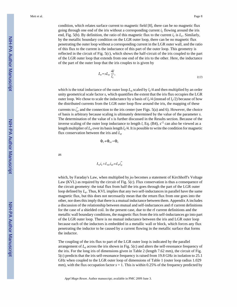
condition, which relates surface current to magnetic field [8], there can be no magnetic fluxgoing through one end of the iris without a corresponding current ic flowing around the irisend, Fig. 5(b). By definition, the ratio of this magnetic flux to the current ic is Lc. Similarly,by the metallic boundary condition on the LGR outer loop, there can be no magnetic fluxpenetrating the outer loop without a corresponding current in the LGR outer wall, and the ratioof this flux to the current is the inductance of this part of the outer loop. This geometry isreflected in the circuit of Fig. 5(c), which shows the half-circuit of the iris coupled to the partof the LGR outer loop that extends from one end of the iris to the other. Here, the inductanceof the part of the outer loop that the iris couples to is given by
(17)
which is the total inductance of the outer loop Lo scaled by lc/4 and then multiplied by an orderunity geometrical scale factor s, which quantifies the extent that the iris flux occupies the LGRouter loop. We chose to scale the inductance by a basis of lc/4 (instead of lc/2) because of howthe distributed currents from the LGR outer loop flow around the iris, the mapping of thesecurrents to , and the connection to the iris center (see Figs. 5(a) and 6). However, the choiceof basis is arbitrary because scaling is ultimately determined by the value of the parameter s.The determination of the value of s is further discussed in the Results section. Because of theinverse scaling of the outer loop inductance to length l, Eq. (B4), s-1 can also be viewed as alength multiplier of Le over its basis length lc/4. It is possible to write the condition for magneticflux conservation between the iris and Le
as
which, by Faraday's Law, when multiplied by jω becomes a statement of Kirchhoff's VoltageLaw (KVL) as required by the circuit of Fig. 5(c). Flux conservation is thus a consequence ofthe circuit geometry: the total flux from half the iris goes through the part of the LGR outerloop defined by Le. Thus, KVL implies that any two self-inductances in parallel have the samemagnetic flux, but this does not necessarily mean that the return flux from one goes into theother, nor does this imply that there is a mutual inductance between them. Appendix A includesa discussion of the relationship between mutual and self-inductances and rf current definitionsfor the case of a shielded coil. In the present case, due to the rf current definitions and themetallic wall boundary conditions, the magnetic flux from the iris self-inductances go into partof the LGR outer loop. There is no mutual inductance between the iris and LGR outer loopbecause each of the inductors is embedded in a metallic wall or block, which forces any fluxpenetrating the inductor to be caused by a current flowing in the metallic surface that formsthe inductor.
The coupling of the iris flux to part of the LGR outer loop is indicated by the parallelarrangement of Le across the iris shown in Fig. 5(c) and alters the self-resonance frequency ofthe iris. For the long iris of dimensions given in Table 2 (length 7.62 mm), the circuit of Fig.5(c) predicts that the iris self-resonance frequency is raised from 19.8 GHz in isolation to 25.1GHz when coupled to the LGR outer loop of dimensions of Table 1 (outer loop radius 1.029mm), with the flux occupation factor s = 1. This is within 0.25% of the frequency predicted by
Mett et al. Page 8
Appl Magn Reson. Author manuscript; available in PMC 2009 June 3.
NIH
-PA Author Manuscript
NIH
-PA Author Manuscript
NIH
-PA Author Manuscript

Ansoft HFSS eigenmode simulations with shorted gap. Significantly shorter irises havesignificantly higher self-resonance frequencies, which can be influenced by coupling to higherorder modes that are not accounted for in the model.
2.4 Circuit Model of Connected Iris and LGRWe build on the results of the previous three sections and construct the half-circuit model ofthe combined iris and LGR, Fig. 6. Here, we separate the total LGR outer loop half-circuitinductance 2Lo into two parts,
(18)
so that their parallel combination gives the inductance of the half outer loop. Equation (18)defines . Similarly, since the outer loop resistance is caused by the same surface current thatproduces the inductance (see Eq. (B8) discussion), we modify an outer loop resistance,
(19)
and break it into two parts to define ,
(20)
The resistance is a small correction to the total outer loop impedance. By the arguments of theprevious section, the circuit connections of Fig. 6 with KVL imply (neglecting Ro) the magneticflux conservation rule
or
(21)
In the absence of iris flux, these equations show that the flux in Le and is the same (the signis due to the current direction definition), and this flux can also be shown to be equal to theflux in 2Lo (and Lo). Since Eq. (21) is implied by the circuit equations, it can be substituted forany one of the circuit relations implied by Fig. 6 without changing the solution.
The circuit of Fig. 6 shows that the voltage developed across the iris drives part of the LGRouter loop inductance Le, which in turn drives the modified LGR impedance . Theinductance Le acts as the bridge element in a pi network between the impedances Ziris and
. The size of Le influences the coupling strength, and its value depends on the length of theiris. The shape of the iris determines not only the iris impedance but also the value of Le, whichin turn influences the modified LGR impedance . This complex interaction between theiris and the LGR is captured by the circuit of Fig. 6.
Mett et al. Page 9
Appl Magn Reson. Author manuscript; available in PMC 2009 June 3.
NIH
-PA Author Manuscript
NIH
-PA Author Manuscript
NIH
-PA Author Manuscript
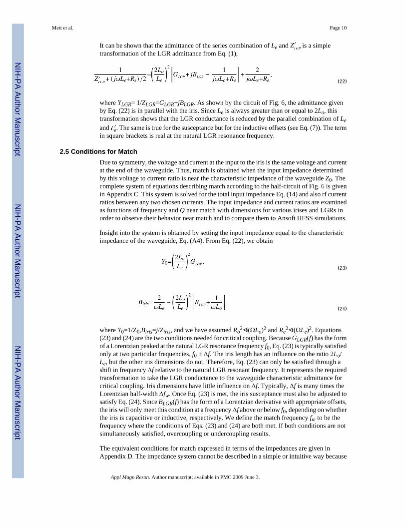
It can be shown that the admittance of the series combination of Le and is a simpletransformation of the LGR admittance from Eq. (1),
(22)
where YLGR= 1/ZLGR=GLGR+jBLGR. As shown by the circuit of Fig. 6, the admittance givenby Eq. (22) is in parallel with the iris. Since Le is always greater than or equal to 2Lo, thistransformation shows that the LGR conductance is reduced by the parallel combination of Leand . The same is true for the susceptance but for the inductive offsets (see Eq. (7)). The termin square brackets is real at the natural LGR resonance frequency.
2.5 Conditions for MatchDue to symmetry, the voltage and current at the input to the iris is the same voltage and currentat the end of the waveguide. Thus, match is obtained when the input impedance determinedby this voltage to current ratio is near the characteristic impedance of the waveguide Z0. Thecomplete system of equations describing match according to the half-circuit of Fig. 6 is givenin Appendix C. This system is solved for the total input impedance Eq. (14) and also rf currentratios between any two chosen currents. The input impedance and current ratios are examinedas functions of frequency and Q near match with dimensions for various irises and LGRs inorder to observe their behavior near match and to compare them to Ansoft HFSS simulations.
Insight into the system is obtained by setting the input impedance equal to the characteristicimpedance of the waveguide, Eq. (A4). From Eq. (22), we obtain
(23)
(24)
where Y0=1/Z0,Biris=j/Ziris, and we have assumed Ro2⪡(ΩLo)2 and Re
2⪡(ΩLe)2. Equations(23) and (24) are the two conditions needed for critical coupling. Because GLGR(f) has the formof a Lorentzian peaked at the natural LGR resonance frequency f0, Eq. (23) is typically satisfiedonly at two particular frequencies, f0 ± Δf. The iris length has an influence on the ratio 2Lo/Le, but the other iris dimensions do not. Therefore, Eq. (23) can only be satisfied through ashift in frequency Δf relative to the natural LGR resonant frequency. It represents the requiredtransformation to take the LGR conductance to the waveguide characteristic admittance forcritical coupling. Iris dimensions have little influence on Δf. Typically, Δf is many times theLorentzian half-width Δfw. Once Eq. (23) is met, the iris susceptance must also be adjusted tosatisfy Eq. (24). Since BLGR(f) has the form of a Lorentzian derivative with appropriate offsets,the iris will only meet this condition at a frequency Δf above or below f0, depending on whetherthe iris is capacitive or inductive, respectively. We define the match frequency fm to be thefrequency where the conditions of Eqs. (23) and (24) are both met. If both conditions are notsimultaneously satisfied, overcoupling or undercoupling results.
The equivalent conditions for match expressed in terms of the impedances are given inAppendix D. The impedance system cannot be described in a simple or intuitive way because
Mett et al. Page 10
Appl Magn Reson. Author manuscript; available in PMC 2009 June 3.
NIH
-PA Author Manuscript
NIH
-PA Author Manuscript
NIH
-PA Author Manuscript
the LGR impedance does not have symmetry about f0 and because the impedancetransformation between ZLGR and is more complicated than the transformation in Eq. (22).The impedance system is further discussed in the following section and Appendix D.
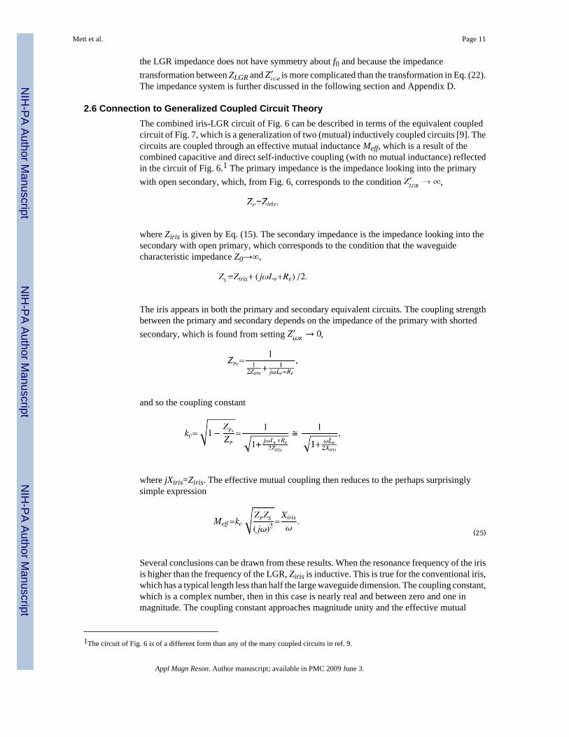
2.6 Connection to Generalized Coupled Circuit TheoryThe combined iris-LGR circuit of Fig. 6 can be described in terms of the equivalent coupledcircuit of Fig. 7, which is a generalization of two (mutual) inductively coupled circuits [9]. Thecircuits are coupled through an effective mutual inductance Meff, which is a result of thecombined capacitive and direct self-inductive coupling (with no mutual inductance) reflectedin the circuit of Fig. 6.1 The primary impedance is the impedance looking into the primarywith open secondary, which, from Fig. 6, corresponds to the condition ,
where Ziris is given by Eq. (15). The secondary impedance is the impedance looking into thesecondary with open primary, which corresponds to the condition that the waveguidecharacteristic impedance Z0→∞,
The iris appears in both the primary and secondary equivalent circuits. The coupling strengthbetween the primary and secondary depends on the impedance of the primary with shortedsecondary, which is found from setting ,
and so the coupling constant
where jXiris=Ziris. The effective mutual coupling then reduces to the perhaps surprisinglysimple expression
(25)
Several conclusions can be drawn from these results. When the resonance frequency of the irisis higher than the frequency of the LGR, Ziris is inductive. This is true for the conventional iris,which has a typical length less than half the large waveguide dimension. The coupling constant,which is a complex number, then in this case is nearly real and between zero and one inmagnitude. The coupling constant approaches magnitude unity and the effective mutual
1The circuit of Fig. 6 is of a different form than any of the many coupled circuits in ref. 9.
Mett et al. Page 11
Appl Magn Reson. Author manuscript; available in PMC 2009 June 3.
NIH
-PA Author Manuscript
NIH
-PA Author Manuscript
NIH
-PA Author Manuscript

coupling is positive real and approaches infinity as the resonance frequency of the irisapproaches that of the LGR from above. However, when the resonance frequency of the irisis lower than the frequency of the LGR, which is true for a long iris of length comparable tothe large waveguide dimension, Ziris is capacitive. Then, depending on the value of Le, thecoupling constant can be either nearly imaginary and between zero and one in magnitude, ornearly real and between one and infinity in magnitude. For the long iris, the coupling constantis typically imaginary and of magnitude less than unity as discussed further below. Thecoupling constant approaches magnitude unity and the effective mutual coupling is negativereal and approaches infinity as the iris resonance frequency approaches that of the LGR frombelow.
At critical coupling, it is commonly understood that the effective mutual coupling reactanceωMeff is equal to the square root of the product of the primary and secondary resistances [9].This is true when the primary reactance is negligible compared to the primary resistance. Mostof Terman's analysis carries this assumption and also the additional constraint that theresonance frequencies of the primary and secondary are equal. Neither of these assumptionsapply in our problem. From an analysis of the circuit of Terman (Sect. 3, Fig. 16 [which is notfurther analyzed there]), the effective mutual coupling is given by
In terms of the present circuit values, this equation can be written
(26)
The combination of Eqs. (26) and (25) results in one of impedance conditions for criticalcoupling, Eq. (D2). However, because is a function of frequency, Eq. (D2) can be satisfiedat almost any frequency without achieving critical coupling. As discussed in the previoussection and in Appendix D, the other condition, Eq. (D1), must simultaneously be met toachieve critical coupling. This additional constraint is not discussed in ref. 9.
At critical coupling, it is commonly understood that the coupling constant is equal to thereciprocal of the square root of the product of the primary and secondary Q's [9]. This is notthe case in the present problem because the primary and secondary reactances are not pureinductances. Since the primary resistance Z0 is in parallel with the resonant iris circuit, Fig. 5(b), the primary Q is given by
where fc is the iris resonance frequency, Eq. (16), and the equivalent inductance of the primaryis given by the term in parenthesis. This equivalent inductance was derived by equating themagnetic flux and energy at iris self-resonance to those of an equivalent parallel L-C circuit.The secondary circuit, which consists of the circuit of Fig. 6 with open input, is morecomplicated. Analysis of this circuit with zero resistances leads to an expression for thesecondary resonance frequency fS, which includes the presence of the iris. The expression was
Mett et al. Page 12
Appl Magn Reson. Author manuscript; available in PMC 2009 June 3.
NIH
-PA Author Manuscript
NIH
-PA Author Manuscript
NIH
-PA Author Manuscript
found using Mathematica and is a solution to a quartic in fS2. The frequency can be evaluatedand is a measure of the frequency at critical coupling fm.2 It is typically within 1% above orbelow the natural LGR resonance frequency, Eq. (6). An analysis of the stored magnetic fluxand energy at this frequency can be used to obtain an equivalent secondary inductance LS, and,with the resistances added to the circuit of Fig. 6, the dissipated power at this frequency leadsto an equivalent resistance RS. These in turn produce the secondary Q,
This Q is typically within about 5% above or below the isolated LGR Q, Eq. (4).
3 ResultsFrom the previous section, critical coupling between the LGR and waveguide is made bymeeting two conditions. The first is the transformation of the LGR equivalent conductancefrom Eq. (1) into the waveguide characteristic admittance, Eq. (23). Due to the Lorentzianbehavior of GLGR (f), this condition is typically met through a frequency shift relative to thenatural LGR resonance frequency. The LGR and sample geometry also strongly influence thiscondition. However, iris dimensions do not. The second condition is that the iris susceptancecancel the LGR susceptance, Eq. (1), as seen by the iris at this frequency shift, Eq. (24). Irisdimensions strongly influence only the second match condition.
The results are divided into four parts. First, we show details of the process of coupling betweena WR-28 waveguide and the 3-loop-2-gap 10-mm-long Q-band LGR of dimensions shown inTable 1, made by irises of characteristically different dimensions, Table 2. It is found, forvarious iris types, that increasing the iris length or width increases the coupling strength, andincreasing the thickness decreases the coupling strength in the circuit model, consistent withAnsoft HFSS simulations. For this study, the iris dimensions for the circuit model were chosenby first simulating the LGR, iris, and waveguide using the driven mode Ansoft HFSS. Thedimensions used in the circuit model were exactly those required to achieve critical couplingin Ansoft HFSS. The flux occupation factor s, defined by Eq. (17), was then adjusted for criticalcoupling. Values that produced critical coupling for these two irises are shown in Table 2. Theyare different because of differences in the magnitude of magnetic flux from each iris relativeto the flux in the LGR outer loop. It is found that s ≅ 0.2|Φe/Φc|, where and Φc =Lcic (see Fig. 6). Although it is possible to obtain s strictly within the circuit model from thecircuit currents by iteration, it is more practical to treat s as a matching parameter, similar tothe adjustment of a tuning pill in a conventional iris tuning system.
From this study, we find that the magnitude of the frequency shift at match relative to thenatural LGR resonance frequency is determined by the LGR and waveguide dimensions, notby the iris. In the remaining results, insights gained from the circuit model are used to explorethe behavior of different iris types. In Sect. 3.2, we examine an iris with a self-resonancefrequency close to the LGR and find that as the iris becomes resonant, the iris width must bemade smaller to achieve critical coupling. Types of frequency pulling are discussed in Sect.3.3 as are the advantages of the long (capacitive) iris over the conventional (inductive) irisbecause frequency shift due to sample size is opposite to the frequency shift due to iris tuningto accommodate reduced Q value. Finally, in Sect. 3.4, the circuit model is used to design anew LGR and coupler without frequency pulling. Results are consistent with finite elementsimulations.
Mett et al. Page 13
Appl Magn Reson. Author manuscript; available in PMC 2009 June 3.
NIH
-PA Author Manuscript
NIH
-PA Author Manuscript
NIH
-PA Author Manuscript

3.1 Conventional vs. Long Iris
The admittance of the series combination of Le and as a function of frequency near thenatural LGR resonance frequency for conventional and long irises is shown in Fig. 8. TheLorentzian and Lorentzian-derivative variation with frequency are due to GLGR and BLGR,respectively, Eq. (22). For any iris, match occurs when the LGR conductance is transformedto the reciprocal of the waveguide characteristic impedance, Eq. (23). Since the iris propertiescontribute only to the inductance ratio in Eq. (23), the transformation is largely accomplishedthrough a frequency shift relative to the natural LGR resonance frequency. The frequency shiftfor the conventional iris, Figs. 8(a) and (b), is negative (-372 MHz, Table 2) because it has aninductive susceptance, which exactly cancels the LGR susceptance at this frequency shift, Eq.(24). In contrast, the long iris is capacitive, and so the frequency shift is positive (251 MHz,Table 2). Again, the iris susceptance exactly cancels the LGR susceptance, Eq. (24), that occurswhen the LGR conductance is transformed to the reciprocal of the waveguide characteristicimpedance, Eq. (23), except now on the other side of the Lorentzian peak. The amount offrequency shift predicted by the circuit model for both irises is within 20% of Ansoft HFSS.
For decreasing LGR Q, the Lorentzian in GLGR becomes wider, and it is seen from Fig. 8(b)that the conventional iris will match at progressively lower frequencies. Because the real partof the sample dielectric constant also pulls the natural LGR resonance frequency down forincreasing sample size, the two effects are additive and cause a large negative frequencydifference between match without sample and match with sample, fmn-fms. For the long iris,the opposite occurs: as the Lorentzian in GLGR becomes wider, match appears at higherfrequencies, Fig. 8(d), and sample presence pulls the natural resonance frequency down. Thetwo effects tend to cancel, reducing fmn-fms. This is consistent with Ansoft HFSS simulations.
In addition to the iris reactance type and frequency shifts, other properties of the conventionaland long irises are complementary or dual. The coupling constant at match is nearly of unitymagnitude for both irises, Table 2, but is positive real for the conventional and negativeimaginary for the long. Ansoft HFSS simulations of the LGR and iris wall surface currents forthe conventional and long irises are shown in Fig. 9. It is seen that the surface current at theend of the iris is significantly stronger for the conventional iris, Figs. 9(a) and (b). This irisalso perturbs the LGR wall surface currents significantly more than the long iris. The magneticfield vector plots, Figs. 9(c) and (d), indicate a phase reversal of the iris currents relative to theinner loop LGR currents. These current properties and phase shifts are also reflected in thecircuit model as indicated by the current ratios in Table 2. The currents are defined by thecircuit of Fig. 6. The current at the inductive end of the iris relative to the intercepted outerloop current is five times stronger for the conventional iris than the long. This current alsohas nearly 90† phase shift for the conventional iris, whereas the long iris has almost no phaseshift. Due to the definitions in Fig. 6, the absence of phase shift between the iris and LGR outerloop current components is reflected by a negative sign in the ratio. Therefore, the numbers inTable 2 show that the LGR wall current splits and flows around the outside of the conventionaliris with a reversal in the center and a 90† phase shift. For the long iris, the LGR wall currentcomes together and flows primarily as displacement current across the middle of the iris withsome counterflow at the ends. Very small phase shift is seen. The current iCc represents the(displacement) current through the center of the iris, capacitor Cc, and is given by
. The overall current magnitude is about three times stronger for theconventional iris than the long. All of these observations are consistent with Ansoft HFSSsimulations. The peak magnetic field strength in the iris as observed by Ansoft is also a factorof three larger for the conventional iris than the long. The observed fields are consistent withthe conventional iris being primarily magnetic (inductive) and the long iris primarily electric(capacitive). The last three current ratios in Table 2 show the current in the LGR inner looprelative to the two outer loops and the input current. The conventional iris is seen to perturb
Mett et al. Page 14
Appl Magn Reson. Author manuscript; available in PMC 2009 June 3.
NIH
-PA Author Manuscript
NIH
-PA Author Manuscript
NIH
-PA Author Manuscript
the outer loop current by about a factor of three more than the long and in the opposite way.Perhaps, surprisingly, both irises significantly perturb the flux symmetry between the outerloops. The last entry shows the level of flux magnification delivered by the LGR, which is thesame for both irises as expected. The phase reversal shown between the inner loop and inputcurrent is consistent with the Ansoft HFSS magnetic field vectors shown in Figs. 9(c) and (d).The difference in currents between the long and conventional irises produces the difference inthe rf magnetic energy density profile at the sample as shown in Fig. 2(a). The conventionaliris degrades the uniformity by 8% while the long iris improves the uniformity by about 7%.The long iris thus gives an overall uniformity improvement of 15% over the conventionalslotted iris.
3.2 Resonant IrisAn iris that produces match near its isolated self-resonance frequency, f0 ≅ fc0 of Eq. (16)
has no unique properties because the presence of the LGR outer loop alters theresonance frequency of the iris due to the modification of the iris flux as described in Sect. 2.3.However, an iris that produces match near its self-resonance frequency in the presence of theLGR outer loop as computed from the circuit of Fig. 5(c) does have unique properties. As theiris self-resonance frequency approaches the match frequency (lc ≅ 4.65 mm for the LGRdimensions of Table 1), the iris width must be reduced by over an order of magnitude (wc ≅8 μ) to obtain critical coupling. The primary quality factor QP increases by an order ofmagnitude from order unity. The stored energy in the iris therefore increases. Sensitivity ofmatch to percentage changes in the iris dimensions also increases. The amount of frequencyshift relative to the natural LGR resonance frequency stays about the same, consistent with thefirst condition for match, Eq. (23). The iris reactance at match is also similar as required byEq. (24).
A resonant iris has advantages, such as permitting iris location in weak field regions, but adifferent approach must be taken to reduce the frequency shift.
3.3 Frequency PullingThe circuit model permits detailed analysis of frequency pulling, which can be defined aschanges in frequency at match fm with respect to changes in LGR resonance frequency f0,resonator Q, or sample size a, which typically influences both f0 and Q. As discussed in Sects.2 and 3.1, the sign of Δf = fm f0 is equal to the sign of the iris susceptance. As shown in Table2, the magnitude of Δf is comparable for the conventional and long irises, with the long iris abit smaller due to its greater flux occupation factor, which reduces the admittance. The longiris has a ∂fm/∂Q opposite the direction of ∂f0/∂a due to the real part of the sample and sampleholder dielectric constants, decreasing the difference in fm with and without sample comparedto the conventional iris. Perhaps, surprisingly, frequency shifts due to iris adjustments neededto accommodate changes in Q value can be larger than the corresponding LGR naturalresonance frequency shifts due to sample size.
Differences in match frequency fm at different LGR Q can be reduced by adjusting the LGRdimensions so that GLGR meets Eq. (23) closer to the natural LGR resonance frequency f0. Thiscondition is where the normalized conductance is unity, Fig. 8. In the case of the 3-loop-2-gapLGR (Table 1 dimensions), fm can be put closer to f0 by increasing the outer loop diameterrelative to the inner loop diameter. Analysis of the crossings of the conductance curves for theQ values from 871 to 229 in Fig. 8(a) or (c) shows that the variation in match frequency overthe range of these Q values can be reduced to 8.5 MHz, compared with the excursion of —180MHz for the conventional iris and +115 MHz for the long iris as shown in Figs. 8(b) and (d),respectively. If the LGR geometry is designed so that GLGR satisfies Eq. (23) where theconductance curves for two particular Q values cross, then the match frequency is identical for
Mett et al. Page 15
Appl Magn Reson. Author manuscript; available in PMC 2009 June 3.
NIH
-PA Author Manuscript
NIH
-PA Author Manuscript
NIH
-PA Author Manuscript

these two Q values. Similarly, the LGR geometry can be designed so that GLGRmeets Eq. (23)where ∂fm ∂Q is nulled for changes in Q about any particular Q value. Then, the matchfrequency is invariant for small changes in Q about that particular Q value. These predictionshave been validated by Ansoft HFSS simulations. Practical resonator design must alsoaccommodate changes in f0 due to sample. This is discussed further in the next section.
The circuit model also shows that the match frequency can be made fixed over large Qvariations by the adjustment of an element that changes the natural LGR resonance frequencyf0 in addition to the adjustment of the iris dimensions. However, a more attractive and novelalternative is to match at precisely f0, which, from Fig. 8(a) or (c), requires a constant irissusceptance and an adjustment of the LGR conductance GLGR. Changing the LGR conductanceis not possible through a typical reactive iris, and, therefore, another form is needed, forexample, something that varies the LGR magnetic flux near the iris or changes the transmissionline characteristic impedance. There could be an EPR signal-to-noise ratio benefit with thiscoupling method.
3.4 LGR Design for Reduced Frequency PullingThe predictions of the circuit model were used to design a new LGR in Ansoft HFSS. Startingfrom the 10-mm-long 3-loop-2-gap LGR and a sample of the dimensions shown in Table 1,the inner loop radius was decreased to 0.234 mm and the outer loop radius was increased to1.905 mm. This should increase the equivalent resistance as seen by the iris and place matchcloser to the natural resonance frequency. As predicted by the circuit model, the width of thelong iris increased to 2.16 mm to produce match. This is a surprisingly large iris opening, morethan half the waveguide width. The Q of the LGR decreased to 125. The match frequency was140 MHz above f0. The magnetic field energy density profiles on the LGR axis for eigenmodeand driven solutions are shown in Fig. 2(b). The eigenmode uniformity is significantlyimproved over the unmodified LGR due to the smaller inner loop. The iris further improvesthe uniformity, like the previous long iris; however, the difference is much smaller, consistentwith a smaller iris perturbation. The lower the Δf = fm - f0, the lower the perturbation of themode by the iris relative to the eigenmode solution. The difference in flux between the coupledouter loop and the uncoupled outer loop is reduced. Magnetic field uniformity can be furthertrimmed using the techniques of ref. 11. These techniques are more easily applied when theiris has a smaller perturbation on the resonator.
A thin metallic baffle of 0.1-mm thickness, 1.72-mm width, and 7.22-mm length was insertedinto the iris opening to reduce coupling when the sample was removed. Consistent with thecircuit model, the difference in fm with and without sample was only 20 MHz. Thus, frequencypulling relative to changes in sample can be eliminated with an appropriate LGR and iris design.
4 SummaryIn electrical engineering, lumped R-L-C models work well when characteristic dimensions ofthe structure to be modeled are much less than a wavelength. Similarly, distributed circuitmodels based on analytical solutions to Maxwell's equations are useful when characteristicdimensions are similar or greater than a wavelength. In this latter situation, lumped circuitmodels can also be selectively used [8,12,14]. Computer-based finite element modelingprovides rigorous solutions but can be criticized because the insight provided by analyticsolutions is lost. In this paper, we have developed an R-L-C model for a problem that falls inan intermediate wavelength range. Finite element modeling was used not only in thedevelopment but also for validation of the R-L-C model.
The rationale for this paper is the physical insight that the R-L-C model provides in describingmicrowave coupling from a waveguide to an LGR. Q-values of the primary (waveguide and
Mett et al. Page 16
Appl Magn Reson. Author manuscript; available in PMC 2009 June 3.
NIH
-PA Author Manuscript
NIH
-PA Author Manuscript
NIH
-PA Author Manuscript
iris) and secondary (iris and LGR) are low and resonance frequencies disparate, soapproximations customarily made in the analysis of coupling to high-Q cavities are no longerappropriate. The analysis has been carried out with and without an aqueous sample. Adjustmentbetween these states was modeled by changing the iris dimensions or by placement of a metallicbaffle in the iris (Sect. 3.4). More typically, a secondary circuit is introduced between the irisand waveguide and often takes the shape of a moveable metallic pill. If the iris and LGR areproperly designed, this secondary circuit introduces a straightforward transformation of thecomplex impedance. It has not been explicitly considered in the present analysis and is thesubject for a future investigation. Preliminary observations using Ansoft HFSS suggest thatthe movement of a given-size pill across the waveguide width can accommodate a larger LGRQ variation when used with the long iris than the conventional iris. The R-L-C model wasvaluable, and perhaps essential in providing insight into the design of the coupler.
The iris produces critical coupling in an analogous way to a basic single-stub or slide-screwtuner [15]. Critical coupling is accomplished in two parts. First, the length of transmission linebetween the mismatched load and the stub provides a rotation on the admittance chart fromthe normalized load admittance to the normalized G = 1 circle. The rotation is about the centerof the chart. Second, the normalized susceptance component of the load admittance at this pointis canceled by the pure susceptance of the stub, producing critical coupling. It is necessary toplace the stub at G = 1 so that the stub can have a pure susceptance. (A stub conductance willcause power loss.) The stub tuner theoretically produces critical coupling with no frequencyshift, fm = f0.3. In the case of the iris, critical coupling is also a two-part process. However, therotation from the normalized load admittance to the normalized G = 1 circle, Eq. (23), isaccomplished by a frequency shift relative to the LGR natural resonance frequency throughthe Lorentzian behavior of GLGR(f). The rotation is about a point other than the center of theSmith chart and is related to the LGR outer loop inductance, Eq. (24). The rotation to thenormalized G = 1 circle determines the frequency at which critical coupling occurs. The secondpart of critical coupling, the cancellation of the normalized susceptance component of the LGRadmittance at this point by the pure susceptance of the iris, Eq. (24), is accomplished by theiris in the same way as the stub tuner.
The long iris has benefits over the conventional iris for the EPR spectroscopist. These includeimproved rf magnetic field uniformity at the sample and reduced frequency pulling. The longiris has also been used to match cavities. Other shapes of irises can be modeled using the circuitmodel with appropriate modification of the reactive elements with the iris dimensions. Themodel led to the design of an LGR with unusually large outer loops and an unusually large iris,which are critically coupled close to the natural LGR resonance frequency. The circuit modelcan be used to explore a wide range of parameter space outside the range of conventionalthinking. Typically, the circuit model would be used to guide, and not replace, the use of afinite element code. For the cases presented here, when the dimensions predicted by the circuitmodel were used in the finite element code, critical coupling was sufficiently close thatreasonably small changes in iris dimensions were required to obtain critical coupling. Exactiris and LGR dimensions, typically produced using electric discharge machining (EDM) orlaser milling, would be determined by finite element modeling at the final stages of design.
AcknowledgementsThis work was supported by grants EB001417, EB001980, and EB002052 from the National Institutes of Health.
3However, in practice, a transition is needed to provide a connection between the resonator and the transmission line. This transition willact like an iris.
Mett et al. Page 17
Appl Magn Reson. Author manuscript; available in PMC 2009 June 3.
NIH
-PA Author Manuscript
NIH
-PA Author Manuscript
NIH
-PA Author Manuscript

Appendix A: Relationship between self and mutual inductance exampleThe cross-section of a long solenoid inside a metallic shield is shown in Fig. 10. Figure 10(a)represents a low-frequency limit where the coil thickness is much less than the skin depth, andFig. 10(b) shows a high frequency limit where the coil thickness is much larger than the skindepth. We present three treatments leading to the same analytic expression for the self-inductance of the inner coil in the presence of the shield. The first closely follows Bogle [16]and is a low frequency treatment involving magnetic flux conservation in the shield withoutconsideration of mutual inductance. The accuracy of the self-inductance expression in variouslimits is extensively discussed by Bogle. The second is also a low frequency treatment butexplicitly treats the mutual inductance between the shield and the coil. The third is a highfrequency limit that permits the separation of the total current on the inner coil into an innersurface current and an outer surface current. This leads to the total self-inductance of the coilexpressed by two self inductances connected in parallel with no mutual coupling. The resultsare consistent with a statement by Grover [10]: “Self-inductance is merely a special case ofmutual inductance.” The presentation shows, for this particular case, that the metallic wall rfboundary condition can be used to define surface currents and distinct regions, which permitsthe shielded coil to be separated into two self-inductances connected in parallel. In this paper,this approach includes capacitances and resistances and is applied to the coupled iris-LGR.
In Fig. 10(a), there is a total azimuthal current i uniformly distributed along a total length l andan induced uniformly distributed total current I in the shield. Ampere's law can be used to relatethe current to the magnetic field between coil and shield, Ho = I/l, and inside the coil, Hi = (i- I)/l. The magnetic field inside the coil is reduced by the shield current. Then, the total magnetic
flux between shield and coil is , and inside the coil, . Inorder for the total magnetic flux in the shield to be zero, these two fluxes must be equal; thisyields a relationship between the coil and shield currents,
(A1)
This equation can be substituted into the equation for Φi, and the self-inductance of the coil inthe presence of the shield L = Φi/i can be written as
(A2)
This equation, which is consistent with Bogle [16], indicates that the shield reduces the self-inductance of the coil.
The same equation can be obtained by considering a mutual inductance between shield andcoil. Following the definition of mutual inductance, the total emf induced in the coil can bewritten as
(A3)
Mett et al. Page 18
Appl Magn Reson. Author manuscript; available in PMC 2009 June 3.
NIH
-PA Author Manuscript
NIH
-PA Author Manuscript
NIH
-PA Author Manuscript
where is the ratio of the flux in the coil produced by the coil current i to the coilcurrent i, and is the ratio of the flux in the coil produced by the shield current I tothe shield current I. Therefore, Eq. (A3) can be written as
(A4)
where the last step was obtained by substituting Eq. (A1). Therefore, the equivalent self-inductance of the coil is given by the term in front of the last time derivative, which matchesEq. (A2).
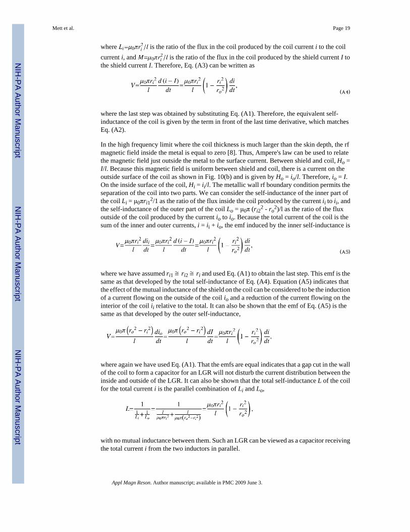
In the high frequency limit where the coil thickness is much larger than the skin depth, the rfmagnetic field inside the metal is equal to zero [8]. Thus, Ampere's law can be used to relatethe magnetic field just outside the metal to the surface current. Between shield and coil, Ho =I/l. Because this magnetic field is uniform between shield and coil, there is a current on theoutside surface of the coil as shown in Fig. 10(b) and is given by Ho = io/l. Therefore, io = I.On the inside surface of the coil, Hi = ii/l. The metallic wall rf boundary condition permits theseparation of the coil into two parts. We can consider the self-inductance of the inner part ofthe coil Li = μ0πri1
2/1 as the ratio of the flux inside the coil produced by the current ii to ii, andthe self-inductance of the outer part of the coil Lo = μ0π (ri2
2 - ro2)/l as the ratio of the flux
outside of the coil produced by the current io to io. Because the total current of the coil is thesum of the inner and outer currents, i = ii + io, the emf induced by the inner self-inductance is
(A5)
where we have assumed ri1 ≅ ri2 ≅ ri and used Eq. (A1) to obtain the last step. This emf is thesame as that developed by the total self-inductance of Eq. (A4). Equation (A5) indicates thatthe effect of the mutual inductance of the shield on the coil can be considered to be the inductionof a current flowing on the outside of the coil io and a reduction of the current flowing on theinterior of the coil ii relative to the total. It can also be shown that the emf of Eq. (A5) is thesame as that developed by the outer self-inductance,
where again we have used Eq. (A1). That the emfs are equal indicates that a gap cut in the wallof the coil to form a capacitor for an LGR will not disturb the current distribution between theinside and outside of the LGR. It can also be shown that the total self-inductance L of the coilfor the total current i is the parallel combination of Li and Lo,
with no mutual inductance between them. Such an LGR can be viewed as a capacitor receivingthe total current i from the two inductors in parallel.
Mett et al. Page 19
Appl Magn Reson. Author manuscript; available in PMC 2009 June 3.
NIH
-PA Author Manuscript
NIH
-PA Author Manuscript
NIH
-PA Author Manuscript

Appendix B: LGR lumped circuit values at cutoffIn Ref. [11], Mett et al. present a lumped circuit model and the corresponding lumped circuitvalues of inductance, resistance, and capacitance of an LGR at high frequencies. The valuesare functions of the LGR dimensions and conductivity and do not include effects of sample.The circuit model is for the LGR at cutoff where the fields are axially uniform. Mett et al. alsopresent a transmission line model that accounts for the deviation of the LGR resonancefrequency from cutoff and a corresponding axial non-uniformity of the LGR fields producedby a loading of the LGR by an impedance at the LGR ends. Results are compared to finiteelement simulations and agreement is good, for both a long LGR with a length of about onefree space wavelength and a short LGR with a length of 12% of the free space wavelength.The impedance of the ends of the LGR is found to perturb the resonance frequency of the shortLGR more than the long (3.4% vs. 1.0% from cutoff), whereas the axial field non-uniformityis more apparent in the long LGR. This type of non-uniformity can be eliminated by an enddesign that presents an rf open impedance to the LGR ends. Then, the LGR resonates at itscutoff frequency.
At cutoff, the LGR rf currents are transverse and can be considered to flow on the interior metalsurfaces of the LGR (see Fig. 1), penetrating to a depth of one skin depth [8],
where the frequency f = ω2π,μ0 is the magnetic permeability of free space, and σ is theconductivity of the metal. We assume that the LGR has an axial length l with m equal gaps ofthickness t and width w with a single inner loop of radius ri and m equal loops of radius ro (inFig. 1, m = 2). Similar to the configuration in Appendix A, the magnetic flux in the inner loopreturns in the outer loops. Each LGR gap is a capacitor fed by a self-inductive loop on each ofits two ends. Using the metallic wall rf boundary condition to define the current in each loop,the self-inductance of each loop is given by
(B1)
where r is the respective loop radius. However, since the rf current enters each gap end, thereis an additional self-inductance caused by the resulting magnetic flux in each gap end. Jackson[12] shows that the self-inductance of a set of parallel plates of dimensions equal to the gapdimensions and fed from one end is given by
(B2)
which is one-third the self-inductance of the plates shorted at the end opposite the feed. In thecase of the LGR, the gap is fed from both ends, and there is an rf current null between them ata location that depends on the relative sizes of the self-inductances on each end. The locationof the null can be found by using the null to separate the gap into two parts—one that feeds rfcurrent to the outer loop and one to the inner loop. Like the example shown in Appendix A,the loop voltage on each side of the rf current null is the same and the two parts are in parallel.Since the resonance frequency of each part is the same, we find (for m gaps),
Mett et al. Page 20
Appl Magn Reson. Author manuscript; available in PMC 2009 June 3.
NIH
-PA Author Manuscript
NIH
-PA Author Manuscript
NIH
-PA Author Manuscript
(B3)
where, using Eqs. (B1) and (B2),
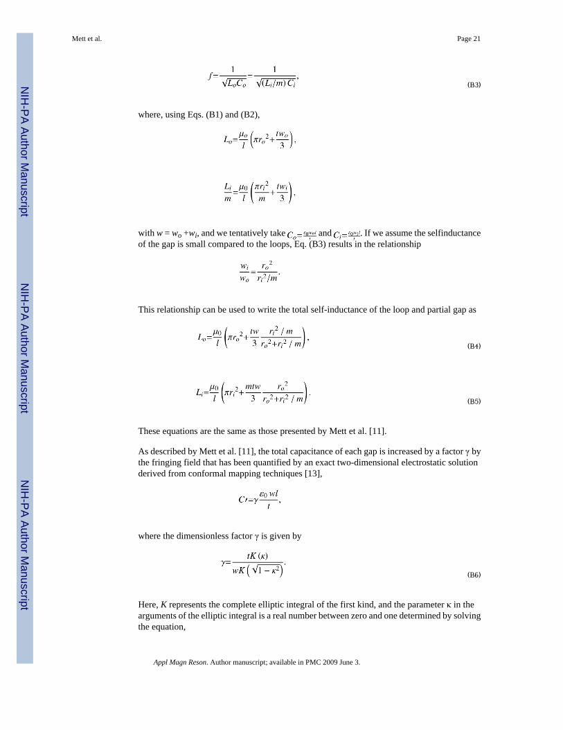
with w = wo +wi, and we tentatively take and . If we assume the selfinductanceof the gap is small compared to the loops, Eq. (B3) results in the relationship
This relationship can be used to write the total self-inductance of the loop and partial gap as
(B4)
(B5)
These equations are the same as those presented by Mett et al. [11].
As described by Mett et al. [11], the total capacitance of each gap is increased by a factor γ bythe fringing field that has been quantified by an exact two-dimensional electrostatic solutionderived from conformal mapping techniques [13],
where the dimensionless factor γ is given by
(B6)
Here, K represents the complete elliptic integral of the first kind, and the parameter κ in thearguments of the elliptic integral is a real number between zero and one determined by solvingthe equation,
Mett et al. Page 21
Appl Magn Reson. Author manuscript; available in PMC 2009 June 3.
NIH
-PA Author Manuscript
NIH
-PA Author Manuscript
NIH
-PA Author Manuscript

(B7)
In this equation, E of single argument represents the complete elliptic integral of the secondkind while E of double argument represents the elliptic integral of the second kind. Also, Frepresents the elliptic integral of the first kind. Equation (B7) was solved numerically and Eq.(B6) evaluated using Mathematica.
Finally, based on the metallic wall rf boundary condition, which relates the magnetic field tothe surface current, the resistance of each LGR loop plus partial gap (see Eqs. (B4) and (B5))was found by scaling 1/σ by the length of the current path divided by the cross-sectional areaof the current path l δ. The length of the current path is the circumference of the loop less thegap thickness plus twice the effective gap inductance gap width wo/3 or wi/3 since the currentflows oppose across the vacuum gap,
(B8)
(B9)
These equations differ from those presented by Mett et al. in the gap thickness correction andhave been found to give Q values (through Eqs. (2)-(4) of the main text) about three times moreaccurate (within 1.5% instead of 5% of Ansoft HFSS values) than without this correction.
Appendix C: Circuit equationsA complete set of circuit equations for the half-circuit of Fig. 6 is derived from the definedmesh currents and component voltage drops given by
(C1)
Mett et al. Page 22
Appl Magn Reson. Author manuscript; available in PMC 2009 June 3.
NIH
-PA Author Manuscript
NIH
-PA Author Manuscript
NIH
-PA Author Manuscript
where Ccc and Lcc are given by Eqs. (12) and (13). Since there are 11 voltage and currentquantities and 10 equations, the ratio between any two of these quantities is found by solvingthe system of equations for one quantity in terms of the other (e.g., using Mathematica).
Match is obtained when the input impedance given by Eq. (14), with the set of circuit equations,is near the characteristic impedance of the waveguide. The waveguide characteristic impedancefor a TE10 mode in rectangular waveguide is given by [8]
(C2)
where η is the impedance of free space and a is the large dimension of the waveguide.
If a length of waveguide lg exists between the iris and the input port, the input impedance istransformed by the waveguide according to
where the waveguide wavenumber for a TE10 mode in rectangular waveguide is
Mett et al. Page 23
Appl Magn Reson. Author manuscript; available in PMC 2009 June 3.
NIH
-PA Author Manuscript
NIH
-PA Author Manuscript
NIH
-PA Author Manuscript
These equations were used to compare the impedances predicted by the circuit model nearmatch to Ansoft HFSS.
Appendix D: Impedance at critical couplingIn terms of the iris-modified LGR impedance defined in Fig. 6, equating the inputimpedance to the waveguide characteristic impedance yields a relationship between the bridgeelement Le value, the real and imaginary parts of , and the waveguide characteristicimpedance,
(D1)
and the and a value for the iris reactance from Eq. (15) in terms of the real part of and thewaveguide characteristic impedance,
(D2)
The iris-modified LGR resistance and reactance can be expressed in terms of the real andimaginary parts of the pure LGR impedance ZLGR, Eq. (1), as
(D3)
(D4)
Equations (D1) and (D2) are the two conditions needed for critical coupling, and Eqs. (D3)and (D4) relate the iris-modified LGR impedance to the pure LGR impedance. In these
equations, we have neglected terms of order , and , which is a good approximation.The LGR dimensions and sample determine RLGR and XLGR, and the iris dimensions determineZiris and how Lo is split between Le and , Eqs. (17) and (18). Both the real and imaginaryparts of the LGR impedance are strongly frequency dependent and must be determined fromEq. (1). Very near the natural resonance frequency of the LGR, Eq. (6), X LGR is typically onthe order of an Ohm and RLGR is close to the equivalent resistance given by Eq. (3). For a fixedLGR Q, the value of RLGR increases as the ratio of the outer loop to inner loop cross-sectionalarea increases. Because of this, the behavior of the iris changes with LGR dimensions. For agiven LGR and a given iris length, it is usually possible to adjust the iris width to producematch; larger width increases coupling strength. The match is typically achieved with nonzeroLGR reactance and therefore a frequency deviation from the natural LGR frequency. Thedirection and amount of frequency shift, along with other types of iris behavior, depend on theiris dimensions as further discussed in Sect. 3.
Mett et al. Page 24
Appl Magn Reson. Author manuscript; available in PMC 2009 June 3.
NIH
-PA Author Manuscript
NIH
-PA Author Manuscript
NIH
-PA Author Manuscript
References1. Mett RR, Hyde JS. Rev. Sci. Instrum 2005;76:014702.2. Froncisz W, Hyde JS. J. Magn. Reson 1982;47:515–521.3. Hyde, JS.; Froncisz, W. Advanced EPR: Applications in Biology and Biochemistry. Hoff, AJ., editor.
Elsevier; Amsterdam: 1989. p. 277-306.4. Rinard, GA.; Eaton, GR. Biological Magnetic Resonance, Volume 24: Biomedical EPR -Part B:
Methodology and Instrumentation. Eaton, SS.; Eaton, GR.; Berliner, LJ., editors. Kluwer Academic/Plenum Publishers; New York: 2004. p. 19-52.
5. Froncisz W, Oles T, Hyde JS. Rev. Sci. Instrum 1986;57:1095–1099.6. Klug CS, Camenisch TG, Hubbell WL, Hyde JS. Biophys. J 2005;88:3641–3647. [PubMed: 15749769]7. Ginzton, EL. Microwave Measurements. McGraw-Hill; New York: 1957.8. Ramo, S.; Whinnery, JR.; Van Duzer, T. Fields and Waves in Communication Electronics. Vol. 2nd
edn.. Wiley; New York: 1984. sects. 4.12, 7.11, 10.12, 119. Terman, FE. Radio Engineers' Handbook, sects. 2, 3. McGraw-Hill; New York: 1943.10. Grover, FW. Inductance Calculations. Van Nostrand; New York: 1946. p. 311. Mett RR, Sidabras JW, Hyde JS. Appl. Magn. Reson 2007;31:571–587.12. Jackson, JD. Classical Electrodynamics. Vol. 2nd edn.. Wiley; New York: 1975. sect. 8.2, problems
6.5, 6.1413. Smythe, WR. Static and Dynamic Electricity. Vol. 2nd edn.. McGraw-Hill; New York: 1950. chapter
IV, problem 5914. Marcuvitz, N., editor. Waveguide Handbook, chapters 5, 8. Boston Technical Publishers; Lexington,
MA: 1964.15. Brown, RG.; Sharpe, RA.; Hughes, WL.; Post, RE. Lines, Waves, and Antennas: The Transmission
of Electric Energy. Vol. 2nd edn.. Wiley; New York: 1973. chapter 416. Bogle AG. Journal I. E. E 1940;87:299–316.
Mett et al. Page 25
Appl Magn Reson. Author manuscript; available in PMC 2009 June 3.
NIH
-PA Author Manuscript
NIH
-PA Author Manuscript
NIH
-PA Author Manuscript

Fig. 1.Mechanical drawing of bisected 10-mm-long Q-band 3-loop-2-gap LGR. Resonator body isshown in gray and the sample tube in blue. Gaps face bisecting plane. Coupling iris slot appearson nearest edge.
Mett et al. Page 26
Appl Magn Reson. Author manuscript; available in PMC 2009 June 3.
NIH
-PA Author Manuscript
NIH
-PA Author Manuscript
NIH
-PA Author Manuscript
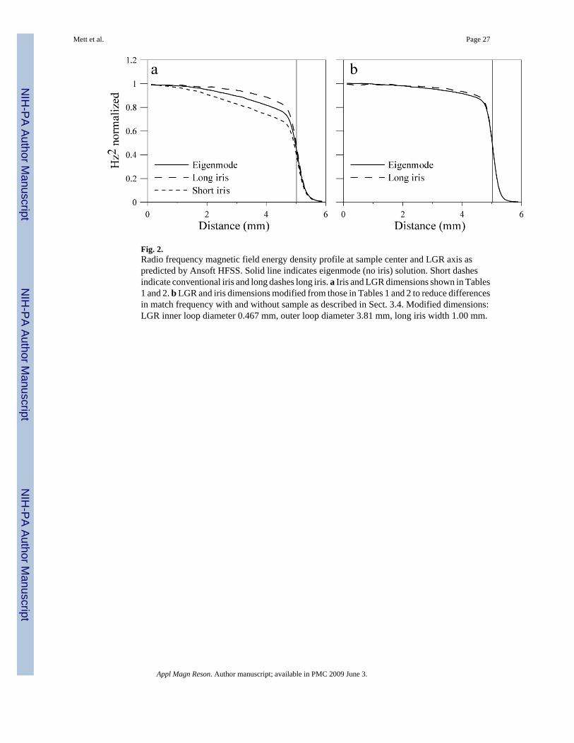
Fig. 2.Radio frequency magnetic field energy density profile at sample center and LGR axis aspredicted by Ansoft HFSS. Solid line indicates eigenmode (no iris) solution. Short dashesindicate conventional iris and long dashes long iris. a Iris and LGR dimensions shown in Tables1 and 2. b LGR and iris dimensions modified from those in Tables 1 and 2 to reduce differencesin match frequency with and without sample as described in Sect. 3.4. Modified dimensions:LGR inner loop diameter 0.467 mm, outer loop diameter 3.81 mm, long iris width 1.00 mm.
Mett et al. Page 27
Appl Magn Reson. Author manuscript; available in PMC 2009 June 3.
NIH
-PA Author Manuscript
NIH
-PA Author Manuscript
NIH
-PA Author Manuscript

Fig. 3.LGR cross-sections. a 1-loop-1-gap, no return flux loop. b 1-loop-1-gap. Sample is placed insmaller loop and larger loop is flux return path. c 3-loop-2-gap. d 5-loop-4-gap.
Mett et al. Page 28
Appl Magn Reson. Author manuscript; available in PMC 2009 June 3.
NIH
-PA Author Manuscript
NIH
-PA Author Manuscript
NIH
-PA Author Manuscript

Fig. 4.LGR circuit with driving point at fully broken outer loop.
Mett et al. Page 29
Appl Magn Reson. Author manuscript; available in PMC 2009 June 3.
NIH
-PA Author Manuscript
NIH
-PA Author Manuscript
NIH
-PA Author Manuscript

Fig. 5.Iris a drawing showing qualitative current flow, b isolated iris half-circuit, c half-circuit of irisin proximity to LGR outer loop.
Mett et al. Page 30
Appl Magn Reson. Author manuscript; available in PMC 2009 June 3.
NIH
-PA Author Manuscript
NIH
-PA Author Manuscript
NIH
-PA Author Manuscript

Fig. 6.Half-circuit of connected iris and LGR.
Mett et al. Page 31
Appl Magn Reson. Author manuscript; available in PMC 2009 June 3.
NIH
-PA Author Manuscript
NIH
-PA Author Manuscript
NIH
-PA Author Manuscript

Fig. 7.Generalized coupled circuit equivalent form [9].
Mett et al. Page 32
Appl Magn Reson. Author manuscript; available in PMC 2009 June 3.
NIH
-PA Author Manuscript
NIH
-PA Author Manuscript
NIH
-PA Author Manuscript
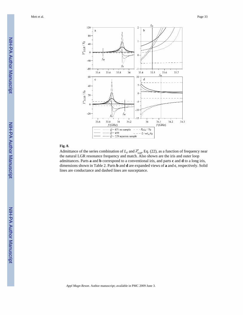
Fig. 8.Admittance of the series combination of Le and , Eq. (22), as a function of frequency nearthe natural LGR resonance frequency and match. Also shown are the iris and outer loopadmittances. Parts a and b correspond to a conventional iris, and parts c and d to a long iris,dimensions shown in Table 2. Parts b and d are expanded views of a and c, respectively. Solidlines are conductance and dashed lines are susceptance.
Mett et al. Page 33
Appl Magn Reson. Author manuscript; available in PMC 2009 June 3.
NIH
-PA Author Manuscript
NIH
-PA Author Manuscript
NIH
-PA Author Manuscript
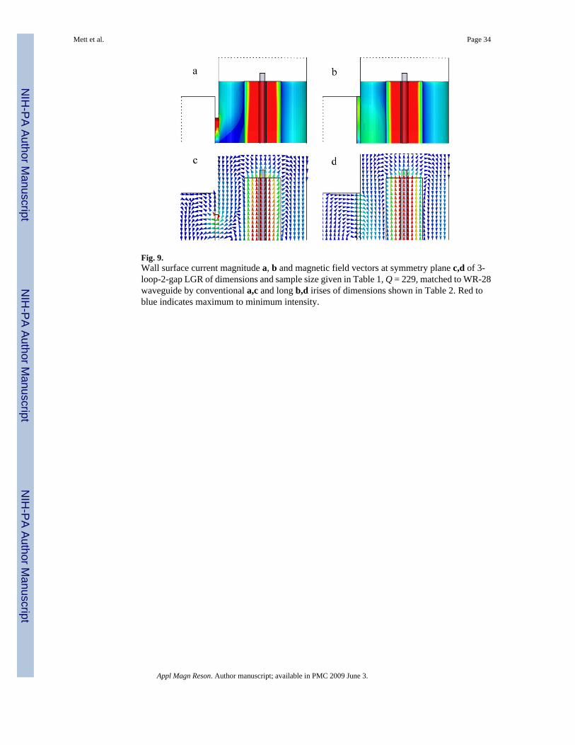
Fig. 9.Wall surface current magnitude a, b and magnetic field vectors at symmetry plane c,d of 3-loop-2-gap LGR of dimensions and sample size given in Table 1, Q = 229, matched to WR-28waveguide by conventional a,c and long b,d irises of dimensions shown in Table 2. Red toblue indicates maximum to minimum intensity.
Mett et al. Page 34
Appl Magn Reson. Author manuscript; available in PMC 2009 June 3.
NIH
-PA Author Manuscript
NIH
-PA Author Manuscript
NIH
-PA Author Manuscript
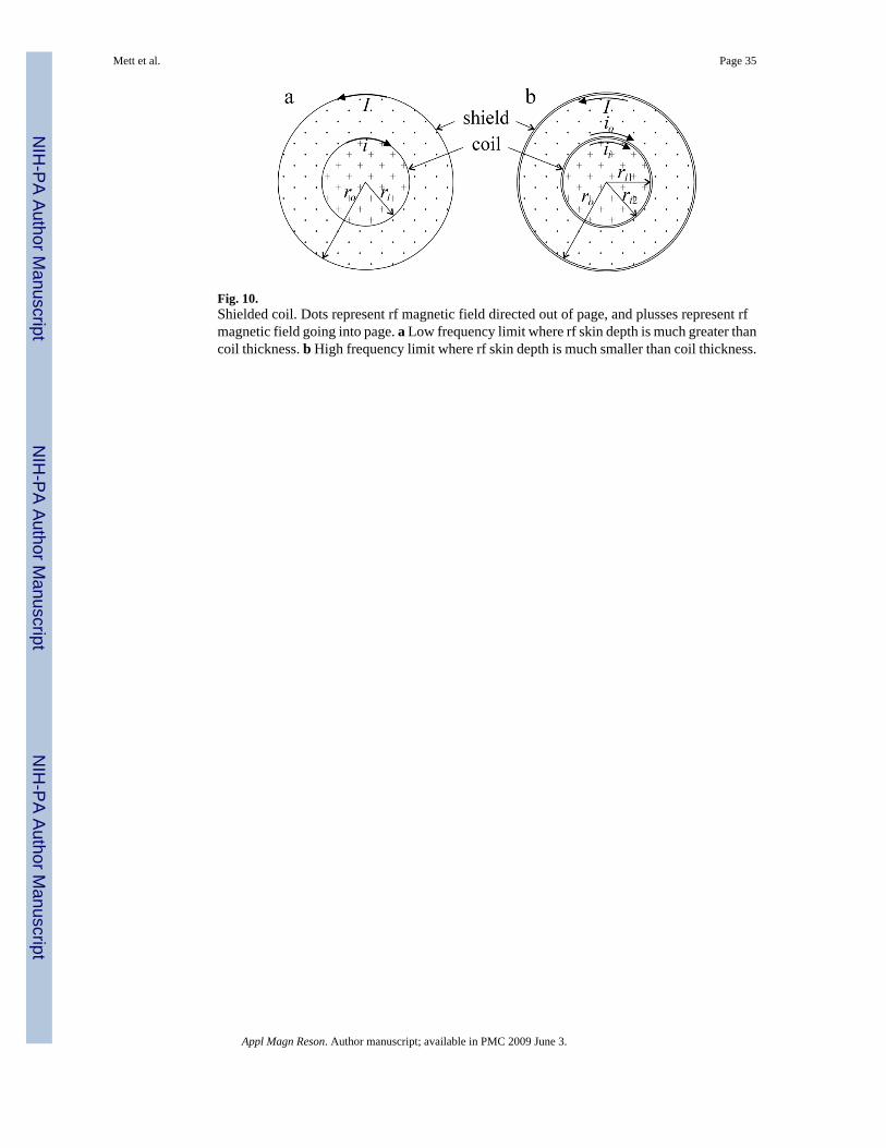
Fig. 10.Shielded coil. Dots represent rf magnetic field directed out of page, and plusses represent rfmagnetic field going into page. a Low frequency limit where rf skin depth is much greater thancoil thickness. b High frequency limit where rf skin depth is much smaller than coil thickness.
Mett et al. Page 35
Appl Magn Reson. Author manuscript; available in PMC 2009 June 3.
NIH
-PA Author Manuscript
NIH
-PA Author Manuscript
NIH
-PA Author Manuscript
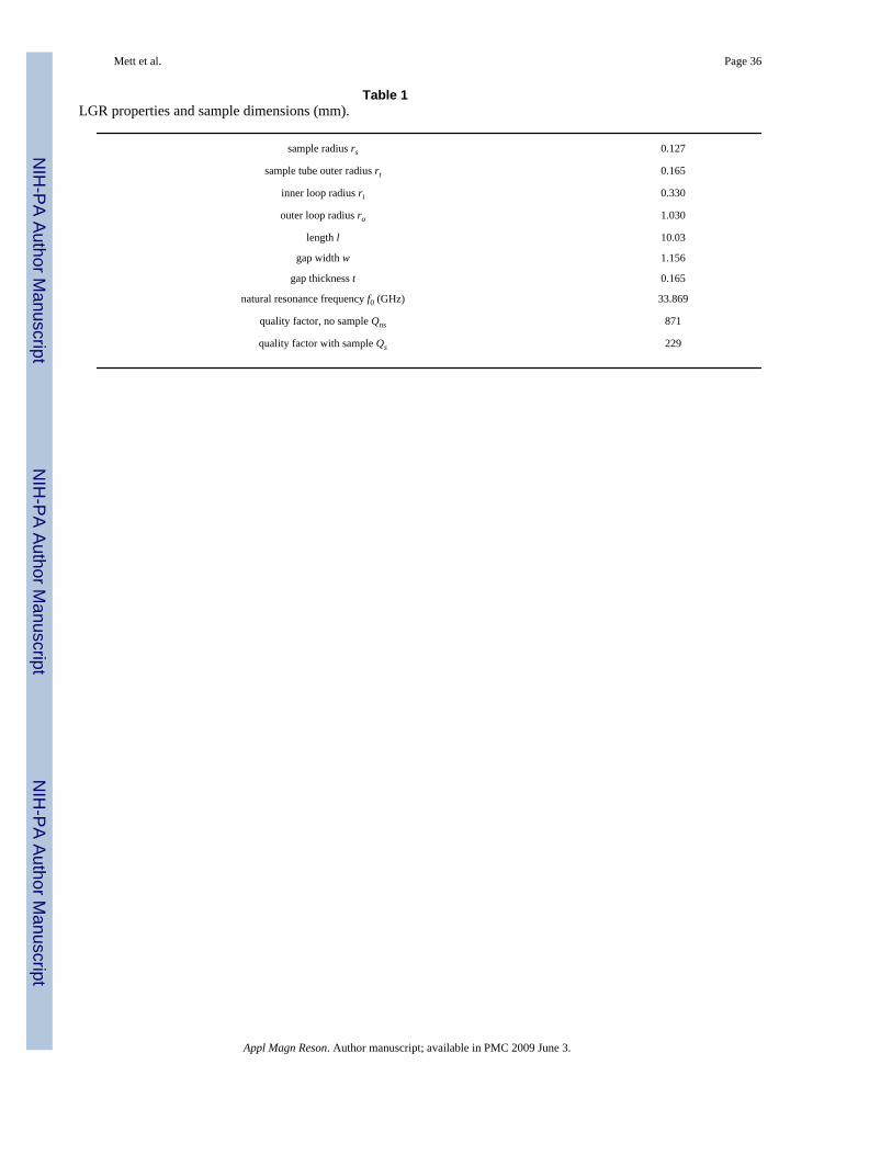
NIH
-PA Author Manuscript
NIH
-PA Author Manuscript
NIH
-PA Author Manuscript
Mett et al. Page 36
Table 1LGR properties and sample dimensions (mm).
sample radius rs 0.127
sample tube outer radius rt 0.165
inner loop radius ri 0.330
outer loop radius ro 1.030
length l 10.03
gap width w 1.156
gap thickness t 0.165
natural resonance frequency f0 (GHz) 33.869
quality factor, no sample Qns 871
quality factor with sample Qs 229
Appl Magn Reson. Author manuscript; available in PMC 2009 June 3.

NIH
-PA Author Manuscript
NIH
-PA Author Manuscript
NIH
-PA Author Manuscript
Mett et al. Page 37
Table 2Coupled LGR-iris properties.
conventional long
iris wall thickness tc(mm) 0.305 0.305
iris opening width wc (mm) 0.533 0.276
iris length lc (mm) 4.06 7.62
iris outer loop flux occupation factor s 0.25 0.66
iris resonance frequency in presence of LGR outer loop fc0(GHz)
37.2 27.4
match frequency relative to f0, Δf(MHz) -372 251
primary quality factor QP 2.8 5.6
secondary quality factor QS 225 245
iris reactance Xiris (Ω) 808 -71.1
coupling constant kc 0.94 -0.92 j
ic ∕ io″ -1.4-2.4 j 0.57 - 0.089 j
icc ∕ io″ -1.1-2.0 j 0.22 - 0.034 j
iCc ∕ io″ -0.88 + 1.6 j -1.2-0.19 j
ii/io -39-18 j - 9.7 - 0.95 j
ii ∕ io′ -14 + 0.005 j -15-0.005 j
ii/iin -17 - 88 j -25 + 85 j
Appl Magn Reson. Author manuscript; available in PMC 2009 June 3.
Copyright © 2022 FDOKUMEN