Electrically Addressed Dual Resonator Sensing Platform for Biochemical Detection
10
34 JOURNAL OF MICROELECTROMECHANICAL SYSTEMS, VOL. 21, NO. 1, FEBRUARY 2012 Electrically Addressed Dual Resonator Sensing Platform for Biochemical Detection Angel T.-H. Lin, Member, IEEE, Jize Yan, Member, IEEE, and Ashwin A. Seshia, Senior Member, IEEE Abstract—Chemically functionalized silicon microresonators provide the potential for sensitive, label-free biomolecular de- tection by coupling small induced perturbations in stiffness, mass, and dissipation due to surface bound analyte to their measured frequency response. However, several implementation challenges arise from the necessity of operation in compatible biological buffer solutions. These challenges include minimizing undesired effects of fluid-structure interaction and buffer interfer- ence with signal transduction. In this paper, we present a novel dual resonator sensing platform (DRP) to address these chal- lenges, wherein electrical transduction and biochemical sensing are spatially separated onto two different mechanically coupled resonators. This enables electrical interrogation of the sensor with- out compromising the sensing environment, allowing for relative ease of fabrication and the possibility of integration with on-chip electronics. We demonstrate the functionality of the DRP as a mass sensing platform, with a mass responsivity of 34 Hz/ng in air. The viscous effects on dynamic response of the DRP were investigated by comparing the measurements with theoretical values, and a quality factor of 221 in water is demonstrated. Furthermore, char- acterization of the DRP was preformed with streptavidin-coated microbeads, and the measured response is in close agreement with the model. Finally, the use of DRP for measurement of dried cell mass and accurate cell counting is demonstrated with a detection limit of 1.46 ng. [2011-0118] Index Terms—Biosensors, bulk acoustic resonator, coupled res- onators, fluid damping, micromechanical sensors. I. I NTRODUCTION M ICROFABRICATED chemical and biological sensors are being developed to address technical challenges associated with detection sensitivity, sample and reagent han- dling, portability and cost, particularly for emerging point-of- care diagnostic and clinical monitoring applications with a view toward shifting the testing burden from centralized laboratories to the patient bedside [1]. A number of biological and chem- ical sensing principles have been realized at the micro- and nanoscale; however, miniaturization also provides opportunities to enhance detection sensitivities associated with a certain sub- set of these principles due to beneficial scaling characteristics Manuscript received April 21, 2011; revised September 2, 2011; accepted September 13, 2011. Date of publication December 1, 2011; date of current version February 3, 2012. This work was supported in part by a grant from the Royal Society. Subject Editor A. J. Ricco. The authors are with the Department of Engineering, University of Cambridge, Cambridge CB2 1PZ, U.K., and also with the Nanoscience Centre, University of Cambridge, Cambridge CB3 0FF, U.K. (e-mail: angel.lin@ cantab.net; [email protected]; [email protected]). Color versions of one or more of the figures in this paper are available online at http://ieeexplore.ieee.org. Digital Object Identifier 10.1109/JMEMS.2011.2174420 [2]. In recent years, micro- and nanomechanical resonators have been advanced as highly sensitive mass sensors [3], [4] with scaled sensitivities directly benefiting from miniaturization and have received great interest due to the potential for integra- tion with electronics and microfluidic handling for electrical readout of target analyte in a label-free format. Compared to macroscale counterparts, it is envisioned that micro- and nanomechanical resonators can couple the advantages provided by integration and miniaturization for multiplexed parallel ar- rayed detection on a chip and the potentially higher detection sensitivities, making it an attractive technology for biochemical detection [5]. The operating principle of a resonant biochemical sensor lies in transducing the added mass on the resonator as a downward shift in resonant frequency. Single cell [6], [7], bacteria [8], viruses [9], and protein biomarkers [10] have been detected using this technique. However, the integration of these mi- croresonators with electrical readout for operation in biochem- ical medium is challenging, in part due to the differences in the requirements associated with electrical signal transduction and optimization of the sensing environment. These challenges include electrolysis of the liquid media which limits the voltage headroom and hence results in low signal readability, and the increased energy dissipation from fluid damping also results in a lower quality factor leading to a lower mass resolution. Additionally, coupling of the readout to the electrical properties of the associated buffer solution is usually undesirable. Previous approaches to address these challenges include us- ing external excitation and readout setups (e.g., using chip-scale piezoelectric actuators and optical detection), encapsulating the transducer element inside the resonator, such as piezoelectric [4], [11] and electrothermal [12] transduction methods, or en- capsulating the fluid inside the resonator such as the suspended microchannel resonator [13], [14]. However, these methods often require a more complex fabrication process and may not easily lend themselves readily to integration (e.g., due to the requirements for optical readout). This in turn often adds to the complexity to the material stack on the sensor surface which needs to be optimized for chemical functionalization and biocompatible operation. Piezoelectric transduction meth- ods require integration of piezoelectric materials which may not be compatible with the fabrication of CMOS electron- ics. Electrothermal actuation may result in undesired heating, and thermal stresses in a composite material stack may de- grade resonator output fidelity. The suspended microchannel encapsulates the fluid inside the resonant element to reduce viscous damping effects; however, this prevents direct access to the sensor surface area for functionalization, and chemical 1057-7157/$26.00 © 2011 IEEE
-
Upload
independent -
Category
Documents
-
view
0 -
download
0
Transcript of Electrically Addressed Dual Resonator Sensing Platform for Biochemical Detection

34 JOURNAL OF MICROELECTROMECHANICAL SYSTEMS, VOL. 21, NO. 1, FEBRUARY 2012
Electrically Addressed Dual Resonator SensingPlatform for Biochemical Detection
Angel T.-H. Lin, Member, IEEE, Jize Yan, Member, IEEE, and Ashwin A. Seshia, Senior Member, IEEE
Abstract—Chemically functionalized silicon microresonatorsprovide the potential for sensitive, label-free biomolecular de-tection by coupling small induced perturbations in stiffness,mass, and dissipation due to surface bound analyte to theirmeasured frequency response. However, several implementationchallenges arise from the necessity of operation in compatiblebiological buffer solutions. These challenges include minimizingundesired effects of fluid-structure interaction and buffer interfer-ence with signal transduction. In this paper, we present a noveldual resonator sensing platform (DRP) to address these chal-lenges, wherein electrical transduction and biochemical sensingare spatially separated onto two different mechanically coupledresonators. This enables electrical interrogation of the sensor with-out compromising the sensing environment, allowing for relativeease of fabrication and the possibility of integration with on-chipelectronics. We demonstrate the functionality of the DRP as a masssensing platform, with a mass responsivity of 34 Hz/ng in air. Theviscous effects on dynamic response of the DRP were investigatedby comparing the measurements with theoretical values, and aquality factor of 221 in water is demonstrated. Furthermore, char-acterization of the DRP was preformed with streptavidin-coatedmicrobeads, and the measured response is in close agreement withthe model. Finally, the use of DRP for measurement of dried cellmass and accurate cell counting is demonstrated with a detectionlimit of 1.46 ng. [2011-0118]
Index Terms—Biosensors, bulk acoustic resonator, coupled res-onators, fluid damping, micromechanical sensors.
I. INTRODUCTION
M ICROFABRICATED chemical and biological sensorsare being developed to address technical challenges
associated with detection sensitivity, sample and reagent han-dling, portability and cost, particularly for emerging point-of-care diagnostic and clinical monitoring applications with a viewtoward shifting the testing burden from centralized laboratoriesto the patient bedside [1]. A number of biological and chem-ical sensing principles have been realized at the micro- andnanoscale; however, miniaturization also provides opportunitiesto enhance detection sensitivities associated with a certain sub-set of these principles due to beneficial scaling characteristics
Manuscript received April 21, 2011; revised September 2, 2011; acceptedSeptember 13, 2011. Date of publication December 1, 2011; date of currentversion February 3, 2012. This work was supported in part by a grant from theRoyal Society. Subject Editor A. J. Ricco.
The authors are with the Department of Engineering, University ofCambridge, Cambridge CB2 1PZ, U.K., and also with the Nanoscience Centre,University of Cambridge, Cambridge CB3 0FF, U.K. (e-mail: [email protected]; [email protected]; [email protected]).
Color versions of one or more of the figures in this paper are available onlineat http://ieeexplore.ieee.org.
Digital Object Identifier 10.1109/JMEMS.2011.2174420
[2]. In recent years, micro- and nanomechanical resonators havebeen advanced as highly sensitive mass sensors [3], [4] withscaled sensitivities directly benefiting from miniaturization andhave received great interest due to the potential for integra-tion with electronics and microfluidic handling for electricalreadout of target analyte in a label-free format. Comparedto macroscale counterparts, it is envisioned that micro- andnanomechanical resonators can couple the advantages providedby integration and miniaturization for multiplexed parallel ar-rayed detection on a chip and the potentially higher detectionsensitivities, making it an attractive technology for biochemicaldetection [5].
The operating principle of a resonant biochemical sensor liesin transducing the added mass on the resonator as a downwardshift in resonant frequency. Single cell [6], [7], bacteria [8],viruses [9], and protein biomarkers [10] have been detectedusing this technique. However, the integration of these mi-croresonators with electrical readout for operation in biochem-ical medium is challenging, in part due to the differences inthe requirements associated with electrical signal transductionand optimization of the sensing environment. These challengesinclude electrolysis of the liquid media which limits the voltageheadroom and hence results in low signal readability, and theincreased energy dissipation from fluid damping also resultsin a lower quality factor leading to a lower mass resolution.Additionally, coupling of the readout to the electrical propertiesof the associated buffer solution is usually undesirable.
Previous approaches to address these challenges include us-ing external excitation and readout setups (e.g., using chip-scalepiezoelectric actuators and optical detection), encapsulating thetransducer element inside the resonator, such as piezoelectric[4], [11] and electrothermal [12] transduction methods, or en-capsulating the fluid inside the resonator such as the suspendedmicrochannel resonator [13], [14]. However, these methodsoften require a more complex fabrication process and maynot easily lend themselves readily to integration (e.g., due tothe requirements for optical readout). This in turn often addsto the complexity to the material stack on the sensor surfacewhich needs to be optimized for chemical functionalizationand biocompatible operation. Piezoelectric transduction meth-ods require integration of piezoelectric materials which maynot be compatible with the fabrication of CMOS electron-ics. Electrothermal actuation may result in undesired heating,and thermal stresses in a composite material stack may de-grade resonator output fidelity. The suspended microchannelencapsulates the fluid inside the resonant element to reduceviscous damping effects; however, this prevents direct accessto the sensor surface area for functionalization, and chemical
1057-7157/$26.00 © 2011 IEEE
LIN et al.: ELECTRICALLY ADDRESSED DUAL RESONATOR SENSING PLATFORM FOR BIOCHEMICAL DETECTION 35
specification of the sensor surface becomes more difficult. Asthe microchannel scales down in size, the flow rate becomeslow at practical operating pressures, and mass transport limita-tions may become a concern [13]. The device also has a lowquality factor of 85 in air and requires operation in vacuum forhigher/improved mass resolution [13]. Although piezoresistivedetection has been implemented on the suspended microchan-nel resonator recently [15], the device suffers from the electricalcoupling between the on-chip drive electrode and the piezore-sistor, and an external piezocrystal actuation was therefore usedin their reported measurements.
In this paper, we proposed a novel dual resonator sensingplatform (DRP) to address these challenges that enables electri-cal read-out and fabrication in a commercial foundry process.The DRP comprises of two bulk acoustic wave silicon mi-croresonators that are mechanically coupled together via a thinbeam, allowing the two coupled structures to vibrate togetherat the same frequency. This configuration enables the physicalseparation of the electrical transduction and sensing region ofthe device, and hence allows for the possibility of optimizingthe sensing and transduction design aspects independently.Table I summarizes existing microresonator implementationsfor biochemical detection in comparison to the DRP presentedin this work. Comparing to previous work, with an addi-tional resonator, the DRP can be fully electrically addressed(capacitive-to-piezoresistive transduction), and the associatedfabrication is relatively simple. As shown in this paper, areasonably good quality factor in liquid has been obtained atan operating frequency of several MHz.
The purpose of this paper is to present the design andcharacterization of the proposed DRP and to demonstrate itsapplication potential for biochemical sensing. The viscous ef-fects on the dynamic response of the DRP in liquid were studiedby comparing measured results with the analytical modeling.The mass sensitivity was demonstrated by thin-film deposi-tion of Chrome. Furthermore, the mass of streptavidin-coatedpolystyrene microbeads bond to the biotin-functionalized DRPis quantified to validate the analytical model underlying detec-tion of attached biological species. Lastly, the use of the DRPfor cell counting is performed using High-Five insect cells.
II. DEVICE CONCEPT AND OPERATION
Fig. 1 shows the configuration of the DRP, wherein twoidentical resonators are mechanically coupled together. Oneresonator, labeled as the “transduction resonator,” is used fordriving the device into vibration and sensing the combinedvibratory response, and the surface of the other resonator,labeled as the “sensor resonator,” is configured for biochemicalsensing. The electrical transduction of the coupled device istherefore spatially separated from the sensing zone with theadvantage that: 1) The detection and physical transductionfunctions can be optimized independently, and not limited bythe requirements of the individual functions (e.g., conductivityof fluid, temperature, applied voltage), with the potential forinnovative device design. 2) The sensor resonator does notrequire any electrodes, and hence associated damping effectscan be eliminated to improve the quality factor in liquid.
3) The sensing environment can be better defined for the bio-logical system of interest, and impervious from the transductionregion.
The DRP presented in this work consists of two identicalsquare plate resonators that are mechanically coupled togetherat the center edges of the square plate via a thin beam. Thesquare plates are anchored at each of the four corners via aT-shaped connecting stem, with electrodes on each side of theresonator. This allows the vibration of the square plates inthe square-extensional (SE) mode, wherein the square platesextend and contract symmetrically on all four sides. The SEmode was chosen for its in-plane vibration which is mostlyin shearing contact with the liquid media, and therefore couldachieve a higher quality factor as compared with those offlexural mode devices where the vibration motion compressesthe surrounding media and therefore have a higher energy loss.We have also previously shown that the electrical transductionof the SE mode could be greatly enhanced using the capacitive-to-piezoresistive transduction technique, utilizing voltages anorder of magnitude lower [25].
The devices are fabricated in a commercial foundry process(MEMSCAP), and an optical micrograph of the fabricated DRPis shown in Fig. 1. The coupling beam connecting the squaresallows the two to vibrate together, where two closely spacedresonant modes of interest exist for this structure: the in-phaseSE mode, where the squares are extending and contractingsymmetrically and vibrating in-phase; and the out-of-phaseSE mode, where the squares are vibrating 180◦ out of phase.The length of the coupling beam length is designed to beapproximately half-wavelength to separate the modal peaks suf-ficiently apart to facilitate the precise selection of one mode formeasurement at a given time [26]. Two different size coupledSE mode resonators are tested in this work, and measurementswere all done in the in-phase mode. The smaller device has aside length of 800 μm, and an in-phase resonant frequency of5.492 MHz. The larger device has a side length of 1400 μmand an in-phase resonant frequency of 3.145 MHz. The deviceparameters are summarized in Table II.
The frequency response of the coupled device was mea-sured using differential capacitive actuation and piezoresistivesensing [25], [27]. The schematic of the measurement setupis shown in Fig. 2, where ac (Vac) and dc (Vdc) voltages areapplied to the electrodes of the transduction resonator, whichgenerates a time varying electrostatic force that drives bothresonators into motion. A dc voltage Vd is applied across thetwo corners of the square for the detection of the vibratoryresponse as the electrical resistance of the square changesdue to the piezoresistive effect. Detailed description of thetransduction method can be found in [25].
III. VISCOUS EFFECTS ON THE DYNAMIC RESPONSE
The frequency-resolved mass resolution of the resonant sen-sor depends on the quality factor (Q) of the resonator, suchthat the resolution improves with Q. However, fluid damping inliquid can be very significant, and the Q is substantially reducedby the associated viscous loss. We have previously studied fluiddamping losses in single SE mode resonators [27]; here, we

36 JOURNAL OF MICROELECTROMECHANICAL SYSTEMS, VOL. 21, NO. 1, FEBRUARY 2012
TAB
LE
IS
UM
MA
RY
OF
MIC
RO
RE
SO
NA
TO
RIM
PL
EM
EN
TA
TIO
NS
FO
RB
IOC
HE
MIC
AL
DE
TE
CT
ION

LIN et al.: ELECTRICALLY ADDRESSED DUAL RESONATOR SENSING PLATFORM FOR BIOCHEMICAL DETECTION 37
Fig. 1. Optical micrograph of the fabricated 5.492 MHz DRP.
extend the model to estimate Q for the SE-mode DRP andcompare with measured results in water.
A. Analytical Modelling
Damping in mechanical resonators can arise from a num-ber of sources, such as viscous drag, squeeze film damping,acoustic radiation loss via attachments (anchor loss), and otherinternal loss mechanisms. The quality factor is the ratio ofenergy stored per cycle to the energy dissipated per radian. Fora mechanical resonator, it is given by the expression
Q =mω0
b(1)
where m,ω0, b is the equivalent mass, angular resonant fre-quency of the resonator, and damping constant, respectively.Since energy loss from all sources adds directly to the totalenergy loss, the overall Q factor of a resonator is given by:
1Qtotal
=1
Qvis_drag+
1Qsqueeze_film
+1
Qanchor+
1Qother
.
(2)
The quality factor for an array of n mechanically coupledresonator is given by the relation [28]:
Qarray = n ·(
1Q1
+1
Q2+ . . . +
1Qn
)−1
(3)
where Q1, Q2, . . . , Qn are Q-factors of the individual res-onators in the array. It was shown by Lin et al. [28] that a low Qresonator embedded in a mechanically coupled resonator arrayof much higher Qs can boost the overall Q of the resonatorby a factor approximately equal to the number of resonators inthe array. Since the quality factor of the transduction resonator(QTrans) is usually much higher than the quality factor of thesensor resonator (QSensor), as the fluid damping in liquid ismuch larger than air, the DRP has the advantage that the overallQ factor in liquid can be boosted, given by:
QDRP ≈ 2QSensor, (QTrans � QSensor). (4)
1) Viscous Damping of Laterally Vibrating Plate: The vis-cous damping model developed here for square extensionalmode resonators is calculated from the solution of the Navier-Stokes equation for an incompressible fluid for oscillatorymotion parallel to the surface of the resonator. In the model,
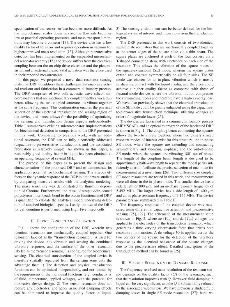
we follow the procedure as described by Vignola et al. [29],and make the fluid contact area A a parameter. If we take theresonator surface as the yz-plane, and the fluid region as x > 0,as shown in Fig. 3, the viscous force per unit area is givenby [30]
Fvis =
√12ωηρfluid(j − 1)υ (5)
where η, ρfluid, υ is the viscosity, density, and velocity of thefluid. At x = 0, υ = u, where u is the velocity of the resonatorsurface, defined by the corresponding mode shape equation. Ifwe divide the resonator surface into equal elements of area Ai,small enough that the velocity is approximately uniform overAi, the energy dissipated can be calculated from the real part ofFvis, and the damping constant bvis,i due to viscous drag at Ai
is given by
bvis,i =Fvis,iAi
ui=
√12ωηρfluidAi. (6)
Assuming that the velocity is uniform in the area element Ai
and summing up the damping contribution of all such elements,the Q factor for the resonator due to viscous damping for fluidcontact area A is given by
Qviscous =mω0
bvis=
ρSiHL2ω0√12ω0ηρfluidA
=ρSiH
√2ω0
ηρfluid
(L2
A
)
(7)
where ρSi,H, L is the density, thickness, and length of thesquare plate resonator. Substituting the water droplet contactarea into A for Qwater_drop due to viscous damping from waterdroplet, and taking the rest of the area covered by air forQremain_air due to viscous damping from the air contact, thetotal Q due to in-plane viscous drag can be approximated as
1Qvis_drag
=1
Qwater_drop+
1Qremain_air
. (8)
2) Squeeze Film Damping: Squeeze film damping for elec-trostatically driven resonators can occur between the resonatorside walls and the actuation electrodes. The resonator has fourelectrodes for actuation on each side of the square plate. Thedamping constant for squeeze film damping for electrode platesof length Le, width H and gap size g0, is given by [31]
bsqueeze_film =96η(4Le)H3
π4g30
=384ηLeH
3
π4g30
. (9)
The quality factor due to squeeze film damping is therefore
Qsqueeze_film =mω
bsqueeze_film=
ρsiL2ω0π
4g30
384ηLeH2(10)
and the total Q due to fluid damping is
1Qfluid
=1
Qvis_drag+
1Qsqueeze_film
. (11)
Using the above models, the estimated Q factor of a singleSE-mode resonator immersed in liquid medium versus the
38 JOURNAL OF MICROELECTROMECHANICAL SYSTEMS, VOL. 21, NO. 1, FEBRUARY 2012
TABLE IISUMMARY OF DEVICE PARAMETERS
Fig. 2. Schematic showing differential capacitive actuation and piezoresistivesensing measurement setup for the DRP.
Fig. 3. Diagram illustrating the water droplet spotted on the center of theresonator, where the resonator surface is the yz-plane, with the fluid regionat x > 0.
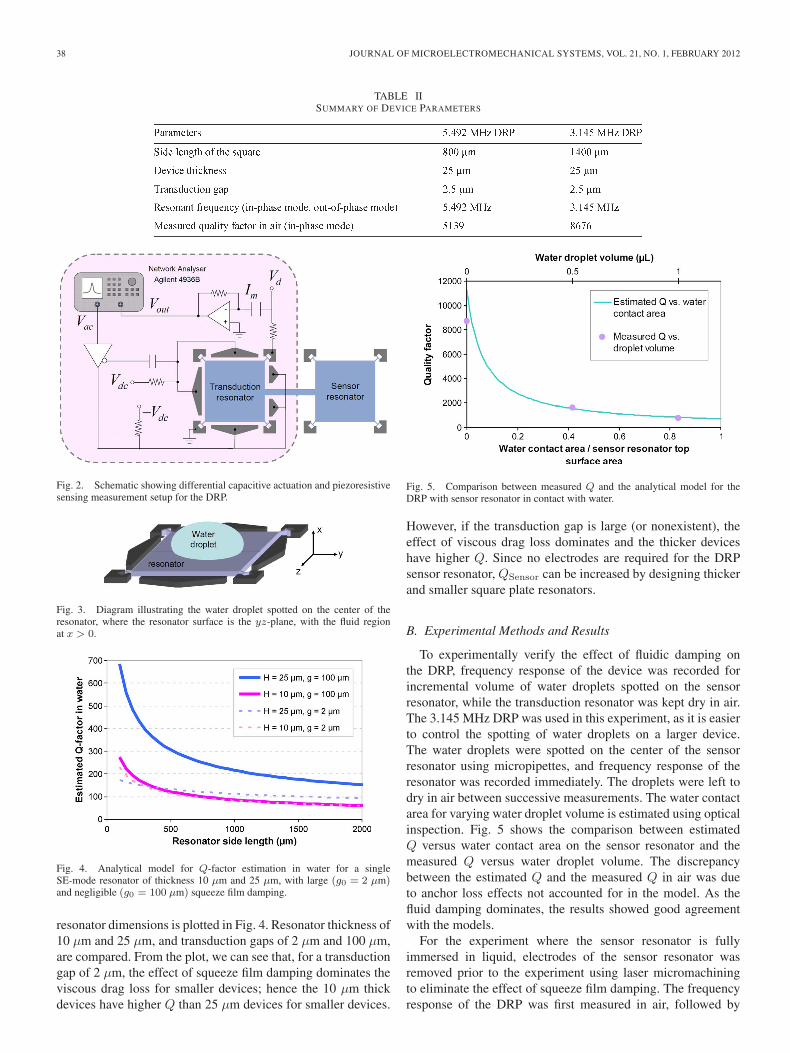
Fig. 4. Analytical model for Q-factor estimation in water for a singleSE-mode resonator of thickness 10 μm and 25 μm, with large (g0 = 2 μm)and negligible (g0 = 100 μm) squeeze film damping.
resonator dimensions is plotted in Fig. 4. Resonator thickness of10 μm and 25 μm, and transduction gaps of 2 μm and 100 μm,are compared. From the plot, we can see that, for a transductiongap of 2 μm, the effect of squeeze film damping dominates theviscous drag loss for smaller devices; hence the 10 μm thickdevices have higher Q than 25 μm devices for smaller devices.
Fig. 5. Comparison between measured Q and the analytical model for theDRP with sensor resonator in contact with water.
However, if the transduction gap is large (or nonexistent), theeffect of viscous drag loss dominates and the thicker deviceshave higher Q. Since no electrodes are required for the DRPsensor resonator, QSensor can be increased by designing thickerand smaller square plate resonators.
B. Experimental Methods and Results
To experimentally verify the effect of fluidic damping onthe DRP, frequency response of the device was recorded forincremental volume of water droplets spotted on the sensorresonator, while the transduction resonator was kept dry in air.The 3.145 MHz DRP was used in this experiment, as it is easierto control the spotting of water droplets on a larger device.The water droplets were spotted on the center of the sensorresonator using micropipettes, and frequency response of theresonator was recorded immediately. The droplets were left todry in air between successive measurements. The water contactarea for varying water droplet volume is estimated using opticalinspection. Fig. 5 shows the comparison between estimatedQ versus water contact area on the sensor resonator and themeasured Q versus water droplet volume. The discrepancybetween the estimated Q and the measured Q in air was dueto anchor loss effects not accounted for in the model. As thefluid damping dominates, the results showed good agreementwith the models.
For the experiment where the sensor resonator is fullyimmersed in liquid, electrodes of the sensor resonator wasremoved prior to the experiment using laser micromachiningto eliminate the effect of squeeze film damping. The frequencyresponse of the DRP was first measured in air, followed by

LIN et al.: ELECTRICALLY ADDRESSED DUAL RESONATOR SENSING PLATFORM FOR BIOCHEMICAL DETECTION 39
Fig. 6. Extracted frequency response curves for the DRP with the sensorresonator in air, top surface covered with water and completely immersed inwater.
sensor resonator top surface completely covered with water, andfurther followed by the sensor resonator completely immersedin water. The results are plotted in Fig. 6. The extracted qualityfactors are 10 940, 653, and 221, respectively. Using the ana-lytical model above, we calculate the Q of the DRP when thesensor resonator top surface is covered with water and whenimmersed in water to be 694 and 356, respectively. Comparingthis with our experimental data, the measured Q is lower thanthat of the estimated by ∼6% (partially covered) and ∼38%(immersed), respectively. This may be due to the fact that thetransduction signals in liquid were relatively poor due to thelower quality factor and the large transduction gaps fabricatedon the transduction resonator (2.5 μm). The measured signalstrength can be improved with smaller transduction gaps, andfrom our model, we expect the Q to increase with thicker andsmaller devices.
IV. MASS SENSING AND CELL COUNTING
The DRP designed in this work is coupled via half-wavelength coupling beam, which pushes other vibrationmodes far apart and allows the two resonators to vibrate to-gether as a single “composite” resonator. The in-phase mode ofthe DRP can therefore be modeled using a single mass-spring-damper system [32]. For small changes in mass, the variation infrequency can be approximated as
Δf
f0= −Δm
2m(12)
where f0,m is the nominal frequency and effective mass ofthe DRP. In practice, both the structures effective mass andeffective stiffness will be affected when particles attach to theresonant structure. This could occur under two conditions. First,when the attached layer of biomaterial is thick and denselypacked, the Young’s modulus of the combined structure is likelyto be different from that of the resonator alone, and if thestiffness change effect is larger than the added mass effect, apositive frequency shift may be observed [17]. In the other case,positive frequency shifts could also be observed with looselybond particles that are sparsely attached [33]–[35]. When thefrequency of the attached particle (modeled by the mass of the
Fig. 7. Comparison between measured frequency shift and the analyticalmodel to the thickness of Cr film deposited on the DRP sensor resonator. Thedotted lines represent the best fit curves to the measured data.
particle and the spring constant of the attachment bond) is closeto or lower than the operating frequency of the sensor itself,the loading becomes elastic and can be modeled with the twodegrees of freedom mechanical model [33], [36], given by
ω2 =12
(K
M+
kp
M+
kp
mp
)
±
√14
(K
M+
kp
M+
kp
mp
)2
− K
M
kp
mp(13)
where ω is the angular frequency of the coupled system, M,Kis the mass and spring constant of the unloaded resonator,and mp, kp is the mass and spring constant of the attachedparticle. The model shows that the frequency response could beenhanced when the frequency of the attached particle is closeto that of the unloaded resonator, and the mass loading effectpredicted by (12) is merely the limit at which the frequencyof the attached particle ωp is much larger than the operatingfrequency of the resonator ωr. For detection of soft biomaterialswhich are firmly attached to the sensor surface, the massloading phenomenon will likely be observed.
A. Thin Film Monitoring Experiment
To obtain the mass sensitivity for the DRP, successive layersof chrome (Cr) were deposited over the front side of the massloading resonator in 5-nm increments using thermal evapora-tion via a shadow mask. The 5.492 MHz DRP was used inthis experiment. The frequency response was measured on thetransduction resonator after each incremental deposition in bothair and vacuum. A corresponding shift in resonant frequencycan be clearly observed after each deposition increments, asshown in Fig. 7. The measured down shift in frequency ver-sus thickness of deposited Cr is found to be linear, and thedifferences in the values measured in vacuum and in air maybe due to temperature variations. The 8% ∼ 12% deviationof the experimental results from the analytical modeling maybe due to the fact that the deposited Cr increases the effectivestiffness of the structure, and thus has the effect of reducingthe actual resonant frequency downshift due to mass loading aspredicted by (12). The 5.492 MHz DRP has a mass responsivity
40 JOURNAL OF MICROELECTROMECHANICAL SYSTEMS, VOL. 21, NO. 1, FEBRUARY 2012
of −34 Hz/ng(−219 Hz cm2/μg) in air and −32 Hz/ng(−209 Hz cm2/μg) in vacuum operating in the in-phase mode.
B. Microbeads Experiment
To demonstrate the applicability of the DRP for biochem-ical sensing, experiments were carried out with streptavidin-coated polystyrene microbeads (SCPM) of diameters 5.61 μmand 15.68 μm attached to the biotin-functionalized surfaceof the sensor resonator. The SCPMs have a mass density of1050 kg/m3 which models that of biological species and canprovide a good quantification of the sensor response to differ-ent number and size of attached cells or bacteria. Frequencyresponses were recorded for different number of beads andcompared with the analytical model.
1) Preparation of the Resonator Surface and SCPM So-lution: The 3.145 MHz DRP devices were used in this ex-periment. The top surface of the DRP sensor resonator wasfirst coated with 3 nm of chrome and 20 nm of gold usingthermal evaporation in high vacuum (10−6 mBar) via a shadowmask. The freshly coated gold film is immediately immersed in1 mM of biotin-HPDP (Thermal Scientific) in absolute ethanolfor 1 h. This is done by dipping the device vertically in theprepared solution with the sensor resonator completely coveredin solution, while the transduction resonator was kept in air.The chips were then rinsed in absolute ethanol to wash awayunbounded biotin. The devices were then left to dry overnightin air at 4 ◦C.
The SCPM (Bangs Laboratories Inc.) were washed inMilli-Q water 3–5 times by centrifuging using Millipore filtersat 6000 g for 5 min to remove various additives. The washedSCPM were then diluted with Milli-Q water to the requiredconcentration. As provided by SCPM datasheet, the variationin the SCPM diameter is less than 10%.
The prepared device was connected to electronics for contin-uous frequency sweeping, and measurements were taken every30 s. First, the Milli-Q water were spotted on the functionalizedsurface of the sensor resonator and allowed to dry in air. Thissets up the initial conditions/baseline for reference frequencyon the same DRP. The SCPM solution was then spotted onthe sensor resonator, and allowed to dry in air. Measurementswere stopped after the SCPM solution has dried completely andthe number of attached beads was counted under the opticalmicroscope. This procedure was repeated for varying numberof SCPM for both bead sizes.
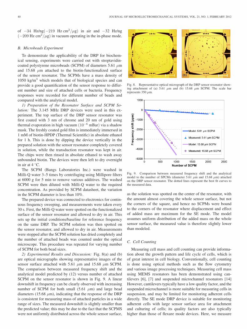
2) Experimental Results and Discussion: Fig. 8(a) and (b)are optical micrographs showing representative images of thesensor surface attached with 5.61 μm and 15.68 μm SCPM.The comparison between measured frequency shift and theanalytical model predicted by (12) versus number of attachedSCPM on the sensor resonator is shown in Fig. 9. A lineardownshift in frequency can be clearly observed with increasingnumber of SCPM for both small (5.61 μm) and large beaddiameters (15.68 μm), indicating that the response of the DRPis consistent for measuring mass of attached particles in a widerange of sizes. The measured downshift is slightly smaller thanthe predicted value; this may be due to the fact that the SCPMSwere not uniformly distributed across the whole sensor surface,
Fig. 8. Representative optical micrograph of the DRP sensor resonator show-ing attachment of (a) 5.61 μm and (b) 15.68 μm SCPM. The scale barrepresents 350 μm.
Fig. 9. Comparison between measured frequency shift and the analyticalmodel to the number of SPCMs (diameter 5.61 μm and 15.68 μm) attachedon the DRP sensor resonator. The dotted lines represent the best fit curves tothe measured data.
as the solution was spotted on the center of the resonator, withthe amount almost covering the whole sensor surface, but notthe corners of the square, and hence no SCPMs were boundto the corners of the resonator where displacement and effectof added mass are maximum for the SE mode. The modelassumes uniform distribution of the added mass on the wholesensor surface, the measured value is therefore slightly lowerthan modeled.
C. Cell Counting
Measuring cell mass and cell counting can provide informa-tion about the growth pattern and life cycle of cells, which isof great interest in cell biology. Conventionally, cell countingis done using optical methods such as the flow cytometryand various image processing techniques. Measuring cell massusing MEMS resonators has been demonstrated using can-tilevers [6], [7] and suspended microchannel resonators [14]However, cantilevers typically have a low quality factor, and thesuspended microchannel is more suitable for measuring cells insuspension, and may be limited for monitoring adherent cellsdirectly. The SE mode DRP device is suitable for monitoringadherent cells with large sensor surface area for attachmentand culturing of cells; its quality factors are also typicallyhigher than those of flexure mode devices. Here, we measure

LIN et al.: ELECTRICALLY ADDRESSED DUAL RESONATOR SENSING PLATFORM FOR BIOCHEMICAL DETECTION 41
Fig. 10. Optical micrograph showing the High Five insect cells suspended inMilli-Q water.
Fig. 11. Extracted frequency response curves for different number of attachedinsect cells.
the frequency downshift of the DRP due to added cell mass toquantify the number of attached cells in air.
High Five insect cells were used in this experiment. HighFive cells are a clonal isolate, derived from the parentalTrichoplusia ni cell line. The concentrated cells suspended inbuffer solution were first diluted approximately 1000 times inMilli-Q water. The diluted cells were then deposited on thesensor resonator and allowed to dry in air. Frequency responseof the DRP is measured before and after deposition of theinsect cells. The dimension of the cells are approximately15–30 μm in diameter, and the number of cells depositedwas approximated by multiplying the volume of cell solutionby the concentration of cells in the solution. Fig. 10 is anoptical micrograph of the insect cells suspended in Milli-Qwater. Fig. 11 shows the measured frequency response curvesfor different number of attached insect cells and Fig. 12 plotsthe measured frequency shift versus the number of dried insectcells on the sensor surface. A linear downshift in frequency isobserved for the added cells, demonstrating the feasibility ofthe DRP for cell counting with a responsivity of −12 Hz/cell(−3.89 ppm/cell) using the 3.145 MHz DRP device.
The linear response of the frequency shift versus numberof cells shows that the DRP can be calibrated and used foraccurate counting of cells suspended in milli-Q water. For cellssuspended in serum or other buffer solutions, reference devicescan be included for measuring the mass of serum to deducethe mass of cells. Furthermore, encapsulation of the DRP in aflow cell and integration with microfluidic channels allows for
Fig. 12. Measured frequency shift versus the number of High Five insect cellsattached on the DRP sensor resonator, the straight line represents best fit curveto the measured data.
Fig. 13. Frequency and temperature variation of the DRP over time.
real-time monitoring of adherent cells in a noninvasive mannerwithout detaching them from the sensor surface.
To estimate the effective mass resolution of the DRP sensor,continuous frequency measurements of the DRP were recordedfor 100 min at a sampling rate of 54 s in air. The resonantfrequencies were extracted by taking the frequency correspond-ing to the peak magnitude of the measured response in eachfrequency sweep. Fig. 13 shows the measured frequency andtemperature variations over time. The standard deviation ofmeasured data points is found to be 20.87 Hz. This corre-sponds to an approximate frequency resolution of 6.36 ppmcorresponding to 1.46 ng of mass, limited by the noise in theinterface electronics and environmental drift.
The system resolution can be improved by embedding theDRP in a closed-loop oscillator circuit and constructing op-timized frequency measurement circuits. However, the extentto which the resolution can be improved is limited in part bythe quality factor of the resonator, as the minimal detectablefrequency (limited by thermal noise) is inversely proportionalto the quality factor, such that the higher the quality factor,the higher the frequency resolution. The detection limit demon-strated in this work of 1.46 ng or 36 ng/cm2 in air correspondsto approximately the mass of ∼1.68 dried High Five insect cells(15–30 μm in diameter). For the detection of smaller scale cellsand molecules, further miniaturization or secondary mass labelswould be required to enhance the sensitivity. Comparing the

42 JOURNAL OF MICROELECTROMECHANICAL SYSTEMS, VOL. 21, NO. 1, FEBRUARY 2012
mass detection limit of the DRP reported in this work to thereported detection limit in liquid for the QCM (5.2 ng/cm2)[22], C-FBARS (1.78 ng/cm2) [24] and SMR (0.01 ng/cm2)[14] reveals that the DRP is not superior. However, it should benoted that this work is an initial demonstration, and the devicereported here has not been optimized for sensitivity. Addition-ally, it is worth noting that low-noise oscillators for MEMSresonators with similar motional parameters have demonstratedshort-term frequency stability in the order of 20 ppb [37]and that the thermomechanical noise [38] limited frequencyresolution is on the order of 1 ppb, pointing toward the potentialfor further improvement in the mass resolution for this device.
V. CONCLUSION
We have proposed a DRP, which enables physical separationof the electrical transduction and sensing regions of the devicefor biochemical sensing. This allows for the possibility ofoptimizing the biosensing and physical transduction indepen-dently to a much greater extent, and addresses the challengesof integrating the electronics with the biosensing interface torealize lab-on-a-chip devices. As compared to previous works,the DRP can be fully electrically addressed (capacitive-to-piezoresistive transduction) and does not have strenuous fabri-cation requirements, nor the requirement for expensive externalmeasurement setups.
An analytical model describing fluid damping was given toestimate the resonator quality factor for a SE mode DRP. Thecomparison between estimated and measured Q shows that thedecreasing trend of the estimated Q is in good agreement withthe measured Q for varying water contact area. The 3.145 MHzDRP demonstrated a Q of 221 when immersed in water, andthe Q factor is predicted to increase for smaller and thickerdevices. The functionality of the dual resonator system as amass sensing platform was verified via successive Cr thin filmdeposition, with a mass responsivity of 34 Hz/ng (5.492 MHzDRP). Its feasibility to quantify biochemical attachment ofparticles was further demonstrated using streptavidin-coatedmicrobeads. The downshifts in resonant frequency due to theadded masses in both cases are linear and in close agreementwith the analytical modeling. Finally, the use of DRP forcell counting is performed with High Five insect cells anddemonstrated a responsivity of −12 Hz/cell and mass resolutionof ∼1.46 ng or ∼1.68 cells (3.145 MHz DRP), limited by thenoise of the interface electronics and environmental drift.
We anticipate the integration of the dual resonator sensingplatform with microfluidic sample handling in the near futureto construct inexpensive arrays of resonant sensors to enablehighly multiplexed and real-time biochemical detection inliquid.
ACKNOWLEDGMENT
The authors would like to thank Dr. Y. Li for providing theHigh Five insect cells used in this study, Dr. W. Shu for hishelpful advice on the device functionalization procedures, andS. K. Ghosh for the valuable discussions on the microbeadsexperiments. A. T-H. Lin is a Cambridge Commonwealth TrustScholar.
REFERENCES
[1] I. R. Lauks, “Microfabricated biosensors and microanalytical systems forblood analysis,” Acc. Chem. Res., vol. 31, no. 5, pp. 317–324, May 1998.
[2] M. J. Madou and R. Cubicciotti, “Scaling issues in chemical and biologi-cal sensors,” Proc. IEEE, vol. 91, no. 6, pp. 830–838, Jun. 2003.
[3] Y. T. Yang, C. Callegari, X. L. Feng, K. L. Ekinci, and M. L. Roukes,“Zeptogram-scale nanomechanical mass sensing,” Nano Lett., vol. 6,no. 4, pp. 583–586, Apr. 2006.
[4] W. Pang, L. Yan, H. Zhang, H. Y. Yu, E. S. Kim, and W. C. Tang,“Femtogram mass sensing platform based on lateral extensional modepiezoelectric resonator,” Appl. Phys. Lett., vol. 88, no. 24, p. 243 503,Jun. 12, 2006.
[5] P. S. Waggoner and H. G. Craighead, “Micro- and nanomechanical sen-sors for environmental, chemical, and biological detection,” Lab Chip,vol. 7, no. 10, pp. 1238–1255, Oct. 2007.
[6] B. Ilic, D. Czaplewski, M. Zalalutdinov, H. G. Craighead, P. Neuzil,C. Campagnolo, and C. Batt, “Single cell detection with micromechanicaloscillators,” J. Vac. Sci. Technol. B, Microelectron. Nanometer Struct.,vol. 19, no. 6, pp. 2825–2828, Nov. 2001.
[7] K. Park, J. Jang, D. Irimia, J. Sturgis, J. Lee, J. P. Robinson, M. Toner,and R. Bashir, “‘Living cantilever arrays’ for characterization of massof single live cells in fluids,” Lab Chip, vol. 8, no. 7, pp. 1034–1041,Jul. 2008.
[8] A. Gupta, D. Akin, and R. Bashir, “Detection of bacterial cells and an-tibodies using surface micromachined thin silicon cantilever resonators,”J. Vac. Sci. Technol. B, Microelectron. Nanometer Struct., vol. 22, no. 6,pp. 2785–2791, Nov./Dec. 2004.
[9] B. Ilic, Y. Yang, and H. G. Craighead, “Virus detection using nanoelectro-mechanical devices,” Appl. Phys. Lett., vol. 85, no. 13, pp. 2604–2606,Sep. 27, 2004.
[10] P. S. Waggoner, M. Varshney, and H. G. Craighead, “Detection of prostatespecific antigen with nanomechanical resonators,” Lab Chip, vol. 9,no. 21, pp. 3095–3099, Nov. 2009.
[11] H. Zhang, M. S. Marma, E. S. Kim, C. E. McKenna, and M. E. Thompson,“A film bulk acoustic resonator in liquid environments,” J. Micromech.Microeng., vol. 15, no. 10, pp. 1911–1916, Oct. 2005.
[12] J. H. Seo and O. Brand, “High Q-factor in-plane-mode resonant microsen-sor platform for gaseous/liquid environment,” J. Microelectromech. Syst.,vol. 17, no. 2, pp. 483–493, Apr. 2008.
[13] T. P. Burg, A. R. Mirza, N. Milovic, C. H. Tsau, G. A. Popescu,J. S. Foster, and S. R. Manalis, “Vacuum-packaged suspended microchan-nel resonant mass sensor for biomolecular detection,” J. Microelectro-mech. Syst., vol. 15, no. 6, pp. 1466–1476, Dec. 2006.
[14] T. P. Burg, M. Godin, S. M. Knudsen, W. Shen, G. Carlson, J. S. Foster,K. Babcock, and S. R. Manalis, “Weighing of biomolecules, single cellsand single nanoparticles in fluid,” Nature, vol. 446, no. 7139, pp. 1066–1069, Apr. 2007.
[15] J. Lee, R. Chunara, W. Shen, K. Payer, K. Babcock, T. P. Burg, andS. R. Manalis, “Suspended microchannel resonators with piezoresistivesensors,” Lab Chip, vol. 11, no. 4, pp. 645–651, Feb. 2011.
[16] R. A. Barton, B. Ilic, S. S. Verbridge, B. R. Cipriany, J. M. Parpia, andH. G. Craighead, “Fabrication of a nanomechanical mass sensor contain-ing a nanofluidic channel,” Nano Lett., vol. 10, no. 6, pp. 2058–2063,Jun. 2010.
[17] A. K. Gupta, P. R. Nair, D. Akin, M. R. Ladisch, S. Broyles,M. A. Alam, and R. Bashir, “Anomalous resonance in a nanomechanicalbiosensor,” Proc. Nat. Acad. Sci. U.S.A., vol. 103, no. 36, pp. 13 362–13 367, Sep. 2006.
[18] T. Adrega, V. Chu, and J. P. Conde, “Resonance of electrostatically ac-tuated thin-film amorphous silicon microelectromechanical systems mi-croresonators in aqueous solutions: Effect of solution conductivity andviscosity,” J. Appl. Phys., vol. 101, no. 9, p. 094308, May 2007.
[19] S. Dohn, O. Hansen, and A. Boisen, “Cantilever based mass sensor withhard contact readout,” Appl. Phys. Lett., vol. 88, no. 26, p. 264 104,Jun. 2006.
[20] C. Riesch, E. K. Reichel, A. Jachimowicz, J. Schalko, P. Hudek,B. Jakoby, and F. Keplinger, “A suspended plate viscosity sensor featuringin-plane vibration and piezoresistive readout,” J. Micromech. Microeng.,vol. 19, no. 7, p. 075010, Jul. 2009.
[21] W. Xu, X. Zhang, H. Yu, A. Abbaspour-Tamijani, and J. Chae, “In-liquid quality factor improvement for film bulk acoustic resonators byintegration of microfluidic channels,” IEEE Electron Device Lett., vol. 30,no. 6, pp. 647–649, Jun. 2009.
[22] J. Weber, W. M. Albers, J. Tuppurainen, M. Link, R. Gabl, W. Wersing,and M. Schreiter, “Shear mode FBARs as highly sensitive liquid biosen-sors,” Sens. Actuators A, Phys., vol. 128, no. 1, pp. 84–88, Mar. 2006.

LIN et al.: ELECTRICALLY ADDRESSED DUAL RESONATOR SENSING PLATFORM FOR BIOCHEMICAL DETECTION 43
[23] G. Wingqvist, J. Bjurstrom, L. Liljeholm, V. Yantchev, and I. Katardjiev,“Shear mode AlN thin film electro-acoustic resonant sensor operation inviscous media,” Sens. Actuators B, Chem., vol. 123, no. 1, pp. 466–473,Apr. 2007.
[24] W. C. Xu, S. Choi, and J. Chae, “A contour-mode film bulk acousticresonator of high quality factor in a liquid environment for biosens-ing applications,” Appl. Phys. Lett., vol. 96, no. 5, p. 053703,Feb. 2010.
[25] A. T. H. Lin, J. E. Y. Lee, J. Yan, and A. A. Seshia, “Methods forenhanced electrical transduction and characterization of micromechani-cal resonators,” Sens. Actuators A, Phys., vol. 158, no. 2, pp. 263–272,Mar. 2010.
[26] Y. W. Lin, S. S. Li, Z. Y. Ren, and C. T. C. Nguyen, “Low phase noisearray-composite micromechanical wine-glass disk oscillator,” in IEDMTech. Dig., 2005, pp. 278–281.
[27] A. T. H. Lin, J. Yan, and A. A. Seshia, “Dynamic response of water dropletcoated silicon MEMS resonators,” in Proc. IEEE Int. Ultrason. Symp.,2009, pp. 669–672.
[28] Y. W. Lin, L. W. Hung, S. S. Li, Z. Y. Ren, and C. T. C. Nguyen, “Qualityfactor boosting via mechanically-coupled arraying,” in Transducers Eu-rosensors XXI Dig. Tech. Papers, 2007, vol. 1/2, pp. 2453–2456.
[29] J. F. Vignola, J. A. Judge, J. Jarzynski, M. Zalalutdinov, B. H. Houston,and J. W. Baldwin, “Effect of viscous loss on mechanical resonatorsdesigned for mass detection,” Appl. Phys. Lett., vol. 88, no. 4, p. 041921,Jan. 23, 2006.
[30] L. D. Landau and E. M. Lifshitz, Fluid Mechanics, 2nd ed. Oxford, U.K.:Reed Educ. Prof. Publ. Ltd., 1987.
[31] S. D. Senturia, Microsystem Design, 1st ed. New York: Springer Sci. Bus.Media, 2000.
[32] S. S. Li, Y. W. Lin, Z. Y. Ren, and C. T. C. Nguyen, “Disk-array designfor suppression of unwanted modes in micromechanical composite-arrayfilters,” in Proc. 19th IEEE Int. Conf. MEMS, Tech. Dig., 2006, pp. 866–869.
[33] G. L. Dybwad, “A sensitive new method for the determination of adhesivebonding between a particle and a substrate,” J. Appl. Phys., vol. 58, no. 7,pp. 2789–2790, Oct. 1985.
[34] B. Y. Du, A. M. Konig, and D. Johannsmann, “On the role of capil-lary instabilities in the sandcastle effect,” New J. Phys., vol. 10, p. 14,May 2008.
[35] A. Pomorska, D. Shchukin, R. Hammond, M. A. Cooper, G. Grundmeier,and D. Johannsmann, “Positive frequency shifts observed upon adsorbingmicron-sized solid objects to a quartz crystal microbalance from the liquidphase,” Anal. Chem., vol. 82, no. 6, pp. 2237–2242, Feb. 2010.
[36] W. W. Seto, Schaum’s Outline of Theory and Problems of MechanicalVibrations. New York: McGraw-Hill, 1964.
[37] K. E. Wojciechowski, “Electronics for resonant sensors,” Ph.D. disserta-tion, Dept. Elect. Eng. Comput. Sci., Univ. California, Berkeley, 2005.
[38] K. Ekinci and M. L. Roukes, “Ultimate limits to inertial mass sensingbased upon nanoelectromechanical systems,” J. Appl. Phys., vol. 95, no. 5,pp. 2682–2689, Mar. 2004.
Angel T.-H. Lin (S’06–M’12) received the B.Sc. andM.Sc. degrees in electrical and computer engineeringfrom the University of Cape Town, Cape Town,South Africa, in 2005 and 2007, respectively, and thePh.D. degree in engineering from the University ofCambridge, Cambridge, U.K., in 2011.
During her time at the University of Cambridge,she was affiliated with the Nanoscience Centre. Sheis currently working as a Research Scientist withthe Institute of Microelectronics, Singapore. Her re-search interest is in the design and fabrication of
microelectromechanical systems sensors.
Jize Yan (S’06–M’09) received the B.S. degree fromTsinghua University, Beijing, China, in 2003, andthe Ph.D. degree from the University of Cambridge,Cambridge, U.K., in 2007.
He is currently a Research Associate with the En-gineering Department, University of Cambridge. Hisresearch interests include radio-frequency MEMS,MEMS/nanoelectromechanical system sensors,power harvesting, and micro-/nanofabrication.
Ashwin A. Seshia (S’98–M’02–SM’10) receivedthe B.Tech. degree in engineering physics from theIndian Institute of Technology Bombay, Mumbai,India, in 1996, the M.S. and Ph.D. degrees in elec-trical engineering and computer sciences from theUniversity of California, Berkeley, in 1999 and 2002,respectively, and the M.A. degree from the Univer-sity of Cambridge, Cambridge, U.K., in 2008.
During his time at the University of California,Berkeley, he was affiliated with the Berkeley Sensorand Actuator Center. He joined the faculty of the
Engineering Department, University of Cambridge, in October 2002, where heis presently a Reader in Microsystems Technology and a Fellow of Queens’College, Cambridge, U.K. His research interests include the design and fab-rication of micro- and nanoscale sensory systems with applications to themonitoring and study of natural and built environments.
Dr. Seshia was appointed as a Fellow of the ERA Foundation in 2008. Heserves on the Technical Program Committees of the IEEE Frequency ControlSymposium, the European Time and Frequency Forum, the IEEE InternationalElectron Devices Meeting, and the Editorial Board of the JOURNAL OF MI-CROELECTROMECHANICAL SYSTEMS.