Controlling dynamics in external-cavity laser diodes with electronic impulsive delayed feedback
11
Controlling dynamics in external-cavity laser diodes with electronic impulsive delayed feedback A. V. Naumenko, N. A. Loiko, and S. I. Turovets Institute of Physics, Academy of Sciences, 70 Skarina Avenue, Minsk 220072, Belarus P. S. Spencer and K. A. Shore University of Wales, Bangor, School of Electronic Engineering and Computer Systems, Bangor, LL571UT, Wales, UK Received May 6, 1997; revised manuscript received August 5, 1997 The possibility of controlling chaos in a model of an external-cavity laser diode with optimized impulsive de- layed feedback is demonstrated. An examination is made of the application of such feedback by means of modulation of three different parameters, which determine the laser operation: (i) laser-drive current, (ii) laser-field phase, and (iii) laser-cavity losses. Account is taken of practical constraints arising from a techni- cal delay in application of the control signal. The roles of the phase, width, and shape of the feedback pulses are elucidated for optimizing the control process. The effectiveness of the various methods of applying the control is analyzed by computing domains of control and finding the optimal conditions for control. It is dem- onstrated also that the preliminary targeting of dynamics to an unstable orbit by means of the present method is applicable to dynamical systems with many degrees of freedom and thus facilitates the process of controlling chaos. © 1998 Optical Society of America [S0740-3224(98)04702-X] OCIS codes: 140.5960, 140.1540, 190.0190. 1. INTRODUCTION Recent advances in the understanding of nonlinear dy- namical systems have led to interest in developing prac- tical applications for chaotic dynamics in a number of dis- ciplines, including laser physics, medicine, and communications. The major advance that has stimu- lated these efforts is the development of techniques for controlling chaotic dynamics. Following publication of a chaos-control technique by Ott, Grebogi, and Yorke (OGY), 1 a number of successful applications of this method and its variants for taming chaotic dynamics in experiments, including lasers, have been reported. In particular, Roy et al. have resolved the problem of multi- mode instability (the so-called green problem) in the Nd:YAG laser with intracavity frequency doubling on the KTP crystal; 2 Glorieux and coworkers have stabilized a chaotic output of the self-pulsing fiber 3 and modulated CO 2 lasers. 4 Some attempts to control chaotic dynamics in external-cavity laser diodes exhibiting socalled coher- ence collapse have also been reported. In particular, use was made of occasionally proportional impulsive feedback, 5,6 which originates in the OGY techniques, ex- ternal microwave modulation, 7–9 and continuous Pyragas-like electronic feedback, 10 albeit with moderate success because of specific features of semiconductor la- sers such as high levels of intrinsic noise and the need for extremely high sampling frequencies. Interest in controlling semiconductor laser dynamics has been stimulated in particular by the possibilities for achieving secure communication systems that exploit the properties of chaotic dynamics systems. 11 The idea here is to control chaotic dynamics in a manner prescribed by an information-carrying signal. Techniques for the control of chaos would permit the selection and stabilization of one of the unstable orbits that are available within the dynamics of a chaotic sys- tem. Then the control signal is substituted by an infor- mational targeting signal. The transmitted data is then recovered from the transmitted perturbed chaos. Cha- otic communications may also be produced by mixing the message signal with the output from a chaotic transmit- ter and then recovering the message from the received transmitted chaos by means of a rather different concept of chaos synchronization. 12 An efficient algorithm for im- proving the locking rate between receiver and transmitter has been reported previously. 13 The feasibility of optical injection-locking techniques for reciprocal synchroniza- tion of two distant chaotic laser diodes has also been con- sidered recently. 14 Based on the availability of an improved synchroniza- tion algorithm, consideration has been given to the devel- opment of practical laser-diode chaotic transmitters for use in optical-fiber communications systems. Laser di- odes subject to phase-conjugate optical feedback offer an- other possible method for implementing a controllable chaotic transmitter. The required controllable phase- conjugate feedback could itself be generated by enhanced multiwave mixing in laser-diode structures. 15 The re- sponse of laser diodes when they are subject to phase- conjugate optical feedback has already been demon- strated as giving rise to a transition to chaos. 16,17 Another practical context where chaos-control tech- Naumenko et al. Vol. 15, No. 2 / February 1998 / J. Opt. Soc. Am. B 551 0740-3224/98/020551-11$10.00 © 1998 Optical Society of America
Transcript of Controlling dynamics in external-cavity laser diodes with electronic impulsive delayed feedback
Naumenko et al. Vol. 15, No. 2 /February 1998 /J. Opt. Soc. Am. B 551
Controlling dynamics in external-cavity laserdiodes with electronic
impulsive delayed feedback
A. V. Naumenko, N. A. Loiko, and S. I. Turovets
Institute of Physics, Academy of Sciences, 70 Skarina Avenue, Minsk 220072, Belarus
P. S. Spencer and K. A. Shore
University of Wales, Bangor, School of Electronic Engineering and Computer Systems, Bangor, LL57 1UT, Wales, UK
Received May 6, 1997; revised manuscript received August 5, 1997
The possibility of controlling chaos in a model of an external-cavity laser diode with optimized impulsive de-layed feedback is demonstrated. An examination is made of the application of such feedback by means ofmodulation of three different parameters, which determine the laser operation: (i) laser-drive current, (ii)laser-field phase, and (iii) laser-cavity losses. Account is taken of practical constraints arising from a techni-cal delay in application of the control signal. The roles of the phase, width, and shape of the feedback pulsesare elucidated for optimizing the control process. The effectiveness of the various methods of applying thecontrol is analyzed by computing domains of control and finding the optimal conditions for control. It is dem-onstrated also that the preliminary targeting of dynamics to an unstable orbit by means of the present methodis applicable to dynamical systems with many degrees of freedom and thus facilitates the process of controllingchaos. © 1998 Optical Society of America [S0740-3224(98)04702-X]
OCIS codes: 140.5960, 140.1540, 190.0190.
1. INTRODUCTIONRecent advances in the understanding of nonlinear dy-namical systems have led to interest in developing prac-tical applications for chaotic dynamics in a number of dis-ciplines, including laser physics, medicine, andcommunications. The major advance that has stimu-lated these efforts is the development of techniques forcontrolling chaotic dynamics. Following publication of achaos-control technique by Ott, Grebogi, and Yorke(OGY),1 a number of successful applications of thismethod and its variants for taming chaotic dynamics inexperiments, including lasers, have been reported. Inparticular, Roy et al. have resolved the problem of multi-mode instability (the so-called green problem) in theNd:YAG laser with intracavity frequency doubling on theKTP crystal;2 Glorieux and coworkers have stabilized achaotic output of the self-pulsing fiber3 and modulatedCO2 lasers.4 Some attempts to control chaotic dynamicsin external-cavity laser diodes exhibiting socalled coher-ence collapse have also been reported. In particular, usewas made of occasionally proportional impulsivefeedback,5,6 which originates in the OGY techniques, ex-ternal microwave modulation,7–9 and continuousPyragas-like electronic feedback,10 albeit with moderatesuccess because of specific features of semiconductor la-sers such as high levels of intrinsic noise and the need forextremely high sampling frequencies.
Interest in controlling semiconductor laser dynamicshas been stimulated in particular by the possibilities forachieving secure communication systems that exploit theproperties of chaotic dynamics systems.11 The idea here
0740-3224/98/020551-11$10.00 ©
is to control chaotic dynamics in a manner prescribed byan information-carrying signal.
Techniques for the control of chaos would permit theselection and stabilization of one of the unstable orbitsthat are available within the dynamics of a chaotic sys-tem. Then the control signal is substituted by an infor-mational targeting signal. The transmitted data is thenrecovered from the transmitted perturbed chaos. Cha-otic communications may also be produced by mixing themessage signal with the output from a chaotic transmit-ter and then recovering the message from the receivedtransmitted chaos by means of a rather different conceptof chaos synchronization.12 An efficient algorithm for im-proving the locking rate between receiver and transmitterhas been reported previously.13 The feasibility of opticalinjection-locking techniques for reciprocal synchroniza-tion of two distant chaotic laser diodes has also been con-sidered recently.14
Based on the availability of an improved synchroniza-tion algorithm, consideration has been given to the devel-opment of practical laser-diode chaotic transmitters foruse in optical-fiber communications systems. Laser di-odes subject to phase-conjugate optical feedback offer an-other possible method for implementing a controllablechaotic transmitter. The required controllable phase-conjugate feedback could itself be generated by enhancedmultiwave mixing in laser-diode structures.15 The re-sponse of laser diodes when they are subject to phase-conjugate optical feedback has already been demon-strated as giving rise to a transition to chaos.16,17
Another practical context where chaos-control tech-
1998 Optical Society of America

552 J. Opt. Soc. Am. B/Vol. 15, No. 2 /February 1998 Naumenko et al.
niques may have an important role to play is in the engi-neering of immunity to coherence collapse caused by un-intentional optical feedback, which may arise in thehybrid integration and packaging of commercial laser di-odes. The phenomenon of coherence collapse relates to asudden increase of single-mode linewidth and amplitude-intensity fluctuations, which may occur in semiconductorlasers when they are subjected to external optical feed-back. The phenomenon is known to depend upon thestrength of the optical feedback and the distances to ex-ternal reflectors. In particular, it has been found thatvery low external reflectivities such as those that resultfrom the connector on the fiber pigtail of a laser-diodemodule (of order 0.01%) can cause the laser to enter thevery noisy coherence-collapse regime. To ensure immu-nity to this phenomenon in practical devices, rather ex-pensive optical isolators must be used to avoid the rel-evant optical-feedback regimes. Recent reviews of theeffect and further references thereon may be found inRefs. 18 and 19.
The scheme of chaos control proposed in the presentstudy allows the convenient manipulation of the regimesof operation in such possible devices. The combination ofan efficient control algorithm and a practical chaotic opti-cal transmitter offers an opportunity for a novel securecommunications system based on chaotic encryption. Al-ternative methods involving continuous optoelectronicfeedback studied recently10 are not so flexible in respectto manipulating complex dynamics (for instance, they arenot able to control unstable states with positive Floquetmultipliers such as those arising as a result of a saddle-node bifurcation,21) although they are possibly more ad-vantageous in the context of engineering immunity to co-herence collapse owing to their modest requirement onthe bandwidth of the electronic components in the feed-back loop.
With a view to such potential applications, this paperreports a detailed investigation of the potential of discretechaos-control schemes based on the original OGYmethod1 and its more sophisticated modification20 fromthe viewpoint of its application to the control of thecoherence-collapse phenomenon in an external-cavity la-ser diode. It is important to emphasize that the first at-tempts to control chaos in laser-diode models were basedon an oversimplified version of the OGY method like oc-casionally proportional impulsive feedback.5 Lack of apreliminary targeting process in this scheme is paid forby rather long time transients to satisfy the conditionthat two successive samples of laser intensity fall withina user-prescribed window, the so-called «-ball condition.The need to readjust numerous control-scheme param-eters did not permit effective optimization and led to alack of robustness to noise. Taken together with high op-erating frequencies this lack of robustness has had arather discouraging impact on the perspectives of experi-mental implementation of such a scheme. In contrast, inthis paper attention is focused on optimization of param-eters of control schemes with the aim of relaxing the re-quirements imposed by such basic features of laser diodesas high levels of noise and fast dynamics. In particular,an examination is made of several possible means of ap-plying optimized discontinuous delayed feedback through
different laser-control parameters (as was found to be in-structive in the case of impulsive control of a class Blaser 21): laser-drive current, laser-field phase modula-tion in the external resonator, and modulation of cavitylosses. (It is noted that loss modulation is also a practi-cal option in some laser-diode structures such as vertical-cavity surface-emitting lasers and distributed bragg re-flector lasers.22) A special emphasis is given to theinfluence of real technical delay of a controlling signal andthe presence of intrinsic laser noise. The roles of thephase, width, and shaping of feedback pulses are eluci-dated for optimizing a process of control. The approachtaken is to analyze the effectiveness of the specific controlscheme by computing domains of control and finding theoptimal conditions of control in the space of accessiblecontrol parameters. In this way it is found that optimalcontrol in terms of stability and noise robustness corre-sponds to the minima of the Lyapunov exponents of theclosed-loop feedback scheme. For such optimal condi-tions, practical constraints on control schemes imposed byintrinsic noise and high operating frequencies can be sig-nificantly relaxed.
Strategies for control of chaos generally involve an ini-tial targeting of an unstable orbit, which is to bestabilized.23 This can be achieved by bringing a systemexhibiting developed chaos into a regime of periodic dy-namics, using the kick24 or off–on manipulationsmethods25,26 to target and control an unstable orbit, andfinally tracking the stabilized system as the system is re-turned to the chaotic regime. It should be emphasizedthat, although this method has been previously success-fully applied to low-dimensional nonlinear dynamic sys-tems such as a modulated CO2 laser,24 it is not evident, apriori, that the method will work equally well for time-delay systems that have infinite degrees of freedom.27
Consideration is thus required of the possibility of usingthe present kick method to direct a dynamical trajectoryof the infinite-dimensional external-cavity laser-diodesystem toward a desired unstable orbit.
2. MODELIt is assumed that the laser operates in a single longitu-dinal mode and is subject to weak optical feedback froman external mirror. A rate-equation treatment of thisconfiguration has recently been developed on the basis ofthe Lang–Kobayashi model to take into account feedbackeffects in modulated external-cavity laser diodes.28,29
The equations are as follows:
dS~t8!
dt85 S~t8!H Gn@N~t8! 2 N0#GF 1
1 1 «8S~t8!G 21
tphJ
1gGN~t8!
tsp1 2
kext
tLAS~t8!AS~t8 2 text!
3 cos@u~t8!# 1 Fs~t8!, (1)
dN~t !
dt85
I~t8!
eV2
N~t8!
tsp2 S~t8!Gn@N~t8! 2 N0#
3 F 11 1 «8S~t8!G 1 Fn~t8!, (2)

Naumenko et al. Vol. 15, No. 2 /February 1998 /J. Opt. Soc. Am. B 553
dF~t8!
dt85
12
aGn@N~t8! 2 Nth#G
2kext
tL
AS~t8 2 text!
AS~t8!sin@u~t8!# 1 Ff~t8!,
(3)
where
u~t8! 5 F~t8! 2 F~t8 2 text! 1 vthtext . (4)
In the rate equations, N(t8) is the carrier density, S(t8) isthe photon density, F(t8) is the electric-field phase, I(t8)is the injection current, and e is the electronic charge.Typical laser parameters for a distributed feedback laserare used, where V is the active-region volume (1.53 10216 m3), tsp is the carrier lifetime (2 ns), Gn is thegain slope (2.125 3 10212 m3 s21), Nth is the thresholdcarrier density (9.9 3 1023 m23), «8 is the saturation pa-rameter (3 3 10223 m3), g is the spontaneous-emissionfactor (1 3 1025), tph is the photon lifetime (2 ps), G is theconfinement factor (0.4), a8 is the linewidth-enhancementfactor (5.5), N0 is the transparency carrier density (43 1023 m23), vth is the operating frequency (l5 1.55 mm), R2 is the laser-facet reflectivity (0.309), h isthe laser-to-fiber–coupling efficiency (0.4), and tL is thelaser-cavity round-trip delay (9 ps). In the optical feed-back terms, Rext is the external-reflector reflectivity andtext is the external-cavity round-trip delay (0.2 ns, whichcorresponds to an external cavity of approximately 2 cmfor the fiber refractive index 1.5). kext is the feedback-coupling parameter, given by
kext 51 2 R2
AR2
ARexth,
The model can, in general, account for the effects ofLangevin noise terms, but the calculations described be-low consider mainly noise-free deterministic dynamicsunless specified otherwise (see Subsection 4.D).
Introducing the new variables u 5 SGntsp , n5 NGntph , t 5 t8/tsp , we have obtained the followingnormalized equations, which are more convenient for thesubsequent analysis:
u 5 vu@g~n, u !G 2 1 2 K1~t !# 1 rn 1 2kAuut cos u,
(5)n 5 P0 1 K2~t ! 2 n 2 ug~n, u !, (6)
F 5 a~n 2 nth!G 2 kAut /u sin u,
u 5 F 2 Ft 1 vt 1 K3~t !. (7)
Here g(n, u) 5 (n 2 n0)(1 2 «u), n0 5 N0Gntph , «5 «8/Gntsp , v 5 vthtsp , r 5 vgG, v 5 tsp /tph , k5 kexttsp /tL , a 5 a8vG/2, P0 5 IGntphtsp /eV, and t5 text /tsp.
The laser is taken to be supplied with a dc injectioncurrent IDC > 2Ith (in fact, with nth 5 4.2075, P0 5 8.2,we have P0 /nth 5 1.9489), where Ith is the threshold cur-rent. This ensures that the operation conditions aretypical of those classified as the coherence-collapse re-gime. No consideration is given here to low-frequencyfluctuation processes such as the Sisyphus effect18 that
take place for biases just above the threshold. The coher-ence collapse is well documented in such an arrangement.Because the external cavity is short (2 cm), a typical routeto chaos is a Hopf instability of a single external cavity-mode steady state (Rext ' 6.25 3 1024 or k ' 2.5) fol-lowed by the Feigenbaum period-doubling tree. The firstperiod-doubling bifurcation takes place at k ' 4.26; fullchaos is developed at k ' 4.79. It is noted that addi-tional external-cavity modes are born in pairs; a stablemode and an unstable antimode arise only at k ' 5.2 and11.5. First of all, the additional cavity mode is stable andnot active in the coherence-collapse regime, but at k' 5.5 it loses stability through a Hopf bifurcation fol-lowed by its own Feigenbaum period-doubling tree.However, this period-doubling branch is truncated at k' 6.0 owing to a collision with a stable manifold of theantimode (which is a saddle steady-state point), and thebasins of attraction of two external-cavity modes becomemerged. At that level of external optical feedback atleast two external-cavity modes are active in thecoherence-collapse regime. In all calculations reportedbelow the domain of interest is set typically for k < 6.0,although in some cases the range of parameters includesk < 10. It is noted again that, because of the short ex-ternal cavity, regimes II and III, classified for a laser di-ode with optical feedback,18,19,28 are mixed with thecoherence-collapse (IV) regime, and the system enters re-gime IV directly from regime I.
The terms Kj(t) ( j 5 1, 2, 3) describe an impulseperiodic-control action applied to an appropriate modula-tor. The rate equations (1)–(3) are solved numerically bymeans of a fourth-order Runge–Kutta algorithm with avariable integration time step.
3. IMPULSIVE OPTOELECTRONICFEEDBACKIt is assumed that an impulsive electronic-feedback signalapplied to a laser diode is created by a microwave pulse-train generator and that the amplitude of every sequen-tial impulse in the chain is proportional to the differencebetween laser optical output powers taken at discrete mo-ments of time. Such an arrangement implies detectionand sampling of the output intensity synchronized withthe pulse-train generator. Mathematically, the impulseoptoelectronic-feedback terms in the dimensionless equa-tions are taken in the form
Kj~t ! 5 b j(i
@u~w j 1 ti! 2 u~w j 1 ti 2 Ti!#
3 f @t 2 ~w j 1 ti 1 tel!#. (8)
The factors b j are attributed to amplification in theelectronic-feedback loop and will be referred to as thefeedback strength. The tunable phases w j specify aphase shift between a chain of applied correction pulsesand a reference signal, which is as convenient to choose asthe laser output itself, and to measure phase with respectto a laser-intensity maximum emitted at the discrete mo-ments of time ti 5 (k51
i Tk .We will refer to the quantities b j , w j as the parameters
of the control scheme that are to be optimized. Finally,

554 J. Opt. Soc. Am. B/Vol. 15, No. 2 /February 1998 Naumenko et al.
Ti is assumed to be self adjustable during the process ofcontrolled time delay and equal to a time interval be-tween successive laser-intensity maxima. This meansthat the pulse generator triggering the time and the in-terval of sampling are synchronized to a detected maxi-mum intensity (or the pulse generator is synchronized di-rectly by a signal that is proportional to laser intensity asmeasured by a monitoring photodiode). Actually, thisproperty constitutes one of the major differences betweenthe present scheme and the occasional proportional feed-back scheme.5
The terms Kj(t) are used to modify slightly a corre-sponding control parameter of the laser diode, which isdependent on the choice of the following control schemes:(1) voltage on a Bragg mirror to modulate cavity losses(K1 , b1 , w1), (2) laser-driving current (K2 , b2 , w2), or(3) applied voltage on a phase modulator in the externalresonator (K3 , b3 , w3).
Equation (8) essentially assumes that the electroniccomponents of feedback Kj(t) are fast enough to followthe laser-output pulsations in real time, detect itsmaxima, and trigger the pulse generator. In practice, ofcourse, there will always be some frequency cutoff, owingto the finite bandwidth, and also technical phase shift, at-tributed in part to a finite speed of the electrical signalthrough the loop. The latter is taken into account simplyby an additional time delay tel in Eq. (8), which includesalso a natural time shift by a half-width of an appliedpulse. The former might be considered as taking the av-eraged with appropriate weight difference signal, over theperiod of control. It is supposed, nevertheless, that thebandwidth is wide enough to permit microwave spectra ofamplitude fluctuations centered at the relaxation fre-quency (approximately 3 GHz for the parameters usedhere) to pass without significant distortion and to besampled. This is feasible with current electronic-feedback circuit performance; see, e.g., Ref. 30. It is con-ceivable that such a device would be implemented bymeans of a customized integrated optoelectronic circuit,which gives advantages in a bandwidth, an electronic-feedback loop delay, etc., in comparison with a discretesystem in which components are coupled with bond wiresand in which parasitics may not permit operation in thegigahertz domain. It is noted that laser-diode transmit-ters and receivers, external modulators capable of inte-gration and operation in the gigahertz domain, are com-mercially available.
The motivation for choosing feedback in the specifiedform is as follows. First, to produce stabilization thefeedback should be negative; second, the feedback is de-signed so that it has no effect on the state in which thesystem has been initially prepared by preliminary target-ing (e.g., an unstable periodic orbit with period T).
Every kick of the control scheme has a functional formgiven by f(t). Its amplitude (see Eq. 8) is proportional tothe difference between the output powers that were emit-ted at instants of time w j 1 ti 2 tel and those emitted ata previous time w j 1 ti 2 tel 2 Ti . The functional formof the kicks was chosen to be super-Gaussian:
f~t ! 5 M exp~2at2m!, a 5 @G~1/2m !/mw#2m,
M 5 1/w, (9)
where G(1/2m) is the special G function31 or super-Lorentzian
f~t ! 5s2m21/Q
t2m 2 s2m , Q 5 p/m sin~p/2m !,
s 5 w/Q. (10)
The impulse function f(t) is normalized in such a waythat its integral area is a unity. When its effective widthw tends to zero, then it approaches a Dirac d function,while the exponent m regulates the specific shape of akick. In particular, in the extreme case of m → ` with afinite w, the pulses acquire a nearly square form. Thusit is allowed to model kicks of an almost arbitrary dura-tion and shape.
4. RESULTSA. Targeting Unstable T-periodic OrbitsAs was indicated in section 1, general strategies of chaoscontrol often imply a preliminary targeting of an unstableorbit, which is to be stabilized. For the present system,which exhibits a period-doubling route to chaos, one pos-sible way of achieving this is to pull a system back from aregime of developed chaos into a period-doubling regime.In this way it is possible to target and control an unstableorbit and thence to track the stabilized system into theinitial chaotic regime. It has been noted already thatsuch an approach has been applied previously to low-dimensional dynamical systems, but here consideration isgiven to the efficiency of the approach in the infinite di-mensional external-cavity laser-diode configuration.
The laser diode is assumed to be operating with a levelof optical feedback such that its dynamics is set just afterthe first period-doubling bifurcation (k ' 4.6). The pro-cess of targeting consists of applying a single kick givenby
Kj~targ!~t ! 5 btarg f~t 2 wtarg!, (11)
and applied at the appropriate phase wtarg and with anappropriate amplitude btarg to one of the same laser pa-rameters as defined by the feedback terms K j .
In Fig. 1 we demonstrate a typical example of a single
Fig. 1. Laser intensity u versus time t: a single event of thetargeting by means of a perturbation of the driving current.Time of the correction kick (marked by a circle) is equal towtarg /2T 5 0.0179 (2T 5 0.326tsp 5 652 ps). The targetingkicks have a super-Gaussian form with the form factor m 5 2,pulse strength b targ 5 0.1, and pulse width w/2T 5 0.4. At thebottom a 2T-periodic signal is given for reference. The normal-ized parameters are as follows: v 5 1000, G 5 0.4, r 5 43 1023, n0 5 1.7, nth 5 4.2075, a 5 2500, l0 5 8.2,vt 5 4.256, « 5 7.059 3 1023, t 5 0.1, k 5 4.6.

Naumenko et al. Vol. 15, No. 2 /February 1998 /J. Opt. Soc. Am. B 555
event of targeting. Consideration is given here to the be-havior of the laser after the cessation of turn-on tran-sients. For the sake of convenience, the zero time scale isassociated with a specified laser-intensity maximum inthe stable period-doubled regime.
By scanning the phase wtarg (i.e., the time when the tar-geting impulse is applied) it is quite easy to find specialvalues (the first of them is marked by a circle in Fig. 1)under which a perfect fragment of the T-periodic regimein the transient can be seen, see the center of Fig. 1. Innonlinear-dynamics terminology this means that the spe-cially phased impulse delivers the system to a stablemanifold of the saddle T cycle, and after a short transientalong the separatrix the system arrives at the unstableT-periodic orbit.
In turn, because of instability, the system spends only alimited time at the T cycle depending on how accurate thetargeting was (in the particular case of Fig. 1 the time isalmost 10 ns) and relaxes back to one of the previous2T-periodic regimes (cf. the right side of Fig. 1). Notethat the 2T regimes are always born in pairs in a period-doubling bifurcation tree and differ from each other by ap phase shift. In Fig. 1 the case depicted corresponds ex-actly to the occurrence of such a phase slipping of the finalattractor phase relative to the initial attractor phase.The 2T-periodic signal at the bottom of Fig. 1 is givensimply to provide a phase reference. One can see thatthe large maxima of the initial 2T regime coincide withthe maxima of the reference signal, while the largemaxima of the final 2T regime coincide with the minimaof the reference signal. The whole relaxation time Trel ofthe process caused by a targeting impulse comprises threeparts: first, the time to reach the T-cycle (3T, which is 1ns in Fig. 1), the time spent on the T cycle itself (;27T,which is 10 ns in this case), and finally, the time neededto escape from the T cycle to 2T (the last part of the tran-sient at t . 5, which lasts ;5T, i.e., 1.7 ns, in Fig. 1).The transient is considered as having ceased when thesystem arrives at the final attractor with a prescribed ac-curacy (1024 in the simulations undertaken here). Obvi-ously, when targeting does not take place (so no time isspent on the T cycle), there is no second contribution tothe total relaxation time, and relaxation times are notice-ably shorter.
Figure 2b demonstrates this effect through explorationof the whole possible range of changing wtarg (from 0 to2T) under the action of short kicks to the driving current.The time scale is given here in units of a self-pulsation pe-riod, i.e., 2T, which here is 652 ps, the feedback strengthbtarg 5 0.1, and the pulse width w 5 0.8T. The sharptargeting peaks in the plot of relaxation time Trel versuswtarg [Fig. 2(a)] correspond to the targeting events duringwhich the trajectories pass near the unstable T cycle, ashas already been explained, while the dips correspond tofalling onto the stable manifolds of the T cycle. At thepeak itself (a targeting phase) the 2T-periodic attractorslips by p [cf. Fig. 2(b), where the attractor phase is de-fined relative to some common reference signal]. Thesituation here is similar to some extent to the targetingprocess in a class B laser using on/off switchmanipulations.25,26 The difference is that in this case thesystem is autonomous and the phase of its self-oscillation
reacts [cf. the smooth parts of the plot in Fig. 2(b)] to thekicks noticeably even far enough from the targetingpoints (at targeting points we simply have jumps in thephase response), while in an actively modulated systemthe phase is locked by an external modulating signal andis not changed between targeting points. Second, we ob-serve a larger number of targeting points here, which,from a nonlinear dynamics viewpoint, is indicative of themore complex behavior of the separatrix.26 Neverthe-less, it may be said that the dynamics of our system is ef-fectively taking place in some low-dimensional subspaceof the full infinite-dimensional phase space.
We successfully applied this kick method of targetingwith all three of the above-mentioned schemes of controland pulses of different widths and shaping. For in-stance, the finite width of a targeting impulse added tothe loss’s modulator voltage basically retains all the fea-tures of targeting with extremely short pulses. The onlydifference is that the laser diode reacts to the widerpulses more readily and plots between targeting pointsbecome steeper.
B. Control of Unstable OrbitsGiven that the period of self-oscillation in an autonomousnonlinear system depends on the system parameters (aparticular operating point) and the amplitude of oscilla-tions and generally is unknown before activating the con-trol scheme, we adopt here an approach using in part theidea of adaptive control.20,21 The latter property allowsstabilization of the unstable orbit even when a laser pa-rameter is swept without readjusting the parameters ofthe control scheme. Specifically, it is assumed that thepulse-train generator supplying kicks to the controlscheme works in a waiting regime and is triggered by
Fig. 2. Targeting the unstable T cycle by short-kick perturba-tions of the driving current. The parameters of the targetingpulse are the same as in Fig. 1. The time scale is given here inunits of a self-pulsation period, i.e., 2T, which is 652 ps. (a) Re-laxation time Trel versus the time needed to apply a targetingkick. (b) Final 2T-periodic regime phase taken with respect tothe phase of initial 2T-periodic oscillations and normalized to 2pversus time needed to apply a targeting kick. Sharp attractorphase switchings by p (or 0.5 in normalized units) correspond tothe location of peaks in the Fig. 2(a).

556 J. Opt. Soc. Am. B/Vol. 15, No. 2 /February 1998 Naumenko et al.
laser-output maxima. Thus in the present simulationsuse was made of a procedure for synchronizing the time oftriggering the correction pulse to a maximum in the out-put intensity. As another practical option a direct syn-chronization of a microwave generator by a signal from aphotomonitoring diode might be considered.
It is noted that inasmuch as the condition of maximumin the laser intensity du/dt 5 0 defines a Poincare sec-tion of the system given by the term on the right of Eq.(5), the index i in Eq. (8) represents successive intersec-tions of the Poincare section by a trajectory. In the in-terval of time w j (which is a parameter of a control schemeand does not depend on i, although in principle it can in-clude some technical delay as needed to process a signalin the feedback loop) after that intersection, the laser in-tensity @u(w j 1 ti)# is sampled and stored, the differencesignal @u(w j 1 ti) 2 u(w j 1 ti 2 Ti)# is constructed, anda correction pulse is triggered and delivered with a tech-nical delay tel to a specific modulator (depending on theparticular form of control chosen). The process is re-peated with the next intersection. It is noted that onlyone previous value of the laser-diode intensity needs to bestored until the next correcting pulse. This function mayalso be implemented electronically.
In such a controlling process the delay Ti is self ad-justed and tends to the period of an unstable cycle T whencontrol is achieved. It should be noted that althoughsuch adaptive control indirectly implies a knowledge of aPoincare section, it should be feasible to perform experi-mentally because it requires merely the monitoring of in-stants of time when du/dt 5 0 by means of a fast peakdetector. If the generator is synchronized by the laseroutput directly, then its own pulses can be considered as
Fig. 3. Time-domain demonstration of the processes of targetingand subsequent activation of the control scheme to stabilize theunstable T cycle by means of short-kick perturbations oflosses (w → 0). The targeting-kick parameters are wtarg /2T5 0.113829, btarg 5 0.2. Time is normalized to tsp ; other pa-rameters are as in Fig. 1. (a) Laser intensity u versus time t.After having delivered the laser to the T cycle by a targetingpulse [marked by the circle in Fig. 3(b)] the control scheme is ac-tivated [the first peak in Fig. 3(b)]; b1 5 0.8; w1 5 0.6 (in units ofT 5 0.163). (b) Controlling-kick strength b1@u(w1 1 ti)2 u(w1 1 ti 2 Ti)# versus time t, measured in units of inten-sity and tending to zero when control is achieved.
supplying the clock frequency, and the requirement to de-tect laser-intensity maxima with high accuracy may befurther relaxed.
In Fig. 3 we demonstrate in the time domain how thismethod works using short pulses of the cavity-loss modu-lation. First, a single targeting pulse was applied withan appropriate phase taken from the results of the pre-liminary targeting process, as described in the previoussubsection [t 5 wtarg 5 0.113829, marked by a circle inFig. 3(b)]; then after a short transient, the system arrivedin the vicinity of the unstable T-periodic orbit. Finally,after a few periods, the control scheme was activated. Itcan be seen that the unstable orbit is stabilized, and thecontrol signal tends to zero. As is seen from Fig. 3(b),even at the start of control the strength of the controllingkicks b1@u(w1 1 ti) 2 u(w1 1 ti 2 Ti)# is smaller than1% of the normalized intensity. Note that the kickstrength b1@u(w1 1 ti) 2 u(w1 1 ti 2 Ti)# is plotted inFig. 3(b) rather that the control signal K1(t), which is achain of extremely short pulses with an infinite amplitude(a Dirac d-function limit of the control-pulse shaping). Ofcourse, the kick strength at the first stage dependsstrongly on how accurately the system has been targetedto the unstable T-periodic cycle.
In Fig. 4 we demonstrate in the time domain the pro-cess of targeting and subsequent activation of the controlscheme to stabilize the unstable T cycle by means of thefinite-width kick perturbations of a driving current. Theexplicit control-signal function K2(t) is plotted in Fig.4(b). It can be seen that the unstable orbit is stabilizedeven more readily and that the control signal tends tozero faster than in the previous case. The first targeting
Fig. 4. Time-domain demonstration of the processes of targetingand subsequent activation of the control scheme to stabilize theunstable T cycle using the finite-width-kick perturbations of adriving current. The parameters of the control scheme arew/T 5 0.4; b2 5 0.2; w2 /T 5 0.58, m 5 3. The parameters ofthe targeting pulse are wtarg /2T 5 0.030825, btarg 5 0.1. Timeis normalized to tsp ; the rest of parameters are as in Fig. 1. (a)Laser intensity u versus time t. After having delivered the la-ser to the T cycle by a targeting pulse [marked by the circle inFig. 4(b)], the control scheme is activated [the first peak in Fig.4(b)]. (b) Controlling kicks signal K2(t) versus time; measuredin the same units as the pump current and tending to zero whencontrol is achieved.
Naumenko et al. Vol. 15, No. 2 /February 1998 /J. Opt. Soc. Am. B 557
impulse in this configuration is relatively large and is notshown here, but the moment of targeting-impulse appli-cation is marked by a circle.
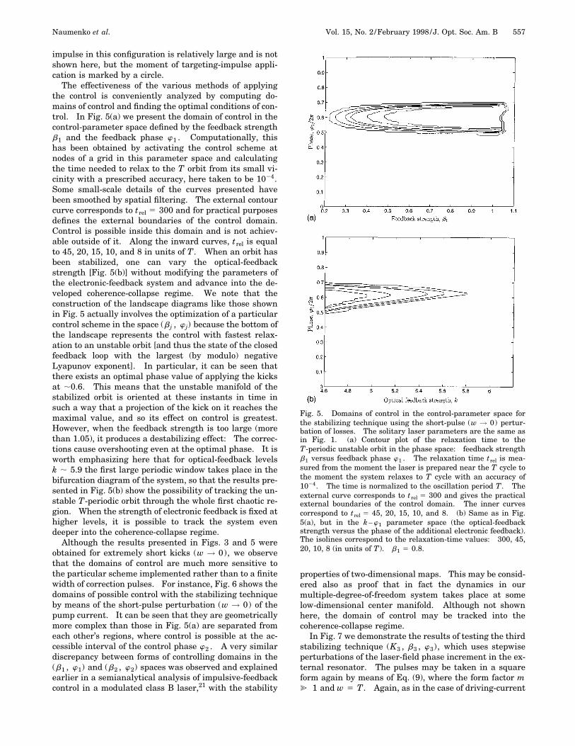
The effectiveness of the various methods of applyingthe control is conveniently analyzed by computing do-mains of control and finding the optimal conditions of con-trol. In Fig. 5(a) we present the domain of control in thecontrol-parameter space defined by the feedback strengthb1 and the feedback phase w1 . Computationally, thishas been obtained by activating the control scheme atnodes of a grid in this parameter space and calculatingthe time needed to relax to the T orbit from its small vi-cinity with a prescribed accuracy, here taken to be 1024.Some small-scale details of the curves presented havebeen smoothed by spatial filtering. The external contourcurve corresponds to trel 5 300 and for practical purposesdefines the external boundaries of the control domain.Control is possible inside this domain and is not achiev-able outside of it. Along the inward curves, trel is equalto 45, 20, 15, 10, and 8 in units of T. When an orbit hasbeen stabilized, one can vary the optical-feedbackstrength [Fig. 5(b)] without modifying the parameters ofthe electronic-feedback system and advance into the de-veloped coherence-collapse regime. We note that theconstruction of the landscape diagrams like those shownin Fig. 5 actually involves the optimization of a particularcontrol scheme in the space (b j , w j) because the bottom ofthe landscape represents the control with fastest relax-ation to an unstable orbit [and thus the state of the closedfeedback loop with the largest (by modulo) negativeLyapunov exponent]. In particular, it can be seen thatthere exists an optimal phase value of applying the kicksat ;0.6. This means that the unstable manifold of thestabilized orbit is oriented at these instants in time insuch a way that a projection of the kick on it reaches themaximal value, and so its effect on control is greatest.However, when the feedback strength is too large (morethan 1.05), it produces a destabilizing effect: The correc-tions cause overshooting even at the optimal phase. It isworth emphasizing here that for optical-feedback levelsk ; 5.9 the first large periodic window takes place in thebifurcation diagram of the system, so that the results pre-sented in Fig. 5(b) show the possibility of tracking the un-stable T-periodic orbit through the whole first chaotic re-gion. When the strength of electronic feedback is fixed athigher levels, it is possible to track the system evendeeper into the coherence-collapse regime.
Although the results presented in Figs. 3 and 5 wereobtained for extremely short kicks (w → 0), we observethat the domains of control are much more sensitive tothe particular scheme implemented rather than to a finitewidth of correction pulses. For instance, Fig. 6 shows thedomains of possible control with the stabilizing techniqueby means of the short-pulse perturbation (w → 0) of thepump current. It can be seen that they are geometricallymore complex than those in Fig. 5(a) are separated fromeach other’s regions, where control is possible at the ac-cessible interval of the control phase w2 . A very similardiscrepancy between forms of controlling domains in the(b1 , w1) and (b2 , w2) spaces was observed and explainedearlier in a semianalytical analysis of impulsive-feedbackcontrol in a modulated class B laser,21 with the stability
properties of two-dimensional maps. This may be consid-ered also as proof that in fact the dynamics in ourmultiple-degree-of-freedom system takes place at somelow-dimensional center manifold. Although not shownhere, the domain of control may be tracked into thecoherence-collapse regime.
In Fig. 7 we demonstrate the results of testing the thirdstabilizing technique (K3 , b3 , w3), which uses stepwiseperturbations of the laser-field phase increment in the ex-ternal resonator. The pulses may be taken in a squareform again by means of Eq. (9), where the form factor m@ 1 and w 5 T. Again, as in the case of driving-current
Fig. 5. Domains of control in the control-parameter space forthe stabilizing technique using the short-pulse (w → 0) pertur-bation of losses. The solitary laser parameters are the same asin Fig. 1. (a) Contour plot of the relaxation time to theT-periodic unstable orbit in the phase space: feedback strengthb1 versus feedback phase w1 . The relaxation time trel is mea-sured from the moment the laser is prepared near the T cycle tothe moment the system relaxes to T cycle with an accuracy of1024. The time is normalized to the oscillation period T. Theexternal curve corresponds to trel 5 300 and gives the practicalexternal boundaries of the control domain. The inner curvescorrespond to trel 5 45, 20, 15, 10, and 8. (b) Same as in Fig.5(a), but in the k –w1 parameter space (the optical-feedbackstrength versus the phase of the additional electronic feedback).The isolines correspond to the relaxation-time values: 300, 45,20, 10, 8 (in units of T). b1 5 0.8.

558 J. Opt. Soc. Am. B/Vol. 15, No. 2 /February 1998 Naumenko et al.
control, the domains of control are multiple [Fig. 7(a)] andtracking the stable orbit into the well-developedcoherence-collapse regime is quite feasible [Fig. 7(b)].We have found through simulations that wide squarepulses are most suitable for control in such an arrange-ment. We should note here that as far as the laser-fieldphase enters the model equations as an argument oftrigonometric functions whose absolute values are lessthan or equal to 1, there is no benefit from applying veryshort and large perturbations (a Dirac-function limit) tothe phase because the integral effect of the short pulsewill be zero as far as its amplitude will be limited by sinu-soidal functions. Of course, the instant laser frequencyexperiences a fast excursion during any perturbation ofphase [as well as the first derivative of the laser intensity;see Eqs. (5) and (7)]. But these excursions do not changean absolute position of the trajectory in the phase space,because they do not effect a change in the complete set ofdynamical variables (intensity, inversion, phase, etc.) atthe end of the pulse. It is noted that even the frequencycontent is reestablished at the end of such a pulse. How-ever, the aim of any control procedure is to put a systeminto a different dynamical state, and this does not occurwhen D-function pulses are applied to the phase.
C. Influence of Technical DelayThe results given above have been found by assumingthat the technical phase shift is zero (tel 5 0). However,because of the principle of causality, technical phase shiftis unavoidable in any feedback loop, and thus it repre-sents one of the most important practical constraints onthe present procedure. (In contrast, it is to be expectedthat the bandwidth requirements normally can be metmore readily.) An examination has thus been made ofthe influence of the technical phase shift tel on the perfor-mance of this configuration. As is shown in Fig. 8, this
Fig. 6. Domains of control for the stabilizing technique usingthe short-pulse (w → 0) perturbation of pump current, feedback-monitored by the difference of intensities. The solitary laser-parameter values and meaning of the plots are the same as inFig. 5. Contour plot of the relaxation time to the T-periodic un-stable orbit in the b2 –w2 space (feedback strength versus feed-back phase). The isolines correspond to the relaxation-time val-ues 300, 40, 20, and 15. In small islands of control, only theexternal curve trel 5 300 is shown.
phase shift strongly affects the stabilizing effect of theelectronic feedback. This is explained by the fact thatthe negative feedback is converted into considerable posi-tive feedback (and vice versa) when an increase of an oddmultiple of p occurs, owing to the technical phase shifttelvc (where vc is a central frequency of the instability tobe suppressed). In turn, the specific kind of feedbackshould be reestablished when this technical phase shifttelvc is a multiple of 2p. For the present case of period-doubling instabilities with vc 5 p/T one may anticipatealteration (from negative to positive values of b j) of is-lands of stability with a period T and their recurrencewith a period 2T. Exactly this effect is demonstrated inFig. 8, where the feedback delay tel is scanned through
Fig. 7. Domain of control for the stabilizing technique usingstepwise perturbations of the laser field phase increment in theexternal resonator, feedback monitored by the difference of in-tensities. The parameter values of the laser diode and meaningof the plots are the same as in Figs. 5 and 6. The parameters ofthe control-scheme pulses are w/T 5 1; m 5 .` (a squareform). (a) Contour plot of the relaxation time to the T-periodicunstable orbit in the space; feedback strength b3 and feedbackphase w3 . The isolines correspond to the relaxation-time values300, 45, 30, 15, and 10. (b) Contour plot of the relaxation timein the k –w3 phase space (optical-feedback strength versus thephase of the additional electronic feedback) for b3 5 22. Theisolines correspond to the relaxation-time values 300, 45, and 20.

Naumenko et al. Vol. 15, No. 2 /February 1998 /J. Opt. Soc. Am. B 559
three periods of the stabilized orbit. To assist the eye,the dotted curve represents an isoline corresponding to afixed positive Lyapunov exponent (or, in terms of expo-nential evolution in the linear vicinity of the unstable or-bit, a negative relaxation time trel). It can be seen thatthe islands of stability (solid curves) recur for feedbackstrengths of opposite sign with a period T (the technicalphase shift is p), albeit with their size shrinking as out-put intensities are taken progressively from the distantpast. Such a recurrence of islands of controlled dynamicsbounded by regimes of more complex dynamics are well inaccord with previous results on modulated lasers21 and alaser diode with a Pyragas-like continuous optoelectronicfeedback.10 The results presented in Fig. 8 were ob-tained for a finite width of control pulses added to a driv-ing current and fixed phase w2 . Figure 9 demonstratesbroadening of the boundaries of control with increasingcontrol-pulse width. The actual scale of the feedback de-lay is shifted by a half width of a correction pulse. So inthis configuration the wider pulses [Fig. 9(b)] again aremore advantageous for control.
Fig. 8. Effects of the finite width of correcting pulses and thefinite technical delay on the domains of control for the stabilizingtechnique using the pump current. Contour plots of the relax-ation time to the T-periodic unstable orbit in the tel /T –b2 space(feedback technical delay versus feedback strength) for w2 5 0.The parameters of the super-Gaussian pulses are the following:w/T 5 0.2, m 5 2. The actual scale of the technical delay isshifted from zero by a half-width of the controlling pulse. Solidcurves correspond to trel 5 300 and essentially give the externalboundaries of the control domain. Control is possible inside thisdomain and not achievable outside of it. The dotted curves cor-respond to the negative relaxation time trel 5 210 (the scheme isunstable). The patterns demonstrate two tendencies in the be-havior of the boundaries of control: their recurrency with a pe-riod 2T and narrowing with increasing technical delay.
Fig. 9. Contour plots of the relaxation time to the T-periodic un-stable orbit in the b2 –tel /T space (feedback strength versusfeedback technical delay) for the different super-Gaussian pulsesparameters. Here m 5 3 and (a) w/T 5 0.4 and (b) w/T5 0.8. The actual scale of the technical delay does not include ahalf-width of the controlling pulse. The pictures demonstratebroadening of the boundaries of control with increasing control-pulse width.
D. Noise EffectsIn the above we have established the possibility of usingdifferent kinds of impulsive self-adjusting optoelectronicfeedback for the stabilization of unstable orbits, thus pro-ducing coherence-collapse control in external-cavity laserdiodes by means of a deterministic model of the deviceconfiguration. From a practical point of view it is impor-tant to establish the robustness of the performance tonoise perturbations. This requires the retention in Eqs.(1)–(3) of the Langevin sources that describe spontaneousemission and shot-carrier noise (see, for example, Refs. 28and 29). The Langevin noise terms are calculated as fol-lows:
Fn~t ! 5 2A2S~ti!gNG
tspDtxs 1 A2N~ti!
tspDtVxn ,
Fs~t ! 5 A2S~ti!gNG
tspDtxs ,
FF~t ! 51
S~t !AS~ti!gNG
2tspDtxF . (12)
Here S(ti) and n(ti) are photon and carrier densities, re-spectively, at the start of the interval Dt(20 ps); xn , xs ,and xF are Gaussian-distributed random variables withzero mean and unity variance. In Fig. 10 we present theresults of preliminary simulations with noise showing anoisy 2T-periodic cycle (light shading) of the system with-out control and the controlled T-periodic cycle (dark shad-ing). The parameters of the control were taken from thecenter of the control domain in Fig. 6, where the controlscheme is expected to be the most stable to any kind ofperturbations. Figure 10 shows that the method workswell in a noisy environment provided the parameters of acontrol scheme have been subject to a preliminary optimi-zation (i.e., put in the centers of the control domains).
Fig. 10. Noise performance of the control scheme using the driv-ing current in three-dimensional phase space representation.The parameters are the same as in Fig. 4; the Langevin forcesare given by Eqs. (12).

560 J. Opt. Soc. Am. B/Vol. 15, No. 2 /February 1998 Naumenko et al.
More detailed results on the noise performance of the sug-gested configuration will be reported elsewhere.32
5. DISCUSSIONThe results presented in the previous sections clearlyshow that, notwithstanding the high levels of intrinsicnoise and the high relaxation-oscillation frequencies ofthe order of 1 GHz in semiconductor laser diodes, whichgenerally, of course, cannot be avoided, complex nonlineardynamic regimes such as the coherence-collapse regimecan be controlled with proper optimization. In particu-lar, we have found the following: (i) the domain of con-trol is wider when control is undertaken through cavitylosses (optimization by implementation of control to thespecific laser-diode parameters); (ii) the domains in allthree schemes studied have optima in their centers (themost stable configuration of a solitary external-cavity la-ser diode plus an electronic-feedback loop); (iii) whennoise has been included, the control method worked wellfor the optimal states (see subsection 4.D and Fig. 10). Itshould be noted that because the parameters of feedbackwere chosen at random, the occasional proportional feed-back method5 was not effective even when the noisestrength is taken smaller than realistic values. We notealso that, with a view to possible applications for secureoptical communications, noise problems might be dimin-ished by choosing an operating point of the laser diode farabove the threshold. Relative-intensity noise is known toscale as the inverse of the emitted optical power,28 or, as-suming the averaged optical power to be proportional to(I 2 Ithr), we have RIN ' 1/(I 2 Ithr)
3. However, therelaxation frequency scales as (I 2 Ithr)
1/2, so there is atrade-off between diminishing noise effects and increas-ing the basic frequency of the system. Nevertheless, itseems the optimum can be found here as well.
Finally we observe that as soon as optimization is per-formed, it is possible to apply correction pulses in this op-timal regime less frequently, thus relaxing the require-ment on the speed of the control scheme. Indeed, thephase w j for applying a correction kick in accordance withits definition is varied from 0 to 1 in units of T in Figs.5–7, i.e., the correction kick is applied every period. If,for example, the phase w2 is more than 1 (but less that 2),then the correction pulse is applied to the driving currentevery other period. Such a scheme, although still for-mally described by Eq. (8), has different stabilityproperties20,21 and will be considered elsewhere.32 (It isclear that when the correction of events is too infrequent,the scheme does not converge.) Thus the patterns pre-sented in Figs. 5–7 are not necessarily periodic in w j , butthey narrow with increasing w j , demonstrating the be-havior seen in Fig. 8. Nevertheless, it can be seen fromFigs. 6 and 7(a) that the control zones are clearly ex-tended into the region where w j is more than 1. Thismeans that the model presents the worst-case situation inthe context of the required speed for sampling of the laserintensity and applying the correction kicks. In fact,given that the unstable trajectory was subject to prelimi-nary targeting and the optimal parameters of the controlscheme were chosen, the laser intensity may be sampled
and the impulse corrections can be applied less frequently(e.g., every other or every third period).
6. CONCLUSIONIn conclusion, the opportunity for realizing control ofchaos in external-cavity laser diodes by means of impul-sive delayed feedback has been demonstrated. It hasbeen shown that such feedback may be effectively appliedwith a number of laser operating parameters includingdrive-current modulation, external-cavity phase modula-tion of the laser-field phase increment, and cavity-lossmodulation. An examination has been made of practicalconstraints arising from technical delay in application ofthe control signal. The dependence of the control processon the phase, width, and shaping of feedback pulses hasbeen described. The effectiveness of the control schemehas been characterised by computing the domains of con-trol for each of the three control schemes and finding theoptimal conditions of control in the space of accessiblecontrol parameters. Preliminary results indicating therobustness of the procedure to noise influences have alsobeen presented.
ACKNOWLEDGMENTSA. V. Naumenko, N. A. Loiko, and S. I. Turovets acknowl-edge financial support from the Royal Society, London,which permitted visits to the University of Wales;Bangor, where part of this work was carried out. In part,they were also supported by The Belorussian Foundationfor Fundamental Research and International ScientificFoundation. The work of P. S. Spencer and K. A. Shorewas supported by the Engineering and Physical SciencesResearch Council of the United Kingdom.
REFERENCES1. E. Ott, C. Greboggi, and J. A. Yorke, ‘‘Controlling chaos,’’
Phys. Rev. Lett. 64, 1196–1199 (1990).2. R. Roy, T. W. Murphy, T. D. Maier, Z. Gills, and E. R. Hunt,
‘‘Dynamical control of a chaotic laser: experimental stabi-lisation of a globally coupled system,’’ Phys. Rev. Lett. 68,1259–1261 (1992).
3. S. Bielawski, M. Bouazaoui, D. Derosier, and P. Glorieux,‘‘Stabilization and characterization of unstable steadystates in a laser,’’ Phys. Rev. A 47, 3276–3279 (1993).
4. S. Bielawski, M. Bouazaoui, D. Derosier, and P. Glorieux,‘‘Controlling unstable periodic orbits by delayed continuousfeedback,’’ Phys. Rev. E 49, 971–973 (1994).
5. G. R. Gray, A. T. Ryan, G. P. Agrawal, and E. C. Gage,‘‘Optical-feedback-induced chaos and its control in semicon-ductor lasers,’’ in Chaos in Optics, R. Roy, ed., Proc. SPIE2039, 45–57 (1993).
6. Y. Liu and J. Ohtsubo, ‘‘Experimental control of chaos in alaser diode interferometer with delayed feedback,’’ Opt.Lett. 19, 448–450 (1994).
7. A. T. Ryan, G. P. Agrawal, G. R. Gray, and E. C. Gage,‘‘Optical-feedback-induced chaos and its control in semicon-ductor lasers,’’ IEEE J. Quantum Electron. 30, 668–679(1994).
8. N. Watanabe and K. Karaki, ‘‘Inducing periodic oscillationsfrom chaotic oscillations of a compound-cavity laser diodewith sinusoidally modulated drive,’’ Opt. Lett. 20, 725–727(1995).
Naumenko et al. Vol. 15, No. 2 /February 1998 /J. Opt. Soc. Am. B 561
9. Y. Liu, N. Kikuchi, and J. Ohtsubo, ‘‘Controlling dynamicalbehavior of a semiconductor laser with external opticalfeedback,’’ Phys. Rev. E 51, 2697–2700 (1995); N. Kikuchi,Y. Liu, and J. Ohtsubo, ‘‘Chaos control and noise suppres-sion in external cavity semiconductor lasers,’’ IEEE J.Quantum Electron. 33, 56–65 (1997).
10. S. I. Turovets, J. Dellunde, and K. A. Shore, ‘‘Selective ex-citation of periodic dynamics in external-cavity laser di-odes,’’ Electron. Lett. 32, 42–43 (1996); S. I. Turovets, J.Dellunde, and K. A. Shore, ‘‘Nonlinear dynamics of a laserdiode subjected to both optical and electronic feedback,’’ J.Opt. Soc. Am. B 14, 200–208 (1997).
11. S. Hayes, C. Greboggi, and E. Ott, ‘‘Communicating withchaos,’’ Phys. Rev. Lett. 70, 3031–3034 (1993).
12. K. M. Cuomo and A. V. Oppenheim, ‘‘Circuit implementa-tion of synchronised chaos with applications in communica-tions,’’ Phys. Rev. Lett. 71, 65–68 (1993).
13. K. A. Shore and D. T. Wright, ‘‘Improved synchronisationalgorithm for secure communications systems using chaoticencryption,’’ Electron. Lett. 30, 1203–1204 (1994).
14. C. R. Mirasso, P. Colet, and P. Garcia-Fernandez, ‘‘Synchro-nization of chaotic semiconductor lasers: application to en-coded communications,’’ IEEE Photon. Tech. Lett. 8, 299–301 (1996).
15. W. M. Yee and K. A. Shore, ‘‘Nearly degenerate four-wavemixing in laser diodes with nonuniform longitudinal gaindistribution,’’ J. Opt. Soc. Am. B 11, 1211–1218 (1994).
16. L. N. Langley and K. A. Shore, ‘‘The effect of phase conju-gate optical feedback on the intensity noise in laser diodes,’’Opt. Lett. 18, 1432–1434 (1993).
17. L. N. Langley and K. A. Shore, ‘‘Intensity noise and line-width characteristics of laser diodes subject to phase conju-gate optical feedback,’’ IEE Proc.: Optoelectron. 141, 103–108 (1994).
18. G. H. M. van Tartwijk and D. Lenstra, ‘‘Semiconductor la-sers with optical injection and feedback,’’ Quantum Semi-class. Opt. 7, 87–143 (1995).
19. K. Petermann, ‘‘External Optical Feedback Phenomena inSemiconductor Lasers,’’ IEEE J. Sel. Top. Quantum Elec-tron. 1, 480–489 (1995).
20. S. Bielawski, D. Derosier, and P. Glorieux, ‘‘Experimentalcharacterization of unstable periodic orbits by controllingchaos,’’ Phys. Rev. A 47, R2492–R2495 (1993).
21. N. A. Loiko, A. V. Naumenko, and S. I. Turovets, ‘‘Charac-terization and stabilization of unstable cycles in a modu-lated class-B laser,’’ in Laser Optics, N. B. Abraham and Y.I. Khanin, ed., Proc. SPIE 2792, 102–111 (1996); N. A.Loiko, A. V. Naumenko, and S. I. Turovets, ‘‘Impact of
Pyragas-like feedback on dynamics of a modulated class Blaser,’’ Sov. Phys. JETP (to be published).
22. E. A. Avrutin, V. B. Gorfinkel, S. Luryi, and K. A. Shore,‘‘Control of emitting laser diodes by modulating the distrib-uted Bragg mirror reflectivity: small signal analysis,’’Appl. Phys. Lett. 63, 2460–2462 (1993); N. Tessler, M. Mar-galit, G. Eisenstein, and U. Koren, ‘‘Wide-band amplitude-modulation by electrooptic tuning of the center wavelengthin short-cavity distributed Bragg reflector lasers,’’ IEEE J.Sel. Top. Quantum Electron. 1, 490–493 (1995).
23. T. Shinbrot, E. Ott, C. Greboggi, and J. A. Yorke, ‘‘Usingchaos to direct trajectories to targets,’’ Phys. Rev. Lett. 65,3215–3218 (1990).
24. A. M. Samson, S. I. Turovets, V. N. Chizhevsky, and V. V.Churakov, ‘‘Nonlinear dynamics of a loss-switched CO2 la-ser,’’ Sov. Phys. JETP 74, 628–639 (1992); V. N. Chizhevskyand S. I. Turovets, ‘‘Modulated CO2 laser as an opticalphase and amplitude multitrigger,’’ Phys. Rev. A 50, 1840–1843 (1994).
25. L. A. Kotomtseva, A. V. Naumenko, A. M. Samson, and S. I.Turovets, ‘‘Targeting unstable orbits and steady states inclass-B lasers by using simple off/on manipulations,’’ Opt.Commun. 136, 335–348 (1997); L. A. Kotomtseva, A. V.Naumenko, A. M. Samson, and S. I. Turovets, ‘‘On observ-ability of unstable orbits in lasers with a step-wiseQ-switching,’’ presented at the European Quantum Elec-tronics Conference (Hamburg, Germany, September 1996).
26. S. I. Turovets, A. Valle, and K. A. Shore, ‘‘Effects of noise onthe turn-on dynamics of a modulated class-B laser in thegeneralized multistability domain,’’ Phys. Rev. A 55, 2426–2434 (1997).
27. L. N. Langley, S. Turovets, and K. A. Shore, ‘‘Targeting pe-riodic dynamics of external cavity semiconductor laser,’’Opt. Lett. 20, 725–727 (1995).
28. K. Petermann, Laser Diode Modulation and Noise (KluwerAcademic, Boston, 1991).
29. L. N. Langley and K. A. Shore, ‘‘The effect of external opti-cal feedback on timing jitter in modulated laser diodes,’’ J.Lightwave Technol. 11, 434–441 (1993).
30. G. Li, R. K. Boncek, X. Wang, and D. H. Sackett, ‘‘Transientand optoelectronic feedback-sustained pulsation of laser di-odes at 1300 nm,’’ IEEE Photon. Technol. Lett. 7, 854–856(1995).
31. M. Abramowitz and I. Stegun, Handbook on MathematicalFunctions, 10th ed., Vol. 55 of Applied Mathematics Series(National Bureau of Standards, Washington, D.C., 1972).
32. A. V. Naumenko, Institute of Physics, Minsk 220072, Be-larus (personal communication, 1997).