Controller PS-24 RCM-PM PMEC/AMEC PSEP/ASEP ...
140
Controllers Controller PS-24 RCM-PM PMEC/AMEC PSEP/ASEP ROBONET ERC2 PCON ACON PCON/ACON-ABU SCON PSEL ASEL SSEL XSEL PS241/PS242 RCM-PM-01 PMEC/AMEC PSEP/ASEP ROBONET ERC2 PCON ACON PSEL SCON ASEL XSEL PCON-ABU ACON-ABU 461 Controller Controller ELECTROMATE Toll Free Phone (877) SERVO98 Toll Free Fax (877) SERV099 www.electromate.com [email protected] Sold & Serviced By:
-
Upload
khangminh22 -
Category
Documents
-
view
1 -
download
0
Transcript of Controller PS-24 RCM-PM PMEC/AMEC PSEP/ASEP ...
Controllers
Controller
PS-24RCM-PMPMEC/AMECPSEP/ASEPROBONET
ERC2PCONACONPCON/ACON-ABUSCON
PSELASELSSELXSEL
PS241/PS242 RCM-PM-01 PMEC/AMEC PSEP/ASEP ROBONET ERC2
PCON ACON PSELSCON ASEL XSELPCON-ABUACON-ABU
461 Controller
Controller
ELECTROMATEToll Free Phone (877) SERVO98
Toll Free Fax (877) SERV099www.electromate.com
Sold & Serviced By:
Controllers
P M E CA M E C
R C M - P M
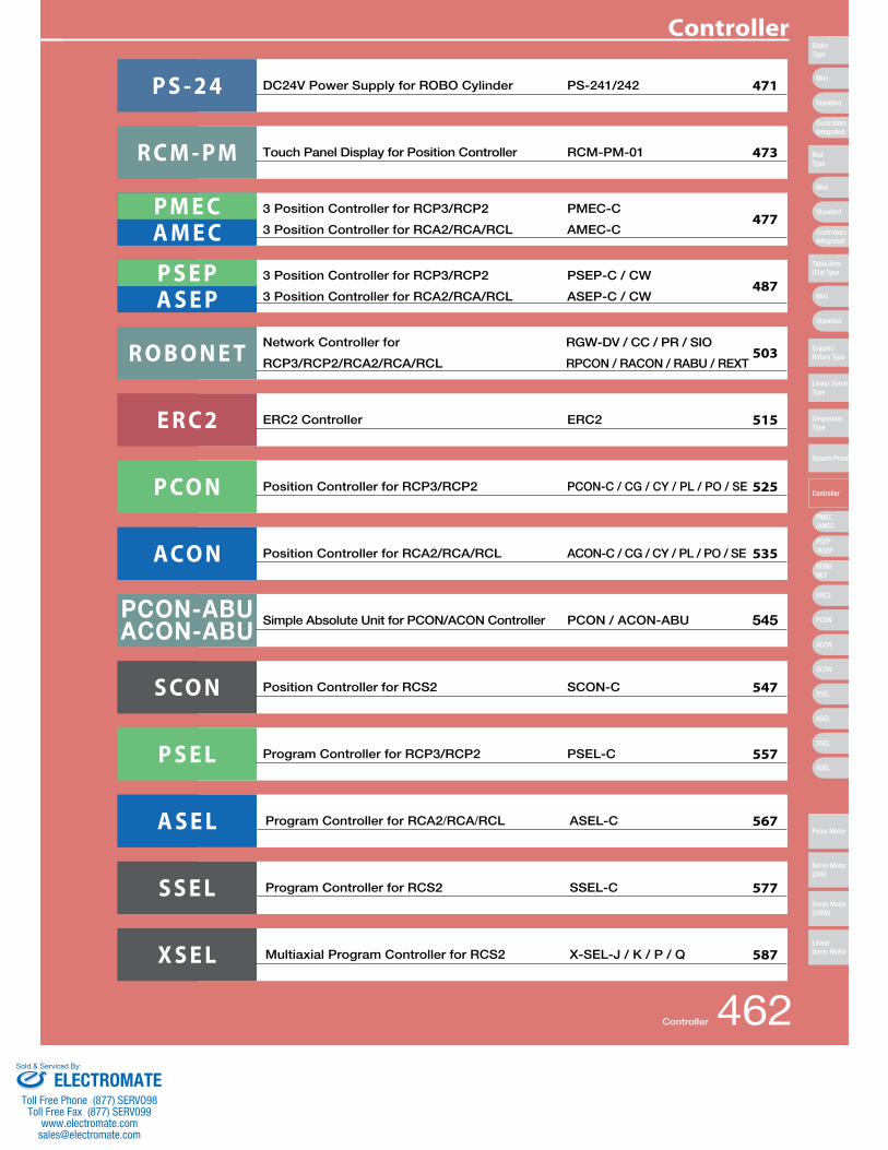
3 Position Controller for RCP3/RCP2 PMEC-C
3 Position Controller for RCA2/RCA/RCL AMEC-C
Touch Panel Display for Position Controller RCM-PM-01
477
473
P S E PA S E P
3 Position Controller for RCP3/RCP2 PSEP-C / CW
3 Position Controller for RCA2/RCA/RCL ASEP-C / CW487
PCON-ABUACON-ABU
Simple Absolute Unit for PCON/ACON Controller PCON / ACON-ABU 545
P S - 2 4 DC24V Power Supply for ROBO Cylinder PS-241/242 471
R O B O N E T Network Controller for
RCP3/RCP2/RCA2/RCA/RCL
RGW-DV / CC / PR / SIO
RPCON / RACON / RABU / REXT503
E R C 2 ERC2 Controller ERC2 515
P CO N Position Controller for RCP3/RCP2 PCON-C / CG / CY / PL / PO / SE 525
ACO N Position Controller for RCA2/RCA/RCL ACON-C / CG / CY / PL / PO / SE 535
S CO N Position Controller for RCS2 SCON-C 547
P S E L Program Controller for RCP3/RCP2 PSEL-C 557
A S E L Program Controller for RCA2/RCA/RCL ASEL-C 567
S S E L Program Controller for RCS2 SSEL-C 577
X S E L Multiaxial Program Controller for RCS2 X-SEL-J / K / P / Q 587
Controller 462
Controller
Mini
Mini
PSEP/ASEP
PMEC/AMEC
ROBONET
ERC2
PCON
ACON
SCON
PSEL
ASEL
SSEL
XSEL
Standard
Mini
Standard
Standard
ControllersIntegrated
ControllersIntegrated
SliderType
RodType
Table/Arm/Flat Type
Gripper/Rotary Type
Linear ServoType
CleanroomType
Splash-Proof
Controller
Pulse Motor
Servo Motor (24V)
Servo Motor (200V)
LinearServo Motor
ELECTROMATEToll Free Phone (877) SERVO98
Toll Free Fax (877) SERV099www.electromate.com
Sold & Serviced By:
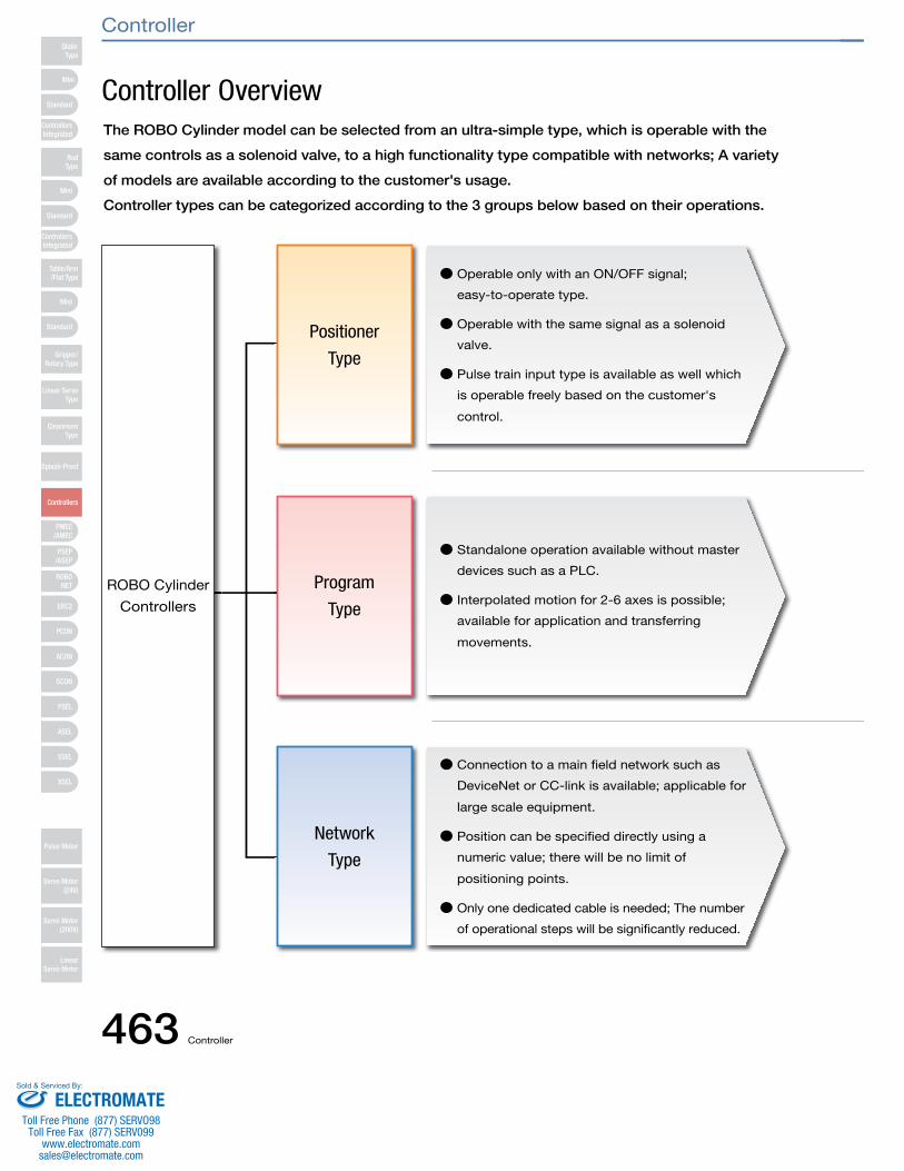
Controller OverviewThe ROBO Cylinder model can be selected from an ultra-simple type, which is operable with the
same controls as a solenoid valve, to a high functionality type compatible with networks; A variety
of models are available according to the customer's usage.
Controller types can be categorized according to the 3 groups below based on their operations.
● Operable only with an ON/OFF signal;
easy-to-operate type.
● Operable with the same signal as a solenoid
valve.
● Pulse train input type is available as well which
is operable freely based on the customer's
control.
● Standalone operation available without master
devices such as a PLC.
● Interpolated motion for 2-6 axes is possible;
available for application and transferring
movements.
● Connection to a main field network such as
DeviceNet or CC-link is available; applicable for
large scale equipment.
● Position can be specified directly using a
numeric value; there will be no limit of
positioning points.
● Only one dedicated cable is needed; The number
of operational steps will be significantly reduced.
ROBO Cylinder
Controllers
Positioner
Type
Program
Type
Network
Type
Mini
Mini
PSEP/ASEP
PMEC/AMEC
ROBONET
ERC2
PCON
ACON
SCON
PSEL
ASEL
SSEL
XSEL
Standard
Mini
Standard
Standard
ControllersIntegrated
ControllersIntegrated
RodType
Table/Arm/Flat Type
Gripper/Rotary Type
Linear ServoType
CleanroomType
Splash-Proof
Controllers
Pulse Motor
Servo Motor (24V)
Servo Motor (200V)
LinearServo Motor
SliderType
Controller
463 Controller
ELECTROMATEToll Free Phone (877) SERVO98
Toll Free Fax (877) SERV099www.electromate.com
Sold & Serviced By:
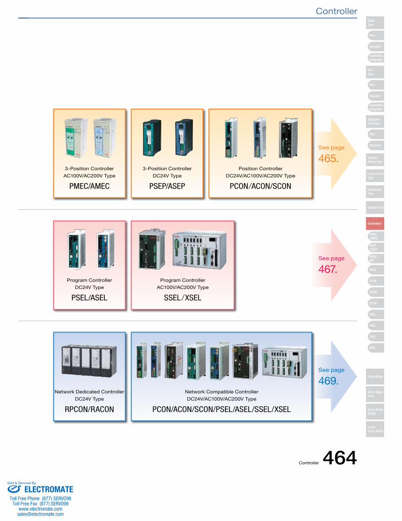
See page
465.
See page
467.
See page
469.
3-Position Controller
AC100V/AC200V Type
PMEC/AMEC
3-Position Controller
DC24V Type
PSEP/ASEP
Position Controller
DC24V/AC100V/AC200V Type
PCON/ACON/SCON
Program Controller
DC24V Type
PSEL/ASEL
Program Controller
AC100V/AC200V Type
SSEL/XSEL
Network Dedicated Controller
DC24V Type
RPCON/RACON
Network Compatible Controller
DC24V/AC100V/AC200V Type
PCON/ACON/SCON/PSEL/ASEL/SSEL/XSEL
Mini
Mini
PSEP/ASEP
PMEC/AMEC
ROBONET
ERC2
PCON
ACON
SCON
PSEL
ASEL
SSEL
XSEL
Standard
Mini
Standard
Standard
ControllersIntegrated
ControllersIntegrated
SliderType
RodType
Table/Arm/Flat Type
Gripper/Rotary Type
Linear ServoType
CleanroomType
Splash-Proof
Controllers
Pulse Motor
Servo Motor (24V)
Servo Motor (200V)
LinearServo Motor
Controller
Controller 464ELECTROMATE
Toll Free Phone (877) SERVO98Toll Free Fax (877) SERV099
Sold & Serviced By:
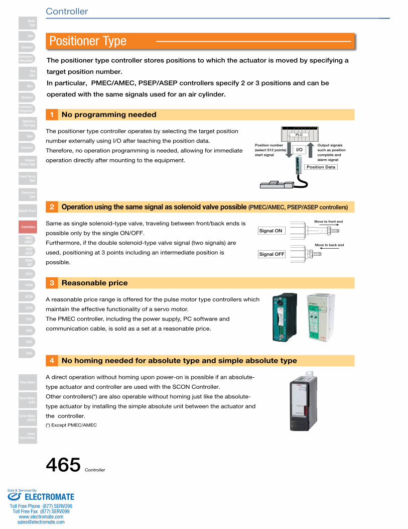
Positioner TypeThe positioner type controller stores positions to which the actuator is moved by specifying a
target position number.
In particular, PMEC/AMEC, PSEP/ASEP controllers specify 2 or 3 positions and can be
operated with the same signals used for an air cylinder.
The positioner type controller operates by selecting the target position
number externally using I/O after teaching the position data.
Therefore, no operation programming is needed, allowing for immediate
operation directly after mounting to the equipment.
Same as single solenoid-type valve, traveling between front/back ends is
possible only by the single ON/OFF.
Furthermore, if the double solenoid-type valve signal (two signals) are
used, positioning at 3 points including an intermediate position is
possible.
A reasonable price range is offered for the pulse motor type controllers which
maintain the effective functionality of a servo motor.
The PMEC controller, including the power supply, PC software and
communication cable, is sold as a set at a reasonable price.
A direct operation without homing upon power-on is possible if an absolute-
type actuator and controller are used with the SCON Controller.
Other controllers(*) are also operable without homing just like the absolute-
type actuator by installing the simple absolute unit between the actuator and
the controller.
(*) Except PMEC/AMEC
No programming needed1
Operation using the same signal as solenoid valve possible (PMEC/AMEC, PSEP/ASEP controllers)2
Reasonable price3
No homing needed for absolute type and simple absolute type4
Position Data
Output signals such as position complete and alarm signal
I/OPosition number(select 512 points)start signal
PLC
Signal ON
Signal OFF
Move to back end
Move to front end
Mini
Mini
PSEP/ASEP
PMEC/AMEC
ROBONET
ERC2
PCON
ACON
SCON
PSEL
ASEL
SSEL
XSEL
Standard
Mini
Standard
Standard
ControllersIntegrated
ControllersIntegrated
RodType
Table/Arm/Flat Type
Gripper/Rotary Type
Linear ServoType
CleanroomType
Splash-Proof
Controllers
Pulse Motor
Servo Motor (24V)
Servo Motor (200V)
LinearServo Motor
SliderType
Controller
465 Controller
ELECTROMATEToll Free Phone (877) SERVO98
Toll Free Fax (877) SERV099www.electromate.com
Sold & Serviced By:
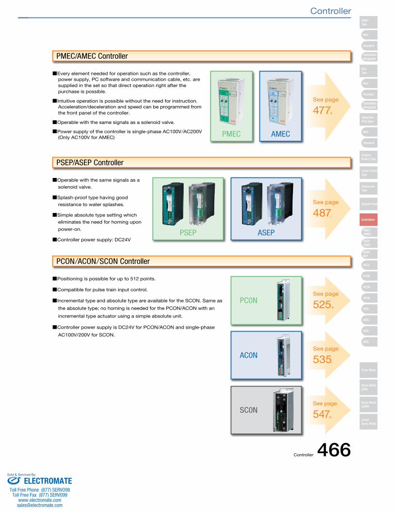
■Every element needed for operation such as the controller,power supply, PC software and communication cable, etc. aresupplied in the set so that direct operation right after thepurchase is possible.
■Intuitive operation is possible without the need for instruction.Acceleration/deceleration and speed can be programmed fromthe front panel of the controller.
■Operable with the same signals as a solenoid valve.
■Power supply of the controller is single-phase AC100V/AC200V(Only AC100V for AMEC)
■Operable with the same signals as a
solenoid valve.
■Splash-proof type having good
resistance to water splashes.
■Simple absolute type setting which
eliminates the need for homing upon
power-on.
■Controller power supply: DC24V
■Positioning is possible for up to 512 points.
■Compatible for pulse train input control.
■Incremental type and absolute type are available for the SCON. Same as
the absolute type; no homing is needed for the PCON/ACON with an
incremental type actuator using a simple absolute unit.
■Controller power supply is DC24V for PCON/ACON and single-phase
AC100V/200V for SCON.
PMEC
ASEP
PC0N
AC0N
SC0N
PSEP
AMEC
PMEC/AMEC Controller
PSEP/ASEP Controller
PCON/ACON/SCON Controller
See page
477.
See page
487.
See page
525.
See page
535.
See page
547.
Mini
Mini
PSEP/ASEP
PMEC/AMEC
ROBONET
ERC2
PCON
ACON
SCON
PSEL
ASEL
SSEL
XSEL
Standard
Mini
Standard
Standard
ControllersIntegrated
ControllersIntegrated
SliderType
RodType
Table/Arm/Flat Type
Gripper/Rotary Type
Linear ServoType
CleanroomType
Splash-Proof
Controllers
Pulse Motor
Servo Motor (24V)
Servo Motor (200V)
LinearServo Motor
Controller
Controller 466ELECTROMATE
Toll Free Phone (877) SERVO98Toll Free Fax (877) SERV099
Sold & Serviced By:
Input sensorsignal
Output conveyorstop signal
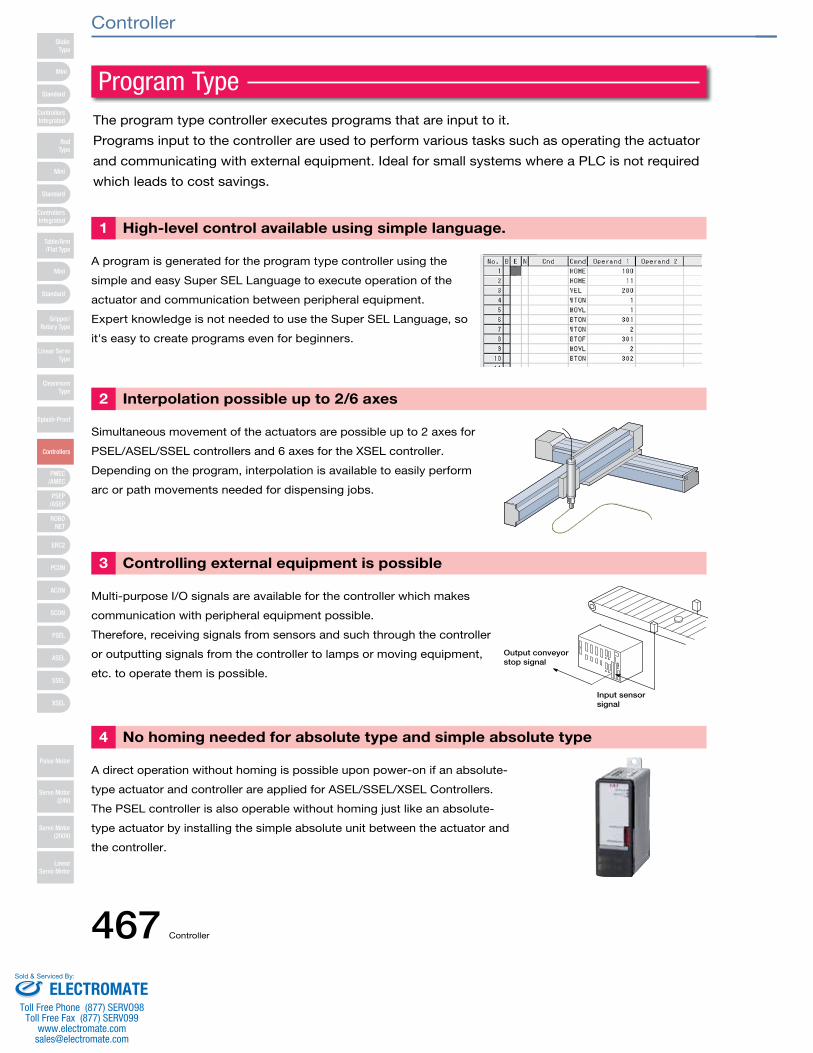
The program type controller executes programs that are input to it.
Programs input to the controller are used to perform various tasks such as operating the actuator
and communicating with external equipment. Ideal for small systems where a PLC is not required
which leads to cost savings.
A program is generated for the program type controller using the
simple and easy Super SEL Language to execute operation of the
actuator and communication between peripheral equipment.
Expert knowledge is not needed to use the Super SEL Language, so
it's easy to create programs even for beginners.
Simultaneous movement of the actuators are possible up to 2 axes for
PSEL/ASEL/SSEL controllers and 6 axes for the XSEL controller.
Depending on the program, interpolation is available to easily perform
arc or path movements needed for dispensing jobs.
Multi-purpose I/O signals are available for the controller which makes
communication with peripheral equipment possible.
Therefore, receiving signals from sensors and such through the controller
or outputting signals from the controller to lamps or moving equipment,
etc. to operate them is possible.
A direct operation without homing is possible upon power-on if an absolute-
type actuator and controller are applied for ASEL/SSEL/XSEL Controllers.
The PSEL controller is also operable without homing just like an absolute-
type actuator by installing the simple absolute unit between the actuator and
the controller.
High-level control available using simple language. 1
Interpolation possible up to 2/6 axes2
Controlling external equipment is possible3
No homing needed for absolute type and simple absolute type4
Program Type
Mini
Mini
PSEP/ASEP
PMEC/AMEC
ROBONET
ERC2
PCON
ACON
SCON
PSEL
ASEL
SSEL
XSEL
Standard
Mini
Standard
Standard
ControllersIntegrated
ControllersIntegrated
RodType
Table/Arm/Flat Type
Gripper/Rotary Type
Linear ServoType
CleanroomType
Splash-Proof
Controllers
Pulse Motor
Servo Motor (24V)
Servo Motor (200V)
LinearServo Motor
SliderType
Controller
467 Controller
ELECTROMATEToll Free Phone (877) SERVO98
Toll Free Fax (877) SERV099www.electromate.com
Sold & Serviced By:
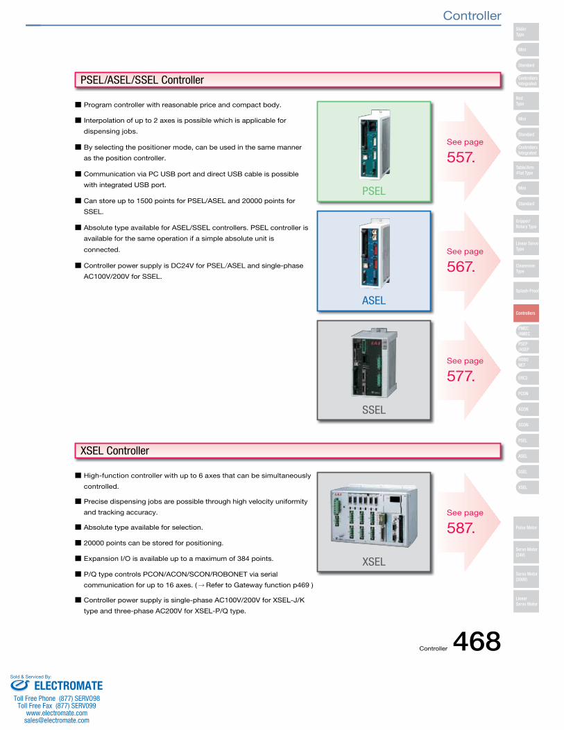
■ Program controller with reasonable price and compact body.
■ Interpolation of up to 2 axes is possible which is applicable for
dispensing jobs.
■ By selecting the positioner mode, can be used in the same manner
as the position controller.
■ Communication via PC USB port and direct USB cable is possible
with integrated USB port.
■ Can store up to 1500 points for PSEL/ASEL and 20000 points for
SSEL.
■ Absolute type available for ASEL/SSEL controllers. PSEL controller is
available for the same operation if a simple absolute unit is
connected.
■ Controller power supply is DC24V for PSEL/ASEL and single-phase
AC100V/200V for SSEL.
■ High-function controller with up to 6 axes that can be simultaneously
controlled.
■ Precise dispensing jobs are possible through high velocity uniformity
and tracking accuracy.
■ Absolute type available for selection.
■ 20000 points can be stored for positioning.
■ Expansion I/O is available up to a maximum of 384 points.
■ P/Q type controls PCON/ACON/SCON/ROBONET via serial
communication for up to 16 axes. (→ Refer to Gateway function p469 )
■ Controller power supply is single-phase AC100V/200V for XSEL-J/K
type and three-phase AC200V for XSEL-P/Q type.
PSEL
ASEL
SSEL
XSEL
PSEL/ASEL/SSEL Controller
XSEL Controller
See page
557.
See page
567.
See page
577.
See page
587.
Mini
Mini
PSEP/ASEP
PMEC/AMEC
ROBONET
ERC2
PCON
ACON
SCON
PSEL
ASEL
SSEL
XSEL
Standard
Mini
Standard
Standard
ControllersIntegrated
ControllersIntegrated
SliderType
RodType
Table/Arm/Flat Type
Gripper/Rotary Type
Linear ServoType
CleanroomType
Splash-Proof
Controllers
Pulse Motor
Servo Motor (24V)
Servo Motor (200V)
LinearServo Motor
Controller
Controller 468ELECTROMATE
Toll Free Phone (877) SERVO98Toll Free Fax (877) SERV099
Sold & Serviced By:
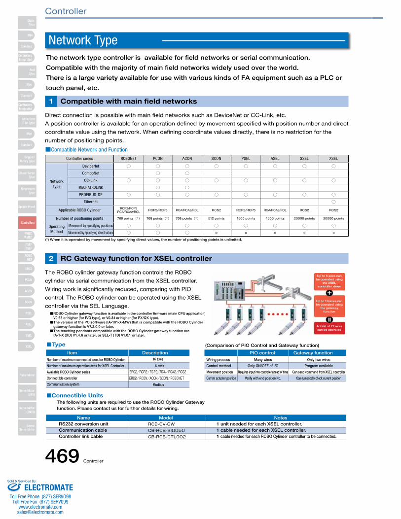
The network type controller is available for field networks or serial communication.
Compatible with the majority of main field networks widely used over the world.
There is a large variety available for use with various kinds of FA equipment such as a PLC or
touch panel, etc.
Direct connection is possible with main field networks such as DeviceNet or CC-Link, etc.
A position controller is available for an operation defined by movement specified with position number and direct
coordinate value using the network. When defining coordinate values directly, there is no restriction for the
number of positioning points.
■Compatible Network and Function
The ROBO cylinder gateway function controls the ROBO
cylinder via serial communication from the XSEL controller.
Wiring work is significantly reduced, comparing with PIO
control. The ROBO cylinder can be operated using the XSEL
controller via the SEL Language.
Compatible with main field networks1
RC Gateway function for XSEL controller2
Controller series ROBONET PCON ACON SCON PSEL ASEL SSEL XSEL
NetworkType
DeviceNet ○ ○ ○ ○ ○ ○ ○ ○
CompoNet ○ ○
CC-Link ○ ○ ○ ○ ○ ○ ○ ○
MECHATROLINK ○ ○
PROFIBUS-DP ○ ○ ○ ○ ○ ○ ○ ○
Ethernet ○
Applicable ROBO Cylinder RCP2/RCP3RCA/RCA2/RCL RCP2/RCP3 RCA/RCA2/RCL RCS2 RCP2/RCP3 RCA/RCA2/RCL RCS2 RCS2
Number of positioning points 768 points(*) 768 points(*) 768 points(*) 512 points 1500 points 1500 points 20000 points 20000 points
Operating Method
Movement by specifying positions ○ ○ ○ ○ ○ ○ ○ ○
Movement by specifying direct values ○ ○ ○ × × × × ×
(*) When it is operated by movement by specifying direct values, the number of positioning points is unlimited.
Type
Connectible Units
The version of the PC software (IA-101-X-MW) that is compatible with the ROBO Cylinder gateway function is V7.2.0.0 or later.The teaching pendants compatible with the ROBO Cylinder gateway function areIA-T-X (XD) V1.4.6 or later, or SEL-T (TD) V1.0.1 or later.
ROBO Cylinder gateway function is available in the controller firmware (main CPU application)V0.68 or higher (for P/Q type), or V0.34 or higher (for PX/QX type).
Modbus
16 axes
6 axes
Item Description
Number of maximum connected axes for ROBO Cylinder
Number of maximum operation axes for XSEL Controller
Available ROBO Cylinder series
Connectible controller
Communication system
(Comparison of PIO Control and Gateway function)
PIO control Gateway function
Wiring process Many wires Only two wires
Control method Only ON/OFF of I/O Program available
Movement position Requires input into controller ahead of time Can send command from XSEL controller
Current actuator position Verify with end position No. Can numerically check current position
The following units are required to use the ROBO Cylinder Gateway function. Please contact us for further details for wiring.
Name Model NotesRS232 conversion unit 1 unit needed for each XSEL controller.Communication cable 1 cable needed for each XSEL controller.Controller link cable 1 cable needed for each ROBO Cylinder controller to be connected.
Up to 6 axes can be operated using
the XSEL controller alone
Up to 16 axes can be operated using
the gateway function
A total of 22 axes can be operated
Network Type
Mini
Mini
PSEP/ASEP
PMEC/AMEC
ROBONET
ERC2
PCON
ACON
SCON
PSEL
ASEL
SSEL
XSEL
Standard
Mini
Standard
Standard
ControllersIntegrated
ControllersIntegrated
RodType
Table/Arm/Flat Type
Gripper/Rotary Type
Linear ServoType
CleanroomType
Splash-Proof
Controllers
Pulse Motor
Servo Motor (24V)
Servo Motor (200V)
LinearServo Motor
SliderType
Controller
469 Controller
ELECTROMATEToll Free Phone (877) SERVO98
Toll Free Fax (877) SERV099www.electromate.com
Sold & Serviced By:
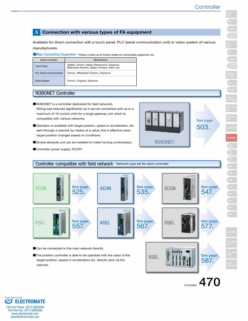
■Main Connecting Equipment * Please contact us for further details for connectable equipment, etc.
Available for direct connection with a touch panel, PLC (serial communication unit) or vision system of various
manufacturers.
Connection with various types of FA equipment3
Name of product Manufacturer
Touch Panel Digital, Omron, Hakko Electronics, Keyence, Mitsubishi Electric, Beijer, Proface, Red Lion
PLC (Serial communication) Omron, Mitsubishi Electric, Keyence
Vision System Omron, Cognex, Keyence
■ROBONET is a controller dedicated for field networks.
Wiring was reduced significantly as it can be connected with up to a
maximum of 16 control units for a single gateway unit which is
compatible with various networks.
■Operation is available with target position, speed or acceleration, etc.
sent through a network by means of a value; this is effective when
target position changes based on conditions.
■Simple absolute unit can be installed to make homing unnecessary.
■Controller power supply; DC24V
■Can be connected to the main network directly.
■The position controller is able to be operated with the value of the
target position, speed or acceleration etc. directly sent via the
network.
ROBONET
ROBONET Controller
Controller compatible with field network * Network type set for each controller
See page
503.
See page
547.SC0N
See page
577.SSEL
See page
525.PC0N See page
535.AC0N
See page
587.XSEL
See page
557.PSEL See page
567.ASEL
Mini
Mini
PSEP/ASEP
PMEC/AMEC
ROBONET
ERC2
PCON
ACON
SCON
PSEL
ASEL
SSEL
XSEL
Standard
Mini
Standard
Standard
ControllersIntegrated
ControllersIntegrated
SliderType
RodType
Table/Arm/Flat Type
Gripper/Rotary Type
Linear ServoType
CleanroomType
Splash-Proof
Controllers
Pulse Motor
Servo Motor (24V)
Servo Motor (200V)
LinearServo Motor
Controller
Controller 470ELECTROMATE
Toll Free Phone (877) SERVO98Toll Free Fax (877) SERV099
Sold & Serviced By:
PS-24 Controller
471 PS-24
Large load (load is approaching the rated load capacity)
“Severe load conditions” refers to:
Basically, how many power-supply units you need should be determined in such a way that the total rated current of all actuators will remain within the rated current of the PS-24. If the load condition is tight, however, the power-supply capacity may still become inadequate. In such cases, add an extra power supply or supplies.
Number of Power-Supply Units
When selecting a power-supply unit for operating multiple actuators, normally a unit with a capacity equal to or exceeding the total maximum current of all actuators is chosen. However, actuators generate their maximum current only momentarily during acceleration, etc., and in many cases the power-supply is over-specified. On the other hand, the PS-24 power supply provides the following advantages:1. Supporting maximum momentary current of up to twice the rated current.2. If you need more power-supply capacity, you can simply add an extra unit or units.
The above features let you select an optimal power-supply capacity.
No. of Connected units
Table 1. PS-24 Rated Current and Allowable Maximum Momentary Electric Current
Table 2. Actuator vs. Power Supply Current
Note: For the second and subsequent units, add a 10% safety buffer (loss). *1
Rated current [A] Max. momentary current [A]
Selection target Number of actuators connected
PSEPRPCONPCON
ERC2 ERC2
PCON-CF
ASEPRACONACON
All models of RCP3/RCP2(* Excluding the 5 models below)
RCP2-HS8C / RCP2-HS8RRCP2-RA10CRCP2W-RA10C / RCP2W-SA16C
Rated(=Maximum)
Rated(=Maximum)
Rated 1.3
2 8 8
6 2 2
3
4
3
3
4
6
6
5
6
6
SA4, SA5 (20W)
Controller Type Actuator TypeNumber of Connectible Units
for PS-24 (Reference)*1If the servo is on for all axes simultaneously
If the servo is NOT on for all
axes simultaneously
Power supply current [A]
High acceleration/decelerationHigh speed
Simultaneous operation of multiple axes
Use of the RCS2-SRA7 series (Structurally these actuators allow maximum current to flow for a longer period).
SA6 (30W)
RA3 (20W)
RA4 (20W)
RA4 (30W)
MaximumRated
MaximumRated
MaximumRated
MaximumRated
Maximum
4.41.3
41.75.11.34.41.3
4
1
2
3
4
5
8.5
15.3
22.95
30.6
38.25
17
30.6
45.9
61.2
76.5
The figures in “Number of Connectable Units for PS-24 (Reference)” are calculated based on the following: When supplying power to multiple controllers, make sure that the sum of the rated current for the individual axes stays LOWER than the PS-24’s rated current (8.5A). Exceptions: For RCP3/RCP2/RCP2W, make sure that the sum of the rated current for the individual axes is LOWER than the PS-24’s maximum momentary current (17A).For PSEL/ASEL, this varies with number of axes used and the model. Please ask for details.
Features
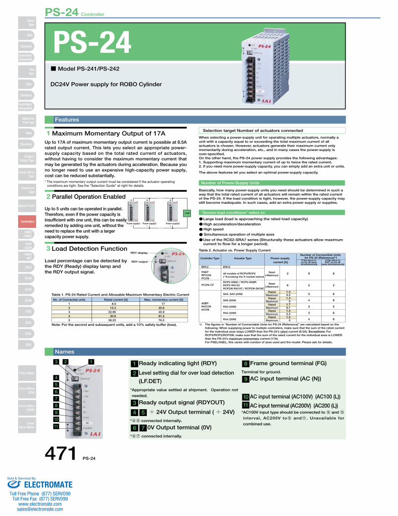
DC24V Power supply for ROBO Cylinder
■Model PS-241/PS-242
Names
PS-24
1 Maximum Momentary Output of 17A Up to 17A of maximum momentary output current is possible at 8.5A rated output current. This lets you select an appropriate power-supply capacity based on the total rated current of actuators, without having to consider the maximum momentary current that may be generated by the actuators during acceleration. Because you no longer need to use an expensive high-capacity power supply, cost can be reduced substantially.* The maximum momentary output current must be considered if the actuator operating
conditions are tight. See the “Selection Guide” at right for details.
2 Parallel Operation Enabled
Up to 5 units can be operated in parallel. Therefore, even if the power capacity is insufficient with one unit, this can be easily remedied by adding one unit, without the need to replace the unit with a larger capacity power supply.
3 Load Detection Function
Load percentage can be detected by the RDY (Ready) display lamp and the RDY output signal.
Power supply1 Power supply2 Power supply5
Load
RDY display
RDY output
1 Ready indicating light (RDY)
2 Level setting dial for over load detection
(LF.DET) * Appropriate value settled at shipment. Operation not
needed.
3 Ready output signal (RDYOUT)
4 5 + 24V Output terminal (+ 24V) *45 connected internally.
6 7 0V Output terminal (0V) *67 connected internally.
8 Frame ground terminal (FG) Terminal for ground.
9 AC input terminal (AC (N))
10 AC input terminal (AC100V) (AC100 (L))
11 AC input terminal (AC200V) (AC200 (L)) * AC100V input type should be connected to 9 and 0 interval, AC200V to9 andA . Unavailable for
combined use.
3
4
5
6
7
8
9
10
11
2 1
Mini
Mini
PSEP/ASEP
PMEC/AMEC
ROBONET
ERC2
PCON
ACON
SCON
PSEL
ASEL
SSEL
XSEL
Standard
Mini
Standard
Standard
ControllersIntegrated
ControllersIntegrated
RodType
Table/Arm/Flat Type
Gripper/Rotary Type
Linear ServoType
CleanroomType
Splash-Proof
Controllers
Pulse Motor
Servo Motor (24V)
Servo Motor (200V)
LinearServo Motor
SliderType
ELECTROMATEToll Free Phone (877) SERVO98
Toll Free Fax (877) SERV099www.electromate.com
Sold & Serviced By:
PS-24 Controller
PS-24 472
List of Models
Specification List
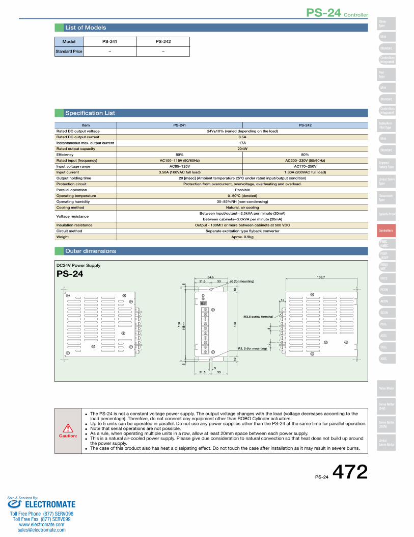
Outer dimensions
Item
Rated DC output voltage
Rated DC output current
Instantaneous max. output current
Rated output capacity
Efficiency
Rated input (frequency)
Input voltage range
Input current
Output holding time
Protection circuit
Parallel operation
Operating temperature
Operating humidity
Cooling method
Voltage resistance
Insulation resistance
Circuit method
Weight
PS-241 PS-242
24V±10% (varied depending on the load)
8.5A
17A
204W
80% 80%
AC100~115V (50/60Hz) AC200~230V (50/60Hz)
AC85~125V AC170~250V
3.50A (100VAC full load) 1.80A (200VAC full load)
20 [msec] (Ambient temperature 25ºC under rated input/output condition)
Protection from overcurrent, overvoltage, overheating and overload.
Possible
0~50ºC (derated)
30~85%RH (non-condensing)
Natural, air cooling
Between input/output···2.0kVA per minute (20mA)
Between cabinets···2.0kVA per minute (20mA)
Output - 100MΩ or more between cabinets at 500 VDC
Separate excitation type flyback converter
Aprox. 0.9kg
53331.5
64.53331.5
1013
810
R2. 5 (for mounting)
810
514
8±0.
55
158
13
M3.5 screw terminal
(for mounting)ø5139.7
DC24V Power Supply
PS-24
Caution:
The PS-24 is not a constant voltage power supply. The output voltage changes with the load (voltage decreases according to the • load percentage). Therefore, do not connect any equipment other than ROBO Cylinder actuators. Up to 5 units can be operated in parallel. Do not use any power supplies other than the PS-24 at the same time for parallel operation. • Note that serial operations are not possible.• As a rule, when operating multiple units in a row, allow at least 20mm space between each power supply. • This is a natural air-cooled power supply. Please give due consideration to natural convection so that heat does not build up around • the power supply. The case of this product also has heat a dissipating effect. Do not touch the case after installation as it may result in severe burns. •
Model
Standard Price
PS-241 PS-242
− −
Mini
Mini
PSEP/ASEP
PMEC/AMEC
ROBONET
ERC2
PCON
ACON
SCON
PSEL
ASEL
SSEL
XSEL
Standard
Mini
Standard
Standard
ControllersIntegrated
ControllersIntegrated
SliderType
RodType
Table/Arm/Flat Type
Gripper/Rotary Type
Linear ServoType
CleanroomType
Splash-Proof
Controllers
Pulse Motor
Servo Motor (24V)
Servo Motor (200V)
LinearServo Motor
ELECTROMATEToll Free Phone (877) SERVO98
Toll Free Fax (877) SERV099www.electromate.com
Sold & Serviced By:
RCM-PM-01 Controller
473 RCM-PM-01
Characteristics
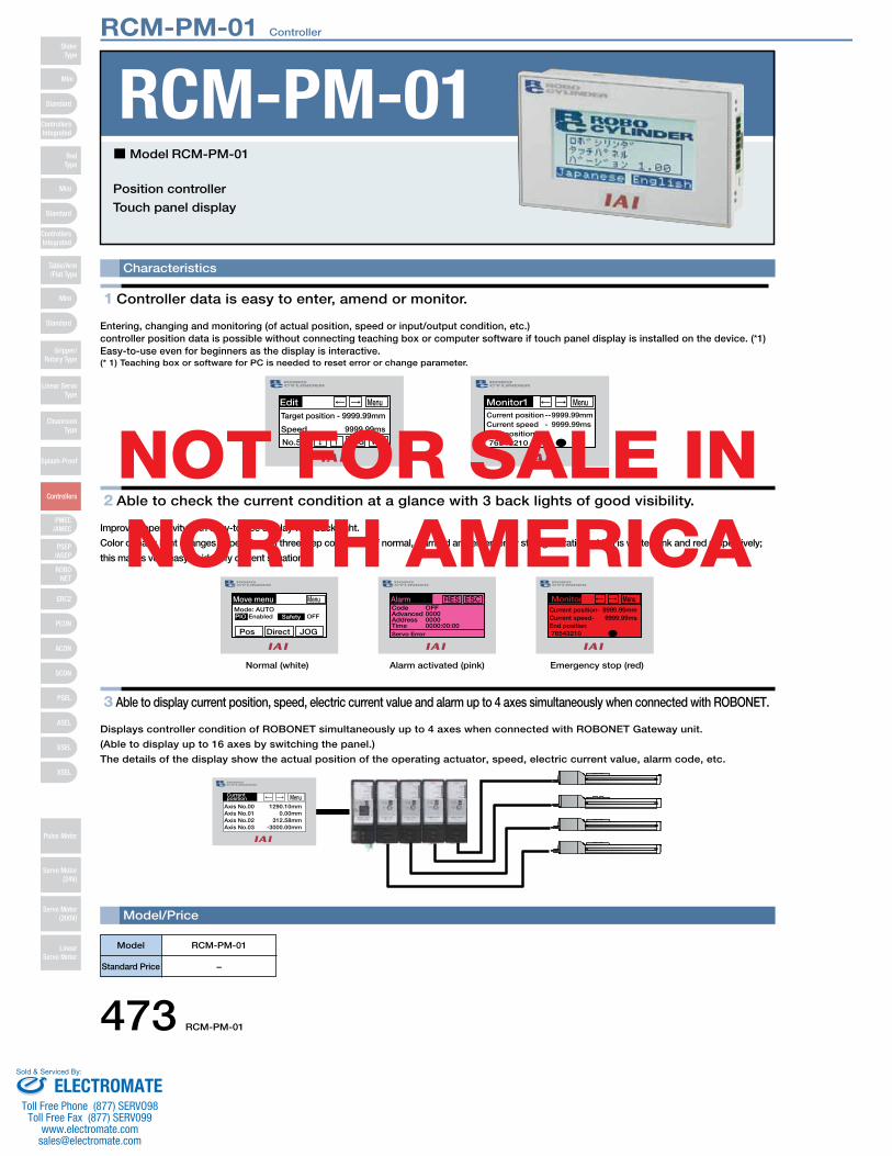
Position controller
Touch panel display
Model/Price
RCM-PM-01
1 Controller data is easy to enter, amend or monitor.
Entering, changing and monitoring (of actual position, speed or input/output condition, etc.) controller position data is possible without connecting teaching box or computer software if touch panel display is installed on the device. (*1)Easy-to-use even for beginners as the display is interactive. (* 1) Teaching box or software for PC is needed to reset error or change parameter.
2 Able to check the current condition at a glance with 3 back lights of good visibility.
Improved operativity with easy-to-see display with back-light.
Color of back light changes depending on three step conditions of normal, alarmed and emergency stop generation which is white, pink and red respectively;
this makes very easy to identify current situation.
3 Able to display current position, speed, electric current value and alarm up to 4 axes simultaneously when connected with ROBONET.
Displays controller condition of ROBONET simultaneously up to 4 axes when connected with ROBONET Gateway unit.
(Able to display up to 16 axes by switching the panel.)
The details of the display show the actual position of the operating actuator, speed, electric current value, alarm code, etc.
Model
Standard Price
RCM-PM-01
−
Edit9999.99mm
No.511
Menu
WRTJOG
Monitor1
76543210
Current position -- 9999.99mmCurrent speed - 9999.99ms
Menu
9999.99ms
Target position -
Speed End position
Normal (white)
Move menuMode: AUTO
Menu
JOGDirectPos
Alarm activated (pink)
Alarm
Servo Error
ESCRES
Emergency stop (red)
Monitor1
76543210
9999.99mm
Menu
SafetyEnabledPIO OFFOFF000000000000:00:00
CodeAdvancedAddressTime
9999.99msEnd position
Current position-Current speed-
Current position
1290.10mm
Menu
0.00mm312.58mm
-3000.00mm
Axis No.00Axis No.01Axis No.02Axis No.03
■Model RCM-PM-01
NOT FOR SALE IN NORTH AMERICA
Mini
Mini
PSEP/ASEP
PMEC/AMEC
ROBONET
ERC2
PCON
ACON
SCON
PSEL
ASEL
SSEL
XSEL
Standard
Mini
Standard
Standard
ControllersIntegrated
ControllersIntegrated
RodType
Table/Arm/Flat Type
Gripper/Rotary Type
Linear ServoType
CleanroomType
Splash-Proof
Controllers
Pulse Motor
Servo Motor (24V)
Servo Motor (200V)
LinearServo Motor
SliderType
ELECTROMATEToll Free Phone (877) SERVO98
Toll Free Fax (877) SERV099www.electromate.com
Sold & Serviced By:

RCM-PM-01 Controller
RCM-PM-01 474
Connecting methods
RCM-PM-01Pin No. Signal Name
1 DC24V
Controller SIO port
[MiniDIN]
Pin No. Signal Name1 SGA
24V power+24V
GND
* The above connection diagram only shows the serial line. Please see the instructions manual for the controllerfor connecting the power and emergency stop lines.
[When Connecting to a Separate Power Source]
0.2m
Model : CB-RCB-CTL002Standard price:
Controller link cable(option)
e-CON connector (AMP 4-1473562-4)
* Each controller link cable comes with a e-CON connector, a junction, and a terminal resistance.
* Please provide the wiring from the touch panel to the junction.
Junction (AMP 5-1473574-4)
120Ω1/4W
RCM-PM-01
Emergency stop switch
Pin No. Signal Name1 DC24V
Controller SIO port
[MiniDIN]
Pin No. Signal Name1 SGA
[When Connecting to the Controller's Power Source]
Emergency stop switch
3m
Controller connection cablewith emergency stop switch(optional)Model : CB-PM-SIO030-EBStandard price:
* The yellowish green wiring is optional.
* The yellowish green wiring is optional.
* The yellowish green wiring is optional.
24V power+24V
GND
RCM-PM-01Pin No. Signal Name
1 DC24V
1st controllerSIO port
[MiniDIN]
Pin No. Signal Name1 SGA
SGB5VENBEMGA24VGNDEMGB
2nd controllerSIO port
[MiniDIN]
Pin No. Signal Name1 SGA
SGB5VENBEMGA24VGNDEMGB
nth controllerSIO port
Terminal resistance
220Ω1/4W
[MiniDIN]
Pin No. Signal Name1 SGA
* The above connection diagram only shows the serial line. Please see the instructions manual for the controller for connecting the power and emergency stop lines.
[When Connecting to Multiple Controllers]
1st controller
e-CON connector (AMP 4-1473562-4)
* Each controller link cable comes with a e-CON connector,a junction, and a terminal resistance.
* Please provide the wiring fromthe touch panel to the junctionas well as between junctions.
Model : CB-RCB-CTL002Standard price:
Controller link cable(option)
PCONACONSCON
Power I/O cable (supplied with actuator)
[CB-ERC2-PWBIO���]Length: 1m/3m/5m
ERC2 (SIO type)
Junction (AMP 5-1473574-4)
Terminal resistanceR=220Ω
0.2m 0.2m 0.2m
2nd controller
When linking and using multiple controllers,you will need a teaching pendant or a PC software to set the station numbers ofPCON/ACON-CY/SE/PL/PO and ERC2
Note:
2345678
2345678
2345678
2345678
SGB5VENBEMGA24VGNDEMGB
GNDFGRS422 SD+RS422 SD-RS422 RD+RS422 RD-RS422 E
SGB5VENBEMGA24VGNDEMGB
GNDFGRS422 SD+RS422 SD-RS422 RD+RS422 RD-RS422 E
2345678
2345678
SGB5VENBEMGA24VGNDEMGB
2345678
GNDFGRS422 SD+RS422 SD-RS422 RD+RS422 RD-RS422 E
2345678
NOT FOR SALE IN NORTH AMERICA
Mini
Mini
PSEP/ASEP
PMEC/AMEC
ROBONET
ERC2
PCON
ACON
SCON
PSEL
ASEL
SSEL
XSEL
Standard
Mini
Standard
Standard
ControllersIntegrated
ControllersIntegrated
SliderType
RodType
Table/Arm/Flat Type
Gripper/Rotary Type
Linear ServoType
CleanroomType
Splash-Proof
Controllers
Pulse Motor
Servo Motor (24V)
Servo Motor (200V)
LinearServo Motor
ELECTROMATEToll Free Phone (877) SERVO98
Toll Free Fax (877) SERV099www.electromate.com
Sold & Serviced By:
RCM-PM-01 Controller
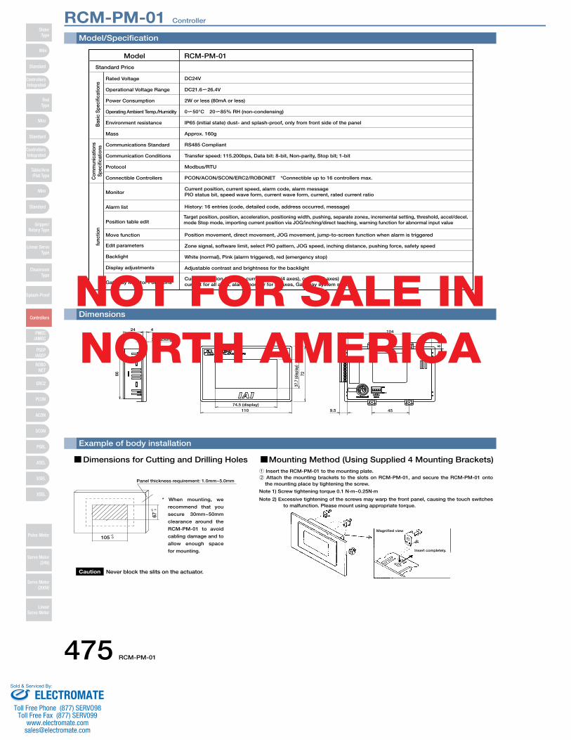
475 RCM-PM-01
Model/Specification
Position movement, direct movement, JOG movement, jump-to-screen function when alarm is triggered
History: 16 entries (code, detailed code, address occurred, message)
Current position, current speed, alarm code, alarm messagePIO status bit, speed wave form, current wave form, current, rated current ratio
Current position (4 axes), current speed (4 axes), current (4 axes)current for all axes, alarm monitor for all axes, Gateway system status
Standard Price
Model RCM-PM-01
Monitor
Rated Voltage
Alarm list
Position table edit
Move function
Edit parameters
Backlight
Display adjustments
Gateway Monitor Functions
Operational Voltage Range
Power Consumption
Operating Ambient Temp./Humidity
Environment resistance
Mass
Communications Standard
Communication Conditions
Protocol
Connectible Controllers
DC24V
DC21.6 26.4V
2W or less (80mA or less)
0 50°C 20 85% RH (non-condensing)
IP65 (initial state) dust- and splash-proof, only from front side of the panel
Approx. 160g
RS485 Compliant
Transfer speed: 115.200bps, Data bit: 8-bit, Non-parity, Stop bit; 1-bit
Modbus/RTU
PCON/ACON/SCON/ERC2/ROBONET *Connectible up to 16 controllers max.
Zone signal, software limit, select PIO pattern, JOG speed, inching distance, pushing force, safety speed
White (normal), Pink (alarm triggered), red (emergency stop)
Adjustable contrast and brightness for the backlight
Bas
ic S
peci
ficat
ions
Com
mun
icat
ions
S
peci
ficat
ions
func
tion
Target position, position, acceleration, positioning width, pushing, separate zone±, incremental setting, threshold, accel/decel. mode Stop mode, importing current position via JOG/inching/direct teaching, warning function for abnormal input value
Dimensions
9.5 45
8
104
74.5 (display) 110
37.7
(dis
play
) 72
424
2 (packing)
66
Example of body installation
Dimensions for Cutting and Drilling Holes
Panel thickness requirement: 1.0mm~5.0mm
67+1
0
105+1 0
Caution Never block the slits on the actuator.
Mounting Method (Using Supplied 4 Mounting Brackets)
* When mounting, we
recommend that you
secure 30mm~50mm
clearance around the
RCM-PM-01 to avoid
cabling damage and to
allow enough space
for mounting.
Note 2) Excessive tightening of the screws may warp the front panel, causing the touch switches to malfunction. Please mount using appropriate torque.
Note 1) Screw tightening torque 0.1 N∙m~0.25N∙m
1 Insert the RCM-PM-01 to the mounting plate. 2 Attach the mounting brackets to the slots on RCM-PM-01, and secure the RCM-PM-01 onto
the mounting place by tightening the screw.
Magnified view
Insert completely.
NOT FOR SALE IN NORTH AMERICA
Mini
Mini
PSEP/ASEP
PMEC/AMEC
ROBONET
ERC2
PCON
ACON
SCON
PSEL
ASEL
SSEL
XSEL
Standard
Mini
Standard
Standard
ControllersIntegrated
ControllersIntegrated
RodType
Table/Arm/Flat Type
Gripper/Rotary Type
Linear ServoType
CleanroomType
Splash-Proof
Controllers
Pulse Motor
Servo Motor (24V)
Servo Motor (200V)
LinearServo Motor
SliderType
ELECTROMATEToll Free Phone (877) SERVO98
Toll Free Fax (877) SERV099www.electromate.com
Sold & Serviced By:
RCM-PM-01 476
RCM-PM-01 Controller
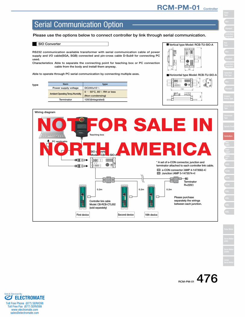
RS232 communication available transformer with serial communication cable of power supply and I/O cable(SGA, SGB) connected and pin-cross cable D-Sub9 for connecting PC used.Characteristics Able to separate the connecting point for teaching box or PC connection
cable from the body and install them anyway.
Able to operate through PC serial communication by connecting multiple axes.
type
SIO Converter Vertical type Model: RCB-TU-SIO-A
Horizontal type Model: RCB-TU-SIO-A
Item
Power supply voltage
Ambient Operating Temp./Humidity
Terminator
type
DC24V±10%0~ 50°C, 85% RH or less
(Non-condensing)
120Ω (Integrated)
0.2m 0.2m 0.2m
PC applicable
Teaching box
SIO converterModel: TCB-TU-SIO-A(B)
* A set of e-CON connector, junction and terminator attached to each controller link cable.
e-CON connector(AMP 4-1473562-4)Junction(AMP 5-1473574-4)
Terminator R=220Ω
Please purchase separately the wirings between each junction.
Controller link cableModel: CB-RCB-CTL002(sold separately)
First device Second device 16th device
Wiring diagram
Please use the options below to connect controller by link through serial communication.
Serial Communication Option
NOT FOR SALE IN NORTH AMERICA
Mini
Mini
PSEP/ASEP
PMEC/AMEC
ROBONET
ERC2
PCON
ACON
SCON
PSEL
ASEL
SSEL
XSEL
Standard
Mini
Standard
Standard
ControllersIntegrated
ControllersIntegrated
SliderType
RodType
Table/Arm/Flat Type
Gripper/Rotary Type
Linear ServoType
CleanroomType
Splash-Proof
Controllers
Pulse Motor
Servo Motor (24V)
Servo Motor (200V)
LinearServo Motor
ELECTROMATEToll Free Phone (877) SERVO98
Toll Free Fax (877) SERV099www.electromate.com
Sold & Serviced By:

477 PMEC / AMEC
Accel & Speed Setting
Middle
FWDPOS
BACKPOS
Test run
Manual
FWD
STOP
RUN
BACK
Continuous
Test run
Manual
FWD
STOP
RUN
Complete
Accel & Speed Setting
Middle
BACK
Normal
Brake
Release
Teaching Port
USB
FWDPOS
BACKPOS
HOME
Continuous
plete
Accel & Speed Setting
Middle
FWDPOS
BACKPOS
HOME
Test run
Manual
FWD
STOP
RUN
Complete
Accel & Speed Setting
Middle
BACK
Normal
Brake
Release
Teaching Port
USB
FWDPOS
BACKPOS
HOME
Continuous
Feature
1 Low Cost
2 Easy Operation
3 Easy Replacement from yourAir-cylinder System
4 Push-motion Operation/IntermediateStopping
ROBO Cylinder 3-position controller MEC (Mechanical Engineer Control)
2 Adjustment
1 Manual setting
3 Trial operation
ReplacementAir cylinder ROBO cylinder
PLC
Controller
Power supply
PC connection cable
The PMEC package, which comes with a
controller, power supply, acceleration/speed
change function and PC connection cable,
among others, is at an affordable price. The
MEC PC software can be downloaded free of
change from IAI’s website.
Even a beginner can set up the controller without
reading the operation manual. The acceleration and
speed can be changed using the knobs on the
controller.
Operation signals are exactly the same as
those used to operate air cylinders. This
means that you can use the program of your
current PLC directly.
Push-motion operation can be performed in the same
manner as you would with any air-cylinder system.
Also, you can cause the actuator to stop at any
desired intermediate point between the home
position and stroke end by changing the setting of
the intermediate point using the MEC PC software.
* Setting range for acceleration/speed varies depending onthe actuator.Please refer to the instruction manual for further detail.
3-position, AC100/200V controller
for RCP2/RCP3 Series
3 position, AC100V controller
for RCA/RCA2/RCL Series
Complete
FWDPOS
BACKPOS
Accel & Speed Setting
Normal
Brake
Release
HOME
Teaching Port
Test run
Manual
Continuous
FWD
STOP
RUN
BACK
USB
Test run
Manual
FWD
STOP
RUN
Complete
Accel & Speed Setting
Middle
BACK
Normal
Brake
Release
Teaching Port
USB
FWDPOS
BACKPOS
HOME
Continuous
Mini
Mini
PSEP/ASEP
PMEC/AMEC
ROBONET
ERC2
PCON
ACON
SCON
PSEL
ASEL
SSEL
XSEL
Standard
Mini
Standard
Standard
ControllersIntegrated
ControllersIntegrated
RodType
Table/Arm/Flat Type
Gripper/Rotary Type
Linear ServoType
CleanroomType
Splash-Proof
Controllers
Pulse Motor
Servo Motor (24V)
Servo Motor (200V)
LinearServo Motor
SliderType
PMEC / AMEC Controller
ELECTROMATEToll Free Phone (877) SERVO98
Toll Free Fax (877) SERV099www.electromate.com
Sold & Serviced By:
PMEC / AMEC 478
Test run
Manual
FWD
STOP
RUN
Complete
Accel & Speed Setting
Middle
BACK
Normal
Brake
Release
Teaching Port
USB
FWDPOS
BACKPOS
HOME
Continuous
Complete
FWDPOS
BACKPOS
Accel & Speed Setting
Normal
Brake
Release
HOME
Teaching Port
Test run
Manual
Continuous
FWD
STOP
RUN
BACK
USB
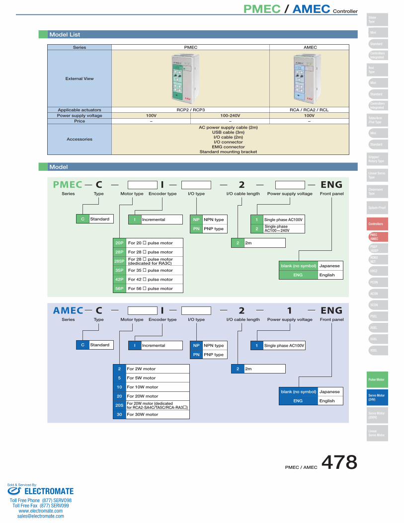
Model List
Model
C Standard I Incremental
2 2m
NP NPN type
PN PNP type
1 Single phase AC100V
AMECType Motor type Encoder type I/O type I/O cable length Power supply voltage
I 2C 1
20
10
5
2
20S
30
For 20W motor
For 10W motor
For 20W motor (dedicatedfor RCA2-SA4C/TA5C/RCA-RA3�)
For 5W motor
For 2W motor
For 30W motor
Series
C Standard I Incremental
2 2m
NP NPN type
PN PNP type 2Single phase AC100~240V
1 Single phase AC100V
ENG English
blank (no symbol) Japanese
PMECTypeSeries Motor type Encoder type I/O type I/O cable length Power supply voltage Front panel
ENG English
blank (no symbol) Japanese
Front panel
I 2 ENG
ENG
C
35P
28SP
28P
20P
42P
56P
For 35 � pulse motor
For 28 � pulse motor (dedicated for RA3C)
For 28 � pulse motor
For 20 � pulse motor
For 42 � pulse motor
For 56 � pulse motor
Series PMEC
External View
Applicable actuatorsPower supply voltage
Price
RCP2 / RCP3 RCA / RCA2 / RCL100V
−100-240V
−
AC power supply cable (2m)USB cable (3m)I/O cable (2m)I/O connector
EMG connectorStandard mounting bracket
100V−
Accessories
AMEC
Mini
Mini
PSEP/ASEP
PMEC/AMEC
ROBONET
ERC2
PCON
ACON
SCON
PSEL
ASEL
SSEL
XSEL
Standard
Mini
Standard
Standard
ControllersIntegrated
ControllersIntegrated
RodType
Table/Arm/Flat Type
Gripper/Rotary Type
Linear ServoType
CleanroomType
Splash-Proof
Controllers
Pulse Motor
Servo Motor (24V)
Servo Motor (200V)
LinearServo Motor
SliderType
Mini
Mini
PSEP/ASEP
PMEC/AMEC
ROBONET
ERC2
PCON
ACON
SCON
PSEL
ASEL
SSEL
XSEL
Standard
Mini
Standard
Standard
ControllersIntegrated
ControllersIntegrated
SliderType
RodType
Table/Arm/Flat Type
Gripper/Rotary Type
Linear ServoType
CleanroomType
Splash-Proof
Controllers
Pulse Motor
Servo Motor (24V)
Servo Motor (200V)
LinearServo Motor
PMEC / AMEC Controller
ELECTROMATEToll Free Phone (877) SERVO98
Toll Free Fax (877) SERV099www.electromate.com
Sold & Serviced By:
479 PMEC / AMEC
Test run
Manual
FWD
STOP
RUN
Complete
Accel & Speed Setting
Middle
BACK
Normal
Brake
Release
Teaching Port
USB
FWDPOS
BACKPOS
HOME
Continuous
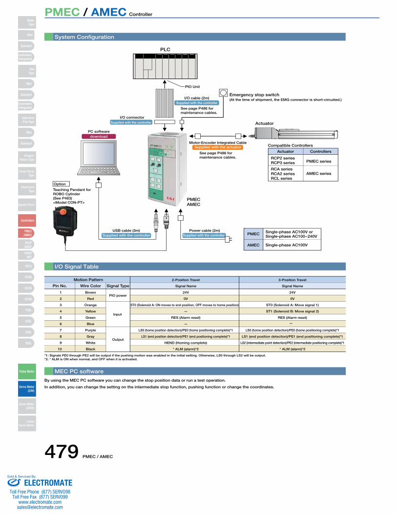
System Configuration
PLC
downloadPC software
Teaching Pendant forROBO Cylinder(See P483)<Model CON-PT>
Option
PIO Unit
Supplied with the actuatorMotor-Encoder Integrated Cable
Supplied with the controllerPower cable (2m)
Supplied with the controllerUSB cable (3m)
Actuator
Emergency stop switch
Compatible Controllers
RCP2 seriesPMEC series
AMEC seriesRCA series
Actuator Controllers
Single-phase AC100V or Single-phase AC100~240V
Single-phase AC100V
PMEC
AMEC
PMEC
I/O Signal Table
MEC PC software
By using the MEC PC software you can change the stop position data or run a test operation.
In addition, you can change the setting on the intermediate stop function, pushing function or change the coordinates.
Supplied with the controllerI/O cable (2m)
Supplied with the controller
I/O connector
(At the time of shipment, the EMG connector is short-circuited.)
Motion Pattern
Pin No.
1 Brown 24V 24VPIO power
Wire Color Signal Type Signal Name Signal Name
2-Position Travel 3-Position Travel
*1: Signals PE0 through PE2 will be output if the pushing motion was enabled in the initial setting. Otherwise, LS0 through LS2 will be output.
See page P486 formaintenance cables.
See page P486 formaintenance cables.
RCP3 series
RCA2 seriesRCL series
AMEC
2
3
4
5
6
7
8
9
10
Red
Orange
Yellow
Green
Blue
Purple
Gray
White
Black
0V
ST0 (Solenoid A: ON moves to end position, OFF moves to home position)
—
RES (Alarm reset)
—
LS0 (home position detection)/PE0 (home positioning complete)*1
LS1 (end position detection)/PE1 (end positioning complete)*1
HEND (Homing complete)
* ALM (alarm)*2
Input
Output
0V
ST0 (Solenoid A: Move signal 1)
ST1 (Solenoid B: Move signal 2)
RES (Alarm reset)
LS0 (home position detection)/PE0 (home positioning complete)*1
LS1 (end position detection)/PE1 (end positioning complete)*1
LS2 (intermediate point detection)/PE2 (intermediate positioning complete)*1
* ALM (alarm)*2
*2: * ALM is ON when normal, and OFF when it is activated.
—
Mini
Mini
PSEP/ASEP
PMEC/AMEC
ROBONET
ERC2
PCON
ACON
SCON
PSEL
ASEL
SSEL
XSEL
Standard
Mini
Standard
Standard
ControllersIntegrated
ControllersIntegrated
RodType
Table/Arm/Flat Type
Gripper/Rotary Type
Linear ServoType
CleanroomType
Splash-Proof
Controllers
Pulse Motor
Servo Motor (24V)
Servo Motor (200V)
LinearServo Motor
SliderType
PMEC / AMEC Controller
ELECTROMATEToll Free Phone (877) SERVO98
Toll Free Fax (877) SERV099www.electromate.com
Sold & Serviced By:
PMEC / AMEC 480
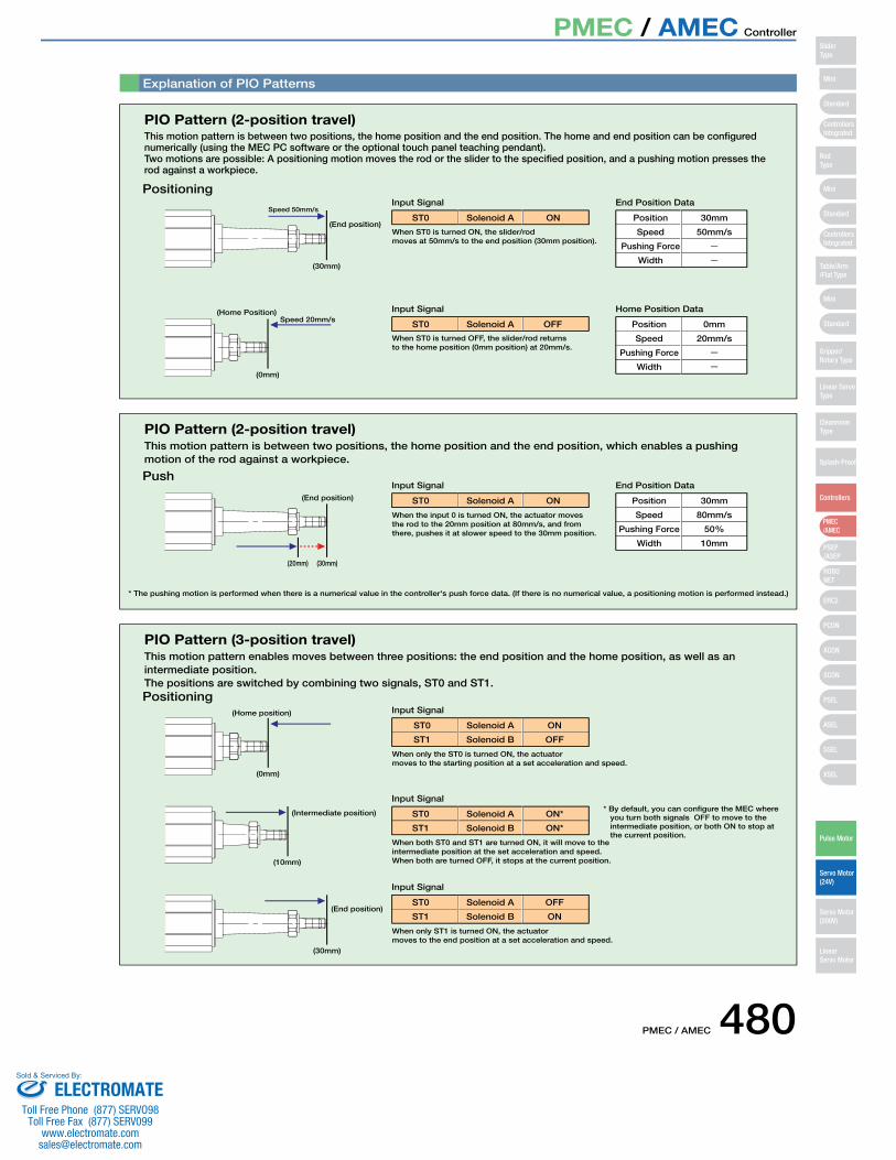
Explanation of PIO Patterns
PIO Pattern (2-position travel)
Input Signal
Input Signal
When ST0 is turned ON, the slider/rod moves at 50mm/s to the end position (30mm position).
When ST0 is turned OFF, the slider/rod returns to the home position (0mm position) at 20mm/s.
Positioning
This motion pattern is between two positions, the home position and the end position. The home and end position can be configured numerically (using the MEC PC software or the optional touch panel teaching pendant).Two motions are possible: A positioning motion moves the rod or the slider to the specified position, and a pushing motion presses the rod against a workpiece.
(End position)
(30mm)
(0mm)
(Home Position)
Speed 50mm/s
Speed 20mm/s
ST0 ONSolenoid A
End Position Data
Home Position Data
ST0 OFFSolenoid A
Position
Speed
Pushing Force
Width
30mm
50mm/s
Position
Speed
Pushing Force
Width
0mm
20mm/s
PIO Pattern (2-position travel)
Input Signal
When the input 0 is turned ON, the actuator moves the rod to the 20mm position at 80mm/s, and from there, pushes it at slower speed to the 30mm position.
Push
This motion pattern is between two positions, the home position and the end position, which enables a pushing motion of the rod against a workpiece.
ST0 ONSolenoid A
End Position Data
Position
Speed
Pushing Force
Width
30mm
80mm/s
50%
10mm
* The pushing motion is performed when there is a numerical value in the controller's push force data. (If there is no numerical value, a positioning motion is performed instead.)
(End position)
(30mm)(20mm)
PIO Pattern (3-position travel)
Input Signal
When only the ST0 is turned ON, the actuator moves to the starting position at a set acceleration and speed.
Positioning
This motion pattern enables moves between three positions: the end position and the home position, as well as an intermediate position. The positions are switched by combining two signals, ST0 and ST1.
ST0 ON
ST1 OFF
Solenoid A
Solenoid B
(0mm)
(Home position)
Input Signal
When both ST0 and ST1 are turned ON, it will move to the intermediate position at the set acceleration and speed. When both are turned OFF, it stops at the current position.
ST0 ON*
ST1 ON*
Solenoid A
Solenoid B
Input Signal
When only ST1 is turned ON, the actuator moves to the end position at a set acceleration and speed.
ST0 OFF
ST1 ON
Solenoid A
Solenoid B
(Intermediate position)
(10mm)
(End position)
(30mm)
* By default, you can configure the MEC where you turn both signals OFF to move to the intermediate position, or both ON to stop at the current position.
Mini
Mini
PSEP/ASEP
PMEC/AMEC
ROBONET
ERC2
PCON
ACON
SCON
PSEL
ASEL
SSEL
XSEL
Standard
Mini
Standard
Standard
ControllersIntegrated
ControllersIntegrated
SliderType
RodType
Table/Arm/Flat Type
Gripper/Rotary Type
Linear ServoType
CleanroomType
Splash-Proof
Controllers
Pulse Motor
Servo Motor (24V)
Servo Motor (200V)
LinearServo Motor
PMEC / AMEC Controller
ELECTROMATEToll Free Phone (877) SERVO98
Toll Free Fax (877) SERV099www.electromate.com
Sold & Serviced By:

481 PMEC / AMEC
PowerGreen :Normal
Red: Alarm
Complete
HOME
SAVE
Test run
Manual
Manual
Continuous
Auto
Ext. Start
Accel & Speed Setting
FWDPOS
BACKPOS
Middle
Accel Speed
FWD BACK
RUN STOP
Normal Release
Brake
Teaching Port
PowerGreen :Normal
Red: Alarm
CompleteHOME
SAVE
Test run
Manual
Manual
Continuous
Auto
Ext. Start
Accel & Speed Setting
FWDPOS
BACKPOS
Middle
Accel Speed
FWD BACK
RUN STOP
Normal Release
Brake
Teaching Port
Specifications Table
Item Type
Controller Type PMEC AMEC
Connectible Actuators RCP2/RCP3 Series Actuators RCA/RCA2/RCL Series Actuators
Number of Controllable Axes Single axis
Operation Method Positioner Type
Number of Positions 2 positions / 3 positions
Backup Memory EEPROM
I/O Connector 10-pin terminal block
I/O Points 4 input points / 4 output points
Power for I/O Externally supplied DC24V±10%
Serial Communication RS485: 1ch/USB: 1ch
Position Detection Method Incremental encoder
AC100V-115V±10%
1.3A
30A
AC90V~264V
0.67A (AC100V)/0.36A (AC200V)
15A (AC100V)/30A (AC200V)
0.50mA max
AC100V-115V±10%
2.4A
15A
500g 508g 614g
0.50mA max
Power Supply Voltage
Rated Current
Rush Current
Leak Current
Dielectric Strength Voltage DC500V 1MΩ
Vibration ResistanceXYZ directions 10~57Hz One-side amplitude 0.035mm (continuous), 0.075mm (intermittent)
57~150Hz 4.9m/s2 (continuous), 9.8m/s2 (intermittent)
Ambient Operating Temperature 0~40˚C
Ambient Operating Humidity 10~85% RH (non-condensing)
Ambient Operating Atmosphere Free from corrosive gases
Protection Class IP20
Weight
0.40mA max (AC100V)0.75mA max (AC200V)
Outer Dimensions
226
216
85 2-ø5 through
200
42.5
8289.8
2
85 87.8
80
200
182
99
4.1
8.5 8.568
4-M3 tapped hole
[With standard mounting bracket]
The standard mounting bracket is supplied with the controller.
Note: The minimum/maximum speeds vary depending on the actuator model. For more information, see the instruction manual, or contact IAI.
Mini
Mini
PSEP/ASEP
PMEC/AMEC
ROBONET
ERC2
PCON
ACON
SCON
PSEL
ASEL
SSEL
XSEL
Standard
Mini
Standard
Standard
ControllersIntegrated
ControllersIntegrated
RodType
Table/Arm/Flat Type
Gripper/Rotary Type
Linear ServoType
CleanroomType
Splash-Proof
Controllers
Pulse Motor
Servo Motor (24V)
Servo Motor (200V)
LinearServo Motor
SliderType
PMEC / AMEC Controller
ELECTROMATEToll Free Phone (877) SERVO98
Toll Free Fax (877) SERV099www.electromate.com
Sold & Serviced By:
PMEC / AMEC 482
PowerGreen :Normal
Red: Alarm
CompleteHOME
SAVE
Test run
Manual
Manual
Continuous
Auto
Ext. Start
Accel & Speed Setting
FWDPOS
BACKPOS
Middle
Accel Speed
FWD BACK
RUN STOP
Normal Release
Brake
Teaching Port
PowerGreen :Normal
Red: Alarm
CompleteHOME
SAVE
Test run
Manual
Manual
Continuous
Auto
Ext. Start
Accel & Speed Setting
FWDPOS
BACKPOS
Middle
Accel Speed
FWD BACK
RUN STOP
Normal Release
Brake
Teaching Port
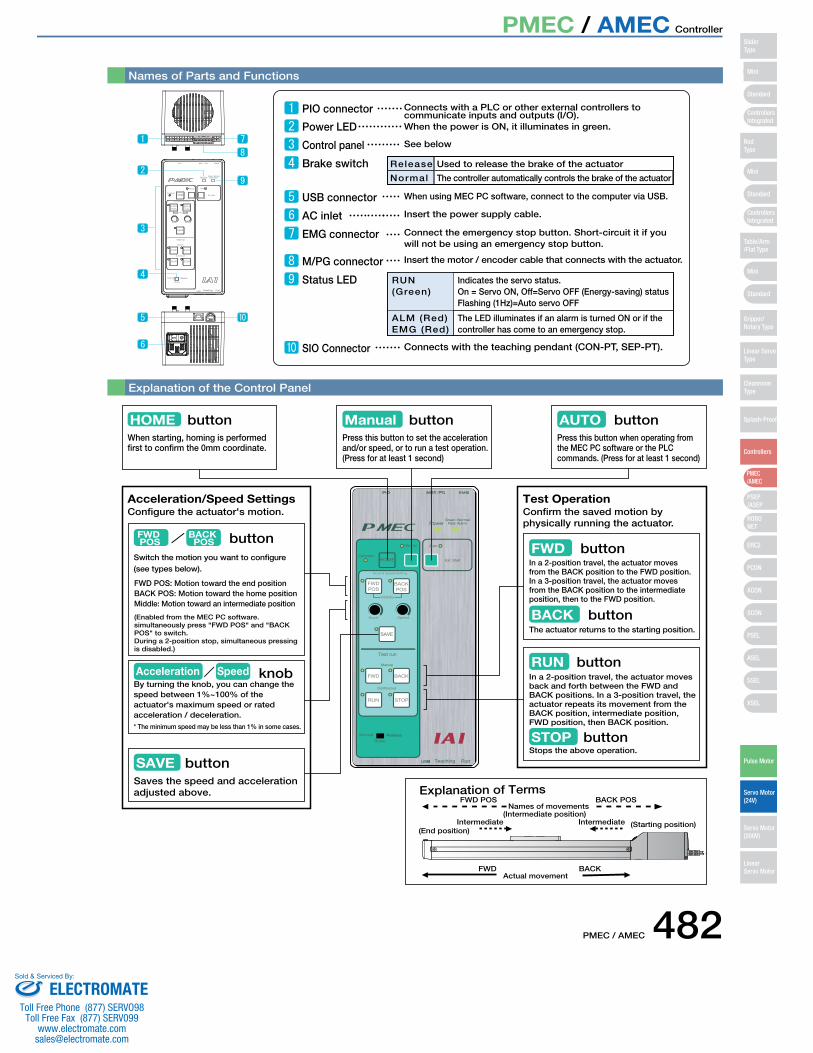
Names of Parts and Functions
Explanation of the Control Panel
AUTO buttonPress this button when operating from the MEC PC software or the PLC commands. (Press for at least 1 second)
Configure the actuator's motion.
buttonHOMEWhen starting, homing is performed first to confirm the 0mm coordinate.
Explanation of Terms
(Enabled from the MEC PC software. simultaneously press "FWD POS" and "BACK POS" to switch. During a 2-position stop, simultaneous pressing is disabled.)
FWD POS: Motion toward the end positionBACK POS: Motion toward the home positionMiddle: Motion toward an intermediate position
FWD POS
BACK POS button
Switch the motion you want to configure (see types below).
Acceleration/Speed Settings
SAVE buttonSaves the speed and acceleration adjusted above.
Confirm the saved motion by physically running the actuator.
Test Operation
FWD buttonIn a 2-position travel, the actuator moves from the BACK position to the FWD position. In a 3-position travel, the actuator moves from the BACK position to the intermediate position, then to the FWD position.
BACK buttonThe actuator returns to the starting position.
RUN buttonIn a 2-position travel, the actuator moves back and forth between the FWD and BACK positions. In a 3-position travel, the actuator repeats its movement from the BACK position, intermediate position, FWD position, then BACK position.
STOP buttonStops the above operation.
Press this button to set the acceleration and/or speed, or to run a test operation. (Press for at least 1 second)
Manual button
FWD POS BACK POS
Intermediate(Intermediate position)
FWD BACKActual movement
(End position)(Starting position)Intermediate
Names of movements
PIO connector Connects with a PLC or other external controllers to communicate inputs and outputs (I/O).
Power LED When the power is ON, it illuminates in green.
Control panel See below
Brake switch Release
Normal
Used to release the brake of the actuator
The controller automatically controls the brake of the actuator
USB connector When using MEC PC software, connect to the computer via USB.
AC inlet Insert the power supply cable.
EMG connector Connect the emergency stop button. Short-circuit it if you will not be using an emergency stop button.
M/PG connector Insert the motor / encoder cable that connects with the actuator.
Status LED RUN (Green)
ALM (Red)EMG (Red)
Indicates the servo status. On = Servo ON, Off=Servo OFF (Energy-saving) statusFlashing (1Hz)=Auto servo OFF
The LED illuminates if an alarm is turned ON or if the controller has come to an emergency stop.
SIO Connector Connects with the teaching pendant (CON-PT, SEP-PT).
Acceleration Speed knobBy turning the knob, you can change the speed between 1%~100% of the actuator's maximum speed or rated acceleration / deceleration.* The minimum speed may be less than 1% in some cases.
Mini
Mini
PSEP/ASEP
PMEC/AMEC
ROBONET
ERC2
PCON
ACON
SCON
PSEL
ASEL
SSEL
XSEL
Standard
Mini
Standard
Standard
ControllersIntegrated
ControllersIntegrated
SliderType
RodType
Table/Arm/Flat Type
Gripper/Rotary Type
Linear ServoType
CleanroomType
Splash-Proof
Controllers
Pulse Motor
Servo Motor (24V)
Servo Motor (200V)
LinearServo Motor
PMEC / AMEC Controller
ELECTROMATEToll Free Phone (877) SERVO98
Toll Free Fax (877) SERV099www.electromate.com
Sold & Serviced By:
483 PMEC / AMEC
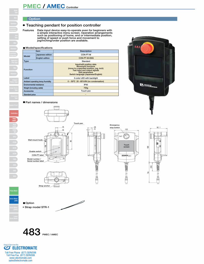
Touch screen
Teaching pendant for position controller
Option
Data input device easy-to-operate even for beginners with a simple interactive menu screen. Operation arrangements such as positioning of home, end or intermediate position, setting of speed or push force and movement to jog/inching/order position are available.
Item
ModelJapanese edition CON-PT-M
Standard
3-color LED with backlight
IP40
750g
Touch pen
Wall mount hook
Touch penEmergency
stop botton
Enable switch
CON-PT label
Model number / Serial number label
Strap anchor
0 ~ 50ºC 20 ~85%RH (no condensation)
Input/edit position dataMovement functions
(move to a specified position, jog, inch) Test input and output signals
Edit parameters Switch language (Japanese/English)
CON-PT-M-ENGEnglish edition
Ambient operating temp./humidity
Environmental resistance
Standard price
Accessories
Weight (including cable)
Function
Label
Type
Description
Features
Model/specifications
Part names / dimensions
• Strap model STR-1
Option
Mini
Mini
PSEP/ASEP
PMEC/AMEC
ROBONET
ERC2
PCON
ACON
SCON
PSEL
ASEL
SSEL
XSEL
Standard
Mini
Standard
Standard
ControllersIntegrated
ControllersIntegrated
RodType
Table/Arm/Flat Type
Gripper/Rotary Type
Linear ServoType
CleanroomType
Splash-Proof
Controllers
Pulse Motor
Servo Motor (24V)
Servo Motor (200V)
LinearServo Motor
SliderType
PMEC / AMEC Controller
ELECTROMATEToll Free Phone (877) SERVO98
Toll Free Fax (877) SERV099www.electromate.com
Sold & Serviced By:
PMEC / AMEC 484
1m
3m
5m
1m
3m
5m
1m
3m
5m
1m
3m
5m
2m
3m
5m
3m
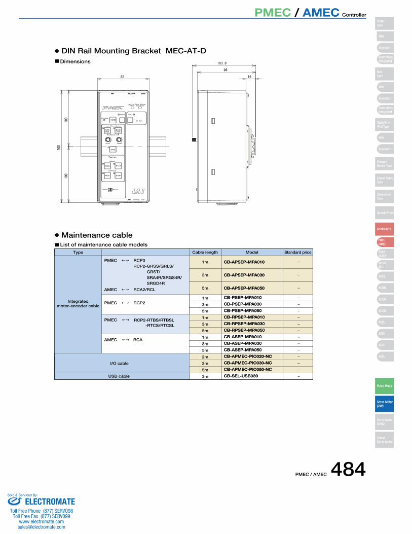
CB-PSEP-MPA010CB-PSEP-MPA010
CB-APSEP-MPA010CB-APSEP-MPA010
PMEC �� RCP2
AMEC �� RCA
PMEC �� RCP2-RTBS/RTBSL
PMEC �� RCP3RCP2-GRSS/GRLS/
GRST/SRA4R/SRGS4R/SRGD4R
AMEC �� RCA2/RCL
-RTCS/RTCSL
CB-PSEP-MPA030CB-PSEP-MPA030
CB-PSEP-MPA050CB-PSEP-MPA050
CB-RPSEP-MPA010CB-RPSEP-MPA010
CB-RPSEP-MPA030CB-RPSEP-MPA030
CB-RPSEP-MPA050CB-RPSEP-MPA050
CB-ASEP-MPA010CB-ASEP-MPA010
CB-ASEP-MPA030CB-ASEP-MPA030
CB-ASEP-MPA050CB-ASEP-MPA050
CB-APMEC-PIO020-NCCB-APMEC-PIO020-NC
CB-APMEC-PIO030-NCCB-APMEC-PIO030-NC
CB-APMEC-PIO050-NCCB-APMEC-PIO050-NC
CB-SEL-USB030CB-SEL-USB030
CB-APSEP-MPA030CB-APSEP-MPA030
CB-APSEP-MPA050CB-APSEP-MPA050
DIN Rail Mounting Bracket MEC-AT-D
Maintenance cable
Dimensions
List of maintenance cable modelsType
Integrated motor-encoder cable
I/O cable
USB cable
Cable length Model Standard price
Power Green :NormalRed: Alarm
CompleteHOME
SAVE
Test run
Manual
Manual
Continuous
Auto
Ext. Start
Accel & Speed Setting
FWDPOS
BACKPOS
Middle
Accel Speed
FWD BACK
RUN STOP
Normal Release
Brake
Teaching Port
Mini
Mini
PSEP/ASEP
PMEC/AMEC
ROBONET
ERC2
PCON
ACON
SCON
PSEL
ASEL
SSEL
XSEL
Standard
Mini
Standard
Standard
ControllersIntegrated
ControllersIntegrated
SliderType
RodType
Table/Arm/Flat Type
Gripper/Rotary Type
Linear ServoType
CleanroomType
Splash-Proof
Controllers
Pulse Motor
Servo Motor (24V)
Servo Motor (200V)
LinearServo Motor
PMEC / AMEC Controller
ELECTROMATEToll Free Phone (877) SERVO98
Toll Free Fax (877) SERV099www.electromate.com
Sold & Serviced By:
485 PMEC / AMEC
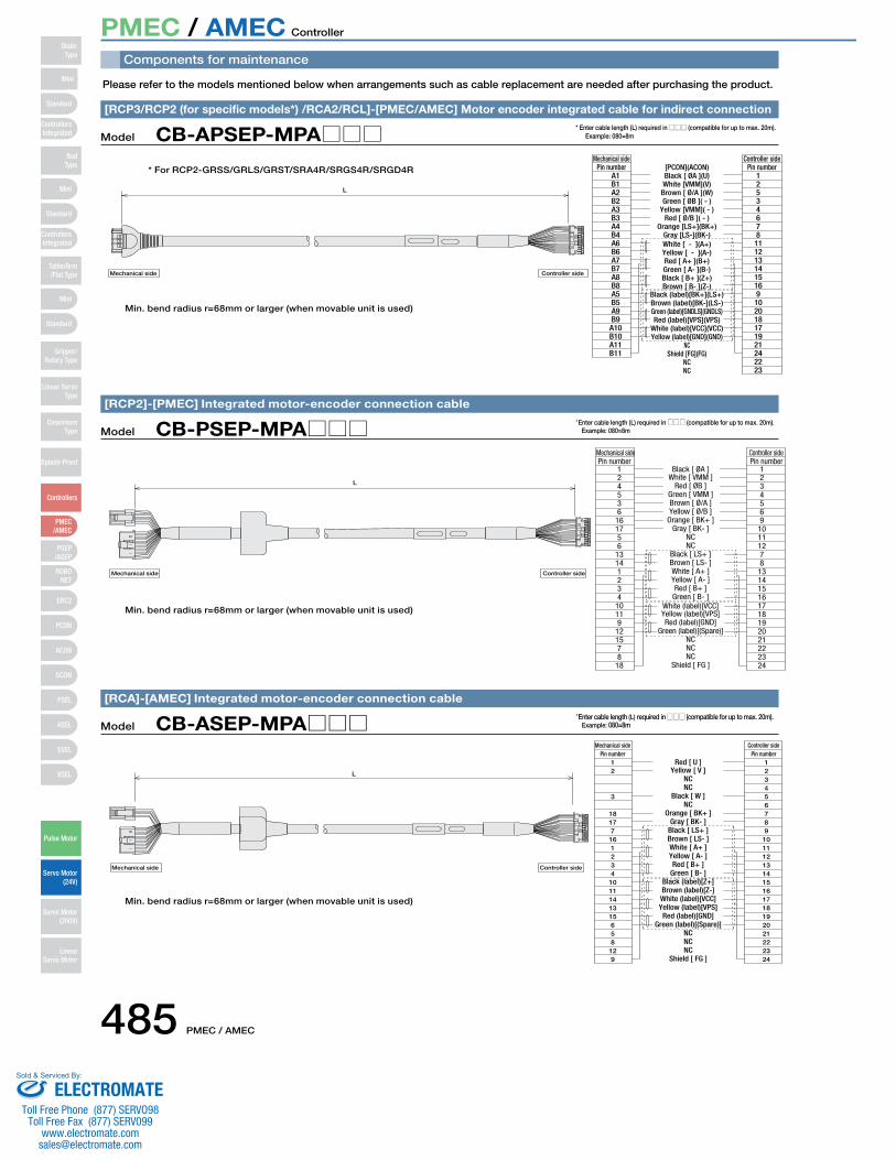
Components for maintenance
Please refer to the models mentioned below when arrangements such as cable replacement are needed after purchasing the product.
Controller sideMechanical side
Red [ U ]
L
Mechanical side Controller side
Pin number12
3
18177
161234
1011141315658
129
Yellow [ V ]NCNC
Black [ W ]NC
Orange [ BK+ ]Gray [ BK- ]
Black [ LS+ ]Brown [ LS- ]White [ A+ ]Yellow [ A- ]Red [ B+ ]
Green [ B- ]Black (label)[Z+]Brown (label)[Z-]White (label)[VCC]Yellow (label)[VPS]Red (label)[GND]
Green (label)[(Spare)]NCNCNC
Shield [ FG ]
Pin number123456789
101112131415161718192021222324
Model CB-ASEP-MPA□□□[RCA]-[AMEC] Integrated motor-encoder connection cable
Controller sideMechanical side
L
Black [ ØA ]
Mechanical side Controller side
Pin number124536
161756
13141234
10119
121578
18
White [ VMM ]Red [ ØB ]
Green [ VMM ]Brown [ Ø/A ]Yellow [ Ø/B ]
Orange [ BK+ ]Gray [ BK- ]
NCNC
Black [ LS+ ]Brown [ LS- ]White [ A+ ]Yellow [ A- ]Red [ B+ ]
Green [ B- ]White (label)[VCC]Yellow (label)[VPS]Red (label)[GND]
Green (label)[(Spare)]NCNCNC
Shield [ FG ]
Pin number1234569
10111278
131415161718192021222324
Model CB-PSEP-MPA□□□[RCP2]-[PMEC] Integrated motor-encoder connection cable
Controller sideMechanical side
NC
Black (label)[BK+](LS+)
White [ - ](A+)
[PCON](ACON)
L
Mechanical side Controller side
Pin numberA1B1A2B2A3B3A4B4A6B6A7B7A8B8A5B5A9B9A10B10A11B11
Pin number12534678
1112131415169
102018171921242223
Black [ ØA ](U)White [VMM](V)
Brown [ Ø/A ](W)Green [ ØB ]( - )
Yellow [VMM]( - )Red [ Ø/B ]( - )
Orange [LS+](BK+)Gray [LS-](BK-)
Yellow [ - ](A-)Red [ A+ ](B+)Green [ A- ](B-)Black [ B+ ](Z+)Brown [ B- ](Z-)
Brown (label)[BK-](LS-)Green (label)[GNDLS](GNDLS)Red (label)[VPS](VPS)
White (label)[VCC](VCC)Yellow (label)[GND](GND)
Shield [FG](FG)NCNC
Model CB-APSEP-MPA□□□[RCP3/RCP2 (for specific models*) /RCA2/RCL]-[PMEC/AMEC] Motor encoder integrated cable for indirect connection
* Enter cable length (L) required in □□□ (compatible for up to max. 20m). Example: 080=8m
*Enter cable length (L) required in □□□ (compatible for up to max. 20m). Example: 080=8m
*Enter cable length (L) required in □□□ (compatible for up to max. 20m). Example: 080=8m
Min. bend radius r=68mm or larger (when movable unit is used)
* For RCP2-GRSS/GRLS/GRST/SRA4R/SRGS4R/SRGD4R
Min. bend radius r=68mm or larger (when movable unit is used)
Min. bend radius r=68mm or larger (when movable unit is used)
Mini
Mini
PSEP/ASEP
PMEC/AMEC
ROBONET
ERC2
PCON
ACON
SCON
PSEL
ASEL
SSEL
XSEL
Standard
Mini
Standard
Standard
ControllersIntegrated
ControllersIntegrated
RodType
Table/Arm/Flat Type
Gripper/Rotary Type
Linear ServoType
CleanroomType
Splash-Proof
Controllers
Pulse Motor
Servo Motor (24V)
Servo Motor (200V)
LinearServo Motor
SliderType
PMEC / AMEC Controller
ELECTROMATEToll Free Phone (877) SERVO98
Toll Free Fax (877) SERV099www.electromate.com
Sold & Serviced By:

PMEC / AMEC 486
L
Controller sideMechanical side
Black [ ØA ]
Mechanical side Controller side
Pin numberA1B1A2B2A3B3A6B6A7B7A8B8A4B4A5B5A9B9A10B10A11B11
White [ VMM ]Brown [ Ø/A ]Green [ ØB ]
Yellow [ VMM ]Red [ Ø/B ]
Orange [ LS+ ]Gray [ LS- ]Red [ A+ ]
Green [ A- ]Black [ B+ ]Brown [ B- ]
NCNC
Black (label)[BK+]Brown (label)[BK-]
Green (label)[GNDLS]Red (label)[VPS]
White (label)[VCC]Yellow (label)[GND]
NCShield [ FG ](FG)
NCNC
Pin number1253467813141516789102018171921242223
Model CB-RPSEP-MPA□□□[RCP2 small rotary]-[PMEC] Motor encoder integrated cable for indirect connection
L
Flat cable (10 pin)
Model CB-APMEC-PIO□□□-NCI/O cable for PMEC-C/AMEC-C
*Enter cable length (L) required in □□□ (compatible for up to max. 20m). Example: 080=8m
Min. bend radius r=68mm or larger (when movable unit is used)
Pin NO. Electric wire color Signal
1 BrownPIO
Power supply2 Red
3 Orange
Input
4 Yellow
5 Green
6 Blue
7 Purple
8 Grey
Output9 White
10 Black
*The 3 types differ in cable length: 020=2m, 030=3m,050=5m
Mini
Mini
PSEP/ASEP
PMEC/AMEC
ROBONET
ERC2
PCON
ACON
SCON
PSEL
ASEL
SSEL
XSEL
Standard
Mini
Standard
Standard
ControllersIntegrated
ControllersIntegrated
SliderType
RodType
Table/Arm/Flat Type
Gripper/Rotary Type
Linear ServoType
CleanroomType
Splash-Proof
Controllers
Pulse Motor
Servo Motor (24V)
Servo Motor (200V)
LinearServo Motor
PMEC / AMEC Controller
ELECTROMATEToll Free Phone (877) SERVO98
Toll Free Fax (877) SERV099www.electromate.com
Sold & Serviced By:
PSEP / ASEP Controller
Model C/CW
3-position controller for RCP2/RCP3
Position Controller
Model C/CW
3-position controller for RCA/RCA2/RCL
Position Controller
Feature
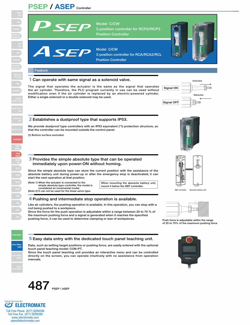
1 Can operate with same signal as a solenoid valve.
The signal that operates the actuator is the same as the signal that operates the air cylinder. Therefore, the PLC program currently in use can be used without modification even if the air cylinder is replaced by an electric-powered cylinder.Either a single solenoid or a double solenoid may be used.
2 Establishes a dustproof type that supports IP53.
We provide dustproof type controllers with an IP53 equivalent (*1) protection structure, so that the controller can be mounted outside the control panel.
(1) Bottom surface excluded.
3 Provides the simple absolute type that can be operatedimmediately upon power-ON without homing.
Since the simple absolute type can store the current position with the assistance of the absolute battery unit during power-up or after the emergency stop is deactivated; it can start the next operation at that position.
(Note 1) When the actuator is connected to the simple absolute type controller, the model is considered an incremental model.
(Note 2) It can not be used for the linear servo type.
4 Pushing and intermediate stop operation is available. Like air cylinders, the pushing operation is available. In this operation, you can stop with a rod being pushed to a workpiece.Since the force for the push operation is adjustable within a range between 20 to 70 % of the maximum pushing force and a signal is generated when it reaches the specified pushing force, it can be used to determine clamping or size of workpieces.
5 Easy data entry with the dedicated touch panel teaching unit.
Data, such as setting target positions or pushing force, are easily entered with the optional touch panel teaching model: CON-PT.Since the touch panel teaching unit provides an interactive menu and can be controlled directly on the screen, you can operate intuitively with no assistance from operation manuals.
Signal ON
Signal OFF
Retracted
Extended
SEP controller Absolute battery unit
Push force is adjustable within the range of 20 to 70% of the maximum pushing force
When mounting the absolute battery unit, mount it below the SEP controller.
Mini
Mini
PSEP/ASEP
PMEC/AMEC
ROBONET
ERC2
PCON
ACON
SCON
PSEL
ASEL
SSEL
XSEL
Standard
Mini
Standard
Standard
ControllersIntegrated
ControllersIntegrated
RodType
Table/Arm/Flat Type
Gripper/Rotary Type
Linear ServoType
CleanroomType
Splash-Proof
Controllers
Pulse Motor
Servo Motor (24V)
Servo Motor (200V)
LinearServo Motor
SliderType
487 PSEP / ASEP
ELECTROMATEToll Free Phone (877) SERVO98
Toll Free Fax (877) SERV099www.electromate.com
Sold & Serviced By:
PSEP / ASEP Controller
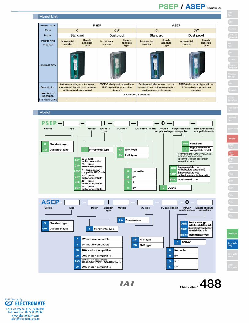
Model List
0I
C Standard type
CW Dustproof type I Incremental type
0 DC24V
0 No cable
2 2m
3 3m
5 5m
NP NPN type
PN PNP type
ABUN
(Blank) Incremental type
ABU Simple absolute type(with absolute battery unit)Simple absolute type(without absolute battery unit)
PSEPSeries Type Motor Encoder
typeI/O type I/O cable length Power
supply voltageSimple absolute
compatible
35P
28SP
28P
20P
42P
56P
35 � pulse motor-compatible
28 � pulse motorcompatible (RA3C only)
28 � pulse motor-compatible
20 � pulse motor compatible
42 � pulse motor-compatible56 � pulse motor-compatible
High acceleration compatible model
Blank Standard
HHigh acceleration compatible model
* If connecting to RCP3-SA4/SA5/SA6 RCP2(RCP2CR)-SA5/SA6, specify "H", for high-acceleration compatible model.
ASEP 0
C Standard type
CW Dustproof type
20 20W motor-compatible
10 10W motor-compatible
5 5W motor-compatible
2 2W motor-compatible
20S20W motor-compatible(RCA2-SA4�/TA5�, RCA-RA3� only)
30 30W motor-compatible
I Incremental type
0 DC24V
0 No cable
2 2m
3 3m
5 5m
I
Power-saving
NP NPN type
PN PNP type
ABUN
ABU
Series Type Motor OptionEncodertype
I/O type I/O cable length Power supply voltage
Simple absolute type (without absolute battery unit)
(Blank) Incremental type
Simple absolute type(with absolute battery unit)
Simple absolute compatible
LA
Type
Series name
Name
External View
DescriptionPosition controller, for pulse motors,
specialized to 2 positions / 3 positions positioning and easier control
PSEP-C dustproof type with an IP53 equivalent protection
structure
Position controller, for servo motors, specialized to 2 positions / 3 positions
positioning and easier control
ASEP-C dustproof type with an IP53 equivalent protection
structure
PSEP
C CW C CW
Standard Dustproof Standard Dust proof
ASEP
Positioning
methodIncremental
encoder
Simpleabsolute
type
Incremental encoder
Simpleabsolute
type
Incremental encoder
Simpleabsolute
type
Incremental encoder
Simpleabsolute
type
Model
Number of positions
Standard price
2 positions / 3 positions
− − − − − − − −
Mini
Mini
PSEP/ASEP
PMEC/AMEC
ROBONET
ERC2
PCON
ACON
SCON
PSEL
ASEL
SSEL
XSEL
Standard
Mini
Standard
Standard
ControllersIntegrated
ControllersIntegrated
SliderType
RodType
Table/Arm/Flat Type
Gripper/Rotary Type
Linear ServoType
Cleanroom Type
Splash-Proof
Controllers
Pulse Motor
Servo Motor (24V)
Servo Motor (200V)
LinearServo Motor
PSEP / ASEP 488ELECTROMATE
Toll Free Phone (877) SERVO98Toll Free Fax (877) SERV099
Sold & Serviced By:
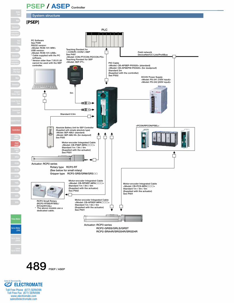
PSEP / ASEP Controller
PLC
Field networkDeviceNet/CC-Link/ProfiBus
Teaching Pendant for�CON/R�CON/�SEPSee P497<Model: CON-PT/CON-PD/CON-PG>Teaching Pendant for SEP<Model: SEP-PT>
Absolute Battery Unit for SEP Controller(Supplied with simple absolute type)<Model: SEP-ABU> (standard)<Model: SEP-ABU-W> (for dustproof)See P500
DC24V Power Supply<Model: PS-241 (100V input)><Model: PS-242 (200V input)>
<PCON/RPCON/PSEL>
PIO Cable<Model: CB-APSEP-PIO020> (standard)<Model: CB-APSEPW-PIO020> (for dustproof)Standard 2m(Supplied with the controller)See P502
Motor-encoder Integrated Cable<Model: CB-PCS-MPA���>Standard 1m / 3m / 5m(Supplied with the actuator)See P501
Motor-encoder Integrated Cable<Model: CB-APSEP-MPA���>Standard 1m / 3m / 5m(Supplied with the actuator)See P501
Motor-encoder Integrated Cable<Model: CB-RPSEP-MPA���>Standard 1m / 3m / 5m(Supplied with the actuator)See P502
RCP2 Small Rotary(RCP2-RTBS/RTBSL/RTCS/RTCSL)
Motor-encoder Integrated Cable<Model: CB-PSEP-MPA���>Standard 1m / 3m / 5m(Supplied with the actuator)See P501
5m
Standard 0.5m
PC SoftwareSee P499RS232 version:<Model: RCM-101-MW>USB version: <Model: RCM-101-USB>* Cable supplied with the PC software.* Version older than 7.00.01.00 cannot be used with the SEP controller.
Actuator: RCP3 series
* The above models use a dedicated cable.
Actuator: RCP2 seriesRotary type RCP2-RT(See below for small rotary)Gripper type RCP2-GRS/GRM/GR3��
RCP2-GRSS/GRLS/GRSTRCP2-SRA4R/SRGS4R/SRGD4R
System structure
[PSEP]
Mini
Mini
PSEP/ASEP
PMEC/AMEC
ROBONET
ERC2
PCON
ACON
SCON
PSEL
ASEL
SSEL
XSEL
Standard
Mini
Standard
Standard
ControllersIntegrated
ControllersIntegrated
RodType
Table/Arm/Flat Type
Gripper/Rotary Type
Linear ServoType
CleanroomType
Splash-Proof
Controllers
Pulse Motor
Servo Motor (24V)
Servo Motor (200V)
LinearServo Motor
SliderType
489 PSEP / ASEP
ELECTROMATEToll Free Phone (877) SERVO98
Toll Free Fax (877) SERV099www.electromate.com
Sold & Serviced By:
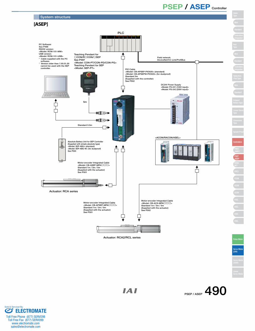
PSEP / ASEP Controller
PLC
Field networkDeviceNet/CC-Link/ProfiBus
PC SoftwareSee P499RS232 version:<Model: RCM-101-MW>USB version: <Model: RCM-101-USB>
Teaching Pendant for�CON/R�CON/�SEPSee P497<Model: CON-PT/CON-PD/CON-PG>Teaching Pendant for SEP<Model: SEP-PT>
Absolute Battery Unit for SEP Controller(Supplied with simple absolute type)<Model: SEP-ABU> (standard)<Model: SEP-ABU-W> (for dustproof)See P500
DC24V Power Supply<Model: PS-241 (100V input)><Model: PS-242 (200V input)>
PIO Cable<Model: CB-APSEP-PIO020> (standard)<Model: CB-APSEPW-PIO020> (for dustproof)Standard 2m(Supplied with the controller)See P502
Motor-encoder Integrated Cable<Model: CB-ACS-MPA���>Standard 1m / 3m / 5m(Supplied with the actuator)See P502
Motor-encoder Integrated Cable<Model: CB-APSEP-MPA���>Standard 1m / 3m / 5m(Supplied with the actuator)See P501
5m
Standard 0.5m
Motor-encoder Integrated Cable<Model: CB-ASEP-MPA���>Standard 1m / 3m / 5m(Supplied with the actuator)See P501
Actuator: RCA series
<ACON/RACON/ASEL>
Actuator: RCA2/RCL series
* Cable supplied with the PC software.* Version older than 7.00.01.00 cannot be used with the SEP controller.
System structure
[ASEP]
Mini
Mini
PSEP/ASEP
PMEC/AMEC
ROBONET
ERC2
PCON
ACON
SCON
PSEL
ASEL
SSEL
XSEL
Standard
Mini
Standard
Standard
ControllersIntegrated
ControllersIntegrated
SliderType
RodType
Table/Arm/Flat Type
Gripper/Rotary Type
Linear ServoType
Cleanroom Type
Splash-Proof
Controllers
Pulse Motor
Servo Motor (24V)
Servo Motor (200V)
LinearServo Motor
PSEP / ASEP 490ELECTROMATE
Toll Free Phone (877) SERVO98Toll Free Fax (877) SERV099
Sold & Serviced By:
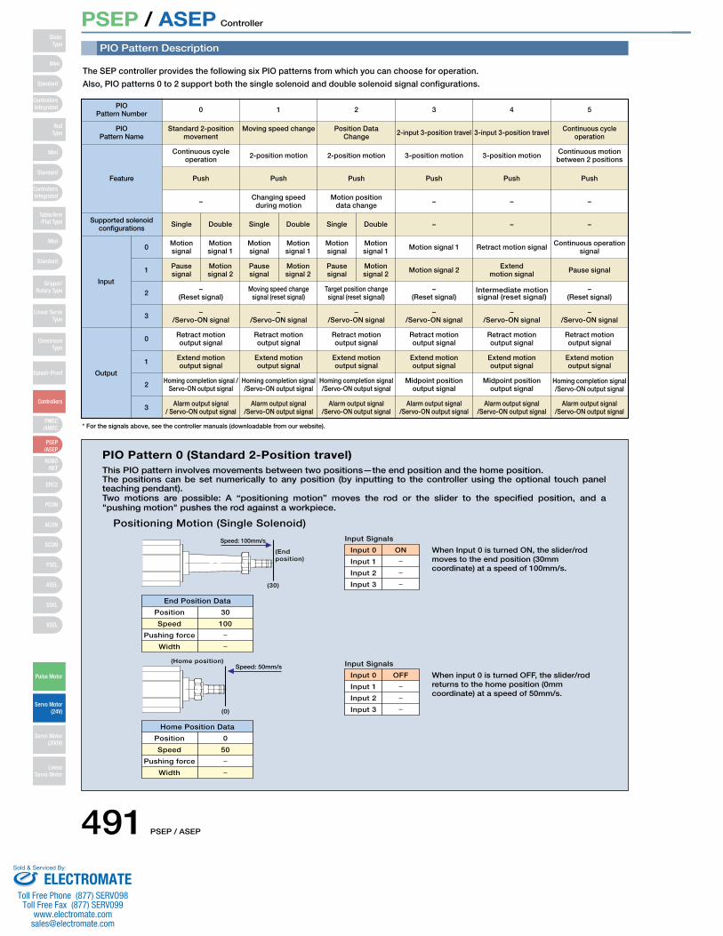
PSEP / ASEP Controller
PIO Pattern Description
PIO Pattern 0 (Standard 2-Position travel)This PIO pattern involves movements between two positions—the end position and the home position. The positions can be set numerically to any position (by inputting to the controller using the optional touch panel teaching pendant).Two motions are possible: A “positioning motion” moves the rod or the slider to the specified position, and a "pushing motion" pushes the rod against a workpiece.
Positioning Motion (Single Solenoid)
End Position Data
Position 30
Input 0
Input Signals
ON
Home Position Data
Position 0
When Input 0 is turned ON, the slider/rodmoves to the end position (30mm coordinate) at a speed of 100mm/s.
Input 0
Input Signals
OFF When input 0 is turned OFF, the slider/rodreturns to the home position (0mmcoordinate) at a speed of 50mm/s.
(End position)
(30)
(0)
(Home position)
Speed: 100mm/s
Speed: 50mm/s
Speed
Pushing force
Width
Input 1
Input 2
Input 3
100
Input 1
Input 2
Input 3
50Speed
Pushing force
Width
The SEP controller provides the following six PIO patterns from which you can choose for operation.
Also, PIO patterns 0 to 2 support both the single solenoid and double solenoid signal configurations.
PIO Pattern Number
PIO Pattern Name
Feature
Supported solenoid configurations
Input
0
1
2
3
Output
0
1
2
3
1 2 3 4 5
Single
Motion signal
Pause signal
0
Standard 2-position movement
Continuous cycle operation
Push
−
−(Reset signal)
−/Servo-ON signal
Retract motion output signal
Extend motion output signal
Homing completion signal /Servo-ON output signal
Alarm output signal/ Servo-ON output signal
Alarm output signal/Servo-ON output signal
Alarm output signal/Servo-ON output signal
Alarm output signal/Servo-ON output signal
Alarm output signal/Servo-ON output signal
Alarm output signal/Servo-ON output signal
Moving speed change signal (reset signal)
−/Servo-ON signal
Retract motion output signal
Extend motion output signal
Homing completion signal/Servo-ON output signal
Target position change signal (reset signal)
−/Servo-ON signal
Retract motion output signal
Extend motion output signal
Homing completion signal/Servo-ON output signal
−(Reset signal)
−/Servo-ON signal
Retract motion output signal
Extend motion output signal
Midpoint position output signal
Intermediate motion signal (reset signal)
−/Servo-ON signal
Retract motion output signal
Extend motion output signal
Midpoint position output signal
−(Reset signal)
−/Servo-ON signal
Retract motion output signal
Extend motion output signal
Homing completion signal/Servo-ON output signal
Double
Motion signal 1
Motion signal 2
Single
Motion signal
Pause signal
Moving speed change
2-position motion
Push
Changing speed during motion
Double
Motion signal 1
Motion signal 2
Single
Motion signal
Pause signal
Position DataChange
2-position motion
Push
Motion position data change
2-input 3-position travel
3-position motion
Push
−
Double
Motion signal 1
Motion signal 2
−
Motion signal 1
Motion signal 2
3-input 3-position travel
3-position motion
Push
−
−
Retract motion signal
Extend motion signal
Continuous cycle operation
Continuous motion between 2 positions
Push
−
−
Continuous operation signal
Pause signal
* For the signals above, see the controller manuals (downloadable from our website).
Mini
Mini
PSEP/ASEP
PMEC/AMEC
ROBONET
ERC2
PCON
ACON
SCON
PSEL
ASEL
SSEL
XSEL
Standard
Mini
Standard
Standard
ControllersIntegrated
ControllersIntegrated
RodType
Table/Arm/Flat Type
Gripper/Rotary Type
Linear ServoType
CleanroomType
Splash-Proof
Controllers
Pulse Motor
Servo Motor (24V)
Servo Motor (200V)
LinearServo Motor
SliderType
491 PSEP / ASEP
ELECTROMATEToll Free Phone (877) SERVO98
Toll Free Fax (877) SERV099www.electromate.com
Sold & Serviced By:
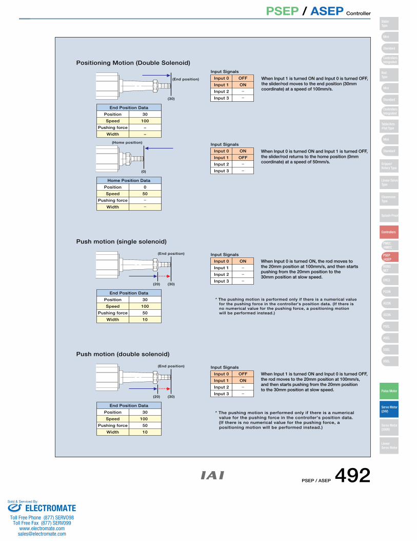
PSEP / ASEP Controller
Positioning Motion (Double Solenoid)
End Position Data
Position 30
Input 0
Input Signals
OFF
Home Position Data
Position 0
Input 0
Input Signals
ON
(End position)
(30)
Push motion (single solenoid)
End Position Data
Position 30
100
50
10
Input 0
Input Signals
ON When Input 0 is turned ON, the rod moves tothe 20mm position at 100mm/s, and then starts pushing from the 20mm position to the 30mm position at slow speed.
(End position)
(30)(20)
Push motion (double solenoid)
End Position Data
Position 30
Input 0
Input Signals
OFF When Input 1 is turned ON and Input 0 is turned OFF, the rod moves to the 20mm position at 100mm/s, and then starts pushing from the 20mm position to the 30mm position at slow speed.
(0)
(Home position)
(End position)
(30)(20)
Speed
Pushing force
Width
100
−
−
Speed
Pushing force
Width
50
Input 1
Input 2
Input 3
OFF
Speed
Pushing force
Width
Input 1
Input 2
Input 3
Input 1
Input 2
Input 3
ON
Speed
Pushing force
Width
100
50
10
ONInput 1
Input 2
Input 3
When Input 1 is turned ON and Input 0 is turned OFF, the slider/rod moves to the end position (30mm coordinate) at a speed of 100mm/s.
When Input 0 is turned ON and Input 1 is turned OFF,the slider/rod returns to the home position (0mm coordinate) at a speed of 50mm/s.
* The pushing motion is performed only if there is a numericalvalue for the pushing force in the controller's position data.(If there is no numerical value for the pushing force, apositioning motion will be performed instead.)
* The pushing motion is performed only if there is a numerical valuefor the pushing force in the controller's position data. (If there is no numerical value for the pushing force, a positioning motion will be performed instead.)
Mini
Mini
PSEP/ASEP
PMEC/AMEC
ROBONET
ERC2
PCON
ACON
SCON
PSEL
ASEL
SSEL
XSEL
Standard
Mini
Standard
Standard
ControllersIntegrated
ControllersIntegrated
SliderType
RodType
Table/Arm/Flat Type
Gripper/Rotary Type
Linear ServoType
Cleanroom Type
Splash-Proof
Controllers
Pulse Motor
Servo Motor (24V)
Servo Motor (200V)
LinearServo Motor
PSEP / ASEP 492ELECTROMATE
Toll Free Phone (877) SERVO98Toll Free Fax (877) SERV099
Sold & Serviced By:
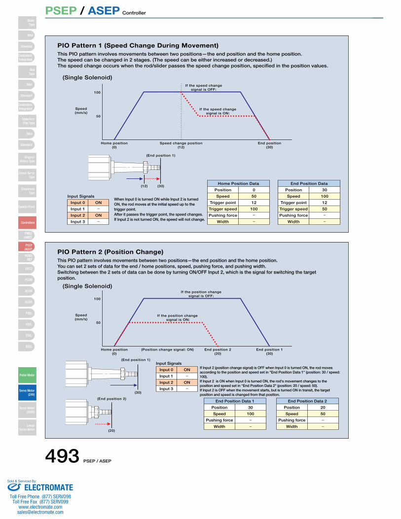
PSEP / ASEP Controller
PIO Pattern 1 (Speed Change During Movement)This PIO pattern involves movements between two positions—the end position and the home position. The speed can be changed in 2 stages. (The speed can be either increased or decreased.)The speed change occurs when the rod/slider passes the speed change position, specified in the position values.
(Single Solenoid)
Input 0
Input Signals
ON
Home Position Data
Position 0
End Position Data
Position 30
(End position 1)
Home position(0)
End position(30)
50
100
Speed(mm/s)
Speed change position(12)
If the speed changesignal is OFF:
If the speed changesignal is ON:
(30)(12)
Input 1
Input 2
Input 3
ON
Speed
Trigger point
Trigger speed
Pushing force
Width
50
12
100
Speed
Trigger point
Trigger speed
Pushing force
Width
100
12
50
When Input 0 is turned ON while Input 2 is turned ON, the rod moves at the initial speed up to the trigger point.After it passes the trigger point, the speed changes. If Input 2 is not turned ON, the speed will not change.
PIO Pattern 2 (Position Change)This PIO pattern involves movements between two positions—the end position and the home position. You can set 2 sets of data for the end / home positions, speed, pushing force, and pushing width. Switching between the 2 sets of data can be done by turning ON/OFF Input 2, which is the signal for switching the target position.
(Single Solenoid)
Input 0
Input Signals
ON
End Position Data 1
Position 30
End Position Data 2
Position 20
(End position 1)
Home position(0)
End position 1(30)
End position 2(20)
50
100
Speed(mm/s)
(Position change signal: ON)
(End position 2)
(30)
(20)
If Input 2 (position change signal) is OFF when Input 0 is turned ON, the rod moves according to the position and speed set in "End Position Data 1" (position: 30 / speed: 100). If Input 2 is ON when Input 0 is turned ON, the rod's movement changes to the position and speed set in “End Position Data 2" (position: 20 / speed: 50). If Input 2 is OFF when the movement starts, but is turned ON in transit, the target position and speed is changed from that position.
If the position change signal is OFF:
If the position change signal is ON:
Input 1
Input 2
Input 3
ON
Speed
Pushing force
Width
100 Speed
Pushing force
Width
50
Mini
Mini
PSEP/ASEP
PMEC/AMEC
ROBONET
ERC2
PCON
ACON
SCON
PSEL
ASEL
SSEL
XSEL
Standard
Mini
Standard
Standard
ControllersIntegrated
ControllersIntegrated
RodType
Table/Arm/Flat Type
Gripper/Rotary Type
Linear ServoType
CleanroomType
Splash-Proof
Controllers
Pulse Motor
Servo Motor (24V)
Servo Motor (200V)
LinearServo Motor
SliderType
493 PSEP / ASEP
ELECTROMATEToll Free Phone (877) SERVO98
Toll Free Fax (877) SERV099www.electromate.com
Sold & Serviced By:
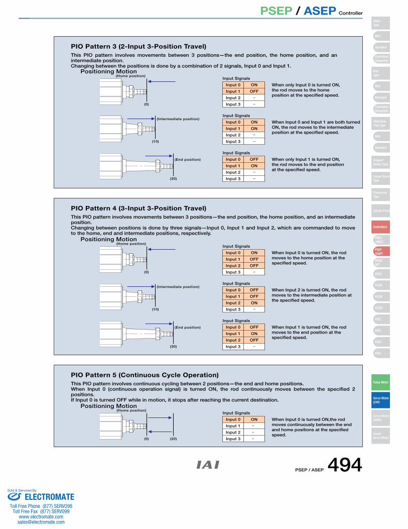
PSEP / ASEP Controller
(20)
Input 0
Input Signals
ON
(0)
(Home position)
PIO Pattern 5 (Continuous Cycle Operation) This PIO pattern involves continuous cycling between 2 positions—the end and home positions. When Input 0 (continuous operation signal) is turned ON, the rod continuously moves between the specified 2 positions. If Input 0 is turned OFF while in motion, it stops after reaching the current destination.
Positioning Motion
Input 1
Input 2
Input 3
When Input 0 is turned ON,the rod moves continuously between the end and home positions at the specified speed.
Input 0
Input Signals
ON When Input 0 is turned ON, the rod moves to the home position at the specified speed.
Input 0
Input Signals
OFF When Input 2 is turned ON, the rod moves to the intermediate position at the specified speed.
Input 0
Input Signals
OFF When Input 1 is turned ON, the rod moves to the end position at the specified speed.
(End position)
(Intermediate position)
(30)
(0)
(Home position)
(10)
PIO Pattern 4 (3-Input 3-Position Travel) This PIO pattern involves movements between 3 positions—the end position, the home position, and an intermediate position. Changing between positions is done by three signals—Input 0, Input 1 and Input 2, which are commanded to move to the home, end and intermediate positions, respectively.
Positioning Motion
Input 1
Input 2
Input 3
Input 1
Input 2
Input 3
Input 1
Input 2
Input 3
OFF
OFF
OFF
ON
ON
OFF
Input 0
Input Signals
ON When only Input 0 is turned ON,the rod moves to the home position at the specified speed.
Input 0
Input Signals
ON When Input 0 and Input 1 are both turned ON, the rod moves to the intermediate position at the specified speed.
Input 0
Input Signals
OFF When only Input 1 is turned ON, the rod moves to the end positionat the specified speed.
(End position)
(Intermediate position)
(30)
(0)
(Home position)
(10)
PIO Pattern 3 (2-Input 3-Position Travel)This PIO pattern involves movements between 3 positions—the end position, the home position, and an intermediate position. Changing between the positions is done by a combination of 2 signals, Input 0 and Input 1.
Positioning Motion
Input 1
Input 2
Input 3
Input 1
Input 2
Input 3
Input 1
Input 2
Input 3
OFF
ON
ON
Mini
Mini
PSEP/ASEP
PMEC/AMEC
ROBONET
ERC2
PCON
ACON
SCON
PSEL
ASEL
SSEL
XSEL
Standard
Mini
Standard
Standard
ControllersIntegrated
ControllersIntegrated
SliderType
RodType
Table/Arm/Flat Type
Gripper/Rotary Type
Linear ServoType
Cleanroom Type
Splash-Proof
Controllers
Pulse Motor
Servo Motor (24V)
Servo Motor (200V)
LinearServo Motor
PSEP / ASEP 494ELECTROMATE
Toll Free Phone (877) SERVO98Toll Free Fax (877) SERV099
Sold & Serviced By:
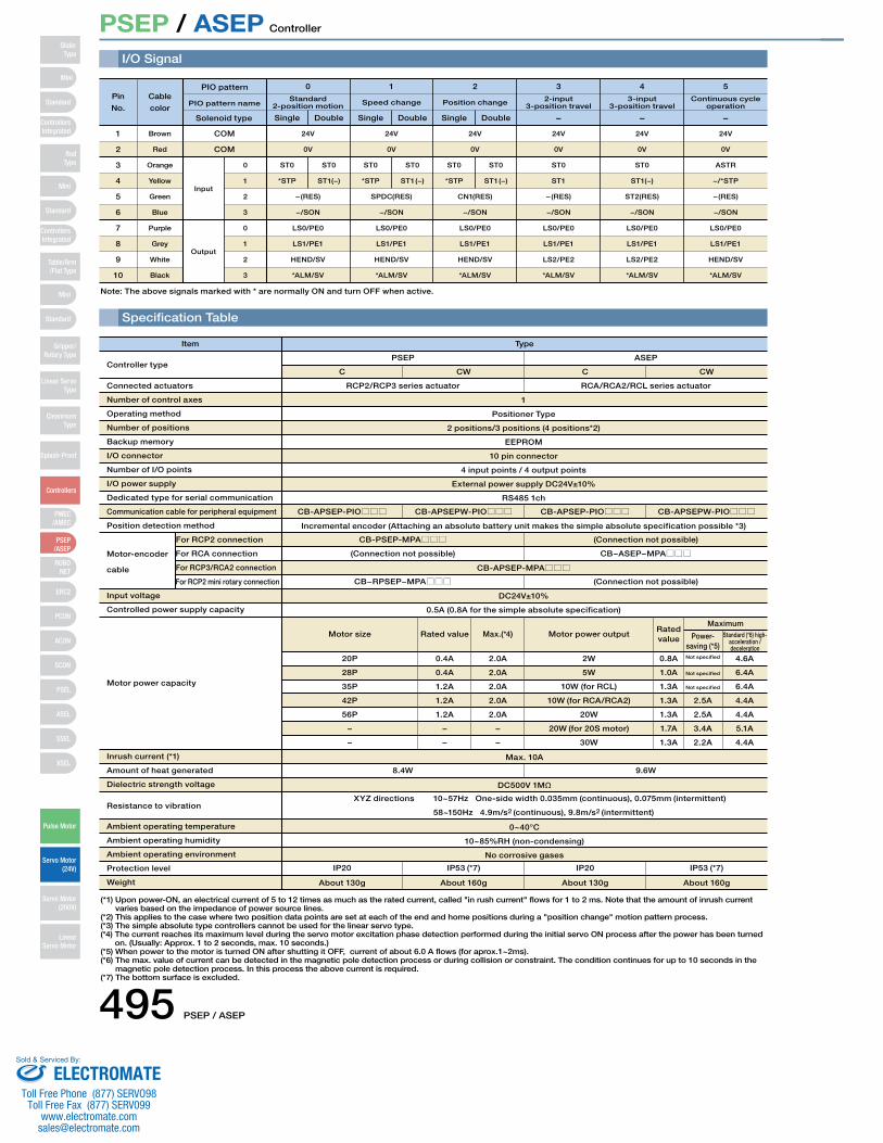
PSEP / ASEP Controller
I/O Signal
Specification Table
PIO pattern name
COM
COM
24V
0V
24V
0V
24V
0V
24V
0V
24V
0V
24V
0V
0
Standard 2-position motion
SingleSolenoid type Double Single Double Single Double − − −
Speed change Position change 2-input 3-position travel
3-input 3-position travel
Continuous cycleoperation
1 2 3 4 5Pin
No.
Cable
color
− (RES)
−/SON
LS0/PE0
LS1/PE1
HEND/SV
*ALM/SV
− (RES)
−/SON
LS0/PE0
LS1/PE1
HEND/SV
*ALM/SV
SPDC(RES)
−/SON
LS0/PE0
LS1/PE1
HEND/SV
*ALM/SV
CN1(RES)
−/SON
LS0/PE0
LS1/PE1
HEND/SV
*ALM/SV
− (RES)
−/SON
LS0/PE0
LS1/PE1
LS2/PE2
*ALM/SV
ST2(RES)
−/SON
LS0/PE0
LS1/PE1
LS2/PE2
*ALM/SV
ST0
*STP
ST0
ST1(−)
ST0
*STP
ST0
ST1 (−)
ST0
*STP
ST0
ST1 (−)
ST0
ST1
ST0
ST1(−)
ASTR
−/*STP
Output
1
2
3
4
5
6
7
8
9
10
0
1
2
3
0
1
2
3
Brown
Red
Orange
Yellow
Green
Blue
Purple
Grey
White
Black
Input
Note: The above signals marked with * are normally ON and turn OFF when active.
Type
PSEPController type
Connected actuators
Number of control axes
Operating method
Number of positions
Backup memory
I/O connector
Number of I/O points
I/O power supply
Dedicated type for serial communication
Communication cable for peripheral equipment
Position detection method
Input voltage
Controlled power supply capacity
Motor power capacity
Inrush current (*1)
Amount of heat generated
Dielectric strength voltage
Resistance to vibration
Ambient operating temperature
Ambient operating humidity
Ambient operating environment
Protection level
Weight
Motor-encoder
cable
For RCP2 connection
For RCA connection
For RCP3/RCA2 connection
For RCP2 mini rotary connection
RCP2/RCP3 series actuator
CB-PSEP-MPA□□□
(Connection not possible)
CB−RPSEP−MPA□□□
20P
28P
35P
42P
56P
−
−
Motor size
8.4W 9.6W
0.4A
0.4A
1.2A
1.2A
1.2A
−
−
Rated value
2.0A
2.0A
2.0A
2.0A
2.0A
−
−
Max.(*4)
2W
5W
10W (for RCL)
10W (for RCA/RCA2)
20W
20W (for 20S motor)
30W
Motor power output
0.8A
1.0A
1.3A
1.3A
1.3A
1.7A
1.3A
Rated value
Not specified
Not specified
Not specified
2.5A
2.5A
3.4A
2.2A
4.6A
6.4A
6.4A
4.4A
4.4A
5.1A
4.4A
Maximum
Power-saving (*5)
Standard (*6) high-acceleration /deceleration
(Connection not possible)
CB−ASEP−MPA□□□
(Connection not possible)
CB-APSEP-PIO□□□
IP20
About 130g
IP53 (*7)
About 160g
IP20
About 130g
IP53 (*7)
About 160g
XYZ directions 10~57Hz One-side width 0.035mm (continuous), 0.075mm (intermittent)
58~150Hz 4.9m/s2 (continuous), 9.8m/s2 (intermittent)
CB-APSEPW-PIO□□□ CB-APSEP-PIO□□□ CB-APSEPW-PIO□□□
Max. 10A
DC500V 1MΩ
0~40°C
10~85%RH (non-condensing)
No corrosive gases
RCA/RCA2/RCL series actuator
C CW C CW
ASEP
Item
(*1) Upon power-ON, an electrical current of 5 to 12 times as much as the rated current, called "in rush current" flows for 1 to 2 ms. Note that the amount of inrush current varies based on the impedance of power source lines.
(*2) This applies to the case where two position data points are set at each of the end and home positions during a "position change" motion pattern process.(*3) The simple absolute type controllers cannot be used for the linear servo type.(*4) The current reaches its maximum level during the servo motor excitation phase detection performed during the initial servo ON process after the power has been turned
on. (Usually: Approx. 1 to 2 seconds, max. 10 seconds.) (*5) When power to the motor is turned ON after shutting it OFF, current of about 6.0 A flows (for aprox.1~2ms).(*6) The max. value of current can be detected in the magnetic pole detection process or during collision or constraint. The condition continues for up to 10 seconds in the
magnetic pole detection process. In this process the above current is required.(*7) The bottom surface is excluded.
1
Positioner Type
2 positions/3 positions (4 positions*2)
EEPROM
10 pin connector
4 input points / 4 output points
External power supply DC24V±10%
RS485 1ch
Incremental encoder (Attaching an absolute battery unit makes the simple absolute specification possible *3)
CB-APSEP-MPA□□□
DC24V±10%
0.5A (0.8A for the simple absolute specification)
PIO pattern
Mini
Mini
PSEP/ASEP
PMEC/AMEC
ROBONET
ERC2
PCON
ACON
SCON
PSEL
ASEL
SSEL
XSEL
Standard
Mini
Standard
Standard
ControllersIntegrated
ControllersIntegrated
RodType
Table/Arm/Flat Type
Gripper/Rotary Type
Linear ServoType
CleanroomType
Splash-Proof
Controllers
Pulse Motor
Servo Motor (24V)
Servo Motor (200V)
LinearServo Motor
SliderType
495 PSEP / ASEP
ELECTROMATEToll Free Phone (877) SERVO98
Toll Free Fax (877) SERV099www.electromate.com
Sold & Serviced By:
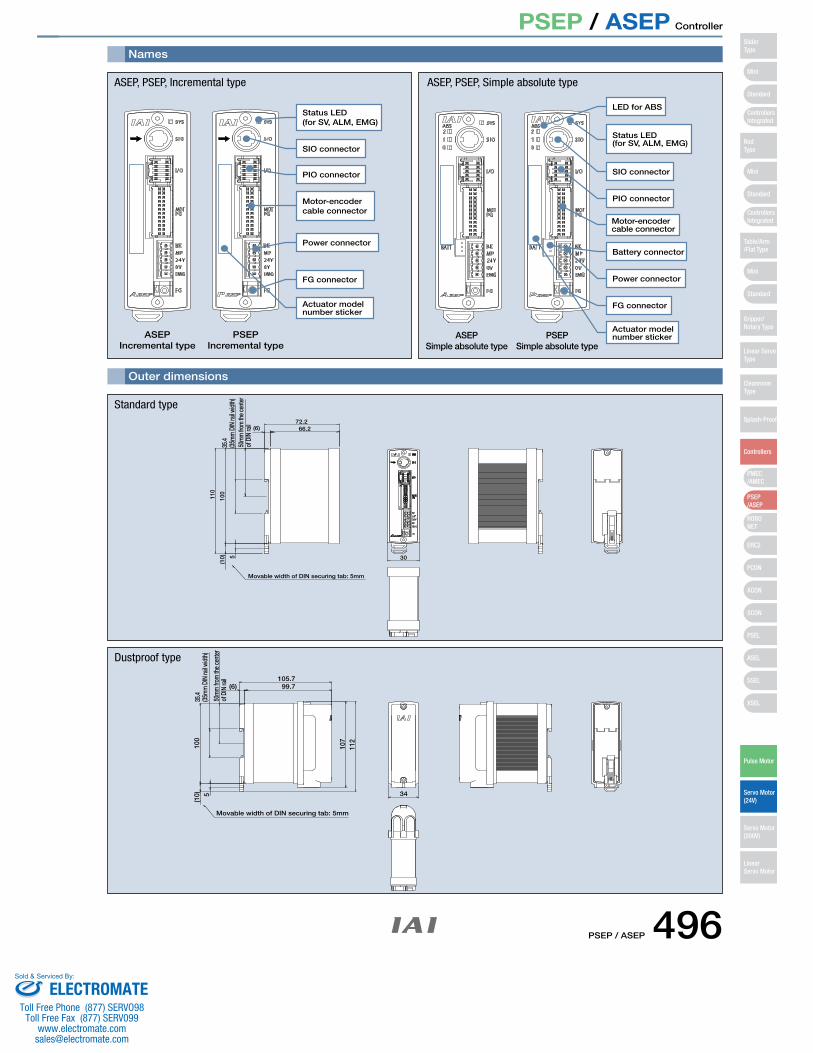
PSEP / ASEP Controller
ASEPIncremental type
PSEPIncremental type
Status LED(for SV, ALM, EMG)
Motor-encodercable connector
SIO connector
PIO connector
Power connector
FG connector
Actuator model number sticker
(6) 66.2
30
Movable width of DIN securing tab: 5mm
72.2
110
100
(10) 5
35.4
(35m
m D
IN ra
il wid
th)
50m
m fr
om th
e cen
ter
of D
IN ra
il
100
107
112
(10) 5
Movable width of DIN securing tab: 5mm
34
(6) 99.7105.7
35.4
(35m
m D
IN ra
il wid
th)
50m
m fr
om th
e cen
ter
of D
IN ra
il
ASEP, PSEP, Incremental type
Status LED(for SV, ALM, EMG)
SIO connector
PIO connector
LED for ABS
Motor-encoder cable connector
Battery connector
Power connector
FG connector
Actuator model number stickerASEP
Simple absolute typePSEP
Simple absolute type
ASEP, PSEP, Simple absolute type
Standard type
Dustproof type
Names
Outer dimensions
Mini
Mini
PSEP/ASEP
PMEC/AMEC
ROBONET
ERC2
PCON
ACON
SCON
PSEL
ASEL
SSEL
XSEL
Standard
Mini
Standard
Standard
ControllersIntegrated
ControllersIntegrated
SliderType
RodType
Table/Arm/Flat Type
Gripper/Rotary Type
Linear ServoType
Cleanroom Type
Splash-Proof
Controllers
Pulse Motor
Servo Motor (24V)
Servo Motor (200V)
LinearServo Motor
PSEP / ASEP 496ELECTROMATE
Toll Free Phone (877) SERVO98Toll Free Fax (877) SERV099
Sold & Serviced By:
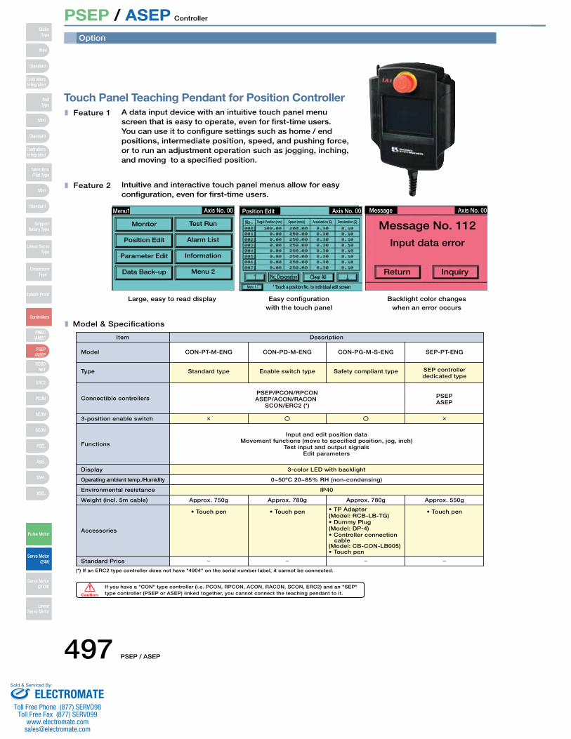
PSEP / ASEP Controller
Touch Panel Teaching Pendant for Position ControllerA data input device with an intuitive touch panel menu screen that is easy to operate, even for first-time users. You can use it to configure settings such as home / end positions, intermediate position, speed, and pushing force, or to run an adjustment operation such as jogging, inching, and moving to a specified position.
Feature 1
Feature 2 Intuitive and interactive touch panel menus allow for easy configuration, even for first-time users.
Large, easy to read display Easy configurationwith the touch panel
Backlight color changeswhen an error occurs
Axis No. 00
Monitor
Position Edit
Parameter Edit
Data Back-up
Test Run
Alarm List
Information
Menu 2
Menu1 Position Edit Axis No. 00
Target Position (mm)
Menu 1
Speed (mm/s) Acceleration (G) Deceleration (G)
No. Designation Clear All
* Touch a position No. to individual edit screen
Axis No. 00Message
Message No. 112
Input data error
InquiryReturn
Model & Specifications
Item
Standard type
3-color LED with backlight
Approx. 750g Approx. 780g Approx. 780g Approx. 550g
PSEP/PCON/RPCON
Input and edit position data
PSEP
• Touch pen • TP Adapter(Model: RCB-LB-TG)
• Touch pen• Touch pen
Enable switch type Safety compliant type SEP controllerdedicated type
Model
(*) If an ERC2 type controller does not have "4904" on the serial number label, it cannot be connected.
Type
Connectible controllers
3-position enable switch
Functions
Display
Operating ambient temp./Humidity
Environmental resistance
Weight (incl. 5m cable)
Accessories
Standard Price
Description
If you have a "CON" type controller (i.e. PCON, RPCON, ACON, RACON, SCON, ERC2) and an "SEP" type controller (PSEP or ASEP) linked together, you cannot connect the teaching pendant to it.
CON-PT-M-ENG CON-PD-M-ENG CON-PG-M-S-ENG SEP-PT-ENG
ASEP/ACON/RACONSCON/ERC2 (*) ASEP
Movement functions (move to specified position, jog, inch)Test input and output signals
Edit parameters
0~50ºC 20~85% RH (non-condensing)
IP40
• Dummy Plug(Model: DP-4)• Controller connection cable(Model: CB-CON-LB005)• Touch pen
Caution:
Option
Mini
Mini
PSEP/ASEP
PMEC/AMEC
ROBONET
ERC2
PCON
ACON
SCON
PSEL
ASEL
SSEL
XSEL
Standard
Mini
Standard
Standard
ControllersIntegrated
ControllersIntegrated
RodType
Table/Arm/Flat Type
Gripper/Rotary Type
Linear ServoType
Cleanroom Type
Splash-Proof
Controllers
Pulse Motor
Servo Motor (24V)
Servo Motor (200V)
LinearServo Motor
SliderType
497 PSEP / ASEP
ELECTROMATEToll Free Phone (877) SERVO98
Toll Free Fax (877) SERV099www.electromate.com
Sold & Serviced By:
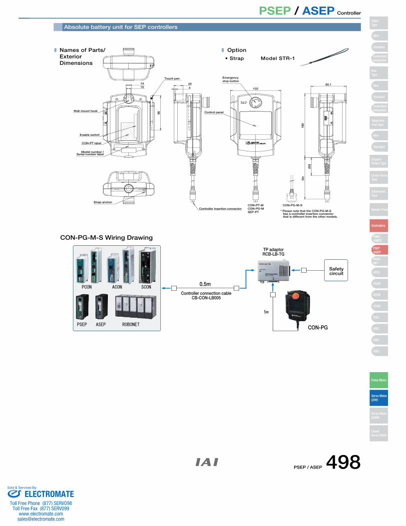
PSEP / ASEP Controller
Names of Parts/Exterior Dimensions
Strap anchor
424
Emergency stop button
Control panel
13292.1
180
(50)
5m
Option
• Strap Model STR-1
Wall mount hook
Enable switch
CON-PT label
Model number / Serial number label
98
Touch pen
1410
Controller insertion connectorCON-PT-M CON-PG-M-S
* Please note that the CON-PG-M-S has a controller insertion connector that is different from the other models.
CON-PD-MSEP-PT
ACONPCON
ROBONETPSEP ASEP
SCON
5m
Absolute battery unit for SEP controllers
CON-PG-M-S Wiring Drawing
Controller connection cableCB-CON-LB005
0.5m
CON-PG
TP adaptorRCB-LB-TG
Safety circuit
Mini
Mini
PSEP/ASEP
PMEC/AMEC
ROBONET
ERC2
PCON
ACON
SCON
PSEL
ASEL
SSEL
XSEL
Standard
Mini
Standard
Standard
ControllersIntegrated
ControllersIntegrated
SliderType
RodType
Table/Arm/Flat Type
Gripper/Rotary Type
Linear ServoType
Cleanroom Type
Splash-Proof
Controllers
Pulse Motor
Servo Motor (24V)
Servo Motor (200V)
LinearServo Motor
PSEP / ASEP 498ELECTROMATE
Toll Free Phone (877) SERVO98Toll Free Fax (877) SERV099
Sold & Serviced By:
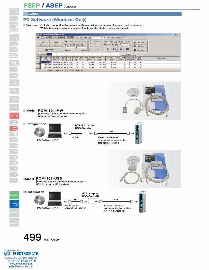
PSEP / ASEP Controller
PC Software (Windows Only)Features A startup support software for inputting positions, performing test runs, and monitoring.
With enhancements for adjustment functions, the startup time is shortened.
Model
Configuration
(External device communication cable + RS232 conversion unit)
RCM-101-MW
0.3m
5m
External device communication cableCB-RCA-SIO050
PC Software (CD)
RS232 adapterRCB-CV-MW
Model
Configuration
RCM-101-USB(External device communication cable +USB adapter + USB cable)
5m3m
PC Software (CD)External device communication cableCB-RCA-SIO050
USB cableCB-SEL-USB030
USB adapterRCB-CV-USB
Option
Mini
Mini
PSEP/ASEP
PMEC/AMEC
ROBONET
ERC2
PCON
ACON
SCON
PSEL
ASEL
SSEL
XSEL
Standard
Mini
Standard
Standard
ControllersIntegrated
ControllersIntegrated
RodType
Table/Arm/Flat Type
Gripper/Rotary Type
Linear ServoType
Cleanroom Type
Splash-Proof
Controllers
Pulse Motor
Servo Motor (24V)
Servo Motor (200V)
LinearServo Motor
SliderType
499 PSEP / ASEP
ELECTROMATEToll Free Phone (877) SERVO98
Toll Free Fax (877) SERV099www.electromate.com
Sold & Serviced By:
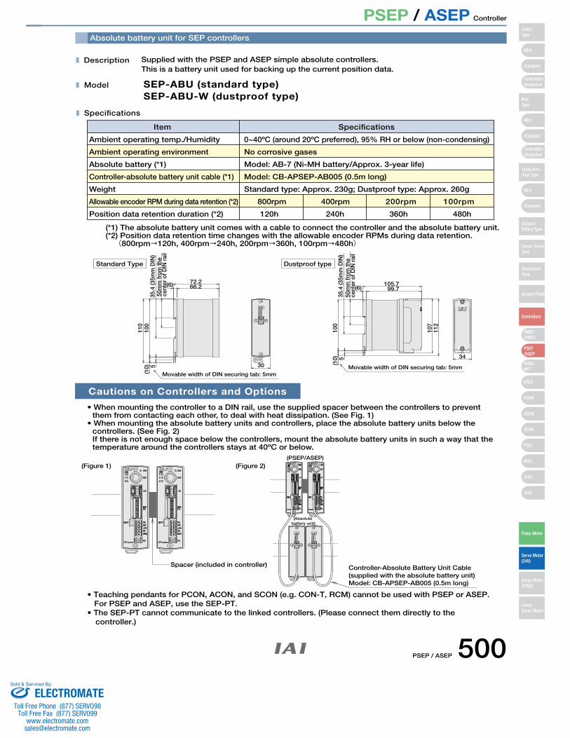
PSEP / ASEP Controller
Description Supplied with the PSEP and ASEP simple absolute controllers. This is a battery unit used for backing up the current position data.
Model SEP-ABU (standard type)SEP-ABU-W (dustproof type)
Specifications
Ambient operating temp./Humidity 0~40ºC (around 20ºC preferred), 95% RH or below (non-condensing)
Item Specifications
Cautions on Controllers and Options
• When mounting the controller to a DIN rail, use the supplied spacer between the controllers to prevent them from contacting each other, to deal with heat dissipation. (See Fig. 1)
• When mounting the absolute battery units and controllers, place the absolute battery units below the controllers. (See Fig. 2)If there is not enough space below the controllers, mount the absolute battery units in such a way that the temperature around the controllers stays at 40ºC or below.
(*1) The absolute battery unit comes with a cable to connect the controller and the absolute battery unit. (*2) Position data retention time changes with the allowable encoder RPMs during data retention.
(800rpm�120h, 400rpm�240h, 200rpm�360h, 100rpm�480h)
• Teaching pendants for PCON, ACON, and SCON (e.g. CON-T, RCM) cannot be used with PSEP or ASEP.
Spacer (included in controller)
(PSEP/ASEP)
(Absolute battery unit)
Controller-Absolute Battery Unit Cable(supplied with the absolute battery unit)Model: CB-APSEP-AB005 (0.5m long)
Movable width of DIN securing tab: 5mm
Standard Type Dustproof type
50m
m fr
om th
e ce
nter
of D
IN ra
il
35.4
(35m
m D
IN)
72.266.2(6)
110
100
(10) 5 30 Movable width of DIN securing tab: 5mm
35.4
(35m
m D
IN)
50m
m fr
om th
e ce
nter
of D
IN ra
il
(6)105.7
99.7
107
112
100
(10) 5 34
(Figure 1) (Figure 2)
Ambient operating environment
Absolute battery (*1)
Controller-absolute battery unit cable (*1)
Weight
Allowable encoder RPM during data retention (*2)
Position data retention duration (*2)
No corrosive gases
Model: AB-7 (Ni-MH battery/Approx. 3-year life)
Model: CB-APSEP-AB005 (0.5m long)
Standard type: Approx. 230g; Dustproof type: Approx. 260g
100rpm200rpm 400rpm800rpm
120h 240h 360h 480h
For PSEP and ASEP, use the SEP-PT.• The SEP-PT cannot communicate to the linked controllers. (Please connect them directly to the
controller.)
Absolute battery unit for SEP controllers
Mini
Mini
PSEP/ASEP
PMEC/AMEC
ROBONET
ERC2
PCON
ACON
SCON
PSEL
ASEL
SSEL
XSEL
Standard
Mini
Standard
Standard
ControllersIntegrated
ControllersIntegrated
SliderType
RodType
Table/Arm/Flat Type
Gripper/Rotary Type
Linear ServoType
Cleanroom Type
Splash-Proof
Controllers
Pulse Motor
Servo Motor (24V)
Servo Motor (200V)
LinearServo Motor
PSEP / ASEP 500ELECTROMATE
Toll Free Phone (877) SERVO98Toll Free Fax (877) SERV099
Sold & Serviced By:
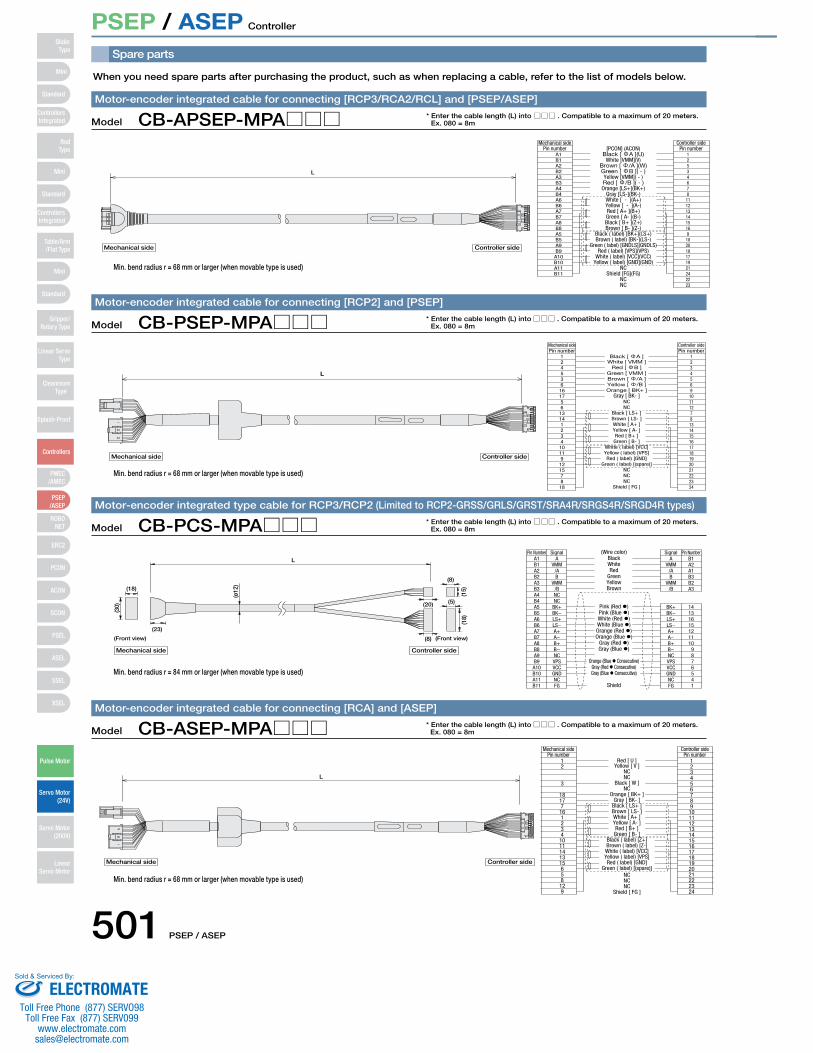
501 PSEP / ASEP
PSEP / ASEP Controller
Spare parts
When you need spare parts after purchasing the product, such as when replacing a cable, refer to the list of models below.
Controller sideMechanical side
Controller sideMechanical side
Red [ U ]
L
Pin number12
3
181771612341011141315658129
Yellow [ V ]NCNC
Black [ W ]NC
Orange [ BK+ ]Gray [ BK- ]
Black [ LS+ ]Brown [ LS- ]White [ A+ ]Yellow [ A- ]Red [ B+ ]
Green [ B- ]Black ( label) [Z+]Brown ( label) [Z-]White ( label) [VCC]Yellow ( label) [VPS]Red ( label) [GND]
Green ( label) [(spare)]NCNCNC
Shield [ FG ]
Pin number123456789101112131415161718192021222324
Model CB-ASEP-MPA□□□Motor-encoder integrated cable for connecting [RCA] and [ASEP]
Controller sideMechanical side
L
Black [ A ]Pin number
124536161756131412341011912157818
White [ VMM ]Red [ B ]
Green [ VMM ]Brown [ /A ]Yellow [ /B ]Orange [ BK+ ]
Gray [ BK- ]NCNC
Black [ LS+ ]Brown [ LS- ]White [ A+ ]Yellow [ A- ]Red [ B+ ]
Green [ B- ]White ( label) [VCC]Yellow ( label) [VPS]Red ( label) [GND]
Green ( label) [(spare)]NCNCNC
Shield [ FG ]
Pin number123456910111278131415161718192021222324
Controller sideMechanical side
Model CB-PSEP-MPA□□□Motor-encoder integrated cable for connecting [RCP2] and [PSEP]
Controller sideMechanical side[PCON] (ACON)
L
Pin numberA1B1A2B2A3B3A4B4A6B6A7B7A8B8A5B5A9B9A10B10A11B11
Black [ A ](U)White [VMM](V)
Brown [ /A ](W)Green [ B ]( - )Yellow [VMM]( - )Red [ /B ]( - )Orange [LS+](BK+)
Gray [LS-](BK-)White [ - ](A+)Yellow [ - ](A-)Red [ A+ ](B+)Green [ A- ](B-)Black [ B+ ](Z+)Brown [ B- ](Z-)
Black ( label) [BK+](LS+)Brown ( label) [BK-](LS-)
Green ( label) [GNDLS](GNDLS)Red ( label) [VPS](VPS)
White ( label) [VCC](VCC)Yellow ( label) [GND](GND)
NCShield [FG](FG)
NCNC
Pin number125346781112131415169102018171921242223
Controller sideMechanical side
Model CB-APSEP-MPA□□□Motor-encoder integrated cable for connecting [RCP3/RCA2/RCL] and [PSEP/ASEP]
* Enter the cable length (L) into □□□ . Compatible to a maximum of 20 meters.Ex. 080 = 8m
* Enter the cable length (L) into □□□ . Compatible to a maximum of 20 meters.Ex. 080 = 8m
L
(15)
(ø12
)
BlackA1 A
(18)
(8)
(20)
(8)
(5)
(30)
(18)
(23)
(Wire color)Pin Number SignalA B1
BK+ 14
Signal Pin Number
Controller sideMechanical side
(Front view)(Front view)
B1A2B2A3B3A4B4A5B5A6B6A7B7A8B8A9B9A10B10A11B11
VMM/AB
VMM/BNCNC
BK+BK−LS+LS−A+A−B+B−NCVPSVCCGNDNCFG
WhiteRed
GreenYellowBrown
Pink (Red �)Pink (Blue �)White (Red �)White (Blue �)Orange (Red �)Orange (Blue �)
Gray (Red �)Gray (Blue �)
Orange (Blue � Consecutive)Gray (Red � Consecutive)Gray (Blue � Consecutive)
Shield
VMM/AB
VMM/B
A2A1B3B2A3
131615121110
9876541
BK−LS+LS−A+A−B+B−NCVPSVCCGNDNCFG
Model CB-PCS-MPA□□□Motor-encoder integrated type cable for RCP3/RCP2 (Limited to RCP2-GRSS/GRLS/GRST/SRA4R/SRGS4R/SRGD4R types)
* Enter the cable length (L) into □□□ . Compatible to a maximum of 20 meters.Ex. 080 = 8m
* Enter the cable length (L) into □□□ . Compatible to a maximum of 20 meters.Ex. 080 = 8m
Min. bend radius r = 68 mm or larger (when movable type is used)
Min. bend radius r = 68 mm or larger (when movable type is used)
Min. bend radius r = 68 mm or larger (when movable type is used)
Min. bend radius r = 84 mm or larger (when movable type is used)
Mini
Mini
PSEP/ASEP
PMEC/AMEC
ROBONET
ERC2
PCON
ACON
SCON
PSEL
ASEL
SSEL
XSEL
Standard
Mini
Standard
Standard
ControllersIntegrated
ControllersIntegrated
RodType
Table/Arm/Flat Type
Gripper/Rotary Type
Linear ServoType
Cleanroom Type
Splash-Proof
Controllers
Pulse Motor
Servo Motor (24V)
Servo Motor (200V)
LinearServo Motor
SliderType
ELECTROMATEToll Free Phone (877) SERVO98
Toll Free Fax (877) SERV099www.electromate.com
Sold & Serviced By:
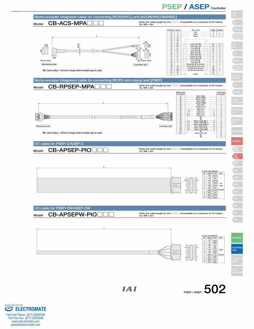
PSEP / ASEP 502
PSEP / ASEP Controller
L
Controller sideMechanical side
Black [ ØA ]
Mechanical side Controller side
Pin numberA1B1A2B2A3B3A6B6A7B7A8B8A4B4A5B5A9B9A10B10A11B11
White [ VMM ]Brown [ Ø/A ]Green [ ØB ]
Yellow [ VMM ]Red [ Ø/B ]
Orange [ LS+ ]Gray [ LS- ]Red [ A+ ]
Green [ A- ]Black [ B+ ]Brown [ B- ]
NCNC
Black ( label) [BK+]Brown ( label) [BK-]
Green ( label) [GNDLS]Red ( label) [VPS]
White ( label) [VCC]Yellow ( label) [GND]
NCShield [ FG ] (FG)
NCNC
Pin number1253467813141516789102018171921242223
Model CB-RPSEP-MPA□□□Motor-encoder integrated cable for connecting [RCP2 mini rotary] and [PSEP]
2
10 9
1
OUT3OUT2OUT1OUT07
1098
65432
51353-1000 (MOLEX)Signal Color Wire
24VBrown-White
RedRed-White
Brown
Cable
No.
1
YellowYellow-White
GreenGreen-White
BlackBlack-White
(crimped)
0VIN0IN1IN2IN3
L
Model CB-APSEPW-PIO□□□I/O cable for PSEP-CW/ASEP-CW
2
10 9
1
OUT3OUT2OUT1OUT07
1098
65432
51353-1000 (MOLEX)Signal Color Wire24V
RedOrangeYellow
BrownNo.1
GreenBlue
PurpleGrayWhiteBlack
(crimped)
0VIN0IN1IN2IN3
L
Flatcable
Model CB-APSEP-PIO□□□I/O cable for PSEP-C/ASEP-C
* Enter the cable length (L) into □□□ . Compatible to a maximum of 20 meters.Ex. 080 = 8m
* Enter the cable length (L) into □□□ . Compatible to a maximum of 10 meters.Ex. 080 = 8m
* Enter the cable length (L) into □□□ . Compatible to a maximum of 10 meters.Ex. 080 = 8m
L
URed(Wire color)
1A1 U
Signal Pin NumberPin Number Signal
BK+ 16
(10)
(ø12
)
(18)
(8)
(12)
(23)
(8)
(5)
(30)
(18)
Controller sideMechanical side
(Front view)(Front view)
B1A2B2A3B3A4B4A5B5A6B6A7B7A8B8A9B9A10B10A11B11
VWNCNCNC
BK+BK−LS+LS−A+A−B+B−Z+Z−−
/PSVCCGNDNCFG
YellowBlack
Yellow (Red �)Yellow (Blue �)
Pink (Red �)Pink (Blue �)White (Red �)White (Blue �)Orange (Red �)Orange (Blue �)
Gray (Red �)Gray (Blue �)
Orange (Red � Consecutive)Orange (Blue � Consecutive)
Gray (Red � Consecutive)Gray (Blue � Consecutive)
Shield
BK−LS+LS−A+A−B+B−Z+Z−−
/PSVCCGNDNCFG
151817141312111098765
1
23
VW
Model CB-ACS-MPA□□□Motor-encoder integrated cable for connecting [RCA2/RCL] and [ACON/RACON/ASEL]
* Enter the cable length (L) into □□□ . Compatible to a maximum of 20 meters.Ex. 080 = 8m
Min. bend radius r = 68 mm or larger (when movable type is used)
Min. bend radius r = 84 mm or larger (when movable type is used)
Mini
Mini
PSEP/ASEP
PMEC/AMEC
ROBONET
ERC2
PCON
ACON
SCON
PSEL
ASEL
SSEL
XSEL
Standard
Mini
Standard
Standard
ControllersIntegrated
ControllersIntegrated
SliderType
RodType
Table/Arm/Flat Type
Gripper/Rotary Type
Linear ServoType
CleanroomType
Splash-Proof
Controllers
Pulse Motor
Servo Motor (24V)
Servo Motor (200V)
LinearServo Motor
ELECTROMATEToll Free Phone (877) SERVO98
Toll Free Fax (877) SERV099www.electromate.com
Sold & Serviced By:
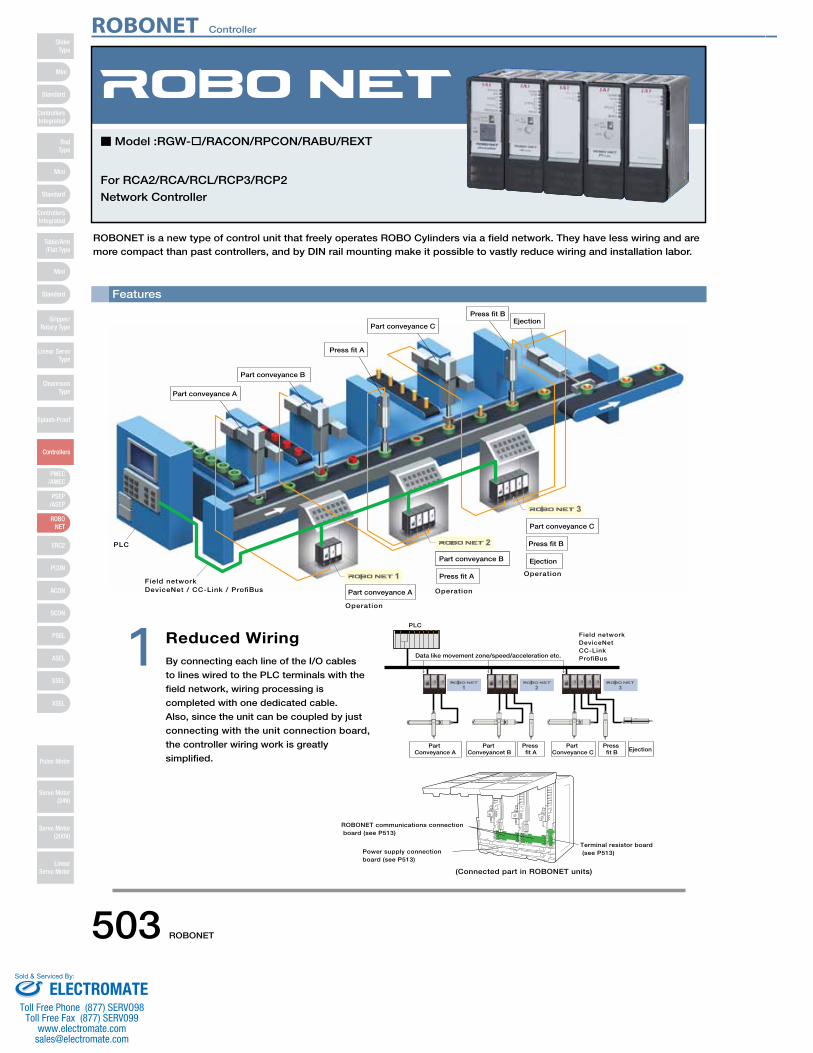
Features
ROBONET is a new type of control unit that freely operates ROBO Cylinders via a field network. They have less wiring and are more compact than past controllers, and by DIN rail mounting make it possible to vastly reduce wiring and installation labor.
Reduced WiringBy connecting each line of the I/O cables
to lines wired to the PLC terminals with the
field network, wiring processing is
completed with one dedicated cable.
Also, since the unit can be coupled by just
connecting with the unit connection board,
the controller wiring work is greatly
simplified.
1
1
2
3
Field networkDeviceNet / CC-Link / ProfiBus
Operation
Operation
Operation
PLC
Part conveyance A
Part conveyance A
Part conveyance B
Part conveyance B
Part conveyance C
Part conveyance C
Press fit A
Press fit BEjection
Press fit B
Ejection
Data like movement zone/speed/acceleration etc.
PLC
Field networkDeviceNetCC-LinkProfiBus
Part Conveyance A
Part Conveyancet B
Part Conveyance C
Press fit A
Press fit B Ejection
Power supply connection board (see P513)
ROBONET communications connection board (see P513)
(Connected part in ROBONET units)
Terminal resistor board (see P513)
Press fit A
For RCA2/RCA/RCL/RCP3/RCP2
Network Controller
■ Model :RGW- /RACON/RPCON/RABU/REXT
ROBONET Controller
503 ROBONET
Mini
Mini
PSEP/ASEP
PMEC/AMEC
ROBONET
ERC2
PCON
ACON
SCON
PSEL
ASEL
SSEL
XSEL
Standard
Mini
Standard
Standard
ControllersIntegrated
ControllersIntegrated
RodType
Table/Arm/Flat Type
Gripper/Rotary Type
Linear ServoType
Cleanroom Type
Splash-Proof
Controllers
Pulse Motor
Servo Motor (24V)
Servo Motor (200V)
LinearServo Motor
SliderType
ELECTROMATEToll Free Phone (877) SERVO98
Toll Free Fax (877) SERV099www.electromate.com
Sold & Serviced By:
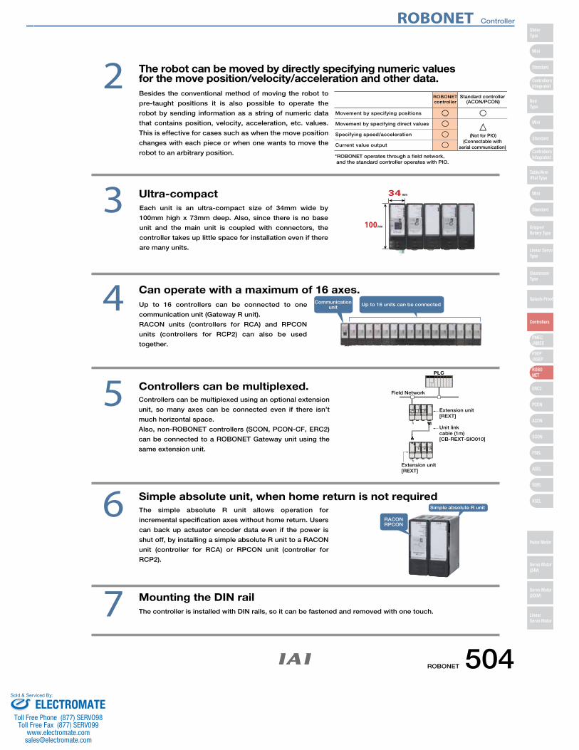
The simple absolute R unit allows operation for
incremental specification axes without home return. Users
can back up actuator encoder data even if the power is
shut off, by installing a simple absolute R unit to a RACON
unit (controller for RCA) or RPCON unit (controller for
RCP2).
Simple absolute unit, when home return is not required 6
2
Ultra-compact3
Mounting the DIN railThe controller is installed with DIN rails, so it can be fastened and removed with one touch.7
Can operate with a maximum of 16 axes. 4 Communicationunit
RACONRPCON
Up to 16 units can be connected
Simple absolute R unit
Controllers can be multiplexed. 5FG
FG
PLC
Field Network
Extension unit[REXT]
Extension unit[REXT]
Unit linkcable (1m)[CB-REXT-SIO010]
The robot can be moved by directly specifying numeric values for the move position/velocity/acceleration and other data.
ROBONETcontroller
Movement by specifying positions
Movement by specifying direct values
Specifying speed/acceleration
Current value output
○○○○
○
△
Standard controller (ACON/PCON)
(Not for PIO)(Connectable with
serial communication)
*ROBONET operates through a field network, and the standard controller operates with PIO.
Besides the conventional method of moving the robot to
pre-taught positions it is also possible to operate the
robot by sending information as a string of numeric data
that contains position, velocity, acceleration, etc. values.
This is effective for cases such as when the move position
changes with each piece or when one wants to move the
robot to an arbitrary position.
Each unit is an ultra-compact size of 34mm wide by
100mm high x 73mm deep. Also, since there is no base
unit and the main unit is coupled with connectors, the
controller takes up little space for installation even if there
are many units.
Up to 16 controllers can be connected to one
communication unit (Gateway R unit).
RACON units (controllers for RCA) and RPCON
units (controllers for RCP2) can also be used
together.
Controllers can be multiplexed using an optional extension
unit, so many axes can be connected even if there isn’t
much horizontal space.
Also, non-ROBONET controllers (SCON, PCON-CF, ERC2)
can be connected to a ROBONET Gateway unit using the
same extension unit.
ROBONET Controller
ROBONET 504
Mini
Mini
PSEP/ASEP
PMEC/AMEC
ROBONET
ERC2
PCON
ACON
SCON
PSEL
ASEL
SSEL
XSEL
Standard
Mini
Standard
Standard
ControllersIntegrated
ControllersIntegrated
SliderType
RodType
Table/Arm/Flat Type
Gripper/Rotary Type
Linear ServoType
Cleanroom Type
Splash-Proof
Controllers
Pulse Motor
Servo Motor (24V)
Servo Motor (200V)
LinearServo Motor
ELECTROMATEToll Free Phone (877) SERVO98
Toll Free Fax (877) SERV099www.electromate.com
Sold & Serviced By:
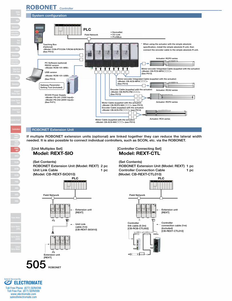
System configuration
ROBONET Extension Unit
PLC
Teaching Box(Optional)<Model: CON-PT/CON-T/RCM-E/RCM-P>(See P512)
USB version
<Model: RCM-101-USB>
(See P512)
PC Software (optional)RS232 version<Model: RCM-101-MW>
<Model: PS-241 (100V input)><Model: PS-242 (200V input)>(See P471)
DC24V Power Supply
Motor Cable (supplied with the actuator)<Model: CB-RCP2-MA���> (see P513)
Encoder Cable (supplied with the actuator)<Model: CB-RCP2-PB���>(See P513)
Motor-encoder Integrated Cable (supplied with the actuator)<Model: CB-ACS-MPA���>(See P514)
Motor-encoder Integrated Cable (supplied with the actuator)<Model: CB-PCS-MPA���>(See P513)
Motor Cable (supplied with the actuator)<Model: CB-ACS-MA���> (see P514)
Encoder Cable (supplied with the actuator)<Model: CB-ACS-PA���> (see P514)
Field Network• DeviceNet
Actuator: RCA series
Actuator: RCP2 series
Gateway Parameter-Setting Tool (included)
Actuator: RCA2 series
Actuator: RCP3 series
• CC-Link• ProfiBus
* When using the actuator with the simple absolute
specification, install the simple absolute R unit, then
connect the encoder cable to the simple absolute R unit.
If multiple ROBONET extension units (optional) are linked together they can reduce the lateral width needed. It is also possible to connect individual controllers, such as SCON, etc. via the ROBONET.
[Unit Multiplex Set]
Model: REXT-SIO
(Set Contents) ROBONET Extension Unit (Model: REXT) 2 pcUnit Link Cable 1 pc(Model: CB-REXT-SIO010)
FG
FG
PLC
Field Network
Extension unit[REXT]
Extension unit[REXT]
Unit Linkcable (1m)[CB-REXT-SIO010]
[Controller Connecting Set]
Model: REXT-CTL
(Set Contents) ROBONET Extension Unit (Model: REXT) 1 pcController Connection Cable 1 pc (Model: CB-REXT-CTL010)
R
EMG±
e-C
ON
e-C
ON
EMG±
FG
PLC
Field Network
Extension unit[REXT]
Controllerlink cable (0.2m)[CB-RCB-CTL002]
Controllerconnection cable (1m)(Included)[CB-REXT-CTL010]
EMG±
ROBONET Controller
505 ROBONET
Mini
Mini
PSEP/ASEP
PMEC/AMEC
ROBONET
ERC2
PCON
ACON
SCON
PSEL
ASEL
SSEL
XSEL
Standard
Mini
Standard
Standard
ControllersIntegrated
ControllersIntegrated
RodType
Table/Arm/Flat Type
Gripper/Rotary Type
Linear ServoType
Cleanroom Type
Splash-Proof
Controllers
Pulse Motor
Servo Motor (24V)
Servo Motor (200V)
LinearServo Motor
SliderType
ELECTROMATEToll Free Phone (877) SERVO98
Toll Free Fax (877) SERV099www.electromate.com
Sold & Serviced By:
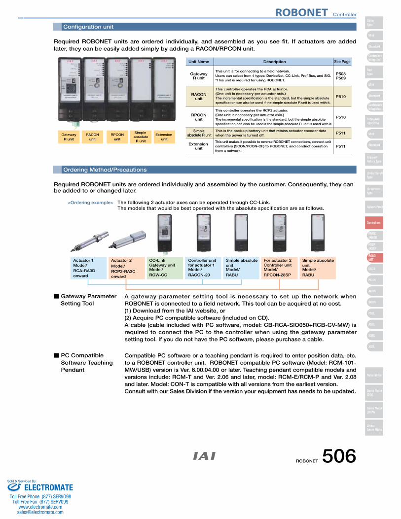
Configuration unit
Simple absolute R unit
Unit Name See PageDescription
This unit is for connecting to a field network.Users can select from 4 types: DeviceNet, CC-Link, ProfiBus, and SIO.*This unit is required for using ROBONET.
This controller operates the RCP2 actuator. (One unit is necessary per actuator axis.)The incremental specification is the standard, but the simple absolute specification can also be used if the simple absolute R unit is used with it.
This is the back-up battery unit that retains actuator encoder data when the power is turned off.
P508P509
P510
P510
P511
Extension unit P511
GatewayR unit
RACONunit
RPCONunit
Simple absolute
R unit
Extension unit
GatewayR unit
RACONunit
RPCONunit
This controller operates the RCA actuator. (One unit is necessary per actuator axis.)The incremental specification is the standard, but the simple absolute specification can also be used if the simple absolute R unit is used with it.
This unit makes it possible to reverse ROBONET connections, connect unit controllers (SCON/PCON-CF) to ROBONET, and conduct operation from a network.
Required ROBONET units are ordered individually, and assembled as you see fit. If actuators are added later, they can be easily added simply by adding a RACON/RPCON unit.
Ordering Method/Precautions
Required ROBONET units are ordered individually and assembled by the customer. Consequently, they can be added to or changed later.
■ Gateway ParameterSetting Tool
A gateway parameter setting tool is necessary to set up the network when ROBONET is connected to a field network. This tool can be acquired at no cost.(1) Download from the IAI website, or (2) Acquire PC compatible software (included on CD). A cable (cable included with PC software, model: CB-RCA-SIO050+RCB-CV-MW) is required to connect the PC to the controller when using the gateway parameter setting tool. If you do not have the PC software, please purchase a cable.
■ PC CompatibleSoftware TeachingPendant
Compatible PC software or a teaching pendant is required to enter position data, etc. to a ROBONET controller unit. ROBONET compatible PC software (Model: RCM-101-MW/USB) version is Ver. 6.00.04.00 or later. Teaching pendant compatible models and versions include: RCM-T and Ver. 2.06 and later, model: RCM-E/RCM-P and Ver. 2.08 and later. Model: CON-T is compatible with all versions from the earliest version. Consult with our Sales Division if the version your equipment has needs to be updated.
<Ordering example> The following 2 actuator axes can be operated through CC-Link. The models that would be best operated with the absolute specification are as follows.
RCA-RA3Donward
Model/Actuator 1
RCP2-RA3Conward
Model/Actuator 2
RGW-CCModel/Gateway unitCC-Link
RACON-20Model/
Controller unitfor actuator 1
RABUModel/
Simple absolute unit
RABUModel/
Simple absolute unit
RPCON-28SPModel/Controller unitFor actuator 2
ROBONET Controller
ROBONET 506
Mini
Mini
PSEP/ASEP
PMEC/AMEC
ROBONET
ERC2
PCON
ACON
SCON
PSEL
ASEL
SSEL
XSEL
Standard
Mini
Standard
Standard
ControllersIntegrated
ControllersIntegrated
SliderType
RodType
Table/Arm/Flat Type
Gripper/Rotary Type
Linear ServoType
Cleanroom Type
Splash-Proof
Controllers
Pulse Motor
Servo Motor (24V)
Servo Motor (200V)
LinearServo Motor
ELECTROMATEToll Free Phone (877) SERVO98
Toll Free Fax (877) SERV099www.electromate.com
Sold & Serviced By:
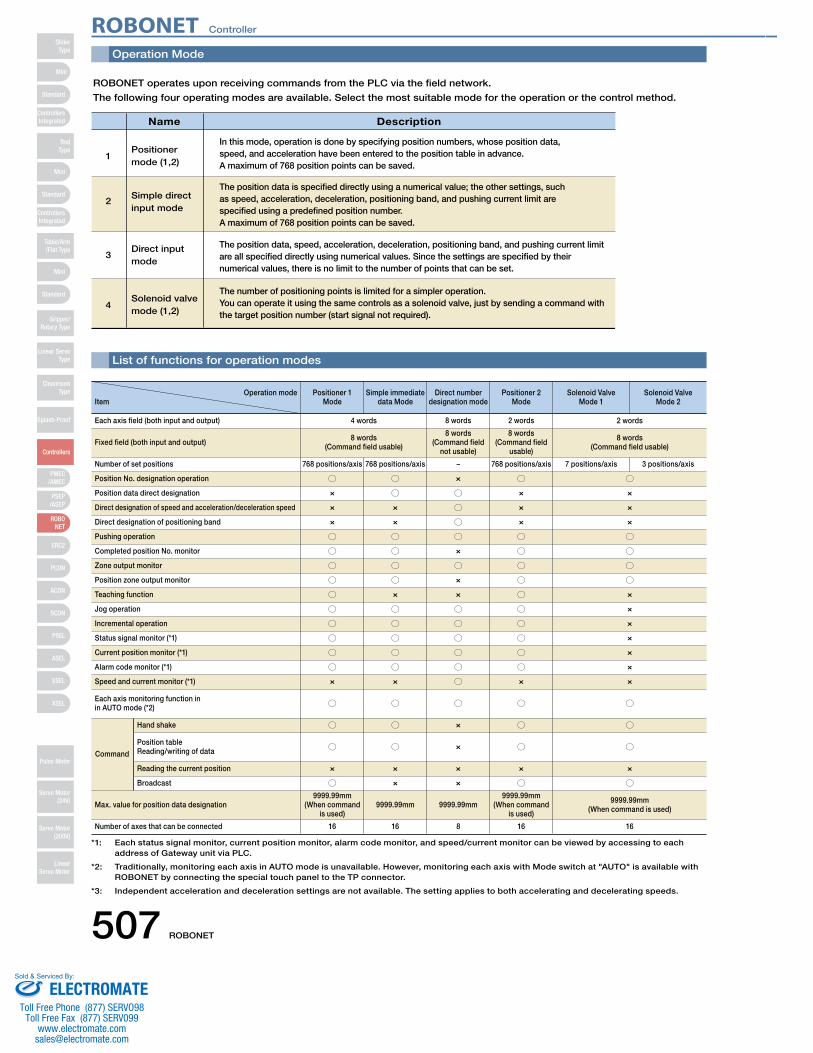
Operation Mode
List of functions for operation modes
ROBONET operates upon receiving commands from the PLC via the field network.
The following four operating modes are available. Select the most suitable mode for the operation or the control method.
Name Description
Positionermode (1,2)
Simple direct input mode
Direct inputmode
Solenoid valvemode (1,2)
1
2
3
4
In this mode, operation is done by specifying position numbers, whose position data, speed, and acceleration have been entered to the position table in advance. A maximum of 768 position points can be saved.
The position data is specified directly using a numerical value; the other settings, such as speed, acceleration, deceleration, positioning band, and pushing current limit are specified using a predefined position number. A maximum of 768 position points can be saved.
The position data, speed, acceleration, deceleration, positioning band, and pushing current limit are all specified directly using numerical values. Since the settings are specified by their numerical values, there is no limit to the number of points that can be set.
The number of positioning points is limited for a simpler operation. You can operate it using the same controls as a solenoid valve, just by sending a command with the target position number (start signal not required).
Operation modeItem
Positioner 1Mode
Simple immediate data Mode
Direct number designation mode
Positioner 2Mode
Solenoid ValveMode 1
Solenoid ValveMode 2
Each axis field (both input and output) 4 words 8 words 2 words 2 words
Fixed field (both input and output) 8 words(Command field usable)
8 words(Command field
not usable)
8 words(Command field
usable)
8 words(Command field usable)
Number of set positions 768 positions/axis 768 positions/axis − 768 positions/axis 7 positions/axis 3 positions/axis
Position No. designation operation ○ ○ × ○ ○
Position data direct designation × ○ ○ × ×
Direct designation of speed and acceleration/deceleration speed × × ○ × ×
Direct designation of positioning band × × ○ × ×
Pushing operation ○ ○ ○ ○ ○
Completed position No. monitor ○ ○ × ○ ○
Zone output monitor ○ ○ ○ ○ ○
Position zone output monitor ○ ○ × ○ ○
Teaching function ○ × × ○ ×
Jog operation ○ ○ ○ ○ ×
Incremental operation ○ ○ ○ ○ ×
Status signal monitor (*1) ○ ○ ○ ○ ×
Current position monitor (*1) ○ ○ ○ ○ ×
Alarm code monitor (*1) ○ ○ ○ ○ ×
Speed and current monitor (*1) × × ○ × ×
Each axis monitoring function inin AUTO mode (*2) ○ ○ ○ ○ ○
Command
Hand shake ○ ○ × ○ ○
Position tableReading/writing of data ○ ○ × ○ ○
Reading the current position × × × × ×
Broadcast ○ × × ○ ○
Max. value for position data designation9999.99mm
(When command is used)
9999.99mm 9999.99mm9999.99mm
(When command is used)
9999.99mm(When command is used)
Number of axes that can be connected 16 16 8 16 16
*1: Each status signal monitor, current position monitor, alarm code monitor, and speed/current monitor can be viewed by accessing to each address of Gateway unit via PLC.
*2: Traditionally, monitoring each axis in AUTO mode is unavailable. However, monitoring each axis with Mode switch at "AUTO" is available with ROBONET by connecting the special touch panel to the TP connector.
*3: Independent acceleration and deceleration settings are not available. The setting applies to both accelerating and decelerating speeds.
ROBONET Controller
507 ROBONET
Mini
Mini
PSEP/ASEP
PMEC/AMEC
ROBONET
ERC2
PCON
ACON
SCON
PSEL
ASEL
SSEL
XSEL
Standard
Mini
Standard
Standard
ControllersIntegrated
ControllersIntegrated
RodType
Table/Arm/Flat Type
Gripper/Rotary Type
Linear ServoType
Cleanroom Type
Splash-Proof
Controllers
Pulse Motor
Servo Motor (24V)
Servo Motor (200V)
LinearServo Motor
SliderType
ELECTROMATEToll Free Phone (877) SERVO98
Toll Free Fax (877) SERV099www.electromate.com
Sold & Serviced By:

Configuration unit (Gateway R unit)
Gateway R Unit for DeviceNet
A communications unit to operate ROBONET via DeviceNet.
Model RGW-DV
Specifications
Comm. Standard
Item Specifications Specifications
DC24V ±10%
Bit strobe
500k/250k/125kbps (switchable by software)
Comm. Speed
Max. network length
Max. branch length
Total branch length
500kbps 100m
6m
39m
0~40ºC
IP20
Power
Current consumption
Item
Master-slaveconnection
No. occupied nodes
Comm.cable length (*1)
Note: When using a large cable for DeviceNet
Ambient op. temperature
Protection class*1 If you wish to use T-junction communication, see the instructions manual for your master unit or PLC.
Gateway R Unit for CC-Link
A communications unit to operate ROBONET via CC-Link.
Model RGW-CC
Specifications
Network cable
Black
Pin Color Description
Power cable negative (-) sideWire diameter
Item Description
Cable connector-compatible wiring
7mm
Twisted wire: AWG24-12 (0.2~2.5mm2)
:Connector on Gateway Side
MSTBA2.5/5-G-5.08 ABGY AU
(Made by: Phoenix Contact)
Connector on Cable Side
MSTB2.5/5-ST-5.08 ABGY AU
(Made by: Phoenix Contact)
= Standard accessory
Network cable
DA
Signal Name Description
Communication line A
Wire diameter
Item Description
Cable connector-compatible wiring
Twisted wire:
Connector on Gateway Side:
MSTBA2.5/5-G-5.08AU
(Made by Phoenix Contact)
Comm. Cable Length (*2)
IP20Protection class
Comm. Standard
Error Control Method
Item Specifications Specifications
DC24V ±10% CRC (X16+X12+X5+1)Power Supply
Item
*1 Certification acquired
*2 If you wish to use T-junction communication, see the
instruction manual for your master unit or PLC.
Comm. Speed (bps)Total Cable Length (m)
10M 5M 2.5M 625k 156k
100 160 400 900 1200
Connector on Cable Side:
MSTB2.5/5-ST-5.08 ABGY AU
(Made by Phoenix Contact) =
Standard accessory
Terminal resistor board (model TN-1)Network connector, Emergency stop connector
Terminal resistor board (model TN-1)Network connector, Emergency stop connectorTerminal resistor cable (110Ω/130Ω)
Black Blue White Red
DA DB DG SLD FG
Comm. Spec.
Comm. Speed
600mA max.
DeviceNet 2.0-certified interface module
Group 2 only server
Insulated node operating on network power supply
Polling
Cyclic Ambient op. humidity
Ambient op.environment
Weight
Accessories
250kbps
125kbps
250m
500m
78m
156m
1 node
95% RH or below (non-condensing)
No corrosive or flammable gasses, oil mist, or dust.
140g
Stripped wire length
Comm. data Low side
Shield
Comm. data High side
Power cable plus (+) side
Blue
−
White
Red
600mA max.
CC-Link Ver2.0 (*1)
10M/5M/2.5M/625k/156kbps (switchable by software)
Broadcast polling method
Frame synchronization method
NRZI
Bus format (EIA RS485 compliant)
HDLC compliant
Comm. Speed
Comm. Method
Sync. Method
Encoding Method
Transf. Type
Transf. Format
Current consumptionStation occupancy
Comm. Cable
Weight
Accessories
Remote device stations: ×1, 4 st.; ×4, 2 st.; ×8, 2 st
Dedicated CC-Link cable
0~40ºC
95% RH or below (non-condensing)
No corrosive or flammable gasses, oil mist, or dust.
Communication line B
Ground
The shield and cable's shield are connected, then they are connected to "FG"and the chassis.
Frame ground Connected to "SLD" and the chassis.
Stripped wire length 7mm
140g
Dev
iceN
et S
peci
ficat
ions
Envi
ronm
ent
Req
uire
men
tsD
evic
eNet
Spe
cific
atio
ns
CC-L
ink
Spec
ifica
tions
CC-L
ink
Spec
ifica
tions
Envi
ronm
ent
Req
uire
men
ts
DB
DG
SLD
FG
Ambient op. temperatureAmbient op. humidity
Ambient op.environment
AWG24-12 (0.2~2.5mm2)
ROBONET Controller
ROBONET 508
Mini
Mini
PSEP/ASEP
PMEC/AMEC
ROBONET
ERC2
PCON
ACON
SCON
PSEL
ASEL
SSEL
XSEL
Standard
Mini
Standard
Standard
ControllersIntegrated
ControllersIntegrated
SliderType
RodType
Table/Arm/Flat Type
Gripper/Rotary Type
Linear ServoType
Cleanroom Type
Splash-Proof
Controllers
Pulse Motor
Servo Motor (24V)
Servo Motor (200V)
LinearServo Motor
ELECTROMATEToll Free Phone (877) SERVO98
Toll Free Fax (877) SERV099www.electromate.com
Sold & Serviced By:
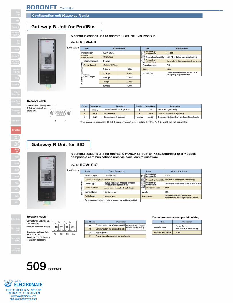
Configuration unit (Gateway R unit)
FG SG SB SA
15
69
Gateway R Unit for ProfiBus
A communications unit to operate ROBONET via ProfiBus.
Model RGW-PRSpecifications
Comm. Speed
Comm. Cable Length
Comm. Standard
Item Specifications Specifications
DC24V ±10%
9.6kbps 1500m
0~40ºC
IP20
Power Supply
Item
Ambient op. temperature
Protection class
Gateway R Unit for SIO
A communications unit for operating ROBONET from an XSEL controller or a Modbus-compatible communications unit, via serial communication.
RGW-SIOModel
Specifications
Network cable
* The matching connector (D-Sub 9-pin connector) is not included. * Pins 1, 2, 7, and 9 are not connected
3 B-Line +5V
Pin No. Pin No.Signal Name Description Description
Communication line B (RS485) +5V output (insulated)
Connector on Gateway Side: D-Sub connector, 9-pinsocket side
Network cable
SA
Signal Name Description
Communication line A (+positive side)Wire diameter
Item Description
Cable connector-compatible wiring
7mm
Connector on Gateway Side
MC1.5/4-G-3.5
(Made by Phoenix Contact)
Weight
Comm. Type
Item Specifications Specifications
DC24V ±10% 0~40ºCPower Supply
Item
Connector on Cable Side: MC1.5/4-ST-3.5(Made by Phoenix Contact)= Standard accessory
6
Signal Name
Built-in RS485-compliantterminal resistor (220Ω)
Terminal resistor board (model TN-1)Emergency stop connector
Terminal resistor board (model TN-1)Network connector, Emergency stop connector
Current Consumption 600mA max.
DP slave
9.6kbps~12Mbps
500kbps
1.5Mbps
3Mbps
12Mbps
400m
200m
200m
100m
Ambient op. humidityAmbient op. environment
95% RH or below (non-condensing)
No corrosive or flammable gases, oil mist, or dust.
140gWeight
Accessories
4
5
RTS
GND
Request send
Signal ground (insulated)
8
Housing
A-Line
Shield
Communication line A (RS485)
Connected to the cable's shield and the chassis.
600mA max.
RS485-compliant (Modbus protocol) 1: 1 communication connection
Asynchronous method, half-duplex
230.4kbps max.
100m or less
2 pairs of twisted pair cables (shielded)
Protection class
Accessories
95% RH or below (non-condensing)
No corrosive or flammable gases, oil mist, or dust.
IP20
140g
Comm. Method
Comm. Speed
Cable Length
Recommended cable
Current consumption
SB
SG
FG
Communication line B (-negative side)
Signal ground
Frame ground connected to the chassis.
Stripped wire length
Pro
fiBus
Spe
cific
atio
ns
Envi
ronm
ent
Req
uire
men
ts
SIO
Spe
cific
atio
ns
Env
ironm
ent
Req
uire
men
ts Ambient op. temperature
Ambient op. humidityAmbient op. environment
Twisted wire: AWG28-16 (0.14~1.5mm2)
ROBONET Controller
509 ROBONET
Mini
Mini
PSEP/ASEP
PMEC/AMEC
ROBONET
ERC2
PCON
ACON
SCON
PSEL
ASEL
SSEL
XSEL
Standard
Mini
Standard
Standard
ControllersIntegrated
ControllersIntegrated
RodType
Table/Arm/Flat Type
Gripper/Rotary Type
Linear ServoType
Cleanroom Type
Splash-Proof
Controllers
Pulse Motor
Servo Motor (24V)
Servo Motor (200V)
LinearServo Motor
SliderType
ELECTROMATEToll Free Phone (877) SERVO98
Toll Free Fax (877) SERV099www.electromate.com
Sold & Serviced By:
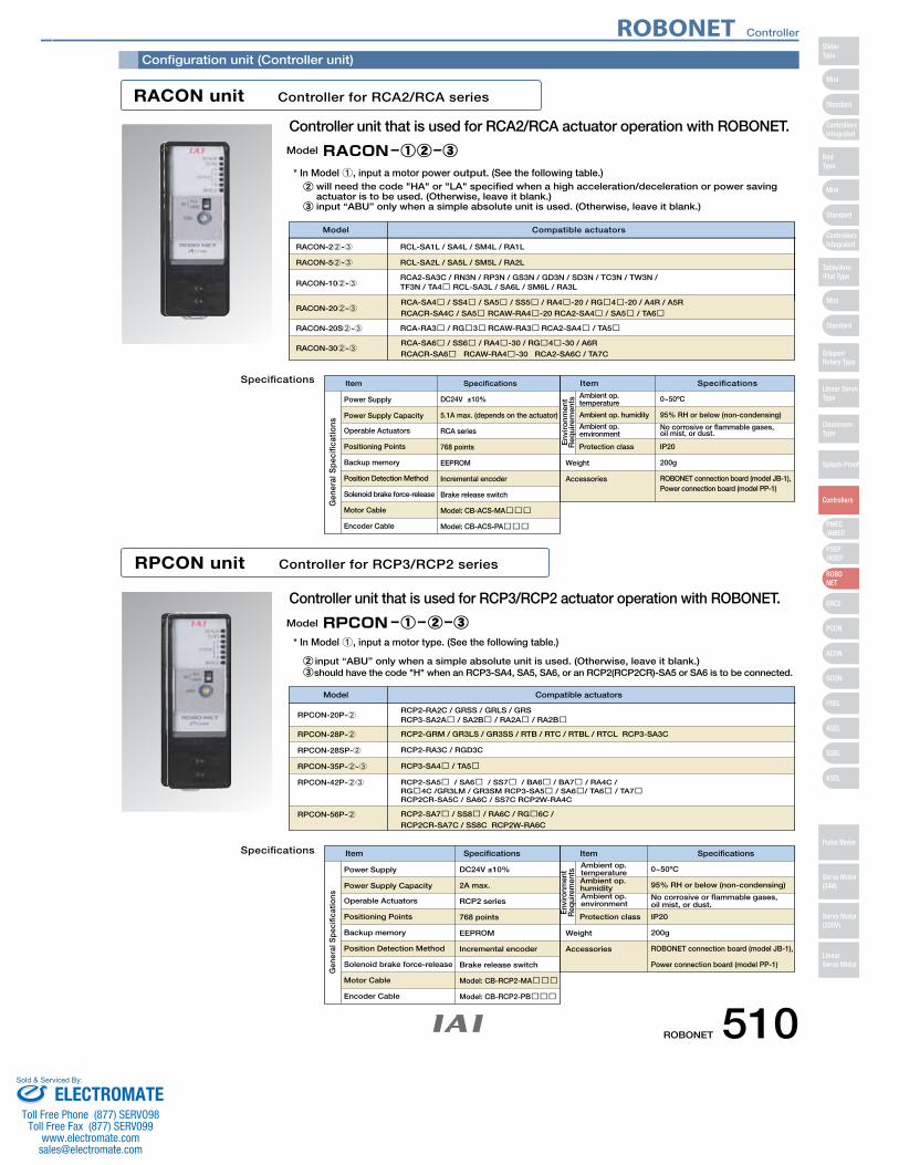
Configuration unit (Controller unit)
Controller unit that is used for RCA2/RCA actuator operation with ROBONET.
Controller unit that is used for RCP3/RCP2 actuator operation with ROBONET.
RACON unit Controller for RCA2/RCA series
Specifications
RPCON unit Controller for RCP3/RCP2 series
Specifications
Weight
Operable Actuators
Item Specifications Specifications
DC24V ±10% 0~50ºCPower Supply
Item
Weight
Operable Actuators
Item Specifications Specifications
DC24V ±10% 0~50ºCPower Supply
Item
Model Compatible actuators
RPCON-20P-2RCP2-RA2C / GRSS / GRLS / GRSRCP3-SA2A� / SA2B� / RA2A� / RA2B�
RCP2-RA3C / RGD3C
RCP3-SA4� / TA5�
RCP2-SA7� / SS8� / RA6C / RG�6C /
RCP2CR-SA7C / SS8C RCP2W-RA6C
RCP2-SA5� / SA6� / SS7� / BA6� / BA7� / RA4C / RG�4C /GR3LM / GR3SM RCP3-SA5� / SA6�/ TA6� / TA7�RCP2CR-SA5C / SA6C / SS7C RCP2W-RA4C
RCP2-GRM / GR3LS / GR3SS / RTB / RTC / RTBL / RTCL RCP3-SA3C
Model Compatible actuators
RCA-SA4� / SS4� / SA5� / SS5� / RA4�-20 / RG�4�-20 / A4R / A5R
RCACR-SA4C / SA5� RCAW-RA4�-20 RCA2-SA4� / SA5� / TA6�
RCA-SA6� / SS6� / RA4�-30 / RG�4�-30 / A6R
RCACR-SA6� RCAW-RA4�-30 RCA2-SA6C / TA7C
RCA-RA3� / RG�3� RCAW-RA3� RCA2-SA4� / TA5�
RCA2-SA3C / RN3N / RP3N / GS3N / GD3N / SD3N / TC3N / TW3N / TF3N / TA4� RCL-SA3L / SA6L / SM6L / RA3LRACON-102-3
RCL-SA1L / SA4L / SM4L / RA1LRACON-22-3
RCL-SA2L / SA5L / SM5L / RA2LRACON-52-3
RACON-202-3
RACON-20S2-3
RACON-302-3
will need the code "HA" or "LA" specified when a high acceleration/deceleration or power saving actuator is to be used. (Otherwise, leave it blank.)input “ABU” only when a simple absolute unit is used. (Otherwise, leave it blank.)
input “ABU” only when a simple absolute unit is used. (Otherwise, leave it blank.)should have the code "H" when an RCP3-SA4, SA5, SA6, or an RCP2(RCP2CR)-SA5 or SA6 is to be connected.
Power Supply Capacity
Positioning Points
Backup memory
Position Detection Method
Solenoid brake force-release
Motor Cable
Encoder Cable
5.1A max. (depends on the actuator)
RCA series
768 points
EEPROM
Incremental encoder
Brake release switch
Model: CB-ACS-MA���
Model: CB-ACS-PA���
Protection class
95% RH or below (non-condensing)
No corrosive or flammable gases, oil mist, or dust.
IP20
200g
ROBONET connection board (model JB-1), Power connection board (model PP-1)
Accessories
RPCON-28P-2
RPCON-28SP-2
RPCON-35P-2-3
RPCON-42P-23
RPCON-56P-2
Power Supply Capacity
Positioning Points
Backup memory
Position Detection Method
Solenoid brake force-release
Motor Cable
Encoder Cable
2A max.
RCP2 series
768 points
EEPROM
Incremental encoder
Brake release switch
Model: CB-RCP2-MA���
Model: CB-RCP2-PB���
Protection class
Accessories
95% RH or below (non-condensing)
No corrosive or flammable gases, oil mist, or dust.
IP20
200g
ROBONET connection board (model JB-1),
Power connection board (model PP-1)
Gen
eral
Sp
ecifi
catio
ns
Envi
ronm
ent
Req
uire
men
ts
Gen
eral
Sp
ecifi
catio
ns
En
viro
nm
ent
Req
uir
emen
ts
Ambient op. temperature
Ambient op. humidity
Ambient op. environment
Ambient op. temperatureAmbient op. humidityAmbient op. environment
Model
Model
* In Model 1, input a motor power output. (See the following table.)
* In Model 1, input a motor type. (See the following table.)
ROBONET Controller
ROBONET 510
Mini
Mini
PSEP/ASEP
PMEC/AMEC
ROBONET
ERC2
PCON
ACON
SCON
PSEL
ASEL
SSEL
XSEL
Standard
Mini
Standard
Standard
ControllersIntegrated
ControllersIntegrated
SliderType
RodType
Table/Arm/Flat Type
Gripper/Rotary Type
Linear ServoType
Cleanroom Type
Splash-Proof
Controllers
Pulse Motor
Servo Motor (24V)
Servo Motor (200V)
LinearServo Motor
ELECTROMATEToll Free Phone (877) SERVO98
Toll Free Fax (877) SERV099www.electromate.com
Sold & Serviced By:
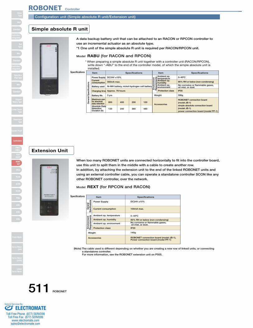
Configuration unit (Simple absolute R unit/Extension unit)
Simple absolute R unit
Extension Unit
A data backup battery unit that can be attached to an RACON or RPCON controller to
use an incremental actuator as an absolute type.
*1 One unit of the simple absolute R unit is required per RACON/RPCON unit.
Model RABU (for RACON and RPCON)
Specifications
Weight
Item Specifications Specifications
DC24V ±10% 0~40ºCPower Supply
Item
800 400 200 100
When too many ROBONET units are connected horizontally to fit into the controller board,
use this unit to split them in the middle with a cable to create another row.
In addition, by attaching the extension unit to the end of the linked ROBONET units and
using an external controller cable, you can operate a standalone controller SCON like any
other ROBONET controller, over the network.
Model REXT (for RPCON and RACON)
Specifications Item Specifications
DC24V ±10%Power Supply
Weight
(Note) The cable used is different depending on whether you are creating a new row of linked units, or connecting a standalone controller. For more information, see the ROBONET extension unit on P505.
Gen
eral
Spe
cific
atio
ns
Envi
ronm
ent
Req
uire
men
ts
Gen
eral
Sp
ecifi
catio
nsEn
viro
nmen
t R
equi
rem
ents
* When preparing a simple absolute R unit together with a controller unit (RACON/RPCON),write down “-ABU” to the end of the controller model, of which the simple absolute unit isinstalled.
ROBONET connection board (model JB-1)simple absolute connection board (model JB-1)power connection board (model PP-1)
Current consumption
Battery used
Charging time
Battery life
Maximum rpm for absolute data retentionAbsolute Data Retention Duration (h)
120 240 360 480
Accessories
Protection class
95% RH or below (non-condensing)
No corrosive or flammable gases, oil mist, or dust.
IP20
330g
Current consumption
Protection class
Accessories
100mA max.
0~40ºC
95% RH or below (non-condensing)No corrosive or flammable gases, oil mist, or dust.
IP20
140g
ROBONET connection board (model JB-1), Power connection board (model PP-1)
300mA max.
Ni-MH battery, nickel-hydrogen cell battery
Approx. 78 hours
3 yrs
Ambient op. temperatureAmbient op. humidityAmbient op. environment
Ambient op. temperature
Ambient op. humidity
Ambient op. environment
ROBONET Controller
511 ROBONET
Mini
Mini
PSEP/ASEP
PMEC/AMEC
ROBONET
ERC2
PCON
ACON
SCON
PSEL
ASEL
SSEL
XSEL
Standard
Mini
Standard
Standard
ControllersIntegrated
ControllersIntegrated
RodType
Table/Arm/Flat Type
Gripper/Rotary Type
Linear ServoType
Cleanroom Type
Splash-Proof
Controllers
Pulse Motor
Servo Motor (24V)
Servo Motor (200V)
LinearServo Motor
SliderType
ELECTROMATEToll Free Phone (877) SERVO98
Toll Free Fax (877) SERV099www.electromate.com
Sold & Serviced By:
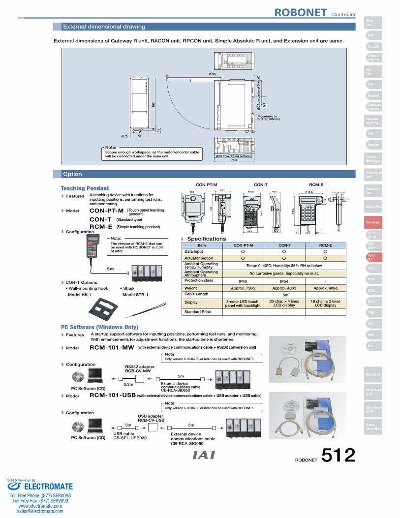
External dimensional drawing
Option
External dimensions of Gateway R unit, RACON unit, RPCON unit, Simple Absolute R unit, and Extension unit are same.
(0.5) 34
(10)5
100
(69.3 from DIN rail surface)73.3
(160)
(50
from
cen
ter o
f DIN
rail)
35.4
* Mountable toDIN rail (35mm)
Secure enough workspace, as the motor/encoder cable will be connected under the main unit.
Note:
RCM-ECON-TCON-PT-M
21
6.326.215.1
23.5
43
148.
5
7 (34)72.5
(113.5)
46.939.0
66.6110.0
218.
3
89.6
CON-T Options
Model
Configuration
• Wall-mounting hook
Model HK-1
• Strap
Model STR-1
13292.1
180
Teaching Pendant
PC Software (Windows Only)
Features A teaching device with functions for inputting positions, performing test runs, and monitoring.
Model
RCM-E (Simple teaching pendant)
CON-T (Standard type)
CON-PT-M ( Touch panel teaching pendant)
Configuration
Specifications
Data Input
3-color LED touch panel with backlight
Approx. 750g
IP40 IP54
20 char. × 4 linesLCD display
Approx. 400g
Temp: 0~40ºC; Humidity: 85% RH or below
Approx. 400g
16 char. × 2 linesLCD display
Item CON-PT-M CON-T RCM-E
5m
Features A startup support software for inputting positions, performing test runs, and monitoring. With enhancements for adjustment functions, the startup time is shortened.
Model
Configuration
RCM-101-MW (with external device communications cable + RS232 conversion unit)
0.3m
5m
External device communications cableCB-RCA-SIO050PC Software (CD)
RS232 adapterRCB-CV-MW
RCM-101-USB (with external device communications cable + USB adapter + USB cable)
5m3m
PC Software (CD)USB cableCB-SEL-USB030
USB adapterRCB-CV-USB
The version of RCM-E that can be used with ROBONET is 2.08 or later.
Note:
Only version 6.00.04.00 or later can be used with ROBONET.Note:
Only version 6.00.04.00 or later can be used with ROBONET.Note:
Actuator motionAmbient Operating Temp./HumidityAmbient Operating AtmosphereProtection class
Weight
Cable Length
Display
Standard Price
5m
No corrosive gases. Especially no dust.
External device communications cable CB-RCA-SIO050
ROBONET Controller
ROBONET 512
Mini
Mini
PSEP/ASEP
PMEC/AMEC
ROBONET
ERC2
PCON
ACON
SCON
PSEL
ASEL
SSEL
XSEL
Standard
Mini
Standard
Standard
ControllersIntegrated
ControllersIntegrated
SliderType
RodType
Table/Arm/Flat Type
Gripper/Rotary Type
Linear ServoType
Cleanroom Type
Splash-Proof
Controllers
Pulse Motor
Servo Motor (24V)
Servo Motor (200V)
LinearServo Motor
ELECTROMATEToll Free Phone (877) SERVO98
Toll Free Fax (877) SERV099www.electromate.com
Sold & Serviced By:
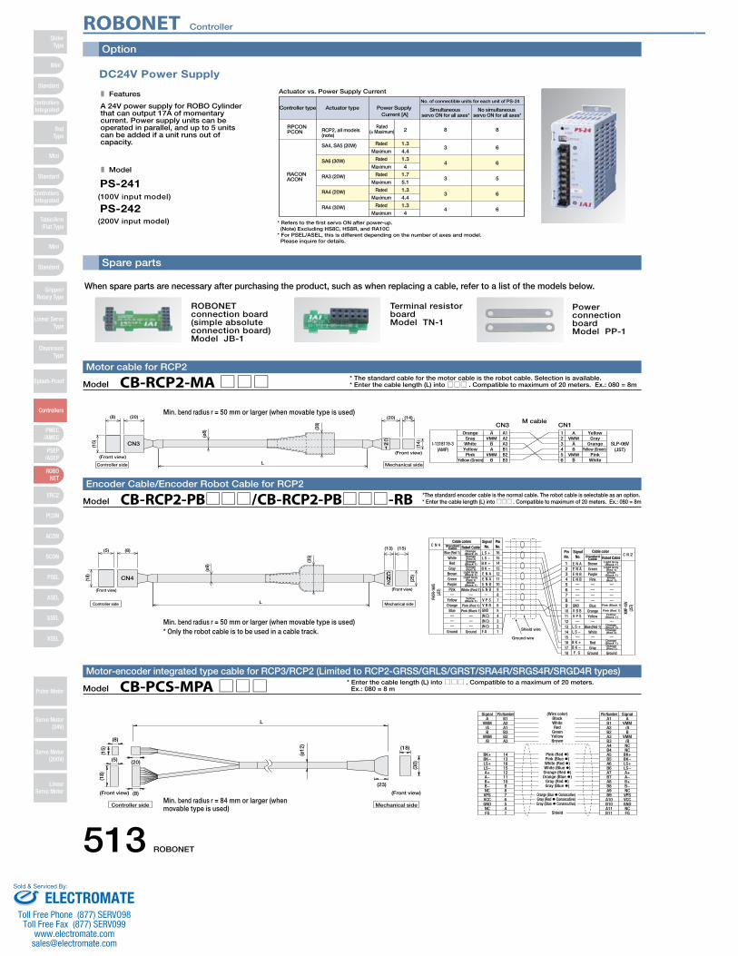
Option
SA4, SA5 (20W)
SA6 (30W)
RA3 (20W)
RA4 (20W)
RA4 (30W)
Maximum
Rated
Maximum
Rated
Maximum
Rated
Maximum
Rated
Maximum
4.4
1.3
4
1.7
5.1
1.3
4.4
1.3
4
(200V input model)
PS-242(100V input model)
PS-241
Actuator vs. Power Supply Current
Rated(= Maximum) 2RCP2, all models
(note)
6Rated 1.3
8
3
8RPCONPCON
RACONACON
Controller type Actuator type Simultaneous servo ON for all axes*
No. of connectible units for each unit of PS-24
No simultaneous servo ON for all axes*
Power Supply Current [A]
* Refers to the first servo ON after power-up.(Note) Excluding HS8C, HS8R, and RA10C
* For PSEL/ASEL, this is different depending on the number of axes and model. Please inquire for details.
DC24V Power Supply
Features
A 24V power supply for ROBO Cylinder that can output 17A of momentary current. Power supply units can be operated in parallel, and up to 5 units can be added if a unit runs out of capacity.
Model4
3
3
4
6
5
6
6
Spare parts
ROBONET connection board(simple absolute connection board)Model JB-1
Terminal resistor boardModel TN-1
Power connection boardModel PP-1
When spare parts are necessary after purchasing the product, such as when replacing a cable, refer to a list of the models below.
L
(15)
(ø12
)
A BlackB1 A1 A
BK+ 14
(18)
(8)
(20)
(8)
(5)
(30)
(18)
(23)
Signal Pin Number (Wire color) Pin Number Signal
Controller side Mechanical side
(Front view) (Front view)
VMM/AB
VMM/B
A2A1B3B2A3
1316151211109876541
BK−LS+LS−A+A−B+B−NCVPSVCCGNDNCFG
WhiteRed
GreenYellowBrown
Pink (Red �)Pink (Blue �)White (Red �)White (Blue �)Orange (Red �)Orange (Blue �)
Gray (Red �)Gray (Blue �)
Orange (Blue � Consecutive)Gray (Red � Consecutive)Gray (Blue � Consecutive)
Shield
B1A2B2A3B3A4B4A5B5A6B6A7B7A8B8A9B9A10B10A11B11
VMM/AB
VMM/BNCNC
BK+BK−LS+LS−A+A−B+B−NCVPSVCCGNDNCFG
Model CB-PCS-MPA□□□Motor-encoder integrated type cable for RCP3/RCP2 (Limited to RCP2-GRSS/GRLS/GRST/SRA4R/SRGS4R/SRGD4R types)
* Enter the cable length (L) into □□□ . Compatible to a maximum of 20 meters.Ex.: 080 = 8 m
A A
I-1318119-3(AMP)
SLP-06V(JST)
M cableCN3 CN1
Orange YellowA1 1
(20)(8)
(Front view)
(15)
L
CN3CN1
(ø8)
(28)
(14)(1
4)(20)
(Front view)
Mechanical sideController side
GrayWhiteYellowPink
Yellow (Green)
VMMBA
VMMB
A2A3B1B2B3
23456
VMMAB
VMMB
GrayOrange
Yellow (Green)Pink
White
Model CB-RCP2-MA□□□Motor cable for RCP2
* The standard cable for the motor cable is the robot cable. Selection is available.* Enter the cable length (L) into □□□ . Compatible to maximum of 20 meters. Ex.: 080 = 8m
PHDR
-16V
S(JS
T)
XMP-
18V
(JST)
Blue (Red 1)
C N 4
C N 2Cable color
SignalNo.
PinNo.
Brown Light Gray (Black 1)
Orange (Black 2)
1
L S + L S − B K + B K − E N A E N A E N B E N B
V P S V B B
(N.C)(N.C)(N.C)F.G
E N A E N A E N B E N B
GNDGND V B B
V P S
L S + L S −
B K + B K − F .G
16
Shield wire
Ground wire
Cable colors Robot Cable
Robot CableSignal
No.PinNo.
L
CN2
CN4
(5) (8) (13) (15)
(18)
(Front view)
(ø9)
(35)
(25)
(Front view)
Mechanical sideController side
WhiteRedGray
BrownGreenPurplePink
YellowOrange
Blue
Ground
Orange (Red 2)Orange (Black 1)Orange (Red 1)
Light Gray (Black 1)
Light Gray (Red 1)White
(Black 1)
White (Red 1)
Yellow (Black 1)
Pink (Red 1)
Pink (Black 1)
Ground
151413121110987654321
23456789101112131415161718
GreenPurplePink
BlueOrangeYellow
Blue (Red 1)White
RedGray
Ground
Light Gray (Red 1)White
(Black 1)White (Red 1)
Pink (Black 1)
Pink (Red 1)Yellow
(Black 1)
Orange (Black 2)Orange (Red 2)
Orange (Black 1)Orange (Red 1)
Ground
Standard Cable
Standard Cable
Model CB-RCP2-PB□□□/CB-RCP2-PB□□□-RBEncoder Cable/Encoder Robot Cable for RCP2
*The standard encoder cable is the normal cable. The robot cable is selectable as an option.* Enter the cable length (L) into □□□ . Compatible to maximum of 20 meters. Ex.: 080 = 8m
Min. bend radius r = 84 mm or larger (when movable type is used)
Min. bend radius r = 50 mm or larger (when movable type is used)
Min. bend radius r = 50 mm or larger (when movable type is used)* Only the robot cable is to be used in a cable track.
ROBONET Controller
513 ROBONET
Mini
Mini
PSEP/ASEP
PMEC/AMEC
ROBONET
ERC2
PCON
ACON
SCON
PSEL
ASEL
SSEL
XSEL
Standard
Mini
Standard
Standard
ControllersIntegrated
ControllersIntegrated
RodType
Table/Arm/Flat Type
Gripper/Rotary Type
Linear ServoType
Cleanroom Type
Splash-Proof
Controllers
Pulse Motor
Servo Motor (24V)
Servo Motor (200V)
LinearServo Motor
SliderType
ELECTROMATEToll Free Phone (877) SERVO98
Toll Free Fax (877) SERV099www.electromate.com
Sold & Serviced By:
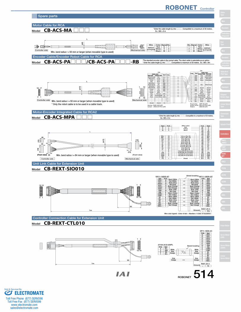
1 2 3 4 5 6 7 8 9
10 11 12 13 14
15 16 17 18
− −
−
−
White/Blue White/Yellow White/Red
White/Black − −
White/Purple −
GroundOrange Green Purple Gray Red
Black White/Gray
Blue Yellow
Robot Cable Gray Red
Black Yellow
− −
Blue −
GroundPink
Purple White
Blue/red Orange/White
Green/White Orange Brown Green
Standard Cable
18
17 16 15 14 13 12 11 10
9 8 7 6 5 4 3 2 1
White/Purple
White/Gray Yellow Blue
White/Blue White/Yellow White/Red
White/Black Orange
Green Purple Gray Red
Black −−−
Ground
Robot Cable Blue
Orange Green Brown Gray Red
Black Yellow Pink
Purple White
Blue/red Orange/White Green/White
− − −
Ground
Standard Cable LS+
LS− BK+ BK− ENA ENA ENB ENB ENZ
ENZ −
VPS 5V
GND − − −
F.G
Housing: PHDR-18VR (JST) Contact : SPHD-001T-P0.5 (JST)
Plug housing : XMP-18V (JST)Socket contact : BXA-001T-P0.6 (JST)Retainer : XMS-09V (JST)
Pin No. Signal
CN1CN2 Cable color
Cable color Signal
ENAENA ENB ENB
LS+
FG ENZ ENZ
VPS 5V
GND LS− BK− BK+
1
9 18
1018
2 1
17
Mechanical sideController side
L(ø
10)
Pin No.
Spare parts
AWG22(crimped) White
Wire Color Signal No.U 1
No. Signal Color WireRed 1
23Black
VW
23 W
VU Red
WhiteBlack
AWG22(crimped)
13 3
1
L
Mechanical sideController side
(ø9)
Model CB-ACS-MA□□□Motor Cable for RCA
* Enter the cable length (L) into □□□ . Compatible to a maximum of 20 meters. Ex.: 080 = 8 m
Model CB-ACS-PA□□□/CB-ACS-PA□□□-RBEncoder Cable/Encoder Robot Cable for RCA
*The standard encoder cable is the normal cable. The robot cable is selectable as an option.* Enter the cable length (L) into □□□ . Compatible to maximum of 20 meters. Ex.: 080 = 8m
L
U Red(Wire color)
123
A1 USignal Pin No. Pin No. Signal
BK+ 16
(Front view)
(10)
(ø12
)
(18)
(8)
(12)
(23)
(8)
(5)
(30)
(18)
Controller side
(Front view)
Mechanical side
(Front view)
VW
BK−LS+LS−A+A−B+B−Z+Z−−
/PSVCCGNDNCFG
151817141312111098765
1
YellowBlack
Yellow (Red �)Yellow (Blue �)
Pink (Red �)Pink (Blue �)White (Red �)White (Blue �)Orange (Red �)Orange (Blue �)
Gray (Red �)Gray (Blue �)
Orange (Red � Consecutive)Orange (Blue � Consecutive)Gray (Red � Consecutive)Gray (Blue � Consecutive)
Shield
B1A2B2A3B3A4B4A5B5A6B6A7B7A8B8A9B9A10B10A11B11
VWNCNCNCBK+BK−LS+LS−A+A−B+B−Z+Z−−/PSVCCGNDNCFG
Model CB-ACS-MPA□□□Motor-Encoder Integrated Cable for RCA2
* Enter the cable length (L) into □□□ . Compatible to a maximum of 20 meters. Ex.: 080 = 8 m
21
1615
16 15
12
Signal Pin No.DF11-16DS-2C
Ground
DF11-16DS-2C
Wire color legend: <Color of dot> <Number>/<Color of insulation>
RAV1.25-3FG−
Black 2/White Black 2/White Signal
Shield braiding
1m
50
/RSV1RSV1/ROUTROUT/RSV0RSV0/ENAENA
COM2COM1SD-SD+RD-RD+EMG-EMG+
16151413121110987654321
Red 2/WhiteBlack 2/GrayRed 2/Gray
Black 2/OrangeRed 2/OrangeBlack 1/PinkRed 1/Pink
Black 1/YellowRed 1/YellowBlack 1/WhiteRed 1/WhiteBlack 1/GrayRed 1/Gray
Black 1/OrangeRed 1/Orange
Red 2/WhiteBlack 2/GrayRed 2/Gray
Black 2/OrangeRed 2/OrangeBlack 1/PinkRed 1/Pink
Black 1/YellowRed 1/YellowBlack 1/WhiteRed 1/WhiteBlack 1/GrayRed 1/Gray
Black 1/OrangeRed 1/Orange
16151413121110987654321
/RSV1RSV1/ROUTROUT/RSV0RSV0/ENAENA
COM2COM1SD-SD+RD-RD+EMG-EMG+
Pin No.
Model CB-REXT-SIO010Unit Link Cable for Extension Unit
21
1615
Ground
DF11-16DS-2C
RAV1.25-3FG−
37104-3122-000FL
4321
WhiteGray
Orange
GrayOrange
WhiteGray
Orange
GrayOrange
1234
Shield braiding
1m
50
N.C.GNDSD-SD+
16151413121110987654321
/RSV1RSV1/ROUTROUT/RSV0RSV0/ENAENA
COM2COM1SD-SD+RD-RD+EMG-EMG+
SignalPin No.
SignalPin No.
Model CB-REXT-CTL010Controller Connection Cable for Extension Unit
Min. bend radius r = 50 mm or larger (when movable type is used)* Only the robot cable is to be used in a cable track.
Min. bend radius r = 84 mm or larger (when movable type is used)
Min. bend radius r = 50 mm or larger (when movable type is used)
ROBONET Controller
ROBONET 514
Mini
Mini
PSEP/ASEP
PMEC/AMEC
ROBONET
ERC2
PCON
ACON
SCON
PSEL
ASEL
SSEL
XSEL
Standard
Mini
Standard
Standard
ControllersIntegrated
ControllersIntegrated
SliderType
RodType
Table/Arm/Flat Type
Gripper/Rotary Type
Linear ServoType
Cleanroom Type
Splash-Proof
Controllers
Pulse Motor
Servo Motor (24V)
Servo Motor (200V)
LinearServo Motor
ELECTROMATEToll Free Phone (877) SERVO98
Toll Free Fax (877) SERV099www.electromate.com
Sold & Serviced By:
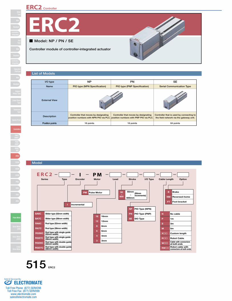
ERC2 Controller
515 ERC2
SliderType
Mini
Mini
PSEP/ASEP
PMEC/AMEC
ROBONET
ERC2
PCON
ACON
SCON
PSEL
ASEL
SSEL
XSEL
Standard
Standard
Standard
ControllersIntegrated
ControllersIntegrated
RodType
Table/Arm/FlatType
Gripper/Rotary Type
Linear ServoType
CleanroomType
Splash-Proof
Controllers
Pulse Motor
Servo Motor (24V)
Servo Motor (200V)
LinearServo Motor
Mini
List of Models
■ Model: NP / PN / SE
Controller module of controller-integrated actuator
E R C 2 I P MSeries Type MotorEncoder Lead I/O TypeStroke Cable Length Option
SA7C
SA6C
RA6C
RA7C
RGS6C Rod type with single guide(52mm width)
Slider type (52mm width)
Slider type (58mm width)
Rod type (52mm width)
Rod type (58mm width)
RGS7C
RGD6C
RGD7C
Rod type with single guide(58mm width)Rod type with double guide(52mm width)Rod type with double guide(58mm width)
I Incremental
16 16mm
12 12mm
8 8mm
6 6mm
4 4mm
3 3mm
PM Pulse Motor (50mm increments)
NP PIO Type (NPN)
PN PIO Type (PNP)
SE SIO Type
B Brake
NM Reversed-home
FT Foot bracket
N No cable
P 1m
S 3m
M 5m
X�� Custom length
R�� Robot Cable
W��Cable with connectors at both ends
RW�� Robot cable with connectors at both ends
50mm~
600mm
50~
600
I/O type NP
PIO type (NPN Specification)Name
External View
DescriptionController that moves by designating
position numbers with NPN PIO via PLC.
Position points 16 points
PN
PIO type (PNP Specification)
Controller that moves by designatingposition numbers with PNP PIO via PLC.
16 points
SE
Serial Communication Type
Controller that is used by connecting to the field network via the gateway unit.
64 points
Model
ERC2
ELECTROMATEToll Free Phone (877) SERVO98
Toll Free Fax (877) SERV099www.electromate.com
Sold & Serviced By:
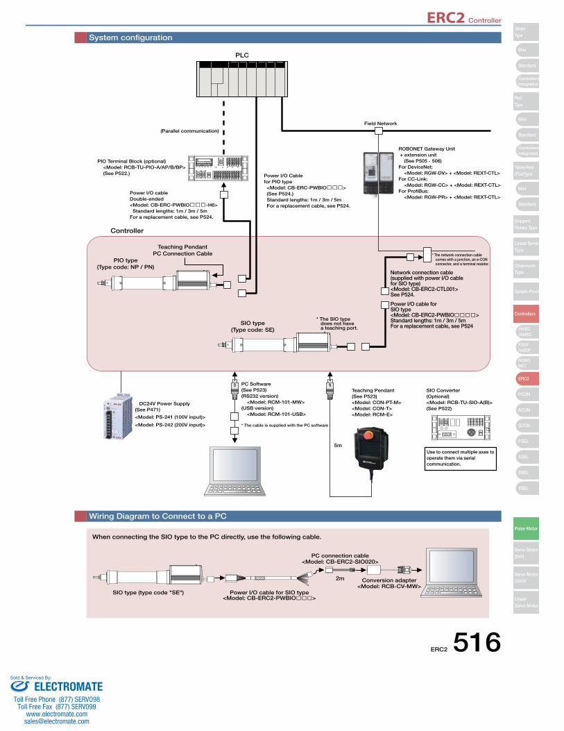
ERC2 Controller
ERC2 516
Mini
Mini
Mini
Standard
Standard
ControllersIntegrated
Standard
ControllersIntegrated
PSEP/ASEP
PMEC/AMEC
ROBONET
ERC2
PCON
ACON
SCON
PSEL
ASEL
SSEL
XSEL
SliderType
RodType
Table/Arm/FlatType
Gripper/Rotary Type
Linear ServoType
CleanroomType
Splash-Proof
Controllers
Pulse Motor
Servo Motor (24V)
Servo Motor (200V)
LinearServo Motor
Power I/O cable for SIO type<Model: CB-ERC2-PWBIO����>Standard lengths: 1m / 3m / 5mFor a replacement cable, see P524
Network connection cable(supplied with power I/O cable for SIO type)<Model: CB-ERC2-CTL001>See P524.
ROBONET Gateway Unit + extension unit (See P505 - 506)For DeviceNet: <Model: RGW-DV> + <Model: REXT-CTL>For CC-Link: <Model: RGW-CC> + <Model: REXT-CTL>For ProfiBus: <Model: RGW-PR> + <Model: REXT-CTL>
Field Network
Power I/O Cable for PIO type <Model: CB-ERC-PWBIO���> (See P524.) Standard lengths: 1m / 3m / 5m For a replacement cable, see P524.
Power I/O cableDouble-ended<Model: CB-ERC-PWBIO���-H6> Standard lengths: 1m / 3m / 5mFor a replacement cable, see P524.
PIO Terminal Block (optional) <Model: RCB-TU-PIO-A/AP/B/BP> (See P522.)
(Parallel communication)
<Model: PS-241 (100V input)>
<Model: PS-242 (200V input)>
PC Software(See P523)(RS232 version) <Model: RCM-101-MW>(USB version) <Model: RCM-101-USB>
Teaching Pendant(See P523)<Model: CON-PT-M><Model: CON-T><Model: RCM-E>
SIO Converter(Optional)<Model: RCB-TU-SIO-A(B)>(See P522)
5m
* The cable is supplied with the PC software
* The SIO typedoes not havea teaching port.
SIO type(Type code: SE)
PIO type(Type code: NP / PN)
Teaching PendantPC Connection Cable
Controller
PLC
DC24V Power Supply(See P471)
Use to connect multiple axes to operate them via serial communication.
* The network connection cable comes with a junction, an e-CON connector, and a terminal resistor.
System configuration
Wiring Diagram to Connect to a PC
SIO type (type code "SE") Power I/O cable for SIO type<Model: CB-ERC2-PWBIO���>
PC connection cable<Model: CB-ERC2-SIO020>
2m Conversion adapter<Model: RCB-CV-MW>
When connecting the SIO type to the PC directly, use the following cable.
Mini
Mini
Mini
Standard
Standard
ControllersIntegrated
Standard
ControllersIntegrated
PSEP/ASEP
PMEC/AMEC
ROBONET
ERC2
PCON
ACON
SCON
PSEL
ASEL
SSEL
XSEL
SliderType
RodType
Table/Arm/FlatType
Gripper/Rotary Type
Linear ServoType
CleanroomType
Splash-Proof
Controllers
Pulse Motor
Servo Motor (24V)
Servo Motor (200V)
LinearServo Motor
ELECTROMATEToll Free Phone (877) SERVO98
Toll Free Fax (877) SERV099www.electromate.com
Sold & Serviced By:
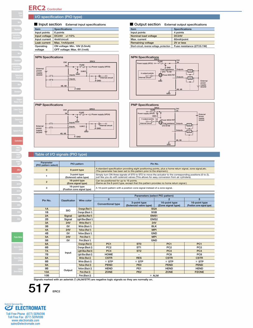
ERC2 Controller
517 ERC2
SliderType
Mini
Mini
PSEP/ASEP
PMEC/AMEC
ROBONET
ERC2
PCON
ACON
SCON
PSEL
ASEL
SSEL
XSEL
Standard
Standard
Standard
ControllersIntegrated
ControllersIntegrated
RodType
Table/Arm/FlatType
Gripper/Rotary Type
Linear ServoType
CleanroomType
Splash-Proof
Controllers
Pulse Motor
Servo Motor (24V)
Servo Motor (200V)
LinearServo Motor
Mini
I/O specification (PIO type)
Table of I/O signals (PIO type)
ItemInput pointsInput voltageInput currentLeak currentOperating voltage
Specifications6 pointsDC24V +/-10%4mA/circuitMax. 1mA/pointON voltage: Min. 18V (3.5mA)OFF voltage: Max. 6V (1mA)
External power supplyDC24V
Power supply (VP24)
Inputs
CN1
3A
4B, 5B
Inputs
5.6KΩ
FUSE
ERC2
GND
GND
GND
Internal circuit
+
■ Input section External input specifications
ItemInput pointsNominal load voltageMax. currentRemaining voltageShort-circuit, reverse voltage, protection
Specifications4 pointsDC24V60mA/point2V or lessFuse resistance (27Ω0.1W)
External power supply DC24V
Power supply (VP24)
Outputs
Outputs
4 output points
Load
Load
27Ω 0.1WFuse resistance
ERC2CN13A
4B, 5B
FUSE
GND
GND
GND
Power MOS FET
Internal circuit
+
External power supply DC24V
Power supply (VP24)
Inputs
CN1
3A
4B, 5B
Inputs 5.6KΩ
FUSE
ERC2
GND
GND
GND
GND
Internal circuit
External power supply DC24V
Power supply (VP24)
Outputs
Outputs
4 output points
Load
Load 27Ω 0.1W
Fuse resistance
ERC2CN13A
4B, 5B
FUSE
GND
GND
Power MOS FET
Internal circuit
+
■ Output section External output specifications
NPN Specifications NPN Specifications
PNP Specifications PNP Specifications
0
1
2
3
8-point type
16-point type(Zone signal type)
3-point type(Solenoid valve type)
16-point type(Position zone signal type)
A standard specification providing eight positioning points, plus a home return signal, zone signal,etc. (The parameter has been set to this pattern prior to the shipment.)
Simply turn ON three signals of ST0 to ST2 to move the actuator to the corresponding positions (0 to 2), just like you do with solenoid valves (This allows for easy conversion from air cylinders).
Can be positioned for up to 16 points. (Same as the 8-point type, except that this pattern provides no home return signal.)
A 16-point pattern with a position zone signal instead of a zone signal.
Parameter (PIO pattern select) PIO pattern Pin No.
1A1B2A2B3A3B4A4B5A5B6A6B7A7B8A8B9A9B10A10B
SignalSignal
24V0V
24V0V
24V0V
SIO
Input
Output
Orange (Red 1)Orange (Black 1)Light Blue (Red 1)
Light Blue (Black 1)White (Red 1)
White (Black 1)Yellow (Red 1)
Yellow (Black 1)Pink (Red 1)
Pink (Black 1)Orange (Red 2)
Orange (Black 2)Light Blue (Red 2)Light Blue (Black 2)
White (Red 2)White (Black 2)Yellow (Red 2)
Yellow (Black 2)Pink (Red 2)
Pink (Black 2)
PC1PC2PC4
HOMECSTR
* STPPENDHENDZONE
ST0ST1ST2
−RES
* STPPE0PE1PE2
* ALM
SGASGB
EMS1EMS224VBLKMPIGNDMPIGND
Pin No. Classification Wire color
Parameters (select PIO pattern)0 1
PC1PC2PC4PC8
CSTR
* STPPENDHENDZONE
2
Conventional type 3-point type(Solenoid valve type)
16-point type(Zone signal type)
Signals marked with an asterisk (*) (ALM/STP) are negative logic signals so they are normally on.
PC1PC2PC4PC8
CSTR
* STPPENDHEND
PZONE
316-point type
(Position zone signal type)
ELECTROMATEToll Free Phone (877) SERVO98
Toll Free Fax (877) SERV099www.electromate.com
Sold & Serviced By:
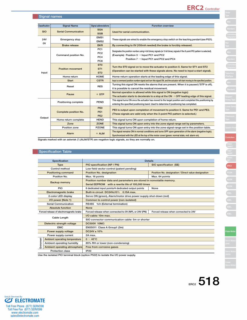
ERC2 Controller
ERC2 518
Mini
Mini
Mini
Standard
Standard
ControllersIntegrated
Standard
ControllersIntegrated
PSEP/ASEP
PMEC/AMEC
ROBONET
ERC2
PCON
ACON
SCON
PSEL
ASEL
SSEL
XSEL
SliderType
RodType
Table/Arm/FlatType
Gripper/Rotary Type
Linear ServoType
CleanroomType
Splash-Proof
Controllers
Pulse Motor
Servo Motor (24V)
Servo Motor (200V)
LinearServo Motor
Signal names
Specification Table
Specification
Type
Control method
Positioning command
Position No.
Backup memory
PIO
Electromagnetic brake
2-color LED display
I/O power (Note 1)
Serial Communication
Absolute function
Forced release of electromagnetic brake
Cable Length
Dielectric strength voltage
EMC
Power supply voltage
Power supply current
Protection class
Details
PIO specification (NP / PN) SIO specification (SE)
Low field vector control (patent pending)
Position No. designation Position No. designation / Direct value designation
Max. 16 points Max. 64 points
Position number data and parameters are stored in nonvolatile memory.
Serial EEPROM with a rewrite life of 100,000 times
6 dedicated input points/4 dedicated output points None
Built-in circuit DC24V±10% 0.15A max.
Servo ON (green), Alarm/motor drive power supply shut-down (red)
Common to control power (non-isolated)
RS485 1ch (External termination)
None
Forced release when connected to 0V (NP), or 24V (PN) Forced release when connected to 24V
I/O cable: 10m max.
SIO connector communication cable: 5m or shorter
DC500V 10MΩ
EN55011 Class A Group1 (3m)
DC24V ± 10%
2A max.
0~ 40°C
85% RH or lower (non-condensing)
Free from corrosive gases
IP20
Envir
onm
ent
Ambient operating temperature
Ambient operating humidity
Ambient operating atmosphere
Classification
SIO
24V
0V
Input
Output
Signal Name
Serial Communication
Emergency stop
Brake release
Command position No.
Position movement
Home return
Start
Reset
Pause
Positioning complete
Complete position No.
Home return complete
Zone
Position zone
Alarm
Signal abbreviations
SGA
SGB
EMS1
EMS2
BKR
PC1
PC2
PC4
PC8
ST0
ST1
ST2
HOME
CSTR
RES
* STP
PEND
PE0
PE1
PE2
HEND
ZONE
PZONE
* ALM
Function overview
Used for serial communication.
These signals are wired to enable the emergency stop switch on the teaching pendant (see P521).
By connecting to 0V (150mA needed) the brake is forcibly released.
Designates the position number using 4-bit binary signals (or 3-bit binary signals if the 8-point PIO pattern is selected).
(Example) Position 3 → Input PC1 and PC2
Position 7 → Input PC1 and PC2 and PC4
Turn the ST0 signal on to move the actuator to position 0. Same for ST1 and ST2
(Operation can be started with these signals alone. No need to input a start signal).
Home-return operation starts at the leading edge of this signal.
Input a command position number signal and turn this signal ON, and the actuator will start moving to the specified position.
Turning this signal ON resets the alarms that are present. When it is paused (*STP is off),
it is possible to cancel the residual movement.
Normal operation is allowed while this signal is ON (negative logic)
The actuator starts to decelerate to a stop at the ON → OFF leading edge of this signal.
This signal turns ON once the actuator has moved to the target position and completed the positioning by
entering the specified positioning band. Used to determine if positioning has completed.
PE0 is output upon completion of movement to position 0. Same for PE1 and PE2.
(These signals are valid only when the 3-point PIO pattern is selected.)
This signal turns ON upon completion of home return.
This signal turns ON upon entry into the zone signal range set by parameters.
This signal turns ON upon entry into the zone signal range set in the position table.
The signal remains ON in normal conditions and turns OFF upon generation of the alarm (negative logic).
Synchronized with the LED at the top of the motor cover (green: normal state, red: alarm on).
Signals marked with an asterisk (*) (ALM/STP) are negative logic signals, so they are normally on.
Use the isolated PIO terminal block (option P522) to isolate the I/O power supply.
ELECTROMATEToll Free Phone (877) SERVO98
Toll Free Fax (877) SERV099www.electromate.com
Sold & Serviced By:

ERC2 Controller
519 ERC2
SliderType
Mini
Mini
PSEP/ASEP
PMEC/AMEC
ROBONET
ERC2
PCON
ACON
SCON
PSEL
ASEL
SSEL
XSEL
Standard
Standard
Standard
ControllersIntegrated
ControllersIntegrated
RodType
Table/Arm/FlatType
Gripper/Rotary Type
Linear ServoType
CleanroomType
Splash-Proof
Controllers
Pulse Motor
Servo Motor (24V)
Servo Motor (200V)
LinearServo Motor
Mini
I/O wiring drawing
24V
0V
FG
Input Voltage (2A or more)
SGA
SGB
Control power supply
Normally: OFF. When released: ON (for brake specification)
Motor drive power supply
I/O interface (See I/O connection for each PIO pattern.)
Serial Communication
6A
6B
EMS12A
EMS22B
MPI4A
GND4B
MPI5A
GND5B
24V3A
BKR3B
7A
7B
8A
8B
9A
9B
10A
10B
1A
1B
MC
EMG signal
Forced brake release switch
(Note)
60mA Max
Upper level system < PLC >
Teaching Pendant EMG switch contact output(See P521 for information on emergency stop circuit.)
ERC2 PIO type
CN1
CN2
FG
(Red 1) Yellow
(Black 1) Yellow
(Red 1) * Light Blue
(Black 1) * Light Blue
(Red 1) Pink
(Black 1) Pink
(Red 1) White
(Black 1) White
(Red 2) Orange
(Black 2) Orange
(Red 2) * Light Blue
* Light Blue (Black 2)
(Red 2) White
(Black 2) White
(Red 2) Yellow
(Black 2) Yellow
(Red 2) Pink
(Black 2) Pink
(Red 1) Orange
(Black 1) Orange (Not used)
Ground wire (Note) To forcibly release the brake, turn the switch to ON between BKR and 0V.
* For robot cables, the wire colors as as follows.
Wire colorGray (Red 1)Gray (Black 1)Gray (Red2)Gray (Black 2)
Pin Number
2A2B7A7B
Out-put side
In-put side
PIO Type NP (NPN Specification)
PIO Type PN (PNP Specification)
* For robot cables, the wire colors as as follows.
Wire colorGray (Red 1)Gray (Black 1)Gray (Red2)Gray (Black 2)
Pin Number
2A2B7A7B
24V
0V
FG
Input Voltage (2A or more)
SGA
SGB
Control power
Normally: OFF. When released: ON (for brake specification)
Motor drive power supply
I/O interface (See I/O connection for each PIO pattern.)
Serial Communication
6A
6B
EMS12A
EMS22B
MPI4A
GND4B
MPI5A
GND5B
24V3A
BKR3B
7A
7B
8A
8B
9A
9B
10A
10B
1A
1B
MC
EMG signal
60mA Max
Upper level system < PLC >
Teaching Pendant
ERC2 PIO type
CN1
CN2
FG
(Red 1) Yellow
(Black 1) Yellow
(Red 1) * Light Blue
(Black 1) * Light Blue
(Red 1) Pink
(Black 1) Pink
(Red 1) White
(Black 1) White
(Red 2) Orange
(Black 2) Orange
(Red 2) * Light Blue
(Black 2) * Light Blue
(Red 2) White
(Black 2) White
(Red 2) Yellow
(Black 2) Yellow
(Red 2) Pink
(Black 2) Pink
(Red 1) Orange
(Black 1) Orange (Not used)
Ground wire
Forced brake release switch
(Note)
EMG switch contact output (See P521 for information on emergency stop circuit.)
(Note) To forcibly release the brake, turn the switch to ON between BKR and 24V.
Out-put side
In-put side
ELECTROMATEToll Free Phone (877) SERVO98
Toll Free Fax (877) SERV099www.electromate.com
Sold & Serviced By:
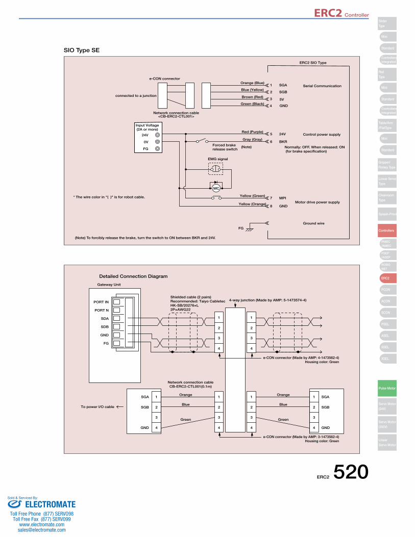
ERC2 Controller
ERC2 520
Mini
Mini
Mini
Standard
Standard
ControllersIntegrated
Standard
ControllersIntegrated
PSEP/ASEP
PMEC/AMEC
ROBONET
ERC2
PCON
ACON
SCON
PSEL
ASEL
SSEL
XSEL
SliderType
RodType
Table/Arm/FlatType
Gripper/Rotary Type
Linear ServoType
CleanroomType
Splash-Proof
Controllers
Pulse Motor
Servo Motor (24V)
Servo Motor (200V)
LinearServo Motor
* The wire color in "( )" is for robot cable.
24V
0V
FG
Input Voltage (2A or more)
SGA
SGB
5V
GND
Control power supply
Motor drive power supply
Serial Communication
MPI7
GND8
24V5
BKR6
1
2
3
4
MC
EMG signal
Forced brake release switch
(Note)
ERC2 SIO Type
e-CON connector
connected to a junction
Network connection cable<CB-ERC2-CTL001>
FGGround wire
Orange (Blue)
Brown (Red)
Blue (Yellow)
Green (Black)
Red (Purple)
Gray (Gray)
Yellow (Green)
Yellow (Orange)
(Note) To forcibly release the brake, turn the switch to ON between BKR and 24V.
Normally: OFF. When released: ON (for brake specification)
SIO Type SE
PORT IN
PORT N
SDA
SDB
GND
FG
Gateway Unit
Shielded cable (2 pairs)Recommended: Taiyo CabletecHK-SB/20276×L2P×AWG22
4-way junction (Made by AMP: 5-1473574-4)
e-CON connector (Made by AMP: 4-1473562-4)Housing color: Green
e-CON connector (Made by AMP: 3-1473562-4)Housing color: Green
Orange
Blue
Green
Orange
Network connection cableCB-ERC2-CTL001(0.1m)
To power I/O cableBlue
Green
Detailed Connection Diagram
1
2
3
4
1
2
3
4
1
2
3
4
1
2
3
4
1
2
3
4
SGA
SGB
GND
SGA
SGB
GND
1
2
3
4
ELECTROMATEToll Free Phone (877) SERVO98
Toll Free Fax (877) SERV099www.electromate.com
Sold & Serviced By:
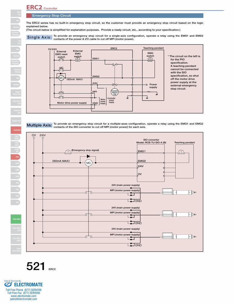
ERC2 Controller
521 ERC2
SliderType
Mini
Mini
PSEP/ASEP
PMEC/AMEC
ROBONET
ERC2
PCON
ACON
SCON
PSEL
ASEL
SSEL
XSEL
Standard
Standard
Standard
ControllersIntegrated
ControllersIntegrated
RodType
Table/Arm/FlatType
Gripper/Rotary Type
Linear ServoType
CleanroomType
Splash-Proof
Controllers
Pulse Motor
Servo Motor (24V)
Servo Motor (200V)
LinearServo Motor
Mini
Emergency Stop Circuit
The ERC2 series has no built-in emergency stop circuit, so the customer must provide an emergency stop circuit based on the logic explained below. (The circuit below is simplified for explanation purposes. Provide a ready circuit, etc., according to your specification.)
To provide an emergency stop circuit for a single-axis configuration, operate a relay using the EMS1 and EMS2 contacts of the power & I/O cable to cut off MPI (motor power). S i n g l e A x i s :
External EMO reset
switch
External EMG
switch
ERC2 Teaching pendant
Power supply
EMG switch
Motor drive power supply
Motor power supply
Controller power supply
Connection detection
relay
To provide an emergency stop circuit for a multiple-axes configuration, operate a relay using the EMG1 and EMG2 contacts of the SIO converter to cut off MPI (motor power) for each axis.Multiple Axis:
(Emergency stop signal)
SIO converterModel: RCB-TU-SIO-A (B) Teaching pendant
24V (main power supply)
MPI (motor power supply)
24V (main power supply)
24V (main power supply)
MPI (motor power supply)
MPI (motor power supply)
* The circuit on the left isfor the PIOspecification.A teaching pendantcannot be connectedwith the SIOspecification, so shutoff the motor drivepower supply at theexternal emergencystop circuit.
ELECTROMATEToll Free Phone (877) SERVO98
Toll Free Fax (877) SERV099www.electromate.com
Sold & Serviced By:
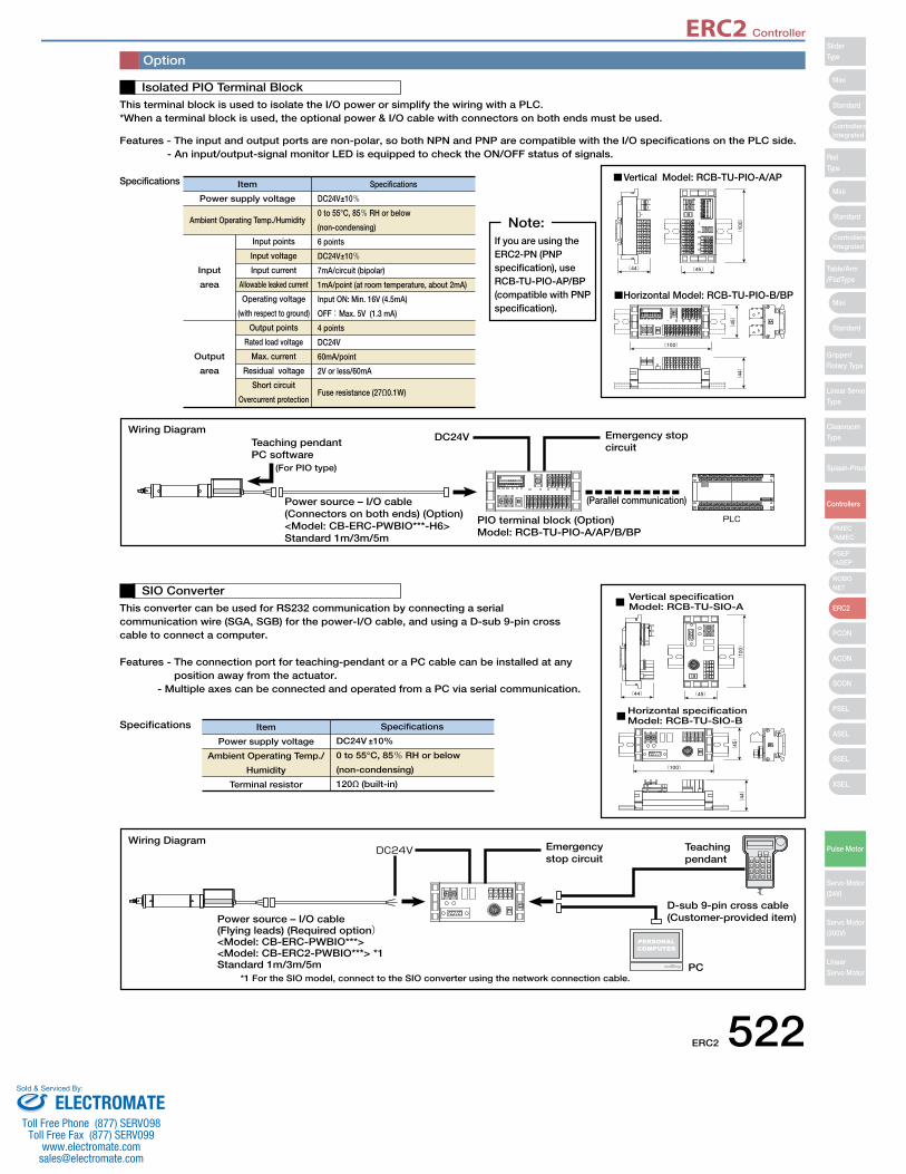
ERC2 Controller
ERC2 522
Mini
Mini
Mini
Standard
Standard
ControllersIntegrated
Standard
ControllersIntegrated
PSEP/ASEP
PMEC/AMEC
ROBONET
ERC2
PCON
ACON
SCON
PSEL
ASEL
SSEL
XSEL
SliderType
RodType
Table/Arm/FlatType
Gripper/Rotary Type
Linear ServoType
CleanroomType
Splash-Proof
Controllers
Pulse Motor
Servo Motor (24V)
Servo Motor (200V)
LinearServo Motor
Option
This terminal block is used to isolate the I/O power or simplify the wiring with a PLC. *When a terminal block is used, the optional power & I/O cable with connectors on both ends must be used.
Features - The input and output ports are non-polar, so both NPN and PNP are compatible with the I/O specifications on the PLC side.- An input/output-signal monitor LED is equipped to check the ON/OFF status of signals.
Specifications
Isolated PIO Terminal Block
Vertical Model: RCB-TU-PIO-A/AP
Horizontal Model: RCB-TU-PIO-B/BP
This converter can be used for RS232 communication by connecting a serial communication wire (SGA, SGB) for the power-I/O cable, and using a D-sub 9-pin cross cable to connect a computer.
Features - The connection port for teaching-pendant or a PC cable can be installed at any position away from the actuator.
- Multiple axes can be connected and operated from a PC via serial communication.
Specifications
SIO Converter Vertical specificationModel: RCB-TU-SIO-A
Horizontal specificationModel: RCB-TU-SIO-B
Item
Power supply voltage
Ambient Operating Temp./Humidity
Input
area
Input points
Input voltage
Input current
Allowable leaked current
Operating voltage
(with respect to ground)
Output points
Rated load voltage
Max. current
Residual voltage
Short circuit
Overcurrent protection
Output
area
Specifications
DC24V±10%0 to 55°C, 85% RH or below
(non-condensing)
6 points
DC24V±10%7mA/circuit (bipolar)
1mA/point (at room temperature, about 2mA)
Input ON: Min. 16V (4.5mA)
OFF: Max. 5V (1.3 mA)
4 points
DC24V
60mA/point
2V or less/60mA
Fuse resistance (27Ω0.1W)
Item
Power supply voltage
Ambient Operating Temp./
Humidity
Terminal resistor
Specifications
DC24V ±10%
0 to 55°C, 85% RH or below
(non-condensing)
120Ω (built-in)
(For PIO type)
Teaching pendantPC software
Power source – I/O cable(Connectors on both ends) (Option)<Model: CB-ERC-PWBIO***-H6>Standard 1m/3m/5m
PIO terminal block (Option)Model: RCB-TU-PIO-A/AP/B/BP
Emergency stop circuit
DC24V
(Parallel communication)
Wiring Diagram
*1 For the SIO model, connect to the SIO converter using the network connection cable.
Power source – I/O cable(Flying leads) (Required option)<Model: CB-ERC-PWBIO***><Model: CB-ERC2-PWBIO***> *1Standard 1m/3m/5m
Emergency stop circuit
Teaching pendant
D-sub 9-pin cross cable(Customer-provided item)
PC
Wiring Diagram
If you are using the ERC2-PN (PNP specification), use RCB-TU-PIO-AP/BP (compatible with PNP specification).
Note:
ELECTROMATEToll Free Phone (877) SERVO98
Toll Free Fax (877) SERV099www.electromate.com
Sold & Serviced By:
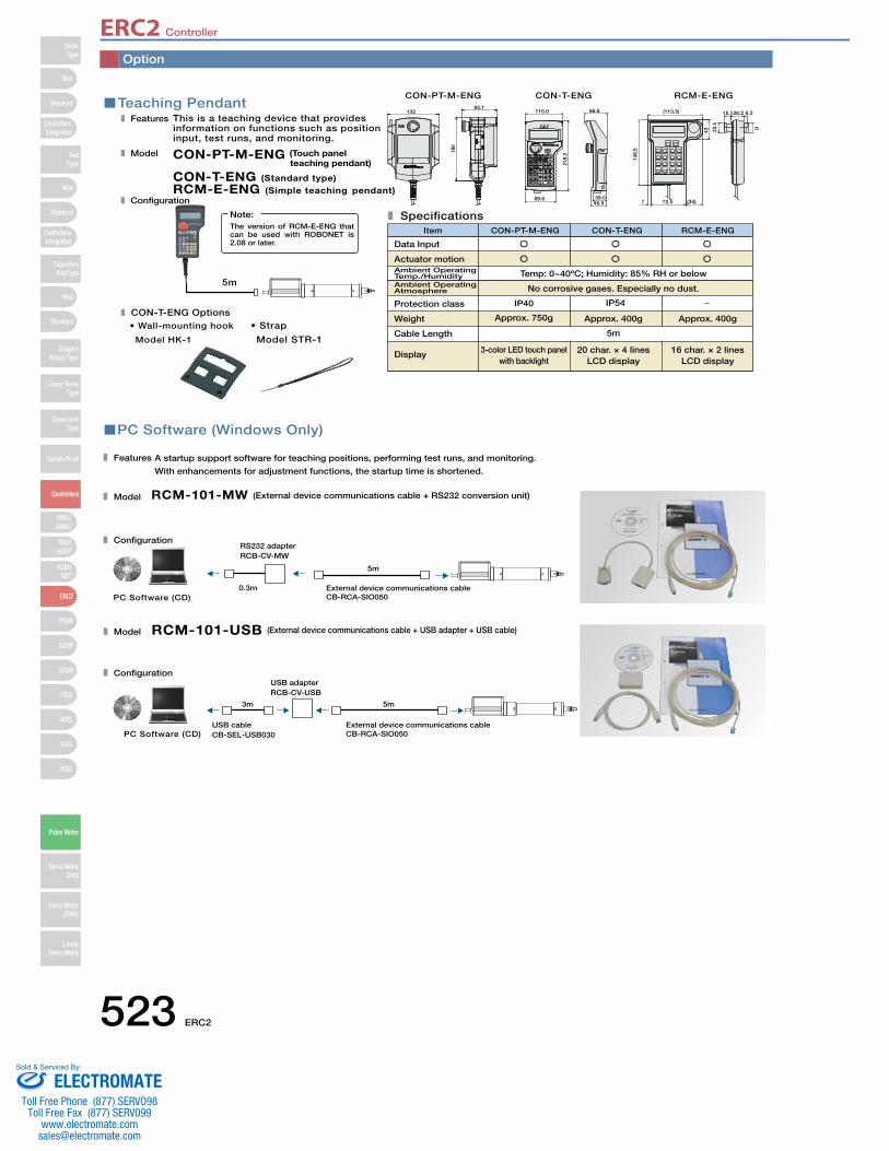
ERC2 Controller
523 ERC2
SliderType
Mini
Mini
PSEP/ASEP
PMEC/AMEC
ROBONET
ERC2
PCON
ACON
SCON
PSEL
ASEL
SSEL
XSEL
Standard
Standard
Standard
ControllersIntegrated
ControllersIntegrated
RodType
Table/Arm/FlatType
Gripper/Rotary Type
Linear ServoType
CleanroomType
Splash-Proof
Controllers
Pulse Motor
Servo Motor (24V)
Servo Motor (200V)
LinearServo Motor
Mini
PC Software (Windows Only)
A startup support software for teaching positions, performing test runs, and monitoring.
With enhancements for adjustment functions, the startup time is shortened.
Features
Model
Configuration
RCM-101-MW (External device communications cable + RS232 conversion unit)
0.3m
5m
External device communications cableCB-RCA-SIO050PC Software (CD)
RS232 adapterRCB-CV-MW
Model
Configuration
RCM-101-USB (External device communications cable + USB adapter + USB cable)
5m3m
PC Software (CD)External device communications cableCB-RCA-SIO050
USB cableCB-SEL-USB030
USB adapterRCB-CV-USB
Teaching PendantThis is a teaching device that provides information on functions such as position input, test runs, and monitoring.
CON-PT-M-ENG (Touch panelteaching pendant)
CON-T-ENG (Standard type)RCM-E-ENG (Simple teaching pendant)
Features
Model
Configuration
Specifications
Display
Data Input
3-color LED touch panelwith backlight
Approx. 750g
IP40 IP54
20 char. × 4 linesLCD display
5m
Approx. 400g
No corrosive gases. Especially no dust.
Temp: 0~40ºC; Humidity: 85% RH or below
16 char. × 2 linesLCD display
Approx. 400g
Item CON-PT-M-ENG CON-T-ENG RCM-E-ENG
5m
The version of RCM-E-ENG that can be used with ROBONET is 2.08 or later.
Note:
RCM-E-ENGCON-T-ENGCON-PT-M-ENG
21
6.326.215.1
23.5
43
148.
5
7 (34)72.5
(113.5)
46.939.0
66.6110.0
218.
3
89.6
CON-T-ENG Options• Wall-mounting hook
Model HK-1
• Strap
Model STR-1
13292.1
180
Actuator motionAmbient Operating Temp./HumidityAmbient Operating Atmosphere
Protection class
Weight
Cable Length
Option
ELECTROMATEToll Free Phone (877) SERVO98
Toll Free Fax (877) SERV099www.electromate.com
Sold & Serviced By:
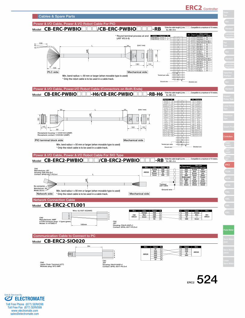
ERC2 Controller
ERC2 524
Mini
Mini
Mini
Standard
Standard
ControllersIntegrated
Standard
ControllersIntegrated
PSEP/ASEP
PMEC/AMEC
ROBONET
ERC2
PCON
ACON
SCON
PSEL
ASEL
SSEL
XSEL
SliderType
RodType
Table/Arm/FlatType
Gripper/Rotary Type
Linear ServoType
CleanroomType
Splash-Proof
Controllers
Pulse Motor
Servo Motor (24V)
Servo Motor (200V)
LinearServo Motor
Cables & Spare Parts
Wire colorStandard Cable Robot Cable
(ø9)
PLC side Mechanical side
Color SignalSignal
Orange (Red 1)Orange (Black1)
Orange (Red 1)Orange (Black1)Light Blue (Red 1)Light Blue (Black 1)White (Red 1)White (Black 1)Yellow (Red 1)Yellow (Black 1)Pink (Red 1)Pink (Black 1)Orange (Red 2)Orange (Black2)
Light Blue (Red 2)
Light Blue (Black 2)
White (Red 2)
White (Black 2)
Yellow (Red 2)
Yellow (Black 2)
Pink (Red 2)
Pink (Black 2)
Gray (Black 2)Gray (Red 2)
Gray (Black 1)Gray (Red 1)
Twisted pair cable
Ground wire Shielded wire
(Unit / mm)
* Round terminal process at end(JST VO.5-3)
Receptacle housing: 1-1318118-9 (AMP)Receptacle contact: 1318108-1(AMP)
(Unit / mm)
Twisted pair cable
Ground wire Shielded wire
Signal Signal
(ø9)
PIO terminal block side Mechanical side
Model CB-ERC-PWBIO□□□/CB-ERC-PWBIO□□□-RBPower & I/O Cable, Power & I/O Robot Cable For PIO
* Enter the cable length (L) into □□□ . Compatible to a maximum of 10 meters. Ex.: 080 = 8 m
Model CB-ERC-PWBIO□□□-H6/CB-ERC-PWBIO□□□-RB-H6Power & I/O Cable, Power-I/O Robot Cable (Connectors on Both Ends)
* Enter the cable length (L) into □□□ . Compatible to a maximum of 10 meters. Ex.: 080 = 8 m
Manufacturer: JSTModel: V0.5-3
No connector
L
CN2Manufacturer: JSTHousing: PAP-04V-S×1Contact: SPHD-001T-P0.5×4
Twistedpair cable
Ground wire
ColorOrange
BlueBrownGreen
Wire
AWG26
Signal No.1234
SGASGB5V
GND
Signal Name
OrangeSGABlue
BrownGreen
SGB5V
GND
Robot CableStandard CableWire color
No.
1234
BlueYellow
RedBlack
RedControl power5 PurpleGrayBrake6 Gray
YellowMPI7 GreenBlackGND8 OrangeShieldShield9 Shield
(ø8)
Network side Mechanical side
Model CB-ERC2-PWBIO□□□/CB-ERC2-PWBIO□□□-RBPower & I/O Cable, Power & I/O Robot Cable For SIO Type
* Enter the cable length (L) into □□□ . Compatible to a maximum of 10 meters. Ex.: 080 = 8 m
1234
1234
Wire: UL1007 #22AWG
100mm
CN2Manufacturer: AMPe-CON connector plugs - 4 types (green)Model: 4-1473562-4
CN1JSTHousing: PALR-04VF×1Contact: SPAL-001T-P0.5×4
ColorOrange
BlueGreen
Wire
CN2AWG22
Signal No.1234
SGASGBGNDNC
ColorOrange
Blue—
Green
Wire
CN1AWG22
SignalNo.1234
SGASGB5V
GND
Model CB-ERC2-CTL001Network Connection Cable
Wire
AWG26
Signal No.1234
5VSGAGNDSGB
5GND65V
Wire
AWG26
SignalNo.1234
SGASGB5V
GND
1234
2m
CN2Japan Chain Terminal (JCT)Modular plug: NTC-66R
CN1JSTHousing: PALR-04VF×1Contact: SPAL-001T-P0.5×4
Model CB-ERC2-SIO020Communication Cable to Connect to PC
Min. bend radius r = 50 mm or larger (when movable type is used)* Only the robot cable is to be used in a cable track.
Min. bend radius r = 50 mm or larger (when movable type is used)* Only the robot cable is to be used in a cable track.
Min. bend radius r = 50 mm or larger (when movable type is used)* Only the robot cable is to be used in a cable track.
ELECTROMATEToll Free Phone (877) SERVO98
Toll Free Fax (877) SERV099www.electromate.com
Sold & Serviced By:
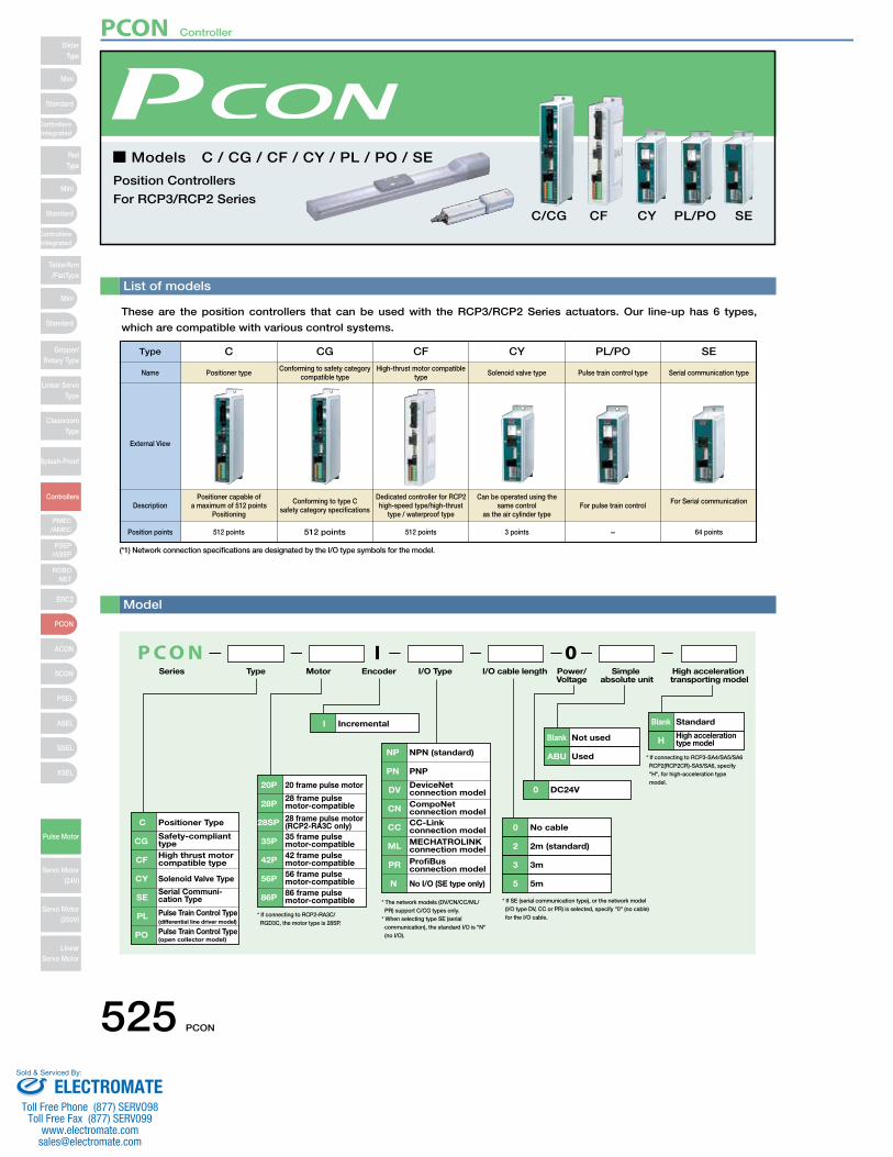
List of models
These are the position controllers that can be used with the RCP3/RCP2 Series actuators. Our line-up has 6 types,
which are compatible with various control systems.
■ Models C / CG / CF / CY / PL / PO / SE
Position Controllers
For RCP3/RCP2 SeriesCF CY PL/PO SE
P C O NSeries
0
C Positioner Type
CGSafety-compliant type
CY Solenoid Valve Type
CF High thrust motor compatible type
SESerial Communi-cation Type
PL(differential line driver model)Pulse Train Control Type
PO(open collector model)Pulse Train Control Type
20P 20 frame pulse motor
28P28 frame pulse motor-compatible
42P 42 frame pulse motor-compatible
35P 35 frame pulse motor-compatible
56P 56 frame pulse motor-compatible
86P 86 frame pulse motor-compatible
28SP 28 frame pulse motor(RCP2-RA3C only)
I Incremental
NP NPN (standard)
PN PNP
PR ProfiBusconnection model
ML MECHATROLINK connection model
CC CC-Linkconnection model
DVDeviceNetconnection model
CN CompoNet connection model
No I/O (SE type only)
0 DC24V
0 No cable
2 2m (standard)
Blank Not used
ABU Used
3 3m
5 5m
I
* If SE (serial communication type), or the network model (I/O type DV, CC or PR) is selected, specify "0" (no cable) for the I/O cable.* If connecting to RCP2-RA3C/
RGD3C, the motor type is 28SP.
* The network models (DV/CN/CC/ML/ PR) support C/CG types only. * When selecting type SE (serial communication), the standard I/O is "N" (no I/O).
Blank Standard
HHigh acceleration type model
* If connecting to RCP3-SA4/SA5/SA6 RCP2(RCP2CR)-SA5/SA6, specify "H", for high-acceleration type model.
N
Type I/O Type I/O cable length Power/Voltage
Simple absolute unit
High acceleration transporting model
Motor Encoder
Type C
Positioner typeName
External View
DescriptionPositioner capable of
a maximum of 512 points Positioning
Position points 512 points
CG
Conforming to safety category compatible type
Conforming to type C safety category specifications
512 points
CF
High-thrust motor compatible type
Dedicated controller for RCP2 high-speed type/high-thrust
type / waterproof type
512 points
CY
Solenoid valve type
Can be operated using the same control
as the air cylinder type
3 points
PL/PO
Pulse train control type
For pulse train control
−
SE
Serial communication type
For Serial communication
64 points
Model
(*1) Network connection specifications are designated by the I/O type symbols for the model.
C/CG
525 PCON
SliderType
Mini
Mini
PSEP/ASEP
PMEC/AMEC
ROBONET
ERC2
PCON
ACON
SCON
PSEL
ASEL
SSEL
XSEL
Standard
Standard
Standard
ControllersIntegrated
ControllersIntegrated
RodType
Table/Arm/FlatType
Gripper/Rotary Type
Linear ServoType
CleanroomType
Splash-Proof
Controllers
Pulse Motor
Servo Motor (24V)
Servo Motor (200V)
LinearServo Motor
Mini
PCON Controller
ELECTROMATEToll Free Phone (877) SERVO98
Toll Free Fax (877) SERV099www.electromate.com
Sold & Serviced By:
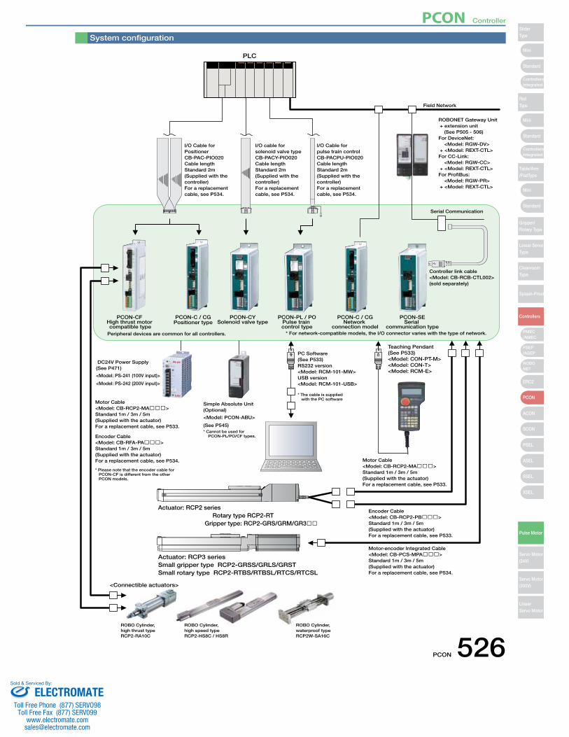
PCON-SESerial
communication type
PCON-PL / POPulse train control type
PCON-C / CGNetwork
connection model
Field Network
I/O Cable for pulse train controlCB-PACPU-PIO020Cable lengthStandard 2m(Supplied with the controller)For a replacement cable, see P534.
I/O cable for solenoid valve typeCB-PACY-PIO020Cable lengthStandard 2m(Supplied with the controller)For a replacement cable, see P534.
I/O Cable for PositionerCB-PAC-PIO020Cable lengthStandard 2m(Supplied with the controller) For a replacement cable, see P534.
Motor Cable<Model: CB-RCP2-MA���>Standard 1m / 3m / 5m(Supplied with the actuator)For a replacement cable, see P533.
Motor Cable<Model: CB-RCP2-MA���>Standard 1m / 3m / 5m(Supplied with the actuator)For a replacement cable, see P533.
Encoder Cable<Model: CB-RFA-PA���>Standard 1m / 3m / 5m(Supplied with the actuator)For a replacement cable, see P534.
<Model: PS-241 (100V input)>
<Model: PS-242 (200V input)>
PC Software(See P533)RS232 version<Model: RCM-101-MW>USB version<Model: RCM-101-USB>
Teaching Pendant
* The cable is supplied with the PC software
* For network-compatible models, the I/O connector varies with the type of network.
* Please note that the encoder cable for PCON-CF is different from the other PCON models.
* Cannot be used for PCON-PL/PO/CF types.
Encoder Cable<Model: CB-RCP2-PB���>Standard 1m / 3m / 5m(Supplied with the actuator)For a replacement cable, see P533.
Motor-encoder Integrated Cable<Model: CB-PCS-MPA���>Standard 1m / 3m / 5m(Supplied with the actuator)For a replacement cable, see P534.
Serial Communication
Controller link cable<Model: CB-RCB-CTL002>(sold separately)
PCON-CYSolenoid valve type
PCON-C / CGPositioner type
Peripheral devices are common for all controllers.
PLC
PCON-CFHigh thrust motor compatible type
DC24V Power Supply(See P471)
<Model: PCON-ABU>
(See P545)
Simple Absolute Unit(Optional)
<Connectible actuators>
ROBO Cylinder, high thrust typeRCP2-RA10C
ROBO Cylinder, high speed typeRCP2-HS8C / HS8R
ROBO Cylinder, waterproof typeRCP2W-SA16C
ROBONET Gateway Unit + extension unit (See P505 - 506)For DeviceNet: <Model: RGW-DV> + <Model: REXT-CTL>For CC-Link: <Model: RGW-CC> + <Model: REXT-CTL>For ProfiBus: <Model: RGW-PR> + <Model: REXT-CTL>
Actuator: RCP2 series
Actuator: RCP3 seriesSmall gripper type RCP2-GRSS/GRLS/GRSTSmall rotary type RCP2-RTBS/RTBSL/RTCS/RTCSL
Rotary type RCP2-RTGripper type: RCP2-GRS/GRM/GR3��
(See P533)<Model: CON-PT-M><Model: CON-T><Model: RCM-E>
System configuration
PCON 526
Mini
Mini
Mini
Standard
Standard
ControllersIntegrated
Standard
ControllersIntegrated
PSEP/ASEP
PMEC/AMEC
ROBONET
ERC2
PCON
ACON
SCON
PSEL
ASEL
SSEL
XSEL
SliderType
RodType
Table/Arm/FlatType
Gripper/Rotary Type
Linear ServoType
CleanroomType
Splash-Proof
Controllers
Pulse Motor
Servo Motor (24V)
Servo Motor (200V)
LinearServo Motor
PCON Controller
ELECTROMATEToll Free Phone (877) SERVO98
Toll Free Fax (877) SERV099www.electromate.com
Sold & Serviced By:
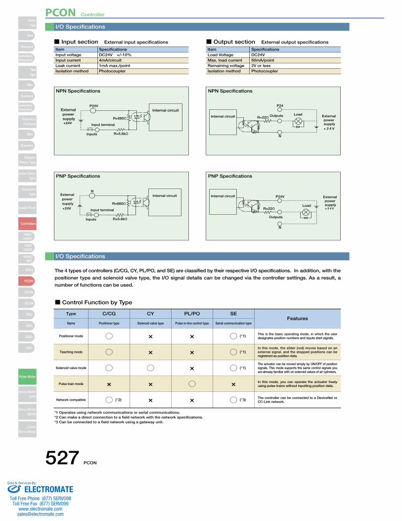
I/O Specifications
I/O Specifications
The 4 types of controllers (C/CG, CY, PL/PO, and SE) are classified by their respective I/O specifications. In addition, with the
positioner type and solenoid valve type, the I/O signal details can be changed via the controller settings. As a result, a
number of functions can be used.
■ Control Function by Type
ItemInput voltageInput currentLeak currentIsolation method
SpecificationsDC24V +/-10%4mA/circuit1mA max./pointPhotocoupler
P24V
R=5.6kΩInputs
R=680Ω+24V
External power supply
Input terminal
Internal circuit
■ Input section External input specifications
ItemLoad VoltageMax. load current Remaining voltageIsolation method
SpecificationsDC24V50mA/point2V or lessPhotocoupler
P24
N
OutputsR=22ΩInternal circuitLoad
+ 2 4 V
External power supply
N
R=5.6kΩInputs
R=680Ω+24V
External power supply
Input terminal
Internal circuit P24V
N
Outputs
Internal circuit
+ 2 4 V
External power supplyLoad
R=22Ω
■ Output section External output specifications
NPN Specifications NPN Specifications
PNP Specifications PNP Specifications
Type C/CG
Positioner typeFeatures
Name
Positioner mode ○
CY
Solenoid valve type
×
PL/PO
Pulse in-line control type
×
SE
Serial communication type
○ This is the basic operating mode, in which the user designates position numbers and inputs start signals.
Teaching mode ○ × × ○In this mode, the slider (rod) moves based on an external signal, and the stopped positions can be registered as position data.
Solenoid valve mode ○ ○ × ○The actuator can be moved simply by ON/OFF of position signals. This mode supports the same control signals you are already familiar with on solenoid valves of air cylinders.
Pulse train mode × × ○ × In this mode, you can operate the actuator freely using pulse trains without inputting position data.
Network compatible ○ × × ○ The controller can be connected to a DeviceNet or CC-Link network.
*1 Operates using network communications or serial communications. *2 Can make a direct connection to a field network with the network specifications. *3 Can be connected to a field network using a gateway unit.
(*1)
(*1)
(*1)
(*3) (*2)
527 PCON
SliderType
Mini
Mini
PSEP/ASEP
PMEC/AMEC
ROBONET
ERC2
PCON
ACON
SCON
PSEL
ASEL
SSEL
XSEL
Standard
Standard
Standard
ControllersIntegrated
ControllersIntegrated
RodType
Table/Arm/FlatType
Gripper/Rotary Type
Linear ServoType
CleanroomType
Splash-Proof
Controllers
Pulse Motor
Servo Motor (24V)
Servo Motor (200V)
LinearServo Motor
Mini
PCON Controller
ELECTROMATEToll Free Phone (877) SERVO98
Toll Free Fax (877) SERV099www.electromate.com
Sold & Serviced By:
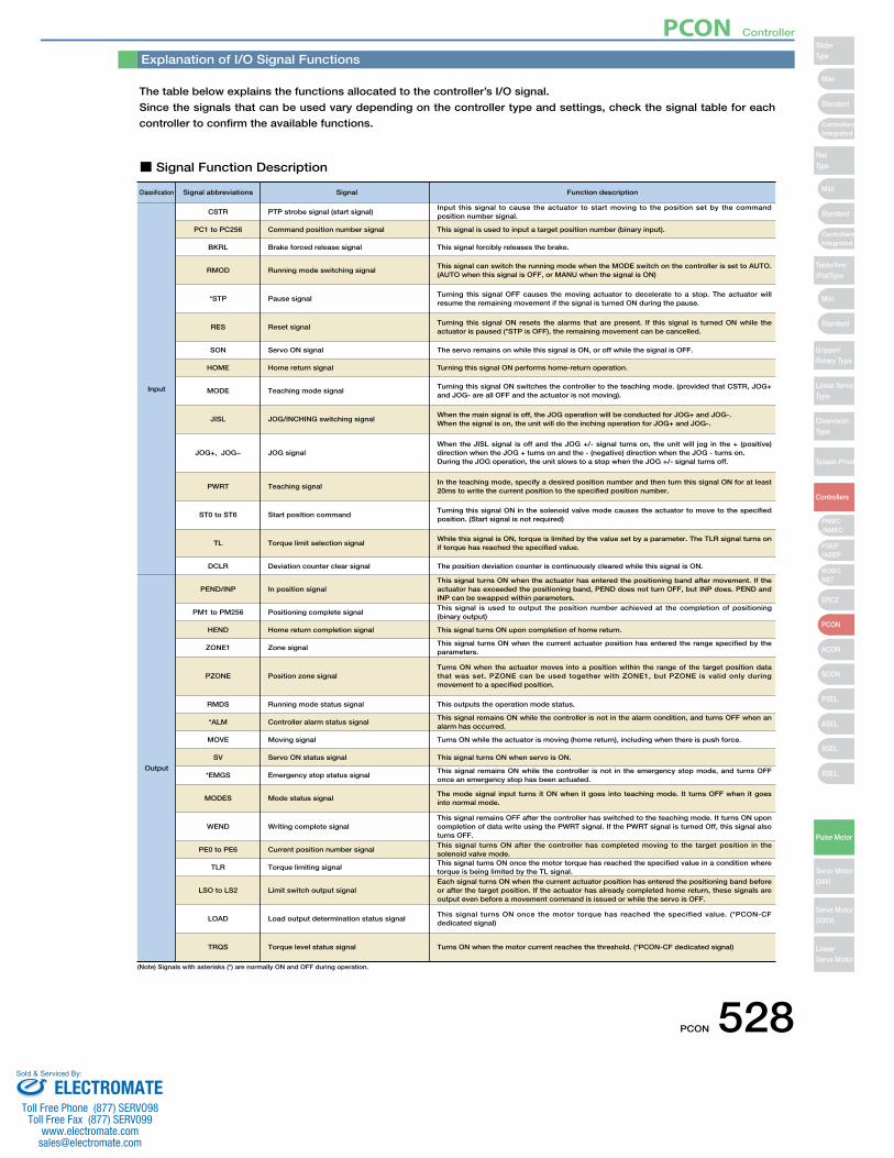
Explanation of I/O Signal Functions
The table below explains the functions allocated to the controller’s I/O signal.
Since the signals that can be used vary depending on the controller type and settings, check the signal table for each
controller to confirm the available functions.
■ Signal Function Description
Classification Signal abbreviations
CSTR PTP strobe signal (start signal)
Signal
Input this signal to cause the actuator to start moving to the position set by the command position number signal.
PC1 to PC256 Command position number signal This signal is used to input a target position number (binary input).
Function description
BKRL Brake forced release signal This signal forcibly releases the brake.
RMOD Running mode switching signalThis signal can switch the running mode when the MODE switch on the controller is set to AUTO. (AUTO when this signal is OFF, or MANU when the signal is ON)
*STP Pause signalTurning this signal OFF causes the moving actuator to decelerate to a stop. The actuator will resume the remaining movement if the signal is turned ON during the pause.
MODE Teaching mode signalTurning this signal ON switches the controller to the teaching mode. (provided that CSTR, JOG+ and JOG- are all OFF and the actuator is not moving).
RES Reset signalTurning this signal ON resets the alarms that are present. If this signal is turned ON while the actuator is paused (*STP is OFF), the remaining movement can be cancelled.
SON Servo ON signal The servo remains on while this signal is ON, or off while the signal is OFF.
JISL JOG/INCHING switching signalWhen the main signal is off, the JOG operation will be conducted for JOG+ and JOG-.When the signal is on, the unit will do the inching operation for JOG+ and JOG-.
JOG+, JOG− JOG signalWhen the JISL signal is off and the JOG +/- signal turns on, the unit will jog in the + (positive) direction when the JOG + turns on and the - (negative) direction when the JOG - turns on.During the JOG operation, the unit slows to a stop when the JOG +/- signal turns off.
ST0 to ST6 Start position commandTurning this signal ON in the solenoid valve mode causes the actuator to move to the specified position. (Start signal is not required)
TL Torque limit selection signalWhile this signal is ON, torque is limited by the value set by a parameter. The TLR signal turns on if torque has reached the specified value.
DCLR Deviation counter clear signal The position deviation counter is continuously cleared while this signal is ON.
PEND/INP In position signalThis signal turns ON when the actuator has entered the positioning band after movement. If the actuator has exceeded the positioning band, PEND does not turn OFF, but INP does. PEND and INP can be swapped within parameters.
PWRT Teaching signalIn the teaching mode, specify a desired position number and then turn this signal ON for at least 20ms to write the current position to the specified position number.
HOME Home return signal Turning this signal ON performs home-return operation.
Input
Output
PM1 to PM256 Positioning complete signalThis signal is used to output the position number achieved at the completion of positioning (binary output)
HEND Home return completion signal This signal turns ON upon completion of home return.
ZONE1 Zone signalThis signal turns ON when the current actuator position has entered the range specified by the parameters.
PZONE Position zone signalTurns ON when the actuator moves into a position within the range of the target position data that was set. PZONE can be used together with ZONE1, but PZONE is valid only during movement to a specified position.
RMDS Running mode status signal This outputs the operation mode status.
*ALM Controller alarm status signalThis signal remains ON while the controller is not in the alarm condition, and turns OFF when an alarm has occurred.
SV Servo ON status signal
*EMGS Emergency stop status signalThis signal remains ON while the controller is not in the emergency stop mode, and turns OFF once an emergency stop has been actuated.
MODES Mode status signalThe mode signal input turns it ON when it goes into teaching mode. It turns OFF when it goes into normal mode.
WEND Writing complete signalThis signal remains OFF after the controller has switched to the teaching mode. It turns ON upon completion of data write using the PWRT signal. If the PWRT signal is turned Off, this signal also turns OFF.
PE0 to PE6 Current position number signalThis signal turns ON after the controller has completed moving to the target position in the solenoid valve mode.
TLR Torque limiting signalThis signal turns ON once the motor torque has reached the specified value in a condition where torque is being limited by the TL signal.
LSO to LS2
LOAD
TRQS
Limit switch output signal
Load output determination status signal
Torque level status signal
Each signal turns ON when the current actuator position has entered the positioning band before or after the target position. If the actuator has already completed home return, these signals are output even before a movement command is issued or while the servo is OFF.
This signal turns ON once the motor torque has reached the specified value. (*PCON-CF dedicated signal)
Turns ON when the motor current reaches the threshold. (*PCON-CF dedicated signal)
MOVE Moving signal Turns ON while the actuator is moving (home return), including when there is push force.
This signal turns ON when servo is ON.
(Note) Signals with asterisks (*) are normally ON and OFF during operation.
PCON 528
Mini
Mini
Mini
Standard
Standard
ControllersIntegrated
Standard
ControllersIntegrated
PSEP/ASEP
PMEC/AMEC
ROBONET
ERC2
PCON
ACON
SCON
PSEL
ASEL
SSEL
XSEL
SliderType
RodType
Table/Arm/FlatType
Gripper/Rotary Type
Linear ServoType
CleanroomType
Splash-Proof
Controllers
Pulse Motor
Servo Motor (24V)
Servo Motor (200V)
LinearServo Motor
PCON Controller
ELECTROMATEToll Free Phone (877) SERVO98
Toll Free Fax (877) SERV099www.electromate.com
Sold & Serviced By:
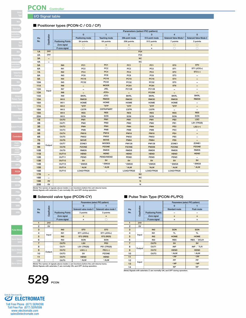
Parameters (select PIO pattern)
0
Positioning mode
64 points
I/O Signal table
■ Positioner types (PCON-C / CG / CF)
○○
1
Teaching mode
64 points
×
○
2
256-point mode
256 points
×
○
3
512-point mode
512 points
×
×
4
Solenoid Valve Mode 1
7 points
○○
5
Solenoid Valve Mode 2
3 points
○○
PinNo.
Clas
sific
atio
n
Positioning Points
Zone signal
P-zone signal
PC1
PC2
PC4
PC8
PC16
PC32
−−−
BKRL
RMOD
HOME
*STP
CSTR
RES
SON
PM1
PM2
PM4
PM8
PM16
PM32
MOVE
ZONE1
PZONE
RMDS
HEND
PEND
SV
* EMGS
* ALM
LOAD/TRQS
PC1
PC2
PC4
PC8
PC16
PC32
MODE
JISL
JOG+
JOG-
RMOD
HOME
*STP
CSTR/PWRT
RES
SON
PM1
PM2
PM4
PM8
PM16
PM32
MOVE
MODES
PZONE
RMDS
HEND
PEND/WEND
SV
* EMGS
* ALM
−
PC1
PC2
PC4
PC8
PC16
PC32
PC64
PC128
−BKRL
RMOD
HOME
*STP
CSTR
RES
SON
PM1
PM2
PM4
PM8
PM16
PM32
PM64
PM128
PZONE
RMDS
HEND
PEND
SV
* EMGS
* ALM
LOAD/TRQS
PC1
PC2
PC4
PC8
PC16
PC32
PC64
PC128
PC256
BKRL
RMOD
HOME
*STP
CSTR
RES
SON
PM1
PM2
PM4
PM8
PM16
PM32
PM64
PM128
PM256
RMDS
HEND
PEND
SV
* EMGS
*ALM
LOAD/TRQS
ST0
ST1
ST2
ST3
ST4
ST5
ST6
−−
BKRL
RMOD
HOME
*STP
−RES
SON
PE0
PE1
PE2
PE3
PE4
PE5
PE6
ZONE1
PZONE
RMDS
HEND
PEND
SV
* EMGS
* ALM
LOAD/TRQS
ST0
ST1 (JOG+)
ST2 (-)
−−−−−−
BKRL
RMOD
−−−
RES
SON
LSO
LS1 (TRQS)
LS2 (−)
−−−−
ZONE1
PZONE
RMDS
HEND
−SV
* EMGS
* ALM
−
Input
Output
1A
2A
3A
4A
5A
6A
7A
8A
9A
10A
11A
12A
13A
14A
15A
16A
17A
18A
19A
20A
1B
2B
3B
4B
5B
6B
7B
8B
9B
10B
11B
12B
13B
14B
15B
16B
17B
18B
19B
20B
IN0
IN1
IN2
IN3
IN4
IN5
IN6
IN7
IN8
IN9
IN10
IN11
IN12
IN13
IN14
IN15
OUT0
OUT1
OUT2
OUT3
OUT4
OUT5
OUT6
OUT7
OUT8
OUT9
OUT10
OUT11
OUT12
OUT13
OUT14
OUT15
P24
NC
NC
N
NC
NC
N
P24
Parameters (select PIO pattern)
0
Solenoid valve mode 0
3 points
■ Solenoid valve type (PCON-CY)
×
×
1
Solenoid valve mode 1
3 points
×
○
PinNo.
Clas
sific
atio
n
Positioning Points
Zone signal
P-zone signal
1
2
3
4
5
6
7
8
9
10
11
12
ST0
ST1 (JOG+)
ST2 (RES)
SON
LS0
LS1 (TRQS)
LS2 (−)
SV
HEND
* ALM
ST0
ST1 (JOG+)
ST2 (RES)
SON
PE0
PE1 (TRQS)
PE2 (−)
PZONE
HEND
* ALM
IN0
IN1
IN2
IN3
OUT0
OUT1
OUT2
OUT3
OUT4
OUT5
24V
0V
Input
Output
0
Parameters (select PIO pattern)
Standard mode
−
■ Pulse Train Type (PCON-PL/PO)
×
1
Push mode
−×
PinNo.
Clas
sific
atio
n
Positioning Points
Zone signal
× ×P-zone signal
1
2
3
4
5
6
7
8
9
10
11
12
13
14
SON
TL
HOME
RES
SV
INP
HEND
* ALM
* PP
PP
* NP
NP
SON
TL
HOME
RES/ DCLR
SV
INP/ TLR
HEND
* ALM
* PP
PP
* NP
NP
IN0
IN1
IN2
IN3
OUT0
OUT1
OUT2
OUT3
24V
0V
Input
Output
Input
−−0V
0V
24V
24V
−−
(Note) The names of signals above inside ( ) are functions before the unit returns home.(Note) Signals with asterisks (*) are normally ON, and OFF during operation.
(Note) The names of signals above inside ( ) are functions before the unit returns home.(Note) Signals with asterisks (*) are normally ON, and OFF during operation.
(Note) Signals with asterisks (*) are normally ON, and OFF during operation.
529 PCON
SliderType
Mini
Mini
PSEP/ASEP
PMEC/AMEC
ROBONET
ERC2
PCON
ACON
SCON
PSEL
ASEL
SSEL
XSEL
Standard
Standard
Standard
ControllersIntegrated
ControllersIntegrated
RodType
Table/Arm/FlatType
Gripper/Rotary Type
Linear ServoType
CleanroomType
Splash-Proof
Controllers
Pulse Motor
Servo Motor (24V)
Servo Motor (200V)
LinearServo Motor
Mini
PCON Controller
ELECTROMATEToll Free Phone (877) SERVO98
Toll Free Fax (877) SERV099www.electromate.com
Sold & Serviced By:
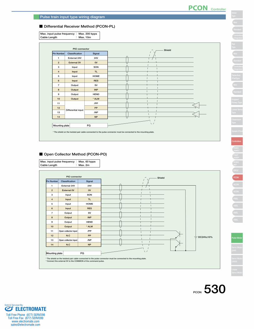
Pin Number
1 External 24V 24V
Differential input
Classification Signal
PIO connector Shield
Mounting plate FG
* The shield on the twisted pair cable connected to the pulse connector must be connected to the mounting plate.
2
3
4
5
6
7
8
9
10
11
12
13
14
External 0V
Input
Input
Input
Input
Output
Output
Output
Output
0V
SON
TL
HOME
RES
SV
INP
HEND
* ALM
/PP
PP
/NP
NP
Pulse train input type wiring diagram
■ Differential Receiver Method (PCON-PL)
■ Open Collector Method (PCON-PO)
Max. input pulse frequency : Max. 200 kppsCable Length : Max. 10m
Pin Number
1 External 24V 24V
Classification Signal
PIO connector Shield
DC24V±10%
Mounting plate FG
* The shield on the twisted pair cable connected to the pulse connector must be connected to the mounting plate. * Connect the external 0V to the COMMON of the command pulse.
2
3
4
5
6
7
8
9
10
11
12
13
14
External 0V
Input
Input
Input
Input
Output
Output
Output
Output
Open collector input
N.C
Open collector input
N.C
0V
SON
TL
HOME
RES
SV
INP
HEND
* ALM
/PP
PP
/NP
NP
Max. input pulse frequency : Max. 60 kppsCable Length : Max. 2m
PCON 530
Mini
Mini
Mini
Standard
Standard
ControllersIntegrated
Standard
ControllersIntegrated
PSEP/ASEP
PMEC/AMEC
ROBONET
ERC2
PCON
ACON
SCON
PSEL
ASEL
SSEL
XSEL
SliderType
RodType
Table/Arm/FlatType
Gripper/Rotary Type
Linear ServoType
CleanroomType
Splash-Proof
Controllers
Pulse Motor
Servo Motor (24V)
Servo Motor (200V)
LinearServo Motor
PCON Controller
ELECTROMATEToll Free Phone (877) SERVO98
Toll Free Fax (877) SERV099www.electromate.com
Sold & Serviced By:
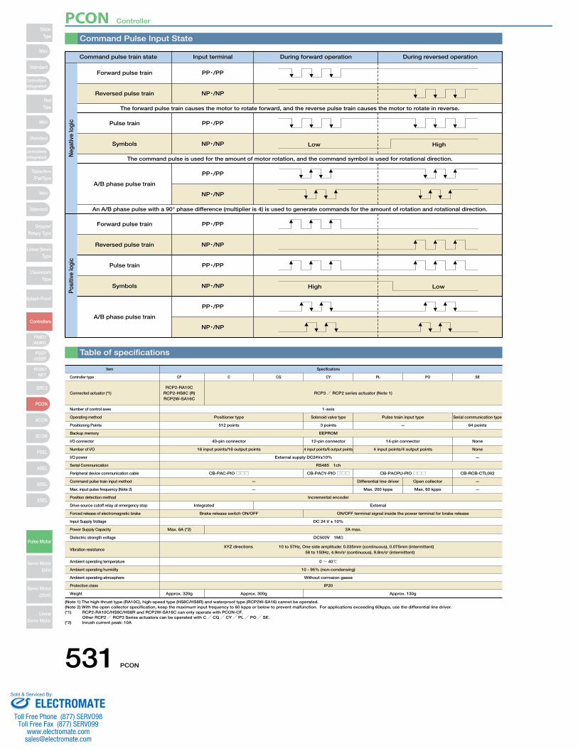
Command Pulse Input State
Table of specifications
Low High
High Low
Forward pulse train
Reversed pulse train
The forward pulse train causes the motor to rotate forward, and the reverse pulse train causes the motor to rotate in reverse.
Pulse train
Symbols
The command pulse is used for the amount of motor rotation, and the command symbol is used for rotational direction.
A/B phase pulse train
An A/B phase pulse with a 90° phase difference (multiplier is 4) is used to generate commands for the amount of rotation and rotational direction.
Forward pulse train
Reversed pulse train
Pulse train
Symbols
A/B phase pulse train
PP・/PP
NP・/NP
PP・/PP
NP・/NP
PP・/PP
NP・/NP
PP・/PP
NP・/NP
PP・/PP
NP・/NP
PP・/PP
NP・/NP
Command pulse train state Input terminal During forward operation During reversed operation
Neg
ativ
e lo
gic
Pos
itive
logi
c
Item Specifications
RCP3/ RCP2 series actuator (Note 1)RCP2-RA10C
RCP2-HS8C (R)RCP2W-SA16C
1-axis
EEPROM
40-pin connector 12-pin connector 14-pin connector None
16 input points/16 output points
External supply DC24V±10%
RS485 1ch
CB-PAC-PIO□□□ CB-PACY-PIO□□□ CB-RCB-CTL002
4 input points/6 output points 4 input points/4 output points None
—
Positioner type Solenoid valve type
Controller type
Connected actuator (*1)
Number of control axes
Operating method
Positioning Points
Backup memory
I/O connector
Number of I/O
I/O power
Serial Communication
Peripheral device communication cable
Command pulse train input method
Max. input pulse frequency (Note 2)
Position detection method
Drive-source cutoff relay at emergency stop
Forced release of electromagnetic brake
Input Supply Voltage
Power Supply Capacity
Dielectric strength voltage
Vibration resistance
Ambient operating temperature
Ambient operating humidity
Ambient operating atmosphere
Protection class
Weight
CCF CG CY PL PO SE
Pulse train input type Serial communication type
512 points 3 points
—
Incremental encoder
Integrated
Brake release switch ON/OFF
Max. 6A (*2)
DC 24 V ± 10%
2A max.
DC500V 1MΩ
0~ 40℃
10 - 95% (non-condensing)
Without corrosion gases
IP20
Approx. 300gApprox. 320g Approx. 130g
XYZ directions 10 to 57Hz, One side amplitude: 0.035mm (continuous), 0.075mm (intermittent) 58 to 150Hz, 4.9m/s2 (continuous), 9.8m/s2 (intermittent)
ON/OFF terminal signal inside the power terminal for brake release
External
CB-PACPU-PIO□□□
Differential line driver Open collector —
— Max. 200 kpps Max. 60 kpps —
— 64 points
(Note 1) The high-thrust type (RA10C), high-speed type (HS8C/HS8R) and waterproof type (RCP2W-SA16) cannot be operated.(Note 2) With the open collector specification, keep the maximum input frequency to 60 kpps or below to prevent malfunction. For applications exceeding 60kpps, use the differential line driver. (*1) RCP2-RA10C/HS8C/HS8R and RCP2W-SA16C can only operate with PCON-CF.
Other RCP2/ RCP3 Series actuators can be operated with C/ CG/ CY/ PL/ PO/ SE.(*2) Inrush current peak: 10A
531 PCON
SliderType
Mini
Mini
PSEP/ASEP
PMEC/AMEC
ROBONET
ERC2
PCON
ACON
SCON
PSEL
ASEL
SSEL
XSEL
Standard
Standard
Standard
ControllersIntegrated
ControllersIntegrated
RodType
Table/Arm/FlatType
Gripper/Rotary Type
Linear ServoType
CleanroomType
Splash-Proof
Controllers
Pulse Motor
Servo Motor (24V)
Servo Motor (200V)
LinearServo Motor
Mini
PCON Controller
ELECTROMATEToll Free Phone (877) SERVO98
Toll Free Fax (877) SERV099www.electromate.com
Sold & Serviced By:
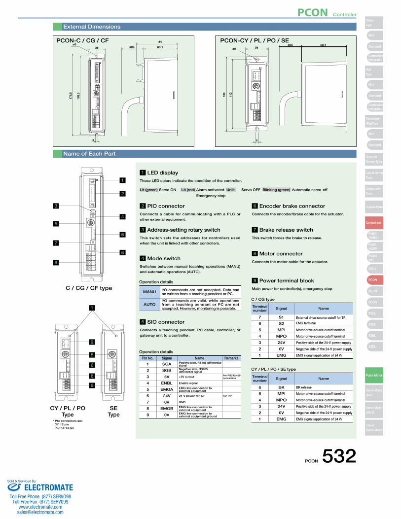
35 (80)
178.
5
170.
5
ø584
68.1
5
External Dimensions
Name of Each Part
* PIO connectors are:CY: 12 pinPL/PO: 14 pin
PCON-C / CG / CF
120
112
35
5
ø568.1(80)
1
1
2
3
4
5
6
7
8
C / CG / CF type
CY / PL / POType
SEType
9
5
6
8
9
2
2 PIO connector Connects a cable for communicating with a PLC or
other external equipment.
7 Brake release switchThis switch forces the brake to release.
8 Motor connectorConnects the motor cable for the actuator.
9 Power terminal blockMain power for controller(s), emergency stop
3 Address-setting rotary switch This switch sets the addresses for controllers used
when the unit is linked with other controllers.
5 SIO connectorConnects a teaching pendant, PC cable, controller, or
gateway unit to a controller.
4 Mode switchSwitches between manual teaching operations (MANU)
and automatic operations (AUTO).
Pin No. Signal Name Remarks
1 SGA Positive side, RS485 differential signal
2
3
4
5
6
7
8
9
SGB
5V
ENBL
EMGA
24V
0V
EMGB
0V
Negative side, RS485 differential signal
+5V output For RS232/485 conversion
For T/P
Enable signal
EMG line connection to external equipment
24-V power for T/P
GND
EMG line connection to external equipmentEMG line connection to external equipment ground
Operation details
MANU I/O commands are not accepted. Data can be written from a teaching pendant or PC.
AUTOI/O commands are valid, while operations from a teaching pendant or PC are not accepted. However, monitoring is possible.
Operation details
Terminal number Signal Name
7 S1 External drive-source cutoff for TP_
EMG terminal6
5
4
3
2
1
S2
MPI
MPO
24V
0V
EMG
Motor drive-source cutoff terminal
Motor drive-source cutoff terminal
Positive side of the 24-V power supply
Negative side of the 24-V power supply
EMG signal (application of 24 V)
Terminal number Signal Name
BK release6
5
4
3
2
1
BK
MPI
MPO
24V
0V
EMG
Motor drive-source cutoff terminal
Motor drive-source cutoff terminal
Positive side of the 24-V power supply
Negative side of the 24-V power supply
EMG signal (application of 24 V)
C / CG type
CY / PL / PO / SE type
PCON-CY / PL / PO / SE
6 Encoder brake connectorConnects the encoder/brake cable for the actuator.
1 LED display These LED colors indicate the condition of the controller.
Lit (green) Servo ON Lit (red) Alarm activated Unlit Servo OFF Blinking (green) Automatic servo-off
Emergency stop
PCON 532
Mini
Mini
Mini
Standard
Standard
ControllersIntegrated
Standard
ControllersIntegrated
PSEP/ASEP
PMEC/AMEC
ROBONET
ERC2
PCON
ACON
SCON
PSEL
ASEL
SSEL
XSEL
SliderType
RodType
Table/Arm/FlatType
Gripper/Rotary Type
Linear ServoType
CleanroomType
Splash-Proof
Controllers
Pulse Motor
Servo Motor (24V)
Servo Motor (200V)
LinearServo Motor
PCON Controller
ELECTROMATEToll Free Phone (877) SERVO98
Toll Free Fax (877) SERV099www.electromate.com
Sold & Serviced By:

Teaching PendantThis is a teaching device that provides information on functions such as the position input, test runs, and monitoring.
RCM-E-ENG (Simple teaching pendant)
CON-T-ENG (Standard type)
CON-PT-M-ENG (Touch panel teachingpendant)
Features
Model
Configuration
Model
Configuration
Features
Model
Specifications
Data input
3-color LED touch panelwith backlight
Approx. 750g
IP40 IP54
20 char. × 4 linesLCD display
5m
Approx. 400g
No corrosive gases. Especially no dust.
Temp: 0~40ºC; Humidity: 85% RH or below
16 char. × 2 linesLCD display
Approx. 400g
Item CON-PT-M-ENG CON-T-ENG RCM-E-ENG
5m
The version of RCM-E-ENG that can be used with ROBONET is 2.08 or later.
Note:
RCM-E-ENGCON-T-ENGCON-PT-M-ENG
21
6.326.215.1
23.5
43
148.
5
7 (34)72.5
(113.5)
46.939.0
66.6110.0
218.
3
89.6
CON-T-ENG Options• Wall-mounting hook
Model HK-1
• Strap
Model STR-1
13292.1
180
Configu-ration
PC Software (Windows Only)A startup support software for inputting positions, performing test runs, and monitoring. With enhancements for adjustment functions, the startup time is shortened.
RCM-101-MW (External device communications cable + RS232conversion unit)
0.3m
5m
External device communications cable CB-RCA-SIO050PC Software (CD)
RS232 adapterRCB-CV-MW
RCM-101-USB (External device communications cable + USB adapter + USB
cable)
5m3m
PC Software (CD)USB cableCB-SEL-USB030
USB adapterRCB-CV-USB
Actuator motionAmbient Operating temp/humidityAmbient Operating atmosphere
Protection class
Weight
Cable length
Display
External device communications cableCB-RCA-SIO050
Option
Spare PartsWhen you need spare parts after purchasing the product, such as when replacing a cable, refer to the list of models below.
A A
I-1318119-3(AMP)
SLP-06V(JST)
M cableCN3 CN1Orange YellowA1 1
(20)(8)
(Front view)
(15)
L
CN3CN1
(ø8) (2
8) (14)
(14)
(20)
(Front view)
Mechanical sideController side
GrayWhiteYellowPink
Yellow (Green)
VMMBA
VMMB
A2A3B1B2B3
23456
VMMAB
VMMB
GrayOrange
Yellow (Green)Pink
White
Model CB-RCP2-MA□□□Motor Cable for RCP2
* Enter the cable length (L) into □□□ . Compatible to a maximum of 20 meters. Ex.: 080 = 8 m
* The standard cable for the motor cable is the robot cable.
PHDR
-16V
S(J
ST)
XMP-
18V
(JST
)
Blue (Red 1)
C N 4
C N 2Cable color
SignalPinNo.
Brown Light Gray (Black 1)
Orange (Black 2)
1
L S + L S −B K + B K − E N A E N A E N B E N B
− V P S V B B
F.G
E N A E N A E N B E N B
GNDGND(NC)(NC)(NC)
V B B V P S
L S + L S −
B K + B K − F . G
16
Shielded wire
Ground wire
Cable color Standard
Cable Robot Cable
Standard Cable Robot CableSignalPinNo.
L
CN2
CN4
(5) (8) (13) (15)
(18)
(Front view)
(ø9)
(35)
(25)
(Front view)
Mechanical sideController side
WhiteRedGray
BrownGreenPurplePink
−YellowOrange
Blue−−−
−−−
Ground
Orange (Red 2)Orange (Black 1)Orange (Red 1)Light Gray (Black 1)Light Gray (Red 1)White (Black 1)White (Red 1)
−Yellow (Black 1)
Pink (Red 1)Pink (Black 1)
Ground
151413121110987654321
23456789101112131415161718
GreenPurplePink
BlueOrangeYellow
Blue (Red 1)White
RedGray
Ground
Light Gray (Red 1)White (Black 1)White (Red 1)
Pink (Black 1)Pink (Red 1)
Yellow (Black 1)
Orange (Black 2)Orange (Red 2)
Orange (Black 1)Orange (Red 1)Ground
Model CB-RCP2-PB□□□/CB-RCP2-PB□□□-RBEncoder Cable/Encoder Robot Cable for RCP2
* Enter the cable length (L) into □□□ . Compatible to a maximum of 20 meters. Ex.: 080 = 8 m
* The standard cable for the encoder cable is the normal cable. A robot cable can be specified as an option.
Min. bend radius r = 50 mm or larger (when movable type is used)* Only robot cable is to be used in a cable track.
Min. bend radius r = 50 mm or larger (when movable type is used)
533 PCON
SliderType
Mini
Mini
PSEP/ASEP
PMEC/AMEC
ROBONET
ERC2
PCON
ACON
SCON
PSEL
ASEL
SSEL
XSEL
Standard
Standard
Standard
ControllersIntegrated
ControllersIntegrated
RodType
Table/Arm/FlatType
Gripper/Rotary Type
Linear ServoType
CleanroomType
Splash-Proof
Controllers
Pulse Motor
Servo Motor (24V)
Servo Motor (200V)
LinearServo Motor
Mini
PCON Controller
ELECTROMATEToll Free Phone (877) SERVO98
Toll Free Fax (877) SERV099www.electromate.com
Sold & Serviced By:
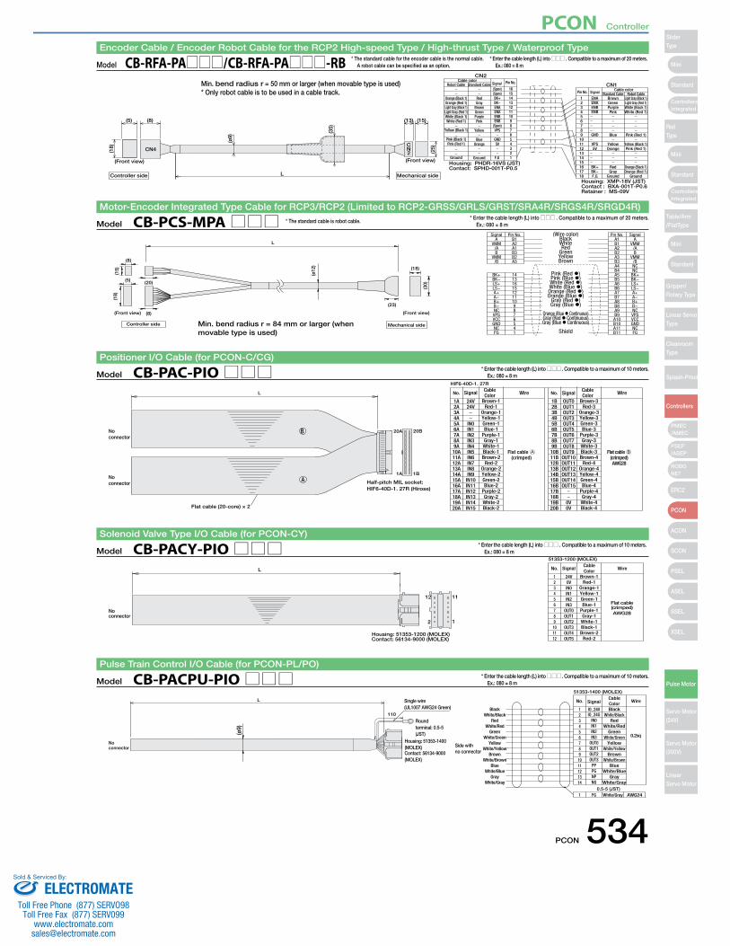
Robot CableStandard Cable
Yellow (Black 1)
Orange (Black 1) Light Gray (Black 1)Brown
Robot Cable
Standard Cable(Spare) 16
1 ENA
Housing: PHDR-16VS (JST)Contact: SPHD-001T-P0.5
Housing: XMP-18V (JST)Contact : BXA-001T-P0.6Retainer : MS-09V
CN2
CN1Cable color
Pin No.Cable color Signal
Signal
Orange (Red 1)Light Gray (Black 1)Light Gray (Red 1)White (Black 1)White (Red 1)
Pink (Black 1)Pink (Red 1)
Ground
RedGray
BrownGreenPurplePink
Yellow
BlueOrange
Ground
(Spare)BK+BK−ENAENAENBENB
(Spare)VPS
GND5V
F.G
151413121110987654321
Mechanical side
(Front view)
CN2
(13) (15)
(25)
L
CN4
(5) (8)
(18)
(Front view)
(ø9)
(35)
Controller side
23456789
101112131415161718
ENAENBENB
GND
VPS5V
BK+BK−F.G
GreenPurplePink
Blue
YellowOrange
RedGray
Ground
Light Gray (Red 1)White (Black 1)White (Red 1)
Pink (Red 1)
Yellow (Black 1)Pink (Red 1)
Orange (Black 1)Orange (Red 1)
Ground
Pin No.
Model CB-RFA-PA□□□/CB-RFA-PA□□□-RBEncoder Cable / Encoder Robot Cable for the RCP2 High-speed Type / High-thrust Type / Waterproof Type
* Enter the cable length (L) into □□□ . Compatible to a maximum of 20 meters. Ex.: 080 = 8 m
1
1112
2
Housing: 51353-1200 (MOLEX)Contact: 56134-9000 (MOLEX)
(crimped)AWG28
Flat cable
51353-1200 (MOLEX)
No connector
LBrown-1
CableColor
No. Signal Wire
24V123456789
101112
0VIN0IN1IN2IN3
OUT0OUT1OUT2OUT3OUT4OUT5
Red-1Orange-1Yellow-1Green-1Blue-1
Purple-1Gray-1White-1Black-1Brown-2
Red-2
Model CB-PACY-PIO□□□Solenoid Valve Type I/O Cable (for PCON-CY)
* Enter the cable length (L) into □□□ . Compatible to a maximum of 10 meters. Ex.: 080 = 8 m
0.2sq
51353-1400 (MOLEX)
Single wire (UL1007 AWG24 Green)
No connector Side with
no connector
Housing: 51353-1400 (MOLEX)Contact: 56134-9000 (MOLEX)
Round terminal: 0.5-5 (JST)
110
0.5-5 (JST)White/Gray
(ø9)
L
BlackBlack
CableColor
No. Signal Wire
IO_24V
FG
1
1 AWG24
White/BlackRed
White/RedGreen
White/GreenYellow
White/YellowBrown
White/BrownBlue
White/BlueGray
White/Gray
23456789
1011121314
IO_24GIN0IN1IN2IN3
OUT0OUT1OUT2OUT3
PPPGNPNG
White/BlackRed
White/RedGreen
White/GreenYellow
White/YellowBrown
White/BrownBlue
White/BlueGray
White/Gray
Model CB-PACPU-PIO□□□Pulse Train Control I/O Cable (for PCON-PL/PO)
* Enter the cable length (L) into □□□ . Compatible to a maximum of 10 meters. Ex.: 080 = 8 m
B
Flat cable A(crimped)
Flat cable B(crimped)AWG28
Half-pitch MIL socket:HIF6-40D-1. 27R (Hirose)
Flat cable (20-core) × 2
HIF6-40D-1. 27R
20B20A
1B1AA
No connector
No connector
Brown-1
CableColorL No. Signal Wire
24V1A Brown-3
CableColorNo. Signal Wire
OUT01B2A3A4A5A6A7A8A9A10A11A12A13A14A15A16A17A18A19A20A
24V
IN0IN1IN2IN3IN4IN5IN6IN7IN8IN9IN10IN11IN12IN13IN14IN15
Red-1Orange-1Yellow-1Green-1Blue-1
Purple-1Gray-1White-1Black-1Brown-2
Red-2Orange-2Yellow-2Green-2Blue-2
Purple-2Gray-2White-2Black-2
2B3B4B5B6B7B8B9B10B11B12B13B14B15B16B17B18B19B20B
OUT1OUT2OUT3OUT4OUT5OUT6OUT7OUT8OUT9OUT10OUT11OUT12OUT13OUT14OUT15
0V0V
Red-3Orange-3Yellow-3Green-3Blue-3
Purple-3Gray-3White-3Black-3Brown-4
Red-4Orange-4Yellow-4Green-4Blue-4
Purple-4Gray-4White-4Black-4
Model CB-PAC-PIO□□□Positioner I/O Cable (for PCON-C/CG)
* Enter the cable length (L) into □□□ . Compatible to a maximum of 10 meters. Ex.: 080 = 8 m
* The standard cable for the encoder cable is the normal cable. A robot cable can be specified as an option.
L
(15)
(ø12
)
A
Pink (Red �)Pink (Blue �)White (Red �)White (Blue �)Orange (Red �)Orange (Blue �)
Gray (Red �)Gray (Blue �)
Orange (Blue � Continuous)Gray (Red � Continuous)Gray (Blue � Continuous)
Shield
BlackB1 A1 A
BK+ 14
(18)
(8)
(20)
(8)
(5)
(30)
(18)
(23)
Signal Pin No. (Wire color) Pin No. Signal
Controller side Mechanical side
(Front view) (Front view)
BK−LS+LS−A+A−B+B−NCVPSVCCGNDNCFG
VMM/AB
VMM/B
A2A1B3B2A3
1316151211109876541
WhiteRed
GreenYellowBrown
B1A2B2A3B3A4B4A5B5A6B6A7B7A8B8A9B9A10B10A11B11
VMM/AB
VMM/BNCNC
BK+BK−LS+LS−A+A−B+B−NCVPSVCCGNDNCFG
Model CB-PCS-MPA□□□Motor-Encoder Integrated Type Cable for RCP3/RCP2 (Limited to RCP2-GRSS/GRLS/GRST/SRA4R/SRGS4R/SRGD4R)
* Enter the cable length (L) into □□□ . Compatible to a maximum of 20 meters. Ex.: 080 = 8 m
* The standard cable is robot cable.
Min. bend radius r = 50 mm or larger (when movable type is used)* Only robot cable is to be used in a cable track.
Min. bend radius r = 84 mm or larger (when movable type is used)
PCON 534
Mini
Mini
Mini
Standard
Standard
ControllersIntegrated
Standard
ControllersIntegrated
PSEP/ASEP
PMEC/AMEC
ROBONET
ERC2
PCON
ACON
SCON
PSEL
ASEL
SSEL
XSEL
SliderType
RodType
Table/Arm/FlatType
Gripper/Rotary Type
Linear ServoType
CleanroomType
Splash-Proof
Controllers
Pulse Motor
Servo Motor (24V)
Servo Motor (200V)
LinearServo Motor
PCON Controller
ELECTROMATEToll Free Phone (877) SERVO98
Toll Free Fax (877) SERV099www.electromate.com
Sold & Serviced By:
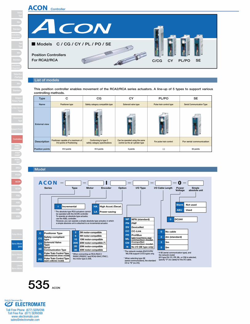
List of models
This position controller enables movement of the RCA2/RCA series actuators. A line-up of 5 types to support various controlling methods.
■ Models C / CG / CY / PL / PO / SE
Position Controllers
For RCA2/RCA C/CG CY PL/PO SE
A C O N 0Series Type Motor Encoder Option I/O Type I/O Cable Length Power
Voltage
C Positioner Type
CGSafety-compliant type
CY Solenoid Valve Type
SESerial Communication Type
PL Pulse Train Control Type(differential line driver model)
PO Pulse Train Control Type(open collector model)
20S 20W motor-compatible (*)
10
5
10W motor-compatible
2 2W motor-compatible
5W motor-compatible
20 20W motor-compatible
30 30W motor-compatible
I Incremental
0 DC24V
0 No cable
2 2m (standard)
3 3m
5 5m
I
* When connecting an RCA-RA3�/ RGS3�/RGD3� and RCA2-SA4�/TA5�, the motor type is 20S.
* The absolute-type RCA actuators cannot be operated with the ACON controller To operate an absolute-type actuator, use the ASEL controller. However, you can operate a simple absolute-type actuator, in which a simple absolute unit is attached to an incremental actuator.
* The network models (DV/CC/PR/ ML/CN) support C/CG types only.
* When selecting type SE (serial communication), the standard I/O is "N" (no I/O).
NP NPN (standard)
PN PNP
PR
ML
CN
ProfiBusMECHATROLINK connection modelCompoNet connection model
CC CC-Link
DV DeviceNet
No I/O (SE type only)N
HA High Accel./Decel.
LA Power-saving
Simple absolute unit
Blank Not used
ABU Used
* If SE (serial communication type), and the network model (I/O type DV, CC, PR, ML, or CN) is selected, specify "0" (no cable) for the I/O cable.
Type C
Positioner typeName
External view
Description Positioner capable of a maximum of 512 points of Positioning
Position points 512 points
CG
Safety category compatible type
Conforming to type C safety category specifications
512 points
CY
Solenoid valve type
Can be operated using the same control as the air cylinder type
3 points
PL/PO
Pulse train control type
For pulse train control
(−)
SE
Serial Communication Type
For serial communication
64 points
Model
ACON Controller
535 ACON
SliderType
Mini
Mini
PSEP/ASEP
PMEC/AMEC
ROBONET
ERC2
PCON
ACON
SCON
PSEL
ASEL
SSEL
XSEL
Standard
Standard
Standard
ControllersIntegrated
ControllersIntegrated
RodType
Table/Arm/FlatType
Gripper/Rotary Type
Linear ServoType
CleanroomType
Splash-Proof
Controllers
Pulse Motor
Servo Motor (24V)
Servo Motor (200V)
LinearServo Motor
Mini
ELECTROMATEToll Free Phone (877) SERVO98
Toll Free Fax (877) SERV099www.electromate.com
Sold & Serviced By:
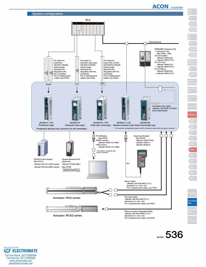
ACON-SESerial communication type
ACON-PL / POPulse train control type
Actuator: RCA series
Actuator: RCA2 series
Motor Cable <Model: CB-ACS-MA���> Standard 1m / 3m / 5m For a replacement cable, see P543.
PC Software (See P543)RS232 version <Model: RCM-101-MW>USB version <Model: RCM-101-USB>
Teaching Pendant (See P543) <Model: CON-PT-M> <Model: CON-T> <Model: RCM-E>
* The cable is supplied with the PC software
Encoder Cable<Model: CB-ACS-PA���>Standard 1m / 3m / 5mFor a replacement cable, see P544.
Motor-encoder Integrated Cable<Model: CB-ACS-MPA���>Standard 1m / 3m / 5mFor a replacement cable, see P544.
Controller link cable<Model: CB-RCB-CTL002>(sold separately)
ACON-CYSolenoid valve type
ACON-C / CGPositioner type
Peripheral devices are common for all controllers.
ACON-C / CGNetwork connection model
PLC
<Model: PS-241 (100V input)>
<Model: PS-242 (200V input)>
DC24V Power Supply(See P471)
I/O Cable for pulse train controlCB-PACPU-PIO020Cable lengthStandard 2m(Supplied with the controller)
I/O cable for solenoid valve typeCB-PACY-PIO020Cable lengthStandard 2m(Supplied with the controller)
I/O cable for positionerCB-PAC-PIO020Cable lengthStandard 2m(Supplied with the controller)For a replacement cable, see P544.
For a replacement cable, see P544.
For a replacement cable, see P544.
Field Network
5m
* For network-compatible models, the I/O connector varies with the type of network.
* Cannot be used for ACON-PL/PO types.
<Model: PCON-ABU>
(See P545)
Simple Absolute Unit(Optional)
ROBONET Gateway Unit + extension unit (See P505 - 506)For DeviceNet: <Model: RGW-DV> + <Model: REXT-CTL>For CC-Link: <Model: RGW-CC> + <Model: REXT-CTL>For ProfiBus: <Model: RGW-PR> + <Model: REXT-CTL>
System configuration
ACON Controller
ACON 536
Mini
Mini
Mini
Standard
Standard
ControllersIntegrated
Standard
ControllersIntegrated
PSEP/ASEP
PMEC/AMEC
ROBONET
ERC2
PCON
ACON
SCON
PSEL
ASEL
SSEL
XSEL
SliderType
RodType
Table/Arm/FlatType
Gripper/Rotary Type
Linear ServoType
CleanroomType
Splash-Proof
Controllers
Pulse Motor
Servo Motor (24V)
Servo Motor (200V)
LinearServo Motor
ELECTROMATEToll Free Phone (877) SERVO98
Toll Free Fax (877) SERV099www.electromate.com
Sold & Serviced By:

I/O Specifications
I/O Specifications
The 4 types of controllers (C/CG, CY, PL/PO, and SE) are classified by their respective I/O specifications. Also, for the
positioner type and solenoid valve type, the I/O signal information can be changed in the controller settings, so multiple
functions can be effectively used.
■ Control Function by Type
ItemInput voltageInput currentLeak currentIsolation method
SpecificationsDC24V ±10%4mA/circuit1mA max./pointPhotocoupler
P24V
R=5.6kΩInputs
R=680Ω
+24V
External power supply
Input terminal
Internal circuit
■ Input section External input specifications
ItemLoad VoltageMax. load current Remaining voltageIsolation method
SpecificationsDC24V50mA/point2V or lessPhotocoupler
P24
N
OutputsInternal circuitLoad
+ 2 4 V
External power supplyR=22Ω
N
R=5.6kΩInputs
R=680Ω
+24V
External power supply
Input terminal
Internal circuit P24V
N
Outputs
Internal circuit
+24V
External power supply
LoadR=22Ω
■ Output section External output specifications
NPN Specifications NPN Specifications
PNP Specifications PNP Specifications
Type C/CG
Positioner typeFeatures
Name
Positioner mode ○
CY
Solenoid valve type
×
PL/PO
Pulse train control type
×
SE
Serial communication type
○ (*1)
(*1)
(*1)
(*3)
This is the basic operating mode, in which the user designates position numbers and inputs start signals.
Teaching mode ○ × × ○In this mode, the slider (rod) moves based on an external signal, and the stopped positions can be registered as position data.
Solenoid valve mode ○ ○ × ○
The actuator can be moved simply by ON/OFF position signals. This mode supports the same control signals you are already familiar with on solenoid valves of air cylinders.
Pulse train mode × × ○ × In this mode, you can operate the actuator freely without inputting position data.
Network compatible ○ × × ○ The controller can be connected to a DeviceNet or CC-Link network.
*1 Operates using network communications or serial communications. *2 Can make a direct connection to a field network with the network specifications. *3 Can be connected to a field network using a gateway unit.
(*2)
ACON Controller
537 ACON
SliderType
Mini
Mini
PSEP/ASEP
PMEC/AMEC
ROBONET
ERC2
PCON
ACON
SCON
PSEL
ASEL
SSEL
XSEL
Standard
Standard
Standard
ControllersIntegrated
ControllersIntegrated
RodType
Table/Arm/FlatType
Gripper/Rotary Type
Linear ServoType
CleanroomType
Splash-Proof
Controllers
Pulse Motor
Servo Motor (24V)
Servo Motor (200V)
LinearServo Motor
Mini
ELECTROMATEToll Free Phone (877) SERVO98
Toll Free Fax (877) SERV099www.electromate.com
Sold & Serviced By:
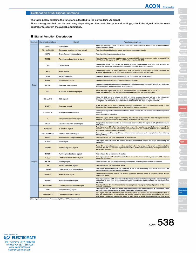
Explanation of I/O Signal Functions
The table below explains the functions allocated to the controller’s I/O signal.
Since the signals that can be used vary depending on the controller type and settings, check the signal table for each
controller to confirm the available functions.
■ Signal Function Description
Classification Signal abbreviations
CSTR Start signal
Signal
Input this signal to cause the actuator to start moving to the position set by the command position number signal.
PC1 to PC256 Command position number signal This signal is used to input a target position number (binary input).
Function description
BKRL Brake forced release signal This signal forcibly releases the brake.
RMOD Running mode switching signal This signal can switch the running mode when the MODE switch on the controller is set to AUTO. (AUTO when this signal is OFF, or MANU when the signal is ON).
* STP Pause signal Turning this signal OFF causes the moving actuator to decelerate to a stop. The actuator will resume the remaining movement if the signal is turned ON during the pause.
MODE Teaching mode signal Turning this signal ON switches the controller to teaching mode (provided that CSTR, JOG+ and JOG- are all OFF and the actuator is not moving).
RES Reset signal Turning this signal ON resets the alarms that are present. If this signal is turned ON while the actuator is paused (*STP is OFF), the remaining movement can be cancelled.
SON Servo ON signal The servo remains on while this signal is ON, or off while the signal is OFF.
JISL JOG/INJOG switching signal When the main signal is off, the JOG operation will be conducted for JOG+ and JOG-.When the signal is on, the unit will do the inching operation for JOG+ and JOG-.
JOG+, JOG− JOG signalWhen the JISL signal is off and the JOG +/- signal turns on, the unit will jog in the + (positive) direction when the JOG + turns on and the - (negative) direction when the JOG - turns on.During the JOG operation, the unit slows to a stop when the JOG +/- signal turns off.
ST0 to ST6 Start position commandTurning this signal ON in the solenoid valve mode causes the actuator to move to the specified position.(Start signal is not required)
TL Torque limit selection signal While this signal is ON, torque is limited by the value set by a parameter. The TLR signal turns on if torque has reached the specified value. (Dedicated pulse train type)
DCLR Deviation counter clear signal The position deviation counter is continuously cleared while this signal is ON. (Dedicated pulse train type)
PEND/INP In position signalThis signal turns ON when the actuator has entered the positioning band after movement. If the actuator has exceeded the positioning band, PEND does not turn OFF, but INP does. PEND and INP can be swapped within parameters.
PWRT Teaching signal In the teaching mode, specify a desired position number and then turn this signal ON for at least 20ms to write the current position to the specified position number.
HOME Home return signal Turning this signal ON performs home-return operation.
Input
Output
PM1 to PM256 Position complete signal This signal is used to output the position number achieved at the completion of positioning (binary output)
HEND Home return completion signal This signal turns ON upon completion of home return.
ZONE1 Zone signal This signal turns ON when the current actuator position has entered the range specified by the parameters.
PZONE Positioning zone signalTurns ON when actuator moves into a position within the range of the target position data that was set. PZONE can be used together with ZONE1, but PZONE is valid only during movement to a specified position.
RMDS Running mode status signal This outputs the operation mode status.
* ALM Controller alarm status signal This signal remains ON while the controller is not in the alarm condition, and turns OFF when an alarm has occurred.
SV Servo ON status signal
* EMGS Emergency stop status signal This signal remains ON while the controller is not in the emergency stop mode, and turns OFF once an emergency stop has been actuated.
MODES Mode status signal The mode signal input turns it ON when it goes into teaching mode. It turns OFF when it goes into normal mode.
WEND Writing complete signalThis signal remains OFF after the controller has switched to the teaching mode. It turns ON upon completion of data write using the PWRT signal. If the PWRT signal is turned Off, this signal also turns OFF.
PE0 to PE6 Current position number signal This signal turns ON after the controller has completed moving to the target position in the solenoid valve mode.
TLR Torque limiting signal This signal turns ON once the motor torque has reached the specified value in a condition where torque is being limited by the TL signal. (Dedicated pulse train type)
LSO to LS2 Limit switch output signalEach signal turns ON when the current actuator position has entered the positioning band before or after the target position. If the actuator has already completed home return, these signals are output even before a movement command is issued or while the servo is OFF. (Dedicated Solenoid Valve Mode)
MOVE Moving signal Turns ON while the actuator is moving (home return), including when there is push force.
This signal turns ON when servo is ON.
(Note) Signals with asterisks (*) are normally ON and OFF during operation.
ACON Controller
ACON 538
Mini
Mini
Mini
Standard
Standard
ControllersIntegrated
Standard
ControllersIntegrated
PSEP/ASEP
PMEC/AMEC
ROBONET
ERC2
PCON
ACON
SCON
PSEL
ASEL
SSEL
XSEL
SliderType
RodType
Table/Arm/FlatType
Gripper/Rotary Type
Linear ServoType
CleanroomType
Splash-Proof
Controllers
Pulse Motor
Servo Motor (24V)
Servo Motor (200V)
LinearServo Motor
ELECTROMATEToll Free Phone (877) SERVO98
Toll Free Fax (877) SERV099www.electromate.com
Sold & Serviced By:
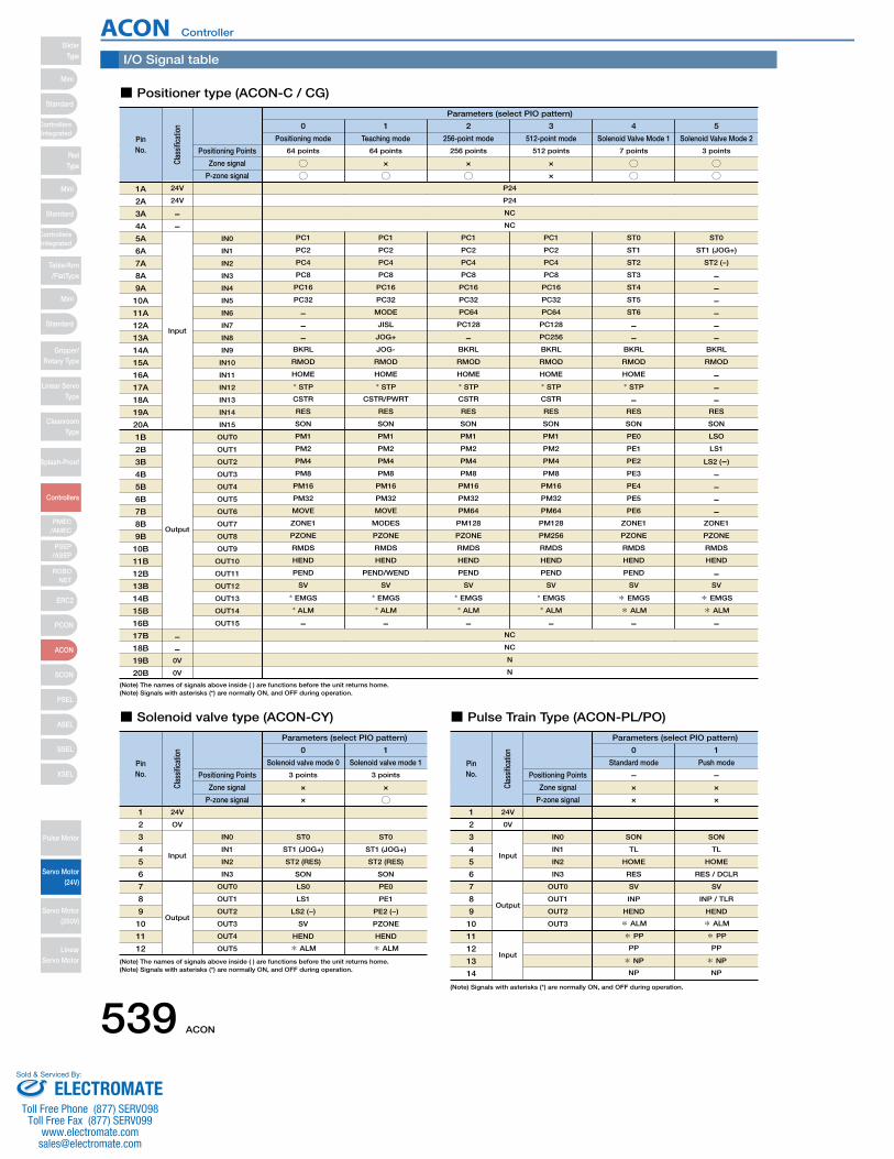
Parameters (select PIO pattern)
0
Positioning mode
64 points
I/O Signal table
■ Positioner type (ACON-C / CG)
○○
1
Teaching mode
64 points
×
○
2
256-point mode
256 points
×
○
3
512-point mode
512 points
×
×
4
Solenoid Valve Mode 1
7 points
○○
5
Solenoid Valve Mode 2
3 points
○○
PinNo.
Clas
sific
atio
n
Positioning Points
Zone signal
P-zone signal
PC1
PC2
PC4
PC8
PC16
PC32
−−−
BKRL
RMOD
HOME
* STP
CSTR
RES
SON
PM1
PM2
PM4
PM8
PM16
PM32
MOVE
ZONE1
PZONE
RMDS
HEND
PEND
SV
* EMGS
* ALM
−
PC1
PC2
PC4
PC8
PC16
PC32
MODE
JISL
JOG+
JOG-
RMOD
HOME
* STP
CSTR/PWRT
RES
SON
PM1
PM2
PM4
PM8
PM16
PM32
MOVE
MODES
PZONE
RMDS
HEND
PEND/WEND
SV
* EMGS
* ALM
−
PC1
PC2
PC4
PC8
PC16
PC32
PC64
PC128
−BKRL
RMOD
HOME
* STP
CSTR
RES
SON
PM1
PM2
PM4
PM8
PM16
PM32
PM64
PM128
PZONE
RMDS
HEND
PEND
SV
* EMGS
* ALM
−
PC1
PC2
PC4
PC8
PC16
PC32
PC64
PC128
PC256
BKRL
RMOD
HOME
* STP
CSTR
RES
SON
PM1
PM2
PM4
PM8
PM16
PM32
PM64
PM128
PM256
RMDS
HEND
PEND
SV
* EMGS
* ALM
−
ST0
ST1
ST2
ST3
ST4
ST5
ST6
−−
BKRL
RMOD
HOME
* STP
−RES
SON
PE0
PE1
PE2
PE3
PE4
PE5
PE6
ZONE1
PZONE
RMDS
HEND
PEND
SV
* EMGS
* ALM
−
ST0
ST1 (JOG+)
ST2 (-)
−−−−−−
BKRL
RMOD
−−−
RES
SON
LSO
LS1
LS2 (−)
−−−−
ZONE1
PZONE
RMDS
HEND
−SV
* EMGS
* ALM
−
Input
Output
1A
2A
3A
4A
5A
6A
7A
8A
9A
10A
11A
12A
13A
14A
15A
16A
17A
18A
19A
20A
1B
2B
3B
4B
5B
6B
7B
8B
9B
10B
11B
12B
13B
14B
15B
16B
17B
18B
19B
20B
IN0
IN1
IN2
IN3
IN4
IN5
IN6
IN7
IN8
IN9
IN10
IN11
IN12
IN13
IN14
IN15
OUT0
OUT1
OUT2
OUT3
OUT4
OUT5
OUT6
OUT7
OUT8
OUT9
OUT10
OUT11
OUT12
OUT13
OUT14
OUT15
P24
NC
NC
N
NC
NC
N
P24
Parameters (select PIO pattern)
0
Solenoid valve mode 0
3 points
■ Solenoid valve type (ACON-CY)
×
×
1
Solenoid valve mode 1
3 points
×
○
PinNo.
Clas
sific
atio
n
Positioning Points
Zone signal
P-zone signal
1
2
3
4
5
6
7
8
9
10
11
12
ST0
ST1 (JOG+)
ST2 (RES)
SON
LS0
LS1
LS2 (−)
SV
HEND
* ALM
ST0
ST1 (JOG+)
ST2 (RES)
SON
PE0
PE1
PE2 (−)
PZONE
HEND
* ALM
IN0
IN1
IN2
IN3
OUT0
OUT1
OUT2
OUT3
OUT4
OUT5
24V
OV
Input
Output
24V
24V
−−
−−0V
0V
■ Pulse Train Type (ACON-PL/PO)
0
Parameters (select PIO pattern)
Standard mode
−×
1
Push mode
−×
PinNo.
Clas
sific
atio
n
Positioning Points
Zone signal
× ×P-zone signal
1
2
3
4
5
6
7
8
9
10
11
12
13
14
SON
TL
HOME
RES
SV
INP
HEND
* ALM
* PP
PP
* NP
NP
SON
TL
HOME
RES / DCLR
SV
INP / TLR
HEND
* ALM
* PP
PP
* NP
NP
IN0
IN1
IN2
IN3
OUT0
OUT1
OUT2
OUT3
24V
0V
Input
Output
Input
(Note) The names of signals above inside ( ) are functions before the unit returns home.(Note) Signals with asterisks (*) are normally ON, and OFF during operation.
(Note) The names of signals above inside ( ) are functions before the unit returns home.(Note) Signals with asterisks (*) are normally ON, and OFF during operation.
(Note) Signals with asterisks (*) are normally ON, and OFF during operation.
ACON Controller
539 ACON
SliderType
Mini
Mini
PSEP/ASEP
PMEC/AMEC
ROBONET
ERC2
PCON
ACON
SCON
PSEL
ASEL
SSEL
XSEL
Standard
Standard
Standard
ControllersIntegrated
ControllersIntegrated
RodType
Table/Arm/FlatType
Gripper/Rotary Type
Linear ServoType
CleanroomType
Splash-Proof
Controllers
Pulse Motor
Servo Motor (24V)
Servo Motor (200V)
LinearServo Motor
Mini
ELECTROMATEToll Free Phone (877) SERVO98
Toll Free Fax (877) SERV099www.electromate.com
Sold & Serviced By:
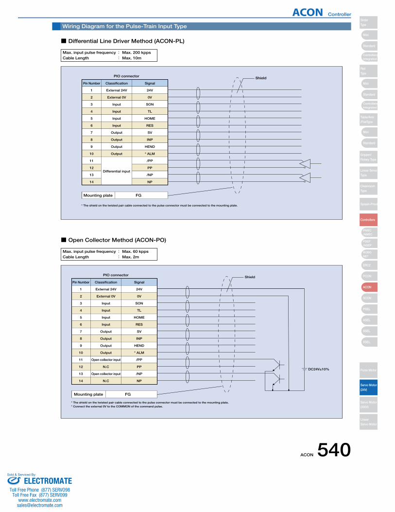
Pin Number
1 External 24V 24V
Differential input
Classification Signal
PIO connector Shield
Mounting plate FG
* The shield on the twisted pair cable connected to the pulse connector must be connected to the mounting plate.
2
3
4
5
6
7
8
9
10
11
12
13
14
External 0V
Input
Input
Input
Input
Output
Output
Output
Output
0V
SON
TL
HOME
RES
SV
INP
HEND
* ALM
/PP
PP
/NP
NP
Wiring Diagram for the Pulse-Train Input Type
■ Differential Line Driver Method (ACON-PL)
■ Open Collector Method (ACON-PO)
Max. input pulse frequency : Max. 200 kppsCable Length : Max. 10m
Pin Number
1 External 24V 24V
Classification Signal
PIO connector Shield
DC24V±10%
Mounting plate FG
* The shield on the twisted pair cable connected to the pulse connector must be connected to the mounting plate. * Connect the external 0V to the COMMON of the command pulse.
External 0V
Input
Input
Input
Input
Output
Output
Output
Output
Open collector input
N.C
Open collector input
N.C
0V
SON
TL
HOME
RES
SV
INP
HEND
* ALM
/PP
PP
/NP
NP
2
3
4
5
6
7
8
9
10
11
12
13
14
Max. input pulse frequency : Max. 60 kppsCable Length : Max. 2m
ACON Controller
ACON 540
Mini
Mini
Mini
Standard
Standard
ControllersIntegrated
Standard
ControllersIntegrated
PSEP/ASEP
PMEC/AMEC
ROBONET
ERC2
PCON
ACON
SCON
PSEL
ASEL
SSEL
XSEL
SliderType
RodType
Table/Arm/FlatType
Gripper/Rotary Type
Linear ServoType
CleanroomType
Splash-Proof
Controllers
Pulse Motor
Servo Motor (24V)
Servo Motor (200V)
LinearServo Motor
ELECTROMATEToll Free Phone (877) SERVO98
Toll Free Fax (877) SERV099www.electromate.com
Sold & Serviced By:
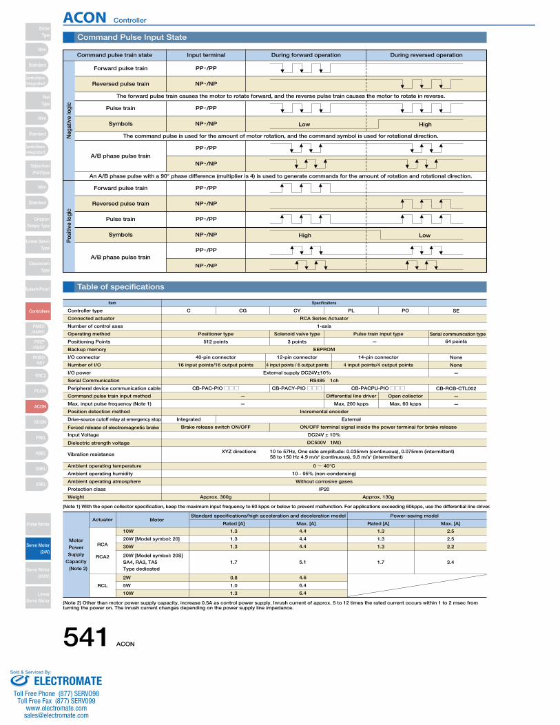
Motor
Power
Supply
Capacity
(Note 2)
Command Pulse Input State
Table of specifications
Low High
High Low
Forward pulse train
Reversed pulse train
The forward pulse train causes the motor to rotate forward, and the reverse pulse train causes the motor to rotate in reverse.
Pulse train
Symbols
The command pulse is used for the amount of motor rotation, and the command symbol is used for rotational direction.
A/B phase pulse train
An A/B phase pulse with a 90° phase difference (multiplier is 4) is used to generate commands for the amount of rotation and rotational direction.
Forward pulse train
Reversed pulse train
Pulse train
Symbols
A/B phase pulse train
PP・/PP
NP・/NP
PP・/PP
NP・/NP
PP・/PP
NP・/NP
PP・/PP
NP・/NP
PP・/PP
NP・/NP
PP・/PP
NP・/NP
Command pulse train state Input terminal During forward operation During reversed operation
Neg
ativ
e lo
gic
Pos
itive
logi
c
Item Specifications
Standard specifications/high acceleration and deceleration model
Rated [A] Max. [A]
Power-saving model
Rated [A] Max. [A]
RCA Series Actuator
1-axis
EEPROM
40-pin connector 12-pin connector 14-pin connector None
16 input points/16 output points
External supply DC24V±10%
RS485 1ch
CB-PAC-PIO□□□ CB-PACY-PIO□□□ CB-RCB-CTL002
4 input points / 6 output points 4 input points/4 output points None
—
Positioner type Solenoid valve type
Controller type
Actuator
RCA
RCA2
RCL
Motor
1.3
1.3
1.3
1.7
0.8
1.0
1.3
1.3
1.3
1.3
1.7
2.5
2.5
2.2
3.4
10W
20W [Model symbol: 20]
30W
20W [Model symbol: 20S]SA4, RA3, TA5Type dedicated
2W
5W
10W
4.4
4.4
4.4
5.1
4.6
6.4
6.4
Connected actuator
Number of control axes
Operating method
Positioning Points
Backup memory
I/O connector
Number of I/O
I/O power
Serial Communication
Peripheral device communication cable
Command pulse train input method
Max. input pulse frequency (Note 1)
Position detection method
Drive-source cutoff relay at emergency stop
Forced release of electromagnetic brake
Input Voltage
Dielectric strength voltage
Vibration resistance
Ambient operating temperature
Ambient operating humidity
Ambient operating atmosphere
Protection class
Weight
C CG CY PL PO SE
Pulse train input type Serial communication type
512 points 3 points
—
Incremental encoder
Integrated
Brake release switch ON/OFF
DC24V ± 10%
DC500V 1MΩ
0~ 40°C
10 - 95% (non-condensing)
Without corrosive gases
IP20
Approx. 300g Approx. 130g
XYZ directions 10 to 57Hz, One side amplitude: 0.035mm (continuous), 0.075mm (intermittent) 58 to 150 Hz 4.9 m/s2 (continuous), 9.8 m/s2 (intermittent)
ON/OFF terminal signal inside the power terminal for brake release
External
CB-PACPU-PIO□□□Differential line driver Open collector —
— Max. 200 kpps Max. 60 kpps —
— 64 points
(Note 1) With the open collector specification, keep the maximum input frequency to 60 kpps or below to prevent malfunction. For applications exceeding 60kpps, use the differential line driver.
(Note 2) Other than motor power supply capacity, increase 0.5A as control power supply. Inrush current of approx. 5 to 12 times the rated current occurs within 1 to 2 msec from turning the power on. The inrush current changes depending on the power supply line impedance.
ACON Controller
541 ACON
SliderType
Mini
Mini
PSEP/ASEP
PMEC/AMEC
ROBONET
ERC2
PCON
ACON
SCON
PSEL
ASEL
SSEL
XSEL
Standard
Standard
Standard
ControllersIntegrated
ControllersIntegrated
RodType
Table/Arm/FlatType
Gripper/Rotary Type
Linear ServoType
CleanroomType
Splash-Proof
Controllers
Pulse Motor
Servo Motor (24V)
Servo Motor (200V)
LinearServo Motor
Mini
ELECTROMATEToll Free Phone (877) SERVO98
Toll Free Fax (877) SERV099www.electromate.com
Sold & Serviced By:
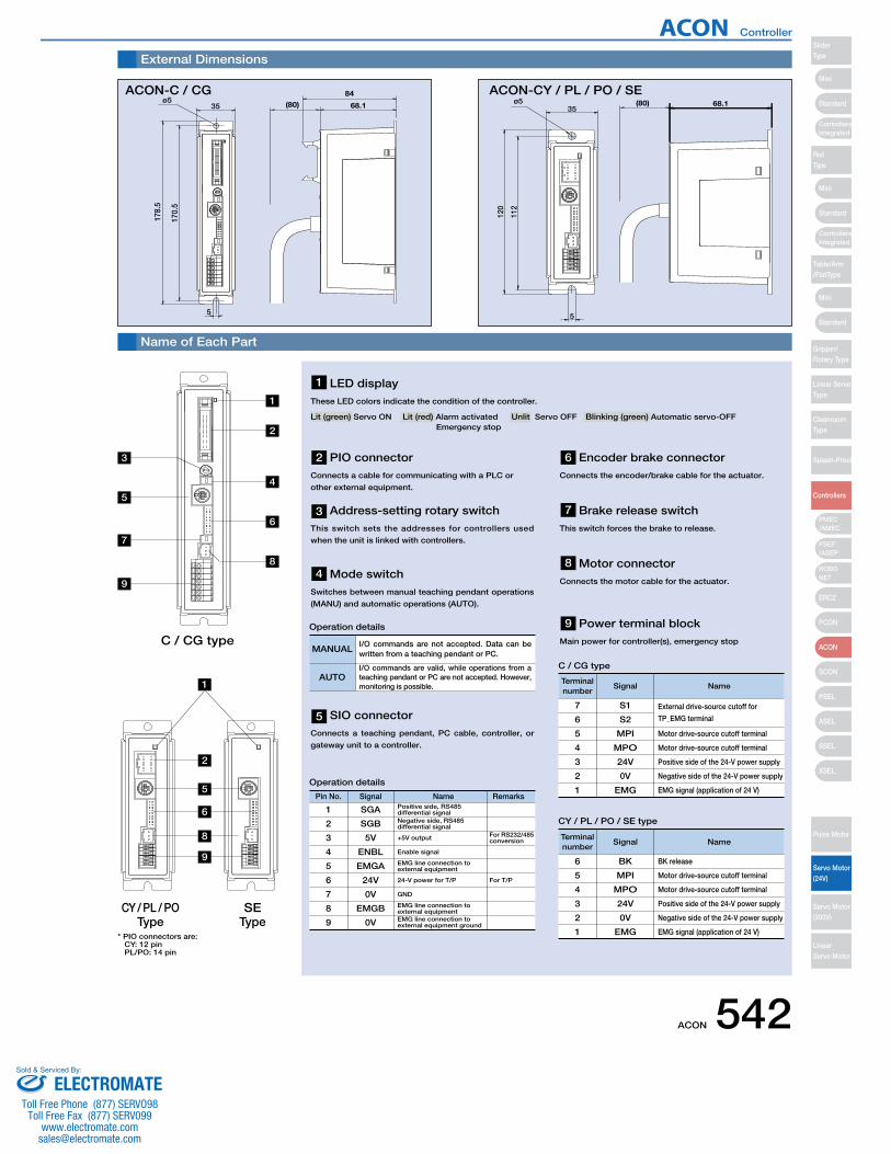
5
170.
5
178.
5
ø535 (80)
84
68.1
External Dimensions
Name of Each Part
* PIO connectors are: CY: 12 pin PL/PO: 14 pin
ACON-C / CG68.1
120
112
5
35ø5 (80)
1
1
2
3
4
5
6
7
8
C / CG type
CY / PL / POType
SEType
9
5
6
8
9
2
PIO connector Connects a cable for communicating with a PLC or
other external equipment.
Brake release switchThis switch forces the brake to release.
Motor connectorConnects the motor cable for the actuator.
Power terminal blockMain power for controller(s), emergency stop
Address-setting rotary switch This switch sets the addresses for controllers used
when the unit is linked with controllers.
SIO connectorConnects a teaching pendant, PC cable, controller, or
gateway unit to a controller.
Mode switchSwitches between manual teaching pendant operations
(MANU) and automatic operations (AUTO).
Pin No. Signal Name Remarks
1 SGA Positive side, RS485 differential signal
2
3
4
5
6
7
8
9
SGB
5V
ENBL
EMGA
24V
0V
EMGB
0V
Negative side, RS485 differential signal
+5V output For RS232/485 conversion
For T/P
Enable signal
EMG line connection to external equipment
24-V power for T/P
GND
EMG line connection to external equipmentEMG line connection to external equipment ground
Operation details
MANUALI/O commands are not accepted. Data can be written from a teaching pendant or PC.
AUTOI/O commands are valid, while operations from a teaching pendant or PC are not accepted. However, monitoring is possible.
Operation details
Terminal number
Signal Name
7 S1 External drive-source cutoff for
TP_EMG terminal6
5
4
3
2
1
S2
MPI
MPO
24V
0V
EMG
Motor drive-source cutoff terminal
Motor drive-source cutoff terminal
Positive side of the 24-V power supply
Negative side of the 24-V power supply
EMG signal (application of 24 V)
Terminal number
Signal Name
BK release6
5
4
3
2
1
BK
MPI
MPO
24V
0V
EMG
Motor drive-source cutoff terminal
Motor drive-source cutoff terminal
Positive side of the 24-V power supply
Negative side of the 24-V power supply
EMG signal (application of 24 V)
C / CG type
CY / PL / PO / SE type
ACON-CY / PL / PO / SE
Encoder brake connectorConnects the encoder/brake cable for the actuator.
1
2
3
4
5
6
7
8
9
LED display These LED colors indicate the condition of the controller.
Lit (green) Servo ON Lit (red) Alarm activated Unlit Servo OFF Blinking (green) Automatic servo-OFFEmergency stop
ACON Controller
ACON 542
Mini
Mini
Mini
Standard
Standard
ControllersIntegrated
Standard
ControllersIntegrated
PSEP/ASEP
PMEC/AMEC
ROBONET
ERC2
PCON
ACON
SCON
PSEL
ASEL
SSEL
XSEL
SliderType
RodType
Table/Arm/FlatType
Gripper/Rotary Type
Linear ServoType
CleanroomType
Splash-Proof
Controllers
Pulse Motor
Servo Motor (24V)
Servo Motor (200V)
LinearServo Motor
ELECTROMATEToll Free Phone (877) SERVO98
Toll Free Fax (877) SERV099www.electromate.com
Sold & Serviced By:
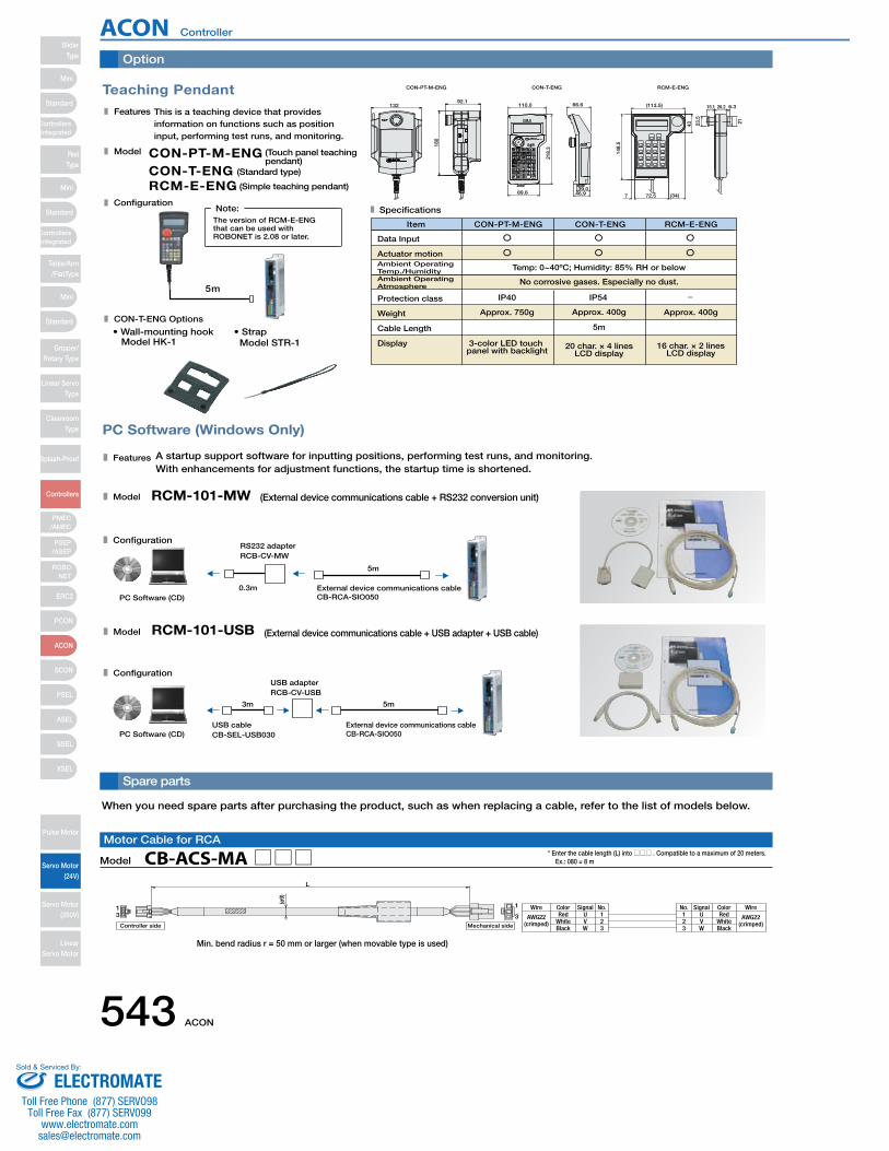
Teaching Pendant
This is a teaching device that provides information on functions such as position input, performing test runs, and monitoring.
RCM-E-ENGCON-T-ENGCON-PT-M-ENG
(Simple teaching pendant)
(Standard type)
(Touch panel teaching pendant)
Data Input
3-color LED touch panel with backlight
Approx. 750g
IP40 IP54
20 char. × 4 linesLCD display
5m
Approx. 400g
No corrosive gases. Especially no dust.
Temp: 0~40ºC; Humidity: 85% RH or below
16 char. × 2 linesLCD display
Approx. 400g
Item CON-PT-M-ENG CON-T-ENG RCM-E-ENG
5m
The version of RCM-E-ENG that can be used with ROBONET is 2.08 or later.
Note:
RCM-E-ENGCON-T-ENGCON-PT-M-ENG
21
6.326.215.1
23.5
43
148.
5
7 (34)72.5
(113.5)
46.939.0
66.6110.0
218.
3
89.6
CON-T-ENG Options
• Wall-mounting hookModel HK-1
• StrapModel STR-1
13292.1
180
PC Software (Windows Only)
A startup support software for inputting positions, performing test runs, and monitoring. With enhancements for adjustment functions, the startup time is shortened.
RCM-101-MW (External device communications cable + RS232 conversion unit)
0.3m
5m
External device communications cableCB-RCA-SIO050PC Software (CD)
RS232 adapterRCB-CV-MW
(External device communications cable + USB adapter + USB cable)RCM-101-USB
5m3m
PC Software (CD)External device communications cableCB-RCA-SIO050
USB cableCB-SEL-USB030
USB adapterRCB-CV-USB
Features
Specifications
Model
Features
Model
Configuration
Model
Configuration
Actuator motionAmbient OperatingTemp./HumidityAmbient OperatingAtmosphere
Protection class
Weight
Cable Length
Display
Configuration
Option
Spare parts
AWG22(crimped) White
Wire Color Signal No.U 1
No. Signal Color WireRed 1
23Black
VW
23 W
VU Red
WhiteBlack
AWG22(crimped)
13 3
1
L
Mechanical sideController side
(ø9)
Model CB-ACS-MA□□□Motor Cable for RCA
* Enter the cable length (L) into □□□ . Compatible to a maximum of 20 meters. Ex.: 080 = 8 m
When you need spare parts after purchasing the product, such as when replacing a cable, refer to the list of models below.
Min. bend radius r = 50 mm or larger (when movable type is used)
ACON Controller
543 ACON
SliderType
Mini
Mini
PSEP/ASEP
PMEC/AMEC
ROBONET
ERC2
PCON
ACON
SCON
PSEL
ASEL
SSEL
XSEL
Standard
Standard
Standard
ControllersIntegrated
ControllersIntegrated
RodType
Table/Arm/FlatType
Gripper/Rotary Type
Linear ServoType
CleanroomType
Splash-Proof
Controllers
Pulse Motor
Servo Motor (24V)
Servo Motor (200V)
LinearServo Motor
Mini
ELECTROMATEToll Free Phone (877) SERVO98
Toll Free Fax (877) SERV099www.electromate.com
Sold & Serviced By:

L
U
Shield
Yellow (Red •)Yellow (Blue •)
Pink (Red •)Pink (Blue •)White (Red •)White (Blue •)Orange (Red •)Orange (Blue •)
Gray (Red •)Gray (Blue •)
Orange (Red • Consecutive)Orange (Blue • Consecutive)
Gray (Red • Consecutive)Gray (Blue • Consecutive)
Red(Wire color)
1 A1 USignal Pin No. Pin No. Signal
BK+ 16
(Front view)
(10)
(ø12
)
(18)
(8)
(12)
(23)
(8)
(5)
(30)
(18)
Controller side
(Front view)
Mechanical side
(Front view)
BK−LS+LS−A+A−B+B−Z+Z−
/PSVCCGNDNCFG
151817141312111098765
1
VW
23
B1A2B2A3B3A4B4A5B5A6B6A7B7A8B8A9B9A10B10A11B11
VWNCNCNC
BK+BK−LS+LS−A+A−B+B−Z+Z−−
/PSVCCGNDNCFG
YellowBlack
0.2sq
51353-1400 (MOLEX)
Single wire (UL1007 AWG24 Green)
No connector
Side with no connector
Housing: 51353-1400 (MOLEX)Contact: 56134-9000 (MOLEX)
Round terminal: 0.5-5 (JST)
110
0.5-5 (JST)White/Gray
(ø9)
L
BlackBlack
CableColorNo. Signal
Name Wire
IO_24V
FG
1
1 AWG24
White/BlackRed
White/RedGreen
White/GreenYellow
White/YellowBrown
White/BrownBlue
White/BlueGray
White/Gray
IO_24GIN0IN1IN2IN3
OUT0OUT1OUT2OUT3
PPPGNPNG
White/BlackRed
White/RedGreen
White/GreenYellow
White/YellowBrown
White/BrownBlue
White/BlueGray
White/Gray
234567891011121314
1
9 18
10
20
18
2 1
17
Mechanical sideController side
L
(ø10
)
White/Purple Blue LS+ 181 ENA Gray White/BlueRobot Cable Standard Cable
Housing : PHDR-18VR (JST)Contact : SPHD-001T-P0.5 (JST)
Plug housing : XMP-18V (JST)Socket contact : BXA-001T-P0.6 (JST)Retainer : XMS-09V (JST)
CN2CN1
Cable color Standard Cable Robot CablePin No.
Cable color SignalSignal Pin
No.
White/GrayYellowBlue
White/BlueWhite/YellowWhite/Red
White/BlackOrangeGreenPurpleGrayRed
Black
Ground
OrangeGreenBrownGrayRed
BlackYellowPink
PurpleWhite
Blue/redOrange/WhiteGreen/White
Ground
LS−BK+BK−ENAENAENBENBENZENZ
VPS5V
GND−−−
F.G
1716151413121110987654321
23456789
101112131415161718
ENAENBENB
−−
LS+−FG
ENZENZ−
VPS5V
GNDLS−BK−BK+
RedBlackYellow
−−
Blue−
GroundPink
PurpleWhite
Blue/redOrange/WhiteGreen/White
OrangeBrownGreen
White/YellowWhite/Red
White/Black−−
White/Purple−
GroundOrangeGreenPurpleGrayRed
BlackWhite/Gray
BlueYellow
Model CB-ACS-PA□□□/CB-ACS-PA□□□-RBEncoder Cable / Encoder Robot Cable for RCA
* Enter the cable length (L) into □□□ . Compatible to a maximum of 20 meters. Ex.: 080 = 8 m
1
1112
2
Housing: 51353-1200 (MOLEX)Contact: 56134-9000 (MOLEX)
(crimped)AWG28
Flat cable
51353-1200 (MOLEX)
No
connector
LBrown-1
CableColor
PinNo.
Signal Wire
24V123456789101112
0VIN0IN1IN2IN3
OUT0OUT1OUT2OUT3OUT4OUT5
Red-1Orange-1Yellow-1Green-1Blue-1
Purple-1Gray-1White-1Black-1Brown-2
Red-2
Model CB-PACY-PIO□□□I/O Cable for Solenoid Valve Type (for ACON-CY)
* Enter the cable length (L) into □□□ . Compatible to a maximum of 10 meters. Ex.: 080 = 8 m
Model CB-PACPU-PIO□□□Pulse Train Control I/O Cable (for ACON-PL/PO)
* Enter the cable length (L) into □□□ . Compatible to a maximum of 10 meters. Ex.: 080 = 8 m
B
(crimped)Flat cable A
(crimped)AWG28
Flat cable B
Half-pitch MIL socket:HIF6-40D-1. 27R (Hirose)
Flat cable (20-core) × 2
HIF6-40D-1. 27R
20B20A
1B1AA
No
connector
No
connector
Brown-1
CableColorL
PinNo.
SignalWire
24V1A Brown-3
CableColor
PinNo.
SignalWire
OUT01B2A3A4A5A6A7A8A9A10A11A12A13A14A15A16A17A18A19A20A
24V
IN0IN1IN2IN3IN4IN5IN6IN7IN8IN9IN10IN11IN12IN13IN14IN15
Red-1Orange-1Yellow-1Green-1Blue-1
Purple-1Gray-1White-1Black-1Brown-2
Red-2Orange-2Yellow-2Green-2Blue-2
Purple-2Gray-2White-2Black-2
2B3B4B5B6B7B8B9B10B11B12B13B14B15B16B17B18B19B20B
OUT1OUT2OUT3OUT4OUT5OUT6OUT7OUT8OUT9OUT10OUT11OUT12OUT13OUT14OUT15
0V0V
Red-3Orange-3Yellow-3Green-3Blue-3
Purple-3Gray-3White-3Black-3Brown-4
Red-4Orange-4Yellow-4Green-4Blue-4
Purple-4Gray-4White-4Black-4
Model CB-PAC-PIO□□□I/O Flat Cable (for ACON-C / CG)
* Enter the cable length (L) into □□□ . Compatible to a maximum of 10 meters. Ex.: 080 = 8 m
* The standard cable for the encoder cable is the normal cable. A robot cable can be specified as an option.
Model CB-ACS-MPA□□□Motor-Encoder Integrated Cable for RCA2
* Enter the cable length (L) into □□□ . Compatible to a maximum of 20 meters. Ex.: 080 = 8 m
Min. bend radius r = 50 mm or larger (when movable type is used)* Only robot cable is to be used in a cable track.
Min. bend radius r = 84 mm or larger (when movable type is used)
* The standard cable is a robot cable.
ACON Controller
ACON 544
Mini
Mini
Mini
Standard
Standard
ControllersIntegrated
Standard
ControllersIntegrated
PSEP/ASEP
PMEC/AMEC
ROBONET
ERC2
PCON
ACON
SCON
PSEL
ASEL
SSEL
XSEL
SliderType
RodType
Table/Arm/FlatType
Gripper/Rotary Type
Linear ServoType
CleanroomType
Splash-Proof
Controllers
Pulse Motor
Servo Motor (24V)
Servo Motor (200V)
LinearServo Motor
ELECTROMATEToll Free Phone (877) SERVO98
Toll Free Fax (877) SERV099www.electromate.com
Sold & Serviced By:
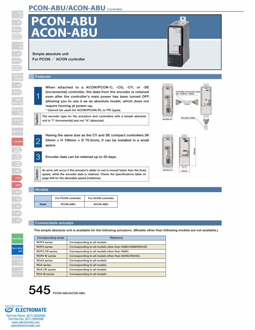
545 PCON-ABU/ACON-ABU
PCON-ABU/ACON-ABU ControllerSlider
Type
Mini
Mini
PSEP/ASEP
PMEC/AMEC
ROBONET
ERC2
PCON
ACON
SCON
PSEL
ASEL
SSEL
XSEL
Standard
Standard
Standard
ControllersIntegrated
ControllersIntegrated
RodType
Table/Arm/FlatType
Gripper/Rotary Type
Linear ServoType
CleanroomType
Splash-Proof
Controllers
Pulse Motor
Servo Motor (24V)
Servo Motor (200V)
LinearServo Motor
Mini
Features
Simple absolute unit
For PCON/ ACON controller
Models
Connectable actuator
PCON-ABUACON-ABU
For PCON controller For ACON controller
Model PCON-ABU ACON-ABU
When attached to a ACON/PCON-C, -CG, -CY, or -SE (incremental) controller, the data from the encoder is retained even after the controller's main power has been turned OFF, allowing you to use it as an absolute model, which does not require homing at power-up.* Cannot be used for ACON/PCON-PL or PO types.
1
Having the same size as the CY and SE compact controllers (W
34mm × H 100mm × D 75.3mm), it can be installed in a small
space.2
3 Encoder data can be retained up to 20 days.
ACON-CY
100m
m
34mmAn error will occur if the actuator's slider or rod is moved faster than the fixed speed, while the encoder data is retained. Check the specifications table on page 546 for the allowable speed (rotations).
The encoder type for the actuators and controllers with a simple absolute
unit is "I" (incremental) and not "A" (absolute).
0.2m
Controller connection cableCB—AC(PC)—PJ002
Encoder CableACON-CY
Cau
tion:
Cau
tion:
Corresponding series Reference
RCP3 series Corresponding to all models
RCP2 series Corresponding to all models other than HS8C/HS8R/RA10C.
RCP2 CR series Corresponding to all models other than HS8C.
RCP2 W series Corresponding to all models other than SA16C/RA10C.
RCA2 series Corresponding to all models
RCA series Corresponding to all models
RCA CR series Corresponding to all models
RCA W series Corresponding to all models
The simple absolute unit is available for the following actuators. (Models other than following models are not available.)
ELECTROMATEToll Free Phone (877) SERVO98
Toll Free Fax (877) SERV099www.electromate.com
Sold & Serviced By:
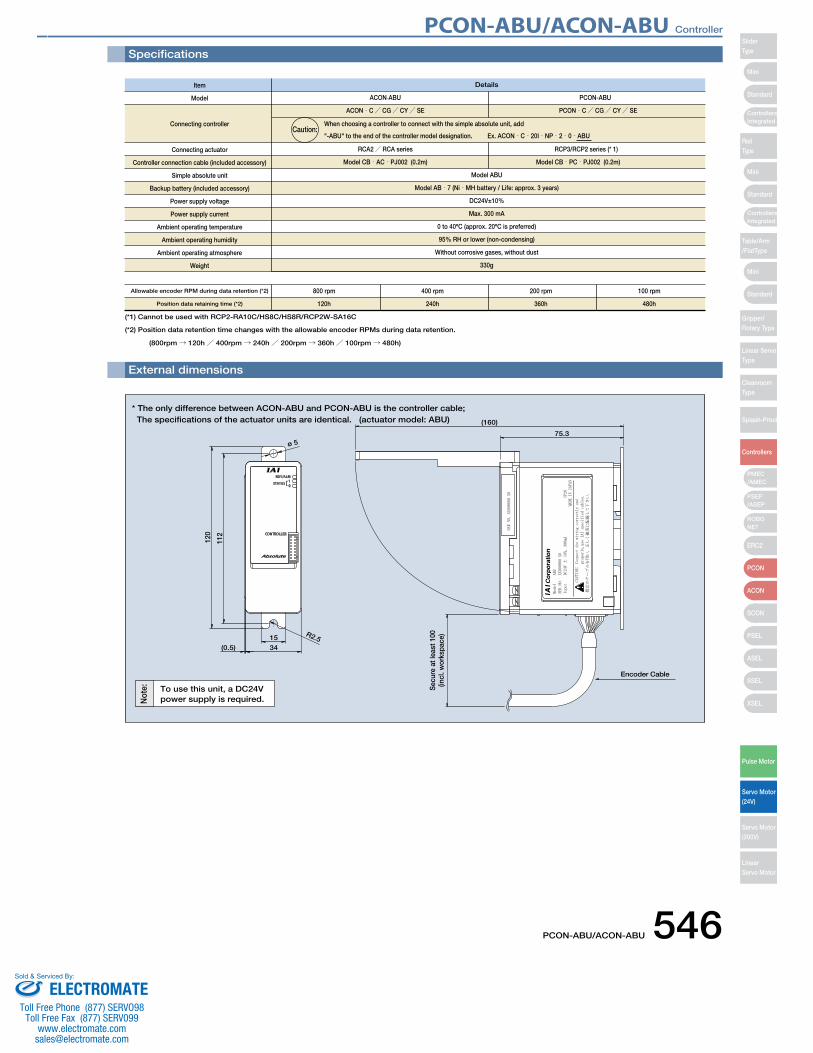
PCON-ABU/ACON-ABU 546
PCON-ABU/ACON-ABU Controller
Mini
Mini
Mini
Standard
Standard
ControllersIntegrated
Standard
ControllersIntegrated
PSEP/ASEP
PMEC/AMEC
ROBONET
ERC2
PCON
ACON
SCON
PSEL
ASEL
SSEL
XSEL
SliderType
RodType
Table/Arm/FlatType
Gripper/Rotary Type
Linear ServoType
CleanroomType
Splash-Proof
Controllers
Pulse Motor
Servo Motor (24V)
Servo Motor (200V)
LinearServo Motor
Specifications
External dimensions
Item
Model
Connecting controller
Connecting actuator
Controller connection cable (included accessory)
Simple absolute unit
Backup battery (included accessory)
Power supply voltage
Power supply current
Ambient operating temperature
Ambient operating humidity
Ambient operating atmosphere
Weight
Allowable encoder RPM during data retention (*2)
Position data retaining time (*2)
Details
Model ABU
Model AB‐7 (Ni‐MH battery / Life: approx. 3 years)
DC24V±10%
Max. 300 mA
0 to 40ºC (approx. 20ºC is preferred)
95% RH or lower (non-condensing)
Without corrosive gases, without dust
330g
800 rpm
120h
400 rpm
240h
200 rpm
360h
100 rpm
480h
When choosing a controller to connect with the simple absolute unit, add
"-ABU" to the end of the controller model designation. Ex. ACON‐C‐20I‐NP‐2‐0‐ABU
(*1) Cannot be used with RCP2-RA10C/HS8C/HS8R/RCP2W-SA16C
(*2) Position data retention time changes with the allowable encoder RPMs during data retention.
(800rpm→ 120h/ 400rpm→ 240h/ 200rpm→ 360h/ 100rpm→ 480h)
Caution:
120
112
(0.5)
ø 5
34
Sec
ure
at le
ast 1
00(in
cl. w
orks
pace
)
(160)
75.3
15R2.5
* The only difference between ACON-ABU and PCON-ABU is the controller cable;The specifications of the actuator units are identical. (actuator model: ABU)
To use this unit, a DC24Vpower supply is required.
Encoder Cable
Not
e:
ACON-ABU PCON-ABU
ACON‐C/ CG/ CY/ SE PCON‐C/ CG/ CY/ SE
RCA2/ RCA series RCP3/RCP2 series (* 1)
Model CB‐AC‐PJ002 (0.2m) Model CB‐PC‐PJ002 (0.2m)
ELECTROMATEToll Free Phone (877) SERVO98
Toll Free Fax (877) SERV099www.electromate.com
Sold & Serviced By:
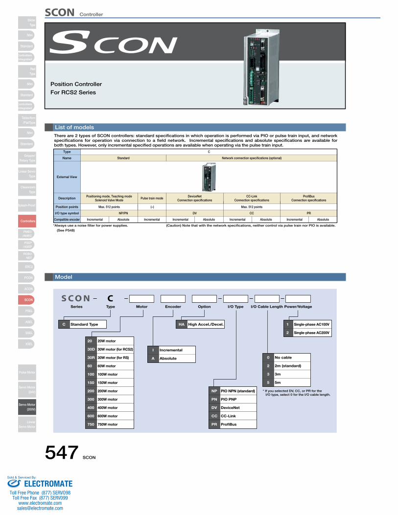
547 SCON
List of modelsThere are 2 types of SCON controllers: standard specifications in which operation is performed via PIO or pulse train input, and network specifications for operation via connection to a field network. Incremental specifications and absolute specifications are available for both types. However, only incremental specified operations are available when operating via the pulse train input.
Position Controller
For RCS2 Series
S C O NSeries Type Motor Encoder Option I/O Type I/O Cable Length Power/Voltage
C Standard Type
20 20W motor
30D 30W motor (for RCS2)
30R 30W motor (for RS)
60 60W motor
100 100W motor
150 150W motor
200 200W motor
300 300W motor
400 400W motor
600 600W motor
750 750W motor
I Incremental
A Absolute
NP PIO NPN (standard)
PN PIO PNP
DV DeviceNet
CC CC-Link
PR ProfiBus
HA High Accel./Decel. 1 Single-phase AC100V
2 Single-phase AC200V
0 No cable
2 2m (standard)
3 3m
5 5m
C
* If you selected DV, CC, or PR for the I/O type, select 0 for the I/O cable length.
Type C
StandardName
External View
Description Positioning mode, Teaching modeSolenoid Valve Mode
Position points
I/O type symbol
Compatible encoder
Max. 512 points
Incremental
NP/PN
Pulse train mode DeviceNetConnection specifications
CC-LinkConnection specifications
ProfiBusConnection specifications
(−)
Network connection specifications (optional)
Max. 512 points
DV CC PR
Model
Absolute Incremental Incremental Absolute Incremental Absolute Incremental Absolute
(Caution) Note that with the network specifications, neither control via pulse train nor PIO is available.*Always use a noise filter for power supplies.
(See P548)
SCON ControllerSlider
Type
Mini
Mini
PSEP/ASEP
PMEC/AMEC
ROBONET
ERC2
PCON
ACON
SCON
PSEL
ASEL
SSEL
XSEL
Standard
Standard
Standard
ControllersIntegrated
ControllersIntegrated
RodType
Table/Arm/FlatType
Gripper/Rotary Type
Linear ServoType
CleanroomType
Splash-Proof
Controllers
Pulse Motor
Servo Motor (24V)
Servo Motor (200V)
LinearServo Motor
Mini
ELECTROMATEToll Free Phone (877) SERVO98
Toll Free Fax (877) SERV099www.electromate.com
Sold & Serviced By:
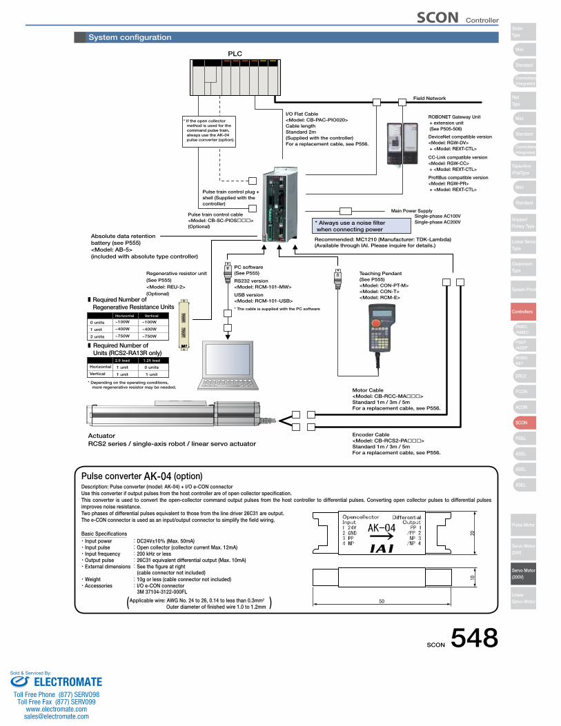
SCON 548
Pulse converter AK-04 (option)Description: Pulse converter (model: AK-04) + I/O e-CON connectorUse this converter if output pulses from the host controller are of open collector specification. This converter is used to convert the open-collector command output pulses from the host controller to differential pulses. Converting open collector pulses to differential pulses improves noise resistance. Two phases of differential pulses equivalent to those from the line driver 26C31 are output.The e-CON connector is used as an input/output connector to simplify the field wiring.
Basic Specifications・Input power :DC24V±10% (Max. 50mA) ・Input pulse :Open collector (collector current Max. 12mA) ・Input frequency :200 kHz or less・Output pulse :26C31 equivalent differential output (Max. 10mA) ・External dimensions :See the figure at right
(cable connector not included) ・Weight :10g or less (cable connector not included) ・Accessories :I/O e-CON connector
3M 37104-3122-000FL
Applicable wire: AWG No. 24 to 26, 0.14 to less than 0.3mm2
Outer diameter of finished wire 1.0 to 1.2mm
ActuatorRCS2 series / single-axis robot / linear servo actuator
I/O Flat Cable<Model: CB-PAC-PIO020>Cable lengthStandard 2m(Supplied with the controller)For a replacement cable, see P556.
Pulse train control plug + shell (Supplied with the controller)
Pulse train control cable<Model: CB-SC-PIOS���>(Optional)
Motor Cable<Model: CB-RCC-MA���>Standard 1m / 3m / 5mFor a replacement cable, see P556.
USB version<Model: RCM-101-USB>
RS232 version<Model: RCM-101-MW>
PC software(See P555) Teaching Pendant
(See P555)<Model: CON-PT-M><Model: CON-T><Model: RCM-E>
* The cable is supplied with the PC software
* Always use a noise filter when connecting power
Encoder Cable<Model: CB-RCS2-PA���>Standard 1m / 3m / 5mFor a replacement cable, see P556.
PLC
Main Power SupplySingle-phase AC100VSingle-phase AC200V
Recommended: MC1210 (Manufacturer: TDK-Lambda)(Available through IAI. Please inquire for details.)
Absolute data retentionbattery (see P555)<Model: AB-5>(included with absolute type controller)
Regenerative resistor unit(See P555)<Model: REU-2>(Optional)
Field Network
ProfiBus compatible version<Model: RGW-PR> + <Model: REXT-CTL>
CC-Link compatible version<Model: RGW-CC> + <Model: REXT-CTL>
DeviceNet compatible version<Model: RGW-DV> + <Model: REXT-CTL>
ROBONET Gateway Unit + extension unit (See P505-506)
Required Number of Regenerative Resistance Units
Required Number of Units (RCS2-RA13R only)
0 units ~100W
Horizontal
~100W
Vertical
* Depending on the operating conditions, more regenerative resistor may be needed.
Horizontal 1 unit
2.5 lead
0 units
1.25 lead
Vertical 1 unit 1 unit
~400W
~750W
~400W
~750W
1 unit
2 units
* If the open collector method is used for the command pulse train, always use the AK-04 pulse converter (option).
System configuration
) (
SCON Controller
Mini
Mini
Mini
Standard
Standard
ControllersIntegrated
Standard
ControllersIntegrated
PSEP/ASEP
PMEC/AMEC
ROBONET
ERC2
PCON
ACON
SCON
PSEL
ASEL
SSEL
XSEL
SliderType
RodType
Table/Arm/FlatType
Gripper/Rotary Type
Linear ServoType
CleanroomType
Splash-Proof
Controllers
Pulse Motor
Servo Motor (24V)
Servo Motor (200V)
LinearServo Motor
ELECTROMATEToll Free Phone (877) SERVO98
Toll Free Fax (877) SERV099www.electromate.com
Sold & Serviced By:
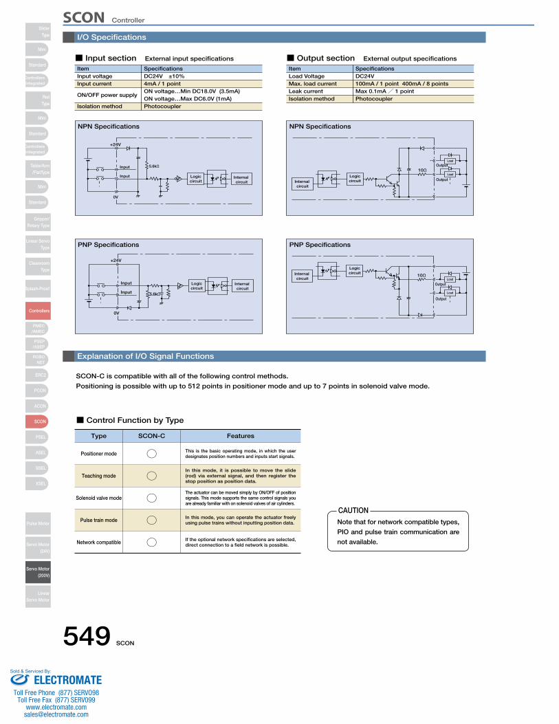
549 SCON
I/O Specifications
Explanation of I/O Signal Functions
SCON-C is compatible with all of the following control methods.
Positioning is possible with up to 512 points in positioner mode and up to 7 points in solenoid valve mode.
■ Control Function by Type
ItemInput voltageInput current
ON/OFF power supply
Isolation method
SpecificationsDC24V ±10%4mA / 1 pointON voltage…Min DC18.0V (3.5mA)ON voltage…Max DC6.0V (1mA)Photocoupler
+24V
0V
Input 5.6kΩ
Logiccircuit
Internal circuit
Input
■ Input section External input specifications
ItemLoad VoltageMax. load current Leak currentIsolation method
SpecificationsDC24V100mA / 1 point 400mA / 8 pointsMax 0.1mA/ 1 pointPhotocoupler
10Ω
Output
Output
Load
Load
LogiccircuitInternal
circuit
+24V
0V
Input Logiccircuit
Internal circuit
Input 5.6kΩ
10Ω
Output
Output
Load
Load
LogiccircuitInternal
circuit
■ Output section External output specifications
NPN Specifications NPN Specifications
PNP Specifications PNP Specifications
Type SCON-C Features
Positioner mode ○ This is the basic operating mode, in which the user designates position numbers and inputs start signals.
Teaching mode ○In this mode, it is possible to move the slide (rod) via external signal, and then register the stop position as position data.
Solenoid valve mode ○The actuator can be moved simply by ON/OFF of position signals. This mode supports the same control signals you are already familiar with on solenoid valves of air cylinders.
Pulse train mode ○ In this mode, you can operate the actuator freely using pulse trains without inputting position data.
Network compatible ○ If the optional network specifications are selected, direct connection to a field network is possible.
CAUTIONNote that for network compatible types,
PIO and pulse train communication are
not available.
SCON ControllerSlider
Type
Mini
Mini
PSEP/ASEP
PMEC/AMEC
ROBONET
ERC2
PCON
ACON
SCON
PSEL
ASEL
SSEL
XSEL
Standard
Standard
Standard
ControllersIntegrated
ControllersIntegrated
RodType
Table/Arm/FlatType
Gripper/Rotary Type
Linear ServoType
CleanroomType
Splash-Proof
Controllers
Pulse Motor
Servo Motor (24V)
Servo Motor (200V)
LinearServo Motor
Mini
ELECTROMATEToll Free Phone (877) SERVO98
Toll Free Fax (877) SERV099www.electromate.com
Sold & Serviced By:
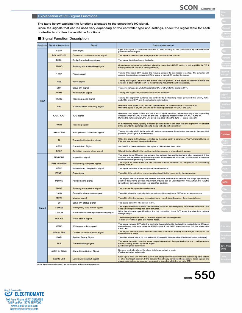
SCON 550
Explanation of I/O Signal Functions
The table below explains the functions allocated to the controller’s I/O signal.
Since the signals that can be used vary depending on the controller type and settings, check the signal table for each
controller to confirm the available functions.
■ Signal Function Description
Classification Signal abbreviations
CSTR Start signal
Signal
Input this signal to cause the actuator to start moving to the position set by the command position number signal.
PC1 to PC256 Command position number signal This signal is used to input a target position number (binary input).
Function description
BKRL Brake forced release signal This signal forcibly releases the brake.
RMOD Running mode switching signal Operations mode can be switched when the controller’s MODE switch is set to AUTO. (AUTO if this signal is OFF, MANU if the signal is ON)
* STP Pause signal Turning this signal OFF causes the moving actuator to decelerate to a stop. The actuator will resume the remaining movement if the signal is turned ON during the pause.
MODE Teaching mode signal Turning this signal ON switches the controller to the teaching mode (provided that CSTR, JOG+ and JOG- are all OFF and the actuator is not moving)
RES Reset signal Turning this signal ON resets the alarms that are present. If this signal is turned ON while the actuator is paused (*STP is OFF), the remaining movement can be cancelled.
SON Servo ON signal The servo remains on while this signal is ON, or off while the signal is OFF.
JISL
JOG+, JOG−
JOG/INCHING switching signal
JOG signal
When the main signal is off, the JOG operation will be conducted for JOG+ and JOG-.When the signal is on, the unit will do the inching operation for JOG+ and JOG-.
When the JISL signal is OFF and the JOG +/- signal turns ON, the unit will jog in the + (positive) direction when the JOG + turns on and the - (negative) direction when the JOG - turns on.During the JOG operation, the unit slows to a stop when the JOG +/- signal turns off.
ST0 to ST6 Start position command signal Turning this signal ON in the solenoid valve mode causes the actuator to move to the specified position. (Start signal is not required)
TL Torque limit selection signal While this signal is ON, torque is limited by the value set by a parameter. The TLM signal turns on if torque has reached the specified value.
CSTP Forced Stop Signal Servo OFF is performed when this signal is ON for more than 10ms.
DCLR Deviation counter clear signal When this signal is ON, the position deviation counter is cleared continuously.
PEND/INP In position signalThis signal turns ON when the actuator has entered the positioning band after movement. If the actuator has exceeded the positioning band, PEND does not turn OFF, but INP does. PEND and INP can be swapped using a parameter.
PWRT Teaching signal In the teaching mode, specify a desired position number and then turn this signal ON for at least 20ms to write the current position to the specified position number.
HOME Home return signal Turning this signal ON preforms home-return operation.
Input
Output
PM1 to PM256 Positioning complete signal This signal is used to output the position number achieved at completion of positioning (binary output)
HEND Home return completion signal This signal turns ON upon completion of home return.
ZONE1 Zone signal Turns ON if the actuator’s current position is within the range set by the parameter.
PZONE Position zone signalThis signal turns ON when the current actuator position has entered the range specified by position data during position movement. PZONE can be used together with ZONE1, but PZONE is valid only during movement to a specified position.
RMDS Running mode status signal This outputs the operation mode status.
* ALM Controller alarm status signal Turns ON when the controller is in normal condition, and turns OFF when an alarm occurs.
SV Servo ON status signal
* EMGS Emergency stop status signal This signal remains ON while the controller is not in the emergency stop mode, and turns OFF once an emergency stop has been actuated.
* BALM Absolute battery voltage drop warning signal With the absolute specifications for the controller, turns OFF when the absolute battery voltage drops.
MODES Mode status signal The mode signal input turns it ON when it goes into teaching mode. It turns OFF when it goes into normal mode.
WEND Writing complete signalThis signal remains OFF after the controller has switched to the teaching mode. It turns ON upon completion of data write using the PWRT signal. If the PWRT signal is turned Off, this signal also turns OFF.
PE0 to PE6 Current position number signal This signal turns ON after the controller has completed moving to the target position in the solenoid valve mode.
PWR System Ready Signal Turns ON when it starts up normally after turning ON the controller. (Dedicated pulse train type)
TLR Torque limiting signalThis signal turns ON once the motor torque has reached the specified value in a condition where torque is being limited by the TL signal.(Dedicated pulse train mode)
ALM1 to ALM8 Alarm Code Output Signal During a controller alarm, the alarm details are output in code.(Dedicated pulse train mode)
LSO to LS2 Limit switch output signalEach signal turns ON when the current actuator position has entered the positioning band before or after the target position. If the actuator has already completed home return, these signals are output even before a movement command is issued or while the servo is OFF.
MOVE Moving signal Turns ON while the actuator is moving (home return), including when there is push force.
This signal turns ON when servo is ON.
(Note) Signals with asterisks (*) are normally ON and OFF during operation.
SCON Controller
Mini
Mini
Mini
Standard
Standard
ControllersIntegrated
Standard
ControllersIntegrated
PSEP/ASEP
PMEC/AMEC
ROBONET
ERC2
PCON
ACON
SCON
PSEL
ASEL
SSEL
XSEL
SliderType
RodType
Table/Arm/FlatType
Gripper/Rotary Type
Linear ServoType
CleanroomType
Splash-Proof
Controllers
Pulse Motor
Servo Motor (24V)
Servo Motor (200V)
LinearServo Motor
ELECTROMATEToll Free Phone (877) SERVO98
Toll Free Fax (877) SERV099www.electromate.com
Sold & Serviced By:
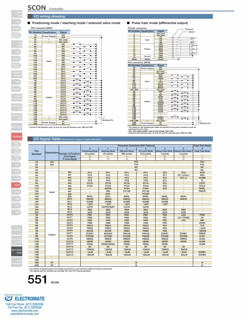
551 SCON
PIO connector (NPN)
* Connect 24V between pins 1A and 2A, and 0V between pins 19B and 20B.
Pin Number Classification Signal1A 24V
Power Supply
Power Supply
Input
Output
DC24V±10%
PIO connector (NPN)
1A 24V
DC24V±10%
PULSE connector
Pin Number Classification Signal
Pin Number Classification Signal
1 Not used
Shield
Twist pair
Shield
Input
Output
Ground
Power Supply
Input
Output
Power Supply
Positioning mode / teaching mode / solenoid valve mode Pulse train mode (differential output)
Classification
Parameter Selections (PIO Patterns) Pulse Train Mode
P24
PC1 PC1 PC1 ST0PC1 ST0IN0
Number of PositionsZone Signal
P-zone Signal
0 1 2 3 4 5 0Positioning Mode Teaching Mode 256-point Mode 512-point Mode Solenoid Valve Mode 1 Solenoid Valve Mode 2 Pulse Train Mode
64 points 64 points 256 points 512 points 7 points 3 points
P24
* The names of signals above, the values enclosed in ( ) are functions before homing is performed. * The signals with an asterisk are normally ON, and OFF during operation.
2A3A4A5A6A7A8A9A
10A11A12A13A14A15A16A17A18A19A20A1B2B3B4B5B6B7B8B9B
10B11B12B13B14B15B16B17B18B19B20B
24VNot usedNot used
IN0IN1IN2IN3IN4IN5IN6IN7IN8IN9
IN10IN11IN12IN13IN14IN15OUT0OUT1OUT2OUT3OUT4OUT5OUT6OUT7OUT8OUT9
OUT10OUT11OUT12OUT13OUT14OUT15
Not usedNot used
0V0V
234567891011121314
Shell
Not usedPP/PPNP/NPAFB/AFBBFB/BFBZFB/ZFBGNDGND
Shield
2A3A4A5A6A7A8A9A10A11A12A
13A~20A1B2B3B4B5B6B7B8B9B10B11B12B13B14B15B16B
17B~18B19B20B
24VNot usedNot used
SONRES
HOMETL
CSTPDCLRBKRLRMOD
Not usedPWRSVINP
HENDTLR
*ALM*EMGSRMDSALM1ALM2ALM4ALM8
ZONE1ZONE2
Not used0V0V
* The shield on the twisted pair cable connected to the pulse connector must be connected to the shell. Also, the cable length must not be longer than 10m.
* Connect 24V between pins 1A and 2A, and 0V between pins 19B and 20B.
PinNumber
1A2A3A4A5A6A7A8A9A
10A11A12A13A14A15A16A17A18A19A20A1B2B3B4B5B6B7B8B9B
10B11B12B13B14B15B16B17B18B19B20B
24V
Input
Output
24V
0V0V
IN1IN2IN3IN4IN5IN6IN7IN8IN9IN10IN11IN12IN13IN14IN15OUT0OUT1OUT2OUT3OUT4OUT5OUT6OUT7OUT8OUT9OUT10OUT11OUT12OUT13OUT14OUT15
PC2PC4PC8PC16PC32
BKRLRMODHOME* STPCSTRRESSONPM1PM2PM4PM8PM16PM32MOVEZONE1PZONERMDSHENDPEND
SV* EMGS* ALM
* BALM
PC2PC4PC8
PC16PC32MODEJISL
JOG+JOG−RMODHOME* STP
CSTR/PWRTRESSONPM1PM2PM4PM8
PM16PM32MOVE
MODESPZONERMDSHEND
PEND/WENDSV
* EMGS* ALM
* BALM
PC2PC4PC8
PC16PC32PC64
PC128−
BKRLRMODHOME* STPCSTRRESSONPM1PM2PM4PM8
PM16PM32PM64
PM128PZONERMDSHENDPEND
SV* EMGS* ALM
* BALM
PC2PC4PC8
PC16PC32PC64
PC128PC256BKRLRMODHOME* STPCSTRRESSONPM1PM2PM4PM8
PM16PM32PM64
PM128PM256RMDSHENDPEND
SV* EMGS* ALM
* BALM
ST1ST2ST3ST4ST5ST6
BKRLRMODHOME* STP
RESSONPE0PE1PE2PE3PE4PE5PE6
ZONE1PZONERMDSHENDPEND
SV* EMGS* ALM
* BALM
ST1 (JOG+)ST2 (-)
BKRLRMOD
RESSONLSO
LS1 (TRQS)LS2
ZONE1PZONERMDSHEND
SV* EMGS* ALM
* BALM
P24NCNC
P24NCNC
SONRES
HOMETL
CSTPDCLRBKRLRMOD
PWRSVINP
HENDTLR
* ALM* EMGSRMDSALM1ALM2ALM4ALM8
ZONE1ZONE2
NN
NN
I/O wiring drawing
I/O Signal Table *Choose from 7 types of signal allocation.
SCON ControllerSlider
Type
Mini
Mini
PSEP/ASEP
PMEC/AMEC
ROBONET
ERC2
PCON
ACON
SCON
PSEL
ASEL
SSEL
XSEL
Standard
Standard
Standard
ControllersIntegrated
ControllersIntegrated
RodType
Table/Arm/FlatType
Gripper/Rotary Type
Linear ServoType
CleanroomType
Splash-Proof
Controllers
Pulse Motor
Servo Motor (24V)
Servo Motor (200V)
LinearServo Motor
Mini
ELECTROMATEToll Free Phone (877) SERVO98
Toll Free Fax (877) SERV099www.electromate.com
Sold & Serviced By:
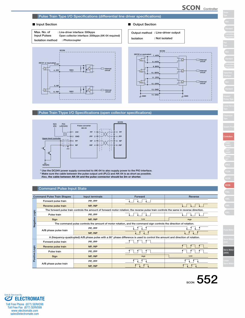
SCON 552
Input Section Output Section
: Photocoupler
: Line-driver interface: 500kpps Open collector interface: 200kpps (AK-04 required)
Max. No. ofInput Pulses
Isolation method
Output method : Line-driver output
: Not isolatedIsolation
26C31 or equivalent3. PP
4. /PP 180ΩInternal circuit
5. NP
6. /NP 180ΩInternal circuit
SCON
26C32 or equivalent7. AFB
SCON
8. /AFBInternal circuit
9. BFB
10. /BFBInternal circuit
11. ZFB
13. GND
14. GND
12. /ZFBInternal circuit
GND GND
* Use the DC24V power supply connected to AK-04 to also supply power to the PIO interface. * Make sure the cable between the pulse output unit (PLC) and AK-04 is as short as possible. Also, the cable between AK-04 and the pulse connector should be 2m or shorter.
Pulse converterAK-04
Upper-level controller
P24(+DC24V)
N24(0V)
N24(0V)
SCON
1 24V
2 GND
3 PP
4 NP
3
4
5
6
PP
/PP
NP
/NP
PP 1
/PP 2
NP 3
/NP 4
Forward pulse train
Forward pulse train
Pulse train
PP, /PP
PP, /PP
PP, /PP
PP, /PP
The forward pulse train controls the amount of forward motor rotation; the reverse pulse train controls the same in reverse direction.
A (frequency-quadrupled) A/B phase pulse with a 90° phase difference is used to control the amount and direction of rotation.
The command pulse controls the amount of motor rotation, and the command sign controls the direction of rotation.
High
High
Low
Low
A/B phase pulse train
A/B phase pulse train
Command Pulse Train Shapes Input terminals ReverseForward
Reverse pulse train
Sign
Reverse pulse train
Pulse train
Sign
NP, /NP
NP, /NP
NP, /NP
NP, /NP
PP, /PP
NP, /NP
PP, /PP
NP, /NP
Neg
ativ
e Lo
gic
Pos
itive
Log
ic
Pulse Train Type I/O Specifications (differential line driver specifications)
Pulse Train Ttype I/O Specifications (open collector specifications)
Command Pulse Input State
SCON Controller
Mini
Mini
Mini
Standard
Standard
ControllersIntegrated
Standard
ControllersIntegrated
PSEP/ASEP
PMEC/AMEC
ROBONET
ERC2
PCON
ACON
SCON
PSEL
ASEL
SSEL
XSEL
SliderType
RodType
Table/Arm/FlatType
Gripper/Rotary Type
Linear ServoType
CleanroomType
Splash-Proof
Controllers
Pulse Motor
Servo Motor (24V)
Servo Motor (200V)
LinearServo Motor
ELECTROMATEToll Free Phone (877) SERVO98
Toll Free Fax (877) SERV099www.electromate.com
Sold & Serviced By:
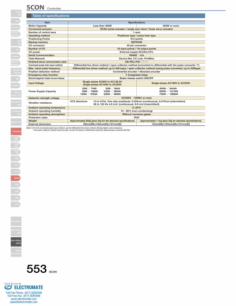
553 SCON
Table of specifications
Item Specifications
RCS2 series actuator / single axis robot / linear servo actuator1-axis
EEPROM40 pin connector
16 input points / 16 output points External supply DC24V±10%
RS485 1chDevice Net, CC-Link, ProfiBus
CB-PAC-PIO□□□
Positioner type / pulse train type
Motor CapacityConnected actuatorNumber of control axesOperating methodPositioning PointsBackup memoryI/O connectorNumber of I/O I/O powerSerial CommunicationField NetworkPeripheral device communication cableCommand pulse train input method Max. input pulse frequencyPosition detection methodEmergency stop functionElectromagnetic brake forced release
Input Voltage
Power Supply Capacity
Dielectric strength voltage
Vibration resistance
Ambient operating temperatureAmbient operating humidityAmbient operating atmosphereProtection classWeightExternal dimension
Less than 400W 400W or more
512 points
Differential line driver method / open collector method (converted to differential with the pulse converter *1)
Incremental encoder / Absolute encoderY (integrated relay)
Brake release switch ON/OFF
Single-phase AC90V to AC126.5VSingle-phase AC180V to AC253V
Single-phase AC180V to AC253V
20W/ 74VA 30W/ 94VA 60W/ 186VA 100W/ 282VA150W/ 376VA 200W/ 469VA
400W/ 844VA600W/ 1212VA750W/ 1569VA
DC500V 100MΩ or more
0~40ºC10 - 95% (non-condensing)
Without corrosive gasesIP20
Approximately 800g (plus 25g for the absolute specifications)58mm (W)×194mm (H)×121mm (D)
Approximately 1.1kg (plus 25g for absolute specifications)72mm(W)×194mm (H)×121mm (D)
XYZ directions 10 to 57Hz, One side amplitude: 0.035mm (continuous), 0.075mm (intermittent) 58 to 150 Hz 4.9 m/s2 (continuous), 9.8 m/s2 (intermittent)
Differential line driver method: up to 500 kpps / open collector method (using pulse converter): up to 200kpps
(Note 1) For the command-pulse input method, use the differential line driver method offering higher noise resistance.If the open collector method must be used, convert the pulse to differential using the optional pulse converter (AK-04).
SCON ControllerSlider
Type
Mini
Mini
PSEP/ASEP
PMEC/AMEC
ROBONET
ERC2
PCON
ACON
SCON
PSEL
ASEL
SSEL
XSEL
Standard
Standard
Standard
ControllersIntegrated
ControllersIntegrated
RodType
Table/Arm/FlatType
Gripper/Rotary Type
Linear ServoType
CleanroomType
Splash-Proof
Controllers
Pulse Motor
Servo Motor (24V)
Servo Motor (200V)
LinearServo Motor
Mini
ELECTROMATEToll Free Phone (877) SERVO98
Toll Free Fax (877) SERV099www.electromate.com
Sold & Serviced By:
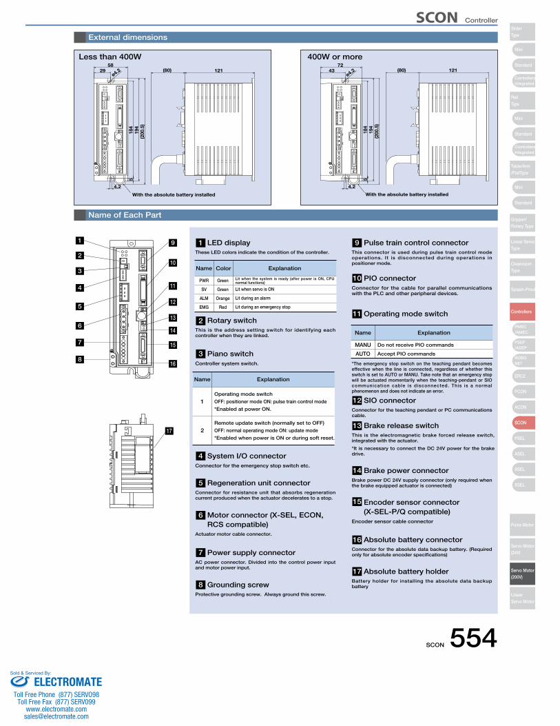
SCON 554
58
4.2
184
519
4(2
00.5
)
ø4.229 121(80)
With the absolute battery installed
External dimensions
Name of Each Part
Less than 400W72
4.2
184
519
4(2
00.5
)
ø4.243 121
With the absolute battery installed
(80)
LED display These LED colors indicate the condition of the controller.
Rotary switch This is the address setting switch for identifying each controller when they are linked.
Piano switch Controller system switch.
Regeneration unit connectorConnector for resistance unit that absorbs regeneration current produced when the actuator decelerates to a stop.
Motor connector (X-SEL, ECON,RCS compatible)
Actuator motor cable connector.
Power supply connectorAC power connector. Divided into the control power input and motor power input.
Grounding screwProtective grounding screw. Always ground this screw.
System I/O connectorConnector for the emergency stop switch etc.
1Operating mode switch
OFF: positioner mode ON: pulse train control mode
*Enabled at power ON.
2Remote update switch (normally set to OFF)
OFF: normal operating mode ON: update mode
*Enabled when power is ON or during soft reset.
PWR
SV
ALM
EMG
Green
Green
Orange
Red
Name Color Explanation
Lit when the system is ready (after power is ON, CPU normal functions)
Lit when servo is ON
Lit during an alarm
Lit during an emergency stop
400W or more
Pulse train control connector This connector is used during pulse train control mode operations. It is disconnected during operations in positioner mode.
PIO connectorConnector for the cable for parallel communications with the PLC and other peripheral devices.
SIO connectorConnector for the teaching pendant or PC communications cable.
Brake release switchThis is the electromagnetic brake forced release switch, integrated with the actuator.
*It is necessary to connect the DC 24V power for the brake drive.
Brake power connectorBrake power DC 24V supply connector (only required when the brake equipped actuator is connected)
Encoder sensor connector (X-SEL-P/Q compatible)
Encoder sensor cable connector
Absolute battery connectorConnector for the absolute data backup battery. (Required only for absolute encoder specifications)
Absolute battery holderBattery holder for installing the absolute data backup battery
*The emergency stop switch on the teaching pendant becomes effective when the line is connected, regardless of whether this switch is set to AUTO or MANU. Take note that an emergency stop will be actuated momentarily when the teaching-pendant or SIO communicat ion cable is disconnected. This is a normal phenomenon and does not indicate an error.
Operating mode switch
Name Explanation
MANU
AUTO
Name Explanation
Do not receive PIO commands
Accept PIO commands
17
1
2
3
4
5
6
7
8
14
13
12
11
10
9
15
16
1
2
3
4
5
6
7
8
17
16
15
14
13
12
11
10
9
SCON Controller
Mini
Mini
Mini
Standard
Standard
ControllersIntegrated
Standard
ControllersIntegrated
PSEP/ASEP
PMEC/AMEC
ROBONET
ERC2
PCON
ACON
SCON
PSEL
ASEL
SSEL
XSEL
SliderType
RodType
Table/Arm/FlatType
Gripper/Rotary Type
Linear ServoType
CleanroomType
Splash-Proof
Controllers
Pulse Motor
Servo Motor (24V)
Servo Motor (200V)
LinearServo Motor
ELECTROMATEToll Free Phone (877) SERVO98
Toll Free Fax (877) SERV099www.electromate.com
Sold & Serviced By:
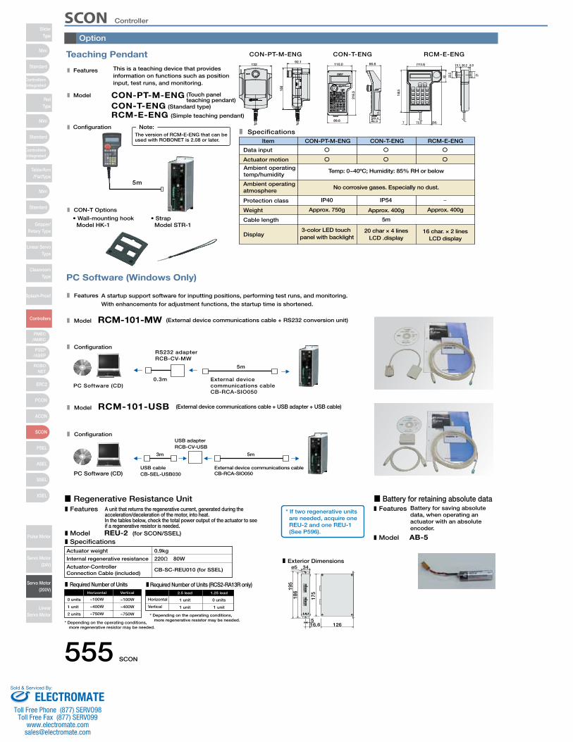
555 SCON
Teaching Pendant
PC Software (Windows Only)
A startup support software for inputting positions, performing test runs, and monitoring.
With enhancements for adjustment functions, the startup time is shortened.
RCM-101-MW (External device communications cable + RS232 conversion unit)
0.3m
5m
External device communications cableCB-RCA-SIO050
PC Software (CD)
RS232 adapterRCB-CV-MW
RCM-101-USB (External device communications cable + USB adapter + USB cable)
5m3m
PC Software (CD)External device communications cableCB-RCA-SIO050
USB cableCB-SEL-USB030
USB adapterRCB-CV-USB
This is a teaching device that provides information on functions such as position input, test runs, and monitoring.
CON-PT-M-ENG (Touch panel teaching pendant)
RCM-E-ENG (Simple teaching pendant)
(Standard type)CON-T-ENG
Features
Model
Configuration
Model
Configuration
Features
Model
Specifications
Display3-color LED touch panel with backlight
Approx. 750g
IP40 IP54
20 char × 4 linesLCD .display
5m
Approx. 400g
No corrosive gases. Especially no dust.
Temp: 0~40ºC; Humidity: 85% RH or below
16 char. × 2 linesLCD display
Approx. 400g
Item CON-PT-M-ENG CON-T-ENG RCM-E-ENG
5m
The version of RCM-E-ENG that can be used with ROBONET is 2.08 or later.
Note:
RCM-E-ENGCON-T-ENGCON-PT-M-ENG
21
6.326.215.1
23.5
43
148.
5
7 (34)72.5
(113.5)
46.939.0
66.6110.0
218.
3
89.6
CON-T Options
• Wall-mounting hookModel HK-1
• StrapModel STR-1
13292.1
180
Configuration
Data input
Actuator motion
Ambient operating temp/humidity
Ambient operating atmosphere
Protection class
Weight
Cable length
Option
A unit that returns the regenerative current, generated during the acceleration/deceleration of the motor, into heat. In the tables below, check the total power output of the actuator to see if a regenerative resistor is needed.REU-2 (for SCON/SSEL)
Features
ModelSpecifications
Actuator weight
Actuator-Controller
0.9kg
CB-SC-REU010 (for SSEL)
Required Number of Units Required Number of Units (RCS2-RA13R only)
0 units ~100W
Horizontal
~100W
Vertical
* Depending on the operating conditions, more regenerative resistor may be needed.
* Depending on the operating conditions, more regenerative resistor may be needed.
Exterior Dimensionsø5
16.6 126
34
5
175
195
186
Horizontal 1 unit
2.5 lead
0 units
1.25 lead
1 unit
2 units
~400W
~750W
~400W
~750W
Vertical 1 unit 1 unit
220Ω 80W
* If two regenerative units are needed, acquire one REU-2 and one REU-1 (See P596).
Internal regenerative resistance
Connection Cable (included)
■ Regenerative Resistance Unit ■ Battery for retaining absolute dataBattery for saving absolute data, when operating an actuator with an absolute encoder.
AB-5
Features
Model
SCON ControllerSlider
Type
Mini
Mini
PSEP/ASEP
PMEC/AMEC
ROBONET
ERC2
PCON
ACON
SCON
PSEL
ASEL
SSEL
XSEL
Standard
Standard
Standard
ControllersIntegrated
ControllersIntegrated
RodType
Table/Arm/FlatType
Gripper/Rotary Type
Linear ServoType
CleanroomType
Splash-Proof
Controllers
Pulse Motor
Servo Motor (24V)
Servo Motor (200V)
LinearServo Motor
Mini
ELECTROMATEToll Free Phone (877) SERVO98
Toll Free Fax (877) SERV099www.electromate.com
Sold & Serviced By:
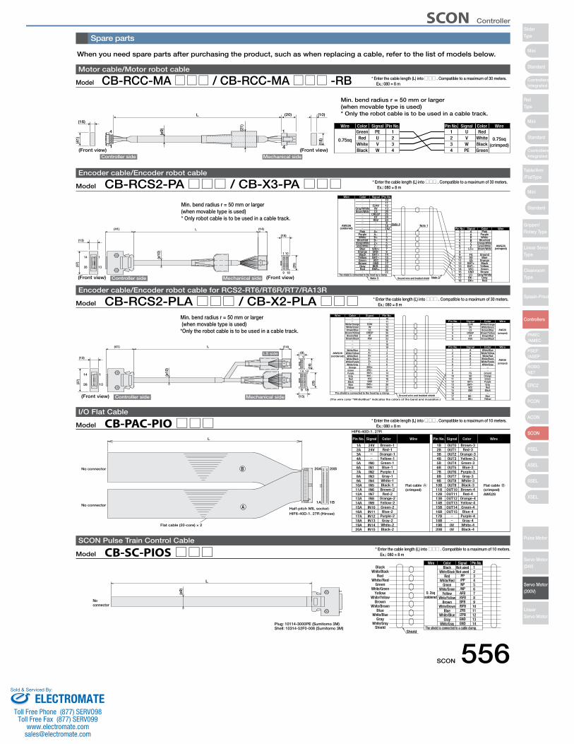
SCON 556
Spare parts
ShieldShield
White/GrayGray
White/BlueBlue
White/BrownBrown
White/YellowYellow
White/GreenGreen
White/RedRed
BlackWhite/Black
The shield is connected to a cable clamp.
0. 2sqsoldered
14131211109876543
12
Pin No.Wire
White/GrayGray
White/BlueBlue
White/BrownBrown
White/YellowYellow
White/GreenGreen
White/RedRed
BlackWhite/Black
ColorNot usedNot used
GNDGND/ZFBZFB/BFBBFB/AFBAFB/NPNP/PPPP
Signal
L
Plug: 10114-3000PE (Sumitomo 3M)Shell: 10314-52F0-008 (Sumitomo 3M)
No connector
(ø9)
Model CB-SC-PIOS□□□SCON Pulse Train Control Cable
* Enter the cable length (L) into □□□ . Compatible to a maximum of 10 meters. Ex.: 080 = 8 m
When you need spare parts after purchasing the product, such as when replacing a cable, refer to the list of models below.
Model CB-RCC-MA□□□ / CB-RCC-MA□□□ -RBMotor cable/Motor robot cable
* Enter the cable length (L) into □□□ . Compatible to a maximum of 30 meters. Ex.: 080 = 8 m
L
4
1
1
4
Wire Color Signal Pin No. Pin No.
0.75sq
Green PE 1WireColorSignal
0.75sq(crimped)
RedU1
(10)(20)
Controller side Mechanical side(Front view)(Front view)
(16)
(ø9) (2
1)
(18)(41) U
VW
RedWhiteBlack
234
234
VWPE
WhiteBlackGreen
Model CB-RCS2-PA□□□ / CB-X3-PA□□□Encoder cable/Encoder robot cable
* Enter the cable length (L) into □□□ . Compatible to a maximum of 30 meters. Ex.: 080 = 8 m
1
9
1
13
14
26
18
10
L
Ground wire and braided shield
Note 1
Note 2
Note 4
GrayRed
Brown
YellowGreen
Black
Green/White AWG26(crimped)
Orange
GroundBlue
Blue/redOrange/White
WhitePurplePink
15161718
1413121110
6
987
3
54
21
Pin No.
BK−BK+
GNDLS-
BAT+BAT−VCC
Z
FGSDSD
LS+
B
ZB
AA
Signal Color Wire
The shield is connected to the hood by a clamp.Note 3
AWG26(soldered)
Wire
212017
22
6
16151487
3
54
21
25
1819
2324
9
1011121326
Pin No.
BKR+BKR-GND
Z−
BAT+
VCCBAT−
SRD-SRD+
B+
Z+B−
A−A+
CREEPOT
RSV
E24V0VLS
Signal
Brown/White
Gray/White
Color
Brown
RedGray
Green/WhiteOrange/White
WhiteBlue/red
Purple
GreenYellowBlack
Blue
Pink
Orange
Brown/WhiteGray/White
(ø10
)
(41) (14)
(13)
(37)
(15)
(25)
Controller side Mechanical side (Front view)(Front view)
Model CB-RCS2-PLA□□□ / CB-X2-PLA□□□Encoder cable/Encoder robot cable for RCS2-RT6/RT6R/RT7/RA13R
* Enter the cable length (L) into □□□ . Compatible to a maximum of 30 meters. Ex.: 080 = 8 m
1
9
1
13
14
26
18
10
L
6
1
(ø10
)
Ground wire and braided shield
(crimped)AWG26
AWG26(soldered)
White/Blue
White/Orange
A+
E24V
10
White/BlueA1
Wire Color Signal Pin No.
WireColorSignalPin No.
The shield is connected to the hood by a clamp.
(The wire color "White/Blue" indicates the colors of the band and insulation.)
(crimped)AWG26
White/OrangeE24V1WireColorSignalPin No.
White/YellowWhite/Red
White/BlackWhite/PurpleWhite/Gray
OrangeGreenPurpleGrayRed
BlackBlue
Yellow
White/GreenBrown/Blue
Brown/YellowBrown/Red
Brown/Black
0VLS
CREEPOT
RSV
A−B+B−Z+Z−
SRD+SRD−BAT+BAT−VCCGND
BKR−BKR+
11121326252423918191234567814151617202122
LS side(13)
(41) (14)
(37)
(8)
(15)
(18)
(25)
23456
23456789101112131415161718
ABBZZ
FGSDSD
BAT+BAT−VCCGND
BK−BK+
0VLS
CREEPOT
RSV
White/GreenBrown/Blue
Brown/YellowBrown/Red
Brown/Black
White/YellowWhite/Red
White/BlackWhite/PurpleWhite/Gray
GroundOrangeGreenPurpleGrayRed
Black
BlueYellowController side Mechanical side(Front view)
B
Flat cable A(crimped)
Flat cable B(crimped)AWG28
Half-pitch MIL socket:HIF6-40D-1. 27R (Hirose)
Flat cable (20-core) × 2
HIF6-40D-1. 27R
20B20A
1B1AA
No connector
No connector
Brown-1
ColorL Pin No. Signal Wire
24V Brown-3
ColorPin No. Signal Wire
OUT01A2A3A4A5A6A7A8A9A10A11A12A13A14A15A16A17A18A19A20A
24V
IN0IN1IN2IN3IN4IN5IN6IN7IN8IN9IN10IN11IN12IN13IN14IN15
Red-1Orange-1Yellow-1Green-1Blue-1
Purple-1Gray-1White-1Black-1Brown-2
Red-2Orange-2Yellow-2Green-2Blue-2
Purple-2Gray-2White-2Black-2
1B2B3B4B5B6B7B8B9B10B11B12B13B14B15B16B17B18B19B20B
OUT1OUT2OUT3OUT4OUT5OUT6OUT7OUT8OUT9OUT10OUT11OUT12OUT13OUT14OUT15
0V0V
Red-3Orange-3Yellow-3Green-3Blue-3
Purple-3Gray-3White-3Black-3Brown-4
Red-4Orange-4Yellow-4Green-4Blue-4
Purple-4Gray-4White-4Black-4
Model CB-PAC-PIO□□□I/O Flat Cable
* Enter the cable length (L) into □□□ . Compatible to a maximum of 10 meters. Ex.: 080 = 8 m
Min. bend radius r = 50 mm or larger (when movable type is used)* Only robot cable is to be used in a cable track.
Min. bend radius r = 50 mm or larger (when movable type is used)* Only the robot cable is to be used in a cable track.
Min. bend radius r = 50 mm or larger (when movable type is used)*Only the robot cable is to be used in a cable track.
SCON Controller
Mini
Mini
Mini
Standard
Standard
ControllersIntegrated
Standard
ControllersIntegrated
PSEP/ASEP
PMEC/AMEC
ROBONET
ERC2
PCON
ACON
SCON
PSEL
ASEL
SSEL
XSEL
SliderType
RodType
Table/Arm/FlatType
Gripper/Rotary Type
Linear ServoType
CleanroomType
Splash-Proof
Controllers
Pulse Motor
Servo Motor (24V)
Servo Motor (200V)
LinearServo Motor
ELECTROMATEToll Free Phone (877) SERVO98
Toll Free Fax (877) SERV099www.electromate.com
Sold & Serviced By:
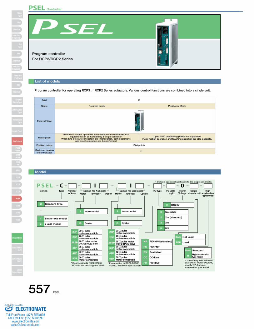
List of models
Program controller for operating RCP3/ RCP2 Series actuators. Various control functions are combined into a single unit.
Program controller
For RCP3/RCP2 Series
P S E LSeries
* 2nd axis specs not applicable to the single-axis model.
C Standard Type
B Brake B Brake
20P 20 � pulse motor-compatible
28P 28 � pulse motor-compatible
28SP 28 � pulse motor(RCP2-RA3C only)
42P 42 � pulse motor-compatible
35P 35 � pulse motor-compatible
56P 56 � pulse motor-compatible
20P 20 � pulse motor-compatible
28P 28 � pulse motor-compatible
28SP 28 � pulse motor(RCP2-RA3C only)
42P 42 � pulse motor-compatible
35P 35 � pulse motor-compatible
56P 56 � pulse motor-compatible
1 Single-axis model
2 2-axis model
I Incremental I Incremental
NP PIO NPN (standard)
PN PIO PNP
DV DeviceNet
CC CC-Link
PR ProfiBus
0 DC24V
0 No cable
2 2m (standard)
3 3m
5 5m
Blank Not used
ABU Used
0C I I
* If connecting to RCP2-RA3C/ RGD3C, the motor type is 28SP.
* If connecting to RCP2-RA3C/RGD3C, the motor type is 28SP.
Blank Standard
H High acceleration type model
* If connecting to RCP3-SA4/SA5/SA6 or RCP2-SA5/SA6,specify "H", for high-
acceleration type model.
Type Number of Axes Motor Encoder Option Motor Encoder Option
I/O Cable Length
PowerVoltage
Simple absolute unit
High acceleration type model
I/O Type(Specs for 1st axis) (Specs for 2nd axis)
Model
Type C
Program mode Positioner ModeName
External View
Description
Both the actuator operation and communication with external equipment can be handled by a single controller.
When two axes are connected, arc interpolation, path operations, and synchronization can be performed.
Up to 1500 positioning points are supported. Push-motion operation and teaching operation are also possible.
Position points 1500 points
2Maximum number of control axes
PSEL Controller
557 PSEL
Mini
Mini
PSEP/ASEP
PMEC/AMEC
ROBONET
ERC2
PCON
ACON
SCON
PSEL
ASEL
SSEL
XSEL
Standard
Mini
Standard
Standard
ControllersIntegrated
ControllersIntegrated
RodType
Table/Arm/Flat Type
Gripper/Rotary Type
Linear ServoType
Cleanroom Type
Splash-Proof
Controllers
Pulse Motor
Servo Motor (24V)
Servo Motor (200V)
LinearServo Motor
SliderType
ELECTROMATEToll Free Phone (877) SERVO98
Toll Free Fax (877) SERV099www.electromate.com
Sold & Serviced By:
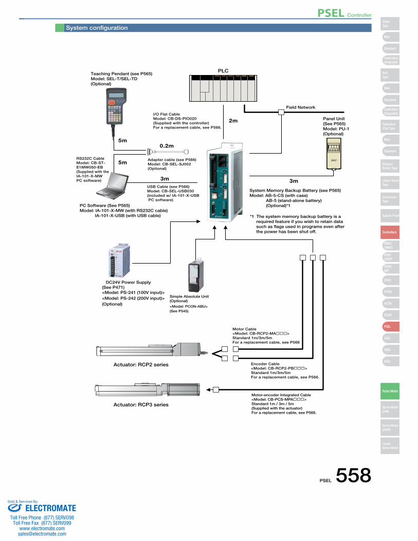
Teaching Pendant (see P565)Model: SEL-T/SEL-TD(Optional)
I/O Flat CableModel: CB-DS-PIO020(Supplied with the controller)For a replacement cable, see P566.
Panel Unit(See P565)Model: PU-1(Optional)
Field Network
Encoder Cable<Model: CB-RCP2-PB���>Standard 1m/3m/5mFor a replacement cable, see P566.
Motor Cable<Model: CB-RCP2-MA���>Standard 1m/3m/5mFor a replacement cable, see P566
PC Software (See P565)Model: IA-101-X-MW (with RS232C cable)
IA-101-X-USB (with USB cable)
System Memory Backup Battery (see P565)Model: AB-5-CS (with case)
AB-5 (stand-alone battery)(Optional)*1
*1 The system memory backup battery is a required feature if you wish to retain data such as flags used in programs even after the power has been shut off.
USB Cable (see P566)Model: CB-SEL-USB030(included w/ IA-101-X-USB PC software)
RS232C CableModel: CB-ST-E1MW050-EB(Supplied with the IA-101-X-MWPC software)
Adapter cable (see P566)Model: CB-SEL-SJ002(Optional)
2m
0.2m
3m 3m
5m
5m
<Model: PS-241 (100V input)><Model: PS-242 (200V input)>(Optional)
DC24V Power Supply(See P471)
PLC
Actuator: RCP2 series
Actuator: RCP3 series
Motor-encoder Integrated Cable<Model: CB-PCS-MPA���>Standard 1m / 3m / 5m(Supplied with the actuator)For a replacement cable, see P566.
<Model: PCON-ABU>(See P545)
Simple Absolute Unit(Optional)
System configuration
PSEL Controller
PSEL 558
Mini
Mini
PSEP/ASEP
PMEC/AMEC
ROBONET
ERC2
PCON
ACON
SCON
PSEL
ASEL
SSEL
XSEL
Standard
Mini
Standard
Standard
ControllersIntegrated
ControllersIntegrated
SliderType
RodType
Table/Arm/Flat Type
Gripper/Rotary Type
Linear ServoType
Cleanroom Type
Splash-Proof
Controllers
Pulse Motor
Servo Motor (24V)
Servo Motor (200V)
LinearServo Motor
ELECTROMATEToll Free Phone (877) SERVO98
Toll Free Fax (877) SERV099www.electromate.com
Sold & Serviced By:
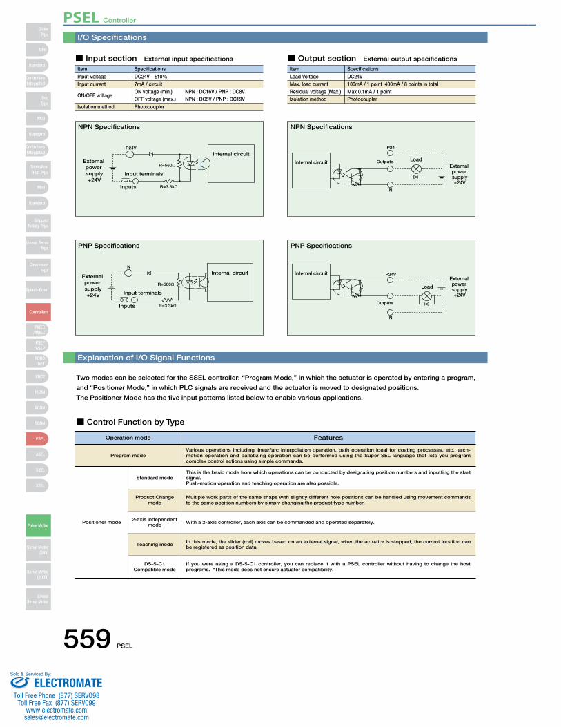
I/O Specifications
Explanation of I/O Signal Functions
Two modes can be selected for the SSEL controller: “Program Mode,” in which the actuator is operated by entering a program,
and “Positioner Mode,” in which PLC signals are received and the actuator is moved to designated positions.
The Positioner Mode has the five input patterns listed below to enable various applications.
■ Control Function by Type
ItemInput voltageInput current
ON/OFF voltage
Isolation method
SpecificationsDC24V ±10%7mA / circuitON voltage (min.) NPN : DC16V / PNP : DC8VOFF voltage (max.) NPN : DC5V / PNP : DC19VPhotocoupler
P24V
R=3.3kΩInputs
R=560ΩExternal power supply+24V
Input terminals
Internal circuit
■ Input section External input specifications
ItemLoad VoltageMax. load current Residual voltage (Max.) Isolation method
SpecificationsDC24V100mA / 1 point 400mA / 8 points in totalMax 0.1mA / 1 pointPhotocoupler
P24
N
OutputsInternal circuit LoadExternal power supply+24V
N
R=3.3kΩInputs
R=560Ω
External power supply+24V Input terminals
Internal circuit P24V
N
Outputs
Internal circuitExternal power supply+24V
Load
■ Output section External output specifications
NPN Specifications NPN Specifications
PNP Specifications PNP Specifications
Operation mode Features
Program mode
Positioner mode
This is the basic mode from which operations can be conducted by designating position numbers and inputting the start signal.Push-motion operation and teaching operation are also possible.
Various operations including linear/arc interpolation operation, path operation ideal for coating processes, etc., arch-motion operation and palletizing operation can be performed using the Super SEL language that lets you program complex control actions using simple commands.
Multiple work parts of the same shape with slightly different hole positions can be handled using movement commands to the same position numbers by simply changing the product type number.
With a 2-axis controller, each axis can be commanded and operated separately.
In this mode, the slider (rod) moves based on an external signal, when the actuator is stopped, the current location can be registered as position data.
Standard mode
Product Change mode
2-axis independent mode
Teaching mode
DS-S-C1Compatible mode
If you were using a DS-S-C1 controller, you can replace it with a PSEL controller without having to change the host programs. *This mode does not ensure actuator compatibility.
PSEL Controller
559 PSEL
Mini
Mini
PSEP/ASEP
PMEC/AMEC
ROBONET
ERC2
PCON
ACON
SCON
PSEL
ASEL
SSEL
XSEL
Standard
Mini
Standard
Standard
ControllersIntegrated
ControllersIntegrated
RodType
Table/Arm/Flat Type
Gripper/Rotary Type
Linear ServoType
Cleanroom Type
Splash-Proof
Controllers
Pulse Motor
Servo Motor (24V)
Servo Motor (200V)
LinearServo Motor
SliderType
ELECTROMATEToll Free Phone (877) SERVO98
Toll Free Fax (877) SERV099www.electromate.com
Sold & Serviced By:
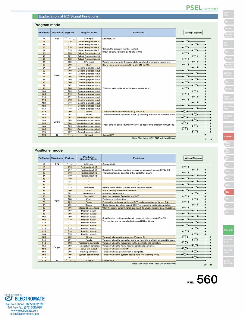
Explanation of I/O Signal Functions
Pin Number Classification
Input
Output
N
24V input Connect 24V.
Program Mode Functions
Resets the system to the same state as when the power is turned on.
Turns off when an alarm occurs. (Contact B)
Turns on when the controller starts up normally and is in an operable state.
Connect 0V.
These outputs can be turned ON/OFF as desired via program instructions.
Starts the program selected by ports 016 to 022.
Waits for external input via program instructions.
Selects the program number to start.
(Input as BCD values to ports 016 to 022)
0V 24
Wiring Diagram
1A P24
1B
2A
2B
3A
3B
4A
4B
5A
5B
6A
6B
7A
7B
8A
8B
9A
9B
10A
10B
11A
11B
12A
12B
13A
13B
14A
14B
15A
15B
16A
16B
17A
17B
016
Port No.
017
018
019
020
021
022
023
000
001
002
003
004
005
006
007
008
009
010
011
012
013
014
015
300
301
302
303
304
305
306
307
Select Program No. 1
Select Program No. 2
Select Program No. 4
Select Program No. 8
Select Program No. 10
Select Program No. 20
Select Program No. 40
CPU reset
Start
General-purpose input
General-purpose input
General-purpose input
General-purpose input
General-purpose input
General-purpose input
General-purpose input
General-purpose input
General-purpose input
General-purpose input
General-purpose input
General-purpose input
General-purpose input
General-purpose input
General-purpose input
Alarm
Ready
General-purpose output
General-purpose output
General-purpose output
General-purpose output
General-purpose output
General-purpose output
0V input
Pin Number
24V input Connect 24V.
PositionerStandard Mode Functions
Resets minor errors. (Severe errors require a restart.)
Turns off when an alarm occurs. (Contact B)
Turns on when the controller starts up normally and is in an operable state.
Turns on when the movement to the destination is complete.
Turns on when the home return operation is complete.
Turns on when servo is ON.
Turns on when a push motion is complete.
Turns on when the system battery runs low (warning level).
Connect 0V.
Starts moving to selected position.
Performs home return.
Switches between Servo ON and OFF.
Performs a push motion.
Pauses the motion when turned OFF, and resumes when turned ON.
Stops the motion when turned OFF. The remaining motion is canceled.
When this signal is turned ON for a 2-axis model, the actuator moves by linear interpolation.
Specifies the position numbers to move to, using ports 007 to 019.
The number can be specified either as BCD or binary.
Specifies the position numbers to move to, using port number 007 to 019.
The number can be specified either as BCD or binary.
0V 24
Wiring Diagram
1A
1B
2A
2B
3A
3B
4A
4B
5A
5B
6A
6B
7A
7B
8A
8B
9A
9B
10A
10B
11A
11B
12A
12B
13A
13B
14A
14B
15A
15B
16A
16B
17A
17B
Position input 10
Position input 11
Position input 12
Position input 13
Error reset
Start
Home return
Servo ON
Push
Pause
Cancel
Interpolation settings
Position input 1
Position input 2
Position input 3
Position input 4
Position input 5
Position input 6
Position input 7
Position input 8
Position input 9
Alarm
Ready
Positioning complete
Home return complete
Servo ON output
Pushing complete
System battery error
0V input
Classification
Input
Output
N
P24016
Port No.
017
018
019
020
021
022
023
000
001
002
003
004
005
006
007
008
009
010
011
012
013
014
015
300
301
302
303
304
305
306
307
Program mode
Positioner mode
Note: This is for NPN. PNP will be different.
Note: This is for NPN. PNP will be different.
PSEL Controller
PSEL 560
Mini
Mini
PSEP/ASEP
PMEC/AMEC
ROBONET
ERC2
PCON
ACON
SCON
PSEL
ASEL
SSEL
XSEL
Standard
Mini
Standard
Standard
ControllersIntegrated
ControllersIntegrated
SliderType
RodType
Table/Arm/Flat Type
Gripper/Rotary Type
Linear ServoType
Cleanroom Type
Splash-Proof
Controllers
Pulse Motor
Servo Motor (24V)
Servo Motor (200V)
LinearServo Motor
ELECTROMATEToll Free Phone (877) SERVO98
Toll Free Fax (877) SERV099www.electromate.com
Sold & Serviced By:
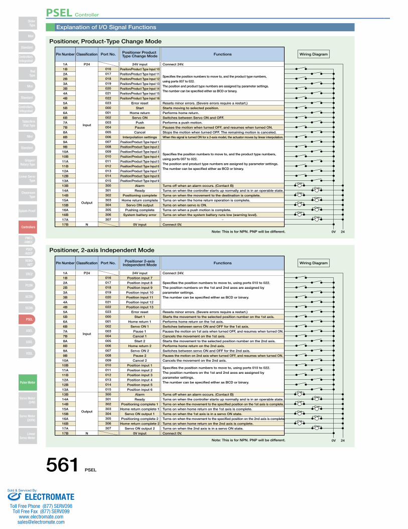
Explanation of I/O Signal Functions
Pin Number
24V input Connect 24V.
Positioner Product Type Change Mode Functions
Connect 0V.
0V 24
Wiring Diagram
1A
Resets minor errors. (Severe errors require a restart.)
Turns off when an alarm occurs. (Contact B)
Turns on when the controller starts up normally and is in an operable state.
Turns on when the movement to the destination is complete.
Turns on when the home return operation is complete.
Turns on when servo is ON.
Turns on when a push motion is complete.
Turns on when the system battery runs low (warning level).
Starts moving to selected position.
Performs home return.
Switches between Servo ON and OFF.
Performs a push motion.
Pauses the motion when turned OFF, and resumes when turned ON.
Stops the motion when turned OFF. The remaining motion is canceled.
When this signal is turned ON for a 2-axis model, the actuator moves by linear interpolation.
Specifies the position numbers to move to, and the product type numbers,
using ports 007 to 022.
The position and product type numbers are assigned by parameter settings.
The number can be specified either as BCD or binary.
Specifies the position numbers to move to, and the product type numbers,
using ports 007 to 022.
The position and product type numbers are assigned by parameter settings.
The number can be specified either as BCD or binary.
1B
2A
2B
3A
3B
4A
4B
5A
5B
6A
6B
7A
7B
8A
8B
9A
9B
10A
10B
11A
11B
12A
12B
13A
13B
14A
14B
15A
15B
16A
16B
17A
17B
Position/Product Type Input 10
Position/Product Type Input 11
Position/Product Type Input 12
Position/Product Type Input 13
Position/Product Type Input 14
Position/Product Type Input 15
Position/Product Type Input 16
Error reset
Start
Home return
Servo ON
Push
Pause
Cancel
Interpolation settings
Position/Product Type Input 1
Position/Product Type Input 2
Position/Product Type Input 3
Position/Product Type Input 4
Position/Product Type Input 5
Position/Product Type Input 6
Position/Product Type Input 7
Position/Product Type Input 8
Position/Product Type Input 9
Alarm
Ready
Positioning complete
Home return complete
Servo ON output
Pushing complete
System battery error
0V input
Classification
Input
Output
N
P24016
Port No.
017
018
019
020
021
022
023
000
001
002
003
004
005
006
007
008
009
010
011
012
013
014
015
300
301
302
303
304
305
306
307
Pin Number
24V input Connect 24V.
Positioner 2-axisIndependent Mode Functions
Connect 0V.
0V 24
Wiring Diagram
1A
Resets minor errors. (Severe errors require a restart.)
Turns off when an alarm occurs. (Contact B)
Turns on when the controller starts up normally and is in an operable state.
Turns on when the movement to the specified position on the 1st axis is complete.
Turns on when home return on the 1st axis is complete.
Turns on when the 1st axis is in a servo ON state.
Turns on when the movement to the specified position on the 2nd axis is complete.
Turns on when home return on the 2nd axis is complete.
Turns on when the 2nd axis is in a servo ON state.
Starts the movement to the selected position number on the 1st axis.
Performs home return on the 1st axis.
Switches between servo ON and OFF for the 1st axis.
Pauses the motion on 1st axis when turned OFF, and resumes when turned ON.
Cancels the movement on the 1st axis.
Starts the movement to the selected position number on the 2nd axis.
Performs home return on the 2nd axis.
Switches between servo ON and OFF for the 2nd axis.
Pauses the motion on 2nd axis when turned OFF, and resumes when turned ON.
Cancels the movement on the 2nd axis.
Specifies the position numbers to move to, using ports 010 to 022.
The position numbers on the 1st and 2nd axes are assigned by
parameter settings.
The number can be specified either as BCD or binary.
Specifies the position numbers to move to, using ports 010 to 022.
The position numbers on the 1st and 2nd axes are assigned by
parameter settings.
The number can be specified either as BCD or binary.
1B
2A
2B
3A
3B
4A
4B
5A
5B
6A
6B
7A
7B
8A
8B
9A
9B
10A
10B
11A
11B
12A
12B
13A
13B
14A
14B
15A
15B
16A
16B
17A
17B
Position input 7
Position input 8
Position input 9
Position input 10
Position input 11
Position input 12
Position input 13
Error reset
Start 1
Home return 1
Servo ON 1
Pause 1
Cancel 1
Start 2
Home return 2
Servo ON 2
Pause 2
Cancel 2
Position input 1
Position input 2
Position input 3
Position input 4
Position input 5
Position input 6
Alarm
Ready
Positioning complete 1
Home return complete 1
Servo ON output 1
Positioning complete 2
Home return complete 2
Servo ON output 2
0V input
Classification
Input
Output
N
P24016
Port No.
017
018
019
020
021
022
023
000
001
002
003
004
005
006
007
008
009
010
011
012
013
014
015
300
301
302
303
304
305
306
307
Positioner, Product-Type Change Mode
Positioner, 2-axis Independent Mode
Note: This is for NPN. PNP will be different.
Note: This is for NPN. PNP will be different.
PSEL Controller
561 PSEL
Mini
Mini
PSEP/ASEP
PMEC/AMEC
ROBONET
ERC2
PCON
ACON
SCON
PSEL
ASEL
SSEL
XSEL
Standard
Mini
Standard
Standard
ControllersIntegrated
ControllersIntegrated
RodType
Table/Arm/Flat Type
Gripper/Rotary Type
Linear ServoType
Cleanroom Type
Splash-Proof
Controllers
Pulse Motor
Servo Motor (24V)
Servo Motor (200V)
LinearServo Motor
SliderType
ELECTROMATEToll Free Phone (877) SERVO98
Toll Free Fax (877) SERV099www.electromate.com
Sold & Serviced By:
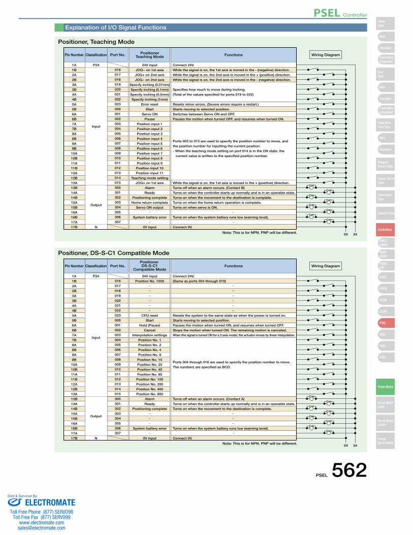
Explanation of I/O Signal Functions
Pin Number
24V input Connect 24V.
While the signal is on, the 1st axis is moved in the - (negative) direction.
While the signal is on, the 2nd axis is moved in the + (positive) direction.
While the signal is on, the 2nd axis is moved in the - (negative) direction.
Specifies how much to move during inching.
(Total of the values specified for ports 019 to 022)
PositionerTeaching Mode Functions
Connect 0V.
0V 24
Wiring Diagram
1A
Resets minor errors. (Severe errors require a restart.)
Turns off when an alarm occurs. (Contact B)
While the signal is on, the 1st axis is moved in the + (positive) direction.
Turns on when the controller starts up normally and is in an operable state.
Turns on when the movement to the destination is complete.
Turns on when the home return operation is complete.
Turns on when servo is ON.
Turns on when the system battery runs low (warning level).
Starts moving to selected position.
Switches between Servo ON and OFF.
Pauses the motion when turned OFF, and resumes when turned ON.
Ports 003 to 013 are used to specify the position number to move, and
the position number for inputting the current position.
- When the teaching mode setting on port 014 is in the ON state, the
current value is written to the specified position number.
1B
2A
2B
3A
3B
4A
4B
5A
5B
6A
6B
7A
7B
8A
8B
9A
9B
10A
10B
11A
11B
12A
12B
13A
13B
14A
14B
15A
15B
16A
16B
17A
17B
JOG− on 1st axis
JOG+ on 2nd axis
JOG− on 2nd axis
Specify inching (0.01mm)
Specify inching (0.1mm)
Specify inching (0.5mm)
Specify inching (1mm)
Error reset
Start
Servo ON
Pause
Position input 1
Position input 2
Position input 3
Position input 4
Position input 5
Position input 6
Position input 7
Position input 8
Position input 9
Position input 10
Position input 11
Teaching mode setting
JOG+ on 1st axis
Alarm
Ready
Positioning complete
Home return complete
Servo ON output
System battery error
0V input
Classification
Input
Output
N
P24016
Port No.
017
018
019
020
021
022
023
000
001
002
003
004
005
006
007
008
009
010
011
012
013
014
015
300
301
302
303
304
305
306
307
Pin Number Classification
Input
Output
N
01624V input Connect 24V.
(Same as ports 004 through 015)
Port No.Positioner DS-S-C1
Compatible ModeFunctions
Connect 0V.
0V 24
Wiring Diagram
1A P24
Resets the system to the same state as when the power is turned on.
Turns off when an alarm occurs. (Contact A)
Turns on when the controller starts up normally and is in an operable state.
Turns on when the movement to the destination is complete.
Turns on when the system battery runs low (warning level).
Starts moving to selected position.
Pauses the motion when turned ON, and resumes when turned OFF.
Stops the motion when turned ON. The remaining motion is canceled.
When this signal is turned ON for a 2-axis model, the actuator moves by linear interpolation.
Ports 004 through 016 are used to specify the position number to move.
The numbers are specified as BCD.
1B
2A
2B
3A
3B
4A
4B
5A
5B
6A
6B
7A
7B
8A
8B
9A
9B
10A
10B
11A
11B
12A
12B
13A
13B
14A
14B
15A
15B
16A
16B
17A
17B
017
018
019
020
021
022
023
000
001
002
003
004
005
006
007
008
009
010
011
012
013
014
015
300
301
302
303
304
305
306
307
Position No. 1000
CPU reset
Start
Hold (Pause)
Cancel
Interpolation settings
Position No. 1
Position No. 2
Position No. 4
Position No. 8
Position No. 10
Position No. 20
Position No. 40
Position No. 80
Position No. 100
Position No. 200
Position No. 400
Position No. 800
Alarm
Ready
Positioning complete
System battery error
0V input
Positioner, Teaching Mode
Positioner, DS-S-C1 Compatible Mode
Note: This is for NPN. PNP will be different.
Note: This is for NPN. PNP will be different.
PSEL Controller
PSEL 562
Mini
Mini
PSEP/ASEP
PMEC/AMEC
ROBONET
ERC2
PCON
ACON
SCON
PSEL
ASEL
SSEL
XSEL
Standard
Mini
Standard
Standard
ControllersIntegrated
ControllersIntegrated
SliderType
RodType
Table/Arm/Flat Type
Gripper/Rotary Type
Linear ServoType
Cleanroom Type
Splash-Proof
Controllers
Pulse Motor
Servo Motor (24V)
Servo Motor (200V)
LinearServo Motor
ELECTROMATEToll Free Phone (877) SERVO98
Toll Free Fax (877) SERV099www.electromate.com
Sold & Serviced By:
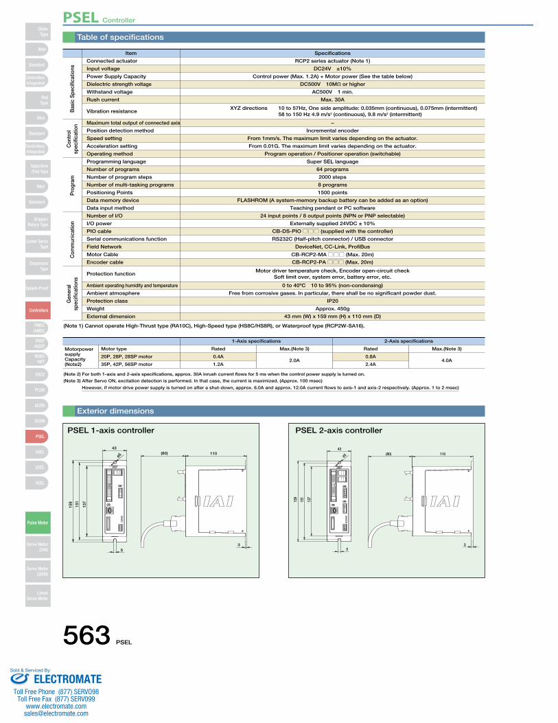
Table of specifications
Item Specifications
1-Axis specifications 2-Axis specifications
Connected actuator
Motor type
Maximum total output of connected axis
Position detection method
Speed setting
Acceleration setting
Operating method
Input voltage
20P, 28P, 28SP motor
Power Supply Capacity
35P, 42P, 56SP motor
Dielectric strength voltage
Withstand voltage
Rush current
Vibration resistance
RCP2 series actuator (Note 1)
Rated Max.(Note 3) Rated Max.(Note 3)
DC24V ±10%
0.4A2.0A
0.8A4.0A
Control power (Max. 1.2A) + Motor power (See the table below)
1.2A 2.4A
DC500V 10MΩ or higher
AC500V 1 min.
Max. 30A
XYZ directions 10 to 57Hz, One side amplitude: 0.035mm (continuous), 0.075mm (intermittent) 58 to 150 Hz 4.9 m/s2 (continuous), 9.8 m/s2 (intermittent)
−
Incremental encoder
From 1mm/s. The maximum limit varies depending on the actuator.
From 0.01G. The maximum limit varies depending on the actuator.
Program operation / Positioner operation (switchable)
(80) 11043
ø5
159
151
137
53
Exterior dimensions
PSEL 1-axis controller
159
151
137
53
43(80) 110
ø5
PSEL 2-axis controller
Bas
ic S
peci
ficat
ions
Con
trol
sp
ecifi
catio
n
Programming language
Number of programs
Number of program steps
Number of multi-tasking programs
Positioning Points
Data memory device
Data input method
Number of I/O
I/O power
PIO cable
Serial communications function
Field Network
Motor Cable
Encoder cable
Protection function
Ambient operating humidity and temperature
Ambient atmosphere
Protection class
Weight
External dimension
Super SEL language
64 programs
2000 steps
8 programs
1500 points
FLASHROM (A system-memory backup battery can be added as an option)
Teaching pendant or PC software
24 input points / 8 output points (NPN or PNP selectable)
Externally supplied 24VDC ± 10%
CB-DS-PIO□□□ (supplied with the controller)
RS232C (Half-pitch connector) / USB connector
DeviceNet, CC-Link, ProfiBus
CB-RCP2-MA□□□ (Max. 20m)
CB-RCP2-PA□□□ (Max. 20m)
Motor driver temperature check, Encoder open-circuit checkSoft limit over, system error, battery error, etc.
0 to 40ºC 10 to 95% (non-condensing)
Free from corrosive gases. In particular, there shall be no significant powder dust.
IP20
Approx. 450g
43 mm (W) x 159 mm (H) x 110 mm (D)
Pro
gram
Com
mun
icat
ion
Gen
eral
sp
ecifi
catio
ns
(Note 1) Cannot operate High-Thrust type (RA10C), High-Speed type (HS8C/HS8R), or Waterproof type (RCP2W-SA16).
(Note 2) For both 1-axis and 2-axis specifications, approx. 30A inrush current flows for 5 ms when the control power supply is turned on.
(Note 3) After Servo ON, excitation detection is performed. In that case, the current is maximized. (Approx. 100 msec)
However, if motor drive power supply is turned on after a shut-down, approx. 6.0A and approx. 12.0A current flows to axis-1 and axis-2 respectively. (Approx. 1 to 2 msec)
Motorpower supply Capacity (Note2)
PSEL Controller
563 PSEL
Mini
Mini
PSEP/ASEP
PMEC/AMEC
ROBONET
ERC2
PCON
ACON
SCON
PSEL
ASEL
SSEL
XSEL
Standard
Mini
Standard
Standard
ControllersIntegrated
ControllersIntegrated
RodType
Table/Arm/Flat Type
Gripper/Rotary Type
Linear ServoType
Cleanroom Type
Splash-Proof
Controllers
Pulse Motor
Servo Motor (24V)
Servo Motor (200V)
LinearServo Motor
SliderType
ELECTROMATEToll Free Phone (877) SERVO98
Toll Free Fax (877) SERV099www.electromate.com
Sold & Serviced By:
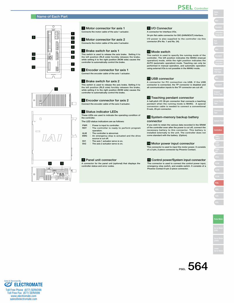
Name of Each Part
13
14
19
1 Motor connector for axis 1 Connects the motor cable of the axis 1 actuator.
8 Panel unit connector A connector for the panel unit (optional) that displays the controller status and error codes.
9 I/O Connector A connector for interface I/Os.
34-pin flat cable connector for DIO (24IN/8OUT) interface.
I/O power is also supplied to the controller via this connector (Pin No. 1 and No. 34).
10 Mode switch This switch is used to specify the running mode of the controller. The left position indicates the MANU (manual operation) mode, while the right position indicates the AUTO (automatic operation) mode. Teaching can only be performed in manual operation, and automatic operation using external I/Os is not possible in the MANU mode.
11 USB connectorA connector for PC connection via USB. If the USB connector is connected, the TP connector is disabled and all communication inputs to the TP connector are cut off.
12 Teaching pendant connectorA half-pitch I/O 26-pin connector that connects a teaching pendant when the running mode is MANU. A special conversion cable is needed to connect a conventional D-sub, 25-pin connector.
14 Motor power input connectorThis connector is used to input the motor power. It consists of a 2-pin, 2-piece connector by Phoenix Contact.
15 Control power/System input connectorThis connector is used to connect the control power input, emergency stop switch, and enable switch. It consists of a Phoenix Contact 6-pin 2-piece connector.
13 System-memory backup battery connectorIf you wish to retain the various data recorded in the SRAM of the controller even after the power is cut off, connect the necessary battery to this connector. This battery is installed externally to the unit. The controller does not come standard with the battery (Option).
2 Motor connector for axis 2 Connects the motor cable of the axis 2 actuator.
4 Encoder connector for axis 1Connect the encoder cable of the axis 1 actuator.
6 Encoder connector for axis 2Connect the encoder cable of the axis 2 actuator.
7 Status indicator LEDsThese LEDs are used to indicate the operating condition of the controller.
The LED status indicators are as follows:
3 Brake switch for axis 1 This switch is used to release the axis brake. Setting it to the left position (RLS side) forcibly releases the brake, while setting it to the right position (NOM side) causes the controller to automatically control the brake.
5 Brake switch for axis 2 This switch is used to release the axis brake. Setting it to the left position (RLS side) forcibly releases the brake, while setting it to the right position (NOM side) causes the controller to automatically control the brake.
PWR : Power is input to controller.RDY : The controller is ready to perform program
operation. ALM : The controller is abnormal. EMG : An emergency stop is actuated and the drive
source is cut off. SV1 : The axis 1 actuator servo is on. SV2 : The axis 2 actuator servo is on.
10
11
12
2
3
4
5
6
8
7
15
PSEL Controller
PSEL 564
Mini
Mini
PSEP/ASEP
PMEC/AMEC
ROBONET
ERC2
PCON
ACON
SCON
PSEL
ASEL
SSEL
XSEL
Standard
Mini
Standard
Standard
ControllersIntegrated
ControllersIntegrated
SliderType
RodType
Table/Arm/Flat Type
Gripper/Rotary Type
Linear ServoType
Cleanroom Type
Splash-Proof
Controllers
Pulse Motor
Servo Motor (24V)
Servo Motor (200V)
LinearServo Motor
ELECTROMATEToll Free Phone (877) SERVO98
Toll Free Fax (877) SERV099www.electromate.com
Sold & Serviced By:
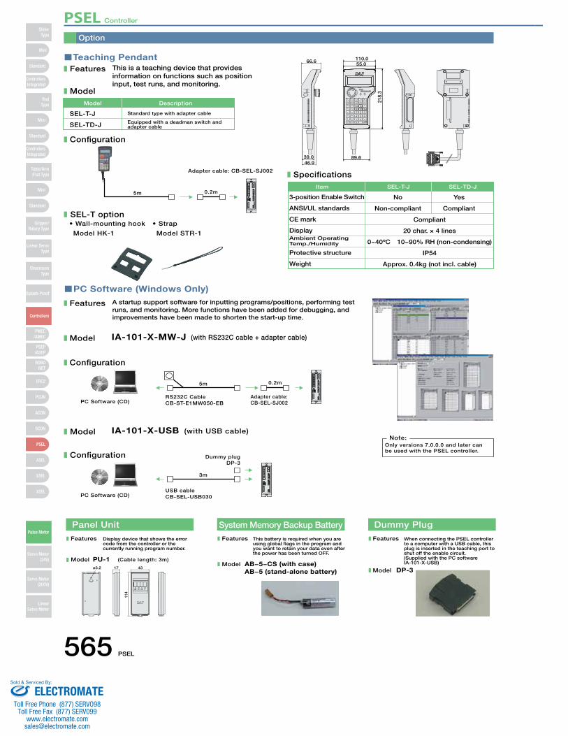
Option
This is a teaching device that provides information on functions such as position input, test runs, and monitoring.
Features
Model
Configuration
SEL-T option
A startup support software for inputting programs/positions, performing test runs, and monitoring. More functions have been added for debugging, and improvements have been made to shorten the start-up time.
Features
Model
Configuration
IA-101-X-MW-J (with RS232C cable + adapter cable)
Specifications
3-position Enable Switch No Yes
Compliant
Item SEL-T-J SEL-TD-J
SEL-T-J
SEL-TD-J
Standard type with adapter cable
Equipped with a deadman switch and adapter cable
Model Description
5m
5m
Adapter cable: CB-SEL-SJ002
0.2m
0.2m
Adapter cable: CB-SEL-SJ002PC Software (CD)
RS232C CableCB-ST-E1MW050-EB
IA-101-X-USB (with USB cable)
3m
Dummy plugDP-3
PC Software (CD)USB cableCB-SEL-USB030
Only versions 7.0.0.0 and later can be used with the PSEL controller.
Note:Model
Configuration
66.6
46.939.0
55.0
89.6
218.
3
110.0Teaching Pendant
PC Software (Windows Only)
• Wall-mounting hook
Model HK-1
• Strap
Model STR-1
ANSI/UL standards
CE mark
DisplayAmbient OperatingTemp./Humidity
Protective structure
Weight
Non-compliant
20 char. × 4 lines
0~40ºC 10~90% RH (non-condensing)
IP54
Approx. 0.4kg (not incl. cable)
Compliant
Panel Unit System Memory Backup BatteryFeatures Display device that shows the error
code from the controller or the currently running program number.
Model PU-1 (Cable length: 3m)
This battery is required when you are using global flags in the program and you want to retain your data even after the power has been turned OFF.
Features
Model AB−5−CS (with case)AB−5 (stand-alone battery)
Dummy Plug
When connecting the PSEL controller to a computer with a USB cable, this plug is inserted in the teaching port to shut off the enable circuit. (Supplied with the PC software IA-101-X-USB)
Features
Model DP-3ø3.2 17
114
43
PSEL Controller
565 PSEL
Mini
Mini
PSEP/ASEP
PMEC/AMEC
ROBONET
ERC2
PCON
ACON
SCON
PSEL
ASEL
SSEL
XSEL
Standard
Mini
Standard
Standard
ControllersIntegrated
ControllersIntegrated
RodType
Table/Arm/Flat Type
Gripper/Rotary Type
Linear ServoType
Cleanroom Type
Splash-Proof
Controllers
Pulse Motor
Servo Motor (24V)
Servo Motor (200V)
LinearServo Motor
SliderType
ELECTROMATEToll Free Phone (877) SERVO98
Toll Free Fax (877) SERV099www.electromate.com
Sold & Serviced By:
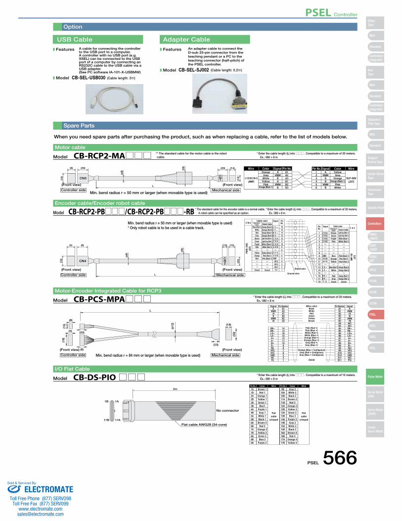
A cable for connecting the controller to the USB port to a computer. A controller with no USB port (e.g. XSEL) can be connected to the USB port of a computer by connecting an RS232C cable to the USB cable via a USB adapter. (See PC software IA-101-X-USBMW)
USB Cable Adapter Cable
Features
Model CB-SEL-USB030 (Cable length: 3m)
An adapter cable to connect the D-sub 25-pin connector from the teaching pendant or a PC to the teaching connector (half-pitch) of the PSEL controller.
Features
Model CB-SEL-SJ002 (Cable length: 0.2m)
Spare Parts
Option
A A
I-1318119-3(AMP)
SLP-06V(JST)
Orange Yellow123456
(20)(8)
(Front view)
(15)
L
CN3CN1
(ø8)
(28) (14)
(14)
(20)
(Front view)
Mechanical sideController side
GrayWhiteYellowPink
Orange (Black 1)
VMMBA
VMMB
A1A2A3B1B2B3
VMMAB
VMMB
GrayOrange
Orange (Black 1)Pink
White
Wire Color Signal Pin No. Pin No. WireColorSignal
Model CB-RCP2-MA□□□Motor cable
* Enter the cable length (L) into □□□ . Compatible to a maximum of 20 meters. Ex.: 080 = 8 m
* * The standard cable for the motor cable is the robot cable.
When you need spare parts after purchasing the product, such as when replacing a cable, refer to the list of models below.
PHDR
-16V
S(J
ST)
XMP-
18V
(JST)
Blue (Red 1)
C N 4
C N 2Cable color
Signal PinNo.
Brown Light Gray (Black 1)
Orange (Black 2)
1
L S + L S −B K + B K − E N A E N A E N B E N B
V P S V B B
(N.C)(N.C)(N.C)F.G
E N A E N A E N B E N B
GNDGND
V B B V P S
L S + L S −
B K + B K − F .G
16
Shield wire
Ground wire
Cable color Standard
Cable Robot Cable
Standard Cable Robot Cable
SignalPinNo.
L
CN2
CN4
(5) (8) (13) (15)
(18)
(ø9)
(35)
(25)
WhiteRedGray
BrownGreenPurplePink
YellowOrange
Blue
Ground
Orange (Red 2)Orange (Black 1)Orange (Red 1)Light Gray (Black 1)Light Gray (Red 1)White (Black 1)White (Red 1)
Yellow (Black 1)Pink (Red 1)
Pink (Black 1)
Ground
151413121110987654321
23456789101112131415161718
GreenPurplePink
BlueOrangeYellow
Blue (Red 1)White
RedGray
Ground
Light Gray (Red 1)White (Black 1)White (Red 1)
Pink (Black 1)Pink (Red 1)
Yellow (Black 1)
Orange (Black 2)Orange (Red 2)
Orange (Black 1)Orange (Red 1)
Ground
(Front view) (Front view)
Mechanical sideController side
Model CB-RCP2-PB□□□/CB-RCP2-PB□□□-RBEncoder cable/Encoder robot cable
* Enter the cable length (L) into □□□ . Compatible to a maximum of 20 meters. Ex.: 080 = 8 m
ColorPin No. Wire
Flatcable
crimped
Wire
Flatcable
crimped
ColorPin No.1A Brown 1 9B Gray 2
1B 1A
17B 17A
Flat cable AWG28 (34-core)
2m
No connector
1B2A2B3A3B4A4B5A5B6A6B7A7B8A8B9A
Red 1Orange 1Yellow 1Green 1Blue1
Purple 1Gray 1White 1Black 1Brown-2
Red 2Orange 2Yellow 2Green 2Blue 2
Purple 2
10A10B11A11B12A12B13A13B14A14B15A15B16A16B17A17B
White 2Black 2Brown-3
Red 3Orange 3Yellow 3Green 3Blue 3
Purple 3Gray 3White 3Black 3Brown-4
Red 4Orange 4Yellow 4
Model CB-DS-PIO□□□I/O Flat Cable
* Enter the cable length (L) into □□□ . Compatible to a maximum of 10 meters. Ex.: 080 = 8 m
* The standard cable for the encoder cable is a normal cable. A robot cable can be specified as an option.
L
(15)
(ø12
)
A
Shield
Pink (Red •)Pink (Blue •)White (Red •)White (Blue •)Orange (Red •)Orange (Blue •)
Gray (Red •)Gray (Blue •)
Orange (Blue • Contiguous)Gray (Red • Contiguous)Gray (Blue • Contiguous)
BlackWhiteRed
GreenYellowBrown
B1 A1 A
BK+ 14
(18)
(8)
(20)
(8)
(5)
(30)
(18)
(23)
Signal Pin Number (Wire color) Pin Number Signal
VMM/AB
VMM/B
A2A1B3B2A3
BK−LS+LS−A+A−B+B−NCVPSVCCGNDNCFG
1316151211109876541
B1A2B2A3B3A4B4A5B5A6B6A7B7A8B8A9B9A10B10A11B11
VMM/AB
VMM/BNCNCBK+BK−LS+LS−A+A−B+B−NCVPSVCCGNDNCFG
(Front view) (Front view)
Mechanical sideController side
Model CB-PCS-MPA□□□Motor-Encoder Integrated Cable for RCP3
* Enter the cable length (L) into □□□ . Compatible to a maximum of 20 meters. Ex.: 080 = 8 m
Min. bend radius r = 50 mm or larger (when movable type is used)* Only robot cable is to be used in a cable track.
Min. bend radius r = 84 mm or larger (when movable type is used)
Min. bend radius r = 50 mm or larger (when movable type is used)
PSEL Controller
PSEL 566
Mini
Mini
PSEP/ASEP
PMEC/AMEC
ROBONET
ERC2
PCON
ACON
SCON
PSEL
ASEL
SSEL
XSEL
Standard
Mini
Standard
Standard
ControllersIntegrated
ControllersIntegrated
SliderType
RodType
Table/Arm/Flat Type
Gripper/Rotary Type
Linear ServoType
Cleanroom Type
Splash-Proof
Controllers
Pulse Motor
Servo Motor (24V)
Servo Motor (200V)
LinearServo Motor
ELECTROMATEToll Free Phone (877) SERVO98
Toll Free Fax (877) SERV099www.electromate.com
Sold & Serviced By:
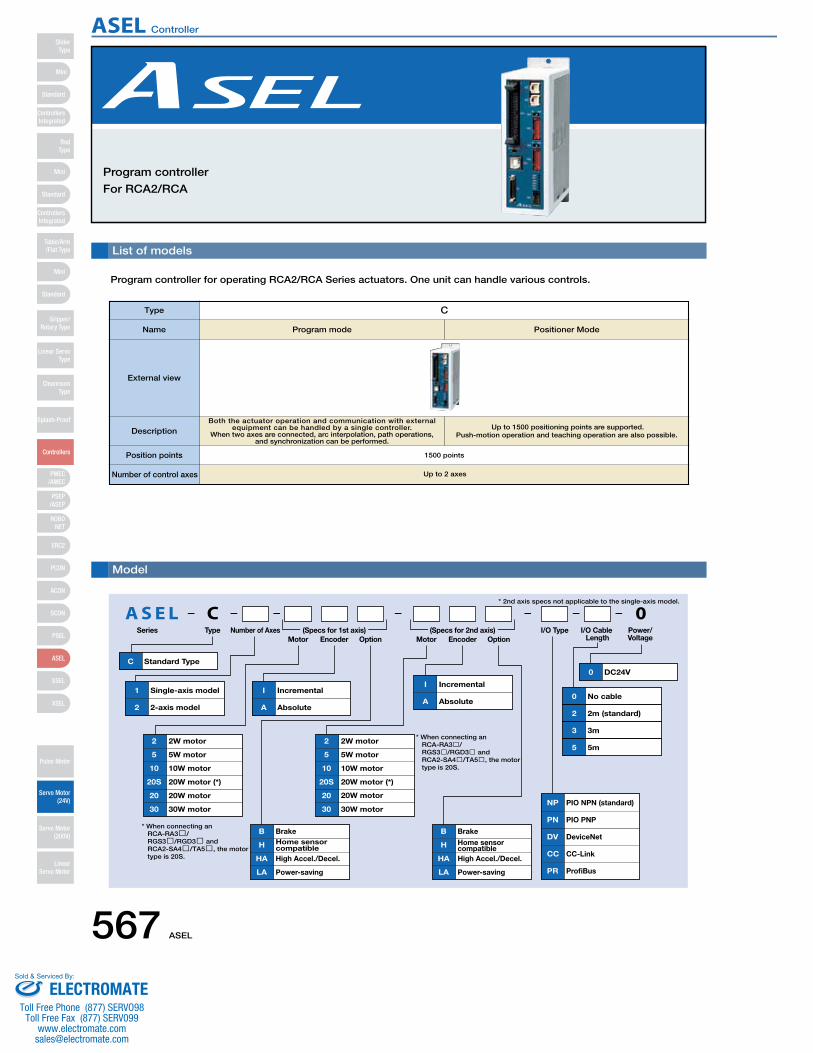
List of models
Program controller for operating RCA2/RCA Series actuators. One unit can handle various controls.
Program controller
For RCA2/RCA
0CA S E LSeries Type Number of Axes
Motor Encoder Option Motor Encoder OptionI/O Cable
LengthPower/Voltage
* 2nd axis specs not applicable to the single-axis model.
I/O Type
C Standard Type
20
20S
20W motor
20W motor (*)
10 10W motor
5 5W motor
2 2W motor
30 30W motor
1 Single-axis model
2 2-axis model
I Incremental
A Absolute
I Incremental
A Absolute
DV DeviceNet
CC CC-Link
PR ProfiBus
NP PIO NPN (standard)
PN PIO PNP
B Brake
H Home sensor compatible
HA High Accel./Decel.
LA Power-saving
B Brake
H Home sensor compatible
HA High Accel./Decel.
LA Power-saving
0 DC24V
0 No cable
2 2m (standard)
3 3m
5 5m
20
20S
20W motor
20W motor (*)
30 30W motor
10 10W motor
5 5W motor
2 2W motor
(Specs for 1st axis) (Specs for 2nd axis)
* When connecting an RCA-RA3�/RGS3�/RGD3� and RCA2-SA4�/TA5�, the motor type is 20S.
* When connecting an RCA-RA3�/RGS3�/RGD3� and RCA2-SA4�/TA5�, the motor type is 20S.
Model
Type C
Program mode Positioner ModeName
External view
DescriptionBoth the actuator operation and communication with external
equipment can be handled by a single controller.When two axes are connected, arc interpolation, path operations,
and synchronization can be performed.
Up to 1500 positioning points are supported. Push-motion operation and teaching operation are also possible.
Position points 1500 points
Number of control axes Up to 2 axes
567 ASEL
Mini
Mini
PSEP/ASEP
PMEC/AMEC
ROBONET
ERC2
PCON
ACON
SCON
PSEL
ASEL
SSEL
XSEL
Standard
Mini
Standard
Standard
ControllersIntegrated
ControllersIntegrated
RodType
Table/Arm/Flat Type
Gripper/Rotary Type
Linear ServoType
Cleanroom Type
Splash-Proof
Controllers
Pulse Motor
Servo Motor (24V)
Servo Motor (200V)
LinearServo Motor
SliderType
ASEL Controller
ELECTROMATEToll Free Phone (877) SERVO98
Toll Free Fax (877) SERV099www.electromate.com
Sold & Serviced By:
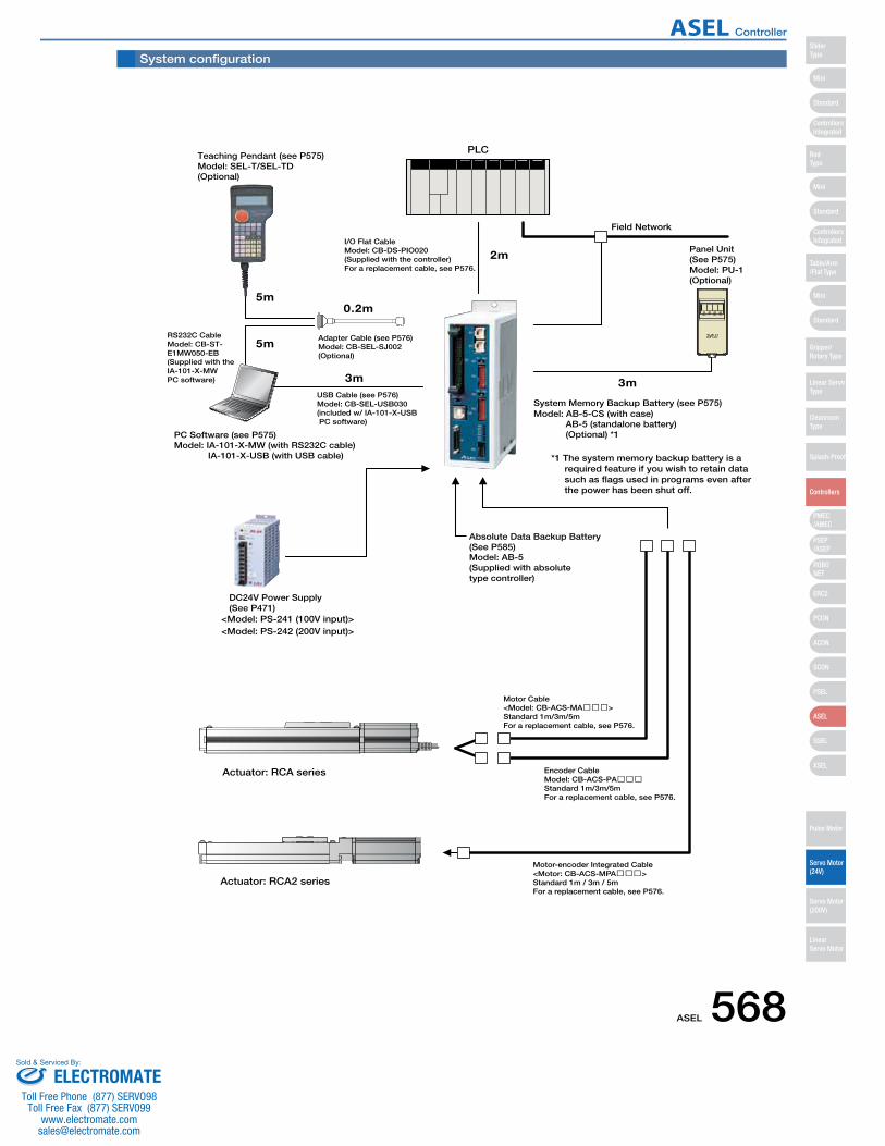
Teaching Pendant (see P575)Model: SEL-T/SEL-TD(Optional)
I/O Flat CableModel: CB-DS-PIO020(Supplied with the controller)For a replacement cable, see P576.
Panel Unit(See P575)Model: PU-1(Optional)
Encoder CableModel: CB-ACS-PA���Standard 1m/3m/5mFor a replacement cable, see P576.
Motor Cable<Model: CB-ACS-MA���>Standard 1m/3m/5mFor a replacement cable, see P576.
PC Software (see P575)Model: IA-101-X-MW (with RS232C cable)
IA-101-X-USB (with USB cable)
USB Cable (see P576)Model: CB-SEL-USB030(included w/ IA-101-X-USB PC software)
RS232C CableModel: CB-ST-E1MW050-EB(Supplied with the IA-101-X-MWPC software)
Adapter Cable (see P576)Model: CB-SEL-SJ002(Optional)
2m
0.2m
3m 3m
5m
5m
<Model: PS-241 (100V input)><Model: PS-242 (200V input)>
DC24V Power Supply (See P471)
PLC
Actuator: RCA series
Model: AB-5-CS (with case)AB-5 (standalone battery)(Optional) *1
System Memory Backup Battery (see P575)
Absolute Data Backup Battery(See P585)Model: AB-5(Supplied with absolute type controller)
Actuator: RCA2 series
Motor-encoder Integrated Cable<Motor: CB-ACS-MPA���>Standard 1m / 3m / 5mFor a replacement cable, see P576.
Field Network
*1 The system memory backup battery is a required feature if you wish to retain data such as flags used in programs even after the power has been shut off.
System configuration
ASEL 568
Mini
Mini
PSEP/ASEP
PMEC/AMEC
ROBONET
ERC2
PCON
ACON
SCON
PSEL
ASEL
SSEL
XSEL
Standard
Mini
Standard
Standard
ControllersIntegrated
ControllersIntegrated
SliderType
RodType
Table/Arm/Flat Type
Gripper/Rotary Type
Linear ServoType
Cleanroom Type
Splash-Proof
Controllers
Pulse Motor
Servo Motor (24V)
Servo Motor (200V)
LinearServo Motor
ASEL Controller
ELECTROMATEToll Free Phone (877) SERVO98
Toll Free Fax (877) SERV099www.electromate.com
Sold & Serviced By:

I/O Specifications
Explanation of I/O Signal Functions
Two modes can be selected for the ASEL controller: “Program Mode,” in which the actuator is operated by entering a program,
and “Positioner Mode,” in which PLC signals are received and the actuator is moved to designated positions.
The Positioner Mode has the five input patterns listed below to enable various applications.
P24V
R=3.3kΩInputs
R=560Ω
+24V
External power supply
Input terminal
Internal circuitP24
N
OutputsInternal circuit Load
+ 2 4 V
External power supply
N
R=3.3kΩInputs
R=560Ω
+24V
External power supply
Input terminal
Internal circuit P24V
N
Outputs
Internal circuit
+ 2 4 V
External power supply Load
NPN Specifications NPN Specifications
PNP Specifications PNP Specifications
ItemInput voltageInput current
ON/OFF voltage
Isolation method
SpecificationsDC24V ±10%7mA / circuitON voltage (min.) NPN : DC16V / PNP : DC8VOFF voltage (max.) NPN : DC5V / PNP : DC19VPhotocoupler
■ Input section External input specifications
ItemLoad VoltageMax. load current Residual voltage (Max.) Isolation method
SpecificationsDC24V100mA / 1 point 400mA / 8 points in totalMax 0.1mA / 1 pointPhotocoupler
■ Output section External output specifications
■ Control Function by Type
Operation mode Features
Program mode
Positioner mode
This is the basic mode from which operations can be conducted by designating position numbers and inputting the start signal.Push-motion operation and teaching operation are also possible.
Various operations including linear/arc interpolation operation, path operation ideal for coating processes, etc., arch-motion operation and palletizing operation can be performed using the Super SEL language that lets you program complex control actions using simple commands.
Multiple parts of the same shape with slightly different hole positions can be handled using movement commands to the same position numbers by simply changing the product type number.
With a 2-axis controller, each axis can be commanded and operated separately.
In this mode, the slider (rod) moves based on an external signal, when the actuator is stopped, the current location can be registered as position data.
Standard mode
Product Change
mode
2-axis independent
mode
Teaching mode
DS-S-C1
Compatible modeIf you were using a DS-S-C1 controller, you can replace it with a ASEL controller without having to change the host programs. *This mode does not ensure actuator compatibility.
569 ASEL
Mini
Mini
PSEP/ASEP
PMEC/AMEC
ROBONET
ERC2
PCON
ACON
SCON
PSEL
ASEL
SSEL
XSEL
Standard
Mini
Standard
Standard
ControllersIntegrated
ControllersIntegrated
RodType
Table/Arm/Flat Type
Gripper/Rotary Type
Linear ServoType
Cleanroom Type
Splash-Proof
Controllers
Pulse Motor
Servo Motor (24V)
Servo Motor (200V)
LinearServo Motor
SliderType
ASEL Controller
ELECTROMATEToll Free Phone (877) SERVO98
Toll Free Fax (877) SERV099www.electromate.com
Sold & Serviced By:
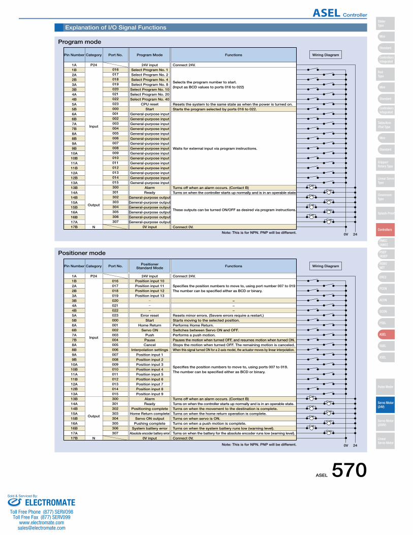
Explanation of I/O Signal Functions
Pin Number Category
Input
Output
N
01624V input Connect 24V.
Port No. Program Mode Functions
Resets the system to the same state as when the power is turned on.
Turns off when an alarm occurs. (Contact B)Turns on when the controller starts up normally and is in an operable state.
Connect 0V.
These outputs can be turned ON/OFF as desired via program instructions.
Starts the program selected by ports 016 to 022.
Waits for external input via program instructions.
Selects the program number to start. (Input as BCD values to ports 016 to 022)
0V 24
Wiring Diagram
1A P241B2A2B3A3B4A4B5A5B6A6B7A7B8A8B9A9B10A10B11A11B12A12B13A13B14A14B15A15B16A16B17A17B
017018019020021022023000001002003004005006007008009010011012013014015300301302303304305306307
Select Program No. 1Select Program No. 2Select Program No. 4Select Program No. 8Select Program No. 10Select Program No. 20Select Program No. 40
CPU resetStart
General-purpose inputGeneral-purpose inputGeneral-purpose inputGeneral-purpose inputGeneral-purpose inputGeneral-purpose inputGeneral-purpose inputGeneral-purpose inputGeneral-purpose inputGeneral-purpose inputGeneral-purpose inputGeneral-purpose inputGeneral-purpose inputGeneral-purpose inputGeneral-purpose input
AlarmReady
General-purpose outputGeneral-purpose outputGeneral-purpose outputGeneral-purpose outputGeneral-purpose outputGeneral-purpose output
0V input
Pin Number Category
Input
Output
N
01624V input Connect 24V.
Port No. PositionerStandard Mode Functions
Resets minor errors. (Severe errors require a restart.)
−−−
Turns off when an alarm occurs. (Contact B)Turns on when the controller starts up normally and is in an operable state.Turns on when the movement to the destination is complete.Turns on when the home return operation is complete.Turns on when servo is ON.Turns on when a push motion is complete.Turns on when the system battery runs low (warning level).Turns on when the battery for the absolute encoder runs low (warning level).Connect 0V.
Starts moving to the selected position.Performs Home Return.Switches between Servo ON and OFF.Performs a push motion.Pauses the motion when turned OFF, and resumes motion when turned ON.Stops the motion when turned OFF. The remaining motion is canceled.When this signal turned ON for a 2-axis model, the actuator moves by linear interpolation.
Specifies the position numbers to move to, using ports 007 to 019. The number can be specified either as BCD or binary.
Specifies the position numbers to move to, using port number 007 to 019 The number can be specified either as BCD or binary.
0V 24
Wiring Diagram
1A P241B2A2B3A3B4A4B5A5B6A6B7A7B8A8B9A9B10A10B11A11B12A12B13A13B14A14B15A15B16A16B17A17B
017018019020021022023000001002003004005006007008009010011012013014015300301302303304305306307
Position input 10Position input 11Position input 12Position input 13
Error resetStart
Home ReturnServo ON
PushPauseCancel
Interpolation settingsPosition input 1Position input 2Position input 3Position input 4Position input 5Position input 6Position input 7Position input 8Position input 9
AlarmReady
Positioning completeHome Return complete
Servo ON outputPushing complete
System battery errorAbsolute encoder battery error
0V input
Program mode
Positioner mode
Note: This is for NPN. PNP will be different.
Note: This is for NPN. PNP will be different.
ASEL 570
Mini
Mini
PSEP/ASEP
PMEC/AMEC
ROBONET
ERC2
PCON
ACON
SCON
PSEL
ASEL
SSEL
XSEL
Standard
Mini
Standard
Standard
ControllersIntegrated
ControllersIntegrated
SliderType
RodType
Table/Arm/Flat Type
Gripper/Rotary Type
Linear ServoType
Cleanroom Type
Splash-Proof
Controllers
Pulse Motor
Servo Motor (24V)
Servo Motor (200V)
LinearServo Motor
ASEL Controller
ELECTROMATEToll Free Phone (877) SERVO98
Toll Free Fax (877) SERV099www.electromate.com
Sold & Serviced By:

Explanation of I/O Signal Functions
Pin Number Category
Input
Output
N
016
24V input Connect 24V.
Port No.Positioner
Product Type Change ModeFunctions
Connect 0V.
0V 24
Wiring Diagram
1A P24
Resets minor errors. (Severe errors require a restart.)
Turns off when an alarm occurs (Contact B)
Turns on when the controller starts up normally and is in an operable state.
Turns on when the movement to the destination is complete.
Turns on when the home return operation is complete.
Turns on when servo is ON.
Turns on when a push motion is complete.
Turns on when the system battery runs low (warning level).
Turns on when the battery for the absolute encoder runs low (warning level).
Starts moving to the selected position.
Performs Home Return.
Switches between Servo ON and OFF.
Performs a push motion.
Pauses the motion when turned OFF, and resumes motion when turned ON.
Stops the motion when turned OFF. The remaining motion is canceled.
When this signal is turned ON for a 2-axis model, the actuator moves by linear interpolation.
Specifies the position numbers to move to, and the product type numbers,
using ports 007 to 022.
The position and product type numbers are assigned by parameter settings.
The number can be specified either as BCD or binary.
Specifies the position numbers to move to, and the product type numbers,
using ports 007 to 022.
The position and product type numbers are assigned by parameter settings.
The number can be specified either as BCD or binary.
1B
2A
2B
3A
3B
4A
4B
5A
5B
6A
6B
7A
7B
8A
8B
9A
9B
10A
10B
11A
11B
12A
12B
13A
13B
14A
14B
15A
15B
16A
16B
17A
17B
017
018
019
020
021
022
023
000
001
002
003
004
005
006
007
008
009
010
011
012
013
014
015
300
301
302
303
304
305
306
307
Position/Product Type Input 10
Position/Product Type Input 11
Position/Product Type Input 12
Position/Product Type Input 13
Position/Product Type Input 14
Position/Product Type Input 15
Position/Product Type Input 16
Error reset
Start
Home Return
Servo ON
Push
Pause
Cancel
Interpolation settings
Position/Product Type Input 1
Position/Product Type Input 2
Position/Product Type Input 3
Position/Product Type Input 4
Position/Product Type Input 5
Position/Product Type Input 6
Position/Product Type Input 7
Position/Product Type Input 8
Position/Product Type Input 9
Alarm
Ready
Positioning complete
Home Return complete
Servo ON output
Pushing complete
System battery error
Absolute encoder battery error
0V input
Pin Number Category
Input
Output
N
01624V input Connect 24V.
Port No. Positioner 2-axis Independent Mode Functions
Connect 0V.
0V 24
Wiring Diagram
1A P24
Resets minor errors. (Severe errors require a restart.)
Turns off when an alarm occurs (Contact B)Turns on when the controller starts up normally and is in an operable state.Turns on when the movement to the specified position on the 1st axis is complete.Turns on when home return on the 1st axis is complete.Turns on when the 1st axis is in a servo ON state.Turns on when the movement to the specified position on the 2nd axis is complete.Turns on when home return on the 2nd axis is complete.Turns on when the 2nd axis is in a servo ON state.
Starts movement to the selected position number on the 1st axis.Performs home return on the 1st axis.Switches between servo ON and OFF for the 1st axis.
Cancels the movement on the 1st axis.Starts the movement to the selected position number on the 2nd axis.Performs home return on the 2nd axis.Switches between servo ON and OFF for the 2nd axis.
Cancels the movement on the 2nd axis.
Specifies the position numbers to move to, using ports 010 to 022. The position numbers on the 1st and 2nd axes are assigned by parameter settings. The number can be specified either as BCD or binary.
Specifies the position numbers to move to, using ports 010 to 022. The position numbers on the 1st and 2nd axes are assigned by parameter settings. The number can be specified either as BCD or binary.
Pauses the motion on 1st axis when turned OFF, and resumes motion when turned ON.
Pauses the motion on 2nd axis when turned OFF, and resumes when turned ON.
1B2A2B3A3B4A4B5A5B6A6B7A7B8A8B9A9B10A10B11A11B12A12B13A13B14A14B15A15B16A16B17A17B
017018019020021022023000001002003004005006007008009010011012013014015300301302303304305306307
Position input 7Position input 8Position input 9Position input 10Position input 11Position input 12Position input 13
Error resetStart 1
Home Return 1Servo ON 1
Pause 1Cancel 1Start 2
Home Return 2Servo ON 2
Pause 2Cancel 2
Position input 1Position input 2Position input 3Position input 4Position input 5Position input 6
AlarmReady
Positioning complete 1Home Return complete 1
Servo ON output 1Positioning complete 2
Home Return complete 2Servo ON output 2
0V input
Positioner, Product-Type Change Mode
Positioner, 2-axis Independent Mode
Note: This is for NPN. PNP will be different.
Note: This is for NPN. PNP will be different.
571 ASEL
Mini
Mini
PSEP/ASEP
PMEC/AMEC
ROBONET
ERC2
PCON
ACON
SCON
PSEL
ASEL
SSEL
XSEL
Standard
Mini
Standard
Standard
ControllersIntegrated
ControllersIntegrated
RodType
Table/Arm/Flat Type
Gripper/Rotary Type
Linear ServoType
Cleanroom Type
Splash-Proof
Controllers
Pulse Motor
Servo Motor (24V)
Servo Motor (200V)
LinearServo Motor
SliderType
ASEL Controller
ELECTROMATEToll Free Phone (877) SERVO98
Toll Free Fax (877) SERV099www.electromate.com
Sold & Serviced By:
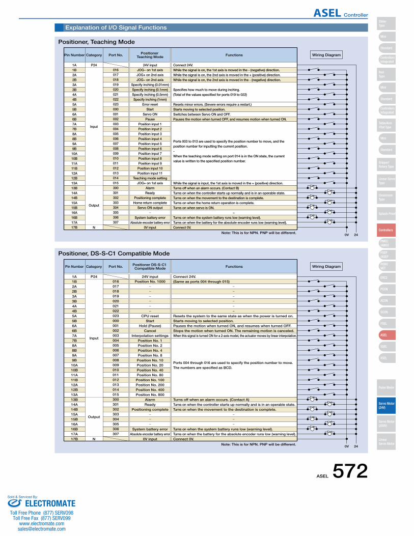
Explanation of I/O Signal Functions
Pin Number Category
Input
Output
N
01624V input Connect 24V.
While the signal is on, the 1st axis is moved in the - (negative) direction.While the signal is on, the 2nd axis is moved in the + (positive) direction.While the signal is on, the 2nd axis is moved in the - (negative) direction.
Specifies how much to move during inching. (Total of the values specified for ports 019 to 022)
Port No. Positioner Teaching Mode Functions
Connect 0V.
0V 24
Wiring Diagram
1A P24
Resets minor errors. (Severe errors require a restart.)
Turns off when an alarm occurs. (Contact B)While the signal is input, the 1st axis is moved in the + (positive) direction.
Turns on when the controller starts up normally and is in an operable state.Turns on when the movement to the destination is complete.Turns on when the home return operation is complete.Turns on when servo is ON.
−Turns on when the system battery runs low (warning level).Turns on when the battery for the absolute encoder runs low (warning level).
Starts moving to selected position.Switches between Servo ON and OFF.Pauses the motion when turned OFF, and resumes motion when turned ON.
Ports 003 to 013 are used to specify the position number to move, and the position number for inputting the current position. - When the teaching mode setting on port 014 is in the ON state, the current value is written to the specified position number.
1B2A2B3A3B4A4B5A5B6A6B7A7B8A8B9A9B10A10B11A11B12A12B13A13B14A14B15A15B16A16B17A17B
017018019020021022023000001002003004005006007008009010011012013014015300301302303304305306307
JOG− on 1st axisJOG+ on 2nd axisJOG− on 2nd axis
Specify inching (0.01mm)Specify inching (0.1mm)Specify inching (0.5mm)Specify inching (1mm)
Error resetStart
Servo ONPause
Position input 1Position input 2Position input 3Position input 4Position input 5Position input 6Position input 7Position input 8Position input 9Position input 10Position input 11
Teaching mode settingJOG+ on 1st axis
AlarmReady
Positioning completeHome return complete
Servo ON output
System battery errorAbsolute encoder battery error
0V input
Pin Number Category
Input
Output
N
01624V input Connect 24V.
(Same as ports 004 through 015)
Port No. Positioner DS-S-C1 Compatible Mode Functions
Connect 0V.
0V 24
Wiring Diagram
1A P24
Resets the system to the same state as when the power is turned on.
Turns off when an alarm occurs. (Contact A)Turns on when the controller starts up normally and is in an operable state.Turns on when the movement to the destination is complete.
Turns on when the system battery runs low (warning level).Turns on when the battery for the absolute encoder runs low (warning level).
Starts moving to selected position.Pauses the motion when turned ON, and resumes when turned OFF.Stops the motion when turned ON. The remaining motion is canceled.When this signal is turned ON for a 2-axis model, the actuator moves by linear interpolation.
Ports 004 through 016 are used to specify the position number to move. The numbers are specified as BCD.
1B2A2B3A3B4A4B5A5B6A6B7A7B8A8B9A9B10A10B11A11B12A12B13A13B14A14B15A15B16A16B17A17B
017018019020021022023000001002003004005006007008009010011012013014015300301302303304305306307
Position No. 1000
CPU resetStart
Hold (Pause)Cancel
Interpolation settingsPosition No. 1Position No. 2Position No. 4Position No. 8Position No. 10Position No. 20Position No. 40Position No. 80Position No. 100Position No. 200Position No. 400Position No. 800
AlarmReady
Positioning complete
System battery errorAbsolute encoder battery error
0V input
Positioner, Teaching Mode
Positioner, DS-S-C1 Compatible Mode
Note: This is for NPN. PNP will be different.
Note: This is for NPN. PNP will be different.
ASEL 572
Mini
Mini
PSEP/ASEP
PMEC/AMEC
ROBONET
ERC2
PCON
ACON
SCON
PSEL
ASEL
SSEL
XSEL
Standard
Mini
Standard
Standard
ControllersIntegrated
ControllersIntegrated
SliderType
RodType
Table/Arm/Flat Type
Gripper/Rotary Type
Linear ServoType
Cleanroom Type
Splash-Proof
Controllers
Pulse Motor
Servo Motor (24V)
Servo Motor (200V)
LinearServo Motor
ASEL Controller
ELECTROMATEToll Free Phone (877) SERVO98
Toll Free Fax (877) SERV099www.electromate.com
Sold & Serviced By:
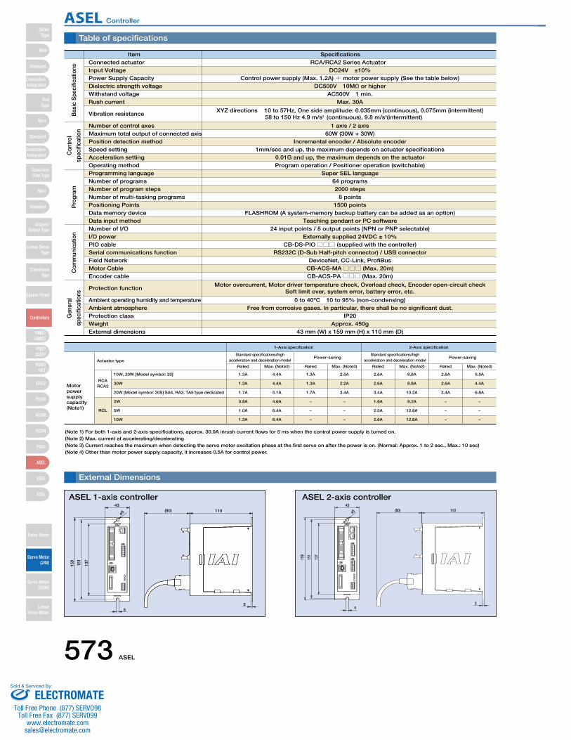
1-Axis specification 2-Axis specification
Actuator type
Standard specifications/high acceleration and deceleration model
Power-savingStandard specifications/high
acceleration and deceleration modelPower-saving
Rated Max. (Note2) Rated Max. (Note3) Rated Max. (Note2) Rated Max. (Note3)
Motor power supplycapacity(Note1)
RCARCA2
10W, 20W [Model symbol: 20] 1.3A 4.4A 1.3A 2.5A 2.6A 8.8A 2.6A 5.0A
30W 1.3A 4.4A 1.3A 2.2A 2.6A 8.8A 2.6A 4.4A
20W [Model symbol: 20S] SA4, RA3, TA5 type dedicated 1.7A 5.1A 1.7A 3.4A 3.4A 10.2A 3.4A 6.8A
RCL
2W 0.8A 4.6A − − 1.6A 9.2A − −
5W 1.0A 6.4A − − 2.0A 12.8A − −
10W 1.3A 6.4A − − 2.6A 12.8A − −
Table of specifications
Item SpecificationsConnected actuator
Number of control axesMaximum total output of connected axis Position detection methodSpeed settingAcceleration setting Operating methodProgramming languageNumber of programsNumber of program stepsNumber of multi-tasking programsPositioning PointsData memory deviceData input methodNumber of I/O I/O powerPIO cableSerial communications functionField NetworkMotor CableEncoder cable
Protection function
Ambient operating humidity and temperatureAmbient atmosphereProtection classWeightExternal dimensions
Input Voltage
Dielectric strength voltageWithstand voltageRush current
Vibration resistance
RCA/RCA2 Series ActuatorDC24V ±10%
Power Supply Capacity Control power supply (Max. 1.2A)+ motor power supply (See the table below)DC500V 10MΩ or higher
AC500V 1 min.Max. 30A
XYZ directions 10 to 57Hz, One side amplitude: 0.035mm (continuous), 0.075mm (intermittent) 58 to 150 Hz 4.9 m/s2 (continuous), 9.8 m/s2(intermittent)
1 axis / 2 axis60W (30W + 30W)
Incremental encoder / Absolute encoder1mm/sec and up, the maximum depends on actuator specifications
0.01G and up, the maximum depends on the actuatorProgram operation / Positioner operation (switchable)
Super SEL language64 programs2000 steps
8 points1500 points
FLASHROM (A system-memory backup battery can be added as an option)Teaching pendant or PC software
24 input points / 8 output points (NPN or PNP selectable)Externally supplied 24VDC ± 10%
CB-DS-PIO□□□ (supplied with the controller) RS232C (D-Sub Half-pitch connector) / USB connector
DeviceNet, CC-Link, ProfiBusCB-ACS-MA□□□ (Max. 20m)CB-ACS-PA□□□ (Max. 20m)
Motor overcurrent, Motor driver temperature check, Overload check, Encoder open-circuit checkSoft limit over, system error, battery error, etc.
0 to 40ºC 10 to 95% (non-condensing)Free from corrosive gases. In particular, there shall be no significant dust.
IP20Approx. 450g
43 mm (W) x 159 mm (H) x 110 mm (D)
(80) 11043
ø5
159
151
137
53
External Dimensions
ASEL 1-axis controller
ø5
159
151
137
53
43(80) 110
ASEL 2-axis controller
Bas
ic S
peci
ficat
ions
Con
trol
spec
ifica
tion
Pro
gram
Com
mun
icat
ion
Gen
eral
spec
ifica
tions
(Note 1) For both 1-axis and 2-axis specifications, approx. 30.0A inrush current flows for 5 ms when the control power supply is turned on. (Note 2) Max. current at accelerating/decelerating(Note 3) Current reaches the maximum when detecting the servo motor excitation phase at the first servo on after the power is on. (Normal: Approx. 1 to 2 sec., Max.: 10 sec)(Note 4) Other than motor power supply capacity, it increases 0.5A for control power.
573 ASEL
Mini
Mini
PSEP/ASEP
PMEC/AMEC
ROBONET
ERC2
PCON
ACON
SCON
PSEL
ASEL
SSEL
XSEL
Standard
Mini
Standard
Standard
ControllersIntegrated
ControllersIntegrated
RodType
Table/Arm/Flat Type
Gripper/Rotary Type
Linear ServoType
Cleanroom Type
Splash-Proof
Controllers
Pulse Motor
Servo Motor (24V)
Servo Motor (200V)
LinearServo Motor
SliderType
ASEL Controller
ELECTROMATEToll Free Phone (877) SERVO98
Toll Free Fax (877) SERV099www.electromate.com
Sold & Serviced By:
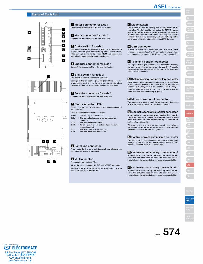
Name of Each Part
13
14
19
1 Motor connector for axis 1 Connect the motor cable of the axis 1 actuator.
8 Panel unit connector A connector for the panel unit (optional) that displays the controller status and error codes.
9 I/O Connector A connector for interface I/Os.
34-pin flat cable connector for DIO (24IN/8OUT) interface.
I/O power is also supplied to the controller via this connector (Pin No. 1 and No. 34).
10 Mode switch This switch is used to specify the running mode of the controller. The left position indicates the MANU (manual operation) mode, while the right position indicates the AUTO (automatic operation) mode. Teaching can only be performed in manual operation, and automatic operation using external I/Os is not possible in the MANU mode.
11 USB connectorA connector for PC connection via USB. If the USB connector is connected, the TP connector is disabled and all communication inputs to the TP connector are cut off.
12 Teaching pendant connectorA half-pitch I/O 26-pin connector that connects a teaching pendant when the running mode is MANU. A special conversion cable is needed to connect a conventional Dsub, 25-pin connector.
14 Motor power input connectorThis connector is used to input the motor power. It consists of a 2-pin, 2-piece connector by Phoenix Contact.
15 External regenerative resistor connectorA connector for the regenerative resistor that must be connected when the built-in regenerative resistor alone does not offer sufficient capacity in high-acceleration/ high-load operation, etc.
Whether or not an external regenerative resistor is necessary depends on the conditions of your specific application such as the axis configuration.
16 Control power/System input connectorThis connector is used to connect the control power input, emergency stop switch, and enable switch. It consists of a Phoenix Contact 6-pin 2-piece connector.
17 Absolute-data backup battery connector for axis 1A connector for the battery that backs up absolute data when the actuator uses an absolute encoder. Secure installation of the battery is the customer’s responsibility.
18 Absolute-data backup battery connector for axis 2A connector for the battery that backs up absolute data when the actuator uses an absolute encoder. Secure installation of the battery is the customer’s responsibility.
13 System-memory backup battery connectorIf you wish to retain the various data recorded in the SRAM of the controller even after the power is cut off, connect the necessary battery to this connector. This battery is installed externally to the unit. The controller does not come standard with the battery (Option).
2 Motor connector for axis 2 Connect the motor cable of the axis 2 actuator.
4 Encoder connector for axis 1Connect the encoder cable of the axis 1 actuator.
6 Encoder connector for axis 2Connect the encoder cable of the axis 2 actuator.
3 Brake switch for axis 1 This switch is used to release the axis brake. Setting it to the left position (RLS side) forcibly releases the brake, while setting it to the right position (NOM side) causes the controller to automatically control the brake.
5 Brake switch for axis 2 This switch is used to release the axis brake.
Setting it to the left position (RLS side) forcibly releases the brake, while setting it to the right position (NOM side) causes the controller to automatically control the brake.
7 Status indicator LEDsThese LEDs are used to indicate the operating condition of the controller.
The LED status indicators are as follows:
PWR : Power is input to controller.RDY : The controller is ready to perform program
operation. ALM : The controller is abnormal. EMG : An emergency stop is actuated and the drive
source is cut off. SV1 : The axis 1 actuator servo is on. SV2 : The axis 2 actuator servo is on.
10
11
12
2
3
4
5
6
8
7
15 16
1718
ASEL 574
Mini
Mini
PSEP/ASEP
PMEC/AMEC
ROBONET
ERC2
PCON
ACON
SCON
PSEL
ASEL
SSEL
XSEL
Standard
Mini
Standard
Standard
ControllersIntegrated
ControllersIntegrated
SliderType
RodType
Table/Arm/Flat Type
Gripper/Rotary Type
Linear ServoType
Cleanroom Type
Splash-Proof
Controllers
Pulse Motor
Servo Motor (24V)
Servo Motor (200V)
LinearServo Motor
ASEL Controller
ELECTROMATEToll Free Phone (877) SERVO98
Toll Free Fax (877) SERV099www.electromate.com
Sold & Serviced By:

Option
Teaching Pendant
PC Software (Windows Only)
• Wall-mounting hook
Model HK-1
• Strap
Model STR-1
Features This is a teaching device that provides information on functions such as position input, test runs, and monitoring.
A startup support software for entering programs/positions, performing test runs, and monitoring. More functions have been added for debugging, and improvements have been made to shorten the start-up time.
IA-101-X-MW-J (with RS232C cable + adapter cable)
Specifications
3-position Enable Switch No Yes
Compliant
Item SEL-T-J SEL-TD-J
SEL-T-J Standard typewith adapter cable
Equipped with a deadman switch and adapter cable
Model Description
5m
5m
Adapter cable: CB-SEL-SJ002
0.2m
0.2m
Adapter cable: CB-SEL-SJ002PC Software (CD)
RS232C CableCB-ST-E1MW050-EB
IA-101-X-USB (with USB cable)
3m
Dummy plugDP-3
PC Software (CD)USB cableCB-SEL-USB030
Only versions 7.0.0.0 and later can be used with the PSEL controller.
Note:
Features
Model
Configuration
Model
Configuration
66.6
46.939.0
55.0
89.6
218.
3
110.0
Model
Configuration
SEL-T dedicated optionsANSI/UL standards
CE mark
DisplayAmbient OperatingTemp./Humidity
Protective structure
Weight
Non-compliant Compliant
20 char. × 4 lines
0~40ºC 10~90% RH (non-condensing)
IP54
Approx. 0.4kg (not incl. cable)
SEL-TD-J
Panel UnitDisplay device that shows the error code from the controller or the currently running program number.
PU-1 (Cable length: 3m)
ø3.2 17
114
43
Battery for saving absolute data, when operating an actuator with an absolute encoder. Same as the battery used for system memory backup.
AB-5
Absolute Data Backup Battery System Memory Backup BatteryThis battery is required when you are using global flags in the program and you want to retain your data even after the power has been turned OFF.
AB-5AB-5-CS
(Standalone battery)
(with case)
Features
Model
Features
Model
Features
Model
575 ASEL
Mini
Mini
PSEP/ASEP
PMEC/AMEC
ROBONET
ERC2
PCON
ACON
SCON
PSEL
ASEL
SSEL
XSEL
Standard
Mini
Standard
Standard
ControllersIntegrated
ControllersIntegrated
RodType
Table/Arm/Flat Type
Gripper/Rotary Type
Linear ServoType
Cleanroom Type
Splash-Proof
Controllers
Pulse Motor
Servo Motor (24V)
Servo Motor (200V)
LinearServo Motor
SliderType
ASEL Controller
ELECTROMATEToll Free Phone (877) SERVO98
Toll Free Fax (877) SERV099www.electromate.com
Sold & Serviced By:
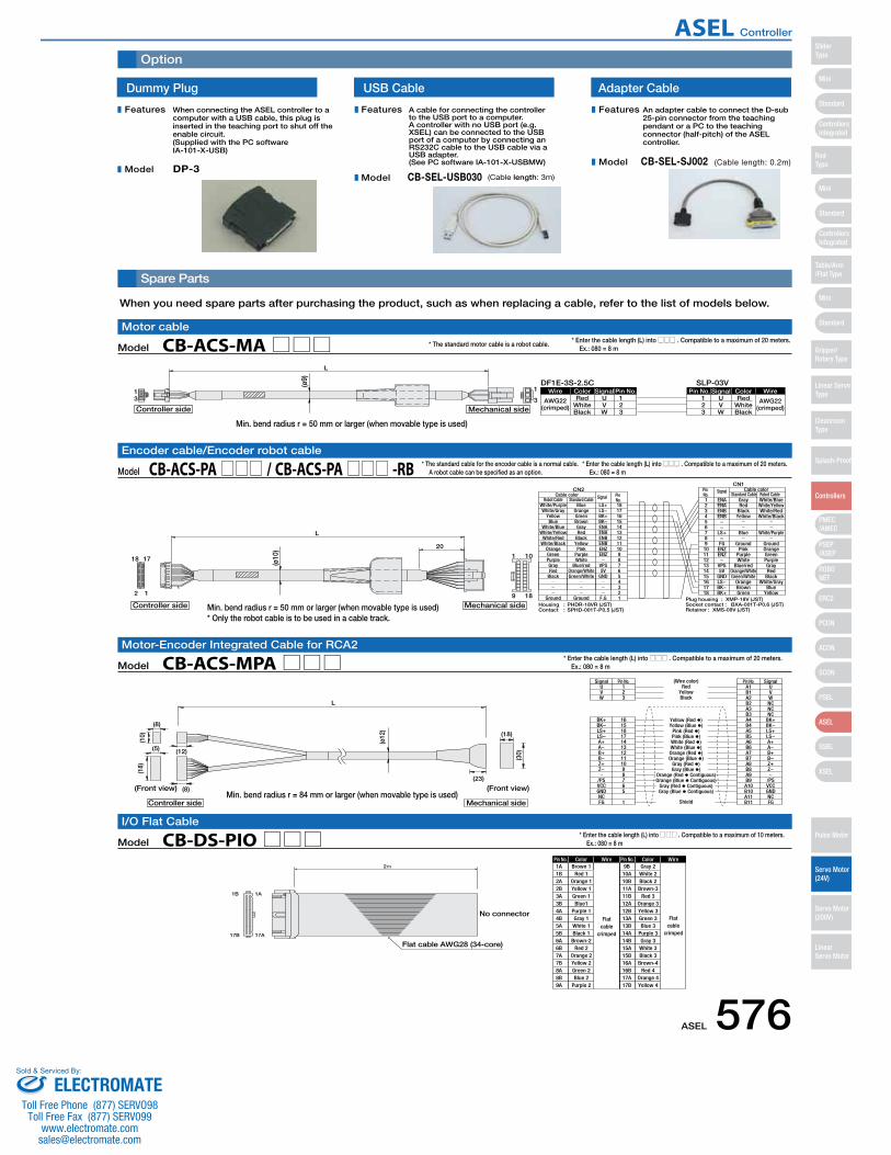
Spare Parts
Option
ColorPin No. Wire
Flatcable
crimped
Wire
Flatcable
crimped
ColorPin No.1A Brown 1 9B Gray 2
1B 1A
17B 17A
Flat cable AWG28 (34-core)
2
No connector
1B2A2B3A3B4A4B5A5B6A6B7A7B8A8B9A
Red 1Orange 1Yellow 1Green 1Blue1
Purple 1Gray 1White 1Black 1Brown-2
Red 2Orange 2Yellow 2Green 2Blue 2
Purple 2
10A10B11A11B12A12B13A13B14A14B15A15B16A16B17A17B
White 2Black 2Brown-3
Red 3Orange 3Yellow 3Green 3Blue 3
Purple 3Gray 3White 3Black 3Brown-4
Red 4Orange 4Yellow 4
Model CB-DS-PIO□□□I/O Flat Cable
* Enter the cable length (L) into □□□ . Compatible to a maximum of 10 meters. Ex.: 080 = 8 m
When you need spare parts after purchasing the product, such as when replacing a cable, refer to the list of models below.
Dummy Plug
When connecting the ASEL controller to a computer with a USB cable, this plug is inserted in the teaching port to shut off the enable circuit. (Supplied with the PC software IA-101-X-USB)
A cable for connecting the controller to the USB port to a computer. A controller with no USB port (e.g. XSEL) can be connected to the USB port of a computer by connecting an RS232C cable to the USB cable via a USB adapter. (See PC software IA-101-X-USBMW)
DP-3
USB Cable Adapter Cable
CB-SEL-USB030 (Cable length: 3m)
An adapter cable to connect the D-sub 25-pin connector from the teaching pendant or a PC to the teaching connector (half-pitch) of the ASEL controller.
CB-SEL-SJ002 (Cable length: 0.2m)
Features
Model
Features
Model
Features
Model
AWG22(crimped) White
Wire Color Signal Pin No. Pin No.U 1
Signal Color WireRed 1
23Black
VW
23 W
VU Red
WhiteBlack
AWG22(crimped)
DF1E-3S-2.5C SLP-03V13 3
1
L
Mechanical sideController side
(ø9)
White/Purple Blue LS+ 181 ENA Gray White/BlueRobot Cable Standard Cable
Housing : PHDR-18VR (JST)Contact : SPHD-001T-P0.5 (JST)
Plug housing : XMP-18V (JST)Socket contact : BXA-001T-P0.6 (JST)Retainer : XMS-09V (JST)
CN2CN1
Pin No.
Cable color Signal Robot CableStandard CableCable color
1
9 18
10
20
18
2 1
17
Mechanical sideController side
L
(ø10
)
White/GrayYellowBlue
White/BlueWhite/Yellow
White/RedWhite/Black
OrangeGreenPurpleGrayRed
Black
Ground
OrangeGreenBrownGrayRed
BlackYellowPink
PurpleWhite
Blue/redOrange/WhiteGreen/White
Ground
LS−BK+BK−ENAENAENBENBENZENZ
VPS5V
GND
F.G
1716151413121110987654321
23456789
101112131415161718
ENAENBENB
−−
LS+−FG
ENZENZ−
VPS5V
GNDLS−BK−BK+
RedBlackYellow
Blue
GroundPink
PurpleWhite
Blue/redOrange/WhiteGreen/White
OrangeBrownGreen
White/YellowWhite/Red
White/Black
White/Purple
GroundOrangeGreenPurpleGrayRed
BlackWhite/Gray
BlueYellow
Pin No.
Signal
Model CB-ACS-MA□□□Motor cable
* Enter the cable length (L) into □□□ . Compatible to a maximum of 20 meters. Ex.: 080 = 8 m
Model CB-ACS-PA□□□ / CB-ACS-PA□□□ -RBEncoder cable/Encoder robot cable
* Enter the cable length (L) into □□□ . Compatible to a maximum of 20 meters. Ex.: 080 = 8 m
* The standard cable for the encoder cable is a normal cable. A robot cable can be specified as an option.
* The standard motor cable is a robot cable.
BK−LS+LS−A+A−B+B−Z+Z−
/PSVCCGNDNCFG
L
UVW
Shield
Yellow (Red �)Yellow (Blue �)
Pink (Red �)Pink (Blue �)White (Red �)White (Blue �)Orange (Red �)Orange (Blue �)
Gray (Red �)Gray (Blue �)
Orange (Red � Contiguous)Orange (Blue � Contiguous)
Gray (Red � Contiguous)Gray (Blue � Contiguous)
RedYellowBlack
(Wire color)123
A1 USignal Pin No. Pin No. Signal
BK+ 16
(10)
(ø12
)
(18)
(8)
(12)
(23)
(8)
(5)
(30)
(18)
Controller side
(Front view)
Mechanical side
(Front view)
151817141312111098765
1
B1A2B2A3B3A4B4A5B5A6B6A7B7A8B8A9B9A10B10A11B11
VWNCNCNC
BK+BK−LS+LS−A+A−B+B−Z+Z−
/PSVCCGNDNCFG
Model CB-ACS-MPA□□□Motor-Encoder Integrated Cable for RCA2
* Enter the cable length (L) into □□□ . Compatible to a maximum of 20 meters. Ex.: 080 = 8 m
Min. bend radius r = 50 mm or larger (when movable type is used)* Only the robot cable is to be used in a cable track.
Min. bend radius r = 84 mm or larger (when movable type is used)
Min. bend radius r = 50 mm or larger (when movable type is used)
ASEL 576
Mini
Mini
PSEP/ASEP
PMEC/AMEC
ROBONET
ERC2
PCON
ACON
SCON
PSEL
ASEL
SSEL
XSEL
Standard
Mini
Standard
Standard
ControllersIntegrated
ControllersIntegrated
SliderType
RodType
Table/Arm/Flat Type
Gripper/Rotary Type
Linear ServoType
Cleanroom Type
Splash-Proof
Controllers
Pulse Motor
Servo Motor (24V)
Servo Motor (200V)
LinearServo Motor
ASEL Controller
ELECTROMATEToll Free Phone (877) SERVO98
Toll Free Fax (877) SERV099www.electromate.com
Sold & Serviced By:
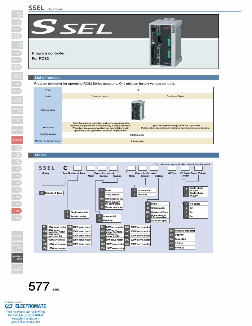
577 SSEL
List of models
Program controller for operating RCS2 Series actuators. One unit can handle various controls.
Program controller
For RCS2
Type Number of AxesMotor Encoder Option Motor Encoder Option
I/O Cable Length
Power Voltage
* 2nd axis specs not applicable to the single-axis model.
I/O Type
B Brake
C Creep sensor
HA High Accel./Decel.
L Home sensor/LS-compatible
M Master axis spec
B Brake
C Creep sensor
HA High Accel./Decel.
L Home sensor/LS-compatible
S Slave axis spec
20 20W servo motor
30D 30W servo motor for RCS2
30R 30W servo motor for RS
60 60W servo motor
100 100W servo motor
150 150W servo motor
200 200W servo motor
300 300W servo motor
400 400W servo motor
600 600W servo motor
750 750W servo motor
20 20W servo motor
30D 30W servo motor for RCS2
30R 30W servo motor for RS
60 60W servo motor
100 100W servo motor
150 150W servo motor
200 200W servo motor
300 300W servo motor
400 400W servo motor
600 600W servo motor
750 750W servo motor
1 Single-axis model
2 2-axis model I Incremental
A Absolute
I Incremental
A Absolute
NP PIO NPN (standard)
PN PIO PNP
DV DeviceNet
CC CC-Link
PR ProfiBus
1 Single-phase AC100V
2Single-phase AC200V
0 No cable
2 2m
3 3m
5 5m
C Standard Type
CS S E LSeries (Specs for 1st axis) (Specs for 2nd axis)
Model
Type C
Program mode Positioner ModeName
Number of control axes:
External View
Description
Both the actuator operation and communication with external equipment can be handled by a single controller.
When two axes are connected, arc interpolation, path operations, and synchronization can be performed.
Up to 20000 positioning points are supported. Push-motion operation and teaching operation are also possible.
Position points 20000 points
2 axes max.
Mini
Mini
PSEP/ASEP
PMEC/AMEC
ROBONET
ERC2
PCON
ACON
SCON
PSEL
ASEL
SSEL
XSEL
Standard
Mini
Standard
Standard
ControllersIntegrated
ControllersIntegrated
RodType
Table/Arm/Flat Type
Gripper/Rotary Type
Linear ServoType
Cleanroom Type
Splash-Proof
Controllers
Pulse Motor
Servo Motor (24V)
Servo Motor (200V)
LinearServo Motor
SliderType
SSEL Controller
ELECTROMATEToll Free Phone (877) SERVO98
Toll Free Fax (877) SERV099www.electromate.com
Sold & Serviced By:
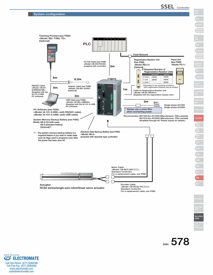
SSEL 578
PLC
I/O Flat Cable (see P586)<Model: CB-DS-PIO020>(supplied with controller)
Regenerative Resistor Unit(See P585)<Model: REU-2>(Optional)
Panel Unit(See P585)<Model: PU-1>
Cable for Regenerative Resistor Unit<Model: CB-SC-REU010>(Supplied with the regenerative resistor unit.)
Absolute Data Backup Battery (see P585)<Model: AB-5>(included with absolute type controller)
Teaching Pendant (see P585)<Model: SEL-T/SEL-TD>(Optional)
Encoder Cable<Model: CB-RCS2-PA���>Standard 1m/3m/5mFor a replacement cable, see P586.
Motor Cable<Model: CB-RCC-MA���>Standard 1m/3m/5mFor a replacement cable, see P586
PC Software (see P585)<Model: IA-101-X-MW> (with RS232C cable)<Model: IA-101-X-USB> (with USB cable)
USB Cable (see P586)<Model: CB-SEL-USB030>(Supplied with the IA-101-X-USBPC software)
RS232C Cable<Model: CB-ST-E1MW050-EB>(Supplied with the IA-101-X-MWPC software)
Adapter Cable (see P586)<Model: CB-SEL-SJ002>(Optional)
0.2m
3m
5m
5m
ActuatorRCS2 series/single-axis robot/linear servo actuator
2m
1m
3m
Model: AB-5-CS (with case) AB-5 (standard battery) (Optional)*1
System Memory Backup Battery (see P585)
*1 The system memory backup battery is a required feature if you wish to retain data such as flags used in programs even after the power has been shut off.
Main Power Supply Single-phase AC100V
Single-phase AC200V
Recommended: MC1220 (for AC100V) (Manufacturer: TDK-Lambda)MC1210 (for AC200V) (Manufacturer: TDK-Lambda)(Available through IAI. Please inquire for details.)
* Always use a noise filter when connecting power
Field Network
Required Number of Regenerative Resistor Units
0 units ~200W
Horizontal
~200W
Vertical
* Depending on the operating conditions, more regenerative resistors may be needed.
1 unit
2 units
~800W ~600W
~800W
System configuration
Mini
Mini
PSEP/ASEP
PMEC/AMEC
ROBONET
ERC2
PCON
ACON
SCON
PSEL
ASEL
SSEL
XSEL
Standard
Mini
Standard
Standard
ControllersIntegrated
ControllersIntegrated
SliderType
RodType
Table/Arm/Flat Type
Gripper/Rotary Type
Linear ServoType
Cleanroom Type
Splash-Proof
Controllers
Pulse Motor
Servo Motor (24V)
Servo Motor (200V)
LinearServo Motor
SSEL Controller
ELECTROMATEToll Free Phone (877) SERVO98
Toll Free Fax (877) SERV099www.electromate.com
Sold & Serviced By:
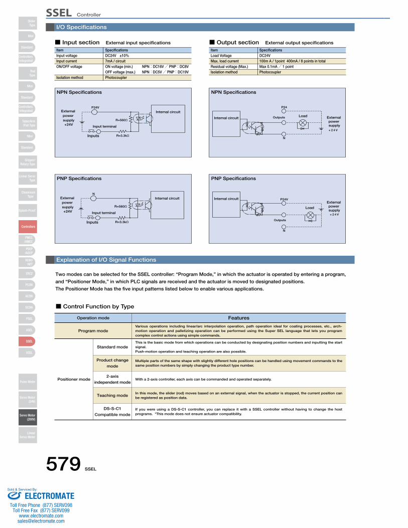
579 SSEL
I/O Specifications
Explanation of I/O Signal Functions
Two modes can be selected for the SSEL controller: “Program Mode,” in which the actuator is operated by entering a program,
and “Positioner Mode,” in which PLC signals are received and the actuator is moved to designated positions.
The Positioner Mode has the five input patterns listed below to enable various applications.
P24V
R=3.3kΩInputs
R=560Ω
External power supply+24V Input terminal
Internal circuitP24
N
Outputs Internal circuit Load External
power supply+ 2 4 V
N
R=3.3kΩInputs
R=560Ω
External power supply+24V Input terminal
Internal circuit P24V
N
Outputs
Internal circuitExternal power supply+ 2 4 V
Load
NPN Specifications NPN Specifications
PNP Specifications PNP Specifications
ItemInput voltageInput currentON/OFF voltage
Isolation method
SpecificationsDC24V ±10%7mA / circuitON voltage (min.) NPN:DC16V/ PNP:DC8VOFF voltage (max.) NPN:DC5V/ PNP:DC19VPhotocoupler
■ Input section External input specifications
ItemLoad VoltageMax. load current Residual voltage (Max.) Isolation method
SpecificationsDC24V100m A / 1point 400mA / 8 points in totalMax 0.1mA/ 1 pointPhotocoupler
■ Output section External output specifications
■ Control Function by Type
Operation mode Features
Program mode
Positioner mode
This is the basic mode from which operations can be conducted by designating position numbers and inputting the start signal.Push-motion operation and teaching operation are also possible.
Various operations including linear/arc interpolation operation, path operation ideal for coating processes, etc., arch-motion operation and palletizing operation can be performed using the Super SEL language that lets you program complex control actions using simple commands.
Multiple parts of the same shape with slightly different hole positions can be handled using movement commands to the same position numbers by simply changing the product type number.
With a 2-axis controller, each axis can be commanded and operated separately.
In this mode, the slider (rod) moves based on an external signal, when the actuator is stopped, the current position can be registered as position data.
Standard mode
Product change
mode
2-axis
independent mode
Teaching mode
DS-S-C1
Compatible modeIf you were using a DS-S-C1 controller, you can replace it with a SSEL controller without having to change the host programs. *This mode does not ensure actuator compatibility.
Mini
Mini
PSEP/ASEP
PMEC/AMEC
ROBONET
ERC2
PCON
ACON
SCON
PSEL
ASEL
SSEL
XSEL
Standard
Mini
Standard
Standard
ControllersIntegrated
ControllersIntegrated
RodType
Table/Arm/Flat Type
Gripper/Rotary Type
Linear ServoType
Cleanroom Type
Splash-Proof
Controllers
Pulse Motor
Servo Motor (24V)
Servo Motor (200V)
LinearServo Motor
SliderType
SSEL Controller
ELECTROMATEToll Free Phone (877) SERVO98
Toll Free Fax (877) SERV099www.electromate.com
Sold & Serviced By:
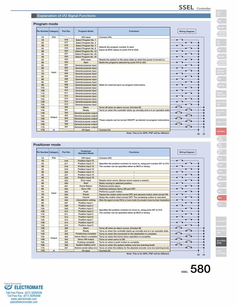
SSEL 580
Explanation of I/O Signal Functions
Pin Number Category
Input
Output
N
01624V input Connect 24V.
Port No. Program Mode Functions
Resets the system to the same state as when the power is turned on.
Turns off when an alarm occurs. (Contact B)Turns on when the controller starts up normally and is in an operable state.
Connect 0V.
These outputs can be turned ON/OFF as desired via program instructions.
Starts the programs selected by ports 016 to 022.
Waits for external input via program instructions.
Selects the program number to start. (Input as BCD values to ports 016 to 022)
0V 24
Wiring Diagram
1A P241B2A2B3A3B4A4B5A5B6A6B7A7B8A8B9A9B10A10B11A11B12A12B13A13B14A14B15A15B16A16B17A17B
017018019020021022023000001002003004005006007008009010011012013014015300301302303304305306307
Select Program No. 1Select Program No. 2Select Program No. 4Select Program No. 8Select Program No. 10Select Program No. 20Select Program No. 40
CPU resetStart
General-purpose inputGeneral-purpose inputGeneral-purpose inputGeneral-purpose inputGeneral-purpose inputGeneral-purpose inputGeneral-purpose inputGeneral-purpose inputGeneral-purpose inputGeneral-purpose inputGeneral-purpose inputGeneral-purpose inputGeneral-purpose inputGeneral-purpose inputGeneral-purpose input
AlarmReady
General-purpose outputGeneral-purpose outputGeneral-purpose outputGeneral-purpose outputGeneral-purpose outputGeneral-purpose output
0V input
Pin Number Category
Input
Output
N
016
24V input Connect 24V.
Port No. PositionerStandard Mode Functions
Resets minor errors. (Severe errors require a restart.)
−−−
Turns off when an alarm occurs. (Contact B)Turns on when the controller starts up normally and is in an operable state.Turns on when the movement to the destination is complete.Turns on when the home return operation is complete.Turns on when servo is ON.Turns on when a push motion is complete.Turns on when the system battery runs low (warning level).Turns on when the battery for the absolute encoder runs low (warning level).Connect 0V.
Starts moving to selected position.Performs home return.Switches between Servo ON and OFF.Performs a push motion.Pauses the motion when turned OFF, and resumes motion when turned ON.Stops the motion when turned OFF. The remaining motion is canceled.When this signal is turned ON for a 2-axis model, the actuator moves by linear interpolation.
Specifies the position numbers to move to, using ports 007 to 019. The number can be specified either as BCD or binary.
Specifies the position numbers to move to, using port number 007 to 019 The number can be specified either as BCD or binary.
0V 24
Wiring Diagram
1A P241B2A2B3A3B4A4B5A5B6A6B7A7B8A8B9A9B10A10B11A11B12A12B13A13B14A14B15A15B16A16B17A17B
017018019020021022023000001002003004005006007008009010011012013014015300301302303304305306307
Position input 10Position input 11Position input 12Position input 13Position input 14Position input 15Position input 16
Error resetStart
Home ReturnServo ON
PushPauseCancel
Interpolation settingPosition input 1Position input 2Position input 3Position input 4Position input 5Position input 6Position input 7Position input 8Position input 9
AlarmReady
Positioning completeHome Return complete
Servo ON outputPushing complete
System battery errorAbsolute encoder battery error
0V input
Program mode
Positioner mode
Note: This is for NPN. PNP will be different.
Note: This is for NPN. PNP will be different.
Mini
Mini
PSEP/ASEP
PMEC/AMEC
ROBONET
ERC2
PCON
ACON
SCON
PSEL
ASEL
SSEL
XSEL
Standard
Mini
Standard
Standard
ControllersIntegrated
ControllersIntegrated
SliderType
RodType
Table/Arm/Flat Type
Gripper/Rotary Type
Linear ServoType
Cleanroom Type
Splash-Proof
Controllers
Pulse Motor
Servo Motor (24V)
Servo Motor (200V)
LinearServo Motor
SSEL Controller
ELECTROMATEToll Free Phone (877) SERVO98
Toll Free Fax (877) SERV099www.electromate.com
Sold & Serviced By:
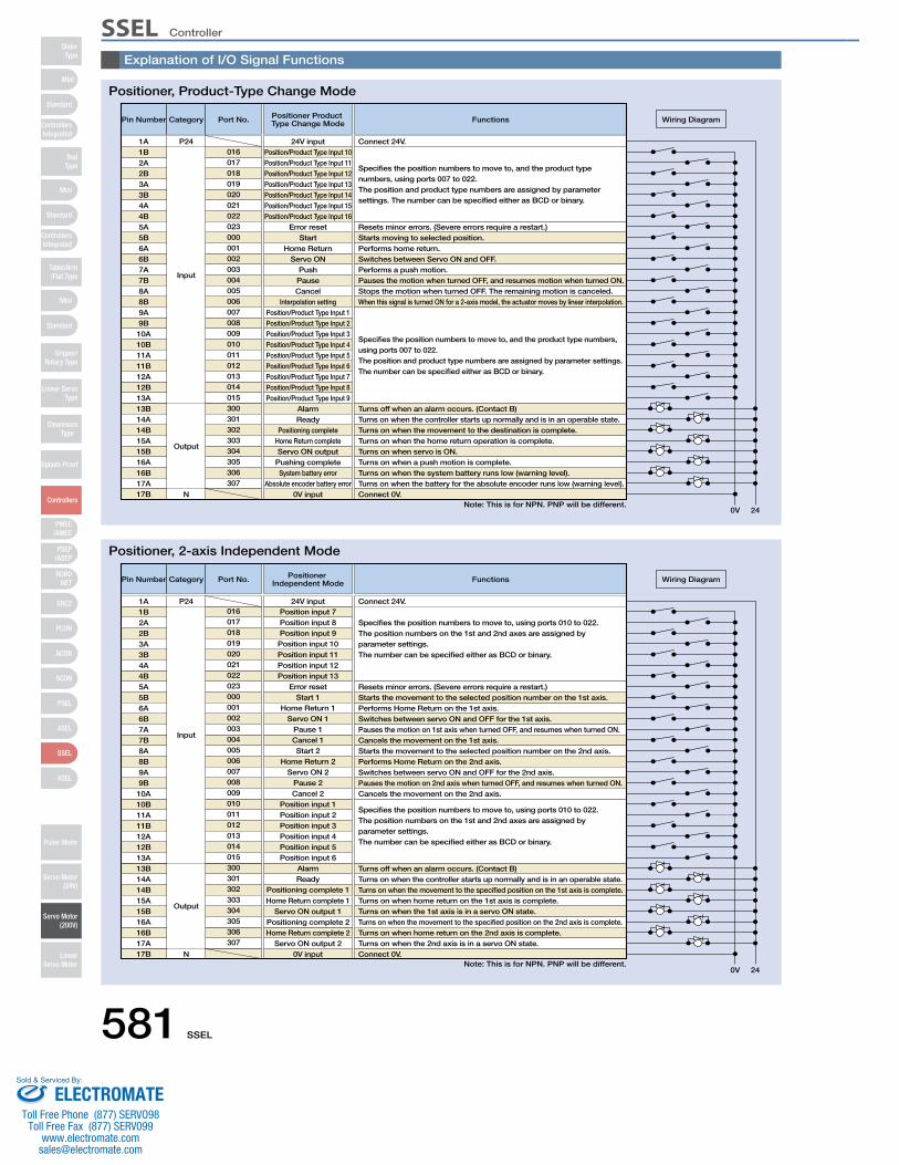
581 SSEL
Explanation of I/O Signal Functions
Pin Number Category
Input
Output
N
01624V input Connect 24V.
Port No. Positioner Product Type Change Mode Functions
Connect 0V.
0V 24
Wiring Diagram
1A P24
Resets minor errors. (Severe errors require a restart.)
Turns off when an alarm occurs. (Contact B)Turns on when the controller starts up normally and is in an operable state.Turns on when the movement to the destination is complete.Turns on when the home return operation is complete.Turns on when servo is ON.Turns on when a push motion is complete.Turns on when the system battery runs low (warning level).Turns on when the battery for the absolute encoder runs low (warning level).
Starts moving to selected position.Performs home return.Switches between Servo ON and OFF.Performs a push motion.Pauses the motion when turned OFF, and resumes motion when turned ON.Stops the motion when turned OFF. The remaining motion is canceled.When this signal is turned ON for a 2-axis model, the actuator moves by linear interpolation.
Specifies the position numbers to move to, and the product type numbers,using ports 007 to 022. The position and product type numbers are assigned by parameter settings. The number can be specified either as BCD or binary.
Specifies the position numbers to move to, and the product type numbers, using ports 007 to 022. The position and product type numbers are assigned by parameter settings. The number can be specified either as BCD or binary.
1B2A2B3A3B4A4B5A5B6A6B7A7B8A8B9A9B10A10B11A11B12A12B13A13B14A14B15A15B16A16B17A17B
017018019020021022023000001002003004005006007008009010011012013014015300301302303304305306307
Position/Product Type Input 10Position/Product Type Input 11Position/Product Type Input 12Position/Product Type Input 13Position/Product Type Input 14Position/Product Type Input 15Position/Product Type Input 16
Error resetStart
Home ReturnServo ON
PushPauseCancel
Interpolation settingPosition/Product Type Input 1Position/Product Type Input 2Position/Product Type Input 3Position/Product Type Input 4Position/Product Type Input 5Position/Product Type Input 6Position/Product Type Input 7Position/Product Type Input 8Position/Product Type Input 9
AlarmReady
Positioning completeHome Return completeServo ON output
Pushing completeSystem battery error
Absolute encoder battery error0V input
Pin Number Category
Input
Output
N
01624V input Connect 24V.
Port No. Positioner Independent Mode Functions
Connect 0V.
0V 24
Wiring Diagram
1A P24
Resets minor errors. (Severe errors require a restart.)
Turns off when an alarm occurs. (Contact B)Turns on when the controller starts up normally and is in an operable state.Turns on when the movement to the specified position on the 1st axis is complete.Turns on when home return on the 1st axis is complete.Turns on when the 1st axis is in a servo ON state.Turns on when the movement to the specified position on the 2nd axis is complete.Turns on when home return on the 2nd axis is complete.Turns on when the 2nd axis is in a servo ON state.
Starts the movement to the selected position number on the 1st axis.Performs Home Return on the 1st axis.Switches between servo ON and OFF for the 1st axis.
Cancels the movement on the 1st axis.Starts the movement to the selected position number on the 2nd axis.Performs Home Return on the 2nd axis.Switches between servo ON and OFF for the 2nd axis.
Cancels the movement on the 2nd axis.
Specifies the position numbers to move to, using ports 010 to 022. The position numbers on the 1st and 2nd axes are assigned by parameter settings. The number can be specified either as BCD or binary.
Specifies the position numbers to move to, using ports 010 to 022. The position numbers on the 1st and 2nd axes are assigned by parameter settings. The number can be specified either as BCD or binary.
Pauses the motion on 1st axis when turned OFF, and resumes when turned ON.
Pauses the motion on 2nd axis when turned OFF, and resumes when turned ON.
1B2A2B3A3B4A4B5A5B6A6B7A7B8A8B9A9B10A10B11A11B12A12B13A13B14A14B15A15B16A16B17A17B
017018019020021022023000001002003004005006007008009010011012013014015300301302303304305306307
Position input 7Position input 8Position input 9Position input 10Position input 11Position input 12Position input 13
Error resetStart 1
Home Return 1Servo ON 1
Pause 1Cancel 1Start 2
Home Return 2Servo ON 2
Pause 2Cancel 2
Position input 1Position input 2Position input 3Position input 4Position input 5Position input 6
AlarmReady
Positioning complete 1Home Return complete 1
Servo ON output 1Positioning complete 2Home Return complete 2
Servo ON output 20V input
Positioner, Product-Type Change Mode
Positioner, 2-axis Independent Mode
Note: This is for NPN. PNP will be different.
Note: This is for NPN. PNP will be different.
Mini
Mini
PSEP/ASEP
PMEC/AMEC
ROBONET
ERC2
PCON
ACON
SCON
PSEL
ASEL
SSEL
XSEL
Standard
Mini
Standard
Standard
ControllersIntegrated
ControllersIntegrated
RodType
Table/Arm/Flat Type
Gripper/Rotary Type
Linear ServoType
Cleanroom Type
Splash-Proof
Controllers
Pulse Motor
Servo Motor (24V)
Servo Motor (200V)
LinearServo Motor
SliderType
SSEL Controller
ELECTROMATEToll Free Phone (877) SERVO98
Toll Free Fax (877) SERV099www.electromate.com
Sold & Serviced By:
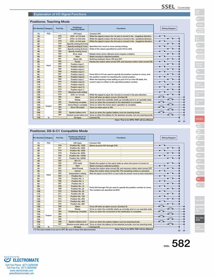
SSEL 582
Explanation of I/O Signal Functions
Pin Number Category
Input
Output
N
01624V input Connect 24V.
While the signal is input, the 1st axis is moved in the - (negative) direction.While the signal is input, the 2nd axis is moved in the + (positive) direction.While the signal is input, the 2nd axis is moved in the - (negative) direction.
Specifies how much to move during inching. (Total of the values specified for ports 019 to 022)
Port No. Positioner Teaching Mode Functions
Connect 0V.
0V 24
Wiring Diagram
1A P24
Resets minor errors. (Severe errors require a restart.)
Turns off when an alarm occurs. (Contact B)While the signal is input, the 1st axis is moved in the plus direction.
Turns on when the controller starts up normally and is in an operable state.Turns on when the movement to the destination is complete.Turns on when the home return operation is complete.Turns on when servo is ON.
Turns on when the system battery runs low (warning level).Turns on when the battery for the absolute encoder runs low (warning level).
Starts moving to selected position.Switches between Servo ON and OFF.Pauses the motion when turned OFF, and resumes motion when turned ON.
Ports 003 to 013 are used to specify the position number to move, and the position number for inputting the current position. When the teaching mode setting on port 014 is in the ON state, the current value is written to the specified position number.
1B2A2B3A3B4A4B5A5B6A6B7A7B8A8B9A9B10A10B11A11B12A12B13A13B14A14B15A15B16A16B17A17B
017018019020021022023000001002003004005006007008009010011012013014015300301302303304305306307
JOG− on 1st axisJOG+ on 2nd axisJOG− on 2nd axis
Specify inching (0.01mm)Specify inching (0.1mm)Specify inching (0.5mm)Specify inching (1mm)
Error resetStart
Servo ONPause
Position input 1Position input 2Position input 3Position input 4Position input 5Position input 6Position input 7Position input 8Position input 9Position input 10Position input 11
Teaching mode settingJOG+ on 1st axis
AlarmReady
Positioning completeHome Return complete
Servo ON output
System battery errorAbsolute encoder battery error
0V input
Pin Number Category
Input
Output
N
01624V input Connect 24V.
(Same as ports 004 through 015)
Port No. Positioner DS-S-C1 Compatible Mode Functions
Connect 0V.
0V 24
Wiring Diagram
1A P24
Resets the system to the same state as when the power is turned on.
Turns off when an alarm occurs. (Contact A)Turns on when the controller starts up normally and is in an operable state.Turns on when the movement to the destination is complete.
Turns on when the system battery runs low (warning level).Turns on when the battery for the absolute encoder runs low (warning level).
Starts moving to selected position.Pauses the motion when turned ON, and resumes motion when turned OFF.Stops the motion when turned ON. The remaining motion is canceled.When this signal is turned ON for a 2-axis model, the actuator moves by linear interpolation.
Ports 004 through 016 are used to specify the position number to move. The numbers are specified as BCD.
(*1) The input needs to be set to OFF. Be sure to leave this disconnected.
1B2A2B3A3B4A4B5A5B6A6B7A7B8A8B9A9B10A10B11A11B12A12B13A13B14A14B15A15B16A16B17A17B
017018019020021022023000001002003004005006007008009010011012013014015300301302303304305306307
Position No. 1000Position No. 2000Position No. 4000Position No. 8000Position No. 10000Position No. 20000
NC (*1)CPU reset
StartHold (Pause)
CancelInterpolation setting
Position No. 1Position No. 2Position No. 4Position No. 8Position No. 10Position No. 20Position No. 40Position No. 80Position No. 100Position No. 200Position No. 400Position No. 800
AlarmReady
Positioning complete
System battery errorAbsolute encoder battery error
0V input
Positioner, Teaching Mode
Positioner, DS-S-C1 Compatible Mode
Note: This is for NPN. PNP will be different.
Note: This is for NPN. PNP will be different.
Mini
Mini
PSEP/ASEP
PMEC/AMEC
ROBONET
ERC2
PCON
ACON
SCON
PSEL
ASEL
SSEL
XSEL
Standard
Mini
Standard
Standard
ControllersIntegrated
ControllersIntegrated
SliderType
RodType
Table/Arm/Flat Type
Gripper/Rotary Type
Linear ServoType
Cleanroom Type
Splash-Proof
Controllers
Pulse Motor
Servo Motor (24V)
Servo Motor (200V)
LinearServo Motor
SSEL Controller
ELECTROMATEToll Free Phone (877) SERVO98
Toll Free Fax (877) SERV099www.electromate.com
Sold & Serviced By:
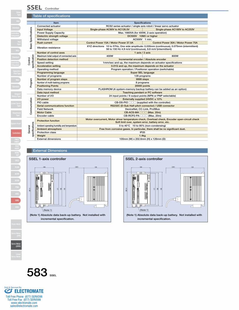
583 SSEL
Table of specifications
Item SpecificationsConnected actuator
Number of control axesMaximum total output of connected axis Position detection methodSpeed settingAcceleration setting Operating methodProgramming languageNumber of programsNumber of program stepsNumber of multi-tasking programsPositioning PointsData memory deviceData input methodNumber of I/O I/O powerPIO cableSerial communications functionField NetworkMotor CableEncoder cable
Protection function
Ambient operating humidity and temperatureAmbient atmosphereProtection classWeightExternal dimensions
Input VoltagePower Supply CapacityDielectric strength voltageWithstand voltageRush current
Vibration resistance
RCS2 series actuator / single axis robot / linear servo actuatorSingle-phase AC90V to AC126.5V
Max. 1660VA (for 400W, 2-axis operation)Single-phase AC180V to AC253V
DC500V 10MΩ or higherAC500V 1 min.
Control Power 15A / Motor Power 37.5A Control Power 30A / Motor Power 75A
XYZ directions 10 to 57Hz, One side amplitude: 0.035mm (continuous), 0.075mm (intermittent) 58 to 150 Hz 4.9 m/s2 (continuous), 9.8 m/s2 (intermittent)
1 axis / 2 axis400W 800W
Incremental encoder / Absolute encoder1mm/sec and up, the maximum depends on actuator specifications
0.01G and up, the maximum depends on the actuatorProgram operation / Positioner operation (switchable)
Super SEL language128 programs
9999 steps8 programs
20000 pointsFLASHROM (A system-memory backup battery can be added as an option)
Teaching pendant or PC software24 input points / 8 output points (NPN or PNP selectable)
Externally supplied 24VDC ± 10% CB-DS-PIO□□□ (supplied with the controller)
RS232C (D-Sub Half-pitch connector) / USB connectorDeviceNet, CC-Link, ProfiBus
CB-ACS-MA□□□ (Max. 20m)CB-RCP2-PA□□□ (Max. 20m)
Motor overcurrent, Motor driver temperature check, Overload check, Encoder open-circuit checkSoft limit over, system error, battery error, etc.
0 to 40°C 10 to 95% (non-condensing)Free from corrosive gases. In particular, there shall be no significant dust.
IP201.4kg
100mm (W) x 202.6mm (H) x 126mm (D)
(Note 1)
External Dimensions
SSEL 1-axis controller
(Note 1) Absolute data back-up battery. Not installed with
incremental specification.
(Note 1)
SSEL 2-axis controller
(Note 1) Absolute data back-up battery. Not installed with
incremental specification.
Bas
ic S
peci
ficat
ions
Con
trol
spec
ifica
tion
Pro
gram
Com
mun
icat
ion
Gen
eral
spec
ifica
tions
Mini
Mini
PSEP/ASEP
PMEC/AMEC
ROBONET
ERC2
PCON
ACON
SCON
PSEL
ASEL
SSEL
XSEL
Standard
Mini
Standard
Standard
ControllersIntegrated
ControllersIntegrated
RodType
Table/Arm/Flat Type
Gripper/Rotary Type
Linear ServoType
Cleanroom Type
Splash-Proof
Controllers
Pulse Motor
Servo Motor (24V)
Servo Motor (200V)
LinearServo Motor
SliderType
SSEL Controller
ELECTROMATEToll Free Phone (877) SERVO98
Toll Free Fax (877) SERV099www.electromate.com
Sold & Serviced By:
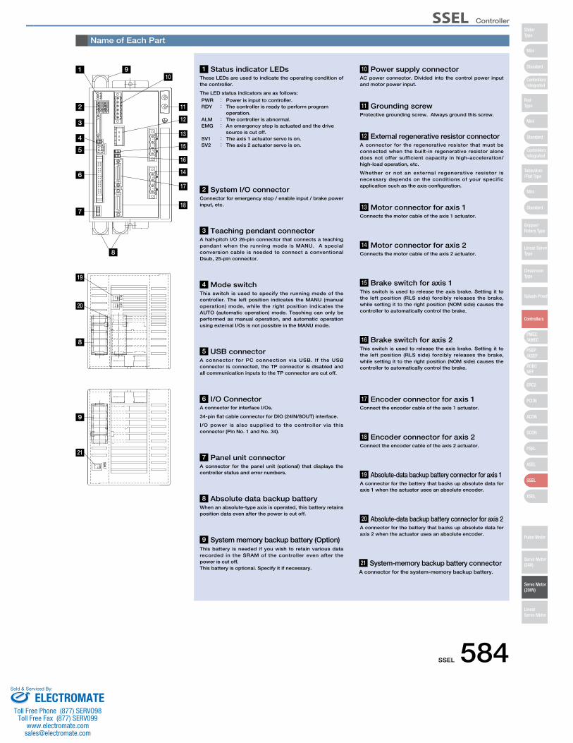
SSEL 584
Name of Each Part
2 System I/O connectorConnector for emergency stop / enable input / brake power input, etc.
11 Grounding screw Protective grounding screw. Always ground this screw.
12 External regenerative resistor connectorA connector for the regenerative resistor that must be connected when the built-in regenerative resistor alone does not offer sufficient capacity in high-acceleration/ high-load operation, etc.
Whether or not an external regenerative resistor is necessary depends on the conditions of your specific application such as the axis configuration.
13 Motor connector for axis 1 Connects the motor cable of the axis 1 actuator.
14 Motor connector for axis 2 Connects the motor cable of the axis 2 actuator.
16 Brake switch for axis 2 This switch is used to release the axis brake. Setting it to the left position (RLS side) forcibly releases the brake, while setting it to the right position (NOM side) causes the controller to automatically control the brake.
17 Encoder connector for axis 1Connect the encoder cable of the axis 1 actuator.
18 Encoder connector for axis 2Connect the encoder cable of the axis 2 actuator.
19 Absolute-data backup battery connector for axis 1A connector for the battery that backs up absolute data for axis 1 when the actuator uses an absolute encoder.
20 Absolute-data backup battery connector for axis 2A connector for the battery that backs up absolute data for axis 2 when the actuator uses an absolute encoder.
21 System-memory backup battery connectorA connector for the system-memory backup battery.
15 Brake switch for axis 1 This switch is used to release the axis brake. Setting it to the left position (RLS side) forcibly releases the brake, while setting it to the right position (NOM side) causes the controller to automatically control the brake.
3 Teaching pendant connectorA half-pitch I/O 26-pin connector that connects a teaching pendant when the running mode is MANU. A special conversion cable is needed to connect a conventional Dsub, 25-pin connector.
4 Mode switch This switch is used to specify the running mode of the controller. The left position indicates the MANU (manual operation) mode, while the right position indicates the AUTO (automatic operation) mode. Teaching can only be performed as manual operation, and automatic operation using external I/Os is not possible in the MANU mode.
5 USB connectorA connector for PC connection via USB. If the USB connector is connected, the TP connector is disabled and all communication inputs to the TP connector are cut off.
6 I/O Connector A connector for interface I/Os.
34-pin flat cable connector for DIO (24IN/8OUT) interface.
I/O power is also supplied to the controller via this connector (Pin No. 1 and No. 34).
7 Panel unit connector A connector for the panel unit (optional) that displays the controller status and error numbers.
8 Absolute data backup batteryWhen an absolute-type axis is operated, this battery retains position data even after the power is cut off.
9 System memory backup battery (Option)This battery is needed if you wish to retain various data recorded in the SRAM of the controller even after the power is cut off.This battery is optional. Specify it if necessary.
10 Power supply connectorAC power connector. Divided into the control power input and motor power input.
1 Status indicator LEDsThese LEDs are used to indicate the operating condition of the controller.
The LED status indicators are as follows:
PWR : Power is input to controller.RDY : The controller is ready to perform program
operation. ALM : The controller is abnormal. EMG : An emergency stop is actuated and the drive
source is cut off. SV1 : The axis 1 actuator servo is on. SV2 : The axis 2 actuator servo is on.
11
13
14
18
17
12
15
16
1 910
8
2
3
4
5
6
7
19
20
8
9
21
Mini
Mini
PSEP/ASEP
PMEC/AMEC
ROBONET
ERC2
PCON
ACON
SCON
PSEL
ASEL
SSEL
XSEL
Standard
Mini
Standard
Standard
ControllersIntegrated
ControllersIntegrated
SliderType
RodType
Table/Arm/Flat Type
Gripper/Rotary Type
Linear ServoType
Cleanroom Type
Splash-Proof
Controllers
Pulse Motor
Servo Motor (24V)
Servo Motor (200V)
LinearServo Motor
SSEL Controller
ELECTROMATEToll Free Phone (877) SERVO98
Toll Free Fax (877) SERV099www.electromate.com
Sold & Serviced By:

585 SSEL
Option
A teaching device for entering programs and positions, test runs, and monitoring.
Specifications
3-position Enable Switch No Yes
Compliant
Item SEL-T-J SEL-TD-J
SEL-T-J
SEL-TD-J
Standard type with adapter cable
Deadman's switch type and adapter cable
Model Description
5m
Adapter cable: CB-SEL-SJ002
0.2m
66.6
46.939.0
55.0
89.6
218.
3
110.0
• Wall-mountinghook
Model HK-1
• Strap
Model STR-1
Teaching Pendant
PC Software (Windows Only)A startup support software for entering programs/positions, performing test runs, and monitoring. More functions have been added for debugging, and improvements have been made to shorten the start-up time.
IA-101-X-MW (with RS232C cable)
IA-101-X-MW-J (with RS232C cable + adapter cable)
5m 0.2m
Adapter cable: CB-SEL-SJ002PC Software (CD)
RS232C CableCB-ST-E1MW050-EB
IA-101-X-USB (with USB cable)
3m
Compatible controllerSSEL-C
Dummy plugDP-3
PC Software (CD)USB cableCB-SEL-USB030
Only versions 6.0.0.0 and later can be used with the SSEL controller.
Note:
Features
Model/Price
Configuration
Features
Model
Configuration
Model
Configuration
SEL-T option
ANSI/UL standards
CE mark
DisplayAmbient Operating Temp./Humidity
Protective structure
Weight
Non-compliant
20 char. × 4 lines
0~40ºC 10~90% RH (non-condensing)
IP54
Approx. 0.4kg (not incl. cable)
Compliant
Panel Unit
Display device that shows the error code from the controller or the currently running program number.
PU-1 (Cable length: 3m)
ø3.2 17
114
43
Battery for saving absolute data, when operating an actuator with an absolute encoder. Same as the battery used for system memory backup.
AB-5
Absolute Data Backup Battery System Memory Backup Battery
This battery is required, for example, when you are using global flags in the program and you want to retain your data even after the power has been turned OFF.
AB-5AB-5-CS
(Standalone battery)
(with case)
Features
Model
Features
Model
Features
Model
A unit that converts the regenerative current, generated during the acceleration/deceleration of the of the motor, into heat. In the table on the right, check the total power output of the actuator to see if a regenerative resistor is needed.REU-2 (for SCON/SSEL)
Features
Model
SpecificationsWeight of main unit
Main unit-ControllerConnection Cable (included)
0.9kg
CB-SC-REU010 (for SSEL)
Required Number of Units Exterior Dimensions
0 units ~200W
Horizontal
~200W
Vertical
* Depending on the operating conditions, more regenerative resistors may be needed.
ø5
16.6 126
34
5
175
195
186
Regenerative Resistor Unit
Standard Price
Internal regenerative resistance 220Ω 80W
1 unit
2 units
~800W ~600W
~800W
* If 2 regenerative units are needed, acquire one REU-2 and one REU-1 (See P596).
Mini
Mini
PSEP/ASEP
PMEC/AMEC
ROBONET
ERC2
PCON
ACON
SCON
PSEL
ASEL
SSEL
XSEL
Standard
Mini
Standard
Standard
ControllersIntegrated
ControllersIntegrated
RodType
Table/Arm/Flat Type
Gripper/Rotary Type
Linear ServoType
Cleanroom Type
Splash-Proof
Controllers
Pulse Motor
Servo Motor (24V)
Servo Motor (200V)
LinearServo Motor
SliderType
SSEL Controller
ELECTROMATEToll Free Phone (877) SERVO98
Toll Free Fax (877) SERV099www.electromate.com
Sold & Serviced By:
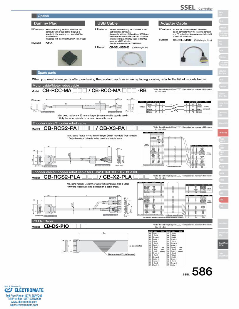
SSEL 586
Spare parts
Option
ColorPin No. Wire
Flatcable
crimped
Wire
Flatcable
crimped
ColorPin No.1A Brown 1 9B Gray 2
1B 1A
17B 17A
Flat cable AWG28 (34-core)
2m
No connector
1B2A2B3A3B4A4B5A5B6A6B7A7B8A8B9A
Red 1Orange 1Yellow 1Green 1Blue1
Purple 1Gray 1White 1Black 1Brown-2
Red 2Orange 2Yellow 2Green 2Blue 2
Purple 2
10A10B11A11B12A12B13A13B14A14B15A15B16A16B17A17B
White 2Black 2Brown-3
Red 3Orange 3Yellow 3Green 3Blue 3
Purple 3Gray 3White 3Black 3Brown-4
Red 4Orange 4Yellow 4
Model CB-DS-PIO□□□I/O Flat Cable
* Enter the cable length (L) into □□□ . Compatible to a maximum of 10 meters. Ex.: 080 = 8 m
When you need spare parts after purchasing the product, such as when replacing a cable, refer to the list of models below.
Dummy Plug
When connecting the SSEL controller to a computer with a USB cable, this plug is inserted in the teaching port to shut off the enable circuit. (Supplied with the PC software IA-101-X-USB)
A cable for connecting the controller to the USB port to a computer. A controller with no USB port (e.g. XSEL) can be connected to the USB port of a computer by connecting an RS232C cable to the USB cable via a USB adapter. (See PC software IA-101-X-USBMW)DP-3
USB Cable Adapter Cable
CB-SEL-USB030 (Cable length: 3 )
An adapter cable to connect the D-sub 25-pin connector from the teaching pendant or a PC to the teaching connector (half-pitch) of the SSEL controller.
CB-SEL-SJ002 (Cable length: 0.2 )
Features
Model
Features
Model
Features
Model
Model CB-RCC-MA□□□ / CB-RCC-MA□□□ -RBMotor cable/Motor robot cable
* Enter the cable length (L) into □□□ . Compatible to a maximum of 30 meters. Ex.: 080 = 8 m
L
Controller side
4
1
1
4
Wire Color Signal
0.75sqGreen PE 1
WireColorSignal
0.75sq(crimped)
RedU1
Mechanical side
(10)(20)
(Front view)(Front view)
(16)
(ø9)
(21)
(18)(41) Red
WhiteBlack
UVW
234
234
VWPE
WhiteBlackGreen
Model CB-RCS2-PA□□□ / CB-X3-PA□□□Encoder cable/Encoder robot cable
* Enter the cable length (L) into □□□ . Compatible to a maximum of 30 meters. Ex.: 080 = 8 m
1
9
1
13
14
26
18
10
L
Ground wire and shield braiding GrayRed
Brown
YellowGreen
Black
Green/White AWG26(crimped)
Orange
GroundBlue
Blue/redOrange/White
WhitePurplePink
15161718
1413121110
6
987
3
54
21
No.
BK−BK+
GNDLS-
BAT+BAT−VCC
Z
FGSDSD
LS+
B
ZB
AA
Signal Color Wire
The shield is connected to the hood by a clamp.
AWG26(soldered)
Wire
212017
22
6
16151487
3
54
21
25
1819
2324
9
1011121326
No.
BKR+BKR-GND
Z−
BAT+
VCCBAT−
SRD-SRD+
B+
Z+B−
A−A+
CREEPOT
RSV
E24V0VLS
Signal
Brown/White
Gray/White
Brown
RedGray
Green/WhiteOrange/White
WhiteBlue/red
Purple
GreenYellowBlack
Blue
Pink
Orange
Color
Brown/WhiteGray/White
(ø10
)
(41) (14)
Controller side
(13)
(37)
Mechanical side(Front view) (Front view)
(15)
(25)
Model CB-RCS2-PLA□□□ / CB-X2-PLA□□□Encoder cable/Encoder robot cable for RCS2-RT6/RT6R/RT7R/RA13R
* Enter the cable length (L) into □□□ . Compatible to a maximum of 30 meters. Ex.: 080 = 8 m
Ground wire and shield braiding
(crimped)AWG26
AWG26(soldered)
10
White/BlueA1
Wire Color Signal No.
WireColorSignalNo.
The shield is connected to the hood by a clamp.
(The wire color "White/Blue" indicates the colors of the band and insulation.)
(crimped)AWG26
White/OrangeE24V1WireColorSignalNo.
1
9
1
13
14
26
18
10
L
6
1
(ø10
)
Controller side Mechanical side
LS side(13)
(41) (14)
(37)
(Front view)
(8)
(15)
(18)
(25)
White/OrangeWhite/GreenBrown/Blue
Brown/YellowBrown/Red
Brown/Black
White/BlueWhite/Yellow
White/RedWhite/BlackWhite/PurpleWhite/Gray
OrangeGreenPurpleGrayRed
BlackBlue
Yellow
E24V0VLS
CREEPOT
RSV
A+A−B+B−Z+Z−
SRD+SRD−BAT+BAT−VCCGND
BKR−BKR+
11121326252423918191234567814151617202122
23456
23456789101112131415161718
0VLS
CREEPOT
RSV
ABBZZ
FGSDSD
BAT+BAT−VCCGND
BK−BK+
White/GreenBrown/BlueBrown/YellowBrown/RedBrown/Black
White/YellowWhite/Red
White/BlackWhite/PurpleWhite/Gray
GroundOrangeGreenPurpleGrayRed
Black
BlueYellow
Min. bend radius r = 50 mm or larger (when movable type is used)* Only the robot cable is to be used in a cable track.
Min. bend radius r = 50 mm or larger (when movable type is used)* Only the robot cable is to be used in a cable track.
Min. bend radius r = 50 mm or larger (when movable type is used)* Only the robot cable is to be used in a cable track.
Mini
Mini
PSEP/ASEP
PMEC/AMEC
ROBONET
ERC2
PCON
ACON
SCON
PSEL
ASEL
SSEL
XSEL
Standard
Mini
Standard
Standard
ControllersIntegrated
ControllersIntegrated
SliderType
RodType
Table/Arm/Flat Type
Gripper/Rotary Type
Linear ServoType
Cleanroom Type
Splash-Proof
Controllers
Pulse Motor
Servo Motor (24V)
Servo Motor (200V)
LinearServo Motor
SSEL Controller
ELECTROMATEToll Free Phone (877) SERVO98
Toll Free Fax (877) SERV099www.electromate.com
Sold & Serviced By:
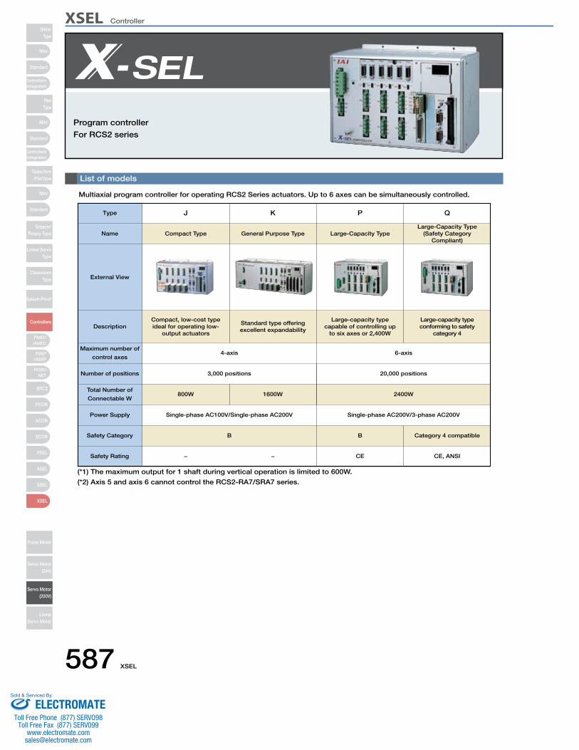
XSEL ControllerSlider
Type
Mini
Mini
PSEP/ASEP
PMEC/AMEC
ROBONET
ERC2
PCON
ACON
SCON
PSEL
ASEL
SSEL
XSEL
Standard
Standard
Standard
ControllersIntegrated
ControllersIntegrated
RodType
Table/Arm/FlatType
Gripper/Rotary Type
Linear ServoType
CleanroomType
Splash-Proof
Controllers
Pulse Motor
Servo Motor (24V)
Servo Motor (200V)
LinearServo Motor
Mini
List of models
Program controller
For RCS2 series
Multiaxial program controller for operating RCS2 Series actuators. Up to 6 axes can be simultaneously controlled.
Type J K P Q
Name
External View
DescriptionCompact, low-cost type ideal for operating low-
output actuators
Compact Type General Purpose Type Large-Capacity TypeLarge-Capacity Type
(Safety Category Compliant)
Standard type offering excellent expandability
Large-capacity type capable of controlling up
to six axes or 2,400W
Large-capacity type conforming to safety
category 4
Total Number of
Connectable W
Number of positions
Maximum number of
control axes
Safety Rating
Safety Category
Power Supply
−
B
Single-phase AC100V/Single-phase AC200V
800W
3,000 positions
4-axis
1600W
Single-phase AC200V/3-phase AC200V
2400W
20,000 positions
6-axis
− CE
B
CE, ANSI
Category 4 compatible
(*1) The maximum output for 1 shaft during vertical operation is limited to 600W.
(*2) Axis 5 and axis 6 cannot control the RCS2-RA7/SRA7 series.
587 XSEL
ELECTROMATEToll Free Phone (877) SERVO98
Toll Free Fax (877) SERV099www.electromate.com
Sold & Serviced By:
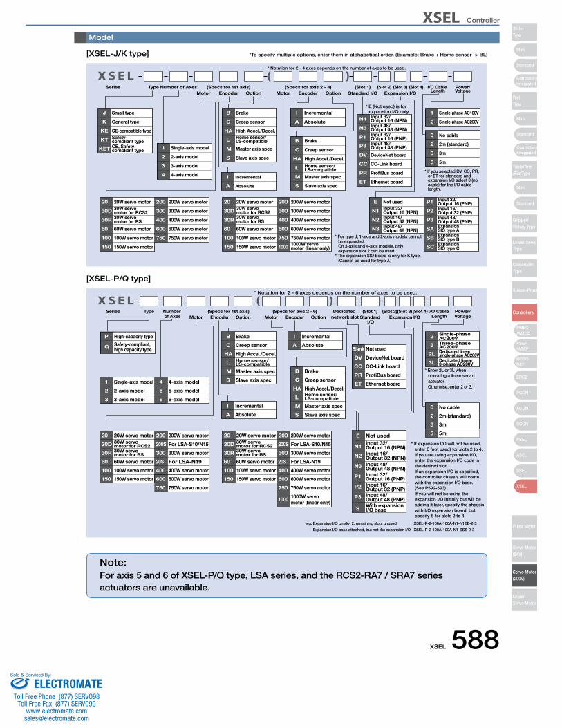
XSEL Controller
Mini
Mini
Mini
Standard
Standard
ControllersIntegrated
Standard
ControllersIntegrated
PSEP/ASEP
PMEC/AMEC
ROBONET
ERC2
PCON
ACON
SCON
PSEL
ASEL
SSEL
XSEL
SliderType
RodType
Table/Arm/FlatType
Gripper/Rotary Type
Linear ServoType
CleanroomType
Splash-Proof
Controllers
Pulse Motor
Servo Motor (24V)
Servo Motor (200V)
LinearServo Motor
Brake
Creep sensor
High Accel./Decel.Home sensor/LS-compatible
Master axis spec
Slave axis spec
Brake
Creep sensor
High Accel./Decel.Home sensor/LS-compatibleMaster axis spec
Slave axis spec
20W servo motor30W servo motor for RCS230W servo motor for RS
60W servo motor
100W servo motor
150W servo motor
200W servo motor
300W servo motor
400W servo motor
600W servo motor
750W servo motor
20W servo motor30W servo motor for RCS230W servo motor for RS
60W servo motor
100W servo motor
150W servo motor
200W servo motor
300W servo motor
400W servo motor
600W servo motor
750W servo motor1000W servo motor (linear only)
Single-axis model
2-axis model
3-axis model
4-axis model Incremental
Absolute
Incremental
Absolute
Not used
Input 48/Output 48 (NPN)Input 32/Output 16 (PNP)Input 48/Output 48 (PNP)
DeviceNet board
Input 32/Output 16 (NPN)Input 16/Output 32 (NPN)Input 48/Output 48 (NPN)
Input 32/Output 16 (PNP)Input 16/Output 32 (PNP)Input 48/Output 48 (PNP)
CC-Link board
ProfiBus board
Ethernet board
Expansion SIO type AExpansion SIO type BExpansion SIO type C
Single-phase AC100V
Single-phase AC200V
No cable
2m (standard)
3m
5m
Small type
General type
CE-compatible typeSafety-compliant typeCE, Safety-compliant type
Input 32/Output 16 (NPN)
Series Type Number of AxesMotor Encoder Option Motor Encoder Option
I/O Cable Length
Power/VoltageStandard I/O Expansion I/O
(Slot 1) (Slot 2) (Slot 3) (Slot 4)
B
C
HA
L
M
S
B
C
HA
L
M
S
20
30D
30R
60
100
150
200
300
400
600
750
20
30D
30R
60
100
150
200
300
400
600
750
1000
1
2
3
4 I
A
I
A
E
N3
P1
P3
DV
N1
N2
N3
P1
P2
P3
CC
PR
ET
SA
SB
SC
1
2
0
2
3
5
J
K
KE
KT
KET
(Specs for 1st axis) (Specs for axis 2 - 4)
* Notation for 2 - 4 axes depends on the number of axes to be used.
N1
* For type J, 1-axis and 2-axis models cannot be expanded.On 3-axis and 4-axis models, only expansion slot 2 can be used.
* The expansion SIO board is only for K type.(Cannot be used for type J.)
* If you selected DV, CC, PR, or ET for standard and expansion I/O select 0 (no cable) for the I/O cable length.
* E (Not used) is for expansion I/O only.
[XSEL-J/K type]
Series Type Number of Axes Motor Encoder Option Motor Encoder Option
I/O Cable Length
Power/VoltageStandard
I/OExpansion I/O
(Slot 1) (Slot 2)(Slot 3)(Slot 4)
Blank Not used
DV DeviceNet board
CC CC-Link board
PR ProfiBus board
ET Ethernet board
20 20W servo motor
30D 30W servo motor for RCS2
30R 30W servo motor for RS
60 60W servo motor
100 100W servo motor
150 150W servo motor
200 200W servo motor
200S For LSA-S10/N15
300 300W servo motor
20S For LSA-N19
400 400W servo motor
600 600W servo motor
750 750W servo motor
20 20W servo motor
30D 30W servo motor for RCS2
30R 30W servo motor for RS
60 60W servo motor
100 100W servo motor
150 150W servo motor
200 200W servo motor
200S For LSA-S10/N15
300 300W servo motor
20S For LSA-N19
400 400W servo motor
600 600W servo motor
750 750W servo motor
1000 1000W servo motor (linear only)
1 Single-axis model
2 2-axis model
3 3-axis model
4 4-axis model
5 5-axis model
6 6-axis modelI Incremental
A Absolute
I Incremental
A Absolute
N1Input 32/Output 16 (NPN)
E Not used
N2 Input 16/Output 32 (NPN)
N3 Input 48/Output 48 (NPN)
P1 Input 32/Output 16 (PNP)
P2 Input 16/Output 32 (PNP)
P3 Input 48/Output 48 (PNP)
SWith expansion I/O base
2 Single-phase AC200V
3 Three-phase AC200V
2L Dedicated linear single-phase AC200V
3L Dedicated linear 3-phase AC200V
0 No cable
2 2m (standard)
3 3m
5 5m
P High-capacity type
Q Safety-compliant, high capacity type
(Specs for 1st axis) (Specs for axis 2 - 6) Dedicated network slot
* Notation for 2 - 6 axes depends on the number of axes to be used.
B Brake
C Creep sensor
HA High Accel./Decel.
L Home sensor/LS-compatible
M Master axis spec
S Slave axis spec
B Brake
C Creep sensor
HA High Accel./Decel.
L Home sensor/LS-compatible
M Master axis spec
S Slave axis spec
* If expansion I/O will not be used, enter E (not used) for slots 2 to 4.
If you are using expansion I/O, enter the expansion I/O code in the desired slot.
If an expansion I/O is specified, the controller chassis will come with the expansion I/O base.
(See P592-593) If you will not be using the
expansion I/O initially but will be adding it later, specify the chassis with I/O expansion board, but specify S for slots 2 to 4.
* Enter 2L or 3L when operating a linear servo actuator.
Otherwise, enter 2 or 3.
e.g. Expansion I/O on slot 2, remaining slots unused XSEL-P-2-100A-100A-N1-N1EE-2-3
Expansion I/O base attached, but not the expansion I/O XSEL-P-2-100A-100A-N1-SSS-2-3
[XSEL-P/Q type]
*To specify multiple options, enter them in alphabetical order. (Example: Brake + Home sensor -> BL)
Note:For axis 5 and 6 of XSEL-P/Q type, LSA series, and the RCS2-RA7 / SRA7 series actuators are unavailable.
Model
XSEL 588ELECTROMATE
Toll Free Phone (877) SERVO98Toll Free Fax (877) SERV099
Sold & Serviced By:
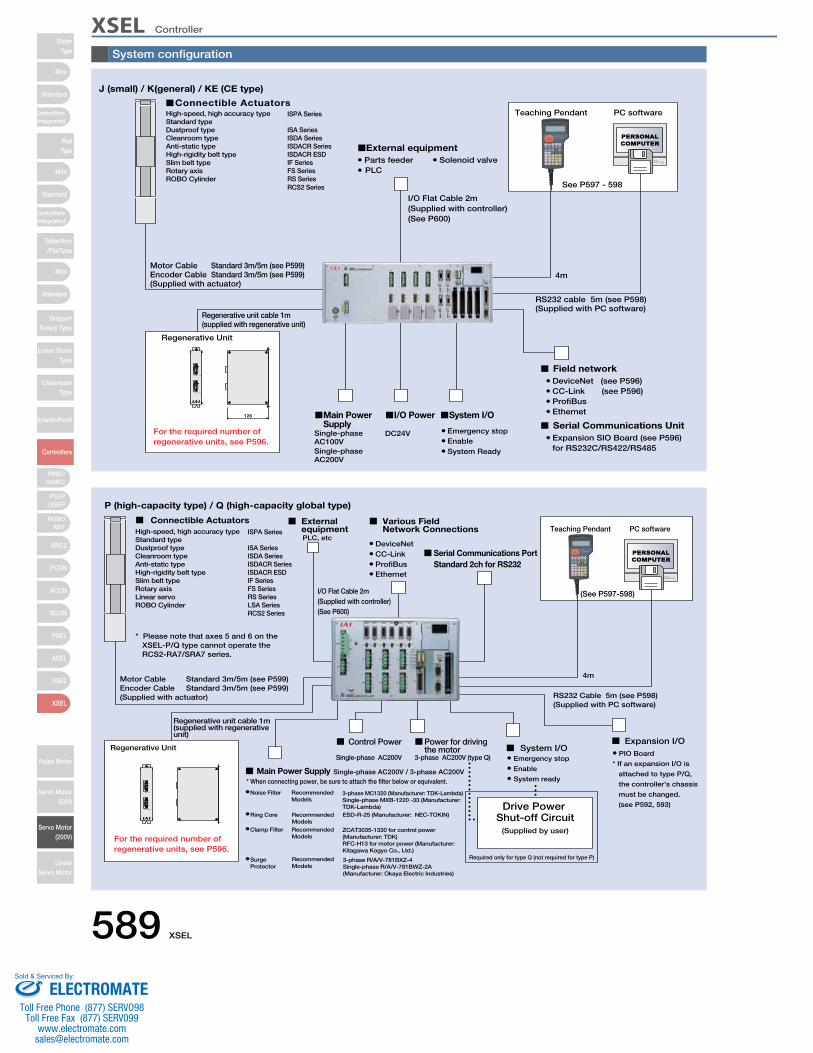
XSEL ControllerSlider
Type
Mini
Mini
PSEP/ASEP
PMEC/AMEC
ROBONET
ERC2
PCON
ACON
SCON
PSEL
ASEL
SSEL
XSEL
Standard
Standard
Standard
ControllersIntegrated
ControllersIntegrated
RodType
Table/Arm/FlatType
Gripper/Rotary Type
Linear ServoType
CleanroomType
Splash-Proof
Controllers
Pulse Motor
Servo Motor (24V)
Servo Motor (200V)
LinearServo Motor
Mini
System configuration
PLCParts feeder Solenoid valve
Teaching Pendant
Regenerative Unit
PC software
Motor CableEncoder Cable(Supplied with actuator)
Regenerative unit cable 1m(supplied with regenerative unit)
Single-phase AC100V
DC24V
System ReadyEnableEmergency stop
EthernetProfiBusCC-Link (see P596)DeviceNet (see P596)
Expansion SIO Board (see P596)for RS232C/RS422/RS485
I/O Flat Cable 2m(Supplied with controller)(See P600)
4m
RS232 cable 5m (see P598)(Supplied with PC software)
Standard 3m/5m (see P599)Standard 3m/5m (see P599)
126
Connectible Actuators
External equipment
Main Power Supply
I/O Power System I/O
Field network
Serial Communications Unit
See P597 - 598
For the required number of regenerative units, see P596.
J (small) / K(general) / KE (CE type)
Single-phase AC200V
ISPA Series
ISA SeriesISDA SeriesISDACR SeriesISDACR ESDIF SeriesFS SeriesRS SeriesRCS2 Series
High-speed, high accuracy typeStandard typeDustproof typeCleanroom typeAnti-static typeHigh-rigidity belt typeSlim belt typeRotary axisROBO Cylinder
P (high-capacity type) / Q (high-capacity global type)
PLC, etcTeaching Pendant
Regenerative Unit
PC software
Motor CableEncoder Cable(Supplied with actuator)
* Please note that axes 5 and 6 on theXSEL-P/Q type cannot operate the RCS2-RA7/SRA7 series.
Regenerative unit cable 1m(supplied with regenerative unit)
* If an expansion I/O is
attached to type P/Q,
the controller's chassis
must be changed.
(see P592, 593)
PIO Board
I/O Flat Cable 2m(Supplied with controller)(See P600)
4m
RS232 Cable 5m (see P598)(Supplied with PC software)
Standard 3m/5m (see P599)Standard 3m/5m (see P599)
ISPA Series
Connectible Actuators External equipment
EthernetProfiBusCC-LinkDeviceNet
Various Field Network Connections
Serial Communications PortStandard 2ch for RS232
Expansion I/O
(See P597-598)
Single-phase AC200V 3-phase AC200V (type Q)
Required only for type Q (not required for type P)
System ready
Enable
Emergency stop
Control Power
* When connecting power, be sure to attach the filter below or equivalent.
Recommended Models
Recommended Models
Recommended Models
ESD-R-25 (Manufacturer: NEC-TOKIN)
RecommendedModels
Surge Protector
Clamp Filter
Ring Core
Noise Filter
Single-phase AC200V / 3-phase AC200VMain Power Supply
Power for driving the motor System I/O
Drive Power Shut-off Circuit
(Supplied by user)For the required number of regenerative units, see P596.
ISA SeriesISDA SeriesISDACR SeriesISDACR ESDIF SeriesFS SeriesRS SeriesLSA SeriesRCS2 Series
High-speed, high accuracy typeStandard typeDustproof typeCleanroom typeAnti-static typeHigh-rigidity belt typeSlim belt typeRotary axisLinear servoROBO Cylinder
3-phase MC1320 (Manufacturer: TDK-Lambda)Single-phase MXB-1220 -33 (Manufacturer: TDK-Lambda)
ZCAT3035-1330 for control power (Manufacturer: TDK)RFC-H13 for motor power (Manufacturer: Kitagawa Kogyo Co., Ltd.)
3-phase R/A/V-781BXZ-4Single-phase R/A/V-781BWZ-2A(Manufacturer: Okaya Electric Industries)
589 XSEL
ELECTROMATEToll Free Phone (877) SERVO98
Toll Free Fax (877) SERV099www.electromate.com
Sold & Serviced By:
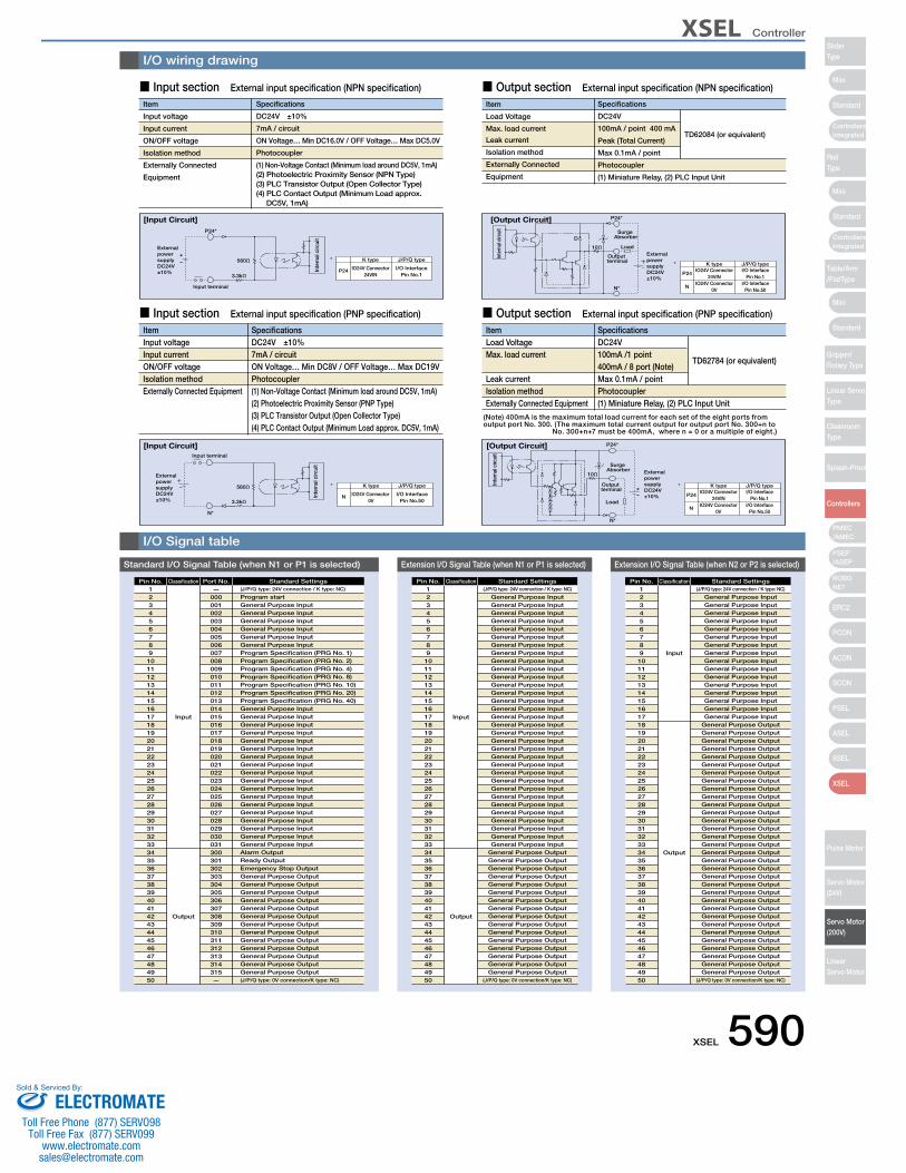
XSEL Controller
Mini
Mini
Mini
Standard
Standard
ControllersIntegrated
Standard
ControllersIntegrated
PSEP/ASEP
PMEC/AMEC
ROBONET
ERC2
PCON
ACON
SCON
PSEL
ASEL
SSEL
XSEL
SliderType
RodType
Table/Arm/FlatType
Gripper/Rotary Type
Linear ServoType
CleanroomType
Splash-Proof
Controllers
Pulse Motor
Servo Motor (24V)
Servo Motor (200V)
LinearServo Motor
1234567891011121314151617181920212223242526272829303132333435363738394041424344454647484950
Input
Output
—000001002003004005006007008009010011012013014015016017018019020021022023024025026027028029030031300301302303304305306307308309310311312313314315—
(J/P/Q type: 24V connection / K type: NC)
Program startGeneral Purpose InputGeneral Purpose InputGeneral Purpose InputGeneral Purpose InputGeneral Purpose InputGeneral Purpose InputProgram Specification (PRG No. 1)Program Specification (PRG No. 2)Program Specification (PRG No. 4)Program Specification (PRG No. 8)Program Specification (PRG No. 10)Program Specification (PRG No. 20)Program Specification (PRG No. 40)General Purpose InputGeneral Purpose InputGeneral Purpose InputGeneral Purpose InputGeneral Purpose InputGeneral Purpose InputGeneral Purpose InputGeneral Purpose InputGeneral Purpose InputGeneral Purpose InputGeneral Purpose InputGeneral Purpose InputGeneral Purpose InputGeneral Purpose InputGeneral Purpose InputGeneral Purpose InputGeneral Purpose InputGeneral Purpose InputAlarm OutputReady OutputEmergency Stop OutputGeneral Purpose OutputGeneral Purpose OutputGeneral Purpose OutputGeneral Purpose OutputGeneral Purpose OutputGeneral Purpose OutputGeneral Purpose OutputGeneral Purpose OutputGeneral Purpose OutputGeneral Purpose OutputGeneral Purpose OutputGeneral Purpose OutputGeneral Purpose Output(J/P/Q type: 0V connection/K type: NC)
Standard I/O Signal Table (when N1 or P1 is selected)
Standard SettingsPort No.ClassificationPin No.123456789
1011121314151617181920212223242526272829303132333435363738394041424344454647484950
Input
Output
(J/P/Q type: 24V connection / K type: NC)
General Purpose InputGeneral Purpose InputGeneral Purpose InputGeneral Purpose InputGeneral Purpose InputGeneral Purpose InputGeneral Purpose InputGeneral Purpose InputGeneral Purpose InputGeneral Purpose InputGeneral Purpose InputGeneral Purpose InputGeneral Purpose InputGeneral Purpose InputGeneral Purpose InputGeneral Purpose Input
General Purpose OutputGeneral Purpose OutputGeneral Purpose OutputGeneral Purpose OutputGeneral Purpose OutputGeneral Purpose OutputGeneral Purpose OutputGeneral Purpose OutputGeneral Purpose OutputGeneral Purpose OutputGeneral Purpose OutputGeneral Purpose OutputGeneral Purpose OutputGeneral Purpose OutputGeneral Purpose OutputGeneral Purpose OutputGeneral Purpose OutputGeneral Purpose OutputGeneral Purpose OutputGeneral Purpose OutputGeneral Purpose OutputGeneral Purpose OutputGeneral Purpose OutputGeneral Purpose OutputGeneral Purpose OutputGeneral Purpose OutputGeneral Purpose OutputGeneral Purpose OutputGeneral Purpose OutputGeneral Purpose OutputGeneral Purpose OutputGeneral Purpose Output
(J/P/Q type: 0V connection/K type: NC)
Extension I/O Signal Table (when N2 or P2 is selected)
Standard SettingsClassificationPin No.123456789
1011121314151617181920212223242526272829303132333435363738394041424344454647484950
Input
Output
(J/P/Q type: 24V connection / K type: NC)
General Purpose InputGeneral Purpose InputGeneral Purpose InputGeneral Purpose InputGeneral Purpose InputGeneral Purpose InputGeneral Purpose InputGeneral Purpose InputGeneral Purpose InputGeneral Purpose InputGeneral Purpose InputGeneral Purpose InputGeneral Purpose InputGeneral Purpose InputGeneral Purpose InputGeneral Purpose InputGeneral Purpose InputGeneral Purpose InputGeneral Purpose InputGeneral Purpose InputGeneral Purpose InputGeneral Purpose InputGeneral Purpose InputGeneral Purpose InputGeneral Purpose InputGeneral Purpose InputGeneral Purpose InputGeneral Purpose InputGeneral Purpose InputGeneral Purpose InputGeneral Purpose InputGeneral Purpose Input
General Purpose OutputGeneral Purpose OutputGeneral Purpose OutputGeneral Purpose OutputGeneral Purpose OutputGeneral Purpose OutputGeneral Purpose OutputGeneral Purpose OutputGeneral Purpose OutputGeneral Purpose OutputGeneral Purpose OutputGeneral Purpose OutputGeneral Purpose OutputGeneral Purpose OutputGeneral Purpose OutputGeneral Purpose Output
(J/P/Q type: 0V connection/K type: NC)
Extension I/O Signal Table (when N1 or P1 is selected)
Standard SettingsClassificationPin No.
I/O wiring drawing
I/O Signal table
Item
Input voltage
Input current
ON/OFF voltage
Isolation method
Externally Connected
Equipment
Specifications
DC24V ±10%
7mA / circuit
ON Voltage… Min DC16.0V / OFF Voltage… Max DC5.0V
Photocoupler
(1) Non-Voltage Contact (Minimum load around DC5V, 1mA)(2) Photoelectric Proximity Sensor (NPN Type)(3) PLC Transistor Output (Open Collector Type)(4) PLC Contact Output (Minimum Load approx. DC5V, 1mA)
[Input Circuit]
560Ω
3.3kΩ
Input terminal
P24*
+−
External power supply DC24V±10%
K type
IO24V Connector24VIN
I/O InterfacePin No.1
J/P/Q type
P24
*
Inte
rnal
circ
uit
■ Input section External input specification (NPN specification)
Item
Load Voltage
Max. load current
Leak current
Isolation method
Externally Connected
Equipment
Specifications
DC24V
100mA / point 400 mA
Peak (Total Current) Max 0.1mA / point
Photocoupler
(1) Miniature Relay, (2) PLC Input Unit
TD62084 (or equivalent)
[Output Circuit]
10Ω
P24*
D
Output terminal
Load
Surge Absorber
K typeIO24V Connector
24VINI/O Interface
Pin No.1
J/P/Q type
P24
IO24V Connector0V
I/O InterfacePin No.50
N
*
N*
External power supply DC24V±10%
Inte
rnal
circ
uit
■ Output section External input specification (NPN specification)
ItemInput voltageInput currentON/OFF voltageIsolation methodExternally Connected Equipment
SpecificationsDC24V ±10%7mA / circuitON Voltage… Min DC8V / OFF Voltage… Max DC19VPhotocoupler(1) Non-Voltage Contact (Minimum load around DC5V, 1mA)(2) Photoelectric Proximity Sensor (PNP Type)(3) PLC Transistor Output (Open Collector Type)(4) PLC Contact Output (Minimum Load approx. DC5V, 1mA)
[Input Circuit]
560Ω
3.3kΩ
N*
Input terminal
External power supply DC24V±10%
K type
IO24V Connector 0V
I/O InterfacePin No.50
J/P/Q type
N
*
Inte
rnal
circ
uit
■ Input section External input specification (PNP specification)
ItemLoad VoltageMax. load current
Leak currentIsolation methodExternally Connected Equipment
SpecificationsDC24V100mA /1 point 400mA / 8 port (Note)Max 0.1mA / pointPhotocoupler(1) Miniature Relay, (2) PLC Input Unit
TD62784 (or equivalent)
[Output Circuit]
+−
10Ω
P24*
External power supply DC24V±10%
N*
Output terminal
Load
Surge Absorber
K typeIO24V Connector
24VINI/O Interface
Pin No.1
J/P/Q type
P24
IO24V Connector0V
I/O InterfacePin No.50
N
*Inte
rnal
circ
uit
■ Output section External input specification (PNP specification)
(Note) 400mA is the maximum total load current for each set of the eight ports from output port No. 300. (The maximum total current output for output port No. 300+n to
No. 300+n+7 must be 400mA, where n = 0 or a multiple of eight.)
XSEL 590ELECTROMATE
Toll Free Phone (877) SERVO98Toll Free Fax (877) SERV099
Sold & Serviced By:
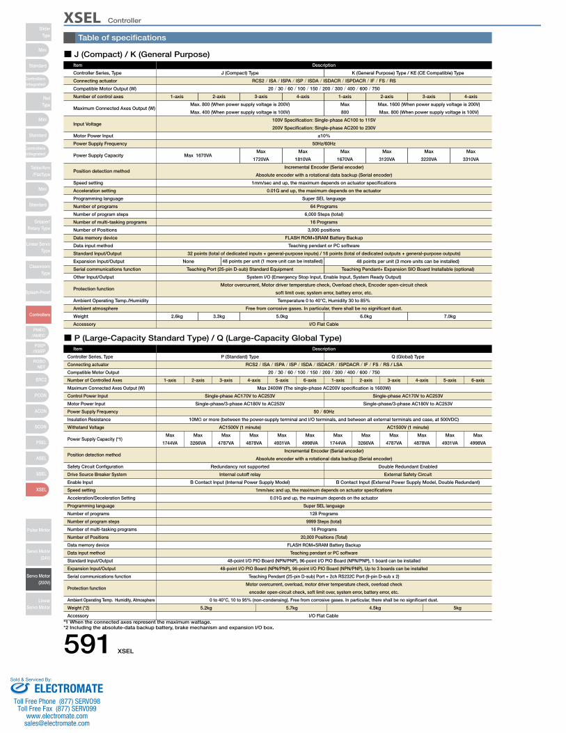
XSEL ControllerSlider
Type
Mini
Mini
PSEP/ASEP
PMEC/AMEC
ROBONET
ERC2
PCON
ACON
SCON
PSEL
ASEL
SSEL
XSEL
Standard
Standard
Standard
ControllersIntegrated
ControllersIntegrated
RodType
Table/Arm/FlatType
Gripper/Rotary Type
Linear ServoType
CleanroomType
Splash-Proof
Controllers
Pulse Motor
Servo Motor (24V)
Servo Motor (200V)
LinearServo Motor
Mini
Table of specifications
Controller Series, Type
Connecting actuator
Compatible Motor Output (W)
Number of control axes
Maximum Connected Axes Output (W)
Input Voltage
Motor Power Input
Power Supply Frequency
Power Supply Capacity
Position detection method
Speed setting
Acceleration setting
Programming language
Number of programs
Number of program steps
Number of multi-tasking programs
Number of Positions
Data memory device
Data input method
Standard Input/Output
Expansion Input/Output
Serial communications function
Other Input/Output
Protection function
Ambient Operating Temp./Humidity
Ambient atmosphere
Weight
Accessory
J (Compact) Type
RCS2 / ISA / ISPA / ISP / ISDA / ISDACR / ISPDACR / IF / FS / RS
20 / 30 / 60 / 100 / 150 / 200 / 300 / 400 / 600 / 750
100V Specification: Single-phase AC100 to 115V
200V Specification: Single-phase AC200 to 230V
±10%
50Hz/60Hz
1-axis
Max 1670VA
Incremental Encoder (Serial encoder)
Absolute encoder with a rotational data backup (Serial encoder)
1mm/sec and up, the maximum depends on actuator specifications
0.01G and up, the maximum depends on the actuator
Super SEL language
64 Programs
6,000 Steps (total)
16 Programs
3,000 positions
FLASH ROM+SRAM Battery Backup
Teaching pendant or PC software
32 points (total of dedicated inputs + general-purpose inputs) / 16 points (total of dedicated outputs + general-purpose outputs)
None
2.6kg
I/O Flat Cable
3.3kg 5.0kg 6.0kg 7.0kg
Teaching Port (25-pin D-sub) Standard Equipment
System I/O (Emergency Stop Input, Enable Input, System Ready Output)
Motor overcurrent, Motor driver temperature check, Overload check, Encoder open-circuit check
soft limit over, system error, battery error, etc.
Temperature 0 to 40°C, Humidity 30 to 85%
Free from corrosive gases. In particular, there shall be no significant dust.
48 points per unit (1 more unit can be installed) 48 points per unit (3 more units can be installed)
Teaching Pendant+ Expansion SIO Board Installable (optional)
Max. 800 (When power supply voltage is 200V)
Max. 400 (When power supply voltage is 100V)
2-axis 3-axis 4-axis 1-axis 2-axis
Max
800
Max. 1600 (When power supply voltage is 200V)
Max. 800 (When power supply voltage is 100V)
3-axis 4-axis
Max
1720VA
Max
1810VA
Max
1670VA
Max
3120VA
Max
3220VA
Max
3310VA
K (General Purpose) Type / KE (CE Compatible) Type
Item Description
P (Standard) Type
1-axis 2-axis 3-axis 4-axis 5-axis 6-axis 1-axis 2-axis 3-axis 4-axis 5-axis 6-axis
RCS2 / ISA / ISPA / ISP / ISDA / ISDACR / ISPDACR / IF / FS / RS / LSA
20 / 30 / 60 / 100 / 150 / 200 / 300 / 400 / 600 / 750
Max 2400W (The single-phase AC200V specification is 1600W)
50 / 60Hz
10MΩ or more (between the power-supply terminal and I/O terminals, and between all external terminals and case, at 500VDC)
AC1500V (1 minute)
Redundancy not supported
Internal cutoff relay
B Contact Input (Internal Power Supply Model)
5.2kg
I/O Flat Cable
5.7kg 4.5kg 5kg
Double Redundant Enabled
External Safety Circuit
B Contact Input (External Power Supply Model, Double Redundant)
Max
1744VA
Incremental Encoder (Serial encoder)
Absolute encoder with a rotational data backup (Serial encoder)
1mm/sec and up, the maximum depends on actuator specifications
0.01G and up, the maximum depends on the actuator
Super SEL language
128 Programs
9999 Steps (total)
16 Programs
20,000 Positions (Total)
FLASH ROM+SRAM Battery Backup
Teaching pendant or PC software
48-point I/O PIO Board (NPN/PNP), 96-point I/O PIO Board (NPN/PNP), 1 board can be installed
48-point I/O PIO Board (NPN/PNP), 96-point I/O PIO Board (NPN/PNP), Up to 3 boards can be installed
Teaching Pendant (25-pin D-sub) Port + 2ch RS232C Port (9-pin D-sub x 2)
Motor overcurrent, overload, motor driver temperature check, overload check
encoder open-circuit check, soft limit over, system error, battery error, etc.
0 to 40°C, 10 to 95% (non-condensing). Free from corrosive gases. In particular, there shall be no significant dust.
Max
3266VA
Max
4787VA
Max
4878VA
Max
4931VA
Max
4998VA
Max
1744VA
Max
3266VA
Max
4787VA
Max
4878VA
Max
4931VA
Max
4998VA
AC1500V (1 minute)
Single-phase AC170V to AC253V
Single-phase/3-phase AC180V to AC253V
Single-phase AC170V to AC253V
Single-phase/3-phase AC180V to AC253V
Q (Global) TypeController Series, Type
Connecting actuator
Compatible Motor Output
Number of Controlled Axes
Maximum Connected Axes Output (W)
Control Power Input
Motor Power Input
Power Supply Frequency
Insulation Resistance
Withstand Voltage
Power Supply Capacity (*1)
Position detection method
Safety Circuit Configuration
Drive Source Breaker System
Enable Input
Speed setting
Acceleration/Deceleration Setting
Programming language
Number of programs
Number of program steps
Number of multi-tasking programs
Number of Positions
Data memory device
Data input method
Standard Input/Output
Expansion Input/Output
Serial communications function
Protection function
Ambient Operating Temp. Humidity, Atmosphere
Weight (*2)
Accessory
Item Description
*1 When the connected axes represent the maximum wattage.*2 Including the absolute-data backup battery, brake mechanism and expansion I/O box.
■ J (Compact) / K (General Purpose)
■ P (Large-Capacity Standard Type) / Q (Large-Capacity Global Type)
591 XSEL
ELECTROMATEToll Free Phone (877) SERVO98
Toll Free Fax (877) SERV099www.electromate.com
Sold & Serviced By:
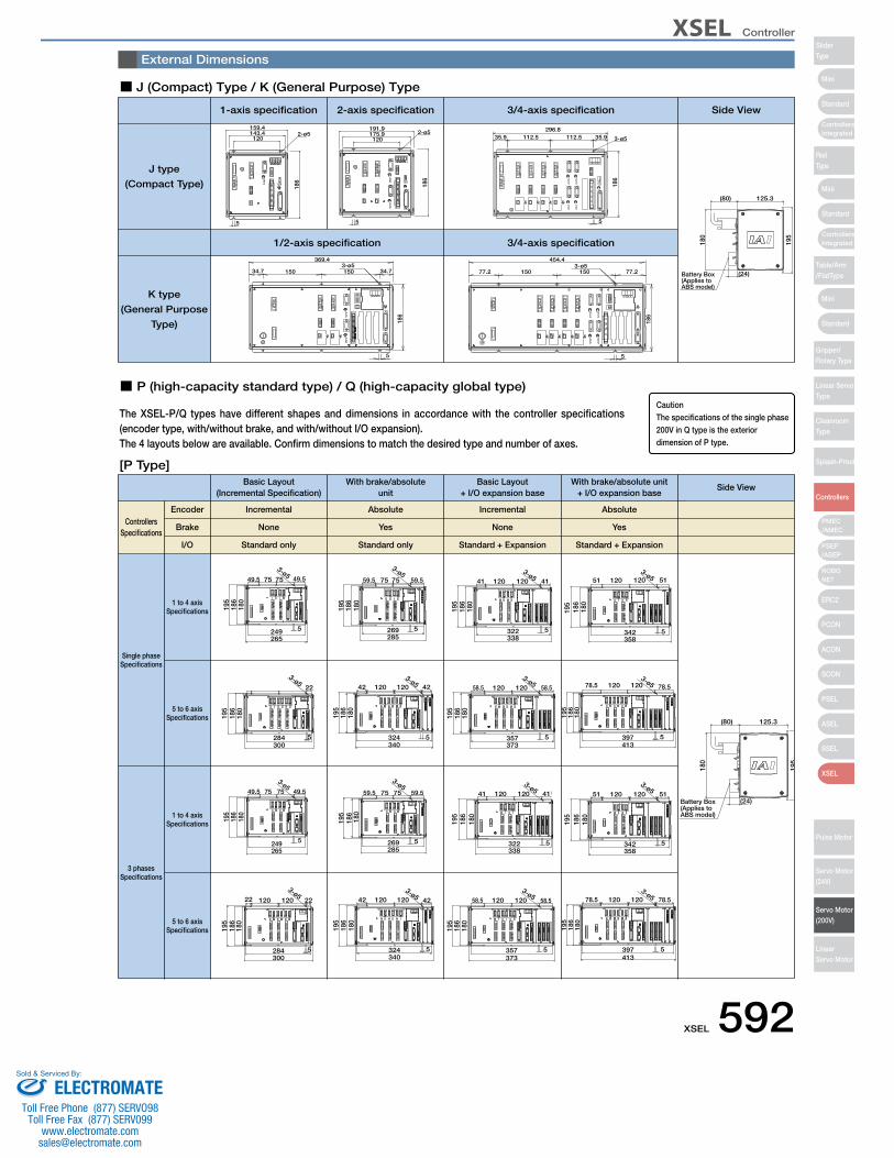
XSEL Controller
Mini
Mini
Mini
Standard
Standard
ControllersIntegrated
Standard
ControllersIntegrated
PSEP/ASEP
PMEC/AMEC
ROBONET
ERC2
PCON
ACON
SCON
PSEL
ASEL
SSEL
XSEL
SliderType
RodType
Table/Arm/FlatType
Gripper/Rotary Type
Linear ServoType
CleanroomType
Splash-Proof
Controllers
Pulse Motor
Servo Motor (24V)
Servo Motor (200V)
LinearServo Motor
180
186
195
5
3-ø549.5 75 75 49.5
265249
180
186
195
3-ø5
5
59.5 75 75 59.5
285269
180
186
195
3-ø5
5
41 120 120 41
338322
180
186
195
3-ø5
5
51 120 120 51
358342
284300
180
186
195
2212012022
5
3-ø5
324340
180
186
195
4212012042
5
3-ø5
357373
180
186
195
58.512012058.5
5
3-ø5
397413
180
186
195
78.512012078.5
5
3-ø5
External Dimensions
The XSEL-P/Q types have different shapes and dimensions in accordance with the controller specifications (encoder type, with/without brake, and with/without I/O expansion). The 4 layouts below are available. Confirm dimensions to match the desired type and number of axes.
XSEL-P XSEL-Q
IncrementalEncoderControllers
Specifications
Single phaseSpecifications
J type
(Compact Type)
K type
(General Purpose
Type)
3 phasesSpecifications
1 to 4 axisSpecifications
5 to 6 axisSpecifications
1 to 4 axisSpecifications
5 to 6 axisSpecifications
Brake
I/O Standard only Standard only Standard + Expansion Standard + Expansion
Absolute Incremental Absolute
None Yes None Yes
■ P (high-capacity standard type) / Q (high-capacity global type)
[P Type]
■ J (Compact) Type / K (General Purpose) Type
Basic Layout(Incremental Specification)
1-axis specification 3/4-axis specification Side View
1/2-axis specification 3/4-axis specification
2-axis specification
With brake/absoluteunit
Basic Layout + I/O expansion base
With brake/absolute unit+ I/O expansion base
Side View
180
186
195
49.5
3-ø5
5
49.5 75 75
265249
159.42-ø5143.4
120
186
5
35.9112.5112.5296.8
35.9
186
5
3-ø5
125.3(80)
195
180
(24)Battery Box(Applies to ABS model)
3-ø5
5
186
34.7 34.7150150
369.43-ø5
5
186
77.2
454.4
77.2150150
191.9
120175.9
186
2-ø5
5
180
186
195
3-ø5
5
59.5 75 75 59.5
285269
180
186
195
3-ø5
5
41 120 120 41
338322
180
186
195
3-ø512051
5
120 51
358342
125.3(80)
195
180
(24)Battery Box(Applies to ABS model)
284300
180
186
195
22
5
3-ø5
324340
180
186
195
4212012042
5
3-ø5
357373
180
186
195
58.512012058.5
5
3-ø5
397413
180
186
195
78.512012078.5
5
3-ø5
CautionThe specifications of the single phase 200V in Q type is the exterior dimension of P type.
XSEL 592ELECTROMATE
Toll Free Phone (877) SERVO98Toll Free Fax (877) SERV099
Sold & Serviced By:
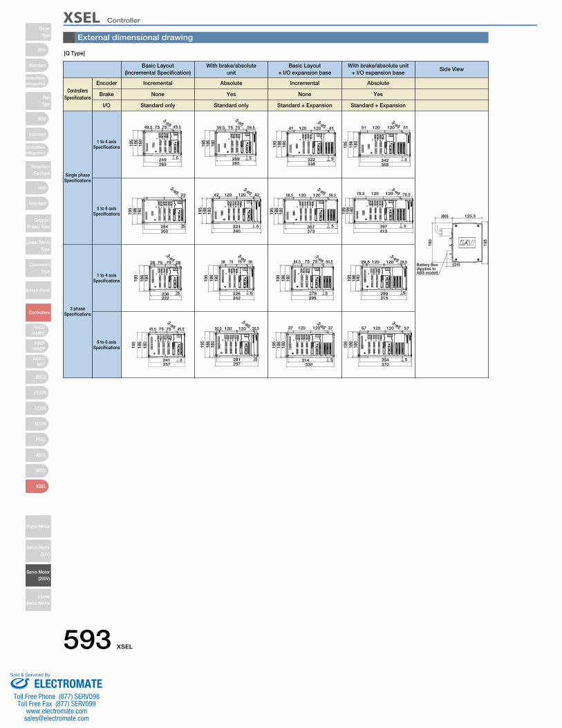
XSEL ControllerSlider
Type
Mini
Mini
PSEP/ASEP
PMEC/AMEC
ROBONET
ERC2
PCON
ACON
SCON
PSEL
ASEL
SSEL
XSEL
Standard
Standard
Standard
ControllersIntegrated
ControllersIntegrated
RodType
Table/Arm/FlatType
Gripper/Rotary Type
Linear ServoType
CleanroomType
Splash-Proof
Controllers
Pulse Motor
Servo Motor (24V)
Servo Motor (200V)
LinearServo Motor
Mini[Q Type]
XSEL-P XSEL-Q
IncrementalEncoderControllers
Specifications
Single phaseSpecifications
3 phaseSpecifications
1 to 4 axisSpecifications
5 to 6 axisSpecifications
1 to 4 axisSpecifications
5 to 6 axisSpecifications
Brake
I/O Standard only Standard only Standard + Expansion Standard + Expansion
Absolute Incremental Absolute
None Yes None Yes
Basic Layout(Incremental Specification)
With brake/absoluteunit
Basic Layout + I/O expansion base
With brake/absolute unit+ I/O expansion base
Side View
180
186
195
49.5
3-ø5
5
49.5 75 75
265249
180
186
195
3-ø5
5
59.5 75 75 59.5
285269
180
186
195
3-ø5
5
41 120 120 41
338322
180
186
195
3-ø512051
5
120 51
358342
125.3(80)
195
180
(24)Battery Box(Applies to ABS model)
284300
180
186
195
22
5
3-ø5
324340
180
186
195
4212012042
5
3-ø5
357373
180
186
195
58.512012058.5
5
3-ø5
397413
180
186
195
78.512012078.5
5
3-ø5
222206
195
186
180
28757528
5
3-ø5
226242
180
186
195
38757538
5
3-ø5
295279
195
186
180
64.5757564.5
5
3-ø5
299315
180
186
195
29.512012029.5
5
3-ø5
241257
180
186
195
45.5757545.5
5
3-ø5
180
186
195
3-ø5
5
20.5 120 120 20.5
297281 314
330
180
186
195
3712012037
5
3-ø5
354370
180
186
195
5712012057
5
3-ø5
External dimensional drawing
593 XSEL
ELECTROMATEToll Free Phone (877) SERVO98
Toll Free Fax (877) SERV099www.electromate.com
Sold & Serviced By:

XSEL Controller
Mini
Mini
Mini
Standard
Standard
ControllersIntegrated
Standard
ControllersIntegrated
PSEP/ASEP
PMEC/AMEC
ROBONET
ERC2
PCON
ACON
SCON
PSEL
ASEL
SSEL
XSEL
SliderType
RodType
Table/Arm/FlatType
Gripper/Rotary Type
Linear ServoType
CleanroomType
Splash-Proof
Controllers
Pulse Motor
Servo Motor (24V)
Servo Motor (200V)
LinearServo Motor
Part Names
J type (Compact) K type (General)
1 FG Connection TerminalA terminal for connecting to the FG terminal on the enclosure.The PE of the AC input are connected to the enclosure inside the controller.
11 System I/O ConnectorA connector for three input/output points including two inputs used to for the controller operation, and one system status output.
12 I/O 24V Power Connector (K Type only) , This connector is for supplying external I/O power to the insulator when DIs and DOs are installed in the I/O boards.
13 Panel WindowThis window has a 4-digit, 7-segment LED and five LED lamps showing the system status.
14 Mode switchThis is a locking toggle switch for designating the controller operating mode.Pull the switch forward and then tilt it up or down. The top position indicates the MANU (manual operation) mode, while the bottom position indicates the AUTO (automatic operation) mode.Teaching can only be performed in manual operation,and automatic operation using external I/Os is not possible in the MANU mode.
15 Teaching ConnectorThis is a 25-pin D-sub connector for connecting a teaching pendant or PC cable to enter programmed positions.
16 Standard I/O Slot (Slot 1)A 32-point input / 16-point output PIO board is installed as standard equipment.
17 Expansion I/O Slots (Slot 2, Slot 3, Slot 4)Install an expansion I/O board. (Option)
2 Fuse Holder (K Type only)This is the single-pole fuse holder for overcurrent protection in the AC input.
3 Main Power Input ConnectorThis connector is for the AC100/200V single-phase input.
4 Regeneration Resistance Unit ConnectorThis connector is for the regenerative resistance unit (optional/REU-1) that is connected when there is insufficient capacity with the built-in regenerative resistor for high-acceleration/high-loads, etc.
5 Motor Cable ConnectorA connector for the motor power-supply cable of the actuator.
6 Actuator Sensor Input ConnectorA connector for axis sensors such as LS, CREEP and OT.
7 Absolute-data backup batteryThis is the encoder backup battery unit when an absolute encoder is used.This battery is not connected for a non-absolute axis.
8 Brake Release Switch (Brake-equipped specification only)Locking toggle switch for releasing the axis brake. Pull the switch forward and then tilt it up or down.Set the switch to the top position (RLS) to forcibly release the brake, or to the bottom position (NOM) to have the brake automatically controlled by the controller.
9 Axis Driver Status LEDThis LED is for monitoring the operating status of the driver CPU that controls the motor drive.Features the following three LEDs..
10 Encoder sensor cable connector15-pin D-sub connector for the actuator encoder cable.
NameALM
SVONBATT ALM
OrangeGreen
Orange
Indicates when an error has been detected by the driver.Indicates that the servo is ON and the motor is driven.Indicates low absolute battery charge.
Color Function description
NameEMGENBRDY
Emergency stop inputSafety Gate InputSystem Ready Relay Output
ON=operation enabled, OFF=emergency stopON=operation enabled, OFF=servo OFFThis signal outputs the status of this controller.Cascade connection is supported.Short=ready, Open=not ready
16 17
XSEL 594ELECTROMATE
Toll Free Phone (877) SERVO98Toll Free Fax (877) SERV099
Sold & Serviced By:

XSEL ControllerSlider
Type
Mini
Mini
PSEP/ASEP
PMEC/AMEC
ROBONET
ERC2
PCON
ACON
SCON
PSEL
ASEL
SSEL
XSEL
Standard
Standard
Standard
ControllersIntegrated
ControllersIntegrated
RodType
Table/Arm/FlatType
Gripper/Rotary Type
Linear ServoType
CleanroomType
Splash-Proof
Controllers
Pulse Motor
Servo Motor (24V)
Servo Motor (200V)
LinearServo Motor
Mini Type P (Standard 4-axis) Type Q (Absolute brake unit + expansion base, 6-axis)
3
6
4
6
1 72 7 9
16
17
18
19
1
5 10
13
12
4
3
5 10 11 1211
15
2
1598
14
14
13
1 FG Connection TerminalA terminal for connecting to the FG terminal on the enclosure. The PE of the AC input are connected to the enclosure inside the controller.
11 Panel WindowThis window consists of a 4-digit, 7-segment LED and five LED lamps showing the system status.
12 Mode switchThis is a locking toggle switch for designating the controller operating mode. Pull the switch forward and then tilt it up or down. The top position indicates the MANU (manual operation) mode, while the bottom position indicates the AUTO (automatic operation) mode. Teaching can only be performed in manual operation, and automatic operation using external I/Os is not possible in the MANU mode.
2 External regeneration unit connectorA connector for the regenerative resistor that must be connected when the built-in regenerative resistor alone does not offer sufficient capacity in high-acceleration/ high-load operation, etc. Whether or not an external regenerative resistor is necessary depends on the conditions of your specific application such as the axis configuration.
4 Control Power Monitor LEDA green light illuminates while the control power supply is properly generating internal controller power.
5 Enable/Disable Switch for Absolute BatteryThis switch is for enabling/disabling the encoder backup using the absolute data backup battery. The encoder backup has been disabled prior to shipment. After connecting the encoder/axis-sensor cables, turn on the power, and then set this switch to the top position.
6 Encoder/Axis Sensor ConnectorA connector for axis sensors such as LS, CREEP and OT. *: LS, CREEP, and OT are options.
7 Motor connectorA connector for driving the motor in the actuator.
8 Teaching Pendant Type Selection SwitchThis switch is for selecting the type of teaching pendant to connect to the teaching connector. Switch between an IAI standard teaching pendant and the ANSI-compatible teaching pendant. Operate the switch on the front face of the board in accordance with the teaching pendant used.
9 Teaching ConnectorThe teaching interface is used for connecting the IAI teaching pendant or the software on a PC to operate and configure the system, etc.
10 System I/O connectorA connector for managing the safety operation functions of the controllers. Controllers of the global specification let you configure a safety circuit conforming to safety categories of up to 4 using this connector and an external safety circuit.
3 AC Power Input ConnectorAC200V 3-phase input connector. It consists of six terminals including motor power-supply, control power-supply and PE terminals.Standard equipment only includes a terminal block.Due to risk of electrical shock, do not touch this connector while power is supplied.
Description of five LEDsNameRDYALMEMG
PSECLK
Status when LED is litCPU Ready (programs can be run)CPU Power (System Down Level Error) CPU Hardware ProblemEmergency stop status, CPU hardware problem, or power system hardware problemPower supply hardware problemSystem clock problem
13 Standard I/O connector50-pin flat connector structure, comprised of 32 input / 16 output DIOs.
ItemConnector Name
Applicable connectorPower Supply
InputOutput
Connected to
Overview of Standard I/O Interface SpecificationsDetails
I/O50-Pins, Flat ConnectorPower is supplied through connector pins No. 1 and No. 50.32 points (including general-purpose and dedicated inputs)16 points (including general-purpose and dedicated inputs)External PLC, sensors, etc.
14 General-purpose RS232C Port ConnectorThis port is for connecting general-purpose RS232C equipment. (2-channels are available)
15 Field network board slotA slot that accepts a fieldbus interface module.
16 Expansion I/O Board (optional)Slots that accept optional expansion I/O boards.
17 Brake Power Input ConnectorA power input connector for driving the actuator brake. DC 24V must be supplied externally. If this power supply is not provided, the actuator brake cannot be released. Be certain that power is supplied to the brake-equipped axis. Use a shielded cable for the brake power cable, and connect the shielding on the 24V power supply side.
18 Brake Release Switch ConnectorA connector for the switch that releases the actuator brake externally to the controller. Shorting the COM terminal and BKMRL* terminal of this connector will release the brake. Use this method if you wish to manually operate the actuator after the controller has experienced a power failure or malfunction.
19 Brake SwitchLocking toggle switch for releasing the axis brake. Pull the switch forward and then tilt it up or down. Setting it to the top position (RLS side) forcibly releases the brake, while setting it to the bottom position (NOM side) causes the controller to automatically control the brake.
Part Names
595 XSEL
ELECTROMATEToll Free Phone (877) SERVO98
Toll Free Fax (877) SERV099www.electromate.com
Sold & Serviced By:
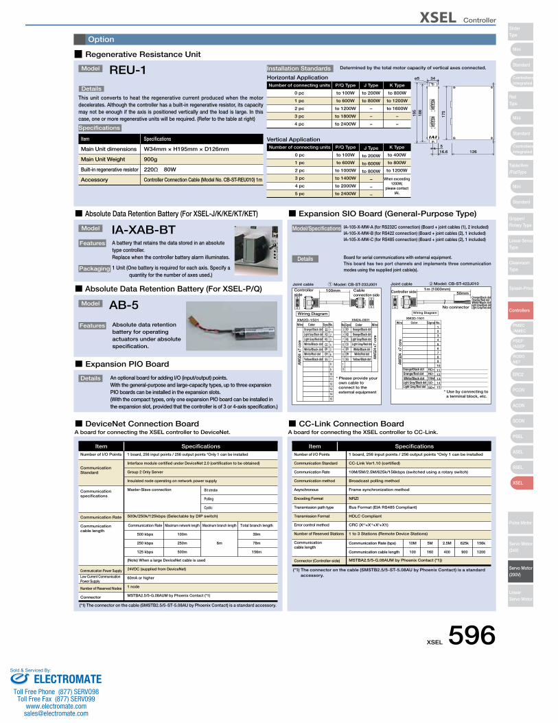
XSEL Controller
Mini
Mini
Mini
Standard
Standard
ControllersIntegrated
Standard
ControllersIntegrated
PSEP/ASEP
PMEC/AMEC
ROBONET
ERC2
PCON
ACON
SCON
PSEL
ASEL
SSEL
XSEL
SliderType
RodType
Table/Arm/FlatType
Gripper/Rotary Type
Linear ServoType
CleanroomType
Splash-Proof
Controllers
Pulse Motor
Servo Motor (24V)
Servo Motor (200V)
LinearServo Motor
Option
Model
Details
This unit converts to heat the regenerative current produced when the motor decelerates. Although the controller has a built-in regenerative resistor, its capacity may not be enough if the axis is positioned vertically and the load is large. In this case, one or more regenerative units will be required. (Refer to the table at right)
REU-1
Item
Main Unit dimensions
Main Unit Weight
Built-in regenerative resistor
Accessory
Specifications
W34mm × H195mm × D126mm
900g
220Ω 80W
Controller Connection Cable (Model No. CB-ST-REU010) 1m
Specifications
ø5
16.6 126
34
5
175
195
186
Installation Standards Determined by the total motor capacity of vertical axes connected.
▉ Regenerative Resistance Unit
■ Absolute Data Retention Battery (For XSEL-J/K/KE/KT/KET)
Model
Features
Packaging
IA-XAB-BTA battery that retains the data stored in an absolute type controller.Replace when the controller battery alarm illuminates.
1 Unit (One battery is required for each axis. Specify a quantity for the number of axes used.)
■ Expansion SIO Board (General-Purpose Type)
■ Absolute Data Retention Battery (For XSEL-P/Q)
Model
Features
AB-5
Absolute data retention battery for operating actuators under absolute specification.
■ Expansion PIO Board
■ DeviceNet Connection Board ■ CC-Link Connection BoardA board for connecting the XSEL controller to DeviceNet. A board for connecting the XSEL controller to CC-Link.
ItemNumber of I/O Points
Communication Standard
Communication specifications
Communication Rate
Communicationcable length
Communication Power Supply
Low Current Communication Power Supply
Number of Reserved Nodes
Connector
1 board, 256 input points / 256 output points *Only 1 can be installed
Interface module certified under DeviceNet 2.0 (certification to be obtained)
Group 2 Only Server
Insulated node operating on network power supply
Master-Slave connection
500k/250k/125kbps (Selectable by DIP switch)
(Note) When a large DeviceNet cable is used
24VDC (supplied from DeviceNet)
60mA or higher
1 node
MSTBA2.5/5-G.08AUM by Phoenix Contact (*1)
Specifications
Communication Rate
500 kbps
250 kbps
125 kbps
Maximum network length
100m
250m
500m
Maximum branch length
6m
Total branch length
39m
78m
156m
Bit strobe
Polling
Cyclic
(*1) The connector on the cable (SMSTB2.5/5-ST-5.08AU by Phoenix Contact) is a standard accessory.
Details An optional board for adding I/O (input/output) points.With the general-purpose and large-capacity types, up to three expansion PIO boards can be installed in the expansion slots.(With the compact types, only one expansion PIO board can be installed in the expansion slot, provided that the controller is of 3 or 4-axis specification.)
Details Board for serial communications with external equipment.This board has two port channels and implements three communication modes using the supplied joint cable(s).
Model/Specifications IA-105-X-MW-A (for RS232C connection) (Board + joint cables (1), 2 included)IA-105-X-MW-B (for RS422 connection) (Board + joint cables (2), 1 included)IA-105-X-MW-C (for RS485 connection) (Board + joint cables (2), 1 included)
Joint cable Model: CB-ST-232J0011
Controller side
Cable connection side
11
100mm
AWG
24 x
7 co
re
19
11
AWG
24 x
7 co
re
8
10
SG
1312
4ER 5 ER
RS 3
3SD 1 SD
6 DRDR 6
9
Wiring Diagram
CSCS 4
RS7
XM2A-0901XM2D-1501
SG57
1514
WireNo.Signal ColorWire ColorOrange/Black dotLight Gray/Black dotLight Gray/Red dotWhite/Black dot
White/Black dotWhite/Red dot
Yellow/Black dot
Orange/Black dotOrange/Black dot
Light Gray/Black dotLight Gray/Red dot
White/Black dotWhite/Red dot
Yellow/Black dot
Signal No.
2 RDRD 2
8
* Please provide your own cable to connect to the external equipment
Joint cable Model: CB-ST-422J0102
Controller side
* Use by connecting to a terminal block, etc.
AWG2
4 x
7 co
re
1
No connector
1m (1000mm)50mm
11
8
109
1514
SD+
1312
TRM
5
Wire Color Signal
2
RD-
4
RD+
3
1
SD-
6
XM2D-1501
7
No.
Wiring Diagram
Orange/Black dotOrange/Red dot
Light Gray/Black dotLight Gray/Red dot
White/Black dot
Orange/Black dotOrange/Red dot
Light Gray/Black dotLight Gray/Red dot
White/Black dot
ItemNumber of I/O Points
Communication Standard
Communication Rate
Communication method
Asynchronous
Encoding Format
Transmission path type
Transmission Format
Error control method
Number of Reserved Stations
Communication cable length
Connector (Controller-side)
1 board, 256 input points / 256 output points *Only 1 can be installed
CC-Link Ver1.10 (certified)
10M/5M/2.5M/625k/156kbps (switched using a rotary switch)
Broadcast polling method
Frame synchronization method
NRZI
Bus Format (EIA RS485 Compliant)
HDLC Compliant
CRC (X16+X12+X5+X1)
1 to 3 Stations (Remote Device Stations)
MSTBA2.5/5-G.08AUM by Phoenix Contact (*1))
Specifications
Communication Rate (bps)
Communication cable length
10M
100
5M
160
2.5M
400
625k
900
156k
1200
(*1) The connector on the cable (SMSTB2.5/5-ST-5.08AU by Phoenix Contact) is a standard accessory.
Number of connecting units
0 pc
1 pc
2 pc
3 pc
4 pc
P/Q Type
to 100W
to 600W
to 1200W
to 1800W
to 2400W
J Type
to 200W
to 800W
−
−
−
K Type
to 800W
to 1200W
to 1600W
−
−
Horizontal Application
Number of connecting units
0 pc
1 pc
2 pc
3 pc
4 pc
5 pc
P/Q Type
to 100W
to 600W
to 1000W
to 1400W
to 2000W
to 2400W
J Type
to 200W
to 600W
to 800W
−
−
−
K Type
to 400W
to 800W
to 1200W
When exceeding 1200W,
please contact IAI.
Vertical Application
XSEL 596ELECTROMATE
Toll Free Phone (877) SERVO98Toll Free Fax (877) SERV099
Sold & Serviced By:
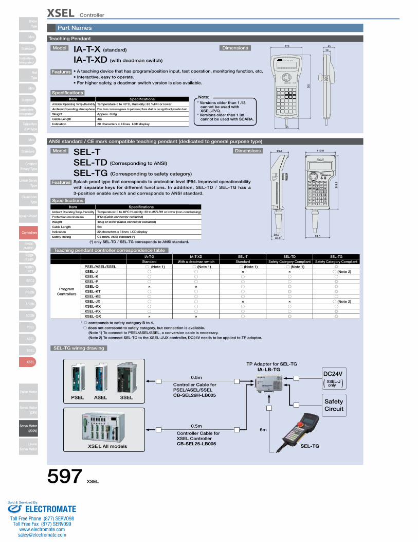
XSEL ControllerSlider
Type
Mini
Mini
PSEP/ASEP
PMEC/AMEC
ROBONET
ERC2
PCON
ACON
SCON
PSEL
ASEL
SSEL
XSEL
Standard
Standard
Standard
ControllersIntegrated
ControllersIntegrated
RodType
Table/Arm/FlatType
Gripper/Rotary Type
Linear ServoType
CleanroomType
Splash-Proof
Controllers
Pulse Motor
Servo Motor (24V)
Servo Motor (200V)
LinearServo Motor
Mini Teaching Pendant
Model Dimensions
Features • A teaching device that has program/position input, test operation, monitoring function, etc.• Interactive, easy to operate.• For higher safety, a deadman switch version is also available.
IA-T-X (standard)
IA-T-XD (with deadman switch)
ItemItem
SpecificationsAmbient Operating Temp./Humidity
Ambient Operating atmosphere
Weight
Cable Length
Indication
Temperature 0 to 40°C, Humidity: 85 %RH or lower
Free from corrosive gases. In particular, there shall be no significant powder dust.
Approx. 650g
4m
20 characters x 4 lines LCD display
Specifications
* Versions older than 1.13 cannot be used with XSEL-P/Q.
* Versions older than 1.08 cannot be used with SCARA.
Note:
ANSI standard / CE mark compatible teaching pendant (dedicated to general purpose type)
Model
Features
Dimensions
Splash-proof type that corresponds to protection level IP54. Improved operationability with separate keys for different functions. In addition, SEL-TD / SEL-TG has a 3-position enable switch and corresponds to ANSI standard.
SEL-TSEL-TD (Corresponding to ANSI)
SEL-TG (Corresponding to safety category)
Item SpecificationsAmbient Operating Temp./Humidity
Protection mechanism
Weight
Cable Length
Indication
Safety Rating
Temperature: 0 to 40ºC Humidity: 30 to 85%RH or lower (non-condensing)
IP54 (Cable connector excluded)
400g or lower (Cable connector excluded)
5m
32 characters x 8 lines LCD display
CE mark, ANSI standard (*)
Specifications
Teaching pendant controller correspondence table
SEL-TG wiring drawing
110.0
218.
3
66.6
39.046.9
89.6
(*) only SEL-TD / SEL-TG corresponds to ANSI standard.
IA-T-XStandard
IA-T-XDWith a deadman switch
SEL-TStandard
SEL-TDSafety Category Compliant
SEL-TGSafety Category Compliant
ProgramControllers
PSEL/ASEL/SSELXSEL-JXSEL-KXSEL-PXSEL-QXSEL-KTXSEL-KEXSEL-JXXSEL-KXXSEL-PXXSEL-QX
○ (Note 1)○○○×
○○○○○×
○ (Note 1)○○○×
○○○○○×
○ (Note 1)×
○○○○○×
○○○
○ (Note 1)×
○○◎◎○×
○○◎
◎○ (Note 2)○◎◎◎○○ (Note 2)○◎◎
* ◎ correponds to safety category B to 4.
○ does not corresond to safety category, but connection is available.(Note 1) To connect to PSEL/ASEL/SSEL, a conversion cable is necessary.(Note 2) To connect SEL-TG to the XSEL-J/JX controller, DC24V needs to be applied to TP adaptor.
SafetyCircuit
TP Adapter for SEL-TGIA-LB-TG
5m
0.5m
0.5m
ASELPSEL SSEL
XSEL All models SEL-TG
DC24VXSEL-Jonly( )Controller Cable for
PSEL/ASEL/SSELCB-SEL26H-LB005
Controller Cable forXSEL ControllerCB-SEL25-LB005
Part Names
597 XSEL
ELECTROMATEToll Free Phone (877) SERVO98
Toll Free Fax (877) SERV099www.electromate.com
Sold & Serviced By:
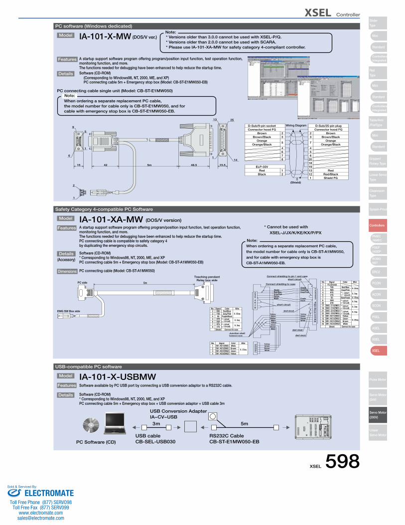
XSEL Controller
Mini
Mini
Mini
Standard
Standard
ControllersIntegrated
Standard
ControllersIntegrated
PSEP/ASEP
PMEC/AMEC
ROBONET
ERC2
PCON
ACON
SCON
PSEL
ASEL
SSEL
XSEL
SliderType
RodType
Table/Arm/FlatType
Gripper/Rotary Type
Linear ServoType
CleanroomType
Splash-Proof
Controllers
Pulse Motor
Servo Motor (24V)
Servo Motor (200V)
LinearServo Motor
Safety Category 4-compatible PC Software
Model
Features A startup support software program offering program/position input function, test operation function, monitoring function, and more. The functions needed for debugging have been enhanced to help reduce the startup time.PC connecting cable is compatible to safety category 4by duplicating the emergency stop circuits.
Software (CD-ROM)* Corresponding to Windows98, NT, 2000, ME, and XPPC connecting cable 5m + Emergency stop box (Model: CB-ST-A1MW050-EB)
IA-101-XA-MW (DOS/V version)
Details
PC connecting cable (Model: CB-ST-A1MW050)Dimensions
(Accessory)
When ordering a separate replacement PC cable,
the model number for cable only is CB-ST-A1MW050,
and for cable with emergency stop box is
CB-ST-A1MW050-EB.
Note:
short circuit
short circuit
Connect shielding to pin 1 and case
short circuit
3
SW1. NC22(EMG2)SW1. NC21(EMG2)SW1. NC12(EMG1)SW1. NC11(EMG1)
SignalNo.
4321
YellowWire
0. 25sq
Color
YellowGreenBrownWhite
21
34
WhiteBrownGreen
Junction shellSoldered inside
87645
WhiteBrown
YellowGreen
White
GreenBrown
Yellow
BlackPurple
WireSignalNo.
(short circuit)
Connect to case
(short circuit)
ShieldCTS
DSRRTS
876
DTRSG
RXDTXD
45
23
Color
Purple/Black
Red/BlueGray/Pink
0. 3sq
0. 3sq
0. 25sq
2
Connect shielding to case
Red/BlueShield
Gray/Pink CTS54Black/Purple
16
short circuit
White 24
GreenBrown
Yellow
PurpleBlack
1312222119
206
17
57
2416
Shield
22
1312
21191720
76 DSR
DTR
SG
Connect to case
0. 25sq
WhiteBrown
0. 3sq(short circuit)
0. 3sq
YellowGreen
(short circuit)
0. 25sq
0. 3sq(short circuit)
Red/BlueRed/BlueShield
Gray/Pink
short circuit
1
32
4321No.
RTS
TXDRXD
FG (Shield)Signal
0. 25sq
0. 3sq
Gray/Pink(short circuit)
Color WirePC side
EMG SW Box side
5mRelay box side
Teaching pendant
SW1. NC22(EMG2)SW1. NC21(EMG2)
SW2. C12(ENB1)
SW2. C22(ENB2)SW2. C21(ENB2)
SW1. NC12(EMG1)SW1. NC11(EMG1)
SW2. C11(ENB1)
USB-compatible PC software
Model
Features Software available by PC USB port by connecting a USB conversion adaptor to a RS232C cable.
Software (CD-ROM)* Corresponding to Windows98, NT, 2000, ME, and XPPC connecting cable 5m + Emergency stop box + USB conversion adaptor + USB cable 3m
IA-101-X-USBMW
Details
5m3m
PC Software (CD)RS232C CableCB-ST-E1MW050-EB
USB cableCB-SEL-USB030
USB Conversion AdapterIA−CV−USB
* Cannot be used with
XSEL-J/JX/K/KE/KX/P/PX
PC software (Windows dedicated)
Model
Features A startup support software program offering program/position input function, test operation function, monitoring function, and more. The functions needed for debugging have been enhanced to help reduce the startup time.
Details Software (CD-ROM) (Corresponding to Windows98, NT, 2000, ME, and XP)
PC connecting cable 5m + Emergency stop box (Model: CB-ST-E1MW050-EB)
PC connecting cable single unit (Model: CB-ST-E1MW050)
IA-101-X-MW (DOS/V ver.)
When ordering a separate replacement PC cable,the model number for cable only is CB-ST-E1MW050, and for cable with emergency stop box is CB-ST-E1MW050-EB.
Note:
* Versions older than 3.0.0 cannot be used with XSEL-P/Q. * Versions older than 2.0.0 cannot be used with SCARA. * Please use IA-101-XA-MW for safety category 4-compliant controller.
Note:
15.548.55m4215
Wiring Diagram
1
2233
445
5
667
Connector hood FG Connector hood FG
(Shield)
8 201819
7
1312
12
Shield FG
D-Sub/25-pin plugD-Sub/9-pin socket
ELP-02V
BlackRed
Orange Orange
Brown BrownBrown/Black Brown/Black
Orange/BlackOrange/Black
RedRed/Black
1
13 25
1
5
14
6
9
2
1
XSEL 598ELECTROMATE
Toll Free Phone (877) SERVO98Toll Free Fax (877) SERV099
Sold & Serviced By:
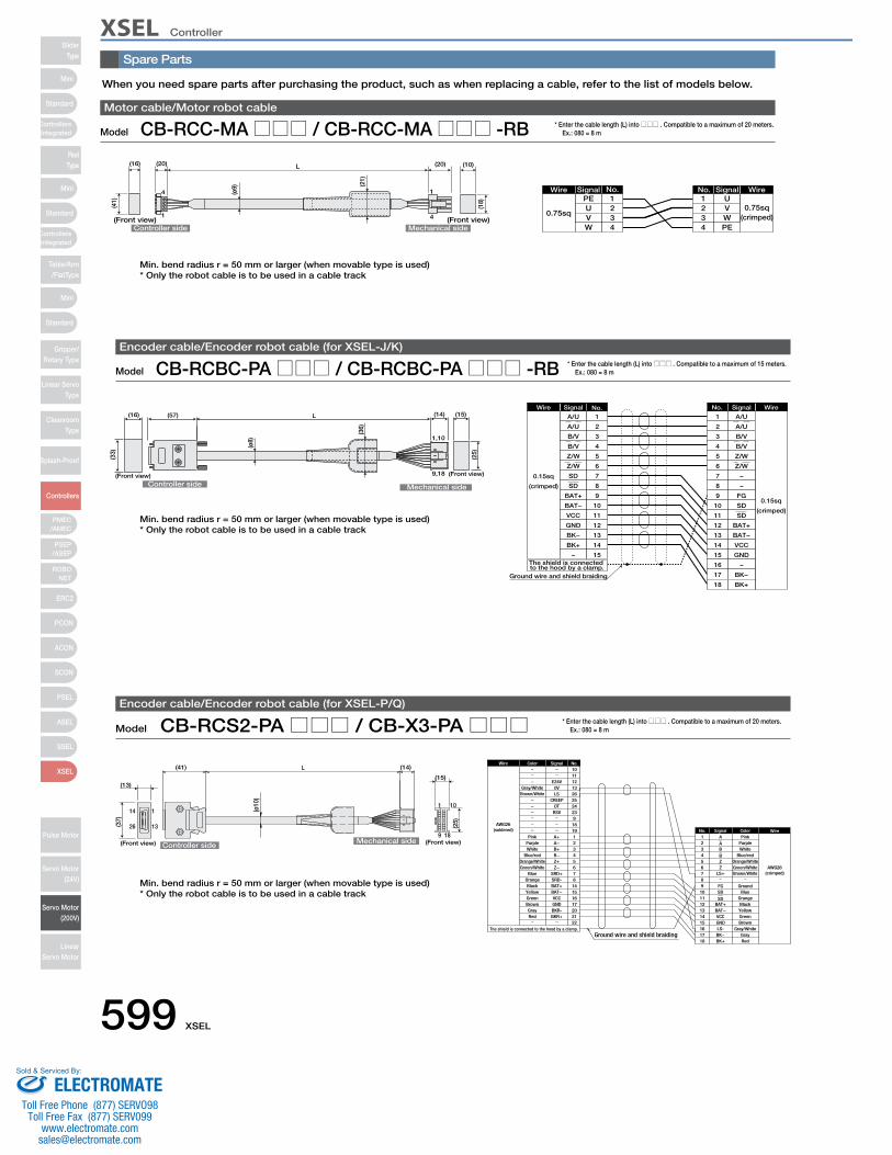
XSEL ControllerSlider
Type
Mini
Mini
PSEP/ASEP
PMEC/AMEC
ROBONET
ERC2
PCON
ACON
SCON
PSEL
ASEL
SSEL
XSEL
Standard
Standard
Standard
ControllersIntegrated
ControllersIntegrated
RodType
Table/Arm/FlatType
Gripper/Rotary Type
Linear ServoType
CleanroomType
Splash-Proof
Controllers
Pulse Motor
Servo Motor (24V)
Servo Motor (200V)
LinearServo Motor
Mini
Controller side Mechanical side
Wire Signal
0.15sq
(crimped)
A/U 1
The shield is connected to the hood by a clamp.
WireSignal
0.15sq
(crimped)
A/U1
Ground wire and shield braiding
L
1,10
9,18
(ø8)
(36)
(16)
(Front view)
(33)
(57)
(Front view)
(15)(14)
(25)
A/U
B/V
B/V
Z/W
Z/W
SD
SD
BAT+
BAT−
VCC
GND
BK−
BK+
–
2
3
4
5
6
7
8
9
10
11
12
13
14
15
2
3
4
5
6
7
8
9
10
11
12
13
14
15
16
17
18
A/U
B/V
B/V
Z/W
Z/W
–
–
FG
SD
SD
BAT+
BAT−
VCC
GND
–
BK−
BK+
No. No.
Model CB-RCBC-PA□□□ / CB-RCBC-PA□□□ -RBEncoder cable/Encoder robot cable (for XSEL-J/K)
* Enter the cable length (L) into □□□ . Compatible to a maximum of 15 meters. Ex.: 080 = 8 m
Model CB-RCS2-PA□□□ / CB-X3-PA□□□Encoder cable/Encoder robot cable (for XSEL-P/Q)
* Enter the cable length (L) into □□□ . Compatible to a maximum of 20 meters. Ex.: 080 = 8 m
1
9
1
13
14
2618
10
L
Ground wire and shield braiding GrayRed
Brown
YellowGreen
Black
Green/White AWG26(crimped)
Orange
GroundBlue
Blue/redOrange/White
WhitePurplePink
15161718
1413121110
6
987
3
54
21
No.
BK−BK+
GNDLS-
BAT+BAT−VCC
Z
FGSD
SD
LS+
B
ZB
A
ASignal Color Wire
The shield is connected to the hood by a clamp.
AWG26(soldered)
Wire
212017
22
6
16151487
3
54
21
25
1819
2324
9
1011121326
No.
BKR+BKR-GND
Z−
BAT+
VCCBAT−
SRD-SRD+
B+
Z+B−
A−A+
CREEPOT
RSV
E24V0VLS
Signal
Brown/White
Gray/White
Brown
RedGray
Green/WhiteOrange/White
WhiteBlue/red
Purple
GreenYellowBlack
Blue
Pink
Orange
Color
Brown/WhiteGray/White
(ø10
)
(41) (14)
Controller side
(13)
(37)
Mechanical side(Front view) (Front view)
(15)
(25)
Spare Parts
When you need spare parts after purchasing the product, such as when replacing a cable, refer to the list of models below.
Controller side Mechanical side
L
4
1
1
4
Wire Signal
0.75sq
PE 1WireSignal
0.75sq(crimped)
U1
(16) (20) (20) (10)
(Front view) (Front view)
(41)
(ø9) (2
1)
(18)
UVW
234
234
VWPE
No. No.
Model CB-RCC-MA□□□ / CB-RCC-MA□□□ -RBMotor cable/Motor robot cable
* Enter the cable length (L) into □□□ . Compatible to a maximum of 20 meters. Ex.: 080 = 8 m
Min. bend radius r = 50 mm or larger (when movable type is used)* Only the robot cable is to be used in a cable track
Min. bend radius r = 50 mm or larger (when movable type is used)* Only the robot cable is to be used in a cable track
Min. bend radius r = 50 mm or larger (when movable type is used)* Only the robot cable is to be used in a cable track
599 XSEL
ELECTROMATEToll Free Phone (877) SERVO98
Toll Free Fax (877) SERV099www.electromate.com
Sold & Serviced By:

XSEL Controller
Mini
Mini
Mini
Standard
Standard
ControllersIntegrated
Standard
ControllersIntegrated
PSEP/ASEP
PMEC/AMEC
ROBONET
ERC2
PCON
ACON
SCON
PSEL
ASEL
SSEL
XSEL
SliderType
RodType
Table/Arm/FlatType
Gripper/Rotary Type
Linear ServoType
CleanroomType
Splash-Proof
Controllers
Pulse Motor
Servo Motor (24V)
Servo Motor (200V)
LinearServo Motor
Spare Parts
Model CB-X-PIO□□□I/O flat cable (for XSEL-J/K/P/Q)
* Enter the cable length (L) into □□□ . Compatible to a maximum of 10 meters. Ex.: 080 = 8 m
234567891011121314151617
L
Flat cable (50-core)
No connector
2 1
50 49
ColorNumber Wire
Flatcable
crimped
Wire
Flatcable
crimped
Wire
Flatcable
crimped
ColorNumber ColorNumber1 Brown 1 18 Gray 2 35 Green 4
Red 1Orange 1Yellow 1Green 1Blue1
Purple 1Gray 1White 1Black 1Brown-2
Red 2Orange 2Yellow 2Green 2Blue 2
Purple 2
19202122232425262728293031323334
White 2Black 2Brown-3
Red 3Orange 3Yellow 3Green 3Blue 3
Purple 3Gray 3White 3Black 3Brown-4
Red 4Orange 4Yellow 4
363738394041424344454647484950
Blue 4Purple 4Gray 4White 4Black 4Brown-5Red 5
Orange 5Yellow 5Green 5Blue 5
Purple 5Gray 5White 5Black 5
Model CB-RCS2-PLA□□□ / CB-X2-PLA□□□Rotary Dedicated Encoder Cable / Encoder Robot Cable
* Enter the cable length (L) into □□□ . Compatible to a maximum of 30 meters. Ex.: 080 = 8 m
Ground wire and shield braiding
(crimped)
AWG26
AWG26
(soldered)
10
White/BlueA1
Wire Color Signal No.
WireColorSignalNo.
The shield is connected to the hood by a clamp.
(The wire color "White/Blue" indicates the colors of the band and insulation.)
(crimped)
AWG26
White/BlueE24V1
WireColorSignalNo.
1
9
1
13
14
26
18
10
L
6
1
(ø10
)
Controller sideMechanical side
LS side(13)
(41) (14)
(37)
(Front view)
(8)
(15)
(18)
(25)
White/Orange
White/Green
Brown/Blue
Brown/Yellow
Brown/Red
Brown/Black
White/Blue
White/Yellow
White/Red
White/Black
White/Purple
White/Gray
Orange
Green
Purple
Gray
Red
Black
Blue
Yellow
E24V
0V
LS
CREEP
OT
RSV
A+
A−
B+
B−
Z+
Z−
SRD+
SRD−
BAT+
BAT−
VCC
GND
BKR−
BKR+
11
12
13
26
25
24
23
9
18
19
1
2
3
4
5
6
7
8
14
15
16
17
20
21
22
2
3
4
5
6
0V
LS
CREEP
OT
RSV
White/Yellow
White/Red
White/Black
White/Purple
White/Gray
2
3
4
5
6
7
8
9
10
11
12
13
14
15
16
17
18
A
B
B
Z
Z
FG
SD
SD
BAT+
BAT−
VCC
GND
BK−
BK+
White/Yellow
White/Red
White/Black
White/Purple
White/Gray
Ground
Orange
Green
Purple
Gray
Red
Black
Blue
Yellow
Model CB-RCBC-PLA□□□Encoder cable (when using a XSEL-J/K type a homing sensor is used)
* Enter the cable length (L) into □□□ . Compatible to a maximum of 20 meters. Ex.: 080 = 8 m
1
9 18
10
56
4
23
1
The shield is connected to the hood by a clamp.
GND
Ground wire and shield braiding
23
15
4
MC1.5/6-ST-3.5
BAT+BAT−
Wire Color Signal No.
(crimped)
5
98
67
Ground
Wire
AWG26
43
SDSD
21
XMP-18VNo. Signal Color
VCC
876
45
3
12
A+A−B+B−Z+Z−
SRD+SRD−
BKR−BKR+
RSVOT
CREEPLS
1011121314
1
56
0VE24V
1011121314
18171615
BK+BK−
GNDVCC
BAT−BAT+
FG
AABBZZ
BlueYellow
GrayRed
Black
Green
White/Blue
Orange
Purple
White/Yellow
White/BlackWhite/Red
White/PurpleWhite/Gray White/Gray
White/PurpleWhite/BlackWhite/RedWhite/YellowWhite/Blue
Black
GreenOrange
GrayPurple
Red
YellowBlue
LS+
LS− White/Green
White/OrangeAWG26(crimped)
AWG24(screwed
on)
Wire Color Signal No.
9
White/GreenWhite/Orange
BlackRed
17HE-23150-C (D13A)
Controller side Mechanical side
(ø8)
(15)
(25)
Brown/BlueBrown/YellowBrown/RedBrown/Black
Min. bend radius r = 50 mm or larger (when movable type is used)* Only the robot cable is to be used in a cable track
*This cable is a standard type.
XSEL 600ELECTROMATE
Toll Free Phone (877) SERVO98Toll Free Fax (877) SERV099
Sold & Serviced By: