PS Power Control
26
PS Power Control GBSS13.0 Feature Parameter Description Issue 02 Date 2012-06-30 HUAWEI TECHNOLOGIES CO., LTD.
-
Upload
istanbultek -
Category
Documents
-
view
0 -
download
0
Transcript of PS Power Control

PS Power Control GBSS13.0
Feature Parameter Description
Issue 02
Date 2012-06-30
HUAWEI TECHNOLOGIES CO., LTD.

Copyright © Huawei Technologies Co., Ltd. 2012. All rights reserved.
No part of this document may be reproduced or transmitted in any form or by any means without prior written consent of Huawei Technologies Co., Ltd.
Trademarks and Permissions
and other Huawei trademarks are trademarks of Huawei Technologies Co., Ltd.
All other trademarks and trade names mentioned in this document are the property of their respective holders.
Notice
The purchased products, services and features are stipulated by the contract made between Huawei and
the customer. All or part of the products, services and features described in this document may not be
within the purchase scope or the usage scope. Unless otherwise specified in the contract, all statements,
information, and recommendations in this document are provided "AS IS" without warranties, guarantees or representations of any kind, either express or implied.
The information in this document is subject to change without notice. Every effort has been made in the
preparation of this document to ensure accuracy of the contents, but all statements, information, and recommendations in this document do not constitute the warranty of any kind, express or implied.
Huawei Technologies Co., Ltd.
Address: Huawei Industrial Base
Bantian, Longgang
Shenzhen 518129
People's Republic of China
Website: http://www.huawei.com
Email: [email protected]

GSM BSS
PS Power Control Contents
Issue 02 (2012-06-30) Huawei Proprietary and Confidential
Copyright © Huawei Technologies Co., Ltd.
i
Contents
1 Introduction ........................................................................................................................... 1-1
1.1 Scope ...................................................................................................................................... 1-1
1.2 Intended Audience ................................................................................................................... 1-1
1.3 Change History ........................................................................................................................ 1-1
2 Overview ................................................................................................................................ 2-1
3 Uplink PS Power Control .................................................................................................... 3-1
4 Downlink PS Power Control............................................................................................... 4-1
4.1 Principles ................................................................................................................................. 4-1
4.2 MR Processing ......................................................................................................................... 4-1
4.3 Decision Algorithms .................................................................................................................. 4-1
4.4 Coding Scheme Stability Check ................................................................................................ 4-2
4.5 Calculation of the Dynamic Power Attenuation Value ................................................................ 4-3
4.6 Dynamic Power Control ............................................................................................................ 4-3
5 Related Features .................................................................................................................. 5-1
6 Impact on the Network ........................................................................................................ 6-1
6.1 Impact on System Capacity ...................................................................................................... 6-1
6.2 Impact on Network Performance .............................................................................................. 6-1
7 Engineering Guidelines ...................................................................................................... 7-1
7.1 When to Use PS Power Control................................................................................................ 7-1
7.2 Information to Be Collected ...................................................................................................... 7-2
7.3 Network Planning ..................................................................................................................... 7-2
7.4 Overall Deployment Procedure ................................................................................................. 7-2
7.5 Deploying PS Power Control .................................................................................................... 7-2
7.6 Performance Optimization ........................................................................................................ 7-2
7.7 Troubleshooting ....................................................................................................................... 7-3
8 Parameters ............................................................................................................................ 8-1
9 Counters ................................................................................................................................ 9-1
10 Glossary ............................................................................................................................. 10-1
11 Reference Documents ..................................................................................................... 11-1

GSM BSS
PS Power Control 1 Introduction
Issue 02 (2012-06-30) Huawei Proprietary and Confidential
Copyright © Huawei Technologies Co., Ltd.
1-1
1 Introduction
1.1 Scope
This document describes the PS power control feature of Huawei GBSS by providing mainly the functions and technical principles of the PS uplink power control and the PS downlink power control.
The feature involved is GBFD-119504 PS Power Control.
1.2 Intended Audience
It is assumed that users of this document are familiar with GSM basics and have a working knowledge of GSM telecommunication.
This document is intended for:
Personnel working on Huawei GSM products or systems
System operators who need a general understanding of this feature
1.3 Change History
This section provides information on the changes in different document versions.
There are two types of changes, which are defined as follows:
Feature change:
refers to the change in the PS power control feature of a specific product version.
Editorial change:
refers to the change in wording or the addition of the information that was not described in the earlier version.
Document Issues
The document issues are as follows:
02 (2012-06-30)
01 (2011-03-31)
Draft A (2011-01-15)
01 (2012-06-30)
This is the second release of GBSS 13.0.
Compared with issue 01 (2011-03-31) of GBSS13.0, issue 02 (2012-06-30) of GBSS13.0 incorporates the changes described in the following table.
Change Type Change Description Parameter Change
Feature change None. None.
Editorial change Added the following chapters:
Chapter 5 “Related Features”
Chapter 6 “Impact on the Network”
Chapter 7 “Engineering Guidelines”
None.

GSM BSS
PS Power Control 1 Introduction
Issue 02 (2012-06-30) Huawei Proprietary and Confidential
Copyright © Huawei Technologies Co., Ltd.
1-2
01 (2011-03-31)
This is the commercial release of GBSS13.0.
Compared with issue Draft A (2011-01-15) of GBSS13.0, this issue incorporates no change.
Draft A (2011-01-15)
This is the draft release of GBSS13.0.
Compared with issue 01 (2010-06-30) of GBSS12.0, issue Draft A (2011-01-15) of GBSS13.0 has no change.

GSM BSS
PS Power Control 2 Overview
Issue 02 (2012-06-30) Huawei Proprietary and Confidential
Copyright © Huawei Technologies Co., Ltd.
2-1
2 Overview
PS power control is a technology based on which the transmit power of the MS or BTS is adjusted according to the quality of the link over the Um interface after setup. In this manner, the transmit power is reduced without affecting the link quality, thus reducing the network interference and expanding the network capacity.
The benefits of PS power control are as follows:
Reducing the network interference
After PS power control is enabled, signals received by the MS or BTS remain stable, adjacent-channel interference is reduced, and carrier interference ratio (CIR) is increased.
Reducing power consumption
When the transit power of the MS and BTS decreases, the maximum standby and speech time of the MS will increase, and less power will be required by the BTS.
Improving voice quality
After downlink PS power control is enabled, the interference to TCHs is reduced, thereby improving the KPIs of CS services.
There are two types of PS power control:
Uplink PS power control
Uplink PS power control is applicable to the MS. Uplink PS power control is used to adjust the transmit power of the MS, so that the receive signal strength of the BTS remains stable, and adjacent-channel interference and MS power consumption are decreased.
Downlink PS power control
Downlink PS power control is applicable to the BTS. Downlink PS power control is used to adjust the transmit power of the BTS, so that the receive signal strength of the MS remains stable, and adjacent-channel interference and BTS power consumption are decreased.

GSM BSS
PS Power Control 3 Uplink PS Power Control
Issue 02 (2012-06-30) Huawei Proprietary and Confidential
Copyright © Huawei Technologies Co., Ltd.
3-1
3 Uplink PS Power Control
Uplink PS power control is classified into uplink open loop power control and uplink closed loop power control. Currently, only uplink open loop power control is supported.
To enable the uplink open loop power control, set the ALPHA parameter to a value except 0(0,0).
Provided that the uplink and the downlink have the same path loss, the uplink open loop power control enables the MS to adjust the output power based on the RX level.
For all the PDCHs allocated to the GPRS/EGPRS MS, the output power is calculated as follows:
PCH = min (Γ0 - ΓCH - α x (C + 48), PMAX)
Here,
ΓCH is sent through the RLC/MAC radio block to the MS. For details, see 3GPP TS 44.060. By default, ΓCH is the value of the GAMMA parameter.
Γ0 is 39 dBm for GSM850 and GSM900, and 36 dBm for DCS1800 and PCS1900.
α is a system-level parameter. It is broadcast on the PBCCH or sent through an RLC/MAC control message to the MS. For details, see 3GPP TS 44.018 and 3GPP TS 44.060. By default, α is the value of ALPHA.
C is the filtered RX signal strength.
PMAX is the maximum transmit power of the MS allowed in the cell. It can be specified by the cell-level parameter FMSMAXOPCC.
The channel on which the MS measures the RX level for uplink power control is specified by PCMEASCHAN, which can be BCCH or PDCH.
On receiving an RLC/MAC control message that contains a new α or ΓCH, the MS performs power control calculation and update after two radio block periods. When an MS moves to a new cell, the MS uses the maximum transmit power PMAX before it receives a new power control parameter.

GSM BSS
PS Power Control 4 Downlink PS Power Control
Issue 02 (2012-06-30) Huawei Proprietary and Confidential
Copyright © Huawei Technologies Co., Ltd.
4-1
4 Downlink PS Power Control
4.1 Principles
The downlink PS power control is implemented through the collaboration of the BSC, BTS, and MS. Figure 4-1 shows the collaboration between NEs.
Figure 4-1 Collaboration between NEs
The procedure is described as follows:
1. The MS measures the quality of each downlink radio block.
2. The MS sends the downlink quality information (MEAN_BEP or RXQUAL) to the BSC through PS downlink acknowledge messages.
3. The BSC pre-processes (filters) the downlink quality information.
4. The BSC makes the downlink PS power control decision according to the downlink quality and the power control threshold. If power adjustment is needed, the BSC calculates the power attenuation value.
5. The BSC sends the power attenuation value to the BTS.
6. The BTS adjusts the transmit power for the current radio block according to the power attenuation value.
4.2 MR Processing
The bit error probability (BEP) measurement report (MR) from the MS reflects the receive quality. The BEP MR contains the mean bit error probability (MEAN_BEP) and CV bit error probability (CV_BEP). To minimize the effect on the decision due to sudden changes of a specific MR, the BSC filters the BEP MRs from the MS by calculating the MEAN_BEP and CV_BEP of each TBF. MEAN_BEP reflects the mapping between the measured BEP value and the CIR, that is, the CIR of the TBF that carries the MS can be obtained through the downlink BEP MR of the MS.
The BSC calculates the most appropriate coding scheme for the TBF that carries the MS according to the MEAN_BEP.
4.3 Decision Algorithms
To enable the downlink power control decision, set the SUPPSDLPC parameter to YES(Yes).
In the EGPRS, each coding scheme (MCSi) maps to a MEAN_BEP range [BEPi, min, BEPi, max]. Then, based on the MEAN_BEP range and the link adaptation mode, the CIR range can be obtained, as shown in Table 4-1.

GSM BSS
PS Power Control 4 Downlink PS Power Control
Issue 02 (2012-06-30) Huawei Proprietary and Confidential
Copyright © Huawei Technologies Co., Ltd.
4-2
Each coding scheme maps to one target CIR range [CIRi, min, CIRi, max]. The target CIR (CIRi, target) is the one when the signal quality of the network under that coding scheme is the best. It can be obtained by setting the TGTCIRPOS parameter. CIRi, upper and CIRi, lower are determined by TGTCIRPOS (TGT_LOC) and TGTCIROFFSET (TGT_OFFSET). Here,
CIRi, target = min (CIRi, min + TGT_LOC, CIRi, max)
CIRi, lower = max (CIRi, target – TGT_OFFSET, CIRi, min)
CIRi, upper = min (CIRi, target + TGT_OFFSET, CIRi, max)
Table 4-1 Mapping between CIR range and EGPRS downlink coding scheme
LA/IR Mode LA Mode
Coding Scheme
MEAN_BEP Range
CIR Range (dB) MEAN_BEP Range
CIR Range (dB)
MCS5 5~6 10~1 7~9 11~13
MCS6 11~16 14~19 11~16 14~19
MCS7 17~21 19~27 18~21 21~27
MCS8 22~26 27~34 22~27 27~35
MCS9 27~31 34~40 28~31 35~40
LA/IR mode means that both the link adaption (LA) mode and the incremental redundancy (IR) mode exist in the current link. For details, see of EGPRS Coding Scheme Adjustment Algorithm in the GPRS/EGPRS Link Quality Control Parameter Description.
The triggering conditions of the downlink power control are as follows:
1. The current TBF coding scheme is higher than the coding scheme threshold for triggering the downlink power control.
The coding scheme threshold of enabling downlink EGPRS power control can be set through the parameter DLPCSTARTTHR.
2. The most appropriate coding scheme of the TBF that carries the MS is stable. For the stability check, see 4.4 Coding Scheme Stability Check.
3. The current CIR is greater than the CIRi, upper corresponding to the most appropriate coding scheme of the TBF that carries the MS, or the current CIR is smaller than the CIR i, lower corresponding to the most appropriate coding scheme of the TBF that carries the MS.
4.4 Coding Scheme Stability Check
To avoid frequent change of the coding scheme in the downlink power control, the coding scheme stability check is required before the downlink power control. The downlink power control can be enabled only when the coding scheme is stable.
P/N criterion is applied in the coding scheme stability check. That is, within the number of times specified by MCSSTATTHR, if the number of times that the coding scheme is used is greater than or equal to MCSSTABTHR, the coding scheme is stable.

GSM BSS
PS Power Control 4 Downlink PS Power Control
Issue 02 (2012-06-30) Huawei Proprietary and Confidential
Copyright © Huawei Technologies Co., Ltd.
4-3
The BSC obtains and uses the most appropriate coding scheme according to the MEAN_BEP. In this case, the time of using the coding scheme is incremented by one. Within the number of times specified by MCSSTATTHR, if the use time of the coding scheme is greater than or equal to MCSSTABTHR, the coding scheme is stable and thus the downlink power control can be performed on the TBF that carries the MS.
4.5 Calculation of the Dynamic Power Attenuation Value
When the triggering conditions of the downlink power control are met, the BSC starts to perform downlink power control on the TBF that serves the MS. In this step, the BSC calculates the power adjustment value first. Based on the power adjustment value, the BSC calculates the downlink dynamic power attenuation value.
The procedure for calculating the power adjustment value is as follows:
If the current coding scheme that passes the stability check is lower than the previously used coding scheme, the power of the downlink TBF must be increased. The BTS transmits this downlink TBF at the maximum power.
If the current CIR is smaller than the lower threshold of the CIR range corresponding to the current coding scheme, the power of the downlink TBF must be improved by DP. DP is the accumulated attenuation value of the power relative to the (BCCH - P0), where P0 is the value of the DLPCINITPR parameter.
If the current CIR is greater than the upper threshold of the CIR range corresponding to the current coding scheme, the power of the downlink TBF must be decreased. The decreased value is obtained according to the current CIR and the target CIR but cannot exceed the value of MAXPCSTEP. MAXPCSTEP is used to avoid the excessive power adjustment.
PR is the dynamic power attenuation value relative to (BCCH level – P0), where P0 is the value of the DLPCINITPR parameter. PR can be calculated on the basis of power adjustment value. In dynamic power control, the power control step is determined by PSPCPRES. In addition, the power control step must be smaller than or equal to MAXPCSTEP.
The power attenuation value for Dummy control blocks is calculated as follows:
For downlink Dummy control blocks that do not carry USF (USF is equal to 7), a fixed power attenuation granularity is used, which is determined by the DummyPRGran parameter.
For downlink Dummy control blocks that carry USF (USF is not equal to 7), the formula for calculating the power attenuation value is as follows: (Current C/I – CS1 target C/I) x USFDummyPCFactor/10. This power attenuation value is not restricted by MAXPCSTEP but is restricted by the maximum power control value 10 dB.
Where, Current C/I maps the quality of link carrying the downlink TBF that the USF corresponds to. CS1 target C/I maps the CS1 coding scheme.
If the power attenuation value of the downlink Dummy control blocks (including those carry USF and do not carry USF) exceeds 15, which is the maximum value of the Power Reduce (PR) defined in the TRAU/PTRAU frame, multiplied by PSPCPRES, then the power attenuation value for the downlink Dummy control blocks is 15.
4.6 Dynamic Power Control
The BSC does not perform dynamic power control on the PBCCH, PCCCH, and PTCCH. These channels use fixed output power that is specified by the BTS. The BSC performs dynamic power control on the PDTCH and PACCH. That is, the BTS dynamically regulates the output power on the PDTCH and PACCH. The details are as follows:

GSM BSS
PS Power Control 4 Downlink PS Power Control
Issue 02 (2012-06-30) Huawei Proprietary and Confidential
Copyright © Huawei Technologies Co., Ltd.
4-4
The power attenuation value of the PTCCH is Pb. The output power on the PTCCH equals PBCCH minus Pb. The BTS uses fixed output power on the PTCCH. The PBCCH equals the maximum output power of the BCCH TRX minus power backup. Pb is the value of the PB parameter.
The BTS determines the power attenuation value of other PDCH channels based on the value of the DLPCINITPR parameter and the dynamic power attenuation value PR. The power attenuation value of other PDCH channels equals P0 plus PR. The output power on these channels equals PBCCH minus the sum of P0 and PR. The details are as follows:
− The PR of the PBCCH and PCCCH = max{Pb - P0, 0}. The power attenuation value is P0 or Pb. The BTS uses fixed output power on the PBCCH and PCCCH. The fixed output power equals PBCCH minus P0 or PBCCH minus Pb.
− If the BSC disables PS downlink closed loop power control on the PDTCH and PACCH, the values of P0 and PR are both zero, and the value of power attenuation value is zero. That is, the BTS uses fixed output power, PBCCH, on the PDTCH and PACCH. If the BSC enables PS downlink closed loop power control on the PDTCH and PACCH, the BTS dynamically regulates the output power on these two channels. The power attenuation value of these two channels equals the sum of P0 and PR. The output power on these two channels equals the PBCCH minus the sum of P0 and PR.

GSM BSS
PS Power Control 5 Related Features
Issue 02 (2012-06-30) Huawei Proprietary and Confidential
Copyright © Huawei Technologies Co., Ltd.
5-1
5 Related Features
Table 5-1 Related features
Feature Prerequisite Feature
Mutually Exclusive Feature
Affected Feature
PS Power Control
GBFD-114201 EGPRS
None Using this feature together with MCPA reduces the probability of excessive power adjustment and peak clipping on the BTS side but increases the BTS power.

GSM BSS
PS Power Control 6 Impact on the Network
Issue 02 (2012-06-30) Huawei Proprietary and Confidential
Copyright © Huawei Technologies Co., Ltd.
6-1
6 Impact on the Network
6.1 Impact on System Capacity
This feature does not affect the system capacity.
6.2 Impact on Network Performance
Coding schemes for EGPRS is closely related with power control, and power control under low coding schemes may affect the throughput greatly. Therefore, EGPRS power control is recommended only to the network that supports the highest coding scheme.
The downlink PS power control algorithm evaluates CS services in terms of speech quality, KPIs, and DT/CQT indicators and evaluate PS services in terms of proportion of high-rate coding schemes, KPIs, and DT/CQT indicators. Assuming that PS Power Control is enabled:
Larger proportions of high quality indicators (HQIs) 0 to 3 for CS services indicate better speech quality.
Larger values of CS-related KPIs such as success rate of handovers and call setup success rate indicate better speech quality.
Smaller values of KPIs such as TCH call drop rate indicate better speech quality.
Larger mean opinion score (MOS) values of a dive test (DT) or a call quality test (CQT) for CS services and larger proportions of downlink HQIs 0 to 5 indicate better speech quality.
Larger values of the following indicators indicate better speech quality:
Proportions of PS high-rate coding schemes such as MCS7 to MCS9
PS KPIs such as downlink call setup success rate and downlink throughput
PS DT/CQT indicators such as throughput and proportion of high-rate coding schemes in the application layer
Smaller values of the following indicators indicate better speech quality:
downlink TBF call drop rate
downlink RLC block error rate

GSM BSS
PS Power Control 7 Engineering Guidelines
Issue 02 (2012-06-30) Huawei Proprietary and Confidential
Copyright © Huawei Technologies Co., Ltd.
7-1
7 Engineering Guidelines
The PS Power Control feature is applicable in all networking scenarios. The gain of PS power control, however, varies with the frequency reuse pattern and the distance between sites:
When the frequencies are highly reused and the distance between sites is short, the radio interference within the system is great, and therefore the gain of PS power control is great.
When the frequencies are loosely reused and the distance between sites is long, the radio interference within the system is small, and therefore the gain of PS power control is small.
When PS power control is used together with frequency hopping, the co-channel interference and the adjacent-channel interference in the system can be reduced, however, the use of frequency hopping decreases the gain of the PS power control.
If the BTSs are enabled with transmit diversity, the path loss and shadow attenuation are decreased, and therefore the gain of PS power control is improved.
In the case of a concentric cell, the gain of the PS power control in the overlaid subcell is greater than that in the underlaid subcell.
7.1 When to Use PS Power Control
Downlink PS power control is performed based on the distribution of EGPRS coding schemes and the proportions of data blocks for power control.
Perform power control only on high-rate coding schemes such as MCS9 for EGPRS as follows:
Step 1 Obtain the proportions of data blocks and high-rate coding schemes for EGPRS power control from traffic measurement.
Step 2 Observe the proportions of high-rate coding schemes on which power control is not performed.
Step 3 Optimize the downlink power control threshold for EGPRS.
Step 4 Balance decreased power amount with appropriate values for performance counters by referring to the downlink average transmit power for EGPRS radio blocks and other related CS/PS KPIs. To achieve the expected control result, you can enhance or ease the effect of power control by adjusting the maximum power control step and power control precision.
PS power control applies to various networking scenarios. The gain of PS power control, however, varies with PS service models, PS traffic volume, and related parameters. You are advised to enable this feature in the following scenarios:
CS and PS services are distributed at the frequency hopping layer, the frequencies are intensively reused (such as 1 x 3 or more intensive), and the CIR is large.
Urban areas where the distance between BTSs is short or areas where the PS traffic volume is large.
This feature provides a power control policy on PS high-rate coding schemes such as MCS9 for EGPRS and a power control policy on different coding schemes such as MCS7 to MCS9 for EGPRS. The two power control policies have different impact on PS services. Performing power control only on high-rate coding schemes produces limited effects but maximizes the performance of PS services. Performing power control on different coding schemes produces massive effects and improves the network quality but exerts negative impacts on PS services. In the network that supports downlink PS power control, you are advised to configure downlink closed-loop power control only on high-rate coding schemes. If the operator requires high network quality for CS services and allows certain negative impacts on PS services, you are advised to enable downlink closed-loop power control for different coding schemes.

GSM BSS
PS Power Control 7 Engineering Guidelines
Issue 02 (2012-06-30) Huawei Proprietary and Confidential
Copyright © Huawei Technologies Co., Ltd.
7-2
7.2 Information to Be Collected
Before deploying this feature, collect the following information to monitor and evaluate the impact of PS power control on the network:
HQIs on the live network
Throughput of PS services
PS call drop rate
Proportions of high-rate coding schemes
7.3 Network Planning
RF Planning
N/A
Network Topology
N/A
Hardware Planning
N/A
7.4 Overall Deployment Procedure
To deploy the PS Power Control feature, perform the following operations:
Check the HQIS, interference to the network, and PS traffic volume. If the HQIs are low, interference is strong, and the PS traffic volume is large, this feature needs to be enabled
Obtain a license and enable PS Power Control.
Monitor the KPIs of the entire network for several days. Observe the changes in HQIs, PS throughput decrease, and PS power control effect. Then, verify that PS Power Control is enabled.
7.5 Deploying PS Power Control
For details about how to activate, verify, and deactivate this feature, see Configuring PS Power Control.
7.6 Performance Optimization
Monitoring
When downlink EGPRS power control and PS discontinuous transmission (DTX) are enabled, monitor the following counters to evaluate the effect of PS power control in decreasing power: R9217: Sum of Power Control Percentages of Untransmitted Packet Downlink Dummy Control Blocks over the PDCH with DTX Enabled R9218: Sum of Power Control Percentages of Transmitted Downlink EGPRS Data Blocks
The percentage of CS services in each quality rank indicated by the MRs and the changes in HQIs in the entire network before and after PS power control is enabled
The changes in the throughput of PS services in the entire network before and after PS power control is enabled

GSM BSS
PS Power Control 7 Engineering Guidelines
Issue 02 (2012-06-30) Huawei Proprietary and Confidential
Copyright © Huawei Technologies Co., Ltd.
7-3
Parameter Optimization
If the observation result shows that PS power control greatly decreases the throughput of PS services, increase the values of DLPCSTARTTHR and MCSSTABTHR, and raise the requirements for triggering PS power control to reduce the impact of PS power control on the throughput of PS services.
If the observation result shows that the power is excessively decreased or the coding schemes are adjusted back and forth, increase the value of PSPCPRES and decrease the maximum step of power control to reduce the impact of PS power control on the coding schemes.
7.7 Troubleshooting
None
GSM BSS
PS Power Control 8 Parameters
Issue 02 (2012-06-30) Huawei Proprietary and Confidential
Copyright © Huawei Technologies Co., Ltd.
8-1
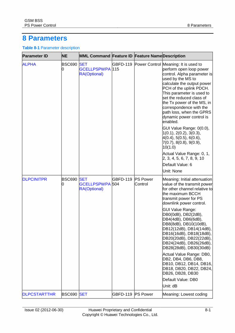
8 Parameters
Table 8-1 Parameter description
Parameter ID NE MML Command Feature ID Feature Name Description
ALPHA BSC6900
SET GCELLPSPWPARA(Optional)
GBFD-119115
Power Control Meaning: It is used to perform open loop power control. Alpha parameter is used by the MS to calculate the output power PCH of the uplink PDCH. This parameter is used to set the reduced class of the Tx power of the MS, in correspondence with the path loss, when the GPRS dynamic power control is enabled.
GUI Value Range: 0(0.0), 1(0.1), 2(0.2), 3(0.3), 4(0.4), 5(0.5), 6(0.6), 7(0.7), 8(0.8), 9(0.9), 10(1.0)
Actual Value Range: 0, 1, 2, 3, 4, 5, 6, 7, 8, 9, 10
Default Value: 6
Unit: None
DLPCINITPR BSC6900
SET GCELLPSPWPARA(Optional)
GBFD-119504
PS Power Control
Meaning: Initial attenuation value of the transmit power for other channel relative to the maximum BCCH transmit power for PS downlink power control.
GUI Value Range: DB0(0dB), DB2(2dB), DB4(4dB), DB6(6dB), DB8(8dB), DB10(10dB), DB12(12dB), DB14(14dB), DB16(16dB), DB18(18dB), DB20(20dB), DB22(22dB), DB24(24dB), DB26(26dB), DB28(28dB), DB30(30dB)
Actual Value Range: DB0, DB2, DB4, DB6, DB8, DB10, DB12, DB14, DB16, DB18, DB20, DB22, DB24, DB26, DB28, DB30
Default Value: DB0
Unit: dB
DLPCSTARTTHR BSC690 SET GBFD-119 PS Power Meaning: Lowest coding

GSM BSS
PS Power Control 8 Parameters
Issue 02 (2012-06-30) Huawei Proprietary and Confidential
Copyright © Huawei Technologies Co., Ltd.
8-2
Parameter ID NE MML Command Feature ID Feature Name Description
0 GCELLPSPWPARA(Optional)
504 Control scheme (with 8PSK used) to start downlink power control. If the current coding scheme is equal to or higher than this parameter, downlink power control can be started. Downlink power control is not required when EGPRS GMSK is applied.
GUI Value Range: MCS5(MCS5), MCS6(MCS6), MCS7(MCS7), MCS8(MCS8), MCS9(MCS9)
Actual Value Range: MCS5, MCS6, MCS7, MCS8, MCS9
Default Value: MCS9
Unit: None
DummyPRGran BSC6900
SET GCELLPSPWPARA(Optional)
GBFD-119504
PS Power Control
Meaning: Set the power reduce granularity for the Dummy control blocks with reserved Uplink State Flag (USF). When the parameter is set to 0, power control is not performed on the Dummy control blocks with reserved USF.
GUI Value Range: 0~15
Actual Value Range: 0~15
Default Value: 15
Unit: None
FMSMAXOPCC BSC6900
SET GCELLCCCH(Optional)
GBFD-111003
GBFD-111101
Radio Common Channel Management
System Information Sending
Meaning: Maximum transmit power level of MSs. As one of the cell reselection parameters in system message 3, this parameter is used to control the transmit power of MSs. For details, see GSM Rec. 05.05.
In a GSM900 cell, the maximum power control level of an MS ranges from 0 to 19, corresponding respectively to the

GSM BSS
PS Power Control 8 Parameters
Issue 02 (2012-06-30) Huawei Proprietary and Confidential
Copyright © Huawei Technologies Co., Ltd.
8-3
Parameter ID NE MML Command Feature ID Feature Name Description
following values (unit: dBm): 43, 41, 39, 37, 35, 33, 31, 29, 27, 25, 23, 21, 19, 17, 15, 13, 11, 9, 7, and 5.Generally, the maximum transmit power supported by an MS is level 5 (corresponding to 33 dBm). The minimum transmit power supported by an MS is level 19 (corresponding to 5 dBm). Other transmit power levels are reserved for high-power MSs.
In a GSM1800 or GSM1900 cell, the maximum power control level of an MS ranges from 0 to 31, corresponding respectively to the following values (unit: dBm): 30, 28, 26, 24, 22, 20, 18, 16, 14, 12, 10, 8, 6, 4, 2, 0, 0, 0, 0, 0, 0, 0, 0, 0, 0, 0, 0, 0, 0, 36, 34, and 32. Generally, the maximum transmit power supported by an MS is level 0 (corresponding to 30 dBm). The minimum transmit power supported by an MS is level 15 (corresponding to 0 dBm). Other transmit power levels are reserved for high-power MSs.
GUI Value Range: 0~19
Actual Value Range: 0~19
Default Value: 5
Unit: None
GAMMA BSC6900
SET GCELLPSPWPARA(Optional)
GBFD-119115
Power Control Meaning: Expected signal receiving strength on the BTS side when GPRS dynamic power control is implemented
GUI Value Range: 0~31
Actual Value Range: 0~31
Default Value: 12
Unit: None
MAXPCSTEP BSC690 SET GBFD-119 PS Power Meaning: Maximum step

GSM BSS
PS Power Control 8 Parameters
Issue 02 (2012-06-30) Huawei Proprietary and Confidential
Copyright © Huawei Technologies Co., Ltd.
8-4
Parameter ID NE MML Command Feature ID Feature Name Description
0 GCELLPSPWPARA(Optional)
504 Control size of power control
GUI Value Range: 1~15
Actual Value Range: 1~15
Default Value: 1
Unit: None
MCSSTABTHR BSC6900
SET GCELLPSPWPARA(Optional)
GBFD-119504
PS Power Control
Meaning: Threshold for the times of using current coding scheme in a measurement period. This parameter is used to determine whether the coding scheme is stable. When the number of using the current coding scheme in a measurement period is equal to this parameter, the coding scheme is stable.
GUI Value Range: 1~16
Actual Value Range: 1~16
Default Value: 8
Unit: None
MCSSTATTHR BSC6900
SET GCELLPSPWPARA(Optional)
GBFD-119504
PS Power Control
Meaning: Threshold for the times of coding scheme adaptation (measurement period in which the stability of a code scheme can be determined). That is, the coding scheme stability can be determined only when the times of coding scheme adaptation is equal to this parameter.
GUI Value Range: 1~16
Actual Value Range: 1~16
Default Value: 10
Unit: None
PB BSC6900
SET GCELLPSPWPARA(Optional)
GBFD-119115
Power Control Meaning: BTS power attenuation on the measured PBCCH
GUI Value Range: DB0(0dB), DB2(-2dB), DB4(-4dB), DB6(-6dB), DB8(-8dB), DB10(-10dB), DB12(-12dB), DB14(-14dB), DB16(-16dB),

GSM BSS
PS Power Control 8 Parameters
Issue 02 (2012-06-30) Huawei Proprietary and Confidential
Copyright © Huawei Technologies Co., Ltd.
8-5
Parameter ID NE MML Command Feature ID Feature Name Description
DB18(-18dB), DB20(-20dB), DB22(-22dB), DB24(-24dB), DB26(-26dB), DB28(-28dB), DB30(-30dB)
Actual Value Range: DB0, DB2, DB4, DB6, DB8, DB10, DB12, DB14, DB16, DB18, DB20, DB22, DB24, DB26, DB28, DB30
Default Value: DB2
Unit: dB
PCMEASCHAN BSC6900
SET GCELLPSPWPARA(Optional)
GBFD-119115
Power Control Meaning: Channel used for the measured receiving power. It is used to set the measured receiving power level of the channel and control the power of the uplink.
GUI Value Range: BCCH(BCCH), PDCH(PDCH)
Actual Value Range: BCCH, PDCH
Default Value: PDCH
Unit: None
PSPCPRES BSC6900
SET GCELLPSPWPARA(Optional)
GBFD-119504
PS Power Control
Meaning: This parameter indicates the minimum granularity of BTS output power during PS downlink power control.
GUI Value Range: 0.2dB(0.2dB), 0.4dB(0.4dB), 0.6dB(0.6dB), 0.8dB(0.8dB), 1.0dB(1.0dB), 1.2dB(1.2dB), 1.4dB(1.4dB), 1.6dB(1.6dB), 1.8dB(1.8dB), 2.0dB(2.0dB)
Actual Value Range: 0.2dB, 0.4dB, 0.6dB, 0.8dB, 1.0dB, 1.2dB, 1.4dB, 1.6dB, 1.8dB, 2.0dB

GSM BSS
PS Power Control 8 Parameters
Issue 02 (2012-06-30) Huawei Proprietary and Confidential
Copyright © Huawei Technologies Co., Ltd.
8-6
Parameter ID NE MML Command Feature ID Feature Name Description
Default Value: 0.6
Unit: dB
SUPPSDLPC BSC6900
SET GCELLPSPWPARA(Optional)
GBFD-119504
PS Power Control
Meaning: Whether to support downlink EGPRS closed-loop power control.
GUI Value Range: NO(No), YES(Yes)
Actual Value Range: NO, YES
Default Value: NO
Unit: None
TGTCIROFFSET BSC6900
SET GCELLPSPWPARA(Optional)
GBFD-119504
PS Power Control
Meaning: Maximum offset of the target CIR. This parameter, together with target CIR, is used to determine the value range of the target CIR.
GUI Value Range: 0~10
Actual Value Range: 0~10
Default Value: 2
Unit: dB
TGTCIRPOS BSC6900
SET GCELLPSPWPARA(Optional)
GBFD-119504
PS Power Control
Meaning: Position corresponding to the target CIR in the value range for the specified coding scheme, that is, the delta between the target CIR and the minimum value in the value range.
GUI Value Range: 0~10
Actual Value Range: 0~10
Default Value: 3
Unit: dB
USFDummyPCFactor
BSC6900
SET GCELLPSPWPARA(Optional)
GBFD-119504
PS Power Control
Meaning: Set the power reduce granularity for the Dummy control blocks with valid USF. When the parameter is set to 0, power control is not performed on the Dummy control blocks with valid USF.
GUI Value Range: 0~10
Actual Value Range: 0~10
Default Value: 3

GSM BSS
PS Power Control 8 Parameters
Issue 02 (2012-06-30) Huawei Proprietary and Confidential
Copyright © Huawei Technologies Co., Ltd.
8-7
Parameter ID NE MML Command Feature ID Feature Name Description
Unit: None

GSM BSS
PS Power Control 9 Counters
Issue 02 (2012-06-30) Huawei Proprietary and Confidential
Copyright © Huawei Technologies Co., Ltd.
9-1
9 Counters
Table 9-1 Counter description
Counter ID
Counter Name Counter Description Feature ID Feature Name
1282449300
POWER.CONTROL.PERCENTAGE.DTX.SUM
R9217:Sum of Power Control Percentages of Untransmitted Packet Downlink Dummy Control Blocks over the PDCH with DTX Enabled
GBFD-119504
PS Power Control
1282449301
POWER.CONTROL.PERCENTAGE.EGPRS.DATA.SUM
R9218:Sum of Power Control Percentages of Transmitted Downlink EGPRS Data Blocks
GBFD-119504
PS Power Control
1282449302
POWER.CONTROL.PERCENTAGE.DUMMY.WITH.VALID.USF.SUM
R9219:Sum of Power Control Percentages of Transmitted Packet Downlink Dummy Control Blocks with Valid USF
GBFD-119504
PS Power Control
1282449303
POWER.CONTROL.PERCENTAGE.DUMMY.WITH.RESERVED.USF.SUM
R9220:Sum of Power Control Percentages of Transmitted Packet Downlink Dummy Control Blocks with Reserved USF
GBFD-119504
PS Power Control
GSM BSS
PS Power Control 10 Glossary
Issue 02 (2012-06-30) Huawei Proprietary and Confidential
Copyright © Huawei Technologies Co., Ltd.
10-1
10 Glossary
For the acronyms, abbreviations, terms, and definitions, see the Glossary.

GSM BSS
PS Power Control 11 Reference Documents
Issue 02 (2012-06-30) Huawei Proprietary and Confidential
Copyright © Huawei Technologies Co., Ltd.
11-1
11 Reference Documents
[1] 3GPP TS 45.008: "RF power control"
[2] BSC6900 Feature List
[3] BSC6900 Optional Feature Description
[4] BSC6900 GSM Parameter Reference
[5] BSC6900 GSM MML Command Reference
[6] BSC6900 GSM Performance Counter Reference