
AUTO POWER CONTROL OF FOUR DIFFERENT SOURCES ...
63
Sudan University of Science and Technology Final Year Project Department of Electrical Engineering AUTO POWER CONTROL OF FOUR DIFFERENT SOURCES TO ENSURE NO POWER BREAK ذاد الكهزبيهع انقطاى عذم اطاقة لضوالربعة هصادر لقة في الطاحكن الذاتي في ا التA project Report Submitted to The Department of Electrical and Nuclear Engineering in The Full Fulfillment of The Requirements of BSc. Electrical Engineering By Omer Mohamed Ahmed Hamid Alsafy Saif Aldowla Mohamed Ali Hamid Hammad Yousif Abdalbasit Mokhtar Hamid Supervised By: Dr. Alfadel Zakareya Yahya October, 2017
-
Upload
khangminh22 -
Category
Documents
-
view
1 -
download
0
Transcript of AUTO POWER CONTROL OF FOUR DIFFERENT SOURCES ...

37
Sudan University of Science and Technology Final Year Project
Department of Electrical Engineering
AUTO POWER CONTROL OF FOUR DIFFERENT
SOURCES TO ENSURE NO POWER BREAK
التحكن الذاتي في الطاقة في اربعة هصادر للطاقة لضواى عذم انقطاع االهذاد الكهزبي
A project Report Submitted to The Department of Electrical and
Nuclear Engineering in The Full Fulfillment of The Requirements of
BSc. Electrical Engineering
By
Omer Mohamed Ahmed Hamid Alsafy
Saif Aldowla Mohamed Ali Hamid Hammad
Yousif Abdalbasit Mokhtar Hamid
Supervised By:
Dr. Alfadel Zakareya Yahya
October, 2017

I
DEDICATION
We dedicate this work to
Our loving mothers
Their strong and gentle souls who taught us in Allah, believe in hard work
and that so much could be done.
Our fathers
Who provided an honest life for us, who taught us to believe in our selves
-

II
ACKNOWLEDGEMENT
First, all praise gratitude belong to Allah, today we fold the day, not only for
given us life, but also for making life beautiful for us by knowledge.
We would like to express our deepest gratitude to our supervisor Dr. AlFadel
Zakareya Yahya for his continues support, patience, motivation and
immense knowledge throughout this research. Working under his
supervision was a very great experience.

III
ABSTRACT
The main objective of this project is to provide uninterrupted power
supply to a load, by selecting the supply from any source out of 4 such as
main power supply, generator, solar, and wind power supply automatically
in the absence of any of the source. The demand for electricity is increasing
every day and frequent power cuts is causing many problems in various
areas like industries, hospitals and houses. An alternative arrangement for
power source is a serious matter.
In this project we used four switches to demonstrate the respective
failure of that power supply. When any of the switches is pressed it shows
the absence of that particular source, switches are connected to
microcontroller as input signals. A microcontroller of ATMEGA-32 family
is used. The output of microcontroller is given to the relay driver IC, which
switches appropriate relay to maintain uninterrupted supply to the load. The
output shall be observed using a lamp drawing power supply from main
supply initially. On failure of the main supply (which is actuated by pressing
the appropriate switch) the load gets supply from the next available source,
say the solar. If the solar also fails it switches over to the next available
source and so on. The current status, as to which source supplies the load is
also displayed on an LCD. As it is not feasible to provide all 4 different
sources of supply, one source with alternate switches are provided to get the
same function, Taking in consideration the use of the source whose cost is
the lowest then, the higher cost sources and so on.

IV
:الوستخلص
رنهك باخخياس يٍ انبذث هى حىفيش ايذاد دائى نهطاقت انكهشبائيت بانُسبت نهذًم و انهذف االساسي
يصذس انطاقت انشًسيت،يصذس وهي )انًصذس انشئيسي ،يٍ بيٍ اسبؼت يصادس يصذس االيذاد حهقائيا
اٌ سابقا، انًصادس انًزكىسةاٌ اي يٍ طاقت انشياح ويصذس انًىنذ انكهشبائي( في دانت فشم أوفقذ
يشكهت اَقطاع انكهشباء انًخكشسة حسبب انؼذيذ يٍ انخسائش يىييا في يخخهف انًجاالث انصُاػيت
نزنك البذ يٍ احخار اجشاءاث ادخياطيت بانُسبت نُظاو انطىاسئ انكهشبائي نخفادي وانزساػيت وانصذيت
وحقهيم انضشس انُاجى ػٍ يشكهت االَقطاع انكهشبائي .
كم سيالي يخصم بًفخاح في هزا انًششوع يثهُا انًصادس االسبؼت باسخخذاو اسبؼت سيالياث
نيًثم انؼطم انزي قذ يطشأ في ادذ انًصادس االسبؼت، يخى انخذكى في هزة انذائش بىاسطت
انًيكشوكُخشونش ديث يخى ػشض انبياَاث في شاشت ػشض يٍ انُىع ال سي دي فيها يىضخ
فىنج،حخى ػًهيت انخبذيم بيٍ 222ي يخى ػبشِ االيذاد انكهشبائي نهذًم انزي هى يصباح انًصذس انز
انًصادس بسشػت فائقت بذيث اليُقطغ االيذاد ػٍ انذًم.

IV
List OF CONTENTS
Title…………………………………………………………...page No
Dedication……………………………………………………………..I
Acknowledgement…………………………………………………….II
Abstract……………………………………………………………….III
List of contents……………………………………………………..IV-V
List of figures…………………………………………………….VI-VII
List of abbreviations………………………………………………...VIII
Chapter one: Introduction…………………………………………..1
1.1 Overview…………………………………………………………1-2
1.2 problem statement………………………………………………....3
1.3 Objectives………………………………………………………….3
Thesis layout..........................................................................................4
Chapter two: Literature review……………………….…………5-16
2.1 Introduction……………………………………………………..5-6
2.1 Background…………………………….………………………….7
2.2 Review in solar and wind energy……………………………….....7
2.2.1 Solar…………………………………………………………..7-8
2.2.2 Advantages of solar energy……………………………………..8
2.2.3 Disadvantages of solar energy…………………………………..8
2.3 Wind energy……………………………………………………8-10
2.3.1 Advantages of wind energy……………………………………...8
2.3.2 Disadvantages of wind energy………………………………..9-10

V
2.4 Comparison between wind and solar……………………………..11
2.5 Renewable energy in Sudan…………………………………...11-12
2.6 Wind energy in Sudan…………………………………………12-13
2.7 Solar energy in Sudan…………………………………………13-14
2.8 Previous studies……………………………………………….14-16
Chapter three: Design methodology……………………………17-36
3.1 Introduction…………………………………………………….....17
3.2 Working principle……………………………………………..18-21
3.3 Hardware equipments………………………………………….22-36
Chapter four: Results, circuit operation and simulation………37-45
4.1 Practical model result…………………………………………..…37
4.2 project simulation……………………………………………...37-42
4.3 Circuit operation…………………………………………….…43-44
Chapter five: Conclusion and recommendation………………..45-53
5.1 Conclusion………………………………………………………....45
5.2 Recommendation…………………………………………………..46
References……………………….………………………………...47-48
Appendices………………………………………………………...49-53
Appendix A………………………………………………………...59-53

VI
LIST OF FIGURES
Figure…………………………………………………………page No
Figure (2.1) simple UPS system……………………………………….....6
Figure (2.2) wind power plant places in Sudan……………....................13
Figure (2.3) a solar power project in northern Sudan………...................14
Figure (3.1) the project block diagram……………………………….…21
Figure (3.2) the project flow chart program………………………….…22
Figure (3.3) Atmega32 pin diagram………………………………….…25
Figure (3.4) the ATMEGA block diagram………………………….….28
Figure (3.5) the actual relay and the relay circuit…………………....…29
Figure (3.6) actual relay internal construction and internal circuit….....30
Figure (3.7) the relay block diagram…………………………………....30
Figure (3.8) the relay derive IC……………………………………….....31
Figure (3.9) actual LEDs………………………………………………...32
Figure (3.10) actual LCD……………………………………………...…34
Figure (3.11) LCD’s connections…………………………………..........35
Figure (3.12) LCD’s 8 mode interfacing…………………………….......36
Figure (3.13) LCD’s 4 mode interfacing………………………….……..37
Figure (4.1) shows the practical circuit result…………………………...38
Figure (4.2) the project simulation when all switches are OFF……...….39

VII
Figure (4.3) the project simulation when switch 1 is ON………………...40
Figure (4.4) the project simulation when the solar supply is active……...41
Figure (4.5) the state when the solar supply fails………………………...42
Figure (4.6) the state when the wind supply fails………………………...43

VIII
LISTOF ABBREVIATIONS
UPS: Uninterruptable Power Supply.
EMI: Electromagnetic Interface.
RFI: Radio Frequency Interface.
MED: Ministry of Electricity and Damps.
DC: Direct Current.
AC: Alternative Current.
LED: Light Emitting Diode.
IC: Integrated Circuit.
NO: Normal Open.
NC: Normal Close.
V: Voltage.
LCD: Liquid Crystal Display.
R: Resistor.
AVR: Alf and Vegard’s RISC processor.
ADC: Analog to Digital Convertor.
EEPROM: Electrical Erasable Programmable Read Only Memory.
SPI: Serial Peripheral Interface.
USART: Universal Synchronous and Asynchronous Receiver and
Transmitter.

1
CHAPTER 1
INTRODUCTION
1.1 Overview
As a matter of fact the problem of electricity cut is affecting daily
human activities every day , specially here in Sudan the demand for
electricity is increasing day by day and frequent power cuts are causing
many problems in various areas like industrial areas , hospitals , banks
,companies and houses. So, an alternative arrangement for the power source
must be made in order to avoid the damage caused by the power cut. An
important requirement of electric power distribution systems is the need for
automatic operation. In particular, the rapid and reliable transfer of the
power supply system from one power source to another during certain
system events is important in achieving the reliability goals for such systems
and the facility serves. However, the design of such an automatic transfer
system is all–too-often considered “less important” than many other aspects
of the overall power system design. Nowadays, electrical power supply is
one of the important elements in human being's needs. The most of the
human activities is dependent on electrical power supply. In other words,
without electrical power supply, almost the whole activities are become
postponed or worse cancelled. For usage of daily routine, voltage supplied is
within 220V ac. The need for power supply is paramount for the growth of a
country, access to electricity as the basic form of energy supply to the
masses is vital for the development of a nation's economy. The strategic role
and policy of generation electricity in the development of an economy has
always been appreciated by most developed nations, with the likes of

2
France, Germany, and Italy. All these mentioned countries are well and truly
developed countries that sustain the supply of energy to it environment for
the purpose of industrial development. The power sector provides a platform
for economic development; electricity has brought about development in all
area of productions and services. Electricity has become indispensable to
socio-economic and industrial development of any nation. Using
uninterrupted power supply in an automated mode, we always have a
substitute arrangement as backup to take place of main power supply in case
of power-cut in an emergency case, where the power cut cannot be avoided
[1].

3
1.2 Problem statement
In fact power cut or interruption is a real problem facing countries
which having a lack of power generation, or power shortage issues. This
problem is really affecting human life in so many aspects costing people a
lot of money in industrial areas, trading companies and banks. Not only this
but also, putting human life in danger as interruptions happen also in
hospitals. It is obvious that power cut problems complicate human’s daily
life as electricity is involved in most of human activities. Moreover, a lot of
emergency power systems do not provide an uninterruptable power supply
to the load. Thus, a special arrangements for the power emergency systems
need to be made.
1.3 Objectives
To solve the power cut or power shortage problem.
To design an emergency system that ensures the continuous
supply of power to any specified load even during fault
conditions.
To minimize the delay in the process of shifting the supply
source from the main supply to the alternative back up source to
the smallest possible value.
To reduce the power bill by setting a selecting sequence of
sources which will select the lowest at first then, the higher cost
and so on.

4
Thesis Layout
This project is organized into five chapters:
Chapter one gives the introduction to the project and the project
objectives, Chapter two is the literature review which discusses the use of
solar and wind energy, their advantages and disadvantages and their use
here in Sudan. Chapter three gives the design methodology and the
complete description of the project components. Chapter four shows the
project simulation and the design results. Chapter five gives the
conclusion of the whole project, the future scope and outlines both
appendices and references used.

5
CHAPTER 2
LITERATURE REVIEW
2.1 Introduction
In fact there are several types of emergency power systems being used
all over the world, one of the most used types is the UPS system, also known
as an uninterruptible power supply which is an electrical apparatus that
provides emergency power to load when input source, typically the main
source power fails. It provides near-instantaneous protection from input
power interruptions by supplying energy stored in batteries.
The disturbances which normally occur in commercial supply are as
follows:
1. Transients – occur due to lightning, switching of power network which
may result in instantaneous rise of voltage.
2. Momentary over- and under- voltage which may be due to large changes
of loads in power systems.
3. Generation of harmonics or distortion of waveforms.
4. Electromagnetic interference (EMI) or Radio frequency interference (RFI)
or noise are introduced in the supply line due to lighting, power network
switching, continuous switching by some equipment like static inverters.
The uninterruptible power supply (UPS) is the best solution to power
conditioning for critical loads, such as real-time data processing computers,
air route traffic, control centers, industrial process control system because
they are very sensitive to the nature of power supply for their operation,

6
protection of the equipment and continuity of a process or transfer of
information.
Input Output
charching backup
Figure 2.1: shows simple UPS system
The difference between the circuit that we are about to design is that the
UPS’s main function is to protect critical loads against the different types of
disturbance which may occurs with the power sources by shifting the supply
to the backup rechargeable battery. So, the load will have an uninterruptable
power supply of power. On the other hand, our project aims to have no
interruption on power being supplied to the load by shifting the supply to the
backup solar, wind and a generator sources as well as to reduce the financial
cost of using such an emergency power system, and that by using the solar
and wind power supplies as backup sources because they have low operating
cost. Although, the circuit we are attempting to design will work effectively
during faults and not in response to small disturbances of power source, but
also it has a noticeable benefits.
DC UPS
Battery
7
2.1 Background
In this project we are attempting to solve the power interruption problem
as it is a serious matter here in Sudan, like most of the oil importing
countries Sudan suffered a lot from sharp increase of oil prices in the last
decades, as this country is having a power shortage problem we introduced
the use of renewable energy like solar and wind power supplies as a
solution.
Solar and wind are all clean renewable energies with a huge amount of
resource and a great potential of electricity generation .nowadays there is a
real need to develop renewable energy for so many reasons:
First, they are inexhaustible compared to the other types.
Second, they are clean and don’t cause any type of air or
environmental pollution.
Third, they are safe and cause no threat to human life unlike the
nuclear energy.
2.2 Review in solar and wind energy
2.2.1 Solar:
Solar energy is derived from the sun’s radiation. The sun is a
powerful energy source. Did you know that the energy that it provides
to earth for one hour could meet the global energy needs for one entire
year? We are able to harness only 0.001 percent of that energy.
There is a reason why solar energy has become a trending topic
when talking about renewable energies .While it has been popularly
criticized for being expensive or not very efficient, solar energy has

8
now proved to be very beneficial not only for the environment but
also financially speaking. Additionally, due to the higher demand the
technology has been improved considerably, turning into a very
efficient source of clean energy [2].
2.2.2 Advantages of solar energy
Renewable source of energy.
Reduces electricity bills.
Divisive applications
Low maintenance cost.
Technology development
2.2.3 Disadvantages of solar energy
Installation cost is quite high.
Whether dependant.
Solar energy storage is expensive.
Require a lot of space.
2.3 Wind energy
Wind energy offers many advantages, which explains why it’s one
of the fastest growing energy sources in the world. Wind has a
powerful mechanical energy able to drive large shafts of electricity
generators providing clean energy and in somehow solving the planet
pollution issue [2].

9
2.3.1 Advantages of wind energy
The wind is free and with modern technology it can be
captured efficiently.
Once the wind turbine is built the energy it provides does not
cause green house gases or other pollutants.
Although wind turbines can be very tall each takes up a small
plot of land. This means that the land below can still be used.
This is specially the case in agricultural areas as farming can
still continue.
Many people find wind farms an interesting feature of
landscape.
Remote areas that are not connected the electricity power grid
can use wind turbines to produce their own supply.
Wind turbines have a role to play in both the developed and
third world.
Wind turbines are available in a range of sizes which means a
vast range of people and businesses can use them single
households to small towns and villages can make good use of
range of wind turbines available today [2].

10
2.3.2 Disadvantages of wind power
The strength of the wind is not constant and it varies from zero to
storm force. This means that wind turbines do not produce the same
amount of electricity all the time. There will be time when they
produce no electricity at all.
Many people feel that the countryside should be left untouched,
without these large structures being built. The landscape should left in
its natural form for everyone to enjoy.
Wind turbines are noisy. Each one can generate the same level of
noise as a family car travelling at 70 mph.
Many people see large wind turbines as unsightly structures and not
pleasant or interesting to look at. They disfigure the countryside and
are generally ugly.
When wind turbines are being manufactured some pollution is
produced. Therefore wind power does produce some pollution.
Large wind farms are needed to provide entire communities with
enough electricity. For example, the largest single turbine available
today can only provide enough electricity for 475 homes, when
running at full capacity. How many would be needed for a town of
100 000 people? [2].

11
2.4 Comparison between wind and solar:
Solar power is only available during the day while wind power is
available even at night.
Wind power is mechanical while solar power can be mechanical or
purely electrical.
Solar power can be extracted at minute amounts while the same
cannot be done with wind power.
Solar power can be used with vehicles but not wind power.
Wind power does not take up as much land as solar power [3].
2.5 Renewable energy in Sudan
Sudan is an agricultural country with fertile land, plenty of water
resources, livestock, forestry resources and agricultural residues. Energy is
one of the key factors for the development of national economies in Sudan.
An overview of the energy situation in Sudan is introduced with reference to
the end uses and regional distribution. Energy sources are divided into two
main types; conventional energy (biomass, petroleum products, and
electricity); and non-conventional energy (solar, wind, hydro, etc.). Sudan
possesses a relatively high abundance of sunshine, solar radiation and
moderate wind speeds, hydro and biomass energy resources. Application of
new and renewable sources of energy available in Sudan is now a major
issue in the future energy strategic planning for the alternative to the fossil
conventional energy to provide part of the local energy demand. Sudan is an
important case study in the context of renewable energy. It has a long history

12
of meeting its energy needs through renewable energy. Sudan’s renewable
energy diverse, due in part to the country’s wide range of climates and
landscapes. Like many of the African leaders in renewable energy
utilization, Sudan has a well-defined commitment to continue research,
development, and implementation of new technologies. Sustainable low-
carbon energy scenarios for the new century emphasize the untapped
potential of renewable resources. Rural areas of Sudan can benefit from this
transition. The increased availability of reliable and efficient energy services
stimulates new development alternatives. It is concluded that renewable
environmentally friendly energy must be encouraged, promoted,
implemented and demonstrated by full-scale plant for the use in remote rural
areas [4].
2.6 Wind energy in Sudan
Acknowledging the huge potential for renewable energies in Sudan, the
Ministry of Electricity and Dams of Sudan (MED) intends to develop
renewable energy power projects in order to promote sustainable
development. In the initial stage, MED has foreseen to focus on wind energy
projects and awarded a contract to Lahmeyer International as consultant for
the development of the first three wind farms:
Nyala, located in “Darfour” state in western Sudan, capacity: 20 MW
Dongola, located in the north of Sudan, where Lahmeyer International
performed on-site wind measurements in 2001 and 2002, capacity: 100 MW
Red Sea Cost, capacity: 180 MW [5].

13
Figure 2.2: shows wind power plant places in Sudan
2.7 Solar energy in Sudan
Solar energy-powered pumps project for irrigation in the Northern State:
The idea behind the project is to replace the diesel-powered water pumps
currently used in agricultural schemes with solar energy- powered ones
whose lifespan is now roughly 25 years without having operation costs, such
as fuel and spare parts. The project will also reduce emissions of carbon
dioxide resulting from the burning of diesel fuel [6].
Figure 2.3: shows a solar power project in northern Sudan

14
2.8 Previous studies
Robert Douwona [7] found out that emergency power systems
were used as early as World War II on naval ships. In combat, a ship
may lose the function of its steam engines which powers the steam-
driven turbines for the generator. In such a case, one more diesel
engines are used to drive backup generators. Early changeover
switches relied on manual operation: two switches would be placed
horizontally in line and the “ON” position facing each other, a rod
placed in between, in order to operate the changeover switch, one
source must be turned off, the rod moved to the other side and other
turned on. With adequate power supply base of the nation at the
moment, it is almost impossible to supply electricity to consumers at
all times. The unreliable public power supply has led many to the
alternative power supply sources. In Nigeria today, the use of
generators to power businesses and machines have become the norm.
According to the Director-General of Centre for Management
Development, Dr. Kabir Usman that Nigeria has the highest number
of standby generators in Africa, averaging to every 2.5 people has at
least one standby generator. He also pointed out that about 60million
Nigerians spend 1.6trillion naira on generators annually. Many
generators are in use; while some are manually started others are
automatically activated.
According to Jonathan [8], manual changeover switch system
still remains the oldest changeover switch box used by majority of
the electricity consumers. Manual changeover switch box separates
the source between a generator and public supply. Whenever there is

15
power failure, change-over is done manually by an individual and
the same happens when the public power is restored. This is usually
accompanied by a loud noise and electrical sparks. According to him
there are some of the limitations in the manual change over switch
i.e. manual changeover is time wasting whenever there is power
failure, it is strenuous to operate because a lot of energy is required,
it causes device process or product damage, it has the potential to
cause fire outbreak and it is usually accomplished by a lot of noise
which may sometimes be psychologically destabilizing.
According to Mbaocha [9], Manual changeover maintenance is
frequent because the changeover action causes tear and wear.
According Katz R and Boriella [10], the main advantage of the
sequential logic control power changeover switch is its simplicity.
According to them there are some of the disadvantages in sequential
logic control system i.e. the main possible clock rate is determined
by the slowest logic path in the circuit, otherwise known as the
critical path. Every logical calculation, from the simplest to the most
complex must be complete in one clock cycle, so logic paths that
complete their calculations quickly are idle much of time, waiting for
the next clock pulse. The clock signal must be distributed to every
flip-flop in the circuit. As the clock is usually a high frequency
signal, this distribution consumes a relatively large amount of power
and dissipates much heat. Even the flip-flop that is doing nothing
consumes a small amount of power, thereby generating waste heat in
the chip.
According to ShanmukhaNagaraj and Ramesh [11], in
sequential logic control of power selection, sequential digital circuits

16
are used to effect the detection and control of the supplied power.
Sequential logic control involves only an automatic violation of the
public power source in the event of power failure, but the generator
activation to supply alternative power is done manually. In effect the
sequential logic control is more efficient then the manual control.

17
CHAPTER THREE
DESIGN METHODOLOGY
3.1 Introduction
When the supply from all the sources (Mains, Solar, wind and
generator) are ready, first “Normally open” switch is pressed then the main
gets failed and the supply automatically shifts to solar. To proceed further,
second normally open switch is pressed then the solar get failed and supply
is provided from wind and so on. Priority is assigned to each power source
in the order of Mains, solar, wind and Generator. In case the mains power
supply fails, the supply should automatically shift to the solar but if solar
also fails at the moment then the supply will automatically shift to next
priority source. Figure below explains the construction of the Auto power
supply of four different sources. As shown in the diagram the four sources
are Mains, solar, wind and Generator, four “Normally open” switches are
used to show the failure of each supply source, four relays are used to
provide protection at each respective output. This output can be used to drive
any load such as a lamp or motor. LEDs are used to display the source of
supply. Other case is when the power switches from one source to another,
say solar fails and supply shifts to wind, if the mains come back then the
supply will automatically reach back to mains power instead of switching to
solar. At the output of microcontroller, each output port is connected to
positive DC voltage. Relays are used in contact with the output port to
provide switching at the output.

18
3.2 Working Principle
The project uses an arrangement where four different sources of supply
are channelized to a load so as to have an uninterrupted operation of the
load. As it is not practicable to get four sources of supply such as mains
supply, generator supply, wind supply and solar supply, we used relays only.
The source of 220-v supply is used and assumed as if being fed from four
different sources by connecting all the four incoming sources in parallel as
seen in the block circuit diagram. The AC source to the lamp is connected to
relay 1, relay 2, relay 3 and relay 4 by making the entire “NO” (normally
open) contacts parallel and all the common contacts in parallel. Four
selecting switches representing failure of corresponding supply such as
mains, solar, wind and generator respectively connected to pin 0,1, 2,3 on
port “C” in the ATMEGA32 microcontroller, The port pins are pulled up
with 10k resistors for reliable operation of achieving high and low logic by
the program. It is so written that initially the relay driver IC ULN2003 pin
number 1 gets a logic high from microcontroller port ”D” pin 1 that results
in pin number 16 of the ULN 2003 going low to activate the relay 1 which
results in the load i.e., lamps gets the supply through relay 1 “NO” contacts.
While the selecting switch meant for mains is pressed that represents failure
of mains supply resulting in port “D” pin 2 going high along with ULN2003
pin 2 (pin number 15) goes low and pin 16 of ULN2003 going high. These
results in pin number 16 of ULN2003 going low while pin number 15 goes
high simultaneously. This causes relay 2 to switch „ON‟ that represents
supply source from generator, thus the lamp gets supply now from the solar
in the event of mains fail. After that if both main button and generator

19
buttons are pressed meaning both mains and generator supply fail to the
micro controller input that results in port “D” pin 3 to go high at that time
pin 1 and 2 go to low. Accordingly pin14 of ULN2003 goes low leaving
pin16 and 15 to high such that the relay 3 is switched on while relay 1 and 2
remain in switched off condition. As the relay 3 corresponds to solar supply
the lamp now gets the supply from solar. If the solar selecting button is
pressed along with the main and solar button that simulates failure of main,
generator, solar resulting in microcontroller pin no 4 going high leaving port
1, 2, 3 low which enables the ULN2003 pin no 13 to go low leaving pin no
16, 15, and 14 high such that relay 4 is switched ON that gets supply from
the wind source. If the wind button is pressed together with main, solar,
wind simulating failure of all the supply sources results in port “D” pin
1,2,3,4 which results in pin no 13,14,15,16 of the ULN2003 going high
together with. Thus all the relays are off leaving no supply to the lamp. One
16 x 2 lines LCD is used to display the condition of the supply sources and
the load on real time base.

20
Figure 3.1: shows the project block diagram
Lamp
220V
Indicator
Lamp
ATMEGA
Microcontr
oller
DC Power
Supply 5V
Keyboard
Relay
Driver
IC
LCD
Relay1
Relay2
Relay3
Relay4
Four
Defer
ent
sourc
es
(220V
AC)

21
Figure 3.2: shows the project flow chart program
main power supply
Switch1 OFF, main supply fails, supply shifts to solar supply
Switch1
Swich3, OFF, solar supply fails, supply shifts to wind
Swich4, OFF wind supply fails
switch2 ON
Supply shifts to generator
Switch 2 OFF, generator fails
YES
NO
YES
NO
If
YES
NO

22
3.3 Hardware Equipments
3.3.1 Atmega32 8bit microcontroller
It is the control unit of the whole circuit. Which gives the command signals
depending on a C program which been installed in it already.
Background
In our days, there have been so advancement in the field of Electronics
and many cutting edge technologies are being developed every day, but still
8 bit microcontrollers have its own role in the digital electronics market
dominated by 16-32 & 64 bit digital devices. Although powerful
microcontrollers with higher processing capabilities exist in the market, 8bit
microcontrollers still hold its value because of their easy-to-understand-
operation, very much high popularity, ability to simplify a digital circuit,
low cost compared to features offered, addition of many new features in a
single IC and interest of manufacturers and consumers.
Today’s microcontrollers are much different from what it were in the initial
stage, and the number of manufacturers are much more in count than it was a
decade or two ago. At present some of the major manufacturers are
Microchip (publication PIC microcontrollers), Atmel (publication AVR
microcontrollers). Our interest is upon ATmega32. It belongs to Atmel’s
AVR series micro controller family. Let’s see the features [12].
23
PIN count:
Atmega32 has got 40 pins. Two for Power (pin no.10: +5v, pin no. 11:
ground), two for oscillator (pin 12, 13), one for reset (pin 9), three for
providing necessary power and reference voltage to its internal ADC, and 32
(4×8) I/O pins [12].
About I/O pins:
ATmega32 is capable of handling analogue inputs. Port A can be used
as either DIGITAL I/O Lines or each individual pin can be used as a single
input channel to the internal ADC of ATmega32, plus a pair of pins AREF,
AVCC & GND (refer to ATmega32 data sheet) together can make an ADC
channel [12].
No pins can perform and serve for two purposes (for an example: Port A
pins cannot work as a Digital I/O pin while the Internal ADC is activated) at
the same time. It’s the programmers are responsibility to resolve the conflict
in the circuitry and the program. Programmers are advised to have a look to
the priority tables and the internal configuration from the datasheet [12].
Digital I/O pins:
ATmega32 has 32 pins (4portsx8pins) configurable as Digital I/O pins.
Timers:
3 Inbuilt timer/counters, two 8 bit (timer 0, timer 2) and one16 bit
(timer1).

24
ADC:
It has one successive approximation type ADC in which total 8 single
channels are selectable. They can also be used as 7 (for TQFP packages) or 2
(for DIP packages) differential channels. Reference is selectable, either an
external reference can be used or the internal 2.56V reference can be brought
into action. There external reference can be connected to the AREF pin.
Communication Options:
ATmega32 has three data transfer modules embedded in it. They are
Two Wire Interface
USART
Serial Peripheral Interface
Figure 3.3 shows Atmega32 pin diagram

25
Analog comparator:
On-chip analog comparator is available. An interrupt is assigned for
different comparison result obtained from the inputs.
External Interrupt:
3External interrupt is accepted. Interrupt sense is configurable.
Memory:
It has 32Kbytes of In-System Self-programmable Flash program
memory, 1024 Bytes EEPROM, 2Kbytes Internal SRAM. Write/Erase
Cycles: 10,000 flash / 100,000 EEPROM.
Clock:
It can run at a frequency from 1 to 16 MHZ. Frequency can be obtained
from external Quartz Crystal, Ceramic crystal or an R-C network. Internal
calibrated RC oscillator can also be used.

26
More Features:
Up to 16 MIPS throughput at 16 MHz .Most of the instruction executes
in a single cycle. Two cycle on-chip multiplication. 32 × 8 General Purpose
Working Registers
Programming:
Atmega32 can be programmed either by In-System Programming via
Serial peripheral interface or by Parallel programming. Programming via
JTAG interface is also possible. Programmer must ensure that SPI
programming and JTAG are not being disabled using fuse bits; if the
programming is supposed to be done using SPI or JTA [12].

27
ATMEGA block diagram:
Figure 3.4: shows the ATMEGA block diagram
3.3.2 Relay
It is an electromagnetic switch.
Used to control the electrical devices.
Copper core magnetic flux plays an important role here.

28
A relay is an electrically operated switch. Current flowing through the
coil of the relay creates a magnetic field which attracts a lever and changes
the switch contacts. The coil current can be on or off so relays have two
switch positions and they are double throw (changeover) switches.
The relay’s switch connections are usually labeled COM (POLE), NC
and NO, COM/POLE= Common, NC and NO always connect to the moving
part of the switch. NC = Normally Closed, COM/POLE is connected to this
when the relay coil is not magnetized. NO = Normally Open, COM/POLE is
connected to this when the relay coil is magnetized and vice versa.
A relay shown in the picture is an electromagnetic or mechanical relay.
Figure 3.5: shows the actual relay and the relay circuit

29
Figure 3.6: shows actual relay internal construction and internal circuit
Figure 3.7: shows the relay block diagram
3.4.1Relay derive
• The ULN functions as an inverter.

30
• If the logic at input 1B is high then the output at its corresponding pin
1C will be low.
The ULN2003A is an array of seven NPN Darlington transistors
capable of 500m.A, 50 V output. It features common-cathode fly back
diodes for switching inductive loads. It can come in PDIP, SOIC, SOP or
TSSOP packaging [13].
Figure 3.8: shows the relay derive IC

31
3.3.3 LED
LEDs are semiconductor devices are made out of silicon. When current
passes through the LED, it emits photons as a byproduct. Normal light bulbs
produce light by heating a metal filament until its white hot.
LEDs present many advantages over traditional light sources including
lower energy consumption, longer lifetime, improved robustness, smaller
size and faster switching. They do dozens of different jobs and are found in
all kinds of devices. Among other things, they form numbers on digital
clocks, transmit information from remote controls, light up watches and tell
you when your appliances are turned on. Collected together, they can form
images on a jumbo television screen or illuminate a traffic light [14].
Figure 3.9: shows actual LEDs
32
3.3.4 Liquid crystal LCD
Most common LCDs connected to the microcontrollers are 16x2 and
20x2 displays.
This means 16 characters per line by 2 lines and 20 characters per line
by 2 lines, respectively.
The standard is referred to as HD44780U, which refers to the
controller’s chip which receives data from an external source (and
communicates directly with the LCD.
LCD (Liquid Crystal Display) is an electronic display which is
commonly used nowadays in applications such as calculators, laptops,
tablets, mobile phones etc. 16×2 character LCD module is a very basic
module which is commonly used by electronic hobbyists and is used in
many electronic devices and project. It can display 2 lines of 16 characters
and each character is displayed using 5×7 or 5×10 pixel matrix. Interfacing
16×2 LCD with Atmega32 Atmel AVR Microcontroller using Atmel Studio
is bit complex as there is no built in libraries. To solve this difficulty we
developed a LCD library which includes the commonly used features. Just
include our header file and enjoy. You can download the header file from the
bottom of this article. 16×2 LCD can be interfaced with a microcontroller in
8 Bit or 4 Bit mode. These differ in how data and commands are send to
LCD. In 8 Bit mode character data (as 8 bit ASCII) and LCD command are
sent through the data lines D0 to D7. That is 8 bit data is send at a time and
data strobe is given through E of the LCD. But 4 Bit mode uses only 4 data
lines D4 to D7. In this 8 bit data is divided into two parts and are sent
sequentially through the data lines. The idea of 4 bit communication is
33
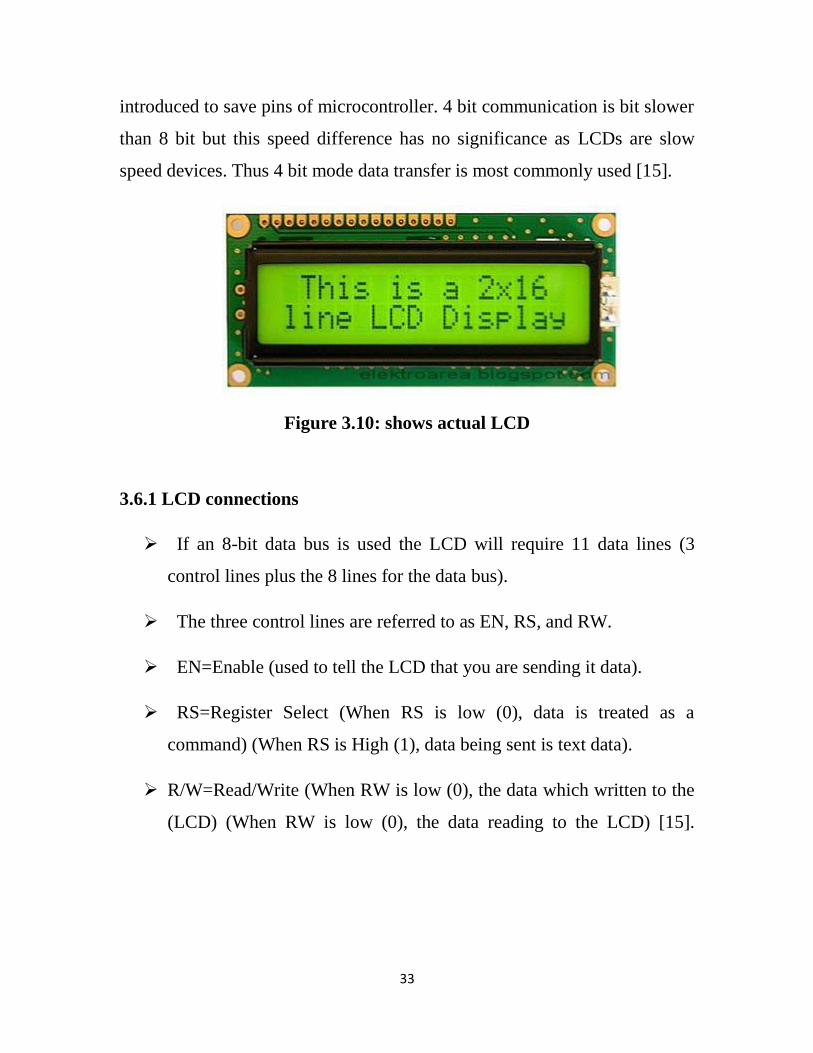
introduced to save pins of microcontroller. 4 bit communication is bit slower
than 8 bit but this speed difference has no significance as LCDs are slow
speed devices. Thus 4 bit mode data transfer is most commonly used [15].
Figure 3.10: shows actual LCD
3.6.1 LCD connections
If an 8-bit data bus is used the LCD will require 11 data lines (3
control lines plus the 8 lines for the data bus).
The three control lines are referred to as EN, RS, and RW.
EN=Enable (used to tell the LCD that you are sending it data).
RS=Register Select (When RS is low (0), data is treated as a
command) (When RS is High (1), data being sent is text data).
R/W=Read/Write (When RW is low (0), the data which written to the
(LCD) (When RW is low (0), the data reading to the LCD) [15].

34
Figure 3.11: shows LCD’s connections

35
8 mode interfacing
Circuit diagram:
+
Figure 3.12: shows LCD’s 8 mode interfacing

36
4 Bit Mode Interfacing
Circuit Diagram
Figure 3.13: shows LCD’s 4 mode interfacing
37
CHAPTER 4
RESULTS, CIRCUIT OPERATION AND
SIMULATION
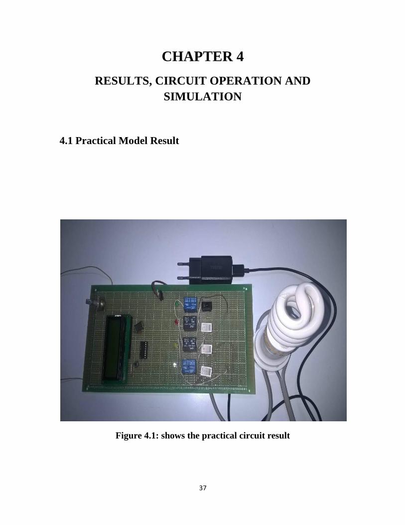
4.1 Practical Model Result
Figure 4.1: shows the practical circuit result

38
4.2 Project Simulation
4.2.1 First, initial state:
Figure 4.2: shows the project simulation when all switches are OFF
It is clear that when all switches are OFF there’s no power being
supplied to the load or the (220V) Lamp.

39
4.2.2 Second, when the main supply is active:
Figure 4.3: shows the project simulation when switch 1 is ON
It is obvious that when switch (1) is ON the active source is the main
power supply as shown in the screen. The indicator lamp (D1) as shown in
figure (12) above, indicates that the relay which supplying power to the
(220V) lamp is the relay which representing the main supply source.

40
4.2.3Third, the main supply fails:
Figure 4.4: shows the project simulation when the solar supply is active
As switch (1) is OFF, this represents a fault being happening within the
main power supply. So the circuit shifts immediately to the solar supply, the
screen status and the indicator lamp (D3) as shown in figure (13) above,
indicates that the (220V) lamp is being fed from relay (2) which representing
the solar supply.
41
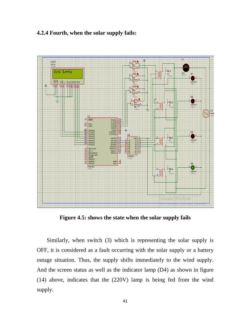
4.2.4 Fourth, when the solar supply fails:
Figure 4.5: shows the state when the solar supply fails
Similarly, when switch (3) which is representing the solar supply is
OFF, it is considered as a fault occurring with the solar supply or a battery
outage situation. Thus, the supply shifts immediately to the wind supply.
And the screen status as well as the indicator lamp (D4) as shown in figure
(14) above, indicates that the (220V) lamp is being fed from the wind
supply.
42
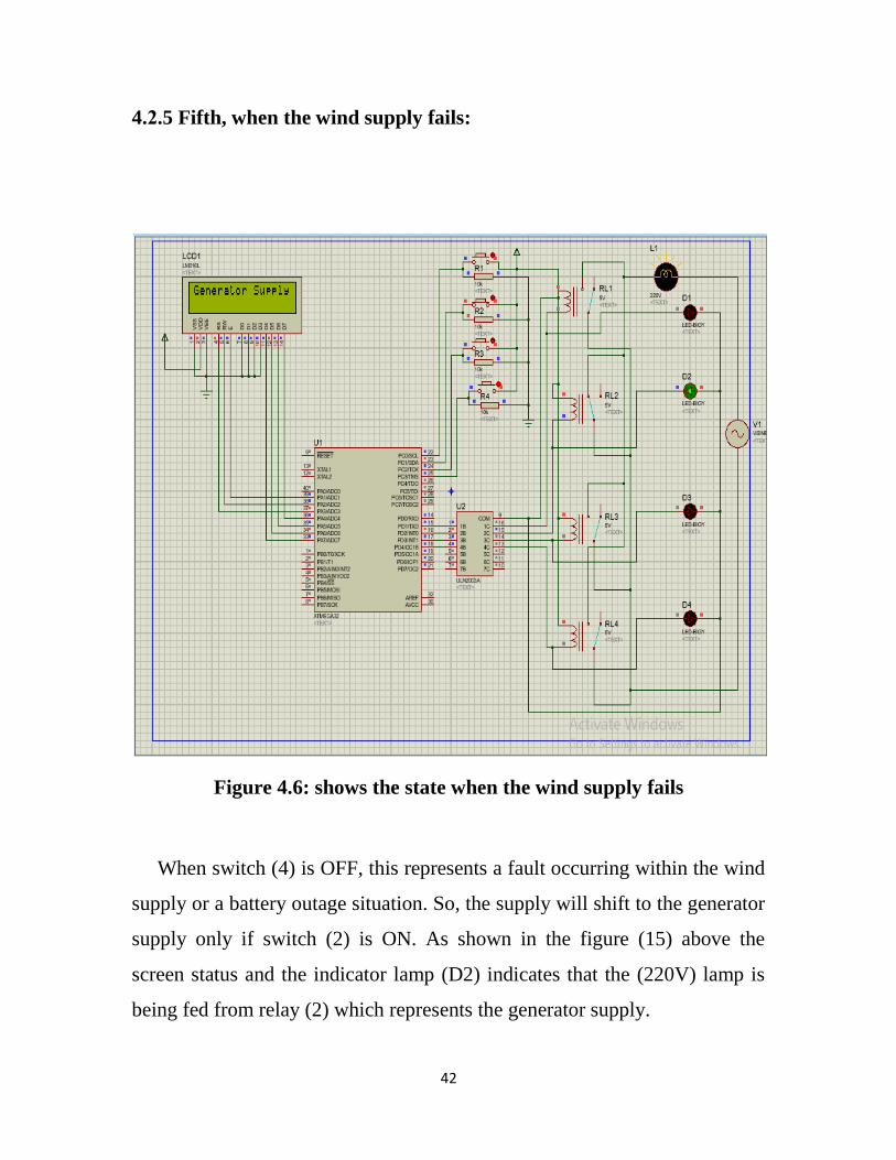
4.2.5 Fifth, when the wind supply fails:
Figure 4.6: shows the state when the wind supply fails
When switch (4) is OFF, this represents a fault occurring within the wind
supply or a battery outage situation. So, the supply will shift to the generator
supply only if switch (2) is ON. As shown in the figure (15) above the
screen status and the indicator lamp (D2) indicates that the (220V) lamp is
being fed from relay (2) which represents the generator supply.

43
4.3 Circuit Operation
From the previous simulation it’s clear that, this circuit we’ve
designed shifts between the supplies both automatically and manually as
every switch is connected to a certain relay, and all the relays are connected
in parallel to the load which means the load can be fed separately from any
source. Thus, if we want the circuit to shift automatically between the
sources all the backup sources need to be switched ON, and if all the
switches were turned ON the load will be fed from the first order source
typical to the sequence being set in the “C” language “code”, in other words
if all the switches were turned ON say, (switch 2, 3, 4) only the relay related
to the switch on top of the sequence will be energized feeding the load
which is relay (2) .The sequence we used in shifting between the different
sources is as follows: (The main power supply, the solar supply, the wind
supply and the generator supply). First of all, we put the generator supply at
the tail of the sequence because of its high operating cost when being
compared with the other sources, because of the increasing cost of fuel
which is needed to run the generator. Secondly, although the generator is in
the tail of the sequence but, the switch which representing the generator is
the second switch after the main supply switch, because in the case of
emergency the generator need a time give a stable output. So, the generator
switch will be kept always opened and the circuit will not run the generator
automatically, but it will jump to the solar or the wind supply and as we
know solar and wind power will not remain for a long time but it will give
the user sufficient time to turn ON the generator and keep the load’s power
uninterrupted.

44
As we mentioned earlier in this report, we have used a
microcontroller from “ATMEGA 32” family which can be programmed in
many ways. Thus, we used a “C” language program so as to make the
microcontroller controls the circuit as we need. Through this program or
code we can control what will appear in the screen, what sequence we want
to use in the control process. In other words, the code which will be burnt at
the microcontroller will determine every single step that would be taken
during the control process.
45
CHAPTER 5
CONCLUSION AND RECOMMENDATION
5.1 Conclusion
This project intended to design an auto power control of four different
sources circuit, the main scope of this paper is to provide a continuous
power supply to the load through any of the sources in the absence of any
source. Taking in consideration the use of the source whose cost is the
lowest then, the higher and so on.
The first stage was to provide the four different sources, as it’s not
practicable to do so at the moment we connected four lines to a particular
load which is a 220-V lamp each line connected to a 5-V relay representing
the four sources. The second stage was to control the circuit with the aid of
ATMEGA-32 microcontroller by burning a C language program into the
ATMEGA-32. To sum up, the objectives which were stated in the first
chapter were met successfully.
The significance of this paper lies in its various advantages and wide places
of applications where this project can be used efficiently.

46
5.2 Recommendation
Although this paper went along way on designing some sort of an
uninterruptable power supply but there are some important elements which
are needed to be added .The circuit can be further enchanted by adding
battery tracker so as to show the power level in the battery in order to help in
the control arrangements. In addition to GSM which can be used as a remote
control as well as to know the power status from outside the home or
company which put our circuit in use. Also the circuit can be provided by a
voltage monitoring system so the circuit can respond not only to faults but
also to small voltage interruptions i.e. over and under voltage, harmonics,
sages and etc.

47
REFRENCES
[1] Auto power control to four different sources, by/ Smt. Thilagavathy
R1, Smt. Spoorthi Y2, Ms. Nalina H D3 1,2,3 Asstistant Professor,
Dept. of ECE, GSSSIETW, Mysuru, Karnataka, (India),
NOVEMBER 2016.
[2] El-Ali, A., N. Moubayed, and R. Outbib. "Comparison between solar
and wind energy in Lebanon." Electrical Power Quality and
Utilisation, 2007. EPQU 2007. 9th International Conference on. IEEE,
2007.
[3] Difference between Wind Power and Solar Power | web site:
http://www.differencebetween.net/science/physics-science/difference-
between-wind-power-and-solar-power/.
[4] Solar Energy in Sudan UNDP in Sudan| web site:
http://www.sd.undp.org/content/sudan/en/home/ourwork/environmentand
energy/successstories/Solar_Energy_in_Sudan.htm/.
[5] Lahmeyer International: Wind Energy: Development of Three Wind
Farms in Sudan| web site:
http://www.lahmeyer.de/projekte/energie/windenergie/single/article/wind
-energy-development-of-three-wind-farms-in-sudan.html.
[6] Robert Dowuona – Owoo Design and construction of three phase
automatic transfer switch. A thesis presented at regent university
college of science and technology Ghana, 2000.
[7] Solar Energy in Sudan UNDP in Sudan| web site:
http://www.sd.undp.org/content/sudan/en/home/ourwork/environmentand
energy/successstories/Solar_Energy_in_Sudan.html.
48
[8] LS Ezema, B U Peter, O O Haris, “DESIGN OF AUTOMATIC
CHANGE OVER SWITCH WITH GENERATOR CONTROL
MECHANISM”, ISSN:2223-9944, vol 3, No 3, November 2003.
[9] Jonathan (2007) – Manually Controlled Changeover System. Vol.2,
No.5. November, 2011.
[10] Mbaocha C. Smart Phase Changeover Switch using AT89C52
Microcontroller. Journal of Electrical and Electronics Engineering
vol.1; Issue 3: PP 31-44, 2012.
[11] Katz R and Boriella G Contemporary Logic Design. 2nd
edition. Prentice Hall, Italy. PP 445-589, 2005.
[12] Atmega32 AVR Microcontroller (8 bit)-Introduction to
architecture| web site: http://www.circuitstoday.com/atmega32-avr-
microcontroller-an-introduction.
[13] ULN2003A – Wikipedia web site:
https://en.wikipedia.org/wiki/ULN2003A.
[14] How Light Emitting Diodes Work | How Stuff Work web site:
http://electronics.howstuffworks.com/led.htm.
[15] Interfacing 16x2 LCD with Atmega32 Microcontroller using
Atmel Studio| web site: https://www.electrosome.com/interfacing-lcd-
atmega32-microcontroller-atmel-studio/.
49
Appendix A
The project “c” language program “code”:
/*********************
#include <stdio.h>
#include <mega16.h>
#include <io.h>
#include <alcd.h>
void main(void)
{
// Alphanumeric LCD initialization
// Connections are specified in the
// Project|Configure|C Compiler|Libraries|Alphanumeric LCD menu:
// RS - PORTA Bit 3
// RD - PORTA Bit 2
// EN - PORTA Bit 1
// D4 - PORTA Bit 7
// D5 - PORTA Bit 6

50
// D6 - PORTA Bit 5
// D7 - PORTA Bit 4
// Characters/line: 16
DDRC=0x00;
PORTC=0x00;
DDRD=0xff;
PORTD=0x00;
lcd_init(16);
lcd_clear();
while (1)
{
if(PINC.0==1)
{
lcd_gotoxy(0,0);
lcd_puts("Main Power ");
lcd_gotoxy(1,1);
lcd_puts("Supply ");
PORTD&=~(1<<2);
PORTD&=~(1<<3);

51
PORTD&=~(1<<4);
PORTD|=0x02;
}
else if(PINC.1==1)
{
lcd_gotoxy(0,0);
lcd_puts("Generator Supply");
lcd_gotoxy(1,1);
lcd_puts(" ");
PORTD&=~(1<<1);
PORTD&=~(1<<3);
PORTD&=~(1<<4);
PORTD|=0x04;
}
else if(PINC.2==1)
{
lcd_gotoxy(0,0);
lcd_puts("Solar Supply ");
lcd_gotoxy(1,1);

52
lcd_puts(" ");
PORTD&=~(1<<1);
PORTD&=~(1<<2);
PORTD&=~(1<<4);
PORTD|=0x08;
}
else if(PINC.3==1)
{
lcd_gotoxy(0,0);
lcd_puts("Wind Supply ");
lcd_gotoxy(1,1);
lcd_puts(" ");
PORTD&=~(1<<1);
PORTD&=~(1<<2);
PORTD&=~(1<<3);
PORTD|=0x10;
}
else
{

53
lcd_clear();
PORTD=0x00;
}
}
}