Voltage control Compensation techniques And power factor ...
90
Voltage control Compensation techniques And power factor correction. Prof. N. VISHALI Dept. of EEE, JNTUA College of Engineering, Kalikiri Chittoor District, A P, India Prof. N. VISHALI, Dept. of EEE, JNTUA College of Engineering, Kalikiri, Chittoor District, A P, India
-
Upload
khangminh22 -
Category
Documents
-
view
3 -
download
0
Transcript of Voltage control Compensation techniques And power factor ...
Voltage control Compensation techniques
And power factor correction.
Prof. N. VISHALI
Dept. of EEE,
JNTUA College of Engineering, Kalikiri
Chittoor District, A P, India
Prof. N. VISHALI, Dept. of EEE, JNTUA College of Engineering, Kalikiri, Chittoor District, A P, India
Outline of Presentation
Prof. N. VISHALI, Dept. of EEE, JNTUA College of Engineering, Kalikiri, Chittoor District, A P, India
1. Introduction.
2. Types of compensation techniques.
3. About shunt compensation.
4. Series compensation.
5. Problems on compensation techniques.
6. Approach of compensation problems in gate.
7. Power factor correction.
8. Problems on power factor correction.

Introduction
Prof. N. VISHALI, Dept. of EEE, JNTUA College of Engineering, Kalikiri, Chittoor District, A P, India
1. In a power system, voltage at various buses tends to increase or decrease during its daily
operation. To ensure constant voltage to consumers, various techniques are utilized.
2. When the voltage is below the required level, reactive power produced by inductance
needs to be offset by capacitance.
Ex: synchronous condenser, shunt capacitor, series capacitor, tap changing transformer etc.
3. When the voltage is above the required level, reactive power produced by capacitance
needs to be offset by inductance.
Ex: shunt reactor, static VAR compensators etc.
4. Voltage control in an electrical power system is important for proper operation of electrical
power equipment to prevent damage such as overheating of generators and motors, to reduce
transmission losses and to maintain the ability of the system to withstand and prevent voltage
collapse.
Introduction (contd…)
Prof. N. VISHALI, Dept. of EEE, JNTUA College of Engineering, Kalikiri, Chittoor District, A P, India
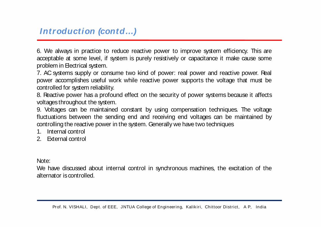
6. We always in practice to reduce reactive power to improve system efficiency. This areacceptable at some level, if system is purely resistively or capacitance it make cause someproblem in Electrical system.7. AC systems supply or consume two kind of power: real power and reactive power. Realpower accomplishes useful work while reactive power supports the voltage that must becontrolled for system reliability.8. Reactive power has a profound effect on the security of power systems because it affectsvoltages throughout the system.9. Voltages can be maintained constant by using compensation techniques. The voltagefluctuations between the sending end and receiving end voltages can be maintained bycontrolling the reactive power in the system. Generally we have two techniques1. Internal control2. External control
Note:We have discussed about internal control in synchronous machines, the excitation of thealternator is controlled.

Types of compensation techniques
Prof. N. VISHALI, Dept. of EEE, JNTUA College of Engineering, Kalikiri, Chittoor District, A P, India
In power systems, we have discussed about the external control of voltage fluctuations
those are called compensation techniques. They are:
1. Shunt capacitor
2. Shunt reactor
3. Series capacitor
4. Synchronous condenser
5. Synchronous inductor
6. Synchronous phase modifier.
Among this the first three compensators are static compensators and the next three are
dynamic compensators.
Note:
According to gate syllabus, in this we learn about the static compensator.

Prof. N. VISHALI, Dept. of EEE, JNTUA College of Engineering, Kalikiri, Chittoor District, A P, India
Shunt compensation
1. For high voltage transmission line the line capacitance is high and plays a significant role involtage conditions of the receiving end.2. When the line is loaded then the reactive power demand of the load is partially met by thereactive power generated by the line capacitance and the remaining reactive power demandis met by the reactive power flow through the line from sending end to the receiving end.3. By placing shunt capacitor/shunt reactor during the undervoltage/overvoltage conditionsrespectively we can overcome the voltage fluctuations.4. When load is high (more than SIL) then a large reactive power flows from sending end tothe receiving end resulting in large voltage drop in the line.5. To improve the voltage at the receiving end shunt capacitors may be connected at thereceiving end to generate and feed the reactive power to the load so that reactive powerflow through the line and consequently the voltage drop in the line is reduced.
6. To meet the variable reactive power demands requisite number of shunt capacitors areswitched in, in addition to the shunt reactor, which results in adjustable reactive powerabsorption by the combination.

Prof. N. VISHALI, Dept. of EEE, JNTUA College of Engineering, Kalikiri, Chittoor District, A P, India
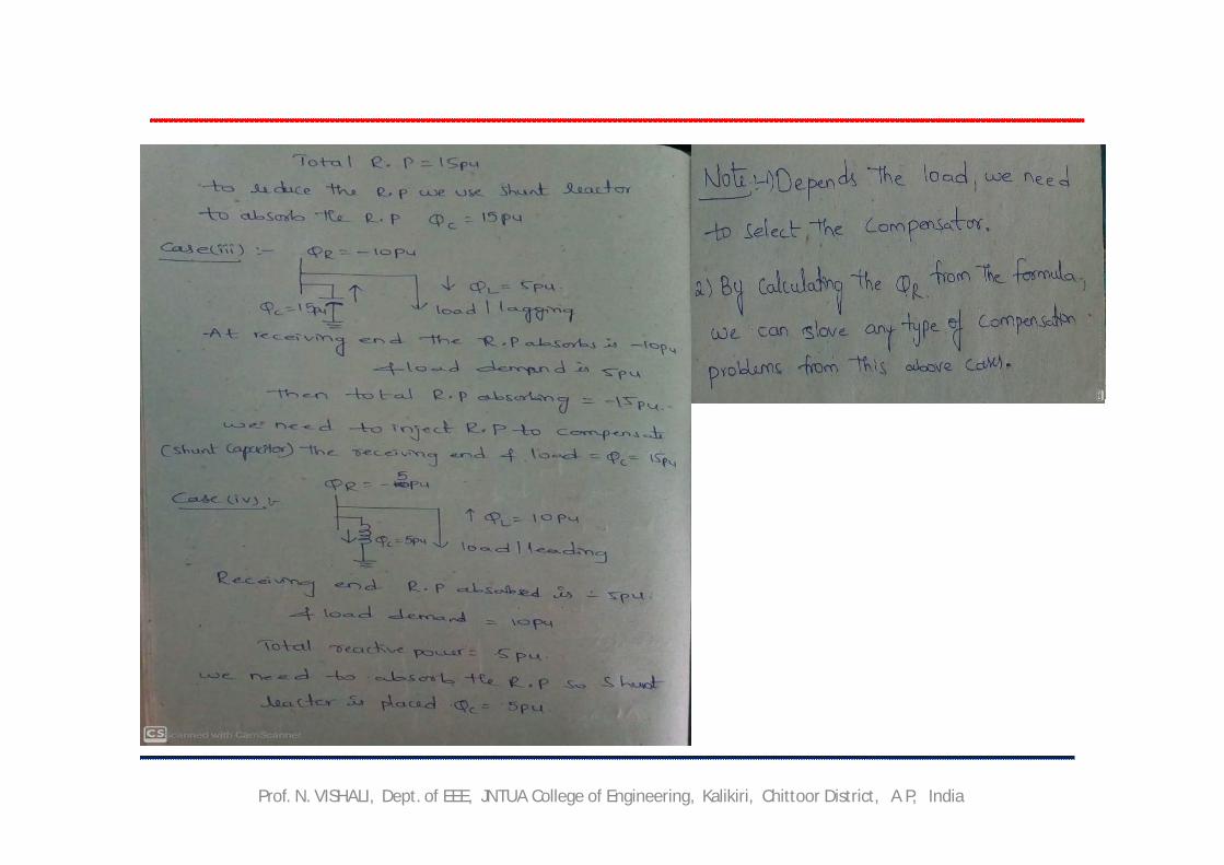
5. Shunt capacitor:a. This method is used to improve the power factor. Whenever an inductive load is connectedto the transmission line, power factor lags because of lagging load current. To compensate, ashunt capacitor is connected which draws current leading the source voltage.b. They also improve the voltage stability and reduce network losses.c. Improving the power factor also means a higher power transmission capability and increasedcontrol of the power flow.
Qc = P (tanΦ1 – tanΦ2)
QR = (VSVR / XL )cosδ – VS * VS /XL
φ1 = angle before compensation.
φ2 = angle after compensation.
Shunt compensation (cont.….)
From the figure the QR = Qc + QL , for UPF the QR = QC
If XC = 1/ Cω be the reactance of the shunt capacitor then the reactive power generated of leading VAR supplied by the capacitor:
QC = VR * VR / XC = VR ^2*Cω

Shunt compensation(cont.…..)
Prof. N. VISHALI, Dept. of EEE, JNTUA College of Engineering, Kalikiri, Chittor District, A P, India
6. Shunt reactor: 1. A shunt reactor is used to absorb the reactive Power. Which means it is used to compensatethe undesirable voltage due to line capacitance (Ferranti effect).2. The sending end voltage is higher than the receiving end voltage. The shunt reactor reducesthe voltage when the receiving end voltage is higher than the sending end voltage. Therefore, itincreases the energy efficiency of the power system.3. It is the most compact device commonly used for reactive power compensation in long high-
voltage transmission lines and in cable systems.4. If XL = Lω be the reactance of the shunt reactor (inductor) then the reactive VAR absorbed
by the shunt reactor:QC = VR*VR/XL = VR^2/Lω
QL = PL tanφ
5. To control the receiving end voltage generallyone shunt rector is installed and switched induring the light load condition.

Series compensation
Prof. N. VISHALI, Dept. of EEE, JNTUA College of Engineering, Kalikiri, Chittoor District, A P, India

Prof. N. VISHALI, Dept. of EEE, JNTUA College of Engineering, Kalikiri, Chittoor District, A P, India
where K is degree of compensation.The economic degree of compensation lies in the range of 40-70% (K < 1, i.e. 0.4-0.7)
Series compensation (cont.….)

prof N. VISHALI, Dept. of EEE, JNTUA College of Engineering, Kalikiri, Chittor District, A P, India
Series compensation (cont.….)
Prof. N. VISHALI, Dept. of EEE, JNTUA College of Engineering, Kalikiri, Chittoor District, A P, India
PROBLEMS
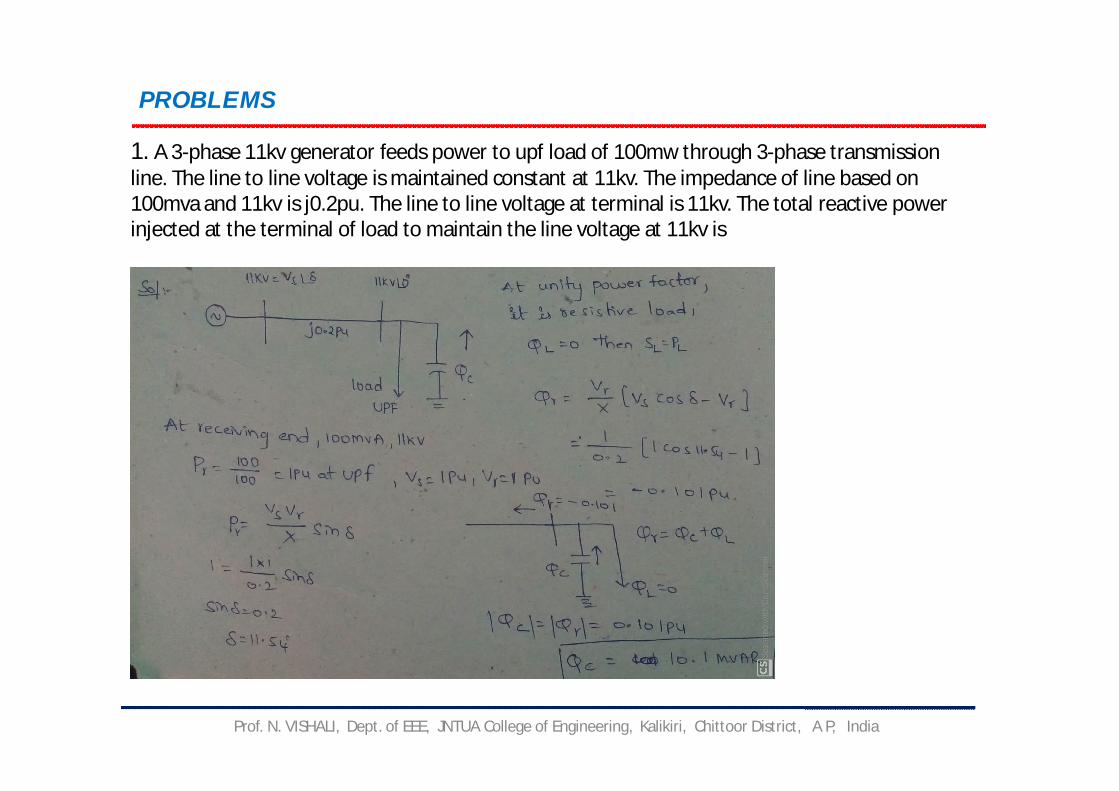
1. A 3-phase 11kv generator feeds power to upf load of 100mw through 3-phase transmission line. The line to line voltage is maintained constant at 11kv. The impedance of line based on 100mva and 11kv is j0.2pu. The line to line voltage at terminal is 11kv. The total reactive power injected at the terminal of load to maintain the line voltage at 11kv is

Prof. N. VISHALI, Dept. of EEE, JNTUA College of Engineering, Kalikiri, Chittoor District, A P, India
2. For the system shown below SD1 and SD2 are the complex power demand of buses 1 & 2 respectively. If V2 = 1pu then the VAR rating of capacitor Qc will be ?

Prof. N. VISHALI, Dept. of EEE, JNTUA College of Engineering, Kalikiri, Chittoor District, A P, India

Prof. N. VISHALI, Dept. of EEE, JNTUA College of Engineering, Kalikiri, Chittoor District, A P, India
Approach of compensation problems in gate
Prof. N. VISHALI, Dept. of EEE, JNTUA College of Engineering, Kalikiri, Chittoor District, A P, India

Prof. N. VISHALI, Dept. of EEE, JNTUA College of Engineering, Kalikiri, Chittoor District, A P, India
POWER FACTOR CORRECTION
1. The power factor correction means bringing the power factor of an AC circuit nearer to one
by using the equipment which absorbs or supply the reactive power to the circuit.
2. Usually, the power factor correction can be done by using the capacitor and the
synchronous motor in the circuit.
3. The power factor correction will not change the amount of true power, but it will reduce the
apparent power and the total current drawn from the load.
4. The most economical value of power factor lies between 0.9 to 0.95. If the value of power
factor lies below 0.8 (approx.), then it draws more current from the load.
5. The large current increases the losses and requires a large conductor, thus increases the
cost of the system. The loss can be reduced by correcting the power factor of the system.
Power Factor Correction MethodsThe power factor correction methods are mainly classified into two types, i.e., by
using the capacitor or through the synchronous condenser.

Prof. N. VISHALI, Dept. of EEE, JNTUA College of Engineering, Kalikiri, Chittoor District, A P, India
Power Factor Correction by using Capacitor Bank:1. In three phase system, the power factor isimproved by connecting the capacitors in star ordelta. The star and delta connected banks areshown in the figure.2. The capacitance requires in star connection ofthree phase transformer is equal to three times thecapacitance requires per phase when the capacitorsare connected in delta.3. Also, the working voltage of the star connectedbank is 1/√3 equal to the delta connected bank. Forthese reasons, the capacitors are connected in thedelta in three phase system for power factorimprovement.4. Delta connection is also better if the capacitors aredesigned for higher working voltage.

Prof. N. VISHALI, Dept. of EEE, JNTUA College of Engineering, Kalikiri, Chittoor District, A P, India
Power Factor Correction by Using Synchronous Condenser
1. The power factor can also be correct by installing the specially designed induction motor,
known as the synchronous condenser.
2. The synchronous condenser was running without the mechanical load, and it is connected
in parallel with the load.
3. It absorbs and generates the reactive power (Var) by varying the excitation of the motor
field winding.
4. The synchronous condenser is used for improving the power factor in bulk.
5. The output of the phase modifier can be varied smoothly.
6. The synchronous condenser has some disadvantage like it is costly and their installation,
maintenance and operation are also not easy.
Prof. N. VISHALI, Dept. of EEE, JNTUA College of Engineering, Kalikiri, Chittoor District, A P, India
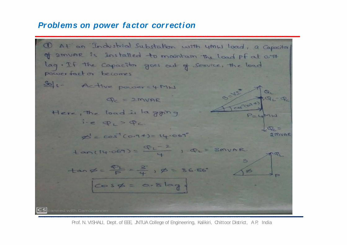
Problems on power factor correction

Prof. N. VISHALI, Dept. of EEE, JNTUA College of Engineering, Kalikiri, Chittoor District, A P, India

Prof. N. VISHALI, Dept. of EEE, JNTUA College of Engineering, Kalikiri, Chittoor District, A P, India
Home work problems
1. A balanced delta connected load of 8+j6 Ω/ph is connected to 400v, 50hz, 3-Φ
supply. If the input power factor is to be improved by connecting a bank of star
connected capacitor the required KVAR of the bank is ……
2. A feeder with reactance of 0.2j pu has a Vs = 1.2pu. If QR = 0.3pu then
approximate voltage drop in feeder will be …… pu.
3. A transmission line has XL = j0.5pu. Calculate the rating and type of compensator
required for maintaining VS = VR = 1pu for the load.
(i) PR = 1pu at UPF. (ii) PR = 1pu at 0.8pf
Models & Performance of Transmission Lines
Prof. N. Visali
Dept. of EEE,
JNTUA College of Engineering, Kalikiri
Chittoor District, A P, India
Prof. N Visali, Dept. of EEE, JNTUA College of Engineering, Kalikiri, Chittoor District, A P, India

Outline of Presentation
Prof. N Visali, Dept. of EEE, JNTUA College of Engineering, Kalikiri, Chittoor District, A P, India
Introduction
Types of Transmission lines
1. Short transmission line
2. Medium transmission line
3. Long transmission line
Skin Effect
Proximity Effect
Ferranti Effect
Surge Impedance
Previous GATE questions
1. one mark questions
2. Two mark questions
Work to students

Introduction
Prof. N Visali, Dept. of EEE, JNTUA College of Engineering, Kalikiri, Chittoor District, A P, India
• The important considerations in the operation of Transmission line
are voltage drop, Power loss, Efficiency
• The performance of transmission lines depends on the R,L,C and
conductor - G
fcVXV
C
2
Effect G - It is due to leakage current it is predominant only during
bad Weather conditions (so we are neglecting G)
In Overhead lines reactance effects are more
In Underground cables reactance effects are small and capacitance
effects are more.
Introduction
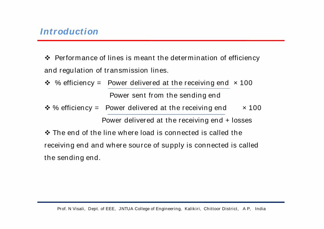
Performance of lines is meant the determination of efficiency
and regulation of transmission lines.
% efficiency = Power delivered at the receiving end × 100
Power sent from the sending end
% efficiency = Power delivered at the receiving end × 100
Power delivered at the receiving end + losses
The end of the line where load is connected is called the
receiving end and where source of supply is connected is called
the sending end.
Prof. N Visali, Dept. of EEE, JNTUA College of Engineering, Kalikiri, Chittoor District, A P, India

Introduction (contd.)
Prof. N Visali, Dept. of EEE, JNTUA College of Engineering, Kalikiri, Chittoor District, A P, India
The regulation of a line is defined as the change in the receiving end
voltage, expressed in per cent of full load voltage, from no load to full load,
keeping the sending end voltage and frequency constant.
Mathematically expressed as,
% regulation = Vr′ - Vr × 100
Vr
where Vr′ is the receiving end voltage under no load condition and Vr the
receiving end voltage under full load condition.
It is to be noted here that Vr′ and Vr are the magnitudes of voltages.

Introduction (contd.)
Prof. N Visali, Dept. of EEE, JNTUA College of Engineering, Kalikiri, Chittoor District, A P, India
It is to be noted that the electrical power is being transmitted over the
overhead lines at approximately the speed of light. In order to get one full
wave variation of voltage or current on the line, the length of the line for
50 Hz supply will be given by
f . λ = v
where f is frequency of supply,
λ is the wavelength i.e., the length of the line in this case and
v is the velocity of the wave i.e., the velocity of light.
Introduction (contd.)
Prof. N Visali, Dept. of EEE, JNTUA College of Engineering, Kalikiri, Chittoor District, A P, India
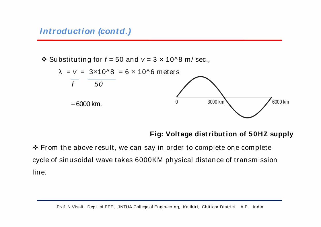
Substituting for f = 50 and v = 3 × 10^8 m/sec.,
λ = v = 3×10^8 = 6 × 10^6 meters
f 50
= 6000 km.
Fig: Voltage distribution of 50HZ supply
From the above result, we can say in order to complete one complete
cycle of sinusoidal wave takes 6000KM physical distance of transmission
line.

Types of transmission lines
Prof. N Visali, Dept. of EEE, JNTUA College of Engineering, Kalikiri, Chittoor District, A P, India
Based on the length of the length of the transmission lines it can be
classified as
1. Short Transmission Line ( <80KM)
2. Medium Transmission Line ( >80KM, <160KM)
3. Long Transmission Line ( >160KM)
1. Short Transmission Line (<80KM)
Prof. N Visali, Dept. of EEE, JNTUA College of Engineering, Kalikiri, Chittoor District, A P, India
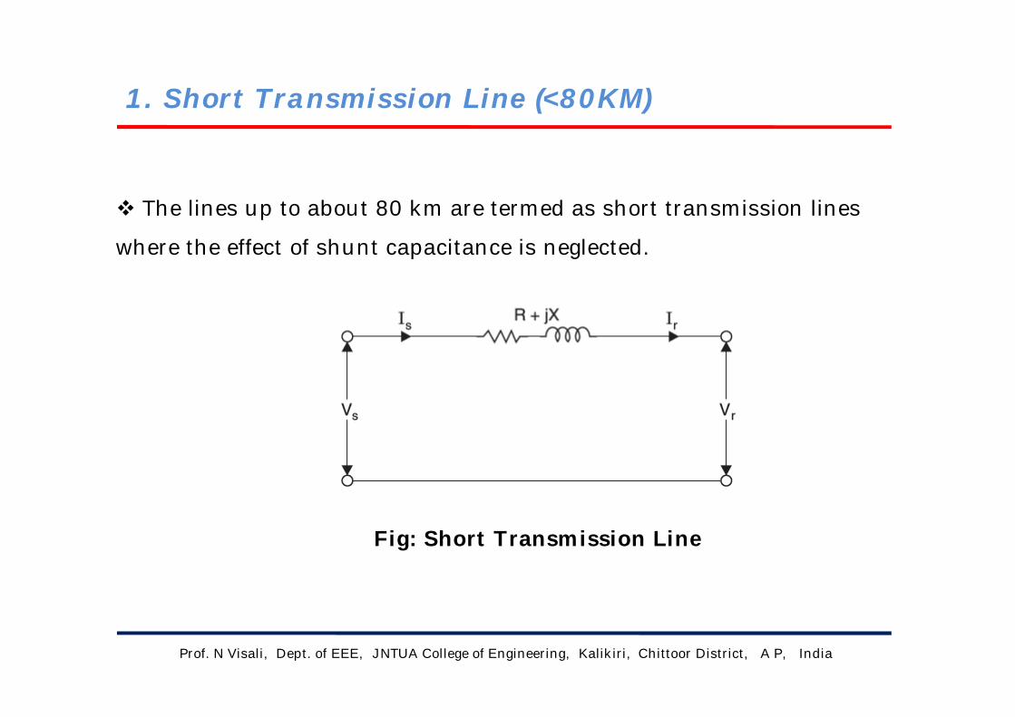
The lines up to about 80 km are termed as short transmission lines
where the effect of shunt capacitance is neglected.
Fig: Short Transmission Line

Short Transmission Line (contd.)
Prof. N Visali, Dept. of EEE, JNTUA College of Engineering, Kalikiri, Chittoor District, A P, India
The vector diagram is drawn taking Ir, the receiving end current, as the
reference.
From the vector diagram,
Vs cos φs = Vr cos φr + Ir R
Vs sin φs = Vr sin φr + Ir X
Fig.: vector diagram for short transmission line
Short Transmission Line (contd.)
Prof. N Visali, Dept. of EEE, JNTUA College of Engineering, Kalikiri, Chittoor District, A P, India
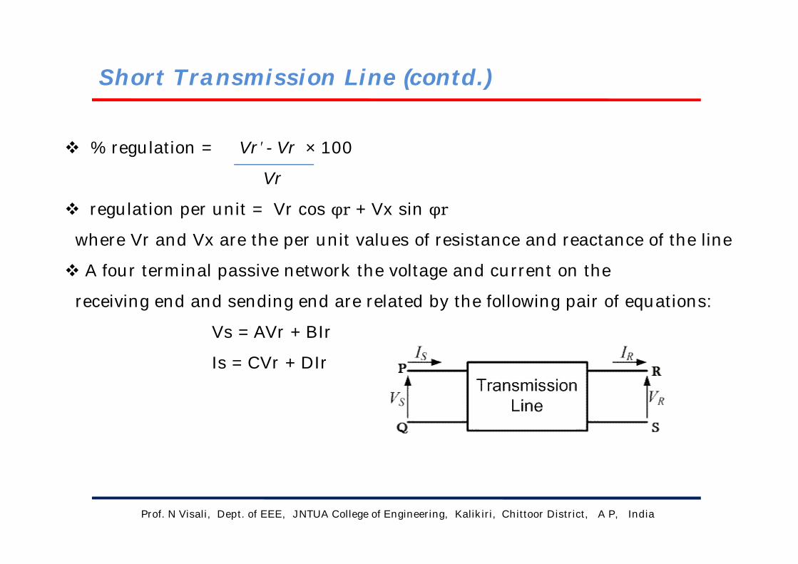
% regulation = Vr′ - Vr × 100
Vr
regulation per unit = Vr cos φr + Vx sin φr
where Vr and Vx are the per unit values of resistance and reactance of the line
A four terminal passive network the voltage and current on the
receiving end and sending end are related by the following pair of equations:
Vs = AVr + BIr
Is = CVr + DIr
Short Transmission Line (contd.)
Prof. N Visali, Dept. of EEE, JNTUA College of Engineering, Kalikiri, Chittoor District, A P, India
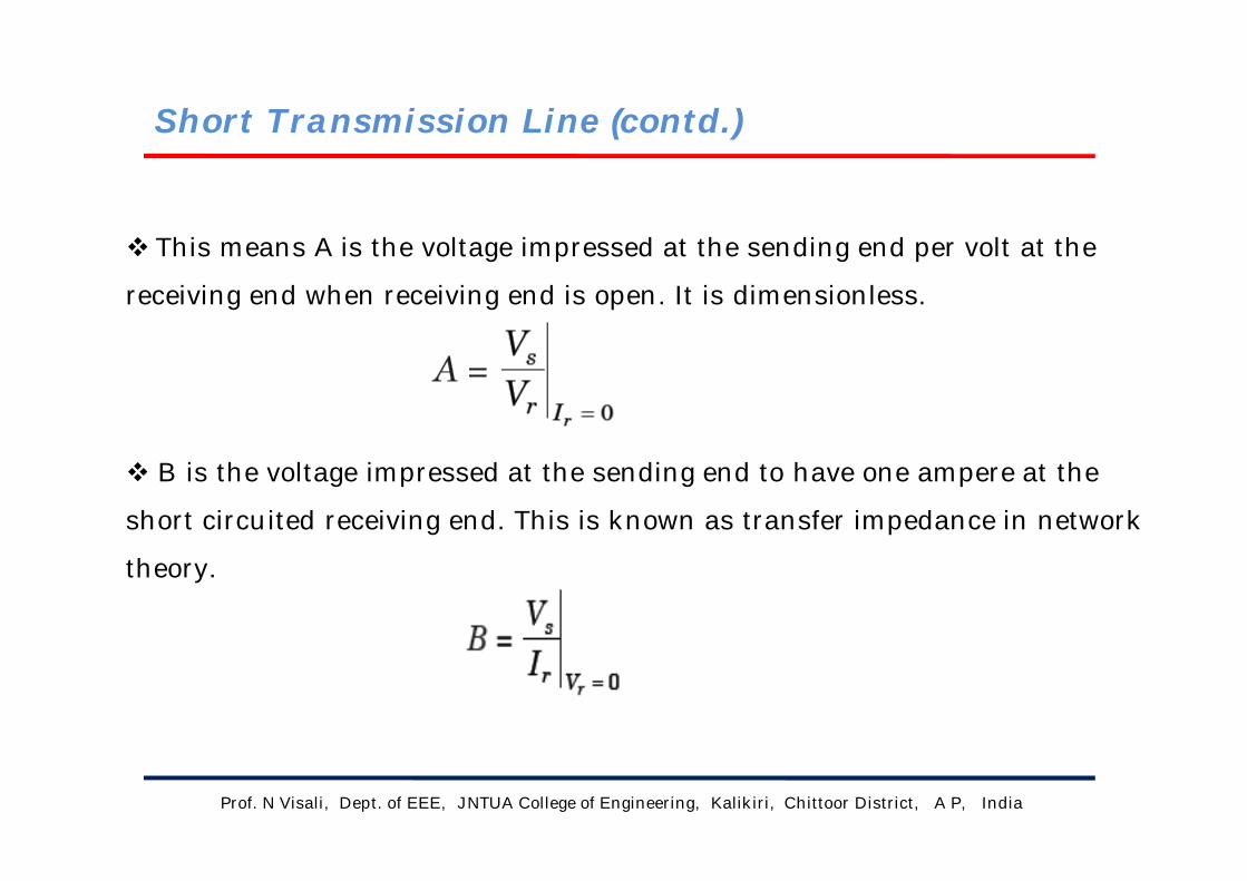
This means A is the voltage impressed at the sending end per volt at the
receiving end when receiving end is open. It is dimensionless.
B is the voltage impressed at the sending end to have one ampere at the
short circuited receiving end. This is known as transfer impedance in network
theory.

Short Transmission Line (contd.)
Prof. N Visali, Dept. of EEE, JNTUA College of Engineering, Kalikiri, Chittoor District, A P, India
C is the current in amperes into the sending end per volt on the open-
circuited receiving end. It has the dimension of admittance.
D is the current at the sending end for one ampere of current at the
short circuited receiving end.

Short Transmission Line (contd.)
Prof. N Visali, Dept. of EEE, JNTUA College of Engineering, Kalikiri, Chittoor District, A P, India
The sending end voltage and current can be written from the equivalent
network as
Vs = Vr + IrZ
Is = Ir
The constants for short transmission line are when compared to ABCD
parameter equations is given by
A = 1 ; B = Z
C = 0 ; D = 1
Then determine sending end voltage using relation
Vs = AVr + BIr
To determine Vr′ the no load voltage at the receiving end
Vr′= Vs / A , when Ir = 0
Short Transmission Line (contd.)
Prof. N Visali, Dept. of EEE, JNTUA College of Engineering, Kalikiri, Chittoor District, A P, India
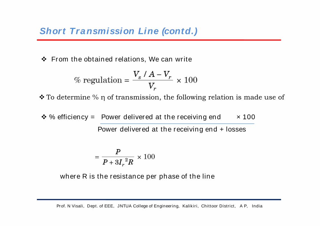
From the obtained relations, We can write
To determine % η of transmission, the following relation is made use of
% efficiency = Power delivered at the receiving end × 100
Power delivered at the receiving end + losses
where R is the resistance per phase of the line

2. Medium Transmission Line ( >80KM, <160KM)
Prof. N Visali, Dept. of EEE, JNTUA College of Engineering, Kalikiri, Chittoor District, A P, India
It has been mentioned previously that transmission lines with lengths
between 80 km and 160 km are categorized as medium length lines where
the parameters are assumed to be lumped.
The shunt capacitance is either assumed to be concentrated at the
middle of the line or half of the total capacitance is concentrated at each
end of the line.
The two configurations are as follows
nominal-T and
nominal-π

Medium Transmission Line (contd.)
Prof. N Visali, Dept. of EEE, JNTUA College of Engineering, Kalikiri, Chittoor District, A P, India
Nominal T In this method, the whole line capacitance is assumed to be concentrated at
the middle point of the line and half the line resistance and reactance are
lumped on its either side as shown in Fig.
Therefore, in this arrangement, full charging current flows over half the line.
In Fig. one phase of 3-phase transmission line is shown as it is advantageous
to work in phase instead of line-to-line values.
Fig: Nominal T

Medium Transmission Line (contd.)
Prof. N Visali, Dept. of EEE, JNTUA College of Engineering, Kalikiri, Chittoor District, A P, India
The vector diagram for lagging power factor load is shown in Fig. While
analyzing the medium length lines using nominal-T, it is preferable to take
receiving end current as the reference vector as the calculations become
relatively easier as compared to taking Vr as the reference.
Fig.: vector diagram for nominal T transmission line

Medium Transmission Line (contd.)
Prof. N Visali, Dept. of EEE, JNTUA College of Engineering, Kalikiri, Chittoor District, A P, India
% regulation = Vr′ - Vr × 100
Vr
Where,
Vr′ is the receiving end voltage under no load condition
Vr is the receiving end voltage under full load condition
Vr′ can be written as (voltage divider rule)
Medium Transmission Line (contd.)
Prof. N Visali, Dept. of EEE, JNTUA College of Engineering, Kalikiri, Chittoor District, A P, India
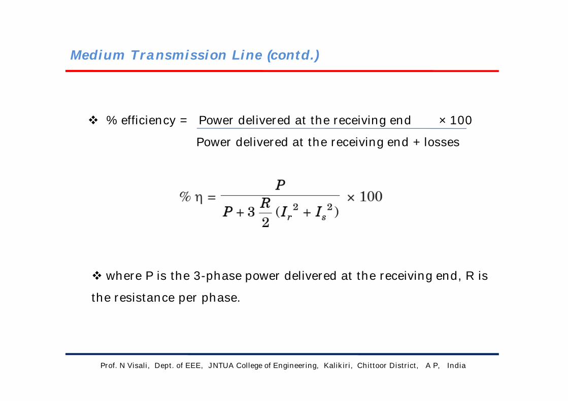
% efficiency = Power delivered at the receiving end × 100
Power delivered at the receiving end + losses
where P is the 3-phase power delivered at the receiving end, R is
the resistance per phase.

Medium Transmission Line (contd.)
Prof. N Visali, Dept. of EEE, JNTUA College of Engineering, Kalikiri, Chittoor District, A P, India
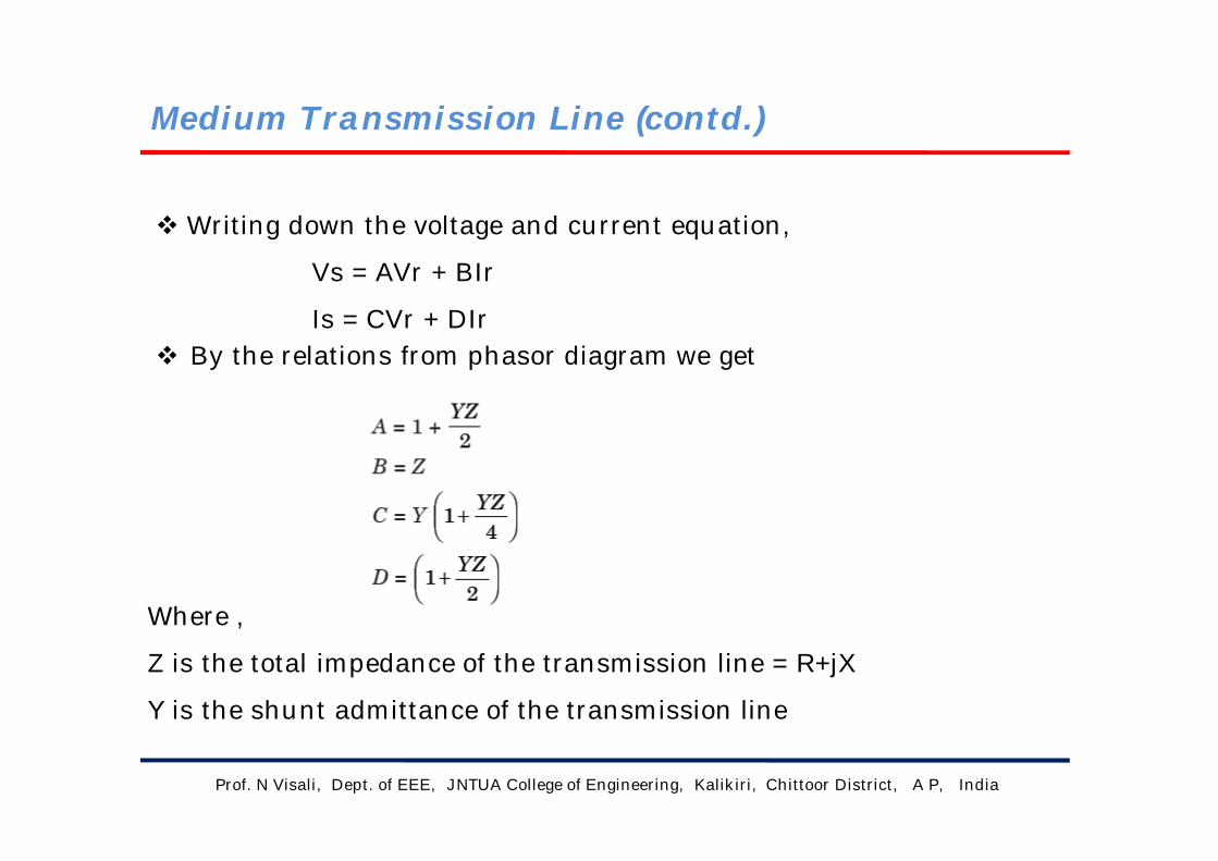
Writing down the voltage and current equation,
Vs = AVr + BIr
Is = CVr + DIr By the relations from phasor diagram we get
Where ,
Z is the total impedance of the transmission line = R+jX
Y is the shunt admittance of the transmission line

Medium Transmission Line (contd.)
Prof. N Visali, Dept. of EEE, JNTUA College of Engineering, Kalikiri, Chittoor District, A P, India
In the nominal pi model of a medium transmission line, the series
impedance of the line is concentrated at the centre and half of each
capacitance is placed at the centre of the line. The nominal Pi model of
the line is shown in the diagram below.
Nominal π
Fig.: vector diagram for nominal π transmission line
Medium Transmission Line (contd.)
Prof. N Visali, Dept. of EEE, JNTUA College of Engineering, Kalikiri, Chittoor District, A P, India
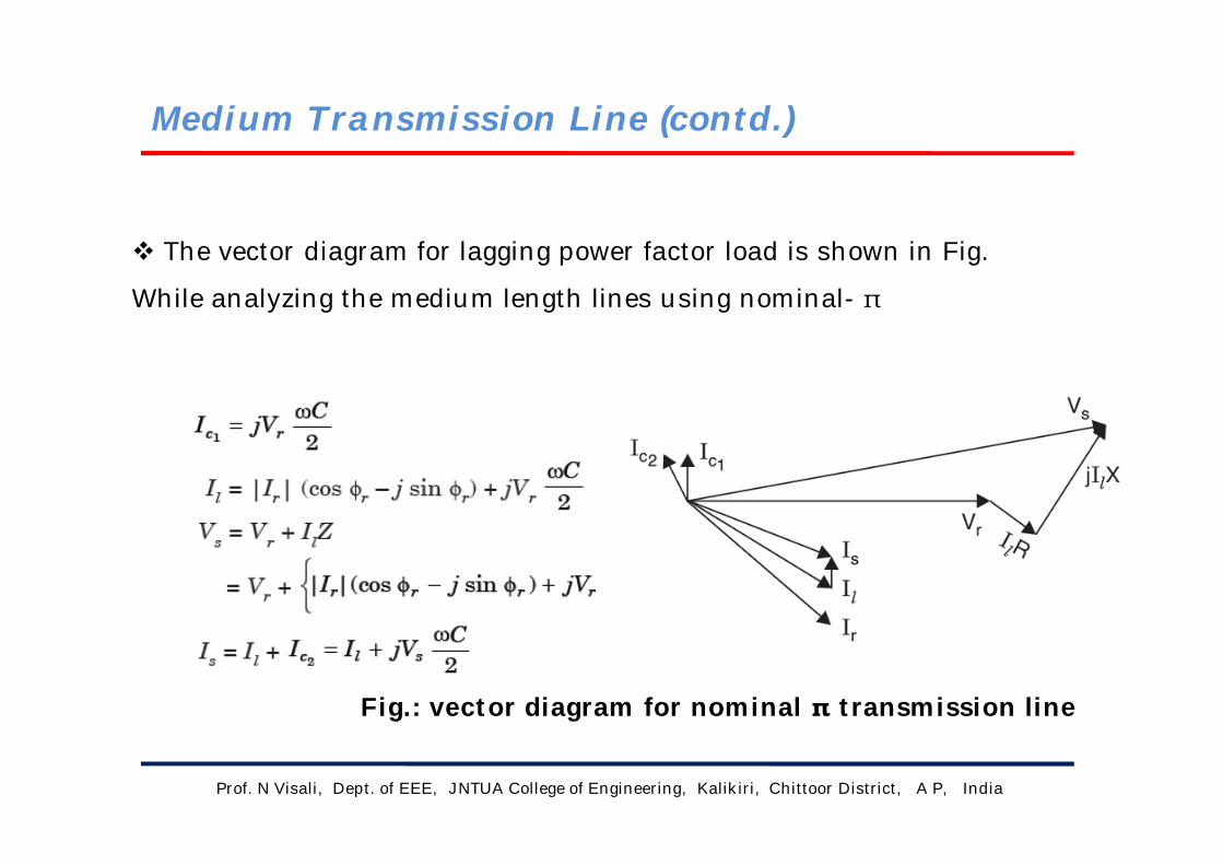
The vector diagram for lagging power factor load is shown in Fig.
While analyzing the medium length lines using nominal- π
Fig.: vector diagram for nominal π transmission line
Medium Transmission Line (contd.)
Prof. N Visali, Dept. of EEE, JNTUA College of Engineering, Kalikiri, Chittoor District, A P, India
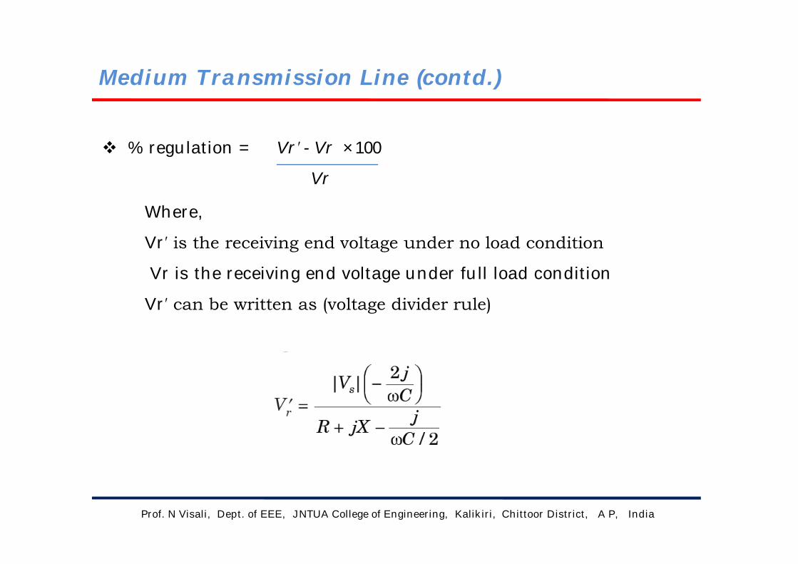
% regulation = Vr′ - Vr × 100
Vr
Where,
Vr′ is the receiving end voltage under no load condition
Vr is the receiving end voltage under full load condition
Vr′ can be written as (voltage divider rule)

Medium Transmission Line (contd.)
Prof. N Visali, Dept. of EEE, JNTUA College of Engineering, Kalikiri, Chittoor District, A P, India
% efficiency = Power delivered at the receiving end × 100
Power delivered at the receiving end + losses
where P is the 3-phase power delivered at the receiving end, R is the resistance per phase.
Medium Transmission Line (contd.)
Prof. N Visali, Dept. of EEE, JNTUA College of Engineering, Kalikiri, Chittoor District, A P, India
Writing down the voltage and current equation,
Vs = AVr + BIr
Is = CVr + DIr By the relations from phasor diagram we get
Where ,
Z is the total impedance of the transmission line = R+jX
Y is the shunt admittance of the transmission line

3. Long Transmission Line (>160KM)
Prof. N Visali, Dept. of EEE, JNTUA College of Engineering, Kalikiri, Chittoor District, A P, India
So far electrically short transmission lines less than 160 km in length
have been considered wherein the parameters are assumed to be
lumped.
In case the lines are more than 160 km long, for accurate solutions
the parameters must be taken as distributed uniformly along the length
as a result of which the voltages and currents will vary from point to
point on the line. Consider Fig. below for analysis.

Long Transmission Line (contd.)
Prof. N Visali, Dept. of EEE, JNTUA College of Engineering, Kalikiri, Chittoor District, A P, India
Let z = series impedance per unit length
y = shunt admittance per unit length
l = length of the line
Z = zl = total series impedance
Y = yl = total shunt admittance
Fig: Long Transmission Line
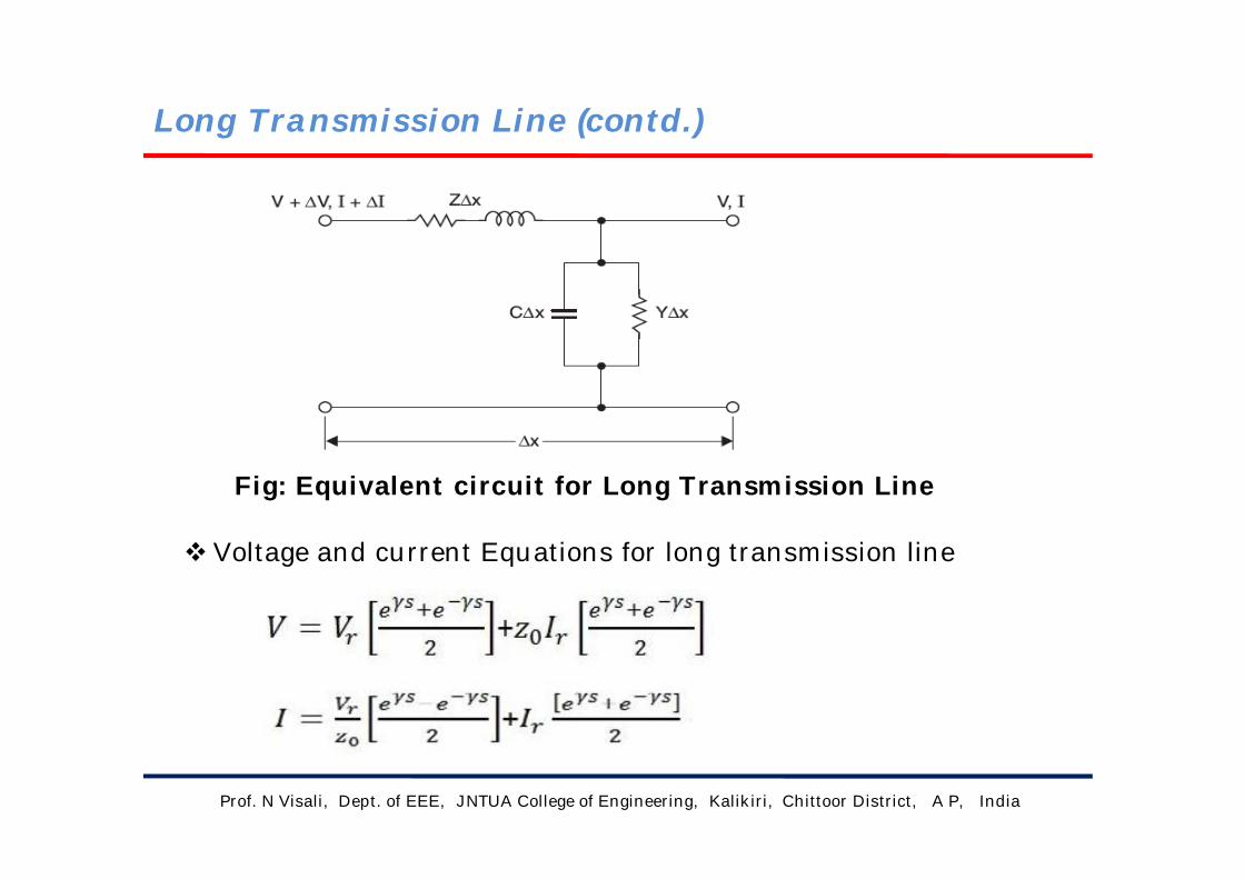
Long Transmission Line (contd.)
Prof. N Visali, Dept. of EEE, JNTUA College of Engineering, Kalikiri, Chittoor District, A P, India
Fig: Equivalent circuit for Long Transmission Line
Voltage and current Equations for long transmission line
Long Transmission Line (contd.)
Prof. N Visali, Dept. of EEE, JNTUA College of Engineering, Kalikiri, Chittoor District, A P, India
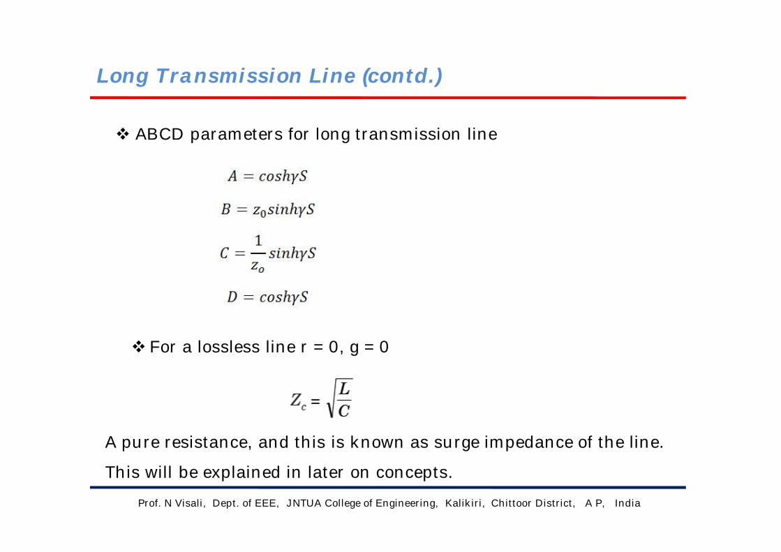
ABCD parameters for long transmission line
For a lossless line r = 0, g = 0
A pure resistance, and this is known as surge impedance of the line.
This will be explained in later on concepts.

Prof. N Visali, Dept. of EEE, JNTUA College of Engineering, Kalikiri, Chittoor District, A P, India
Skin effect is the tendency of an alternating electric current(AC) to become
distributed within a conductor such that the current density is largest near
the surface of the conductor, and decreases with greater depths in the
conductor. The electric current flows mainly at the "skin" of the conductor,
between the outer surface and a level called the skin depth.
The distribution of current over the entire cross section of the conductor is
quite uniform in case of a DC system. But what we are using an alternating
current system, where the current tends to flow with higher density through the
surfaceof the conductors (i.e. skin of the conductor), leaving the core deprived of
necessary number of electrons.
Skin Effect

Prof. N Visali, Dept. of EEE, JNTUA College of Engineering, Kalikiri, Chittoor District, A P, India
In fact there even arisesa condition when
absolutely no current flows through the core
and concentrating the entire amount on the
surface region, thus resulting in an increase
in the effective electrical resistanceof the conductor.
This particular trend of anACtransmission
system to take the surface path for the flow
of current depriving the core is referred to as the skin
Effect in transmission lines.
Skin Effect contd.
Skin Effect contd.
Prof. N Visali, Dept. of EEE, JNTUA College of Engineering, Kalikiri, Chittoor District, A P, India
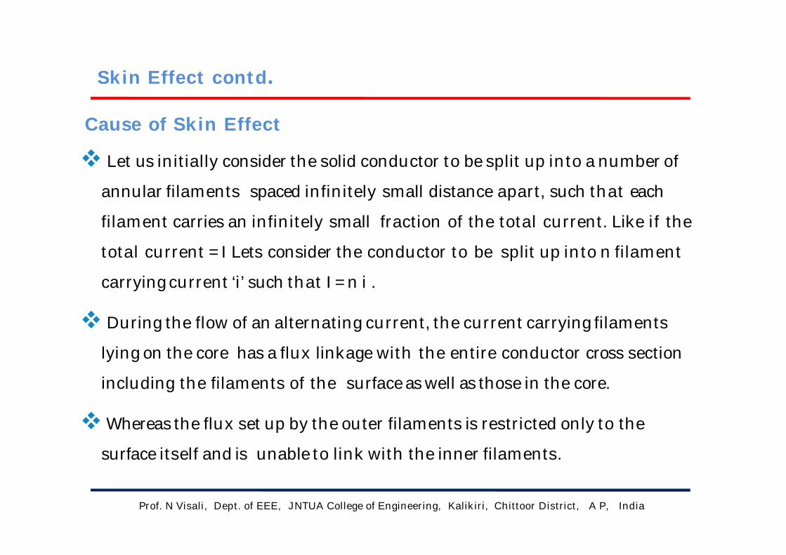
Let us initially consider the solid conductor to be split up into a numberof
annular filaments spaced infinitely small distance apart, such that each
filament carries an infinitely small fraction of the total current. Like if the
total current = I Lets consider the conductor to be split up into n filament
carrying current ‘i’ such that I =n i .
During the flow of an alternating current, the current carrying filaments
lying on the core has a flux linkage with the entire conductor cross section
including the filaments of the surfaceaswell as those in the core.
Whereasthe flux set up by the outer filaments is restricted only to the
surface itself and is unable to link with the inner filaments.
Cause of Skin Effect

Prof. N Visali, Dept. of EEE, JNTUA College of Engineering, Kalikiri, Chittoor District, A P, India
Thus the flux linkage of the conductor increases aswe move closer towards
the core and at the same rate increases the inductor as it has a direct
proportionality relationship with flux linkage.
This results in a larger inductive reactancebeing induced into the core as
compared to the outer sections of the conductor.
The high value of reactance in the inner section results in the current
being distributed in an un-uniform manner and forcing the bulk of the
current to flow through the outer surface or skin giving rise to the
phenomenacalled skin effect in transmission lines.
Skin Effect contd.

Prof. N Visali, Dept. of EEE, JNTUA College of Engineering, Kalikiri, Chittoor District, A P, India
Skin Effect contd.

Prof. N Visali, Dept. of EEE, JNTUA College of Engineering, Kalikiri, Chittoor District, A P, India
The skin effect in an ac system
depends on
Shape of conductor
Type of material
Diameter ofthe conductors
Operational frequency
Skin Effect contd.
Prof. N Visali, Dept. of EEE, JNTUA College of Engineering, Kalikiri, Chittoor District, A P, India
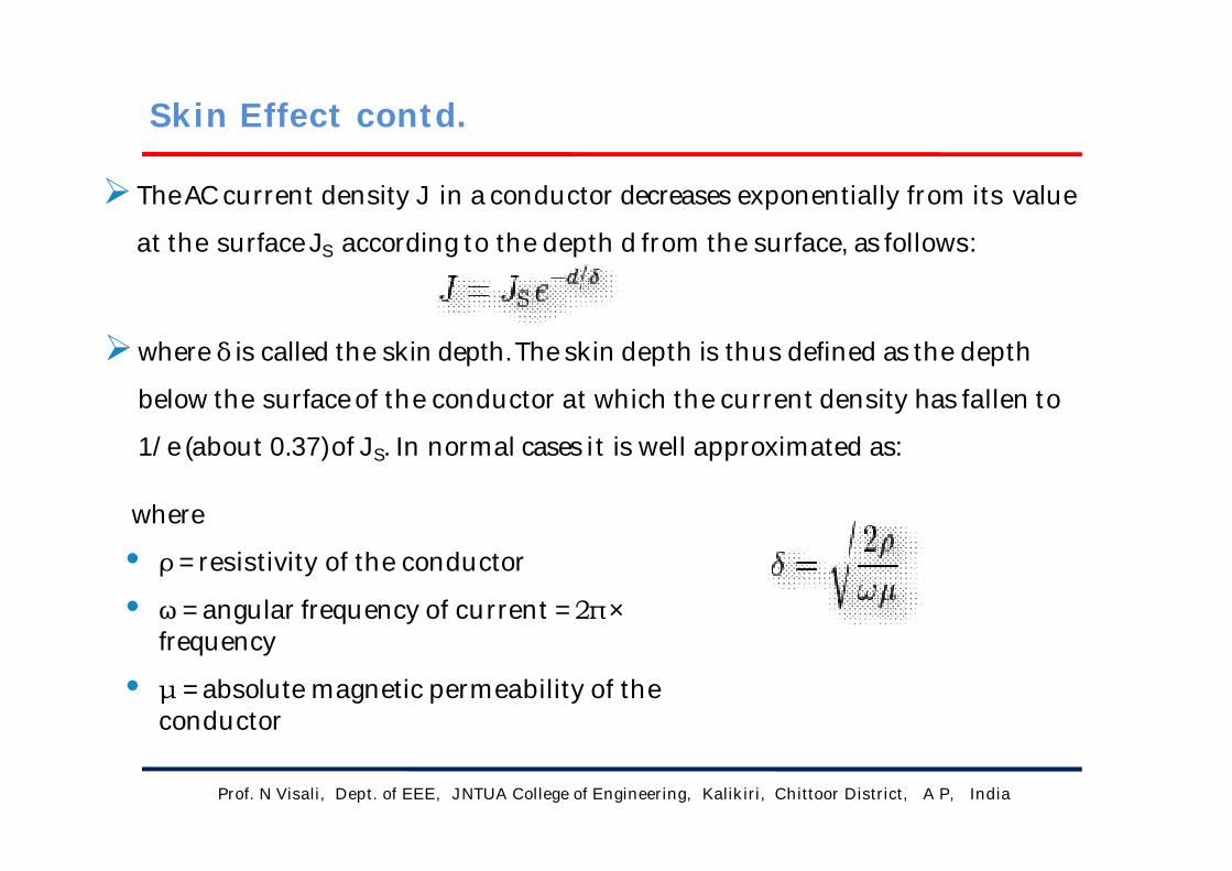
TheACcurrent density J in aconductor decreases exponentially from its value
at the surfaceJS according to the depth d from the surface, as follows:
where δ is called the skin depth.The skin depth is thus defined as the depth
below the surfaceof the conductor at which the current density has fallen to
1/e (about 0.37)of JS. In normal cases it is well approximated as:
where
• ρ =resistivity of the conductor
• ω =angular frequency of current =2π×frequency
• μ =absolute magnetic permeability of theconductor
Skin Effect contd.

Prof. N Visali, Dept. of EEE, JNTUA College of Engineering, Kalikiri, Chittoor District, A P, India
Instead of normal conductors/wires A type of cable called litz wire
(from the German Litzendraht, braided wire) is used to mitigate the
skin effect for frequencies of a few kilohertz to about one megahertz.
It consists of a number of insulated wire strands woven together in a
carefully designed pattern, so that the overall magnetic field acts equally
on all the wires and causes the total current to be distributed equally
among them.
With the skin effect having little effect on each of the thin strands, the
bundle does not suffer the same increase in ACresistance that a solid
conductor of the same cross-sectional area would due to the skin effect.
Mitigation of Skin Effect
Skin Effect contd.
Prof. N Visali, Dept. of EEE, JNTUA College of Engineering, Kalikiri, Chittoor District, A P, India
Proximity Effect
When the conductors carry the high alternating voltage then the currents
are non-uniformly distributed on the cross-section area of the conductor.
This effect is called proximity effect.
The proximity effect results in the increment of the apparent resistance
of the conductor due to the presence of the other conductors carrying current
in its vicinity.
When two or more conductors are placed near to each other, then their
electromagnetic fields interact with each other. Due to this interaction, the
current in each of them is redistributed such that the greater current density is
concentrated in that part of the strand most remote from the interfering
conductor.

Prof. N Visali, Dept. of EEE, JNTUA College of Engineering, Kalikiri, Chittoor District, A P, India
If the conductors carry the current in the same direction, then the
magnetic field of the halves of the conductors which are close to
each other is cancelling each other and hence no current flow
through that halves portion of the conductor. The current is crowded
in the remote half portion of the conductor.
Proximity Effect contd.

Prof. N Visali, Dept. of EEE, JNTUA College of Engineering, Kalikiri, Chittoor District, A P, India
When the conductors carry the current in the opposite direction, then
the close part of the conductor carries, the more current and the
magnetic field of the far off half of the conductor cancel each other.
Thus, the current is zero in the remote half of the conductor and
crowded at the nearer part of the conductor.
Proximity Effect contd.

Prof. N Visali, Dept. of EEE, JNTUA College of Engineering, Kalikiri, Chittoor District, A P, India
Factors Affecting the Proximity EffectFrequency – The proximity increases with the increases in the frequency.
Diameter – The proximity effect increases with the increase in the
conductor.
Structure – This effect is more on the solid conductor as compared to the
stranded conductor (i.e., ASCR) because the surface area of the stranded
conductor is smaller than the solid conductor.
Material – If the material is made up of high ferromagnetic material then
the proximity effect is more on their surface.
Proximity Effect contd.
Prof. N Visali, Dept. of EEE, JNTUA College of Engineering, Kalikiri, Chittoor District, A P, India
The proximity effect can be reduced by using the ACSR (Aluminum
Core Steel Reinforced) conductor. In ACSR conductor the steel is
placed at the centre of the conductor and the aluminum conductor is
positioned around steel wire.
The steel increased the strength of the conductor but reduced the
surface area of the conductor. Thus, the current flow mostly in the
outer layer of the conductor and no current is carried in the centre of
the conductor. Thus, reduced the proximity effect on the conductor.
Proximity Effect contd.
Proximity Effect Mitigation

Prof. N Visali, Dept. of EEE, JNTUA College of Engineering, Kalikiri, Chittoor District, A P, India
Ferranti Effect
The effect in which the voltage at the receiving end of the
transmission line is more than the sending voltage is known as the
Ferranti effect. Such type of effect mainly occurs because of light load
or open circuit at the receiving end.
Ferranti effect is due to the charging current of the line. When an
alternating voltage is applied, the current that flows into the capacitor
is called charging current. A charging current is also known as
capacitive current. The charging current increases in the line when the
receiving end voltage of the line is larger than the sending end.
Prof. N Visali, Dept. of EEE, JNTUA College of Engineering, Kalikiri, Chittoor District, A P, India
The transmission line generates capacitive reactive volt-amperes in its
shunt capacitance and absorbing reactive volt-amperes in its series
inductance. The load at which the inductive and capacitive reactive volt-
amperes are equal and opposite, such load is called surge impedance load.
It is also called natural load of the transmission line because power is
not dissipated in transmission. In surge impedance loading, the voltage
and current are in the same phase at all the point of the line. When the
surge impedance of the line has terminated the power delivered by it is
called surge impedance loading.
Surge Impedance

Prof. N Visali, Dept. of EEE, JNTUA College of Engineering, Kalikiri, Chittoor District, A P, India
Shunt capacitance charges the transmission line when the circuit
breaker at the sending end of the line is close. As shown below
Surge Impedance Contd.

Prof. N Visali, Dept. of EEE, JNTUA College of Engineering, Kalikiri, Chittoor District, A P, India
Let V = phase voltage at the receiving end
L = series inductance per phase
XL = series inductance reactance per phase
XC = shunt capacitance reactance per phase
Zo = surge impedance loading per phase
Capacitive volt-amperes (VAr) generated in the line
Surge Impedance Contd.

Prof. N Visali, Dept. of EEE, JNTUA College of Engineering, Kalikiri, Chittoor District, A P, India
The series inductance of the line consumes the electrical energy when
the sending and receiving end terminals are closed.
Inductive reactive volt-amperes (VAr) absorbed by the line
Surge Impedance Contd.
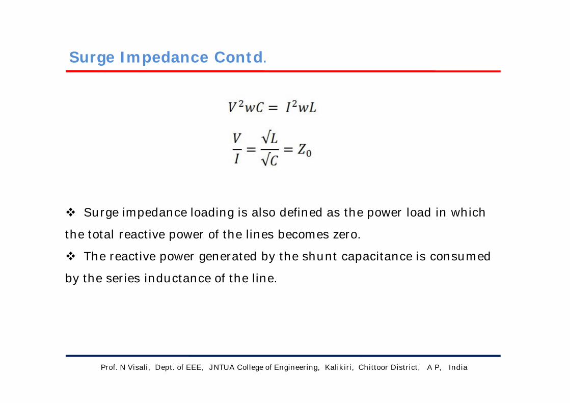
Prof. N Visali, Dept. of EEE, JNTUA College of Engineering, Kalikiri, Chittoor District, A P, India
Surge impedance loading is also defined as the power load in which
the total reactive power of the lines becomes zero.
The reactive power generated by the shunt capacitance is consumed
by the series inductance of the line.
Surge Impedance Contd.
GATE previous questions (1m)
Prof. N Visali, Dept. of EEE, JNTUA College of Engineering, Kalikiri, Chittoor District, A P, India
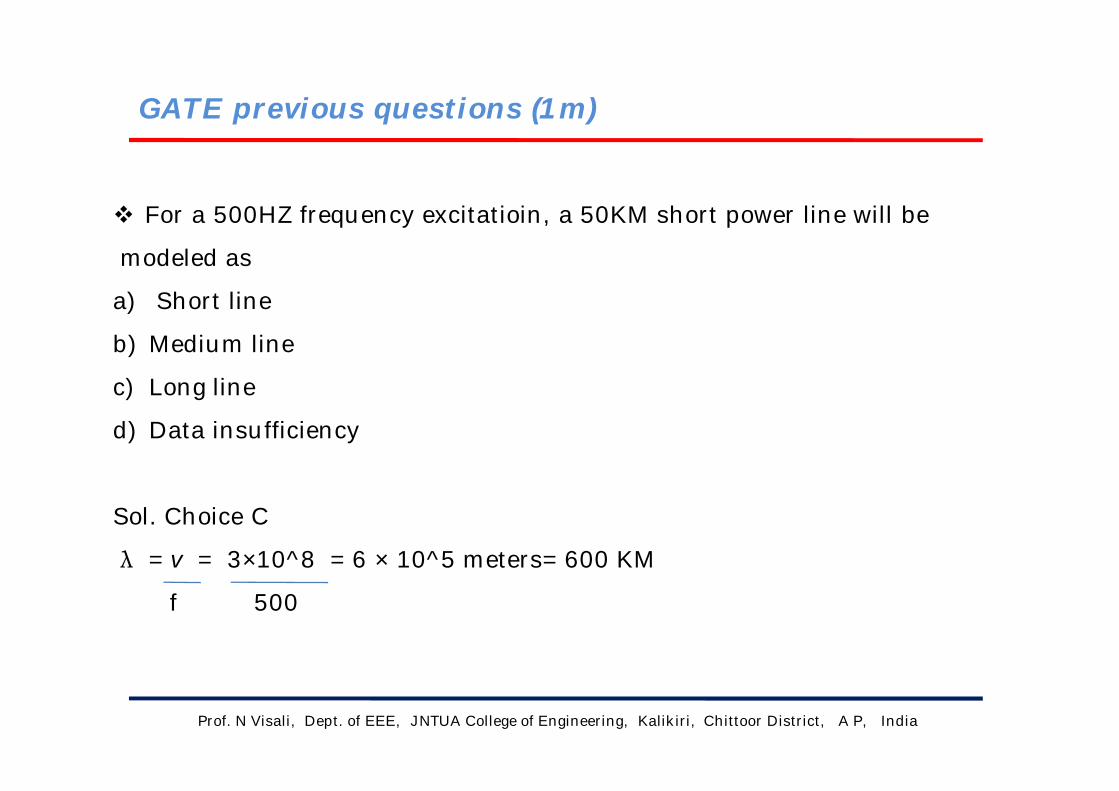
For a 500HZ frequency excitatioin, a 50KM short power line will be
modeled as
a) Short line
b) Medium line
c) Long line
d) Data insufficiency
Sol. Choice C
λ = v = 3×10^8 = 6 × 10^5 meters= 600 KM
f 500

GATE previous questions (1m) contd.
Prof. N Visali, Dept. of EEE, JNTUA College of Engineering, Kalikiri, Chittoor District, A P, India
The concept of electricity short, medium and long line primarily
based on the
a) Nominal voltage of the line
b) Physical length of the line
c) Wavelength of the line
d) Power transmitted over the line
Sol.: choice C
Depending upon the wavelength of the line, charging current
changes and we consider the line parameters as lumped or
distributed. The concept of short, medium and long lines depends on
the parameters (i.e. lumped or distributed).

GATE previous questions (1m) contd.
Prof. N Visali, Dept. of EEE, JNTUA College of Engineering, Kalikiri, Chittoor District, A P, India
Total instantaneous power supplied by 3-phase Ac supply to balanced
R-L load is
a) zero
b) constant
c) Pulsating with zero average
d) pulsating with non- zero average
Sol.: choice B , instantaneous phase voltage and currents are
va = Vm sin ωt Ia = Im sin (ωt- Φ)
vb = Vm sin (ωt-120) Ib = Im sin (ωt- Φ-120)
vc = Vm sin (ωt-240) Ic = Im sin (ωt- Φ-240)
Power = va Ia + vb Ib + vc Ic = 3VI Cos φ ( constant )
GATE previous questions (1m) contd.
Prof. N Visali, Dept. of EEE, JNTUA College of Engineering, Kalikiri, Chittoor District, A P, India
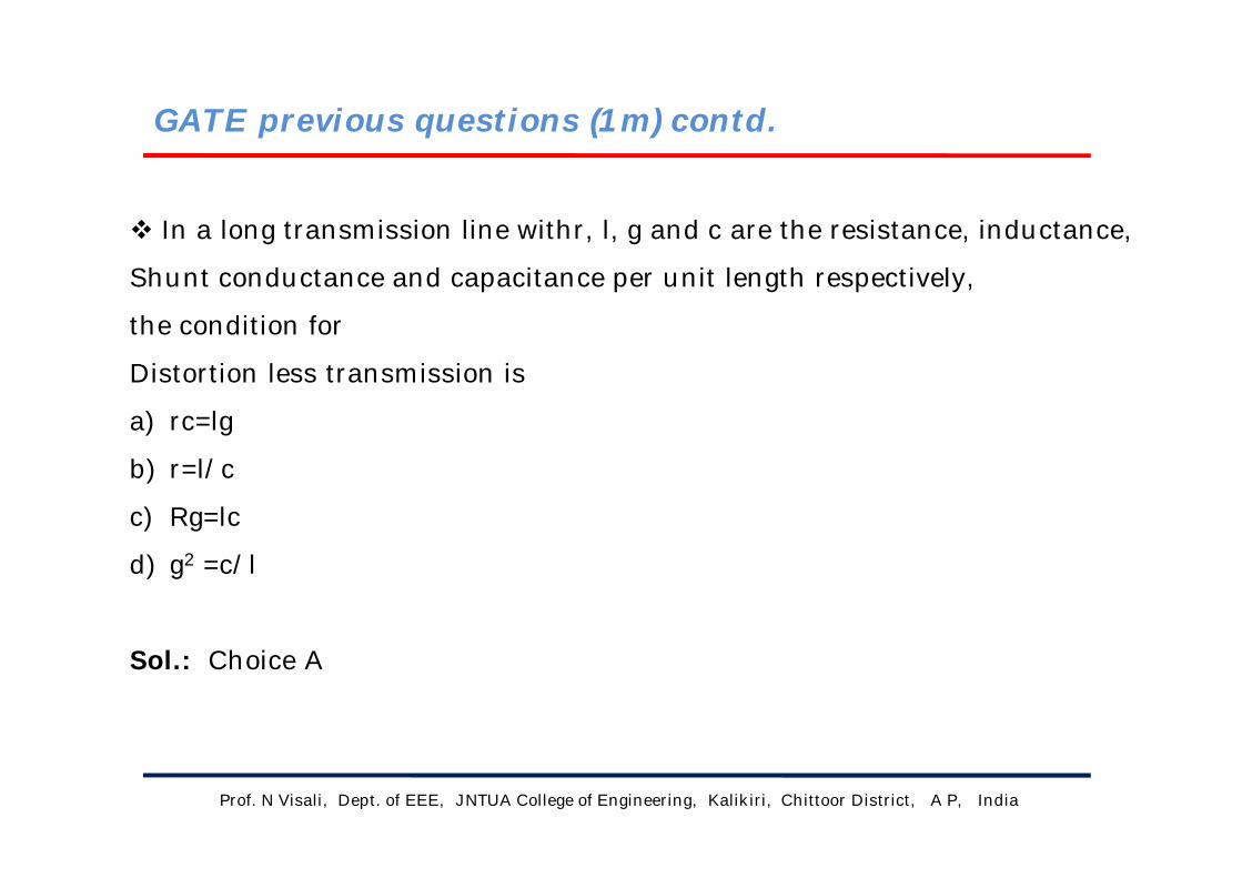
In a long transmission line withr, l, g and c are the resistance, inductance,
Shunt conductance and capacitance per unit length respectively,
the condition for
Distortion less transmission is
a) rc=lg
b) r=l/c
c) Rg=lc
d) g2 =c/l
Sol.: Choice A

GATE previous questions (1m) contd.
Prof. N Visali, Dept. of EEE, JNTUA College of Engineering, Kalikiri, Chittoor District, A P, India
A 220KV, 20Km long, 3-phase transmission line has following ABCD
Parameters A=D=0.96 ∠ 3°,B=55 ∠ 65° ohm/phase,
C=0.5*10-4 ∠ 90° mho/phase. Its correct charging current per phase is
a) 11*sqrt(3) A
b) 11 A
c) 220 A
d) 220/sqrt(3) A
Sol. : choice A
charging current = Vph*Y
=220*103*0.5*10-4/sqrt(3)
= 11/sqrt(3) A
Prof. N Visali, Dept. of EEE, JNTUA College of Engineering, Kalikiri, Chittoor District, A P, India
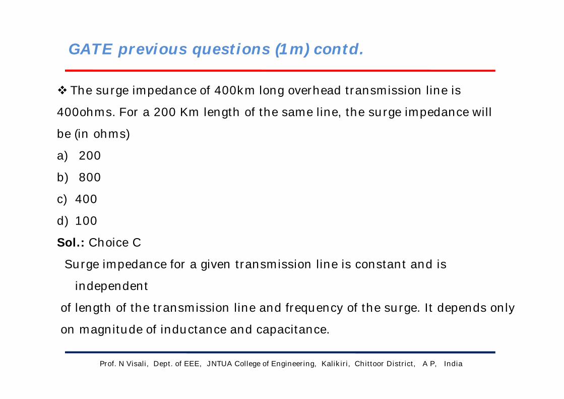
The surge impedance of 400km long overhead transmission line is
400ohms. For a 200 Km length of the same line, the surge impedance will
be (in ohms)
a) 200
b) 800
c) 400
d) 100
Sol.: Choice C
Surge impedance for a given transmission line is constant and is
independent
of length of the transmission line and frequency of the surge. It depends only
on magnitude of inductance and capacitance.
GATE previous questions (1m) contd.

GATE previous questions (2m)
Prof. N Visali, Dept. of EEE, JNTUA College of Engineering, Kalikiri, Chittoor District, A P, India
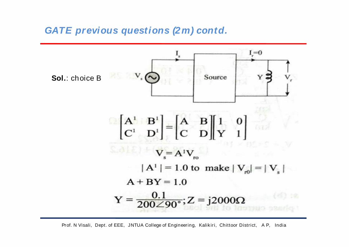
The ABCD parameters of a 3-phase transmission line are A=D=0.9 ∠ 0°,
B=200 ∠ 90° ohm and C=0.95*10-3 ∠ 90° mho. At no-load condition, a
shunt inductive reactor is connected at the receiving end of the line to
Limit the receiving-end voltage to be equal to sending –end voltage. The
Ohmic value of the reactor is
a) Infinity ohm
b) 2000 ohm
c) 105.26 ohm
d) 1052.6 ohm
Prof. N Visali, Dept. of EEE, JNTUA College of Engineering, Kalikiri, Chittoor District, A P, India
Sol.: choice B
GATE previous questions (2m) contd.

Prof. N Visali, Dept. of EEE, JNTUA College of Engineering, Kalikiri, Chittoor District, A P, India
At no load condition, a 3-phase, 50HZ, lossless power transmission line has sending-end
And receiving –end voltages of 400Kv and 420kv respectively. Assuming the velocity of
travelling wave to be the Light, the length of the line,in km,is
GATE previous questions (2m) contd.

Prof. N Visali, Dept. of EEE, JNTUA College of Engineering, Kalikiri, Chittoor District, A P, India
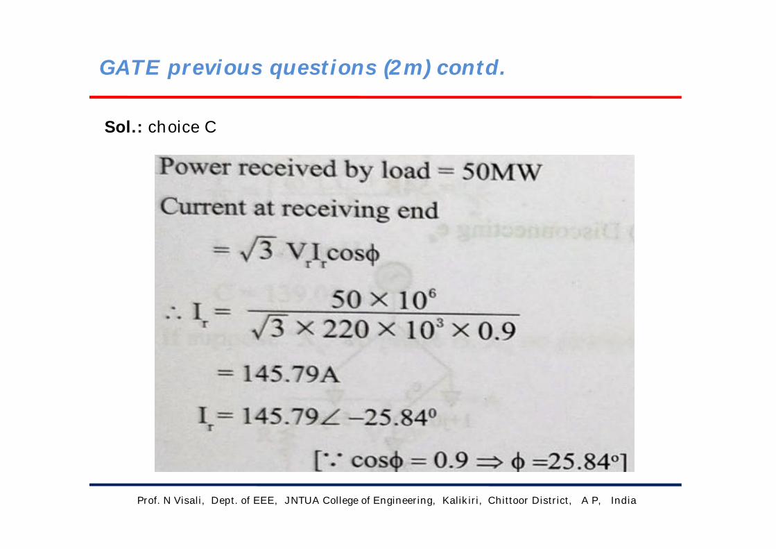
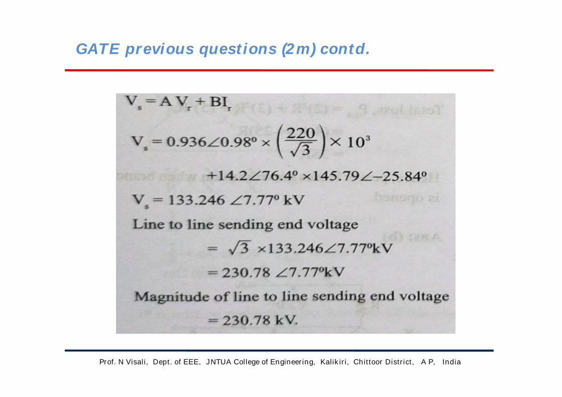
The generalized circuit constants of 3-phase, 220KV rated, medium
length transmission line are A=D=0.936+j0.016=0.936 ∠ 0.98°,
B=33.5+j138=142.0 ∠ 76.4° ohm
C=(-5.18+j 914) * 10-6 mho
If the load at the receiving end is 50MW at 220KV with a power factor 0.9
Lagging, then magnitude of line to line sending end voltage should be
a) 133.23 KV
b) 220.00 KV
c) 230.78 KV
d) 246.30 KV
GATE previous questions (2m) contd.
Prof. N Visali, Dept. of EEE, JNTUA College of Engineering, Kalikiri, Chittoor District, A P, India
Sol.: choice C
GATE previous questions (2m) contd.
Prof. N Visali, Dept. of EEE, JNTUA College of Engineering, Kalikiri, Chittoor District, A P, India
GATE previous questions (2m) contd.

Prof. N Visali, Dept. of EEE, JNTUA College of Engineering, Kalikiri, Chittoor District, A P, India
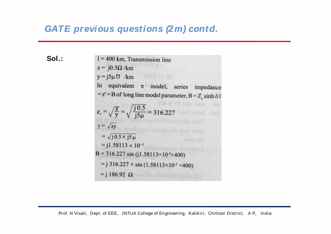
For a 400 Km long transmission line, the series impedance is
(0.0+j0.5)/km and the Shunt admittance is (0.0+j5.0)* 10-6 mho/km.
The magnitude of the series impedance (In ohms) of the equivalent pi
circuit of the transmission line is
GATE previous questions (2m) contd.
Prof. N Visali, Dept. of EEE, JNTUA College of Engineering, Kalikiri, Chittoor District, A P, India
Sol.:
GATE previous questions (2m) contd.

Prof. N Visali, Dept. of EEE, JNTUA College of Engineering, Kalikiri, Chittoor District, A P, India
A three-phase 50 HZ, 400KV transmission line is 300Km long. The line
inductance is1mH/Km per phase and the capacitance is 0.01*10-6F/ Km per
phase. The line is under Open circuit condition at the receiving end and
energized with 400KV at the sending end, the receiving end line voltage in KV
( round off to two decimal places) will be
GATE previous questions (2m) contd.

Prof. N Visali, Dept. of EEE, JNTUA College of Engineering, Kalikiri, Chittoor District, A P, India
Sol.:
GATE previous questions (2m) contd.

Prof. N Visali, Dept. of EEE, JNTUA College of Engineering, Kalikiri, Chittoor District, A P, India
A lossless transmission line having surge impedance loading (SIL) of 2280MW. ASeries capacitive compensation of 30% is emplaced. Then SIL of the compensated Transmission line will be (in MW)a) 1835b) 2280c) 2725d) 3257
A cable has the following characteristics, L=0.201micro H/m and C= 196.2pico F/m. The velocity of the wave propagation through the cable is (in m/sec)
a) 32b) 159.24c) 0.0312d) 159.24
Work to Students
Prof. N Visali, Dept. of EEE, JNTUA College of Engineering, Kalikiri, Chittoor District, A P, India
The total reactance and total susceptance of a lossless overhead EHV
line, operating at 50Hz are given by 0.045 pu and 1.2 pu respectively. If
the velocity of the wave propagation is 3*105 Km/sec, then the
approximate length of line is
A 3-phase, 50HZ generator supplies power of 3MW at 17.32KV to a
balanced 3-phase Inductive load through an overhead line. The per unit
phase line resistance are 0.25 ohm and 3.925 ohm respectively. If the
voltage at the generator terminal is 17.87KV, the Power factor of the load is
Work to Students

Prof. N Visali, Dept. of EEE, JNTUA College of Engineering, Kalikiri, Chittoor District, A P, India
The End