RCM-101-USB.pdf - PC Software - AMSAMOTION
328
PC Software RCM-101-MW, RCM-101-USB Operation Manual Twenty-ninth Edition IAI Corporation
-
Upload
khangminh22 -
Category
Documents
-
view
2 -
download
0
Transcript of RCM-101-USB.pdf - PC Software - AMSAMOTION

PC Software
RCM-101-MW, RCM-101-USB
Operation Manual Twenty-ninth Edition
IAI Corporation


Please Read Before Use Thank you for purchasing our product. This Operation Manual explains the handling methods, structure and maintenance of this product, among others, providing the information you need to know to use the product safely. Before using the product, be sure to read this manual and fully understand the contents explained herein to ensure safe use of the product. The DVD that comes with the product contains operation manuals for IAI products. When using the product, refer to the necessary portions of the applicable operation manual by printing them out or displaying them on a PC. After reading the Operation Manual, keep it in a convenient place so that whoever is handling this product can reference it quickly when necessary.
[Important] This Operation Manual is original. The product cannot be operated in any way unless expressly specified in this Operation Manual. IAI
shall assume no responsibility for the outcome of any operation not specified herein. Information contained in this Operation Manual is subject to change without notice for the purpose of
product improvement. If you have any question or comment regarding the content of this manual, please contact the IAI
sales office near you. Using or copying all or part of this Operation Manual without permission is prohibited. The company names, names of products and trademarks of each company shown in the sentences
are registered trademarks.

CAUTION
Disconnection of the Teaching Pendant from the PCON, ACON, DCON, SCON ERC2, ERC3, ROBONET, PSEP, ASEP, DSEP, MSEP, MSCON, MCON Controller and ELECYLINDER * After disconnecting the Teaching Pendant from the PCON, ACON, DCON, SCON, ROBONET, MSEP,
MSCON or MCON controller with the AUTO/MANU switch, always turn the AUTO/MANU switch to AUTO. * For the PCON, ACON, ERC2, ERC3, PSEP, ASEP, DSEP controller and ELECYLINDER without AUTO/MANU
switch, always set the MANU operation mode to “Monitor Mode 2” on the main window before disconnecting the Teaching Pendant from the controller. (Refer to 3.2, “Operations Using the Toolbar Buttons.”) (Note) When connected to the controller without AUTO/MANU switch, the conditions shown below occur.
When the controller is set by connecting the Teaching Pendant to the gateway unit/SIO converter, the conditions shown below occur. ● If the Teaching Pendant is disconnected while the setting of “Teach 1”or “Teach 2” remains, I/O
will become invalid and control from PLC will become impossible. ● If the Teaching Pendant is disconnected while the setting of “Monitor 1” remains, the maximum
speed will become the safety speed set for the parameter regardless of a command from PLC.


Software License Agreement Before opening this product, read the software license agreement (hereinafter referred to as “Agreement”). This Agreement applies to the PC software that comes with this product (hereinafter referred to “Software”). By using this software, you are deemed to have agreed to the terms of this Agreement. You may not use this software if you do not agree to the terms of this Agreement. If you do not agree to the terms of this Agreement, please return your product in the original, unused condition, and IAI will refund the price you paid for the product.
IAI Corporation (hereinafter referred to as “IAI”) shall grant to the user (hereinafter referred to as “the User”), and the User shall accept, a non-transferable, non-exclusive right to use the software program supplied with this Agreement (hereinafter referred to as “the Licensed Software”), based on the following terms and conditions.
Witnesseth 1. Term of Agreement This Agreement shall take effect when the User opens this software and remain effective and in force until this Agreement is terminated upon a written request made by the User to IAI or pursuant to the provision of Section 3. 2. Right of Use The User may use this software on a computer on the condition that an external equipment communication cable manufactured and sold by IAI (hereinafter referred to as “Dedicated Connection Cable”) is used. The User or a third party may use this software on multiple computers on the condition of using dedicated connection cables. 3. Termination of Agreement If the User violates any of the provisions specified in this Agreement or any material reason arises that makes continuation of this Agreement difficult, IAI may terminate this Agreement immediately without serving any notice. If this Agreement is terminated, the User shall destroy this software, dedicated connection cable or cables, and all copies of this software, within ten (10) days from the date of termination of this Agreement. 4. Scope of Protection IAI may change any and all specifications regarding this software without prior notice. IAI shall also provide no warranty in connection with this software. Neither the User nor any third party may demand compensation for any loss suffered by the User or third party as a result of use of this software by the User or third party.

Supported Models The PC software RCM-101-MW and RCM-101-USB supports the following controller models of the specified versions and later.
Table 1 List of Supported Models Model Name Initial Supported Version Model Name Initial Supported Version
RCP *1 V1.00.00.00 MSCON V9.02.00.00
RCS *1 V3.00.00.00 MSEP (with 3D or T included in model code) *3 V9.06.00.00
E-Con *1 V3.00.05.00 SCON-CAL/CGAL V9.07.00.00 RCP2 *1 V4.00.00.00 ACON-CB V10.00.00.00 ERC *1 V4.00.00.00 DCON-CB V10.00.00.00 ERC2 V6.00.00.00 SCON-CB V10.00.00.00 ERC3 V8.03.00.00 MCON V10.00.00.00 PCON (other than PCON-CA, PCON-CB, CYB, PLB, POB)
V6.00.00.00 PCON-CB V10.02.00.00
PCON-CA V8.03.00.00 RCP6S V10.02.00.00 ACON (other than ACON-CA, ACON-CB, CYB, PLB, POB)
V6.00.00.00 RCM-P6PC V12.00.00.00
RCM-P6AC V12.00.00.00
ACON-CA V9.05.00.00 RCM-P6DC V12.00.00.00 DCON-CA V9.05.00.00 PCON-CB, CYB, PLB, POB V10.03.00.00 SCON-C V6.00.00.00 ACON-CB, CYB, PLB, POB V10.03.00.00
SCON-CA V8.00.00.00 DCON-CB, CYB, PLB, POB V10.03.00.00
ROBONET V6.00.04.00 MCON (MECHATROLINK-Ⅲ: with ML3 included in model code) (SSCNETⅢ/H: with SSC included in model code) (EtherCAT Motion: with ECM included in model code)
V10.04.00.00 ASEP *2 V7.00.00.00
PSEP *2 V7.00.00.00
DSEP *2 V8.04.00.00
MSEP (without 3D or T included in model code) *3, MSEP-LC*3
V9.01.00.00 ELECYLINDER V12.00.00.00
Model Code of MSEP 3D (3W, Brush-less DC Electric Motor), T (High-thrust Setting Type) *1: This PC software also supports the RCP, RCS, E-Con, RCP2, and ERC controllers.
(Note) Confirm the connected model and version of this application. If any unsupported model is connected, it
may operate unexpectedly. (Note) ERC2, ERC3, PCON, ACON, SCON or MSCON cannot be used by linking with any model shown in *1, *2
and *3. Models in *1, *2 and *3 cannot be linked with each other. The software reset function is effective for models corresponding to V4.00.00.00 or later of the supported version.

A Word of Caution [1] This software is copyrighted by IAI Corporation (IAI). [2] The software and the manual can only be used upon the software license agreement. [3] IAI cannot assume responsibility for any damage or loss resulting from the use of this software or the
manual. [4] Please note that the version or edition number printed on the face of this manual does not correspond to the
software version number. [5] The content of this manual is subject to change without notice. [6] This software runs on Windows shown below. This manual has been written on the assumption that the user
already has a basic understanding of Windows operations. (However, this software does not contain Windows.)
Port used Type Supported Operating Systems RS-232C RCM-101-MW Windows 7 *1, Windows8, 8.1 *2, Windows 10 *3
USB RCM-101-USB Windows 7 *1, Windows8, 8.1 *2, Windows 10 *3
*1 Supported by software version V9.00.00.00 or later *2 Supported by software version V9.08.00.00 or later *3 Supported by software version V11.00.00.00 or later
Microsoft, MS, MS-DOS, Windows, Windows 98SE, Windows Me, Windows 2000, Windows XP, Windows Vista, Windows 7, Windows 8, 8.1 and Windows 10 are registered trademarks of Microsoft Corporation. Copyright© Feb 2012. IAI Corporation. All rights reserved.

Table of Contents 1. Preparation Before Use.................................................................................................................... 1
1.1 Items Supplied with This Software (Product Components)........................................................... 1 1.2 Operating Environment................................................................................................................. 2 1.3 Installing the Software .................................................................................................................. 3
1.3.1 How to Install the PC Interface Software for RC.........................................................................3 1.3.2 How to Uninstall PC Interface Software for RC ..........................................................................9 1.3.3 How to Install the USB Conversion Adapter Driver Software ...................................................10 1.3.4 How to Change the IAI USB COM Port.....................................................................................24
1.4 Starting the Software ...................................................................................................................26 1.5 Setting of communication Window...............................................................................................28
2. Checking for Connected Axes........................................................................................................ 29 3. Main Window.................................................................................................................................. 30
3.1 Operating from the Main Menu ....................................................................................................32 3.2 Operations Using the Toolbar Buttons.........................................................................................43 3.3 Tree View ....................................................................................................................................45 3.4 Status Bar....................................................................................................................................46
4. Selecting an Axis............................................................................................................................ 47 5. Editing Position Data on CON Controllers and Older Models ........................................................ 48
5.1 Online Mode ................................................................................................................................48 5.2 Offline Mode ................................................................................................................................75
5.2.1 Creating New Position Data ......................................................................................................75 5.2.2 Reading a File ...........................................................................................................................77
6. Initial Setting and Position Data Editing for SEP Controllers.......................................................... 79 6.1 Initial Setting ................................................................................................................................79 6.2 Editing Position Data ...................................................................................................................86
6.2.1 Online Mode..............................................................................................................................86 6.2.2 Offline Mode..............................................................................................................................97
7. ELECYLINDER Simple Data Setting............................................................................................ 101 7.1 Online Mode ..............................................................................................................................101 7.2 Offline Mode ..............................................................................................................................109
7.2.1 Creating New Position Data ....................................................................................................109 7.2.2 Reading a File .........................................................................................................................109
8. Editing Parameters....................................................................................................................... 111 9. Monitoring .................................................................................................................................... 116
9.1 Status Monitor Window..............................................................................................................116 9.2 CTL Alarm List...........................................................................................................................123 9.3 Velocity/Current Monitor Window ..............................................................................................125 9.4 Servo Monitor Window ..............................................................................................................127 9.5 Maintenance information Window..............................................................................................135 9.6 Gateway Data Monitor ...............................................................................................................138 9.7 Network Data Monitor ................................................................................................................141
9.7.1 How to Display Monitoring Window.........................................................................................141 9.7.2 Monitoring Window..................................................................................................................145

10. Setup............................................................................................................................................ 147 10.1 Setting of application Window....................................................................................................147 10.2 Assigning an Axis Number.........................................................................................................152 10.3 Time Setting ..............................................................................................................................153 10.4 Load Cell Calibration .................................................................................................................155
11. Version Information ...................................................................................................................... 157 12. Smart Tuning Function (Version V8.03.00.00 or Later)................................................................ 158
12.1 Restrictions................................................................................................................................159 12.1.1 Actuator Applicable for Smart Tuning Function ......................................................................159 12.1.2 Parameter Setting ...................................................................................................................159
12.2 Outline of Smart Tuning Function ..............................................................................................159 12.2.1 Setting of maximum acceleration/deceleration speed considering the indicated
carrier load and velocity ..........................................................................................................160 12.2.2 Setting of acceleration/deceleration speed to provide the shortest operation time
figured out from the indicated carrier load and moving distance ............................................160 12.2.3 Overshoot judgment on S motion operation ...........................................................................160 12.2.4 Test run ...................................................................................................................................160 12.2.5 Cycle time calculation .............................................................................................................160
12.3 Operation in Edit position data Window.....................................................................................161 12.3.1 Explanation of Window Screen ...............................................................................................161 12.3.2 Explanation of Each Operation ...............................................................................................165
12.4 Operation on Test Run and Cycle Time Calculation..................................................................176 12.4.1 Outline of Test Run Operation ................................................................................................176 12.4.2 Explanation of Each Window for Test Run Operation.............................................................177 12.4.3 Explanation of Cycle Time Calculation Window......................................................................192
13. Off Board Tuning Function ........................................................................................................... 201 13.1 Restrictions................................................................................................................................202
13.1.1 Actuators Applicable for Off Board Tuning Function...............................................................202 13.1.2 Restrictions in Operation.........................................................................................................202 13.1.3 Caution Regarding Gain Set No. 0..........................................................................................202
13.2 Guideline of Off Board Tuning Function ....................................................................................203 13.3 How to Start up..........................................................................................................................203 13.4 Operation to Select Target Axis Number for Off Board Tuning..................................................204
13.4.1 Explanation of Each Item Shown in Window ..........................................................................204 13.5 Operation on Off Board Tuning..................................................................................................206
13.5.1 Outline of Operation ................................................................................................................206 13.5.2 Explanations for each Item in Select actuator Window...........................................................207 13.5.3 Explanations for each Item in Carrier load Select Window.....................................................213 13.5.4 Explanations for each Item in Select adjustment method Window.........................................219 13.5.5 Explanations for each Item in Manual Window.......................................................................223 13.5.6 Explanations for each Item in Test run Window......................................................................229 13.5.7 Explanations for each Item in Adjustment record data save Window.....................................237
13.6 Operations in Cycle Time calculation ........................................................................................239 13.6.1 Explanations for each Item in Cycle Time calculation Window...............................................239 13.6.2 Test run plan Setting Window .................................................................................................240 13.6.3 Test run result Display Window...............................................................................................244

14. Frequency Analysis for Vibration Control (Version V8.00.00.00 or later of SCON-CA, Version V9.02.00.00 or later of MSCON, Version V9.07.00.00 or later for SCON-CAL/CGAL, V10.00.00.00 or later for SCON-CB)....................... 248 14.1 Operation Overview...................................................................................................................249 14.2 Explanation of Each Window.....................................................................................................251
14.2.1 Measurement Data Selection Window....................................................................................251 14.2.2 Sampling Window....................................................................................................................254 14.2.3 Analysis Result Display Window.............................................................................................265 14.2.4 Print Setting Window...............................................................................................................269
14.3 Operating Procedure .................................................................................................................275 15. Press Program Editing and Operation of Servo Press (V10.00.00.00 or later for SCON-CB) ..... 280
15.1 Operation Outline ......................................................................................................................280 15.2 Outline of Operation in Each Window........................................................................................282
15.2.1 Press Program Editing Window ..............................................................................................282 15.2.2 Multi Press Program Editing Window......................................................................................289 15.2.3 Press Program Operation / Monitor Window ..........................................................................290
15.3 Servo Press Related in Application Setting Window ...................................................................302 16. Appendix ...................................................................................................................................... 303
16.1 Parameter (Factory Default Setting) Initializing Method ............................................................303 16.2 PC Software Error List ...............................................................................................................305
17. File Extensions............................................................................................................................. 309 18. Change History ............................................................................................................................ 311


1. Preparation Before U
se
1
1. Preparation Before Use 1.1 Items Supplied with This Software (Product Components)
Please check to make sure that the following items are included in your software package. [1] Operation manual (1) [2] CD-ROM containing the software*1 (1) [3] Customer registration card (1) [4] External connection cables (1)
External connection cables vary depending on the PC interface software type. The types and external connection cables are shown in the table below.
Type External Connection Cable
RCM-101-MW RS232C conversion unit (RCB-CV-MW): 1 cable Communication cable (CB-RCA-SIO050): 1 cable
Con
nect
ion
Con
figur
atio
n
Type External Connection Cable
RCM-101-USB USB conversion unit (RCB-CV-USB): 1 cable Communication cable (CB-RCA-SIO050): 1 cable USB cable (CB-SEL-USB030): 1 cable
Con
nect
ion
Con
figur
atio
n
*1 ROBONET Gateway Parameter Setting Tool is stored in the CD-ROM.
Refer to ROBONET Operation Manual for the how to use the tool.
RS232C conversion unit RCB-CV-MW
Communication cable: CB-RCA-SIO050
Compatible controllerPCON, etc.
USB cable CB-SEL-USB030
Communication cable CB-RCA-SIO050
USB conversion unit (RCB-CV-USB)
Compatible controllerPCON, etc.

1. P
repa
ratio
n B
efor
e U
se
2
1.2 Operating Environment You need the following environment to run this software.
Model number Supported operating systems
RCM-101-MW Windows 7 *1, Windows 8, 8.1 *2, Windows 10 *3
RCM-101-USB Windows 7 *1, Windows 8, 8.1 *2, Windows 10 *3
Applicable operating systems
*1 Supported by software version V9.00.00.00 or later *2 Supported by software version V9.08.00.00 or later
Applicable for 32 bit and 64 bit versions of the OS. *3 Supported by software version V11.00.00.00 or later
Computer Personal computer running an applicable operating system (Windows)
Keyboard Keyboard compatible with a personal computer running an applicable operating system (Windows)
Memory Enough memory needed to run an applicable operating system (Windows)
Display XGA or higher
Pointing device Mouse and other compatible driver
Memory-medium reading drive CD-ROM drive
Hard disk Hard disk with at least 20 MB of free space (This software must be installed on the hard disk.)
Serial port RS232C (compatible with EIA-S74)
An applicable serial port is required if the model number of your PC software is as follows: Model number: RCM-101-MW
USB port An applicable serial port is required if the model number of your PC software is as follows: Model number: RCM-101-USB

1. Preparation Before U
se
3
1.3 Installing the Software
This software is run from the hard disk. This section explains how to install the software. 1.3.1 How to Install the PC Interface Software for RC
[1] Insert the CD-Rom containing this software into your CD-ROM drive. [2] The installed data selection window (Fig. 1.1) will be displayed.
Select the version you wish to install from these choices: PC Interface Software for RC (ENG) and PC Interface Software for RC (EUR). Then click the corresponding button to begin the installation. (Some items are not indicated depending on the version.)
Fig. 1.1 Installed Data Selection Window (The displayed window may vary depending on the version or other factor.)
* What to do when the Installed Data Selection window (Fig. 1.1) does not appear
If the Installed Data Selection window (Fig. 1.1) does not appear after inserting the CD-ROM, follow the procedure below to display the Installed Data Selection window. a. Use Explorer, etc., to display a list of folders and files in the CD-ROM.
The window should display the icons shown in Fig. 1.2.
Fig. 1.2 Icons
b. Double-click among the icons displayed. The Installed Data Selection window (Fig. 1.1) will appear.

1. P
repa
ratio
n B
efor
e U
se
4
[3] A previous version install check window (Fig. 1.3) is displayed.
Click Yes if no previous version has been installed. Click No if any previous version has been installed. Installation is interrupted, then uninstall using the Program add/remove icon on the control panel.
Fig. 1.3 Previous Version Install Check Window If the installer still detects that a previous version is installed after you have clicked Yes, the previous version detection window (Fig. 1.4) appears. If this window appears, uninstall the previous version and then repeat the installation process from the beginning.
Fig. 1.4 Previous Version Install Check Window * How to uninstall is described at the end of how to install PC Interface Software for RC. Refer to it.

1. Preparation Before U
se
5
[4] The installation window (Fig. 1.5) for PC Interface Software for RC
Click Next.
Fig. 1.5 Installation Window
[5] Customer information register window (Fig. 1.6) is displayed. Enter customer information and click
Next.
Fig. 1.6 Customer Information Registration
1. P
repa
ratio
n B
efor
e U
se
6
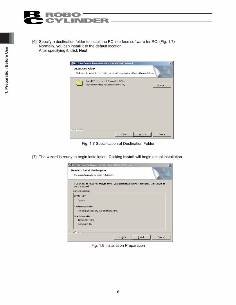
[6] Specify a destination folder to install the PC interface software for RC. (Fig. 1.7) Normally, you can install it to the default location. After specifying it, click Next.
Fig. 1.7 Specification of Destination Folder
[7] The wizard is ready to begin installation. Clicking Install will begin actual installation.
Fig. 1.8 Installation Preparation

1. Preparation Before U
se
7
The window shown in Fig. 1.9 will be displayed during installation.
Fig. 1.9 Installation Progress
[8] When installation is completed, the window shown in Fig. 1.10 will be displayed.
Fig. 1.10 Installation Completion

1. P
repa
ratio
n B
efor
e U
se
8
[9] When the install program is ended, a shortcut in Program IAI ROBO Cylinder PC Interface Software for RC is displayed on the start menu. This software starts by selecting this item.
[10] Remove the CD-ROM.
* If install is completed with the previous version installed, two shortcuts may be located in Program IAI ROBO Cylinder on the start menu. In this case, only the short cut corresponding to the present version is deleted when uninstalled. Right click the shortcut for the previous version (PC Interface software for RC&E-Con) click Delete to manually delete it.
Fig. 1.11 Shortcut Delete Window for Previous Version

1. Preparation Before U
se
9
1.3.2 How to Uninstall PC Interface Software for RC [1] Open the application add and delete window on the control panel. [2] Select RcPc on the application add and delete window, and click Change/Remove.
Fig. 1.12 Application Add and Delete [3] When a file delete check window (Fig. 1.13) is displayed, click Yes.
Fig. 1.13 File Delete Check
1. P
repa
ratio
n B
efor
e U
se
10
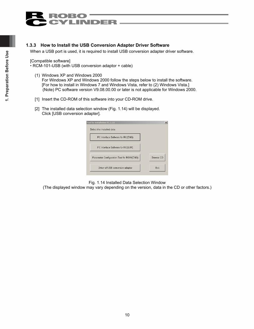
1.3.3 How to Install the USB Conversion Adapter Driver Software
When a USB port is used, it is required to install USB conversion adapter driver software. [Compatible software] RCM-101-USB (with USB conversion adaptor + cable)
(1) Windows XP and Windows 2000
For Windows XP and Windows 2000 follow the steps below to install the software. [For how to install in Windows 7 and Windows Vista, refer to (2) Windows Vista.] (Note) PC software version V9.08.00.00 or later is not applicable for Windows 2000.
[1] Insert the CD-ROM of this software into your CD-ROM drive. [2] The installed data selection window (Fig. 1.14) will be displayed.
Click [USB conversion adapter].
Fig. 1.14 Installed Data Selection Window (The displayed window may vary depending on the version, data in the CD or other factors.)

1. Preparation Before U
se
11
[3] You are prompted to set the folder of the copy destination. If you use the displayed folder as it is, click
Copy. To change it, enter it manually or click Browse to set the folder of the copy destination. On the browse for folder window (Fig. 1.16), click the folder of the copy destination to select it and then click OK. Once you have clicked OK, the browse for folder window (Fig. 1.16) will disappear and the selected folder path will be displayed on the window to specify the folder of the copy destination (Fig. 1.15).
Fig. 1.15 Window to Specify Folder of Copy Destination
Fig. 1.16 Browse for Folder Window
[4] When the folder of IAI USB (copy data) already exists in the copy destination, you are prompted to overwrite it. Click OK to overwrite it, or click Cancel to stop copying.
Fig. 1.17 Overwrite Confirmation Window
[5] The complete window (Fig. 1.18) will be displayed.
Fig. 1.18 Complete Window

1. P
repa
ratio
n B
efor
e U
se
12
[6] Once the complete window (Fig. 1.18) has been displayed, click OK. The complete window (Fig. 1.18)
will disappear. Then, click Cancel on the window to specify the folder of the copy destination (Fig. 1.15). The window to specify the folder of the copy destination (Fig. 1.15) will disappear. Finally, click Exit on the data selection window (Fig. 1.14). The data selection window (Fig. 1.14) will disappear.
[7] Remove the CD-ROM. [8] Then, insert the USB conversion adapter (RCB-CV-USB) into the USB port of your PC.
[9] Windows will open the Found New Hardware Wizard.
Click Next.
Fig. 1.19 Found New Hardware Wizard Start Window

1. Preparation Before U
se
13
[10] The driver search select window will open. Check the Search for a suitable driver for my device (recommended). Click Next.
Fig. 1.20 Driver Search Select Window
[11] The locate driver files window will open. Select Specify a location. Click Next.
Fig. 1.21 Specify the Locate Driver Files Window

1. P
repa
ratio
n B
efor
e U
se
14
[12] The “Copy manufacturer’s files from:” window will open. Click Browse and find K: \IAI USB (the folder you have specified in [3] of 1.3.3) and set it. Click OK.
Fig. 1.22 Specify the Copy Manufacturer’s Files from Window
[13] The driver files search results window will open. Click Next.
Fig. 1.23 Driver Files Search Results Window

1. Preparation Before U
se
15
[14] When the IAI USB Composite Device driver installation finish is displayed, the installation of the driver is completed. Click Finish.
Fig. 1.24 IAI USB Composite Device Installation Finish Window
[15] Subsequently, the found new hardware wizard window will open. Click Next.
Fig. 1.25 Found New Hardware Wizard Window

1. P
repa
ratio
n B
efor
e U
se
16
[16] The install hardware device drivers window will open.
Select the Search for a suitable driver for my device recommended. Click Next.
Fig. 1.26 Driver Search Select Window
[17] The locate driver files window will open. Select Specify a location. Click Next.
Fig. 1.27 Locate Driver Files Window

1. Preparation Before U
se
17
[18] The copy manufacturer’s files from window will open. Click Browse and find K:\IAI USB (the folder you have specified in [3] of 1.3.3) and set it. Click OK.
Fig. 1.28 Specify the Copy Manufacturer’s Files from Window
[19] The driver files search results window will open. Click Next.
Fig. 1.29 Driver Files Search Results Window

1. P
repa
ratio
n B
efor
e U
se
18
[20] When the IAI USB to UART Bridge Controller driver installation finish window is displayed, the driver installation is completed. Click Finish.
Fig. 1.30 IAI USB to UART Bridge Controller Installation Finish Window
[21] The installation of all drivers is completed.

1. Preparation Before U
se
19
[22] Click Start on the Windows taskbar, Settings, and then Control Panel to open the Control Panel. Double-click System to open System Properties. Click the Hardware tab in System. Click Device Manager in Hardware. Double-click Ports (COM & LPT) in Device Manager to expand the folder tree. If there is IAI USB to UART Bridge Controller (COM?) under Ports (COM & LPT) in Device Manager, the driver has normally been installed and operated. (Note) The number added to the end of COM? becomes the number of the inserted COM port.
Fig. 1.31 Device Manager Window

1. P
repa
ratio
n B
efor
e U
se
20
(2) Windows 7, Windows Vista, Windows 8, 8.1, Windows 10 For Windows 7, follow the steps below to install the software. You shall follow the same steps for Windows Vista and Windows 8, 8.1, Windows 10.
[1] Insert the CD-ROM of this software into your CD-ROM drive. [2] Click on Driver of USB conversion adapter in the window to select what to install. [3] A previous version install check window is displayed.
Click Yes if no previous version has been installed. Click No if any previous version has been installed. Installation is interrupted, then uninstall using the Program add/remove icon on the control panel.
Fig. 1.32 Previous Version Install Check Window [4] IAI Corporation USB to UART Bridge Controller Driver Installer window appears. Click Next>.
Fig. 1.33 IAI Corporation USB to UART Bridge Controller Driver Installer Window

1. Preparation Before U
se
21
[5] The drivers are now installing... window appears.
Fig. 1.34 The drivers are now installing... window [6] Once the installation is completed, “The drivers were successfully installed on this computer.” is shown on
IAI Corporation USB to UART Bridge Controller Driver Installer window. Click Finish.
Fig. 1.35 IAI Corporation USB to UART Bridge Controller Driver Installer Window
[7] Connect the PC and USB conversion adapter using a USB cable. [8] Installation of the driver is complete. If the installation does not complete, follow the instruction from [9].

1. P
repa
ratio
n B
efor
e U
se
22
[9] Open Device Manager. Right-click on CP2102 USB to UART Bridge Controller, and then left-click on Update Driver Software.
Fig. 1.36 Device Manager Window [10] Update window for the driver software opens. Click on Browse my computer for driver software
button in Update Driver Software window.
Fig. 1.37 Update Driver Software Window

1. Preparation Before U
se
23
[11] Update window for the driver software opens. In the box circled in Update Driver Software window, input the directory “C:Program Files\IAI\IAI USBv4\Vista-8”. Click Next>.
Fig. 1.38 Update Driver Software Window [12] Driver software update complete (IAI USB to UART Bridge Controller) window opens. Click Close in
the Update Driver Software window.
Fig. 1.39 Update Driver Software Complete (IAI USB to UART Bridge Controller) Window [13] Installation of the driver is complete.
C:Program Files\IAI\IAI USBv4\Vista-8

1. P
repa
ratio
n B
efor
e U
se
24
1.3.4 How to Change the IAI USB COM Port The COM port set during the installation of the USB conversion adapter driver software can be changed by following the procedure below: [1] Click Start on the Windows taskbar, Settings, and then Control Panel to open the Control Panel. Double-click System to open System Properties.
Click the Hardware tab in System. Click Device Manager in Hardware. Double-click Ports (COM & LPT) in Device Manager to expand the folder tree.
[2] Double-click IAI USB to UART Bridge Controller (COM?). (Note) “COM?” indicates the current COM port before change.
Fig. 1.40 Device Manager Dialog Box [3] The IAI USB to UART Bridge Controller (COM?) Properties dialog box appears.
Click Advanced... in the properties dialog box.
Fig. 1.41 Properties Dialog Box
IAI USB to UART Bridge Controller (COM?)

1. Preparation Before U
se
25
[4] The COM? Port Advanced Settings dialog box appears.
Change the COM port number currently selected under COM Port Number:, to a desired number. After the COM port number has been changed, click OK.
Fig. 1.42 COM? Port Advanced Settings Dialog Box [5] The COM? Port Advanced Settings dialog box closes.
Click OK in the Properties dialog box (Fig. 1.41), and the COM port will be changed. [6] Close the Device Manager dialog box and then open it again. You should now see the new COM port
number. After confirming the new COM port number, close the Device Manager dialog box and all other dialog boxes currently open.
COM Port Number:

1. P
repa
ratio
n B
efor
e U
se
26
1.4 Starting the Software
[1] Turn off the power to the controller and PC, and connect the controller to the PC using the standard RS232C cable or USB cable that comes with the software.
[2] Turn on the power to the controller and PC, and start Windows. [3] If your controller has a port switch, turn the port switch ON before starting this software. * This software judges whether the mode is online or offline depending on whether the controller and
personal computer are connected or not. A controller equipped with a PORT switch does not operate in the online mode even if the port switch of the controller is turned ON after this software is started. In this case, the online mode is turned on by performing [Reconnect] (Refer to 3.1 (5) [2] [Setting of controller]).
[4] A check for connected axis appears and a check for connected axis is started. (Refer to 2. Checking for Connected Axes).
[In the case of PCON, ACON, DCON, SCON, ERC2, ERC3, ROBONET, ASEP, PSEP, DSEP, MSEP, MSCON, MCON and ELECYLINDER]
Before the connected axis is checked, the setting of communication window (Fig. 1.45) appears, but only
when the software is started for the first time after its installation. [Refer to 1.5, “Setting of Communication Window.”]
[5] When a check for the connected axis is completed, the main window is displayed, and at the same
time, a window to select Manual operation mode shown in Fig. 1.43 is displayed. Select the operation mode according to the purpose and press OK. Hereinafter, select the operation mode according to the purpose of operation.
Fig. 1.43 Manual Operation Mode Select Window
Select the manual operation mode from the following four choices. Teach mode 1 (Safety speed effective/PIO start prohibition)
PIO start prohibition: Position data and parameter, etc., are allowed to be written in the controller and actuator operation is commanded by the PC software (I/O ineffective).
Safety speed effective: Maximum speed becomes safety speed (set by a parameter) regardless of speed designation of position data.
Teach mode 2 (Safety speed ineffective/ PIO start prohibition) PIO start prohibition: Position data and parameter, etc., are allowed to be written in the controller
and actuator operation is commanded by the PC software (I/O ineffective). Safety speed ineffective: Allows operation at the speed set in the speed designation of the position data
table (safety speed or higher).

1. Preparation Before U
se
27
Monitor mode 1 (Safety speed effective/PIO start permission)
PIO start permission: Monitoring is only allowed. Position data and parameter, etc., are not allowed to be written in the controller and actuator operation is not commanded by the PC Software. Operation command (jog, home return, etc.) cannot be performed from the PC Interface software.
Safety speed effective: Maximum speed becomes safety speed (set by a parameter) regardless of speed designation of position data.
Monitor mode 2 (Safety speed ineffective/PIO start permission) PIO start permission: Monitoring is only allowed. Position data and parameter, etc., are not allowed
to be written in the controller and actuator operation is not commanded by the PC Software. Operation command (jog, home return, etc.) cannot be performed from the PC Interface software.
Safety speed ineffective: Allows to operate at a speed (safety speed or higher) as commanded from the PLC.
If a warning of “Baud rate of personal computer is not supported” is given and connection with the controller cannot be performed, select other baud rate. ・ Click setting of main menu, and select “Application”. ・ Change baud rate on the “Setting of application” window (Fig. 10.1). ● When PCON, ACON, DCON, SCON, MSCON, ERC2, ERC3, MCON and ELECYLINDER are
connected, the operation mode is in “Safety speed effective (with safety limit speed)” when this software is started. In other words, the maximum speed attained in any position movement operation performed from the PC software (in the test operation mode) will correspond to the safety speed set by the applicable parameter. To operate the actuator with speed commands specifying any speed greater than the safety speed set in the position data table, you must change the operation mode to “Safety speed ineffective (without safety limit speed).” For switching between with safety speed and without safety speed, refer to 3.2, “Operations using toolbar buttons.”
[In the case of RCP, RCS, E-Con, RCP2 and ERC2] [5] When checking if the connected axis is completed, a warning window is displayed.
When OK is clicked, a main window is displayed.
Fig. 1.44 Warning

1. P
repa
ratio
n B
efor
e U
se
28
1.5 Setting of communication Window The “Setting of communication” window (Fig. 1.45) is displayed only at the initial start after the software has been installed. In this window, setting for communication with the controller is made.
Fig. 1.45 Setting of Communication Window
[1] Port From the list, select the serial port to be used to communicate with the controller.
[2] Baud rate
From the list, select the baud rate. * The baud rate selected here is used only in the communication between this application and controller.
It does not affect the communication speed parameters of the controller. * If baud rate is not supported by the port selected in [1], an error occurs when connection is checked.
[3] Last axis No.
Select the axis number of the last axis to be checked for connection. * Axes of numbers greater than the value selected here will not be checked for connection. Select an
appropriate axis number after checking the axis numbers of the connected axes. After setting the above items, click the OK button, then checking for connected axes is performed. (From the next start, checking for connected axes will be automatically performed by this setting.) * Contents set here can be changed on the setting of application window (Fig. 10.1).
If the Cancel button is clicked, application is ended without performing checking for connected axes (this setting of communication window will be displayed again.)

2. Checking for C
onnected Axes
29
2. Checking for Connected Axes The software checks for connection of all axes up to the axis specified in the Last Axis NO. box of the “Setting of communication” window (Fig. 1.45) or “Setting of application” window (Fig. 10.1). After the check, “(Connecting)” will be shown for those axes whose connection has been confirmed, while “-” will be shown for all other axes.
Fig. 2.1 Check for Connected Axes Window (Checking for Connection)
Fig. 2.2 Check for Connected Axes Window (Connection Check Completed) Check for connected axes can be cancelled by pressing the [ESC] key. (In this case, offline mode is set.) Connecting a controller whose enable function is enabled
If you have connected a controller whose enable function is enabled by the applicable parameter, a window appears with the message asking if you want to disable the enable function. If the enable function remains enabled, the servo cannot be turned ON in the teaching mode.

3. M
ain
Win
dow
30
3. Main Window (1) PCON, ACON, DCON, SCON, ROBONET, ASEP, PSEP, DSEP, MSEP, MSCON, MCON controllers,
ERC2, ERC3 and ELECYLINDER As shown in Fig. 3.1, the main window consists of main menu, toolbar buttons, tree view and status bar. The tree view on the left side of the window can be displayed by operation of “Window” “Tree view” on the menu. (Initial window: Main menu)
Fig. 3.1 Main Window (Online Window) Select each item explained in 3.1, “Operating from the Main Menu” or 3.2, “Operations Using the Toolbar Buttons” from the main menu in the main window (Fig. 3.1) or by clicking the corresponding tool button.
Main menu Toolbar buttons
Tree view
Status bar

3. Main W
indow
31
(2) RCP, RCS, E-Con, RCP2 controller and ERC As shown in Fig. 3.2, the main window consists of main menu, toolbar buttons, tree view, and status bar. The tree view on the left side of the window can be displayed by operation of “Window” “Tree view” on the menu. (Initial window: Main menu)
Fig. 3.2 Main Window (Online Window) Select each item explained in 3.1, “Operating from the Main Menu” or 3.2, “Operations Using the Toolbar Buttons” from the main menu in the main window (Fig. 3.2) or by clicking the corresponding tool button.
Main menu
Toolbar buttons
Tree view

3. M
ain
Win
dow
32
3.1 Operating from the Main Menu (1) File
[1] [New]
Create new position data. [2] [Open]
Load position data or parameters from a file. [3] [Close]
Close the active file. [4] [Send to Controller] (Available in the online mode) [Position Data] Write position data in a file to the controller. [Parameter] Write parameters in a file to the controller. [5] [Backup] (Available in the online mode) [Save from Controller to File] Save all position data and parameters in the controller to a file. [Send from File to Controller] Send all position data and parameters in a file to the controller. [Backup data print] Print backup data. The following menus are added from V8.2.0.0. [Parameter edit] Editing is available in the parameter edit window from the backup file. [Position data edit] Editing is available in the position data edit from the backup file. [Batch Backup] The position parameter data of the axes selected from the connected multiple axes can be stored at once to the individual file. [Batch Restore] The position parameter data of the files exist in the selected folders can be transferred to the controller at once. [6] [Recently used file]
History of recently read files are displayed, and you can select file name from these to read. [7] [Exit]
Exit this application. (2) Position (Available in the online mode)
[1] [Edit/Teach]
Load position data from the controller for editing or use in teaching. * In the case of pulse sequence mode of PCON-PL/PO, ACON-PL/PO, SCON-C, SCON-CA,
SCON-CB, PCON -CA, PCON-CB, ACON-CA, ACON-CB, DCON-CA, DCON-CB and ERC3 position data cannot be entered. For this reason the simple program line, teach position button, step move, play button, etc. are not displayed. [Refer to 5. “Editing Position Data on CON Controllers and Older Models.”] [Refer to 6.2. “Editing Position Data.”] [Refer to 7. “ELECYLINDER Simple Data Setting”]

3. Main W
indow
33
[2] [Send to Controller]
Transfer (write) edited position data to the controller. * In the case of pulse sequence mode of PCON-PL/PO, ACON-PL/PO, SCON-C, SCON-CA,
SCON-CB, PCON-CA, PCON-CB, ACON-CA, ACON-CB, DCON-CA, DCON-CB and ERC3 position data cannot be sent to the controller. Even when you attempt to send position data to the controller, it is not displayed as a selectable controller on the “select axis number” window.
[3] [Print]
Print the position data you are currently editing. * In the case of pulse sequence mode of PCON-PL/PO, ACON-PL/PO, SCON-C, SCON-CA,
SCON-CB, PCON-CA, PCON-CB, ACON-CA, ACON-CB, DCON-CA, DCON-CB and ERC3 position data cannot be printed.
(3) Parameter (Available in the online mode)
[1] [Edit]
Load parameters from the controller for editing. [Refer to 8. “Editing Parameters.”]
[2] [Send to Controller]
Transfer (write) edited parameter to the controller. [3] [Print]
Print the parameter you are currently editing. [4] [SEP Controller Setting Information]
In here, shows the details of the initial settings done to SEP controller. [5] [Control Parameter Setting]
• Smart Tuning Trial run and cycle time calculation of the smart tuning can be conducted. [Refer to 12, “Smart Tuning Function (Version V8.03.00.00 or Later).”]
• Offboard Tuning Offboard tuning can be conducted. * Only on SCON-CA, SCON-CAL/CGAL, SCON-CB, ACON-CA, ACON-CB, MSCON and MCON (Servo
motor) [Refer to 13, “Off Board Tuning Function on SCON-CA and MSCON Controller.”]
• Frequency Analysis for Vibration Control Calculate the vibration frequency of the load whose vibration you want to suppress, and set appropriate parameters.
* Only on SCON-CA, SCON-CAL/CGAL, SCON-CB, ACON-CA, ACON-CB, MSCON and MCON (Servo motor) [Refer to 14, “Frequency Analysis for Vibration Control Function.”]

3. M
ain
Win
dow
34
(3) Parameter (Available in the online mode) (Continuation)
[6] [SCON Parameter File Converter Tool] * Software Version 11.00.02.00 and later
The following SCON controller parameter files (converting source files) can be changed into the converted files. The extension of converted files will have $$, not like an extension created in a PC software.
Converting Source File Converted File Parameter file (.prsc) for SCON-C Parameter file (.$$prsa) for SCON-CA Parameter file (.prsc) for SCON-C Parameter file (.$$prsb) for SCON-CB Parameter file (.prsa) for SCON-CA Parameter file (.$$prsb) for SCON-CB Parameter file (.$$prsa) for SCON-CA Parameter file (.$$prsb) for SCON-CB Parameter file (.prsam) for SCON-CA (MECHATROLINK-Ⅲ: with ML3 included in model code)
Parameter file (.$$prsbm) for SCON-CB (MECHATROLINK-Ⅲ: with ML3 included in model code)
The converted files can be transferred to the following controllers. Converted File Controller Available for Transfer
Parameter file (.$$prsa) for SCON-CA SCON-CA Parameter file (.$$prsb) for SCON-CB SCON-CB Parameter file (.$$prsbm) for SCON-CB (MECHATROLINK-Ⅲ: with ML3 included in model code)
SCON-CB (MECHATROLINK-Ⅲ: with ML3 included in model code)
[Operation] 1) From the main menu, click Parameter (P), and then select SCON Parameter File Converter Tool (S).
The main window of the parameter converter tool is displayed.
Fig. 3.3 Parameter Converter Tool Main Window

3. Main W
indow
35
(3) Parameter (Available in the online mode) (Continuation) 2) Select Converting Source File
To select a source file for converting, pick a file that you would like to convert and drag and drop in the main window, or click the browse button( ) and open the folder that the file you would like to convert is stored and select the file in the “Open File ”dialog box. The name of the selected file will be shown in the “Source file name” box if the correct file is chosen. If a file that the parameter converting tool is not applicable to is selected, a message stating “This tool is not applicable for the selected extension.” will be displayed.
3) Convert a File
To convert a file, click the conversion button( ). As “Save As” dialog box will be displayed, indicate the place and file name to save the file and click “Save” button. A message stating “Conversion Complete” will be displayed if the conversion finishes with no problem, and the file name that was saved will be shown in the “Converted file name” box. (Note) For SCON-C parameter files (.prsc), there are two types object to conversion against one
converting source file. In this case, switch the type object to conversion in the file type box and select the file type for output.
[7] I/O customize
When selecting PIO pattern 5 (user selection mode) of PCON-CYB, ACON-CYB and DCON-CYB controllers, set the I/O signal on the “I/O customize” screen. Select your desired position number from “Number of positioning points” (4 positions, 8 positions, 16 positions, 32 positions and 64 positions). So the following necessary signals, “Command position No. signal PC*”, “Completion position No. signal PM*”, “Start signal CSTR” and “Positioning complete signal PEND” are allocated to the I/O (input/output) signals. You can select other signals from the specified ones. * Software Version 10.03.00.00 and later
[Operation] Select [I/O customize], and the “I/O customize” window is displayed. Allocate the functions to the I/O signals on the I/O Customize window. After allocating to the I/O signals, click to transfer the data to the controller.
Fig. 3.4 I/O Customize Window
Position number
Input port /Output port setting

3. M
ain
Win
dow
36
[Number of positioning points]
Select from 4, 8, 16, 32 and 64 points. It is set to 64 points at the delivery. a) Initial Assignment at Delivery
b) Select 64 points and one signal can be selected and assigned to each input and output.
c) Select 32 points and two signals can be selected and assigned to each input and output.
d) Select 16 points and three signals can be selected and assigned to each input and output.
Input Side
5 6 7 8 9
10 11 12
Output Side
13 14 15 16 17 18 19 20
Input Side
5 6 7 8 9
10 11 12
Output Side
13 14 15 16 17 18 19 20 ←□: Signal selectable
Input Side
5 6 7 8 9
10 11 12
Output Side
13 14 15 16 17 18 19 20
Input Side
5 6 7 8 9
10 11 12
Output Side
13 14 15 16 17 18 19 20
←□: Signal selectable
←□: Signal selectable

3. Main W
indow
37
e) Select 8 points and four signals can be selected and assigned to each input and output.
f) Select 4 points and five signals can be selected and assigned to each input and output.
[Selection of signal for input port/output port
Select signals optionally from those shown in the tables below. [For details of signals, refer to the instruction manual of each controller.]
Input *STP Pause: Turn off to issue pause command SON Servo-ON Command: Turn on to turn servo on HOME Home return: Turn on to issue home-return command RES Reset: Turn on to execute reset JISL Jog/inching switch:
Turn off for JOG operation, on for Inching operation JVEL Switchover between JOG velocity / Inching distance:
Turn off to use setting in Parameter No. 26 “JOG Velocity” and “Parameter No. 48 “Inching Distance” Turn on to use setting in Parameter No. 47 “JOG Velocity 2” and “Parameter No. 49 “Inching Distance 2”
JOG+/JOG- JOG: JOG+: Turn on to move opposite home direction JOG-: Turn on to move to home direction *The direction to move is opposite for reversed type.
RMOD Operation Mode: Turn off for AUTO Mode, on for MANU Mode
BKRL Brake Control Release: Turn on to release brake NC Function is not allocated.
(Note) * in symbols above shows that it is in active low.
Input Side
5 6 7 8 9
10 11 12
Output Side
13 14 15 16 17 18 19 20
←□: Signal selectable
←□: Signal selectable
Input Side Output Side

3. M
ain
Win
dow
38
Output MOVE Moving Signal:
Turns on while actuator in movement SV Preparation End:
Turns on when servo turns on HEND Home Return Completion:
Turns on when home-return operation completed *ALM Alarm: Turns off when alarm issued ZONE1 Zone 1:
Turns on when current position is in zone setting ZONE2 Zone 2:
Turns on when current position is in zone setting PZONE Position Zone:
Turns on when current position is in position zone setting *EMGS Emergency Stop:
Turns off during emergency stop status RMDS Operation Mode Status:
Turns off when current status is in AUTO Mode, and on when MANU Mode
LOAD Load output judgment: Turns on when reached and off when not
TRQS Torque level: Turns on when reached and off when not
PSFL Miss-Pressing: Turns on when miss-pressing occurred
PWR Controller Standby: Turns on when ready CM1 to CM8 * All from CM1 to CM8 need to be assigned. Therefore, only four or eight
points can be selected for the number of positioning points. In PCON-CYB, the current load current is output at intervals of 6.25%. In ACON-CYB and DCON-CYB, the current load current is output at intervals of 18.75%.
PUSH In Pressing Process: Turns on during pressing operation
GHMS In Home-Return Process: Turns on during home-return operation
MEND Turns on when either of positioning complete or pressing is complete or miss-pressing, and turns off when movement started
*ALML Light Malfunction Status: Turns OFF when light level alarm generated which is possible to continue operation
*OVLW Overload Warning Signal: Turned OFF when the presumed motor temperature exceeds the set value, and turned ON when it is below the set value.
*ALMC Critical Malfunction Status: Turned OFF when an alarm indicating that continuous operation is not possible has occurred. (It is necessary to turn on the power again.)
NC Function is not allocated. (Note) * in symbols above shows that it is in active low.

3. Main W
indow
39
(4) Monitor (Available in the online mode)
[1] [Status]
You can check the various statuses of each axis (axis status, internal flags and I/O ports). [Refer to 9.1, “Status Monitor Window.”] [2] [CTL Alarm List]
Display the CTL alarm list window. [Refer to 9.2, “CTL Alarm List.”] [3] [Velocity/Current]
Display the velocity/current monitor window. * RCP, RCS and E-Con cannot use this function.
Refer to “Supported Models.” [Refer to 9.3, “Velocity/Current Monitor Window.”] [4] [Servo Monitor]
Display the servo monitor window. * This window can use this function only with SCON-CA, PCON-CA, ERC3 (Software Version
V8.03.00.00 or later) and SCON-CB, ACON-CA, ACON-CB, DCON-CA, DCON-CB, PCON-CB, MSCON, MCON controllers.
[Refer to 9.4, “Servo Monitor Window.”]
[5] [Maintenance Information] Display the maintenance information window. * This window is available only with SCON-CA, PCON-CA, ERC3 (Software Version V8.03.00.00 or
later) and SCON-CB, ACON-CA, ACON-CB, DCON-CA, DCON-CB, PCON-CB, MSCON, MCON, SCON-CAL/CGAL, ELECYLINDER controllers.
[Refer to 9.5, “Maintenance Information Window.”] [6] [Gateway Data Monitor]
Driving source current consumption can be monitored. * It can be displayed only on RCP6S Gateway Unit. [Refer to 9.6 Gateway Data Monitor]
[7] [Network Data Monitor]
Data received by the host PLC and the fieldbus can be monitored. * This feature is not applicable for the controllers in following types.
• Motion type fieldbus such as MECHATROLINK-Ⅲ • Multiple-axis controllers : MCON-C/CG, MSEP-C, MSCON-C • Controllers with PLC features : MCON-LC/LCG, MSEP-LC, SCON-LC/PCG
[Refer to 9.7 Network Data Monitor]

3. M
ain
Win
dow
40
(5) Setup
[1] [Application Setup]
Set up the application (baud rate and ports). [Refer to 10.1, “Setting of application Window.”]
[Controller Other than ASEP, PSEP, DSEP and MSEP] You can separately change the system passwords needed to open the position data edit window and parameter setting window. Note that if the password for the position data edit window is “0000” (factory-set password), you need not enter any password to open the position data edit window. [Refer to 5. “Editing Position Data on CON Controllers and Older Models.”] [ASEP, PSEP, DSEP and MSEP Controller] You can change the passwords needed to open the parameter setting window and initial setting window. With ASEP, PSEP, DSEP and MSEP controllers, the password for the position data edit window is set by parameter No. 20. Note that if the password for the position data edit window is “0000” (factory-set password), you need not enter any password to open the position data edit window. [Refer to 6.1. “Initial Setting.”, 6.2. “Editing Position Data.”]

3. Main W
indow
41
(5) Setup (Continuation) [2] [Controller Setup] [Reconnect]: Reconnect the axes. If the software connects to multiple controllers linked by controller link cables, always select Reconnect after cycling power to a connected controller to which the teaching pendant is not connected directly.
[Disconnect] : Cuts the communication with all the connected axes. [Assign Axis Number] : Available only for types not equipped with axis number setup rotary SW.
The last axis number will be the axis number set for the last axis number* on the setting of application window. [Refer to 10.2, “Assigning an Axis Number.”]
[Reset Software] : Reset (restart) the software. * RCP, RCS and E-Con cannot reset the software.
[Initial Setting for SEP Controller] : Select the operation pattern of your SEP controller (from PIO patterns 0 to 6) and set the operation mode (single-solenoid, double-solenoid, etc.), among others. [Refer to 6.1, “Initial Setting.”]
[Time Setting] : Set the time for SCON-CA, SCON-CAL/CGAL, SCON-CB, PCON-CA, PCON-CB, ACON-CA, ACON-CB, DCON-CA, DCON-CB and ERC3 PIO Converter. *The time for SCON-CA, PCON-CA and ERC3 PIO Converter (Software Version 8.03.00.00 or later) can be set. [Refer to 10.3, “Time Setting.”]
[Load Cell Calibration] : Perform the load cell calibration on actuator equipped with load cell. [Refer to 10.4, “Load Cell Calibration.”]
[Actuator Replacement] : Reset the counter to 0 for the total travel times and total driving distance [km] in the maintenance information. Input the password 5119 and press OK.
[FAN Replacement] : Reset the counter to 0 for the total fan driving time [days] in the maintenance information. Input the password 5119 and press OK.
[All Press Program Initialization] : Initialize all the press programs. [Load Cell Inactivation] : Use this when required to inactivate the load cell in such a case as in
alarm occurrence. In order to activate it again after made invalid, have a reboot by conducting such as software reset. It will be activated again.
[Pairing I.D. Clear] : The pairing I.D. of the controller applicable for the battery-less
absolute encoder is to be cleared. Input the password 5119 and press OK.
(Note) When the motor of the actuator is replaced, do not clear the pairing I.D., but make sure to conduct the home-return operation. Without the home-return operation being conducted, the home position will not be established.

3. M
ain
Win
dow
42
(6) Window [1] [Cascade]
Rearrange all open windows in such a way that they are cascaded (staggered) on top of each other.
[2] [Tile Vertical] Rearranges all open windows as vertical tiles.
[3] [Tile Horizontal]
Rearranges all open windows as horizontal tiles.
[4] [Arrange Icons] Arrange all window icons (minimized windows).
[5] [Minimize All]
Minimize all open windows.
[6] [Maximize All] Restore all window icons (minimized windows) to their original size.
[7] [Close All]
Close all the windows that are open.
[8] [Tree View] Show/hide the tree view (Fig. 3.7).
[9] [Font size]
Change font size on the position data edit window (Fig. 5.5, Fig. 5.6, Fig. 6.12) and the parameter edit window (Fig. 8.7), etc. Select font size from largest, large, medium, small and smallest.
(7) Help
[1] [Help]
Display the help file.
[2] [Version Information] Display the version information of this application. [Refer to 11, “Version Information.”]
* The menu items shown in gray cannot be selected.

3. Main W
indow
43
3.2 Operations Using the Toolbar Buttons
Fig. 3.5 Toolbar Buttons
[1] New position data Same as clicking File, pointing to New, and then selecting Position Data.
[2] Open file
Same as clicking File, and then selecting Open.
[3] Edit/teach position data Same as clicking Position, and then selecting Edit/Teach.
* In the case of pulse sequence mode of PCON-PL/PO, ACON-PL/PO, SCON-C, SCON-CA, SCON-CB, PCON-CA, PCON-CB, ACON-CA, ACON-CB, DCON-CA, DCON-CB and ERC3 position data cannot be entered. For this reason, the JOG window (Fig. 5.7) in which the position input part, tool buttons and simple program are not displayed is displayed. (Note) You cannot open the position data edit window and parameter edit window at the same time.
[4] Edit parameters
Same as clicking Parameter, and then selecting Edit.
[5] Monitor Same as clicking Monitor, and then selecting Status.
[6] CTL alarm list
Display the CTL alarm list window. Same as clicking Monitor, and then selecting CTL Alarm List. Content of CTL alarm list is stored by battery backup. Even if power is turned off, content of controller alarm list is not erased. (ERC2, ERC3, SCON, ACON, PCON, DCON, ASEP, PSEP, DSEP, MSEP, ROBONET, MSCON, MCON and ELECYLINDER)
[7] Display the current/velocity current/velocity monitor window.
Same as clicking Monitor, and then selecting Velocity/Current. * RCP, RCS and E-Con cannot use this function. Refer to “Supported Functions.”
[8] Reconnect
Same as clicking Setup, pointing to Controller Setup, and then selecting Reconnect. [9] Disconnect
Same as clicking Setup, pointing to Controller, and then selecting Disconnect.
[10] Save all data Same as clicking File, pointing to Backup, and then selecting Save from Controller to File.
[11] Send all data
Same as clicking File, pointing to Backup, and then selecting Send from File to Controller. * The menu items shown in gray cannot be selected.
[1] [2] [3] [4][5][6][7] [8][9][10][11]

3. M
ain
Win
dow
44
Fig. 3.6 Toolbar Buttons
[12] Cascade windows Same as clicking Window, and then selecting Cascade.
[13] Tile windows vertically
Same as clicking Window, and then selecting Tile Vertical.
[14] Tile windows horizontally Same as clicking Window, and then selecting Tile Horizontal.
[15] Select manual operation mode. Select from the following four menus. * Menus are not displayed in case of RCP, RCS, E-Con, RCP2 controllers and ERC. Teach mode 1 (Safety speed effective/PIO start prohibition)
PIO start prohibition: Position data and parameter, etc., are allowed to be written in the controller and actuator operation is commanded by the PC software.
Safety speed effective: Maximum speed becomes safety speed (set by a parameter) regardless of speed designation of position data.
Teach mode 2 (Safety speed ineffective/ PIO start prohibition) PIO start prohibition: Position data and parameter, etc., are allowed to be written in the controller
and actuator operation is commanded by the PC software. Safety speed ineffective: Allows operation at the speed set in the speed designation of the position data
table (safety speed or higher). Monitor mode 1 (Safety speed effective/PIO start permission)
PIO start permission: Monitoring is only allowed. Position data and parameter, etc., are not allowed to be written in the controller and actuator operation is not commanded by the PC Software. Operation command (jog, home return, etc.) cannot be performed from the PC Interface software.
Safety speed effective: Maximum speed becomes safety speed (set by a parameter) regardless of speed designation of position data.
Monitor mode 2 (Safety speed ineffective/PIO start permission) PIO start permission: Monitoring is only allowed. Position data and parameter, etc., are not allowed
to be written in the controller and actuator operation is not commanded by the PC Software. Operation command (jog, home return, etc.) cannot be performed from the PC Interface software.
Safety speed ineffective: Allows operation at a speed (safety speed or higher) as commanded from the PLC.
If the controller has an MANU/AUTO switch, the menus become available when the switch is set to the MANU.
[12][13][14] [15]

3. Main W
indow
45
3.3 Tree View
From the main menu, click Window, and then select Tree View.
Fig. 3.7 Tree View [1] Axis No. 0 [PCON-CY]
The axis number of each axis and the corresponding controller model are shown. A light blue icon is shown if the controller is normal. If the controller is in an error state, a red icon is shown.
* The axis name set instead of the axis number can be displayed in Application Setting Window. Also, it is able to show the axis number and the axis name at the same time.
* The controller model name can be shown and hidden. * The time passed since the controller has started up can be shown and hidden.
(Software version V10.00.00.00) [Refer to 10.1 Setting of Application Window]
[2] Position data You can double-click this item to open the position data edit window. * In the case of pulse sequence mode of PCON-PL/PO, ACON-PL/PO, SCON-C, SCON-CA,
SCON-CB, PCON-CA, PCON-CB, ACON-CA, ACON-CB, DCON-CA, DCON-CB and ERC3 position data cannot be entered. For this reason, the JOG window (Fig. 5.7) in which position input part, tool buttons and simple program line are not displayed is displayed.
(Note) You cannot open the position data edit window and parameter edit window at the same time.
[3] Parameter
You can double-click this item to open the parameter edit window. [4] Status monitor
You can double-click this item to open the status monitor window. [5] CTL alarm list
You can double-click this item to open the CTL alarm list window. [6] Velocity/Current
You can double-click this item to open the velocity/current monitor window. * The specific tree view will vary depending on the model of the connected controller.

3. M
ain
Win
dow
46
3.4 Status Bar [1] [2] [3]
Fig. 3.8 Status Bar
[1] Tool tip Moving the mouse cursor over a toolbar button will display the tool tip on the button.
[2] Port name
The serial port currently in use is indicated.
[3] Baud rate The baud rate (bps) of the current communication is indicated.

4. Selecting an Axis
47
4. Selecting an Axis To perform any of the following operations, select the axis number of the target axis in the “Select axis number” window (Fig. 4.1).
[1] Open the position data edit window in the online mode. Refer to 5.1 and 6.2 (Note) [2] Send position data edited in the offline mode to the controller. Refer to 5.2 and 6.3 (Note) [3] Open the parameter edit window in the online mode. Refer to 6 (Note) [4] Send parameters edited in the offline mode to the controller. Refer to 6 (Note) [5] Collectively save all data from the main window: Refer to 3.1 (Note) [6] Collectively send all data from the main window: Refer to 3.1 (Note) [7] Open the status monitor window of the monitor from the main window: Refer to 3.1 [8] Open the CTL alarm list window of the monitor from the main window: Refer to 3.1 [9] Open the velocity/current monitor window of the monitor from the main window: Refer to 3.1 [10] Open the servo monitor window of the monitor from the main window. Refer to 3.1. [11] Reset the software: Refer to 3.1 [12] Set the time: Refer to 3.1. [13] Display maintenance information: Refer to 3.1.
Before the software switches to the applicable mode in each of the above operations, the “Select axis number” window appears. The axis numbers corresponding to the connected axes are shown in the box under Connected axes. Move the cursor to the axis you want to operate, click to > select the axis, and then click OK. To select all axes, click >>, and then click OK.
Fig. 4.1 Select Axis Number Window Note: The axes for which the “Position data edit window” or “Parameter edit window” is currently open in the
online mode are not shown. To select any such axis, close the applicable edit window first.

5. E
ditin
g Po
sitio
n D
ata
on C
ON
Con
trol
lers
and
Old
er M
odel
s
48
5. Editing Position Data on CON Controllers and Older Models
Edit position data online or offline on the following controller series: CON controllers: ERC2, ERC3, PCON, ACON, DCON, SCON, ROBONET, MSCON and MCON Older models: RCP, RCS, E-Con, RCP2, ERC 5.1 Online Mode This mode reads data from the controller to edit. For ERC2, ERC3, PCON, ACON, DCON, SCON, ROBONET, MSCON and MCON Fig. 5.5 is displayed. However, for pulse sequence mode of the PCON-PL/PO, ACON-PL/PO, SCON-C, SCON-CA, SCON-CB, PCON-CA, PCON-CB, ACON-CA, ACON-CB, DCON-CA, DCON-CB and ERC3 controller, position data cannot be entered. The JOG window in which the position input part, tool buttons and simple program are not displayed is displayed. (Fig. 5.7) For RCP, RCS, E-Con, RCP2 and ERC, Fig. 5.8 is displayed. Click Position and then select Edit/Teach from the main menu, or click in the toolbar. In the select axis number window, select the axis number corresponding to the axis whose position data you want to edit. Refer to 4, “Selecting an Axis.” If the password is not “0000,” the input password window appears. Enter the applicable password.
Fig. 5.1 Input Password Window

5. Editing Position Data on C
ON
Controllers and O
lder Models
49
To change the password, perform the operations explained below. [How to Set Password for Position Data Edit Window] [1] From the main menu, click Setup and then select Setting of application.
Click the Change Password button.
Fig. 5.2 Setting of Application Window [2] Select the Position data edit password, and then click the OK button.
Fig. 5.3 Select Password Window [3] Enter the current password, new password, and new password again (for confirmation), and then click the
OK button. Once the new password has been set, you must enter the new password to edit position data.
Fig. 5.4 System Password Window

5. E
ditin
g Po
sitio
n D
ata
on C
ON
Con
trol
lers
and
Old
er M
odel
s
50
In the position data edit window, you can create position data by “MDI (Mathematical Direct Input),” “Direct Teaching,” “Jogging” or “Inching” operation. Created/edited position data will become effective after it has been sent to the controller. To send position data to the controller, click Position from the main menu and then select Send to Controller, or click in the position data edit window. You can also check the teaching positions in two test operation modes: “Positioning” and “Program.”
Fig. 5.5 Position Data Edit Window (Detail Display in Online Mode): PCON, ACON, SCON, ERC2 and ROBONET (excluding the PCON-CA, PCON-CB, ACON-CA, ACON-CB, SCON-CA, SCON-CAL/CGAL and SCON-CB) (Versions older than V8.00.00.00)
* The input range is determined by soft limit + side and soft limit – side of the parameter. (Refer to 8, “Editing parameters.”)
The input range of each item is shown.
“Modified” is shown if a change has been made to the loaded data.

5. Editing Position Data on C
ON
Controllers and O
lder Models
51
Fig. 5.6 Edit position data Window: PCON, ACON, SCON, ERC2, ERC3, ROBONET (Software Version
V8.00.00.00 or later), PCON-CA, PCON-CB, ACON-CA, ACON-CB, DCON-CA, DCON-CB, SCON-CA, SCON-CAL/CGAL, SCON-CB, MSCON, MCON
Fig. 5.7 Jog Window (Online Display) : PCON-PL/PO, ACON-PL/PO, SCON-C, SCON-CA, SCON-CB, PCON-CA, PCON-CB, ACON-CA, ACON-CB, DCON-CA, DCON-CB or ERC3 in Pulse-train Mode

5. E
ditin
g Po
sitio
n D
ata
on C
ON
Con
trol
lers
and
Old
er M
odel
s
52
Fig. 5.8 Position Data Edit Window (Detail Display in Online Mode): RCP, RCS, E-Con, RCP2 and ERC * While the position data edit window of a given axis is open in the online mode, the parameter edit window of
the same axis cannot be opened. (You can open the parameter edit window of any other axis.) * When the MANU operation mode on the main window is monitor mode 1 or monitor mode 2, this online
mode cannot be executed. Operations of writing into the controller, jog and home return cannot be performed.
The operating methods of buttons and input controls available in this window are explained below. (1) Toolbar buttons [1] [2] [3] [4] [5] [6] [7] [8] [9] [10]
Fig. 5.9 Toolbar in Position Data Edit Window
[1] Save to file Save data to a file.
[2] Send to controller
Send (write) data to the controller.
The input range of each item is shown.
“Modified” is shown if a change has been made to the loaded data.

5. Editing Position Data on C
ON
Controllers and O
lder Models
53
[3] Reload position data
Reload position data from the controller and then refresh the displayed data. If the position data has been changed in the position data edit window (when “Modified” is shown in the status bar), clicking this button will display the warning message shown in Fig. 5.10.
* Take note that if you select Yes in this window, data that have been edited but not yet been written to the controller will be lost.
Fig. 5.10 Warning Message
[4] Print Output position data to the printer. Print setting window is displayed. Set top, left and row margins (mm) and printing orientation, and then print.
[5] Cut
Cut the range of data selected in the position data input area and save it to the clipboard.
* You can select data in units of rows.
[6] Copy Copy to the clipboard the range of data selected in the position data input area.
* You can select data in units of rows. [7] Paste
Paste the data that has been cut or copied from the position data input area, to the selected position. [8] Switch display
Change the display mode of the position data input area from normal to detail (or vice versa). (Fig. 5.24, Fig. 5.25) or (Fig. 5.27, Fig. 5.28)
[9] Show status monitor window
Display the status monitor window of the axis you are currently editing. This window is the same as the one you can open by selecting Status from Monitor in the main menu of the main window.
[10] Divide position data equally
Clicking this button will display the window shown in Fig. 5.12. Set appropriate values in Start Position No. and End Position No., select an appropriate option under Fraction processing, and then click OK. The distance between the specified two position data will be divided equally. (This function is called “Equal division function”) When the check box for “Also divide the velocity” is selected, the velocity between the two specified position tables will also be divided equally. (The “Also divide the velocity” check box is available in Ver. V6.00.04.00 or later.)
Fig. 5.11 Print Setting Window

5. E
ditin
g Po
sitio
n D
ata
on C
ON
Con
trol
lers
and
Old
er M
odel
s
54
* Clicking this button while multiple rows are selected in the position data input area will cause the software to automatically populate the Start Position No. and End Position No. field.
Start Position No.: First position in the selected range End Position No.: Last position in the selected range
Fig. 5.12 Divide Position Data at Equal Intervals Window If data has been input between the specified two positions, the warning message in Fig. 5.13 will be displayed.
Fig. 5.13 Warning Message The input fields of position data generated by the equal division function, other than Position and Comment, will be populated by the corresponding values for the position specified in Start Position No. The Comment field will be cleared. * The equal division function can also be implemented from the pop-up menu (Fig. 5.14) displayed by
right-clicking the position data input area.
Fig. 5.14 Pop-up Menu

5. Editing Position Data on C
ON
Controllers and O
lder Models
55
(2) Current position/alarm code The current position of the axis you are editing (unit: mm) and the associated alarm code, if any, are shown.
Fig. 5.15 Current Position/Alarm Code For emergency stop, “Emergency stop” is displayed on the current position and alarm code displaying part.
Fig. 5.16 Emergency Stop Indication When motor voltage lowers, “Motor volt. low” is displayed on the current position and alarm code displaying part.
Fig. 5.17 Motor Voltage Low Indication
* When the motor voltage low is displayed, it means a state that the motor drive power is shut off. (3) Jogging/Inching operation controls Select Jog or Inc. (by adding a check mark to the corresponding checkbox) and use the Fw (+) Bw (-) buttons to move the axis. Select the jogging speed from “1,” “10,” “30,” “50” and “100” [mm/sec] using the track bar. In the inching mode, select the feed pitch from “0.03,” “0.10” and “0.50” [mm] using the applicable radio button. A click will move the axis by the specified pitch, while holding down the mouse button will cause the axis to jog at 1 mm/sec after 2 second. If the mouse button is held continuously, the jogging speed will increase from “10” to “30” and to “100” [mm/sec] every second. If home return has been completed, clicking Teach will load the current position to the point data input area. * In the position data input area, the loaded data will be input to the row where the cursor is located. Check the cursor position before clicking Teach.
Fig. 5.18 Jogging/Inching Operation Controls
Track bar Checkbox Radio buttons

5. E
ditin
g Po
sitio
n D
ata
on C
ON
Con
trol
lers
and
Old
er M
odel
s
56
(4) Positioning (test operation mode) You can move the axis to the position corresponding to the cursor row in the position data input area. The moving speed is calculated by multiplying the speed set in the position data input area with the speed factor. (The speed factor can also be set by the track bar.)
Fig. 5.19 Positioning
Clicking (step) will move the axis by one position, while clicking (continuous move) will cause the axis to move continuously by looping within the block of specified position data. Clicking again while the axis is moving continuously will stop the axis when it reaches the next position. Clicking will stop the axis (the axis will start decelerating the moment the button is clicked and continue to decelerate until it finally stops.) * What is a continuous move? If a continuous move command is issued at position No. 2 when the position table is set as follows, the actuator will operate continuously through a group of positions where data is available (= until the position immediately before one where no data is registered (whose data fields are empty)), starting from the position at which the command is issued. In this example, the actuator will operate from position No. 2 No. 3 No. 1 No. 2, and so on. * If the data loaded from the controller has been changed, write the modified data again to the controller
beforehand. * While this mode is active, data cannot be entered in the jogging/inching control groups or point data input
area. ● When PCON, ACON, DCON, SCON, MSCON, MCON, ERC2 and ERC3 are connected, the maximum
speed becomes the safety speed of 250 mm/sec or less if the MANU operation mode is set to the teach mode 1 (safety speed effective).
Speed factor Track bar
Step, continue and stop buttons from the left
Multiple axes simultaneous start
Position Velocity Acceleration Deceleration

5. Editing Position Data on C
ON
Controllers and O
lder Models
57
Simultaneous Movement of Multiple Axes (Note) MCON Controller is not applicable. Multiple axes simultaneous start button
You can use this button to simultaneously move the selected axes, from among the multiple axes currently connected by link cables. Click the multiple axes simultaneous start button in the positioning setting area.
Fig. 5.20 Multiple Axes Simultaneous Start Button
The “Start multiple axes simultaneously” window will open.
Fig. 5.21 Start Multiple Axes Simultaneously Window
Axis number Position
Checkbox
Step, continue and stop buttons from the left

5. E
ditin
g Po
sitio
n D
ata
on C
ON
Con
trol
lers
and
Old
er M
odel
s
58
Checkbox: The axes with a check mark in this box will move. The selectable checkboxes are
those of axes whose point edit window is currently open. Axis: Axis number. Position: Set a position number in one field. This position determines the movement range
for each specified axis based on a routine similar to continuous movement, and the axis will move over the determined range. All selected axes will move to this position. (If no position data is set, the axes will not move.)
Location: The current position of each axis is shown. Step movement button: Clicking this button will move the axes to the next position and complete the
movement. Continuous move button: Move the axes continuously. If this button is clicked during continuous movement,
the axes will stop moving after they have reached the current positions. Stop button: Clicking this button will cancel the current movement and stop the axes on the spot. * Step movement and continuous movement are activated at a speed set with the position data of each axis. Example of use) When the “Start multiple axes simultaneously” window is set as shown in Fig. 5.21 and
position data for each axis is set as follows Clicking (continuous movement) will move the actuators as follows. The actuator corresponding to axis number 2 does not move, because its checkbox is not selected. The actuators do not move if position data is not set for the corresponding axes.
Axis number
Position
Axis number 0 Axis number 1 Axis number 2 Axis number 3
Does not move. Does not move.
Does not move. After all specified axes have completed their movement, they will move to the next positions.
Does not move.

5. Editing Position Data on C
ON
Controllers and O
lder Models
59
(5) Program Just like positioning, this is also a test operation mode. In the program mode, however, you can set a desired sequence of movement. In the position number input area, enter position numbers (0 to maximum numbers of positions), or if repeated execution is required, input “R” (a symbol specifying a repeat of the preceding numbers) at the end, and then click Start. The stop time of “T1” to “T5” is able to be input between position number from the Version V8.03.00.00 and later. Up to 16 steps can be specified, including “R.” If a blank field exists, all subsequent steps are considered invalid. The simple program stops. All steps after “R” are also considered invalid.
Fig. 5.22 Program Mode Clicking Start will start the specified movement, and the button text will change to Stop. The button text will change back to Start when the movement ends or the button is clicked again. The sequence set in the program mode will not be saved to the controller or a file. (for the versions before V9.00.00.00) For Version V9.00.00.00 and later, the files can be stored. The stop time of “T1” to “T5” can be set if clicking on “Stop Time Setting”. (V8.03.00.00 or later)
Fig. 5.23 Stop Time Setting If a repeat of “R” is set and “Number of Program Execution” is 0, it continuously moves until it stops. If the number is indicated, the move is executed up to the indicated number. The remaining times is displayed in Remaining. “Number of Program Execution” would not be set if a repeat of “R” is not set. (V8.03.00.00 or later)
Position number input area Start button

5. E
ditin
g Po
sitio
n D
ata
on C
ON
Con
trol
lers
and
Old
er M
odel
s
60
(6) Servo, Home and Alarm buttons
Fig. 5.24 Servo, Home and Alarm Buttons
[1] Servo button
This button lets you turn on/off the servo. When the servo is on, a blue lamp illuminates on the button. After home return, you can turn off the servo, move the actuator manually and then click Teach to capture a desired position.
Note: Closing the software when the servo is off will keep the servo in the off state, thus disabling the PIO
operation. To reset the servo, restart the software with the controller connected, or reconnect the controller power.
[2] Home button
This button lets you perform home return. Once home return is complete, a green lamp will illuminate on the button.
[3] Alarm button
This button lets you reset an alarm. Note that an alarm can be reset only when the servo is off and the cause of the alarm has been removed. While an alarm is present, a red lamp remains lit on the button.

5. Editing Position Data on C
ON
Controllers and O
lder Models
61
(7) Position data input area: PCON, PCON-CA, PCON-CB, ACON, ACON-CA, ACON-CB, DCON-CA,
DCON-CB, SCON-C, SCON-CA, SCON-CAL/CGAL, SCON-CB, ERC2, ERC3, ROBONET, MSCON and MCON
Input the position data. It is normally possible to input five items of Position, Speed, Acceleration (ACC), Deceleration (DCL) and Comment, however, it becomes further possible to input items of Push, Threshold (LoTh), Positioning Band, Zone+, Zone-, Acceleration and deceleration (Acc/Dcl) mode, Incremental (ABS/INC), Command (Cmnd) mode and Stop mode by switching to detailed indication with the Indication switching button . In Version V8.03.00.00, “Command Mode” changes to “Gain Set” and “Vib. Sup. No.” is also added. (Refer to (8), “Position data input area: SCON-CA, SCON-CB, SCON-CAL/CGAL, PCON-CA, ACON-CA, ACON-CB, DCON-CA, DCON-CB, ERC3, MSCON and MCON.”) As shown in the table, the zone+, zone-, acceleration and deceleration mode, stop mode are enabled or disabled depending on the type of controller.
List of ON/OFF of Position Table According to Model AccDcl Mode Stop Mode
Position Table Zone +/- Trapezoid S-shape First-order
Delay Full Servo Auto Servo OFF
Gain Set Vib. Sup.No.
ERC2 PIO pattern: 3 × × × ×
ERC2-SE - × × × × ×
ERC3 PIO pattern: 3 × ×
ERC3 PIO Converter PIO pattern: 0, 1, 2, 4, 5 × ×
PCON-C/CG/CF PIO pattern: 0, 1, 2, 4, 5 × × × ×
PCON-CA PIO pattern: 0, 1, 2, 4, 5 × ×
-CY PIO pattern: 1 × × × ×
-SE - × × × × ×
PCON-CB PIO pattern: 0, 1, 2, 4, 5, 6, 7 × ×
PCON-CYB PIO pattern: 0, 2, 3, 4, 5 × ×
RPCON PIO pattern: 0, 1, 2, 4, 5 × × × × ×
ACON-C/CG PIO pattern: 0, 1, 2, 4, 5 × ×
-CY PIO pattern: 1 × ×
-SE - × × ×
RACON PIO pattern: 0, 1, 2, 4, 5 × × ×
ACON-CA PIO pattern: 0, 1, 2, 4, 5
ACON-CB PIO pattern: 0, 1, 2, 4, 5
ACON-CYB PIO pattern: 0, 2, 3, 4, 5

5. E
ditin
g Po
sitio
n D
ata
on C
ON
Con
trol
lers
and
Old
er M
odel
s
62
AccDcl Mode Stop Mode
Position Table Zone +/- Trapezoid S-shape First-order
Delay Full Servo Auto Servo OFF
Gain Set Vib. Sup. No.
DCON-CA PIO pattern: 0, 1, 2, 4, 5 × ×
DCON-CB PIO pattern: 0, 1, 2, 4, 5 × ×
DCON-CYB PIO pattern: 0, 2, 3, 4, 5 × ×
SCON-C positioner PIO pattern: 0, 1, 2, 4, 5 × ×
SCON-CA positioner PIO pattern: 0, 1, 2, 4, 5, 6, 7
SCON-CAL/CGAL PIO pattern: 0, 1, 2, 4, 5, 6, 7
SCON-CB positioner PIO pattern: 0, 1, 2, 4, 5, 6, 7
MSCON -
MSCON (Pulse motor type) -
Transported load
MSCON (Servo motor type) -
MSCON (Brushless DC
motor) -

5. Editing Position Data on C
ON
Controllers and O
lder Models
63
Fig. 5.25 Position Data Input Area (Normal Mode)
Fig. 5.26 Position Data Input Area (Detail Mode) [1] No.: Indicates the position data number.
Warning: In the case of a PCON-C/CG/CF, PCON-CA, PCON-CB, ACON-C/CG, ACON-CA, ACON-CB, DCON-CA, DCON-CB, SCON-C, SCON-CA, SCON-CAL/CGAL, SCON-CB, ROBONET, ERC3 PIO Converter, MSCON (remote I/O mode) or MCON (remote I/O mode) controller operating in solenoid mode 2 or PCON-CY or ACON-CY controller operating in solenoid mode 0, be sure to use absolute coordinates. If relative coordinates are used, position data errors will occur. Also note that if relative coordinates are used on any of these controllers operating the specified push mode, completion of push operation cannot be determined.
[2] Position: Input the target position to move the actuator to, in [mm].
Absolute Coordinates (Incremental:0) : Input the target location by determining the distance between the original point and target position. No negative value can be input.
Relative Coordinates (Incremental:1) : Input the target location by determining the distance between the current position and target position. Any negative value can be input (if coordinates are in the negative direction).
[3] Vel: Input the speed at which the actuator will be moved, in [mm/sec].
The initial value will depend on the actuator type. (Note) For SCON-CA, SCON-CAL/CGAL, SCON-CB, PCON-CA, PCON-CB, ACON-CA,
ACON-CB, DCON-CA, DCON-CB, ERC3, MSCON and MCON, an alarm will be displayed if the set value is lower than the minimum velocity.
[1] [2] [3] [4] [5] [6] [7] [8] [9] [10] [11] [12] [13]

5. E
ditin
g Po
sitio
n D
ata
on C
ON
Con
trol
lers
and
Old
er M
odel
s
64
[4] Acc/Dcl: Input the acceleration/deceleration at which the actuator will be moved, in [G].
Basically, use acceleration/deceleration within the catalog rated value range. The input range allows larger value input than the catalog rated values, on the assumption that the cycle time will be reduced if the transfer mass is significantly smaller than the rated value. Make the numeric value smaller if transferred work part vibrates and causes trouble during acceleration/deceleration.
The acceleration will become sudden if the numeric value is made larger, and it will become gradual if the numeric value is made smaller. (Note) For SCON-CA, SCON-CAL/CGAL, SCON-CB, PCON-CA, PCON-CB, ACON-CA,
ACON-CB, DCON-CA, DCON-CB, ERC3, MSCON and MCON an alarm will be displayed if the set value exceeds the rated acceleration/deceleration.
Caution: (1) Enter appropriate values for Vel and Acc/Dcl in such a way as to prevent excessive
impact or vibration from being applied to the actuator in consideration of the installation conditions and the shape of transferred work part by referring to the “List of Actuator Specifications” in the Appendix of the operation manual for each controller. Increasing such values largely relates to the transfer mass and the actuator characteristics vary depending on the model, consult IAI regarding the input-limiting values.
(2) Establish the setting as the datum on one finger for Gripper Type. Therefore, the relative speed and relative acceleration/deceleration between two fingers should be counted double.
(3) For rotary actuators and lever type grippers, the values are to be treated as an angle. [mm] becomes [deg]. For acceleration/deceleration, the values are defined 1G = 9800deg/S2 as the standard.e.g. 0.3G should be taken as 2940deg/S2.
[5] Push: Select the positioning operation or push operation.
The default value is “0.” 0 : Normal positioning operation Other than 0: Indicates the current-limiting value and indicates the push operation.
Speed
Acceleration Deceleration
Target position
Time Target position

5. Editing Position Data on C
ON
Controllers and O
lder Models
65
[6] LoTh : In the case of a SCON-CA, SCON-CAL/CGAL, SCON-CB, PCON-CF, PCON-CFA, and
PCON-CFB controller, the load output signal (PI0) will be output when the command torque exceeds the value set in the “LoTh” field (%) within the certification range. The certification range is set by “Zone+/-.” Use this signal to determine if a press-fit operation has been successful. * For details, refer to the operation manual for your applicable controller.
[7] Positioning band : The “positioning operation” and “push operation” have different meanings.
Positioning operation: It defines the distance to the target position from a position at which the position complete signal turns ON. The default value is 0.1 mm.
Standard type
Note that with a PCON-C/CG/CF, PCON-CA, PCON-CB, ACON-C/CG, ACON-CA, ACON-CB, DCON-CA, DCON-CB, SCON-C, SCON-CA, SCON-CAL/CGAL, SCON-CB, ERC3 PIO Converter, MSCON (remote I/O mode) or MCON (remote I/O mode)controller operating in solenoid mode 2 or PCON-CY or ACON-CY operating in solenoid mode 1, you should define the band within which the complete signal will turn ON.
Push operation: It defines the maximum push amount from the target position in the push operation. Set the positioning band in such a way as to prevent positioning completion before the actuator contacts work part by considering mechanical variations of work part.
(Note) For PCON-CA, PCON-CB, ACON-CA, ACON-CB, DCON-CA, DCON-CB and
ERC3, a smaller value than the minimum positioning band width cannot be set.
Since increasing the positioning band value hastens the next sequence operation, it becomes a factor for cycle time reduction. Set the optimum value by considering the balance of the entire equipment.
Timing of position complete signal turning ON
Positioning bandTarget position
Position at which the position complete signal turns ON when the actuator contacts work part and push completion is judged
Target position
Positioning band (maximum push amount)
Work part
Target position
Positioning band Position complete signal
ON
OFF
PCON-C/CG/CF, PCON-CA, PCON-CB, ACON-C/CG, ACON-CA, ACON-CB, DCON-CA, DCON-CB, SCON-C, SCON-CA, SCON-CAL/CGAL, SCON-CB, ERC3 PIO Converter, MSCON (remote I/O mode) or MCON (remote I/O mode)controller operating in solenoid mode 2 or PCON-CY or ACON-CY operating in

5. E
ditin
g Po
sitio
n D
ata
on C
ON
Con
trol
lers
and
Old
er M
odel
s
66
[8] Zone +: It defines the zone where the zone output signal of the standard type turns ON. [9] Zone -: Individual setting is available for each target position to give flexibility.
No. Position [mm] Zone+ [mm] Zone- [mm] Note 0 5.00 100.00 0.00 Backward end1 380.00 400.00 300.00 Forward end2 200.00 250.00 150.00 Midpoint
Movement command to Position No. 0 (backward end)
Movement command to Position No. 1 (forward end)
Movement command to Position No. 2 (midpoint)
[Setting example]
HomeZone output signal
Backward end
+ side limit Zone output signal
Forward end
Zone output signalMidpoint

5. Editing Position Data on C
ON
Controllers and O
lder Models
67
[10] Acc/Dcl Mode:
It defines the acceleration/deceleration characteristics. The default value is 0. 0: Trapezoid pattern 1: S-shaped motion 2: First-order delay filter
Trapezoid pattern
* Set the acceleration and deceleration in the “Acc” and “Dcl” fields of the position table.
S-shaped motion A curve, which is gradual at the beginning of acceleration but rises sharply halfway, is drawn. Use it in the applications for which you want to set the acceleration/deceleration high due to cycle time requirement but desire a gradual curve at the beginning of movement or immediately before stop.
* Set the degree of the S-shaped motion with the parameter No. 56 [S-shaped motion ratio
setting]. The setting unit is % and the setting range is between 0 and 100. (The above is the image graph when 100% setting is made.) If “0” is set, the S-shaped motion becomes invalid. However, it will not be reflected in jogging/increment movement by PC or Teaching Pendant operation.
(Note) It cannot be set for the ERC2, PCON-C or RPCON controller. The parameter No. 56 is reserved.
Speed
Acceleration Deceleration
Time
Speed
Time

5. E
ditin
g Po
sitio
n D
ata
on C
ON
Con
trol
lers
and
Old
er M
odel
s
68
First-order delay filter More gradual acceleration/deceleration curves are drawn than the linear acceleration/deceleration (trapezoid pattern). Use this in the applications by giving micro vibrations to work part during acceleration/deceleration not desired.
* Set the degree of the first-order lag with the parameter No. 55 (constant for the position
command first-order filtering). The setting unit is 0.1 msec and the setting range is between 0.0 and 100.0. If “0” is set, the first-lag filter will become invalid. However, it will not be reflected in jogging/increment movement by PC or Teaching Pendant operation. (Note) It cannot be set for the ERC2, PCON or RPCON controller. The parameter No. 55
is reserved.
[11] ABS/INC: Select either the absolute or incremental positioning.
The factory setting is 0. 0: Absolute positioning 1: Incremental positioning Warning: In the case of a PCON-C/CG, PCON-CA, PCON-CB, ACON-C/CG,
ACON-CA, ACON-CB, DCON-CA, DCON-CB, SCON-C, SCON-CA, SCON-CAL/CGAL, SCON-CB, ERC3 PIO Converter, MSCON (remote I/O mode) or MCON (remote I/O mode) controller operating in solenoid mode 2 or PCON-CY or ACON-CY controller operating in solenoid mode 0, be sure to use absolute coordinates. If relative coordinates are used, position data errors will occur.
[12] Cmnd Mode: This field is invalid.
The factory setting is 0.
Speed
Time

5. Editing Position Data on C
ON
Controllers and O
lder Models
69
[13] Stop Mode: It defines the power saving method on standby after completion of positioning to the target
position set in the “Position” field of the position number. 0: No power saving method * The default setting is 0 (none). 1: Auto servo OFF method. Delay time defined with the parameter No. 36 2: Auto servo OFF method. Delay time defined with the parameter No. 37 3: Auto servo OFF method. Delay time defined with the parameter No. 38 4: Full servo control method
Full servo control method
The holding current can be reduced by servo-controlling the pulse motor. The degree of reduction varies depending on the actuator model, load condition, etc., but the holding current decreases approximately by a factor of 1/2 to 1/4. No displacement occurs since this method maintains the servo ON status. The actual holding current can be checked on the monitoring window of PC software.
Auto servo OFF method
When a given length of time has elapsed after completion of positioning, the servo OFF status is automatically entered. (Since the holding current does not flow, the power consumption can be saved by the same amount.) When a movement command is subsequently given from PLC, the status returns to the servo ON and the actuator starts to move.
Movement command
Servo status
Actuator movement
Servo ON status
Auto servo OFF (Green LED flashing)
Target position T: Delay time (sec) until the servo OFF
status is entered after completion of positioning It is set with the parameter.

5. E
ditin
g Po
sitio
n D
ata
on C
ON
Con
trol
lers
and
Old
er M
odel
s
70
(8) Position data input area On the SCON-CA (Software Version V8.00.00.00 or later), SCON-CB, ACON-CA, ACON-CB, MSCON, SCON-CAL/CGAL and MCON the following input items have been changed or added. These items are effective only on SCON-CA, SCON-CAL/CGAL, SCON-CB, ACON-CA, ACON-CB, MSCON and MCON (Servo motor type) controllers: [1] Gain Set “Cmnd Mode” has been changed to “Gain Set.” [2] Vib. Sup. No. “Vib. Sup. No.” has been added. (Note) For PCON, ACON, SCON-C, DCON-CA, DCON-CB, ERC2 and ROBONET as well as SCON-CA,
SCON-CB, SCON-CAL/CGAL, ACON-CA, ACON-CB, MSCON and MCON, Version V8.00.00.00 and later show the following screen display.
Fig. 5.27 The changed/added items are explained below. [1] Gain Set ·········Six parameters needed to adjust the servo gain are put together as one set. Four different
sets can be registered, so you can switch the servo gain for each positioning operation. [Parameters constituting one set] • Servo gain number (position gain) • Position feed-forward gain • Speed loop proportional gain • Speed loop integral gain • Torque filter time constant • Current control band number
Setting Operation after completion of position Parameter number
0 Gain set 0 7, 71, 31 to 33, 54 1 Gain set 1 120 to125 2 Gain set 2 126 to131 3 Gain set 3 132 to137
[1] [2]

5. Editing Position Data on C
ON
Controllers and O
lder Models
71
[2] Vib. Sup. No. ····You can suppress the vibration (resonance) of the load installed on the actuator.
Three levels of vibration can be suppressed. Four parameters are provided for each vibration level, where all four parameters constitute one set. Set the position number requiring vibration suppression, and applicable parameter set, in the position table.
Setting Suppressing vibration frequency (characteristic vibration frequency) Parameter number
0 Normal position control (No control) –
1 Parameter set for vibration suppression control 1 97 to 100
2 Parameter set for vibration suppression control 2 101 to 104
3 Parameter set for vibration suppression control 3 105 to 108
Warning: (1) Vibration frequencies that can be controlled (target characteristic vibration frequencies)
are from 0.5 Hz to 30 Hz. (2) Only the vibration of the load induced by the actuator connected to this controller is
suppressed. No other vibration can be controlled. (3) Vibration can be suppressed only in the same direction as the moving direction of the
actuator. Vibration in no other direction can be controlled. (4) Vibration cannot be suppressed during home return or push-motion operation. (5) This function is not available in the pulse-train input mode. (6) When the set characteristic vibration frequency is low, the cycle time may become
longer. As a guide, the positioning settling time becomes 150 ms or longer when the characteristic vibration frequency is approx. 6 Hz or below.

5. E
ditin
g Po
sitio
n D
ata
on C
ON
Con
trol
lers
and
Old
er M
odel
s
72
(9) Position data input area: RCP, RCS, E-Con, RCP2 and ERC Enter position data in this area. It is normally possible to input four items of “Position,” “Speed,” “ACC” and “Comment,” however, it becomes further possible to input items of “Push,” “Pos. band,” “MAX ACC,” “ABS INC” by switching to detailed indication with the “Indication switching” button .
Fig. 5.28 Position Data Input Area (Normal Mode)
Fig. 5.29 Position Data Input Area (Detail Mode) [1] No.: Shows position data No.
[2] Position: The desired move location from home in millimeters.
Absolute Positioning: (Incremental:0) Moves the actuator to the desired location in reference to the home location. Inputting negative values is not possible.
Relative Positioning: (Incremental:1) Moves the actuator to the desired position in reference to the current position. Inputting negatives values is possible. (during negative direction of the display coordinate)
Caution: There are cases when the input value may be rounded off to the least common denominator multiple of the controller. (when data is acquired from the controller).
[1] [2] [3] [4] [5] [6] [7] [8]

5. Editing Position Data on C
ON
Controllers and O
lder Models
73
[3] Vel: The speed when moving the actuator (mm/sec).
The default value will depend on the actuator type.
[4] Acc/Dcl: The acceleration/deceleration setting for the move to the corresponding position (in G’s). The default value will depend on the actuator type.
[5] Push: Selects the positioning mode or push mode.
The default value is set as 0. 0: Positioning Mode (normal movement) Besides 0: Push Mode (%)
In the case of push mode, data number is the motor current limiting value during push. Uses a value that matches the actuator type with a maximum value of 70%.
[6] Positioning band :
In positioning mode, the position complete detection band (distance to the target position). The distance to the target position refers to the distance before the value entered here
reaches the target position and the position complete signal is output once the actuator enters that range. The default value will depend on the actuator type. (see diagram A)
The push mode uses the maximum push amount (distance from the target position). [mm] (see diagram B)
When the push direction is negative direction of display coordinates, a “minus” sign should be placed in the input value.
Diagram A Diagram B
Spee
d
Spee
d
[5] When push = 0 [1] Distance up to the position
[5] When push 0 [1] Distance up to the position
Transfer distance Transfer distance [6] Positioning band [6] Positioning band

5. E
ditin
g Po
sitio
n D
ata
on C
ON
Con
trol
lers
and
Old
er M
odel
s
74
[7] MAX Acceleration:
Selects either the assigned acceleration or the maximum acceleration. Inputs are either 1 or 0. The default value is set as 0. 0: Assigned acceleration
The value placed in [4] will be used as the actual acceleration value and deceleration value.
1: Maximum acceleration This will automatically utilize the maximum acceleration matched to the load. Deceleration remains as the assigned value in [4].
[8] ABS/INC Select either the absolute or incremental positioning.
0: Absolute positioning 1: Incremental positioning
[7] When acceleration only MAX = 0 [4] The value set in
acceleration/deceleration
[7] When acceleration only MAX = 1
Transfer distance
Transfer distance
The maximum acceleration matches the load
[4] The value set in acceleration/decelerationSp
eed
Spee
d

5. Editing Position Data on C
ON
Controllers and O
lder Models
75
5.2 Offline Mode When editing data after creating new data or loading data from a file, you are editing the data in the offline mode. In this mode, the window controls relating to axis operation are grayed out, and only the toolbar buttons and position data input area become active. Items that cannot be operated offline are grayed out. 5.2.1 Creating New Position Data To create new position data, click File from the main menu, and then select New. [1] When the position data format selection window appears, select the controller whose position data you
want to create, and then click OK.
Fig. 5.30 Position Data Format Selection Window [2] The position data input window appears.
Enter position data in the position data input area.
Fig. 5.31 Position Data Edit Window (Offline Mode – New)
Tool buttons
Position data input area

5. E
ditin
g Po
sitio
n D
ata
on C
ON
Con
trol
lers
and
Old
er M
odel
s
76
[3] The created position data can be saved to a file or sent to the connected controller.
(Saving the position data to a file) To save the position data to a file, click the tool button . The save as window appears. Enter a desired file name and click the Save button, and the position data will be saved to a file under the specified name.
Fig. 5.32 Save As Window (Sending the position data to the connected controller) Connect the controller and PC. Click Position and select Send to Controller, or click the tool button . When the axis selection window appears, select the axis number of the controller to send the position data to. (Refer to 4, “Selecting an Axis.”) * “Comments” can be saved only to files. They cannot be saved to controllers.

5. Editing Position Data on C
ON
Controllers and O
lder Models
77
5.2.2 Reading a File To read position data from a file, click File and then select Open to open the “Open” window. Alternatively, you can click File, point to Send to Controller and then select Position to open the “Open” window.
Fig. 5.33 “Open” Window Select (click) “File name” you want to open, and click Open on the “Open” window, then the position data edit window is displayed. Position data can be edited offline.
Fig. 5.34 Position Data Edit Window (Offline Mode)
Select folder in which position data is saved. Saved file name
Select controller.
Tool buttons
Position data input area

5. E
ditin
g Po
sitio
n D
ata
on C
ON
Con
trol
lers
and
Old
er M
odel
s
78
The edited position data can be saved to a file or sent to the connected controller. (Saving the position data to a file) To save the position data to a file, click the tool button . The save as window appears. Enter a desired file name and click the Save button, and the position data will be saved to a file under the specified name.
Fig. 5.35 Save As Window (Sending the position data to the connected controller) Connect the controller and PC. Click Position and select Send to Controller, or click the tool button . When the axis selection window appears, select the axis number of the controller to send the position data to. (Refer to 4, “Selecting an Axis.”) * “Comments” can be saved only to files. They cannot be saved to controllers.

6. Initial Setting and Position Data Editing for SEP C
ontrollers
79
6. Initial Setting and Position Data Editing for SEP Controllers
SEP controllers: ASEP, PSEP, DSEP and MSEP 6.1 Initial Setting Select a desired operation pattern (PIO pattern) (from 0 to 5) and set the necessary operation parameters (such as selecting the single-solenoid or double-solenoid mode). (Note) For Fieldbus Type MSEP Controllers, Positioner Mode of Operation Pattern (PIO Pattern) 6 can be
selected. The initial setting is not necessary if Positioner Mode is selected. Click Setup from the main menu, point to Controller Setup, and then select Initial Setting for SEP Controller. If the input password window appears, enter the password. * On the versions V7.00.03.00 or later, the default password is “0000”, so the input password window will not
appear. * On the versions V7.00.01.00/V7.00.02.00, the default password is “5119.” Enter “5119” and click the OK
button.
Fig. 6.1 Input Password Window To change the password, perform the operations explained below.

6. In
itial
Set
ting
and
Posi
tion
Dat
a Ed
iting
for S
EP C
ontr
olle
rs
80
[How to Set Initial Password] * The password should be the same as the one used for editing parameters.
When the password set here is changed, the parameter edit password will also change to the new password. [1] From the main menu, click Setting and then select Application.
Click the Change Password button.
Fig. 6.2 Setting of Application Window [2] Enter the current password, (the default password is “0000” for Version V7.00.03.00 or later, or "5119" for
Version V7.00.01.00/V7.00.02.00), new password, and new password again (for confirmation), and then click the OK button.
Fig. 6.3 System Password Window Select a desired operation pattern in the IO pattern select window, and then click OK. (Note) When connected to MSEP Controllers, 6: Positioner Mode is displayed. If 6: Positioner Mode is
selected, it is not necessary to have the initial setting process. The initial setting window would not appear.
Fig. 6.4 IO Pattern Select Window

6. Initial Setting and Position Data Editing for SEP C
ontrollers
81
In the initial setting for SEP controller window, set the necessary operation parameters (such as selecting the single-solenoid or double-solenoid mode), and then click OK. The operation parameters to be set vary depending on the operation pattern (PIO pattern). Those parameters that need not be set are grayed out.
Fig. 6.5 Initial Setting for SEP Controller Window In the confirmation window for restarting the controller (resetting the software), click Yes.
Fig. 6.6 Confirmation Window for Restarting Controller If the actuator servo is currently ON, a warning window appears with the message saying that you must turn OFF the servo. Click Yes.
Fig. 6.7 Warning Window The controller will be restarted and the operation parameters you have set will be applied to the controller.

6. In
itial
Set
ting
and
Posi
tion
Dat
a Ed
iting
for S
EP C
ontr
olle
rs
82
Six types of operation patterns (PIO patterns) are available on ASEP, PSEP, DSEP and MSEP controllers. Set each item according to the selected operation pattern (PIO pattern). (Note) For MSEP Controllers, Positioner Mode of Operation Pattern (PIO Pattern) 6 can be selected in addition
to the 6 types. The initial setting is not necessary if Positioner Mode is selected. Operation pattern
Equivalent air cylinder circuits are shown for your reference. Operation pattern Description Motorized cylinder connection
method Air cylinder circuit (reference)
PIO pattern 0 Single solenoid type (Standard movement between 2 points)
PIO pattern 0 Double solenoid type (Standard movement between 2 points)
The actuator can be moved between two points using the same control you normally use with an air cylinder. The target position (forward end, backward end) can be set. The travel speed and acceleration/deceleration can be specified. Push-motion operation can also be performed.
PIO pattern 1 Single solenoid type (Movement between two points) (Change travel speed)
PIO pattern 1 Double solenoid type (Movement between two points) (Change travel speed)
The actuator can be moved between two points using the same control you normally use with an air cylinder. The speed can be changed during movement. The target position (forward end, backward end) can be set. The travel speed and acceleration/deceleration can be specified. Push-motion operation can also be performed.
(Note) The air cylinder circuits are drawn with signal symbols corresponding to those used by ASEP, PSEP, DSEP and MSEP controllers. For details on signal symbols, refer to “ASEP/PSEP/DSEP Operation Manual” and “MSEP Operation Manual”.
Backward end position detection signal (LS0) Forward end position detection signal (LS1)
Forward end movement signal (ST1)
Backward end movement signal (ST0)
Air cylinder
Solenoid Solenoid
(Air)
Backward end position detection signal (LS0) Forward end position detection signal (LS1)
Travel speed switching signal (SPDC)
Movement signal
Air cylinder
Solenoid
(Air)
Solenoid
(Air)
Air cylinder
Solenoid
Backward end position detection signal (LS0) Forward end position detection signal (LS1)
Forward end movement signal (ST1)
Backward end movement signal (ST0)
Travel speed switching signal (SPDC)
Air cylinder
Spring Solenoid
P (Air)Solenoid
Backward end position detection signal (LS0) Forward end position detection signal (LS1)
Movement signal(STO)
Backward end position detection signal (LS0) Forward end position detection signal (LS1)
Movement signal(STO)
Motorized cylinder
Dedicated cable ASEP,
PSEP, DSEP, MSEP
Backward end position detection signal (LS0) Forward end position detection signal (LS1)
Forward end movement signal (ST1)
Backward end movement signal (ST0)
Motorized cylinder
Dedicated cable ASEP,
PSEP, DSEP, MSEP
Backward end position detection signal (LS0) Forward end position detection signal (LS1)
Travel speed switching signal (SPDC)
Movement signal
Motorized cylinder
Dedicated cable ASEP,
PSEP, DSEP, MSEP
Motorized cylinder
Dedicated cable Backward end
position detection signal (LS0) Forward end position detection signal (LS1)
Forward end movement signal (ST1)
Backward end movement signal (ST0)
Travel speed switching signal (SPDC)
ASEP, PSEP, DSEP, MSEP

6. Initial Setting and Position Data Editing for SEP C
ontrollers
83
Operation pattern
Equivalent air cylinder circuits are shown for your reference. Operation pattern Description Motorized cylinder connection
method Air cylinder circuit (reference)
PIO pattern 2 Single solenoid type (Movement between two points) (Position data change)
PIO pattern 2 Double solenoid type (Movement between two points) (Position data change)
The actuator can be moved between two points using the same control you normally use with an air cylinder. You can switch between positioning operation and push-motion operation during operation. The target position (forward end, backward end) can be set. The travel speed and acceleration/deceleration can be specified. Push-motion operation can also be performed.
PIO pattern 3 Single solenoid type (Movement by 2 inputs among 3 points)
The actuator can be moved among three points using the same control you normally use with an air cylinder. The target position (forward end, backward end) can be set. The travel speed and acceleration/deceleration can be specified. Push-motion operation can also be performed.
PIO pattern 4 Double solenoid type (Movement by 3 inputs among 3 points)
The actuator can be moved among three points using the same control you normally use with an air cylinder. The target position (forward end, backward end) can be set. The travel speed and acceleration/deceleration can be specified. Push-motion operation can also be performed.
PIO pattern 5 (Continuous back-and-forth operation)
The actuator moves back and forth between the two points of forward end and backward end. The target position (forward end, backward end) can be set. The travel speed and acceleration/deceleration can be specified. Push-motion operation can also be performed.
(Note) The air cylinder circuits are drawn with signal symbols corresponding to those used by ASEP, PSEP, DSEP and MSEP controllers. For details on signal symbols, refer to “ASEP/PSEP/DSEP Operation Manual” and “MSEP Operation Manual”.
Backward end position detection signal (LS0) Forward end position detection signal (LS1)
Movement signal
Target position switching signal (CN1)
Air cylinder
P (Air)
P (Air)
Backward end position detection signal (LS0) Forward end position detection signal (LS1)
Forward end movement signal (ST1)
Backward end movement signal (ST0)
Target position switching signal (CN1)
Air cylinder
P (Air)
P (Air)
Backward end position detection signal (LS0) Forward end position detection signal (LS1) Midway position detection signal (LS2)
Movement signal 1 Movement signal 2
Air cylinder
Air cylinder
P (Air)
P (Air)P (Air)
P (Air)
P (Air)
P (Air)
Backward end position detection signal (LS0) Forward end position detection signal (LS1) Midway position detection signal (LS2)
Midway point movement signal (ST2)
Forward end movement signal (ST1)
Backward end movement signal (ST0)
Backward end position detection signal (LS0) Forward end position detection signal (LS1)
Movement signal
Motorized cylinder
Dedicated cable
Target position switching signal (CN1)
ASEP, PSEP, DSEP, MSEP
Backward end position detection signal (LS0) Forward end position detection signal (LS1)
Forward end movement signal (ST1)
Backward end movement signal (ST0)
Motorized cylinder
Dedicated cable
Target position switching signal (CN1)
ASEP, PSEP, DSEP, MSEP
Backward end position detection signal (LS0)Forward end position detection signal (LS1)Midway position detection signal (LS2)
Movement signal 1 Movement signal 2
Motorized cylinder
Dedicated cable ASEP,
PSEP, DSEP, MSEP
Motorized cylinder
Dedicated cable
Backward end position detection signal (LS0)Forward end position detection signal (LS1)Midway position detection signal (LS2)
Midway point movement signal (ST2)
Forward end movement signal (ST1)
Backward end movement signal (ST0)
ASEP, PSEP, DSEP, MSEP

6. In
itial
Set
ting
and
Posi
tion
Dat
a Ed
iting
for S
EP C
ontr
olle
rs
84
[Types of Operation Parameters] Solenoid
Select either the single-solenoid operation mode or double-solenoid operation mode.
Servo control Select whether or not to use servo control (IN3 input signal SON (servo ON/OFF control)).
Stop signal Select whether or not to use the pause signal *STP (input to IN2) when the single-solenoid type and operation pattern 5 are selected.
Input signal mode Select continuous current flow (level) or instantaneous current flow (edge) as the double-solenoid ON condition when the double-solenoid type and operation pattern 4 are selected.
Home operation Select a desired home return method. AUTO: Home return commences when the power is input. MANU: Home return commences when the ST0 signal is input for the first time after the power has been
input. Output signal type
Select the signal to be output after the actuator has moved and positioning is completed. Select either the limit switch (LS) or positioning (PE) signal.
Output signal When operation pattern 0, 1, 2 or 5 is selected: Select one of the following options.
Selection 1 Selection 2 Selection 3
OUT2 HEND (home return complete signal)
SV (servo ON output signal)
HEND (home return complete signal)
OUT3 *ALM (alarm output signal)
*ALM (alarm output signal)
SV (servo ON output signal)
When operation pattern 3 or 4 is selected:
Select either *ALM (alarm) or SV (servo ON output signal) for the OUT3 output signal. Intermediate position move mode
Select whether the ST0 and ST1 signals must be both ON or both OFF for the actuator to move to the intermediate position when operation pattern 3 is set.

6. Initial Setting and Position Data Editing for SEP C
ontrollers
85
The operation parameters to be set vary depending on the operation pattern (PIO pattern).
Setting item
Operation mode
Midway position
Movement method
Double solenoid
type
Pause Signal *STP
Control Servo SON
OUT2, OUT3 OUT3 Home
return DO signal
Operation pattern Single
solenoid/ double
solenoid
Both OFF/ Both ON
Level Edge
Not usedUse
Non-useControl
HEND,*ALM/ SV,*ALM/ HEND,SV
*ALM/ SV
MANU/AUTO
Limit switch LS/
Positioning PE
PIO pattern 0 Standard movement
between 2 points
Double solenoid is selected
Single solenoid is selected
PIO pattern 1 Change travel speed
Double solenoid is selected
Single solenoid is selected
PIO pattern 2 Position data change
Double solenoid is selected
Single solenoid is selected
PIO pattern 3 Movement by 2 inputs
among 3 points
PIO pattern 4 Movement by 3 inputs
among 3 points
PIO pattern 5 Continuous
back-and-forth operation
For details on each setting item, refer to “ASEP/PSEP/DSEP Operation Manual” and “MSEP Operation Manual”.

6. In
itial
Set
ting
and
Posi
tion
Dat
a Ed
iting
for S
EP C
ontr
olle
rs
86
6.2 Editing Position Data 6.2.1 Online Mode In this mode, data is read from the controller and edited. The window is different according to each operation pattern. Click Position from the main menu and select Edit/Teach, or click the button. In the axis selection window, select the axis number corresponding to the position data you want to edit. Refer to 4, “Selecting an axis.” If the position data edit password is not “0000,” the input password window appears. Enter the password. * The factory-set password is “0000.” If the factory-set password is valid, the input password window does not
appear.
Fig. 6.8 Input Password Window

6. Initial Setting and Position Data Editing for SEP C
ontrollers
87
To change the password, perform the operations explained below. [How to Set Password for Edit Position Data Window] [1] Click Parameter from the main menu, and then select Edit. [2] In the axis selection window, select the axis number corresponding to the parameters you want to edit.
(Refer to 4, “Selecting an Axis.) [3] Enter the password in the input password window. (The factory-set password is “0000.”) [4] Set the password under the Parameter No. 20, “Position data edit password.”
Fig. 6.9 Edit Parameter Window [5] Click Parameter from the main menu, and then select Send to Controller. [6] When the axis selection window appears, select the axis number of the controller to send the parameter(s)
to. (Refer to 4, “Selecting an Axis.”)
[7] When OK is clicked in the axis selection window, the following warning window appears. Click Yes, and
the parameters will be sent to the controller.
Fig. 6.10 Warning

6. In
itial
Set
ting
and
Posi
tion
Dat
a Ed
iting
for S
EP C
ontr
olle
rs
88
[8] After the parameters have been sent, a confirmation window appears asking if you want to restart the
controller (execute a software reset). Click Yes to execute a software reset.
Fig. 6.11 Confirmation Window for Restarting Controller [9] Once a password has been set, you must enter the password to edit position data.

6. Initial Setting and Position Data Editing for SEP C
ontrollers
89
In the position data edit window, you can create position data by “MDI (Mathematical Direct Input),” “Direct Teaching,” “Jogging” or “Inching” operation. Created/edited position data will become effective after it has been sent to the controller. To send position data to the controller, click Position from the main menu and then select Send to Controller, or click in the position data edit window. You can also check the teaching positions by “Positioning” operations. The position data edit window varies depending on the operation pattern (PIO pattern). (Note) If Operation Pattern 6: Positioner Mode is selected in MSEP Controllers, 256 points of position data can
be established. “Position Name” in the window changes to “Position Number” and 0 to 255 are shown.
Fig. 6.12 Edit Position Data Window (Detailed Online View): Display Example for Operation Pattern 0 (Note) While the edit position data window is open in the online mode, the edit parameter window cannot be
opened for the same axis. (You can open the parameter edit window for a different axis.) (Note) You cannot write data to the controller, perform jogging or home return, or carry out certain other
operations when the MANU operation mode selected in the main window is monitor mode 1 or monitor mode 2.
Clicking either the or button opens a confirmation window with the message, “Data editing is prohibited while not in a MANU teaching mode. Do you want to switch the MANU operation mode?” Click Yes, and the current MANU operation mode will change to the applicable teaching mode. Monitor mode 1 will change to teaching mode 1. Monitor mode 2 will change to teaching mode 2.
If the data originally read has been modified, “Modified” is shown.
The input range of each item is shown.
* The input range is determined by the applicable soft limit parameters. (Refer to 8, “Editing Parameters.”)

6. In
itial
Set
ting
and
Posi
tion
Dat
a Ed
iting
for S
EP C
ontr
olle
rs
90
How the respective buttons and input areas are operated is explained below. (1) Tool buttons
Fig. 6.14 Tool Buttons [1] Save to file
Save data to a file. [2] Send to controller
Send (write) data to the controller. [3] Read position data again
Read position data from the controller again, and then refresh the data display. If position data has been modified in the edit window (= “Modified” is shown in the status bar), the warning message shown in Fig. 6.15 appears. * Take note that selecting Yes will clear the data that has been edited (but not yet written to the controller).
Fig. 6.15 Warning Message [4] Print
Output position data to the printer. The print setup window appears where you can set the top, left and row margins (in mm) as well as print orientation. When all settings are complete, click Print.
[5] Cut
Cut the data inside the range selected in the position data input area. * Data can be selected in units of rows.
[6] Copy
Copy the data inside the range selected in the position data input area. * Data can be selected in units of rows.
[7] Paste
Paste the data that has been cut or copied from the position data input area, to the selected position. [8] Show status monitor window
Show the status monitor window of the axis you are currently editing. The window displayed by clicking this button is the same as the one that appears when you click Monitor from the main menu in the main window and then select Status.
[1] [2] [3] [4] [5] [6] [7] [8]
Fig. 6.16 Print Setting Window
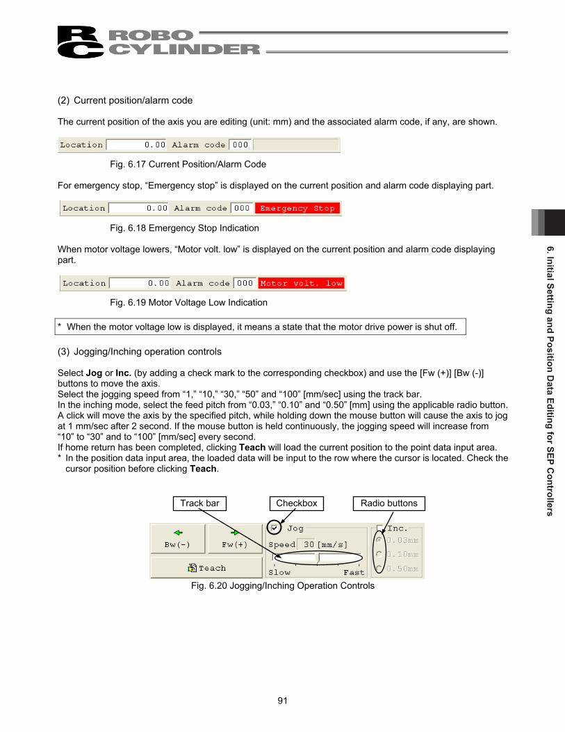
6. Initial Setting and Position Data Editing for SEP C
ontrollers
91
(2) Current position/alarm code The current position of the axis you are editing (unit: mm) and the associated alarm code, if any, are shown.
Fig. 6.17 Current Position/Alarm Code For emergency stop, “Emergency stop” is displayed on the current position and alarm code displaying part.
Fig. 6.18 Emergency Stop Indication When motor voltage lowers, “Motor volt. low” is displayed on the current position and alarm code displaying part.
Fig. 6.19 Motor Voltage Low Indication * When the motor voltage low is displayed, it means a state that the motor drive power is shut off. (3) Jogging/Inching operation controls Select Jog or Inc. (by adding a check mark to the corresponding checkbox) and use the [Fw (+)] [Bw (-)] buttons to move the axis. Select the jogging speed from “1,” “10,” “30,” “50” and “100” [mm/sec] using the track bar. In the inching mode, select the feed pitch from “0.03,” “0.10” and “0.50” [mm] using the applicable radio button. A click will move the axis by the specified pitch, while holding down the mouse button will cause the axis to jog at 1 mm/sec after 2 second. If the mouse button is held continuously, the jogging speed will increase from “10” to “30” and to “100” [mm/sec] every second. If home return has been completed, clicking Teach will load the current position to the point data input area. * In the position data input area, the loaded data will be input to the row where the cursor is located. Check the
cursor position before clicking Teach.
Fig. 6.20 Jogging/Inching Operation Controls
Track bar Checkbox Radio buttons

6. In
itial
Set
ting
and
Posi
tion
Dat
a Ed
iting
for S
EP C
ontr
olle
rs
92
(4) Positioning (test operation mode) You can move the axis to the position corresponding to the cursor row in the position data input area. The moving speed is calculated by multiplying the speed set in the position data input area with the speed factor. (The speed factor can also be set by the track bar.)
Fig. 6.21 Positioning Use the (step move) button to move the actuator by one position, or use the (continuous move) button to move the actuator continuously by looping a series of successive positions. Click the (stop) button to stop the actuator. (The actuator starts decelerating the moment the button is clicked, and continues to decelerate until it stops.) * If the data loaded from the controller has been changed, write the modified data again to the controller
beforehand. * While this mode is active, data cannot be entered in the jogging/inching control groups or point data input
area. ● If the MANU operation mode is set to teaching mode 1 (safety speed effective), the maximum speed is
limited to the safety speed set by the applicable parameter.
Speed factor Track bar
Step, continue and stop buttons from the left

6. Initial Setting and Position Data Editing for SEP C
ontrollers
93
(5) Servo, Home and Alarm buttons
Fig. 6.22 Servo, Home and Alarm Buttons
[1] Servo button This button lets you turn on/off the servo. When the servo is on, a blue lamp illuminates on the button. After home return, you can turn off the servo, move the actuator manually and then click Teach to capture a desired position.
[2] Home button
This button lets you perform home return. Once home return is complete, a green lamp will illuminate on the button.
[3] Alarm button
This button lets you reset an alarm. Note that an alarm can be reset only when the servo is off and the cause of the alarm has been removed. While an alarm is present, a red lamp remains lit on the button.

6. In
itial
Set
ting
and
Posi
tion
Dat
a Ed
iting
for S
EP C
ontr
olle
rs
94
(6) Position input area Set the position data needed to operate the actuator.
Actuator
Fig. 6.23 Position Data Input Area [1] Position ····················Set the position to move the actuator to.
Set position Operation pattern Move Forward position Backward position Center position
Standard move between 2 points: 0 Move between 2 points Speed change: 1 Move between 2 points Position data change: 2 Move between 2 points Move among 3 points with 2 inputs: 3 Move between 3 points Move among 3 points with 3 inputs: 4 Move between 3 points Continuous back-and-forth operation: 5 Move between 2 points
[2] Speed ······················Set the actuator speed. [3] Push power ···············Set a desired current-limiting value (%) other than 0 when performing push
operation. If 0 is set, positioning operation will be performed. [4] Push band ················Except for CON method pressing in Fieldbus Type MSEP Controllers, the band for
the pressing operation up to the movement target position is to be set. Push operation will start from the position forward of the target position of move (forward position or backward position) by the distance corresponding to the push band.
Forward position Center position
Backward position
Motor
Speed
Position at which the push position is deemed complete after contacting the load
Load
Start position of push operation
Push band Target position

6. Initial Setting and Position Data Editing for SEP C
ontrollers
95
If CON method pressing is selected in MSEP Controllers, the maximum pressing
amount in the pressing operation from the target position needs to be defined in Positioner Mode. While considering the mechanical inconsistency of the work piece, set the positioning band so the positioning would not end before the work piece gets pressed towards the target.
[5] ACC ························Set the actuator acceleration.
The input range permits entry of a value greater than the value specified in the catalog. However, you should set a value not exceeding the rated acceleration in the catalog.
[6] DCL·························Set the actuator deceleration.
The input range permits entry of a value greater than the value specified in the catalog. However, you should set a value not exceeding the rated deceleration in the catalog.
[7] Energy-saving Mode… When 1 “Enable” is set in the Energy-saving Mode field, the actuator will turn OFF
the servo automatically after elapse of a specified time. Since the holding current does not flow while the actuator is stopped, the current consumption can be saved. Once a move command is issued, the servo will turn ON again and the actuator will start moving.
The time until the servo turns OFF is set by the parameter for auto servo OFF delay time.
Move command
Servo status
Actuator move
Servo ON
Servo automatically turned OFF (Green LED blinking)
Target position T: Delay after completion of positioning
until servo OFF (sec) T is set by a parameter.
Position at which the position complete signal turns ON when the actuator contacts work part and push completion is judged
Target position
Positioning band (maximum push amount)
Work part

6. In
itial
Set
ting
and
Posi
tion
Dat
a Ed
iting
for S
EP C
ontr
olle
rs
96
When changing the speed in operation pattern (PIO pattern) 1, set the position at which to change the speed, and new speed, in addition to position data.
Fig. 6.24 Position Data Input Area: Operation Pattern 1 [8] Speed Chg Pos··········Set the position at which to switch the speed while the actuator is moving to the
forward position or backward position. [9] Speed Chg Vel···········Set the speed to change to.
When changing the position data in operation pattern (PIO pattern) 2, set the position data to be changed at the forward or backward, in addition to the forward position or backward position data. When CN1 (operation switching signal) is OFF, the forward position data corresponds to Forward
Position 1. When this signal is ON, the forward position data corresponds to Forward Position 2.
When CN1 (operation switching signal) is OFF, the backward position data corresponds to Backward Position 1. When this signal is ON, the backward position data corresponds to Backward Position 2.
Fig. 6.25 Position Data Input Area: Operation Pattern 2

6. Initial Setting and Position Data Editing for SEP C
ontrollers
97
6.2.2 Offline Mode When editing data after creating new data or loading data from a file, you are editing the data in the offline mode. In this mode, the window controls relating to axis operation are grayed out, and only the tool buttons and position data input area become active. Items that cannot be operated offline are grayed out. (1) Creating new position data To create new position data, click File from the main menu, and then select New. [1] When the position data format selection window appears, select the controller whose position data you
want to create, and then click OK.
Fig. 6.26 Position Data Format Selection Window [2] The IO pattern select window appears.
Select the operation pattern in which to create new position data.
Fig. 6.27 IO Pattern Select Window

6. In
itial
Set
ting
and
Posi
tion
Dat
a Ed
iting
for S
EP C
ontr
olle
rs
98
[3] The position data input window corresponding to the selected operation pattern appears.
Enter desired position data in the position data input area.
Fig.6.28 Position Data Edit Window (Offline Mode – New) [4] The created position data can be saved to a file or sent to the connected controller.
(Saving the position data to a file) To save the position data to a file, click the tool button . The save as window appears. Enter a desired file name and click the Save button, and the position data will be saved to a file under the specified name.
Fig.6.29 Position Data Edit Window (Offline Mode – New) (Sending the position data to the connected controller) Connect the controller and PC. Click Position and select Send to Controller, or click the tool button . When the axis selection window appears, select the axis number of the controller to send the position data to. (Refer to 4, “Selecting an Axis.”) * “Comments” can be saved only to files. They cannot be saved to controllers.

6. Initial Setting and Position Data Editing for SEP C
ontrollers
99
[5] Reading a File
To read position data from a file, click File and then select Open to open the “Open” window. Alternatively, you can click File, point to Send to Controller and then select Position to open the “Open” window.
Fig. 6.30 “Open” Window Select (click) “File name” you want to open, and click Open on the “Open” window, then the position data edit window is displayed.
Select folder in which position data is saved. Saved file name
Select controller.

6. In
itial
Set
ting
and
Posi
tion
Dat
a Ed
iting
for S
EP C
ontr
olle
rs
100
Fig. 6.31 Position Data Edit Window (Offline Mode) The edited position data can be saved to a file or sent to the connected controller. (Saving the position data to a file) To save the position data to a file, click the tool button . The save as window appears. Enter a desired file name and click the Save button, and the position data will be saved to a file under the specified name.
Fig. 6.32 Save As Window (Sending the position data to the connected controller) Connect the controller and PC. Click Position and select Send to Controller, or click the tool button . When the axis selection window appears, select the axis number of the controller to send the position data to. (Refer to 4, “Selecting an Axis.”) * “Comments” can be saved only to files. They cannot be saved to controllers.
Position data input area
Tool buttons

7. ELECYLIN
DER
Simple D
ata Setting
101
7. ELECYLINDER Simple Data Setting Position data can be edited online or offline. 7.1 Online Mode This mode reads data from the controller to edit. Click Position and then select Edit/Teach from the main menu, or click in the toolbar. When the position edit password is set to other than ‘0000’, the password input window will appear. Input the password. Fig. 7.1 Input Password Window Simple Data Setting window will be shown.
Fig.7.2 Simple Data Setting Window
If it is necessary to change the position edit password, conduct the process explained in [How to Set Password for Position Data Edit Window] in the next page.

7. E
LEC
YLIN
DER
Sim
ple
Dat
a Se
tting
102
[How to Set Password for Position Data Edit Window] [1] From the main menu, click Setup and then select Setting of application.
Click the Change Password button.
Fig. 7.3 Setting of Application Window [2] Select the Position data edit password, and then click the OK button.
Fig. 7.4 Select Password Window [3] Enter the current password, new password, and new password again (for confirmation), and then click the
OK button. Once the new password has been set, you must enter the new password to edit position data.
Fig. 7.5 System Password Window

7. ELECYLIN
DER
Simple D
ata Setting
103
In Simple Data Setting window, setting of the operational conditions (velocity, acceleration / deceleration and pressing force) and position setting (forward end, backward end and pressing start point) can be conducted and also display of the current position, cycle time and setting dialog, and manual operation can be conducted. The operational condition data and the position setting data set in this window should be activated after it is transferred to the controller. Conduct either operation from the followings in order to transfer the data.
[1] Click Transfer button in the bottom right of the window. [2] Click icon in the top left. [3] Select [Position] -> [Transfer to Controller] from the main menu.
Fig. 7.6 Features of Simple Data Setting Window It is also necessary to transfer data to the controller when manual operation is to be conducted.
(1) Toolbar buttons (2) Op. condition
(3) Position setting (4) Manual Mode (5) Transfer Button
(6) Transfer Log
(1)Toolbar buttons

7. E
LEC
YLIN
DER
Sim
ple
Dat
a Se
tting
104
The operating methods of buttons and input controls available in this window are explained below. (1) Toolbar buttons [1] [2] [3] [4] [5] [6] [7] Fig. 7.7 Toolbar in Simple Data Setting Window
[1] Save to file Displayed data gets saved in a file.
[2] Send to controller
Send (write) data to the controller. [3] Reload position data
Data display will be updated after all the data in the screen gets reloaded from the controller.
[4] Print
Output data to the printer. Printout setting window appears. Setting of margins on top, left and between lines (mm) and direction of printing can be adjusted. Click Print button to start printing.
[5] Unit Change
The unit of the setting items and displayed items can be switched over as shown below.
Velocity : % ⇔ mm/s ACC / DCL : % ⇔ G Push power : % ⇔ N (Reference)
[6] Load Setting
Payload setting window is displayed. [7] Test run
Trial Operation Window is displayed.
Fig. 7.8 Print Setting Window

7. ELECYLIN
DER
Simple D
ata Setting
105
(2) Op. condition, (3) Position setting
[Positioning Operation]
[1] Push Select------------------- If there is no check mark ( ) in the check box ( ) for pressing operation, positioning operation will be performed.
[2] Position setting [mm]------- Position of the backward end and forward end can be input.
It is the coordinate of positioning and should be the position from the home to be input. The unit is mm, and a number can be input down to two decimal places.
[3] Velocity [% or mm/s] ------- Setup of positioning operation velocity can be conducted.
Set a number between 0% and 100%. The unit can be switched with Unit Change button to mm/s unit. For mm/s unit, a number can be input down to two decimal places.
* Note 1 Calculate the minimum velocity using the following formula. Minimum Velocity [mm/s] = Lead Length [mm] / 800 / 0.001 [sec]
[4] ACC [% or G] ---------------- Setup of acceleration at start of operation can be conducted.
Set a number between 0% and 100%. The unit can be switched with Unit Change button to G unit. For G unit, a number can be input down to two decimal places.
[5] DCL [% or G]----------------- Setup of deceleration at stop of operation can be conducted.
Set a number between 0% and 100%. The unit can be switched with Unit Change button to G unit. For G unit, a number can be input down to two decimal places.
[6] Cycle time [s]----------------- Cycle time can be figured out from the setting velocity, acceleration and
deceleration, and displayed.
Fig. 7.9 Positioning Operation Setting Items
[4]
[3]
[5]
[6]
[1]
[2][2]

7. E
LEC
YLIN
DER
Sim
ple
Dat
a Se
tting
106
[Pressing Operation]
[1] Push Select------------------- If there is a check mark ( ) in the check box ( ) for pressing operation,
pressing operation will be performed. [2] Position setting [mm]------- Setting of the operation start point (backward end or forward end) and the
pressing start point can be conducted. It is the coordinate of positioning and should be the position from the home to be input. The unit is mm, and a number can be input down to two decimal places.
[3] Velocity [% or mm/s] ------- Setup of the operation velocity from the operation start point (backward
end or forward end) to the pressing start point can be conducted. Set a number between 0% and 100%. The unit can be switched with Unit Change button to mm/s unit. For mm/s unit, a number can be input down to two decimal places.
* Note 1 Calculate the minimum velocity using the following formula. Minimum Velocity [mm/s] = Lead Length [mm] / 800 / 0.001 [sec]
[4] ACC [% or G] ---------------- Setup of acceleration at start of operation can be conducted.
Set a number between 0% and 100%. The unit can be switched with Unit Change button to G unit. For G unit, a number can be input down to two decimal places.
[5] DCL [% or G]----------------- Setup of the operation deceleration from the operation start point to the
pressing start point can be conducted. Set a number between 0% and 100%. The unit can be switched with Unit Change button to G unit. For G unit, a number can be input down to two decimal places.
[6] Push Power [% or N] ------- Setting of the pressing torque (current limit) can be conducted in %.
The pressing velocity should be 20mm/s. If the velocity is set to 20mm/s or less, pressing operation will be performed in the setting velocity. The unit can be switched with Unit Change button to N (Reference) unit.
Fig. 7.10 Pressing Operation Setting Items
[4]
[3]
[5]
[1]
[2]
[2]
[6]

7. ELECYLIN
DER
Simple D
ata Setting
107
(4) Manual Mode (JOG operation)
Fig. 7.11 Manual Operation Display, Operation Buttons
[1] Current Position [mm]------ The current position should be displayed. [2] B.End button ---------------- Click this button and the actuator moves towards the backward end.
The operation stops if stop clicking or LS Signal of the backward end turns on.
[3] F.End button ---------------- Click this button and the actuator moves towards the forward end.
The operation stops if stop clicking or LS Signal of the forward end turns on. (Note) Operation is available when the backward button and forward button are activated in green. If they
are not in green, the setting parameters are not yet transferred. Transfer the setting parameters to the controller with (5) Transfer Button in advance.
(5) Transfer Button
[4] Transfer Button ------------ The data which a change has been made to the setting can be transferred.
(6) Transfer Log
30
30
30
30
60
50
75
30
30
30
30
30
0.572
0.620
0.536
0.856
Fig. 7.12 Transference History Display Make a change to the operational condition (velocity, acceleration / deceleration or pressing force) on either the way forward or backward and transfer the data to the controller, and the old parameter settings will be displayed in the previous setting lines and the new parameter settings in the current setting lines, and the cycle time figured out from these settings will also be displayed. In case that the pressing operation is selected in the operational condition, the previous setting and the current setting are not to be displayed.
[4] [1]
[2] [3]

7. E
LEC
YLIN
DER
Sim
ple
Dat
a Se
tting
108
[Reference] Here in below, explains acceleration. The idea is the same for deceleration. 1G = 9800mm/s2: Acceleration can be performed with 9800mm/s in 1 second 0.3G: 9800mm/s in 1 second × 0.3 = Acceleration can be performed with 2940mm/s
Fig. 7.13 ACC
Caution: Consider to decrease the acceleration / deceleration in case of any impact or vibration being applied to an actuator or a workpiece. Continuing operation in such a condition will shorten the life of the actuator drastically.
Velocity
Time
9800mm/s
1s
1G
2940mm/s
0.3G

7. ELECYLIN
DER
Simple D
ata Setting
109
7.2 Offline Mode When editing data after creating loading data from a file, you are editing the data in the offline mode. When this mode is activated, parts related to axis operation will not function, and only the tool buttons and simple data setting part will be valid. Items that cannot be operated offline are grayed out. 7.2.1 Creating New Position Data It is not available to create a new file. 7.2.2 Reading a File To read position data from a file, click File and then select Open to open the “Open” window. Alternatively, you can click File, point to Send to Controller and then select Position to open the “Open” window.
Fig. 7.14 “Open” Window Select (click) “File name” you want to open, and click Open on the “Open” window, then the simple data setting window is displayed. Operating condition and position setting can be edited offline.
Fig. 7.15 Simple Data Setting Window (Offline Mode)
Position Data for ELECYLINDER(*.ptec)
Axis03.ptec
Saved file name
Select controller.
Select folder in which position data is saved.

7. E
LEC
YLIN
DER
Sim
ple
Dat
a Se
tting
110
The edited operating condition and position setting can be saved to a file or sent to the connected controller. (Saving the position data to a file) To save the position data to a file, click the tool button . The save as window appears. Enter a desired file name and click the Save button, and the position data will be saved to a file under the specified name.
Fig. 7.16 Save As Window (Sending the position data to the connected controller) Connect the controller and PC. Click Position and select Send to Controller, or click the tool button . When the axis selection window appears, select the axis number of the controller to send the position data to. (Refer to 4, “Selecting an Axis.”) * “Comments” can be saved only to files. They cannot be saved to controllers.
Position Data for ELECYLINDER(*.ptec)
Axis03.ptec

8. Editing Parameters
111
8. Editing Parameters To load parameter data from the controller, click Parameter (P) and then select Edit (E) from the main menu, or click in the toolbar. In the “Select axis number” window, select the axis number corresponding to the axis whose parameters you want to edit. (Refer to 4, “Selecting an Axis.”) * On the versions V7.0.3.0 or later, the default password is “0000”, so the input password window will not
appear. * On the versions V7.00.1.00/V7.00.2.00, the default password is “5119.” Enter “5119” and click the OK button.
Fig. 8.1 Input Password Window To change the password, perform the operations explained below. [How to Set Password] [1] From the main menu, click Setting and then select Application.
Click the Change Password button.
Fig. 8.2 Setting of Application Window [2] If you are using a CON controller, select “System Password” and then click the OK button.
This window does not appear if you are using a SEP controller.
Fig. 8.3 Select Password Window [3] Enter the current password, new password, and new password again (for confirmation),
and then click the OK button. Once the new password has been set, you must enter the new password to edit parameter data.
Fig. 8.4 System Password Change Window

8. E
ditin
g Pa
ram
eter
s
112
To read a parameter from the file, click File and then select Open to display a “File open” window. Or click File, point to Send to controller and then select Parameter, to display the “Open” window.
Fig. 8.5 “Open” Window Select (click) “File name” you want to open, and click Open on the “File Open” window, then the parameter edit window is displayed. You can load data from the controller or a file and edit the loaded data. Fig. 8.7 is a display example when the PCON-CY controller is connected. You can also print the loaded data. Edited data can be sent to the controller or saved to a file. Edited parameters that have been sent to the controller will become effective after the controller power is reconnected. To send data to the controller, click Parameter and then select Send to Controller from the main menu, or click in the toolbar of the parameter edit window.
Select folder in which parameter data is saved.Saved file name.
Select controller.

8. Editing Parameters
113
To send parameter read from the file to the controller, click Parameter and then select Send to controller, or click the button on the parameter edit window. Select axis number window is displayed, then select axis No. of the controller. (Refer to “4. Selecting an axis.”) Click OK on the select axis number window, then the following warning window is displayed. Click Yes, then the parameter is sent to the controller.
Fig. 8.6 Warning
Fig. 8.7 Parameter Edit Window
The contents of display may be different depending on the controller model type.
Note: While the position data edit window is open, the parameter edit window cannot be opened. When the button is clicked, the select axis number window is displayed, but axis to be selected is not displayed.

8. E
ditin
g Pa
ram
eter
s
114
ELECYLINDER Parameter Setting Window In the ELECYLINDER parameter setting window, an explanation of the setting items will be shown in the bottom of the window. Also, for the items to select a value, click on the right of the item and the candidate list will be shown in pulldown. Select a candidate and click it.
Fig. 8.8 Parameter Setting Window (ELECYLINDER) Depending on the controller model, a confirmation window (Fig. 8.9) may be displayed after parameters have been sent to the controller, asking if you want to restart the controller (execute a software reset). (This window appears only when the controller to which data has been written supports the software reset function. (Except RCP, RCS and E-Con controllers.))
Fig. 8.9 Controller Restart Confirmation Window
Explanation of Item
Pulldown List

8. Editing Parameters
115
If you want to change the soft limits, set values corresponding to 0.3 mm outside of the desired effective
range. Example 1) CON controllers and older models
To set the effective range to 0 to 80 mm + soft limit: 80.3 - soft limit: -0.3
Example 2) SEP controllers
To set the effective range to 0 to 80 mm soft limit: 80.0
In the case of the RCP, RCS, E-Con, RCP2 and ERC controller, if the home return direction is changed, all
position data currently input will be cleared. Before changing the home return direction, therefore, back up the data, if necessary.
In the case of rod-type actuators (excluding the RCP2-RA3C, 4C and 6C), the home return direction cannot
be reversed only by changing the factory-set parameter. Note: After parameters have been changed, reconnect the controller power or execute a software reset (if the
controller supports the software reset function). Parameters will be rewritten simply by turning the emergency stop switch or PORT switch to OFF and then ON again, but the new value may not become effective depending on the parameter.
Soft Limit set in controller
Effective area
Jog Increment allowable range after home return Approx. 0.1 mm
Approx. 0.3 mm
Approx. 0.3 mm
Approx. 0.1 mm
Soft Limit set in controller
Effective area
Jog Increment allowable range after home return
Approx. 0.1 mm
Approx. 0.1 mm

9. M
onito
ring
116
9. Monitoring Various statuses, controller error lists, and velocity/current waveforms (other than RCP, RCS and E-CON models), can be monitored. 9.1 Status Monitor Window To monitor various statuses, click Monitor and then select Status in the main menu, or click in the toolbar. In the “Select axis number” window, select the axis number corresponding to the axis whose statuses you want to monitor. (Refer to 4, “Selecting an Axis.”) (Fig. 9.1 shows an example of the display when a PCON-C controller is connected. Fig. 9.7 shows an example of the display when a RCP2 controller is connected. Fig. 9.8 is an example of display when ELECYLINDER is connected. The displayed information will vary depending on the controller type.) [In the case of PCON, ACON, DCON, SCON, ERC2, ERC3, ROBONET, ASEP, PSEP, DSEP, MSEP, MSCON and MCON] Axis status Location Speed (moving speed) Alarm code
Internal flags Power: Main controller power ON/OFF status Servo: Servo command status Home Cmplt: Home return completion flag
ON/OFF status Run: Actual servo status Home check sensor: Indicates that the home
check sensor is ON. This is displayed when the actuator is provided with a home check sensor.
MANU: Status (MANU or AUTO) of the manual switch is displayed. Even some machine types which are not equipped with manual switch, such as PCON-CY, indicate MANU.
Emergency stop, motor voltage low indication * As shown in Fig. 9.5 and 9.6, this is displayed
in the case of emergency stop and motor voltage low. Motor voltage low means a status in which the motor drive source is shut off.
Inputs The ON/OFF status of each PIO input port is shown.
Outputs The ON/OFF status of each PIO output port is shown.
(Note) The status monitor window cannot be displayed for SCON-CB□F, CGB□F, LC□F and LCG□F equipped with the servo pressing feature. The display of those such as the axis status is to be shown in the pressing program operation / monitor window. [Refer to 15.2.3 Press Program Operation / Monitor Window]
(Note) For a controller equipped with PLC feature such as SCON-LC/LCG, the internal resister for axis
operation is displayed for the input and output. It may be different from the status of the I/O signal communicating directly with the host PLC as it does not display it. Also, even though the internal relay (M) assigned to the input and output will not be updated when the ladder program is stopped, the monitor display of input and output will be updated.

9. Monitoring
117
Indication ON/OFF button (axis status, internal flags, current, input, output, special input port)
The currently selected PIO pattern number is displayed only when the controller supports the “PIO pattern selection function” (parameter). * The displayed input and output port names will vary depending on the value set in the PIO pattern selection parameter. Overload level is displayed with %. Reach 100% and the overload error will be issued (Error Code 0E0). If a value smaller than 100% is set to the overload level ratio [%] in Parameter No. 143 of SCON-CA, SCON-CAL/CGAL, SCON-CB, PCON-CA, PCON-CB, ACON-CA, ACON-CB, DCON-CA, DCON-CB, ERC3, MSCON and MCON, an alarm is generated when it reaches that value.
Fig. 9.1 Axis Status Monitor Window (Force Control Function Not Supported)
* Output port number is displayed in the version V10.00.00.00 and later.
The background color is yellow-green only in “ON” display.
Indicates ratio to the present current command and rated value. * With the pulse motor type, the command
value reflects the compensation for motor ripple. In other words, the “Cur. cmnd” value may become greater than the “Cur. Ratio” value depending on the motor type.
Indicates status of mode SW etc. (Indicated content depends on machine type.) Note) The following outputs are not shown even
when the controller supports these functions: Emergency stop Moving Battery alarm
I/O Test button

9. M
onito
ring
118
The link status should be displayed if connection is established with the host controller such as PLC in the field network. Fig. 9.2 is an example of MECHATROLINK-I and II. The display will be shown with white for the background and black for the letters when connection is established with the host controller such as PLC.
Fig. 9.2 Axis Status Monitor Window (Field Network Type)
1) Type : The type of the network such as MECHATROLINK-I and II which is under
connection is displayed. 2) Address : Items such as node address are displayed. 3) Baudrate : Baud rate is displayed. 4) Mode : Operation mode of the controller such as Remote I/O and Simple Direct Mode is
displayed. 5) MAC address : MAC address is displayed for those such as EtherNet.
For the field network connection, the input port is shown for 6) Input Data in Remote I/O Mode. The control signal is displayed in a mode such as Remote I/O Mode. The output port is shown for 7) Output Data in Remote I/O Mode. The status signal is displayed for Simple Direct Mode.
Status of Network Link
6) 7)
1) 2) 3) 4) 5)

9. Monitoring
119
On models supporting the force control function, Force FB and Calibration are displayed. (Note) These items are displayed only on SCON-CA (of Version V8.00.00.00 or later), SCON-CB controllers.
Fig. 9.3 Axis Status Monitor Window (Force Control Function Supported)

9. M
onito
ring
120
DO output test button Clicking the DO output button opens the I/O Test window. Here, you can click a desired port and add a check mark to forcibly turn ON the applicable signal.
Fig. 9.4 DO Test Window
Fig. 9.5 Emergency Stop Indication Fig. 9.6 Motor Voltage Low Indication

9. Monitoring
121
[In the case of RCP, RCS, E-Con, RCP2 and ERC] Axis status
Location Speed (moving speed) Alarm code
Internal flags Power : Main controller power ON/OFF
status Servo : Servo command status Home Cmplt : Home return complete flag ON/OFF Run : Actual servo status
Inputs The ON/OFF status of each PIO input port is shown.
Outputs The ON/OFF status of each PIO output port is shown.
Indication ON/OFF button (axis status, internal flags, input, output)
Fig. 9.7 Status Monitor
The currently selected PIO pattern number is displayed only when the controller supports the “PIO pattern selection function” (parameter). * The displayed input and output port names will vary depending on the value set in the PIO pattern selection parameter.
Note) The following outputs are not shown even when the controller supports these functions:
Emergency stop Moving Battery alarm

9. M
onito
ring
122
[In the case of ELECYLINDER] Axis status
Location Speed (moving speed) Alarm code Cycle time Overload level
Internal flags Power : Main controller power ON/OFF
status Servo : Servo command status Home Cmplt : Home return complete flag ON/OFF Run : Actual servo status
Inputs The ON/OFF status of each PIO input port is shown.
Outputs The ON/OFF status of each PIO output port is shown.
Fig. 9.8 Status Monitor (ELECYLINDER)
Current rates to the current command value and rating are displayed. * For the pulse motor, as it should be the command
value to compensate the motor ripple, this value could show a number larger than the rated current for some motor types.
Display ON/OFF Button (From left, Axis Status, Internal Flag, Current, Input and Output)
DO Output Test Button

9. Monitoring
123
9.2 CTL Alarm List To monitor the controller error list, click Monitor and then select CTL alarm list from the main menu, or click
in the toolbar. In the “Select axis number” window, select the axis number corresponding to the axis whose controller error list you want to monitor. (Refer to 4. Selecting an Axis.)
Fig. 9.9 Controller Alarm List Window Fig. 9.10 Controller Alarm List Window (SCON-CA, SCON-CAL/CGAL, SCON-CB, PCON-CA, PCON-CB,
ACON-CA, ACON-CB, DCON-CA, DCON-CB, ERC3 PIO Converter, MSCON and MCON) (1) Alarm list Indicates detected warning code, alarm codes for past 16 times (eight times on older models) and address in which data error occurred in execution (for maker investigation), detail code and occurred time. (Note) “Power ON log (no error)” indicates the controller power was turned on. It does not indicate an error.
The “Occurrence time” field indicates the elapsed time after the time of this “Power ON log (no error).” (Note) The occurrence time is displayed only on SCON-CA, SCON-CAL/CGAL, SCON-CB, PCON-CA,
PCON-CB, ACON-CA, ACON-CB, DCON-CA, DCON-CB, ERC3 PIO Converter, MSEP, MSCON and MCON controllers (Version V8.03.00.00 or later, V9.01.00.00 or later for MSEP, V9.02.00.00 or later for MSCON, V9.07.00.00 or later for SCON-CAL/CGAL, V10.00.00.00 or later for SCON-CB, ACON-CB, DCON-CB and MCON, V10.02.00.00 or later for PCON-CB).
(Note) For SCON-CB (servo press), when the alarm code is [094: Press Program Alarm Detected], the contents of the detail code can be confirmed by double-clicking on the detail code part in the list. (Software version V10.00.00.00 or later)

9. M
onito
ring
124
(2) Toolbar
[1] [2] [3] [4]
Fig. 9.11 Toolbar
[1] Save as Save the error list to a file (CSV format). * The saved file cannot be read in this application. [2] Print
Print the error list. [3] Refresh
Acquire the error list from the controller again to refresh the information displayed in the window. [4] Alarm list clear
Content of the alarm list is not deleted even if the power is turned OFF (ERC2, ERC3, SCON, ACON, PCON, DCON, ROBONET, ASEP, PSEP, DSEP, MSEP, MSCON and MCON). For this reason, content of the alarm list is deleted by using the alarm list clear. When the alarm list clear is pressed, a warning in Fig. 9.12 is displayed. When Yes is clicked, the content of the alarm list is deleted.
Fig. 9.12 Warning

9. Monitoring
125
9.3 Velocity/Current Monitor Window To monitor velocity/current, click Monitor and then select Velocity/Current from the main menu, or click in the toolbar. In the select axis number window, select the axis number corresponding to the axis whose velocity/current you want to monitor. (Refer to 4. Selecting an Axis.) The software will start monitoring velocity/current when is clicked.
Fig. 9.13 Velocity/Current Monitor Window
* The RCP, RCS, E-Con series and ELECYLINDER do not support this function. It is supported by the RCP2, ERC, ERC2, PCON, ACON, SCON, ROBONET, ASEP, PSEP, DSEP, MSEP, MSCON and MCON series.
(1) Current data display
[1] Current (command value) display (When the Rated current ratio checkbox is not selected) The vertical axis represents current (command value) [mA], while the horizontal axis represents elapsed time after the start of monitoring [100 msec]. * With the pulse motor type, the command value reflects the compensation for motor ripple. In other
words, the “Current (Command)” value may become greater than the “Rated current” value depending on the motor type.
[2] Rated current ratio display (When the Rated current ratio checkbox is selected)
The vertical axis represents rated current ratio [%], while the horizontal axis represents elapsed time after the start of monitoring [100 msec].
(2) Velocity data display
The vertical axis represents velocity [mm/s], while the horizontal axis represents elapsed time after the start of monitoring [100 msec]. * Current data and velocity data are acquired from the controller at the intervals of approx. 100 msec.
(The data acquisition interval varies depending on the number of connected axes.) Therefore, changes in current/velocity occurring within these intervals cannot be monitored accurately.
* Monitoring ends automatically as soon as the horizontal axis value reaches 65535.
Monitor start button Rated current ratio checkbox

9. M
onito
ring
126
(3) Toolbar
[1] [2] [3] [4] [5] [6]
Fig. 9.14 Toolbar
[1] Save as
Save the displayed current data and velocity data to a file (CSV format). * Only the range of data displayed in the data display area will be saved. * The saved file cannot be read in this application.
[2] Print
Print the displayed current and velocity data. [3] Monitor start button
Start monitoring. [4] Monitor stop button
Stop monitoring. [5] Vertical axis magnification change button (current)
Change the vertical axis magnification in the current data display area. [6] Vertical axis magnification change button (velocity)
Change the vertical axis magnification in the velocity data display area. [7] Current/speed horizontal axis record number change button
Changes horizontal axis record number of current data indicating part and speed data indicating part. [8] Rated current ratio indicating check box
Changes data type indicated on the current data indicating part. When checked Rated current ratio indication [%] When not checked Current value (Command value) [mA]
[7] [8]

9. Monitoring
127
9.4 Servo Monitor Window (Note) This window can be displayed only on SCON-CA, PCON-CA, PCON-CB, ACON-CA, DCON-CA and
ERC3 (of Software Version V8.03.00.00 or later), SCON-CB, ACON-CB, DCON-CB, MSCON and MCON controllers.
To monitor the amount of velocity operation, etc., click Monitor from the main menu and then select Servo Monitor. On the axis selection window, select the target axis number. [Refer to 4, “Axis Selection.”] Press Fixed next. (Version V9.02.00.00 or later) Press and monitoring starts. Among others, the following items can be monitored:
[1] Current Position (unit: [mm] or [pls]) [2] Amount of velocity operation (unit: [mm/sec] or [pls/sec]) [3] Actual velocity instruction (unit: [mm/sec] or [pls/sec]) [4] Present speed (unit: [mm/sec]) or [pls/sec]) [5] Current instruction (unit: [mA] or [%] (percentage of the rated current)) [6] Feedback current value [mA] or [%] [7] Force feedback data [N] (SCON-CA) [8] Deviation (unit: [pls]) [9] Command pulse counter (unit: [pls])
Fig. 9.15 Servo Monitor Window (General) (before Version V9.02.00.00)
Fig. 9.16 Servo Monitor Window (General) (Version V9.02.00.00 or later)

9. M
onito
ring
128
[Servo Monitor Window for SCON-CB, ACON-CB, DCON-CB, PCON-CB and MCON (Version V10.00.00.00 and later, V10.02.00.00 or later for PCON-CB)] Set the trigger and monitoring can be started.
[Refer to (1) Common Buttons for how to operate] [Refer to (4) Trigger Setting Part for how to set the trigger]
The sampling period can be changed by the operation on the screen. [Refer to (2) Display Settings Part]
Left-click on the graph, and a crosshair cursor and the X coordinate and the Y coordinate values [msec] at the clicked point are shown.
Fig. 9.17 Servo Monitor Window (General) (SCON-CB, PCON-CB, ACON-CB, DCON-CB, MCON)

9. Monitoring
129
[Number of channels] The number of channels is 4 or 8. (MSCON, MCON, PCON-CB, ACON-CA, ACON-CB, DCON-CA, DCON-CB is 2, 4 or 8.) A desired number can be selected using user parameter No. 112, “Monitoring mode selection.” (Setting: “0” = 0 channel (This function is not used), “1” = 4 channels, “2” = 8 channels) (MSCON, MCON, SCON-CA, SCON-CB, PCON-CB, ACON-CA, ACON-CB, DCON-CA, DCON-CB is “3” = 2 channels.)
[Monitoring period] For the monitoring period of ACON-CA, DCON-CA, PCON-CA, ERC3, SCON-CA, MSCON, SCON-CB a desired value between 1 and 1,000 [msec] can be set using user parameter No. 113, “Monitoring period.” (Setting: “1” to “1,000” [msec]) The monitoring frequency of PCON-CB, PCON-CYB, PLB, POB, ACON-CB, ACON-CYB, PLB, POB, DCON-CB, DCON-CYB, PLB, POB, and MCON is 1 to 60000 [msec].
[Number of records that can be monitored] When the SCON-CA, the number of records that can be monitored is 30,000 in the 4-channel mode and 15,000 in the 8-channel mode. When the SCON-CB, the number of records that can be monitored is 60,000 in the 2-channel mode, 30,000 in the 4-channel mode and 15,000 in the 8-channel mode. When the MSCON, the number of records that can be monitored is 30,000 in the 2-channel mode, 15,000 in the 4-channel mode and 7,500 in the 8-channel mode. When the PCON-CA and ERC3, the number of records that can be monitored is 3,072 in the 2-channel mode, 1,536 in the 4-channel mode and 768 in the 8-channel mode. When the PCON-CB, ACON-CA, ACON-CB, DCON-CA and DCON-CB the number of records that can be monitored is 8,192 in the 2-channel mode, 4,096 in the 4-channel mode and 2,048 in the 8-channel mode. When the MCON the number of records that can be monitored is 4,096 in the 2-channel mode, 2,048 in the 4-channel mode and 1,024 in the 8-channel mode. When using the PCON-CYB/PLB/POB, ACON-CYB/PLB/POB and DCON-CYB/PLB/POB, the number of records that can be monitored is 4096 in the 4-channel mode and 2048 in the 8-channel mode.

9. M
onito
ring
130
(1) Common buttons
[1] [2] [3] [4] [5] [6] [7] [8]
Fig. 9.18 Servo Monitor Window (Common Buttons) (Except for SCON-CB, ACON-CB, DCON-CB, MCON)
[1] Save As button Save the monitored data to a file (*.bsmrc).
[2] Print button Print the graph.
[3] Start Monitor button Start monitoring.
[4] End Monitor button End monitoring.
[5] Zoom In along Vertical Graph Axis button Zoom in along the vertical axis of the graph.
[6] Zoom Out along Vertical Graph Axis button Zoom out along the vertical axis of the graph.
[7] Zoom In along Horizontal Graph Axis button Zoom in along the horizontal axis of the graph.
[8] Zoom Out along Horizontal Graph Axis button Zoom out along the horizontal axis of the graph.
[9] [3] [4]
Fig. 9.19 Servo Monitor Window (Common Buttons) (SCON-CB, ACON-CB, DCON-CB, MCON)
[9] Trigger Start button
Press the start button and the status becomes the trigger standby, and monitoring starts once the trigger is detected. To start monitoring without using the trigger, press the [3] Start Monitor button. To finish monitoring, press [4] End Monitor button.

9. Monitoring
131
(2) Display setting area
Fig. 9.20 Servo Monitor Window (Display Setting Area)
[1] Show/hide selection check boxes Selecting each check box displays a graph of the corresponding channel. When the check box is cleared, the graph disappears.
[2] Data type selection combo boxes Select the type of each data you want to monitor.
[3] Position/speed display setting radio buttons Select the display unit of position/speed data (mm or pls).
[4] Current display setting radio button Select the display unit of current data ([mA] or [% of rated current]).
[5] Show/hide sub-grid line selection check box Selecting this check box shows sub-grid lines. When the check box is cleared, sub-grid lines become hidden.
[6] Fixed (Version V9.02.00.00 or later) Determine the data type in the channel setting. After the confirmation, monitoring becomes available.
[1]
[6]
[2]
[3]
[4]
[5]

9. M
onito
ring
132
Fig. 9.21 Servo Monitor Window (Display Setting Area) (SCON-CB, ACON-CB, DCON-CB, MCON)
[7] Sampling period setting
For SCON-CB, PCON-CB, DCON-CB and MCON, the time frequency (sampling period) to acquire data can be changed in Display Setting Window. The minimum settable value should be the value set in Parameter No. 113 (Monitoring Period). The maximum value should be the maximum value settable to Parameter No. 113 (Monitoring Period). (Note) For the controllers other than SCON-CB, PCON-CB, DCON-CB and MCON, the
sampling period setting part is not displayed. It is necessary to change Parameter No. 113 (Monitoring Period) when it is required to change the sampling period.
[7]

9. Monitoring
133
(3) Peak value display area
Fig. 9.22 Servo Monitor Window (Peak Value Display Area)
[1] Minimum value The minimum value of data monitored on each channel is shown.
[2] Maximum value The maximum value of data monitored on each channel is shown.
[3] Position/speed display setting radio buttons Select the display unit of position/speed data (mm or pls).
[4] Current display setting radio buttons Select the display unit of current data ([mA] or [% of rated current]).
[2]
[3]
[4]
[1]

9. M
onito
ring
134
(4) Trigger Setting Part
For SCON-CB, PCON-CB, DCON-CB and MCON, trigger setting is available to start monitoring. Set the trigger in the trigger setting part. (Version V10.00.00.00 and later)
Fig. 9.23 Servo Monitor Window (Trigger Setting) (Version V10.00.00.00 and later)
[1] Data types
The following data types can be selected. PIO signal (input) allocation (bit) PIO signal (output) allocation (bit) Clock
[2] Trigger Type When PIO signal (input) assign (bit) or PIO signal (output) assign (bit) is selected, select either Rising edge (bit) or Falling edge (bit). It is not necessary to select any if Clock is selected.
[3] Assign Signals When PIO signal (input) assign (bit) is selected, select from the PIO input port signals. When PIO signal (output) assign (bit) is selected, select from the PIO output port signals. It is not necessary to select any if Clock is selected.
[4] Data When Clock is selected, the current time in the controller is shown first. With that time as the standard, set the time that trigger is required at. For example, if you would like to trigger in one minute, forward the minute setting for one minute.
[5] Trigger delay [sec] In case that the data before having a trigger is required to be acquired, set the time [sec] in Trigger delay [sec]. It enables to acquire the data before the time of trigger being conducted.
[6] Occurrence The controller clock when trigger is conducted is displayed. When Clock is selected, the same time as the set trigger time is displayed.
[1]
[2]
[3]
[5]
[4]
[6]

9. Monitoring
135
9.5 Maintenance information Window (Note) This window is available only with SCON-CA, SCON-CAL/CGAL, SCON-CB, PCON-CA, PCON-CB,
ACON-CA, ACON-CB, DCON-CA, DCON-CB, ERC3, MSEP, MSCON and MCON controllers (Version V8.03.00.00 or later, V9.01.00.00 or later for MSEP, V9.02.00.00 or later for MSCON, V9.07.00.00 or later for SCON-CAL/CGAL, V10.00.00.00 or later for SCON-CB, ACON-CB, DCON-CB, MCON, V10.02.00.00 or later for PCON-CB).
* Refer to the next page for ELECYLINDER. The total number of movements of the actuator, and total distance traveled, are displayed. Total number of movements The cumulative number of times the actuator has moved is displayed. Total distance traveled The cumulative distance the actuator has traveled is displayed. The total
operation distance can be switched between km and m.
Fig. 9.24 Maintenance information Window Fig. 9.25 Maintenance information Window km display (Except for PCON-CFA, CFB) m display (Except for PCON-CFA, CFB)
For PCON-CFA Controller, the following items are displayed in addition. Total driving time of fan Shows the total driving time of the fan on the controller.
Fig. 9.26 Maintenance information Window Fig. 9.27 Maintenance information Window km display (PCON-CFA, CFB) m display (PCON-CFA, CFB)
(1) Changing the total number of movements and total distance traveled
Set a desired value in the refreshed maintenance information data field of total number of movements or total distance traveled, and then click Send. The total number of movements or total distance traveled, as applicable, will be refreshed. (Password is required.)
(2) Thresholds for total number of movements and total distance traveled
You can set thresholds for total number of movements and total distance traveled so as to generate an alarm if the thresholds are exceeded. The thresholds you have set will be stored in the following parameters:
Parameter No. Name
147 Threshold for total number of movements 148 Threshold for total distance traveled
Refreshed data of maintenance information
Display switch between km and m

9. M
onito
ring
136
Message-level Alarms Alarm code Name Description
4E Movements threshold exceeded This alarm generates when the total number of movements has exceeded the threshold set in parameter No. 147.
4F Traveled distance threshold exceeded This alarm generates when the total number of movements has exceeded the threshold set in parameter No. 148.
For ELECYLINDER (V12.00.00.00 and later)
The total number of movements and the total driving distance should be displayed. • Total moving count The sum total of the number of the actuator movements should be displayed. • Total moving distance The sum total of the actuator driving distance should be displayed. The unit of
the total driving distance can be switched over between km and m.
Fig. 9.28 Maintenance information Window (ELECYLINDER)
[1] Change of Total Number of Movements and Total Driving Distance Set a number to the maintenance information update data of the total number of movements or the total driving distance and click Update button, and a change will be made to the total number of movements or the total driving distance. (Password is required.)
[2] About Target Value for Total Number of Movements and Total Driving Distance Set a target value other than 0 to the total number of movement and the total driving distance, and a message level alarm (Maintenance Alert 1 / Maintenance Alert 2) will get displayed when the number exceeds the target. In order to set the target value, set a number to the maintenance information update data and click Update button.
Overload Warning Load Level Ratio
With the motor raising temperature assumed to generate the overload alarm set as 100%, when the motor temperature exceeds the rate set in this window, the LED lamp gets turned on in green as the overload warning, and notification will be made in Maintenance Alert 3 window at the same time. Overload warning level setting Set a number to the maintenance information update data of the overload warning level and click Update button, and the setting can be established. Set it to 100, and judgement will not be conducted.
Refreshed data of maintenance information
Display switch between km and m

9. Monitoring
137
[Example of use for Total Drive Distance Times] For an instance, it is recommended to have a grease supply on the scraper area every 300km in the regular inspections when the drive distance exceeds 300km within 3 months for RCPW Rod Type Actuator. (Have a supply every 3 months for those which do not exceed it.) In this case, set ‘300’ in Parameter No. 148 at the start of the first run, and an alarm notifies that grease supply is required when the drive distance exceeds 300km. After the grease supply, set multiple numbers of 300, such like 600, 900, in Parameter 148, and the notification continues to be made for the timings of grease supply.

9. M
onito
ring
138
9.6 Gateway Data Monitor
(Note) It can be displayed only on RCP6S Gateway Unit. Driving source consumption current should be displayed for versions from V10.02.00.00 before V11.00.00.00. Monitoring of driving source consumption current became available from V11.00.00.00. Select [Monitor] → [Gateway Data Monitor] in the main menu when monitoring is required.
(1) Versions from V10.02.00.00 before V11.00.00.00 Current value [A] should be displayed since the screen is turned on. The peak values are unbuffered data acquired in the acquirement cycles (approx. 80msec) of the PC software.
Fig. 9.29 Driving source consumption current Window
[1] Current [A] It shows the peak values of driving source consumption current on each axis.
[2] Sum of all [A] It shows the peak values of the total driving source consumption current on all the axes.
[3] Sum (Max) [A] It shows the sum of peak values on all axes since the power was turned on. Data can be cleared by pressing Reset button.
[1]
[2] [3]

9. Monitoring
139
(2) Versions after V11.00.00.00
A monitoring window was added on the left to show driving source consumption current. The displays of current [A], sum of all [A] and Sum (Max) [A] are the same as those before V11.00.00.00. Monitoring starts by pressing the monitoring start button . Display of driving source consumption current also starts once the monitoring start button is pressed. Recording can be performed for ten minutes at maximum regardless of number of axes.
Fig. 9.30 Driving source consumption current monitor Window
[1] Graph Select the axis number to be displayed in [7] Chart. Click in a box □ at the axis number to be monitored to put a check mark . Monitor display will be performed on the axis numbers with a check mark .
[2] Check all / Reset all Click Check all button and all the axis numbers will be selected. A check mark will be put on every axis number. Click Reset all button and all the axis numbers will be cancelled. All the check marks will be removed from the axis numbers and the boxes will become blank.
[3] Monitoring Start Button Display of monitoring and driving source consumption current gets started. If a check mark () is put on [Clear “Sum (Max)[A]” reading when beginning monitoring], the “Sum (Max)[A]” will be cleared before monitoring is started.
[4] Monitoring Stop Button Monitoring gets stopped.
[5] Vertical / Horizontal Zoom-in / Zoom-out Buttons Zooming in and out of vertical or horizontal axes continues while a buttons is held down and stops once it is released.
[1]
[2] [3] [4] [5]
[7]
[6]

9. M
onito
ring
140
[6] [Clear “Sum (Max)[A]” reading when beginning monitoring] Click box.
If a check mark () is put, the Sum (Max)[A] will be cleared before monitoring is started. [7] Chart
The current [A] of the selected axis number should be displayed in waveform. The current [A] is the drive source consumption current [A] on each axis. Vertical axis shows the current [A] and the horizontal shows the time [msec]. The colors of the lines for the waveforms are as shown below.

9. Monitoring
141
9.7 Network Data Monitor
* Applicable versions: V11.00.00.00 and later This feature is not applicable for the controllers in following types. Multiple-axis controllers : MCON-C/CG、MSEP-C、MSCON-C Controllers with PLC features : MCON-LC/LCG、MSEP-LC、SCON-LC/LCG
The data received by the host PLC and the fieldbus can be monitored when the following parameter settings are established in the controllers applicable for the fieldbus. Monitoring window will be closed once the software reset gets conducted while the monitoring window is in display.
User Parameter No. Name Setting value (Note 1) 84 Fieldbus Operation Mode Any number but 0 87 Network Type Any number but 0
Note 1 Values available for setting differ depending on controllers. 9.7.1 How to Display Monitoring Window
The monitoring window can be displayed in the following way. Also, when 0A3 Error (Position Indication Information Data Error) is occurred, the monitoring window will be displayed automatically if the controller is in AUTO Mode.
No. Way to Display 1 Display from main menu in main window 2 Display from tree view in main window 3 Display from axis status window 4 Display from network information window
5 Displayed automatically if the controller is in AUTO Mode when 0A3 Error (Position Indication Information Data Error) is occurred

9. M
onito
ring
142
[Display from main menu in main window]
[1] Select [Monitor] -> [Network Data Monitor] from the main menu. (Note) It is available to select while online. (Note) A message showing “There is no selected axis” will be displayed when controllers that are
not to be shown in the monitoring window are connected, such as a controller not applicable for the fieldbus or a controller with the parameters in No. 84 and 87 set to 0.
Fig. 9.31 Main menu Window
[2] When there is one axis that is applicable for the fieldbus and the parameters in No. 84 and 87 are set to a number other than 0, the monitoring window will be displayed. When a controller possesses multiple axes, the axis select window opens. Select axes to be shown in the monitoring window. The monitoring window gets displayed.
Fig. 9.32 Select axis number Window

9. Monitoring
143
[Display from tree view in main window]
Select the network data monitor in the tree view. The monitoring window gets displayed. (Note) “Network Data Monitor” will be shown in the tree view if the controller is applicable for the fieldbus. (Note) When the parameters in No. 84 and 87 are set to 0, the monitoring window will not be displayed
even if selected.
Fig. 9.33 Tree view Window
[Display from axis status window]
Select the network monitor in the axis status window. Select the network data monitor in the tree view. (Note) “Network Monitor” tab will not be displayed when controllers that are not to be shown in the
monitoring window are connected, such as a controller not applicable for the fieldbus or a controller with the parameters in No. 84 and 87 set to 0.
Fig. 9.34 Axis status monitor Window

9. M
onito
ring
144
[Display from network information window]
Select the network monitor in the network information window. Select the network data monitor in the tree view. (Note) “Network Monitor” tab will not be displayed when controllers that are not to be shown in the
monitoring window are connected, such as a controller not applicable for the fieldbus or a controller with the parameters in No. 84 and 87 set to 0.
Fig. 9.35 Network information Window

9. Monitoring
145
9.7.2 Monitoring Window
Following monitoring windows will be displayed.
Fig. 9.36 Network Data Monitor Window [1] Screen Caption
It is shown as Network Data Monitor [X]. In the part expressed with “X” should be replaced with the display of either the axis number, axis name or axis number + axis name depending on the applicable controller and tool setting.
[2] Network Setting Part
Monitoring information and the setting status of the related parameters should be displayed.
Displayed Contents No. Contents Remarks 1 Fieldbus Operation Mode 2 Fieldbus Output Format
3 Velocity Unit in Semi Direct Mode It is not displayed in any mode except for Semi Direct Mode
[3]
[1]
[5]
[6]
[4]
[2]

9. M
onito
ring
146
[3] Input Data Monitoring Part
Contents, values and input range of the received data (from PLC to controller) should be displayed. The values should be displayed in the swapped form or converted unit, not in the real data forms of the received data. The data to be displayed should be the contents in relation to the applicable controllers and operation modes. Refer to the sections for the input and output signal assignments in the instruction manual for the network to be used. In those above, the occupation information should not be displayed.
[4] Output Data Monitoring
Contents and values of the sent data (from controller to PLC) should be displayed. As well as the input monitoring, the values should be displayed in the swapped form or converted unit. As well as the input data monitoring part, the data to be displayed should be the contents in relation to the applicable controllers and operation modes. In those above, the occupation information should not be displayed.
[5] Signal Data Display Format Part
Display of the control signals and status signals can be selected from binary numbers and hexadecimal numbers.
[6] Close Button
Click this button and this window closes.

10. Setup
147
10. Setup 10.1 Setting of application Window Click Setting from the main menu, and then select Application.
Fig. 10.1 Setting of application Window
[1] Port When is clicked, the serial port list to communicate with the controller is displayed. Select port from the list. If there is not check mark in the box of “Show All”, the COM ports detected automatically are shown. With check mark, all the COM ports are shown.
[2] Baud rate
When is clicked, the communication baud rate the serial port list is displayed. Select baud rate from the list. * The baud rate selected here is used only in the communication between this application and
controller. It does not affect the communication speed parameters of the controller. [3] Last axis No.
When is clicked, the axis No. list is displayed. Select axis No. intended for connected axis check. * Axes of numbers greater than the value selected here will not be checked for connection. Select an
appropriate axis number after checking the axis numbers of the connected axes. [4] Unit of display at pulse-train mode
When is clicked, units of display [mm], [pulse] in pulse-train mode are displayed. For pulse sequence input controller such as PCON-PL/PO, units such as the current position on the status monitor window (Fig. 9.1) can be changed.
[5] Start position of program (V8.03.00.00 or later)
When is clicked, it can be selected whether the simple program is to be started from the cursor position or the top of the program.
[6] Display type of position data (V8.03.00.00 or later)
When is clicked, the way to show the position data when the position data edit window is displayed can be selected whether it should be shown with the simple display or normal display.
[1] [2] [3] [4] [5] [6] [7]
[8]

10. S
etup
148
[7] Input warning outside the recommended range (V8.03.00.00 or later) When is clicked, the display can be selected from show/not to show of the alarm issued when the input value is out of the recommended range and may cause an abnormal noise or vibration at the time of parameter or position data input.
[8] Servo monitor data file format (V8.03.00.00 or later)
When is clicked, the file format to save the data monitored in the servo monitoring window can be set.
Changing any of the items in [1] to [3] and then clicking OK will display the re-connection confirmation window shown in Fig. 10.2. To reflect the change, click Yes to reconnect the axes. * The change will become effective once the application is restarted or the axes are reconnected.
Fig. 10.2 Re-connection Confirmation Window
In the version V10.00.00.00 and later, the axis number can be displayed in the axis display in Application Setting Window such as in the tree view.
Fig. 10.3 Setting of application Window (Axis name display setting) (Version V10.00.00.00 or later)
[9] Axis name display setting
Press this button and Axis Display Window is displayed. Setting for axis display shown in tree view and so on can be conducted.
[9]

10. Setup
149
[Axis display setting] ■ Setting details
[1] Tree View with axis numbers: The way to display each axis in the tree view in Main Window can be selected from the Axis No., Axis name and combination with axis No..
[2] Tree View with model names: To display or hide the controller name can be selected.
[3] Tree View with elapsed time: To display or hide the time passed since the controller has started up can be selected.
[4] Show Screen title axis: The way to display axis number added in the window titles at the start of each window such as Edit Parameter Window and Edit Position Data Window can be selected from the axis number, axis name and combination with axis number.
[5] Save file name initial display: The file name displayed initially when saving files for parameters and position data can be selected from the axis number, axis name and combination with axis number.
Fig. 10.4 Axis name display setting Window [Axis name setting/editing]
To set or edit the axis name can be conducted by opening Axis name display setting window from the popup menu displayed when right-clicking on the tree view in Main Window.
Fig. 10.5 Right-click axis display part in tree view in Main Window
Fig. 10.6 Axis name setting Window
The settable number of characters in the axis name is 12 in half-size font (6 in full-size font). Axis No. will be shown when no setting is conducted.

10. S
etup
150
In the version V10.00.00.00 and later, only in SCON-CB controller, setting to make the data acquirement of the servo monitor in high speed is available in Application Setting Window. By setting it in high speed, the graph display (update) in the servo monitor becomes fast.
Fig. 10.7 Application Setting Window (High-Speed Servo Monitor)
[1] High accuracy PC timer: Select whether to make the timer operation in the PC to high precision at the servo monitor startup. Have SCON-CB and the models other than SCON-CB also set effective.
[2] Acquisition method Monitoring data: Select from low / mid / high speed for data acquirement at monitoring. Setting to high speed makes the servo monitor display (update) fast. Regardless of the setting, operation should be in low speed for the models other than SCON-CB.
[3] Extended time for reception completion determination: Set it for adjustment in case standard communication cannot be held in normal condition in the settings of [1] and [2]. (Unit is [msec].) Make the value bigger little by little in case connection between the PC and controller cannot be established and try to reconnect.
[1]
[2]
[3]

10. Setup
151
Caution: 1. Exercise precaution to the following when using the high-speed servomotor feature. (1) When SCON-CB (controller applicable servomotor acceleration) or a controller equipped with the
gateway feature *1 is connected, servomotor acceleration cannot be utilized. Have either [1] or [2] below conducted. Utilizing servomotor acceleration without conducting either of them may disable normal communication. [1] Set the monitoring data acquirement to “Low Speed” in Application Setting. (Set the
high-speed servomotor feature invalid.) [2] Do not attempt to connect a controller equipped with the gateway feature *1 when the
servomotor is accelerated in SCON-CB. *1 Products equipped with gateway feature: XSEL RC Gateway, ROBONET Gateway, MSCON,
MOCON, etc. (2) If a communication error occurs while in use of the high-speed servomotor feature, try the
following step. Set the monitoring data acquirement to “Low Speed” in Application Setting. (Set the high-speed servomotor feature invalid.)
2. In cause of communication error occurrence such as “check sum error” during communication
with a controller, try following countermeasures and the situation could be improved. [1] Change “Extended Time for Reception Completion Determination” in Application Setting
Window. Increase the value gradually like 16, 32, 48 … to see if improvement can be confirmed. Try [2] if no improvement can be confirmed even if increased to 128.
[2] Make “High accuracy PC timer” inactivated in Application Setting Window.
* By having countermeasures in [1] and [2], the communication period with a controller becomes longer.

10. S
etup
152
10.2 Assigning an Axis Number To assign an axis number to any model without axis number setting rotary switches, click Setting from the main menu and then select Controller Addressing axis number.
Fig. 10.8 Addressing Axis Number Window In the axis number assignment window (Fig. 10.8), select a desired axis number and then click OK. When the warning window (Fig. 10.9) appears, click OK. The axis number will change.
Fig. 10.9 Warning Window In the addressing axis number window (Fig. 10.8), click Cancel to close the window.

10. Setup
153
10.3 Time Setting (Note) This setting is available only with SCON-CA, SCON-CAL/CGAL, SCON-CB, PCON-CA, PCON-CB,
ACON-CA, ACON-CB, DCON-CA, DCON-CB, ERC3 PIO Converter, (Version V8.03.00.00 or later, Version V9.07.00.00 or later for SCON-CAL/CGAL, Version V10.00.00.00 or later for SCON-CB, ACON-CB, DCON-CB, Version V10.02.00.00 or later for PCON-CB).
(Note) Establish the settings on Gateway Parameter Setting Tool for MSEP, MSCON and MCON. From the main menu, click Setting, point to Controller Setup, and then select Time setting. On the axis selection window, select the target axis number. Refer to 4, “Axis Selection.”
If a warning message appears when setting the axis number, switch the controller and PC software settings according to the message, and then click Setting, point to Controller Setup, and select Time setting to repeat setting from the beginning.
Fig. 10.10 Warning Message
Fig. 10.11 Time setting Window
[1] Date setting area Set the last two digits of the year (2010 “10”), month, and day.
[2] Time setting area Set the hours, minutes and seconds.
[2]
[5]
[1]
[4]
[3]

10. S
etup
154
[3] Synchronizing to PC Clock The date and time on the PC is set to the controller. When the setting is complete, the message “The time setting was completed” (Fig. 10.12) appears.
Fig. 10.12 Time Setting Completion Message
If the setting was not successful, the message “It failed in the time setting” (Fig. 10.13) appears.
Fig. 10.13 Time Setting Failure Message
[4] Setting button
Clicking this button sets the date and time set in [1] and [2] to the controller. When the setting is complete, the message “The time setting was completed” (Fig. 10.14) appears.
Fig. 10.14 Time Setting Completion Message
If the setting was not successful, the message “It failed in the time setting” (Fig. 10.15) appears.
Fig. 10.15 Time Setting Failure Message
[5] Close button
Clicking this button closes the time setting window.
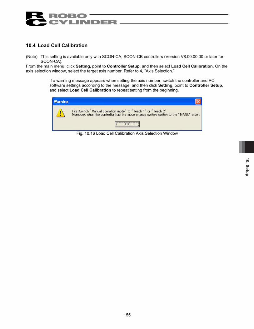
10. Setup
155
10.4 Load Cell Calibration (Note) This setting is available only with SCON-CA, SCON-CB controllers (Version V8.00.00.00 or later for
SCON-CA). From the main menu, click Setting, point to Controller Setup, and then select Load Cell Calibration. On the axis selection window, select the target axis number. Refer to 4, “Axis Selection.”
If a warning message appears when setting the axis number, switch the controller and PC software settings according to the message, and then click Setting, point to Controller Setup, and select Load Cell Calibration to repeat setting from the beginning.
Fig. 10.16 Load Cell Calibration Axis Selection Window

10. S
etup
156
(1) The message “Load cell calibration executing…” (Fig. 10.17) appears and the calibration is performed.
Fig. 10.17 Load Cell Calibration In-Progress Message
(2) When the calibration is complete, the message “The load cell calibration was completed”
(Fig. 10.18) appears.
Fig. 10.18 Load Cell Calibration Completion Message
If the calibration was not successful, the message “It failed in the load cell calibration” (Fig. 10.19) appears. If this message appears, check the cable connection of the load cell, etc., and then perform the calibration again.
Fig. 10.19 Load Cell Calibration Failure Message

11. Version Information
157
11. Version Information
Fig. 11.1 Version Information
[1] Application version The version of this application is shown.
[2] Version Information of each Function DLL (V8.03.00.00 or later)
In here, shows the version information of each function DLL. Nothing will be shown if the DLL file does not exist in the same folder as the program executable file.
[3] Controller version
The software version and manufacturing information of each connected controller are shown. (Manufacturing information may not be displayed depending on the controller type.)
[1]
[2]
[3]

12. S
mar
t Tun
ing
Func
tion
(Ver
sion
V8.
03.0
0.00
or L
ater
)
158
12. Smart Tuning Function (Version V8.03.00.00 or Later) If RC PC software (Version V8. 03. 00. 00 or later) is installed, the key file (OffBrdTune.dll file) and such as AtrDatActuator_24V_PM_BU.oact that are required for the smart tuning function are also installed.
They are installed in the folder that the executable file for ‘RcPc PC PC software’ is stored. Example of storage folder: C:\Program Files\IAI\RoboCylinder
Fig. 12.1 Folder with RC PC Software Executable File Stored
In DB_OFFBRD folder, files listed below etc. are to be stored; • AtrDatActuator_24V_PM_BU.oact • DatRcrdAdjsted_24V_PM_BU.ocrd • TblDatAdjstManuEasily.omnu • DatLimtrAdjst.olmt
OACT file23 KB
OLMT file1 KB
OMNU file3 KB
Fig. 12.2 Data Stored to DB_OFFBRD Folder
PC software for RCIAI America Inc.
RcPc PC software for RCExecutable file
Key file (OffBrdTune.dll file)
DB_OFFBRD folder

12. Smart Tuning Function (Version V8.03.00.00 or Later)
159
12.1 Restrictions 12.1.1 Actuator Applicable for Smart Tuning Function
Smart Tuning Function is available only on the actuators registered in the actuator attribute data (AtrDatActuator_24V_PM_BU.oact etc.).
12.1.2 Parameter Setting
Smart Tuning Function is available only when the parameters are set as shown below: [1] User Parameter No.152 High Output Setting : 1 (Enabled) [2] User Parameter No.144 Gain scheduling Upper Limit Multiplying Ratio (%) :
100 or less (gain scheduling function inactivated) (Note) Gain scheduling is the function to change the gain in accordance with the number of motor
rotation. Gain scheduling function becomes activated when the value is set more than 100.
12.2 Outline of Smart Tuning Function
With the Smart Tuning Function, the following 5 operations can be performed. [1] Setting of maximum acceleration/deceleration speed considering the indicated carrier load and velocity [2] Setting of acceleration/deceleration speed to provide the shortest operation time figured out from the
indicated carrier load and moving distance [3] Overshoot judgment on S motion operation [4] Test Run [5] Cycle time calculation
The table below shows the screens that each function can be used.
List of Windows Each Function is supported Function [1] [2] [3] [4] [5]
Edit Position Data Window Test Run and Cycle Time Calculation
Operation Window
Cycle Time Calculation Window

12. S
mar
t Tun
ing
Func
tion
(Ver
sion
V8.
03.0
0.00
or L
ater
)
160
12.2.1 Setting of maximum acceleration/deceleration speed considering the indicated
carrier load and velocity It is the function to set the maximum acceleration/deceleration speed available at the indicated carrier load and velocity.
12.2.2 Setting of acceleration/deceleration speed to provide the shortest operation time figured out from the indicated carrier load and moving distance
It is the function to set the combination of velocity and acceleration/deceleration that provide the shortest operation time for the indicated moving distance in several patterns of selectable combinations of the velocity and acceleration/deceleration with accordance with the carrier load. When 12.0 [Kg] is indicated for the carrier load, for an instance, the combination of the velocity and acceleration/deceleration to provide the shortest operation time for each moving distance is as shown below: [1] When 30.00 [mm] is indicated
Velocity and acceleration for shortest operation time : 250.00 [mm/sec], 0.70 [G] [2] When 40.00 [mm] is indicated
Velocity and acceleration for shortest operation time : 300.00 [mm/sec], 0.50 [G] (Note) The search of the combination of velocity and acceleration/deceleration for the shortest operation
time refers to the test run plan time. For a reference, the following table shows the list of the operation time for each moving distance.
List of Operation Time for Each Moving Distance Carrier load
[Kg] Travel [mm] Velocity [mm/sec]
Acceleration/Deceleration [G]
Operation Time [msec]
250.00 0.70 156 30.00 300.00 0.50 161 250.00 0.70 196 12.0
40.00 300.00 0.50 195
12.2.3 Overshoot judgment on S motion operation It is the function to judge if the indicated operation setting has the risk of overshooting. In the S motion operation, there is a risk of overshooting in an operation setting with no enough acceleration (deceleration) time. To avoid this, it is necessary to judge if the time setting has a risk of overshooting or not with a calculation of the acceleration (deceleration) time in the test run plan.
12.2.4 Test run It is the function to have the actuator run for a trial with the indicated operation settings. For the test run, the operation mode can be selected from trapezoid and S motion operations. Also, it is able to check the time spent from the operation start till PEND is issued.
12.2.5 Cycle time calculation In this, the value figured out by the cycle time calculation with the indicated operation settings can be checked.

12. Smart Tuning Function (Version V8.03.00.00 or Later)
161
12.3 Operation in Edit position data Window In this section, explains the following operations performed in Edit position data window. [1] Setting of maximum acceleration/deceleration speed considering the indicated carrier load and velocity [2] Setting of acceleration/deceleration speed to provide the shortest operation time figured out from the
indicated carrier load and moving distance [3] Overshoot judgment on S motion operation
12.3.1 Explanation of Window Screen (1) Edit position data Window
Fig. 12.3 Overall View of Edit position data Window
[1] Smart tuning valid/Invalid changeover button
This button can switch between valid and invalid of the smart tuning function in the position data edit process. When the smart tuning is set invalid, the display is turned OFF. The display is on when the setting is valid. When it is set invalid, the shortest smart tuning setting display area gets shaded and setting is disabled.
Fig. 12.4 Smart tuning valid/Invalid changeover button
(Invalid)
Fig. 12.5 Smart tuning
valid/Invalid changeover button (Valid)
[2] Box to show actuator setting applicable for velocity and acceleration/deceleration settings
[3] Box to show carrier load setting for velocity and acceleration/deceleration settings
[1] Smart tuning valid/Invalid changeover button

12. S
mar
t Tun
ing
Func
tion
(Ver
sion
V8.
03.0
0.00
or L
ater
)
162
Fig. 12.6 Smart Tuning Setting Window (Function Invalid)
[2] Box to show actuator setting applicable for velocity and acceleration/deceleration settings
Fig. 12.7 Box to show actuator setting applicable for velocity and acceleration/deceleration settings
Data Type (Version V9.02.00.00 or later) Data type can be selected from the standard and the special order if there is the actuator attribute data file for the special order. Model In here, shows the model code of the actuator currently set to the controller.
Lead [mm] In here, shows the actuator lead [mm] currently set to the controller.
Stroke [mm] In here, shows the actuator stroke [mm] currently set to the controller.
Direction In here, shows the posture of the actuator currently set to the controller.
Setting Actuator Button Click here and “Actuator setting for Vel and Acc setting” window (Fig. 12.9) opens.
[3] Box to show carrier load setting for velocity and acceleration/deceleration settings
Fig. 12.8 Box to show carrier load setting for velocity and acceleration/deceleration settings
Carrier load pattern number select Select the carrier load to be used for the velocity and acceleration/deceleration settings. There are 4 options from 0 to 3 available to choose from.
Selected carrier load In here, shows the carrier load set to the carrier load pattern number selected in the carrier load pattern number select. Fig. 11.8 shows the case of 3.500 [Kg] being set to Carrier Load No. 0.
Load Setting Button Click here and “Load Setting for Vel and Acc setting” window (Fig. 12.10) opens.
Model Direction Lead[mm]
Stroke [mm]
Setting Actuator Button
Carrier load number select Selected carrier
load
Load Setting Button
Data type

12. Smart Tuning Function (Version V8.03.00.00 or Later)
163
(2) Actuator setting for Vel and Acc setting
Fig. 12.9 Actuator setting for Vel and Acc setting Window
[1] Model Select the actuator model code that is applicable for the velocity and acceleration/deceleration settings. (Note) The models available to select from are only the ones registered in “Actuator Attribute Data File”.
[2] Lead [mm] Select the lead of the actuator that is applicable for the velocity and acceleration/deceleration settings. (Note) The lead available to select from is one listed up in the selected model code.
[3] Stroke [mm] Select the stroke of the actuator that is applicable for the velocity and acceleration/deceleration settings. (Note) The stroke available to select from is one from the stroke range listed up in the selected model
code.
[4] Direction Select the posture (horizontal or vertical) of the actuator that is applicable for the velocity and acceleration/deceleration settings. (Note) The posture that can be selected is limited only to those supported in the selected model.
[5] Setting Button
Click this button and the settings of 1) to 4) are written to the controller and the window will close.
[6] Cancel Button Click this button and the window will close without writing the settings of 1) to 4) to the controller.
[1] Model [2] Lead [mm] [3] Stroke [mm] [5] Setting Button
[6] Cancel Button
[4] Direction

12. S
mar
t Tun
ing
Func
tion
(Ver
sion
V8.
03.0
0.00
or L
ater
)
164
(3) Carrier load setting for Smart tuning function
Fig. 12.10 Carrier load setting for Smart tuning function Window
[1] Load Setting
Input the carrier load to be set to Carrier Load Pattern No.0 to 3. The range available to input is from 0 to the value of the maximum carrier load. (Input the values in [kg] unit for the straight axis type and [kgm2] for the rotary axis.)
[2] OK Button Click this button and the setting of 1) is written to the controller and the window will close.
[3] Cancel Button Click this button and the window will close without writing the setting of 1) to the controller. (Note) Even if a change is made to the carrier load settings in this window, the acceleration/deceleration
speed in the position data that is already set will not be changed to the speed suitable for the carrier load.
[1] Load Setting
[2] OK Button [3] Cancel Button

12. Smart Tuning Function (Version V8.03.00.00 or Later)
165
12.3.2 Explanation of Each Operation
(1) The way to operate the maximum acceleration/deceleration speed setting function against the indicated carrier load and velocity
[1] Click Smart tuning button to activate the smart tuning.
The display turns on and the function turns available.
Fig. 12.11 Smart tuning button
[2] Click Setting Actuator button at the setting display of the actuator applicable for velocity and acceleration/deceleration settings.
Fig. 12.12 Box to show actuator setting applicable for velocity and acceleration/deceleration settings
[3] Set the model code, lead stroke and the posture of the applicable actuator in “Actuator setting for Vel
and Acc setting” window. Click Setting button.
Fig. 12.13 Actuator setting for Vel and Acc setting Window
Setting Actuator Button
[1] Model [2] Lead [mm] [3] Stroke [mm] [5] Setting Button
[6] Cancel Button
[4] Direction
[1] Smart tuning button

12. S
mar
t Tun
ing
Func
tion
(Ver
sion
V8.
03.0
0.00
or L
ater
)
166
[4] Click Load Setting button at the setting display of the actuator applicable for velocity and
acceleration/deceleration settings.
Fig. 12.14 Box to show carrier load setting for velocity and acceleration/deceleration settings
[5] Set the carrier load in “Carrier load setting for Smart tuning function” window. Click OK button.
Fig. 12.15 Carrier load setting for Smart tuning function Window
[6] Select the carrier load number.
Fig. 12.16 Box to show Carrier load setting for Smart tuning function
Load Setting Button
Load pattern No. select
[1] Load Setting
[2] OK Button [3] Cancel Button

12. Smart Tuning Function (Version V8.03.00.00 or Later)
167
[7] Set the position and velocity in the blank position numbers.
(Note) In the position numbers with data already set, this function cannot be used.
Fig. 12.17 Edit position data Window
(Note) If the set velocity exceeds the maximum velocity for the carrier load, overwrite the set velocity with the maximum speed for the carrier load.
(Note) If there is no value set in the velocity cell, the speed shown below will be set in the velocity cell.
This value will also be used as the maximum acceleration speed in Step [9]. If a value is set in the acceleration and deceleration cells, they will be overwritten in Step [9].
Adoptable Speed for Each Condition
Conditions Velocity set in the speed cell
Speed used for max. acceleration/deceleration speed setting
Default speed ≤ Max. speed for carrier load Default speed
Default speed > Max. speed for carrier load Max. speed for carrier load
[8] “Smart tuning method select” window will appear. Select “Auto-configure Acc depend Carrier load and
Vel.” and click OK Button.
Fig. 12.18 Smart tuning method select Window
(Auto-configure Acc depend Carrier load and Vel being selected)
[9] The maximum acceleration and deceleration speed for the carrier load and velocity are set to the acceleration and deceleration.
Position and velocity setting cell
Acceleration and deceleration setting cell
Position data input area
Carrier load setting cell

12. S
mar
t Tun
ing
Func
tion
(Ver
sion
V8.
03.0
0.00
or L
ater
)
168
(2) The way to operate the velocity and acceleration/deceleration speed setting function to figure out the
shortest operation time from the indicated carrier load and moving distance [1] Click Smart tuning button to activate the smart tuning.
The display turns on and the function turns available.
Fig. 12.19 Smart tuning button [2] Click Setting Actuator button at the setting display of the actuator applicable for velocity and
acceleration/deceleration settings.
Fig. 12.20 Box to show actuator setting applicable for velocity and acceleration/deceleration settings
[3] Set the model code, lead stroke and the posture of the applicable actuator in “Actuator setting for Vel
and Acc setting” window. Click Setting button.
Fig. 12.21 Actuator setting for Vel and Acc setting Window
Setting Actuator Button
[1] Model [2] Lead [mm] [3] Stroke [mm] [5] Setting Button
[6] Cancel Button
[4] Direction
[1] Smart tuning button

12. Smart Tuning Function (Version V8.03.00.00 or Later)
169
[4] Click Load Setting button at the setting display of the actuator applicable for velocity and
acceleration/deceleration settings.
Fig. 12.22 Box to show carrier load setting for velocity and acceleration/deceleration settings
[5] Set the carrier load in “Load setting for Vel and Acc setting” window. Click OK button.
Fig. 12.23 Carrier load setting for Smart tuning function Window
[6] Set the position and velocity in the blank position numbers.
(Note) In the position numbers with data already set, this function cannot be used.
Fig. 12.24 Edit position data Window
(Note) The value set to the cells that is to be set automatically with this function, such as the velocity cell, can also be overwritten.
Load Setting Button
[1] Load Setting
[2] OK Button [3] Cancel Button
Position and velocity setting cell
Acceleration and deceleration setting cell
Carrier load setting cell
Position data input area

12. S
mar
t Tun
ing
Func
tion
(Ver
sion
V8.
03.0
0.00
or L
ater
)
170
[7] “Smart tuning method select” window will appear. Select “Auto-configure Auto-configure Acc and vel
depend Carrier load and distance.” and click OK Button.
Fig. 12.25 Smart tuning method select Window (Auto-configure Acc and Vel depend Carrier load and distance being selected)
[8] “Moving Distance Setting” window appears. Select the way to indicate the moving distance.
Fig. 12.26 Distance setting Window (Select 2 position)
Fig. 12.27 Distance setting Window (Assign distance)
For the following sections, the operation differs for the cases when indicating 2 points of positions and when indicating the moving distance. ● When indicating 2 points of positions [9] Set the start position number setting box and click on OK button.
Fig. 12.28 Distance setting Window (Select 2 position)
(Note) The position number set in Step [6] will be shown in End Position box.
It is able to change End Position. However, if End Position is changed, the velocity, acceleration and deceleration are figured out based on the distance between the set start position and end position, and set to the position that the position was set in Step [6].
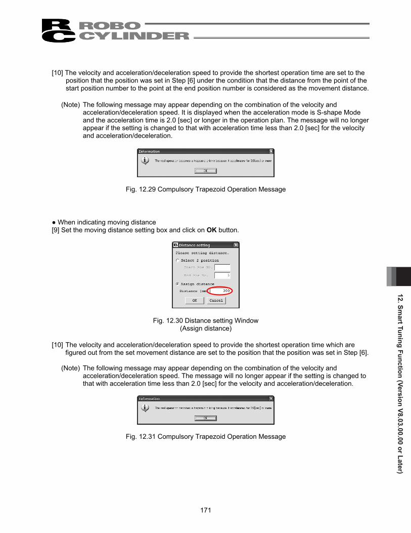
12. Smart Tuning Function (Version V8.03.00.00 or Later)
171
[10] The velocity and acceleration/deceleration speed to provide the shortest operation time are set to the
position that the position was set in Step [6] under the condition that the distance from the point of the start position number to the point at the end position number is considered as the movement distance.
(Note) The following message may appear depending on the combination of the velocity and
acceleration/deceleration speed. It is displayed when the acceleration mode is S-shape Mode and the acceleration time is 2.0 [sec] or longer in the operation plan. The message will no longer appear if the setting is changed to that with acceleration time less than 2.0 [sec] for the velocity and acceleration/deceleration.
Fig. 12.29 Compulsory Trapezoid Operation Message
● When indicating moving distance [9] Set the moving distance setting box and click on OK button.
Fig. 12.30 Distance setting Window (Assign distance)
[10] The velocity and acceleration/deceleration speed to provide the shortest operation time which are
figured out from the set movement distance are set to the position that the position was set in Step [6].
(Note) The following message may appear depending on the combination of the velocity and acceleration/deceleration speed. The message will no longer appear if the setting is changed to that with acceleration time less than 2.0 [sec] for the velocity and acceleration/deceleration.
Fig. 12.31 Compulsory Trapezoid Operation Message

12. S
mar
t Tun
ing
Func
tion
(Ver
sion
V8.
03.0
0.00
or L
ater
)
172
(3) The way to operate the overshoot judgment function at S motion operation [1] Click Smart tuning button to activate the smart tuning.
The display turns on and the function turns available.
Fig. 12.32 Smart tuning button [2] Click Setting Actuator button at the setting display of the actuator applicable for velocity and
acceleration/deceleration settings.
Fig. 12.33 Box to show actuator setting applicable for velocity and acceleration/deceleration settings
[3] Set the model code, lead stroke and the posture of the applicable actuator in “Actuator setting for Vel
and Acc setting” window. Click Setting button.
Fig. 12.34 Actuator setting for Vel and Acc setting Window
Setting Actuator Button
[1] Model [2] Lead [mm] [3] Stroke [mm] [5] Setting Button
[6] Cancel Button
[4] Direction
[1] Smart tuning button

12. Smart Tuning Function (Version V8.03.00.00 or Later)
173
[4] Click Load Setting button at the setting display of the actuator applicable for velocity and
acceleration/deceleration settings.
Fig. 12.35 Box to show carrier load setting for velocity and acceleration/deceleration settings
[5] Set the carrier load in “Carrier load setting for Smart tuning function” window. Click OK button.
Fig. 12.36 Carrier load setting for Smart tuning function Window
[6] Right-click on the position data cell that the overshoot judgment is desired, and select “Check risk
overshoot, when drive S motion.”.
Fig. 12.37 Popup Menu (Check risk overshoot, when drive S motion.)
Load Setting Button
[1] Load Setting
[2] OK Button [3] Cancel Button

12. S
mar
t Tun
ing
Func
tion
(Ver
sion
V8.
03.0
0.00
or L
ater
)
174
[7] “Distance setting” window appears. Select the way to indicate the moving distance.
Fig. 12.38 Distance setting Window (Select 2 position)
Fig. 12.39 Distance setting Window (Assign distance)
For the following sections, the operation differs for the cases when indicating 2 points of positions and when indicating the moving distance. ● When indicating 2 points of positions [8] Set the start position number setting box and click on OK button.
Fig. 12.40 Distance setting Window (Select 2 position)
[9] With the position set in the start position number and position set in the end position number as the
moving distance, overshoot judgment is conducted regarding the position set in the end position. When the risk of overshooting is high, the message shows “Risk High”, while when it is low, shows “Risk Low”.
Fig. 12.41 Overshoot Judgment Message (Risk High)
Fig. 12.42 Overshoot Judgment Message (Risk Low)

12. Smart Tuning Function (Version V8.03.00.00 or Later)
175
● When indicating moving distance [8] Set the moving distance setting box and click on OK button.
Fig. 12.43 Distance setting Window (Assign distance)
[9] In the position where the cursor showed the popup menu (background color: blue), the overshoot
judgment is conducted at the set moving distance. When the risk of overshooting is high, the message shows “Risk High”, while when it is low, shows “Risk Low”.
Fig. 12.44 Overshoot Judgment Message (Risk High)
Fig. 12.45 Overshoot Judgment Message (Risk Low)

12. S
mar
t Tun
ing
Func
tion
(Ver
sion
V8.
03.0
0.00
or L
ater
)
176
12.4 Operation on Test Run and Cycle Time Calculation This section explains how to operate the test run and cycle time calculation.
To open the operation window for test run and cycle time calculation, select [Main Menu] [Parameter] [Control Parameter Setting] [Offboard Tuning]. Select actuator window (Fig. 12.46) will be displayed. (Note) “Takt Time” is changed to “Cycle Time” from the software version V9.05.00.00.
12.4.1 Outline of Test Run Operation In the test run operation, the setting work is to be done in the order of following windows. By clicking on Next button on the bottom of the screen, the window forwards to the next one. [1] Select Actuator ↓ [2] Carrier Load Select ↓ [3] Test Run ↓ [4] Adjustment Record Save In the following pages, shows how to operate in each window.

12. Smart Tuning Function (Version V8.03.00.00 or Later)
177
12.4.2 Explanation of Each Window for Test Run Operation
(1) Select actuator Window Select the model in this window. Select the model in [2] Select actuator model, and click Next.
Fig. 12.46 Select actuator Window
[1] Displayed Window/Model Information Display Area
Fig. 12.47 Displayed Window/Model Information Display Area
Displayed Window Information The name of the window currently displayed is shown.
Model Information The information of actuator selected in “Select actuator” window is shown.
[1] Displayed Window/Model Information Display Area [2] Select actuator model
[3] Adjustment record data Display Area [4] Common Buttons Area[5] Database File Version Display Area
Displayed Window Information Model Information

12. S
mar
t Tun
ing
Func
tion
(Ver
sion
V8.
03.0
0.00
or L
ater
)
178
[2] Select actuator model
Fig. 12.48 Select actuator model
Source Data Select for Model Select Select whether creating a “new adjustment model” or “choosing from the adjustment record”. If creating a “new adjustment model” is selected, select a model to have a test run and cycle time calculation from the models registered in the actuator attribute data file. If “choosing from the adjustment record”, select a model to have a test run and cycle time from the models registered in the adjustment record data stored in the past. (Note) “Adjustment record” is not available to select unless there is adjustment record data.
Model Select Settings Set the data type, model code, lead stroke and posture of actuator installation of the model that will have a test run and cycle time calculation. (Note) The model code, lead or stroke that is not registered in the actuator attribute data file cannot be
selected.
Adjustment Record Data File Select
Fig. 12.49 Adjustment Record Data File Select
By clicking on button, the adjustment record data file to be used can be changed. The name of the adjustment record data file being used is shown on the right of the button with an under line.
(Note) Selecting the adjustment record data file is only available when Source Data Select for Model
Select is set to “Select from Adjustment Record”. (Note) The file initially selected when the Test run and Cycle Time Calculation Operation Window is
open is “\[RC PC Software Save Folder]\DB_OFFBRD\DatRcrdAdjsted_24V_PM_BU.orcd”. (Note) If there is no Adjustment Record Data File, or failed to open the file, the display of the adjustment
record data file select changes to the following display.
Fig. 12.50 Adjustment Record Data File Select (File not selected)
Source Data Select for Model Select Model Select Settings
Tuning Record Data SelectTuning Record Data File Select

12. Smart Tuning Function (Version V8.03.00.00 or Later)
179
Adjustment Record Data Select This is used when switch over the adjustment record data. Number of selectable adjustment record data is shown on the right side. It is able to narrow down the search of the adjustment record data by model select setting. The item with blank in the model select setting gets excluded from the search conditions.
Example) If set as: Model Code = RCP4-RA5C, Lead = 3mm The search result is narrowed down from the adjustment record data to those for
RCP4-RA5C with 3mm lead. Example) If set as: Model Code = RCP4-RA5C, Lead = Blank
The search result is narrowed down from the adjustment record data to those for RCP4-RA5C no matter the lead length.
Click on << or >> button and the data on the very end can be selected from the selectable adjustment record data. Click < or > button and the cursor moves from 1 record to the next in the selected adjustment record data. Putting a number to Edit lying between < and > buttons will let select the indicated adjustment record data directly.

12. S
mar
t Tun
ing
Func
tion
(Ver
sion
V8.
03.0
0.00
or L
ater
)
180
[3] Adjustment Record Data Display Area
In here, shows the details of the adjustment record data selected in “Select from Adjustment Record” in the actuator select actuator.
Fig. 12.51 Adjustment record data Display Area (Select actuator Window)
Data No. It shows the data number of the displayed adjustment record.
Model, Lead (mm), Stroke (mm) It shows the information of actuator selected in “Select actuator” window.
Origin gain In here, shows the origin gain if the origin gain is the stored adjustment record data. For the adjustment record data without the stored origin gain, it is shown with blank.
Fig. 12.52 Origin gain (Select actuator Window) (Not stored)

12. Smart Tuning Function (Version V8.03.00.00 or Later)
181
Adjustment gain Since it is not applicable for PCON-CA, PCON-CB, ERC3 and MCON (Pulse motor) gain tuning, adjustment gain display is shown with blank.
Fig. 12.53 Adjustment gain (Not stored)
Sys identification Since PCON-CA, PCON-CB, ERC3 and MCON (Pulse motor) are not applicable for system identification, a blank is displayed here.
Fig. 12.54 Sys identification (Not stored)
Load In “Carrier load select” window, the carrier load which was indicated is displayed.
Tuning Since PCON-CA, PCON-CB, ERC3 and MCON (Pulse motor) are not applicable for gain tuning, a blank is displayed here. Comment The comment, if any left in “Adjustment record data save” when the adjustment record was saved, is displayed.

12. S
mar
t Tun
ing
Func
tion
(Ver
sion
V8.
03.0
0.00
or L
ater
)
182
[4] Common Buttons Area
Fig. 12.55 Common Buttons Area (Condition of all buttons displayed)
Next Button Click this button and the next window is displayed. In “Adjustment record data save” window, this button changes to the following.
Fig. 12.56 Display in Adjustment record data save Window
(Note) When a setting process in the currently displayed window to move onto the next window is incomplete, a message will be displayed and cannot go to the next window.
Back Button
Click this button and the screen goes back to the window shown before the currently displayed window. (Note) This button is not shown in “Select actuator” window.
Cycle Time Calculation Button
Click this button and the cycle time calculation window is displayed. (Note) This button is available to click only when showing “Test run” window or “Adjustment record
data save” window.
[5] Database File Version Display Area
In here, shows the file version of the database file necessary for the test run and cycle time calculation.

12. Smart Tuning Function (Version V8.03.00.00 or Later)
183
(2) Carrier Load Select Window
Set the carrier load in this window. After setting, click Next.
Fig. 12.57 Carrier load Select Window [1] Carrier Load Indication Method Select
Assign carrier load Indicate the carrier load with the value directly input. This is the only way to select for PCON-CA, PCON-CB, ERC3 and MCON (Pulse motor).
It calculates by the system identification. This cannot be used for PCON-CA, PCON-CB, ERC3 and MCON (Pulse motor).
[2] Carrier Load Indication Input a value to set the carrier load.
[3] System Identification Setting
This cannot be used for PCON-CA, PCON-CB, ERC3 and MCON (Pulse motor). [4] System Identification Result
This cannot be used for PCON-CA, PCON-CB, 1ERC3 and MCON (Pulse motor).
[1] Carrier Load Indication Method Select
[2] Carrier Load Indication
[3] System Identification Setting
[4] System Identification Result

12. S
mar
t Tun
ing
Func
tion
(Ver
sion
V8.
03.0
0.00
or L
ater
)
184
(3) Test run
Indicate the operation settings in this window, and the actuator can have a test run. (Note) The test run function is available only in the online work. When it is offline the screen shows as
shown in the next page and the test run function cannot be used.
Fig. 12.58 Test run Window (in online work)
[1] Gain Display Area
[2] Test run setting
[3] Test run result Display Area

12. Smart Tuning Function (Version V8.03.00.00 or Later)
185
Fig. 12.59 Test run Window (in online work)
[1] Gain Display Area The servo gain used in the test run is shown.
Fig. 12.60 Gain Display Area
[2] Test run setting
Fig. 12.61 Test run setting

12. S
mar
t Tun
ing
Func
tion
(Ver
sion
V8.
03.0
0.00
or L
ater
)
186
Start pos (mm) Set the test run start position of the actuator.
End pos (mm) Set the test run end position of the actuator.
Vel (mm/s) Set the test run velocity of the actuator.
Acc (G) Set the test run acceleration of the actuator.
Dcl (G) Set the test run deceleration of the actuator.
Use gain set No. Set the gain set number used in the test run. * No. 0 is only available for PCON-CA, PCON-CB, ERC3 and MCON (Pulse motor).
Complete pos Set the actuator stop position after operation complete from the start position to the end position. The following two items can be selected for the stop position. • Soft limit - • Start pos
Drv Mode Set the operation mode during test run. The operation mode can be selected from the following two items. • Trapezoid • S-shape
* The following message may appear after clicking Start button depending on the parameter setting.
Select Yes and the following user parameters are changed as described, and the test run starts executed.
<Parameters to be changed>
Set value Name Trapezoid S-shape
No.56 “Sigmoid motion ratio setting [%]” Original Setting*1 100 No.71 “Position feed-forward gain” Original Setting*1 90
*1 If a change has made to the S motion operation parameter in “Cycle time calculation” window, the parameter for the trapezoid operation is changed from the original values to that of S motion operation.
Select No and the test run is cancelled with no change to the parameters.
Fig. 12.62 Confirmation message for Change to S motion Operation Parameter

12. Smart Tuning Function (Version V8.03.00.00 or Later)
187
Operation Start Button
Click this button to start the test run. (Note) Without clicking on Stop button, the test run automatically finishes at the end. (Note) In some cases of start position and end position settings, the following message may appear.
In the case this message is displayed, change the start position and end position so the moving distance can be long enough.
Fig. 12.63 Operation Unable Message due to Moving Distance too short (Note) The following message may appear depending on the combination of velocity and
acceleration/deceleration settings when “S Motion” is selected for the operation mode. The message will no longer appear if the setting is changed to that with acceleration time less than 2.0 [sec] for the velocity and acceleration/deceleration.
Fig. 12.64 Compulsory Trapezoid Operation Message (Note) The following message may appear depending on the operation settings when “S Motion” is
selected for the operation mode. Select Yes and the test run operation can be executed. To make the warning not to appear, change the operation setting so the acceleration time becomes longer.
Fig. 12.65 Overshoot Warning Message
Stop Button Click this button and the test run is cancelled.

12. S
mar
t Tun
ing
Func
tion
(Ver
sion
V8.
03.0
0.00
or L
ater
)
188
[3] Test run Result Display
Fig. 12.66 Test run result Display Area
Tool button
Fig. 12.67 Tool button (Test run Window)
Open the comparison file Click this button, and comparison file to be shown with the test run result. Comparison file is a file in the servo monitor format.
Save with a new name
Click this button to save the wave formed data of the test run result with the data format described below.
• bsmrc format (file format available for comparison file) • csv format (Note) Multiple formats can be selected.
Tool Button Test run result Graph

12. Smart Tuning Function (Version V8.03.00.00 or Later)
189
Zoom in/out of Vertical Axis Click these buttons to zoom in and out the vertical axis of the test run result.
Zoom in/out of Horizontal Axis
Click these buttons to zoom in and out the horizontal axis of the test run result.
Displayed Data Switchover The data (velocity/current) shown on the test run result graph can be switched over with this radio button. * Only the velocity is available to show for PCON-CA, PCON-CB, ERC3 and MCON
(Pulse motor).

12. S
mar
t Tun
ing
Func
tion
(Ver
sion
V8.
03.0
0.00
or L
ater
)
190
(4) Adjustment record data save window
Save the adjustment record in this window.
Fig. 12.68 Adjustment record data save Window
[1] Adjustment Record Data Display Data saved as the adjustment record can be displayed. For the two items shown below, the display and function change from the adjustment record data display in “Select actuator” window.
Fig. 12.69 Display of Origin gain (Adjustment record data save Window)
Fig. 12.70 Comment Box (Adjustment record data save Window)
[1] Adjustment Record Data Display
[2] Save new record /Over write present record
Gain Set No. Select
Comment Input Box

12. Smart Tuning Function (Version V8.03.00.00 or Later)
191
Gain Set No. Select Select the gain set number that is to be saved as the origin gain. The gain which is set to the controller at the startup of the Test run and Cycle time Calculation Operation Window can be saved. Since PCON-CA, PCON-CB, ERC3 and MCON (Pulse motor) are not applicable for the gain setting, the only number being able to choose for Gain Set Number is ‘0’. When “Select from Adjustment Record” is selected in “Select actuator” window, and if the adjustment record data before the gain is saved, the origin gain that was saved in the origin gain record can be saved by selecting “*” in the gain set number window shown below. The gain set to the controller cannot be saved.
Fig. 12.71 Gain Set Number Select (When origin gain is saved in adjustment record)
(Note) “*” can be displayed only when the origin gain is saved in the adjustment record data. (Note) The display of the gain set No. select changes to the one as shown below when it is offline.
Fig. 12.72 Display of Origin gain (Adjustment record data save Window) (with no origin gain)
Fig. 12.73 Display of Origin gain (Adjustment record data save Window) (with origin gain)
Comment Input Box A comment to save in the adjustment record can be input. The comment can be made with 32 half-sized characters at the maximum.
[2] Save new record/Over write present record Button
Save new record Button Click this button and the adjustment record that is displayed in the adjustment record data display can be saved as another file.
Over write present record Button
Click this button and the adjustment record at the data number in the adjustment record data display is overwritten. (Note) Overwriting is available only after the adjustment record currently displayed is already saved
at least once, or when “Adjustment record” is chosen in “Select actuator” window.

12. S
mar
t Tun
ing
Func
tion
(Ver
sion
V8.
03.0
0.00
or L
ater
)
192
12.4.3 Explanation of Cycle Time Calculation Window Cycle time calculation can be performed in this window.
* Click the Cycle Time Calculation button in “Test Run” or “Adjustment Record Save” window.
Fig. 12.74 Common Buttons Area in Smart tuning Window
Fig. 12.75 Cycle time calculation Window (Test run plan Setting Window)
[1] Display Switchover Tab
With these tabs, the displays of “Test run plan setting” window and “Test run result Display” window can be switched over.
Cycle Time Calculation
[1] Display Switchover Tab

12. Smart Tuning Function (Version V8.03.00.00 or Later)
193
(1) Test run plan
Fig. 12.76 Test run plan Setting Window
The settings of operation pattern to be held for cycle time calculation can be conducted in this window. The maximum operation patterns available to set are 10 patterns.
[1] Friction Display
Fig. 12.77 Friction Display Area
Viscs frct In here, shows the coefficient of viscous friction. The setting unit is [Nms]. (Note) Since PCON-CA, PCON-CB, ERC3 and MCON (Pulse motor) are not complied with system
identification, “0.000000000” is displayed in the box.
[1] Friction Display Area [2] Operation Pattern Setting Grid
[3] Operation Pattern Setting Tool Buttons [4] Parameter
setting

12. S
mar
t Tun
ing
Func
tion
(Ver
sion
V8.
03.0
0.00
or L
ater
)
194
Dynmic frct In here, shows the kinetic friction torque. The setting unit is [Nm]. (Note) Since PCON-CA, PCON-CB, ERC3 and MCON (Pulse motor) are not complied with system
identification, “0.000000” is displayed in the box.
Tuning For a controller applicable for gain tuning, the way to tune is displayed. * Since PCON-CA, PCON-CB, ERC3 and MCON (Pulse motor) are not applicable for gain tuning, a
blank is displayed here.
[2] Operation Pattern Setting Grid
Set the operation patterns to have cycle time calculation. Once the cycle time calculation is complete, the operation pattern can be copied and pasted to Position Data Edit window.
Fig. 12.78 Operation Pattern Setting Grid
Load (kg) Set the carrier load. (Note) The settings of carrier load are reflected to the limitations of velocity and
acceleration/deceleration.
Pos (mm) Set the position. The top line (No.S) is the start position setting cell.
Vel (mm/s) Set the velocity.

12. Smart Tuning Function (Version V8.03.00.00 or Later)
195
Acc (G) Set the acceleration.
Dcl (G) Set the deceleration.
INP (mm) Set the positioning width.
SMotion Set the operation type from trapezoid and S motion operations, which is to be used for the cycle time calculation. The numbers corresponding to the trapezoid and S motion operations are as shown below. • Trapezoid : 0 • S Motion : 1
INC Set the movement type from absolute move and incremental move, which is to be used for the cycle time calculation. The numbers corresponding to the absolute and incremental moves are as shown below. • Absolute : 0 • Incremental : 1
Gain Set Set the gain set number used for the cycle time calculation. * For PCON-CA, PCON-CB, ERC3 and MCON (Pulse motor), only Gain Set No. 0 is available.
Rest time (s) Set the rest time.

12. S
mar
t Tun
ing
Func
tion
(Ver
sion
V8.
03.0
0.00
or L
ater
)
196
[3] Operation Pattern Setting Tool Buttons
Fig. 12.79 Operation Pattern Setting Tool Buttons
Fastest ptn Button
Click this button to set the operation pattern that provides the shortest operation time considering the moving distance. (Note) Fastest Operation Setting cannot be set unless the settings for the carrier load and moving
distance are complete.
Copy Button Click this button to copy the content of selected cell.
Paste Button
Click this button to paste the copied content to the selected cell.
Ins 1 line Button Click this button to insert a blank line to the selected cell.
Del 1 line Button
Click this button to delete the content of the selected line and let the lines below the deleted line go up by one line.
Del all line Button
Click this button to delete all the settings in the operation pattern setting grid.
Execute Button Click this button to execute the cycle time calculation with the operation pattern set to the operation pattern setting grid.

12. Smart Tuning Function (Version V8.03.00.00 or Later)
197
[4] Parameter Setting
Fig. 12.80 Parameter Setting Change parameter for S Motion Click this button to change the following parameters for the gain set indicated in the operation pattern that the cycle time calculation is already complete with S motion operation.
<Parameters to be changed>
Name Set value No.56 “Sigmoid motion ratio setting [%]” 100 No.71 “Position feed-forward gain” 90
Restore parameter This returns to the parameter settings displayed in the test run window for the gain set that the parameters were Change parameter for S Motion button.

12. S
mar
t Tun
ing
Func
tion
(Ver
sion
V8.
03.0
0.00
or L
ater
)
198
(2) Test run result
Fig. 12.81 Test run result Display Window
[1] Test run result Time Display Area
Fig. 12.82 Test run result Time Display Area
[1] Test run result Time Display Area [2] Test run result Graph Display Area
Pattern selection

12. Smart Tuning Function (Version V8.03.00.00 or Later)
199
Operation pattern selection Select the pattern to be displayed in the cycle time calculation result graph with this combo box. The operation pattern numbers that the cycle time calculation was held with are available to choose.
INP time (s) In here, shows the positioning time of the operation pattern selected in the pattern select in “Test run result Time Display Area”.
Cycle time (s) In here, shows the cycle time of the operation pattern selected in the pattern select in “Test run result Time Display Area”. Cycle time is the sum of positioning time and pause time.
Accum. cycle time (s) In here, shows the cumulative total cycle times from Pattern 1 to the pattern selected in the pattern select in “Test run result Time Display Area”.
Total cycle time (s) In here, shows the total cycle time of all the patterns included in the cycle time calculation.
[2] Test run Result Graph Display Area
Fig. 12.83 Test run result Graph Display
Test run result Graph Tool button

12. S
mar
t Tun
ing
Func
tion
(Ver
sion
V8.
03.0
0.00
or L
ater
)
200
Tool Button
Fig. 12.84 Tool Button (Cycle Time Calculation Window)
Zoom in/out of Vertical Axis Click this button to zoom in/out the vertical axis of the operation graph.
Zoom in/out of Horizontal Axis
Click this button to zoom in/out the horizontal axis of the operation graph.
Displayed Data Switchover The data (velocity/position) shown on the cycle time calculation result graph can be switched over with this radio button.
Test run Result Graph
Fig. 12.85 Test run result Graph (Velocity response)
The data selected with the check box on the displayed data switchover radio button can be shown.

13. Off B
oard Tuning Function
201
13. Off Board Tuning Function
(Note) The following features cannot be performed on SCON-CAL/CGAL as the servo monitoring cannot be performed. • Method by system identification to actually operate an actuator • Display of result after trial run
If RC PC software (Version V8. 05. 00. 00 or later, V9.02.00.00 or later for MSCON, V9.07.00.00 or later for SCON-CAL/CGAL, Version V10. 00. 00. 00 or later for SCON-CB) is installed, the key file (OffBrdTune.dll file), and an actuator attribute data file (such as AtrDatActuator_200V_AC.oact) that are required for the off board tuning function are also installed, the off board tuning function can be used.
They are installed in the folder that the executable file for ‘RcPc PC software’ is stored. Example of storage folder : C:\Program Files\IAI\RoboCylinder
Fig. 13.1 Folder with RC PC Software Executable File Stored In DB_OFFBRD folder, files listed below etc. are to be stored;
• AtrDatActuator_200V_AC.oact • DatRcrdAdjsted_200V_AC.orcd • TblDatAdjstManuEasily.omnu • DatLimtrAdjst.olmt
(Note) The directory for the database files except for the adjustment record data is to be fixed. Changing the
directory will make the system judge that the files do not exist. (Note) The file name of the adjustment record data is initially selected when the off board tuning window opens.
Only this file is allowed to change the file to be used. (For the details, refer to Adjustment Record Data File Select.)
PC software for RCIAI America Inc.
RcPc PC software for RCExecutable file
Key file (OffBrdTune.dll file)
DB_OFFBRD folder

13. O
ff B
oard
Tun
ing
Func
tion
202
13.1 Restrictions 13.1.1 Actuators Applicable for Off Board Tuning Function The Off Board Tuning Function is only available for the actuators registered in the actuator attribute data file (AtrDatActuator_200V_AC.oact etc.). The gain calculation is conducted based on the actuator attribute data file. The gain calculation for the actuator not registered in the actuator attribute data file cannot be conducted. 13.1.2 Restrictions in Operation 1) The Off Board Tuning Function is not available when any of the following windows are activated:
• “Parameter edit” Window • “Servo monitoring” Window • “Frequency analysis for anti-vibration control”
2) The following windows cannot be activated during the use of Off Board Tuning Function: • “Parameter edit” Window • “Servo monitoring” Window • “Frequency analysis for anti-vibration control”
3) Parameter setting to the controller using Off Board Tuning Function cannot be performed if it is offline.
13.1.3 Caution Regarding Gain Set No. 0 The home-return operation is conducted using the gains in Gain Set No. 0. Follow the cautions stated below and have the settings of Gain Set No. 0 set up. (1) When the carrier load is lighter than the rated carrier load;
1) Set either one of the following gains to Gain Set No. 0. • The gain set up in the condition when the product was shipped out • Adjustment gain suited to the rated carrier load
2) Adjustment gain should be set to Gain Set No. 1, 2 or 3, not to Gain Set No. 0. If the adjustment gain is set to Gain Set No. 0, it may cause a problem such as vibration in the home-return
operation. (2) When the carrier load is heavier than the rated carrier load;
Set the adjustment gain to Gain Set No. 0. With the gain set before the product is shipped out, it may not be able to perform the home-return operation since the load is heavier than the rated carrier load.

13. Off B
oard Tuning Function
203
13.2 Guideline of Off Board Tuning Function Off Board Tuning Function is a function aiming for the optimum gain calculation considering the carrier load. The following 6 types of gains are calculated:
[1] Servo-Motor Gain Number [2] Position Feed Forward Gain [3] Speed Loop Proportional Gain [4] Speed Loop Integral Gain [5] Torque Filter Time Constant [6] Current Control Band Number
There are 4 gain sets to store the 6 types of gain stated above to the parameters in the controller. The calculated gain can be written to the indicated gain set. 13.3 How to Start up Select [Parameter (P)] [Control Parameter Setting (C)] [Off Board Tuning (T)] from the main menu.

13. O
ff B
oard
Tun
ing
Func
tion
204
13.4 Operation to Select Target Axis Number for Off Board Tuning 13.4.1 Explanation of Each Item Shown in Window Select the axis number to conduct the off board tuning in this window. If online work is desired for off board tuning, select Online work, select the axis number, and click on the OK button. If offline is desired for off board tuning, select Offline work, select the motor type, and click on the OK button. Offline work (only to calculate the gain, not to send the parameters to the controller) is also available.
Fig. 13.2 Select target axis no. for off board tuning.
[1] Online work/Offline work switchover Online work Select this radio button and activate the “Select actuator” window to enable the online tuning. (Note) System identification, test run and data sending of the calculated gain to the controller is available
online. (Note) Online work is only available when connected to a controller that supports the off board tuning
function.
Offline work Select this radio button and activate the “Select actuator” window to enable the offline tuning. (Note) System identification, test run and data sending of the calculated gain to the controller are not
available if it is offline. (Note) Offline work is available even when not connected to a controller.
Gain calculation and cycle time calculation can be performed both online/offline.
[2] Select Axis No. Select the axis number that tuning is to be conducted. (Note) This item can be set only when Online work is selected. (Note) Only axis numbers for actuators supporting the off board tuning function are selectable.
[1] Online work/Offline work switchover
[2] Select Axis No.
[4] OK/CANCEL button
[3] Select Motor type

13. Off B
oard Tuning Function
205
[3] Select Motor type
Select the motor type of the actuator for the tuning in the offline work.
[4] OK/CANCEL button OK button Click on the OK button to close “Select target axis no. for off board tuning” window and activate “Select actuator” window. There may be a case the following message box opens after clicking OK. Follow the message and select the appropriate answer.
Fig. 13.3 Confirmation for MANU Operation Mode Change (at the start of Off board tuning window) (Note) The off board tuning window would not start unless the mode is changed from MANU Mode to
Teach Mode. (Note) If clicking Yes to change the setting of MANU Operation Mode, the following message will show
up at the end Off board tuning window. Close the message box and the settings of MANU Operation Mode and Safety Speed will be changed back as they were before changing.
Fig. 13.4 Confirmation for MANU Mode and Safety Speed Changes (at the end of Off board tuning window)
CANCEL button Click on the Cancel button and “Off board tuning target axis no. select” window will close, and the activation of “Select actuator” window will be cancelled.

13. O
ff B
oard
Tun
ing
Func
tion
206
13.5 Operation on Off Board Tuning 13.5.1 Outline of Operation The off board tuning is to be conducted in the process shown below:
[1] Set the model in Select actuator window.
Click Next and the step forwards to Carrier load select window.
↓ [2] Set the load in Carrier load Select window.
There are 2 ways to set the load as shown below. • To indicate the carrier load • To identify the system that actually moves the actuator
(This operation cannot be conducted on SCON-CAL/CGAL.) Click Next and the step forwards to Select adjustment method window.
↓
[3] Select the method to adjust the gain in Select adjustment method window.
There are 3 types for the adjustment. • Set the Base Control Band • Set the Simple Tuning • Set the Manual Except for the Manual Adjustment setting, click Next and the gain adjustment starts. Once the gain adjustment is complete, a message box asking whether setting the calculated gain to the parameter opens. Click OK and the calculated gain is set to the parameter, and the step forwards to the test run.
↓
[4] For the Manual Adjustment setting, gain is to be adjusted manually in the Manual window.
Click Next and the gain adjustment starts. Once the gain adjustment is complete, a message box asking whether setting the calculated gain to the parameter opens. Click OK and the calculated gain is set to the parameter, and the step forwards to the test run.
↓
[5] Have a test run of the adjusted gain in the test run window to check the operation.
(SCON-CAL/CGAL can perform a trial run, but the result cannot be displayed.) Click Next and Adjustment record save window opens.
↓
[6] The result of the gain adjustment can be stored in Adjustment record save window. The following pages, provide the explanations for the operations in each window.

13. Off B
oard Tuning Function
207
13.5.2 Explanations for each Item in Select actuator Window Select the model of the actuator for tuning in this window.
Fig. 13.5 Select actuator Window
[1] Displayed Window/Model Information Display
Fig. 13.6 Displayed Window/Model Information Display
Displayed Window Information The name of the window currently displayed is shown.
Model Information The information of actuator selected in “Select actuator” window is shown.
[1] Displayed Window/Model Information Display Area [2] Select actuator model
[3] Adjustment record data Display Area [4] Common Buttons Area[5] Database File Version Display
Displayed Window Information Model Information

13. O
ff B
oard
Tun
ing
Func
tion
208
[2] Select actuator model
Fig. 13.7 Select actuator model
Source Data Select for Select actuator Select the source data for the model selection. If choosing “New adjustment model”, select the model to tune from the models registered in the actuator attribute data file. If choosing “Adjustment record”, select the model to tune from the models registered in the adjustment record data saved in the past. (Note) “Adjustment record” is not available to select unless there is adjustment record data.
Select actuator Settings Set the data type, model code, lead, stroke and actuator installed orientation for the model to be tuned. (Note) The model code, lead or stroke not registered in the source data for select actuator cannot be set. Adjustment Record Data File Select
Fig. 13.8 Adjustment Record Data File Select
By clicking on button, the adjustment record data file to be used can be changed. The name of the adjustment record data file being used is shown on the right of the button and is underlined. (Note) Selecting the adjustment record data file is only available when Source Data Select for Select
actuator is set to “Adjustment record”. (Note) The file initially selected when the Off board tuning window is open is “\[RC PC Software Save
Folder]\DB_OFFBRD\DatRcrdAdjsted_200V_AC.orcd”. (Note) If there is no adjustment Record Data File, or failed to open the file, the display of the adjustment
record data file select changes to the following display.
Fig. 13.9 Adjustment Record Data File Select (File not selected)
Source Data Select for Select actuator Select actuator Settings
Adjustment Record Data Select Adjustment Record Data File Select

13. Off B
oard Tuning Function
209
Adjustment Record Data Select This is used when switch over the adjustment record data. Number of selectable adjustment record data is shown on the right side. It is able to narrow down the search of the adjustment record data by select actuator setting. The item with blank in the select actuator setting gets excluded from the search conditions. Example) If set as: Model Code = ISB-SXM-60, Lead = 4mm
The search result is narrowed down from the adjustment record data to those for ISB-SXM-60 with 4mm lead.
Example) If set as: Model Code = ISB-SXM-60, Lead = Blank
The search result is narrowed down from the adjustment record data to those for ISB-SXM-60 no matter the lead length. Click on << or >> button and the data on the very end can be selected from the selectable adjustment record data. Click < or > button and the cursor moves from 1 record to the next in the selected adjustment record data. Putting a number between < and > buttons will select the indicated adjustment record data directly.

13. O
ff B
oard
Tun
ing
Func
tion
210
[3] Adjustment record data Display
Fig. 13.10 Adjustment record data Display (Select actuator Window)
The details of the adjustment record data selected in Adjustment record data select is displayed.
Data No. It shows the data number of the displayed adjustment record. Model, Lead (mm) and Stroke (mm) It shows the information of actuator selected in “Select actuator” window. Origin gain In here, shows the origin gain if the origin gain is the stored adjustment record data. For the adjustment record data without the stored origin gain, it will be as shown below.
Fig. 13.11 Origin gain (Select actuator Window) (Origin gain not stored)

13. Off B
oard Tuning Function
211
Adjustment gain The gain after tuning is displayed. For the adjustment record the adjustment gain is sent to the controller, the gain set number that the gain is set to is shown in Gain Set No., and “-“ is shown if not sent. Sys identification The result of the system identification is displayed for the adjustment record the system identification is conducted. Nothing is displayed as shown below for the adjustment record data saved with no system identification.
Fig. 13.12 Sys identification (Not stored)
Load In “Carrier load Select” window, the carrier load which was indicated is displayed. For the record, the carrier load calculated backwards from the synthetic inertia is displayed. Tuning The method of adjustment selected in “Select adjustment method” window is shown. The display is switched as shown below depending on the selected method.
Fig. 13.13 Tuning display (When the Base ctrl band)
Fig. 13.14 Tuning display (When the simple tuning)
Fig. 13.15 Tuning display (When the Manual)
Comment The comment is shown for the adjustment record data saved with a comment.

13. O
ff B
oard
Tun
ing
Func
tion
212
[4] Common Buttons Area
Fig. 13.16 Common Buttons Area (Condition of all buttons displayed)
Next button Click this button and the next window is displayed. In “Adjustment Record Save” window, this button changes to the following.
Fig. 13.17 Display in Adjustment Record Save Window
(Note) When a setting process in the currently displayed window to move onto the next window is incomplete, a message will be displayed and cannot go to the next window.
Back button Click this button and the screen goes back to the window shown before the currently displayed window. (Note) This button is not shown in “Select actuator” window.
Cycle Time Calculation button Click this button and the cycle time calculation window is displayed. (Note) This button is available to click only when showing “Test Run” window or “Adjustment Record
Save” window.
[5] Database File Version Display Area
In here, shows the file version of the database file necessary for the tuning.

13. Off B
oard Tuning Function
213
13.5.3 Explanations for each Item in Carrier load Select Window Set the carrier load in this window. There are 2 ways for the selection of the carrier load, one is to indicate the carrier load and the other is to figure out from the system identification, and selection can be made from these 2 ways. (Note) The system identification is available to select only in the system identification model, such as
SCON-CA. In the online work of SCON-CAL/CGAL and offline work of SCON-CA, SCON-CB and SCON-CAL/CGAL, the window switches to the one as shown in Fig. 13.19.
Fig. 13.18 Carrier load Select Window (in online work of SCON-CA)
[2] Carrier Load Indication
[3] System Identification Setting
[1] Carrier Load Indication Method Select
[4] System Identification Result

13. O
ff B
oard
Tun
ing
Func
tion
214
Fig. 13.19 Carrier load Select Window (In the online work of SCON-CAL/CGAL and in the offline work of SCON-CA, SCON-CB and SCON-CAL/CGAL)
[1] Carrier Load Indication Method Select
Assign carrier load Select this radio button and the indicated carrier load can be set. It calculates by the system identification. Select this radio button and the actuator actually operates in back and forth directions to estimate the carrier load from the speed and current data obtained from the controller.
[2] Carrier Load Indication Carrier load can be set with the numeric value input in Edit in Carrier load Select window 2.

13. Off B
oard Tuning Function
215
[3] System Identification Setting
Operation setting for the system identification can be conducted.
Fig. 13.20 System Identification Setting
Start pos (mm) The start position for the back and forth operation can be set. (Note) In the operation for the system identification, the actuator moves back and forth between the start
position and end position. End pos (mm) The end position for the back and forth operation can be set. (Note) In the operation for the system identification, the actuator moves back and forth between the start
position and end position. Load (kg) Set the carrier load. (Note) This is the value used for the system identification calculation and the maximum speed operation
setting. Set the size of the load roughly even if you do not know the accurate load size. It is not necessary to change the value from the initial setting if you do not know the load size at all.
Example) In the case you have the information that the load size is approximately 2 [kg], but you do not
know exactly; Set “2.000” in Carrier load (kg).

13. O
ff B
oard
Tun
ing
Func
tion
216
Acc (G) Set the acceleration speed for back and forth operation. Dcl (G) Set the deceleration speed for back and forth operation. Vel (mm/s) Set the velocity for back and forth operation. Complete pos Set the data at what coordinates the actuator is to be stopped after the back and forth operation for system identification is complete. The selection is to be made from the following two;
• Soft limit – : Stops on the soft limit – side (origin side) • Start Position : Stops at the start position set in the identification setting
(Note) An operation suitable for the system identification is that with the acceleration time, constant
velocity time and deceleration time evenly divided, and the current condition that the peak equals to the rated current.
Fastest ptn button Click this button and the operation setting that provides the maximum load applied to the motor is calculated from the start position, end position and carrier load, and set to the system identification setting. (Note) For the fastest ptn setting, the information of the start position, end position and carrier load is
necessary.
Start button Click this button and the actuator starts to operate back and forth with the provided operation setting. (Note) The operation of the actuator automatically stops once the buffering of 30,000 records is finished.
Stop button Click this button to interrupt the system identification. (Note) If clicking Stop button before obtaining the number of data necessary for the system identification
from the controller (at least 15,000 data for each velocity and current), the system identification calculation would not be carried out.
(Note) Even if not clicking Stop button, it will automatically stop once the maximum obtainable number of data (30,000 data) is obtained from the controller.

13. Off B
oard Tuning Function
217
[4] System Identification Result
Fig. 13.21 System Identification Result Display
Result display for system identification calculation In here, shows the result of the system identification calculation. Tool button
Fig. 13.22 Tool button (Carrier load Select Window)
Save with a new name Click this button and the data of the waveforms for the velocity and current shown in the system identification test run result graph is saved as a csv file.
Zoom in/out of Vertical Axis Click this button to zoom in/out the vertical axis of the system identification operation graph.
Zoom in/out of Horizontal Axis Click this button to zoom in/out the horizontal axis of the system identification operation graph.
Displayed Data Switchover The data (velocity/current) shown on the test run result graph can be switched over with this radio button.
Result display for system identification calculation Tool button
System identification operation graph

13. O
ff B
oard
Tun
ing
Func
tion
218
System identification operation graph
Fig. 13.23 System Identification Result Graph (Velocity (Resp))
The graph for the data selected with the displayed data switchover radio button is shown.

13. Off B
oard Tuning Function
219
13.5.4 Explanations for each Item in Select adjustment method Window Set the gain adjustment method in this window.
Fig. 13.24 Select adjustment method Window
[1] Select Adjust gain set No. Select the gain set number which the adjusted gain is to be sent. The relation of the gain set numbers and the parameters where the gain is sent to is as shown below. (Note) The gain set number where the gain is adjusted to would not be shown when in the offline work.
Table for Gain Set Number and Parameter No. Parameter No. Parameter Name Set No.0 Set No.1 Set No.2 Set No.3
Servo-Motor Gain Number 7 120 126 132 Position Feed Forward Gain 71 121 127 133
Speed Loop Proportional Gain 31 122 128 134 Speed Loop Integral Gain 32 123 129 135
Torque Filter Time Constant 33 124 130 136 Current Control Band Number 54 125 131 137
[1] Select Adjust gain set No.
[2] Select adjustment method

13. O
ff B
oard
Tun
ing
Func
tion
220
[2] Select adjustment method
Fig. 13.25 Select adjustment method
Base ctrl band Select this radio button and click on Next button to perform the gain adjustment by the base control band. The base control band setting suits to a case when the automatic calculation of the gain considering the carrier load is required, but it is not necessary to increase the responsiveness. Simple tuning Setting
Fig. 13.26 Simple tuning Setting Select this radio button and click on Next button to perform the gain adjustment based on the selected tuning. The simple tuning suits to a case when the automatic calculation of the gain considering the carrier load is required, and the increase of the responsiveness is also necessary. The tuning can be selected from the following four items;
Tuning and Explanation Tuning Explanation
Default
The optimum rule for the selected actuator is selected, and adjustment is made based on the selected rule. (Note) Optimum rule : This is a rule that considers the generation the vibration and
noise, selected from the three rules, Tight, Ratio and Stiff, and also the responsiveness is increased as much as possible at the same time.
Tight This rule possesses the highest increase of the responsiveness among the three, but has the highest risk of vibration and noise generations.
Ratio The increase of the responsiveness is higher than Stiff, but lower than Tight. The risk of vibration and noise is lower than Tight, but higher than Stiff.
Stiff This rule possesses the lowest risk of the generation of vibration and noise among the three, but has the lowest increase of the responsiveness.
(Note) The explanations of Tight, Ratio and Stiff stated above are the tendency when the carrier load is smaller than the rated transportable weight. The tendency flows the other way around when the carrier load is larger than the rated transportable weight.
Base ctrl band
Simple tuning Setting
Manual Setting

13. Off B
oard Tuning Function
221
Manual Setting
Fig. 13.27 Manual Setting
Select this radio button and click the Next button, and then the Manual window will show up. The manual suits to a case when it is necessary to set the value which the gain calculation is based on individually considering the target (directionality of the adjustment). Basis gain Select the gain that the adjustment is based on in the Manual window. The basis gain can be selected from the following seven items.
• Origin gain • Adjustment record gain • Base control band (basis gain) at rated load • Simple tuning gain (Default) • Simple tuning gain (Tight) • Simple tuning gain (Ratio) • Simple tuning gain (Stiff)
(Note) Origin gain is selectable only when the adjustment record data which the origin gain has been stored was selected in “Select actuator” window, or while in the online work and when the new adjustment model is selected.
(Note) Adjustment record gain is selectable only when the adjustment record data is selected in “Select actuator” window. The band setting used in the calculation of the adjustment gain stored in the adjustment record data selected in the model select window will be the initial value in the manual adjustment window of this time.
Directionality Directionality for the adjustment in the Manual window can be selected. The directionality can be selected from the following four items.
• Control vibration • Control noise • Increase responsiveness • Increase external disturbance suppression

13. O
ff B
oard
Tun
ing
Func
tion
222
[Parameter Transfer] In the online work a message box appears in the following timings;
• When “Base control band” is selected and the Next button is clicked in the Select adjustment method window
• When “Simple tuning” is selected and the Next button is clicked in the Select adjustment method window
Fig. 13.28 Confirmation of Parameter Transfer When Yes is clicked : The adjusted gain is sent to the set adjustment gain set number and the test
run window is displayed. When No is clicked : The test run window is displayed without the adjusted gain being sent. When Cancel is clicked : The adjusted gain is not sent and the test run window is also not displayed. If the adjusted gain is sent, a message box asking you to reboot the controller will show up. (The message box for the confirmation of servo-off at reboot is displayed only when the servo is on.) Click on Yes button in each box to reboot the controller. (Note) The sent parameters will be reflected to the setting after the reboot of the controller. Reboot the
controller first if a test run is desired with the sent parameters.
Fig. 13.29 Confirmation for Controller Reboot
Fig. 13.30 Confirmation for Servo-off at Reboot

13. Off B
oard Tuning Function
223
13.5.5 Explanations for each Item in Manual Window Perform the gain adjustment with operating each adjustment switches in this window.
Fig. 13.31 Manual Window
[1] Manual Setting [2] Adjustment Status Display
[3] Adjustment Band Settings

13. O
ff B
oard
Tun
ing
Func
tion
224
[1] Manual Setting
Fig. 13.32 Manual Setting
Basis gain The basis gain for the adjustment set in “Select adjustment method” window is displayed.
Directionality The directionality for the adjustment set in “Select adjustment method” window is displayed.
Content Select the content of the adjustment. The content can be selected from the following four items. Select an appropriate content if an improvement is required at the same time in addition to the directionality of the adjustment.
• Control vibration • Control noise • Increase responsiveness • Increase external disturbance suppression
(Note) The main frame of the adjustment is what is selected as the directionality for the adjustment. If an adjustment with the adjustment content as the main frame is required, make a change to the setting of the directionality for the adjustment.
Reflct viscs frct. Put a check mark in this check box to add a consideration of the viscous friction to the gain calculation.

13. Off B
oard Tuning Function
225
[2] Adjustment Status Display
Fig. 13.33 Adjustment Status Display
Fig. 13.34 Adjustment Status Display
Display of status change in each direction This shows the change of the status from the current ones in each adjustment direction for the five items listed on the left side of the window. The meanings of the displayed arrows are as explained in the following table;
Status Change in each Adjustment Direction and Arrow Displays
Adjustment Direction Status Change
Left RightNo impact Improved Worsened
Possibly worsened If taking PI Break Frequency in Figure 13.31 as an example, it can be defined that;
• the vibration, abnormal noise and overshoot can be improved if an adjustment is made to the left (to make the setting smaller),but the remaining items would not be improved.
Display of adjustment degree Display of status change in each direction
Display of interlock adjuster switch under influence

13. O
ff B
oard
Tun
ing
Func
tion
226
Display of adjustment degree This shows the degree of the adjustment against the initial condition of each adjustment switch for the five items listed on the left side of the window. The left side of the gauge extends if it is worsened and the right side extends when there is an improvement. The gauge for the adjustment degree is displayed in 2 steps. The worsened gauge changes as “yellow red” while improved gauge goes “light blue blue”.
Fig. 13.35 Adjustment Degree (Improved)
(most worsened condition)
Fig. 13.36 Adjustment Degree (Improved)
(most improved condition) Only red in the worsened gauge is the most worsened condition while only blue in the improved gauge is the most improved condition that can currently be improved the most.
If taking PI Break Frequency in Figure 13.31 as an example, it can be defined that;
• the vibration, abnormal noise and overshoot are improved from the initial condition, and • the response and suppress disturb are worsened from the initial condition.
(Note) The display of the adjustment degree is a relative display compared with the initial conditions at
the start when the Manual window is opened. (Note) If an adjustment is made to the control velocity band, it will give an impact to the overshooting
degrees for the position gain, PI break frequency, control current band and torque filter. Display of interlocked adjustment switch under influence This shows the adjustment switches which are influenced by the adjustment degree and overshooting degree when the interlocked adjustment switches are operated. An influence is given when Interlock adjuster 1 is operated if is displayed. An influence is given when Interlock adjuster 2 is operated if is displayed. (Note) The number of interlock adjuster may differ depending on the directionality, content and the
manual data version.

13. Off B
oard Tuning Function
227
[3] Adjustment Band Settings
Fig. 13.37 Adjustment Band Settings
Fig. 13.38 Adjustment Band Settings (Pos Gain)
Band setting scroll bar By operating this scroll bar, the band setting of the switch can be changed. (Note) The operation is available only on the switches that are available for adjustment only.
Band setting display In here, displays the current band setting. Band setting degree display In here, displays the degree of the current band setting. The gauge changes in the order of blue light blue yellow red. Higher the setting gets, the closer the color of the gauge comes to red.
Fig. 13.39 Interlock adjuster Band Setting
Torque filter bandwidth inactivated (Version V9.02.00.00 or later)
Fig. 13.40 Torque filter bandwidth inactivated
The settings are as shown below for when there is a tick in the checkbox for the torque filter bandwidth inactivated and there is no check.
Check Adjustment Gain Torque Filter Time Constant When there is a tick () 0 When there is no tick (blank) Value calculated from torque filter bandwidth setting
(Note) Even when there is a tick in the checkbox, changes can be made in the torque filter bandwidth
itself and the setting in the torque filter bandwidth by the interlocking adjuster. (Note) When the manual adjustment window is shown from the adjustment method select window, and
when the torque filter constant in the adjustment gain is 0, the tick in the checkbox is kept ().
Band setting scroll bar Band setting display
Band setting degree display
Band setting scroll bar
Torque filter bandwidth inactivated

13. O
ff B
oard
Tun
ing
Func
tion
228
Band setting scroll bar By operating this scroll bar, the band setting can be changed by the interlock adjuster. By utilizing the interlock adjuster, the band setting for a several switches can be changed at the same time. (Note) The combinations of the interlock adjuster the band setting is changed at the same time may
differ depending on the directionality and content. (Note) The operation is available only on the interlock adjuster that are available for adjustment only.
[Parameter Transfer] In the offline work a message box appears in the following timings;
• When Next button is clicked in the Manual window
Fig. 13.41 Confirmation of Parameter Transfer When Yes is clicked : The adjusted gain is sent to the set adjustment gain set number and the test
run window is displayed. When No is clicked : The test run window is displayed without the adjusted gain being sent. When Cancel is clicked : The adjusted gain is not sent and the test run window is also not displayed. If the adjusted gain is sent, a message box asking you to reboot the controller will show up. (The message box for the confirmation of servo-off at reboot is displayed only when the servo is on.) Click on Yes button in each box to reboot the controller. (Note) The sent parameters will be reflected to the setting after the reboot of the controller. Reboot the
controller first if a test run is desired with the sent parameters.
Fig. 13.42 Confirmation for Controller Reboot
Fig. 13.43 Confirmation for Servo-off at Reboot

13. Off B
oard Tuning Function
229
13.5.6 Explanations for each Item in Test run Window A test run of the actuator is available with using the adjusted gain in this window. (Note) The test run function is available only in the online work. When it is offline the screen shows as shown in
the Fig. 13.46 and the test run function cannot be used. (Note) SCON-CAL/CGAL can perform a trial run, but the result cannot be displayed. (Fig. 13.45)
Fig. 13.44 Test run Window (in online work)
[1] Tuning Setting/Result Display [2] Test run setting
[3] Test run result Display

13. O
ff B
oard
Tun
ing
Func
tion
230
Fig. 13.45 Test run Window (in online work of SCON-CAL/CGAL)

13. Off B
oard Tuning Function
231
Fig. 13.46 Test run Window (in offline work)
[1] Tuning Setting/Result Display
Fig. 13.47 Tuning Setting (When Manual)
Fig. 13.48 Gain display (Test run Window)
Adjustment method select setting display The tuning method set in “Select Tuning Method” window is displayed. (Note) The display differs depending on the selected tuning method. The display for the modes other
than the Manual is as shown below.
Fig. 13.49 Tuning Setting
(at base ctrl band) Fig. 13.50 Tuning Setting
(at Simple tuning)
Adjustment method select setting display
Gain display

13. O
ff B
oard
Tun
ing
Func
tion
232
Gain display Shows the gain indicated in the used gain set number for the test run setting. The selection is to be made from the following two;
• Adjustment gain : Shows the adjustment gain. The gain set number shows “-” as shown in the figure below when the adjustment gain is not sent to the controller.
• Test run gain : Shows the gain indicated in the used gain set number for the test run setting.
Fig. 13.51 Adjustment Gain Display (Test run Window) (not sent)
[2] Test run setting
Fig. 13.52 Test run setting
Start pos (mm) Set the test run start position. (Note) In the test run, the actuator runs through between the start position and end position once. End pos (mm) Set the test run end position. (Note) In the test run, the actuator runs through between the start position and end position once. Vel (mm/s) Set the test run velocity. Acc (G) Set the test run acceleration. Dcl (G) Set the test run deceleration. Use gain set No. Set the gain set number used in the test run. Complete pos It can be set at what coordinates the actuator is to be stopped after the back and forth operation for the test run. The selection is to be made from the following two;
• Soft limit – : Stops on the soft limit – side (origin side) • Start Position : Stops at the start position set in the identification setting

13. Off B
oard Tuning Function
233
Drv Mode Set the operation mode during test run. The following two items can be selected for the operation mode.
• Trapezoid • S motion
(Note) When Operation Start button is clicked, a message box may open to confirm the change to the S motion parameter depending on the parameter settings. Select Yes and the following user parameters are changed as described, and the test run starts executed.
<Parameters to be changed>
Set value Name Trapezoid S-shape
No.56 “Sigmoid motion ratio setting [%]” Original Setting (Note 1) 100 No.71 “Position feed-forward gain” Original Setting (Note 1) 90
(Note 1) If a change has made to the S motion operation parameter in “Cycle time calculation” window, the parameter for the trapezoid operation is changed from the original values to that of S motion operation.
Select No and the test run is cancelled with no change to the parameters.
Fig. 13.53 Confirmation message for Change to S motion Operation Parameter

13. O
ff B
oard
Tun
ing
Func
tion
234
Start button Click this button to start the test run. (Note) Without clicking on Stop button, the test run automatically finishes at the end. (Note) In some cases of start position and end position settings, the following message may appear. In
the case this message is displayed, change the start position and end position so the moving distance can be long enough.
Fig. 13.54 Operation Unable Message due to Moving Distance too short
(Note) The following message may appear depending on the combination of the velocity and acceleration/deceleration. The message will no longer appear if the setting is changed to that with acceleration time less than 2.0 [sec] for the velocity and acceleration/deceleration.
Fig. 13.55 Compulsory Trapezoid Operation Message
(Note) A message box may open for the overshooting alarm depending on the operation settings. Select Yes and the test run operation can be executed. To make the warning not to appear, change the operation setting so the acceleration time becomes longer.
Fig. 13.56 Overshoot Warning Message
Stop button Click this button and the test run is cancelled.

13. Off B
oard Tuning Function
235
[3] Test Run Result Display
Fig. 13.57 Test run result Display
Tool button
Fig. 13.58 Tool button (Test run Window)
Reading File for Comparison Click on this button and a file is read and drawn on the same graph to compare with the test run result.
Saving Test run result File Click this button and the data of the waveforms for the velocity and current for the test run result is saved as a bsmrc or csv file.
Zoom in/out of Vertical Axis Click these buttons to zoom in and out the vertical axis of the test run result.
Zoom in/out of Horizontal Axis Click these buttons to zoom in and out the horizontal axis of the test run result.
Displayed Data Switchover The data (velocity/current) shown on the test run result graph can be switched over with this radio button.
Tool button Test run result Graph

13. O
ff B
oard
Tun
ing
Func
tion
236
Test run result Graph
Fig. 13.59 Test run result Graph (Velocity (Resp))
The graph for the data selected with the displayed data switchover radio button is shown. The vertical red line and PEND display on the top right indicated with the arrows show the positioning complete time.
Positioning Complete Time
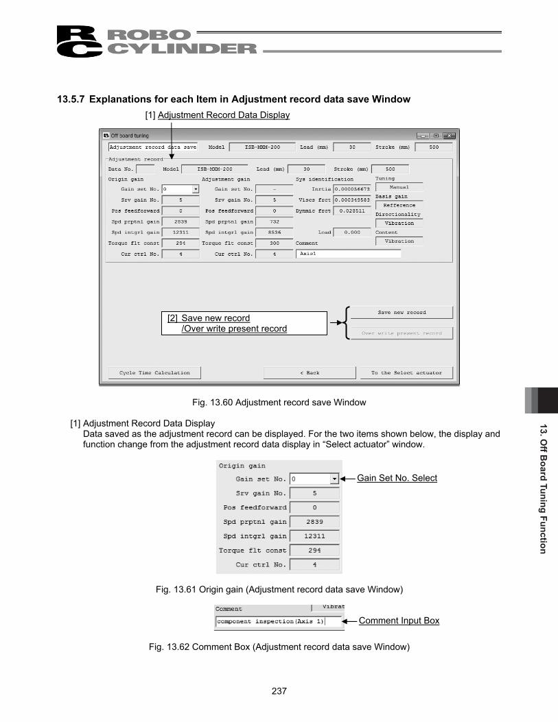
13. Off B
oard Tuning Function
237
13.5.7 Explanations for each Item in Adjustment record data save Window
Fig. 13.60 Adjustment record save Window
[1] Adjustment Record Data Display Data saved as the adjustment record can be displayed. For the two items shown below, the display and function change from the adjustment record data display in “Select actuator” window.
Fig. 13.61 Origin gain (Adjustment record data save Window)
Fig. 13.62 Comment Box (Adjustment record data save Window)
[1] Adjustment Record Data Display
[2] Save new record /Over write present record
Gain Set No. Select
Comment Input Box

13. O
ff B
oard
Tun
ing
Func
tion
238
Gain Set No. Select Select the gain set number that is to be saved as the origin gain. At the time the Off board tuning window is activated, the gain set selected from the gain sets No. 0 to 3 set to the controller can be saved. If the origin gain is already saved to the adjustment record data at the time “Adjustment record” was chosen in “Select actuator” window, the origin gain saved in the adjustment record can be saved by selecting “*” in the gain set number in the following window.
Fig. 13.63 Gain Set Number Select (when origin gain is saved in adjustment record)
(Note) “*” can be displayed only when the origin gain is saved in the adjustment record data. (Note) The display of the gain set No. select changes to the one as shown below when it is offline.
Fig. 13.64 Display of Origin gain
(Adjustment record data save Window) (with no origin gain)
Fig. 13.65 Display of Origin gain
(Adjustment record data save Window) (with origin gain)
Comment Input Box A comment to save in the adjustment record can be input. The comment can be made with 32 half-sized characters at the maximum.
[2] Save new record/Over write present record button
Save new record button Click on this button and the adjustment record displayed on the Adjustment record data display ([1] in Adjustment record data save window) can be additionally saved.
Over write present record button Click on this button and the file can be overwritten to the adjustment record of the data number in the Adjustment record data display ([1] in Adjustment record data save window). (Note) Overwriting is available only after the adjustment record currently displayed is already saved at
least once, or when “Adjustment record” is chosen in “Select actuator” window.

13. Off B
oard Tuning Function
239
13.6 Operations in Cycle Time calculation To conduct the cycle time calculation, click on the Cycle Time Calculation button in the Off board tuning window. (Note) “Cycle time calculation” window can be opened from “Test run” window or “Adjustment record data
save” window.
Fig. 13.66 Common Buttons Area in Off board tuning Window
13.6.1 Explanations for each Item in Cycle Time calculation Window Cycle time calculation can be performed in this window.
Fig. 13.67 Cycle time calculation Window (Test run plan Setting Window)
[1] Display Switchover Tab With these tabs, the displays of “Test run plan Setting” window and “Test run result Display” window can be switched over.
Cycle Time Calculation button
[1] Display Switchover Tab

13. O
ff B
oard
Tun
ing
Func
tion
240
13.6.2 Test run plan Setting Window The settings of operation pattern to be held for cycle time calculation can be conducted in this window. The maximum operation patterns available to set are 10 patterns.
Fig. 13.68 Test run plan Setting Window
[1] Friction Display Area
Fig. 13.69 Friction Display Area
Viscs frct In here, shows the coefficient of viscous friction. The setting unit is [Nms].
Dynmic frct In here, shows the kinetic friction torque. The setting unit is [Nm].
Tuning The adjustment method used in the gain calculation is displayed.
[1] Friction Display Area [2] Operation Pattern Setting Grid
[3] Operation Pattern Setting Tool Buttons [4] Parameter Setting

13. Off B
oard Tuning Function
241
[2] Operation Pattern Setting Grid
Set the operation patterns to have cycle time calculation. Once the cycle time calculation is complete, the operation pattern can be copied and pasted to Position Data Edit window.
Fig. 13.70 Operation Pattern Setting Grid
Load (kg) Set the carrier load. (Note) Only the ratio of load can be reflected to the calculation for the setting of carrier load. Pos (mm) Set the position. The top line (No. S) is the start position setting cell. Vel (mm/s) Set the velocity. Acc (G) Set the acceleration. Dcl (G) Set the deceleration. INP (mm) Set the positioning width. SMotion Set the operation type from trapezoid and S motion operations, which is to be used for the cycle time calculation. The numbers corresponding to the trapezoid and S motion operations are as shown below.
• Trapezoid : 0 • S Motion : 1

13. O
ff B
oard
Tun
ing
Func
tion
242
INC Set the movement type from absolute move and incremental move, which is to be used for the cycle time calculation. The numbers corresponding to the absolute and incremental moves are as shown below.
• Absolute : 0 • Incremental : 1
Gain Set Set the gain set number used for the cycle time calculation.
Rest time (s) Set the rest time.
[3] Operation Pattern Setting Tool Buttons
Fig. 13.71 Operation Pattern Setting Tool Buttons
Fastest ptn button Click on this button and the operation pattern can be set in the selected line to maximize the load applied to the motor. (Note) Fastest operation setting cannot be executed as long as the carrier load and movement distance
settings are incomplete.
Copy button Click this button to copy the content of selected cell.
Paste button Click this button to paste the copied content to the selected cell.
Ins 1 line button Click this button to insert a blank line to the selected cell.
Del 1 line button Click this button to delete the content of the selected line and let the lines below the deleted line go up by one line.
Del all line button Click this button to delete all the settings in the operation pattern setting grid.
Execute button Click this button to execute the cycle time calculation with the operation pattern set to the operation pattern setting grid.

13. Off B
oard Tuning Function
243
[4] Parameter Setting
Fig. 13.72 Parameter Setting
Change parameter for S Motion Click this button to change the following parameters for the gain set indicated in the operation pattern that the cycle time calculation is already complete with S motion operation.
<Parameters to be changed>
Name Set value
No.56 “Sigmoid motion ratio setting [%]” 100 No.** “Position feed-forward gain” 90
** : The position feed-forward gain corresponding to the gain set number set to the operation pattern is to be applied.
Restore parameter The gain set with the parameters changed can be returned to the parameter settings at the startup of the cycle time calculation window with Change parameter for S Motion button.

13. O
ff B
oard
Tun
ing
Func
tion
244
13.6.3 Test run result Display Window
Fig. 13.73 Test run result Display Window
[1] Test run result Time Display Area
Fig. 13.74 Test run result Time Display Area
[1] Test run result Time Display Area
[2] Test run result Graph Display Area
Pattern select

13. Off B
oard Tuning Function
245
Pattern select Select the pattern to be displayed in the cycle time calculation result graph with this combo box. The pattern numbers that the cycle time calculation was held with are available to choose.
INP time (s) The positioning time for the pattern selected in the Pattern select is shown.
Cycle time (s) The cycle time for the pattern selected in the Pattern select is shown. Cycle time is the sum of positioning time and pause time.
Load factor (%) The load factor for the pattern selected in the Pattern select is shown.
Accum. cycle time (s) The accumulative cycle time for those from Pattern 1 to the pattern selected in the Pattern select is shown.
Accum. load factor (%) The accumulative load factor for those from Pattern 1 to the pattern selected in the Pattern select is shown.
Total cycle time (s) In here, shows the total cycle time of all the patterns included in the cycle time calculation.
Total factor load (%) The total load factor for all the patterns the cycle time calculation is conducted on is shown.

13. O
ff B
oard
Tun
ing
Func
tion
246
[2] Test run result Graph Display Area
Fig. 13.75 Test run result Graph Display
Tool button
Fig. 13.76 Tool button (Cycle Time Calculation Window)
Zoom in/out of Vertical Axis Click this button to zoom in/out the vertical axis of the operation graph.
Zoom in/out of Horizontal Axis Click this button to zoom in/out the horizontal axis of the operation graph.
Displayed Data Switchover The data (velocity/position) shown on the cycle time calculation result graph can be switched over with this radio button. Also, by putting a check mark in Rated cur ratio check box, the waveform for the rated current ratio can be displayed on the cycle time calculation result graph.
Test run result Graph Tool button

13. Off B
oard Tuning Function
247
Test run result Graph
Fig. 13.77 Test run result Graph (Velocity Responsiveness)
The data selected with the check box on the displayed data switchover radio button can be shown.

14. F
requ
ency
Ana
lysi
s fo
r Vib
ratio
n C
ontr
ol
248
14. Frequency Analysis for Vibration Control (Version V8.00.00.00 or later of SCON-CA, Version V9.02.00.00 or later of MSCON, Version V9.07.00.00 or later for SCON-CAL/CGAL, V10.00.00.00 or later for SCON-CB)
Note: As servo monitoring cannot be performed on SCON-CAL/CGAL, it is not available to operate an
actuator, take in the measurement data (sampling), and export the vibration frequency of the load. Import measurement data externally taken by a measurement device, have an FFT analysis and set the vibration control parameters.
(Note) To use the frequency analysis for vibration control function, you must install the key file (Fam.dll file).
Contact IAI for information on how you can obtain the key file (Fam.dll file). [Setting up the vibration suppression frequency analysis function] Move the key file (Fam.dll file) you have obtained to the folder in which the execution file of the “RcPc RC PC Software” is stored. Example of storage folder: C:¥Program Files¥IAI¥RoboCylinder
Fig. 14.1 RC PC Software Execution File Folder After the key file has been moved, start the RC PC software and then click Parameter (P) menu and select Control Parameter Setup (C). The “Frequency analysis for vibration control (F)” window will appear, where you can perform frequency analysis for vibration control.
Key file (Fam.dll file)
RC PC software

14. Frequency Analysis for Vibration C
ontrol
249
14.1 Operation Overview (Note) The following new controller data cannot be imported for SCON-CAL/CGAL.
Import measurement data externally taken by a measurement device, have an FFT analysis and set the vibration control parameters.
A general operation flow from measuring the vibration frequency of the load whose vibration you want to suppress, to setting the applicable parameters, is shown below. [For each window, refer to 14.2, “Explanation of Each Window.] [For the specific operations, refer to 14.3, “Operations”]
[1] Select the measurement data. Select “Import new controller data” so that you can move the actuator and import vibration data to measure the vibration frequency of the load. You can also read external measurement data to measure the vibration frequency of the load.
Fig. 14.2 Measurement Data Selection Window
[2] If you have selected “Import new controller data,” move the actuator and import vibration data to measure the vibration frequency of the load. The imported vibration data is displayed under “Measurement Data.” FFT analysis must be performed to extract the vibration frequency of the load. As a preparation for this analysis, set the necessary items such as the range of FFT analysis using the measurement data you have just imported.
Fig. 14.3 Measurement Data Display/Analysis Details Setting Window
Imported vibration data
Data used for FFT analysis
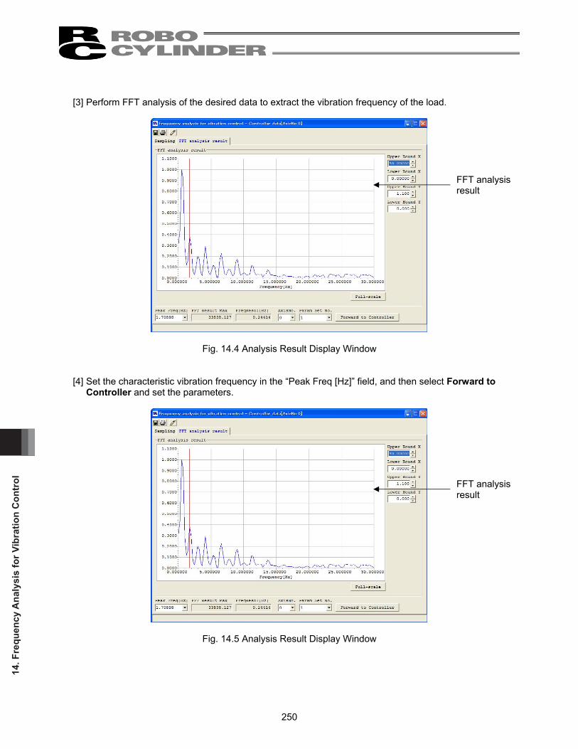
14. F
requ
ency
Ana
lysi
s fo
r Vib
ratio
n C
ontr
ol
250
[3] Perform FFT analysis of the desired data to extract the vibration frequency of the load.
Fig. 14.4 Analysis Result Display Window
[4] Set the characteristic vibration frequency in the “Peak Freq [Hz]” field, and then select Forward to
Controller and set the parameters.
Fig. 14.5 Analysis Result Display Window
FFT analysis result
FFT analysis result

14. Frequency Analysis for Vibration C
ontrol
251
14.2 Explanation of Each Window 14.2.1 Measurement Data Selection Window This window is used to select measurement data. Click the Parameter (P) menu, point to Controller Parameter Setup (C), and then select Frequency Analysis for Vibration Control (F), and the measurement data selection window will appear. (Note) [1] Import new controller data cannot be selected in SCON-CAL/CGAL.
Fig. 14.6 Measurement Data Selection (“Import New Controller Data” Selected)
[1] Import new controller data Select this option if you want to move the connected actuator and import (sample) measurement data to extract and set the vibration frequency of the load. The frequency analysis for vibration control window (Fig. 14.10) appears where you can perform FFT analysis of the imported measurement data (sampled data). Select the axis number under which to set the vibration frequency of the load.
Fig. 14.7 Measurement Data Selection
[1] Import new controller data
[2] Read external measurement data file
[3] Read analytical already data file
[1] Select the axis number under which to import controller data.

14. F
requ
ency
Ana
lysi
s fo
r Vib
ratio
n C
ontr
ol
252
[2] Read external measurement data file Select this option if you want to read an external measurement data file containing data measured with a measuring equipment, etc., to perform FFT analysis and extract the vibration frequency of the load. You can select a desired existing analysis file by clicking the file browse button. Or, enter the file name directly in the file path display/file history field. When the file has been selected, click OK. The frequency analysis for vibration control window (Fig. 14.10) appears where you can perform FFT analysis. Any external measurement data file having the extension “csv” or “txt” can be read. This option is selectable regardless of whether the controller is online or offline or regardless of the model of the connected actuator. Clicking Cancel closes the measurement data selection window.
Fig. 14.8 Measurement Data Selection (“Read External Measurement Data File” Selected)
[1] Select a file in the file path display/file history field.
[2] File browse button

14. Frequency Analysis for Vibration C
ontrol
253
[3] Read analytical already data file Select this option if you want to read an existing analytical data file. You can select a desired existing analytical data file by clicking the file browse button. Or, enter the file name directly in the file path display/file history field. Click OK. If the extension of the file you have read is “fmdrc,” the frequency analysis for vibration control window (Fig. 13.10) appears where you can perform FFT analysis. If the file extension is “fds,” the “analysis result display” window (Fig. 14.10) appears where you can display the analysis result saved in the file. This option is selectable regardless of whether the controller is online or offline or regardless of the model of the connected actuator. Clicking Cancel closes the measurement data selection window.
Fig. 14.9 Measurement Data Selection (“Read Analytical Already Data File” Selected)
[1] Select a file in the file path display/file history field.
[2] File browse button

14. F
requ
ency
Ana
lysi
s fo
r Vib
ratio
n C
ontr
ol
254
14.2.2 Sampling Window This window is used to import vibration data from the controller by moving the actuator. (SCON-CAL/CGAL cannot import the vibration data by operating an actuator.) You can also perform various operations in this window, such as setting the range of data used in FFT analysis after vibration data has been imported from the controller or external measurement data or existing analysis data (extension “fmd”) has been read. When you select the “Import new controller data,” “Read external measurement data file” or “Read analytical already data file (extension “fmd”)” option in the measurement data selection window, the display switches to this window.
Fig. 14.10 Sampling Window
[1] Tool buttons [2] Sampling/FFT analysis result window switching [5] Measurement data
[6] Data to be analyzed [4] Sampling setting [7] Execute FFT analysis
[3] FFT analysis setting

14. Frequency Analysis for Vibration C
ontrol
255
[1] Tool buttons
Fig. 14.11 Tool Buttons
Save As Clicking this button opens the pop-up menu where you can select the type of data to be saved to a file. Select the applicable data type in this menu and save the selected data to a file under a desired name.
Fig. 14.12 File Save Data Type Selection Pop-up Menu
Only data of the supported data types can be saved. For example, assume that measurement data is displayed but FFT analysis result is not yet displayed. In this case, the following conditions apply:
• Save measurement data: Selectable • Save FFT result data: Not selectable
Fig. 14.13 File Save Data Type Selection (Only “Save Measurement Data” Selectable)
Print Clicking this button opens the “print setting” window where you can select desired print settings. [For the print setting, refer to 14.2.4, “Print Setting Window.]
Edit Position Data Clicking this button launches the position data edit window (online edit window) where you can edit position data. This button is selectable only when “Import new controller data” was selected in the “measurement data selection” window.

14. F
requ
ency
Ana
lysi
s fo
r Vib
ratio
n C
ontr
ol
256
[2] Sampling/FFT analysis result window switching tabs
Fig. 14.14 Sampling/FFT Analysis Result Window Switching Tabs
You can click a desired tab to switch between the sampling window and FFT analysis result window. [For the FFT analysis result window, refer to 14.2.3, “Analysis Result Display Window.”] The selectable tab is shown with black text, while the text on the unavailable tab is grayed out. The currently selected tab is indicated by blue text. [3] FFT setting
Fig. 14.15 Axis-specific Setting Items
Analysis start time [sec]
Data used
Number of thinning
Window function selection
Sight application of window function
Analysis time [sec]
Frequency resolution [Hz]

14. Frequency Analysis for Vibration C
ontrol
257
Analysis Start Time [sec] Specify the start position of the range of measurement data to be used for FFT analysis, in units of [sec]. Enter a value directly in the input field or click the buttons on the right side of the input field to change the current setting, to set the analysis start time. You can also set a desired analysis time by dragging the mouse while holding down the right button over the measurement data graph to move the two red vertical lines displayed on the graph. Note, however, that the end of the data to be analyzed cannot exceed the end of the measurement data. Any change to the set analysis start time will not be reflected in the FFT analysis result unless FFT analysis is performed again. If the data has been read from an existing analytical data file (file extension: fmd), the new setting will be saved when the file is saved.
Fig. 14.16 Changing Analysis Start Time on Measurement Data Graph
Num of Use Data Set the total number of data to be analyzed. Clicking the button on the right displays a list, where you can select a desired number. The following values can be set, but the set value cannot exceed the total number of data to be analyzed:
• 128 • 256 • 512 • 1024 • 2048 • 4096 • 8192 • 16384
Any change to the set number of use data will not be reflected in the FFT analysis result unless FFT analysis is performed again. If the data has been read from an existing analytical data file (file extension: fmd/fsd), the new setting will be saved when the file is saved. The default value of 4096 is set immediately after the PC software has been installed.
Analysis start time
Analysis time

14. F
requ
ency
Ana
lysi
s fo
r Vib
ratio
n C
ontr
ol
258
Num of Thinning Set how many data will be skipped before the next analysis data is adopted when the data to be analyzed is generated from the measurement data. Enter a value directly in the input field or click the buttons on the right side of the input field to change the current setting. Any value between 0 and 31 can be set, but the number of measurement data cannot exceed the total number of data to be analyzed that has been generated through thinning. The following is the example of how data to be analyzed is generated when the number of thinning is set.
[Example] How data to be analyzed is generated when the number of thinning is set to “2” • The number in each cell represents a measurement data number, where measurement data are
arranged in the order of 0, 1, 2, 3... • Generation of data to be analyzed starts from measurement data 0.
Measurement data 0 1 2 3 4 5 6 7 8 9 10 …
0 3 6 9 12 … Data to be analyzed
Fig. 14.17 Relationship of Measurement Data and Data to Be Analyzed
In the above example, the number of thinning is set to “2,” meaning that every third measurement data is adopted for analysis. (Note) Any change to the set number of thinning will be reflected only when FFT analysis is performed.
Unless FFT analysis performed, the change will not be reflected in the FFT analysis result. (Note) If the data has been read from an existing analytical data file (file extension: fmd), the new setting
will be saved when the file is saved. (Note) The default value of 0 is set immediately after the PC software has been installed.
Hereafter data will be adopted in the same manner until the number of use data is reached.

14. Frequency Analysis for Vibration C
ontrol
259
AnalyzTime [sec] The range of data to be analyzed you have just set is indicated in [sec]. The analysis time is calculated from the number of use data and number of thinning. If the data has been read from an existing analytical data file (file extension: fsd), the new setting will be saved when the file is saved. In the measurement data, the range of data to be analyzed, which is determined from the analysis start time [sec], number of use data and number of thinning, is indicated by two red vertical lines on the measurement data graph (the two vertical lines indicated by the arrows in the figure below).
Fig. 14.18 Indication of Range of Data to Be Analyzed on Measurement Data Graph
The data in the set range is shown under “Analytical object data” at the bottom of the window.
Fig. 14.19 Frequency Analysis for Vibration Control Window
Analysis start time
Imported vibration data
Data used for FFT analysis
Analysis time

14. F
requ
ency
Ana
lysi
s fo
r Vib
ratio
n C
ontr
ol
260
FreqResol [Hz] The effective frequency resolution of FFT analysis is indicated. This value indicates the resolution of FFT analysis result. FFT analysis result data are integer multiples of the frequency resolution. Window Func Select the window function to be applied to the data to be analyzed in FFT analysis. One of the following four window functions can be selected:
• Rectangle • Hanning • Humming • Blackman
General shapes of window functions are shown below for your reference.
Fig. 14.20 Rectangle Fig. 14.21 Hanning
Fig. 14.22 Humming Fig. 14.23 Blackman
Any change to the set window function will not be reflected in the FFT analysis result unless FFT analysis performed again. If the data has been read from an existing analytical data file (file extension: fmd), the new setting will be saved when the file is saved. The default value of “Hanning” is set immediately after the PC software has been installed. Sight Application Func When this check box is selected, the window function is applied to the data to be analyzed and function-applied data is displayed. If the check box is cleared, the data to be analyzed to which window function is not yet applied is displayed. Regardless of this setting, FFT analysis is performed on the data to which the window function has been applied. The “Sight application function” box is cleared by default immediately after the PC software has been installed. The “Sight application function” of number of use data, number of thinning, window function selection and window function saves the measurement axis settings which become the default value at the start next time onward. Note however that if an existing analytical data file (file extension: fmd) is read, the number sent to the file is set.

14. Frequency Analysis for Vibration C
ontrol
261
[4] Sampling setting
Fig. 14.24 All-axis Setting Items
These settings are available only when “Import new controller data” has been selected.
Select data type When you move the actuator to import data, the type of data corresponding to the selected check box is imported. Two data types of torque current response and velocity command response can be selected. Multiple data types can be selected. Normally torque current response data is used to extract characteristic vibration frequencies. This item can be set only when the actuator is moved to import data after selecting “Import new controller data.” Link start drive When you move the actuator to import data, driving of the actuator will start simultaneously as sampling is started if this check box is selected. Position number selection If sampling is to be performed with the “Link start drive” check box selected, select the position numbers of two points between which the actuator will move back and forth. (Note) These boxes can be set only when “Import new controller data” has been selected. (Note) These boxes can be set only when the “Link start drive” check box is selected. (Note) Position data must be already set under the position numbers selected here. If any position number
is selected under which no position data is set, sampling will be cancelled.
Data type selection
Linked driving start
Position number selection
Wait time setting
Start/Stop buttons
14. F
requ
ency
Ana
lysi
s fo
r Vib
ratio
n C
ontr
ol
262
Wait time [sec] If sampling is to be performed with the “Link start drive” check box selected, set how long the actuator will wait after moving to the target position, before starting the next movement. (Note) This box can be set only when “Import new controller data” has been selected. (Note) This box can be set only when the “Link start drive” check box is selected. (Note) An error of approx.0.0 to 0.1 [sec] may generate between the set wait time [sec] and wait time during
actual operation.
If the wait time is set to a value other than “0.0” and sampling is performed, the actuator will wait for the specified time and then start moving to the next target position, unless the actuator operation is stopped. Accordingly, although the actuator may appear stopped because the set time has not elapsed, it is actually active and may start moving suddenly. Exercise caution.
Start/Stop buttons When importing new controller data, use these buttons to start and stop sampling. Clicking the Start button starts sampling, while clicking the Stop buttons stops sampling. These buttons are available only when the actuator is moved to import data. Execute FFT button Clicking this button starts FFT analysis based on the settings you have made in the FFT setting area. If the actuator is moved to import data, FFT analysis cannot be performed unless sampling is performed.
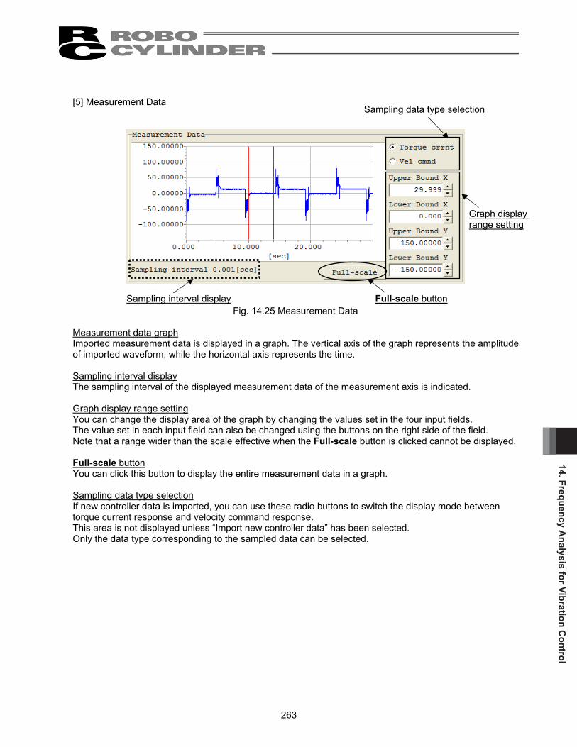
14. Frequency Analysis for Vibration C
ontrol
263
[5] Measurement Data
Fig. 14.25 Measurement Data
Measurement data graph Imported measurement data is displayed in a graph. The vertical axis of the graph represents the amplitude of imported waveform, while the horizontal axis represents the time. Sampling interval display The sampling interval of the displayed measurement data of the measurement axis is indicated. Graph display range setting You can change the display area of the graph by changing the values set in the four input fields. The value set in each input field can also be changed using the buttons on the right side of the field. Note that a range wider than the scale effective when the Full-scale button is clicked cannot be displayed. Full-scale button You can click this button to display the entire measurement data in a graph. Sampling data type selection If new controller data is imported, you can use these radio buttons to switch the display mode between torque current response and velocity command response. This area is not displayed unless “Import new controller data” has been selected. Only the data type corresponding to the sampled data can be selected.
Sampling data type selection
Graph display range setting
Full-scale button Sampling interval display

14. F
requ
ency
Ana
lysi
s fo
r Vib
ratio
n C
ontr
ol
264
[6] Analytical object data
Fig. 14.26 Analytical Object Data
Analytical object data graph The current analytical object data is displayed in a graph. The vertical axis of the graph represents the amplitude of waveform, while the horizontal axis represents the time. Graph display range setting You can change the display area of the graph by changing the values set in the four input fields. The value set in each input field can also be changed using the buttons on the right side of the field. Along the horizontal axis, a range wider than the scale effective when the Full-scale button is clicked cannot be displayed. Full-scale button You can click this button to display the entire analytical object data in a graph. Offset Use this field to move the center of amplitude of analytical object data. The settable range is from -MAX to MAX, where “MAX” indicates the maximum absolute value of measurement data. If the analysis start time, number of use data or number of thinning is changed, an appropriate offset will be calculated and set automatically. If the data has been read from an existing analytical data file (file extension: fmd), the new setting will be saved when the file is saved.
[7] Execute FFT button Click this button, and FFT analysis will be performed based on the settings you have made, for the axis set as the analysis target.
Analytical object data graph
Graph display range setting
Full-scale button
Offset

14. Frequency Analysis for Vibration C
ontrol
265
14.2.3 Analysis Result Display Window Setting items common to all axes on the frequency analysis for vibration control window Clicking the Execute FFT button performs FFT analysis and the display switches to this window.
Fig. 14.27 FFT Analysis Result Win
[1] FFT analysis setting data
[3] Maximum value of FFT [5] Axis number selection [7] Forward to Controller button
[2] Peak frequency setting [4] Frequency resolution [6] Parameter set number selection

14. F
requ
ency
Ana
lysi
s fo
r Vib
ratio
n C
ontr
ol
266
[1] FFT analysis result data
Fig. 14.28 FFT Analysis Result Data Graph
FFT analysis result data graph FFT analysis result of the measured axis is displayed in a graph. FFT analysis result data is displayed in a normalized pattern based on the maximum value of data being 1. Graph display range setting You can change the display area of the graph by changing the values set in the four input fields. The value set in each input field can also be changed using the buttons on the right side of the field. Note that a range wider than the scale effective when the Full-scale button is clicked cannot be displayed. Full-scale button Clicking this button lets you display in a graph all FFT analysis result data in the range from 0 to the maximum frequency [Hz] that permits forwarding of data to the controller.
Graph display range setting
Full-scale buttonFFT analysis result data graph

14. Frequency Analysis for Vibration C
ontrol
267
[2] Peak frequency setting
Here, set the frequency you want to set in the applicable controller parameter. Any value between 0.5 and 30 [Hz] can be set. Enter a value directly in the input field, or click the [] button on the right side of the input field, if candidate peak frequencies have been set, to select a desired setting from the displayed list. The set frequency is indicated by a red vertical line on the FFT analysis result data graph. (Note) Up to five candidate peak frequencies are identified based on the FFT analysis result and shown.
Depending on the FFT analysis result, no candidate may be found, in which case the peak frequency may vary from the actual vibration frequency.
(Note) If the data has been read from an existing analytical data file (file extension: fsdrc), the new setting will be saved when the file is saved.
(Note) When the “FFT analysis result” window appears after the FFT analysis, the first candidate peak frequency is set by default. If the data has been read from an existing analytical data file (file extension: fsdrc), the value saved in the file is set.
Fig. 14.29 Candidate Peak Frequency List
Fig. 14.30 Indication of Set Value on Graph
[3] Maximum value of FFT The maximum value of FFT analysis result data before normalization is shown. (Note) If the data has been read from an existing analytical data file (file extension: fsdrc), the new
setting will be saved when the file is saved. (Note) This value is determined by the FFT analysis result and will not change even when settings are
changed on the “FFT analysis result” window.

14. F
requ
ency
Ana
lysi
s fo
r Vib
ratio
n C
ontr
ol
268
[4] Frequency resolution
The frequency resolution of FFT analysis result is shown. The distance between adjacent plotting points on the FFT analysis result data graph is indicated visually in [Hz]. (Note) This value is determined by the analysis time, which in turn is determined in the “sampling”
window, and will not change even when settings are changed on the “FFT analysis result” window.
[5] Axis number selection
Set the axis number to forward the parameters to. When new controller data is imported, the axis number selected in the “measurement data selection” window is set. Otherwise, you can select any axis number to which data can be forwarded.
[6] Parameter set number selection
Select one of parameter sets 1 to 3 containing the parameter in which the set frequency will be set. [7] Forward to Controller button
Clicking this button forwards the parameters to the controller. (Note) If one of the following conditions applies, the parameters cannot be forwarded to the controller:
• The connected controller does not support the vibration control function. • The system is offline.

14. Frequency Analysis for Vibration C
ontrol
269
14.2.4 Print Setting Window Clicking the Print button in the measurement data display/analysis details setting window switches the display to this window. Set the print options.
Fig. 14.31 Print Setting (for Both Data Types)
[1] Print setting for measurement data [3] Print setting for FFT result data
[2] Print setting for analysis data [4] Print/Close buttons

14. F
requ
ency
Ana
lysi
s fo
r Vib
ratio
n C
ontr
ol
270
Print setting can be performed only for printable data types as of the time the print setting window opens. Display examples of windows where only print setting for measurement data is possible, and print setting for FFT result data is possible, are shown below.
Fig. 14.32 Print Setting (for Measurement Data Only) Fig. 14.33 Print Setting (for FTT Result Data Only)
[1] Print setting for measurement data
Fig. 14.34 Print Setting for Measurement Data
Print type selection Only the type of printing corresponding to the selected check box is performed. Details of each setting are explained below. (Note) If no check box is selected, data cannot be printed.
Print type selection
Setting for print list range

14. Frequency Analysis for Vibration C
ontrol
271
• Print list: Measurement data included in the range specified in the “Setting for print list range” area is printed in the format shown below.
Fig. 14.35 Printing Format of Measurement Data List
• Print Graph The measurement data graph currently displayed in the “sampling” window is printed in the format shown below.
Fig. 14.36 Printing Format of Measurement Data Graph

14. F
requ
ency
Ana
lysi
s fo
r Vib
ratio
n C
ontr
ol
272
Setting for print list range Set the range of data rows you want to print by entering values in the “Print start time [sec]” and “Print end time [sec]” input fields. Only the measurement data rows included in the range set here will be printed. The setting unit of fields in the “Setting for print list range” area is [sec]. [2] Print setting for analysis data
Fig. 14.37 Print Setting for Analysis Data
In this area, print setting for analysis data is performed. Since the function of each setting item is the same as in [1], “Print setting for measurement data,” only the printing format of analysis data is shown in the figure below.
• Print list:
Analysis data included in the range specified in the “Setting for print list range” area is printed in the format specified below.
Fig. 14.38 Printing Format of Analysis Data List
Print type selection
Setting for print list range

14. Frequency Analysis for Vibration C
ontrol
273
• Print data graph The analysis data graph currently displayed in the “sampling” window is printed in the format specified below.
Fig. 14.39 Printing Format of Analysis Data Graph
(Note) Different options can be selected in the “Print setting for measurement data” area and “Print setting for analysis data” area, respectively.
[3] Print setting for FFT result data
Fig. 14.40 Print Setting for FFT Analysis Result Data
In this area, print setting for FFT analysis result data is performed. The printing format of FFT analysis result data is shown in the figure on the next page. The function of each setting item is the same as in [1], “Print setting for measurement data” and [2], “Print setting for analysis data.” The setting unit of fields in the “Setting for print list range” area is [Hz].
Print type selection
Setting for print list range

14. F
requ
ency
Ana
lysi
s fo
r Vib
ratio
n C
ontr
ol
274
Fig. 14.41 Printing Format of FFT Result Data List
Fig. 14.42 Printing Format of FFT Result Data Graph
[4] Print/Close buttons Clicking either button closes the print setting window. If the Print button is clicked, data is printed based on the print setting options effective when the button is clicked. If the Close button is clicked, data is not printed.

14. Frequency Analysis for Vibration C
ontrol
275
14.3 Operating Procedure Perform operations according to the procedure specified below. (1) Select measurement data.
[1] Click the Parameter (P) menu, point to Control Parameter Setup (C), and then select Frequency
Analysis for Vibration Control (F). [2] When the “measurement data selection” window appears, select the type of measurement data to be
imported in the “measurement data display/analysis details setting/analysis result display” window under the frequency analysis for vibration control function. (Note) [1] Import new controller data cannot be selected in SCON-CAL/CGAL.
Import measurement data externally taken by a measurement device by indicating [2] Read external measurement data file. Have this data analyzed on FFT and set the vibration control parameters.
Fig. 14.43 Measurement Data Selection (“Import New Controller Data” Selected)
[3] If “Import new controller data” has been selected, select the axis number under which to set the load vibration frequency, and then click the OK button. If any other option has been selected, select the file to be read and click the OK button, and the “frequency analysis for vibration control” window will appear. If the Cancel button is clicked, the “frequency analysis for vibration control” window does not appear and the “measurement data selection” window closes. (Note) If “Read external measurement data file” or “Read analytical already data file” has been selected,
measurement data cannot be imported from the controller. If you want to import measurement data from the controller, select “Import new controller data.”
In the “sampling” window or “FFT analysis result” window opened by the aforementioned step, save the data type currently selected. This way, the saved data type will be automatically selected the next time the “measurement data selection” window opens. If “Import new controller data” is selected for the data type currently saved, but the PC software connection status does not permit selection of “Import new controller data,” “Read external measurement data file” will be selected. (Note) The default value of “Import new controller data” is selected immediately after the PC software
has been installed.
[1] Import new controller data
[2] Read external measurement data file
[3] Read analytical already data file

14. F
requ
ency
Ana
lysi
s fo
r Vib
ratio
n C
ontr
ol
276
(2) If “Import new controller data” has been selected, move the actuator to import analysis data. [1] The “sampling” window (new controller data) appears.
Fig. 14.44 Sampling Window
[2] Under “Select data type” on the “Sampling” tab, select the data type you want to import during sampling. Multiple data types can be selected.
[3] To start actuator operation simultaneously as sampling is started, select the “Link start drive” check box
on the “Sampling” tab and set the position numbers of two points between which the actuator will move back and forth in the “Start No” and “End No” fields.
[4] Set the wait time in the “Wait time” field.
(Note) Steps [2] to [4] can be performed in any order.
[1] Tool buttons [2] Sampling/FFT analysis result window switching [5] Measurement data
[6] Data to be analyzed [4] Sampling setting [3] FFT analysis setting

14. Frequency Analysis for Vibration C
ontrol
277
[5] Clicking the Start button in the bottom left-hand corner of the window starts sampling. While sampling is in progress, the display of the “sampling” window changes as shown below and the measurement data graph gets updated continuously.
Fig. 14.45 Sampling Window (Sampling in Progress)
[6] When the maximum number of importable data have been sampled, sampling stops automatically. To stop sampling at any point, click the Stop button.

14. F
requ
ency
Ana
lysi
s fo
r Vib
ratio
n C
ontr
ol
278
(3) Perform FFT analysis. Perform steps [1] to [6] in the sampling window. (Steps [1] to [4] can be performed in any order.)
[1] Set the analysis start time in the “FFT setting” area. [2] Set the number of use data in the “FFT setting” area. [3] Set the number of thinning in the “FFT setting” area. [4] Set the window function in the “FFT setting” area. [5] When all items in the “FFT setting” area have been set, click the Execute FFT button, and FFT analysis
will be performed. The FFT result is displayed.
Fig. 14.46 FFT Analysis Result Win
[1] FFT analysis result data
[3] Maximum value of FFT [5] Axis number selection [7] Forward to Controller button
[2] Peak frequency setting [4] Frequency resolution [6] Parameter set number selection

14. Frequency Analysis for Vibration C
ontrol
279
(4) From the FFT result, select the setting of characteristic vibration frequency to be forwarded to the controller as a parameter set value, and forward to the controller.
[1] Set the value you want to forward to the controller, in the “Peak Freq” field. Set the axis number and
parameter set number.
Fig. 14.47 FFT Analysis Result Window
[2] Click the Forward to Controller button. [3] When the data has been forwarded to the controller, a confirmation message appears, asking if you
want to restart the controller. Click the Yes (Y) button to restart the controller. (Note) The values forwarded to the controller will not be reflected in the vibration control function unless
the controller is restarted.
“Peak Freq” field

15. P
ress
Pro
gram
Edi
ting
and
Ope
ratio
n of
Ser
vo P
ress
(V
10.0
0.00
.00
or la
ter f
or S
CO
N-C
B)
280
15. Press Program Editing and Operation of Servo Press (V10.00.00.00 or later for SCON-CB)
15.1 Operation Outline Conduct the following steps to edit press program in the servo press. [1] Select the press program number to show press program editing window. Press program editing window
can be selected from either of show detail window or simple display window which enables minimum necessary settings. [Refer to 15.2.1 Press Program Editing Window] Also, it is available to edit all press program at the same time in multi press program editing window *1.
*1 It is what the individual press programs (Press program No. 0 to 63) are all shown in table form at once.
[2] Select from eight patterns of press motion modes in press program editing window. [Refer to 15.2.1 Press Program Editing Window [1] (2) Press program Input for how to set up] [Refer to SCON-CB controller instruction manual for each press motion mode] [Press Motion Mode] 1 : Speed control - Keeping Position 2 : Speed control - Keeping Distance 3 : Speed control - Holding Load 4 : Speed control - Holding Incremental Load 5 : Force control - Keeping Position 6 : Force control - Keeping Distance 7 : Force control - Holding Load 8 : Force control - Holding Incremental Load 9 : Force control - Keeping Position 2
[3] Select the items correspond to the press motion mode set in press program editing window.
[Refer to 15.2.1 Press Program Edit Window for how to set up] [Refer to SCON-CB Controller Instruction Manual for Speed control, Force control, Keeping position, Keeping Distance, Holding Load and Holding Incremental Load] * The position can be read in by aligning the position of the rod in Trial Operation Window in the press
program operation / monitor and returning to Press Program Editing Window. Right-click on the item to set the point for the end position (mm) of Approach Motion to read it in. [Refer to 15.2.3 Press Program Operation / Monitor Window [2] Operation]
* By setting Continuous Prg. No. in press program editing window, continuous operation such as the two-step pressing can be conducted. [Refer to 15.2.1 Press Program Editing Window]

15. Press Program Editing and O
peration of Servo Press (V10.00.00.00 or later for SC
ON
-CB
)
281
[4] Check the operation by setting Start Prg. No. operated in press program operation window in the press
program operation / monitor to move. [Refer to 15.2.3 Press Program Operation / Monitor Window [2] Operation] * Adjust the force gain in Gain Set No. by considering the hardness of an object to be pressed.
[Refer to SCON-CB controller instruction manual for the force gain] [Refer to 8. Editing Parameters for how to set up parameters]
* Items such as Current Load Feedback (N) and Overload Level (%) can be checked in the axis status. [Refer to 15.2.3 Press Program Operation / Monitor Window [3] Axis Status]
* Check current value and others in the servo monitor if necessary. [Refer to 15.2.3 Press Program Operation / Monitor Window [4] Monitor]
Settings in the PC software is complete. Have a trial operation with commands from the host controller such as PLC.

15. P
ress
Pro
gram
Edi
ting
and
Ope
ratio
n of
Ser
vo P
ress
(V
10.0
0.00
.00
or la
ter f
or S
CO
N-C
B)
282
15.2 Outline of Operation in Each Window
15.2.1 Press Program Editing Window It is a window to set and edit the servo press operation. [1] Either select Press Program (R) → Edit (E) from the menu in main window or click on button on the
toolbar in main window to show a window to select either of press program editing window or the multi press program editing window. It can also be started from the tree view.
Fig. 15.1 Select Press Program Window
[2] Choose select press program, and select a press program number (0 to 63).
Click OK. Simple display window in pres program editing window appears. (Note) Setting in application setting window can make show detail window show up from the beginning.
[Refer to sections related to the servo press in 15.3 Servo Press Related in Application Setting Window]
Fig. 15.2 Simple Display Window in Press Program Editing Window

15. Press Program Editing and O
peration of Servo Press (V10.00.00.00 or later for SC
ON
-CB
)
283
[3] Click on button to set or edit the press program in show details window.
Show details window appears.
Fig. 15.3 Show Details Window in Press Program Editing Window

15. P
ress
Pro
gram
Edi
ting
and
Ope
ratio
n of
Ser
vo P
ress
(V
10.0
0.00
.00
or la
ter f
or S
CO
N-C
B)
284
[1] Show Details Window in Press Program Editing Window
It is a window that enables detailed setting and editing of the servo press operation.
Fig. 15.4 Show Details Window in Press Program Editing Window
(1) Toolbar
Fig. 15.5 Toolbar in Press Program Editing Window
[1] Save : It saves data to a file. [2] Transfer : It transfers (writes) the data to a controller. [3] Update : It updates the data display after reading out a press program from a
controller again. [4] Printout : It makes an output of a press program to a printer. [5] Display switchover : It switches over the display of the editing window between Simple
Display and show details. [6] Prg comment : It shows the editing window for Prg comment.
Input a comment and click OK, and a comment shows up in “ ” in the comment display area.
Fig. 15.6 Prg Comment Input Window
[1] [2] [3] [4] [5] [6] [7]
(1) Toolbar (2) Press Program Input Part
(3) Statusbar
Comment Display Area

15. Press Program Editing and O
peration of Servo Press (V10.00.00.00 or later for SC
ON
-CB
)
285
[7] Continuous consolidated list : The continuous consolidated list for the press programs is displayed. Select a press program number in searching program files, put a check mark by clicking on □ in Show, and only those related to the selected press program numbers are shown.
[Explanation of Displayed Contents] P ** : Program No. (T *** *.) : Prg No of standby time
( The time set in Wait Time in the press program input part) R -> P ** : Return Prg No.
For example, as Start Point Prg. No. 2 in the figure does, if 2 is set in Consolidated Prg. No. at Last Point Prg. No. 4 so it returns to No. 2, R -> P02 will be displayed. As Start Point Prg. No. 0 does, if None is set in Consolidated Prg. No. at Later Prg. No. 1, because the press program does not return, R -> P*** will not be displayed.
Fig. 15.7 Continuous Consolidated List Display

15. P
ress
Pro
gram
Edi
ting
and
Ope
ratio
n of
Ser
vo P
ress
(V
10.0
0.00
.00
or la
ter f
or S
CO
N-C
B)
286
(2) Press Program Input Part
[Refer to SCON-CB instruction manual for the contents of settings in each item of each press motion mode] * Right-click on a value of where the unit is [mm], such as distance upper limit [mm], read in Current
Position (T) button appears. Click on read in Current Position (T) button and current position can be read in. Axis movement by JOG / Inching can be conducted in Press Program Operation / Monitor Window. [Refer to 15.2.3 Press Program Operation / Monitor Window]
Fig. 15.8 Press Program Input Part in Press Program Editing Window
[1] Press motion mode : It switches over the press motion modes.
1 : Speed control - Keeping Position 2 : Speed control - Keeping Distance 3 : Speed control - Holding Load 4 : Speed control - Holding Incremental Load 5 : Force control - Keeping Position 6 : Force control - Keeping Distance 7 : Force control - Holding Load 8 : Force control - Holding Incremental Load 9 : Force control - Keeping Position 2
[7]
[1] [2]
[3] [4]
[8]
[5] [6]
[11] [12] [13]
[14] [18]
[19]
[17]
[15]
[16]
[9][10]

15. Press Program Editing and O
peration of Servo Press (V10.00.00.00 or later for SC
ON
-CB
)
287
* Speed control : It is a control to perform pressing with the pressing speed kept constant. Positioning should be performed to the set position. Therefore, the position after pressing completed is constant, but the pressing force may not be constant.
* Force control : It is a control to perform pressing with the pressing force kept constant to achieve the target load. Pressing operation should be continued at stop. The pressing force after pressing completed is constant, but the position may not be constant.
[Refer to SCON-CB instruction manual for the contents in each item of each press motion mode]
[2] Prg home position: Set the start position for a press program. [3] Position. decision type : Judgment can be made with the position (distance) and the
load during a stop after pressing stage completed. For the position (distance) judgment, select whether to have the
position judgment or distance judgment. [4] Position upper limit distance : Set the upper limit and lower limit for the judgment range for the [5] Position lower limit distance position (distance) judgment.
Setting Range : + soft limit ~ - soft limit [6] Load upper limit : Set the upper limit and lower limit for the judgment range for the [7] Load lower limit load judgment.
Setting Range : 0.01 ~ Maximum pressing force [8] Return movement of Press Prg alarm :
Select whether to return to the home position of the program and turn the servo OFF or stop at the position without returning to the home position and turn the servo OFF in case of press Prg. alarm being issued.
[9] Continuous Prg No. : Set the press program numbers to execute continuously. [Refer to SCON-CB controller instruction manual for how to consolidate the press programs]
[10] Gain Set No. : Indicate the gain set number to be used from the four types of servo-motor gain registered in advance. The gain set can be switched over for each press program.
[11] Wait time : Set the wait time after a press program is finished will executing another.
[12] Allowed Prg operating time : Set the execution time for the whole press programs. [13] Acceleration and deceleration : Set the acceleration and deceleration in actuator operation in a
press program if [14] Show acceleration and deceleration Individually is not pressed. All the operation in the press program is performed with the acceleration and deceleration set here.

15. P
ress
Pro
gram
Edi
ting
and
Ope
ratio
n of
Ser
vo P
ress
(V
10.0
0.00
.00
or la
ter f
or S
CO
N-C
B)
288
[14] Show Acceleration and deceleration individually : Press Show acceleration and deceleration individually, and the acceleration and deceleration settings in each operation in a press program can be established. [15] Approach motion : Approach motion can be set.
Approach motion is an operation to approach a work piece from the press program home position till a point before touching the work piece. Approach motion will not be performed if a check mark is removed. [Refer to SCON-CB controller instruction manual for how to set up Approach motion]
[16] Work search : Work search can be set. Work search is an operation to confirm the touch to a work piece in low speed. Search motion will not be performed if a check mark is removed. [Refer to SCON-CB controller instruction manual for how to set up Work Search
[17] Press motion : Press motion can be set. Press motion is an operation to perform pressing under the
specified conditions. There are some cases that the names for the setting items may differ depending on the press motion mode. [Refer to SCON-CB controller instruction manual for how to set up Press motion]
[18] Depression operation : Depression Operation can be set. Depression Operation is an operation to move away from a work piece in low speed. Depression operation will not be performed if a check mark is removed. [Refer to SCON-CB controller instruction manual for how to set up depression operation]
[19] Return movement : Return movement can be set. Return movement is an operation to move away from a work
piece in high speed and return to Prg. home position. Return movement will not be performed if a check mark is removed. [Refer to SCON-CB controller instruction manual for how to set up return movement]
(3) Statusbar
Fig. 15.9 Statusbar
[1] Modified or not : “Modified” is shown if any change has been made. “Not Modified” is shown if
no change has been made. [2] Input Range : The input range of an item that the cursor is placed on is displayed. [3] Initial Value : The initial value of an item that the cursor is placed on is displayed.
[1] [2] [3]

15. Press Program Editing and O
peration of Servo Press (V10.00.00.00 or later for SC
ON
-CB
)
289
15.2.2 Multi Press Program Editing Window It is a window to set and edit all the operations of the servo press in the individual press programs (No. 0 to 63) at once. It is displayed if All Press Programs is selected in the press program select.
Fig. 15.10 Multi Press program Editing Window

15. P
ress
Pro
gram
Edi
ting
and
Ope
ratio
n of
Ser
vo P
ress
(V
10.0
0.00
.00
or la
ter f
or S
CO
N-C
B)
290
15.2.3 Press Program Operation / Monitor Window Check of axis status (I/O, network setting, current position, current speed, press program status, etc.), teaching, trial operation, execution of servo monitor and display of results can be conducted. Either select Press Program (R) → Operation / Monitor (Z) from the menu in Main Window or click on button on the toolbar in Main Window, and Press Program Operation / Monitor Window appears. It can also be started from the tree view.
Fig. 15.11 Press Program Operation / Monitor Window
[5] I/O Monitor
[1] Toolbar [2] Operation
[3] Axis Status
[4] Monitor

15. Press Program Editing and O
peration of Servo Press (V10.00.00.00 or later for SC
ON
-CB
)
291
[1] Toolbar
Fig. 15.12 Toolbar in Press Program Operation / Monitor Window
[1] Edit Press program : Edit press program window gets shown in another window. [2] Network : Network status gets displayed. [3] I/O monitor : To show / hide input and output ports is switched over. [4] DO Output Test: DO output test window gets shown in another window.
[Refer to 9.1 Status Monitor Window for DO output test window] [5] Alarm : Alarm codes get displayed. “000” is shown when no alarm is
issued. [6] Emergency stop / Motor voltage drop :
It gets displayed at emergency stop or motor voltage drop. [7] MANU/AUTO : The status of the MANU (manual) / AUTO (auto) gets displayed. [8] Network (link) : The status of the network link gets displayed.
[1] [2] [3] [4] [6] [5] [7] [8]

15. P
ress
Pro
gram
Edi
ting
and
Ope
ratio
n of
Ser
vo P
ress
(V
10.0
0.00
.00
or la
ter f
or S
CO
N-C
B)
292
[2] Operation
There are two types, Prg. operation and Trial operation. Change the window on the tabs.
(1) Prg operation In Prg. operation, prepare for press program and execute it.
Fig. 15.13 Prg Operation Window
[1] Servo : Servo can be turned ON/OFF. [2] Home position : Home-return operation can be held. [3] Alarm : Alarm status can be released. Note that it can be released
only when the cause of the alarm is already solved. [4] Press Prg alarm : The press program alarm codes get displayed.
[Refer to SCON-CB controller instruction manual for the alarm codes]
[5] Press Prg alarm detail : Contents of the press program alarms get displayed. [6] Start Prg No.: The start press program is to be set up. [7] Prg Home position : It enables to move to Prg. Home Positon.
[8] Work search stop : Press this before pressing button to execute a program when it is required to finish the program at work search operation. Execute the program and it stops at work search stop.
[9] Programs execution : A program can be executed from the press program set in start program number. Once the program is finished in the normal condition, the result of position (distance) judgment and Load Judgment gets shown in [13] Judgment display. It will not be shown when judgment is invalid.
[10] Program stop : The press program being executed can be stopped. [11] Excutive Prg No. display : Prg. No. being executed gets displayed.
In the right column, the stage being executed, such as Approach, gets displayed.
[12] Press motion mode display : The press motion mode being executed, such as Speed Control – Keeping Position, gets displayed.
[1]
[2]
[3]
[6]
[5][4]
[7][8] [9] [10]
[11]
[12]
[13]

15. Press Program Editing and O
peration of Servo Press (V10.00.00.00 or later for SC
ON
-CB
)
293
[13] Judgment display : The result of Position (distance) judgment and Load
Judgment gets displayed. Also, from the result of position (distance) and load, the result of comprehensive judgment gets displayed. [Refer to SCON-CB Controller Instruction Manual for the judgment]

15. P
ress
Pro
gram
Edi
ting
and
Ope
ratio
n of
Ser
vo P
ress
(V
10.0
0.00
.00
or la
ter f
or S
CO
N-C
B)
294
(2) Trial Operation
In Trial operation, axis movement by JOG and Inching and direct position move by indicating a position can be conducted. The position that the movement was made to can be read in by pressing Edit Press Program Button and opening edit press program window in another window.
Fig. 15.14 Trial Operation Window
[1] Servo : Servo can be turned ON/OFF. [2] Home position : Home-return operation can be held. [3] Alarm : Alarm status can be released. Note that it can be released
only when the cause of the alarm is already solved. [4] Press Prg alarm : The press program alarm codes get displayed.
[Refer to SCON-CB controller instruction manual for the alarm codes]
[5] Press Prg alarm detail : Contents of the press program alarms get displayed. [6] JOG Key : Axis can be moved with JOG and Inching. [7] JOG Select : JOG operation can be held by selecting JOG.
JOG speed setting can be held. [8] Inching Select : Inching operation can be held by selecting Inching.
Setting of Inching distance can be conducted. [9] Direct position move execution :
With the speed set in [12] Speed, moves to the position set in [11] Position.
[10] Direct position move stop : An axis in move can be stopped. [11] Direct position move setting : The position for direct position move can be set. [12] Direct position move speed specified :
The speed for direct position move can be set.
[1]
[2]
[3]
[6]
[5][4]
[7]
[9] [10]
[8]
[11]
[12]

15. Press Program Editing and O
peration of Servo Press (V10.00.00.00 or later for SC
ON
-CB
)
295
[3] Axis Status
The current status of an axis gets displayed. The following items are shown.
• Current position [mm] • Current speed [mm/s] • Current load [N] (Note 1) • Calibration (Note 1) : Complete / Incomplete • Overload level [%] • Command current ratio [%] • Feedback current ratio [%] Note 1 When the load cell is inactivated, “inactive” is displayed.
Fig. 15.15 Axis Status Window

15. P
ress
Pro
gram
Edi
ting
and
Ope
ratio
n of
Ser
vo P
ress
(V
10.0
0.00
.00
or la
ter f
or S
CO
N-C
B)
296
[4] Monitor
The status of an axis gets shown in the monitoring display. The following four items can be monitored.
• Current position [mm] • Current load [N] • Feedback current ratio [%] (Note 1) • Current speed [mm/s] (Note 1) Note 1 It is available to change to another item.
Fig. 15.16 Monitor Window
[1] Save : Monitor Data can be saved. [2] Monitoring setting : Monitoring Setting Window gets displayed. [Refer to next page] [3] Detail monitor : Servo Monitor Result Displayed Window gets displayed. [Refer to [6]
Servo Monitor Result Window] [4] Trigger start : Monitoring starts with the set trigger.
Trigger setting can be held in Monitoring Setting Window. [Refer to next page]
[5] Start : Monitoring gets started. [6] Stop : Monitoring gets stopped. [7] Linked with Prg. : The start of monitoring and start of a program get linked with each
other. [8] Legend Display / Hide Select :
Click in □ to put a check mark, and a legend for [9] gets displayed. Click again to remove the check mark, and the legend for [9] gets hidden.
[9] Legend Display : The line colors and their titles in the graph get displayed. [10] Monitoring Window : Monitoring data gets updated and displayed.
The number of records available to monitor is 30000.
[1] [2] [3]
[4] [5] [6]
[7]
[10]
[8]
[9]

15. Press Program Editing and O
peration of Servo Press (V10.00.00.00 or later for SC
ON
-CB
)
297
(1) Monitoring setting
It gets displayed if Monitoring Setting Button in monitoring window is pressed. Setting for displayed items in each channel, sampling period setting and trigger setting to be held in monitoring can be conducted.
Fig. 15.17 Monitoring Setting Window
[1] Channel setting : Monitoring items can be set. CH1 and CH2 cannot be changed. [2] Sampling period setting : Sampling period setting in monitoring can be changed.
The settable value should be from 1msec to 1000msec. [3] Trigger setting : Conditions for trigger start can be set.
[Refer in the next page for how to set up]
[1] [3]
[2]

15. P
ress
Pro
gram
Edi
ting
and
Ope
ratio
n of
Ser
vo P
ress
(V
10.0
0.00
.00
or la
ter f
or S
CO
N-C
B)
298
[Trigger Setting]
Fig. 15.18 Monitoring Setting Window (Trigger Setting)
[1] Data types
The following data types can be selected. • PIO signal (input) allocation (bit) • PIO signal (output) allocation (bit) • Clock
[2] Trigger Type When PIO feature input assignment (bit) or PIO feature output assignment (bit) is selected, select either Rising edge (bit) or Falling edge (bit). It is not necessary to select any if Clock is selected.
[3] Assign Signals When PIO feature input assignment (bit) is selected, select from the PIO input port signals. When PIO feature output assignment (bit) is selected, select from the PIO output port signals. It is not necessary to select any if Clock is selected.
[4] Data When Clock is selected, the current time in the controller is shown first. With that time as the standard, set the time that trigger is required at.
For example, if you would like to trigger in one minute, forward the minute setting for one minute. [5] Trigger delay [sec]
In case that the data before having a trigger is required to be acquired, set the time [sec] in Trigger Delay [sec]. It enables to acquire the data before the time of trigger being conducted.
[1]
[2]
[3]
[5]
[4]

15. Press Program Editing and O
peration of Servo Press (V10.00.00.00 or later for SC
ON
-CB
)
299
[5] I/O Monitor
Status of input ports, output ports and special input ports get displayed.
Fig. 15.19 Ports Input and Output Window
[1] Input Ports : The status of being ON/OFF for the PIO input ports is displayed. [2] Output Ports : The status of being ON/OFF for the PIO output ports is displayed. [3] Special Input Ports : The status of being ON/OFF for the special input ports is displayed.
[1] [2] [3]

15. P
ress
Pro
gram
Edi
ting
and
Ope
ratio
n of
Ser
vo P
ress
(V
10.0
0.00
.00
or la
ter f
or S
CO
N-C
B)
300
[6] Servo Monitor Result Window
Click on Detail Monitor Button in Press Program Operation / Monitor Window, and the result of the executed monitoring can be confirmed in the dedicated result display window. Also, servo monitor files already saved can be confirmed.
Fig. 15.20 Servo Monitor Result Window
(1) Toolbar
Fig. 15.21 Toolbar
[1] Save Prg File : Data and settings are saved in a file if the displayed data is
not from a file. [2] Printout : It makes an output of a monitoring result to a printer. [3] Scale-up/down : Display can be scaled up and down in each vertical direction
and horizontal direction. [4] Horizontal Axis Switchover : The item to display on the horizontal axis can be selected
from Time and Position. If it is switched over to Position, variation of force in each position can be confirmed.
[1] [2] [3] [4]
(1) Toolbar (2) Channel Setting
(3) Sampling Period Setting
(4) Linked with program
(5) Trigger Setting

15. Press Program Editing and O
peration of Servo Press (V10.00.00.00 or later for SC
ON
-CB
)
301
(2) Channel setting
Monitored items can be displayed / hidden for each channel.
Fig. 15.22 Displayed Channel Setting
(3) Sampling period setting Sampling Period Setting gets displayed.
Fig. 15.23 Sampling period setting
(4) Linked with program
Status gets displayed if Monitoring Start and Program Start are linked with each other.
Fig. 15.24 Linked with Program
(5) Trigger setting Trigger Setting gets displayed in case of monitoring with Trigger Start.
Fig. 15.25 Linked with Program

15. P
ress
Pro
gram
Edi
ting
and
Ope
ratio
n of
Ser
vo P
ress
(V
10.0
0.00
.00
or la
ter f
or S
CO
N-C
B)
302
15.3 Servo Press Related in Application Setting Window Select [Setting] → [Application Setting] from the menu in main window.
Fig. 15.26 Application Setting
The initial display type of Program Editing Window can be selected from Simple Display and Show Details.

16. Appendix
303
16. Appendix 16.1 Parameter (Factory Default Setting) Initializing Method Note: Parameters (factory default setting) can be initialized only for PCON, ACON, SCON, ERC2, ERC3,
ROBONET, ASEP, PSEP, DSEP, MSEP, MSCON and MCON controller. Note: Note that parameters set by user are changed to the factory default parameters when parameters
(factory default setting) are initialized. (1) Right click a blank part of the toolbar (Appendix Fig. 16.1) while pressing the Ctrl key, then input password
window as shown in Fig. 16.2 is displayed.
Fig. 16.1 Menu Bar
Fig. 16.2 Input Password Window (2) Input the password (5119) on the displayed input password window, then the “Controller Initialization”
(factory default setting) menu is displayed (Fig. 16.3). (Note) The password inputted once is effective until the application ends.
Fig. 16.3 Menu Bar (Parameter Initialization (Factory Default Setting))
Right-click the blank part of the tool bar while pressing Ctrl.

16. A
ppen
dix
304
(3) When the menu “Controller Initialization” (factory default setting) displayed in (2) is selected, a dialog box
in appendix Fig. 16.4 is displayed. Click OK when one axis is connected. Set axis No. and click OK when multiple axes are connected.
Fig. 16.4 Initialization Dialog Box (4) Then, a warning dialog in Fig. 16.5 is displayed. If there is no problem, click Yes.
Fig. 16.5 Warning Windows
A warning dialog in Fig. 16.6 is further displayed when the servo is ON. If there is no problem, click Yes.
Fig. 16.6 Warning Window
Note: The encoder parameters cannot be initialized. For this reason, if any actuator different from the factory default setting is connected, an unexpected error may be detected.

16. Appendix
305
16.2 PC Software Error List These errors are specific to the PC software. For the controller errors, refer to the operation manual for each controller. Code Message Description 103 File write error This error indicates that writing of one of various data files (position data
files, parameter files, all data backup files, etc.) failed. The following causes are considered: The file to be written is read only. The current login account of the OS has no permission to modify the
file.
104 105
Entered value too small Entered value too large
The entered value is smaller than the setting range. The entered value is larger than the setting range. Refer to the actuator specification or parameter list and enter an appropriate value again.
108 Teaching prohibited before home return
This error indicates that an attempt was made to write the current position when home return was not yet complete. Perform home return first.
10B File open error (read) This error indicates that the specified file could not be opened. The following causes are considered: The specified file does not exist. The specified file is already opened in other application.
10C File open error (write) This error indicates that the destination file could not be opened. The following causes are considered: The specified file is already opened in other application.
10D File read error This error indicates that the file could not be read. The following cause is considered: There is no enough memory to read the file.
10E File type error This error indicates that an attempt was made to send parameter files or all data backup files to a model different from the one which is the source of the applicable files.
10F Incremental specification function not supported
This error indicates that an attempt was made to write position data containing data of incremental specification to a model not supporting the “incremental specification” function (move by relative position specification).
111 File data error This error indicates that reading of a file failed. The following cause is considered: The specified file contains invalid data.
119 Multiple axes detected This error indicates that “axis number assignment” was attempted when multiple axes were connected. Always assign an axis number when only one axis is connected.

16. A
ppen
dix
306
Code Message Description 11A No effective axis This error indicates that “axis number assignment” was attempted when no
axis was connected. Or, the axis number of controller may not have been recognized. Causes : [1] The controller is not operating properly.
[2] The signal wire (SGA/SGB), and only the signal wire, is broken in the supplied cable.
[3] If a SIO converter is used, the link cable is not connected although 24 V is supplied to the converter.
[4] If multiple controllers are linked, two ADRS switches are setting the same number by mistake.
Actions : [1] Check if the RDY lamp on the controller is lit. If not, the controller is faulty.
[2] If a spare connection cable is available, try swapping the cable to see if the problem is resolved.
[3] Eliminate duplicate ADRS switch settings. If the problem still persists, contact IAI.
122 Input data error This error indicates that inappropriate data was entered. Check the entered data.
123 Inconsistent data version This indicates that an attempt was made to send data which was saved on a controller of an incompatible version. Check the version of the source controller and that of the destination controller.
124 Data editing prohibited in non-MANU teaching mode
This error indicates that an attempt was made to write position data or parameters to the controller in the AUTO mode or any MANU monitor mode.The following causes are considered: The controller’s mode switch is set to “AUTO” (if the controller has a
mode switch). The PC software is in “MANU monitor mode 1” or MANU monitor mode
2.” 125 Axis operation prohibited in
non-MANU teaching mode This error indicates that an attempt was made to perform axis operation (jogging, home return of an operation-prohibited axis, continuous move, etc.) in the AUTO mode or any MANU monitor mode. The following causes are considered: The controller’s mode switch is set to “AUTO” (if the controller has a
mode switch). The PC software is in “MANU monitor mode 1” or “MANU monitor mode
2.” 20C Start signal ON This error indicates that the start signal (CSTR) was turned ON by the PLC
while the actuator was moving, and duplication of move commands occurred as a result.
20D STP signal OFF This error indicates that the pause signal (*STP) was turned OFF by the PLC while the actuator was moving, and the actuator became no longer movable as a result.
20E Soft limit exceeded This error indicates that a move command to outside the soft limit range was issued while the actuator was moving.
211 HOME signal ON This error indicates that the home return signal (HOME) was turned ON by the PLC while the actuator was moving, and duplication of move commands occurred as a result.

16. Appendix
307
Code Message Description 212 JOG signal ON This error indicates that the jog signal (JOG) was turned ON by the PLC
while the actuator was moving, and duplication of move commands occurred as a result.
300 COM port open error This error indicates that the COM port specified in the “application of setting window” could not be opened. The following causes are considered: The specified COM port does not exist. The specified COM port is already used in other application, etc.
301 Receive timeout error This error indicates that a receive timeout error occurred while the PC software was communicating with the connected controller. Causes : [1] Communication fault due to poor connection between the PC
and controller [2] Communication fault due to noise (data turning into garbage,
etc.) [3] The controller power was cut OFF.
Actions : [1] Check if the connectors on the PC-controller connection cable are firmly connected.
[2] Readjust the wiring, equipment installation, etc., to eliminate noise.
[3] Check if the controller power is supplied. If the problem still persists, contact IAI.
302 Receive buffer overflow This error indicates that the receive buffer overflowed when a response message was received from the controller. Causes : [1] Communication fault due to poor connection between the PC
and controller [2] Communication fault due to noise (data turning into garbage,
etc.) Actions : [1] Check if the connectors on the PC-controller connection cable
are firmly connected. [2] Readjust the wiring, equipment installation, etc., to eliminate
noise. If the problem still persists, contact IAI. 303 Receive overrun This error indicates that a receive overrun occurred at the COM port on the
PC when a response message was received from the controller. Select a lower baud rate in the “application of setting window.”
304 Receive framing error This error indicates that a receive framing error occurred when a response message was received from the controller. Causes : [1] Communication fault due to poor connection between the PC
and controller [2] Communication fault due to noise (garbled data, etc.)
Actions : [1] Check if the connectors on the PC-controller connection cable are firmly connected.
[2] Readjust the wiring, equipment installation, etc., to eliminate noise.
If the problem still persists, contact IAI.

16. A
ppen
dix
308
Code Message Description 305
Communication error A communication error not specified above occurred when a response
message was received from the controller. Causes : [1] Communication fault due to poor connection between the PC
and controller [2] Communication fault due to noise (garbled data, etc.)
Actions : [1] Check if the connectors on the PC-controller connection cable are firmly connected.
[2] Readjust the wiring, equipment installation, etc., to eliminate noise.
If the problem still persists, contact IAI. 306 Checksum error A checksum error occurred when a response message was received from
the controller. Causes : [1] Communication fault due to poor connection between the PC
and controller [2] Communication fault due to noise (garbled data, etc.)
Actions : [1] Check if the connectors on the PC-controller connection cable are firmly connected.
[2] Readjust the wiring, equipment installation, etc., to eliminate noise.
If the problem still persists, contact IAI. 307 CRC error A CRC error occurred when a response message was received from the
controller. Causes : [1] Communication fault due to poor connection between the PC
and controller [2] Communication fault due to noise (garbled data, etc.)
Actions : [1] Check if the connectors on the PC-controller connection cable are firmly connected.
[2] Readjust the wiring, equipment installation, etc., to eliminate noise.
If the problem still persists, contact IAI. 308 Receive message error This error indicates that the response message from the controller contains
abnormal data. Causes : [1] Communication fault due to poor connection between the PC
and controller [2] Communication fault due to noise (garbled data, etc.)
Actions : [1] Check if the connectors on the PC-controller connection cable are firmly connected.
[2] Readjust the wiring, equipment installation, etc., to eliminate noise.
If the problem still persists, contact IAI. 310 Connected model not
supported This error indicates that connection of a model not supported by the PC software was detected. Check the version of the PC software and models supported by the software.
311 Baud rate specification error (PC COM port)
This error indicates that the port could not be opened at the baud rate specified in the “application of setting window.” The following cause is considered: The specified baud rate is not supported by the COM port on the PC.
Change the baud rate to a supported setting.

17. File Extensions
309
17. File Extensions
List of File Extensions Model name Position data file Parameter file Backup file
RCP *.ptr *.pmr *.bkr RCS *.ptr *.prr *.bur
E-Con * pte *.pre *.bue RCP2 *.ptr2 *.pmr2 *.bkr2 ERC *.ptre *.pmre *.bkre
ERC2 *.ptre2 *.pmre2 *.bkre2 ERC3 *.ptre3 *.pmre3 *.bkre3
PCON, RPCON *.ptpc *.prpc *.bkpc PCON-CA *.ptpa *.prpa *.bkpa
ACON, RACON *.ptac *.prac *.bkac ACON-CA *.ptaa *.praa *.bkaa
ACON-CB/CGB *.ptab *.prab *.bkab ACON-CB
(MECHATROLINK-Ⅲ: with ML3 included in model code)
- *.prabm *.bkabm
ACON-CYB, PLB, POB *.ptacl *.pracl *.bkacl DCON-CA *.ptda *.prda *.bkda
DCON-CB/CGB *.ptdb *.prdb *.bkdb DCON-CB
(MECHATROLINK-Ⅲ: with ML3 included in model code)
- *.prdbm *.bkdbm
DCON-CYB, PLB, POB *.ptdcl *.prdcl *.bkdcl SCON-C *.ptsc *.prsc *.bksc
SCON-CA *.ptsa *.prsa *.bksa SCON-CA
(MECHATROLINK-Ⅲ: with ML3 included in model code)
- *.prsm *.bksm
SCON-CAL/CGAL *.ptscl *.prscl *.pkscl SCON-CB *.ptsb *.prsb *.bksb SCON-CB
(MECHATROLINK-Ⅲ: with ML3 included in model code)
- *.prsbm *.bksbm
ASEP *.ptas *.pras *.bkas PSEP *.ptps *.prps *.bkps DSEP *.ptds *.prds *.bkds

17. F
ile E
xten
sion
s
310
Model name Position data file Parameter file Backup file PCON-CB/CGB/CFB/CGFB *.ptpb *.ptpb *.ptpb PCON-CYB, PLB, POB *.ptpcl *.prpcl *.bkpcl
RCP6S *.ptp6 *.prp6 *.bkp6 RCM-P6PC *.ptp6pc *.prp6pc *.bkp6pc RCM-P6AC *.ptp6ac *.prp6ac *.bkp6ac RCM-P6DC *.ptp6dc *.prp6dc *.bkp6dc
MSEP (with D included in model code) *.ptmd *.prmd *.pkmd
MSEP (with T included in model code) *.ptmp2 *.prmp2 *.pkmp2
MSCON *.ptms *.prms *.bkms MCON
(Servo Motor) *.ptmac *.prmac *.bkmac
MCON (Pulse Motor) *.ptmpc *.prmpc *.bkmpc
MCON (Brushless DC Motor) *.ptmdc *.prmdc *.bkmdc
MCON (with T included in model code) *.ptmpc *.prmpc *.bkmpc
MCON (Servo Motor) (MECHATROLINK-Ⅲ:
with ML3 included in model code) (SSCNETⅢ/H :
with SSC included in model code) (EtherCat Motion :
with ECM included in model code)
- *.prmacm *.bkmacm
MCON (Pulse Motor) (MECHATROLINK-Ⅲ:
with ML3 included in model code) (SSCNETⅢ/H :
with SSC included in model code) (EtherCat Motion :
with ECM included in model code)
- *.prmpcm *.bkmpcm
MCON (Brushless DC Motor) (MECHATROLINK-Ⅲ:
with ML3 included in model code) (SSCNETⅢ/H :
with SSC included in model code) (EtherCat Motion :
with ECM included in model code)
- *.prmdcm *.bkmdcm
ELECYLINDER *.ptec *.prec *.bkec
Model name Position data file Parameter file Backup file SCON-CB
(Servo Motor) (with F included in model code)
*.prg *.prsbf *.bksbf

18. Change H
istory
311
18. Change History
Revision Date Description of Revision
December 2009
February 2010
August 2011
September 2011
September 2011
September 2011
October 2011
November 2011
January 2012
June 2012
August 2012
April 2013
July 2013
Added descriptions of ASEP/PSEP controller operations. Change the default system password from “5119” to “0000.” Sixth edition Change in software license agreement Seventh edition P39 Added the PCON-CA position window. P58 Added PCON-CA in (8), “Position data input area” P97 Added the PCON-CA alarm display window. P101 to 104 Added 8.4, “Servo Monitor Window.” P105 8.5, “Maintenance Information Window” P109, 110 Added 9.3, “Time Setting.” P112 to 158 Added 11, “Smart Tuning Function” P159 Added PCON-CA to 12, “File Extensions.” Eighth edition P111 to 156 Contents changed in 11, Smart Tuning Function Ninth edition The contents of ERC3 are added Tenth edition DSEP added Eleventh edition The contents of SCON-CA are added Twelfth edition • Caution, Operational Environment and Applicable for Windows Vista and Windows
7 are added • Instruction how to install driver to Windows 7 and Windows Vista added to
instructions to install USB conversion adapter • MSEP added Thirteenth edition Change in how to install Windows 7 and Windows Vista. Fourteenth edition MSCON added Fifteenth edition [3] “Appearance of Process to Test run Plan Display” deleted from (2) “Test run result” in 11.4.3 “Explanation of Takt Time Calculation Window” Sixteenth Edition P35 and 117 MSEP and MSCON deleted from clock setting section.

18. C
hang
e H
isto
ry
312
Revision Date Description of Revision
October 2013
October 2013
March 2014
May 2014
August 2014
October 2014
January 2015
February 2015
October 2015
February 2016
March 2016
April 2016
Seventeenth Edition P35 Note corrected
Password 5119 → Password 6451 Eighteenth Edition The contents of ACON-CA and DCON-CA added “Takt Time” changed to “Cycle Time” in 11. “Smart Tuning (Version V8.03.00.00 and later)” and 12. “Offboard Tuning Function on SCON-CA and MSCON Controller” Nineteenth Edition MSEP (with 3D or T included in model code) and MSEP-LC added to supported model Twentieth Edition P112 Correction made to contents of maintenance information Twenty-first Edition The contents of SCON-CAL/CGAL added Twenty-second Edition P35 Password for “Actuator Replacement” changed from 6451 to 5119 P112 Correction made on total operation distance in Maintenance Window to
available to change between km and m Twenty-third Edition A Word of Caution, P2 Windows 8, 8.1 added
Windows 2000 deleted Twenty-fourth Edition P20 to P23 Installation procedure of USB conversion adapter changed for
Windows Vista, Windows 7, Windows 8 and 8.1 Twenty-fifth Edition SCON-CB, ACON-CB, DCON-CB and MCON Controllers added 15. Press Program Editing and Operation of Servo Press added Twenty-sixth Edition PCON-CB Controllers added Twenty-seventh Edition PCON-CYB/PLB/POB, ACON-CYB/PLB/POB and DCON-CYB/PLB/POB are added to the supported models. P34 to P37 I/O customize” is added P115 The contents of PCON-CYB/PLB/POB, ACON-CYB/PLB/POB and
DCON-CYB/PLB/POB are added. P285 to P286 File extensions for PCON-CYB/PLB/POB, ACON-CYB/PLB/POB and
DCON-CYB/PLB/POB are added. 27B Edition P36 to P37 Delete the CSTR and PEND from the table P59 to P60 Table to PCON-CYB, ACON-CYB and DCON-CYB added

18. Change H
istory
313
Revision Date Description of Revision
June 2016
27C Edition Supported Models Applicable versions added for MECHATROLINK-Ⅲ of MCON
and SSCNETⅢ/H P115 The monitoring period of ACON-CA, DCON-CA, PCON-CA,
ERC3, SCON-CA, MSCON, SCON-CB changed. 1 to 100 [msec] → 1 to 1,000 [msec] P286 File Extensions MECHATROLINK-Ⅲ of MCON and SSCNETⅢ/H added
July 2016 27D Edition P256, P262 9 : Force control - Keeping Position 2 added
July 2016 27E Edition P40 Contents added for pairing I.D. clear P107 Explanation added for status display for network link in the status
monitor window
September 2016 Twenty-eighth Edition A Word of Caution P2 Windows 10 added Windows 7, Windows Vista, deleted P20 Windows 10 added
October 2016 28B Edition P40 Note added to state loadcell gets activated if rebooted with such
as software reset 8.6 Gateway Data Unit and 8.7 Network Data Monitor added
November 2016
April 2017
28C Edition P34, P35 The contents of SCON Parameter Converter Tool added Twenty-ninth Edition Became applicable for ELECYLINDER Became applicable for MCON-C/CG EtherCAT Motion
June 2017
August 2017
29B Edition Supported Models, 17. File Extensions
RCM-P6PC, RCM-P6AC and RCM-P6DC added
29C Edition P57 Note added stating MCON Controller is not applicable


Manual No.: ME0155-29C (August 2017)
The information contained in this document is subject to change without notice for purposes of product improvement.Copyright © 2017. Aug. IAI Corporation. All rights reserved.
17.08.000
Head Office: 577-1 Obane Shimizu-KU Shizuoka City Shizuoka 424-0103, JapanTEL +81-54-364-5105 FAX +81-54-364-2589
website: www.iai-robot.co.jp/
Ober der Röth 4, D-65824 Schwalbach am Taunus, GermanyTEL 06196-88950 FAX 06196-889524
SHANGHAI JIAHUA BUSINESS CENTER A8-303, 808, Hongqiao Rd. Shanghai 200030, ChinaTEL 021-6448-4753 FAX 021-6448-3992
website: www.iai-robot.com
825 PhairojKijja Tower 12th Floor, Bangna-Trad RD., Bangna, Bangna, Bangkok 10260, ThailandTEL +66-2-361-4458 FAX +66-2-361-4456
Technical Support available in USA, Europe and China
Head Office: 2690 W. 237th Street, Torrance, CA 90505TEL (310) 891-6015 FAX (310) 891-0815
Chicago Office: 110 East State Parkway, Schaumburg, IL 60173TEL (847) 908-1400 FAX (847) 908-1399
TEL (678) 354-9470 FAX (678) 354-9471website: www.intelligentactuator.com
Atlanta Office: 1220 Kennestone Circle, Suite 108, Marietta, GA 30066


![[3937]-101 P553](https://static.fdokumen.com/doc/165x107/63338430a6138719eb0aa5bc/3937-101-p553.jpg)


![[5437]-101 M.Sc ENVIRONMENTAL SCIENCE EVSC 101](https://static.fdokumen.com/doc/165x107/631d8020ec7900c0c80d1eb7/5437-101-msc-environmental-science-evsc-101.jpg)