control systems
58
C ONTROL S YSTEMS Doç. Dr. M urat Efe WEEK 8
-
Upload
khangminh22 -
Category
Documents
-
view
0 -
download
0
Transcript of control systems

CONTROL SYSTEMS
Doç. Dr. Murat Efe
WEEK 8

Transient Response AnalysisSecond Order Systems
T(s) Y(s)R(s)
We will studyThe unit step response, R(s)=1/sThe unit ramp response, R(s)=1/s2
The unit impulse response, R(s)=1Clearly, Y(s)=T(s)R(s)

Transient Response AnalysisSecond Order Systems
Note that

Transient Response AnalysisSecond Order Systems
Overdamped
Underdamped
Critically Damped

Transient Response AnalysisSecond Order Systems, R(s)=1/s
Underdampedz=0.2 Critically Damped
z=1
Overdampedz=5
wn=5
Suspension system in a car
needs to be critically damped

Transient Response AnalysisSecond Order Systems, R(s)=1/sUnderdamped Case (0<z<1)
Damping ratio
Natural frequency
Damped natural frequency

Transient Response AnalysisSecond Order Systems, R(s)=1/sUnderdamped Case (0<z<1)

Transient Response AnalysisSecond Order Systems, R(s)=1/sUnderdamped Case (0<z<1)

Transient Response AnalysisSecond Order Systems, R(s)=1/sUnderdamped Case (0<z<1) - Digression
sin(q) cos(q)

Transient Response AnalysisSecond Order Systems, R(s)=1/sUnderdamped Case (0<z<1) - Digression
1
q

Transient Response AnalysisSecond Order Systems, R(s)=1/sUnderdamped Case (0<z<1) - Digression
End of digression

Transient Response AnalysisSecond Order Systems, R(s)=1/sUnderdamped Case (0<z<1)
Damped sinusoidaloscillation convergesto zero, e(t)0
wn=5z=0.2
Oscillation frequency is wd

Transient Response AnalysisSecond Order Systems, R(s)=1/sExtreme Case (z=0, Undamped)
Oscillations continue indefinitely

Transient Response AnalysisSecond Order Systems, R(s)=1/sCritically Damped Case (z=1)

Transient Response AnalysisSecond Order Systems, R(s)=1/sOverdamped Case (z>1)
Two distinct poles onthe negative real axis

Transient Response AnalysisSecond Order Systems, R(s)=1/sOverdamped Case (z>1)

Transient Response AnalysisSecond Order Systems, R(s)=1/sOverdamped Case (z>1). See s1,2 for wn=1
As z increases, s2
determines the response dominantly, because it approaches
the jw axis

Transient Response AnalysisSecond Order Systems, R(s)=1/sOverdamped Case (z>>1)
When z>>1s1 -2zwn
s2 0
y(0)=0, y()=1 are satisfied by an approximatedominant first order dynamics
0

Mp
td0.5
1.0
0.0
tr
tp
ts
Transient Response Analysis - DefinitionsSecond Order Systems, R(s)=1/s
Settling time
Peak time
Delay time
Rise time
Maximum overshoot

Transient Response Analysis - DefinitionsSecond Order Systems, R(s)=1/s
Delay Time (td): The time required to reach thehalf of the final value. Note that delay time is thetime till first reach is observed.

Rise Time (tr): The time required to rise from10% to 90% or 5% to 95% or 0% to 100%of the final value.
Transient Response Analysis - DefinitionsSecond Order Systems, R(s)=1/s
Generally for underdamped2nd order systems
Generally foroverdampedsystems

Transient Response Analysis - DefinitionsSecond Order Systems, R(s)=1/s
Peak Time (tp): The time required for the responseto reach the first peak of the overshoot.

Transient Response Analysis - DefinitionsSecond Order Systems, R(s)=1/s
Maximum (percent) Overshoot (Mp): The maximumpeak value measured from the steady state value.
This is a measure of relativestability of the system

Transient Response Analysis - DefinitionsSecond Order Systems, R(s)=1/s
Settling Time (ts): The time required for theresponse to remain within a desired percentage(2% or 5%) of the final value.

Transient Response SpecificationsSecond Order Systems, R(s)=1/s
In a control system, the designer maywant to observe some set of predefinedtransient response characteristics. Thissection focuses on the computation ofthe variables of transient response andtheir relevance to closed loop transferfunction. Ultimately, this relevance willbring a set of constraints for the designof the controller.

Transient Response SpecificationsSecond Order Systems, R(s)=1/sCalculation of Rise Time (tr)

Transient Response SpecificationsSecond Order Systems, R(s)=1/sCalculation of Rise Time (tr)
wnz
b
wd
jw
s
jwd

Transient Response SpecificationsSecond Order Systems, R(s)=1/sCalculation of Peak Time (tp)
At t=tp, dy/dt=0

Transient Response SpecificationsSecond Order Systems, R(s)=1/sCalculation of Peak Time (tp)

Transient Response SpecificationsSecond Order Systems, R(s)=1/sCalculation of Maximum Overshoot (Mp)
Note that maximum overshoot occurs at t=tp

Transient Response SpecificationsSecond Order Systems, R(s)=1/sCalculation of Settling Time (ts)
2% Criterion
5% Criterion

Using Matlab with Simulink
1. Set your path
2. Enter the commands here
3. Create anew m-file
4. Open anexisting m-file
6. Run Simulink

Using Matlab with Simulink
»inv(A)»det(A)»eig(A)»A.^2»A^2»A*A»sum(A)»sum(sum(A))
»A’»A(:,1)»A(2,:)»diag(A)»A(1,1)*A(1,2)»A^3»i*A»A+eye(2,2)
Try these first, see the results

Using Matlab with SimulinkUseful commands/examples
» clc» clear» figure» help {keyword}» close all» size(A)» rand(3,2)» real(a)» imag(a)» grid» zoom» clf
» max(A)» min(A)» flops» who» whos» sin(pi/2)» cos(1.34)» atan(1.34)» abs(-2)» log(3)» log10(3)» sign(-2)
» save» zeros(3,1)» ones(2,4)» ceil(1.34)» floor(1.34)» ezplot(‘sin(x)’,[0,2])» helpdesk» roots([1 7 10])» ltiview» rlocus» nyquist» bode» margin

Using Matlab with SimulinkA command line demo - Step Response
Numerator
Denominator
TransferFunction
StepResponse

Using Matlab with SimulinkA command line demo - Impulse Response
Numerator
Denominator
TransferFunction
ImpulseResponse

Using Matlab with Simulink
Type »help toolbox/control
To see all control systems relatedfunctions and library tools
Type »help elmat
To see elementary matrix operatorsand related tools

Using Matlab with SimulinkSimulink
Opens Simulink
Creates a new model

Using Matlab with SimulinkSimulink
1. Drag & Drop!
2. Connect the components
4. Run the model
3. Double click to set the internalparameters (e.g. magnitude orphase of sine wave, initial value ofthe integrator etc.)

P-4 Steady State Errors
Steady state response is the manner in which the system output behaves as time approaches infinity
This is the steadystate value

Steady State Errors
Transient response
Steady stateresponse
Steady stateerror

Steady State Errors
We will analyze the steady state error forcertain types of inputs, such as step, rampor parabolic commands.
Control systems can be classified accordingto their ability to follow several test inputs.
Most input signals can be written ascombinations of these signals, so theclassification is reasonable.

Steady State Errors
Whether a given control system will exhibitsteady state error for a given type of inputdepends on the type of open loop transferfunction of the system.
Type of open loop transfer function is thenumber of integrators contained.

Steady State Errors
N=0N=1N=2
Type 0Type 1Type 2
We will consider onlyE(s)

Steady State Errors
E(s)
Final Value Theorem

Steady State Errors
Position Velocity Acceleration
Pressure PressureChange
Change inPressure Change
Temperature TemperatureChange
Change inTemperature Change
Regardless of the corresponding physics, we will consider position, velocity and acceleration outputs

Steady State ErrorsStatic Position/Velocity/AccelerationError Constants
The larger the constants, the smaller the ess

Steady State ErrorsStatic Position/Velocity/AccelerationError Constants
InputType
SystemType

Transient ResponseSteady State Response
We analyzed the characteristics of the response of the closed loop system. In any practical design, you will have a number of design specifications, which may impose penalties on transient or steady state characteristics.

An Example
CONTROLLER
C(s)ACTUATOR
A(s)
PLANTP(s)
TRANSDUCERB(s)S
R(s) Y(s)
+ _
Open LoopTransfer Function

An Example
Design a PD controller such thatThe closed loop system becomes stableThe closed loop system follows the unit rampwith minimum possible steady state errorResponse of the closed loop for unit step inputexhibits maximum overshoot Mp=0.1
••
•
These are the specifications of the design...

An ExampleStability Requirement
Choose controller as
Open Loop TF
Closed LoopTF

An ExampleSteady State Error RequirementObtain minimum ess for ramp input
Should you choose K as large as possible?

An ExampleMaximum Overshoot Requirement
Closed LoopTF

An ExampleJustification of the Design
CONTROLLER

An ExampleJustification of the Design
Zoom

An ExampleJustification of the Design
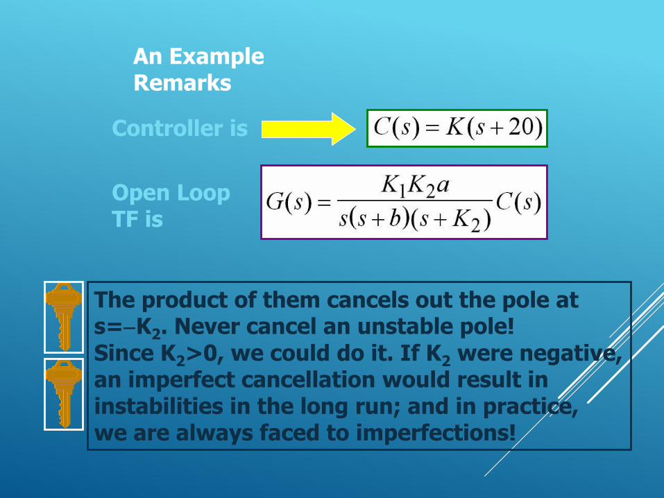
An ExampleRemarks
Controller is
Open LoopTF is
The product of them cancels out the pole ats=-K2. Never cancel an unstable pole!Since K2>0, we could do it. If K2 were negative,an imperfect cancellation would result ininstabilities in the long run; and in practice,we are always faced to imperfections!