CONTROL SYSTEMS GATE CLASSES Dr. T.Devaraju
54
Dr.T.DEVARAJU PROFESSOR OF EEE CONTROL SYSTEMS GATE CLASSES Dr. T.Devaraju Professor of EEE Sree Vidyanikethan Engineering College
-
Upload
khangminh22 -
Category
Documents
-
view
1 -
download
0
Transcript of CONTROL SYSTEMS GATE CLASSES Dr. T.Devaraju

Dr.T.DEVARAJU PROFESSOR OF EEE
CONTROL SYSTEMS
GATE CLASSES
Dr. T.Devaraju Professor of EEE
Sree Vidyanikethan Engineering College

LESSON PLAN • Introduction to Control systems
• Modeling of Physical systems
• Transfer function - Block diagram reduction Techniques
• Transfer function through Signal flow graph
• Time response of second order systems
• Steady state and Transient analysis
• Time-domain specifications and Static error coefficients.
• Routh-Hurwitz stability, Finding the range of K for stability
• Concepts of state, state variables and state model.
• Derivation of state model from transfer function
• State transition matrix, Properties, determination of STM
• Conversion from SS to TF Dr.T.Devaraju,Professor of EEE Sree Vidyanikethan Engineering College

DAY-1
Dr.T.Devaraju,Professor of EEE Sree Vidyanikethan Engineering College
• Introduction to Control systems
• Modeling of Physical systems
• Transfer function from Block diagram

Dr.T.Devaraju,Professor of EEE Sree Vidyanikethan Engineering College

When a number of elements are combined together to form a system to produce
desired output then the system is referred to as control system
The main feature of a control system is that there should be a clear mathematical
relationship between input and output of the system.
When the relation between input and output of the system can be represented by a
linear proportionality, the system is called a linear control system
The system used for controlling the position, velocity, acceleration, temperature,
pressure, voltage and current etc. are examples of control systems
Types of control system.
Open loop control system
Closed loop control system
CONTROL SYSTEM
Dr.T.Devaraju,Professor of EEE Sree Vidyanikethan Engineering College

Definitions
System – An interconnection of elements and devices for a desired
purpose.
Control System – An interconnection of components forming a system
configuration that will provide a desired response.
Process – The device, plant, or system under control. The input and
output relationship represents the cause-and-effect relationship of the
process.
Process Input Output
Dr.T.Devaraju,Professor of EEE Sree Vidyanikethan Engineering College
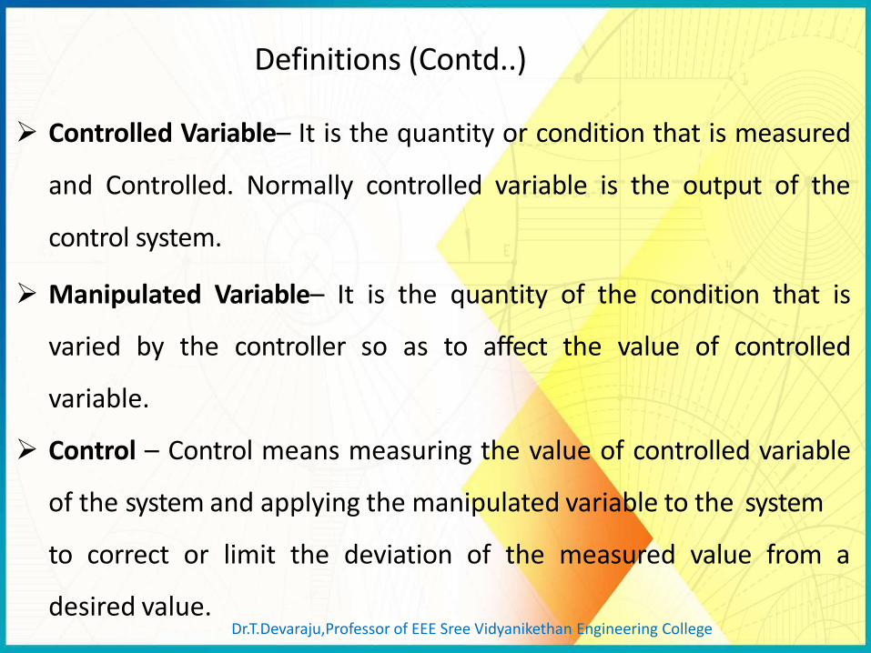
Controlled Variable– It is the quantity or condition that is measured
and Controlled. Normally controlled variable is the output of the
control system.
Manipulated Variable– It is the quantity of the condition that is
varied by the controller so as to affect the value of controlled
variable.
Control – Control means measuring the value of controlled variable
of the system and applying the manipulated variable to the system
to correct or limit the deviation of the measured value from a
desired value.
Definitions (Contd..)
Dr.T.Devaraju,Professor of EEE Sree Vidyanikethan Engineering College

Output Or Controlled Variable
Input or Set point or reference
Disturbances– A disturbance is a signal that tends to adversely affect
the value of the system. It is an unwanted input of the system.
If a disturbance is generated within the system, it is called internal
disturbance. While an external disturbance is generated outside the
system.
Controller Process
Manipulated Variable
Definitions
Dr.T.Devaraju,Professor of EEE Sree Vidyanikethan Engineering College

Open-Loop Control Systems utilize a controller or control actuator
to obtain the desired response.
Output has no effect on the control action. No feedback – no
correction of disturbance
Controller Process
Examples:- Washing Machine, Toaster, Electric Fan In other words output is neither measured nor fed back.
Types of Control System
Dr.T.Devaraju,Professor of EEE Sree Vidyanikethan Engineering College

Practical Examples Electric Hand Drier – Hot air (output) comes out as long as you keep your hand under the machine, irrespective of how much your hand is dried. Automatic Washing Machine – This machine runs according to the pre-set time irrespective of washing is completed or not. Bread Toaster – This machine runs as per adjusted time irrespective of toasting is completed or not. Timer Based Clothes Drier – This machine dries wet clothes for pre-adjusted time, it does not matter how much the clothes are dried. Volume on Stereo System – Volume is adjusted manually irrespective of output volume level.
OPEN LOOP SYSTEM
Dr.T.Devaraju,Professor of EEE Sree Vidyanikethan Engineering College
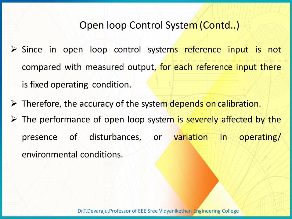
Since in open loop control systems reference input is not
compared with measured output, for each reference input there
is fixed operating condition.
Therefore, the accuracy of the system depends on calibration.
The performance of open loop system is severely affected by the
presence of disturbances, or variation in operating/
environmental conditions.
Open loop Control System (Contd..)
Dr.T.Devaraju,Professor of EEE Sree Vidyanikethan Engineering College

Closed-Loop Control Systems utilizes feedback to compare the
actual output to the desired output response.
Output Input
Controller Process Comparator
Measurement
Dr.T.Devaraju,Professor of EEE Sree Vidyanikethan Engineering College

Examples of Control Systems
Room temperature control
Dr.T.Devaraju,Professor of EEE Sree Vidyanikethan Engineering College
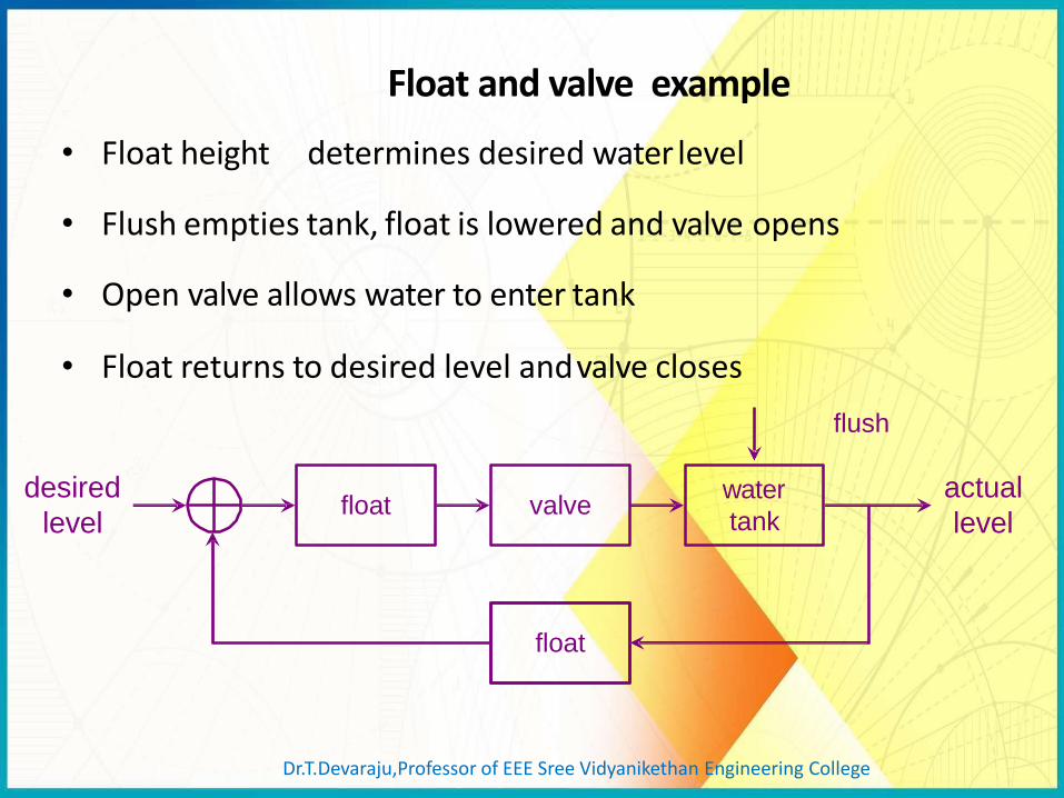
Float and valve example
valve
float
desired
level
actual
level float
water
tank
• Float height determines desired water level
• Flush empties tank, float is lowered and valve opens
• Open valve allows water to enter tank
• Float returns to desired level and valve closes
flush
Dr.T.Devaraju,Professor of EEE Sree Vidyanikethan Engineering College

Modeling of physical systems
The control systems can be represented with a set of mathematical equations
known as mathematical model.
These models are useful for analysis and design of control systems. Analysis of
control system means finding the output when we know the input and
mathematical model.
Design of control system means finding the mathematical model when we know the
input and the output.
The following mathematical models are mostly used.
• Differential equation model
• Transfer function model
• State space model
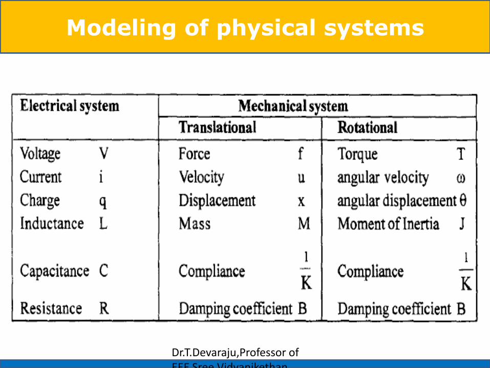
Various types of physical systems are Mechanical systems,
Electrical systems Thermal systems Hydraulic systems
Chemical system etc.,
Dr.T.Devaraju,Professor of EEE Sree Vidyanikethan Engineering College
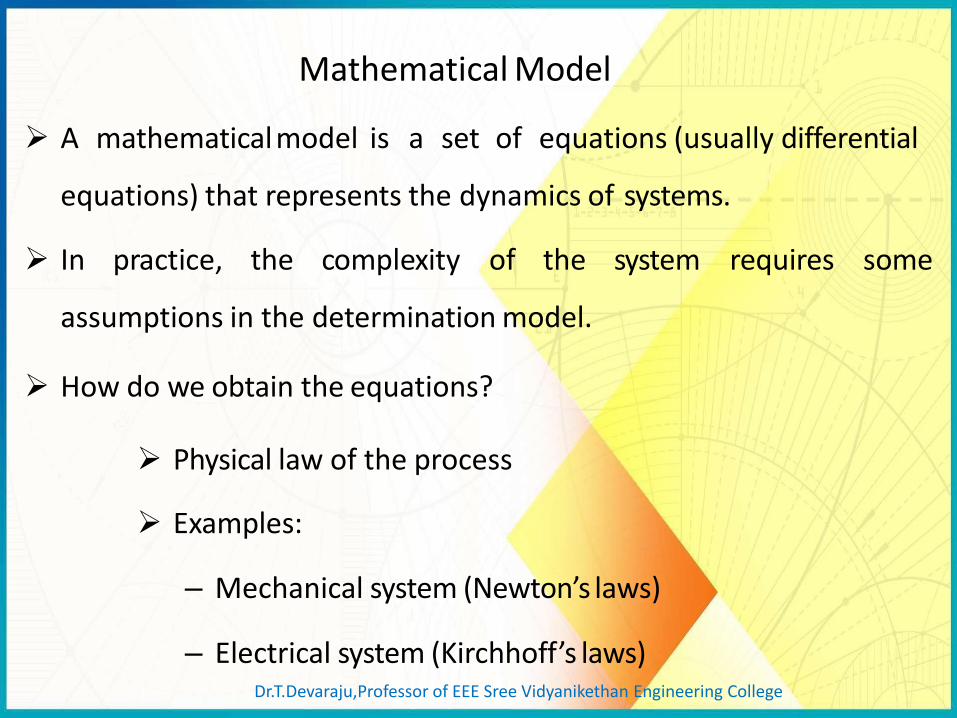
Mathematical Model
A mathematical model is a set of equations (usually differential
equations) that represents the dynamics of systems.
In practice, the complexity of the system requires some
assumptions in the determination model.
How do we obtain the equations?
Physical law of the process
Examples:
– Mechanical system (Newton’s laws)
– Electrical system (Kirchhoff’s laws) Dr.T.Devaraju,Professor of EEE Sree Vidyanikethan Engineering College
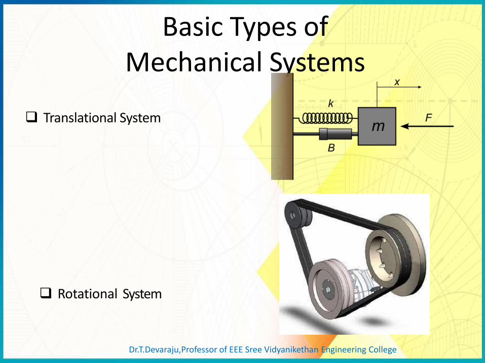
Basic Types of Mechanical Systems
Translational System
Rotational System
Dr.T.Devaraju,Professor of EEE Sree Vidyanikethan Engineering College

Translational Mechanical Systems
Translational Spring
Translational Mass
Translational Damper
These systems mainly consist of three basic elements. Mass, spring and dashpot or damper.
Dr.T.Devaraju,Professor of EEE Sree Vidyanikethan Engineering College

Circuit Symbols
Translational Mechanical Systems
A translational spring is a mechanical element that can be deformed
by an external force such that the deformation is directly
proportional to the force applied to it.
Translational Spring
Translational Spring
Dr.T.Devaraju,Professor of EEE Sree Vidyanikethan Engineering College

Translational Mechanical Systems
Spring is an element, which stores potential energy.
Fα x =>
=>
Where,
•F is the applied force
•Fk is the opposing force due to elasticity of spring
•K is spring constant
•x is displacement
Dr.T.Devaraju,Professor of EEE Sree Vidyanikethan Engineering College

Translational Mechanical Systems
Translational Mass Translational Mass is an inertia
element. A mechanical system without
mass does not exist.
If a force F is applied to a mass and it is displaced to x meters then the relation b/w force and
given by Newton’s
( t )
M F
x ( t )
displacements is law.
=>
=>
Dr.T.Devaraju,Professor of EEE Sree Vidyanikethan Engineering College

Translational Mechanical Systems
Dash Pot: If a force is applied on dashpot B, then it is opposed by an
opposing force due to friction of the dashpot. This opposing force is
proportional to the velocity of the body. Assume mass and elasticity
are negligible.
Dr.T.Devaraju,Professor of EEE Sree Vidyanikethan Engineering College

Transfer function of Translational Mechanical Systems
First, draw a free-body diagram, placing on the body all forces that act on the body either in the direction of motion or opposite to it.
Second, use Newton’s law to form a differential equation of motion by summing the forces and setting the sum equal to zero.
Finally, assuming zero initial conditions, we take the Laplace
transform of the differential equation, separate the variables, and arrive at the transfer function.
Dr.T.Devaraju,Professor of EEE Sree Vidyanikethan Engineering College

Rotational Mechanical Systems
Those These systems mainly consist of three basic elements.
are moment of inertia, torsional spring and dashpot.
Moment of Inertia
In translational mechanical system, mass stores kinetic energy.
Similarly, in rotational mechanical system, moment of inertia stores
kinetic energy.
Dr.T.Devaraju,Professor of EEE Sree Vidyanikethan Engineering College

Rotational Mechanical Systems
=>
=>
Where,
• T is the applied torque
• Tj is the opposing torque due to moment of inertia
• J is moment of inertia
• α is angular acceleration
• θ is angular displacement
Dr.T.Devaraju,Professor of EEE Sree Vidyanikethan Engineering College

Rotational Mechanical Systems
Torsional Spring:
In translational mechanical system, spring stores potential energy.
Similarly, in rotational mechanical system, torsional spring stores
potential energy.
=>
=> Where,
• T is the applied torque • Tk is the opposing torque due to elasticity of torsional spring • K is the torsional spring constant • θ is angular displacement
Dr.T.Devaraju,Professor of EEE Sree Vidyanikethan Engineering College
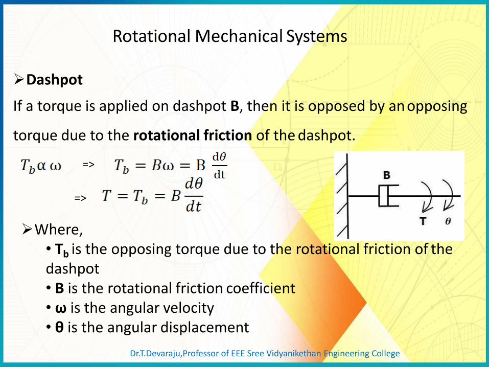
Rotational Mechanical Systems
Dashpot
If a torque is applied on dashpot B, then it is opposed by an opposing
torque due to the rotational friction of the dashpot.
=>
=>
Where, • Tb is the opposing torque due to the rotational friction of the dashpot • B is the rotational friction coefficient • ω is the angular velocity • θ is the angular displacement
Dr.T.Devaraju,Professor of EEE Sree Vidyanikethan Engineering College

Mechanical Translational System
Consider the following system
Free Body Diagram
M F
f k
M f
f B
F f k f M f B
2
1
Ms Bs k
X ( s )
F ( s )
Dr.T.Devaraju,Professor of EEE Sree Vidyanikethan Engineering College
f ( t ) f M
f k f
M
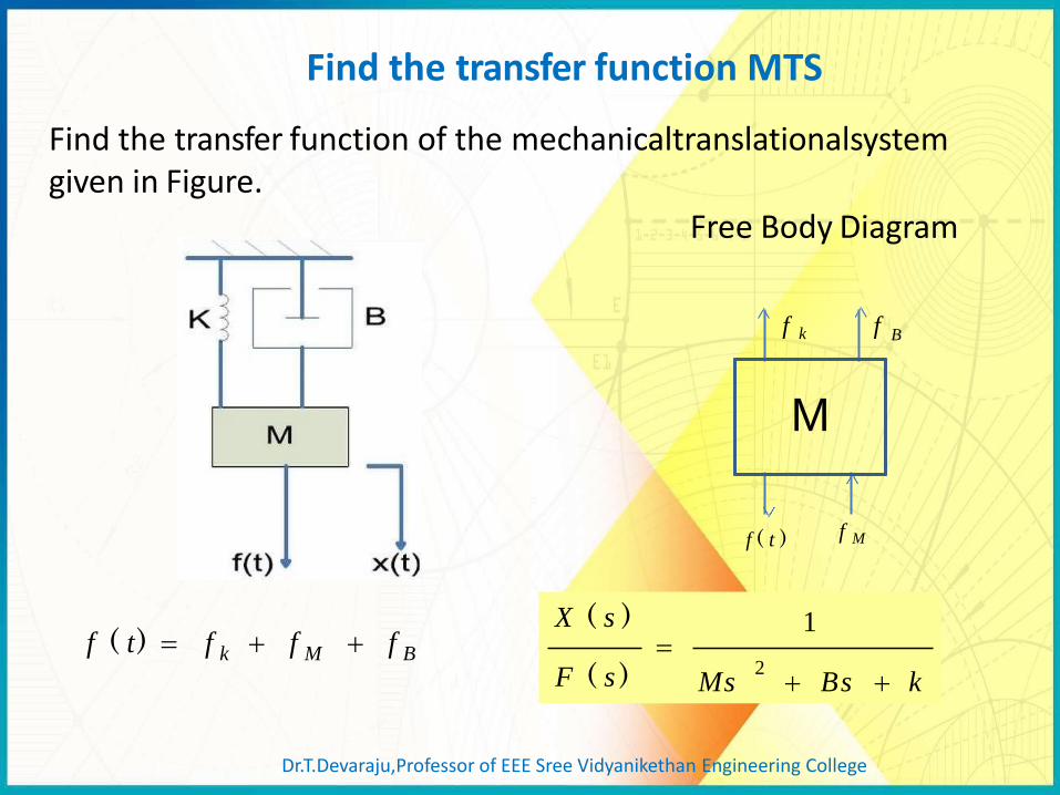
Find the transfer function of the mechanicaltranslationalsystem given in Figure.
Free Body Diagram
B
f ( t ) f k f M f B 2
1
Ms Bs k
X ( s )
F ( s )
Find the transfer function MTS
Dr.T.Devaraju,Professor of EEE Sree Vidyanikethan Engineering College

Draw the free body diagram for the mechanical system
M1
1
f M 1
f B
F ( t )
f k f k 1
f M 2
f B
M2
f k 2
k 2
F ( t ) f k f k f M f B 1 2 2
0 f k f M f B 1 1
Modeling of a mechanical system
Dr.T.Devaraju,Professor of EEE Sree Vidyanikethan Engineering College

Mathematical Model of Electrical System
The mathematical model of electrical systems can be obtained by
using resistor, capacitor and inductor
Dr.T.Devaraju,Professor of EEE Sree Vidyanikethan Engineering College
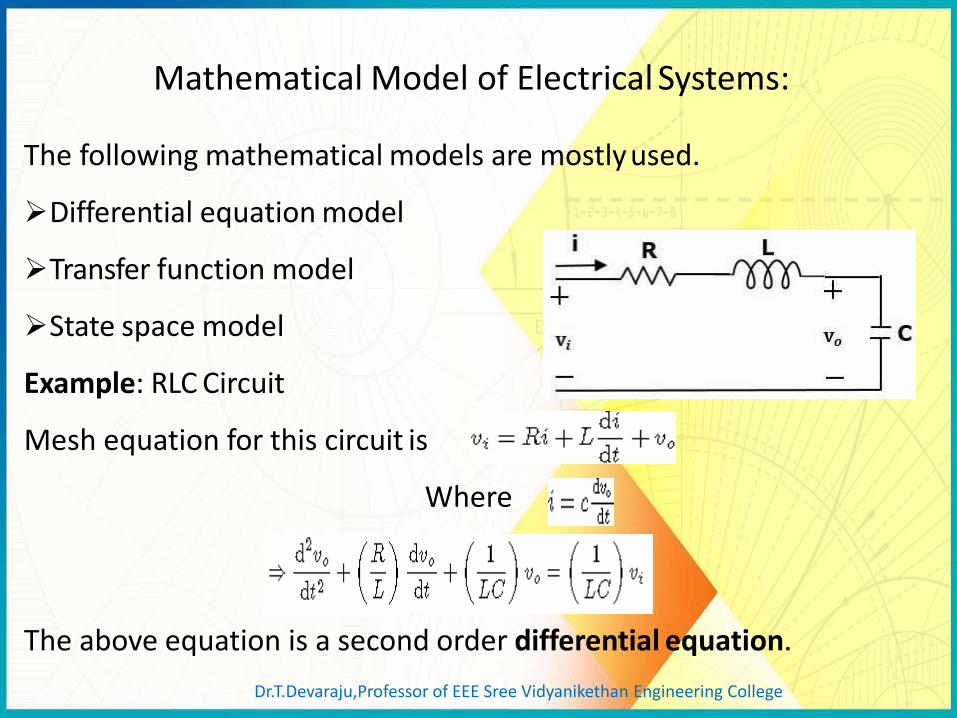
The following mathematical models are mostly used.
Differential equation model
Transfer function model
State space model
Example: RLC Circuit
Mesh equation for this circuit is
Where
The above equation is a second order differential equation.
Mathematical Model of Electrical Systems:
Dr.T.Devaraju,Professor of EEE Sree Vidyanikethan Engineering College

Differential Equation Model Differential equation model is a time domain mathematical model of control systems. Apply basic laws to the given control system to find the differential equation model in terms of input and output
Consider the following electrical system
Modeling of physical systems
Dr.T.Devaraju,Professor of EEE Sree Vidyanikethan Engineering College

Transfer Function Model
The Transfer function of a Linear Time Invariant (LTI) system is
defined as the ratio of Laplace transform of output and Laplace
transform of input by assuming all the initial conditions are zero.
If x(t) and y(t) are the input and output of an LTI system, then the
corresponding Laplace transforms are X(s) and Y(s).
The transfer function model
of an LTI system is shown in the
following figure. Dr.T.Devaraju,Professor of EEE Sree Vidyanikethan Engineering College

Transfer Function of Linear System
1
1
Cs
I ( s) V ( s ) R
1
2
Cs
V ( s ) I ( s )
Cs
Cs
1 sRC
1
1
1
V 1 ( s ) R
V 2 ( s ) Transfer function
Dr.T.Devaraju,Professor of EEE Sree Vidyanikethan Engineering College
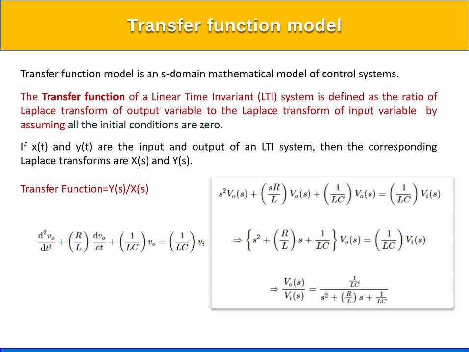
Transfer function model
Transfer function model is an s-domain mathematical model of control systems.
The Transfer function of a Linear Time Invariant (LTI) system is defined as the ratio of Laplace transform of output variable to the Laplace transform of input variable by assuming all the initial conditions are zero.
If x(t) and y(t) are the input and output of an LTI system, then the corresponding Laplace transforms are X(s) and Y(s). Transfer Function=Y(s)/X(s)

Analogous Systems
Electrical Analogous of mechanical Translational System:
As the electrical systems has two types of inputs either voltage or
current source. There are two types of analogies .
•Force- Voltage analogy
•Force- Current analogy
Dr.T.Devaraju,Professor of EEE Sree Vidyanikethan Engineering College

Force- Voltage Analogy:
Dr.T.Devaraju,Professor of EEE Sree Vidyanikethan Engineering College

Force- Voltage Analogy:
Dr.T.Devaraju,Professor of EEE Sree Vidyanikethan

Force- Current Analogy:
Dr.T.Devaraju,Professor of EEE Sree Vidyanikethan
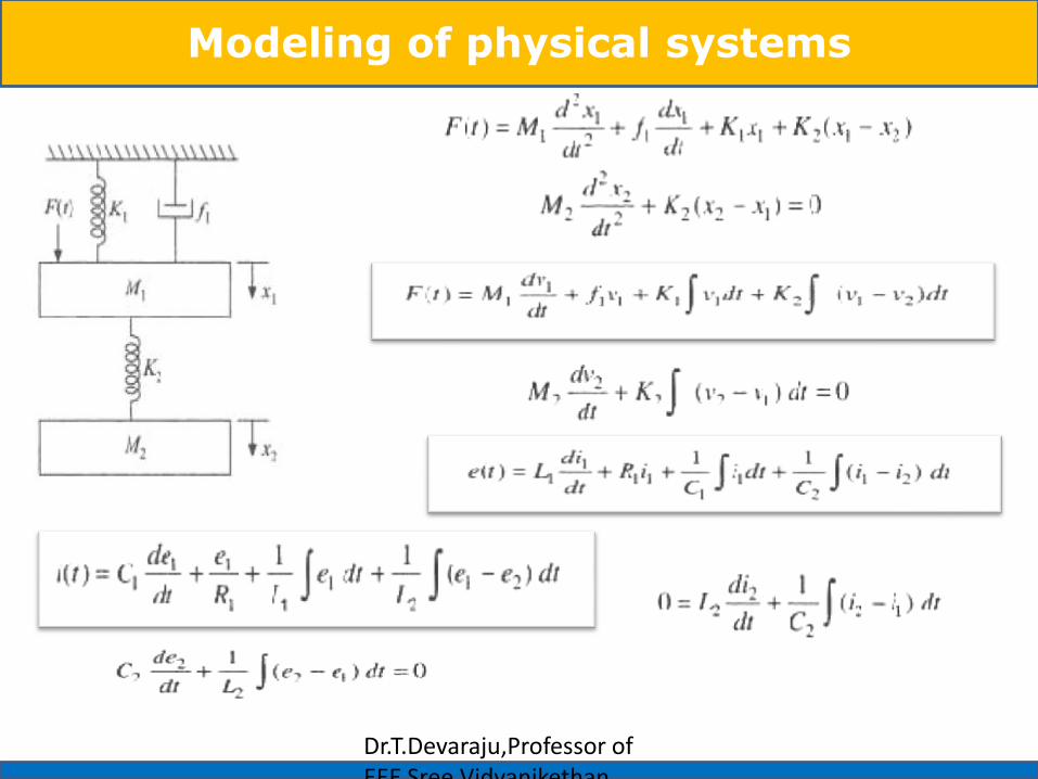
Modeling of physical systems
Dr.T.Devaraju,Professor of EEE Sree Vidyanikethan
Modeling of physical systems
Dr.T.Devaraju,Professor of EEE Sree Vidyanikethan

F-V and F-I analogous circuits
Dr.T.Devaraju,Professor of EEE Sree Vidyanikethan

Modeling of physical systems
Dr.T.Devaraju,Professor of EEE Sree Vidyanikethan

Modeling of physical systems
Dr.T.Devaraju, Professor of EEE, Sree Vidyanikethan Engineering College

We often represent control systems using block diagrams. A block
diagram consists of blocks that represent transfer functions of the
different variables of interest.
If a block diagram has many blocks, not all of which are in cascade,
then it is useful to have rules for rearranging the diagram such that
you end up with only one block.
Block Diagram Algebra
Dr.T.Devaraju,Professor of EEE Sree Vidyanikethan Engineering College

Reduction techniques
G1 G 2
1. Combining blocks in cascade
2 1 G G
2. Combining blocks in parallel
Dr.T.Devaraju,Professor of EEE Sree Vidyanikethan Engineering College

3. Moving a summing point behind a block
G G
G
Reduction techniques
4. Moving a summing point ahead of a block
G
1
G
G -
Dr.T.Devaraju,Professor of EEE Sree Vidyanikethan Engineering College

5. Moving a pickoff point ahead of a block
G G
G G
1
G
G
4. Moving a pickoff point behind a block
Reduction techniques
Dr.T.Devaraju,Professor of EEE Sree Vidyanikethan Engineering College

6. Eliminating a feedback loop
G
H
G
1 ± GH
A B B A
G
H 1
7. Swap with two neighboring summing points
G
1 ± G
Reduction techniques
Dr.T.Devaraju,Professor of EEE Sree Vidyanikethan Engineering College

Rules in block diagram reduction
Dr.T.Devaraju, Professor of EEE, Sree Vidyanikethan Engineering College

Block diagram reduction technique
What is the overall transfer function of the block diagram
Rearrange the above block
cascade combination
Dr.T.Devaraju, Professor of EEE, Sree Vidyanikethan Engineering College

Block diagram reduction technique
Dr.T.Devaraju, Professor of EEE, Sree Vidyanikethan Engineering College

Block diagram reduction technique
We will discuss
Dr.T.Devaraju, Professor of EEE, Sree Vidyanikethan Engineering College