General Architecture for Text Engineering (GATE) Developer ...
Upload
khangminh22Category
view
1download
0
5/18/2020
Prof. B. Jayarami Reddy
Y.S.R. ENGINEERING COLLEGE OF YOGI VEMANA UNIVERSITY, PRODDATUR 1
GATE – CIVIL ENGINEERING
Prof.B.Jayarami Reddy Professor and Head
Department of Civil Engineering
Y.S.R. Engineering College of
Yogi Vemana University,
Proddatur, Y.S.R.(Dt.), A.P-516360.
GEOTECHNICAL ENGINEERING

5/18/2020
Prof. B. Jayarami Reddy
Y.S.R. ENGINEERING COLLEGE OF YOGI VEMANA UNIVERSITY, PRODDATUR 2
8.7 Seepage Analysis

5/18/2020
Prof. B. Jayarami Reddy
Y.S.R. ENGINEERING COLLEGE OF YOGI VEMANA UNIVERSITY, PRODDATUR 3
8.7 Seepage Analysis
Types of Head:
Total head = Pressure head + Velocity head + Datum head
Velocity head is very small in soils and can be neglected.
Total head = pressure head + datum head.
• Flow takes place only due to difference in total heads.
• Pressure head difference alone or datum head difference alone cannot cause the
flow of water through the soil
Hydraulic Gradient:
• It is the loss of head per unit seepage length. or
Seepage Pressure :
• The pressure exerted by water on the soil through which it percolates
Seepage pressure,
wh h z
hi
L
sP
.s wp h
hi
z

5/18/2020
Prof. B. Jayarami Reddy
Y.S.R. ENGINEERING COLLEGE OF YOGI VEMANA UNIVERSITY, PRODDATUR 4
eg. Assuming datum head at the surface of the downstream water
At Point A:
Total head,
Datum head
Pressure head
At point B:
Pressure head,
Datum head
Total head
At point C:
Total head,
Datum head
Pressure head
.Ah h i y
1x
1Ax h x
1Bh h
2h
1 2h h
0Ch
1z x
1 10 ( )z x z x Datum

5/18/2020
Prof. B. Jayarami Reddy
Y.S.R. ENGINEERING COLLEGE OF YOGI VEMANA UNIVERSITY, PRODDATUR 5
Upward seepage through soil
At the bottom of the soil A:
. .w saty z
wu h y z
. .w sat wu y z h y z
.sat w wz h
. .wz h

5/18/2020
Prof. B. Jayarami Reddy
Y.S.R. ENGINEERING COLLEGE OF YOGI VEMANA UNIVERSITY, PRODDATUR 6
Downward seepage through soil
At the bottom of soil A:
Hence
.sat wz y h
wu y z
.sat w wz y h y z
. . .sat w w wz h z h
. .wz h

5/18/2020
Prof. B. Jayarami Reddy
Y.S.R. ENGINEERING COLLEGE OF YOGI VEMANA UNIVERSITY, PRODDATUR 7
where : Net head causing flow.
: Hydraulic gradient.
: Seepage length
Seepage force = Seepage pressure Area
Seepage force per unit volume =
• Seepage pressure always acts in the direction of flow.
• Due to seepage pressure, vertical effective pressure may be increased or decreased
based upon direction of flow.
• Effective stress increases if flow is downwards.
• Effective stress decreases if flow is upwards.
. .s wp i z
hiz
. . .s wp A i z A
. . ..s w
w
p A i z Ai
V z A

5/18/2020
Prof. B. Jayarami Reddy
Y.S.R. ENGINEERING COLLEGE OF YOGI VEMANA UNIVERSITY, PRODDATUR 8
Quick Sand Condition:
• Quick sand is a flow condition existing in fine sand or coarse silt.
• When flow takes place in upward direction, the seepage pressure acts in the upward
direction and the effective pressure is reduced.
• When the soil pressure and seepage pressure equals, the effective stress reduced to 0.
• Cohesionless soil looses its shear strength and soil particles move in upward
direction.
• Quick Condition or Boiling Condition is
Seepage pressure = Effective pressure =
: Submerged weight of soil
: Unit weight of water
: Thickness of soil sample
: Head causing flow.
. . 0wz h
. . .w wi z h z
w
z
h

5/18/2020
Prof. B. Jayarami Reddy
Y.S.R. ENGINEERING COLLEGE OF YOGI VEMANA UNIVERSITY, PRODDATUR 9
: Soil pressure
: Seepage pressure at quick condition,
Soil pressure = Seepage pressure
• Quick Sand is not a type of sand but a flow condition occurring in cohesionless
soils.
• In Coarse sand water escapes easily due to high permeability. It requires large
heads to make quick condition. But it is not possible in practice.
• The quick condition is most likely to arise in silts and fine sands.
• Quick sand condition does not occur in clay soils as their cohesion holds the grains
together even under upward flow at critical hydraulic gradient.
z
wh
wz h

5/18/2020
Prof. B. Jayarami Reddy
Y.S.R. ENGINEERING COLLEGE OF YOGI VEMANA UNIVERSITY, PRODDATUR 10
To Prevent quick sand condition:
• Putting some surcharge loads on soil.
• Lowering water table by driving bore holes. Bore holes shall not be completely
dewatered.
Critical Hydraulic Gradient line:
• The Hydraulic gradient at the critical condition when the soil particles just begin to
move is known as Critical Hydraulic Gradient Line.
• When the exit gradient is equal to or greater than critical hydraulic gradient, the
soil is said to be in quick condition.
• Critical hydraulic gradient depends on the specific gravity and void ratio of the
soil.
• more common in uniform sands and silts with high void ratios.
1
1 11
c
w
Gi G n
e

5/18/2020
Prof. B. Jayarami Reddy
Y.S.R. ENGINEERING COLLEGE OF YOGI VEMANA UNIVERSITY, PRODDATUR 11
For value , and
The critical hydraulic gradient is not affected by depth of water over the soil surface.
Effect of Surcharge on quick condition:
Piping or Undermining:
If seepage takes place through a soil mass below a hydraulic structure, the grains will
be lifted by water if effective pressure reduces to 0 and exist gradient is greater than
critical hydraulic gradient.
With the removal of the surface soil at the downstream floor there is further
concentration of flow into the resulting depression and more soil is removed.
The process of erosion progressively extends backwards towards the upstream side and
results in the removal of soil and developing pipe like formation beneath the floor.
The floor may subside in the hollows so formed and fail which is known as failure due
to Piping or Undermining.
2.6 2.85G 0.6 0.85e
.. ; w
w
z qh z q h
1ci

5/18/2020
Prof. B. Jayarami Reddy
Y.S.R. ENGINEERING COLLEGE OF YOGI VEMANA UNIVERSITY, PRODDATUR 12
Backward erosion piping
Prevention:
• Providing sufficient length of the impervious floor so that the path of percolation is
increased and exit gradient is reduced.
• Providing piles at the upstream and downstream ends of the impervious floor.
• Providing drainage filter like Graded filter or Inverted filter (Rock toe, Chimney
drain etc.)
Factor of safety against piping or quick sand
Critical hydraulic gradient
Actual or Exit gradientF

5/18/2020
Prof. B. Jayarami Reddy
Y.S.R. ENGINEERING COLLEGE OF YOGI VEMANA UNIVERSITY, PRODDATUR 13
Assumptions in Laplace equation for two dimensional flow :
1. Soil mass is homogeneous and isotropic.
2. The soil and water are incompressible.
3. The flow is assumed to be laminar so that Darcy's Law is valid.
4. Quantity of water stored in soil pores is constant so that steady flow conditions
established.
Flow of water through soil for a two dimensional flow conditions can be expressed
mathematically as
• For steady flow and isotropic conditions, the above equation reduces to
• Solutions of this equation gives two sets of curves known as Stream lines and
Equipotential lines.
2 2
2 2. . 0x yk k
x y
2 2
2 20
x y

5/18/2020
Prof. B. Jayarami Reddy
Y.S.R. ENGINEERING COLLEGE OF YOGI VEMANA UNIVERSITY, PRODDATUR 14
Seepage Analysis
• Percolation of water through the soil pores under an energy gradient is known as
seepage.
• The pressure exerted on the soil due to seepage of water is known as seepage force
or seepage pressure.
• Seepage problems occur in all earthen dams, retaining walls and foundations on
permeable soil.

5/18/2020
Prof. B. Jayarami Reddy
Y.S.R. ENGINEERING COLLEGE OF YOGI VEMANA UNIVERSITY, PRODDATUR 15
Flow nets:
• The flow of water through a soil can be represented by a flow net, a form of
curvilinear made up of a set of flow lines intersected by a set of equipotential lines.
Flow lines:
• Flow line is the line along which flow takes place.
• Water flows from points of high head to points of low heads and makes smooth
curves representing the paths followed by moving particles of water.
• Flow lines are also called as stream lines

5/18/2020
Prof. B. Jayarami Reddy
Y.S.R. ENGINEERING COLLEGE OF YOGI VEMANA UNIVERSITY, PRODDATUR 16
Equipotential line
• Equipotential line is a line joining all the points having equal total heads or
potential head
• If piezometers are inserted into the soil at different points along an equipotential
line, water would rise to the same elevation in all these piezometers.
Flow path or flow channel
• Flow path or flow channel is the space between two adjacent flow lines
• : Number of flow channels
Field
• Field is the space between any two adjacent flow lines and adjacent equipotential
lines
Characteristics of flow net
• Flow lines and equipotential lines are orthogonal (perpendicular) to each other.
• The quantity of seepage in each flow channel is same
• Drop in head between adjacent equipotential lines is same
fN

5/18/2020
Prof. B. Jayarami Reddy
Y.S.R. ENGINEERING COLLEGE OF YOGI VEMANA UNIVERSITY, PRODDATUR 17
• Two flow lines or two equipotential lines can never meet or cross each other.
• Fields are kept approximately squares.
• Smaller the dimension of the field, greater will be the hydraulic gradient and
velocity of flow through it.
• In homogeneous soil, every transition in the shape of curves is smooth, being either
electrical or parabolic in shape.
• Flow net does not depend on permeability of the soil and head causing flow
• Flow net depends on boundary conditions only.
Uses of flow net:
• To compute seepage quantity or seepage loss
• To compute seepage pressure
• To compute uplift pressure
• To compute exit gradient.
Total head lossPotential drop=
Number of fields
( )k ( )h

5/18/2020
Prof. B. Jayarami Reddy
Y.S.R. ENGINEERING COLLEGE OF YOGI VEMANA UNIVERSITY, PRODDATUR 18
Seepage Quantity:
= Permeability of soil
For an isotropic soil
: Permeability in horizontal direction
: Permeability in vertical direction
: Net head causing flow (difference between u/s and d/s water levels)
: number of flow channels
: the number of potential drops
• The ratio of is called shape factor of a flow net.
. .f
d
Nq k h
N
k
.x yk k k
xk
yk
H
fN
dN
f
d
N
N

5/18/2020
Prof. B. Jayarami Reddy
Y.S.R. ENGINEERING COLLEGE OF YOGI VEMANA UNIVERSITY, PRODDATUR 19
• For a given boundary conditions, ratio remains same.
• For a particular set of boundary conditions, the flow net will be unique
Calculation of seepage pressure ( ) using flow net
The upward Seepage force
Seepage force per unit volume
: Unit weight of water
: Hydraulic potential or balance hydraulic head after potential drops
: Head causing flow or difference between u/s and d/s water levels.
Head drop through field,
f
d
N
N
sp
.wh A
. ..
.
ww
h Ai
A L
w
1h
1 .h h n h
h
d
hh
N
n
5/18/2020
Prof. B. Jayarami Reddy
Y.S.R. ENGINEERING COLLEGE OF YOGI VEMANA UNIVERSITY, PRODDATUR 20
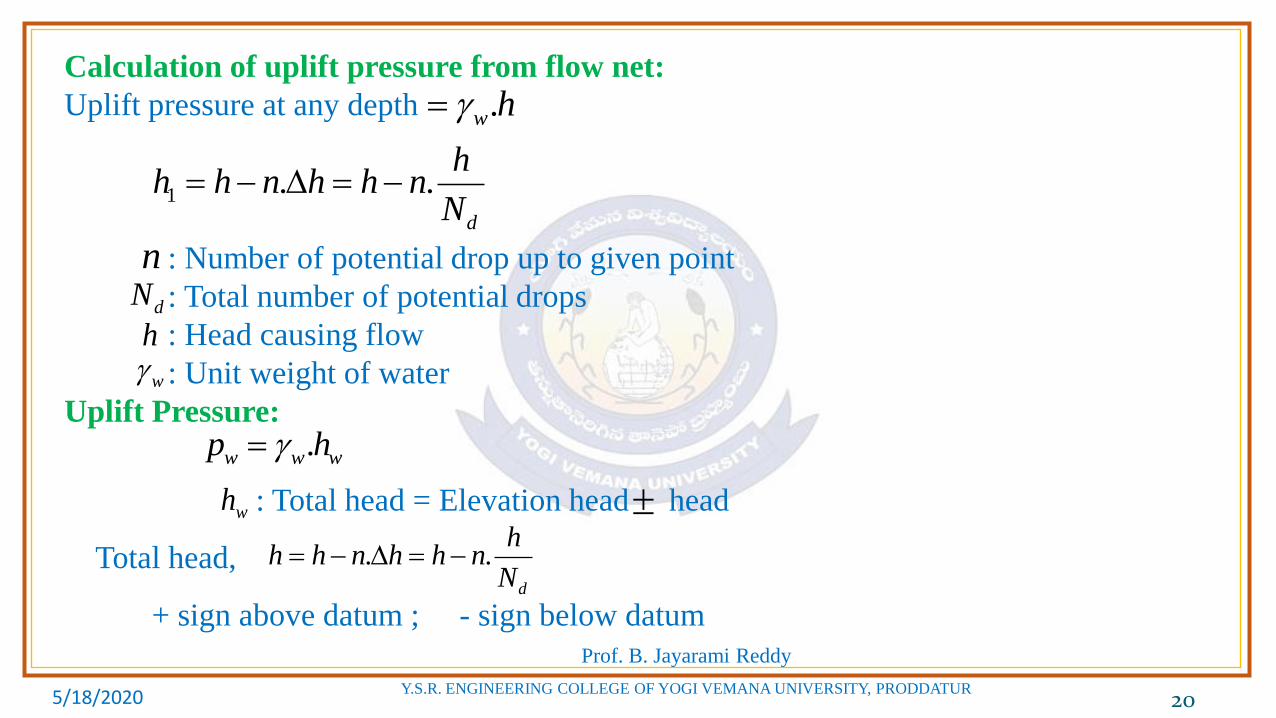
Calculation of uplift pressure from flow net:
Uplift pressure at any depth
: Number of potential drop up to given point
: Total number of potential drops
: Head causing flow
: Unit weight of water
Uplift Pressure:
: Total head = Elevation head head
Total head,
+ sign above datum ; - sign below datum
.w h
1 . .d
hh h n h h n
N
n
dN
h
w
.w w wp h
wh
. .d
hh h n h h n
N

5/18/2020
Prof. B. Jayarami Reddy
Y.S.R. ENGINEERING COLLEGE OF YOGI VEMANA UNIVERSITY, PRODDATUR 21
Exit Gradient:
Head drop per field,
: Average length of last field at exit point
• For safety against piping the must always be less than the critical hydraulic
gradient ( ).
Factor of safety against piping,
Seepage pressure at a point ( )
Total head of that point,
: Number of potential drops upto the point
exit
hi
L
d
Hh
N
L
exiti
ci
c
exit
iF
i
sp
.s wp h
1 .h h n h
n

5/18/2020
Prof. B. Jayarami Reddy
Y.S.R. ENGINEERING COLLEGE OF YOGI VEMANA UNIVERSITY, PRODDATUR 22
Potential drop per field,
Hydrostatic pressure a point:
: Datum head at that point.
d
hh
N
wh h z
1 .h h n h
z

5/18/2020
Prof. B. Jayarami Reddy
Y.S.R. ENGINEERING COLLEGE OF YOGI VEMANA UNIVERSITY, PRODDATUR 23
Phreatic Line:
• Phreatic line is also called as seepage line or top flow line
• Along Phreatic line pressure head is zero. Only atmospheric pressure exists.
• Profile of Phreatic line is in parabolic shape.
• The pressure head at the intersection of the Phreatic line and any equipotential line is 0.
• The head existing on top flow line is Elevation Head (Velocity head neglected, pressure
head 0)
• Kozeiny's Solution is used to find seepage through earth dams.
: Focal distance
(i.e. distance between focus and directrix of the parabolic shape phreatic line) .q k S S
Drainage filter
5/18/2020
Prof. B. Jayarami Reddy
Y.S.R. ENGINEERING COLLEGE OF YOGI VEMANA UNIVERSITY, PRODDATUR 24
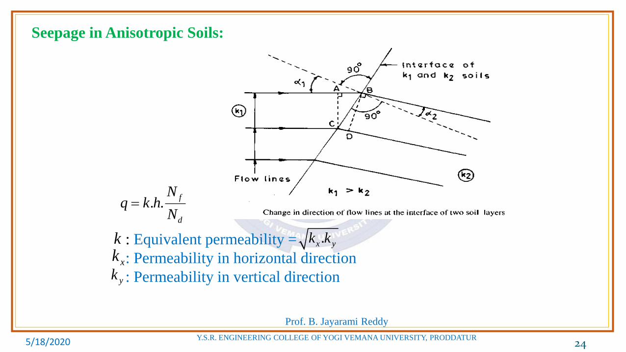
Seepage in Anisotropic Soils:
: Equivalent permeability =
: Permeability in horizontal direction
: Permeability in vertical direction
. .f
d
Nq k h
N
k .x yk k
xk
yk

5/18/2020
Prof. B. Jayarami Reddy
Y.S.R. ENGINEERING COLLEGE OF YOGI VEMANA UNIVERSITY, PRODDATUR 25
• Flow lines and equipotential lines get deflected at the interface between two
dissimilar soils, when they pass from one soil to other.
1 1
2 2
tan
tan
k
k

5/18/2020
Prof. B. Jayarami Reddy
Y.S.R. ENGINEERING COLLEGE OF YOGI VEMANA UNIVERSITY, PRODDATUR 26
Seepage Analysis
Numerical Questions
5/18/2020
Prof. B. Jayarami Reddy
Y.S.R. ENGINEERING COLLEGE OF YOGI VEMANA UNIVERSITY, PRODDATUR 27
SEEPAGE ANALYSIS
01. If the specific gravity and void ratio of the coarse grained soil deposit are 2.67 and
0.7 respectively, then the critical hydraulic gradient is
a. 0.64 b. 0.96 c. 0.98 d. 1.0
Ans. c
Specific gravity of soil, = 2.67
Void ratio, = 0.7
Critical hydraulic gradient,
G
e1 2.67 0.7
0.981 1 0.7
c
Gi
e

5/18/2020
Prof. B. Jayarami Reddy
Y.S.R. ENGINEERING COLLEGE OF YOGI VEMANA UNIVERSITY, PRODDATUR 28
02. A stiff clay stratum extended upto a depth of 12m below ground level with a
saturated unit weight of 17.6 kN/m3 and was underlain by a sand stratum. An
excavation is carried out in a clay and when the depth of excavation reached 6.4 m,
the bottom of the pit started rising, cracked and a mixture of soil and water was
flowing out of the cracks. If the bore hole is made prior to excavation, the height to
which the water would have rised above the surface of the sand stratum is
a. 5.6 m b. 6.4 m c. 7.2 m d. 9.86 m
Ans. d
wh12m

5/18/2020
Prof. B. Jayarami Reddy
Y.S.R. ENGINEERING COLLEGE OF YOGI VEMANA UNIVERSITY, PRODDATUR 29
Let : height to which water will have risen in bore hole, above surface of sand
stratum, prior to excavation.
Quick sand condition occurs at the surface of the clay stratum when effective
stress becomes zero at that level.
wh
. 17.6 5.6. . 0 9.86 m
10sat
sat w w w
w
zz h h
wh12m

5/18/2020
Prof. B. Jayarami Reddy
Y.S.R. ENGINEERING COLLEGE OF YOGI VEMANA UNIVERSITY, PRODDATUR 30
03. A cylindrical mould of diameter 10 cm contains 15 cm long soil sample having
coefficient of permeability 1×10⁻³ cm/sec with void ratio of 0.7 and specific
gravity of 2.70. If water is made to flow through soil sample in upward direction
and the rate of discharge is 0.05 ml/sec, the effective stress at the middle of
sample is
a. 0 b. 0.27 kN/m2 c. 0.54 kN/m2 d. 0.75 kN/m2
Ans. b
Diameter of the soil sample, = 10 cm
Length of the soil sample, = 15 cm
Coefficient of permeability, = 1 × 10⁻³ cm/sec.
Void ratio, = 0.7
Specific gravity of soil, = 2.70
Discharge, = 0.05 ml/sec = 0.05 cm3/sec
Cross sectional area
d
Lk
eG
q
2 210 78.54cm
4

5/18/2020
Prof. B. Jayarami Reddy
Y.S.R. ENGINEERING COLLEGE OF YOGI VEMANA UNIVERSITY, PRODDATUR 31
When the flow of water is in upward direction, the effective stress at a point is
given by
,
Effective stress at the middle of sample
3
0.05. . 0.64
. 1 10 78.54
qq k i A i
k A
s wz p z iz
31 2.70 110 10 kN/m
1 1 0.7w
G
e
210 0.075-0.64 0.075 10 0.27kN/m
5/18/2020
Prof. B. Jayarami Reddy
Y.S.R. ENGINEERING COLLEGE OF YOGI VEMANA UNIVERSITY, PRODDATUR 32
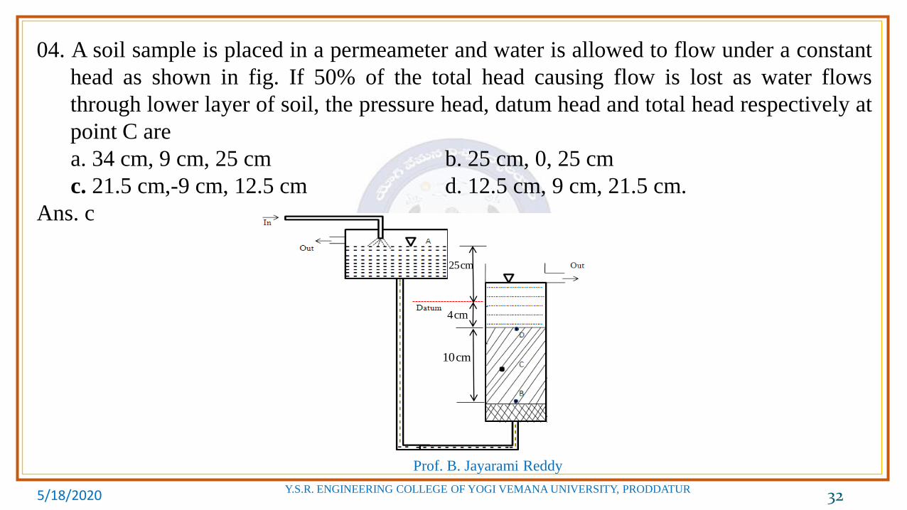
04. A soil sample is placed in a permeameter and water is allowed to flow under a constant
head as shown in fig. If 50% of the total head causing flow is lost as water flows
through lower layer of soil, the pressure head, datum head and total head respectively at
point C are
a. 34 cm, 9 cm, 25 cm b. 25 cm, 0, 25 cm
c. 21.5 cm,-9 cm, 12.5 cm d. 12.5 cm, 9 cm, 21.5 cm.
Ans. c
10cm
4cm
25cm

5/18/2020
Prof. B. Jayarami Reddy
Y.S.R. ENGINEERING COLLEGE OF YOGI VEMANA UNIVERSITY, PRODDATUR 33
04. Ans. c
At A,
At B, = 10 + 4 + 25 = 39 cm
= -14 cm
= 39 – 14 = 25 cm.
At C, = 25 – 0.5 × 25 = 12.5 cm
= -(4+5) = -9 cm
= 12.5 – (-9) = 21.5 cm.
At D,
= - 4 cm
= 0 – (- 4) = 4 cm.
0wh
25z cm
25wh h z cm
wh
zh
hz
wh
0h
zwh h z

5/18/2020
Prof. B. Jayarami Reddy
Y.S.R. ENGINEERING COLLEGE OF YOGI VEMANA UNIVERSITY, PRODDATUR 34
05. Two different types of soil are placed in a permeameter and water is allowed to
flow under a constant head as shown in fig. If 60% of the total head causing flow
is lost as water flows through lower layer of soil, the pressure head, datum head
and total head respectively at point C are
a. 20 cm, -10 cm, 10 cm
b. 10 cm, -10 cm, 20 cm
c. 20 cm, 10 cm, 10 cm
d. 10 cm, 10 cm, 20 cm.
Ans. a

5/18/2020
Prof. B. Jayarami Reddy
Y.S.R. ENGINEERING COLLEGE OF YOGI VEMANA UNIVERSITY, PRODDATUR 35
05 Ans. a
At A,
At B, = 8 + 6 + 4 + 25 = 43 cm
= -18 cm
= 43 – 18 = 25 cm.
At C, = 25 – 0.6 × 25 = 10 cm
= -(4+6) = -10 cm
= 10 – (-10) = 20 cm.
At D,
= - 4 cm
= 0 – (- 4) = 4 cm.
0wh
25z cm
25wh h z cm
wh
zh
hz
wh
0h
zwh h z
25cm
4cm
6cm
8cm
Datum

5/18/2020
Prof. B. Jayarami Reddy
Y.S.R. ENGINEERING COLLEGE OF YOGI VEMANA UNIVERSITY, PRODDATUR 36
06. A soil sample is placed in a permeameter mould having cross sectional area
50 cm2 and water is allowed to flow under a constant head as shown in fig. If the
coefficient of permeability of soil is 2×10⁻³ cm/sec, the rate of discharge is
a. 2.5 cm3/sec. b. 0.25 cm3/sec c. 3.9 cm3/sec d. 0.39 cm3/sec
Ans. b
Total head at B = 25 cm
Total head at C = 0
Head lost during flow through soil
h = 25 – 0 = 25 cm.
Length of sample, = 10 cm
Hydraulic gradient,
Rate of discharge, = 2×10-3×2.5×50
= 0.25 cm3/sec.
L
252.5
10
hi
L
q kiA
25cm
10cm
C
B
5/18/2020
Prof. B. Jayarami Reddy
Y.S.R. ENGINEERING COLLEGE OF YOGI VEMANA UNIVERSITY, PRODDATUR 37
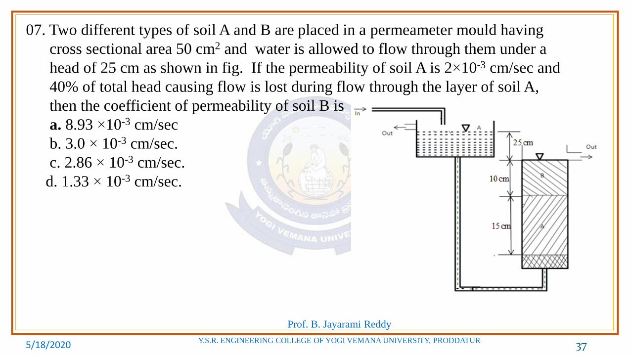
07. Two different types of soil A and B are placed in a permeameter mould having
cross sectional area 50 cm2 and water is allowed to flow through them under a
head of 25 cm as shown in fig. If the permeability of soil A is 2×10⁻³ cm/sec and
40% of total head causing flow is lost during flow through the layer of soil A,
then the coefficient of permeability of soil B is
a. 8.93 ×10⁻³ cm/sec
b. 3.0 × 10⁻³ cm/sec.
c. 2.86 × 10⁻³ cm/sec.
d. 1.33 × 10⁻³ cm/sec.

5/18/2020
Prof. B. Jayarami Reddy
Y.S.R. ENGINEERING COLLEGE OF YOGI VEMANA UNIVERSITY, PRODDATUR 38
07 Ans. a
Cross sectional area of sample A, = 50 cm2.
Coefficient of permeability of soil A, = 2×10⁻³ cm/sec.
Total head at bottom of soil A = 25 cm.
Head lost during flow through soil A = 0.4×25 = 10 cm.
Hydraulic gradient,
Rate of discharge though soil A,
= 2 × 10-3 × 0.67 × 50 = 0.67 cm3/sec.
Head lost during flow through soil B = 0.6 × 25 = 15 cm
Hydraulic gradient,
Coefficient of permeability of soil B,
Ak
100.67
15
hi
L
q kiA
151.5
10
hi
L
.B
qk
i A
30.678.93 10 cm/sec
1.5 50Bk
25cm
10cm
15cm

5/18/2020
Prof. B. Jayarami Reddy
Y.S.R. ENGINEERING COLLEGE OF YOGI VEMANA UNIVERSITY, PRODDATUR 39
08. Two different types of soil A and B are placed in a permeameter mould having
cross sectional area 100 cm2 and water is allowed to flow through them under a
constant head of 30 cm. The thickness of soil A and soil B are 20 cm and 15 cm
respectively. The void ratio and specific gravity of soil A are 0.6 and 2.76 and that
of soil B are 0.8 and 2.62 respectively. It is found that 60% of the total head causing
flow is lost during flow through the soil A. The total
head either of the soil will be under quick condition is .
a. 30 cm b. 33.75 cm c. 36.67 cm d. 45 cm
Ans. b
Critical hydraulic gradient,
For soil A, = 2.76 = 0.6 = 10 cm
For soil B, = 2.62 = 0.8 = 15 cm
1
1c
Gi
e
G e z
2.76 11.1
1 0.6Ai
2.62 10.9
1 0.8Bi
G e z

5/18/2020
Prof. B. Jayarami Reddy
Y.S.R. ENGINEERING COLLEGE OF YOGI VEMANA UNIVERSITY, PRODDATUR 40
Head lost in soil A
1.1×20 =
= 36.67 cm
Head lost in soil B
= 33.75 cm
Quick sand occurs in soil B when total hydraulic head reaches 33.75 cm.
. 0.6Ai z h
h
. 0.4Bi z h
0.9 15 0.4h h
0.6h

5/18/2020
Prof. B. Jayarami Reddy
Y.S.R. ENGINEERING COLLEGE OF YOGI VEMANA UNIVERSITY, PRODDATUR 41
13. Flow takes place through a non-homogeneous deposit from zone A to zone B.
The coefficient of permeability of zone A is 1×10⁻⁶ m/sec and that of zone B is
4×10⁻⁶ m/sec. If the angle of incidence is 30°, then the angle of deflection with
respect to normal to interface is
a. b. c. d.
Ans. a
070 58019 2 08 4 081 56

5/18/2020
Prof. B. Jayarami Reddy
Y.S.R. ENGINEERING COLLEGE OF YOGI VEMANA UNIVERSITY, PRODDATUR 42
Deflection of flow lines at interface between two soils with different permeabilities.
For soil A, ,
For soil B, ,
6
1 1 10 m/seck 0
1α 30
6
2 4 10 m/seck 2α ?
6
1 1
6
2 2 2
Tanα Tan30 1 10
Tanα Tanα 4 10
k
k
0
2α 70 58

5/18/2020
Prof. B. Jayarami Reddy
Y.S.R. ENGINEERING COLLEGE OF YOGI VEMANA UNIVERSITY, PRODDATUR 43
14. A dam is located over anisotropic soil having coefficient of permeability of 8×10⁻⁶m/sec
in horizontal direction and 2×10⁻⁶ m/sec in vertical direction. The flow net drawn has 6
numbers of flow channels and 12 numbers of equipotential drops. If the head causing
flow is 16 m, the quantity of seepage through the dam in 10-6 m3/sec/m run is
a. 2 b. 8 b. 16 d. 32
Ans. d
Horizontal permeability of soil, = 8×10⁻⁶ m/sec.
Vertical permeability of soil, = 2×10⁻⁶ m/sec.
Number of flow channels, = 6
Number of equipotential drops, = 12
xk
yk
fN
dN

5/18/2020
Prof. B. Jayarami Reddy
Y.S.R. ENGINEERING COLLEGE OF YOGI VEMANA UNIVERSITY, PRODDATUR 44
Head causing flow, = 16 m
Quantity of seepage through the dam
= 32 × 10-6 m3/sec/m run
h
. .f
x y
d
Nq k k h
N
6 6 68 10 2 10 16
12q

5/18/2020
Prof. B. Jayarami Reddy
Y.S.R. ENGINEERING COLLEGE OF YOGI VEMANA UNIVERSITY, PRODDATUR 45
15. The discharge through a pervious soil under the weir section is 264 cm3/day. The
flow net shows 4 flow channels and 12 equipotential drops. If the head causing
flow is 4.0 m, then the coefficient of permeability of soil is
a. 22.9 × 10⁻⁴ m/sec. b. 22.9 × 10⁻⁴ cm/sec.
c. 198 m/day d. 1.98 × 10⁻² m/sec.
Ans. b
Quantity of seepage through soil, = 264 cm3/day
Number of flow channels, = 4
Number of potential drops, = 12
Head causing flow, = 4 m
Coefficient of permeability of soil =
q
fN
dN
h
k
-44. . 264 400 = 1.98 cm/day = 22.9 × 10 cm/sec.
12
f
d
Nq k h k k
N

5/18/2020
Prof. B. Jayarami Reddy
Y.S.R. ENGINEERING COLLEGE OF YOGI VEMANA UNIVERSITY, PRODDATUR 46
16. A flow net shows 12 equipotential drops and the approximate size of each field is
0.50 m. If the head causing the flow in a saturated medium is 4 m, then the
hydraulic gradient across each field is ………….

5/18/2020
Prof. B. Jayarami Reddy
Y.S.R. ENGINEERING COLLEGE OF YOGI VEMANA UNIVERSITY, PRODDATUR 47
Seepage Analysis
Previous GATE Questions

5/18/2020
Prof. B. Jayarami Reddy
Y.S.R. ENGINEERING COLLEGE OF YOGI VEMANA UNIVERSITY, PRODDATUR 48
1. The soil profile at a site up to a depth of 10 m is shown in the figure (not drawn to
the scale ). The soil is preloaded with a uniform surcharge (q) of 70 kN/m2 at the
ground level. The water table is at a depth of 3 m below ground level. The soil unit
weight of the respective layers is shown in the figure. Consider unit weight of
water as 9.81 kN/m3 and assume that the surcharge (q) is applied instantaneously.
Immediately after preloading, the effective stresses (in kPa) at points P and Q,
respectively, are GATE CE 2020
a. 124 and 204 b. 36 and 90 c. 36 and 126 d. 54 and 95
Ans.d

5/18/2020
Prof. B. Jayarami Reddy
Y.S.R. ENGINEERING COLLEGE OF YOGI VEMANA UNIVERSITY, PRODDATUR 49
1 Ans.d
Immediately after the application of surcharge load at the ground level, the effective
stress does not change as the load does not get transferred to the soil grains. Hence
effective stress at point P and Q immediately after the application of surcharge load
remains the same as that before the load application.
Effective stress at P, = 3 × 18=54kN/
Effective stress at Q, =3 × 18+4(20-.81)=94.76 kN/

5/18/2020
Prof. B. Jayarami Reddy
Y.S.R. ENGINEERING COLLEGE OF YOGI VEMANA UNIVERSITY, PRODDATUR 50
2.Water flows in the upward direction in a tank through 2.5 m thick sand layer as
shown in the figure. The void ratio and specific gravity of sand are 0.58 and 2.7,
respectively. The sand is fully saturated. Unit weight of water is 10 kN/m3.
The effective stress (in kPa, round off to two
decimal places) at point A, located 1 m above
the base of tank, is ….
Ans. 8.94
Void ratio, e = 0.58
Specific gravity, G =2.7
Unit weight of water,
Effective stress at A,
310 /w kN m
31 2.7 110 10.76 kN/m
1 1 0.58sub w
G
e
1 . .A wr h i h
21.210.76 1.5 1.5 10 8.94 /
2.5A kN m

5/18/2020
Prof. B. Jayarami Reddy
Y.S.R. ENGINEERING COLLEGE OF YOGI VEMANA UNIVERSITY, PRODDATUR 51
(OR)
Total stress at A,
Total head loss in sand = 1.2 m
Head loss up to point
Pore water pressure at A,
Effective stress at A,
32.7 0.5810 20.76 KN/m
1 1 0.58sat w
G e
e
2
1 2 10 1 20.76 1.5 41.14 kN/mA w sath h
1.21
2.5A
21.23.7 10 32.2 kN/m
2.5uA
241.14 32.2 8.94 kN/mA A uA

5/18/2020
Prof. B. Jayarami Reddy
Y.S.R. ENGINEERING COLLEGE OF YOGI VEMANA UNIVERSITY, PRODDATUR 52
03. In a soil specimen, the total stress, effective stress, hydraulic gradient and critical
hydraulic gradient are and , respectively. For initiation of quicksand
condition, which one of the following statements is true? CE 2019
a. and b. and
c. and d. and
Ans.b
In the case of upward seepage, quick sand condition occurs when the seepage force
becomes equal to the buoyant weight of the soil ie., effective stress in the soil
becomes equal to zero.
For quick sand condition to occur, and
, , i ci
0 ci i 0 ci i0 ci i 0 ci i
. . 0 . . .w w wz h z i z i
c
w
i i i
0 ci i

5/18/2020
Prof. B. Jayarami Reddy
Y.S.R. ENGINEERING COLLEGE OF YOGI VEMANA UNIVERSITY, PRODDATUR 53
04. A flownet below a dam consists of 24 equipotential drops and 7 flow channels. The
difference between the upstream and downstream water levels is 6 m. The length of
the flow line adjacent to the toe of the dam at exit is 1 m. The specific gravity and
void ratio of the soil below the dam are 2.70 and 0.70, respectively. The factor of
safety against piping is CE2 2018
a. 1.67 b. 2.5 c. 3.4 d. 4
Ans. d
Number of equipotential drops, = 24
Number of flow channels, = 7
Head causing flow, = 6m
Length of flow line adjacent to the toe of the dam exit, =1m
Specific gravity of soil, = 2.70
dN
fN
hL
G

5/18/2020
Prof. B. Jayarami Reddy
Y.S.R. ENGINEERING COLLEGE OF YOGI VEMANA UNIVERSITY, PRODDATUR 54
Void ratio of soil, = 0.70
Factor of safety against piping, = ?
Critical hydraulic gradient,
Loss of head per drop,
Exit gradient,
eF
1 2.70 1 1.701
1 1 0.70 1.70c
Gi
e
6 1
24 4d
hh
N
1/ 4 1
1 4e
hi
L
14
1/ 4
c
e
iF
i

5/18/2020
Prof. B. Jayarami Reddy
Y.S.R. ENGINEERING COLLEGE OF YOGI VEMANA UNIVERSITY, PRODDATUR 55
05. At a construction site, a contractor plans to make an excavation as shown in the
figure. The water level in the adjacent river is at an elevation of 20 m . Unit weight
of water is 10 kN/m3. The factor of safety (up to two decimal places) against sand
boiling for the proposed excavation is…. CE1 2018

5/18/2020
Prof. B. Jayarami Reddy
Y.S.R. ENGINEERING COLLEGE OF YOGI VEMANA UNIVERSITY, PRODDATUR 56
05. Ans. 1
Uplift pressure due to pore water pressure = = 10×20 = 200 kN/m2.
Total downward pressure at the interface of sand and clay after excavation =
= 20×10 = 200 kN/m2.
Factor of safety,
wh
h
Total downward pressure 2001
Uplift pressure 200F

5/18/2020
Prof. B. Jayarami Reddy
Y.S.R. ENGINEERING COLLEGE OF YOGI VEMANA UNIVERSITY, PRODDATUR 57
06. A sheet pile has an embedment depth of 12 m in a homogeneous soil stratum. The
coefficient of permeability of soil is 10-6 m/s. Difference in the water levels
between the two sides of the sheet pile is 4 m. The flow net is constructed with
five number of flow lines and eleven number of equipotential lines. The quantity
of seepage (in cm3/s per m. up to one decimal place) under the sheet pile is .
Ans. 1.6 CE2 2017
Embedment depth of sheet pile = 12 m
Coefficient of permeability of soil, = 10-6 m/s
Head of water, = 4m
Number of flow lines = 5
Number of flow channels, = 4
k
h
fN

5/18/2020
Prof. B. Jayarami Reddy
Y.S.R. ENGINEERING COLLEGE OF YOGI VEMANA UNIVERSITY, PRODDATUR 58
Number of equipotential lines = 11
Number of potential drops, = 10
Quantity of seepage,
width.
11 1dN
. .f
d
Nq k h
N
6 6 3 6 6 3410 4 1.6 10 / / 1.6 10 10 / /
10q m s m cm s m
31.6 / /q cm s m

5/18/2020
Prof. B. Jayarami Reddy
Y.S.R. ENGINEERING COLLEGE OF YOGI VEMANA UNIVERSITY, PRODDATUR 59
07. The seepage occurring through an earthen dam is represented by a flow net comprising
of 10 equipotential drops and 20 flow channels. The coefficient of permeability of the
soil is 3 mm/min and the head loss is 5 m. The rate of seepage (expressed in cm3/s per
m length of the dam) through the earthen dam is ………
Ans. 500 CE2 2016
Number of equipotential drops,
Number of flow channels,
Coefficient of permeability of the soil,
Head loss,
Rate of seepage,
10dN
20fN
3 / mink mm53
5 10 /1000 60
k m s
5h m
. .f
d
Nq k h
N
5 4 3 4 6 3 3205 10 5 5 10 / / 5 10 10 / / 500 / /
10q m s m cm s m cm s m

5/18/2020
Prof. B. Jayarami Reddy
Y.S.R. ENGINEERING COLLEGE OF YOGI VEMANA UNIVERSITY, PRODDATUR 60
08. The relationship between the specific gravity of sand and the hydraulic gradient to
initiate quick condition in the sand layer having porosity of 30% is
CE1 2016
a. b. c. d.
Ans. c
: Specific gravity of sand
: Hydraulic gradient
Porosity, =30%
At quick sand condition,
0.7 1G i 1.43 1G i 1.43 1G i 0.7 1G i
G
in
ci i
1 1 1 1 0.3 1 0.71
G ei G n G i G
e
1.43 1G i
5/18/2020
Prof. B. Jayarami Reddy
Y.S.R. ENGINEERING COLLEGE OF YOGI VEMANA UNIVERSITY, PRODDATUR 61
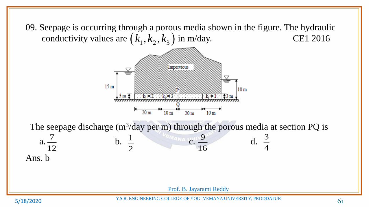
09. Seepage is occurring through a porous media shown in the figure. The hydraulic
conductivity values are in m/day. CE1 2016
The seepage discharge (m3/day per m) through the porous media at section PQ is
a. b. c. d.
Ans. b
1 2 3, ,k k k
7
12
1
2
9
16
3
4

5/18/2020
Prof. B. Jayarami Reddy
Y.S.R. ENGINEERING COLLEGE OF YOGI VEMANA UNIVERSITY, PRODDATUR 62
Equivalent hydraulic conductivity
Seepage discharge,
1 2 /k m day1 20Z m
2 3 /k m day
3 1 /k m day
2 10 20 30Z m
3 10Z m
15 10 5 , 60h m L m
:k
1 2 3
31 2
1 2 3
20 30 102 /
20 30 10
2 3 1
Z Z Zm day
ZZ Z
k k k
. . . .h
Q k i A k AL
352 3 1 0.5 / /
60Q m day m

5/18/2020
Prof. B. Jayarami Reddy
Y.S.R. ENGINEERING COLLEGE OF YOGI VEMANA UNIVERSITY, PRODDATUR 63
10. Which of the following statements if TRUE for the relation between discharge
velocity and seepage velocity? CE1 2015
a. Seepage velocity is always smaller than discharge velocity
b. Seepage velocity can never be smaller than discharge velocity
c. Seepage velocity is equal to the discharge velocity
d. No relation between seepage velocity and discharge velocity can be
established.
Ans. b
Discharge velocity ( ) is the rate of discharge of water through a porous medium
per unit of total area perpendicular to the direction of flow. Seepage velocity (or
Actual velocity or true velocity) is the velocity of water through soil obtained by
considering the actual pre space available for flow.
Porosity of soil
is always less than 1.
Therefore, seepage velocity ( ) is always greater than the discharge velocity ( ).
i.e.,
V
S
VV
n
:nn
SV V
SV V

5/18/2020
Prof. B. Jayarami Reddy
Y.S.R. ENGINEERING COLLEGE OF YOGI VEMANA UNIVERSITY, PRODDATUR 64
11. Water is flowing at a steady rate through a homogeneous and saturated horizontal soil
strip at 10 m length. The strip is being subjected to a constant water head ( ) of 5 m
at the beginning and 1 m at the end. If the governing equation of the flow in the soil
strip is (where is the distance along the soil strip), the value of (in m) at
the middle of the strip is _________ CE2 2014
Ans. 3
Length of the soil strip,
At Head of water,
At Head of water,
The equation of flow in the soil strip is
H
H2
20
d H
dx
10L m0x 5H m10x m 1H m
2
20
d H
dx

5/18/2020
Prof. B. Jayarami Reddy
Y.S.R. ENGINEERING COLLEGE OF YOGI VEMANA UNIVERSITY, PRODDATUR 65
At , Head of water,
Integrating with respect to ,
Integrating again with respect to ,
At ,
At ,
Therefore,
At ,
5x ?H
x
x
2 20, 5 5 0 5x H m C C
110 , 1 1 10 5x m H m C
25
5H x
25 , 5 5 3
5x m H m
1 1
210 4
5C C
1
dHC
dx
1 2H C x C

5/18/2020
Prof. B. Jayarami Reddy
Y.S.R. ENGINEERING COLLEGE OF YOGI VEMANA UNIVERSITY, PRODDATUR 66
12. The flow net constructed for the dam is shown in the figure below. Taking coefficient
of permeability as 3.8×10⁻⁶ m/s, the quantity of flow (in cm3/sec) under the dam per meter
of dam is _________ CE1 2014
Ans. 7.182
Coefficient of permeability,
Head of water causing flow,
Number of flow channels,
Number of equi-potential drops,
Quantity of flow under the dam,
63.8 10 / seck m
6.3h m
3fN
10dN
. .f
d
Nq k H
N
6 6 3 6 6 333.8 10 6.3 7.182 10 / sec/ 7.182 10 10 / sec/
10q m m cm m

5/18/2020
Prof. B. Jayarami Reddy
Y.S.R. ENGINEERING COLLEGE OF YOGI VEMANA UNIVERSITY, PRODDATUR 67
13. The ratio is known as shape factor, where is the number of flow lines
and is the number of equipotential drops. Flow net is always drawn with a
constant ratio, where and are distances between two consecutive flow
lines and equipotential lines, respectively. Assuming that ratio remains the same,
the shape factor of a flow net will change if the 2013
a. upstream and downstream heads are interchanged
b. soil in the flow space is changed.
c. dimensions of the flow space are changed
d. head difference causing the flow is changed.
Ans. c
: Number of flow lines
: Number of equipotential drops
Flow net is always drawn with a constant ratio.
f dN N fN
dN
/b a b a
fN
dN
/b a
5/18/2020
Prof. B. Jayarami Reddy
Y.S.R. ENGINEERING COLLEGE OF YOGI VEMANA UNIVERSITY, PRODDATUR 68
: Distance between two consecutive flow lines
: Distance between two consecutive equipotential lines
Shape factor =
Seepage through flownet,
Shape factor does not depends on
i. Interchanging the upstream and downstream heads. ie., Head causing flow is
same.
ii. Soil in the flow space is changed and varies accordingly.
iii. Head difference causing the flow is changed.
ba
f dN N
. . .f
d
N bq k H
N a

5/18/2020
Prof. B. Jayarami Reddy
Y.S.R. ENGINEERING COLLEGE OF YOGI VEMANA UNIVERSITY, PRODDATUR 69
Common Data for Questions: 14 and 15:
The flow net around a sheet pile wall is shown in the sketch. The properties of the soil
are: permeability coefficient = 0.09 m/day (isotropic), specific gravity =2.70 and void
ratio = 0.85. The sheet pile wall and the bottom of the soil are impermeable.
The factor of safety against the occurrence of piping failure is 2012
a. 3.55 b. 2.93
c. 2.60 d. 0.39
Ans. c
Factor of safety against the occurrence of
piping failure
Critical hydraulic gradient
Actual exit gradientF
. c
e
iF S
i
e
hi
l

5/18/2020
Prof. B. Jayarami Reddy
Y.S.R. ENGINEERING COLLEGE OF YOGI VEMANA UNIVERSITY, PRODDATUR 70
8.5Head loss per drop,
8d
hh
N
length of flow, 3l 8.5
0.3548 3
ei
1 2.7 10.919
1 1 0.85c
Gi
e
0.919
. 2.600.354
c
e
iF S
i
5/18/2020
Prof. B. Jayarami Reddy
Y.S.R. ENGINEERING COLLEGE OF YOGI VEMANA UNIVERSITY, PRODDATUR 71
15. The seepage loss (in m3 per day per unit length of the wall) of water is 2012
a. 0.33 b. 0.38 c. 0.43 d. 0.54
Ans. b
Coefficient of permeability, =0.09 m/day
Specific gravity of soil, =2.70
Void ratio, = 0.85
Head of water, =10 -1.5 = 8.5m
Number of flow channels, =4
Number of equipotential drops, =8
Seepage loss per unit length of wall,
kG
eh
fN
dN
. .f
d
Nq k h
N
340.09 8.5 0.38 m /day/m run
8q

5/18/2020
Prof. B. Jayarami Reddy
Y.S.R. ENGINEERING COLLEGE OF YOGI VEMANA UNIVERSITY, PRODDATUR 72
16. For a saturated sand deposit, the void ratio and the specific gravity of solids are
0.70 and 2.67, respectively. The critical (upward) hydraulic gradient for the deposit
would be 2011
a. 0.54 b. 0.98 c. 1.02 d. 1.87
Ans. b
Void ratio, = 0.70
Specific gravity of solids, = 2.67
Critical hydraulic gradient, = ?
eG
ci
1 2.67 10.98
1 1 0.7c
Gi
e

5/18/2020
Prof. B. Jayarami Reddy
Y.S.R. ENGINEERING COLLEGE OF YOGI VEMANA UNIVERSITY, PRODDATUR 73
17. Quick sand condition occurs when 2010
a. The void ratio of the soil becomes 1.0
b. The upward seepage pressure in soil becomes zero
c. The upward seepage pressure in soil becomes equal to the saturated unit weight
of the soil
d. The upward seepage pressure in soil becomes equal to the submerged unit
weight of the soil
Ans. d
Quick sand condition occurs when the upward seepage pressure in soil becomes
equal to the submerged unit weight of the soil.

5/18/2020
Prof. B. Jayarami Reddy
Y.S.R. ENGINEERING COLLEGE OF YOGI VEMANA UNIVERSITY, PRODDATUR 74
18. To provide safety against piping failure, with a factor of safety of 5, what should
be the maximum permissible exit gradient for soil with specific gravity of 2.5 and
porosity of 0.35? 2006
a. 0.155 b. 0.176 c. 0.195 d. 0.213
Ans. c
Factor of safety,
Specific gravity,
Porosity,
Permissible exit gradient
Void ratio,
Critical hydraulic gradient,
Permissible exit gradient,
5F
2.5G
0.35n
i0.35
0.5381 1 0.35
ne
n
1 2.5 1
0.9751 1 0.538
c
Gi
e
0.975
0.1955
ce
ii
F

5/18/2020
Prof. B. Jayarami Reddy
Y.S.R. ENGINEERING COLLEGE OF YOGI VEMANA UNIVERSITY, PRODDATUR 75
19. The range of void ratio between which quick sand conditions occurs in
cohesionless granular soil deposits is 2006
a. 0.4-0.5 b. 0.6-0.7 c. 0.8-0.9 d. 1.0-1.1
Ans. b
Critical hydraulic gradient,
The specific gravity of cohesionless granular soil varies from 2.6 to 2.7. Quick
sand condition occurs when the critical hydraulic gradient is unity.
The range of void ratio is 0.6 to 0.7
1
1
Gi
e

5/18/2020
Prof. B. Jayarami Reddy
Y.S.R. ENGINEERING COLLEGE OF YOGI VEMANA UNIVERSITY, PRODDATUR 76
20. The figure below shows two flow lines for seepage across an interface between
two soil media of different co-efficients of permeability. If entrance angle =300,
the exit angle will be 2004
a. 7.500 b. 14.030
c. 66.590 d. 75.960
Ans. C
We know that
1 1
2 2
tan
tan
k
k
7 00
2 27
2
1.0 10 tan 30; tan 2.309; 66.59
4.0 10 tan

5/18/2020
Prof. B. Jayarami Reddy
Y.S.R. ENGINEERING COLLEGE OF YOGI VEMANA UNIVERSITY, PRODDATUR 77
21. An unit volume of a mass of saturated soil is subjected to horizontal seepage. The
saturated unit weight is 22 KN/m3 and the hydraulic gradient is 0.3. The resultant
body force on the soil mass is 2004
a. 1.98 KN b. 6.6 KN c. 11.49 KN d. 22.97 KN
Ans. --
Saturated unit weight of soil,
Hydraulic gradient,
Horizontal seepage force per unit volume
Vertical force due to submerged soil mass per unit volume,
Resultant body force on the soil mass,
322 /sat kN m
0.3i
. wi 0.3 10 3HF kN
22 10 12VF kN
2 2 2 2(3) (12) 12.37H VR F F kN

5/18/2020
Prof. B. Jayarami Reddy
Y.S.R. ENGINEERING COLLEGE OF YOGI VEMANA UNIVERSITY, PRODDATUR 78
22. A masonry dam is founded on pervious sand having porosity equal to 45% and
specific gravity of sand particles is 2.65. For a desired factor of safety of 3 against
sand boiling, the maximum permissible upward gradient will be 2003
a. 0.225 b. 0.302 c. 1.0 d. None of these
Ans. b
Porosity of sand,
Specific gravity of sand,
Factor of safety,
Critical hydraulic gradient,
45% 0.45n 2.65G
3F 1
1c
Gi
e
1 1 2.65 1 1 0.45 0.9075ci G n
Critical hydraulic gradient( )
Maximum permissible gradient (i)
ciF
0.90750.3025
3
ciiF

5/18/2020
Prof. B. Jayarami Reddy
Y.S.R. ENGINEERING COLLEGE OF YOGI VEMANA UNIVERSITY, PRODDATUR 79
23. The specific gravity and in-situ void ratio of a soil deposit are 2.71 and 0.85
respectively. The value of the critical hydraulic gradient is 2002
a. 0.82 b. 85 c. 0.92 d. 0.95
Ans. c
Specific gravity of soil,
Void ratio,
Critical hydraulic gradient,
2.71G 0.85e
1
1c
Gi
e
2.71 10.924
1 0.85ci

5/18/2020
Prof. B. Jayarami Reddy
Y.S.R. ENGINEERING COLLEGE OF YOGI VEMANA UNIVERSITY, PRODDATUR 80
24. The coefficients of permeability of a soil in horizontal and vertical directions
are 3.46 m/day and 1.5 m/day respectively. The base length of a concrete dam
resting in this soil is 100 m. When the flow net is developed for this soil with 1:25
scale factor in the vertical direction, the reduced base length of the dam will be
a. 2.63 m b. 4.00 m c. 6.08 m d. 5.43 m 2001
Ans. a
Coefficient of permeability in horizontal direction,
Coefficient of permeability in vertical direction,
Base length of concrete dam,
Scale factor in vertical direction
Let Reduced horizontal dimension for the transformed section.
Reduced base width of scale
3.46 /xk m day
1.5 /yk m day
100B m
1: 25
:b
y
x
kb
B k
1.5100 65.84
3.46b m
65.842.63
25m

5/18/2020
Prof. B. Jayarami Reddy
Y.S.R. ENGINEERING COLLEGE OF YOGI VEMANA UNIVERSITY, PRODDATUR 81
25. The proposed dam shown in the figure is 90 m long and the coefficient of
permeability of the soil is 0.0013 mm/s. The quantity of water (m3) that will be
lost per day be seepage is (rounded to the nearest number): 1998
a. 55 b. 57
c. 59 d. 61
Ans. b
Length of the dam,
Coefficient of permeability of soil,
Quantity of seepage through the dam,
Quantity of water lost through seepage,
Head of water,
Number of flow lines,
Number of equipotential drops,
90L m0.0013 /k mm s
?Q . .
f
d
Nq k H
N
9h m5fN
8dN
3 350.0013 10 60 60 24 9 0.632 / /
8q m day m
3. 0.632 90 56.88 /Q q L m day
5/18/2020
Prof. B. Jayarami Reddy
Y.S.R. ENGINEERING COLLEGE OF YOGI VEMANA UNIVERSITY, PRODDATUR 82
26. Piping in soil occurs when 1996
a. the soil is highly porous b. sudden change in permeability occurs
c. effective pressure becomes zero d. the soil is highly stratified
Ans. c
Piping in soil occurs when effective pressure becomes zero.
5/18/2020
Prof. B. Jayarami Reddy
Y.S.R. ENGINEERING COLLEGE OF YOGI VEMANA UNIVERSITY, PRODDATUR 83
27. Seepage force per unit volume ( ) can be expressed as 1996
a. b. c. d.
Ans. d
Seepage pressure,
Seepage force = Seepage pressure × area.
Seepage force per unit volume
: Unit weight of water
: Head loss
: Hydraulic gradient
: Length of seepage
j. .wi L .i L .w h . wi
. . .s w wp h i z
. . .s wP i z A
. . ..
.
s ww
P i z Ai
V z A
whi /h zz

5/18/2020
Prof. B. Jayarami Reddy
Y.S.R. ENGINEERING COLLEGE OF YOGI VEMANA UNIVERSITY, PRODDATUR 84
28. The number of flow channels and head drops is 4 and 12 respectively. If the
difference in the upstream and downstream water levels is 3 m, what is the
discharge per meter width of a sheet pile wall, if 1992
Ans. 0.1 m3/s/m.
Number of flow channels,
Number of head drops,
Head causing flow,
Coefficient of permeability,
Discharge per m width of sheet pile,
0.1 / ?k m s
4fN
12dN
3h m
0.1 /k m s
. .f
d
Nq k h
N
340.1 3 0.1 / /
12q m s m
5/18/2020
Prof. B. Jayarami Reddy
Y.S.R. ENGINEERING COLLEGE OF YOGI VEMANA UNIVERSITY, PRODDATUR 85
29. Along a phreatic line in an earth dam 1991
a. the total head is constant but not zero b. the total head is everywhere zero
c. the pressure head is everywhere zero d. None of the above
Ans. c
Phreatic line is the top flow line which follows the path of base parabola. It is a
stream line. The pressure head on the phreatic line is atmosphere (zero) and the
total head is equal to the elevation head. Below this line, the pressure is
hydrostatic. Therefore, along the phreatic line in an earth dam, the pressure head
is zero, everywhere.
Copyright © 2022 FDOKUMEN