Constraints on deformation conditions and the origin of oceanic detachments: The Mid-Atlantic Ridge...
37
Constraints on deformation conditions and the origin of oceanic detachments: The Mid-Atlantic Ridge core complex at 15° 45 0 N J. Escartı ´n and C. Me ´ vel Laboratoire de Ge ´osciences Marines (CNRS UMR7097), Institut de Physique du Globe, 75252 Paris, France ([email protected]; [email protected]) C. J. MacLeod Cardiff School of Earth, Ocean and Planetary Sciences, Cardiff University, Cardiff CF10 3YE, UK ([email protected]) A. M. McCaig School of Earth Sciences, University of Leeds, Leeds LS2 9JT, UK ([email protected]) [1] Deformed rocks sampled from a corrugated detachment fault surface near the Mid-Atlantic Ridge (15°45 0 N) constrain the conditions of deformation and strain localization. Samples recovered in situ record deformation restricted to the cold (shallow) lithosphere (greenschist facies), with no evidence for significant high-temperature deformation either at the fault zone or in the footwall near it. High-temperature deformation (720–750°C) is observed only at two sites, and cannot be directly linked to the detachment. Detachment faulting was coeval with dyke intrusions that cross cut it, as demonstrated by the presence of undeformed and highly deformed diabase found in shear zones, and by the presence of chill margins in diabase against fault rock. Basalts are very scarce and restricted to clasts in breccias, with no evidence of pillows or extrusive structures. Gabbros crop out along mass-wasted and fault scarps structurally below the detachment. Footwall rocks show little or no deformation, due to strain localization along a narrow shear zone (<200 m) with fluid flow, as required to form talc- and amphibole schists after an ultramafic protolith. We speculate that the alteration front in a heterogeneous lithosphere may be a rheological boundary that may localize deformation during long periods of time. Our observations and other geological evidence elsewhere suggest that this detachment model limited to the cold (shallow) lithosphere is applicable to other corrugated surfaces along slow- and intermediate-spreading ridges. These observations preclude detachment models rooting in melt-rich zones (i.e., Atlantis Bank, Southwest Indian Ridge) or recording high-temperature deformation. We infer that oceanic detachment faults (1) localize strain at T < 500–300°C, (2) persist during active magmatism, and (3) root at shallow rheological boundaries, such as a melt-rich zone or magma chamber (‘‘hot’’ detachments) or an alteration front (‘‘cold’’ detachments). Components: 19,237 words, 16 figures, 7 tables. Keywords: Faulting; mid-ocean ridge; detachment; rheology. Index Terms: 8010 Structural Geology: Fractures and faults; 8159 Tectonophysics: Rheology—crust and lithosphere; 3035 Marine Geology and Geophysics: Midocean ridge processes. Received 6 November 2002; Revised 12 April 2003; Accepted 17 April 2003; Published 7 August 2003. Escartı ´n, J., C. Me ´vel, C. J. MacLeod, and A. M. McCaig, Constraints on deformation conditions and the origin of oceanic detachments: The Mid-Atlantic Ridge core complex at 15°45 0 N, Geochem. Geophys. Geosyst., 4(8), 1067, doi:10.1029/ 2002GC000472, 2003. G 3 G 3 Geochemistry Geophysics Geosystems Published by AGU and the Geochemical Society AN ELECTRONIC JOURNAL OF THE EARTH SCIENCES Geochemistry Geophysics Geosystems Article Volume 4, Number 8 7 August 2003 1067, doi:10.1029/2002GC000472 ISSN: 1525-2027 Copyright 2003 by the American Geophysical Union 1 of 37
Transcript of Constraints on deformation conditions and the origin of oceanic detachments: The Mid-Atlantic Ridge...
Constraints on deformation conditions and the origin ofoceanic detachments: The Mid-Atlantic Ridge core complexat 15�450N
J. Escartın and C. MevelLaboratoire de Geosciences Marines (CNRS UMR7097), Institut de Physique du Globe, 75252 Paris, France([email protected]; [email protected])
C. J. MacLeodCardiff School of Earth, Ocean and Planetary Sciences, Cardiff University, Cardiff CF10 3YE, UK ([email protected])
A. M. McCaigSchool of Earth Sciences, University of Leeds, Leeds LS2 9JT, UK ([email protected])
[1] Deformed rocks sampled from a corrugated detachment fault surface near the Mid-Atlantic Ridge
(15�450N) constrain the conditions of deformation and strain localization. Samples recovered in situ record
deformation restricted to the cold (shallow) lithosphere (greenschist facies), with no evidence for significant
high-temperature deformation either at the fault zone or in the footwall near it. High-temperature
deformation (�720–750�C) is observed only at two sites, and cannot be directly linked to the detachment.
Detachment faulting was coeval with dyke intrusions that cross cut it, as demonstrated by the presence of
undeformed and highly deformed diabase found in shear zones, and by the presence of chill margins in
diabase against fault rock. Basalts are very scarce and restricted to clasts in breccias, with no evidence of
pillows or extrusive structures. Gabbros crop out along mass-wasted and fault scarps structurally below the
detachment. Footwall rocks show little or no deformation, due to strain localization along a narrow shear
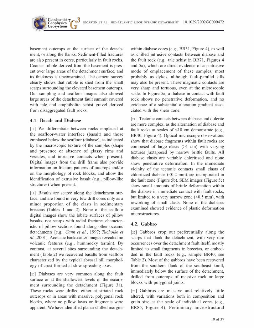
zone (<200 m) with fluid flow, as required to form talc- and amphibole schists after an ultramafic protolith.
We speculate that the alteration front in a heterogeneous lithosphere may be a rheological boundary that may
localize deformation during long periods of time. Our observations and other geological evidence elsewhere
suggest that this detachment model limited to the cold (shallow) lithosphere is applicable to other corrugated
surfaces along slow- and intermediate-spreading ridges. These observations preclude detachment models
rooting in melt-rich zones (i.e., Atlantis Bank, Southwest Indian Ridge) or recording high-temperature
deformation. We infer that oceanic detachment faults (1) localize strain at T < 500–300�C, (2) persist duringactive magmatism, and (3) root at shallow rheological boundaries, such as a melt-rich zone or magma
chamber (‘‘hot’’ detachments) or an alteration front (‘‘cold’’ detachments).
Components: 19,237 words, 16 figures, 7 tables.
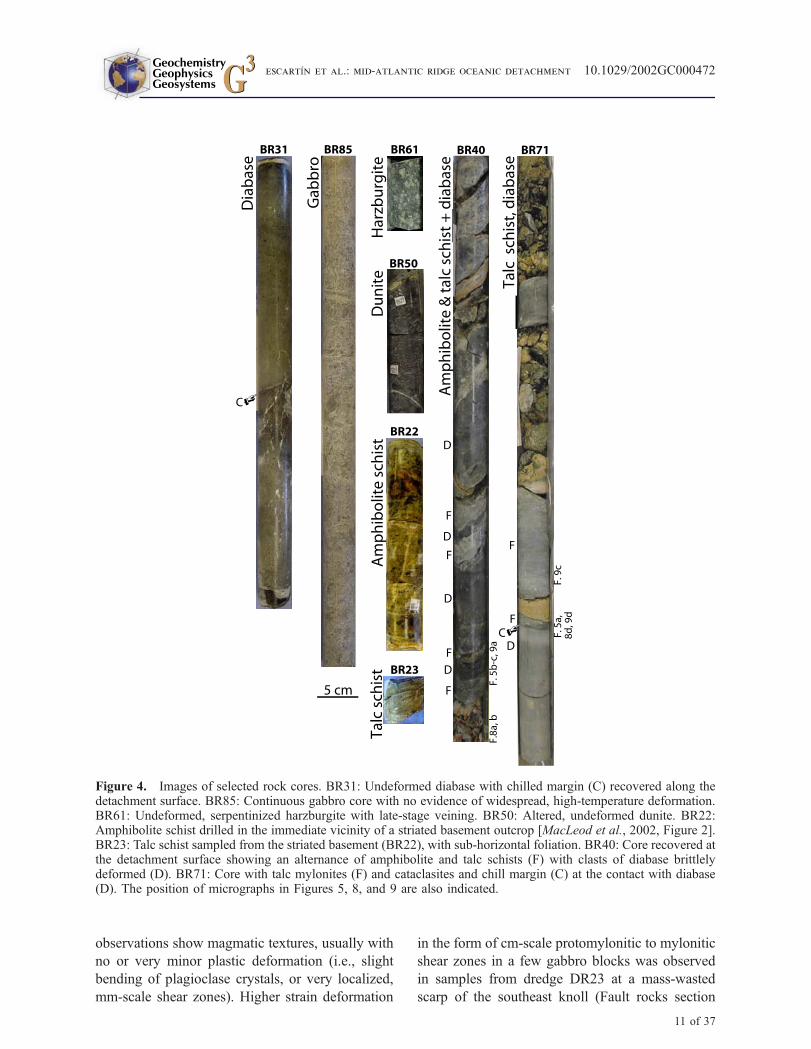
Keywords: Faulting; mid-ocean ridge; detachment; rheology.
Index Terms: 8010 Structural Geology: Fractures and faults; 8159 Tectonophysics: Rheology—crust and lithosphere; 3035
Marine Geology and Geophysics: Midocean ridge processes.
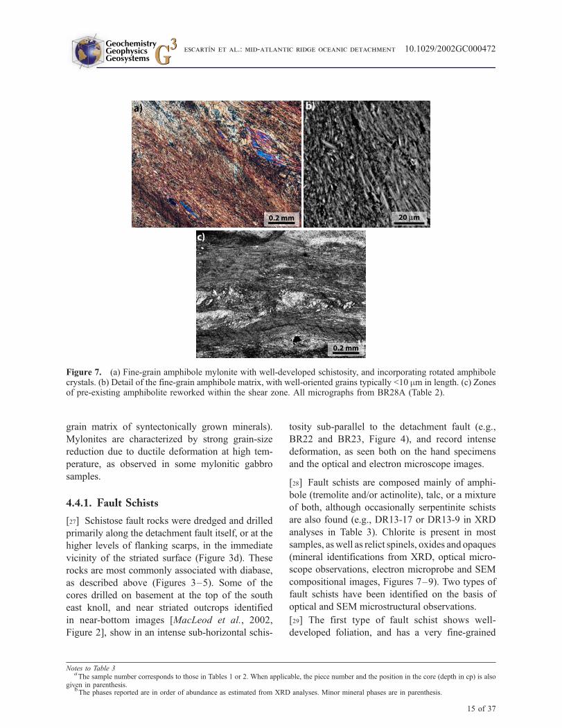
Received 6 November 2002; Revised 12 April 2003; Accepted 17 April 2003; Published 7 August 2003.
Escartın, J., C. Mevel, C. J. MacLeod, and A. M. McCaig, Constraints on deformation conditions and the origin of oceanic
detachments: The Mid-Atlantic Ridge core complex at 15�450N, Geochem. Geophys. Geosyst., 4(8), 1067, doi:10.1029/2002GC000472, 2003.
G3G3GeochemistryGeophysics
Geosystems
Published by AGU and the Geochemical Society
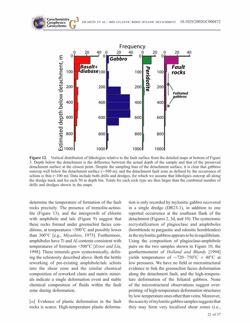
AN ELECTRONIC JOURNAL OF THE EARTH SCIENCES
GeochemistryGeophysics
Geosystems
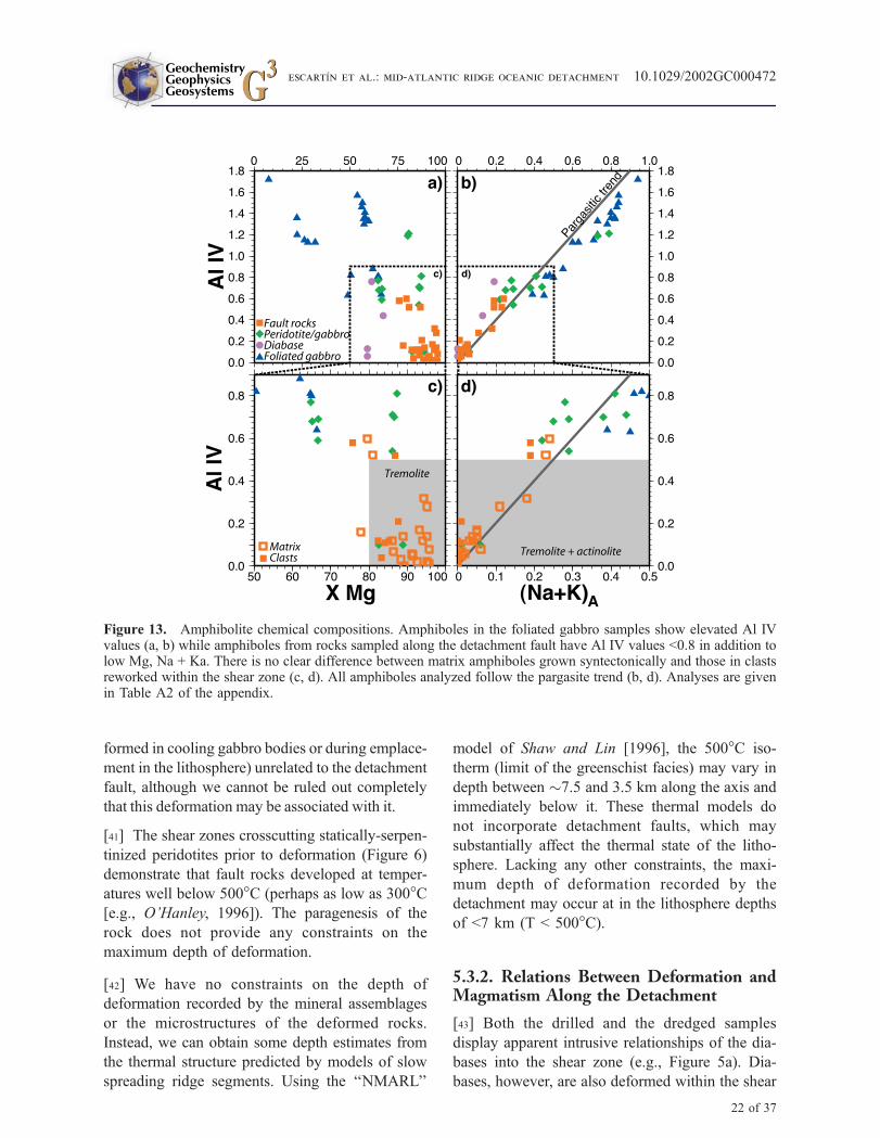
Article
Volume 4, Number 8
7 August 2003
1067, doi:10.1029/2002GC000472
ISSN: 1525-2027
Copyright 2003 by the American Geophysical Union 1 of 37
1. Introduction and Background
[2] Numerous structures interpreted as oceanic
low-angle normal faults (detachments) have been
identified along slow- and intermediate spreading
mid-oceanic ridges in recent years.Morphologically,
these structures are characterized by continuous
surfaces on which prominent striations parallel to
the spreading direction are observed at wave-
lengths of >1 km to <100 m [e.g., Cann et al.,
1997; Christie et al., 1997; Casey et al., 1998;
Deplus et al., 1998; Martinez et al., 1998; Mitchell
et al., 1998; Tamaki et al., 1998; Tucholke et al.,
1998, 2001; Searle et al., 1999; Escartın and
Cannat, 1999; Ranero and Reston, 1999; MacLeod
et al., 2002; Reston et al., 2002]. They are often
domal in form, dipping shallowly (<20�) toward theaxis near the ridge, curving to become sub-horizon-
tal or dipping gently away from the axis. Samples
recovered from the striated surfaces include serpen-
tinized peridotite and gabbro, in addition to basalt
and diabase [e.g., Cann et al., 1997; Escartın et al.,
1999; Tucholke et al., 2001], suggesting that the
structures can be responsible for denuding deep
lithospheric levels. Recovery of highly deformed in
situ rocks from the striated surfaces confirms the
supposition that they represent low-angle faults
[MacLeod et al., 2002]. Positive gravity anomalies
[Blackman et al., 1998] and high seismic velocities
at <1 km below the seafloor [Collins and Detrick,
1998] suggest that, in some cases at least, the
geophysically defined crust is very thin due to
tectonic unroofing along detachments.
[3] Models of continental detachment faults [e.g.,
Wernicke, 1981; Davis, 1983] have been used as a
base to interpret these oceanic ‘‘core complexes’’
[Tucholke et al., 1998]. The size of the structures,
the inferred geometry of the detachment surface,
the length (longevity) of the faults, or the expo-
sures of rocks from deep lithospheric levels are
common to both oceanic and continental core
complexes. The root of continental detachments
is commonly placed within or near the top of a
ductile layer [e.g., Wernicke, 1981; Lister et al.,
1984; Anderson et al., 1988; Lister and Baldwin,
1993]. Similarly, it has been proposed that oceanic
detachments root either at the brittle-ductile tran-
sition immediately below the surface expression of
the ridge axis [e.g., Tucholke et al., 1998, 2001], or
in a melt-rich zone near the dyke-gabbro transition
[Dick et al., 1991, 2000]. Seismic profiles over
detachment faults in old oceanic crust image
reflectors reaching maximum depths of <3 km
below basement [Ranero and Reston, 1999], but
their continuity or geometry at deeper levels is
unknown. The presence of rubble and/or sediments
over most of these detachments [e.g., Searle et al.,
1999; Kelley et al., 2001; Tucholke et al., 2001;
Schroeder et al., 2002] has prevented detailed in
situ sampling of the associated fault rocks, except
in the case of Atlantis Bank at the Southwest
Indian Ridge [e.g., Robinson et al., 1989;MacLeod
et al., 1998; Dick et al., 1999, 2002].
[4] In this paper we present geological, petrological
and microstructural observations, together with
geochemical analyses of fault rocks sampled along
an off-axis striated surface north of the Fifteen-
Twenty Fracture zone (15�450N and 46�550W)
along the Mid-Atlantic Ridge [Escartın and
Cannat, 1999; MacLeod et al., 2002; Fujiwara et
al., 2003] (Figure 1). RRS James Clark Ross cruise
JR63 (April –May 2001). In an earlier paper
[MacLeod et al., 2002] we presented the initial
results of the cruise JR63 (April–May 2001) on
board RRS James Clark Ross [MacLeod et al.,
2001], during which we collected bathymetry and
high-resolution acoustic backscatter imagery to con-
strain the tectonic structure of the area (Figure 2).
The results from the study of these samples, together
with other geological and tectonic observations, are
contrasted with predictions inferred from existing
oceanic detachment models, and with results from
other oceanic detachment faults elsewhere.
2. Experiment, Sampling, and Methods
[5] The first part of cruise JR63 was dedicated to a
complete deep-towed TOBI side-scan sonar survey
of the 15�450N detachment [MacLeod et al., 2002].
The second part of the cruise was dedicated to rock
sampling using oriented wire line drill coring and
dredging [MacLeod et al., 2001]. Multibeam ba-
thymetry (Figure 2a) was collected throughout the
cruise, and used in combination with the acoustic
GeochemistryGeophysicsGeosystems G3G3
escartIn et al.: mid-atlantic ridge oceanic detachment 10.1029/2002GC000472
2 of 37
backscatter data to select sampling targets. Dredged
and cored rocks were described and curated on-
board, and a subset of representative samples were
cut and prepared for thin sectioning. Microstructural
studies, electron microprobe analyses and Scanning
Electron Microcopy (SEM) were conducted on
selected thin sections, as described below.
2.1. Bathymetry and Deep-TowAcoustic Backscatter
[6] Multibeam bathymetry was acquired with the
SIMRAD EM12 system, and using a continuous
Global Positioning (GPS). Data was cleaned
manually to remove spurious points, and gridded
at 100 m grid spacing (Figure 2a). Deeptow
side-scan sonar (TOBI) was acquired and processed
to obtain high-resolution backscatter maps of the
area (see MacLeod et al. [2001, 2002] for details
and Figure 1c therein) and to identify tectonic
features (e.g., scarps and lineations, Figure 2b).
2.2. Sampling
[7] Rock samples were obtained using both
dredges and the BGS BRIDGE wire line, oriented
seabed rock drill [MacLeod et al., 1998; Allerton et
al., 1999]. On-bottom dredge positions reported in
Table 1 are estimated from the position of the ship,
wire out, and local topography. Drill sites were
selected using the seafloor images from the digital
camera mounted on the BRIDGE drill frame.
Positions of some of the drill sites and the dredges
at the seafloor were determined using acoustic
navigation. These differed by <20 m from those
of the ship’s GPS position. Positions reported in
Tables 1 and 2 correspond to the GPS position of
the ship during drilling operations for consistency.
Owing to the precise location of the BRIDGE drill,
rock cores provide more accurate information on
the spatial distribution of lithologies than that
obtained from the less precisely located dredge
samples.
2.3. Optical and Scanning ElectronMicroscopy (SEM)
[8] Thin sections of selected samples were pre-
pared for both conventional optical and electronic
microscopy. Both back-scattered electron (BSE)
and element images were acquired with a JEOL
JSM840A from Universite Pierre et Marie Curie at
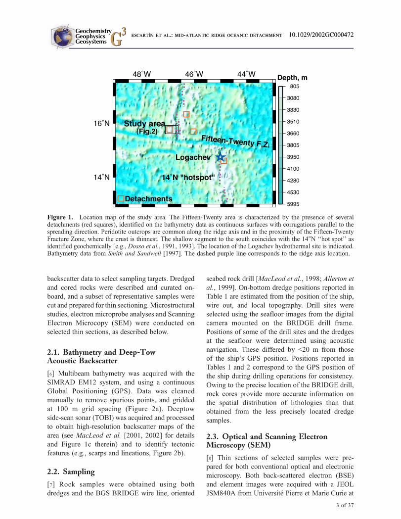
Figure 1. Location map of the study area. The Fifteen-Twenty area is characterized by the presence of severaldetachments (red squares), identified on the bathymetry data as continuous surfaces with corrugations parallel to thespreading direction. Peridotite outcrops are common along the ridge axis and in the proximity of the Fifteen-TwentyFracture Zone, where the crust is thinnest. The shallow segment to the south coincides with the 14�N ‘‘hot spot’’ asidentified geochemically [e.g., Dosso et al., 1991, 1993]. The location of the Logachev hydrothermal site is indicated.Bathymetry data from Smith and Sandwell [1997]. The dashed purple line corresponds to the ridge axis location.
GeochemistryGeophysicsGeosystems G3G3
escartIn et al.: mid-atlantic ridge oceanic detachment 10.1029/2002GC000472escartIn et al.: mid-atlantic ridge oceanic detachment 10.1029/2002GC000472
3 of 37
a voltage of 25 kV, and a CamScan Series 4
from the University of Leeds at a voltage of
20 kV.
2.4. Electron Microprobe Analyses
[9] Mineral compositions were determined with a
CAMECA SX50 microprobe at CAMPARIS, Uni-
versite Pierre et Marie Curie. A combination of
oxides and silicates were used as standards. The
accelerating voltage was 15 kV, and the beam
current 10 nA. Because minerals grain sizes in
fault schists are very small (see description of
microstructures), it was impossible to analyze
single crystals of talc, amphibole or serpentine in
the matrix. Spinel, amphibole and chlorite anal-
yses are given in the Appendix (Tables A1–A3,
respectively).
2.5. X-Ray Diffraction (XRD) Analyses
[10] Small amounts of powder (�1 g) from
selected samples was analyzed with a Phillips
Automated Powder Diffractometer at Cardiff
Figure 2. (a) Multibeam bathymetry and (b) geological interpretation of the study area. The detachment is locatedbetween anomalies 2n and 2An [Fujiwara et al., 2003], and cut by several fault scarps (blue lines). The detachmentfault surface (light green) shows both bathymetric corrugations (thick grey lines) and acoustic backscatter striations(thin black lines) as identified in TOBI imagery (see backscatter images in MacLeod et al. [2002]). Gabbros andperidotites shown have been previously sampled at the south flank of the detachment and along the rift-boundingfault. The axial volcanic ridge (AVR, pink area) and the volcanic cones are also indicated (data from FARANAUT[Cannat et al., 1997] and MODE’98 cruises [Fujiwara et al., 2003]). The contour interval in a) is 500 m, and thelocation of the bathymetric profile across the detachment in Figure 16c is also indicated.
GeochemistryGeophysicsGeosystems G3G3
escartIn et al.: mid-atlantic ridge oceanic detachment 10.1029/2002GC000472
4 of 37

Table 1. Dredge Locations and Water Depth, Recovered Lithologies and Their Abundance
Dredgea
DR
Startb Endb
Lithologies AbundancecLat. (N) Lon. (W)Depth,m Lat. (N) Lon. (W)
Depth,m
01 13�47.0500 44�59.0000 3477 13�47.3000 44�59.3200 3373 Glassy basalt pillow,MnO coating
B (4)
02 15�39.6200 46�04.2800 3506 15�39.9100 46�03.2700 3107 Serpentinized peridotite,basalt pillows,gabbro boulder
P (25), B(14.5), G (5)
03 15�44.5100 45�58.4700 2674 15�45.1600 45�57.8000 2381 Weathered basalt,peridotite andgabbro fragments
B (6), P (1), G
04 15�41.8100 45�03.4700 3409 15�41.8400 45�03.3100 3143 Serpentinizedperidotite pebbles
P
07 15�53.1240 46�51.8220 2282 15�53.7200 46�52.1500 2094 Serpentinized harzburgite,Ol gabbro
P (300), G
08 15�50.6120 46�56.9880 2885 15�51.2130 46�57.2870 2460 Serpentinized harzburgite,gabbro pebbles
P (16), G
09 15�52.8010 46�58.4970 2936 15�52.7090 46�57.9610 2597 Serpentinized harzburgite,sedimentary breccia
P (48)
10 15�50.0080 46�53.9630 2765 15�50.1990 46�53.5890 2514 Fresh pillow basalt,serpentinized peridotite
B (13), P(7), F
11 15�54.4620 46�48.2480 2680 15�54.9330 46�48.5160 2355 Pillow basalts with glass,serpentinized peridotiteboulder
B (13), P (1)
12 15�43.5030 46�57.1730 2523 15�43.7490 46�57.3580 2308 Fragments of peridotite,diabase, and basalt
P, B, D, F, *
13 15�44.0370 46�56.7860 2426 15�44.8150 46�56.5910 2235 Serpentinized harzburgiteand dunite, pillowfragments and diabase.Serpentinite andtalc schists.
P (42), B (21),D (4), F, *
14 15�43.0140 46�56.6660 2622 15�43.4180 46�56.1640 2344 Weathered serpentinizedperidotite,basalt pebbles
P (4), B (2.5),F, *
15 15�43.0100 47�00.4650 2759 15�43.2910 46�59.9120 2471 Serpentinized peridotite P (102), F16 15�42.3680 46�54.9710 2857 15�42.5410 46�54.8110 2661 Fine-grain gabbro G (1.5)17 15�43.4430 46�54.7740 2339 15�43.6710 46�54.7700 2119 Medium/coarse-grain
gabbro, doleriteG (24), D(8)
18 15�43.6410 46�54.4890 2216 15�43.8860 46�54.4900 1325 Medium/coarse-graingabbro, dolerite,serpentinized peridotite
G, D, P
19 15�43.2610 46�53.5930 2414 15�43.2340 46�53.5940 2433 Clasts of serpentinizedperidotite
P
20 15�43.7600 46�53.3480 2215 15�44.1060 46�53.5960 1917 Medium- and coarse-grainedoxide gabbro
G (2)
21 15�44.6030 46�52.5440 2321 15�44.5270 46�52.7220 2246 Medium- and coarse-grainedgabbro
G (7)
22 15�46.0320 46�53.8960 2156 15�45.8800 46�53.8910 1972 Basalt fragments,erpentinized peridotite,gabbro pebbles
B (2), P (1.5), G
23 15�46.1920 46�52.5350 2601 15�46.2930 46�52.8040 2337 Cataclastic and myloniticfoliated gabbro,fine-grain dolerite
G (8), D (4), Fd
24 15�45.2800 46�52.8910 2296 15�45.2870 46�52.9320 2263 Dolerite D (0.5)26 15�43.7000 46�52.1760 2770 15�43.8310 46�52.4240 2374 Serpentinized peridotite,
fine-grain dolerite, gabbroP (4), D (2),G (0.5), F
27 15�43.5960 46�52.7920 2399 16�44.0290 46�52.8340 2289 Serpentinized peridotiteand gabbro pebbles
P, G
28 15�44.1100 46�52.7210 2329 16�44.2390 46�52.8200 2077 Gabbro and dolerite G (14), D (2.5)29 15�45.6810 46�52.9010 2354 15�45.6510 46�53.1910 2050 Dolerite D (2)
GeochemistryGeophysicsGeosystems G3G3
escartIn et al.: mid-atlantic ridge oceanic detachment 10.1029/2002GC000472
5 of 37
University using standard analysis and identifica-
tion techniques.
2.6. Whole Rock Analyses
[11] Whole rocks analyses have been performed at
the SARM, CRPG-CNRS (Nancy, France). Major
elements were analyzed with an ICP-AES Jobin-
Yvon JY70. REE were analyzed with an ICP-MS
Perkin-Elmer ELAN 5000. Analytical results are
given in the Appendix (Table A4).
3. The 15�450N Detachment:Setting, Structure, and Prior Results
[12] The detachment at 15�450N is located 35 km
north of the Fifteen-Twenty Fracture Zone and
�27 km west of the Mid-Atlantic Ridge axis,
and is bounded by the anomalies 2An and 2r
(�2.5 and 2.1 Ma, respectively), according to the
interpretation of Fujiwara et al. [2003] (Figure 2b).
The corrugated surface covers >350 km2, extending
�25 km along the axis and�15 km along-flowline,
and, unlike most oceanic core complexes, is not
directly associated with any clear transform or
non-transform discontinuity of the ridge. The fault
is inferred to have been active between �1 M.y.
[MacLeod et al., 2002] and �0.5 M.y., as indicated
by the spreading rates and size of the fault surface,
and by the interpreted magnetic anomalies, respec-
tively. Magma supply to the present-day axis
appears to be low within 50 km of the fracture
zone, as indicated by extensive peridotite outcrops
along the rift valley walls [Cannat and Casey,
1995; Escartın and Cannat, 1999] (Figure 2b),
and by the thin (<3 km) seismic crust [Detrick et
al., 1999]. Off axis gravity data also indicates an
anomalously thin crust on both sides of the fracture
zone, suggesting that reduced melt supply to the
ridge axis has persisted over periods of �3 Ma or
more [Escartın and Cannat, 1999]. This area of
thin crust is associated with irregular abyssal hill
terrain where several detachments can be identified
from the multibeam bathymetry data available
[Escartın et al., 1999; Fujiwara et al., 2003]
(Figure 1). Normal or anomalously high melt
supply to the axis both to the north and south of
this area can be inferred from bathymetry and
gravity data [Escartın and Cannat, 1999; Fujiwara
et al., 2003]. The southern gravity low coincides
with a geochemical anomaly centered on the 14�N‘‘hot spot’’ [Dosso et al., 1991, 1993] (Figure 1).
[13] The detachment surface shows a very clear
bathymetric corrugations and acoustic backscatter
lineations parallel to the spreading direction, which
are associated with striated outcrops. The structural
continuity of this surface, and the presence of
striations and corrugation, allow us to define the
extension of the exposed detachment fault surface,
as shown in Figures 2 and 3. The bathymetry
shows a long-wavelength undulation of �10 km
in wavelength and �1 km in amplitude, with
smaller-scale corrugations and slope breaks of
Table 1. (continued)
Dredgea
DR
Startb Endb
Lithologies AbundancecLat. (N) Lon. (W)Depth,m Lat. (N) Lon. (W)
Depth,m
30 15�43.0130 46�52.8200 2471 15�43.2100 46�52.9490 2300 Fine-grain dolerite,altered gabbro
D (4), G (1)
31 15�42.2310 46�55.3530 2898 15�42.5490 46�55.7050 2532 Deformed gabbro,vesicular basalt,coarse-grain dolerite
G (17), B (5.5)D (3)
32 15�48.8130 46�45.3400 2745 15�49.5120 46�45.1430 2532 Pillow basalt fragmentswith glass
B (11)
aBold numbers indicate dredges that have been sampled and analyzed under optical microscope.
bStart and end positions correspond to the estimated run of the dredge over the bottom.
cAbundance is reported for the different lithologies, with the number of kilos recovered in parenthesis. B, Basalt; D, Diabase; G, Gabbro;
P, Serpentinized peridotite; F, Fault rocks, mainly amphibole, talc and/or serpentinite schists; sediment content and dredges with sediment only havebeen omitted; asterisks: See Table 3 for XRD mineral identifications.
dHigh-T gabbro mylonite.
GeochemistryGeophysicsGeosystems G3G3
escartIn et al.: mid-atlantic ridge oceanic detachment 10.1029/2002GC000472
6 of 37

Table 2. Location of BGS-Drill Sites and Recovered Lithologies
BR Lat. (N) Lon. (W)Depth,m
Core LengthRecovereda, cm Descriptionb Lithologiesc XRDd
21 15�44.6400 46�54.2400 1620 Serpentinized harzburgite,amph/talc schist
P, F
22 15�44.6360 46�54.2470 1614 20 Serpentinite/amphibolite fromstriated outcrop, with sub-horizontalshear zone on top.
P, F *
23 15�44.6260 46�54.2380 1612 3.5 Fault schist from striated outcrop P, F *24 15�44.6400 46�54.2410 1626 7 Gravel of sheared amphibole/serpentinite F *25 15�44.6310 46�54.2380 1611 33 Lithified breccia with serpentinite,
fault schists, and doleriteP, D, F *
26 15�44.6340 46�54.2430 1616 3 Fault schist, dolerite F, D27 15�44.6350 46�54.2480 1608 9 Fault schist, serpentinite, dolerite F, P, D *28 15�44.6380 46�54.2340 1616 14 Amphibolite fault schist F *29 15�44.4580 46�53.6180 1586 30.5 Lithified breccia with gabbro,
serpentinite/amphibolite schists,serpentinite, and dolerite
G, F, P, D *
30 15�44.4630 46�53.7080 1575 11 Dolerite D31 15�44.1460 46�54.1330 1610 46 Dolerite with possible chilled margin
and brecciated; serpentinite/amphiboliteshear zones
D, F
32 15�44.1060 46�54.1350 1644 3.5 Dolerite and serpentinite/amphiboliteschist pebbles
F, D
33 15�44.2060 46�54.1350 1581 67.5 Dolerite, serpentinite/amphibolite schist D, F *34 15�44.5400 46�53.1130 1756 13 Dolerite and serpentinite/amphibolite schist D, F *35 15�44.5130 46�53.0300 1813 9.5 Dolerite D36 15�45.3800 46�53.5050 1719 52 Dolerite D *37 15�45.1020 46�54.9720 1755 60.5 Lithified breccia with vesicular basalt
clasts and serpentinite/amphibilite schist,serpentinized peridotite
B, P, F *
39 15�44.1530 46�54.6280 1661 44 Lithified breccia with dolerite,some clasts of serpentinite/amphiboliteschist and basalt
D, F, B *
40 15�44.3260 46�54.5220 1557 53 Dolerite and amphibole/talc schist F, D *41 15�44.4770 46�54.4400 1560 5 Serpentinite/amphibolite schist,
and dolerite pebblesF, D *
43 15�44.9340 46�53.3410 1670 30 Lithified breccia with serpentinizedperidotite and dolerite, and core ofdolerite and serpentinite/amphibole schist
P, D, F *
45 15�44.3300 46�54.2240 1544 65 Dolerite cross-cut by talc-bearingshear zones; serpentinized peridotites
D, P, F *
46 15�44.0530 46�54.2840 1620 11.5 Dolerite, fault schist gravel D, F *47 15�44.3150 46�53.9190 1606 43 Serpentinized peridotite pebbles P *49 15�44.5780 46�55.1450 1750 53.5 Dolerite D50 15�45.8670 46�54.8160 2044 49.5 serpentinized harzburgite and dunite P *52 15�43.7190 46�53.8680 2064 14 Dolerite D53 15�44.1760 46�53.0100 1681 19 Dolerite D54 15�44.2270 46�54.0260 1614 2 Dolerite and fault schist D, F *55 15�44.2270 46�54.0160 1617 22.5 Altered serpentinized harzburgite and dunite P *56 15�44.2650 46�52.4770 2272 14 Dolerite D57 15�45.9080 46�53.2650 2013 54 Dolerite, serpentinized peridotite,
fault schist pebblesD, P, F
58 15�44.7150 46�58.2610 1887 2 Dolerite pebbles D60 15�44.5970 46�58.2520 1942 25 Highly weathered serpentinized
harzburgiteP *
61 15�45.4900 46�59.3040 2091 20 Serpentinized harzburgite P *62 15�46.4990 46�58.2510 2305 48 Serpentinized harzburgite, dolerite P, D63 15�50.6760 46�52.3370 2015 26 Dolerite, serpentinite and fault schist pebbles D, P *64 15�49.9700 46�52.0410 2242 2 Fault schist pebbles F *65 15�51.1110 46�52.1150 2133 10 Dolerite and fault schist pebbles D, F *66 15�51.0890 46�51.5920 2324 – No core - serpentinite (?) fragments
on BGS Drill frameP
GeochemistryGeophysicsGeosystems G3G3
escartIn et al.: mid-atlantic ridge oceanic detachment 10.1029/2002GC000472
7 of 37

wavelengths of �1 km and amplitudes of <200 m.
Finer striations in the acoustic backscatter images
(see Figure 1c in MacLeod et al. [2002]) have
wavelengths of 100 m–1 km, and are similar to
those observed at detachments north of the Atlantis
FZ [Cann et al., 1997] and along the South West
Indian Ridge [Searle et al., 1999]. Striations at
cm-scale, and also parallel to the spreading direction,
are observed at basement outcrops at the summit of
the detachment [MacLeod et al., 2002, Figure 2]. A
high-angle, ridge-parallel normal fault with a ver-
tical displacement of >1 km (Figure 2a) terminates
the detachment toward the ridge, while smaller
faults define a ridge-parallel graben at the centre
of the detachment. The interference of this axis-
parallel graben with the large-scale, axis-perpen-
dicular undulations define four shallow areas or
knolls. The striated surface appears to be a contin-
uous structure with a rapid transition into abyssal
hill terrain toward the west, north and south, with
no clear tectonic boundary to accommodate the
change in tectonic structure (Figure 2). The slopes
around the detachment and the ridge-facing fault
are steep and show numerous mass-wasting scarps
that dissect the striated surface and expose deeper
structural levels of the footwall.
[14] Dredges and drill sites selected during cruise
JR63 concentrated both on the detachment surface
and on the fault-bounded and mass-wasted scarps
beneath it. These scarps were targeted to sample
rocks associated with or in structural proximity to
the detachment fault, and lithologies of the foot-
wall proper. Geological observations and rock
samples available from a Shinkai dive (MODE’98
cruise Dive 422 [M. Braun, personal communica-
tion; Matsumoto et al., 1998]) along the southeast
flank of the southeast knoll (Figure 2b) yielded
gabbroic samples in the lower part of the slope.
Gabbros, harzburgites and dunites were found near
the summit of the knoll, where sub-horizontal
striated fault surfaces were recognized during Dive
Table 2. (continued)
BR Lat. (N) Lon. (W)Depth,m
Core LengthRecovereda, cm Descriptionb Lithologiesc XRDd
67 15�52.7090 46�52.1910 2204 11 Dolerite and fault schist pebbles D, F *70 15�45.3860 46�53.5050 1718 22 Fault schist pebbles F *71 15�44.1440 46�54.2420 1586 52 Dolerite in contact with fault
schist and cataclasiteD, F *
72 15�44.1540 46�54.4220 1589 27 Lithified breccia with serpentinizedharzburgite, gabbro and dolerite
P, G, D
73 15�43.5620 46�54.3660 2295 36.5 Gabbro cross-cut by dolerite G, D74 15�43.8460 46�54.6290 1934 35 Coarse-grain gabbro with cataclastic seams G75 15�43.6820 46�55.0410 2186 34 Dolerite with screens of fault schist D, F76 15�44.0500 46�55.2940 2066 33 Dolerite with screens of fault schist D, F *77 15�43.9450 46�53.7150 1992 16 Medium to fine-grain gabbro G78 15�44.0870 46�53.2910 2080 26 Serpentinized dunite with melt impregnations P *79 15�44.0480 46�54.1720 1656 42 Dolerite, dolerite and fault schist pebbles on top D, F *80 15�44.0610 46�53.9920 1792 8.5 Dolerite pebbles, minor amounts of gabbro D, G81 15�44.0660 46�53.6020 1965 31 Dolerite D82 15�43.9530 46�53.9900 1854 41.5 Gabbro and brecciated dolerite G, D84 15�43.6540 46�53.9930 2112 – No core; gabbro fragments on BGS Drill frame G85 15�44.0760 46�54.4290 1674 58 Gabbro G86 15�44.6340 46�54.2450 1625 27.5 Fault schist, serpentinized peridotite, dolerite P, D, F *87 15�44.4800 46�54.4250 1563 8.5 Dolerite, serpentinized peridotite pebbles D, P89 15�44.0360 46�53.5210 2018 5.5 Dolerite D90 15�44.0180 46�54.0680 1745 39 Dolerite, fault schist D, F *91 15�44.1590 46�54.3340 1575 20 Dolerite, fault schist D, F *92 15�43.5420 46�38.6580 3968 3968 Pillow basalt B
aEstimated actual length of sample cored, including sediments.
bDescription of lithologies present in the core.
cSummary of lithologies present in the cores, ordered from most to least abundant; the presence of fault rocks is also indicated. B, Basalt;
D, Dolerite; G, Gabbro; P, Peridotite; F, Fault rock.dSee XRD analyses in Table 3.
GeochemistryGeophysicsGeosystems G3G3
escartIn et al.: mid-atlantic ridge oceanic detachment 10.1029/2002GC000472
8 of 37
422 [Matsumoto et al., 1998]. A near-bottom
digital camera survey (RV Atlantis Cruise A4-4
[MacLeod et al., 2002, Figure 3]) also revealed
several basement outcrops with striations sub-par-
allel to the spreading direction at the summit of the
southeast knoll.
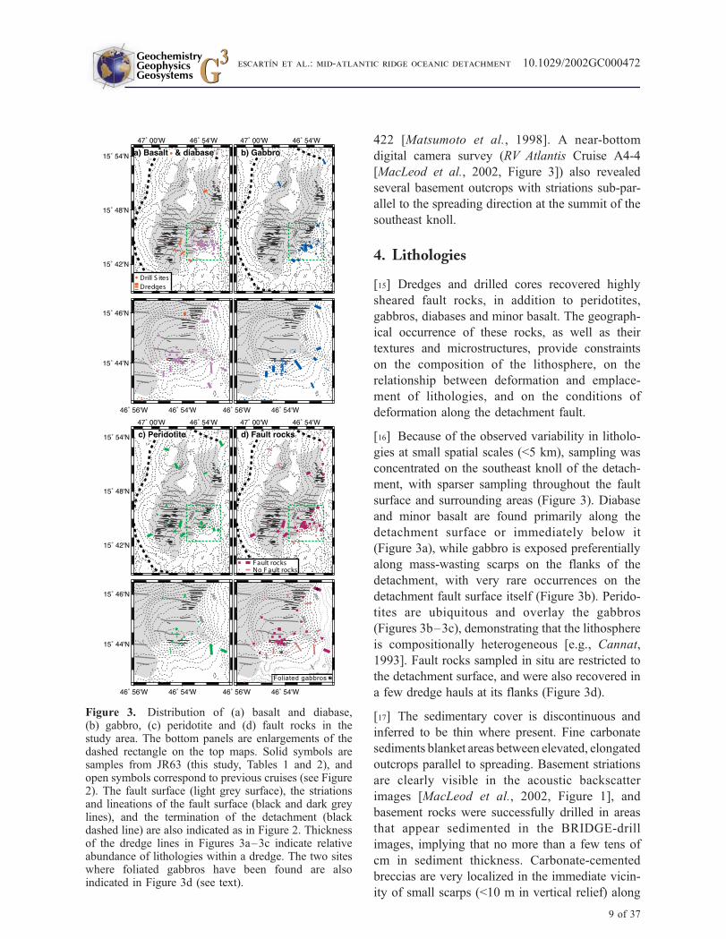
4. Lithologies
[15] Dredges and drilled cores recovered highly
sheared fault rocks, in addition to peridotites,
gabbros, diabases and minor basalt. The geograph-
ical occurrence of these rocks, as well as their
textures and microstructures, provide constraints
on the composition of the lithosphere, on the
relationship between deformation and emplace-
ment of lithologies, and on the conditions of
deformation along the detachment fault.
[16] Because of the observed variability in litholo-
gies at small spatial scales (<5 km), sampling was
concentrated on the southeast knoll of the detach-
ment, with sparser sampling throughout the fault
surface and surrounding areas (Figure 3). Diabase
and minor basalt are found primarily along the
detachment surface or immediately below it
(Figure 3a), while gabbro is exposed preferentially
along mass-wasting scarps on the flanks of the
detachment, with very rare occurrences on the
detachment fault surface itself (Figure 3b). Perido-
tites are ubiquitous and overlay the gabbros
(Figures 3b–3c), demonstrating that the lithosphere
is compositionally heterogeneous [e.g., Cannat,
1993]. Fault rocks sampled in situ are restricted to
the detachment surface, and were also recovered in
a few dredge hauls at its flanks (Figure 3d).
[17] The sedimentary cover is discontinuous and
inferred to be thin where present. Fine carbonate
sediments blanket areas between elevated, elongated
outcrops parallel to spreading. Basement striations
are clearly visible in the acoustic backscatter
images [MacLeod et al., 2002, Figure 1], and
basement rocks were successfully drilled in areas
that appear sedimented in the BRIDGE-drill
images, implying that no more than a few tens of
cm in sediment thickness. Carbonate-cemented
breccias are very localized in the immediate vicin-
ity of small scarps (<10 m in vertical relief) along
*
Foliated gabbros
Figure 3. Distribution of (a) basalt and diabase,(b) gabbro, (c) peridotite and (d) fault rocks in thestudy area. The bottom panels are enlargements of thedashed rectangle on the top maps. Solid symbols aresamples from JR63 (this study, Tables 1 and 2), andopen symbols correspond to previous cruises (see Figure2). The fault surface (light grey surface), the striationsand lineations of the fault surface (black and dark greylines), and the termination of the detachment (blackdashed line) are also indicated as in Figure 2. Thicknessof the dredge lines in Figures 3a–3c indicate relativeabundance of lithologies within a dredge. The two siteswhere foliated gabbros have been found are alsoindicated in Figure 3d (see text).
GeochemistryGeophysicsGeosystems G3G3
escartIn et al.: mid-atlantic ridge oceanic detachment 10.1029/2002GC000472
9 of 37
basement outcrops at the surface of the detach-
ment, or along the flanks. Sediment-filled fractures
are also present in cores, particularly in fault rocks.
Coarser rubble derived from the basement is pres-
ent over large areas of the detachment surface, and
its thickness is unconstrained. The camera survey
clearly shows that rubble is shed from the small
scarps surrounding the elevated basement outcrops.
Our sampling and seafloor images also showed
large areas of the detachment fault summit covered
with talc and amphibolite schist gravel derived
from disaggregated fault rocks.
4.1. Basalt and Diabase
[18] We differentiate between rocks emplaced at
the seafloor-water interface (basalt) and those
emplaced below the seafloor (diabase), as indicated
by the macroscopic texture of the samples (shape
and presence or absence of glassy rims and
vesicles, and intrusive contacts when present).
Digital images from the drill frame also provide
information on fracture patterns of outcrops and/or
on the morphology of rock blocks, and allow the
identification of extrusive basalt (e.g., pillow-like
structures) when present.
[19] Basalts are scarce along the detachment sur-
face, and are found in very few drill cores only as a
minor proportion of the clasts in sedimentary
breccias (Tables 1 and 2). None of the seafloor
digital images show the lobate surfaces of pillow
basalts, nor scarps with radial fractures character-
istic of pillow sections found along other oceanic
detachments [e.g., Cann et al., 1997; Tucholke et
al., 2001]. Acoustic backscatter images revealed no
volcanic features (e.g., hummocky terrain). By
contrast, at several sites surrounding the detach-
ment (Table 2) we recovered basalts from seafloor
characterized by the typical abyssal hill morphol-
ogy of crust formed at slow-spreading axes.
[20] Diabases are very common along the fault
surface or at the shallowest levels of the escarp-
ment surrounding the detachment (Figure 3a).
These rocks were drilled either at striated rock
outcrops or in areas with massive, polygonal rock
blocks, where no pillow lavas or fragments were
apparent. We have identified planar chilled margins
within diabase cores (e.g., BR31, Figure 4), as well
as chilled intrusive contacts between diabase and
the fault rock (e.g., talc schist in BR71, Figures 4
and 5a), which are direct evidence of an intrusive
mode of emplacement of these samples, most
probably as dykes, although fault-parallel sills
may also be present. These magmatic contacts are
very sharp and tortuous, even at the microscopic
scale. In Figure 5a, a diabase in contact with fault
rock shows no penetrative deformation, and no
evidence of a substantial alteration gradient asso-
ciated with the shear zone.
[21] Tectonic contacts between diabase and dolerite
are more complex, as the alternation of diabase and
fault rocks at scales of <10 cm demonstrate (e.g.,
BR40, Figure 4). Optical microscope observations
show that diabase fragments within fault rocks are
composed of large clasts (>1 cm) with varying
textures juxtaposed by narrow brittle faults. All
diabase clasts are variably chloritized and none
show penetrative deformation. In the immediate
vicinity of the tectonic contacts small clasts of
chloritized diabase (<0.2 mm) are incorporated in
the fault zone (Figure 5b). SEM images (Figure 5c)
show small amounts of brittle deformation within
the diabase in immediate contact with fault rocks,
but limited to a very narrow zone (<0.5 mm), with
reworking of small clasts. None of the diabases
examined showed evidence of plastic deformation
microstructures.
4.2. Gabbro
[22] Gabbros crop out preferentially along the
scarps that flank the detachment, with very rare
occurrences over the detachment fault itself, mostly
limited to small fragments in breccias, or embed-
ded in the fault rocks (e.g., sample BR40; see
Table 2). Most of the gabbros have been recovered
from the southern flank of the southeast knoll,
immediately below the surface of the detachment,
drilled from outcrops of massive rock or large
blocks with polygonal joints.
[23] Gabbros are massive and relatively little
altered, with variations both in composition and
grain size at the scale of individual cores (e.g.,
BR85, Figure 4). Preliminary microstructural
GeochemistryGeophysicsGeosystems G3G3
escartIn et al.: mid-atlantic ridge oceanic detachment 10.1029/2002GC000472
10 of 37
observations show magmatic textures, usually with
no or very minor plastic deformation (i.e., slight
bending of plagioclase crystals, or very localized,
mm-scale shear zones). Higher strain deformation
in the form of cm-scale protomylonitic to mylonitic
shear zones in a few gabbro blocks was observed
in samples from dredge DR23 at a mass-wasted
scarp of the southeast knoll (Fault rocks section
BR40
5 cm
F. 5
a,
8d, 9
d
BR71BR31 BR85 BR61
BR50
BR22
BR23
Dia
bas
e
Gab
bro
Har
zbu
rgit
eD
un
ite
Am
ph
ibo
lite
sch
ist
Am
ph
ibo
lite
& t
alc
sch
ist
+ d
iab
ase
Talc
sch
ist,
dia
bas
e
C
Talc
sch
ist
F
F
D
D
F
DC
D
F
D
F
F
F. 5
b-c
, 9a
F.8a
, b
F. 9
c
Figure 4. Images of selected rock cores. BR31: Undeformed diabase with chilled margin (C) recovered along thedetachment surface. BR85: Continuous gabbro core with no evidence of widespread, high-temperature deformation.BR61: Undeformed, serpentinized harzburgite with late-stage veining. BR50: Altered, undeformed dunite. BR22:Amphibolite schist drilled in the immediate vicinity of a striated basement outcrop [MacLeod et al., 2002, Figure 2].BR23: Talc schist sampled from the striated basement (BR22), with sub-horizontal foliation. BR40: Core recovered atthe detachment surface showing an alternance of amphibolite and talc schists (F) with clasts of diabase brittlelydeformed (D). BR71: Core with talc mylonites (F) and cataclasites and chill margin (C) at the contact with diabase(D). The position of micrographs in Figures 5, 8, and 9 are also indicated.
GeochemistryGeophysicsGeosystems G3G3
escartIn et al.: mid-atlantic ridge oceanic detachment 10.1029/2002GC000472
11 of 37

below, Table 1, and Figures 2b and 3b). These
shear bands appear to be minor as they are very
localized and are not penetrative even at the scale
of hand specimens.
4.3. Peridotites
[24] Harzburgites and dunites are recovered both
from the detachment fault surface itself, and along
the flanking scarps beneath it (Figure 3c). Most of
these peridotites have been statically serpentinized,
and show the typical serpentine mesh texture
replacing olivine crystals, and serpentine pyroxene
pseudomorphs (bastites [see MacLeod et al., 2002,
Figure 3]). Magnetite and other oxides are very
abundant in some samples, and tend to concentrate
along mesh rims and within serpentine veins. Un-
altered spinels and relict fresh fragments of olivine
crystals (Figure 6a) are found in some of the
samples. In addition to static serpentinization, some
samples display direct alteration of fresh olivine to
talc (e.g., DR13-3, Figure 6a), or talc shear zones
grading into halos of undeformed talc replacing the
pre-existing serpentine (DR26-5, Figure 6b).
[25] There is no clear record of plastic deforma-
tion either prior to or after serpentinization.
Brittle deformation is present, in the form of
distributed fracturing, shear zones localized at
the scale of a thin section, or veins of serpentine,
talc, amphibolite or calcite. Brittle damage
with no obvious associated strain is recognized
from broken bastites whose fragments show no
noticable relative translation or rotation, that are
surrounded by serpentine or talc veins (e.g.,
Figure 6a) or halos. This brittle deformation
therefore accommodates minor amounts of strain;
most samples, however, show no deformation.
Localized shear zones are cataclastic and com-
posed of serpentine and chlorite clasts, in addi-
tion to the talc shear zones described above
(Figure 6b). Veins are common in most samples,
Figure 5. (a) SEM image of the sharp and irregular intrusive contact of diabase and the fault rock (red dashed line;BR71C, see Figure 4). No penetrative deformation nor alteration is observed near the diabase. The fault schist iscomposed mainly of talc (Tc) clasts embedded in a talc +amphibole (Amp) matrix. Pl: Plagioclase. (b) Optical and(c) SEM, tectonic contact of diabase with fault rocks (BR40A, see Figure 4). Clasts of fully chloritized diabase areincorporated in the shear zone (Figure 5b), composed mainly of amphibolite and chlorite (Cl). Sph: accessory sphene.Diabase in the immediate vicinity of the contact (Figure 5c) shows limited brittle cracking over a narrow band, withno penetrative deformation. Small diabase clasts (<25 mm) are reworked into the fault rock.
GeochemistryGeophysicsGeosystems G3G3
escartIn et al.: mid-atlantic ridge oceanic detachment 10.1029/2002GC000472
12 of 37

recording late-stage, static crack dilation [e.g.,
O’Hanley, 1992].
4.4. Fault Rocks
[26] In this paper we differentiate between highly
sheared rocks recovered mainly along the exposed
detachment fault (fault schists), and mylonites
(foliated gabbros below), following Passchier
and Trouw [1998]. Fault schists may record brittle
(cataclastic) deformation, plastic deformation (e.g.,
syntectonic growth of crystals), or semibrittle de-
formation (e.g., cataclastic porphyroclasts in a fine-
Figure 6. (a) Static talc (Tc) alteration after olivine (Ol) along pre-existing fractures (sample DR13-3). (b) Talcshear zones cross-cutting a serpentinized peridotite (serp.). The peridotite was serpentinized prior to talc alteration, asindicated by the gradual textural transition from the highly-deformed shear zones to undeformed talc halos whichreplace the undeformed, mesh-textured serpentinized peridotite (sample DR26-5).
GeochemistryGeophysicsGeosystems G3G3
escartIn et al.: mid-atlantic ridge oceanic detachment 10.1029/2002GC000472
13 of 37

Table 3. Summary of XRD Mineral Identifications
Samplea Description Phases Identifiedb
BR22 (pc 1a, 0 cm) Fault schist core TalcBR22 (pc 1c, 13 cm) Undeformed altered peridotite TalcBR23 (5 cm) Fault schist core ActinoliteBR24 (pc 1, 0–20 cm) Fault schist fragment Chlorite, hydrotalciteBR24 (0–23 cm) Fault schist core Chlorite (quartz, hydrotalcite)BR24 (23–30 cm) Fault schist fragment Chlorite (hydrotalcite)BR25 (pc 3, 14–21 cm) Fault schist fragment Talc, chloriteBR25 (14–21 cm) Fault schist fragment Talc, chloriteBR26 (9 cm) Fault schist fragment Chlorite, talc, ferropargasiteBR27 (11–25 cm) Altered core (dolerite ?) ChloriteBR27 (15–17 cm) Alteration mud Chlorite (quartz, calcite)BR28 (0–8 cm) Fault schist fragment Tremolite, actinoliteBR28 (8–11 cm) Fault schist fragment (BR28A) Actinolite, chloriteBR28 (pc 3b, 18–19 cm) Fault schist core Actinolite (crossite)BR29 (pc 2d, 54 cm) Fault schist fragment in sedimentary breccia Tremolite (crossite, quartz)BR32 (3 cm) Fault schist fragment Talc, chlorite, pargasiteBR33 (0 cm) Fault schist core Talc, chloriteBR34 (pc 3, 15 cm) Undeformed gabbro Anorthite, augite, saponite, talcBR36 (pc 2, 34–36 cm) Breccia in contact between dolerite dykes (?) Talc, chlorite, actinoliteBR37 (pc 5d, 51 cm) Fault schist fragment in sedimentary breccia Talc, chloriteBR39 (pc 2b, 29) Fault schist fragment in sedimentary breccia Talc, actinoliteBR40 (pc 1b, 8 cm) Fault schist core (BR40D) Talc, chlorite, actinoliteBR40 (pc 1b, 11 cm) Fault schist core Amphibole, chloriteBR40 (pc 2B, 17 cm) Fault schist core Chlorite, tremoliteBR40 (66–74 cm) Fault schist fragment (BR40E) Chlorite, actinoliteBR41 (pc 4, 13 cm) Fault schist fragment Actinolite, chloriteBR43 (pc 3, 33 cm) Fault schist fragment Actinolite, chloriteBR45 (pc 1, 3 cm) soft pale highly sheared serp Chlorite, actinolite, talcBR45 (pc 13, 77–84 cm) Fault schist fragment Talc, actinolite, chloriteBR46 (6–16 cm) Fault schist fragment Chlorite, talcBR47 (pc 5, 29 cm) Fault schist fragment TalcBR50 (pc 2a, 1 cm) Vein in serpentinized dunite Chrysotile, talc, calcite/dolomiteBR50 (pc 7a, 48 cm) Serpentinized dunite Lizardite, diopsideBR54 (pc 1, 5 cm) Fault schist in dolerite core Actinolite, chloriteBR55 (pc 2, 5 cm) Vein in serpentinized peridotite Talc, chrysotileBR60 (23 cm) Mud from serpentinized harzburgite LizarditeBR61 (pc 3c, 15 cm) Mesh-textured serpentinized peridotite LizarditeBR63 (0 cm) Fault schist core ActinoliteBR64 (4 cm) Fault schist fragment Actinolite, chloriteBR65 (17 cm) Fault schist fragment TalcBR67 (7–18 cm) Fault schist fragment Chlorite, talcBR70 (0–27 cm) Fault schist fragment Talc (chlorite)BR71 (3–12 cm) Fault schist fragment Talc, actinoliteBR76 (pc 1c, 23 cm) Fault schist in dolerite core Chlorite, actinoliteBR78 (pc 3, 28–30 cm) Serpentinized dunite Lizardite, talc, chloriteBR79 (0–13 cm) Fault schist fragment Actinolite, ChloriteBR86 (pc 4, 17–22 cm) Carbonate vein cutting serpentinized peridotite
core near contact with doleriteCalcite, talc
BR86 (pc 4, 17–22 cm) Serpentinized peridotite core near contact with dolerite Talc (chlorite, tremolite)BR86 (23–32 cm) Fault schist fragment (BR86B) Chlorite, talc, actinoliteBR90 (18 cm) Fault schist fragment Actinolite, chloriteBR90 (pc 7a, 26 cm) Fault schist core (BR90-A) Actinolite, chloriteBR91 (pc 1a, 0 cm) Fault schist core Talc, chloriteDR12-1 Fault schist Actinolite, chloriteDR12-3 Green alteration ChloriteDR13-1 Fault schist fragment Talc, chloriteDR13-4 Fault schist fragment Talc, chloriteDR13-9 Fault schist, fibrous ChrysotileDR14-4 Fault schist fragment Talc, actinolite, chloriteDR14-Bag 4 Fault schist fragment Talc, actinolite, chlorite
GeochemistryGeophysicsGeosystems G3G3
escartIn et al.: mid-atlantic ridge oceanic detachment 10.1029/2002GC000472
14 of 37
grain matrix of syntectonically grown minerals).
Mylonites are characterized by strong grain-size
reduction due to ductile deformation at high tem-
perature, as observed in some mylonitic gabbro
samples.
4.4.1. Fault Schists
[27] Schistose fault rocks were dredged and drilled
primarily along the detachment fault itself, or at the
higher levels of flanking scarps, in the immediate
vicinity of the striated surface (Figure 3d). These
rocks are most commonly associated with diabase,
as described above (Figures 3–5). Some of the
cores drilled on basement at the top of the south
east knoll, and near striated outcrops identified
in near-bottom images [MacLeod et al., 2002,
Figure 2], show in an intense sub-horizontal schis-
tosity sub-parallel to the detachment fault (e.g.,
BR22 and BR23, Figure 4), and record intense
deformation, as seen both on the hand specimens
and the optical and electron microscope images.
[28] Fault schists are composed mainly of amphi-
bole (tremolite and/or actinolite), talc, or a mixture
of both, although occasionally serpentinite schists
are also found (e.g., DR13-17 or DR13-9 in XRD
analyses in Table 3). Chlorite is present in most
samples, aswell as relict spinels, oxides and opaques
(mineral identifications from XRD, optical micro-
scope observations, electron microprobe and SEM
compositional images, Figures 7–9). Two types of
fault schists have been identified on the basis of
optical and SEM microstructural observations.
[29] The first type of fault schist shows well-
developed foliation, and has a very fine-grained
Notes to Table 3aThe sample number corresponds to those in Tables 1 or 2. When applicable, the piece number and the position in the core (depth in cp) is also
given in parenthesis.bThe phases reported are in order of abundance as estimated from XRD analyses. Minor mineral phases are in parenthesis.
Figure 7. (a) Fine-grain amphibole mylonite with well-developed schistosity, and incorporating rotated amphibolecrystals. (b) Detail of the fine-grain amphibole matrix, with well-oriented grains typically <10 mm in length. (c) Zonesof pre-existing amphibolite reworked within the shear zone. All micrographs from BR28A (Table 2).
GeochemistryGeophysicsGeosystems G3G3
escartIn et al.: mid-atlantic ridge oceanic detachment 10.1029/2002GC000472
15 of 37
matrix (<10–100 mm) of syntectonically-grown
minerals (mainly amphibole, Figures 7a and 7b, or
talc and chlorite). This matrix embeds brittlely
reworked porphyroclasts of amphibole grains and
of amphibole schist in the fault zone, defining
elongated areas parallel to, and draped by the
foliation of the matrix (Figure 7c). None of the
amphibole porphyroclasts show kinking or bending,
and show clear solid rotation of individual grains
and cataclastic grain size reduction (0.2mm–10 mm,
Figures 7a and 7c). Fibrous veins crosscut the
schistosity at high angles. These veins record vein
opening that is coeval with the formation of the
matrix schistosity, as shown by amphibole fibers
that are sub-perpendicular to cracks at their core,
and that curve toward the edges of the vein where
they show continuity with the matrix schistosity.
[30] The second type is composed of amphibole,
talc, or a combination of both, with less-developed
schistosity, and is characterized by a complex
microtexture with sigmoidal bands of syntectoni-
cally-grown amphibole and/or talc and cataclastic
bands (Figure 8). These latter microstructures re-
cord a complex history of deformation, with both
reworking of fault rock and syntectonic growth of
talc or amphibole. The sigmoidal zones, which
define a weak and irregular foliation, are composed
of amphibole/talc and chlorite (Figures 8a and
8c–8d) and display homogenous optical extinction
(Figure 5b). Thin (<1 mm) chlorite-rich zones with
well-developed foliation drape the sigmoidal clasts.
Clasts of amphibole and talc schist (<1 mm) show
internal foliation that is at high angle to the overall
schistosity, indicating solid rotation and reworking
Figure 8. (a) Fault schist showing sigmoidal zones of amphibole + chlorite (dark lens-shaped areas) surrounded bychlorite-rich bands (light grey areas) and bands of cataclastic amphibole grains (lighter bands, detail in Figure 8b).(b) Band of fine-grain amphibolite clasts within foliated chlorite bands (sample BR40E, Figure 4). (c) Sigmoidalbands of amphibolite surrounded by chlorite and containing clasts of amphibole crystals and other accessory minerals(BR40A, Figure 4). (d) Sigmoidal bands of talc surrounded by chlorite and containing cataclastic porphyroclasts ofsphene and other minerals (sample BR71C, Figure 4).
GeochemistryGeophysicsGeosystems G3G3
escartIn et al.: mid-atlantic ridge oceanic detachment 10.1029/2002GC000472
16 of 37

of previously existing fault schists (e.g., Figure 8).
SEM images show porphyroclasts of variable sizes
(down to <50 mm) both distributed throughout the
amphibole/talc-rich sigmoidal areas, and concen-
trated in narrow bands (�100 mm or less, Figures 8a
and 8b) of very finely crushed clasts. The
porphyroclasts are composed, in order of abun-
dance, of amphibole and amphibolite schists,
sphene, chromite, oxides and spinel (Figure 9).
These microstructures record a complex history
of phases of ductile and brittle deformation.
[31] Optical microscope observations and SEM
element analysis demonstrate the syntectonic inter-
growth of amphibole and talc with chlorite. Anom-
alous blue chlorite (Figure 5b) is oriented parallel
to the foliation draping around the sigmoidal clasts
(light areas in Figures 8a–8c), or alternate with
amphibole- and chlorite-rich areas at scales of
0.1 mm to <50 mm (Figures 9a–9c). Some fault
schists are cross cut by late-stage brittle cracks
accommodating small amounts of strain. Irregular
patches (<2 mm) of brown chlorite (Figure 9d)
with a radial habit demonstrate that these rocks
underwent post-tectonic, static chloritization.
4.4.2. Foliated Gabbro
[32] One dredge with a few gabbro mylonite sam-
ples was recovered on the east flank of the south-
east knoll (DR23-1, Figures 3d and 10). These
gabbros show and alternation of highly deformed
zones with well-developed foliation and composi-
tional banding at <1 cm scale. The foliation is
defined by alternating bands of pyroxene, brown
amphibole and plagioclase, indicating grain size
reduction (pyroxene), dynamic recrystallization
(plagioclase) and syntectonic crystal growth (am-
phibole; Figure 10). Zones with relict magmatic
textures show large plagioclase and pyroxene crys-
tals with recrystallization along their boundaries.
Some of these foliated rocks have sharp boundaries
and are in direct contact with highly fractured and
altered gabbro (Figure 10b). These high-tempera-
ture amphibolite facies shear zones appear to
overprint lower temperature pseudomorphic alter-
ation, and are cross cut by undeformed ferrohorn-
blende and plagioclase veins. Amphiboles both in
shear zones and veins are chlorite-rich, suggesting
involvement of seawater-derived brines in the
deformation zone. Gabbro mylonites have also
Figure 9. SEM micrographs and selected element distribution maps of fault schists. (a) Fault rock composed ofamphibole (high Si and Ca concentrations) and chlorite in contact with diabase (BR40A, same micrograph as inFigure 5c). (b) Gradual compositional variations within the shear zone, with chlorite- and amphibole-rich zones(BR40E, Figure 4). Clorite- and amphibole-rich zones alternate at scales of <25 mm. (c) Irregular patches of talc- andchlorite + amphibolite-rich zones in a talc schist (BR71B, Figure 4). (d) Late chlorite patches with radial habitoverprinting talc schist (BR71C, Figure 4). These irregular patches are also found in amphibolite-rich schists (seebrown patches in Figure 5b). All samples show minor amounts of Ca-rich sphene (Sph).
GeochemistryGeophysicsGeosystems G3G3
escartIn et al.: mid-atlantic ridge oceanic detachment 10.1029/2002GC000472
17 of 37

been sampled during the MODE’98 Dive 422 from
the base of the south flank of the southeast knoll
[M. Braun, personal communication; Matsumoto et
al., 1998]. Mylonitic gabbros are therefore a very
rare occurrence volumetrically, are restricted solely
to two sites, and we cannot establish any direct
spatial association of these samples with the de-
tachment fault.
5. Results
5.1. Fault Schist Protolith
[33] The bulk-rock compositions of the fault
schists (talc, amphibole, serpentinite, and chlorite)
are not consistent with those of any primary rock
from the ocean lithosphere (basalt, gabbro, perido-
tite) and suggest important chemical remobilization
during deformation and alteration. Despite the
obliteration of primary textures and chemical com-
position by metamorphic crystallization, it is never-
theless possible to conclude that the fault rocks
derive mainly from ultramafic rocks based on: (1)
the composition of the small spinel grains that have
been preserved during mylonitization, and (2) the
bulk composition of serpentinized peridotites,
gabbros, and fault schists. There is evidence for
some contribution of gabbro or diabase/basalt in
the fault zone, but this component appears to be
very minor or negligible.
[34] Figure 11a clearly shows that the composition
of small chromian spinel porphyroclasts found in
both amphibole and talc fault schists have Cr# and
Mg# consistent with those measured in spinels
from serpentinized peridotites in this area, or with
values reported for oceanic ultramafic peridotites
[e.g., Dick and Bullen, 1984] (Table A1 in Appen-
dix). Only an altered spinel grain shows Cr# and
Mg# values well outside the ultramafic peridotite
domain. These compositions demonstrate that spi-
nel clasts in fault schists have an ultramafic origin.
[35] The bulk compositions of two fault rocks (talc
and serpentine schists) have been compared with
those of two undeformed serpentinized peridotites
and of two diabases. Major element abundances
(Table 4) show that the serpentinite fault rock has a
bulk composition consistent with that of unde-
formed serpentinite, while the talc-schist is very
enriched in silica. The rare earth elements (REE),
however, yield very low concentrations for both
fault rocks, similar to those of serpentinized perid-
otites recovered in the area (Figure 11b) and other
ultramafic rocks. REE concentrations in the dia-
bases are an order of magnitude or more higher. As
REEs are not normally mobilized during alteration
Figure 10. (a) SEM micrograph of foliated gabbro with alternating bands of amphibole (Amp), pyroxene (Px)and plagioclase (Pl), indicating deformation at T > 700�C (see text; DR23-1, Figure 3d and Table 1). Accessoryilmenite (Il) is also present. (b) Gabbro with plagioclase-amphibole foliation in contact with rock wall and crosscut byamphibole vein (DR23-4, Table 1).
GeochemistryGeophysicsGeosystems G3G3
escartIn et al.: mid-atlantic ridge oceanic detachment 10.1029/2002GC000472
18 of 37
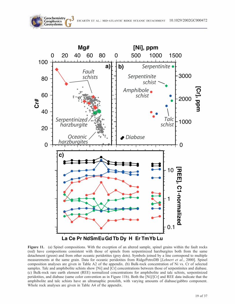
Figure 11. (a) Spinel compositions. With the exception of an altered sample, spinel grains within the fault rocks(red) have compositions consistent with those of spinels from serpentinized harzburgites both from the samedetachment (green) and from other oceanic peridotites (grey dots). Symbols joined by a line correspond to multiplemeasurements at the same grain. Data for oceanic peridotites from RidgePetroDB [Lehnert et al., 2000]. Spinelcomposition analyses are given in Table A2 of the appendix. (b) Bulk-rock concentration of Ni vs. Cr of selectedsamples. Talc and amphibolite schists show [Ni] and [Cr] concentrations between those of serpentinites and diabase.(c) Bulk-rock rare earth element (REE) normalized concentrations for amphibolite and talc schists, serpentinizedperidotites, and diabase (same color convention as in Figure 11b). Both the [Ni]/[Cr] and REE data indicate that theamphibolite and talc schists have an ultramaphic protolith, with varying amounts of diabase/gabbro component.Whole rock analyses are given in Table A4 of the appendix.
GeochemistryGeophysicsGeosystems G3G3
escartIn et al.: mid-atlantic ridge oceanic detachment 10.1029/2002GC000472
19 of 37

processes, the REE patterns further support the
conclusion from the spinel compositions that the
protolith is ultramafic. Microstructural observa-
tions demonstrate that diabase both intrudes into,
and is deformed by the shear zone and incorporated
into it (Figure 6). In the samples studied so far
the volume of magmatic rocks incorporated into the
protolith must be negligible so as not to increase the
REE concentrations significantly above those
typical of ultramafics. The presence of sphene in
some samples may indicate that gabbro or diabase
dykelets cross cutting the ultramafic protolith, as
commonly observed in abyssal peridotites from the
MidAtlantic Ridge [e.g.,Mevel et al., 1991; Cannat
et al., 1992], were deformed and recrystallized
together with the enclosing peridotite. Alternatively,
diabase dykes emplaced in the detachmentmay have
been deformed and recrystallized.
5.2. Composition of the Footwall
[36] Detachments expose sub-surface levels of the
oceanic lithosphere, and their detailed sampling
provides constraints on the composition and distri-
bution of lithologies within the footwall, in addi-
tion to information on deformation processes along
the fault. Sampling is uneven and irregular along
the detachment fault, but shows that gabbros are
mostly found at the southeast knoll, where sam-
pling was concentrated (elsewhere, the only occur-
rences are two dredges at the north edge of the
detachment, Figure 3b). Peridotite, diabase and
basalt, on the other hand, are found throughout
the detachment surface (Figure 3).
[37] Close examination of the well-sampled south-
east knoll indicates that gabbros are not directly
exposed along the fault surface, but crop out
structurally below the detachment itself. To study
the vertical distribution of lithologies relative to the
irregular detachment surface, we have estimated
the relative position of each drill and dredge with
respect to the fault surface as identified in the
bathymetry and side-scan sonar images (shaded
area in Figures 2 and 3). We have restricted our
analysis to the rectangular area shown in the
detailed maps in Figure 3 (bottom), because of
the higher sampling density there, but the more
limited sampling of other parts of the detachment
indicate similar relationships. An indicative relative
maximum depth of a sample below the detachment
surface is calculated from the difference between the
depth of the detachment surface at the closest point
and the actual depth at which the sample was
recovered (Figure 3, bottom). Dredge data are not
located as precisely as the drill sites, but we have
included them in our analysis assuming that lithol-
ogies dredged occur along the whole length of the
dredge path. These samples may correspond to
rubble shed from outcrops at higher levels, and
therefore the calculated depths below the detach-
ment are also a maximum estimate. The data were
binned at 50-m intervals, as shown in the histograms
in Figure 12. These data clearly show thatmost of the
gabbro outcrops occur at depths of �500 m below
the detachment surface, with scarce occurrences in
the immediate vicinity of the detachment fault.
Diabase, peridotite and fault rocks outcrop prefer-
entially along the detachment surface, and are pres-
ent but scarce at deeper levels. These data indicate
that the fault zone associated with the detachment is
very thin, as fault rocks are found mainly within
<100 m of the striated surface. The two high-
temperature mylonitic gabbro occurrences reported
in this study (see section 5.4 Fault rocks) and in
Matsumoto et al. [1998] are well below the detach-
ment fault surface (>100 and�500m, respectively).
5.3. Deformation Along the Detachment,Magmatism, and Fluid Circulation
[38] The macro- and microstructural observations
of the fault rocks, the relationships between the
different lithologies at individual cores or through-
out the detachment, and their composition, provide
constraints on: (1) the conditions of deformation
along the detachment fault; (2) the relationship
between deformation and magmatism associated
with the emplacement of the diabases; and (3) the
required fluid-rock interactions that result in the
alteration of the ultramafic protolith into talc and/or
amphibole schists.
5.3.1. Conditions of Deformation Alongthe Detachment Faults
[39] Because of the nature of the mineral assem-
blages of the fault schists, it is not possible to
GeochemistryGeophysicsGeosystems G3G3
escartIn et al.: mid-atlantic ridge oceanic detachment 10.1029/2002GC000472
20 of 37
determine the temperature of formation of the fault
rocks precisely. The presence of tremolite-actino-
lite (Figure 13), and the intergrowth of chlorite
with amphibole and talc (Figure 9) suggest that
these rocks formed under greenschist facies con-
ditions, at temperatures <500�C and possibly lower
than 300�C [e.g., Miyashiro, 1973]. Furthermore,
amphiboles have Ti and Al contents consistent with
temperatures of formation <500�C [Ernst and Liu,
1998]. These minerals grew syntectonically, defin-
ing the schistosity described above. Both the brittle
reworking of pre-existing amphibole/talc schists
into the shear zone and the similar chemical
composition of reworked clasts and matrix miner-
als indicate a single deformation event and stable
chemical composition of fluids within the fault
zone during deformation.
[40] Evidence of plastic deformation in the fault
rocks is scarce. High-temperature plastic deforma-
tion is only recorded by mylonitic gabbro recovered
in a single dredge (DR23-1), in addition to one
reported occurrence at the southeast flank of the
detachment (Figures 2, 3d, and 10). The syntectonic
recrystallization of plagioclase and amphiboles
(hornblende to pargasitic and edenitic hornblendes)
in themylonitic gabbros appears to be in equilibrium.
Using the composition of plagioclase-amphibole
pairs on the two samples shown in Figure 10, the
geothermometer of Holland and Blundy [1994]
yields temperatures of �720–750�C ± 40�C at
low pressures. We have no field or microstructural
evidence to link the greenschist facies deformation
along the detachment fault, and the high-tempera-
ture deformation of the foliated gabbros. None
of the microstructural observations suggest over-
printing of high-temperature deformation structures
by low-temperature ones other thanveins.Moreover,
thescarcityofmyloniticgabbrosamplessuggests that
they may form very localized shear zones (i.e.,
Figure 12. Vertical distribution of lithologies relative to the fault surface from the detailed maps at bottom of Figure3. Depth below the detachment is the difference between the actual depth of the sample and that of the preserveddetachment surface at the closest point. Despite the sampling bias of the detachment surface, it is clear that gabbrosoutcrop well below the detachment surface (�500 m), and the detachment fault zone as defined by the occurrence ofschists is thin (<100 m). Data include both drills and dredges, for which we assume that litholigies outcrop all alongthe dredge track and for each 50 m depth bin. Totals for each rock type are thus larger than the combined number ofdrills and dredges shown in the maps.
GeochemistryGeophysicsGeosystems G3G3
escartIn et al.: mid-atlantic ridge oceanic detachment 10.1029/2002GC000472
21 of 37
formed in cooling gabbro bodies or during emplace-
ment in the lithosphere) unrelated to the detachment
fault, although we cannot be ruled out completely
that this deformation may be associated with it.
[41] The shear zones crosscutting statically-serpen-
tinized peridotites prior to deformation (Figure 6)
demonstrate that fault rocks developed at temper-
atures well below 500�C (perhaps as low as 300�C[e.g., O’Hanley, 1996]). The paragenesis of the
rock does not provide any constraints on the
maximum depth of deformation.
[42] We have no constraints on the depth of
deformation recorded by the mineral assemblages
or the microstructures of the deformed rocks.
Instead, we can obtain some depth estimates from
the thermal structure predicted by models of slow
spreading ridge segments. Using the ‘‘NMARL’’
model of Shaw and Lin [1996], the 500�C iso-
therm (limit of the greenschist facies) may vary in
depth between �7.5 and 3.5 km along the axis and
immediately below it. These thermal models do
not incorporate detachment faults, which may
substantially affect the thermal state of the litho-
sphere. Lacking any other constraints, the maxi-
mum depth of deformation recorded by the
detachment may occur at in the lithosphere depths
of <7 km (T < 500�C).
5.3.2. Relations Between Deformation andMagmatism Along the Detachment
[43] Both the drilled and the dredged samples
display apparent intrusive relationships of the dia-
bases into the shear zone (e.g., Figure 5a). Dia-
bases, however, are also deformed within the shear
Figure 13. Amphibolite chemical compositions. Amphiboles in the foliated gabbro samples show elevated Al IVvalues (a, b) while amphiboles from rocks sampled along the detachment fault have Al IV values <0.8 in addition tolow Mg, Na + Ka. There is no clear difference between matrix amphiboles grown syntectonically and those in clastsreworked within the shear zone (c, d). All amphiboles analyzed follow the pargasite trend (b, d). Analyses are givenin Table A2 of the appendix.
GeochemistryGeophysicsGeosystems G3G3
escartIn et al.: mid-atlantic ridge oceanic detachment 10.1029/2002GC000472
22 of 37

zone, as they occur as small clasts or thin deformed
(<5 cm levels embedded within the sheared rocks
(Figures 4 and 5b–5c). These observations indicate
that deformation is coeval with the diabase injec-
tion. As there is no record of off-axis volcanism
along slow-spreading ridges, we infer that magma-
tism occurred at the ridge axis, and therefore the
detachment fault was active below the rift valley.
Dyke intrusions cross-cutting the fault zone were
probably restricted spatially and separated in time
so as to allow the mechanical continuity of the
detachment required for ongoing deformation un-
der the ridge axis. Frequent or continuous dyke
injections would crosscut the detachment fault and
arrest its development, as suggested in previous
models of oceanic detachment faulting [e.g.,
Tucholke et al., 2001].
5.3.3. Fluids, Alteration and Deformation
[44] The presence of fluids along the detachment
fault zone during deformation is required, strongly
altering the chemical composition of the protolith.
Important enrichments of silica and, to a lesser
degree, of calcium are required to allow the crys-
tallization of both talc and tremolite, respectively.
Silica enrichment can result both from silica input
by the fluid phase, or by a loss of magnesium and
other elements during recrystallization. Chlorites
show a compositional evolution, with a progressive
enrichment in Fe (Figure 14) in the later chloriti-
zation events (veins and radial patches, Figure 9).
This may indicate either a progressive enrichment
in iron of the fluids circulating along the fault zone,
or a phase of chloritization post-dating the defor-
mation of the detachment, with Fe-rich fluids
unrelated to those within the fault zone. Fluids
within the fault zone probably developed high pore
fluid pressures at moderate to low temperatures, as
indicated by the dilatant amphibole veins cross-
cutting the schistose foliation. Flow rates were
probably high in order to allow the alteration of
the protolith and the mobilization of elements, but
additional oxygen isotope work (in progress) is
required to better constrain fluid volumes and
fluxes required to form the synkinematic assemb-
lages reported.
[45] Experimental work by Allen and Seyfried
[2003] demonstrates that at T � 400�C and P �500 bar pyroxene is altered preferentially over
olivine, as forsterite remains stable. The resulting
fluid phase is enriched in Ca, SiO2, Fe and H2. An
increased silica activity in the fluid phase results in
the stability of talc or tremolite, depending on the
Ca activity, rather than serpentine. The widespread
abundance of talc and amphibole in detachment
fault rocks could therefore result from focused flow
Figure 14. (a) Chlorite chemical composition. Amphiboles from talc schists have lower X Fe and higher Si values.(b) As in the case of amphiboles, there is no difference between chlorite intergrown with amphibole and talc in thefault rocks. Late stage chloritization, indicated by irregular patches with radial chlorite and static chloritization, showdifferent compositions. Analyses are given in Table A3 of the appendix.
GeochemistryGeophysicsGeosystems G3G3
escartIn et al.: mid-atlantic ridge oceanic detachment 10.1029/2002GC000472
23 of 37
along the detachment of fluids discharging from
deeper levels of the fault zone. These fluids may
have either interacted with peridotites at temper-
atures >350�C, with basaltic rocks, or with both.
Fluids that interacted with ultramafic rocks at
lower temperatures would not have the required
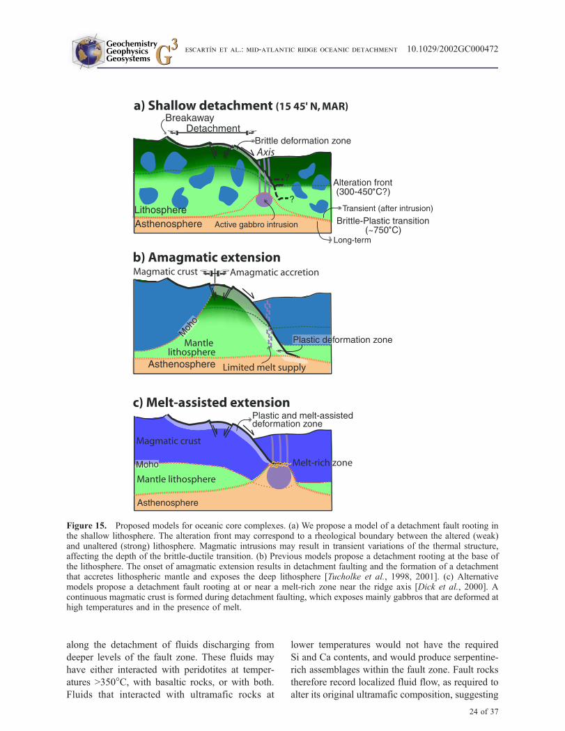
Si and Ca contents, and would produce serpentine-
rich assemblages within the fault zone. Fault rocks
therefore record localized fluid flow, as required to
alter its original ultramafic composition, suggesting
˚
˚
Figure 15. Proposed models for oceanic core complexes. (a) We propose a model of a detachment fault rooting inthe shallow lithosphere. The alteration front may correspond to a rheological boundary between the altered (weak)and unaltered (strong) lithosphere. Magmatic intrusions may result in transient variations of the thermal structure,affecting the depth of the brittle-ductile transition. (b) Previous models propose a detachment rooting at the base ofthe lithosphere. The onset of amagmatic extension results in detachment faulting and the formation of a detachmentthat accretes lithospheric mantle and exposes the deep lithosphere [Tucholke et al., 1998, 2001]. (c) Alternativemodels propose a detachment fault rooting at or near a melt-rich zone near the ridge axis [Dick et al., 2000]. Acontinuous magmatic crust is formed during detachment faulting, which exposes mainly gabbros that are deformed athigh temperatures and in the presence of melt.
GeochemistryGeophysicsGeosystems G3G3
escartIn et al.: mid-atlantic ridge oceanic detachment 10.1029/2002GC000472
24 of 37
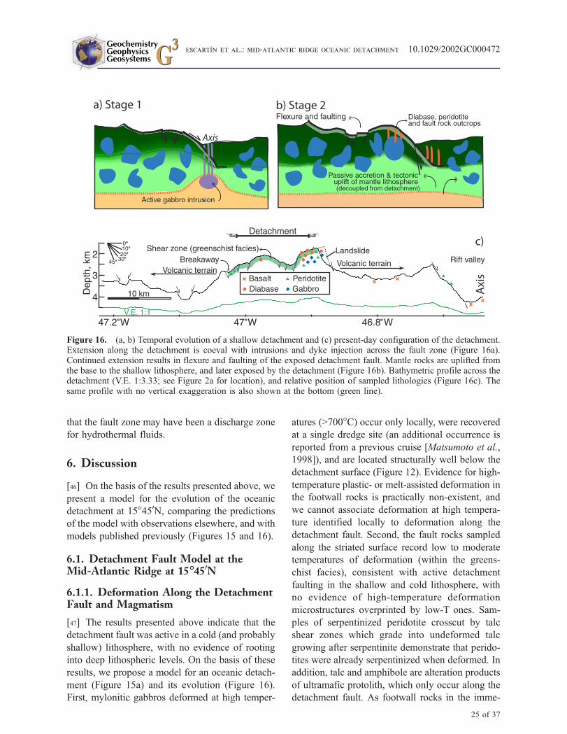
that the fault zone may have been a discharge zone
for hydrothermal fluids.
6. Discussion
[46] On the basis of the results presented above, we
present a model for the evolution of the oceanic
detachment at 15�450N, comparing the predictions
of the model with observations elsewhere, and with
models published previously (Figures 15 and 16).
6.1. Detachment Fault Model at theMid-Atlantic Ridge at 15�450N
6.1.1. Deformation Along the DetachmentFault and Magmatism
[47] The results presented above indicate that the
detachment fault was active in a cold (and probably
shallow) lithosphere, with no evidence of rooting
into deep lithospheric levels. On the basis of these
results, we propose a model for an oceanic detach-
ment (Figure 15a) and its evolution (Figure 16).
First, mylonitic gabbros deformed at high temper-
atures (>700�C) occur only locally, were recovered
at a single dredge site (an additional occurrence is
reported from a previous cruise [Matsumoto et al.,
1998]), and are located structurally well below the
detachment surface (Figure 12). Evidence for high-
temperature plastic- or melt-assisted deformation in
the footwall rocks is practically non-existent, and
we cannot associate deformation at high tempera-
ture identified locally to deformation along the
detachment fault. Second, the fault rocks sampled
along the striated surface record low to moderate
temperatures of deformation (within the greens-
chist facies), consistent with active detachment
faulting in the shallow and cold lithosphere, with
no evidence of high-temperature deformation
microstructures overprinted by low-T ones. Sam-
ples of serpentinized peridotite crosscut by talc
shear zones which grade into undeformed talc
growing after serpentinite demonstrate that perido-
tites were already serpentinized when deformed. In
addition, talc and amphibole are alteration products
of ultramafic protolith, which only occur along the
detachment fault. As footwall rocks in the imme-
Figure 16. (a, b) Temporal evolution of a shallow detachment and (c) present-day configuration of the detachment.Extension along the detachment is coeval with intrusions and dyke injection across the fault zone (Figure 16a).Continued extension results in flexure and faulting of the exposed detachment fault. Mantle rocks are uplifted fromthe base to the shallow lithosphere, and later exposed by the detachment (Figure 16b). Bathymetric profile across thedetachment (V.E. 1:3.33; see Figure 2a for location), and relative position of sampled lithologies (Figure 16c). Thesame profile with no vertical exaggeration is also shown at the bottom (green line).
GeochemistryGeophysicsGeosystems G3G3
escartIn et al.: mid-atlantic ridge oceanic detachment 10.1029/2002GC000472
25 of 37
diate vicinity of the detachment do not show these
alteration phases, we infer that fluid flow was
effectively restricted to the fault zone. Finally, there
is almost no evidence of plastic deformation in
serpentinites as most of them preserve the micro-
structures of static serpentinization (i.e., bastites).
Little evidence of any earlier higher temperature
plastic deformation has been found. As serpentin-
ites are extremely weak [e.g., Reinen et al., 1993;
Moore et al., 1997; Escartın et al., 1997a], defor-
mation of serpentinized peridotites associated with
the detachment occurred probably at T < 300�C or
less, within the brittle regime. Deformation was
localized very efficiently along the detachment
fault since the footwall rocks are mostly unde-
formed.
[48] Development of a detachment fault requires
effective localization of deformation over long
periods of time. Several models have invoked the
presence of a rheological boundary at depth that
guides stresses and fixes deformation. This bound-
ary has been identified as the brittle-plastic transi-
tion in continental and oceanic detachments [e.g.,
Wernicke, 1990; Davis and Lister, 1988; Tucholke
et al., 2001] and in analogue models [Brun et al.,
1994; Gartell, 1997; Mulugeta and Ghebreab,
2001] (Figure 15b), or as melt-rich zones within
the lithosphere [e.g., Dick et al., 1991, 2000; Lister
and Baldwin, 1993; Parsons and Thompson, 1993]
(Figure 15c). Experimental studies have shown that
low degrees of serpentinization (<15%) substan-
tially reduce the strength of strong peridotites to
that of weak serpentine [Escartın et al., 2001],
indicating that the alteration front may correspond
to a transition from strong, unaltered to weak,
altered oceanic lithosphere. This rheological
boundary within the brittle lithosphere could serve
as a horizon for detachments to sole out (Figures 15a
and 15b). The detachment may also root above this
alteration front or below it (Figure 15a). If rooting
is within the altered lithosphere, we do not have
any mechanism that may fix deformation at this
location during long periods of time (i.e., no
rheological boundary). Rooting at deeper levels
may be possible, but we do not have any observa-
tions that may support this model. In all cases, the
geometry of the detachment is unconstrained.
[49] Effective localization of deformation is likely
to be assisted by the presence of weak minerals and
fluids along a very thin fault zone. The mechanical
properties of talc, chlorite and serpentinite [e.g.,
Reinen et al., 1991; Escartın et al., 1997a; Moore
et al., 1997] suggest that fault schists containing
these minerals are considerably weaker. While no
rheological data exists on amphibolite composi-
tionally schists similar to those described here, the
similarity of the deformation microstructures with
those of the talc and serpentinite schists (Figures 4
and 7–9), and the presence of weak chlorite
suggests that these rocks are also very weak.
Presence of fluids within the fault zone, as required
to form the mineral assemblages described, together
with the mode of deformation of some hydrous
silicates [Escartın et al., 1997b], can further reduce
the effective confining pressure and hence the
strength of the fault.
[50] If the detachment was indeed initiated in the
relatively shallow lithosphere, the exposures along
the detachment fault surface record shallow mag-
matic processes in a heterogeneous lithosphere,
and do not necessarily expose deep sections of
the oceanic lithosphere. The presence of numerous
deformed and undeformed diabase intrusions along
the fault surface indicates an interaction of the
active detachment fault with axial magmatism
(Figure 15a). Chilled margins in diabase (Figure 4)
indicate that the lithosphere and the fault zone were
cold during their emplacement, consistent with
temperatures recorded by fault rock mineral
assemblages. The lack of basalt over the detach-
ment faults indicates that no magmatism took place
while the inactive detachment fault was exposed at
the seafloor off-axis, and that the extrusives were
very effectively carried away by the hanging wall
(Figure 16). These diabases may correspond to the
melts extracted from the gabbros below the detach-
ment, although no geochemical evidence is yet
available to establish possible this link. Alterna-
tively, melts could have been transported laterally
by dyke propagation along the ridge axis while the
detachment was active.
[51] Long-lived detachment faulting and coeval
magmatism suggest an important temporal vari-
ability in the thermal structure in the shallow
GeochemistryGeophysicsGeosystems G3G3
escartIn et al.: mid-atlantic ridge oceanic detachment 10.1029/2002GC000472
26 of 37

lithosphere. Gabbro bodies probably intruded a
cold lithosphere, resulting in important and local
variations of temperatures. The spatial distribution
and duration of gabbro emplacement must have
been limited so as to allow continued deformation
along the fault zone (Figure 15a). The size of the
gabbro outcrop sampled is relatively small (<5 km
in diameter), consistent with spatial variations in
lithologies observed along the rift valley walls at
15�N [Cannat et al., 1997]. The geological evi-
dence recovered here is consistent with that of
previous studies in the same area [Cannat and
Casey, 1995; Cannat et al., 1997; Lagabrielle et
al., 1998], which suggest that the formation of a
compositionally heterogeneous lithosphere [e.g.,
Cannat, 1993] occurred while the detachment
was active (Figures 15a and 16a–16b). Although
the amount of magmatism cannot be quantified
with the existing data, magmatic accretion was not
continuous. Sustained dyke injections across the
fault zone would have dissected the detachment at
depth below the ridge axis, disrupting its mechan-
ical continuity, and resulting in its termination.
6.1.2. Geometry of the Detachment Fault
[52] The morphology of the detachment fault
records a history of flexure and related high-angle
faulting. The along-axis large-scale undulations
and the bathymetric corrugations (Figure 2) have
been maintained by the fault over a long period of
time, suggesting that they are inherited from deep-
seated irregularities of the fault [e.g., Jackson and
White, 1989; Tucholke et al., 1998], and are similar
to those observed at continental detachments [e.g.,
Spencer, 1984; Wright et al., 1974; John, 1987].
The observations presented here do not support
other proposed mechanisms that require plastic
deformation, such as folding of the fault surface
at depth [e.g., Spencer, 1984; Fletcher et al., 1995],
or continuous casting [e.g., Spencer, 1999].
[53] Flexure of the exposed fault is evident from
the undulations of the detachment surface along the
spreading direction, defining a low at the centre of
the detachment, from the irregular faults bounding
this central depressed section, and from the shallow
tilt away from the axis of parts of the detachment
(see Figures 2 and 16c). Rollover models of low-
angle [Wernicke and Axen, 1988] or steeply dip-
ping faults at depth [e.g., Buck, 1988; Lavier et al.,
1999] predict important flexure of the footwall.
Part of the strain associated with plate flexure is
accommodated by high-angle normal faults that
dissect the exposed, inactive portion of the detach-
ment fault (Figure 2). The detachment is terminated
to the east by a high-angle normal fault with a
vertical throw of >1.5 km (Figures 2 and 16) that
we interpret as a former rift-bounding wall. Flexu-
ral response to large normal faults can result in
>10� of tilt [e.g., Shaw, 1992], and can account for
the detachment fault dipping slightly away from
the ridge axis (Figure 16c). The detailed geometry
or the fault at depth and the mode of dissipation of
the deformation at the fault root are also uncon-
strained. Finally, detachment faults may not be
stable in time and excise material from the footwall
or hangingwall due to changes in position. While
unsampled strands of a complex detachment fault
may exist below the exposed fault surface, none of
the samples structurally below the detachment
show the fault-related assemblages that may be
expected.
6.1.3. Deformation of the LowerLithosphere
[54] We have no evidence of a direct link between
the shallow deformation recorded by the detach-
ment fault rocks, and the deeper deformation
processes operating near the brittle-plastic transi-
tion required to expose mantle rocks at the seafloor
(Figure 16b). Exposure of serpentinized peridotites
at the nearby ridge axis (Figure 2) has been
explained by a network of crosscutting shear zones
that uplifts material from the top of the astheno-
sphere to the seafloor through the whole thickness
of the lithosphere right below the ridge axis [e.g.,
Cannat et al., 1997; Lagabrielle et al., 1998]. The
dominance of undeformed over deformed rocks
from possible shear zones suggests that deforma-
tion is highly localized along shear zones, leaving a
large portion of the lithospheric material unde-
formed. The specific deformation mechanisms, or
the geometry of this tectonic lift is not constrained
nor properly understood. In the absence of any
additional information, we propose that a similar
GeochemistryGeophysicsGeosystems G3G3
escartIn et al.: mid-atlantic ridge oceanic detachment 10.1029/2002GC000472
27 of 37
mode of tectonic uplift operated in the lithosphere
below the detachment while it was active below the
ridge axis, as the peridotites and the nature of
deformation that they record are comparable to
those reported from the ridge axis. Alternatively,
deformation at the base of the detachment fault
may be more distributed over a broad area. There-
fore the link between the detachment and lower
lithosphere deformation is unconstrained, lacking
both geological and geophysical constraints. How-
ever, we cannot rule out that the detachment may
continue into deep lithosphere or even the upper
asthenosphere, and its geometry (i.e., steep versus
shallow dipping fault at depth) is unknown.
6.2. Comparison With Existing Models ofOceanic Detachments
[55] Two alternative models have been previously
proposed to explain large detachment surfaces
observed along the Mid-Atlantic Ridge and the
South West Indian Ridge. Both models propose
rooting of the detachment fault in a rheological
boundary, but their geological predictions on the
mode of deformation, nature of exposures and
distributions of lithologies do not fully agree
with our observations. The first model invokes
amagmatic extension during detachment faulting
(Figure 15b), and the second continuous magmatic
supply with direct feedback between the detach-
ment fault and the magmatic system (Figure 15c).
6.2.1. Amagmatic Extension andDetachment Faulting
[56] Tucholke et al. [1998, 2001] proposed that
detachment faults cut through the whole thickness
of the lithosphere, soling out at the brittle-plastic
transition at its base. In this model detachment
faults develop during periods of amagmatic accre-
tion when the lithosphere is cold and the isotherms
depressed. These faults are terminated when mag-
matic activity raises the isotherms and normal
magmatic accretion of oceanic crust is reinitiated.
This model has been developed from morpholog-
ical characteristics, geological observations, and
relatively sparse sampling of tectonic structures
along the Mid-Atlantic Ridge that are similar to
the one at 15�450N described here [Tucholke et al.,
1997, 1998, 2001]. All these structures show
corrugated, striated and domed surfaces that are
structurally continuous, with gabbros and perido-
tites found along their surface in association with
diabase, the occurrence of serpentine and other
fault schists, and with a lack of evidence for
widespread high-temperature deformation of the
footwall rocks. Many of these detachments show
large areas covered with basaltic rocks, including
pillow lavas (e.g., Dante’s Dome [Tucholke et al.,
2001] and Atlantis massif [Cann et al., 1997;
Blackman et al., 1998]), which are absent from
the detachment surface at 15�450N. Most of these
basalts may have been rafted from the hanging wall
along the exposed and inactive detachment fault at
the seafloor, as suggested by the presence of
tectonic klippens at the Atlantis massif [Cann et
al., 1997; Blackman et al., 1998], or erupted
directly onto the fault surface in close proximity
to the ridge axis [Tucholke et al., 2001].
[57] The model of oceanic detachment faults root-
ing in ductile levels is closely related to that
developed for continental core complexes. Conti-
nental detachments are characterized by a wide
(>250 m) zone of pervasive ductile deformation,
and a progressive localization of the deformation
with a transition to brittle deformation overprinting
the previous ductile fabric [e.g., Miller et al., 1983;
Bykerk-Kauffman and Janecke, 1987; Lee and
Lister, 1992; Mueller and Snoke, 1993]. Although
high-temperature ductilely deformed peridotites
and gabbros have been sampled in proximity to
oceanic detachments [e.g., Cannat et al., 1992;
Jaroslow et al., 1996; Karson, 1999], they are
mainly sampled along nearby transform valley
walls and are probably associated with the trans-
form fault instead of detachment faulting, although
there is little information on the orientation of such
deformation zones. As observed at 15�450N, most
of the recovered gabbros along these detachments
are undeformed, and serpentinite and/or amphibole
schists are common [e.g., Cann et al., 1997;
Campbell-Stone et al., 2000; Tucholke et al.,
2001; Reston et al., 2002; Dick et al., 2002], even
when footwall rocks are sampled immediately
below the detachment at scarps cross-cutting it
(e.g., 5�S at the Mid-Atlantic Ridge [Reston et
GeochemistryGeophysicsGeosystems G3G3
escartIn et al.: mid-atlantic ridge oceanic detachment 10.1029/2002GC000472
28 of 37

al., 2002]). Thus all these observations appear to
be systematic and common to striated detachment
surfaces identified along the Mid-Atlantic Ridge.
Existing observations are not consistent with
models rooting at or near the brittle ductile transi-
tion. First, there is no evidence of a wide zone of
ductile deformation associated with these detach-
ments, as may be expected if the fault rooted near
or into the plastic deformation regime. Second,
there is little evidence of widespread ductilely
deformed rocks overprinted by low-temperature,
brittle deformation, as would be expected if the
deformation evolved from wide ductile shear zones
at depth to narrow, more brittle deformation zones
above the �500�C isotherm. Instead, these obser-
vations are more consistent with the model pro-
posed above, in which the detachment fault does
not reach deep lithospheric levels, but soles out in
the cold lithosphere. We speculate that the fault
may root near the alteration front, which may act as
a rheological boundary, but we cannot fully rule
out that rooting may take place below or above this
alteration front (Figure 15a).
6.2.2. Magmatic Extension andDetachment Faulting
[58] An alternative detachment model proposes
that the detachment fault soles out in a melt-rich,
hot zone near the gabbro-dyke transition, also in
the shallow lithosphere [Dick et al., 1991]. This
model is based on geological observations at the
Atlantis II Bank (South West Indian Ridge), which
has been the target of two ODP legs drilling a
�1500 m deep section of gabbro [Robinson et al.,
1989; Dick et al., 1991, 2000, 2002], and system-
atic sampling with both dredges and wire line rock
drilling [MacLeod et al., 1998]. The gabbros show
a gradual decrease in deformation with depth, with
ample evidence of sub-horizontal deformation fab-
rics, plasticity and melt-assisted deformation in the
upper 250 m and along the surface of the Atlantis II
Bank. These observations have been interpreted as
evidence for a direct link of the detachment fault-
ing into the axial magmatic system, most likely
soling at the melt-rich gabbro-dyke transition. The
detachment fault, while active, was an active part
of the magmatic accretion system. Similar links
between detachment faulting and magmatism have
also been invoked to explain the origin of some
low-angle continental faults [e.g., Anderson et al.,
1988; Lister and Baldwin, 1993; Campbell-Stone
et al., 2000].
[59] Atlantis Bank differs substantially in morphol-
ogy from the striated and corrugated oceanic
detachments described above. This detachment
stands �5 km above surrounding seafloor, with a
summit that has been wave-cut and subsequently
subsided to a water depth of �700 m at the present
time, indicating higher tectonic uplifts than any of
the striated surfaces here or elsewhere [Tucholke et
Table A1. Spinel Major Element Analyses
Sample IPa SiO2 TiO2 Al2O3 Cr2O3 Fe2O3 FeO MnO MgO Total Cr# Mg#
BR40E-1 27 1.81 0.82 2.83 42.66 15.81 31.83 0.90 1.31 97.96 91.00 6.83BR40E-1 28 6.78 0.53 8.08 33.48 6.91 32.04 0.49 5.20 93.51 73.53 22.4386A-4 33 0.02 0.23 26.85 40.22 2.06 16.00 0.39 12.86 98.63 50.12 58.8986A-4 35 0.04 0.11 24.54 40.45 1.40 18.13 0.11 10.72 95.50 52.51 51.34DR13-23-1 40 0.00 0.06 29.96 36.38 15.82 0.13 15.73 98.08 44.89 69.86DR13-23-1 41 0.05 0.06 30.45 36.21 15.59 0.16 15.56 98.09 44.37 69.03DR13-23-1 42 0.04 0.09 30.01 37.37 15.56 0.21 15.36 98.64 45.51 68.09DR13-3-4 0 0.00 0.08 22.96 47.29 14.50 0.25 14.35 99.43 58.01 65.62DR14-5-1 81 0.06 0.06 35.31 33.51 13.64 0.18 17.47 100.22 41.41 74.41DR14-5-1 82 0.08 0.05 33.32 33.77 12.74 0.34 17.47 97.77 39.82 76.04DR14-5-1 83 0.04 0.00 34.96 34.11 13.31 0.10 17.28 99.78 40.74 73.80DR14-5-1 84 0.07 0.04 33.35 33.38 13.35 0.06 16.88 97.13 40.12 73.77DR2-9-6 26 0.06 0.07 35.42 32.82 14.20 0.10 15.59 98.25 38.32 67.63DR2-9-6 27 0.01 0.04 35.49 32.99 15.08 0.09 15.60 99.29 38.40 67.24DR2-9-6 28 0.03 0.09 35.29 32.67 14.47 0.25 15.71 98.50 38.31 68.25DR2-9-6 29 0.00 0.06 35.08 33.39 14.41 0.04 16.01 98.99 38.96 69.00
aProbe analysis number.
GeochemistryGeophysicsGeosystems G3G3
escartIn et al.: mid-atlantic ridge oceanic detachment 10.1029/2002GC000472
29 of 37

Table A2. Amphibole Major Element Analyses
Sample IP a Modeb SiO2 TiO2 Al2O3 Cr2O3 FeO MnO MgO CaO Na2O K2O Total XMg XFe Na + K A AlIV
BR28A-2 2 C 57.18 0.00 0.58 0.07 3.79 0.03 22.36 12.62 0.08 0.00 96.70 91.25 8.68 0.016 0.058BR28A-2 4 C 56.53 0.07 1.29 0.03 5.79 0.19 20.98 12.06 0.27 0.00 97.20 86.20 13.36 0.038 0.117BR28A-2 5 C 58.18 0.10 0.54 0.02 3.19 0.00 22.67 12.64 0.12 0.00 97.45 92.68 7.32 0.000 0.016BR28A-2 6 C 56.43 0.03 1.31 0.36 4.64 0.08 21.42 12.55 0.23 0.05 97.09 88.99 10.81 0.049 0.144BR28A-1 10 C 57.48 0.00 0.61 0.00 4.85 0.12 21.29 12.97 0.10 0.00 97.42 88.41 11.31 0.000 0.032BR28A-1 11 C 56.54 0.03 0.92 0.00 5.80 0.00 20.82 12.35 0.13 0.00 96.60 86.47 13.53 0.009 0.070BR28A-1 12 C 57.21 0.00 0.77 0.09 3.62 0.01 21.88 12.99 0.12 0.00 96.68 91.49 8.50 0.001 0.052BR28A-1 13 C 58.00 0.06 0.59 0.06 3.81 0.09 22.35 12.91 0.12 0.00 97.97 91.09 8.70 0.005 0.046BR28A-1 14 S 55.87 0.00 1.41 0.18 6.62 0.00 19.77 12.24 0.22 0.02 96.34 84.18 15.82 0.011 0.107BR28A-1 16 S 56.26 0.04 1.08 0.14 6.24 0.11 20.51 12.47 0.21 0.00 97.05 85.21 14.54 0.041 0.115BR40C-1 5 S 56.93 0.07 1.05 0.10 6.81 0.21 19.60 12.24 0.26 0.11 97.38 83.25 16.24 0.000 0.038BR40C-1 6 C 54.83 0.12 1.62 0.09 9.06 0.16 18.17 12.14 0.30 0.03 96.52 77.83 21.78 0.053 0.163BR40C-1 7 C 52.44 0.05 4.15 0.81 7.76 0.04 18.53 12.17 0.77 0.08 96.79 80.89 19.00 0.233 0.518BR40C-4 26 G 49.57 0.38 5.60 0.08 12.93 0.11 14.70 11.82 0.86 0.10 96.12 66.77 32.95 0.293 0.694BR40C-4 27 G 48.27 1.43 5.21 0.03 13.77 0.23 14.47 10.74 0.83 0.11 95.10 64.81 34.61 0.282 0.772BR40C-4 29 G 51.23 0.40 5.03 0.14 13.25 0.05 14.92 12.07 0.66 0.09 97.85 66.66 33.22 0.216 0.595BR40C-4 31 G 49.59 0.43 5.43 0.27 13.65 0.10 14.44 11.53 0.69 0.06 96.18 65.17 34.58 0.249 0.680BR40D-2 59 C 58.24 0.09 0.19 0.09 1.83 0.05 23.42 13.09 0.12 0.01 97.14 95.68 4.20 0.000 0.012BR40D-2 60 C 55.49 0.11 2.35 0.51 2.11 0.00 22.97 12.09 0.44 0.04 96.11 95.09 4.91 0.110 0.280BR40D-2 61 C 56.90 0.03 1.38 0.51 2.07 0.01 22.81 12.73 0.32 0.01 96.76 95.13 4.83 0.044 0.143BR40D-3 64 C 55.60 0.08 2.53 0.69 2.37 0.16 23.22 11.61 0.83 0.00 97.08 94.24 5.40 0.183 0.323BR40D-3 65 C 57.34 0.09 0.31 0.00 1.78 0.07 23.65 13.19 0.10 0.06 96.58 95.81 4.03 0.059 0.075BR40E-2 37 S 53.05 0.18 4.54 0.87 5.42 0.05 20.20 11.45 0.83 0.01 96.60 86.82 13.07 0.192 0.523BR40E-2 40 S 55.51 0.07 2.32 0.21 5.19 0.12 21.17 11.53 0.07 0.01 96.19 87.64 12.06 0.009 0.210BR71C-2 40 C 52.10 0.21 5.32 0.09 8.03 0.25 18.11 12.31 0.78 0.06 97.27 79.57 19.80 0.239 0.601BR73A-2 16 P 51.96 0.25 3.29 0.13 14.66 0.14 12.05 0.41 0.01 0.03 96.37 59.20 40.42 0.000 0.131BR73A-2 18 P 52.47 0.30 2.97 0.01 14.51 0.13 11.92 0.47 0.02 0.00 96.30 59.20 40.44 0.000 0.063BR90A-1 11 S 50.91 0.45 4.47 0.08 9.87 0.20 17.63 11.41 0.34 0.00 95.35 75.73 23.79 0.188 0.577BR90A-1 19 S 58.01 0.01 0.47 0.05 3.51 0.09 21.84 12.82 0.04 0.00 96.83 91.53 8.26BR90A-1 20 S 55.43 0.06 1.47 0.09 7.37 0.20 19.86 11.29 0.11 0.02 95.91 82.38 17.16 0.003 0.121BR90A-2 21 C 58.04 0.00 0.65 0.15 2.40 0.00 21.75 13.48 0.11 0.00 96.57 94.18 5.82BR90A-2 24 C 57.78 0.04 0.57 0.11 2.83 0.09 21.71 13.31 0.11 0.05 96.60 92.97 6.80BR90A-2 25 C 57.44 0.11 1.09 0.18 2.57 0.03 23.03 12.99 0.14 0.00 97.58 94.05 5.89 0.034 0.124BR90A-2 26 C 57.09 0.15 1.87 0.00 2.84 0.13 22.48 12.83 0.33 0.00 97.72 93.10 6.59 0.051 0.173BR90A-4 31 C 58.26 0.04 0.55 0.09 2.05 0.06 23.13 13.06 0.07 0.00 97.33 95.12 4.73 0 0.023BR90A-3 38 Px 51.98 0.21 4.28 0.00 12.68 0.17 14.93 11.83 0.60 0.02 96.69 67.44 32.13 0.135 0.439BR90A-2 28 C 57.77 0.05 0.64 0.06 4.49 0.18 21.36 12.60 0.08 0.02 97.26 89.08 10.50 0 0.003BR90A-7 41 Px 49.06 1.16 6.53 0.05 13.93 0.23 12.61 12.08 0.84 0.11 96.59 61.34 38.02 0.195 0.763DR13-3-1 15 58.98 0.04 0.21 0.05 1.72 0.16 24.39 12.22 0.05 0.00 97.82 95.85 3.78DR13-3-1 1 59.24 0.00 0.11 0.00 1.44 0.09 23.91 13.12 0.04 0.00 97.96 96.52 3.27DR2-9-1 2 56.44 0.12 1.09 0.06 8.25 0.13 22.21 8.23 0.41 0.06 97.00 82.53 17.19 0.060 0.105DR2-9-1 3 46.90 0.02 9.41 0.27 7.34 0.20 17.79 11.72 2.68 0.28 96.60 80.78 18.70 0.795 1.213DR2-9-1 4 47.17 0.12 9.40 0.02 7.85 0.09 18.05 11.48 2.43 0.09 96.71 80.19 19.57 0.729 1.195DR2-9-3 21 52.18 0.11 4.31 0.23 6.01 0.19 21.52 9.43 0.99 0.07 95.04 86.08 13.49 0.291 0.536DR2-9-3 22 52.03 0.10 6.10 0.12 5.65 0.15 20.23 11.39 1.81 0.08 97.65 86.14 13.49 0.440 0.709DR2-9-3 23 51.93 0.16 6.16 0.48 5.50 0.05 20.08 11.11 1.67 0.03 97.17 86.57 13.31 0.379 0.703DR2-9-3 24 51.26 0.09 7.31 0.56 4.90 0.22 19.77 11.28 1.83 0.05 97.28 87.29 12.15 0.415 0.806DR2-9-3 25 56.67 0.41 1.59 0.19 4.59 0.12 20.99 11.42 0.65 0.04 96.65 88.82 10.90 0.012 0.105DR23-1-2 43 V 43.71 0.46 7.68 0.00 26.13 0.28 5.73 11.43 1.56 0.32 97.29 28.10 71.90 0.631 1.127DR23-1-2 44 P 44.60 1.98 8.13 0.00 16.20 0.06 12.23 11.23 2.70 0.25 97.36 57.38 42.63 0.776 1.302DR23-1-2 45 P 50.56 1.23 4.41 0.02 13.59 0.19 15.08 10.65 1.80 0.11 97.64 66.40 33.60 0.391 0.640DR23-1-2 46 P 49.18 1.28 5.04 0.00 14.17 0.21 14.78 11.30 1.79 0.17 97.91 65.02 34.98 0.499 0.804DR23-1-2 47 P 38.39 0.20 11.74 0.09 31.34 0.09 1.46 10.91 2.20 0.41 96.83 7.684 92.32 0.945 1.715DR23-1-2 48 V 43.58 0.39 7.54 0.00 26.94 0.14 5.38 11.73 1.86 0.22 97.78 26.25 73.75 0.708 1.147DR23-1-2 50 P 49.32 1.29 5.15 0.00 14.47 0.29 14.86 11.29 1.53 0.13 98.32 64.67 35.33 0.458 0.813DR23-1-2 51 V 42.92 0.29 7.90 0.03 28.35 0.00 4.61 11.44 1.87 0.23 97.65 22.48 77.52 0.732 1.196DR23-1-4 52 M 41.46 0.22 8.92 0.00 27.78 0.11 4.50 11.77 1.91 0.27 96.93 22.40 77.60 0.819 1.363DR23-1-4 53 M 47.37 0.65 5.08 0.09 19.24 0.23 11.04 12.08 1.24 0.15 97.15 50.55 49.45 0.485 0.822DR23-1-4 54 M 43.48 0.39 7.77 0.04 24.72 0.31 6.50 11.40 1.39 0.23 96.21 31.90 68.10 0.597 1.134DR23-1-4 55 M 48.60 0.36 4.20 0.00 20.33 0.21 10.95 10.68 1.52 0.12 96.97 48.97 51.04 0.448 0.630DR23-1-3 58 R 44.39 1.96 8.57 0.00 16.22 0.16 12.14 11.25 2.84 0.28 97.80 57.16 42.85 0.817 1.355
GeochemistryGeophysicsGeosystems G3G3
escartIn et al.: mid-atlantic ridge oceanic detachment 10.1029/2002GC000472
30 of 37
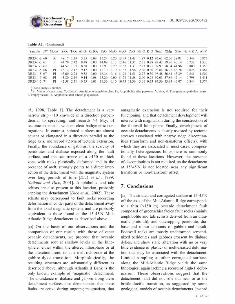
al., 1998, Table 1]. The detachment is a very
narrow strip �10 km-wide in a direction perpen-
dicular to spreading, and records >4 M.y. of
tectonic extension, with no clear bathymetric cor-
rugations. In contrast, striated surfaces are almost
equant or elongated in a direction parallel to the
ridge axis, and record <2 Ma of tectonic extension.
Finally, the abundance of gabbros, the scarcity of
peridotites and diabase exposed along the fault
surface, and the occurrence of a >150 m thick
zone with rocks plastically deformed and in the
presence of melt, strongly points to a direct inter-
action of the detachment with the magmatic system
over long periods of time [Dick et al., 1999;
Natland and Dick, 2001]. Amphibolite and talc
schists are also present at this location, probably
capping the detachment [Dick et al., 2002]. These
schists may correspond to fault rocks recording
deformation in colder parts of the detachment away
from the axial magmatic system, and are probably
equivalent to those found at the 15�450N Mid-
Atlantic Ridge detachment as described above.
[60] On the basis of our observations and the
comparison of our results with those of other
oceanic detachments, we propose that oceanic
detachments root at shallow levels in the litho-
sphere, either within the altered lithosphere or at
the alteration front, or at a melt-rich zone at the
gabbro-dyke transition. Morphologically, the
resulting structures are substantially different as
described above, although Atlantis II Bank is the
only known example of ‘magmatic’ detachment.
The abundance of diabase and gabbro along these
detachment surfaces also demonstrates that these
faults are active during ongoing magmatism, that
amagmatic extension is not required for their
functioning, and that detachment development will
interact with magmatism during the construction of
the footwall lithosphere. Finally, development of
oceanic detachments is clearly assisted by tectonic
stresses associated with nearby ridge discontinu-
ities (transform and non-transform offsets), with
which they are associated in most cases; composi-
tionally heterogeneous lithosphere is commonly
found at these locations. However, the presence
of discontinuities is not required, as the detachment
at 15�450N is not located near any significant
transform or non-transform offset.
7. Conclusions
[61] The striated and corrugated surface at 15�450Noff the axis of the Mid-Atlantic Ridge corresponds
to a thin (<150 m) oceanic detachment fault
composed of greenschist facies fault rocks (mainly
amphibolite and talc schists derived from an ultra-
mafic protolith), and outcropping peridotite, dia-
base and minor amounts of gabbro and basalt.
Footwall rocks are mostly undeformed serpenti-
nized peridotites and gabbros crosscut by diabase
dykes, and show static alteration with no or very
little evidence of plastic- or melt-assisted deforma-
tion that may be associated with the detachment.
Limited sampling at other corrugated surfaces
along the Mid-Atlantic Ridge yields the same
lithologies, again lacking a record of high-T defor-
mation. These observations suggest that the
detachment fault did not sole out near or at the
brittle-ductile transition, as suggested by some
geological models of oceanic detachments. Instead
Table A2. (Continued)
Sample IP a Modeb SiO2 TiO2 Al2O3 Cr2O3 FeO MnO MgO CaO Na2O K2O Total XMg XFe Na + K A AlIV
DR23-1-3 60 R 48.17 1.29 5.25 0.09 15.24 0.20 13.95 11.43 1.87 0.12 97.61 62.00 38.01 0.549 0.875DR23-1-3 61 P 44.70 2.42 8.48 0.00 14.89 0.13 12.46 11.37 2.71 0.28 97.42 59.86 40.14 0.732 1.330DR23-1-3 62 P 44.52 1.97 8.58 0.00 15.93 0.29 12.37 11.33 2.73 0.25 97.97 58.04 41.96 0.800 1.356DR23-1-5 66 Pl 43.12 2.12 9.12 0.00 16.19 0.10 11.67 11.56 2.66 0.30 96.84 56.22 43.78 0.826 1.464DR23-1-5 67 Pl 43.60 2.24 9.58 0.00 16.36 0.16 11.98 11.51 2.77 0.30 98.48 56.61 43.39 0.841 1.504DR23-1-5 68 Pl 43.80 2.19 9.14 0.08 15.29 0.00 11.78 11.58 2.90 0.28 97.03 57.86 42.14 0.798 1.411DR23-1-5 71 Pl 42.58 2.31 10.55 0.01 16.36 0.10 10.75 11.36 3.01 0.33 97.36 53.93 46.07 0.844 1.574
aProbe analysis number.
bS:, Matrix of shear zone; C, Clast; G, Amphibolite in gabbro clast; Px, Amphibolite after pyroxene; V, Vein; M, Fine-grain amphibolite matrix;
P, Porphyroclast; Pl, Amphibole after altered plagioclase.
GeochemistryGeophysicsGeosystems G3G3
escartIn et al.: mid-atlantic ridge oceanic detachment 10.1029/2002GC000472
31 of 37
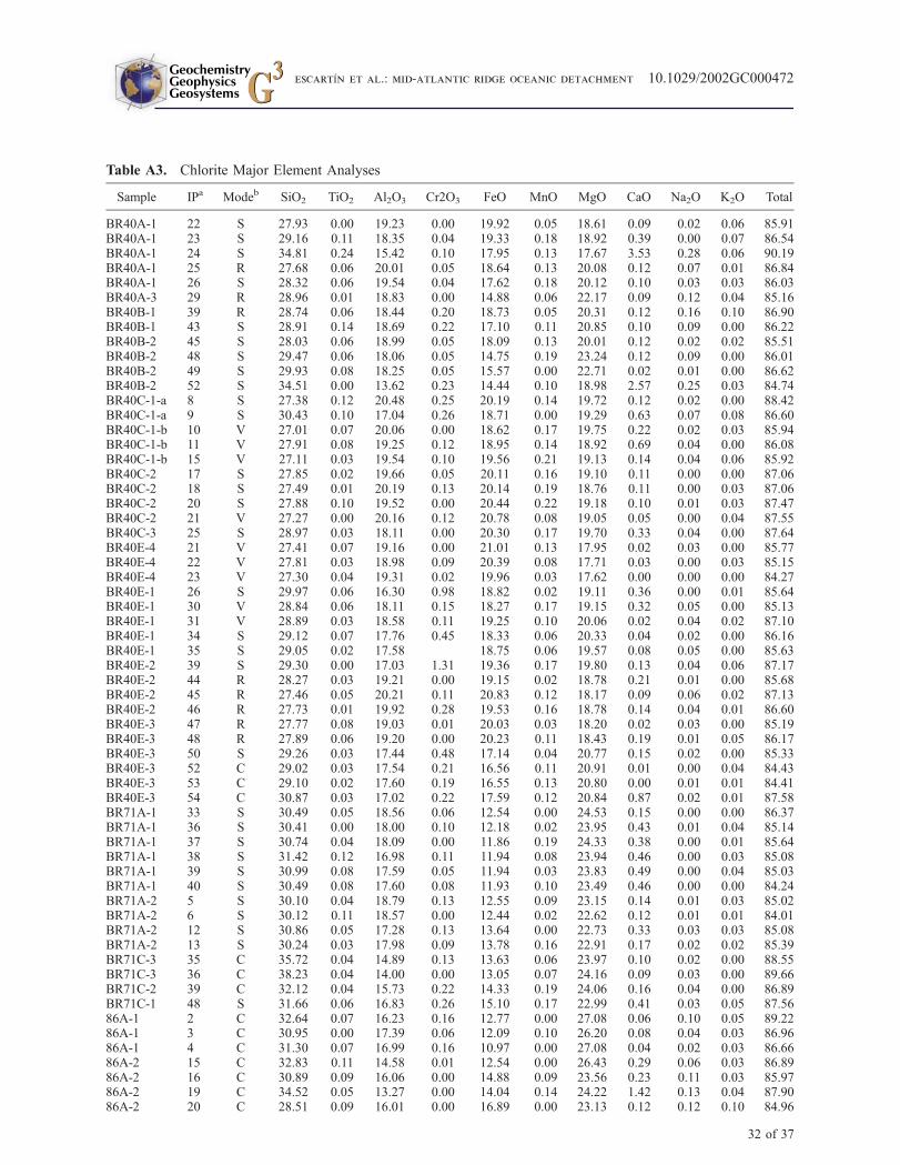
Table A3. Chlorite Major Element Analyses
Sample IPa Modeb SiO2 TiO2 Al2O3 Cr2O3 FeO MnO MgO CaO Na2O K2O Total
BR40A-1 22 S 27.93 0.00 19.23 0.00 19.92 0.05 18.61 0.09 0.02 0.06 85.91BR40A-1 23 S 29.16 0.11 18.35 0.04 19.33 0.18 18.92 0.39 0.00 0.07 86.54BR40A-1 24 S 34.81 0.24 15.42 0.10 17.95 0.13 17.67 3.53 0.28 0.06 90.19BR40A-1 25 R 27.68 0.06 20.01 0.05 18.64 0.13 20.08 0.12 0.07 0.01 86.84BR40A-1 26 S 28.32 0.06 19.54 0.04 17.62 0.18 20.12 0.10 0.03 0.03 86.03BR40A-3 29 R 28.96 0.01 18.83 0.00 14.88 0.06 22.17 0.09 0.12 0.04 85.16BR40B-1 39 R 28.74 0.06 18.44 0.20 18.73 0.05 20.31 0.12 0.16 0.10 86.90BR40B-1 43 S 28.91 0.14 18.69 0.22 17.10 0.11 20.85 0.10 0.09 0.00 86.22BR40B-2 45 S 28.03 0.06 18.99 0.05 18.09 0.13 20.01 0.12 0.02 0.02 85.51BR40B-2 48 S 29.47 0.06 18.06 0.05 14.75 0.19 23.24 0.12 0.09 0.00 86.01BR40B-2 49 S 29.93 0.08 18.25 0.05 15.57 0.00 22.71 0.02 0.01 0.00 86.62BR40B-2 52 S 34.51 0.00 13.62 0.23 14.44 0.10 18.98 2.57 0.25 0.03 84.74BR40C-1-a 8 S 27.38 0.12 20.48 0.25 20.19 0.14 19.72 0.12 0.02 0.00 88.42BR40C-1-a 9 S 30.43 0.10 17.04 0.26 18.71 0.00 19.29 0.63 0.07 0.08 86.60BR40C-1-b 10 V 27.01 0.07 20.06 0.00 18.62 0.17 19.75 0.22 0.02 0.03 85.94BR40C-1-b 11 V 27.91 0.08 19.25 0.12 18.95 0.14 18.92 0.69 0.04 0.00 86.08BR40C-1-b 15 V 27.11 0.03 19.54 0.10 19.56 0.21 19.13 0.14 0.04 0.06 85.92BR40C-2 17 S 27.85 0.02 19.66 0.05 20.11 0.16 19.10 0.11 0.00 0.00 87.06BR40C-2 18 S 27.49 0.01 20.19 0.13 20.14 0.19 18.76 0.11 0.00 0.03 87.06BR40C-2 20 S 27.88 0.10 19.52 0.00 20.44 0.22 19.18 0.10 0.01 0.03 87.47BR40C-2 21 V 27.27 0.00 20.16 0.12 20.78 0.08 19.05 0.05 0.00 0.04 87.55BR40C-3 25 S 28.97 0.03 18.11 0.00 20.30 0.17 19.70 0.33 0.04 0.00 87.64BR40E-4 21 V 27.41 0.07 19.16 0.00 21.01 0.13 17.95 0.02 0.03 0.00 85.77BR40E-4 22 V 27.81 0.03 18.98 0.09 20.39 0.08 17.71 0.03 0.00 0.03 85.15BR40E-4 23 V 27.30 0.04 19.31 0.02 19.96 0.03 17.62 0.00 0.00 0.00 84.27BR40E-1 26 S 29.97 0.06 16.30 0.98 18.82 0.02 19.11 0.36 0.00 0.01 85.64BR40E-1 30 V 28.84 0.06 18.11 0.15 18.27 0.17 19.15 0.32 0.05 0.00 85.13BR40E-1 31 V 28.89 0.03 18.58 0.11 19.25 0.10 20.06 0.02 0.04 0.02 87.10BR40E-1 34 S 29.12 0.07 17.76 0.45 18.33 0.06 20.33 0.04 0.02 0.00 86.16BR40E-1 35 S 29.05 0.02 17.58 18.75 0.06 19.57 0.08 0.05 0.00 85.63BR40E-2 39 S 29.30 0.00 17.03 1.31 19.36 0.17 19.80 0.13 0.04 0.06 87.17BR40E-2 44 R 28.27 0.03 19.21 0.00 19.15 0.02 18.78 0.21 0.01 0.00 85.68BR40E-2 45 R 27.46 0.05 20.21 0.11 20.83 0.12 18.17 0.09 0.06 0.02 87.13BR40E-2 46 R 27.73 0.01 19.92 0.28 19.53 0.16 18.78 0.14 0.04 0.01 86.60BR40E-3 47 R 27.77 0.08 19.03 0.01 20.03 0.03 18.20 0.02 0.03 0.00 85.19BR40E-3 48 R 27.89 0.06 19.20 0.00 20.23 0.11 18.43 0.19 0.01 0.05 86.17BR40E-3 50 S 29.26 0.03 17.44 0.48 17.14 0.04 20.77 0.15 0.02 0.00 85.33BR40E-3 52 C 29.02 0.03 17.54 0.21 16.56 0.11 20.91 0.01 0.00 0.04 84.43BR40E-3 53 C 29.10 0.02 17.60 0.19 16.55 0.13 20.80 0.00 0.01 0.01 84.41BR40E-3 54 C 30.87 0.03 17.02 0.22 17.59 0.12 20.84 0.87 0.02 0.01 87.58BR71A-1 33 S 30.49 0.05 18.56 0.06 12.54 0.00 24.53 0.15 0.00 0.00 86.37BR71A-1 36 S 30.41 0.00 18.00 0.10 12.18 0.02 23.95 0.43 0.01 0.04 85.14BR71A-1 37 S 30.74 0.04 18.09 0.00 11.86 0.19 24.33 0.38 0.00 0.01 85.64BR71A-1 38 S 31.42 0.12 16.98 0.11 11.94 0.08 23.94 0.46 0.00 0.03 85.08BR71A-1 39 S 30.99 0.08 17.59 0.05 11.94 0.03 23.83 0.49 0.00 0.04 85.03BR71A-1 40 S 30.49 0.08 17.60 0.08 11.93 0.10 23.49 0.46 0.00 0.00 84.24BR71A-2 5 S 30.10 0.04 18.79 0.13 12.55 0.09 23.15 0.14 0.01 0.03 85.02BR71A-2 6 S 30.12 0.11 18.57 0.00 12.44 0.02 22.62 0.12 0.01 0.01 84.01BR71A-2 12 S 30.86 0.05 17.28 0.13 13.64 0.00 22.73 0.33 0.03 0.03 85.08BR71A-2 13 S 30.24 0.03 17.98 0.09 13.78 0.16 22.91 0.17 0.02 0.02 85.39BR71C-3 35 C 35.72 0.04 14.89 0.13 13.63 0.06 23.97 0.10 0.02 0.00 88.55BR71C-3 36 C 38.23 0.04 14.00 0.00 13.05 0.07 24.16 0.09 0.03 0.00 89.66BR71C-2 39 C 32.12 0.04 15.73 0.22 14.33 0.19 24.06 0.16 0.04 0.00 86.89BR71C-1 48 S 31.66 0.06 16.83 0.26 15.10 0.17 22.99 0.41 0.03 0.05 87.5686A-1 2 C 32.64 0.07 16.23 0.16 12.77 0.00 27.08 0.06 0.10 0.05 89.2286A-1 3 C 30.95 0.00 17.39 0.06 12.09 0.10 26.20 0.08 0.04 0.03 86.9686A-1 4 C 31.30 0.07 16.99 0.16 10.97 0.00 27.08 0.04 0.02 0.03 86.6686A-2 15 C 32.83 0.11 14.58 0.01 12.54 0.00 26.43 0.29 0.06 0.03 86.8986A-2 16 C 30.89 0.09 16.06 0.00 14.88 0.09 23.56 0.23 0.11 0.03 85.9786A-2 19 C 34.52 0.05 13.27 0.00 14.04 0.14 24.22 1.42 0.13 0.04 87.9086A-2 20 C 28.51 0.09 16.01 0.00 16.89 0.00 23.13 0.12 0.12 0.10 84.96
GeochemistryGeophysicsGeosystems G3G3
escartIn et al.: mid-atlantic ridge oceanic detachment 10.1029/2002GC000472
32 of 37

Table A3. (continued)
Sample IPa Modeb SiO2 TiO2 Al2O3 Cr2O3 FeO MnO MgO CaO Na2O K2O Total
86A-3 24 S 31.32 0.04 14.67 0.24 12.77 0.01 25.74 0.24 0.07 0.04 85.1486A-3 25 S 29.92 0.06 15.22 0.60 13.44 0.04 26.29 0.02 0.04 0.02 85.6686A-3 29 S 31.11 0.02 14.94 0.01 9.92 0.00 27.07 0.23 0.05 0.06 83.4186A-3 30 S 30.59 0.00 15.59 0.07 10.87 0.16 27.01 0.09 0.04 0.05 84.4986A-4 36 S 31.72 0.04 13.71 0.70 9.37 0.06 28.00 0.59 0.09 0.02 84.31DR19-1-2 18 S 37.95 0.00 12.13 0.27 9.06 0.06 27.38 0.11 0.06 0.00 87.03DR19-1-2 20 S 33.62 0.05 14.85 0.19 7.90 0.05 29.21 0.00 0.02 0.03 85.92DR19-1-2 21 S 40.66 0.00 10.58 0.10 8.75 0.04 28.21 0.06 0.05 0.01 88.45DR19-1-3 25 S 36.34 0.04 13.07 0.05 9.67 0.08 27.46 0.06 0.02 0.00 86.79DR19-1-3 27 S 35.89 0.08 15.20 0.01 4.97 0.04 30.06 0.10 0.04 0.01 86.40DR19-1-3 28 S 34.64 0.00 13.75 0.06 8.18 0.00 28.50 0.14 0.04 0.01 85.32DR19-1-3 29 S 35.20 0.00 13.83 0.09 7.75 0.20 29.06 0.06 0.00 0.01 86.21DR19-1-3 30 S 33.69 0.00 14.83 0.03 7.17 0.01 29.00 0.07 0.02 0.04 84.86DR19-1-4 31 X 32.53 0.02 13.26 1.87 7.87 0.10 29.63 0.09 0.05 0.04 85.45DR19-1-4 32 X 32.56 0.04 13.38 1.59 7.93 0.00 29.38 0.04 0.09 0.04 85.02DR19-1-4 33 X 32.79 0.00 13.57 1.68 8.19 0.07 28.55 0.05 0.11 0.00 85.01DR2-9-1 1 V 33.35 0.10 13.90 0.21 8.20 0.07 30.19 0.03 0.00 0.00 86.05DR26-3-1 34 X 35.27 0.08 13.25 0.15 5.11 0.03 31.79 0.12 0.02 1.11 86.92DR26-3-1 39 X 34.39 0.01 12.79 0.02 4.78 0.04 32.08 0.13 0.01 0.12 84.37
aProbe analysis number.
bS, Matrix of shear zone; C, Clast; V, Veins; R, Radial chlorite; X, Static chloritization.
Table A4. Whole Rock Major and Rare Earth Analysesa
Sample DR13-23 DR13-17 DR14-5 DR02-8 DR26-8 DR22-2 BR40-2 BR63-4 BR40-3 BR28-1 BR71-5
Type Talcschist
serpentine serpentine serpentine diabase diabase Talcschist
Talcschist
Amphiboliteschist
Amphiboliteschist
Amphiboliteschist
SiO2 60.04 38.52 38.47 39.51 43.03 45.41 57.68 57.22 42.14 49.89 45.08Al2O3 0.62 0.91 0.81 1.16 18.08 16.53 1.28 0.5 9.1 4.3 7.73Fe2O3 4.24 9.73 8.08 7.44 13.39 10.21 4.42 4.59 13.87 9.65 10.66MnO <D.L. 0.03 0.05 0.03 0.25 0.22 0.03 0.06 0.12 0.09 0.1MgO 29.8 37.77 38.15 38.32 9.02 10.44 28.92 24.9 20.09 21.21 24.85CaO <D.L. <D.L. 0.46 <D.L. 9.03 10.51 2.78 9.8 6.57 9.99 2.95Na2O 0.13 0.16 0.1 0.14 2.3 2.07 0.14 0.29 0.36 0.2 0.39K2O <D.L. <D.L. <D.L. <D.L. <D.L. <D.L. <D.L. <D.L. <D.L. <D.L. <D.L.TiO2 <D.L. <D.L. <D.L. <D.L. 1.46 1.14 <D.L. <D.L. 0.55 <D.L. 0.57P2O5 0.05 0.05 0.06 0.05 0.18 0.12 <D.L. <D.L. 0.05 <D.L. 0.11PF 5.16 12.82 13.92 13.62 3.66 3.18 4.77 2.59 6 4.07 7.52Total 100.04 99.99 100.1 100.27 100.4 99.83 100.02 99.95 98.850 99.40 99.96Cl (ppm) 515 1470 1065 1295 79 490 <D.L <D.L <D.L <D.L <D.LLa (ppm) 0.081 0.333 0.199 0.056 4.87 4.22 0.068 0.571 1.349 0.211 1.695Ce (ppm) 0.094 0.515 0.565 0.172 13.99 11.21 0.185 1.906 5.345 0.835 5.814Pr (ppm) 0.022 0.079 0.093 0.026 2.02 1.70 <D.L 0.317 0.893 0.138 0.914Nd (ppm) 0.09 0.321 0.471 0.127 10.35 8.55 0.12 1.66 4.785 0.84 4.714Sm (ppm) 0.027 0.075 0.148 0.056 3.35 2.80 0.041 0.464 1.564 0.361 1.473Eu (ppm) 0.005 0.038 0.022 0.022 1.66 1.23 0.019 0.234 0.51 0.148 0.592Gd (ppm) 0.033 0.087 0.176 0.07 4.11 3.41 0.046 0.472 1.889 0.632 1.778Tb (ppm) 0.006 0.014 0.032 0.014 0.68 0.58 0.012 0.071 0.317 0.121 0.301Dy (ppm) 0.046 0.108 0.25 0.103 4.54 3.84 0.067 0.449 2.097 0.948 2.035Ho (ppm) 0.01 0.025 0.061 0.025 1.00 0.84 0.014 0.07 0.43 0.212 0.419Er (ppm) 0.028 0.072 0.173 0.073 2.70 2.37 0.049 0.185 1.207 0.66 1.197Tm (ppm) 0.005 0.014 0.03 0.014 0.42 0.36 0.014 0.07 0.43 0.212 0.419Yb (ppm) 0.034 0.106 0.202 0.103 2.74 2.33 0.056 0.105 1.1 1.1 1.243Lu (ppm) 0.006 0.018 0.031 0.018 0.42 0.36 0.009 0.011 0.17 0.199 0.19
aD.L., Detection limit.
GeochemistryGeophysicsGeosystems G3G3
escartIn et al.: mid-atlantic ridge oceanic detachment 10.1029/2002GC000472
33 of 37
we propose that the detachment fault soled out in the
shallow, cold lithosphere, possibly at the alteration
front. The detachment was active below the ridge
axis and during periods of magmatic activity, as
indicated by the presence of both diabase intrusions
into the fault zone and highly deformed diabases
within the fault schists. This detachment model may
be applicable to the corrugated and striated surfaces
found along the Mid-Atlantic Ridge and other
slow- and intermediate-spreading ridges.
[62] Detachments may also develop in the presence
of active magmatism at the ridge axis, as observed
at the Atlantis II Bank. This second type of
detachment is also active during magmatism and
roots in the shallow lithosphere, but soles out in a
melt rich zone (possibly the gabbro-dyke transi-
tion). The detachment morphology, the occurrence
and relative abundance of lithologies, and the
deformation processes recorded by the footwall
rocks differ substantially from one type of detach-
ment to the other. In both cases, however, the
detachments are active in the presence of magma-
tism, confirming that amagmatic extension is not
required for detachment faulting in the oceanic
lithosphere.
Appendix A: Major Element Analyses ofSpinel, Amphibole and Chlorite, andWhole-Rock Major and Rare EarthElement Analyses
[63] In appendix A we report both mineral
and whole rock analyses of selected samples (see
Tables 1 and 2 for sample locations). The major
element analyses of spinel are given in Table A1,
those of amphiboles in Table A2, and those of
chlorite in Table A3. Whole rock analyses of both
major and rare earth elements are given in Table A4.
Acknowledgments
[64] We are grateful to great work of the Captain and the
Crew of the RRS James Clark Ross, the British Geological
Survey Drill Team, the TOBI Team (SOC, UK), and the JR63
Scientific Party, who made possible the success of the cruise.
Discussions with the JR63 Scientific Party during the cruise,
and with M. Cannat and J. Casey, contributed ideas to the
paper. Comments by Roger Searle, Barbara John, an anony-
mous reviewer and the Associate Editor C. Chauvel helped to
clarify and improve the manuscript. This work is partially
supported by a CNRS/NERC ‘‘Egide’’ grant to J. Escartın and
C. J. MacLeod. GMT software [Wessel and Smith, 1991] was
extensively used in this project. This is IPGP Contribution
number 1913 and Cardiff School of Earth, Ocean and Plane-
tary Sciences contribution number 4.
References
Allen, D. E., and W. E. Seyfried, Compositional controls on
vent fluids from ultramafic systems at mid-ocean ridges: An
experimental study at 400�C, 500 bars, Geochim. Cosmo-
chim. Acta, 67, 1531–1542, 2003.
Allerton, S., D. Wallis, J. Derrick, D. Smith, and C. J.
MacLeod, New wireline seafloor drill augers well, Eos
Trans. AGU, 80, 367, 1999.
Anderson, J. L., A. P. Barth, and E. D. Young, Mid-crustal
Cretaceous roots of Cordilleran metamorphic core com-
plexes, Geology, 16, 366–369, 1988.
Blackman, D. K., J. R. Cann, B. Janssen, and D. K. Smith,
Origin of extensional core complexes: Evidence from the
Mid-Atlantic Ridge at Atlantis Fracture Zone, J. Geophys.
Res., 103, 21,315–21,333, 1998.
Brun, J. P., D. Sokoutis, and J. Van Den Driessche, Analogue
modeling of detachment fault systems and core complexes,
Geology, 22, 319–322, 1994.
Buck, R. W., Flexural rotation of normal faults, Tectonics, 7,
959–973, 1988.
Bykerk-Kauffman, A., and S. U. Janecke, Late Cretaceous to
early Tertiary ductile deformation: Catalina-Rincon meta-
morphic core complex, southeastern Arizona, Geology, 15,
569–572, 1987.
Campbell-Stone, E. A., B. E. John, J. W. Geissman, D. A.
Foster, and R. Livicarri, Mechanisms for accommodation
of Miocene extension: Low-angle normal faulting, magma-
tism, and secondary breakaway faulting in the southern
Sacramento Mountains, southeastern California, Tectonics,
19, 566–587, 2000.
Cann, J. R., D. K. Blackman, D. K. Smith, E. McAllister,
B. Janssen, S. Mello, E. Avgerinos, A. R. Pascoe, and J.
Escartın, Corrugated slip surfaces formed at North Atlantic
ridge-transform intersections, Nature, 385, 329–332, 1997.
Cannat, M., Emplacement of mantle rocks in the seafloor at
mid-ocean ridges, J. Geophys. Res., 98, 4163–4172, 1993.
Cannat, M., and J. F. Casey, An ultramaphic lift at the Mid-
Atlantic Ridge: Successive stages of magmatism in serpenti-
nized peridotites from the 15�N region, in Mantle and Lower
Crust Exposed in Oceanic Ridges and in Ophiolites, edited
by R. L. M. Vissers and A. Nicolas, pp. 5–34, Kluwer
Acad., Norwell, Mass., 1995.
Cannat, M., D. Bideau, and H. Bougault, Serpentinized peri-
dotites and gabbros in the Mid-Atlantic Ridge axial valley at
15�370N and 16�520N, Earth Planet. Sci. Lett., 109, 87–106,
1992.
Cannat, M., Y. Lagabrielle, H. Bougault, J. Casey, N. de
Coutures, L. Dmitriev, and Y. Fouquet, Ultramafic and gab-
broic exposures at the Mid-Atlantic Ridge: Geological map-
ping in the 15�Nregion,Tectonophysics, 279, 193–213, 1997.
GeochemistryGeophysicsGeosystems G3G3
escartIn et al.: mid-atlantic ridge oceanic detachment 10.1029/2002GC000472
34 of 37
Casey, J. F., M. G. Braun, and P. B. Kelemen, Megamullions
along the mid-Atlantic ridge between 14�N and 16�N: Re-sults of Leg 1, JAMSTEC/WHOI MODE 98 Survey, Eos
Trans. AGU, 79(46), Fall Meet. Suppl., F920, 1998.
Christie, D. M., B. P. West, and D. G. Pyle, Extreme morpho-
logic and petrologic diversity within the Southeast Indian
Ridge (abstract), Eos Trans. AGU, 78(46), Fall Meet. Suppl.,
F673, 1997.
Collins, J., and R. S. Detrick, Seismic structure of the Atlantis
Fracture Zone megamullion, a serpentinized ultramafic mas-
sif, Eos Trans. AGU, 79(46), Fall Meet. Suppl., F800, 1998.
Davis, G. H., Shear-zone model for the origin of metamorphic
core complexes, Geology, 11, 342–347, 1983.
Davis, G. H., and G. S. Lister, Detachment faulting in conti-
nental extension: Perspectives from the southwestern U.S.
Cordillera, in Processes in continental lithosphere deforma-
tion, edited by S. P. Clark Jr. et al., Geol. Soc. Am. Spec.
Pap., 218, 133–160, 1988.
Deplus, C., J. Escartın, A. Briais, M. Cannat, J. Georgen,
J. Lin, S. Mercouriev, C. Meyzen, M. Muller, G. Pouliquen,
A. Rabain, and P. da Silva, Linking variation in magma
supply and segment growth: Temporal evolution of segment
OH-1(MAR at 35�N), Eos Trans. AGU, 79(46), Fall Meet.
Suppl., F856, 1998.
Detrick, R. S., J. Escartın, and H. Nouze, In situ seismic ve-
locity structure of gabbros and ultramafics exposed at shal-
low crustal levels in the Mid-Atlantic Ridge rift valley at
15�200N (abstract), Geophys. Res. Abstr., 1, 186, 1999.
Dick, H. J. B., and T. Bullen, Chromian spinel as a petrogenic
indicator in abyssal and alpine-type peridotites and spatially
associated lavas, Contrib. Mineral. Petrol., 86, 54–76, 1984.
Dick, H. J. B., H. Schouten, P. S. Meyer, D. G. Gallo,
H. Bergh, R. Tyce, P. Patriat, K. T. M. Johnson, J. Snow,
and A. Fischer, Tectonic evolution of the Atlantis II Fracture
Zone, Proc. Ocean Drill. Program Sci. Results, 118, 359–
398, 1991.
Dick, H. J. B., J. H. Natland, and D. J. Miller, Proc. Ocean
Drill. Program Initial Rep., Leg 176, vol. 176, Ocean Dril-
ling Program, College Station, Tex., 1999.
Dick, H. J. B., et al., Along in situ section of the lower oceanic
crust: Results of ODP Leg 176 drilling at the Southwest
Indian Ridge, Earth Planet. Sci. Lett., 179, 31–51, 2000.
Dick, H. J. B., T. Matsumoto, B. John, H. Kinoshita,
P. Robinson, G. Hirth, J. Natland, and C. J. MacLeod, The
Atlantis Bank Core complex, paper presented at InterRidge
SWIR Workshop, Southampton, U.K., 2002.
Dosso, L., H. Bougault, J. G. Schilling, and J.-L. Joron, Sr-Nd-
Pb geochemical morphology between 10� and 17�N on the
Mid-Atlantic Ridge: A new MORB isotope signature, Earth
Planet. Sci. Lett., 106, 29–43, 1991.
Dosso, L., H. Bougault, and J.-L. Joron, Geochemical mor-
phology of the North Mid-Atlantic Ridge, 10�–24�N: Traceelement-isotope complementary, Earth Planet. Sci. Lett.,
120, 443–462, 1993.
Ernst, W. G., and J. Liu, Experimental phase-equilibrium study
of Al- and Ti-contents of calcic amphibole in MORB—A
semiquantitative thermobarometer, Am. Mineral., 83, 952–
969, 1998.
Escartın, J., and M. Cannat, Ultramafic exposures and the
gravity signature of the lithosphere near the Fifteen-Twenty
Fracture Zone (Mid-Atlantic Ridge, 14�–16.5�N), EarthPlanet. Sci. Lett., 171, 411–424, 1999.
Escartın, J., G. Hirth, and B. Evans, Non-dilatant brittle defor-
mation of serpentinites: Implications for Mohr-Coulomb the-
ory and the strength of faults, J. Geophys. Res., 102, 2897–
2913, 1997a.
Escartın, J., G. Hirth, and B. Evans, Effects of Serpentinization
on the Lithospheric Strength and the Style of Normal Fault-
ing at Slow-Spreading Ridges, Earth Planet. Sci. Lett., 151,
181–190, 1997b.
Escartın, J., G. Hirth, and B. Evans, Strength of slightly ser-
pentinized peridotites: Implications of the tectonics of ocea-
nic lithosphere, Geology, 29, 1023–1026, 2001.
Fletcher, J. M., J. M. Bartley, M. W. Martin, A. Z. Glazner, and
J. D. Walker, Large-magnitude continental extension: An
example from the Central Mojave Desert, Geol. Soc. Am.
Bull., 107, 1468–1483, 1995.
Fujiwara, T., P. B. Kelemen, M. G. Braun, M. Joshima, J. F.
Casey, A. Takeuchi, and G. M. Ceuleneer, Bathymetry, geo-
magnetic and gravity anomalies of the Mid-Atlantic Ridge
between 14�N and 16�N, Eos Trans. AGU, 80(46), Fall
Meet. Suppl., F956, 1999.
Fujiwara, T., J. Lin, T. Matsumoto, P. B. Kelemen, B. E.
Tucholke, and J. F. Casey, Crustal Evolution of the Mid-
Atlantic Ridge near the Fifteen-Twenty Fracture Zone in
the last 5 Ma, Geochem. Geophys. Geosyst., 4(3), 1024,
doi:10.1029/2002GC000364, 2003.
Gartell, A. P., Evolution of rift basins and low-angle detach-
ments in multilayer analog models, Geology, 25, 615–618,
1997.
Holland, T., and J. Blundy, Non-ideal interactions in calcic
amphiboles and their bearing on amphibole-plagioclase ther-
mometry, Contrib. Mineral. Petrol., 116, 433–447, 1994.
Jackson, J. A., and N. J. White, Normal faulting in the upper
continental crust: Observations from regions of active exten-
sion, J. Struct. Geol., 11, 15–36, 1989.
Jaroslow, G. E., H. J. B. Dick, and G. Hirth, Abyssal peridotite
mylonites: Implications for grain-size sensitive flow and
strain partitioning in the oceanic lithosphere, Tectonophysics,
256, 17–37, 1996.
John, B., Geometry and evolution of a mid-crustal extension
fault system: Chemeuevi Mountains, southeastern California,
in Continental Extensional Tectonics, edited by M. P.
Coward, J. F. Dewey, and P. L. Hancock, pp. 313–335,
Geol. Soc., London, 1987.
Karson, J., Geological investigation of a lineated massif at the
Kane Transform: Implications for oceanic core complexes,
Philos. Trans. R. Soc. London, 357, 713–740, 1999.
Kelley, D. S., et al., An off-axis hydrothermal vent field near
the Mid-Atlantic Ridge at 30�N, Nature, 411, 145–149,
2001.
Lagabrielle, Y., D. Bideau, M. Cannat, J. A. Karson, and
C. Mevel, Ultramafic-mafic plutonic rock suites exposed
along the Mid-Atlantic Ridge (10�N–30�N). Symmetrical-
asymmetrical distribution and implications for seafloor
spreading processes, in Faulting and Magmatism at Mid-
GeochemistryGeophysicsGeosystems G3G3
escartIn et al.: mid-atlantic ridge oceanic detachment 10.1029/2002GC000472
35 of 37
Ocean Ridges, Geophys. Monogr. Ser., vol. 106, edited by
W. R. Buck et al., pp. 153–176, AGU, Washington, D. C.,
1998.
Lavier, L., W. R. Buck, and A. N. B. Poliakov, Self-consistent
rolling-hinge model for the evolution of large-offset low-
angle normal faults, Geology, 27, 1127–1130, 1999.
Lee, J., and G. S. Lister, Late Miocene ductile extension and
detachment faulting, Mykonos, Greece, Geology, 20, 121–
124, 1992.
Lehnert, K., Y. Su, C. H. Langmuir, B. Sarbas, and U. Nohl, A
global geochemical database structure for rocks, Geochem.
Geophys. Geosyst., 1, Paper number 1999GC000026, 2000.
Lister, G. S., and S. L. Baldwin, Plutonism and the origin of
metamorphic core complexes, Geology, 21, 607–610, 1993.
Lister, G. S., G. Banga, and A. Feenstra, Metamorphic core
complexes of Cordilleran type in the Cyclades, Aegean Sea,
Greece, Geology, 12, 221–225, 1984.
MacLeod, C. J., et al., Geological mapping of slow-spread
lower ocean crust: A deep-towed video and wireline rock
drilling survey of Atlantis Bank (ODP Site 735, southwest
Indian Ridge), InterRidge News, 7, 39–43, 1998.
MacLeod, C. J., et al., RRS James Clark Ross cruise JR63
Cruise Report, 59 pp., Cardiff Univ., Wales, 2001.
MacLeod, C. J., et al., Direct geological evidence for oceanic
detachment fauling: The Mid-Atlantic Ridge, 15�450N, Geol-ogy, 30, 10, 879–882, 2002.
Martinez, F., J. Karsten, and E. M. Klein, Recent kinematics
and tectonics of the Chile Ridge, Eos Trans. AGU, 79(46),
Fall Meet. Suppl., F836, 1998.
Matsumoto, T., and P. B. Kelemen, Precise geological and
geophysical mapping of the 15�200N Fracture Zone on the
MAR - Tectonic extension and its consequent exposure of
ultramafic and plutonic rocks along the magma-poor ridge
axis (MODE’98 Leg 1 Cruise), InterRidge News, 7, 13–17,
1998.
Mevel, C., M. Cannat, P. Gente, E. Marion, J. M. Auzende,
and J. A. Karson, Emplacement of deep crustal and mantle
rocks on the west median valley wall of the MARK area
(MAR, 23�N), Tectonophysics, 190, 31–53, 1991.Miller, E. L., P. B. Gans, and J. Garing, The Snake Range
decollement: An exhumed mid-Tertiary ductile-brittle transi-
tion, Tectonics, 2, 239–263, 1983.
Mitchell, N. C., J. Escartın, and S. Allerton, Detachment faults
at Mid-Ocean Ridges garner interest, Eos Trans. AGU, 79,
127, 1998.
Miyashiro, A., Metamorphism and Metamorphic Belts, John
Wiley, New York, 1973.
Moore, D., D. A. Lockner, M. Shengli, R. Summers, and J. D.
Byerlee, Strength of serpentinite gouges at elevated tempera-
tures, J. Geophys. Res., 102, 14,787–14,801, 1997.
Mueller, K. J., and A. W. Snoke, Progressive overprinting
of normal fault systems and their role in Tertiary exhu-
mation of the East Humboldt-Wood Hills metamorphic
complex northeast Nevada, Tectonics, 12, 361–371,
1993.
Mulugeta, G., and W. Ghebreab, Modeling heterogeneous
stretching during episodic or steady rifting of the continental
lithosphere, Geology, 29, 895–898, 2001.
Natland, J. H., and H. J. B. Dick, Formation of the lower
oceanic crust and the crystallization of gabbroic cumulates
at a very slowly spreading ridge, J. Volcanol. Geotherm.
Res., 110, 191–233, 2001.
O’Hanley, D. S., Solution to the volume problem in serpenti-
nization, Geology, 20, 705–708, 1992.
O’Hanley, D. S., Serpentinites, 277 pp., Oxford Univ. Press,
New York, 1996.
Parsons, T., and G. A. Thompson, Does magmatism influence
low-angle normal faulting?, Geology, 21, 247–250, 1993.
Passchier, C. W., and R. A. J. Trouw, Micro-tectonics, 289 pp.,
Springer-Verlag, New York, 1998.
Ranero, C., and T. J. Reston, Detachment faulting at ocean
core complexes, Geology, 27, 983–986, 1999.
Reinen, L. A., J. D. Weeks, and T. E. Tullis, The frictional
behavior of serpentinite: Implications for aseismic creep on
shallow crustal faults, Geophys. Res. Lett., 18, 1921–1924,
1991.
Reston, T. J., W. Weinrebe, I. Grevemeyer, N. C. Flueh,
L. Kirstein, C. Kopp, H. Kopp, and M. Participants, A rifted
inside corner massif on the Mid-Atlantic Ridge at 5�S, EarthPlanet. Sci. Lett., 200, 255–269, 2002.
Robinson, P. T., et al. (Eds.), Proc. Ocean Drill. Program,
Initial Reports, vol. 118, 826 pp., Ocean Drilling Program,
College Station, Tex., 1989.
Schroeder, T., B. John, and B. R. Frost, Geologic implica-
tions of seawater circulation through peridotite exposed at
slow-spreading mid-ocean ridge, Geology, 30, 367–370,
2002.
Searle, R. C., H. Fujioka, M. Cannat, C. Mevel, H. Fujimoto,
and L. M. Parson, FUJI Dome, a large detachment fault near
64 degrees E on the very slow spreading South West Indian
Ridge (abstract), EOS Trans. AGU, 80(46), Fall Meet.
Suppl., F956, 1999.
Shaw, P. R., Ridge segmentation, faulting and crustal thickness
in the Atlantic Ocean, Nature, 358, 490–493, 1992.
Smith, W. H., and D. T. Sandwell, Global seafloor topography
from satellite altimetry and ship depth soundings, Science,
227, 1956–1962, 1997.
Spencer, J. E., Role of tectonic denudation in warping and
uplift of low-angle normal faults, Geology, 12, 95–98,
1984.
Spencer, J. E., Geologic continuous casting below continental
and deep-sea detachment faults and the striated extrusion of
Sacsayhuaman, Peru, Geology, 27, 327–330, 1999.
Tamaki, K., and C. Mevel, Spreading tectonics of the eastern
part of the Southwestern Indian Ridge: A synthesis of FUJI
expedition (abstract), Eos Trans. AGU, 79(46), Fall Meet.
Suppl., F892, 1998.
Tucholke, B. E., J. Lin, and M. C. Kleinrock, Megamullions
and mullion structure defining oceanic metamorphic core
complexes on the Mid-Atlantic Ridge, J. Geophys. Res.,
103, 9857–9866, 1998.
Tucholke, B. E., J. Lin, M. C. Kleinrock, M. Tivey, T. B. Reed,
J. Goff, and G. E. Jaroslow, Segmentation and crustal struc-
ture of the western Mid-Atlantic Ridge flank, 25�250–27�100N and 0–29 m. y., J. Geophys. Res., 102, 10,203–
10,223, 1997.
GeochemistryGeophysicsGeosystems G3G3
escartIn et al.: mid-atlantic ridge oceanic detachment 10.1029/2002GC000472
36 of 37
Tucholke, B. E., K. Fujioka, T. Ishihara, G. Hirth, and
M. Kinoshita, Submersible study of an oceanic megamullion
in the central North Atlantic, J. Geophys. Res., 106, 16,145–
16,161, 2001.
Wernicke, B., Low-angle normal faults in the Basin and Range
province: Nappe tectonics in an extending orogen, Nature,
291, 645–648, 1981.
Wernicke, B., The fluid crustal layer and its implications for
continental dynamics, in Exposed Cross Sections of the Con-
tinental Crust, edited by M. Salisbury and D. M. Fountain,
pp. 509–544, Kluwer, Norwell, Mass., 1990.
Wernicke, B., and G. J. Axen, On the role of isostasy in the
evolution of normal fault systems, Geology, 16, 848–851,
1988.
Wessel, P., and W. H. F. Smith, Free software helps map and
display data, Eos Trans. AGU, 72, 441, 445–446, 1991.
Wright, L. A., B. W. Troxell, E. G. Williams, M. T.
Roberts, and P. E. Diehl, Precambrian sedimentary
environments of the Death Valley region, California and
Nevada, in Guidebook, Death Valley Region, California
and Nevada, pp. 27–36, Death Valley Publ., Shoshone,
Calif., 1974.
GeochemistryGeophysicsGeosystems G3G3
escartIn et al.: mid-atlantic ridge oceanic detachment 10.1029/2002GC000472
37 of 37