# OAK RIDGE NATIONAL LABORATORY
713
BeotiVf:-!-) nv osT! junQ6 1986 # soml NUREG/CR--3770 TI86 011205 NUREG/CR-3770 ORNL/TM-9176 OAK RIDGE NATIONAL LABORATORY Preliminary Development of an Integrated Approach to the Evaluation of Pressurized Thermal Shock as Applied to the Oconee Unit 1 Nuclear Power Plant Prepared for the Division of Risk Analysis and Operations Office of Nuclear Regulatory Research U.S. Nuclear Regulatory Commission Under Interagency Agreement DOE 40-550-75 OPERATED BY MARTIN MARIEHA ENERGY SYSTEMS, INC. FOR THE UNITED STATES DEPARTMENT OF .ENERGY 0T' ’■'pfBunoN OF !s uNimrfl®
-
Upload
khangminh22 -
Category
Documents
-
view
0 -
download
0
Transcript of # OAK RIDGE NATIONAL LABORATORY

BeotiVf:-!-) nv osT! j u n Q 6 1986
# soml N U R E G / C R - - 3 7 7 0
TI86 011205
NUREG/CR-3770ORNL/TM-9176
OAK RIDGENATIONALLABORATORY Preliminary Development of an
Integrated Approach to the Evaluation of Pressurized
Thermal Shock as Applied to the Oconee Unit 1 Nuclear Power Plant
Prepared for the Division of Risk Analysis and Operations Office of Nuclear Regulatory Research U.S. Nuclear Regulatory Commission
Under Interagency Agreement DOE 40-550-75
OPERATED BYM A R TIN M A R IE H A ENERGY S Y S T E M S , IN C . FOR THE UNITED STATES D EPA RTM EN T OF .ENERGY
0T' ’■'pfBunoN OF !s u N im rfl®

NOTICEThis report was prepared as an account of work sponsored by an agency of the United States Government. Neither the United States Government nor any agency thereof, or any of their employees, makes any warranty, expressed or implied, or assumes any legal liability or responsibility for any third party's use, or the results of such use, of any information, apparatus product or process disclosed in this report, or represents that its use by such third party would not infringe privately owned rights.
DISCLAIM ER
This report was prepared as an account of work sponsored by an agency of the United States Government. Neither the United States Government nor any agency thereof, nor any of their employees, makes any warranty, express or implied, or assumes any legal liability or responsibility for the accuracy, completeness, or usefulness of any information, apparatus, product, or process disclosed, or represents that its use would not infringe privately owned rights. Reference herein to any specific commercial product, process, or service by trade name, trademark, manufacturer, or otherwise does not necessarily constitute or imply its endorsement, recommendation, or favoring by the United States Government or any agency thereof. The views and opinions of authors expressed herein do not necessarily state or reflect those of the United States Government or any agency thereof.
Available from
Superintendent of Documents U.S. Government Printing Office
Post Office Box 37082 Washington, D.C. 20013-7982
and
National Technical Information Service Springfield, VA 22161
'w'.
DISCLAIMER
This report was prepared as an account of work sponsored by an agency of the United States Government. Neither the United States Government nor any agency thereof, nor any of their employees, makes any warranty, express or implied, or assumes any legal liability or responsibility for the accuracy, completeness, or usefulness of any information, apparatus, product, or process disclosed, or represents that its use would not infringe privately owned rights. Reference herein to any specific commercial product, process, or service by trade name, trademark, manufacturer, or otherwise does not necessarily constitute or imply its endorsement, recommendation, or favoring by the United States Government or any agency thereof. The views and opinions of authors expressed herein do not necessarily state or reflect those of the United States Government or any agency thereof.
DISCLAIM ER
Portions of this document may be illegible in electronic image
products. Images are produced from the best available
original document.

NOTICE
T h is report contains in fo rm a tio n o f a p re lim in a ry n a tu re a n d was p re p a re d p rim arily for in te rn a l use a t th e o r ig in a tin g in sta lla tio n . I t is subject to revision o r co rrec tio n an d th e re fo re does not rep re s e n t a fina l report. I t is passed to th e rec ip ien t in confidence a n d should not be a b s tra c te d o r fu r th e r d isclosed w ith o u t th e a p p ro v a l of th e o rig in a tin g in sta lla tio n o r U S D O E O ffic e of S c ie n tif ic and T echnical In fo rm a tio n , O a k R id g e , T N 37830. NUREG/CR-3770
ORNL/TM-9176 Distribution Category RG
Instrumentation and Controls Division
PRELIMINARY OEVELOFMENT OF AN INTEGRATED APPROACH TO THE EVALUATION OF PRESSURIZED THERMAL SHOCK AS APPLIED
TO THE O C W E E UNIT 1 NUCLEAR POWER PLANT
T. J. Burns*R. D. ChevertonG. F. Flanagan*J . D. White D. G. Ball+ ^L . B. Lamoni ca"R. Olsoni
Technical Monitor: Carl Johnson, NRC
MASe
Manuscript Completed: Date Published:
April 1984 May 1986
•Engineering Physics and Mathematics Division. j^Computing and Telecommunications Division. ^Science Applications International Corporation.
Prepared for the Division of Risk Analysis and Operations
Office of Nuclear Regulatory Research U.S. Nuclear Regulatory Commission
Under DOE Interagency Agreement 40-550-75 NRC FIN No. B0468
Prepared by the Oak Ridge National Laboratory Oak Ridge, Tennessee 3 7831
operated by Martin Marietta Energy Systems, Inc.
for the U.S. DEPARTMENT OF ENERGY
under Contract No. DE-AC05-840R21400
P OF 7W3 OOCUMfJIlT IS UNUMIT9

PREFACE
This report snnmarizes the results of a plant-specific evaluation of pres
surized thermal shock (PTS) based on the Oconee Unit 1 Nuclear Power Plant.
This evaluation was the first of three undertaken by ORNL for the Nuclear
Regulatory Commission. (The other two evaluations were for Calvert Cliffs
Unit 1 and H. B. Robinson Unit 2.)
Assessment of the PTS risk to the Oconee plant required the development of
a specialized methodology combining various elements of risk analysis,
thermal hydraulics, and fracture mechanics. Moreover, since the PTS
evaluation was carried out in terms of an overall risk analysis framework,
the supporting thermal-hydraulic and fracture-mechanics analyses were
required to be probabilistic in nature. The integration of these diverse
disciplines into a coherent whole was a major task of this first study. In
particular, the development of system state tree methodology, a probabilis
tic fracture-mechanics model, a simplified thermal-hydraulics approach, and
sensitivity and uncertainty analyses as applied to PTS were all introduced
in the Oconee analysis (and later refined in the evaluations for Calvert
Cliffs and H. B. Robinson).
Development of a new methodology such as that used for the PTS evaluation
is evolutionary; that is, initially selected procedures may prove to be not
the optimum ones. The philosophy followed on the three PTS pilot studies
was to apply the lessons learned from each study to improve the next study,
and not go back and reanalyze the first study with improved methods. Since
this particular study represented the first attempt to combine both
ill

thermal-hydraulic and fracture-mechanics analysis into an integrated risk
analysis methodology, it is not surprising that the results of the
thermal-hydraulics and fracture-mechanics calculations are not as closely
integrated with each other and with the event-tree analyses as in the sub
sequent two studies, as described below. As a result, this report should
be viewed as the documentation of the initial attempt to address the com
plex phenomenon termed "pressurized thermal shock" as a coherent whole,
with the Oconee study serving as the springboard for the Calvert Cliffs and
H. B. Robinson studies in which the methodology was refined and improved.
Several examples of the evolution of the methodology can be given. One is
the selection of the cutoff frequency used to *^rune" the event trees. For
the Oconee Unit 1 study, a frequency value of 1 x 10~® events per reactor
year (1.0E-06/R7) was initially utilized, and all sequences falling below
this value were combined to yield a residual risk component. Using a value
of l.OE-06 resulted in the residual component dominating the overall risk
measure. Although an attempt to analyze some of the residual sequences was
performed (and is incorporated in this report), it is apparent that a smal
ler value for the cutoff frequency is more appropriate. Therefore, a value
of l.OE-07 was utilized for the Calvert Cliffs and H. B. Robinson studies.
Another example of improvement in methodology is the calculation of the
likelihood of an individual sequence driving a crack through the wall. Due
to the potential initiation of PTS transients via secondary side upsets
(e.g., overcooling transients), much of the thermal-hydraulic efforts per
taining to this study involved the detailed modeling of the secondary side
of the nuclear power plants studied. In fact, it is believed that this
iv

study marked the first large-scale application of the computer codes TRAC
and RELAP to the secondary side of nuclear steam supply systems. One of
the problems of this initial study was that the coolant temperature during
a postulated event sequence was calculated in detail only during the ini
tial (rapidly moving) phase of the transient and the temperature/pressure
descriptions were then extrapolated to longer times (roughly two hours).
Hence, for those transients in which this procedure was utilized to deter
mine the full two-hour transient, the longer term pressures and tempera
tures are subject to an additional amount of uncertainty. Also a large
number of possible sequences were "binned" into relatively few categories
of thermal-hydraulic transients for estimating the conditional probability
of a through-the-wall crack. In general, this led to conservative estima
tes of vessel failure for each transient considered. In the Calvert Cliffs
and H. B. Robinson studies, thermal-hydraulic and fracture-mechanics calcu
lations were performed for a higher percentage of the transients and there
was less reliance on extrapolations.
Owing to the limited number of thermal-hydraulic transients available
(either calculated or estimated), the influence of the reactor operator as
modeled in the Oconee study by Operator Action Trees was often reduced to a
single action (e.g., isolating the feedwater systems), even though it was
understood that other actions would also influence the course of a given
transient. Due to the limitations, only the operator action regarded as
most significant was incorporated into the analysis. In the other two stu
dies an alternate method (i.e.. influence diagrams) of accounting for the
operator during the course of a PTS transient was employed.

As part of the methodology development of this study, the sensitivity and
uncertainty analyses were approached from an analytical standpoint. The
use of analytical procedures to assess the uncertainty in the results for
the Oconee study necessitated the use of symmetric distributions to
represent the various components of the overall uncertainty (that is, the
uncertainty arising from the event tree analyses, the thermal-hydraulic
analyses, etc.). In retrospect, the assumption of symmetric uncertainty
distributions was not appropriate for many of the parameters addressed,
such as the coolant temperatures reached at the end of a two-hour tran
sient. However, since the analytical procedure chosen for the Oconee sen
sitivity and uncertainty analyses required the use of such distributions,
the (probably conservative) assumption that the actual distributions could
be approximated by symmetric ones was made. The methodology utilized in
the Calvert Cliffs and H. B. Robinson studies was changed to a stochastic
or Monte Carlo procedure.
In conclusion, it is the authors' and NRC program monitor's opinion that
this report is important because it presents the basic analysis methodology
that was later finalized in the later two studies. In addition, it provi
des insight with respect to the PTS issue for the Oconee Unit 1 plant.
However, the reader should be cautioned in the use of the absolute numbers
presented in the report.
Authcir
NRC Technical Monitor
VI

CONTENTS
Page
ABSTRACT...................................................... xv
1.0 INTRODUCTION....................................... 1.1
1.1 Background........................................ 1.1
1.2 Overall Objectives of PTS Studies.................. 1.3
1.3 Limitations of the S t u d i e s ........................ 1.4
1.4 PTS Analysis for Oconee, Unit I .................... 1.4
1.5 Description of this R e p o r t ........................ 1.6
REFERENCES.................................................... 1,8
2.0 PLANT DESIGNS AND OPERATIONS PERTINENT TO PRESSURIZEDTHERMAL SHOCK ............................................ 2.1
2.1 Introduction...................................... 2.1
2.2 Systems............................................ 2.1
2.2.1 Reactor Cooling Systems (RCS) ................ 2.1
2.2.2 Feedwater and Steam Systems................. 2.14
2.2.3 Control Systems............................. 2.23
2.2.4 Support Systems............................. 2.32
2.3 Operations........................................ 2.35
2.3.1 Reactor T r i p .............................. 2.36
2.3.2 LOCA Events................................ 2.39
2.3.3 Secondary-Side Overcooling Events .......... 2.40
REFERENCES.................................................... 2.43
3.0 EVENT SEQUENCE ANALYSIS ................................... 3.1
3.1 Introduction...................................... 3.1
3.2 Methodology........................................ 3.2
Vll

Page
3.3 Construction of the Oconee-1 System State Trees . . . . 3.7
3.3.1 Secondary Pressure Control System State Trees . 3.7
3.3.2 Feedwater System State Trees ................ 3.12
3.3.3 Primary Loop Coolant Flow System State Trees . 3.22
3.3.4 Primary Pressure Control System State Tree . . 3.31
3.4 Quantification of the Functional System State Trees . . 3.35
3.4.1 Quantification of the Secondary Pressure-Control System State Tree .................... 3.38
3.4.2 Quantification of the Feedwater System StateTrees.......................................... 3.41
3.4.3 Probability Modifications Required for Off-Normal Situations.............................. 3.47
3.4.4 Quantification of the Primary Loop ECCS SystemState T r e e .................................... 3.51
3.5 Transient Categorization ............................ 3.57
3.5.1 Secondary Pressure-Control System (SPC) . . . . 3.57
3.5.2 Feedwater System (FWS) ...................... 3.59
3.5.3 Emergency Core Cooling System (ECCS) ......... 3.60
3.5.4 Primary Pressure Control System (PPC) ........ 3.60
3.6 Initiator-Specific System State Tree Construction . . . 3.61
3.6.1 Reactor/Turbine T r i p ........................... 3.63
3.6.2 Excessive MFW: Initial Conditions andConditioning Event Assumptions .............. 3.71
3.6.3 Large Steam Line Break (LSLB): InitialConditions and Conditioning Event Assumptions . 3.72
3.6.4 Small Steam Line B r e a k ......................... 3.73
3.6.5 Loss of MFW (LOMFW): Initial Conditions andConditioning Event Assumptions 3.74
Vlll

Page
3.6.6 Small-Break LOCA 1: Initial Conditions andConditioning Event Assumptions .............. 3.74
3.6.7 Small-Break LOCA 2: Initial Conditions andConditioning Event Assumptions .............. 3.75
3.6.8 Inadvertent Safety Injection (SI): InitialConditions and Conditioning Event Assumptions 3.76
3.6.9 Categorization of Initiator-SpecificAsymptotic Transients ...................... 3.76
3.7 Effect of Operator Actions .......................... 3.77
4.0 THERMAL-HYDRAULIC EVALUATION .............................. 4.1
4.1 Introduction........................................ 4.1
4.2 Detailed Thermal-Hydraulic Models .................. 4.6
4.2.1 RELAF5 Model Description .................... 4.6
4.2.2 TRAC Model Description...................... 4.18
4.3 Results of Detailed Calculations .................... 4.28
4.3.1 RELAP5 Calculations ........................ 4.28
4.3.2 TRAC Calculations.......................... 4.64
4.4 Evaluation of Flow Stratification Effects .......... 4.101
4.5 Extrapolated Sequences .............................. 4.107
4.5.1 Methodology................................ 4.107
4.5.2 Turbine Bypass Valve Failures at Full Power . 4.110
4.5.3 Turbine Bypass Valve Failures at Hot Standby . 4.113
4.5.4 PORV-Sized LOCA C a s e s ...................... 4.118
4.5.5 Feedwater Overfeed Cases .................... 4.126
4.5.6 Steam Generator Tube Rupture ................ 4.131
4.5.7 Main Steam Line Break C a s e s ............ .. . 4.131
4.6 Summary of Thermal-Hydraulic Evaluations ............ 4.138
REFERENCES.................................................... 4.143
IX
Page
5.0 CONDITIONAL PROBABILITY OF VESSEL FAILURE .................. 5.1
5.1 Introduction........................................ 5.1
5.2 Description of Basic P r o b l e m ........................ 5.1
5.3 Calculational Models ................................ 5.6
5.3.1 Fracture-Mechanics Model .................... 5.6
5.3.2 Stress Analysis Model ........................ 5.14
5.3.3 Thermal Analysis Model ...................... 5.16
5.3.4 Probabilistic Analysis Model ................ 5.17
5.4 Flaw-Related Data for the Oconee-1 Reactor PressureV e s s e l ................................................ 5.27
5.5 Results of Analysis.....................................5.31
5.5.1 Types of Analyses Conducted .................. 5.31
5.5.2 Conditional Probability of Vessel Failure . . . 5.31
5.5.3 Sensitivity Analysis ........................ 5.42
5.5.4 Effect of Including W P S .........................5.43
5.5.5 Effect of Proposed Remedial Measures on P(F/E) 5.45
REFERENCES...................................................... 5.50
6.0 PTS INTEGRATED RISK AND POTENTIAL MITIGATION MEASURES . . . . 6.1
6.1 Introduction.........................................6.1
6.2 Risk Integration.................................... 6.1
6.3 Potential Mitigation Measures ........................ 6.11
6.3.1 Limit Primary System Repressurization ........ 6.11
6.3.2 Effect of High SG Level Trip System............. 6.12
6.3.3 Neutron Fluence Rate Reduction................... 6.13
6.3.4 Effect of HPl Heating........................... 6.13
X
Page
6.3.5 In-Service Inspection ........................ 6.18
6.3.6 Vessel Annealing ............................ 6.18
6.3.7 Operator Training ............................ 6.19
7.0 SENSITIVITY AND UNCERTAINTY ANALYSES ...................... 7.1
7.1 Introduction........................................ 7.1
7.2 Uncertainty Analysis ................................ 7.1
7.3 Discussion of Assumptions .......................... 7.3
7.4 Transient Frequency Uncertainties .................... 7.5
7.5 Branch Point Uncertainties .......................... 7.6
7.6 Residual Branch Point Analysis ....................... 7.8
7.7 Human Factor Analysis ................................ 7.10
7.8 Fracture Mechanics Analysis.......................... 7.10
7.9 Thermal-Hydraulic Analysis .......................... 7.11
7.10 Summary and Discussion.................................7.11
8.0 CONCLUSIONS AND RECOMMENDATIONS.............................. 8.1
8.1 Introduction........................................ 8.1
8.2 Conclusions from the Oconee-1 Study....................8.1
8.2.1 Oconee-1 System Features and Proposed SystemChanges...................................... 8.1
8.2.2 Accident Sequence Analysis .................. 8.3
8.2.3 Fracture Mechanics Analysis .................. 8.4
8.2.4 Uncertainty and Sensitivity Analysis ........ 8.5
8.2.5 General Conclusions .......................... 8.6
8.3 Areas Requiring Further Study and Development ......... 8.7
8.3.1 Human Reliability ............................ 8.7
XI
Page
8.3.2 System Interactions.......................... 8.7
8.3.3 External Events.............................. 8.8
8.3.4 Flooding.................................... 8.8
8.3.5 Thermal-Hydraulic Modeling .................. 8.8
8.3.6 Decay Heat Assumptions...................... 8.9
8.3.7 Duration of Calculated Transients ............ 8.9
8.4 Summary................................................. 8.10
APPENDIX A - EVENT TREES........................................ A.l
A.l Sequences by Identification Number and Frequency,System State Tree Branch Points ...................... A.2
A.2 Sequences Summed by System State Category ........... A.24
A.3 General Table of Vessel Through-Wall Crack FrequencyResults.............................................. A.30
APPENDIX B - EVENT TREE QUANTIFICATION .......................... B.l
B.l Introduction.........................................B.l
B.2 System-Related Probability Values ..................... B.2
B.3 Human Error-Related Probability Values ............... B.2
B.4 Thermal-Hydraulic-Related Probability Values ......... B.IO
APPENDIX C - ESTIMATION OF PRESSURE, TEMPERATURE, AND HEATTRANSFER COEFFICIENT ...................................... C.l
C.l Introduction.........................................C.l
C.2 Methodology...........................................C.3
C.2.1 General Approach ............................. C.3
C.2.2 Sequence Grouping ............................. C.6
C.2.3 Cooldown M o d e l ...............................C.6
C.3 Main Steam Line Break................................... C.16
C.3.1 MSLBl........................................... C.18
Xll
Page
C.3.2 MSLB2..........................................C.25
C.3.3 MSLB3..........................................C.26
C.3.4 MSLB4..........................................C.28
C.3.5 MSLB5..........................................C.34
C.3.6 MSLB6..........................................C.37
C.3.7 MSLB7..........................................C.42
C.4 Turbine Bypass Failures at Full Power ............... C.43
C.4.1 ORNL-Defined TBV Cases (19 Total)..............C.43
C.4.2 Group 1 — Cases TBVl, TBV2, and T B V 9 .... C.49
C.4.3 Group 2 — Cases TBV3 and T B V 5 .......... C.54
C.4.4 Group 3 — Cases TBV4 and T B V 6 .......... C. )5
C.4.5 Group 4 — Case T B V 7 .................... C.58
C.4.6 Group 5 — Cases TBV8 and TBV16 . . . . . . . . C.63
C.4.7 Group 6 — Cases TBVIO, TBV13, and TBV15 . . . C.66
C.4.8 Group 7 — Case TBV12.................... C.69
C.4.9 Group 8 — Case TBVll.................... C.72
C.4.10 Group 9 -- Case TBV17.................... C.75
C.4.11 Group 10 — Cases TBV 18 and TBV 1 9 ............C.75
C.5 Turbine Bypass Valve Failures in Hot Standby ....... C.81
C.5.1 Basis..........................................C.81
C.5.2 Departures from B a s i s ........................C.81
C.5.3 Applicable Data from Other C a s e s ..............C.83
C.5.4 Extrapolation Assumptions, Procedures, andResults........................................ C.83
C.6 PORV-Sized LOCA Cases.................................. C.95
C.6.1 ORNL-Defined PORV-Sized LOCAs ............... C.95
xiix
Page
C.6.2 Group 1 -- Cases SBLOCAl and SBL0CA7........ C.98
C.6.3 Group 2 — Cases SBL0CA2, SBL0CA4, and SBL0CA8 C.lOl
C.6.4 Group 3 — SBL0CA3 and SBL0CA9.............. C.104
C.6.5 Group 4 — Case S B L 0 C A 5 .................... C.107
C.6.6 Group 5 — Case S B L 0 C A 6 .................... C.lll
C.l Feedwater Transient Cases ......................... C.115
C.7.1 ORNL-Defined Feedwater Transient Cases . . . . C.115
C.l.2 Cases FWl and F W 2 .......................... C.117
C.7.3 Case F W 3 .................................... C.118
C.7.4 Case F W 4 .................................... C.124
C.l.5 Case F W S ........................................... C.124
C.7.6 Case F W 6 .................................... C.127
C.7.7 Case F W 7 .................................... C.133
C.8 Steam Generator Tube Rupture....................... C.137
APPENDIX D - CONTRIBUTION TO P(F/E) OF FLAWS IN THE CIRCUMFERENTIALWELDS AND THE BASE MATERIAL.............................. D.I
REFERENCES.................................................... D.3
APPENDIX E - COMPILATION OF RESULTS OF OCNONEE-I PROBABILISTICFRACTURE-MECHANICS ANALYSIS .............................. E.I
APPENDIX F - ALTERNATIVE APPROACH TO SEQUENCE ASSIGNMENT........ F.I
APPENDIX G - RESPONSE TO UTILITY COMMENTS ..................... G.I
X I V

ABSTRACT
An evaluation of the risk to the Oconee-1 nuclear plant due to pressurized
thermal shock (PTS) has been completed by Oak Ridge National Laboratory
(ORNL). This evaluation was part of a Nuclear Regulatory Commission (NRC)
program designed to study the PTS risk to three nuclear plants: Oconee-1,
a Babcock and Wilcox reactor plant owned and operated by Duke Power Com
pany; Calvert Cliffs-1, a Combustion Engineering reactor plant owned and
operated by Baltimore Gas and Electric Company; and H. B. Robinson-2, a
Westinghouse reactor plant owned and operated by Carolina Power and Light
Company. Studies of Calvert Cliffs—1 and H. B. Robinson-2 are still
underway.
The specific objectives of the Oconee-1 study were to: (1) provide a best
estimate of the probability of a through-the-wall crack (TWO occurring in
the reactor pressure vessel as a result of PTS; (2) determine dominant
accident sequences, plant features, operator and control actions and uncer
tainty in the PTS risk; and (3) evaluate effectiveness of potential correc
tive measures. To perform the studies, (®NL constructed millions of
hypothetical overcooling events (using computer-generated event trees) and
then estimated both the consequences and the probabilities of occurrence
for each of these events. A screening frequency of 10“^ per reactor year
was used to screen out those event tree branches (scenarios) whose frequen
cies were below that value. All of the remaining scenarios were considered
explicitly. The scenarios initially screened out were not discarded but
rather were included in a residual category, and their probability contri
butions were included in the study. Detailed thermal-hydraulic (T-H)
X V

analyses were performed on a few of the scenarios by Los Alamos National
Laboratory and Idaho National Engineering Laboratory and these were
reviewed by Brookhayen National Laboratory. For some transients, downcomer
mixing calculations were performed by Purdue University. Thermal-hydraulic
consequences of all remaining transients (including as one group all those
in the residual) were estimated by Science Applications, Inc. For all
transients, probabilistic fracture-mechanics calculations were performed by
ORNL. The results of all these analyses were integrated by ORNL to predict
the probability of TWC for Oconee-1.
Our best estimate of the frequency of a TWC at Oconee-1 due to PIS at 32
EFPY was 4.5 X 10~6/reactor year. However, an uncertainty analysis perfor
med by ORNL for this best-estimate frequency indicates that a factor of
about 100 is an appropriate 95% confidence interval, assuming a log-normal
uncertainty distribution. Steamline breaks were the most significant con
tributors to the TWC risk for the t3rpes of sequences considered. Uncer
tainty in downcomer temperatures was the most important contributor to the
overall uncertainty in the risk. The most important plant features which
were determined to reduce PTS risk at Oconee-1 were: (1) internal vent val
ves and (2) feedwater pump trip on high steam generator level. The most
iaqportant operator action for negating PTS was the isolation of a steam
generator during a steamline break.
Minimal systems interactions were considered in this study and no external
events (fire, floods, seismic events) were considered.
XVI
1. INTRODUCTION
I. D. White, Oak Ridge National Laboratory
1.1. Background
Before the late 1970s it vas postulated that the most severe thermal shock
a pressurized-vater reactor vessel would be required to withstand would
occur during a large-break loss-of-coolant accident (LOCA). In this type
of overcooling transient, room-temperature emergency core coolant would
flood the reactor vessel within a few minutes and rapidly cool the vessel
wall. The resulting temperature difference across the wall would cause
thermal stresses, with the inside surface of the wall in tension. However,
the addition of pressure stresses to the thermal stresses was not con
sidered, since it was expected that during a large-break LOCA the system
would remain at low pressure.
In 1978, the occurrence of a non—LOCA—tj^pe event at the Rancho Seco Nuclear
Power Plant in California showed that during some types of overcooling
transients the rapid cooldown could be accompanied by repressurization of
the primary system, ^ i c h would compound the effects of the thermal
stresses. As long as the fracture resistance of the reactor vessel remains
relatively high, such transients are not expected to cause the reactor
vessel to fail. However, after the fracture toughness of the vessel is
gradually reduced by neutron irradiation, severe pressurized thermal shock
(PTS) might cause a small flaw already existing near the inner surface of
1.1

the wall to propagate throngh the wall. Depending on the progression of
the accident, such a through-the-wa11 crack (TWC) could lead to core mel
ting.
Following the Rancho Seco incident, the Nuclear Regulatory Commission (NSC)
designated pressurized thermal shock as an unresolved safety issue (A-49),
and the effects of pressurized thermal shock at (^crating PWRs were
analyzed with input from the owner groups and from eight selected utilities. On the basis of these analyses, NRC concluded that no event having a
significant probability of occurring could cause a FWR vessel to fail today
or within the next few years. However, NRC projected that as FWR vessels
are irradiated, particularly those containing copper in their welds, a few
vessels could eventually become susceptible to pressurized thermal shock
(SECY-82-465, SECY-83-288, and SECY-83-443).
In order to address the PTS possibility, NRC published a proposed rule that
(1) establishes a screening criterion on the reference temperature for
nil-ductility transition (RTNDT), (2) requires licensees to accomplish
reasonably practicable flux reductions to avoid exceeding the screening
criterion, and (3) requires plants that cannot stay below the screening
criterion to submit a plant-specific safety analysis to determine what, if
any, modifications are necessary if continued operation beyond the screen
ing limit is allowed.
In addition, NRC organized a PTS research project, described in part in
this report, to help confirm the technical bases for the proposed PTS rule
and to aid in the development of guidance for the licensee plant-specific
1.2

PTS analyses, as well as tlie development of acceptance criteria for pro
posed corrective measures. The research project consisted of PTS pilot
analyses for three PWRs: Oconee Unit 1, designed by Babcock and Wilcox;
Calvert Cliffs Unit 1, designed by Combustion Engineering; and H. B. Robin
son Unit 2, designed by Westinghouse. The study team consisted of Oak
Ridge National Laboratory (ORNL), Idaho National Engineering Laboratory
(INEL), Los Alamos National Laboratory (LANL), Brookhaven National Labora
tory (BNL), and Purdue University, with the results being integrated by
ORNL. The results of the first of the three planned pilot analyses, that
for Oconee Unit 1, is described in this report. The second analysis, for
Calvert Cliffs Unit 1, and the third, for H. B. Robinson Unit 2, are
described in separate reports.
1.2. Overall Objectives of PTS Studies
The overall objectives of the PTS studies at ORNL are: (1) to provide for
each of the three plants an estimate of the probability of a crack propaga
ting through the wall of a reactor pressure vessel due to pressurized ther
mal shock, (2) to determine the dominant overcooling sequences, plant
features, and operator and control actions and the uncertainty in the plant
risk due to pressurized thermal shock; and (3) to evaluate the effec
tiveness of potential corrective measures. (X^NL was also to determine what
parts of the studies might have generic applicability.
1.3

1.3. Limitations of the Studies
Determining the conseonences of a through-the-wall crack was not a part of
the program; that is, studies of the geometry of a through-the-wall crack,
missile formation, the means for cooling the core, the extent of radiation
releases, and risks to the public were not addressed. These consequences
are to be studied under other NRC-sponsored work.
Neither did the program consider the effects of external events, such as
earthquakes, fires, and floods (both external and internal to the containment), and sabotage. ORNL suspects that the effect of excluding such
events is not serious because of (1) the low probabilities that the events
will occur and (2) the likelihood that failures of systems due to external
events would cause undercooling situations rather than overcooling situa
tions.
1.4. PTS Analysis for Oconee Unit 1
This report describes the PTS analysis of Oconee Unit 1, a PWR designed by
Babcock and Wilcox (B&W). Xhe reactor is owned and operated by the Duke
Power Company.
The reactor coolant system of Oconee Unit 1 has two hot legs and four cold
legs and utilizes two B&W once-through steam generators. The PTS analysis
for the unit consisted of:
1.4

(1) gathering plant data,
(2) building event tree models and thermal-hydraulic models,
(3) quantifying frequencies of event tree end states,
(4) predicting thermal-hydraulic responses of the plant to the
events,
(5) calculating the conditional probability of a through-the-wall
crack (TWC) for each event,
(6) integrating steps 3 and 5 to produce an estimate of overall
through-the-wall crack frequency at Calvert Cliffs Unit 1 due to
all events considered,
(7) performing sensitivity and uncertainty analyses on the results,
and
(8) evaluating potential corrective measures.
In support of the program, Duke Power Canpany provided the research team
with copies of plant drawings, plant data and operating procedures for
Oconee Unit 1, Thermal-hydraulic analysis models were developed by Idaho
National ^gineering Laboratory (INEL), Los Alamos National Laboratory
(LANL), Science Applications Incorporated (SAI) under subcontract to ORNL,
and Purdue liiiversity under other NRC-funded programs supporting the ORNL
PTS studies.
1.5
The SAI models were used by OBNL to provide an early understanding of plant
behavior, which was useful in building event tree models. The models
developed by INEL and LANL, which became available later, were necessarily
very complicated and expensive to run, and because of funding limitations,
only a few overcooling scenarios (less than 20) could be calculated expli
citly. The scenarios calculated were chosen carefully to provide a basis for estimating the results of the remaining thousands of potential
scenarios.
INEL and LANL calculations were reviewed by Brookhaven National Laboratory.
In addition, because the computer code used by INEL (the RQ,AP5 code) and
LANL (the TRAC code) could not perform detailed mixing calculations, addi
tional thermal-hydraulic studies that included mixing were performed under
another NRC contract by Purdue University. These detailed analyses by
INEL, LANL and Purdue were then used by SAI as a basis for estimating the
Oconee Unit 1 thermal-hydraulic behavior during the remainder of the
hypothetical transients.
1.5. Description of This Report
This report presents the results of the specific study for Oconee Unit 1
and describes the methodology developed for performing the analysis. Chap
ter 2 describes the plant's components and operational behavior character
istics that are believed by (®NL to be pertinent to the PTS issue.
1.6
Hopefully, this chapter and the accompanying references could be used to
build other models of the unit. The reader is advised, however, that buil
ding a model useful in PTS studies is a difficult process due to the many
complex systems interactions occurring in operational upsets and the model
may not be applicable to other types of transients.
Chapter 3 describes the h3rpothetical overcooling sequences considered in
the analysis. The methodology used to determine what sequences are possi
ble and how frequencies for the sequences are estimated is discussed in
detail. An event tree approach was chosen; no fault trees were used in
this analysis.
Chapter 4 discusses the thermal-hydraulics models and summarizes the calcu
lations from the INEL, LANL, SAI and Purdue analyses. From this chapter,
the reader can obtain a good understanding of how Oconee Ihiit 1 is
predicted to behave under hypothetical overcooling scenarios.
Chapter 5 describes the calculations of conditional TWC probabilities for
groups of thermal-hydraulic responses. This work, done at ORNL, utilized
probabilistic fracture-mechanics analytical methods in assessments of the
probability that cracks might propagate through the reactor vessel wall.
The chapter describes the vessel welds and their chemistries and gives
estimated fluences throughout the expected plant lifetime. The assumed
crack densities and distributions are also described.
The integration of the event sequences analysis, thermal-hydraulic analysis
and fracture-mechanics analysis to produce an overall best estimate of PTS
1.7
risk at Oconee Unit 1 is described in Chapter 6. In this chapter the dom
inant contributions to the risk and effects of potential corrective
measures are discussed. Although a need for corrective measures at Oconee
Unit 1 has not been established, the effects of corrective measures were
studied to give the NRC or other future analysts an idea of the relative
in^ortance of different corrective actions. The overall effects of PTS
corrective measures on plant safety and their cost effectiveness have not
been examined.
An analysis of the uncertainties performed by SAI and ORNL is described in
Chapter 7, in which the major contributors to the uncertainty in overall
PTS risks are identified.
Conclusions of the study and recommendations are given in Chapter 8. It
should be noted that Appendix G is not referred to in the text but
represents a series of utility comments and the authors' responses to those
comments.
REFERENCES
1. D. L. Selby, fit al., Pressurized Thermal Shock Evaulation of Calvert
Cliffs Unit 1 Nuclear Power Plant. NUREG/CR-4022 (ORNL/TM-9408), Sep
tember 1985.
2. D. L. Selby, fii j^l.. Pressurized Thermal Shock Evaulation of H. B.
Robinson Unit 2 Nuclear Power Plant. NUREG/CR-4183 (ORNL/TM-9567),
September 1985.
1.8
2.0 PLANT DESIGNS AND OPEBATIONS PERTINENT TO PRESSURIZED THERMAL SHOCK
L. B. LaMonica, Science Applications. Incorporated
2.1 Introduction
The elenents working together in PTS situations include the physical design
of plant systems, actions of automatic controls, and operator interwention.
These elements influence both thermal-hydraulic and probabilistic analyses
of overcooling events. This section describes only the hardware systems,
controls, and operations pertinent to PIS risk evaluation. A complete
description of the Oconee-1 plant is beyond the scope of this document.
This section includes summary descriptions of the reactor cooling system
(RCS) primary and the feedwater, steam generator, and steam distribution
(secondary) systems. The physical relationships of these systems as they
bear on PTS is addressed. More general discussions of Oconee-1 systems2 1 2 2 2 3may be obtained from the Oconee FSAR ' and other sources. * ' * The
instrumentation and controls influencing the response of the primary and
secondary loops and the plant auxiliaries are discussed in Section 2.2.
Section 2.3 addresses the intended operation of hardware and controls in
conjunction with operator actions as defined by plant procedures.
2.2 Svstems
2.2.1 Reactor Cooling Systems (RCS)
The Oconee-1 Nuclear Power Station employs a Babcock Si Wilcox (BSiW) designed
177 fuel assembly pressurized water reactor (PWR) rated at 2568 MWt. The
two cooling loops, A and B, consist of a hot leg, a once-through steam
2.1
generator (OTSG), two reactor coolant pnaps (RCP) per loop, and two cold
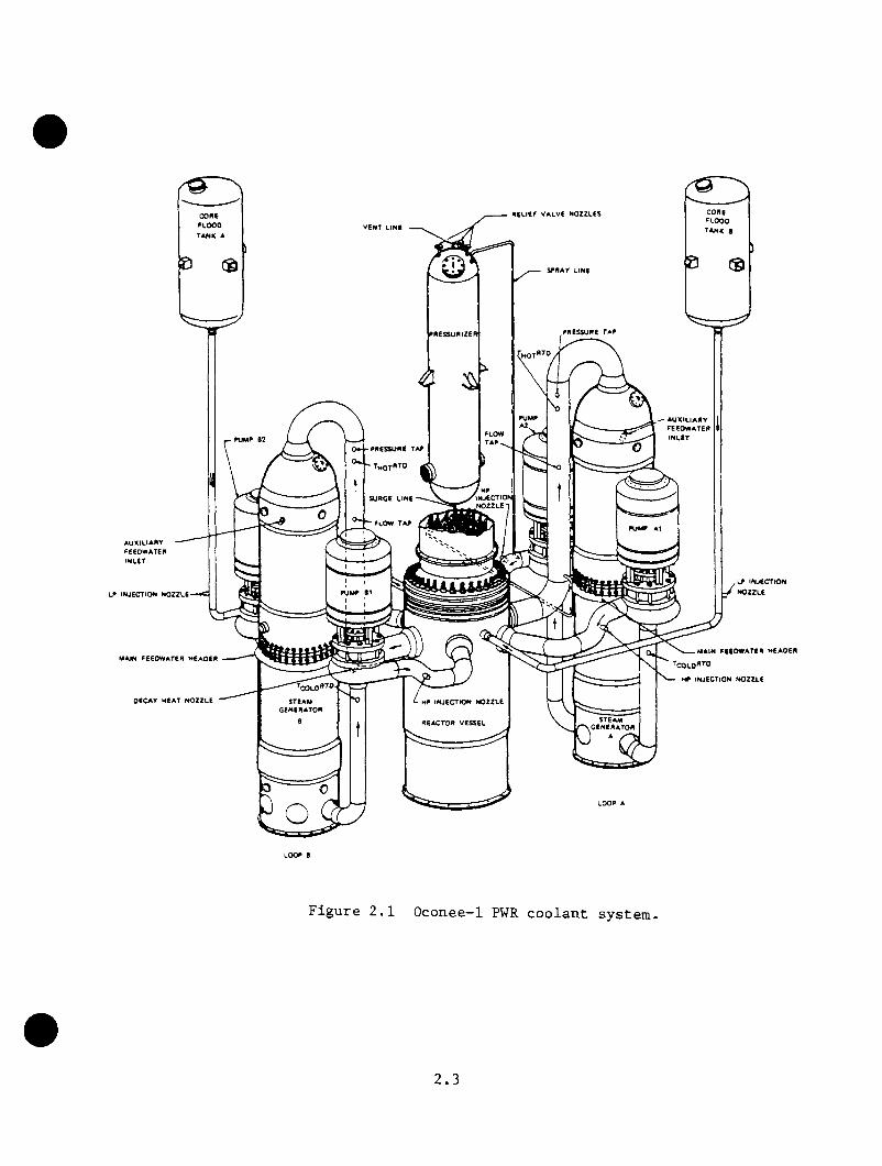
legs per loop. The unit is of lonered loop design, meaning the bases of
the steam generators lie below the horizontal plane through the top of the
reactor core. This arrangement is illustrated in Figure 2.1. The cold
legs discharge coolant into an annular downcomer between the vessel wall
and the thermal shield (Figure 2.2). The coolant flows down to the lower
plenum and then up through the core region to the upper plenum and into the
hot legs. The pressures, temperatures, and mass flows for this system at
hot standby and full power conditions are summarized in Table 2.1.
A pressurizer vessel connected to loop A provides pressure control for the
primary coolant system. The coolant inventory control system augments the
pressure control function by adding or withdrawing coolant based on indi
cated inventory.
The emergency core cooling systems (ECCS) include high-pressure injection
(HPI), core flood tanks (CFT), and low-pressure injection systems (LPI).
These safety grade systems inject cool water into the primary to prevent
fuel overheating under accident conditions. The HPI system can also
repressurize the RCS for certain small-break loss-of-coolant accident
(LOCA) and overcooling events and so is an important factor in PTS evalua
tion.
The features of the different reactor cooling system components are
described below.
2.2
COAfi P lO O O rANK 8
R 6 U E F V A L V e N O ZZ L E SC O flE ^L O O O
tA M K AV ENT LIN E
SP ttA V LINE
PR E SSU R E T A PPAESSUniZEK
PU M P A U X IL IA R Yp e e o w a t e r
IN L E TFLOWTA P
PR E SS U R E TAP
^M0T"T0
IN JEC T IO Nn o z z l e
SU R G E LIN E
FLOW T A PPU M P A l
A U X IL IA R Y
FEED W ATERinlet
‘COLO"^®EAM
G E N E R A T O RIN JE C T IO N
R E A C T O R V ESSEL \ STEA Mp v G E N E R A T O R
LP IN JEC T IO N N O ZZ L E
MAIN FE E D W A T E R H E A D E R
D ECA Y h e a t n o z z l e
.L P IN JE C T IO N
y N O ZZ L E
M AIN FE E D W A T E R H E A D E R
COLO ''’0H P IN JE C T IO N N O ZZ L E
Figure 2.1 Oconee—1 PWR coolant system.
2.3
Control Rod Drive
Closure Head
Control Rod Assembly ' ' Studs
Internals Vent Valve
PlenumAssembly Control Rod
Guide Tube
Core Support Shield
Inlet Nozzle (one of 4)
Outlet Nozzle ^ (one of 2 —rotated for illustration)
Fuel Assembly
Core Barrel
Reactor Vessel
Surveillance Specimen — Holder Tube
\ Core Thermal Shield
Guide LugsLower Grid rnrt?h h )Flow Distributor In-Core Instrument
Guide Tube
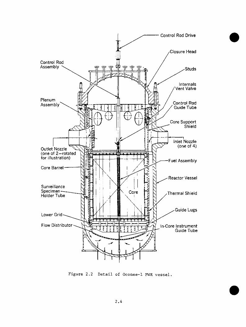
Figure 2.2 Detail of Oconee-1 PWR vessel.
2.4

Table 2,1 Oconee-I PWR steady state conditions2 .4 .2.5
Parameter Full Power Hot Zero Power
RCS Primarv
Power (MW) 2568.0 9.0Coolant flow rate, total (Eg/s) 17640.0Hot leg temperature (K) 589.3Cold leg temperature (E) 563.5 551.0Primary pressure (MPa) 14.96 14.8Core pressure drop (MPa) 0.11Vessel pressure drop (MPa) 0.41Pressurizer water level (m) 5.6HPI/LfI coolant temperature (E) 305.4 305.4Accumulator coolant temperature 305.4 305.4
Feedwater flow per loop (Eg/sec) 680.4Feedwater temperature (E) 511.0 305.4Steam generator outlet pressure (Mpa) 6.38 6.21Steam outlet superbeat (E) 33.3 0.0Steam generator secondary inventory (Eg) <1.77E4 <2.64E4Steam generator nominal level (m) 6.1 (operating) 9.1 (staiMFW pump inlet pressure (MPa) 2.77MFW pump inlet temperature (E) 461.0 305.4C.B. pump inlet pressure (MPa) 0.8C.B. pump inlet temperature (E) 308.3 305.4Hotwell pressure (MPa) 0.01 0.01Hotwell temperature (E) 305.4 305.4Hotwell inventory (Eg) 5.31E5 5.31E5Upper surge tank inventory (Eg) 2.69E5 2.69E5
2.5

2.2.1.1 Reactor Vessel
The reactor pressure vessel is illustrated in Figure 2.2. The core barrel
divides the voluae of the vessel into a core region and an annular region
called the downcomer. The core barrel provides structural support for
the core and defines the coolant flow path. Coolant enters the downcomer
annulus through the four cold leg nozzles located on an elevation above
the top of the core. The two hot leg nozzles pass through the downcomer
region and the core barrel and have the same center-line elevation as the
cold leg nozzles.
There are eight vent valves in the core barrel above the hot and cold
leg nozzles. The primary purpose of the vent valves is to facilitate
core reflooding following a postulated large-break LOCA in the reactor
cold leg piping by allowing flow of steam from the upper plenum to the
break. The vent valves also allow flow of hot water into the downcomer
region during PTS transients when natural circulation flow is restricted
or lost. The hot vent valve flow mixes with the HPI flow to moderate
downcomer temperatures.
Each vent valve consists of a hinged disc and valve body situated to remain
closed under normal operating conditions (i.e., with RCP running). When
natural circulation and/or flow stagnation is experienced, the differential
pressure drop between the downcomer and upper plenum reverses, causing the
valves to open. The valves begin to open on a differential pressure of
0.85 EPa (0.125 paid) and are fully open at 1.79 KPa (0.26 paid).
2.6
Besides these hydraulic characteristics, the vessel eabodies metallurgical
and neutron fluence factors important to PTS. These are discussed in
Chapter 5.
2.2.1.2 Steam Generators and Primary Piping
The configuration of the once-through steam generators is depicted in
Figure 2.3. In this configuration the primary coolant makes a single
pass from top to bottom through straight tubes. Steam generated outside
the tubes flows up the shell side of the steam generator, countercurrent
to primary coolant downward flow. This arrangement promotes superheating
of steam during normal operations. During transient operation, primary
reheating (reverse heat transfer) by steam condensation on the tubes may
contribute to loop flow stagnation. The secondary side of the steam
generators is discussed in Section 2.2.2.
The hot leg pipes connecting the vessel outlet to the upper plenum of each
steam generator are referred to as "candy canes" due to their appearance
(see Figure 2.1). Under natural circulation conditions, steam voids may
collect at the top of these pipes and block natural circulation flow in
the loop.
Coolant exits the tubes at the lower plenum of the steam generator. The
loop flow is split between the two cold legs at the lower plenum of the
steam generator (Figures 2.1 and 2.3). The piping forms a trap or loop
seal at its lowest point and then runs upward to the reactor coolant pumps
at the same level as the vessel inlet-outlet nozzles.
2.7

R eactor Coolant Inlet
M anw ayInspection P o rt
8 in. minT u b e sh e e t
Vent & Level S ensing
M anway
6 .6 2 5 in. min
Auxiliary Feedw ater Inlet
■Tube S u p p o rt P la te s
U pper Baffle H andhole
6 .6 2 5 in. minDrain
Steam O utlet
F eed w ater InletLevel Sensing
Level S ensingTtierm owell
4 .1 8 7 in. min 1 3 8 in. ID,=11Lower Baffle
Level S ensing
6 .6 2 5 in. min
M anwayDrain & S am ple
H andholeTherm ow ell
Level S ensing
T u b esh ee tDrain
R eactor C oolant O utlet
M anway
Inspection P o rtDrain
Figure 2.3 Detail of once through steam generator.
2 . 8

2.2.1.3 Reactor Coolant Pumps
Forced circulation is maintained by four reactor coolant pumps (RCP), tvo
on each loop. Each pnmp has a rated flow of 5.56 m /s (88,000 gpm) with
a developed head of 0.78 HPa (113 psid) . The rated maximum pump power
is 6.7 MV (9000 hp) per pump. The pnmp flywheel inertia is sufficient
to prolong pump spindown for about 100 s after trip, maintaining forced
circulation for the same period.
2.2.1.4 Pressurizer and Pressure Control
The pressurizer, depicted in Figure 2.4, serves as an expansion or surge
tank for controlling system pressure. A 0.254m (10-in.) i.d. pipe
connects the pressurizer to the loop A hot leg. During normal operation3 3 3 3the pressurizer contains 19.8m (700 ft ) of steam and 22.7m (800 ft ) of
water at saturation conditions. The pressurizer heater has a maximum input
capacity of 1.638 MW. Rapid overcooling incidents usually lower the water
level below the heater trip level, removing the heater from operation.
Unless it is manually reset, the heater has little influence on pressure
recovery for overcooling events.
The pressurizer is also equipped with one power-operated relief valve
(PORV) and two code safety relief valves. A motor-operated block valve can
be used to isolate the PORV. The PORV has an effective inside diameter of
2.77 cm (1.09 in.) and a design steam flow capacity of 13.51 kg/s (107,000
Ib/h) . The PORV is programmed to open at 16.9 MPa (2450 psig) and close
at 16.6 MPa (2400 psig). The two code safety relief valves each have an
effective inside diameter of 4.57 cm (1.8 in.) and together have a design
2.9

Vent Nozzle Relief Valve Nozzle (typical of 3)
Water Spray Nozzle
Vessel Supports
Rotated for Illustration
Water Spray CJonnection from Reactor Coolant
Inlet Line
Level Sensing Nozzle (typical of 3)
Steam Space
Normal Water Level
Thermowell (Sample Nozzle behind)
Electric Heater Bundle
Level Sensing Nozzle (typical of 3)
Surge Diffuser
Surge Line Nozzle from Reactor Coolant
Outlet Line
Figure 2.4 Detail of pressurizer. 2.10

steam flow capacity of 84.2 kg/s (667,000 Ib/h) . The code safety relief
valves begin opening at a system pressure of 17.2 MPa (2,500 psig).
2.2.1.5 Emergency Core Cooling Systems
High-Pressure Injection System
The high-pressure injection (HPI) system consists of three motor-driven
centrifugal pumps and a header system that can deliver flow to each of
the cold legs downstream of the respective reactor coolant pumps. During
normal operation, one pump in the HPI system runs continuously as part of
the inventory control system, injecting makeup water into the loop A cold
legs to counter the letdown flow.
When transient events cause depressurization of the primary system to
below 10.34 MPa (1500 psig), the safety injection actuation signal starts
the two remaining pumps and aligns valves to provide a path for pumping
borated water from the borated water storage tank into all four cold legs.
Approximately two-thirds of the total flow enters loop A and the remainder
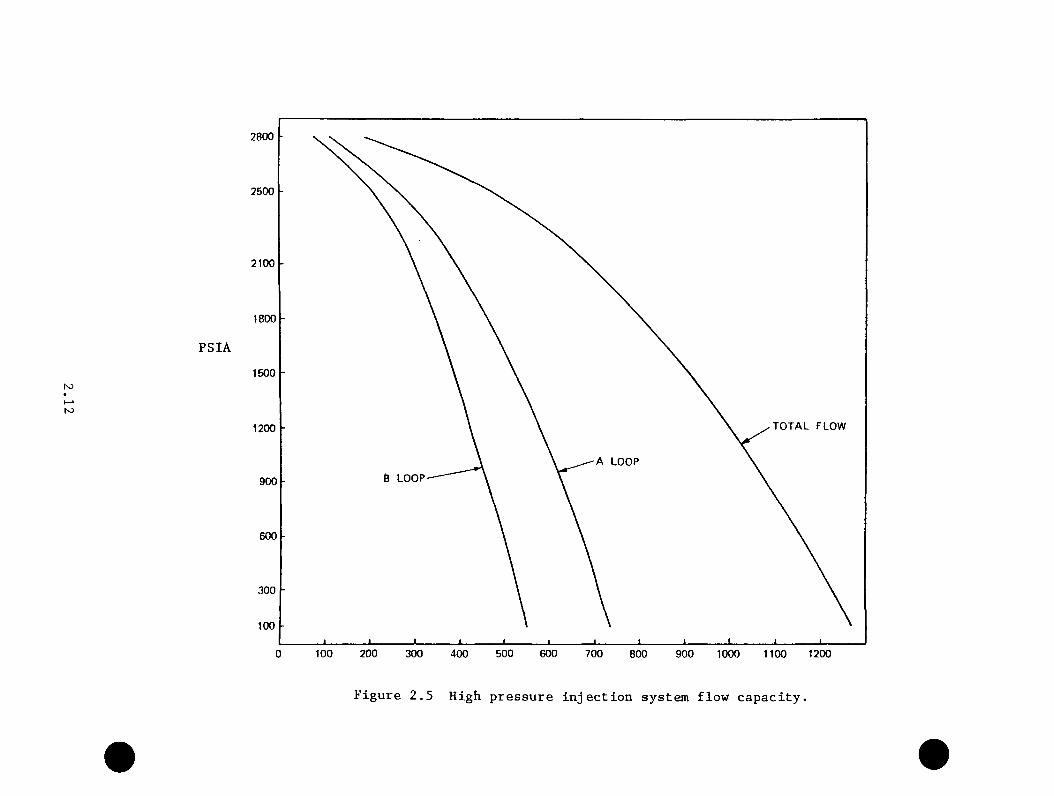
enters loop B. Since the HPI system uses centrifugal pumps, the total
flow rate is a function of cooling system pressure. This relationship is
presented in Figure 2.5. The HPI system can repressurize an intact primary
coolant system up to the safety relief valve set point (2500 psig) and can
partially repressurize the system during certain small-break LOCA events.
After actuation by the safety injection signal, the HPI system remains in
operation until it is manually shut off.
2.11
PSIA
N5I—*ro
2800
2500
2100
1800
1500
T OTAL FLOW1200
A LOOP
8 LOOP900
600
3 00
100
200 4 0 0 500 60 00 100 3 00 7 00 8 0 0 9 0 0 1100 12001000
Figure 2.5 High pressure injection system flow capacity.
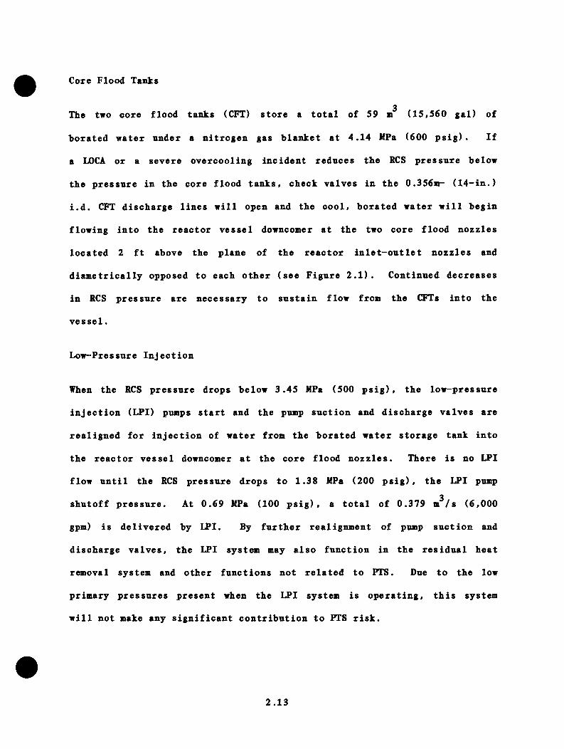
Core Flood Tanks
3The two core flood tanks (CFT) store a total of 59 m (15,560 gal) of
borated water under a nitrogen gas blanket at 4.14 MPa (600 psig). If
a LOCA or a severe overcooling incident reduces the RCS pressure below
the pressure in the core flood tanks, check valves in the 0.356n>- (14-in.)
i.d. CFT discharge lines will open and the cool, borated water will begin
flowing into the reactor vessel downcomer at the two core flood nozzles
located 2 ft above the plane of the reactor inlet-outlet nozzles and
diametrically opposed to each other (see Figure 2.1). Continued decreases
in RCS pressure are necessary to sustain flow from the CFTs into the
vessel.
Low-Pressure Injection
When the RCS pressure drops below 3.45 MPa (500 psig), the low-pressure
injection (LPI) pumps start and the pump suction and discharge valves are
realigned for injection of water from the borated water storage tank into
the reactor vessel downcomer at the core flood nozzles. There is no LPI
flow until the RCS pressure drops to 1.38 MPa (200 psig), the LPI pump3
shutoff pressure. At 0.69 MPa (100 psig), a total of 0.379 m /s (6,000
gpm) is delivered by LPI. By further realignment of pump suction and
discharge valves, the LPI system may also function in the residual heat
removal system and other functions not related to PTS. Due to the low
primary pressures present when the LPI system is operating, this system
will not make any significant contribution to PTS risk.
2.13

2.2.2 Feedwater and Steam Systems
The steam generators and their associated feedwater system and pressure
control systems play a pivotal role in PTS sequences. The steam generators
provide cooling to the reactor coolant system during both normal operations
and overcooling events. The performance of the various feedwater and steam
system components influences the rate of cooldown during an accident. The
feedwater and steam systems form a closed loop as illustrated in Figure
2.6. The portions of the loop most significant to PTS events are indicated
by bold flow lines. The main feedwater (HFW) train runs from the condenser
hotwell to the steam generators and supplies a regulated flow of preheated
water. The emergency feedwater (EFW) train (not depicted on Figure 2.6)
pumps cool water from the condenser hotwell and/or the upper (condensate)
surge tank directly to the steam generators without any preheating.
The two once-through steam generators are capable of generating 2.45 x 10^
kg/h (5.39 X 10^ Ib/h) of steam at 6.27 MPa (910 psia) and 572 K (570°F).
The once-through steam generator design yields steam superheats of 33.3
(60^F) to improve power cycle efficiency. Achievement of these steam
conditions requires precise control of feedwater flows via the integrated
control system (ICS).
The main steam lines connect the steam generators to the high-pressure
turbine header at the turbine stop valves. A scoping study of the steam2 6and power conversion systems * suggests that the turbine stop valves serve
as the boundary point for PTS modeling of the Oconee-1 plant. Failure of
a stop valve will yield no impact if the turbine control valves operate
properly or will yield conditions similar to a small or large steam
2.14

N3h-*Ui
C\ A
26 24 25l l23
Sica* Gcncr stor k $t«a« Gcnarator 0Hafn Steaalin* Saf«ty/fi«l(«f Valvct Main Sltanlinc Turbfr.i 9yp>«ss Va)v«s To Cona«ns«'STo Main Fc<!Owat«r Pump T'jrbfraiTo Concanscr Slaai Air ijactortTo Cm«rgcncy FccCwatar P*.»p TurbineHlg.b-prenurt Torplre SlcpHigb*pr«j»ure TorolnaR«h«atar/Moisturc Stparaicr Assemolltileheatcr Crain PumpMoisture Separator Drain PumpsLow-pressure TurbinesCondensersHotwc11sUpper Surge TanksKotwe11 PumpsPo I i sher/DemInera}TierCondensate CoolersGeneral Water CoolersHydrogen CoolersCondenser Steas Air EjectorsFrom Main SteamllnesSteam Seal CondensersFrom Turbine Steam SealsTo Condensate Storage TanksCondensate Booster Pumoslow-pressure F Condensate Heaterslow-pressure E Condensate HeatersLow-pressure E Condensate Heater Drain Pumpslow-pressu e 9 Condensate HeatersLow-pressure D Condensate Heater flash TanksLow-pressure D Condensate Heater Drain PumpsLow-pressure C Condensate HeatersLow-pressure C Ccnoensate Heater Flasn TanksLow-pressure C Conoensate Heater Drain CoolerfMain feedwater PlumpsMain Feedwater Pump TurbinesHigh-pressure 9 Fceowater HeaterfHigh-pressure A Feedwater HeatersMain Control Valves
Figure 2.6 Oconee-1 main feedwater, steam, and power systems.
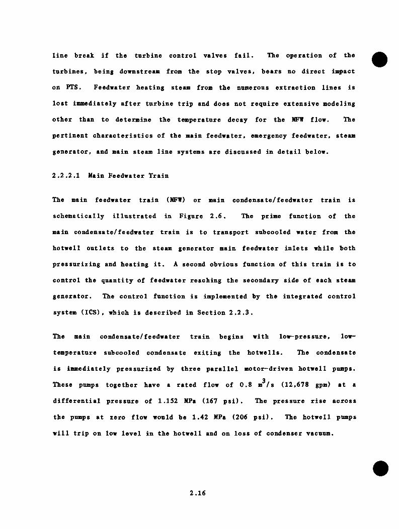
line break if the turbine control valves fail. The operation of the
turbines, being dovnstreaai from the stop valves, bears no direct ia^act
on PIS. Feedvater heating steam from the nnmerons extraction lines is
lost immediately after tnrbine trip and does not require extensive modeling
other than to determine the temperature decay for the MFW flow. The
pertinent characteristics of the main feedwater, emergency feedwater, steam
generator, and main steam line systems are discussed in detail below.
2.2.2.1 Main Feedwater Train
The main feedwater train (MFW) or main condensate/feedwater train is
schematically illustrated in Figure 2.6. The prime function of the
main condensate/feedwater train is to transport subcooled water from the
hotwell outlets to the steam generator main feedwater inlets while both
pressurizing and heating it. A second obvious function of this train is to
control the quantity of feedwater reaching the secondary side of each steam
generator. The control function is implemented by the integrated control
system (ICS), which is described in Section 2.2.3.
The main condensate/feedwater train begins with low-pressure, low-
temperature subcooled condensate exiting the hotwells. The condensate
is immediately pressurized by three parallel motor-driven hotwell pumps.
These pumps together have a rated flow of 0.8 m /s (12,678 gpm) at a
differential pressure of 1.152 MPa (167 psi). The pressure rise across
the pumps at zero flow would be 1.42 MPa (206 psi). The hotwell pumps
will trip on low level in the hotwell and on loss of condenser vacuum.
2.16

The condensate then flovs through the polisher/demineralizers, resin trap,
and the tube sides of the condensate coolers, hydrogen coolers, general
water coolers (these coolers are known collectively as the plant heat dump),
condensate steam air ejector, and steam seal condensers. The slightly
warmer, low-pressure subcooled condensate leaving the steam seal condensers
is then pressurized by three parallel motor-driven condensate booster pumps
whose function is to provide adequate suction pressure to the main feedwater
pumps after the frictional losses of the low-pressure condensate heaters.
The differential pressure rise generated by the condensate booster pumps
is 2.94 MPa (426 psi) at rated flow. At zero flow the pressure rise across
these pumps would be 3.14 MPa (455 psi). The condensate booster pumps will
trip on sustained low suction pressure of 0.21 MPa (30.7 psi).
Departing from the condensate booster pumps, the condensate is heated
significantly by passage through the tube side of four stages of low-
pressure condensate heaters. The first stage consists of three parallel
low-pressure condensate heaters (F heaters): the second stage consists of
two parallel low-pressure condensate heaters (E heaters): the third stage
consists of two parallel low-pressure condensate heaters (D heaters) in
series with two parallel low-pressure condensate heaters (C heaters). The
condensate next travels to the two parallel turbine-driven main feedwater
pumps that provide final pressurization of the feedwater. Frictional los
ses in the high-pressure A and B feedwater heaters and main control valves
reduce the feedwater pressure to the desired delivery pressure at the steam
generator main feedwater inlets. The integrated control system (ICS)
varies both the main feedwater pump speed and feedwater control valve posi
tion to maintain optimum control of flow rate and pressure drop. The ICS
2.17
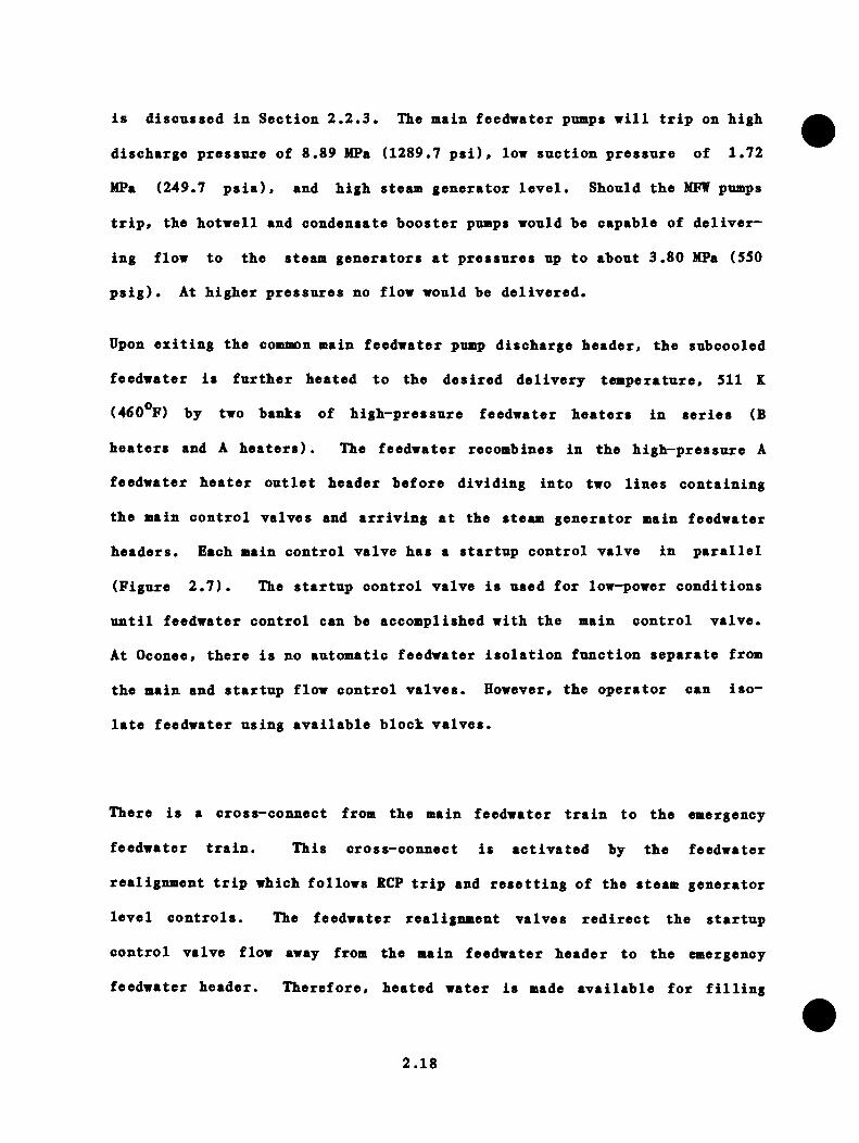
is discussed in Section 2.2.3. The main feedwater pumps will trip on high
discharge pressure of 8.89 MPa (1289.7 psi)» low suction pressure of 1.72
MPa (249.7 psia), and high steam generator level. Should the MFW pumps
trip, the hotwell and condensate booster pnmps would be capable of deliver
ing flow to the steam generators at pressures up to about 3.80 MPa (550
psig). At higher pressures no flow would be delivered.
Upon exiting the common main feedwater pnmp discharge header, the subcooled
feedwater is further heated to the desired delivery temperature, 511 K
(460**F) by two banks of high-pressure feedwater heaters in series (B
heaters and A heaters). The feedwater recombines in the high-pressure A
feedwater heater outlet header before dividing into two lines containing
the main control valves and arriving at the steam generator main feedwater
headers. Each main control valve has a startup control valve in parallel
(Figure 2.7). The startup control valve is used for low-power conditions
until feedwater control can be accomplished with the main control valve.
At Oconee, there is no automatic feedwater isolation function separate from
the main and startup flow control valves. However, the operator can iso
late feedwater using available block valves.
There is a cross-connect from the main feedwater train to the emergency
feedwater train. This cross-connect is activated by the feedwater
realignment trip which follows RCP trip and resetting of the steam generator
level controls. The feedwater realignment valves redirect the startup
control valve flow away from the main feedwater header to the emergency
feedwater header. Therefore, heated water is made available for filling
2.18

E ME RG E NC YF EE DWA T ER - [ X 3 ------- NORMALLY O P E N
E ME R GE N CYF EE DW A T E R
HE ADER
STEAMG E NE R A T O R
K) (— *
MAINF EE DW A T E R
H EADER
NORMALLY C L O SE DEFWV
X
S UF CV
i X }
MFCV
{XI—[X}6
F EE DW A T E RTRAIN
3
123
4.56
EFWVSUFCV
MFCV
EM E R GE N CY F E E D W A T E R C H E C K VALVE R E ALIGNMENT C H E C K VALVE MAIN F E E D W A T E R C H E C K VALVE F EE DW A T E R R E AL IGNMENT VALVES MAIN F E E D WA T ER BLOCK VALVES E M E R GE N CY F E E D WA T ER VALVE STAR TUP F L O W C O N T R O L VALVE MAIN F L O W CO N T R O L VALVE
Figure 2.7 Oconee-1 feedwater valve schematic.

tlie steam generator to the natural circulation set point level, or 60%
of the indicated range, thus enhancing natural circulation with less
overcooling of the primary.
2.2.2.2 Emergency Feedwater Train
The emergency feedwater (EFW) train consists of two motor-driven pumps
(one to each steam generator) and one turbine-driven pump whose discharge
is cross-connected to the discharges of both motor-driven pumps. The
motor-driven pumps draw low-pressure, low-temperature subcooled condensate
from the upper surge tanks and/or the hotwells. High-pressure subcooled
feedwater from the combined emergency turbine- and motor-driven pumps
continues to the secondary-side emergency feedwater inlet of each steam
generator through independent lines containing a steam generator level
control valve. The level control function is independent of the ICS. A
one-way cross-connect exists for each steam generator downstream of the
level control valve to allow main feedwater to enter the emergency feedwater
lines (Figure 2.7). Insignificant heating of the feedwater occurs in the
emergency feedwater train. Check valves throughout the emergency feedwater
train prevent improper reverse flows throughout the train.
The emergency feedwater pumps are activated when the main feedwater pumps
trip off or if MFW pressure drops below 750 psig. The emergency feedwater
pumps continue running until shut off manually or tripped because of
mechanical failure.
2.20
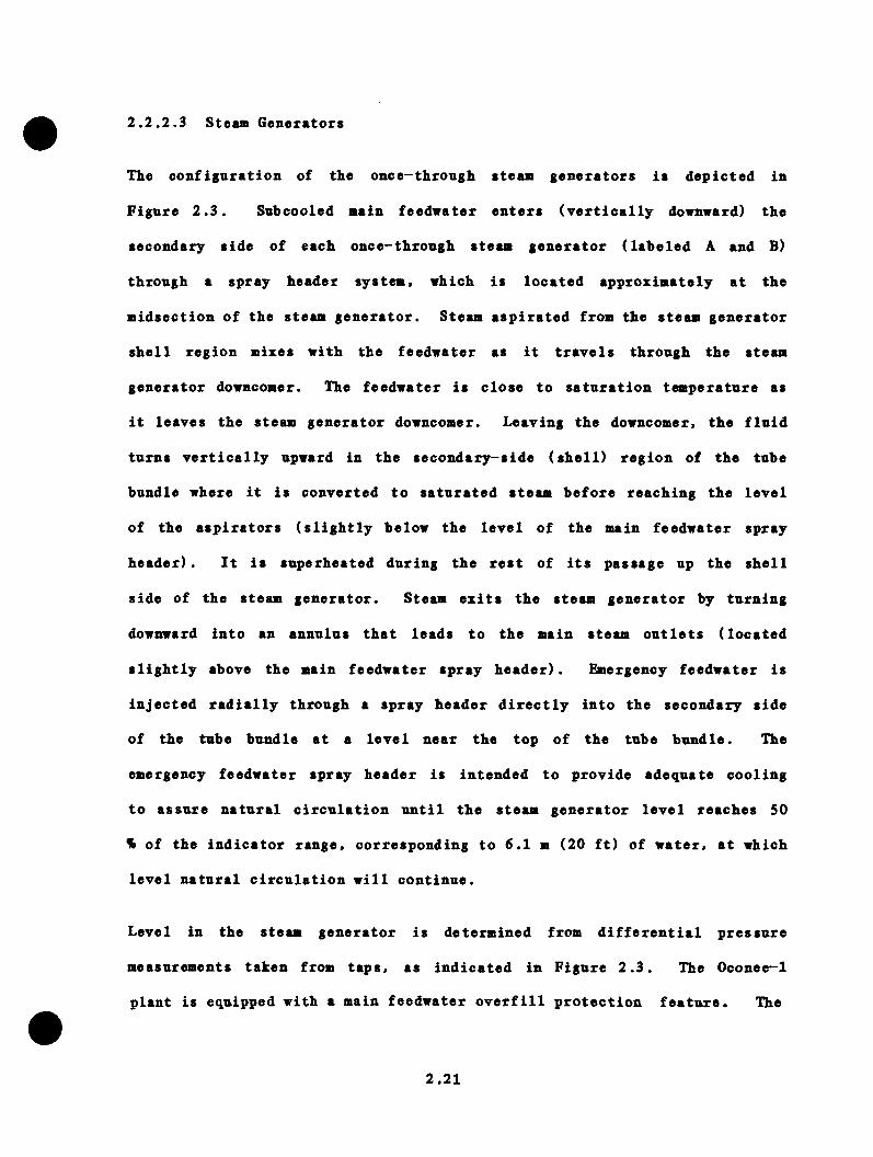
2.2.2.3 Steam Generators
The configuration of the once-through steam generators is depicted in
Figure 2.3. Subcooled main feedwater enters (vertically downward) the
secondary side of each once-through steam generator (labeled A and B)
through a spray header system, which is located approximately at the
midsection of the steam generator. Steam aspirated from the steam generator
shell region mixes with the feedwater as it travels through the steam
generator downcomer. The feedwater is close to saturation temperature as
it leaves the steam generator downcomer. Leaving the downcomer, the fluid
turns vertically upward in the secondary-side (shell) region of the tube
bundle where it is converted to saturated steam before reaching the level
of the aspirators (slightly below the level of the main feedwater spray
header) . It is superheated during the rest of its passage up the shell
side of the steam generator. Steam exits the steam generator by turning
downward into an annulus that leads to the main steam outlets (located
slightly above the main feedwater spray header). Emergency feedwater is
injected radially through a spray header directly into the secondary side
of the tube bundle at a level near the top of the tube bundle. The
emergency feedwater spray header is intended to provide adequate cooling
to assure natural circulation until the steam generator level reaches 50
% of the indicator range, corresponding to 6.1 m (20 ft) of water, at which
level natural circulation will continue.
Level in the steam generator is determined from differential pressure
measurements taken from taps, as indicated in Figure 2.3. The Oconee-1
plant is equipped with a main feedwater overfill protection feature. The
2.21
protection system monitors the steam generator differential taps and trips
the main feedwater pomps when either steam generator exceeds 90% of indica
tor range.
2.2.2.4 Main Steam Lines
The main steam lines run from the steam generators to the main steam
line penetrations of the containment and into the tnrbine bnilding. Eight
safety/relief valves located on each main steam line limit steam line
pressure by venting to the atmosphere excess main steam line mass flow that
cannot be accommodated by the tnrbine bypass steam lines. The relief valve
set points range from 7.24 MPa (1050 psig) to 7.61 MPa (1104 psig). With
all 16 valves open, 114% of the design steam flow may be vented to the
atmosphere.
Unlike many other plants, Oconee-1 has no main steam isolation valves.
Down-stream from the safety valve taps, there are branches to several
possible destinations; the condenser via the tnrbine bypass steam lines, the
steam turbines that drive both main feedwater pnmps and the tnrbine-driven
emergency feedwater pnmp, the reheater/moistnre separator assemblies, the
condenser air ejector assembly, and the tnrbine stop valves. The tnrbine
governor valves and the high-pressure tnrbine are downstream of the tnrbine
stop valves.
A manually actuated atmospheric dump valve is provided on each main steam
line. Because of the large time lag expected for manual operation of
these valves, it is unlikely that they could contribute significantly to
the progress or control of an overcooling event.
2.22
The turbine bypass valves are used to control steam system and RCS
temperature during lov-pover and transient conditions. There are two of
these valves on each steam line, making a total of four valves. The
turbine bypass valve system can vent 25% of full-power steam flow to the
condensers. The control of these valves is discussed in Section 2.2.3.
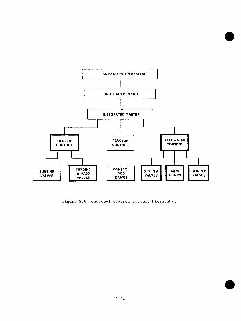
2,2.3 Control Systems
The integrated control system (ICS) is a comprehensive system that
controls all power generation operations of the plant. Separate safety
instrumentation and controls are provided for mitigation of and recovery
from transient conditions. Nevertheless, the scope of the ICS is such that
it can significantly influence the course of an overcooling event. Figure
2.8 diagrams the Oconee-1 control system hierarchy. The higher-order
segments such as the auto dispatch system and unit load demand generate
a power demand signal that serves as a set point for the lower control
systems. The integrated master system coordinates the activities of the
reactor control, feedwater control, and (secondary steam) pressure control
systems to compensate for upsets in any of the lower-order systems and to
satisfy the demands of the higher-level systems.
The contributions of the ICS to PTS risk are twofold. First, failures
in the ICS can initiate reactor trip and such overcooling events as steam
generator overfeed and turbine bypass valve control failure. Therefore,
the ICS can influence the frequency and, to an extent, the type of event
initiators. Second, after the initiation of an overcooling event, portions
of the ICS (namely, feedwater control and pressure control) can influence
the response of the plant to the initiator. The structure of the ICS
2.23
F E E D WA T ERC O N T R O L
P R E S S U R EC O N T R O L
T URBI NEB YP AS SVALVES
S T G E N B VALVES
MF WP U M P S
S T G E N A VALVES
TURBI NEVALVES
C O N T R O LROD
DRIVES
R E AC T ORC O N T R O L
I NTEGRATED MA ST ER
UNIT LOAD DEMAND
AUTO D I SPA TC H SYS TE M
Figure 2.8 Oconee-1 control systems hierarchy.
2.24

pertaining to feedwater control and pressure control is important to the2 7thermal-hydraulic analysis of the plant. * These systems are described in
the following sections.
2.2.3.1 ICS Feedwater Control Logic
This section briefly summarizes the control algorithm implemented in the
ICS for feedwater control. The discussion includes the necessary signals
from the unit load demand and reactor control systems and describes the
feedwater control logic concisely without detailing other ICS functions
not directly related to PTS. The different elements of the ICS feedwater
control system are diagrammed in Figure 2.9.
Unit Load/Reactor/Feedwater Demand Characterization
The unit load demand subsystem (ULD) establishes the demand for megawatt
generation of the unit. Many conditions within the unit can result in
preventing the unit from generating the requested megawatts. In this
case, the unit must follow the limiting variable in order to maintain
coordination of all the control variables. This mode of operation is
termed "traching," and the generated power signal is used as the indication
of the limited variable. Although several conditions cause a transfer
to the tracking mode, only reactor trip is pertinent in the transients
to be considered. Since a turbine trip also produces an anticipatory
reactor trip, this condition is included. On reactor trip, ULD tracks
generated megawatts at a maximum rate of 20% full power per minute (FP/min).
Since the generated megawatts will fall off much faster than 20% FP/min,
the ULD can be modeled effectively with a 20% FP/min ramp initiated at
2.25

N5K>
FeedwaterFlow
LevelLimiters
BTU Limiter
MFW Pump Speed Control
Feedwater Valves Control
Neutron Power Cross Limiter
MFCV Pressure Drop
Figure 2.9 ICS feedwater control scheme.

reactor trip. If one or more reactor coolant pumps or main feeduater pumps
are tripped before ULD runback is complete, then the runback rate becomes
50% FP/min instead of 20% FP/min. Since the primary runback signal to
feedwater control is the neutron cross-limit and the Btu limit, this is not
considered significant. If operational transients were to be considered,
the additional detail would be required.
Reactor demand is scaled from ULD to provide the required reactor power at
steady state. This scaling is necessary since full-scale ranges of reactor
power, feedwater flow, and generated megawatts are somewhat different. The
reactor demand signal is then limited between 10% and 103%. The neutron
power signal is compared with the reactor demand signal to develop the
neutron power error. The resultant signal is sent to the feedwater control
subsystem for cross-limiting feedwater demand.
Feedwater demand is characterized from the ULD to provide the required
steam flow for a given power level at steady state. This characterization
is such that the nominal feedwater flow rate is requested at full-power
conditions.
Compensated Feedwater Demand
The steam generator demand is characterized to represent the expected
feedwater temperature. This signal is compared to the actual feedwater
temperature to produce a feedwater temperature error signal that compensates
the feedwater demand.
The neutron error signal from the reactor control subsystem can also modify
the total feedwater demand. If the neutron error becomes greater than
2.27
± 5%, the total feedwater demand will be modified to maintain the proper
ratio between feedwater flow and reactor power. If this signal is greater
than + 5%, the nnit is said to be operating under "cross limits." Note that
after a reactor trip, it is the cross-limit signal that initiates rapid
runback of feedwater flow since the ULD ramp rate is merely 20% FP/min.
Feedwater Loop A and B Demand
Separate feedwater flow demands are developed for loop A and B. In the ICS,
these demands are characterized to meet the requirements of total feedwater
demand and to maintain a set point temperature differential (normally zero)
between the two reactor cold legs. Since this ratio controller output
is blocked when either steam generator is on a level limit or during a
transient, it is not important. Consequently, the total feedwater demand
signal can be sent unmodified to each loop in the model used for FTS
studies.
BTU Limited Feedwater (FW) Demand
The outlet steam pressure of each steam generator is characterized to
produce a signal equivalent to the FW flow limit for that pressure.
Likewise, the FW temperature, the selected reactor outlet temperature, and
primary loop flow are conditioned to produce equivalent FW flow limit
signals. These signals are then used to develop a Btu availability
limit signal, which limits the feedwater demand for the steam generator
to prevent a reduction in steam temperature. The Btu signal is then
auctioneered against the loop demand signal. The limiting signal (lower
2.28

FW demand) is used to develop the loop demand for MFW pnmp control and
in the development of the FW flov error signal.
Feedwater Flow Error
The loop FW flow signal is compared with the FW flow demand to produce
the loop FW flow error. The total FW flow in the loop is obtained from
the sum of the startup and main feedwater flows. The measured flow is
fed through a lag unit to produce a more stable control signal.
High and Low Steam Generator Downcomer Level Limits
The FW flow error signal is compared with high- and low-level error
signals. Thus, if the FW flow error demands an increase in FW flow and
the downcomer level is at the maximum allowable, the level error signal
will assume control to prevent flooding of the aspirating steam ports.
Similarly, if the FW flow error tries to reduce the FW flow to a point
where the downcomer level drops below the minimum allowable value, the low-
level error signal will take control.
Feedwater Valve Control
The level-limited FW demand error is used for control of the main and
startup FW valves. Proportional plus integral (P + I) action is applied
to the error signal from two different controllers. During level control
at the low-level limit, one of the controllers is used while the output
of the other controller is blocked. When not on low-level control, the
level controller is blocked and the other controller provides the control
2.29

signal to the valves. Smooth transfer is provided when snitching from one
control signal to the other.
Feedwater Pnmp Control
Loop A and B FW valve differential pressure signals are auctioneered to
select the signal representing the smaller differential pressure. The
selected signal is then compared with the minimum differential pressure set
point to produce an error signal. This error signal is modified with a
gaining factor, which increases as the error increases. Proportional and
integral action is applied to this error signal. The resultant signal is
used to modify the total pump demand signal.
The modified FW demand signals from loop A and loop B are summed to produce
a total FW demand signal used as the demand signal for the FW pumps. On a
load change, this signal will anticipate a change in differential pressure
and cause the pump speed to change, thus minimizing the error.
Feedwater Control System Set Points
The set points used in modeling the Oconee feedwater control system are
given below.
2.30

Limit or Set Points
Expected FW temperature
Btu limits
High level limit
Low level limit
Low level limit
FW valve AP
Value
Function developed by ICS
Function developed by ICS
8.14 m (344 in.) H^O
0.64 m (25 in.) H^o
6.1 m (240 in.) H^O
0.24 MPa (35 PSID)
Remarks
RC pump(s) operating
RC pump(s) tripped
2.2 .3.2 Description of Turbine Bypass Valve Control
Turbine control is a portion of the integrated master subsystem of the
ICS. Since the simulation models do not include the turbine, modeling the
turbine control valve is not necessary. Thus, the turbine header pressure
is a boundary condition for the ICS model.
Turbine bypass control provides high-pressure relief if the turbine header
pressure exceeds its set point by 0.34 MPa (50 psi) under noirmal conditions
or by 0.86 MPa (125 psi) if the reactor is tripped. The turbine header
pressure error is applied through proportional plus integral control.
Independent pressure relief is provided if the outlet pressure of either
steam generator exceeds its set point. This relief is direct, proportional
control action. The turbine bypass control system selects whichever
control signal requires more bypass steam flow around the turbine.
On loss of condenser vacuum, the turbine bypass valves are shut to avoid
sending further steam to the condenser.
2.31
2.2.3.3 Description of Emergency Feednater Valve Control Logic
Emergency feedwater control systems manipnlate a control valve to maintain
level in the steam generator. The startup level is maintained if the
reactor coolant pnmps are operating, and a 6.1-m (20-ft) level is maintained
if they are tripped. This is to encourage natural circulation during
conditions when the reactor coolant pumps are tripped. The actual steam
generator level (as determined for MFW control) is compared with the level
set point, and EFW flow to the steam generator is adjusted accordingly.
There is no automatic isolation of feedwater to a steam generator with a
steam line break or similar depressurization event.
2.2.4 Support Systems
Support systems supply power or cooling to many of the major systems and
components described in Sections 2.2.1 to 2.2.3. These support systems
were considered because of the potential of single failures of support sys
tems to lead to overcooling transients in nuclear power plants. The prin
cipal support systems in the Oconee—1 plant are
Cooling water systems (CWS),
Instrument air systems (IAS), and
Electrical and instrumentation power systems (EPS).
Each of these systems has redundant busses or trains or alternate backup
systems. The detailed description of these systems is beyond the scope
of this section. An interaction evaluation of the support systems was
2.32
performed to determine which failures would initiate or influence FTS2 8sequences. Six "systems" were identified as main candidates, namely:
(1) PORV
(2) HPI/reactor coolant makeup and purification (MD&P)
(3) Turbine bypass valves (TBV)
(4) Turbine trip
(5) Main feedwater
(6) Emergency feedwater
The PORV (and its controls) was selected since its failure in the open
position is a small LOCA, one of the PTS initiating transients of concern.
The HPI/NU&P system is required to operate to repressurize the RCS in
almost all PTS transients considered. In addition, the HPI/MD&P provides
RC pump seal injection, which is ia^ortant to the prevention of RC pump
seal failure. The turbine trip function and the IBV were selected since
untripped or open failures could result in steam generator depressurization
and RCS cooldown. The main or emergency feedwater systems' function
is required in all non-LOCA PTS transients to cause the RCS overcooling
condition.
The results of the interaction study are summarized in Table 2.2. The PORV
and its control circuitry do not depend on the the CWS directly or on the
IAS. The valve will be closed in the event of associated EPS failures.
The HPI/MU&P systems require cooling water, but a single failure is
overcome by manual changeover from low-pressure service water (LPSW) to
high-pressure service water (HPSW). Instrument air failures will cause the
2.33

Table 2.2 Failure nodes of systens in response to support*systens single failures
Systen CVS Failure IAS Failure EPS Failure
PORV Operable Operable •*ClosedHPI/MD P
o HPI Operable/off Operable Operable/offo Makeup control valve Operable Closed Manually/o RCP Seal Inj. control operable
valve Operable Open ThrottledTBV Operable/closed Closed Closed */
nanuallyoperable
Turbine trip Tripped Tripped TrippedMain feedwater Tripped As is ThrottledEnergency feedwater Operable/off Operable Operable
•Letter fron R.L. Gill, Jr. 19, 1982.
(Duke Power) to R.C. Kryter (ORNL), October
••Telecon with D.V. Henneke (Duke Power), Novenber 11, 1982. Source:Reference 2.8,
2.34
nakenp control valve to fail closed and the RCP seal injection valve to
fail open. EPS failure will, depending on which supply is lost, throttle
the valves and affect HPI motor control (i.e., start or stop motors already
running).
The turbine bypass valves will fail closed or be manually operable for any
single support system failure. Multiple failures causing erroneous signals
from the ICS may cause the valves to fail 50% open.
A disabling failure of any of these support systems will result in turbine
trip. Main feedwater will trip on loss of cooling to the feedwater pumps.
Loss of IAS will freeze the feedwater regulating valves in position. The
valves will throttle on EPS failure-related loss of control signal.
Because of backup electrical and air systems, the emergency feedwater
systems will initially function. Loss of backup pressurized-nitrogen
systems would cause the EFW control valves to fail open. Loss of cooling
could cause eventual failure or trip of the EFW pnmps.
2.3 Operations
The Oconee-1 plant systems and operating procedures are intended to provide
sufficient cooling to prevent core damage for sequences up to the design
basis accidents. Likewise, the design and operations also seek to limit RCS
cooldown rates to 55.56 K (100^F)/h, the design cooldown rate for reactor
vessel protection. RCS temperature and pressure response to overcooling
events are influenced by three main mechanisms:
(1) Automatic system responses.
2.35
(2) Operator intervention, and
(3) Passive features.
Antovatic responses include reactor and tnrbine trips, feedwater runback by
ICS, tnrbine bypass valve and PORV operation, HPI initiation, EFW initiation
and control, and other assorted autoaiatic trips. Operator interventions
include tripping and starting of reactor coolant puaps, throttling of HPI,
and manual control or isolation of selected systems. Such actions are
governed by written procedures. Passive features include the safety relief
valves for RCS and steam system pressure control, reactor vessel internal
vent valves, and design-related pheuimiena such as RCS natural circulation.
The normal interplay of these actors for overcooling sequences is discussed
below.
2.3.1 Reactor Trip
The normal reactor trip sequence represents the baseline against which
other more severe transients may be compared. Prior to the reactor trip,
the core power level is steady, the reactor coolant pumps are operating,
and the ICS is maintaining a constant steam flow corresponding to system
power output. The normal primary (RCS) flow paths are diagrammed in Figure
2.10. The initiating event is assumed to be external to the nuclear and
steam-generating systems. A turbine trip satisfies this assumption. The
turbine trip simultaneously triggers the reactor trip and begins closure of
the turbine stop valves in each main steam line. The ICS commences runback
of main feedwater by closing the main flow control valves (Figure 2.7),
throttling the startup flow control valves, and reducing main feedwater
pump speed. The ICS action is to track reactor power following the trip
2.36

H O T L E G P I P E
C O L D L E G P I P EP R E S S U R I Z E R
C O R ES U R G E L I N E
R E A C T O RV E S S E L
D O W N C O M E R
L H P I I N J E C T I O N N O Z Z L E
S T E A M G E N E R A T O R
Figure 2.10 RCS flow during normal operation.
2.37

and naintain atean generator water inventory without overfeeding the steaa
generators.
After the turbine stop valves close, the pressure in each steaa line
rises and the ICS opens the turbine bypass valves to relieve the pressure
and coaaence cooldown of the plant. Several of the steaa safety relief
valves aay also open aoaentarily after turbine stop valve closure. As
the RCS heat inventory and reactor power continue to decrease, the steaa
generation rate falls and the ICS sK>dulates the IBVs to aaintain constant
steaa generator pressure 6.97 MPa ClOlO psig) and. indirectly, constant
RCS teaperature. Therefore, the plant is brought to a steady condition
with the average RCS teaperature dropping to about 560 K (549^F) froa 577
K (579°F). Operator-ii^leaented cooldown procedures are then used to bring
the plant to shutdown condition.
The RCS also undergoes a pressure response related to its teaperature
response. Following reactor trip, heat transfer to the secondary side
causes reduction in coolant teaperature and specific voluae. Tliis coolant
shrinkage results in liquid flow out of the pressurizer. which in turn
leads to steaa expansion in the pressurizer doae and a drop in RCS
pressure. The pressurizer design voluae is saall relative to the rest of
the RCS so that coolant shrinkage froa aild transients can lead to loss of
pressurizer water level indication and tripping of the pressurizer heaters.
To aaintain pressurizer water level, the operator aay aanually start a
second HPI puap to coapleaent the noraal aakeup flow. (This operator
action was not aodeled in the transient analyses for this study.) The
aakeup flow stabilizes the RCS pressure and will cause repressurization
2.38
once the systea cooldown rate decreases. If the operator does not throttle
the HPI/makenp systea at soae lower pressnre, the RCS will reach the PORV
set point pressnre 16.9 MPa (2450 psig) where it will be regulated by the
action of the PORV. Written procedure specifies that the operator throttle
the aakeup systea on attainaent of 27.8 K (SO^F) subcooling in the RCS.
The flow regiae in the RCS is unaffected in this transient since the
reactor coolant puaps are not tripped.
2.3.2 LOCA Events
Loss-of-coolant accidents (LOCA) have the potential to generate stagnated
flow regiaes that can contribute to localized rapid cooldown of the reactor vessel. Depending on break size, the RCS aay reaain at high pressure
(saall breaks) or drop to low pressures (intermediate and large breaks).
The location of the break can also influence system flows and cooldown
rates. The general system responses to this type of event are described
below.
Prior to initiation of the break, the noraal circulation of the coolant is
as shown in Figure 2.10. After the break opens, the loss of coolant causes
a drop in pressure, which will cause reactor trip on P-T relationship or
low-pressure 12.41 MPa (1800 psig) and initiate HPI at 10.34 MPa (1500
psig). Operating procedures require the operator to trip all four reactor
coolant puaps following actuation of HPI. For very saall breaks, the HPI
system capacity is greater than the break flow, giving the operator control
over systea pressure and allowing orderly cooldown. For saall breaks
where the HPI capacity matches the break flow, the pressure will seek the
value dictated by the HPI pump head-capacity curves (Figure 2.5). Such
2.39

transients are characterized by a senisteady flov and pressure conditions
with teaiperature slowly declining as decay heat decreases. Beyond a
certain break size, the HPI cannot maintain pressure, so RCS pressure may
drop to 4.14 MPa (600 psig) where CFT flow begins or to 1.38 MPa (200 psig)
where LPI flow begins.
With the reactor coolant pumps tripped, continued heat transfer from the
primary to the secondary through the steam generators will induce coolant
density differences around the cooling loops and cause natural circulation
flow. This condition will continue until either steam voids collect in the
candy cane(s) interrupting flow or the RCS becomes cooler than the steam
generators, setting up opposing density gradients that result in a zero
net driving force for natural circulation flow. Despite the stagnation of
loop flows, the differences in downcomer and core region coolant density
are sufficient to yield circulation through the vent valves (see Figure 2.2
and Section 2.2.1). There is also a net flow towards the location of the
break. Figure 2.11 depicts the flow regime for a break at the top of the
pressurizer. The vent valves are designed to promote continued circulation
of coolant through the core region as well as provide warm water to mix
with HPI flows entering the downcomer region.
2.3.3 Secondary^Side Overcooling Events
Secondary^side overcooling events include steam line breaks and feedwater
overfeed events. Steam line breaks include stuck-open valves as well as
pipe breaks. The initial response of the RCS to a significant overfeed or
steam line break is similar to the response to a small-break LOCA; that is,
RCS pressure drops below the HPI initiation pressure and temperature
2.40

V A L V E
H O T L E G P I P
C O L O L E G P I P E
V E N T V A L V E
R E A C T O RV E S S E L
D O W N C O M E R
T O Q U E N C H T A N K
■ H P I I N J E C T I O N F R O M B W S T
S T E A MG E N E R A T O R
P R E S S U R I Z E R
S U R G E L I N E
Figure 2.11 RCS flows during SBLOCA at the top of the pressurizer.
2 . 4 1

declines rapidly. For this reason, the operator will handle the sequence
as a LOCA (i.e., trip the RCPs) until continued monitoring of the RCS and
steam generators allows elimination of LOCA concerns and confirmation of an
overfeed or steam line break.
Since the Oconee-1 plant is not equipped with main steam isolation valves
or main feedwater and EFW isolation systems and supporting logic systems,
feedwater isolation and TBV isolation, are accomplished by manual control.
The flow regime behavior is similar to that of the small-break LOCA
described above. The reactor coolant pumps, are tripped following actuation
of HPI. Natural circulation is initially established in both cooling loops.
This circulation will be for "symmetric" conditions such as overfeeds
to both steam generators or breaks affecting both steam lines. If only
one steam generator is subject to overcooling, natural circulation flows
will be nonsymmetric. The loop containing the intact steam generator may
stagnate if the RCS is cooled below the intact steam generator temperature,
causing cancelation of flow-driving potential for the loop. For severe
cooldown and primary depressurization events, voiding of the candy cane may
physically block flow of liquids. With the loss of loop flow, the vent
valves will allow continued core region to downcomer flow as in the LOCA
case, although flow rates will vary.
If the affected loop secondary dries out or is isolated, the system will
reheat until natural circulation is reestablished in the intact loop. The
intact loop then can be used for system heat removal during final shutdown.
2.42
REFERENCES
2.1. Duke Pover Company. "Oconee Nuclear Station Final Safety Analysis
Report," Chapters 4, 6, 7, 8, 9, 10.
2.2. Babcock & Wilcox. "Steam. Its Generation and Use." The
Babcock & Wilcox Company. New York. 1978. Chapters 21, 23. 35.
2.3. Duke Power Company. "Reactor Vessel Pressurized Thermal Shock
Evaluation." DPC-RS-1001. January 1982.
2.4. J. Ireland, et. al.. "TRAC Analyses of Severe Overcooling Transients
for the Oconee-1 PWR." LA-DR-83-3182 (no date), pp. 33. 34.
2.5. C.D. Fletcher. et. al.. "RELAP5 Thermal Hydraulic Analysis of
Pressurized Thermal Shock Sequences for the Oconee-1 Pressurized Water
Reactor." EGG-NSMD-6343, July 1983. p. 97.
2.6. "A Pressurized Thermal Shock Scenario Compatible RELAP5 Thermal-
Hydraulic Model of the Oconee-1 Steam and Power Conversion System
Main/Emergency Feedwater Trains." SAI #1-245-08-388-01, prepared for
Instrumentation and Controls Division. ORNL by Science Applications.
Incorporated. Oak Ridge. Tennessee. December 1982.
2.7. "Overview of Integrated Control System Modeling for the Pressurized
Thermal Shock Study." prepared for ORNL by Science Applications.
Incorporated. Oak Ridge. Tennessee. October 13. 1982.
2.8. A.F. McBride, letter to J.D. White. ORNL. "Oconee Interaction Analysis
- Incorporation of Duke Power Comments." May 10. 1983.
2.43

3.0 EVENT SEQUENCE ANALYSIS
T. J. Burns, Oak Ridge National Laboratory
R. Olson, Science Applications, Inc.
3.1 Introdnction
Tbe purpose of the event sequence development and analysis in this project
was to document the event sequences that could involve significant potential
for pressurized thermal shock (PTS), to select sequences with a range
of severities for detailed thermal-hydraulic analysis, and to estimate the
probability of occurrence of all sequences.
A straightforward application of event tree methods to the PTS problem
would result in an entirely unmanageable number of sequences, far more than
would result if core damage were being investigated, and far more than
could be studied with thermal-hydraulic analysis at any reasonable cost.
The event tree task thus used a modular approach. System state trees
were developed for the major plant systems independently of the transient
initiating events. These event trees were made to be applicable to
the various initiating events by incorporating "conditioning events," that
contain the proper system configuration (i.e., pressure, temperature) for
each initiating event. Human error or actions were coded into "operator
action trees" separately from the system state trees, and these trees were
used to modify the outcomes of the system state trees for each initiating
event, as appropriate.
The methodology is described in Section 3.2, the construction of the system
state trees is discussed in Section 3.3, and the quantification of the
3.1
trees is discussed in Section 3.4. The way in which the transients
were categorized for consideration of operator action is shown in Section
3.5, and the construction of the initiator-specific system state trees
is described in Section 3.6. The construction and quantification of the
operator action trees are described in Section 3.7.
3.2 Methodology
The representation of FTS transients using the "standard" event tree
formalism is extremely difficult because of the complexity inherent in
the PTS phenomena. The principal reason for this complexity is the
dependence of the consequences of PTS transients (the failure/non failure
of the pressure vessel) on the temperature history of the near-wall
primary coolant as well as the pressure. Thus, the timing of various
system actions during a transient can have a significant impact on the
consequences of the transient. A second complexity is related to the fact
that for FTS transients, the consequences may not be monotonic functions
of the principal transient parameters. Thus, intermediate values of the
parameters (e.g., valve positions) may result in more severe consequences
then either of the two extreme positions (i.e., fully open or fully
closed). Additionally, PTS transients are usually characterized by strong
interactions among thermal-hydraulic parameters, and these interactions
must be properly accounted for in any tree-type representation. Finally,
there is the question of operator actions and, more specifically, the
timing of operator actions. For some FTS-related transients, mitigating
actions by the operator are the only mechanism for preventing challenges
to the pressure vessel. However, successful mitigative action is dependent
3.2
on the time available for such action, which is, of course, dependent on
the specific transient.
Rather than try to incorporate all of the above effects into standard event
tree formalism, an alternate methodology was developed and used for this.
Two sets of trees were developed to represent FTS-related transients, a
group of system state trees and a set of operator action trees. The system
state trees were designed to permit the ready identification of the possible
system configurations and to assist in the specification of the transient
sequences to be subjected to detailed thermal-hydraulic moduling and
calculation. The rationale for separate operator action trees (as opposed
to incorporating operator actions into an event tree) is two fold; (1) the
need to consider various timing options for specified operator actions,
and (2) the recognition that operator action under FTS conditions may
require cognitive processes in addition to purely mechanistic actions.
The separation of the operator actions analysis from the system response
analysis facilitates both objectives. It should be emphasized that the use
of separate trees for the system and operator responses does not imply that
they are independent conceptually. They should be viewed as parallel trees
(in time) with a high level of interaction.
The system state trees were developed on a functional basis. Since
FTS transients typically involve a significant number of systems and
subsystems, it was felt that a functional level approach would serve to
clarify both the reasons for the modeling as well as the interrelationship
between the systems. The four functional groupings used in this study
were:
3.3
1. Secondary pressnre control (steam lines, tnrbine stop valves, tnrbine
bypass valves, and steam relief valves),
2. Steam generator feedwater snpply (main feedwater and emergency feedwater
systems),
3. Primary loop coolant flow (reactor coolant pnmps, bigb-pressnre
injection, core flood tanks, low-pressnre injection, and vent valves),
and
4. Primary loop pressnre control (PORV, safety relief valves, pressnrizer
sprays and beaters).
Tbese fonr fnnctional gronpings were fonnd to be inclnsive enongb to
encompass tbe transients tbat resnlt in low flnid temperatnres conpled witb
(or followed by) bigb primary system pressnre.
To facilitate tbe initial representation of PTS-related transients on
tbe system state trees, two distinct types of events are considered:
system response events, and conditioning events. Tbe majority of tbe
events represent system responses to tbe transient in qnestion. In many
cases tbe system response events include representation beyond tbe binary
success and failure branches found on most standard event trees. Sucb
a representation was felt to be necessary to distinguish between system
states sucb as "one of two valves fails" and "two of two valves fail."
Tbe conditioning events represent tbermal-bydraulic states and serve a
dual purpose; they restrict tbe number of potential end-states for a
given system state tree, and they permit tbe coupling between tbe various
functional system state trees (due to tbe tbermal-bydraulic interactions)
3.4

to be represented. An example of a conditioning event is the turbine
stop valve status (open or closed) dependent on the plant status (at power
or at hot standby). The conditioning event terminology is used since
subsequent system responses are considered conditional on the thermal-
hydraulic parameters that comprise the conditioning event description.
Initially, the system state trees are considered to be time-independent.
From such a perspective, the end-states can be viewed as an asymptotic
distribution of possible system configuration. It must be noted that such
an interpretation implicitly contains three assumptions:
1. No operator action to mitigate (or exacerbate) the transient,
2. Infinite capacities for reservoirs involved in the transient (e.g., the
borated water storage tank), and
3. No thermal-hydraulic limitations to the proper functioning of operating
systems (e.g., the RC pumps do not cavitate under low pressure or two-
phase flow conditions).
In spite of the unrealistic nature of these assumptions, the system state
trees represent an extremely useful and instructive initial categorization
of the extent of FTS challenge inherent in the systems. In particular,
the subsequent interpretation of the trees as time-dependent, coupled
with thermal-hydraulic analysis, permits the identification of inherent
system limitations that serve to mitigate the severity of FTS transients.
Moreover, analysis of a few of the asymptotic cases from both a thermal-
hydraulic and fracture mechanics perspective allowed the estimation of
reference time frames within which operator action is effective. This
3.5
information is necessary to quantify the operator action trees for each
transient because the probability of operator error is related to the time
available for the action. The use of the asymptotic end-state perspective
also permits a unique interpretation of the operator actions. The actions
of the reactor operator(s) can be viewed as "switching" a transient from
"on track" to an alternate asymptotic configuration. And, for most of the
envisioned PTS transients, the end-state ultimately switched to does not
require the assumptions listed above.
In general, an operator action tree must be constructed for each unique
asymptotic end-state. The operator action trees are based on the premise
that the transient is proceeding towards the specified asymptotic end-
state, and they detail the significant action/non action available to the
operator. In reality, some operator actions, particularly those involving
long time displays, may be precluded by the failure to hold of one of
the other two thermal-hydraulic assumptions. However, the initial operator
action trees were constructed without regard to this effect.
The overall system state tree/operator action tree methodology can be
suaimarized as a seven-step procedure:
1. The identification of the relevant conditioning events for each of
the four functional groupings (secondary pressure control, feedwater,
primary coolant flow, and primary pressure control);
2. The construction of generic system state trees for each functional
group that incorporate the conditioning events and their appropriate
system/subsystem responses;
3.6

3. The merging of the system state trees for each of the four functional
groupings into a single system state tree for a specific transient
initiator:
4. The quantification of the branch probabilities based on the appropriate
conditioning events;
5. The pruning of the overall system state tree based on frequency (this
study utilized l.OE-06 as a ncminal cutoff), physical impossibility,
and engineering judgment regarding the conditioning event;
6. The construction of an operator action tree for the remaining
significant end-states;
7. The quantification of each operator action tree to determine the
overall frequency of the various end-states including the effects of
operator actions.
3.3 Construction of the Oconee-1 Svstem State Trees
3.3.1 Secondary Pressure Control System State Trees
Since an excessive steam demand can result in a potential over cooling
transient, the secondary-side pressure-control system is a requisite part
of any PTS analysis. The mechanisms for control of the secondary-side
pressure for the Oconee-1 plant include the turbine stop valves, the turbine
governing valves, the secondary steam relief valves, and the turbine bypass
system. The Oconee-1 plant has four turbine stop valves (TSVs) (two on
each steam line) linked to a common header upstream of the four governing
3.7

valves. Each steam line has four pairs of safety valves which open sequen
tially. Finally, two pairs of turbine b3rpass valves (one pair per steam
line) permit the dumping of steam directly to the condenser and serve as a
pressure-control mechanism for each steam line.
In constructing the secondary-side system state trees, it is necessary to
develop the state tree for each steam line separately so that possible
interactions can be accommodated. For the purposes of this discussion,
the response of steam line B is assumed to be conditioned on the system
state of steam line A. Since the Oconee-1 plant is symmetrical in this
regard, the corollary description is straightforward. Additionally, in
constructing the system state tree for steam line A, an attempt has been
made to order the events to maintain chronological order where possible.
The status of the turbine stop valves and their response to a control
signal are the most important considerations in describing the response
of the secondary pressure-control system. For most areas of PTS concern
(i.e., steam line breaks upstream of the TSV), the relevant question is
whether the TSVs on steam line A close in response to a turbine trip
signal, thereby isolating steam line A from both the turbine and steam
line B, preventing a blowdown of both steam generators. To model this
response, a binary event branch is assumed, with the success branch defined
as the closure of both TSVs. Additionally, this event branch point also
serves as a convenient means for treating the status of the TSVs where
it is specified by the initial conditions (e.g., closed at hot standby).
This knowledge is incorporated into the quantification process by setting
the success branch probability equal to 1. Finally, transients can be
3.8

postnlated wherein the relevant PTS question is not whether steam line A is
isolated from steam line B but whether either one or both are isolated
from the turbine itself. For this case, the relevant failure branch is
interpreted as the failure of at least one TSV to close on demand and
the failure of at least one turbine governing valve to close on a turbine
trip. However, unless specifically noted in the discussion, the initial
definition of this event will be used.
If the turbine stop valves on steam line A successfully close (or are
closed), the response of the remaining pressure control subsystems becomes
relevant to the FTS problem. It is assumed that if the TSVs do not meet
the success criterion, there will be no demand for any additional secondary
pressure relief.
Given success of the TSV branch, a conditioning event based on the
maximum steam line pressure occurring in steam line A is introduced. This
conditioning event is used as a demand switch to identify which of the
remaining two secondary pressure control systems are demanded, the safety
relief valves (SBYs) or the turbine bypass valves (TBVs). Three relevant
states are employed: State 0 - maximum steam line pressure greater than
1050 psi (both SRVs and TBVs demanded); State 1 - pressure between 935 and
1050 psi (only TBVs) demanded); and State 2 - maximum pressure is less than
935 psi (neither demanded). Generally, only one branch is applicable to
a given transient, and the appropriate branch is determined from thermal-
hydraulic analyses. However, as will be apparent in the discussion of
the initiator-specific event trees, using such conditioning event switches
greatly facilitates the construction of the initiator-specific event trees.
3.9

The operability of the turbine bypass systeai is the next event considered
in developing the secondary pressure control system state tree. Given
a demand signal, three TBV response states are defined. For the first
(State 0), the TBVs on steam line A function as designed to control the
secondary pressure, opening on high pressure and modulating to maintain
desired pressure. The first failure branch (State 1) is defined as at
least one TBV's failure to modulate back from its maximum ojwn position.
For this state the possibility of the stuck-open TBV's reclosing at some
point later in the transient is neglected. State 2 is defined as a failure
of both TBVs to open on demand.
The next response of concern to the FTS analysis is whether, given that at
least one SRV is demanded, the valve opens. For this analysis, it is assumed
that if the SKVs are demanded, they will open as designed, hence a specific
branch relative to the opening of the SRVs is not employed. The subsidary
question of whether the SRVs, having opened as designed reseat when the
steam line pressure is reduced, is represented by a separate event, which
can be integrated as an induced steam line break. For the purposes of this
analysis, the success branch is defined as all SRVs, which have opened on
demand, reseating at pressures greater than 1000 psi. The failure branch
is defined as at least one S R V s failure to reseat at a pressure > 1000
psi. Although the possibility exists that the malfunctioning valve may
reseat at a lower pressure than the design value, it is assumed that the
failure is in effect for the length of the transient.
Figure 3.1 depicts the system state tree that results from combining the
four secondary-side pressure-control events outlined above. Additionally,
3.10

TSVS fl MRX SL R RLL TBV RLL SSRV SEQUENCECLOSE PRESSURE MODULRTE? RESERT NUMBER
YES
YES
P > 1050
JES.NO
FAIL OPEN
FAIL CLOSED
955 < P < 1050
P < 955
SPflOl
SPfl02
SPR03
SPR04
SPR05
SPR06
SPR07
SPR08
SPR09
SPRIO
SPRll
SPR12'
Figure 3.1 Secondary pressure control (SL A) system state tree; initiator: unspecified.
for convenience. Table 3.1 presents an abbreviated version of the
success/failure criteria for each branch.
The system state tree for steam line B is constructed in an analogous
fashion to that of A with one notable exception, that of the conditional
probability of failure of the pressure-control components of steam line
B given the failure of the same or related components of steam line A.
Structurally, the system state tree for steam line B is identical to that
for steam line A. Hovever, as vill be discussed in the following section,
the assumption of a degree of commonality between components actually
results in multiple system state trees for B conditioned on the system
state of steam line A. At least five distinct categories of end-states
can be distinguished: nominal operation (sequences SPAOl, OS, 07, 09, 11),
open TBVs (SPA 03. 08), SKV failures (SPA02, 06, 10), TSV failures (SPA12),
and multiple failures (SPA04). Each requires that the generic steam line
B system state tree be quantified using conditional probabilities. The
generic secondary pressure control system state tree for steam line B is
given as Figure 3.2.
3.3.2 Feedwater System State Trees
A second potential contributor to a PTS transient is the overall feedwater
supply system. Excessive feedwater (via either the main feedwater supply
system, the emergency feedwater supply system, or both) can result in a
rapid cooldown of the primary system and lead to a potential PTS condition.
The main feedwater system of the Oconee-1 plant consists of two main
feedwater pumps, three condensate booster pumps, and three hotwell pumps.
Main feedwater (MFW) flow is typically controlled via a feedwater control
3 . 1 2

Table 3.1. Secondary pressure control system states
1. A. EVENT/STATE - Turbine stop valves on steam line A close.B. ABBREV - TSVS A CLOSEC. EVENT TTFG: System ResponseD. m N C H DESCRIPTION:
STATE 0: Botb turbine stop valves on steam line A close.STATE 1: At least one TSV on steam line A fails to close.
2. A. EVENT/STATE - Maximum steam line pressure is vitbin designatedlimits.
B. ABBREV - MAX SL PRESSUREC. EVENT ITPE: ConditioningD. BRANCH DESCRIPTION:
STATE 0: Maximum secondary steam line pressure is 2 lOSO psi.(Demand to botb TBVs and SSRVs.)
STATE 1: Maximum secondary steam line pressure 2 935 Psi but^ 1050 psi. (Only TBVs demanded.)
STATE 2: Maximum secondary steam line pressure 2 935 psi.(No pressure relief demand.)
3. A. EVENT/STATE - Turbine bypass valves on steam line A modulate tomaintain steam line pressure.
B. ABBREV - ALL TBV MODULATEC. EVENT TYPE: System ResponseD. BRANCH DESCRIPTIONS:
STATE 0: Botb turbine bypass valves on steam line A modulate tomaintain proper steam line pressure.
STATE 1: At least one TBV fails to function properly resultingin a steam line pressure less tban tbe set point.
STATE 2: Botb TBVs fail to open on demand.4. A. EVENT/STATE - Secondary side relief valves reseat given pressure
reduction below tbeir reseat point.B. ABBREV - ALL SSRV RESEATC. EVENT TYPE: System ResponseD. BRANCH DESCRIPTIONS:
STATE 0: All secondary side relief valves on steam line A reseatgiven pressure reduction.
STATE 1: At least one SSRV fails to reseat.
3-13
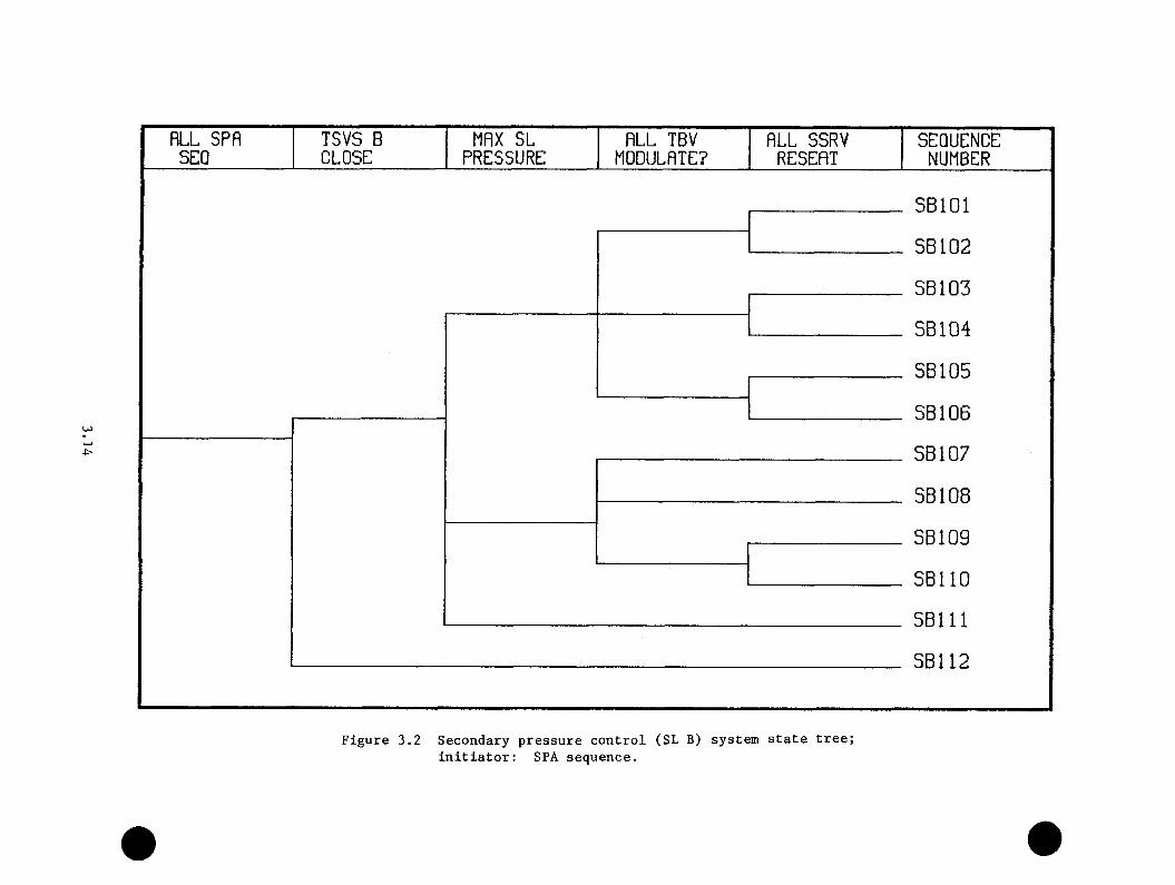
RLL SPfl TSVS B MAX SL RLL TBV RLL SSRV SEQUENCESEQ CLOSE PRESSURE MODULRTE? RESERT NUMBER
U )
SBlOl
SB102
SB 103
SB 104
SB 105
SB 106
SB 107
SB 108
SB109
SBllO
SBlll
SB112
Figure 3.2 Secondary pressure control (SL B) system state tree; initiator: SPA sequence.

valve, although manual control is possible. The MFW pumps are in turn
controlled via the differential pressure across the MFW control valves.
The emergency feedwater (EFW) pumps (two motor-driven and one turbine-
driven) start on low-MFW pump discharge pressure. Emergency feedwater
flow, however, is controlled by the emergency feedwater control valves,
which respond to the steam generator (S6) level-sensing system.
Unlike the case for the secondary-side pressure-control state tree, no
single conditioning event can be used to simplify the feedwater system state
tree. For the feedwater system, three conditioning events are employed,
leading to a conditioning event tree. As in the previous section, the
conditioning events are included to permit the consideration of both normal
and off-normal responses. The relevent conditioning events used consist of
the availability of the main feedwater supply system, the transient-induced
MFW pump discharge pressure, and the response of the SG level control
system to the transient-induced thermal-hydraulic conditions.
The availability of the MFW system is included as a conditioning event to
account for those transients whose initiators disable the MFW system and
hence preclude any automatic response by the system. The principal example
of this type of event is a transient initiated by loss of MFW. The success
branch for this conditioning event is defined to be the normal operation
of the MFW system immediately following an initiating event. Failure is
defined as no MFW flow. This conditioning event also serves to screen
transients that begin from initial conditions where the MFW system is not
functioning or in operation.
3.15
Hie second conditioning event employed is a binary branch based on the MFW
pnmp discharge pressure. As noted above, the magnitude of the MFW pump
discharge pressure determines the demand for EFW pump actuation. Thus,
the second feedwater conditioning event is defined as the minimum MFW pump
discharge pressure induced by the transient. State 0 is defined as MFW
pump discharge pressure greater than 725 psi (no EFW demand signal), while
State 1 is taken to be a pressure less than 725 psi (EFW demanded).
The final conditioning event includes the response of the steam generator
level control system. Recognizing the fact that certain transients have
the potential for creating false signals in the SG level control system,
three relevant branches are defined. The first state (State 0) is one
in which the SG level control signals indicate a high-level condition in
at least one SG due to transient-induced phenomena. The second state
(State 1) is defined as the nominal response of the level control system
(i.e., the control signals accurately reflect the condition of the steam
generators). The remaining state (State 2) is defined as an indication
of a low-level condition in at least one SG due to the transient-induced
phenomena.
Combining these three conditioning events results in the feedwater
conditioning event tree depicted by Figure 3.3. It should be noted that the
high-MFW-pressure case with MFW unavailable has been eliminated because,
without the MFW pumps, the discharge pressure is limited by the shutoff
head of the condensate booster pumps.
The conditioning event branches give rise to nine feedwater system state
trees. However, since the nine trees have many events in common (differing
3.16

MFW SYS. flVfllLflBLE?
MFW LINE PRESSURE?
SG LEVEL SIGNRLS
SEQUENCENUMBER
HIGH FCEGI
> 725 NOMINAL FCEG2
LOW FCEG3YES
FCEG4
< 725 FCEG5
FCEG6
FCEG7
NO FCEG8
FCEG9
Figure 3.3 Feedwater conditioning event tree; initiator: unspecified.
only in the probability of individual branches), only the significant
differences will be called ont explicitly in this discussion.
Because the primary concern regarding the feedwater supply is that of
excessive feedwater relative to the heat source, the feedwater system trees
are constructed on the basis of an implied reduction of the heat source
(i.e., a reactor trip). The case of a malfunction resulting in excessive
feedwater for a constant heat source will be treated on an exceptional
basis later in the discussion. Within this context, the primary event of
concern is the success of MFW runback on demand. Four PTS-relevant runback
states are of concern: the runback is successful; it is unsuccessful in
a single SG resulting in excessive MFW to the SG; it is unsuccessful with
regard to both SGs (i.e., a double overfeed); and lastly, the attempted
runback results in the trip of the MFW pumps, which for most transients
is equivalent to the loss of MFW flow. State 0 is defined as a successful
runback wherein the MFW flow to each SG is modulated to maintain the
correct SG levels. State 1 is defined as an unsuccessful runback for a
single SG with an uncontrolled level increase. State 2 is defined as an
unsuccessful runback to each SG resulting in increasing levels, and State
3 is defined as the loss of both MFW pumps as a result of an attempted
runback.
The second system of interest concerns the steam generator protection
system installed at the Oconee-1 plant. This system is designed to trip
the MFW pumps if the level in either SG reaches 90% of the operating range.
This level is inferred from Ap sensors in each steam generator. Since
the 90% level is beyond the normal operational range, this event is only
3.18

relevant for those branches indicative of overfeeds. The success branch
is defined as the trip of both liFW pumps, given that the 90% level has
been reached, and the failure branch is defined as the failure to trip at
least one MFW pump, given that the 90% level has been reached.
In addition to the response of the system, the response of the
emergency feedwater system is also relevant to the PTS analyses. The first
response of interest is whether the EFW pumps start, given a demand for
EFW. The success branch, denoted by State 0, is defined as the start
of at least one (of three) EFW pumps. Two different failure states are
distinguished: State 1, failure of a manual start of the EFW pumps; and
State 2, failure of all EFW pumps to start due to the unavailability of
their emergency feedwater system. This distinction is made because the EFW
system can be manually restored, which will be considered in the operator
action trees.
The final system response concerns the potential for EFW overfeeds, given
the success of EFW pump actuation. Three possible flow-control branches
are distinguished. State 0 describes the condition whereby EFW flow to
both SGs is modulated to maintain the correct SG water level. For State 1,
the EFW flow to a single SG is greater than that required to maintain the
appropriate water level, and for State 2, the EFW flow is greater than that
required for water level maintenance to both SGs. Table 3.2 summarizes
the branch definition for all FW events.
Combining these four system responses under the assumptions of the
first feedwater conditioning event end-state (FCEOl)— i.e., MFW system
operational, MFW pump discharge pressure > 725 psia, and high SG level
3.19
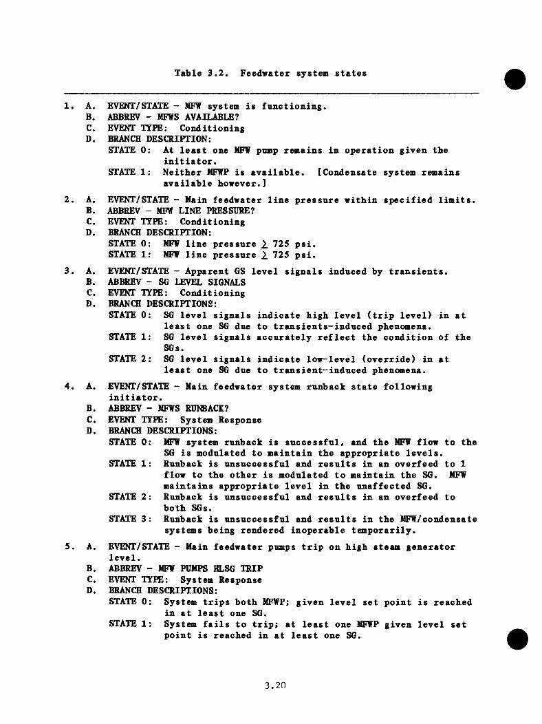
Table 3.2. Feedwater system states
1. A. EVENT/STATE - MFW system is functioning.B. ABBREV - MFWS AVAILABLE?C. EVENT TTFE: ConditioningD. BRANCH DESCRIPTION:
STATE 0: At least one MFW pump remains in operation given tbeinitiator.
STATE 1: Neither MFWP is available. [Condensate system remainsavailable however.]
2. A. EVENT/STATE - Main feedwater line pressure within specified limits.B. ABBREV - MFW LINE PRESSURE?C. EVENT TYPE: ConditioningD. BRANCH DESCRIPTION:
STATE 0: MFW line pressure >. 725 psi.STATE 1: MFW line pressure ^ 725 psi.
3. A. EVENT/STATE - Apparent GS level signals induced by transients.B. ABBREV - SG LEVEL SIGNALSC. EVENT TYPE: ConditioningD. BRANCH DESCRIPTIONS:
STATE 0: SG level signals indicate high level (trip level) in atleast one SG due to transients-induced phenomena.
STATE 1: SG level signals accurately reflect the condition of theSGs.
STATE 2: SG level signals indicate low-level (override) in atleast one SG due to transient-induced phenomena.
4. A. EVENT/STATE - Main feedwater system runback state followinginitiator.
B. ABBREV - MFWS RUNBACE?C. EVENT TYPE: System ResponseD. BRANCH DESCRIPTIONS:
STATE 0: BIFW system runback is successful, and the MFW flow to theSG is modulated to maintain the appropriate levels.
STATE 1: Runback is unsuccessful and results in an overfeed to 1flow to the other is modulated to maintain the SG. MFW maintains appropriate level in the unaffected SG.
STATE 2: Runback is unsuccessful and results in an overfeed toboth SGs.
STATE 3: Runback is unsuccessful and results in the MFW/condensatesystems being rendered inoperable temporarily.
5. A. EVENT/STATE - Main feedwater pumps trip on high steam generatorlevel.
B. ABBREV - MFW PUMPS HLSG TRIPC. EVENT TYPE: System ResponseD. BRANCH DESCRIPTIONS:
STATE 0: System trips both MFWP; given level set point is reachedin at least one SG.
STATE 1: System fails to trip; at least one MFWP given level setpoint is reached in at least one SG.
3.20

6. A. EVENT/STATE - Emergency feedvater pnmps start.B. ABBREV - EFVPs STARTC. EVENT TTFE: System ResponseD. BRANCH DESCRIPTIONS:
STATE 0: At least one EFWP (of the two MDEFWP and 1 IDEFWP) startsupon demand.
STATE 1: No EFW pnmp starts dne to EFW pnmp controls being inmanna1.
STATE 2: No EFW pnmp starts dne to EFW system nnavailability.7. A. EVENT/STATE - Emergency feedwater flow to steam generators
controlled or SG level set point.B. ABBREV - EFW FLW CNTRL/LEVELC. EVENT TTFE: System ResponseD. BRANCH DESCRIPTIONS:
STATE 0: EFW flow to botb SGs is nominal. Tbe EFW flow to eachSG is modnlated to maintain tbe appropriate SG level.
STATE 1: EFW flow to 1 SG is greater tban that required to maintainSG level. Flow to unaffected SG is modnlated to maintain tbe appropriate level.
STATE 2: EFW flow to botb SGs is no greater tban that required tomaintain SG level.
3 . 2 1

signals— ^yields tlie systeai state tree given in Figure 3.4. For this
system state tree, the EFW system is only demanded if the MFW pumps are
tripiied (either dne to high SG level or rnnbach difficulties). Similarly,
using the assumption of FC!E02, Figure 3.5 can be constructed. The major
differences in structure involve the EFW pump activation event of the
successful MFW runback branch. Figures 3.6 through 3.10 depict the system
state trees resulting from the remaining conditioning event assumptions.
3.3.3 Primary Loop Coolant Flow System State Trees
Whereas both the secondary'side pressure-control systems and the feedwater
supply systems influence the fluid conditions seen by the pressure vessel
indirectly (via the steam generator), the coolant flow patterns in the
primary loops directly impact pressure and temperature. Of concern to
the PTS analysis are both the normal primary coolant flow systems (i.e.,
the status of the reactor coolant pumps and the core vent valves) and the
emergency core cooling systems (ECCS). For the Oconee-1 plant, however,
the status of the reactor coolant pumps (RCPs) is governed by operator
action, so discussion of possible changes of state of the RCPs will be
deferred to the section on operator actions. Similarly, because of the
intimate connection between the status of the RCPs and the functioning
of the vent valves, discussion of the vent valve operation will also be
deferred. The remaining systems of concern are the ECC systems [the high-
pressure injection system (HPI), the core flood tanks, and the low-pressure
injection system (LPI)].
The HPI system is of concern primarily because of the system capability
to maintain a high RCS pressure or subsequently to repressurize to a
3.22
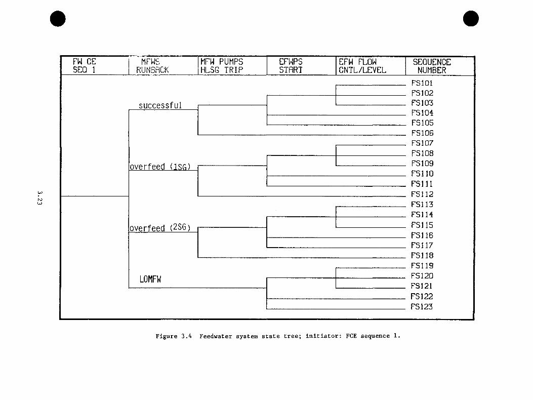
FW CE MFWS MFW PUMPS EFWPS EFW FLOW SEQUENCESEQ 1 RUN3RGK HLSG TRIP START CNTL/LEVEL NUMBER
su c cess fu l
K)U>
overfeed (J.SCi)
overfeed (2SG)
LOMFW
FSlOlFS102FS103FS104FS105FS106FS107FS108FS109FsnoFsniFS112FS113FSIHFS115FS116FS117FS118FS119FS12QFS121FS122FS123
Figure 3.4 Feedwater system state tree; initiator: FCE sequence 1.
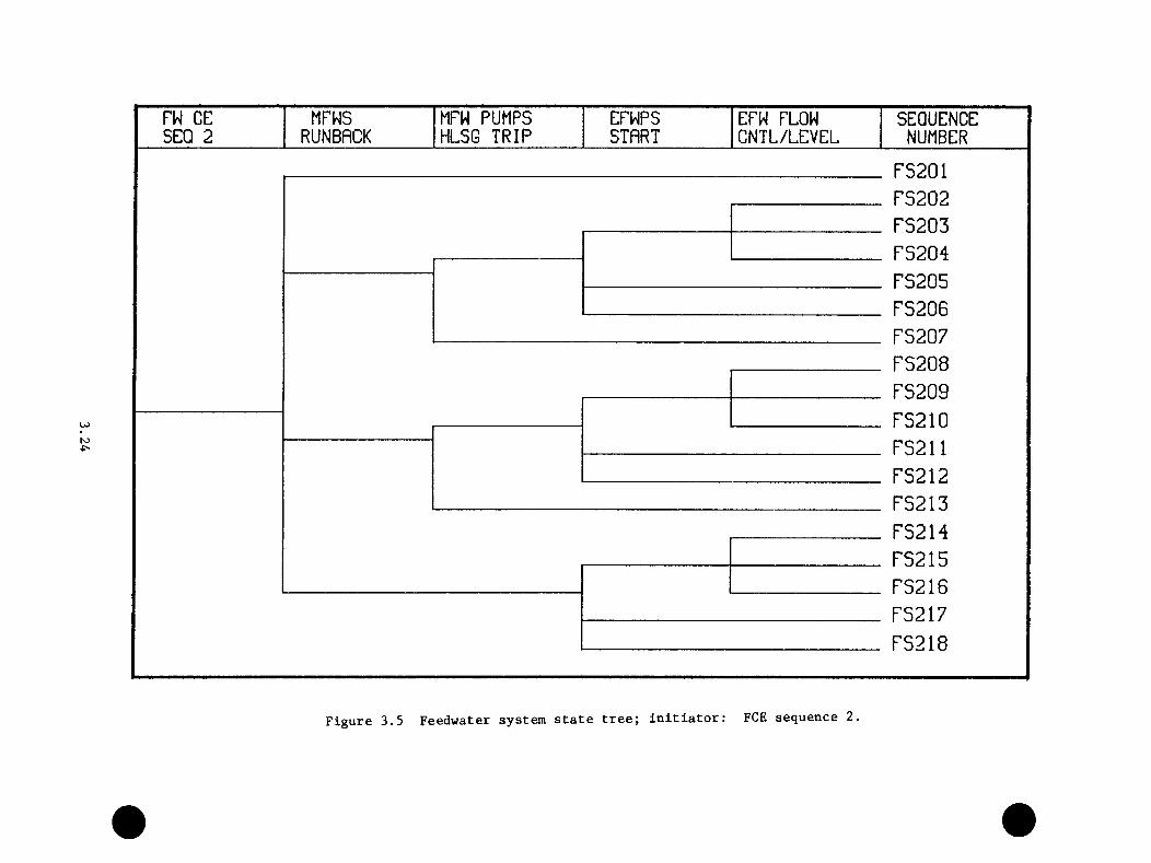
FW CE MFWS MFW PUMPS EFWPS EFW FLOW SEQUENCESEQ 2 RUNBRCK HLSG TRIP STRRT CNTL/LEVEL NUMBER
N5
FS201FS202FS203FS204FS205FS206FS207FS208FS209FS210FS211FS212FS213FS214FS215FS216FS217FS218
Figure 3.5 Feedwater system state tree; initiator: FCE sequence 2.
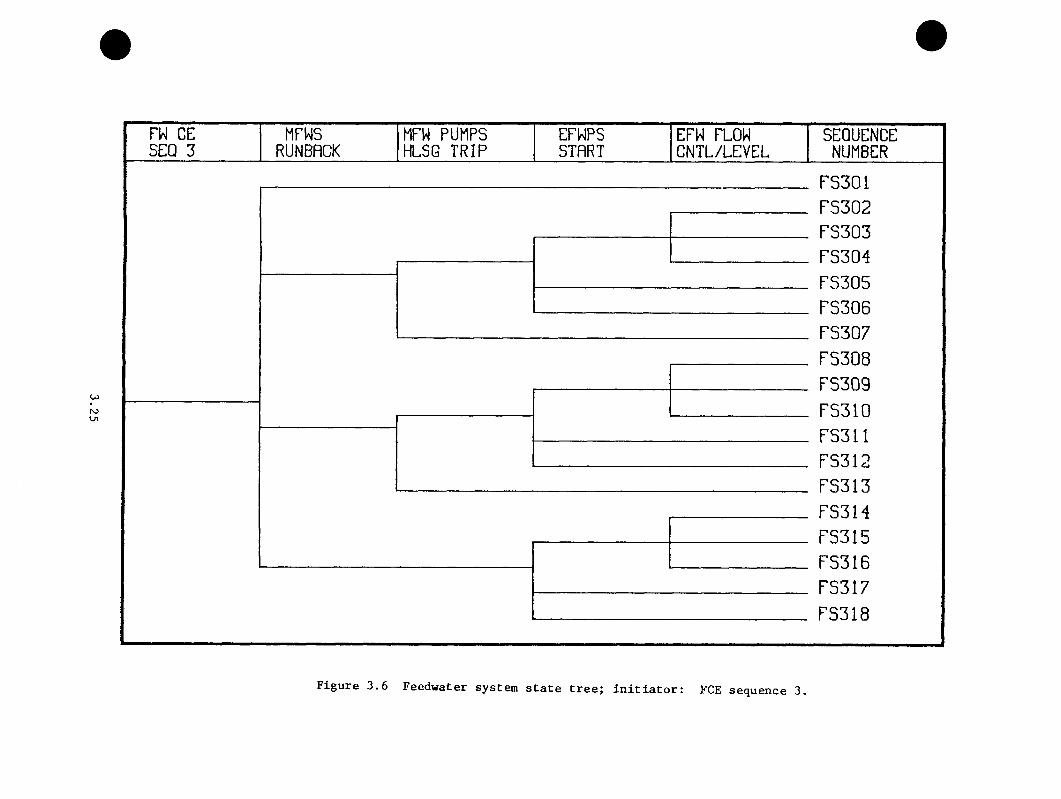
FW CE MFWS MFW PUMPS EFWPS EFW FLOW SEQUENCESEQ 3 RUNBRCK HLSG TRIP START CNTL/LEVEL NUMBER
roU i
FS301PS302FS303FS304FS305FS306FS307FS308FS309FS310FS311FS312FS313FS314FS315FS316FS317FS318
Figure 3.6 Feedwater system state tree; initiator: FCE sequence 3.

rw CE MFWS MFW PUMPS EFWPS EFW FLOW SEQUENCESEQ 4 RUNBACK HLSG TRIP START CNTL/LEVEL NUMBER
N5O'
F 3 « l PS 402 FS403 PS 404 PS 405 F5406 PS 407 P3408 PS 409 FS410 FS411 PS412 PS413 PS414 F3415 PS416 P3417 PS418 FS419 PS420 PS 421 P 3422 PS423 PS 424 P3425 PS 426 PS 427 PS 428 FS429 PS430 PS431 PS 432 PS 433 PS434 FS435
Figure 3.7 Feedwater system state tree; initiator: FCE sequence 4,

FW CE MFWS MFW PUMPS EFWPS EFW FLOW SEQUENCESEQ 5 RUNBRCK HLSG TRIP STRRT CNTL/LEVEL NUMBER
U)
FS50]F3502F5503PS504FS505FS506F3507FS508FS509F551DFS511FS512FS513FS514FS515FS516FS517FS518F5519F5520FS521FS522FS523FS524FS525F352B
Figure 3.8 Feedwater system state tree; initiator: FCE sequence 5.

FW CE MFWS MFW PUMPS EFWPS EFW FLOW SEQUENCESEQ 6 RUNBRCK HLSG TRIP STRRT CNTL/LEVEL NUMBER
tsj00
FS601FS602FS603FS604FS605FS606F3607FS608FS609FS61QFS611FS612FS613FS614FS615FS616FS617FS618F5619FS620FS621FS622FS623F5624FS625F362B
Figure 3.9 Feedwater system state tree; initiator: FCE sequence 6.
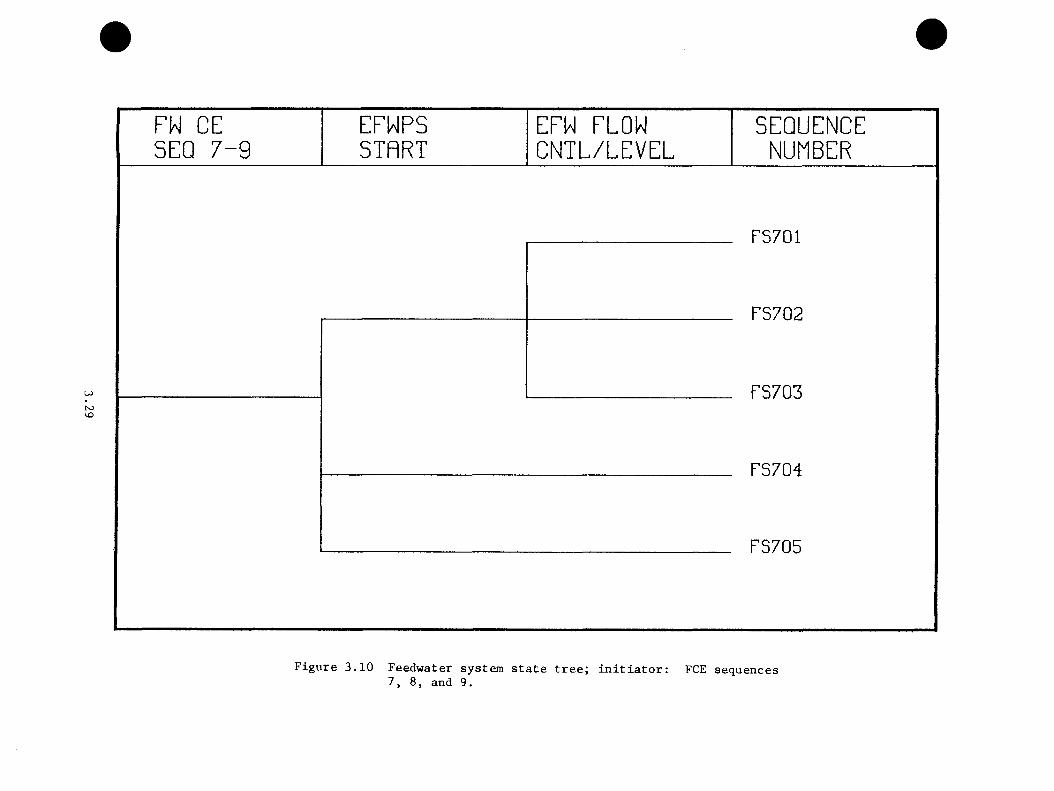
ho
PW CE SEQ 7 - 9
EFWPSSTART
EPW PLOW C N TL /LE V E L
SEQUENCENUMBER
Fszni
F9,7n2
F9>7m
FS7H4
............. .... FS705
Figure 3.10 Feedwater system state tree; initiator: FCE sequences7, 8, and 9.

higli pressure. However, for certain transients (i.e., those with low RC
pressure), the temperature effects of the cold HPI fluid may also be an
important factor. The core flood tanks and LPI system are of concern for
the inverse reason. Although the pressure effect is inherently limited,
these systems have the capacity for replacing a large fraction of the
primary coolant inventory with "cold" fluid. Moreover, both of these
systems inject fluid directly into the downcomer, whereas the HP injection
point is 16 ft upstream from the cold leg nozzle.
Since the demand signals for the various ECC systems are based on primary
system pressure, the appropriate conditioning parameter is the minimum
reactor coolant system pressure reached during the transient. Four possible
discriminants are used: State 0 - minimum RC pressure > 1500 psi (no
ECCS demand); State 1 - RCS pressure between 610 and 1500 psi (only HPI
demanded); State 2 - RCS pressure between 200 and 610 psi (both HPI and CFT
demanded); and lastly. State 3 - RCS pressure less than 200 psi (all three
systems, HPI, LPI, and CFT, demanded). This conditioning event serves to
simplify the construction of the initiator trees by restricting the number
of event branches that must be considered.
Given a demand for the HPI system, the next system response of interest
is whether the system functions as designed. A binary branch is defined
for this event. The success state is defined as transfer of all three HPI
pumps to the injection mode and coolant delivery to the RCS. The failure
branch is defined as failure of all HPI pumps to deliver coolant, given a
demand. As noted in the above discussion, the principal PTS concern in the
ECC systems is the success state (i.e., the system functions as designed).
3.30
The failure of these systems to operate properly upon demand generally
reduces the severity of PTS phenomena. However, the failure branches are
included to account for the potential of operator error upon restoration
(i.e., overcompensation) because of the generally high reliability of these
systems.
The branch point regarding the core flood tanks is defined similarly. The
success state is defined as the discharge of at least one core flood tank
into the downcomer upon demand. The failure state is the failure of both
flood tanks to discharge. The LPI branch is also defined similarly to
the previous two branches. The success state is defined as at least one
LPI pump's operating and coolant being delivered to the downcomer. The
corresponding failure state is that no low-pressure injection occurs.
The system state tree comprising these four events is depicted in Figure
3.11. Table 3.3 summarizes the definitions of the four events.
3.3.4 Primary Pressure Control System State Tree
The PTS concern with the primary-system pressure-control systems (PORV and
RVs) is centered on the potential for the creation of loss-of-coolant
situations and hence the triggering of ECC systems (if not already running).
In particular, the relief valves serve as a mechanism for the removal of
heat energy directly from the primary loop.
The appropriate conditioning event for the primary pressure-control system
state tree is the extent of the demand for pressure relief as indicated
by the maximum RCS pressure attained in the primary loop during the course
of the transient. Three states are categorized. State 0 is defined as the
3 . 3 1

MINIMUM HP I CFT LPI SEQUENCERCS PRESS INITIflTED DISCHflRQE INITIRTED NUMBER
U5N5
P > 1500
610 < p < 1500
200 610
p < 200
ECCOl ECC02 ECC03 ECC04 ECC05 ECC06 ECC07 ECC08 ECC09 ECC 10 ECC 11 ECC 12 ECC 13 ECC 14 ECC 15 ECC 16 ECC 17 ECC 18 ECC 19
Figure 3.11 Primary loop ECCS system state tree; initiator: unspecified.
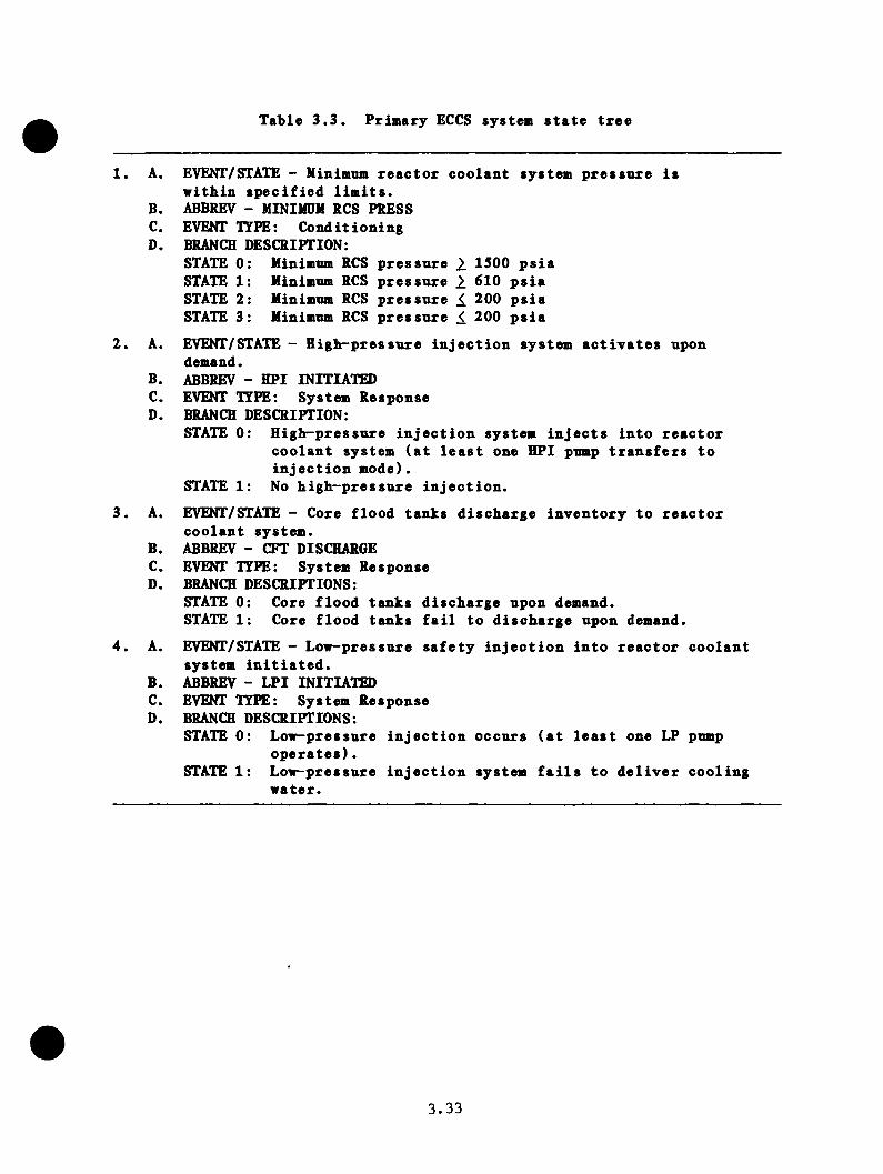
Table 3.3. Primary ECCS system state tree
1. A. EVENT/STATE - Minimxim reactor coolant system pressure is within specified limits.
B. ABBREV - MININDM RCS PRESSC. EVENT ITPE: ConditioningD. BRANCH DESCRIPTION:
STATE 0 STATE 1 STATE 2 STATE 3
Minimum RCS pressure 2. 1500 psiaMinimum RCS pressure 610 psiaMinimum RCS pressure 200 psiaMinimum RCS pressure 200 psia
2. A. EVENT/STATE - High-pressure injection system activates upondemand.
B. ABBREV - HPI INITIATEDC. EVENT TYPE: System ResponseD. BRANCH DESCRIPTION:
STATE 0: High-pressure injection system injects into reactorcoolant system (at least one HPI pump transfers to injection mode).
STATE 1: No high-pressure injection.3. A. EVENT/STATE - Core flood tanks discharge inventory to reactor
coolant system.B. ABBREV - CFT DISCHARGEC. EVENT TYPE: System ResponseD. BRANCH DESCRIPTIONS:
STATE 0: Core flood tanks discharge upon demand.STATE 1: Core flood tanks fail to discharge upon demand.
4. A. EVENT/STATE - Low-pressure safety injection into reactor coolantsystem initiated.
B. ABBREV - LPI INITIATEDC. EVENT TYPE: System ResponseD. BRANCH DESCRIPTIONS:
STATE 0: Low-pressure injection occurs (at least one LP pumpoperates).
STATE 1: Low-pressure injection system fails to deliver coolingwater.
3.33

condition in which the mazimnm RCS pressure remains less than 2450 psi (the
nominal PORV set point) and hence there is no demand for pressure relief.
State 1 is defined as the condition in wich reactor coolant pressure is
between 2450 psi and 2500 psi (the SRV set point), so that only the PORV is
demanded. Finally. State 2 is defined as the maximum RCS pressure's being
greater than or equal to 2500 psi, so that both PORV and SRVs are demanded.
For those conditioning states wherein the PORV is demanded, the next
relevant event is the operability of the PORV. This is, in effect, a two
part event. The first is the actual functioning of the PORV represented
by a binary event in which the success state is that the PORV lifts upon
demand and the failure state is the failure of the PORV to open upon
demand. The second part of this event is a conditioning event related to
the status of the block valve downstream of the POV. This is included
as part of the system state tree, because, if closed, operation of the PORV
upon demand will not provide any pressure relief. Again, a binary branch
is used, with success defined as the block valve's being open and failure
by its being closed.
Given a sufficient pressure relief demand, the next event is the operation
of the safety relief valves. The relevent question is whether the relief
valves, having opened on demand, reseat when the primary pressure is
reduced. If this fails to occur, the plant experiences a transient-induced
loss-of-coolant event. The first reseat question concerns the SRVs, and
success is defined as the closure, upon pressure reduction, of all the SRVs
that have opened. Failure is defined as the failure of at least one SRV
3 . 3 4

to reseat. The implicit assumption contained in this analysis is that if
the SRVs are demanded, they mill open with a probability of 1.
The rationale for discriminating between a stnch-open PORV and a stnck-open
SRV is linked to the possible corrective operator actions. The former is
an isolable loss-of-coolant accident (LOCA), whereas the later is not.
These five events comprise the primary pressure control system state tree
depicted by Figure 3.12. Table 3.4 summarizes the branch definitions
specified in the above discussion.
3.4 Quantification of the Functional Svstem State Trees
One of the primary purposes for introducing the concept of a conditioning
event was to permit the quantification of each of the four functional
system state trees (secondary pressure control, feedwater supply, primary
ECC systems, and primary pressure control) separately. Once each is
quantified, the initiator-specific event trees are constructed by combining
the four functional trees into an overall system state tree and by selecting
the appropriate set of conditioning events for the given initiator. This
section discusses the numerical values used to quantify each of the four
functional system state trees.
Probability values were estimated, when possible, from operational
information, which was as close to Oconee-specific as possible. If Oconee-
specific information was available, then it was used. If this was not
the case, B&V-specific and finally PWR-specific operational information was
employed. Additional information was obtained from lEEE-SOO, the NREP
Generic Data Base screening values, as well as from other sources.
3.35
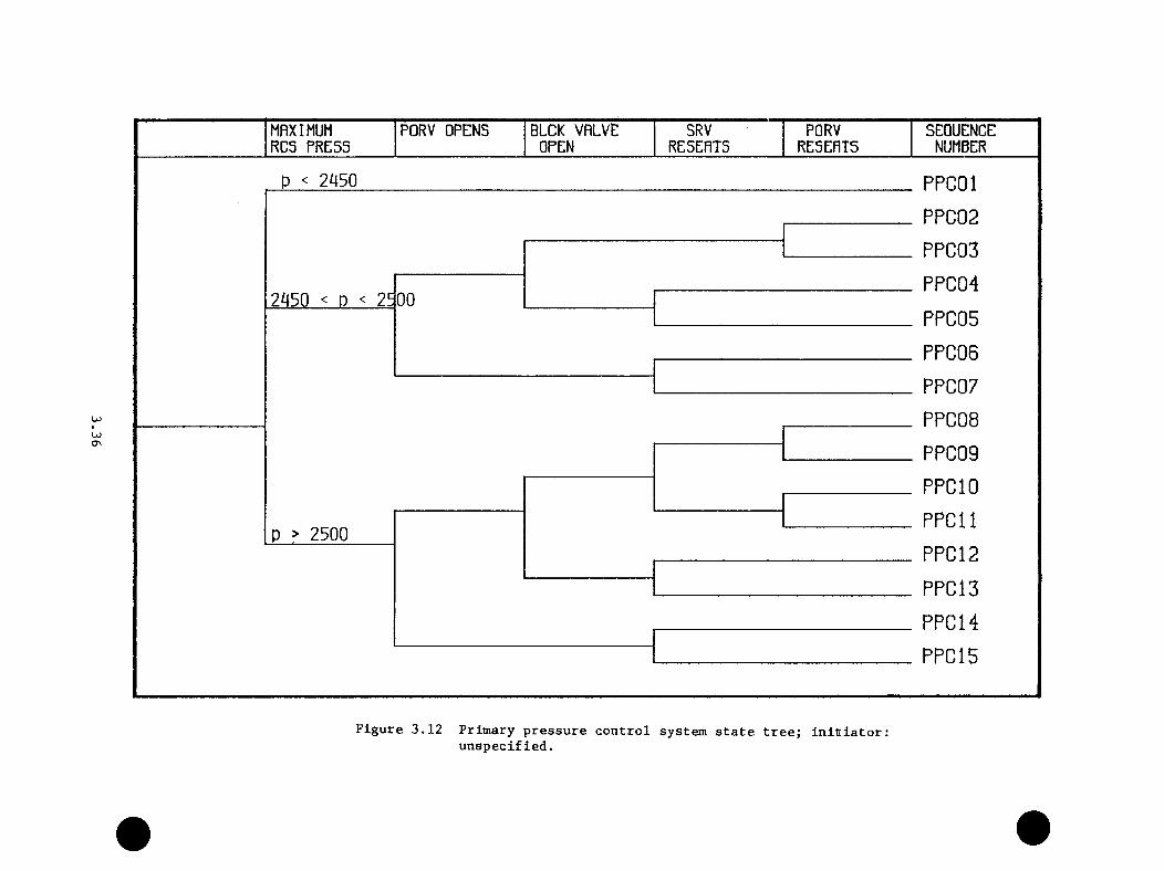
MAXIMUM PORV OPENS BLOK VALVE SRV PORV SEQUENCERCS PRESS OPEN RESEATS RESEATS NUMBER
COCTn
p < 2450
2^50 < D < 25 00
p > 2500
PPCOl PPC02 PPC03 PPC04 PPC05 PPC06 PPC07 PPC08 PPC09 PPCIO PPG 11 PPG 12 PPG 13 PPG 14 PPG15
Figure 3.12 Primary pressure control system state tree; initiator;unspecified.

Table 3.4. Prinary pressure control systen state tree
1. A. EVENT/STATE - Maximum reactor coolant system pressure is within specified limits.
B. ABBREV - MAXIMDM RCS PRESSC. EVENT TYPE: ConditioningD. BRANCH DESCRIPTION:
STATE 0 STATE 1 STATE 2
Maximum RCS pressure < 2450 psiaMaximum RCS pressure > 2450 psiaMaximum RCS pressure > 2500 psia
2. A. EVENT/STATE - Power operated relief valve opens, given RCS pressure> 2450 psi.
B. ABBREV - PORV OPENSC. EVENT TYPE: System ResponseD. BRANCH DESCRIPTION:
STATE 0: PORV opens at 2450 psi to relief RCS pressure.STATE 1: PORV fails to open (fails closed).
3. A. EVENT/STATE - Block valve downstream of PORV is open.B. ABBREV - BLCK VALVE OPENC. EVENT TYPE: ConditioningD. BRANCH DESCRIPTIONS:
STATE 0: Block valve is initially open.STATE 1: Block valve is initially closed (PROV disabled).
4. A. EVENT/STATE - Safety relief valve reseats, given pressure reductionbelow reseat pressure.
B. ABBREV - SRV RESEATSC. EVENT TYPE: System ResponseD. BRANCH DESCRIPTIONS:
STATE 0: Safety relief valve reseats, given pressure reduction. STATE 1: Safety relief valve fails to reseat, given pressure
reduction.5. A. EVSn'/STATE - Powex^generated relief valve reseats, given pressure
reduction.B. ABBREV - PORV RESATSC. EVENT TYPE: System ResponseD. BRANCH DESCRIPTIONS:
STATE 0: Power operated relief valve reseats, given a sufficientpressure reduction.
STATE 1: PORV fails to reseat, given pressure reduction.
3,37
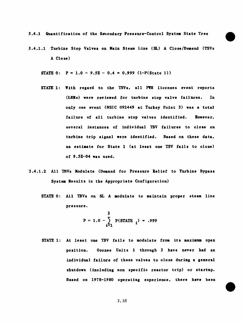
3.4.1 Qaantlfication of the Secondary Pressnre-Control System State Tree
3.4.1.1 Turbine Stop Valves on Main Steam Line (SL) A Close/Demand (TSVs
A Close)
STATE 0: P = 1.0 - 9.5E - 0.4 = 0.999 (l-P(State D )
STATE 1: Vith regard to the TSVs, all PVR licenses event reports
(LERs) were reviewed for turbine stop valve failures. In
only one event (NSIC 092449 at Turkey Point 3) was a total
failure of all turbine stop valves identified. However,
several instances of individual TSV failures to close on
turbine trip signal were identified. Based on these data,
an estimate for State 1 (at least one TSV fails to close)
of 9.5E-04 was used.
'3.4.1.2 All IBVs Modulate (Demand for Pressure Relief to Turbine Bypass
System Results in the Appropriate Configuration)
STATE 0: All IBVs on SL A modulate to maintain proper steam line
pressure.2
P = 1.0 - 5 P(STATE .) = .999 i=l ^
STATE 1: At least one TBV fails to modulate from its maximum open
position. Oconee Units 1 through 3 have never had an
individual failure of these valves to close during a general
shutdown (including non specific reactor trip) or startup.
Based on 1978-1980 operating experience, there have been
3.38
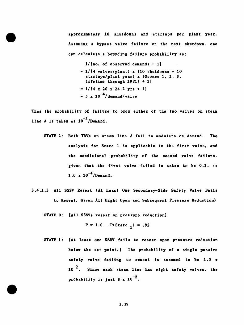
approximately 10 shutdowns and startups per plant year.
Assuming a bypass valve failure on the next shutdown, one
can calculate a bounding failure probability as:
1/[no. of observed demands + 11= l/[4 valves/plant) x (10 shutdowns + 10
startups/plant year) x (Oconee 1, 2, 3, lifetime through 1981) + 1]
= l/[4 X 20 X 24.2 yrs + 1]—4= 5 X 10 /demand/valve
Thus the probability of failure to open either of the two valves on steam_3line A is taken as 10 /Demand.
STATE 2: Both IBVs on steam line A fail to modulate on demand. The
analysis for State 1 is applicable to the first valve, and
the conditional probability of the second valve failure,
given that the first valve failed is taken to be 0.1, is -41.0 X 10 /Demand.
3.4.1.3 All SSSV Reseat (At Least One Secondary^Side Safety Valve Fails
to Reseat, Given All Eight Open and Subsequent Pressure Reduction)
STATE 0: [All SSSVs reseat on pressure reduction]
P = 1.0 - P(State j) = .92
STATE 1: [At least one SSRV fails to reseat upon pressure reduction
below the set point.] The probability of a single passive
safety valve failing to reseat is assumed to be 1.0 x _210 . Since each steam line has eight safety valves, the
_2probability is just 8 x 10
3.39
3.4.1.4 Modifications of Secondary Pressnre-Control Branches for SL B Due
to Conditioning Events/Steam Line A Events
Turbine Stop Valves on SL A Fail To Close
The only event relative to SL B assumed to be conditional on the closure
of the TSVs on SL A is the closure of the TSVs on SL B. A conditional
probability of failure of 0.1 is assumed in this case to include potential
common-course failure coupling.
STATE 0; P = 0.9
STATE 1: P = 0.1
Turbine Bypass Valves on SL A Fails to Modulate (Fails Open)
A conditional probability of 0.1 for the same failure mode on SL B is
assumed. The failure probability for the alternate failure mode is assumed
unaffected.2
STATE 0: P = 1- ^ P(State - 0 . 9i=l
STATE 1: P = 1.0 x lO"^
STATE 2: P = 1.0 x 10“^
Turbine Bypass Valves on SL A Fail Closed
A conditional probability of 0.1 for the same failure mode on SL B is
assumed. The failure probability for the alternate failure mode is assumed
unaffected.
3.40
2STATE 0: P = 1- J P(State - 0 . 9
i=l
STATE 1: P = 1.0 x 10“^
STATE 2: P = 1.0 x 10 ^
Secondary Side Safety Valves on SL A Fail to Reseat
A conditional probability (attributable to identical valves, maintenance
operations, calibration, etc.) of 0.1 is assumed.
STATE 0: P = 9.0 x lO"^
STATE 1; P = 1.0 x 10“^
Using these assumptions, the overall secondary pressure control system
state tree given by Figure 3.13 was constructed.
3.4.2 Quantification of the Feedwater System State Trees
The quantification of the feedwater system state trees will be discussed
relative to the following set of conditioning parameters:
a. MFW pumps are running,
b. MFW line pressure remains greater than 725 psia as long as
the MFW pumps operate, and
c. The apparent SG level signals are nominally correct.
This set of conditions corresponds to feedwater conditioning event end-
state FOS 02 on Figure 3.3.
3 . 4 1

3.4.2.1 NFWS Runback (Main Feedwater Systea Rnnback Results in a Given
Configuration)
STATE 0: Rnnback of MFW is successful.3
P = 1.0 - 5 State . i=l
STATE 1: Rnnback is unsuccessful; overfeed to either SG. "The
Oconee Pressurized Thermal Shock Evaluation" (DPC-RS-lOGl,
January 1982) identifies four failures to rnnback following
a reactor trip:
Unit 2, September 17, 1974
Unit 2, April 30. 1974
Unit 2, January 30, 1980
Unit 3, March 14, 1980
During the time period considered in the Oconee study
(24 plant-years), approximately 144 reactor trips occurred.
This results in a failure to rnnback of roughly 4/144 >= 2.8_2- 10 /demand.
STATE 2: Rnnback is unsuccessful, resulting in an overfeed to both
SGs. Since a detailed failure analysis was not done for
this branch, it is calculated by assuming a conditional
probability of 0.1 for the second SG. That is, the
probability of an overfeed in the second steam generator
given an overfeed in the first *= 0.1. Thus, the probability
3.42
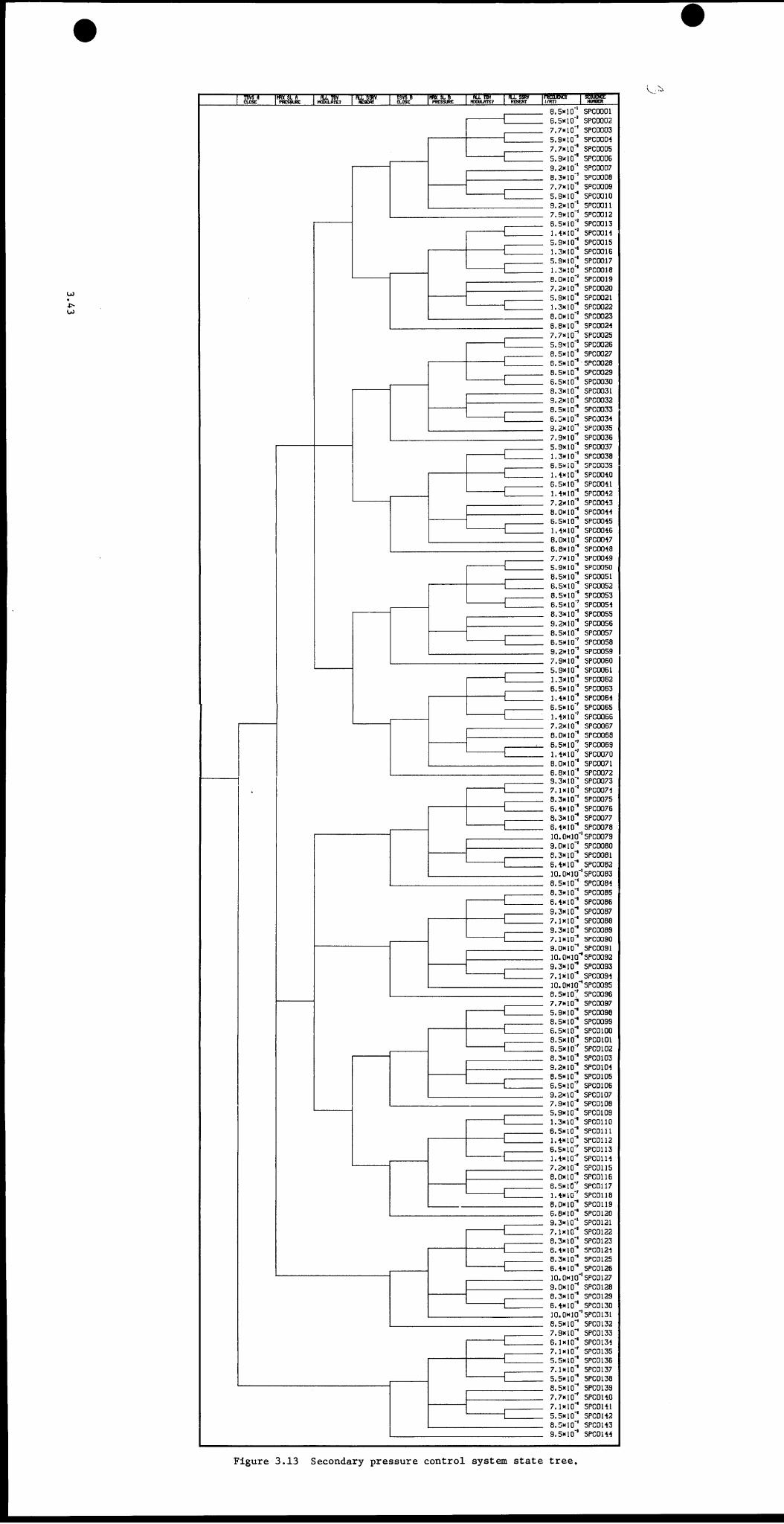
" w rCLOSE m SLAPFESBURE rsrwMOXtflrE? ncrswfESEftt TsrrCLOSE IHRKILSI PWSSURE McxxiLfrrE?icrm— \mmttBSERT I (/RY) SMUEf g "NUdGER
_ 8.5X10'' SPCOOOl6.5K10‘’ SPC00027.7* 10’’ SPC00035.9x10'’ SPC0004
_ 7.7x10'’ SPC00055.9x10'' SPC00069.2x10'' SPC00078.3x10'* SPC00087.7x10'* SPC00095.9x10'* SPCOOlO9.2x10'' SPCOOl17.9x10'* SPC00126.5x10'' SPCOOl3l.-txlO'* SPCOOl45.9x10'* SPCOOl51.3x10'* SPCOOl65.9x10'* SPCOOl71.3x10'* SPCOOl88.0X10'* SPCOOl97.2x10'* SPC00205.9x10'* SPC00211.3x10'* SPC00228.0x10'' SPC0023B.OxlO"* SPC00247.7x10'* SPC00255.9x10'* SPC00268.5x10'* SPC00276.5x10'* SPC00288.5x10'* SPC00296.5x10'* SPC00308.3x10'* SPC00319.2x10'* SPC00328.5X10'* SPC00336.3x10'* SPCC0349.2x10'* SPC00357.9x10'’ SPC003B5.9x10'* SPC00371.3x10"* SPC00386.5x10'* SPC00391.4x10'* SPC00406.5x10'* SPC00411.4x10"* SPC00427.2x10"* SPC00438.0x10"* SPC00446.5x10"* SPC00451.4x10"* SPC00468.0x10"* SPC00476.8x10"* SPC00487.7x10"* SPC00495.9x10"* SPCOQ508.5X10'* SPC00516.5x10'* SPC00528.5x10"* SPC00536.5x10"' SPC00548.3x10'* SPCD0559.2x10"* SPC00568.5x10'* SPC00576.5x10"' SPC00589.2x10"* SPC00597.9x10"* SPC00605.9x10"* SPC00611.3x10'* SPC00626.5x10"* SPC00631.4x10"* SPC00646.5x10"' SPC00651.4xl0' SPC00667.2x10"* SPC00678.0x10"* SPC00686.5x10"' SPC00691.4x10"' SPC00708.0x10'* SPC00716.8x10'* SPC00729.3x10 ‘ SPC00737.1X10"' SPC00748.3x10"* SPC00756.4x10"* SPC007B8.3x10"* SPC00776.4x10"* SPC007810.0x10 'SPC00799.0x10"* SPC00808.3x10"* SPC00816.4x10"* SPC008210.0X10 'SPC00838.5x10"* SPC00848.3x10"* SPC00856.4x10"* SPC00869.3x10"* SPC00877.1x10"* SPC00889.3x10"* SFC00897.1x10"* SPC00909.0x10'* SPC0091lO.OxlO*’SPC0092
_ 9.3x10"* SPC00937.1x10'* SPC009410.OHIO 'SPC00958.5x10^ SPC00967.7»10 SPC00975.9x10"* SPC0098
_ 8.5x10"* SPC0099_ 6.5x10"* SPCOlOO
8.5x10"* SPCOlOl6.5x10"' SPC01028.3x10"* SPC01039.2x10"* SPC01048.5x10"* SPC01056.5x10"' SPCOlOB9.2x10"* SPC01077.9x10"* SPCOlOB5.9x10"* SPC01091.3x10"* SPCOllO6.5x10"* SPCOlll1.4x10"* SPC01126.5x10"' SPC0U31.4x10"' SPC01147.2x10"* SPC01I58.0x10"* SPC01166.5x10"' SPC01171.4x10"' SPC0U88.0x10"* SPC01196.8X10"* SPC01209.3x10"' SPC01217.1x10"' SPC01228.3x10"* SPC01236.4x10"* SPC01248.3x10"* SPCD1256.4x10"* SPC0126
_ 10.0x10 'SPC01279.0x10"* SPC01288.3x10"* SPC01296.4x10"* SPC013010.0x10 '5PC01318.5x10"* SPC0132
_ 7.9x10"’ SPC01336.1x10"' SPC01347.1x10"' SPC01355.5x10"* SPC013B7.1x10"* SPC01375.5x10"* SFC01388.5x10"* SPC01397.7x10"' SPC01407.1x10"* SPC01415.5x10"' SPC01428.5x10 * SPC01439.5x10"* SPC0144
Figure 3.13 Secondary pressure control system state tree.
-2of this branch is given by 1.4 z 10 x 0.1 x 2 conbination
= 2.8 X 10"^.
STATE 3: Rnnback is nnsnccessfnl, resulting in a trip of the MFW
pumps. NDREG-0560 identifies five events at B6W plants
(through April 4, 1979, the date of IE Bulletin 79-05A) in
which feedwater was lost subsequent to a reactor trip. If
the Oconee-1 trip rate is assumed to be a typical value
for B6W plants (6 trips/year x 30.18 years of operation =
181 trips), this results in a probability of 5/181 = 2.8
This estimate does not include instrument bus failures that
result in a simultaneous reactor trip and a loss of MFW. P
= 2.8 X 10"^.
3.4.2.2 MFW Pumps HL6S Trip (Failure of the High Steam Generator Signal
to Trip Both MFW Pumps Given on Overfeed)
This trip circuit is tested yearly. Assuming a general instrumentation
failure rate of l.OE - 06/h (lEEE-SOO) results in a failure probability of-3l.OE - 06 X 8760 x 0.5 = 4.4 x 10 for the SG experiencing the overfeed.
This estimate is appropriate for those branches involving overfeeds to a
single SG. For the case of a high-level trip failure, given a double
overfeed, an alternate estimate must be made. Each SG has a separate
trip system; however, all signals (from either generator) use a common
relay. Thus, for branches involving a double overfeed, a value of 1.0 x—410 /demand (NPRDS value for relays) is assumed.
STATE 0: [High level protection system trips both MFW pumps]
3.44
P = 1 - P(State = .996
STATE 1: [High level protection system fails to trip at least 1 MFW
pump]
Pj = 4 X 10~^
3.4.2.3 EFW Pumps Start (Failure of All EFW Pumps to Start on Demand)
STATE 0: [At least one EFW pump starts on demand.]2
= 1 - 3 P(State .) = .993i=l
STATE 1: [Failure of EFW pumps to start on demand - system in manual
control.] The EFW system is assumed to be in manual control
(i.e., for testing maintenance, etc.) approximately 4 h/mo.
This results in a probability to start automatically on
demand of 4/(30 x 24) = 5.6 x IC"^ P = 5.6 x 10“^.
STATE 2: [Failure of EFW pumps to start on demand - system is
unavailable.] NDRE6/CR-2497 identified emergency feedwater-3failures on demand. This value was 1.1 x 10 , but it
included credit for short-term rectification. Excluding the
possibility of rectification (to be included in the operator_3action trees), the observed value was 1.4 x 10 /demand.
Oconee observed EFW unavailabilities at the pump level (in
1980 and 1981) are
Oconee Unavailabilitv Date
1 turbine pump 5/80
3.45
2 turbine pump 4/81
3 turbine pump 11/80
1 turbine pump 6/81
3 motor-driven pump 5/81
2 motor-driven pump 3/81
2 turbine pump 5/81
For the 17-mo period between May 1980 and September 1981,
there were seven unavailabilities, which results in an
unavailability per pump of 7/(1 test [demand]/mo x 17 mo
X 3 pumps/plant x 3 plants) = 0.05/demand. With only
one pump required for success, one can derive a system
failure probability of 0.05 (failure of first pump) X 0.3
(failure of third, given failure of first and second) = 1.5_3
X 10 /demand. This is consistent with the NDREG/CR-2497_3value of 1.4 X 10 /demand.
3.4.2.4 EFW Flow Q4TL/Level (Failure to Modulate EFW Flow to the SGs to
Maintain SG Water Level)
STATE 0: [EFW flow is modulated to maintain appropriate levels in
both SGs.)
P = 1.0 - 5 P(State .)i=l ‘
STATE 1: [EFW flow is excessive to 1 SG.] The EFW level circuit
consists of a level transmitter on each steam generator, an
associated E/P converter, and flow control valve. Additional
3.46
instrumentation is provided to change the SG level based
on whether or not the RCPs are operating. An alternate
level control channel is provided in the event power is lost
to the operating channel. It is assnmed that accessible
instrumentation is tested monthly and that the level changes
during operation can be cross-checked among the SG operating
and startup range level indications. Based on this, one can
roughly estimate the probability of overfill on initiation
as the probability of tranmitter failure or converter
failure or valve failure (10 ^/h x 720 h (level controllers,
IEEE-500) + 1 X 10 ^/demand (valve failure, WASH-1400) =_31.7 X 10 /demand for a specified generator. This gives an
estimate for either steam generator of 3.4E-03.
3.4.3 Probability Modifications Required for Off-Normal Situations
3.4.3.1 Apparent SG Level Signals Indicate High Level
HFWS Runback: No modification
For a normal runback (e.g., following reactor trip close to full power),
the SGs initially contain more inventory than is required. Thus, it is
assumed that the integrated control system (ICS) perceives this situation
as normal.
MFW Pumps EQ.SG Trip: No Modification
The probability of the SG protection system functioning is assumed
independent of the reading. The net effect of these two assumptions
3.47

however is that trip of the MFW ptimps becomes the most likely branch given
the conditioning event.
EFW Pnmps Start: No Modification
EFW Flow CNTL/Level: No Modifications
Although the same phenomena which produce the apparent high SG level
signals provided to the ICS will likely affect the EFW flow control system,
the phenomena are assumed to he of short duration. Since this system does
not involve trips, normal operation will be recovered when the phenomenon
ceases.
3.4.3.2 Apparent SG Level Signals Indicate Low Level
MFWS Runback
The assumption inherent in this conditioning event is that the SG phenomena
will result in a low-level that will which will override the runback to
the affected steam generator and will, in effect, overfeed the generator.
STATE 0: Given a low SG level control signal in the affected SG, it
is assumed that the probability of a normal runback is 0.0.3
STATE 1: P = 1.0 - J P(State .) = 0.96i=l ^
STATE 2: The probability of an overfeed to a second generator is
assumed to be the probability of a single SG overfeed on_2attempted runback, which is equal to 1.4 x 10
3.48
STATE 3: The probability of a loss of the MFWP on the attempted
rnnback is assnmed to be nnchanged by this conditioning_2event and thns eqnals 2.8 x 10
MFW Pnmps HLSG Trip
Since the SG high-level (HL) protection signals are based on the same type
of sensors as the rnnback signals (Ap sensors), it is likely that, at least
for the dnration of the apparent low-level signals, the HL trip system
will be inoperative. Thns, for the branch involving a single overfeed,
the failnre probability of the HL trip system is assnmed to be 1. However,
for the case of a donble overfeed, the nnaffected SGs protection system_3will fnnction. For this case, a failnre probability of 4.4 x 10 (the
same valne nsed for a single protection circnit) is assnmed.
EFW Pnmps Start (No Modifications)
EFW Flow (!NTL/Level
Again, the same phenomena which affect the MFW control system will affect
the EFW flow control system. Thns, the EFW to the affected SG will
likely be excessive for the dnration of the phenomenon. It is assnmed that
this is of short dnration, and since no trips are involved, continned EFW
overfeed wonld reqnire a system failnre. Hence, the branch probabilities
assigned in the reference case are nsed.
Using these assnmptions, the overall feedwater snpply system state tree
given by Fignre 3.14 was constrncted.
3.49
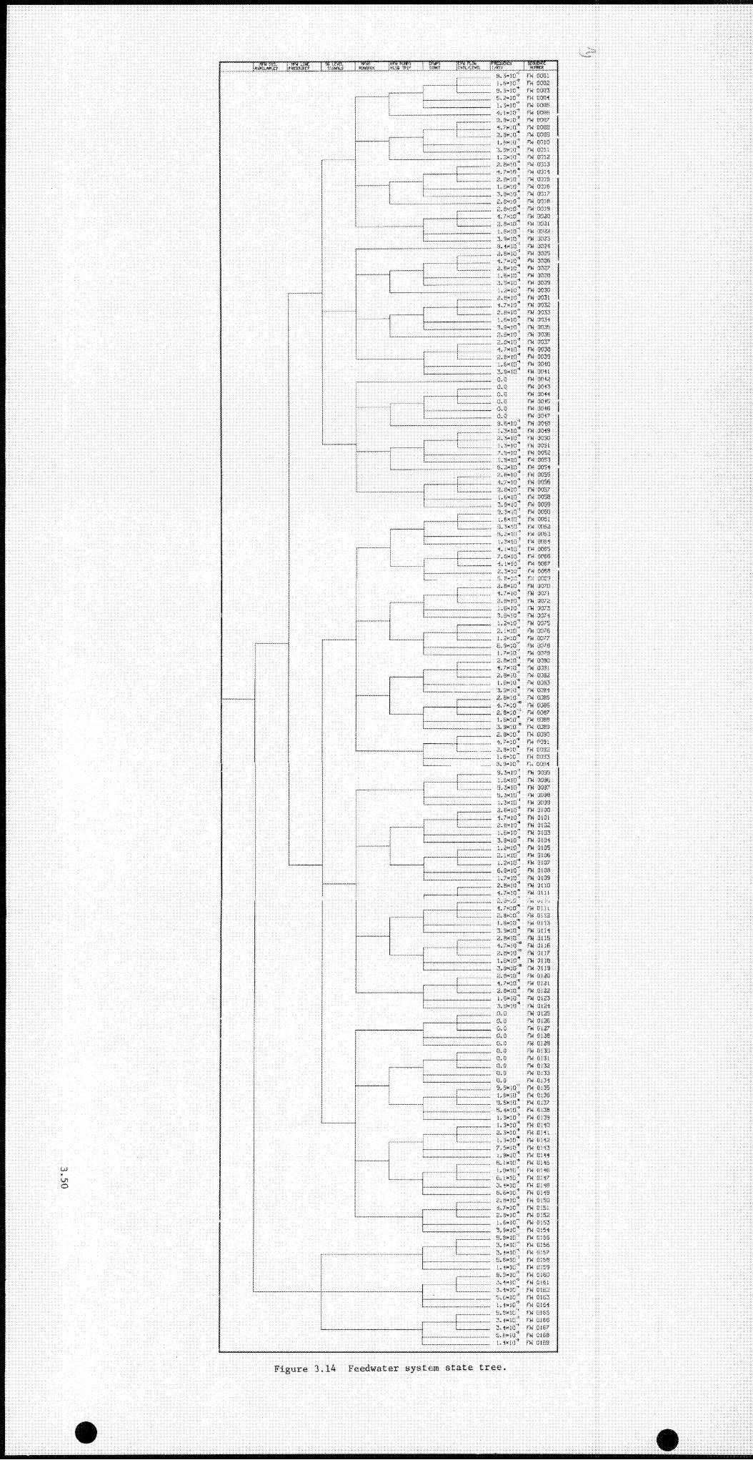
■'tnmr g .....
u io
...................... S.'i-JO’’ fri 8051Tii 805S........... ..........
.............. a.S-K:'’ >'fi 0053in"’ Hi 80331
i.rivjo'* FB 80S3S<;.!><! o'’ F'3 ooirn0. a«:o'’ m 80333'
............... < .7k:o'’ Fil 80333;................ 3,3xiCj'* PW 5033S
PW 5038............. .............. ........ :l :)x yn 0031.. ......... i r yn 5032
7. iix-iO'* •'■■4 0033............ r'H 5038
0, axis'’ !'« 5038uaxiB '’ r« 003 S
axis'* •■11 5;317................... 0 ,»x i3 '’ m O’Oia
................. ixSxiO'* r,i d s is.................. . a. /'xia"' r,1 8820
a .a x o i’’ fH ••821l.SxiO'’3. SaiJO'’ n'i ■ias:5
..................... S.-ixjO'’ 2034
................ . 3 .sx te '' 5335:
..................... Oi-; 5335
..................... 2 ,«xi0 '’ m 5337
..................... '.QXiO'’ ri'i 5333
..................... ■.S.'jxJB'’ m 0333
...................... i.iixJC'’ rw 00^3S.XMlii’’ • m 0331
....... mO.'ixin'’ ■ r'K' S3:i 1i.P.-xtc'’ C3Ho.sxiO''' 33;«i.O.ilxiC'’ fu ?3;;3
............. ,.,,.. S,5xJij'* rw'3337...................... x, 7x (f)'* m Q30S..........:.......... ii.SxjC’' fvi 3303........... :......... n>i 33'13
... x.Sxif!"’ m 33^1CiS
.......... 0,0 m 03^5. ■
........... ..........;: 0 ,0 m "03-<4 ■0.0 rw 03' 5' '
......... ......:... 0 .0 m- 53 * 30 ,0 m 33^7
................ . SiOxse"’ rn 03-J3 ■I....,...,:.!....:. i,0i><3o'’ i ■■'W ■03• 3 :^......,....... . 0,0i*30'* m OOS3':'............. . i i ix jo '’ rw oos-i.................. 0’ ,S"30'’ 7W'035a'.. i,sx)i5'* rw;''s353. '..........OiOXJO'’ •rw 033i, ..... . .iOSOjcd' m 33S5
....... 0,0x30'’SiJixJO'’'- m 3357i.BMtO'O 'm'.C303'
................ 3,SxiQ'* Bi . 0353
..................... s . rwiO'’ B 3303
................ l.gx iii'’ B ' 1535!0. Ox'-!"’ f'w ■S.O xii:’ fw 535;5i.S x tn ’’ B 53&a. i Kin"’ rw 53$57,0x10'' fw 53S3
i 4 . (K10' fw QG&7i . . ...................... ^.Ox;,!' fW' 03SS ■U - .... 5.9»3£i*
.................... o.oxm'*B 03S3
0373..................... ■3,;'x33:'’ f'3 0371
O.S.xiO'’ i'U 0373...................... i.i-x io '’ l'3 0377
................... ;?.,3-xi!3'’ IB 03741.7x13'* B Q373 ■
o. ix'iOi'’ B •1375..................... ) . ox.i.a’' f'rt UCJ77
fi. SkTO'' B; 5373t . 7x:n'' B; 53?3■7. 0x10"’ m 03S3
B 03-21a.oxoi"*■7.0X10'* B 0335
..................... I.RX’O'’ B 0335
..................... 3> ■ixis'' rB 3-:?3-37. axis'’ IB 3I1334. 7X113'” ■B 35S3
] 3,0x10'“ B 3037] 1,0x10'’ P4 3-388[ •,.0x10'” TH 3333
3. OXIO’ rn 35S30,7x;0'' B 3031
.................... .ii,8»;ct'* Yri im 2...................... !,ti»:o'’ I'li 0333'
...... 0,»"3C'’0.7-xlf!'*
03:HB 0053
I>6x'i0'’ B ' 0003! ................... 9,3x:sfi'' B 00071 ...................... S.3*7!i''’ B U0S3: B 5330
.3.0x10'** B 5300__ _____ 8,7x30'’ 7H 0101
• ...................... 0,x»3C'’ m 0103i .................... 1,H»iO'* B 0153: ,O..Sxifl'’ B 0154
..................... 1, axis'* B 0103B - 0:105
i B 5307Bl 530>3
..................... i,;'»30'* rn 0103, .................. ,. a.swiij** IB 0110
0.7x10'’ IB 0113:.......... _ XvOxiCi'’. . . . . . . .. .. •l.ixICl” ■B Oil 1:
1 ............. .. 8<oci' •B 01121 ................ . . s'. OxlCi'’* Bi 5315j ____ 2.3X10'’ BJ 5314
..................... 2. RxiO'* B CHS
..................... 0<?x;t3'” B 0110
..................... 2.Sxi!3'" IB 0117t.Sxin '’ B 01133,.sxin'*“ B 0U 3
................. . ;:,8xiCi'’ B 0330
..................... 8 .7«lCi'* B 3131
i........................................ 3.8X10'’..................... 1 .8X10'’..................... O.lixiiS'*
B G132 B 0123 IB 0157
fl.i! B 015Sfi, n B 015S0. n B 0337
B 01300. 0..................... Ci, 0 .B £1330
...............0 .0 B £13'.}il0.11 7>3 3-3 310.11 ryS 03 330 .0 B 03350 .0 B 0:34
.,,................. 5,Sxi.3'* B 0135
..................... I.Sxir.l'’ B 0136
..................... i3,Sx1:3” B 013^
..................... 0,4X10'’ IB 0-!,361 ,ax is'’ B 0130i.axirt'* B 014:3
...................... i!,'JX3Cl'* IB OHl •
...................... ;,1>x30'' B £l:4:i7 . Ox 10'* B 0343
..... .............. 1,8x10'' B 0144..................... B, ixKi” IB 0140..................... i.ttxin'' IB 33146
B, ■ xin B 01-4? rn 0148.2 . xxio"*
.................... .0 . fixio'’ m 0143................. a.SKic'* B OBI
X. 7x10'’ B 01013.0x10'’ B oio:i1 .0x10'* B 0353'3,8x10'’ B 0354
..................... if, 8x11! ' B 0365
..................... 5. jxlli "* B 0366....... 3, ixlG * B 03 6 7
0,0x10'’ B ' QiiS: ,x x ir ” B QiZS
.................3,3x30'’ m 5100
...................... .3,x»30'’ B ClOl
.............. 3.8x30'’ B Cl Oil0.P,X'30'’ B 0153
_______ l . ix lS '” B 5364O.SXII:'* B 53662. axlfi"’ B 51863.1X30'’ B 5157
..................... 5. Sxii3’’ l'« 0156
............ ........ 1,1x113'’ I*i4 0150
Figure 3<14 Feedwater system <state tree.

3.4.4 Quantification of the Primary Loop ECCS System State Tree
3.4.4.1 High-Pressure Injection System Activates on Demand
STATE 0: P = 1.0 - P(State
STATE 1: NHREG/CR-2497 provides a probability for HPI system failures_3
on demand of 1.3 z 10 /demand. HPI unavailabilities at the
pump/train level observed at Oconee between April 1978 and
September 1981 (41 plant-montbs) include:
Oconee Unavailabilitv Date
3 train B 11/78
3 train A 4/78
2 pump A 2/81
2 pump B 1/81
2 pump B 11/80
2 pump B 7/80
2 pump B 7/80
Assuming these seven failures to be unconnected (this is.
in actuality. probably not so with the four Oconee 2 pump
B failures) on both a train and pump basis results in the
following unavailability estimates:
7/(41 mo z 2 trains/plant z 3 plants) == 0.028
and
7/(41 mo z 3 pumps/plant z 3 plants) = 0.019
3 . 5 1

With only one train or pump required for success, one can
derive system failure probabilities of 0.028 (first train)
X 0.1 (second train x failure given failure of the first
train) = 2.8 x 10 /demand
and
0.019 (first pump) x 0.1 (second pump x failure given
failure of the first) x 0.3 (third pump x failure given—4
failure of the first and second) = 6 x 10 /demand. These
values are consistent vith the NUREG/CR-2497 value of 1.3 x-310 /demand, which was used in this analysis.
3.4.4.2 Core Flood Tanks Discharge upon Demand
STATE 0: P = 1.0 - P(State ^)
STATE 1: Since the CFT system is a passive one, the failure
probability is assumed to be dominated by the failure of
either check valve connecting the CFTs to the downcomer to
open on demand. This is assumed to be 4.0 x 10 ^ for at
least one check valve in each line.
3.4.4.3 Low-Pressure Safety Injection into Downcomer Initiated
STATE 0: P = 1.0 - P(State ^)
STATE 1: A value of 4.5 x 10 ^ for the unavailability of the LPI
system (given CFT successful operation) is assumed.
3.52
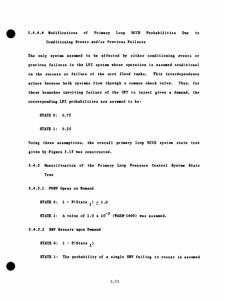
3.4.4.4 Modifications of Primary Loop ECCS Probabilities Due to
Conditioning Events and/or Previous Failures
The only system assumed to be affected by either conditioning events or
previous failures is the LPI system whose operation is assumed conditional
on the success or failure of the core flood tanks. This interdependence
arises because both systems flow through a common check valve. Thus, for
those branches involving failure of the CFT to inject given a demand, the
corresponding LPI probabilities are assumed to be:
STATE 0: 0.75
STATE 1: 0.25
Using these assumptions, the overall primary loop ECCS system state tree
given by Figure 3.15 was constructed.
3.4.5 Quantification of the Primary Loop Pressure Control System State
Tree
3.4.5.1 PORV Opens on Demand
STATE 0: 1 - P(State ,) ~ 1.01 ~
STATE 1: A value of 1.0 z 10 ^ (WASH-1400) was assumed.
3.4.5.2 SRV Reseats upon Demand
STATE 0: 1 - P(State
STATE 1: The probability of a single SRV failing to reseat is assumed
3.53
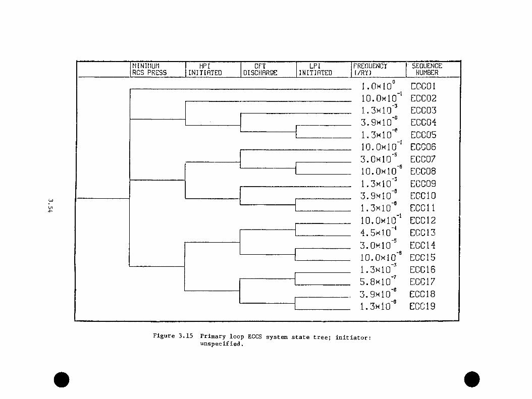
MINIMUn HPI CFT LPI FREOUENCT SEQUENCERCS PRESS INITinTED DISCHflRQE INITIflTED (/RY) NUMBER
I.OhIo”10.0m10‘‘
CCCOlECC02EG003
3.9x10"' EC0041.3h10"'lO.Oxlo"'
ECC05ECC06
3.0x10'' EC007lO.Oxlo'® E0C081.3x10"' ECC093.9x10'® ECO 101.3x10'® ECCll10.0x10' ECC 124.5x10' ECC 133.0x10'® ECC 14lO.Oxlo'® ECC 151.3x10'® ECC 165.8x10'' ECC 173.9x10'® ECC 181.3x10'® ECC 19
Figure 3.15 Primary loop ECCS system state tree; initiator;unspecified.
—2to be 1.0 X 10 /demand. Since tbe Oconee 1 plant has two-2SRVs, a probability of 2.9 x 10 is used.
3.4.5.3 PORV Reseats upon Demand
STATE 0: 1 - P(State = .973
STATE 1: NIJREG-0560 reports four failures of the PORV to close when
expected, once it had opened, in approximately 150 demands._2This results in a failure probability of 4/15 = 2.7 x 10
Using these assumptions, the overall primary pressure control system state
tree given by Figure 3.16 was constructed.
3.55
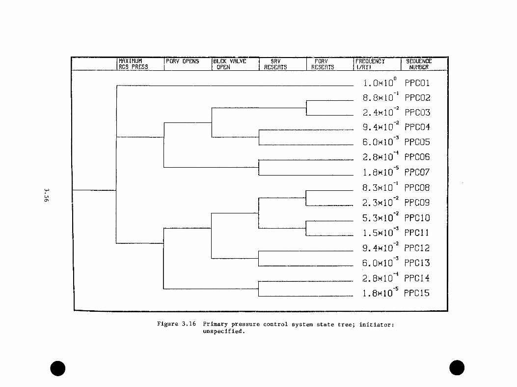
mXIMUMR c s p r e :s s
PCRV OPENS BLOK VRLVE OPEN
SRVRESEATS
PORVRESEPTS
FREQUENCYt/R Y )
SEQUENCENUMBER
Ln0\
PPCOl8.8xl0"‘ PPC022.4h10'' PPC039.4k10‘" PPC046.0x10"" PPCG52.8x10"* PPC061.8x10'' PPC078.3x10'* PPC082.3x10'" PPC095.3x10'" PPG 101.5x10'' PPCll9.4x10'" PPG 126.0x10'' PPC132.8x10"* PPG 141.8x10'' PPC15
Figure 3.16 Primary pressure control system state tree; initiator:unspecified.

3.5 TRANSIENT CATEGORIZATION
To reduce tEe potentially large nnmber of end-states (6,9335,760) that
result from the combination of the four system state trees (SPG, FWS,
ECC, and PPG), it is useful to group transients with similar thermal-
hydraulic behavior into categories. The individual end state frequencies
can be summed to give a category frequency and a representative transient
selected to estimate the conditional probability of vessel failure, given
the occurrence of the transient. The categories were chosen largely on
the basis of the operator action involved, but all were not monotonically
increasing in PTS severity. The following categories have therefore been
defined:
3.5.1 Secondary Pressure-Gontrol System (SPG)
GATEGORY 0: No significant thermal-hydraulic effect. This category
accounts for those transients in which either no
malfunctions take place or in which a malfunction does
occur but does not affect the course of the transient.
An example of the latter case is that of a 16V failure
to open on demand, but where the SSRVs operate to limit
the secondary side pressure.
CATEGORY 1: This category is appropriate for those transients
involving a nonisolable break in a single steam line.
Typically, breaks in the steam line upstream of the TSVs,
or stuck-open SSRVs, fall in this category.
3.57
CATEGORY 2: Tliis category involves those transients in which an
isolable break is present in a single steam line. This
category is typified by a stnck open TBV (isolable by the
turbine block valves) or a steam line break downstream of
the TSVs.
CATEGORY 3: This category involves those transients in which both
steam lines are subject to depressurization due to a
secondary pressure-control malfunction and neither steam
line can be isolated from the break(s). An example of
this category is a transient involving a stuck open SSRV
on each steam line (perhaps because of a common-cause
effect).
CATEGORY 4: This category accounts for those transients in which both
steam lines are involved but in which one can be isolated
from the break(s). It thus combines malfunctions of
Categories 1 and 2.
CATEGORY 5: This category accounts for those transients in which both
steam lines are involved and in which both steam lines
can be isolated from the break(s). An example of this
category is a transient involving a stuck-open TBV on
each steam line.
CATEGORY 6: This category is a catchall to account for those
transients (end-states) that cannot be characterized
3.58

by Categories 0 tbrongb 5 and that mnst be examined
individually to determine the thermal-hydraulic response.
3.5.2 Feedwater System (FWS)
CATEGORY 0: No significant thermal-hydraulic effect. An example of
this category would be a transient in which the HFW
system is lost on an attempted runback together with the
operation of the EFW system as designed.
CATEGORY 1: This category accounts for those transients that involve
an unsustained NFW overfeed. That is> an MFW overfeed
is terminated by the high SG level trip system.
CATEGORY 2: This category accounts for those transients that involve
a sustained HFW overfeed, typically because of a failure
of the high-level trip system.
CATEGORY 3: This category accounts for those transients that involve
an overfeed by the EFW system. Thus, it also includes
those transients in which a MFW overfeed has taken place
(either sustained or unsustained) together with an EFW
overfeed.
CATEGORY 4: This category accounts for those transients in which all
feedwater (HFW and EFW) is lost to the steam generators.
An example transient in this category is one in which the
HFW system is lost on an attempted runback and the EFW
system fails to initiate.
3.59
3.5.3 Emergency Core Cooling System (ECCS)
CATEGORY 0: This category accounts for the transients in which no
ECCS failures occur. An example of this category is one
in which no demand for the ECCS function is made (i.e.,
primary system pressure remains above the HPI set point
of 1500 psi).
CATEGORY 1: This category is comprised of those transients in
which the HPI system fails to initiate upon demand.
Although HPI failure effectively prohibits system repres-
surization, the HPI failure can cause a demand for the
CFT and LPI systems (which inject directly into the
downcomer), which is a potential PTS concern. Moreover,
the possibility of operator action to restore the HPI
function must be addressed.
CATEGORY 2: This category accounts for multiple failures within the
ECC system, such as HPI and CFT failures.
3.5.4 Primary Pressure (k>ntrol System (PPC)
CATEGORY 0: This category is characterized by no failures within
the primary pressure control system (i.e., the PORV and
SRYs).
CATEGORY 1: This category involves those breaks in the primary
coolant system which can be isolated. An example of this
3.60

is a stnck-open PORV that can be isolated by the block
valve dovnstream.
CATEGORY 2: This category involves those primary system break that
are not isolable, such as a stnck-open SRV or a small
break in one of the coolant legs.
As a notational convenience, transients are identified by four category
numbers, ordered as follows: SPG, FWS, ECC, and PPC. Thus, a transient
designated as (1,3,0,1) indicates SPC Category 1, FWS Category 3, ECC
Category 0, and PPC Category 1, and can be described as a nonisolable break
in one steam line coupled with an EFW overfeed and a failure of the PORV.
3.6 Initiator-Specific System State Tree Construction
To employ the methodology outlined in the previous sections, a initiator-
specific system state tree must be constructed for each initiator of
interest. This construction consists of specifying conditioning event
states appropriate for the initiator for each of the four system state
trees, combining the four system state trees into an overall system state
tree that describes the asymptotic end-states that remain possible, pruning
those end states whose frequency is below the cutoff value (taken as
l.Oe-06/RY in this study) from the overall tree, and finally evaluating
the effect of operator actions by which the frequency (and in some cases,
the possibility) of various end states can be altered. The initiators
considered in this study are listed in Table 3.5. For each initiator
listed, an overall system state tree was constructed and evaluated, and
this procedure will be discussed in the following sections.
3 . 6 1
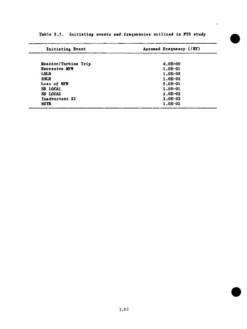
Table 3.5. Initiating events and frequencies utilized in PTS study
Initiating Event Assumed Frequency (/HI)
Reactor/Turbine Trip 6.0E+00Excessive MFW l.OE-01LSLB l.OE-03SSLB l.OE-02Loss of MFW 5.0E-01SB LOCAl l.OE-01SB L0CA2 l.OE-02Inadvertent SI l.OE-02S6TR l.OE-02
3.62
3.6.1 Re act or/Turbine Trip
3.6.1.1 Initial Coxiditions and Conditioning Event Assumptions
The initial conditions for this initiator assianed that reactor power is
greater than 45% and that the decay heat capability of the core was
approximately the ANS standard. Based on the specified initial conditions,
the following conditioning event assumptions were made:
1. Following the trip, the steam line pressure in both steam
lines will be sufficient to challenge both the turbine
bypass system and the secondary-side relief valves (at least
momentarily). Thus, the high SL pressure branches for both
steam lines on the SPC system state tree are activated.
2. The HFW system is operating with both HFW pumps on-line,
and in the absence of any secondary side pressure control
difficulty, the HFW line pressure will remain above the EFW
initiation set point. If any secondary pressure-control
valve fails to reseat (either a TBV or a SSRV), it is
assumed that the MFW line pressure will decrease below
the EFW set point (725 psi). Further, should a secondary
side depressurization take place, it is assumed that such a
depressurization will not be rapid enough to induce a false
high-level signal from the instruments. Therefore, it is
assumed that the SG level signals are nominally correct for
all cases.
3.63

3. With regard to the ECC system, it is assumed that, if
no secondary~side depressurization or overfeed occurs, no
demand for an ECCS response vill be made. If either a
depressurization or an overfeed takes place, it is further
assumed that only the HPI system will be demanded.
4. It is assumed that the PORV block valve is closed 50% of the
time. This assumption is conservative in that it forces the
safety valves to open more frequently. The safety valves
cannot have block valves, and thus a failed-open safety
valve is a nonisolable break.
Since this is the first initiator to be discussed, it is useful to observe
the effect of these conditioning event assumptions on the four system
state trees. The four trees are given by Figures 3.17 through 3.20. As
indicated in assumption 2 above, two FW system state trees result from the
depressurization/no-depressurization cases.
3.6.1.2 Reactor/Turbine Trip System State Tree
Combining the four system state trees given by Figures 3.17 through 3.20
results in an overall reactor trip system state tree comprised of 448 end-
states with frequencies greater than l.OE-06. Additionally, the end states
eliminated in the pruning process represent an additional frequency of
1.9E-04. As an alternate perspective, the surviving end-states have been
grouped according to the system (or systems) that malfunctioned during the
transient. These results are presented in Table 3.6. As expected, the case
of no malfunctions clearly dominates in terms of frequency of occurrence.
3.64
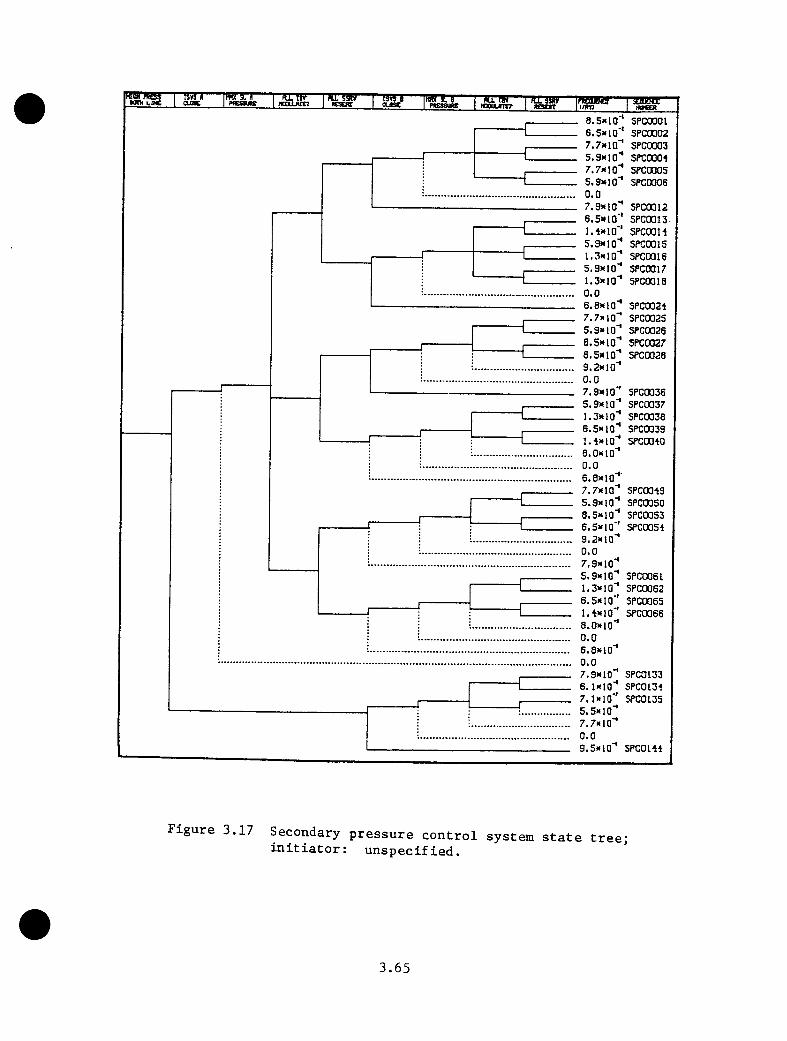
nira'WKI KWH LBC cuac n trw"'I ngm jrt? ■ a r s R — “ T3«T--- IMIJL8 “ STTB?— i m a j —ftCSCRTKSEX oasc 1 piEsajRC nouuinr TBBBS"i/»n
8. Sal o'* SPCOOOl6.5*10'' SPC00027.7*10'* SPC00035.9*10'* SPCOOOl7.7*10'* SPC0Q055.9*10'* SPC00060.07.9*10"* 5PC00126.5*10" SPC0013l.'talO" SPCOOH5.9*10" 5PC00151.5*10" SPC00165.9*10" SPC00171.3*10" SPC0Q180.06.8*10" SPC00217.7*10" SPC0Q255.9*10" SPC00268.5*10" SPC00276.5*10" 5PC00289.2*10"0.07.9*1 O'* SPC00365.9*10" SPC00371.3»10" SPC00386.5*10" SPC0039i.-t*io" SPCOO-tO8.0*10"0.06.8»10"7.7*10" spcoo-tg5.9*10" SPCOQSO8.5*10" 5PC00S36.5*10'' SPCOQSO9.2*10"0.07.9*10"5.9*1Q" SPC00611.3*10" SPC00625.5*10" SPC0Q65l.t*10" SPC0Q668.0»10"0.06.8*10"0.07.9*10" SPCG1336.1*10" SPC01347.1»10" 5PC01355.5*10"7.7*10"0.09.5»10" spcom
Figure 3.17 Secondary pressure control system state tree; initiator: unspecified.
3.65
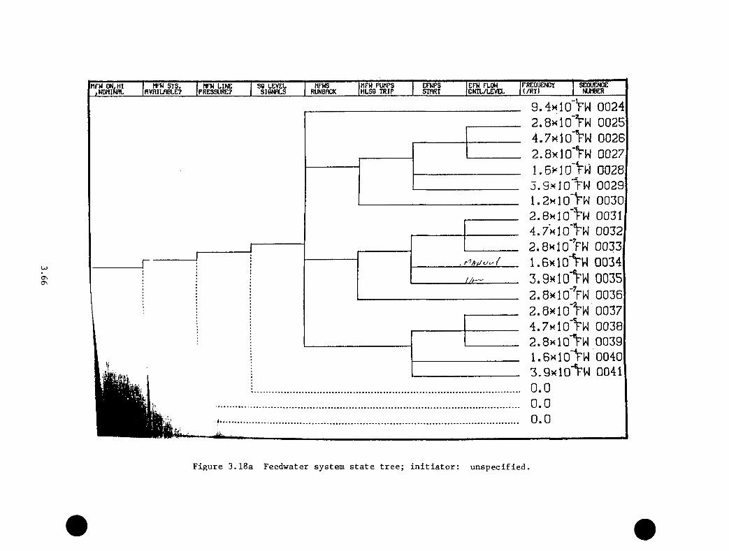
HFHS HFW PUMPS EFHPS EFW FLOW FREQUENCY SEQUENCERUNBRCK HLSQ TRIP STRRX CNTL/LEVEL t/RY) NUMBER
ONCT
HFH SYS. RVfllLflBLE?
MFH ON, HI ,NWlNfi MFH LINE PRESSURE?
SG LEVEL S19NHLS
_ 9.4h 10‘V w 0024_ 2.8xlO'Vw 0025_ 4.7xlO'VW 0026_ 2.8xlO’Vw 0027_ 1.6> 10‘Vw 0028. 3.9x10 rw 0029
1.2xlO‘Vw 00302.8xl0'i^W 00314.7’kIO'Vn 00322.8k 10>W 0033l.BxlO’Vw00343.9x10* ^ 00352.8xlO'^rW 00362.8xlO''rW 00374.7xlG'^W 0038
. 2.8xlo1^W 0039
. i.exio’Vw 0040
. B.QxlO'Vw 0041. 0*0. 0.0
0.0
Figure 3.18a Feedwater system state tree; initiator: unspecified.
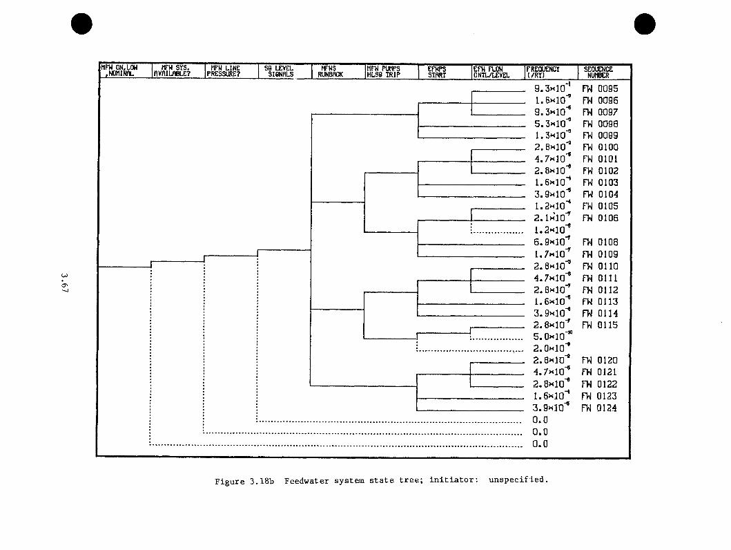
MFH ON.LOH .NOHlNflL
MFH SYS. HFH LINE S0 LEVEL HFHS MFH PUMPS EFHPS EFH FLOH FREQUENCIfiVfllLflBLE? PRESSURE? SI6NRLS RUNBfICK HLS8 TRIP SIRRT CNTL/LEVEL (/Rt) SEQUENCENUMBER
O'
9.3h]0''
e.SHio"*5.3»<1Q^1.3«10'^2.8x10'*'4.7x10'®2.8x10'®i.exio"®3.9x10'®1.axio"®2. Ix'lO'® i.axio"®6.9x10'®1.7x10"®2.8x10^'4.7x10'*2.8x10"®1.6x10'®3.9x10'®2.8x10"®5 .0 x 1 0 '”2.0x10"®a.exio"®4.7x10"®2.8x10'®i.exio"*3.9x10"*0.00.00 . 0
FW 0095FW 0096FW 0097FW 0098FW 0099FW 0100FW 0101FW 0102FW 0103FW 0104FW 0105FW 0106
FW 0108FW 0109FW 0110FW 0111FW 0112FW 0113FW 0114FW 0115
FW 0120FW 0121FW 0122FW 0123FW 0124
Figure 3.18b Feedwater system state tree; initiator: unspecified.
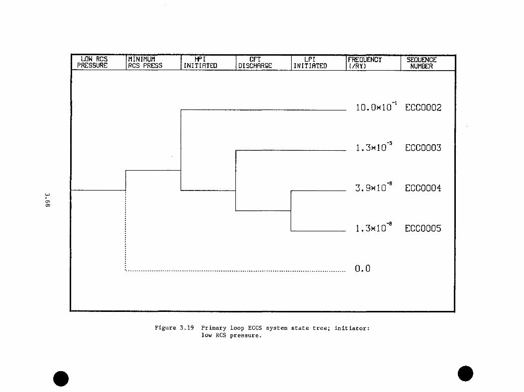
LOW RCS MINIMUM HPI CPI LPI FREDUENCy SEQUENCEPRESSURE RCS PRESS INITIATED DISCHARGE INITIATED (/RY) NUMBER
ON00
10.0><i0"‘ ECC0002
ECC0003
3.9k10'® ECC0004
1.3K10 ECC0005
0.0
Figure 3.19 Primary loop ECCS system state tree; initiator: low RCS pressure.
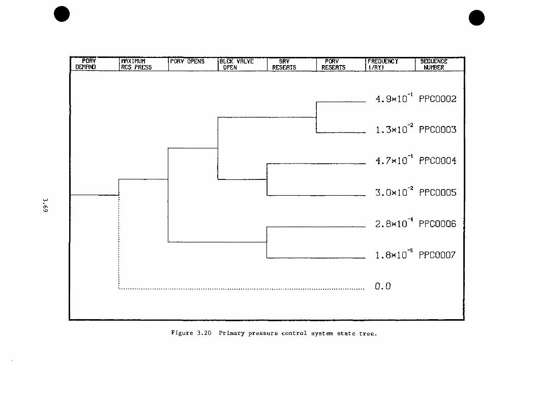
PORVDEMRND
mXIMUM RCS PRESS
PORV OPENS BLCK VRLVE OPEN
SRVRESERTS
PORVRESERTS
FREQUENCYl/R Y )
SEQUENCENUMBER
VD
4.9x10 PPCGGG2
,-21.3x10 PPCGGG3
4.7x10 PPCGGG4
3.0x10"" PPC0005
2.8x10"* PPC0006
1.8x10"' PPC0007
0.0
Figure 3.20 Primary pressure control system state tree.
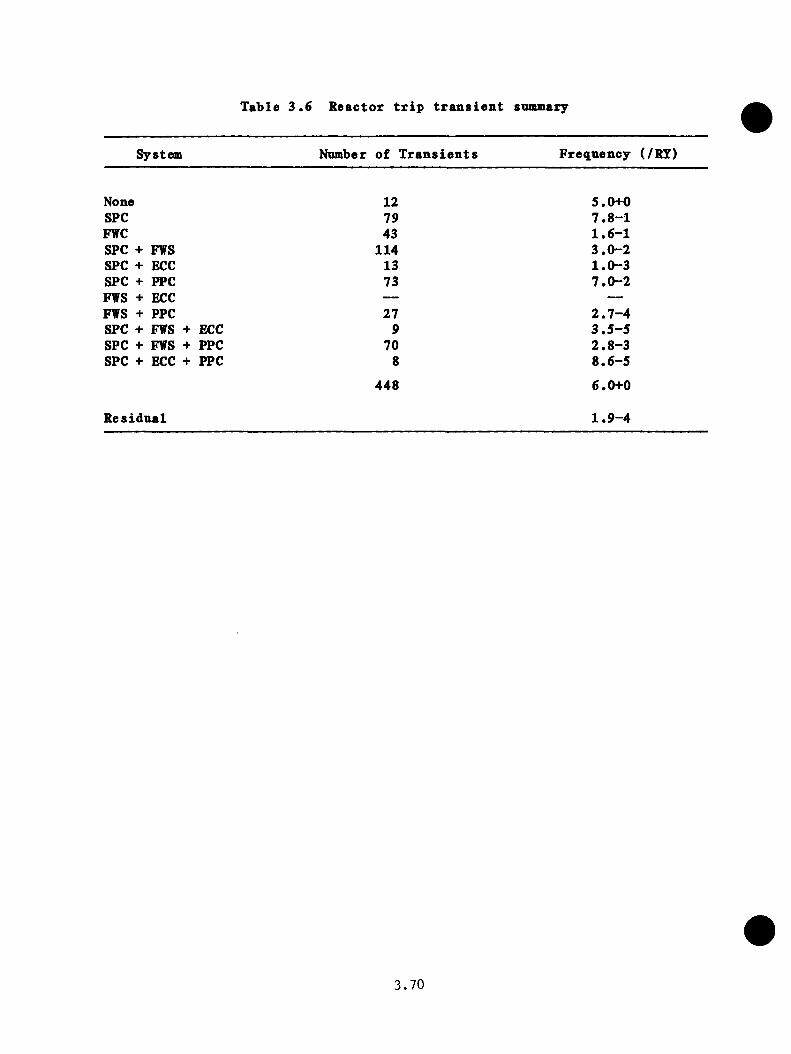
Table 3.6 Reactor trip transient snmmary
System Number of Transients Frequency (/RY)
None 12 5.0+0SPC 79 7.8-1FWC 43 1.6-1SPC + FWS 114 3.0-2SPC + ECC 13 1.0-3SPC + PPC 73 7.0-2FWS + ECC — —FWS + PPC 27 2.7-4SPC + FWS + ECC 9 3.5-5SPC + FWS + PPC 70 2.8-3SPC + ECC + PPC 8 8.6-5
448 6.0+0
Residual 1.9-4
3.70
In terms of nnmber of end-states, the transients involving malfunctions
of both the secondary pressnre control and feedwater systems are the most
numerons. Further, the transients which involve only a SPC malfunction are
the most likely of those transients that involve malfunctions. A complete
list of all transients for this initiator is given in Appendix A, Table
A.l together with the classification of each transient into an appropriate
category.
3.6.2 Excessive EFW: Initial Conditions and Conditioning Event Assumptions
The initial conditions assumed for this initiator are reactor power greater
than 45% and the ANS standard decay heat. Based on the initial conditions,
the following conditioning event assumptions were made:
1. Eventual reactor trip on either low RCS pressure or
unbalanced primary thermal-hydraulic parameters.
2. Following the reactor trip, assumption that the pressure in
both steam lines is sufficient to challenge the secondary
side relief valves.
3. MFW system operating with both MFW pumps on line. In the
absence of a secondary side depressurization due to a stuck-
open valve, it is assumed that the MFW line pressure remains
above the EFW initiation setpoint.
4. The primary-side pressure, assumed to decrease (due to the
MFW overfeed) to below the HPI set point, but to remain
above the CFT set point.
3 . 7 1
s . Assumption that the PORV block valve is closed 50% of the
time.
3.6.3 Large Steam Line Break (LSLB): Initial Conditions and Conditioning
Event Assnmptions
The assumed initial conditions are reactor power greater than 45% power
and ANS standard decay heat. The size of the large steam line break is
assumed to he sufficient to depressurize the steam generator to below the
EFW initiation point. Based on these initial conditions, the following
conditioning events were selected:
1. Low SL pressure in the broken steam line to the extent that
neither the relief valves nor the IBVs are challenged. It
is assumed that the pressure in the unaffected steam line
following the reactor trip is sufficient to challenge both
the secondary relief valves and the turbine bypass valves.
2. NFW system is on, but MFW line pressnre decreases to below
the ERW initiation point.
3. Minimum primary system pressure between 610 and 1500 psi.
4. PORV block valve closed 50% of the time.
3.72
3.6.4 Small Steam Line Break
Initial Conditions and Conditioning Event Assnmptions
The initial conditions assumed are reactor power greater than 45% and
ANS standard decay heat. The size of the steam line break is assnmed
to be insufficient to depressurize the steam generator to the EFW
initiation point. Given these assumptions, the following conditioning
event assumptions were made:
1. Steam line pressure in the affected steam line is low enough
not to challenge either SSRVs or IBVs. Pressure in the
unaffected steam line is sufficient (following reactor trip)
to challenge both the SSRVs and the IBVs.
2. MFW system is initially on line; the depressurization caused
by the steam line break is not sufficient to initiate the
EFW.
3. Minimum RCS pressure reached is between 610 and 1500 psi
(only HPI system demanded).
4. Maximum RCS pressure is sufficient to challenge both the
PORV and the SRVs.
5. PORV block valve is closed 50% of the time.
3.73
3.6.5 Loss of MFW (LOHFW): Initial Conditions and Conditioning Event
Assnmptions
The initial conditions for the LOMFW initiator are reactor power greater
than 45% and the ANS standard decay heat. A trip of the NFW pnmps at the
start of the transient is assnmed. Based on the initial conditions, the
following conditioning event assnmptions were made:
1. Steam line pressure in both steam lines (following reactor
trip) sufficient to challenge both the relief valves and
turbine bypass system.
2. MFW system is unavailable.
3. Primary-side pressure is assumed to be sufficient (given a
failure of the EFW system to initiate) to challenge both the
PORV and the code safety valves.
4. No ECCS demand is assumed if a secondary-side overfeed does
not occur. Given an overfeed, it is assumed that only the
HPI system is demanded.
5. The PORV block valve is closed 50% of the time.
3.6.6 Small Break LOCA 1: Initial Conditions and Conditioning Event
Assumptions
The initial conditions assumed for this initiator are reactor power greater
than 45% and ANS standard decay heat. The size of the break is assumed to
be large enough to depressurize the primary system below the HPI set-point.
3.74
Additionally, it is assumed the break is small enough that the HPI system
is capable of repressnrizing to the PORV/SRV set-points. Based on these
specifications, the following conditioning event assnmptions were made:
1. Reactor trip on low RCS pressnre.
2. High steam line pressnre in both steam lines following the
reactor trip. Both SSRVs and TBVs are challenged.
3. MFW system operating. MFW line pressnre greater than 725 psi
for cases with no secondary pressure control malfunctions;
less than 725 psi for any secondary pressnre control
malfunction (TBVs or SSRVs).
4. Only the HPI system will be demanded.
5. PORV block valve closed 50% of the time.
3.6.7 Small Break LOCA 2: Initial Conditions and Conditioning Event
Assnmptions
The initial conditions assnmed for this initiator are the same as for the
smal 1-break LOCA 1 case. However, the size of this break is asstuaed to
be large enough to prevent the HPI system from repressnrizing the primary
to either the PORV or SRV set points. The following conditioning event
assnmptions were made:
1. Reactor trip on low RCS pressnre.
2. High steam line pressnre in both steam lines following the
reactor trip challenging both the TBVs and the SSRVs.
3.75
3. NFW system operating. NFW line pressnre remains greater
than 725 psi if no secondary depressurization occnrs.
4. Only the HPI system is demanded.
3.6.8 Inadvertent Safety Injection (SI): Initial Conditions and
Conditioning Event Assumptions
The initial conditions assumed are reactor power greater than 45% and ANS
standard decay heat. The following conditioning event assumptions were
made:
1. Reactor trip on high RCS pressure.
2. Nazimum steam line pressure in both steam lines. Both TBVs
and SSRVs are challenged.
3. NFW system operating. NFW line pressure greater than 725
psi for no secondary-side depressurization.
4. Nazimum primary-system pressure— both PORV and SRVs chal
lenged.
5. PORV block valve closed 50% of the time.
3.6.9 Categorization of Initiator-Specific Asymptotic Transients
Table A.l (Appendiz A) summarizes the relevant information for the 1013
initiator-specific asymptotic end-states that survive the pruning process.
In particular, each transient is described by a sequence number (which
is the position of the particular transient in the set of 6,935,760
3.76

possible transients) and four system state branch descriptors that delineate
the particular system state tree end-states reached for the transient.
Additionally, the estimated asymptotic event frequencies are tabulated.
Finally, the system state categories appropriate for each transient (based
on the particular system state end-states) are listed. Examination of
all the transients vill reveal that certain category groupings occur more
than once. Hence, in order to reduce the number of transients to a more
manageable level, transients with identical categorizations were combined.
The transients thus obtained are given in Table A.2.
3.7 Effect of Operator Actions
As discussed previously, it is necessary to construct an operator action
tree detailing those operator actions that significantly affect the thermal-
hydraulic behavior of the system for each unique end-state. Hovever, in
keeping with the categorization of the end-states, it is assumed that an
operator action tree constructed for a representative transient in the
category can be applied to all transients in the category.
As noted in the discussion of conditioning events, it is assumed that any
secondary-side depressurization or overfeed vill lead to a demand for the
HPI system because of lov primary system pressure. Thus, for SPC Category
1 transients, the first relevant operator action is the trip of the reactor
coolant pumps on the valid ECCS demand signal. This action is particularly
important on B6W plants because the trip of the RC pumps permits the vent
valves to function in a manner to mitigate the cooldovn of the vessel.
On diagnosing the problem as a secondary— side rupture or excessive steam
demand, the next relevant step is the isolation of both S6s as called for
3.77
in the procedure. Once the broken secondary loop has been identified, the
next action is the restoration of feedwater to the unaffected loop (and
hence the restoration of the secondary heat sink). The remaining relevant
operator actions consist of throttling the HPI system and the restart of
one RC pump per loop when a SO^’f snbcooling margin has been attained.
Since a detailed task analysis of the relevant procedure was not performed,
generic human error probabilities (HEPs) were used to estimate the
mitigative potential of the generator. For most actions a HEP value of 1.0-2X 10 was employed for the first error in a sequence. The HEP for each
succeeding error was obtained by doubling the previous value. For certain
specific actions for which extensive training had been accomplished (such
as the trip of the RC pumps on a valid ECC signal), a HEP value of 5.0-3X 10 was employed. It should be noted that each operator action requires
that a time interval be associated with it. The generic probabilities
discussed above are based on operator action within a 10-min time frame
except for the RC pump trip in which it is assumed that a 30-s time frame
was sufficient for operator action, if it was to be taken at all.
The operator action tree, constructed using the above assTimptions, is
depicted by Figure 3.21 and is strictly appropriate to only Category
(1,0,0,0) transients. However, it is observed that PSC02 transients differ
only in the fact that the break can be isolated (e.g., a stuck-open TBV
versus a SSRV). It should be noted, however, that a successful isolation
of SGs will result in similar conditions in both steam lines (due to the
closure of the turbine bypass valves), which will make the diagnosis of
3.78
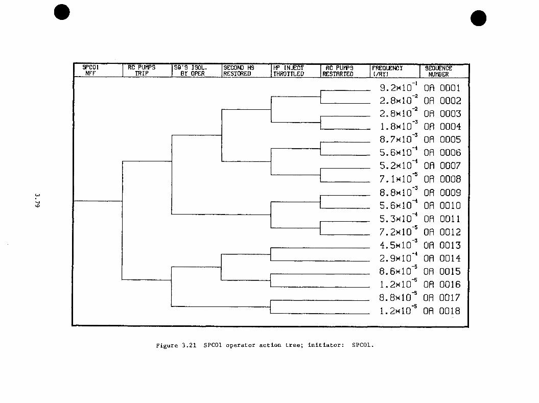
SPCO l RC P U IF S S O 'S IS O L . SECOND HS HP IN JE C T RC PUMPS FREQUENCY SEQUENCENFF T R IP B r OPER RESTORED THROTTLED RESTARTED (/R Y ) NUMBER
•vj
9.2><10'‘ on 00012.8x10'" on 00022.8xl0‘" on 00031.8xlG‘' on 00048.7x10'' on 0005S.BxlO"* on 00065.2x10“ on 00077.1x10“' on 00088.8xl0‘' on 00095.6x10“* on 00105.3x10'* on 00117.2x10'' on 00124.5x10'" on 00132.9x10'* on 00148.6x10'" on 00151.2x10'" on 00168.8x10'" on 00171.2x10'" on 0018
Figure 3.21 SPCOl operator action tree; initiator: SPCOl.
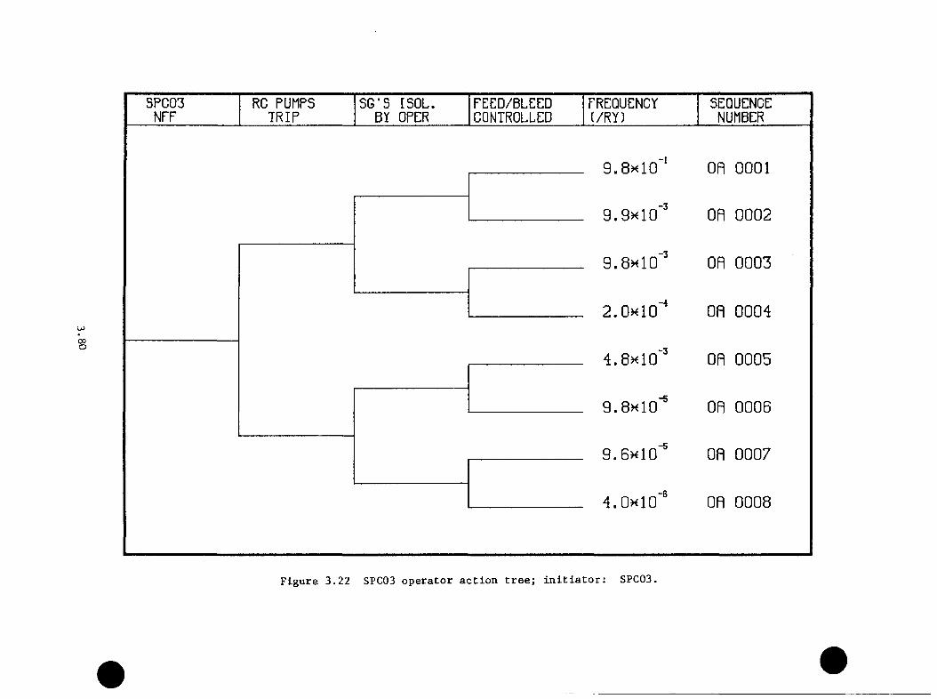
COo
SPC03 RC PUMPS SG*S ISOL. FEED/BLEED FREQUENCY SEQUENCENFF TRIP BY OPER CONTROLLED (/RY) NUMBER
9.8k 10"' on 00019.9h 10'' on 00029.8k 10‘" on 00032.0k 10' on 00044. 8 10'' on 00059.8x10“' on 00069.6x10'® on 00074.0x10“' on 0008
Figure 3.22 SPC03 operator action tree; initiator: SPC03.
the affected steam line more difficnlt. Attempted restoration of the
secondary heat sink, however, will indicate the affected steam line.
For an SPC Category 3 transient, isolation of the steam generators will not
isolate the break, resulting in a depressnrization of both S6s. Because
neither 6S can be restored as a heat sink, it is assumed the reactor
operators will provide cooling to the core via the HPI system (i.e., a
feed/bleed mode). The operator action tree for this case is given by
Figure 3.22.
For SPC Category 4, one steam generator will appear to be unaffected.
However, attempted restoration will indicate that one or more TBVs are
stuck open. It is assumed that the steam generator can be restored as
a viable secondary heat sink by limiting the steam flow through the turbine
bypass block valves. Thus, the appropriate operator action tree for the
case is given by Figure 3.22. In an analogous fashion, this same operator
action tree can also be used for SPC Category 5 transients.
As noted above, SPC Category 6 transients principally account for failures
of the TSVs to close on both lines. If the turbine governing valves close,
these transients can be categorized as SPC Category 0. However, a failure
to trip the turbine, given a reactor trip, will result in an excessive
steam demand relative to the power output of the reactor. Assuming—4a turbine trip failure probability of 2 z 10 /demand yields a revised
-3frequency for SPC Category 6 transients of 1.2 z 10 . In this case,
manual tripping of the turbine, or failing that, manual closure of the
turbine stop valves and/or the turbine governing valves will effectively
isolate the break. It is assumed that, should the manual isolation of the
3 . 8 1
turbine not be accomplished, the transient will be treated as a "double"
steam line rupture (SPC Category 3) with similar operator actions. The
operator action tree for this case is given by Figure 3.23.
For those actions involving only malfunctions of the feedwater system
[Category (0,N,0,0)], a different set of operator action trees is
appropriate. The first nontrivial Category (0,1,0,0) involves unsustained
MFW overfeeds to one or both of the S6s. It is assumed that the time frame
of this overfeed is short enough to preclude any operator action before
the high-level 86 trip system terminates the transient itself.
For FWS Categories 2 and 3, which involve sustained overfeeds by the MFW
and EPV systems respectively, the operator action tree given by Figure
3.24 was constructed. An implicit assumption inherent in his tree is
the initiation of he HPI system on low RCS pressure, thereby requiring a
trip of the RC pumps. The FWS Category, however, is characterized by a
very different thermal-hydraulic behavior. Since this category represents
a loss of both the MW and EFW systems on reactor trips, an automatic
HPI initiation on low RCS pressure is not expected, and the RC pump trip
will not be procedurally required. Additionally, one reason for the non
initiation of the EFW system is that the system was originally in a manual
mode of operation, requiring only a switch bach to automatic mode to effect
EFW supply. The HEP assigned to this branch was 0.01. Alternatively
the EFW system may be unavailable for other reasons. However, because of
the interconnections possible between the EFW system of the three Oconee
units, a 0.98 probability of success of EFW restoration was assumed for
this branch. Also, a potential operator error of commission, restoration
3.82
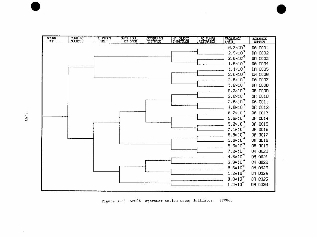
SPC06NTF TURBINE RC PUMPS SB'S ISOL. SECOND HS HP INJECT RC PUMPS FREQUENCYI30LBIED TRIP BY OPER RESTORED THROTTLED RE5TRRTE0 C/RY)SEQUENCENUMBER
00
9 . 3 h 10’’ 08 00012 .9 x 1 0 ^ OR 00022 . 6 h 10'* 08 00031 .8 h 1D^ on 00044.-1X10'' OR 00052.8x10'^ OR 00062 .6 x 1 0 ' ' OR 00073 .6 x 1 0 ^ on 00089.2x10 '" on 00092 .0 x 1 0 ' ' OR 00102 .8 x 1 0 ' ' OR 00111 .8 x 1 0 ’’ OR 0012S./xlO"® on 00135.6x10'® on 00145 .2 x 1 0 ’* OR 00157. I x io ' ' OR 00168 .0x10 '* OR 00175.6x10'® on 00185.3x10'® on 00197 .2 x 1 0 ' ' on 00204 .5x10 '* OR 00212 .9 x 1 0 '“ OR 00228 .6 x 1 0 ' ' on 00231 .2x10 '' on 00248 .8 x 1 0 ' ' OR 00251 .2 x 1 0 ’' OR 0026
Figure 3.23 SPC06 operator action tree; initiator: SPC06.

00
FWS04NFF
EFW SYSTEM IN MRNURL
EFWRESTORED
MFWRESTORED
FREQUENCYI/RY)
SEQUENCENUMBER
2.9k 10‘‘ on OGGI
2.9k 10‘" on GGG27.0m 10"‘ on GGG37. iHlO'" on GGG4
3.5><10''’ on GGG57. iHlO'" GR GGG6
3.6k 10'' GR GGG7
Figure 3.24 FWS04 operator action tree; initiator: FWS04,
of EFW in an uncontrolled manner (ERW overfeed), was also included with
a HEP of 0.01. Should EFW restoration not be possible, a probability of
0.5 of MFW restoration in an uncontrolled manner was employed.
For most of the transients involving both SPC and FWS malfunctions,
isolation of the steam generators mitigates the FWS malfunction. Therefore,
the appropriate operator action trees for categories designated (N,N,0,0)
are the same trees as discussed above for Categories (N,0,0,0). It should
be emphasized, however, that a SPC malfunction coupled with an overfeed
results in more severe thermal-hydraulic behavior even though the operator
actions necessary to mitigate the transient remain the same. For those
combined transients involving FWS Category 4 (loss of all FW), however,
a modified form of the SPC operator action trees is employed. The
modification consists of changing the probability of heat sink restoration
to agree with that indicated by Figure 3.24 to account for the possibility
of uncontrolled EFW or MFW restoration (l.OE-02 and 7.1E-05, respectively).
For those transients involving a failure of the HPI to initiate, a
conservative approximation is made. Because the HPI system will exacerbate
a PTS transient (higher pressure and lower temperature in the downcomer),
those transients that involve HPI failure are included in the category
representing HPI success.
For those transients in which the pressure in the RC system reaches
the PORV/SRV set points, the operator actions necessary to deal with a
potential LOCA situation must be addressed. Two types of potential LOCAs
are represented by the categorization process— LOCAs isolable via the PORV
block valve and non-isolable LOCAs involving the SRVs. It should be noted
3.85

that the LOCA situation may not be initially apparent in many of the tran
sients because the effects may be masked by the overcooling of the primary
system. Hence in this study, the conservative assumption was made that for
those transients involving secondary-side depressnrization or excessive
feedwater. the LOCA situation will only be dealt with following correction
of the secondary side malfunction. For PORV LOCAs. the system can be sta
bilized by closing the PORV block valve and throttling back the HPI, given
that the secondary heat sink has been restored. Thus, an additional opera
tor action, closing the PORV block valve, should be incorporated into the
operator action tree. For the nonisolable LOCA. the ECCS flow rate will
match the break flow at a pressure lower than operating pressure. In both
cases, however, the appropriate operator action depends on the availability
of the secondary heat sink. If it is available. it is assumed that no
operator action is taken to alter the feed/bleed mode in the RCS. If the
SGs are not (or cannot be) restored, an operator action to depressurize the
primary system to utilize the LPI system, is appropriate and is included on
those branches for which secondary side cooling is not restored. Figure
3.25 depicts the operator action tree for Category (1.0.0.1) as an example.
The above discussion is intended to serve as background for the discussion
of initiator-specific transients. In many cases, the operator action
trees postulated are directly applicable to the transients involved. In
certain cases, however, the initiators themselves require modification
of the generic operator action trees postulated based on the transient
categorization. The necessary modifications will be indicated in the
discussion of each specific initiator where appropriate.
3.86

00
SPCOlLOCfl
RC PUMPS TRIP
SG'S ISOL. BY OPER
SECOND HS RESTORED
RCSDEPRESS
FREQUENCY1/RY)
SEQUENCENUMBER
9.8k 10'* on 00019.3h 10'' on 0002
on 00039.4h 10'' on 00046.0x10"* on 00054.8x10' on 00068 . 6 x 1 0 ' ' on 0007
on 00088 . 8 x 1 0 ' ' on 00091 . 2 x 1 0 " ' on 0010
Figure 3.25 SPCOl/LOCA operator action tree; initiator: SPCOl/LOCA.

4.0 THERMAL-HTDRAULIC EVALUATION
L. B. LaMonica, Science Applications, Inc.
4.1
The role of thermal-hydraulic analysis in the probabilistic evaluation of
PTS risks is to couple event tree analysis to the fracture nechanics (FN)
analysis. Each end-state on an event tree defines a series of actions
and/or failures that detemines the response of the plant to the initiating
event. The thermal-hydraulic response— measured as downcomer pressure,
liquid temperature, and heat transfer coefficient— becomes the boundary
condition used in the fracture mechanics calculation of crack propagation
probability.
A thoroughly rigorous evaluation of PTS risk would require precise
calculation of downcomer pressure, temperature, and heat transfer
coefficient over the entire downcomer region for every event tree end-
state. Since there are over 9.6 million end-states on the Oconee-1
event trees and detailed thermal-hydraulic simulation costs are great, a
completely rigorous approach is not practical.
A first simplification of the scope of the analysis may be achieved by the
use of a lower limit (10 V yt) on event frequency to screen out a very
large number of events which individually would not measurably contribute
to overall risk. This screening process is described in Chapter 3.0.
The remaining sequences are still too numerous for individual detailed
evaluation. Furthermore, the development of pressure, temperature, and
heat transfer conditions over the entier downcomer region (i.e., azimuthal
4.1
and axial variations in the bonndary conditions) vonld necessitate the nse
of TRAC or a revised RELAP5 model including multiple downcomer regions.
Therefore, a combination of detailed calculations and engineering estimates
was employed to define "single point" pressure, temperature, and heat
transfer coefficient boundary conditions for all of the sequences. These
single point profiles assume a uniform temperature, pressure, and heat
transfer coefficient throughout the downcomer region. Where a range of
temperatures could be predicated by TRAC or by extrapolation, the downcomer
sector with the lowest temperature profile was used for the FM analysis.
The detailed calculations were performed by Fletcher, et al., at the4 1Idaho National Engineering Laboratory (INEL) using the RELAPS code ' and
by Ireland, et al., at Los Alamos National Laboratory (LAND using the 4 2TRAC-PPl code. ‘ The models developed at INEL and LANL included the
primary and secondary portions of the nuclear steam supply system, main and
emergency feedwater trains, and certain control functions of the ICS. At
the time of their creation, these Oconee-1 plant models were the largest
and most complex models ever applied to the RELAP5 and TRAC-PFl codes. The
characteristics of these models are summarized in Section 4.2.
Oak Ridge National Laboratory identified 14 transient sequences for detailed
evaluation. Tables 4.1 and 4.2 contain a brief description of each
sequence simulated using RELAP5 and TRAC respectively. For purposes of
comparison, the Oconee-3 turbine trip (revised), aiain steamline break, and
pressurizer surge line small-break events were calculated using both RELAP5
and TRAC. More detailed descriptions of the sequences are provided in
Section 4.3. The transient sequences were selected to include 1) major
4.2
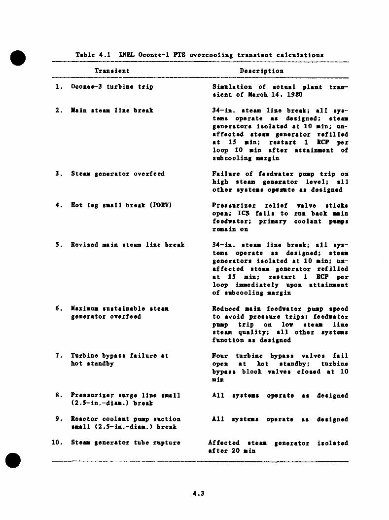
Table 4.1 INEL Oconee-1 PTS oyercooling transient calculations
Transient Description
1. Oconee-3 turbine trip Siainlation of actual plant transient of Marcb 14, 1980
2. Main steaa line break
3. Steam generator overfeed
4. Hot leg small break (PORV)
34-in. steam line break; all systems operate as designed: steamgenerators isolated at 10 min; unaffected steam generator refilled at 15 min; restart 1 RCP per loop 10 min after attainment of snbcooling margin
Failure of feedwater pump trip on high steam generator level; all other systems opcrmte as designed
Pressurizer relief valve sticks open; ICS fails to run back main feedwater; primary coolant pumps remain on
5. Revised main steam line break
6. Maximum sustainable steam generator overfeed
7. Turbine bypass failure at hot standby
34-in. steam line break; all systems operate as designed; steam generators isolated at 10 min; unaffected steam generator refilled at 15 min; restart 1 RCP per loop immediately upon attainment of subcooling margin
Reduced main feedwater pump speed to avoid pressure trips: feedwater pump trip on low steam line steam quality; all other systems function as designed
Four turbine bypass valves fail open at hot standby; turbine bypass block valves closed at 10 min
8. Pressurizer surge line small (2.5-in.-diam.) break
All systems operate as designed
9. Reactor coolant pump suction small (2.5-in.-diam.) break
10. Steam generator tube rupture
All systems operate as designed
Affected steam generator isolated after 20 min
4.3
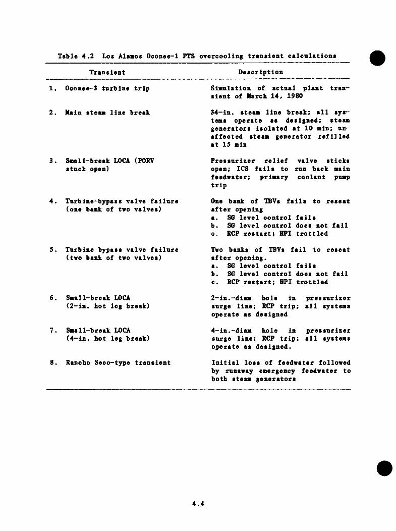
Table 4.2 Los Alamos Oconee-1 PTS oyercooling transient calcnlations
Transient Description
1. Oconee-3 turbine trip Simulation of actual plant transient of Marcb 14, 1980
2. Main steam line break 34-in. steam line break; all systems operate as designed: steamgenerators isolated at 10 min; unaffected steam generator refilled at 15 min
Small-break LOCA (PORV stuck open)
Turbine-bypass valve failure (one bank of two valves)
Pressurizer relief valve sticks open; ICS fails to run back main feeduater; primary coolant pump trip
One bank of TBVs fails to reseat after openinga. SG level control failsb. SO level control does not failc. RCP restart; HPI trottled
5. Turbine bypass valve failure (two bank of two valves)
6. Small-break LOCA(2-in. hot leg break)
7. Small-break LOCA(4-in. hot leg break)
8. Rancho Seco-t3rpe transient
Two banks of TBVs fail to reseat after opening.a. SG level control failsb. SG level control does not failc. RCP restart; HPI trottled
2-in.-diam hole in pressurizer surge line; RCP trip; all systems operate as designed
4-in.-diam hole in pressurizer surge line; RCP trip; all systems operate as designed.
Initial loss of feedwater followed by runaway emergency feedwater to both steam generators
4.4

oyercooling initiators snch as steaa line breaks, feedwater overfeeds,
steaa generator tube rnptnres. and LOCA events and 2) assnaed failures
of controls and operator interventions that vonld otherwise liait systea
cooldown and repressnrization. The intent of this selection process was to
obtain accurate calculation of soae bounding cooldown events. The results
of the detailed calculations are suaaarized in Section 4.3.
The RELAP5 and TRAC codes do not predict the phenoaena of teaperature
pluaes and other related effects. These effects are iaportant because
they can yield downcomer temperatures significantly lower than the values
predicted by RELAPS or TRAC, which both assume perfect mixing. To address
this question, the predicted cold leg and downcomer flows and temperatures4 3were evaluated by T.G. Theophanous of Purdue ’ for potential of flow
stratification effects. These results are suaaarized in Section 4.4.
Section 4.5 deals with the evaluation of pressure, teaperature. and heat
transfer coefficient profiles for PTS sequences retained following the
event tree evaluation and screening process. The methods and criteria used
to screen the set of remaining events for similarity grouping are addressed.
The use of the detailed TRAC and RELAP5 data for direct extrapolation and
in a simple energy balance cooldown aodel is also discussed. The results
are presented for each major cooldown initiator, including turbine bypass
valve failure at full power and at hot standby. PORV-sized LOCA events,
main and emergency feedwater overfeed events, and steam generator tube
rupture events. The summary of the detailed TRAC and RELAPS calculations
and the extrapolated sequences in Section 4.6 provides a key for connecting
4.S
event tree results of Clispter 3.0 to the fracture mechanics results of
Chapter 5.0.
4.2 Detailed Thermal-Hydraulic Models
4.2.1 RELAP5 Model Description
This section provides a summary of the RELAP5 model of the Oconee-1 PWR
prepared at INEL. A detailed description may be found in Reference 4.1.
The RELAP5 Oconee-1 PWR steady state model is a detailed siodel of the
Oconee-1 PWR power plant describing all the major flow paths for both
primary and secondary systems, including the aiain feed train. Power-
operated relief vales (PORV). safety valves, and the emergency core cooling
system (ECCS) also are modeled. Secondary side features include turbine
bypass and turbine stop valves, safety valves, and the emergency feedwater
(EFW) system. The integrated control system (ICS) was another feature
modeled. The model contained 220 volumes, 232 junctions, and 208 heat
structures. The configurations of the full power and hot standby versions
of the model were modified as necessary to match the specifications of the
transient cases. A description of the primary system, secondary system,
feed train, and the control system are presented in the following sections.
4.2.1.1 Primary System
The noding diagrams for the RCS primary are presented in Figures 4.1, 4.2,
and 4.3.
The Oconee-1 PWR plant is a *'2-by-4 configuration," i.e., two loops each
containing one hot leg and two cold legs. The loops were designated as
4.6

-6
U1
U5 -I109
TO S U R Q f LIIfB
1 0 9
1 00
1 9 0 im17 0 176 -3
t 6 9
1 5 0
1401 -3-I711
VESSELDOWNCOMER
VESSELUPPERPLENUM710 71$
I 80 I 30
HIGH PRESSURE INJECTION
Figure 4.1 RELAP5 Oconee-1 model; primary Loop A.
4.7

SAFETY VALVES POWER OPERATED RELIEF VALVES803 801
{XI—
-2
820
800 -4
803 BOO
-S
'--- FROM 1NL2T170
Figure 4.2 RELAP5 Oconee—1 model; pressurizer system.
4.8
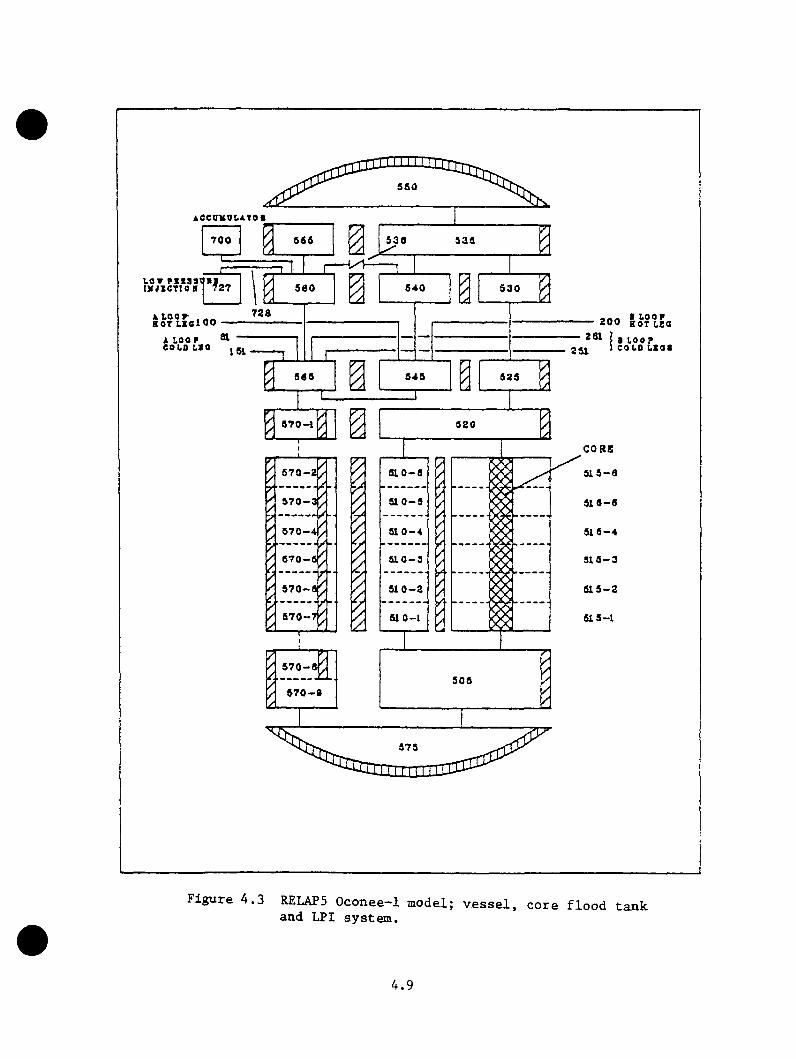
550
iec(rKui.AToi700 530
1.0TI X i l C T I O N 540500 530
- 200I a LOOP
COLO L z o ai LOOP COLO L > 0 251161
SOS
520CORE515-0
510-5 516-5
510-4 515-4
670-6
510-2 815-2
570-7 61 0-1 515-1
570-8505
570-9
575
Figure 4.3 RELAP5 Oconee-1 model; vessel, core flood tank and LPI system.
4.9
loop A and loop B. Each loop contained one hot leg, one steaa generator,
two pnap snction legs, two reactor coolant pnaps, and two cold legs (refer
to Figure 4.1). Loop B does not have the pressurizer surge and spray line
connections, the only difference from loop A. The pressurizer surge line
and pressurizer were attached to the hot leg in loop A (see Figure 4.2).
Each cold leg contained a high-pressure injection (HPI) port.
The RELAP5 vessel model shown in Figure 4.3 consisted of several components
describing the various vessel flow paths. The RELAP5 vessel included an
inlet annulus, downcomer, lower plenum, core, core bypass, upper plenum,
upper head, and a vent valve. The use of a single downcomer region
prevented prediction of nonsymmetric temperature or flow effects due to the
resultant mixing of the four cold leg streams.
The eight reactor vessel internal vent valves between the upper plenum and
downcomer inlet annulus were modeled with a single RELAPS servo valve. A
servo valve uses the output of a RELAP5 control variable to determine the
open area of the valve. The control variable was designed to calculate
a valve flow area as a function of the differential pressure across the
valve. Because the range of differential pressures over which the valve
position changes is small, it was necessary to smooth the calculated
differential pressure to prevent valve chattering. Without smoothing,
the valve position responded instantaneously to the differential pressure
across it. With smoothing, the change in valve position in a time step
was limited, thus preventing excessively quick opening and closing of
the valve and qualitatively simulating the response time of the flapper
valves. Within the limitations of the thermal hydraulic models, the model
4.10
of the vent valve used in the RELAP5 model is the best representation of
the Oconee-1 reactor vessel vent valve presently available.
Also included in the primary system were the low-pressure injection (LPI)
system, the core flood system, PORV, and safety valves. The LPI and core
flood systems were connected to the vessel inlet annulus. The PORV and
safety valves were connected to the top of the pressurizer. Table 4.2
summarizes the relationship between the physical components of the Oconee-1
LPI, core flood systems, PORV, and safety valves and the corresponding
mathematical components of the RELAP5 model.
The RELAP5 nonequilibrium model was applied to all volumes in the
primary system except for the accumulator where the accumulator model was
applied. The wall friction model was applied in all primary volumes.
Centrally located junctions for horizontal stratification were applied to
all horizontal junctions. The choking and two-velocity models were applied
at all primary junctions and an inertial solution was calculated at all
junctions.
Heat structures were used to represent heat transfer and stored energy
from fuel rods, steam generator tubes, loop piping, vessel wall, vessel
internals, pressurizer wall, pressurizer surge line, and pressurizer
heaters.
4.2.1.2 Secondary System
The RELAPS model of the loop A steam generator secondary is shown
schematically in Figure 4.4. Loop B has an identical noding structure.
4.11
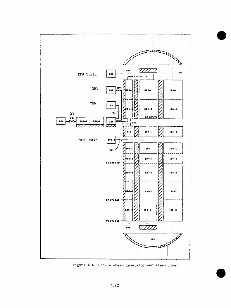
Ufl
EFW Train ess
SRV SOT
TBV
TSVesi — OF L*n.Tij
SSO-2 ) 3SS-1 ' ' 8 4 6 *zzzzkzzzz iZZ2j‘
SSO-l
MFW Train TTS-a
S 0-4■tv LT1.T4F
ao-t
ISS
Figure 4.4 Loop A steam generator and steam line.
4.12
Originally the startup and operating levels were calculated based on the
collapsed downcomer liquid level. Some early calculations were performed
using this approach. For calculations presented in this report, the levels
were based on calculated static pressures and fluid temperatures at the
locations corresponding to pressure and temperature taps in the Oconee-1
steam generators. The calculated temperatures and differential pressures
were smoothed in a manner consistent with the actual instrumentation
system. The improved method of level calculation significantly affected
the sequence of events in the INEL revised main steam line break transient,
as discussed further in Section 4.3, and, in general, improved the behavior
of emergency feedwater injection, which is controlled on level. The RELAPS
options used in the secondary system follow. The nonequilibrium option
was applied to all volumes in the secondary system, a change from the
equilibrium option used to perform the initial calculations with this
model. Difficulties encountered with secondary behavior during the initial
portion of the main steam line break calculation were overcome, allowing
the nonequilibrium option to be used.
This change resulted in a more satisfactory behavior of the secondary
system during periods of emergency feedwater injection. The wall friction
model was applied to all secondary volumes. Centrally located junctions
for horizontal stratification were applied to all horizontal junctions.
The choking and two-velocity models were applied to all junctions, and an
inertial solution was calculated at all junctions.
Heat structures were used to simulate the stored energy contained in the
secondary shell wall, piping, and internals.
4.13

4.2.1.3 Feedwater System
The purpose of the feedwater system is to supply demineralized/deaerated
snbcooled water to the A and B steam generator secondary inlets. The water
is heated and pressurized from 305 K (SK)°F) and 0.01 MPa (14.5 psia) to
511 K (460°F) and 6.55 MPa (950 psia). Figures 4.5 and 4.6 and Table 4.3
show the modeling arrangement of the feedwater trains.
The RELAP5 options used in describing the feedwater system include the
nonequilibrium and wall friction models. Centrally located junctions were
applied to all horizontal junctions* and choking and two-velocity models
were also applied at all junctions.
Heat structures were used to represent the high- and low-pressure heaters
and the piping wall metal masses. The feedwater heaters were modeled
using the appropriate tube bundle surface areas. The energy contributed
to the feedwater from the heater secondaries was modeled using the heat
structure energy source option in RELAP5. The piping was modeled by first
calculating the applicable metal volume, then adding the equivalent metal
thickness to the appropriate heat structure. Heat structures representing
several components were combined and added to selected components to reduce
the computer storage requirements.
4.2.1.4 Control System
The Babcock & Wilcox integrated control system (ICS) is a comprehensive
system that controls all power generation operations of the Oconee-1
plant. The models developed for the pressurized thermal shock program
study of the Oconee-1 plant comprise only three portions of the overall
4.14

E H E A T E R D R A I H D H E A T E R D R A I N
744 750
734 730:730
748743
746,Ly 7 y 7 j / /
740736
/ 7 / f J-T
752
H O T A T E L LP U M P
B O O S T E RP U M P
-e-H-•tn
M A I N F E E D W A T E R P U M P A
M a i n f e e d w a t e rP U M P B
757-Kl- STARTUP
ANDMAINFEEDVALVES
754
762760
756
761756
/ 7 7 7 / X / / / 7 7L
764
//7//y////7
766 i
763 760
Figure 4.5 RELAP5 Oconee-1 model; feedtrain from hotwell to startup and main feed valves.

U O T O R D H I T S H E M E X Q S H C T E E E D T J I T E R
T I T R B I H E D H I V J j : E M E R Q E H C T E E E O T A T C R
<S3-Tn M
S T E A U G E X E S A T O R K S E C O N D A X r U P P E R S T E A M D O M E
77 < 774
7 77
774
S T E A M O S K E R A T O R A D O R N C O M S R
/ / yy-r-ry-.\ 744
— J X . !
3 T S A K G B K C S A T O R1
7 f 0 ~ t 1 7 S 0 > S
................. — , - t II 1L.
B D O l T N C O M Z f t
M O T O R D R I V E N E M E R G E H C T r C S D V A T E R
954904
909 90S — f \ j --- *94
99 a
S T E A M 3 I H E R A T 0 R a S E C O N D A R Y U P P E R S T E A M D O M E
T U R B I N E D R I V E N S M S R O E N C T P E E D V A T E R
Figure 4.6 RELAP5 Oconee—1 model; feedtrain from startup and main feed valves to steam generator, crossover, and emergency feedwater system.
4 . 1 6

Table 4.3 Correspondence betveen physical components and the RELAP5 mathematical components in the Oconoee-1 feedtrain model
Physical Component RELAP5 Component
HotwellHotwellDemineralizer and deaerator system Booster pxunpLow-pressure F and E heaters
E heater drain Low-pressure D heaters D heater drain Low-pressure C heaters A main feedwater pump
A main feedwater piuap discharge line B main feedwater pump inlet line B main feedwater pump Main feedwater pump discharge line Main feedwater pump header
A and B heater train number 1 A and B heater train number 2 High-pressure heater header A and B startup and main feedwater
control valves Steam Generator A control valve header
730734736
738740
742,744746748, 750752ISA
156. 757758760761, 762763
764 766 768770, 771, 772, 773
774, 775
Steam generator B control valve header Steam generator A feedwater header Steam generator B feedwater header Steam generator A feedwater crossover Steam generator B feedwater crossover
776, 777 778, 782 780, 784850, 851, 852, 853, 854 950, 951, 952, 953, 954
4 . 1 7
control system: 1) turbine bypass control, 2) feedwater control, and
3) emergency feedwater control, the EFW control being separate from the ICS.
The model follows the description of the ICS given in Chapter 2.0, Section
2.2.3. The full complement of reactor protection trips and safety system
actuation signals was included in the model.
4.2.2 TRAC Model Description
This section provides a summary of the TRAC model of the Oconee-1 PWR
prepared at LANL. A detailed description may be found in Reference 4.2.
The Oconee-1 model developed for the PIS study represented the most
comprehensive nuclear power plant modeling assembled to date for use with
the TRAC code. The model contains a primary side, a secondary side, and
a complex control system consisting of both trips and controllers.
4.2.2.1 Primary System
The noding diagram is presented in Figure 4.7, the primary side of the
Oconee-1 model. It consists of the three-dimensional vessel, two hot legs,
two once-through steam generators, four cold legs, and soae parts of the
emergency core cooling system (the low-pressure injection system was not
modeled).
The volumes, elevations, and pipe lengths from the Oconee-1 plant are
closely matched in the model. The wall areas and thicknesses of the
primary piping also are modeled so that the thermal response of the piping
is predicted. Heat transfer from the pipe walls to the environment also
is allowed.
4.18
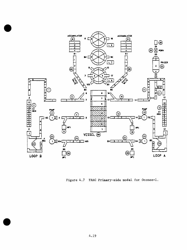
ACCUMJLATOa ACCUMULATOD
ntlUR
VESSEL »9J5L_J
LOOP B LOOP A
figure 4.7 TRAC Primary-side model for Oconee-1.
4 . 1 9
The thxee-diBensionel vessel is nade vp of 96 cells arranged so that
the vessel is divided into eight axial levels, tvo radial rings, and six
azimuthal segments. The lower plenum is made up of one level, the core
of four levels, the upper plenum of two levels, and the upper head region
of one level. The two radial rings are divided so that the core region
is bounded by the inner ring and the downcomer annulus is modeled in the
outer ring.
The vessel metal structures and wall laasses are modeled by assigning a
representative thickness and area of a heat slab to each three-dimensional
cell. Using these heat slabs, the stored energy of the vessel structure
is approximated. The thermal conductivity for each heat slab is calculated
by assigning five nodes across each slab thickness. These nodes are spaced
so that they are closer together on the fluid side of the slab. There
is no heat transfer through heat slabs between cells; that is, each cell's
heat slab is isolated from any other cell's heat slab except through the
fluid-dynamic coupling.
The six azimuthal divisions were chosen to allow for the angle and
separation of the penetration of the hot and cold legs. Also, the
accumulator injection ports were modeled close to their exact positions
(both axially and azimuthally) in the vessel downcomer region.
With only one radial division for the inner portion of the vessel modeled,
the circulation of hot water rising from the core into the upper head and
descending out the hot legs is lost. Without finer noding of the vessel,
the upper head is effectively isolated from the rest of the vessel in
many circumstances. To alleviate this problem, a connection was assumed
4.20

between the npper head and the hot legs so that about one-third of the
nornal steady state flow passes through the upper head. This upper-head
tee connection influenced the movements of steam voids between the upper
head and the candy canes of the hot legs. This behavior is most evident
in the main steam line break sequence suauaarized in Section 4.3.
The vessel includes vent valves that are modeled to allow flow from the
upper plenum directly to the downcomer. This flow path is only available
when the upper plenum pressure is higher than the downcomer pressure. A
composite vent valve made up of one-sixth the total vent-valve area is
modeled in each azimuthal cell of the inner radius of axial level 7. The
vent valves are fully open when the pressure drop between the upper plenum
and downcomer exceeds 0.12 psi.
The loop A and loop B hot legs are modeled symmetrically except for the
surge line connection to the loop A candy cane. The candy canes represent
the highest elevation in the system. The surge line includes a "small-
break" that is activated for the small hot leg break transients.
The pressurizer is modeled with a very small cell at the bottom and two
small cells at the top. This is necessary to allow correct fluid conditions
either to enter or leave the pressurizer.
Pressure relief for the primary system is provided by a single PORV at the
top of the pressurizer. This valve supplies adequate relief for the cases
in which secondary cooling is provided and the reactor has tripped.
A complete model was developed for BSW once-through steam generators. The
primary side of the steam generator is made up of 12 cells, whereas the
4.21

secondary side nses 26. Heat transfer from the priaary occurs through
the steaa generator tubes to the secondary coolant. Cells 2 through 11
(Figure 4.7) represent a coaposite of the voluae inside and wall area of
all tubes, and it is in these cells that heat transfer froa the coolant
to the walls of the tubes occurs. Cells 1 and 12 aodel the upper and
lower plenuas. The wall area and thickness of the plenuas are aodeled so
that the heat capacitance and heat transfer of the external wall can be
calculated.
The secondary of the steaa generator is divided into four coaponents
(Figure 4.8); two aodel the tube-bundle region, one aodels the downcoaer,
and the final one aodels the steaa-outlet annulus. The tube bundle region
is aade up of 10 cells (SG coaponents 12-1 and 12-2 for loop A and 2-1 and
2-2 for loop B in Figure 4.8). These cells aodel the total voluae and the
tube wall area for the region between all the steaa generator tubes, but
aodel the heat transfer characteristics of a unit cell of tubes. The top 4
of these 10 cells coaprise the superheated-steaa region of the aodel during
noraal full-power operation. The connection at the top cell of the tube
bundle region is for the eaergency feedwater (EFW) flow and the realigned
aain feedwater flow. This connection closely aiodels the correct plant
geoaetry so that any flow froa the ''upper header" is correctly injected
into the tube bundle.
The steaa generator downcoaer consists of seven cells (SG coaponents 12-3
and 2-3 of Figure 4.8) plus one cell for the aain feedwater injection and
one cell for the aspirator port. During noraal operation, the downcoaer
condenses enough superheated steaa drawn through the aspirator port to heat
4.22

Sleain Line A
hOOJ
- a i - iz o z r ~ i z i . u : i t ^ i l j t i ■«m y < k>i [ 3 0
B l i e n 'f i I 3 ( Z I T 7 924 E O 920 ^
10 & rfsJ .
e^cnsi aooTD V
©
Sticn
ffiDC o n d a n a o r 8 3 0
surcv1910 l2Xtl312 CJaoeBJO] soa:3 57M PCVXr]504tIXIl«HI 1902
32) 6i) (20
, Slaam Lin* B //0 T 3 :i. o 41 r r .T~E~ r ~ iz iz i : :r ! 0
■ ' U fR)4 C C X 2 B 0 3 C ® ]
TSVH otw tll
: 88CrS]B7lTDV
CPW PumpEPW LineI S38 m B 1 T \ 6 l ~ 5 1 r - f 3 ~ l Z I 1/1 937 t Z
I4 7 l« IE K * rV
JO; (85rT~r~iB03 7(1 (470ifTT5T~
B" HP
H3923A " H P
H i a l e rsuix:v131 I907I7 YT1909 Heeler Pumpe:3 47
MFcv n5 0 3 \ i ^ l \ 0 0 2 \ ] flO I
XT’ l PHntar «S. lUalar ,Z5,Hlr U*Drain QS Dr HIrV L P
690 -* T ’ L P — -l l a a l a r ^ 0 . P u m p a H o l w e l l P u m p a
Figure 4.8 TRAC Secondary-side model for Oconee-1.

the main feedwater to saturation tenperature prior to entry into the tube-
hnndle region. The final six stean generator secondary cells model the
steaa exit annulus. The outlet froa this annulus is near the midpoint of
the steaa generator, close to the actual location in the plant.
The SG water levels were modeled using the best available methodology, a
collapsed liquid level calculation. This method is adequate for transients
in which relatively slow changes in the secondary side occur, but it can
generate wide discrepancies relative to the pressure tap calculation used
in the RELAP5 model for rapid changes, such as in a MSLB transient.
All four cold legs of the plant were aodeled. These legs each consist
of a loop seal (lowest priaary-loop point), a reactor coolant pump (RCP),
and the HPI connection. The HPl nozzles are positioned closely to their
correct height and distance froa the vessel entrance. The RCPs are speed
controlled during steady state operation to obtain the required mass flow,
but their steady state speed is maintained fixed while they are running
during a transient. During noraal operation, the four cold legs of this
model have symmetric flows.
Two major coaponents of the ECCS included in this aodel were the HPI system
and the accumulators (core flood tanks) . If a transient were to be run
that caused the primary pressure to fall below the loir*pressnre injection
system (LPIS) set point, then the LPIS also would have to be added to the
mode1.
The HPI system was modeled as four boundary conditions that can inject
283 K (50^F) water into the priaary through the four side nozzles of the
4.24
cold legs. These nozzles are located so they enter the main cold legs
from the side at an elevation somewhat higher than the centerline of the
cold/hot legs. The pressure-dependent flow rate of the two loop B ports
is identical, as is also the case for loop A, but the loop A capacity is
greater than that of loop B.
There is an accumulator tank for each loop that allows emergency coolant
to flow directly into the downcomer region in axial level 7 of the vessel
(Figure 4.7). The accumulator flow is controlled by check valves so that
when the primary pressure falls below the accumulator-tank pressure, the
check valves open. The initial accumulator pressure was ~4.2 MPa (~610
psia) with a coolant temperature of 305.4 K (90°F).
4.2.2.2 Secondary Side
All major components of the secondary side are modeled except for the
turbine generator equipment and various valves that were not necessary for
any transients of immediate interest. With the exception of the vessel,
the secondary side required much more modeling detail than was necessary
when only the primary system was modeled.
In this discussion, the feedwater train describes the secondary-side
modeling from the condenser to the tee, where the feedwater is divided
between the two steam generators. This section of the modeling takes the
fluid discharge from the turbines and raises it to the temperature and
pressure at which it is delivered to the steam generators.
The condenser is modeled as a large tank with a very large wall area. The
thin walls have a high thermal conductivity and a constant temperature heat
4.25

sink on the outside surface. This aodel fully condenses the incoming steaa
from either the turbine exhaust or the turbine bypass system.
The hotvell is an even larger tank used for the collection and storage
of the condensate. The lowest system pressure and temperature occur in
this component. Cell 1 of the hotwell actually represents the volume and
coolant inventory of the upper surge tank. It is included to reduce the
complexity of the model while still providing an estimate of the available
hotwell inventory. The coolant supplied to the emergency feedwater system
is taken from the hotwel1/upper surge tank combination.
The hotwell pump (component 51) includes the demineralizer/aerator section
of the feedwater train. The model accounts for the effects of this section
by including additional frictional losses and heat addition to the coolant.
Each feedwater heater is modeled to achieve a feedwater temperature rise
close to the design value for that heater. In addition, the model includes
a time-dependent estimate of the feedwater-heater heat capacitance.
The two parallel MFW pumps of the actual plant are combined into a single
pump for this model. This is a variable speed pump with the speed
determined by the ICS.
The coolant flow from the feedwater train splits to provide flow to the
steam generator-control valve section of each major loop. The loop A and
loop B flow-control valves are identical. The ICS varies both NFV pump
speed and feedwater control valve position to optimize control. Additional
details of the model are available in Reference 4.2.
4.26
The EF¥ system is modeled so that it takes water from the hotwell and
delivers it to the E F W s of both steam generators. The EFW pnmp is modeled
as a composite of the tnrbine-driven and motor-driven pnmps in the actual
plant and therefore, has a large capacity. The EFW is delivered to a
tee (component 152, Figure 4.8) that splits the flow between the two steam
generators. If both EFWVs are open, the EFW flow is symmetrically split
as long as the secondary pressure of the two steam generators is equal. If
only one EFWV is open, the full flow available is delivered to that steam
generator. The EFW flow stops if the hotwell inventory has been depleted.
The steam line for steam generator B is longer than that of steam generator
A. Other than this difference, the steam lines and their valves are
identical. A pressure boundary condition models the steam flow existing
the secondary into the turbine inlet. During steady state operation, the
steam mass flow is modeled to reenter the secondary as boundary condition
inlets to the condenser and the two heaters drain. Following a turbine
trip, the turbine stop valves (TSVs) close the steam lines. If any pressure
relief from the closed steam lines is necessary, steam is released through
the turbine bypass valves into the condenser. For a normal reactor/turbine
trip transient, the steam relief from the turbine bypass valves is adequate
so that modeling the main steam safety valves is not necessary.
4.2.2.3 Control Systems
The TRAC model included the integrated control system (ICS) functions
discussed in Chapter 2.0, Section 2.2.3, namely, turbine bypass valve
control, feedwater valve control, and main feedwater pump control. The
4.27

full coBpleBent of reactor protection trips and safety systeB actuation
signals was included in the Bodels as described in Reference 4.2.
4.3 Results of Detailed Calculations
4.3.1 RELAP5 Calculations
The sequences siBulated by the RELAP5 Bodel are listed in Table 4.1.
Detailed discussion of the transients and the results are available in
Reference 4.1. Suaawry descriptions of the transients are provided here to
provide a context for discussion of sequence extrapolation in Section 4.5.
The results for the Oconee-3 feedwater transient are oaitted in reference
4.1 and are likewise not included here. A suaaary of all transients
discussed here and in Sections 4.3.2 and 4.5 is provided in Section 4.6
and Table 4.25.
4.3.1.1 INEL Original Main Steaa Line Break
A description of the transient appears in Table 4.4. The sequence is
identical to that for the revised aain steaa line break presented in Section
4.3.1.4 except for the reactor coolant (RCP) restart and high-pressure
injection (HPI) throttling criteria. For this sequence, one RCP per loop
is to be restarted 10 ain after attainaent of 28 K (50°F) subcooling in
both hot legs, and HPI is not throttled. In the revised sequence, the
RCP restart is iaaediate upon attaining 42 K (75°F) subcooling, and HPI
is to be throttled to aaintain 28 to 56 K (50** to lOO^F) subcooling.
Results of the calculation and extrapolations to 2 h are shown in Figures
4.9 through 4.11. Figure 4.9 shows the reactor vessel downcoaer pressure
4.28

Table 4.4 INEL original main steam line break transient scenario
1. Reactor trips, coincident vith break of 0.86 m (34 in) steam line
2. Turbine trips; TSVs close
3. ICS functions as designed
4. Protection systems on hotwell, condensate booster; NEW pumps function as designed
5. HPI actuates at set point of 10.34 MPa (1500 psig)
6. Operator trips RC pumps 30 s after HPI actuation
7. EFV pumps start when low MFW pump discharge pressure is sensed
8. MFW/E^ system attempts to maintain 6.1 m (240 in.) steam generator level
*9. Core flood tanks actuate at set point
10. LPI actuates at set point•a
11. Operator isolates feedwater to affected steam generator 10 min into the transient
*•*12. Operator restarts one RC piunp in each loop 10 min after attaining28 K (50^F) subcooling in the hot legs
13. PORV opens at set point of 16.9 MPa (2450 psig)*14. SRVs open at set point of 17.2 MPa (2500 psig)
15. PORV/SRVs reseat at their set points of 16.5 MPa (2400 psig)
16. Pressurizer goes water-solid
17. EFW surge tank capacity of 272544 liters (72,00 gal) is exhausted; the two motor-driven EFW pumps trip
*18. Turbine-driven EFW continues to draw from hotwell
* Event is phenomenologically dependent.• a Five times a typical time for operator action, based on simulator
experience.
Two times a typical time for operator action, based on simulator experence.
4.29

20— CALCULATED- • EXTRAPOLATED
-2300
UiCKZ3(A(OLUqe:a.
-1500Ui3_iO>
-1000
1000 2000 3000 4000 5000Time (s)
6000 7000 8000
(DQ.
3O)v>o
9£3o>
Figure 4.9 Main steam line break, RV downcomer pressure.
580CALCULATEDEXTRAPOLATED
--550
-500
520cr
500
4800 2000 3000 4000 5000 7000 80006000
9u.3o«a.£0>
3cr
£3O>
T im e (s)
Figure 4.10 Main steam line break, RV downcomer fluid temperature.
4.30
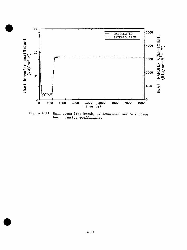
30
20 ■<u Oo I u Etn V C Vw/o
— CALCULATED h - - - EXTRAPOLATED
-5000
-4.000 ^
10 ■■
a49X
o a y -u_LU I O cm'
-3000 O
-2000
iLto \ X 3
-1000LU X
1000 2000 3000 4000 5000Time (s)
6000 7000 8000
Figure 4.11 Main steam line break, RV downcomer inside surface beat transfer coefficient.
4 . 3 1
response. The minimniD pressure calculated vas 5.02 MPa (728 psia) and
the maximum was 16.99 MPa (2465 psia), the opening set point of the power-
operated relief valve. Figure 4.10 shows the reactor vessel downcomer
fluid temperature. The minimum temperature calculated was 482 K (407*^ F).
The reactor vessel wall inside surface heat transfer coefficient is shown
in Figure 4.11. The low values (for example, at 500 s) correspond to
periods of natural circulation flow, and high values correspond to periods
when reactor coolant pumps are operating.
4.3.1.2 Steam Generator Overfeed
A description of the transient is in Table 4.5. This sequence is transient
number 53 (INEL3) in Table 4.25. The scenario differs from that of the
maximum sustainable overfeed transient (presented in Section 4.3.1.5) in
the availability of feed train protection functions. For this sequence,
the protection functions, primarily low suction pressure trips on the feed
train pumps, were available, and as a result the main feedwater pumps were
tripped shortly after the transient was initiated. This sequence further
differs from the sequence in Section 4.3.1.5 in that reactor coolant pump
power is not tripped off by the operator.
Results of the calculation and extrapolations to 2 h are shown in Figures
4.12 through 4.14. Figure 4.12 shows the reactor vessel downcomer fluid
pressure response; the minimum pressure calculated was 8.92 MPa (1293
psia). The maximum pressure calculated was 16.99 MPa (2465 psia), which
corresponds to the power-operated relief valve opening set point pressure.
The minimum calculated downcomer fluid tmaperature was 505 K (450*’F), as
shown in Figure 4.13. The reactor vessel wall inside surface heat transfer
4.32
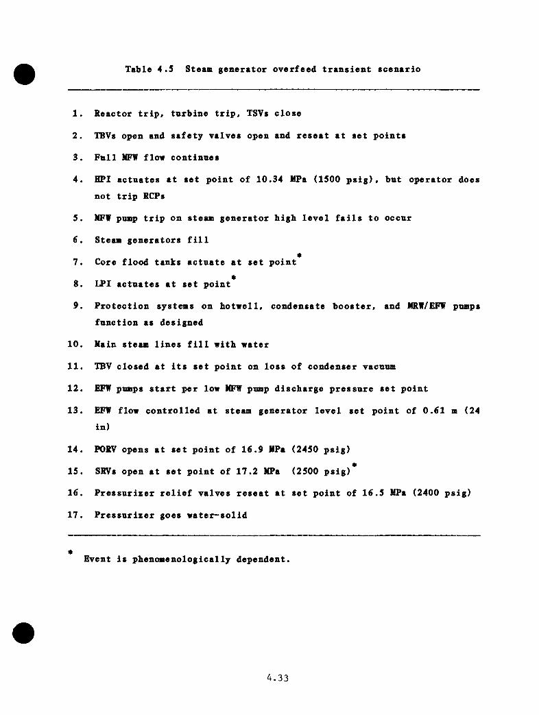
Table 4.5 Stean generator overfeed transient scenario
#
1. Reactor trip, tnrbine trip. TSVs close
2. TBVs open and safety valves open and reseat at set points
3. Full MFW flow continues
4. HPI actuates at set point of 10.34 MPa (1500 psig). but operator doesnot trip RCPs
5. MFW pump trip on steam generator high level fails to occur
6. Steam generators fill*7. Core flood tanks actuate at set point
8. IPI actuates at set point
9. Protection systems on hotwell, condensate booster, and MRW/EFW pumps function as designed
10. Main steam lines fill with water
11. TBV closed at its set point on loss of condenser vacuum
12. EFW pumps start per low MFW pump discharge pressure set point
13. EFW flow controlled at steam generator level set point of 0.61 m (24 in)
14. PORV opens at set point of 16.9 MPa (2450 psig)
15. SRVs open at set point of 17.2 MPa (2500 psig)
16. Pressurizer relief valves reseat at set point of 16.5 MPa (2400 psig)
17. Pressurizer goes water-solid
*Event is phenomenologically dependent.
4.33
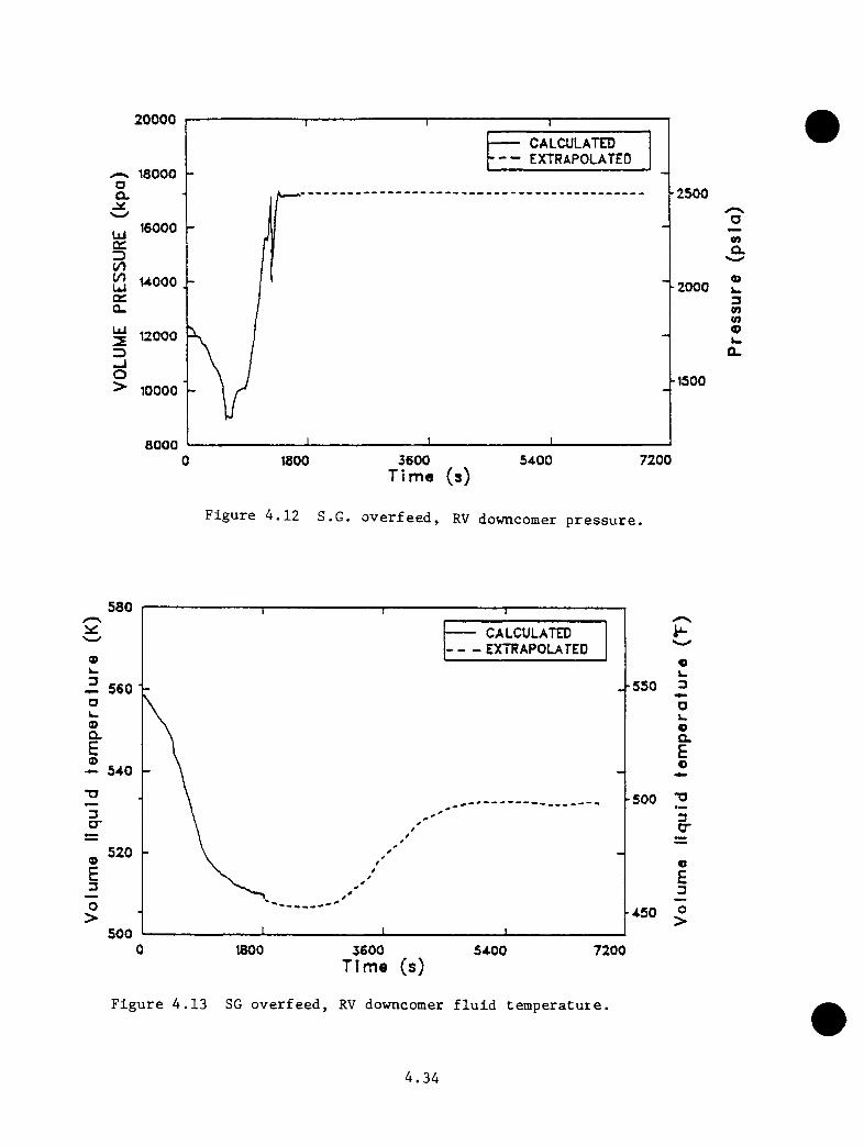
20000 CALCULATTO EXTRAPOLATED
^ 18000•2500Q.
16000LUcr
-2000
12000
-150010000
800072003600 54000 1800
Time (s)
Figure 4.12 S.G. overfeed, RV downcomer pressure.
xnO.
3nm9
580— CALCULATED- - EXTRAPOLATED
k.3 -550560 ■ak.oa.Eo> 540
•5003cr
5209E3O>
5000 1800 3600 7200
Time (s)
Figure 4.13 SG overfeed, RV downcomer fluid temperature.
«k-3Oi-oa.Eo
3O'
«£_3O>
4.34
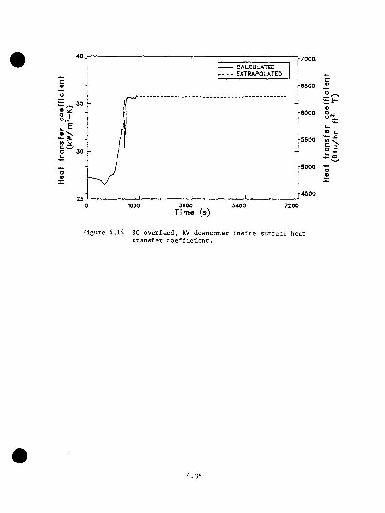
F7000 CALCULATTD EXTRAPOLATED
■6500
35-6000
NE
-550030
■500C
-4.500251800 3600
TFme (s)5400 7200
® 1o I
x: a
• E CD
oa>
Figure 4.14 SG overfeed, RV dovmcomer inside surface heat transfer coefficient.
4.35

coefficient, shown in Figure 4.14, represents forced convection conditions
throughout the calculation. The variations observed in the coefficient are
prinarily due to changing fluid densities and pressures as the transient
proceeded.
4.3 .1.3 Hot Leg Snal1-Break Transient
The sequence is initiated by a stuck-open power-operated relief valve. The
operator is assuned not to trip power to the reactor coolant pumps. The
transient is described in Table 4.6. This sequence is transient number
52 (INEL2) in Table 4.25.
Results of the calculation and an extrapolation to 2 h are shown in Figures
4.15 through 4.17. Figure 4.15 shows the reactor vessel downcomer fluid
pressure response. The minimum calculated pressure was 8.68 MPa (1259
psia). As shown in Figure 4.8, the minimum downcomer fluid temperature
was 545 K (521*’f ) and occurred at 2 h the end of the extrapolation. The
extrapolated primary pressure at 2 h is 11.38 MPa (1650 psia). The heat
transfer coefficient on the inside surface of the reactor vessel downcomer
wall is extrapolated to drift downward as fluid properties change, as shown
in Figure 4.17. The coefficient represents forced-convection conditions
throughout the calculation.
4.3.1.4 Revised Main Steam Line Break
The revised main steam line break has the same specification as the LANL
main steam line break base case (Section 4.3.2.1). This sequence is
transient 51 (INELl) in Table 4.25. The revised case differs from the
original INEL case in the reactor coolant pump (RCP) restart and the high-
4.36
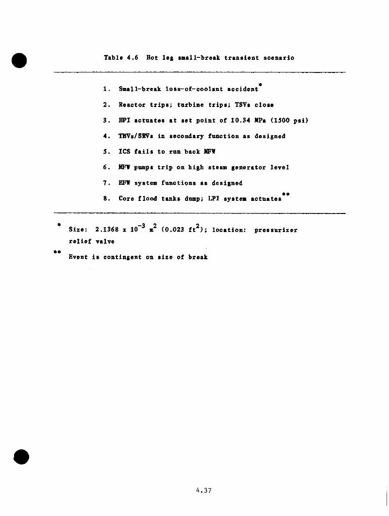
Table 4.6 Hot leg small-break transient scenario
1. Small-break loss-o£-coolant accident
2. Keactor trips; tnrbine trips; TSVs close
3. HPI actuates at set point of 10.34 MPa (ISOO psi)
4. IBVs/SRVs in secondary function as designed
5. ICS fails to run back MFW
6. NFV pumps trip on high steam generator level
7. EFW system functions as designed
8. Core flood tanks dump; LPI system actuates
*•
Size: 2.1368 z 10 ^ m^ (0.023 ft^); location: pressurizerrelief valve
Event is contingent on size of break
4.37

16000
Ojst UOOO
Uicr3t/y(/y 12000Uicrcu
O10000
8000
— CALCULATED EXTRAPOLATED
| X _ ..........................
2200
2000
-1800
na.
3-
1600 *» V u a.
huoo
h120O1000 2000 3000 AOOO 5000
Time (s)6000 7000 SOOQ
Figure 4.15 Hot leg small break, RV downcomer pressure.
580
cr3H-<01 Uicr2
570
560
3O
Ui23_lO>
550
540
— CALCULATED EXTRAPOLATED
580 ^
560
540
520
UIQC3I—<cruia.2Uia3a
23-JO>
1000 2000 3000 4000 5000Time (s)
6000 7000 8000
Figure 4,16 Hot leg small break RV downcomer fluid temperature.
4.38
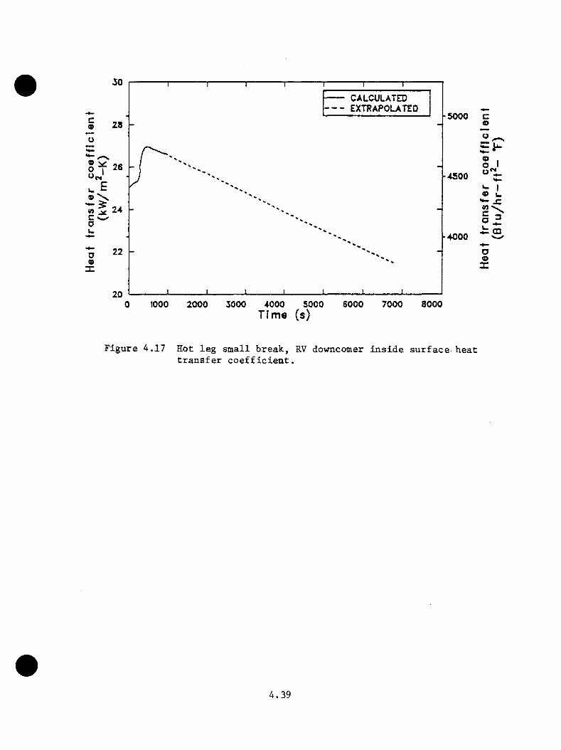
CALCULATED- - EXTRAPOLATED ■5000
28
s> ^ O I
l- -4000
206000 7000 8000tooo 3000 4000 50000 2000
c(D
•*- •® IO Io*V
•*- XO X ^ ffl
ooX
Time (s)
Figure 4.17 Hot leg small break, RV downcomer inside surface-heat transfer coefficient.
4.39

pressure injection (HPI) throttling criteria. In this case, the restart
of one RCP per loop is iamediate upon attaining 42^C (7S^F) snbcooling,
and HPI is throttled to aaintain snhcooling of 42 - 14*^0 (75 - 25^F).
The sequence is initiated by a 200% double-ended rupture of a aain steaa
line on one steaa generator. All autcaatic plant functions are assuaed
to be operative. Operator actions are assuaed to trip reactor coolant
puap power 30 s after initiation of high-pressure injection, terainate
all feedwater and turbine bypass on both steaa generators at 10 ain, and
reactivate eaergency feedwater and turbine bypass to the unaffected steaa
generator at 15 ain.
Table 4.7 gives the sequence of events for the calculation. Figures 4.18
through 4.20 susuaarize the results of the calculation and extrapolation to
7200 s.
As shown in Figures 4.18 and 4.19, the calculated ainiaua reactor vessel
downcoaer aixed fluid teaperature was 494 K (429°F) and the calculated
aaxiaua subsequent fluid pressure was 16.99 MPa (2465 psia). The downcoaer
heat transfer coefficient is given in Figure 4.20.
The calculation of downcoaer fluid teaperature was particularly sensitive
to the requireaent in the scenario to restart reactor coolant puaps upon
attaining 42 K (75°F) subcooling in both hot legs. This requireaent was
aet 300 s into the transient, and the restarting of the puaps caused the
ainiaua downcoaer teaperature to be much warmer than if the puaps had not
been restarted. Since the attainaent of subcooling is sensitive to hot leg
asyaaietry and because a one-diaensional coaputer aodel such as RELAP5 will
4.40

Table 4.7 Revised MSLB sequence of events
Event
Time from Start of Transient
(s)
Reactor trip; tnrbine trip break opens 0
Main feedwater pnmps tripped on high level in affected steam 0.3generator
Emergency feedwater tripped on, based on low main feedwater pnmp 4.4discharge pressure
HPI tripped on, based on low hot leg pressure 5.3
RC pnmps tripped (30 s after HPI initiation) and main feedwater 35.3rerouted to emergency feedwater header
75°F snhcooling attained in both hot legs, 2 RC pnmps restarted, 300 and HPI throttled to maintain 50-100°F snhcooling
Unaffected steam generator level recovered to 240 in; main 320feedwater to this steam generator is terminated and emergency feedwater is throttled to maintain 240-in. level
Restarted RC pnmps are up to full speed 360
Hotwell surge tank is empty: motor-driven emergency feedwater 513is terminated to both steam generators
Per scenario, all main and emergency feedwater and tnrbine 600bypass capability is terminated
Per scenario, tnrbine bypass and tnrbine-driven emergency 900feedwater is made available to the unaffected steam generator
Last time HPI is injected because snhcooling is greater 1992than lOO^F after this time
Pressurizer level reaches top 2354
PORV opening set point pressure reached 2432
Calculation terminated 2697
4 . 4 1
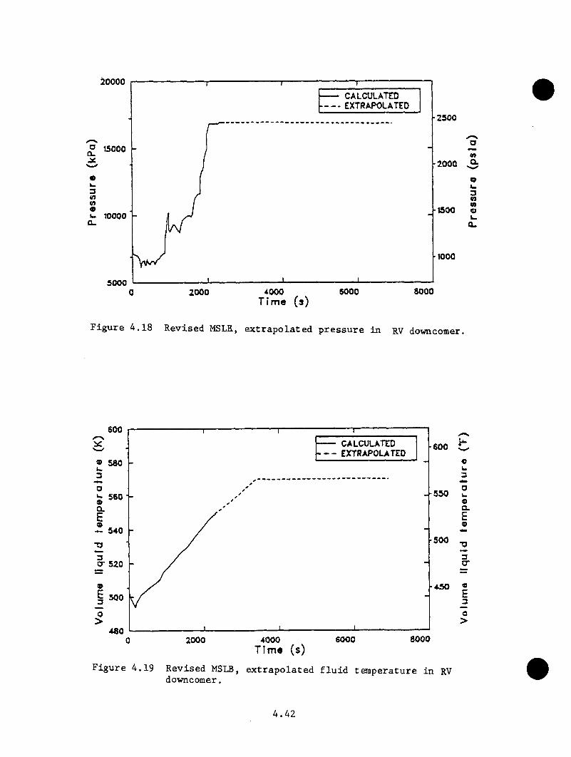
20000— CALCULATED - - EXTRAPOLATED
■2500
P 15000•2000
■1500k. 10000O.
■1000
50006000 8000400020000
tnQ.
3tntnVu0.
Figure 4.18 Revised MSLR, extrapolated pressure in RV downcomer.
600- CALCULATED- EXTRAPOLATED
-600» 580
■550
■500
cr 520
500
480800060002000 40000
«k.3Ok.oaEo
3tr
E_3O>
Figure 4.19 Revised MSLB, extrapolated fluid temperature in RV downcomer.
4.42
not predict this asymmetry, the timing of the pump restart is uncertain.
The effect of this and other specific uncertainties on minimum downcomer
fluid temperature has been estimated to reduce the best estimate minimum
downcomer fluid temperature to 462 K (372°F) with a lower uncertainty bound
of 415 K (287°F).e See Reference 4.1 for further details.
4.3 .1.5 Maximum Sustainable Overfeed Transient
The maximum sustainable overfeed transient employed a reduced MFW pump
speed to circumvent the automatic feedwater system protection features
(i.e., NFV pump trip on low suction pressure) that tripped the feedwater
system early in the steam generator overfeed transient (Section 4.3.1.2).
The maximum sustainable overfeed sequence is transient 56 (INEL6) in Table
4.25.
The transient was initiated from full-power steady state conditions (nominal
temperature and pressure). The pressurizer heaters and spray operate as
designed. The transient was initiated by a turbine trip that tripped
the reactor and closed the turbine stop valves. Decay heat was assumed
to be at the ANS standard rate. Instead of running back flow, the main
feedwater system continued to supply the maximum sustainable flow to both
steam generators without a trip from the component protection feature to
the main feedwater pumps. It was assumed the main feedwater pump trip on
steam generator high level failed to occur, allowing both steam generators
to fill completely. The main feedwater pumps were eventually tripped on
low steam quality in the main steam lines.
*It should be noted that the adjustment of the downcomer temperature to reflect the uncertainty is inconsistent with the uncertainty analyses described later in this report.
4.43
Table 4.8 gives tbe sequence of events calculated for the transient. At
the teraiination of the calculation, systea behavior had been established
such that extrapolation of the dovnconer pressure, temperature, and vessel
inside wall heat transfer coefficient to 7200 s was possible, as shown in
Figures 4.21 through 4.23. The lowest downcomer liquid temperature in this
time frame was 500 K (440^F). Subsequent to this minimum temperature, the
maximum downcomer pressure was 16.99 MPa (2465 psia).
4.3.1.6 Turbine Bypass Valve Failure at Reactor Hot Standby
The turbine bypass valve failure at reactor hot standby is listed as
transient 57 (LANL7) in Table 4.25. The RELAP5 full-power model was
converted to hot standby conditions by the changes listed in Reference 4.1.
As specified, the realignment of MFW to the emergency feedwater headers was
locked out for this calculation.
The transient was initiated with the reactor at hot standby conditions.
At zero time, all four turbine bypass valves (two on each steam line) are
assumed to fail open, and all automatic plant systems are assumed to be
operative. Operator actions are assumed for tripping reactor coolant pump
power 30 s after high-pressure injection begins and closing turbine bypass
block valves at 10 min.
Table 4.9 gives the sequence of events for the calculation. Figures 4.24
through 4.26 summarize the results of the calculation.
As shown in Figure 4.25, the minimum calculated reactor vessel downcomer
fluid temperature was 387 K (237°F) near the end of the transient. The
maximum calculated reactor vessel downcomer pressure was 16.99 MPa (2465
4.44

Table 4.8 Mazimim sustainable overfeed transient sequence of events
TimeEvent (s)
Turbine trip, reactor trip, turbine stop valves close, main 0.0feedwater pumps run back to 490 rad/s (4675 rpm); secondary pressure increased to turbine bypass and; safety relief valve set points. Feed train beater drains begin to close; pressurizer begins to drain
Heater drains closed 5.0
Steam generator 6 secondary pressure dropped below safety relief 25.0valve set point; valves close
Steam generator A secondary pressure dropped below safety relief 28.0valve set point; valves close
Pressurizer liquid level dropped below beater cutoff set point; 35.0beaters latcbed off
Steam generator B secondary completely liquid-full and steam line 240.0commenced to fill
Steam generator A secondary completely liquid-full and steam line 250.0commenced to fill
Primary pressure dropped below bigb-pressure injection set point 269.0and bigb-pressure injection flow was initiated
Vessel upper bead began to void 275.0
Reactor coolant pumps trip; feed flow realigned to EFW header; 299.0main feed valves close
Steam generator B turbine bypass valves close 341.0
Steam generator A turbine bypass valves close 350.0
Void in steam line B dropped below 20%; main feedwater pumps 417.0trip off
Void in vessel upper bead collapsed 434.0
Pressurizer began to refill 448.0
Primary system began to repressurize 524.0
4.45

Table 4.8 (continned)
TimeEvent (s)
Steam generator A secondary pressure reached turbine bypass 930.0valve set point and valves crach open
Primary pressure reached power-operated relief valve opening 1054.0set point and cycles around set point
Pressurizer becomes liquid-solid 1079.0
Steam generator B secondary pressure reached turbine bypass 1424.0valve set point and valves crack open
Transient terminated; system pressure stabilized at power- 1695.0operated relief valve opening set point; primary temperature was slowly increasing
4.46
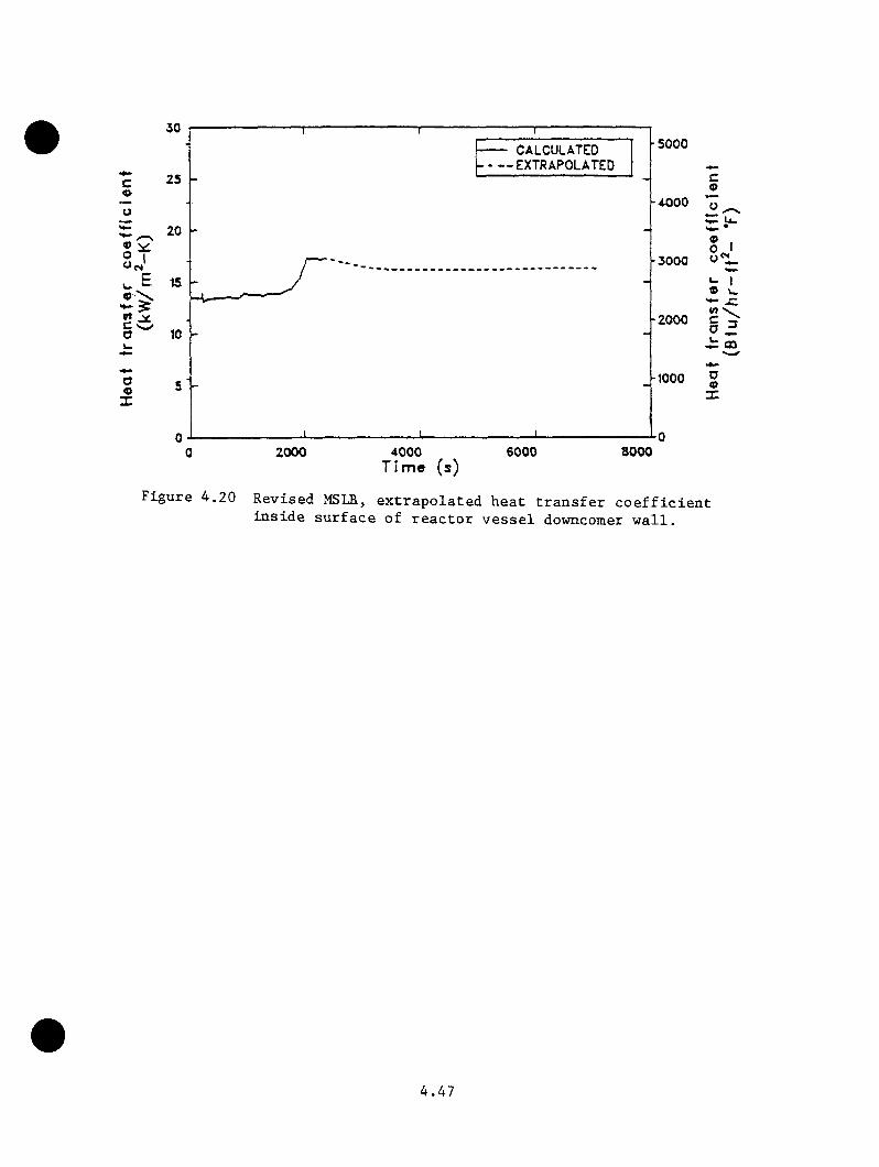
■5000 CALCULATED EXTRAPOLATED
25
20-3000
« VC O -2000
-1000
2000 4000 Time (s)
6000 8000
co
® IO I o'!.
» I-x:
o<D
Figure 4,20 Revised MSLB-, extrapolated heat transfer coefficient inside surface of reactor vessel downcomer wall.
4.47
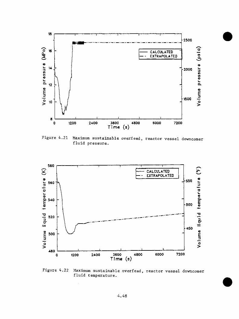
18-2500
18 CALCULATED— - e x t r a p o l a t e d
CL
U -2000
12
-150010
a1200 2400 3600 4800
T im e (s)8000 7200
mCL
3n(Oo
oE3O>
Figure 4.21 Maximum sustainable overfeed, reactor vessel downcomer fluid pressure.
580 CALCULATED— - EXTRAPOLATED
-550
•500
*o520
O"
500
7200600036000 1200
«i-3a«a.Eo
3cr
«E3O>
T im e (s)
Figure 4.22 Maximum sustainable overfeed, reactor vessel downcomerfluid temperature.
4.48

Table 4.9. Turbine bypass valve failure at reactor bot standby transientsequence of events
EventTime(s)
Turbine bypass valves fail open 0MFW pump discharge pressure decreases to 765 psia 27.3HPI initiated 125.1RCPs tripped— steam generator low-level limit changed from relative to SU level taps to 240 in. relative to operating taps
24 in. level
155.1
EFW initiated in steam generator A and steam generator B because of change in low-level set pointCondensate booster pump trips on low suction pressure 163.4MFW pump trips on low suction pressure 168.5MFW train isolated from steam generators after feedwater flow decreases to zero
228.6
Core flood tank injection initiated 383.5Core flood tank injection ends 391.6Turbine bypass valves closed 600.0Pressurizer filled 900.0PORV set point reached 949.6Steam generator operating level at 240 in. 1010.2Steam generator EFW sources tripped off for last time 1030.4Steam generator A operating level at 240 in. 1070.5Steam generator A EFW sources tripped off for last time 1074.6Primary loop B cold leg suction temperature exceeds loop B leg temperature
hot 1620.5
Primary loop A cold leg suction temperature exceeds loop A leg temperature
hot 1892.2
Downcomer wall temperature reaches 265^F 4600.0Transient terminated 7200.0
4.49
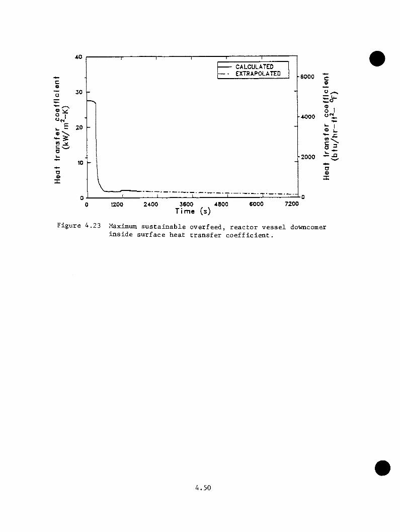
CALCULATEDEXTRAPOLATED -6000
30
” IIE 20
-2000
«•X
1200 2400 3600 4800Time (s)
6000 7200
c<DO,
® 1 o 1
o Lc > a ^-Jrxia(S
X
Figure 4.23 Maximum sustainable overfeed, reactor vessel downcomer inside surface heat transfer coefficient.
4.50
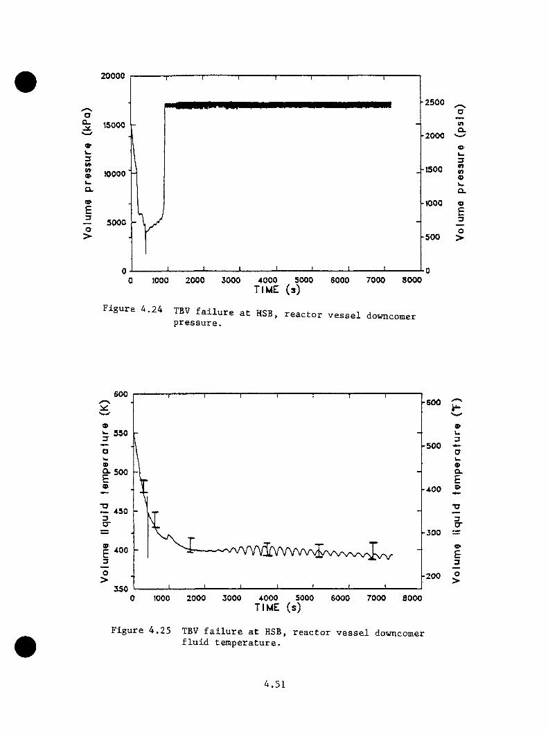
20000
■2500
-2000O'w3«»S 10000 ■wa.o£— 5000O >
.-1500
-1000
-500
tna.4)U.3tntno>
oE3
O>
1000 2000 3000 4000 5000TIME (»)
6000 7000 8000
Figure 4.24 TBV failure at HSB, reactor vessel downcomer pressure.
600-600
i: 550-500
9- 500-400
450
-300400
-200350
»u3
9Q.£
3cr
9E3O>
1000 2000 3000 4000 5000TIME (s)
6000 7000 8000
Figure 4.25 TBV failure at HSB, reactor vessel downcomerfluid temperature.
4.51

psia), tlie opening set point pressure for the power-operated relief valve
(see Figure 4.24).
The uncertainty in the calculated downconer fluid teaperature, expressed
as error bars in Figure 4.2S, was assessed. This uncertainty was due
to startup valve operation, code-calculated condensation effects, and low
level limit determination method. The uncertainty was found to be minor,
and the conclusion is that the calculated temperature represents the lower
temperature limit of the uncertainty band.
4.3.1.7 Pressurizer Surge Line Small-Break Transient
The pressurizer surge line small-break transient was calculated using both
RELAP5 and T8AC (see Section 4.3.2.5). The INEL calculation is transient
55 (INEL5) in Table 4.25.
The transient was initiated by a 0 .0508-m-(2-in.) diam break in the
horizontal section of the pressurizer surge line with the reactor at full
power conditions. Operator action is assumed to trip power to the reactor
coolant pumps (RCPs) 30 s after initiation of high-pressure injection
(HPI). This scenario is similar to that discussed in Section 4.3.1.3
except that the break is larger and has been relocated from the PORV to
the surge line. Operator action to trip RCPs is assumed.
Table 4.10 gives the sequence of events for the calculation. Figures 4.27
through 4.29 suamarize the results of the calculation and extrapolation to
7200 s. Error bars indicate the uncertainty limits for this calculation.
4.52
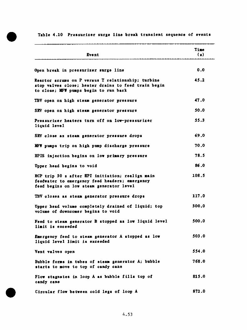
Table 4.10 Pressnxizer surge line break transient sequence of events
TimeEvent (s)
Open break in pressurizer surge line 0.0
Reactor scrams on P versus T relationship: turbine 45.2stop valves close; heater drains to feed train begin to close; MFW pumps begin to run back
TBV open on high steam generator pressure 47.0
SRV open on high steam generator pressure 50.0
Pressurizer heaters turn off on lov-pressurizer 55.3liquid level
SRV close as steam generator pressure drops 69.0
MFW pumps trip on high pump discharge pressure 70.0
HPIS injection begins on low primary pressure 78.5
Upper head begins to void 86.0
RCP trip 30 s after HPI initiation; realign main 108.5feedwater to emergency feed headers; emergency feed begins on low steam generator level
TBV closes as steam generator pressure drops 117.0
Upper head volume completely drained of liquid; top 300.0volume of downcomer begins to void
Feed to steam generator B stopped as low liquid level 500.0limit is exceeded
Emergency feed to steam generator A stopped as low 503.0liquid level limit is exceeded
Vent valves open 554.0
Bubble forms in tubes of steam generator A; bubble 768.0starts to move to top of candy cane
Flow stagnates in loop A as bubble fills top of 815.0candy cane
Circular flow between cold legs of loop A 872.0
4.53
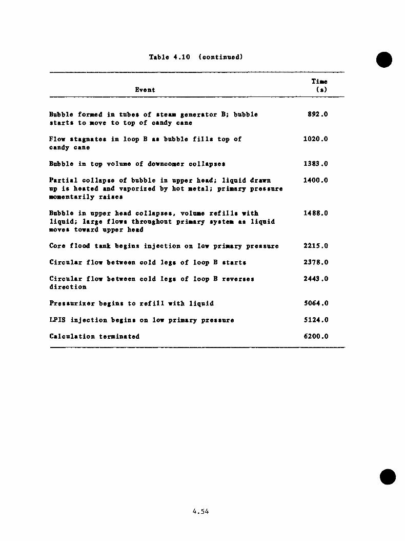
Table 4.10 (continued)
EventTime(s)
Bubble formed in tubes of steam generator B; bubble 892.0starts to move to top of candy cane
Flow stagnates in loop B as bubble fills top of 1020.0candy cane
Bubble in top volume of downcomer collapses 1383.0
Partial collapse of bubble in upper head: liquid drawn 1400.0up is heated and vaporized by hot metal; primary pressure momentarily raises
Bubble in upper head collapses, volume refills with 1488.0liquid; large flows throughout primary system as liquid moves toward upper head
Core flood tank begins injection on low primary pressure 2215.0
Circular flow between cold legs of loop B starts 2378.0
Circular flow between cold legs of loop B reverses 2443.0direction
Pressurizer begins to refill with liquid 5064.0
LPIS injection begins on low primary pressure 5124.0
Calculation terminated 6200.0
4.54
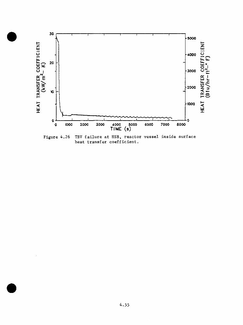
30-5000
-4000u. 20
-3000
-2000
-1000Ui
2000 3000 5000 SOOO 7000 SOOO1000 40000
zUi
CJti. tZ"Ui •O I
Q£ I ui ^ Li- JZ
Q1 CQ t—
<UJ
TIME (s)
Figure 4.26 TBV failure at HSB, reactor vessel inside surface heat transfer coefficient.
4.55

oa.2
ocz>tninU ioca.U i2Z>_ (o>
20 CALCULATED EXTRAPOLATED -2500
15 -2000
-150010
-1000
5-500
01000 2000 3000 4000 5000 SOOO 7000 8000
Time (s)0
Figure 4.27 Pressurizer surge line bxeak, extrapolated RV downcomer pressure.
-600 CALCULATED EXTRAPOLATED
b 550-500
-400
450
-300
400
-200350
ou3
001£9
3O'
9E3O>
1000 2000 3000 4000 SOOOTime (s)
6000 7000 8000
Figure 4.28 Pressurizer surge line break, extrapolated RV downcomerfluid temperature.
4.56
As shovn in Figure 4.28, the BiniauB downcoBer fluid teaperature calculated
vas 380 K (22S°F) and occurred at the end of the calculation, 6200 s. By
extrapolating trends evident near the end of the calculation, the downcoaer
teaperature would drop to 355 K (180*^F) by 7200 s. The ainiaua cold leg
teaperature calculated (adjacent to the reactor vessel) was 333 K (140*^F),
which occurred at 1130 s when the priaary systea pressure was 6.1 MPa (740
psia). At the end of the calculation, the priaary systea pressure was at
the LPI shutoff head, 1.48 MPa (214 psia). Since LPI injection was holding
priaary pressure at this point, it would be expected to stay very close
to that pressure through 7200 s.
4.3 .1.8 Reactor Coolant Puap Suction Saall-Break Transient
The reactor coolant puap suction saall-breah sequence is transient 58
(INEL8) in Table 4.25.
The transient is initiated froa full power steady state (noainal teaperature
and pressure). The pressurizer heaters and spray operate as designed. The
transient is begun by a break downstreaa of a valve in the letdown line
connected to the bottoa of the A-1 puap suction leg.
The letdown line is 0.0635 a (2-1/2 in) in diaaeter. The break was assuaed
to occur downstreaa of a aotor valve that could be isolated. Closure
of this block valve was si>ecified to occur only after core flood tank
injection. The distance froa the priaary piping to the valve in the line
was approxiaately 15.24 a (50 ft). The valve throat was assuaed to have
the saae inside diaaeter as the pipe.
4.57
Folloving reactor scraa, the decay heat ia assumed to be the ANS standard.
The tnrbine stop valves close, and it is assnmed the integrated control
system operates as designed. After the core flood tanks empty, the break
is isolated and high-pressnre injection flow is throttled when 28 K (50°F)
snbcooling is attained, bnt only if the primary system has repressnrized
to the power-operated relief valve (PORV) set point.
Table 4.11 gives the sequence of events for the calculation. Figures
4.30 through 4.32 summarize the calculation and extrapolation to 7200 s for
downcomer temperature and pressure. Error bars in the figures identify the
uncertainty limits. Calculated oscillations of cold leg flow contributed
to the uncertainty and caused early termination of the calculation.
For the reactor coolant pump suction break sequence, the downcomer fluid
temperature was 470 E (38d^F) at the end of the calculation (4900 s). The
transient was extrapolated to 7200 s (2 h), and at that time, the downcomer
temperature was estimated to be 446 K (343^F) at a pressure of 5.1 NPa
(740 psia).
The major uncertainty in the calculation is related to the existence
of loop flow oscillations. Had these oscillations not been present in
the calculation, the downcomer fluid temperature at 2 h would have been
estiaiated to be 390 K (242°F) .
The sequence requirement to isolate the break (by closing the motor block
valve in the letdown) was not encountered because core flood tank injection
did not occur. Had this isolation occurred, the subsequent maximum primary
4.58
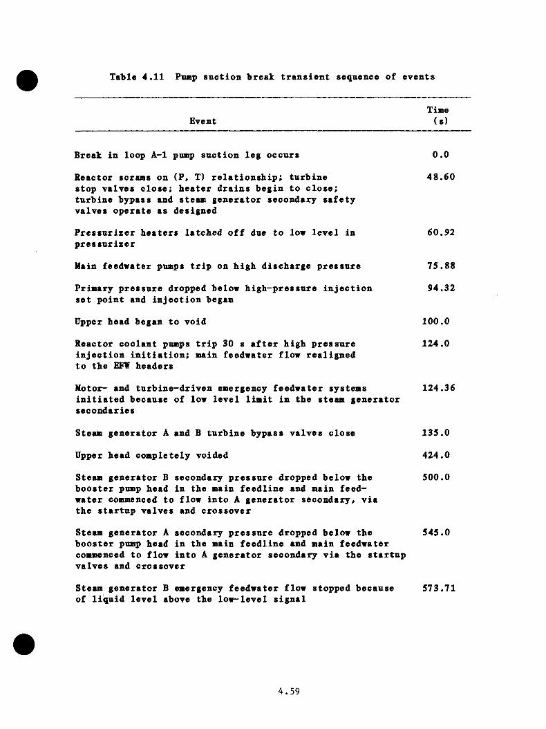
Table 4.11 Pnaip suction bxeak transient sequence of events
EventTime(s)
Break in loop A-1 pump suction leg occurs 0.0
Reactor scrams on (P, T) relationship; turbine 48.60stop valves close: heater drains begin to close; turbine bypass and steam generator secondary safety valves operate as designed
Pressurizer heaters latched off due to low level in 60.92pressurizer
Main feedwater pumps trip on high discharge pressure 75.88
Primary pressure dropped below high-pressure injection 94.32set point and injection began
Upper head began to void 100.0
Reactor coolant pumps trip 30 s after high pressure 124.0injection initiation; main feedwater flow realigned to the EFW headers
Motor- and turbine-driven emergency feedwater systems 124.36initiated because of low level limit in the steam generator secondaries
Steam generator A and B turbine bypass valves close 135.0
Upper head completely voided 424.0
Steam generator B secondary pressure dropped below the 500.0booster pump head in the main feedline and main feedwater commenced to flow into A generator secondary, via the startup valves and crossover
Steam generator A secondary pressure dropped below the 545.0booster pump head in the main feedline and main feedwater commenced to flow into A generator secondary via the startup valves and crossover
Steam generator B emergency feedwater flow stopped because 573.71of liquid level above the low-level signal
4.59
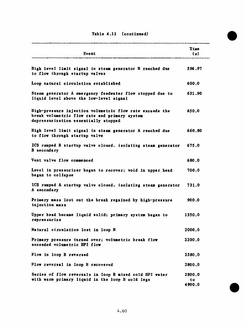
Table 4.11 (continued)
EventTiine(s)
High level U n i t signal in steam generator B reached due 596.97to flow through startup valves
Loop natural circulation established 600.0
Steam generator A emergency feedwater flow stopped due to 631.90liquid level above the low-level signal
High-pressure injection volumetric flow rate exceeds the 650.0break volumetric flow rate and primary system depressurization essentially stopped
High level limit signal in steam generator A reached due 660.80to flow through startup valve
ICS ramped B startup valve closed, isolating steam generator 675.0 B secondary
Vent valve flow commenced 680.0
Level in pressurizer began to recover; void in upper head 700.0began to collapse
ICS ramped A startup valve closed, isolating steam generator 731.0 A secondary
Primary mass lost out the break regained by high-pressure 900.0injection mass
Upper head became liquid solid: primary system began to 1350.0repressurize
Natural circulation lost in loop B 2000.0
Primary pressure turned over; volumetric break flow 2200.0exceeded volumetric HPI flow
Flow in loop B reversed 2380.0
Flow reversal in loop B recovered 2800.0
Series of flow reversals in loop B mixed cold BPI water 2800.0with warm primary liquid in the loop B cold legs to
4900.0
4.60
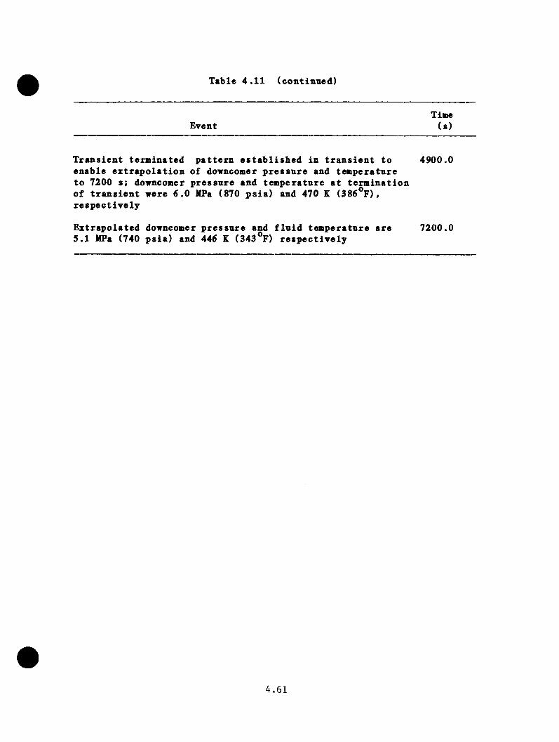
Table 4.11 (continued)
TimeEvent (s)
Transient terminated pattern established in transient to 4900.0enable extrapolation of downcomer pressure and temperature to 7200 s; downcomer pressure and temperature at termination of transient were 6.0 MPa (870 psia) and 470 K (386*^F), respectively
Extrapolated downcomer pressure and fluid temperature are 7200.05.1 MPa (740 psia) and 446 K (343°F) respectively
4 . 6 1
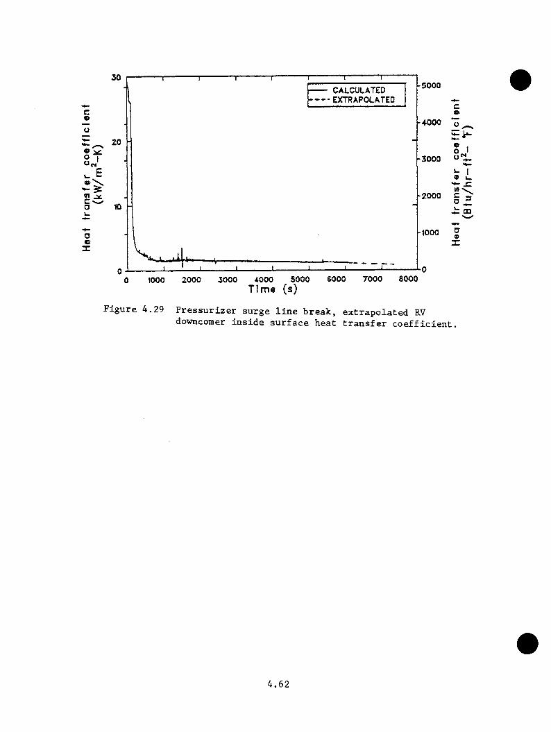
I
<Rc-a
30 -5000• CALCULATED - EXTRAPOLATED
20-3000
-200010
-1000
0 7000 3000600050002000 3000 40000 1000
ca>
® I° J
a ^ m
a9
X
Figure 4.29 Pressurizer surge line break, extrapolated RVdowncomer inside surface heat transfer coefficient.
4.62
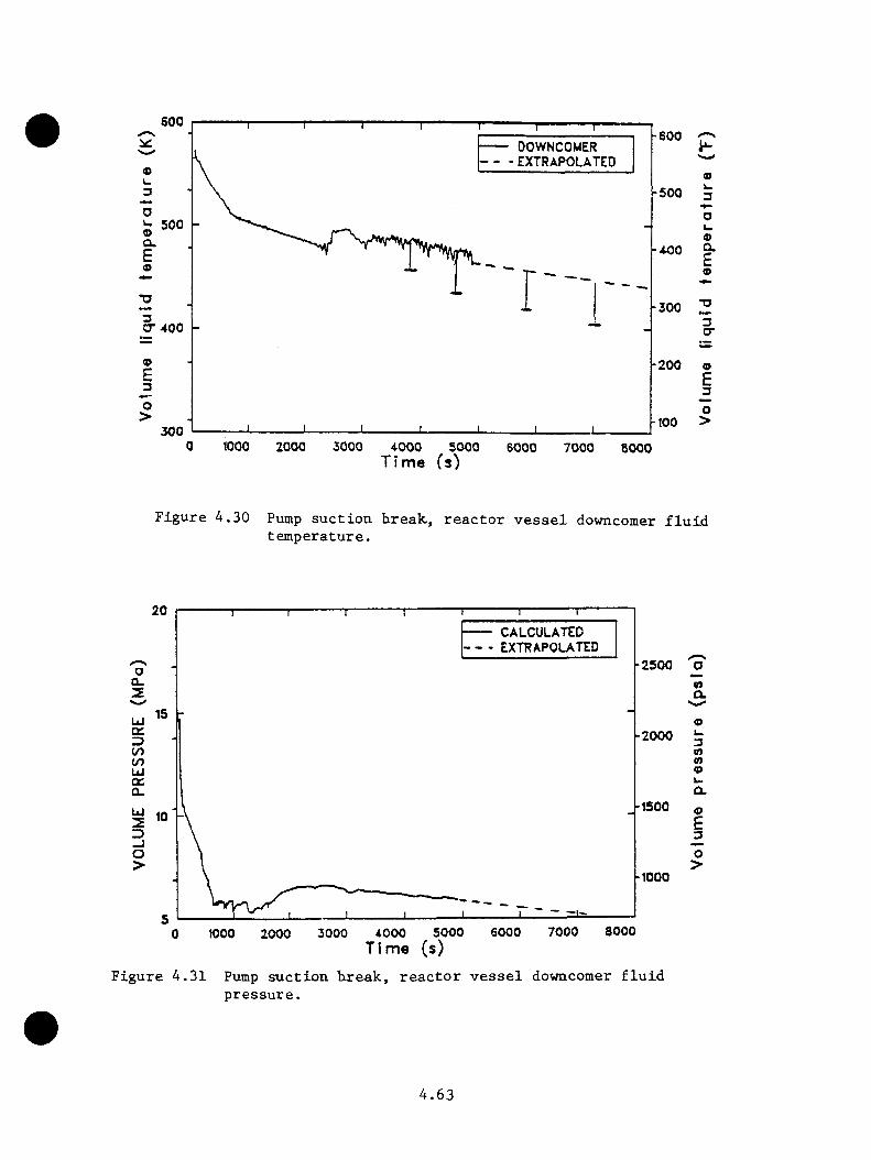
600-600
• DOWNCOMER - EXTRAPOLATED
-500
« 500 Q.
-300CT400
-200
-1003000 1000 30002000 4000 5000 6000 7000 8000
o>k.3
9aEo
3or
(0£3O>
Time (s)
Figure 4.30 Pump suction Loreak, reactor vessel downcomer fluid temperature.
20CALCULATEDEXTRAPOLATED
-2500CL
LJ□C -2000toUIQCQ.
-1500Ui
-1000
SOOO7000SOOO 60003000 40000 1000 2000
0)Ol
3nn9
9E3O>
Time (s)Figure 4.31 Pump suction tireak, reactor vessel downcomer fluid
pressure.
4.63

pressure vould have bees ~16.99 MPa (2465 psia)< tbe opening pressure set
point of tbe power-operated relief valve.
4.3 .1.9 Steam Generator Tube Rupture Transient
Tbe steam generator tube rupture sequence is transient 59 (INEL9) in Table
4.25. Tbe transient is initiated from full power steady state conditions
(nominal temperature and pressure). Tbe pressurizer beaters and spray
operate as designed. Tbe transient begins witb a rupture of a single steam
generator tube (double-ended break) in tbe A loop steam generator. It is
assumed tbe ICS operates as designed. Tbe reactor scrams and tbe turbine
stop valves close. Emergency feedwater starts on low-level limit signal
and secondary safety relief and turbine bypass valves operate as designed.
Table 4.12 gives tbe sequence of events for tbe calculation. Figures 4.33
tbrougb 4.35 summarize tbe calculation and extrapolation to 7200 s. At tbe
termination of tbe transient, tbe primary system pressure was oscillating
around tbe PORV set point pressure of 17.0 MPa (2465 psia). Tbe reactor
vessel downcomer liquid temperature, wbicb is of PIS concern, was at 517
K (470°F) and increasing slightly. As sbown in Figures 4.33 and 4.34,
tbe extrapolated values of pressure and temperature to 7200 s are 17.0 MPa
(2465 psia) and 544 K (520°F) respectively. Tbe lowest vessel downcomer
liquid temperature was 505 K (450°F), wbicb occurred at 1700 s.
4.3.2 TRAC Calculations
Tbe sequences simulated by tbe TRAC model are listed in Table 4.2. Detailed
discussion of tbe transients and tbe results are available in Reference
4.2. A summary of all transients discussed bere and in Sections 4.3.1
4.64
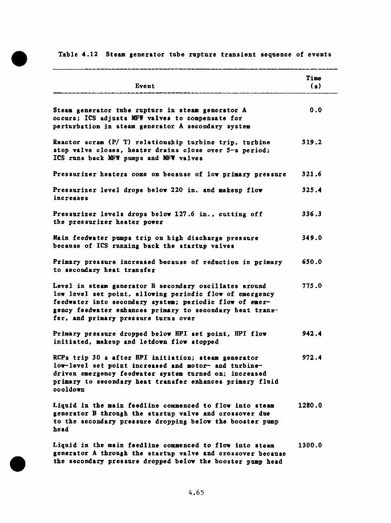
Table 4.12 Steam generator tube rupture transient sequence of events
EventTime(s)
Steam generator tube rupture in steam generator A occurs: ICS adjusts MFW valves to compensate for perturbation in steam generator A secondary system
Reactor scram (P/ T) relationship turbine trip, turbine stop valve closes, heater drains close over 5-s period;ICS runs back MFW pumps and MFW valves
Pressurizer heaters come on because of low primary pressure
Pressurizer level drops belov 220 in. and makeup flow increases
Pressurizer levels drops below 127.6 in. the pressurizer heater power
cutting off
Main feedwater pumps trip on high discharge pressure because of ICS running back the startup valves
Primary pressure increased because of reduction in primary to secondary heat transfer
Level in steam generator B secondary oscillates around low level set point, allowing periodic flow of emergency feedwater into secondary system: periodic flow of emergency feedwater enhances primary to secondary heat transfer, and primary pressure turns over
Primary pressure dropped below HPI set point, HPI flow initiated, makeup and letdown flow stopped
RCPs trip 30 s after HPI initiation: steam generator low-level set point increased and motor- and turbine- driven emergency feedwater system turned on; increased primary to secondary heat transfer enhances primary fluid cooldown
0.0
319.2
321.6
325.4
336.3
349.0
650.0
775.0
942.4
972.4
Liquid in the main feedline commenced to flow into steam generator B through the startup valve and crossover due to the secondary pressure dropping below the booster pump head
1280.0
Liquid in the main feedline commenced to flow into steam generator A through the startup valve and crossover because the secondary pressure dropped below the booster pump head
1300.0
4.65

Table 4.12 (continued)
EventTime(s)
Liquid level in steam generator A rose above the level limit 1396.6set point and EFW into the secondary uas terminated
Liquid level in steam generator B rose above the low level 1415.5limit set point and EFW into the secondary was terminated
Liquid level in steam generator A rose above the high-level 1426.0limit set point and ICS closed the startup valve, isolating steam generator A
Liquid level in steam generator B rose above the high-level 1437.6limit set point and ICS closed the startup valve, isolating steam generator B
Steam generators become heat sources; primary temperatures 1600.0begin to increase
Primary pressure reached PORV set point; the valves 2200.0oscillate around the set point, maintaining primarypressure
Pressurizer becomes liquid-solid 2450.0
Transient terminated; vessel downcomer liquid temperature 2800.0at 517 E (471°F) and increasing; pressure at the PORV set point
4.66
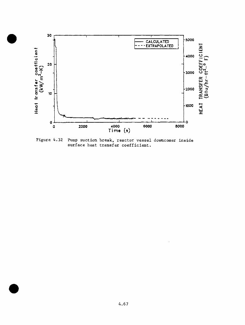
c
« > •** ><2C '«w'ou
ooX
30 p
t
20 H§Y
10 -
I — ' ■CALCULATED
•EXTRAPOLATED
2000J ______________________ L
60004000 Time (s)
5000
-4000
-3000
-2000
-1000
SOOO
o i Z ^<^o UJ Io j
q: IUI ^ u. ^ to Z 3^ m
Figure 4.32 Pump suction hreak, reactor vessel downcomer inside surface heat transfer coefficient.
4.67
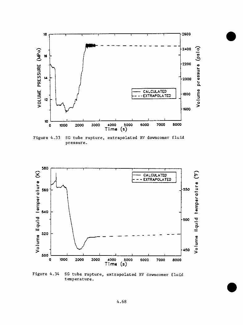
1 - 2 6 0 018
-24.00
-2200UJoc2D</)CO -2000U i
CALCULATED EXTRAPOLATED
O>-tsoo
8000700060003000 4000 5000Time (s)
20001000
<oQ.
3nV)9k.Q.OE3O>
Figure 4.33 SG tube rupture, extrapolated RV downcomer fluid pressure.
580 CALCULATED EXTRAPOLATED
-550a9Q.E9 540
-5003CT
5209E3O>
5000 1000 30002000 4000 5000 6000 7000 8000
Figure 4.34
Time (s)
SG tube rupture, extrapolated RV downcomer fluidtemperature.
9u3Ok.oa.Ee
3CT
9E_3O>
4.68
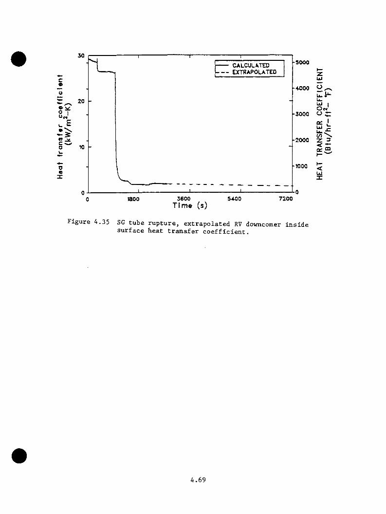
co
co
o«X
30
10 -
CALCULATEDEXTRAPOLATED
-5000
1800 3600Ti me (s)
5A00 7200
zUI
O n3000 O C
q: I
2000
woo <utX
Figure 4.35 SG tube rupture, extrapolated RV downcomer inside surface heat transfer coefficient.
4.69
and 4.5 is provided in Section 4.6 and Table 4.25. The Oconee-3 feedvater
transient was a benchaark case of no direct iaportance to this study and
is oaiitted here. Reference 4.2 contains a discussion of that calculation.
4.3 .2.1 Main Steaai Line Break
The LANL aiain steaa line break (MSLR) base case is the TRAC model
calculation (Section 4.3.1.4). Three parametric cases (cases 2, 3 and
4) reflecting different feedvater system responses were also performed.
The MS LB base case and parametric cases 2 and 3 appear in Table 4.25 as
transients 35 (LANLl), 37 (LANL3)< and 38 (LANL4) respectively. Parametric
case 4 was provided too late for inclusion in all phases of this study, but
would significantly impact the extrapolation of steam line break sequences
(see Appendix C, Section C.3.) The present discussion centers on the MS LB
base case calculation.
The transient is initiated by a double ended 34-in.-diam break in Steam
Line A. In the unaffected steamline (SG B) the TSV was closed, and the
TBV system operated as designed. All of the other systems also operated
as designed except for the parametric cases. The significant features
and initial conditions for the MS IB calculations were: (1). Full reactor
power. (2). Nominal temperatures and pressures in primary/secondary.
(3). Decay heat - 1.0 times ANS standard. (4). Reactor and turbine trips
coincident with ISLB. (5). Operator fails to isolate feedvater to both
SGs until 600 s. (6). Operator restores unaffected SG (SG B) at 900 s.
(7). RCPs restarted after 42 K subcooling reached. (8) . HPI throttled
to maintain 42 +12.5 K snbcooling.
A. 70

Cas« 2 v « t id o B t io a l t o th e base case excep t th e EFf system d id n o t a c tu a te
as d e s ig n ed because o f a m odeling e x ro r in tb e in p u t deck . In case 3 , in
a d d i t i o n t o the EFW s y s te m 's f a i l i n g to a c tu a te as d e s ig n ed , th e RCPs never
r e s t a r t e d a f t e r the su b co o lin g margin was reached because o f inpu t deck
e r r o r s . In case A, th e MFW pump was t r i p p e d a t 0 .5 s and th e subcoo ling
m on ito r f o r r e s t a r t i n g th e RCPs was moved from the h o t le g to the top
o f the c o re , th e p ro p e r l o c a t i o n . A lthough th e se p a ra m e tr ic ca se s were
n o t s p e c i f i e d , th ey a re s t i l l u s e f u l c a l c u l a t i o n s because they g ive o th e r
p o s s i b l e s c e n a r io s t h a t p o s s i b ly cou ld occur du r in g a NSLB t r a n s i e n t and
a r e u s e f u l f o r e x t r a p o l a t i o n a c t i v i t i e s .
T ab le 4 .13 g iv e s th e sequence o f e v en ts f o r the base case c a l c u l a t i o n .
F ig u re s 4 .3 6 th ro u g h 4 .3 8 summarize the r e s u l t s o f th e base case
c a l c u l a t i o n . The main fo r c in g f u n c t io n f o r the o v e rco o l in g was a s p e c i f i e d
d e la y o f th e o p e r a to r in i s o l a t i n g the a f f e c t e d steam g e n e ra to r coupled w ith
a d e la y in t h r o t t l i n g th e HPI f l o u . The base case ana lyzed had a l l p la n t
p r o t e c t i o n and c o n t r o l system s o p e ra te as d e s ig n e d . The minimum dovncomer
f l u i d te m p e ra tu re c a l c u l a t e d f o r the base case was 405 K. R e p r e s s u r iz a t io n
o f the p rim ary system to th e PORV s e t p o in t was c a l c u l a t e d f o r the base
case fo llo w in g an i n i t i a l d e p r e s s u r i z a t i o n to 3 .5 MPa.
In th e f i r s t two p a ra m e tr ic c a se s ( c a s e s 2 and 3 ) , in p u t and modeling
e r r o r s p re v e n te d th e EFW system from o p e ra t in g as d e s ig n ed . Case 3
had an a d d i t i o n a l in p u t e r r o r t h a t p re v e n te d th e RCPs from r e s t a r t i n g
once adequa te su b co o lin g was ach iev ed . For th e se p a ra m e tr ic c a s e s , th e
downcomer f l u i d te m p e ra tu re s were c o n s id e ra b ly h ig h e r than th e base case
4 . 7 1
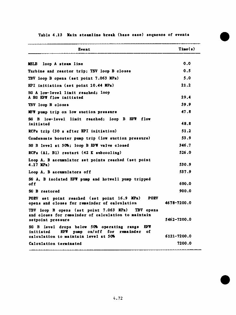
Table 4 .1 3 Main s te a m lin e b re a k (base ca se ) sequence o f ev en ts
Event Time(s)
MSLB loop A s t e a a l i n e 0 .0
T urb ine and r e a c t o r t r i p : TSV loop B c lo s e s 0 .5
TBV loop B opens ( s e t p o in t 7 .063 MPa) 5 .0
HPI i n i t i a t i o n ( s e t p o in t 10 .44 MPa) 21 .2
SG A lo w - le v e l l i m i t r e a c h e d ; loop A SG EFf flow i n i t i a t e d 29 .4
TBV loop B c lo s e s 39 .9
NFV pump t r i p on low s u c t io n p r e s s u r e 4 7 .8
SG B lo w - le v e l l i m i t reach ed : loop B EFf flow i n i t i a t e d 48 .8
SCPs t r i p (30 s a f t e r HPI i n i t i a t i o n ) 51.2
Condensate b o o s t e r pump t r i p (low s u c t io n p r e s s u r e ) 53 .9
SG B l e v e l a t 50%: loop B EFf v a lv e c lo se d 346.7
RCPs (A l, B l) r e s t a r t (42 E subcoo ling ) 526.0
Loop A, B accum ula to r s e t p o in t s reached ( s e t p o in t 4 .17 MPa) 530.9
Loop k , B acc u m u la to rs o f f 537.9
SG A, B i s o l a t e d EFf pump and h o tw e l l pump t r i p p e d o f f 600.0
SG B r e s to r e d 900.0
PORV s e t p o in t reached ( s e t p o in t 1 6 .9 MPa) PORV opens and c lo s e s f o r rem ainder o f c a l c u l a t i o n 4678-7200.0
TBV loop B opens ( s e t p o in t 7 .063 MPa) TBV opens and c lo s e s f o r rem a inder o f c a l c u l a t i o n t o m a in ta in s e t p o i n t p r e s s u r e 5462-7200.0
SG B le v e l d rops below 50% o p e ra t in g range EFf i n i t i a t e d EFf pump o n / o f f f o r rem ainder of c a l c u l a t i o n to m a in ta in l e v e l a t 50% 6121-7200.0
C a lc u la t io n te rm in a te d 7200.0
4 . 7 2
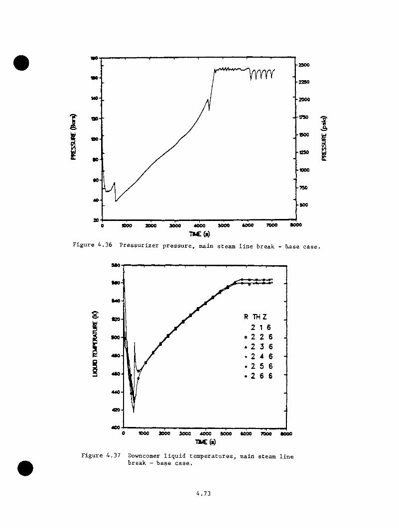
•0-2900
«0-2290
MO- -2000
1790no
-000
■0 -
-1000
• 0 --790
-900
•0007000•0001000 90000 2000 3000 4000
T»C(»)F ig u re 4 .3 6 P r e s s u r iz e r p r e s s u r e , main steam l i n e break — b a se c a s e .
940
9«0-
TVIZ820-
900
490-
400«00 2000 9000 4000 9000 *000 7000
m c (s )
F ig u re 4 .3 7 Downcomer l iq u id te m p e r a tu r e s , main steam l i n e break - b a se c a s e .
4.73
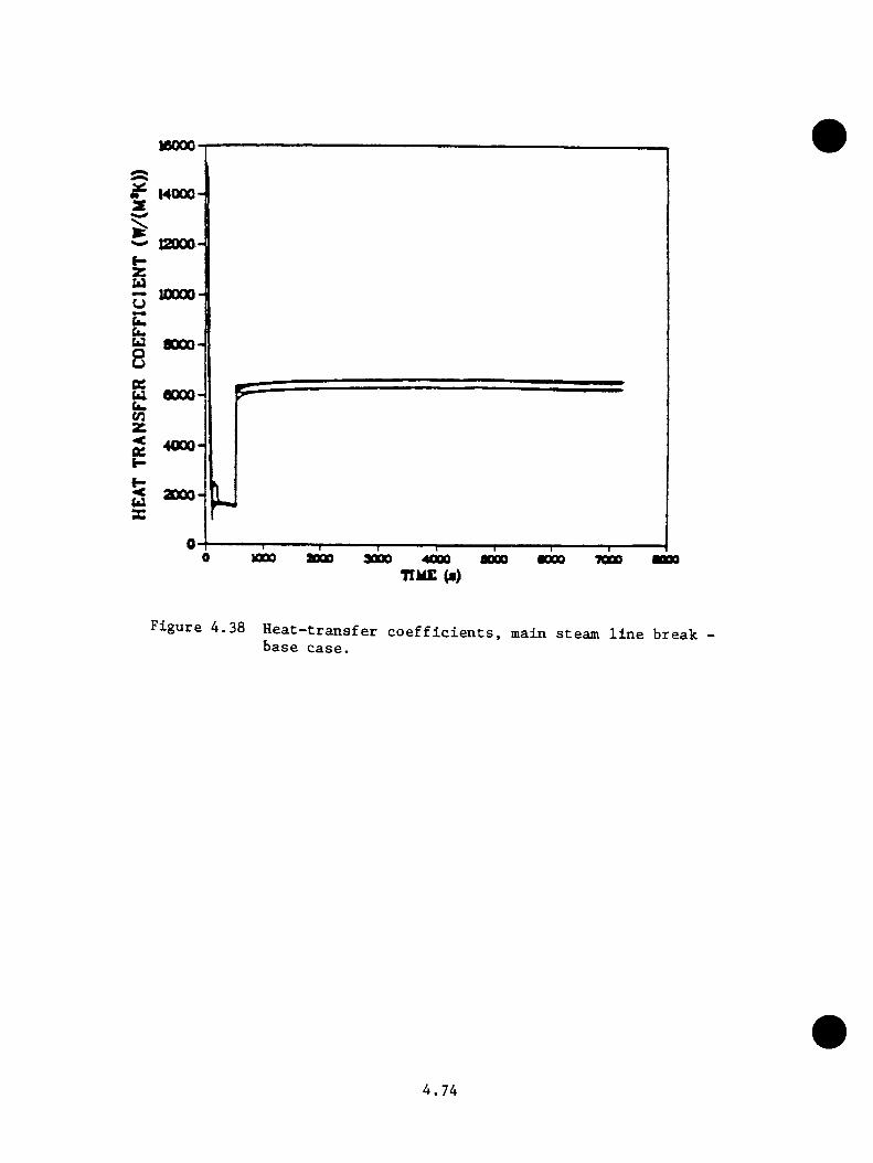
10000-
14000-z
12000-t -z u— 20000
(ZCuu aooo-4 8 zU. 6000-u,V3z^ 40004
■
2 X
MOO aoQo aooo 40oo TIME (a)
•000 7000
F ig u re 4 .3 8 H e a t - t r a n s f e r c o e f f i c i e n t s , m ain s team l i n e b r e a k b a s e c a s e .
4 . 7 4

(c a se 2 475 K; case 3 450 K ); th u s g r e a t e r m argins a g a in s t PTS were
c a l c u l a t e d .
In th e l a s t p a ra m e tr ic case (ca se 4 ) , o th e r changes were made to the model
t o r e f l e c t in fo rm a t io n p ro v id e d by Duke Power a f t e r the base case was ru n .
I n t h i s c a s e , th e su b co o lin g m on ito r was c o r r e c te d and the MFW pump was
t r i p p e d a t 0 .5 s . T h is case was run to 2100 s . and the minimum downcomer
f l u i d te m p e ra tu re was 420 K. None of th e changes in c o rp o ra te d in to case
4 r e s u l t e d in s i g n i f i c a n t d i f f e r e n c e s from the base c a s e .
4 .3 .2 .2 PORV LOCA T r a n s ie n t
The PORV LOCA sequence c a l c u l a t e d by LANL i s t r a n s i e n t 39 (LANL5) in Table
4 .2 5 . T h is case i s th e same as th e INEL PORV sm all ho t leg b re a k , excep t
f o r th e t r i p p i n g o f th e RCPs by th e o p e r a to r in th e LANL c a se .
The PORV was assumed to open a t t r a n s i e n t i n i t i a t i o n and rem ain s tu c k open
f o r th e rem ainder o f th e a c c id e n t sequence . T h is even t was fo llow ed by
th e r e a c t o r and tu r b in e t r i p s from f u l l power. I n a d d i t i o n to the PORV
f a i l u r e , th e ICS f a i l e d to run back th e main fe e d w a te r . As a r e s u l t ,
th e steam g e n e ra to r s c o n t in u e d to f i l l u n t i l the NFV pumps were t r i p p e d on
h ig h SG l e v e l s i g n a l . To ac h ie v e t h i s o v e r f i l l , th e h igh d is c h a rg e and low
s u c t i o n p r e s s u r e t r i p s o f th e NFV pumps were o v e r r id d e n . The PORV f a i l u r e ,
NFV t r i p o v e r r id e , and th e ICS f a i l u r e were th e on ly assumed s y s te m - re la te d
f a i l u r e s . The RCPs t r i p p e d 30 s a f t e r HPI i n i t i a t i o n , and t h i s was th e
o n ly s p e c i f i e d o p e r a to r a c t i o n .
Table 4 .1 4 g iv e s th e sequence of e v e n ts f o r the c a l c u l a t i o n . F ig u re s 4 .39
4 . 7 5
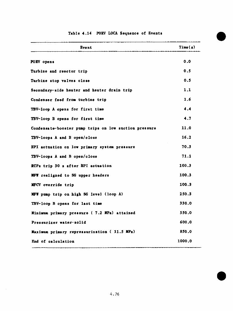
Table 4 .1 4 PORV LOCA Sequence o f Events
Event T ime(s)
PORV opens 0 .0
T urb ine and r e a c t o r t r i p 0 .5
T urb ine s to p v a lv e s c lo s e 0 .5
S eco n d a ry -s id e b e a t e r and b e a t e r d r a in t r i p 1 .1
Condenser feed from tu r b i n e t r i p 1 .6
TBV-loop A opens f o r f i r s t time 4 .4
TBV-loop B opens f o r f i r s t time 4 .7
C o n d e n s a te -b o o s te r pump t r i p s on low s u c t i o n p r e s s u r e 1 1 .0
TBV-loops A and B o p e n /c lo s e 16.2
HPI a c t u a t i o n on low p rim ary system p r e s s u r e 70.3
TBV-loops A and B o p e n /c lo se 71 .1
RCPs t r i p 30 s a f t e r HPI a c t u a t i o n 100.3
MFW r e a l ig n e d t o SG upper h ead e rs 100.3
MFCV o v e r r id e t r i p 100.3
MFW pump t r i p on b ig b SG le v e l ( lo o p A) 250.3
TBV-loop B opens f o r l a s t t isw 330 .0
Minimum p rim ary p r e s s u r e ( 7 . 2 MPa) a t t a i n e d 550.0
P r e s s u r i z e r v a t e r - s o l i d 600 .0
Maximum p rim ary r e p r e s s u r i z a t i o n ( 11 .5 MPa) 850 .0
End o f c a l c u l a t i o n 1000.0
4 . 7 6
thTOOgb 4 .41 s u a n a r iz e th e r e s u l t s o f th e c a l c u l a t i o n and e x t r a p o l a t i o n to
7200 s .
TRAC c a l c u l a t e d a minimua v e s s e l dovncomer l i q u id te m p era tu re of 528 K
between 600 s and 700 s i n t o th e t r a n s i e n t . The prim ary system was
c a l c u l a t e d to r e p r e s s u r i z e to 11 .5 MPa a f t e r 800 s . A f te r re c o v e r in g
b r i e f l y betw een 800 s and 1000 s , th e downcomer tem pera tu re was e x t r a p o la t e d
to 527 (489°F) a t 7200 s . P r e s s u r e remained a t 11 .5 MPa to the end of
the t r a n s i e n t .
4 . 3 .2 . 3 F a i l u r e of Two T urb ine Bypass V alves a t F u l l Power
The LANL c a l c u l a t i o n s o f two tu r b i n e bypass v a lve (TBV) f a i l u r e s a t f u l l
power in c lu d e a base case (5A) and two p a ra m e tr ic cases (5B and 5 0 . These
sequences appea r in Table 4 .2 5 as t r a n s i e n t s 40 (LANL6), 41 (LANL7), and
42 (LANL8).
The s i g n i f i c a n t f e a t u r e s o f th e 2-TBV f a i l u r e t r a n s i e n t base case (5A) a r e :
( 1 ) . R eac to r and tu r b in e t r i p s cause th e IBVs to open.
( 2 ) . F a i l u r e o f one bank o f TBVs t o c lo s e causes a sec o n d a ry -s id e
d e p r e s s u r i z a t i o n th ro u g h th e a f f e c t e d loop .
( 3 ) . The ICS f a i l s to runback to th e a f f e c t e d steam g e n e ra to r .
( 4 ) . F a i l u r e o f th e SG l i q u i d l e v e l c o n t r o l in the a f f e c t e d loop
fo l lo w s i n i t i a t i o n o f EFW.
( 5 ) . The o p e r a to r does n o t r e s t a r t the RCPs.
( 6 ) . The o p e r a to r does n o t t h r o t t l e the HPI.
( 7 ) . The o p e r a to r does n o t i s o l a t e / c o n t r o l feed w ate r .
Two p a ra m e tr ic ca se s were a l s o c a l c u l a t e d . The steam g e n e ra to r l i q u i d -
l e v e l c o n t r o l in the a f f e c t e d loop o p e r a t e s c o r r e c t l y in case 1 (5 B ) .
4 .7 7

EXTRAPOLATED
•00
•00070000 noo iooo •000aooo 4000
71M£(*)
F ig u re 4 , 3 9 PORV LOCA e x tr a p o la te d system p r e s s u r e .
•70
-sso••0EXTRAPOLATED
•60
-SM636-
-600
926-
120«XW 2000 9000 9000 7000•000
Q5s
F ig u re 4 .4 0 PORV LOCA e x tr a p o la te d downcomer l iq u id tem p era tu re .
4. 78
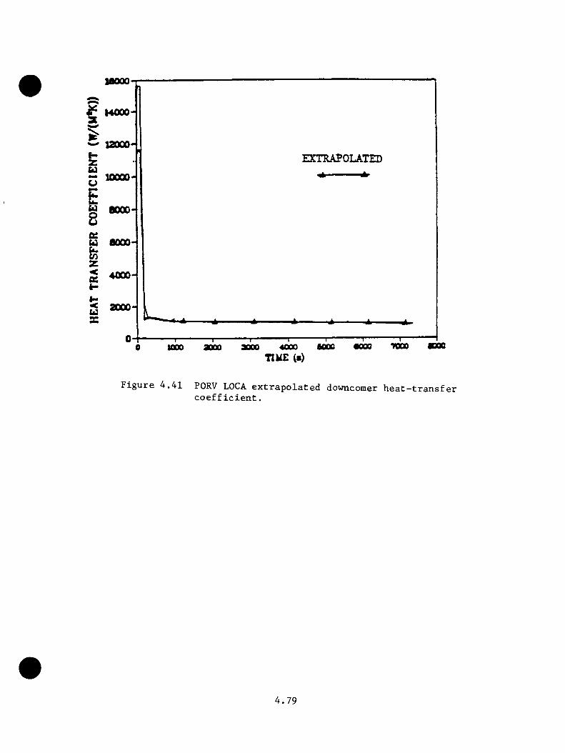
IflOOO
^ MOOO
^ 12000EXTRAPOLATED
BOOO
6000
4000
2000
7000fiOOO1000 aoooTIM£ (s)
^»41 PORV LOCA e x t r a p o l a t e d downconier h e a t —t r a n s f e r c o e f f i c i e n t .
4 . 7 9

The s t e a a g e n e ra to r l i q u i d l e v e l c o n t r o l a l s o o p e r a te s c o r r e c t l y in case
2 (SC), and o p e r a to r a c t io n s to r e s t a r t th e RCPs and t h r o t t l e th e HPI
a re p e rm i t t e d i f the p r im ary system s n b co o lin g -m o n ito r t r i p p o in t s a re
exceeded .
Table 4 .1 5 g iv e s th e sequence of e v en ts f o r the base c a s e . The p a ra m e tr ic
c a s e s fo llo w t h i s ex a c t sequence to the s t a r t i n g o f the EFW pump a t 209
s . In p a ra m e tr ic case 1 , th e c lo s u re o f th e EFW c o n t r o l v a lv e on SGA (290
s) speeds th e c lo s u r e o f the EFW v a lve to SGB (460 s) and opening o f th e
PORV (975 s ) . In p a ra m e tr ic case 2 , th e c lo s u r e of the EFW v a lve to SGA
(290 s) b r in g s about RCP r e s t a r t a t 383 s , c lo s u r e of th e EFW v a lv e to
SGB (395 s ) , and t h r o t t l i n g o f HPI (485 s ) .
F ig u re 4 .42 g iv e s th e c a l c u l a t e d and e x t r a p o la t e d p r e s s u r e s f o r th e b ase
and p a ra m e tr ic c a s e s . F ig u re s 4 .43 th ro u g h 4 .4 5 g iv e s th e c a l c u l a t e d and
e x t r a p o la t e d te m p e ra tu re s f o r the base and p a ra m e tr ic c a s e s . F ig u re 4 .46
g iv e s the c a l c u l a t e d and e x t r a p o la t e d h e a t t r a n s f e r c o e f f i c i e n t f o r th e
base case and p a r a m e tr i c Case 1 . A f te r r e s t a r t o f 1 RCP/loop in p a ra m e tr ic2
case 2 , a f i n a l h e a t t r a n s f e r c o e f f i c i e n t of 7500 w/m K i s o b ta in e d .
The f a i l u r e to i s o l a t e main and emergency feed w a te r to th e a f f e c t e d steam
g e n e r a to r r e s u l t e d in v e ry low te m p e ra tu re s f o r a l l th r e e cases a t 7200
s . The base case was e x t r a p o la t e d to 365 K. P a ra m e tr ic cases 1 and 2
were e x t r a p o la t e d to 440 K and 430 K r e s p e c t i v e l y .
4 . 3 . 2 . 4 F a i l u r e o f Four T urb ine Bypass V alves a t F u l l Power
The LANL c a l c u l a t i o n s o f fo u r tu r b in e bypass v a lv e s (TBV) a t f u l l power,
l i k e the two-TBV f a i l u r e c a s e s (S e c t io n 4 . 3 . 2 . 3 ) , a l s o in c lu d e a b ase case
4 . 8 0

Table 4 .1 5 2-IBV f a i l u r e f u l l power sequence o f ewents (base case)
Event Time(s)
T urb ine and r e a c t o r t r i p 0 .5
T urb ine s to p v a lv e s c lo se 0 .5
IBV loop A opens ( f a i l s t o r e s e a t t h e r e a f t e r ) 4 .1
TBV loop B opens 4.3
NFV pump t r i p on h ig h SG A l i q u i d l e v e l 60.7
HPI s t a r t e d fo l lo w in g t r i p on low p r e s s u r e 153.1
RCPs t r i p on 3 0 -s d e la y a f t e r HPI a c t u a t i o n 183.0
Feedw ater r e a l ig n m e n t 183.0
Main flow c o n t r o l v a lv e s o v e r r id in g t r i p s 183.0
EFW flow i n i t i a t e d 209.1
Loop-B EFW v a lv e shu t on h ig h SG l i q u i d l e v e l 460.8
PORV opens 1036.7
4 . 8 1

lao-2535
!S6 2235
-1835f 130.
1*0 ltd) BASE(dash) PARAMETRIC 1• chndah) PARAMETRIC 2
106
66 --735
90 4350 1000 2000 70003000 60004000 5000
F ig u r e 4 .4 2 P r e s s u r i z e r p r e s s u r e h i s t o r i e s f o r 2 TBV f a i l u r e s ( c a s e 5A -base ; c a s e 5 B - p a r a m e t r i c ; c a s e S C -p a ra m e t r i c 2) .
4 . 8 2

• THETA « 1• THETA * 2 •THETA - 3 ■ THETA • 4 •THETA « 5 •THETA - e
S40
^ 510
ua 480
^ 450-
u420-
248.3360-
188.33006000 700050002000 3000 400010000
P ig u re 4 . 4 3 Downcomer l iq u id tem p eratu res fo r c a se 5A.
500 684J3
- 539.3
•THETA - 1 • THETA ■ 2 •THETA - 3
THETA « 4 •THETA - 5 •THETA - 6
U 480
- 359.3
F ig u re 4 . 4 4 Downcomer l iq u id tem p eratu res fo r c a se 5B.
4. 83
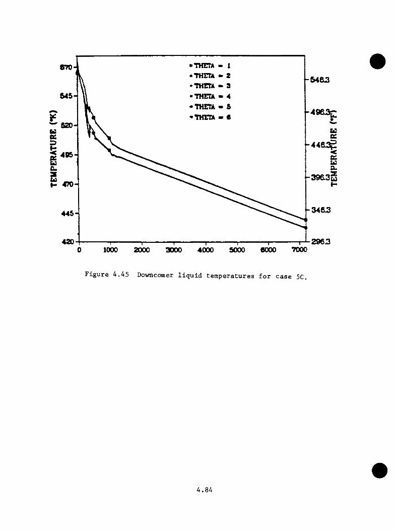
• THETA• THETA •THETA •THEEA -THETA •THETA
870
545
520
uH 470
445-
42070000 1000 2000 3000 5000 60004000
F i g u r e 4 ,4 5 Downcomer l i q u i d t e m p e r a t u r e s f o r c a s e 5C.
4 . 8 4

12000
u i a rn o 8U 6000 fa.
g 4000
8000-X
m o TOGOaooo aooo aooo4000TIME (•)
F ig u r e 4 ,4 6 H e a t - t r a n s f e r c o e f f i c i e n t s f o r c a s e 5A.
4 . 8 5
(6A) and tv o p a r a a e t r i o c a se s (6B and 6 0 . These sequences ap p ea r in Table
4 .2 5 as t r a n s i e n t s 43 (LANL9). 44 (LANLIO), and 45 (LANUl) r e s p e c t i v e l y .
The base and p a r a a e t r i c case d e s c r i p t i o n s a re th e saae as f o r th e tvo-TBV
f a i l u r e c a se s ex cep t t h a t a l l fo u r TBVs ( tv o on each s t e a a l i n e ) f a i l to
r e s e a t a f t e r open ing .
T ab le 4 .1 6 g iv e s th e sequence o f e v e n ts f o r the base c a s e . P a r a a e t r i c
case 1 b e h a v io r d i f f e r s f r o a th e b ase case on ly in th e p ro p e r o p e r a t io n
o f th e EFV c o n t r o l s . P a r a a e t r i c case 2 i s a l s o s i a i l a r to th e b ase case
u n t i l th e HPI i s t h r o t t l e d (421 s) and 1 RCP/loop i s r e s t a r t e d (517 s ) .
The in c re a s e d c o o l in g due to RCP o p e r a t io n red u ces p r i a a r y p r e s s u r e so t h a t
a c c u a u la to r i n j e c t i o n occu rs a t 566 s . F ig u re 4 .47 g iv e s th e c a l c u la te d
and e x t r a p o la t e d p r e s s u r e s f o r th e base and p a r a a e t r i c c a s e s . F ig u re s
4 .4 8 th ro u g h 4 .5 0 l ik e w is e g ive c a l c u l a t e d and e x t r a p o la t e d t e a p e r a t u r e s .
F ig u re 4 .5 1 g iv e s th e h e a t t r a n s f e r c o e f f i c i e n t f o r the b ase case and
p a r a a e t r i c c a se 1 . A f te r r e s t a r t o f th e RCPs, th e h e a t t r a n s f e r c o e f f i c i e n t2
f o r p a r a a e t r i c case 2 a s su a e s a f i n a l v a lu e of 7500 v / a K. As in the
tvo-TBV f a i l u r e c a s e , th e f a i l u r e to i s o l a t e main and eae rgency feed w ate r
t o b o th s t e a a g e n e ra to r s r e s u l t e d in v e ry low t e a p e r a t u r e s . M iniaua
t e a p e r a t u r e s o f 350 K, 465 E, and 350 K r e s p e c t i v e l y were e x t r a p o la t e d f o r
th e base and p a r a a e t r i c c a s e s .
4 .3 .2 .5 Small Break LOCA Two-In. Hot Leg Break
The 2 - i n . - d i a a ho t le g b re a k LOCA c a l c u l a t e d by LANL a o d e l s th e saae
c o n d i t io n s as th e INEL p r e s s u r i z e r surge l i n e sm all ( 2 - i n . - d i a a ) b re a k
t r a n s i e n t . The LANL c a l c u l a t i o n i s t r a n s i e n t 47 (LANL 13) in T ab le 4 .2 5 .
4 . 8 6
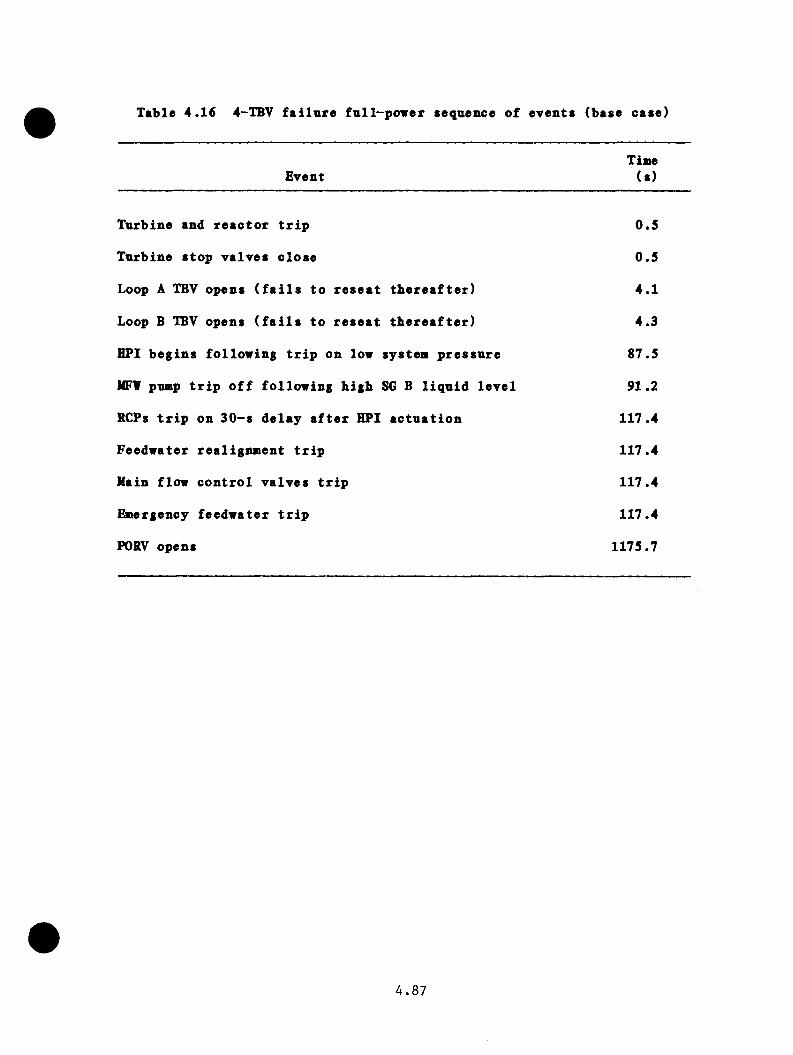
Table 4 .1 6 4-TBV f a i l u r e f n l l - p o w e r sequence o f e v en ts (base case)
EventTime
(s )
T urb ine and r e a c t o r t r i p 0 .5
T urb ine s to p v a lv e s c lo s e 0 .5
Loop A TBV opens ( f a i l s t o r e s e a t t h e r e a f t e r ) 4 .1
Loop B TBV opens ( f a i l s t o r e s e a t t h e r e a f t e r ) 4 .3
HPI b e g in s fo l lo w in g t r i p on low sy s te n p r e s s u r e 87.5
MFV pump t r i p o f f fo l lo w in g h ig h SG B l i q u i d l e v e l 91.2
RCPs t r i p on 3 0 -s d e la y a f t e r HPI a c t u a t i o n 117.4
F eedw ater re a l ig n m e n t t r i p 117.4
Main flow c o n t r o l v a lv e s t r i p 117.4
l^ e rg e n c y fe ed w a te r t r i p 117.4
PORV opens 1175.7
4 . 8 7
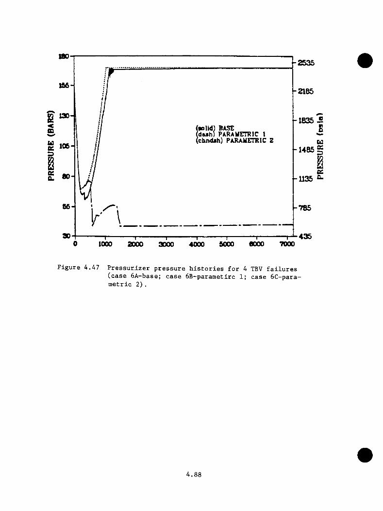
sao2535
156--2185
8 -1B35[aoUd) BASEdash) PARAyiTRIC 1chndsh) PARAMmiC Z
106 -1485
ao- -1135 C-
-785
ao 435700060001000 2000 50003000 4000
F ig u r e 4 .4 7 P r e s s u r i z e r p r e s s u r e h i s t o r i e s f o r 4 TBV f a i l u r e s ( c a s e 6 A -b ase ; c a s e 6 B -p a ra m e t i r c 1; c a s e 6 C -p a ra - m e t r i c 2 ) .
4 . 8 8
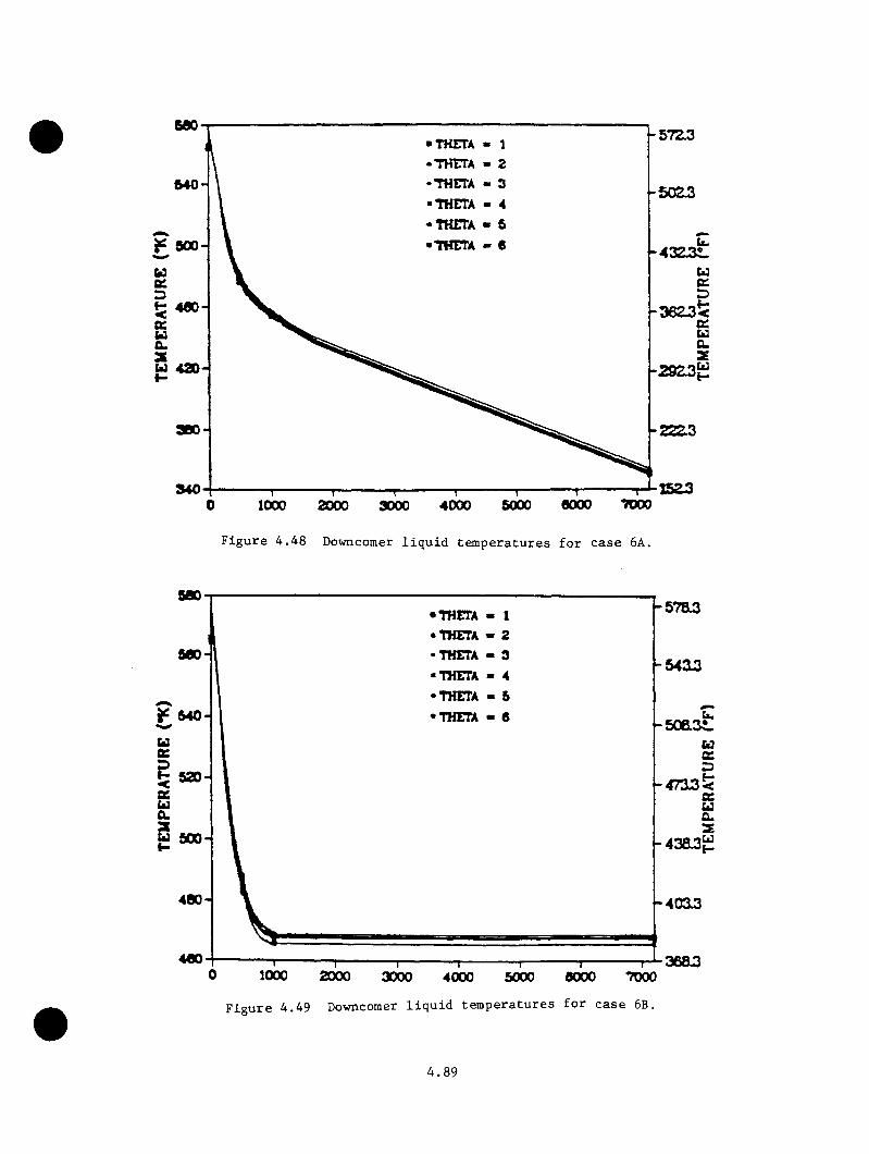
500THETA « 1 THETA - 2 THETA - 3 THETA - 4 THETA « 6 THETA - 6 4323L
U 43}
0 1000 2000 9000 4000 5000 0000 TVOO
F igu re 4 . 4 8 Downcomer l iq u id tem p eratu res fo r c a se 6A.
500-
500-
y 540-
U3ee
<0£UCL
520-
500-
400-
•THETA - 1 •THETA » 2 •THETA - 3 ■THETA - 4 •THETA « 5 •THET4 - 6
400-
-5 7 a3
-5403
s o a s tuD
4 7 3 3 ^ceuCL2
4 3 a3 S
-4003
1000 2000 3000 4000 5000 6000 7000
F ig u re 4 . 49 Downcomer l iq u id tem p eratu res fo r c a se 6B.
3683
4.89

600-57Z3■THCTA « 1
• THCTA « 2 THETA - 3
•THETA « 4 •THETA « 6 •THETA - 6
U 420
1000 2000 3000 4000 5000 0000
F ig u re 4 .5 0 Downcomer l i q u i d t e m p e r a t u r e s f o r c a s e 6C.
4 . 9 0

14000-
^ , £3000-
u*** 10000* O WWWbZSbU 8000- 8u aooo- u .«0 22 4000-1 t -H ____< 2000-£
— r - - r - '■■■ “-I—8000
TIME (s)•000 TOOO 8000
F i g u r e 4 .5 1 H e a t - t r a n s f e r c o e f f i c i e n t s f c r c a s e 6A.
4 . 9 1
The sequence i s i n i t i a t e d by a 2 - in . - d i a m b re a k in th e snrge l i n e midway
betw een th e p r e s s u r i z e r and r i s e r o f th e h o t l e g .
F o llow ing th e i n i t i a t i o n o f the b re a k , th e r e a c t o r and tu r b in e t r i p from
f u l l power. R eac to r decay h e a t was s p e c i f i e d as 1 .0 t im es th e ANS
s ta n d a r d . For t h i s t r a n s i e n t c a l c u l a t i o n , th e ICS and a l l key system
components were assumed to f u n c t i o n c o r r e c t l y . The on ly s p e c i f i e d o p e r a to r
a c t i o n was th e RCP t r i p 30 s a f t e r HPI a c t u a t i o n . Two c a se s in v o lv in g
HPI t h r o t t l i n g to system su b co o lin g were i n v e s t i g a t e d . One c a l c u l a t i o n
i n v e s t i g a t e d th e e f f e c t s o f HPI t h r o t t l i n g to 42 + 1 2 .5 K su b co o lin g and
th e o th e r i n v e s t ig a t e d th e e f f e c t s o f no HPI t h r o t t l i n g . The t h r o t t l e d
HPI case was n o t run because th e su b co o lin g m argin was n e v e r a c h ie v e d .
Table 4 .1 7 g iv e s th e sequence o f e v e n ts f o r the c a l c u l a t i o n . F ig u re s 4 .52
th ro u g h 4 .5 4 p r e s e n t th e r e s u l t s of th e c a l c u l a t i o n and e x t r a p o l a t i o n s w ith
and w ith o u t LPI o p e r a t io n assumed.
TRAC c a l c u l a t e d a r e l a t i v e minimum in te m p era tu re a t ap p ro x im a te ly 1000 s
i n t o th e t r a n s i e n t : th e p r e s s u r e a t 1000 s was 6 .2 MPa. The te m p era tu re
and p r e s s u r e were b o th d e c re a s in g a t the end o f the c a l c u l a t i o n a t 3760
s and had v a lu e s o f 450 K and 2 .1 MPa r e s p e c t i v e l y .
The c a l c u l a t e d minimum downcomer l i q u i d te m p e ra tu re s n e v e r approached the
c u r r e n t NOT v a lu e o f Oconee-1 f o r two re a s o n s : (a ) v e n t v a lv e flow mixing
w i th the f l u i d in th e downcomer r e g io n and (b) c a l c u l a t e d loop o s c i l l a t i o n s .
However, i f th e c a l c u l a t i o n were c o n t in u e d , th e LPI system would a c t u a t e as
a r e s u l t o f th e d e p r e s s u r i z a t i o n . The a d d i t i o n o f LPI would p ro b a b ly r e s u l t
i n downcomer l i q u i d te m p e ra tu re s approach ing o r exceed ing th e c u r r e n t NDT
4 . 9 2

Table 4 .1 7 Hot le g b re a k LOCA — 2 - i n . b re a k sequence o f e v en ts
EventTime
(s)
Break opens 0 .0
R eac to r and tu r b i n e t r i p s 0 .5
TSVs c lo s e (b o th loops) 0 .5
TBVs open (b o th loops) 4 .2
HPI a c t u a t i o n 43.1
TBVs o p e n /c lo s e (b o th loops) 51.0
RCPs t r i p 71.0
MFV rea l ig n m e n t 73.1
TBVs o p e n /c lo s e (b o th loops) 75.7
Vent v a lv e s open 100
ICS c lo s e s SHFCVs 300
Candy canes rem ain vo ided 500
Minimum downcomer te m p e ra tu re ( 470 K; 6 .2 MPa) 750
Loop flow o s c i l l a t i o n s b e g in 1200
Accumulator i n j e c t i o n b e g in s 1750
End o f c a l c u l a t i o n 3670
4 . 9 3

-MOO
EXTRAPOLATED (NO L P I)-OOG
•»00EXTRAPOLATED (L P I)
-soo
-•00
0 1000 •000 woo3000 woo 4000 •ooom c(«)
F igure 4 . 5 2 2 -in ..-d la m SBLOCA e x tr a p o la te d system p r e s su r e .
•00
au-
500-
4M-
400-EXTRAPOLATED (NO L P I)
S7S--300
335-EXTRAPOLATED (L P I)
275-7000•000woo40003000
M
in
TlM CCs)
F igure 4 . 5 3 2 - in .-d ia m SBLOCA e x tr a p o la te d downcomer l iq u id tem p eratu re .
4.94

18000
p 16000- 2
^ 14000-
12000-
10000-Cbblo
0000-
q:bl^ 0000- Z
« 4000-
U 2000- X
EXTRAPOLATED (NO L P I)^ ------ Ik
EXTRAPOLATED (L P I)A-' -' A.
n i l ii Ji>l
1000 aooo aooo 40oo w oo aooo tooo TIME (a)
F ig u r e 4 .5 4 2 - i n . - d i a m SBLOCA e x t r a p o l a t e d downcomer h e a t - t r a n s f e r c o e f f i c i e n t .
4 . 9 5
o f the Oconee-1 p l a n t . Hovevex, t h i s t r a n s i e n t may no t be i a ^ o r t a n t in
te rm s o f PIS because th e p rim ary system p r e s s u r e w i l l be q u i t e low when
th e downcomer l i q u i d te m p e ra tu re f a l l s below th e NOT l i m i t .
4 . 3 . 2 . 6 Small B reak LOCA 4 - I n . Hot Leg Break
The 4 - in . - d i a m h o t leg b re a k LOCA c a l c u l a t e d by LANL i s t r a n s i e n t 48 (LANL
14) in Tab le 4 .2 5 . T h is t r a n s i e n t i s i n i t i a t e d by a 4 - in . - d i a m b re a k in
th e surge l i n e midway between th e p r e s s u r i z e r and the r i s e r p o r t i o n o f the
h o t l e g .
F o llow ing th e i n i t i a t i o n o f th e b re a k , th e r e a c to r and tu r b i n e t r i p from
f u l l power. R eac to r decay h e a t was s p e c i f i e d as 1 .0 t im es th e ANS s ta n d a rd .
In t h i s t r a n s i e n t , th e ICS and a l l key components a re assumed to fu n c t io n
c o r r e c t l y . The o n ly s p e c i f i e d o p e r a to r a c t i o n was th e RCP t r i p 30 s a f t e r
HPI a c t u a t i o n .
Table 4 .1 8 g iv e s th e sequence o f e v e n ts f o r th e c a l c u l a t i o n . F ig u re s 4 .55
th ro u g h 4 .57 suounarize th e r e s u l t s o f th e c a l c u l a t i o n and e x t r a p o l a t i o n to
7200 seco n d s . TRAC c a l c u l a t e d a minimum downcomer l i q u i d te m p e ra tu re of
350 K; th e system p r e s s u r e a t t h i s minimum te m p e ra tu re was 1 .0 MPa.
Adequate f l u i d mixing betw een th e v e n t -v a lv e f l u i d and th e c o ld le g (HPI)
f l u i d in th e downcomer a t the c o ld le g ju n c t i o n m a in ta in e d th e downcomer
l i q u i d te m p e ra tu re s above 450 K. However, th e a c t u a t i o n o f the LPI
system a t 1240 s dropped th e downcomer te m p e ra tu re s v ery r a p i d l y and below
th e c u r r e n t NDT v a lue (365 K) f o r th e Oconee-1 p l a n t . Even though the
downcomer l i q u i d te m p e ra tu re s were c a l c u l a t e d to be below th e c u r r e n t
4 . 9 6
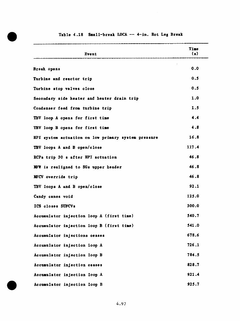
Table 4 .1 8 Small-break LOCA — 4 - in . Hot Leg Break
TimeEvent (s )
Break opens 0 .0
T urb ine and r e a c t o r t r i p 0 .5
T nrb ine s to p v a lv e s c lo se 0 .5
Secondary s id e b e a t e r and b e a t e r d r a in t r i p 1 .0
Condenser feed from tu r b in e t r i p 1 .5
TBV loop A opens f o r f i r s t time 4 .4
TBV loop B opens f o r f i r s t time 4 .8
HPI system a c t u a t i o n on low p rim ary system p r e s s u r e 16 .8
TBV loops A and B o p e n /c lo s e 117.4
RCPs t r i p 30 s a f t e r HPI a c t u a t i o n 4 6 .8
MFW is r e a l ig n e d t o SGs upper h e a d e r 46 .8
MFCV o v e r r id e t r i p 46 .8
TBV loops A and B o p e n /c lo se 92.1
Candy canes v o id 125.0
ICS c lo s e s SUFCVs 300.0
Accumulator i n j e c t i o n loop A ( f i r s t tim e) 540.7
Accumulator i n j e c t i o n loop B ( f i r s t tim e) 541.0
Accumulator i n j e c t i o n s c e a se s 678.6
Accumulator i n j e c t i o n loop A 726.1
Accumulator i n j e c t i o n loop B 784.5
A ccumulator i n j e c t i o n c e a se s 828.7
Accumulator i n j e c t i o n loop A 921.4
A ccumulator i n j e c t i o n loop B 925.7
4 . 9 7
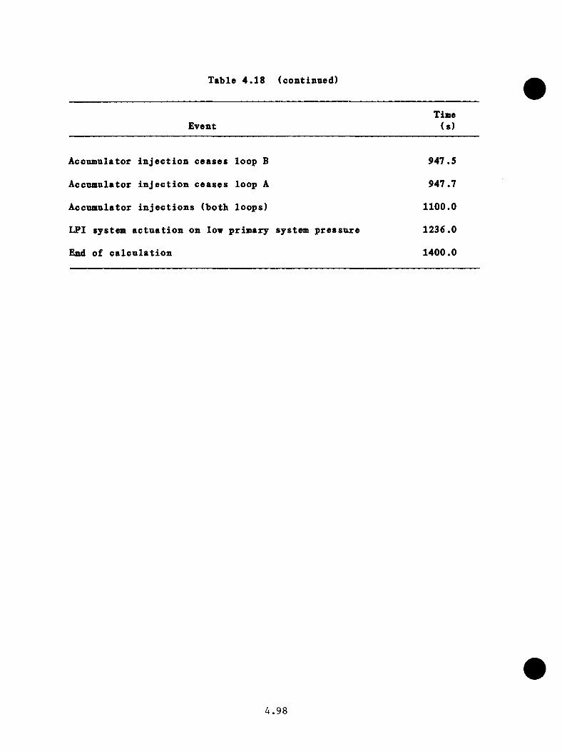
Table 4 .1 8 (continued)
TimeEvent ( s)
Accumulator i n j e c t i o n c e a se s loop B 947.5
Accumulator i n j e c t i o n c e a se s loop A 947.7
A ccum ulator i n j e c t i o n s (b o th lo o p s ) 1100.0
LPI system a c t u a t i o n on low p r im ary system p r e s s u r e 1236.0
End o f c a l c u l a t i o n 1400.0
4 . 9 8

e x t r a p o l a t e d
. -too
-400
-aoo
7000 MOO0 MOO MOO1000 2000 MOO 4000
5• I
TlME(s)
F ig u re 4 . 5 5 4 - in .-d ia m SBLOCA e x tr a p o la te d system p r e s su r e .
-M O
9 M -
-M O
EXTRAPOLATEDsoo-
-400
-ttOaeo-
«oo 2000 MOO 7000
F ig u re 4 . 5 6 4 - in .-d ia m SBLOCA e x tr a p o la te d downcomer l iq u id tem p eratu re .
4.99
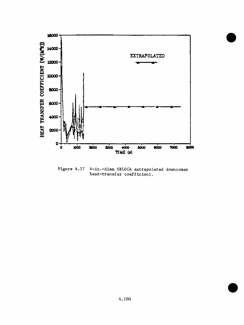
IBOOO
^ 14000-EXTRAPOLATED
12000
U 6000-
•0000 1000 •000 7000•000 6000 •0004000TIME (i)
F ig u r e 4 .5 7 4 - i n . - d i a m SBLOCA e x t r a p o l a t e d downcomerh e a t - t r a n s f e r c o e f f i c i e n t .
4 . 1 0 0

NDT Oconee-1, t h i s c a l c n l a t i o n cou ld n o t be c o n s id e re d a s i g n i f i c a n t PTS
t r a n s i e n t because r e p r e s s u r i z a t i o n d id n o t o ccu r .
4 .3 .2 .7 S tea n G en e ra to r Dryout Follow ed by EFW Overfeed
The t r a n s i e n t f e a t u r e s s te a n g e n e r a to r d ryou t fo llow ed by emergency
feed w ate r o v e r fe e d modeling the Rancho Seco t r a n s i e n t s as c l o s e l y as
p o s s i b le on th e Oconee-1 p l a n t system . T h is sequence i s t r a n s i e n t 49 (LANL
15) on T ab le 4 .2 5 . The a c c id e n t sequence began as a lo s s -o f -m a in feed w ate r
t r a n s i e n t (MFW pumps t r i p ) . The EFW-control v a lv es f a i l e d to open on
demand bu t were s u b se q u e n t ly m anually opened by the o p e r a to r . A lso , th e
RCPs rem ained on d u r in g th e t r a n s i e n t , and th e EFW to th e SGs was no t
t e rm in a te d u n t i l 4200 s . The p rim ary system r e p r e s s u r i z a t i o n was l im i te d
to 1 3 .8 NPa as a r e s u l t o f th e o p e r a t o r ' s t h r o t t l i n g the HPI system.
Table 4 .19 g iv e s th e sequence o f e v e n ts f o r the c a l c u l a t i o n . F ig u re s 4 .5 8
th rough 4 . ( 0 summarize th e c a l c u l a t i o n and e x t r a p o la t io n s to 7200 s . At
4200 s th e minimum downcomer f l u i d te m p e ra tu re o f 452 K was r e p o r te d . At
th e same i n s t a n t , system p r e s s u r e was 1 3 .8 MPh. Both tem pera tu re and p r e s
su re were assumed to in c re a s e over the e x t r a p o l a t i o n p e r io d .
4 .4 E v a lu a t io n o f Flow S t r a t i f i c a t i o n E f f e c t s
The TRAC and RELAP5 codes cannot p r e d i c t th e fo rm a t io n o f co ld w a te r plumes
and s i m i l a r flow s t r a t i f i c a t i o n e f f e c t s . S t r a t i f i c a t i o n occu rs when co ld
and h o t s tream s a re b ro u g h t to g e th e r w i th o u t s u f f i c i e n t tu rb u le n c e to mix
them. Cold HPI f l u i d , b e in g d e n s e r , may form a l a y e r a t the bottom of
th e co ld le g p ip in g below th e b u lk o f th e warmer f l u i d in the c o ld le g .
T h is l a y e r o r plume cou ld run a long th e co ld le g to th e v e s s e l and s p i l l
4 . 1 0 1

Table 4 .1 9 S te a a g e n e r a to r d ryon t f o l lo v e d by EFW o y erfeed (Ranobo S eeo - ty p e ) t r a n s i e n t sequence o f e v en ts
EventTiae
(s )
MFW pnaps t r i p , IffCVs and SUFCVs c lo s e 0 .0
TSVs c lo s e (b o tb loops) 0 .0
R eac to r t r i p s on h ig b p r e s s n r e 4 .4
TBYs a c tu a te d 4.6
PORV a c tu a te d 226.4
EFW i n i t i a t e d t o b o tb SGs 540.0
HPI a c tu a te d on low p r e s s u r e 738.0
HPI t h r o t t l e d t o l i a i t r e p r e s s u r i z a t i o n 1255.0
EFW t e r a i n a t e d t o b o tb SGs 4200.0
M iniaua v e s s e l douncoaer l i q u i d t e a p e r a t u r e ( 452 K) c a l c u l a t e d
4200.0
C a l c u l a t i o n t e r a i n a t e d 4300.0
4 . 1 0 2
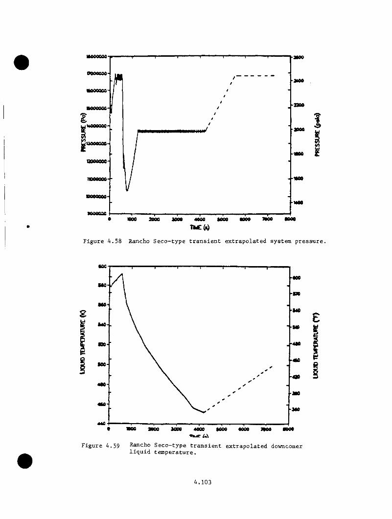
MOOSCO «ooe
F igu re 4 .5 8 Rancho S e c o -ty p e t r a n s ie n t e x tr a p o la te d system p r e s su r e .
COO-coo
SCO
-M2
•00-
JCO
440 - I -c ■000•0004000
F ig u re 4 . 5 9 Rancho S e c o -ty p e t r a n s ie n t e x tr a p o la te d downcomer l iq u id tem p era tu re .
4.103
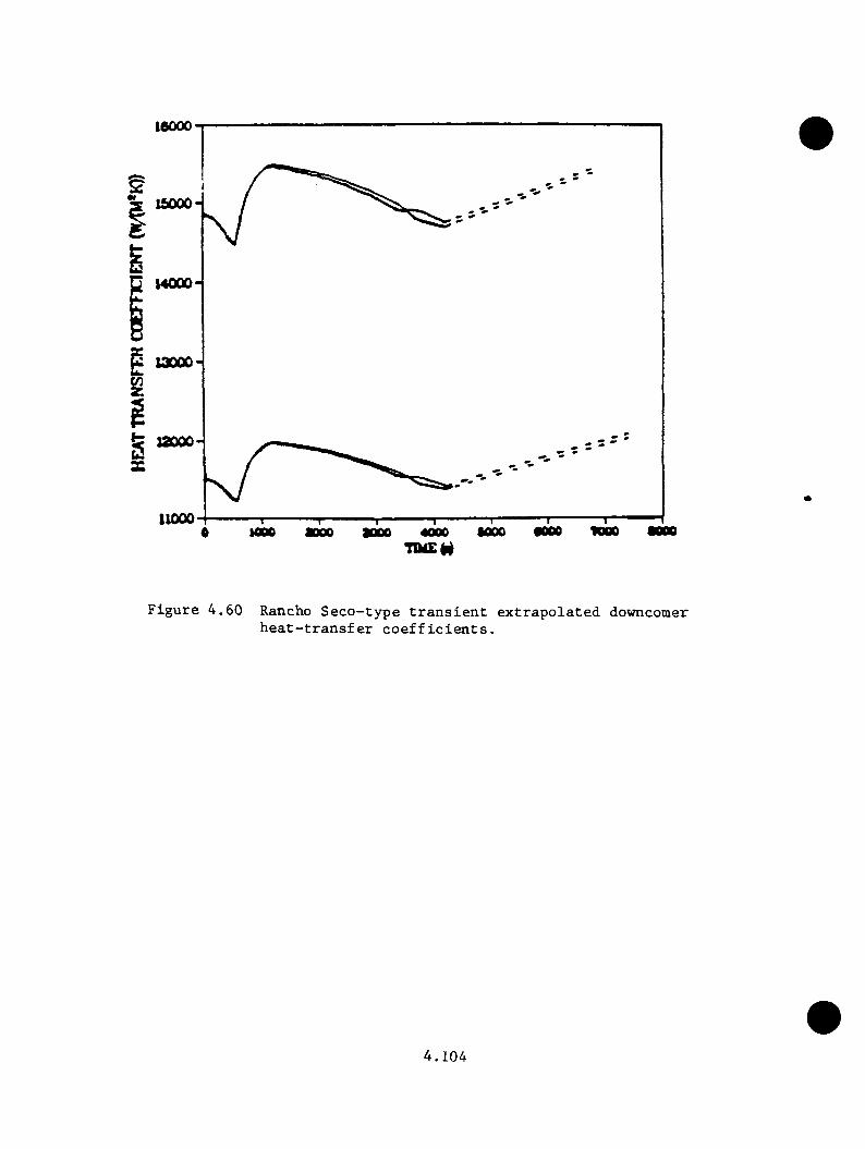
16000
14000
t 12000
11000•0001000 6000
F ig u r e 4 .6 0 Rancho S e c o - ty p e t r a n s i e n t e x t r a p o l a t e d downcomer h e a t - t r a n s f e r c o e f f i c i e n t s .
4 . 1 0 4

down along th e downcoaer w a l l , p ro d u c in g lo c a l i z e d c o ld t e a p e r a tn r e s on
th e downcoaer which cou ld g r e a t l y i a p a c t th e f r a c t u r e p r o b a b i l i t y fo r the
v e s s e l . F a c to r s a f f e c t i n g p lu a e d e v e lo p a e n t in c lu d e HPI no zz le and co ld
leg g e o a e t r y , c o ld le g b u lk flow and t e a p e r a t u r e c o n d i t io n s , ven t v a lve
flow r a t e s and t e a p e r a t u r e s , and downcoaer g e o a e try .
4 3This s e c t i o n s u a a a r i z e s a rev iew by T.G. Theophanous, ’ Purdue U n iv e r s i t y ,
o f th e INEL- and LA N L-ealculated t r a n s i e n t s f o r flow s t r a t i f i c a t i o n e f f e c t s .
The approach o f th e rev iew in c lu d ed th e use o f s c reen in g c r i t e r i a based
on e a p i r i c a l and t h e o r e t i c a l a i z in g a o d e l s to i d e n t i f y th e c a se s where flow
s t r a t i f i c a t i o n aay o c c u r . Suspect c a se s were su b je c te d t o d e t a i l e d a i z in g
c a l c u l a t i o n s to d e t e r a in e p luae e z t e n t and t e a p e r a t u r e . The a i z in g a o d e l
was henchaarked a g a i n s t e z p e r i a e n t s in a h a l f - s c a l e t e s t f a c i l i t y s e t up
fo r th e Oconee-1 g e o a e t ry .
The s c re e n in g c r i t e r i a e l i a i n a t e d a l l b u t seven o f th e d e t a i l e d c a l c u l a t i o n s
f r o a c o n s id e r a t io n o f s t r a t i f i e d flow . The INEL cases f o r which no
s t r a t i f i c a t i o n was p r e d i c t e d w ere: r e v i s e d a a i n s t e a a l i n e b re a k , s tu c k
open PORV, s t e a a g e n e r a to r o v e r fe e d , a a z ia u a s u s t a in a b le o v e r fe e d , and
s t e a a g e n e r a to r tube r u p tu r e . LANL c a s e s in c lu d e d TBV c a se s SB, 5C, 6A,
6b, and 6C; th e a a i n s t e a a l i n e b re a k c a s e s ; PORV LOCA; and the s te a a
g e n e r a to r d ry o u t fo llow ed by EFV o v e r f i l l c a s e s .
For th e seven r e a a in in g t r a n s i e n t s , i t was d e te r a in e d t h a t the TRAC
and RELAP c a l c u l a t e d b u lk t e a p e r a tu r e s were ad eq u a te . The rea so n s a re
s u a a a r iz e d below .
4 . 1 0 5

The LANL 4 - l n . h o t leg b re a k t r a n s i e n t e x h ib i te d v e ry low p r e s s n r e when
s t r a t i f i c a t i o n wonld p r e v a i l ( a f t e r 300 s) . With t h i s low p r e s s n r e and
tw o-phase flow c o n d i t io n s in th e downcomer, th e t r a n s i e n t was n o t a PIS
co n ce rn .
The INEL RC pnmp s n c t io n b re a k a l s o had v e ry r a p id d e p r e s s n r i z a t i o n . An
asjrmmetric s t a g n a t io n c o n d i t io n p r e v a i l e d w i th v en t v a lv e f low s eqnal to
o r g r e a t e r than th e n n s ta g n a te d loop f lo w s . C a lc n la te d plnme te m p era tn re s
s ta y e d w i th in 10 °C o f th e b n lk te m p e ra tn re of th e flow ing lo o p . The
s t ro n g v e n t v a lv e flow w i l l a l s o b re a k np th e plnm es.
The INEL p r e s s n r i z e r sn rge l i n e b re a k shows s t a g n a t io n in loop A between 750
and 1250 s and in loop B betw een 1000 and 2500 s i n t o th e t r a n s i e n t . S trong
v e n t v a lv e flow d u r in g th e s e p e r io d s broke np th e p lnm es. A lso , p la n a r
plnme m ixing c a l c n l a t i o n s showed r e s t r i c t i o n s to plnme l a t e r a l growth snch
t h a t th e l o n g i tu d in a l w elds were n o t a f f e c t e d .
The LANL two-lBV f a i l u r e case (5A) i s a h ig h - p r e s s u r e t r a n s i e n t w ith one
f low ing loop (A) and one s ta g n a n t loop (B ) . Vent v a lv e flow i s s t ro n g ,
and i s e f f e c t i v e a t m ixing th e downcomer. The plnmes f o r th e s ta g n a n t loop
were found to be on ly 10 c o ld e r th a n th e flow ing lo o p .
The INEL o r i g i n a l main s te a m lin e b reak case i s a l s o a h ig h - p r e s s u r e
t r a n s i e n t . Loop B s t a g n a t e s betw een 250 and 950 s . Loop A s ta g n a te s
betw een 200 and 350 s and a g a in betw een 650 and 950 s . Vent v a lv e flow i s
s t r o n g o v e r th e se p e r io d s . T em peratures o f 450 K (350°F) were c a l c u l a t e d
a t th e s ta g n a te d c o ld le g n o z z l e s . The s tro n g v en t v a lv e f low s p rev en ted
th e growth o f th e plumes o ver th e l o n g i tu d in a l w elds .
4 . 1 0 6
The INEL four-TBV f a i l u r e a t h o t s tandby case i s a h ig h -p re s s u re t r a n s i e n t
in which th e re was n o t s t a g n a t io n o r v en t v a lv e f low . However, th e low loop
f low s n e r i t e d concern f o r plume developm ent. The RELAP5 model p r e d ic te d
o s c i l l a t i n g f low s , w hich, i f a c t u a l l y en co u n te re d , would g e n e ra te e x c e l l e n t
m ix ing . Even i f plume development were s i g n i f i c a n t , th e e x c e l l e n t co ld
le g mixing c h a r a c t e r i s t i c s and th e g e n e ra l cooldown o f the system would
m inim ize th e d i f f e r e n c e betw een b u lk and plume te m p e ra tu re s .
The LANL 2 - i n . h o t le g b re a k case i s a lo w -p re s su re t r a n s i e n t . This case
i s s i m i l a r to th e co rre sp o n d in g INEL c a s e .
In summary, th e mixing geom etry o f the co ld le g s and th e s t ro n g v en t va lve
flow s m i t ig a t e d bo th th e r e l a t i v e te m p era tu re d ec re ase and the spread of
plumes in h ig h - p r e s s u r e t r a n s i e n t s . I n lo w -p re s s u re t r a n s i e n t s th e plumes
cou ld be c o ld e r , b u t th e low p r e s s u r e s n u l l i f i e d the impact to r i s k of
v e s s e l f a i l u r e .
4 .5 E ^ trgpg jlg tpd Segppncgs
4 .5 .1 Methodology
4 . 5 .1 . 1 G eneral Approach
A f te r an i n i t i a l su rvey o f th e da ta re s o u rc e s and of the sequences
i d e n t i f i e d f o r e s t i m a t io n , a f i v e - s t e p p ro c e s s was developed f o r the
e s t i m a t io n o f Oconee-1 p r e s s u r e , te m p e ra tu re , and h e a t t r a n s f e r c o e f f i c i e n t
p r o f i l e s . T h is approach a llow ed lo g i c a l r e d u c t io n of the number of cases
t o be e v a lu a te d and d e r iv e d th e g r e a t e s t b e n e f i t from the in fo rm a tio n in
4 . 1 0 7

th e TRAC and RELAP c a l c n l a t i o n s . The approach i s d is c u s s e d f u r t h e r in
Appendix C.
The f i r s t s te p in v o lv ed th e g roup ing o f s i m i l a r sequences . An e v a l u a t i o n
o f th e TRAC and RELAP c a l c u l a t i o n s f o r th e e f f e c t s from d i f f e r e n t o p e ra t in g
s t a t e s p ro v id e d th e c r i t e r i a f o r ass ignm ent o f sequences i n t o g roups .
B es id es p ro v id in g g roup ing c r i t e r i a , s te p 2 developed th e p a ram e te rs f o r
th e cooldown model used on o c c a s io n f o r t h i s s tu d y . To a s s u re c o r r e c t
i n t e r p r e t a t i o n o f c o n d i t io n s du r in g seq u en ces , th e a p p ro p r ia te p a ram e te rs
would he a p p l ie d t o th e cooldown model to d u p l i c a t e p o r t i o n s o f sequences
c a l c u l a t e d by TRAC o r RELAP. T his v a l i d a t i o n e f f o r t took p la c e i n s te p 3 .
I n s te p 4 , th e p r e s s u r e , te m p e ra tu re , and h e a t t r a n s f e r c o e f f i c i e n t s were
e s t im a te d . T em perature cou ld be e s t im a te d e i t h e r by p ie cew ise a p p l i c a t i o n
o f TRAC and RELAP r e s u l t s o r by c a l c u l a t i o n u s in g th e cooldown model.
The method s e l e c t i o n depended on th e com p lex ity of the sequence and the
a v a i l a b i l i t y o r absence o f d i r e c t l y a p p l i c a b l e d a ta from the TRAC o r
RELAP c a l c u l a t i o n s . E a r ly p o r t i o n s of sequences where HPI, fe e d w a te r ,
and p r im ary loop f low s and downcomer te m p e ra tu re s v a ry r a p id l y were no t
d i r e c t l y a p p l i c a b le to th e cooldown model, so p ie cew ise use o f TRAC and
RELAP d a ta was a p p l i e d . L ate in t r a n s i e n t s when th e loop f low s a re more
s t a b l e , a cooldown model was a p p l ie d to p r e d i c t the te m p e ra tu re s t r e n d s .
The cooldown model i s an energy b a la n c e which acco u n ts f o r th e h e a t in g
and cooldown mechanisms p r e s e n t in th e Oconee-1 system . The cooldown
model was most u s e f u l where th e e n d - s t a t e c o n f ig u r a t io n s in th e r e q u e s te d
sequence e v a lu a t io n s d e v ia te d s i g n i f i c a n t l y from those in th e TRAC and
4 . 1 0 8

RELAP c a l c u l a t i o n s . The d e r i y a t i o n o f th e cooldown model i s a l s o in c lu d ed
in Appendix C.
P re s s u re e s t im a te s were d e r iv e d s o l e l y from o b s e r v a t io n o f p r e s s u re t r e n d s
in th e TRAC and RELAP c a l c u l a t i o n s . The a b i l i t y o f th e h ig h -h ead HPI system
in th e Oconee-1 p l a n t to q u ic k ly r e p r e s s u r i z e th e p rim ary was r e f l e c t e d by
th e TRAC and RELAPS c a l c u l a t i o n s . The p r e s s u r e b e h a v io r of the v a r io u s
c a l c u l a t i o n s was s u f f i c i e n t l y un ifo rm to su g g es t t h a t p ie cew ise s e l e c t i o n
o f TRAC and RELAP p r e s s u r e c u rv e s was v a l i d .
Heat t r a n s f e r c o e f f i c i e n t s were based on p ie cew ise s e l e c t i o n of TRAC d a ta .
In g e n e r a l , th e c a l c u l a t i o n s p r e d ic te d r e l a t i v e l y c o n s ta n t v a lu e s w hile
th e r e a c t o r c o o l in g pumps (RCP) a re runn ing and s te p down to a lower bu t
c o n s ta n t v a lu e a f t e r RCP t r i p and e s ta b l i s h m e n t o f n a t u r a l c i r c u l a t i o n .
The h e a t t r a n s f e r c o e f f i c i e n t s p r e d ic te d by TRAC d id n o t in c lu d e c o r r e c t io n
f o r f r e e c o n v e c t io n e f f e c t s . T h e re fo re , th e v a lu e s were u n d e rp re d ic te d f o r
n a t u r a l c i r c u l a t i o n flow c o n d i t i o n s . T h is e f f e c t was compensated f o r in
th e f r a c t u r e m echanics c a l c u l a t i o n s by s p e c i fy in g a minimum h e a t t r a n s f e r0 r\
c o e f f i c i e n t o f 600 B tu /h f t F (3400 W/m^K). Any lower v a lu e s re p o r te d
in t h i s s e c t i o n o r th e appendix were superceded by th e s p e c i f i e d l i m i t .
The com pleted e s t im a t io n s were documented in s te p 5 . T h is docum entation
com prises S e c t io n s C.3 th ro u g h C.8 o f Appendix C.
4 . 5 . 1 . 2 Sequence Grouping
The o v e rc o o l in g sequence ev en t t r e e s fo rm u la ted by ORNL p o sse ssed over
6 .7 m i l l i o n e n d - s t a t e s . A p p l ic a t io n of a 10 ^ / y r s c re e n in g l i m i t on even t
f requency reduced th e number o f sequences r e q u i r i n g s p e c i f i c e s t im a te to
4 . 1 0 9
u n d er 100. These were grouped in t o sm all s e t s by i n i t i a t o r , t h a t i s
tu r b i n e bypass v a lv e f a i l u r e s a t f u l l power, tu r b i n e bypass v a lv e f a i l u r e s
a t h o t s ta n d b y , POBY-sized LOCA, feed w ate r o v e r fe e d s , steam g e n e r a to r tube
r u p t u r e s , and main steam l i n e b r e a k s .
Some a d d i t i o n a l g rouping o f sequences b ased on component s t a t e s '
s i m i l a r i t i e s f u r t h e r reduced th e number o f e s t im a te s to 97 . However,
g rouping by component s t a t e s ( i . e . , v a lv e s t i c k s open, ICS f a i l s t o runback
fe e d w a te r , e t c . ) does n o t accoun t f o r th e th e rm a l -h y d ra u l ic impact o f such
s t a t e s . The a c t u a l iaq>act w i l l a l s o depend on the f u n c t io n o r f a i l u r e
o f o th e r system s and on feedback from th e rm a l -h y d ra u l ic impact o f such
s t a t e s . By o b s e r v a t io n and e v a lu a t io n o f s i m i l a r e v en ts in the THAC and
RELAP c a l c u l a t i o n s , th e c o n t r i b u t i n g e v e n ts in a sequence were c l a s s i f i e d
as dom inant, m inor , o r in c o n s e q u e n t i a l . Sequences w ith the same dominant
e v e n ts were grouped t o g e th e r f o r a n a l y s i s . I n l a t e r s t e p s , th e in f lu e n c e
o f minor e v e n ts was e v a lu a te d where p o s s i b l e t o check th e c o n s is te n c y of
th e g ro u p in g s . Some sequences were r e a s s ig n e d to o th e r groups based on
th o se ch eck s .
The sequence g roup ings and th e r e s u l t s o f sequence e x t r a p o l a t i o n a re
p r e s e n te d by i n i t i a t o r in th e fo l lo w in g s e c t i o n s .
4 . 5 .2 T u rb ine Bypass Valve F a i l u r e s a t F u l l Power
E v a lu a t io n o f t u r b i n e bypass f a i l u r e s a t f u l l power concerned th e 19
c a s e s i d e n t i f i e d in Tab le 4 .2 0 . The t a b l e l i s t s th e s p e c i f i e d c o n d i t io n s ,
which in c lu d e v a r io u s com binations o f f a i l e d TBYs, feed w ate r system
perfo rm ance , p r im ary p r e s s u r e c o n t r o l s , and o p e r a to r a c t i o n s . These cases
4 . 1 1 0
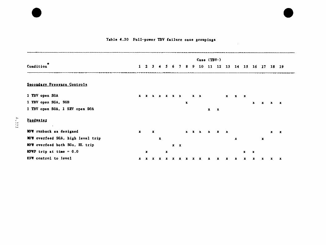
Table 4.20 Fnll-power TBV failure case groupings
ConditionCase (TBV-)
1 2 3 4 5 6 7 8 9 10 11 12 13 14 15 16 17 18 19
Secondary Pressure Controls
1 TBV open SGA1 TBV open SGA, SGB1 TBV open SGA, 1 SBV open SGA
Feedwater
MFW runback as designed MFW overfeed SGA, high level trip MFW overfeed both SGs, HL trip MFWP trip at time =0.0 EFW control to level
X X Z Z X X X X X
X
X X XX X X X
X X
X X X X X X X X X X
X X X
X X
X X X X
X X X X X X X X X X X X X X X X X X X
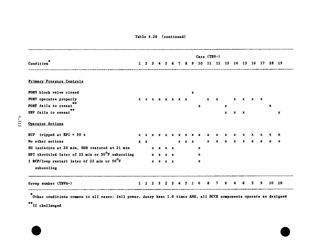
Table 4.20 (continued)
ConditionCase (TBV-)
1 2 3 4 5 6 7 8 9 10 11 12 13 14 15 16 17 18 19
E£iffiS^X_E£es&Mfc„Cgat£ols
POSV block valve closedPORV operates properly
e«PORF fails to reseat eeSRV fails to reseat
x z x x x x z z X X X X
X X X
Operator Actions
RCP tripped at HPI + 30 s No other actionsSG isolation at 20 min, SGB restored at 21 min HPI throttled later of 22 min or 50^F subcooling 1 RCP/loop restart later of 22 min or 50^F
subcooling
X X X X X X X X X X
X X X X XX X X X
X X X X
X X X X
X
XX
X
X
X
X
X
X X
X X
X
X
X
X
X
X
Group number (TBVG-) 1 1 2 3 2 3 4 5 1 6 8 7 6 4 6 5 9 10 10
Other conditions common to all cases: full power« decay heat 1.0 times ANS, all ECCS components operate as designed
If challenged

were c o n s o l id a te d i n t o th e 10 groups in d i c a te d a t the bottoai of Table
4 .2 0 . These groups r e p r e s e n t t r a n s i e n t s 1 (IBVGl) th rough 10 (TBVGIO) on
Table 4 .2 5 . F ig u re s 4 .5 1 th rough 4 .53 g iv e the e x t r a p o la te d p r e s s u r e s ,
te m p e ra tu re s , and h e a t t r a n s f e r c o e f f i c i e n t s f o r groups 1 , 2 , 4 , 5 , and
7 . These groups a re r e p r e s e n t a t i v e of a l l groups as a w hole. Groups 3
and 8 co rresp o n d c l o s e l y to group 2 , which i s in th e f i g u r e . L ikew ise ,
group 9 i s s i m i l a r to group 4 , and groups 4 and 10 a re s im i l a r to group 5
in t h e i r r e s p o n s e s . S e c t io n C.4 o f Appendix C p ro v id e s d e t a i l e d in d iv id u a l
e v a lu a t io n s o f th e se g ro u p s . The u n i fo rm i ty of te m p era tu re t r e n d s i s in
keeping w ith the mechanisms d r iv in g the cooldown. Group 2 , th e on ly group
to ex p e r ie n c e r e h e a t in g , does so upon th e d ryou t of the a f f e c t e d steam
g e n e ra to r a f t e r fee d w a te r i s o l a t i o n . Groups 1 , 5 and 7 a l l f e a t u r e p ro p e r
ICS feed w ate r c o n t r o l so t h a t th e steam g e n e ra to r s a re no t f looded o u t .
T h e re fo re , th e s e groups c l u s t e r t o g e th e r l a t e in th e sequences, a l th o u g h
th e e q u iv a le n t of two s tu ck -o p en TBVs a r e in groups 5 and 7 vs on ly one
in group 1 . In TBV group 4 , an ICS f a i l u r e a l low s con tin u ed flow of main
feed w a te r (from the h o tw e l l and condensa te pumps) t o f lo o d the a f f e c t e d
steam g e n e r a to r ( s ) . T h is i s the case a l s o f o r the LANL two-TBV f a i l u r e
and four-TBV f a i l u r e c a s e s . (The two-TBV b ase case (5A) v a lu e s were
th e r e f o r e g iv e n to TBVG4.) T h is f lo o d in g produces th e low est e x t r a p o la t e d
te m p e ra tu re s . The minimum te m p e ra tu re s f o r TBV groups 1 , 2 , 4 , 5 , and 7
a re 420 K, 471 K, 355 K, 398 K, and 405 K r e s p e c t i v e l y .
4 .5 .3 T u rb ine Bypass Valve F a i l u r e s a t Hot Standby
E v a lu a t io n o f t u r b i n e bypass v a lve f a i l u r e s a t h o t s tandby invo lved th e fo u r
ca se s i d e n t i f i e d in T ab le 4 .2 1 . The t a b l e l i s t s th e c o n d i t io n s modeled.
4 . 1 1 3
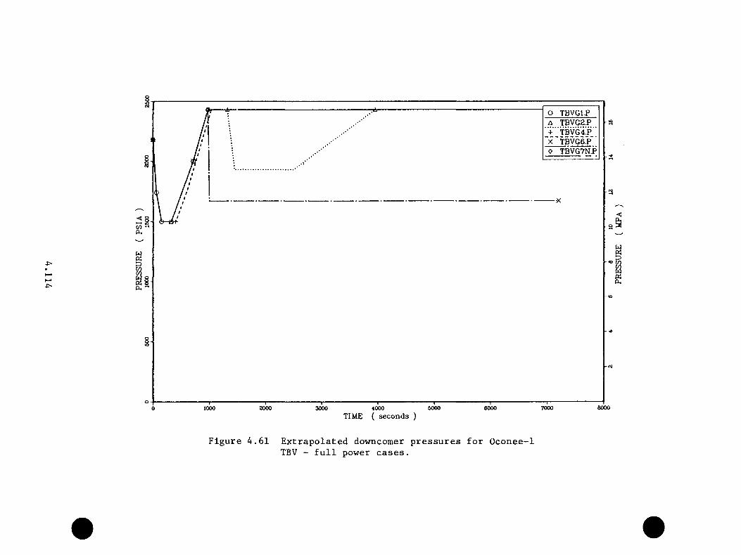
O TBVGl.PA TBVG2.P + ”TBVG4P‘‘ 'x^ T B V G ey o TBVG7N.P
80006000 6000 70001000 2000 3000 40000TIME ( seconds )
Figure 4.61 Extrapolated downcomer pressures for Oconee-1TBV - full power cases.
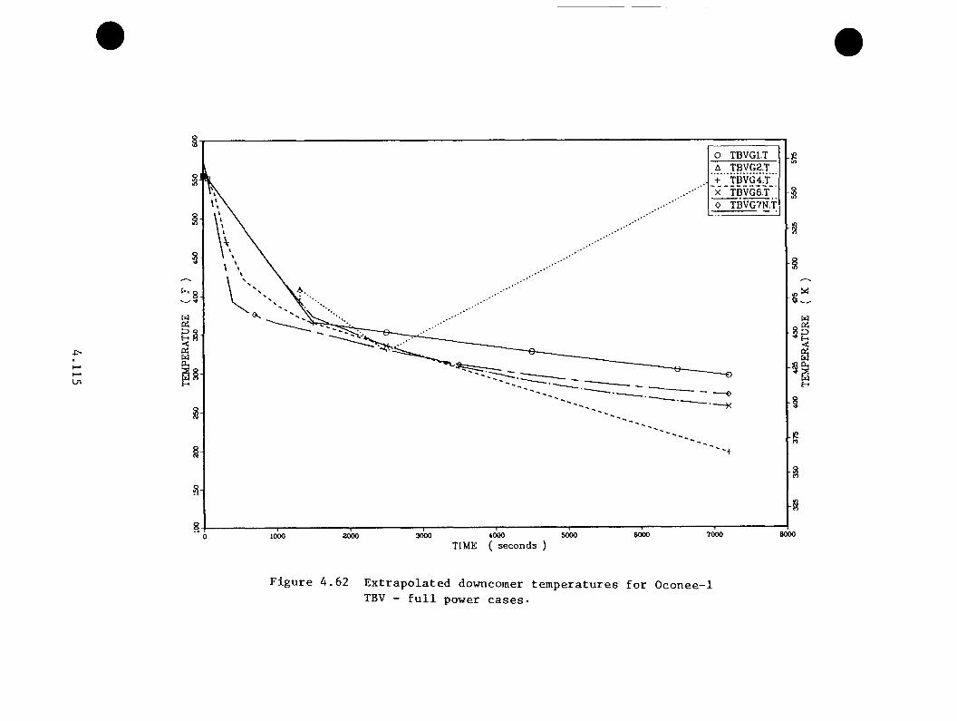
O TBVGl.TA TBVG2.T + "TBVG4!f‘' x~TBVG6.T~' O TBVG7N.T
eooo6000 70004000TIME ( seconds )
600030001000 2000
Figure 4.62 Extrapolated downcomer temperatures for Oconee-1TBV - full power cases-
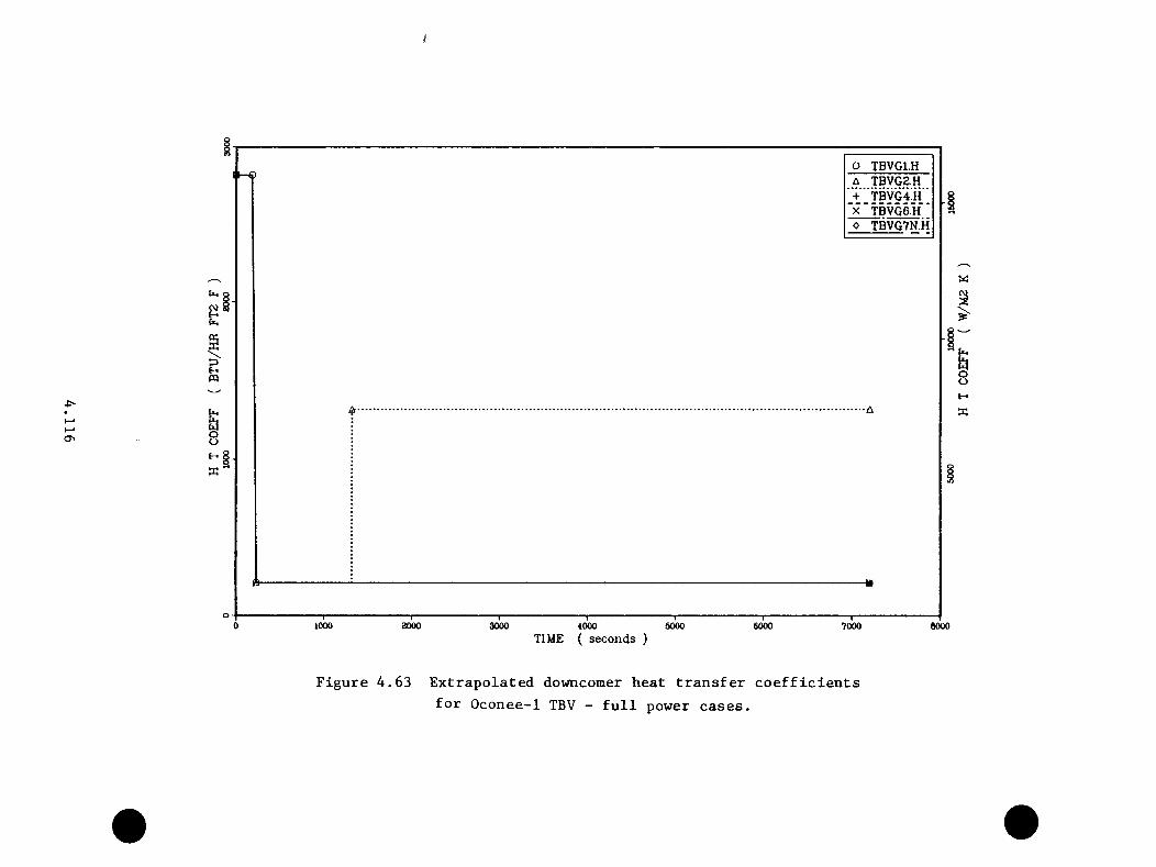
O TBVG1.HA TBVG2.H + "TBVG4!h '
'x ‘ TBVG6.H'o TBVG7N.H
ooE-» 1
w'
&oot - 4
K
1000 0000 4000 5000TIME ( seconds )
6000 7000 6000
Figure 4.63 Extrapolated dovmcomer heat transfer coefficientsfor Oconee-1 TBV - full power cases.
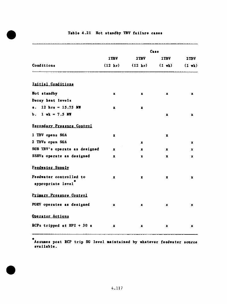
Table 4 .2 1 Hot standby TBV f a i lu r e cases
C o n d it io n s
Case
ITBV 2TBV ITBV
(12 h r ) (12 h r) (1 wk)
2TBV
(1 wk)
I n i t i a l C o n d it io n s
Hot s tandby
Decay h e a t l e v e l s
a . 12 h r s = 15 .75 MW
b . 1 wk = 7 .5 MW
Secondary P re s s n re C on tro l
1 TBV opens SGA
2 TBVs open SGA
SGB TBV's o p e r a te as des igned
SSRVs o p e ra te as des ig n ed
X
X
X
X
X
X
X
X
X
X
Feedw ater c o n t r o l l e d to
a p p r o p r ia t e l e v e l
re C on tro l
PORV o p e r a t e s as des ig n ed
RCPs t r i p p e d a t HPI + 30 s
Assumes p o s t RCP t r i p SG l e v e l m a in ta in e d by w hatever feed w ate r source a v a i l a b l e .
4 . 1 1 7
v h ic h in c lu d e d one and two v a lv e f a i l u r e s a t power l e v e l s co rre sp o n d in g to
12 h and 1 wk a f t e r shutdown. These c a se s co rresp o n d to t r a n s i e n t s 24
(ZPITBV). 25 (ZP2TBV). 33 (WITBV), and 34 (VZTBV) on T able 4 .2 5 . F ig u re s
4 .6 4 th ro u g h 4 .6 6 g ive th e e x t r a p o la t e d p r e s s u r e s , te m p e ra tu r e s , and h e a t
t r a n s f e r c o e f f i c i e n t s f o r the c a s e s . The t e a p e r a t u r e t r e n d s show t h a t
decay h e a t e f f e c t s a re a o s t n o ta b le a t the end o f the sequences where
an o f f s e t of 14^C s e p a r a t e s th e co r re sp o n d in g o n e -v a lv e and tw o-valve
f a i l u r e s . The a i n i a u a t e a p e r a t u r e s f o r ZPllBV, ZP2TBV, ZWITBV, and ZW2IBV
a re 385 K, 371 K, and 358 K. The f a i l u r e to i s o l a t e the s t e a a g e n e ra to r s
and t h r o t t l e HPI le d to low er t e a p e r a tu r e s th an were o b ta in e d f o r the INEL
four-TBV f a i l u r e a t h o t s tan d b y c a l c u l a t i o n .
4 . 5 .4 POBV-Sized LOCA Cases
Nine PORV-sized LOCA sequences i d e n t i f i e d f o r e v a l u a t i o n a re l i s t e d in
T ab le 4 .2 2 . These a re reduced to f i v e g roups , as i n d i c a te d a t th e bottom o f
Tab le 4 .2 2 . These groups a re t r a n s i e n t s 11 (PSBGl) th ro u g h 15 (PSBG5) in
T ab le 4 .2 5 . F ig u re s 4 .6 7 , 4 .6 8 , and 4 .69 g ive th e e x t r a p o la t e d p r e s s u r e s ,
t e a p e r a t u r e s , and h e a t t r a n s f e r c o e f f i c i e n t s f o r g roups 1 , 3 , 4 , and 5 .
Group 2 i s v e ry s i m i l a r t o group 1 . D e ta i l e d d e s c r i p t i o n s o f th e groups and
th e e x t r a p o l a t i o n p ro c e d u re a re a v a i l a b l e in Appendix C, S e c t io n C .6 . The
main d i f f e r e n c e s between th e sequences a re due to th e feed w a te r s i t u a t i o n
accompanying the p r im ary b r e a k . The PORV-sized LOCA r e s u l t s in s u f f i c i e n t
HPI flow so t h a t n e a r l y a l l o f the decay h e a t can be absorbed by the
p r im a ry , even e a r l y in th e t r a n s i e n t . L a t e r , a f t e r th e decay h e a t has d ied
down, th e HPI i s ab le t o coo l th e system somewhat. In t h i s s i t u a t i o n ,
l i t t l e o r no steam i s g e n e ra te d in th e s e c o n d a r i e s . T h e re fo re , b o th normal
4 . 1 1 8

VO
Q ZP1TBV.PA ZW1TBV.P + ‘*ZP2TBV.P x"ZW2TBV‘P
< §
1000 2000 3000 iOOO
TIME ( seconds )5000 6000 7000 6000
Figure 4*64 Extrapolated downcomer pressures for Oconee-1TBV failure at hot stand-by cases.

N5O
§O ZPITBV.T
§
I
— ©
§
870004000 5000 6000 60000 1000 2000 3000
TIME ( seconds )
Figure 4,65 Extrapolated downcomer temperatures for Oconee—1TBV failure at hot stand-by cases.

4>*h-»ho
csiHU-t
&oot~* I a '
O ZP1TBV.HA ZW1TBV.H + ' ZP2TBV.H
‘x'ZWBTBVii
aOJa
wou
■■4000
■ r ■" 50002000 7000 6000
TIME ( seconds )
Figure 4.66 Extrapolated downcomer heat transfer coefficientsfor Oconee-1 TBV failure at hot stand-by cases.
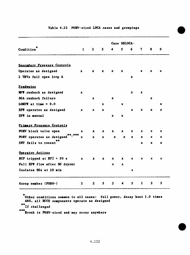
Table 4 .2 2 POKV-sized LOCA cases and groupings
Case SBLOCA-*
C o n d it io n 1 2 3 4 5 6 7 8 9
Secondary P r e s s u r e C o n tro ls
O p era te s as d es igned X z z z X z z z
2 TBVs f a i l open loop A z
FpotfwutorMFl runback as d es igned z z z
SGA runback f a i l u r e z z z
LOMFW a t t i n e » 0 .0 z z z
EFV o p e r a te s as d es igned z z z z z z z
EFW in manual z z
P rim ary P r e s s u r e C o n tro ls
PORV b lo c k y a ly e open z z z z z z z z z* * * * *
PORV o p e ra te s as des ig n ed z z z z z z z z z**
SRV f a i l s t o r e s e a t z z z
O p era to r A c tio n s
RCP t r i p p e d a t HPI -i- 30 s z z z z z z z z z
F u l l EFV flow a f t e r SG d ry o u t z z
I s o l a t e s SGs a t 20 min z
Group number (PSBG-) 1 2 3 2 4 5 1 2 3
*O ther c o n d i t io n s coauion to a l l c a s e s : f u l l power , decay h e a t 1 .0 tim es
• •
• • •
ANS, a l l ECCS coaiponents o p e r a te as d es igned
I f c h a l le n g e d»Break i s POKV-sized and may o ccu r anyvhere
4 . 1 2 2
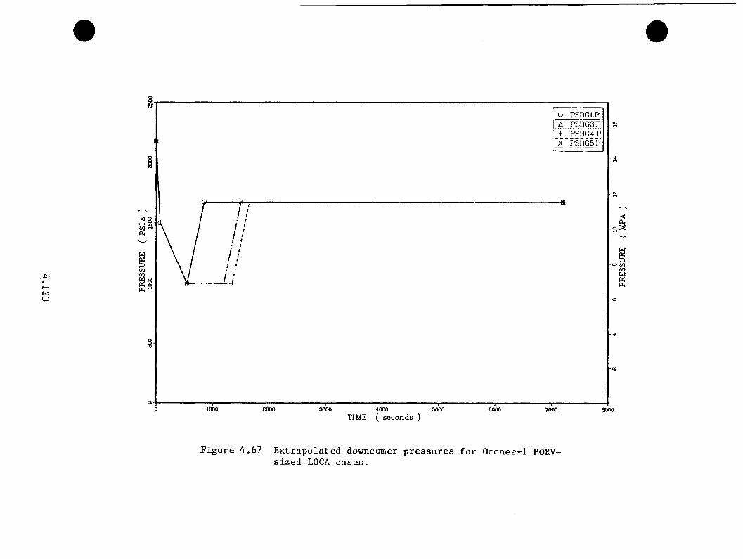
N>LO
O PSBGl.P
« 8 -
1000 2000 3000 4000TIME ( seconds )
5000 6000 7000 eooo
w
w
Figure 4.67 Extrapolated downcomer pressures for Oconee-1 PORV-sized LOCA cases.
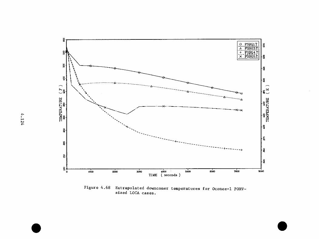
ho
O PSBGl.TA PSBG3.T + ‘pSBG4‘t X~PSBG5.T
----------
60007000600050003000 4000TIME ( seconds )
j20001000
Figure 4.68 Extrapolated downcomer temperatures for Oconee-1 PORV-sized LOCA cases.
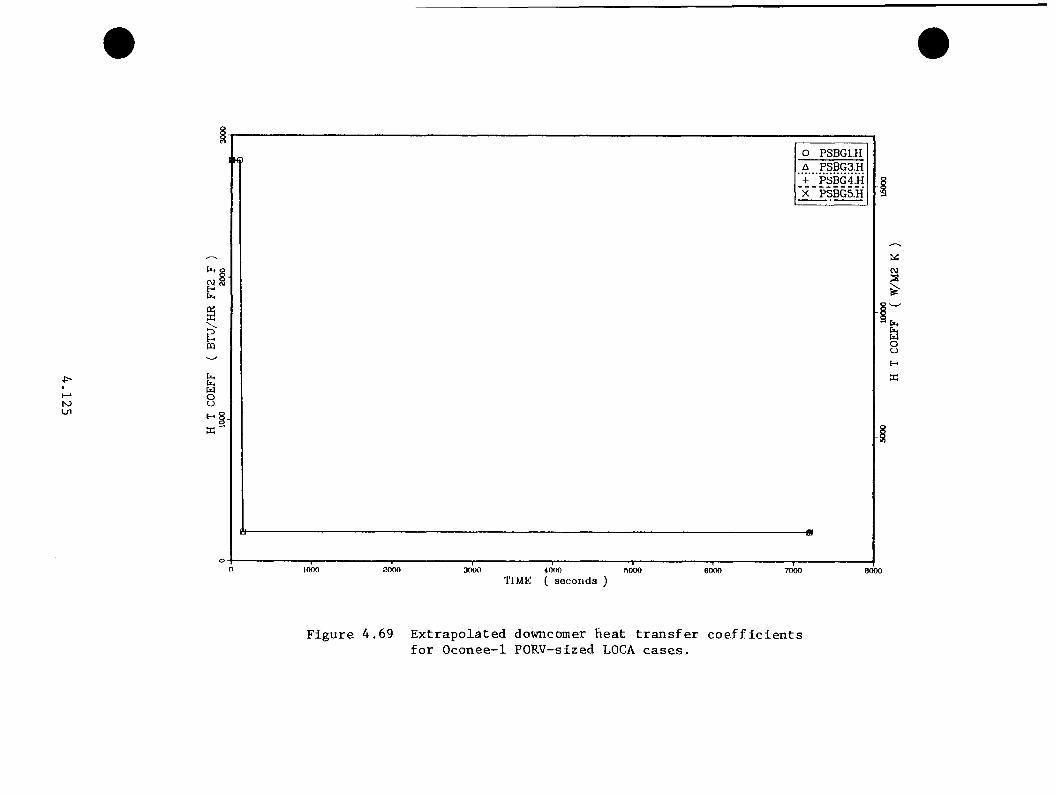
N>Ln
C\JHOi,XXHOQ
OO
O PSB G 1.H A PSB G 3 .H
’ + " P S B G 4 .H ’x 'P S B G 5 -H
Wcv}X
4UooHw
4000TIMK ( s e c o n d s )
7000
Figure 4.69 Extrapolated downcomer heat transfer coefficientsfor Oconee-1 PORV—sized LOCA cases.
f e e d v a te r o p e r a t io n (PSBGl) and NFW o v e rfeed w ith t r i p on SG l e v e l (PSBG2)
have th e sane in f lu e n c e s in c e th e steam g e n e ra to r s a r e f i l l e d once and o n ly
once . Group 3 s t a r t s ou t c o o l e r i n i t i a l l y becau se of th e e x c lu s iv e use of
c o ld EFW to f i l l th e steam g e n e r a to r s to th e l e v e l f o r n a t u r a l c i r c u l a t i o n .
The steam g e n e ra to r s are> in e f f e c t , t o t a l l y i s o l a t e d and do n o t c o n t r i b u t e
f u r t h e r to system cooldown. In group 4 , th e EFW le v e l c o n t r o l f a i l s and
th e steam g e n e ra to r s f lo o d o u t , a l lo w in g th e steam g e n e r a to r s t o work w ith
th e HPI to coo l th e system to v ery low te m p e ra tu r e s . In group 5 , th e
i s o l a t i o n o f th e s tu c k -o p e n TBVs a l lo w s a te m p e ra tu re reco v e ry upon lo s s o f
t h i s cooldown mechanism. The minimum te m p e ra tu re s f o r c a se s PSBGl th rough
PSBG5 a re 472 K, 474 K, 459 K, 350 K, and 436 K. The f i n a l downcomer
p r e s s u r e in each case i s 11 .5 MPA.
4 . 5 .5 F eedw ater O verfeed Cases
Seven feed w a te r o v e r fe e d c a s e s were o r i g i n a l l y i d e n t i f i e d f o r e v a lu a t io n .
L a t e r , a v e ry m ild e ig h th case was added. The seven ca se s appear as
t r a n s i e n t s 16 (FWl o r OVRFDl) th ro u g h 22 (FW7 o r 0VRFD7) in Table 4 .2 5 .
Tab le 4 .23 p r e s e n t s th e c o n d i t io n s f o r th e se c a s e s . F ig u re s 4 .7 0 th rough
4 .7 2 g iv e th e e x t r a p o la t e d p r e s s u r e s , te m p e ra tu r e s , and h e a t t r a n s f e r
c o e f f i c i e n t s f o r c a s e s 1 , 3 , 6 , 7 , and the new case number 8 ( l o s s of main
fe e d w a te r w ith subsequen t r e f i l l w ith EFW c o n t r o l l e d to l e v e l ) . With the
e x c e p t io n o f case 6 , a l l o f the t r a n s i e n t s a re v e ry m ild . Cases 2 and
4 a r e s i m i l a r to case 1 . Case 6 a c h iev es low te m p e ra tu re s because of an
e x t e n s iv e EFW o v e rfe e d s i m i l a r to th e Rancho S eco -type t r a n s i e n t . Minimum
te m p e ra tu re s f o r c a se s FWl th rough FW8 a re 560 K, 560 K, 530 K,- 550 E,
560 E, 419 E, 537 E, and 560 E.
4 . 1 2 6
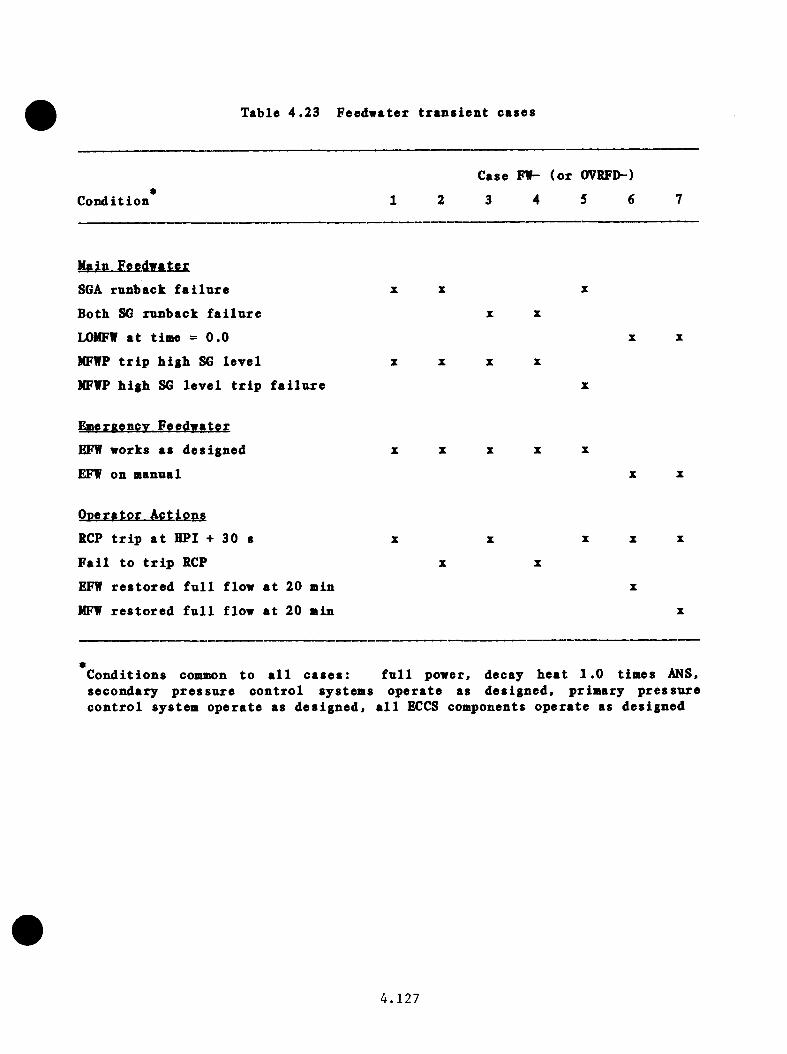
Table 4 .23 Feedwater tr a n s ie n t cases
*C o n d it io n 1 2
Case FW- (o r
3 4
OVRFD-)
5 6 7
Main Feedw ater
SGA runback f a i l u r e X X X
Both SG runback f a i l u r e X X
LOMFW a t time - 0 .0 X X
MFWP t r i p h ig h SG l e v e l z X X X
MFWP h ig h SG l e v e l t r i p f a i l u r e X
Emeraencv Feedw ater
EFW works as des igned X X X X X
EFW on manual X X
O n era to r A c tio n s
RCP t r i p a t HPI + 30 s X X X X X
F a i l to t r i p RCP X X
EFW r e s t o r e d f u l l flow a t 20 min X
NFW r e s t o r e d f u l l flow a t 20 min X
•C o n d i t io n s common to a l l c a s e s : f u l l power. decay h e a t 1 .0 tim es ANS,secondary p r e s s u r e c o n t ro l system s o p e ra te as d e s ig n ed , p r im ary p r e s s u re c o n t r o l system o p e ra te as d e s ig n e d , a l l ECCS components o p e ra te as des igned
4 . 1 2 7

< I1—4 ,S '
77- 7 7
/ /
7/ “
O FW1.P A FW3.P + ''f W6.P
"x ' fwY po FW8.P
— o
N500
wPi
a.
2000 3000 4000TIME ( seconds )
5000 7000
Figure 4.70 Extrapolated downcomer pressures for Oconee-1feedwater transient cases.
6000
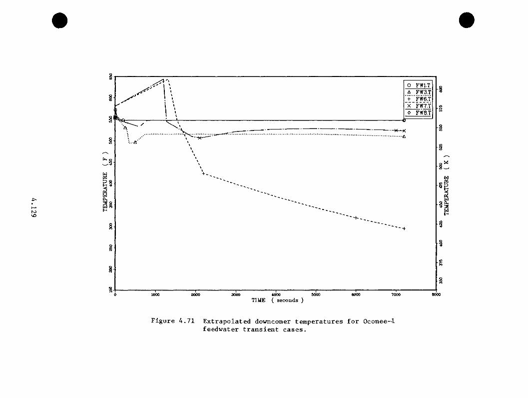
roVO
UOi
I ' I ■■'■ ■ ■” 'r3000 4000 5000
TIME ( seconds )
o FWl.TA FW3.T+ FW6.TX FW7.T0 FW8.T
>
•“H—K A
’ ■ ■ ' I ' " ' "7000 aooo
Figure 4.71 Extrapolated downcomer temperatures for Oconee-1feedwater transient cases.

U)o
OFWl.H
o
1000 2000 3000 6000 60004000TIME ( seconds )
7000 eooo
Figure 4,72 Extrapolated downcomer heat transfer coefficientsfor Oconee-1 feedwater transient cases.

4 . 5 .6 S te a a G en e ra to r Tube R upture
Tbe steam g e n e ra to r tube r u p tu r e I s e s s e n t i a l l y a sm a l l -b re a k LOCA t h a t
dumps th e l o s t p r im ary c o o la n t i n t o th e steam g e n e r a to r . For a s in g le tube
r u p t u r e , th e INEL SGTR c a l c u l a t i o n in S e c t io n 4 . 3 . 1 . 9 a p p l i e s d i r e c t l y . For
m u l t i p l e tube r u p t u r e s , th e PORV-sized LOCA e x t r a p o la t i o n s would g e n e r a l ly
be r e p r e s e n t a t i v e . In e i t h e r e v e n t , th e te m p era tu re and p r e s s u r e response
o f th e Oconee-1 p l a n t shou ld be m i ld as f a r as FTS i s concerned .
4 . 5 .7 Main Steam L ine Break Cases
Seven main steam l i n e b re a k c a s e s were e v a lu a te d . Table 4 .2 4 l i s t s th e
c o n d i t io n s f o r th e se c a s e s . The sequences com prise t r a n s i e n t s 26 (MSLBl)
th ro u g h 32 (MSLB7) r e s p e c t i v e l y in Tab le 4 .2 5 . F ig u re s 4 .73 th rough
4 .75 p r e s e n t the e x t r a p o la t e d p r e s s u r e s , te m p e ra tu re s , and h e a t t r a n s f e r
c o e f f i c i e n t s f o r c a se s HSLBl, MSLB3, NSLB4, and HSLB6. Cases HSLB2 and
7 co rre sp o n d c l o s e l y t o NSLBl. L ikew ise , MSLB5 i s v e ry s im i l a r to MSLB3.
E x t r a p o la t io n o f th e se sequences was p ro b le m a tic because of th e d i s p a r i t y
o f s p e c i f i c a t i o n s between th e RELAP5 and TRAC d e t a i l e d c a l c u l a t i o n s and
th e s e e x t r a p o la t e d c a s e s .
Most n o ta b ly , th e 20-min d e la y o f fe e d w a te r i s o l a t i o n , RCP r e s t a r t , and HPI
f o r the e x t r a p o la t e d c a se s r e p r e s e n te d a v e ry long d e la y r e l a t i v e to the
e a r l y RCP r e s t a r t s and i s o l a t i o n o f feed w a te r a t 10 min in th e LANL and
INEL main steam l i n e b re a k c a l c u l a t i o n s . The r a p id cooldown r a t e s in the
d e t a i l e d c a l c u l a t i o n s ( se e S e c t io n s 4 . 3 . 1 . 4 and 4 . 3 .2 . 1 ) cou ld n o t p o s s ib ly
be s u s t a in e d f o r 20 min. The cooldown model in Appendix C cou ld no t be
a p p l i e d because th e complex tw o-phase h e a t t r a n s f e r regime in th e a f f e c t e d
4 . 1 3 1
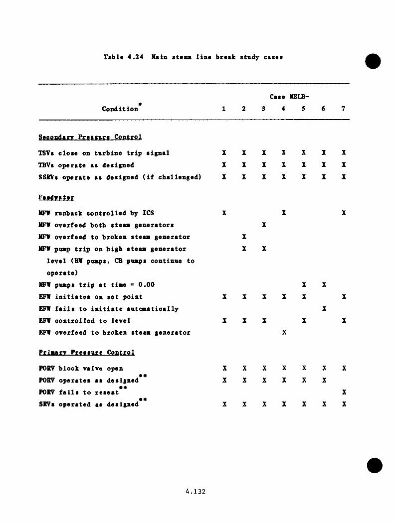
Table 4 .2 4 Main steaai l in e break stndy cases
C o n d it io n
Case MSLB-
1 2 3 4 5
Secondary P r e s s u r e C o n tro l
TSVs c lo s e on tu r b i n e t r i p s ig n a l X X X X X X X
TBVs o p e r a te as d e s ig n ed X X X X X X X
SSBVs o p e ra te as d e s ig n ed ( i f c b a l le n g e d ) X X X X X X X
NFV runback c o n t r o l l e d by ICS X X X
NFV o v e r fe e d b o th s t e a a g e n e ra to r s X
NFV o v e rfe e d to b ro k en s t e a a g e n e ra to r X
NFV puBp t r i p on b ig b s t e a a g e n e ra to r X X
le v e l (HV puaps , CB puaps c o n t in u e to
o p e ra te )
NFV puaps t r i p a t t i a e = 0 .0 0 X X
EFV i n i t i a t e s on s e t p o in t X X X X X X
EFV f a i l s t o i n i t i a t e a u t o a a t i c a l l y X
EFV c o n t r o l l e d t o l e v e l X X X X X
EFV o v e r fe e d t o b ro k en s t e a a g e n e r a to r X
f i i w r y cp .p trp i
PORV b lo c k v a lv e open X X X X X X X**
PORV o p e r a t e s as des ig n ed X X X X X X• *
PORV f a i l s t o r e s e a t X• •
SRVs o p e ra te d as des ig n ed X X X X X X X
4 . 1 3 2
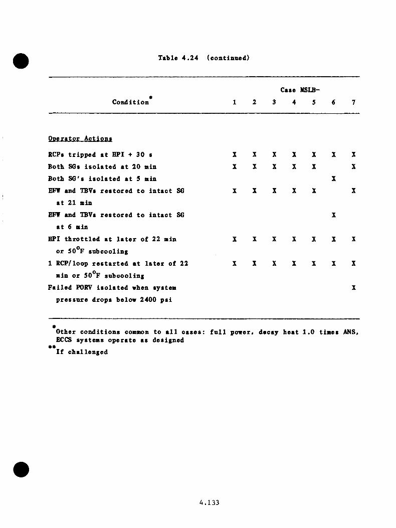
Table 4 .2 4 (oontinned)
C o n d i t io n
Case MSLB-
3 4 5
O pera to r A c tio n s
RCPs t r i p p e d a t HPI + 30 s
Both SGs i s o l a t e d a t 20 min
Both SG's i s o l a t e d a t 5 min
EFW and TBVs r e s t o r e d t o i n t a c t SG
a t 21 min
EFW and TBVs r e s t o r e d t o i n t a c t SG
a t 6 min
HPI t h r o t t l e d a t l a t e r o f 22 min
o r 50**F snbcoo ling
1 RCP/loop r e s t a r t e d a t l a t e r o f 22
min o r 50°F sn b co o lin g
F a i l e d PORV i s o l a t e d when system
p r e s s u r e d rops below 2400 p s i
X X X X X X X
X X X X X X
X
X X X X X X
X
X X X X X X X
X X X X X X X
X
*O ther c o n d i t io n s common to a l l c a s e s : f u l l power, decay h e a t 1 .0 t im es ANS, ECCS system s o p e ra te as des igned
*•I f c h a l le n g e d
4 . 1 3 3
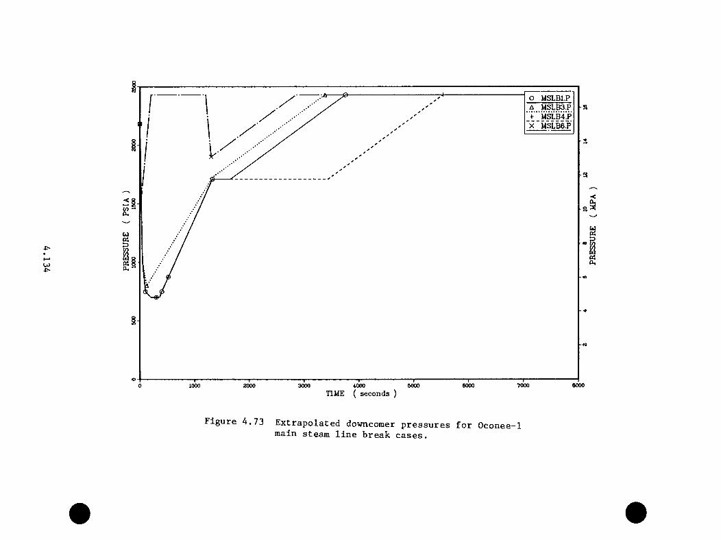
u>■p-
O MSLB1.P-a
<I
§
§
o6000 7000 90001000 4000 50000 2000 3000
TIME ( seconds )
Figure 4.73 Extrapolated downcomer pressures for Oconee-1main steam line break cases.
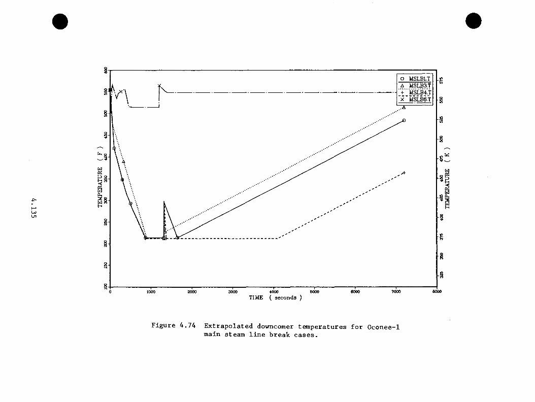
LOUi
§O MSLBl.T
§
%
§
§
§
87000 eooo2000 60000 1000 3000 4000 5000
TIME ( seconds )
Figure 4.74 Extrapolated downcomer temperatures for Oconee-1main steam line break cases.
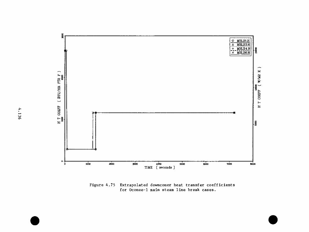
O MSLB1.HA MSLB3.H + "msLB41h
"x "MSLB6.H
cvja
OJON
pq
&ouH JK '
' Pm Oof-K
rr
1000 2000 3000 4000 5000TIME ( seconds )
6000 7000 8000
Figure 4.75 Extrapolated downcomer heat transfer coefficientsfor Oconee-1 main steam line break cases.
s t e a a g e n e ra to r v i o l a t e s th e m o d e l 's s i a p l i f y i n g a s s n a p t io n s ( see Appendix
C, S e c t io n C .2 .3 ) . A lso , th e n a t u r a l c i r c u l a t i o n flow d a ta n e c e s sa ry to
s e t up th e model were c u t s h o r t by the e a r l y r e s t a r t o f th e r e a c t o r co o l in g
puaps .
As a r e s u l t , a v e ry sia ip le approach was ta k e n to e x t r a p o la t e th e se c a s e s .
F i r s t , th e LANL a a i n s t e a a l i n e b reak ca se s were s e l e c t e d as th e base s
f o r e x t r a p o l a t i o n , as th e y p r e d ic t e d th e most severe cooldown r a t e s . Next,
the downcomer te m p e ra tu re re sponse of th e e x t r a p o la t e d ca se s was ta k en to
be s i m i l a r to th e p o r t i o n o f th e LANL case p r i o r to the r e s t a r t o f the
RCPs a t 526 s . C on tinu ing on th e same s lo p e , th e downcomer tem p era tu re
was e x t r a p o la t e d to a minimum te m p e ra tu re o f 373 K (212*^F). This minimum
te m p e ra tu re i s c o n s id e re d a c o n s e r v a t iv e p h y s ic a l l i m i t .
The te m p e ra tu re rem ains a t t h i s minimum l i m i t u n t i l the steam g e n e ra to r
d r i e s o u t . The en tra in m e n t of l i q u i d s from the b roken steam g e n e ra to r
i s assumed to a b a te a t low te m p e ra tu re s , a l low ing th e steam g e n e ra to r to
r e f i l l . The time to steam g e n e ra to r d ry o u t r e f l e c t s th e time needed to
accum ula te s u f f i c i e n t decay h e a t and RCP power d i s s i p a t i o n to complete
th e steam g e n e ra to r d ry o u t . R ehea ting and r e p r e s s u r i z a t i o n t r e n d s from
th e LANL c a se s were employed to com plete th e e x t r a p o la t i o n a f t e r steam
g e n e r a to r d r y o u t .
The te m p e ra tu re e x t r a p o l a t i o n s f o r MSLBl, MSLB3, and MSLB4 in F ig u re 4 .74
were b ased on th e above a s su m p tio n s . The d i f f e r e n c e s in th e se cu rves can be
a s c r ib e d to th e q u a n t i t y o f w a te r accum ula ted in th e b roken steam g e n e ra to r s
p r i o r to i s o l a t i o n . The NSLB6 c ase does n o t ex p e r ien ce o v e rco o l in g due to
th e l o s s o f a l l feed w ate r fo llow ed by e a r l y i s o l a t i o n o f the b roken steam
4 . 1 3 7
g e n e r a to r and c o n t r o l l e d cooldown u s in g th e i n t a c t s t e a a g e n e r a to r . See
Appendix C, S e c t io n C .3 , f o r d e t a i l e d d i s c u s s io n o f th e s e t r a n s i e n t s .
4 .6 Suaaary o f T h e ra a l-H y d ra u l ic E v a lu a t io n s
P r e s s u r e , t e a p e r a t u r e , and h e a t t r a n s f e r c o e f f i c i e n t re sp o n se p r o f i l e s were
c a l c u l a t e d and a s s ig n e d f o r eve ry ev en t t r e e e n d - s t a t e hav ing a frequency
o f o ccu rre n c e g r e a t e r than 10 ^ p e r y e a r . The use of sequence s i a i l a r i t y
g roup ings f u r t h e r reduced th e nuaber o f sequences e v a lu a te d .
D e ta i l e d c a l c u l a t i o n s u s in g th e RELAPS and TRAC a o d e l s p ro v id ed the
d a ta upon which sequence e x t r a p o l a t i o n s were d eve loped . The d e t a i l e d
c a l c u l a t i o n s in c lu d ed even t i n i t i a t o r s known o r s u sp e c te d to r e s u l t in
s i g n i f i c a n t o v e rc o o l in g r e s p o n s e s . These i n i t i a t o r s in c lu d e d s t e a a l i n e
b r e a k s , t u r b i n e bypass v a lv e f a i l u r e s , feed w ate r o v e r f e e d s , s t e a a g e n e ra to r
tube r u p t u r e s , and sm all p r im ary b r e a k s . The RELAPS and TRAC models
developed f o r t h i s s tudy w ere , a t the t i a e , th e most complex a p p l i c a t i o n s
o f th e codes t o d a t e .
E x t r a p o la t io n s were based on th e r e s u l t s o f th e d e t a i l e d c a l c u l a t i o n s .
Where s p e c i f i e d c o n d i t io n s o f an e x t r a p o la t e d t r a n s i e n t c l o s e l y laatched
th o se of a c a l c u l a t e d sequence , th e c a l c u l a t e d r e s u l t s ( i . e . , p r e s s u r e
and t e a p e r a t u r e t r e n d s ) were used o v er the a p p l i c a b l e p o r t i o n o f the
e x t r a p o l a t i o n . T e a p e ra tu re e x t r a p o l a t i o n s were f a c i l i t a t e d by the use
o f a cooldown model, which accoun ted f o r a l l major h e a t in g and c o o lin g
mechanisms and the system mass and loop mass f low s d e te rm in in g th e time
c o n s ta n t s on th e r e sp o n s e .
4 . 1 3 8

The r e s u l t s o f th e e z t r a p o l s t i o n s and d e t a i l e d c a l c u l a t i o n s a re su a n a r iz e d
on T ab le 4 .2 5 . The t r a n s i e n t nnmbers and i d e n t i f i c a t i o n s c o r r e l a t e to
th e noaiencla tn re used in th e f r a c t u r e aiechanics (C hap te r 5 .0 ) and r e s u l t s
(C h ap te r 6 .0 ) s e c t i o n s . The minimuai downcomer te m p era tu re s and e x te n t of
p r im ary r e p r e s s u r i z a t i o n f a c i l i t a t e r e f e r e n c e s to the f r a c t u r e mechanics
c a l c u l a t i o n .
4 . 1 3 9
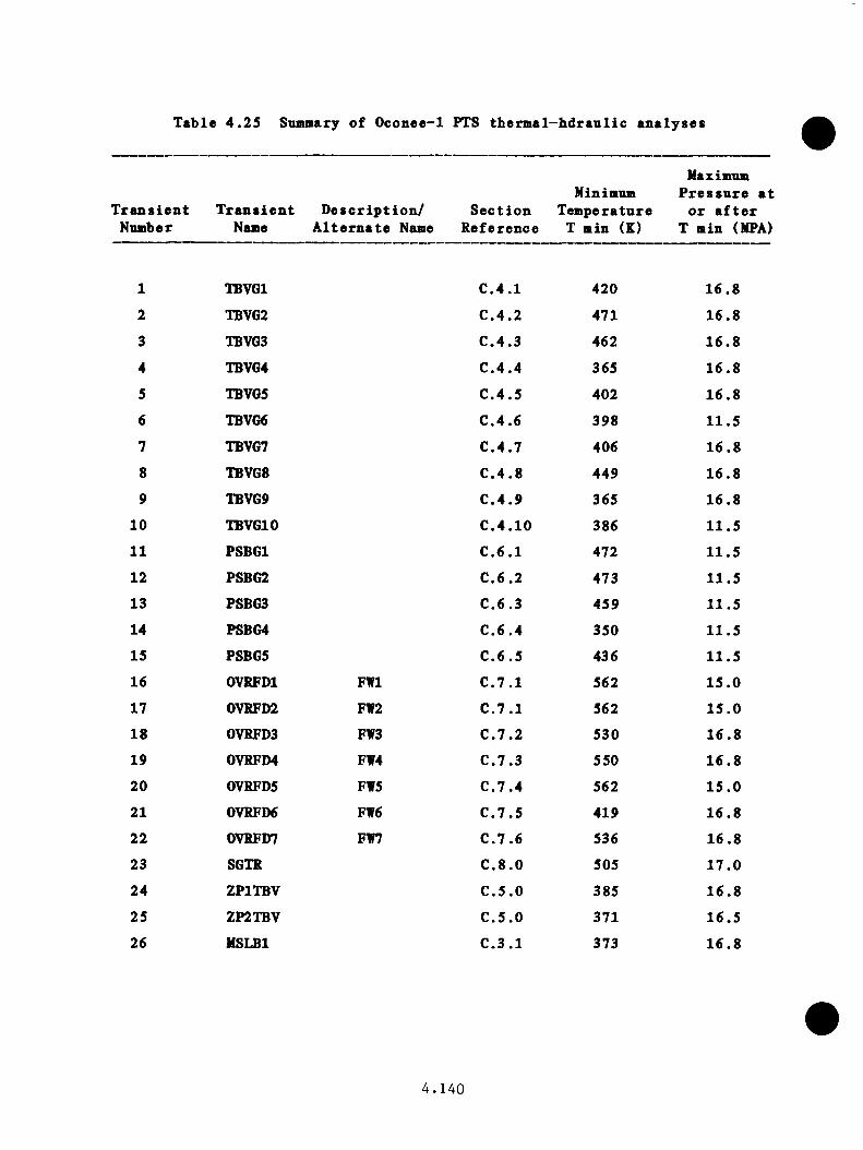
Table 4 .2 5 Sunmary o f Oconee-1 PTS therm al-hdran lic an a lyses
T r a n s ie n t T r a n s ie n t D e s c r ip t io n / Nnnber Nane A l t e r n a t e Naae
Minimnm S e c t io n Tem perature
R eference T min (K)
Maximum P r e s s u r e a t
o r a f t e r T min (MPA)
1 TBVGl C .4 .1 420 16 .8
2 TBVG2 C .4 .2 471 16 .8
3 TBVG3 C .4 .3 462 16 .8
4 TBVG4 C .4 .4 365 16 .8
5 TBVG5 C .4 .5 402 1 6 .8
6 TBVG6 C .4 .6 398 11 .5
7 TBVG7 C .4 .7 406 16 .8
8 TBVG8 C .4 .8 449 16 .8
9 TBVG9 C .4 .9 365 16 .8
10 TBVGl0 C .4 .10 386 11 .5
11 PSBGl C .6 .1 472 11.5
12 PSBG2 C .6 .2 473 11.5
13 PSBG3 C .6 ,3 459 11.5
14 PSBG4 C .6 .4 350 11 .5
15 PSBG5 C .6 .5 436 11 .5
16 OVRFDl FWl C .7 .1 562 15 .0
17 0VRFD2 FW2 C .7 .1 562 15 .0
18 0VRFD3 FW3 C .7 .2 530 16 .8
19 0VRFD4 FW4 C .7 .3 550 1 6 .8
20 0VRFD5 FW5 C .7 .4 562 1 5 .0
21 0VRFD6 FW6 C .7 .5 419 1 6 .8
22 0VRFD7 FW7 C .7 .6 536 16 .8
23 SGTR C .8 .0 505 17 .0
24 ZPITBV C .5 .0 385 16 .8
25 ZP2TBV C .5 .0 371 16.5
26 MSLBl C .3 .1 373 1 6 .8
4 . 1 4 0
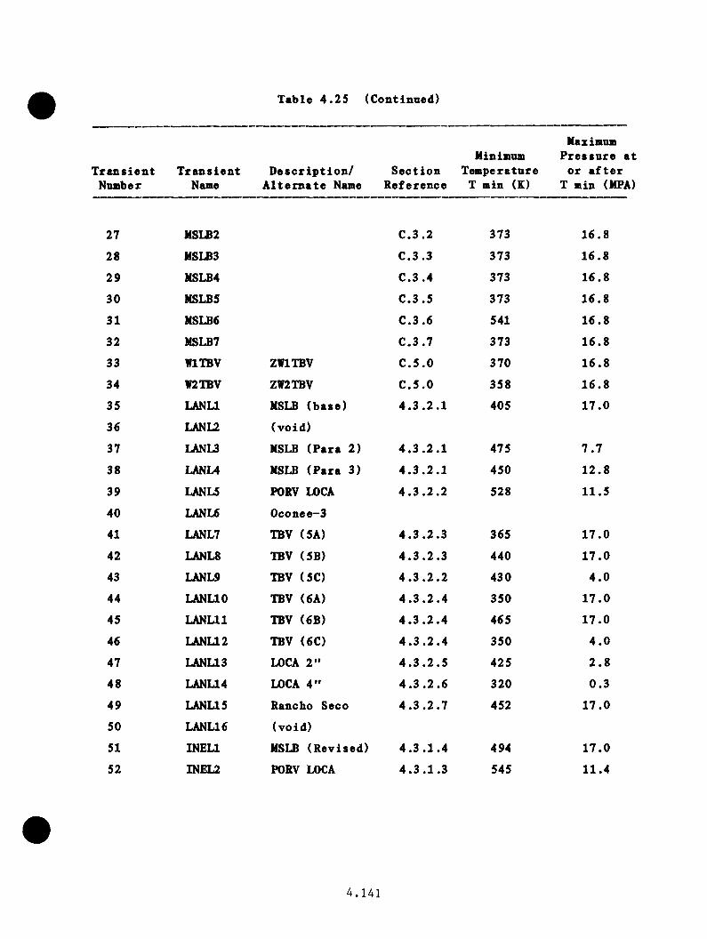
Table 4 . 25 (ContinTied)
T r a n s ie n tNumber
T r a n s ie n tName
D e s c r ip t io n / A l t e r n a t e Name
Minimum S e c t io n Tem perature
R eference T min (K)
Maximum P re s su re a t
o r a f t e r T min (MPA)
27 MSLB2 C .3 .2 373 16 .8
28 MSLB3 C .3 .3 373 16.8
29 MSLB4 C.3 .4 373 16.8
30 MSLB5 C .3 .5 373 16 .8
31 MSLB6 C .3 .6 541 16 .8
32 MSLB7 C .3 .7 373 16.8
33 WITBV ZWITBV C .5 .0 370 16 .8
34 W2TBV ZW2TBV C .5 .0 358 16 .8
35 LANU MSLE (b ase ) 4 .3 .2 .1 405 17 .0
36 LANLZ (vo id )
37 LANU MSLB (P a ra 2) 4 .3 .2 .1 475 7 .7
38 LANU MSLB (P a ra 3) 4 .3 .2 .1 450 12 .8
39 LANU PORV LOCA 4 .3 .2 .2 528 11.5
40 LANU Oconee-3
41 LANL7 TBV (5A) 4 .3 .2 .3 365 17 .0
42 LANL8 TBV (5B) 4 .3 .2 .3 440 17 .0
43 LANL9 TBV ( 5 0 4 .3 .2 .2 430 4 .0
44 LANUO TBV (6A) 4 . 3 .2 . 4 350 17 .0
45 LANLll TBV (6B) 4 .3 .2 .4 465 17 .0
46 LANL12 TBV ( 6 0 4 . 3 .2 . 4 350 4 .0
47 LANU3 LOCA 2 ” 4 . 3 .2 . 5 425 2 .8
48 LANL14 LOCA 4" 4 .3 .2 .6 320 0.3
49 LANL15 Rancho Seco 4 .3 .2 .7 452 17 .0
50 LANL16 (vo id )
51 INEU MSLB (R evised) 4.3 .1 .4 494 17 .0
52 INEU PORV LOCA 4 .3 .1 .3 545 11.4
4 . 1 4 1

Table 4 . 25 (Continued)
T r a n s ie n tNumber
T r a n s ie n tName
D e s c r ip t i o n / A l t e r n a t e Name
S e c t io nR eference
Minimum Tem perature
T min (K)
Maximum P re s s u re a
o r a f t e r T min (MPA
53 INEL3 O verfeed 4 .3 .1 .2 505 17 .0
54 INEL4 Oconee-3
55 INEL5 LOCA 2" 4 . 3 .1 . 7 355 1 .5
56 INEL6 Max. Sus. NFV 4 . 3 .1 . 5 500 17 .0
57 INEL7 4TBV-HS 4 . 3 .1 . 6 387 17 .0
58 INEL8 Pump S u c t io n 2 .5 " 4 . 3 . 1 . 8 446 5 .2
59 INEL9 SGTR 4 . 3 . 1 . 9 505 17 .0
4 . 1 4 2
REFERENCES
4 .1 C. D. F l e t c h e r and o t h e r s , "RELAPS T herm al-H ydrau lic A n a ly s is of
P r e s s n r i z e d Thermal Shock Sequences f o r the Oconee-1 P r e s s u r i z e d Water
R e a c to r , " E6G-NSMD-63343, J u ly 1983.
4 .2 J . I r e l a n d and o t h e r s , "TRAC A n a ly s is o f Severe O vercooling T r a n s ie n t s
f o r the Oconee-1 PWR," LA-UR-83-3182, (no d a t e ) .
4 .3 T. G. Theophanous, Purdue U n iv e r s i t y , l e t t e r to J . D. White, ORNL,
December 22 , 1983.
4 . 1 4 3
5.0 CONDITIONAL PROBABILITY OF VESSEL FAILURE
R. D. C h e v e r to n , Oak R id g e N a t io n a l L a b o r a to ry
5.1 Introduction
The c o n d i t i o n a l p r o b a b i l i t y o f v e s s e l f a i l u r e ( t h r o u g h - w a l l c r a c k in g )
w as c a l c u l a t e d f o r th e O conee-1 r e a c t o r p r e s s u r e v e s s e l . The n e c e s s a r y
m o d e ls f o r p e r f o r m in g a p r o b a b i l i s t i c f r a c t u r e - m e c h a n i c s a n a l y s i s f o r
t h e O c o n e e -1 r e a c t o r p r e s s u r e v e s s e l an d t h e r e s u l t s o f th e a n a l y s i s a r e
d i s c u s s e d .
5 .2 D e s c r i p t i o n o f B a s ic P ro b lem
D u rin g a n o v e r c o o l i n g t r a n s i e n t i n a p r e s s u r i z e d - w a t e r r e a c t o r (PWR),
t h e r e a c t o r p r e s s u r e v e s s e l i s s u b j e c t e d t o th e rm a il sh o c k i n t h e s e n s e
t h a t th e r m a l s t r e s s e s a r e c r e a t e d i n t h e v e s s e l w a l l a s a r e s u l t o f
r a p i d re m o v a l o f h e a t fro m i t s i n n e r s u r f a c e . The th e rm a l s t r e s s e s a r e
s u p e r im p o s e d o n t h e p r e s s u r e s t r e s s e s w i t h t h e r e s u l t t h a t t h e n e t
s t r e s s e s a r e p o s i t i v e ( t e n s i l e ) a t and n e a r t h e i n n e r s u r f a c e o f t h e
w a l l and a r e s u b s t a n t i a l l y lo w e r an d p e r h a p s n e g a t i v e e l s e w h e r e , d e p e n d
in g o n th e m a g n i tu d e o f t h e p r e s s u r e s t r e s s . The c o n c e r n o v e r t h e h ig h
t e n s i l e s t r e s s e s n e a r t h e i n n e r s u r f a c e i s t h a t th e y r e s u l t i n h ig h
s t r e s s i n t e n s i t y f a c t o r s (K ^) f o r i n n e r - s u r f a c e f l a w s t h a t may be
p r e s e n t . To com pound t h e m a t t e r , t h e r e d u c e d t e m p e r a tu r e a s s o c i a t e d
w i t h t h e th e r m a l s h o c k an d r a d i a t i o n dam age r e s u l t i n r e l a t i v e l y low
f r a c t u r e to u g h n e s s v a l u e s f o r t h e v e s s e l m a t e r i a l , p a r t i c u l a r l y n e a r t h e
5.1

i n n e r s u r f a c e . T h u s , t h e r e i s a p o s s i b i l i t y o f p r o p a g a t i o n o f i n i t i a l l y
v e r y s h a l lo w a s w e l l a s d e e p e r f l a w s , an d t h e p r o b a b i l i t y i n c r e a s e s w i th
t im e b e c a u s e o f t h e t im e d e p e n d e n c e o f r a d i a t i o n d am ag e .
The p o s i t i v e g r a d i e n t i n t e m p e r a t u r e an d t h e n e g a t i v e g r a d i e n t s i n
s t r e s s an d f l u e n c e th r o u g h t h e w a l l t e n d t o p r o v id e a m ech an ism f o r
c r a c k a r r e s t . E ven s o , i f t h e c r a c k i s v e r y lo n g o n t h e s u r f a c e and
p r o p a g a t e s d e e p e n o u g h , t h e r e m a in in g v e s s e l l i g a m e n t w i l l becom e p l a s
t i c , an d t h e v e s s e l i n t e r n a l p r e s s u r e w i l l u l t i m a t e l y r e s u l t i n r u p t u r e
o f t h e v e s s e l . T h u s , f o r e a c h th e r m a l t r a n s i e n t t h e r e w i l l b e a maximum
p e r m i s s i b l e p r e s s u r e t h a t i s a f u n c t i o n o f t h e t im e t h a t t h e v e s s e l h a s
b e e n i n o p e r a t i o n .
C ra c k p r o p a g a t io n may a l s o b e l i m i t e d by a phenom enon r e f e r r e d t o a s
warm p r e s t r e s s i n g (W PS), w h ic h h a s b e e n d e m o n s t r a te d i n t h e l a b o r a t o r y
w i t h s m a l l sp e c im e n s^ an d a l s o i n a r a t h e r l a r g e , t h i c k - w a l l e d c y l i n d e r
2d u r i n g a th e r m a l - s h o c k e x p e r im e n t . I n s u c h c a s e s , WPS s im p ly r e f e r s t o
t h e i n a b i l i t y o f a c r a c k t o i n i t i a t e w h i l e i s d e c r e a s i n g w i th t im e ,
t h a t i s , w h i l e t h e c r a c k i s c l o s i n g . W h ile t h i s s p e c i a l s i t u a t i o n i s
e n c o u n te r e d d u r in g som e s p e c i f i c o v e r c o o l i n g a c c i d e n t s , c a u t i o n m u s t be
e x e r c i s e d i n t a k i n g c r e d i t f o r WPS b e c a u s e c h a n g e s i n t h e p r e s s u r e t h a t
a f f e c t l i t t l e e l s e c a n d e l a y o r e l i m i n a t e t h e r e q u i s i t e c o n d i t i o n s f o r
WPS.
The a r e a o f th e v e s s e l o f p a r t i c u l a r c o n c e rn i n t h e e v e n t o f a n o v e r
c o o l i n g a c c i d e n t (OCA) i s t h e s o - c a l l e d b e l t l i n e r e g i o n , t h a t i s , t h e
5.2

a r e a d i r e c t l y a c r o s s f r c a i t h e c o r e w h e re (1 ) t h e r a d i a t i o n dam age i s t h e
g r e a t e s t , ( 2 ) t h e th e r m a l s h o c k c o u ld b e s e v e r e , an d (3 ) a r u p t u r e o f
t h e v e s s e l c o u ld p r e c lu d e f l o o d i n g o f t h e c o r e . W h e th e r o r n o t a p a r
t i c u l a r d e g r e e o f r u p t u r e a s s o c i a t e d w i t h a p a r t i c u l a r t r a n s i e n t c o u ld
i n f a c t p r e c lu d e f l o o d i n g o f t h e c o r e h a s n o t b e e n d e te r m in e d . F o r th e
p u rp o s e o f t h i s r e p o r t , i t i s s u f f i c i e n t t o p r e d i c t w h e th e r a f l a w w i l l
p r o p a g a t e c o m p le te ly th r o u g h t h e w a l l o f t h e v e s s e l .
The r a d i a t i o n - i n d u c e d r e d u c t i o n i n f r a c t u r e to u g h n e s s o f t h e v e s s e l
m a t e r i a l i s p r i m a r i l y a f u n c t i o n o f t h e f a s t - n e u t r o n f l u e n c e an d th e
c o n c e n t r a t i o n s o f c o p p e r ( a c o n ta m in a n t ) and n i c k e l ( a n a l l o y i n g e l e
m e n t ) . I n m o s t PWR v e s s e l s t h e h i g h e s t c o n c e n t r a t i o n s o f c o p p e r a r e
fo u n d i n t h e w e ld s t h a t j o i n t h e s e g m e n ts o f t h e v e s s e l , and many o f
t h e s e w e ld s h a v e h ig h c o n c e n t r a t i o n s o f n i c k e l a s w e l l . T h u s , f o r some
PWR v e s s e l s t h e w e ld s a r e o f p r im a r y c o n c e r n , an d t h e O c o n e e -1 r e a c t o r
p r e s s u r e v e s s e l f a l l s i n t h i s c a t e g o r y .
The b e l t l i n e r e g i o n o f r e a c t o r p r e s s u r e v e s s e l s i s f a b r i c a t e d u s in g
e i t h e r f o r g e d - r i n g s e g m e n ts o r r o l l e d - p l a t e s e g m e n ts . V e s s e l s made w i th
f o r g i n g s h a v e o n ly c i r c u m f e r e n t i a l w e ld s , w h i le p l a t e - t y p e v e s s e l s h av e
b o th c i r c u m f e r e n t i a l an d a x i a l w e ld s , a s show n i n F ig u r e 5 . 1 . F o r
p l a t e - t y p e v e s s e l s w i th s t a g g e r e d a x ie i l w e ld s an d f o r w h ic h r a d i a t i o n
deimage i s m uch m ore s e v e r e i n t h e w e ld s t h a n i n t h e b a s e m a t e r i a l , t h e
f i n a l s u r f a c e l e n g t h o f a p r o p a g a t i n g i n n e r - s u r f a c e a x i a l f la w t e n d s t o
b e l i m i t e d t o t h e l e n g t h o f t h e a x ie i l w e ld i n w h ic h i t r e s i d e s , t h a t i s ,
5.3

t h e h e i ^ t o f t h e s h e l l c o u r s e . F u r th e r m o r e , o n ly t h a t p o r t i o n o f a
w e ld t h a t i s w i t h i n t h e a x i a l b o u n d s o f t h e c o r e n ee d b e c o n s id e r e d
b e c a u s e o f t h e s t e e p a t t e n u a t i o n o f t h e f a s t - n e u t r o n f l u x b ey o n d t h e
f u e l r e g i o n .
The e x te n d e d l e n g t h o f a n i n i t i a l l y s h o r t , c i r c u m f e r e n t i a l l y o r i e n t e d
f l a w l o c a t e d i n a c i r c u m f e r e n t i a l w e ld a l s o t e n d s t o be l i m i t e d b e c a u s e
o f a n a z im u th a l v a r i a t i o n i n t h e f a s t - n e u t r o n f l u x ( s e e F ig u r e 5 . 1 ) .
The b e h a v io r o f an assu m ed f la w c a n b e p r e d i c t e d f o r a g i v e n t r a n s i e n t
u s i n g f r a c t u r e - m e c h a n i c s m e th o d s o f a n a l y s i s . I n s u c h a n a n a l y s i s t h e
p a r a m e te r s an d c o n s i d e r a t i o n s i n v o l v e d a r e t h e s i z e , s h a p e , an d o r i e n t a
t i o n o f t h e f l a w ; t h e th e r m a l an d p r e s s u r e s t r e s s e s r e s u l t i n g fro m a
s p e c i f i c t r a n s i e n t ; t h e t e m p e r a t u r e an d f a s t - n e u t r o n f l u e n c e d i s t r i b u
t i o n s th r o u g h o u t t h e v e s s e l w a l l ; t h e e f f e c t o f f l u e n c e a n d m a t e r i a l
c h e m is t r y on r a d i a t i o n dameige; a v a r i e t y o f m a t e r i a l p r o p e r t i e s ; an d a
c o m p a r is o n o f t h e s t r e s s i n t e n s i t y f a c t o r (K ^) a s s o c i a t e d w i th t h e t i p
o f t h e f l a w w i th t h e m a t e r i a l ’ s s t a t i c c r a c k - i n i t i a t i o n an d c r a c k - a r r e s t
f r a c t u r e - t o u g h n e s s v a l u e s an d . E ach o f t h e s e f a c t o r s m u s t be
c o n s i d e r e d i n t h e d e v e lo p m e n t o f a n a p p r o p r i a t e a n a l y t i c a l m odel f o r
e v a l u a t i n g t h e i n t e g r i t y o f a PWR v e s s e l w hen s u b j e c t e d t o OCA l o a d i n g
c o n d i t i o n s . The n e c e s s a r y m o d e ls f o r p e r fo rm in g a p r o b a b i l i s t i c
f r a c t u r e - m e c h a n i c s a n a l y s i s f o r t h e O c o n e e -1 r e a c t o r p r e s s u r e v e s s e l and
t h e r e s u l t s o f t h e a n a l y s i s a r e d i s c u s s e d i n t h e r e m a in d e r o f t h i s
c h a p t e r .
5.4
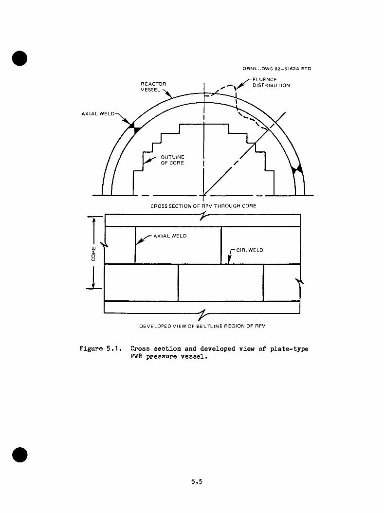
O R N L - D W G 8 2 - 5 1 6 2 A ETD
F L U E N C ED I S T R I B U T I O N
A X I A L W E L D
O U T L I N E O F C O R E
C R O S S S E C T I O N O F R P V T H R O U G H C O R E
A X I A L W E L D
C I R . W E L D
D E V E L O P E D V I E W O F B E L T L I N E R E G I O N O F R P V
F ig u r e 5 . 1 . C ro s s s e c t i o n an d d e v e lo p e d v ie w o f p l a t e - t y p e PWR p r e s s u r e v e s s e l .
5.5

5 .3 C a l o u l a t l o n a l M o d els
The c o n d i t i o n a l p r o b a b i l i t y o f v e s s e l f a i l u r e ( t h r o u g h - w a l l c r a c k i n g )
w as c a l c u l a t e d f o r t h e O co n ee-1 r e a c t o r p r e s s u r e v e s s e l u s i n g t h e OCA-P
3c o d e . OCA-P a c c e p t s a s i n p u t t h e p r im a ry s y s te m p r e s s u r e , t h e te m p e ra
t u r e o f t h e c o o l a n t i n t h e r e a c t o r v e s s e l dow ncom er, a n d t h e f l u i d - f i l m
h e a t t r a n s f e r c o e f f i c i e n t a d j a c e n t t o t h e v e s s e l w a l l , a l l a s a f u n c t i o n
o f t im e i n a s p e c i f i e d OCA t r a n s i e n t . The co d e t h e n p e r fo rm s o n e
d im e n s io n a l th e r m a l an d s t r e s s a n a l y s e s f o r t h e v e s s e l w a l l an d f i n a l l y
a p r o b a b i l i s t i c f r a c t u r e - m e c h a n i c s a n a l y s i s . D e t a i l s o f OCA-P n e c e s s a r y
f o r a n u n d e r s t a n d in g o f t h e O c o n e e -1 v e s s e l a n a l y s i s a r e d i s c u s s e d
b e lo w .
5 . 3 .1 F r a c tu r e - M e c h a n ic s M odel
The f r a c t u r e - m e c h a n i c s (FM) m o d el i n OCA-P i s b a s e d o n l i n e a r e l a s t i c
f r a c t u r e m e c h a n ic s (LEFM) an d u s e s a s p e c i f i e d maximum v a lu e o f K_ t ol a
a c c o u n t f o r u p p e r - s h e l f b e h a v i o r . The s t r e s s i n t e n s i t y f a c t o r (K ^) i s
c a l c u l a t e d u s i n g s u p e r p o s i t i o n t e c h n i q u e s i n c o n j u n c t i o n w i t h i n f l u e n c e
c o e f f i c i e n t s t h a t w e re c a l c u l a t e d u s i n g f i n i t e - e l e m e n t t e c h n i q u e s . The
a p p l i c a t i o n o f t h i s p r o c e d u r e m ak es i t p o s s i b l e t o p e r fo rm a l a r g e
num ber o f d e t e r m i n i s t i c FM c a l c u l a t i o n s a t r e a s o n a b l e c o s t , a n e c e s s a r y
c o n d i t i o n f o r p e r f o r m in g t h e p r o b a b i l i s t i c a n a l y s i s .
The O conee-1 v e s s e l w as f a b r i c a t e d fro m s e c t i o n s o f p l a t e an d h a s b o th
a x i a l an d c i r c u m f e r e n t i a l w e ld s i n t h e b e l t l i n e r e g i o n , a s show n i n F ig
u r e 5 . 2 . S e v e re d o f t h e w e ld s h a v e r a t h e r h ig h c o n c e n t r a t i o n s o f c o p p e r
an d n i c k e l w h i l e t h e c o n c e n t r a t i o n o f c o p p e r i n t h e b a s e m a t e r i a l i s
5.6
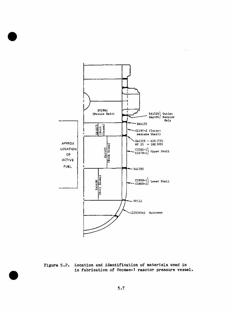
A P P R O X
L O C A T I O N
O F
A C T I V E
F U E L
ZV2861 (Nozzle Belt) SA1526] Outlet
SA1494/ Nozzles Only
SA1135
C2197-2 (Intermediate Shell)
SA1229 - 61Z (ID) MF 25 - 39Z (OD)C3265-1 C3278-1 Upper Shell
SA1585
C2800-11 Lower Shell C2800-2J
o
WF112
122S34VA1 Dutchman
F ig u r e 5 . 2 . L o c a t io n and i d e n t i f i c a t i o n o f m a t e r i a l s u s e d i ni n f a b r i c a t i o n o f O conee-1 r e a c t o r p r e s s u r e v e s s e l ,
5.7
s i g n i f i c a n t l y lo w e r . F u r th e r m o r e , v a l u e s o f K j fo p ^ e e p a x i a l f l a w s a r e
much g r e a t e r t h a n f o r d e e p c i r c u m f e r e n t i a l f l a w s . T hus a s d i s c u s s e d i n
S e c t i o n 5 .4 an d A p p e n d ix D i n g r e a t e r d e t a i l , t h e f l a w s o f i n t e r e s t a r e
r e s t r i c t e d t o th e a x i a l l y o r i e n t e d w e ld s .
The l e n g t h o f f l a w s i n t h e a x i a l w e ld s w i t h d e p th s g r e a t e r t h a n mm
w as assu m ed t o b e 1 .8 m, w h ich i s a p p r o x im a te ly t h e h e i g h t o f a s h e l l
c o u r s e , an d t h e s h a p e w as a ssu m ed t o be s e m i e l l i p t i c a l ( t h i s f l a w i s
r e f e r r e d t o a s t h e 2-m f l a w ) . S in c e t h e e n d s o f t h i s f l a w a r e f i x e d ,
p r o p a g a t i o n w as ju d g e d o n t h e b a s i s o f t h e K r a t i o s (K _/K .. , K -/K .. ) a tI 1C 1 l a
t h e d e e p e s t p o i n t o f t h e f l a w .
S h a l lo w e r f l a w s w e re assu m ed to b e tw o -d im e n s io n a l ( te r m e d 2-D f l a w s ) ,
s i n c e lo n g s h s d lo w f l a w s a r e e s s e n t i a l l y tw o - d im e n s io n a l , and s h o r t f l a w s
t e n d t o g ro w on th e s u r f a c e t o becom e lo n g f l a w s ,^ a t l e a s t i n t h e a b s e n c e
o f c l a d d i n g . B e c a u se t h e e f f e c t o f c l a d d i n g on t h e s u r f a c e e x t e n s i o n o f
s h o r t f l a w s i s n o t known a t t h i s t im e , an y p o s s i b l e b e n e f i c i a l e f f e c t h a s
b e e n d i s c o u n t e d .
C la d d in g o n t h e i n n e r s u r f a c e o f PWR p r e s s u r e v e s s e l s w as i n c l u d e d i n
t h e OCA-P a n a l y s i s a s a d i s c r e t e r e g i o n t o t h e e x t e n t t h a t t h e th e rm e il
an d s t r e s s e f f e c t s w e re a c c o u n te d f o r . As m e n t io n e d a b o v e , t h e e f f e c t
o f c l a d d i n g o n t h e s u r f a c e e x t e n s i o n o f f i n i t e - l e n g t h f l a w s w as n o t c o n
s i d e r e d .
5.8
B e c a u se o f t h e d i f f e r e n c e i n t h e c o e f f i c i e n t o f th e r m a l e x p a n s io n
b e tw e e n th e c l a d d i n g a n d b a s e m a t e r i a l , t h e c a l c u l a t e d s t r e s s e s i n t h e
c l a d d i n g e x c e e d t h e y i e l d s t r e n g t h o f t h e c l a d d i n g by a n a p p r e c i a b l e
a m o u n t, and t h i s r e s u l t s i n a n o v e r e s t i m a t i o n o f t h e v a l u e s f o r th e
f l a w s , w h ic h w e re assu m ed t o t e r m i n a t e i n t h e c l a d d i n g o r e x te n d th ro u g h
t h e c l a d d i n g i n t o t h e b a s e m a t e r i a l . An a l t e r n a t i v e a p p ro a c h w ou ld be
t o l i m i t t h e s t r e s s i n t h e c l a d d i n g t o t h e y i e l d s t r e s s , b u t t h i s
u n d e r e s t im a te s b e c a u s e K . i s s e n s i t i v e t o t h e s t r a i n , w h ich i s n o t
l i m i t e d by t h e y i e l d i n g phen o m en o n . The d i f f e r e n c e i n b e tw e e n t h e s e
tw o e x t r e m e s i s n o t l a r g e * t h u s t h e c o n s e r v a t i v e e x tre m e w as s e l e c t e d .
M a t e r i a l p r o p e r t i e s r e q u i r e d f o r t h e f r a c t u r e - m e c h a n ic s a n a l y s i s i n c l u d e
t h e s t a t i c c r a c k i n i t i a t i o n an d a r r e s t to u g h n e s s v s i lu e s and
a n d t h e n i l - d u c t i l i t y r e f e r e n c e t e m p e r a tu r e (RTNDT). F o r t h e p ro b a
b i l i s t i c f r a c t u r e - m e c h a n i c s a n a l y s i s , m ean v e ilu e s o f t h e s e p a r a m e te r s
a r e r e q u i r e d , an d th e y w e re o b t a i n e d f o r t h e v e s s e l w e ld m a t e r i a l a s
f o l l o w s :
K jc = 1 .4 3 {36 .5 + 3 .0 8 4 exp [ 0 .0 3 6 (T - RTNDT + 5 6 ) ] } , MPa /m ( 5 .1 )
= 1 .2 5 {29 .5 + 1.344 exp [0 .0 2 6 1 (T - RTNDT + 89) ] } , MPa ( 5 .2 )
5w h e re t h e q u a n t i t y i n b r a c e s r e p r e s e n t s t h e ASME S e c t i o n XI lo w e r-b o u n d
to u g h n e s s v a lu e an d T i s t h e t e m p e r a tu r e a t t h e t i p o f t h e f la w i n °C.
T h ese e x p r e s s i o n s w e re o b t a i n e d by l e t t i n g t h e ASME lo w e r bound c u r v e s
r e p r e s e n t th e m ean v a l u e s m in u s tw o s t a n d a r d d e v i a t i o n s (2a) and by l e t
t i n g . = 0 .15 K . a n d a . „ . = 0 .1 0 K_ .( K j^ ) I c ( K j^ ) l a
5.9
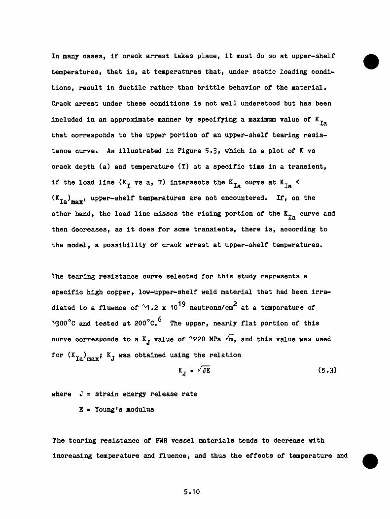
I n m any o a s e s , i f c r a c k a r r e s t t a k e s p l a c e , i t m u s t do s o a t u p p e r - s h e l f
t e m p e r a t u r e s , t h a t I s , a t t e m p e r a t u r e s t h a t , u n d e r s t a t i c l o a d i n g c o n d i
t i o n s , r e s u l t I n d u c t i l e r a t h e r th a n b r i t t l e b e h a v io r o f t h e m a t e r i a l .
C ra c k a r r e s t u n d e r t h e s e c o n d i t i o n s I s n o t w e l l u n d e r s to o d b u t h a s b e e n
I n c lu d e d I n a n a p p r o x im a te m an n er by s p e c i f y i n g a maximum v a lu e o f
t h a t c o r r e s p o n d s t o t h e u p p e r p o r t i o n o f a n u p p e r - s h e l f t e a r i n g r e s i s
t a n c e c u r v e . As I l l u s t r a t e d I n F ig u r e 5 . 3 , w h ic h I s a p l o t o f K v s
c r a c k d e p th ( a ) an d t a n p e r a t u r e (T ) a t a s p e c i f i c t im e I n a t r a n s i e n t .
I f t h e l o a d l i n e (K_ v s a , T) I n t e r s e c t s t h e K . c u r v e a t K_ <X x a Xa
(K ia)m ax» u p p e r - s h e l f t o n p e r a t u r e s a r e n o t e n c o u n te r e d . I f , on t h e
o t h e r h a n d , t h e l o a d l i n e m i s s e s t h e r i s i n g p o r t i o n o f t h e c u r v e an d
t h e n d e c r e a s e s , a s I t d o e s f o r scmie t r a n s i e n t s , t h e r e I s , a c c o r d in g t o
t h e m o d e l , a p o s s i b i l i t y o f c r a c k a r r e s t a t u p p e r - s h e l f t e m p e r a t u r e s .
The t e a r i n g r e s i s t a n c e c u r v e s e l e c t e d f o r t h i s s t u d y r e p r e s e n t s a
s p e c i f i c h ig h c o p p e r , l o w - u p p e r - s h e l f w e ld m a t e r i a l t h a t had b e e n I r r a -
19 2d l a t e d t o a f l u e n c e o f '^"1.2 x 10 n e u t r o n s /c m a t a t e m p e r a tu r e o f
''^300°C an d t e s t e d a t 2 0 0 °C .^ The u p p e r , n e a r l y f l a t p o r t i o n o f t h i s
c u r v e c o r r e s p o n d s t o a K j v a lu e o f " ^ 2 0 MPa an d t h i s v a lu e w as u s e d
f o r (K - ) i K t w as o b t a i n e d u s i n g t h e r e l a t i o n l a max J
K j = / J E ( 5 .3 )
w h e re J = s t r a i n e n e rg y r e l e a s e r a t e
E = Y o u n g 's m o d u lu s
T h e t e a r i n g r e s i s t a n c e o f PWR v e s s e l m a t e r i a l s t e n d s t o d e c r e a s e w i th
I n c r e a s i n g t e m p e r a tu r e and f l u e n c e , £Uid t h u s t h e e f f e c t s o f t e m p e r a tu r e and
5.10

la ^max
arrest
mat' 1
ar res t
T,
a , T
F ig u r e 5 . 3 . I l l u s t r a t i o n o f a m e th o d o f s e l e c t i n g (K )XSl lUcLX
5.11
f l u e n c e t e n d t o c o m p e n s a te f o r e a c h o t h e r th ro u g h t h e w a l l o f t h e
v e s s e l . B e c a u se o f t h i s an d t h e v e r y a p p ro x im a te n a t u r e o f t h e t r e a t
m en t o f a r r e s t o n t h e u p p e r s h e l f , no a t t e m p t w as m ade t o a c c o u n t m ore
a c c u r a t e l y f o r t h e e f f e c t s o f t e m p e r a t u r e an d f l u e n c e o n (K_ )l a max
The n i l - d u c t i l i t y r e f e r e n c e t e m p e r a t u r e (RTNDT) i s e q u a l t o t h e sum o f
a n i n i t i a l ( z e r o f l u e n c e ) v a lu e (RTNDT ) an d a n i n c r e a s e d u e t o r a d i a -o
t i o n dam age (ARTNDT)j t h a t i s ,
RTNDT = RTNDT + ARTNDT ( 5 .4 )o
The c o r r e l a t i o n f o r ARTNDT u s e d i n t h e s e s t u d i e s w as r e c e n t l y p ro p o s e d
7by R a n d a l l an d i s
ARTNDT = 0 .5 6 [ - 1 0 + 4 70 Cu + 350 Cu N i] (F x 1 0 " ' '^ ) ° ’ ^'^ , °C ( 5 .5 )
o r
- 19^ 0.194ARTNDT = 0 .5 6 [2 8 3 (F x 1 0 " ^ ) ^ - 4 8 ] , °C ( 5 .6 )
w h ic h e v e r i s s m e i l le r , w h e re
Cu, N i = c o n c e n t r a t i o n s o f c o p p e r an d n i c k e l , w t $ ,
F = f a s t - n e u t r o n f l u e n c e ( n e u t r o n e n e rg y > 1 MeV), n e u t r o n s /c m2
T he a t t e n u a t i o n o f t h e f l u e n c e th r o u g h t h e w a d i o f t h e v e s s e l i s a p p ro x
im a te d w i th
F , F e-O-OO S'' “ ( 5 .7 )o
w h e re F i s t h e f l u e n c e a t t h e i n n e r s u r f a c e o f t h e v e s s e l an d a i s t h e o
c r a c k d e p th i n m i l l i m e t e r s . The s p e c i f i c v a lu e o f t h e c o e f f i c i e n t i n
t h e e x p o n e n t a c c o u n t s t o som e e x t e n t f o r t h e e f f e c t o f s p a c e - w is e s p e c -
7t r a l c h a n g e s o n r a d i a t i o n d am ag e .
5.12
I f t h e a s s u m p t io n i s m ade t h a t a s h o r t a n d s h a l lo w s u r f a c e f la w c a n
e x te n d o n th e s u r f a c e th ro u g h t h e c l a d d i n g t o becom e a lo n g f la w (a n d
t h i s a s s u m p t io n i s made f o r t h e s e s t u d i e s ) , t h e n i t m u s t b e assu m ed t h a t
u n d e r t h e p r o p e r c i r c u m s ta n c e s a v e r y sh e illo w f la w t h a t i n i t i a l l y
r e s i d e s e n t i r e l y w i t h i n t h e c l a d d i n g c a n p r o p a g a te r a d i a l l y . U n fo r
t u n a t e l y , t h e f r a c t u r e - t o u g h n e s s p r o p e r t i e s o f t h e c l a d d in g m a t e r i a l a r e
v e r y u n c e r t a i n , an d t h e few e x p e r im e n ta l d a t a t h a t a r e a v a i l a b l e i n d i
c a t e a r a d i a t i o n - i n d u c e d r e d u c t i o n i n f r a c t u r e to u g h n e s s s i m i l a r t o t h a t
f o r th e b a s e m a t e r i a l . As a n e x p e d ie n c y , w h ich may o r may n o t be co n
s e r v a t i v e , i t w as assu m ed t h a t t h e c l a d d i n g h a s t h e sam e f r a c t u r e -
to u g h n e s s p r o p e r t i e s a s t h e b a s e m a t e r i a l (E q s . 5 . 1 , 5 . 2 , 5 . 5 , an d 5 . 6 ) .
I n t h e OCA-P a n a l y s i s , a s s u m p t io n s r e g a r d i n g t h e f r a c t u r e b e h a v io r o f th e
c l a d d i n g i n f l u e n c e o n ly t h e i n i t i a t i o n o f v e r y s h a l lo w f la w s t h a t i n i
t i a l l y t e r m i n a t e i n t h e c l a d d i n g . U nder som e c i r c u m s t a n c e s , i n c l u d i n g
t h e ab o v e a s s u m p t io n r e g a r d i n g t h e f r a c t u r e to u g h n e s s o f t h e c l a d d i n g ,
t h e s e s h a l lo w f l a w s w i l l i n i t i a t e an d r e s u l t i n v e s s e l f a i l u r e . T h e re
f o r e i t w as n e c e s s a r y t o i n c l u d e t h e f r a c t u r e p r o p e r t i e s o f t h e c l a d
d in g .
The d e t e r m i n i s t i c f r a c t u r e - m e c h a n i c s m odel d e s c r i b e d a b o v e i s u s e d i n
OCA-P t o p r e d i c t t h e b e h a v io r o f a f la w d u r in g a s p e c i f i e d OCA a t a
s p e c i f i e d t im e i n t h e l i f e o f t h e v e s s e l , an d t h e c a l c u l a t e d b e h a v io r
c a n b e i l l u s t r a t e d w i th a s e t o f c r i t i c a l - c r a c k - d e p t h c u r v e s s i m i l a r t o
t h o s e show n i n F ig u r e 5 . 4 . The f i g u r e c o n s i s t s o f a p l o t o f c r a c k
d e p th s c o r r e s p o n d in g t o v a r i o u s e v e n t s a n d c o n d i t i o n s a s a f u n c t i o n o f
t h e t im e i n t h e t r a n s i e n t a t w h ic h t h e e v e n t s o r c o n d i t i o n s t a k e p l a c e o r
5.13

e x i s t . F ig u r e 5 .4 i n c l u d e s ( f o r 2-D f l a w s o n ly ) t h e l o c u s o f p o i n t s f o r
K j = ( c r a c k - i n i t i a t i o n c u r v e ) , ( c r a c k - a r r e s t c u r v e ) , K j =s
(K ) (warm p r e s t r e s s c u r v e w i t h = 0 ) , an d = c o n s t a n t ( i s o K_X l Qo 2 X X X
c u r v e s ) . F o r t im e s l e s s t h a n t h o s e i n d i c a t e d by t h e WPS c u r v e , c r a c k
i n i t i a t i o n w i l l t a k e p l a c e , b u t f o r g r e a t e r t im e s i n i t i a t i o n w i l l n o t
t a k e p l a c e u n l e s s p e r h a p s t h e r e i s a p e r t u r b a t i o n i n t h a t n e g a te s t h e
r e q u i s i t e c o n d i t i o n s f o r WPS.
The d a s h e d l i n e s i n F ig u r e 5 .4 i n d i c a t e t h e b e h a v io r o f tw o i n i t i a l l y
s h a l lo w f l a w s , i g n o r i n g t h e e f f e c t s o f WPS. The d e e p e r f la w w ou ld i n i
t i a t e a t a t im e o f 42 m in i n t o t h e t r a n s i e n t an d w o u ld e x te n d th ro u g h
t h e w a l l w i th o u t a r r e s t i n g . The o t h e r f l a w w o u ld i n i t i a t e a t a n e a r l i e r
t i m e , w o u ld a r r e s t a t a p o i n t 36$ o f t h e way th r o u g h t h e w a l l , an d th e n
w o u ld r e i n i t i a t e a t a t im e o f '^^8 m in an d p e n e t r a t e t h e w a l l . E a r l i e r
i n t h e l i f e o f t h e v e s s e l t h e te n d e n c y f o r c o m p le te p e n e t r a t i o n o f t h e
w a l l i s l e s s .
5 . 3 . 2 S t r e s s A n a ly s i s M odel
U s in g t h e s u p e r p o s i t i o n t e c h n iq u e i n c o m b in a t io n w i t h i n f l u e n c e c o e f f i
c i e n t s , t h e s t r e s s e s r e q u i r e d f o r t h e c a l c u l a t i o n o f a r e t h o s e a t t h e
c r a c k p la n e c a l c u l a t e d i n t h e a b s e n c e o f t h e c r a c k a n d w i th no v a r i a t i o n
i n th e d i r e c t i o n o f t h e l e n g t h o f t h e c r a c k . F o r t h e O c o n e e -1 a n a l y s i s ,
i t w as assu m ed t h a t t h e r e w as no a z im u th a l v a r i a t i o n a s w e l l , an d th u s
t h e o n e - d im e n s io n a l s t r e s s a n a l y s i s m odel i n c o r p o r a t e d i n OCA-P w as a d e
q u a t e .
5.14
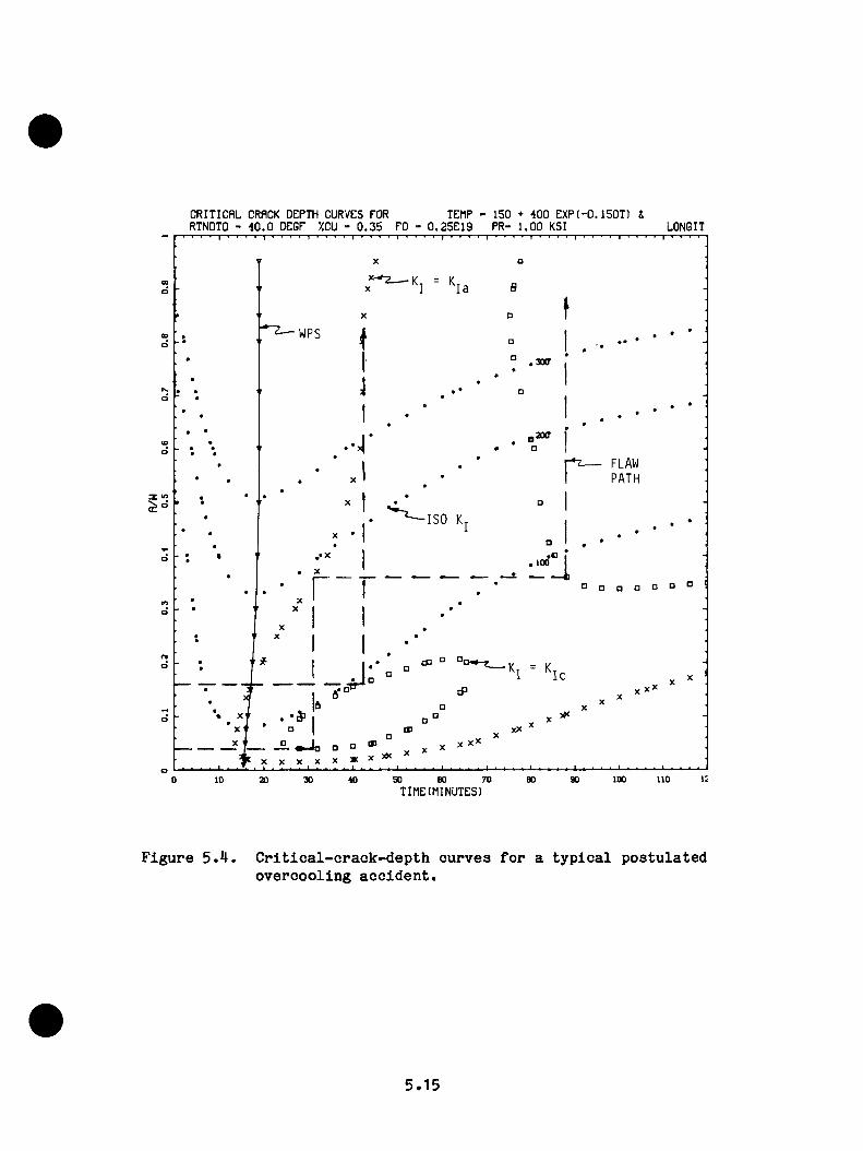
CRITICAL CRACK DEPTH CURVES FOR TEMP - ISO + 400 EXP(-0.1SOT) iRTNOTO - 40.0 OEGF XCU - 0.35 FO - 0.2SE19 PR- 1.00 KSI LONGIT
o>d
WP S(Dd
2CX7(OdFLAWP A T H
3 «I S O K
.oo 100
d
C ld
dm
o IX noso X 70 X X0 10 X X X TIME(MINUTES)
F ig u r e 5 * 4 . C r i t i c a l - c r a c k - d e p t h c u r v e s f o r a t y p i c a l p o s t u l a t e d o v e r c o o l i n g a c c i d e n t .
5.15
M a t e r i a l p r o p e r t i e s r e q u i r e d f o r t h e s t r e s s a n a l y s i s i n c l u d e d t h e c o e f
f i c i e n t o f th e r m a l e x p a n s io n ( c t) , Y oung’ s m o d u lu s ( E ) , and P o i s s o n ’ s
r a t i o ( v ) . A lth o u g h t h e s e p r o p e r t i e s h a v e som e t e m p e r a tu r e d e p e n d e n c e ,O
i t w as d e te r m in e d t h a t t h e u s e o f a p p r o p r i a t e a v e r a g e v a l u e s r e s u l t s i n
a n e r r o r i n t h e c a l c u l a t e d v a l u e o f o f l e s s t h a n 1 0 $ , T h u s , a v e r a g e
v a l u e s w e re u s e d b a s e d o n t h e d a t a i n R e fe r e n c e 9* The v a l u e s u s e d f o r
t h e O conee-1 a n a l y s i s a r e a s f o l l o w s :
P r o p e r ty B ase M a t e r i a l C la d d in g
a , °C "'' 1.M5 X 10"^ 1 .7 9 x 10"^
E , MPa 1 .9 3 X 10^ 1 .8 6 x 10^
V 0 .3 0 0 .3 0
5 . 3 . 3 T h erm a l A n a ly s i s M odel
T e m p e ra tu re s i n t h e w a l l o f t h e v e s s e l a r e r e q u i r e d f o r tw o p u r p o s e s : t o
c a l c u l a t e t h e th e r m a l s t r e s s e s an d t o c a l c u l a t e t h e f r a c t u r e t o u g h n e s s .
T he t e m p e r a t u r e s r e q u i r e d f o r d e t e r m in in g t h e f r a c t u r e to u g h n e s s a r e
t h o s e i n t h e p l a n e o f t h e f l a w , w h i l e t h o s e u s e d i n t h e o n e - d im e n s io n a l
a n a l y s i s o f t h e th e r m a l s t r e s s e s m u s t r e p r e s e n t som e ty p e o f a v e r a g e
d i s t r i b u t i o n th r o u g h t h e w a l l . The th e r m a l s t r e s s e s i n t h e v i c i n i t y o f
t h e c r a c k p l a n e a r e m ore s e n s i t i v e t o t h e r a d i a l t e m p e r a t u r e d i s t r i b u
t i o n a t t h e c r a c k p l a n e th a n e l s e w h e r e . S in c e t h e s e t e m p e r a t u r e s a r e
t h e ssune a s t h o s e n e e d e d f o r t h e f r a c t u r e - t o u g h n e s s d e t e r m i n a t i o n s , an d
s i n c e o n ly o n e s e t o f t e m p e r a t u r e s w as t o be u s e d f o r b o th t h e s t r e s s
a n d to u g h n e s s c a l c u l a t i o n s , t h e l o c a l t e m p e r a t u r e s w o u ld b e t h e c h o i c e .
T h e se p a r t i c u l a r t e m p e r a t u r e s w e re n o t a v a i l a b l e , b u t f o r t u n a t e l y t h e
5.16

r e s u l t s o f t h e t h e n n a l - h y d r a u l l c a n a l y s i s i n d i c a t e d t h a t f o r t h e t r a n
s i e n t s o f I n t e r e s t t h e r e w as n o t much a z im u th a l v a r i a t i o n I n t h e dow nco
m er c o o l a n t t a i p e r a t u r e . T h u s , t h e t im e - d e p e n d e n t t e m p e r a tu r e d i s t r i b u
t i o n s I n t h e w a l l o f t h e v e s s e l w e re c a l c u l a t e d w i th t h e o n e - d lm e n s lo n a l
t h e r m a l - a n a l y s l s m o d e l I n OCA-P u s i n g a v e r a g e dow ncom er c o o l a n t te m p e ra
t u r e s an d h e a t t r a n s f e r c o e f f i c i e n t s .
M a t e r i a l p r o p e r t i e s r e q u i r e d f o r t h e th e r m a l a n a l y s i s I n c lu d e th e t h e r
m al c o n d u c t i v i t y ( k ) , s p e c i f i c h e a t ( c ^ ) , and d e n s i t y (p) o f th e v e s s e l
m a t e r i a l . The v a l u e s u s e d a r e a s f o l l o w s :
Property Base Material Cladding k , W /m-°C M l.5 1 7 .3
c , J /k g * ° C 502 502P
P , Kg/m^ 7830 78 3 0
5 .3 .M P r o b a b i l i s t i c A n a ly s i s M odel
The OCA-P p r o b a b i l i s t i c m o d e l , w h ic h I s s i m i l a r t o t h a t d e v e lo p e d by
G am ble an d S t r o s n l d e r , ^ ^ I s b a s e d o n M onte C a r lo t e c h n i q u e s ; t h a t I s , a
l a r g e num ber o f v e s s e l s I s g e n e r a t e d , and e a c h v e s s e l I s th e n s u b j e c t e d
t o a f r a c t u r e - m e c h a n i c s a n a l y s i s t o d e te r m in e w h e th e r t h e v e s s e l w i l l
f a l l . E ach v e s s e l I s d e f in e d by ra n d o m ly s e l e c t e d v a l u e s o f s e v e r a l
p a r a m e te r s t h a t a r e ju d g e d t o h a v e s i g n i f i c a n t u n c e r t a i n t i e s a s s o c i a t e d
w i th th em . The c a l c u l a t e d p r o b a b i l i t y o f v e s s e l f a i l u r e I s s im p ly th e
num ber o f v e s s e l s t h a t f a l l d i v i d e d by t h e t o t a l num ber o f v e s s e l s g en
e r a t e d . I t c o n s t i t u t e s a c o n d i t i o n a l p r o b a b i l i t y o f f a i l u r e , P ( f 1e ) ,
b e c a u s e t h e a s s u m p t io n I s m ade t h a t t h e OCA ( e v e n t ) t a k e s p l a c e . A
5.17
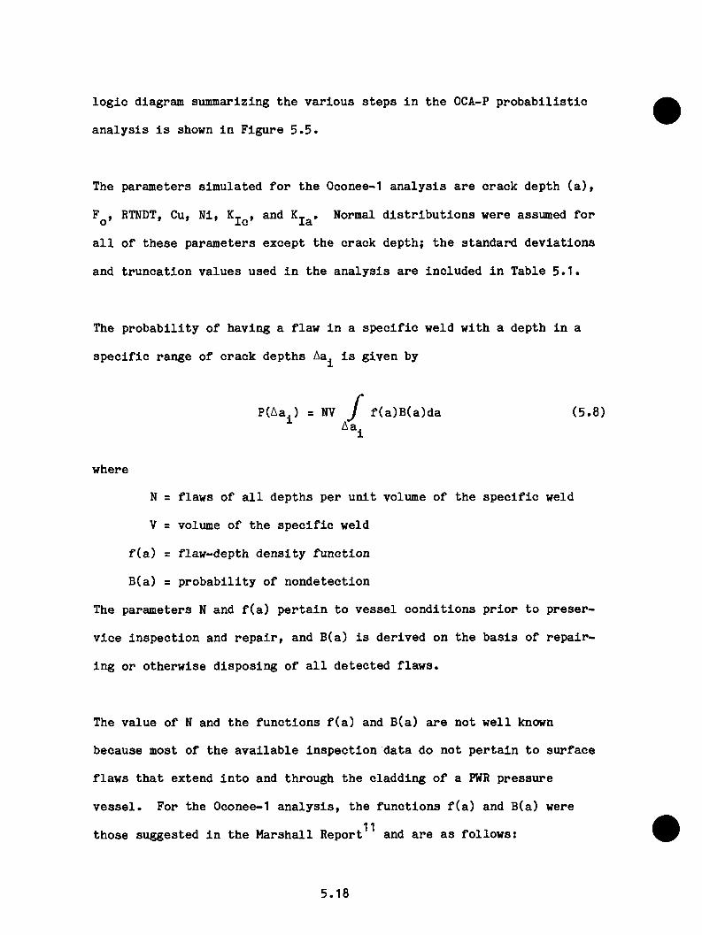
l o g i c d ia g ra m s u m m a r iz in g t h e v a r i o u s s t e p s i n t h e OCA-P p r o b a b i l i s t i c
a n a l y s i s i s show n i n F ig u r e 5 . 5 .
The p a r a m e te r s s i m u la te d f o r t h e O conee-1 a n a l y s i s a r e c r a c k d e p th ( a ) ,
F , RTNDT, Cu, N i , K,. , an d K,. . N orm al d i s t r i b u t i o n s w e re assu m ed f o rO J J W
a l l o f t h e s e p a r a m e te r s e x c e p t t h e c r a c k d e p t h ; t h e s t a n d a r d d e v i a t i o n s
an d t r u n c a t i o n v a l u e s u s e d i n t h e a n a l y s i s a r e i n c l u d e d i n T a b le 5 . 1 .
The p r o b a b i l i t y o f h a v in g a f l a w i n a s p e c i f i c w e ld w i t h a d e p th i n a
s p e c i f i c r a n g e o f c r a c k d e p t h s Aa^ i s g iv e n by
P (A a ,) = NV / f ( a ) B ( a ) d a ( 5 .8 )
w h e re
N = f l a w s o f a l l d e p t h s p e r u n i t v o lu m e o f t h e s p e c i f i c w e ld
V = v o lum e o f t h e s p e c i f i c w e ld
f ( a ) = f l a w - d e p t h d e n s i t y f u n c t i o n
B (a ) = p r o b a b i l i t y o f n o n d e t e c t io n
The p a r a m e te r s N an d f ( a ) p e r t a i n t o v e s s e l c o n d i t i o n s p r i o r t o p r e s e r
v i c e i n s p e c t i o n an d r e p a i r , an d B (a ) i s d e r iv e d o n t h e b a s i s o f r e p a i r
i n g o r o th e r w is e d i s p o s i n g o f a l l d e t e c t e d f l a w s .
The v a lu e o f N an d t h e f u n c t i o n s f ( a ) an d B (a ) a r e n o t w e l l known
b e c a u s e m o s t o f t h e a v a i l a b l e i n s p e c t i o n d a t a do n o t p e r t a i n t o s u r f a c e
f l a w s t h a t e x te n d i n t o an d th r o u g h t h e c l a d d i n g o f a PWR p r e s s u r e
v e s s e l . F o r t h e O co n ee-1 a n a l y s i s , t h e f u n c t i o n s f ( a ) an d B (a ) w e re
t h o s e s u g g e s te d i n t h e M a r s h a l l R e p o r t^ ^ and a r e a s f o l l o w s :
5.18

O R N L - D W G 8 4 - 4 1 7 4 E T D
S I M U L A T E K E R R O R
A D V A N C E T I M E
N O
N O
Y E SY E S
Y E S
N O
C A L C U L A T E R T N D T
K / K ,
Y E S
N O
N U M B E R O F ^ C R A C K D E P T H S
E X H A U S T E D ’N O
[ y e s
N O
[ y e s
P E R F O R M E D E N O U G H
_ T R I A L S ’
P L A S T I CI N S T A B I L I T Y ’
"- IS THE T R A N S I E N T
OVER?
C A L C U L A T E R T N D T
S I M U L A T E K
A D D O N E T O N U M B E R O F F A I L U R E S
A D D O N E T O N U M B E R O F N O N F A I L U R E S
C A L C U L A T E C O N D I T I O N A L P R O B A B I L I T Y O F F A I L U R E
A D O O N E T O N U M B E R O F T R I A L S
S E T C R A C K D E P T H T O A R R E S T D E P T H
A D V A N C E C R A C K D E P T H
D E F I N E T R A N S I E N T A N D
C A L C U L A T E T v s ( a / w , t )K v s ( a / w . t )
C A L C U L A T E K | ^
= f ( R T N D T ( a / w l .
T l a / w . t )
K , E R R O R )
S E L E C T M E A N V A L U E S O F
F L U E N C EN I C K E LC O P P E RR T N D T
C R E A T E A V E S S E L B Y S I M U L A T I N G
C R A C K D E P T H A R T N D T E R R O R W E L D
F L U E N C EN I C K E LC O P P E RR T N D T ^
F ig u r e 5 . 5 . OCA-P p ro g ram l o g i c .
5.19
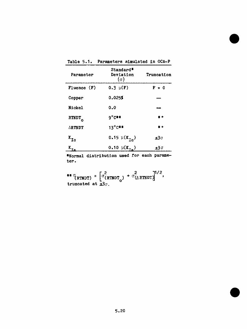
Table 5.1. Parameters simulated in OCA-P
P aram eterS tan d ard *D e v ia tio n
( a )T ru n c a tio n
F luence (F) 0 .3 y (F ) F = 0
Copper 0.025$ —
N ick e l 0 .0 —
RTNDTo9°C»« « *
ARTNDT 13°C»« » *
KtIc 0 .1 5 y (K jc ) ±3a
Kt— la ------------------ 0 .1 0 ±30
•N o rm al d i s t r i b u t i o n u s e d f o r e a c h p aram et e r .
r 2 2 11/2(RTNDT) = [^(RTNDT^) ^(ARTNDT^ '
t r u n c a t e d a t ± 3 a .
5.20
f(a) = 0.16 ® (5.9)
B (a ) = 0 .0 0 5 + 0 .9 9 5 ^ ( 5 .1 0 )
w h e re
a = c r a c k d e p t h , mm
00
/ f ( a ) d a = 1
F o r t h e O conee-1 v e s s e l t h e p r o b a b i l i t y o f n o n d e t e c t io n , B ( a ) , s h o u ld
p r o b a b ly b e s e t e q u a l t o u n i t y , in d e p e n d e n t o f a , b e c a u s e i t i s n o t
l i k e l y t h a t a r e l i a b l e i n s p e c t i o n w as m ade f o r f l a w s i n an d e x te n d in g a
s h o r t d i s t a n c e b ey o n d t h e c l a d d i n g . F u r th e r m o r e , i t i s n o t l i k e l y t h a t
a n y d e t e c t e d f l a w s o f t h i s ty p e w e re r e p a i r e d . E ven s o , E q . 5 .1 was
u s e d i n t h e O conee-1 a n a l y s i s . I f B (a ) = 1 w e re u s e d i n s t e a d , P (F |E)
w o u ld b e a b o u t tw ic e a s m uch . T hus t h e r e s u l t s o f t h i s s tu d y c a n be
i n t e r p r e t e d a c c o r d i n g l y .
A f t e r O conee-1 h ad b e e n i n o p e r a t i o n f o r '^lO y e a r s , an i n - s e r v i c e
i n s p e c t i o n o f t h e r e a c t o r p r e s s u r e v e s s e l w as p e r fo rm e d . No f l a w s w e re
fo u n d } h o w e v e r, t h e s i g n i f i c a n c e o f t h i s i n s p e c t i o n i n te rm s o f d i f f e r
e n c e s b e tw e e n th e assu m ed a n d a c t u a l f l a w - d e p th d e n s i t y f u n c t i o n and
f l a w d e n s i t y was n o t a p p a r e n t a t t h e t im e o f t h i s w r i t i n g .
The v a lu e o f N u s e d i n t h e O co n ee-1 a n a l y s i s w as 1 f la w /m o f w e ld
m a t e r i a l , an d i t w as assu m ed t h a t a l l f l a w s w e re i n n e r - s u r f a c e f la w s
n o rm a l t o t h e s u r f a c e an d o r i e n t e d i n t h e l e n g t h - d i r e c t i o n o f t h e w e ld .
5.21
T h is v a l u e o f t h e f l a w d e n s i t y a g r e e s w i t h t h a t s u g g e s te d i n t h e
M a r s h a l l R e p o r t , b u t t h e u n c e r t a i n t y i s c o n s i d e r e d t o b e v e r y l a r g e ( a iv
1 0 ^ ).
The v o lu m e (V) o f a w e ld u s e d f o r c a l c u l a t i n g t h e num ber o f s u r f a c e
f l a w s i n a w e ld w as t h e t o t a l v o lu m e o f t h a t p o r t i o n o f t h e w e ld t h a t
w as n e a r l y w i t h i n t h e a x i a l c o n f i n e s c o r r e s p o n d in g t o t h e a c t i v e l e n g t h
o f t h e c o r e .
As m e n t io n e d a b o v e , t h e c a l c u l a t e d p r o b a b i l i t y o f v e s s e l f a i l u r e f o r
t h i s s tu d y i s t h e num ber o f s im u la te d v e s s e l s c a l c u l a t e d t o f a i l d i v i d e d
by t h e t o t a l num ber o f v e s s e l s s i m u la te d o r o t h e r w is e a c c o u n te d f o r .
T h u s ,w
P ( F |E ) = E - j 7 r ^ V N / * f ( a ) B ( a ) d a ( 5 .1 1 )j v j J •()
w h e re
= num ber o f v e s s e l s w i t h a f l a w i n t h e j t h w e ld t h a t f a i l
= num ber o f v e s s e l s s i m u la te d w i t h a f la w i n t h e j t h w e ld
V j = v o lu m e o f j t h w e ld
The i n t e g r a l i n E q , 5 .1 1 a c c o u n t s f o r t h e v e s s e l s t h a t h a v e no f l a w s
w h a ts o e v e r , an d e a c h te rm i n E q . 5 .1 1 r e p r e s e n t s t h e c o n t r i b u t i o n t o
P ( F |E ) o f e a c h w e ld .
F o r v e r y s m a l l v a l u e s o f P ( F |E ) , t h e v a l u e o f r e q u i r e d t o a c h ie v e
r e a s o n a b l e a c c u r a c y b eco m es q u i t e l a r g e . U nder s a n e c i r c u m s ta n c e s t h e
5.22
v a l u e o f N’ y j c a n b e r e d u c e d by u s i n g s t r a t i f i e d s a m p lin g o f one o r m ore
o f t h e p a r a m e te r s s i m u la t e d . T h is w as d o n e f o r t h e f la w d e p th , a s s u m in g
a u n i fo rm d i s t r i b u t i o n o f d e p t h s . T h is p r o c e d u r e a l lo w s a m ore f r e q u e n t
s a m p l in g o f t h e l e s s p r o b a b le d e e p f l a w s , w h ic h , f o r l o w - p r o b a b i l i t y
t r a n s i e n t s t h a t a r e c h a r a c t e r i z e d by h ig h p r e s s u r e an d a m ild th e rm a l
s h o c k , a r e r e s p o n s i b l e f o r m o s t o f t h e i n i t i a t i o n e v e n t s t h a t l e a d t o
f a i l u r e . The r e s u l t s a r e t h e n w e ig h te d by t h e a c t u a l f l a w - d e p th d e n s i t y
t o o b t a i n
P (F |E ) = L E
w h e re
/ f ( a ) B ( a ) d a
w
j" f ( a ) B ( a ) d a
r R 1NV / f ( a ) B ( a ) d a
0
* * * fij “ num ber o f v e s s e l s t h a t f a i l w i th a f la w i n t h e j t h w e ld
w i t h d e p th i n Aa^
= num ber o f v e s s e l s s i m u la te d w i th a f la w i n t h e j t h w e ld
w i t h d e p th i n Aa^
A d e t e r m i n i s t i c a n a l y s i s i s made f o r e a c h o f t h e s im u la te d v e s s e l s t o
d e te r m in e i f f a i l u r e w i l l o c c u r d u r i n g a p a r t i c u l a r t r a n s i e n t a t a
s p e c i f i e d t im e i n t h e l i f e o f t h e p l a n t . The c r i t e r i o n by w h ich f a i l u r e
i s ju d g e d i s a s f o l l o w s ; i f , f o l l o w i n g a n i n i t i a t i o n e v e n t , r e m a in s
g r e a t e r t h a n u p t o o r b ey o n d t h e p o i n t a t w h ich p l a s t i c i n s t a b i l i t y
o c c u r s i n t h e r e m a in in g l i g a m e n t , f a i l u r e i s a s su m e d . The o n s e t o f
p l a s t i c i n s t a b i l i t y i s e v a lu a t e d o n t h e b a s i s o f a c h ie v in g a n a v e ra g e
p r e s s u r e s t r e s s i n t h e r e m a in in g l i g a m e n t e q u a l t o t h e f lo w s t r e s s . The
f lo w s t r e s s i s a ssu m ed t o be i n d e p e n d e n t o f t e m p e r a tu r e and f l u e n c e and
i s s p e c i f i e d a s 550 MPa.
5.23
T he num ber o f v e s s e l s t h a t m u s t b e s im u la te d d e p e n d s u p o n t h e a c c u r a c y
r e q u i r e d f o r t h e c a l c u l a t e d v a l u e o f P ( F |E ) , an d a s s m a l l a num ber a s
p r a c t i c a l I s u s e d t o m in im iz e ccm ip u te r c o s t s . The minimum num ber o f
s i m u la t e d v e s s e l s r e q u i r e d t o s a t i s f y a s p e c i f i e d a c c u r a c y I s e s t i m a t e d
12b y a p p l y i n g t h e c e n t r a l l i m i t th e o re m ,
f y l n g a 95$ c o n f id e n c e l e v e l y i e l d s
U s in g t h i s a p p r o a c h an d s p e c l -
P ( F |E ) j = P j NV^y* f ( a ) B ( a ) d a ± 1 .9 6 ( 5 .1 3 )
w h e re
P ( F |E ) j = t r u e v a l u e o f t h e c o n d i t i o n a l p r o b a b i l i t y o f v e s s e l f a i l u r e
f o r t h o s e v e s s e l s h a v in g f l a w s I n t h e j t h w e ld o n ly
= o n e s t a n d a r d d e v i a t i o n
N*P = —
j N»v j
F o r t h e d i r e c t a p p ro a c h ( n o t u s i n g s t r a t i f i e d s a m p l in g ) ,
N»vJ
1/2NVj /* f ( a ) B ( a ) d a'/
( 5 .1 4 )
When s t r a t i f i e d s a m p l in g I s u s e d ,
■/ f ( a ) B ( a ) d a
Vf
i/f ( a ) B ( a ) d a
w h e re
N'
I j ■ N*mv l j
N'v l j
1/2( 5 .1 5 )
NVj / * f ( a ) B ( a ) d a
‘I
5.24

The v a l u e o f a c o r r e s p o n d in g t o a l l o f t h e v e s s e l s s im u la te d i s
^ p ( f | e ) ” ( 5. 16) J
an d t h e e r r o r , a s s o c i a t e d w i t h t h e j t h w e ld i s
_ ( 5 .1 7 )j " ^
P j NV i f f ( a ) B ( a ) d a■/0
The t o t a l e r r o r , e , c o n s i d e r i n g a l l w e ld s o f i n t e r e s t i s
£ 1 .9 6 g p ( p |E ) ( 5 ,1 8 )
2 ^ P . NV. / f ( a ) B ( a ) d a3 J jy
0T h re e s p e c i f i c c r i t e r i a w e re u s e d i n s e l e c t i n g t h e num ber o f v e s s e l s t o
b e s i m u la t e d :
<’ > ' “ ' v j W ' 5 0 0 .0 0 0
<2) < " V j > m l n ' ’ “ -O"'’
(3 ) e , = 10*
The a p p l i c a t i o n o f t h e s e c r i t e r i a i n te rm s o f £ j v s P j i s show n i n F ig
u r e 5 .6 f o r t h e d i r e c t ( n o n s t r a t i f i e d ) s a m p l in g m e th o d .
f ( a ) B ( a ) d a v a r i e s fro m 0 .6 x 10 to
- 2 ® I2 .3 X 10 . T h u s , w i t h i n a f a c t o r o f a b o u t 2 , P ( F |E ) j i s tw o o r d e r s o f
m a g n itu d e l e s s t h a n P j , an d t h e i n f o r m a t i o n i n F ig u r e 5 .6 c a n be i n t e r
p r e t e d a c c o r d i n g l y . F o r i n s t a n c e , s u p p o s e (1 ) t h e r e i s a n eed t o c a l c u l a t e
v a l u e s o f P (F |e ) a s lo w a s 3 x 10“ "^, ( 2 ) t h e r e a r e t h r e e w e ld s o f c o n c e r n ,
an d (3 ) a c o r r e s p o n d in g v a lu e o f P ( f 1 e ) j i s 1 x 10“ "^. T h u s , P j ^ 1 x 10“ ^ ,
an d fro m th e c u r v e i n F ig u r e 5 . 6 , lii 8 0 $ . The . e r r o r i n P ( f | e ) w ould
b e a p p r o x im a te ly 8 0 $ / ✓J 2 5 0 $ .
5.25
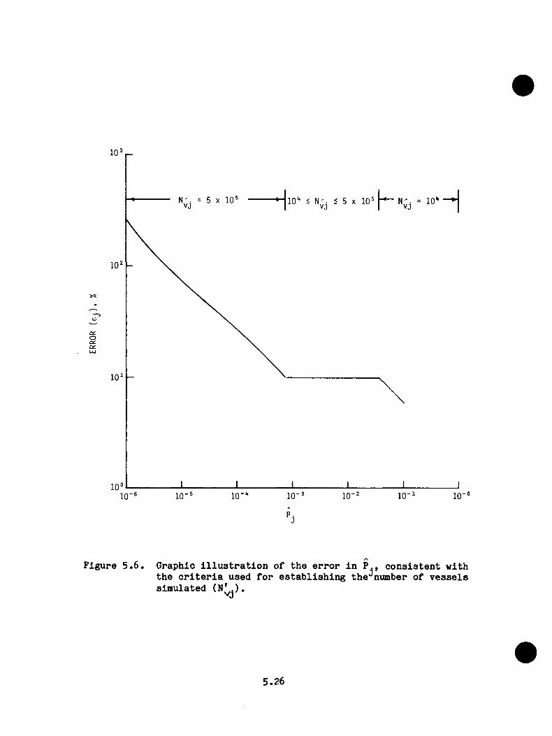
0Od01
10
10
10
F ig u r e 5 . 6 . G ra p h ic i l l u s t r a t i o n o f t h e e r r o r i n P . , c o n s i s t e n t w i th t h e c r i t e r i a u s e d f o r e s t a b l i s h i n g th e ^ n u m b e r o f v e s s e l s s im u la te d
5.26
F o r t h e p u rp o s e o f e s t i m a t i n g t h e a b s o l u t e f r e q u e n c y o f v e s s e l f a i l u r e
o r i d e n t i f y i n g d o m in a n t t r a n s i e n t s , t h e m a g n itu d e o f t h e e r r o r s i n d i
c a t e d i n F ig u r e 5 .6 i s a c c e p t a b l e . H ow ever, f o r t h e s e n s i t i v i t y s t u
d i e s , l a r g e r v a l u e s o f w e re u s e d w h e re a p p r o p r i a t e t o r e d u c e th e
e r r o r .
5 .4 F la w - R e la te d D a ta f o r t h e O co n ee-1 R e a c to r Pr e s s u r e V e s s e l
As a l r e a d y m e n t io n e d , t h e a r e a s o f t h e v e s s e l o f p a r t i c u l a r c o n c e r n w i th
r e g a r d t o f l a w p r o p a g a t i o n a r e t h e o n e s t h a t a r e m o s t l i k e l y t o h av e
f l a w s an d r e l a t i v e l y h ig h v a l u e s o f F ^ , RTNDT^, Cu, and N i. The r e g io n
d i r e c t l y o p p o s i t e t h e a c t i v e p o r t i o n o f t h e c o r e i s e x p o s e d t o th e
h i g h e s t n e u t r o n f l u x e s , an d t h e a t t e n u a t i o n b ey o n d t h e a c t i v e l e n g t h o f
t h e c o r e i s v e r y s t e e p . T h u s , o n ly t h i s b e l t l i n e r e g i o n o f t h e v e s s e l
w as c o n s i d e r e d .
W i th in th e b e l t l i n e r e g i o n t h e c o n c e n t r a t i o n o f c o p p e r i s s i g n i f i c a n t l y
l e s s i n t h e b a s e m a t e r i a l t h a n i n t h e w e ld s , a s i n d i c a t e d by t h e d a t a i n
T a b le 5 .2 an d F ig u r e s 5 . 2 , 5 . 7 , an d 5 . 8 . P r e l im in a r y OCA-P c a l c u l a t i o n s
( s e e A p p e n d ix D) i n d i c a t e d t h a t b e c a u s e o f i t s lo w e r c o p p e r c o n c e n t r a
t i o n th e b a s e m a te r i s i l c o n t r i b u t e d r e l a t i v e l y l i t t l e t o v e s s e l f a i l u r e ,
a s s u m in g t h e sam e f l a w d e n s i t y i n b o th t h e b a s e m a t e r i a l and w e ld s .
T h e se p r e l i m i n a r y c a l c u l a t i o n s a l s o i n d i c a t e d t h a t w e ld s SA1073> 1 4 3 0 ,
an d 1 4 9 3 , e a c h o f w h ic h i s o r i e n t e d i n a n a x i a l d i r e c t i o n , c o n t r i b u t e d
f a r m ore t h a n a l l t h e o t h e r w e ld s . F u r th e r m o r e , t h e s t a g g e r e d a r r a n g e
m en t o f t h e s e s i x w e ld s ( tw o e a c h ) an d t h e r e l a t i v e l y low c o n c e n t r a t i o n
o f c o p p e r i n t h e b a s e m a t e r i a l t e n d t o p r e v e n t s u r f a c e e x t e n s i o n o f a
5.27

T able 5 .2 . M a te r ia l p r o p e r t ie s used i n th e LEFM a n a ly s i s o f th e Oconee-1 r e a c to r v e s s e l
ro00
M a te r ia l I d e n t i f i c a t io n ^C hem istry^^
(wt %)
N eutron F lu e n ce , In s id e S u rface
(n/cm )I n i t i a l ^ ^ ^
RTNDTr o
Weld o r Heat Number Type Cu Ni 5 EFPY 32 EFPT
Volume(m ^
AHR-54 SA508, 0L2 0.16 NA 1.97E18 (+16)
SA1135 C irc u m fe re n tia lweld
0 .25 0 .54 1.97E18 ( -7 )
02197 SA302B 0.15 NA 9.35E18 (+4)
SA1073 L o n g itu d in a lweld
0.31 0 .64 1.43E18 7.38E18 ( -7 ) 0.01
SA1229 C irc u m fe re n tia lweld
0.26 0.61 9.35E18 (-7 )
SA1493 L o n g itu d in a lweld
0 .29 0 .55 1.74E18 8.98E18 ( -7 ) 0 .04
03278-1 SA302B 0 .1 2 NA 1.23E19 (+4)
SA1585 C irc u m fe re n tia lweld
0.21 0 .59 1.23E19 (-7 )
02800-1 SA302B 0.11 NA 1.23E19 (+4)SA1430 L o n g itu d in a l
weld0 .29 0 .55 2.11E18 1.09E19 ( -7 ) 0 .04
•S o u rce : BAW-1436, Septem ber 1977.
• •C h em is try so u rc e : BAW-1511Pf O ctober 1980.
• • •E s tim a te d RTNDT v a lu e s so u rc e : BAW-10046A, Rev. 1 , March 1976.
NA — Not a v a i l a b le .

FLUENCE NORMALIZED
NOZZLE VESSEL
INLET NOZZLE
TO PEAK FLUENCE LOCATION 12" —
19" SA-I>I30 WELD22" SA-1073 WELD
.77.70
COREREGION
t~cF ig u r e 5 . 7 . L o n g i t u d in a l w e ld l o c a t i o n s t o a z im u th a l f l u e n c e
p r o f i l e . 13
5.29
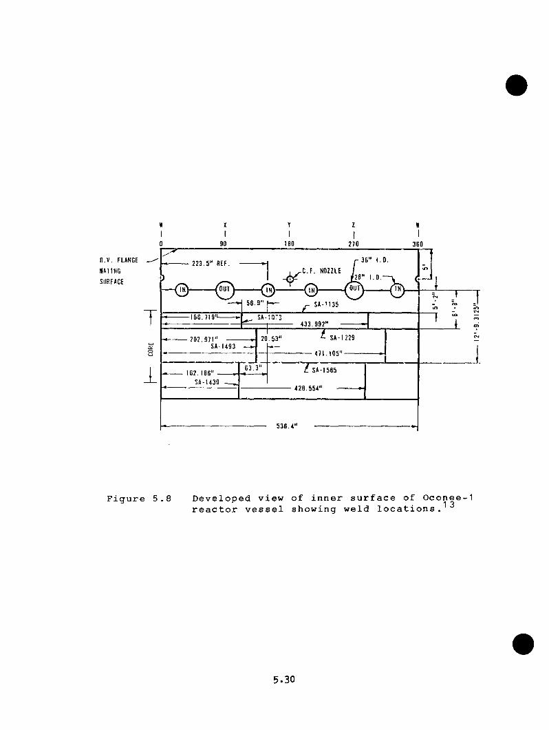
90
Y
II BO
Z
I270
«I
360
li.V. FLANGE
MATING
S U R F A C E
223.5“ REF.C.F. NOZZLE
O U TOUT
56.9
166.719'433.992'
SA-122920.53'202.971SAI493
471.105'
63.3' SA-I5B5162.186" -
SA-1430428.554'
536.4'
F i g u r e 5 . 8 D e v e l o p e d v i e w o f i n n e r s u r f a c e o f O c o n e e - 1r e a c t o r v e s s e l s h o w i n g w e l d l o c a t i o n s . 1 3
5.30
f l a w b ey o n d t h e e n d s o f t h e w e ld s . T h u s , t h e o n ly r e g i o n s o f t h e v e s s e l
c o n s i d e r e d i n t h e f i n a l a n a l y s i s w e re t h e s e s i x w e ld s .
V a lu e s o f Cu, N i, F , RTNDT , an d V f o r t h e s i x w e ld s o f c o n c e r n a r eo o
i n c l u d e d i n T a b le 5 . 2 . The f l u e n c e r a t e , F/EFPY , w as assu m ed t o be co n
s t a n t b e f o r e and a f t e r 5 EFPY, a t w h ic h t im e th e f l u e n c e r a t e a t O conee was
r e d u c e d . The w e ld v o lu m e s a r e b a s e d o n t h e t o t a l l e n g t h s o f t h e w e ld s
b e c a u s e , a s show n i n F ig u r e 5 . 2 , t h e u p p e rm o s t w e ld (SA 1073) i s f u l l y
w i t h i n t h e a c t i v e l e n g t h o f t h e c o r e and t h e lo w e r w e ld (SA 1430) e x te n d s
o n ly a s h o r t d i s t a n c e b ey o n d t h e a c t i v e l e n g t h .
5 .5 R e s u l t s o f A n a lv s i s
5 . 5 .1 T y p es o f A n a ly s e s C o n d u c ted
P r o b a b i l i s t i c f r a c t u r e - m e c h a n i c s c a l c u l a t i o n s w e re p e r fo rm e d t o d e t e r
m in e (1 ) t h e c o n d i t i o n a l p r o b a b i l i t y o f v e s s e l f a i l u r e [ P ( f | e ) ] f o r a
num ber o f p o s t u l a t e d O conee-1 t r a n s i e n t s , ( 2 ) t h e s e n s i t i v i t y o f P ( f | e )
t o s m a l l c h a n g e s i n t h e m ean v e d u e s o f c e r t a i n p a r a m e t e r s , (3 ) th e
e f f e c t o f i n c l u d i n g WPS, a n d (4 ) t h e e f f e c t on P (F |e ) o f c e r t a i n p ro
p o s e d re m e d ie d m e a s u r e s . The r e s u l t s o f t h e s e e f f o r t s a r e p r e s e n t e d
b e lo w .
5 . 5 . 2 C o n d i t i o n a l P r o b a b i l i t y o f V e s s e l F a i l u r e
The s p e c i f i c t r a n s i e n t s c o n s i d e r e d f o r a d e t a i l e d OCA-P a n a l y s i s a r e
d e s c r i b e d i n C h a p te r 3 , an d t h e o n e s a c t u a l l y c a l c u l a t e d a r e i n d i c a t e d
5.31

i n T a b le 5 . 3 . T h o se t r a n s i e n t s n o t c a l c u l a t e d w e re Ju d g e d t o h a v e
v a l u e s o f P ( f | e ) a t 32 EFPY l e s s t h a n 10’*'^.
F o r t h o s e t r a n s i e n t s c a l c u l a t e d , v a l u e s o f P ( F |e ) w e re d e te r m in e d f o r
s e v e r a l t im e s (EFPY s) i n t h e e x p e c te d l i f e o f t h e v e s s e l . The r e s u l t s
a r e su m m arize d i n T a b le 5 .3 an d a r e p r e s e n t e d g r a p h i c a l l y i n F ig u r e 5 .9
a s P (F |E ) v s EFPY. A lso i n c l u d e d o n t h e a b s c i s s a o f F ig u r e 5 .9 a r e t h e
m ean v a l u e s o f RTNDT an d F a t t h ^ i n n e r s u r f a c e o f t h e v e s s e l f o r w e ld
SA 1430.
A sum m ary o f m ore d e t a i l e d r e s u l t s f o r e a c h t r a n s i e n t c a l c u l a t e d i s
p r e s e n t e d i n d i g i t a l fo rm i n A p p e n d ix E . An ex a m p le i s shown i n T a b le
5 .4 f o r t r a n s i e n t No. 4 4 . The sum m ary s h e e t i n c l u d e s t h e d a t a f o r a
v a r i e t y o f h i s t o g r a m s ; a s e t o f f o u r h i s to g r a m s f o r t r a n s i e n t No. 44 i s
show n i n F ig u r e s 5 .1 0 — 5 . 1 3 .
A p p e n d ix E a l s o i n c l u d e s f o r e a c h t r a n s i e n t c a l c u l a t e d a d e f i n i t i o n o f
t h e t r a n s i e n t i n p u t t o OCA-P (dow ncom er c o o l a n t t e m p e r a tu r e v s t im e ,
p r im a r y - s y s te m p r e s s u r e v s t im e , a n d f l u i d - f i l m h e a t t r a n s f e r c o e f f i
c i e n t a t t h e v e s s e l i n n e r s u r f a c e v s t i m e ) , t e m p e r a tu r e d i s t r i b u t i o n s i n
t h e w a l l , an d a s e t o f c r i t i c a l - c r a c k - d e p t h c u r v e s f o r w e ld SA1430 b a s e d
o n m ean v a l u e s o f a l l p a r a m e te r s e x c e p t an d w h ic h a r e - 2 a
v a l u e s . E x am p les o f t h e s e g r a p h i c a l o u t p u t s a r e show n i n F ig u r e s 5 .1 4 —
5 .1 7 f o r t r a n s i e n t No. 4 4 .
5.32
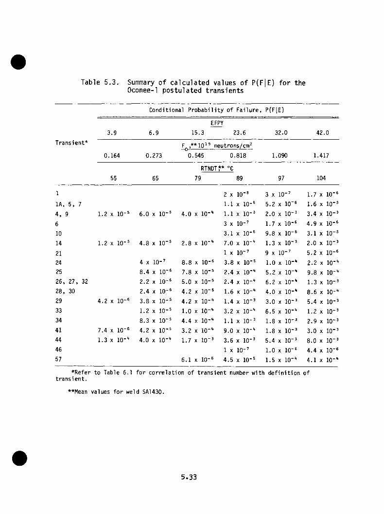
Table 5 . 3 . Summary o f c a l c u la t e d values o f P(F|E) for theOconee-1 p o s tu la ted t r a n s ie n t s
Condi t iona l P r o b a b i l i t y o f F a i l u r e , P(FlE)
EFPY
1.9 6.9 15 .3 23.6 32.0 42.0T ran s i en t* 10^® neutrons/cm’
0 . 164 0.273 0 .,545 0 ,.818 1.,090 1 ,,417
RTNDT** °C
55 65 79 89 97 104
1 2 X 10" ® 3 X 10- ’ 1.7 X 10"®
l A , 5 , 7 1.1 X 10- ® 5.2 X 10" ® 1.6 X 10- ®
4 , 9 1.2 X 10- ® 6.0 X 10- ® 4.0 X 10- “ 1.1 X 10- ® 2.0 X 10- ® 3.4 X 10- ®
6 3 X 10- ’ 1.7 X 10- ® 4.9 X 10- ®
10 3.1 X 10- ® 9.8 X 10- ® 3.1 X 10- ®
14 1.2 X 10- ® 4.8 X 10' ® 2.8 X 10- “ 7.0 X 10" “ 1.3 X 10" ® 2.0 X 10- ®
21 1 X 10- ’ 9 X 10- ’ 5.2 X 10- ®
24 4 X 10- ’ 8.8 X 10- ® 3.8 X 10"® 1.0 X 10- “ 2,2 X 10- “
25 8.4 X 10- ® 7.8 X 10- ® 2.4 X 10” “ 5.2 X 10" “ 9.8 X 10- “
26 , 27 , 32 2.2 X 10- ® 5.0 X 10- ® 2.4 X 10- “ 6.2 X 10- “ 1.3 X 10- ®
28 , 30 2.4 X 10- ® 4.2 X 10" ® 1.6 X 10- “ 4.0 X 10- “ 8.6 X 10- “
29 4.2 X 10- ® 3.8 X 10- ® 4.2 X 10- “ 1.4 X 10" ® 3.0 X 10- ® 5.4 X 10- ®
33 1.2 X 10- ® 1.0 X 10- “ 3.2 X 10- “ 6.5 X 10- “ 1.2 X 10- ®
34 8.3 X 10‘ ® 4.4 X 10- “ 1.1 X 10- ® 1.8 X 10- ® 2.9 X 10- ®
41 7.4 X 10- ® 4.2 X 10- ® 3.2 X 10- “ 9.0 X 10- “ 1.8 X 10- ® 3.0 X 10- ®
44 1.3 X 10- “ 4.0 X 10- “ 1.7 X 10" ® 3.6 X 10- ® 5.4 X 10" ® 8.0 X 10" ®
46 1 X 10- ’ 1.0 X 10- ® 4.4 X 10- ®
57 6.1 X 10- ® 4.5 X 10- ® 1.5 X 10- “ 4.1 X 10- “
♦Refer to Table 6.1 f o r c o r r e l a t i o n of t r a n s i e n t number with d e f i n i t i o n of t r a n s i e n t .
**Mean va lues f o r weld SA1430.
5.33
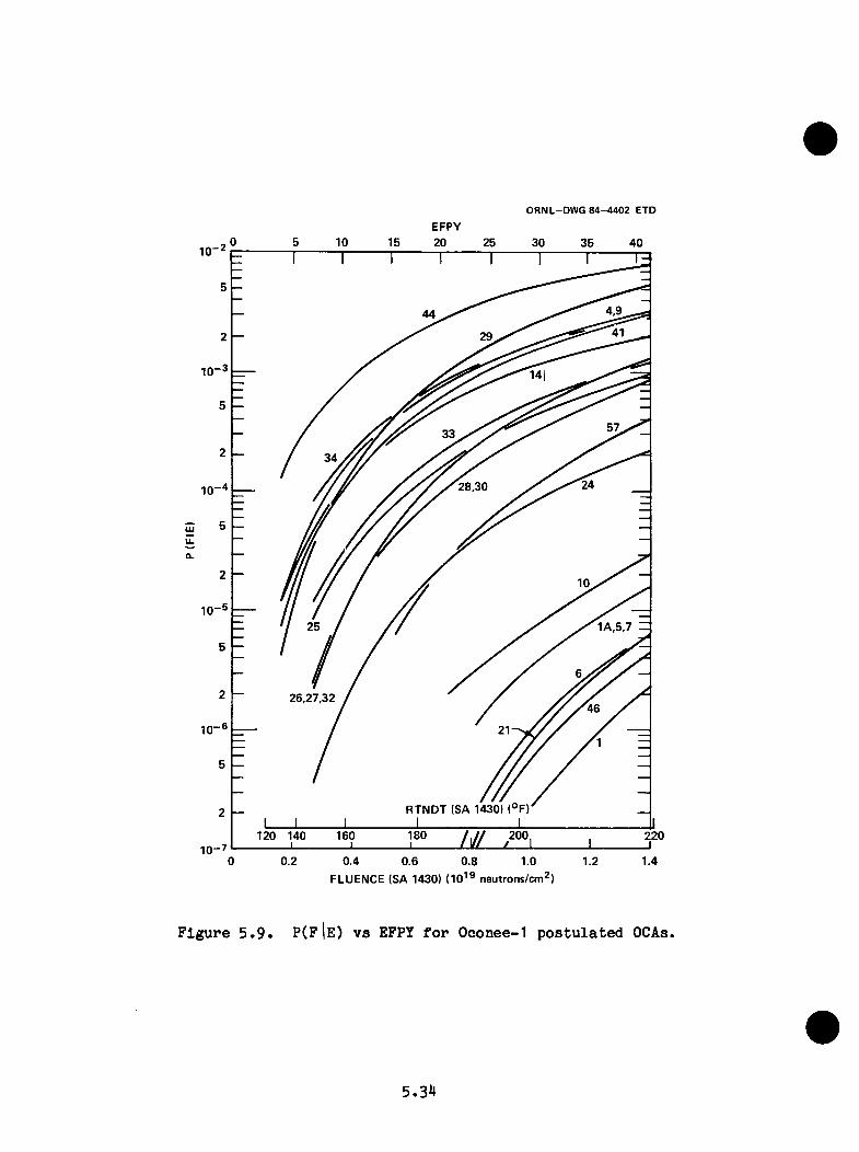
ORNL-DW G 8 4 -4 4 0 2 ETD
EFPY30 40
1 - 2
4,944
1-3
34
28,301 - 4
UJIL
a.
1-5
1A,5,7 H25
26,27,3246
1 -6
RTNDT (SA 1430) (°F)
180 200 220160
0 0.2 0.4 0.8 1.0 1.40.6 1.2FLUENCE (SA 1430) (10’® neutrons/cm^)
Figure 5.9. P(F 1e ) v s EFPY for Oconee-1 postulated OCAs.
5.34
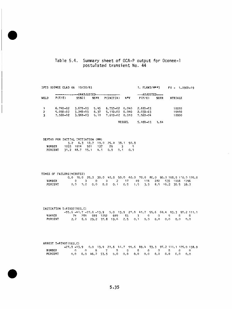
Table 5 . 4 . Summary s h ee t o f OCA-P output for Oconee-1pos tu la ted t r a n s i e n t No. 44
IPTS OCONEE CLAD 6A 1 0 / 2 0 / 8 3
WELD P ( F / E )-UNADJUSTED--------------------------95%CI SERR P( I NI TI A) N»V
1. FLAWS/M»»3
ADJUSTED-------P ( F / E ) tERR
FO = 1.090D+19
NTRIALS
1 6 . 7 4 D - 0 2 3 . 6 7 D - 0 3 5 . 9 5 6 . 7 5 D - 0 2 0 . 0 9 0 2 . 6 9 D - 0 3 100002 5 . 0 9 D - 0 2 3 . 2 9 D - 0 3 6 . 3 7 5 . 11D-02 0 . 0 9 0 2 . 03D-Q3 100003 7 . 5 6 D - 0 2 3 . 8 6 D - 0 3 5 . 10 7 . 6 1 D - 0 2 0 . 0 1 0 7 . 5 6 D - 0 9 10000
VESSEL 5 . 9 9 D - 0 3 3 . 5 9
DEPTHS FOR INITIAL INITIATION (MM)3. 2 6 . 3 1 2 . 7 1 9 . 0 2 5 . 9 38. 1 5 0 . 8
NUMBER 1033 1619 501 137 26 3 0PERCENT 3 1 . 2 9 8 . 7 15. 1 9. 1 0 . 8 0 . 1 0 . 0
TIMES OF FAILURE(MINUTES)0 . 0 10 . 0 2 0 . 0 3 0 . 0 9 0 . 0 5 0 . 0 6 0 . 0 7 0 . 0 8 0 . 0 9 0 . 0 1 0 0 . 0 1 1 0 . 0 1 2 0 . 0
NUMBER 0 0 0 0 2 17 99 1 19 282 535 1006 1296PERCENT 0 . 0 0 . 0 0 . 0 0 . 0 0 . 1 0 , 5 1 . 5 3 . 5 8 . 5 1 6 . 2 3 0 , 5 3 9 . 3
INITIATION T-RTNDT(DEG.C)- 5 5 . 6 - 9 1 . 7 - 2 7 . 8 - 1 3 . 9 0 . 0 1 3 . 9 2 7 . 8 9 1 . 7 5 5 . 6 6 9 . 9 83. 3 9 7 . 2 11 1.1
NUMBER 79 289 969 1252 699 83 3 0 0 0 0 0PERCENT 2 . 2 8 . 6 2 9 . 2 3 7 . 8 1 9 . 6 2 . 5 0 . 1 0 . 0 0 . 0 0 . 0 0 . 0 0 . 0
ARREST T-RTNDT(DEG.C)- 2 7 . 8 - 1 3 . 9 0 . 0 1 3 . 9 2 7 . 8 91.
NUMBER 0 0 6 7 0PERCENT 0 . 0 0 . 0 9 6 . 2 5 3 . 8 0 . 0
7 5 5 . 6 6 9 . 9 83 . 3 9 7 . 2 1 11. 1 1 2 5 . 0 1 3 8 . 90
0 . 0
0
0 . 0
0
0 . 0
0
0 . 0
0
0 . 0
0
0 . 0
0
0 . 0
5 .35

OCft-P IPTS OCONEE CLflO 6R 10/20/83INITIflTION CRflCK DEPTHS PO- 1.090E19
COS! g .o ■MEh< R-MEh
a. 2 ■
8-<HM 9- 2
3.a C.3 U.7 ia.0 3>.lCfWCK DEPTH, ttl
90.*
Figure 5.10 Histogram of percent initiations vs crack depth for first initiation event (Oconee-1 postulated transient No. 44; at 32 EFPY).
OCn-P IPTS OCONEE CliO 8R 10/20/83TIME OF FfllUJRE FO- 1.090E19
TIME, MIN.
Figure 5 .11. Histogram o f pe rcen t f a i lu r e s vs tim e of f a i lu r e (Oconee-1 p o s tu la te d t r a n s ie n t No. a t 32 EFPY).
5.36
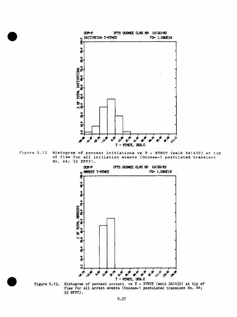
OCn-P IPTS OCONEE CLfO 8fl 10/20/83INITinilON T-RTNDT FO- 1.090E19
o
7 ^ jy V .y ^ ^ 4'r - RTNDT, DEC.C
Figure 5.12 Histogram of percent initiations vs T - RTNDT (weld SA1430) at tip of flaw for all initiation events (Oconee-1 postulated transient No. 44; 32 EFPY).
OCn-P IPTS OCONEE CLflO 6fl 10/^83FO- 1.090E19ARREST T-RTNDT
m
a
7 A* O- ^ 4 -T - RTNDT, DE8.C
Figure 5 .1 3 . Histogram of percen t a r r e s ts vs T - RTNDT (weld SA1430) a t t ip of flaw fo r a l l a r r e s t even ts (Oconee-1 p o stu la ted t r a n s ie n t No. 44; 32 EFPY).
5.37
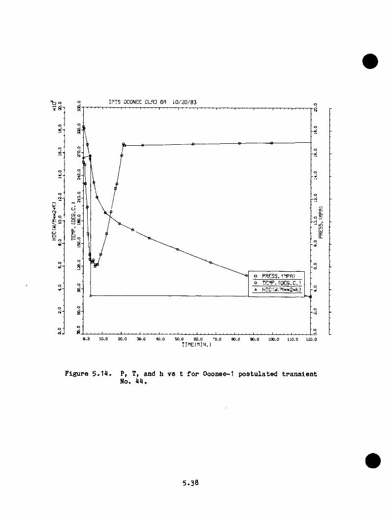
tD oX R
rrvjr : o
oh-*X ,
IPTS OCONr:^ CLSD 6R 10/20/33
oCD of . ) .
° 8
cna.ECDO)UJ010-
u .EI- o
□ PRISSS. (MPR)o TEMP,(PEG.C.)A HTC( /M?xx2?<K)
0.0 10.0 20.0 30 .0 40.0 50.0 60 .0 80 .0 90 .0 100.0 110.0 120.0
F ig u r e 5 .1 4 . P , T, an d h v s t f o r O oonee-1 p o s t u l a t e d t r a n s i e n t No. 4 4 .
5.38
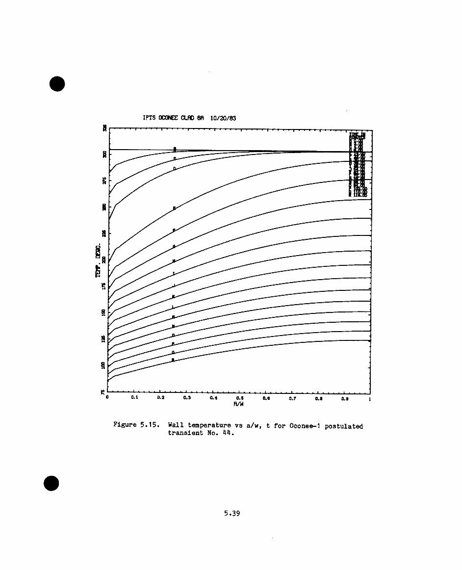
6£'s
®9tlO0,0 5 ,
Ve S4 *°^?^®Tsue
TIb/j .- ^
^/OZ/Ql“"»a«noSiJI
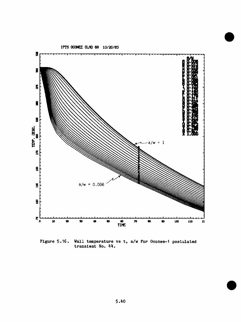
IPTS OCONEE CLflO 6fl 10/20/83
a/w = 1
a/w = 0 .006
F ig u r e 5 . 1 6 , W a ll t e m p e r a tu r e v s t , a /w f o r O conee-1 p o s t u l a t e d t r a n s i e n t No. 4 4 .
5.40
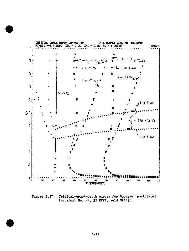
CRITICflL CRflCK DEPTH CURVES FOR IPTS OCONEE CLRO 6R 1 0 /2 0 /8 3RTNDTO — 6 .7 DE6C ZCU - 0 .2 9 ZNI - 0 .5 5 PO - 1.09E19 L0N8IT
t •
ci -
’‘* * ^ 2 - 0 f l a w * o - » z _ 2_D f l a w
X ♦ O
X
♦
2-m f l a w2-m f l a w<
-WPS
a
o
«
, 2 - m f l a w♦ ♦ V
♦ “ * , ■
..................................... y. • • + ’ * Kt = 220 MPa
X . - < *
• • X *
a «D ♦
2-D f l a w
Xx ^ *>#
Bp
Ba
I ■ ■ I I 1 . . . - . - I . .. . 1 I **^?????y??xxyxx°gg8S g8 iS 88B B B B 8B B H «aiU) 80 ao 70
TIME(MINUTES)too lie K
F ig u r e 5 . 1 7 . C r i t i c a l - c r a c k - d e p t h c u r v e s f o r O conee-1 p o s t u l a t e d t r a n s i e n t No. 4 4 , 32 EFPY, w e ld SA 1430.
5.41

5 . 5 . 3 S e n s i t i v i t y A n a ly s i s
The s e n s i t i v i t y a n a l y s i s w as c o n d u c te d by d e t e r m in in g t h e c h a n g e i n
P (F |E ) c o r r e s p o n d in g t o a ch a n g e i n t h e m ean v a l u e o f e a c h o f s e v e r a l
p a r a m e t e r s . The m ean v a l u e o f o n ly o n e p a r a m e te r w as c h a n g ed a t a t im e
w h i l e a l l o t h e r p a r a m e te r s r e t a i n e d t h e i r o r i g i n a l m ean v a l u e s . The
p a r a m e te r s c h a n g e d w e re RTNDT, Cu, F , f l u i d - f i l m h e a t t r a n s f e r
c o e f f i c i e n t , dow ncom er c o o l a n t t a n p e r a t u r e , p r im a r y - s y s te m p r e s s u r e , an d
f l a w d e n s i t y . The am o u n t o f t h e c h a n g e f o r e a c h p a r a m e te r w as o n e s t a n
d a r d d e v i a t i o n , £ind f o r s a n e p a r a m e te r s b o th p l u s a n d m in u s c h a n g e s w e re
m ade b e c a u s e o f a s u s p e c te d s t r o n g n o n l i n e a r i t y .
The v e d u e s o f a u s e d i n t h e s e n s i t i v i t y a n a l y s i s f o r RTNDT,
Cu, and F a r e l i s t e d i n T a b le 5 . 1 , a n d t h e v a l u e s o f t h e f la w d e n s i t y ,
2 -2N, c o r r e s p o n d in g t o t h e a p p l i c a t i o n o f ± 1 a w e re 10 and 10 t im e s t h e
o r i g i n a l m ean v a l u e . The l a ch a n g e i n t h e dow ncom er c o o l a n t t e m p e r a tu r e
c o n s t i t u t e d a l i n e a r c h a n g e i n t e m p e r a tu r e f r a n z e r o a t t im e z e r o t o
28 °C a t a t im e c o r r e s p o n d in g t o t h e minimum p o i n t i n t h e t e m p e r a tu r e v s
t im e c u r v e . From th e n o n , t h e c h a n g e i n t e m p e r a t u r e w as a c o n s t a n t
v a l u e o f 2 8 °C. The l a c h a n g e i n t h e h e a t t r a n s f e r c o e f f i c i e n t , h , w as
0 .2 5 h an d f o r t h e p r e s s u r e , 0 .3 4 MPa.
The r e s u l t s o f t h e s e n s i t i v i t y s tu d y a r e p r e s e n t e d i n T a b le 5 .5 f o r 32
EFPY. T a b le 5 .5 i n c l u d e s t h e v a l u e s o f P ( f | e ) c o r r e s p o n d in g t o t h e o r i
g i n a l m ean v a l u e s o f t h e p a r a m e te r s an d t h e c h a n g e s i n P (F |E )
c o r r e s p o n d in g t o e a c h o f t h e l a c h a n g e s .
5.42
I t i s o f i n t e r e s t t o n o t e (b o tto m o f T a b le 5 .5 ) t h a t a s i d e f r o n t h e s e n
s i t i v i t y t o N, P (F |E ) i s m o s t s e n s i t i v e by f a r t o t h e r e d u c t i o n i n down
com er c o o l a n t t a n p e r a t u r e an d i s a b o u t a f a c t o r o f 6 l e s s s e n s i t i v e t o a
r e d u c t i o n i n an d a n i n c r e a s e i n RTNDT. The p r o b a b i l i t y o f f a i l u r e
i s l e a s t s e n s i t i v e t o v a r i a t i o n s i n t h e h e a t t r a n s f e r c o e f f i c i e n t and
t h e p r im a ry s y s te m p r e s s u r e .
5 . 5 .4 E f f e c t o f I n c l u d i n g WPS
D u rin g m any o f t h e p o s t u l a t e d OCAs, t h e s t r e s s i n t e n s i t y f a c t o r , K^, f o r
a l l c r a c k d e p th s f i r s t i n c r e a s e s w i t h t im e , r e a c h e s a meiximum, an d th e n
d e c r e a s e s . F o r t h e s h a l lo w f l a w s t h a t a r e g e n e r a l l y r e s p o n s i b l e f o r t h e
i n i t i a l c r a c k i n i t i a t i o n e v e n t , o n c e b e g in s t o d e c r e a s e i t d o e s so
th r o u g h o u t t h e r e m a in d e r o f t h e t r a n s i e n t . T h is t im e - d e p e n d e n t b e h a v io r
o f K j may p r e v e n t f a i l u r e o f a v e s s e l b e c a u s e a f la w c a n n o t i n i t i a t e
w h i l e K j i s d e c r e a s i n g , e v e n th o u g h 2. 1 . T h is p h e n a n e n o n , w h ic h ,
a s n o te d e a r l i e r , i s r e f e r r e d t o a s w ann p r e s t r e s s i n g (W PS), an d th e
t im e o f i n c i p i e n t WPS i s t h e t im e a t w h ic h becom es e q u a l t o z e r o .
F o r m o s t o f t h e O co n ee-1 p o s t u l a t e d t r a n s i e n t s , WPS c o u ld b e a f a c t o r
b e c a u s e t h e c a l c u l a t i o n s i n d i c a t e t h a t d o e s n o t becom e e q u a l t o
u n t i l a f t e r t h e t im e o f WPS. A t y p i c a l c a s e i s i l l u s t r a t e d i n F ig u r e s
5 .4 and 5 .1 1 . The r e a s o n f o r n o t i n c l u d i n g WPS i n m o s t o f t h e c a l c u l a
t i o n s i s t h a t t h e v s t c u r v e s f o r t h e s h a l lo w f l a w s a r e v e r y f l a t ,
m ak in g i t d i f f i c u l t t o d e te r m in e w h e re t h e mciximvun i s . F u r th e r m o r e ,
u n f o r e s e e n p e r t u r b a t i o n s i n p r e s s u r e and c o o l a n t t e m p e r a tu r e m ig h t e x i s t
an d d e f e a t WPS. E ven s o , i t i s o f i n t e r e s t t o s e e w h a t t h e e f f e c t i s
5.43
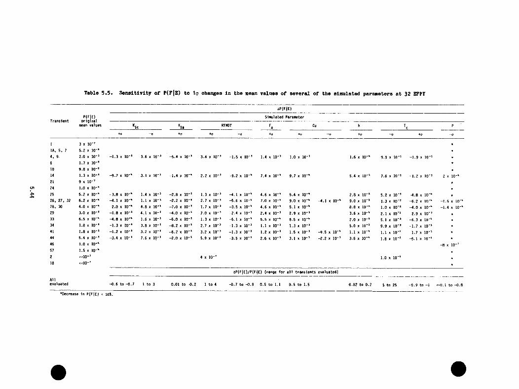
Table 5 .5 . S en sitiv ity of P(F|E) to 1o ohanges In the mean values of several of the simulated parameters a t 32 EFPY
T ransien tP(FlE)
o r ig in a l mean values
aP(F|E)
Simulated Parameter
RTNOT fo Cu h P
+0 -o +0 +0 -0 +0 ♦o —tJ + 0 —0 +o —0
1 3 % 10-’ *
lA, 5 , 7 5 .2 « 10-‘ *
4 . 9 2.0 X 10-’ -1 .3 X 10-* 3.6 X 10-* -5 .4 X 10-’ 3 .4 X 10- -1 .5 X 10-’ 1.4 X 10-’ 1.0 X 10-’ 1.6 X 10-' 9 .9 X 10"* -1 .9 X 10'* *
6 1.7 X 10 -' *
10 9 .8 X 10 - ' *
14 1.3 X 10-’ -9 .2 X 10-" 3.1 X 10'* -1 .4 X 10-' 2 .2 X 10- -9 .2 X 10 - ' 7.4 X 10-' 9 .7 X 10 -' 5 .4 X 10-' 7 .6 X 10-* -1 .2 X 10’ * -2 X 10-"21 9 X 10-’ *24 1.0 X 10 - ' *25 5.2 X 10 - ' -3 .8 X 10-" 1.4 X 10-* -2 .8 X 10-’ 1.3 X 10- -4 .1 X 10-' 4 .6 X 1 0-' 5 .4 X 10 - ' 2 .8 X 10 - ' 5 .2 X 10‘ * -4 .8 X 10'" *26. 27. 32 6.2 X 10 - ' -4 .1 X 10-" 1.1 X 10-* -2 .2 X 10 - ' 2 .7 X 10- -5 .6 X 10-' 7.0 X 1 0-' 9 .0 X 1 0 - ' -4 .1 X 10-' 9 .0 X 10-' 1.3 X 10‘ * -6 .2 X 10'" -1 .5 X 10-"28. 30 4 .0 X 10 - ' -2 .0 X 10-" 4 .8 X 10-" -7 .0 X 10-’ 1.7 X 10- -3 .5 X 10-' 4 .6 X 10 - ' 5.1 X 10 -' 8 .8 X 10-' 1.0 X 10'* -4 .0 X 10-" -1 .4 X 1Q-"29 3.0 X 10-’ -1 .8 X 10-* 4.1 X 10-* -4 .0 X 10 - ' 7 .0 X 10- -2 .4 X 10-’ 2 .4 X 10-’ 2 .9 X 10-’ 3 .6 X 10 - ' 2 .1 X 10'* -2 .9 X 10'* *
33 6.5 X 10-' -4 .8 X 10-" 1.6 X 10-* -5 .0 X 10 - ' 1.3 X 10- -5 .1 X 10 - ' 5 .5 X 10 -' 6 .5 X 1 0 - ' 2 .0 X 10-' 5.1 X 1Q-* -6 .3 X 10'" *34 1.8 X 10-’ -1 .3 X 10-* 3.8 X 10-* -8 .2 X 1 0-' 2 .7 X 10- -1 .3 X 10-’ 1.1 X 10-’ 1.3 X 10-’ 5 .0 X 10 - ' 9 .9 X 10"* -1 .7 X 10'* *41 1.8 X 10-’ -1 .2 X 10-* 3.2 X 10-* -6 .2 X 1 0 - ' 3 .2 X 10- -1 .3 X 10-’ 1.2 X 10-’ 1.5 X 10-’ -9 .5 X 10-' 1.1 X 10 -' 1.1 X 10'* -1 .7 X 10-* *44 5.4 X 10-’ -3 .4 X 10-* 7.6 X 10-* -2 .0 X 10 - ' 5 .9 X 10- -3 .5 X 10-’ 2.6 X 10-’ 3.1 X 10-’ -2 .2 X 10-’ 3 .6 X 10 -' 1 .8 X 10'* -5 .1 X IQ-* *46 1.0 X 10-' -8 X 10-’57 1.5 X 10-' *
2 « io - ’ 4 X 10-’ 1.0 X 10'* ♦
18 « io - ’
aP (F |E )/P (F |E ) {range fo r a l l tr a n s ie n ts evaluated)
Allevaluated -0 .6 to -0 .7 1 to 3 -0 .01 to -0 .2 1 to 4 -0 .7 to -0 .9 0 .5 to 1.1 0 .5 to 1.5 0.02 to 0 .2 5 to 25 0 .9 to -1 <-0.1 to -0 .8
‘ Decrease in P(F|E) < lOX.
f o r t h e i d e a l i z e d t r a n s i e n t s , an d t h e r e s u l t s o f su o h a s tu d y a r e
p r e s e n t e d i n T a b le 5 . 6 .
T a b le 5 .6 show s t h e t im e o f WPS f o r e a c h o f t h e t r a n s i e n t s c o n s id e r e d
an d t h e c a l c u l a t e d v a l u e s o f P ( F |e ) w i th an d w i t h o u t WPS in c lu d e d i n t h e
a n a l y s i s . I t i s a p p a r e n t t h a t f o r t h e s e i d e a l i z e d t r a n s i e n t s WPS h a s a
v e r y s i g n i f i c a n t e f f e c t .
5 . 5 . 5 E f f e c t o f P ro p o s e d R em e d ia l M e a s u re s on P ( F [ e )
The p ro p o s e d r e m e d ia l m e a s u re s c o n s id e r e d i n t h e f r a c t u r e - m e c h a n ic s s t u
d i e s w e re (1 ) r e d u c t i o n i n t h e f l u e n c e r a t e , (2 ) i n - s e r v i c e i n s p e c t i o n
f o r f l a w s i n t h e v e s s e l , ( 3 ) a l i m i t o n r e p r e s s u r i z a t i o n , an d (4 )
a n n e a l i n g o f t h e v e s s e l .
5 . 5 . 5 . 1 R e d u c t io n i n F lu e n c e R a te
The r e d u c t i o n i n f l u e n c e r a t e w as a ssu m ed t o t a k e p l a c e o n J a n u a ry 1 ,
1 9 8 5 , an d i t w as assu m ed t o b e t h e sam e a t a l l c r i t i c a l l o c a t i o n s i n t h e
v e s s e l w a l l . The e f f e c t w as s im p ly t o c h a n g e t h e p r o p o r t i o n a l i t y co n
s t a n t b e tw e e n F^ an d EFPY b ey o n d J a n u a r y 1 , 1 9 8 5 . A t t h i s t im e th e
v e s s e l w i l l h a v e b e e n i n s e r v i c e f o r '^7 EFPY, an d t h e f l u e n c e f o r w e ld
SA1430 w i l l be 2 .7 6 x 10^® n e u t r o n s /c m ^ . The i n f o r m a t i o n i n F ig u r e 5 .9
17i s b a s e d o n a f l u e n c e r a t e f o r w e ld SA1430 o f 3 .2 6 x 10
2n e u t r o n s / ( c m *EFPY) f o r t h e p e r io d 5 EFPY t o 32 EFPY. The num ber o f
EFPY c o r r e s p o n d in g t o t h e f l u e n c e i n F ig u r e 5 .9 a f t e r J a n u a r y 1 , 1985 ,
i s
EFPY = 7 + 3 .0 7 xIO "^® f ( F - 2 .7 6 x 10^®) ( 5 .1 9 )o
5.45
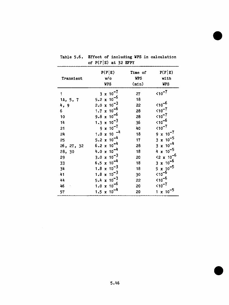
T a b le 5 . 6 . E f f e c t o f i n c l u d i n g WPS i n c a l c u l a t i o n o f P ( f 1e ) a t 32 EFPY
T r a n s i e n tP (F lE )
w /oWPS
Tim e o f WPS
(m in )
p ( f ] e )w ithWPS
1 3 X 1 0 "J 27 <10"'^
1A, 5 , 7 5 .2 X 1 0 "° 18
4 , 9 2 .0 X 10"^ 22 <10"^6 1 .7 X 10"^ 28 <10""^10 9 .8 X 10"^ 28 <10"'^14 1 .3 X 10"^ 36 <10"^21 9 X 10""^ 40 <10""^24 1 .0 X 10 18 9 X lO""^25 5 .2 X 10"^ 17 3 X 10"^2 6 , 2 7 , 32 6 .2 X 10"^ 28 3 X 10"^2 8 , 30 4 .0 X 10"^ 18 4 X 10"^
29 3 .0 X 10"^ 20 <2 X 10"®
33 6 .5 X 10"^ 18 3 X 10"®34 1 .8 X 10"^ 18 5 X 10"^41 1 .8 X 10"^ 30 <10"®44 5 .4 X 10"^ 22 <10"®46 1 .0 X 10"^ 20 <10""^
57 1 .5 X 10"^ 20 1 X 10"^
5.46

where
f = f a c to r by which f lu en ce r a t e i s reduced on January 1, 1985
F = in n e r-su rfa c e f lu e n c e fo r weld SA1430 o
For t h i s p a r t ic u la r s tudy , f lu en ce re d u c tio n f a c to rs of 2 , 4 , and 8 were
examined. Using th ese f a c to r s in Eq. 5 .19 r e s u l t s in F^ (32 EFPY) = 6.84 x
I 0 I8 , 4 .80 X 10^®, and 3 .78 x 10 ® neu trons/cm ^, re s p e c tiv e ly , compared to
10.9 X IQI® neutrons/cm 2 fo r f = 1. The corresponding v a lu es o f P(F|E) fo r
the t r a n s ie n t s included in F igu re 5 .9 can be estim ated by e n te r in g these
f lu e n c e s on the a b sc is sa o f F igu re 5 .9 . (The EFPY sc a le i s , o f course ,
in c o r r e c t except fo r f = 1 .) These r e s u l t s a re summarized in Table 5 .7 .
5 .5 .5 .2 In -s e rv ic e In sp e c tio n
In -s e rv ic e in sp e c tio n was assumed to have a c a p a b i l i ty o f f in d in g e i th e r
90? o r 99? o f the su rfa c e flaw s w ith dep ths equal to o r g r e a te r than 6 mm and
none o f the flaw s w ith dep ths l e s s than 6 mm. I t was f u r th e r assumed th a t
a l l flaw s found would be re p a ire d . I f b e fo re th e in -s e rv ic e in sp e c tio n ,
no c a lc u la te d f a i l u r e s were a t t r ib u te d to i n i t i a l flaw s w ith depths l e s s
than 6 mm, then th e 90$ and 99$ in sp e c tio n would reduce P ( f |e ) by fa c
to r s o f 0.1 and 0 .0 1 , r e s p e c t iv e ly . However, in most cases th e very
shallow flaw s do r e s u l t in f a i l u r e . The c a lc u la te d e f f e c t of in -s e rv ic e
in sp e c tio n under th ese c o n d itio n s i s in d ic a te d in Table 5 .7 fo r a tim e
in the l i f e o f the v e sse l o f 32 EFPY.
5 .5 .5 .3 L im it on R e p re ssu riz a tio n
The e f f e c t on P (F |e ) o f a l im i t on r e p r e s s u r iz a t io n was in v e s tig a te d by
sp e c ify in g a s in g le l im i t o f 6 .9 MPa. The b e n e f i t o f th i s l im i t i s
5.47

Table 5.7. Benefit of remedial measures,
Transient
Reduction In Fluence In-service Rate on Jan. 1. 1985 Inspection
P(F|e ) InspectionOriginal Rate Reduction Factor Capability**
Mean Values ------------------------------------at 32 EFPT 2 4 8 90J 99>
Limit on Repressurization
P(f 1e ) P„: conditional probability of failure with remedial measure. P(F|e )
Annealing at 9 EFPy
1 3 X 1 0 “ ^ * • 1 • » §
1A , 5 , 7 5 . 2 X 10"® 0 . 0 8 • • • • • • 0 . 1 3 0 . 0 4 0 . 1 9
2 « 1 0 " ^ < • « « « • • • •
4 , 9 2 . 0 X 1 0 "® 0 . 4 0 . 2 0 . 0 3 0 . 2 9 0 . 2 2 0 . 5 0
6 1 . 7 X 10"® • • • 0 . 1 0
1 0 9 . 8 X 10"® 0 . 2 • • • • • • 0 . 0 3 0 . 3 0
14 1 . 3 X 1 0 " ^ 0 . 4 0 . 2 0 . 0 8 0 . 2 8 0 . 2 1 0 . 1 3 0 . 5 4
1 8 « 1 0 " ^ flC*
21 9 X 1 0 " ^ • • •
2 4 1 . 0 X 10"** 0 . 2 0 . 0 5 0 . 0 2 0 . 1 5 0 . 0 6 0 . 3 7
2 5 5 . 2 X 10"^* 0 . 4 0 . 1 0 .06 0 . 2 1 0 . 1 3 0 . 4 2
2 6 , 2 7 , 3 2 6 . 2 X 1 0 " ^ 0 . 2 0 . 0 5 0 . 0 2 0 . 5 5 0 . 5 1 0 . 3 5
2 8 , 30 4 . 0 X lO""* 0 . 2 0 . 0 8 0 . 0 3 0 . 5 0 0 . 4 5 • • • 0 . 3 8
2 9 3 . 0 X 1 0 " ^ 0 . 3 0 . 1 0 . 0 3 0 . 5 6 0 . 5 1 0 . 0 7 0 . 4 3
3 3 6 . 5 X 10"^* 0 . 3 0 . 1 0 . 0 5 0 . 4 6
3 4 1 . 8 X 1 0 " ^ 0 . 4 0 . 2 0 . 1 0 . 6 1
41 1 . 8 X 1 0 " ^ 0 . 3 0 . 1 0 . 0 5 0 . 3 1 0 . 2 4 0 . 5 6
4 4 5 . 4 X 1 0 " ^ 0 . 6 0 . 2 0 . 1 0 . 3 8 0 . 3 1 0 . 0 2 0 . 6 5
4 6 1 . 0 X 1 0 ' ® • • • 0 . 2 8
5 7• l l
1 . 5 X 10 0 . 1 0 . 0 2 • • • 0 . 0 1
•'wRMtlonal proballlty of failure without remedial measure. w/oRM' condl-
**Refer to text for an explanation of Inspection capability and assumption regarding of flaws.
repair
***P(F|E) <10“'.
5.48
p r e s e n t e d i n T a b le 5 .7 f o r 32 EFPY, F o r s e v e r a l o f t h e t r a n s i e n t s t h e
p r e s s u r e d o e s n o t d ro p b e lo w 6 .9 MPa, a n d f o r t h e s e t r a n s i e n t s t h e l i m i t
o n r e p r e s s u r i z a t i o n d o e s n o t a p p l y .
5 . 5 . 5 . 4 A n n e a l in g
A n n e a l in g o f t h e p r e s s u r e v e s s e l w i l l i n c r e a s e t h e f r a c t u r e to u g h n e s s o f
t h e v e s s e l m a t e r i a l , an d t h e am o u n t o f t h e i n c r e a s e w i l l d e p e n d o n th e
a n n e a l i n g t e m p e r a t u r e an d t im e , t h e c h e m is t r y o f t h e m a t e r i a l , an d t h e
num ber o f t im e s t h e v e s s e l i s a n n e a l e d . T e s t r e s u l t s frcmi s m a l l s p e c i
m ens i n d i c a t e t h a t e s s e n t i a l l y f u l l r e c o v e r y o f t h e i n i t i a l f r a c t u r e
to u g h n e s s m ig h t b e a c h ie v e d by a n n e a l i n g i n t h e te m p e r a tu r e r a n g e 4 0 0 -
o 14450 C f o r '^200 h . A lth o u g h p r e l i m i n a r y s t u d i e s i n d i c a t e t h a t s u c h a
p r o c e s s w o u ld p r o b a b ly b e f e a s i b l e i n som e PWR p l a n t s , t h e f e a s i b i l i t y
o f a n n e a l i n g t h e O co n ee-1 v e s s e l u n d e r t h e s e c o n d i t i o n s h a s n o t b e e n
e s t a b l i s h e d . N e v e r t h e l e s s , f o r t h e p u rp o s e o f t h i s s t u d y i t w as assu m ed
t h a t th e O c o n e e -1 v e s s e l w o u ld b e a n n e a le d w hen t h e p l a n t a c h ie v e d ' 9
EFPY ( '^ J a n u a ry 1 9 8 7 ) . I n e f f e c t , 9 y r w o u ld b e s u b t r a c t e d frcm i t h e EFPY
s c a l e i n F ig u r e 5 .9 f o r EFPY 2. 9 . The b e n e f i t a t 32 EFPY o f t h i s
assu m ed a n n e a l i n g s i t u a t i o n i s i n d i c a t e d i n T a b le 5 . 7 .
5.49

REFERENCES
1 . F . J . L o s s , R. A. G ra y , J r . , an d J . R. H a w th o rn e , ’’ S i g n i f i c a n c e o f Warm
P r e s t r e s s t o C rac k I n i t i a t i o n D u r in g T h erm al S h o c k ,” R e p o r t NRL/NGREG-8165,
N a v a l R e s e a r c h L a b o r a to r y , N TIS, S e p te m b e r 2 9 , 1 9 7 7 .
2 . R. D. C h e v e r to n an d S . K. I s k a n d e r , ’’ T h e rm a l-S h o c k I n v e s t i g a t i o n s , "
i n " H e a v y -S e c t io n S t e e l T e c h n o lo g y P ro g ram Q u a r t e r l y P r o g r e s s R e p o r t
O c to b e r-D e c e m b e r 1 9 8 0 ," NUREG/CR-1941 (ORNL/NDREG/TM-437), p p . 3 7 -5 4 , U nion
C a rb id e C o r p o r a t io n - N u c le a r D i v i s i o n , Oak R id g e N a t i o n a l L a b o r a to r y .
3 . R. D. C h e v e r to n an d D. G. B a l l , ’’ OCA-P, A P r o b a b i l i s t i c F r a c tu r e - M e c h a n ic s
Code f o r A p p l i c a t i o n t o P r e s s u r e V e s s e l s , " NUREG/CR-3618 (O R N L -5991), U nion
C a rb id e C o r p o r a t io n - N u c le a r D i v i s i o n , Oak R id g e N a t i o n a l L a b o r a to r y ( i n
p r e p a r a t i o n ) .
4 . R. D. C h e v e r to n , D. G. B a l l , an d S . E . B o l t , ’’ T h e rm a l-S h o c k I n v e s t i g a
t i o n s , " i n ’’H e a v y -S e c t io n S t e e l T e c h n o lo g y P ro g ram Q u a r t e r l y P r o g r e s s R e p o r t
A p r i l - J u n e 1 9 8 3 ," NUREG/CR-3334, V o l. 2 (0R N L /T M -8787/V 2), p p . 5 7 -7 4 , U nion
C a rb id e C o r p o r a t io n - N u c le a r D i v i s i o n , Oak R id g e N a t i o n a l L a b o r a to r y .
5 . T . U. M a rs to n ( E d . ) , " F la w E v a l u a t i o n P r o c e d u r e s , ASME S e c t i o n X I,
B a ck g ro u n d an d A p p l i c a t i o n o f ASME S e c t i o n X I, A p p e n d ix A, S p e c i a l R e p o r t , "
EPRI N P -719-S R , A m erican S o c i e t y o f M e c h a n ic a l E n g in e e r s , E l e c t r i c Pow er
R e s e a rc h I n s t i t u t e , A u g u st 1 9 7 8 .
6 . L e t t e r fro m F . J . L o ss (NRL) t o R. H. B ry an (ORNL), M arch 3 1 , 1 9 8 1 .
5.50
7 . NRC s t a f f e v a l u a t i o n o f P r e s s u r i z e d T h erm a l S h o ck , S e p t . 1 3 , 1982
d r a f t , a t t a c h m e n t t o t r a n s m i t t a l d o c u m e n t. S ecy 8 2 -4 6 5 , Nov. 2 3 , 1 9 8 2 .
(A v s d .la b le i n NRC p u b l i c d o cu m en t ro o m .)
8 . R. D. C h e v e r to n an d D. G. B a l l , ” T h e rm a l-S h o c k I n v e s t i g a t i o n s , " i n
" H e a v y - S e c t io n S t e e l T e c h n o lo g y P ro g ram Q u a r t e r l y P r o g r e s s R e p o r t
O c to b e r-D e c e m b e r 1 9 8 2 ," NDREG/CR-2751, V o l. 4 (O R N L/TM -8369/V 4), p . 6 8 , O n ion
C a rb id e C o r p o r a t i o n - N u c l e a r D i v i s i o n , Oak R id g e N a t io n a l L a b o r a to r y .
9 . ASME B o i l e r an d P r e s s u r e V e s s e l C ode. S e c t i o n I I I , D i v i s i o n I , Sub
s e c t i o n NA, A p p en d ix I , A m eric an S o c i e t y o f M e c h a n ic a l E n g in e e r s , New Y o rk ,
1 9 7 4 .
1 0 . R. M. G am ble and J . S t r o s n i d e r , J r . , "A n A ss e s s m e n t o f t h e F a i l u r e R a te
f o r th e B e l t l i n e R e g io n o f PWR P r e s s u r e V e s s e l s D u r in g N orm al O p e r a t io n and
C e r t a i n T r a n s i e n t C o n d i t i o n s , " NDREG-0778, J u n e 1 9 8 1 .
1 1 . W. M a r s h a l l , "A n A s s e s s m e n t o f t h e I n t e g r i t y o f PWR P r e s s u r e V e s s e l s , "
U n i te d K ingdom A to m ic E n e rg y A u t h o r i t y , S eco n d R e p o r t , M arch 1 9 8 2 .
1 2 . R. Y, R u b i n s t e in , " S i m u l a t io n an d t h e M onte C a r lo M e th o d ," I s r a e l
I n s t i t u t e o f T e c h n o lo g y , J o h n W iley & S o n s , New Y o rk , 1 9 8 1 , p p . 1 1 5 -1 1 7 .
1 3 . " R e a c t o r V e s s e l P r e s s u r i z e d T h erm a l S h o ck E v a l u a t i o n , " D PC -R S-1001,
Duke Pow er Company O conee N u c le a r S t a t i o n , J a n u a r y 1 9 8 2 .
1 4 . J . R. H a w th o rn e , N a v a l R e s e a rc h L a b o r a to r y , p e r s o n a l c o m m u n ic a tio n t o
R. D. C h e v e r to n , Oak R id g e N a t io n a l L a b o r a to r y .
5.51

6 .0 PTS INTEGRATED RISK AND POTENTIAL MITIGATION MEASURES
T . J . Burns, Oak Ridge N a t io n a l L a b o ra to ry .
6 .1 I n t r o d u c t io n
The p rec e d in g t h r e e c h a p te r s have o u t l in e d th e p ro ced u res and te ch n iq u es
enployed to e s t im a te th e th r e e fundam ental p a ra m e te rs ( t r a n s i e n t f req u en cy ,
th e rm a l -h y d ra u l ic h i s t o r y , and th e c o n d i t io n a l p r o b a b i l i t y of v e s s e l
f a i l u r e ) r e q u i r e d to q u a n t i f y the r i s k in h e re n t in a PTS t r a n s i e n t .
T h is c h a p te r d i s c u s s e s the means by which th e se th re e in f lu e n c e s a re
i n t e g r a t e d t o y i e l d an e s t im a te d freq u en cy o f v e s s e l f a i l u r e ( th ro u g h -w a l l
c ra c k p e n e t r a t i o n ) , th e r e s u l t s o f t h i s i n t e g r a t i o n p ro c e s s , and, b r i e f l y ,
the impact o f p o t e n t i a l m i t i g a t in g a c t io n s which c o u ld be a p p l ie d to an
Oconee type p l a n t .
6 .2 R isk I n t e g r a t i o n
In o rd e r to q u a n t i f y th e c o n d i t io n a l p r o b a b i l i t y of v e s s e l f a i l u r e fo r
each e n d s ta t e o f the i n i t i a t o r - s p e c i f i c as jrm pto tic even t t r e e s ( i . e . .
Table A.2 ) , two f u r t h e r e s t im a t io n s a re r e q u i r e d . F i r s t , th e in f lu e n c e
o f o p e r a to r a c t io n s in m odify ing the co u rse of a p a r t i c u l a r a sym pto tic
t r a n s i e n t on th e t r a n s i e n t f requency must be q u a n t i t a t i v e l y e s t im a te d , and
second, a th e rm a l - h y d r a u l ic h i s t o r y r e f l e c t i n g the o p e ra to r a c t io n s must
be a s s ig n e d to each o f th e t r a n s i e n t s . The th e rm a l-h y d ra u l ic h i s t o r y
w i l l d i r e c t l y r e l a t e a t r a n s i e n t t o f r a c t u r e m echanics c a l c u l a t i o n s o f the
v e s s e l f a i l u r e p r o b a b i l i t y , g iven th e o ccu rre n c e o f th e t r a n s i e n t .
While t h i s approach i s t h e o r e t i c a l l y a p p e a l in g , th e r e a re s i g n i f i c a n t
o p e r a t io n a l and re s o u rc e problem s a s s o c i a t e d w ith i t . In th e f i r s t p la c e ,
th e th e rm a l -h y d ra u l ic h i s t o r i e s o f a p p ro x im a te ly 6000 t r a n s i e n t s (248
6 . 1

a s y n p to t i c t r a n s i e n t s x ~20 o p e r a to r a c t i o n co m b in a tio n s ) vou ld bave to be
c a l c u l a t e d o r e s t im a te d . M oreover, tb e c o n d i t i o n a l f a i l u r e p r o b a b i l i t y f o r
each t r a n s i e n t mould bave t o be c a l c u l a t e d u s in g tb e f r a c tu re -m e c b a n ic s
t e c h n iq u e s o u t l in e d p r e v io u s l y . Sucb an e f f o r t was c l e a r l y beyond tbe
r e s o u rc e s a v a i l a b l e to t b i s p r o j e c t , and an a l t e r n a t e , a l b e i t l e s s p r e c i s e ,
p ro ced u re was employed.
As n o te d in C hapter 4 . 0 , a l i m i t e d number o f ev e n t sequences mere c a l c u l a t e d
in d e t a i l u s in g tb e TRAC and RELAP codes . These sequences se rved as a b a s i s
f o r tbe e s t im a t io n o f a p p ro x im a te ly 30 a d d i t i o n a l sequences . F r a c tu r e
m echanics c a l c u l a t i o n s ( S e c t io n 5 .0 ) v e re th e n perfo rm ed on a s u b se t of
tb e t o t a l o f a p p ro x im a te ly 60 c a l c u l a t e d and e s t im a te d th e rm a l-h y d ra u l ic
h i s t o r i e s as a f u n c t i o n o f tb e f lu e n c e s u s t a in e d by tb e v e s s e l . Tbe r e s u l t s
o f tb e FM c a l c u l a t i o n s se rv e as tb e b a s i s f o r e s t im a t in g tb e r e q u i re d
P(TWC/E^) f o r tbe t r a n s i e n t s . Table 6 .1 summarizes tb e s e t o f tb e rm a l-
b y d r a u l i c / f r a c t u r e m echanics d a ta a v a i l a b l e f o r use in tb e r i s k i n t e g r a t i o n
p ro c e d u re .
One consequence o f tb e l i m i t e d number o f t r a n s i e n t s t h a t v e re ana ly zed i s a
s e v e re l i m i t a t i o n on tb e number o f o p e r a to r a c t io n s t h a t could be modeled.
I n most c a s e s , tb e o p e r a to r a c t i o n t r e e s d e s c r ib e d in O ia p te r 3 .0 v e re
c o l l a p s e d to accoun t on ly f o r tb e most s i g n i f i c a n t a c t i o n o f th o se p o s s ib le
(b ased on e n g in e e r in g ju d g m en t) . F or most PTS t r a n s i e n t s , t b i s co rre sponds
t o tb e i s o l a t i o n o f a f f e c t e d steam g e n e r a to r . Tbe f a i l u r e b ran ch i s th e n
d e f in e d as tbe la c k o f i s o l a t i o n on tb e p a r t o f tb e o p e r a to r . I n c e r t a i n
c a s e s ( s p e c i f i c a l l y th o se in v o lv in g a l o s s o f a l l f e e d v a t e r ) , tb e p o t e n t i a l
f o r o p e r a to r e r r o r s o f coaunission vas in c o rp o r a te d . An example of t b i s
6 . 2
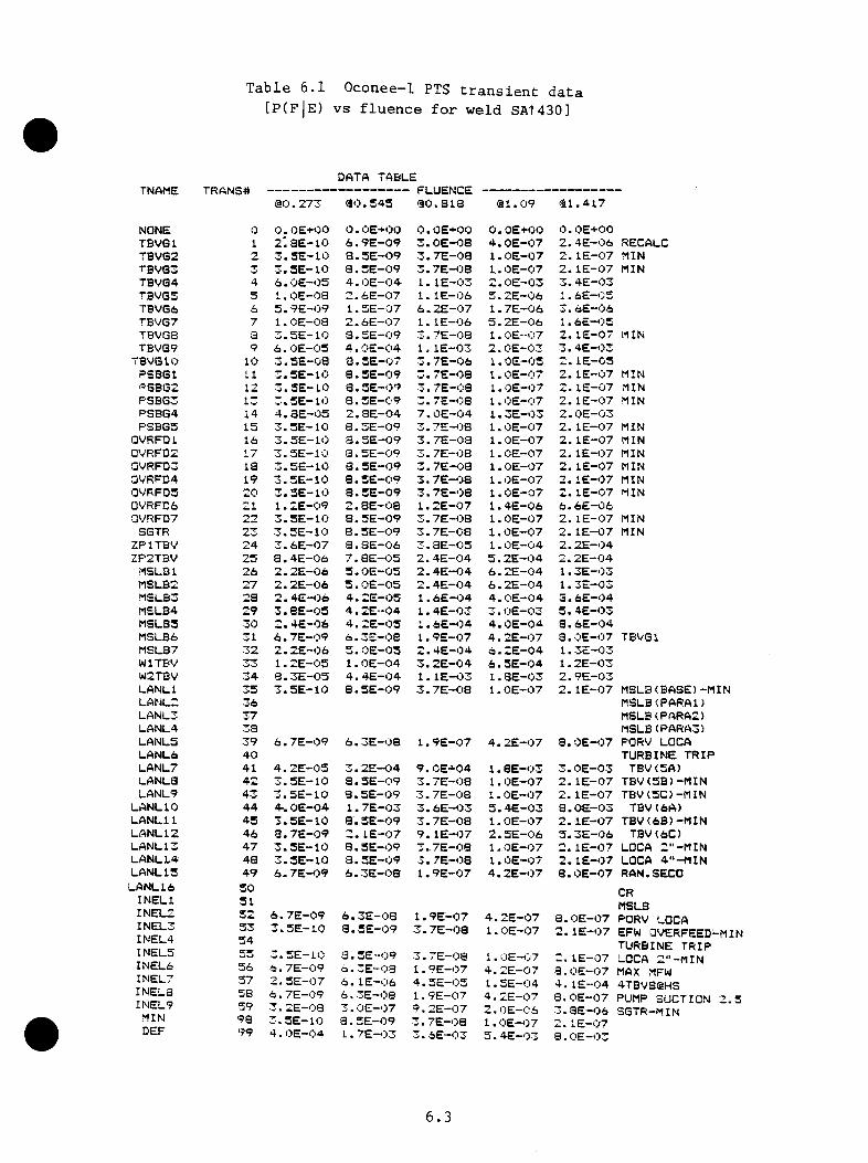
(fl■u
^
oTJ
(V,
C <
5
CO
s-
cd uCOHCL,
rHI
0)so>4-((1)oc0
) (1)
s ^
oooVO0)
1-HcdH
M-l
CO>
J
Iin
I <r
I I I<i
I H
1
<I 1
Q
I
UJ<tU
2 Z
U »-i n
ar
c
2\-42
Z 2
Z 2
2 2
2 2
2
►-»2
22
2
22
22
22
2
W (-4
2 2
(D>CQ
21Q ^
cn Qc <i <r m
a.tn m
j
J
0) U)2
2
Q.
M
zz
z
z
z10
fiC »>( M »~t
MI-4<l <r
<11- T z z
EEo
cflcu
.-
I
0. CL _i z
111 a u
-0 ffi o N
^ tD
«^10 1il''4I— U)
ttica>o>
>'^''>
''><
r<i .
J_
liEC
C(n
>>
CB
>(
D(
JU
Z
03
(no
Di-<
D(D
i-mi-o
o<
iE
EC
LI-
h-H
I-
J_IO
CI
O >0 N
N
I'l m -0
m N
M m
N
N K
lO
N
N N
N
N N
-O N
N ■4-
^
M
11 •»■ t'l ’4- tv I'l M
M N
I |v
O
O O
O
O •■'• O
O
O O
O O
O
O
O
O O
O O
O
O O
O O
O
O
O
O O
O
'“v o o
oI
-> +
I
I I
I I
I I
I I
I. I
I I
I I
I I
I I
I I
I I
I I
I 1
I I
I I
I I
I I
I ^ quiqiijquiqujuiiijqiijiijiiiuitjuiuiuitijujujiijuiujujqijquitijuiiijuiquj
I ■
o «t
M rf vo '0 -o ^
o -•-* -r4
T-» -.-I *-4 ^0 ri N
fo to <1 't' '0 o (0 n
0^I
ist o
r-i r i n t > -4 to ^
n ro ci n
v\ cj rJ N
ci n r*3 f-i ^ r3 r i ri ( 3
m m
uj u-J aJ ro -3 J r3 r3
I II o I
o
I •
I ^I mIIlUU
COztii 0) D
.
J o
u. ®»
I N
O N
S N
n <t >0 >0 N
h ) in N N
K ro N
N h. s
N N
'O N
«4^ ^
^
to N
«t to
•0
*^
0*
'^
O O
^
'*• O
O
O
r, n>
^ r't
Q> ^
r\ r*t
+
1 I
II
.
ii
T:
Ti
I
iT
iT
iT
iT
i
ii
TT
Ti
Ti
Ti
Ti
Ti
T
UJlU
UJU
UtliJU
lUJU
JUJU
JUJlliL
iJUJL
UU
JLu
UJU
JIlJlxllJiU
JUJU
JUJU
lUlU
IUL
iJUJliiU
tUt
O
O O
O
O
f>l N fv|
O o
o
O O
O 10 O
O O
O O
O ^
O O
O
H f >1 M
O
o O
f I f >1 10 03
O
O
‘d’ M
r "I bT lO
^ t-4 »-l M
T-l M »H M
M «H M
M M
t-4 n|J «Q ^
f^
^ -43
^
O 00 ©
CD hO >0 N >0 ro to >0 GO 03 to «t 00 ro CD 0) CO 00 t^ 00 CO 10 ^
<r ^
10 ^
to CDo
o
o o
o o
o o
o o
o o
o o
o o
o o
o o
o o
o o
o o
c o
o o
o o
o o
o o
-1 I I
I I
1 I
I f
I I
I I
I I
I I
I I
I I
I I
I I
I I
I I
I I
I I
I I
TU
JUIU
JUIU
IUIU
JlilUJtiJlJJtlJlilL
UU
JUJU
JUJU
iuiU
JUJU
JUlU
JUIU
IUIU
lUJU
IUJtJJU
JIlJLlJ
O O
N N
M
fA| M N
M
N N
fv o r . N
N N
N
H N
N ro «t ^
^ -O
«0 O
' -t N
O
10 3 r? -<
M >0 M
to
M 13
to to 13 N
13 tO 10
tO tO
m 13 tO
tO
N f'J f 1
m w
J
N tO
10
O
O O
O O
O O
O
O O
O
O C' o
o o
o o
o o
o o
o o
o o
o o
o o
o o
o o
o+
I I
I I
I i
I I
I I
I I
I I
I I
I I
I I
I I
I I
I f
I I
! I
I I
I I
Iu
JU
JiiJ
uitiJ
tiJiu
uju
ttiiuiiiJ
ijJu
iiiJu
iuJ
iiJiiiu
JU
iiJiiJ
UJ
iiJu
iLiJ
UJ
UiiiiU
JiiitiJ
mu
ibj
o O
' 10 n o
'0 b
i nO b) o
lo
vj \n
bi oi bi
bi in m
b3 ii) to
lo n
co cd o
o
c-i u
f-i to o o
't m
O -O
CD to *t f J
r>l 0) CO CD 0)
00 N 03
05 CO 0) CO
OJ f 3 DO 00 (D
h! 10 b
W
^
0 hi M
rt 03
oo
oo
in
oj
(>
a3
0i
no
3o
oo
in
oo
oo
oo
oo
oN
<i
>o
*c
oi
O'
jo
o'
<j
io
tf
3o
Q^
Mr
-«
00
0 0
'-^
0 0
M-
4M
0'
^-
<M
M^
MQ
Mi
,-
4Q
r^
00
Q0
0'
^0
0 0
’-* t
I I
I I
I I
I <
I I
I 1
I I
I i
I I
I I
I I
I I
I I
I T
I
I I
I I
1 I
UlllliJtiJU
IlilUJL
LlU
iUlU
JliJlitUIU
JliJUJU
JUJljJIiJU
JUJljJIiiliiU
JUlL
illJiUlU
JUlL
iJUJU
J1
.Q
CO 10lO
Q,O
'o
bl•3»
10bl
lO hi
CObl
blbl to
bl10
nbl
tt)>0
^ rj N
VO 'ts
CJ Cl
H10
Nf j to
lo o
blN
lOto
N1
o■»
• •
■•
•t
i■
••
••
4•
••
■ •
■•
••
«•
• •
••
•t
•t
•a
aa
■ a
a J
aa
i■
aa
,1
<5» I
1^N
toto
▼ 4bl
M13
sOto
toto 13
•t13
13to
n to
Mto
to00 N
r Ito
n<r
C'"! M03
'0^
to to ^
toCD
^3t o
sO
niM
ri1-3 •t
m'J3
NCO
O'
o1-4
n 1)
blO
N (D
O'o
iHri
tob
l '0 h-
00Q
^4M
M10 *0 t^ CO cr
oM
C il M
bl'0
N©
#1-4
-4 T-lvt-4
^4 1—4 1-4Cil
Cl
NN
f'lf t C
t MNn
toto
11 Mto
to to to to
to<|-
m<LX
2.1Q 0.
UJ M
Z
UJ DC W <I IL I-
2
u
q: I
COO
Ul tlJ :
3 1
J >
z ri ij. o
O
n
E tn
m >
o
j <i >
-I o
: 3 IX
u X
0) c
cu
ioiL
oo
ai-
O E
a. Ill I- J
E
u z30) E
!CL IX E
I- 3
UJ (L 01
N H N h. 1-1 S O N N tv
0
OO
OO
OO
OO
O1
I 1
I I,
I I
I I
I ui
uiiiiiiiuJiiJUJm
uJuiC
' ^
to M
^4■
■•
••
••
«•
•00
t o U N
03 N 10 f t N
00
N t'3t^N
tOf^'O
Nt'-N
0 O O O O O O O O
1 I
I I
I I
I I
I
IU
I U
JUIU
JUIU
JUJU
JUJU
Jn
00 o
o
o 10 o
o r-i
■4"
4 M b"3
f''! M M
^
t^ «
rC
OQ
3lO
OD
NO
O0
N^ r*.
r> r\T
i
I T
I I
I T
I T
UI
UJllJU
lUIU
JUlU
IUJU
JO'
Ot'-N
Ot^-^N
NO
'-3
O' to to
to
■3 O'
to to M
OO <
^•O
'O'^
OO
'NC
^O
'05
0 O
OO
OO
OO
OO
1 T
I
I I
I I
I I
IU
I U
JU
lUJU
lUiU
IUJ
UJ
Ul
r 3 f t 10 UI t bo
m 10 13
^0 t'*!
CD CD
to
f t CD 03 'O
a iooo«toO
'OoO
'i^t 1-4 T"l
--4 13
C*I
I I
I I
I I
I I
I U
I lilU
lUlU
IUJU
IliJliJUf
N N
0 o
1 I
UI U
I O
’-t
00 O'
/-» r%1
I U
J UI
to b)
O' ooill t!iN
lo
t^ N ^
fv .0 N
to0 •''' •'*'1
I I T
T
T
[UJ
UI U
I UI U
I UI U
IO
O CO M o
oj r-i M
(D rt 00 (1
r 100t' tv r% .-VI
I U
J UJ
M O
tv 0)0 o1
I U
J q(h
IV
N N
tv -0 tv M
* V
n,
i i-k
Q
I I
I I
I T
I
UJ
q U
J UI q
U
I UJo f j in r i o
o >t
-< rt -I rf f J J
in
01 S 111 N |V 00 H
0 o o o o
o1
I I
I I
I I
q UI q q q q qI' um
i> ri IV -o-• tl
I I n T
t n (t
10 10
0- ro -0
oo Jv
O' MO
O
O
<-ii
I I T
I
T
Tq q q
q q
q qIII I I
n
10 O
111 N
'0 ro
01 0 -o -0 to ® -I
0
O' N O' m
o ^n o O O O n O1
I I
I I
I I
q
q q
q q
q
q111
tv 111 iv r I 111 o-0 J l
I I 1 N ^ U to to->f'itotn<ii^a)C
ha)0'111 m
111 Id bi 111 b
i bi 111 b
l O' O
'
<ri
VO
til*-• T'i to ^
bl>0N
© O'
a-4C ii t o ^ blt o ^
bl vft N>
>-• C J t o
10>0 N
> >
f 1 t o bl >0
N ©
O' O—4
N 11
in2
UI 0 ©
© ©
©©
© ©
©©
© ©
© ©
pa
OO
Pu
aft
toto
to to toto
toto to to to
J -J J J JJ
1-41-4 1-4
n2
> > > >
>>
> > >
©to
to to to to u.u. Ll Ll U.Ll Llh*- 1“
HJ
-J t-“ I-*z
t: Z
Z z
22
22 -J
-12
o to ©
(XI ©to
toto to to
>©
© ©
© ©
ccCL
XX
X(jc er
©»4
f'l© ©
© UI ©
© ©<c <t <r <r <t<tct «t<r z
zz z
zz
t-2 H
I- t- 1-1”
1-H t- t-
to1-ft.0_ CL CL CL > O
>O> >
> o
o o
> > o
o©
ft.tsl 0.M
2 2 2
22
2 2 3 3J
J J J JJ
_l JJ
J3
33
J<I_l
■T ri n
( I M "»• b
l -O t- m
O'
-v*
4n
.|ii j
ll
lj
iz
qjjq
jujq
q^
aZ
ZZ
ZZ
ZZ
ZZ
ZZ
ZZ
EO
type of e r r o r i s th e r e s t o r a t i o n o f EFW in an n n c o n t ro l le d manner. I t
must be n o te d , however, t h a t c e r t a i n o p e r a to r a c t io n s , in p a r t i c u l a r the
t r i p / n o t r i p o f th e RCPs on a v a l i d ECCS demand, were n e g le c te d .
By examining th e system s t a t e c a t e g o r i e s f o r each t r a n s i e n t l i s t e d in Table
A.2 to g e th e r w i th the t r a n s i e n t i n i t i a t o r , th e most s i g n i f i c a n t o p e ra to r
a c t i o n ( s ) were d e te rm in e d , and th e p r o b a b i l i t y o f each e n d - s t a t e on the
c o l l a p s e d o p e r a to r a c t io n y i e l d s an e s t im a te o f a t r a n s i e n t frequency
t h a t acc o u n ts f o r o p e r a to r i n t e r v e n t i o n . Then, from the s e t o f a v a i l a b l e
t r a n s i e n t s , th e co r resp o n d in g th e rm a l - h y d r a u l ic h i s t o r y was a s s ig n e d to
each of the t r a n s i e n t s . For th o se t r a n s i e n t s f o r which a d e t a i l e d
even t d e s c r i p t i o n was u n a v a i la b l e ( i . e . , th o se t r a n s i e n t s whose in d iv id u a l
a sy m p to t ic f r e q u e n c ie s were l e s s th a n l .O E -0 6 ) , a d e f a u l t t r a n s i e n t was
a s s ig n e d . T h is d e f a u l t t r a n s i e n t r e p re s e n te d th e h ig h e s t c o n d i t io n a l
p r o b a b i l i t y of f a i l u r e o b ta in e d o f a l l the t r a n s i e n t s c a l c u l a t e d . The
d e f a u l t t r a n s i e n t i s LANLIO in T ab le 6 . 1 , th e LANL c a l c u l a t i o n o f 4
TBVs f a i l e d open a f t e r r e a c t o r t r i p from f u l l power ( see C hap ter 4 . 0 ,
S e c t io n 4 . 3 . 2 . 4 f o r a d e s c r i p t i o n o f t h i s s eq u en ce ) . Table A.3 summarizes
th e r e s u l t s o f th e t r a n s i e n t a ss ignm ent p ro ced u re f o r the 498 t r a n s i e n t s
o b ta in e d by in c o rp o r a t in g o p e r a to r a c t io n s i n t o th e 295 t r a n s i e n t s l i s t e d
in Table A.2 . A lso l i s t e d in Table A.3 a re the c o n d i t io n a l p r o b a b i l i t y
o f f a i l u r e , g iv e n the o ccu rren c e o f th e t r a n s i e n t P(f|E^> ( a t a f lu e n c e
e q u iv a le n t to 32 EFPT), and th e c o n t r i b u t i o n to th e o v e r a l l frequency o f
v e s s e l f a i l u r e jXTWC). By suaiming o v e r a l l t r a n s i e n t s in T ab le A.3 , an
e s t im a te d freq u en cy o f v e s s e l f a i l u r e , f o r the i n i t i a t o r s c o n s id e re d , o f
4 .5 E-06/RY i s o b ta in e d .
6 . 4

In o r d e r to summarize th e r e s u l t s , each t r a n s i e n t l i s t e d in Table A.3
was a l s o c l a s s i f i e d by type o f m a lfu n c t io n in v o lv ed . F or example, a FW
( fe e d w a te r ) t r a n s i e n t in c o rp o r a te s some m a lfu n c t io n o f the feed w a te r system,
an SL (s team l i n e ) t r a n s i e n t in v o lv e s a p r e s s u r e c o n t r o l m a lfu n c t io n , e t c .
A lso , a combined t r a n s i e n t type (SS f o r secondary s id e ) vas used to d e s c r ib e
th o se t r a n s i e n t s t h a t in v o lv e bo th feed w ate r and steam l i n e problem s.
Tab le 6 .2 suaimarizes th e f req u en cy o f v e s s e l f a i l u r e (as a fu n c t io n of
f lu e n c e ) fo r each t r a n s i e n t ty p e . As i n d i c a te d , th e dominant t r a n s i e n t
type i s l a b e le d RES ( i . e . , r e s i d u a l ) and accoun ts f o r those t r a n s i e n t s
whose in d iv id u a l f r e q u e n c ie s were l e s s than l.O E-06 b u t whose cum ulative
f r e q u e n c ie s a r e s i g n i f i c a n t . The t o t a l frequency o f v e s s e l f a i l u r e and the
i n d i v id u a l c o n t r i b u t i o n s o f th e v a r io u s i d e n t i f i e d i n i t i a t o r s as a f u n c t io n
o f EFPT f lu e n c e , and RTNDT a re d e p ic te d g r a p h ic a l l y on F ig u re s 6 .1 a , 6 .1 b ,
and 6 .1 c .
F i n a l l y , i t i s i n s t r u c t i v e to examine those t r a n s i e n t s t h a t dominate the
e s t im a te d f requency o f v e s s e l f a i l u r e . Table 6 .3 l i s t s th o se t r a n s i e n t s
whose c o n t r i b u t i o n t o th e o v e r a l l f requency of v e s s e l f a i l u r e a re >1.0E-08.
These 21 t r a n s i e n t s accoun t f o r ap p ro x im ate ly 95% of the o v e r a l l frequency
and, as can be seen by i n s p e c t i o n , a r e dominated by th e r e s i d u a l components
(59% o f th e t o t a l ) , p a r t i c u l a r l y th o se o r i g i n a t i n g from the r e a c to r t r i p
i n i t i a t o r (21% o f th e t o t a l ) .
6 . 5

Table 6 . 2 . Breakdown o f t(TWC) by tr a n s ie n t type
TYPE TFRE©Fluence for Weld SA1340 (10^® neutrons/cm^)
0.273 0 .595 0 .818 1 .09 1.417
FW 2 .6 -0 1 4 .3 -1 0 4 .1 -0 9 1 .4 -0 8 3 .4 -0 8 6 .7 -0 8
SL 9 .8 -0 1 1 .8 -0 8 1 .8 -0 7 6 .7 -07 1 .6 -0 6 3 .1 -0 6
SS 2 .7 -0 2 2 .9 -0 9 2 .1 -0 8 5 .8 -0 8 1 .1 -07 2 .0 -0 7
LOCA 1 .6 -0 1 6 .1 -1 0 4 .3 -0 9 1 .3 -0 8 3 .0 -0 8 5 .8 -0 8
SGTR 9 .9 -0 3 1 .3 -1 0 8 .1 -1 0 2 .2 -0 9 4 .3 -0 9 7 .3 -0 9
RES 5 .0 -0 4 2 .0 -0 7 8 .5 -0 7 1 .8 -0 6 2 .7 -0 6 4 .0 -0 6
TOTAL 2 .2 -0 7 1 .1 -0 6 2 .6 -0 6 4 .5 -0 6 7 .5 -0 6
6 . 6

> -cc
o
O
ORNL-DWG 84-9482
TOTAL
RESIDUAL “
,-6SL
r 7
SS
FW
LOCA8
SGTR
9
rIO
0 2 5 3520 3 0E F F E C T IV E FULL POWER YEARS (E FPY )
F ig u re 6 .1 a T o ta l and com ponent f r e q u e n c ie s o f v e s s e l th ro u g h w a l l c r a c k as a f u n c t io n o f e f f e c t i v e f u i l power y e a r s .
6.7

ORNL-OWG 84-9481
TOTAL
RESIDUAL SL H
r 6
S3
FWLOCA
>IT
O
I -
O
SGTR
1.750 1.250 . 2 5 0 . 5 0 0 .7 5
FLUENCE FOR WELD SA1430 (lo"'^ NEUTRONS/CM^ )
F ig u re 6 .1 b T o ta l and com ponent f r e q u e n c ie s o f v e s s e l th ro u g h w a l l c ra c k a s a f u n c t io n o f f lu e n c e .
6.8
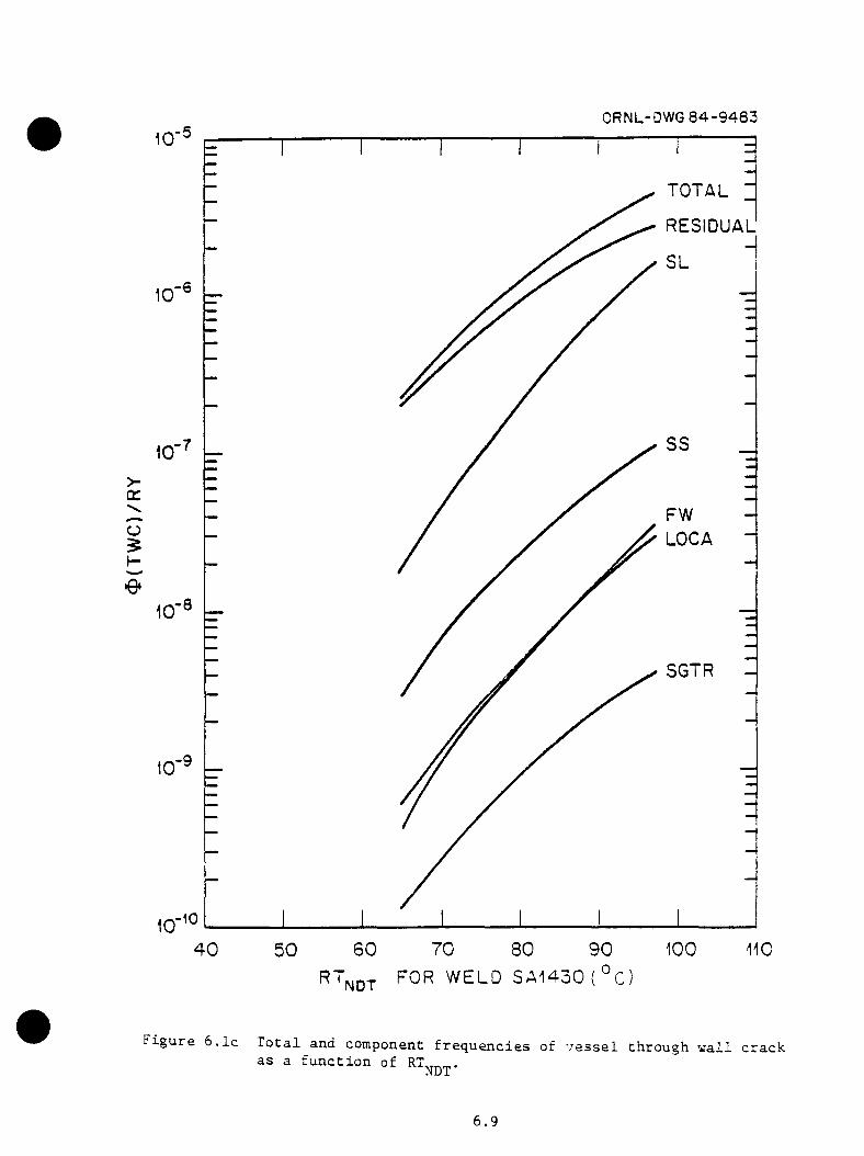
ORNL-OWG 84-9483
TOTAL
RESIDUAL
SL,-6
SS
>q:
FWLOCACJ
$
O
SGTR
riO
7 0 80 1006 0 9 04 0 5 0
RT^ j3T f o r w e l d SA 1 43 0 ( ° C)
F i g u r e 6 . 1 c T o t a l and c o m p o n en t f r e q u e n c i e s o f v e s s e l th r o u g h w a l l c r a c ka s a f u n c t i o n o f R T „ „ .
NDT
6.9
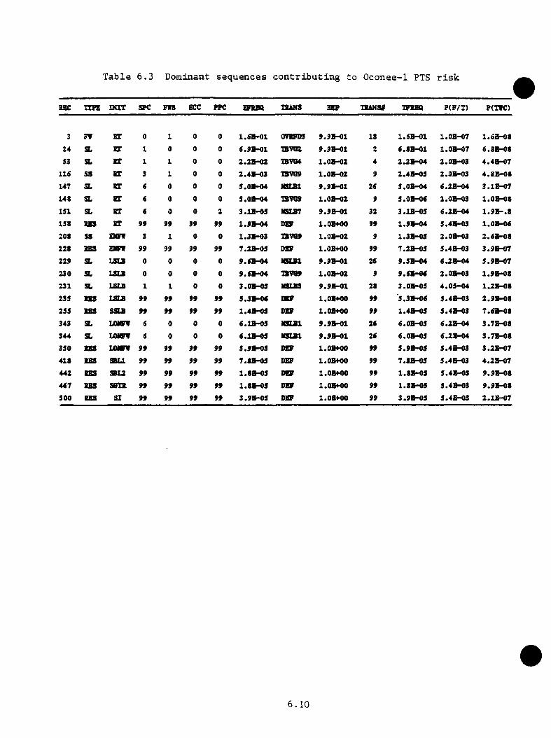
Table 6.3 Dominant sequences contributing to Oconee-1 PTS risk
REC XIPK DOT SPC FWS ECC rpc EFBBQ XB8NS 3BP TBANS# 1FBBQ P(F/T) P(TWC)
3 FW BT 0 1 0 0 1.6B-01 0VBFO3 9.9B-01 18 1.6B-01 l.O B-07 1.6B -08
24 SL BX 1 0 0 0 6.9BH)1 IBVIEB 9.9B-01 2 6.8B -01 l.O B-07 6.8B-08
53 SL BT 1 1 0 0 2.2B -02 TBVG4 l.O B-02 4 2.2BHM 2.0B-03 4.4B -07
116 SS BT 3 1 0 0 2.4B-03 1BWS9 l.O B-02 9 2.4B-03 2.0B-03 4 .3S -08
147 SL BT 6 0 0 0 5.0BH)4 B S U l 9.9B-01 26 5.0B -04 6.2B-04 3.1E -07
14« SL BT 6 0 0 0 S.OB-04 1BVQ9 l.O B -02 9 5.0B-06 2.0B-03 l.O B -08
151 SL BT 6 0 0 2 3.1B-05 HSLB7 9.9B-01 32 3.1B-0S 6 .28-04 1 .9 B -.815S IBS BT 99 99 99 99 1 . 9 » ^ DBF l.OBHM) 99 1.9B -04 5.4B-03 l.OBHM
208 SS EMFW 3 1 0 0 1 .31-03 1BVS9 l.O B -02 9 1.3B-09 2.0B-03 2.6B -08
228 BBS m m 99 99 99 99 7.2B-05 DBF 1.0E4K)0 99 7.2B-05 5.4B-03 3.9B -07
229 SL LSLB 0 0 0 0 9.6B-04 NSLBl 9.9B-01 26 9.5B -04 6.2B-04 5.9B-07
230 SL LSU 0 0 0 0 9 .6» -04 1BWS9 l.O B -02 9 9.6B -06 2.0B-03 1.9B -08
231 SL TiW P 1 1 0 0 3.0B-09 MSIB3 9 .9 B ^ 1 28 3.0B-OS 4 .0S -04 1.2B -08
233 BBS LSLB 99 99 99 99 5.3H-0< DBF l.OBHM 99 '5.3B-06 5.4B-03 2.9B -08
255 BBS SSU 99 99 99 99 1.4B-05 DBF 1.0B400 99 1.4B-05 5.4B-03 7.6B-08
343 SL LOWW 6 0 0 0 6.1B-0S ta u t 9.9B -01 26 6.0B-05 6.2B-04 3.7B -08
344 SL LOWW 6 0 0 0 6.1B-05 H SU l 9.9B-01 26 6.0B-05 6.2B-04 3.7B -08330 P M LOWW 99 99 99 99 5.9B-0S jta l.OBHM 99 5.9B -05 5.4B-03 3.2BHI7
418 BBS S8U 99 99 99 99 7.8B-03 DBF l.OBHM 99 7.8B-OS 5.4B-03 4.2E-07
442 P M S8L2 99 99 99 99 1.8B-0S DBF l.OBHM 99 1.8B-03 5.4B-03 9.9B-08
467 P M SBIB 99 99 99 99 1.8B-03 DBF l.OBHM 99 1.8B-0S 5.4B-03 9.9B-08
500 BBS SI 99 99 99 99 3.9B-03 DBF l.OBHM 99 3.9B -05 5.4B-03 2 .1» -07
6.10
6.3 P o te n t ia l M it ig a t io n Measures
The e f f e c t s o f p o t e n t i a l m i t i g a t i n g a c t i o n s were examined as a p a r t of t h i s
s tu d y . This s e c t i o n i s n o t in te n d e d as a l i s t o f recommendations b u t i s
p ro v id ed to g iv e in fo rm a t io n on th e r e l a t i v e v a lu e o f a c t io n s which could
be taken p ro v id e d a need to reduce th e i n t e g r a t e d r i s k o f a th ro u g h - th e -
w a ll c ra c k due to PTS i s i d e n t i f i e d . I n a d d i t i o n , i t should be n o ted t h a t
the s a f e ty impact o f m i t i g a t in g a c t i o n s on o th e r types o f ev en ts has no t
been perfo rm ed and th e c o s t b e n e f i t o f th e se a c t io n s has n o t been e v a lu a te d
a t t h i s t im e .
6 .3 .1 L im it P rim ary System R e p r e s s u r i z a t io n
The v e s s e l f a i l u r e p r o b a b i l i t y i s v e ry s e n s i t i v e to p rim ary p r e s s u r e during
th e p o r t i o n o f an o v e rc o o l in g t r a n s i e n t in which th e v e s s e l becomes v u ln e r
ab le to b r i t t l e f r a c t u r e . The a c t i o n o f th e h ig h head HPI system i s to
r a p i d l y r e p r e s s u r i z e th e p r im ary system . I f l e f t u n t h r o t t l e d , th e system
may r e p r e s s u r i z e to th e PORV s e t p o in t p r e s s u r e in l e s s th an 20 min.
However, p l a n t p ro c e d u re s c a l l f o r t h r o t t l i n g o f HPI so t h a t the p l a n t P-T
s p e c i f i c a t i o n i s n o t v i o l a t e d .
A p o t e n t i a l m i t i g a t in g measure fo r red u c in g PTS r i s k would be to a s s u re
t h a t the p r im ary r e p r e s s u r i z a t i o n be l i m i t e d to 1000 p s i a . The e f f e c t of
such a l i m i t on r e p r e s s u r i z a t i o n was e v a lu a te d and i t was found t h a t the
f requency of v e s s e l th r o u g h - th e - w a l l c ra c k in g was reduced to 3 .2 x 10“ ^/RY
from the c u r r e n t e s t im a te of 4 .5 x 10 ^/RY f o r 32 EFPY.
6.11
6 .3 .2 E f f e c t o f High SG Level T r ip System
As in d ic a te d in th e system d e s c r i p t i o n , th e SGs a t th e Oconee-1 p l a n t a re
equ ipped w ith in s t r u m e n ta t io n des ig n ed to t r i p th e MFW pumps, shou ld th e SG
l e v e l r e a c h 90%. A lthough th e frequency of v e s s e l f a i l u r e of 4 .5 x 10 ^/RY
in c lu d e s the in f lu e n c e o f t h i s system , i t i s d e s i r a b l e to a s s e s s th e p o ten
t i a l m i t i g a t i v e v a lu e o f t h i s system f o r p l a n t s which do n o t in c o rp o ra te a
h ig h SG l e v e l p r o t e c t i o n system .
R a th e r than r e a n a ly z e a l l th e sequences f o r the case o f no-SG p r o t e c t i o n
system , th e e f f e c t of t h i s system was ro u g h ly e s t im a te d . The p r i n c i p a l
e f f e c t of the p ro p e r o p e r a t io n o f the system i s to te rm in a te an MFW
o v e rfe e d t r a n s i e n t . I n th e te rm ino logy of the even t t r e e c h a p te r , t h i s
s w itc h e s a p o t e n t i a l s u s t a in e d MFW ov erfeed t r a n s i e n t (FW c a te g o ry 2) to
an u n s u s ta in e d MFW o v e rfe e d t r a n s i e n t . Thus, one e f f e c t o f the e l im in a t io n
o f the SG p r o t e c t i o n system i s t h a t a l l FW c a te g o ry 1 t r a n s i e n t s become FW
c a te g o ry 2 t r a n s i e n t s . A d d i t i o n a l l y , th e e l im i n a t io n o f th e system reduces
th e f req u en cy o f EFW o v e r fe e d s because the p r i n c i p a l means by which the EFW
system i s i n i t i a t e d ( i . e . , t r i p o f th e MFW pumps) i s no lo n g e r p o s s i b l e .
In e s t i i a a t in g th e v a lu e o f th e SG p r o t e c t i o n system , o n ly the change in
th e f r e q u e n c ie s o f FW c a t e g o r i e s 1 and 2 a re c o n s id e re d . The s l i g h t
o f f s e t t i n g change due to th e r e d u c t io n o f EFW o v e r fe e d s i s n e g le c te d ,
changing a l l p re v io u s FW c a te g o ry 1 t r a n s i e n t s t o FW c a te g o ry 2 t r a n s i e n t s .
T oge ther w ith th e a p p r o p r i a t e , b u t more sev e re t r a n s i e n t d e s c r i p t i o n s ,
t h i s r e s u l t s i n an o v e r a l l f req u en cy o f v e s s e l f a i l u r e o f 6 .1 x 10 ^/RY.
T h is r e p r e s e n t s a 35% in c re a s e in th e o v e r a l l f a i l u r e frequency and i s
i n d i c a t i v e o f th e inq>ortance o f t h i s p a r t i c u l a r sy stem . I t shou ld be n o te d ,
however, t h a t t h i s i s o n ly a rough e s t im a te of th e v a lu e o f th e system .
6.12
A d e t a i l e d r e a n a l y s i s o f th e s e t o f t r a n s i e n t s would be r e q u i re d f o r a
■ore p r e c i s e v a lu e . A d d i t i o n a l l y , i t should be no ted t h a t the p h y s ic a l
l i m i t a t i o n s o f the system v e re e s s e n t i a l l y ignored in a r r i v i n g a t t h i s
e s t i m a t e . I n p a r t i c u l a r , th e p o t e n t i a l fo r s e l f - m i t i g a t i o n of an MFW
o v e rfe e d ( i . e . , th e MFW pump t u r b i n e s t r i p p i n g because o f low steam q u a l i t y
caused by th e o v erfeed ) has been ig n o re d .
6 .3 .3 N eutron F luence Rate R educ tion
The b e n e f i t from red u c in g th e n e u t ro n f lu e n c e r a t e in th e v e s s e l w a l l by
f a c t o r s o f 2 , 4 , and 8 were e v a lu a te d . S ince f lu e n c e w ie ld s a cum ula tive
im pact on v e s s e l RTNDT, th e r e d u c t io n in f lu e n c e r a t e w i l l r e t a r d the
e f f e c t i v e r a t e o f a g in g . F lu e n c e - r a te r e d u c t io n f a c t o r s o f 2 , 4 , and 8
would r e s u l t in PTS r i s k r e d u c t io n s by f a c t o r s o f ap p ro x im ate ly 2 , 6 , and
14 r e s p e c t i v e l y a t 32 EFPY.
6 . 3 .4 E f f e c t o f HPI H ea ting
The h ig h - p r e s s u r e i n j e c t i o n system i s o f concern in PTS e v a lu a t io n because
i t in t ro d u c e s c o ld (50^F) l i q u i d i n t o th e co ld le g s of the RCS prim ary
c lo s e to th e v e s s e l downcomer. V arious lo c a l i z e d phenomena such as plume
fo rm a t io n , m e ta l -w a te r h e a t t r a n s f e r , f l u i d mixing in the co ld l e g , and
f l u i d m ixing in th e downcomer r e g io n w i l l de te rm ine w hether th e v e s s e l w a ll
w i l l be s u b je c te d to te m p e ra tu re s s i g n i f i c a n t l y lower th an th e c o o la n t bu lk
average te m p e ra tu re . As d i s c u s s e d in C hap te r 4 . 0 , S e c t io n 4 . 4 , th e rm a l-
h y d r a u l i c a n a ly se s by Theophanous have de te rm ined t h a t plume fo rm a tio n i s
n o t im p o rtan t f o r th e LANL- and IN E L -ca lcu la ted c a se s where b o th h igh p r i
mary p r e s s u re and loop flow s ta g n a t io n o c c u r . T h e re fo re , b u lk mixing may
6 . 13
be r e a s o n a b ly assumed f o r s i t u a t i o n s s i m i l a r to th o se e v a lu a te d by Theo
phanous .
When in j e c t e d in l a rg e q u a n t i t y , HPI f lo v can cause s i g n i f i c a n t c o o l in g .
Houever, th e concep t of h e a t in g the HPI to 90°F o r 100®F w i l l no t g r e a t l y
in f lu e n c e th e te m p e ra tu re response o f the Oconee-1 p l a n t to o v e rco o l in g
e v e n t s . The amount of system c o o l in g due to HPI i s a s t ro n g f u n c t io n of
system te m p e ra tu re . T h is i s i l l u s t r a t e d by F ig u re 6 . 2 . Simply s t a t e d ,
th e g r e a t e r th e te m p e ra tu re d i f f e r e n c e between th e HPI f l u i d and i t s f i n a l
maximum te m p e ra tu re ( say a t th e co re e x i t ) , th e g r e a t e r the h e a t abso rbed .
As th e maximum system te m p e ra tu re d e c l in e s tow ard th e HPI te m p e ra tu re , the
c o o l in g r a t e w i l l approach z e ro . T h is b e h a v io r i s ex p ressed in F ig u re 6 . 2 .
H eating HPI to 90°F cau ses an o f f s e t of 2 .9 MW ( a t HPI flow co rresp o n d in g
t o o p e ra t io n a t PORV s e t p o in t p r e s s u r e ) . Assuming a b a la n c e between h e a t
in p u t and c o o l in g , a f i n a l te m p era tu re in c re a s e o f c lo se to SO^F cou ld
be r e a l i z e d . I f a n o th e r te m p era tu re -d e p e n d e n t cooldown mechanism, such
as steam g e n e r a to r o v e r fe e d s o r blowdown, i s o c c u r r in g , th e te m p era tu re
b e n e f i t of HPI h e a t in g w i l l be reduced . F or example, a t r a n s i e n t w ith
one TBV s tu c k open w ith f a i l u r e s to i s o l a t e feed w a te r and to t h r o t t l e
HPI w i l l y i e l d l e s s than a lO^F b e n e f i t from r a i s i n g HPI te m p e ra tu re to
90*^F. L a rg e r s e c o n d a ry -s id e cooldown mechanisms would f u r t h e r reduce the
b e n e f i t : i n c r e a s e s in HPI flow r e l a t i v e to th e o th e r cooldown mechanisms
would in c re a s e th e b e n e f i t .
The o th e r a s p e c t of HPI h e a t in g i s the e f f e c t on l o c a l i z e d c o o l in g
phenomena. Loop flow and v e n t v a lv e flow combine w ith HPI flow to y i e l d
a w eigh ted ave rage te m p e ra tu re f o r the m ix tu re . The r e l a t i o n s h i p between
6 . 14
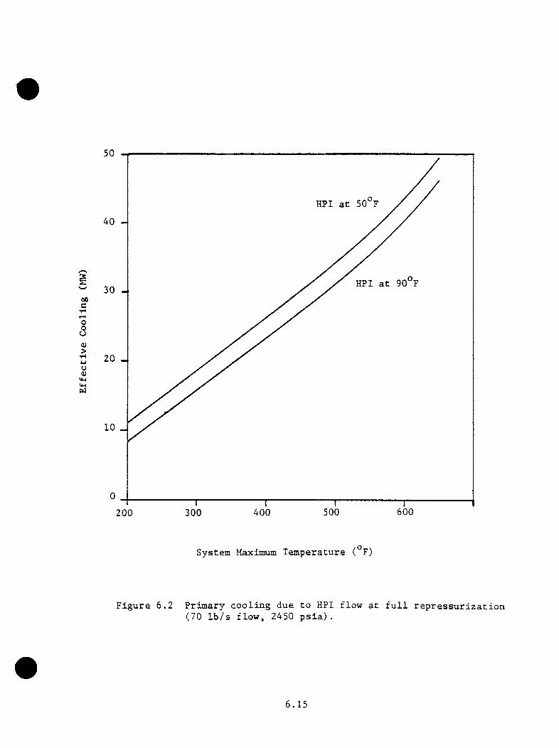
50
HPI a t 50 F
40
HPI a t 90 F30
soc•HrHoouOJ>•H4-1 20u0)
10
600500400300200
System Maximum T e m p e ra tu re ( F)
F ig u re 6 .2 P r im a ry c o o l in g due to HPI flo w a t f u l l r e p r e s s u r i z a t i o n (70 I b / s f lo w , 2450 p s i a ) .
6 . 15

m ix tu re te m p e ra tu re and flow r a t i o o f loop and v e n tv a lv e flow to HPI flow
i s d e p ic te d in F ig u re 6 . 3 . The f i g u r e c o n ta in s s e t s o f c u rv es f o r mixing of
550°F loop flow w ith e i t h e r 50®F o r 90°F HPI and 300®F loop flow w ith 50°F
o r 90°F HPI f low . The loop te m p e ra tu re dom inates th e average te m p era tu re
f o r flow r a t i o s g r e a t e r than 10 ( l o o p ) : l (H PI) . HPI te m p e ra tu re dom inates
f o r r a t i o s l e s s th a n 0 . 1 . At a f low r a t i o o f 1 . 0 , th e b e n e f i t o f HPI
h e a t in g i s o n e - h a l f the HPI te m p e ra tu re d i f f e r e n c e , o r 20^F. The b e n e f i t
d e c re a s e s f o r h ig h e r flow r a t i o s and in c r e a s e s to th e f u l l 40^F v a lu e only
f o r v e ry low flow r a t i o s . A lso in d i c a te d on F ig u re 6 .3 a re th e c a l c u l a t e d
flow r a t i o s f o r s e v e r a l o f the TRAC c a l c u l a t i o n s perform ed by LANL marked
loops A and B r e s p e c t i v e l y . The s o l i d m arkers i n d i c a t e r a t i o s based on
loop flow s a lo n e . The dashed m arkers in c lu d e b o th s ta g n a te d loop and
v e n t v a lv e flow in th e c a l c u l a t i o n s o f flow r a t i o . For some c a se s the
o bserved range i s a l s o n o te d . These cases su g g es t t h a t the flow ing loop
in a t r a n s i e n t w i l l have a f low r a t i o on th e o rd e r o f 10 w h ile a s ta g n a te d
loop w i l l have a r a t i o o f about 1 . 0 . Such c o n d i t io n s m inim ize th e b e n e f i t s
t o be ga ined from h e a t in g th e HPI. Measures to r e s t o r e loop flow would
be o f g r e a t e r b e n e f i t in p r e v e n t in g l o c a l i z e d cooldown s i t u a t i o n s .
O v e r a l l , HPI h e a t in g cou ld p ro v id e s<ne sm all b u t v a r i a b l e b e n e f i t in
te rm s o f downcomer te m p e ra tu re re s p o n s e . The s e n s i t i v i t y o f th e f r a c t u r e
m echanics c a l c u l a t i o n to low downcomer te m p era tu re may t r a n s l a t e th e very
sm a ll te m p e ra tu re b e n e f i t i n t o a m easu rab le r e d u c t io n o f r i s k . However,
o th e r methods w i th g r e a t e r p o t e n t i a l f o r te m p era tu re improvement (such as
loop f low au g m en ta t io n , e t c . ) shou ld be i n v e s t i g a t e d f i r s t .
6 . 16

- LANL 2 " LOCA
B - LANL 6A (4TBV Open)F lo w in g Loop
- LANL 5A (2TBV Open)S ta g n a n t Loop
Loop A, Loop B
O b se rv e d R ange
- LANL PORV LOCA600
— LANL MSLB (B a s e Casc^550.
500 -- SG
3 350--
300—
300 FSG
200 - .
90 Fiiriion_.
so-so FHPI
10(1100 .0 0 1 0 . 0 1
Flow R a t io (in,
Figure 6.3 Downcomer temperature vs loop/HPI flow ratio and comparison with THAC results
6 . 3 .5 I n - S e r v ic e I n s p e c t io n
Improved i n - s e r v i c e in s p e c t io n te c h n iq u e s hav ing th e c a p a b i l i t y of
d e t e c t i n g e i t h e r 90% o r 99% o f th e s u r f a c e f law s w i th d ep th s eq u a l to or
g r e a t e r th a n 6 mm were e v a lu a te d . I t was f u r t h e r assumed t h a t a l l
f la w s found would be r e p a i r e d . I f . b e fo re the i n - s e r v i c e i n s p e c t io n , no
c a l c u l a t e d f a i l u r e s were a t t r i b u t e d t o i n i t i a l f law s w ith d ep ths l e s s than
6 mm. th e n th e 90% and 99% i n s p e c t io n would reduce P(F/E) by f a c t o r s of
0 .1 and 0 .01 r e s p e c t i v e l y . However, in most ca se s th e v e ry sha llow flaw s
w hich would n o t be d e te c te d o r r e p a i r e d make a s i g n i f i c a n t c o n t r i b u t i o n
to f a i l u r e . The c a l c u l a t e d e f f e c t of i n - s e r v i c e i n s p e c t io n under th e se
c o n d i t io n s i s in d i c a te d in Tab le 5 .7 f o r an e f f e c t i v e v e s s e l age of 32
EFPY. For many s ev e re t r a n s i e n t s , th e d e t e c t i o n and r e p a i r o f 90% o r 99%
o f a l l l a rg e f law s would reduce the p r o b a b i l i t y o f v e s s e l f a i l u r e by one-
h a l f . The r e d u c t io n f a c t o r was l i m i t e d by th e f a c t t h a t th e v e ry sha llow
flaw s which would n o t be d e t e c te d o r r e p a i r e d a c t u a l l y make a s i g n i f i c a n t
c o n t r i b u t i o n to th e t o t a l p r o b a b i l i t y o f v e s s e l f a i l u r e .
6 . 3 .6 V esse l A nnealing
A nnealing o f the v e s s e l i s presumed to r e s t o r e th e f r a c t u r e thoughness o f
th e v e s s e l m a te r i a l to i t s p r e - i r r a d i a t e d v a lu e e f f e c t i v e l y c a n c e l l in g th e
e f f e c t s o f n e u t ro n f lu e n c e . The e x t e n t o f reco v e ry w i l l depend on the
c h e m is t ry o f th e v e s s e l m a t e r i a l , th e t im e - te m p e ra tu re c h a r a c t e r i s t i c s o f
th e a n n e a l in g p ro c e d u re , and th e number o f t im es the v e s s e l i s an n ea led .
Assuming f u l l r e c o v e ry , r i s k r e d u c t io n by 1 t o 2 o rd e r s o f magnitude r e l a
t i v e to th e r i s k a t 32 EFPY may be a c h ie v e d . However. in some in s ta n c e s
a n n e a l in g may be r e q u i r e d on some p e r io d i c b a s i s i f t h i s measure i s to
6 . 1 8

p re v e n t reg row th of th e r i s k . The f e a s i b i l i t y of in - p la c e v e s s e l an n ea lin g
has n o t been a d d re s s e d in s u f f i c i e n t d e t a i l to a s s u re th e e f f e c t i v e n e s s and
p r a c t i c a l i t y o f t h i s m easu re .
6 .3 .7 O pera to r T ra in in g
O pera to r t r a i n i n g v as n o t a d d re s se d s i> e c i f i c a l ly in t h i s s tn d y . However,
the b e n e f i t s o f v ery e a r l y a c t io n to i s o l a t e a broken steam g e n e ra to r
o r t h r o t t l e HPI to l i m i t r e p r e s s u r i z a t i o n o f the p rim ary were reco g n ized .
W r i t te n p ro ced u re s d i r e c t th e o p e ra to r s to make such b e n e f i c i a l a c t io n
where a p p l ic a b le and c o u ld s i g n i f i c a n t l y m i t ig a te many t r a n s i e n t s . The
time r e q u i r e d f o r the o p e r a to r s to an a ly ze the s i t u a t i o n and app ly the
s p e c i f i e d c o r r e c t i v e a c t io n s w i l l t h e r e f o r e de te rm ine to a g r e a t e x te n t
th e s e v e r i t y o f a t r a n s i e n t .
In th e u n c e r t a i n t y a n a l y s i s (C hap te r 7) , th e s e n s i t i v i t y of the r i s k to
o p e r a to r a c t i o n in th e p e r io d o f 10 to 20 min i n t o a t r a n s i e n t was observed
to be s m a l l . For s e v e re t r a n s i e n t s , a c t i o n s ta k e n in t h i s p e r io d were too
l a t e t o m i t i g a t e the a c c id e n t s . For m ild t r a n s i e n t s , th e o p e ra to r a c t io n s
made l i t t l e d i f f e r e n c e in what were a l r e a d y low PTS r i s k t r a n s i e n t s .
Thus, o p e ra to r t r a i n i n g may be o f s i g n i f i c a n t b e n e f i t i f the response time
to a sev e re o v e rc o o l in g t r a n s i e n t can be reduced to under 10 m in u te s .
O p e ra to r t r a i n i n g may a l s o be b e n e f i c i a l in red u c in g e r r o r r a t e s below
th o se assumed in t h i s a n a l y s i s and th u s r e s u l t i n low er f r e q u e n c ie s f o r
some o f the more s ev e re t r a n s i e n t s .
6.19
7 .0 SENSITIVITY AND UNCERTAINTY ANALYSES
T. J . B u rns« Oak Ridge N a t io n a l L abo ra to ry
7 .1 I n t r o d n c t io n
In a d d i t i o n to tbe e s t im a te o f th e ex pec ted frequency o f v e s s e l f a i l u r e ,
a complementary (and p e rh ap s even more s i g n i f i c a n t ) a n a l y s i s o f the degree
of u n c e r t a i n t y a s s o c i a t e d w ith th e e s t im a te i s r e q u i r e d . In f a c t , g iven some
o f th e p a ra m e te r e s t i m a t io n p ro c e d u re s used in t h i s s tu d y , th e expec ted
f req u en cy o f v e s s e l f a i l u r e d e r iv e d p r e v io u s ly can on ly be reg a rd ed as
a c rude e s t i m a t e . The purpose o f t h i s c h a p te r i s to a s s e s s the degree
o f co n f id e n ce t h a t can be a s s o c ia t e d w ith th e e s t im a te . T h is i s done by
c o n s id e r in g most of th e p a ra m e te rs used in t h i s s tudy as random v a r i a b l e s
and by e s t im a t in g th e in f lu e n c e o f p a ram e te r v a r i a t i o n on th e f i n a l r e s u l t ,
the p r o b a b i l i t y o f a th ro u g h -w a l l v e s s e l f a i l u r e p e r r e a c t o r - y e a r .
7 .2 U n c e r ta in tv A n a lv s is
In o rd e r to a s s e s s the u n c e r t a i n t y in r i s k o f v e s s e l f a i l u r e , the
f requency o f f a i l u r e i s expanded about i t s e s t im a te d v a lue u s ing a T ay lo r
s e r i e s . V esse l f a i l u r e i s a f u n c t i o n o f ev en t f req u en cy , th e rm a l-h y d ra u l ic
c o n d i t io n s , and m e t a l l u r g i c a l s t a t e of th e w a l l . The frequency of f a i l u r e
i s expanded in term s o f i t s independen t v a r i a b l e s as
7.1

8*(TffC) ^ 8<»(TWC)♦ ( n r c ) - ♦(TVC) ----------------- (M-M) + > ------------------- [ T ( E . ) - T ( E . ) ]
8M 7 6T(E.)
+ } 6*(TWC) - (7 .1 )[ ♦ ( E J - ♦ ( E , ) ]
8<>(Ep+ h ig h e r o r d e r term s
where {>(TVC) = f requency o f v e s s e l f a i l u r e ( th ro u g h -w a l l c rac k )
H » m e t a l l u r g i c a l p a ra m e te rs r e p r e s e n t in g the s t a t e of the
p r e s s u r e v e s s e l a t th e time even t E , occu rs
T(E^) » th e rm a l - h y d r a u l ic c o n d i t io n s ( p r e s s u r e , te m p e ra tu re , h e a t
t r a n s f e r c o e f f i c i e n t ) used t o d e s c r ib e ev en t E^
t (E ^ ) = f requency o f o ccu rre n c e of even t E ^
The e x p re s s io n in Eq. 7 .1 i s used i n f in d in g th e v a r ia n c e o f th e e s t im a te dA
f re q u e n c y o f f a i l u r e , o [^(TWC)]. The v a r ia n c e i s th e ex p ec ted v a lu e o f
[♦(TffC) - 4(TWC)] . S quaring th e r ig h t - h a n d s id e of Eq. 7 .1 and expanding ,
<t [*(TVC)] = s V + J J cov[M ,T (E j)] + J V * ( E . ) co v [M ,|) (E p ]i ^ i ^
+ ^ ^m^T(E.) ®®''^tM,T(Ej^) ] + 5 5 ®T(e ) ®T(E.) » T(Ej )1i i j ^ ^
■*■1 I ®T(E.) ®<>(E.) ® ov[T (E j) , ♦< E j) li j ^
'*’ 5 ®m®^(E.) covIM ,I(E j ) ] +5 5 St (E .) ®^(E.) ® °^ tT (E j) , ♦(E^^)]i i j J ‘
H(E. ) i j •*+ h ig h e r o r d e r term s (7 .2 )
7 .2

Where d en o tes the p a r t i a l d e r i v a t i v e w ith r e s p e c t to the v a r i a b l e x,
th e v a r ia n c e s a re d e f in e d by
2 r /Ni (7 .3 )= Ix -x l p (x )d x
and the c o v a r ia n c e s by
c o v [x ,y l = [ y - ^ Ix- 'x1p(x ,y)dxdy (7 .4 )
I f i t i s assumed t h a t
(1) N and T(E^) a re independen t v a r i a b l e s ,
(2) M and 4>(Ej,) a r e independen t v a r i a b l e s ,
(3) T(E^) and independen t f o r i j ,
(4) T(E^) and independen t v a r i a b l e s ,
(5) {>(E^) and independen t f o r i ^ j ,
and i t i s f u r t h e r assumed t h a t h ig h e r o rd e r term s can be ig n o red , th e
v a r ia n c e o f the r e s u l t i s g iv e n by
."(Kno) - sV ♦ } . } s% „ 5 ,
1 1 , 1 1 1 i
Each o f the components M, T (E ^ ) , and 4>(E^) o f Eq. 7 .5 a c t u a l l y r e p r e s e n t
a s e t of p a ra m e te rs , and each i s c o n s id e re d s e p a r a t e ly when perfo rm ing the
c a l c u l a t i o n s . F i r s t , a d i s c u s s i o n of the assum ptions n e c e s s a ry to g e t to
th e form o f Eq. 7 .5 i s r e q u i r e d .
7 .3 D is c u s s ion o f AssumBt i q a s
Most of the assum ptions r e q u i r e d to g e t to the form o f Eq. 7 .5 a re
re a so n a b ly a c c u r a te . For i n s t a n c e , i t i s l i k e l y t h a t the m e ta l l u r g i c a l
c o n d i t io n o f the v e s s e l w a l l a t the b e g in n in g of a t r a n s i e n t w i l l be
7.3
independen t o f th e t r a n s i e n t . O ther assnm ptions a re n o t as a c c n ra te«
however. F o r i n s t a n c e , an im p lied assnm ption in th e development has been
t h a t the e r r o r s a s s o c i a t e d w i th each v a r i a b l e a re u n b ia se d . T h is i s
o b v io n s l j n o t th e c a s e .
One source of b i a s i s the e r r o r a s s o c i a t e d w i th th e rm a l -h y d ra u l ic m ode ling .
When u n c e r t a i n t i e s a re p r e s e n t , the tendency i s t o e r r on th e s id e of
c o n s e rv a t is m . Hie many c o n s e rv a t iv e a ssu m p tio n s p r e s e n t in th e computer
models tend to b i a s th e p r e s s u r e s , t e m p e ra tu re s , and h e a t t r a n s f e r
c o e f f i c i e n t s r e s u l t i n g from t r a n s i e n t c a l c u l a t i o n s .
The same type o f b i a s i s p r e s e n t in th e m e t a l l u r g i c a l c a l c u l a t i o n s . Where
r e a l i s t i c numbers can n o t be p r e c i s e l y o b ta in e d , c o n s e rv a t iv e assum ptions
a r e made.
A t h i r d , and p o s s i b ly th e most s i g n i f i c a n t , sou rce o f b i a s in th e e r r o r s
comes from th e lumping o f a l a rg e c l a s s o f t r a n s i e n t s . F or a g iven
i n i t i a t o r , many d i f f e r e n t e v e n ts a re p o s s i b l e , depending on th e o p e r a to r
a c t i o n . Of th e s e many e v e n t s , o n ly two ( o r sometimes th r e e ) a re a n a ly z e d ,
and th e p r o b a b i l i t y a s s o c i a t e d w ith a l l the e v e n ts i s d i s t r i b u t e d to th o s e .
The e v e n ts examined a r e the most " s i g n i f i c a n t " in term s o f p r e s s u r i z e d
the rm al shock. This te n d s t o b i a s th e r e s u l t s toward th e se s i g n i f i c a n t
e v e n t s .
A nother r e q u i r e d assum ption i s t h a t the c o v a r ia n c e between a l l v a r i
a b le s ( th e r m a l - h y d r a u l i c c o n d i t i o n s , m e t a l l u r g i c a l p a ra m e te r s , and even t
f r e q u e n c ie s ) be z e r o . As m en tioned , t h i s i s p ro b a b ly a c c u r a te f o r most
v a r i a b l e s . F o r some, however, th e c o v a r ia n c e may be s i g n i f i c a n t .
7 .4
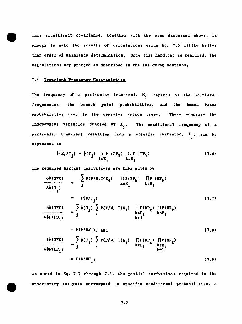
Tliis s i g n i f i c a n t c o v a r i a n c e , to g e th e r w ith the b ia s d is c u s s e d above, i s
enough to make the r e s u l t s o f c a l c u l a t i o n s us ing Eq. 7 .5 l i t t l e b e t t e r
th a n o rd e r^ o f-m ag n itu d e d e t e r m in a t io n . Once t h i s hand icap i s r e a l i z e d , the
c a l c u l a t i o n s may p roceed as d e s c r ib e d in the fo llo w in g s e c t i o n s .
7 .4 T r a n s ie n t Freouencv U n c e r t a i n t i e s
The f req u en cy o f a p a r t i c u l a r t r a n s i e n t , depends on the i n i t i a t o r
f r e q u e n c i e s , the b ra n c h p o in t p r o b a b i l i t i e s , and the human e r r o r
p r o b a b i l i t i e s used in th e o p e r a t o r a c t i o n t r e e s . These com prise the
independen t v a r i a b l e s deno ted by . The c o n d i t io n a l frequency of a
p a r t i c u l a r t r a n s i e n t r e s u l t i n g from a s p e c i f i c i n i t i a t o r , , can be
e x p re s se d as
♦ ( E . / I . ) = ♦ ( ! . ) I I P (BPp ) H P ( H P . ) (7 .6 )" J J ksE . ® keE. ^
The r e q u i r e d p a r t i a l d e r i v a t i v e s a r e th en g iv e n by
6*(TffC) P(F/M,T(E^> nP (B P ^) I lP (H F j ,)keEj kaEj
= P ( F / I ) (7 .7 )
8*(TffC) 5 5 P(F/M, T (E .) r iP (B P-) riP(HF. = , , ksE. ksE.8*P(PBj) J ^
)
= P (F /B P j) , and (7 .8 )
8*(TffC) 5 ♦ d j ) 5 P(F/M. T (E .) r iP (B P .) riP(HF,-------------------- 38*P(HFj) kjtl
)
= P(F/HFj) (7 .9 )
As n o ted in Eq. 7 .7 th ro u g h 7 . 9 , th e p a r t i a l d e r i v a t i v e s r e q u i r e d in the
u n c e r t a i n t y a n a l y s i s co rresp o n d to s p e c i f i c c o n d i t io n a l p r o b a b i l i t i e s , a
7 .5
f a c t t h a t f a c i l i t a t e s b o th t h e i r c a l c u l a t i o n and t h e i r i n t e r p r e t a t i o n . For
exam ple, Eq. 7 .7 i n d i c a t e s t h a t th e r e q u i r e d c o n s ta n t f o r each i n i t i a t o r
examined i s j u s t the c o n d i t io n a l p r o b a b i l i t y o f v e s s e l f a i l u r e , g iv e n the
o ccu r re n c e o f th e i n i t i a t o r . S i m i l a r l y , the p a r t i a l d e r i v a t i v e r e q u i r e d
f o r the b ra n c h p o in t c o n t r i b u t i o n to the v a r ia n c e i s j u s t th e c o n d i t io n a l
p r o b a b i l i t y of f a i l u r e g iv e n t h a t b ran ch p o in t BP^ i s p r e s e n t in the
d e s c r i p t i o n of the t r a n s i e n t f o r each i n i t i a t o r summed over a l l
i n i t i a t o r s and E . .1
Table 7 .1 c o n ta in s the i n i t i a t o r f r e q u e n c ie s and m u l t i p l i c a t i v e u n c e r t a i n t y
f a c t o r s used in t h i s s tu d y . These in c lu d e the v a r ia n c e in th e e s t im a te
o f each i n i t i a t o r f requency and a p a r t i a l d e r i v a t i v e r e l a t i n g t h i s v a r ia n c e
to the v a r i a n c e in ^(TWC).
7 .5 Branch P o in t U n c e r t a in t i e s
Due to th e t r a n s i e n t c a t e g o r i z a t i o n p ro c e s s employed in e s t im a t in g the
th e rm a l - h y d r a u l ic and f r a c t u r e mechanic p a ra m e te r s , the a n a l y s i s o f the
e f f e c t o f b ra n c h p o in t p r o b a b i l i t y u n c e r t a i n t i e s on the f req u en cy o f v e s s e l
f a i l u r e r e q u i r e s a ts ro -s tep p ro c e d u re . The b ra n c h p o in t c o e f f i c i e n t s
a r e e s t im a te d by f i r s t d e te rm in in g the c o n d i t io n a l p r o b a b i l i t y of v e s s e l
f a i l u r e g iv e n o c c u rre n c e o f a c e r t a i n c a te g o ry t r a n s i e n t . Then the
c o n d i t i o n a l p r o b a b i l i t y o f t h a t c a te g o ry t r a n s i e n t g iven a s p e c i f i c b ran ch
p r o b a b i l i t y i s c a l c u l a t e d , i . e . ,
P[*(E^) BPj] = J p [* (E ^ ) /C a t^ ]P [C a t^ /B P j] (7 .10 )h
A su pp lem en ta l b e n e f i t o f t h i s tw o -s ta g e p ro c e s s i s t h a t th e c o n d i t io n a l
p r o b a b i l i t i e s o f v e s s e l f a i l u r e , g iv e n s p e c i f i c t r a n s i e n t c a t e g o r i e s , a re
7 .6
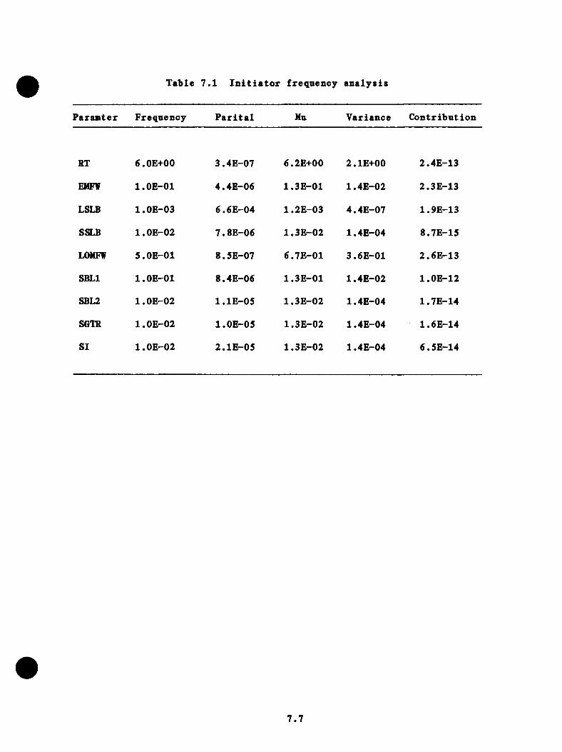
Table 7 .1 I n i t i a t o r frequency a n a ly s i s
P aram ter Frequency P a r i t a l Hu V ariance C o n tr ib u t io n
RT 6.0E+00 3.4E-07 6.2E+00 2.1E+00 2.4E-13
EMFW l.O E-01 4 .4E-06 1.3E-01 1.4E-02 2.3E-13
LSLB l.O E-03 6.6E-04 1.2E-03 4.4E-07 1.9E-13
SSLB l.O E-02 7.8E-06 1 .3E-02 1.4E-04 8.7E-15
LOMFW 5.0E-01 8.5E-07 6.7E-01 3.6E-01 2.6E-13
SBLl l.O E-01 8.4E-06 1.3E-01 1.4E-02 l.O E-12
SBL2 l.O E-02 l . l E - 0 5 1 .3E-02 1.4E-04 1.7E-14
SGTR l.O E -02 l.O E-05 1.3E-02 1.4E-04 1.6E-14
SI l.O E -02 2.1E-05 1 .3E-02 1.4E-04 6.5E-14
7.7
o b ta in e d and can be used to e s t im a te the PTS c h a l le n g e on a system -
f u n c t i o n a l b a s i s .
Once the c o n d i t i o n a l p r o b a b i l i t i e s of v e s s e l f a i l u r e f o r s p e c i f i c c a t e g o r i e s
have been o b ta in e d , i t i s r e l a t i v e l y s t r a i g h t f o n r a r d to sum those end-
s t a t e s (Ej^) t h a t a r e c l a s s i f i e d as be ing in a s p e c i f i c c a te g o ry and t h a t
in v o lv e th e b ran ch p o in t in q u e s t io n . The c o n d i t i o n a l p r o b a b i l i t i e s o f
a s p e c i f i c c a te g o ry b e in g s e l e c t e d can th e n be d e te rm in e d . I n c o rp o ra t in g
th e se v a lu e s i n t o Eq. 7 .1 0 and u s in g Eq. 7 .7 and 7 .9 p e rm i ts the r e q u i r e d
p a r t i a l d e r i v a t i v e s to be d e te rm in e d .
T able 7 .2 summarizes the r e s u l t s o f the b ran ch p o i n t s e n s i t i v i t y / u n c e r t a i n t y
a n a l y s i s f o r those e n d - s t a t e s t h a t meet th e i n i t i a l c r i t e r i o n of t (E ^ ) >
l .O E -0 6 . The a n a l y s i s f o r the u n c e r t a i n t y a t t r i b u t a b l e to th o se e n d - s t a t e s
n o t s p e c i f i c a l l y i d e n t i f i e d ( i . e . , the r e s i d u a l u n c e r t a in t y ) i s d e s c r ib e d
b e lo v .
7 .6 R es id u a l Branch P o in t A n a lv s is
Since th e t r a n s i e n t s w i th e s t im a te d f r e q u e n c ie s below l.O E -6 were n o t
examined, i d e n t i f i c a t i o n o f a s p e c i f i c s e t o f b ra n c h p o i n t s com pris ing each
t r a n s i e n t i s n o t p o s s i b l e . However, i t i s known t h a t a l l th e r e s i d u a l
t r a n s i e n t s in v o lv e one b ran ch p o in t f o r each systma s t a t e e v e n t . Thus,
as an upper bound on u n c e r t a i n t y f o r th e r e s i d u a l t r a n s i e n t s , i t i s assumed
t h a t the b ran ch p o in t having th e l a r g e s t u n c e r t a i n t y f o r a g iven system
s t a t e even t was s e l e c t e d . T r a n s ie n ts d e f in e d by t h i s s e l e c t i o n of b ran ch
p o i n t s do n o t n e c e s s a r i l y co rrespond to e i t h e r the s p e c i f i c t r a n s i e n t s
o b ta in a b le u s in g th e system s t a t e t r e e s o r even p h y s i c a l l y p o s s i b le
7 .8
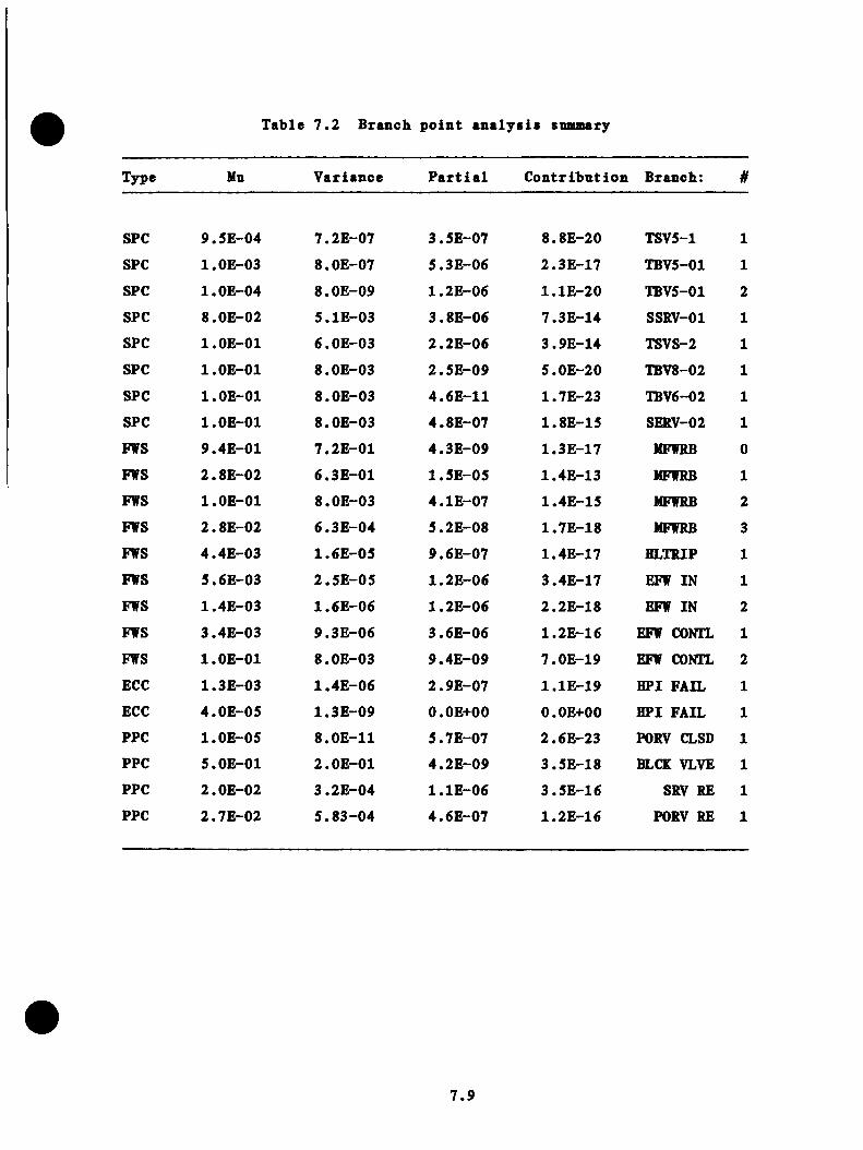
Table 7 . 2 Branch po in t a n a ly s i s snamary
Type Mu V ariance P a r t i a l C o n t r ib u t io n Branch: #
SPC 9.5E-04 7.2E-07 3.5E-07 8.8E-20 TSV5-1 1
SPC l.O E-03 8.0E-07 5.3E-06 2.3E-17 TBV5-01 1
SPC l.O E-04 8 .0E-09 1.2E-06 l . l E - 2 0 TBV5-01 2
SPC 8.0E-02 5.1E-03 3.8E-06 7.3E-14 SSRV-01 1
SPC l.O E-01 6 .0E-03 2.2E-06 3.9E-14 TSVS-2 1
SPC l.O E-01 8.0E-03 2.5E-09 5.0E-20 TBV8-02 1
SPC l.O E-01 8.0E-03 4.6E-11 1.7E-23 TBV6-02 1
SPC l.O E-01 8.0E-03 4.8E-07 1.8E-15 SERV-02 1
FWS 9.4E-01 7 .2E-01 4.3E-09 1.3E-17 MFWRB 0
FWS 2.8E-02 6 .3E-01 1.5E-05 1.4E-13 MFWRB 1
FWS l.O E-01 8.0E-03 4.1E-07 1.4E-15 MFWRB 2
FWS 2.8E-02 6 .3E -04 5.2E-08 1.7E-18 MFWRB 3
FWS 4.4E-03 1.6E -05 9.6E-07 1.4E-17 HLTRIP 1
FWS 5.6E-03 2 .5E -05 1.2E-06 3.4E-17 EFW IN 1
FWS 1.4E-03 1.6E -06 1.2E-06 2.2E-18 EFW IN 2
FWS 3.4E-03 9.3E -06 3.6E-06 1.2E-16 EFW CONTL 1
FWS l.O E-01 8.0E-03 9.4E-09 7.0E-19 EFW CONTL 2
ECC 1.3E-03 1.4E -06 2.9E-07 l . l E - 1 9 HPI FAIL 1
ECC 4.0E-05 1 .3E-09 O.OE+00 O.OE+00 HPI FAIL 1
PPC l.O E-05 8 .0E-11 5.7E-07 2.6E-23 PORV CLSD 1
PPC 5.0E-01 2 .0E-01 4.2E-09 3.5E-18 BLCK VLVE 1
PPC 2.0E-02 3.2E -04 l . l E - 0 6 3.5E-16 SRV RE 1
PPC 2.7E-02 5 .8 3 -0 4 4.6E-07 1.2E-16 PORV RE 1
7 .9
t r a n s i e n t s . R a th e r t h i s p ro ced u re s e rv e s as a means o f e s t im a t in g an upper
bound on the u n c e r t a i n t y a t t r i b u t a b l e to b ran ch p o i n t s of sm all p r o b a b i l i t y
t r a n s i e n t s . The e f f e c t o f i n i t i a t o r f req u en cy u n c e r t a i n t y r e l a t i v e to
th e se same t r a n s i e n t s has a l r e a d y been accoun ted f o r in th e v a lu e s f o r
th e i n i t i a t o r f req u en cy c o n t r i b u t i o n . S ince no o p e r a t o r i n t e r v e n t i o n vas
assumed f o r the r e s i d u a l t r a n s i e n t s , no u n c e r t a i n t y because of th e human
f a c t o r component i s a p p r o p r i a t e .
7 .7 Human F a c to r A n a lv s is
Because of th e t r a n s i e n t assigxunent p ro ced u re u sed , i t v as n e c e s s a ry
to reduce th e o p e r a to r a c t io n t r e e s down to the s in g le o p e r a to r a c t io n
most s i g n i f i c a n t to the t r a n s i e n t . T h is r e d u c t io n p r e v e n ts a d e t a i l e d
e s t i m a t io n of th e in d iv id u a l o p e r a to r a c t i o n com pris ing th e v a r io u s a c t io n
t r e e s . However, i t i s p o s s ib le to o b ta in an e s t im a te o f th e u n c e r t a i n t y in
exp ec ted o p e r a to r a c t i o n . The human f a c t o r p r o b a b i l i t i e s f o r th e se a c t io n s
a r e 1 .2 E -2 . Using t h i s as a mean, and an u n c e r t a i n t y f a c t o r of 30,
produced a c o n t r i b u t i o n to the v a r ia n c e in ^(XVC) o f 5.2E-13/RY^.
7 .8 F r a c tu r e M echanics A n a lv s is
The s e n s i t i v i t y c o e f f i c i e n t s and p a r t i a l d e r i v a t i v e s f o r the v a r io u s
f r a c t u r e m echanics p a ram e te rs were o b ta in e d by re ru n n in g th e f r a c t u r e
m echanics c a l c u l a t i o n w i th on ly a s in g le p a ra m e te r change. A l l p a ra m e te rs
a n a ly z e d , w ith th e e x c e p t io n o f the f law d e n s i t y , were assumed to be
r e p r e s e n t a b l e by normal d i s t r i b u t i o n s . The f law d e n s i t y was assumed to be
log-norm al w ith a mean o f 1 .0 and a m u l t i p l i c a t i v e f a c t o r o f 300.
7 .1 0
7.9 Therm al- H y d ra u l ic s A n a lv s is
The p a r t i a l d e r i v a t i v e r e q u i r e d by the u n c e r t a i n t y a n a ly s i s f o r the th r e e
p r i n c i p a l th e rm a l—h y d r a u l i c v a r i a b l e s (p» T, and h) was o b ta in e d i n an
analogous manner to t h a t u sed f o r th e f r a c t u r e mechanics v a r i a b l e s . Even
though i t ap p ea rs t h a t c o n se rv a t is m s were in c lu d e d i n th e th e rm a l-h y d ra u l ic
a n a ly s e s , i t was n e c e s s a r y to assume a normal d i s t r i b u t i o n f o r a l l th r e e
th e rm a l—h y d r a u l i c v a r i a b l e s , s in c e on ly l i m i t e d in fo rm a t io n was a v a i l a b l e .
7.10 Snmmarv and D is c u s s io n
T able 7 .3 summarizes the r e s u l t s f o r a l l p a ram e te rs examined as p a r t of
the u n c e r t a in t y a n a l y s i s . The e s t im a te d s ta n d a rd d e v ia t io n in th e f r e
quency o f v e s s e l f a i l u r e . er[d (TWC)] i s 5E-5/RT. The expec ted v a lu e of
i (TWC) o b ta in e d i n t h i s s tu d y was 4 .5E-6/R T, and to g e th e r th e se two
p a ra m e te rs c h a r a c t e r i z e th e d i s p e r s io n and c e n t r a l tendency o f the f i n a l
d i s t r i b u t i o n . They do n o t , however, i d e n t i f y th e type o f d i s t r i b u t i o n . I t
i s e v id e n t t h a t th e f req u en cy o f f a i l u r e w i l l be n o n n e g a t iv e . The s ta n d a rd
d e v i a t i o n , however, i s 10 tim es th e e s t im a te d v a lu e . T h is would su g g es t a
lo g —normal d i s t r i b u t i o n , r e s u l t i n g i n th e co n f id en ce i n t e r v a l s l i s t e d in
Tab le 7 .4 .
The amount o f d i s p e r s i o n in th e r e s u l t a t t r i b u t a b l e to the v a r ia n c e o f each
p a ra m e te r has been c a l c u l a t e d and i s t a b u l a t e d in Table 7 . 3 . As in d i c a te d ,
th e m a jo r i t y of u n c e r t a i n t i e s (60%) can be a t t r i b u t e d to the u n c e r t a in t y
in h e re n t in th e te m p e ra tu re h i s t o r i e s used to c h a r a c t e r i z e the t r a n s i e n t s .
T h is i s due to th e l a rg e p a r t i a l d e r i v a t i v e d e r iv e d f o r t h i s pa ram ete r
(1 .4E —6/RY p e r C ) . coup led w ith the la rg e assumed p a ram ete r u n c e r t a in t y
(<y = 2 8 °C ) .
7.11

Table 7 .3 S e n s i t i v i t y / u n c e r t a i n t y r e s u l t s suausary
C la ss P a r a a e t e r Type Mn V ariance P a r t i a l C o n t r ib u t io n Branch: #
FREQ RT INIT 6.0E+00 2.0E+00 3 .43 -07 2.3E-13 TSVS 1
FREQ EMFW INIT l.O E -01 8.0E-03 4.4E -06 1.5E-13 TBVS-01 1
FREQ LSLB INIT l.O E -03 3.3E-07 6 .6E-04 1.4E-13 TBVS-Cl 2
FREQ SSLB INIT l.O E -02 8.0E-05 7 .8E-06 4.8E-15 SSRV-01 1
FREQ LOMFW INIT 5.0E-01 2.0E-01 8.5E-07 1.5E-13 TSVS-2 1
FREQ SBLl INIT l.O E -01 8.0E-03 8.4E-06 5.7E-13 TBVS-02 1
FREQ SBL2 INIT l.O E -02 8.0E-05 l . l E - 0 5 9.7E-15 TBVS-C2 1
FREQ SGTR INIT l.O E -02 8.0E-05 l.O E-05 8.7E-15 SSRV-02 1
FREQ SI INIT l.O E -02 8.0E-05 2.1E-05 3.6E-14 MFWRB 0
FREQ BP SPC 9.5E -04 2.4E-06 3.5E-07 2.9E-19 MFWRB 1
FREQ BP SPC l.O E-03 2.6E-06 5.3E-06 7.4E-17 MFWRB 2
FREQ BP SPC l.O E-04 2.6E-08 1 .2E-06 3.6E-20 MFWRB 3
FREQ BP SPC 8.0E -02 1 .7E-02 3.8E-06 2.4E-13 HLTRIP 1
FREQ BP SPC l.O E-01 2 .6E-02 2.2E -06 1.3E-13 EFW IN 1
FREQ BP SPC l.O E-01 2.6E-02 2.5E-09 1.6E-19 EFW IN 2
FREQ BP SPC l.O E-01 2.6E-02 4.6E-11 5.5E-23 EFW CONTL 1
FREQ BP SPC l.O E-01 2.6E-02 4.8E-07 6.0E-15 EFW CONTL 2
FREQ BP FWS 9.4E-01 2.3E+00 4.3E-09 4.2E-17 HPI FAIL 1
FREQ BP FWS 2.8E -02 2.1E-03 1.5E-05 4.6E-13 CFT FAIL 1
FREQ BP FWS l.O E-01 2.6E-02 4.1E-07 4 .5E-15 PORV CLSD 1
FREQ BP FWS 2.8E -02 2.1E-03 S.2E-08 5.6E-18 BLCK VLVE 1
FREQ BP FWS 4.4E-03 5.1E-05 9.6E-07 4.6E-17 SRV RE 1
FREQ BP FWS 5.6E-03 8.2E-05 1.2E-06 l . l E - 1 6 PORV RE 1
7 .12
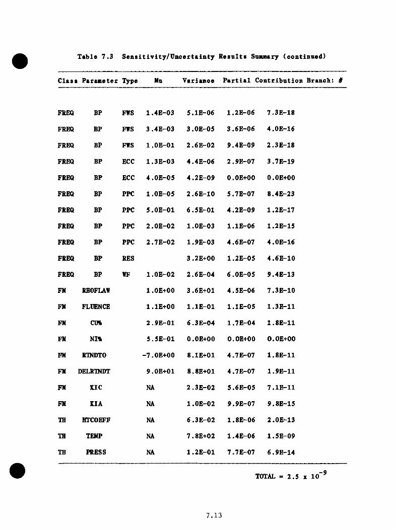
Table 7 .3 S e n s i t i v i t y / U n c e r t a i n t y R esul t s S u u a ry (continued)
C la ss P a ra n e te x Type Nu V ariance P a r t i a l C o n tr ib u t io n Branch: #
FREQ BP FWS 1 .4E-03 5.1E-06 1.2E-06 7.3E-18
FREQ BP FWS 3 .4E-03 3.0E-05 3.6E-06 4.0E-16
FREQ BP FWS l.O E-01 2.6E-02 9.4E-09 2.3E-18
FREQ BP ECC 1.3E-03 4.4E-06 2.9E-07 3.7E-19
FREQ BP ECC 4 .OE-05 4.2E-09 O.OE+OO O.OE+OO
FREQ BP PPC 1 .OE-05 2.6E-10 5.7E-07 8.4E-23
FREQ BP PPC 5.0E-01 6.5E-01 4.2E-09 1 .2E-17
FREQ BP PPC 2.0E -02 l.OE-03 l . l E - 0 6 1.2E-15
FREQ BP PPC 2.7E -02 1.9E-03 4.6E-07 4.0E-16
FREQ BP RES 3.2E+00 1.2E-05 4.6E-10
FREQ BP WF l.O E-02 2.6E-04 6.0E-05 9.4E-13
FH RHOFLAW 1 .OE+00 3 .6E+01 4.5E-06 7.3E-10
FH FLIJENCE I.IE+OO l . l E - 0 1 l . l E - 0 5 1.3E-11
FN CD% 2.9E-01 6.3E-04 1.7E-04 1.8E-11
FH NI% 5.5E-01 O.OE+OO O.OE+OO O.OE+OO
FH RTNDTO -7.0E+00 8.1E+01 4.7E-07 1.8E-11
FH DELRTNDT 9.0E+01 8.8E+01 4.7E-07 1.9E-11
FH KIC NA 2.3E -02 5.6E-05 7.1E-11
FH KIA NA l.O E-02 9.9E-07 9.8E-15
IB HTCOEFF NA 6.3E-02 1.8E-06 2.0E-13
TH TEHP NA 7.8E+02 1.4E-06 1.5E-09
TH PRESS NA 1.2E-01 7.7E-07 6.9E-14
TOTAL = 2 . 5 X 10,-9
7 . 13

Table 7 .4 C onfidence i n t e r v a l s f o r a lognorm al assnm ption
Confidence Level F a c to r Lover Bound Upper Bound
68% 9 .0 5.0E-07 4.1E-05
95% 82 5.5E-08 3.7E-04
99.7% 737 6.1E-09 3.3E-03
7 .14

The second l a r g e s t c o n t r i b u t i o n (29%) to the o y e r a l l u n c e r t a in t y i s t h a t
a t t r i b u t a b l e to th e f law d e n s i t y in th e w eld . Once a g a in , th e magnitude o f
the c o n t r i b u t i o n i s due t o a la rg e p a r t i a l d e r i v a t i v e coupled w ith a la rg e
p a ram e te r u n c e r t a i n t y .
Ranking t h i r d (18%) as a sou rce o f u n c e r t a i n t y i s th e c o n t r i b u t i o n due to
th e r e s i d u a l t r a n s i e n t u n c e r t a i n t i e s . T h is c o n t r i b u t i o n i s a t t r i b u t a b l e
t o two f a c t o r s . F i r s t , th e v a r ia n c e e s t im a te d f o r the b ranch p o in t s i s
l a rg e as a r e s u l t o f th e c o n s e rv a t iv e p rocedu re u t i l i z e d to o b ta in i t .
Second, th e p a r t i a l d e r i v a t i v e c a l c u l a t e d f o r t h i s p a ram e te r in c o rp o ra te s
th e c o n d i t i o n a l p r o b a b i l i t y of f a i l u r e [P (F /E ^)] c a l c u l a t e d f o r th e d e f a u l t
t r a n s i e n t ( the h ig h e s t c o n d i t io n a l f a i l u r e p r o b a b i l i t y o b ta in e d f o r any of
the t r a n s i e n t s ) .
F i n a l l y , i t i s u s e f u l t o sum th e c o n t r i b u t i o n s o f th e v a r io u s p a ram e te rs
i n t o t h r e e c l a s s e s r e p r e s e n t in g th e th r e e m ajor in f lu e n c e s on f requency o f
v e s s e l f a i l u r e (ev en t f req u e n c y , f r a c t u r e m echan ics , or the rm al hydrau
l i c s ) . This breakdown i s g iven in Tab le 7 .5 .
7 .15
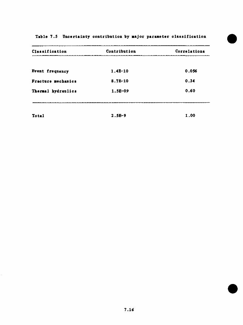
Table 7 .5 Uncerta in ty co n tr ib u t io n by major parameter c l a s s i f i c a t i o n
C l a s s i f i c a t i o n C o n t r ib u t io n C o r r e la t io n s
Event frequency 1.4E-10 0.056
F r a c tu r e m echanics 8.7E-10 0.34
Thermal h y d r a u l i c s 1.5E-09 0 .60
T o ta l 2 .5E -9 1 .00
7 .16
8 .0 CONCLUSIONS AND RECOMMENDATIONS
6 . F. F lanagan , Oak Ridge N a t io n a l L ab o ra to ry
8 .1 I n t r o d u c t io n
T his c h a p te r c o n s i s t s o f s p e c i f i c and g e n e ra l c o n c lu s io n s which were drawn
from the r e s u l t s o f th e r e p o r t and a l s o from v a r io u s a s p e c t s o f the
a n a l y s i s . In a d d i t i o n . S e c t io n 8 .3 d i s c u s s e s a re a s o f the r e p o r t t h a t
r e q u i r e f u r t h e r s tudy and developm ent i f a s im i l a r P r e s s u r i z e d Thermal
Shock (PTS) a n a l y s i s were to be perfo rm ed on o th e r n u c le a r p l a n t s .
8 .2 C onc lus ions from t he Oconee-1 S tudv
8 .2 .1 Oconee-1 System F e a tu re s and P roposed System CSianges
Major system s r e l a t e d to th e Oconee-1 PTS a n a l y s i s were d e s c r ib e d in (3iap-
t e r 2 . From th e a n a l y s i s i t became a p p a re n t t h a t two of th e Oconee-1 sy s
tem f e a t u r e s p la y major r o l e s i n re d u c in g th e th ro u g h - th e -w a l l c ra c k (TVC)
r i s k :
(1) The v e n t v a lv e s i n th e B&V r e a c t o r v e s s e l minimize therm al s t r a t i
f i c a t i o n in the downcomer r e g io n when p r im ary loop flow s t a g n a t e s .
(2) The steam g e n e ra to r a t Oconee-1 has a h ig h l e v e l t r i p f e a t u r e
( i n s t a l l e d by Duke Power) which p re v e n t s o v e r f i l l on MFW. W ithout such a
f e a t u r e , the o v e r a l l r i s k o f a TWC in c r e a s e s by 35%. T his in c re a s e was
based on the assum ption t h a t main fee d w a te r flow cou ld be s u s ta in e d a f t e r
8.1
the steam g e n e r a to r f i l l e d w i th w a te r . I t ap p ea rs t h a t t h e r e a re some
a s p e c t s o f th e d es ig n o f th e system t h a t m ight i n v a l i d a t e t h i s assnm ption
and th u s reduce the in c re a s e in TWC r i s k . One o f th e se a s p e c t s i s t h a t the
main fe e d w a te r pnmps a re d r iv e n by steam tu r b in e s which e x t r a c t t h e i r steam
from the lo w es t p o in t a t th e end o f th e steam l i n e . Water e n t r a in e d in the
steam would r e s u l t in l o s s o f t u r b i n e power to th e fe ed w a te r pumps and sub
s e q u e n t ly r e s u l t in a t e rm in a t io n o f th e feed w ate r e v e n t . Secondly , the
w a te r dynamics i n th e steam l i n e m ight le a d to f a i l u r e i n th e steam l i n e
w hich would p ro b a b ly r e s u l t in a blowdown in s t e a d o f an o v e r fe e d . These
e f f e c t s were n o t an a ly zed i n t h i s s tu d y and th u s canno t be q u a n t i f i e d .
Two system changes have been examined which cou ld le a d to a d d i t i o n a l red u c
t i o n o f th e r i s k o f TWC:
(1) The f i r s t change in v o lv e s th e h e a t in g o f the h ig h - p r e s s u r e i n j e c
t i o n (HPI) w a te r by SO°F. S ince com plete mixing o ccu rs d u r in g most o f the
t r a n s i e n t s i n O conee-1, th e a c t u a l downcomer w a te r te m p e ra tu re i s e s t im a te d
t o in c r e a s e l e s s th an lO^^F (w e ll w i th in th e e s t im a te d te m p e ra tu re u n ce r
t a i n t y o f t h i s s tu d y ) , th e re b y p ro v id in g n e g l i g i b l e b e n e f i t .
(2) A second system change i s a m o d i f ic a t io n o f th e c o n t ro l o r opera
t i o n a l p ro c e d u re s so as t o l i m i t th e r e p r e s s u r i z a t i o n o f th e p r im ary system
d u r in g an o v e rc o o l in g t r a n s i e n t . I f such a system were 100% e f f e c t i v e , the _»T
r i s k o f a TWC would d e c re a se a t l e a s t a f a c t o r o f 14 to 3 .2 x 10 /RY.
T h is cou ld most e a s i l y be accom plished by a p p r o p r ia te t h r o t t l i n g o f the
HPI. (T h is t h r o t t l i n g was n o t ta k e n in t o accoun t i n th e Oconee-1 s tu d y . )
I t shou ld be n o te d t h a t Duke Power i s c u r r e n t l y im plem enting the
8.2

a n t i c i p a t e d t r a n s i e n t o p e r a t in g g u id e l in e (ATOG) program which in c lu d e s
o p e r a to r a c t io n to l i m i t r e p r e s s u r i z a t i o n as p a r t o f the response to o v e r -
c o o l in g e v e n t s .
8 . 2 .2 A cciden t Sequence A n a ly s is
The a c c id e n t sequence a n a l y s i s i s d is c u s s e d in C hap te rs 3 and 6 o f t h i s
r e p o r t and s e v e r a l s i g n i f i c a n t c o n c lu s io n s can be drawn:
(1) The r e s u l t s show t h a t th e r i s k p r o f i l e i s dom inated by the “r e s i
dua l r i s k . " * The t h r e e r e a so n s f o r t h i s la rg e r e s i d u a l r i s k a re as f o l
lows: (a) No o p e r a to r a c t i o n t r e e s were a s s ig n e d to any sequence in th e
“r e s i d u a l r i s k " c a te g o ry ; th u s th e human e r r o r p r o b a b i l i t y was 1 .0 . (b) A
s in g le seve re th e rm a l - h y d r a u l ic t r a n s i e n t was a s s ig n e d to each even t
sequence in the r e s i d u a l c a te g o ry , which r e s u l t e d in a c o n s ta n t c o n d i t io n a l —3
p r o b a b i l i t y o f TWC o f 5 .4 x 10 . (c ) There was a l a rg e number o f even t
sequences ( s e v e r a l m i l l i o n ) which were lumped i n t o th e " r e s id u a l r i s k "
c a te g o r y . T h e re fo re , i t i s ou r o p in io n t h a t more s e l e c t i v e te ch n iq u es
sh o u ld be c o n s id e re d f o r a s s ig n in g t r a n s i e n t s to the r e s i d u a l r i s k c a te g o ry
i n f u tu r e s t u d i e s .
(2) In a s s e s s in g th e o v e r a l l r i s k o f TWC i n Oconee-1, no in d iv id u a l
sequence , when combined w i th th e c o n d i t io n a l p r o b a b i l i t y o f a TWC, had a
f req u en cy l a r g e r than 6 x 10 /RT.
(3) The steam l i n e b re a k i n i t i a t o r s were found to be the most impor
t a n t c o n t r i b u t o r s to r i s k (second o n ly to the r e s i d u a l in t o t a l r i s k
c o n t r i b u t i o n s ) .
*A11 even t sequences whose f r e q u e n c ie s were l e s s th a n 10 ^/RY were lumped i n t o a c a te g o ry c a l l e d " r e s id u a l r i s k . "
8.3

(4) Of the sequences analyzed* th o se v i t h h ig h f requency o f o ccu rren c e
have low TWC c o n d i t i o n a l p r o b a b i l i t y . Conversely* e v e n ts which have h igh
TWC c o n d i t i o n a l p r o b a b i l i t y have low f req u en cy o f o c c u rre n c e .
8 .2 .3 F r a c tu r e Mechanics A n a ly s is
From the f r a c t u r e m echanics a n a l y s i s in C hap ter 5* s e v e r a l c o n c lu s io n s can
be drawn:
(1) The a x i a l welds (Weld Numbers SA1073* SA1430* and SA1493) dominate
the c o n t r i b u t i o n to th e TWC c o n d i t i o n a l p r o b a b i l i t y . Assuming th e same
flaw d e n s i t y th ro u g h o u t th e b e l t l i n e r e g io n o f the v e s se l* th e c i rc u m fe re n
t i a l welds would add ap p ro x im a te ly 5% to P (F /E ) and the base m a te r i a l
a p p ro x im a te ly 30%.
(2) Aside from the f law d e n s i ty * P (F /E ) i s by f a r most s e n s i t i v e to
u n c e r t a i n t i e s in th e te m p era tu re o f th e c o o la n t i n th e downcomer and l e a s t
s e n s i t i v e to the f l u i d - f i l m h e a t t r a n s f e r c o e f f i c i e n t a t the v e s s e l in n e r
s u r f a c e and the p rim arjr-system p r e s s u r e .
(3) A r e d u c t io n in the f lu e n c e r a t e cou ld have a s i g n i f i c a n t im pact on
th e r i s k o f a TWC* b u t a c o s t / b e n e f i t a n a l y s i s i s needed .
(4) Improved i n - s e r v i c e in s p e c t io n fo llo w ed by r e p a i r o f a l l f law s
t h a t a re found cou ld reduce the PTS r i s k s i g n i f i c a n t l y * b u t com plete r e p a i r
and p r e c i s e d e t e c t i o n o f f law s a re d i f f i c u l t w i th t o d a y 's te ch n o lo g y .
8.4

(5) A nnealing the p r e s s u r e v e s s e l would s i g n i f i c a n t l y reduce the PTS
r i s k , b u t the c o s t and u n c e r t a i n t y re g a rd in g t e c h n ic a l f e a s i b i l i t y p rob ab ly
r e n d e r t h i s a l a s t r e s o r t f i x t o th e PTS problem .
(6) The in c lu s io n o f WPS in th e FM a n a l y s i s reduces P(F /E) by s e v e ra l
o rd e r s o f m agnitude fo r many, b u t n o t a l l , o f the id e a l i z e d t r a n s i e n t s .
Because of concerns over th e a p p l i c a b i l i t y o f WPS under a c tu a l t r a n s i e n t
c o n d i t io n s , i t was n o t in c lu d e d i n th e e s t im a te o f (TWC), b u t t h i s does
n o t mean t h a t c o n d i t io n s f o r which WPS would be e f f e c t i v e cannot be expec
te d t o o c c u r .
(7) L im it in g th e p r im ary -sy s te m p r e s s u r e to app ro x im ate ly 7 MPa (1000
p s i ) d u r in g r e p r e s s u r i z a t i o n f o r th o se t r a n s i e n t s t h a t would o th e rw ise
ex p e r ie n c e h ig h e r p r e s s u r e s reduced P (F /E ) by as much as two o rd e rs o f mag
n i tu d e f o r i n d i v id u a l t r a n s i e n t s .
(8) For many o f the t r a n s i e n t s , th e p r e d i c t e d f a i l u r e s o cc u r re d n ea r
the end o f th e assumed 2-h d u r a t i o n (see Appendix E ) . This i s approach ing
a c o ld o v e r p r e s s u r i z a t i o n s i t u a t i o n , and th u s ex ten d in g th e d u r a t io n o f the
t r a n s i e n t c o u ld s u b s t a n t i a l l y in c re a s e P (F /E ) . C onverse ly , i f th e d u r a t io n
were d e c re a se d , P (F /E) would be d e c re a se d .
8 .2 .4 U n c e r ta in ty and S e n s i t i v i t y A n a ly s is
The u n c e r t a i n t y and s e n s i t i v i t y a n a l y s i s r e p o r t e d in C hapter 7 i n d i c a te s
the fo l lo w in g :
8.5

(1) The im c e r t a i n t y in th e te m p e ra tu re o f th e downcomer f l u i d (±28^C)
dom inates the u n c e r t a i n t y in f re q u e n c y o f a TVC.
(2) The u n c e r t a i n t y in th e f law d e n s i t y i s th e l a r g e s t u n c e r t a i n t y of
any f a c t o r c o n s id e re d and r e s u l t s i n th e second l a r g e s t u n c e r t a i n t y c o n t r i
b u t i o n to th e TWC f req u en cy .
(3) The f a i l u r e o f the o p e r a to r to i s o l a t e th e steam g e n e r a to r du r in g
a steam l i n e b re a k r e p r e s e n t s , w ith th e e x c e p t io n o f th e f a i l u r e to
t h r o t t l e HPI, the l a r g e s t human e r r o r c o n t r i b u t i o n to th e f req u en cy o f a
TWC.
8 .2 .5 G eneral C onclusions
In a d d i t i o n to the s p e c i f i c c o n c lu s io n s drawn from the s p e c i f i c c h a p te r s o f
th e s tu d y , th e fo l lo w in g g e n e ra l s ta t e m e n t s can be made:
(1) Only minimal system i n t e r a c t i o n s , no e x t e r n a l e v e n ts ( f i r e s ,
f l o o d s , e a r th q u a k e s , o r s ab o tag e ) and no in a d v e r te n t o p e r a to r a c t io n s were
c o n s id e re d i n the Oconee-1 s tu d y . The impact o f th e se e f f e c t s on th e f r e
quency of a TWC cannot be e s t im a te d e i t h e r q u a l i t a t i v e l y o r q u a n t i t a t i v e l y
w i th o u t f u r t h e r a n a l y s i s .
(2) The b e s t e s t im a te o f th e f req u en cy o f a TWC (4 .5 x 10~^/RY) i s
sm all* when compared to th e p roposed s a f e t y g o a l . T h is number i s about a
*This assumes t h a t th e c o n d i t io n a l p r o b a b i l i t y o f co re m e l t , g iv e n a TWC, i s 1 .
8.6

f a c t o r of 10 l e s s th an th e dominant core m e l t p r o b a b i l i t i e s c a l c n l a t e d in
p l a n t - s p e c i f i c PRAs, which im p l ie s t h a t PTS i s a sm all c o n t r i b u to r to
o y e r a l l r i s k o f co re m e l t .
(3) The b e s t e s t im a te o f th e f req u en cy o f a IVC based on in fo rm a tio n
u t i l i z e d in t h i s r e p o r t i s n e a r l y s ix t im es l a r g e r than th e upper l i m i t
(8 .5 X 10 ^/RY) r e p o r t e d i n the B&V Owners Group S tudy .*
8 .3 Areas R eq u ir in g F u r th e r Studv and Development
8 .3 .1 Human R e l i a b i l i t y
The method used f o r q u a n t i f i c a t i o n o f human e r r o r in th e Oconee-1 s tu d y
c l e a r l y needs improvement. A more s o p h i s t i c a t e d te ch n iq u e was adopted f o r
l a t e r s tu d i e s perform ed f o r the C a lv e r t C l i f f s - 1 and H. B. Robinson-2
p l a n t s . As in a l l PRAs. t h i s s u b je c t d e se rv e s c o n s id e ra b le a t t e n t i o n . The
o p e r a to r o b v io u s ly p la y s a s i g n i f i c a n t r o l e i n th e p ro g re s s o f a PTS
sequence , b u t because o f th e s i m p l i s t i c t r e a tm e n t in t h i s s tu d y , th e c a lc u
l a t e d s e n s i t i v i t y o f th e TWC to o p e ra to r a c t i o n i s p ro b ab ly n o t as l a rg e as
would occur i f a more s o p h i s t i c a t e d approach to htiman a c t i o n were to be
im plem ented.
8 . 3 .2 System I n t e r a c t i o n s
The approach used to e v a lu a te system i n t e r a c t i o n s f o r t h i s s tu d y was a l s o
s i m p l i s t i c and no system i n t e r a c t i o n s were i d e n t i f i e d in the Oconee-1
•B&W Owners Group, 'P r o b a b i l i t y E v a lu a t io n o f P r e s s u r i z e d Thermal Shock Phase I , " p p . 2 -3 , BAW-1791 (June 1983).
8.7

a n a l y s i s . More in - d e p th a n a ly se s f o r th e C a lv e r t C l i f f s - 1 and H. B.
Robinson-2 s tu d ie s d id i n d i c a t e the e x i s t e n c e o f system i n t e r a c t i o n s , which
cou ld prove im p o r tan t to PTS sequences i n th e s e p l a n t s .
8 .3 .3 E x te rn a l E vents
The freq u en cy o f e x t e r n a l e v e n ts and t h e i r im pact on PTS was exc luded from
th e Oconee-1 s tu d y and from the C a lv e r t C l i f f s - 1 and H. B. Robinson-2 s tu
d i e s as w e l l . S ince many o f th e s i g n i f i c a n t sequences i n Oconee-1 in v o lv e
m u l t i p l e f a i l u r e s , i t i s p o s s i b l e t h a t an e x t e r n a l even t cou ld in c re a s e the
f req u en cy o f the dominant sequences by e l im i n a t in g th e randomness o f the
f a i l u r e s . However, most e x t e r n a l even t a n a ly s e s a r e found to a f f e c t the
c o o l in g system s and c o n t r o l system s o f r e a c t o r s and one m ight ex p ec t an
u n d e rc o o l in g even t due to a e x t e r n a l h a z a rd to be more p r e v a l e n t th a n an
o v e rc o o l in g e v e n t .
8 .3 .4 F lood ing
L ate in the s tu d y , the s u b je c t o f f lo o d in g o f th e r e a c t o r c a v i ty su r ro u n
d ing the v e s s e l was d i s c u s s e d ; however, n e i t h e r time n o r money was a v a i l a
b l e to an a ly ze t h i s s c e n a r io .
8 .3 .5 T herm al-H ydrau lic Modeling
I t i s c l e a r t h a t the th e rm a l -h y d ra u l ic (T-H) m odeling r e q u i r e s c o n s id e ra b le
e f f o r t in b u i ld in g and v a l i d a t i n g th e p r im ary and secondary m odels , e s p e c i
a l l y in c o n ju n c t io n w i th an i n t e g r a t e d c o n t r o l system such as ap p ea rs in
th e Oconee-1 r e a c t o r . Even when th e p l a n t system s a re p u rp o r te d to he
8.8
c o r r e c t l y modeled, the RELAP and TRAC codes do no t g ive i d e n t i c a l answ ers,
and in one c a s e , the p r e d i c t e d downcomer te m p era tu re s d i f f e r e d by more than
140°F. xhe e f f e c t o f modeling shou ld be c a r e f u l l y ad d re s se d whenever a PTS
s tudy i s done .
8 . 3 .6 Decay Heat Assumptions
Because o f the v en t v a lv e s in O conee-1, loop s t a g n a t io n does n o t appear to
be a problem f o r l o s s - o f - c o o l a n t a c c id e n t s (LOCA). However, shou ld a LOCA
occur a t h o t s tandby fo l lo w in g an ex ten d ed shutdown, s t a g n a t io n i s l i k e l y
to o ccu r and m ight l e a d to low downcomer te m p e ra tu re s . A lso , w ith o u t a
sou rce o f decay h e a t , a steam l i n e b re a k a t ho t s tandby cou ld cause s i g n i
f i c a n t l y lower downcomer te m p e ra tu r e s . On the o th e r hand, the frequency of
th e s e e v e n ts i s lower than s i m i l a r e v e n ts a t f u l l power, so th e e f f e c t on
th e t o t a l r i s k shou ld be examined in f u t u r e s t u d i e s .
8 .3 .7 D u ra t io n o f C a lc u la te d T r a n s ie n t s
Throughout the s tu d y the T-H a n a l y s i s was a r b i t r a r i l y te rm in a te d a f t e r two
h o u rs , the u n d e r ly in g assum ption be ing t h a t some o p e r a to r a c t io n would be
ta k e n by t h a t time to m i t i g a t e th e e v e n t . However, fo r n o n - i s o l a t a b l e
e v e n ts (LOCAs and steam l i n e b r e a k s ) , t h i s may n o t be a r e a l i s t i c assump
t i o n . F u r th e rm o re , i t ap p ea rs t h a t f o r s e v e r a l t r a n s i e n t s a l a rg e p e rcen
tag e o f TWCs occu r a t the two hour l i m i t . The e f f e c t o f th e two hour l im i
t a t i o n m e r i t s f u r t h e r a n a l y s i s i n l i g h t o f the r e l a t i v e im portance of the
cho ice o f t h i s time p e r io d .
8.9

8 . 4 S n m n m r v
A lthough t h i s s tu d y does n o t co m p le te ly e l im in a te p r e s s u r i z e d the rm al shock
as an u n re s o lv e d s a f e ty i s s u e f o r th e Oconee-1 p l a n t , i t does p ro v id e a
tho rough s tu d y o f the e f f e c t o f v a r io u s p o t e n t i a l o v e rc o o l in g t r a n s i e n t s on
th e r e a c t o r v e s s e l . I t i s r e a l i z e d t h a t much o f what i s s t a t e d i n t h i s
r e p o r t was known to some e x te n t and i n p iecem eal f a s h io n by v a r io u s t e c h n i
c a l s p e c i a l i s t s p r i o r to th e s tu d y . However, by i n t e g r a t i n g th e d i s c i
p l i n e s o f p r o b a b i l i s t i c r i s k a n a l y s i s , th e rm a l-h y d ra u l ic a n a l y s i s , and
f r a c t u r e m echan ics , and by a d o p t in g a c o n s i s t e n t te ch n iq u e o f a s s e s s in g
u n c e r t a i n t i e s and s e n s i t i v i t i e s a c r o s s th e s e d i s c i p l i n e s , a c l e a r e r under
s ta n d in g o f the t o t a l a s p e c t o f th e p r e s s u r i z e d the rm al shock problem has
r e s u l t e d . In p a r t i c u l a r , the u n c e r t a i n t y a n a l y s i s , a l th o u g h f a r from p e r
f e c t , r e p r e s e n t s an a t te m p t to adop t a c o n s i s t e n t and m a th e m a t ic a l ly sound
a n a l y s i s o f the problem . Such an a n a l y s i s shou ld be a r e q u i s i t e f o r any
f u tu r e p r e s s u r i z e d the rm al shock s tu d y perfo rm ed by NRC or a u t i l i t y . Even
w i th the d e f i c i e n c i e s o u t l i n e d i n S e c t io n 8 .3 , th e r e s u l t s o f t h i s s tudy
sh o u ld be o f use to b o th NRC and Duke Power Company in r e s o lv i n g the
p l a n t - s p e c i f i c a s p e c t s o f p r e s s u r i z e d the rm al shock. The approach ta k e n in
th e Oconee-1 s tu d y (w ith m o d i f i c a t io n s ) shou ld p ro v id e a b a s i s f o r f u tu r e
p l a n t - s p e c i f i c p r o b a b i l i s t i c r i s k a s se s sm e n ts o f p r e s s u r i z e d the rm al shock.
8.10
APPENDIX A
EVENT TREES
The o o a p n te r iz e d even t t r e e s a re e x te n s iv e and to o la rg e to be in c lu d ed in
t h i s r e p o r t . They a re a v a i l a b l e from George Flanagan* E n g in ee r in g P h y s ic s
and M athem atics D iv is io n , B u ild in g 6025, Oak Ridge N a tio n a l L ab o ra to ry ,
P .O. Box X, Oak R idge , TN 37831.
Three s e t s o f d a ta a re p r e s e n te d in t h i s appendix ; S e c t io n A .l i s a
log o f sequences by i d e n t i f i c a t i o n number and frequency f o r system s t a t e
t r e e b ran ch p o i n t s . S e c t io n A.2 i s a log of sequences summed by system
s t a t e c a te g o ry , and S e c t io n A.3 r e l a t e s th e com bination o f end s t a t e
f r e q u e n c ie s o f S e c t io n A.2 o p e r a to r a c t i o n p r o b a b i l i t i e s and f r a c t u r e ^
m echanics p r o b a b i l i t i e s o f Table 6 . 1 .
A .l

A .l Sequence* by I d c a t i f i c t t i o n Nuabor »n4 Frequ^pcy^ System S U t e Tree
Bynncb Pc iit*
A.2

-SYSTEH STftTE BRflNCHES- -CATE60RIES-REC IN IT SEQ* SPC FNS ECC PPC EFRE8 SPC FHS ECC PPC
1 RT 6556 I 24 1 1 4 .8E + 00 0 0 0 02 RT 6841 1 25 1 1 1 .4 E -0 1 0 1 0 0
RT 7148 1 26 2 8 2 .0 E -0 4 0 •J 0 0RT 7149 1 26 n 9 5 .5 E -0 6 0 •i 0 1
5 RT 7150 I 26 nL 10 1 .3 E -0 5 0 3 0 ■-!
6 RT 7152 1 26 ■•y 12 2 .3 E -0 5 0 3 0 07 RT 7153 1 26 •7i. 13 1 .4E -C 6 0 •3 0 2a RT 7433 1 27 3 1 .2 E -0 5 0 7-j 0 09 RT 7437 1 n - T 2 12 1 .3 E -0 6 0 3 0 0
10 RT 7703 1 23 1 8 6 .6 E -0 4 0 4 0 011 RT 7704 1 28 1 9 1 .8 E -0 5 0 4 0 112 RT 7705 1 28 1 10 4 .2 E -0 5 0 4 0 213 RT 7706 1 23 1 11 1 .2 E -0 6 0 4 0 n
14 RT 7707 1 28 1 12 7 .5 E -0 5 0 4 0 015 RT 7708 1 23 1 13 4 .S E -0 6 0 4 0 n
L
16 RT 7988 I 29 1 8 1 .7 E -0 4 0 4 0 017 RT 7989 1 29 )i 9 4 .6 E -0 6 n 4 0 1l a RT 7990 1 29 1 10 l . l E - 0 5 0 4 0 z
19 RT 7992 1 29 1 12 1 .9 E -0 5 0 4 0 020 RT 7993 1 29 1 13 1 .2 E -0 6 0 4 0 221 RT 8238 1 30 n 8 5 .2 E -0 4 0 9 0 022 RT 8289 1 30 n
L 9 1 .4 E -0 5 AV
•-) 0 i23 RT 8290 1 30 z 10 3 .3 E -0 5 (I T
L, 024 RT 8 2 9 2 1 30 2 12 5 .9 E -0 5 0 9 0 025 RT 3293 1 30 n
L 13 3 .8 E -0 6 0 0 n
26 RT 8551 1 71•J I 1 1 1 .4 E -0 2 0 I 0 0
27 RT 8858 1 32 2 8 2 .0 E -0 5 0 ■j 0 023 RT 3360 1 t n
■JL. 2 10 1 .3 E -0 6 0 ■j 0 £.
29 RT 8362 1 32 L 12 2 .3 E -0 6 0 ■j 0 030 RT 9143 1 33 3 1 .2 E -0 6 0 A 0 031 RT 9413 1 34 1 B 6 .6 E -0 5 0 4 0 032 RT 9414 1 34 i 9 1 .3 E -0 6 0 4 0 4
33 RT 9415 I 34 1 10 4 .2 E -0 6 f*t 4 0 nL
34 RT 9417 1 34 4i 12 7 .5 E -0 6 0 4 0 0
35 RT 9698 1 7 5 4I 8 1 .7 E -0 5 A 4 0A
36 RT 9700 1 35 1 10 1 .1E-Q 6 'v 4 nV ni .
37 RT 9702 1 35 1 12 1 .9 E -0 6 0 4 i) 038 RT 9998 1 36 2 3 1 .2 E -0 6 0 •T ( j 039 RT 10261 1 j / 1 1 1 .4 E -0 1 0 0 040 RT 10568 1 38 n
L 8 2 .0 E -0 4 0 • j 0 041 RT 10569 1 38 9 5 .5 E -0 6 0 • j 0 142 RT 10570 1 33 n, 10 1 .3 E -0 5 0 3 0 243 RT 10572 1 38 12 2 .3 E -0 5 0 3 0 044 RT 10573 1 38 n
L 13 1 .4 E -0 6 0 7 0 245 RT 10853 1 39 1 8 1 .2 E -0 5 0 3 0 046 RT 10857 1 39 1 12 1 .3 E -0 6 0 7 0 047 RT 11123 1 40 1 8 6 .6 E -0 4 0 4 0 048 RT 11124 1 40 I 9 1 .8 E -0 5 0 4 0 147 RT 11125 1 40 1 1 0 .4 .2 E -0 5 0 4 0 n
L
A.3

-3YSTEH STATE 8RANCHES- --CATEGQRIES-REC IMIT SE8* SPC FRS ECC PPC EFRES SPC F»S ECC PPC
50 RT 11126 1 40 I 11 1 .2 E -0 6 0 4 0 n
5 i RT 11127 1 40 1 12 7 .5 E -0 5 0 4 0 05 2 RT 11123 1 40 1 13 4 .8 E -0 6 0 4 0 n
5 3 RT 11408 1 41 1 8 1 .7 E -0 4 0 4 0 054 RT 11409 1 41 1 9 4 .6 E -0 6 0 4 0 L55 RT 11410 1 41 1 10 l . l E - 0 5 0 4 0 256 RT 11412 1 41 1 12 1 .9 E -0 5 0 4 0 057 RT 11413 1 41 <i 13 1 .2 E -0 6 0 4 0 T
58 RT 74973 2 95 nL. 3 3 .0 E -0 1 1 0 0 0
59 RT 74979 n 95 0L. 9 8 .3 E -0 3 1 0 0 1
60 RT 74930 2 95 0 10 1 .9 E -0 2 1 0 0 261 RT 74981 n
L 95 nL 11 5 .3 E -0 4 1 0 0 2
6 2 RT 74982 L 95 0 12 3 .4 E -0 2 1 0 0 06 3 RT 74983 1 95 n 13 2 .2 E -0 3 1 0 0 T4k
64 RT 74984 2 95 2 14 l .O E -0 4 I 0 0 065 RT 74985 2 95 15 6 .5 E -0 6 1 A 0 n
L
66 RT 74993 r\ 95 3 3 3 .9 E -0 4 1 0 1 0
67 RT 74994 nL 95 3 9 l . l E - 0 5 I 0 1 1
68 RT 74995 «/ 95 • j 10 2 .5 E -0 5 f
i 0 1 TL.
69 RT 74997 2 95 3 12 4 .4 E -0 5 51 0
70 RT 74998 / 95 3 13 2 .S E -0 6 1i
A 4i
■7
71 RT 75263 2 96 2 3 5 .1 E -0 4 1 0 0
72 RT 75264 2 96 nL 9 1 .4 E -0 5 1 • j 0 1
73 RT 75265 •y 96 n 10 3 .3 E -0 5 I 3 0 2
74 RT 75267 L 96 2 12 5 .3 E -0 5 I ‘j 0 0
75 RT 75268 n 96 nL 13 3 .7 E -0 6 1 0 L
76 RT 75548 2 97 1 8 3 .0 E -0 5 I 0 077 RT 75550 97 •) 10 1 .9 E -0 6 1 i
ClV
nL
78 RT 75552 2 97 2 12 3 .4 E -0 6 1L 0 0
79 RT 75833 98 2 8 1 .7 E -0 3 I 4 0 080 RT 75834 2 98 2 9 4 .7 E -0 5 { 4 0 181 RT 75835 z 98 2 10 l . l E - 0 4 1 4 0
7
82 RT 75836 2 93 2 11 3 .0 E -0 6 1 0 L
83 RT 75337 98 2 12 1 .9 E -0 4 1 4 04*1
84 RT 75838 2 93 2 13 1 .2 E -0 5 I 0 2
85 RT 75848 L 98 3 8 2 .2 E -0 6 1 1 036 RT 76113 2 99 2 a 4 .3 E -0 4 1 4 0 087 RT 76119 n
L 99 nL 9 1 .2 E -0 5 i
I 0 188 RT 76120 2 99 0 10 2 .7 E -0 5 I 0
•y
89 RT 76122 •) 99 2 12 4 .8 E -0 5 1 4 0 0
90 RT 76123 2 99 2 13 3 .1 E -0 6 1 4 0 291 RT 76403 L 100 2 8 8 .9 E -0 3 1 1 0 092 RT 76404 1 100 2 9 2 .5 E -0 4 1 0 193 RT 76405 2 100 2 10 5 .7 E -0 4 1 1 0 294 RT 76406 2 100 2 11 1 .6 E -0 5 1 1 0 u
95 RT 76407 n 100 nL 12 l .O E -0 3 1 1 0 0
96 RT 76408 2 100 1 13 6 .5 E -0 5 1 1 0 297 RT 76409 L 100 2 14 3 .0 E -0 6 1 I 0 098 RT 76 4 1 8 1 100 3 8 1 .2 E -0 5 1 1 I 0
A .4
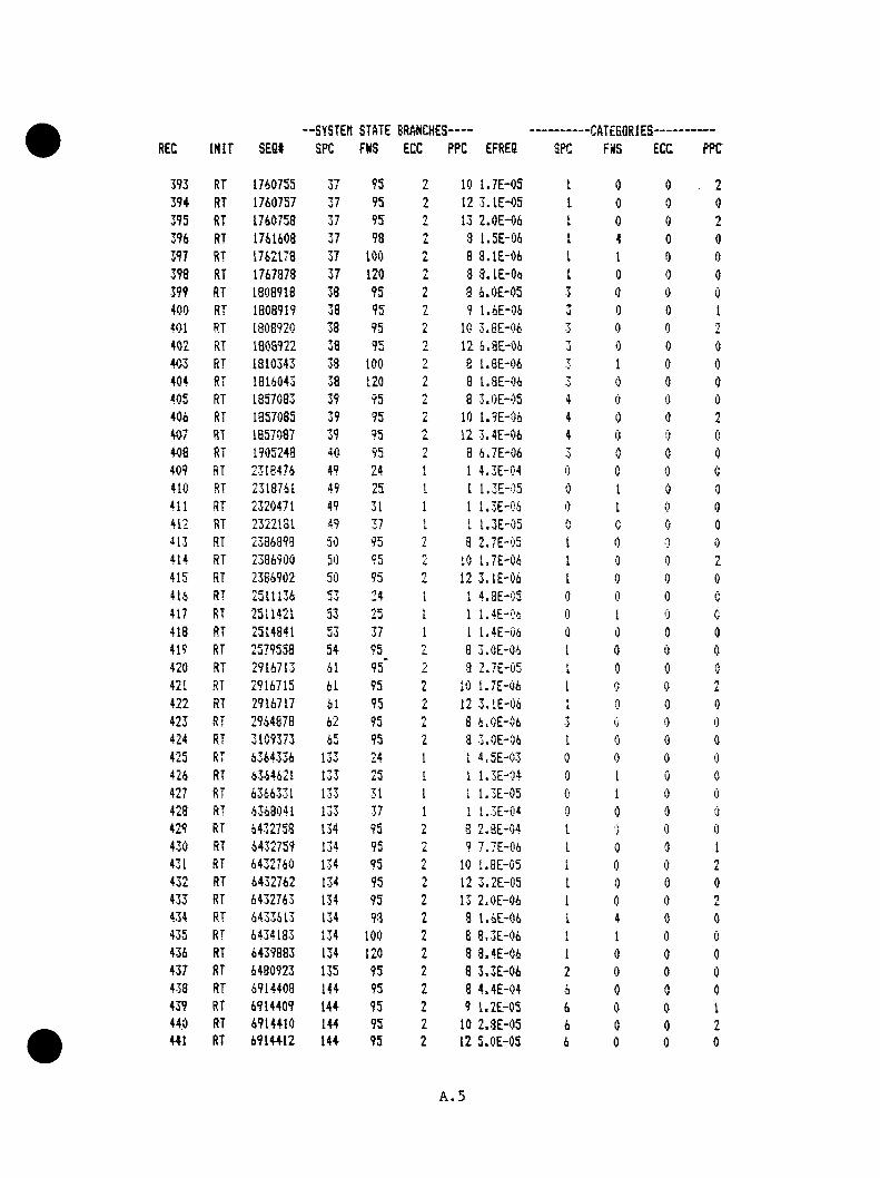
:c IN IT SE St--SYSTEtt STATE BRANCHES
SPC FHS ECC PPC EFRE8 SPC--CflTEBQRIES
FilS ECC PPC
393 RT 1760755 TTit 95 n
i. 10 1 .7 E -0 5 1 0 0 23 94 RT 1760757 37 95 2 12 3 .1 E -0 5 L 0 0 0395 RT 1760758 37 95 13 2 .0 E -0 6 ti 0 0 7396 RT 1761608 37 98 n 8 1 .5 E -0 6 I 4 0 0397 RT 1762173 37 100 n
L 8 a . lE - 0 6 I I 0 0398 RT 1767373 37 120 2 3 8 .1 E -0 6 1 0 0 0399 RT 1808918 38 95 2 8 6 .0 E -0 5 3 0 0 0400 RT 1808919 38 95 2 9 1 .6 E -0 6 0 0 0 1401 RT 1808920 38 95 n
L 10 3 .8 E -0 6 T■i 0 0 •T
402 RT 1308922 38 95 'y 12 6 .3 E -0 6 3 0 0 0403 RT 1810343 38 100 8 1 .8 E -0 6 1 0 0404 RT 1816043 38 120 8 1 .8 E -0 6 •j 0 0 0405 RT 1857083 39 95 n 8 3 .0 E -0 5 4 0 0 0406 RT 1357085 39 95 2 10 1 .9 E -0 6 4 0 0 T
407 RT 1857037 39 95 12 3 .4 E -0 6 4 0 0 0408 RT 1905248 40 95 3 6 .7 E -0 6 T 0 0 040? RT 2318476 49 24 1 1 4 .3 E -0 4 (S 0 0 0410 RT 2318761 49 25 1 1 1 .3 E -0 5 0 1 0 0411 RT 2320471 49 31 1 1 1 .3 E -0 6 0 1 0 0412 RT 2322131 4 ? 37 iL 1 1 .3 E -0 5 V G V 0i l 3 RT 2336393 50 95 i* 8 2 .7 E -0 5 1 0 0 0414 RT 2386900 50 95 "J 10 1 .7 E -0 6 1 0 0 2415 RT 2 366902 50 95 n 12 3 . lE -0 6 1 0 0 0416 RT 2511136 53 24 1 1 4 .3 E '0 5 0 0 0 0417 RT 2511421 53 25 I 1 1 .4 E -0 6 0 1 0 Au
418 RT 2514841 uO 37 1 1 1 .4 E -0 6 0 0 0 0419 RT 2579553 54 95 3 3 .0E -0-6 1 0 0 0420 RT 2916713 61 95* z. 3 -Z.TE-OS 11. 0 0 nV421 RT 2916715 61 95 n
L 10 1 .7 E -0 6 1 0 0TL
422 RT 2916717 61 95 'y 12 3 .1 E -0 6 1 0 0 0423 RT 2964878 62 95 ly 8 6 .0 E -0 6 0 0 0
424 RT 3109373 65 95 2 3 i .0 E " 0 6 1 0 0 0425 RT 6364336 133 24 1 1 4 .5 E -0 3 0 0 0426 RT 6364621 133 25 1 1 1 .3 E -0 4 0 1 0 0427 RT 6366331 133 31 1 1 1 .3 E '0 5 1 0 0428 RT 6363041 1 37 1 1 1 .3 E -0 4 0 0 0 0429 RT 6432758 134 95 -T
L 3 2 .8 E -0 4 1 ) 0 0430 RT 6432759 134 95 2 9 7 .7 E -0 6 1 0 0 1431 RT 6432760 134 95 10 l .B E -0 5 0 0 2432 RT 6 432762 134 95 2 12 3 .2 E -0 5 I 0 0 0433 RT 6432763 134 95 2 13 2 .0 E -0 6 1 0 0 7434 RT 6433613 134 98 2 8 1 .6 E -0 6 1 4 0 0435 RT 6434183 134 100 n
L 8 3 .3 E -0 6 1 1 0 0436 RT 6439883 134 120 2 3 8 .4 E -0 6 1 0 0 0437 RT 6480923 135 95 •y
L 3 3 .3 E -0 6 2 0 0 0438 RT 6914408 144 95 n
L 8 4 .4 E -0 4 6 0 0 0439 RT 6 914409 144 95 2 9 1 .2 E -0 5 6 0 0 1440 RT 6914410 144 95 2 10 2 .8 E -0 5 6 0 0 2441 RT 691 44 12 144 95 2 12 5 .0 E -0 5 6 0 0 0
A.5
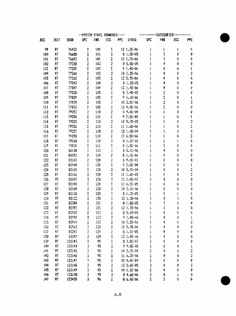
--SYSTEM STATE BRANCHES— -CATE50RIES-EC INIT SEQt SPC FHS ECC PPC EFREB SPC FHS ECC PPC
99 RT 76422 2 100 3 12 1 .3 E -0 6 1 1 1 0100 RT 76638 2 101 2 8 1 .5 E -0 5 1 3 0 0101 RT 76692 n 101 2 12 1 .7 E -0 6 1 3 0 0102 RT 77258 n
L 103 2 8 5 .0 E - 0 5 1 0 0103 RT 77259 2 103 2 9 1 .4 E -0 6 4 0 1104 RT 77260 103 2 10 3 .2 E -0 6 1 4 0 2105 RT 77262 n
L 103 2 12 5 .7 E -0 6 1 4 0 0104 RT 77543 n
L 104 2 8 1 .3 E -0 5 1 4 0 0107 RT 77547 1 104 n 12 1 .4 E -0 4 1 4 0 0108 RT 77328 n 105 n
C 8 3 .9 E -0 5 f\L 0 0
109 RT 77829 n 105 n 9 l . l E - 0 6 1 2 0 I110 RT 77830 2 105 10 2 .5 E -0 6 1 n
L 0 Tu
111 RT 77832 2 105 12 4 .5 E -0 6 tyL 0 0
112 RT 792 53 / IU 110 ' I 8 9 .0 E -0 4 1 1 0 0
113 RT 79254 1 110 9 2 .5 E -0 5 1 1 0 1114 RT 79255 n
L 110 nC 10 5 *7 E -05 1 1 0 2
115 RT 79256 n 110 nL 11 1 .6 E -0 6 1 i
I 0 Tu
114 RT 79257 L, 110 nL 12 l .O E -0 4 1 1 0 0
117 RT 79258 n 110 •yL 13 4 .5 E -0 6 1 1 0 2
l i e RT 79268 2 110 3 1 .2 E -0 4 1 I 1 0119 RT 79538 n 111 1 8 1 .5 E -0 6 I • J 0 0120 RT 30108 n 113 A
L 8 5 .1 E -0 4 1 4 0 0121 RT 80393 n
L 114 •yL 8 1 .3 E -0 6 1 4 0 0
122 RT 32103 nL 120 L 8 9 .0 E -0 3 1 0 0 0
123 RT 82104 120 •y 9 2 .5 E -0 4 1 0 0 1124 RT 82105 n
L 120 2 10 5 .7 E -0 4 1 0 0 nL
125 RT 82104 120 11 1 .6 E -0 5 1 0 0 0
126 RT 32107 nL 120 *y
L 12 l.O E -0 3 1 0 0 0127 RT 82108 0 120 ry 13 4 .5 E -0 5 I 0 0 TL.
128 RT 32109 120 nL 14 3 .1 E -0 6 0 0 0
129 RT 82113 2 120 3 3 U 2 E -0 5 0 1 0130 RT 32122 n 120 T 12 1 .3 E -0 6 1 0 1 0131 RT 82388 o
L 121 0u 8 1 .5 E -0 5 1 •) 0 0132 RT 32392 •1 121 n
L 12 1 .7 E -0 4 1 3 0 0133 RT 82958 n 123 J 8 5 .1 E -0 5 1 4 0 0134 RT 32959 n
L 123 2 9 1 .4 E -0 6 1 4 0 I135 RT 32940 L
n ? >y 10 3 .2 E -0 4 1 4 0 2134 RT 32942 2 123 i. 12 5 .7 E -0 6 1 4 0 0137 RT 83243 fy 124 8 1 .3 E -0 5 1 4 0 0138 RT 83247 n
L 124 n 12 1 .4 E -0 6 1 4 0 0139 RT 123143 3 95 •J 3 3 .5 E -0 3 0 0 0 0140 RT 123144 3 95 'J 9 9 .3 E -0 5 n 0 0 1141 RT 123145 ■j 95 »y 10 2 .3 3 - 0 4 2 0 0 •y
L
142 RT 123146 3 95 2 11 6 .2 E -0 6 2 0 0 2143 RT 123147 3 95 L 1 2 4 .0 E -0 4 2 0 0 0144 RT 123148 3 95 2 13 2 .6 E -0 5 2 0 0 2145 RT 123149 3 95 n
L 14 1 .2 E -0 6 2 0 0 0144 RT 123158 3 95 3 8 4 .6 E -0 4 2 0 1 0147 RT 123428 J 96 2 8 6 .0 E -0 6 2 3 0 0
A. 6

--SYSTEH STATE BRANGHES- -CATEGQRIES-c INIT SEQt SPC FNS ECC PPC EFREQ SPC FWS ECC PPC
148 RT 123998 3 98 2 8 2 .0 E -0 5 2 4 0 0149 RT 124000 3 98 n
L 10 1 .3 E -0 6 4 0 nL
150 RT 124002 3 98 2 12 2 .3 E -0 6 2 4 0 0151 RT 124283 3 99 n
L 8 5 .0 E -0 6 2 0 0152 RT 124568 •J 100 7 3 l . l E - 0 4 n
L I 0 0153 RT 124569 3 100 L 9 2 .9 E -0 6 n
L 1 0 1154 RT 124570 3 100 •y 10 6 .7 E -0 6 n 1 0 2155 RT 124572 0 100 n
L 12 1 .2 E -0 5 2 1 0 0156 RT 127418 7■J 110 n
L 8 l . l E - 0 5 2 1 0 0157 RT 127422 3 110 L 12 1 .2 E -0 6 2 1 c 0158 RT 130268 3 120 2 8 l . l E - 0 4 0 0 0 0159 RT 130269 3 120 2 9 2 .9 E -0 6 2 0 1160 RT 130270 120 2 10 6 .7 E -0 6 0 A
L
161 RT 130272 7■j 120 a
L 12 1 .2 E -0 5 2 0 0 0162 RT 171308 4 95 8 2 .7 E - 0 4 1 0 0 0163 RT 171309 4 95 f\ 9 7 .5 E -0 6 I 0 0 I164 RT 171310 4 95 1 10 1 .7 E -0 5 1 0 0 2165 RT 171312 4 95 2 12 3 .1 E -0 5 1 0 0 0166 RT 171313 4 95 2 13 2 .0 E -0 6 1 0 0 A
L
167 RT 172163 4 98 n 8 1 .5 E -0 6 1 4 0 0168 RT 172733 4 100 n
L 8 8 .0 E -0 6 [ 1 0 0169 RT 178433 4 120 2 8 8 .1 E -0 6 I 0 0 0
170 RT 199216 5 24 1 1 4 .3 E -0 4 0 0 0 0171 RT 199501 5 25 1 1 1 .3 E -0 5 !) i
i 0 0172 RT 201211 5 31 1 I 1 .3 E -0 6 0 1 0 0173 RT 202921 5 37 1 1 1 .3 E -0 5 0 0 0 0174 RT 267638 6 95 2 8 2 .7 E -0 5 1 0 0 0175 RT 267640 6 95 n
L 10 1 .7 E -0 6 1 0 0 •7i.
176 RT 267642 6 95 nL 12 3 .1 E -0 6 1 0 A'.} 0
177 RT 536371 12 24 1 1 4 .4 E -0 3 0 c 0 0178 RT 536656 12 25 1 1 1 .3 E -0 4 0 1 0 0179 RT 538366 12 31 I 1 1 .3 E -0 5 0 1 0 n
V
180 RT 540076 12 37 1 1 1 .3 E -0 4 0 0 0 0181 RT 604793 13 95 L 8 3 .0 E -0 1 1 0 0 0182 RT 604794 13 95 n
L 9 3 .3 E -0 3 1 0 0 i
183 RT 604795 13 95 L 10 1 .9 E -0 2 1 0 0 0u184 RT 604796 13 95 n
L 11 5 .3 E -0 4 1 AV 0 T
L
185 RT 604797 95 n 12 3 .4 E -0 2 1 0 A 0136 RT 604798 13 95 n
L. 13 2 .2 E -0 3 1 0 0 • TL
187 RT 604799 13 95 L 14 l.O E -0 4 1 0 0 0188 RT 604300 13 95 2 15 6 .6 E -0 6 I 0 0 2189 RT 604808 13 95 3 3 3 .9 E -0 4 1 0 1 0190 RT 604809 13 95 ■ J 9 l . l E - 0 5 1 1 1191 RT 604810 13 95 3 10 2 .5 E -0 5 1 I 2192 RT 6 04 81 2 13 95 3 12 4 .5 E -0 5 1 1 0193 RT 604813 13 95 3 13 2 .8 E -0 6 1 1 2194 RT 6 05 07 3 13 96 2 8 5 .2 E -0 4 1 70 0 0195 RT 605079 13 96 L 9 1 .4 E -0 5 1 3 0 1196 RT 6 05080 13 96 2 10- 3 .3 E -0 5 L 3 0 2
A.7
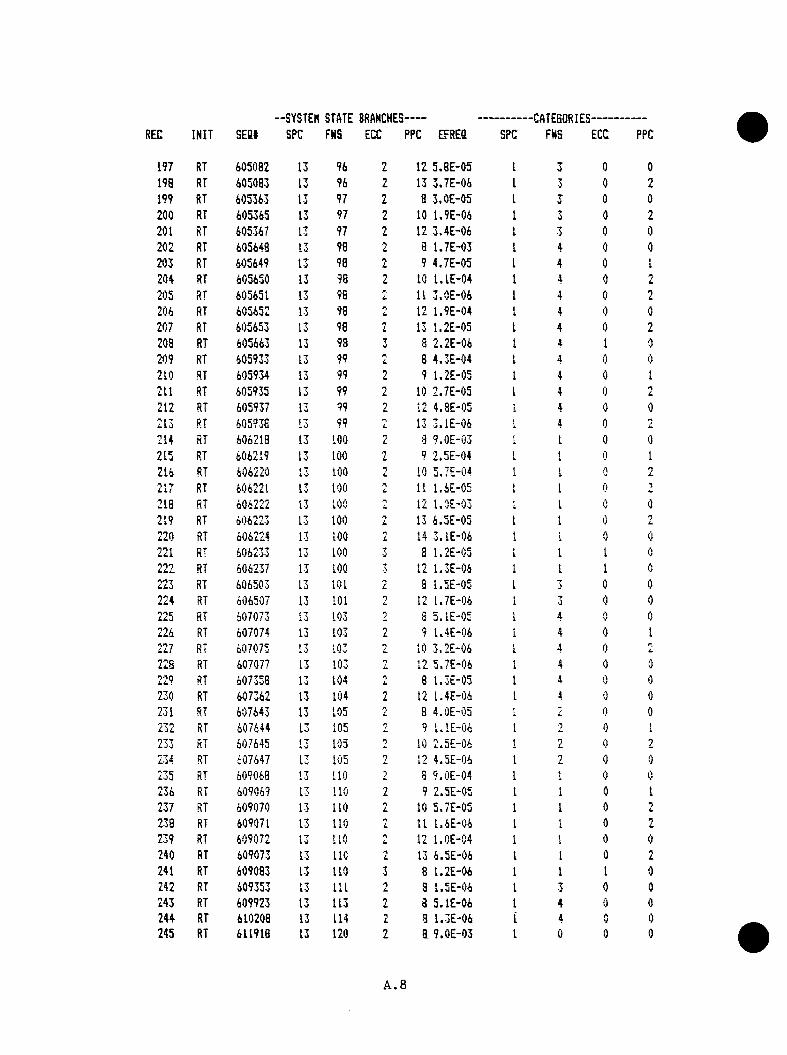
--SYSTEM STATE BRANCHES- -CATESORIES-EC INIT SE St SPC FHS ECC PPC EFREQ SPC FHS ECC PPC
197 RT 605082 13 96 2 12 5 .B E -0 5 1 3 0 0198 RT 605083 13 96 2 13 3 .7 E -0 6 1 3 0 2199 RT 605363 13 97 2 a 3 .0 E -0 5 1 a 0 0200 RT 605365 13 97 2 10 1 .9 E -0 6 1 3 0 2201 RT 605367 13 97 n
L 12 3 .4 E -0 6 1 3 0 0202 RT 605648 13 98 2 a 1 .7 E -0 3 1 4 0 0203 RT 605649 13 98 L 9 4 .7 E -0 5 1 4 0 t1204 RT 605650 13 98 n 10 l . l E - 0 4 1 4 0 2205 RT 605651 13 96 i. 11 3 .0 E -0 6 1 4 0 n
L
206 RT 605652 13 98 12 1 .9 E -0 4 4 0 0207 RT 605653 13 98 2 13 1 .2 E -0 5 1 4 0 2208 RT 605663 13 98 7w a 2 .2 E -0 6 I 4 1 0209 RT 605933 13 99 2 8 4 .3 E -0 4 I 4 0 0210 RT 605934 13 99 9 1 .2 E -0 5 \i 4 0 1211 RT 605935 13 99 7
i . 10 2 .7 E -0 5 I 4 0 n
212 RT 605937 13 99 7 12 4 .8 E -0 5 4 0 0213 RT 605938 13 99 n
L 13 3 .1 E -0 6 [ 4 0 jL
214 RT 606213 13 100 2 3 9 .0 E -0 3 I 1 0 0215 RT 606219 13 100 n
L 9 2 .5 E -0 4 1 [ 0 1216 RT 606220 f 7
L -J 100 nL 10 5 .7 E -0 4 1 1 A T
RT 606221 13 100 r\ 11 1 .6 E -0 5 1i 1 0218 RT 606222 13 100 n 12 l.O E -0 3 i 1 0 0219 RT 606223 13 100 n
L 13 6 .5 E -0 5 1 I 0 L
220 RT 606224 13 100 2 14 3 . lE -0 6 4 1 0 0221 RT 606233 13 100 •J a 1 .2 E -0 5 <L 1 1 02 22 RT 606237 13 100 7 12 1 .3 E -0 6 I 1 1 0223 RT 606503 13 101 8 1 .5 E -0 5 1 3 0 0224 RT 606507 13 101 •*> 12 1 .7 E -0 6 i
L•y•J 0 0
225 RT 607073 13 103 2 8 5 .1 E -0 5 1 4 AV 0226 RT 607074 13 103 2 9 1 .4 E -0 6 1 4 0 1
RT 607075 13 103 2 10 3 .2 E -0 6 1 4 0 L
223 RT 607077 13 103 L 12 5 .7 E -0 6 1i 4 0 0229 RT 607358 13 104 n
L 8 1 .3 E -0 5 1 4 0 0230 RT 607362 13 104 2 12 1 .4 E -0 6 I 4 0 0231 RT 607643 13 105 2 8 4 .0 E -0 5 L 0 0232 RT 607644 13 105 n 9 U lE - 0 6 i
i•T 0 1
233 RT 607645 13 105 10 2 .5 E -0 6 \ 2 0 9
RT 607647 13 105 n 12 4 .5 E -0 6 \i 2 0 0235 RT 609068 13 110 n 3 9 .0 E -0 4 1 1 0 0236 RT 609069 13 110 2 9 2 .5 E -0 5 1 1 0 1237 RT 609070 13 110 n
L 10 5 .7 E -0 5 1 1 0 2238 RT 609071 13 110 2 11 1 .6 E -0 6 1 t 0 9
239 RT 6 09072 13 110 n 12 l .O E -0 4 1 1 0 0240 RT 609073 13 l i e n
L 13 6 .5 E -0 6 1 I 0 2241 RT 609083 13 110 3 8 1 .2 E -0 6 1 1 1 0242 RT 609353 13 111 3 1 .5 E -0 6 1 3 0 0243 RT 609923 13 113 n
L 8 5 .1 E -0 6 1 4 0 0244 RT 610208 13 114 n
L 3 1 .3 E -0 6 i 4 0 0245 RT 611918 13 120 2 a 9 .0 E -0 3 iL 0 0 0
A.8

--SYSTEH STATE BRANCHE3-- -CATESQRIES-:c IN IT s e a * SPC FNS ECC PPC EFRES SPC FNS ECC PPC
2 4 i RT 611919 13 120 2 9 2 .5 E - 0 4 1 0 0 1247 RT 611920 13 120 L 10 5 .7 E -0 4 1 0 0 n
L
248 RT 611921 13 120 2 11 1 .6 E -0 5 (I 0 0 n
L
249 RT 6 11922 13 120 L 12 l .O E -0 3 I 0 0 0
250 RT 611923 13 120 2 13 6 .5 E -0 5 1 0 0 2251 RT 611924 13 120 TL. 14 3 .1 E -C 6 4
i 0 0 02 52 RT 611933 13 120 7 a 1 .2 E -0 5 1 0 1 0253 RT 611937 13 120 3 12 1 .3 E -0 6 1 0 0254 RT 612203 13 121 n 8 U 5 E -0 5 1 3 0 0255 RT 6122Q7 13 121 7 12 U 7 E -0 6 1 • J
A•J 0256 RT 612773 13 123 n
L 8 5 .1 E -0 5 1 4 0 0257 RT 612774 13 123 9 1 .4 E -0 6 1 4 0 1258 RT 612775 13 123 £ 10 3 .2 E -0 6 1 4 0 2259 RT 612777 13 123 L 12 5 .8 E -0 6 1 4 0 0260 RT {>lo058 13 124 1 a 1 .3 E -0 5 1 4 A
y 0261 RT 613062 13 124 1 12 1 .4 E -0 6 4
i 4 ') 0262 RT 652958 14 95 L 3 6 .6 E -0 2 0 0 0263 RT 652959 14 95 n 9 1 .3 E -0 3 0 0
1L
264 RT 652960 14 95 n 10 4 .2 E -0 3 0 0 0 *7
265 RT 652961 14 95 2 11 1 .2 E -0 4 • i i j 0nL
266 RT 652962 14 95 2 12 7 .5 E -0 3 • j 0 V 0
267 RT 652963 14 95 7 13 4 .3 E -0 4 3 0 Q •7L,
268 RT 652964 14 95 2 14 2 .3 E -0 5 • J 0 0 0269 RT 652965 14 95 L 15 1 .4 E -0 6 0 0 7
270 RT 652973 14 95 3 3 8 .6 E - 0 5 •J 0 1 0271 RT 652974 14 95 T 9 2 .4 E -0 6 ■'j 0 L
<
272 RT 652975 14 95 T• J 10 5 .5 E -0 6 3 0 1
i i
273 RT 652977 14 95 3 12 9 .S E -0 6 • J 0 1 V
274 RT 653243 14 96 2 a l . l E - 0 4 T AV 0
275 RT 653244 14 96 0 9 3 . lE -0 6 • JA 1
276 RT 653245 14 96 n 10 7 .2 E -0 6 ■J •jt ( j i
277 RT 653247 14 96 0 12 1 .3 E -0 5 ■j i ) A
278 RT 653523 14 97 2 a 6 .7 E -0 6 T 70 0
279 RT 653813 14 93 L 8 3 .8 E -0 4 »0 0
280 RT 653814 14 98 ' ) 9 l .O E -0 5 i 0 12 8 1 RT i r T " i s
i - J 14 98 n 10 2 .4 E -0 5 3 4 0 L
282 RT 653317 14 98 / 12 4 .3 E -0 5 T 4 0 0
283 RT 653818 14 93 / 13 2 .7 E -0 6 3 4 0 2284 RT 654098 14 99 3 9 .4 E -0 5 3 4 0 0285 RT 654099 14 99 • n
L 9 2 -6 E -0 6 J 4 0 I
286 RT 654100 14 99 n 10 6 .0 E -0 6 3 4 0 2237 RT 654102 14 99 i 12 l . l E - 0 5 3 4 0 0
288 RT 654383 14 to o £ 3 2 .0 E -0 3 7 1 0 0289 RT 654384 14 100 2 9 5 .4 E -0 5 3 1 ( 1 I
290 RT 654385 14 100 2 10 1 .3 E -0 4 7W 1 0 2
291 RT 654386 14 100 L 11 3 .5 E -0 6 J 1 0 7u
2 92 RT 654387 14 100 n 12 2 .2 E -0 4 7•i 1 0 0
293 RT 654388 14 100 13 1 .4 E -0 5 7• J 1 0 7
2 9 4 RT 6 5 4 3 9 8 14 100 3 a 2 .6 E -0 6 3 1 1 0
A.9
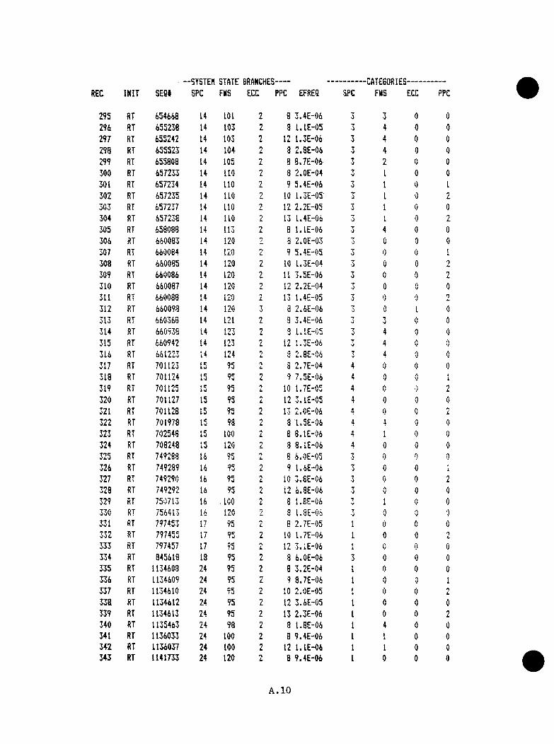
-SYSTEM SlftTE BRANCHES- -CATEGORIES-;c IK IT SE 8I SPC FMS ECC PPC EFRES SPC FHS ECC PPC
295 RT 454448 14 101 2 8 3 .4 E -0 4 3 3 0 0m RT 455238 14 103 2 3 l . l E - 0 5 3 4 0 02 9 7 RT 435242 14 103 2 12 1 .3 E -0 4 3 4 0 0298 RT 455523 14 104 n
L 3 2 .8 E -0 4 T 4 0 0299 RT 453808 14 105 1 8 8 .7 E -0 4 3 2 0 0300 RT 457233 14 110 2 8 2 .0 E -0 4 T
•J 1 0 0301 RT 457234 14 110 2 9 5 .4 E -0 4 3 I 0 1302 RT 457235 14 110 2 10 1 .3 E -0 5 •J 1 0 23 03 RT 457237 14 110 2 12 2 .2 E -0 5 7
•J 1 0 0304 RT 457238 14 110 Z 13 1 .4 E -0 4 ■J
»i 0 2305 RT 458038 14 113 2 8 l . l E - 0 4 3 4 0 0304 RT 440083 14 120 2 8 2 .0 E -0 3 7
0 0 0307 RT 440084 14 120 n-
L 9 5 .4 E -0 5 3 0 0 (i
308 RT 440085 14 120 2 10 1 .3 E -0 4 3 0 0309 RT 440084 14 120 2 11 3 .5 E -0 4 C l 0 0310 RT 440087 14 120 • ■ J 12 2 .2 E -0 4 ‘j 0 0311 RT 440088 14 120 L 13 1 .4 E -0 5 ■J 0 0 2312 RT 440093 14 120 3 e 2 .6 E -0 4 7
•J 0 I 0313 RT 640348 14 121 L 3 3 .4 E -0 4 •'j
7 0 0314 RT 440938 14 123 1 3 1 .1E -C 5 7 4 0 0315 RT 440942 14 123 2 12 1 .3 E -0 6 J 4 0 n
314 RT 441223 14 124 0L, 3 2 .8 E -0 6 7 4 0 0
317 RT 701123 15 95 f\L, 8 2 .7 E -0 4 4 0 0 0
318 RT 701124 15 95 1 9 7 .5 E -0 6 4 0 0 1319 RT 701125 15 95 2 10 1 .7 E -0 5 4 0 i ) 2320 RT 701127 15 95 2 12 3 .1 E -0 5 4 0 0 0321 RT 701128 15 95 2 13 2 .0 E -0 6 4 0 0 £
3 22 RT 701973 15 98 nL 3 1 .5 E -0 6 4 4
'J 0323 RT 702548 15 100 i. 8 8 .1 E -0 4 4 [ 0 0
324 RT 708243 15 120 nL 3 8 .1 E -0 6 4 0 0 0
325 RT 749288 14 95 nL 8 6 .0 E -0 5 3 0 A A
324 RT 749289 16 95 u 9 1 .6 E -0 4 j 0 0 i
327 RT 749290 14 95 2 10 3 .8 E -0 4 3 0 0 i.
328 RT 749292 14 95 12 4 .8 E -0 6 ;j 0 0329 RT 750713 16 ^ ICO ? 8 1 .8 E -0 4 7 1 u 0330 RT 754413 16 120 Z 8 1 .3 E -0 6 0 0
331 RT 797453 i * T1 / 95 nL 8 2 .7 E -0 5 1 0 0 0
RT 797455 17 95 2 10 1 .7 E -0 6 1 0 0333 RT 797457 17 95 n
L 12 3 .1 E -0 4 1 0 0 0334 RT 845418 18 95 n
L 8 4 .0 E -0 4 3 0 0 03 35 RT 1134408 24 95 2 8 3 .2 E -0 4 1 0 0 0334 RT 1134409 24 95 z 9 3 .7 E -0 4 1 0 ■ } 1337 RT 1134410 24 95 L 10 2 .0 E -0 5 1 0 0 n
L
338 RT 1134412 24 95 2 12 3 .4 E -0 5 1 0 0 0339 RT 1134413 24 95 2 13 2 .3 E - 0 4 1 0 0 2340 RT 1135443 24 98 n
L a 1 .8 E -0 4 1 4 0 0341 RT 1134033 24 100 2 8 9 .4 E -0 4 1 1 0 03 4 2 RT 1134037 2 4 to o 2 12 l . l E - 0 4 1 1 0 03 43 RT 1141733 24 120 2 8 9 .4 E -0 4 1 0 0 0
A.IO

-SYSTEH STATE 8RAHCHES- -CATESQRIE3-:c INIT SEQ4 SPC FNS ECC PPC EFREa SPC FNS ECC PPC
344- RT 1141737 24 120 n{. 12 U lE -0 6 1 0 0 0
345 RT 1182773 25 95 L 8 3 .6 E -0 3 TL 0 0 0346 RT 1182774 25 95 •T
L 9 9 .8 E -0 5 nL 0 0 1L
347 RT 1182775 25 95 •TL 10 2 .3 E -0 4 1 0 0 0
L
348 RT 1182776 25 95 n U 6 .2 E -0 6 2 0 u nL
349 RT 1182777 25 95 nL 12 4 .0 E -0 4 TI, 0 0 0
350 RT 1182773 25 95 rSL 13 2 .6E -05 i. 0 0 2
351 RT 1182779 25 95 L 14 1 .2E -06 nL 0 0 0
352 RT 1132783 25 95 8 4 .6 E -0 6 L 0 I 0353 RT 1183058 25 96 L 8 6 . 1E“ 06 L 0 0354 RT 1183628 25 98 n
L 3 2 .0E -05 nL 4 0 0
355 RT 1183630 25 98 2 10 1 .3E -06 1 4 0 2356 RT 1183632 25 93 1 12 2 .3E -06 4 Ai 0357 RT 1183913 25 99 L 8 5 .0 E -0 6 n
L 4 0 0358 RT 1184198 25 too n
L 3 l .L E -0 4 Tu 1 0 0359 RT 1184199 25 100 0 9 2 .9 E -0 6 2 1 0 [
360 RT 1184200 25 100 ni. 10 6 .7 E -0 6 2 1i 0 • T
I.
361 RT 1184202 n e1-J 100 L 12 1 .2E -05 n
I 1 0 0362 RT 1187043 25 110 n
L a l . lE - 0 5 7 1 0 0363 RT 1187052 25 l i e n
L 12 1 .2E -06 7 1 0 0364 RT 1189898 25 120 • 7 a l . lE - 0 4 0 0 0365 RT 1139899 n c 120 9 2 .9E-C 6 0
& 0 I j 1366 RT 1189900 L-J 120 • T
L 10 6 .3 E -0 6 2 0 0 7
367 RT 1189902 120 2 12 1 .2E -05 nL 0 0 0
363 RT 1230938 26 95 0L. 8 2 .7E -04 4 0 0 0369 RT 1230939 26 95 n
L 9 7 .5E -06 4 0 0 1370 RT 1230940 26 95 n
L 10 1 .7E -05 4 0 0 n
371 RT 1230942 26 95 L 12 3 .1 E -0 5 4 0 n 0372 RT 1230943 26 95 2 13 2 .0 E -0 6 4 0 0 2V I • j RT 1231793 26 98 3 1 .5E -06 4 4 0 0374 RT 1232363 26 100 2 3 3 .1 E -0 6 4 i 0 0375 RT 1238063 26 120 / 3 3 . 1E“ 06 4 V 0 A
V
376 RT 1279103 27 95 a 3 .9 E -0 4 r• J 0 0 0
377 RT 1279104 27 95 9 l . lE - 0 5 5 0 0 1378 RT 1279105 27 95 7 10 2 .5E -05 J 0 0 7
379 RT 1279107 27 95 L 12 4 .5E -05 c■ J 0 I ' l 0
380 RT 1279108 0 7 95 nu 13 2 .9E -06 5 0 0 n
38! RT 1279958 • ■ V Tt ! 98 L 3 2 .2E -06 r. 4 0 0
332 RT 1280523 27 100 2 8 1 .2E -05 5 1 0 0383 RT 1280532 27 100 n
L 12 1 .3E -06 5 1 0 0384 RT 1283378 27 110 L a 1 .2E -06 5 1 0 0385 RT 1286228 27 120 2 8 1 .2E -05 5 0 0 0386 RT 1286232 27 120 2 12 1 .3E-06 5 0 0 0387 RT 1327268 28 95 n
L 3 3 .0 E -0 5 4 0 0 0388 RT 1327270 28 95 1 10 1 .9E -06 4 0 0 2389 RT 1327272 28 95 1 12 3 .4 E -0 6 4 0 0 0390 RT 1712588 36 95 2 8 3 .6 E -0 6 2 0 0 0391 RT 1760753 37 95 2 a 2 .7E -04 i 0 0 0392 RT 1760754 37 95 2 9 7 .5 E -0 6 1 0 0 1
A . l l

•C IHIT SEQt-SYSTEM STATE BRANCHES
SPC FWS ECC PPC EFREQ SPC-CATEBQRIES
FWS ECC PPC
491 EilFH 7 7 8 2 8 nL. 105 L 8 2 .1 E -0 5 1 n
L 0 0492 ENF« 77830 1 105 2 10 1 .3 E -0 6 I
0i. 0 2495 EHFH 778 32 1 105 2 12 2 .4 E -0 6 1 fy
L 0 0494 EHFW 79253 2 110 2 3 5 .3 E -0 4 1 1 0 0495 EMFM 7 9254 2 110 2 9 U 5 E -0 5 1 1 0 1496 EMFW 7 92 55 2 110 2 10 3 .4 E -0 5 1 1 0 2
497 EHFH 7 92 57 2 110 nL 12 6 .1 E -0 5 1 t 0 0
498 EflF« 79258 z 110 L 13 3 .9 E -0 6 1 1 0 nL
499 EHF« 80108 2 113 2 8 3 .0 E -0 6 - 1 4 0 0
500 EI1FH 124563 7 100 n a 5 .6 E -0 5 2 i 0 0501 EHFW 124569 3 100 L 9 1 .6 E -0 6 2 1 0 1502 EMFW 124570 7
J 100 U 10 3 .6 E -0 6 nL 1 0 2
503 EMFW 124572 100 2 12 6 .4 E - 0 6 nL 1 0 0
504 EMFW 127418 C p 110 2 8 6 .3 E -0 6 7 1i 0 0
505 EMFW 172733 4 100 i. 8 4 .3 E -0 6 1 i 0 0506 EMFW 199501 C
- J 23 1 1 6 .8 E -0 6 0 1 0 0507 EMFW 536656 12 •nc.:j 1 1 7 .0 E -0 5 0 i 0 0508 EMFW 538366 12 31 1 1 7 .8 E -0 6 1 0 0509 EMFW 606218 13 100 0L. 8 4 .0 E -0 3 1 L 0 0510 EMFW 606219 13 100 2 9 1 .3 E -0 4 1 i 0 1511 EMFW 606220 13 100 2 10 3 .1 E -0 4 1 0 n
512 EMFW 606221 13 100 2 11 8 .5 E -0 6 I 1 0 L
513 EMFW 606222 13 100 L 12 5 .4 E -0 4 1 1 0 0514 EMFW 606223 13 100 13 3 .5 E -0 5 1 1 0 n
L
515 EMFW 606224 13 100 14 1 .6 E -0 6 1 1 0 0516 EMFW 606233 13 100 8 6 .3 E -0 6 1 1 1 0517 EMFW 606503 13 101 2 8 8 .2 E -0 6 I 3 0 0518 EMFW 607073 13 103 3 2 .7 E -0 5 I 4 0 0519 EMFW 607075 13 103 2 10 1 .7 E -0 6 1 4 0 L
520 EMFW 607077 13 103 2 12 3 .1 E -0 6 1 4 0 0521 EMFW 607358 13 104 8 6 .8 E -0 6 1 4 0 0522 EMFW 607643 13 105 2 a 2 .1 E -0 5 a 0523 EMFW 607645 13 105 2 10 1 .4 E -0 6 1 2 0 i
524 EMFW 607647 13 105 n 12 2 .4 E -0 6 1 2 0 0525 EMFW 609068 13 110 2 3 5 .4 E -0 4 1 1 0 0526 EMFW 609069 13 110 9 1 .5 E -0 5 1 1 0 J
k
527 EMFW 609070 13 110 ni . 10 3 .4 E -0 5 1 1 0 n
L
523 EMFW 609072 13 110 nL 12 6 . lE -0 5 1 1 0 0
529 EMFW 609073 13 110 nL 13 3 .9 E -0 6 1 1 0 7im.
530 EMFW 609923 13 113 1 3 3 .0 E -0 6 1 4 0 0531 EMFW 6 54383 14 100 2 8 l . l E - 0 3 0 1 0 0532 EMFW 654384 14 100 n
L 9 2 .9 E -0 5 3 1 0 1533 EMFW 654385 14 too 2 10 6 .7 E -0 5 • J 1 0 2
534 EMFW 654386 14 100 2 11 1 .9 E -0 6 7• J I 0 2
535 EMFW 654387 14 100 nL 1 2 1 .2 E -0 4 3 1 0 0
536 EMFW 654388 14 100 0L. 13 7 .6 E -0 6 3 1 0 2537 EMFW 654398 14 100 3 8 1 .4 E -0 6 3 1 1 0538 EMFW 654668 14 101 n
L 8 1 .8 E -0 6 7- J 3 0 0
539 EMFW 6 55 23 8 14 103 1 8 6 . 0 8 - 0 6 3 4 0 0
A.12

-SYSTEK STATE SftANCHES- -CATESQRIES-—.c INIT SE St SPC FWS ECC PPC EFREQ SPC FWS ECC PPC
442 RT 6914413 144 95 2 13 3 .2 E -0 6 6 0 0 2443 RT 6915263 144 98 2 8 2 .5 E -0 6 6 4 0 0444 RT 6 91 58 33 144 100 2 8 1 .3 E -0 5 6 I 0 0445 RT 6 915837 144 100 2 12 1 .5 E -0 6 6 1 0 0446 RT 691 86 83 144 110 2 8 1 .3 E "0 6 6 1 0 0447 RT 6 921533 144 120 n
L 8 1 .3 E -0 5 6 0 0448 RT 6 921537 144 120 2 12 1 .5 E -0 6 a 0 0449 ENFN 6841 1 25 1 1 7 .6 E -0 2 1 0 0450 ENFW 7148 1 26 n 3 l . l E - 0 4 0 • j 0 0451 EHFjf 714? 1 26 n
L 9 2 .9 E -0 6 0 • J 0 I4 52 EHFH 7150 1 26 n
L 10 6 .8 E -0 6 0 V 0 2453 ERFN 7152 1 26 2 12 1 .2 E -0 5 0 7
• J 0 0
454 ERFW 7433 1 27 n 3 6 .3 E -0 6 0 0 0455 EHF« 7703 1i 28 1 8 3 .5 E - 0 4 0 4 0 0456 EHFN 7704 1 28 1 9 9 .8 E -0 6 0 4 0 I457 E m 7705 1 28 1
X 10 2 .3 E -0 5 0 4 0nL
458 EHF« 7707 1 23 iX 12 4 .0 E -0 5 0 4 0 0
459 ENFK 7708 1i 28 1 13 2 .6 E -0 6 0 4 0
ni.
460 EKFN 7988 1 29 1 8 3 .9 E -0 5 0 4 0 0461 ERFN 7989 I 29 I 9 2 .4 E -0 6 0 4 0 I
462 E m 7990 ii 29 1 10 5 .7 E -0 6 0 4 0 2463 EMFW 7992 1 29 1 12 1 .0 E -0 5 4 0 0
464 E m 8288 1 30 nL 3 2 .8 E -0 4 z 0 0
465 EMFH 3289 i 30 •TL 9 7 .7 E -0 6 n
L 0 1466 ENFN 3290 1
i 30 2 10 1 .3 E -0 5 00L. 0 2
467 E m 3292 1 30 2 12 3 .2 E -0 3 0 2 0 0
468 EMFW 8293 1 30 2 13 2 .0 E -0 6 0 0i. 0 2469 EMFW 8551 1 31 1 1 S .4 E -0 3 0 [ 0 0470 EMFW 8853 1 T T L 8 1 .2 E -0 5 0 • j 0 0471 EMFW 3862 1 32 7 12 1 .3 E -0 6 0 j 0 0472 EMFs 9413 1 34 1 3 4 .0 E -0 5 0 4 0 0473 EMFW 9414 1 34 1 9 l . l E - 0 6 0 4 0 I474 EMFW 9415 1 34 1 10 2 .5 E -0 6 0 4 0 n
L
475 EMFW 9417 1 34 1 12 4 .5 E -0 6 0 4 0 0476 EMFW 9698 1 35 1 8 9 .9 E -0 6 0 4 0 A
V
477 EMFW 9702 1 35 1 12 l . l E - 0 6 0 4 0 0478 EMFW 76403 n
L LOO L 3 4 .3 E -0 3 1 I 0 0479 EMFW 76404 9 100 9 1 .3 E -0 4 1 1 0 \
480 EMFW 76405 L 100 10 3 .1 E -0 4 I 1 0 1
481 EMFW 76406 •■J 100 L 11 8 .4 E -0 6 1 I 0 1
482 EMFW 76407 nL 100 7 12 5 .4 E -0 4 1 1 0 0
483 EMFW 76408 •yL too 7 13 3 .5 E -0 5 I 1 0 1
L.
484 EMFW 76409 L 100 7 14 1 .6 E -0 6 I 1 0 0485 EMFW 76418 L 100 3 8 6 .2 E -0 6 1 1 I 0486 EMFW 76688 2 101 2 3 8 .2 E -0 6 I 0 0487 EMFW 77258 n
L 103 2 8 2 .7 E -0 5 1 4 0488 EMFW 77260 2 103 2 10 1 .7 E -0 6 L 4 0489 EMFW 7 7 2 6 2 2 103 2 12 3 .1 E -0 6 1 4 0490 EMFW 7 75 43 2 104 2 8 6 .8 E -0 6 t 4 0 0
A.13

"SYSTEtl STATE 8RANCHES- -CATESORIES-c INIT SEQt SPC FWS ECC PPC EFREQ SPC FWS ECC PPC
540 EHFW 655523 14 104 n 8 1 .5 E -0 6 3 4 0 0541 ENFN 655808 14 105 I. 3 4 .7 E -0 6 3 2 0 0542 ENFW 657233 14 110 1 8 1 .2 E -0 4 1 0 0543 EMFN 657234 14 110 i. 9 3 .2 E -0 6 3 1 0 1544 EMFW 657235 14 110 2 10 7 .5 E -0 6 3 1 0 ' I
L
5 45 EMFW 657237 14 110 TL 12 1 .3 E -0 5 3 1 0 0
546 EMFW 702548 15 100 2 a 4 .3 E -0 6 4 1 0 0547 EMFW 1136033 24 100 2 a 5 .0 E -0 6 I 1 0 0548 EMFW 1184198 25 100 L 8 5 .6 E -0 5 ■1 0 0549 EMFW 1184199 25 100 L 9 1 .6 E -0 6 2 1 0 1550 EMFW 1184200 25 100 n
L 10 3 .6 E -0 6 04. 1 0 2551 EMFW 1184202 4. J 100 L 12 6 .4 E -0 6 n
L I 0 0552 EMFW 1187048 25 110 2 3 6 .3 E -0 6 L I 0 0553 EMFW 1232363 26 100 n
L a 4 .3 E -0 6 4 1 0 0554 EMFW 1280528 27 100 2 3 6 .3 E -0 6 5 1 0 0555 EMFW 1762178 3 7 100 2 8 4 .3 E -0 6 I 1 0 0556 EMFW 2318761 49 25 1 I 6 .8 E -0 6 0 I 0 0557 EMFW 6364621 133 25 1 1 7 .0 E -0 5 0 1 0 0558 EMFW 6366331 133 31 1 1 7 .9 E -0 6 0 I 0 0559 EMFW 6434183 134 100 L 8 4 .5 E -0 6 1 I 0 0560 EMFW 6915833 144 100 9 8 7 .0 E -0 6 6 i 0 0561 L3LB 5786356 121 24 1( 1 8 .7 E -0 5 0 0 05 62 L3LB 5786641 121 25 1 I 2 .6 E -0 6 0 1 0 0563 L3L3 5790061 121 37 1 I 2 .6 E -0 6 0 0 0 1 )
564 LSLB 5854778 122 95 n 8 5 .5 E -0 6 I 0 0 0565 L3LB 6075346 127 24 1 I 3 .4 E -0 4 0 0 0566 LSLB 6075631 127 25 1 1 2 .5 E -0 5 0 0 0567 LSLB 6077341 127 31 1 1 2 .5 E -0 6 0 1 AKJ 0568 LSLB 6079051 127 37 1 1 2 .5 E -0 5 0 0 0 0569 S3L6 5786356 121 24 1 1 6 .7 E -0 3 0 0 0 0570 33LB 5786641 121 25 1 t 2 .6 E -0 4 0 0 0571 SSLB 5787503 121 28 1 3 U 2 E -0 6 0 0 0572 SSLB 5788351 121 31 1 1 2 .6 E -0 5 0 1 0 0573 SSLB 5790061 121 37 1 I 2 .6 E -0 4 0 0 0 0574 SSLB 5790923 121 40 1 8 L .2E -06 0 4 0 0575 SSLB 5834543 122 24 • J 8 5 .5 E -0 4 1 0 0576 SSLB 5834544 122 24 L 9 1 .5 E -0 5 1 0 0 1577 SSLB 5834545 122 24 n
L 10 3 .5 E -0 5 1 0 0 nL
578 SSLB 5834547 122 24 nL 12 6 .2 E -0 5 1 0 0
579 SSLB 5834548 122 24 L 13 4 .0 E -0 6 1 0 0 Ti.
580 SSLB 5834823 122 25 2 3 1 .6 E -0 5 1 1 0 0581 SSLB 5834830 122 25 n 10 l.O E -0 6 1 1 0 2582 SSLB 5834832 122 25 12 1 .8 E -0 6 1 1 0 0583 SSLB 5836538 122 31 2 8 1 .6 E -0 6 1 1 0 0584 SSLB 5838248 122 37 2 8 1 .6 E -0 5 1 0 0 0585 SSLB 5838250 122 37 2 10 l .O E -0 6 1 0 0 2586 SSLB 583 82 52 122 37 n
L 12 1 .8 E -0 6 1 0 0 0587 SSLB 5882708 123 24 1 3 6 .5 E -0 6 2 0 0 05 88 SSLB 6316171 132 24 1 I 8 .0 E -0 6 0 0 0 0
A . I A

REC INIT SE 9I-SYSTEN- STATE BRANCHES
SPC FMS ECC PPC EFRES SPC--CATEBQRIES
FMS ECC PPC
589 SSLB 6 364336 133 24 1 1 7 .5 E -0 6 0 0 0 0590 LQNFN 45323 I 160 1 3 4 .9 E -0 1 0 0 0 0591 LQNFN 45324 1 160 1 9 1 .3 E -0 2 0 0 0 1592 LONFN 4 53 25 1 160 1 10 3 .1 E - 0 2 0 0 0 2593 LQNFN 45326 1 160 1 11 8 .6 E -0 4 0 0 0 2594 LO«F« 45327 1 160 I 12 5 .5 E -0 2 0 0 0 0595 LONFH 45328 1 160 1 13 3 .5 E -0 3 0 0 0 Ti .596 LQMFW 45329 1 160 1 14 1 .7 E -0 4 0 0 0 0597 LOMFW 45330 1 160 1 15 l . l E - 0 5 0 0 0 2598 LQMFH 45608 1 161 1 3 1 .7 E -0 3 0 j 0 0599 LQHFN 45609 I 161 1 9 4 .6 E -0 5 0 3 0 »i
600 LQHFN 45610 1 161 1 10 l . l E - 0 4 0 T'J 0 2601 LQNFM 45611 I 161 1 11 2 .9 E -0 6 0 j 0 n
L
602 LQHFK 45612 1 161 I 12 U 9 E -0 4 0 3 0 0603 LQNFM 45613 1 161 1 13 1 .2 E -0 5 0 3 0 2604 LQNFM 4 58 93 i 162 1 3 1 .7 E -0 4 0 •i 0 0605 LQNFM 45894 1 162 1 9 4 .6 E -0 6 0 7•J 0 1
606 LQNFM 45895 4i 162 1 10 l . l E - 0 5 0 3 0 nL
607 LQNFM 45897 1 162 1 12 1 .9 E -0 5 0 ■j 0 0
608 LQNFM 45898 1 162 1 13 1 .2 E -0 6 0 3 0 2609 LQNFM 46178 1 163 1 8 2 .8 E -0 3 0 4 0 V
610 LQNFM 46179 1 l6 o 1 9 7 .6 E -0 5 0 4 0 1611 LQNFM 4 6 1 BO ii 163 1 10 1 .3 E -0 4 0 4 0 •7
612 LQNFM 46181 1 163 i1 11 4 .9 E -0 6 0 4 0 2613 LQNFM 46132 4I 163 4
i 12 3 . lE -0 4 0 4 0 0614 LQNFM 46183 4
I 163 1 13 2 .0 E -0 5 0 4 0 2615 LQNFM 46463 1 164 ii 8 6 .9 E -0 4 0 4 0 0616 LQNFM 46464 1 164 1I 9 1 .9 E -0 5 0 4 0 1617 LQNFM 46465 1 164 I 10 4 .4 E " 0 5 0 4 0 ■)L.
618 LQNFM 46466 i 164 I 11 1 .2 E -0 6 0 4 0 7i.619 LQNFM 46467 4 164 1 12 7 .8 E -0 5 0 4 0 0620 LQNFM 46468 1 164 i
4 13 5 .0 E -0 6 0 4 0 2
621 LQNFM 93503 •T 160 8 3 .7 E -0 2 1 0 0 0622 LQNFM 93504 2 160 9 l .O E -0 3 1 0 0 1623 LQNFM 93505 2 160 L 10 2 .4 E -0 3 1 0 0 2
624 LQNFM 93506 160 nL 11 6 .6 E -0 5 1 0 0 2
625 LQNFM 935C7 2 160 nL 12 4 .2 E -0 3 1 0 0 0
626 LQNFM 93508 2 160 9 13 2 .7 E -0 4 1 0 0627 LQNFM 93509 Hi 160 L 14 1 .3 E -0 5 I 0 0 0628 LQNFM 93518 2 160 3 3 4 .9 E -0 5 1 0 1 0629 LQNFM 93519 2 160 3 9 1 .3 E -0 6 1 0 1 1630 LQNFM 93520 2 160 7■■i 10 3 . lE -0 6 1 0 I 2631 LQNFM 9 35 22 n 160 3 12 5 .5 E -0 6 I 0 1 0632 LQNFM 93788 2 161 ') 3 1 .3 E -0 4 1 3 0 0633 LQNFM 93789 2 161 2 9 3 .5 E -0 6 1 3 0 1634 LQNFM 93790 2 161 2 10 8 .1 E -0 6 1 3 0 2635 LQNFM 9 3792 L 161 2 12 1 .4 E -0 5 1 3 0 0636 LQNFM 94073 1 162 2 8 1 .3 E -0 5 1 3 0 0637 LQNFM 9 40 77 2 162 2 12 1 .4 E -0 6 1 3 0 0
A. 15

-SYSTEM STATE BRANCHES- -CATESQRIES-c INIT SEQt SPC FMS ECC PPC EFREQ SPC FMS ECC PPC
&3S LQNFN 943 58 2 163 2 3 2 .1 E -0 4 k 4 0 0639 LONFN 94359 2 163 2 9 5 .3 E -0 6 I 4 0 I640 LQNFM 94360 2 163 2 10 1 .3 E -0 5 1 4 0 2641 LQNFM 943 62 2 163 2 12 2 .4 E -0 5 1 4 0 0642 LQNFM 943 63 2 163 2 13 1 .5 E -0 6 I 4 0 i.
643 LQNFM 94643 9 164 2 8 5 .3 E -0 5 4 0 0644 LQNFM 946 44 n
L 164 nL 9 1 .5 E -0 6 I 4 0 I
645 LQNFM 94645 n 164 2 10 3 .4 E -0 6 1 4 0 2
646 LQNFM 94647 n 164 ni. 12 6 .0 E -0 6 1 4 0 0
647 LQNFM 141668 T•J 160 ni. 8 4 .4 E -0 4 2 0 0 0
648 LQNFM 141669 T• j 160 2 9 1 .2 E -0 5 2 0 0 1
649 LQNFM 141670 7■J 160 n 10 2 .8 E -0 5 2 0 0 2650 LQNFM 141672 7 160 9 12 5 .C E -0 5 n 0 0 0
651 LQNFM 141673 3 160 z 13 3 .2 E -0 6 n 0 0 *5
652 LQNFM 141953 161 nL a 1 .5 E -0 6 nL 3 0 0
653 LQNFM 142523 7•J 163 n 8 2 .5 E -0 6 7i. 4 0 0654 LQNFM 139833 i 160 2 8 3 .4 E -0 5 ik 0 0 0655 LQNFM 189335 4 160 n
L 10 2 . lE -0 6 1 0 0 L
656 LQNFM 139837 4 160 1 12 3 .8 E -0 6 1 0 0 0657 LQNFM 237983 c 160 f
i 8 4 .4 E -0 5 0 0 0 0653 LQNFM 237984 w 160 1 9 1 .2 E -0 6 0 0 1I659 LQNFM 237935 c
J 160 1 10 2 .8 E -0 6 0 0 0 2660 LQNFM 237987 e
J 160 1 12 5 .0 E -0 6 0 0 0661 LQNFM 286163 6 160 9 8 3 .4 E -0 6 1 0 0 0662 LQNFM 575133 \k i L 160 1 3 4 .5 E -0 4 0 0 0 0663 LQNFM 575139 12 160 tk 9 1 .2 E -0 5 0 0 0 1664 LQNFM 575140 12 160 1 10 2 .9 E -0 5 0 0 2
665 LQNFM 575142 1 2 160 1 12 5 .1 E -0 5 0 0 0666 LQNFM 575143 12 160 1t 13 3 .3 E -0 6 0 0 0 2667 LOHFM 575423 *7 161 41 8 1 .5 E -0 6 T■J 0 0663 LQNFM 575993 12 163 1 3 2 .6 E -0 6 0 4 0 066? LQNFM 623318 13 160 n 8 3 .7 E -0 2 1 0 0 0670 LQNFM 623319 13 160 n
i. 9 l .O E -0 3 I 0 0 1671 LQNFM 623320 T 7l-j 160 n 10 2 .4 E -0 3 1 0 0 n£
672 LQNFM 623321 13 160 nL 11 6 .6 E -0 5 0 0
673 LQNFM 6 23322 13 160 12 4 .3 E -0 3 0 0 0674 LQNFM 623323 13 160 L 13 2 .7 E -0 4 1 0 0 2675 LOHFM 623324 13 160 n
L 14 1 .3 E -0 5 I 0 0 0676 LQNFM 623333 13 160 7 3 4 .9 E -0 5 1 0 1 0677 LQNFM 623334 13 160 7•J 9 1 .3 E -0 6 1 0 1 1678 LQNFM 623335 13 160 J 10 3 .1 E -0 6 1 0 1 2679 LQNFM 623337 13 160 7 12 5 .5 E -0 6 1 0 I 0680 LQNFM 6 23603 13 161 n
L 8 1 .3 E -0 4 1 • j 0 0681 LQNFM 623604 13 161 L 9 3 .5 E -0 6 1 3 0 1682 LQNFM 623605 13 161 2 10 8 .2 E -0 6 I 3 0 2683 LQNFM 623607 13 161 2 12 1 .4 E -0 5 1 3 0 0
684 LQNFM 623888 13 162 2 8 1 .3 E -0 5 1 j 0 0
685 LQNFM 623892 13 162 2 12 1 .4 E -0 6 I 3 0 0
68& LOHFM 6 2 4 1 7 3 13 163 2 8 2 . 1 E - 0 4 1 4 0 0
A. 16

-SYSTEM STATE BRANCHES- -CATE6QRIE5-:c INIT SEQt SPC FHS ECC PPC EFREQ SPC FHS ECC PPC
687 LOKFH 624174 13 163 2 9 5 .8 E -0 6 1 4 0 I688 LQMFH 624175 13 163 2 10 1 .4 E -0 5 1 4 0 2689 LQMFH 624177 13 163 O
L 12 2 .4 E -0 5 1 0 0690 LQMFH 624178 13 163 2 13 1 .5 E -0 6 1 4 0 2691 LQMFH 624458 13 164 n
L 8 5 .3 E -0 5 1 4 0 06 92 LQMFH 624459 13 164 2 9 1 .5 E -0 6 0 1693 LQMFH 624460 13 164 n 10 3 .4 E -0 6 1 4 0 2694 LQMFH 6 2 4 4 6 2 13 164 n 12 6 .0 E -0 6 I 0 0695 LQMFH 671483 14 160 2 8 8 .2 E -0 3 ■j 0 0696 LQMFH 671484 14 160 2 9 2 .3 E -0 4 0 0 0 1697 LQMFH 671485 14 160 2 10 5 .3 E -0 4 3 0 0 2698 LQMFH 671486 14 160 2 11 1 .4 E -0 5 3 0 0 2699 LQMFH 6 71487 14 160 12 9 .3 E -0 4 ■j 0 0 0700 LQMFH 671488 14 160 2 13 6 .0 E -0 5 0 0 TL.701 LQMFH 671489 14 160 2 14 2 .8 E -0 6 3 0 0 07 02 LQMFH 671498 14 160 3 8 l . l E - 0 5 3 0 1 0703 LQMFH 671502 14 160 12 1 .2 E -0 6 3 0 1 0704 LQMFH 671768 14 161 n
L 3 2 .8 E -0 5 70 3 0 0705 LQMFH 671770 14 161 n
L 10 1 .8 E -0 6 3 •j 0 2706 LQMFH 671772 14 161 12 3 .2 E -0 6 3 0 0707 LQMFH 672053 14 162 L 3 2 .8 E -0 6 3 3 0 0708 LQMFH 672333 14 163 L 8 4 .7 E -0 5 -J 4 0 0709 LQMFH 672339 14 163 n 9 1 .3 E -0 6 3 4 0 1710 LQMFH 6 72340 14 163 •T 10 3 .0 E -0 6 ■j 4 n
V 2711 LQMFH 672342 14 163 12 5 .3 E -0 6 3 4 0 07 12 LQMFH 672623 14 164 2 8 1 .2 E -0 5 3 4 0 0713 LQMFH 672627 14 164 n 12 1 .3 E -0 6 3 4 0 0714 LQMFH 719648 15 160 n
L 3 3 .4 E -0 5 4 0 0 0715 LQMFH 719650 15 160 n 10 2 .2 E -0 6 4 0 c 7
716 LQMFH 719652 15 160 nu 12 3 .8 E -0 6 4 0 0 0
717 LQMFH 767813 16 160 2 a 7 .4 E -0 6 ■J 0 0 0718 LQMFH 815973 17 160 3 3 .4 E -0 6 1 0 0 AV719 LQMFH 1153133 24 160 3 3 .9 E - 0 5 1 r
V 0 0720 LQMFH 1153134 24 160 2 9 l . l E - 0 6 1 0 0 i721 LQMFH 1153135 24 160 n
L 10 2 .5 E -0 6 1 0 0 nL
7 22 LQMFH 1153137 24 160 nL 12 4 .4 E -0 6 1 0 0 0
723 LQMFH 1201298 •ncL J 160 n 8 4 .4 E -0 4 i. 0 0 0
724 LQMFH 1201299 2 j 160 9 1 .2 E -0 5 2 0 0 1725 LQMFH 1201300 25 160 2 10 2 .8 E -0 5 9 0 c 2726 LQMFH 1201302 25 160 n
L 12 5 .0 E -0 5 2 0 c 0727 LQMFH 1201303 25 160 2 13 3 .2 E -0 6 2 0 0 2728 LQMFH 1201583 25 161 2 3 1 .5 E -0 6 i . 3 0 0729 LQMFH 1202153 25 163 2 8 2 .5 E -0 6 n
i . 4 0 0730 LQMFH 1249463 26 160 2 8 3 .4 E -0 5 4 0 0 0731 LQMFH 1249465 26 160 2 10 2 .1 E -0 6 4 0 0 n
L
7 32 LQMFH 1249467 26 160 2 12 3 .8 E -0 6 4 0 0 0733 LQMFH 1297628 27 160 n
L 8 4 .9 E -0 5 5 0 0 0734 LQMFH 1297629 27 160 2 9 1 .3 E -0 6 5 0 0 1735 LQMFH 1297630 2 7 160 2 10 3 .1 E -0 6 5 0 0 2
A.17

-SYSTEH STATE BRANCHES- -CATESQRIE5-.c IN IT SEB4 SPC FMS ECC PPC EFRE8 SPC FMS ECC PPC
736 LQHFN 1 297632 2 7 160 2 1 2 5 .5 E -0 6 5 0 0 0737 LQHFH 1345793 28 160 2 8 3 .7 E - 0 6 4 0 0 0
738 LQHFN 1779278 37 160 2 8 3 .4 E - 0 5 1 0 0 0
739 LOHFM 1779280 37 160 2 10 2 .2 E -0 6 1 0 0 2740 LOHFM 1779282 3 7 160 2 12 3 .8 E -0 6 1 0 0 0
741 LOHFM 1827443 38 160 2 8 7 .4 E -0 6 3 0 0 0
742 LOHFM 1875608 39 160 2 3 3 .8 E -0 6 4 0 0 0
743 LOHFM 2357243 49 160 1 8 4 .4 E -0 5 0 0 0 0
744 LOHFM 2357244 49 160 1 9 1 .2 E -0 6 0 0 0 1745 LOHFM 2357245 49 160 1 10 2 .8 E -0 6 A'1 0 0 2746 LOHFM 2357247 49 160 I 12 5 .0 E -0 6 0 0 0 0
747 LOHFM 2405423 50 160 2 3 3 .4 E -0 6 1 0 0 0
748 LOHFM 2549903 53 160 1 a 4 .9 E -0 6 0 0 0 0
749 LOHFM 2935238 61 160 nL 8 3 .4 E -0 6 1 0 0 0
750 LOHFM 6403103 133 160 1 8 4 .6 E -0 4 0 0 0 0
751 LOHFM 6403104 133 160 1 9 1 .3 E -0 5 0 0 0 1752 LOHFM 6403105 133 160 ) 10 2 .9 E -0 5 0 0 0 2
753 LOHFM 6403107 133 160 1 12 5 .2 E -0 5 0 0 0 0
754 LOHFM 6403108 133 160 1 13 3 i3 E * 0 6 0 0 0 2
755 LOHFM 6403388 133 161 1 8 1 .6 E -0 6 0 •i 0 0
756 LOHFM 6403958 133 163 1 0 2 .6 E -0 6 0 4 0 0
757 LOHFM 6451283 134 160 nL a 3 .5 E -0 5 1 0 0 0
758 LOHFM 6451285 134 160 2 10 2 .2 E -0 6 1 0 0 2759 LOHFM 6451287 134 160 I, 12 3 .9 E -0 6 1 0 0 0
760 LOHFM 6932933 144 160 2 a 5 .4 E -0 5 6 0 0 0
761 LOHFM 6932934 144 160 nL 9 1 .5 E -0 6 6 0 0 1
762 LOHFM 6932935 144 160 1 10 3 .5 E -C 6 A 0 0nL
763 LOHFM 6932937 144 160 nL 12 6 .2 E -0 6 6 0 0 0
764 SSL! 6578 1 24 2 S 6 .6 E -0 2 0 0 0 0
765 SBLl 6579 1 24 L 9 1 .8 E -0 3 0 0 0 1766 SBLl 6580 24 2 10 4 .2 E -0 3 0 0 0 2767 SBLl 6531 I 24 2 11 1 .2 E -0 4 0 0 0 0
768 SBLl 6582 1 24 n 12 7 .5 E -0 3 0 0 0 0
769 SBLl 6583 1 24 2 13 4 .8 E -0 4 0 0 0 2770 SBLl 6584 1 24 14 2 .3 E -0 5 0 0 0 0
771 SBLl 6585 1 24 2 15 1 .4 E -0 6 0 0 0 2
772 SBLl 6593 1 24 V 8 3 .6 E -0 5 0 0 1 0
773 SBLl 6594 24 T‘J 9 2 .4 E -0 6 0 0 1 1774 SBLl 6595 1 24 3 10 5 .5 E -0 6 0 0 1 2
775 SBLl 6597 1 24 3 12 9 .8 E -0 6 0 0 1 0
776 SBLl 6863 1 25 2 3 1 .9 E -0 3 0 1 0 0
777 SBLl 6364 1 25 2 9 5 .4 E -0 5 0 I 0 1778 SBLl 6865 25 n
L 10 1 .2 E -0 4 0 \I 0 2779 SBLl 6866 1 25 n
L l l 3 .4 E -0 6 0 1 0 2780 SBLl 6867 1 25 2 12 2 ,2 E - 0 4 0 I 0 0781 SBLl 6868 1 25 2 13 U 4 E -0 5 0 1 0 2782 SBLl 6878 I 25 3 8 2 .5 E -0 6 0 1 I 0
783 SBLl 7148 1 26 2 a 3 .3 E -0 6 0 3 0 0
7 8 4 SBLL 7718 1 28 2 8 l . l E - 0 5 0 4 0 0
A.18
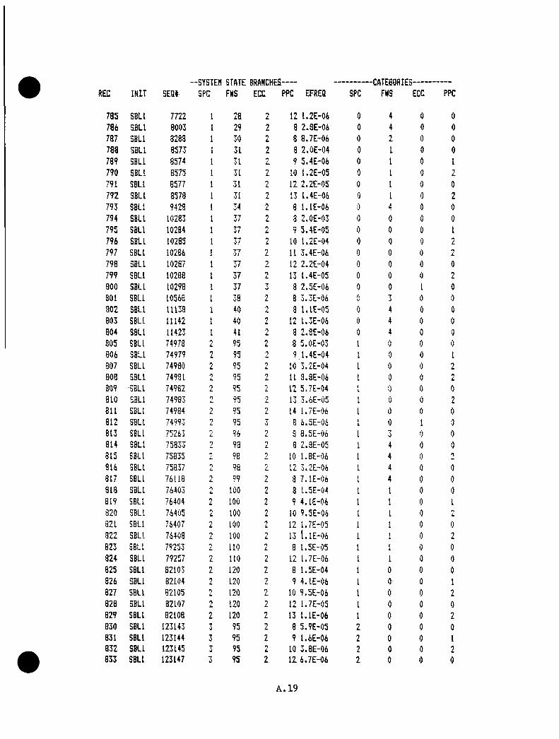
REC IN IT SEQ i--SYSTEH STATE BRANCHES
SPC FNS ECC PPC EFRES SPC--CATE60RIES
FNS ECC PPC
7 85 SBLl 7722 I 28 L 12 1 .2 E -0 6 0 4 0 0786 SBLl 8003 I 29 1 8 2 .8 E -0 6 0 4 0 0787 SBLl 3283 I 30 n
L 8 8 .7 E -0 6 0 2 0 0788 SBLl 8 573 I 31 1 8 2 .0 E - 0 4 0 1 0 0789 SBLl 8574 1 31 2 9 5 .4 E -0 6 0 I 0 1790 SBLl 8575 1 31 2 10 1 .2 E -0 5 0 I 0
791 SBLl 6577 1 31 12 2 .2 E - 0 5 0 1 0 0792 SBLl 8578 I 31 i, 13 1 .4 E -0 6 0 I 0 2793 SBLl 9428 1 34 8 l . l E - 0 6 0 4 0 0
794 SBLl 10283 1 37 3 2 .0 E -0 3 0 0 0 0
795 SBLl 10284 1 37 9 5 .4 E -0 5 0 0 0 I796 SBLl 10235 1 37 10 L 2 E - 0 4 0 0 0 L
797 SBLl 10286 1 37 2 11 3 .4 E - 0 6 0 0 0 1
798 SBLl 10287 1 37 2 12 2 .2 E -0 4 0 0 0 0799 SBLl 10288 1 3 7 n
L 13 1 .4 E -0 5 0 0 0 9
300 SBLl 10298 1 37 7•J 8 2 .5 E -0 6 0 0 1i 0
301 SBLl 10568 I 38 •T 8 3 .3 E -0 6 (\V 3 0 0
3 0 2 SBLl 11133 1 40 3 l . l E - 0 5 0 4 0 0803 SBLl 11142 I 40 2 12 1 .3 E -0 6 0 4 0 0804 SBLl 11423 1 41 a 2 .0 E -0 6 0 4 0 0
805 SBLl 74978 n 95 L 8 5 .0 E -0 3 I 0 0 0
806 SBLl 74979 95 7 9 1 .4 E -0 4 I 0 0 1807 SBLl 74980 95 2 10 3 .2 E - 0 4 1 0 0 9
i .
808 SBLl 74981 •*5 95 nL 11 3 .8 E -0 6 I 0 0 n
L
809 SBLl 74982 L 95 nL, 12 5 .7 E -0 4 K 0 0 0
810 SBLl 74983 n 95 • TL 13 3 .6 E -0 5 I 0 0 2
811 SBLl 74984 n 95 2 14 1 .7 E -0 6 I 0 0 0812 SBLl 74993 2 95 • J 8 6 .5 E -0 6 I 0 I 0
313 SBLl 75263 L 96 2 8 3 .5 E -0 6 I 3 0 0
814 SBLl 75833 98 0i. 8 2 .8 E -0 5 1 4 0 0815 SBLl 75335 2 98 n 10 1 .8 E -0 6 I 4 0
7
8 16 SBLl 75837 n 98 2 12 3 .2 E -0 6 iL 4 0 0
817 SBLl 76118 nL 99 i, 8 7 .1 E -0 6 4
i 4 0 0
313 SBLl 76403 • nL 1 0 0 n
L 8 1 .5 E -0 4 f I 0 0
819 SBLl 76404 2 100 2 9 4 .1 E -0 6 I I 0 I820 SBLl 76405 o
L 1 0 0 L 10 9 .5 E -0 6 I I 0
821 SBLl 76407 L 100 n/ 12 1 .7 E -0 5 I I 0 0
3 22 SBLl 76403 n 100 7 13 l . l E - 0 6 1 t 0 2823 SBLl 79253 n 1 10 n
L 3 1 .5 E -0 5 I I 0 0824 SBLl 79257 n
i. 110 2 12 1 .7 E -0 6 I 1 0 08 25 SBLl 82103 1 120 2 3 1 .5 E -0 4 I 0 0 0826 SBLl 82104 2 120 7 9 4 .1 E -0 6 I 0 0 1827 SBLl 82105 n 120 n
L. 10 9 .5 E -0 6 I 0 0 9u
828 SBLl 32107 nL 120 n
L 12 1 .7 E -0 5 I 0 0 08 29 SBLl 82108 2 120 2 13 l . l E - 0 6 I 0 0 28 30 SBLl 123143 T•J 95 2 8 5 .9 E -0 5 2 0 0 0831 SBLl 123144 3 95 2 9 1 .6 E -0 6 2 0 0 18 32 SBLl 123145 W 95 2 10 3 .8 E -0 6 2 0 0 2833 SBLl 123147 3 95 2 12 6 .7 E -0 6 2 0 0 0
A. 19
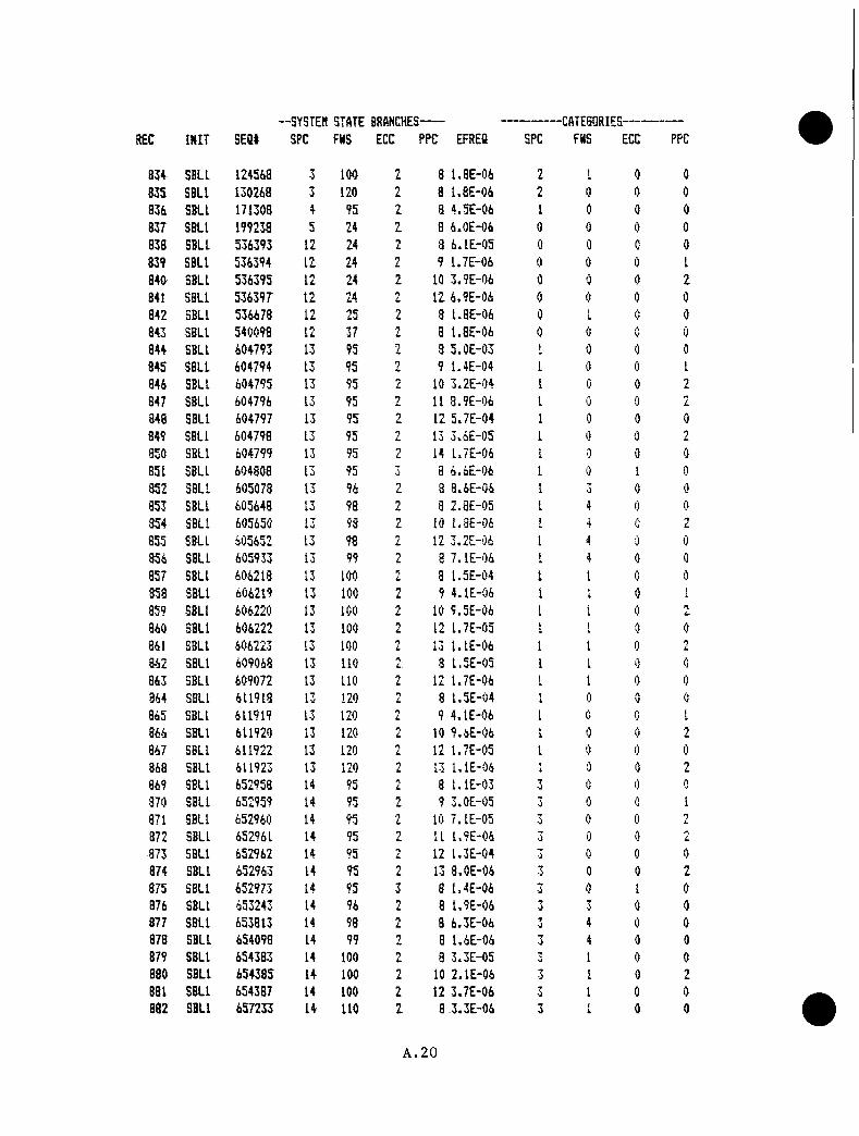
o-o
oo
*—
C'l <o C-J o
<3. —
H o
C--4
<*:? *0 o
—
• CM
.0
c*4 o
—
« c *i c-^
o
r^l c>
o
o
o
C2*
O'
o
I O
i a
c/9tx»Q£OU9 to
O
O*
<2* o
O
*0
'w* "O'
O’
'O
0» O
O
o
O
* -i—•
O
-S* •■"J?
0* O
' 'O
' o
0»
O
' o
0
»
'S*
O
O'
CS* O
' O
' O
' -O
O
' O
’ 'O
’ o
•—
O*
O’
o
o o*
C o
O’
•o
o
"O’
-O’
o
o
ro
*nf "'t*
t-9o
.C
O
rMrM
«-*'0''0.0'0’oh-7 ro h*7 I’O
■? r--?
Q<Ulce:
ac
L
J ■cc CJ oe LuG
O
*0
-0
0
'O-0<3
.•«0
inO’
■<1o
>-0O
’M
3O
’M
3O
’M
30
M0•«r0
O’
M3
•00
InO'
M3
•O-00
inO’
-00-0•0
M3
0-0
-a0*
1/3O
’M
3'O
030
-0O'
•M"
M3
0m•0
M3
t'3•0
in010
•OM
3O
’•O
’-0•01
-00-00
M?
0M
O0
inO'
M3
O'
-000
Jj
UJ
CO
C
Oill10
UJ
O’*
-0
tlir-“
lliO
'
M*
1U
JO
'
M3
ui
03
til0
3U
J0m
1U
JU
JCMM
UJ
cr-
03
tijr«»
tn
1U
l-oftM
»
tiltil-43
-0
til-00
3
UJ
00
r-4
UJ
03
lilCM^'3
UJ
r-^
UJ
mU
J
■It*
tilinO
'
UJ
r''U
lIjJ1/3
Ul
r—til0
3til
«sf
liiM
3
0“
UJ
1—iL
UJ
0t-3
lit
r--
til0
-U
lr-3
UJ
003
Ul
’"♦'U
JO
'mm«M
Ul
1-3M
3
til-0
lilt'3
mCM
liif
-*r-3
UJ
1-3
b3
CO
C
OC
OC
DC
OO
'O
' ■■ 4
cM0
3tm
03
a-
O'
CMM
■tf-C
O0
30
3O
’CM
CO
CO
O'
'Ot'T
03
CM0
3C
r-«
oCM
1-3C
OO
's
-CM
r-3C
OCXI
CO
03
CXI0
CMC
D
CM
cMCM
CMCM
CMCM
C'J
CMCM
CMc-»
CMCM
c-JCM
r-Jr-o
CMCM
CMCM
CMC
-4CM
CMCM
CMCM
CMCM
CMCM
CMC--4
C-4
04
CMCM
C-4CM
h3
CMCM
CMC
4CM
CMCM
OCN
<r COC
O
Ul.
lT5
««
i-«^
'rf-"«
r^in
»h
~-ln
toir?
iolrJ
io«
r?io
-oc
ac
pc
i:io-o
-0’
oO
'0'0
O
- CM
CM
CM
CM
C
-'l O
- t>~
O-
Cr-
0~
O
- cr-
Cr-
0~
O
' o
- O
- O
- -O
O
' O
-O
O
' ■’“
»■O’
o
O'
O' >0
UT tr»
m
IT9 10
in 10
-o
COCM
CM
CM
CM
CM
o
- 0
~
!>• O
* o
- O
- O
' O
- O
-
co
o
>- Ou C
O
CO
I
H?
|v^ tn
CM
C"j
CM
C-4
r-J C
M
1-0 K
» K
» ^
0
fo
t-Tt h*9
r-7 fO
*'">
K9
K9
K«
hO
h-'S h-"*
r-O
f-O
fO
f-O
CD
CO
CD
CD
■«rin
K.
03
CO
1-3in
Ml
I''0
3O
'0
3C
DC
D<31
C-4
h3
03
O'
r-4h
30
3CM
03
Cr-
C3
CMl'-3
CD
et"'S
’CM
tnt"3
r-3m
03
tntn
f-
M3
M3
0h*3
O'
O'
O'
O'
r"O
'O
'O
'0
-O
'O
'O
'O
'0
r*'.in
U3
1-3fM
CMCM
CMM
3f"-
CMC
-4CM
min
M3
-0•M
3•M
lr-—
•ifO
'C
DC
D00
inCM
h3
CMh
3b
3t'7
r*3•M
?<
or
-r—
r-
r-*.r-'
r-
CO
<0
M3
-oM
3cr-
CMCM
CMCM
CM0
0cr-
O"
O'
O'
O'
0-
O'
O'
O-'
O'
O'
CMC
D0
mto
to0
O'
M3
MCIM
3•-0
M3
0•Bt-
-If■If
inU
3in
U3
inM
3M
3-D
-D-0
0-
O'
f-4CM
CMCM
CMCM
CMt-3
1-0CM
f'3r
-O
'1-3
t-3h
3t-3
00
00
0<S’
00
0'w
'0
•S’
00
«C3•S
’•S
’0
0-S
’in
tnU
Tin
inin
inin
tntn
tntn
inm
inin
inin
tnM
3M
3-D
M3
M3
M3
M3
-0•D
m3
•M3
•DM
3M
3M
3-0
M3
M3
M3
M3
M3
M3
-43-43
-DM
3-43
M3
M3
•m3-0
-43-D
•Ml
•M3
•M3
<M3•D
—4, .
, tf
—4
,,
,<■ 4
^4
—4
, (
■ 4w
—4,
. ■ *•1 4
, .
p‘i 4..M
n-4■—
1—
4•.4
•«4-J
—J
-JU
l-J
u_J
—1-J
—J
..J«J
U-J
-J-J
—1
.Ju
_J—
J.-1
.J_
lU
—1
—I
«-Ju
u_J
-_JU
-Ju
IXi
CO
CD
COC
DC
DC
DC
DC
DC
DC
DC
DC
DC
DC
DCO
CD
CD
CD
CD
CD
CD
CD
CD
CD
CD
CD
CD
CD
CD
CD
CD
CD
CO
CD
03
CD
CD
CD
CD
CD
CD
CD
CD
paC
DC
DC
DC
Dto
totn
toC
Oto
toto
cnto
toto
tnto
toto
toto
toto
toto
toto
toto
C/3
toC
Oto
CO
toto
toto
03
toto
C/3
CO
CO
toto
CO
toto
toto
CO
oa^
u-9
m9
h’«
CXI O
'foi
Ml r-o
CMin
M3
r***.00
O'
0,
,CM
K*
inM
3h—
CD
O'
0CM
1-0•M*
inM
3I"
.00
O'
0CM
K>
•BhliO
•M3
h-
CD
O'
0CM
•tfU
'7in
Inin
Inm
inin
inin
-M»M
3-D
•M3
-0-0
M3
-O-O
-0r--
r-~f'.
1"
f"^'-.
r-
r-
r-'f"
CD
09
09
CD
03
CD
03
03
CD
09
CO
OE3o
a0
3C
D0
300
CD
CD
03
CD
CD
03
CD
CD
CD
00
CD
03
03
CO
133C
DC
OC
DC
DC
DC
Dco
03
CD
CD
CD
CD

-o>
o-o
•o-n
-o-o
-o-o
•>o
-o-4:4
>0
-0•n
-0-0
-0-0
-a
-0-0
-0-0
>40
-a
>0
>0
>0
>0
CO
cn
03
CO
00
CO
00
cu
CO
CO
00
CO
00
mC
Ocx
aC
Oc-
4r
oro
roro
hOro
ror-
Jro
ro»—
>O
'0
«o
00
00
00
•>0
>40
•>o
•>0
-JD
-n>4
0>0
-0C
OC
O00
CO
CO
CO
00
O>4
0C
O-o
!>-
cn
-f»>
c-4
rof—
o>•J
O00
•0cr
-c
n•4
k>t-
4ro
0-0
CO
•—4
0c
no»
-C
-4ro
»—0
-43
CO
-0o
>t/
iC
-lro
0•0
CO
-00
-t/
l-r
>
toto
toto
toto
toto
totn
tntn
tnto
UJ
tntn
cnt/
3U
Jcn
tncn
cnc/
acn
tner
aer
atn
tntn
tntn
tnto
tncn
tntn
tnto
totn
tncn
cncn
03
CO
03
oo
ea0
3C
OC
O0
30
30
3C
O0
30
30
30
3C
OC
OC
Oto
03
CO
CO
toC
OC
OC
O0
3C
OC
OC
O0
3C
O0
300
03C
O0
30
3D
30
3C
OC
OC
O03
CO
03
r-
r"
r~r*
r"r“
f—r-
r”
r~r*
f“r~
r~r~
r~r~
l“-
r"
r*"
r~*
r~r—
r~r*
r~r“
r-
r~r~
r~r"
r~r—
r*r~
r“
r~r~
r'
r“
r"r—
r“
Mr
oh
Jro
ro
roro
ror-J
roro
roro
roro
roro
hJro
roro
roro
h-j
rot—
r»►—
r->*—
r—e»
1—“
r->
►—>
r-*
r3
»>•*
Cr-
O'
O'
O'
O'
O'
O'
O'
r-J
*—1 -
r->
r->
•—>
I—>
*—>
o>n>
er'
o>
cr-
ca~cr
-Cr>
O'cn
-OC-4
c-4C-4
c-4c-4
t-4
c-4
•->-4
rj
ro»—
r»>
►—>
~ocr>
O'
O'
9Tc
nc
n0
00
0t-4
r>3
00
'>4
—-1
>»l
-J
'-J•■**
>►—
c-4
O'O'
o>
Cr>
O'O
'O'
"4c-
4CO
COCO
COCO
COC-4
0O'
0-
O'ro
ro>0
cr-
cn
cn
O'c-
4r-
J-0
O'c
nc
n•0
COCO
->j
Cr~
O'
O'r-
JCO
-»h.
CO0
>0
0-0
ror-
Jro
ro0
00
-0c-
4>0
>0
0ro
O'0
»jt-4
r-J
c-4
COr'
J-o
roc
nr-
J-0
00
cn
cn
o*
O't-4
C-4
c-4
c-4
-x4
>0
03
-'.4
•x4
•x4
->-i
0-
00
0<a-
•xj
*0
cn
O'-
—1
CO0
3t-
4-0
-Or-
Jc
n»4
c-4-o
O'to
cn
CO•x
4•0
c/t
o-
O'
O'
cn
cn
>0
cn
0c-
4-0
-0•'
J•x
40
roCO
000
30
-Cr>
O'
•—>
r—r—
►—O
'0
-O
'0
-0
-O
'cr
-O
'►—
►->
O'
O'
»—>
O'
O'
CO0
3c-
4t-4
^J
0-4
3CO
oo
C>l
C4
cnCO
CO-4
tn■*
»C4
COc-4
-0cn
C-4
to m fO
c>i
t-4
cx4
r--:*
c-4
r-J
i-j
h-j
r-J
ro
r.j
*—■
C-4
C-4
C-4
C-4
C--4
C4
C-4
C-4
C-4
C-s
|C
-4C
-4
o
-o
*oO
-t
J -O
-o
o*
i»
•>
- t.r
iCH
c-
4 cH
r
j r-
j *o
-a
c-
4 m
r-
j ro
r-
J r*
Jo
-o
^ «
o CO
lui
<p
cn
cfl
-J c
n
c-4
^s>
ro
r
o
r-si
^•
J ^
o
ro
|v
j r
o
^
•^'o
cr-c
ncnc
ncnc
ncn-
r^cn
-o
-<
3-
or
oo
'-<
‘'4
:i~
o-
<3
>-
o-
^r
'Jr
or
oc
Tic
nt
Ji
c^
^c
ji
cr
ic
nc
nc
nc
n«
oo
o>
to
to
"O -
< ra
CO —H s
2 ^
«n
=2
ts3
ror-
jr-
jro
roro
r-J
ror>
Jr-
Jr>
jrs
>r-
Jr-
Jr>
jro
r-J
r-J
r>J
ror-
Jr-
Jr-
JI
JC
-4r-
Jro
r-J
r-J
hJ
r-J
roro
roro
r-J
r-j
r'j
ror-
Jr-
Jro
^J
ror-
Jro
^J
r-J
r-J
•“►—
»—•—
'—►—
►—►—
►—
1—k—
CO
CO
00
roro
0>0
00
CO
CO
03
CO
CO
CO
ro0
>0
03
CD
00
roC
O0
3
-x|
AO
ht—
'*—
c-4
»—O
'—4
1—>
c-4
►-->
O'
ror-
3,—
■r-
>ro
,—C
Ox
j~|a
>►
->•x
ic-
4•—
cr-
O'
•4*
0-
O'
c-4
•—c
nc
n-«
»t-
4ro
c-4
«•
m•
■•
«m
00
c-4
cza
CO
CO
•4^
0.C
k.»—
>0
30
30
3-o
•—>
c-4
■pm>/
4»<3
>•>
4•0
o>
c-4
—>J
roC
O0
>43
xj
^J
•0c
no
>c
n0
3C
O•'-4
CCl
cr>
>0
c-4
cn
-xl
C-4
Tm
mT
mm
mm 1
mm
mm
mrn
rnm
mm
mm
mm
mm
mm
Tm
mm
rnT
Tm
mrr
i01
T*m
Tm
Tm
*0
0O
'•0
<0
•00
*O
'O
'O
'•0
0-O
•0-C
3•0
0•z
>O
'•0
-o-
•s>
•c>
O'
O'
o>
•00
O'
0•0
1•0
•00
•0<0
00
•00
-o
-O
'c
nO
'c
nO
'o
>O
'O
'c
nO
'c
nO
'O
'O
'tj
nO
'o
>-4
»*c
nC>
-4cr
-O
'O
'O
'Cr
>O
'c
nO
'o
~O
'O
'O
'O
'O
'O
'tn
O'
Cr^
O'
O'tn
m 3
0 ac
m
tn
“tj
I “O
I
"
1 m "T1 so m fo
ro
t-
4
c-4
c-
4r
o
ro
rs
j r
o
foto "O o
c-4 O
-4«- Oi
hO
r--
O
o.
0> t
o O
O'
o o
o* •=
> o*
•£>0
<0<5
>0<0
><^0
0O
' o
>
o>
o
>
O'*
m cn I I I
C> 0
> lO
ojoo
>o>
ro»—
‘0>o
>0'0
>o»0
'0>o
*ro
o o
o o
> ro
o“O

-SYSTEH STATE BRANCHES- -CATEGQRIES-c INIT SEQt SPC FNS ECC PPC EFREQ SPC FNS ECC PPC
9 32 SBL2 6364351 133 24 2 1 7 .5 E -0 6 0 0 0 0933 S6TR 6571 1 24 2 1 8 .0 E -0 3 0 0 0 093* SGTR 6586 1 24 3 1 l.O E -0 5 0 0 1 0935 SGTR 6856 1 25 n
L 1 2 .4 E -0 4 0 1 0 0936 SGTR 7711 1 23 2 1 1 .3 E -0 6 0 4 0 0937 SGTR 8281 1 30 2 1 1 .0 E -0 6 0 2 0 0938 SGTR 8566 1 31 2 1 2 .4 E -0 5 0 I 0 0939 SGTR 10276 1 37 2 1 2 .4 E -0 4 0 0 0 0940 SGTR 11131 1 40 2 1 1 .3 E -0 6 0 4 0 0941 SGTR 74971 2 95 1 6 .1 E -0 4 1 0 0 09 42 SGTR 75256 •J 96 2 1 l.O E -0 6 I 0 0 0943 SGTR 75826 98 2 1 3 .4 E -0 6 1 4 0 0944 SGTR 76396 'I
L. 100 nL 1 1 .3 E -0 5 i 1 0 0
945 SGTR 79246 110 i 1 1 .3 E -0 6 I 4I 0 0
946 SGTR 82096 2 120 2 1 1 .8 E -0 5 1 0 0 0947 SGTR 123136 3 95 2 1 7 .1 E -0 6 L 0 0 0948 SGTR 536386 12 24 n
L I 7 .4 E -0 6 0 0 0 0949 SGTR 604786 13 95 2 1 6 .1 E -0 4 4
i 0 0 0950 SGTR 605071 13 96 n
L 1 l.O E -0 6 fL 3 0 0951 SGTR 605641 1 3 98 n
L 1 3 .4 E -0 6 1 4 0 0952 SGTR 606211 13 100 n
L I 1 .8 E -0 5 1 I 0 0953 SGTR 609061 13 110 •T
L 1 I t E E - 0 6 41 0 0
954 SGTR 611911 13 120 2 I 1 .8 E -0 5 1 0 0 0955 SGTR 652951 14 95 n 1 1 .3 E -0 4 0 0 0956 SGTR 654376 14 100 I 4 .0 E -0 6 3 1 0 0957 SGTR 660076 14 120 L 1 4 .0 E -0 6 3 0 0 0958 SGTR 1182766 25 95 n
L 1 7 .1 E -0 6 0 0 0 0959 SGTR 6364351 133 24 A
L 1 7 .5 E -0 6 0 0 0 0960 S I 6573 1 24 n 8 6 .6 E -0 3 0 0 0 0961 SI 6579 1 24 n
L 9 1 .8 E -0 4 0 0 0 1962 SI 6580 1 24 2 10 4 .2 E -0 4 0 0 0 L
963 SI 6581 1 24 11 1 .2 E -0 5 0 0 • n
964 SI 6582 1 24 1 12 7 .5 E -0 4 0 0 0965 31 6533 1 24 L 13 4 .8 E -0 5 0 0 0 n
L
966 S I 6584 1 24 14 2 .3 E -0 6 c 0 0 0967 S I 6363 1 25 2 8 2 .0 E -0 4 0 1 0 0968 SI 6364 1 25 o
L 9 5 .4 E -0 6 0 1 0 1969 SI 6365 4i 25 n 10 1 .2 E -0 5 0 1 0 n
L
970 SI 6867 1 25 L 12 2 .2 E -0 5 0 4I 0 0
971 SI 6868 1 25 13 1 .4 E -0 6 0 1 0 2972 S I 7718 1 28 n 8 l . l E - 0 6 0 4 0 0973 SI 8573 1 31 n 8 2 .0 E -0 5 0 1 0 0974 SI 8575 1 31 T 10 1 .2 E -0 6 0 I 0 2975 S I B577 1 31 2 12 2 .2 E -0 6 0 1 0 0976 SI 10283 1 37 2 8 2 .0 E -0 4 0 0 0 0977 S I 10284 1 37 O
L 9 5 .4 E -0 6 0 0 0 1978 S I 10285 I 37 2 10 1 .3 E -0 5 0 0 0 2979 S I 10287 1 37 2 12 2 .2 E -0 5 0 0 0 09 80 S I 10288 1 37 2 13 1 .4 E -0 6 0 0 0 2
A.22

--SYSTEtt STATE BRANCHES- -CATEBORIES-REC IN IT SEQ« SPC FNS ECC PPC EFREa SPC FNS ECC PPC
981 S I 11138 1 40 2 8 l . l E - 0 6 0 4 0 09 8 2 S I 74978 2 95 2 8 5 .0 E -0 4 1 0 0 09 8 J S I 74979 2 95 2 9 1 .4 E -0 5 1 0 0 1984 SI 74980 2 95 2 10 3 .2 E -0 5 I 0 0 2985 S I 7 49 82 I, 95 12 5 .7 E -0 5 I 0 0 0986 S I 74983 1 95 n
L 13 3 .6 E -0 6 I 0 2987 S I 75833 2 98 2 8 2 .8 E -0 6 1 4 0 0988 SI 76403 2 100 2 3 L 5 E - 0 5 1 1 0 0989 SI 76407 r\
L 100 L 12 1 .7 E -0 6 1 1 0 0990 S I 79253 2 110 1 8 1 .5 E -0 6 1 1 0 0991 31 82103 n 120 n
L 8 1 .5 E -0 5 I 0 0 0992 S I 82 1 0 7 2 120 n
L 12 1 .7 E -0 6 1 0 0 0993 S I 123143 3 95 n 8 5 .9 E -0 6 T
i. 0 0 0994 31 536393 12 24 2 8 6 .1 E -0 6 0 0 0 0995 S I 604793 13 95 2 8 5 .0 E -0 4 I 0 0 0996 S I 604794 13 95 n 9 1 .4 E -0 5 I 0 0 1997 S I 604795 13 95 10 3 .2 E -0 5 1 0 0 n
L
998 SI 604797 13 95 nL 12 5 .7 E -0 5 1 0 0 0
999 S I 604798 13 95 L 13 3 .7 E -0 6 1 0 0 n
1000 S I 605648 13 98 2 3 2 .9 E -0 6 I I 0 01001 SI 606213 13 100 L 8 1 .5 E -0 5 I 4
i 0 ()
1002 31 6 06222 13 100 L 12 1 .7 E -0 6 >i 1 0 0
1003 31 609068 13 n o 2 8 1 .5 E -0 6 1 1 0 Ay
1004 SI 611918 13 120 0 3 1 .5 E -0 5 si 0 0 0
1005 S I 6 11922 13 120 nL 12 1 .7 E -0 6 1 0 .■j 0
1006 S I 652958 14 95 2 3 l . l E - 0 4 3 0 0 01007 S I 652959 14 95 n
L 9 3 . lE -0 6 3 0 0 I1008 SI 652960 14 95 n
L 10 7 .1 E -0 6 3 0 01009 S I 652962 14 95 12 1 .3 E -0 5 3 'J 01010 S I 654383 14 100 2 8 3 .3 E -0 6 ■j 1 01011 S I 6 60083 14 120 7 8 3 .3 E -0 6 3 0 01012 S i 1182773 25 95 n
L 3 5 .9 E -0 6 0 01013 S I 6364358 133 24 •y
L 3 6 .2 E -0 6 0 0 0 0
A.23

A . 2 S e a u e a c o h v S v « t M i S t a t e C a t e g o r y
A.24

SYSTEM STATE CATEGORIESR E C T Y P E I N I T S P C F W S E C C P P C E F R E Q
1 N O R M R T 0 0 O (IJ 5 « o E " * " 0 0
2 F W . R T 0 1 0 0 1 . 6 E - 0 1
O F W R T C) y 0 1 4 . 9 E - 0 4
4 F W . R T 0 0 o 3 . O E - 0 5
5 ” F W R T 0 4 0 0 1 . 9 E - 0 3
<b F W R T 0 4 0 1 4 . 7 E - 0 5
7 F W R T 0 4 0o
1 . 3 E - 0 4
8 F W R T 0 0 0 5 . 8 E - 0 4
9 F W R T 0 0 1 1 . 4 E - 0 5
1 0 F W R T 0 0 2 3 . 7 E - 0 5
1 1 S L R T 1 0 0 0 6 . 9 E - 0 1
1 2 S L R T 1 0 (I) 1 1 . 7 E - 0 2
1 3 S L R T 1 0 0 y 4 . 5 E - 0 2
1 4 S L R T 1 0 1 0 9 4 0 E ~ 0 4
1 5 S L R T 1 0 1 1 2 * 2 E - 0 5
1 6 S L R T •1 0 1 2 5 . 6 E - 0 5
1 7 S S R T 1 0 1 2 . 3 E - 0 5
1 8 S S R T 1J. "T 0 7 u 7 E - 0 5
1 9 S S R T 1 4 0 Cs 5 « O E - 0 3
2 0 S S R T 1 4 0 1 1 4 2 E - 0 4
2 1 S S R T 4 0 'y3 - 2 E - 0 4
S S R T 1 4 1 0 4 . 4 E - 0 6O ' ? S L R T 1 1 (15 0 2 . 2 E - 0 2
2 4 S S R T 1 1 (Jf 1 5 . 4 E - 0 4
2 5 S S R T 1 1 0 1 4 4 E - 0 3
2 6 S S R T i. 1i. 1 0 2 4 S E - 0 5
2 7 S S R T4X O 0 0 S . B E - 0 5
2 8 S S R T 1 O 0 1•L 2 > 2 E - 0 6
2 9 S S R T 1 !Z (1) 5 . 0 E - - 0 6
3 0 S L R T o 0 0 0 a . 2 E - 0 3
3 1 S L R To 0 0 1 2 . O E - 0 4
S L R T jX 0 <1) '•y5 . 3 E - 0 4
S L R T o 0 1 0 9 . 2 E - - 0 6
3 4 S S R T o y 0 <1) 1 4 2 E - 0 5
3 5 S S R T 4 0 0 5 . 5 E - 0 5
3 6 S S R T 4 0 2 4 6 E " " 0 6^**T
/ S S R T 1 (l! (1) 2 4 6 E ” D 4
3 8 S S R T 1 0 1 5 . 8 E - 0 6
3 9 S S R T uZ 1 0 1 4 3 E - 0 5
4 0 S L R T y, (1) 0 / 4 6 E ~ 0 2
4 1 S L R T 0 1 1 4 9 E - 0 3
4 2 S L R T (1) 5 4 O E - 0 3
4 3 S L R T 1 0 9 4 9 E - 0 5
4 4 S L R T 1 1X 2 4 4 E - 0 6
4 5 S L R T y 1'y 5 . 5 E “ 0 6
4 6 S S R T y (1) 0 1 4 4 E - 0 4
4 7 S S R T y 0 1 3 . l E - 0 6
4 8 S S R T . 1 0 7 . 2 E - 0 6
4 9 S S R T 4 0 0 5 . 5 E - 0 4
5 . 0 S S R T 4 0 1 1 4 3 E - 0 5
5 1 S S R T 4 0 yy 3 . 3 E - 0 5
A.25

SYSTEM STATE CATEGORIESREC TY P E I N I T S P C FWS ECC PPC EFREQ
5 2 S S RT 3 1 0 0 2 . 4 E - 0 35 3 S S RT 1 0 1 6 . O E - 0 55 4 S S RT 1 0 y 1 . 6 E - 0 45 5 S S RT 77 1 1 0 2 . 6 E - 0 65 6 S S RT 0 0 8 . 7 E - 0 65 7 S L RT 4 0 0 0 6 . 9 E —0 45 3 S L RT 4 0 0 1 1 . 5 E - 0 55 9 S L RT 4 0 0 2 4 . 3 E —0 56 0 S S RT 4 4 0 0 3 . l E - 0 66 1 S S RT 4 1 0 0 1 . 6 E - 0 56 2 S L RT 5 Ci 0 C) 4 . 5 E - 0 46 3 S L RT 5 0 0 1 1 . l E - 0 56 4 S L RT 5 0 0 2 . S E - 0 56 5 S S RT 5 4 0 0 2 . 2 E - 0 66 6 S S RT 5 1 0 0 1 . 4 E - 0 56 7 S L RT 6 0 0 0 5 . O E - 0 46 3 S L RT 6 0 0 1 1 . 2 E - 0 56 9 S L RT 6 0 0 2 3 . l E - 0 57 0 S S RT 6 4 0 0 2 . 5 E - 0 67 1 S S RT 6 1 0 0 1 . 6 E —0 57 2 RES RT 9 9 9 9 9 9 9 9 1 . 9 E - 0 47 3 FW EMFW 0 1 0 0 S . 4 E - 0 27 4 FW EMFW 0 0 C) 1 , 4 E - 0 47 5 FW EMFW 0 y 0 1 2 . 9 E - 0 67 6 FW EMFW 0 y 0 2 6 . 3 E - 0 67 7 FW EMFW 0 4 (I) 0 5 . 5 E - 0 47 3 FW EMFW 0 4 0 1 1 . 3 E - 0 57 9 FW EMFW 0 4 0 3 . 3 E - 0 5SO FW EMFW 0 0 0 3 . l E - 0 48 1 FW EMFW 0 0 1 7 . 7 E - 0 63 2 FW EMFW 0 0 2 * 0 E - 0 5S 3 S S EMFW 1 1 0 0 1 . 2 E - 0 23 4 S S EMFW 1 1 0 1 2 . 9 E - 0 43 5 S S EMFW 1 1 0 /< 7 E ~ 0 43 6 S S EMFW 1 1 1 0 1 . 2 E - 0 58 7 S S EMFW 1 0 0 1 . 6 E - 0 58 3 S S EMFW I 4 0 0 3 . O E - 0 58 9 S S EMFW 1 4 0 3 . 5 E - 0 69C) S S EMFW 1 0 0 4 . 7 E - 0 59 1 S S EMFW 1 2 0 2 . 7 E - 0 69 2 S S EMFW 1 0 0 1 . 4 E - 0 49 3 S S EMFW 1 0 1 3 » I E —0 69 4 S S EMFW 1 0 7 . 2 E - 0 69 5 S 3 EMFW 77 1 0 0 1 . 3 E - 0 39 6 S S EMFW 0 1 0 1 3 . 2 E - 0 59 7 S S EMFW 1 0 y S . 4 E - 0 59 8 S S EMFW 0 1 1 0 1 . 4 E - 0 69 9 S S EMFW 7y 0 0 1 . 8 E - 0 6
1 0 0 S S EMFW 4 0 0 7 . 5 E - 0 61 0 1 S S EMFW 0 0 4 . 7 E - 0 61 0 2 S S EMFW 4 1 0 0 8 . 6 E - 0 6
A.26
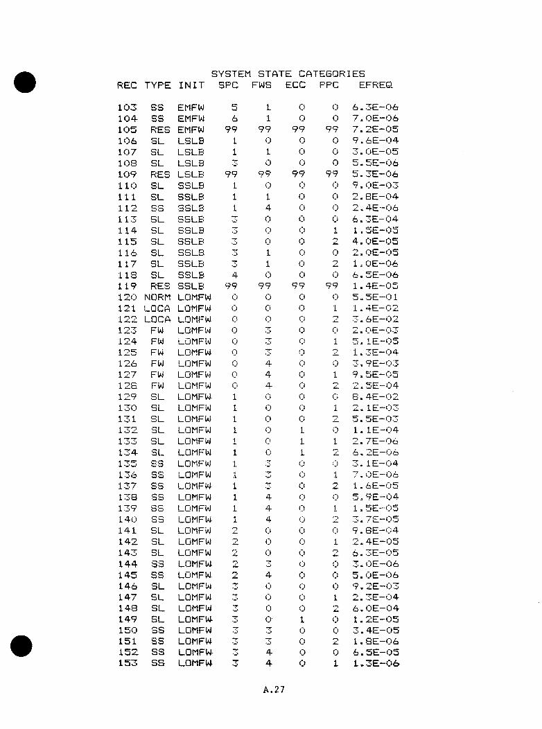
SYSTEM STATE CATEGORIESREC T Y P E I N I T S P C FWS ECC PPC EFREQ
1 0 3 S S EMFW b 1 0 (1) 6 . 3 E - 0 6104- S S EMFW 6 1 0 0 7» 0E~( . )61 0 5 R ES EMFW 9 9 9 9 9 9 9 9 7 . 2 E - 0 51 0 6 S L L S L B 1 0 0 0 9 . 6 E - 0 41 0 7 S L L S L B 1 1 0 0 3 . O E - 0 51 0 8 S L L S L B 0 0 0 5 . 5 E - 0 61 0 9 RES L S L B 9 9 9 9 9 9 9 9 5 . 3 E - 0 61 1 0 S L S S L B 1 0 0 0 9 . O E - 0 31 1 1 S L S S L B 1 1 (I) 0 2 . 8 E - 0 41 1 2 S S S S L B 1 4 0 0 2 . 4 E - 0 61 1 3 S L S S L B 3T 0 0 0 6 * 3 E - 0 41 1 4 S L S S L B 0 0 1 1 . 5 E - 0 51 1 5 S L S S L B 0 0 4 . O E - 0 51 1 6 S L S S L B y 1 0 0 2 . 0 E - 0 51 1 7 S L S S L B y 1 0 1 . O E - 0 61 1 3 S L S S L B 4 0 0 0 6 . 5 E —0 61 1 9 RES S S L B 9 9 9 9 9 9 9 9 1 . 4 E - 0 51 2 0 NORM LOMFW (I) 0 0 (") 5 . 5 E - 0 11 2 1 LOCA LOMFW 0 0 0 1 1 . 4 E - 0 2
LOCA LOMFW 0 0 3 . 6 E - 0 21 2 3 FW LOMFW 0 “T (I) 0 2 . O E - 0 31 2 4 FW LOMFW 0 <;) 1 5 . l E - 0 51 2 5 FW LOMFW 0 0 o 1 . 3 E - 0 41 2 6 FW LOMFW 0 4 0 0 3 . 9 E - 0 31 2 7 FW LOMFW 0 4 0 1 9 . 5 E - 0 51 2 3 FW LOMFW 0 4 0 2 2 . 5 E - 0 41 2 9 S L LOMFW 1 0 0 (■; 8 . 4 E - 0 21 3 0 S L LOMFW 1 0 0 1 2 . l E - 0 31 3 1 S L LOMFW 1 0 0 5 . 5 E - 0 31 ^2. S L LOMFW 1 0 1 0 1 . I E - 0 41 S L LOMFW 1 o 1 1 2 . 7 E ~ 0 61 3 4 S L LOMFW 1 0 2 6 . 2 E - 0 61 3 5 s s LOMFW •i
J .T 0 0 3 , l E - 0 4
1 3 6 S S LOMFW 1 (I) 1 7 . 0 E - 0 61 3 7 S S LOMFW 1 ( j 1 . 6 E - 0 51 3 8 S S LOMFW 1 4 t j 0 5 , 9 E - 0 41 3 9 S S LOMFW 1 4 0 1 1 . 5 E - 0 51 4 0 S 3 LOMFW 1 4 (j 3 . 7 E - 0 51 4 1 S L LOMFW 0 0 0 9 . 8 E - 0 41 4 2 S L LOMFW 0 0 i 2 . 4 E - 0 51 4 3 SL LOMFW !Z 0 0 6 . 3 E - 0 51 4 4 S 3 LOMFW 2 0 0 3 . O E - 0 61 4 5 S S LOMFW 4 0 (Ij 5 . OE—0 61 4 6 S L LOMFW y 0 0 0 9 . 2 E - 0 31 4 7 S L LOMFW y 0 (j 1 2 . 3 E - 0 41 4 8 S L LOMFW y 0 0 6 . O E - 0 41 4 9 S L LOMFW y 0 1 0 1 . 2 E - 0 51 5 0 S S LOMFW y 0 0 3 . 4 E - 0 51 5 1 S S LOMFW y 0 1 . 8 E - 0 61 5 2 S S LOMFW 4 0 0 6 . 5 E - 0 51 5 3 S S LOMFW y 4 0 1 1 . 3 E - 0 6
A.27
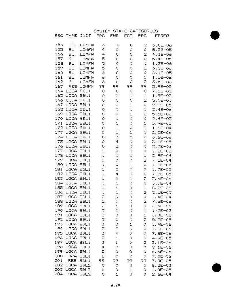
SYSTEM STATE CATEGORIESREC T Y P E I N I T S P C FWS ECC PPC EFREQ
1 5 4 S S LOMFW 4 0 o 3 OE—0 61 5 5 S L LOMFW 4 0 0 0 8 . 3 E - 0 515ci S L LOMFW 4 0 0 4 , 3 E - 0 61 5 7 S L LOMFW 5 0 0 0 5 . 4 E - 0 51 5 8 S L LOMFW 5 0 (D 1 1 . 3 E - 0 61 5 9 S L LOMFW 5 0 o 3 . I E —Ci61 6 0 S L LOMFW 6 0 0 0 6 . l E - 0 51 6 1 S L LOMFW 6 0 0 1 1 . 5 E - 0 61 6 2 S L LOMFW 6 0 <l! 7* 3 . 5 E —Ci61 6 3 RES LOMFW 9 9 9 9 9 9 9 9 5 . 9 E - 0 51 6 4 LOCA S B L l o 0 0 0 7 . 6 E - 0 21 6 5 LOCA S B L l 0 0 0 1 1 . 9 E - 0 31 6 6 LOCA S B L l 0 0 0 5 . O E - 0 31 6 7 LOCA S B L l 0 (l! 1 0 9 . 9 E - 0 51 6 8 LOCA S B L l <;> 0 1 H
J. 2 . 4 E - 0 61 6 9 LOCA S B L l 0 0 1 5 . 5 E - 0 61 7 0 LOCA S B L l (I) 1 0 0 2 . 4 E - 0 31 7 1 LOCA S B L l 0 1 0 1 5 . 9 E “ 0 51 7 2 LOCA S B L l 0 0 o 1 , 6 E - 0 41 7 3 LOCA S B L l 0 1 1 0 2 . 5h.—0 61 7 4 LOCA S B L l X 0 0 6 . 6 E - 0 61 7 5 LOCA S B L l 0 4 C) 0 3 . l E - 0 51 7 6 LOCA S B L l Cj 0 Ci 8 , 7 E - 0 61 7 7 LOCA S B L l 1 0 0 0 1 . 2 E - 0 21 7 8 LOCA S B L l 1 0 0 1 2 . 9 E - 0 41 7 9 LOCA S B L l 1 C) 0 7 . 5 E - 0 41 3 0 LOCA S B L l 1 0 1 0 1 . 3 E - 0 51 8 1 LOCA S B L l 1 0 C) 1 . 7 E - 0 51 8 2 LOCA S B L l 1 4 0 0 7 . 7 E - 0 51 8 3 LOCA S B L l 1 4 0 2 3 . 6 E - 0 61 8 4 LOCA S B L l 1 1 0 C) 3 . 7 E - 0 41 8 5 LOCA S B L l 1 1 0 1 8 . 2 E - 0 61 3 6 LOCA S B L l 1 1 0 •-y 2 . l E - 0 54i G / LOCA S B L l 0 0 0 1 , 4 E - 0 41 8 8 LOCA S B L l 0 0 '•y, ■ / . 6 E - 0 61 8 9 LOCA S B L l lil 1 0 0 3 . 5 E - 0 61 9 0 LOCA S B L l 0 (I) 0 1 w 3 E - 0 31 9 1 LOCA S B L l 71 0 0 1 3 . O E - 0 51 9 2 LOCA S B L l “T 0 0 2 a . 3 E - 0 51 9 3 LOCA S B L l 0 i. (I) 1 . 4 E - 0 61 9 4 LOCA S B L l 17 3 0 Ci 1 . 9 E - 0 61 9 5 LOCA S B L l 4 0 Ci 7 . 8 E —Ci61 9 6 LOCA S B L l "T 1 0 0 4 . O E - 0 51 9 7 LOCA S B L l [T] 1 0 o 2 . l E - 0 61 9 3 LOCA S B L l 4 0 0 Ci 9 . l E - 0 6199 LOCA S B L l 5 0 0 C) 6 . 6 E - 0 62 0 0 LOCA S B L l 6 0 0 Cl 7 . 3 E - 0 62 0 1 RES S B L l 9 9 9 9 9 9 9 9 7 . 8 E - 0 52 0 2 LOCA S B L 2 <I) 0 0 C) 8 . 2 E - 0 32 0 3 LOCA S B L 2 0 0 1 C) i . O E - 0 52 0 4 LOCA S B L 2 0 1 0 0 2 . 6 E - 0 4
A.28

SYSTEM STATE CATESQRIESREC TYP E I N I T S P C FWS ECC PPG EF REQ
2 0 5 LOCA S B L 2 0 4 0 0 2 . 7 E —0 62 0 6 LQCA S B L 2 0 0 0 1 . O E - 0 62 0 7 LOCA S B L 2 1 0 0 0 1 . 2 E - 0 32 0 8 LQCA S B L 2 1 y 0 0 2 . l E - 0 62 0 9 LGCA> S B L 2 1 4 0 0 6 . 9 E - 0 62 1 0 LQCA S B L 2 1 i
J . 0 0 4 . O E - 0 5 -2 1 1 LQCA S B L 2 i iU 0 0 0 1 . 4 E - 0 52 1 2 LQCA S B L 2 r r (I) 0 0 1 . 4 E - 0 42 1 3 LOCA S B L 2 X 1 0 0 4 . O E - 0 62 1 4 RES S B L 2 9 9 9 9 9 9 9 9 1.. 8 E - 0 52 1 5 SGTR SGTR Cj 0 0 0 8 . 2 E - 0 32 1 6 SGTR SGTR 0 0 i
4 . 0 1 . O E - 0 52 1 7 SGTR SGTR 0 j . 0 0 2 , 6 E —0 42 1 8 SGTR SGTR 0 4 0 0 2 - 7 E - 0 62 1 9 SGTR SGTR 0 2 C) 0 1 . O E - 0 62 2 0 SGTR SGTR 1 <j 0 0 1 . 2 E - 0 3
1 SGTR SGTR 1 0 0 2 . l E - 0 6SGTR SGTR 1 4 0 0 6 . 9 E - 0 6SGTR SGTR 1 1 0 0 4 . O E - 0 5
2 2 4 SGTR SGTR 0 0 0 14 4 E - 0 52 2 5 SGTR SGTF'! 0 0 0 1 . 4 E - - 0 42 2 6 SGTR SGTR MT 1 0 44 O E - 0 6
RES SGTR 9 9 9 9 QQ 9 9 14 S E - 0 5NORM s r 0 0 0 0 7-4 6 E - 0 3LQCA S I 0 (I) 0 1 14 9 E - 0 4
2 3 0 LQCA S I ( I '■J 0 5 . : 0 E - 0 42 3 1 F W S I 0 1 0 0 2 . 4 E - 0 44^32 LQCA 3 1 0 .L 0 1 5 . 4 E - 0 62 3 3 LQCA 3 1 0 1 0 •■n 1 . 5 E - 0 52 3 4 F W 3 1 0 4 0 0 2 4 2 E - 0 62 3 5 S L S I 1 0 0 0 14 2 E - 0 32 3 6 S L 3 1 J . 0 0 1 24 3 E - 0 52 3 7 S L S I 1 0 - -r __r> cr
2 3 3 S S S I i. 4 0 i j 5 . 7 E - 0 62 3 9 S S S I 1 1 0 0 3 . 6 E - 0 52 4 0 S L S I 0 0 ( j 14 2 E - 0 52 4 1 S L S I 0 0 0 14 3 E - 0 42 4 2 S L S I 0 0 1 3 4 1 E —0 62 4 3 SL S I 0 0 2 7 4 i ' c . ~ 0 62 4 4 S S S I y 1 0 0 3 . 3 E - 0 62 4 5 RES S I 9 9 9 9 99 9 9 3 4 9 E - 0 5
A.29
A.3 General Tab l e o f Vo s e l ThronKh-W>ll Crack F r e qpcncv Rest t l t$
I t s h o u l d b e n o t e d t h a t a r e v i e w o f t h e a s s i g n m e n t o f r e p r e s e n t a t i v e f r a c t u r e - m e c h a n l c s c a s e s t o e a c h s e q u e n c e r e v e a l e d b o t h c o n s e r v a t i v e an d n o n - c o n s e r v a t i v e a s s i g n m e n t s . I t was t h e o p i n i o n o f t h e a n a l y s t s t h a t I n g e n e r a l c o n s e r v a t i v e an d s o m e t im e s o v e r l y c o n s e r v a t i v e a s s i g n m e n t s w e re m ade. T h i s was p a r t i c u l a r l y t r u e f o r t h e a s s i g n m e n t o f a f r a c t u r e m e c h a n ic s c a s e t o t h e r e s i d u a l c a s e s . An a t t e m p t was made t o r e c o n s t r u c t t h e t a b l e a n d t h u s r e d u c e t h e l e v e l o f c o n s e r v a t i s m I n v o l v e d I n t h i s p o r t i o n o f t h e a n a l y s i s . U n f o r t u n a t e l y , t h e r e was l i t t l e t h a t c o u l d b e d o n e w i t h o u t p e r f o r m i n g a d d i t i o n a l t h e r m a l - h y d r a u l i c a n d / o r f r a c t u r e - m e c h a n l c s c a l c u l a t i o n s . I n a d d i t i o n t h e r e s o l u t i o n o f t h e few n o n - c o n s e r v a t i v e a s s i g n m e n t s l e d t o a h i g h e r o v e r a l l v e s s e l f a i l u r e v a l u e . Thus I n t r y i n g t o r e d u c e b o t h t h e c o n s e r v a t i v e an d n o n - c o n s e r v a t i v e b i a s e s I n t r o d u c e d by t h e a s s i g n m e n t o f f r a c t u r e - m e c h a n l c s c a s e s , we p r o d u c e d a s e t o f d a t a w h ic h was c l e a r l y b i a s e d I n t h e c o n s e r v a t i v e d i r e c t i o n . T h i s d a t a c a n b e fo u n d In A p p e n d ix F a n d I s p r e s e n t e d s i n c e I t I n c l u d e s t h e e l i m i n a t i o n o f some o f t h e n o n - c o n s e r v a t i v e b i a s e s fo u n d I n t h e a n a l y s i s e v e n th o u g h I t f a l l s t o a d d r e s s t h e l a r g e r c a t e g o r y o f c o n s e r v a t i v e b i a s e s .
A.30
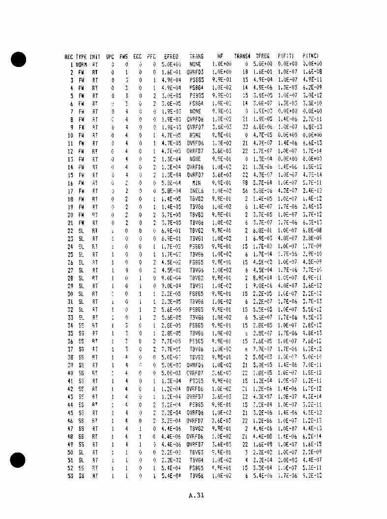
REC TYPE INIT SPC FWS ECC RFC EFREQ TRANS HF TRANS* TFREC P (F ;T ) P(TWC)1 NORN RT 0 0 0 0 5 .0£t0C i NONE l.O E+00 0 5.0E+00 O.OE+OO O.OE+OO2 FH RT 0 1 0 0 1 .6 E -0 1 QVRFD3 l.O E +00 16 1 .6 E -0 1 l.O E -0 7 1.6E-0B3 FW RT 0 3 0 I 4 .9 E -0 4 FSE35 9 .9 E -0 1 15 4 .9 E -0 4 l.O E -0 7 4 .9 E -1 14 FW RT 0 3 0 1 4 .9 E -0 4 P5BG4 l.O E -0 2 14 4 .9 E -0 6 1 .3 E -0 3 6 .2 E -0 95 FW RT 0 3 0 1L 3 .0 E -0 5 P3BG5 9 .9 E -0 1 15 3 .0 E -0 5 l.O E -0 7 3 .0 E -1 26 FW RT ■1 ’ . 'J 0 J. 3 .0 E -0 5 FSB84 l .O E -0 2 14 3 .0 E -0 7 1 .3 E -0 3 3 .3 E -1 07 FW RT 0 4 0 0 1 .9 E -0 3 NQNE 9 .9 E - 0 I 0 1 .5 E -0 3 O.OE+OO O.OE+OO8 FW RT 0 4 0 0 1 .9 E -0 3 QVRFDE l.O E -0 2 21 1 .9 E -0 5 1 .4 E -0 6 2 .7 E -1 19 FW RT 0 4 0 0 1 .9 E -0 3 GVRFBT 3 .6 E -0 3 22 6 .8 E -0 6 l.O E -0 7 6 . B E-13
10 FW RT 0 4 0 1 4 .7 E -0 5 NONE 9 .9 E -C 1 0 4 .7 E -C 5 O.OE+OO O.OE+OO11 FW RT 0 4 0 1 4 .7 E -0 5 00RFD6 1 .0 E -0 2 21 4 .7 E -0 7 1 .4 E -0 6 6 .6 E -1 312 FW RT 0 4 0 i 4 .7 E -0 5 QVRFD7 3 .6 E -0 3 LL 1 .7 E -0 7 l.O E -0 7 1 .7 E -1 413 FW RT 0 4 0 ni. 1 .3 E -0 4 NONE 9 .9 E -0 1 0 1 .3 E -0 4 O.OE+OO O.OE+OO14 FW RT 0 4 0 - 1 .3 E -0 4 OVRFQt. l .O E -0 2 21 1 .3 E -0 6 1 .4 E -0 6 l .S E -1 215 FW RT 0 4 0 V 1 .3 E -0 4 OOR:FB7 3 .6 E -0 3 22 4 .7 E -0 7 l.O E -0 7 4 .7 E -1 416 FW RT 0 2 0 0 5 .3 E -0 4 NIN 9 .9 E -0 1 98 5 .7 E -0 4 l.O E -0 7 5 .7 E -1 117 FW RT 0 2 0 0 5 .0 E -0 4 INEL6 l.O E -0 2 56 S .S E -O i 4 .2 E -0 7 2 .4 E -1 218 FW RT y L 0 i 1 .4 E -0 5 TBVG2 9 .9 E -0 1 2 1 .4 E -0 5 l.O E -0 7 1 .4 E -1 219 FW RT 0 2 0 I 1 .4 E -0 5 TBV66 l .O E -0 2 6 1 .4 E -0 7 1 .7 E -0 6 2 .4 E -1 320 FW RT 0 2 0 2 3 .7 E -0 5 TBVG2 9 .9 E -0 1 nL 3 .7 E -0 5 l.O E -0 7 3 .7 E -1 221 FW RT 0 2 0 nL. 3 .7 E -0 5 TBOGE l,C E -0 2 6 3 .7 E -0 7 I .7 E -0 6 6 .3 E -1 322 SL RT i 0 0 0 6 .9 E -0 1 TBVG2 9 .9 E -0 1 ni. 6 .3 E -0 1 l.O E -0 7 6 .B E -0823 SL RT 0 0 0 6 .9 E -0 1 TBVGl l .O E -0 2 1 6 .9 E -0 3 4 .0 E -C 7 2 .8 E -0 924 SL RT 1 0 0 1 1 .7 E -0 2 PSBG5 9 .9 E -0 1 15 1 .7 E -0 2 l.O E -0 7 1 .7 E -0 925 5L RT 1 0 0 1 1 .7 E -0 2 TBV66 l .O E -0 2 6 1 .7 E -0 4 1 .7 E -0 6 2 .9 E -1 026 EL RT 1 0 0 nL 4 .5 E -0 2 P3BG5 9 .9 E -0 1 15 4 .5 E -0 2 l.O E -0 7 4 .5 E -0 927 SL RT 1 0 0 4 .5 E -0 2 TBVG6 l.O E -0 2 6 4 .5 E -0 4 1 .7 E -0 6 7 .7 E -1 028 SL RT 1 0 1 0 9 .0 E -0 4 TB'v'G2 9 .9 E -0 1 2 3 .9 E -0 4 l.C E -0 7 8 .9 E -1 129 SL RT 1 0 i 0 9 .0 E -0 4 TBVSl l .O E -0 2 1 9 .0 E -0 6 4 .0 E -0 7 3 .6 E -1 230 SL RT ! 0 1 1 2 .2 E -0 5 FSBG5 9 .9 E -0 1 15 2 .2 E -0 5 i.G E -0 7 2 .2 E -1 231 SL RT i 0 1 1 2 .2 E -0 5 TSVG6 l.O E -0 2 6 2 .2 E -0 7 1 .7 E -0 6 3 .7 E -1 332 SL RT 1 0 1 nL 5 .6 E -0 5 PSSG5 9 .9 E -0 1 15 5 .5 E -0 5 l.O E -0 7 5 .5 E -1 233 SL R' 1 (I 1 ni. 5 .6 E -0 5 TBVG6 l.O E -0 2 6 5 .6 E -0 7 1 .7 E -0 6 9 .5 E -1 334 SS R;T 1 3 0 1 2 . SE -05 PSBG5 9 .9 E -0 1 15 2.,SE-05 l.O E -0 7 2 .8 E -1 235 S3 RT 1 3 0 1 2 .8 E -0 5 TBVG6 l.O E -0 2 2 .3 E -0 7 1 .7 E -0 6 4 .S E -1 336 SS RT 1 3 c 2 7 .7 E -0 5 PSBG5 9 .9 E -0 1 15 7 .6 E -0 5 l.O E -0 7 7 .6 E -1 237 S3 RT 3 2 7 .7 E -0 5 TBV66 l .O E -0 2 e 7 .7 E -0 7 1 .7 E -0 6 1 .3 E -1 238 SS RT 1 4 (! 5 .0 E -0 3 TEvG2 9 .9 E -0 1 'NL 5 .0 E -0 3 l.O E-O T 5 .0 E -1 039 SS RT 1 4 0 5 .0 E -0 3 0VRFD4 l.O E -0 2 21 5 .0 E -0 5 1 .4 E -0 6 7 .0 E -1 140 SS RT 1 4 0 0 5 .0 E -0 3 CVRFD7 3 .6 E -0 3 ■”.nLL l .B E -0 5 1 .OE-07 l .S E -1 241 SS RT 1 4 fl 1 1 .2 E -0 4 PSBG5 9 .9 E -0 1 15 1 .2 E -0 4 l.O E -0 7 1 .2 E -1 142 SS RT 1 4 c 1 1 .2 E -0 4 0VRFD6 l.O E -0 2 21 1 .2 E -0 6 1 .4 E -0 6 1 .7 E -1 243 SS RT 1 4 0 1 i .2 E - 0 4 0VRFD7 3 .6 E -0 3 nnLL 4 .3 E -0 7 l.O E -0 7 4 .3 E -1 444 SS RT 4 0 2 3 .2 E -0 4 PSB85 9 .9 E -0 1 15 3 .2 E -0 4 l.O E -0 7 3 .2 E -1 145 SS RT 1 4 0 L 3 .2 E -0 4 0VRFD6 l.O E -0 2 21 3 .2 E -0 6 1 .4 E -0 6 4 .5 E -1 246 SS RT 1 4 0 nL 3 .2 E -0 4 0VRFD7 3 .6 E -0 3 22 1 .2 E -0 6 l.O E -0 7 1 .2 E -1 347 SS RT 1 4 1 0 4 .4 E -0 6 TBVG2 9 .9 E -0 1 2 4 .4E -C 6 l.O E -0 7 4 .4 E -1 348 SS RT 1 4 1 0 4 .4 E -0 6 0VRTD6 l.O E -0 2 21 4 .4 E -0 B 1 .4 E -0 6 6 .2 E -1 449 SS RT 1 4 1 0 4 .4 E -0 6 QVRFD7 3 .6 E -0 3 22 1 .6 E -0 8 l.O E -0 7 1 .6 E -1 550 SL RT 1 1 0 2 .2 E -0 2 TBVG3 9 .S E -0 1 3 2 .2 E -0 2 l.O E -0 7 2 .2 E -0 951 SL RT 1 0 2 .2 E -0 2 TSVG4 l.O E -0 2 4 2 .2 E -0 4 2 .0 E -0 3 4 .4 E -0 752 SS RT 1 1 0 1 5 .4 E -0 4 PSB65 P .9 E -0 1 15 5 .3 E -0 4 1 .0 E -0 7 5 .3 E -1 153 SS RT 1 1 0 I 5 .4 E -0 4 T3VG6 l.O E -0 2 6 5 .4 E -0 6 1 .7 E -0 6 9 .2 E -1 2 .
A.31
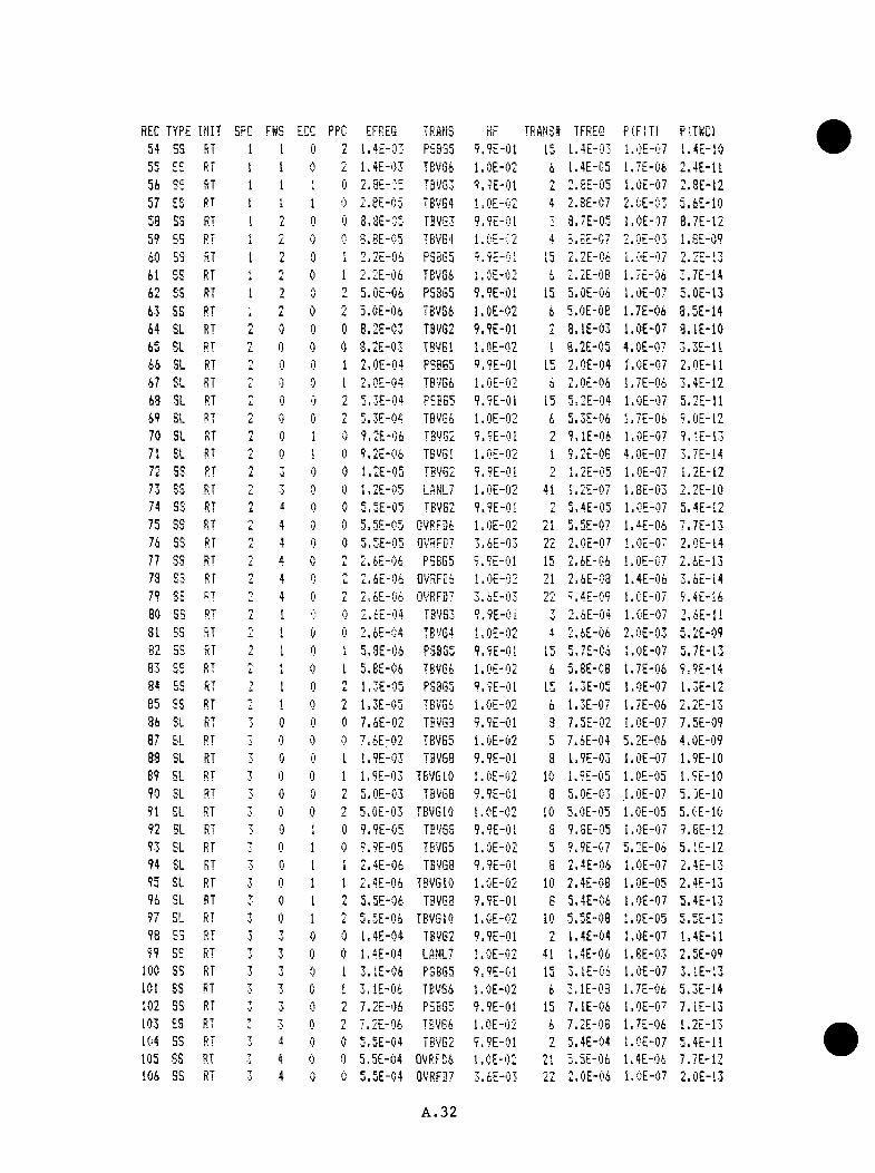
REC TYPE !NIT SPC FWS ECC PPC EFREQ TRAfiS HF TRAN.SI TFREQ PIFIT) P(TKC)54 SS RT I 1 0 2 1.4E-03 PSBG5 9.9E-01 15 1.4E-03 l.OE-07 1.4E-1055 ES RT 1 1 0 L 1.4E-03 TBVG6 l.OE-02 6 1.4E-C5 1.7E-06 2.4E-1156 SS RT I 1 <
i 0 2.8E-V5 TBVG3 9.9E-01 >7L 2.8E-05 I.OE-07 2.8E-1257 ES RT 1 1 1 0 2.eE-05 TBVS4 l.OE-02 4 2.8E-C7 2.CE-03 5.6E-1058 SS RT 1 nL 0 0 3.8E-05 TBVG3 9.9E-01 3 3.7E-05 l.OE-07 8.7E-1259 BS RT 1 L 0 0 8.8E-05 T8VE4 1.0E-C2 4 5.FF-07 2.0E-03 1.8E-0960 S3 RT 1 nL 0 1 2.2E-06 P3BG5 9.9E-01 15 2.2E-06 l.OE-07 2.2E-i361 SS RT 1 r*
L 0 1 2.2E-06 TBv'G6 l.OE-02 6 2.2E-08 1.7E-06 3.7E-1462 S3 RT 1 2 0 ' ) 5.0E-06 PSBG5 9.9E-01 15 5.0E-06 l.OE-07 5.0E-1363 SS RT ; L 0 nL 5.0E-06 TBVG6 l.OE-02 6 5.0E-0E 1.7E-06 3.5E-1464 SL RT nL 0 0 0 8.2E-03 TBVG2 9.9E-01 •7 8.1E-03 l.OE-07 8.1E-1065 SL RT nL 0 0 0 S.2E-03 TB9G1 l.OF-02 1 8.2E-C5 4.0E-07 3.3E-1166 SL RT <*i
L. 0 0 1 2.0E-04 PSBG5 9.9E-01 15 2.0E-04 l.OE-07 2.0E-1167 SL RT I 0 0 I 2.0E-04 TB7G6 l.OE-02 6 2.0F-06 1.7E-06 3.4E-1268 SL RT L 0 0 ■J
i . 5.3E-04 PSBG5 9.9E-01 15 5.2E-04 l.OE-07 5.2E-1169 SL RT >-y 0 0 nL 5.3E-04 TBVGA l.OE-02 6 5.3E-06 1.7E-06 9.0E-1270 SL RT nL 0 1 0 9.2E-06 TBVG2 9.9E-0i 2 9.1E-06 l.OE-07 9 . IE-1371 EL RT nL 0 1 0 9.2E-04 TBVGI l.OE-02 1 9.2£-oe 4.0E-07 3.7E-1472 SS RT 2 3 0 0 1.2E-05 TBVG2 9.9E-01 2 1.2E-05 l.OE-07 1.2E-1273 SS RT n 0 0 1.2E-05 LANL7 l.OE-02 41 1.2E-07 1.8E-03 2.2E-1074 SS RT nL 4 0 0 5.5E-05 TBVG2 9.9E-01 7L 5.4E-05 l,0E-07 5.4E-1275 SS RT •TI 4 0 0 5.5E-05 QVRFD6 l.OE-02 21 5.5E-07 1.4E-06 7.7E-1376 SS RT n 4 0 0 5.5E-05 QVRFD7 3.6E-03 22 2.0E-07 l.OE-07 2.0E-1477 SS RT -Ii 4 0 n
L 2.6E-06 PSBG5 9.9E-01 15 2,6E-06 1.0E-C7 2.6E-1373 S3 RT ni 4 0 n 2.6E-06 0VRFD6 l.OE-02 21 2.6E-03 1.4E-06 3.6E-1479 SS RT 4 0 L 2=6£-06 OVRFDT 3.6E-03 22 5.4E-09 l.OE-07 9.4E-1680 SS RT nL 1 '■) 0 2.6E-04 T3VG3 9,9E-0i 3 2.6E-04 l.OE-07 2.6E-1181 SS RT '*1 1 0 0 2,6£-04 TBVG4 i.OE-02 4 2.6E-06 2.0E-03 5.2E-0982 SS RT -7 1 0 1 5.8E-0.fi P3SG5 9.9E-0i 15 5.7E-06 l.OE-07 5.7E-1383 SS RT n 1 0 I 5.EE-06 TBV66 l.OE-02 6 5.3E-CS 1.7E-06 9.9E-I484 SS RT T I 0 nL 1.3E-05 P3B65 9.9E-01 15 1.3E-05 l.OE-07 1.3E-1285 SS RT 7 1 0 2 1.3E-05 TBVG6 l.OE-02 6 1.3E-07 1.7E-06 2.2E-1386 SL RT 7 0 0 0 7.6E-02 TBVG3 9.9E-C1 3 7.5E-02 1.0E-07 7.5E-0987 SL RT 0 0 0 7=6E-02 TBVG5 l.OE-02 5 7.6E-04 5.2E-06 4.0E-0983 SL RT 7 0 0 1 1.9E-03 TBV68 9.9E-01 3 1.9E-03 l.OE-07 1.9E-1089 SL RT 7 0 0 I 1.9E-03 TEVGIO 1.0E-C2 10 1.9E-05 l.OE-05 1.9E-1090 SL RT 7■J 0 0 5.0E-03 TBVG8 9.9E-C1 8 5.0E-03 .l.OE-07 5.0E-1091 SL RT T 0 0 2 5.0E-03 TBVGIO l.OE-02 10 5.0E-05 l.OE-05 5.0E-1092 SL RT 7 0 1 0 9.9E-05 TEV6S 9.9E-0I a 9.3E-05 i.OE-07 9.3E-1293 SL RT 7 0 1 0 9.9E-05 TBVG5 l.OE-02 5 9.9E-07 5.2E-06 5.1£-1294 SL RT 7
•J 0 1 1 2.4E-06 TBVG8 9.9E-01 8 2.4E-06 l.OE-07 2.4E-1395 SL RT 3 0 1 1 2.4E-06 TSVGIO l.OE-02 10 2.4E-08 l.OE-05 2.4E-1396 SL RT 7 0 1 nL 5.5E-06 TBVG8 9.9E-01 8 5.4E-06 l.OE-07 5.4E-1397 SL RT 3 0 1 2 5.5E-06 TBVGIO l.OE-02 10 5.5E-08 l.OE-05 5.5E-1398 S3 RT 3 3 0 0 1.4E-04 TBV62 9.9E-01 7i. 1.4E-04 l.OE-07 1.4E-1199 SS RT 7 3 0 0 1.4E-04 LANL7 l.OE-02 41 1.4E-06 1.3E-03 2.5E-09
100 SS RT 3 3 0 1 3 . lE-06 PSBG5 9.9E-01 15 Z, lE-Oi l.OE-07 3.1E-13101 SS RT 3 3 c I 3.1E-06 TEVE6 1.OE-02 6 3.1E-03 1.7E-06 5.3E-14102 S3 RT 7
■J 3 0 nL 7.2F-06 PSBGS 9.9E-01 15 7.1E-06 l.OE-OT 7.1E-13103 S3 RT 7 7
• J 0 nL 7.2E-06 TBVG6 l.OE-02 6 7.2E-08 1.7E-06 1.2E-13
104 SS RT 7 4 0 0 5.5E-04 TBVG2 9.9E-01 7L 5.4E-04 l.OE-07 5.4E-11105 SS RT 7
•J 4 0 0 5.5E-04 QVRF06 l.OE-02 21 3.5E-06 1.4E-06 7.7E-12106 SS RT 1 4 0 0 5.5E-04 0VRFD7
A . 32
3.6E-03 22 2.0E-06 l.OE-07 2.0E-13

REC TYPE INIT SRC FHS ECC PPC EFREQ TRANS HF TRftNSi TFREQ P(FIT) P(THC)107 SS RT 3 4 0 1 1.3E-05 PSBS5 9.9E-01 15 U3E-05 l.OE-07 1.3E-12i08 ccuo RT 3 4 0 1 1.3E-05 QVRFD6 l.OE-02 21 1.3E-07 1.4E-06 1.8E-13109 SS RT 3 4 0 1 1.3E-05 OVRFDT 3.4E-03 22 4.7E-03 l.OE-07 4.7E-15110 SS RT T■J 0 TL 3.3E-05 FSEG5 9.9E-01 15 3.3E-05 l.OE-07 3.3E-12111 SS RT 3 4 0 nto 3.3E-05 0VRFD6 l.OE-02 21 3.3E-07 1.4E-06 4.4E-13112 SS RT 3 4 0 n
i. 3.3E-05 0VRFD7 3.4E-03 22 1.2E-07 l.OE-07 1.2E-14113 SS RT T•J 1 0 0 2.4E-03 TBVG3 9.9E-01 8 2.4E-03 l.OE-OT 2.4E-10114 SS RT 3 0 0 2.4E-03 TBVG9 l.OE-02 9 2.4E-05 2.0E-03 4.EE-08115 SS RT 3 1 0 1 6.0E-05 TBVG8 9.9E-01 e 5.9E-05 l.OE-07 5.9E-12116 SS RT 7 1 0 1 4.0E*05 TBVGIO l.OE-02 10 6.0E-07 l.OE-05 6.0E-12117 SS RT 7 1 0 2 1.4E-04 TBVG8 9.9E-01 3 1.4E-C4 l.OE-07 1.6E-11118 SS RT 7, 1 0 n 1.4E-04 TBVGIO l.OE-02 10 1.6E"04 l.GE-05 1.6E-11119 SS RT 7
■J 1 1 0 2.4E-04 TBVG9 9.9E-0! 3 2.4E-06 i.OE-07 2.6E-13120 ecij-j RT 3 1 1 0 2.4E-04 TBVG5 l.OE-02 5 2.6E-08 5.2E-06 l.«E-13121 SS RT 7 2 0 0 3.7E-04 TBVG3 9.9E-01 3 3.4E-06 l.OE-07 3.6E-13122 SS RT 7, 0 0 e.7E-04 TBVG4 l.OE-02 4 8.7E-0G 2.0E-03 1.7E-10123 SL RT 4 0 0 4.9E-04 TBVG2 9.9E-01 -“tto 4.3E-U4 l.OE-07 4.8E-11124 SL RT 4 0 0 0 4.9E-04 TBVGl l.OE-02 1 6.9E-06 4.0E-07 2.BE-12125 SL RT 4 0 0 ! 1.5E-05 TBVG2 9.9E-01 2 1.5E-05 l.OE-07 1.5E-12126 SL RT 4 0 I) 1 1.5E-05 TBVGIO l.OE-02 10 1.5E-07 l.OE-05 1.5E-12127 SL RT 4 0 0 2 4.3E-05 TBVG2 9.9E-01 n 4.3E-05 l.OE-07 4.3E-12128 SL RT 4 0 2 4.3E-05 TBVGIO i.OE-02 10 4.3E-07 l.OE-05 4.3E-12129 S3 RT i 4 0 0 3 . lE-06 TBVG2 9.9E-01 2 3.iE-06 l.OE-07 3.1E-13130 SS RT 4 0 0 3.1E-04 QVRFB4 l.CE-02 21 3.1E-08 1.4E-06 4.3E-14131 S3 RT 4 4 0 0 3.1E-06 QVRFD7 3.4E-03 22 l.lE-03 l.OE-07 l.lE-15132 SS RT 4 1 0 0 1.4E-05 TBVG2 9.9E-01 nL 1.6E-05 l.OE-07 1.4E-12133 SS RT 4 1 0 0 1.4E-05 TBVG9 l.OE-02 9 1.6E-07 2.0E-03 3.2E-10134 SL RT D (I 0 0 4.5E-04 TBVG2 9.9E-01 2 4.5E-04 i.OE-07 4.5E-11135 SL RT C
J 0 0 0 4.5E-04 TBVG5 l.OE-02 5 4.5E-06 5.2E-06 2.3E-U136 SL RT r
J 0 0 1 l.lE-05 TBVG2 9.9E-01 nL l.lE-05 l.OE-0’ l.lE-12137 SL RT 5 0 0 1 l.lE-05 TBVGIO l.OE-02 10 l.lE-07 l,0E-05 l.lE-12138 SL RT r•J 0 0 Tto 2;,BE-05 TBVG2 9.9E-0! 2 2.SE-05 l.OE-07 2.8E-12139 SL RT c
•J 0 0 1 2.SE-05 TBVGIO l.OE-02 10 2.SE-07 l.OE-05 2.3E-12140 3E RT r•J 4 0 0 2.2E-04 TBVG2 9.9E-01 2 2.2E-04 l.OE-07 2.2E-13141 SS RT 5 4 0 0 2.2E-06 0VRFD4 l.OE-02 21 2.2E-03 1.4E-06 3.1E-14142 SS RT J 0 0 2.2E-04 OVRFB? 3.4E-03 22 7.9E-09 l.OE-07 7.9E-16143 SS RT r
w 1 fl 0 1.4E-05 TBVG2 9.9E-01 1.4E-05 l.OE-07 1.4E-12144 SS RT z
J 1 0 0 1.4E-05 TBVG9 l.OE-02 9 1.4E-07 2.0E-03 2.SE-10145 SL RT 0 0 0 5.0E-04 HSLEl 9.9E-01 26 5.0E-04 6.2E-04 3.1E-07146 SL RT 6 0 0 0 5.0E-04 T3VG9 l.OE-02' 9 5.CE-04 2.0E-03 1.0E-C8147 SL RT 4 0 (I 1 1.2E-05 I1SLB7 9.9E-01 32 1.2E-05 6.2E-0i 7.4E-09148 SL RT 4 0 0 1 1.2E-05 TBVG9 l.OE-02 9 1.2E-07 2.CE-03 2.4E-10149 SL RT 4 0 0 2 3.1E-05 NSLB7 9.9E-01 s / i 3.1E-05 4.2E-04 i.9E-08150 SL RT 4 0 0 n
ii. 3.1E-05 TBVG9 i.OE-02 9 3.1E-07 2.0E-03 6.2E-10151 SS RT s 4 0 0 2.5E-06 fISLBl 9.9E-01 26 2.5E-06 4.2E-04 1.5E-09152 SS RT 4 4 0 0 2.5E-04 GVRFD4 t.OE-02 21 2.5E-03 1.4E-04 3.5E-14153 SS RT 4 4 0 0 2.5E-04 OVRFDT 3.4E-03 22 9.0E-09 l.OE-07 9.0E-14154 SS RT 4 1 0 0 1.4E-05 MSLS7 9,9E-0! •yn
• J i 1.4E-05 4.2E-04 9.GE-09155 SS RT 4 1 0 0 1.4E-05 TBVG9 1.OE-02 9 1.6E-07 2.0E-03 3.2E-10156 RES RT 9R 99 99 99 1.9E-04 DEF I. OE+OO 99 1.9E-04 S.4E-03 l.OE-06157 FH EflFH 0 1 0 0 3.4E-02 0VRFD3 l.OE^O 13 8.4E-02 l.OE-07 6.4E-09158 FH ENFH 0 3 0 0 1.4E-04 NIN 9.9E-01 98 1.4E-04 1.0E-C7 l.JE-11159 FH ELIFH 0 T
•J 0 0 1.4E-04 INEL3
A . 33
l.OE-02 53 1.4E-06 l.OE-07 1.4E-13

REC TYPE INIT SPC FWS ECC PPG EFRE3 TRANS HF TRANSit TFREQ P(F!T! P(TWC)160 FW ENFW 0 3 0 1 2.9E-06 PSBGS 9.9E-01 IS 2.9E-06 1.Ct-07 2.9E-13161 FW ENFH 0 3 0 1 2.9E-06 PSBG4 l.OE-02 14 2.9E-08 1.3E-03 3.7E-11'62 FW EHFH 0 3 0 2 6.St-06 PSBGS 9.9E-01 IS 6.7E-06 l.OE-07 6.7E-13163 FW EHFW 0 3 0 2 6.8E-06 PSBG4 l.OE-02 14 6.8E-08 1.3E-03 3.6E-11164 FW EflFW **» 4 0 0 5.5E-04 T3VG2 9.9E-01 n
L 5.4E-04 l.OE-07 5.4E-11165 FH EMFW 0 4 0 0 J.5E-04 0ORFD6 l.OE-02 21 5.SE-06 1.4E-06 7.7E-12166 FW EHFW 0 4 0 0 5.5E-04 OVRFDT 3.6E-03 n n 2.0E-06 1. 0E.-07 2.0E-13167 FW EHFW 0 4 0 1 1.3E-05 PSBG5 9.9E-01 15 1.3E-05 1..0E-07 1.3E-1216S FW EHFW 0 4 0 1 1.3E-05 QVRFD6 l.OE-02 21 1.3E-07 1.4E-06 1.8E-13169 FW EHFW 0 4 0 1 1.3E-05 QVRFD7 3.6E-03 22 4.7E-08 l.OE-07 4.7E-15170 FW EHFW 0 4 0 2 3.3E-05 PSBGS 9.9E-01 15 3.3E-05 l.OE-07 3.3E-12171 FW EHFW 0 4 0 2 3.3E-05 0VRFD6 l.OE-02 21 3.3E-07 1.4E-06 4.6E-13172 FW EHFW 0 4 0 2 3.3E-05 OVRFDT 3.6E-03 1.2E-07 l.OE-OT I.2E-14173 FH EHFW 0 2 0 0 3.1E-04 TBVG2 9.9E-01 2 3.1E-04 l.OE-07 3,1E-11174 FH EHFW 2 0 0 3 . lE-04 TBVGl l.OE-02 1 3.1E-06 4.0E-07 1.2E-12175 FW EHFW 2 0 1 7.7E-06 TBV32 9.9E-01 *5 7.6E-06 l.OE-07 7.6E-13176 FH EHFW 0 2 0 1 7.7E-06 TBVG6 l.OE-02 6 7.7E-03 1.7E-06 1.3E-13177 FH EHFW 2 0 2 2.0E-05 TBVG2 9.9E-01 n 2.0E-OS l.OE-07 2.0E-12178 FW EHFW 2 0 2 2.0E-05 TBVG6 l.OE-02 6 2.0E-07 1.7E-06 3.4E-13179 SS EHFW 1 1 0 0 1.2E-02 TBVG2 9.9E-01 2 1.2E-02 l.OE-07 1.2E-09180 SS EHFW 1 1 0 0 1.2E-02 TBVGl l.OE-02 1 1.2E-04 4.0E-07 4.8E-11181 SS EHFW 1 0 1 2.9E-04 PSBGS 9.9E-01 IS 2.9E-04 l.OE-07 2.9E-11182 SS EHFW 1 1 0 1 2.9E-04 TBVG6 l.OE-02 6 2.9E-06 1.7E-06 4.9E-12183 SS EHFW I 1 0 2 7.7E-04 PSBGS 9.9E-01 15 7.6E-04 1.0E-07 7.6E-11184 SS EHFW 1 0 2 7.7E-04 TBV66 l.OE-02 6 7.7E-06 1.7E-06 1.3E-U185 SS EHFW 1 1 1 0 1.2E-05 TBVG2 9.9E-01 L 1.2E-05 l.OE-07 1.2E-12186 SS EHFW 1 1 1 0 1.2E-05 TBVGl l.OE-02 fi 1.2E-07 4.0E-07 4.8E-14187 SS EHFW 1 3 0 0 1.6E-05 TBVG2 9.9E-01 L 1.6E-0S l.OE-07 1.6E-12IBB SS EHFW 1 3 0 0 1.6E-05 LANL7 l.OE-02 41 1.6E-07 1.8E-03 2.9E-10189 SS EHFW 1 4 0 0 e.OE-05 TBV62 9.9E-01 2 7.9E-05 l.Ot-07 7.9E-12190 SS EHFW 1 4 0 0 8.0E-05 QVRFD6 l.OE-02 21 3.0E-07 1.4E-06 l.lE-12191 SS EHFW 1 4 0 0 8.0E-05 0VRFD7 3.6E-03 22 2.9E-07 l.OE-07 2.9E-14192 SS EHFW 1 4 0 2 3.5E-06 PSBGS 9.9E-01 IS 3.SE-06 l.OE-07 3.5E-13193 SS EHFW 1 4 0 2 3.5E-06 0VRFB6 l.OE-02 21 3.5E-08 1.4E-06 4.9E-14194 SS EHFW 1 4 0 2 3.5E-06 OVRFDT 3.6E-03 22 1.3E-03 l.OE-07 1.3E-15195 SS EHFW 1 2 0 0 4.7E-05 TBVG3 9.9E-01 3 4.7E-05 l.OE-07 4.7E-12196 SS EHFW 1 2 0 0 4.7E-05 TBVS4 l.OE-02 4 4.7E-07 2.CE-03 9.4E-10197 SS EHFW 1 2 0 2 2.7E-06 PSBGS 9.9E-01 15 2.7E-06 l.OE-07 2.7E-13198 SS EHFW 1 2 0 2 2.7E-06 TBVG6 l.OE-02 6 2.7E-C8 1.7E-06 4.6E-14199 SS EHFW 2 1 0 0 1.4E-04 TSVG3 9.9E-01 T 1.4E-04 l.OE-07 1.4E-11200 SS EHFW 2 1 0 0 1.4E-04 TEVG4 1.0E-02 4 1.4E-06 2.0E-03 2.8E-09201 SS EHFW n ■
L 1 0 1 3.1E-06 PSBGS 9.9E-01 15 3.1E-06 l.OE-07 3.1E-13202 cc EHFW 2 1 0 1 3 . lE-06 TBVG6 l.OE-02 6 3.1E-03 1.7E-06 5.3E-14203 SS EHFW o
L 1 0 2 7.2E-06 PSB65 9.9E-01 15 7 . lE-06 l.OE-07 7.1E-13204 SS EHFW n
L 1 0 2 7.2E-06 TBVG6 l.OE-02 6 7.2E-08 1.7E-06 1.2E-13205 SS EHFW 7 1 0 0 1.3E-03 TBV68 9.9E-01 3 1.3E-03 l.OE-07 1.3E-10206 SS EHFW 3 1 0 0 1.3E-03 TBVG9 l.OE-02 9 1.3E-05 2.0E-03 2.6E-08207 SS EHFW T 1 0 1 3.2E-05 TEOGS 9.9E-01 8 3.2E-05 l.OE-07 3.2E-12203 SS EHFW 7 1 0 I 3.2E-05 TBVGIO l.OE-02 10 3.2E-07 l.OE-05 3.2E-12209 £5 EHFW 7 1 0 2 S.4E-C5 TBVG8 9.9E-01 8 8.3E-05 l.OE-07 8.3E-12210 SS EHFW 7
•J 1 0 2 8.4E-05 TBVGIO l.OE-02 10 8.4E-07 l.OE-05 S.4E-12211 SS EHFW ,S 1 1 0 1.4E-06 TBVG8 9.9E-01 8 1.4E-06 l.OE-07 1.4E-13212 SS EHFW 7 1 1 0 1.4E-06 TBVG9
A. 34
l.OE-02 9 1.4E-08 2.0E-03 2.8E-11

REC TYPE INIT SPC FHS ECC PPC EFRES TRANS HF TRANS4 TFREQ PIF T) P(THC)213 SS EftFH 3 3 0 0 l.BE-06 TBVG2 9.9E-01 n i.BE-04 l.CE-07 1.8E-13214 SS EJ1FH T
■J 3 0 0 1.8E-06 LANL7 l.OE-02 41 1.8E-08 l.BE-03 3.2E-11215 S3 EI1FH 3 4 0 0 7.5E-06 TBVG2 9.9E-01 7.4E-04 l.OE-07 7.4E-13216 SS EMFH 3 4 0 0 7.5E-04 OVRF06 l.OE-02 21 7.5E-08 1.4E-04 l.lE-13217 SS EKFH T 4 0 0 7.5E-Q6 0VRFD7 3.4E-03 22 2.7E-03 l.OE-07 2.7E-1521B SS EMFH 3 n
L 0 1) 4.7E-04 TBVG3 9.9E-01 T 4.7E-04 l.OE-07 4.7E-13219 S.S EMFH T n 0 0 4.7E-04 TB'/G4 l.OE-02 4.7E-03 2.0E-03 9.4E-1L220 SS EMFH 4 1 0 0 8,4E-04 TBVG2 9.9E-01 •n
L 8.5E-04 l.OE-07 S.5E-13221 SS EMFH 4 1 0 0 8.6E-06 TBV6? l.OE-02 9 8.4E-03 2.0E-03 1.7E-10222 SS EMFH 5 I 0 0 6. 3E"'.‘6 TBV62 9.9E-01 6.2E-06 l.OE-07 4.2E-13223 SS EMFH 5 I 0 0 6.3E-06 T3VG9 l.OE-02 9 4.3E-08 2.0E-03 1.3E-10224 SS EMFH 6 I 0 0 7.0E-04 MSLB7 9.9E-01 •■iL 4.9E-06 4 .2E-04 4.3E-09225 S3 EMFH 4 1 0 0 7.0E-04 TEVG9 l.OE-02 9 7.0E-08 2.0E-03 1.4E-10226 RES EMFH 99 99 99 99 7.2E-05 DEF 1.OE+OO 99 7.2E-05 5.4E-03 3.9E-07227 SL LSLE I 0 0 9.6E-04 MSLBl 9.9E-01 24 9.5E-04 4.2E-04 5.9E-07228 SL LSLB 1 0 0 9,6E-04 TEVB9 l.OE-02 9 9.4E-06 2.0E-03 1.9E-08229 SL LSLB 1 1 V 0 3.0E-05 MSLB3 9.9E-01 28 3.0E-05 4.0E-04 1.2E-03230 SL LSLB 1 1 0 0 3.0E-05 TBV69 l.OE-02 9 3.0E-07 2.0E-03 4.0E-10231 SL LSLB T 0 0 0 5.5E-06 MSLBl 9.9E-01 26 5.4E-06 4.2E-04 3.4E-09232 SL LSLE 7 0 0 0 5.5E-04 TBVB9 l.OE-02 9 5.5E-08 2.0E-C3 l.lE-10233 RES LSLB 99 99 99 99 5.3E-04 DEF 1.OE+OO 99 5.3E-06 5.4E-03 2.9E-08234 SL SSLB 1 0 0 0 9.0E-03 TBVG2 9.9E-01 ■*k
L 8.9E-03 l.OE-07 S.9E-10235 SL SSLB 1 0 0 0 9.0E-03 TBvGl 1.0E-02 S
i 9.0E-05 4.CE-07 3.4E-11236 SL SSLE 1 1 0 0 2.8E-04 TBV62 9.9E-01 2 2.8E-04 l.OE-07 2.8E-11237 SL SSLB 1 I 0 0 2.8E-04 TBVGi l.OE-02 1
i 2.3E-04 4.0E-07 l.lE-12238 SS SSLB I 4 0 0 2.4E-06 TBVG2 9.9E-01 n
L 2.4E-06 l.OE-07 2.4E-13239 SS SSLB 1 4 0 0 2.4E-04 0VRFD6 l.OE-02 21 2.4E-03 1.4E-04 3.4E-14240 SS uSub 1 4 0 0 2.4E-04 0VRFD7 3.6E-03 8.6E-09 l.OE-07 8.4E-16241 SL SSLB 3 0 0 0 6.3E-04 TB'vSS 9.9E-01 8 4.2E-04 1.CE-07 4.2E-11242 SL SSLB 3 0 0 0 4.3E-04 TBVG5 l.OE-02 c
J 4.3E-04 5.2E-06 3.3E-11243 SL SSLB J 0 0 1 1.5E-05 TBVGB 9.9E-01 8 1.5E-C5 l.OE-07 1.5E-12244 SL SSLB 7 0 0 1 1.5E-05 TBVGIO l.OE-02 10 1.5E-07 l.OE-05 I.5E-12245 SL SSLB 7 0 0 7I. 4.0E-05 TBVG8 9.9E-01 3 4.0E-05 l.OE-07 4.0E-12246 SL SSLB 7 0 0 -*4
L 4.OE-05 TBVGIO 1.0E-02 10 4.0E-07 l.OE-05 4.CE-12247 SL SSLB 7
J 1 0 0 2.0E-05 TBVG8 9.9E-01 8 2.0E-05 l.OE-07 2.0E-12248 EL SSLB 7, I 0 0 2.0E-05 TBVG9 l.OE-02 n
7 2.0E-07 2.0E-03 4.0E-10249 SL SSLB 7 1 0 n
L l.OE-06 TBV6S 9.9E-01 e 9.9E-07 l.CE-07 9.9E-14250 SL SSLB 7 1 0 n l.OE-06 TBVSIO i.OE-02 10 l.OE-08 l.OE-05 1.0E-13251 SL SSLB 4 0 0 0 4.5E-04 TBVGI l.OE-02 1 4.5E-08 4.0E-07 2.4E-14252 SL SSLB 4 0 0 0 6.5E-04 TBVG2 9.9E-01 L 4.4E-04 l.OE-07 4.4E-13253 RES SSLB 99 99 99 99 1.4E-05 DEF 1.OE+OO 99 1.4E-05 5.4E-03 7.4E-03254 HuRft LOMFH 0 0 0 0 5.5E-01 NONE 1.OE+OO 0 5.5E-01 O.OE+OO 0.OE+OO255 LGCh LOMFH 0 0 0 1 1.4E-02 PSBGl 1.OE+OO 11 1.4E-02 l.OE-07 1.4E-09256 LOCA LOMFH 0 0 0 7L. 3.4E-02 PSBGi 1.OE+OO 11 3.6E-02 l.OE-07 3.4E-09257 F« LOMFH 0 7 0 0 2.0E-03 MIN 9.75E-01 98 2.0E-03 1.0E-07 2.0E-10258 FM LOMFH 0 7
■j 0 0 2.0E-03 INEL3 l.OE-02 53 2.0E-05 l.OE-07 2.0E-12259 FH LOMFH 0 ■j 0 I 5.1E-05 PSBGS 9.9E-01 15 5.0E-05 1.OE-07 5.0E-12260 FH LOMFH 0 ■J 0 1 5.1E-05 PSSG4 l.OE-02 14 5.1E-07 1.3E-03 4.4E-10261 FH LOMFH 0 3 0 2 1.3E-04 F'SBG5 9.9E-01 15 1.3E-04 l.OE-07 1.3E-11262 FH LOMFH 0 7 () 7L. 1.3E-04 PSBG4 l.OE-02 14 1.3E-06 1.3E-03 1.4E-09263 FH LOMFH 0 4 0 0 3.9E-03 NONE 9.9E701 0 3.9E-03 O.OE+OO O.OE+OO264 FH LOMFH 0 4 0 0 3.9E-03 0VRFQ6 l.OE-02 21 3.9E-05 1.4E-04 5.5E-11265 FH LOMFH 0 4 0 0 3.9E-03 0VRFD7 3.6E-03 L L 1.4E-05 l.OE-07 1.4E-12
A.35
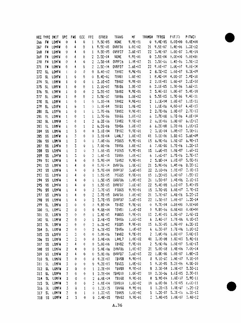
REC TYPE INIT SPC FHS ECC PPC EFREQ TRANS HF TRANS# TFREQ P(FIT) P(THC)266 F« LOMFH 0 4 0 1 9.5E-05 NQNE 9.9E-01 0 9.4E-05 0 .OE+OO O.OE+OO267 F« LOMFH 0 4 0 1 9.5E-05 0VRFD6 l.OE-02 21 9.5E-07 l.4E-0i 1.3E-12268 FH LOMFH 0 4 0 1 9.5E-05 0VRFD7 3.6E-03 22 3.4E-07 1.0E-C7 3.4E-14269 FH LOMFH 0 4 0 T
L 2.5E-04 NONE 9.9E-01 0 2.5E-04 0.OE+OO O.OE+OO270 FH LOMFH 0 4 0 n
L 2.5E-04 0VRFD6 l.OE-02 21 2.5E-0i 1.4E-06 3.5E-L2271 FH LOMFH 0 4 0 9 2.5F-04 OVRFDT 3. iE"'.i3 22 9.0E~i)7 l.OE-OT 9.0E-14272 SL LOMFH 1 0 0 0 3.4E-02 TBVG2 9.9E-01 n
L 3.3E-02 l.OE-07 S.3E-09273 SL LOMFH t
iAV 0 0 8.4E-02 TEVGl 1. OE-02 1 8.4E-04 4.0E-07 3.4E-10
274 SL LOMFH 1 0 0 I 2 . lE-03 TBVG2 9.9E-01 nL 2.1E-03 l.OE-07 2.1E-10
275 BL LOMFH 1 0 0 I 2 . lE-03 TBVG6 l.OE-02 i 2.1E-05 1.7E-06 3 .i£ - l l276 SL LOMFH 1 0 0 n 5.5E-03 TEVG2 9.9E-01 9 5.4E-03 l.OE-07 5.4E-10277 BL LOMFH 1 0 0 L 5.5E-03 TBVG6 l.OE-02 t 5.5E-05 1.7E-0i 9.4E-11278 SL LOMFH 1 0 <i 0 l.lE-04 TBVG2 9.9E-01 2 l.lE-04 l.OE-07 l.lE-11279 SL LOMFH 1 0 1 I ) i.lE-04 TBv'Gl l.OE-02 1 l.lE-06 4.0E-07 4.4E-13280 SL LOMFH 1 0 1 1 2.7E-06 TBVG2 9.9E-01 n 2.7E-06 l.OE-OT 2.7E-13281 SL LOMFH 1 0 1 I 2.7E-06 TBV66 l.CE-02 6 2.7E-08 1.7E-06 4.iE-14282 SL LOMFH I c 1 n 6.2E-06 T3VG2 9.9E-01 9
s . i.lE-Oi l.OE-07 6.LE-13283 SL LOMFH 1 0 1 n
I 6.2E-06 TBVG6 l.OE-02 6 6.2E-08 1.7E-0i l.lE-13284 SS LOMFH 1 3 0 0 3.1E-04 TBV32 9.9E-01 9 3.1E-04 l.OE-07 3.1E-11285 SS LOMFH 1 3 0 0 3.1E-04 LANL7 l.OE-02 41 3.1E-04 l.BE-03 J . 6E-09286 SS LOMFH 1 j 0 1 7.0E-06 P3S55 9.9E-01 15 6.9E-06 l.OE-07 4.9E-13287 SS LOMFH 1 ■J 0 1 7.0E-06 TBVGi l.OE-02 i 7.0E-03 1.7E-0i 1.2E-13238 SS LOMFH 1 T 0 9 1.6E-05 P3BS5 9.9E-01 15 1.6E-05 l.OE-07 l.iE-12289 SS LOMFH 1 ■J 0 9 1.6E-05 TBVGi l.OE-02 i l.iE-07 1.7E-0i 2.7E-13290 S3 LOMFH 1 4 0 0 5.9E-04 TBVG2 9.9E-0i I 5.3E-04 l.OE-OT 5.SE-11291 SS LOMFH 1 4 0 0 5.9E-04 OVRFDi l.OE-02 9 4
L 1 J.9E-06 1.4E-0i 8.3E-12292 SS LOMFH I 4 0 0 5.9E-04 OVRFDT 3.6E-03 n n
i . L 2.1E-06 l.OE-07 2.1E-13293 cc
■J\J LOMFH I 4 0 1 I. 5E-05 PSBGS 9.9E-01 15 1.5E-05 1.OE-07 1.5E-12294 SS LOMFH 1 4 0 i 1.5E-05 QVRFD6 l.OE-02 21 1.5E-07 1.4E-06 2.1E-13295 SS LOMFH 1 4 0 1 1.5E-05 OVRFDT 3.tE-03 22 5.4E-08 l.OE-07 5.4E-15296 SS LOMFH 1 4 fl 1 3.7E-05 PSEG5 9,9E-01 15 3.7E-05 l.OE-07 3.7E-12297 SS LOMFH 1 4 0 n
L 3.7E-05 OVRFDi l.OE-02 21 3.7E-07 1.4E-06 5.2E-13298 SS LOMFH 1 4 0 n
t . 3.7E-05 OVRFDT 3.6E-03 22 1.3E-07 l.OE-07 1.3E-14299 SL LOMFH '■ 0 0 ■') 9.BE-04 TBVG2 9.9E-01 0 9.7E-04 0.OE+OO O.OE+OO300 SL LOMFH n 0 0 0 9.8E-04 TBVGI l.OE-02 0 9.8E-06 O.OE+OO O.OE+OO301 SL LOMFH 9 0 1 2.4E-03 PSEG5 9.9E-01 1 - 2.4E-05 l.OE-07 2.4E-12302 SL LOMFH n
L 0 '■} I 2.4E-05 TBVGi l.OE-02 6 2.4E-D7 1.7E-06 4.1E-13303 SL LOMFH I A 9 6.3E-05 PSBGS 9.9E-0! 15 6.2E-05 l.OE-07 6.2E-12304 SL LOMFH n 0 0 0 4.3E*iJ5 TBVGi l.OE-02 6 6.3E-07 1.7E-06 l.iE-12305 SS LOMFH 2 ' j 0 0 3.0E-06 TBVG2 9.9E-01 n
L 3.0E-06 l.OE-07 3.0E-13306 SS LOMFH • j 0 3.0E-06 LANL7 l.OE-02 41 3.0E-03 1.8E-03 5.4E-11307 SS LOMFH 9 4 0 5.0E-06 TBVG2 9.9E-01 2 5.0E-06 1.OE-07 5.0E-13308 SS LOMFH 2 4 0 j.OE-06 OVRFDi l.OE-02 21 5.0E-08 1.4E-06 7.0E-14309 SS LOMFH 2 4 0 5.0E-06 OVRFDT 3.iE-03 22 1.8E-06 l.OE-07 1.8E-15310 SL LOMFH 3 0 (3 0 9.2E-03 TBVGB 9.9E-01 3 9.1E-03 i.OE-07 9.1E-10311 SL LOMFH 7 0 0 0 9.2E-03 T B v e s l.OE-02 5 9.2E-05 5,2E-0i 4.SE-10312 SL LOMFH 3 0 0 »1. 2.3E-04 TBVG8 9.9E-01 8 2.3E-04 l.OE-07 2.3E-11313 SL LOMFH 3 0 0 1 2.3E-04 TBVGIO I.OE-02 10 2.3E-0i l.OE-05 2.3E-11314 SL LOMFH 7 0 0 9
L. 6.0E-C4 TBVG8 9.9E-01 a 5.9E-04 1.OE-07 5.9E-11315 SL LOMFH 7 0 0 ■n
i . 6.0E-04 TBVGIO 1.OE-02 10 i.OE-06 l.OE-05 i.OE-11316 SL LOMFH 7
•J 0 1 (I 1.2E-05 TBVGB 9.9E-01 8 1.2E-C5 l.OE-07 ' .2E-12317 SL LOMFH 1 0 1 0 1.2E-05 TBVG5 l.OE-02 5 1.2E-07 5.2E-04 4.2E-I3318 SS LOMFH 7
V 3 0 0 3.4E-05 TBVG2 9.9E-01 n 3.4E-C5 1.OE-07 3.4E-12
A . 3 6

REC TYPE INIT SPC FHS ECC PPC EFRES TRANS HF TRAHS# TFREQ PIFITI PITHC)319 S3 LOttFH 7
■J -J 0 0 3.4E-05 LANL7 l.OE-02 41 3.4E-07 1.8E-03 6.1E-10320 SS LOMFH 3 3 0 2 1.8E-06 PSB65 9.9E-01 15 1.8E-06 l.OE-07 l.OE-13321 S3 LOMFH 3 3 0 2 l.SE-06 TBVQ6 l.OE-02 6 1.3E-03 1.7E-06 3.1E-14322 SS LOMFH 3 4 0 0 6.5E-05 TBVB2 9.9E-01 L 6.4E-05 l.OE-07 6.4E-12323 SS LOMFH T 4 0 0 6.5E-05 QVRF06 l.OE-02 21 6.5E-C7 1.4E-06 9.1E-13324 SS LOMFH y
0 4 0 0 6.5E-05 QVRFD7 3.6E-03 2.3E-07 l.OE-07 2.3E-14325 SS LOMFH t; 4 0 1 1.3E-06 PSBGS 9.9E-01 15 1.3E-06 l.OE-07 U3E-13326 S3 LOMFH 3 4 0 1 1.3E-06 QVRFD6 1.0E-U2 21 1.3E-08 1.4E-06 t.8E-14327 SS LOMFH 7
•J 4 0 1 1.3E-06 0VRFD7 3.6E-03 22 4.7E-09 l.OE-07 4.7E-16328 SS LOMFH 7 4 0 nL 3.0E-06 PSBG5 9.9E-01 15 3.0E-06 l.OE-07 3.0E-13329 SS LOMFH 4 0 ')
J . 3.0E-06 0VRF06 l.OE-02 21 3.0E-09 1.4E-C6 4.2E-14330 SS LOMFH 3 4 0 3.0E-06 0VRFD7 3.6E-03 nnLL l.lE-08 l.OE'07 l.lE-15331 SL LOMFH 4 0 0 0 8.3E-05 TBVG2 9.9E-01 2 3.2E-05 l.OE-07 3.2E-12332 SL LOMFH 4 0 0 (I 8.3E-05 TBVGI l.OE-02 1 S.3E-07 4.0E'07 3.3E-13333 SL LOMFH 4 0 0 nL 4.3E-06 TSVG2 9.9E-01 2 4.3E-04 l.OE-07 4.3E-13334 SL LOMFH 4 0 0 4.3E-06 TBVSIO l.OE-02 10 4.3E-0S l.OE-05 4.3E-13335 SL LOMFH 5 0 0 0 5.4E-05 TBV32 9.9E-01 TL 5.3E-05 i.OE-07 5.3E-12336 SL LOMFH r
J 0 0 0 5.4E-05 TBVG5 1.OE-02 CJ 5.4E-07 5 ,ZE'Oi 3.8E-12
337 SL LOMFH 5 0 0 1 1.3E-06 TBVG2 9.9E-01 nL 1.3E-06 l.OE-07 1.3E-13338 SL LOMFH 5 0 0 1i 1.3E-06 TBVGIO 1.0E-02 10 1.3E-03 l.OE-05 1.3E-13339 SL LOMFH c 0 0 nL 3.1E-06 TBVG2 9.9E-01 2 3 . lE-06 1.0E'07 3.1E-13340 SL LOMFH rJ 0 0 n 3.1E-06 TBVGIO l.OE-02 10 3 . lE-08 l.Ot'Oj 3 .IE-13341 SL LOMFH 6 0 0 6.1E-05 MSLBl 9.9E-01 26 6.0E-05 6.2E-04 3.7E-u3342 LOMFH 6 0 0 0 6.1E-05 MSLBl 9.9E-01 26 6.0E-05 6.2E-04 3.7E-0B343 LOMFH 6 0 0 0 6.1E-05 TBVS9 l.OE-02 9 6.1E-07 2.0E-03 1.2E-09344 BL LOMFH 6 Q 0 1 1.5E-06 MSLB7 9.9E-01 32 1.5E-04 6,2E"04 9.2E-10345 SL LOMFH 6 0 0 I 1.5E-06 TBVG9 l.OE-02 9 1.5E-0B LtOE'Oj 3.GE-11346 SL LOMFH 6 0 0 ■T
i . 3-;5E-06 MSlB7 9.9E-01 32 3.5E-06 6.2E-04 2.1E-C9347 SL LOMFH 6 0 0 3.5E-06 T6VG9 l.OE-02 9 3.5E-08 2.0E-03 7.0E-U348 RES LQMFM 99 99 99 99 5.9E-05 OEF 1.OE+OO 99 5.9E-05 5.4E-03 3.2E-07349 LQCA SBLt 0 0 0 0 7.6E-02 PSBGl 1.OE+OO 11 7.6E-02 l.OE-07 7.6E-09350 LOCA SBLl 0 0 0 1 1.9E-03 PSBGl 1.OE+OO 11 1.9E-03 l.OE-07 1.9E-10351 LQCA SBLl 0 0 0 i. 5.0E-03 PSBGl 1.OE+OO 11 5.0E-03 l.OE-07 5.0E-10352 LOCA SBLl 0 0 1 0 9.9E-05 PSBGl 1.OE+OO 11 9.9E-05 I.OE-07 9.9E-12353 LOCA SBLl 0 0 1 I 2.4E-06 PSBGl 1.OE+OO 11 2.4E-06 l.OE-07 2.4E-13354 LOCA SBLl 0 0 1 n 5.5E-06 PSBGl i.OE+OO 11 5.5F-06 l.OE-07 5.5E-13355 LOCA SBLl U 1 0 2.4E-03 PSBGl 1.OE+OO 11 2.4E-03 1.OE-07 2.4E-I0356 LOCA SBLl 0 1 1 5.9E-05 PSBGl 1.OE+OO 11 5.9E-05 1.0E-07 5.9E-12357 LOCA SBLl 0 1 0 9 1.6E-04 PSBG5 1,OE+OO 15 1.6E-04 l.OE-07 1.6E-11358 LOCA SBLl A 1 1 0 2.5E-06 PSBGS 1.OE+OO 15 2.5E-06 l.OE-07 2.5E-13359 LOCA SBLl 0 3 0 0 6.6E-06 PSBGS 9.9E-01 15 4.5E-06 l.OE-07 6.5E-13360 LOCA SBLl 0 0 0 6.6E-06 PSBG4 l.OE-02 14 6.6E-08 1.3E-03 e.3E-ll361 LQCA SBLl 0 4 0 0 3:lE-05 NQNE 9.9E-01 0 3.1E-05 O.OE+OO O.OE+OO362 LQCA SBLl 0 4 0 0 3.1E-05 OVRFDi l.OE-02 21 3.1E-07 1.4E-04 4.3E-13363 LOCA SBLl 0 4 0 3.1E-05 QVRF&7 3.6E-03 •TOLL. l.lE-07 l.OE-07 l.lE-14364 LOCA SBLl 0 0
i . 0 0 B.7E-06 TBVG2 9.9E-01 nL B.6E-06 1.OE-07 8,6E-13365 LOCA SBLl 0 nL 0 c 3.7E-06 TBVG6 l.OE-02 6 3.7E-03 1.7E-06 1.5E-13366 LOCA SBLl i
I 0 0 0 1.2E-02 TBVG2 9.9E-01 nL 1.2E-02 l.CE-07 l,2E-09367 LOCA SBLl 1 0 0 0 1.2E-02 TBVGi l.OE-02 6 1.2E-04 1.7E-0i 2.0E-10363 LOCA SBLl \i 0 0 I 2.9E-04 r» #“■ Cl n «
r a b a - j 9.9E-01 15 2.9E-04 l.OE-07 2.9E-!I369 LQCA SBLl 1 0 0 [ 2.9E-04 TFVG6 l.OE-02 6 2.9E-06 1.7E-06 4.9E-12370 LQCA 3BL1 1 0 0 £ 7;5E-i)4 PS3S‘> 9.9E-01 15 7.4E-04 l.OE-07 7.4E-11371 LQCA SBLl 1 0 0 n
i . 7.5E-04 TBVGi 1.0E-02 6 7.5E-06 1.7E-0t 1.3E-H
A.37
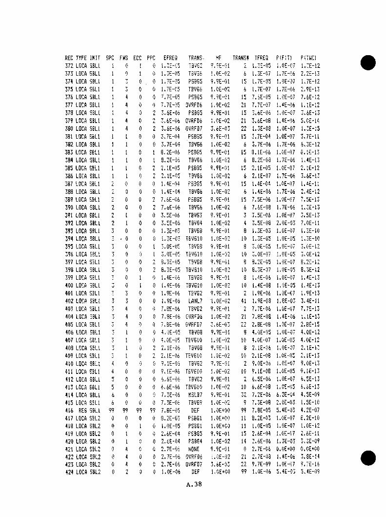
REC TYPE INIT SPC FNS ECC PPC EFREQ TRANS- HF TRANS* TFREQ PlFlTl Pi.INCl372 LGCA SBLl I 0 1 0 1.3E-C5 T3VG2 V.9E-01 2 1.3E-05 1.0E-C7 1.3E-12373 LOCA SBLl 1 0 1 0 1.3E-05 TBVS6 I.OE-02 6 1.3E-07 1.7E-06 2.2E-13374 LQCA SBLl 1 7
■J 0 0 1.7E-05 PS3G5 9.9E-01 15 1.7E-05 l.OE-07 1.7E-12375 LOCA SBLl 1 rj 0 0 117E"Cd TBVG6 l.OE-02 6 1.7E-07 1.7E-06 2.9E-13376 LOCA SBLl I 4 0 0 7.7E-05 PSBG5 9.9E-01 15 7 .SE-05 l.OE-07 7.6E-12377 LOCA SBLl 1 4 0 0 7.7E-05 QVRFD6 l.OE-02 21 7.7E-07 1.4E-06 l.lE-12378 LOCA SBLl 1 4 0 •7
L 3.6E-06 P3065 9.9E-01 15 3.6E-0S l.OE-07 3.4E-13379 LOCA SBLl 1 4 0 i 3.6E-06 QVRFD6 l.CE-02 21 3.6E-08 U4E-06 5.CE-14380 LQCA SSL! 1 4 0 2 3.6E-06 QVRF117 3.6E-03 22 1.3E-03 l.OE-07 1.3E-15381 LOCA SBLl 1 I 0 0 3.7E-04 PSBG5 9.9E-01 15 3.7E-04 l.OE-07 3.7E-11382 LOCA SBLl 1 1 0 0 3.7E-04 TBVG6 l.OE-02 6 3.7E-06 1.7E-06 6.3E-12383 LGCA SBLl 1 1 0 1 8.2E-06 PSBG5 9.9E-01 15 3.1E-C6 l.OE-07 B.lE-13384 LOCA SBLl 1 1 0 I 8.2E-06 TBVG6 l.OE-02 6 3.2E-08 1.7E-06 1.4E-13385 LOCA SELl 1 1 0 2 2.1E-05 FSBG5 9.9E-01 15 2.1E-05 l.OE-07 2.1E-12386 LOCA SBLl 1 1 0 2 2.1E-05 TEV66 l.OE-02 6 2.1E-07 1.7E-06 3.6E-13387 LOCA SBLl L 0 0 0 1.4E-04 P3BQ5 9.9E-01 15 1.4E-C4 l.OE-07 1.4E-11388 LOCA SBLl *
i . 0 0 1.4E-04 TBVG6 l.OE-02 6 1.4E-06 1.7E-06 2.4E-12389 LOCA SBLl L 0 2 7.6E-06 P3BG5 9.9E-0T 15 7.5E-06 l.OE-07 7.5E-13390 LOCA SBLl nt. 0 0 2 7.dE-06 TBVG6 l.OE-02 6 7.4E-0a 1.7E-06 1.3E-13391 LOCA SBLl 2 1 0 0 3.5E-06 78963 9.9E-01 3 3.5E-06 i.OE-07 3.5E-13392 LOCA SBLl 2 1 0 0 3.5E-06 TBVG4 l.OE-02 4 3.5E-08 2.0E-03 7.0E-11393 LOCA SBLl 3 0 0 0 1.3E-03 TBVG8 9.9E-01 8 1.3E-03 l.OE-07 1.3E-10394 LOCA SBLl 7 ’ 0 0 0 1.3E-C3 TBVGIO l.CE-02 10 1.3E-05 l.OE-05 1.3E-10395 LQCA SBLl 7J 0 0 1 3.0E-05 T8VG3 9.9E-01 8 3.0E-05 l.OE-07 3.0E-12396 LQCA SBLl 3 0 0 I 3.0E-05 TBVGIO l.OE-02 10 3.0E-0; l.OE-05 3.0E-12397 LOCA S3L1 7
■J 0 0 L 8.3E-05 TSVG8 9.9E-01 e 3.2E-05 l.OE-07 8.2E-12398 LOCA SELl 3 0 0 2 8.3E-05 TBVGIO l.OE-02 10 S.3E-07 l.OE-05 8.3E-12399 LOCA SBLl 7 0 1 0 1.4E-06 TBV68 9.9E-01 8 1.4E-06 l.OE-07 1.4E-13400 LOCA SBLt j 0 1 0 1.4E-06 TBVGIO l.OE-02 10 i.4E-03 l.OE-05 1.4E-13401 LOCA SBLl 7 3 0 0 1.9E-06 TBVG2 9.9E-01 n
L 1.9E-06 1.0E-C7 1.9E-13402 LOCA SsLl 7
•J 3 0 0 1.9E-04 LANL7 l.OE-02 41 1.9E-03 1.8E-03 3.4E-11403 LOCA SBLl 7 4 0 0 7.8E-06 TBV62 9.9E-01 -n
L 7.7E-06 1.0E-C7 7.7E-13404 LQCA SBLl 7■J 4 0 0 7,8E-06 0VRFD6 l.OE-02 21 7.BE-08 1.4E-06 l.lE-13405 LOCA SELl 7 4 0 0 7.BE-06 0VSFD7 3.6E-03 22 2.3E-C8 l.OE-07 2.8E-15406 LOCA SELl 3 1 0 0 4.0E-05 TBVG3 9.9E-01 8 4.0E-05 l.OE-07 4.0E-12407 LQCA SBLl 3 1 0 0 4.0E-05 TBVGIO l.OE-02 10 4.0E-07 1.0E-C5 4.0E-12403 LCCA SELl 7■J 1 0 2 2.1E-06 TBVGB 9.9E-01 3 2.1E-04 l.OE-07 2.1E-13409 LOCA SBLl 7 I 0 n
i . 2. lE-Ofc TBVGIO l.OE-02 10 2.1E-08 l.OE-05 2.1E-I3410 LOCA SBLl 4 0 0 0 ?.lE-Oi TBVGB 9.9E-01 2 9.0E-06 l.OE-07 9.0E-13411 LQCA SBLl 4 0 0 0 9.(£-06 TBVGIO l.OE-02 10 9.1E-08 l.OE-05 9.1E-13412 LQCA SBLl 5 0 0 0 4.6E-06 TBVGB 9.9E-01 2 6.5E-06 l.OE-07 6.5E-13413 LOCA SBLl 5 0 I) 0 6.6E-06 TBVGIO l.OE-02 10 6.6E-08 i.OE-05 6.6E-13414 LOCA SELl 6 0 0 0 7.3E-04 NSLB7 9.9E-01 32 7.2E-06 6.2E-C4 4.5E-09415 LOCA SSLl 6 0 0 0 7.3E-06 TBVE? l.OE-02 9 7.3E-08 2.0E-03 1.5E-10416 RES SBLl 99 99 99 9? 7.BE-05 DEF 1.OE+OO 99 7.8E-05 5.4E-03 4.2E-07417 LQCA SEL2 0 0 0 0 S.2E-03 PSBGl 1.OE+OO 11 8.2E-03 l.OE-07 8.2E-10418 LQCA SBL2 0 0 1 0 l.OE-05 PSBGl 1.OE+OO 11 l.OE-05 l.OE-07 l.OE-12419 LOCA SBL2 0 I 0 0 2.6E-04 PSBGS 9.9E-01 15 2.6E-04 l.OE-07 2.6E-11420 LQCA SEL2 0 1 e 0 2.6E-04 P38G4 l.OE-02 14 2.6E-06 1.3E-03 3.3E-C9421 LOCA SBL2 0 4 0 0 2.7E-0& NQNE 9.9E-C1 0 2.7E-0i O.OE+OO 0.OE+OO422 LOCA SBL2 0 4 0 0 2.7E-0S 0VRFQ4 l.OE-02 21 2.7E-03 1.4E-06 3.3E-14423 LOCA SBL2 0 4 0 0 2.7E-06 0VRF07 3.6E-03 22 9.7E-09 1.0E-C7 9.7E-14424 LOCA SBL2 0 n
i . 0 0 l.OE-06 DEF
A . 38
1.OE+OO 99 l.OE-06 5.4E-03 5.4E-09
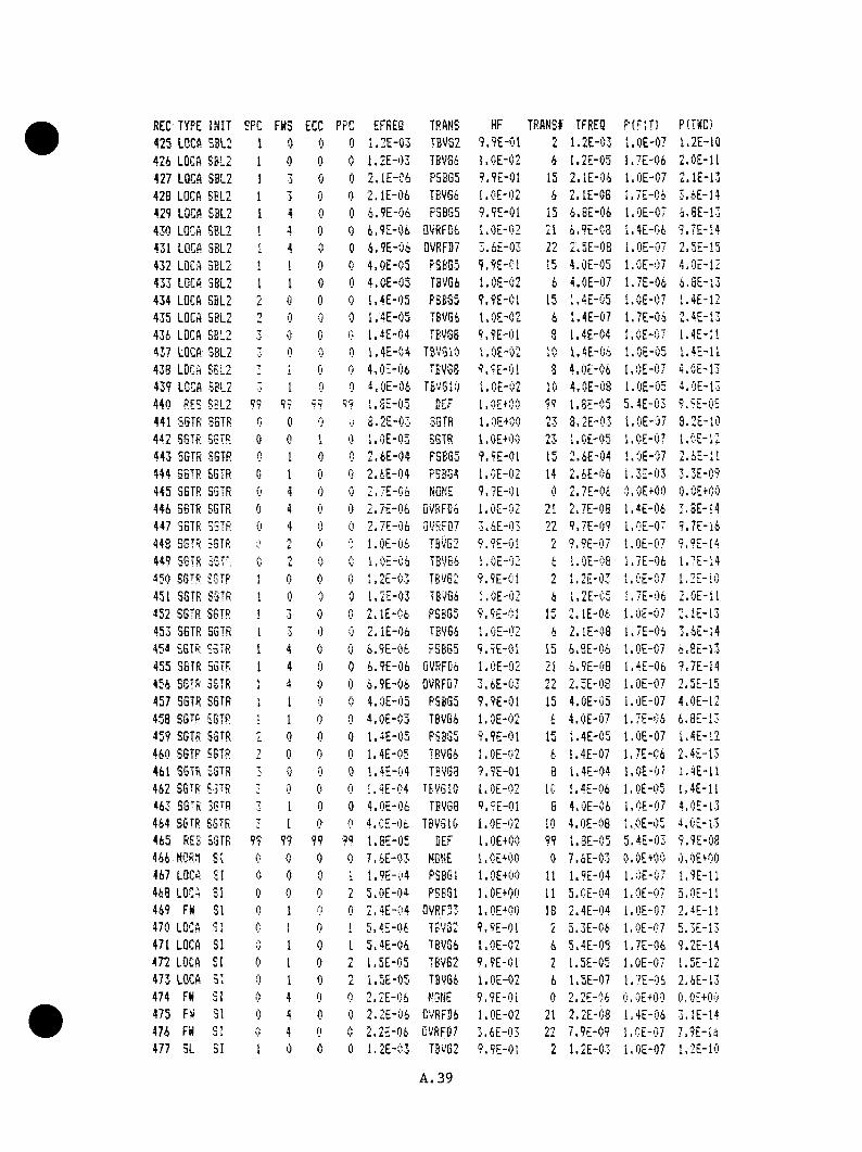
REC TYPE INIT SPC FHS ECC PRC EFREQ TRANS HF TRANSI TFREQ PIFITI P(THC)425 LOCft SBL2 1 0 0 0 1.2E-03 TBVS2 9.9E-01 2 1.2E-03 l.OE-07 1.2E-10424 LQCA SBL2 1 0 0 0 1.2E-03 TSVG4 l.OE-02 4 1.2E-05 1.7E-04 2.0E-11427 LQCA SBL2 1 3 0 0 2.1E-04 PSB65 9.9E-01 15 2. lE-04 1.0E-07 2.1E-13428 LOCA SBL2 1 3 0 0 2.1E-04 TBVG4 l.OE-02 4 2.1E-08 1.7E-04 3.6E-14429 LQCA SBL2 I 4 0 0 4.9E-04 F3BG5 9.9E-01 15 4.BE-04 l.OE-07 4.SE-13430 LGCA SBL2 1 4 0 0 4.9E-04 QVRFG4 l.OE-02 21 4.9E-C3 1.4E-04 9.7E-14431 LQCA SBL2 1 4 0 0 4.9E-04 QVRF37 3.4E-03 L L 2.5E-0S l.OE-07 2.5E-15432 LQCA 3BL2 1 1 0 0 4.0E-05 RSBG5 9.9E-01 15 4.0E-05 l.OE-07 4.0E-12433 LOCA SBL2 1 1 0 0 4.0E-03 TBVG4 l.OE-02 4 4.0E-07 1.7E-04 4.BE-i3434 LQCA SBL2 0 0 1.4E-05 P5BG5 9.9E-01 15 1.4E-05 l.OE-07 1.4E-12435 LOCA S8L2 0 0 0 1.4E-05 TEVG6 l.OE-02 4 1.4E-07 1.7E-04 2.4E-13434 LQCA SEL2 T 0 (l- 1.4E-04 TB0S6 9.9E-01 8 1.4E-04 l.OE-07 1.4E-11437 LQCA SBL2 T 0 0 1.4E-04 TBVGIO l.OE-02 10 1.4E-04 l.OE-05 I.4E-11438 LQCA EBL2 7 0 0 4.0E-04 TEVSB 9.9E-01 3 4.0E-04 l.OE-07 4.0E-I3439 LOCA SBL2 1 0 0 4.0E-04 TBVGIO l.CE-02 10 4.0E-08 l.OE-05 l.OE-13440 RES SBL2 99 99 99 99 1.SE-05 BEF i.Ot+00 99 1.8E-05 5.4E-03 9.9E-0S441 SSTR SSTR 0 0 0 S.2E-03 SGTR 1.OE+OO 23 S.2E-03 l.OE-07 8.2E-10442 SGTR SGTR 0 1 0 l.OE-05 SGTR I.OE+OO 23 l.OE-05 l.OE-07 l.CE-12443 SGTR SGTR 0 1 0 0 2.4E-04 P3EG5 9.9E-01 15 2.4E-04 l.OE-07 2.4E-1I444 SSTR SSTR 0 I 0 0 2.4E-04 PSBG4 l.OE-02 14 2.4E-04 1.3E-03 3.3E-09445 SSTR SGTR 0 4 0 0 2.7E-06 NONE 9.7E-01 0 2.7E-04 O.OE+OO O.OE+OO444 SSTR SGTR 0 4 0 0 2.7E-06 Ov'RFCG l.OE-02 21 2JE-08 1.4E-04 3.BE-14447 SSTR SSTR 0 4 0 0 2.7E-(f4 QVRFD7 3.4E-03 22 9.7E-09 1.0E-07 9.7E-14443 SSTR SGTR ;) 0 hOE-06 TBVG2 9.9E-0i n
L 9.9E-07 l.OE-07 9.9E-14449 SGTR SSTR 0 0 0 l.OE-06 TBVG4 l.OE-02 4 l.OE-OS 1.7E-04 1.7E-14150 SGTR SGTR 1 0 0 1.2E-03 TBVe2 9.9E-01 L 1.2E-03 l.OE-07 1.2E-10451 SGTR SSTR 1 0 0 1.2E-03 TB0G4 l.OE-02 4 I.2E-C5 1.7E-04 2.0E-1I452 SGTR SGTR 1 0 0 2.1E-0fc P3BG5 9.9E-0! 15 2.1E-04 l.OE-07 2.1E-13453 SGTR SGTR 1 3 0 0 2 . IE-04 TBVG6 l.OE-02 4 2.1E-08 1.7E-04 3.4E-14454 SGTR SSTR 1 4 0 0 4.9E-04 PSES5 9.9E-01 15 4.SE-C4 l.OE-07 4.SE-13455 SGTR SGTR 1 4 0 0 4.9E-04 QVRFD4 r.OE-02 21 4.9E-03 1.4E-04 9.7E-14454 SG'R SSTR 1 4 0 0 6.9E-06 QVRFD7 3.4E-03 22 2.5E-08 l.OE-07 2.5E-15457 SGTR SGTR I 1 0 0 4.0E-05 PSBG5 9.9E-01 15 4.0E-05 i.OE-07 4.0E-12458 SGTR SGTR i 1 0 0 4.0E-05 TBVG4 l.OE-02 4 4.0E-07 1.7E-04 4.8E-13459 SGTR SSTR n
i. 0 0 0 l.lE-05 P3SG5 9.9E-0! 15 t.4E-05 l.OE-07 1.4E-12440 SGTR SGTR 0 0 0 1.4E-05 TBV64 l.OE-02 4 1.4E-07 1.7E-C4 2.4E-13441 SGTR iSTR ? 0 0 0 1.4E-04 Tsves 9.9E-01 a 1.4E-04 l.OE-07 1.4E-11442 SSTR SoTR T 0 0 0 1.4E-04 TBVGIO l.OE-02 10 1.4E-04 l.OE-05 1.4E-11443 SG R SG'R T L 0 0 4.0E-04 TBVGB 9.9E-01 s 4.0E-04 l.OE-07 4.0E-13444 SGTR SGTR 7 1 0 f! 4.0E-0& TBVSIO l.OE-02 10 4.0E-06 l.OE-05 i.CE-13445 RES SGTR 9? 99 99 99 I.SE-05 DEF 1.OE+OO 99 l.BE-05 5.4E-03 9.9E-08444-NORN SI 0 0 0 0 7.4E-03 NONE i.CE+00 0 7.4E-03 O.OE+OO O.OE+OO447 LQCA SI 0 0 0 I 1.9E-H PSBGl 1.OE+OO 11 1.9E-04 1.0E-07 1.9E-11448 LOCA SI 0 0 0 i . 5.0E-04 PSBGl ! . OE+OO 11 5.CE-04 l.OE-07 5.0E-11449 FH SI 0 1 0 0 2.4E-04 QVRFB3 1.OE+OO 18 2.4E-04 l.OE-07 2.4E-11470 LGC.A SI 0 1. 0 1 5.4E-04 TEVG2 9.9E-01 2 5..3E-C4 l.OE-07 5.3E-13471 LQCA SI 0 1 0 I 5.4E-04 TBVG4 t.OE-02 4 5.4E-08 1.7E-04 9.2E-14472 LOCA SI 0 I 0 ■1
u 1.5E-05 TBVG2 9.9E-01 2 1.5E-05 l.OE-07 1.5E-12473 LQCA SI 0 1 0 r-i. 1.5E-05 TBVG6 l.OE-02 4 1.5E-07 1.7E-04 2.4E-13474 FH SI I) 4 0 0 2.2E-C6 NONE 9.9E-0i 0 2.2E-04 O.OE+OO 0:OE+OO475 FH SI 0 4 0 0 2.2E-04 QVRFD4 i.OE-02 21 2.2E-08 1.4E-04 3.1E-14474 FH SI (i 4 (1 0 2.2E-06 OVRFDT 3.4E-03 22 7.9E-09 l.CE-07 7.9E-14477 SL 51 1 0 0 0 1.2E-03 TBV82 9.9E-01 2 1.2E-C3 i.OE-07 1.2E-10
A. 39
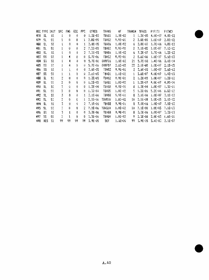
REC TYPE INIT SPC FWS ECC PPC EFREQ TRANS HF TRANS4 TFREQ P(FIT) P(TWC)478 SL SI 1 0 0 0 1.2E-03 TBVGI l.OE-02 1
i 1.2E-05 4.0E-07 4.3E-12479 SL SI 1 0 0 1 2.BE-05 T3VG2 9.9E-01 2 2.6E-05 l.CE-07 2 . e £ - 1 2
4 80C} 31 1 0 0 1 2.3E-05 TBvG6 1.0E-02 6 2.8E-07 1.7E-06 4.3E-13
481 SL SI 1 0 0 ni . 7.2E-05 TBVG2 9.9E-01 2 7.1E-05 l.OE-07 7.1E-12
482 SL 31 1 0 0 0 7.2E-C5 TEVG6 l.OE-02 6 7.2E-07 1.7E-06 1.2E-12483 ES SI f
1 4 0 1) 5.7E-06 T3VS2 9.9E-01 i 5.6E-06 l.OE-07 5.4E-13484 S3 SI I 4 0 0 5.7E-06 QVRFD6 l.OE-02 21 5.7E-03 1.4E-06 3.0E-14485 S3 CT
J L 1 4 1) 0 5.7E-06 0VRFD7 3 ,6E-03 •nn 2.1E-08 l.DE-07 2.1E-15486 SS 51 1 1 0 0 3.6E-05 T3VG2 9.9E-01 2 3.6E-C5 l.OE-07 3.6E-12487 SS SI 1
X 1 0 0 3.6E'i35 'BVGl l.CE-02 1 3.6E-07 4.0E-07 1.4E-13488 SL SI n 0 0 0 1.2E-05 T3VG2 9.9E-01 2 1.2E-C5 l.OE-07 1.2E-12489 SL SI 2 0 0 0 1.2E-05 TBVGI l.OE-02 1 1.2E-C7 l.OE-07 4.0E-14490 SL SI T 0 0 0 1.3E-04 TBVGB 9.9E-01 8 1.3E-04 l.OE-07 1.3E-11491 SL SI 7 0 0 0 1.3E-04 TEVG5 l.OE-02 -J 1.3E-C6 5.2E-06 6.8E-12492 SL SI 3 0 0 I 3 . lE-06 TBV68 9.9E-01 8 3.1E-06 l.OE-07 3.1E-I3493 EL SI 7 0 c
♦i 3.1E-06 TBVGIO l.OE-02 10 3.1E-C8 1.0E-C5 3 . lE-13
494 SL SI t; 0 e A 7.1E-04 TBVGS 9.9E-C1 8 7.0E-06 l.OE-07 7.0E-13495 SL SI T 0 0 n
L 7.1E-06 TBVSIO 1.0E-C2 10 7.1E-08 l.OE-05 7.1E-13496 S3 SI 3 1 0 0 3.3E-06 TBVG3 9.9E-01 8 3.3E-06 l.OE-07 3.3E-13497 SS SI 7 1 0 0 3.3E-06 TBVGS l.OE-02 9 3.3E-08 2.0E-03 4.6E-11498 RES SI 99 99 99 99 3.9E-05 DEF 1.OE+OO 99 3.9E-05 5.4E-03 2.1E-07
A.40

APPENDIX B
EVENT TKEE QUANTIFICATION
B . l I n t r o d u c t io n
T his appendix p r e s e n t s th e i n i t i a l p r o b a b i l i t y in fo rm a t io n used in the
Oconee PIS s tu d y . While n o t a l l of th e in fo rm a tio n in t h i s appendix was
used in th e s tu d y , i t i s in c lu d e d f o r com ple teness .
To d e te rm in e bounding v a lu e s f o r sequence f r e q u e n c ie s , b ranch p r o b a b i l i t i e s
were e s t im a te d f o r each b ran ch on th e ev en t t r e e s . I t must be emphasized
t h a t imposed c o n s t r a i n t s p e r m i t t e d o n ly s im p l i f i e d approaches to f requency
and p r o b a b i l i t y e s t im a t io n , in c lu d in g , in s e v e ra l c a s e s , th e use o f g e n e r ic
d a t a . As w ith a l l even t t r e e s , th e p r o b a b i l i t y of b e ing on a p a r t i c u l a r
b ran ch i s c o n d i t io n a l on th e p r i o r b ran ch e s in th e sequence. In most
c a s e s , however, b ran ch e s were s u f f i c i e n t l y independent to pe rm it th e use
of common p r o b a b i l i t y v a lu e s in th e sequence q u a n t i f i c a t i o n s .
P r o b a b i l i t y v a lu e s were e s t im a te d , when p o s s i b l e , from o p e r a t io n a l
in fo rm a t io n which was as c lo s e t o O c o n e e -s p e c i f ic as p o s s i b l e . I f Oconee-
s p e c i f i c in fo rm a t io n was a v a i l a b l e , th e n i t was u sed . I f t h i s was no t
th e c a s e , B&W-specific and f i n a l l y PW R-specifled o p e r a t io n a l in fo rm a tio n
was employed. A d d i t io n a l in fo rm a t io n was o b ta in e d from sc re e n in g v a lu e s
from "IEEE Guide to th e C o l l e c t io n and P r e s e n t a t i o n o f E l e c t r i c a l ,
E l e c t r o n i c , and Sensing Component R e l i a b i l i t y Data fo r N uclear-Pow er
G en e ra t in g S t a t i o n , " IEEE S td 500-1977, sponsored by th e N uclear Power
E n g in ee r in g Committee o f th e IEEE Power E ng ineer ing S o c ie ty , as w e l l as
o th e r s o u rc e s .
B . l

S e c t io n B.2 p ro v id e s development in fo rm a t io n and f i n a l p r o b a b i l i t y and
f req u en cy v a lu e s f o r s y s t e m - r e l a t e d f a i l u r e s in c lu d e d in tb e even t t r e e s .
A p p lic a b le so u rces o f f a i l u r e in fo rm a t io n a re i d e n t i f i e d . S e c t io n B.3
d e s c r ib e s th e human r e l i a b i l i t y numbers employed on th e t r e e s . P r o b a b i l i t y
v a lu e s s t r o n g ly iaq>acted by th e rm a l -h y d ra u l ic c o n s id e r a t io n s a re d is c u s s e d
in S e c t io n B .4 .
B.2 S ys tem -R e la ted P ro b a b i l i tY _ V a lu e s
The b a s e s f o r th e s y s t e m - r e l a t e d p r o b a b i l i t y v a lu es used on th e even t t r e e
b ran ch e s a re p ro v id e d in T ab le B . l .
B.3 Human E r r o r - R e la te d P r o b a b i l i t v Values
Branch p r o b a b i l i t y v a lu e s dom inated by human perform ance were developed
b ased on th e "Handbook o f Human R e l i a b i l i t y A n a ly s is " (NDRE6/CR-127S), th e
"G eneric D ata Base f o r Data and Models C hap ter of th e NREP Guide" (EGG-
EA-5887, June 1982 ) , p a s t B&V p l a n t o p e r a t io n a l e x p e r ie n c e w ith steam
g e n e r a to r o v e r f i l l ("AEOD O b se rv a t io n s and Recommendations Concerning the
Problem o f Steam G en e ra to r O v e r f i l l and Combined P rim ary and Secondary Side
Blowdown," December 17 , 1 9 8 0 ) , as w e l l as re q u ire m e n ts f o r o p e r a to r a c t io n
as d e s c r ib e d in a p p l i c a b l e Oconee p ro c e d u re s .
I n g e n e r a l , b ran ch p r o b a b i l i t i e s u t i l i z e d on even t t r e e b ran ch e s dominated
by human e r r o r were c o n s i s t e n t w ith NUREG/CR-1278. Human e r r o r v a lu e s used
w ere:
a . For w e l l d e f in e d ta s k s under l i t t l e p r e s s u r e t h a t r e q u i r e d s p e c i f i c_3
a c t i o n , 5 z 10 /D was a s s ig n e d . T h is v a lu e was employed, f o r
B.2

Table B .l S y e tea -R e la ted Event Tree F reqnenoies And B ranch P r o b a b i l l t i e a
Fnnction Diacnaaion Valne Baed
I n i t i a t o r s
R eac to r T rip
Small Break LOCA
Steam Line Break
During 1978 and 1979, Oconee 1 , 2 , and3 ex p erien ced 36 laannal o r antom atic scrams d a rin g fo rced shutdowns (see NDREG 0618 and NnRE6/C3rl496). T his r e s u l t s in a n o n -s p e c if ic r e a c to r t r i p e s tim a te o f 6 /y e a r . A pproxim ately 61% were th e r e s u l t o f e l e c t r i c a l o r steam 6 power co n v ers io n system problem s w hich, in some c a se s , may have im pacted subsequen t p la n t re sp o n se .
The NREP sc reen in g (EG6-EA-5887) fo r a sm allb reak LOCA, 1 x 10 , was used in th i s s tu d y . T hisva ln e i s j x n s i s t e n t w ith th e NDRE6/CR-2497 value o f 8 .3 X 10 /y r f o r PVRs. I t should be no ted th a t t h i s v a lu e may be somewhat h ig h , s ince t r a n s ie n t induced LOCAs a re co n sid e red on the n o n sp e c if ic r e a c to r t r i p even t t r e e .
A viQue equal to the sm all b reak LOCA frequency (10 /y r ) was assumed. T h is va lu e i s a p p lic a b le to a sm all o r m oderate s iz e d steam l in e b re a k . Large steam l in e b reak s would be ex f^ c ted to occur w ith fre q u e n c ie s no g r e a te r th a n 10 /y r .
6 /y r
10 ^ /yr
1 0 "* /y r
Branch P r o b a b i l i t i e s
R eac to r Trip/Demand
T urbine T r ip / R eacto r T rip
A va lne e q u iv a le n t to th e f a i lu r e to t r i p p r o b a b i l i ty developed in WASH- 1400^(3 .6 x 10 /D was employed. Because o f th e 10 /y r frequency c u to f f u sed , sm all v a r i a t io n s in the assumed r e a c to r t r i p p r o b a b i l i ty have no e f f e c t on the sequences id e n t i f i e d in th e s tu d y .
A ll PWR LERs were review ed fo r tu rb in e t r i p , tu rb in e sto p v a lv e , e t c . , f a i l u r e s . While th e re have been s e v e ra l f a i l u r e s o f in d iv id u a l stop v a lv e s ( s in g le steam l in e s ) to c lo s e , only one even t (NSIC 092449 a t Turkey P o in t 3 , 4 ) id e n t i f ie d a t o t a l f a i l u r e of tu rb in e s to p v a lv e s . Assuming ~12 sh u td o w n s/p ian t y e a r (s e e NDREG/CR-1496) and ~350 PWR y e a r s , the number o f tu rb in e s top valve demands i s -4 2 0 0 . One f a i lu r e in th i s number o fd e m a n d s r e s u l t s in a f a i l u r e e s tim a te o f ~2 x 10 /Demand.
3.5xlO~®/d
2 X 10” '*/D
Main F eedw ater R esponse/R eactor T rip
F a ilu r e to Run Back (O verfeed)
Shock E v a lu a tio n id e n t i f i e s fou r
r e a c to r t r i p :
The Oconee P re s su r iz e d Thermal (DPC-RS-1001, January 1982) f a i l u r e s to run back fo llo w in g a
U n it 2 , Septem ber 17 , 1974 U nit 3 , A p ril 30 , 1978 D n it 2 , Jan u a ry 30 , 1980 U n it 3 , March 14, 1980
D uring th e tim e p e rio d co n sid ered in the Oconee study (24 p la n t y e a r s ) , approx im ate ly 144 re a c to r t r i p s o cc u rre d . T his r e s u l t s in a f a i lu r e to run back o f 4 /144 = 0.03/dem and.
0.03/D
B.3

Table B.l (Continned)
Function Discnssion Valne Used
F a i ln r e o f MFW Fnmp Txip C ircu itry /M F ¥ O verfeed
T his t r i p c i r c n i t i s te s te d y e a r ly . A ssn a ii^ a g en e ra l in s t r n a e n ta t io n f a i ln r e r a t e o f 10 /h r (1 ^ -5 0 0 ) r e s n l t s in a f a i l n r e p ro b a b i l i ty o f 4 z 10 "/D .
4 z 10 ^/D
o Loss o f Main Feedw ater
Emergency Feedw ater
NUREG-0560 id e n t i f i e s 5 ev en ts a t B6V p la n ts np to ~4/S /79 ( th e d a te o f IE B n l le t in 79-05A) in w hich feed w ate r was l o s t snbseqnent to a r e a c to r t r i p . I f Oconee has a ty p ic a l r e a c to r t r i p r a t e , then th e ' t o t a l nnaber o f nnschadnled r e a c to r t r i p s on th e se p la n t s np to th a t d a te i s 6 t r i p s / y e a r z 30 .18 y e a rs s in ce c r i t i c a l i t y “ 181 t r i p s . T his r e s n l t s in a lo s s o f feed w ater g iven r e a c to r t r i p p r o b a b i l i ty o f 5/181 “ 0 .0 3 . T his nnmber does n o t in c ln d e in s tm n e n t bns f a i ln r e s which r e s n l te d s im n ltan eo n s ly in r e a c to r t r i p and lo s s o f main feed w a te r .
The emergency feed w ate r system was assnmed to r e q n ire mannal i n i t i a t i o n (becanse of te s t in g o r aw in tenance) ap p rox im ate ly 4 h rs /s io n th . T his r e s n l t s in a p r o b a b i l i ty o f being in . mannal o f 4 hrs/C 30 days z 24 h rs /d a y ) « 5 .6 z 10 /D.
EFT I n i t i a t e d P r io r to Steam G enera to r D ryont
EFW O verfeed (One G e n e ra to r) / I n i t i a t o r
5 .6 z 10"^/D
The EFW le v e l c o n tro l c i r c n i t c o n s is ts o f a le v e l t r a n s m i t t e r on each steam g e n e ra to r , an a s s o c ia te d E/P c o n v e r te r , and flow c o n tro l v a lv e . A d d itio n a l in s tm m e n ta tio n i s p rov ided to change SO le v e l based on w hether o r n o t th e RCPs a re o p e ra t in g . An a l t e r n a t e le v e l c o n tro l channel i s p rov ided in th e even t power i s l o s t to the o p e ra tin g ch an n e l. I t i s assnmed th a t a c c e s s ib le in s tm m e n ta tio n is te s te d m onth ly , and th a t th e le v e l t r a n s m i t t e r s a re e f f e c t i v e ly te s te d m onthly becanse le v e l changes dn ring o p e ra t io n can be c ro ss-cheched among th e S.G. o p e ra tin g and s t a r tn p range le v e l in d ic a t io n s . Based on t h i s , one can ronghly e s tim a te the p r o b a b i l i ty o f o v e r f i l l on i n i t i a t i o n as the p r o b a b i l i ty o f t r a n s m i t t e r f a i ln r e o r c o n v e r te r f a i l n r e o f va lv e f a i l n r e ( ~ 1 0 /^ z 720 h rs ( le v e l c o n t r o l l e r s , IEEB-500),+ 1 z 10 /D (va lve f a i l n r e , WAS-1400)) - 1 ,7 z 10"^/D .
1 .7 z 10 ’ /1>
EFW O verfeed Not T h ro ttle d /O v e rfe e d
I t i s assnmed th a t the EFW system can be p lace d in mannal and e f f e c t iv e ly c o n tro lle d n n le s s the c o n tro l va lv e f a i l s open. Valve f a i ln r e s con- t r i b n t e ~60 p e rc e n t o f th e EFW o v erfeed p ro b a b i l i ty developed above. T h e re fo re , th e p r o b a b i l i ty of f a i l i n g to e f f e c t iv e ly t h r o t t l e an ove rfeed was ass ig n ed a p r o b a b i l i ty o f 0.6/dem and.
0 .6 /D
B.4

Table B.l (Contlaned)
Fimetioii Diioneaioii Value Uied
F a ilu r e o f EFW to I n i t 1a te / Deaand
NnK£G/CBr2497 id e n t i f i e d Emergency Feedw ater S y s |ea f a i l n r e s on deaand. I b i s w alne was 1 .1 z 10 /D in o ln d in g c r e d i t f o r p o te n t ia l r e c t i f i c a t i o n . E zclnd ing the p o s s i b i l i t y of r e c t i f i c a t i o n (as wonld be the case im M d ia te ly a f t e r i n i t i a t i o n and p r io r to any a t t o u t to r e s t a r t ) the observed va ln e was 1 .4 z 10 /D . Oconee observed EFWn n a v a l l a b i l i t i e s a t th e pnap le v e l and in 1980 and 1980 in c ln d e :
1 .4 z 10“ ^ /D
jt£e Date
1 tu rb in e pnap 5/802 tu rb in e pnap 4/813 tu rb in e pump 11/801 tu rb in e pump 6/813 m otor d r iv e n pump 5/802 m otor d r iv e n pnap 3/812 tu rb in e pump 5/81
F o r th e 17 iw nth p e r io d betw een 5 /80 and 9 /8 1 , th e re have been 7 n n a v a i l a b i l i t i e s , which r e s n l t s in an n n a v a i l a b i l i t y p e r pnaip of 7 /(1 t e s t (d eaan d )/ao z 17 aos z 3 p n a p s /p la n t z 3 p la n ts ) ” O.OS/D. With on ly one pnap re q u ire d f o r su ccess , one can d e riv e a system f a i l n r e p ro b a b i l i ty of 0 .0 5 ( f a i l n r e of f i r s t pnaq?) z 0 .1 ( f a i ln r e of s e c o n d / f i r s t ) z 0 .3 , ( f a i l n r e of t h i r d / f i r s t and second) > 1 .5 z 10 /D . T h is i s i n s i s t e n t w ithth e NDEEB/CK-2497 valne o f 1 .4 z 10 /D .
POKV l i f t / n o z a a l NFW o r EFW response
A dequate o p e ra t io n a l d a ta does n o t e z i s t tod e te ia in e th e l i f t p r o b a b i l i ty o f the p re s s n r iz e rPOEV d n ring a n o n -s p e c if ic r e a c to r t r i p s in ce the POBV l i f t s e tp o in t was re v is e d fo llow ing th e m - 2 a c c id e n t . Such l i f t s depend on SCS c o n d itio n sa t th e tim e o f th e t r i p as w e ll as p o te n t ia lv a r ia t io n s in secondary s id e re sp o n se . In l i e n of s p e c i f ic o p e ra t io n a l d a ta , a va lne of 0 .03 /deaand was assumed.
0.03/D
Main Feedw ater R e c o v e re d /In i t ia l Loss o f MFW
A valne o f 0 .5 was assum ed. T his i s c o n s is te n t 0 .5 /D w ith Oconee MFW reco v ery expe rien ce dnring nons t r e s s s i tu a t io n s (EFW i n i t i a t e d ) o f a p p ro z isu te ly 0 .7 /D (P.M. A brahaason, 1 0 /2 0 /8 2 ) .
EFW I n i t i a t e d A f te r As d e sc rib ed under "EFW I n i t i a t e d P r io r to Steam G enera to r D ryont - F a i ln re o f Q rf to In itia te /D e m a n d ," c o n s id e ra t io n of th e p o te n t ia l f o r sh o r t- te rm r e c t i f i c a t i o n fo llow ing EFW/AFW i n i t i a t i o n f a i l n r e s in PWRs r e s n l t s in a d ecrease in th e p r o b a b i l i ^ o f f a i l i n g to I n U ia t e on demand from 1 .4 z 10 VD to 1 .1 z 10"^/D . T his i s e q u iv a le n t to a g e n e r ic p r o b a b i l i ty o f i n i t i a t i n g EFW/An g iven i n i t i a l f a i l n r e o f 1 - 1 .1 z 10 / 1 . 4z 10 o r 0 .2 4 /demand.
0.24/D
B.5
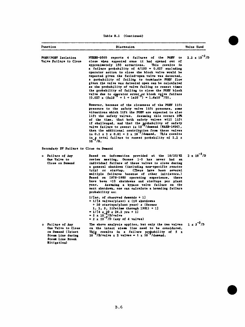
Table B.l (Continned)
Fnnction Dieonstion Valne Deed
POKV/POBV I s o la t io n ValTe F a i ln r e to Close
NUSEG-0560 r e p o r ts 4 f a i l u r e s o f tbe POKV to c lo se when expec ted once i t had opened o u t of a p p ro x isu te ly 150 a c tu a t io n s . T his r e s n l t s in a f a i l n r e p r o b a b i l i ty o f 4 /150 » 0.027 exc lud ing o p e ra to r a c t io n to c lo se th e b lo ck ^ 01x0 wonld be expected g iv en th e f a i le d -o p e n v a lv e was d e te c te d , a p r o b a b i l i ty o f f a l l i n g to t e r a in a t e POEV flow g iv en th e va lv e was d e te c te d open can be c a lc n la te d as the p r o b a b i l i ty o f va lv e f a i l i n g to r e s e a t t i a e s th e p r o b a b i l i ty o f f a i l i n g to c lo se the POEV b lo ck va lv e due to < ^ r a t o r e r r o r m b lo ck r§Xv» f a i l n r e (0 .027 X (5x10 * + 1 + IxlO"®) - 1 .6xlO ~*/D ).
2 .2 X 10~^/D
However, becanse o f th e o lo sen ess o f th e POEV l i f t p re s s u re to the s a f e ty valve l i f t p re s s u re , soae s i tu a t io n s w hich l i f t th e POEV are expected to a ls o l i f t th e s a f e ty v a lv e s . A ssnaing t h i s o ccu rs 10% of th e t i a e . th a t b o th s a f e ty v a lv e s w i l l l i f t i f c h a lle n g e d , and th a t the j v o b a b i l i t y o f s a f e ty v a lv e f a i l n r e to r e s e a t i s 10 /deaand (VASH-1400), th en th e a d d it io n a l c o n tr ib u t io n f ro a th e se v a lv e s i s 0 .1 X 2 X 0 .0 1 - 2 X 10 /d eaan d . T h is r e s n l t s in a t o t a l f a i l n r e to r e s e a t p r o b a b i l i ty o f 2 .2 x 10“^/D .
Secondary EV F a iln re to Close on Deaand
o F a i ln r e o f Any One Valve to C lose on Deaand
o F a i ln r e o f Any One V alve to Close on Deaand ( I n ta c t S teaa L ine dnring S teaa L ine Break H it ig a t io n )
Based on in fo x a a tio n p rov ided a t th e 10 /20 /82 review a e e t in g , Oconee 1~3 has never had an in d iv id u a l f a i l n r e o f th e se v a lv e s to c lo s e dnring a g e n e ra l shutdown ( in c lu d in g n o n -s p e c if ic r e a c to r t r i p ) o r s t a r tn p . (There have been s e v e ra l a n l t i p l e f a i l n r e s becanse of o th e r i n i t i a t o r s . ) Based on 1978-1980 o p e ra tin g ex p e rie n c e , th e re have been ~10 shutdowns and s t a r tu p s p e r p la n t y e a r . A ssnaing a bypass va lve f a i l n r e on then ex t shutdown, one can c a lc u la te a bonnding f a i l n r e p r o b a b i l i ty a s :l / [ n o . o f observed deaands 1]<• l / [ 4 v a lv e s /p la n t) x (10 shutdowns
+■ 10 s t a r tu p s /p l a n t y e a r) x (Oconee 1 , 2 , 3 , l i f e t i a e th rough 1981) + 1]
- l / [ 4 X 20 X 24 .2 y rs + 1]« 5 X 10 ./D /v a lv e “ 2 X 10~ /D (any o f 4 v a lv e s )The above a n a ly s is a p p l i e s , b u t on ly th e two v a lv e s on th e in t a c t s te a a l in e need to be c o n s id e re d . T h ^ r e s u l t s in a f a i l n r e p ro b a b i l i ty o f 5 x 10 /D /v a lv e x 2 v a lv e s - 1 x 10 /d eaan d .
2 X 10“^/D
1 X 3 “ * /D
B.6
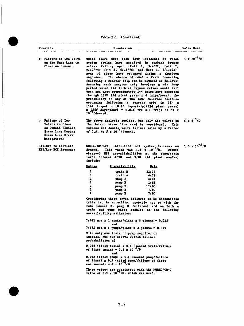
Table B.l (Continiwd)
Fanotlon Diaonsiloa Valne Beed
o F a i ln r e o f Two Valve on the Sane Line to C lose on Deaand
0 F a i ln re o f Two V alves to Close on Deaand ( I n ta c t S teaa L ine Dnring S teaa L ine Break M itig a tio n )
F a i ln r e to I n i t i a t e HPI/Low RCS P re s sn re
While th e re have been fo n r in c id e n ts in which s y s te a f a n l t s have r e s n l te d in tn rb in e bypass v a lv e s f a i l i n g open (U n it 1 . 5 /4 /8 1 ; U nit 2 ,9 /1 0 /7 4 ; U n it 3 . 5 /2 5 /7 5 ; and D n it 3 . 7 /1 3 /7 5 ) , none o f th e se have o ccn rred dnring a shntdown seqnence . The chance o f snch a f a n l t oecn rrin g fo llo w in g a r e a c to r t r i p can be bonnded as fo llo w s: A ssnaing each r e a c to r t r i p in v o lv es a s ix hour p e r io d w hich th e tn rb in e bypass v a lv e s oonld f a i l open and th a t a p p ro x ia a te ly 144 t r i p s have occnrred th rongh 1982 (24 p la n t y e a rs x 6 t r i p s / y e a r ) , the p r o b a b i l i ty o f any of th e fo n r observed f a i ln r e s o e c n rr in g fo llo w in g a r e a c to r t r i p i s (4) x (144 t r i p s ) X (0 .2 5 d a y s / t r i p ) / (24 p ls n t y ea rs ) X _(365 d a y s /y e s r) “ 0 .016 f ro a l l t r i p s o r ~1 x 10 /d eaa n d .
The above a n a ly a is a p p l i e s , b n t on ly th e v a lv e s on th e in t a c t s te a a l in e need be co n s id e re d . This red n ess th e donble va lv e f a i l n r e valne by a f a c to r o f 0 .5 , to 5 X 10 /d eaa n d .
Oconee
1 X lo'^/D
5 X 5~*/D
NUKEG/CR-2497 id e n t i f i e d HPI s y s te a i
deaand. T his v a ln e was 1 .3 X 10"*/observed BPI u n a v a i l a b i l i t i e s a t thele v e l betw een 4 /7 8 and 9/81 (41 p liin c lu d e :
Oconee U n a v a i ls b i l i tv Date3 t r a i n B 11/783 t r a i n A 4/782 pnap A 2/812 pnap B 1/812 pnap B 11/802 pnap B 7/802 pnap B 7/80
1 .3 X 10“^ /D
C onsidering th ese seven f a i l n r e s to be unconnected ( t h i s i s , in a c tu a l i t y , p ro b ab ly n o t so w ith the fo n r Ooonee 2 , pnsQ B f a i ln r e s ) and on b o th a t r a i n and pna^ b a s i s r e s n l t s in the fo llow ing n n a v a i l a b i l i t y e s t i a a t e s :
7 /(4 1 ao s X 2 t r a i n s / p l a n t x 3 p la n t s - 0 .028 and
7 /(4 1 aoa x 3 p n a p s /p la n t x 3 p la n t s - 0 .019With o n ly one t r a i n o r pnap re q u ire d o r sn co ess , one can d e r iv e s y s ta a f a i l u r e p r o b a b i l i t i e s o f
0 .028 ( f i r s t t r a in ) x 0 .1 (second t r a i n / f a i l u r e o f f i r s t t r a in ) - 2 .8 x 10"^/D
and0 .019 ( f i r s t pnap) x 0 .1 (second p n a p /f a i ln re o f f i r s t ) X 0 .3 ( t h i r d p n a p /f a i ln r e o f f i r s t and second) - 6 x 10 /D
These v a lu e s a re c g n a is te n t w ith th e N0KE8/CK-2 va ln e o f 1 .3 x 10 /D , w hich was u sed .
B.7
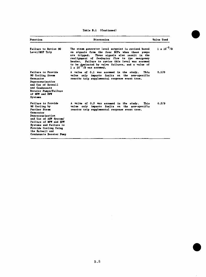
Table B.l (Contianad)
Fanetion Dlteaesion Value Used
F a i lu r e to S ev ise S6 Level/KCP T rip
F a i lu r e to P royide SG Cooling Steam G enera to r D e p re a a u riz a tio n and Uae o f H o tv e ll and Condenaate B ooa te r Pum pa/Failure o f MFW and EFT Syatema
F a i lu r e to P royide SG C ooling by F u r th e r Steam G enera to r D e p re a a u riz a tio n and Dae of AST Syatem/ F a i lu r e o f HFT and EFT Syatema and F a i lu r e to P roy ide C ooling Uaing th e H otw ell and Condenaate B ooater Pomp
The ateam g e n e ra to r le y e l a e tp o in t ia re y ia e d baaed on a ig n a la from the fo u r RCPa when theae pnatpa a re t r ip p e d . Theae a ig n a la a la o r e a u l t in the re a lig n m en t o f feed w ater flow to th e emergency h e a d e r . F a i lu r e to rew iae th i a le y e l waa aaaumed to be ^dominated by ya lye f a i lu r e a , and a y a lu e of 1 z 10~ /D waa aaaumed.
A y a lu e o f 0 .1 waa aaaumed in th e a tu d y . Ih ia ya lue on ly im pacta f a u l t a on th e n o n -a p e o ifio r e a c to r t r i p aupplem ental reaponae ey en t t r e e .
1 z
A ya lu e of 0 .5 waa aaaumed in th e a tu d y . Thia ya lu e on ly im pacta f a u l t a on th e n o n -a p e c if ic r e a c to r t r i p aupplem ental reaponae eyen t t r e e .
0 .1 /D
0.5/D
B . 8

exunp le , f o r f a i l u r e to t r i p th e RCPs on HPI i n j e c t i o n caused by
a t u r b i n e bypass v a lv e s t i c k i n g open a f t e r a n o n s p e c i f ic r e a c t o r
t r i p o r f a i l u r e to i s o l a t e a s tu c k -o p e n tu r b in e bypass va lve under
s i m i l a r c i rc u m s ta n c e s (sequences S14, SIS , S17, S31, S32, and
S33) .
b . For v e i l d e f in e d ta s k s v b ic b r e q u i r e d s p e c i f i c a c t i o n and w ith_2
m oderate p r e s s u r e on tb e o p e r a t o r , 1 z 10 /D was a s s ig n e d . This
v a lue was u se d , f o r example, f o r f a i l u r e to t r i p tbe RCPs a f t e r
HPI i n j e c t i o n d u r in g a sm a l l -b re a k LOCA. With tbe e x c e p t io n of
tbe sequences i d e n t i f i e d in tb e above p a ra g ra p h , a l l sequences
were c o n s id e re d "m oderate p r e s s u r e " sequences .
c . For dynamic t a s k s , such as t h r o t t l i n g HPI to m a in ta in p r e s c r ib e d
p re s s u r e / t e m p e r a tu r e c o n d i t io n s o r r e i n i t i a t i n g c o o l in g to an
i n t a c t steam g e n e r a to r based on p r e s s u r e and l e v e l i n d i c a t i o n s , 3 —2
X 10 /D was u sed .
d . In a d d i t i o n , i f a p re v io u s o p e r a to r e r r o r bad o c c u rre d , tb e
a p p l i c a b l e e r r o r r a t e f o r tb e b ranch under c o n s id e r a t io n vas
doub led . T h is vas tb e c a s e , f o r example, f o r f a i l u r e to e f f e c t
secondary i s o l a t i o n on a steam l i n e b re a k , g iv e n t h a t tbe o p e ra to r
bad f a i l e d t o t r i p tb e RCPs on HPI i n i t i a t i o n .
Tvo o p e ra to r re sp o n se s i t u a t i o n s in c lu d e d on tb e i n i t i a t o r even t t r e e s
a re no t d i r e c t l y a d d re s sed in NUREG/CR-1278; r a p id o p e ra to r response
r e q u i r e d to m i t i g a t e a steam g e n e ra to r o v e r fe e d and a p l a n t c o n d i t io n t h a t
appeared to be beyond tb e a n a l y s i s a ssum ptions fo r a p a r t i c u l a r i n i t i a t o r .
B.9
in p a r t i c u l a r , a f a i l u r e of a tu r b in e to t r i p , which would r e s u l t in th e
d e p r e s s u r i z a t i o n o f b o th steam g e n e ra to r s fo l lo w in g secondary i s o l a t i o n .
In th e s e c a s e s , th e fo l lo w in g o p e r a to r e r r o r assum ptions were made:
a . For steam g e n e r a to r i s o l a t i o n on main o r a u x i l i a r y feed w ate r
o v e r fe e d (which r e q u i r e s o p e r a to r re sponse on the o rd e r of
m in u te s ) , a v a lue o f 0 .1 was u se d . T h is v a lu e i s lower than
th e NREP sc re e n in g guide v a lue o f ~ 0 .6 f o r t h i s time p e r io d .
However, b a sed on th e s u c c e s s f u l manual t e rm in a t io n o f 10 observed
o v e r fe e d s a t B&W u n i t s w ith o u t main feed pump h ig h l e v e l t r i p s (as
d e s c r ib e d in th e December 17 , 1980 AEOD steam g e n e ra to r o v e r f i l l
o b s e r v a t io n s r e p o r t ) , a v a lu e o f 0 .1 i s c o n s id e re d d e f e n s ib l e .
b . For a s i t u a t i o n i n which th e tu r b in e f a i l s t o t r i p , th e p r o b a b i l i t y
o f an o p e r a t o r ' s a t te m p t in g to r e s t o r e secondary c o o l in g a f t e r
i s o l a t i o n was assumed to be 0 . 5 .
As d is c u s s e d p r e v io u s l y , b ran ch es on the i n i t i a t o r t r e e s dominated by
o p e r a to r a c t io n a r e i d e n t i f i e d w ith th e symbol 0 .
B.4 T h e rm a l-H v d ra u l ic -R e la te d P r o b a b i l i t y V alues
P r o b a b i l i t y v a lu e s d e s ig n a te d 'T /H " on th e e v e n t t r e e s a r e e s t im a te s dom inated
by th e rm al—h y d r a u l i c c o n d i t io n s in th e p l a n t . These e s t im a te s have been
deve loped based on r e s u l t s t o d a te in th e Oconee PTS a n a ly se s and S A I 's
e x p e r ie n c e in p r i o r r e a c t o r p l a n t th e rm a l - h y d r a u l ic a n a ly s e s . In g e n e r a l ,
t h r e e v a lu e s were a p p l i e d : 0 .1 i f th e s t a t e was c o n s id e re d u n l i k e l y , 0 .9
i f th e s t a t e was c o n s id e re d q u i t e l i k e l y , and 0 .5 f o r s i t u a t i o n s in between
t h e s e s . Because of th e s o f tn e s s in th e se numbers, sequences in v o lv in g T/H
B.IO

vftlnes were n o t t r u n c a te d a t 10 ^ / y r n n le s s th e sequence frequency*
assuming a T/H p r o b a b i l i t y o f one, was below 10~ ^ /y r .
B . l l
APPENDIX C
ESTIMATION OF PRESSURE, TEMPERATURE,
AND HEAT TRANSFER COEFFICIENT
c .i iatre.jlBg.liea
The e v a l u a t i o n o f th e r i s k s o f p r e s s u r i z e d t h e m a l shock (PTS) e n t a i l s
th e c o u p l in g o f o v e rc o o l in g in c id e n t even t t r e e s to f r a c t u r e aiechanics
c a l c u l a t i o n o f the p r o b a b i l i t y of v e s s e l c ra c k p ro p a g a t io n . The l in k
between an ev en t t r e e and s t a t e and th e f r a c t u r e a e c h a n ic s c a l c u l a t i o n i s
th e t r a n s i e n t b e h a v io r o f p r e s s u r e ( P ) , te m p era tu re ( T ) , and h e a t t r a n s f e r
c o e f f i c i e n t ( h ) , in th e r e a c t o r v e s s e l downcomer re g io n . That i s , th e P,
T, h t r a n s i e n t p r o f i l e s from the sequence d e f in e d by an even t t r e e end-
s t a t e become in p u ts f o r th e f r a c t u r e mechanics c a l c u l a t i o n . There are
te n s o f m i l l i o n s o f e n d - s t a t e s on o v e rc o o l in g t r a n s i e n t even t t r e e s . Due
to th e c o s t and com plex ity of therm al h y d ra u l i c s and f r a c t u r e mechanics
c a l c u l a t i o n s , i t i s n o t p r a c t i c a l t o e v a lu a te every e n d - s t a t e s e p a r a t e ly .
T h e re fo re , i t becomes n e c e s s a ry to a) reduce the number of e n d - s ta t e s
by s i m i l a r i t y g rouping and b) reduce the number o f th e rm a l-h y d ra u l ic
c a l c u l a t i o n s th rough th e use o f l e s s r ig o r o u s e s t im a t io n te c h n iq u e s .
This appendix summarizes th e approach used to group sequences and e s t im a te
P, T, h p r o f i l e s f o r the Oconee-1 PTS s tu d y . S e c t io n C.2 d e s c r ib e s
the e s t i m a t io n methodology deve loped f o r t h i s s tudy and the approach and
r a t i o n a l e f o r sequence g ro u p in g . S e c t io n s C.3 th rough C.8 p r e s e n t the
r e s u l t s o f e v a lu a t io n s f o r each o f th e major i n i t i a t i n g e v e n t s . These
in c lu d e , main steam l i n e b re a k s (MSLB), tu r b in e bypass v a lve f a i l u r e s (TBV)
C.I
a t f u l l power and a t h o t ze ro power, p o w er-o p era ted r e l i e f v a lve s iz e d
p r im ary b re a k s (PORV LOCA), fe e d w a te r t r a n s i e n t s (FV), and s te a n g e n e ra to r
tu b e r u p tu r e (SGTR). O ther i n i t i a t o r s such as l a rg e - b r e a k LOCAs, l a rg e
main s te a m lin e b reak s a t h o t ze ro power, and s m a l l -b re a k LOCAs a t ho t zero
power were n o t ad d re s se d s p e c i f i c a l l y .
The e s t im a te s a re based on TRAC c a l c u l a t i o n s r e p o r te d by Los Alamos
N a t io n a l L ab o ra to ry ( J . I r e l a n d , e t a l . , "TRAC A nalyses o f Severe
O vercoo ling T r a n s ie n t s f o r the Oconee-1 PVR," LA-UR-83-3182, no d a t e ) ,
RELAF5 c a l c u l a t i o n s r e p o r te d by Idaho N a t io n a l E ng in ee r in g L a b o ra to ry (C.
D. F l e t c h e r , e t . a l . , "RELAPS T herm al-H ydrau lic A n a ly s is o f P r e s s u r i z e d
Thermal Shock Sequences f o r th e Oconee-1 P r e s s u r i z e d Water R e a c to r , " EGG-
NSMD-6343, J u l y 1983), and p l a n t - s p e c i f i c in fo rm a t io n a v a i l a b l e to ORNL.
These so u rc e s were the d a ta base used in the developm ent of th e P,
T, h e s t im a te s in t h i s append ix . Term inology from th e se r e f e r e n c e s i s
u se d e x t e n s i v e ly in t h i s append ix . The w r i t t e n d e s c r i p t i o n s assume r e a d e r
f a m i l i a r i t y w ith th e above named r e p o r t s as w e l l as a v a i l a b i l i t y o f the
r e p o r t s f o r r e f e r e n c e to c o n d i t io n s n o te d in t h i s append ix .
C.2

c.2. Methodology
C .2 .1 G enera l Approach
A f te r an i n i t i a l su rvey o f the d a ta re s o u rc e s and th e sequences i d e n t i f i e d
f o r e s t im a t io n , th e f i v e - s t e p p ro c e s s d e p ic te d in F ig u re C .l was employed
in the development of Oconee-1 p r e s s u r e , te m p e ra tu re , and h e a t t r a n s f e r
c o e f f i c i e n t e s t i m a t e s . T h is approach a llow ed lo g i c a l r e d u c t io n of the
number of c a s e s t o be e v a lu a te d and d e r iv e d the g r e a t e s t b e n e f i t from the
in fo rm a t io n in the TRAC and RELAP c a l c u l a t i o n s .
The f i r s t s te p in v o lv e d th e g roup ing o f s i m i l a r sequences. An e v a lu a t io n
o f th e TRAC and RELAP c a l c u l a t i o n s f o r th e e f f e c t s from d i f f e r e n t o p e ra t in g
s t a t e s p ro v id e d th e c r i t e r i a f o r ass ignm ent of sequences i n t o groups.
B es ides p ro v id in g group ing c r i t e r i a , s t e p 2 developed th e p a ram e te rs f o r
th e cooldown model used on o c c a s io n f o r t h i s s tu d y . To a s s u re c o r r e c t
i n t e r p r e t a t i o n o f c o n d i t io n s d u r in g sequences, the a p p ro p r ia te p a ram ete rs
were a p p l ie d t o th e cooldown model t o d u p l i c a te p o r t i o n s of sequences
c a l c u l a t e d by ISAC o r RELAP. T h is v a l i d a t i o n e f f o r t took p la ce in s te p 3 .
In s te p 4 , the p r e s s u r e , te m p e ra tu re , and h e a t t r a n s f e r c o e f f i c i e n t s were
e s t im a te d . Tem perature c o u ld be e s t im a te d e i t h e r by p iecew ise a p p l i c a t i o n
o f TRAC and RELAP r e s u l t s o r by c a l c u l a t i o n u s in g the cooldown model.
The method s e l e c t i o n depended on the com plex ity of the sequence and th e
a v a i l a b i l i t y o r absence o f d i r e c t l y a p p l ic a b le d a ta from the TRAC o r RELAP
c a l c u l a t i o n s . E a r ly p o r t i o n s of sequences where HPI, f e ed w a te r , p rim ary
loop f lo w s , and downcomer te m p e ra tu re s v a ry r a p id l y were no t d i r e c t l y
a p p l ic a b l e to the cooldown model, so p ie cew ise use o f TEtAC and RELAP
C.3

Resource Data
n
ORNL Specified S eq u en ces
Main s t e a m line b reak s TBV la i iures PORV sized 1.0CAS F e e d w a te r t r a n s ie n ts ~ 130 c a s e s c o n d e n s e d to 97 c a s e s
18 ca lc u la t io n s by INEL (RELAP)
S te p 2 S te p 3
and LANL (TRAC) D eterm ine Applicable C heck c o n s i s t e n c yinclude ____ ► TRAC an d RELAP ^ ^ ol p a r a m e te r s
s te a m line b re a k s c a s e s , ex t rac t by d u p l ica t ing TRACTBV lai iures re levant p a r a m e te r s an d RELAP r e su l t s inPORV, 2", 4” SBLOCAs co o ld o w n m odelSGTR, ove r fe eds
S te p 1 S te p 4 S te p 5
G roup spe c if ied s e q u e n c e s by similarity
EvaluateA. T e m p e ra tu re s by
p ie c e w is e s e lec t io n ol TRAC/RELAP cu rves
D o cu m en t
a n d u s e of c o o ldow n m odel
B. P re s s u re s by p ie c e w ise se le c t io n of TRAC/RELAPcurves
C. H e a t T ransfe r Coeff ic ient by p ie c e w ise s e lec t io n of TRAC/RELAP cu rves
F i g u r e C . l P , T, h e s t i m a t i o n a p p r o a c h .
d a ta vas a p p l i e d . Late in t r a n s i e n t s where the loop flow s a re more
s t a b l e , th e cooldown model was a p p l ie d to p r e d i c t the te m p era tu re s t r e n d s .
The cooldown model was most u s e f u l when the c o n d i t io n s in the re q u e s te d
sequence e v a lu a t io n s d e v ia te d s i g n i f i c a n t l y from those in the TRAC and
RELAP c a l c u l a t i o n s .
P r e s s u r e e s t im a te s were d e r iv e d s o l e l y from o b s e rv a t io n o f p r e s s u r e t r e n d s
in th e TRAC and RELAP c a l c u l a t i o n s . The a b i l i t y of the h ig h head HPI system
in th e Oconee-1 p l a n t to r e p r e s s u r i z e the p r im ary q u ic k ly was r e f l e c t e d by
th e TRAC and RELAP5 c a l c u l a t i o n s . The p re s s u re b e h a v io r of the v a r io u s
c a l c u l a t i o n s was s u f f i c i e n t l y un ifo rm to sugges t t h a t p ie cew ise s e l e c t i o n
o f TRAC and RELAP p r e s s u r e cu rv es was v a l i d .
Heat t r a n s f e r c o e f f i c i e n t s were b ased on p ie cew ise s e l e c t i o n o f TRAC d a ta .
I n g e n e r a l , th e c a l c u l a t i o n s p r e d i c t e d r e l a t i v e l y c o n s ta n t v a lu e s w hile
th e r e a c t o r c o o l in g pumps (RCP) a r e runn ing and s te p down to a lower but
c o n s ta n t v a lu e a f t e r RCP t r i p and e s ta b l i s h m e n t o f n a t u r a l c i r c u l a t i o n .
The h e a t t r a n s f e r c o e f f i c i e n t s p r e d i c t e d by TRAC d id n o t in c lu d e c o r r e c t io n
f o r f r e e c o n v e c t io n e f f e c t s . T h e re fo re , th e v a lu e s were u n d e rp re d ic te d fo r
n a t u r a l - c i r c u l a t i o n flow c o n d i t i o n s . T h is e f f e c t was compensated f o r in
th e f r a c t u r e m echanics c a l c u l a t i o n s by s p e c i fy in g a minimum h e a t t r a n s f e r
c o e f f i c i e n t o f 600 B tu /h f t ^ ° F (3400 W/m^K). Any lower v a lu e s re p o r te d
in t h i s appendix were superceded by th e s p e c i f i e d l i m i t .
The com pleted e s t im a t io n s were documented in s tep 5 . T h is docum entation
com prises S e c t io n s C.3 th ro u g h C.8 o f t h i s appendix .
C.5
C .2 .2 Sequence Grouping
The o v e rc o o l in g sequence ev en t t r e e s fo rm u la ted by ORNL p o sse s s e d over
6 .7 m i l l i o n e n d - s t a t e s . A p p l i c a t io n o f a 10 ^ / y r s c re e n in g l i m i t on even t
f req u en cy reduced th e number o f sequences r e q u i r i n g s p e c i f i c e s t im a t io n to
u n d e r 200.
Some a d d i t i o n a l grouping o f sequences based on component s t a t e s '
s i m i l a r i t i e s f u r t h e r reduced the number of e s t im a te s to 9 7 . However,
g roup ing by component s t a t e s ( i . e . . v a lve s t i c k s open. ICS f a i l s t o run
b ack fe e d w a te r . e t c . ) does n o t accoun t f o r th e th e rm a l -h y d ra u l ic impact of
such s t a t e s . The a c t u a l impact w i l l a l s o depend on th e f u n c t io n o r f a i l u r e
of o th e r system s and on feedback from th e rm a l -h y d ra u l ic impact of such
s t a t e s . By o b s e r v a t io n and e v a l u a t i o n o f s i m i l a r e v en ts in th e TRAC and
RELAP c a l c u l a t i o n s , th e c o n t r i b u t i n g e v e n ts in a sequence were c l a s s i f i e d
as dom inant, m inor, o r in c o n s e q u e n t i a l . Sequences w ith the same dominant
e v e n ts were grouped to g e th e r f o r a n a l y s i s . In l a t e r s t e p s , th e in f lu e n c e
o f minor e v e n ts was e v a lu a te d where p o s s ib le to check th e c o n s i s te n c y of
th e g ro u p in g s . Some sequences were r e a s s ig n e d to o th e r g roups based on
th o se ch eck s .
The g ro u p in g s f o r each of th e i n i t i a t o r s a re d is c u s s e d in S e c t io n s C.3
th ro u g h C .8 .
C .2 .3 Cooldown Model
Most o f the o v e rc o o l in g sequences d e f in e d by th e even t t r e e sc re e n in g
p ro c e s s f e a t u r e e v e n ts t h a t v a ry from th e c o n d i t io n s modeled by Idaho
C.6
N a tio n a l E n g in ee r in g L ab o ra to ry (INEL) and Los Alamos N a tio n a l L abo ra to ry
(LAND. In some i n s t a n c e s , th e d i f f e r e n c e s a re n o t g r e a t , so the TRAC and
RELAP5 c a l c u l a t i o n s a re r e p r e s e n t a t i v e . In o th e r c a s e s , the d i f f e r e n c e s
a re very g r e a t , so t h a t the c a l c u l a t i o n s a re no t r e p r e s e n t a t i v e a t a l l .
To p ro v id e sound e s t im a te s o f te m p e ra tu re in cases where TRAC and RELAP5
c a l c u l a t e d c o n d i t io n s may ap p ly , th e cooldown model was developed . The
cooldown model i s a sim ple therm al model; no h y d ra u l ic c a l c u l a t i o n s a re
perfo rm ed . The model r e q u i r e s mass flow r a t e in fo rm a t io n t h a t i s o b ta in e d
from TRAC and RELAPS r e s u l t s and i s t h e r e f o r e no t a s e l f - c o n t a in e d th e rm a l-
h y d r a u l i c s code. The model i s in te n d e d to be a simple " f i r s t p r i n c i p l e s "
to o l to e v a lu a te the impact of h e a t in g and cooldown mechanisms on system
the rm al re sp o n se w ith a minimum of time and expense.
The assum ptions made to s im p l i fy th e system a re summarized in Table
C . l . The assum ptions o f no h e a t t r a n s f e r l i m i t a t i o n , therm al e q u i l ib r iu m ,
and uniform d i s t r i b u t i o n o f energy s im p l i f y the system to a one-node model,
as shown in F ig u re C .2 . The e r r o r s due to h e a t t r a n s f e r r e s i s t a n c e and
sp ace - t im e e f f e c t s a re most n o t i c e a b l e when th e system i s changing r a p id l y ,
i . e . , a t the b eg in n in g o f most sequences (t<1000 s ) .
The lumped system in F ig u re C.2 may be d e s c r ib e d m a th e m a tic a l ly as an energy
b a l a n c e :
d(MU)
d t
where
d(HU)
“ ^t) + Qjjcp + “ hPI^HPI “ fW®FW “ l®L “ “ ST®ST
svs = r a t e o f change in t o t a l system energyd t
C.7
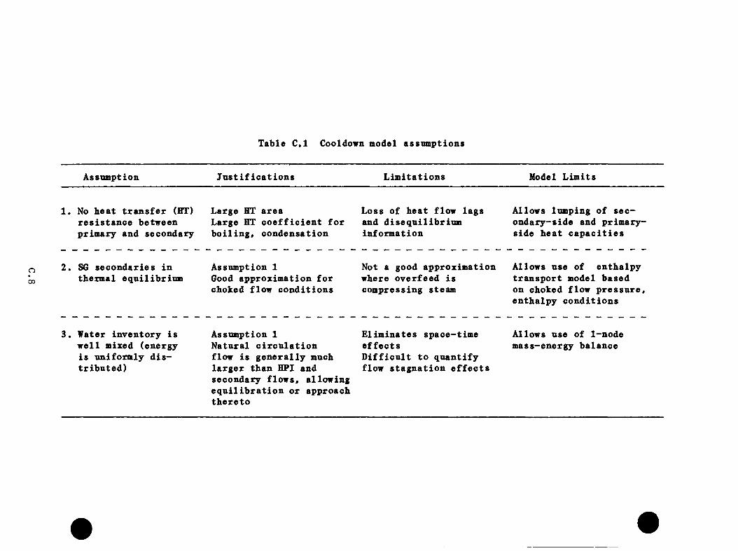
Table C . l Cooldown model assum ptions
Assnmption J u s t i f i c a t i o n s L im i t a t i o n s Model L im its
1 . No b e a t t r a n s f e r (HT) r e s i s t a n c e between p rim ary and secondary
Large HT a re aLarge HT c o e f f i c i e n t f o rb o i l i n g , c o n d e n sa t io n
Loss o f b e a t flow la g s and d i s e q u i l ib r iu m in fo rm a t io n
Allows lumping o f s e c o n d a ry -s id e and p r im a ry - s id e b e a t c a p a c i t i e s
o00
2 . S6 s e c o n d a r ie s in therm al e q u i l ib r iu m
Assumption 1Good app ro x im atio n f o rcboked flow c o n d i t io n s
Not a good ap p ro x im atio n wbere o v e r fe e d i s com pressing steam
Allows use of e n th a lp y t r a n s p o r t model based on cboked flow p r e s s u r e , e n th a lp y c o n d i t io n s
3 . Water in v e n to ry i s w e l l mixed (energy i s un ifo rm ly d i s t r i b u t e d )
Assumption 1 N a tu ra l c i r c u l a t i o n flow i s g e n e r a l ly much l a r g e r th a n HPI and secondary f low s , a l low ing e q u i l i b r a t i o n o r approach th e r e t o
E l im in a te s sp ace - t im e e f f e c t sD i f f i c u l t to q u a n t i f y flow s t a g n a t io n e f f e c t s
Allows use o f 1-node m ass-energy b a lan ce

sys
QDecay HeatQpump power
F ig u re C.2 In p u ts and O utpu ts of system h e a t b a la n c e .
C.9
Qjj(t) = decay h e a t in p u t as a f u n c t i o n o f time
(ANS decay h e a t f u n c t io n )
*RCP = Pumping power d e p o s i te d in c o o la n t
~ P roduc t of HPI mass flow and s p e c i f i c e n th a lp y a t HPI nominal te m p e ra tu re vs thermodynamicr e f e r e n c e te m p e ra tu re
" “ hPI ^p ^^HPI " ^ re f^
= p ro d u c t o f feed w a te r mass flow and s p e c i f i c e n th a lp y a t feed w a te r te m p e ra tu re
" ^p ~ ^ re f^
A^H^ = p ro d u c t o f p r im ary le a k flow ( p r e s s u r i z e r su rge l i n e o r b reak ) and s p e c i f i c e n th a lp y o f the l i q u i d a t the h o t te m p e ra tu re (Th)
= *L S -^ re f>
"ST^ST ~ secondary steam flow and s p e c i f i c e n th a lp y f o rs a tu a r a te d steam a t steam g e n e ra to r c o n d i t io n s (T„_)su
- 's r <“ v < SG> S ' SG -
The d e r i v a t i v e of the t o t a l energy may he expanded u s in g th e ch a in ru le
and s i m p l i f i e d as fo l lo w s .
d(MU) dU dN----------S i s ^ — + U — S i s ^^ 2 )
d t d t d t
where
and
M = t o t a l system masssys •’
D = s p e c i f i c energy a t system te m p e ra tu re , p r e s s u r e
= " v <^H - ^ref>
dU dX„— = c --Sd t ^ d t
dMsvs t"= 2 m = “ g p j + ~ “ sT ~ mass c r o s s in g system
d t boundary
C.IO

Substitntion into the expansion of the derivative yields
d(MU) dT„
“ " sy s ^v ~ * ^v^^H “ "^ref^ ^“ hPI “ fW “ “ l " “ ST d t d t
For l i q u i d s , may be assnmed to be equa l to C^. Then s u b s t i t u t i n g the
expanded d e r i v a t i v e i n t o th e energy b a la n c e
dTfl
and th e n c o l l e c t i n g common term s y i e l d s
"«y» S ■ ®D**’ * ®ECP ' ” hP I *BW ’ P**
- t - T j ) )
Note: M = m (t) = M + (iUroT “ « t ■*■ “ m “ )sys syso m ' l L FW ST o
T h is e q u a t io n g iv e s th e change in h o t le g tem p era tu re f o r the combined
a c t io n o f the h e a t in g /c o o ld o w n mechanisms in the model. I f a l l mechanisms
excep t HPI flow a re ta k e n to have ze ro c o n t r i b u t i o n ( i . e . , a re no t a c t i v e ) ,
th e e q u a t io n may be s o lv ed to y i e l d
-mHPIin
“ ^HPIin ^^o ” ^HPIin^sys
which i s the f a m i l i a r e x p o n e n t ia l cooldown model, which form i s v a l i d f o r
feed w ate r o v e r fe e d s and HPI i n j e c t i o n a t ze ro decay h e a t .
To model a sm all steam l i n e b re a k such as an open IBV, i t i s n e c e ss a ry
to s p e c i fy the steam flow r a t e , Such v a lu e s a re no t known a p r i o r i .
To avo id a r b i t r a r y s e l e c t i o n o f such an inqportant p a ra m e te r , a r e l a t i o n s h i p
C . l l
betw een steam flow and b e t le g te m p era tu re was deve lo p ed . For i s e n t r o p ic
cboked f low , tb e steam flow r a t e i s g iven by
= f(P .H ) A P
2wbere f(P .H ) = mass flow ( I b / b / i n . p s i a (ups tream p r e s s u r e ) ) as a
f u n c t io n o f p r e s s u r e , and m ix tu re e n th a lp y . See ASME
steam t a b l e s , f o u r th e d i t i o n . F ig u re 14 .
2A = b re a k (v a lv e ) s i z e ( i n . )
P = upstream p r e s s u r e (p s ia )
By e v a lu a t in g t h i s e x p r e s s io n f o r s a tu r a t e d steam e n th a lp y a t v a r io u s
p r e s s u r e s and ta k in g a power curve f i t a g a in s t co r re sp o n d in g s a t u r a t i o n
te m p e ra tu r e s , tb e e x p re s s io n was co n v e r ted to
Ag^ = A X 1.87045 x lO"^^ j 4 . 32991
which has an accu racy b e t t e r than +3% between 200^F and 500^F upstream
steam te m p e ra tu re . T h is steam r a t e i s r e l a t e d to ho t leg te m p era tu re
th ro u g h an energy b a la n c e around th e steam g e n e r a to r , which in t ro d u c e s a
te rm f o r h o t leg mass flow (m ^).
(C.8)
Given A^ and T^, Tg^ and Ag^ may be c a l c u l a t e d by i t e r a t i o n . The p h y s ic a l
meaning o f t h i s e x p re s s io n i s t h a t the energy t r a n s p o r t e d in by th e loop
flow ( o r h o t leg mass flow) e q u a ls th e h e a t abso rbed by th e secondary .
With s u b s t i t u t i o n of th e e q u iv a le n t term m^ (Tg cooldown,
Eq. C.8 becomes
C.12
^ ^ S c p _ ” hP I^ i)^^H~^HPI^ _
d t CM CM CM CM (C.9)p sys p sys p sys p sys
Rate o f h e a t in g r a t e h e a t in g r a t e cooldown r a t e cooldown r a t esystem = doe to decay + dne to pnmp - dne to HPI - due to h e a tte m p e ra tu re h e a t power flow t r a n s f e r tochange steam g e n e ra to r
where
M = M + (m„DT* - m, + m™ - m„.p) ( t - t ) sys syso TLPIin L ST o
T his e q u a t io n may he so lv ed u s in g Runge-K utta methods to y i e l d T as aJa
f u n c t io n o f t im e . However, im p o rtan t p a ram e te rs such as m^, nip^,
m^ and an i n i t i a l v a lue o f T^ a re r e q u i r e d as in p u t and must be e x t r a c te d
o r e s t im a te d from th e LANL- and IN E L -ca lcu la ted c a s e s .
With Tg and T ^ known, downcomer te m p e ra tu re may be c a l c u l a t e d by s im u la t in g
stream mixing around th e loop d e p ic te d in F ig u re C .3 . S t a r t i n g a t the ho t
l e g , th e f l u i d p a s s e s th rough th e steam g e n e ra to r where i t i s coo led to
te m p e ra tu re as c a l c u l a t e d above. The f l u i d e n t e r s the co ld leg where
i t i s coo led by mixing w i th HPI (and i s h ea te d by the c o o la n t pumps i f
ru n n in g ) , and i t assumes th e minimum c o o la n t te m p e ra tu re . On e n te r in g the
v e s s e l , th e c o o la n t mixes w ith th e v en t v a lv e flow ( a t T^) to y i e l d the
downcomer te m p e ra tu re . Vent v a lv e flow i s a l s o e x t r a c t e d from the LANL-
and IN E L -ca lcu la ted c a s e s . The downcomer tem p era tu re i s d e f in e d by the
fo l lo w in g e q u a t io n
„ _ “ h^SG “ hP I ^H PI ®V ^H ^®RCP^^p^ipC " ----------------- r— —T------------------------
“ h p i “ vwhere
m^ = v e n t v a lv e flow
T|^^ = downcomer te m p e ra tu re
A l l o th e r term s a re as d e f in e d above.
C.13

I^HL- ’’’h
FW-
FW
H b SG VV ' H
’ HPIHP!
DC- ' DC
CoreD ow ncom er
Pum p
G e n e ra to r
S te a m
F i g u r e C.3 S imple l o o p model f o r downcomer t e m p e r a t u r e e v a l u a t i o n .
C.14
This e q u a t io n y i e l d s mass flow w eigh ted average l i q u i d te m p e ra tu re . Because
o f the mass flow w e ig h t in g , th e r e s u l t i n g te m p era tu re approaches t h a t of
th e dom inating f low , which i s th e loop flow (A^) when n a t u r a l c i r c u l a t i o n
i s s t ro n g o r the RCPs a re ru n n in g . The downcomer te m p era tu re would
approach th e HPI te m p e ra tu re on ly i f th e HPI flow were la rg e r e l a t i v e to
th e loop and v e n t v a lv e f low .
C.15

C•3 Main Steam Line Break
The main steam l i n e b re a k sequences were th e s e v e r e s t c a se s from a cooldown
mechanism s t a n d p o in t . The cooldown model i s no t a p p l i c a b l e because o f the
s e v e r i t y . A l l seven of th e OSNL-defined sequences r e q u i r e d steam g e n e ra to r
i s o l a t i o n a f t e r 20 min (1200 s) and r e s t a r t of the r e a c t o r c o o la n t pumps
a f t e r 22 min (1320 s) . For th e TRAC and RELAPS c a l c u l a t i o n s o f th e se
e v e n t s , steam g e n e ra to r i s o l a t i o n was s p e c i f i e d a t 10 min (600 s ) , and
RCP r e s t a r t was r e q u i r e d on a t ta in m e n t of su b co o lin g m argin (300 s fo r
RELAPS and S26 s f o r TRAC). The r e s u l t o f th e se d i f f e r i n g s p e c i f i c a t i o n s
i s a gap o f 800 t o 1000 s (betw een time = 300 and time = 1320 s in the
sequences) where th e re i s n o t s u f f i c i e n t r e p r e s e n t a t i v e d a ta f o r use in
d e t a i l e d e x t r a p o l a t i o n . The TRAC and RELAPS c a l c u l a t i o n s o f th e main steam
l i n e b re a k t r a n s i e n t show r a p id cooldown t r e n d s e a r l y in the sequence,
p r i o r to r e s t a r t of the RCPs. The cooldown r a t e in the downcomer i s a
c o m p lica ted f u n c t io n o f ho t le g te m p e ra tu re p r im ary loop f low , prim ary^
to - s te a m g e n e r a to r secondary h e a t t r a n s f e r (which in t u r n i s a com plica ted
f u n c t io n o f p r e s s u r e , f e e d w a te r f low , en tra in m e n t l o s s e s , e t c . ) , HPI flow ,
v e n t v a lv e f low , and downcomer w a l l - t o - c o o l a n t h e a t t r a n s f e r . A l l o f th e se
p a ra m e te rs w i l l vary to some e x t e n t as the t r a n s i e n t p r o g r e s s e s . The
l i k e l y re sponse would be t h a t th e i n i t i a l h igh cooldown r a t e s w i l l no t
be s u s t a in e d . I n the absence o f o th e r means o f e s t i m a t io n , th e approach
u sed in th e e v a lu a t io n o f th e main steam l i n e b re a k c a se s was to use a
l i n e a r e x te n s io n o f the e a r l y cooldown t r e n d s . T h is assum ption i s c l e a r l y
c o n s e r v a t iv e . A nother c o n s e r v a t iv e assum ption covers th e use o f 212°F as
th e minimum downcomer te m p e ra tu re . Steam g e n e ra to r b o i l i n g h e a t t r a n s f e r
C.16
would d i c t a t e t h i s v a lu e as a mininuai p h y s ic a l l i m i t . HPI and ven t va lve
flow mixing cou ld e i t h e r r a i s e o r lower the te m p era tu re from t h i s assumed
l i m i t . The main steam l i n e b re a h e s t im a te s r e p o r te d in t h i s s e c t i o n are
a l l s u b je c t to th e s e c o n s e r v a t iv e a ssu m p tio n s . The sequences e s t im a te d fo r
o th e r i n i t i a t o r s a re n o t s u b je c t to th e se assum ptions excep t where n o te d .
A f te r the main steam l i n e b re a k e s t im a te s were in c o rp o ra te d in to the
f r a c t u r e m echanics and r i s k assessm en t p o r t i o n s of t h i s FTS s tu d y , an
a d d i t i o n a l d e t a i l e d c a l c u l a t i o n (MSLB p a ra m e tr ic case 4) was perform ed by
Los Alamos u s in g TBAC. In t h i s r e c a l c u l a t i o n , th e model was changed to
p r o p e r ly p r e d i c t an e a r l y t r i p o f the main feed w ate r pumps and improve
measurement o f th e p a ra m e te rs d i c t a t i n g th e manual t h r o t t l i n g o f HPI and
manual r e s t a r t o f one RCP p e r loop . These changes led to t h r o t t l i n g of
HPI a t 302 s and no r e s t a r t o f the RCPs in p a ra m e tr ic case 4 compared to
HPI t h r o t t l i n g and RCP r e s t a r t a t 526 s f o r the base c a s e .
These changes r e s u l t in a d e c l in in g cooldown r a t e in the downcomer,
su g g e s t in g an a sy m p to tic approach to a te m p era tu re h ig h e r than 212°F.
Between the LANL MSLB b ase case and p a ra m e tr ic case 4 , s u f f i c i e n t
in fo rm a t io n on cooldown mechanisms cou ld be e x t r a c t e d to a llow use of
th e cooldown model to g ive a b e t t e r e s t im a te of the sequences examined
in t h i s s e c t i o n . S ince the e s t im a te s g iven in t h i s s e c t io n f e a t u r e
c o n s e r v a t iv e l y low downcomer te m p e ra tu re s , r e v i s i o n would p ro b ab ly y i e l d
h ig h e r te m p e ra tu re s . However, h ig h e r minimum te m p era tu re s may a l s o mean
l a t e r steam g e n e ra to r d ry o u t t im es because h e a t i s r e t a i n e d by th e system
t h a t would o th e rw ise b o i l away th e w a te r in v e n to ry of the broken steam
C.17

g e n e r a to r . F r a c tn r e m echanics c a l c u l a t i o n s would th e r e f o r e be n e c e s s a ry to
a s s e s s th e impact o f P, T, and h r e v i s i o n on v e s s e l f a i l u r e p r o b a b i l i t y .
The seven sequences d e f in e d by ORNL a re d e s c r ib e d in Table C.2 and in the
fo l lo w in g s e c t i o n s . T ab le C.3 d e s c r ib e s th e p e r t i n e n t f e a t u r e s d r iv in g
th e th e rm o h y d rau lic re sponse o f the system . O v e r s p e c i f i c a t io n e x i s t s in
some of the ca se s because o th e r p l a n t p r o t e c t i o n equipment o r th e rm a l-
h y d r a u l i c phenomena p re v e n t the r e a l i z a t i o n o f the s p e c i f i e d c o n d i t io n .
The b a s i s f o r th e e s t i m a t io n and th e e s t i m a t io n p ro ced u re a re p r e s e n te d , as
a r e t a b u l a r d a ta and p l o t s o f p r e s s u r e s and te m p e ra tu re s f o r th e sequences .
C .3 .1 MSLB 1
C .3 .1 .1 B a s is
Use LANL MSLB base case t o de te rm ine cooldown and r e h e a t in g r a t e s .
C . 3 .1 .2 D e p a r tu re s from B as is
a . SG i s o l a t i o n a t 20 min in s te a d o f 10 min in LANL MSLB base c a s e .
b . HPI t h r o t t l i n g and RCP r e s t a r t a t 22 min in s t e a d o f a t a t ta in m e n t o f
su b co o lin g m arg in , as in LANL MSLB b ase c a s e .
C . 3 .1 .3 A p p lic a b le D ata From O ther Cases
a . One-bank IBV f a i l u r e LANL c a se s 5A, SB, SC, show s i m i l a r n a t u r a l
c i r c u l a t i o n d ( te m p ) /d ( t im e ) s lo p e s (~ 0 .3S ^F /s) t o t h a t found in the
MSLB b ase c a s e . F u r th e r , th e s e ca se s have no RCP r e s t a r t and
downcomer te m p e ra tu re s t h a t a s y m p to t i c a l ly approach co r re sp o n d in g loop
SG te m p e ra tu re s . Tem pera tures in SGA d e c re a se , as d e c re a s in g steam
C.18

Table C.2 Main steaai l i n e b re ak s tudy cases
C o n d i tio n
Case MSLS-
3 4 5
Secondary P re s s u re C o n tro l
TSVs c lo s e on t u r b in e t r i p s i g n a l X X X X X X X
TBVs o p e r a t e as d es ig n ed X X X X X X X
SSRVs o p e r a te as des igned ( i f c h a l le n g e d ) X X X X X X X
F eedw ater
NFW runback c o n t r o l l e d by ICS X X X
MFV o v e r fe e d b o th s t e a a g e n e r a to r s X
NFW o v e r fee d t o b roken steam g e n e ra to r X
NFW pump t r i p on h ig h steam g e n e r a to r X X
l e v e l (HW pumps, CB pumps co n t in u e to
o p e r a te )
NFW pumps t r i p a t time 0 .00 X X
EFW i n i t i a t e s on s e t p o in t X X X X X X
EFW f a i l s t o i n i t i a t e a u to m a t i c a l ly X
EFW c o n t r o l l e d t o l e v e l X X X X X
EFW o v e r fee d t o b roken steam g e n e r a to r X
P rim ary P re s s u re C o n tro l
PORV b lo c k v a lv e open X X X X X X X• e
PORV o p e r a t e s as designed X X X X X X**
PORV f a i l s to r e s e a t Xe*
SRVs o p e r a te d as des igned X X X X X X X
C.19

T able C.2 (c o n tin u e d )
C o n d i tio n
Case HSLB-
3 4 5
RCPs t r i p p e d a t HPI + 30 s
Both SGs i s o l a t e d a t 20 min
Both SGs i s o l a t e d a t 5 min
EFW and TBVs r e s t o r e d to i n t a c t SG
a t 21 min
EFW and TBVs r e s t o r e d t o i n t a c t SG
a t 6 min
HPI t h r o t t l e d a t l a t e r o f 22 min
o r 50*’f sn b co o l in g
1 RCP/loop r e s t a r t e d a t l a t e r o f 22
min o r 50°F subcoo ling
F a i l e d PORV i s o l a t e d when system
p r e s s u r e d ro p s below 2400 p s i
X X XX X
X
X
X
X
X X X X X X X
X X X X X X X
O ther c o n d i t i o n s common to a l l c a s e s : f u l l power, decay h e a t 1 .0 t im es ANS. ECCS system s o p e ra te as des igned
I f c h a l le n g e d
C.20
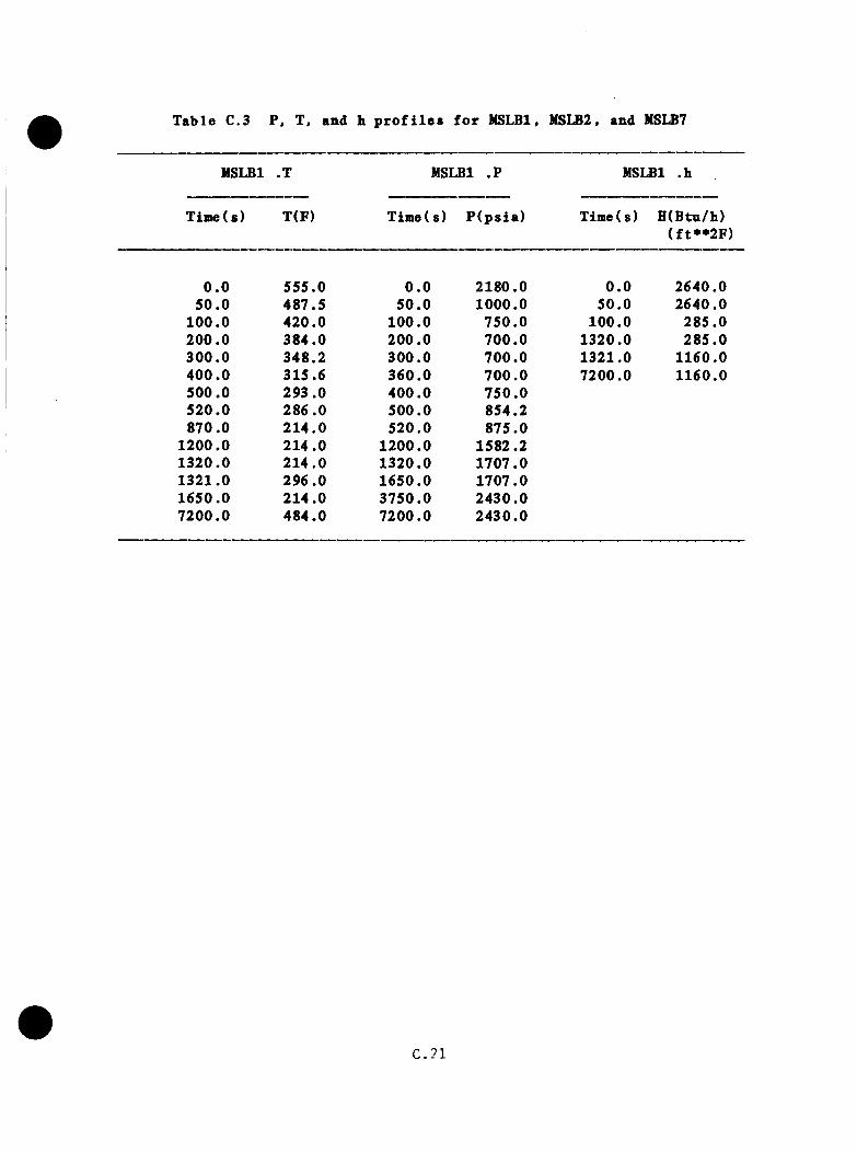
Table C.3 P, T, and h p r o f i l e s f o r MSLBl, MSLB2. and MSLB7
MSLBl .X MSLBl . ? MSLBl .h
Time(s) T(F) Time(s) P (p s ia ) Time( s) H (Btn/h)(f t**2F )
0 .0 555.0 0 .0 2180.0 0 .0 2640.050 .0 487.5 50 .0 1000.0 50.0 2640.0
100.0 420.0 100.0 750.0 100.0 285.0200 .0 384.0 200.0 700.0 1320.0 285.0300 .0 348.2 300.0 700.0 1321.0 1160.0400 .0 315.6 360.0 700.0 7200.0 1160.0500.0 293.0 400.0 750.0520.0 286 .0 500.0 854.2870.0 214 .0 520.0 875.0
1200.0 214.0 1200.0 1582.21320.0 214 .0 1320.0 1707.01321.0 296 .0 1650.0 1707.01650.0 214 .0 3750.0 2430.07200.0 484.0 7200.0 2430.0
C.21

g e n e r a t io n r a t e a l lo w s secondary p r e s s n r e and s a t u r a t i o n t e a p e r a t n r e to
d rop . Tbe saae b e h a v io r i s a ssnaed in tbe MSLB sequence .
b . SGB p r i a a r y flow s t a g n a t e s in c a se s SA, 5B, and 5C, p r e v e n t in g SGB
f r o a supp ly ing b e a t t o tb e p r i a a r y . v b ic b would a i t i g a t e downcoaer
cooldown c o n d i t io n s . Flow s t a g n a t io n in MSLB e x t r a p o l a t i o n i s assuaed
to p r e v a i l u n t i l r e s t a r t o f RCPs (one in each lo o p ) .
C . 3 . 1 .4 E x t r a p o la t io n A ssu a p t io n s and P rocedure
a . T e a p e ra tu re — LANL MSLB base case was used to 520 s w ith low est
t e a p e r a t u r e downcoaer c e l l d a ta be ing i n t e r p o l a t e d by s t r a i g b t - l i n e
s e g a e n t s . T h e r e a f t e r , e x t r a p o l a t i o n co n t in u ed on tb e saae l i n e a r t r e n d
to 870 s when c o l d e s t downcoaer r e g io n reached 212°F. This lower
t e a p e r a tu r e l i a i t was c o n s i s t e n t w ith noncboked flow of s t e a a and
fee d w a te r out tbe b roken s t e a a l i n e , as observed in b o th tbe LANL
and INEL c a l c u l a t i o n s . E x t r a p o la t io n o f tbe loop B v o id c o l la p s e
r a t e p r i o r to 520 s s u g g e s ts t h a t tbe v o id s in tb e loop B candy cane
w i l l a l s o c o l la p s e by 870 s . S ince loop B cou ld supp ly b e a t to tbe
p r i a a r y a f t e r c o l l a p s e , tb e e f f e c t o f c o l la p s e w i l l be t o l i a i t f u r t h e r
t e a p e r a t u r e d e c r e a s e s .
Downcoaer t e a p e r a tu r e d rops to n e a r tbe c o ld le g A t e a p e r a t u r e . which
in tu r n i s i n e q u i l i b r i u a w ith tb e secondary o f SGA. A f te r tb e s y s te a
c o o ls enough so t h a t e n t r a i n a e n t l o s s e s d e c l i n e . SGA b e g in s to f i l l .
EFW flow i s c o n t r o l l e d on l e v e l and cea se s p r i o r to i s o l a t i o n a t 1200
s . Tbe SGA w a te r in v e n to ry o f (0 .0 0 0 lb i s b o i l e d ou t by 1360 s
by decay b e a t . RCP d i s s i p a t i o n , and p r i a a r y b e a t in g by SGB. These
C .2 2
e f f e c t s would i n i t i a l l y r a i s e downconer te m p era tu re to 296°F because of
tb e mixing o f warmer w a te rs from SGB w ith tbe downcomer. This e f f e c t
i s a l s o observed in tbe LANL b ase c a s e . Steam g e n e ra to r A d ryou t a t
1360 s would r e s u l t in a downcomer te m p era tu re of 220°F. I f tb e steam
g e n e r a to r d ry o u t p e r io d were ex ten d ed , tbe te m p era tu re s would remain
h ig h e r . A f t e r 1360 s , tb e system r e h e a t s to 50S^F a t 7200 s because
of decay b e a t and RCP power in p u t . T ab le C.3 and F ig u re C.4 summarize
tb e r e s u l t s f o r t h i s c a se .
b . P r e s s u r e — MSLB base case d a ta were used t o 520 s . Tbe system p r e s s u r e
d rops t o 700 p s i a by 200 s . HPI b e g in s to o f f s e t c o o la n t sh r in k ag e by
400 s and in c r e a s e s p r e s s u r e by 1 .04 p s i / s between 400 and 520 s . T h is
r a t e i s assumed to c o n t in u e u n t i l HPI t h r o t t l i n g a t 1320 s (22 min) ,
a f t e r which p r e s s u r e i s assumed c o n s ta n t a t 1707 p s i a (may a c t u a l l y
drop) betw een 1320 s and SGA d ry o u t a t 1360 s . Then r e p r e s s u r i z a t i o n
o ccu rs a t a r a t e o f 0 .3446 p s i / s to tb e PORV s e t p o in t , 2430 p s i a a t
3460 s , fo l lo w in g which th e p r e s s u r e rem ains c o n s ta n t u n t i l th e end o f
the sequence (7200 s ) . Tab le C.3 and F ig u re C.4 summarize the r e s u l t s
f o r t h i s c a s e .
c . Heat T r a n s f e r C o e f f i c i e n t — H eat t r a n s f e r c o e f f i c i e n t s f o r the MSLB
TRAC base case were o b ta in e d from Appendix A of the LANL Oconee-1
r e p o r t . The i n i t i a l v a lue of 2640 B tu /h f t F (15000 w/m k) p e r s i s t s
u n t i l th e RCPs t r i p a t ~50 s . The h e a t t r a n s f e r c o e f f i c i e n t th e n ramps
down w ith loop flow to 285 B tu /h f t ^ ° F (1620 w/m^k) a t 100 s and i s
assumed to rem ain a t t h i s v a lu e u n t i l r e s t a r t o f two RCPs a t 1320 s .
T h is v a lu e n e g l e c t s d e c re a s e s due to r e d u c t io n of n a t u r a l c i r c u l a t i o n
C .2 3
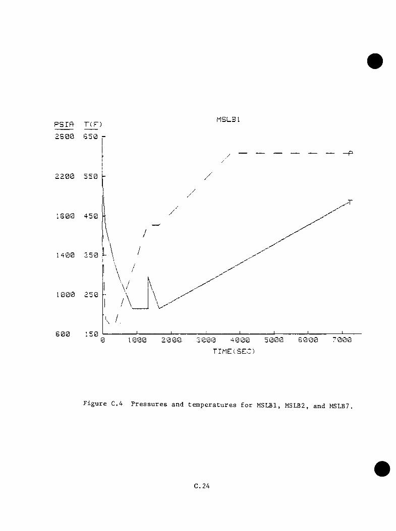
P S r R T ( F )MSLB L
B S00
2200
1 3 0 0
I 4 0 0
1000
3 0 0 0T I M E ( S E C ;
F i g u r e C.4 P r e s s u r e s and t e m p e r a t u r e s f o r MSLBl, MSLB2, and MSLB7,
C.2 4
f l o v s and e l im i n a t io n o f v e n t v a lv e f lo w s . A f te r RCP r e s t a r t , a v a lue
o f 1160 B tu /h f t ^ ° F (6600 W/m^K) was o b ta in e d fo r the rem ainder o f the
t r a n s i e n t . The r e s u l t s a r e summarized in Table C .3 .
C .3 .2 MSLB2
C .3 .2 .1 B as is
LANL MSLB base case to d e te rm in e cooldown and r e h e a t in g r a t e s .
C .3 .2 .2 D ep a r tu re from B a s is
a . MFW o v e rfeed to SGA w ith MFf t r i p on l e v e l .
b . EFW c o n t r o l s t o l e v e l .
C .3 .2 .3 A p p lic ab le D ata From O ther Cases
LANL MSLB case 3 f e a t u r e s NFW pump f a i l u r e s t o t r i p , b u t the r e s u l t i s
o v e r f i l l o f SGB, which t r i p s NFW. L ikew ise , th e MSLB b ase case s u f f e r s
a MFW pump t r i p (low s u c t io n P) when th e ICS i s runn ing back th e fe e d w a te r .
An o v e r fe e d where th e r e i s no v a lv e runback would r e s u l t in MFW pump t r i p
un d er th e s e c o n d i t io n s o r m a lfu n c t io n i f i t rem ained on.
C .3 .2 .4 E x t r a p o la t io n A ssum ptions , P ro c e d u re s , and R e s u l t s
a . T em perature — At th e time of NFW t r i p (45 s) in th e MSLB base
c a s e , th e NFW te m p e ra tu re has s t a r t e d d ropping r a p id l y , i n d i c a t in g
f l a s h i n g to s a t u r a t i o n c o n d i t io n s in th e feed w ate r l i n e s . Heat lo s s
th ro u g h SGA would be l i m i t e d by n a t u r a l c i r c u l a t i o n to app rox im ate ly
370 l b / s e q u iv a le n t in steam w ith an a d d i t i o n a l amount of steam l o s t
C.25
in fe e d w a te r f l a s h i n g . With a nominal SGA feed w ate r r a t e o f 1500
l b / s and assuming no l i q u i d l o s s e s to e n tra in m e n t from the b r e a k , a
n e t in f low o f 1230 l b / s would f i l l the steam g e n e ra to r to 120,000
lb w i th i n 100 s a f t e r RCP t r i p . Downcomer te m p era tu re re sp o n se would
show an e a r l y approach to 212°F b u t p ro b a b ly would n o t drop below
t h a t v a lu e because o f v en t v a lv e f lo w . The case may be approx im ated
by MSLBl and MSLB4. These ca se s p ro v id e the bounds f o r SGA d ry o u t
time a l th o u g h downcomer te m p e ra tu re s may be lower betw een 50-870 s .
MSLBl i s a re a s o n a b le ap p ro x im atio n because the accum ula ted decay h e a t
and p r im ary h e a t in v e n to ry would be cap a b le of e v a p o ra t in g th e excess
w a te r 0 6 0 ,0 0 0 lb ) in SGA p lu s an a d d i t i o n a l 100-200 I b / s o f EFW
and t h e r e f o r e would be a t the same s t a t e as MSLBl a t i s o l a t i o n (1200
s) . Table C.3 and F ig u re C.4 summarize th e r e s u l t s f o r the ro ugh ly
e q u iv a le n t MSLBl c a s e .
b . P r e s s n r e — P r e s s u r e s f o r p o r t i o n s o f th e t r a n s i e n t w i l l be l e s s th an
th o se f o r f i l e MSLBl. Use o f MSLBl would th e r e f o r e be c o n s e r v a t iv e .
c . Heat T r a n s f e r C o e f f i c i e n t — Used same v a lu e s f o r f i l e MSLBl.H.
C .3 .3 MSLB3
C .3 .3 .1 B a s is
LANL MSLB p a ra m e tr i c case 3 (s team l i n e b re a k w i th runaway f e e d w a te r ) .
C .3 .3 .2 D e p a r tu re s from B as is
a . EFW a c t u a t e s and c o n t r o l s on l e v e l .
C .2 6
#
b . I s o l a t i o n o f SGA a t 1200.
c . R e s t a r t 1 RCP/loop and t b r o t t l e HPI a t 1320 s .
C .3 .3 .3 A p p lic a b le Data from O ther Cases
I n LANL MSLB b ase c a s e , t o t a l EFW and HWP/CBP flow r a t e to SGA i s 400 I b / s ;
one-bank TBV f a i l u r e cases LANL SA, SB, SC show downcomer te m p e ra tu re s ;
a s y m p to t ic a ly approach ing r e s p e c t iv e SG te m p e ra tu re s .
C .3 .3 .4 E x t r a p o la t io n A ssum ptions, P ro ced u re s and R e s u l t s
a . T em pera tu res — In MSLB p a ra m e tr i c case 3 , the MFW pumps do no t t r i p
u n t i l h ig h l e v e l in SGB i s e n co u n te red a t 331 s . T h e re fo re , th e minimum
downcomer te m p era tu re p r o f i l e f o r p a ra m e tr ic case 3 was employed to
330 s . A te m p era tu re o f 310**F i s o b ta in e d a t t h i s p o in t . P r i o r
t o NFW pump t r i p , a fe ed w a te r flow r a t e o f ap p ro x im ate ly 440 l b / s
t o SGA i s o b ta in e d . The flow r a t e a f te rw a rd s i s 330 l b / s . These
v a lu e s compare w i th 400 I b / s f o r EFW and HW/CB pump t o t a l flow r a t e
f o r th e LANL MSLB base c a s e . Pump head cu rves and flow r e s i s t a n c e in
th e EFW sp ray r in g may accoun t f o r th e s i m i l a r i t i e s . The e f f e c t of
f e e d w a te r e n tra in m e n t l o s s e s from SGA cou ld n o t be p ro p e r ly e v a lu a te d .
For e x t r a p o l a t i o n p u rp o s e s , an EFW-HW/CB pump t o t a l flow o f 440 l b / s
was assumed. T h e re fo re , th e c o o l in g t r e n d i s co n tin u ed u n t i l th e A-
loop c o ld le g s re a c h 212^F a t 904 s . T h is te m p era tu re w i l l p e r s i s t
u n t i l r e s t a r t o f the RCPs a t 1320 s . Water s t a r t s t o accum ulate in SGA
due to th e n a t u r a l c i r c u l a t i o n mass flow l i m i t a t i o n on h e a t t r a n s f e r .
A pprox im ate ly 60 ,000 lb o f w a te r w i l l be on hand in SGA a t i s o l a t i o n .
At th e r e s t a r t o f th e RCPs (1320 s ) , downcomer te m p era tu re w i l l jump
C.27

to th e p rim ary av e ra g e , 270°F, and drop to 228^F a t 1350 s as the
SGA secondary d r i e s o u t . T h e r e a f t e r , th e system r e h e a t s a t 0 .0 4 8 9 °F /s
u n t i l 7200 s when i t re a c h e s S ld ’ F ( se e Table C.4 and F ig u re C .S ) .
b . P r e s s u r e — System p r e s s u r e d rops t o 800 p s i a t 125 s and th e n in c re a s e s
a t 0 .7 7 p s i / s u n t i l HPI t h r o t t l i n g a t 1320 s . P r e s s u r e i s 1722 p s i
a t t h a t p o i n t . T h e r e a f t e r , system r e h e a t in c r e a s e s p r e s s u r e by 0.3446
p s i / s u n t i l th e PORV s e t p o in t i s reached a t 3375 s and rem ains
c o n s ta n t th rough 7200 s ( s e e Table C.4 and F ig u re C .5 ) .
c . Heat T r a n s f e r C o e f f i c i e n t — While RCPs a re ru n n in g , th e h e a t t r a n s f e r
c o e f f i c i e n t s a re th e same as f o r co r resp o n d in g p o r t i o n s o f MSLBl. The
s i m i l a r n a t u r a l c i r c u l a t i o n r a t e s of MSLBl w i l l cause s i m i l a r v a lu e s
o f h . T h e re fo re , th e h v a lu e s p r e d i c t e d f o r MSLBl app ly to t h i s case
a l s o ( s e e Table C .4 ) .
C .3 .4 MSLB4
C.3 .4 .1 B as is
LANL MSLB b a se c a s e .
C.3 .4 .2 D e p a r tu re s from B as is
Same as MSLBl excep t EFW le v e l c o n t r o l f a i l s , le a d in g to o v e r fe e d o f SGA.
C .3 .4 .3 A p p lic a b le Data From O ther Cases
See MSLBl.
C.3 .4 .4 E x t r a p o la t i o n A ssum ptions and P rocedu res
C .2 8
#

Tab le C.4 P, T, and b p r o f i l e s f o r MSLB3
MSLB3 .T MSLB3 . ? NSLB3 .b
Tiffle(s) T(F) Time(s) P (p s ia ) Time(s) H(Btu/b)(f t**2F )
0 .0 555.0 0 .0 2180.0 0 .0 2640.050 .0 477 .0 50 .0 1000.0 50.0 2640.0
330.0 390.0 125.0 800.0 100.0 285.0904.0 212 .0 1320.0 1722.0 1320.0 285 .0
1320.0 212 .0 3375.0 2430.0 1321.0 1160.01321.0 270.0 7200.0 2430.0 7200.0 1160.01350.0 228 .07200.0 514.0
#C .2 9
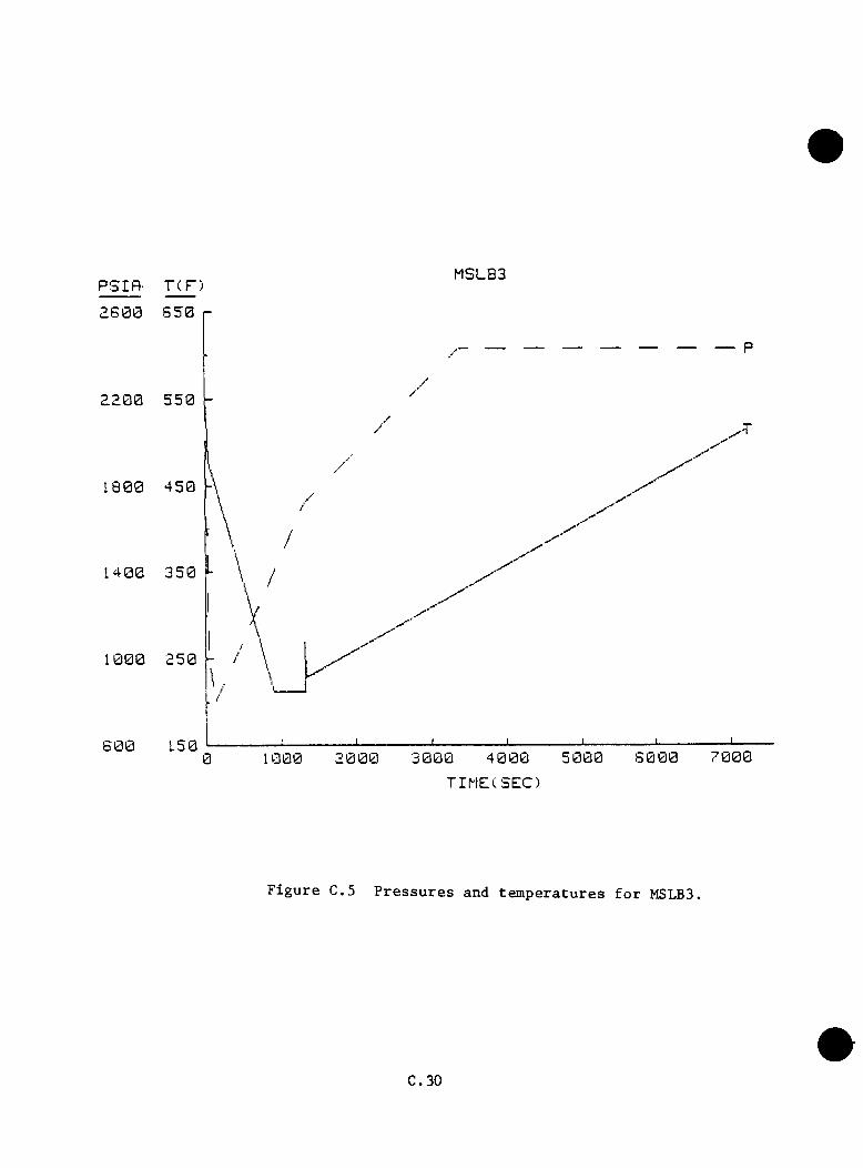
PSIf l - T ( DMSLB3
2 S 0 0 S 5 0 r
^ 2 0 0 5 5 0
1 8 0 0 4 5 0
1 4 0 0 3 5 0
r\
1 0 0 0 2 5 0
6 0 0 1.50
I ' V1 0 0 0 2 0 0 0 3 0 0 0 4 0 0 0 5 0 0 0 S 0 0 0 7 0 0 0
TIME(SEC)
F i g u r e C.5 P r e s s u r e s and t e m p e r a t u r e s f o r MSLB3.
C .3 0
a . T e n p e ra tu re — Case i s tb e same as NSLBl to 1320 s . Minimum te m p era tu re
o f 212°F i s reached a t 870 s , as in HSLfil, E n tra inm en t lo s s e s cou ld
n o t be e v a lu a te d and were c o n s e r v a t iv e ly ig n o red . SGA and steam
l i n e A w a te r in v e n to ry a t i s o l a t i o n (1200 s) i s 150,000 lb compared
t o 60,000 lb f o r MSLBl a t same i n s t a n t . N a tu ra l c i r c u l a t i o n flow s
l i m i t e d cooldown r a t e p r i o r t o i s o l a t i o n . A f te r RCP r e s t a r t a t 1320 s ,
downcomer te m p e ra tu re r i s e s t o 296°F due to mixing o f downcomer and SGB
w a te r s , as d e s c r ib e d in MSLSl. Downcomer te m p era tu re r e t u r n s t o 212°F
a t 1380 s as SGB and p r im ary system h e a t in v e n to r i e s a re ex h au s ted ,
b o i l i n g 70 ,000 lb o f w a te r from SGA in the p ro c e s s . Decay h e a t and
RCP h e a t in p u t (12725 B tu /s f o r two pumps) b o i l d ry th e rem aining w a te r
(80 ,000 lb ) by 4090 s . System h e a t a t 0 .0 4 8 9 °F /s r e tu r n s the system
to 364^F a t 7200 s ( s e e Tab le C.5 and F ig u re C . 6 ) .
b . P r e s s u r e — P re s s u re behaves s i m i l a r l y to MSLBl to 1320 s , t h a t i s ,
d e p r e s s u r i z a t i o n to 700 p s i by 200 s , r e p r e s s u r i z a t i o n to 1707 p s i a t
1320 s . P r e s s u r e i s assumed to h o ld c o n s ta n t (would p ro b ab ly drop
siMBewhat in s te a d ) a t 1707 p s i a u n t i l SGA dryou t a t 4010 s , s in c e HPI
has been t h r o t t l e d and th e r e i s no system r e h e a t du r in g t h i s p e r io d .
A f te rw a rd s , p r e s s u r e c lim bs a t .33446 p s i / s t o PORV s e t p o in t (2430
p s i a ) a t 6190 s and rem ains u n t i l 7200 s ( see Table C.5 and F ig u re
C.6) .
c . Heat T r a n s f e r C o e f f i c i e n t — Case i s i d e n t i c a l to NSLBl (see Table
C.5) .
C.31

T able C.S P, T, and h p r o f i l e s f o r MSL£4
MSLB4 .T NSLB4 . ? NSLB4 .h
TineCs) T(F) Tiaie( s) P (p s ia ) XiBe(s) H(Btn/b)( f t* * 2 F )
5 0 .0 487.5 50 .0 1000.0 50.0 2640.0100 .0 420 .0 100.0 750 .0 100.0 285 .0200 .0 384 .0 200.0 700 .0 1320.0 285 .0300 .0 348.2 300.0 700 .0 1321.0 1160.0400 .0 315.6 360.0 700 .0 7200.0 1160.0500.0 293 .0 400.0 750 .0520 .0 286 .0 500.0 854.2870.0 212 .0 520.0 875.0
1200.0 212 .0 1200.0 1582.21320.0 212 .0 1320.0 1707.01321.0 296 .0 3430.0 1707.01380.0 212 .0 5530.0 2430.04090.0 212 .0 7200.0 2430.07200.0 364 .0
C.3 2

P S I f t TCF)MSLB4
1 8 0 0 4 5 0
1 4 0 0 3 5 0
1 0 0 0 2 5 0
6 0 0 1506 0 0 010000
TIM E(SE C)
F i g u r e C.6 P r e s s u r e s and t e m p e r a t u r e s f o r MSLB4.
C.33

C .S .5 NSLBS
C.S .5 .1 B as is
LANL MSLB base c a s e .
C .S .5 .2 D e p a r tu re s from B a s is
Main f e e d v a te r pumps t r i p a t time 0 . 0 . HW/CB pumps and EFW fu n c t io n
p r o p e r ly .
C .S .5 .S A p p lic a b le Data from O ther Cases
See NSLBl.
C .S .5 .4 E x t r a p o la t i o n A ssum ptions . P ro c e d u re s , and R e s u l t s
a . Tem perature — Loss o f MFW a t time o f 'b r e a k would reduce w a te r a v a i l a b l e
f o r b o i l i n g in SGA o ver f i r s t 50 s o f t r a n s i e n t from 71,500 lb t o
o n ly 25 ,000 lb . As a r e s u l t , te m p e ra tu re d rops to 492**F r a t h e r than
487°F in MSUBl. T h e r e a f t e r , th e same cooldown s lo p e s from MSLBl a re
used to p r o j e c t te m p e ra tu re s a t S50 s (S88^F) and 1150 s (212^F).
An accum ula ted in v e n to ry o f 60 ,000 lb o f w a te r in SGA i s ex pec ted a t
i s o l a t i o n . From 1S20 s on, th e b e h a v io r i s ta k e n to be th e same as
NSLBS (s e e Table C.6 and F ig u re C . 7 ) .
b . P r e s s u re — Since th e i n i t i a l c o o lo f f w i l l be l e s s s ev e re than the
base c a s e , d e p r e s s u r i z a t i o n to th e HPI s e t p o in t would be s l i g h t l y
d e la y e d . The h e a t c o n t r i b u t i o n o f SGB to th e p r im ary i s expec ted t o
s u s t a i n p r im ary p r e s s u r e , as o ccu rred in NSLBS. In th e absence o f
any re a s o n a b le way to p r e d i c t th e d e la y o r e x t e n t o f d e p r e s s u r i z a t i o n .
C.34

Table C.6 P, T, and h p r o f i l e s f o r MSLB5
MSLBS .T NSLB5 .? NSLB5; .h
Time(s) T(F) Time( s) P (p s ia ) Time(s) H(Btu/h)(f t**2F)
0 .0 555.0 0 .0 2180.0 0 .0 2640.050 .0 493 .0 50 .0 1000.0 50.0 2640.0
350 .0 388.0 125 .0 800.0 100.0 285.01150.0 212 .0 1320.0 1722.0 1320.0 285.01320.0 212 .0 3375.0 2430.0 1321.0 1160.01321.0 270.0 7200.0 2430.0 7200.0 1160.01350.0 228.07200.0 514.0
C.3 5
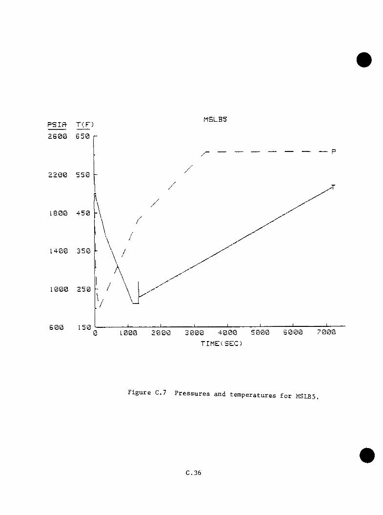
PSIR- T(F) MSLBS2 6 0 0
2200
1 8 0 0
1 4 0 0
1000
6 0 07 0 0 04 0 0 02000 3 0 0 00 1000
TIME(SEC)
F i g u r e C.7 P r e s s u r e s and t e m p e r a t u r e s f o r MSLBS.
C .3 6
th e use o f th e p r e s s u r e curve f o r NSLBS would r e p r e s e n t a c o n s e rv a t iv e
e s t i n a t e ( s e e Table C.6 and F ig u re C .7 ) .
c . Heat T r a n s f e r C o e f f i c i e n t — Case i s i d e n t i c a l to MSLBl (see Table
C.6) .
C .S .6 MSLB6
C .S .6 .1 B as is
LANL MSLB b ase case f o r i n i t i a l response of system fo r t r a n s i e n t , LANL
Rancho S eco -type t r a n s i e n t f o r response o f system to r e f i l l of dry SGB.
C .S .6 .2 D e p a r tu re s From Base Cases
a . Loss o f a l l main feed w a te r flow time 0 . 0 .
b . EFW in manual c o n t r o l .
c . SGs i s o l a t e d a t 5 min.
d. SGB r e s t o r e d a t 6 min w ith f u l l EFW flow .
C .S .6 .S A p p lic a b le D ata from O ther Sources
Not a p p l i c a b l e .
C .S .6 .4 E x t r a p o la t io n A ssum ptions, P ro c e d u re , and R e s u l t s
a . Tem perature — Along w ith th e l o s s o f main feedw ate r a t the beg inn ing
o f th e sequence , i t i s assumed t h a t the h o tw e l l /c o n d e n sa te b o o s te r
pumps a re a l s o u n ab le to d e l i v e r flow to the a f f e c t e d steam g e n e ra to r .
As a r e s u l t , SGA d r i e s ou t v e ry q u ic k ly (p ro b ab ly l e s s th an 20 s)
C.37
because of th e l i q u i d e n t ra in m e n t du r in g the i n i t i a l blowdown. From
th e LANL MSLB c a l c u l a t i o n , th e loop A downcomer r e g io n reac h es SIO^F
a t t h i s moment and th e loop B downcomer rem ains n e a r S70*’f . Having
l o s t a l l o f i t s w a te r in v e n to ry , SGA no lo n g e r c o n t r i b u t e s t o system
cooldown, and the downcomer te m p era tu re soon r e t u r n s to the ho t leg
te m p e ra tu re , > S70^F. SGB d r i e s ou t by about SO s i n t o th e t r a n s i e n t .
The cooldown model was used t o e x t r a p o la t e a system te m p e ra tu re r i s e
to SSS^’f by 6 min (360 s) when EFW is r e s t o r e d to SGB. With EFW
r e s t r i c t e d to SGB o n ly and th e IBVs on SGB c o n t r o l l i n g to p r e s s u r e ,
th e system (h o t le g ) te m p e ra tu re s low ly d e c re a s e s t o 548°F. Downcomer
te m p e ra tu re d e c re a se s t o 534°F a t 460 s because o f mixing o f co ld HPI
w i th e v e r - r e d u c in g amounts o f loop flow , more than o f f s e t t i n g system
h e a tu p . However, as HPI flow d e c re a s e s as th e system re a c h e s PORV s e t
p o in t p r e s s u r e a t 200 s , some mixing e f f e c t s and in c re a s e d loop flow
t o HPI flow r a t i o cause th e downcomer te m p e ra tu re to r i s e to 546°F and
t o co n t in u e to r i s e t o SS6°F a t i n i t i a t i o n of EFW a t 360 s . Assuming
a n a t u r a l c i r c u l a t i o n flow o f 900 I b / s in loop B, m ain tenance o f the SG
e x i t te m p era tu re a t S48°F, 70 l b / s o f HPI flow , and a v e n t v a lv e flow
o f 45 I b / s , th e average downcomer te m p era tu re would f a l l from S56°F a t
360 s t o Sld^’p b e f o r e 460 s because of EFW i n i t i a t i o n . The cooldown
i s n o t as d ram a tic as in th e Rancho S eco-type o f even t b e c a u se , in t h i s
c a s e , o n ly one SG i s in v o lv ed and EFW is c o n t r o l l e d t o l e v e l . A f te r
th e SG f i l l s t o l e v e l , th e downcomer te m p era tu re h o ld s s te a d y a t around
515°F because of th e TBV o p e r a t io n on SGB and c o n t in u e d HPI flow .
At 1200 s th e HPI i s t h r o t t l e d and one RCP p e r loop i s r e s t a r t e d .
T h is r e s u l t s in e x c e l l e n t mixing in the downcomer w i th a te m p era tu re
C .3 8
equa l to th e mean o f th e ho t leg and SGA e x i t te m p e ra tu re s . Downcomer
te m p era tu re r i s e s to 564^F soon a f t e r RCP r e s t a r t and decays to 548°F
by 1420 s , a f t e r which SGB r e g u l a t i o n keeps the system a t 548°F f o r
th e rem ainder o f th e sequence ( s e e Table C.7 and F ig u re C .8 ) .
b . P r e s s u r e — The com bina tion o f main steam l i n e b reak and r e a c to r t r i p
cau ses HPI i n i t i a t i o n ( s e t p o in t 1500 p s ia ) a t 20 s . However, th e
prompt b o i l - d r y of SGA because of th e b reak and SGB because o f lo s s
o f b o th MFW and EFW cau ses r a p id system r e h e a t , which, a long w ith HPI
flow , r e s u l t s in an e q u a l ly r a p id r e p r e s s u r i z a t i o n . The PORV s e t p o in t
p r e s s u r e , 2430 p s i a , i s reached a t 200 s (compare w ith 226 s f o r the
Rancho S eco -type seq u e n c e ) . P r e s s u r e d e c re a se s upon r e s t a r t of the
RCPs because o f enhanced cooldown and c o o la n t s h r in k a g e . LANL cases
5A and 5B c a l c u l a t e d p r e s s u r e r e d u c t io n s on the o rd e r of 500 p s i on
RCP r e s t a r t : a s i m i l a r t r e n d was assumed h e re . A f te r reac h in g 1900
p s i a a t 1300 s , th e p r e s s u r e i s assumed to in c re a s e a t 0 .34 p s i / s , as
in th e LANL MSLB c a l c u l a t i o n . However, p r e s s u r e reco v e ry may no t be
s i g n i f i c a n t because th e system te m p e ra tu re s a re n e a r the ho t s tandby
l e v e l so t h a t r e h e a t in g and expans ion w i l l be minimal ( s e e Table C.7
and F ig u re C . 8 ) .
c . Heat T r a n s f e r C o e f f i c i e n t — Heat t r a n s f e r c o e f f i c i e n t d rops from 28200 i\ 0 i\
B tu /h f t F a t 50 s t o 285 B tu /h f t F a t 100 s because of t r i p and
spindown o f th e RCPs. The n a t u r a l c i r c u l a t i o n va lue p e r s i s t s u n t i l
r e s t a r t of one RCP p e r loop a t 1200 s , whereon th e va lue clim bs to
2o1160 B tu /h f t F f o r th e rem ainder of th e sequence ( s e e Table C .7 ) .
C.39
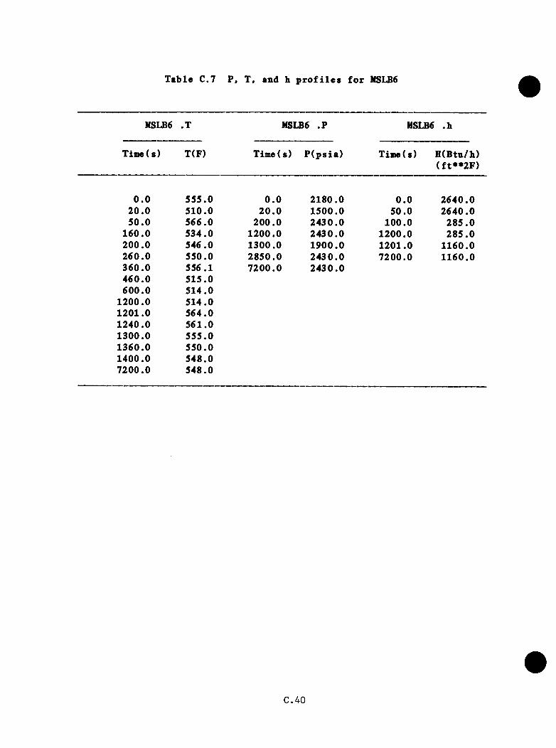
Tab le C.7 P, T, and h p r o f i l e s f o r MSLB6
MSLB6 .T MSLB6 . ? HSLB6 .h
Time( s) T(F) Time(s) P (p s ia ) Time(s) H (Btn/h)(f t* * 2 F )
0 .0 555.0 0 .0 2180.0 0 .0 2640.020 .0 510.0 20 .0 1500.0 50.0 2640.050.0 566.0 200.0 2430.0 100.0 285 .0
160.0 534.0 1200.0 2430.0 1200.0 285 .0200.0 546.0 1300.0 1900.0 1201.0 1160.0260.0 550.0 2850.0 2430.0 7200.0 1160.0360.0 556.1 7200.0 2430.0460.0 515.0600.0 514.0
1200.0 514.01201.0 564.01240.0 561.01300.0 555.01360.0 550.01400.0 548.07200.0 548.0
C.4 0
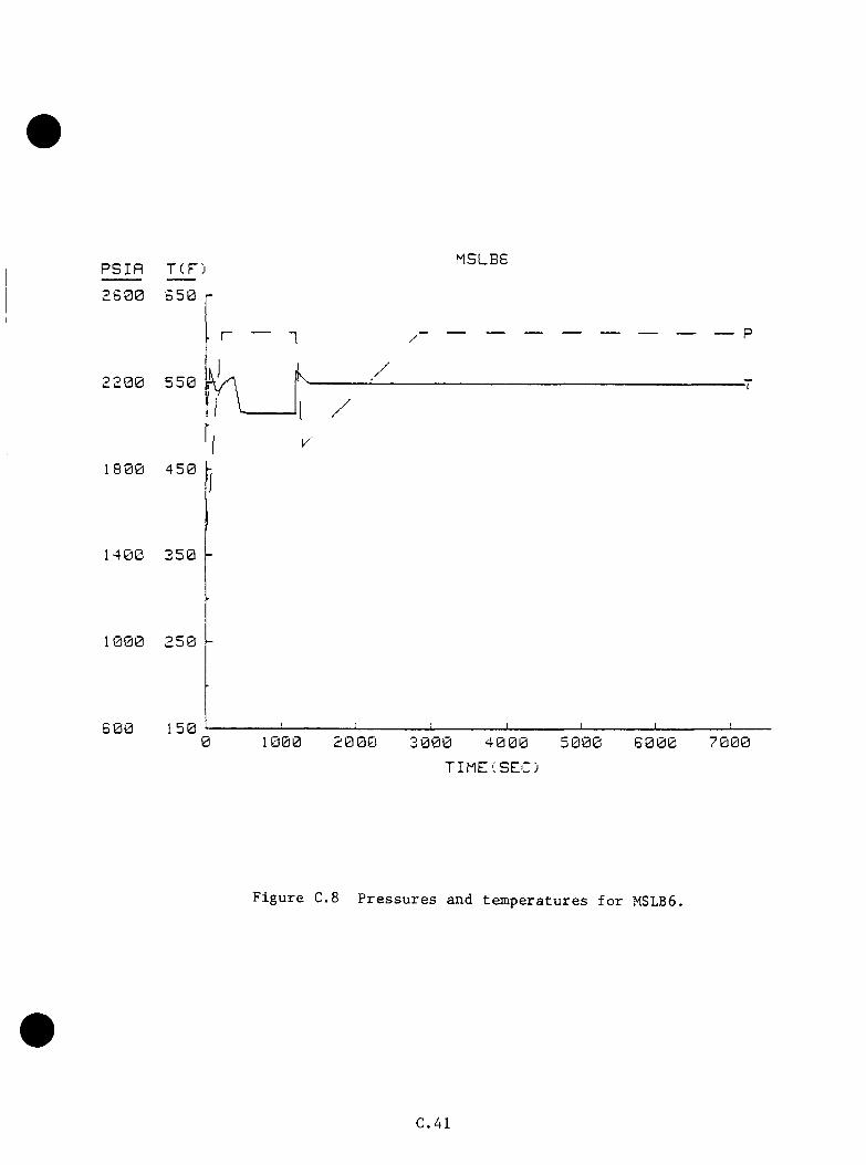
P S I f l TCP)MSLBG
2 6 0 0 6 5 0
-T
1 8 0 0
1 4 0 0
1000
6 0 0 0 2 0 001 7 0 0 0
T I M E ( S E C )
F i g u r e C.S P r e s s u r e s and t e m p e r a t u r e s f o r MSLB6.
C.4 1

C .3 .7 MSLB7
T h is case f e a t u r e s th e same sequence as MSLBl excep t t h a t th e PORV i s
assumed t o f a i l open when c h a l le n g e d and i s i s o l a t e d when p r im ary p r e s s u r e
d rops bach below 2400 p s i . I n MSLBl, th e PORV i s no t c h a l le n g e d u n t i l
3460 s and th e r e i s no m ajor h e a t source to keep th e system p r e s s u r e up.
T h e re fo re , th e b lo c k v a lv e co u ld he c lo s e d p ro m p tly . T h is case would th en
be a s u b s e t o f MSLBl ( s e e Table C.3 and F ig u re C .4 ) .
C .4 2
c.4 Tttrb ine Bypa»g F » il i i re$ > t F u l l Power
C .4 .1 ORNL-Defined TBV Cases (19 T o ta l )
ORNL d e f in e d 19 tu r b i n e bypass v a lv e f a i l u r e ca se s f o r f u l l pover
o p e r a t io n s . These were s o r te d in t o 10 groups d es igned to have s i n i l a r
t r a n s i e n t r e s p o n s e s , e s p e c i a l l y in the l a t e r s ta g e s when te m p era tu re s are
lo w e s t . T ab le C.S d e s c r ib e s th e c h a r a c t e r i s t i c s o f the sequences and l i s t s
group a s s ig n m e n ts . The t r a n s i e n t s a re e v a lu a te d by groups below.
C .4 .1 .1 Base
TBV f a i l u r e s in one loop — LANL 5A, 5B, 5C.
TBV f a i l u r e s in two loops — LANL 6 k , 6B, 6C.
C .4 .1 .2 D e p a r tu re s from Bases
a . A l l s tudy c a se s f a i l , on ly one TBV in a bank. LANL cases f a i l , bo th
TBVs in a bank .
b . A l l s tudy c a s e s have EFW o p e ra te as d es igned and c o n t r o l SG in v e n to ry
to l e v e l . A l l LANL cases f e a t u r e runaway feed w a te r .
c . The s tudy c a se s f e a t u r e a v a r i e t y o f MFW b eh a v io rs (o v e r fe e d s t o one or
b o th SGs, normal runback , and t r i p s c o in c id e n t w ith tu r b in e t r i p an d /o r
r e a c t o r t r i p ) . The LANL cases a l l f e a t u r e o v e rfeed s to SGA or bo th
SGs.
C.43
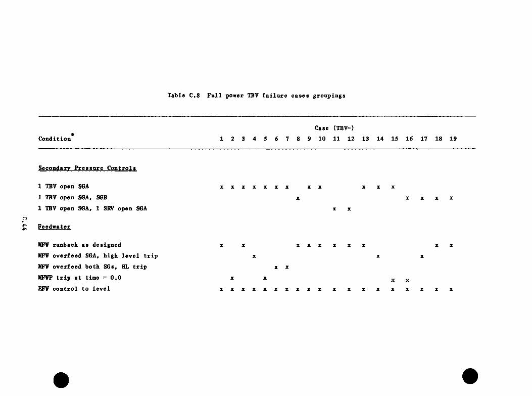
Table C.S F u l l power TBV f a i l u r e c a se s g ro u p in g s
C o n d itio n
Case (TBV-)
1 2 3 4 5 6 7 8 9 10 11 12 13 14 15 16 17 18 19
Secondary P re s s u re C o n tro ls
1 TBV open SGA
1 IBV open SGA, SGB
1 IBV open SGA, 1 SRV open SGA
X X Z Z X X Z X X
X
X X XX X X X
MFW runback as d esig n ed
MFW o v e rfee d SGA, h ig h le v e l t r i p
MFW o v e rfee d b o th SGs, HL t r i p
MFWP t r i p a t tim e = 0 ,0
EFW c o n tro l to le v e l
X X X X X X X X X X
X X
X X
X X X X X X X X X X X X X X X X X X X
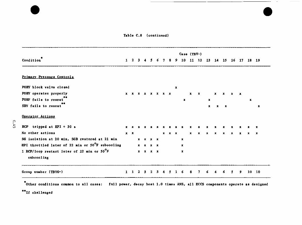
T able C.8 (c o n tin u e d )
oLn
Case (TBV-)*
C o n d itio n 1 2 3 4 5 6 7 8 9 1 0 1 1 1 2 13 14 15 16 17 18 19
P rim ary P re s s u re C o n tro ls
PORV b lo c k v a lv e c lo se d X
PORV o p e ra te s p ro p e r ly X X X X X X X X X X X X X Xee
PORF f a i l s to r e s e a t X X Xee
SRV f a i l s to r e s e a t X X X X
O o era to r A c tio n s
RCP t r ip p e d a t HPI + 30 s X X X X X X X X X X X X X X X X X X X
No o th e r a c t io n s X X X X X X X X X X X X X X
SG i s o l a t i o n a t 20 m in, SGB re s to r e d a t 2 1 min X X X X X
HPI t h r o t t l e d l a t e r o f 22 min o r 50°F su b co o lin g X X X X X
1 RCP/loop r e s t a r t l a t e r o f 22 min o r 50°F X X X X X
su b co o lin g
Group number (IBVG—) 1 1 2 3 2 3 4 5 1 6 8 7 6 4 6 5 9 1 0 1 0
O tber c o n d it io n s common to a l l c a s e s : f u l l pow er, decay b e a t 1 .0 tim es ANS, a l l ECCS com ponents o p e ra te as d esig n ed
I f ch a lle n g ed
c . 4 . 1.3 A p p lic a b le Data froai O ther Cases
E a r ly b e h a v io r of system w ith MFW t r i p a t time = 0 .0 i s a v a i l a b l e from
LANL Rancho S eco -type t r a n s i e n t . The LANL and INEL c a se s on PORV f a i l u r e s
and PORV-sized h o t le g LOCAs a re o f some l i m i t e d use f o r the s tudy cases
in c lu d in g such f a i l u r e . The l i m i t a t i o n s stem from u a t e i r - s o l id c o n d i t io n s
i n the s tudy c a se s compared t o normal p r e s s u r i z e r c o n d i t io n s a t the s t a r t
o f th e LANL and INEL c a s e s .
C .4 .1 .4 E x t r a p o la t i o n A ssumptions
a . T em perature
One-Loop TBV F a i l u r e — A p p l ic a t io n o f the cooldown model to a one loop
TBV f a i l u r e r e q u i r e s knowledge o f n a t u r a l c i r c u l a t i o n and v e n t v a lv e flow
r a t e s and o f th e e f f e c t s o f HPI i n j e c t i o n on s ta g n a te d loop co ld leg
te m p e ra tu r e . LANL cases 5A and 5B were examined w i th re g a rd to th e se
r e q u i r e m e n ts . The r e s u l t i n g d a ta and assum ptions a r e : ( 1 ) . Loop A n a t u r a l
c i r c u l a t i o n rem ains s tead y a t about 1023 l b / s from 400 s u n t i l 1500 s
and i s assumed t o co n t in u e u n t i l 7200 s . Loop B s t a g n a te s a t about 600
s and i s assumed to rem ain so u n t i l 7200 s . The s t a g n a t io n of loop B
i s due to SGBs be ing warmer than th e p r im ary . The d e n s i t y d i f f e r e n c e s
and c o r re sp o n d in g buoyancy e f f e c t s from h ig h e r loop te m p e ra tu re c a n c e l the
f o r c e s in th e v e s s e l t h a t would d r iv e c i r c u l a t i o n in th e loop . ( 2 ) . Vent
va lve mass flow r a t e s co r resp o n d in g to 264 I b / s (120 k g / s ) commence a t 600
s and h o ld s te a d y th rough 1500 s and a r e assumed to c o n t in u e to 7200 s
( v a l i d a s long as SGB rem ains s t a g n a n t ) . ( 3 ) . U n th r o t t l e d HPI f low s t o t a l
40 I b / s (18 K g/s) in loop A and 30 I b / s (14 k g / s ) in loop B a t th e PORV s e t
C.46

p o in t p r e s s u r e (2450 p s i a ) . Loop A HPI flow th o ro u g h ly mixes i n the co ld
l e g . Loop B HPI i s n o t mixed because o f s t a g n a t io n . At 1500 s th e tem
p e r a t u r e i s 134®F a t the loop B HPI i n j e c t i o n p o in t s and 207°F a t th e loop
B c o ld le g n o z z le s a t the v e s s e l . Both te m p era tu re s a re d e c l in in g a t a
r a t e o f 0 .23 ° F /s because c o n t in u e d HPI flow mixing w ith the c o o la n t in th e
c o ld l e g s , the g ra d u a l d isp la cem e n t o f w a te r from th e co ld l e g s , and f l u i d
h e a t in g by the p ip e w a l l s o f th e co ld l e g s . I f th e se t re n d s c o n t in u e , 50°p
( i . e . , the HPI i n j e c t i o n te m p e ra tu re ) w a te r would be enco u n te red a t 1860 s
and 2175 s a t th e se r e s p e c t iv e l o c a t i o n s o f loop B. ( 4 ) . The tu rb in e
bypass v a lv e a re a of 0 .1 6 f t as ta k e n from the LANL model was ha lv ed in
the c a l c u l a t i o n s to s im u la te f a i l u r e o f o n ly one TBV in th e bank. ( 5 ) . In
some c a s e s , a q u a s i - s t a t i c te m p e ra tu re was c a l c u l a t e d a t 1500 s to p ro v id e
a p o in t f o r l i n e a r e x t r a p o l a t i o n to a r e g io n where the cooldown model cou ld
be e a s i l y a p p l i e d . The q u a s i - s t a t i c te m p e ra tu re c a l c u l a t i o n assumes t h a t
the energy lo s s r a t e in th e steam le a v in g th e s tuck -open TBV eq u a ls the
decay h e a t r a t e . A un ique steam g e n e r a to r tem p era tu re i s o b ta in e d f o r t h i s
q u a s i - s t a t i c ene rgy b a la n c e . The downcomer te m p era tu re i s o b ta in e d from a
m ixing c a l c u l a t i o n c o n s id e r in g t h i s steam g e n e ra to r c o n d i t io n and HPI and
v e n t v a lv e flow r a t e s and te m p e ra tu re s .
Two-Loop TBV F a i l u r e — To app ly the cooldown model to the tw o-loop TBV
f a i l u r e , th e fo l lo w in g in fo rm a t io n from LANL case 6A, 6B and assum ptions
a re r e q u i r e d : ( 1 ) . Balanced loop n a t u r a l c i r c u l a t i o n f low s o f 842 l b / s fo r
each loop a re assumed to p e r s i s t to 7200 s . ( 2 ) . Vent v a lv e v e l o c i t i e s
a f t e r 250 s approach v a lu e s c o r re sp o n d in g to 44 I b / s (20 k g / s ) . I t i s
assumed t h a t t h i s v a lue h o ld s to 7200s. ( 3 ) . D n th ro t t l e d HPI flow s t o t a l
40 I b / s (18 k g /s ) in loop A and 30 I b / s (14 k g /s ) in loop B a t th e PORV s e t
C.47
p o in t p r e s s u r e . ( 4 ) . The tu r b in e bypass v a lve a re a of 0.16 f t from
th e LANL model vas h a lv e d in th e c a l c u l a t i o n s to s im u la te f a i l u r e of only
one TBV p e r loop . ( 5 ) . Where a p p l i c a b l e , th e q u a s i - s t a t i c te m p era tu re
(a s d is c u s s e d above) i s used f o r e x t r a p o l a t i o n o f th e i n i t i a l 1500 s of
a sequence .
b . P r e s s u re
P r e s s u r e i s de te rm ined on a c a s e -b y -c a se b a s i s and w i l l depend on i n t i a l
cooldown mechanism. R e p r e s s u r i z a t io n r a t e s observed in LANL c a se s 5A, 5B,
and SC and 6A, 6B. and 60 a re a p p l ie d as e n g in e e r in g judgment s u g g e s ts .
c . Heat T r a n s f e r C o e f f i c i e n t
Heat t r a n s f e r c o e f f i c i e n t s a r e p r i m a r i l y a f u n c t io n o f f l u i d v e l o c i t y . Four
reg im es e x i t i n th e s tudy c a s e s : fo u r RCPs o p e r a t in g , n a t u r a l c i r c u l a t i o n
(tw o - lo o p IBV f a i l u r e ) , n a t u r a l c i r c u l a t i o n w ith one loop s ta g n a n t (one-
loop IBV f a i l u r e ) , and two RCPs (one p e r loop) o p e r a t in g . LANL e s t ia ia te d
2 2 oh e a t t r a n s f e r c o e f f i c i e n t s o f 16000 W/m K (2820 B tu /h f t F) f o r fo u r -
RCP o p e r a t io n , 1200 W/m^K (210 B tu /h f t^ ° F ) f o r b o th n a t u r a l c i r c u l a t i o nfy
c a s e s , and 7500 W/m E (1320 B tu /h f t F) f o r the v e s s e l c e l l s r e c e iv in g
f u l l flow ( a l s o th e c o o l e s t w a te r) from the o p e ra t in g RCP in 1 RCP/loop
o p e r a t io n . These v a lu e s a re a p p l ie d as th e t r a n s i e n t sequence d i c t a t e s .
C.48
c . 4 . 2 Group 1 — Cases TBVl, TBV2, and TBV9
a. Tem perature
PIS concerns w i l l be most e v id e n t l a t e in th e se t r a n s i e n t s . Main
feed w ate r d i s tu r b a n c e s e a r l y in th e se sequences w i l l no t g r e a t l y in f lu e n c e
f i n a l te m p e ra tu re a l th o u g h e a r l y cooldown s lo p e s w i l l be d i f f e r e n t . The
te m p era tu re curve ( f i l e TBVGl.T) was c o n s t r u c te d u s in g the f i r s t 60 s of
LANL case 5B ( v a l i d to t h a t p o i n t ) , s t r a i g h t - l i n e e x t r a p o la t io n to the
q u a s i - s t a t i c te m p e ra tu re o f 366^F a t 1500 s , and fo llow ed by e x t r a p o la t i n g
w i th th e cooldown model t o 297°F a t 7200 s ( see Table C.9 and F ig u re C .9 ) .
Because of s ta g n a te d c o n d i t io n s in loop B, lo c a l tem p era tu res may be
d e p re s se d because o f th e absence of o th e r flow to mix w ith HPI. This
e f f e c t was e s t im a te d u s in g d a ta from th e cooldown model to c a l c u l a t e the
te m p era tu re o b ta in e d from mixing th e loop B HPI flow (30 I b / s ) and one-
h a l f of the t o t a l v en t v a lv e flow (132 I b / s ) . A minimum te m p era tu re of
270^F was o b ta in e d a t 7200 s . T h is minimum should be reexamined should
v en t v a lv e flow be red u ce d , as much low er te m p era tu re s would r e s u l t (see
Table C.IO and F ig u re C.IO)
b . P r e s s u re
P re s s u re was ta k en to fo l lo w the same p r o f i l e as LANL case 5B. T h is i s
c o n s e r v a t iv e , s in c e th e low er cooldown r a t e s w i l l ex tend th e p e r io d o f time
b e fo re HPI comes on and reduce th e time f o r HPI to re c o v e r system p re s s u re
to th e PORV s e t p o i n t , 2430 p s i . As modeled, th e p r e s s u r e drops to 1500
p s i a a t 150 s and rem ains t h e r e u n t i l 320 s , a f t e r which th e p r e s s u re
r i s e s t o i t s f i n a l v a lu e , 2430 p s i a t 975 s . Case IBV9 w i l l e x h ib i t
C.49

Table C.9 Nominal P, T, and b profiles for 16V group 1
TBVGl • T TBVGl .P TBVGl .b
Time(s) T(F) Time(s) P (p s ia ) Time(s) H(Btu/b)(f t**2F )
0 .0 555 .0 0 .0 2180.0 0 .0 2820.05 .0 572.0 60 .0 1740.0 183.0 2820.0
60 .0 552.0 150.0 1500.0 233.0 210.01500.0 366 .0 320.0 1500.0 7200.0 210.02500.0 352.6 710.0 2000.03500.0 339 .8 975.0 2430.04500.0 327 .6 7200.0 2430.05500.0 315 .86500.0 304.67200.0 297 .0
C.50
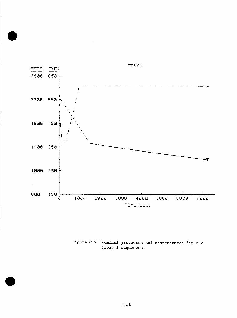
p s r f t T C F )TBVGt
2 6 0 0
2200
1 8 0 0
1 4 0 0
1 0 0 0
6 0 00 1 0 0 0 2 0 0 0 5 0 0 0 7 0 0 0
T I M E ( S E C )
F i g u r e C.9 N o m i n a l p r e s s u r e s and t e m p e r a t u r e s f o r TBVg r o u p 1 s e q u e n c e s .
C .51

Table C.IO P, T, and b profiles for stagnated loop sideof TBV group 1 sequences
TBVGIA .T TBVGIA .P TBVGIA .b
Time(s) T(F) Time(s) P (p s ia ) Time(s) H(Btu/b)(f t* * 2 F )
0 .0 555.0 0 .0 2180.0 0 .0 2820.05 .0 572.0 6 0 .0 1740.0 183.0 2820.0
6 0 .0 552 .0 150.0 1500.0 233 .0 210 .01500.0 366 .0 320.0 1500.0 7200.0 210.02500.0 346.5 710.0 2000.03500.0 328.3 975.0 2430.04500.0 311.2 7200.0 2430.05500.0 295.16500.0 280 .07200.0 270 .0
€.52

PSIF^ T C F )T B V G m
2 S 0 0 6 5 0
2 2 0 0 5 5 0
1 4 0 0 3 5 0
1 0 0 0 2 5 0
6 0 0 150.0 1000 20 00 4 0 0 0 7 0 0 0
TIMECSEC)
F i g u r e C.IO P r e s s u r e s and t e m p e r a t u r e s f o r s t a g n a t e d l o o ps i d e o f TBV g r o u p 1 s e q u e n c e s .
C .5 3
s l i g h t l y d i f f e r e n t b e h a v io r because o f PORV b lo c h v a lv e c l o s u r e . A f i n a l
p r e s s u r e o f 2500 p s i i s a t t a i n e d a t 1025 s when th e s a f e t y r e l i e f v a lv e s
a r e a c tu a te d . Note t h a t the h ig h e r p r e s s u r e would reduce HPI flow and
cooldown because o f t h a t flow (s e e T ab les C.9 and € .1 0 and F ig u re s C.9 and
C .IO ) .
o . Heat T r a n s f e r C o e f f i c i e n t
The h e a t t r a n s f e r c o e f f i c i e n t i s 2820 B tu /h f t F u n t i l th e RCPs t r i p a t2 ft
183 s . The c o e f f i c i e n t th e n d rops a t 210 B tu /h f t F f o r th e rem ainder
o f th e t r a n s i e n t ( s e e T ab les C.9 and C.IO)
C .4 .3 GROUP 2 — Cases TBV3 and TBV5
a . Tem perature
T h is group i s ta k e n to be i d e n t i c a l to TBVGl up th rough 22 min (1320 s)
when one RCP/loop i s r e s t a r t e d . SGB w i l l supp ly h e a t to the p r im ary to
r a i s e the downcomer te m p e ra tu re by an average o f lO^’P. Tem perature w i l l
l i n e a r l y d e c re a se to 328°F a t 2500 s as th e 6 0 ,0 0 0 - lb w a te r in v e n to ry in
SGA d r i e s o u t . Steam flow r e s t r i c t i o n may in c re a s e the d ry o u t p e r io d bu t
would a l s o r e s u l t in h ig h e r f i n a l te m p e ra tu r e s . A f te r steam g e n e r a to r A
d r y o u t , th e system w i l l r e h e a t a t 0 .0 4 8 9 ^ F /s t o re a c h 547^F a t 6980 s , and
i t would be l i m i t e d a t t h a t p o in t by au to m atic a c t i o n o f th e TBVs in steam
g e n e ra to r B ( s e e Table C . l l and F ig u re C . l l ) .
C.54

b . P re s sn re
Tbe p r e s s u r e curve of TBV group 1 (F ig u re C.9) was used to 1320 s . System
sh r in k ag e due to in c re a s e d h e a t t r a n s f e r caused p r e s s u r e d ec re ase on the
o rd e r of 500 p s i a t th e s t a r t u p of the RCPs in LANL case SC. F u r th e r
d rops were c o n t r o l l e d by HPI i n j e c t i o n . S im i la r b e h a v io r i s assumed h e re ,
r e s u l t i n g in a p r e s s u r e change from 2430 p s i a t 1320 s to 1930 p s i a t
1450 s t h a t w i l l c o n t in u e a t t h i s va lue u n t i l SGA dryou t a t 2500 s . Then
p r e s s u r e i s assumed to in c re a s e a t 0 .34 p s i / s (ob se rv ed va lue in LANL MSLB
base case) because of system r e h e a t in g u n t i l reac h in g PORV s e t p o in t 2430
p s i a t 3950 s ( s e e Table C . l l and F ig u re C . l l ) .
c . Heat T r a n s f e r C o e f f i c i e n t
H eat t r a n s f e r i s th e same as fo r TBV group 1 t o 1320 s . With 1 RCP/loop
2 Aflow e s t a b l i s h e d , th e h e a t t r a n s f e r c o e f f i c i e n t becomes 1320 B tu /h f t F
th rough the rem ainder o f th e t r a n s i e n t ( s e e Table C . l l )
C .4 .4 Group 3 — Cases TBV4 and TBV6
a. Tem perature
The m assive HFW o v e r fe e d s in th e se s c e n a r io s w i l l cause the t r a n s i e n t s to
c l o s e l y resem ble LANL c a se s 5A and 5B to 1320 s (372°F) when 1 RCP/loop
i s r e s t a r t e d a f t e r fee d w a te r i s o l a t i o n . A w a te r in v e n to ry of 140.000 lb
i s p r e d i c t e d by LANL c a se s 5A and 5B a t t h i s p o in t in the t r a n s i e n t . The
te m p e ra tu re would th e n d e c re a se to 407°F a t 3520 s when the 1 4 0 ,0 0 0 - lb
w a te r in v e n to ry of SGA i s f i n a l l y e x h au s te d . The system w i l l th en r e h e a t
a t 0 .0 4 8 9 ^F /sec u n t i l re a c h in g 547^F a t 6380 s . Steam v e n t in g by the
C.55

Table C.ll P, T, and h profiles for TBV group 2 sequences
TBVG2 .T TBVG2 .? TBVG2 .b
Tiaie(s) T(F) Tis>e( s) P ( p s i a ) Time(s) H (Btu/b)( f t* * 2 F )
0 .0 555.0 0 .0 2180.0 0 .0 2820.05 .0 572.0 60 .0 1740.0 183.0 2820.0
6 0 .0 552.0 150.0 1500.0 233 .0 210 .01320.0 389.3 320.0 1500.0 1320.0 210 .01321.0 409.3 710.0 2000.0 1321.0 1320.02500.0 328 .0 975.0 2430.0 7200.0 1320.069 80.0 547.0 1320.0 2430.07200.0 547.0 1450.0 1930.0
2500.0 1930.03950.0 2430.07200.0 2430.0
C.56

PSIf l T ( F)TBVG2
6 0 0 £50.
1 4 0 0 3 5 0
1 0 0 0 2 5 0
6 0 0 1500 1000 3 0 0 0 5 0 0 0 7 0 0 0
TIMECSEC)
F i g u r e C . l l P r e s s u r e s an d t e m p e r a t u r e s f o r TBV g r o u p 2 s e q u e n c e s .
C.57

SGB tu r b i n e bypass v a lv e s w i l l keep tb e system a t t b i s te m p e ra tu re f o r tbe
rem ainder o f tb e t r a n s i e n t ( see Table C.12 and F ig u re C .1 2 ) .
b . P r e s s u re
Tbe p r e s s u r e w i l l fo l low a s i m i l a r t r e n d as t b a t of TBV group 2 excep t
t b a t r e p r e s s u r i z a t i o n a f t e r RCP s t a r t u p w i l l be de layed to 3520 s and f i n a l
system p r e s s u r e , 2430 p s i , i s r e g a in e d a t 4970 s (see Table C.12 and F ig u re
C .1 2 ) .
c . Heat T r a n s f e r C o e f f i c i e n t
T bis case i s e x a c t ly tbe same as TBV group 2 ( s e e Table C12).
C .4 .5 Group 4 — Case TBV7
a. T em perature
Because of tb e m assive o v e rfeed o f co o l w a te r to bo tb SGs, s a t u r a t e d b e a t
t r a n s f e r c o n d i t io n s a re no t expec ted and tb e case w i l l c l o s e l y resem ble
LANL case 5A, wbicb i s dominated by a s u s t a in e d main and emergency feedw ater
o v e r fe e d tb ro u g b mucb of tb e sequence . Tbe LANL-supplied v a lu e s f o r LANL
case 5A, in c lu d in g e x t r a p o l a t i o n to 7200 s , were a p p l ie d to t b i s case (see
Table C.13 and F ig u re C .1 3 ) .
I f tb e HW/CB pump system does n o t s u s t a i n flow to tbe d e p r e s s u r iz e d SGA,
tbe open TBV would in s t e a d c o n t r o l tb e cooldown r a t e . However, b ig b e r
te m p e ra tu re s ( t . = 300^F a t 7200 s) would r e s u l t ,min
C.58
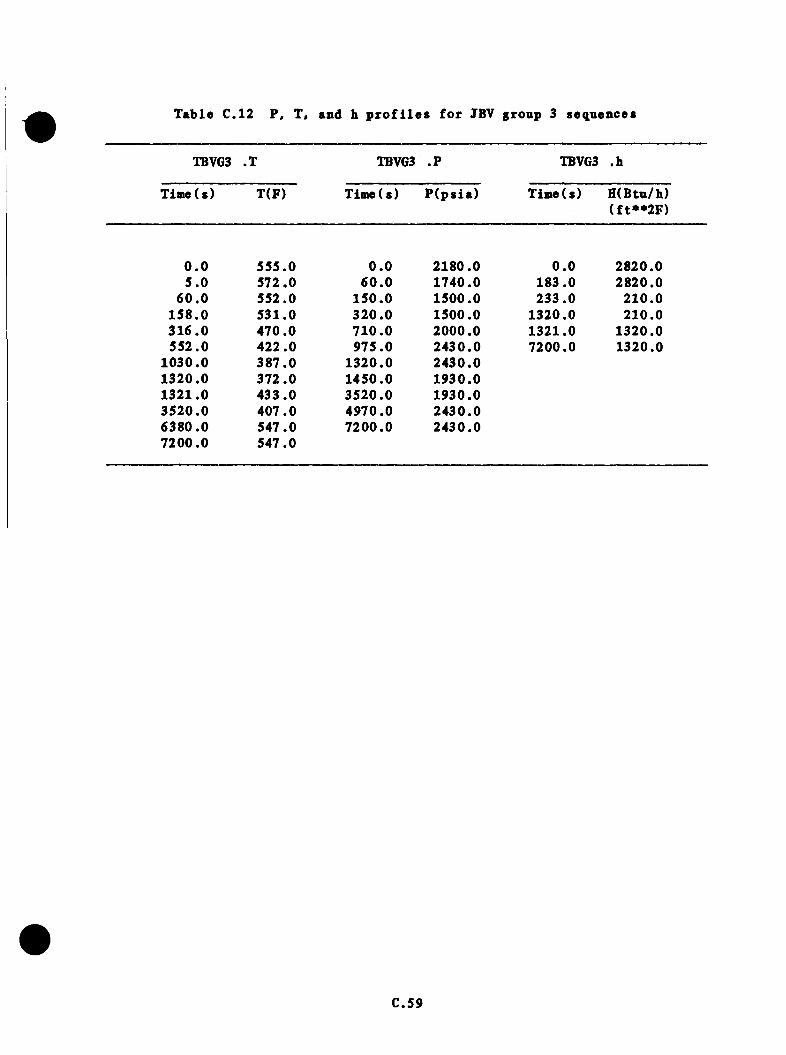
# Table C.12 P, T, and b profiles for JBV group 3 sequences
TBVG3 .T TBVG3 .? TBVG3 .h
Time( s ) T(F) Tim e(s) P (p s ia ) Time(s) H( B tu /h ) (f t**2F )
0 .0 555.0 0 .0 2180.0 0 .0 2820.05 .0 572.0 60 .0 1740.0 183.0 2820.0
6 0 .0 552.0 150.0 1500.0 233.0 210.0158 .0 531.0 320 .0 1500.0 1320.0 210.0316 .0 470.0 710 .0 2000.0 1321.0 1320.0552.0 422 .0 975.0 2430.0 7200.0 1320.0
1030.0 387 .0 1320.0 2430.01320.0 372.0 1450.0 1930.01321.0 433.0 3520.0 1930.03520.0 407.0 4970.0 2430.06380.0 547.0 7200.0 2430.07200.0 547.0
C.59

P S I f t T ( F )TBVG3
2 6 0 0
2200
1 8 0 0
1 4 0 0
1000
6 0 06 0 0 0 7 0 0 00 1000 4 0 0 0
T I M E (S E C )
F i g u r e C.12 P r e s s u r e s and t e m p e r a t u r e s f o r TBV group 3 s e q u e n c e s .
C.60
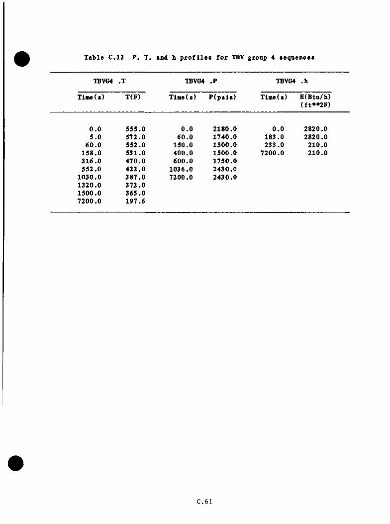
Table C.13 P, T, and h profiles for TBV group 4 sequences
TBVG4 .T TBVG4 .? TBVG4 .b
Time(s) T(F) Time(s) P (p s ia ) Time(s) H(Btu/h)(f t**2F )
0 .0 555.0 0 .0 2180.0 0 .0 2820.05 .0 572.0 60 .0 1740.0 183.0 2820.0
60 .0 552.0 150.0 1500.0 233.0 210.0158 .0 531.0 400.0 1500.0 7200.0 210.0316 .0 470 .0 600 .0 1750.0552.0 422 .0 1036.0 2430.0
1030.0 387 .0 7200.0 2430.01320.0 372 .01500.0 365 .07200.0 197.6
C.6 1

P S I f t TCP)TBVG4
5 6 0 0
2200
1 8 0 0
1 4 0 0
1000
6 0 05 0 0 0 7 0 0 00 1000 2000 4 0 0 0 6 0 0 0
TIMECSEC)
F i g u r e C .1 3 P r e s s u r e s an d t e m p e r a t u r e s f o r TBV g r o u p 4 s e q u e n c e s .
C .62

b . P r e s s a r e
LANL case SA as e x t r a p o la t e d was used f o r t b i s case ( see Table C.13 and
F ig u re C .1 3 ) .
c . Heat T r a n s f e r C o e f f i c i e n t
This case i s i d e n t i c a l t o TBV group 1 ( s e e Table C .13 ) .
C .4 .6 Group 5 — Cases TBV8 and TBV16
a . T em perature
Group 5 fo l lo w s LANL c a se s 6A, 6B, and 6C th rough the f i r s t 60 s .
A f te rw a rd s , s t r a i g h t - l i n e e x t r a p o l a t i o n i s fo llow ed a t the q u a s i - s t a t i c
te m p e ra tu re o f 320°F a t 1500 s . The cooldown model i s fo llow ed to 265°F
a t 7200 8. N e i th e r loop s t a g n a t e s , so HPI mixing i s n o t seen as a problem
(s e e Table C.14 and F ig u re C.14)
b . P r e s s u r e
The p r e s s u r e i s assumed to drop to 1000 p s i a a t 200 s where HPI l i m i t s
f u r t h e r r e d u c t io n s . P r e s s u re rem ains f l a t ou t to 500 s and th e n in c re a s e s
to th e PORV s e t p o in t (2430 p s i a ) a t 1175 s . P r e s s u re rem ains a t PORV
l i m i t f o r th e rem ainder o f th e sequence ( s e e Table C.14 and F ig u re C .14 ) .
c . Heat T r a n s f e r C o e f f i c i e n t
No d i s t i n c t i o n i s made between th e one- lo o p TBV f a i l u r e s and the tw o-loop
TBV f a i l u r e s . T h e re fo re , t h i s case i s i d e n t i c a l to TBV group 1 ( se e Table
C .1 4 ) .
C.63

Table C.14 P, T, and b profiles for TBV gronp 5 sequences
TBVG5 .T TBVG5 .? TBVG5 .b
Tiaie(s) T(F) Time(s) P (p s ia ) T in e ( s ) H(Btn/b)(f t* * 2 F )
0 .0 555.0 0 .0 2180.0 0 .0 2820.05 .0 572.0 200.0 1000.0 183.0 2820.0
6 0 .0 552.0 500.0 1000.0 233 .0 210 .01500.0 320.0 1175.0 2430.0 7200.0 210.02500.0 309.4 7200.0 2430.03500.0 299.34500.0 289.55500.0 280.16500.0 271.07200.0 265.0
C .6 4
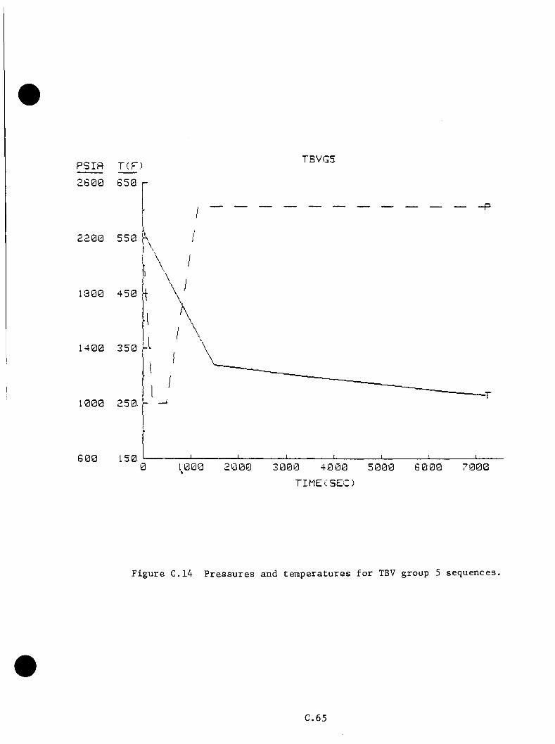
TBVG5
2 6 0 0
£200
1 8 0 0
1 4 0 0
1000
6 0 0 0 1000 2000 7 0 0 03 0 0 0 6 0 005 0 0 0
T I M E ( S E C )
F i g u r e C.14 P r e s s u r e s and t e m p e r a t u r e s f o r TBV group 5 s e q u e n c e s .
C .6 5
C.4.7 Group 6 -- Cases TBVIO, TBV13, and TBV15
a . T e n p e ra tu re
Tbese ca se s a re s i m i l a r to TBV group 1 to 975 s when the PORV a c tu a te s
and s t i c k s open. (TBV13 s p e c i f i e s f a i l u r e o f the PORV and a s a f e ty
r e l i e f v a lv e to c l o s e . Houever, th e SRV would n ever be c h a l le n g e d and
i s t h e r e f o r e no t assumed to f a i l . ) HPI flow in c re a s e s because o f reduced
p r im ary p r e s s u r e . The in c re a s e in flow w i l l cause HPI flow to dominate
o v e r steam flow th rough the open TBV as th e main h e a t removal mechanism
l a t e in th e sequence . Based on lo o p , HPI, and v en t v a lv e f low s from the
LANL PORV-LDCA case 2A and TBV a re a and c o n d i t io n s d e s c r ib e d in S e c t io n
C .4 , a minimum te m p era tu re of 257°F was o b ta in e d a t 7200 s u s in g the
cooldown model ( s e e Table C.15 and F ig u re € .1 5 ) .
b . P r e s s u r e
T h is group i s s i m i l a r to TBV group 1 to 975 s when the PORV i s f i r s t
a c t u a t e d . The p r e s s u r i z e r i s l i q u i d - s o l i d a t t h i s p o in t . F a i l u r e of
th e PORV to c lo se r e s u l t s in w a te r flow th rough the v a lve and a drop in
p r e s s u r e , which prom otes more flow . The p r e s s u r e d e c re a se s and th e flow
in c re a s e s u n t i l an e q u i l ib r iu m i s s t r u c k between PORV flow r e s i s t a n c e and
HPI head c a p a c i t y c h a r a c t e r i s t i c s . T h is e q u i l ib r iu m p o in t i s a t a system
p r e s s u r e o f 1670 p s i a , as o b ta in e d from LANL case 2A. No v o id in g i s
ex p ec ted as a r e s u l t o f t h i s d e p r e s s u r i z a t i o n . The system re a c h e s t h i s
f i n a l p r e s s u r e q u ic k ly (assume 25 s) and rem ains th e r e f o r th e r e s t o f the
t r a n s i e n t ( s e e T ab le € .15 and F ig u re € .1 5 ) .
€.66
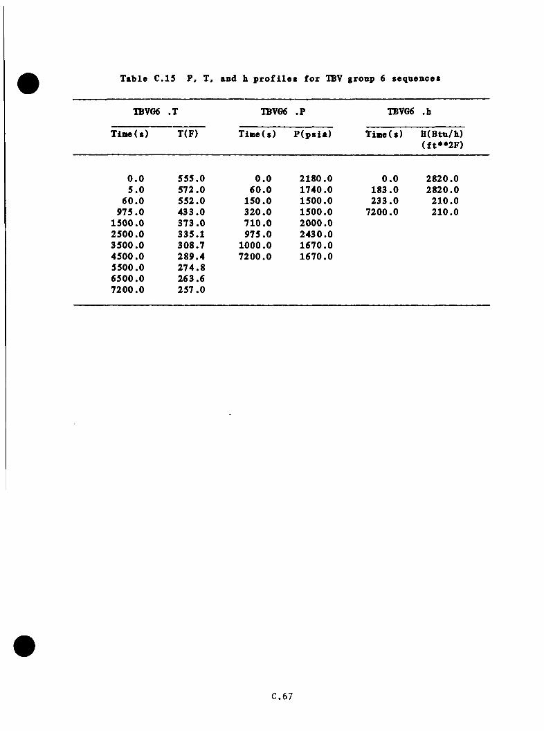
Table C.15 P, T, and b profiles for TBV gronp 6 sequences
IBVG6 .T IBVG6 .? TBVG6 .h
Tim e(s) T(F) Tiaie(s) P ( p s i a ) Tiaie( s) H( B tu /h ) ( f t**2F )
0 .0 555.0 0 .0 2180.0 0 .0 2820.05 .0 572.0 60 .0 1740.0 183.0 2820.0
6 0 .0 552.0 150.0 1500.0 233 .0 210.0975 .0 433.0 320.0 1500.0 7200.0 210.0
1500.0 373 .0 710 .0 2000.02500.0 335.1 975.0 2430.03500.0 308.7 1000.0 1670.04500.0 289.4 7200.0 1670.05500.0 274 .86500.0 263.67200.0 257 .0
C.67
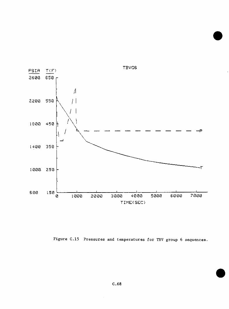
PSIf l TCP)TBVGS
2 8 0 0
2200
1 8 0 0
1 4 0 0
1000
6 0 07 0 0 06 0 0 05 0 0 03 0 0 010000
T I M E ( S E C )
F i g u r e C .15 P r e s s u r e s a n d t e m p e r a t u r e s f o r TBV g r o u p 6 s e q u e n c e s ,
C .6 8
c . Heat T r a n s f e r C o e f f i c i e n t
T h is gronp i s i d e n t i c a l to f i l e TBV gronp 1 ( se e Table € .1 5 ) .
C .4 .8 Gronp 7 — Case TBV12
a. T esiperatnre
The coa ib ina tion o f a s in g l e TBV f a i l n r e and a s in g le steam s a f e ty r e l i e f
v a lv e on loop A makes gronp 7 s i m i l a r to a TBV bank f a i l n r e , as in LANL
cases SA, SB, and SC. However, th e p ro p e r o p e r a t io n o f the NFV system
von ld p re c ln d e th e sev e re o v e r fe e d in g l a t e in LANL cases SA, SB, and SC.
T h e re fo re , cooldown r a t e s c a l c n l a t e d from the expanded cooldown model were
nsed t o p r e d i c t th e system re s p o n s e . LANL case SA was nsed to 60 s (SS2°F).
E x t r a p o la t i o n by the cooldown model y ie ld e d a minimnm te m p era tn re of 272°F
a t 7200 s . T h is te m p e ra tn re re sp o n se i s v e ry s im i l a r to t h a t o f TBV gronp
S, which f e a t n r e s th e same t o t a l b re a k a re a a p p o r t io n e d between b o th lo o p s .
The main d i f f e r e n c e s betw een th e two gronps a re dne to d i f f e r e n t loop flow
and v e n t v a lv e flow r a t e s ( s e e Table C.16 and F ig n re C .1 6 ) .
b . P r e s s n r e
The gronp i s ta k e n to be i d e n t i c a l to TBV gronp 1 ( s e e Table C.16 and
F ig n re C .1 6 ) .
c . Heat T r a n s f e r C o e f f i c i e n t
The gronp i s ta k e n to be i d e n t i c a l to TBV gronp 1 ( se e Table C .16 ) .
C.69

Table C.16 P, T, and b profiles for TBV gronp 7 sequences
TBVG7N ,T 1BVG7N.P TBVG7N.h
T io e ( s ) T(F) Tiaie(s) P ( p s i a ) Tim e(s) H (Btu/h)( f t* * 2 F )
0 .0 555.0 0 .0 2180.0 0 .0 2820.05 .0 572.0 60 .0 1740.0 183.0 2820.0
6 0 .0 552.0 150.0 1500.0 233.0 210.0400 .0 392 .9 320 .0 1500.0 7200.0 210.0500.0 386.2 710.0 2000.0600 .0 380 .0 975.0 2430.0700 .0 376.5 7200.0 2430.0800.0 371 .4900 .0 368.3
1000.0 364 .81500.0 353 .92500 .0 330.03500.0 311.54500.0 297.25500.0 286 .06500 .0 277.27200.0 272.2
C .7 0

PSri=f T ( F )TBVG7N
as 00
2200
1 8 0 0
1 4 0 0
1000
S 0 0 0 2000 3 0 0 0 7 0 0 05 0 0 0
T I M E (S E C )
F i g u r e C .1 6 P r e s s u r e s an d t e m p e r a t u r e s f o r TBV g r o u p 7 s e q u e n c e s .
C .7 1
c . 4 .9 Group 8 — Case TBVll
a . Tem perature
T h is group d i f f e r s from IBV group 7 in t h a t th e fe e d w a te r i s i s o l a t e d a t
20 min and 1 RCP/loop i s r e s t a r t e d a t 22 min (1320 s ) . T h e re fo re , the
case u se s th e e x t r a p o l a t i o n f o r IBV group 7 ou t t o 1320 s . The r e s t a r t
o f th e RCPs cau ses m ixing o f ho t w a te r from SGB w ith th e o th e r w a te r in the
system to r a i s e th e downcomer te m p era tu re to 433°F. Flow choking l i m i t s
th e steam lo s s r a t e in SGA to about 100 I b / s . SGA d ry o u t i s accom plished
a t 1820 s , a t which time system te m p e ra tu re i s 423°F , th e l e v e l n e c e ssa ry
to m a in ta in th e steam lo s s r a t e in SGA. A f te r SGA d ry o u t , th e system
r e h e a t s a t 0.0489*^F/s t o re a c h 547°F a t 4360 s , where i t rem ains f o r the
r e s t o f the sequence (s e e Table C.17 and F ig u re C .1 7 ) .
b . P r e s s u re
This case i s ta k e n to be i d e n t i c a l t o TBV group 3 t o 1450 s . The p r e s s u re
to t h i s p o in t has f a l l e n from 2180 to 1500 p s i a a t 150 s , r i s e n to 2430
p s i a a t 975 s , and dropped to 1930 p s i a a t 1450 s because of mixing of
h o t and coo l l i q u i d s in th e p r im ary a f t e r RCP s t a r t u p . The p r e s s u r e i s
assumed c o n s ta n t t o 1820 s and th e n in c r e a s e s a t 0 .3446 p s i / s to 2430 p s i a
a t 3270 s , where i t rem ains f o r th e r e s t of th e sequence ( see Table C.17
and F ig u re C .1 7 ) .
c . Heat T ra n s f e r C o e f f i c i e n t
T h is group i s ta k e n to be i d e n t i c a l to TBV group 2 ( s e e Table C .1 7 ) .
C.72
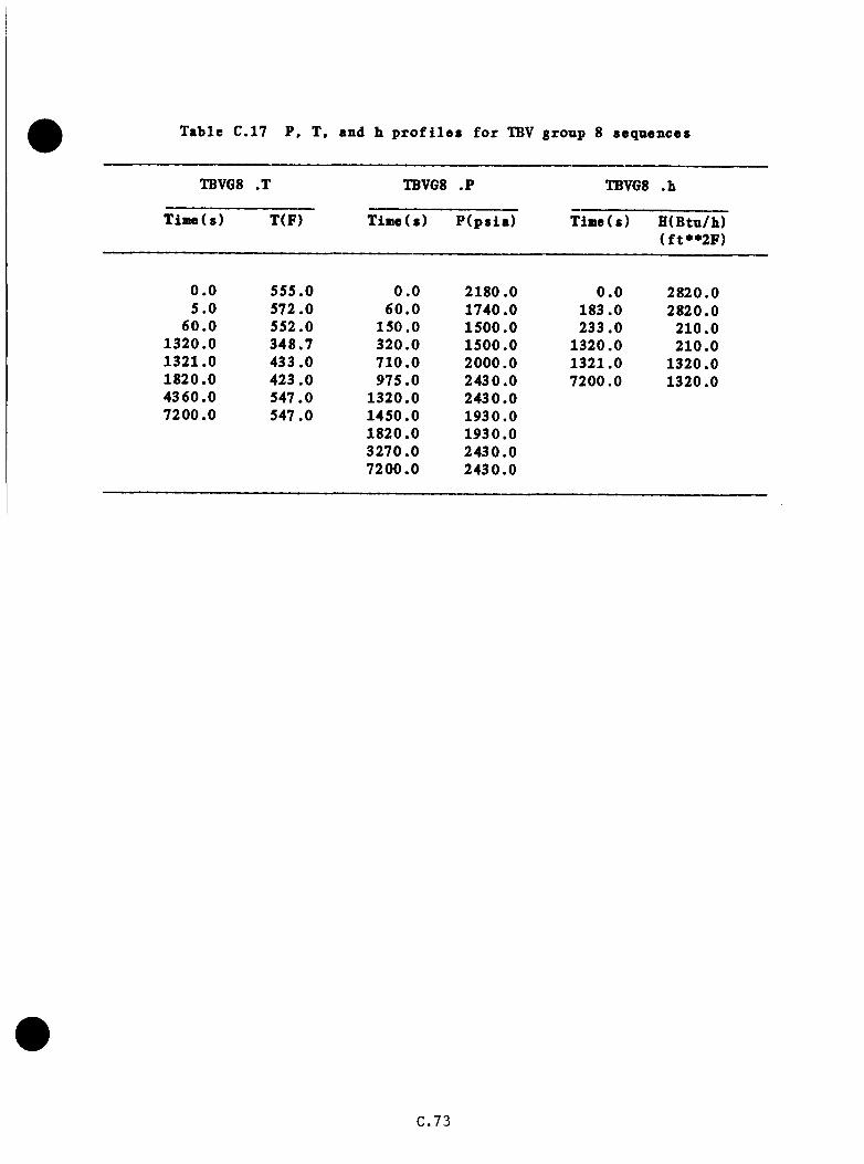
Table C.17 P, T, and h profiles for TBV group 8 sequences
TBVGS .T TBVGS .P TBVGS .b
Tim e(s) T(F) Tim e(s) P (p s ia ) Time( s) H(Btu/b)(f t**2F )
0 .0 555.0 0 .0 2180.0 0 .0 2820.05 .0 572.0 60 .0 1740.0 183.0 2820.0
6 0 .0 552.0 150.0 1500.0 233.0 210.01320.0 348.7 320.0 1500.0 1320.0 210.01321.0 433.0 710 .0 2000.0 1321.0 1320.01820.0 423.0 975.0 2430.0 7200.0 1320.04360.0 547.0 1320.0 2430.07200.0 547.0 1450.0 1930.0
1820.0 1930.03270.0 2430.07200.0 2430.0
C.73

P S I f t TCF)TBVG3
2S00
2200
1 3 0 0
1 4 0 0
1000
6 0 00 1000 3 0 0 0 5 0 0 0 7000 .6 0 0 0
TIMECSCCl
F i g u r e C .17 P r e s s u r e s a n d t e m p e r a t u r e s f o r TBV g r o u p 8 s e q u e n c e s .
C.74
c . 4 .10 Group 9 — Case TBV17
a . T e n p e ra tu re
V ith tlie MFl o v e r fe e d and subsequen t f lo o d in g o f SGA w ith flow f ro o tbe
HW/CB punps v ia the s t a r t u p flow c o n t r o l v a lv e s , th e case should c l o s e l y
resem ble LANL case 5B. A f te r SGA i s co m p le te ly f u l l , feedw ate r w i l l flow
from the feed w a te r r in g to the SG o u t l e t w ith a sm all b u t undeterm ined
amount o f h e a t b e in g abso rbed from th e p r im a ry . For t h i s a n a l y s i s , i t i s
assumed t h a t t h i s fo l lo w s a s in g le loop TBV f a i l u r e response i d e n t i c a l to
LANL case SA, as e x t r a p o la t e d ( s e e Tab le C.18 and F ig u re C .1 8 ) .
b . P r e s s u re
This group i s assumed to be i d e n t i c a l t o TBV group 5 because of e a r l y
e f f e c t s o f system cooldown (s e e Table C.18 and F ig u re C .1 8 ) .
c . Heat T r a n s f e r C o e f f i c i e n t
T his group i s ta k e n to be i d e n t i c a l to TBV group 1 ( s e e Table C .18 ) .
C .4 .11 Group 10 — Cases TBV18 and TBV19
a . Tem perature
T h is group in c lu d e s the e q u iv a le n t o f s in g l e TBV f a i l u r e s in each loop
and a POKV-sized LO(A. The case i s s i m i l a r to TBV group 6 excep t t h a t
b o th loops a re a f f e c t e d . LANL case 5A was used t o 60 s (SST^^F), th e n the
cooldown model was used t o e x t r a p o la t e t o a minimnm te m p era tu re o f 2 3 6 .7^F
a t 7200 s ( s e e Table C.19 and F ig u re C .1 9 ) .
C.75
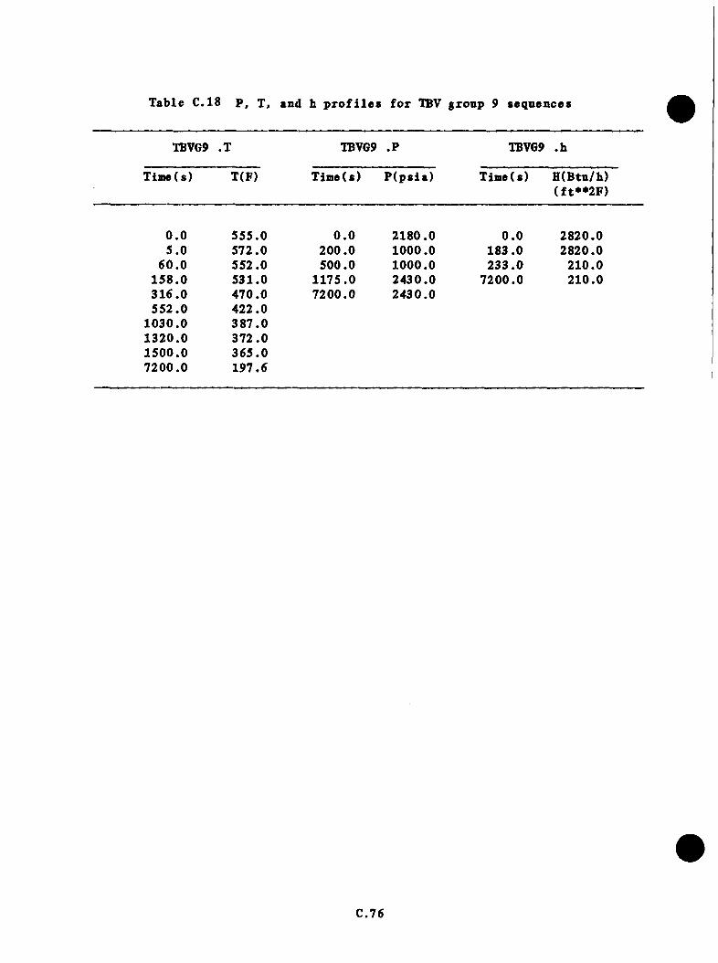
Table C.18 P , T. and h p r o f i l e s f o r TBV gronp 9 sequences
XBVG9 .T TBVG9 .P TBVG9 .h
Time(s) T(F) Time(s) P (p s ia ) T ime(s) H(Btu/h)(f t**2F )
0 .0 555.0 0 .0 2180.0 0 .0 2820.05 .0 572.0 200.0 1000.0 183.0 2820.0
60 .0 552.0 500.0 1000.0 233.0 210.0158 .0 531.0 1175.0 2430.0 7200.0 210.0316 .0 470.0 7200.0 2430.0552.0 422.0
1030.0 387 .01320.0 372.01500.0 365 .07200.0 197.6
c .16
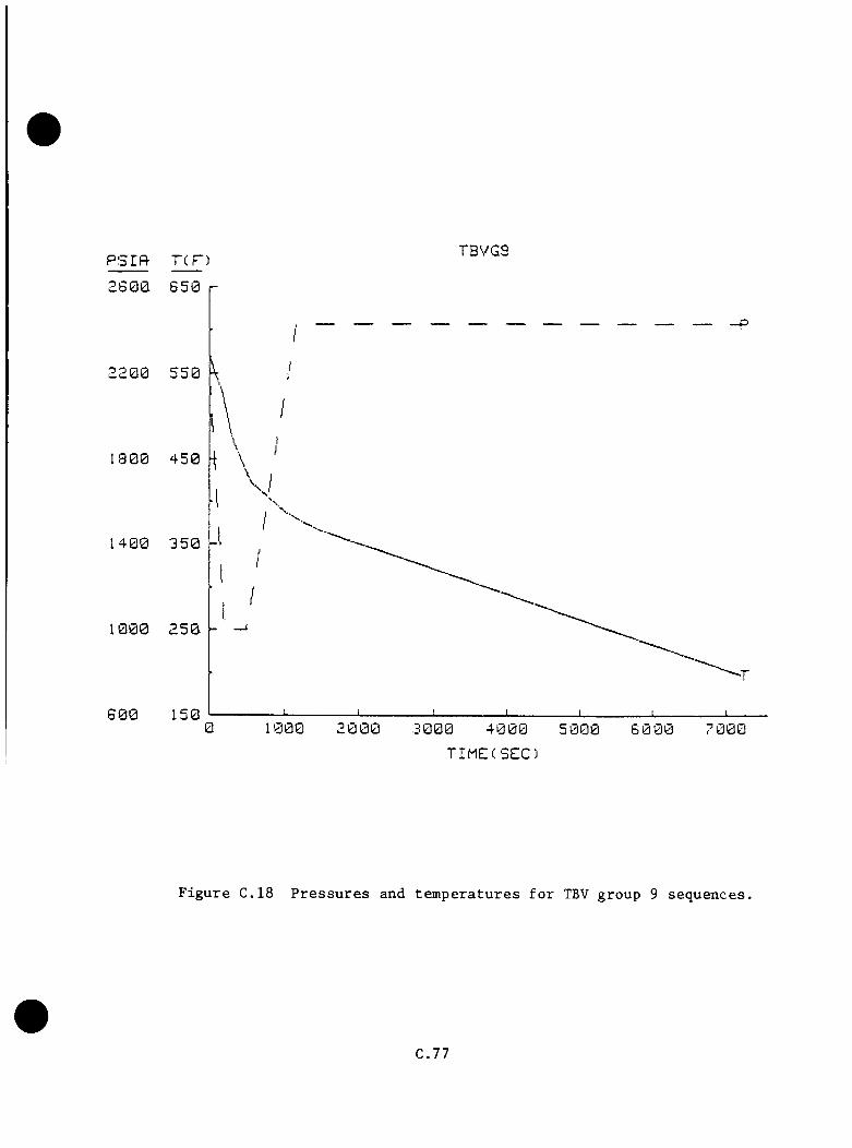
psrfl- TCF) TBVG9L600
2 2 0 0
1 8 0 0
1 4 0 0
1 0 0 0
8 0 00 d 000 5 0 0 0
TIME(SEC)
F i g u r e C .1 8 P r e s s u r e s an d t e m p e r a t u r e s f o r TBV g r o u p 9 s e q u e n c e s .
C .7 7

T able C.19 P. T. and b p r o f i l e s f o r TBV group 10 sequences
TBVGIO.T TBVGIO .P TBVGIO .b
Tim e(s) T(F) TiaieCs) P (p s ia ) Tiaie(s) H (Btu/b)(f t* * 2 F )
0 .0 555.0 0 .0 2180.0 0 .0 2820.05 .0 572.0 200.0 1000.0 183.0 2820.0
6 0 .0 552.0 500.0 1000.0 233 .0 210 .01500.0 331.1 1175.0 2430.0 7200.0 210.02500.0 296.6 1200.0 1670.03500 .0 275.2 7200.0 1670.04500.0 260.45500.0 249 .56500.0 241.37200.0 236.7
C.78
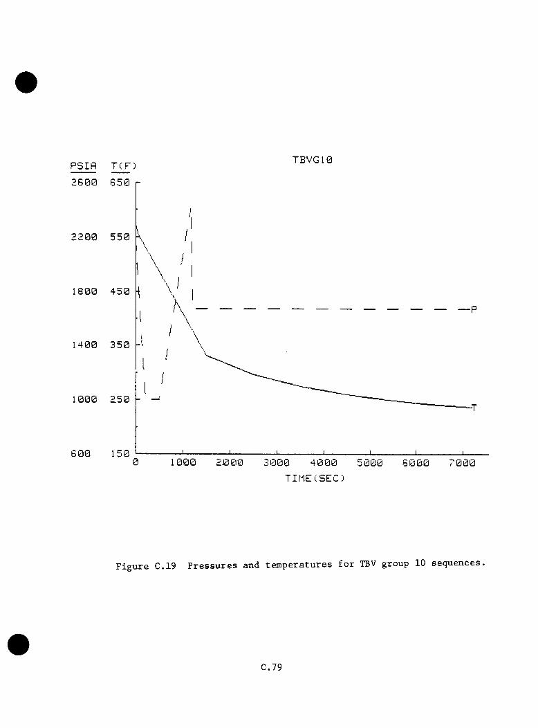
PSIR TCF) TBVG10
2 6 0 0
2 2 0 0
1 8 0 0
1 4 0 0
1000
6 0 0 1000 7 0 0 06 0 00TIME(SEC)
F i g u r e C.19 P r e s s u r e s an d t e m p e r a t u r e s f o r TBV g r o u p 10 s e q u e n c e s .
C.79

b . P r e s s u re
T h is group r e s e n b le s TBV group 5 ou t t o 1175 s . The p r e s s u r e bas dropped
from 2180 p s i a to 1000 p s i a a t 200 s under the in f lu e n c e o f o v e rco o l in g
b o th lo o p s . At 500 s , p r e s s u r e b e g in s to in c re a s e from 1000 p s i a to 2430
p s i a a t 1175 s . PORV s t i c k s open a t t h i s p o i n t , and p r e s s u r e d rops to
1670 p s i a a t 1200 s as HPI flow in c re a s e s t o s u s t a i n p r e s s u r e a t t h i s l e v e l
f o r the rem a inder o f th e sequence ( s e e Table C.19 and F ig u re C .19 ) .
c . Heat T r a n s f e r C o e f f i c i e n t
T h is group i s i d e n t i c a l to TBV group 1 ( s e e Table C .1 9 ) .
C.80
c .5 T u rb ine B y p x t Valve Fn i l n r e s in H ot,S tandby
O vercoo ling e v e n ts a t h o t s tandby can y i e l d sev e re cooldown r a t e s because
o f th e absence of s i g n i f i c a n t decay h e a t in p u t to th e system. INEL
perform ed a c a l c u l a t i o n o f a sequence where a l l fo u r IBVs f a i l open
(because o f a c o n t ro l - s y s te m f a u l t ) and a re i s o l a t e d 10 min l a t e r . ORNL
s p e c i f i e d c a se s where one TBV and two TBVs in one loop f a i l open w ithou t
su bsequen t i s o l a t i o n o f th e TBV(s) o r t h r o t t l i n g o f HPI. To i n v e s t i g a t e
th e s e n s i t i v i t y of th e sequences to decay h e a t l e v e l , decay h e a t r a t e s
c o r re sp o n d in g t o 12 h and 1 wk r e s p e c t i v e l y s in c e shutdown from f u l l power.
Table C.20 d e s c r ib e s th e sequences . The cooldown model p r e d ic te d very
r a p id cooldown r a t e s , l a r g e l y because o f poor acco u n tin g of p ipe and v e s s e l
w a l l - t o - w a t e r h e a t t r a n s f e r . The e r r o r i s l e s s pronounced f o r t r a n s i e n t s
from f u l l power where decay h e a t - in d u c e d n a t u r a l c i r c u l a t i o n and ven t v a lve
f low s swamp any m e ta l - t o - w a te r h e a t in g e f f e c t s .
C .S . l B as is
INEL — 4TBV f a i l u r e a t h o t s tan d b y .
C .S .2 D e p a r tu re s from B a s is
a . One- and two-TBV f a i l u r e s were e v a lu a te d .
b . TBVs in b ase case were i s o l a t e d a t 10 min.
Study ca se s have no TBV i s o l a t i o n .
C .8 1

Table C.20 Hot standby TBV failure cases
C o n d it io n s
ZP ITBV
(12 h)
ZP 2TBV
(12 h)
Case
ZW IIBV
(1 wk)
ZW 2TBV
(1 wk)
Hot s tandby z X X X
Decay h e a t l e v e l s
a . 12 h r = 15.75 MW X X
b . 1 wk = 7 .5 MW X X
Cspi£Ol
1 IBV opens SGA X X
2 TBVs open SGA X X
SGB TBVs o p e ra te as d es igned X X X X
SSKVs o p e r a te as d e s ig n ed X X X X
F eedw ate r Suunlv
Feedw ater c o n t r o l l e d to X X X X*
a p p r o p r ia t e l e v e l
Poptiro i
PORV o p e r a te s as des ig n ed X X X X
O u era to r A c tio n s
RCPs t r i p p e d a t HPI + 30 s X X X X
Assumes post-RCP t r i p SG l e v e l m a in ta in e d by w hatever feed w a te r source a v a i l a b l e
C.8 2
C .5 .3 A p p lic a b le Data from O tber Cases
None.
C .S .4 E x t r a p o la t io n A ssum ptions. P ro c e d u re s , and R e s u l t s
a . T em perature
The cooldown model was employed to e v a lu a te s i n g l e - and double-TBV
f a i l u r e s a t h o t s ta n d b y . T o ta l loop flows o f 40 ,000 I b / s were used
p r i o r t o RCP t r i p , and a t o t a l n a t u r a l c i r c u l a t i o n r a t e of 700 I b / s
was used in l a t e r s ta g e s o f th e t r a n s i e n t s . These v a lu e s were o b ta in e d
from th e INEL base case c a l c u l a t i o n . Two power l e v e l s were examined.
The f i r s t l e v e l used a c o n s ta n t r e s i d u a l decay h e a t of 15 .7 MW,
c o rre sp o n d in g to about 12-14 h a f t e r t r i p from fu l l -p o w e r o p e ra t io n .
The second l e v e l used a v a lu e o f 8 .5 NW, co rresp o n d in g to a shutdown
p e r io d o f 1 wk. A sm all v en t v a lv e flow of 45 I b / s was ta k en from
th e LANL PORV LOCA c a s e . I n i t i a l p r im ary te m p era tu re s o f 548°F and
fe e d w a te r te m p e ra tu re s o f 90°F were assumed f o r bo th th e NFV and EFV
s y s te m s .
For one IBV f a i l u r e a t 12 h a f t e r shutdown, downcomer te m p era tu re
d e c re a s e s to 498^F a t 250 s when HPI comes on, t o 328°F a t 480 s when
SG f i l l s to 20 f t o f w a te r a f t e r RCP t r i p i s com pleted , and th en to
303°F a t 1000 s when th e p r im ary system goes w a t e r - s o l i d and HPI flow
d e c r e a s e s . The downcomer te m p e ra tu re r i s e s t o 307^F a t 1500 s because
o f th e HPI flow d e c re a se r e l a t i v e to the warmer loop f lo w s , bu t then
i t resumes d e c l in e , r e a c h in g 300°F a t 2000 s and 234*^F a t 7200 s ( see
T ab le C.21 and F ig u re C .2 0 ) .
C.83
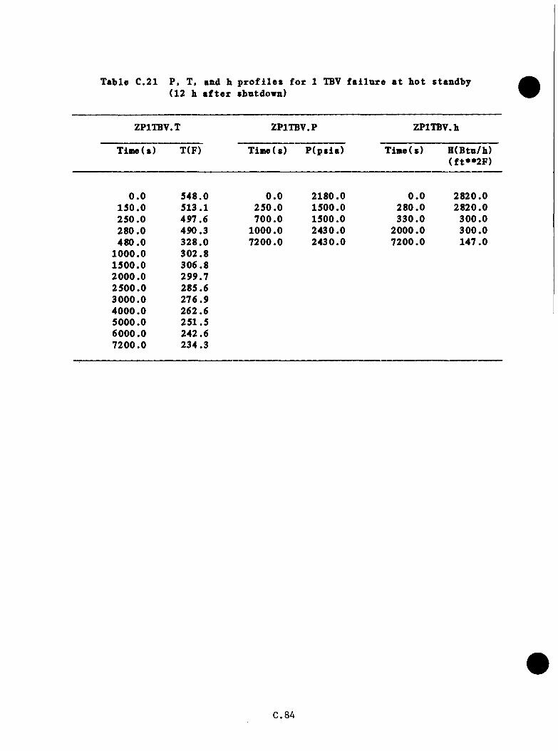
T ab le C.21 P> T, and b p r o f i l e s (12 h a f t e r shntdovn)
f o r 1 TBV f a i l u r e a t h o t s tandby
ZPITBV.T ZPITBV.P ZPlTBV.h
Tim e(s) T(F) Tim e(s) P (p s ia ) Time(s) H (Btu/h)(f t* * 2 F )
0 .0 548.0 0 .0 2180.0 0 .0 2820.0150 .0 513.1 250 .0 1500.0 280.0 2820.0250 .0 497.6 700 .0 1500.0 330 .0 300.0280 .0 490.3 1000.0 2430.0 2000.0 300.0480 .0 328.0 7200.0 2430.0 7200.0 147.0
1000.0 302.81500.0 306.82000.0 299.72500.0 285.63000.0 276.94000.0 262.65000.0 251.56000.0 242.67200.0 234.3
C.8A

PSIft T(.F)Z P IT B V
PC6 0 0
2200
1 8 0 0
1 4 0 0
1000
6 005 0 0 010000
TIMECSEC)
F i g u r e C.20 P r e s s u r e s and t e m p e r a t u r e s f o r 1 TBV f a i l u r e a t h o t s t a n d b y (12 h r s . a f t e r shu tdow n) .
C.85
For one IBV f a i l e d open 1 vk a f t e r skntdown, te m p e ra tn re d e c re a se s
t o 501°F a t 200 s when HPI comes on, t o 327*^F a t 460 s when th e
SGs f i l l to 20 f t of w a te r a f t e r RCP t r i p , and th e n to 298^F a t
1000 s when th e p r im ary goes w a t e r - s o l i d and HPI flow d e c r e a s e s . The
downcomer te m p e ra tn re r i s e s t o 300°F a t 1500 s hecanse of reduced HPI
flow ( te m p e ra tu re d i l u t i o n ) , h u t th e n i t resumes d e c l in e as th e system
cooldown o v e r ta k e s the HPI mixing as th e dominant mechanism. The
downcomer te m p e ra tu re d rops t o 2 8 6 .4^F a t 2000 s and 2 0 7 .2°F a t 7200
s . The d i f f e r e n c e in decay h e a t in p u t i s most n o t i c e a b l e l a t e in th e
sequence (s e e Tab le C.22 and F ig u re C .2 1 ) .
With two TBVs f a i l open 12 h a f t e r shutdown, te m p e ra tu re d e c l in e s to
490°F a t 120 s when th e HPI comes on, to 303**F a t 350 s when SGs f i l l
t o 20 f t o f w a te r a f t e r RCP t r i p i s com ple te , and to 277^F a t 900 s
when th e p r im ary system goes w a t e r - s o l i d . The downcomer te m p era tu re i s
assumed t o s ta y e s s e n t i a l l y c o n s ta n t to 1500 s in re sponse to reduced
HPI flow . Then te m p e ra tu re d e c l in e resum es, and a f i n a l v a lu e o f 209^F
i s reac h ed a t 7200 s ( s e e Table C.23 and F ig u re C .2 2 ) .
For two IBVs f a i l e d open 1 wk a f t e r shutdown, te m p e ra tu re d e c l in e s
t o 4 8 6 .8°F a t 120 s when SG f i l l i s com pleted a f t e r RCP t r i p and
t o 269°F a t 1000 s when th e p rim ary goes w a t e r - s o l i d and HPI flow s
d e c r e a s e . T em perature rem ains r e l a t i v e l y c o n s ta n t to 1500 s because
o f th e r e d u c t io n in HPI flow . Then the te m p e ra tu re d e c l in e resum es,
w ith a f i n a l v a lu e of 185°F reached a t 7200 s . A gain , th e d i f f e r e n c e
in decay in p u t i s o n ly d i s c e r n a b le l a t e in th e sequence ( s e e Table C.24
and F ig u re C .2 3 ) .
C .8 6
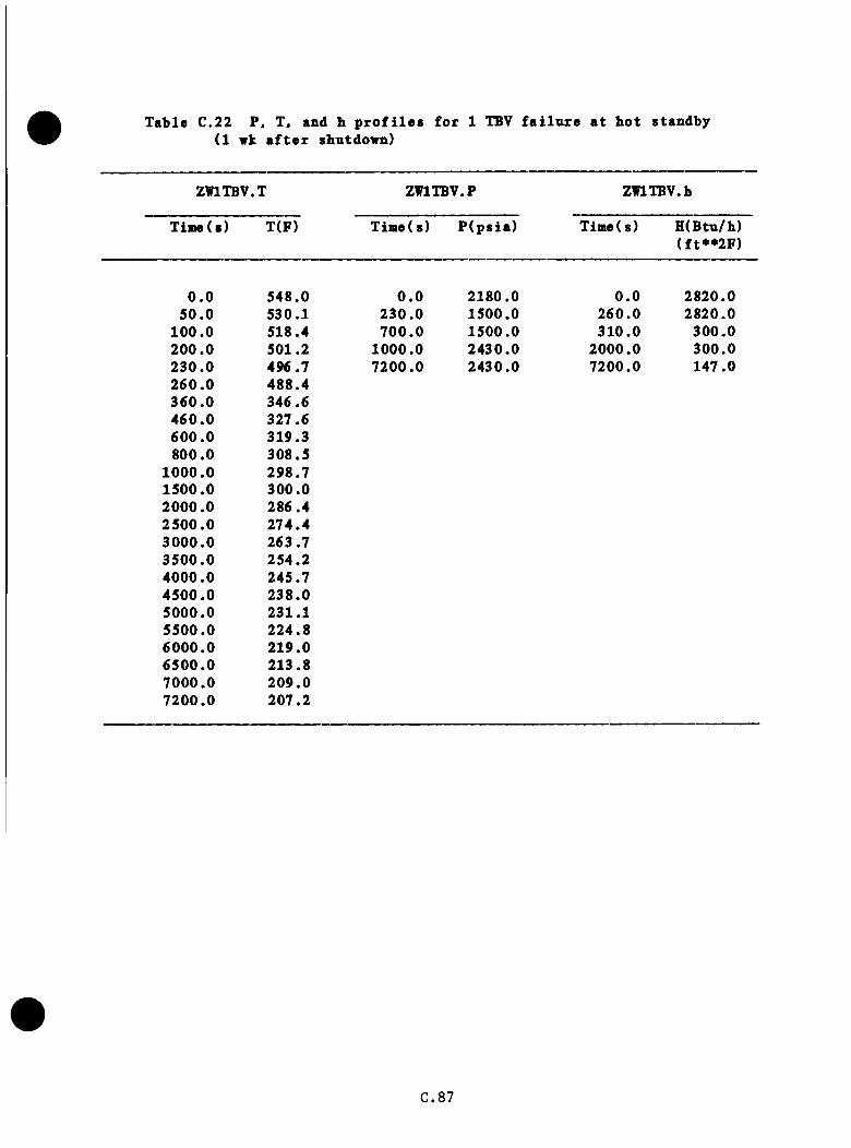
Table C.22 P. T. and h profiles for 1 TBV failure at hot standby(1 vk after shutdown)
ZWITBV.T ZWITBV.P ZWlTBV.h
Time(s) T(F) Time(s) P (p s ia ) Time(s) H(Btu/h)(f t**2F)
0 .0 548.0 0 .0 2180.0 0 .0 2820.050 .0 530.1 230 .0 1500.0 260.0 2820.0
100.0 518.4 700 .0 1500.0 310.0 300.0200 .0 501.2 1000.0 2430.0 2000.0 300.0230 .0 496.7 7200.0 2430.0 7200.0 147.0260 .0 488.4360 .0 346.6460 .0 327.6600 .0 319.3800.0 308.5
1000.0 298.71500.0 300.02000.0 286.42500 .0 274.43000.0 263.73500.0 254.24000.0 245.74500.0 238.05000.0 231.15500.0 224.86000.0 219.06500.0 213.87000.0 209.07200.0 207.2
C.87

P S I R TCP)ZW1TBV
2 6 0 0
2200
1 3 0 0
1 4 0 0
I 0 0 0
6 0 07 0 0 06 0 0 04 0 0 0 5 0 0 00 1000
TIMECSEC)
F i g u r e C.21 P r e s s u r e s and t e m p e r a t u r e s f o r 1 TBV f a i l u r e a t ho t s t a n d b y (1 wk a f t e r s h u t d o w n ) .
C.88

Table C.23 P, T, and h profiles for 2-TBV failure at bot standby(12 b after sbntdovn)
ZP2TBV.T ZP2TBV.P ZP2TBV.b
Time(s) T(F) Time(s) P ( p s i a ) Time(s) H(Btu/b)(f t* * 2 F )
0 .0 548.0 0 .0 2180.0 0 .0 2820.0120 .0 490.7 120.0 1500.0 150.0 2820.0150 .0 478.5 600.0 1500.0 200.0 300.0350 .0 303.1 900.0 2430.0 2000.0 300.0900.0 276.7 7200.0 2430.0 7200.0 147.0
1500.0 275 .82000.0 264 .52500.0 255 .03000.0 246.74000.0 233.55000.0 223.4dOOO.O 215.87200.0 208.7
C.89
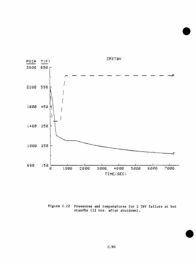
P S l P t T(F) ZP2TBV
2 6 0 0
2200
1 8 0 0
1 4 0 0
1000
6 0 06 0 0 0 7 0 0 02 0 0 00 1000 3 0 0 0
TIMECSEC)
F i g u r e C .2 2 P r e s s u r e s and t e m p e r a t u r e s f o r 2 TBV f a i l u r e a t h o ts t a n d b y ( 1 2 h r s . a f t e r s h u t d o w n ) .
C .90
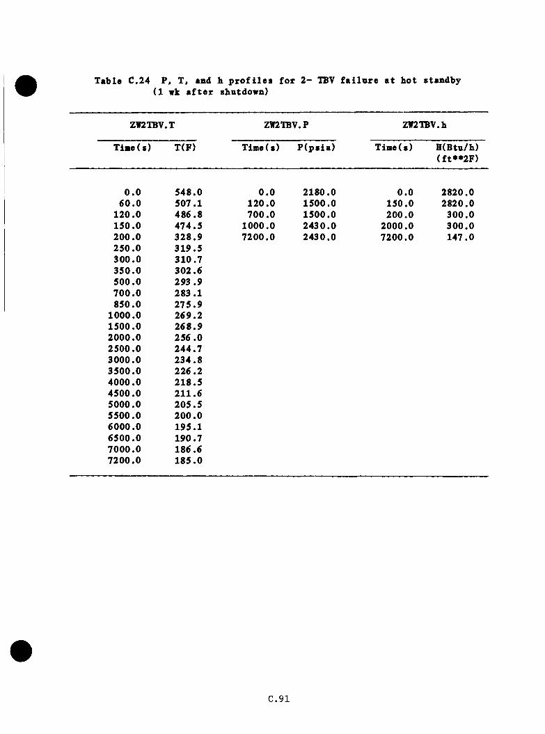
Table C.24 P(1
, T, and b p r o f i l e s f o r 2 - TBV wk a f t e r shutdown)
f a i l u r e a t ho t standby
ZW2TBV.T ZW2TBV.P ZW2TBV.h
T ia e ( s ) T(F) Tim e(s) P (p s ia ) Time(s) H(Btu/h) (f t**2F )
0 .0 548.0 0 .0 2180.0 0 .0 2820.060 .0 507.1 120 .0 1500.0 150.0 2820.0
120.0 486 .8 700 .0 1500.0 200.0 300.0150.0 474.5 1000.0 2430.0 2000.0 300 .0200.0 328 .9 7200.0 2430.0 7200.0 147.0250.0 319.5300 .0 310.7350.0 302.6500.0 293 .9700 .0 283.1850.0 275 .9
1000.0 269.21500.0 268 .92000.0 256 .02500.0 244.73000.0 234 .83500.0 226 .24000.0 218 .54500.0 211.65000.0 205.55500.0 200 .06000.0 195.16500.0 190.77000.0 186.67200.0 185 .0
C .9 1
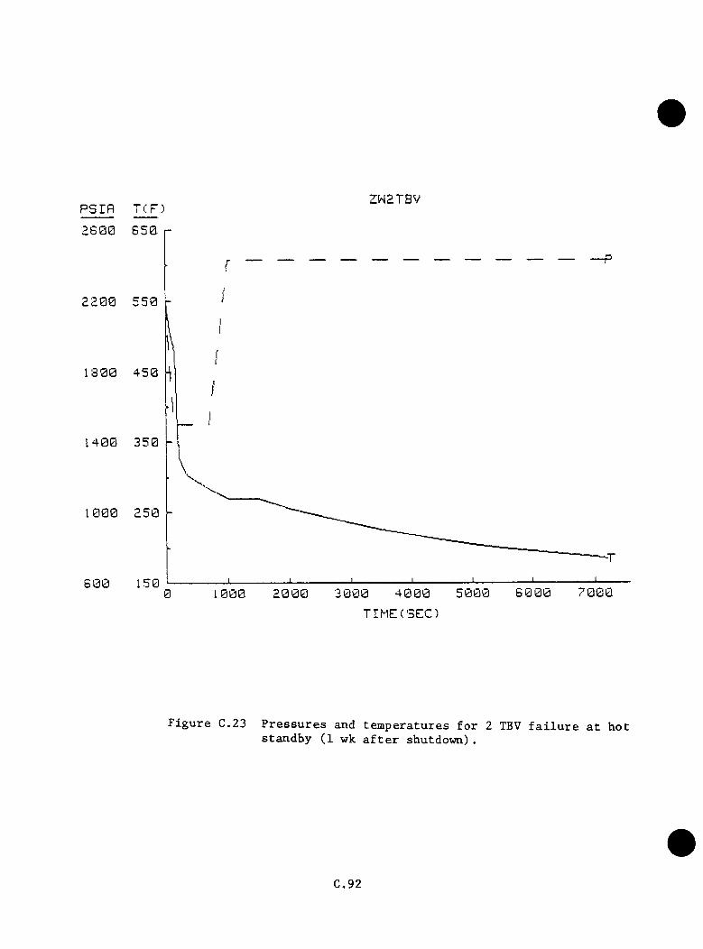
psrfl TCP) ZW2TBV
2 6 0 0
2200
1 3 0 0
1 4 0 0
1000
6 0 07 0 0 03 0 0 0 4 0 0 020000 1 0 0 0
TIMECSEC)
F i g u r e C.23 P r e s s u r e s and t e m p e r a t u r e s f o r 2 TBV f a i l u r e a t h o t s t a n d b y (1 wk a f t e r s h u t d o w n ) .
C.92

N ln ia iw t e a p e r s t u r e s lo v e r th an the b ase case were o b ta in e d f o r th e se
s tu d y c a se s because the TBVs v e re no t i s o l a t e d a t 600 s , as in the
INEL base c a s e .
b . P r e s s u re
The time to reac h HPI s e t p o in t was assumed to be a f u n c t io n of average
c o o la n t te m p e ra tu re . However, th e a c t i o n o f p r e s s u r i z e r h e a t e r s and
m akeup/le tdow n system s g r e a t l y c o m p lic a te s th e s i t u a t i o n . S t a r t i n g
from h o t s tandby c o n d i t i o n s , th e p r e s s u r i z e r should empty when the
average te m p e ra tu re d rops below SOO ’f . I t i s assumed t h a t the p r e s s u r e
i s n e a r the HPI s e t p o in t when th e p r e s s u r i z e r em p tie s . With one TBV
open, th e system d e p r e s s u r i z e s ( c o o ls ) to th e HPI s e t p o in t (1500 p s ia )
a t 230 s (1-wk shutdown) o r 250 s (12 -h shutdow n). HPI i s assumed
to m a in ta in p r e s s u r e a t t h i s l e v e l u n t i l 700 s , whereon p r e s s u r e b eg in s
t o r i s e to the PORV s e t p o i n t , 2 4 3 0 p s i , a t 1000 s where i t rem ains
th ro u g h o u t th e sequence ( s e e T ab les C.21 and € .22 and F ig u re s € .20 and
€ . 21) .
With two TBVs open, th e system re a c h e s HPI s e t p o in t a t 120 s ( s i m i l a r
to base c a s e ) . I n s t e a d o f d e c re a s in g f u r t h e r , i t i s assumed t h a t
p r e s s u r e rem ains a t 1500 p s i a u n t i l 600 s (12-h shutdown) o r 700 s (1 -
wk shutdow n), when i t b e g in s to r i s e to i t s f i n a l v a lue o f 2430 p s i a
a t 900 s (12 -h shutdown) o r 1000 s (1-wk shutdow n). (See T ab les €.23
and €.24 and Figures €.22 and €.23.)
C .9 3
c . Heat T r a n s f e r C o e f f i c i e n t
fS _For b o th c a s e s , an i n i t i a l v a lu e o f 2820 ( B t u / h / f t F) was a p p l ie d
from th e LANL c a l c n l a t i o n s . A f te r RCP t r i p , INEL g iv e s v a lu e s o f 300
( B tu / h / f t ^ ° F ) t o 2000 8, which th e n d e c re a se to 147 (B tu/h/ft^*^F) a t
7200 s . T h is type o f g ra d u a l d e c re a se was expec ted b u t n o t observed
in any o th e r sequences . No c o r r e c t i o n f o r f r e e c o n v e c t io n e f f e c t s i s
in c lu d e d in th e s e v a lu e s ( s e e T ab le s C.21 th ro u g h C .2 4 ) .
C.94

C.6 PORV-Sized LOCA Ca«es
C .6 .1 ORNl>Defined PORV-Sized LOCAs
ORNL d e f in e d n in e PORV-sized LOCA c a s e s . These were s o r te d in to f iv e
groups based on case s i a i l a r i t i e s . The c h a r a c t e r i s t i c s o f th e n in e cases
and t h e i r r e s p e c t iv e g roup ings a r e d i s p la y e d in Table C .25. The t r a n s i e n t s
a re e v a lu a te d by groups below.
€ . 6 .1 . 1 Bases
LANL PORV LOCA case 2A
LANL Rancho Seco-type t r a n s i e n t
LANL TBV f a i l u r e case 5B
C .b .1 .2 D ep a r tu re s from Bases
a . A l l c a se s have a FORV-sized b re a k , b u t not n e c e s s a r i l y a f a i l e d PORV.
L o c a t io n o f the b re a k in the p r e s s u r i z e r surge l i n e ( f o r exam ple),
r a t h e r th an a t th e top o f th e p r e s s u r i z e r , would change system response
s in c e th e system may n o t go w a t e r - s o l i d . However, a s tu ck -o p en PORV
o r an e q u iv a le n t b re a k a t the to p o f th e p r e s s u r i z e r would r e s u l t in
l a r g e r cum ula tive HPI f low s and hence g r e a t e r cooldown th an a s i m i l a r -
s i z e b re a k e lsew h ere .
b . F eedw ate r p e r t u r b a t i o n s such as normal runback , SGA o v e r fe e d s , and lo s s
o f MFV w ith EFW f a i l u r e a re examined. Normal runback i s no t covered
in any o f th e b a s e s .
C .95

Table C.2S PORV-sized LX)CA cases and groupings
C o n d itio n 1 2 3
Case SBLOCA-
4 5 6 7 8 9
Secondary P re s s u re C o n tro ls
O p era tes as d es ig n ed X X X X X X X X
2 TBVs f a i l open loop A X
MFW runback as d es ig n ed X X X
SGA runback f a i l u r e X X X
LOMFW a t tim e = 0 . 0 X X X
EFW o p e ra te s a s d es ig n ed X X X X X X X
EFW in manual X X
P rim ary P re s s u re C o n tro ls
PORV b lo c k y a ly e open X X X X X X X X X** ***
PORV o p e ra te s as d es ig n ed X X X X X X X X X• *
SRV f a i l s to r e s e a t X X X
OpsrwtOf A pfjpppRCP t r ip p e d a t HPI + 30 s X X X X X X X X X
F u l l EFW flow a f t e r SG d ry o n t X X
I s o l a t e s SGs a t 20 min X
Group nnatber (PSBG-) 1 2 3 2 4 5 1 2 3
«O th er c o n d i t io n s common to a l l c a s e s ; f u l l power* decay h e a t 1 .0 tim esANS, a l l ECCS com ponents o p e ra te as d es ig n ed
«*I f c h a lle n g e d
B reak i s POBV-sized and may o ccu r anywhere
C.96

c . 6 . 1 .3 A p p lic a b le Data froat O ther Cases
The INEL 2 - i n . h o t le g and 2 . 5 - i n . c o ld le g LOCA cases show t r e n d s in
system p re s s u re * b re a k flows* downcomer tem pera tu res* and steam g e n e ra to r
secondary re sp o n se s i m i l a r to the LANL PORV LOCA. This su g g es ts a
c o n s i s t e n t cooldown mechanism over a l l the modeled s t a t e s r a t h e r than
sequence s p e c i f i c cooldown mechanisms f o r each c a se .
C .6 .1 .4 E x t r a p o la t io n Assumptions
A sm al1 -b reak LOCA in v o lv e s a l o s s o f h o t p r im ary c o o la n t th rough the b reak
w ith rep lacem en t o f mass in th e form o f c o ld HPI f l u i d . This mechanism
w i l l g r a d u a l ly coo l o f f the p r im ary w h ile m a in ta in in g h ig h p r e s s u r e .
C o n d it io n s p r e v a i l i n g in the p r im ary system during a PORV LOCA in c lu d e
r e l a t i v e l y c o n s ta n t n a t u r a l c i r c u l a t i o n th ro u g h bo th loops* v en t v a lve flow
( a l s o r e l a t i v e l y c o n s ta n t )* and HPI flow s t h a t b a lan ce b reak flow s on a
v o lu m e tr ic b a s i s and ap p ro x im a te ly match on a mass flow b a s i s .
Cold leg* c o ld leg-H PI m ixture* and downcomer te m p era tu re s may be o b ta in e d
from the h o t le g te m p e ra tu re i f the loop flow s and ven t v a lve f low s are
known. In t h i s study* in d iv id u a l loop f low s o f 450 Ib /s* t o t a l v en t v a lve
flow s o f 150 Ib /s* and HPI flows o f 118 l b / s were employed f o r the PORV-
s iz e d LOCA c a s e s . These loop and v en t v a lv e f low s were m a in ta in ed f o r over
700 s i n th e LANL PORV LOCA c a s e . I t i s assumed t h a t th e se c o n d i t io n s
w i l l p r e v a i l th roughou t th e sequences b e in g e v a lu a te d .
C .97

c . 6 . 2 Group 1 — Cases SBLOCAl and SBL0CA7
a . T e a p e ra tn re
These ca se s f e a t u r e n o m a l m nback o f a a i n feed w a te r and p ro p e r
o p e r a t io n of eae rgency fe e d w a te r . Upon opening o f the b re a k a t the
FORV» th e r e a c t o r w i l l t r i p and th e downcomer te m p e ra tn re w i l l i n i t i a l l y
r i s e to 572^F a t 5 s , becanse o f reduced h e a t t r a n s f e r th rough the
steam g e n e ra to r s and th e n s low ly d e c l in e because o f the r e l e a s e of
steam th rough th e TBVs and SSKVs. At 70 s HPI i n j e c t i o n b eg in s and
system cooldown commences, a t f i r s t r a t h e r r a p i d l y due to th e la rg e HPI
f low . The p ro p e r o p e r a t io n o f the main fe ed w a te r system w i l l r e s u l t
in te m p e ra tu re s ro u g h ly 86^F h ig h e r than was c a l c u l a t e d by LANL in the
PORV LOCA w ith o v e r fe e d . T h e re fo re , a downcomer te m p e ra tu re of 500°F
i s a t t a i n e d a t 550 s and rem ains c o n s ta n t to 1000 s .
T h is momentary pause i n cooldown i s due to sharp d e c re a se s in HPI
f low s in the same p e r io d . The c o n t in u in g d e c re a se in steam g e n e ra to r
e x i t te m p e ra tu re s i s masked by t h i s s ia iu lta n eo u s r e d u c t io n in HPI flow .
A f te r 1000 s , th e cooldown model was used to e x t r a p o la t e te m p era tu re s
down t o 390^F a t 7200 s ( s e e Table C.26 and F ig u re C .2 4 ) .
b . P r e s s u re
The LANL PORV LOCA case has HPI i n j e c t i o n s t a r t a t 70 s . L ikew ise , th e
INEL 2 - i n h o t l e g -b re a k LOCA case has HPI b e g in a t 78 s . T h e re fo re ,
i t i s assumed t h a t th e p r im ary d e p r e s s u r iz e s from 2180 p s i a to th e HPI
s e t p o i n t , 1500 p s i a , by 70 s . The system re a c h e s 1000 p s i a a t 550
s . I t i s assumed t h a t th e b re a k i s lo c a te d in th e vapor r e g io n of
C .98
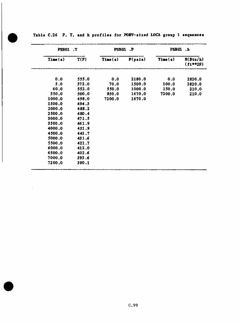
Table C.26 P, T, and h profiles for POKV-sized LOCA group 1 sequences
PSBGl .T PSBGl .P PSBGl .h
Time(s) T(F) T ia e ( s ) P (p s ia ) Time(s) H(Btn/h) ( f t**2F )
0 .0 555.0 0 .0 2180.0 0 .0 2820.05 .0 572.0 7 0 .0 1500.0 100.0 2820.0
6 0 .0 552 .0 550.0 1000.0 150.0 210.0550.0 500.0 850.0 1670.0 7200.0 210.0
1000.0 498 .0 7200.0 1670.01500.0 494.32000.0 488.22500.0 480 .43000.0 471.53500.0 461 .94000.0 451 .94500.0 441.75000.0 431.65500.0 421.76000.0 412 .06500.0 402.67000.0 393.67200 .0 390.1
C .99
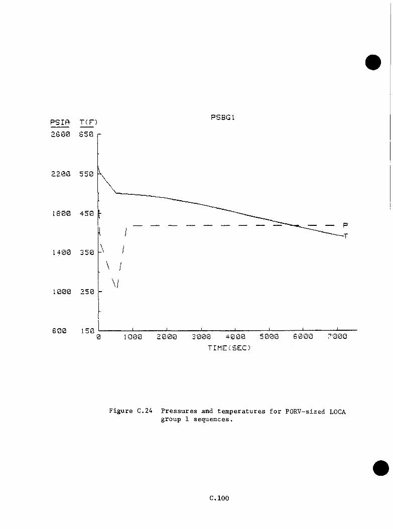
PSIfl- T(D PSBGl2 6 0 0
2200
1 8 0 0
1 4 0 0
1 0 0 0
6 0 07 m e5 0 0 02000
TIMECSEC)
F i g u r e C .24 P r e s s u r e s and t e m p e r a t u r e s f o r PO R V -sized LOCAg ro u p 1 s e q u e n c e s .
C.lOO
th e p r e s s u r i z e r . T h e re fo re , i t i s n e c e s s a ry to go w a t e r - s o l i d in the
p r e s s u r i z e r to re a c h the f i n a l p r e s s u r e of 1670 p s i a observed a t 850
s in th e LANL PORV-size IX)CA. P r e s s u r e i s assuned to remain a t t h i s
v a lu e th roughou t th e rem ainder o f th e sequence. The p r im ary s a f e ty
r e l i e f v a lv e s a re n o t c h a l le n g e d in t h i s sequence ( se e Table C.26 and
F ig u re C.24)
c . Heat T r a n s f e r C o e f f i c i e n t
2LANL e s t im a te d the downcomer h e a t t r a n s f e r c o e f f i c i e n t to 16000w/m K
(2820 B tu /h f t^ ^F ) f o r four-RCP o p e r a t io n and 1200 w/m^K (210 B tu /h
2 of t F) f o r n a t u r a l c i r c u l a t i o n . The change between th e se v a lu e s occurs
a t RCP t r i p a t 100 s ( s e e Table C .2 6 ) .
C .6 .3 Group 2 — Cases SBL0CA2, SBL0CA4, and SBL0CA8
a. T em perature
I n t h i s g roup , th e b re a k i s ta k e n to be a t o r n ea r the PORV in the
vapor r e g io n o f the p r e s s u r i z e r . T h is case fo llo w s th e LANL PORV LOCA
ou t to 1000 s because th e s p e c i f i e d o v e r fe e d resem bles the o v erfeed in
th e LANL c a l c u l a t i o n . Case SBL0CA4 i s in c lu d ed because th e s p e c i f i e d
SG d ry o u t w i l l no t o c c u r . T h e r e a f t e r , th e case fo l lo w s th e cooldown
model fo r the rem ainder o f th e t r a n s i e n t . A te m p era tu re of 3 9 2 .9°F
i s p r o j e c t e d a t 7200 s ( s e e Table C.27 and F ig u re C .25 ) .
C . l O l
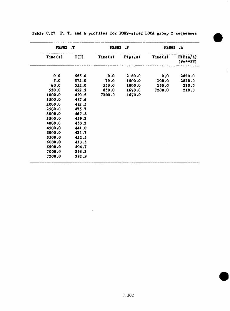
Table C.27 P« X, and b profiles for PORV-sized LOCA group 2 sequences
PSBG2 .X PSBG2 .P PSBG2 .b
Tiaie(s) X(F) Xime(s) P ( p s i a ) Xime(s) H(Btu/b) (f t* * 2 F )
0 .0 555.0 0 .0 2180.0 0 .0 2820.05 .0 572.0 70 .0 1500.0 100 .0 2820.0
6 0 .0 552.0 550.0 1000.0 150 .0 210 .0550.0 492.5 850.0 1670.0 7200.0 210 .0
1000.0 490.5 7200.0 1670.01500.0 487.62000.0 482.52500.0 475.73000.0 467 .83500 .0 459.24000.0 450.24500.0 441.05000.0 431.75500.0 422.56000 .0 413.56500 .0 404.77000 .0 396.27200.0 392.9
C.102
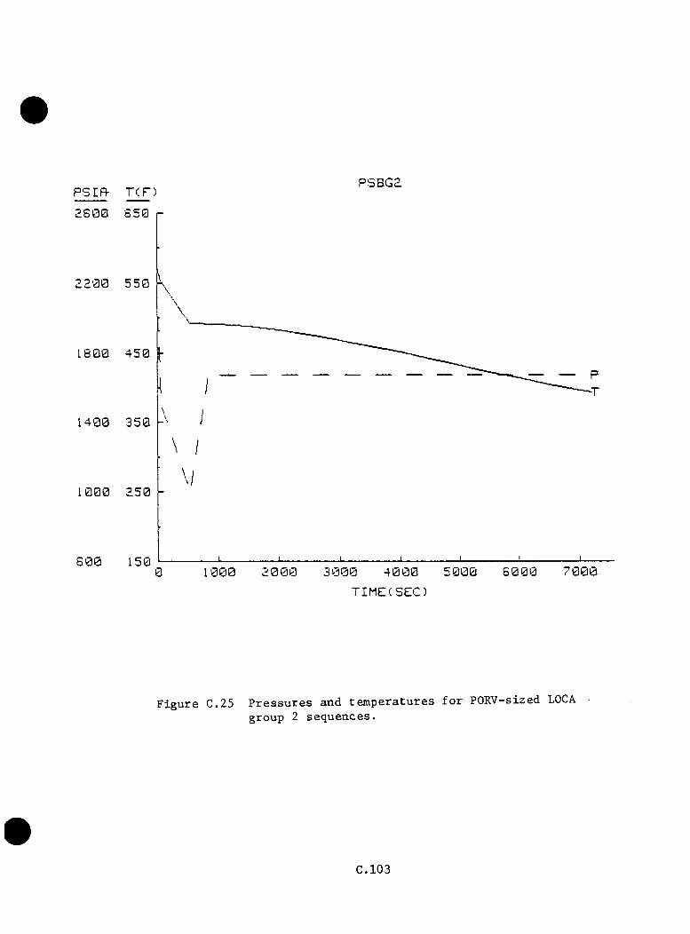
psrfl- rcF) PSBGaa s 0 0
2 2 0 0
1 8 0 0
1 4 0 0
1000
5 0 06 0 0 05 0 0 01 000 2 0 000
TIMECSEC)
F i g u r e C.25 P r e s s u r e s a n d t e m p e r a t u r e s f o r PO R V -sized LOCA g r o u p 2 s e q u e n c e s .
C .103

b . P r e s s u re
The p r e s s u r e b e h a v io r i s ta k e n to be i d e n t i c a l w ith the LANL PORV LOCA
c a l c u l a t i o n ( s e e Table C.27 and F ig u re C .2 5 ) .
c . Heat T r a n s f e r C o e f f i c i e n t
The h e a t t r a n s f e r c o e f f i c i e n t s f o r t h i s group a re ta k en to be i d e n t i c a l
to group 1 ( s e e Table C .2 7 ) .
C .6 .4 Group 3 — Cases SBL0CA3 and SBL0CA9
a . Tem perature
T h is group f e a t u r e s l o s s o f main fe ed w a te r a t th e same time the PORV-
s iz e d b re a k opens . EFW comes on j u s t b e fo r e d ry o u t a t 50 s . T h e re fo re ,
th e steam g e n e r a to r s a re r e f i l l e d w i th c o ld (90^F) EFW r a t h e r than
warm (460^F) NFW. Assuming a t o t a l flow o f 120,000 lb t o f i l l b o th
SGs h a l f f u l l , th e p r im ary te m p era tu re w i l l be d ep re s se d from the LANL
te m p e ra tu re s by an average of 65^F. At a r a t e o f about 160 I b / s
p e r loop , r e f i l l would be com pleted around 425 s i n t o th e sequence .
The downcomer te m p e ra tu re would be ap p ro x im a te ly 427°F a t 550 s . The
te m p e ra tu re w i l l r i s e s l i g h t l y th rough 1500 s because of th e changeover
from SG feed t o b re a k flow as the p r i n c i p a l cooldown mechanism. Then
th e system w i l l coo l down to 3670°F by 7200 s ( see Table C.28 and
F ig u re C .2 6 ) .
C.104

Table C.28 P, T, and b profiles for PORV-sized LOCA group 3 sequences
PSBG3 .T PSBG3 .P PSBG3 .h
Time( s) T(F) Time(s) P (p s ia ) Time(s) H(Btn/h) (f t**2F )
0 .0 555.0 0 .0 2180.0 0 .0 2820.05 .0 572.0 70 .0 1500.0 100.0 2820.0
6 0 .0 552.0 550.0 1000.0 150.0 210.0550.0 427.0 850.0 1670.0 7200.0 210.0
1000.0 431.6 7200.0 1670.01500.0 433.42000.0 432.22500.0 429.03000.0 424.33500.0 418.54000.0 412.14500.0 405.25000.0 398.15500.0 390 .96000.0 383.76500.0 376.77000.0 369 .87200.0 367.0
C .1 0 5
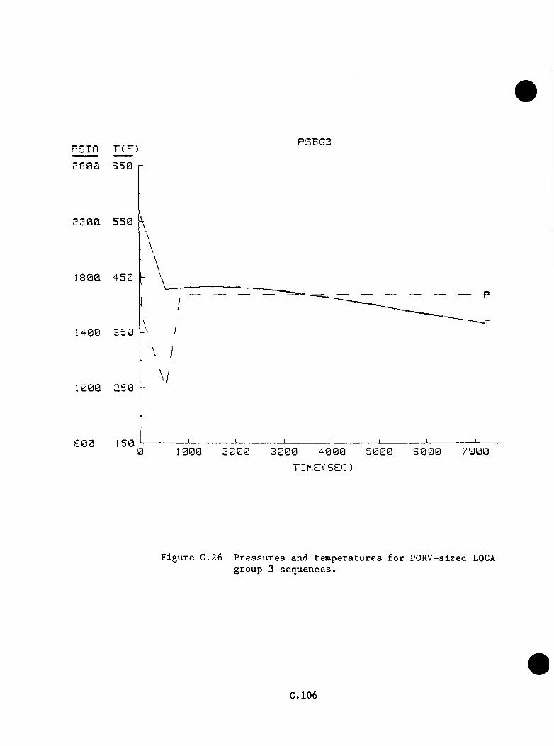
PSIf t TCP)PSBG3
2 6 0 0 6 5 0
1 3 0 0 4 5 0
1 4 0 0 3 5 0 j-'
6 0 0 1507 0 0 00 2 0 0 0 5 0 0 0 6 0 0 01000
T I M E C S e C )
F i g u r e C .2 6 P r e s s u r e s a n d t e m p e r a t u r e s f o r P O R V -s ized LOCAg ro u p 3 s e q u e n c e s .
C .1 0 6

b . P r e s s u r e
T b is case i s ta k e n to be i d e n t i c a l to th e LANL PORV IDCA c a l c u la t io n ^
In a c t u a l p r a c t i c e , th e o v e rc o o l in g o f the systesi by EFW w i l l
t e a ip o ra r i ly reduce systesi p r e s s u r e s . However, HPI flow would in c re a s e
and s u s t a i n p r e s s u r e re c o v e ry u n t i l w a t e r - s o l i d c o n d i t io n s occu r in the
p r e s s u r i z e r and l i q u i d flow choking o c c u rs in the b re a k ( s e e Table C.28
and F ig u re C .2 6 ) .
c . Heat T r a n s f e r C o e f f i c i e n t
T h is case i s ta k e n to be i d e n t i c a l to group 1 ( s e e Table C .2 8 ) .
C .6 .5 Group 4 — Case SBL0CA5
a. Tem perature
T h is case i s c h a r a c t e r i z e d by a l o s s o f main feed w ate r a t the time
th e POKV-sized b re a k opens. The steam g e n e ra to r s b o i l d ry and th en
a re f lo o d ed by c o ld EFW, which i s n o t c o n t r o l l e d to l e v e l . C e r t a in
e lem en ts of t h i s sequence have s i m i l a r i t i e s to th e Rancho Seco-type
e v e n t . A p p lic a b le in fo rm a t io n in c lu d e s EFW flow s o f 160 I b / s i n t o each
loop u n t i l b o th steam g e n e r a to r s and steam l i n e s a re f u l l , time of 3000
s to f i l l secondary system s w ith EFW, and d e c l in e of EFW flow r a t e to
120 I b / s i n t o each loop w ith l i q u i d flow th rough TBVs.
The te m p e ra tu re re sponse o f th e system was p r o je c te d on a p ie cew ise
b a s i s . Through 60 s , system resp o n se i s ta k en to be normal w ith the
downcomer te m p e ra tu re a t S52*^F a t th e end o f t h i s i n t e r v a l .
C .107
Between 60 s and 800 s , th e EFW s t a r t s t o overwhelm th e system , and th e
steam g e n e ra to r s co m p le te ly f i l l by the end o f t h i s p e r io d (downcomer
te m p e ra tu re = 3 8 4 .2 ^ F ) . O v e r f i l l c o n t in n e s a t 160 I b / s p e r steam
g e n e r a to r u n t i l 3000 s i n t o th e t r a n s i e n t when th e s e c o n d a r ie s become
w a t e r - s o l i d and l i q u i d flow r e s t r i c t i o n in c re a s e s p r e s s u r e and reduces
flow to 120 I b / s p e r steam g e n e r a to r . (The sequence may n o t p ro g re s s
t h i s f a r i f th e EFW tu r b i n e pump t r i p s due to low steam q u a l i t y . ) The
te m p e ra tu re a t 3000 s i s 2 3 9 .3°F . T h is assumes t h a t th e EFW is h ea te d
from 90°F to the c u r r e n t steam g e n e ra to r p r im ary e x i t a s i t p a sse s
th rough th e steam g e n e r a to r s . The LANL Rancho S eco -type t r a n s i e n t
c a l c u l a t i o n b e a r s t h i s assum ption o u t , b u t i t i s s t i l l p o s s i b le t h a t
much o f the feed w ate r w i l l bypass d i r e c t l y to th e steam l i n e s and
n o t coo l th e system down. In th e f i n a l mode (120 I b / s ) , te m p era tu re
re a c h e s 171.3*^F a t 7200 s . This seve re o v e rc o o l in g i s due to the
compounding o f HPI i n j e c t i o n and SG o v e rfeed cooldown mechanisms (see
Table C.29 and F ig u re C .2 7 ) .
b . P r e s s u re
The m assive o v e rc o o l in g w i l l d e c re a se system p r e s s u r e below the v a lu e s
used p r e v io u s l y . I t i s assumed t h a t the HPI f a i l s to " g a in " on the
system u n t i l the steam g e n e ra to r s a re r e f i l l e d w ith EFW, o r fo r 800
s . T h is w i l l d e lay th e a t ta in m e n t o f f i n a l system p r e s s u r e (1670 p s ia )
to 1650 s ( s e e Table C.29 and F ig u re € .2 7 ) .
C .108

Table C.29 P. T, and h profiles for PORV-sized LOCA group 4 sequences
PSBG4 .T PSBG4 .P PSBG4 .b
Time(s) T(F) Time(s) P (p s ia ) Time(s) H(Btn/b) (f t**2F )
0 .0 555.0 0 .0 2180.0 0 .0 2820.05 .0 570.0 70 .0 1500.0 100.0 2820.0
6 0 .0 552.0 550.0 1000.0 150.0 210.0500.0 430.9 1350.0 1000.0 7200.0 210.0800.0 394.2 1650.0 1670.0
1000.0 373.5 7200.0 1670.01500.0 328.72000.0 292.52500.0 263.13000.0 239.33500.0 226 .44000.0 215.24500.0 205 .45000.0 196.95500.0 189.56000.0 183.26500.0 177.77000.0 173.07200.0 171.3
C .109

psifi rcF) PSBG4
2 6 0 0
2200
1 3 0 0
1 4 0 0
1000
6 0 04 0 0 00 1000 3 0 0 0
TIMECSEC)
F i g u r e C.27 P r e s s u r e s and t e m p e r a t u r e s f o r PORV-sized LOCA group 4 s e q u e n c e s .
C . l lO
c . Heat T r a n s f e r C o e f f i c i e n t
T h is case i s i d e n t i c a l t o gronp 1 ( s e e Table C .29 ) .
C .6 .6 Gronp 5 — Case SBL0CA6
a. Tem peratnre
In t h i s c a s e , th e POKV-sized b reak i s c o n p l ic a te d by f a i l u r e o f two
TBVs in th e open p o s i t i o n on SGA. Main feed w ate r a t 400^F i s assnmed
a v a i l a b l e o n t i l s te a n g e n e ra to r A feed w a te r i s i s o l a t e d a t 20 s i n .
The te m p era tn re i s assnmed to r i s e from 5 S 5 ° F to 572°F a t 5 s and
th e n drop to SS2°F as a r e s u l t o f IBV o p e r a t io n . T h e r e a f t e r , the
TBVs ro n a in open, and th e system te m p e ra tn re d rops m ain ly because of
h e a t l o s s as steam th rough the open TBVs. The downcomer te m p era tn re
f a l l s t o SSI.S'^F a t 1200 s where feed w a te r i s o l a t i o n o c c u rs . Steam
lo s s c o n t in n e s u n t i l a f f e c t e d SGs d ry out a t 2500 s where a minimum
te m p era tu re of S II .T^’f (av e rag e ) o c c u r s . I f th e TBVs were a l s o
i s o l a t e d a t 1200 s , t h i s a d d i t i o n a l c o o l in g would no t o ccu r . I f loop
B has s ta g n a t e d , th e n minimum te m p e ra tu re s around 250^F w i l l occur a t
t h i s p o i n t .
With steam g e n e r a to r A removed as a h e a t s in k , th e system e q u i l i b r a t e s ,
and downcomer te m p e ra tu re s r i s e as h o t leg te m p era tu re s remain s tead y
u n t i l HPI f low th rough becomes th e p r i n c i p a l h e a t removal mechanism.
A f te r r i s i n g t o 342°F between 3500 and 4000 s , downcomer tem p era tu re
d e c l in e s to 3 2 5 .6^F a t 7200 s . (See Table C.30 and F ig u re C .28 .)
C . l l l
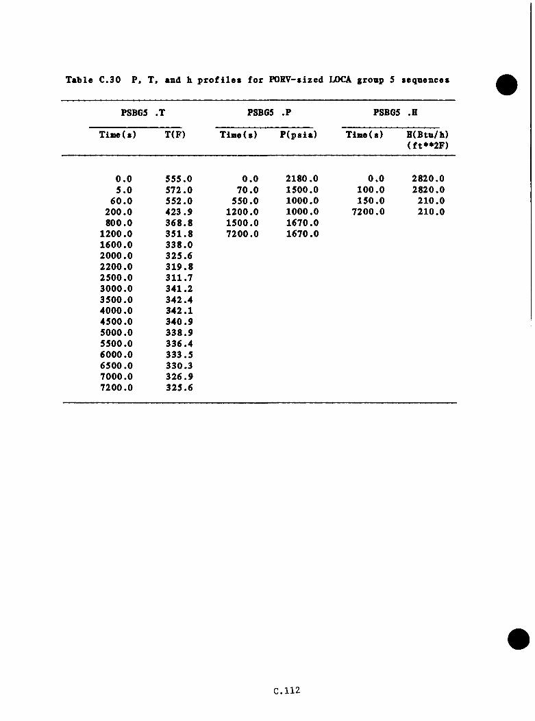
Table C.30 P, T, and h profiles for PORV-sized LOCA gronp S sequences
PSBGS .T PSBG5 .P PSBG5 .H
Tiaie ( s ) T(F) T iD e(s) P (p s ia ) Tim e(s) H(Btn/h) (f t**2F )
0 .0 555.0 0 .0 2180.0 0 .0 2820.05 .0 572.0 70 .0 1500.0 100 .0 2820.0
6 0 .0 552.0 550.0 1000.0 150 .0 210 .0200.0 423.9 1200.0 1000.0 7200.0 210.0800.0 368.8 1500.0 1670.0
1200.0 351 .8 7200.0 1670.01600.0 338 .02000.0 325.62200.0 319 .82500.0 311.73000.0 341.23500.0 342.44000.0 342.14500.0 340 .95000.0 338 .95500.0 336.46000.0 333.56500.0 330.37000.0 326 .97200.0 325.6
C .112

P S I R TCP)PSBGS
2 S 0 0
2200
1 8 0 0
14 0 0
1000
B000 1000 3 0 0 0 7 0 0 04 0 0 0
TIME(SEC)
F i g u r e C .28 P r e s s u r e s a n d t e m p e r a t u r e s f o r P O R V -sized LOCAg r o u p 5 s e q u e n c e s .
C .1 1 3

b . P r e s s u re
Response i s assoaed to be s i a i l a r to t h a t o f gronp 4 excep t t h a t
p r e s s u r e b e g in s t o r i s e a t SGA i s o l a t i o n (1200 s ) . (See Table C.30
and F ig u re C .2 8 .)
c . Heat T r a n s f e r C o e f f i c i e n t
T h is case i s i d e n t i c a l to group 1 ( s e e Table C .3 0 ) .
C .114
C.7 Feedwatex Txansient Cases
C .7 .1 ORNL-Defined F eedw ate r T r a n s ie n t Cases
The c o n d i t io n s f o r th e seven OBNL-defined feed w ate r t r a n s i e n t ca se s a re
d e s c r ib e d in Table C .31 . Dne to th e v a r i a t i o n s in most of th e sequences,
on ly c a s e s 1 and 2 were grouped f o r e v a lu a t io n . The cases a re d e sc r ib e d
in d e t a i l below.
C .7 .1 .1 Bases
INEL maximum s u s t a in a b le o v e r fe e d
LANL Rancho S eco-type t r a n s i e n t
C .7 .2 .1 D e p a r tu re s from Bases
a . Most c a se s a llow main fe e d w a te r t r i p and EFW c o n t r o l on l e v e l w hile
b ase c a s e s do n o t .
b . SG d ry o u t ca se s f e a t u r e ex tended d e la y s in feed w ate r r e s t o r a t i o n (20
min) t o a l lo w h ea tu p o f v e s s e l .
C .7 .1 .3 A p p lic a b le Data from O ther Cases
LANL TBV c a s e s 5A, SC, 6 k , 6C a l s o f e a t u r e o v e rfeed s and p ro v id e feed w ate r
te m p e ra tu re t r e n d in fo rm a t io n and system b e h a v io r w ith RCPs o p e r a t in g .
C .7 .1 .4 E x t r a p o la t io n A ssum ptions, P ro c e d u re s , and R e s u l t s
Steam g e n e r a to r o v e r fe e d s a re so u rces o f co o l in g t h a t a l s o in c re a s e the
t o t a l system h e a t c a p a c i ty (m a s s ) . The system th e r e f o r e becomes more
r e s i s t a n t to f u r t h e r te m p e ra tu re changes u n le s s o th e r cooldown mechanisms,
C.115
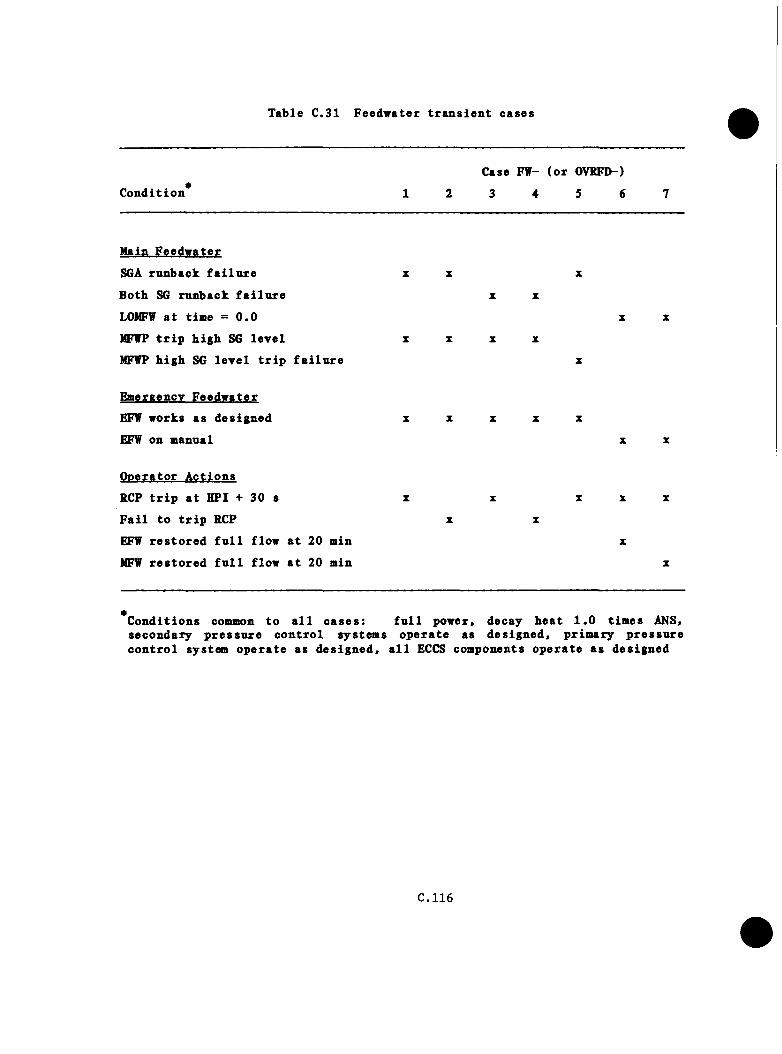
Table C.31 Feedwater tr a n s ie n t cases
Case FW- (o r OVRFD-)
C o n d itio n * 1 2 3 4 5 6 7
Main F eedw ater
SGA runback f a i l u r e X X X
Both SG runback f a i l u r e X X
LOMFV a t tim e = 0 .0 X X
MFWP t r i p h ig h SG le v e l X X X X
MFWP h ig h SG le v e l t r i p f a i l u r e X
Emeraencv F eedw ater
EFW works as d es ig n ed X X X X X
EFW on manual X X
O n era to r A c tio n s
RCP t r i p a t HPI + 30 s X X X X X
F a i l to t r i p RCP X X
EFW r e s to r e d f u l l flow a t 20 min X
MFW r e s to r e d f u l l flow a t 20 min X
* C o n d itio n s common to a l l c a s e s : secondary p re s s u re c o n tro l system s
f u l l power, o p e ra te as
decay h e a t 1 .0 tim es ANS, d e s ig n e d , p rim ary p re s s u re
c o n tro l system o p e ra te as d e s ig n e d , a l l ECCS components o p e ra te a s d esig n ed
C.116
such as HPI f l o v , a re a c t i v a t e d . F o llow ing r e a c to r t r i p , main feedw ate r
te m p era tn re s t a r t s t o d e c l in e because of lo s s o f h e a t e r steam. For
sequences where l e v e l t r i p s o f MFW o ccu r , main feed w ate r te m p era tu re s s ta y
above 350 to 400°F. R e s u l t in g system te m p e ra tu re s a re bounded by normal
o p e ra t in g te m p e ra tu re s and t h i s feed te m p e ra tu re . I f the ov erfeed uses
90*^F EFW, th e r e s u l t i n g te m p e ra tu re s can be much low er.
In most c a s e s , t r a n s i e n t e v a l u a t i o n w i l l siiiq>ly use the a p p l ic a b le p o r t i o n s
o f th e base case c a l c u l a t i o n s . Where e x t r a p o l a t i o n i s n e c e s s a ry , the
cooldown model i s u sed .
C .7 .2 Cases FWl and FW2
a. Tem perature
I n t h i s c a s e , MFW runback f a i l u r e o ccu rs in SGA w hile SGB runback
succeeds MFW pump t r i p on h ig h SG l e v e l . EFW and a l l o th e r systems
o p e ra te as d e s ig n e d . E a r ly in th e t r a n s i e n t , SSRV and TBV steam
r e l e a s e s accoun t f o r a la rg e p o r t i o n of the c o o l in g . A l l of th e se
c o n d i t io n s fo l lo w LANL TBV case SA ou t to 6 0 s when the MFW pump t r i p s
on h igh l e v e l . High p r e s s u r e in SGA p re v e n ts f u r t h e r flow in t o the
SG from HW/CB pump a c t i o n . The downcomer te m p era tu re a t t h i s p o in t
i s 552°F. HPI does n o t come on and th e RCPs rem ain on. The system
i s coo led t o 548^F by c o n t in u in g o p e r a t io n o f th e TBVs w ith o c c a s s io n a l
EFW flow to SGB. T h is f i n a l te m p e ra tu re i s assumed to be reached by
200 s . T em peratu res a re documented in f i l e s FWl.T and FW2 .T. This
case i s ve ry s i m i l a r to FW4 in which HPI comes on bu t the RCPs a re
l e f t ru n n in g . T h e re fo re , HPI does n o t s i g n i f i c a n t l y a f f e c t downcomer
C.117

t e n p e r a tn r e because o f e x c e l l e n t m ix ing . I f HPI comes on and th e RCPs
a re t r i p p e d , as in case FW2, th e te m p e ra tu re s and p r e s s u r e s r e p o r te d in
case r e q u i r e d FW3 would be o b ta in e d ( s e e Table C.32 and F ig u re € .2 9 ) .
b . P r e s s u re
P re s s u re i s assumed to fo l lo w LANL IBV case SA out to 60 s . The
p r e s s u r e d e c l in e s from 2180 p s i a to 1760 p s i a over t h i s p e r io d . With
the c o o l in g mechanism c u r t a i l e d , r e d u c t io n to HPI s e t p o in t does n o t
o c c u r . With oyer 6 f t o f w a te r s t i l l in th e p r e s s u r i z e r , i t i s assumed
t h a t th e h e a t e r s a r e a c t i v a t e d and accom plish r e p r e s s u r i z a t i o n to 2180
p s i a by 200 s ( s e e T ab le € .32 and F ig u re € .2 9 ) .
c . Heat T r a n s f e r C o e f f i c i e n t
S ince th e r e a c t o r c o o la n t pumps rem ain o f f th roughou t the t r a n s i e n t ,
th e h e a t t r a n s f e r c o e f f i c i e n t i s c o n s ta n t a t 2820 B tu /h f t F ( s e e
Table € .3 2 ) .
€ .7 .3 Case FW3
a . Tem perature
In t h i s case th e s t a r t u p flow c o n t r o l v a lv e s rem ain open to b o th steam
g e n e r a to r s , c au s in g main feed w a te r o v e r fe e d to b o th steam g e n e r a to r s .
Both steam g e n e r a to r s reac h the MFW t r i p l e v e l a t about 250 s (LANL
case 6A ). Downcomer te m p era tu re i s abou t 530°F a t t h i s p o in t (from
INEL o v e r f e e d ) . HPI t r i p has n o t y e t o ccu rre d and does n o t occur f o r
an o th e r 20 s in th e INEL o v e r fe e d . I f HPI does n o t come on, th e
system te m p e ra tu re s w i l l b eg in t o r e c o v e r . To s a t i s f y th e s c e n a r io
€.118
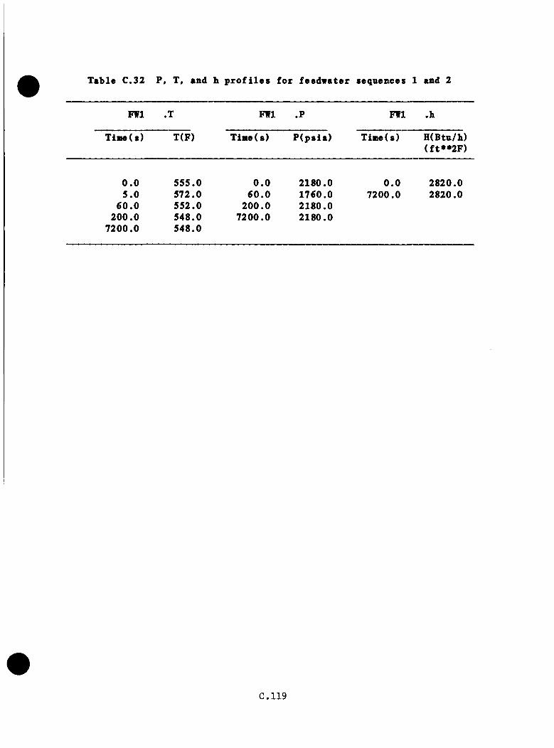
Table C.32 P, T, and h profiles for feedwater sequences 1 and 2
FWl .T FWl .? FWl .h
Time( s) T(F) T in e ( s ) P (p s ia ) Time(s) H(Btu/h)(f t**2F )
0 .0 555.0 0 .0 2180.0 0 .0 2820.05 .0 572.0 6 0 .0 1760.0 7200.0 2820.0
6 0 .0 552.0 200 .0 2180.0200 .0 548.0 7200.0 2180.0
7200.0 548.0
C .119
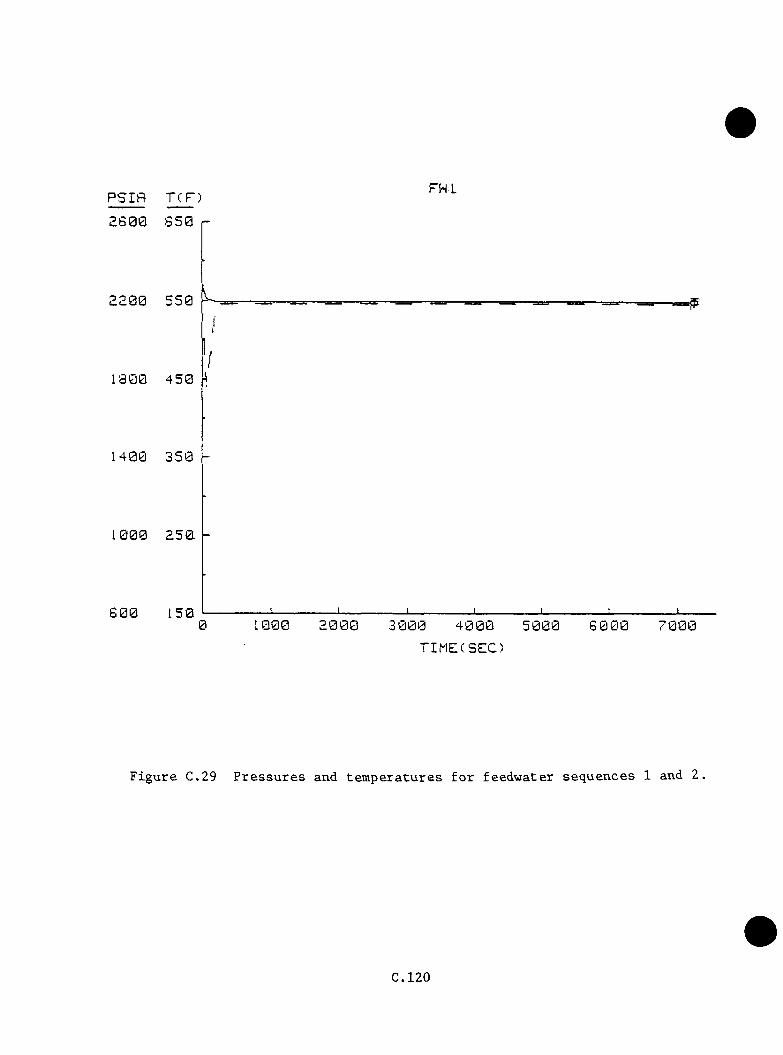
P S I f t T C P
2800- 6 5 0
2 2 0 0 5 5 0
1 8 0 0 4 5 0
1 4 0 0 3 5 0
1 0 0 0 2 5 0
8 0 0 1 5 0
FW-L
J ________________ I________________ I________________L J_________ L.0 1 0 0 0 2 0 0 0 3 0 0 0 4 0 0 0 5 0 0 0 6 0 0 0 7 0 0 0
T I M E (S E C )
F i g u r e C.29 P r e s s u r e s and t e m p e r a t u r e s f o r f e e d w a t e r s e q u e n c e s 1 and 2,
C .120
r e q u i re m e n ts , i t i s assumed t h a t the HPI s e t p o in t (1500 p s i ) i s
reached a t 250 s and t h a t th e RCPs a re t r i p p e d 30 s l a t e r . Downcomer
te m p e ra tu re s s ta y around 5 3 2 .7^F a t 280 s , when the RCPs a re t r i p p e d
and th e n drop to 493 . 8°F a t 350 s where n a t u r a l c i r c u l a t i o n flow i s
e s t a b l i s h e d . Upon re a c h in g th e PORV s e t p o in t p r e s s u r e a t 550 s , flow
d rops from an average 100 I b / s t o a f i n a l va lue of 70 I b / s f o r the
rem ainder o f th e t r a n s i e n t . The r e d u c t io n in c o o lin g coupled t o decay
h e a t in p u t r a i s e s th e h o t le g te m p e ra tu re u n t i l th e TBVs a c tu a te and
the c o n t r o l steam g e n e ra to r te m p e ra tu re goes to 547°F. A f te r 5000 s ,
decay h e a t has reduced to th e p o in t t h a t the TBVs rem ain c lo se d and
the system c o o ls down, because o f HPI f low , t o a f i n a l va lue o f 5 1 0 .2°F
a t 7200 8 ( s e e Table C.33 and F ig u re C .3 0 ) .
b . P r e s s u re
P re s s u re i s assumed to drop to 1500 p s i a a t 250 s to b r in g about HPI
i n j e c t i o n . The HPI i s assumed to r e s t o r e the system to the PORV s e t
p o in t p r e s s u r e 2430 p s i a a t 550 s . P r e s s u re rem ains a t t h i s va lue f o r
the r e s t o f th e sequence ( s e e Table C.33 and F ig u re C .30 ) .
Heat T r a n s f e r C o e f f i c i e n t
Heat t r a n s f e r c o e f f i c i e n t d rops from 2180 B tu / h / f t^ ° F a t RCP t r i p (250
s) to 210 B t u / h / f t ^ ° F a f t e r pump rundown a t 300 s and rem ains a t t h i s
v a lue f o r th e rem a inder o f th e sequence ( s e e Table C .3 3 ) .
C.121
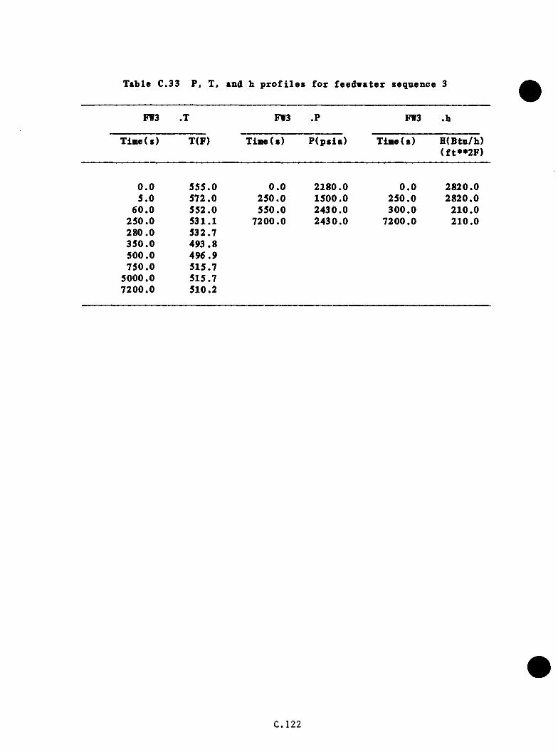
Table C.,33 P. T, and h p r o f i l e s f o r feed w a te r sequence 3
FW3 .T FW3 .P FW3 .b
Tiflw(s) T(F) T ia e ( s ) P (p s ia ) T ia e ( s ) H (Btn/h)(f t* * 2 F )
0 .0 555.0 0 .0 2180.0 0 .0 2820.05 .0 572.0 250 .0 1500.0 250.0 2820.0
60 .0 552.0 550.0 2430.0 300 .0 210.0250.0 531.1 7200.0 2430.0 7200.0 210.0280.0 532.7350 .0 493.8500.0 496.9750.0 515.7
5000.0 515.77200.0 510.2
C.122

p s r f f TCP)PW3
IS 0 a
3 2 0 0
1 8 0 0
1 4 0 0
1000
S 0 02 0 0 0 4 0 0 00 1000 000d
T I M E (S E C )
F i g u r e C .3 0 P r e s s u r e s a n d t e m p e r a t u r e s f o r f e e d w a t e r s e q u e n c e 3.
C .1 2 3

c . 7 .4 Case FW4
a . Tem perature
T his case i s s i m i l a r to case FW3 ex cep t t h a t th e o p e r a to r f a i l s to t r i p
th e RCPs a f t e r HPI i n i t i a t i o n . The e x te n s iv e mixing and a d d i t i o n a l
h e a t in p u t w i l l cause th e te m p era tu re to re c o v e r from 532°F a t 280 s
to 547°F a t about 400 s where i t i s c o n t r o l l e d by TBV a c t io n f o r the
r e s t o f th e sequence (s e e Table C.34 and F ig u re C .3 1 ) .
b . P r e s s u re
T h is case i s ta k e n to be i d e n t i c a l to case FW3 (s e e Table C.34 and
F ig u re C .3 1 ) .
c . Heat T r a n s f e r C o e f f i c i e n t
S ince th e RCPs a re n o t t r i p p e d , t h i s case i s ta k e n to be i d e n t i c a l to
case FWl ( s e e Table C .3 4 ) .
C .7 .5 Case FW5
a . Tem perature
This case f e a t u r e s an o v e r fe e d to SGA where the h ig h SG l e v e l MFW
pump t r i p a l s o f a i l s . SGB feed w ate r i s p r o p e r ly c o n t r o l l e d by ICS.
SGA r e c e iv e s a p p ro x im a te ly 1500 I b / s o f MFW in t h i s c a se , compared to
th e 300 I b / s when b o th SGs a r e b e ing o v e r fe d . T h e re fo re , th e time
to MFW t r i p on low steam q u a l i t y in the steam l i n e w i l l be dropped
from 417 s in th e INEL o v e r fe e d case to a p p ro x im a te ly 85 s . The
te m p e ra tu re re sponse i s assumed to be s i m i l a r to case FWl b e c a u se .
C .1 2 4

T able C. 34 P. T. and h p r o f i l e s fox feedw ater sequence 4
FW3 .T FW3 .? FW3 .h
Tim e(s) T(F) T in e ( s ) P ( p s i a ) Time(s) H(Btu/li)( f t**2F )
0 .0 555.0 0 .0 2180.0 0 .0 2820.05 .0 572.0 250.0 1500.0 7200.0 2820.0
60 .0 552.0 600.0 2430.0250.0 530.0 7200.0 2430.0280 .0 535.6600 .0 548.0
7200.0 548.0
C.125
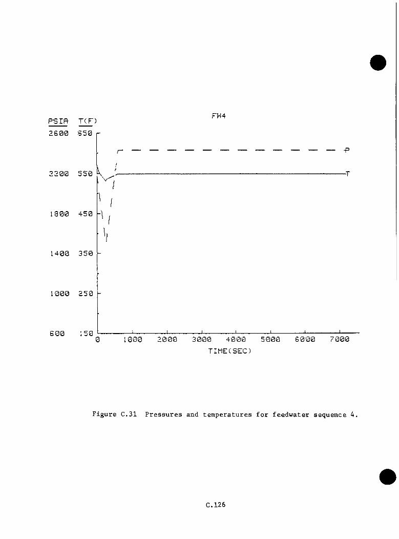
PSIR- TCP)
2 6 0 0
FW4
2 2 0 0
1 3 0 0
1 4 0 0
1000
6 0 07 0 0 00 1000 3 0 0 0
TIMECSEC)
F i g u r e C .3 1 P r e s s u r e s an d t e m p e r a t u r e s f o r f e e d w a t e r s e q u e n c e 4,
C.126

a f t e r the steam g e n e ra to r i s f u l l , a d d i t i o n a l feedw ater w i l l on ly
d i s p la c e o th e r fee d w a te r t h a t has n o t had time to absorb h e a t . The
minimum te m p e ra tn re i s 548°F a t 85 s . The HPI system does n o t come
on and t h e r e f o r e th e RCPs a re no t t r i p p e d . Even i f th e se t r i p s had
o c c u r re d , th e te m p e ra tu re s would rem ain a t or above the f i n a l va lue of
510^F o b ta in e d f o r case FW3 ( s e e Table € .35 and F ig u re € .3 2 ) .
b . P r e s s u re
P re s s u re i s assumed t o d e c l in e a t the same r a t e as observed in case
FWl. At 85 s , th e p r e s s u r e would be 1585.0 p s i a . This i s q u i t e c lo se
to th e HPI s e t p o in t and may p o s s i b ly be reached in a t r a n s i e n t of
t h i s ty p e . However, i t i s assumed t h a t the HPI does no t come on and
t h a t the p r e s s u r i z e r h e a t e r s a re a b le to r e s t o r e the system to 2180
p s i a by 285 s ( s e e Table € .35 and F ig u re € .3 2 ) .
c . Heat T r a n s f e r C o e f f i c i e n t
S ince the RCPs a re n o t t r i p p e d , th e h e a t t r a n s f e r c o e f f i c i e n t rem ains0 A
a t i t s i n i t i a l v a lue o f 2180 B t u / h / f t F th roughou t the t r a n s i e n t in
case FWl ( s e e Table € .3 5 ) .
€ .7 .6 Case FW6
a . Tem perature
This case f e a t u r e s steam g e n e ra to r d ry o u t w ith a 20-min d e la y u n t i l EFW
i s r e s t o r e d a t f u l l f low . EFW i s n o t c o n t r o l l e d to l e v e l . HPI comes
on as d e s ig n e d , and th e RCPs a re t r i p p e d 30 s a f t e r HPI i n i t i a t i o n .
The e a r l y p o r t i o n s o f t h i s t r a n s i e n t a re v ery s im i l a r to the Rancho
C.127

Table C..35 P, T, and b p r o f i l e s f o r fe e d w a te r sequence 5
FW5 .X FW5 .? FW5 .b
TimeCs) T(F) Time(s) P (p s ia ) Time( s) H(Btu/b)(f t**2F )
0 .0 555.0 0 .0 2180.0 0 .0 2820.05 .0 572.0 60 .0 1760.0 7200.0 2820.0
60 .0 552.0 85.0 1585.085 .0 548.0 285.0 2180.0
7200.0 548.0 7200.0 2180.0
C.128

p s r f i T (F )rw 5
2 S 0 0 G50
1 8 0 0 4 5 0
1 4 0 0 350-
1502 0 0 0 5 0 0 00 1000 4 0 0 0
T I M E ( S E C )
F i g u r e C .32 P r e s s u r e s an d t e m p e r a t u r e s f o r f e e d w a t e r s e q u e n c e 5 .
C.129

Seco -type e v e n t . In fo l lo w in g t h i s sequence , th e downcomer te m p era tu re
would r i s e from i t s i n i t i a l v a lue of S55^F to 581^F a t 8 s and
th e n to 644°F a t 1200 s (d T /d t= + 0 .0524°F /s ) T h is te m p e ra tu re i s 20°F
below the s a t u r a t i o n te m p e ra tu re f o r the PORV s e t p o in t p r e s s u r e .
The i n t r o d u c t i o n o f c o ld (90°F) EFW a t 1200 s w i l l cause a d e c l in e
(d T /d t= 0 .2 2 8 °F /s ) t o 548°F a t 1535 s when th e RCPs a re t r i p p e d . ( In
th e LANL Rancho S eco -type t r a n s i e n t , th e te m p e ra tu re a t HPI = 30 s i s
548°F. I t i s assumed t h a t c o o l in g th e system to t h i s s t a t e w i l l y i e l d
com parable HPI r e s p o n s e . ) A f te r th e pumps s p in down, th e system i s
assumed to a t t a i n n a t u r a l c i r c u l a t i o n flow s on th e o rd e r of 820 l b / s
p e r loop and t o t a l v e n t v a lv e f low s o f 45 I b / s , as o bserved in LANL TBV
c a s e s 6A, 6B, and 6C under s im i l a r h ig h cooldown r a t e c i rc u m s ta n c e s .
In t h i s reg im e, th e downcomer te m p era tu re d e c re a s e s to 424*^F a t 2200
s when th e steam g e n e ra to r s a r e l i q u i d f u l l , and th e HPI flow d e c re a se s
as th e p rim ary i s n e a r in g th e PORV s e t p o in t p r e s s u r e . The te m p era tu re
a t 7200 s i s 295°F, i f a l l flow s co n t in u e as s t a t e d . However, i t i s
l i k e l y t h a t EFW w i l l be l o s t a t some e a r l i e r p o in t because of low steam
q u a l i t y in th e seco n d a ry , im pacting th e o p e r a t io n o f th e t u r b i n e - d r iv e n
pump. As a r e s u l t , th e te m p e ra tu re s a f t e r th e l o s s o f EFW would be
h ig h e r th an th e v a lu e s p r e s e n te d h e re ( see Table C.36 and F ig u re C .3 3 ) .
b . P r e s s u re
P r e s s u r e i s g e n e r a l l y ta k e n to mimic th e Rancho S eco-type even t
c a l c u l a t e d by LANL. From an i n i t i a l va lue o f 2180 p s i a , th e p re s s u re
in c re a s e s to th e PORV s e t p o i n t , 2430 p s i a , a t 226 s and rem ains
u n t i l EFW a c t i v a t i o n a t 1200 s . (E a r ly d ip s and peaks in th e LANL
C.130
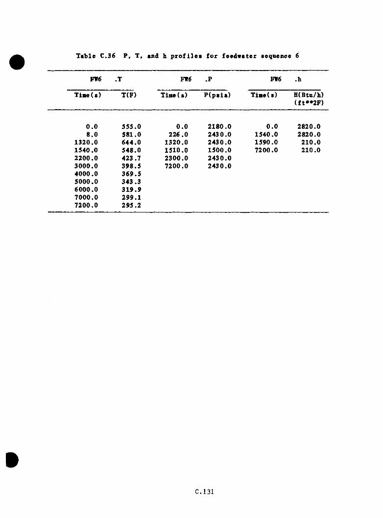
T ab le C..36 P, T. and b p r o f i l e s f o r feed w ate r sequence 6
FW6 .1 FW6 .P FW6 .b
Tiaie(s) T(F) Time(s) P ( p s i a ) Time(s) H(Btu/b)(f t**2F)
0 .0 555.0 0 .0 2180.0 0 .0 2820.08 .0 581.0 226 .0 2430.0 1540.0 2820.0
1320.0 644.0 1320.0 2430.0 1590.0 210.01540.0 548.0 1510.0 1500.0 7200.0 210.02200.0 423.7 2300.0 2430.03000.0 398.5 7200.0 2430.04000.0 369.55000.0 343.36000.0 319 .97000.0 299.17200.0 295.2
C.131
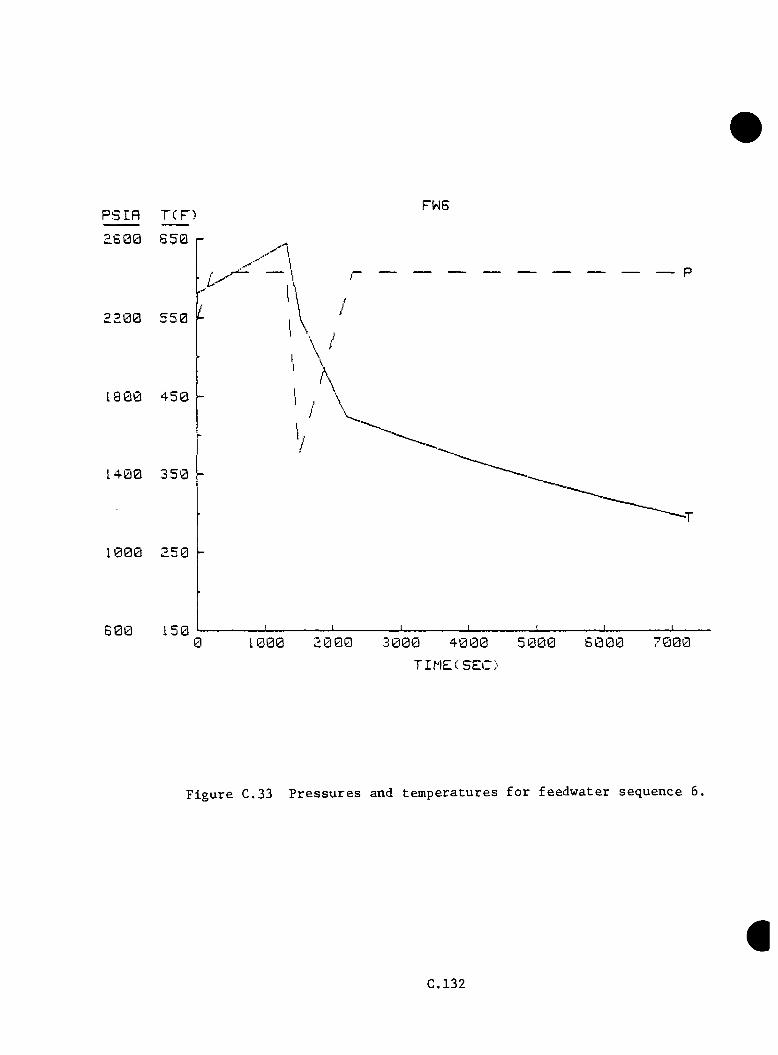
PSIfl TCD FWSa S 0 0
2 2 0 0
1 9 0 0
I 4 0 0
1000
6 0 03 0 0 0 6 0 0 0 7 0 0 00 1000 4 0 0 0 5 0 0 0
TIME(SEC)
F i g u r e C.33 P r e s s u r e s and t e m p e r a t u r e s f o r f e e d w a t e r s e q u e n c e 6.
C.132
c a l c u l a t i o n were no t in c ln d e d because o f the h ig h system te m p e ra tu r e s . )
P r e s s u r e d rops t o 1500 p s i a a t 1510 s u h e re HPI comes on to r e s e rv e
th e t r e n d . R e p r e s s u r iz a t io n to th e f i n a l p r e s s u r e , 2430 p s i a . occurs
a t 2300 s ( s e e Table C.36 and F ig u re C .3 3 ) .
c . Heat T r a n s f e r C o e f f i c i e n t
The downcomer h e a t t r a n s f e r c o e f f i c i e n t r e t a i n s i t s i n i t i a l v a lu e , 2820
B t u / h / f t F , t o 1540 s when th e RCPs a r e t r i p p e d . A f te r a 5 0 -s c o a s t
down p e r io d , th e h e a t t r a n s f e r c o e f f i c i e n t o b ta in s i t s f i n a l va lue of
210 B t u / h / f t ^ ° F ( s e e Table C . 3 6 ) .
€ . 7 . 7 Case FW7
a. Tem perature
This ca se i s s i m i l a r to FW6 ex cep t t h a t the steam g e n e ra to r s a re
r e f i l l e d w ith NFW a t f u l l flow s t a r t i n g a t 20 min. Tem perature
b e h a v io r to 1200 s i s th e same as case FW6. A flow o f 750 l b / s of
450°F w a te r t o each steam g e n e ra to r red u ce s downcomer te m p era tu re to
545^F a t 1280 s when th e RCPs a re assumed to be t r i p p e d . The flow
p a th sw i tch es o v e r to th e EFW h e a d e r s , and flow i s l im i te d to th e SUFCV
va lue o f 112 .5 I b / s p e r steam g e n e r a to r . The steam g e n e ra to r s f i l l ,
and th e MFW t r i p on low steam l i n e q u a l i t y i s assumed to occur a t 2100
s w ith a downcomer te m p era tu re o f 506°F. With HPI flow th rough as the
o n ly cooldown mechanism, th e te m p e ra tu re r i s e s to 528°F a t 5000 s and
d e c l in e s to 523^F a t 7200 s ( s e e Table C.37 and F ig u re C .34 ) .
C.133

Table C..37 P. T, and b p r o f i l e s f o r feed w a te r sequence 7
VWl .T FW7 .P FW7 .b
T in e ( s ) T(F) Tim e(s) P (p s ia ) T i i ie (s ) H(Btn/b)( f t**2F )
0 .0 555.0 0 .0 2180.0 0 .0 2820.08 .0 581.0 226 .0 2430.0 1280.0 2820.0
1200.0 644.0 1200.0 2430.0 1330.0 210.01280.0 545.0 1250.0 1500.0 7200.0 210.01900.0 510.3 2100.0 2430.02100.0 506.5 7200.0 2430.03000 .0 522.04000 .0 527.55000.0 528.86000.0 527.37000.0 524.27200 .0 523.4
C.13A

PSIfl- T ( DFw;
2 6 0 0 6 5 0
1 8 0 0 4 5 0
1 4 0 0 3 5 0
1 0 0 0 2 5 0
1 5 06 0 00 3 0 0 0 4 0 0 0 5 0 0 0 7 0 0 0
TIMECSEC)
F i g u r e C .34 P r e s s u r e s a n d t e m p e r a t u r e s f o r f e e d w a t e r s e q u e n c e 7,
C.135

b . P r e s s u r e
P r e s s u r e s f o l l o v case FW6 to 1200 s . The m assive in - r u s h of
and subsequen t p r im ary h e a t removal i s ta k e n to drop th e p r e s s u r e
to th e HPI s e t p o i n t , 1500 p s i a , a t 1250 s . The HPI i s assumed
to check f u r t h e r d e p r e s s u r i z a t i o n and b eg in r e p r e s s u r i z a t i o n , a l th o u g h
i t i s p o s s i b l e t h a t p r e s s u r e may y e t d e c re a se because of con t in u ed
o v e rc o o l in g . The PORV s e t p o in t p r e s s u r e i s assumed t o be reached a t
2100 s where i t rem ains f o r th e d u r a t i o n o f th e sequence ( s e e Table
C.37 and F ig u re C .3 4 ) .
c . Heat T r a n s f e r C o e f f i c i e n t
The h e a t t r a n s f e r c o e f f i c i e n t i s assumed to rem ain c o n s ta n t a t i t s
i n i t i a l v a lu e , 2820 B t u / h / f t ^ ° F , u n t i l RCP t r i p a t 1280 s , when i t
ramps down to i t s f i n a l v a lue o f 210 B t u / h / f t F by 1330 s ( s e e Table
C .3 7 ) .
C.136

C.8 Steam G enera to r Tnbe R upture
A steam g e n e ra to r tube r u p tu r e i s a form of smal 1 -b reak LOCA. The case
p re p a re d by INEL was d i g i t i z e d and ap p ea rs in Table C.38 and F ig u re C.35.
T h is case does no t appea r w orthy o f concern from FTS s t a n d p o in t , l a r g e ly
because of th e sm alln ess of th e b re a k , which w ithdraw s l e s s flow (40 I b / s )
th a n th e HPI i n j e c t s a t th e PORV s e t p o in t p r e s s u r e (70 I b / s ) . G u i l l o t in e
b re a k s o f two tu b e s would g ive a b re a k s i z e comparable to a s tuck -open PORV.
The te m p e ra tu re s , p r e s s u r e s , and h e a t t r a n s f e r c o e f f i c i e n t s f o r case PORV-
s iz e d LOCA group 11 may be r e p r e s e n t a t i v e of a tw o-tube ru p tu re i f flow
c o m p le x i t ie s do n o t g r e a t l y a l t e r the r e s u l t s . L a rg e r , m u l t i tu b e ru p tu re
i n c i d e n t s would ten d to resem ble l a r g e r LOCAs, a l th o u g h v o id fo rm a t io n in
th e upper hand and candy canes and s i m i l a r e f f e c t s would g r e a t l y co m plica te
th e sequence .
C.137

Table C.38 P, T, and h p r o f i l e s f o r s i n g l e - tu b e s t e a a g e n e ra to r tnbe ru p tu r e case
SGTR .T SGTR .? SGTR .h
Time ( s) T(F) Time(s) P (p s ia ) Time(s) H (Btu/b)( f t* * 2 F )
0 .0 557.0 0 .0 2180.0 0 .0 2820.0320 .0 563.0 160.0 2110.0 975.0 2820.0385 .0 552.7 320.0 2090.0 1025.0 210 .0625 .0 552.7 366.0 1640.0 7200.0 210 .0795 .0 557.0 410.0 1610.0940.0 552.7 650.0 1610.0
1040.0 458.0 720.0 1640.01760.0 450.0 925.0 1509.02240.0 469.0 1135.0 1610.07200.0 477.0 1350.0 1610.0
1550.0 1815.02200.0 2430.07200.0 2430.0
i
€.138

psrft rcF) SGTR
1 8 0 0 4 5 0
1 4 0 0 3 5 0
1 0 0 0 2 5 0
150.0 1 0 0 0 3 0 0 0 4 0 0 0
T I M E ( S E C )
F i g u r e C.35 P r e s s u r e s and t e m p e r a t u r e s f o r s i n g l e t u b e s team g e n e r a t o r t u b e r u p t u r e c a s e .
C.139
APPENDIX D
CONTRIBUTION TO P(F|E) OF FLAWS IN THE CIRCUMFERENTIAL
WELDS AND THE BASE MATERIAL
Flaws anywhere in the beltline region of the reactor vessel will contri
bute to the probability of vessel failure. However, aside from the
effect of flaw depth, some contribute more than others because of
differences in orientation, length, local chemistry of the material, and
local fluence. Axial flaws have the highest values of K^, and in
Oconee-1 the axial welds have higher concentrations of copper than the
circumferential welds and the base material.
Because the difference in copper concentration between the axieil welds
and base material is rather large in terms of radiation damage, the
extended surface length of an axial flaw in a weld tends to be limited
to the height of a shell course, and for deep flaws this limit on sur
face length results in significantly lower values than for much
longer flaws. The surface length of extended flaws in the circumferen
tial welds and in the base material are not limited by this mechanism,
although the lengths of these flaws may be limited by gradients in flu
ence and coolant temperature.
Thus far our fracture-mechanics model is not sufficiently sophisti
cated to consider gradients in fluence and coolant temperature along the
specified surface flaw path. In lieu of considering this sort of
detail, all flaws in the circumferential welds and in the base material
were assumed to be two dimensional. It was believed that even under
D-1
these conservative conditions flaws in the circumferential welds and in
the base material would not be dominant in terms of the calculated pro
bability of vessel failure.
To be certain that the above assumption was reasonable, a few comparison
calculations were made for circumferential flaws in the circumferential
welds, for axial flaws in the base material, and for axial flaws in the
axial welds. The flaw density was assumed to be the same for the three
categories of flaws considered, and since the volume of the base
material is much greater than that of the welds, the base material con
tributed many more flaws than the welds.
The chemistry, maximum fluences, and initial values of RTNDT for each
distinct area of the vessel considered for the three categories of flaws
are given in Table 5.2. In an attempt to account for the azimuthal
variation in fluence in the base plate without dividing the plate region
into several zones, each with a different fluence, an average fluence
was used in accordance with the data in Table 5.2 and Reference 1.
Also, the initial values of RTNDT given in Table 5.2 for the base
material were reduced by 14°C to account for a lower radiation damage2rate in the base material than in the welds. The radiation-damage
trend curve [ARTNDT = f(F, Cu, Ni)] in the fracture-mechanics model
corresponds to weld material only.
The comparison calculations were made for transient No. 44 and for 32
EFPy. The results indicate that the circumferential flaws add '^ 5% to
P(f1e) and the base material ' 30$. Since the contributions were so
D-2
small, flaws In the base material and the circumferential welds were not
Included In the remainder of the studies.
References
1. "Reactor Vessel Pressurized Thermal Shock Evaluation," DPC-RS-1001,
Duke Power Company Oconee Nuclear Station, January 1982.
2. P. N. Randall, U.S. Nuclear Regulatory Commission, personal communi
cation to R. D. Cheverton, Oak Ridge National Laboratory.
D -3

APPENDIX E
COMPILATION OF RESULTS OF OCONEE-1 PROBABILISTIC
FRACTURE-MECHANICS ANALYSIS
Detailed results of the Oconee-1 probabilistic fracture-mechanics
analysis are included in this appendix so that a more thorough under
standing of the effect of the various assumptions used in the fracture-
mechanics model and as related to input to the fracture-mechanics
analysis can be obtained. For instance, the duration of all postulated
transients for this study was specified as two hours. In many cases
most of the failures do not occur until late in the transient. If the
duration of the transient were one instead of two hours, P(f |e ) would be
reduced substantially (' two orders of magnitude for transient No. 44).
Sets of data are included in this appendix for each of the transients
for which P(f |e ) > lO”". A set of data includes, in this order, (1) a
figure of primary-systan pressure, downcomer coolant temperature, and
fluid-film heat-transfer coefficient vs time in transientj (2) a summary
of digital output that includes P(f |e ) for each weld and the vessel, the
estimated error in P(FlE), and histogram data for crack depths, time of
failure (TWC propagation), times and values of T - RTNDT at the crack tip
corresponding to initiation, arrest and failure events; (3) a plot of
vessel wall temperature vs a/w, t; (4) a plot of vessel wall temperature vs
t, a/w; and (5) a set of critical-crack-depth curves obtained using -2a
values of and mean values of all other parameters, and fluences
corresponding to 32 EFPY. The various curves in the set of critical-
crack-depth curves are identified in Figure 5.17 (see Chapter 5).
E-1


TRANSIENT NO. 1 (TBVG1)
E -3

0.0 I _
4.0
6.0H
TC(W
/M«i
^2xK
)8.
0 10
.0
12.0
16.0
i6.0
20.0
>—
JTE
MP.
(DEG
.C.)
300.
033
0.0
270.
0IS
O.O
210.
090
.012
0.0
30.0
60.0
CO O O O z n n o r* o CU < 63 to O V 00 O)
z
“0rj
oC
OC
O
63 O
b 0
.020
.014
.016
.018
.06.0
6.010.
012.
02.0
4.0
PRES
S.(M
Pfl)
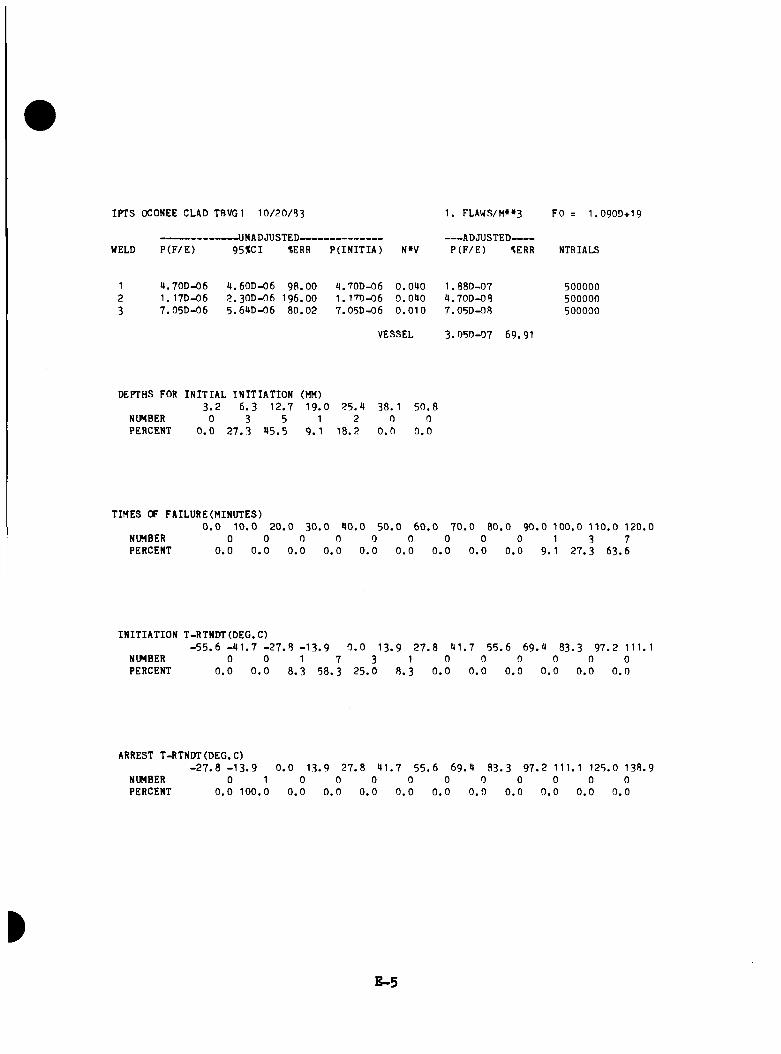
IPTS OCONEE CUD TBVG1 1 0 /2 0 /3 3
WELD P (F /E )-UNADJUSTED-------------------------95%CI *ERR P(INITIA) N»V
1. FLAWS/H»»3
ADJUSTED-------P (F /E ) 3ERR
FO 1.090D+19
NTRIALS
4 .70D -06 1. 17D-06 7 .05D -06
4 .60D -06 9 8 .0 02 .3 0 D -0 6 196 .00 5 .6UD-06 8 0 .0 2
U.70D-06 0 .0 9 0 1 . 88D-07 5000001 .17D-06 0 .0 9 0 9 .7 0 D -0 8 5000007.05D-06 0 .0 1 0 7 .05D -08 500000
VESSEL 3 .05D -07 69.91
DEPTHS FOR INITIAL INITIATION (MM)3 . 2 6 . 3 1 2 .7 1 9 .0 2 5 .9 38. 1 5 0 .8
NUMBER 0 3 5 1 2 0 0PERCENT 0 . 0 2 7 .3 9 5 .5 9 .1 1 8 .2 0 . 0 0 . 0
TIMES OF FAILURE(MINUTES)0 . 0 1 0 .0 2 0 .0 3 0 .0 9 0 .0 5 0 . 0 6 0 .0 7 0 . 0 8 0 .0 9 0 .0 1 0 0 .0 1 1 0 .0 12 0 .0
NUMBER 0 0 0 0 0 0 0 0 0 1 3 7PERCENT 0 . 0 0 . 0 0 . 0 0 . 0 0 . 0 0 . 0 0 . 0 0 . 0 0 . 0 9. 1 2 7 .3 6 3 .6
INITIATION T-RTNDT(DEG.C)- 5 5 . 6 - 9 1 . 7 - 2 7 . 8 - 1 3 . 9 0 . 0 1 3 .9 2 7 . 8 9 1 . 7 5 5 .6 6 9 .9 8 3 .3 9 7 .2 111.1
NUMBERPERCENT
00 . 0
00 . 0
1 7 38 .3 5 8 .3 2 5 .0
18 .3
00 . 0
00 . 0
00 . 0
00 . 0
00 . 0
00 . 0
ARREST T-RTNDT (DEG.C)- 2 7 . 8 - 1 3 . 9 0 . 0 1 3 .9 2 7 .8 9 1 . 7 5 5 .6 6 9 .9 8 3 .3 9 7 .2 111. 1 125 .0 13 8 .9
NUMBERPERCENT
0 1 0 . 0 10 0 . 0
00 . 0
00 . 0
00 . 0
00 . 0
00.0
00.0
00.0
00.0
00.0
00 . 0
E -5
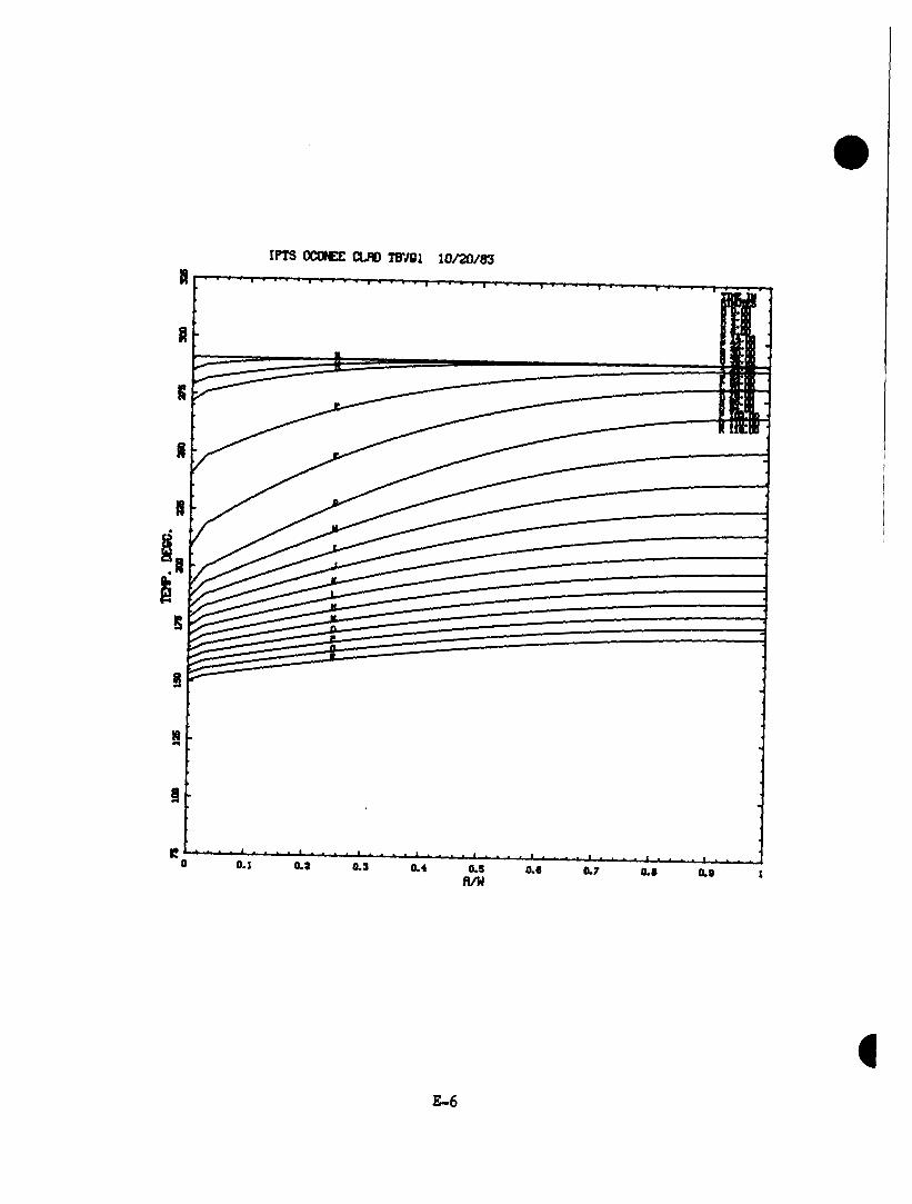
IPTS OCONEE CLflO TBVBl 1 0 /2 0 /8 3
0 .J o.a 0.3 0.4 0.Sfl/W
0.0 0.7 0.0 0.8
E -6
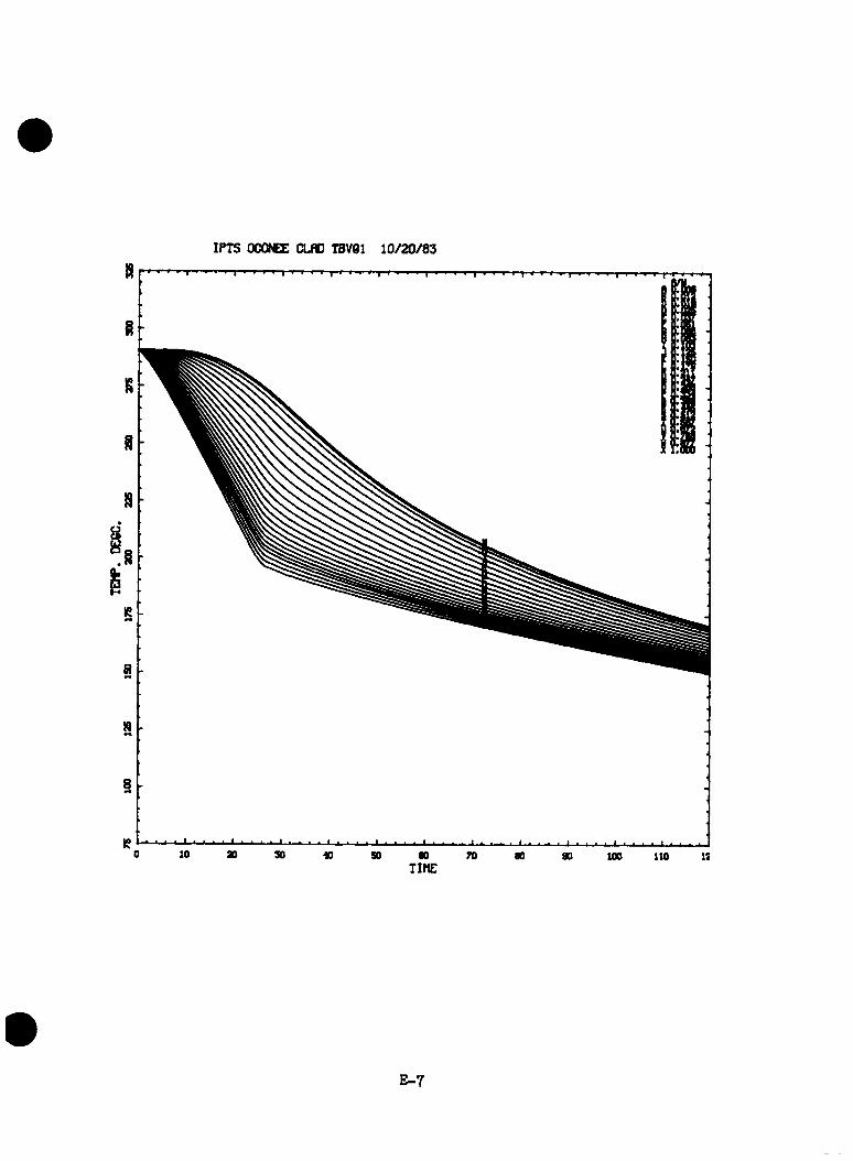
IPTS OCONEZ; CLSO T8V61 1 0 /2 0 /8 3
E -7

CRlTICflL CRfWK DEPTH CURVES FOR IPTS OCONEE OLflD TBVBl 1 0 /2 0 /8 3RTNDTO — 6 .7 DE»0 ZOU - 0 .2 9 ZNl - 0 .5 5 FO - l.OSEllS L0N6IT
O
d “
m
n
o0 30 30 40 SO 0010 70 80 90 100 110 12
T lfC (MINUTES)
E -8
TRANSIENT NO. 4 (TBVG4)
E-9
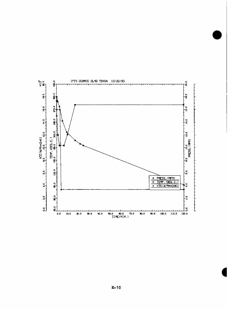
•b«
V!T
CM
CJ X ,
IPTS OCON0E CLRD T3VG4 1 0 /20 /33
oCD o LJ •a 8
P PRESS.(MPfl)o TEnP.(DEG.C.)A hTCfH/hNx2xK)
c0 .
• <n(OuOf0 .
0.0 10.0 20.0 x .o SO.O 00.0 70.0TIMEI^IIN.)
m o 110.0 120.0
E-10

IPTS OCONEE CU D TBVG4 1 0 / ’ 0/B3
WELD P (F /E )-UNADJUSTED-------------------------9 5 tC I tERR P(INITIA) N»V
1. FLAWS/M»»3
ADJUSTED------P (F /E ) tERR
FO r I .O 9OD+I9
MTRIALS
1 2 .7 2 D -0 2 2.1t2D-03 8 .9 0 2 .75D -02 0 .0 9 0 1 .09D -03 100002 1 .6 2 D -0 2 I . 33D-O3 8 . 2 3 1 .63D -02 0 .0 9 0 6 .97D -09 200003 2 .6 3 D -0 2 2 .3 8 D -0 3 9 .0 6 2 .67D -02 0 .0 1 0 2 .63D -09 10000
VESSEL 2 .OOD-O3 5 .6 6
DEPTHS FOR INITIAL INITIATION (MM)3 . 2 6 . 3 1 2 .7 1 9 . 0 2 5 .9 38. 1 5 0 .8
NUMBER 3*18 725 295 89 23 9 0PERCENT 2 3 . 5 9 9 . 0 1 9 . 9 5 . 7 1 .6 0 . 3 0 . 0
TIMES OF FAILURE(MINUTES)0 . 0 1 0 .0 2 0 .0 3 0 . 0 9 0 .0 5 0 .0 6 0 . 0 7 0 . 0 8 0 .0 9 0 .0 100 .0 1 1 0 .0 12 0 .0
NUMBER 0 0 0 0 0 0 2 8 96 1 19 310 976PERCENT 0 .0 0 . 0 0 . 0 0 . 0 0 . 0 0 . 0 0 . 1 0 . 5 3. 1 8. 1 2 1 .2 6 6 .8
INITIATION T-RTNDT(DEG.C)- 5 5 . 6 - 9 1 . 7 - 2 7 . 8 - 1 3 . 9 0 . 0 1 3 .9 2 7 . 8
NUMBER 20 1 13 370 580 3*15 51 1PERCENT 1 .9 7 . 6 2 5 . 0 3 9 .2 2 3 .3 3 . 9 0 .1
9 1 . 7 5 5 . 6 6 9 .9 8 3 .3 9 7 .2 111.10 0 0 0 0
0 . 0 0 . 0 0 . 0 0 . 0 0 . 0
ARREST T-RTNDT(DEG.C)- 2 7 . 8 - 1 3 . 9 0 . 0 13 . 9 2 7 .8 9 1 . 7 5 5 . 6 6 9 .9 8 3 .3 9 7 .2 111. 1 12 5 .0 138 .9
NUMBERPERCENT
00.0
00.0
736.8
1263.2
00.0
00.0
00.0
00.0
00.0
00.0
00.0
00.0
E -11
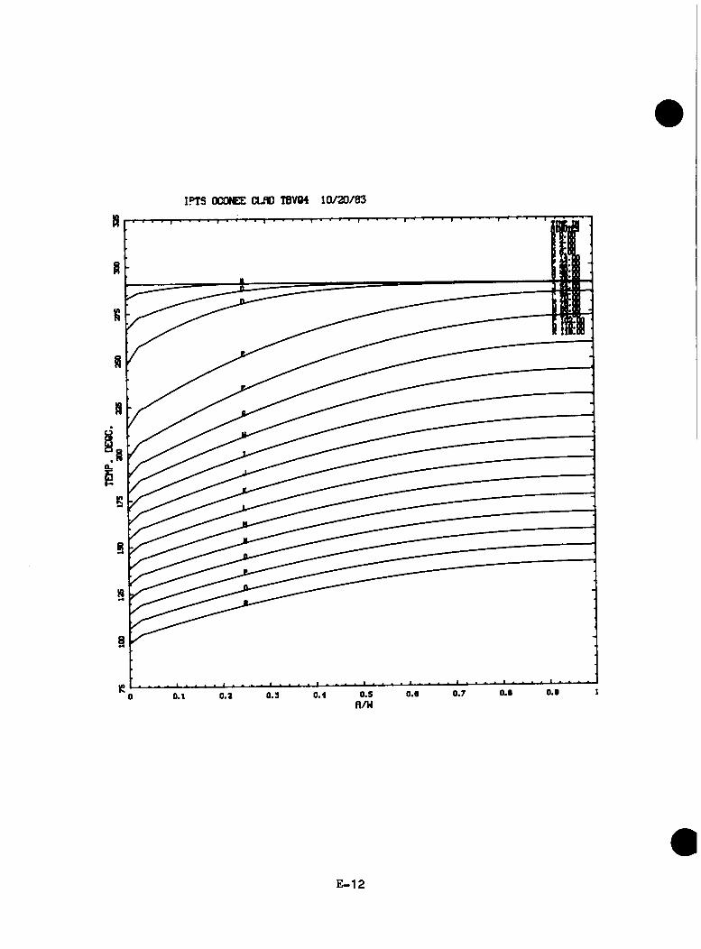
IPTS OOWEE CLflD TBV84 1 0 /2 0 /8 3
E -1 2

IPTS OCONEE CLND TBV64 1 0 /2 0 /8 3
100 110 IS
E -1 3

CRITICflL CRflCK DEPTH OKVES FOR IPTS OCONEE CLflD TBVC4 1 0 /2 0 /8 3RTNDTO — 6 .7 DECC XCU - 0 .2 9 XNI - 0 .5 5 FO - 1 .09E 19 L0N8IT1 1 1 i-T r 1 1 1 1 1 r 1 1 1 » ^ r » 1 » 1 B 1 r 1 1 »-i »■ t p » ............ . i > i ■ i | i , i , | i i i i
X a
X * H ♦
• X ^ n 8 -
BS
X *
° •* - X + B ♦
0
BB
♦X * □ # .
BB
B
♦ 0
> B B B B
B ■ B «•b
X , f - “ □ ♦....................... B ■
B ■ • X ^♦X 4> D «
X □ 0X + ♦
X ♦ D O 4 DO
X
oX
X BN c O
Bo.X
. . . . . . . . . . . ’ ' * * ‘ * * ’‘ ? ’' * * X ¥ x x ^ 8 ! P g a 8 a B 8 H B !
0 to ao 30 « so ao 70 ao 90 100 110 i: TIME(MINUTES)
E - 1 4
d -

TRANSIENT NO. 6 (TBVC36)
E -1 5

IPTS OCONEE CLflO TBVC6 1 /3 /8 4
od a ^ 8
o
□ PRESS, ( y f l )o TSflP. (DEC.C.lA HTC(H/hw2xK)
cc0.
• <o <r>UJQCCL
0.0 ».o x . o 40.0 50.0 eo.o 70.0TIM EtniN.)
ao.o 90.0 100.0 a o .o i x . o
E -1 6
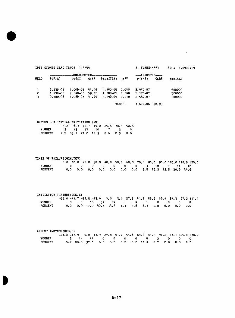
IPTS OCONEE CLAD TBVG6 W 3/SH
----------------------- UNADJUSTED-----WELD P (F /E ) 95<CI »ERR P(IN ITIA ) N»V
1. FLAWS/M»»3
ADJUSTED-------P (F /E ) tERR
FO = 1.090D+19
NTRIALS
1 2 .23D -05 1 .00D -05 U4.96 9 .35D -05 O.QltO 8 .93D -07 5000002 1 .29D -05 7.6AD-06 59 . 10 1 .88D -05 O.OUO 5 . 17D-07 5000003 2 .5 8 0 -0 5 1 .08D -05 4 1 .7 9 3 .2 9 0 -0 5 0 .0 1 0 2 .5 8 0 -0 7 500000
VESSEL 1 .6 7 0 -0 6 30 .9 3
DEPTHS FOR INITIAL INITIATION (MM)3 .2 6 . 3 1 2 .7 1 9 .0 2 5 .4 3 8 .1 5 0 .8
NUMBER 2 43 17 10 7 2 0PERCENT 2 . 5 53. 1 3 1 .0 1 2 .3 8 .6 2 . 5 0 . 0
TIMES OF FAILURE(MINiriESI0 . 0 1 0 .0 2 0 .0 3 0 .0 4 0 .0 5 0 .0
NUMBER 0 0 0 0 0 0PERCENT 0 . 0 0 . 0 0 . 0 0 . 0 0 . 0 0 . 0
6 0 . 0 7 0 .0 8 0 .0 9 0 . 0 1 0 0 .0 110 .0 1 2 0 .0 0 3 10 7 14 18
0 . 0 5 . 8 1 9 .2 1 3 .5 2 6 .9 3 4 .6
INITIATION T-RTNDT(DEG.C)- 5 5 . 6 - 4 1 . 7 - 2 7 . 8 - 1 3 . 9 0 . 0 1 3 .9 2 7 . 8 4 1 .7 5 5 .6 6 9 .4 8 3 .3 9 7 .2 111.1
NUMBER 0 0 1 5 37 29 1 4 1 0 0 0 0PERCENT 0 . 0 0 . 0 1 7 .2 4 2 .5 3 3 .3 1. 1 4 . 6 1. 1 0 . 0 0 . 0 0 . 0 0 .0
ARREST T-RTNDT(DEG.C)- 2 7 . 8 - 1 3 . 9 0 . 0 1 3 .9 2 7 . 8 4 1 .7 5 5 .6 6 9 .4 8 3 .3 9 7 .2 111. 1 125 .0 138 .9
NUMBERPERCENT
25 .7
144 0 .0
1337 .1
00.0
00.0
00.0
00.0
41 1 .4
25 . 7
00.0
00.0
00.0
E -1 7
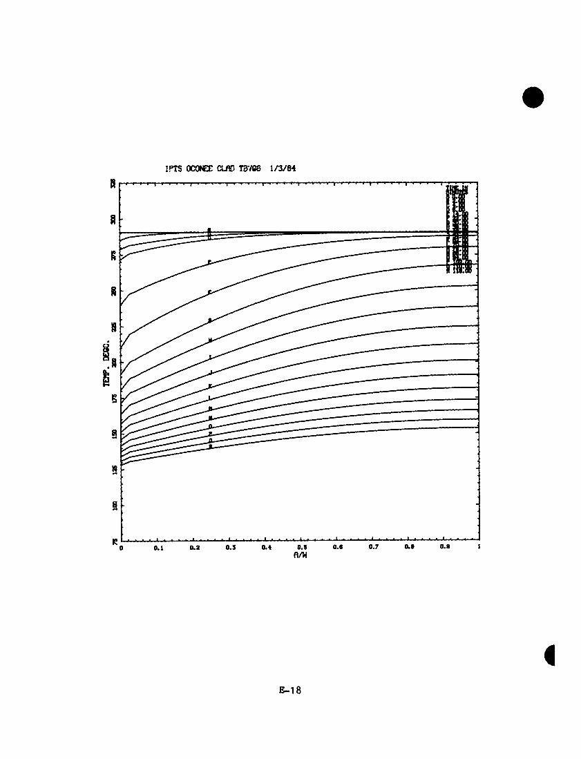
00
tem
p. DE
CC,
aoo
too13
5IT
S33
5ST
S30
033
5
o>

IPTS OCONEE CLflD TBV86 1 /3 /8 4
E -1 9

CRITICflL CRflCK DEPTH CUR'/E3 FOR IPTS OCOICE CLflD TBV06 1 /3 /8 4RTNDTO — 6 .7 KMC XCU - 0 .2 9 XNI - 0 .5 5 FO - 1 .09E 19 LONOIT
230
* 5 < X X X X X X X X X X X X X
ao too 110 i:60 70 600 20 30 so10TIME(MINUTES)
E -2 0

TRANSIENT NO. 7 (TBVG7)
E -21

IPTS OCONEE CLflO T3VQ7 1 0 /2 0 /8 3
Xa oa
o
n PRESS.(HPfl>o TEfip. (oec,c.)A HTC(H/Hx«2xK)
m .o 110.0 lao.o00.0 90.0S0.0 70.020.0 40.0 00.00.0 10.0
• <n(O
TIMEtMIN.)
E-22

IPTS OCONEE CUD TBVG7 1 0 /2 0 /8 3
WELD P (F /E )-UNAOJ'JSTED-------------------------9 5 tC I %ERR P(INITIA)
1. FLAWS/M' S ADJUSTED-------
P (F /E ) tERR
FO 1. 0900+19
NTRIALS
1 8 .1 ID-05 1 .91D-05 2 3 .5 9 9 .2 8 0 -0 5 0 .0 9 0 3 .29D-06 5000002 2 .9 9 0 - 0 5 1. 150-05 3 9 .2 0 3. 17D-05 0 .0 9 0 1. 170-06 5000003 8 .9 6 0 -0 5 1 .9 5 0 -0 5 23. 10 8 .6 9 0 -0 5 0 .0 1 0 8 .9 6 0 -0 7 500000
VESSEL 5 .2 6 0 -0 6 17 .3 7
DEPTHS FOR INITIAL INITIATION (MH)3 . 2 6 . 3 1 2 .7 1 9 .0 2 5 .9 38. 1 5 0 .8
NUMBER 6 82 93 31 15 3 0PERCENT 3 . 3 9 5 .6 2 3 .9 1 7 .2 8 .3 1 .7 0 . 0
TIMES OF FAILURE(MINUTES)0 . 0 1 0 .0 2 0 .0 3 0 .0 9 0 .0 5 0 . 0 6 0 . 0 7 0 .0 8 0 .0 9 0 .0 1 0 0 .0 1 1 0 .0 120 .0
NUMBER 0 0 0 0 1 9 8 18 23 30 39 98PERCENT 0 . 0 0 . 0 0 . 0 0 . 0 0 . 6 2 . 9 9 . 8 1 0 .8 1 3 .9 18. 1 2 0 .5 2 8 .9
INITIATION T-RTNOT(OEG.C)- 5 5 . 6 - 9 1 . 7 - 2 7 . 8 - 1 3 . 9 0 . 0 1 3 .9 2 7 . 8 9 1 . 7 5 5 .6 6 9 .9 8 3 .3 9 7 .2 111.1
NUMBER 0 1 16 56 89 22 1 0 0 0 0 0PERCENT 0 . 0 0 . 6 8 . 9 31. 1 9 6 .7 1 2 .2 0 . 6 0 . 0 0 . 0 0 . 0 0 . 0 0 .0
ARREST T-RTNOT(OEG.C)- 2 7 . 8 - 1 3 . 9 0 . 0 13 .9 2 7 .3 9 1 . 7 5 5 .6 6 9 .9 8 3 .3 9 7 .2 111. 1 12 5 .0 138 .9
NU8BERPERCENT
00.0
21 9 .3
128 5 .7
00.0
00.0
00.0
00.0
00.0
00.0
00.0
00.0
00.0
E-23
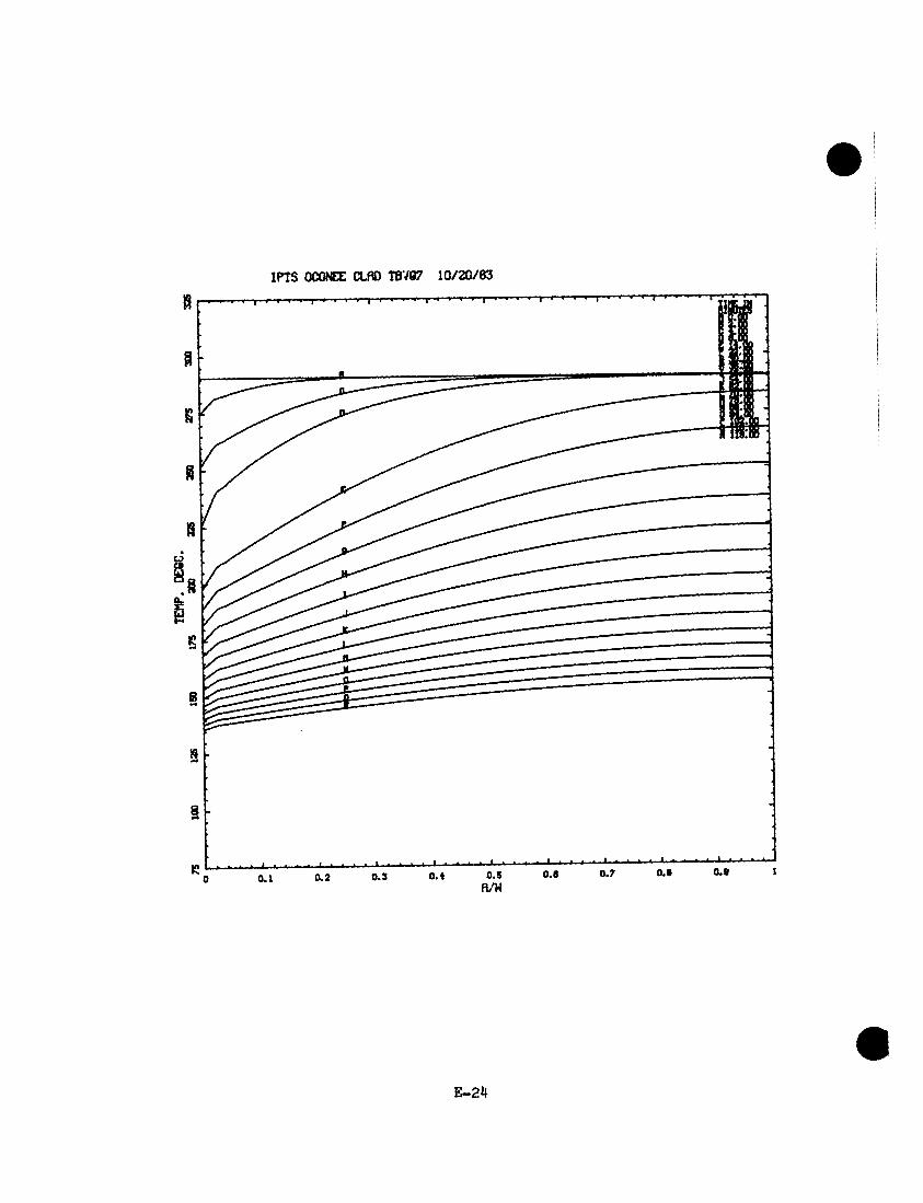
IPTS OCONEE CLflD TBV87 1 0 /2 0 /8 3
I : '
E -2 4
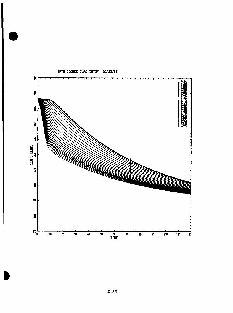
IPTS OCOfCE CLflD TBV87 1 0 /2 0 /8 3
E -2 5
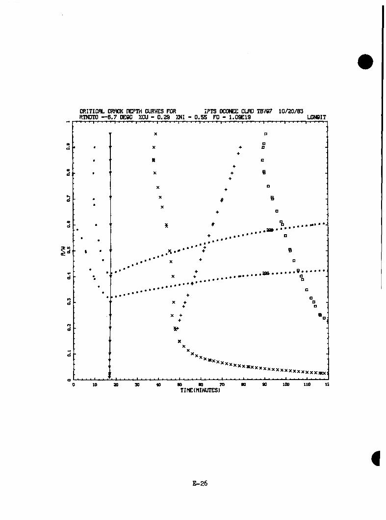
CRITICflL CRflCK nEPTri Cl^VES FOR IPTS OCONEE CLfffl TB787 1 0 /2 0 /8 3RTNDTO — 6 .7 DEBC XCU - 0 .2 9 XNI - 0 .5 5 FO - 1 .09E 19 L0N6IT
me
ma
Ke
«ee
ind
d
K)d
nd
d
oao 110 i:0 « so ao 70 8010 30 30
i:
T IfE (MINUTES)
E -26
TRANSIENT NO. 10 [TBVGIQ(TBVGO)]
E-27

*b ot S-
r j -
Sr.CM
E P-
OX I
IPTS OCONEE CLnO 13700 1 /3 /8 4
oCS o0 8a.EU1
D PRESS.(NPRlo TEnP.(DEG.C.lA HTCiy/>1i<*2*K)
100.0 liO.O 120.000.0 90.030.0 SO.O 70.00.0 20.0 40.0 60.010.0
Q-oE
TIME(MIN.]
E -2 8
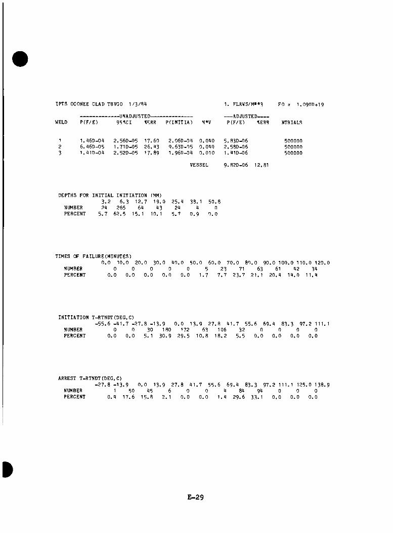
IPTS OCONEE CLAD TBVGO 1 /3 /B 4
WELD P (F /E )-UNADJUSTED-------------------------95».CI tERR P(INITIA) N»V
1. FLAWS/M»»3
ADJUSTED-------P (F /E ) tERR
FO = I .O 9OD+I9
NTRIALS
1 . 1I6D-09 6 . 96D-05 1. lt1D-09
2 .5 6 0 -0 5I . 7 ID-O52 .52D -05
17 .6026 .9 317 .89
2 .06D -099 .6 3 0 -0 51 .9 6 0 -0 4
0 .0 4 0 5 .8 3 0 -0 60 .0 4 0 2 .58D-060 .0 1 0 1 .4 1 0 -0 6
VESSEL 9 .8 2 0 -0 6 12.81
500000500000500000
DEPTHS FOR INITIAL INITIATION (MM)3 . 2 6 .3 1 2 .7 1 9 . 0 2 5 .4 38. 1 5 0 .8
NUMBER 24 265 64 43 24 4 0PERCENT 5 . 7 6 2 .5 15. 1 10. 1 5 . 7 0 . 9 0 . 0
TIMES OF FAILURE(MINUTES)0 . 0 10 . 0 20 .
NUMBER 0 0PERCENT 0 .0 0 . 0
0 3 0 . 0 4 0 .0 5 0 .0 6 0 .0 7 0 .0 8 0 .0 9 0 .0 1 0 0 .0 1 10 .0 120 .00 0 0 5 23 71 63 61 42 34
0 . 0 0 . 0 0 . 0 1 .7 7 . 7 2 3 .7 21 . 1 2 0 .4 1 4 .0 1 1 .4
INITIATION T-RTNDT(DEG.C)- 5 5 . 6 - 4 1 . 7 - 2 7 . 8 - 1 3 . 9 0 . 0 1 3 .9 2 7 .8 41,
NUMBER 0 0 30 180 172 63 106PERCENT 0 .0 0 . 0 5 . 1 3 0 .9 2 9 .5 1 0 .8 1 8 .2
7 5 5 .6 6 9 .4 8 3 .3 9 7 .2 111.132 0 0 0 0
5 .5 0 . 0 0 . 0 0 . 0 0 . 0
ARREST T-RTNDT(DEG.C)- 2 7 . 8 - 13 .9 0 . 0 13 . 9 2 7 .8 4 1 . 7 5 5 .6 6 9 .4 83. 3 9 7 .2 111. 1 125 .0 138 .9
NUMBERPERCENT
10 .4
501 7 .6
451 5 . 8
6 2. 1
00.0
00.0
41 .4
842 9 . 6
9433.1
00.0
00.0
00.0
E-2 9

IPTS OCONEE CLfln TBVeO 1 /3 /8 4
E -3 0
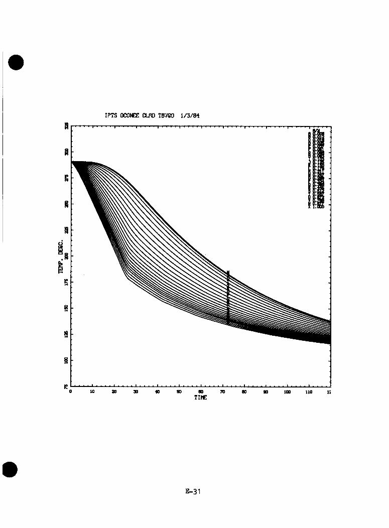
IPTS OCONEE CLflD TBV60 1 /3 /8 4
E -31
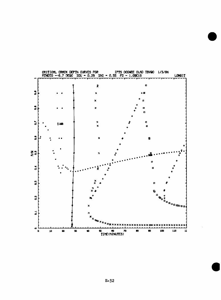
CRITICflL CRflCK DEPTH CURVES FOR IPTS OCONEE CLflO TBVBO 1 /3 /8 4RTNOTO — 6 .7 DECC XCU - 0 .2 9 XNI - 0 .5 5 FO - 1 .09E 19 L0N6IT
md •fO
d
K.d
«od
if»a
d
r>d
rfd
d
^ X X X X X X X X X X X X X X X X M W X X X X X X X X X X X X Xa
100 110 i:00 70 00 90« so0 10 ao 30TIME(MINUTES)
E -3 2

TRANSIENT NO. 14 (PSBG4)
E -3 3

0.02.0
I
_4.
0^
I.
0.0
—L
-*.
0.0
10.0
12.0
14.0
10.010.
0»
-Ml
Cf20
.0
TEM
P.(D
EC.C
.)
U)
330.
030
0.0
240.
02T
0.021
0.0
ISD.
O10
0.0
00.0
00.0
».0
•-1 u> o
X
20.0
10.0
14.0
10.0
b 0
.012.
00.0
10.0
PRES
S. (M
PR)
0.02.0
4.0
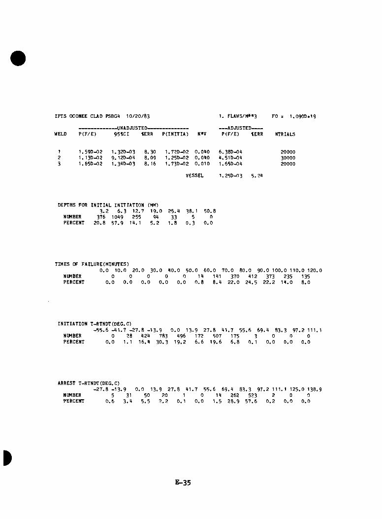
IPTS OCONEE CUD PSBG4 1 0 /2 0 /8 3 1. FLAWS/M» *3 FO = 1.090D+19
WELD P (F /E )—UNADJUSTED-------------------------95*CI tERR P(INITIA) N«V
ADJUSTED-------P (F /E ) tERR NTRIALS
1.59D-02 1. 13D-02 1 .65D -02
1 .32D-03 9 . 12D-0a 1 .39D-03
8. 30 8 .0 9 8. 16
1 . 72D-02 1 . 25D-02 1 . 73D-02
0 .0 9 00 .0 9 00 . 0 1 0
6. 38D-09 9 .51D-09 1 .65D-09
200003000020000
VESSEL 1.25D-03 5 .2 9
DEPTHS FOR INITIAL INITIATION (MM)3 . 2 6 .3 1 2 .7 1 9 .0 2 5 .9 38. 1 5 0 .8
NUMBER 376 1099 255 99 33 5 0PERCENT 2 0 .8 5 7 .9 19. 1 5 . 2 1 .8 0 . 3 0 . 0
TIMES OF FAILURE(MINUTES)0 . 0 1 0 .0 2 0 .0 3 0 .0 9 0 .0 5 0 .0 6 0 . 0 7 0 .0 8 0 .0 9 0 .0 1 0 0 .0 1 1 0 .0 1 2 0 .0
NUMBER 0 0 0 0 0 19 191 370 912 373 235 135PERCENT 0 . 0 0 . 0 0 . 0 0 . 0 0 . 0 0 . 8 8 . 9 2 2 .0 2 9 .5 2 2 . 2 1 9 .0 8 .0
INITIATION T-RTNDT(DEG.C)- 5 5 . 6 - 9 1 . 7 - 2 7 . 8 - 1 3 . 9 0 . 0 1 3 .9 2 7 . 8 9 1 .7 5 5 .6 6 9 .9 8 3 .3 9 7 .2 111.1
NUMBER 0 28 929 783 996 172 507 175 3 0 0 0PERCENT 0 . 0 1. 1 1 6 .9 3 0 .3 1 9 .2 6 . 6 1 9 .6 6 . 8 0 . 1 0 . 0 0 . 0 0 . 0
ARREST T-RTNDT(DEG.C)- 2 7 . 8 - 1 3 . 9 9 1 .7 5 5 .6 6 9 .9 8 3 .3 9 7 .2 111. 1 125 .0 138 .90 . 0 1 3 .9 2 7 .8
NUMBER 5 31 50 20 1 0 19 262 523 2 0 0PERCENT 0 . 6 3 . 9 5 . 5 2 . 2 0 .1 0 . 0 1 . 5 2 8 .9 5 7 . 6 0 . 2 0 . 0 0 . 0
E -3 5

IPTS OCONEE CLflO PSBC4 10/20/83
0.1 o.a 0.3 0.4 0.5n/u 0.0 0.7 0.8 0.S
E -3 6

IPTS OCONEE CLflO PSB84 10/20/83
E -3 7

CRITICflL CRflCK DEPTH 0«V E S FOR IPTS OCONEE CLfiO PS8C4 1 0 /2 0 /8 3RTNDTO — 6 .7 DEOC %CU - 0 .2 9 XNI - 0 .5 5 FO - 1.09E19 L0N6IT
■ P F f 1 1 0 1 0 1 1 0 » ■ 1 * '
X
r 1 F r F r 1 r F F F' r r > F r p p f r t y - f f ppp r p f | p » r
B
01e »2ao \ X
Xm «♦
X + B
md X # D «
X + «
+ ♦KO
X
♦
«»e
• • •r* • • • X
+
♦ a ♦ ♦
• ♦ ••
•* • * .
X+ 0
..........................« .......................
d•• X t ..............................
□ 0
r>e
♦□ «
a 0a
\ X *♦
nd
+!>
X 'D
a□
d X'X
’ □a
a ,0 fc h 0 1 i 1 1 1 1 i 1 1 0 1 . 7 y 7 c ” g ) n 8 S 8 S 5 a ! i ( S S 9 3 9 a B 9 B 9 a 9 S 8 9 a 8 B S 8 9 8 !
to so 00 70TIMEtMINUTESl
too ito
E—38

TRANSIENT NO. 21 [ FW6( 0VRFD6) ]
E -3 9
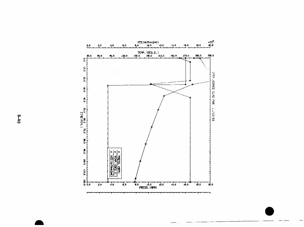
0.0I__ _
2.0 4.0- J _
6.0 I.
HTC(W/M><m2kK) 0 .0 10.0 12.0 14.0 16.0
I L_._10.0
I 1 i20.0
TE?1P. (DEG.C.)
r*O
330.0240.0 2ro.o 300.030.0 90.0 120.0 ISO.O 213.0po
oo
bb O
b8o
Om8oZ.
o
8b8b
•Hn8bpb O
5 1—b 0.0 0.0 10.02.0 4 .0 0.0 10.0 14.0PRESS. (flPR)

IPTS OCONEE CUD FW6 1 1 /1 0 /8 3
WELD P (F /E )-UNADJUSTED-------------------------95JC I %ERR P(INITIA) N»V
1 . FLAWS/M»«3
ADJUSTED-------P ( F /E ) %ERR
FO = I .O 9OD+I9
NTRIALS
1.53D-05 3 .52D-06 1 . 76D-D5
8 . 3OD-O6 5 9 .3 63 .99D -06 113. 16 8 .92D -06 50.61
1 .6 9 0 -0 5 0 .0 9 0 6. 1 ID- 0 7 5000003 .52D -06 0 .0 9 0 1 .9 1 0 -0 7 5000001 ,7 6 0 -0 5 0 .0 1 0 1 .7 6 0 -0 7 500000
VESSEL 9 .28D -07 90 .8 9
DEPTHS FOR INITIAL INITIATION (MM)3 . 2 6 . 3 1 2 .7 1 9 . 0 2 5 .9 38. 1 5 0 .8
NUMBER 1 11 13 9 3 0 0PERCENT 3 . 1 3 9 . 9 9 0 .6 1 2 .5 9 . 9 0 . 0 0 , 0
TIMES OF FAILURE(MINUTES)0 . 0 1 0 .0 2 0 .0 3 0 . 0 9 0 .0 5 0 . 0 6 0 .0 7 0 . 0 8 0 ,0 9 0 .0 1 0 0 .0 11 0 .0 120 .0
NUMBER 0 0 0 0 0 0 0 0 0 0 5 26PERCENT 0 . 0 0 . 0 0 . 0 0 . 0 0 . 0 0 . 0 0 . 0 0 . 0 0 . 0 0 . 0 16. 1 83 .9
INITIATION T-RTNDT(DEG.C)- 5 5 . 6 - 9 1 . 7 - 2 7 . 8 - 1 3 . 9 0 . 0 1 3 .9 2 7 .8 9 1 .7 5 5 .6 6 9 .9 8 3 .3 9 7 .2 111.1
NUMBER 0 0 0 9 23 5 0 0 0 0 0 0PERCENT 0 . 0 0 . 0 0 . 0 1 2 .5 7 1 .9 1 5 .6 0 . 0 0 . 0 0 . 0 0 .0 0 . 0 0 .0
ARREST T-RTNDT(DEG.C)- 2 7 . 8 - 1 3 . 9 0 . 0 13 . 9 2 7 . 8 9 1 .7 5 5 . 6 6 9 .9 8 3 .3 9 7 .2 111. 1 12 5 .0 13 8 .9
NUMBERPERCENT
00.0
0 1 0 . 0 10 0 . 0
00.0
00.0
00.0
00.0
00.0
00.0
00.0
00.0
00.0
E -41
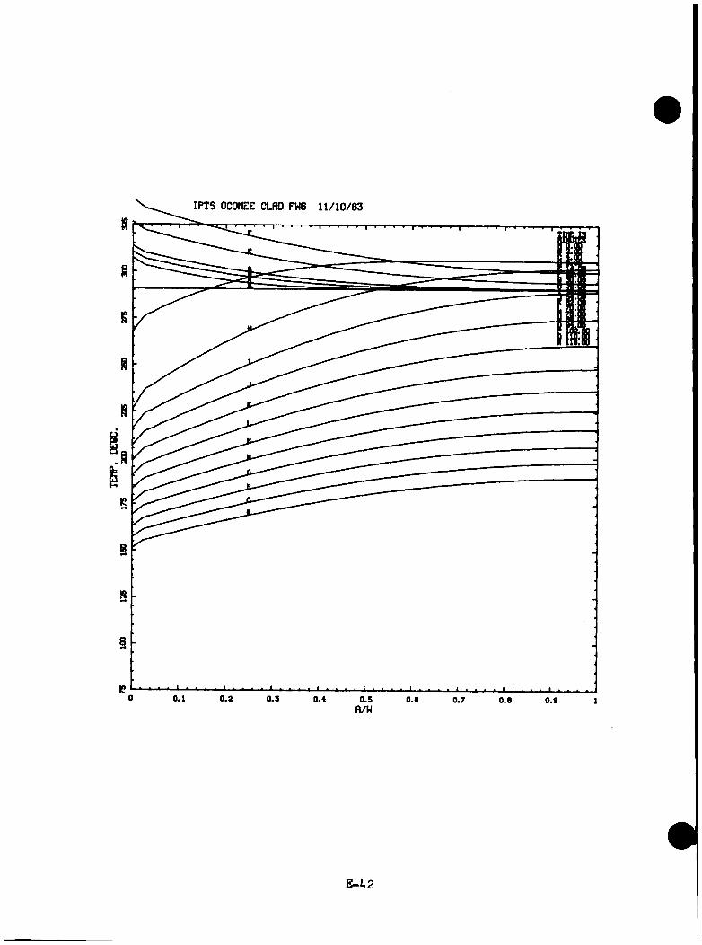
IPTS OCONEE CLflO FV» 1 1 /1 0 /8 3
H
.8
R
8
§
R0 0.1 0 .3 0 .3 0 .4 0 .5 0.6 0.7 0.6 0 .9 1n/w
E-M2

CLflD FM6 1 1 /1 0 /8 3
E -4 3
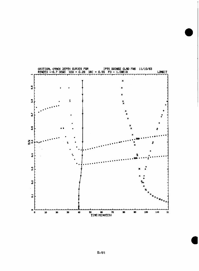
CRITICfiL CRflCK DEFTri CUR'/ES FOR IPTS OCONEE CLflD FW6 1 1 /1 0 /8 3RTNDTO — 6 .7 DECC XCU - 0 .2 9 XNI - 0 .5 5 FO - 1 .09E 19 L0N6IT
n
100 n o i:70 00 9040 SO 000 ao 3010TIME(MINUTES)
E-4H
TRANSIENT NO. 24 [ZITBV(ZPITBV)]
E -4 5

•b o
XrgTE r \ ‘ 3O
IPTS OCONEE CLflD 21TBV 10/20 /33
C J
C9 o
5^8-
o PRESS.(MPfl)o TEMP.(PEG.0.1A HTCtW/N>o<2xK)
so.o0.0 10.0 20.0 30.0 10.0 60.0 70.0 80.0 90.0 i n . o ;;o .o i 20.o
cc0.
• (O<nuft:0.
TIME(MIN.)
E -4 6
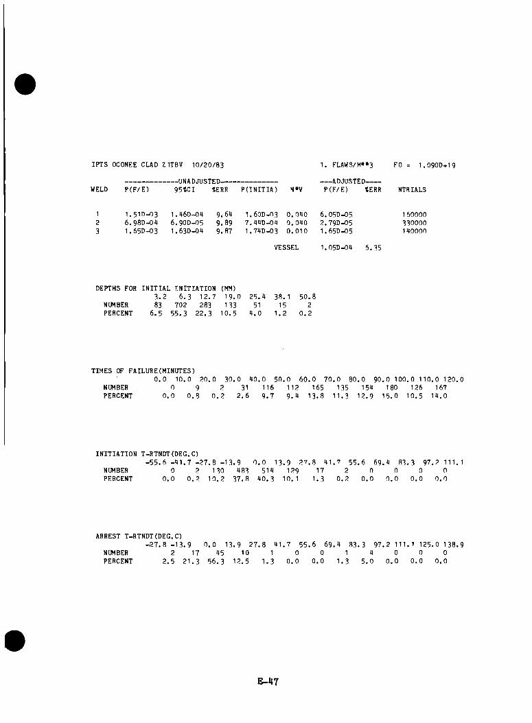
IPTS OCONEE CLAD Z 1TBV 1 0 /2 0 /8 3
WELD P (F /E )-UNADJUSTED-------------------------95*CI %ERR P(INITIA) N»V
1. FLAWS/M»»3
ADJUSTED-------P (F /E ) tERR
FO I .O 9OD+I9
NTRIALS
1 I . 5 ID-O3 1 .9 6 0 -0 4 9 .6 9 I . 6OD-O3 0 .0 9 0 6 .05D-05 1600002 6 .98D -09 6 . 9OD-O5 9 .8 9 7 .99D -09 0 .0 9 0 2 .79D-05 3300003 1 .65D -03 1 .63D-09 9 .8 7 1 .79D -03 0 .0 1 0 1 .65D-05 190000
VESSEL 1.05D-09 6 .3 5
DEPTHS FOR INITIAL INITIATION (MM)3 . 2 6 .3 1 2 .7 1 9 . 0 2 5 .9 38. 1 5 0 .8
NUMBER 83 702 283 133 51 15 2PERCENT 6 . 5 5 5 .3 2 2 .3 1 0 .5 9 . 0 1 . 2 0 . 2
TIMES OF FAILURE(MINUTES)0 . 0 1 0 .0 2 0 .0 3 0 . 0 9 0 .0 5 0 . 0 6 0 .0 7 0 .0 8 0 .0 9 0 .0 1 0 0 .0 110 .0 1 2 0 .0
NUMBER 0 9 2 31 116 1 12 165 135 159 180 126 167PERCENT 0 . 0 0 . 8 0 . 2 2 . 6 9 . 7 9 . 9 1 3 .8 1 1 .3 1 2 .9 1 5 .0 1 0 .5 1 9 .0
INITIATION T-RTNDT(DEG.C)- 5 5 . 6 - 9 1 . 7 - 2 7 . 8 - 1 3 . 9
NUMBERPERCENT
00.0
20.2
1301 0 . 2
0 . 0 1 3 . 9 2 7 . 8 9 1 .7 55. 6 6 9 .9 83. 3 9 7 .2 111.1983
3 7 .8519
9 0 .3129
10. 117
1 .32
0.20
0.00
0.00
0.00
0.0
ARREST T-RTNDT(DEG.C)- 2 7 . 8 - 1 3 . 9
NUMBERPERCENT
22 .5
172 1 .3
0 . 0 1395
5 6 .3
9 2 7 . 8 9 1 .7 5 5 . 6 6 9 .9 8 3 .3 9 7 .2 111. 1 125 .0 138 .910
1 2 .51
1 .30
0.00
0.01
1 .39
5 .00
0.00
0.00
0.0
E-47

IPTS OCONEE CLflD 21TBV W / 2 0 /8 3
0.1 0.2 0 .3 0 .4 0 .Sfl/H 0.6 0 .7 0.8 0.6
E-i|8

IPTS OCONEE CLflO ZITBV 1 0 /2 0 /8 3
E -4 9
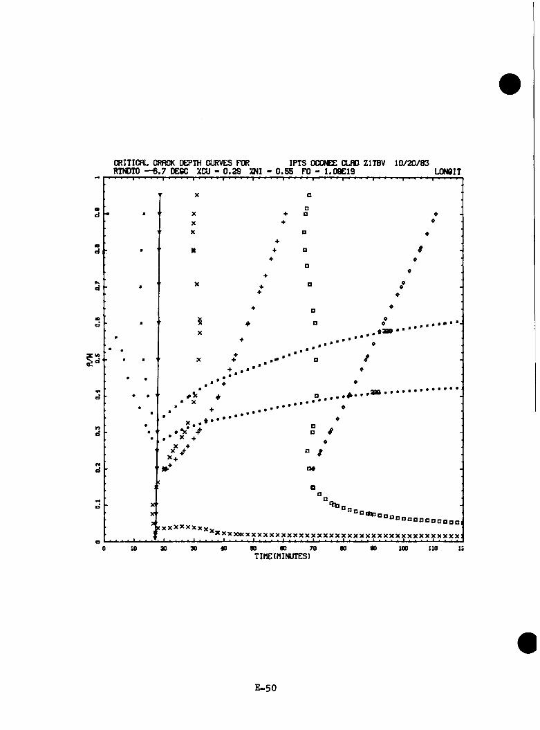
CRITICflL CRflCK DEPTH CURVES FOR IPTS OCONEE CLflD ZITBV 1 0 /2 0 /8 3RTNDTO — 6 .7 DECC ZCU - 0 .2 9 ZNI - 0 .5 5 FO - 1 .09E 19 LONCIT
01d
md
Is.d
IDd
lAd
•0d
n O#d
d
• B D D O B O n o n O B O a D D«XScXXXXXXx
X X X X K X X X X X X X X X X X X X X X X X X X X X X X X X X X X X X X X X X X X
X ’ X '
o9030 40 so 90 70 80 100 110 IS0 10 ao
TIME(MINUTES)
E -5 0

TRANSIENT NO. 25 [Z2TBV(ZP2TBV)]
E -51
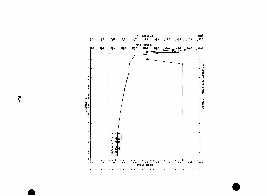
0.0I -
2.0 4.0■ i i
e .oHTC(W/Mn« 2 mK)
8.0 10.0 12.0 14.0 16.0I__
18.0I U-.-
Hicf20.0
TEflP. (DEQ.C.)
PKJ\ro
300.3 330.090.3 ISO.O 180.0 219.330.0 120.0
‘0O)oCD
PIPJo
PJCOCO
o P I
ap)
o
b 0.0 8.0 12.0 14.0 16.02.0 4.0 6.0 10.0PRESS.(MPfl)
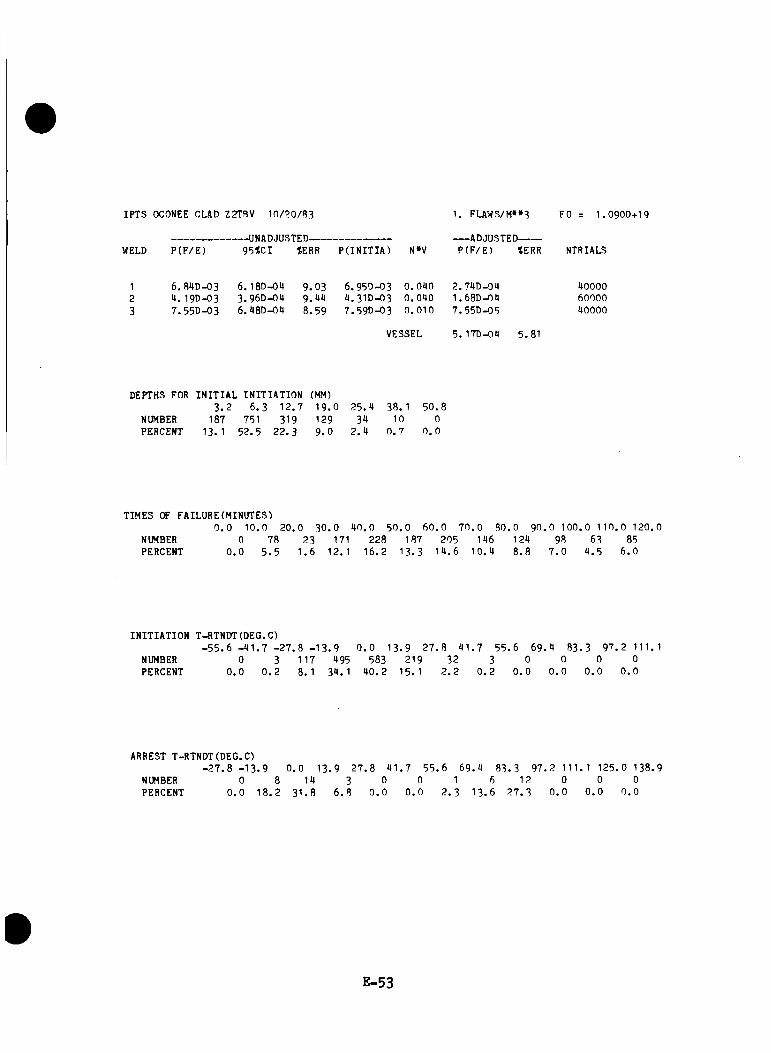
IPTS OCONEE CLAD Z2TBV 10/?0/R3
WELD P (F /E )-UNADJUSTED-------------------------95%CI JERR P(INITIA) N»V
1. FLAWS/M»»3
ADJUSTED-------P (F /E ) %ERR
FO I .O 9OD+I9
NTRIALS
6.84D-03 It. I 9D-O3 7 .55D -03
6. 180-04 3 .9 6 0 -0 4 6. 480-04
9 .0 3 9. 44 8 .5 9
6 .9 5 0 -0 34 . 3ID-037 .5 9 0 -0 3
0 .0 4 0 2 .74D-040 .0 4 0 1 .68D-040 .0 1 0 7 .55D-05
400006000040000
VESSEL 5. 170-04 5 .81
DEPTHS FOR INITIAL INITIATION (MM)3 . 2 6 .3 1 2 .7 1 9 . 0 2 5 .4 38. 1 5 0 .8
NUMBER 187 751 319 129 34 10 0PERCENT 13.1 5 2 .5 2 2 .3 9 . 0 2 . 4 0 . 7 0 . 0
TIMES OF FAILURE(MINUTES)0 . 0 10 .0 2 0 .0 3 0 . 0 4 0 .0 5 0 .0 6 0 .0 7 0 .0 8 0 .0 9 0 .0 1 0 0 .0 1 1 0 .0 120 .0
NUMBER 0 78 23 171 228 187 205 146 124 98 63 85PERCENT 0 . 0 5 . 5 1 .6 12. 1 1 6 .2 1 3 .3 1 4 .6 1 0 .4 8 .8 7 . 0 4 .5 6 .0
INITIATION T-RTNDT(DEG.C)- 5 5 . 6 - 4 1 . 7 - 2 7 .8 - 1 3 . 9 0 . 0 1 3 . 9 2 7 . 8 4 1 .7 5 5 .6 6 9 .4 83. 3 9 7 .2 111.1
NUMBERPERCENT
00.0
30.2
117 8. 1
49534.1
5834 0 .2
219 15. 1
322.2
30.2
00.0
00.0
00.0
00.0
ARREST T-RTNDT(DEG.C)- 2 7 . 8 - 1 3. 9
NUMBERPERCENT
00.0
0 .0 13 . 9 2 7 .8 4 1 .7 5 5 .6 6 9 .4 83. 3 9 7 .2 111. 1 125 .0 138 .9
18.2 1431 . 8
36.8
00.0
00.0
12 . 3
613 . 6
122 7 .3
00.0
00.0
00.0
E-53

IPTS OCONEE CLflO Z2TBV 10/20/83
E-5H

IPTS OCONEE CLflD Z2TBV 1 0 /2 0 /8 3
E -5 5

CRITICflL CRflCK DEPTH CURVES FOR IPTS OCONEE CLflD Z2TBV 1 0 /2 0 /8 3RTNDTO — 6 .7 DE6C XCU - 0 .2 9 XNI - 0 .5 5 FO - 1.09E19 LONCIT
• a
XX
XXX
10X C
XX
X
X B
D
++
0O
fa -
+ . • *
&
D d
x:yxxxxyxxxxyxxxxyxxx5ggS8gS8!j!gg8SgggSgggg8ggg!j!8gggg
• •••
>w
20 10 SO 60 70TIME(MINUTES)
80 100 110
E -56
TRANSIENT NO. 26 (MSLB1)
E -5 7
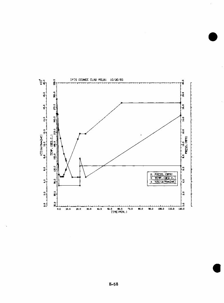
•boxS-1
XOJ X - X ‘
IPTS OCONEE CLflD fISLBl 1 0 /2 0 /8 3
oC9 a
^8-a.r.u
o PRESS.(NPfl)o TEMP.(PEG.C.)A HTC(i /MNi<2xK)
• <n <ohj£
0.0 iO.D 20.0 30.0 40.0 SO.O 60.0 70.0TIME(MIN.)
80.0 90.0 lOO.O 110.0 120.0
E-58
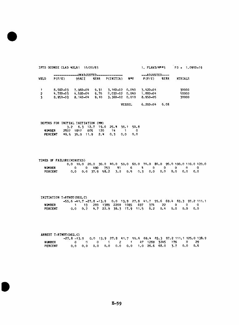
IPTS OCONEE CLAD MSLB1 1 0 /2 0 /8 3
WELD P (F /E )-UNADJUSTED-------------------------9 5 tC I *ERR P(INITIA) N»V
1 . FLAWS/M»»3
ADJUSTED-------P (F /E ) tERR
FO I . O 9 OD+I9
NTRIAU?
1 8 . 56D-O3 7 .9 6 0 -0 9 9 . 31 3. 160-02 0 .0 9 0 3 .92D -09 3OOOO2 9 . 7OD-O3 9 .59D -09 9 .7 6 2 . 03D- 0 2 0 .0 9 0 1 .8 8 0 -0 9 500003 8 .9 5 0 - 0 3 8. 190-09 9 .1 0 3 .3 6 0 -0 2 0 .0 1 0 8 .9 5 0 -0 5 30000
VESSEL 6 .2 0 0 -0 9 6 .0 8
DEPTHS FOR INITIAL INITIATION (MM)3 . 2 6 . 3 1 2 .7 1 9 . 0 2 5 .9 38. 1 5 0 .8
NUMBER 2507 1817 605 120 19 1 0PERCENT 9 9 . 5 3 5 .9 1 1 .9 2 . 9 0 . 3 0 . 0 0 . 0
TIMES OF FAILURE(MINUTES)0 . 0 1 0 .0 2 0 .0 3 0 . 0 9 0 .0 5 0 .0 6 0 . 0 7 0 .0 8 0 .0 9 0 .0 1 0 0 .0 1 1 0 .0 120 .0
NUMBER 0 0 990 753 91 6 9 0 0 0 0 0PERCENT 0 . 0 0 . 0 3 7 .9 5 8 . 2 3 . 2 0 . 5 0 . 3 0 . 0 0 . 0 0 . 0 0 . 0 0 .0
INITIATION T-RTNOT(OEG.C)- 5 5 . 6 - 9 1 . 7 - 2 7 . 8 - 1 3 . 9
NUMBERPERCENT
0 . 0 1 3 . 9 2 7 . 8 9 1 .7 5 5 .6 6 9 .9 8 3 .3 9 7 .2 111.11
0.013
0.22839 .7
13892 2 .9
22003 6 .3
108517.9
6971 1 .5
3796.2
220 .9
00.0
00.0
00.0
ARREST T-RTNOT(OEG.C)- 2 7 . 8 - 1 3 . 9
NUMBERPERCENT
00.0
0 . 0 13 . 9 0 0 1
0 . 0 0 . 0 0 . 0
2 7 .8 9 1 . 7 5 5 . 6 6 9 .9 8 3 .3 9 7 .2 111.1 125 .0 138 .92 1 97 1269 3295 176 0 29
0 . 0 0 . 0 1 .0 2 6 .6 6 8 .0 3 .7 0 . 0 0 .6
E-59
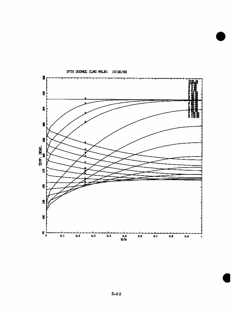
IPTS OCONEE CLflO MSLBl 10/20 /83
E -6 0
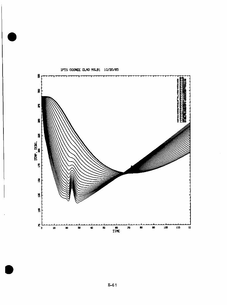
IPTS OCONEE CLflO 10/20/83
E -61
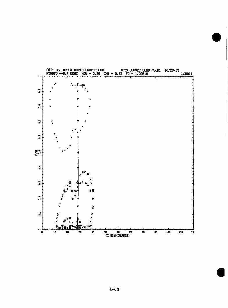
CRITICflL CRfWaC rePTH CURVES FW IPTS OCONEE CLflO HSLBl 1 0 /2 0 /8 3RTNDTO — 6 .7 DE8C XCU - 0 ,2 9 XNI - 0 .5 5 FO - 1 .09E 19 L0N6IT
^ • 1 • • '•
•
•
•
••
•
•
••
• ••
• • '
•
•
••
••
• •• •
-X X
X X
Xik > 4 * ^ X
+
¥* » •*c
XX $
$ XX O j XX iP t a X
...........................................................................................................................................................10 so 00 70
TIME(MINUTES)100 110 12
E -6 2

TRANSIENT NO. 28 (MSLB3)
E -6 3
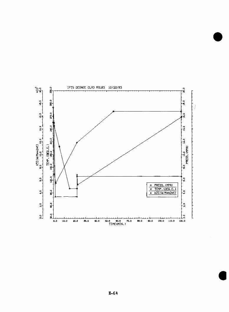
IPTS OCONSE CLflD MSLB3 1 0 /2 0 /8 3
V.T OOJ* _ CS oxH' uj):•r: cj-j o 8-3 • .
Q_r:o“CD
a PRESS.(MPR)o TEflP. (DE6.C.)A hTC(W/Hx>«2xK)
<N“
CL.. r:
• CO<nCiJor.CL.
0 .0 10.0 20.0 30.0 40.0 50.0 60 .0 70.0TIME(MIN.)
80.0 90.0 100.0 110.0 120.0
E -6 4

IPTS OCONEE CLAD MSLB3 1 0 /2 0 /S 3
WELD P (F /E )-UNADJUSTED----9 5 tC I tERR P(IN ITIA ) N»V
1. FLAWS/M»»3
ADJUSTED-------P (F /E ) <ERR
FO I .O 9OD+I9
NTRIALS
5. 3OD-O3 3. 17D-03 6 . 36D-O3
9.87D-0«2.98D-Olt5.96D-OU
9. 19 9 . 40 9 .3 7
3.28D -02 1 . 94D-02 3 .98D -02
0 .0 4 0 2 . 12D-040 .0 4 0 1 .27D-040 .0 1 0 6 .3 6 0 -0 5
VESSEL 4.02D-04 5 .8 7
500008000040000
DEPTHS FOR INITIAL INITIATION (MM)3 . 2 6 .3 1 2 .7 1 9 .0 2 5 .4 38. 1 5 0 .8
NUMBER 4126 2668 847 143 14 1 0PERCENT 5 2 . 9 S'*.2 1 0 .9 1 .8 0 . 2 0 . 0 0 . 0
TIMES OF FAILURE(MINUTES)0 . 0 10 .0 2 0 .0 3 0 . 0 4 0 .0 5 0 .0
NUMBER 0 100 1051 156 7 1PERCENT 0 . 0 7 . 6 7 9 .9 1 1 .9 0 . 5 0 .1
6 0 . 0 7 0 . 0 8 0 . 0 9 0 . 0 1 0 0 . 0 110 .0 1 2 0 . 0 1 0 0 0 0 0
0 . 1 0 . 0 0 . 0 0 . 0 0 . 0 0 . 0
INITIATION T-RTNDT(DEG.C)- 5 5 . 6 - 4 1 . 7 - 2 7 . 8 - 1 3 .9 0 . 0 1 3 . 9 2 7 . 8 4 1 .7 5 5 .6 6 9 .4 8 3 .3 9 7 .2 111.1
NUMBERPERCENT
10 . 0
390 .5
421 5. 1
21112 5 .4
33484 0 .3
16792 0 . 2
4004 . 8
3043 .7
130 . 2
00 . 0
00 . 0
00 . 0
ARREST T-RTNDT(DEG.C)- 2 7 . 8 - 13 . 9 0 . 0 13 . 9 2 7 . 8 4 1 . 7 5 5 . 6 6 9 .4 8 3 .3 9 7 .2 111. 1 125 .0 138 .9
NUMBERPERCENT
00.0
00.0
00.0
00.0
10.0
20.0
440.6
14402 0 . 6
51387 3 .4
3735 .3
00.0
20.0
E -6 5

IPTS OCONEE CLflO MSLB3 10/20/83
E -6 6
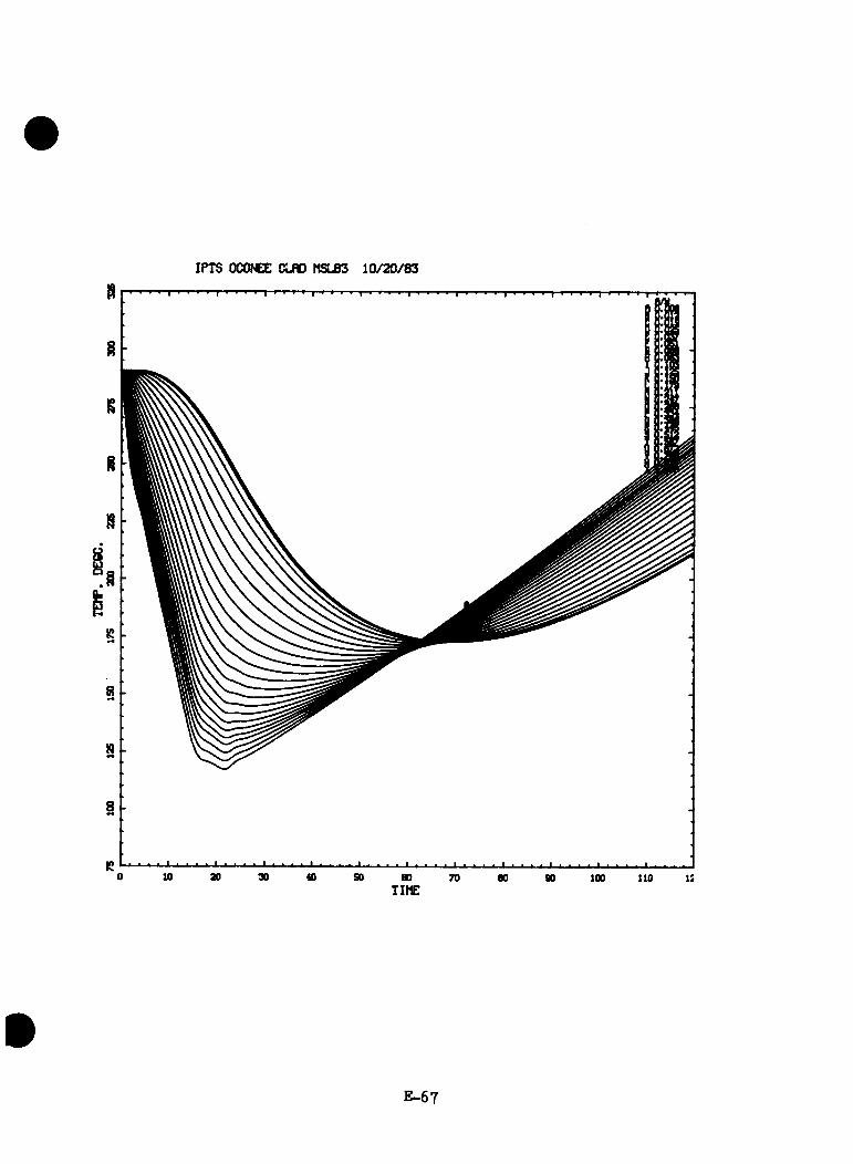
IPTS OCONEE CLflO MSLB3 10/20/83S
8
8
N9*
R0 10 ao 30 40 so 60 70 80 90 100 110 i:TIME
E -6 7
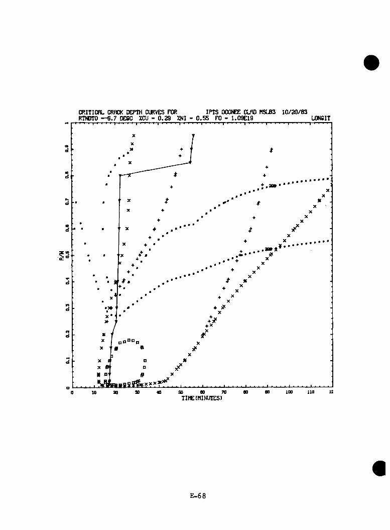
CRITICflL CRACK DEPTH CURVES FOR IPTS OCONEE CLflO MSLB3 lC /2 0 /8 3RTNDTO — 6 .7 DECC %CU - 0 .2 9 XNI - 0 .5 5 FO - 1 .09E 19 L0N6IT
ata
d
INd
«0d
ind
d * *
• 5*d
+ 3? + Xnd
R o §
o 1!90 100 1X000 70 8030 40 SOao0 10TIME(MINUTES)
E -6 8

TRANSIENT NO. 29 (MSLBil)
E -6 9
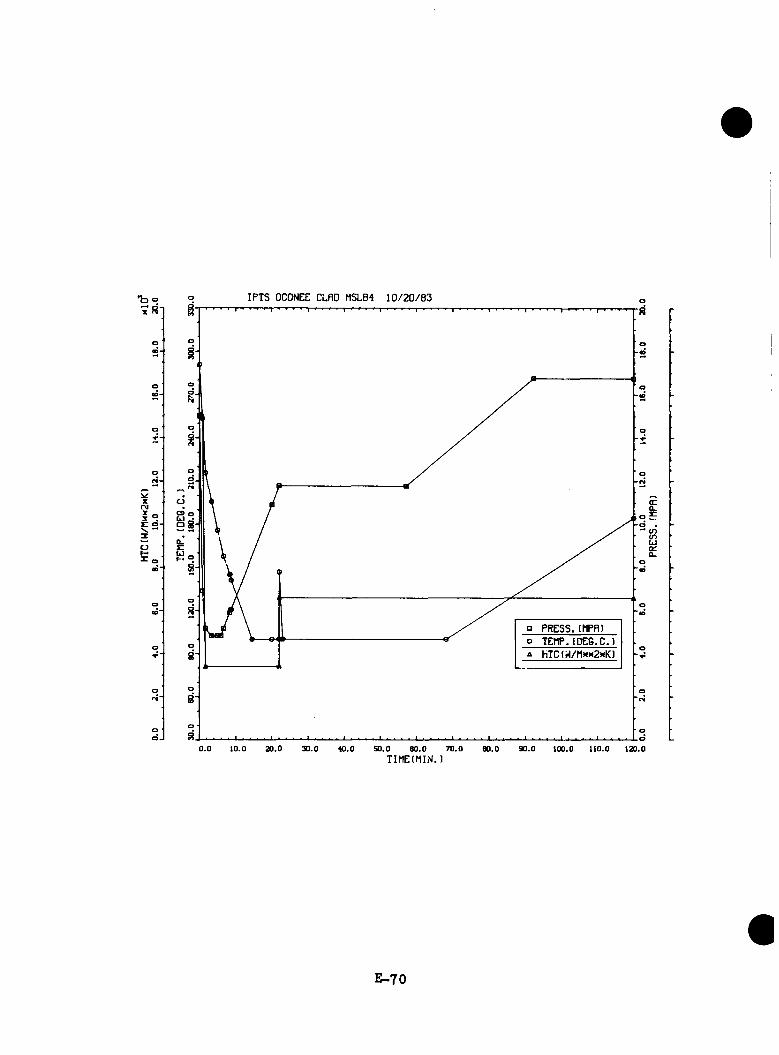
om 8“
E o -V. ^
IPTS OCONEE CLAD MSLB4 1 0 /2 0 /8 3
C9 o LJ •5 8
□ PRESS.(hPfl)o TEHP.(DEG,C.)A HTC( /hxN2xK)
CL
(nuQ_
iO.O 20.0 30.0 40.0 50.0 60 .0 70.0TIME(MIN.)
90.0 loc.o n o .o 120.0
E-70
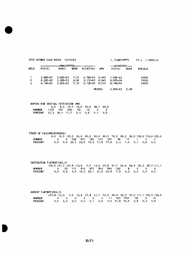
IPTS OCOMEE CLAD MSLBU 1 0 /2 0 /8 3
WELD P (F /E )— UNADJUSTED-------------------------
95*01 *ERR P(IN ITIA ) M»V
1. FLAWS/M»»3
ADJUSTED-------P (F /E ) *ERR
FO = 1 . 0 9 0 D + 1 9
NTRIALS
1 3 .98D -02 2 .89D -03 7 .2 7 4 .7 9 D -0 2 0 .0 4 0 1 .59D -03 100002 2 .3 5 D -0 2 2 .26D -03 9 .6 0 3. 1 ID-02 0 .0 4 0 9 .40D-04 100003 4 .14D -02 2 .95D -03 7 . 12 5. 13D-02 0 .0 1 0 4 . 14D-04 10000
VESSEL 2 .95D -03 5 .0 8
DEPTHS FOR INITIAL INITIATION (MH)3 . 2 6 . 3 1 2 .7 1 9 .0 2 5 .4 38. 1 5 0 .8
NUMBER 1137 757 259 50 13 2 0PERCENT 5 1 .3 34. 1 1 1 .7 2 . 3 0 . 6 0 . 1 0 . 0
TIMES OF FAILURE(MINUTES)0 . 0 10 .0 2 0 .0 3 0 .0 4 0 .0 5 0 .0
NUMBER 0 0 536 421 183 211PERCENT 0 . 0 0 . 0 30. 1 2 3 .6 1 0 .3 1 1 .8
6 0 . 0 7 0 .0 8 0 .0 9 0 .0 1 0 0 .0 1 1 0 .0 120 .0320 94 17 1 0 0
1 7 .9 5 . 3 1 . 0 0 . 1 0 . 0 0 .0
INITIATION T-RTNDT(DEG.C)- 5 5 . 6 - 4 1 . 7 - 2 7 . 8 - 1 3 . 9 0 . 0 1 3 .9 2 7 . 8 41,
NUMBER 0 22 171 610 977 810 854PERCENT 0 . 0 0 . 6 4 . 6 1 6 .3 26. 1 2 1 .6 2 2 .8
7 5 5 .6 6 9 .4 8 3 .3 9 7 .2 111. 12927 .8
80 . 2
00 . 0
00 . 0
00 . 0
ARREST T-RTNDT(DEG.C)- 2 7 . 8 - 1 3 . 9 0 . 0 1 3 .9 2 7 . 8 4 1 .7 5 5 .6 6 9 .4 8 3 .3 9 7 .2 111. 1 125 .0 138 .9
NUMBERPERCENT
00 . 0
00 . 0
00 . 0
00.0
00 . 0
11 0 . 6
4272 1 . 8
14517 4 .0
55 00 . 0
150 . 8
E -71
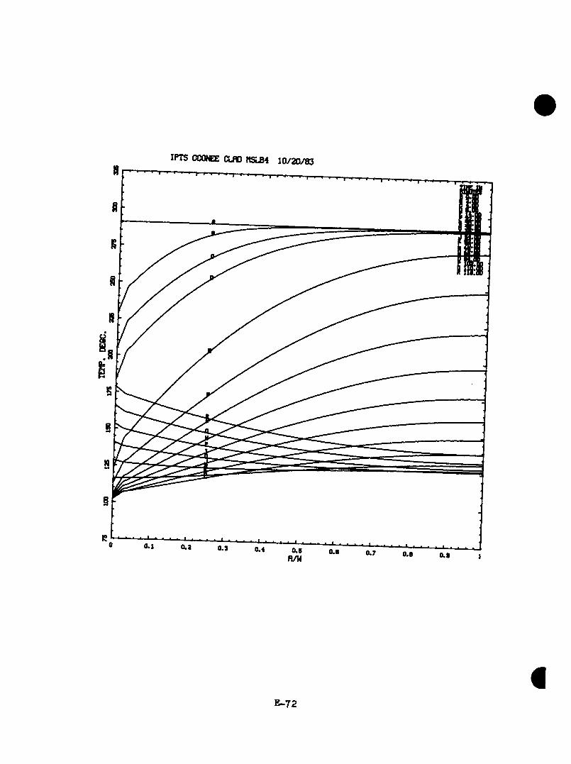
IPTS OCOKEE CLflD MSLB4 10/20/83
E-72

IPTS OCONEE CLflD MSLB4 1 0 /2 0 /8 3
E-73

CRITICflL CRflCK OCPTH CURVES FOR IPTS OCOCE CLflO NSLB4 lO m /8 3RTNDTO — 6 .7 OEOC ZCU - 0 .2 9 %NI - 0 .5 5 FO - 1.09E 19 LONBIT
9f •
I
n
+ •♦x«0
ao 30 « ao • 7D n0 10 n too 110 ISTINE(HINUTES)
E-74

TRANSIENT NO. 33 [W1TBV(ZW1TBV)]
E-75
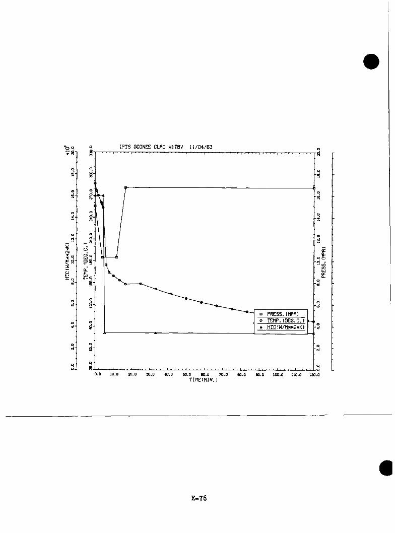
'boIr.
r.(M
IPTS OCONEE CLFID WITBV U / 0 4 / 8 3
oC9 o
9 8r:
~iO□ PRESS. tMPR)o TEMP.(PEG.C.)A HTCrW/!i?<M2xK)
a:a.. x:* <n (o
LJa.
20.0 SO.O 60.0 70.0TIMECMIN.)
E -7 6
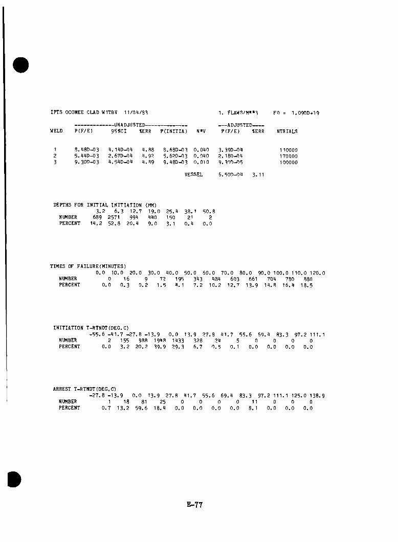
IPTS OCONEE CUD WITBV 1 1 /0 4 /3 3
WELD P (F /E )-UNADJUSTED-------------------------95SCI tERR P(INITIA) N»V
1. FLAWS/M»«3
ADJUSTED-------P (F /E ) tERR
FO = I .O 9OD+I9
NTRIALS
8.48D-035.44D-039 . 3OD-O3
4. 14D-04 2.67D-04 4 .54D-04
4 .8 8 4.934 .8 9
8 . 68D- 035.63D-039.48D-03
0 .0 4 0 3. 39D-040 .0 4 0 2 .18D-040 .0 1 0 9 .3 0 0 -0 8
110000 170000 100000
VESSEL 6 .50D -04 3. 11
DEPTHS FOR INITIAL INITIATION (MM)3 . 2 6 .3 12 .7 19 . 0 2 5 .4 38. 1
NUMBER 689 2571 994 440 150 21PERCENT 1 4 .2 5 2 .8 2 0 .4 9 .0 3. 1 0 .4
5 0 .82
0.0
TIMES OF FAILURE(MINUTES)0 . 0 1 0 .0 20
NUMBER 0 16 9PERCENT 0 . 0 0 . 3 0 . 2
3 0 . 0 4 0 .0 5 0 .0 6 0 .0 7 0 .0 8 0 .0 9 0 .0 100 .0 1 1 0 .0 1 2 0 .072 195 343 484 603 661 704 780 880
1 .5 4 .1 7 . 2 1 0 .2 1 2 .7 1 3 .9 1 4 .8 16 .4 1 8 .5
INITIATION T-RTNDT(DEG.C)- 5 5 . 6 - 4 1 . 7 - 2 7 .8
NUMBER 2 155 988PERCENT 0 . 0 3 . 2 2 0 .2
- 1 3 . 9 0 . 0 13 . 9 2 7 .8 4 1 . 7 5 5 .6 6 9 .4 8 3 .3194839 .9
143329.3
3286 .7
240 .5
5 0. 1
00.0
00.0
00.0
9 7 .2 111.1 0
0.0
ARREST T-RTNDT(DEG.C)- 2 7 . 8 - 1 3 . 9
NUMBERPERCENT
10 .7
181 3 . 2
0 . 0 13 81
5 9 .6
9 2 7 .8 4 1 .7 5 5 .6 6 9 .4 8 3 .3 9 7 .2 111. 1 125 .0 138 .925
18 .40
0.00
0.00
0.00
0.011
?. 10
0.00
0 . 00
0.0
E-77

Co
100
13S
ISOIT
Saa
s30
0
at

IPTS OCONEE CLflD HITBV 11/04/83
E-79
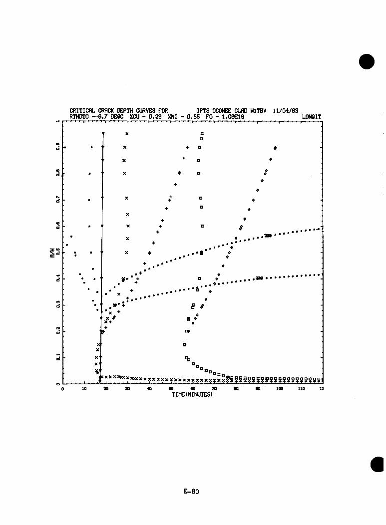
CRITICflL CRflCK DEPTH CURVES FOR IPTS OCONEE CLflD WITBV 1 1 /0 4 /8 3RTNDTO — 6 .7 DECC XCU - 0 .2 9 ZNI - 0 .5 5 FO - 1 .09E 19 LONCIT
X ’X
XX
X
X
++
□a
•f □
o
Q
□O
X
X
X
■ •fX
» • *
9
'
♦
XX-f
*»oBn' ^T’‘’‘’***?^’‘^?>‘=*>=’‘?i<yy>tyxxxxyxxgg§SS!jiB!i!gggg8gg!j!g8g8!j!!j!
10 ao 50 eo 70 TIME(MINUTES)
90 100 110
E -8 0

TRANSIENT NO. 34 [W2TBV(ZW2TBV)]
E -81

IPTS OCONEE CLRD H2T3V 11 /0 4 /8 3
oOJ
o .o cLJ
p PRESS.(HPfl)o TEHP.(DCG.C.)A HTC(W/Mx>* )
"cJ
• tn (nLJora.
0.0 ao.o 30.0 40.0 S0.0 60.0 70.0TIMEtfllN.)
80.0 90.0 ioo.o lio.o 120.0
E -8 2
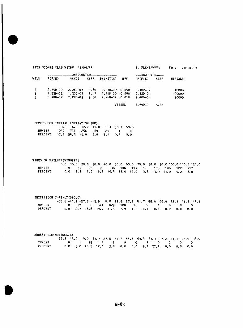
IPTS OCONEE CLAD W2TBV 1 1 /0 4 /8 3
WELD P (F /E )-UNADJUSTED-------------------------95%CI %ERR P(IN ITIA ) N»V
1, FLAWS/H»»3
ADJUSTED-------P ( F /E ) tERR
FO = I .O 9OD+I9
NTRIALS
2 .35D -02 1 .53D -02 2 . 40D-02
2 . 26D-03I . 3OD-O32.28D -03
9 .6 08 .4 79 .5 0
2 . 37D-02 1 .54D -02 2 .46D -02
0 .0 4 0 9 .40D -040 .0 4 0 6 . 12D-040 .0 1 0 2 .40D -04
100002000010000
VESSEL 1 .7 9 0 -0 3 5 .9 5
DEPTHS FOR INITIAL INITIATION (MM)3 . 2 6 . 3 1 2 .7 1 9 . 0 2 5 .4 38 . 1 5 0 .8
NUMBER 240 731 256 89 29 4 0PERCENT 1 7 .8 5 4 . 2 1 9 .0 6 . 6 2 . 1 0 . 3 0 . 0
TIMES OF FAILURE (MINUTES)0 . 0 1 0 .0 2 0 .0 3 0 . 0 4 0 .0 5 0 . 0
NUMBER 0 31 25 90 138 146PERCENT 0 . 0 2 . 3 1 . 9 6 . 8 1 0 .4 1 1 .0
6 0 . 0 7 0 . 0 8 0 . 0 9 0 . 0 1 00 . 0 1 10 . 0 120 . 0 171 170 173 146 122 117
1 2 .9 1 2 .8 1 3 . 0 1 1 . 0 9 . 2 8 .8
INITIATION T-RTNDT(DEG.C)- 5 5 . 6 - 4 1 . 7 - 2 7 . 8 - 1 3 . 9 0 . 0 1 3 .9 2 7 .8
NUMBER 0 37 226 541 429 108 18PERCENT 0 . 0 2 . 7 1 6 .6 3 9 .7 3 1 .5 7 . 9 1 .3
4 1 . 7 5 5 .6 6 9 .4 8 3 .3 9 7 .2 111.12 1 0 0 0
0 . 1 0 . 1 0 . 0 0 . 0 0 . 0
ARREST T-RTNDT(DEG.C)- 2 7 . 8 - 1 3 . 9
NUMBERPERCENT
00.0
0 . 0 13 . 9 2 7 . 8 4 1 . 7 5 5 .6 6 9 .4 8 3 .3 9 7 .2 111. 1 125 .0 13 8 .91
3 . 015
4 5 .54
12. 11
3 .00
0.00
0.03
9.19
2 7 .30
0.00
0.00
0.0
E -8 3
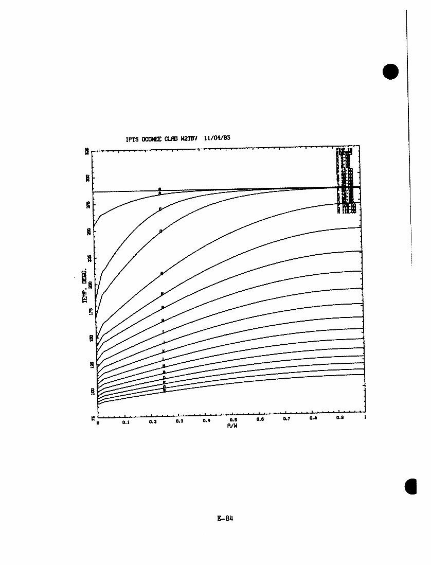
IPTS OCONEE CLflD H2m/ 11/04/83
0.1 0.2 0 .3 0 .4 0 .5fl/W
0.0 0.7 0.0 0.0
E-8lf
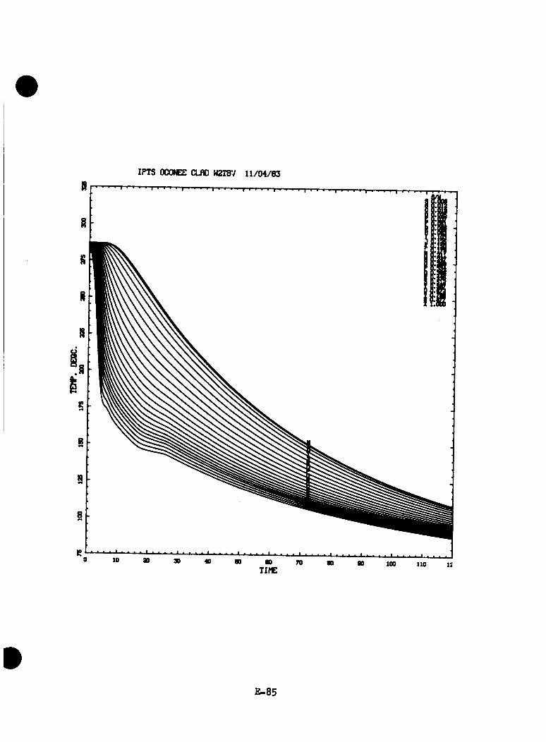
IPTS OCONEE CLflD H2TBV 11/04/83
E-85

CRITlCflL CRflCK CCPTH CURVES FOR IPTS OCONEE CLRD U2TBV 1 1 /0 4 /8 3RTNDTO — 6 .7 OEOC m i - 0 .2 9 %NI - 0 .5 5 FO - 1 .09E 19 L0N6IT' ' ' ' 1 • • » ' 1 1 a 9 1 I a-fa- a y r-a» f t r i i t-1 a i i-t-| i i a-a , , r-f » | » -a i i | i- i i f ,■
’ X Dmd ■ a
OX a ♦♦
m
♦B ^
♦d a
a
X > O 0
* •
Kd a♦ PI ♦
♦ • «
40d » a
a
a
♦X ♦ D • -
0 .......................N a a ' X ♦ B
d
a
: •
* ♦ . • * »
* ♦ B ♦ ......................................................... a
aa
r*d
aa
« XX
f ...........•* *► « /1 • * a 0O0
rtd
09
X rf**4d
X
XX
sCL
e
X ’T3
‘**0...........................................................................................................................................................................................
to » 30 « 90 00 70TIME(MINUTES)
too Ito IS
E-86
TRANSIENT NO. 41 [5A(LANL7)]
E -8 7

0.0
2.06.0
—I
I.8.0 L
_10
.0 12
.014
.0__
l__
16.0
I-18
.0
L_
*_
Mlrf
20.0
00 00
30.0
60
.090
.012
0.0
TEM
P.(D
EG.C
.)15
0.0
180.
0 21
3.0
240.
027
0.0
300.
0o o p o o
O Z
8 bP
I
p o
no oo
S o b s o s o
n COo
8 oC
J nID
o bO
S 1— b 0.0
20.0
14.0
18.0
18.0
2.04.
06.
08.0
10.0
12.0
PRES
S.(M
PR)

IPTS OCONEE CLAD 5A 1 0 /2 0 /3 3
WELD P (F /E )-UNADJUSTED-------------------------95%CX %ERR P(TNITIA) N»V
1. FLAWS/M»»3
ADJUSTED-------P (F /E ) %ERR
FO = 1 .0 9 0 D + 1 9
NTRIALS
1 2 .39D -02 2 .27D -03 9 .5 2 2 .91D -02 0 .0 9 0 9 .56D -04 100002 1.9UD-02 1 .26D -03 3 .7 5 1 . 94D-02 0 .0 9 0 5 .79D -09 200003 2. 39D-02 2 .27D -03 9 .5 2 2 . 93D-02 0 .0 1 0 2 . 39D-09 10000
VESSEL 1.77D-03 6.01
DEPTHS FOR INITIAL INITIATION (MM)3 . 2 6 .3 1 2 .7 1 9 .0 2 5 .9 38. 1 50 .3
NUMBER 333 653 235 70 21 2 0PERCENT 2 5 .3 9 9 .7 1 7 .9 5 . 3 1 .6 0 . 2 0 .0
TIMES OF FAILURE(MINUTES)0 . 0 10 .0 2 0 .0 3 0 .0 9 0 .0 5 0 .0
NUMBER 0 0 0 0 0PERCENT 0 . 0 0 . 0 0 . 0 0 . 0 0 . 0 0.
6 0 .0 7 0 . 0 8 0 .0 9 0 .0 1 0 0 .0 1 10 .0 120 .01 3 19 50 135 392 7581 0 . 2 1. 1 3 .8 1 0 .9 2 6 .2 5 8 .2
INITIATION T-RTNDT(DEG.C)- 5 5 . 6 - 9 1 . 7 - 2 7 . 8 - 1 3 . 9 0 . 0 1 3 .9 2 7 .8 9 1 . 7 5 5 .6 6 9 .9 8 3 .3 9 7 .2 111.1
NUMBER 13 76 293 519 363 56 1 0 0 0 0 0PERCENT 1 .0 5 . 8 2 2 .3 39. 1 2 7 .6 9 . 3 0. 1 0 . 0 0 . 0 0 . 0 0 . 0 0 .0
ARREST T-RTNDT(DEG.C)- 2 7 . 8 - 1 3 . 9 0 . 0 13 .9 2 7 .8 9 1 .7 5 5 .6 6 9 .9 83. 3 9 7 .2 111. 1 125.0 138 .9
NUMBERPERCENT
00.0
00 . 0
53 8 .5
75 3 .8
17 . 7
00 . 0
00 . 0
00 . 0
00 . 0
00 . 0
00 . 0
00 . 0
E -8 9
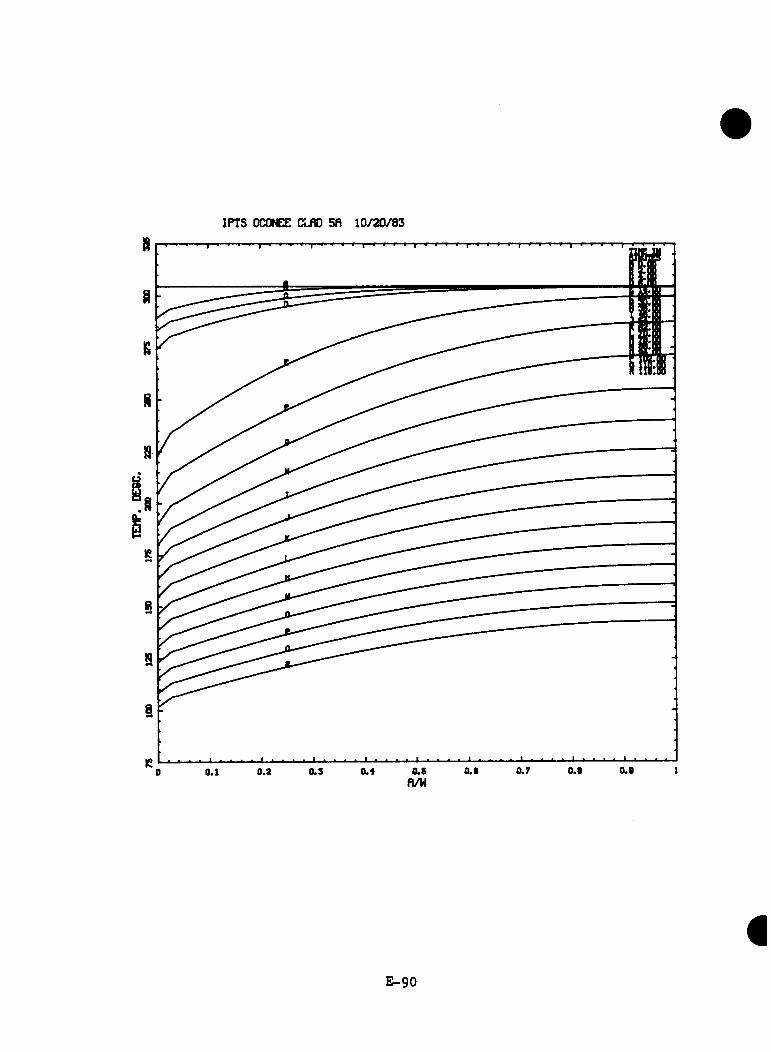
IPTS OCONEE CLfiO 5fl 10/20/83
E -9 0

IPTS OCONEE CLAD 5fi 10/20/83
E -91

CRITlCflL CRflCK DEPTH CURVES FOR IPTS OCONEE CLAD Sfl 10/20/83RTNDTO —6.7 DEOO XOU - 0.29 XNI - 0.55 FO - 1.09E19 LONCIT
r X □XX + D
X + D♦ ‘
X ♦ D ♦ -X 0
+
■
•
• ••
• s
♦^ * D ^ .X ^
+ D ♦
+ ^X + D « -X P +
♦p • •
•
: • . ■ ............•
...............
X + D «
- $ * B *
X ♦ □ «
x .
X aX
^ %X «
. . ...................... ................ ’‘ ’' ’‘ ? * ’‘’‘ ’‘ ?*???¥xx58!R bS !?S S S 8g8 l10 so eo 70
TIME(MINUTES)90 100 110 i:
E -9 2
TRANSIENT NO. H6 [6C(LANL12)]
E -9 3

IPTS OCONEE CLRD 6C 1 0 /2 0 /8 3
oC9 o5 8
UJ
D PRESS.fMPR)o TEMP.(PEG.C.)A HTC(N/Mxn2xK)
* <n tn u QCa .
0 .0 io .o x . o 30.0 40.0 50.0 60.0 70.0TIRE(MIN.)
60.0 90.0 100.0 110.0 120.0
E-94
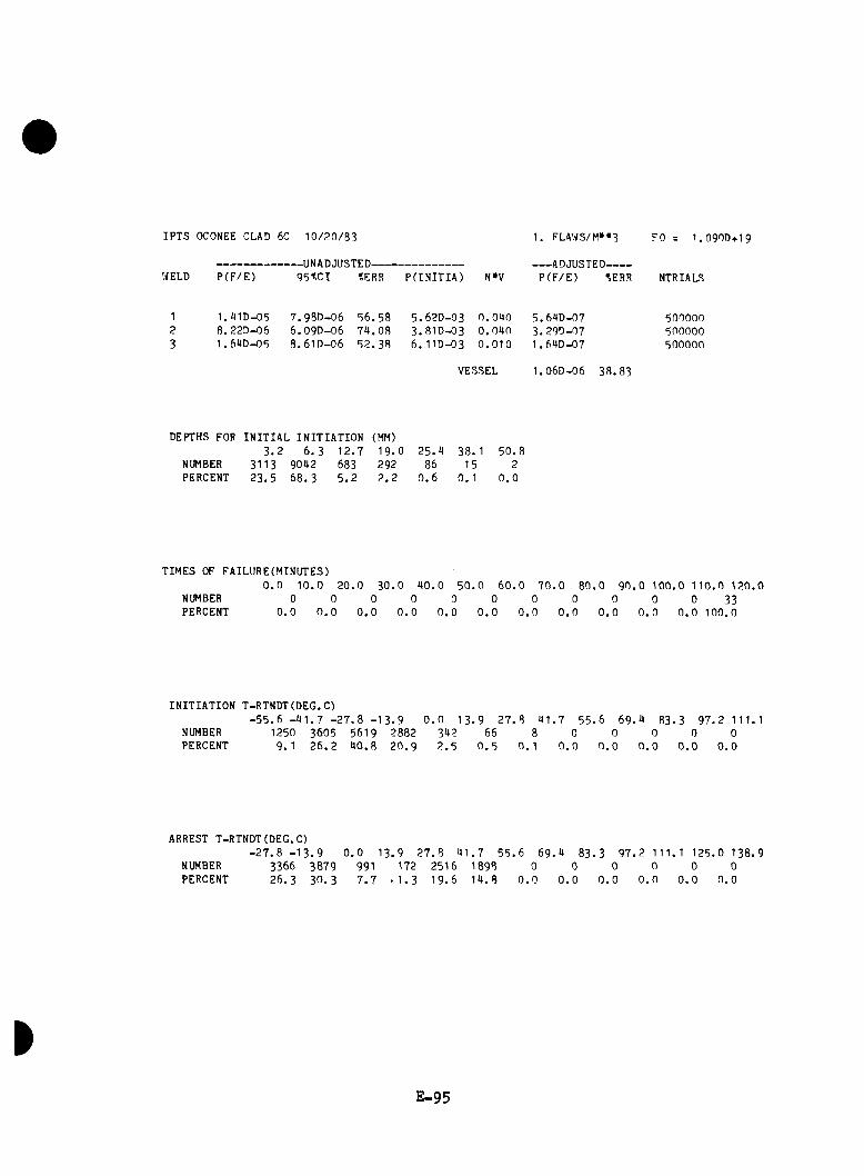
IPTS OCONEE CLAD 6C 1 0 /2 0 /3 3
WELD P (F /E )-UNADJUSTED-------------------------9 5 tC I %ERR P(INITIA) N*V
1. FLAWS/M»»3
ADJUSTED-------P (F /E ) 'JERR
FO = 1 .0 9 O D + 1 9
NTRIALS
1 . «1D-05 8 .22D-06 1. 69D-05
7 .9SD -066 .09D -068 .61D -06
5 6 .5 87 9 .0 85 2 .3 8
5 .62D -03 0 .0 9 0 5 .69D -07 5000003 .81D -03 0 .0 9 0 3 .29D -07 5000006 .11D -03 0 .0 1 0 1 .69D-07 500000
VESSEL 1.06D-06 38 .8 3
DEPTHS FOR INITIAL INITIATION (MM)3 . 2 6. 3 1 2 .7 1 9 .0 2 5 .9 38. 1 5 0 .8
NUMBER 3113 9092 683 292 86 15 2PERCENT 2 3 .5 68. 3 5 . 2 2 . 2 0 . 6 0 . 1 0 .0
TIMES OF FAILURE(MINUTES)0 . 0 1 0 .0 2 0 .0 3 0 .0 9 0 .0 5 0 .0
NUMBER 0 0 0 0 0 0PERCENT 0 .0 0 . 0 0 . 0 0 . 0 0 . 0 0 . 0
6 0 .0 7 0 .0 8 0 .0 9 0 .0 1 0 0 .0 11 0 .0 1 2 0 .00 0 0 0 0 33
0 . 0 0 . 0 0 . 0 0 . 0 0 . 0 100.0
INITIATION T-RTNDT(DEG.C)- 5 5 . 6 - 9 1 . 7 - 2 7 . 8 - 1 3 . 9 0 . 0 1 3 ,9 27 . 8 9 1 .7 5 5 .6
NUMBER 1250 3605 5619 2882 392 66 8 0 0PERCENT 9. 1 2 6 .2 9 0 .8 2 0 .9 2 . 5 0 . 5 0 .1 0 . 0 0 . 0
6 9 .9 8 3 .3 9 7 .2 1 1 1.10
0.00
0 . 00
0.0
ARREST T-RTNDT(DEG.C)- 2 7 . 8 - 1 3 . 9
NUMBERPERCENT
33662 6 .3
38793 0 .3
0 .0 1 3 .9 2 7 .8 9 1 .7 5 5 .6 69.991 172 2516 1898 07 . 7 - 1 . 3 1 9 .6 1 9 .8 0 . 0
9 83.0
0 . 0
3 9 7 .2 111. 1 125 .0 138 .90
0 . 00
0 . 00
0 . 00
0 . 0
E -9 5

IPTS OCONEE CLflD 60 10/20/83
0.S0.S0.70.60 .5fl/W
0 .40 .30.20.1
IE -96

CRITlCflL CRflCK OEPTH CURVES FOR IPTS OCONEE CLflD 6C 10/20/83RTNDTO —6.7 DE8C XCU - 0.29 XNI - 0.55 FO - 1.09E19 LONGIT
220
2»
d ■
90 too 1100 20 3010 SO 7080 80 i:TIME(MINUTES)
E -97
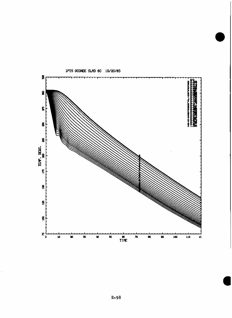
IPTS OCOrCE CLflD 60 10/20/63
E -9 8

TRANSIENT NO. 57 (INEL7)
E -9 9
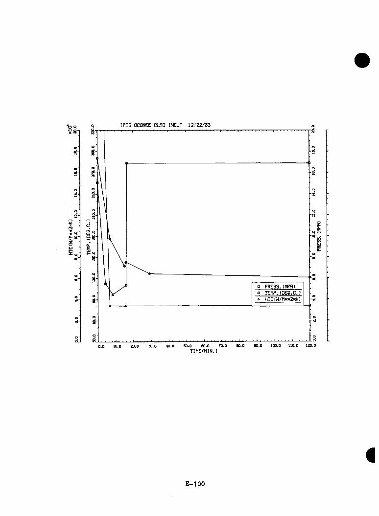
•b o xsn
T(M
5<
IPTS OCONEE CLflD INEL7 1 2 /2 2 /8 3
oCS o
0 8
p PRESS.(MPfl)o TEflP, (DCe.C,)A HTC(^/Mxx2mK)
100.0 110.0 120.090.070.0 80.0SO.O 80.030.0 40.0».010.00 .0
cQ..3C• <ntnLi
0.
TIMEtMIN.)
E -1 0 0

IPTS OCONEE CLAD INEL7 1 2 / 2 2 / 8 3
WELD P(F /E )-UNADJUSTED-------------------------9 5 t C I ■tERR P(INITIA) N»V
1. FLAWS/M»»3
ADJUSTED------p ( F / E ) i;err
FO = I . O 9OD+ I 9
NTRIALS
1 2 .26 D- 03 2. 15D-0U 9 . 50 2. 29D-03 0 . 0 4 0 9 . 06D-05 1 100002 9 . 81D-OH 9 . 6OD-O5 9 . 7 8 9 .81D- 04 0 . 0 4 0 3 .9 3D- 05 2400003 2 . I 7D-O3 2 .10D- 04 9.71 2. I 8D-O3 0 . 0 1 0 2 . 17D- 05 1 10000
VESSEL 1 . 5 1 0- 0 4 6 . 3 7
DEPTHS FOR INITIAL INITIATION (MM)3 . 2 6 . 3 1 2 . 7 1 9 . 0 2 5 . 4 38 . 1 5 0 . !
NUMBER 346 536 275 58 18 4 1PERCENT 2 7 . 9 4 3 . 3 2 2 . 2 4 . 7 1 . 5 0 . 3 0 . 1
TIMES OF FAILURE(MINUTES)0 . 0 1 0 . 0 2 0 . 0 3 0 . 0 4 0 . 0 5 0 . 0 60.
NUMBER 0 93 727 357 8 10PERCENT 0 . 0 7 . 6 59. 1 2 9 . 0 0 . 6 0 . 8
0 7 0 . 0 8 0 . 0 9 0 . 0 100 . 0 110 .0 120 . 0 11 7 6 8 3 1
0. 9 0 . 6 0 . 5 0 . 6 0 . 2 0 .1
INITIATION T-RTNDT(DEG.C)- 5 5 . 6 - 4 1 . 7 - 2 7 . 8 - 1 3 . 9 0 . 0 1 3 . 9 27. 8 4 1 . 7 5 5 . 6 69.
NUMBER 0 0 23 184 526 446 99 8 0PERCENT 0 . 0 0 . 0 1 . 8 14. 3 4 0 . 9 3 4 . 7 7 . 7 0 . 6 0 . 0
4 83. 3 9 7 . 2 111.10 0 0
0 . 0 0 . 0 0 . 0
ARREST T-RTNDT(DEG.C)- 2 7 . 8 - 1 3 . 9
NUMBERPERCENT
00 . 0
0 . 0 13 . 9 0 0 0
0 . 0 0 . 0 0 . 0
2 7 . 8 4 1 . 7 5 5 . 6 6 9 . 4 8 3 . 3 9 7 . 2 111. 1 125 .0 138 .90 0 0 2 1 34 0 0 0
0 . 0 0 . 0 0 . 0 3 8 . 2 6 1 . 8 0 . 0 0 . 0 0 . 0
E -1 0 1

IF*TS OCONEE CLflD I EL7 12/22/83
E - 1 0 2
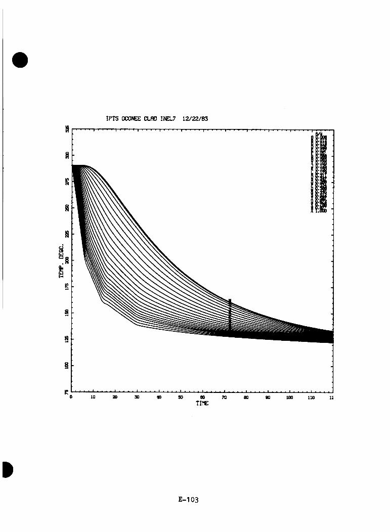
IPTS OCONEE CLflD INEL7 1 2 /2 2 /8 3
E -1 0 3

CRITlCflL CRflCK DEPTH CURVES FOR IPTS OCONEE CLflD INEL7 1 2 /2 2 /8 3RTNDTO — 6 .7 DECC XCU - 0 .2 9 XNI - 0 .5 5 FO - 1 .09E 19 LONCIT
XX
+
c
o
++
X -fX ♦
sJt +
□
□
0a
D O
® C n c Q o Q Q Q Q D o p D D O D D O Q O D D D n n n D D n n O D D D D 1
so eo 70 TIMEtniNUTES)
E -1 0 4
APPENDIX F
ALTERNATIVE APPROACH TO SEQUENCE ASSIGNMENT
A review o f th e ass ignm ent o f r e p r e s e n t a t i v e f ra c tu re -m e c h a n ic s c a se s to e a c h s e q u e n c e , a s p re s e n te d in Table A.3 o f Appendix A, re v e a le d bo th c o n s e rv a t iv e and n o n -c o n s e rv a t iv e a ss ig n m e n ts . I t was th e o p in io n o f th e a n a l y s t s t h a t in g e n e ra l c o n s e rv a t iv e and sometimes o v e r ly c o n s e rv a t iv e ass ignm en ts were made. T h is was p a r t i c u l a r l y t r u e f o r th e ass ignm ent o f a f r a c t u r e m echanics case t o th e r e s i d u a l c a s e s . An a t te m p t was made to r e c o n s t r u c t th e t a b l e and th u s reduce th e le v e l o f co n se rv a t ism Invo lved in t h i s p o r t i o n o f th e Oconee a n a l y s i s . U n fo r tu n a te ly , th e r e was l i t t l e t h a t c o u ld be done w i t h o u t p e r f o r m i n g a d d i t i o n a l t h e r m a l - h y d r a u l i c a n d /o r f r a c tu r e - m e c h a n ic s c a l c u l a t i o n s . In a d d i t i o n th e r e s o l u t i o n o f th e few n o n -c o n se rv a t iv e a ss ignm en ts le d to a h ig h e r o v e r a l l v e s s e l f a i l u r e v a lu e . Thus in t r y i n g to reduce bo th th e c o n s e rv a t iv e and n o n -c o n s e rv a t iv e b ia s e s in t ro d u ced by th e ass ignm ent o f f ra c tu re -m e c h a n ic s c a s e s , we produced a s e t o f d a ta which was c l e a r l y b ia se d in th e c o n s e rv a t iv e d i r e c t i o n . This d a ta i s p re s e n te d h e re a s a s e p a r a t e appendix s in c e i t in c lu d e s th e e l im in a t io n o f some o f th e n o n -c o n s e rv a t iv e b ia s e s found in th e a n a l y s i s even though i t f a i l s to a d d re s s th e l a r g e r c a te g o ry o f c o n s e rv a t iv e b i a s e s .
F . l
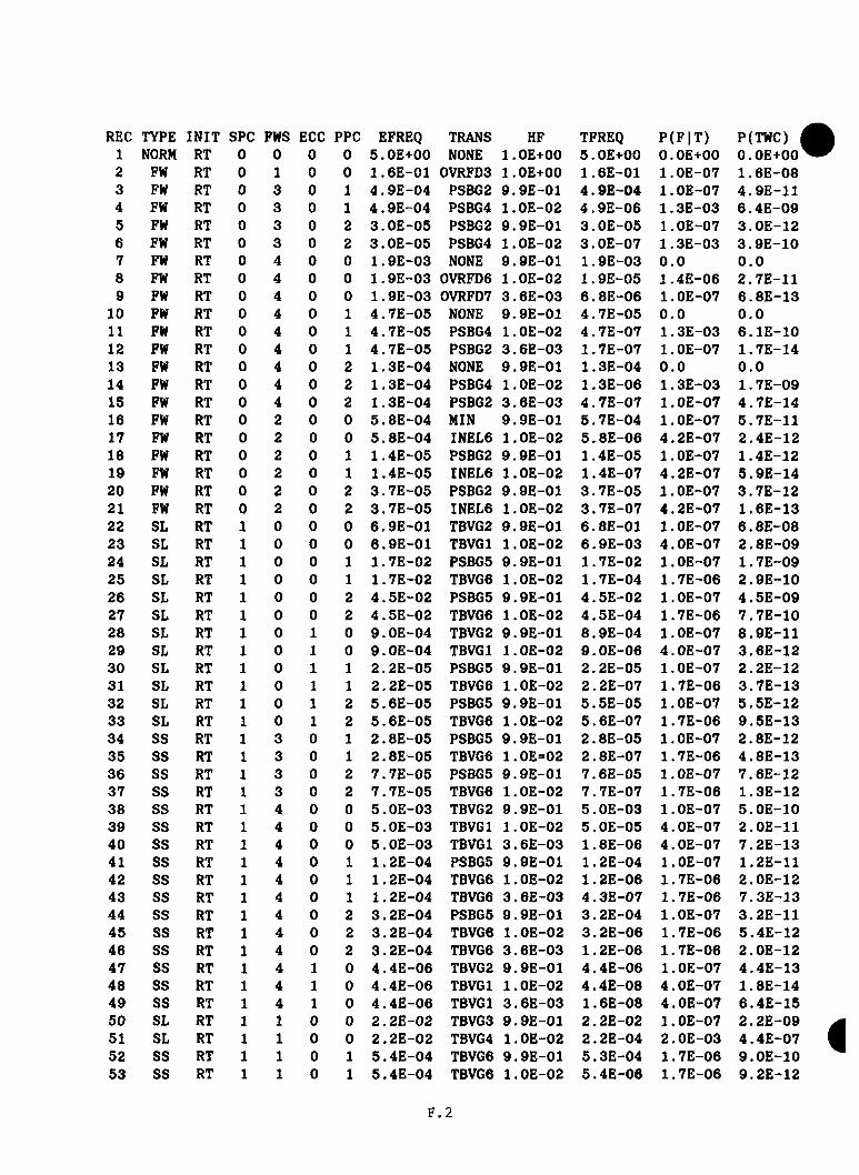
REC TYPE INIT SPC FWS ECC PPC EFREQ TRANS HF TFREQ P(F |T) P(TWC)1 NORM RT 0 0 0 0 5.0E+00 NONE l.OE+00 5.0E+00 O.OE+00 O.OE+002 FW RT 0 1 0 0 1.6E-01 0VRFD3 l.OE+00 1.6E-01 l.OE-07 1 . 6E-083 FW RT 0 3 0 1 4 . 9E-04 PSBG2 9.9E-01 4.9E-04 l.OE-07 4.9E-114 FW RT 0 3 0 1 4.9E-04 PSBG4 l.OE-02 4.9E-06 1.3E-03 6.4E-095 FW RT 0 3 0 2 3.0E-05 PSBG2 9.9E-01 3.0E-05 l.OE-07 3.0E-126 FW RT 0 3 0 2 3.0E-05 PSBG4 l.OE-02 3.0E-07 1.3E-03 3.9E-107 FW RT 0 4 0 0 1.9E-03 NONE 9.9E-01 1.9E-03 0 .0 0 .08 FW RT 0 4 0 0 1.9E-03 0VRFD6 l.OE-02 1 . 9E-05 1.4E-06 2.7E-119 FW RT 0 4 0 0 1.9E-03 0VRFD7 3 . 6E-03 6.8E-06 l.OE-07 6.8E-13
10 FW RT 0 4 0 1 4.7E-05 NONE 9.9E-01 4.7E-05 0 ,0 0 .011 FW RT 0 4 0 1 4.7E-05 PSBG4 l.OE-02 4.7E-07 1.3E-03 6.1E-1012 FW RT 0 4 0 1 4.7E-05 PSBG2 3.6E-03 1.7E-07 l.OE-07 1.7E-1413 FW RT 0 4 0 2 1.3E-04 NONE 9.9E-01 1.3E-04 0 .0 0 .014 FW RT 0 4 0 2 1 . 3E-04 PSBG4 l.OE-02 1.3E-06 1.3E-03 1 . 7E-0915 FW RT 0 4 0 2 1.3E-04 PSBG2 3.6E-03 4.7E-07 l.OE-07 4.7E-1416 FW RT 0 2 0 0 5.8E-04 MIN 9.9E-01 5.7E-04 l.OE-07 5.7E-1117 FW RT 0 2 0 0 5.8E-04 INEL6 l.OE-02 5.8E-06 4.2E-07 2.4E-1218 FW RT 0 2 0 1 1.4E-05 PSBG2 9 . 9E-01 1.4E-05 1 . OE-07 1.4E-1219 FW RT 0 2 0 1 1.4E-05 INEL6 l.OE-02 1.4E-07 4.2E-07 5.9E-1420 FW RT 0 2 0 2 3.7E-05 PSBG2 9.9E-01 3 . 7E-05 l.OE-07 3.7E-1221 FW RT 0 2 0 2 3.7E-05 INEL6 l.OE-02 3.7E-07 4.2E-07 1.6E-1322 SL RT 1 0 0 0 6.9E-01 TBVG2 9.9E-01 6.8E-01 1 . OE-07 6 . 8E-0823 SL RT 1 0 0 0 6.9E-01 TBV61 l.OE-02 6.9E-03 4.0E-07 2 . 8E-0924 SL RT 1 0 0 1 1 . 7E-02 PSBG5 9.9E-01 1 . 7E-02 l.OE-07 1 . 7E-0925 SL RT 1 0 0 1 1.7E-02 TBVG6 l.OE-02 1 . 7E-04 1 . 7E-06 2.9E-1026 SL RT 1 0 0 2 4.5E-02 PSBG5 9.9E-01 4.5E-02 l.OE-07 4 . 5E-0927 SL RT 1 0 0 2 4.5E-02 TBVG6 l.OE-02 4.5E-04 1.7E-06 7.7E-1028 SL RT 1 0 1 0 9.0E-04 TBVG2 9.9E-01 8.9E-04 l.OE-07 8.9E-1129 SL RT 1 0 1 0 9.0E-04 TBVGl l.OE-02 9.0E-06 4.0E-07 3.6E-1230 SL RT 1 0 1 1 2.2E-05 PSBG5 9.9E-01 2.2E-05 l.OE-07 2.2E-1231 SL RT 1 0 1 1 2.2E-05 TBVG6 l.OE-02 2.2E-07 1.7E-06 3.7E-1332 SL RT 1 0 1 2 5.6E-05 PSBG5 9.9E-01 5 . 5E-05 1 . OE-07 5.5E-1233 SL RT 1 0 1 2 5.6E-05 TBVG6 l.OE-02 5.6E-07 1.7E-06 9.5E-1334 SS RT 1 3 0 1 2 . 8E-05 PSBG5 9.9E-01 2.8E-05 l.OE-07 2.8E-1235 SS RT 1 3 0 1 2.8E-05 TBVG6 1.0E=02 2.8E-07 1.7E-06 4.8E-1336 SS RT 1 3 0 2 7 . 7E-05 PSBG5 9.9E-01 7.6E-05 1 . OE-07 7.6E-1237 SS RT 1 3 0 2 7.7E-05 TBVG6 l.OE-02 7.7E-07 1.7E-06 1.3E-1238 SS RT 1 4 0 0 5.0E-03 TBVG2 9.9E-01 5 . OE-03 l.OE-07 5.0E-1039 SS RT 1 4 0 0 5.0E-03 TBVGl l.OE-02 5.0E-05 4.0E-07 2.0E-1140 SS RT 1 4 0 0 5 . OE-03 TBVGl 3.6E-03 1.8E-06 4.0E-07 7.2E-1341 SS RT 1 4 0 1 1.2E-04 PSBG5 9.9E-01 1.2E-04 l.OE-07 1.2E-1142 SS RT 1 4 0 1 1.2E-04 TBVG6 1 . OE-02 1 . 2E-06 1.7E-06 2.0E-1243 SS RT 1 4 0 1 1 . 2E-04 TBVG6 3.6E-03 4.3E-07 1 . 7E-06 7.3E-1344 SS RT 1 4 0 2 3.2E-04 PSBG5 9.9E-01 3.2E-04 l.OE-07 3,2E-1145 SS RT 1 4 0 2 3.2E-04 TBVG6 l.OE-02 3.2E-06 1.7E-06 5.4E-1246 SS RT 1 4 0 2 3 . 2E-04 TBVG6 3.6E-03 1 . 2E-06 1 . 7E-06 2.0E-1247 SS RT 1 4 1 0 4.4E-06 TBVG2 9.9E-01 4.4E-06 l.OE-07 4.4E-1348 SS RT 1 4 1 0 4.4E-06 TBVGl l.OE-02 4.4E-08 4.0E-07 1.8E-1449 SS RT 1 4 1 0 4.4E-06 TBVGl 3.6E-03 1.6E-08 4.0E-07 6.4E-1550 SL RT 1 1 0 0 2.2E-02 TBVG3 9.9E-01 2.2E-02 1 . OE-07 2 . 2E-0951 SL RT 1 1 0 0 2.2E-02 TBVG4 1.0E-02 2.2E-04 2.0E-03 4.4E-0752 SS RT 1 1 0 1 5.4E-04 TBVG6 9.9E-01 5.3E-04 1 . 7E-06 9.0E-1053 SS RT 1 1 0 1 5.4E-04 TBVG6 l.OE-02 5.4E-06 1.7E-06 9.2E-12
F . 2
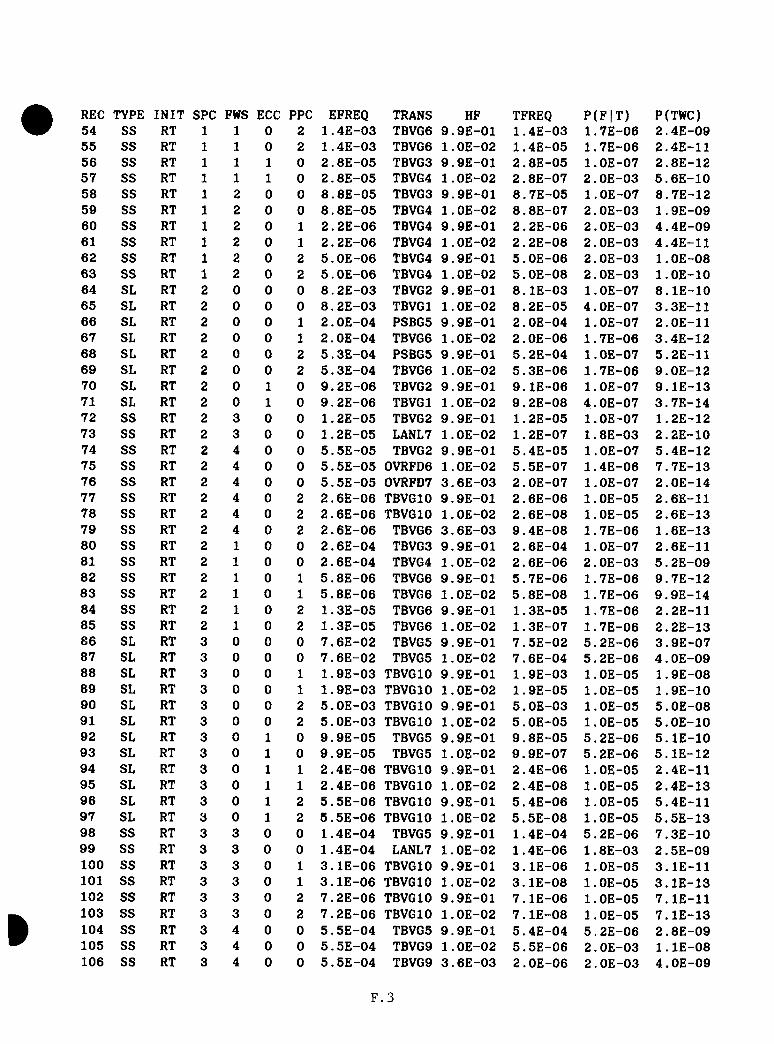
REC TYPE INIT SPC FWS ECC PPC EFREQ TRANS HF TFREQ P(F |T ) P(TWC)54 SS RT 1 1 0 2 1.4E-03 TBVG6 9.9E-01 1.4E-03 1 . 7E-06 2.4E-0955 SS RT 1 1 0 2 1.4E-03 TBVG6 l.OE-02 1.4E-05 1.7E-06 2.4E-1156 SS RT 1 1 1 0 2.8E-05 TBVG3 9.9E-01 2.8E-05 l.OE-07 2.8E-1257 SS RT 1 1 1 0 2.8E-05 TBVG4 l.OE-02 2.8E-07 2.0E-03 5.6E-1058 SS RT 1 2 0 0 8.8E-05 TBVG3 9.9E-01 8.7E-05 l.OE-07 8.7E-1259 SS RT 1 2 0 0 8.8E-05 TBVG4 1 . OE-02 8.8E-07 2.0E-03 1.9E-0960 SS RT 1 2 0 1 2.2E-06 TBVG4 9.9E-01 2.2E-06 2.0E-03 4.4E-0961 SS RT 1 2 0 1 2.2E-06 TBVG4 l.OE-02 2.2E-08 2.0E-03 4.4E-1162 SS RT 1 2 0 2 5.0E-06 TBVG4 9.9E-01 5.0E-06 2.0E-03 l.OE-0863 SS RT 1 2 0 2 5.0E-06 TBVG4 l.OE-02 5.0E-08 2.0E-03 l.OE-1064 SL RT 2 0 0 0 8.2E-03 TBVG2 9.9E-01 8.1E-03 l.OE-07 8.1E-1065 SL RT 2 0 0 0 8 .2E-03 TBVGl l.OE-02 8.2E-05 4.0E-07 3.3E-1166 SL RT 2 0 0 1 2.0E-04 PSBG5 9.9E-01 2.0E-04 l.OE-07 2.0E-1167 SL RT 2 0 0 1 2.0E-04 TBVG6 l.OE-02 2.0E-06 1.7E-06 3.4E-1268 SL RT 2 0 0 2 5 . 3E-04 PSBG5 9.9E-01 5.2E-04 l.OE-07 5.2E-1169 SL RT 2 0 0 2 5.3E-04 TBVG6 1 . OE-02 5.3E-06 1 . 7E-06 9.0E-1270 SL RT 2 0 1 0 9 .2E-06 TBVG2 9.9E-01 9.1E-06 l.OE-07 9.1E-1371 SL RT 2 0 1 0 9.2E-06 TBVGl l.OE-02 9.2E-08 4.0E-07 3.7E-1472 SS RT 2 3 0 0 1.2E-05 TBVG2 9.9E-01 1.2E-05 l.OE-07 1.2E-1273 SS RT 2 3 0 0 1.2E-05 LANL7 l.OE-02 1.2E-07 1.8E-03 2.2E-1074 SS RT 2 4 0 0 5.5E-05 TBVG2 9.9E-01 5.4E-05 l.OE-07 5.4E-1275 SS RT 2 4 0 0 5 .5E-05 0VRFD6 l.OE-02 5.5E-07 1.4E-06 7.7E-1376 SS RT 2 4 0 0 5 .5E-05 0VRFD7 3.6E-03 2.0E-07 l.OE-07 2.0E-1477 SS RT 2 4 0 2 2.6E-06 TBVGIO 9.9E-01 2.6E-06 l.OE-05 2.6E-1178 SS RT 2 4 0 2 2.6E-06 TBVGIO l.OE-02 2.6E-08 l.OE-05 2.6E-1379 SS RT 2 4 0 2 2 .6E-06 TBVG6 3.6E-03 9.4E-08 1.7E-06 1.6E-1380 SS RT 2 1 0 0 2.6E-04 TBVG3 9.9E-01 2.6E-04 l.OE-07 2.6E-1181 SS RT 2 1 0 0 2.6E-04 TBVG4 l.OE-02 2.6E-06 2.0E-03 5.2E-0982 SS RT 2 1 0 1 5.8E-06 TBVG6 9.9E-01 5.7E-06 1.7E-06 9.7E-1283 SS RT 2 1 0 1 5.8E-06 TBVG6 l.OE-02 5.8E-08 1.7E-06 9.9E-1484 SS RT 2 1 0 2 1.3E-05 TBVG6 9.9E-01 1.3E-05 1.7E-06 2.2E-1185 SS RT 2 1 0 2 1.3E-05 TBVG6 l.OE-02 1.3E-07 1.7E-06 2.2E-1386 SL RT 3 0 0 0 7.6E-02 TBVG5 9.9E-01 7.5E-02 5.2E-06 3.9E-0787 SL RT 3 0 0 0 7.6E-02 TBVG5 l.OE-02 7.6E-04 5.2E-06 4.0E-0988 SL RT 3 0 0 1 1.9E-03 TBVGIO 9.9E-01 1.9E-03 l.OE-05 1.9E-0889 SL RT 3 0 0 1 1.9E-03 TBVGIO l.OE-02 1 . 9E-05 l.OE-05 1.9E-1090 SL RT 3 0 0 2 5.0E-03 TBVGIO 9.9E-01 5.0E-03 l.OE-05 5.0E-0891 SL RT 3 0 0 2 5.0E-03 TBVGIO l.OE-02 5.0E-05 l.OE-05 5.0E-1092 SL RT 3 0 1 0 9.9E-05 TBVG5 9.9E-01 9.8E-05 5.2E-06 5.1E-1093 SL RT 3 0 1 0 9 .9E-05 TBVG5 1 . OE-02 9.9E-07 5.2E-06 5.1E-1294 SL RT 3 0 1 1 2.4E-06 TBVGIO 9.9E-01 2 . 4E-06 l.OE-05 2.4E-1195 SL RT 3 0 1 1 2.4E-06 TBVGIO l.OE-02 2.4E-08 l.OE-05 2.4E-1396 SL RT 3 0 1 2 5.5E-06 TBVGIO 9.9E-01 5.4E-06 l.OE-05 5.4E-1197 SL RT 3 0 1 2 5 .5E-06 TBVGIO l.OE-02 5.5E-08 l.OE-05 5.5E-1398 SS RT 3 3 0 0 1.4E-04 TBVG5 9.9E-01 1.4E-04 5.2E-06 7.3E-1099 SS RT 3 3 0 0 1.4E-04 LANL7 l.OE-02 1.4E-06 1.8E-03 2.5E-09100 SS RT 3 3 0 1 3.1E-06 TBVGIO 9.9E-01 3.1E-06 l.OE-05 3 . lE-11101 SS RT 3 3 0 1 3 .1E-06 TBVGIO 1 . OE-02 3.1E-08 1 . OE-05 3.1E-13102 SS RT 3 3 0 2 7.2E-06 TBVGIO 9.9E-01 7.1E-06 l.OE-05 7 . lE-11103 SS RT 3 3 0 2 7.2E-06 TBVGIO l.O E-02 7.1E-08 l.OE-05 7.1E-13104 SS RT 3 4 0 0 5.5E-04 TBVG5 9.9E-01 5.4E-04 5.2E-06 2.8E-09105 SS RT 3 4 0 0 5 .5E-04 TBVG9 l.OE-02 5.5E-06 2.0E-03 l . l E - 0 8106 SS RT 3 4 0 0 5.5E-04 TBVG9 3.6E-03 2.0E-06 2.0E-03 4.0E-09
F . 3
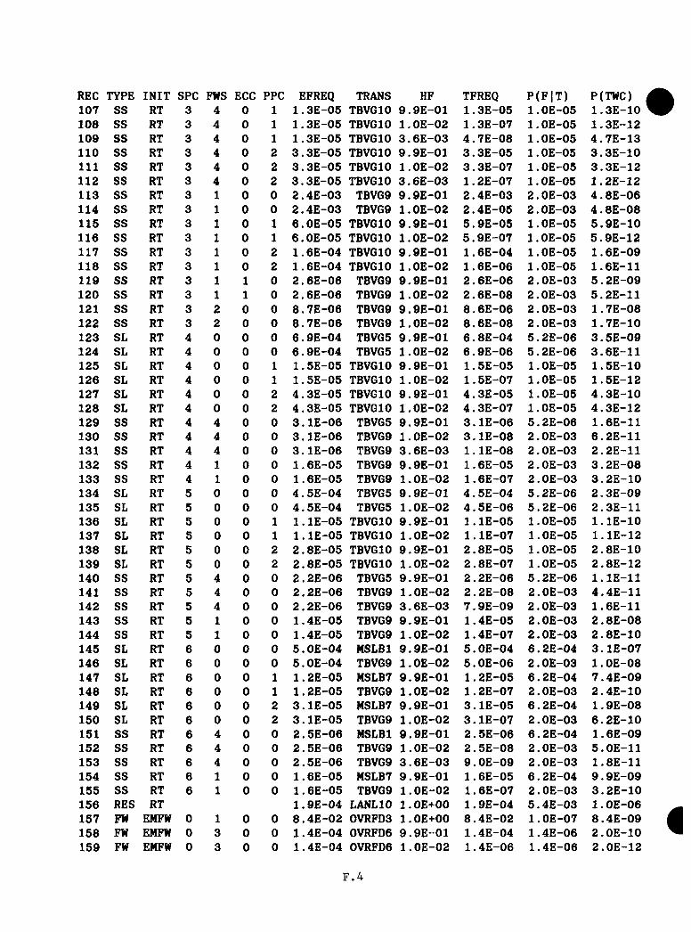
REC TYPE INIT SPC FWS ECC PPC EFREQ TRANS HF TFREQ P(F |T ) P(TWC)107 SS RT 3 4 0 1 1.3E-05 TBVGIO 9.9E-01 1 . 3E-05 l.OE-05 1.3E-10108 SS RT 3 4 0 1 1.3E-05 TBVGIO l.O E-02 1 . 3E-07 1 . OE-05 1.3E-12109 SS RT 3 4 0 1 1.3E-05 TBVGIO 3.6E-03 4 .7E-08 1 . OE-05 4.7E -13110 SS RT 3 4 0 2 3 . 3E-05 TBVGIO 9 . 9E-01 3 . 3E-05 l.OE-05 3 .3E-10111 SS RT 3 4 0 2 3 .3E-05 TBVGIO l.OE-02 3 .3E-07 l.OE-05 3 .3E-12112 SS RT 3 4 0 2 3 .3E-05 TBVGIO 3.6E-03 1 . 2E-07 1 . OE-05 1.2E-12113 SS RT 3 1 0 0 2 .4E-03 TBVG9 9.9E-01 2.4E-03 2 . OE-03 4 .8E-06114 SS RT 3 1 0 0 2 .4E-03 TBVG9 1 . OE-02 2.4E-05 2.0E-03 4 . 8E-08115 SS RT 3 1 0 1 6 .0E-05 TBVGIO 9.9E-01 5.9E-05 l.OE-05 5.9E -10116 SS RT 3 1 0 1 6 .0E-05 TBVGIO l.O E-02 5.9E-07 1 . OE-05 5.9E-12117 SS RT 3 1 0 2 1.6E-04 TBVGIO 9.9E-01 1.6E-04 l.OE-05 1.6E-09118 SS RT 3 1 0 2 1 . 6E-04 TBVGIO l.O E-02 1.6E-06 1 . OE-05 1.6E-11119 SS RT 3 1 1 0 2 . 6E-06 TBVG9 9.9E-01 2 . 6E-06 2.0E-03 5 . 2E-09120 SS RT 3 1 1 0 2 . 6E-06 TBVG9 l.O E-02 2 . 6E-08 2.0E-03 5.2E-11121 SS RT 3 2 0 0 8.7E-06 TBVG9 9.9E-01 8 . 6E-06 2.0E-03 1.7E-08122 SS RT 3 2 0 0 8 .7E-06 TBVG9 l.O E-02 8.6E-08 2 . OE-03 1.7E-10123 SL RT 4 0 0 0 6 . 9E-04 TBVG5 9.9E-01 6.8E-04 5 . 2E-06 3.5E -09124 SL RT 4 0 0 0 6 .9E-04 TBVG5 l.OE-02 6.9E-06 5.2E-06 3.6E-11125 SL RT 4 0 0 1 1 . 5E-05 TBVGIO 9.9E-01 1.5E-05 1 . OE-05 1.5E-10126 SL RT 4 0 0 1 1 . 5E-05 TBVGIO l.O E-02 1.5E-07 l.OE-05 1.5E-12127 SL RT 4 0 0 2 4 .3E-05 TBVGIO 9.9E-01 4.3E -05 l.OE-05 4.3E-10128 SL RT 4 0 0 2 4 .3E-05 TBVGIO l.O E-02 4.3E -07 l.OE-05 4.3E-12129 SS RT 4 4 0 0 3 .1E-06 TBVG5 9.9E-01 3.1E-06 5.2E-06 1.6E-11130 SS RT 4 4 0 0 3 .1E-06 TBVG9 1 . OE-02 3.1E -08 2 . OE-03 6.2E-11131 SS RT 4 4 0 0 3 .1E-06 TBVG9 3.6E-03 l . l E - 0 8 2.0E-03 2.2E-11132 SS RT 4 1 0 0 1.6E-05 TBVG9 9.9E-01 1.6E-05 2 . OE-03 3.2E-08133 SS RT 4 1 0 0 1.6E-05 TBVG9 l.OE-02 1.6E-07 2.0E-03 3.2E -10134 SL RT 5 0 0 0 4.5E-04 TBVG5 9.9E-01 4 . 5E-04 5 . 2E-06 2.3E-09135 SL RT 5 0 0 0 4.5E-04 TBVG5 l.OE-02 4.5E-06 5.2E-06 2,3E-11136 SL RT 5 0 0 1 1 . lE -05 TBVGIO 9.9E-01 1 . lE -0 5 l.OE-05 l . l E - 1 0137 SL RT 5 0 0 1 l . l E - 0 5 TBVGIO l.OE-02 1 . lE -07 l.OE-05 l . l E - 1 2138 SL RT 5 0 0 2 2 .8E-05 TBVGIO 9.9E-01 2 . 8E-05 1 . 0E-05 2.8E-10139 SL RT 5 0 0 2 2.8E-05 TBVGIO l.OE-02 2 .8E-07 l.OE-05 2.8E-12140 SS RT 5 4 0 0 2.2E-06 TBVG5 9.9E-01 2 .2E-06 5.2E-06 l . l E - 1 1141 SS RT 5 4 0 0 2.2E-06 TBVG9 l.O E-02 2 .2E-08 2.0E-03 4.4E-11142 SS RT 5 4 0 0 2 . 2E-06 TBVG9 3.6E -03 7 .9E-09 2 . OE-03 1.6E-11143 SS RT 5 1 0 0 1.4E-05 TBVG9 9.9E-01 1.4E-05 2 . OE-03 2 .8E-08144 SS RT 5 1 0 0 1.4E-05 TBVG9 l.O E-02 1.4E-07 2 . OE-03 2 .8E-10145 SL RT 6 0 0 0 5 .0E-04 MSLBl 9.9E-01 5.0E-04 6.2E-04 3 .1E-07146 SL RT 6 0 0 0 5 .0E-04 TBVG9 1 . OE-02 5 .0E-06 2.0E-03 l.O E-08147 SL RT 6 0 0 1 1 . 2E-05 MSLB7 9.9E-01 1 . 2E-05 6.2E-04 7 .4E-09148 SL RT 6 0 0 1 1 . 2E-05 TBVG9 l.O E-02 1 . 2E-07 2.0E-03 2 .4E-10149 SL RT 6 0 0 2 3 .1E-05 MSLB7 9.9E-01 3 .1E-05 6.2E-04 1 . 9E-08150 SL RT 6 0 0 2 3 .1E-05 TBVG9 l.O E-02 3 .1E-07 2.0E-03 6 .2E-10151 SS RT 6 4 0 0 2.5E-06 MSLBl 9.9E-01 2 . 5E-06 6.2E-04 1.6E-09152 SS RT 6 4 0 0 2 . 5E-06 TBVG9 l.O E-02 2.5E-08 2.0E-03 5.0E-11153 SS RT 6 4 0 0 2.5E-06 TBVG9 3.6E -03 9 .0E-09 2.0E-03 1.8E-11154 SS RT 6 1 0 0 1.6E-05 MSLB7 9.9E-01 1 . 6E-05 6.2E-04 9 .9E-09155 SS RT 6 1 0 0 1.6E-05 TBVG9 l.OE-02 1.6E-07 2.0E-03 3 .2E-10156 RES RT 1 . 9E-04 LANLIO 1 . OE+00 1 . 9E-04 5.4E-03 1 . OE-06157 FW EMFW 0 1 0 0 8 .4E-02 0VRFD3 l.OE+00 8 .4E-02 l.OE-07 8 .4E-09158 FW EMFW 0 3 0 0 1.4E-04 0VRFD6 9.9E-01 1.4E-04 1.4E-06 2 .0E-10159 FW EMFW 0 3 0 0 1.4E-04 0VRFD6 l.O E-02 1.4E-06 1.4E-06 2.0E-12
F . 4

■ REC TYPE INIT SPC FWS ECC PPC EFREQ TRANS HF TFREQ P(FIT) P(TWC)160 FW EMFW 0 3 0 1 2.9E-06 PSBG4 9.9E-01 2.9E-06 1.3E-03 3.8E-09161 FW EMFW 0 3 0 1 2.9E-06 PSBG4 l.OE-02 2.9E-08 1 . 3E-03 3.8E-11162 FW EMFW 0 3 0 2 6.8E-06 PSBG4 9.9E-01 6.7E-06 1.3E-03 8.7E-09163 FW EMFW 0 3 0 2 6.8E-06 PSBG4 l.OE-02 6.8E-08 1.3E-03 8.8E-11164 FW EMFW 0 4 0 0 5.5E-04 0VRFD6 9.9E-01 5.5E-04 1.4E-06 7.7E-10165 FW EMFW 0 4 0 0 5.5E-04 0VRFD6 l.OE-02 5.5E-06 1.4E-06 7.7E-12166 FW EMFW 0 4 0 0 5.5E-04 0VRFD7 3.6E-03 2.0E-06 l.OE-07 2.0E-13167 FW EMFW 0 4 0 1 1.3E-05 PSBG3 9.9E-01 1 . 3E-05 l.OE-07 1.3E-12168 FW EMFW 0 4 0 1 1.3E-05 PSBG4 l.OE-02 1.3E-07 1.3E-03 1.7E-10169 FW EMFW 0 4 0 1 1.3E-05 PSBG2 3.6E-03 4.7E-08 l.OE-07 4.7E-15170 FW EMFW 0 4 0 2 3.3E-05 PSBG3 9.9E-01 3.3E-05 l.OE-07 3.3E-12171 FW EMFW 0 4 0 2 3.3E-05 PSBG4 l.OE-02 3.3E-07 1.3E-03 4.3E-10172 FW EMFW 0 4 0 2 3.3E-05 PSBG2 3.6E-03 1.2E-07 l.OE-07 1.2E-14173 FW EMFW 0 2 0 0 3.1E-04 0VRFD5 9.9E-01 3.1E-04 l.OE-07 3,1E-11174 FW EMFW 0 2 0 0 3.1E-04 0VRFD5 l.OE-02 3.1E-06 l.OE-07 3.1E-12175 FW EMFW 0 2 0 1 7.7E-06 PSBG2 9.9E-01 7.6E-06 l.OE-07 7.6E-13176 FW EMFW 0 2 0 1 7.7E-06 PSBG2 l.OE-02 7.7E-08 l.OE-07 7.7E-15177 FW EMFW 0 2 0 2 2 . OE-05 PSBG2 9.9E-01 2.0E-05 l.OE-07 2.0E-12178 FW EMFW 0 2 0 2 2.0E-05 PSBG2 l.OE-02 2.0E-07 l.OE-07 2.0E-14179 SS EMFW 1 1 0 0 1.2E-02 TBVG3 9.9E-01 1.2E-02 l.OE-07 1.2E-09180 SS EMFW 1 1 0 0 1.2E-02 TBVG4 l.OE-02 1.2E-04 2.0E-03 2.4E-07181 SS EMFW 1 1 0 1 2.9E-04 TBVG6 9.9E-01 2.9E-04 1 . 7E-06 4.9E-10182 SS EMFW 1 1 0 1 2.9E-04 TBVG6 l.OE-02 2.9E-06 1.7E-06 4.9E-12183 SS EMFW 1 1 0 2 7.7E-04 TBVG6 9.9E-01 7 . 6E-04 1.7E-06 1.3E-09184 SS EMFW 1 1 0 2 7.7E-04 TBVG6 l.OE-02 7.7E-06 1 . 7E-06 1.3E-11185 SS EMFW 1 1 1 0 1.2E-05 TBVG3 9.9E-01 1 . 2E-05 l.OE-07 1.2E-12186 SS EMFW 1 1 1 0 1.2E-05 TBVG4 l.OE-02 1.2E-07 2.0E-03 2.4E-10187 SS EMFW 1 3 0 0 1.6E-05 TBVG2 9.9E-01 1.6E-05 l.OE-07 1.6E-12188 SS EMFW 1 3 0 0 1.6E-05 LANL7 l.OE-02 1.6E-07 1.8E-03 2.9E-10189 SS EMFW 1 4 0 0 8.0E-05 TBVG2 9.9E-01 7.9E-05 l.OE-07 7.9E-12190 SS EMFW 1 4 0 0 8.0E-05 TBVGl l.OE-02 8.0E-07 4.0E-07 3.2E-13191 SS EMFW 1 4 0 0 8.0E-05 TBVGl 3.6E-03 2 . 9E-07 4.0E-07 1.2E-13192 SS EMFW 1 4 0 2 3.5E-06 TBVGIO 9.9E-01 3.5E-06 l.OE-05 3.5E-11193 SS EMFW 1 4 0 2 3.5E-06 TBVGIO l.OE-02 3 .5E-08 1 . OE-05 3.5E-13194 SS EMFW 1 4 0 2 3.5E-06 TBVG4 3.6E-03 1.3E-08 2.0E-03 2.6E-11195 SS EMFW 1 2 0 0 4.7E-05 TBVG4 9.9E-01 4.7E-05 2.0E-03 9.4E-08196 SS EMFW 1 2 0 0 4.7E-05 TBVG4 l.OE-02 4.7E-07 2.0E-03 9.4E-10197 SS EMFW 1 2 0 2 2.7E-06 TBVG6 9.9E-01 2.7E-06 1.7E-06 4.6E-12198 SS EMFW 1 2 0 2 2.7E-06 TBVG6 l.OE-02 2 . 7E-08 1.7E-06 4.6E-14199 SS EMFW 2 1 0 0 1.4E-04 TBVG3 9.9E-01 1.4E-04 1 . OE-07 1.4E-11200 SS EMFW 2 1 0 0 1.4E-04 TBVG4 l.OE-02 1.4E-06 2.0E-03 2.8E-09201 SS EMFW 2 1 0 1 3.1E-06 TBVG6 9.9E-01 3.1E-06 1 . 7E-06 5.3E-12202 SS EMFW 2 1 0 1 3.1E-06 TBVG6 l.OE-02 3.1E-08 1.7E-06 5.3E-14203 SS EMFW 2 1 0 2 7.2E-06 TBVG6 9.9E-01 7.1E-06 1 . 7E-06 1.2E-11204 SS EMFW 2 1 0 2 7.2E-06 TBVG6 l.OE-02 7.2E-08 1.7E-06 1.2E-13205 SS EMFW 3 1 0 0 1.3E-03 TBVG5 9.9E-01 1 . 3E-03 5.2E-06 6.7E-09206 SS EFFW 3 1 0 0 1.3E-03 TBVG9 l.OE-02 1.3E-05 2.0E-03 2.6E-08207 SS EMFW 3 1 0 1 3.2E-05 TBVGIO 9.9E-01 3.2E-05 l.OE-05 3.2E-10208 SS EMFW 3 1 0 1 3.2E-05 TBVGIO l.OE-02 3 .2E-07 l.OE-05 3.2E-12209 SS EMFW 3 1 0 2 8.4E-05 TBVGIO 9.9E-01 8 .3E-05 l.OE-05 8.3E-10210 SS EMFW 3 1 0 2 8.4E-05 TBVGIO l.OE-02 8.4E-07 1 . OE-05 8.4E-12211 SS EMFW 3 1 1 0 1.4E-06 TBVG5 9.9E-01 1.4E-06 5.2E-06 7.3E-12212 SS EMFW 3 1 1 0 1.4E-06 TBVG9 l.OE-02 1.4E-08 2.0E-03 2.8E-11
F.5
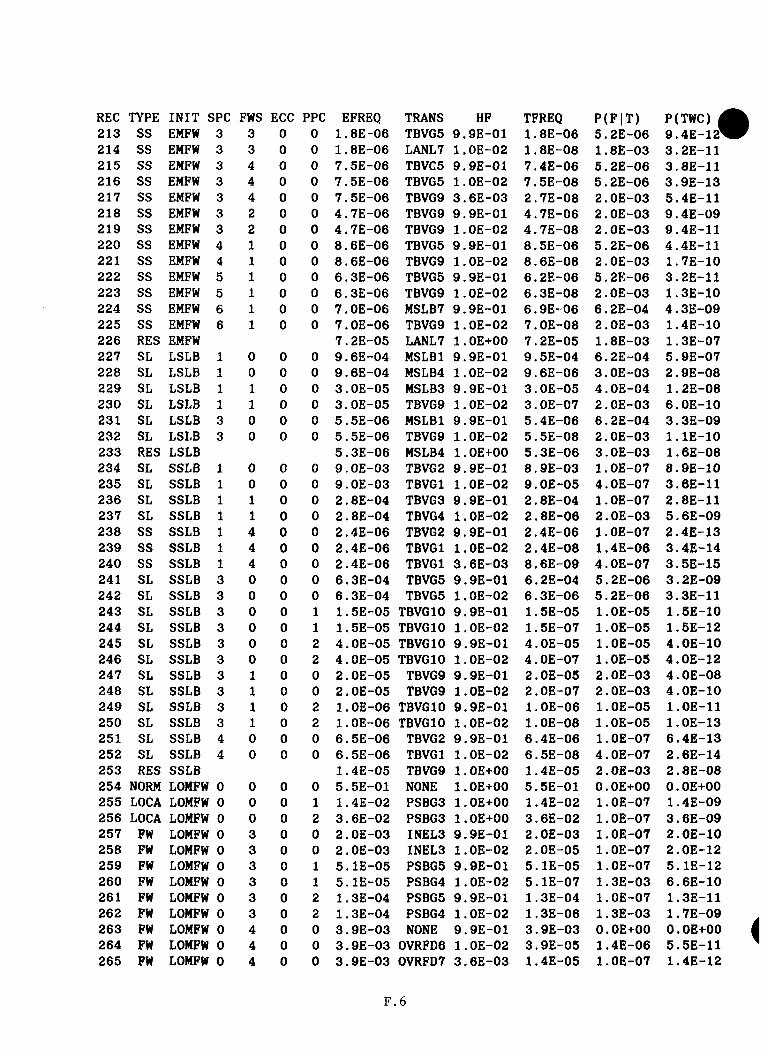
REC TYPE INIT SPC FWS ECC PPC EFREQ TRANS HF TFREQ P(F |T ) P(TWC) 1213 SS EMFW 3 3 0 0 1.8E-06 TBVG5 9.9E-01 1.8E-06 5.2E-06 9.4E-12*214 SS EMFW 3 3 0 0 1.8E-06 LANL7 l.OE-02 1. 8E-08 1.8E-03 3.2E-11215 SS EMFW 3 4 0 0 7.5E-06 TBVG5 9.9E-01 7.4E-06 5 . 2E-06 3.8E-11216 SS EMFW 3 4 0 0 7.5E-06 TBVG5 l.OE-02 7.5E-08 5 . 2E-06 3.9E-13217 SS EMFW 3 4 0 0 7.5E-06 TBVG9 3.6E-03 2.7E-08 2.0E-03 5.4E-11218 SS EMFW 3 2 0 0 4.7E-06 TBVG9 9.9E-01 4.7E-06 2.0E-03 9.4E-09219 SS EMFW 3 2 0 0 4.7E-06 TBVG9 l.OE-02 4.7E-08 2.0E-03 9.4E-11220 SS EMFW 4 1 0 0 8.6E-06 TBVG5 9.9E-01 8.5E-06 5.2E-06 4.4E-11221 SS EMFW 4 1 0 0 8.6E-06 TBVG9 l.OE-02 8.6E-08 2.0E-03 1.7E-10222 SS EMFW 5 1 0 0 6.3E-06 TBVG5 9.9E-01 6.2E-06 5.2E-06 3.2E-11223 SS EMFW 5 1 0 0 6.3E-06 TBVG9 l.OE-02 6.3E-08 2.0E-03 1.3E-10224 SS EMFW 6 1 0 0 7.0E-06 MSLB7 9.9E-01 6.9E-06 6.2E-04 4.3E-09225 SS EMFW 6 1 0 0 7.0E-06 TBVG9 l.OE-02 7.0E-08 2.0E-03 1.4E-10226 RES EMFW 7 . 2E-05 LANL7 l.OE+00 7.2E-05 1.8E-03 1.3E-07227 SL LSLB 1 0 0 0 9.6E-04 MSLBl 9.9E-01 9.5E-04 6.2E-04 5.9E-07228 SL LSLB 1 0 0 0 9.6E-04 MSLB4 l.OE-02 9.6E-06 3.0E-03 2.9E-08229 SL LSLB 1 1 0 0 3.0E-05 MSLB3 9.9E-01 3.0E-05 4.0E-04 1 . 2E-08230 SL LSLB 1 1 0 0 3.0E-05 TBVG9 l.OE-02 3.0E-07 2.0E-03 6.0E-10231 SL LSLB 3 0 0 0 5.5E-06 MSLBl 9.9E-01 5.4E-06 6.2E-04 3.3E-09232 SL LSLB 3 0 0 0 5.5E-06 TBVG9 l.OE-02 5.5E-08 2.0E-03 l . lE - 1 0233 RES LSLB 5.3E-06 MSLB4 l.OE+00 5.3E-06 3.0E-03 1.6E-08234 SL SSLB 1 0 0 0 9.0E-03 TBVG2 9.9E-01 8 . 9E-03 1 . OE-07 8.9E-10235 SL SSLB 1 0 0 0 9.0E-03 TBVGl l.OE-02 9.0E-05 4.0E-07 3.6E-11236 SL SSLB 1 1 0 0 2 . 8E-04 TBVG3 9.9E-01 2.8E-04 l.OE-07 2.8E-11237 SL SSLB 1 1 0 0 2.8E-04 TBVG4 l.OE-02 2 . 8E-06 2.0E-03 5.6E-09238 SS SSLB 1 4 0 0 2.4E-06 TBVG2 9.9E-01 2.4E-06 l.OE-07 2.4E-13239 SS SSLB 1 4 0 0 2.4E-06 TBVGl l.OE-02 2.4E-08 1.4E-06 3.4E-14240 SS SSLB 1 4 0 0 2.4E-06 TBVGl 3.6E-03 8.6E-09 4.0E-07 3.5E-15241 SL SSLB 3 0 0 0 6.3E-04 TBVG5 9.9E-01 6.2E-04 5.2E-06 3.2E-09242 SL SSLB 3 0 0 0 6.3E-04 TBVG5 l.OE-02 6.3E-06 5.2E-06 3.3E-11243 SL SSLB 3 0 0 1 1.5E-05 TBVGIO 9.9E-01 1.5E-05 l.OE-05 1.5E-10244 SL SSLB 3 0 0 1 1.5E-05 TBVGIO l.OE-02 1.5E-07 l.OE-05 1.5E-12245 SL SSLB 3 0 0 2 4.0E-05 TBVGIO 9.9E-01 4.0E-05 l.OE-05 4.0E-10246 SL SSLB 3 0 0 2 4.0E-05 TBVGIO l.OE-02 4.0E-07 l.OE-05 4.0E-12247 SL SSLB 3 1 0 0 2.0E-05 TBVG9 9.9E-01 2.0E-05 2.0E-03 4.0E-08248 SL SSLB 3 1 0 0 2.0E-05 TBVG9 l.OE-02 2.0E-07 2.0E-03 4.0E-10249 SL SSLB 3 1 0 2 l.OE-06 TBVGIO 9.9E-01 l.OE-06 l.OE-05 l.OE-11250 SL SSLB 3 1 0 2 l.OE-06 TBVGIO l.OE-02 l.OE-08 l.OE-05 l.OE-13251 SL SSLB 4 0 0 0 6.5E-06 TBVG2 9.9E-01 6.4E-06 l.OE-07 6.4E-13252 SL SSLB 4 0 0 0 6.5E-06 TBVGl l.OE-02 6.5E-08 4.0E-07 2.6E-14253 RES SSLB 1.4E-05 TBVG9 1 . OE+00 1.4E-05 2.0E-03 2.8E-08254 NORM LOMFW 0 0 0 0 5.5E-01 NONE 1 . OE+00 5.5E-01 O.OE+00 O.OE+00255 LOCA LOMFW 0 0 0 1 1.4E-02 PSBG3 l.OE+00 1.4E-02 l.OE-07 1.4E-09256 LOCA LOMFW 0 0 0 2 3.6E-02 PSBG3 l.OE+00 3.6E-02 l.OE-07 3 . 6E-09257 FW LOMFW 0 3 0 0 2.0E-03 INEL3 9.9E-01 2.0E-03 l.OE-07 2.0E-10258 FW LOMFW 0 3 0 0 2.0E-03 INEL3 l.OE-02 2.0E-05 l.OE-07 2.0E-12259 FW LOMFW 0 3 0 1 5 . lE-05 PSBG5 9.9E-01 5.1E-05 1.0E-07 5.1E-12260 FW LOMFW 0 3 0 1 5.1E-05 PSBG4 l.OE-02 5.1E-07 1.3E-03 6.6E-10261 FW LOMFW 0 3 0 2 1.3E-04 PSBG5 9.9E-01 1.3E-04 l.OE-07 1.3E-11262 FW LOMFW 0 3 0 2 1.3E-04 PSBG4 l.OE-02 1.3E-06 1 . 3E-03 1.7E-09263 FW LOMFW 0 4 0 0 3.9E-03 NONE 9.9E-01 3.9E-03 O.OE+00 O.OE+00264 FW LOMFW 0 4 0 0 3 . 9E-03 0VRFD6 1 . OE-02 3.9E-05 1.4E-06 5.5E-11265 FW LOMFW 0 4 0 0 3.9E-03 0VRFD7 3.6E-03 1.4E-05 l.OE-07 1.4E-12
F . 6
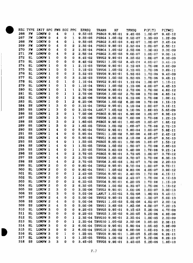
REC TYPE INIT SPC FWS ECC PPC EFREQ TRANS HF TFREQ P(F |T ) P(TWC)266 FW LOMFW 0 4 0 1 9.5E-05 PSBG3 9.9E-01 9.4E-05 l.OE-07 9.4E-12267 FW LOMFW 0 4 0 1 9.5E-05 PSBG4 l.OE-02 9.5E-07 1.3E-03 1.2E-09268 FW LOMFW 0 4 0 1 9.5E-05 PSBG2 3.6E-03 3.4E-07 l.OE-07 3.4E-14269 FW LOMFW 0 4 0 2 2.5E-04 PSBG3 9.9E-01 2.5E-04 l.OE-07 2.5E-11270 FW LOMFW 0 4 0 2 2.5E-04 PSBG4 1 . OE-02 2.5E-06 1.3E-03 3.3E-09271 FW LOMFW 0 4 0 2 2.5E-04 PSBG2 3.6E-03 9.0E-07 l.OE-07 9.0E-14272 SL LOMFW 1 0 0 0 8.4E-02 TBVG2 9.9E-01 8.3E-02 l.OE-07 8.3E-09273 SL LOMFW 1 0 0 0 8.4E-02 TBVGl l.OE-02 8.4E-04 4.0E-07 3.4E-1G274 SL LOMFW 1 0 0 1 2.1E-03 TBVG6 9.9E-01 2 . lE-03 1.7E-06 3.6E-09275 SL LOMFW 1 0 0 1 2.1E-03 TBVG6 l.OE-02 2.1E-05 1.7E-06 3.6E-11276 SL LOMFW 1 0 0 2 5.5E-03 TBVG6 9.9E-01 5.5E-03 1.7E-06 9.4E-09277 SL LOMFW 1 0 0 2 5.5E-03 TBVG6 l.OE-02 5.5E-05 1.7E-06 9.4E-11278 SL LOMFW 1 0 1 0 l . lE - 0 4 TBVG2 9.9E-01 l . lE - 0 4 l.OE-07 l . lE - 1 1279 SL LOMFW 1 0 1 0 1 . lE-04 TBVGl 1 .OE-02 l . l E - 0 6 4.0E-07 4.4E-13280 SL LOMFW 1 0 1 1 2.7E-06 TBVG6 9.9E-01 2 . 7E-06 1.7E-06 4.6E-12281 SL LOMFW 1 0 1 1 2 . 7E-06 TBVG6 l.OE-02 2.7E-08 1 . 7E-06 4.6E-14282 SL LOMFW 1 0 1 2 6.2E-06 TBVG6 9.9E-01 6.1E-06 1.7E-06 l.OE-11283 SL LOMFW 1 0 1 2 6.2E-06 TBVG6 l.OE-02 6.2E-08 1.7E-06 l . l E - 1 3284 SS LOMFW 1 3 0 0 3.1E-04 TBVG2 9.9E-01 3.1E-04 l.OE-07 3.1E-11285 SS LOMFW 1 3 0 0 3.1E-04 LANL7 l.OE-02 3 .1E-06 1.8E-03 5.6E-09286 SS LOMFW 1 3 0 1 7.0E-06 PSBG5 9.9E-01 6.9E-06 l.OE-07 6.9E-13287 SS LOMFW 1 3 0 1 7.0E-06 TBVG6 l.OE-02 7.0E-08 1.7E-06 1.2E-13288 SS LOMFW 1 3 0 2 1.6E-05 PSBG5 9.9E-01 1.6E-05 l.OE-07 1.6E-12289 SS LOMFW 1 3 0 2 1.6E-05 TBVG6 l.OE-02 1.6E-07 1.7E-06 2.7E-13290 SS LOMFW 1 4 0 0 5.9E-04 TBVG2 9.9E-01 5.8E-04 l.OE-07 5.8E-11291 SS LOMFW 1 4 0 0 5.9E-04 TBVGl l.OE-02 5.9E-06 4.0E-07 2.4E-12292 SS LOMFW 1 4 0 0 5.9E-04 TBVGl 3.6E-03 2.1E-06 4.0E-07 8.5E-13293 SS LOMFW 1 4 0 1 1.5E-05 PSBG5 9.9E-01 1 . 5E-05 l.OE-07 1.5E-12294 SS LOMFW 1 4 0 1 1.5E-05 TBVG6 l.OE-02 1.5E-07 1.7E-06 2.6E-13295 SS LOMFW 1 4 0 1 1.5E-05 TBVG6 3.6E-03 5.4E-08 1.7E-06 9.2E-14296 SS LOMFW 1 4 0 2 3.7E-05 PSBG5 9.9E-01 3.7E-05 l.OE-07 3.7E-12297 SS LOMFW 1 4 0 2 3.7E-05 TBVG6 l.OE-02 3.7E-07 1 . 7E-06 6.3E-13298 SS LOMFW 1 4 0 2 3.7E-05 TBVG6 3.6E-03 1.3E-07 1.7E-06 2.2E-13299 SL LOMFW 2 0 0 0 9.8E-04 TBVG2 9.9E-01 9.7E-04 l.OE-07 9.7E-11300 SL LOMFW 2 0 0 0 9.8E-04 TBVGl l.OE-02 9.8E-06 4.0E-07 3.9E-12301 SL LOMFW 2 0 0 1 2.4E-05 TBVG6 9.9E-01 2.4E-05 1.7E-06 4.1E-11302 SL LOMFW 2 0 0 1 2.4E-05 TBVG6 l.OE-02 2.4E-07 1.7E-06 4.1E-13303 SL LOMFW 2 0 0 2 6.3E-05 TBVG6 9.9E-01 6.2E-05 1.7E-06 l . l E - 1 0304 SL LOMFW 2 0 0 2 6.3E-05 TBVG6 l.OE-02 6.3E-07 1.7E-06 l . lE - 1 2305 SS LOMFW 2 3 0 0 3.0E-06 TBVG2 9.9E-01 3.0E-06 l.OE-07 3.0E-13306 SS LOMFW 2 3 0 0 3 .0E-06 LANL7 l.OE-02 3.0E-08 1.8E-03 5.4E-11307 SS LOMFW 2 4 0 0 5 .0E-06 TBVG2 9.9E-01 5.0E-06 l.OE-07 5.0E-13308 SS LOMFW 2 4 0 0 5 .0E-06 TBVGl l.OE-02 5.0E-08 4.0E-07 2.0E-14309 SS LOMFW 2 4 0 0 5 .0E-06 TBVGl 3 .6E-03 1.8E-08 4.0E-07 7.2E-15310 SL LOMFW 3 0 0 0 9 .2E-03 TBVG5 9.9E-01 9.1E-03 5.2E-06 4.7E-08311 SL LOMFW 3 0 0 0 9.2E-03 TBVG5 l.OE-02 9.2E-05 5.2E-06 4.8E-08312 SL LOMFW 3 0 0 1 2.3E-04 TBVGIO 9.9E-01 2.3E-04 l.OE-05 2.3E-09313 SL LOMFW 3 0 0 1 2.3E-04 TBVGIO l.O S-02 2.3E-06 l.OE-05 2.3E-11314 SL LOMFW 3 0 0 2 6.0E-04 TBVGIO 9.9E-01 5.9E-04 l.OE-05 5.9E-09315 SL LOMFW 3 0 0 2 6 .0E-04 TBVGIO l.OE-02 6.0E-06 l.OE-05 6.0E-11316 SL LOMFW 3 0 1 0 1.2E-05 TBVG5 9.9E-01 1.2E-05 5.2E-06 6.2E-11317 SL LOMFW 3 0 1 0 1.2E-05 TBVG5 l.OE-02 1.2E-07 5.2E-06 6.2E-13318 SS LOMFW 3 3 0 0 3 .4E-05 TBVG5 9.9E-01 3.4E-05 5.2E-06 1.8E-10
F. 7
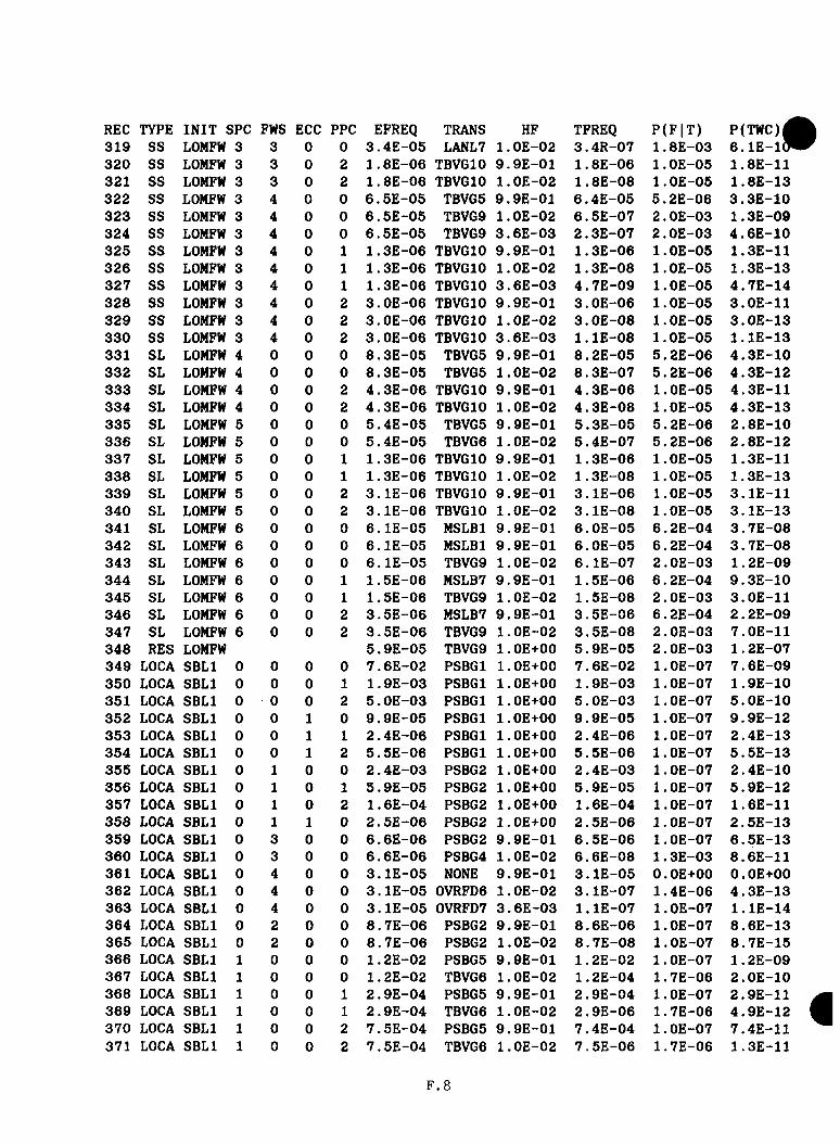
REC TYPE INIT SPC FWS ECC PPC EFREQ TRANS HF TFREQ P(F |T) P(TWC)|319 SS LOMFW 3 3 0 0 3.4E-05 LANL7 l.OE-02 3.4R-07 1.8E-03 6.1E-1(P320 SS LOMFW 3 3 0 2 1 . 8E-06 TBVGIO 9.9E-01 1.8E-06 l.OE-05 1.8E-11321 SS LOMFW 3 3 0 2 1 . 8E-06 TBVGIO l.OE-02 1.8E-08 l.OE-05 1.8E-13322 SS LOMFW 3 4 0 0 6 . 5E-05 TBVG5 9.9E-01 6.4E-05 5.2E-06 3.3E -10323 SS LOMFW 3 4 0 0 6 .5E-05 TBVG9 l.OE-02 6.5E -07 2.0E-03 1.3E-09324 SS LOMFW 3 4 0 0 6 .5E-05 TBVG9 3.6E-03 2.3E-07 2 . OE-03 4.6E -10325 SS LOMFW 3 4 0 1 1.3E-06 TBVGIO 9.9E-01 1.3E-06 l.OE-05 1.3E-11326 SS LOMFW 3 4 0 1 1 . 3E-06 TBVGIO l.OE-02 1 . 3E-08 l.OE-05 1.3E-13327 SS LOMFW 3 4 0 1 1.3E-06 TBVGIO 3.6E-03 4 .7E-09 l.OE-05 4 .7E-14328 SS LOMFW 3 4 0 2 3.0E-06 TBVGIO 9.9E-01 3 .0E-06 l.OE-05 3.0E-11329 SS LOMFW 3 4 0 2 3.0E-06 TBVGIO l.OE-02 3 .0E-08 1 . OE-05 3 .0E-13330 SS LOMFW 3 4 0 2 3.0E-06 TBVGIO 3.6E-03 l . l E - 0 8 l.O E-05 l . l E - 1 3331 SL LOMFW 4 0 0 0 8.3E-05 TBVG5 9.9E-01 8 .2E-05 5.2E-06 4 .3E-10332 SL LOMFW 4 0 0 0 8 . 3E-05 TBVG5 1 . OE-02 8 .3E-07 5 . 2E-06 4 .3E-12333 SL LOMFW 4 0 0 2 4 .3E-06 TBVGIO 9.9E-01 4 . 3E-06 l.OE-05 4.3E-11334 SL LOMFW 4 0 0 2 4.3E -06 TBVGIO l.OE-02 4 .3E-08 1 . OE-05 4.3E -13335 SL LOMFW 5 0 0 0 5 .4E-05 TBVG5 9.9E-01 5 .3E-05 5.2E-06 2 .8E-10336 SL LOMFW 5 0 0 0 5.4E -05 TBVG6 l.O E-02 5 .4E-07 5.2E-06 2 .8E-12337 SL LOMFW 5 0 0 1 1.3E-06 TBVGIO 9.9E-01 1.3E-06 l.OE-05 1.3E-11338 SL LOMFW 5 0 0 1 1.3E-06 TBVGIO l.OE-02 1.3E-08 l.OE-05 1.3E-13339 SL LOMFW 5 0 0 2 3.1E-06 TBVGIO 9.9E-01 3 .1E-06 l.OE-05 3.1E-11340 SL LOMFW 5 0 0 2 3 .1E-06 TBVGIO l.OE-02 3 .1E-08 1 . OE-05 3 .1E-13341 SL LOMFW 6 0 0 0 6 .1E-05 MSLBl 9.9E-01 6 .0E-05 6.2E-04 3 .7E-08342 SL LOMFW 6 0 0 0 6 .1E-05 MSLBl 9.9E-01 6.0E-05 6 . 2E-04 3 . 7E-08343 SL LOMFW 6 0 0 0 6 .1E-05 TBVG9 l.OE-02 6.1E-07 2.0E-03 1.2E-09344 SL LOMFW 6 0 0 1 1 . 5E-06 MSLB7 9.9E-01 1.5E-06 6 . 2E-04 9 .3E-10345 SL LOMFW 6 0 0 1 1.5E-06 TBVG9 l.OE-02 1.5E-08 2.0E-03 3.0E-11346 SL LOMFW 6 0 0 2 3 .5E-06 MSLB7 9.9E-01 3 .5E-06 6.2E-04 2 . 2E-09347 SL LOMFW 6 0 0 2 3 .5E-06 TBVG9 l.OE-02 3.5E-08 2.0E-03 7.0E-11348 RES LOMFW 5.9E-05 TBVG9 l.OE+00 5.9E-05 2.0E-03 1.2E-07349 LOCA SBLl 0 0 0 0 7 .6E-02 PSBGl l.OE+00 7.6E-02 l.OE-07 7.6E-09350 LOCA SBLl 0 0 0 1 1 . 9E-03 PSBGl l.OE+00 1 . 9E-03 1 . OE-07 1.9E-10351 LOCA SBLl 0 0 0 2 5 .0E-03 PSBGl l.OE+00 5 .0E-03 l.OE-07 5 .0E-10352 LOCA SBLl 0 0 1 0 9 .9E-05 PSBGl l.OE+00 9 .9E-05 l.OE-07 9.9E-12353 LOCA SBLl 0 0 1 1 2 .4E-06 PSBGl l.OE+00 2.4E-06 l.OE-07 2.4E-13354 LOCA SBLl 0 0 1 2 5.5E-06 PSBGl l.OE+00 5 .5E-06 l.OE-07 5 .5E-13355 LOCA SBLl 0 1 0 0 2.4E-03 PSBG2 1 . OE+00 2.4E-03 l.OE-07 2.4E-10356 LOCA SBLl 0 1 0 1 5 .9E-05 PSBG2 1 . OE+00 5.9E-05 l.OE-07 5.9E-12357 LOCA SBLl 0 1 0 2 1.6E-04 PSBG2 l.OE+00 1.6E-04 l.OE-07 1.6E-11358 LOCA SBLl 0 1 1 0 2 .5E-06 PSBG2 1 . OE+00 2 . 5E-06 1 . OE-07 2 .5E-13359 LOCA SBLl 0 3 0 0 6 .6E-06 PSBG2 9.9E-01 6 .5E-06 l.OE-07 6 .5E-13360 LOCA SBLl 0 3 0 0 6 . 6E-06 PSBG4 l.OE-02 6 .6E-08 1 . 3E-03 8.6E-11361 LOCA SBLl 0 4 0 0 3 .1E-05 NONE 9.9E-01 3 .1E-05 O.OE+00 O.OE+00362 LOCA SBLl 0 4 0 0 3 .1E-05 0VRFD6 1 . OE-02 3 .1E-07 1.4E-06 4 .3E-13363 LOCA SBLl 0 4 0 0 3.1E-05 0VRFD7 3 .6E-03 l . l E - 0 7 l.OE-07 l . l E - 1 4364 LOCA SBLl 0 2 0 0 8 .7E-06 PSBG2 9.9E-01 8 .6E-06 l.OE-07 8.6E-13365 LOCA SBLl 0 2 0 0 8.7E-06 PSBG2 l.OE-02 8 .7E-08 l.OE-07 8.7E-15366 LOCA SBLl 1 0 0 0 1.2E-02 PSBG5 9 . 9E-01 1.2E-02 l.OE-07 1 . 2E-09367 LOCA SBLl 1 0 0 0 1 . 2E-02 TBVG6 l.OE-02 1.2E-04 1.7E-06 2.0E-10368 LOCA SBLl 1 0 0 1 2.9E-04 PSBG5 9.9E-01 2 . 9E-04 1 . OE-07 2.9E-11369 LOCA SBLl 1 0 0 1 2 .9E-04 TBVG6 l.OE-02 2.9E-06 1.7E-06 4 .9E-12370 LOCA SBLl 1 0 0 2 7.5E-04 PSBG5 9.9E-01 7.4E-04 1 . OE-07 7.4E-11371 LOCA SBLl 1 0 0 2 7.5E-04 TBVG6 l.OE-02 7.5E-06 1.7E-06 1.3E-11
F . 8

REC TYPE INIT SPC FWS ECC PPC EFREQ TRANS HF TFREQ P(F |T ) P(TWC)372 LOCA SBLl 1 0 1 0 1.3E-05 PSBG5 9.9E-01 1 . 3E-05 l.OE-07 1.3E-12373 LOCA SBLl 1 0 1 0 1.3E-05 TBV66 l.OE-02 1.3E-07 1.7E-06 2.2E-13374 LOCA SBLl 1 3 0 0 1.7E-05 PSBG5 9.9E-01 1 . 7E-05 l.OE-07 1.7E-12375 LOCA SBLl 1 3 0 0 1 . 7E-05 TBVG6 l.OE-02 1.7E-07 1 . 7E-06 2.9E-13376 LOCA SBLl 1 4 0 0 7.7E-05 PSBG5 9.9E-01 7.6E-05 l.OE-07 7.6E-12377 LOCA SBLl 1 4 0 0 7 . 7E-05 TBVG6 l.OE-02 7.7E-07 1 . 7E-06 1.3E-12378 LOCA SBLl 1 4 0 2 3.6E-06 PSBG5 9.9E-01 3.6E-06 l.OE-07 3.6E-13379 LOCA SBLl 1 4 0 2 3 . 6E-06 TBVG6 1 . OE-02 3.6E-08 1 . 7E-06 6.1E-14380 LOCA SBLl 1 4 0 2 3.6E-06 TBVG6 3.6E-03 1.3E-08 1.7E-06 2.2E-14381 LOCA SBLl 1 1 0 0 3 . 7E-04 TBVG6 9.9E-01 3.7E-04 1 . 7E-06 6.3E-10382 LOCA SBLl 1 1 0 0 3.7E-04 TBVG6 l.OE-02 3 .7E-06 1.7E-06 6.3E-12383 LOCA SBLl 1 1 0 1 8.2E-06 TBVG6 9.9E-01 8.1E-06 1 . 7E-06 1.4E-11384 LOCA SBLl 1 1 0 1 8.2E-06 TBVG6 l.OE-02 8 .2E-08 1.7E-06 1.4E-13385 LOCA SBLl 1 1 0 2 2 . lE-05 TBVG6 9.9E-01 2.1E-05 1 . 7E-06 3.6E-11386 LOCA SBLl 1 1 0 2 2.1E-05 TBVG6 l.OE-02 2 .1E-07 1.7E-06 3.6E-13387 LOCA SBLl 2 0 0 0 1 . 4E-04 PSBG5 9.9E-01 1.4E-04 l.OE-07 1.4E-11388 LOCA SBLl 2 0 0 0 1.4E-04 TBVG6 l.OE-02 1.4E-06 1.7E-06 2.4E-12389 LOCA SBLl 2 0 0 2 7 . 6E-06 PSBG5 9.9E-01 7 .5E-06 l.OE-07 7.5E-13390 LOCA SBLl 2 0 0 2 7.6E-06 TBVG6 l.OE-02 7.6E-08 1.7E-06 1.3E-13391 LOCA SBLl 2 1 0 0 3.5E-06 TBVG6 9.9E-01 3 .5E-06 1 . 7E-06 6.0E-12392 LOCA SBLl 2 1 0 0 3.5E-06 TBVG6 l.OE-02 3 .5E-08 1.7E-06 6.0E-14393 LOCA SBLl 3 0 0 0 1 . 3E-03 TBVGIO 9.9E-01 1.3E-03 l.OE-05 1.3E-08394 LOCA SBLl 3 0 0 0 1.3E-03 TBVGIO l.OE-02 1.3E-05 l.OE-05 1.3E-10395 LOCA SBLl 3 0 0 1 3.0E-05 TBVGIO 9.9E-01 3 .0E-05 l.OE-05 3.0E-10396 LOCA SBLl 3 0 0 1 3.0E-05 TBVGIO l.OE-02 3 .0E-07 l.OE-05 3.0E-12397 LOCA SBLl 3 0 0 2 8.3E-05 TBVGIO 9.9E-01 8 .2E-05 l.OE-05 8.2E-10398 LOCA SBLl 3 0 0 2 8.3E-05 TBVGIO l.OE-02 8 .3E-07 l.OE-05 8.3E-12399 LOCA SBLl 3 0 1 0 1.4E-06 TBVGIO 9.9E-01 1.4E-06 1 . OE-05 1.4E-11400 LOCA SBLl 3 0 1 0 1.4E-06 TBVGIO l.OE-02 1.4E-08 l.OE-05 1.4E-13401 LOCA SBLl 3 3 0 0 1.9E-06 TBVGIO 9.9E-01 1.9E-06 l.OE-05 1.9E-11402 LOCA SBLl 3 3 0 0 1 . 9E-06 TBVGIO l.OE-02 1.9E-08 l.OE-05 1.9E-13403 LOCA SBLl 3 4 0 0 7.8E-06 TBVGIO 9.9E-01 7.7E-06 1 . OE-05 7.7E-11404 LOCA SBLl 3 4 0 0 7.8E-06 TBVGIO l.OE-02 7.8E-08 l.OE-05 7.8E-13405 LOCA SBLl 3 4 0 0 7.8E-06 TBVGIO 3.6E-03 2.8E-08 l.OE-05 2.8E-13406 LOCA SBLl 3 1 0 0 4.0E-05 TBVGIO 9.9E-01 4.0E-05 l.OE-05 4.0E-10407 LOCA SBLl 3 1 0 0 4.0E-05 TBVGIO l.OE-02 4 .0E-07 l.OE-05 4.0E-12408 LOCA SBLl 3 1 0 2 2.1E-06 TBVGIO 9.9E-01 2.1E-06 l.OE-05 2,1E-11409 LOCA SBLl 3 1 0 2 2.1E-06 TBVGIO l.OE-02 2.1E-08 l.OE-05 2.1E-13410 LOCA SBLl 4 0 0 0 9.1E-06 TBVGIO 9.9E-01 9.0E-06 l.OE-05 9.0E-11411 LOCA SBLl 4 0 0 0 9.1E-06 TBVGIO l.OE-02 9.1E-08 1 . OE-05 9.1E-13412 LOCA SBLl 5 0 0 0 6.6E-06 TBVGIO 9.9E-01 6.5E-06 l.OE-05 6.5E-11413 LOCA SBLl 5 0 0 0 6.6E-06 TBVGIO l.OE-02 6 . 6E-08 l.OE-05 6.6E-13414 LOCA SBLl 6 0 0 0 7.3E-06 MSLB7 9.9E-01 7 .2E-06 6.2E-04 4.5E-09415 LOCA SBLl 6 0 0 0 7 . 3E-06 TBVG9 l.OE-02 7.3E-08 2 . OE-03 1.5E-10416 RES SBLl 7.8E-05 TBVG9 l.OE+00 7.8E-05 2.0E-03 1.6E-07417 LOCA SBL2 0 0 0 0 8 . 2E-03 PSBGl l.OE+00 8 .2E-03 l.OE-07 8.2E-10418 LOCA SBL2 0 0 1 0 l.OE-05 PSBGl l.OE+00 l.O E-05 l.OE-07 l.OE-12419 LOCA SBL2 0 1 0 0 2 . 6E-04 PSBG2 9.9E-01 2.6E-04 l.OE-07 2.6E-11420 LOCA SBL2 0 1 0 0 2.6E-04 PSBG4 l.OE-02 2 .6E-06 1.3E-03 3.4E-09421 LOCA SBL2 0 4 0 0 2 . 7E-06 NONE 9.9E-01 2.7E-06 O.OE+OO O.OE+OO422 LOCA SBL2 0 4 0 0 2.7E-06 0VRFD6 l.OE-02 2 . 7E-08 1.4E-06 3.8E-14423 LOCA SBL2 0 4 0 0 2.7E-06 0VRFD7 3.6E-03 9 .7E-09 l.OE-07 9.7E-16424 LOCA SBL2 0 2 0 0 1 . OE-06 PSBG2 l.OE+00 1 . OE-06 l.OE-07 l.OE-13
F . 9
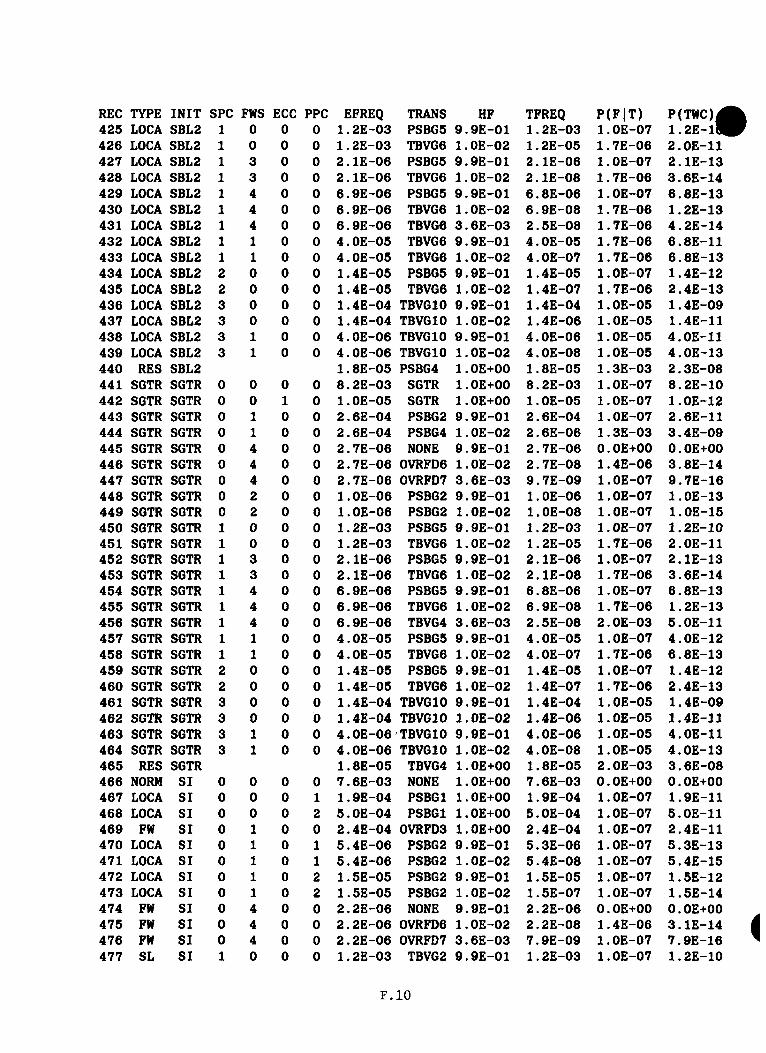
REC TYPE INIT SPC FWS ECC PPC EFREQ TRANS HF TFREQ P(F |T ) P(TWC)|425 LOCA SBL2 1 0 0 0 1.2E-03 PSBG5 9.9E-01 1 . 2E-03 l.OE-07 1 . 2 E - l l426 LOCA SBL2 1 0 0 0 1 . 2E-03 TBVG6 l.OE-02 1.2E-05 1.7E-06 2.0E-11427 LOCA SBL2 1 3 0 0 2.1E-06 PSBG5 9.9E-01 2.1E-06 l.OE-07 2.1E-13428 LOCA SBL2 1 3 0 0 2.1E-06 TBVG6 l.OE-02 2 . lE-08 1 . 7E-06 3.6E-14429 LOCA SBL2 1 4 0 0 6.9E-06 PSBG5 9.9E-01 6.8E-06 l.OE-07 6.8E-13430 LOCA SBL2 1 4 0 0 6.9E-06 TBVG6 l.OE-02 6 . 9E-08 1 . 7E-06 1.2E-13431 LOCA SBL2 1 4 0 0 6.9E-06 TBVG6 3.6E-03 2 . 5E-08 1 . 7E-06 4.2E-14432 LOCA SBL2 1 1 0 0 4 . OE-05 TBVG6 9.9E-01 4 . OE-05 1 . 7E-06 6.8E-11433 LOCA SBL2 1 1 0 0 4.0E-05 TBVG6 l.OE-02 4.0E-07 1 . 7E-06 6.8E-13434 LOCA SBL2 2 0 0 0 1.4E-05 PSBG5 9.9E-01 1.4E-05 l.OE-07 1.4E-12435 LOCA SBL2 2 0 0 0 1.4E-05 TBVG6 l.OE-02 1.4E-07 1 . 7E-06 2.4E-13436 LOCA SBL2 3 0 0 0 1.4E-04 TBVGIO 9.9E-01 1.4E-04 l.O E-05 1.4E-09437 LOCA SBL2 3 0 0 0 1.4E-04 TBVGIO l.OE-02 1.4E-06 l.OE-05 1.4E-11438 LOCA SBL2 3 1 0 0 4 . OE-06 TBVGIO 9.9E-01 4.0E-06 l.OE-05 4.0E-11439 LOCA SBL2 3 1 0 0 4 . OE-06 TBVGIO l.OE-02 4.0E-08 l.OE-05 4.0E-13440 RES SBL2 1.8E-05 PSBG4 l.OE+00 1.8E-05 1.3E-03 2.3E-08441 SGTR SGTR 0 0 0 0 8.2E-03 SGTR l.OE+00 8.2E-03 l.O E-07 8.2E-10442 SGTR SGTR 0 0 1 0 l.OE-05 SGTR l.OE+00 l.OE-05 l.OE-07 l.OE-12443 SGTR SGTR 0 1 0 0 2.6E-04 PSBG2 9.9E-01 2 . 6E-04 l.OE-07 2.6E-11444 SGTR SGTR 0 1 0 0 2.6E-04 PSBG4 l.OE-02 2.6E-06 1 . 3E-03 3.4E-09445 SGTR SGTR 0 4 0 0 2 . 7E-06 NONE 9.9E-01 2.7E-06 O.OE+OO O.OE+OO446 SGTR SGTR 0 4 0 0 2 . 7E-06 0VRFD6 l.OE-02 2 . 7E-08 1.4E-06 3.8E-14447 SGTR SGTR 0 4 0 0 2.7E-06 0VRFD7 3.6E-03 9 . 7E-09 1 . OE-07 9.7E-16448 SGTR SGTR 0 2 0 0 l.O E-06 PSBG2 9.9E-01 1 .OE-06 l.OE-07 l.OE-13449 SGTR SGTR 0 2 0 0 l.OE-06 PSBG2 l.OE-02 l.OE-08 l.OE-07 l.OE-15450 SGTR SGTR 1 0 0 0 1 . 2E-03 PSBG5 9.9E-01 1 . 2E-03 l.O E-07 1.2E-10451 SGTR SGTR 1 0 0 0 1.2E-03 TBVG6 l.OE-02 1 . 2E-05 1.7E-06 2.0E-11452 SGTR SGTR 1 3 0 0 2.1E-06 PSBG5 9.9E-01 2.1E-06 l.OE-07 2.1E-13453 SGTR SGTR 1 3 0 0 2.1E-06 TBVG6 l.OE-02 2.1E-08 1 . 7E-06 3.6E-14454 SGTR SGTR 1 4 0 0 6 . 9E-06 PSBG5 9.9E-01 6.8E-06 l.OE-07 6.8E-13455 SGTR SGTR 1 4 0 0 6.9E-06 TBVG6 l.OE-02 6.9E-08 1.7E-06 1.2E-13456 SGTR SGTR 1 4 0 0 6.9E-06 TBVG4 3.6E-03 2.5E-08 2.0E-03 5.0E-11457 SGTR SGTR 1 1 0 0 4.0E-05 PSBG5 9.9E-01 4.0E-05 l.OE-07 4.0E-12458 SGTR SGTR 1 1 0 0 4.0E-05 TBVG6 1 . OE-02 4.0E-07 1 . 7E-06 6.8E-13459 SGTR SGTR 2 0 0 0 1.4E-05 PSBG5 9.9E-01 1.4E-05 l.OE-07 1.4E-12460 SGTR SGTR 2 0 0 0 1.4E-05 TBVG6 l.OE-02 1.4E-07 1 . 7E-06 2.4E-13461 SGTR SGTR 3 0 0 0 1.4E-04 TBVGIO 9.9E-01 1.4E-04 l.OE-05 1.4E-09462 SGTR SGTR 3 0 0 0 1.4E-04 TBVGIO 1 . OE-02 1 . 4E-06 1 . OE-05 1.4E-11463 SGTR SGTR 3 1 0 0 4.0E-06 TBVGIO 9.9E-01 4.0E-06 l.OE-05 4.0E-11464 SGTR SGTR 3 1 0 0 4 . OE-06 TBVGIO l.OE-02 4.0E-08 1 . OE-05 4.0E-13465 RES SGTR 1.8E-05 TBVG4 l.OE+00 1.8E-05 2.0E-03 3.6E-08466 NORM SI 0 0 0 0 7 . 6E-03 NONE l.OE+00 7.6E-03 O.OE+OO O.OE+OO467 LOCA SI 0 0 0 1 1.9E-04 PSBGl 1 . OE+00 1.9E-04 l.OE-07 1.9E-11468 LOCA SI 0 0 0 2 5 . OE-04 PSBGl l.OE+00 5.0E-04 l.OE-07 5.0E-11469 FW SI 0 1 0 0 2.4E-04 0VRFD3 l.OE+00 2.4E-04 l.OE-07 2.4E-11470 LOCA SI 0 1 0 1 5.4E-06 PSBG2 9.9E-01 5.3E-06 l.OE-07 5.3E-13471 LOCA SI 0 1 0 1 5.4E-06 PSBG2 l.OE-02 5.4E-08 l.OE-07 5.4E-15472 LOCA SI 0 1 0 2 1 . 5E-05 PSBG2 9.9E-01 1.5E-05 l.OE-07 1.5E-12473 LOCA SI 0 1 0 2 1.5E-05 PSBG2 l.OE-02 1.5E-07 l.OE-07 1.5E-14474 FW SI 0 4 0 0 2.2E-06 NONE 9.9E-01 2 . 2E-06 O.OE+OO O.OE+OO475 FW SI 0 4 0 0 2 . 2E-06 0VRFD6 l.OE-02 2.2E-08 1.4E-06 3.1E-14476 FW SI 0 4 0 0 2.2E-06 0VRFD7 3.6E-03 7.9E-09 l.OE-07 7.9E-16477 SL SI 1 0 0 0 1.2E-03 TBVG2 9.9E-01 1.2E-03 l.OE-07 1.2E-10
F. IO

REC TYPE INIT SPC FWS ECC PPC EFREQ TRANS HF TFREQ P(F |T ) P(TWC)478 SL SI 1 0 0 0 1.2E-03 TBVGl l.OE-02 1.2E-05 4.0E-07 4.8E-12479 SL SI 1 0 0 1 2 , 8E-05 PSBG5 9.9E-01 2.8E-05 l.OE-07 2.8E-12480 SL SI 1 0 0 1 2.8E-05 TBVG6 l.OE-02 2.8E-07 1.7E-06 4.8E-13481 SL SI 1 0 0 2 7 .2E-05 PSBG5 9.9E-01 7.1E-05 l.OE-07 7.1E-12482 SL SI 1 0 0 2 7 .2E-05 TBVG6 l.OE-02 7.2E-07 1.7E-06 1.2E-12483 SS SI 1 4 0 0 5 , 7E-06 TBVG2 9.9E-01 5.6E-06 l.OE-07 5.6E-13484 SS SI 1 4 0 0 5 . 7E-06 TBVGl l.OE-02 5.7E-08 4.0E-07 2.2E-14485 SS SI 1 4 0 0 5 .7E-06 TBVGl 3.6E-03 2.1E-08 4.0E-07 8.4E-15486 SS SI 1 1 0 0 3 .6E-05 TBVG3 9.9E-01 3.6E-05 l.OE-07 3.6E-12487 SS SI 1 1 0 0 3 , 6E-05 TBVG4 l.OE-02 3.6E-07 2.0E-03 7.2E-10488 SL SI 2 0 0 0 1 , 2E-05 TBVG2 9.9E-01 1.2E-05 l.OE-07 1.2E-12489 SL SI 2 0 0 0 1.2E-05 TBVGl l.OE-02 1.2E-07 4.0E-07 4.8E-14490 SL SI 3 0 0 0 1.3E-04 TBVG5 9.9E-01 1.3E-04 5.2E-06 6.8E-10491 SL SI 3 0 0 0 1 . 3E-04 TBVG5 l.O E-02 1.3E-06 5.2E-06 6.8E-12492 SL SI 3 0 0 1 3.1E -06 TBVGIO 9.9E-01 3.1E-06 l.OE-05 3.1E-11493 SL SI 3 0 0 1 3 .1E-06 TBVGIO l.O E-02 3.1E-08 l.OE-05 3.1E-13494 SL SI 3 0 0 2 7.1E-06 TBVGIO 9.9E-01 7.0E-06 l.OE-05 7.0E-11495 SL SI 3 0 0 2 7 , lE -06 TBVGIO l.OE-02 7.1E-08 l.OE-05 7.1E-13496 SS SI 3 1 0 0 3 .3E -06 TBVG9 9.9E-01 3.3E-06 2.0E-03 6.6E-09497 SS SI 3 1 0 0 3 . 3E-06 TBVG9 l.OE-02 3.3E-08 2.0E-03 6.6E-11498 RES SI 3 .9E-05 TBVG4 l.OE+00 3.9E-05 2.0E-03 7.8E-08
F . l l
APPENDIX G
RESPONSES TO UTILITY COMMENTS
The m a te r i a l p r e s e n te d in t h i s r e p o r t I s p a r t o f an e v a lu a t io n e f f o r t to p ro v id e In fo rm a t io n on th e u n re so lv e d s a f e t y I s s u e o f p r e s s u r i z e d therm al shock (PTS). Because PTS I s an u n re s o lv e d s a f e t y I s s u e , NRG r e q u i r e s t h a t a l i s t o f I n d u s t r y comments on th e r e p o r t and th e changes which were made as a r e s u l t o f th o s e comments be p ro v id ed a s an appendix to th e r e p o r t . The m a te r i a l p r e s e n te d In t h i s appendix responds to t h a t re q u ire m e n t . The comments a r e l i s t e d and d is c u s s e d by c h a p te r w ith comments on t h e a p p e n d i c e s d i s c u s s e d a lo n g w ith th e a p p r o p r ia te c h a p te r s . Only th o s e comments c o n s id e re d to be p e r t i n e n t to th e PTS s tu d y a re a d d re s se d ; t h a t I s , comments s im ply p o in t in g ou t gram m atical o r s p e l l i n g e r r o r s a r e n o t In c lu d e d .
G eneral Comments
1. T h is r e p o r t r e p r e s e n t s th e r e s u l t s o f a s u b s t a n t i a l l e v e l o f e f f o r t over th e p a s t th r e e y e a r s to e v a lu a te th e r i s k o f P r e s s u r i z e d Thermal Shock a t Oconee N uclea r S t a t i o n , U nit 1. As w r i t t e n th e r e p o r t la c k s c o n s i s te n c y and r e a d a b i l i t y . An enormous w e a l th o f In fo rm a t io n Is p ro v id e d , much o f which i s I n c o n s e q u e n t ia l t o th e f i n a l r e s u l t .
Response: We would ag re e t h a t th e r e p o r t te rm in o lo g y I s I n c o n s i s t e n t andth e r e a d a b i l i t y cou ld be g r e a t l y Improved. However, I t was de term ined t h a t our e f f o r t s would be more w is e ly s p e n t In com ple ting th e C a lv e r t C l i f f s and H. B. Robinson r e p o r t s s in c e th e s e s t u d i e s r e f l e c t a more r e f i n e d e v a lu a t io n p ro c e s s . Thus, v e ry l i t t l e e f f o r t was made to Improve th e r e a d a b i l i t y o f th e r e p o r t . We would ag re e t h a t much o f th e Inform at i o n p r e s e n t e d In t h e r e p o r t I s I n c o n s e q u e n t i a l t o t h e f i n a l r e s u l t . However, I t I s our o p in io n t h a t th e p ro c e s s used to perform th e e v a lu a t io n and a d e t a i l e d d i s c u s s io n o f th e assum ptions made In th e e v a l u a t i o n I s as Im p o r tan t I f n o t more so th a n th e a c t u a l f i n a l r e s u l t I t s e l f . The enormous amount o f In fo rm a t io n I s n e c e s s a ry to p ro v id e : th eapproach used to perform th e e v a l u a t i o n , th e d a ta used In th e e v a lu a t io n , assum ptions made In I d e n t i f y i n g seq u en ce s , and our u n d e rs ta n d in g o f howth e p l a n t responds to c e r t a i n e v e n t s . W ithout t h i s In fo rm a t io n th eq u a l i t y o f th e f i n a l r e s u l t can n o t be d e te rm in ed .
2. The c h a r a c t e r i z a t i o n o f th e f req u en cy (4.5E-6/RY) o f a TWC as a b e s t e s t im a te I s n o t a p p r o p r i a t e from two p e r s p e c t iv e s : (1) A rev iewo f th e r e p o r t I n d i c a t e s c o n se rv a t is m s t h a t on b a lan ce would b ia s th e c i t e d TWC freq u en cy v a lu e tow ards an upper bound and (2) th e l a rg e u n c e r t a i n t y o f a f a c t o r o f 100 and th e r e f o r e a range o f t e n thousand d i l u t e s th e co n f id e n ce o f 4.5E-6/RY as b e in g a b e s t e s t im a te .
Response: A f te r th e com ple tion o f th e C a lv e r t C l i f f s and H. B. Robinsona n a l y s i s , th e Oconee e v a l u a t i o n was rev iew ed In l i g h t of th e Improvements In th e e v a lu a t io n te c h n iq u e s . Both c o n s e rv a t iv e and n o n -c o n s e rv a t iv e f a c t o r s were I d e n t i f i e d In th e Oconee a n a l y s i s . As s t a t e d In th e comment. I t d id appea r t h a t th e b a la n c e o f th e s e f a c t o r s appeared to be In th e c o n s e r v a t iv e d i r e c t i o n . However, w i th o u t r e d o in g th e c a l c u l a t i o n s th e a c t u a l b e s t e s t im a te v a lu e cou ld n o t be d e te rm in ed . The f a c t o r of100 g iven f o r th e u n c e r t a i n t y v a lu e I s a 95% v a lu e . T h is v a lu e maybe somewhat h igh due to th e u n r e a l i s t i c u n c e r t a i n t i e s used In th e n e g a t iv e d i r e c t i o n o f th e te m p e ra tu re p r o f i l e s and th e double co u n t in g e f f e c t f o r v e ry h ig h f law d e n s i t y v a lu e s . However, In l i g h t o f o th e r
G.l

f a c t o r s , u se o f e r r o r f a c t o r s a s 99S5 v a lu e s r a t h e r th an 95* v a lu e s , e t c . , th e u n c e r t a i n t y v a lu e s a r e n o t u n r e a l i s t i c .
3. A ll r e f e r e n c e s o f th e d e s ig n o f o th e r B&W NSSS p l a n t d e s ig n s sh o u ld be d e l e t e d . We have no c u r r e n t knowledge o f th e p r e s e n t d e s ig n o f any o th e r p l a n t and to s t a t e t h a t a p a r t i c u l a r Oconee f e a t u r e I s o r I s n o t p a r t o f a n o th e r p l a n t ' s d e s ig n I s n o t a s ta te m e n t o f f a c t .
Response: We would ag re e t h a t th e c o n c lu s io n s , m i t i g a t in g a c t i o n s ,e t c . sh o u ld be d i s c u s s e d w ith r e s p e c t t o Oconee s in c e t h a t I s th e p l a n tfrom which th e d a t a was o b ta in e d . In fe re n c e o f c o n d i t io n s a t o th e r B&Wp l a n t s based on Oconee r e s u l t s w i th o u t a rev iew o f th e o th e r p l a n t s I s I n a p p r o p r ia te . R e fe re n ces to B&W p l a n t s In g e n e r a l used In t h i s c o n te x t were changed to r e f e r on ly to Oconee.
4 . R e p e a te d r e f e r e n c e I s made to th e b e s t e s t im a te TWC v a lu e o f4.5E-6/RY. I t sh o u ld be made c l e a r t h a t t h i s v a lu e on ly a p p l i e s a t 32 EFPY and t h a t p r i o r to t h a t tim e th e TWC p r o b a b i l i t y I s low er.
Response: We ag re e w i th th e comment. The 32 EFPY d e s ig n a t io n was addedto th e d i s c u s s io n s o f th e b e s t e s t im a te TWC v a lu e .
C hapter 1 .0 Comments
5. The s ta t e m e n t r e g a r d in g f u t u r e use o f th e Oconee PTS model Inth e f i r s t p a ra g ra p h I s I n a p p r o p r ia te . I t s e rv e s no u s e f u l p u rpose , and I s c o n t r a r y t o t h e Im p lied agreem ent we had. Duke r e q u e s t s t h a t I t be d e l e t e d .
Response: The s e n te n c e was d e l e te d from th e t e x t .
C hapter 2 .0 Comments
6. The v e s s e l downcomer I s between th e v e s s e l and th e the rm a l s h i e l d , n o t th e co re b a r r e l .
Response: We concu r . The change was made In th e t e x t .
7 . The c o o l a n t In v e n to ry c o n t r o l system adds o r w ithdraw s c o o la n tbased on I n d ic a t e d In v e n to ry , n o t r e a c t o r power.
Response: We co n cu r . The change was made In th e t e x t .
8. I t sh o u ld be made c l e a r t h a t s a f e t y I n j e c t i o n I s used t o p re v e n t f u e lo v e rh e a t in g o n ly under a c c id e n t c o n d i t io n s .
Response: We a g re e . The t e x t was changed to make t h i s p o in t .
9. The co n d en sa te t r a i n I s I n c o r r e c t l y d e s c r ib e d In th e second p a r a g rap h . The c o n d en sa te p a th I s F H e a te r s , E H e a te r s , D H e a te r s , C H ea te r D rain C o o le rs , and C H e a te r s . The D H ea te rs a r e n o t d r a in c o o l e r s .
Response: We co n cu r . Text was r e v i s e d t o r e f l e c t t h i s comment.
G.2
10. The condensa te b o o s te r pumps a r e cap a b le o f d e l i v e r i n g feed w ate r a t 550 p s lg . n o t 600 p s lg .
Response: We a g re e . The change was made In th e t e x t .
11. The EFW pumps a r e a c tu a te d I f th e MFW pumps t r i p o f f o r I f MFW p r e s s u r e d rops below 750 p s lg .
Response: We a g re e . The change was made In th e t e x t .
12. S e c t io n 2 . 2 .3 . 3 i s co m p le te ly e r ro n e o u s . ICS no lo n g e r c o n t r o l s EFW. EFW i s co m p le te ly s e p a r a t e from ICS and i s i n i t i a t e d and c o n t r o l l e d by a s a f e t y - r e l a t e d system .
Response: We a g re e . The r e f e r e n c e to th e ICS system was in e r r o r . Thisr e f e r e n c e was removed from th e t e x t .
13. In S e c t io n 2 . 2 .4 , no b a s i s has been p ro v id ed to su p p o r t th e s ta te m e n t t h a t t h e r e i s a h i s t o r i c a l r e c o rd o f s in g l e f a i l u r e s o f su p p o r t system s c a u s in g o v e rc o o l in g t r a n s i e n t s .
Response: We a g re e . The t e x t was changed to r e f l e c t th e p o t e n t i a lim portance o f su p p o r t system s r a t h e r th a n any h i s t o r i c a l d a ta .
14. Secondary s id e p r e s s u r e sh o u ld be 1010 n o t 1025 p s lg .
Response: We a g re e . Change in th e t e x t was made.
15 . I t i s a s s e r t e d t h a t LOCAs can g e n e ra te s ta g n a te d flow regim es t h a t can c o n t r i b u t e t o " l o c a l i z e d r a p i d cooldown o f th e r e a c t o r v e s s e l . " Y et, in th e l a s t s e n te n c e o f t h i s s e c t i o n i t i s s t a t e d " th e v en t v a lv e s , t h e r e f o r e , promote c o n t in u e d c i r c u l a t i o n o f c o o la n t th rough th e core re g io n a s w ell a s p ro v id e warm w a te r to mix w ith HPI flow s e n t e r i n g th e downcomer r e g io n . " T h is l a t t e r d i s c u s s io n i s r e p r e s e n t a t i v e o f th e t r u e s i t u a t i o n and would seem to c o n t r a d i c t th e f i r s t s e n te n c e .
Response: The f i r s t s e n te n c e was meant t o imply t h a t in g e n e ra l LOCAshave a p o t e n t i a l to g e n e ra te s t a g n a t e d flow regim es t h a t can c o n t r i b u t e t o l o c a l i z e d r a p id cooldown o f a r e a c t o r v e s s e l . The r e s t o f th e d i s c u s s io n goes on to show t h a t a t Oconee th e o p e ra t io n o f th e ven t v a lv e s prom otes c i r c u l a t i o n and t h e r e f o r e p re c lu d e s o r g r e a t l y l i m i t s th e p o t e n t i a l f o r s ta g n a te d flow reg im es . Some rew ord ing o f t h i s s e c t i o n was made to avo id m isu n d e rs ta n d in g s .
C hapter 3 Comments
16. There a r e two TSVs on each b ran ch , n o t fo u r .
Response: We a g re e . The change was made in th e t e x t .
17. The r e p o r t s t a t e s t h a t secondary u p s e t s w i l l te n d to mask a PORV LOCA, and goes on t o assume t h a t th e o p e r a to r s w i l l do n o th in g to m i t i g a t e such an ev en t u n t i l steam g e n e r a to r h e a t removal c a p a c i ty i s r e s t o r e d . T h is i s c l e a r l y i n c o n s i s t e n t w ith post-TMI o p e r a to r t r a i n i n g
G. 3

program s. We do n o t b e l i e v e t h i s t a k e s In to accoun t th e a d d i t i o n of su b c o o l in g m argin m o n ito rs and co re e x i t therm ocouples to th e c o n t ro l rooms.
Response: We concur t h a t th e assum ption made was a c o n s e rv a t iv e approachand th e r e p o r t was changed to make t h i s p o in t .
C hap ter 4 Comments
18. The emergency feed w ate r system c o n t ro l i s n o t p a r t o f th e ICS.
Response: The s ta te m e n t as p r e s e n te d in th e t e x t i s in r e f e r e n c eto th e o v e r a l l c o n t ro l system n o t j u s t th e ICS. However t o avo id c o n fu s io n a d d i t i o n a l w ording was added to c l e a r l y i n d i c a t e t h a t th e EFW i s no t p a r t o f th e ICS.
19. The l a r g e u n c e r t a i n t i e s shou ld have no e f f e c t on th e b e s t e s t im a te v a lu e . A ll th e y can do i s a f f e c t o v e r a l l u n c e r t a in t y .
Response: We a g re e . The b e s t e s t im a te v a lu e shou ld n o t have beenchanged. Thus, th e use o f th e a d ju s t e d th e rm a l -h y d ra u l ic t r a n s i e n t i s i n c o n s i s t e n t w i th th e t r e a tm e n t o f u n c e r t a i n t y l a t e r in th e r e p o r t . The r e s u l t o f t h i s in c o n s i s t e n c y i s a c o n s e r v a t iv e b ia s f o r t h i s t r a n s i e n t . A se n te n c e was added in th e t e x t t o make t h i s p o in t .
20. The sequence o f e v e n ts i n c o r r e c t l y i n d i c a t e s t h a t EFW i s be ing s t a r t e d on low SG l e v e l .
Response: We a g re e . The EFW flow i n i t i a t e s a t th e tim e in d i c a t e d . However, th e pumps had p r e v io u s ly s t a r t e d . R eference to th e pumps s t a r t i n g a t in d i c a t e d tim e was removed.
2 1 . F o r f a i l u r e o f two tu r b i n e bypass v a lv e s a t f u l l power o th e r s i g n i f i c a n t f e a t u r e s o f th e t r a n s i e n t in c lu d e : O p era to r does no t i s o l a t e / c o n t r o l fe e d w a te r , h ig h l e v e l t r i p f a i l s , MFW i s n o t r e a l ig n e d upon RCP t r i p .
R e s p o n s e : We would ag ree t h a t " o p e r a to r does n o t i s o l a t e / c o n t r o lfeed w ate r" i s a f e a t u r e which shou ld have been i d e n t i f i e d . T h is f e a t u r e was in c lu d e d in th e d i s c u s s io n o f th e t r a n s i e n t . The h igh l e v e l t r i p was n o t assumed to f a i l and in f a c t t r i p p e d th e pumps a t 6 0 .7 seconds as i n d i c a t e d in t a b l e 4 .1 5 . F u r th e rm o re , MFW was r e a l ig n e d upon RCP t r i p as i n d i c a te d in t a b l e 4 .1 5 .
22. The sequence o f e v e n ts shows MFW pump t r i p a t 61 seconds , b u t no EFW a c t u a t i o n u n t i l 210 seconds . T h is does n o t make s e n se .
Response: The r e f e r e n c e to pump a c t u a t i o n a t 209 seconds was meant tor e f e r to a c t u a l EFW flow w ith pumps hav ing been a c tu a te d fo l lo w in g MFW pump t r i p . The t e x t was changed to make t h i s p o in t .
23. The e x t r a p o l a t i o n s o f te m p e ra tu re f o r s e v e r a l o f th e sequences a re u n r e a l i s t i c in a p h y s ic a l sen se and a r e s u b s t a n t i a l l y c o n s e r v a t iv e .
G. 4

Response: We would ag re e t h a t th e e x t r a p o la t e d te m p e ra tu re s appea r to bec o n s e r v a t iv e . However, In l i g h t o f th e p o t e n t i a l c o o l in g o f th e HPI and EFW system s th e le v e l o f c o n se rv a t ism cou ld n o t be de term ined w ith o u t a th e rm a l - h y d r a u l ic c a l c u l a t i o n o f th e com plete two hour a n a l y s i s p e r io d . S ince t h i s was n o t done, th e cu rv es p r e s e n te d In th e r e p o r t do r e f l e c t our b e s t e s t im a te based on th e a v a i l a b l e d a ta and th u s no change was made In t h e d i s c u s s i o n o f th e th e rm a l - h y d r a u l ic s a s s o c ia t e d w ith th e se s e q u e n c e s .
24. There were s e v e r a l g e n e ra l comments made by Duke Power C o rpo ra tion co n ce rn in g what th e y p e rc e iv e d to be c o n s id e r a b le c o n se rv a t ism s used In th e e x t r a p o l a t i o n p ro c e s s .
Response: A lthough ORNL I n t u i t i v e l y ag reed w ith many o f th e s e comments,changes In th e r e p o r t cou ld n o t be made w i th o u t s p e c i f i c d a ta . This d a ta cou ld n o t be o b ta in e d w ith o u t a g r e a t d ea l o f f u r t h e r th e rm a l-h y d ra u l ic c a l c u l a t i o n s . As a r e s u l t , th e d a ta a s p re s e n te d In c h a p te r 4 r e p r e s e n t s th e o n ly d a t a a v a i l a b l e and th u s must be used as b e s t e s t im a te Inform at i o n .
25. R efe ren ce I s made to a s tu d y "under I n v e s t i g a t i o n " . The s p e c i f i c s shou ld be p ro v id e d as a fo o tn o te o r r e f e r e n c e .
Response: The r e f e r e n c e was made to r e s e a r c h be ing perform ed a t P a c i f i cN orthw est L a b o r a to r i e s . I t was d e c id e d , however, t h a t r e f e r e n c e to t h i s s tu d y d e t r a c t e d from th e p o in t b e in g made In th e t e x t and th u s th e r e f e r e n c e was d e l e te d .
26. I t seems t h a t s u b s t a n t i a l u n j u s t i f i e d u n c e r t a in t y I s b e in g a p p l ie d to f law d e n s i t y d i s t r i b u t i o n .
Response: The f law d e n s i t y d i s t r i b u t i o n I s based upon th e e n g in e e r in gjudgement o f our e x p e r t In f r a c t u r e m echan ics . The d i s t r i b u t i o n used was n o t In te n d e d a s a t y p i c a l d i s t r i b u t i o n f o r a p a r t i c u l a r r e a c t o r v e s s e l . I n s t e a d , I t sh o u ld be I n t e r p r e t e d as c o v e r in g th e p o p u la t io n o f a l l p o s s i b l e r e a c t o r v e s s e l s . However, th e f a c t t h a t a p a r t i c u l a r ISI d e t e c te d no n e a r s u r f a c e f law s o f conce rn to PTS does n o t n e c e s s a r i l y r e d u c e th e u n c e r t a i n t y In th e f law d e n s i t y d i s t r i b u t i o n . The ISI te c h n iq u e s used a re p ro b ab ly no t cap a b le o f d e t e c t i n g f law s In and ex te n d in g a s h o r t d i s t a n c e beyond th e c la d d in g . Thus no changes In th e t e x t were made.
27 . F o r t h e d a t a p ro v id e d In Appendix E. I n s u f f i c i e n t d e f i n i t i o n o f term s I s p ro v id ed .
Response: We ag re e t h a t In some I n s ta n c e s d e f i n i t i o n o f te rm s was no tp ro v id e d . In fo rm a t io n was added f o r th o s e term s no t p r e v io u s ly d e f in e d In th e t e x t .
28. Replacem ent o f th e c u r r e n t HPI system w ith a low head system I s d i s c u s s e d . T h is Item I n d i c a t e s a l i m i t e d knowledge o f th e b ig p i c t u r e o f p l a n t s a f e t y and sh o u ld be d e l e t e d .
Response: The comment was n o t meant to be I n t e r p r e t e d as a recommenda-
G.5

t l o n f o r a change in th e Oconee d e s ig n . The purpose o f th e d i s c u s s io n was to i n d i c a t e th e i a p o r t a n c e o f th e r e p r e s s u r i z a t i o n p ro c e s s t o th e PTS phenomenon. The t e x t was changed to make t h i s p o in t c l e a r .
2 9 . The d i s c u s s i o n o f IS I i n t h i s c h a p t e r co m p le te ly ig n o re s th ef a c t t h a t such in s p e c t io n s a r e r e g u la to r y r e q u ire m e n ts .
R e s p o n s e : The i n s e r v i c e i n s p e c t i o n s d is c u s s e d in t h i s c h a p te r a red i f f e r e n t th a n th e i n s e r v i c e i n s p e c t io n s p r e s e n t l y r e q u i r e d by NRC. I twas c l e a r t h a t t h i s d i s t i n c t i o n was n o t made. The t e x t was changed toc l e a r l y p o in t o u t t h a t we were r e f e r r i n g t o improved i n s e r v i c e in s p e c t io n t e c h n iq u e s .
30. T h e rm a l-h y d ra u l ic d i s t r i b u t i o n s were assumed to be norm al, y e t th e dominant c o n t r i b u t o r s , a s p r e v io u s ly n o te d , were c o n s e r v a t iv e l y p r e d i c t e d a s e i t h e r u p p e r p r e s s u r e o r low er te m p e ra tu re bound. I t i s s im ply in c r e d i b l e t h a t a t r a n s i e n t w i th an assumed T^ o f below 212° can have an u n c e r t a i n t y t h a t would p u t th e v a lu e even low er.
Response: Even though i t a p p e a rs t h a t c o n se rv a t ism s were in c lu d e d in th eth e rm a l h y d r a u l i c a n a ly s e s , i t was n e c e s s a ry to assume a normal d i s t r i b u t i o n f o r th e th e rm a l - h y d r a u l i c v a r i a b l e s s in c e o n ly l i m i t e d in fo rm a t io n was a v a i l a b l e . I t shou ld be n o te d t h a t a l th o u g h th e s e c o n se rv a t is m s may be l a r g e , th e y sh o u ld n o t be i n t e r p r e t e d as a b s o lu t e upper and lower bounds o f p r e s s u r e and te m p e ra tu re . F i n a l l y , a s i g n i f i c a n t im portance i s im p l ie d to th e 212° te m p e ra tu re . T h is does n o t r e p r e s e n t a bound f o r th e steeui l i n e b re a k e v e n ts e x c e p t in th e case where steam l i n e breedc occu rs w i th s h o r t d u r a t i o n o f HPI and EFW flow . However, we would a g re e t h a t as t h e s e lo w e r t e m p e r a t u r e v a l u e s a r e r e a c h e d th e u n c e r t a i n t y in th e te m p e ra tu re v a lu e s shou ld s i g n i f i c a n t l y d e c re a se .
31. I t i s i n c r e d i b l e t h a t in l i g h t o f th e ISI t h a t have been done, th e f l a w d e n s i t y c o u l d be s u b s t a n t i a l l y h ig h e r th a n t h a t c o n s e r v a t iv e ly assumed.
R e s p o n s e : The t e x t was c h a n g e d t o em phasize th e o p in io n t h a t th ep r e s e n t ISI te c h n iq u e s in use a r e n o t s u f f i c i e n t to d e t e c t th e ty p e s o f f law s which may be im p o r ta n t t o PTS.
C hap te r 8 Comments
32. The c o n c lu s io n s imply t h a t PTS i s a s a f e t y conce rn , t h a t t h e r e i s a h ig h d eg ree o f u n c e r t a i n t y in th e n o n -c o n s e rv a t iv e d i r e c t i o n and t h a t f u r t h e r s tu d y i s r e q u i r e d in s e v e r a l a r e a s .
Response: The c o n c lu s io n s were n o t meant to imply t h a t PTS i s a s a f e t yconcern a t Oconee. In f a c t t h e o p p o s i te i s s t a t e d in th e c o n c lu s io n s s e c i t i o n s . We would a g re e t h a t th e need f o r f u r t h e r s tu d y o f c e r t a i n a r e a s o f th e a n a l y s i s may have been o v e r s t a t e d . As a r e s u l t some o f th e r e f e r e n c e s to such s t u d i e s were removed. We would s t i l l imply t h a t th e r e a r e u n c e r t a i n t i e s in th e r e s u l t s . A lthough we would i n t u i t i v e l y ag ree t h a t t h e u n c e r t a i n t y may be som ew hat h ig h in th e n o n -c o n s e rv a t iv e d i r e c t i o n due to c o n s e r v a t iv e assum ptions made in th e a n a l y s i s , t h e r e i s
G.6

no t enough s u f f i c i e n t d a ta to imply th e le v e l o f co n se rv a t ism . In l i g h t o f t h i s , no changes were made in th e u n c e r t a i n t y v a lu e s .
33. The p ro p o sa l to h e a t HPI by 50Op c o n t r a d i c t s a s ta te m e n t made in S e c t io n 6 . 3 .4 : " O v e ra l l , HPI h e a t in g c o u ld p ro v id e some sm all bu tv a r i a b l e b e n e f i t i n te rm s o f downcomer te m p e ra tu re re sp o n se " .
Response: The wording in t h i s s e c t i o n was m is le a d in g . The t e x t was changed to make th e p o in t c l e a r e r . I t i s ou r o p in io n t h a t t h e r e i s no t a c o n t r a d i c t i o n .
34. The A n t ic ip a te d T ra n s ie n t O p e ra t in g G u id e l in e s (ATOG) program now be ing implemented a t B&W p la n t s in c lu d e s o p e r a to r a c t io n s to l i m i t p rim ary system r e p r e s s u r i z a t i o n as p a r t o f th e re sp o n se and m i t ig a t io n of o v e rc o o l in g e v e n t s . T h is shou ld be acknowledged in th e NUREG i f the recommendation i s to be r e t a i n e d .
Response: R efe rence to th e ATOG program was made.
35. S e c t io n 8 . 2 .5 item (4) p ro v id e s th e u n c e r t a i n t y d i s t r i b u t i o n and s t a t e s t h a t th e Oconee PTS r i s k i s fo u r t im es h ig h e r th an th e s a f e t y g o a l . T h is shou ld be r e v i s e d to show th e i n t e g r a l r e l a t i o n s h i p w ith th e s a f e t y goa l u s in g th e p o in t e s t im a te w ith and w ith o u t th e r e s i d u a l .
Response: A f te r c a r e f u l c o n s id e r a t i o n , i t was ORNL's d e c i s io n t o removeth e d i s c u s s io n o f th e com parison o f th e 95% v a lu e and th e s a f e t y g o a l . I t was our o p in io n t h a t t h e r e i s c o n s e rv a t is m in th e 95% con fidence l e v e l . T h e re fo re , a c t u a l com parisons o f th e 95% v a lu e and th e s a f e tygoal may be m is le a d in g . As a r e s u l t , i tem (4) was d e le te d from th eco n c lu s io n s s e c t i o n .
36. In th e summary s e c t i o n o f c h a p te r 8, th e f i r s t s en ten c e i s in a p p ro p r i a t e and sh o u ld be removed. I t was n o t th e s t a t e d purpose o f t h i s r e p o r t to judge th e f i n a l s t a t u s o f p r e s s u r i z e d the rm al shock as a s a f e ty i s s u e .
Response: A rev iew o f th e r e f e r e n c e d s e n te n c e , i n d i c a te d t h a t co n c lu s io n s were im p lie d which were n o t j u s t i f i e d . The s en ten c e was d e l e te d from th e t e x t .
G.7

NDREG/CR-3770 ORNL/TM-9176 D i s t r i b u t i o n C ategory RG
INTERNAL DISTRIBUTION1 . L. S. Abbott 15. D. L. Selby2 . D. G. B a l l 16 . H. T. Trammell3 . S. B a l l 17. J . D. White4 . B. R. Bass 18 . 6 . D. Whitman5 . T. J . Burns 19. A. Zucker6 . D. G. Cacuci 2 0 . P. W. Dickson, J r . (C o n su lta n t)7 . R. D. Cheverton 2 1 . G. H. Golub (C o n su l ta n t)8 . J . S. Crowell 2 2 . R. M. H a ra l ic k (C o n su l ta n t)9 . D. M. E issen b e rg 23. D. S te in e r (C o n su l ta n t)
1 0 . G. F. F lanagan 24. C e n tra l Research L ib ra ry1 1 . F. C. M aienschein 25. Y-12 Document R ef. S e c t io n1 2 . A. P. M alinauskas 26. L a b o ra to ry Records ORNL, RC13. F. R. Mynatt 27 . ORNL P a te n t O ff ice14 . R. T. San toro 28. EP§fMD R eports O f f ic e
EXTERNAL DISTRIBUTION
29. O f f ic e o f tbe A s s i s t a n t Manager f o r Energy Research and Development, DOE-ORO, Oak R idge, IN 37830.
30 . B. C hexal, E l e c t r i c Power R esearch I n s t i t u t e , 3412 H il lv ie w A ve.,P. 0 . Box 10412, P a lo A l to , CA 94303.
31 . S. Rosen, I n s t i t u t e o f N uc lea r Power O p e ra t io n s , 1820 Water P la c e , A t l a n t a , GA 30339.
3 2 . S. M. M irsky, B a l t im o re Gas ^ E l e c t r i c Company, P.O. Box 1475, B a l t im o re , MD 21203.
33 . C. D. F l e t c h e r , EG TG Idaho , I n c . , P.O. Box 1625, Idaho F a l l s ,ID 83415.
34 . C. B. D avis , EG TG Idaho , I n c . , P.O. Box 1625, Idaho F a l l s , ID 83415.35. L. P ed e rsen , P a c i f i c N orthw est L a b o ra to ry , B a t t e l l e B ld g . , R ich land ,
WA 99352.36 . B. Boyack, Los Alamos N a t io n a l L a b o ra to ry , P.O. Box 1663, Los Alamos,
MN 87545.3 7 . P. Saha, Brookhaven N a t io n a l L ab o ra to ry , Upton, NY 11973.38 . T. G. Theofanous, U n iv e r s i t y o f C a l i f o r n i a , Department of N uclear
and Chemical E n g in e e r in g , Santa B arb a ra , CA 93106.39 . R. O l iv e r , C o rpo ra te N uc lea r S a f e ty , C a ro l in a Power and L ig h t Co.,
F a y e t t v i l l e S t r e e t M all , R a le ig h , NC 27602.4 0 -4 1 . P. G u i l l , Duke Power Company, P .O . Box 33189, C h a r l o t t e , NC 28242.
42 . J . W. M in ar ick , Sc ience A p p l ic a t io n s I n t e r n a t i o n a l C o rp o ra t io n , Jackson P la z a Tower, 800 Oak Ridge T urnp ike , Oak R idge, TN 37830.
43 . R. O lson, Science A p p l ic a t io n s I n t e r n a t i o n a l C o rp o ra t io n ,Jackson P la z a Tower, 800 Oak Ridge T urnp ike , Oak Ridge, TN 37830.
U.S. N uc lea r R e g u la to ry Commission, W ashington, D.C.
44 . C. £ . Johnson4 5 . H. N ic o la r a s4 6 . J . N. Reyes47 . M. Vagins48 . R. H. Woods
20555;
49 -5 0 . T e c h n ic a l In fo rm a t io n C en ter
51-300 . Given d i s t r i b u t i o n as shomx in NRC C ategory RG, Systems and R e l i a b i l i t y R e p o r ts .
NOTICE
When you no lo n g e r need t h i s r e p o r t , p le a s e r e t u r n i t to D. L. S e lby , E n g in ee r in g P h y s ics and M athem atics D iv is io n , Bldg. 6025, MS 18W, Oak Ridge N a t io n a l L a b o ra to ry , P. 0 . Box X, Oak R idge , Tennessee 37831. Thank you.
i