Conjugate thermal transport in the channel of an extruder for non-newtonian fluids
15
PERGAMON International Journal of Heat and Mass Transfer 41 (1998) 3239-3253 Conjugate thermal transport in the channel of an extruder for non-Newtonian fluids P. Lin, Y. Jaluria* Department of Mechanical and Aerospace Engineering, Rutgers-The State University of New Jersey, New Brunswick, NJ 08903, U.S.A. Received 12 August 1997; in final form 27 December 1997 Abstract A two-dimensional conjugate heat transfer model has been developed for non-Newtonian materials being processed in a single screw extruder. Employing finite difference numerical methods, the governing equations for the fluid and solid regions are solved separately and an iterative numerical procedure is used for matching these solutions at the boundaries of the different regions, such as the barrel, screw and fluid domains. The flow and thermal fields in the screw channel for the non-Newtonian fluid and the thermal fields in the barrel and the screw are obtained. It is found that heat conduction in the screw and in the barrel, particularly that in the latter, has a significant effect on the flow and on the thermal transport. The dependence of the process characteristics on the material properties, thermal boundary conditions, and on the dimensions of the extruder is determined, indicating the need to consider conjugate transport effects for a realistic and accurate modeling of the process. These effects must also be included in the design and control of the extruder systrem in order to obtain optimal heat transfer and desired product quality. 0 1998 Elsevier Science Ltd. All rights reserved. Key words: Fluid flow ; Conjugate heat transfer; Numerical simulation ; Non-Newtonian ; Extrusion Nomenclature B screw channel width Bi Biot number cp specific heat G Griffith number, ~,,rJ’,‘/[k,,r(T,, - TreJl H screw channel height k thermal conductivity L axial screw length ri? mass flow rate mc moisture content n power law index N screw speed, r.p.m. p local pressure Pe Peclet number, I’, * H/a Pr Prandtl number, Pr = v/a q& dimensionless heat flux across the internal wall or barrel surface *Corresponding author. Tel. : 00 732-445-3652; fax: 00 732- 445-5313; e-mail : [email protected]. 0017-9310/98 $19.00 63 1998 Elsevier Science Ltd. All rights reserved PII:SOO17-9310(98)00030-l Re Reynolds number, V, * H/v Rbe barrel external radius Rb, barrel internal radius R, screw body radius T local temperature T bulk bulk temperature u velocity in tangential direction Vb tangential velocity of the barrel (= n2Rb,N/60) w velocity in axial direction x tangential direction y coordinate distance perpendicular to the screw and barrel surfaces z axial direction. Greek symbols a thermal diffusivity, k/pc, /3 helix angle of the screw 6, wall thickness of the barrel dynamic viscosity dimensionless temperature, (T- T,,J/( T, - T,,J kinematic viscosity density.
Transcript of Conjugate thermal transport in the channel of an extruder for non-newtonian fluids

PERGAMON International Journal of Heat and Mass Transfer 41 (1998) 3239-3253
Conjugate thermal transport in the channel of an extruder for non-Newtonian fluids
P. Lin, Y. Jaluria* Department of Mechanical and Aerospace Engineering, Rutgers-The State University of New Jersey, New Brunswick, NJ 08903,
U.S.A.
Received 12 August 1997; in final form 27 December 1997
Abstract
A two-dimensional conjugate heat transfer model has been developed for non-Newtonian materials being processed in a single screw extruder. Employing finite difference numerical methods, the governing equations for the fluid and solid regions are solved separately and an iterative numerical procedure is used for matching these solutions at the boundaries of the different regions, such as the barrel, screw and fluid domains. The flow and thermal fields in the screw channel for the non-Newtonian fluid and the thermal fields in the barrel and the screw are obtained. It is found that heat conduction in the screw and in the barrel, particularly that in the latter, has a significant effect on the flow and on the thermal transport. The dependence of the process characteristics on the material properties, thermal boundary conditions, and on the dimensions of the extruder is determined, indicating the need to consider conjugate transport effects for a realistic and accurate modeling of the process. These effects must also be included in the design and control of the extruder systrem in order to obtain optimal heat transfer and desired product quality. 0 1998 Elsevier Science Ltd. All rights reserved.
Key words: Fluid flow ; Conjugate heat transfer; Numerical simulation ; Non-Newtonian ; Extrusion
Nomenclature B screw channel width Bi Biot number cp specific heat G Griffith number, ~,,rJ’,‘/[k,,r(T,, - TreJl H screw channel height k thermal conductivity L axial screw length ri? mass flow rate mc moisture content n power law index N screw speed, r.p.m. p local pressure Pe Peclet number, I’, * H/a Pr Prandtl number, Pr = v/a q& dimensionless heat flux across the internal wall or barrel surface
*Corresponding author. Tel. : 00 732-445-3652; fax: 00 732- 445-531 3; e-mail : [email protected].
0017-9310/98 $19.00 63 1998 Elsevier Science Ltd. All rights reserved PII:SOO17-9310(98)00030-l
Re Reynolds number, V, * H/v Rbe barrel external radius
Rb, barrel internal radius R, screw body radius T local temperature T bulk bulk temperature u velocity in tangential direction Vb tangential velocity of the barrel (= n2Rb,N/60) w velocity in axial direction x tangential direction y coordinate distance perpendicular to the screw and barrel surfaces z axial direction.
Greek symbols a thermal diffusivity, k/pc, /3 helix angle of the screw 6, wall thickness of the barrel
dynamic viscosity dimensionless temperature, (T- T,,J/( T, - T,,J kinematic viscosity density.

3240 P. Lin, Y. Jaluriallnt. J. Heat Transfer 41 (1998) 3239-3253
Subscripts/superscripts * dimensionless quantity CI ambient f fluid in inlet m fusion ref reference value s screw root, outer screw surface we barrel external surface wi barrel internal surface.
1. Introduction
Screw extrusion is one of the most widely used materials processing methods in many industries. During the past four decades, the performance of plasticating single-screw extruders has been analyzed and studied by numerous investigators [ 1,2]. The experimental and ana- lytical knowledge gained over the years has increased our understanding of the extrusion process and has helped in the design and control of the system, as reviewed by Tadmor and Klein [3] and by Rauwendaal [4]. Typically, a single screw extruder consists of a screw rotating inside a cylindrical barrel. The thermal energy can be supplied to the material undergoing processing through different thermal boundary conditions imposed, over several zones, at the outer surface of the barrel. Viscous dis- sipation in the flow also acts as a thermal source. In analyzing the performance of a plasticating single-screw extruder, one usually divides it into three geometrical sections: (a) the feed section, which is the section near the hopper; (b) the transition or compression section, where the depth of the screw channel decreases gradually and heat is added raising the fluid pressure and tem- perature; (c) the metering section, where the molten material is further heated, accompanied by further increase in pressure and shear to which the material is subjected. The locations of these sections along the screw axis depend on the geometry and the operating conditions.
Most previous analytical/numerical studies entail vary- ing degrees of approximation. The earliest work on melt conveying in extruders dealt with Newtonian fluids with temperature independent viscosity. With the Newtonian fluid assumption, the cross-channel flow could be ana- lyzed independent of the down-channel how. The con- sideration of non-Newtonian fluids adds significantly to the complexity of the analysis and, generally, the equa- tions cannot be solved analytically, but have to be solved by numerical techniques. Colwell and Nicholls [5] were the first to study the non-isothermal non-Newtonian flow problem for a power-law fluid, i.e., a fluid whose viscosity varies as a power law of the shear rate. The cross-channel flow was neglected and fully developed temperature and velocity profiles were assumed in a parallel plate
geometry. Numerical solutions for non-isothermal flow, including cross-channel flow, were carried out by Griffith [6] and Zamodits and Pearson [7], who assumed fully developed flow in both cross-channel and down-channel directions. Some more recent numerical solutions were carried out for temperature dependent viscosity, with a two-dimensional, developing, non-Newtonian flow by Karwe and Jaluria [8], Gopalakrishna et al. [9], Chi- ruvella et al. [lo], among others. A numerical scheme based on the axial and tangential formulation, with one coordinate axis taken along the screw axis instead of along the down-channel direction, can be used to solve the energy equation by a marching procedure [ 111. Three- dimensional non-Newtonian fluid flow in the screw chan- nel of a single screw extruder has also be investigated by Sastrohartono et al. [12], who employed finite-element methods, and by several other researchers.
All of the above studies have made the isothermal barrel or very thin barrel assumption, and the par- ticipation of the barrel wall in the heat transfer process was neglected. Similarly, the screw was taken as iso- thermal or adiabatic. As pointed out in recent reviews, the inclusion of wall conduction effects is of considerable importance in the accurate prediction of heat transfer rates, pressure and temperature rise, and other charac- teristics of the extruder. But a conjugate conduction- convection problem is much more involved, since the full energy equations for both the fluid and the solid have to be solved simultaneously. Conjugate effects are more pronounced when the solid-to-fluid thermal conductivity ratio and the ratio of the wall thickness to the channel height are high and the Peclet number Pe is small [ 13- 16]. In practice, the screw channels are quite shallow and the barrel wall thickness and screw body diameter are quite large. Therefore, the isothermal barrel or very thin barrel assumption is usually not valid. Similarly, the tem- perature of the screw is not known and the adiabatic conduction is generally not applicable. The barrels and screws are usually made of a metal or alloy, such as steel, with a large conductivity as compared to that of the polymeric material. Therefore, the effect of conjugate heat transfer is important for modeling the extrusion process, design of the system, and for control of product quality.
Although there are many studies on the heat transfer and fluid flow in the single screw extruder, a careful examination of the literature reveals that conjugate heat transfer in single extruders with the external surface of the barrel subjected to different thermal boundary conditions has received very little attention. The current work has been carried out to develop a method to treat the con- jugate heat transfer problem for the single screw extruder melt flow and to present characteristic results for the extrusion of a typical material. The energy equations for the barrel and screw body are solved by a finite difference, iterative method, based on a line-by-line application of

P. Lin, Y. Jaluriallnt. J. Heat Transfer 41 (1998) 3239-3253 3241
the TDMA method [17]. The solution of flow and heat transfer in the fluid flowing in the screw channel was obtained by using the axial formulation and a numerical scheme described by Chiruvella [ll]. The velocity and the pressure coupling used in the present study to solve the creeping or low Reynolds number (Re) flow in the screw channel is based on the algorithm proposed by Rai thby and Schneider [ 181.
2. Analysis
In the extrusion process, the polymer is conveyed, melted and extruded It is evident that an extruder cannot melt more than it can convey or extrude more than it can melt and, therefore, the modeling of an extruder should involve modeling of the three different zones. The melting or chemical conversion process occurs in the transition zone and this process must be adequately modeled in order to predict the flow and heat transfer in the extruder. However, modeling of polymer extruders has principally focused on the metering section of the screw, because in most cases it is the metering section that controls the extrusion rate, accounts for the majority of the power consumption, and causes the high pressure which occurs upstream of the die. The metering section of the screw is easier to model than the other zones because the geometry of this section is normally fixed and characteristics of the material are more uniform than they are in either the feed or the transition secuons of the screw. The transport in the other zones is taken care of by a proper imposition of boundary conditions. Therefore, modeling the metering zone is a reasonable approximation to the modeling of the whole extruder and, in many cases, is close enough to reality [ 191.
??The flight effects are negligible and the barrel surface is smooth.
??No-slip conditions apply at the walls in the metering section.
??Gravity and inertia forces are negligible.
Keeping the screw stationary and rotating the barrel, mathematically, is much simpler for modeling purposes, since the coordinate frame of reference is stationary with respect to the screw and a channel flow with the lid moving is obtained. It has been shown by Karwe et al. [20] that the solution is independent of the choice of the coordinate system, as expected. Since the ratio of the channel width to the channel depth is large, the effect of the screw flights on the flow is negligible. This is similar to the flow between parallel, infinite plates. Thus, the transverse convection effects are neglected. This is a reasonable approximation in many practical processes and considerably simplifies the problem by making it two-dimensional. However, the three-dimensional trans- port has been investigated by several researchers, such as Sastrohartono et al. [12] and Lawal and Kalyon [21], and the additional effects due to transverse convection may be evaluated for a particular circumstance.
Figure 1 shows a section of the simplified geometry of Although the curvature effects of the screw channel are
the screw and barrel. To solve the basic flow equations, the following assumptions are made :
??Incompressible, laminar and steady fluid flow in screw channel.
??Coordinate system is fixed to the screw so that the barrel is rotating and the screw is stationary.
??The temperature distributions are axisymmetric and there is no temperature variation in the circumferential direction.
??The screw channel is shallow and the curvature effects are negligible.
Fig. 1. Schematic of the simplified geometry of a single-screw extruder
3242 P. Lin, Y. Jaluriajlnt. J. Heat Transfer 41 (1998) 3239-3253
taken as negligible, the barrel is still treated as a cylinder due to the relatively large thickness of the barrel wall. The density of most polymer melts remains largely unchanged when typical pressures are applied. These materials are, therefore, usually assumed to be incompressible in the numerical simulation. Gravity forces in the metering sec- tion of an extruder are negligible compared to normal operating pressure of 35-60 bar. Inertia forces are also very small compared to viscous forces, because of the typically small Reynolds numbers Re, and are neglected. These approximations are commonly used in polymer processing, as reviewed by Jaluria [22].
2.1. Flow in screw channel
The axial formulation described by Chiruvella [ 1 l] is employed for the solution of the fluid flow in the screw channel. This formulation avoids the problem of fluid recirculation that arises at low flow rates in the down- channel formulation, which is based on a coordinate axis taken along the channel length and which is used exten- sively in the literature. The coordinate system used here was chosen with the axes in the direction of the screw axis and along the tangential direction, the third direction being along the channel height. Only a brief explanation is presented here. Further details and validity of these approximations and formulation are explained by Karwe and Jaluria [8], Chiruvella [ll], Fenner [23], and [21].
The governing equations are non-dimensionalized in terms of the following transformation variables :
The resulting non-dimensional governing equations are :
x-Momentum equation :
ap* a _=_ * au* ax* ay* yI ay* . ( > z-Momentum equation :
ap* a -=- *E az* ay * ( > q ay*
Continuity equation :
l-K .A
J “‘u*dy* = 111 cos p R: P VtJH (3)
s 4 w*dy* =
ril ~ sin /I.
Rf PV~RH
Energy equation :
The boundary conditions are
??U* = w* = 0, 0 = &(z*), for y* = R: ??u* = V,*, w* = 0, 0 = &,,(z*), for y* = Rb:
All the symbols appearing in the preceding equations are defined in the Nomenclature. The velocity profiles at the inlet are calculated by solving the momentum and continuity equations at z = 0 with the temperature taken as equal to the inlet temperature.
2.2. Barrel and screw body
The thickness of the barrel 6, and the diameter of the screw body 2R, are relatively large compared to the depth of the screw channel H. The heat conduction equations for the barrel and the screw body have the same form and are written as :
2 * !x+L~+~=o. ay*2 Y* aY*
The boundary conditions for the barrel are
??At internal barrel surface :
ae kT _=- * aY*
k;r, 4wi 3 for o < z* < L*, Y* = Rb*1.
(6)
??At the beginning of the barrel, an adiabatic condition is assumed. This gives
ae -=0 forz*=O, Rb*,<y*<R&. az* ’
??At the end of the barrel, an adiabatic condition gives
*=O forz*=L*, Rb*,<y*<R&. az* ’
??At the outer surface of the barrel, different ambient temperatures and heat transfer coefficients are specified as :
Bi(@,, -0,) = - $, forO<z*<L*, y*=R&
where the Biot number is defined as :
h-6 Bi = 2
k, . In actual practice, different heating/cooling zones with different mechanisms for heat transfer are used, as also considered in this study.
The boundary conditions for the screw body are
??At the centerline, from symmetry,

P. Lin, Y. Jaluriallnt. J. Heat Transfer 41 (1998) 3239-3253 3243
as - = 0, ay*
for 0 < z* < L*, y* = 0.
??At the beginning of the screw, an adiabatic condition gives
a0 - = 0, az* for a* = 0, 0 < y* < R,*.
??At the end of the screw, an adiabatic condition gives
g = 0, for z* = L,*, O<y*dR,*.
??At the outer surface of the screw,
a0 k,* _=_ * ay* s k*qs3 for 0 < z* < L*, y* = R,*.
The non-dimensional heat flux at the interface of the barrel and the channel fluid qwi is defined as follows :
* _ a0
The non-dimensional heat flux at the interface of the screw and the channel fluid qwi is defined as follows :
Both q$ and q: were numerically evaluated on the fluid side of the solid-fluid interfaces.
The simultaneous solution of the energy equations for both the fluid and the solid requires two explicit com- patibility conditions for the temperature field at both the interfaces. These are
Ql auld side of the mterface - 01 - solldsideoftheinterf~ce 0 G Z* G L*
(9)
k*, _!f solId aY* sohd srdeofthe mte~face
= k$$ 0 < z* < L* (10) ““1 d s,de of the mterface
where k&d stands for the non-dimensional conductivity of the screw kf or the non-dimensional conductivity of the barrel kz.
3. Numerical scheme
Since the governing equations for the fluid and solid regions are different, the problem can not be solved by applying a single numerical scheme throughout the entire calculation domain. Conjugate boundary value problems such as the one expres,sed by equations (7) and (8) require the energy equation to be solved separately over the barrel, screw and fluid (channel) regions.
The solution is achieved by setting up an iterative pro- cedure in which the equations are solved by numerical methods. At the start, guessed temperature distributions
at y* = R$ and y* = R: are chosen to complete the set of conditions at the barrel-fluid and screw-fluid bound- aries. After the temperature field in the channel fluid B(z*, y) is obtained, the heat fluxes qw,(z*) and q,(z*) are computed by using equations (7) and (8). Then the values of the heat fluxes q,(z*) and q,(z*) are used for the boundary conditions for solving the energy equation for the barrel and the screw body. After the temperature fields in the barrel and screw body are obtained, the temperatures at the interface B,,+ and 0, are used as new interfacial temperature boundary conditions to start a new computational run for the solution of the flow in the channel.
The velocity and temperature fields in the screw chan- nel are solved by a finite difference numerical procedure described by [I 1, 181. A strong coupling arises between the flow and the thermal field due to viscosity variation with temperature and shear rate. The momentum and energy equations are iteratively solved at the same axial location till the continuity condition is satisfied, before starting the solution procedure for the next axial location. Therefore the solutions are achieved by marching in the z* direction; the solution at any z* location is inde- pendent of the conditions further downstream during each iteration [17]. The temperature fields in the barrel and the screw body are obtained by a line-by-line pro- cedure with the TDMA method [17]. The numerical schemes for the barrel, channel and screw body were integrated into a single program for convenience.
The iterative procedure is continued until satisfactory convergence in terms of temperature is attained. Since the convergence of the velocity is ensured by the marching scheme to solve the fluid flow in the channel, the velocity is not chosen for checking the convergence of the iterative procedure. Convergence is determined by monitoring the change in temperature at each grid point in the cal- culation domain. When the absolute values of the relative changes in temperature between two successive iterations are below 10m5, the solution is considered to have converged. The grid size, convergence criterion, and other parameters that are chosen arbitrarily to obtain the numerical solution are varied to ensure that the results are essentially independent of these.
4. Results and discussion
For validation purposes, numerical results were obtained for the extrusion of Viscasil-300M (Dimethyl Silicone Fluid), with the barrel conductivity set to a very large value (k, = 1000 W m-’ K-‘) in the program to simulate the case with an isothermal barrel, without sig- nificant conjugate heat transfer effects. The results were compared with the numerical results obtained by Chi- ruvella et al. [l 11. Though not shown here for conciseness,

3244 P. Lin, Y. Jaluriallnt. J. Heat Transfer 41 (1998) 3239-3253
the results from the present study were found to be almost identical to those from Chiruvella et al. [ Ill.
Experiments using corn meal, a popular food material, were performed by Overaker and Sernas [24], and Sernas et al. [25] in a specially built single screw extruder, dis- cussed in these references in greater detail. The single screw extruder employs screw elements from a Werner and Pfleiderer ZSK-30 extruder. The double start screw had a constant pitch of 28 mm, a diameter of 30.85 mm, and a length of 346 mm. The channel height was 4.775 mm and the cross sectional area was 41 mm’. The barrel has three temperature-controlled sections with silicone oil circulating through three jackets on the outside of the barrel, as shown in Fig. 2. The silicone oil was pumped by a circulating bath that could keep the temperature constant to + 0.1 “C. In practical systems, electrical heat- ing as well as recirculating fluid are employed for main- taining the chosen thermal conditions. Such cir- cumstances can easily be simulated by the approach presented here.
Corn meal at 25°C was fed into the extruder through the hopper. The screw transport rate was measured by collecting the material emerging from the die over a mea- sured time interval. Six thermocouples were installed near the internal barrel surface. As shown in Fig. 2, four thermocouples were placed in the measuring section, between the second and third jackets, and the other two thermocouples were placed in the measuring section after the third jacket. As pointed out by Sernas et al. [25], the temperature measured by these thermocouples can be taken as the internal barrel surface temperature if it can be established that the isotherms in the vicinity of the thermocouples are essentially normal to the internal bar- rel surface.
The boundary conditions for the experimental setup are modeled as shown in Fig. 3 for the numerical simu- lation. The heat transfer coefficients for fluid flow in the jackets were determined by experiment [25]. The heat
Hopper
120 mm 90 mm
transfer coefficient for the first and second jackets was taken as 2040 W mm’ K-‘, and that for the third jacket as 680 W m-’ Km’, as given by the earlier experimental study. There were two small adiabatic portions between the three jackets and an adiabatic section at the end.
The model used for the fluid rheology in the com- putation is the one developed by Fletcher [26]. This is based on a power-law variation of viscosity with shear rate, along with dependence on temperature and moisture content. The equation used is written as
? = mjcnm 1) eAE/Rre-b_C_ (11)
where m = 0.49, n = 0.68, (AE/RT) = 3969K, and b, = 0.03, with C,,, as the concentration of moisture on dry-weight basis in percent. Similarly, other expressions for the viscosity may be used to consider other reactive and non-reactive polymeric materials. Here, the fluid is treated as a Generalized Newtonian Fluid (GNF) with the non-Newtonian viscosity function rl given in terms of the shear rate p which is related to the second invariant of the rate of strain tensor (Tadmor and Gogos [2]).
Figure 4 shows the variation of the internal barrel surface temperature T,, along the axial length of the extruder z* at three different operating conditions. The silicone oil temperature in the first and second jackets was maintained at 25°C. The oil temperature in the third jacket was maintained at 160, 140 and 130°C for the three different operations. It is seen that the numerical results agree very well with the experimental results, lending strong support to the numerical model. As expected, for a higher oil-temperature in the jacket, the internal barrel wall surface temperature is higher.
The non-dimensional results on the flow, temperature, pressure and other characteristics were obtained in the barrel, the screw channel and the screw body, from the simulation of the extrusion process for corn meal with 30% moisture content at flow rate ti = 3.6 kg/h, screw speed N = 50 rpm, and with different thermal boundary
120 mm
Cooling Jacket Heati~ Jacket
Fig. 2. Sketch of the heating jackets and measuring stations in a single-screw extruder experimental system.

P. Lin, Y. Jaluria/Int. J. Heat Transfer 41 (1998) 3239-3253 3245
adiab
a dl ??batic
Fig. 3. Boundary conditions for modeling the single-screw extruder experimental system.
T, (“‘2 100
50
160 (Numetical) .--------- 140 (Numerical) =.-.-.-.-.-- 130 (Numeb
0 160 (T/C Exp) A 140 (T/C Exp) 0 130 (T/C Exp)
.OO 0.06 0.10 0.15 0.20 0.25 0.30 Z (m)
Fig. 4. Variation of the internal barrel surface temperature T,, with the axial distance in the extruder z at different operating conditions (riz = 3.6 kg/h, N = 50 rpm, T,. = 25”C, wall material : stainless steel, fluid material : corn meal with 30% moisture content).
conditions at the external barrel surface and with differ- ent barrel materials. The temperature of the silicone oil in the third jacket was taken as the reference temperature T,, for nondimensionalization of the temperature. Fig- ures 5-7 present the results for the case with boundary conditions Bil/Biz/Bi3 = 0.90/0.90/0.30, Ba, = Ba2 = 0 and Ba3 = 1. The temperatures at the first and second jackets were maintained at the same value as the inlet temperature. The temperature at the third jacket was maintained at a higher value.
Figure 5 shows the isotherms in the screw channel, barrel and screw body. It is seen that, in the third heating section, the fluid near the barrel is at a temperature higher than that in the region near the screw. This observation is expected due to the heat transfer from the barrel to the fluid. The temperature in the fluid, barrel and screw body increased only slightly before the end of the second jacket.
The largest temperature gradient in the barrel occurs between the second and third jackets, where the external barrel surface was taken as adiabatic, due to the large temperature difference between the two jackets. The heat conduction in the barrel and the screw was in the negative axial coordinate direction since temperatures increase with 9.
Figure 6 shows the variation of the external and internal barrel surface temperatures, ewe and B,,, along the axial length of the extruder z*. It is seen that the external and internal barrel temperatures are almost identical to the values in the first jacket section and some portion of the second jacket section, while the external barrel temperature is about 5-10% higher than the internal barrel temperature in the third jacket. Although the oil temperature in the second jacket section was main- tained at Ba2 = 0, the barrel temperature increased along

3246 P. Lin, Y. Jaluriallnt. J. Heat Tramfir 41 (1998) 3239-3253
Oo 10 20 30 ??40 60 60
8 0.89 0.03
0.70
0.70
0.64
0.57
0.51
0.46
0.38
0.32
0.28
0.19 0.13
0.06
0.00
Fig. 5. Isotherms in the screw channel, barrel and screw body (0,. = 0, Bil/Biz/BiZ = 0.90/0.90/0.30).
%1=0
1.0 Bil
0.6 t
8 0.6 _________ :;
0.4
e&o
BbrO Bs,
::F . 0 10 20 30 ??40 50 60 70
Fig. 6. Variation of the external barrel surface temperature 0, and the internal barrel surface temperature 8,, with the axial distance in the extruder z* (Q,, = 0, Bi,/Bi,/Bi, = 0.90/0.90/0.30).
the axial direction due to heat conduction in the barrel from the higher temperature third jacket.
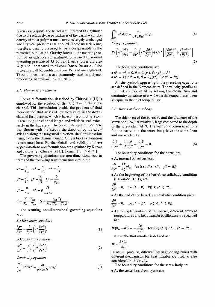
Figure 7 shows the radial temperature profiles at seven axial locations. The graphs clearly show the development of temperature profiles in the barrel, the screw channel and the screw along the axial direction. The temperature profiles before z* = 40 are not shown since very little temperature change had occurred up to this location. The
screw temperatures increase monotonicially as the axial location z* increases. The temperatures in the region close to screw root increases along the axial distance and are much lower than the temperatures in the barrel.
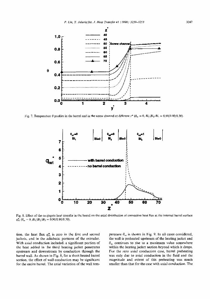
Figure 8 compares the axial distribution of the con- vective heat flux at the internal barrel surface q$ for no axial conduction effects in the barrel with the case of axial conduction effects included. Without the axial conduc-
P. Lin, Y. Jaluria/Int. J. Heat Transfer 41 (1998) 3239-3253
2,
1.0 - 40 _______ 45
0.0 - . . . . . . . . . . . . . . . . 55 ; --___ 60; --
0.6 -
8 0.4+- ._..__.-
----------e--w---
0.2 L . . . . . . . . . . . . . . . . . .
._._.-_._.__._._._._.-.-___._.
3241
__________________ 0.01 : 0 1 * ??
4 Y
Fig. 7. Temperature l3 profiles in the barrel and in the screw channel at different z* (Bin = 0, Bil/Bi,/Bi, = 0.90/0.90/0.30).
I 6 1
r (I I’ I’
?? 5 I’
‘%vi wHh barrelconduction ii
4 ---------nolmrelconductbn I’, I ’ I ’
3 I ’ ! ‘1
e&l
B4 BhO
2
Oo 10 I.. . .I. 20 *..I 30 * * * 40 50 60 70 ??
Fig. 8. Effect of the conjugate heat transfer in the barrel on the axial distribution of convective heat flux at the internal barrel surface q$ (0,” = 0, Bil/Bi2/Bij = 0.90/0.90/0.30).
tion, the heat flux q& is zero in the first and second jackets, and in the adiabatic portions of the extruder. With axial conduction included, a significant portion of the heat added in I;he third heating jacket penetrates upstream and downstream by conduction through the barrel wall. As shown in Fig. 8, for a short heated barrel section, the effect of wall conduction may be significant for the entire barrel. The axial variation of the wall tem-
perature &, is shown in Fig. 9. In all cases considered, the wall is preheated upstream of the heating jacket and O,, continues to rise to a maximum value somewhere within the heating jacket section beyond which it drops. For the zero axial conduction case, barrel preheating was only due to axial conduction in the fluid and the magnitude and extent of this preheating was much smaller than that for the case with axial conduction. The

3248 P. Lin, Y. Jaluriallnt. J. Heat Transfer 41 (1998) 3239-3253
Fig. 9. Effect of the conjugate heat transfer in the barrel on the variation of the internal barrel surface temperature 0,, with the axial distance in the screw extruder z* (0,” = 0, Bi,/Bi2/Bi3 = 0.90/0.90/0.30).
results shown in Fig. 8 also suggest that barrel wall axial conduction tends to dominate over fluid axial conduc- tion. This is expected due to the much higher thermal conductivity of the barrel material, as compared to that of the extruded material. In general, the results of Figs 8 and 9 clearly illustrate the inadequacy of the commonly used approach of ignoring axial conduction in the barrel.
Figures 10 and 11 show the axial distributions of bulk temperature ebulk of the fluid and the temperature at the
internal barrel surface BWi for different barrel con- ductivities k$ Different barrel material conductivities result in different values of the non-dimensional par- ameter Bi. In all cases, the bulk temperature increases monotonically and, due to barrel and/or fluid conduc- tion, &h is greater than zero upstream of the heated third jacket. The temperatures at the internal barrel surface f3,, increase along the axis until they reach a maximum value at the third jacket, and then decrease in the adiabatic
8 bu'k 0.8 - www
0.90~.90/0.30
0m6 : ----- ---- 0.225/0.225/0.075
0.4 -
Fig. 10. Distribution of the bulk temperature 0 buL of the fluid in the extruder channel for different values of the Biot number Bi.

P. Lin, Y. Jaluria/Int. J. Heat Transfer 41 (1998) 3239-3253 3249
Fig. 11. Distributions of the internal barrel surface temperature O,, for different values of the Biot number Bi.
section since the fluid temperature is lower than the barrel temperature. The case of B&/B&/B& = 0.90/0.90/0.30 has a larger barrel thermal conductivity than that for the case of Bil/BiZ/Bi3 = 0.225/0.225/0.075. The values of BWi for the Bi,/Bi,/Bi, = 0.90/0.90/0.30 case are higher than those for the Bi,/Bi,lBi, = 0.225/0.225/0.075 case in both the portions before and after the heating section, but are lower than those for the Bi,lBi2/Bi3 = 0.225/0.225/0.075 case in the heating section. Consequently, the bulk tem- perature of the fluid ebullr is higher in the Bi,/Bi2/Bi3 = 0.90/0.90/0.30 case than that in the Bi,/Bi2/Bi3 = 0.225/0.225/0.075 case. The material in the case with a higher barrel thermal conductivity heats up earlier.
Figure 12 shows distributions of the non-dimensional heat flux at internal barrel surface q$ and non-dimen- sional heat flux at the outer surface of the screw q$ for the case with concluction included in the screw body. It is clearly seen that the heat flux at the outer surface of the screw is not negligible compared to the heat flux rate at the internal barrel surface. The fluid temperature increases monotonically and reaches higher values down- stream. At the location z* > 55, the heat transfer is from the fluid to the screw body. Upstream of this location z* < 55, the heat transfer is from the screw to the fluid. The axial conduction in the screw plays an important role in redistributing the energy transport in the fluid.
Numerical simulations were also carried to study the effects of axial heat conduction in the screw body. The case without heat conduction in the screw body was simu- lated by specifying adiabatic thermal conductions at the
screw-body fluid interface, as done in many earlier studies [22]. Figure 13 shows the isotherms in the screw channel and barrel for the case which did not consider conduction in the screw body. It is clearly seen, by comparing Fig. 5 with Fig. 13, that conduction in screw has a significant effect on the isotherms in the fluid close to the outer surface of the screw. For the case without conduction in the screw, the lowest temperature in the flow is at the outer surface of the screw, while for case with conduction in the screw included, the temperature at the screw sur- face is not the lowest over portion of the extruder and heat transfer occurs from the screw body to the fluid.
Figure 14 compares the axial distributions of tem- perature at screw-body and fluid interface 0, for the case without axial conduction in the screw body with that for the case of axial conduction effects included. It is seen that upstream of the location z* z 60, the temperature at the outer surface of the screw ~9, for the case with axial conduction is higher than that for the case without axial conduction ; while after location z* z 60, the tem- perature 0,, for the case with axial conduction is lower than that for the case without axial conduction. This is due to the thermal energy being transported from the downstream fluid to the upstream fluid through the axial heat conduction in screw body. Consequently, the fluid bulk temperature upstream is higher due to the inclusion of axial conduction in the screw, as shown in Fig. 15. The case with axial conduction included in the screw heats up earlier due to the heat transfer from the downstream fluid to the upstream fluid through the screw body.
The effect of the conjugate heat transfer in the screw

3250 P. Lin, Y. Jaluriallnt. J. Heat Transfer 41 (1998) 3239-3253
2.5
2.0
a- ’ 0 10 20 30 a40 50 60 70
z
Fig. 12. The distribution of the non-dimensional heat flux at the internal barrel surface q& and the non-dimensional heat flux at the outer surface of the screw q:for the case which includes conduction in the screw body (0,” = 0, Bi,/&/Bi? = 0.90/0.90/0.30).
E 6
6
1 4 3
OS_ : 0 10 20 30 .40 50 60 70
0 0.89 0.83
0.76
0.70
0.64
0.57
0.51 0.45
0.30
0.32
0.26
0.19 0.13
0.06
0.00
Z Fig. 13. Isotherms in the screw channel and barrel for the case that does not include conduction in screw body (Bi, = 0, Bi,/&/&/ = 0.90/0.90/0.30/).
on the variation of the internal barrel surface temperature case with axial conduction in screw is slightly higher in OWi along the axial length of the screw z* is shown in Fig. the entire fluid domain. However, the effect of the axial 16. The internal barrel surface temperature 0, for the conduction in the screw on the internal barrel surface

P. Lin, Y. Jaluria/Int. J. Heat Transfer 41 (1998) 3239-3253 3251
0.8 I F
*’ 08 . wtth scmw&0dy conductbn
---------noww-bodyconductbn 0.4
,40 50 80 70
z
Fig. 14. Effect of conjugate heat transfer in the screw body on the variation of the temperature at the outer surface of the screw 0, with the axial distance in the screw extruder z* (0,” = 0, Bi,/B&/B& = 0.90/0.90/0.30).
e bulk
/
with screw-body conductbn 0.8 --------- noacmwdociyconductkm
0.8
Fig. 15. Effect of conj ugate heat transfer in the screw body on the variation of the fluid bulk temperature ebulk with the axial distance in the screw extruder z* (0,” = 0, Bi,/Bi,/Bi, = 0.90/0.90/0.30).
temperature 0, is relatively small due to the low thermal conductivity of the Cd.
5. Conclusions
A two-dimensional numerical model for the fluid flow and conjugate heat transfer in the single screw-extruder
processing of non-Newtonian materials has been developed. The influence of axial conduction in the barrel wall and the screw on the thermal development of laminar flow in a screw channel with a heated section has been investigated. An axial formulation of the flow in screw channel and efficient finite difference numerical tech- niques have been used to obtain the flow and thermal fields in the screw channel and thermal field in the barrel

3252
1.0
0.8
0.8 8 WI
0.4
0.2
P. Lin, Y. Jaluria/Int. J. Heat Transfer 41 (1998) 3239-3253
with scre~body conductlon _--____-- no screw-body conductbn
I * .., I . . . * I t I. 10 20 30 ??40 50 60 70
Z Fig. 16. Effect of conjugate heat transfer in the screw body on the variation of the internal barrel surface temperature 0,, with the axial distance in the screw extruder z* (Bi, = 0, Bi,/&/Bi, = 0.90/0.90/0.30).
and screw body. The solutions show significant depar- tures from the solutions that are obtained by ignoring the conjugate heat transfer effects of the barrel. Axial conduction in barrel has a significant influence on both the pre-heating and post-heating sections. Within the heated section, barrel axial conduction acts to reduce the maximum wall temperature, and the relatively short heated jacket section can influence the local convective heat flux q$ over wider sections. Heat conduction in the screw plays a role in redistributing the energy transport in the fluid by transporting thermal energy from the downstream fluid to upstream fluid. With heat con- duction in the screw, the temperature upstream of the heated section is higher due to thermal energy redis- tribution. Consequently, the material in the channel starts melting at an earlier location. The effect of heat conduction in the screw is not negligible, although it is not as significant as that in the barrel. The numerical predictions are in excellent agreement with experimental temperature measurements and other numerical results available in the literature.
Acknowledgments
The authors acknowledge the partial support provided by the NJ Center for Advanced Food Technology for this work. The first author also acknowledges the financial support provided by the Graduate School, Rutgers Uni- versity in the form of an Excellence Fellowship. Extensive discussions with Professor V. Sernas are acknowledged.
References
PI
PI
[31
[41
[51
PI
171
PI
191
PO1
Pll
1121
Harper I. Food Extrusion. New York: CRC Press, 1980. Tadmor 2, Gogos C. Principles of Polymer Processing. New York : John Wiley and Sons, 1979. Tadmore A, Klein 1. Engineering Principles of Polymer Processing. New York : Van Nostrand Reinhold, 1970. Rauwendaal C. Polymer Extrusion. New York: Hanser Publishers, 1986. Colwell RE, Nicholls KR. The screw extruder. Ind Eng Chem 1959;51:841-3. Griffith RM. Fully developed flow in screw extruders. Ind Eng Chem Fundam 1962;1(3):181-7. Zamodits HJ, Pearson JRA. Flow of polymer melts in extruders: Part-I. The effect of transverse flow and of a superposed steady temperature profile. Trans Sot Rheol 1969;13:357-85. Karwe MV, Jaluria Y. Numerical simulation of fluid flow and heat transfer in a single screw extruder for non-New- tonian fluids. Num Heat Transfer, Part-A 1990;17:167- 90. Gopalakrishna S, Jaluria Y, Karwe MV. Heat and mass transfer in a single screw extruder for non-Newtonian materials. Int J Heat Mass Transfer 1991;35:221L37. Chiruvella RV, Jaluria Y, Abib AH. Numerical simulation of fluid flow and heat transfer in a single-screw extruder with different dies. Polymer Engineering and Science 1995;35(3):261-73. Chiruvella RV, Jaluria Y, Esseghir M, Sernas V. Extrusion of non-Newtonian fluids in a single-screw extruder with pressure back how. Polymer Engineering and Science 1996;36:358-67. Sastrohartono T, Jaluria Y, Esseghir M, Sernas V. A

P. Lin, Y. Jaluriallnr. J. Heat Transfer 41 (1998) 3239-3253 3253
numerical and experimental study of three-dimensional transport in the channel of an extruder for poly- meric materials. Int J Heat Mass Transfer 1995;38: 1957-73.
[13] Bernier MA, Baliga BR. Conjugate conduction and lami- nar mixed convection in vertical pipes for upward flow and uniform wall heat flux. Numerical Heat Transfer 1992;21:313-32.
[14] Barozzi GS, Pagliarini G. Experimental investigation of coupled conduction and laminar convection in a circular tube. Int J Heat Mass Transfer 1985;27:77-83.
[15] Campo A, Schule C. Heat transfer in laminar flow through circular tubes acmcounting for two-dimensional wall con- duction. Int J Heat and Mass Transfer 1988;31:2251-9.
[16] Lin P, Jaluria Y. (Conjugate transport in polymer melt flow through extrusion dies. Polymer Engineering and Science 1997;37: 1582296.
[17] Jaluria Y, Torrance KE. Computational Heat Transfer. Washington, DC: Hemisphere Publishing Corporation, 1986.
[18] Raithby GD, Schneider GE. Numerical solution of prob- lems in incompressible fluid flow : treatment of the velocityy pressure coupling. Num Heat Transfer 1979;2:417- 40.
[19] Pearson JRA. Mechanics of Polymer Processing. London : Elsevier Applied Science 1985.
[20] Karwe MV, Chiruvella RV, Jaluria Y. Coordinate system independence of shear rate during isothermal single screw extrusion of a Newtonian fluid. Journal of Food Processing Engineering 1995;18:55-69.
[21] Lawal A, Kalyon DM. Nonisothermal model of single screw extrusion of generalized Newtonian fluids. Num Heat Transfer 1994;26: 103321.
[22] Jaluria Y. Heat and mass transfer in the extrusion of non- Newtonian materials. Advances in Heat Transfer 1996;28:145-230.
[23] Fenner RT. Developments in the analysis of steady screw extrusion of polymers. Polymer 1977;18:617-35.
[24] Overaker DW, Sernas V. An experimental study of the conversion kinetics of corn meal during extrusion. National Heat Transfer Conference. ASME-HTD, 1995;306:95- 104.
[25] Sernas V, Xiao L, Lin P, Jaluria Y. Axial conduction in a convectively heated/cooled extruder barrel. Proc ANTEC 1996;1:422-6.
[26] Fletcher SI, Master TJ, Smith AC, Richmon P. Rheology and extrusion of maize grits. Chem Eng Commun 1985;32:239-62.