Conformance of navigational behavioural to requirements using animation
27
Int. J. Web Engineering and Technology, Vol. 7, No. 1, 2012 65 Copyright © 2012 Inderscience Enterprises Ltd. Conformance of navigational behavioural to requirements using animation Joumana Dargham* Department of Computer Science, University of Balamand, P.O. Box 100, Al-Koura, Lebanon E-mail: [email protected] *Corresponding author Rima Semaan Department Computer Science, American University of Beirut, P.O. Box 11-0236, Beirut, Lebanon E-mail: [email protected] Hamid Mcheick Université du Québec à Chicoutimi, 555, Boulevard de l’Université, Chicoutimi Québec G7H-2B1, Canada E-mail: [email protected] Abstract: The web has become closely ingrained with our life and massive effort for web development and maintenance continues to take place in an ad hoc manner, resulting in poor quality web systems and applications. Problems such as outdated or irrelevant information, difficulties in using the website, website crashes, and security breaches are common. We encounter these kinds of problems because web developers failed to address users’ needs along with the improper appliance of the web engineering process in all its phases. As a consequence, web engineering and more precisely web requirements engineering is becoming of major importance in the web development process. In this context, this work tackles the validation of the navigational requirements of a web application. A methodology named NRVA is introduced in order to validate the navigational requirements for correctness, consistency, and completeness. It is based on the generation of an XML document defining the navigational rules of the application and used as input to the animator. The supporting tool to the approach does not only validate the correctness of the generated requirements, but also it aids to the elaboration and enhancement of those requirements through visualisation. Keywords: conformance of navigational behaviour; web engineering; finite state machines; model checking; requirements animation. Reference to this paper should be made as follows: Dargham, J., Semaan, R. and Mcheick, H. (2012) ‘Conformance of navigational behavioural to requirements using animation’, Int. J. Web Engineering and Technology, Vol. 7, No. 1, pp.65–91.
Transcript of Conformance of navigational behavioural to requirements using animation
Int. J. Web Engineering and Technology, Vol. 7, No. 1, 2012 65
Copyright © 2012 Inderscience Enterprises Ltd.
Conformance of navigational behavioural to requirements using animation
Joumana Dargham* Department of Computer Science, University of Balamand, P.O. Box 100, Al-Koura, Lebanon E-mail: [email protected] *Corresponding author
Rima Semaan Department Computer Science, American University of Beirut, P.O. Box 11-0236, Beirut, Lebanon E-mail: [email protected]
Hamid Mcheick Université du Québec à Chicoutimi, 555, Boulevard de l’Université, Chicoutimi Québec G7H-2B1, Canada E-mail: [email protected]
Abstract: The web has become closely ingrained with our life and massive effort for web development and maintenance continues to take place in an ad hoc manner, resulting in poor quality web systems and applications. Problems such as outdated or irrelevant information, difficulties in using the website, website crashes, and security breaches are common. We encounter these kinds of problems because web developers failed to address users’ needs along with the improper appliance of the web engineering process in all its phases. As a consequence, web engineering and more precisely web requirements engineering is becoming of major importance in the web development process. In this context, this work tackles the validation of the navigational requirements of a web application. A methodology named NRVA is introduced in order to validate the navigational requirements for correctness, consistency, and completeness. It is based on the generation of an XML document defining the navigational rules of the application and used as input to the animator. The supporting tool to the approach does not only validate the correctness of the generated requirements, but also it aids to the elaboration and enhancement of those requirements through visualisation.
Keywords: conformance of navigational behaviour; web engineering; finite state machines; model checking; requirements animation.
Reference to this paper should be made as follows: Dargham, J., Semaan, R. and Mcheick, H. (2012) ‘Conformance of navigational behavioural to requirements using animation’, Int. J. Web Engineering and Technology, Vol. 7, No. 1, pp.65–91.
66 J. Dargham et al.
Biographical notes: Joumana Dargham is currently an Associate Professor of Computer Science at Balamand University in Lebanon. She holds a Master degree in Networking and a PhD in Software Engineering, both from University of Montreal, Canada. Her research interests fall into: web engineering, separation of concerns, aspect orientation, development processes and ICT. Her research is supported by many research grants she received from Canadian and Lebanese institutions. She has a good number of published papers in international conferences and journals.
Rima Semaan holds an MS in Computer Science from the American University of Beirut. Her research interests are related to web requirements, parallel computing, data mining and data warehousing. She is currently the Lead Software Developer in Business Intelligence Unit, Part of Consolidated and Contractors Company (CCC).
Hamid Mcheick is an Associate Professor at the Computer Science Department at the University of Québec, Chicoutimi, Canada. He obtained his PhD in Software Engineering and Distributed System from the University of Montreal, Canada. He is currently working on software evolution and maintenance, software architecture, software development methodologies, aspect-oriented engineering, service-oriented computing and web applications. He has many research papers in international journals and conference proceeding. He is the Editor, Chair, Co-Chair, Reviewer and member in many organisations around the world.
1 Introduction
As the high demand on web applications has increased significantly over the years, their performance, reliability and quality have become of paramount importance. Thus, the design, development, deployment and maintenance of web-based systems have become more demanding, complex and difficult to manage. Problems such as outdated or irrelevant information, difficulties in finding relevant information, difficulties in browsing, slow response, website crashes, and security breaches are common. We encounter these kinds of problems because web developers failed to address some of the users’ functional and non-functional needs such as content management, maintenance, performance, security, navigational concerns, website exploitation, and scalability of web applications (Gordillo et al., 2006).
These problems are usually handled throughout a disciplined web engineering process which is useful for the validity, scalability, performance, and system maintainability. Requirement engineering is one of the most important process’s phases where requirements are gathered, specified and validated.
1.1 Web requirements engineering
In the development of traditional (non-web) applications both practitioners and process experts regard requirements engineering as the most important phase in the development process since the most common and time-consuming errors as well as the most expensive ones to repair, are usually a consequence of an inadequate engineering of requirements (Escalona and Koch, 2004). Many requirements analysis and specification techniques
Conformance of navigational behavioural to requirements using animation 67
have been proposed such as interviewing or story boarding (Sutherland and Maiden, 2010), scenarios or case modelling (Sutherland and Maiden, 2005), and prototyping. These techniques are poorly applied in the web engineering field (Escalona and Koch, 2004; Cheng, 2007). We stress that on the contrary, web applications require a more extensive and detailed requirements engineering process due to the number of stakeholders involved and to the diversity of the requirements including among others requirements on the navigation and on the business processes (Güell et al., 2000). Therefore, a thoroughly requirements analysis is even more important in the framework of web requirements engineering.
Unfortunately, most of the methodologies that have been proposed for the development of web applications focus on the design phase paying less attention to the requirements engineering and more specifically to requirements validation (Uchitel et al., 2005; Escalona et al., 2007). A comparative study done by Escalona and Koch (2004) to analyse some of the web requirements engineering methodologies showed that web-requirements (Web-RE) is still an ongoing research area evolving day after day.
Web-RE phase encompasses: requirements elicitation, requirements analysis, and requirements validation. These activities are complementary however most of the methodologies consider validation not as relevant as the other two. The validation techniques proposed mainly focus on reviewing the requirements models or the textual descriptions of the requirements. Some of the approaches do not even include the validation phase in their requirements engineering process (Escalona and Koch, 2004).
1.2 Validation of web requirements
Requirements validation is the process of ensuring that the requirements specification document is an accurate reflection of what the user wants. It is concerned with determining if the functional and non-functional requirements are the right requirements and answers the question “will this system, if built correctly, be safe and effective for its intended use”. In other words, the validation phase of Requirements Engineering, involves checking the formal description of the requirements, against the non-formal description of the user’s needs and domain knowledge.
A key obstacle toward this validation is the lack of a shared means of communication between the developer and the user. While the developer needs a precise, preferably formal document a user needs an application oriented description. Thus, if the user is to assist in requirements validation, a medium other than the formal specification is needed.
Adequate validation of system requirements is a critical issue for both current and future software development practises. For instance, a malfunction in medical-based software can be disastrous. The experts state that 40% to 60% of all defects found in a system can be traced back to incomplete or inconsistent requirements capture (Sukumaran et al., 2005).
To avoid errors in later development phases and reduce life cycle costs, it is crucial to insure that the specifications are reliable. By reliable we infer that to what extent are the specifications correct, complete, and consistent (the 3Cs). These properties are defined as follow:
• Correctness: Requirements are correct if they reflect user intentions’ accurately, and thus the system behave as expected.
68 J. Dargham et al.
• Consistency: Requirements are consistent if they don’t have any internal contradictions between each other.
• Completeness: Requirements are complete if they are fully stated without missing information.
1.3 Motivation and objectives
In this paper, we tackle the validation of navigational requirements that constitutes the backbone of the web development. However, the researchers’ main contribution with this regard is on the level of the modelling of the navigational requirements but not on their validation (Escalona et al., 2007; Cheng, 2007).
Navigations are the building block of web applications due to the information they provide, the linking structure they constitute, and the related operations they encompass. Any defect in those navigations can propagate to enforce wrong design decisions and thus faulty web application. For those reasons, validating them at early stages is a basic need to guarantee application quality and trustworthiness.
The state of the art today focuses on two requirement validation methodologies: model checking-based methodology and animation-based methodology (Aderson et al., 2000). In model checking methods, proofs often take the form of checking that a specification model satisfies some constraints. The behavioural models are checked against temporal-logic properties of the requirements (Sreemani and Atlee, 1996; Emerson, 1990).
Unlike the first one, the animation-based methodology assumes that validation is typically a subjective evaluation of the specification with respect to the stakeholder’s informal requirements. As such, validation takes the form of simulations and animations of various requirements, whereby stakeholders are directly involved in reviewing the requirements artefacts (FenKam et al., 2002; Magee et al., 2000; Van et al., 2004; Uchitel et al., 2005).
Each of the available validation techniques has its pros and cons. The concept of validating requirements through model checking has been proven to be effective and moreover can be noted to be formal (Aderson et al., 2000). But its major disadvantage is that it is known to be hard to manipulate and very complex to understand by software engineers along with the stakeholders. On a parallel perspective, the animation technique is becoming a widely adopted method. The reason resides in the fact that it is as effective as model checking and it allows stakeholders to be involved in the validation phase. Furthermore, visualisation allows elaboration of the requirements upon simulating them. So far, no complete visual system capturing navigational requirements exists (Gordillo et al., 2006).
Our major objective is to provide a navigation validation technique (or model) that is:
• Effective: Able to satisfy our goal in validating the navigational requirements for their correctness, consistency, and completeness.
• Easy to use by both the engineers and the stakeholders: We think that involving the stakeholder in the validation is of major importance to guarantee the correctness of the requirements. Thus, the animation method of validating requirements will be adopted to achieve validation.
Conformance of navigational behavioural to requirements using animation 69
• Validate various navigational requirements categories: There are many navigational requirements categories that vary from page reachability to page mode coupling and page sequence patterns. All those criteria are included in the validation method proposed.
After adopting an appropriate method to model the navigational requirements, a visual animation technique is proposed to validate them. The designed tool will constitute the validation of reachability of links, dead ends, security of links, broken links, inconsistent navigational requirements, navigational modes, and missing navigational links. The novelty of the approach is that it proposes a model to validate web navigational requirements using animation accompanied by the interaction with the stakeholder on screen and live system feedback. Moreover, this is probably the first attempt to validate the navigational requirements for the web through animation.
The rest of the paper is organised as follows: Section 2 elaborates more on the existing validation methods for web requirements and defines our approach to model and validate web navigational requirements; in Section 3, we discuss the implementation details of our system; Section 4 presents our experimental studies and assess the efficiency and ability of our model from the generated result; in Section 5, we conclude.
2 Related work
2.1 Requirements validation through animation
Animation-based validation consists of showing how a software system behaves in response to external events and user inputs. Typically, an animation prototype is built from the software specification; the software simulation is visualised on a textual or graphical model representation with a highlight on each element involved in the execution. LSC play-in/play-out, state-based and goal-based systems are typical examples of validation through animation.
2.1.1 LSC play-in/ play-out approach
In the ‘LSC play-in/play-out’ approach the behavioural model is represented as a collection of scenarios (FenKam et al., 2002) specified using the language of live sequence charts (LSCs) (Damm and Harel, 2000). This latter distinguishes between scenarios that may happen in the system called existential charts, from those that must happen and called universal charts. Also, we can specify messages that may be received and the ones that must be received.
The role of the ‘playing in’ process is to prepare the requirements as LSCs-input to the ‘playing out’ process or the simulation process. The role of the ‘playing-out’ process is to allow the user to simulate the provided LSC-based requirements. It interacts with the GUI application and uses it to reflect the system states at any given moment. In this approach there is a tight coupling between the behavioural specifications (generated by play in) and the way the animation is simulated (play out). Any change in the behavioural model will not be easily reflected in the play-out model unless replayed-in and this is true for each change in the requirements (LSC). Furthermore, the simulation relies the generated LSCs which may not conform to the original requirements, thus the criterion to validate the LSCs is not respected.
70 J. Dargham et al.
2.1.2 State-based approach
A graphical state-based animation is developed in Magee et al. (2000) whereby behaviour models, which are specified by timed labelled transition systems (timed LTS), can drive graphical animations. An LTS is a finite state machine whose transitions between states are labelled with actions. The timed LTS is a labelled transition model for components of real-time systems having time-passage actions, in addition to ordinary input, output and internal actions.
Graphical animations are constructed from a library of JavaBeans called SceneBeans. The basic entities in the SceneBeans architecture are scene graphs, behaviours and animations.
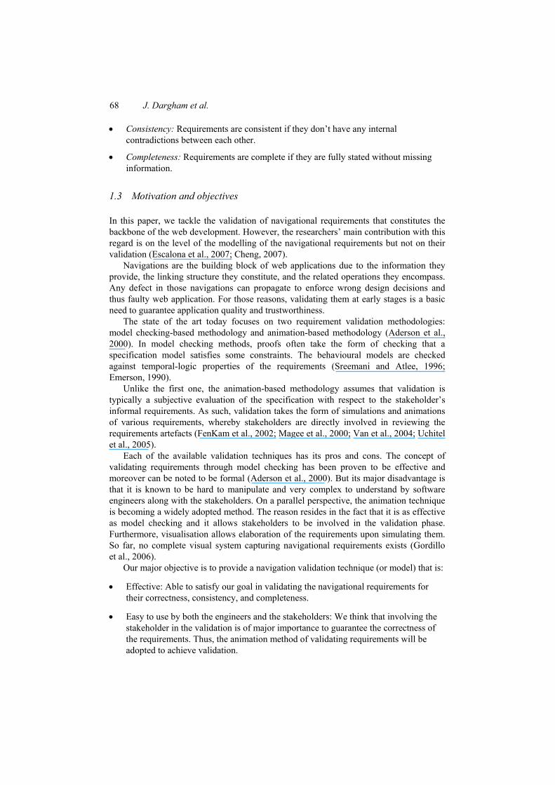
Figure 1 Channel animation (see online version for colours)
(a)
(b)
(c)
Figure 1 corresponds to the generated animation by this model according the LTS provided. Figure 1(a) depicts the situation in which an ‘in’ operation has occurred and the ‘out’ action has not yet happened. The message, represented by the block labelled a, is moving from the input box on the left to output box on the right. Figure 1(b) depicts the state in which the channel ‘fail’ action has occurred. This is animated by replacing the message block with an explosion. Figure 1(c) depicts the situation when the channel does not fail and the ‘out’ action occurs.
SceneBeans presents animation in a user friendly way. But it is notable that providing system behaviour in the form of XML documents is not quite user friendly. Another drawback of the approach is that it is mere animation of the original fixed behavioural model. Validation is left a subjective evaluation of the end user who is viewing the animation.
2.1.3 LTSA goal-based approach
In this approach, a system can be viewed as a set of objectives represented in different use scenarios. These objectives define the goals of the system and are the core elements of the animation system.
The Label Transition System Analyser (LTSA) approach (Uchitel et al., 2005) presents a mechanism in which the visualisations can be constructed based on abstract
Conformance of navigational behavioural to requirements using animation 71
system states rather than on concrete states that the model designer may have chosen to specify system behaviour. This allows for greater generality and flexibility, and allows engineers to produce animations that have a concrete relation to the goals and scenarios that the participating stakeholder has in mind. It also allows a reliable validation technique where inconsistencies or missing scenarios can be depicted from the animation and interaction.
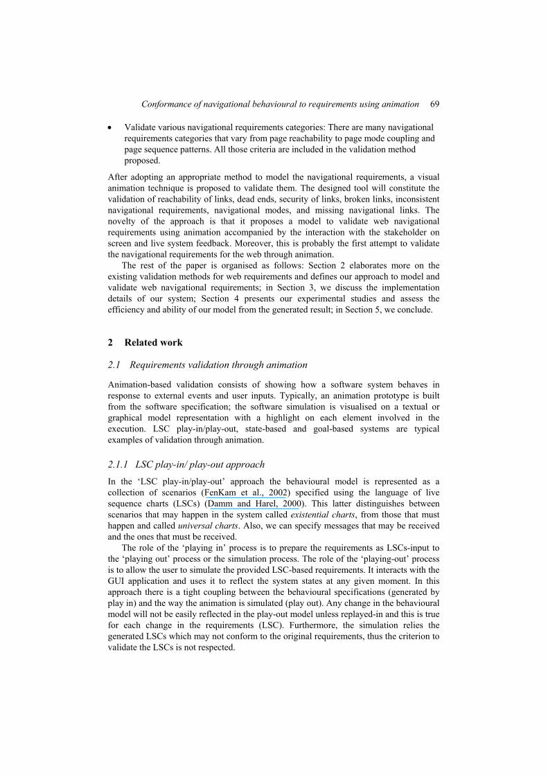
The conceptual animation (Figure 2) model has the following inputs: scenarios, goals and participants’ input.
Figure 2 The conceptual animation model (see online version for colours)
The goals are provided as input to the system in the form of Fluents (Miller and Shanahan, 1999). Fluents are abstractions of system specified in terms of the occurrence of events (Figure 3).
Figure 3 Fluents for the registration and read message constraints
Fluent Registerd = <enable, disable> Fluent ReadingMSg = <selectMsg,closeMsg>
The scenarios are inputs to the system model in the form of message sequence charts (MSCs). MSCs are used for documenting Scenarios which are the standard adopted by the International Telecommunication Union and UML 2.0 sequence diagrams (UML, 2004). MSCs describe the interaction between various components of the system from which the behavioural model can be derived (Figure 4).
The participants resemble users of the system who simulate the website. They vary from developers to normal end users to stakeholders. Those participants are provided to our model as an XML input list, defining possible roles for each and every participant.
Animation is performed by the three components: the animator, the visualiser and the participant. The animator uses the behaviour model to react to events controlled by the animation participant. It also has access to the fluents and forwards their values to the
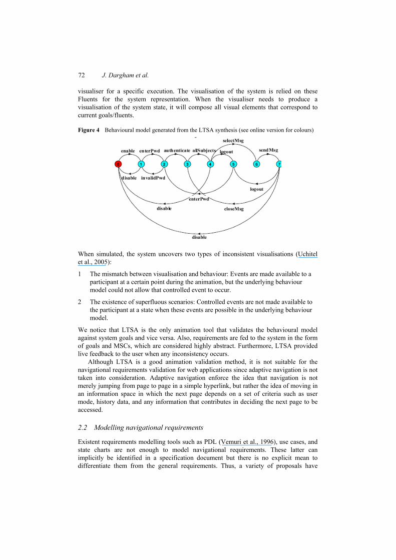
72 J. Dargham et al.
visualiser for a specific execution. The visualisation of the system is relied on these Fluents for the system representation. When the visualiser needs to produce a visualisation of the system state, it will compose all visual elements that correspond to current goals/fluents.
Figure 4 Behavioural model generated from the LTSA synthesis (see online version for colours)
When simulated, the system uncovers two types of inconsistent visualisations (Uchitel et al., 2005):
1 The mismatch between visualisation and behaviour: Events are made available to a participant at a certain point during the animation, but the underlying behaviour model could not allow that controlled event to occur.
2 The existence of superfluous scenarios: Controlled events are not made available to the participant at a state when these events are possible in the underlying behaviour model.
We notice that LTSA is the only animation tool that validates the behavioural model against system goals and vice versa. Also, requirements are fed to the system in the form of goals and MSCs, which are considered highly abstract. Furthermore, LTSA provided live feedback to the user when any inconsistency occurs.
Although LTSA is a good animation validation method, it is not suitable for the navigational requirements validation for web applications since adaptive navigation is not taken into consideration. Adaptive navigation enforce the idea that navigation is not merely jumping from page to page in a simple hyperlink, but rather the idea of moving in an information space in which the next page depends on a set of criteria such as user mode, history data, and any information that contributes in deciding the next page to be accessed.
2.2 Modelling navigational requirements
Existent requirements modelling tools such as PDL (Vemuri et al., 1996), use cases, and state charts are not enough to model navigational requirements. These latter can implicitly be identified in a specification document but there is no explicit mean to differentiate them from the general requirements. Thus, a variety of proposals have
Conformance of navigational behavioural to requirements using animation 73
recommended some ways to explicitly model web navigation. Some of these stresses on the need to represent the dynamic nature of a web application, others on their adaptive nature others on the semantics, but none covers all web applications particularities.
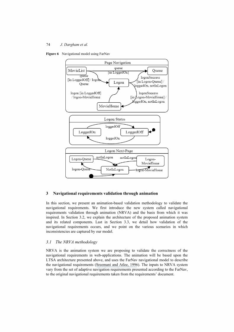
One appealing approach for modelling navigational requirements that takes into consideration the adaptive nature of web applications is FarNav approach presented in Han and Hofmeister (2006). The formal approach for rich navigation modelling (FarNav) is based on State Charts model and enriches it to handle web-based details (Leung et al., 2000; Winckler and Palanque, 2003). It incorporates adaptive navigation by defining semantics for the transition, the event, the action, and the state and thus creating user mode, history mode, and other semantic information mode reflecting navigation dependency.
The approach starts by identifying the views of the application corresponding to its different groups of users and mode adaptations. Then, for each view, it derives the lists of requests and actions from the application’s statement of scope. These lists are used to iteratively build the state table modelling the static and dynamic navigational behaviour of the targeted web application. Practically, the generated FarNav model is composed of parallel substates of the different views. When mapped, they constitute all the states of the application. The main substate contains a state machine in which each webpage is represented as a state. When a web application has only simple (no adaptive) navigation, this substate comprises the entire navigation model. When adaptive navigation is present, each mode is represented by a separate parallel substate with its own state machine.
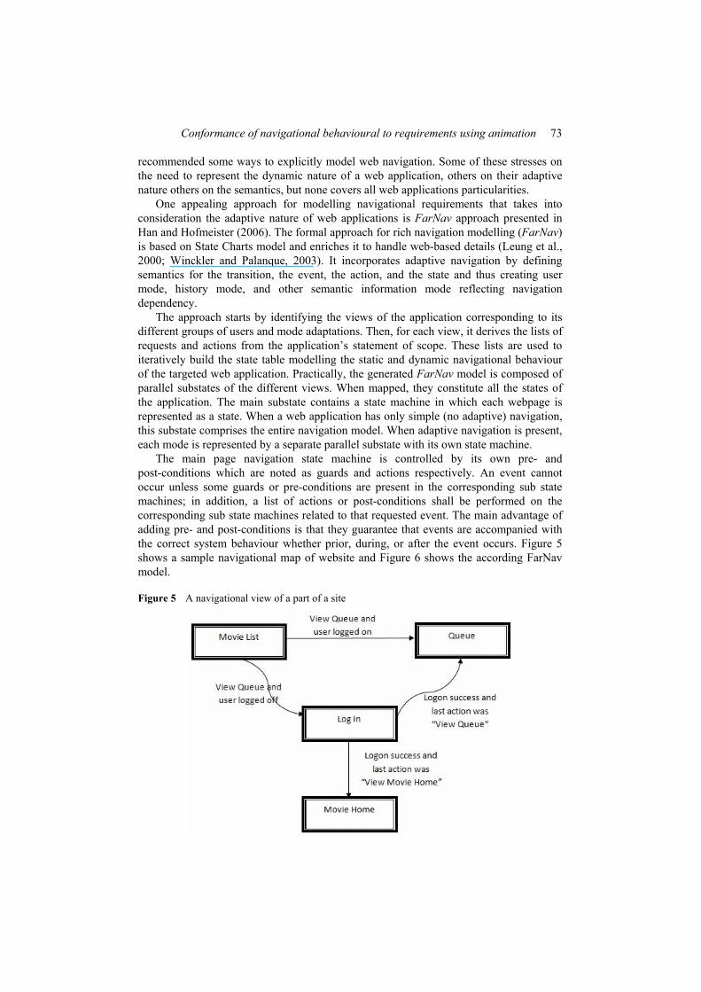
The main page navigation state machine is controlled by its own pre- and post-conditions which are noted as guards and actions respectively. An event cannot occur unless some guards or pre-conditions are present in the corresponding sub state machines; in addition, a list of actions or post-conditions shall be performed on the corresponding sub state machines related to that requested event. The main advantage of adding pre- and post-conditions is that they guarantee that events are accompanied with the correct system behaviour whether prior, during, or after the event occurs. Figure 5 shows a sample navigational map of website and Figure 6 shows the according FarNav model.
Figure 5 A navigational view of a part of a site
74 J. Dargham et al.
Figure 6 Navigational model using FarNav
3 Navigational requirements validation through animation
In this section, we present an animation-based validation methodology to validate the navigational requirements. We first introduce the new system called navigational requirements validation through animation (NRVA) and the basis from which it was inspired. In Section 3.2, we explain the architecture of the proposed animation system and its related components. Last in Section 3.3, we detail how validation of the navigational requirements occurs, and we point on the various scenarios in which inconsistencies are captured by our model.
3.1 The NRVA methodology
NRVA is the animation system we are proposing to validate the correctness of the navigational requirements in web-applications. The animation will be based upon the LTSA architecture presented above, and uses the FarNav navigational model to describe the navigational requirements (Sreemani and Atlee, 1996). The inputs to NRVA system vary from the set of adaptive navigation requirements presented according to the FarNav, to the original navigational requirements taken from the requirements’ document.
Conformance of navigational behavioural to requirements using animation 75
As noted previously, the LTSA is one of the solid animation models available in the area of requirements animation (Sreemani and Atlee, 1996). This is due to the fact that it constitutes the most essential criteria that should be present in any requirements animation\simulation. These criteria include the visualisation, the validation, and the interaction.
First, the fact that the visualisation is based on abstract system states representing predictable and unpredictable navigation decisions makes the approach particularly unique.
Second, the LTSA model does not only simulate the derived behavioural model in the form of an animation understandable by the stakeholder, but also validates this behavioural model with respect to the general goals. This functionality is itself novel since none of the known animation tool validates the runtime phenomena against the underlying requirements.
An asset of LTSA over other systems is that it is based on interactive feedback to the user. It instantly shows the inconsistencies depicted and this leads to an effective stakeholder involvement in the process of validation. The LTSA visual validation leads to the elaboration of requirements from one hand, and their refinement from the other hand.
The major shortcoming of LTSA is that it does not validate adaptive navigational requirements. Even though LTSA encompasses a behavioural model that might be exploited to validate basic non-adaptive navigational requirements, nevertheless the behavioural model adopted does not integrate adaptive navigations. Thus, a model richer than LTSA’s behavioural model must be supplied to validate web navigations.
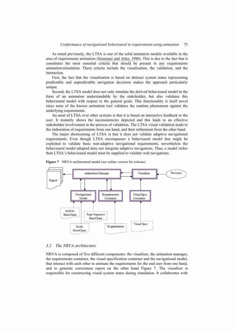
Figure 7 NRVA architectural model (see online version for colours)
3.2 The NRVA architecture
NRVA is composed of five different components: the visualiser, the animation manager, the requirements container, the visual specification container and the navigational model, that interact with each other to animate the requirements for the end user from one hand, and to generate correctness report on the other hand Figure 7. The visualiser is responsible for constructing visual system states during simulation. It collaborates with
76 J. Dargham et al.
the visual specification container component to identify the visual requirement and exchange data with the animation manager. The animation manager component has the task of deciding the next system state and validating navigations using the navigational model and the requirements container data. The major role of the participant is simulating animations. In the following a detailed description of how the two major components, the visualiser and the animator, work.
3.2.1 The visualiser component
The visualiser’s basic functionality resides in mapping the system current state into visual elements in the form of WebPages. In other words, the visualiser acts as a communication medium between the participant (user) and the Animation Manager component. The visualiser reads the visualisation specification, which relates current state(s) of the system to the visual elements.
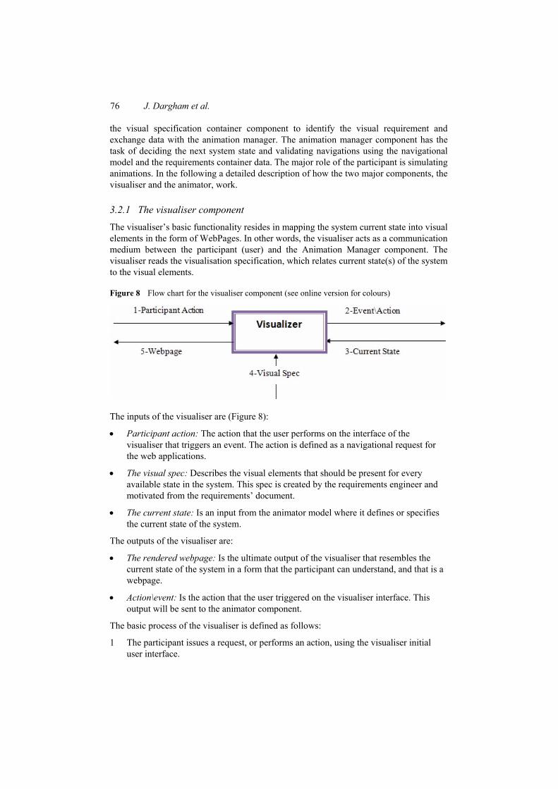
Figure 8 Flow chart for the visualiser component (see online version for colours)
The inputs of the visualiser are (Figure 8):
• Participant action: The action that the user performs on the interface of the visualiser that triggers an event. The action is defined as a navigational request for the web applications.
• The visual spec: Describes the visual elements that should be present for every available state in the system. This spec is created by the requirements engineer and motivated from the requirements’ document.
• The current state: Is an input from the animator model where it defines or specifies the current state of the system.
The outputs of the visualiser are:
• The rendered webpage: Is the ultimate output of the visualiser that resembles the current state of the system in a form that the participant can understand, and that is a webpage.
• Action\event: Is the action that the user triggered on the visualiser interface. This output will be sent to the animator component.
The basic process of the visualiser is defined as follows:
1 The participant issues a request, or performs an action, using the visualiser initial user interface.
Conformance of navigational behavioural to requirements using animation 77
2 The visualiser forwards the request in the form of an event to the animator.
3 The animator analyses the event and replies back to the visualiser by the new current system state that should be displayed to the participant.
4 When the visualiser receives a reply from the animator that indicates the system current state, it builds up the visualisation of that state accordingly from the visualisation spec available. It will compose all visual elements that correspond to that state. The visual elements include active elements (such as buttons and hyperlinks that are related to events that are controllable by the participant), as well as inactive element (text, lines and rectangles) that constitute a webpage.
5 At this stage and after constructing the visualisation of the web page that resembles the status of the system, the page is displayed to the participant on screen.
Note that the animator reply could be merely the inconsistency detected while trying to process the requested event. In this case, the visualiser only displays the error on screen for the user and remains in the previous system state.
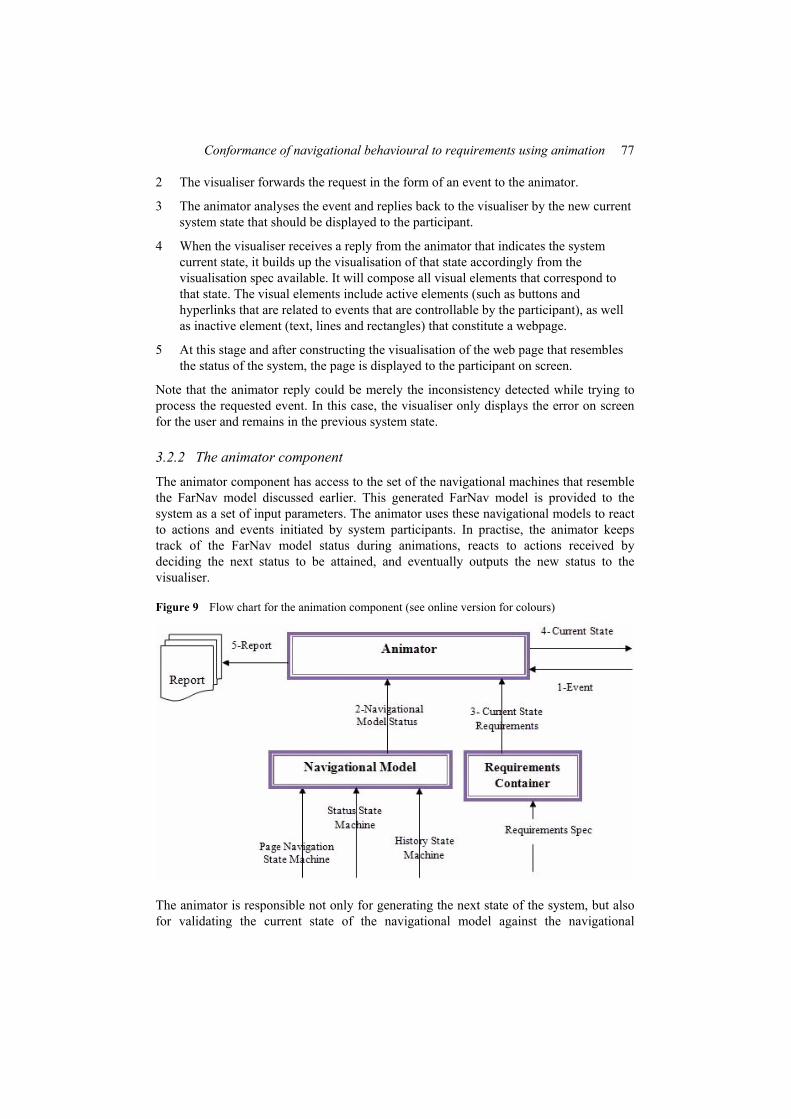
3.2.2 The animator component
The animator component has access to the set of the navigational machines that resemble the FarNav model discussed earlier. This generated FarNav model is provided to the system as a set of input parameters. The animator uses these navigational models to react to actions and events initiated by system participants. In practise, the animator keeps track of the FarNav model status during animations, reacts to actions received by deciding the next status to be attained, and eventually outputs the new status to the visualiser.
Figure 9 Flow chart for the animation component (see online version for colours)
The animator is responsible not only for generating the next state of the system, but also for validating the current state of the navigational model against the navigational
78 J. Dargham et al.
requirements specification. To accomplish this, the navigational requirements spec is provided to the system in a certain format. Any inconsistency detected between the runtime current state and the original requirements will be displayed to the end user accordingly (Figure 9).
The inputs to the animator component are:
• The page navigation state machine: Describes the overall navigational map and links between all pages of the given website.
• The status state machine(s): Is the set of finite state machines that resemble any mode that is regarded to be a key element in the navigations performed.
• The history state machine(s): Is the set of finite state machines that refer to the history of a certain event, when this even is considered to be a key element when performing navigations.
• The event triggered by participant: Is the action requested by the participant on screen. This event is forwarted to the animator through the visualiser.
• The navigational requirements specification: This document corresponds to the navigational requirements of each webpage constituting the system or the website.
The outputs of the animator component are:
• The current state of the system: After analysing and tracking the navigational model, animator returns the current state of the system along with notifications if any inconsistency was detected so far.
• The animation report: The animation report comprises the summary of the overall animation run that took place. It states in details at which pages\nodes inconsistencies took place and explicitly lists the inconsistency in the report. Note that, the report only reflects upon the inconsistency between the original requirements spec and the navigational model. It is the job of the requirements engineer to analyse the report and assess the contradictions and come up with the right solution after negotiating with the stakeholder. Thus, the visual simulation of the inconsistency along with generated report will help this stakeholder assess with the requirements engineer the detected discrepancy and both will try to resolve the issue cooperatively.
The basic process of the animator is defined as follows:
• The animator accepts an event received from the visualiser.
• The animator checks the current state of the FarNav model by checking the state of each and every state machines of the model.
• The animator analyses the navigational states corresponding to that event and decides upon the next page to be viewed and output this page stat to the visualiser. Note that it is at this stage validation of navigations take place. Any violation of the rules available in the requirements document will be perceived and eventually a notification will be raised to user to notify him of the issue. In addition, any missing behaviour that is not taken into consideration in the behavioural model will be detected and user will be notified accordingly. A detailed description of the
Conformance of navigational behavioural to requirements using animation 79
inconsistency that might takes place will be documented in a final report that will be generated.
3.3 The navigational verification rules
In this section, we elaborate on the various navigational validation categories that are applied to validate navigations. Those categories can be used to grasp inconsistencies in navigations. Each category encompasses a set of verification rules that target various scenarios of the same navigation verification category.
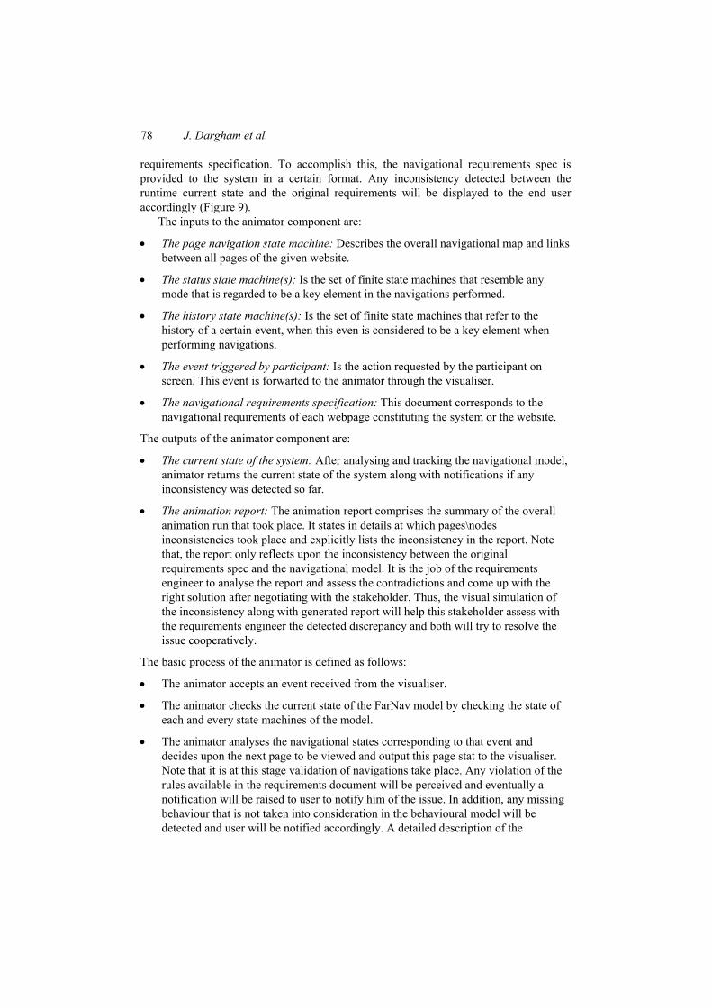
The first category of verification is about the reachability of web pages. This group restrains various rules:
• Rules for checking the general reachability of a web page, i.e., whether the page can be reached through some navigation path. An unreachable page is most likely an error because it is obsolete, or due to design defects that imposed a dead status to the page, or even due to contradicting requirements that eventually made the page unreachable. In Figure 10, Page Z is unreachable although there is a navigation path from Page Y to Page Z. That is because the can never be in a logged in state at Page Y.
Figure 10 An example of an unreachable page
Page X Page Y
Page Z
Page w
Go To W
Go To y and user is logged off
Go To Y and user is logged off
Go To Z and user is logged On
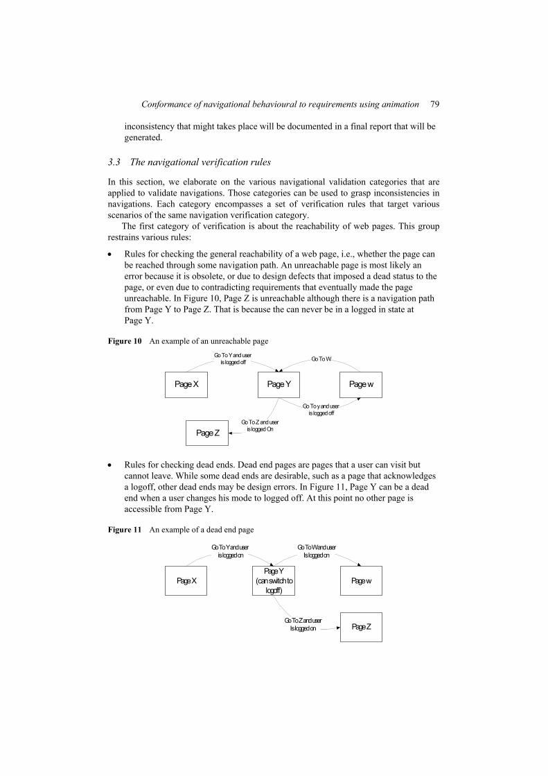
• Rules for checking dead ends. Dead end pages are pages that a user can visit but cannot leave. While some dead ends are desirable, such as a page that acknowledges a logoff, other dead ends may be design errors. In Figure 11, Page Y can be a dead end when a user changes his mode to logged off. At this point no other page is accessible from Page Y.
Figure 11 An example of a dead end page
Page XPage Y
(can switch to logoff)
Page w
Go To W and user Is logged on
Go To Y and user is logged on
Page ZGo To Z and user
Is logged on
80 J. Dargham et al.
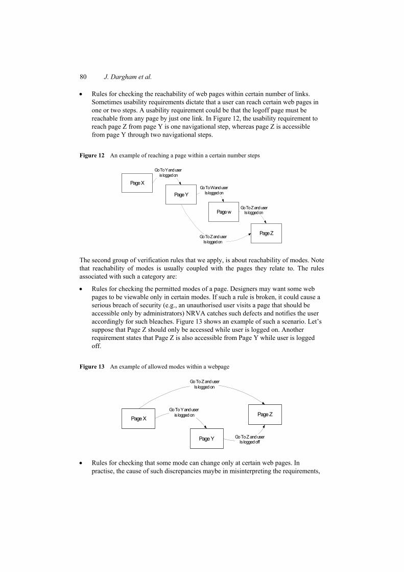
• Rules for checking the reachability of web pages within certain number of links. Sometimes usability requirements dictate that a user can reach certain web pages in one or two steps. A usability requirement could be that the logoff page must be reachable from any page by just one link. In Figure 12, the usability requirement to reach page Z from page Y is one navigational step, whereas page Z is accessible from page Y through two navigational steps.
Figure 12 An example of reaching a page within a certain number steps
Page X
Page Y
Page w
Go To W and user Is logged on
Go To Y and user is logged on
Page Z
Go To Z and user Is logged on
Go To Z and user Is logged on
The second group of verification rules that we apply, is about reachability of modes. Note that reachability of modes is usually coupled with the pages they relate to. The rules associated with such a category are:
• Rules for checking the permitted modes of a page. Designers may want some web pages to be viewable only in certain modes. If such a rule is broken, it could cause a serious breach of security (e.g., an unauthorised user visits a page that should be accessible only by administrators) NRVA catches such defects and notifies the user accordingly for such bleaches. Figure 13 shows an example of such a scenario. Let’s suppose that Page Z should only be accessed while user is logged on. Another requirement states that Page Z is also accessible from Page Y while user is logged off.
Figure 13 An example of allowed modes within a webpage
Page X
Page Y
Page Z
Go To Z and user Is logged off
Go To Y and user is logged on
Go To Z and user Is logged on
• Rules for checking that some mode can change only at certain web pages. In practise, the cause of such discrepancies maybe in misinterpreting the requirements,
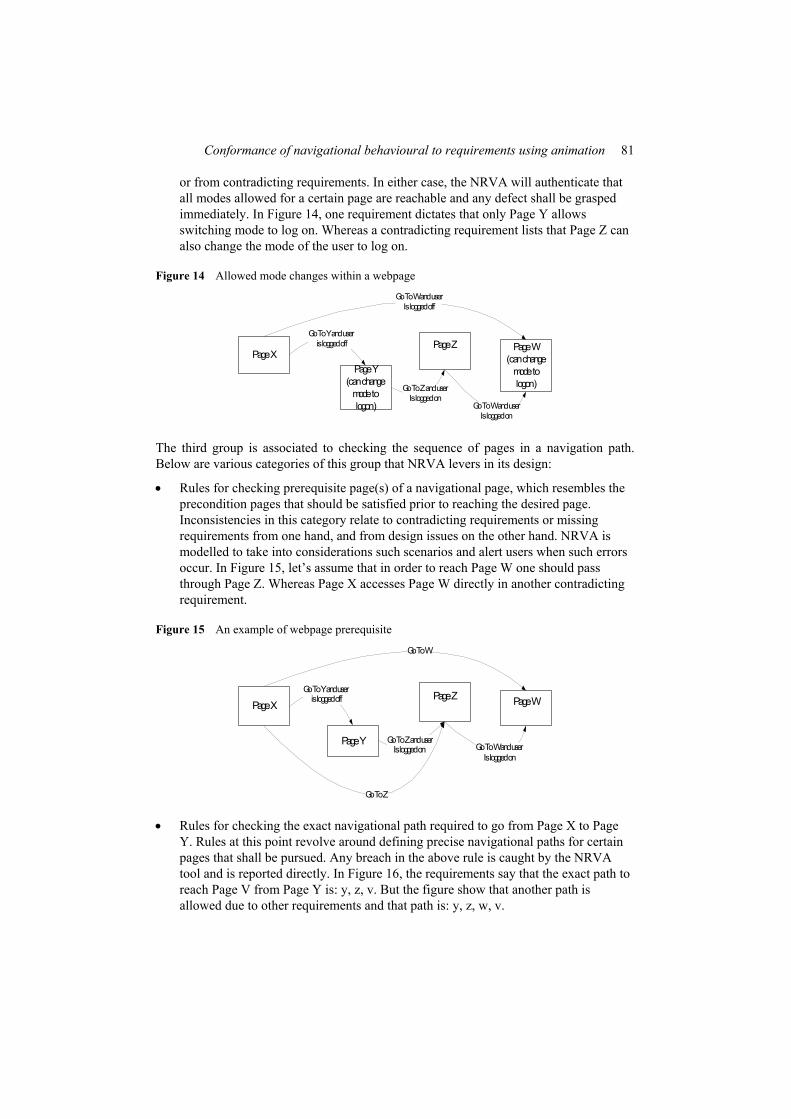
Conformance of navigational behavioural to requirements using animation 81
or from contradicting requirements. In either case, the NRVA will authenticate that all modes allowed for a certain page are reachable and any defect shall be grasped immediately. In Figure 14, one requirement dictates that only Page Y allows switching mode to log on. Whereas a contradicting requirement lists that Page Z can also change the mode of the user to log on.
Figure 14 Allowed mode changes within a webpage
Page XPage Y
(can change mode to logon)
Page Z
Go To Z and user Is logged on
Go To Y and user is logged off Page W
(can change mode to logon)
Go To W and user Is logged off
Go To W and user Is logged on
The third group is associated to checking the sequence of pages in a navigation path. Below are various categories of this group that NRVA levers in its design:
• Rules for checking prerequisite page(s) of a navigational page, which resembles the precondition pages that should be satisfied prior to reaching the desired page. Inconsistencies in this category relate to contradicting requirements or missing requirements from one hand, and from design issues on the other hand. NRVA is modelled to take into considerations such scenarios and alert users when such errors occur. In Figure 15, let’s assume that in order to reach Page W one should pass through Page Z. Whereas Page X accesses Page W directly in another contradicting requirement.
Figure 15 An example of webpage prerequisite
Page X
Page Y
Page Z
Go To Z and user Is logged on
Go To Y and user is logged off Page W
Go To W
Go To W and user Is logged on
Go To Z
• Rules for checking the exact navigational path required to go from Page X to Page Y. Rules at this point revolve around defining precise navigational paths for certain pages that shall be pursued. Any breach in the above rule is caught by the NRVA tool and is reported directly. In Figure 16, the requirements say that the exact path to reach Page V from Page Y is: y, z, v. But the figure show that another path is allowed due to other requirements and that path is: y, z, w, v.
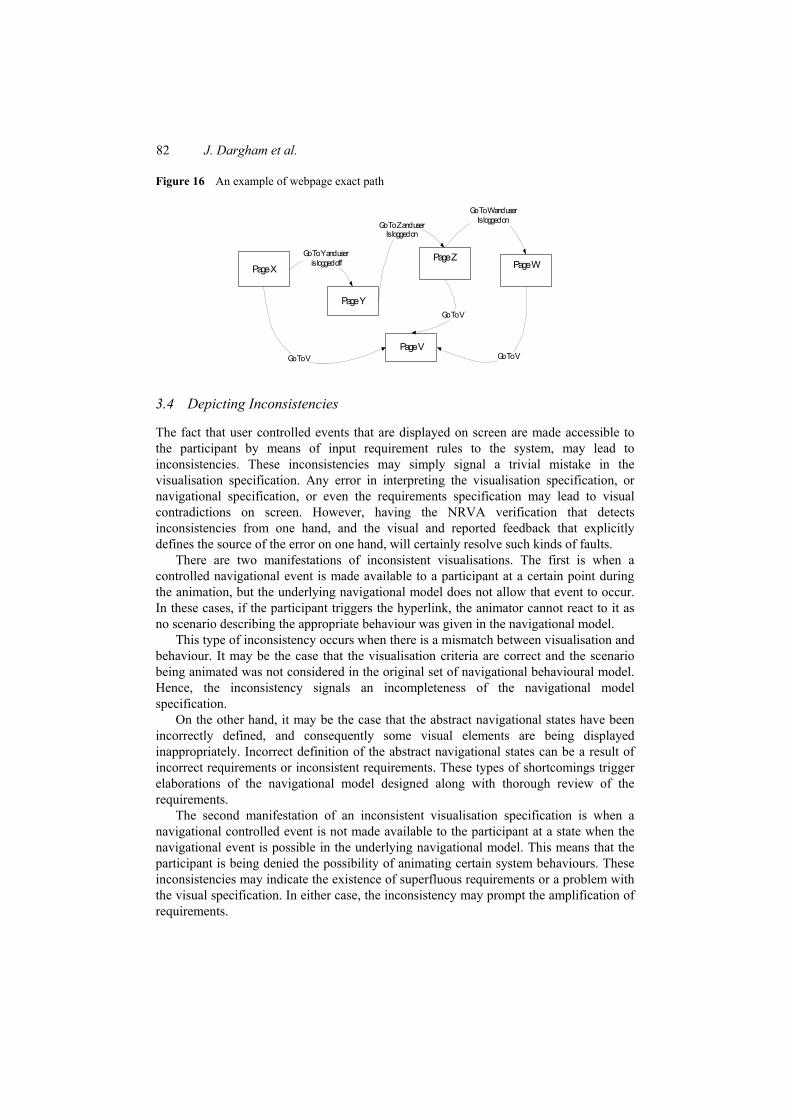
82 J. Dargham et al.
Figure 16 An example of webpage exact path
Page X
Page Y
Page Z
Go To Z and user Is logged on
Go To Y and user is logged off Page W
Go To W and user Is logged on
Go To VPage V
Go To V
Go To V
3.4 Depicting Inconsistencies
The fact that user controlled events that are displayed on screen are made accessible to the participant by means of input requirement rules to the system, may lead to inconsistencies. These inconsistencies may simply signal a trivial mistake in the visualisation specification. Any error in interpreting the visualisation specification, or navigational specification, or even the requirements specification may lead to visual contradictions on screen. However, having the NRVA verification that detects inconsistencies from one hand, and the visual and reported feedback that explicitly defines the source of the error on one hand, will certainly resolve such kinds of faults.
There are two manifestations of inconsistent visualisations. The first is when a controlled navigational event is made available to a participant at a certain point during the animation, but the underlying navigational model does not allow that event to occur. In these cases, if the participant triggers the hyperlink, the animator cannot react to it as no scenario describing the appropriate behaviour was given in the navigational model.
This type of inconsistency occurs when there is a mismatch between visualisation and behaviour. It may be the case that the visualisation criteria are correct and the scenario being animated was not considered in the original set of navigational behavioural model. Hence, the inconsistency signals an incompleteness of the navigational model specification.
On the other hand, it may be the case that the abstract navigational states have been incorrectly defined, and consequently some visual elements are being displayed inappropriately. Incorrect definition of the abstract navigational states can be a result of incorrect requirements or inconsistent requirements. These types of shortcomings trigger elaborations of the navigational model designed along with thorough review of the requirements.
The second manifestation of an inconsistent visualisation specification is when a navigational controlled event is not made available to the participant at a state when the navigational event is possible in the underlying navigational model. This means that the participant is being denied the possibility of animating certain system behaviours. These inconsistencies may indicate the existence of superfluous requirements or a problem with the visual specification. In either case, the inconsistency may prompt the amplification of requirements.
Conformance of navigational behavioural to requirements using animation 83
The animation tool recognises these inconsistencies and informs the participant of when they occur informing the user of the details of the failure. If the participant clicks on a controlled event that is not enabled in the underlying navigational behaviour model, the visualiser will return an error message to the user. When it comes down to it, when the animator decides on the next navigational state (page) of the system, it checks whether the system current state abides by the page requirements that we submitted to the system. It checks for page prerequisites, mode satisfiability and so on. If requirements are met, the visualiser builds the page and displays it to the user accordingly. Otherwise, an error is raised explaining the source of the error in details.
The importance of NRVA methodology revolves around validating adaptive navigational requirements at a time when all of the previous animation approaches failed to do so. Table 1 summarises the characteristics of NRVA animation method. Table 1 NRVA method evaluation
NRVA animation
Define requirements Decoupling requirements and model Define FarNav model
Degree of requirements abstraction that are fed to the system
Abstracted under XMLs
Validation of behavioural models with respect to requirements
In addition to the assessment of the user, the tool also verifies the correctness of the behavioural model with respect to the goals
• User plays animation User/system interaction
• System interactive feedback
• By validating FarNav Validate navigational requirements
• Validating navigational constraints
4 NRVA case study
In this section, we investigate the effectiveness of our approach and the tool to validate the navigational requirements. A case study is conducted to assess the abilities of the NRVA tool. For this case study we suppose that a random user may be selected to be engaged in the validation activity. In Section 4.1, we give an overview of the website to be implemented along with its corresponding requirements and we elaborate on how those requirements were transformed into inputs to the NRVA system. In Section 4.2, we demonstrate the various series of animations performed on those requirements and analyse how the requirements were refined due to NRVA feedback. Last, in Section 4.3 we evaluate the validation results and conclude on the importance and usefulness of the NRVA tool to validate navigational requirements.
4.1 The online music shop application
In our selected example, the website major purpose is to provide online services for renting and buying movies’ and music’s CDs online. The system is composed of 16 web
84 J. Dargham et al.
pages and navigational requirements for those pages were collected from the specification document.
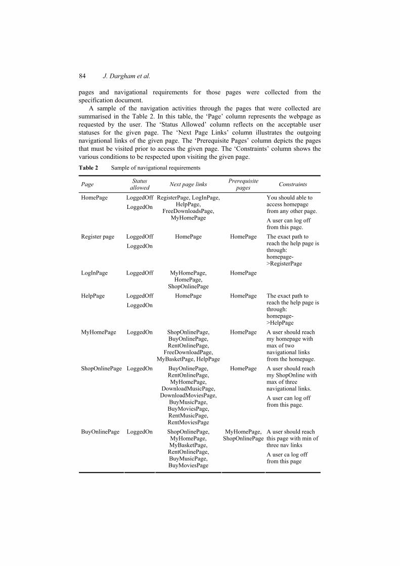
A sample of the navigation activities through the pages that were collected are summarised in the Table 2. In this table, the ‘Page’ column represents the webpage as requested by the user. The ‘Status Allowed’ column reflects on the acceptable user statuses for the given page. The ‘Next Page Links’ column illustrates the outgoing navigational links of the given page. The ‘Prerequisite Pages’ column depicts the pages that must be visited prior to access the given page. The ‘Constraints’ column shows the various conditions to be respected upon visiting the given page. Table 2 Sample of navigational requirements
Page Status allowed Next page links Prerequisite
pages Constraints
LoggedOff You should able to access homepage from any other page.
HomePage LoggedOn
RegisterPage, LogInPage, HelpPage,
FreeDownloadsPage, MyHomePage
A user can log off from this page.
LoggedOff Register page LoggedOn
HomePage HomePage The exact path to reach the help page is through: homepage->RegisterPage
LogInPage LoggedOff MyHomePage, HomePage,
ShopOnlinePage
HomePage
LoggedOff HelpPage LoggedOn
HomePage HomePage The exact path to reach the help page is through: homepage->HelpPage
MyHomePage LoggedOn ShopOnlinePage, BuyOnlinePage, RentOnlinePage,
FreeDownloadPage, MyBasketPage, HelpPage
HomePage A user should reach my homepage with max of two navigational links from the homepage. A user should reach my ShopOnline with max of three navigational links.
ShopOnlinePage LoggedOn BuyOnlinePage, RentOnlinePage, MyHomePage,
DownloadMusicPage, DownloadMoviesPage,
BuyMusicPage, BuyMoviesPage, RentMusicPage, RentMoviesPage
HomePage
A user can log off from this page.
A user should reach this page with min of three nav links
BuyOnlinePage LoggedOn ShopOnlinePage, MyHomePage, MyBasketPage,
RentOnlinePage, BuyMusicPage, BuyMoviesPage
MyHomePage, ShopOnlinePage
A user ca log off from this page
Conformance of navigational behavioural to requirements using animation 85
As mentioned earlier, the FarNav notation is used to specify the navigational requirements. The resulted FarNav model consists of the Page navigation State Chart, and the different parallel state machine corresponding to the different adaptive navigation criteria. For the application in hands, the page navigation State Chart is composed of 16 web pages along with 80 navigational Links. Furthermore, we observed one user status mode related to the logon mode, and 4 history sensitive navigation modes.
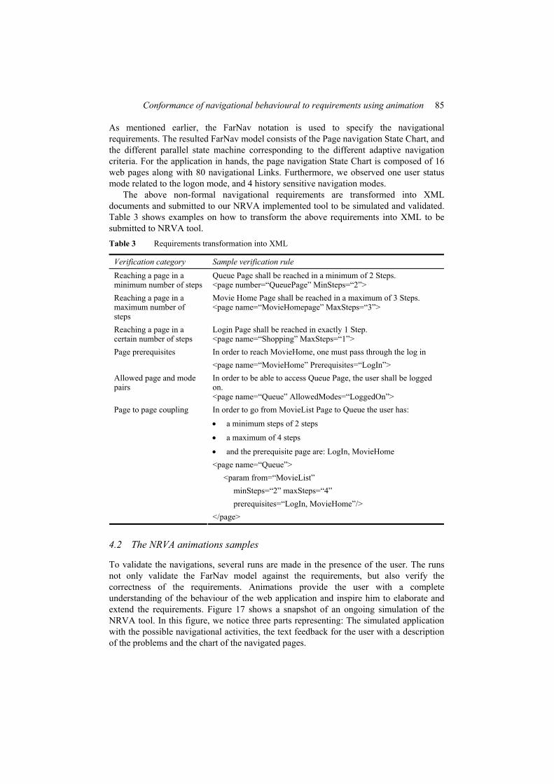
The above non-formal navigational requirements are transformed into XML documents and submitted to our NRVA implemented tool to be simulated and validated. Table 3 shows examples on how to transform the above requirements into XML to be submitted to NRVA tool. Table 3 Requirements transformation into XML
Verification category Sample verification rule
Reaching a page in a minimum number of steps
Queue Page shall be reached in a minimum of 2 Steps. <page number=“QueuePage” MinSteps=“2”>
Reaching a page in a maximum number of steps
Movie Home Page shall be reached in a maximum of 3 Steps. <page name=“MovieHomepage” MaxSteps=“3”>
Reaching a page in a certain number of steps
Login Page shall be reached in exactly 1 Step. <page name=“Shopping” MaxSteps=“1”> In order to reach MovieHome, one must pass through the log in Page prerequisites <page name=“MovieHome” Prerequisites=“LogIn”>
Allowed page and mode pairs
In order to be able to access Queue Page, the user shall be logged on. <page name=“Queue” AllowedModes=“LoggedOn”> In order to go from MovieList Page to Queue the user has:
• a minimum steps of 2 steps
• a maximum of 4 steps
• and the prerequisite page are: LogIn, MovieHome <page name=“Queue”> <param from=“MovieList” minSteps=“2” maxSteps=“4” prerequisites=“LogIn, MovieHome”/>
Page to page coupling
</page>
4.2 The NRVA animations samples
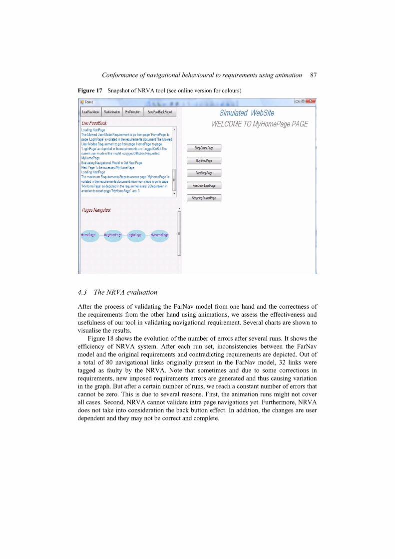
To validate the navigations, several runs are made in the presence of the user. The runs not only validate the FarNav model against the requirements, but also verify the correctness of the requirements. Animations provide the user with a complete understanding of the behaviour of the web application and inspire him to elaborate and extend the requirements. Figure 17 shows a snapshot of an ongoing simulation of the NRVA tool. In this figure, we notice three parts representing: The simulated application with the possible navigational activities, the text feedback for the user with a description of the problems and the chart of the navigated pages.
86 J. Dargham et al.
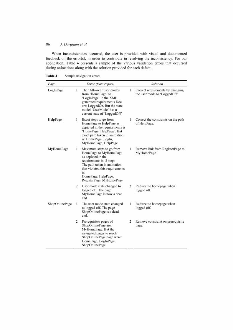
When inconsistencies occurred, the user is provided with visual and documented feedback on the error(s), in order to contribute in resolving the inconsistency. For our application, Table 4 presents a sample of the various validation errors that occurred during animations along with the solution provided for each defect.
Table 4 Sample navigation errors
Page Error (from report) Solution
LogInPage 1 The ‘Allowed’ user modes from ‘HomePage’ to ‘LogInPage’ in the XML generated requirements Doc are: LoggedOn. But the state model ‘UserMode’ has a current state of ‘LoggedOff’
1 Correct requirements by changing the user mode to ‘LoggedOff’
HelpPage 1 Exact steps to go from HomePage to HelpPage as depicted in the requirements is ‘HomePage, HelpPage’. But exact path taken in animation is: HomePage, LogIn, MyHomePage, HelpPage
1 Correct the constraints on the path of HelpPage.
MyHomePage 1 Maximum steps to go from HomePage to MyHomePage as depicted in the requirements is: 2 steps The path taken in animation that violated this requirements is: HomePage, HelpPage, RegisterPage, MyHomePage
1 Remove link from RegisterPage to MyHomePage
2 User mode state changed to logged off. The page MyHomePage is now a dead end.
2 Redirect to homepage when logged off.
1 The user mode state changed to logged off. The page ShopOnlinePage is a dead end.
1 Redirect to homepage when logged off.
ShopOnlinePage
2 Prerequisites pages of ShopOnlinePage are: MyHomePage. But the navigated pages to reach ShopOnlinePage page were: HomePage, LogInPage, ShopOnlinePage
2 Remove constraint on prerequisite page.
Conformance of navigational behavioural to requirements using animation 87
Figure 17 Snapshot of NRVA tool (see online version for colours)
4.3 The NRVA evaluation
After the process of validating the FarNav model from one hand and the correctness of the requirements from the other hand using animations, we assess the effectiveness and usefulness of our tool in validating navigational requirement. Several charts are shown to visualise the results.
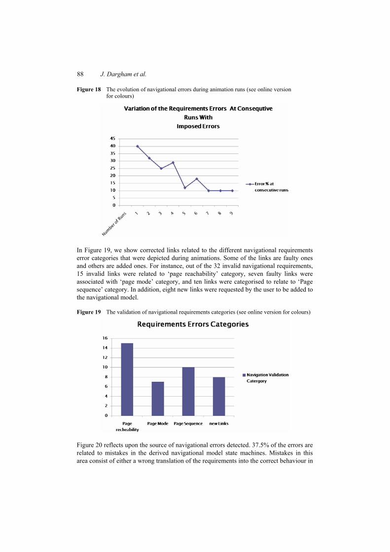
Figure 18 shows the evolution of the number of errors after several runs. It shows the efficiency of NRVA system. After each run set, inconsistencies between the FarNav model and the original requirements and contradicting requirements are depicted. Out of a total of 80 navigational links originally present in the FarNav model, 32 links were tagged as faulty by the NRVA. Note that sometimes and due to some corrections in requirements, new imposed requirements errors are generated and thus causing variation in the graph. But after a certain number of runs, we reach a constant number of errors that cannot be zero. This is due to several reasons. First, the animation runs might not cover all cases. Second, NRVA cannot validate intra page navigations yet. Furthermore, NRVA does not take into consideration the back button effect. In addition, the changes are user dependent and they may not be correct and complete.
88 J. Dargham et al.
Figure 18 The evolution of navigational errors during animation runs (see online version for colours)
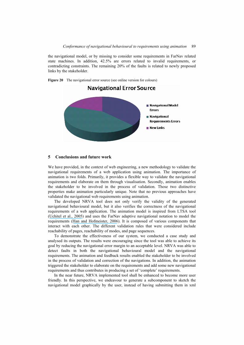
In Figure 19, we show corrected links related to the different navigational requirements error categories that were depicted during animations. Some of the links are faulty ones and others are added ones. For instance, out of the 32 invalid navigational requirements, 15 invalid links were related to ‘page reachability’ category, seven faulty links were associated with ‘page mode’ category, and ten links were categorised to relate to ‘Page sequence’ category. In addition, eight new links were requested by the user to be added to the navigational model.
Figure 19 The validation of navigational requirements categories (see online version for colours)
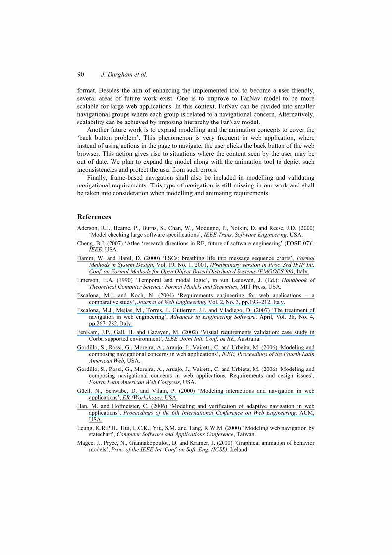
Figure 20 reflects upon the source of navigational errors detected. 37.5% of the errors are related to mistakes in the derived navigational model state machines. Mistakes in this area consist of either a wrong translation of the requirements into the correct behaviour in
Conformance of navigational behavioural to requirements using animation 89
the navigational model, or by missing to consider some requirements in FarNav related state machines. In addition, 42.5% are errors related to invalid requirements, or contradicting constraints. The remaining 20% of the faults is related to newly proposed links by the stakeholder.
Figure 20 The navigational error source (see online version for colours)
5 Conclusions and future work
We have provided, in the context of web engineering, a new methodology to validate the navigational requirements of a web application using animation. The importance of animation is two folds. Primarily, it provides a flexible way to validate the navigational requirements and elaborate on them through visualisation. Secondly, animation enables the stakeholder to be involved in the process of validation. Those two distinctive properties make animation particularly unique. Note that no previous approaches have validated the navigational web requirements using animation.
The developed NRVA tool does not only verify the validity of the generated navigational behavioural model, but it also verifies the correctness of the navigational requirements of a web application. The animation model is inspired from LTSA tool (Uchitel et al., 2005) and uses the FarNav adaptive navigational notation to model the requirements (Han and Hofmeister, 2006). It is composed of various components that interact with each other. The different validation rules that were considered include reachability of pages, reachability of modes, and page sequences.
To demonstrate the effectiveness of our system, we conducted a case study and analysed its outputs. The results were encouraging since the tool was able to achieve its goal by reducing the navigational error margin to an acceptable level. NRVA was able to detect faults in both the navigational behavioural model and the navigational requirements. The animation and feedback results enabled the stakeholder to be involved in the process of validation and correction of the navigations. In addition, the animation triggered the stakeholder to elaborate on the requirements and add some new navigational requirements and thus contributes in producing a set of ‘complete’ requirements.
In the near future, NRVA implemented tool shall be enhanced to become more user friendly. In this perspective, we endeavour to generate a subcomponent to sketch the navigational model graphically by the user, instead of having submitting them in xml
90 J. Dargham et al.
format. Besides the aim of enhancing the implemented tool to become a user friendly, several areas of future work exist. One is to improve to FarNav model to be more scalable for large web applications. In this context, FarNav can be divided into smaller navigational groups where each group is related to a navigational concern. Alternatively, scalability can be achieved by imposing hierarchy the FarNav model.
Another future work is to expand modelling and the animation concepts to cover the ‘back button problem’. This phenomenon is very frequent in web application, where instead of using actions in the page to navigate, the user clicks the back button of the web browser. This action gives rise to situations where the content seen by the user may be out of date. We plan to expand the model along with the animation tool to depict such inconsistencies and protect the user from such errors.
Finally, frame-based navigation shall also be included in modelling and validating navigational requirements. This type of navigation is still missing in our work and shall be taken into consideration when modelling and animating requirements.
References Aderson, R.J., Beame, P., Burns, S., Chan, W., Modugno, F., Notkin, D. and Reese, J.D. (2000)
‘Model checking large software specifications’, IEEE Trans. Software Engineering, USA. Cheng, B.J. (2007) ‘Atlee ‘research directions in RE, future of software engineering’ (FOSE 07)’,
IEEE, USA. Damm, W. and Harel, D. (2000) ‘LSCs: breathing life into message sequence charts’, Formal
Methods in System Design, Vol. 19, No. 1, 2001, (Preliminary version in Proc. 3rd IFIP Int. Conf. on Formal Methods for Open Object-Based Distributed Systems (FMOODS’99), Italy.
Emerson, E.A. (1990) ‘Temporal and modal logic’, in van Leeuwen, J. (Ed.): Handbook of Theoretical Computer Science: Formal Models and Semantics, MIT Press, USA.
Escalona, M.J. and Koch, N. (2004) ‘Requirements engineering for web applications – a comparative study’, Journal of Web Engineering, Vol. 2, No. 3, pp.193–212, Italy.
Escalona, M.J., Mejías, M., Torres, J., Gutierrez, J.J. and Viladiego, D. (2007) ‘The treatment of navigation in web engineering’, Advances in Engineering Software, April, Vol. 38, No. 4, pp.267–282, Italy.
FenKam, J.P., Gall, H. and Gazayeri, M. (2002) ‘Visual requirements validation: case study in Corba supported environment’, IEEE, Joint Intl. Conf. on RE, Australia.
Gordillo, S., Rossi, G., Moreira, A., Araujo, J., Vairetti, C. and Urbeita, M. (2006) ‘Modeling and composing navigational concerns in web applications’, IEEE, Proceedings of the Fourth Latin American Web, USA.
Gordillo, S., Rossi, G., Moreira, A., Aruajo, J., Vairetti, C. and Urbieta, M. (2006) ‘Modeling and composing navigational concerns in web applications. Requirements and design issues’, Fourth Latin American Web Congress, USA.
Güell, N., Schwabe, D. and Vilain, P. (2000) ‘Modeling interactions and navigation in web applications’, ER (Workshops), USA.
Han, M. and Hofmeister, C. (2006) ‘Modeling and verification of adaptive navigation in web applications’, Proceedings of the 6th International Conference on Web Engineering, ACM, USA.
Leung, K.R.P.H., Hui, L.C.K., Yiu, S.M. and Tang, R.W.M. (2000) ‘Modeling web navigation by statechart’, Computer Software and Applications Conference, Taiwan.
Magee, J., Pryce, N., Giannakopoulou, D. and Kramer, J. (2000) ‘Graphical animation of behavior models’, Proc. of the IEEE Int. Conf. on Soft. Eng. (ICSE), Ireland.
Conformance of navigational behavioural to requirements using animation 91
Miller, R. and Shanahan, M. (1999) ‘The event calculus in classical logic – alternative axiomatisations’, Linkoping Electronic Articles in Computer and Information Science, Vol. 4, No. 16, pp.1–27.
Sreemani, T. and Atlee, J.M. (1996) ‘Feasibility of model checking software requirements’, Conf. on Comp. Assur., National Institute of Standards and Technology, USA.
Sukumaran, S., Sreenvias, A. and Venkatesh, R. (2005) ‘A rigorous approach to requirements validation’, Proceedings of the 4th International Conference of Software Engineering, IEEE, USA.
Sutherland, M. and Maiden, N. (2005) ‘Developing use cases and scenarios in the requirements process’, Proceedings of the 27th International Conference of Software Engineering, ACM, USA.
Sutherland, M. and Maiden, N. (2010) ‘Story boarding requirements’, Proceedings of 18th IEEE International Requirements Engineering Conference, USA.
Uchitel, S., Chatley, R. and Magee, J.K.J. (2005) ‘Fluent-based animation: exploiting the relation between goals and scenarios for requirements validation’, Proceedings of the 12th IEEE, Taiwan.
Unified Modeling Language(UML) (2004) available at http://www.omg.org/spec/UML/ (accessed on 2007).
Van, H.T., van Lamsweerde, A., Massonet, P. and Ponsard, C. (2004) ‘Goal-oriented requirements animation’, Proc. of the IEEE Int. Req. Eng. Conf., Japan.
Vemuri, R., Mandayam, R. and Meduri, V. (1996) ‘Performance modeling using PDL’, Proceedings of IEEE Computer, USA.
Winckler, M. and Palanque, P. (2003) ‘Statewebcharts: a formal description technique dedicated to navigation modelling of web applications’, DSV-IS, Portugal.