Configuring the ProCurve Wireless Edge Services xl Module
196
2-1 2 Configuring the ProCurve Wireless Edge Services xl Module Contents Management Interfaces . . . . . . . . . . . . . . . . . . . . . . . . . . . . . . . . . . . . . . . . . . 2-5 The Web Browser Interface . . . . . . . . . . . . . . . . . . . . . . . . . . . . . . . . . . . 2-5 Determining the Dynamic IP Address or Assigning a Static Address . . . . . . . . . . . . . . . . . . . . . . . . . . . . . . . . . . . . . . . . . . . 2-6 Accessing the Web Browser Interface . . . . . . . . . . . . . . . . . . . . . . 2-9 Logging in to the Web Browser Interface . . . . . . . . . . . . . . . . . . . 2-11 Overview of the Web Browser Interface . . . . . . . . . . . . . . . . . . . . 2-12 Applying or Saving Changes . . . . . . . . . . . . . . . . . . . . . . . . . . . . . . 2-12 Logging Out or Refreshing the Screen . . . . . . . . . . . . . . . . . . . . . . 2-14 Accessing the Online Help . . . . . . . . . . . . . . . . . . . . . . . . . . . . . . . 2-14 Using Filtering Options . . . . . . . . . . . . . . . . . . . . . . . . . . . . . . . . . . 2-16 CLI . . . . . . . . . . . . . . . . . . . . . . . . . . . . . . . . . . . . . . . . . . . . . . . . . . . . . . . 2-21 Accessing the Switch CLI Through a Serial Session . . . . . . . . . . 2-21 Accessing the Switch CLI Through a Telnet or SSH Session . . . 2-22 Accessing the Wireless-Services Context . . . . . . . . . . . . . . . . . . . 2-22 Navigating the CLI . . . . . . . . . . . . . . . . . . . . . . . . . . . . . . . . . . . . . . 2-22 Saving Changes to the startup-config . . . . . . . . . . . . . . . . . . . . . . 2-23 CLI Commands . . . . . . . . . . . . . . . . . . . . . . . . . . . . . . . . . . . . . . . . . 2-23 Security . . . . . . . . . . . . . . . . . . . . . . . . . . . . . . . . . . . . . . . . . . . . . . . . . . . 2-24 SSH Access . . . . . . . . . . . . . . . . . . . . . . . . . . . . . . . . . . . . . . . . . . . . 2-24 HTTPS Access . . . . . . . . . . . . . . . . . . . . . . . . . . . . . . . . . . . . . . . . . 2-24 SNMP Support . . . . . . . . . . . . . . . . . . . . . . . . . . . . . . . . . . . . . . . . . 2-24 Controlling Management Access to the Module . . . . . . . . . . . . . . . . . 2-27 Enabling HTTP and HTTPS Access to the Module . . . . . . . . . . . 2-27 Choosing SNMP Versions . . . . . . . . . . . . . . . . . . . . . . . . . . . . . . . . 2-29 Setting Up the Internal FTP Server . . . . . . . . . . . . . . . . . . . . . . . . 2-32
-
Upload
khangminh22 -
Category
Documents
-
view
1 -
download
0
Transcript of Configuring the ProCurve Wireless Edge Services xl Module
2
Configuring the ProCurve Wireless Edge Services xl Module
Contents
Management Interfaces . . . . . . . . . . . . . . . . . . . . . . . . . . . . . . . . . . . . . . . . . . 2-5
The Web Browser Interface . . . . . . . . . . . . . . . . . . . . . . . . . . . . . . . . . . . 2-5
Determining the Dynamic IP Address or Assigning a Static Address . . . . . . . . . . . . . . . . . . . . . . . . . . . . . . . . . . . . . . . . . . . 2-6
Accessing the Web Browser Interface . . . . . . . . . . . . . . . . . . . . . . 2-9
Logging in to the Web Browser Interface . . . . . . . . . . . . . . . . . . . 2-11
Overview of the Web Browser Interface . . . . . . . . . . . . . . . . . . . . 2-12
Applying or Saving Changes . . . . . . . . . . . . . . . . . . . . . . . . . . . . . . 2-12
Logging Out or Refreshing the Screen . . . . . . . . . . . . . . . . . . . . . . 2-14
Accessing the Online Help . . . . . . . . . . . . . . . . . . . . . . . . . . . . . . . 2-14
Using Filtering Options . . . . . . . . . . . . . . . . . . . . . . . . . . . . . . . . . . 2-16
CLI . . . . . . . . . . . . . . . . . . . . . . . . . . . . . . . . . . . . . . . . . . . . . . . . . . . . . . . 2-21
Accessing the Switch CLI Through a Serial Session . . . . . . . . . . 2-21
Accessing the Switch CLI Through a Telnet or SSH Session . . . 2-22
Accessing the Wireless-Services Context . . . . . . . . . . . . . . . . . . . 2-22
Navigating the CLI . . . . . . . . . . . . . . . . . . . . . . . . . . . . . . . . . . . . . . 2-22
Saving Changes to the startup-config . . . . . . . . . . . . . . . . . . . . . . 2-23
CLI Commands . . . . . . . . . . . . . . . . . . . . . . . . . . . . . . . . . . . . . . . . . 2-23
Security . . . . . . . . . . . . . . . . . . . . . . . . . . . . . . . . . . . . . . . . . . . . . . . . . . . 2-24
SSH Access . . . . . . . . . . . . . . . . . . . . . . . . . . . . . . . . . . . . . . . . . . . . 2-24
HTTPS Access . . . . . . . . . . . . . . . . . . . . . . . . . . . . . . . . . . . . . . . . . 2-24
SNMP Support . . . . . . . . . . . . . . . . . . . . . . . . . . . . . . . . . . . . . . . . . 2-24
Controlling Management Access to the Module . . . . . . . . . . . . . . . . . 2-27
Enabling HTTP and HTTPS Access to the Module . . . . . . . . . . . 2-27
Choosing SNMP Versions . . . . . . . . . . . . . . . . . . . . . . . . . . . . . . . . 2-29
Setting Up the Internal FTP Server . . . . . . . . . . . . . . . . . . . . . . . . 2-32
2-1

Configuring the ProCurve Wireless Edge Services xl ModuleContents
Changing the Password for the Default SNMP v3 Users (Operator or Manager) . . . . . . . . . . . . . . . . . . . . . . . . . . . . . . . . . . 2-35
Configuring Web-Users . . . . . . . . . . . . . . . . . . . . . . . . . . . . . . . . . . 2-40
Logging In to the Module as a WebUser Administrator . . . . . . . . . . . 2-48
Creating Guest Accounts on the Local RADIUS Database . . . . . 2-49
Viewing and Deleting Guest Accounts . . . . . . . . . . . . . . . . . . . . . 2-52
Printing Records of Guest Accounts . . . . . . . . . . . . . . . . . . . . . . . 2-54
Radio Port Adoption . . . . . . . . . . . . . . . . . . . . . . . . . . . . . . . . . . . . . . . . . . . 2-56
Network Requirements for Layer 2 Adoption . . . . . . . . . . . . . . . . . . . 2-57
Auto-Provisioning on the Wireless Services-Enabled Switch . . 2-57
Attaching RPs to Infrastructure Switches . . . . . . . . . . . . . . . . . . 2-58
Network Requirements for Layer 3 Adoption . . . . . . . . . . . . . . . . . . . 2-61
Enabling Layer 3 Adoption Through DHCP Option 189 . . . . . . . 2-64
Enabling Layer 3 Adoption Through DNS Lookup . . . . . . . . . . . 2-66
Verifying Layer 3 Adoption . . . . . . . . . . . . . . . . . . . . . . . . . . . . . . . 2-69
Automatic or Manual Adoption of RPs . . . . . . . . . . . . . . . . . . . . . . . . . 2-70
Configuring Manual Adoption for RPs . . . . . . . . . . . . . . . . . . . . . 2-71
Controlling Which Wireless Edge Services xl Module Adopts Particular RPs—Adoption Preference ID . . . . . . . . . . . . . . . . . . . . . . 2-75
802.1X Authentication for RPs . . . . . . . . . . . . . . . . . . . . . . . . . . . . . . . . 2-77
Configuring 802.1X Authentication for RPs . . . . . . . . . . . . . . . . . 2-78
System Maintenance . . . . . . . . . . . . . . . . . . . . . . . . . . . . . . . . . . . . . . . . . . . 2-80
Software Images . . . . . . . . . . . . . . . . . . . . . . . . . . . . . . . . . . . . . . . . . . . 2-80
Viewing the Software Images . . . . . . . . . . . . . . . . . . . . . . . . . . . . . 2-81
Selecting the Software Image That Is Used to Reboot . . . . . . . . 2-82
Changing the Image Failover Setting . . . . . . . . . . . . . . . . . . . . . . . 2-82
Manually Updating the Software Image . . . . . . . . . . . . . . . . . . . . 2-84
Configuration Files . . . . . . . . . . . . . . . . . . . . . . . . . . . . . . . . . . . . . . . . . 2-85
Viewing Configuration Files . . . . . . . . . . . . . . . . . . . . . . . . . . . . . . 2-86
Transferring, or Copying, Files . . . . . . . . . . . . . . . . . . . . . . . . . . . . 2-88
Transferring Configuration Files from an FTP or TFTP Server to the Wireless Edge Services xl Module . . . . . . . . . . . . . 2-88
Transferring Configuration Files from the Wireless Edge Services xl Module to Another Destination . . . . . . . . . . . . . . . . . 2-90
Managing the Directory Structure and Browsing for Files . . . . . 2-94
Deleting a Configuration File . . . . . . . . . . . . . . . . . . . . . . . . . . . . . 2-96
2-2

Configuring the ProCurve Wireless Edge Services xl ModuleContents
Returning the Startup-Config File to Factory Default Settings . . . . . . . . . . . . . . . . . . . . . . . . . . . . . . . . . . . . . . . . 2-97
Update Server . . . . . . . . . . . . . . . . . . . . . . . . . . . . . . . . . . . . . . . . . . . . . 2-98
Checking the Software Image File . . . . . . . . . . . . . . . . . . . . . . . . . 2-98
Checking the Configuration File . . . . . . . . . . . . . . . . . . . . . . . . . . 2-99
Avoiding Problems in Using the Update Server . . . . . . . . . . . . . 2-100
Configuring the Update Server Settings . . . . . . . . . . . . . . . . . . . 2-104
Password Encryption . . . . . . . . . . . . . . . . . . . . . . . . . . . . . . . . . . . . . . 2-105
SNMP Traps and Error Reporting . . . . . . . . . . . . . . . . . . . . . . . . . . . . . . . 2-108
SNMP Communities . . . . . . . . . . . . . . . . . . . . . . . . . . . . . . . . . . . . . . . 2-108
Modifying SNMP v2 Communities . . . . . . . . . . . . . . . . . . . . . . . . 2-109
SNMP Statistics . . . . . . . . . . . . . . . . . . . . . . . . . . . . . . . . . . . . . . . . . . . 2-111
SNMP Traps . . . . . . . . . . . . . . . . . . . . . . . . . . . . . . . . . . . . . . . . . . . . . . 2-112
Enabling SNMP Traps . . . . . . . . . . . . . . . . . . . . . . . . . . . . . . . . . . 2-113
Disabling SNMP Traps . . . . . . . . . . . . . . . . . . . . . . . . . . . . . . . . . . 2-115
Setting Thresholds . . . . . . . . . . . . . . . . . . . . . . . . . . . . . . . . . . . . . 2-115
Sending Traps to an SNMP Receiver . . . . . . . . . . . . . . . . . . . . . . 2-117
Radio Port Licenses . . . . . . . . . . . . . . . . . . . . . . . . . . . . . . . . . . . . . . . . . . . 2-123
Installing or Uninstalling Licenses on a Wireless Edge Services xl Module . . . . . . . . . . . . . . . . . . . . . . . . . . . . . . . . . . . . . . . . 2-127
Registering on the My ProCurve Web Portal . . . . . . . . . . . . . . . 2-127
Understanding the Numbers: IDs and Keys . . . . . . . . . . . . . . . . 2-128
Installing RP Licenses . . . . . . . . . . . . . . . . . . . . . . . . . . . . . . . . . . . . . . 2-128
Removing RP Licenses . . . . . . . . . . . . . . . . . . . . . . . . . . . . . . . . . . . . . 2-132
Redundancy Groups and RP Licensing . . . . . . . . . . . . . . . . . . . . . . . 2-135
Setting System Information—Name, Time, and Country Code . . . . . . . 2-136
Enabling Secure Network Time Protocol (NTP) . . . . . . . . . . . . . . . . . . . 2-138
Secure NTP Overview . . . . . . . . . . . . . . . . . . . . . . . . . . . . . . . . . . . . . . 2-138
NTP Modes and Communications . . . . . . . . . . . . . . . . . . . . . . . . 2-139
NTP Hierarchy . . . . . . . . . . . . . . . . . . . . . . . . . . . . . . . . . . . . . . . . 2-139
Secure NTP Enhancements . . . . . . . . . . . . . . . . . . . . . . . . . . . . . 2-141
Configuring a Secure NTP Server . . . . . . . . . . . . . . . . . . . . . . . . . . . . 2-142
Configuring Secure NTP Options . . . . . . . . . . . . . . . . . . . . . . . . . 2-144
Applying ACLs to NTP Services . . . . . . . . . . . . . . . . . . . . . . . . . . 2-146
Configuring Authentication for Secure NTP . . . . . . . . . . . . . . . 2-148
2-3
Configuring the ProCurve Wireless Edge Services xl ModuleContents
Configuring NTP Neighbors . . . . . . . . . . . . . . . . . . . . . . . . . . . . . 2-152
Configuring the Wireless Edge Services xl Module as a Broadcast Server . . . . . . . . . . . . . . . . . . . . . . . . . . . . . . . . . . . . . 2-155
Viewing NTP Associations and Status . . . . . . . . . . . . . . . . . . . . . . . . 2-158
Viewing Secure NTP Status . . . . . . . . . . . . . . . . . . . . . . . . . . . . . . . . . 2-164
Digital Certificates . . . . . . . . . . . . . . . . . . . . . . . . . . . . . . . . . . . . . . . . . . . . 2-165
Overview . . . . . . . . . . . . . . . . . . . . . . . . . . . . . . . . . . . . . . . . . . . . . . . . . 2-166
Configuring Digital Certificates . . . . . . . . . . . . . . . . . . . . . . . . . . . . . . 2-167
Using the Certificates Wizard . . . . . . . . . . . . . . . . . . . . . . . . . . . . . . . 2-169
Creating Certificates . . . . . . . . . . . . . . . . . . . . . . . . . . . . . . . . . . . 2-170
Uploading a Certificate to the Module . . . . . . . . . . . . . . . . . . . . 2-180
Deleting Trustpoints, Certificates, and Keys . . . . . . . . . . . . . . . 2-183
Uploading a CRL to a Trustpoint . . . . . . . . . . . . . . . . . . . . . . . . . . . . . 2-186
Transferring Trustpoints . . . . . . . . . . . . . . . . . . . . . . . . . . . . . . . . . . . 2-186
Transferring Trustpoints from the Wireless Edge Services xl Module to a Server . . . . . . . . . . . . . . . . . . . . . . . . . . . . . . . . . . . 2-187
Transferring Trustpoints from a Server to the Wireless Edge Services xl Module . . . . . . . . . . . . . . . . . . . . . . . . . . . . . . . . 2-188
Certificate Keys . . . . . . . . . . . . . . . . . . . . . . . . . . . . . . . . . . . . . . . . . . . 2-190
Creating a Key . . . . . . . . . . . . . . . . . . . . . . . . . . . . . . . . . . . . . . . . 2-190
Transferring Keys . . . . . . . . . . . . . . . . . . . . . . . . . . . . . . . . . . . . . . 2-192
2-4

Configuring the ProCurve Wireless Edge Services xl ModuleManagement Interfaces
Management Interfaces
To configure and manage the ProCurve Wireless Edge Services xl Module, you can use one of the following management interfaces:
■ Web browser interface—Accessed through a Web browser, this intui-tive interface provides comprehensive information to help you manage and monitor your company’s wireless services. The menus and online help guide you through configuration steps.
■ Command line interface (CLI)—Available through a serial, Telnet, or Secure Shell (SSH) session, the CLI provides a complete set of commands to configure, manage, and troubleshoot your wireless services.
■ Simple Network Management Protocol (SNMP) applications—SNMP applications allow you to manage your company’s wireless services in the context of other network services. By default, the Wireless Edge Services xl Module supports SNMP v1, v2, and v3. As a result, you can use SNMP applications such as ProCurve Manager (PCM) Plus and ProCurve Mobility Manager (PMM) to manage your wireless services. (For more information about PCM Plus and PMM, visit ProCurve Networking’s Web site at http://www.procurve.com.)
Because the Web browser interface simplifies both management and config-uration tasks, this guide focuses on using the Web browser interface.
The Web Browser Interface
To access the Web browser interface for the ProCurve Wireless Edge Services xl Module, your workstation must be running the Java Virtual Machine (JVM), which enables the Web browser to run Java applets. If your workstation is not running the JVM and you attempt to open the module’s Web browser interface, the workstation will automatically try to access the Internet and download the JVM.
In addition to running JVM, the workstation that is running the Web browser must be able to reach the Wireless Edge Services xl Module’s IP address.
2-5
Configuring the ProCurve Wireless Edge Services xl ModuleManagement Interfaces
Determining the Dynamic IP Address or Assigning a Static Address
Initially, you must access the Wireless Edge Services xl Module through the CLI of the wireless services-enabled switch 5300xl—either to determine the IP address that is assigned to the module through a Dynamic Host Configura-tion Protocol (DHCP) server or to assign the module a static IP address.
By default, the module is configured to receive an IP address through a DHCP server. If you keep this default setting, you can simply access the CLI and determine the IP address dynamically assigned to the module. You can then use this IP address to access the Web browser interface and manage the module.
Alternatively, you can assign the module a static IP address (again through the CLI).
Access the Wireless Edge Services xl Module CLI. To access the Wire-less Edge Services xl Module CLI, you must first access the CLI for the wireless services-enabled switch. You can use one of the following access methods:
■ Serial session
■ Telnet session
■ SSH session
If you are connecting to the wireless services-enabled switch through a serial session, use the serial cable (5184-1894) that was shipped with the switch. Then run terminal session software such as Tera Term or HyperTerminal on your workstation, setting the following parameters for the session:
■ Baud Rate = 9600
■ Parity = None
■ Data Bits = 8
■ Stop Bits = 1
■ Flow Control = None
If prompted for a password, enter the password for either the manager or the operator user on the wireless services-enabled switch.
Move to the wireless-services context by entering:
ProCurve# wireless-services <slot letter>
2-6
Configuring the ProCurve Wireless Edge Services xl ModuleManagement Interfaces
Replace <slot letter> with the letter for the chassis slot in which the Wireless Edge Services xl Module is installed. For example, if the module is installed in chassis slot C, you would enter:
ProCurve# wireless-services c
You access the Wireless Edge Services xl Module CLI with the same rights (either manager or operator) that you have to the switch CLI. For example, when you enter wireless-services <slot letter> command from the switch enable mode context, you also enter the module enable mode context:
ProCurve(wireless-services-C)#
Determine the IP Address Assigned by the DHCP Server. If the Wire-less Edge Services xl Module receives an IP address through a DHCP server, enter:
ProCurve(wireless-services-C)# show ip interface
The IP address and default gateway assigned to the default management interface is listed.
Assign a Static IP Address. If you want to assign a static IP address to the Wireless Edge Services xl Module, move to the global configuration context and enter the following commands:
ProCurve(wireless-services-C)# configure [terminal]ProCurve(wireless-services-C) (config)# interface vlan1ProCurve(wireless-services-C) (config-if)# ip address <A.B.C.D></prefix length>]
Replace <A.B.C.D> with the IP address that you want to assign the Wireless Edge Services xl Module. Replace </prefix length> with the Classless Inter-Domain Routing (CIDR) notation. Do not include a space between the IP address and the prefix length.
Specify a Default Gateway. You should also configure a default gateway for the Wireless Services xl Module. The module directs all traffic destined to a different subnetwork to the gateway device, which routes the traffic.
To specify a default gateway for the Wireless Edge Services xl Module, exit to the global configuration context and enter:
Syntax: ip default-gateway <A.B.C.D>
Replace <A.B.C.D> with the IP address of the default gateway.
2-7
Configuring the ProCurve Wireless Edge Services xl ModuleManagement Interfaces
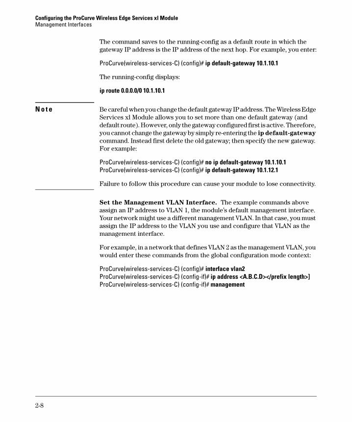
The command saves to the running-config as a default route in which the gateway IP address is the IP address of the next hop. For example, you enter:
ProCurve(wireless-services-C) (config)# ip default-gateway 10.1.10.1
The running-config displays:
ip route 0.0.0.0/0 10.1.10.1
N o t e Be careful when you change the default gateway IP address. The Wireless Edge Services xl Module allows you to set more than one default gateway (and default route). However, only the gateway configured first is active. Therefore, you cannot change the gateway by simply re-entering the ip default-gateway
command. Instead first delete the old gateway; then specify the new gateway. For example:
ProCurve(wireless-services-C) (config)# no ip default-gateway 10.1.10.1ProCurve(wireless-services-C) (config)# ip default-gateway 10.1.12.1
Failure to follow this procedure can cause your module to lose connectivity.
Set the Management VLAN Interface. The example commands above assign an IP address to VLAN 1, the module’s default management interface. Your network might use a different management VLAN. In that case, you must assign the IP address to the VLAN you use and configure that VLAN as the management interface.
For example, in a network that defines VLAN 2 as the management VLAN, you would enter these commands from the global configuration mode context:
ProCurve(wireless-services-C) (config)# interface vlan2ProCurve(wireless-services-C) (config-if)# ip address <A.B.C.D></prefix length>]ProCurve(wireless-services-C) (config-if)# management
2-8
Configuring the ProCurve Wireless Edge Services xl ModuleManagement Interfaces
Enable Secure Management. Secure management forces managers to access the Wireless Edge Services xl Module at the IP address configured on the management VLAN.
For example, you configure VLAN 2 as the management VLAN, and the module’s IP address on VLAN 2 is 10.1.2.30. The module also has an IP address on VLAN 4: 10.1.4.30. By default, you can enter either IP address in your Web browser and access the module’s Web browser interface. However, if you enable secure management, you must enter 10.1.2.30 in your Web browser.
Enter this command from the global configuration mode context to enable secure management:
ProCurve(wireless-services-C) (config)# management secure
Secure management filters management traffic according to the destination address only. In other words, in the example above, secure management forces you to manage the Wireless Edge Services xl Module through its IP address on VLAN 2. However, your management station could be on VLAN 4 and its traffic routed to VLAN 2. To restrict management access to devices in the management VLAN only, you must configure access control lists (ACLs) on the module’s uplink port, on routing devices in your network, or on both.
Accessing the Web Browser Interface
You can access the Web browser interface in one of two ways:
■ Enter the IP address (or hostname) assigned to the Wireless Edge Services xl Module as the URL in your Web browser.
■ Access the Web browser interface for the wireless services-enabled switch.
Entering the IP Address in a Web Browser. Once you know the IP address assigned to the Wireless Edge Services xl Module, enter that address as the URL in your Web browser. For example, if you assigned the Wireless Edge Services xl Module the IP address 192.168.5.20, you would enter http://192.168.5.20 as the URL in your Web browser. (On a module that has multiple IP addresses, you can enter any address, or—if you have enabled secure management—only the address on the management VLAN.)
The first time that you access the Web browser interface, a Security-Warning screen may be displayed, including the following warning: “The application’s signature is invalid. Do you want to run the applications?” Click the Run button to continue.
2-9
Configuring the ProCurve Wireless Edge Services xl ModuleManagement Interfaces
Accessing the Web Browser Interface for the Wireless Services-
Enabled Switch. You can also access the module’s Web browser interface from the Web browser interface for the wireless services-enabled switch. (Like the module’s Web browser interface, the switch’s Web browser interface uses Java applets.) To access the switch’s Web browser interface, enter the IP address for the management interface as the URL in your Web browser. For example, if the management interface has the IP address 192.168.5.1, you would enter http://192.168.5.1.
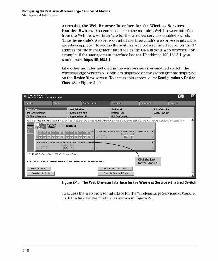
Like other modules installed in the wireless services-enabled switch, the Wireless Edge Services xl Module is displayed on the switch graphic displayed on the Device View screen. To access this screen, click Configuration > Device View. (See Figure 2-1.)
Figure 2-1. The Web Browser Interface for the Wireless Services-Enabled Switch
To access the Web browser interface for the Wireless Edge Services xl Module, click the link for the module, as shown in Figure 2-1.
Click the Link for the Module
2-10

Configuring the ProCurve Wireless Edge Services xl ModuleManagement Interfaces
Logging in to the Web Browser Interface
Whichever way you attempt to access the Web browser interface, you are prompted to enter a username and password. (See Figure 2-2.)
Figure 2-2. Logging In to the Module’s Web Browser Interface
In the Username field, enter manager, and in the Password field, enter the default password procurve. (The Wireless Edge Services xl Module also supports the operator user. For more information, see “Default SNMP v3 Users—Manager and Operator” on page 2-26.)
N o t e To protect your network, ProCurve Networking strongly recommends that you immediately change the password for the manager and operator users. (See “Changing Passwords for Default Users Through SNMP v3” on page 2-36.)
2-11

Configuring the ProCurve Wireless Edge Services xl ModuleManagement Interfaces
Overview of the Web Browser Interface
The Web browser interface includes a navigation bar on the left. (See Figure 2-3.) Using this navigation bar, you can access:
■ Information screens that help you manage and troubleshoot your wireless services
■ Configuration screens that allow you to tailor wireless services for your particular environment
Figure 2-3. Example of a Configuration Screen
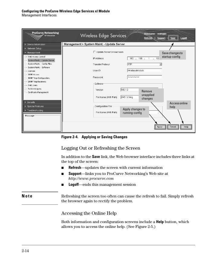
Applying or Saving Changes
When you use the Web browser interface to configure the Wireless Edge Services xl Module, these changes may affect two configuration files, depend-ing on whether you apply or save changes:
■ startup-config—When you save changes, these changes become part of the startup-config file, which is stored in non-volatile RAM (NVRAM) on the module’s internal flash. When the Wireless Edge Services xl Module is rebooted, all of the configurations that are contained in the startup-config file are retained. During the reboot process, the module initializes the designated boot image software and then loads the startup-config.
Navigation bar
2-12
Configuring the ProCurve Wireless Edge Services xl ModuleManagement Interfaces
■ running-config—When the Wireless Edge Services xl Module loads the startup-config, all the configurations become part of the running-config, which is held in RAM. When you make and apply configuration changes in the Web browser interface, these changes become part of the running-config as well. Unless you save the changes that you apply to the running-config, these changes are not retained when the Wireless Edge Services xl Module is rebooted.
Applying Changes to the running-config. You can make and apply con-figuration changes to the running-config in different ways:
■ Apply button—On some configuration screens, you make configuration changes and then click the Apply button.
■ Enable button—In some instances, you enable functionality by clicking the Enable button. To deactivate the functionality, you click the Disable button.
■ OK button in Add or Edit screens—To add information or edit configura-tions, you click the Add or Edit button, make configuration changes on the screen that is displayed, and then click the OK button. (In some cases you can delete specific configurations by clicking the Delete button.)
After you enter changes in a configuration screen but before you click one of these buttons, you have the option of backing out, or deleting, the changes. To back out changes not yet applied to the running-config, click the Revert button. (See Figure 2-4.)
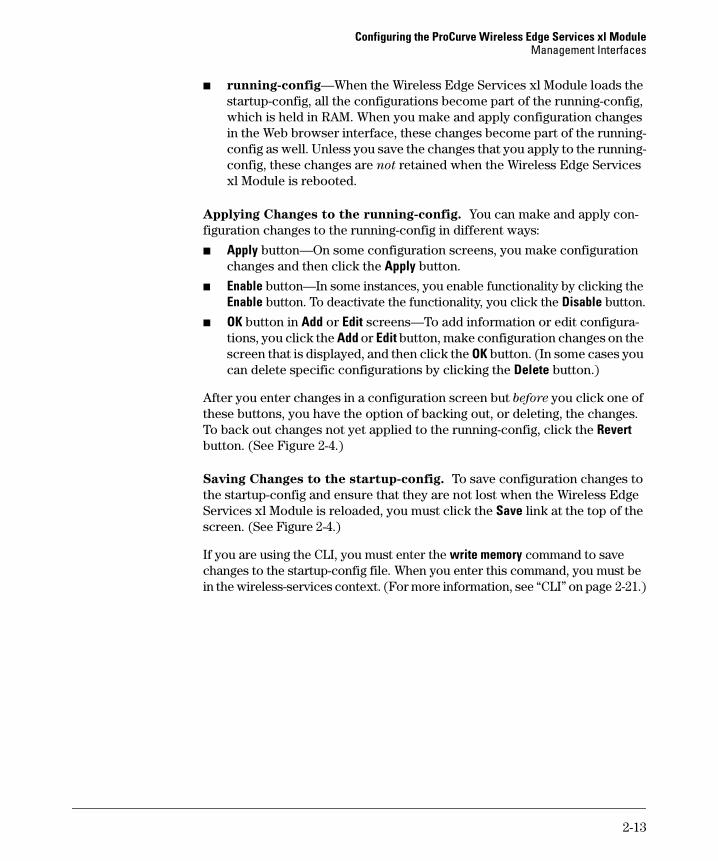
Saving Changes to the startup-config. To save configuration changes to the startup-config and ensure that they are not lost when the Wireless Edge Services xl Module is reloaded, you must click the Save link at the top of the screen. (See Figure 2-4.)
If you are using the CLI, you must enter the write memory command to save changes to the startup-config file. When you enter this command, you must be in the wireless-services context. (For more information, see “CLI” on page 2-21.)
2-13
Configuring the ProCurve Wireless Edge Services xl ModuleManagement Interfaces
Figure 2-4. Applying or Saving Changes
Logging Out or Refreshing the Screen
In addition to the Save link, the Web browser interface includes three links at the top of the screen:
■ Refresh—updates the screen with current information
■ Support—links you to ProCurve Networking’s Web site at http://www.procurve.com
■ Logoff—ends this management session
N o t e Refreshing the screen too often can cause the refresh to fail. Simply refresh the browser again to rectify the problem.
Accessing the Online Help
Both information and configuration screens include a Help button, which allows you to access the online help. (See Figure 2-5.)
Apply changes to running-config
Access online help
Remove unapplied changes
Save changes to startup-config
2-14

Configuring the ProCurve Wireless Edge Services xl ModuleManagement Interfaces
Figure 2-5. Help Navigator Screen
From the Help Navigator screen, you can select one of the following tabs:
■ Content—The Content tab provides a list of available topics. You simply double-click a topic to view the Help information.
■ Search—The Search tab allows you to enter keywords or Boolean expres-sions to find all the information about a specific topic. When the results of the search are listed, select one of the topics and click the Open button to view the Help information.
2-15
Configuring the ProCurve Wireless Edge Services xl ModuleManagement Interfaces
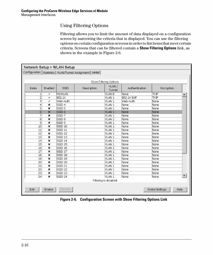
Using Filtering Options
Filtering allows you to limit the amount of data displayed on a configuration screen by narrowing the criteria that is displayed. You can use the filtering options on certain configuration screens in order to list items that meet certain criteria. Screens that can be filtered contain a Show Filtering Options link, as shown in the example in Figure 2-6.
Figure 2-6. Configuration Screen with Show Filtering Options Link
2-16
Configuring the ProCurve Wireless Edge Services xl ModuleManagement Interfaces
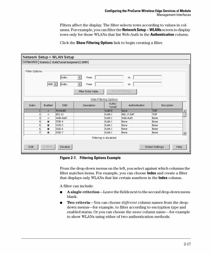
Filters affect the display. The filter selects rows according to values in col-umns. For example, you can filter the Network Setup > WLANs screen to display rows only for those WLANs that list Web-Auth in the Authentication column.
Click the Show Filtering Options link to begin creating a filter.
Figure 2-7. Filtering Options Example
From the drop-down menus on the left, you select against which columns the filter matches items. For example, you can choose Index and create a filter that displays only WLANs that list certain numbers in the Index column.
A filter can include:
■ A single criterion—Leave the fields next to the second drop-down menu blank.
■ Two criteria—You can choose different column names from the drop-down menus—for example, to filter according to encryption type and enabled status. Or you can choose the same column name—for example to show WLANs using either of two authentication methods.
2-17

Configuring the ProCurve Wireless Edge Services xl ModuleManagement Interfaces
When you select two criteria, you must use Boolean operators to link the two:
■ AND—Only rows that match both criteria display.
■ OR—Rows that match either or both criteria display.
In the fields to the right of the drop-down menus (see Figure 2-7 on page 2-17), you create the actual filter. The format for the filter depends on the type of column:
■ Match operators—for columns that include a string.
In the field on the right, you enter the string that must be included in the specified column. For example, if Encryption was selected from the drop-down menu on the left, you could enter TKIP. The string match is case sensitive.
You also select, from a drop-down menu in the middle, the degree to which the string in a column must match the string in the filter. You can choose:
• contain—The column must contain the specified string, but can also include other characters.
• exactly match—The column must include only the specified string.
• start with—The string in the column must start with the specified string, but can include characters after the string.
• end with—The string in the column must end with the specified string, but can include characters before the string.
■ True or false—for columns that have either a green check mark or red X. You choose whether the filter selects items for which the criteria is True (the column has a green check mark) or False (the column has a red X).
■ From and to fields—for columns that list numbers, such as index numbers. The range is inclusive—that is, the filter matches the number in the From field, the number in the to field, or any number between the two.
To use the filtering options on a screen that can be filtered, complete the following steps:
1. On the screen, click Show Filtering Options.
A Filter Options section is displayed on the screen, similar to the example shown in Figure 2-8.
2-18
Configuring the ProCurve Wireless Edge Services xl ModuleManagement Interfaces
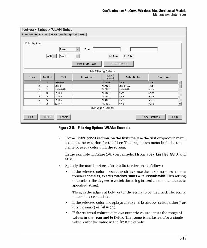
Figure 2-8. Filtering Options WLANs Example
2. In the Filter Options section, on the first line, use the first drop-down menu to select the criterion for the filter. The drop-down menu includes the name of every column in the screen.
In the example in Figure 2-8, you can select from Index, Enabled, SSID, and so on.
3. Specify the match criteria for the first criterion, as follows:
• If the selected column contains strings, use the next drop-down menu to select contains, exactly matches, starts with, or ends with. This setting determines the degree to which the string in a column must match the specified string.
Then, in the adjacent field, enter the string to be matched. The string match is case sensitive.
• If the selected column displays check marks and Xs, select either True (check mark) or False (X).
• If the selected column displays numeric values, enter the range of values in the From and to fields. The range is inclusive. For a single value, enter the value in the From field only.
2-19
Configuring the ProCurve Wireless Edge Services xl ModuleManagement Interfaces
4. If you are also filtering for a second criterion, on the second line, use the drop-down menu to select the Boolean operator for linking the two criteria:
• AND—to list items that meet the criteria on both lines
• OR—to list items that meet the criteria on either line
The OR operator is not an “exclusive OR” operator; it will list items that meet the criteria on either or both lines.
5. If you are also filtering for a second criterion, on the remainder of the second line complete steps 2 and 3 for this criterion.
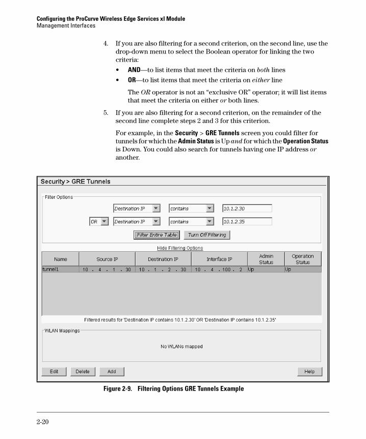
For example, in the Security > GRE Tunnels screen you could filter for tunnels for which the Admin Status is Up and for which the Operation Status is Down. You could also search for tunnels having one IP address or another.
Figure 2-9. Filtering Options GRE Tunnels Example
2-20
Configuring the ProCurve Wireless Edge Services xl ModuleManagement Interfaces
6. After you set the filter criteria, click the Filter Entire Table button. Only the tunnels that match the filter are now listed on the screen. If you want, you can refine your filter criteria and click the Filter Entire Table button again.
N o t e Throughout the Wireless Edge Services xl Module interface (whether or not you are using filtering), you can sort data lines by clicking on the respective column headings. For example, on the screen shown in Figure 2-8, you can click on the SSID column heading to sort the data alphabetically by the SSID name. Click the heading once to sort the column in ascending order (an up-arrow is displayed), and then click the heading again to sort the column in descending order (a down-arrow is displayed). Click the heading a third time to return the column to its original sort order (the arrow will no longer be displayed).
7. When you are finished viewing the filtered results, click the Turn Off Filtering button in order for all tunnels to be listed on the screen.
To hide the filtering options on the screen, click the Hide Filtering Options link. Although the filter itself is hidden, the screen continues to display only the rows that match the filter. To turn off filtering, click the Show Filtering Options link and then click the Turn Off Filtering button.
CLI
You access the Wireless Edge Services xl Module CLI through the CLI for the wireless services-enabled switch. You can access the switch CLI through:
■ serial session
■ Telnet session
■ SSH session
Accessing the Switch CLI Through a Serial Session
If you use a serial session to connect to the wireless services-enabled switch, use the serial cable (5184-1894) that was shipped with the switch. Then run terminal session software such as Tera Term or HyperTerminal on your workstation, setting the following parameters for the session:
■ Baud Rate = 9600
■ Parity = None
■ Data Bits = 8
■ Stop Bits = 1
■ Flow Control = None
2-21

Configuring the ProCurve Wireless Edge Services xl ModuleManagement Interfaces
When you are prompted for a password, enter the password for the manager user on the wireless services-enabled switch.
Accessing the Switch CLI Through a Telnet or SSH Session
You can also use a Telnet or SSH application to access the CLI for the wireless services-enabled switch. For instructions on establishing a Telnet or SSH session, see the management and configuration guide for your switch.
Accessing the Wireless-Services Context
To begin configuring the Wireless Edge Services xl Module, you must move to the wireless-services context in the switch CLI. In essence, the wireless-services context is a subset of the switch CLI.
To access the wireless-services context, enter this command, either from the basic, enable, or global configuration mode context:
ProCurve# wireless-services <slot letter>
Replace <slot letter> with the letter for the chassis slot in which the Wireless Edge Services xl Module is installed. For example, if the module is installed in slot C, you would enter:
ProCurve# wireless-services c
The CLI prompt shows that you are in the wireless-services context. You access the context with the same rights that you had in the switch CLI:
ProCurve(wireless-services-C)#
If you had only operator rights to the switch CLI, you would enter the command from the switch basic mode context and access the module’s basic mode context:
ProCurve> wireless-services cProCurve(wireless-services-C)>
Navigating the CLI
The wireless-services context allows you to configure and manage the Wire-less Edge Services xl Module. The wireless-services context is organized into the same contexts used in the switch CLI. When you first access the wireless-services context, you are at the enable context, which is identified by the # symbol that follows the “(wireless-services-C)” portion of the prompt.
2-22

Configuring the ProCurve Wireless Edge Services xl ModuleManagement Interfaces
From the enable context, you can enter show commands to view information about the Wireless Edge Services xl Module, and you can perform some operations such as erasing the startup-config file and copying configuration files to and from the module.
To make configuration changes, however, you must move to the global con-figuration context. From the global configuration context, you can enter commands to change settings, or you can access other contexts that allow you to change settings.
To move to the global configuration context for wireless services, enter:
ProCurve(wireless-services-C)# configure terminal
Again, the CLI prompt shows your new context:
ProCurve(wireless-services-C) (config)#
To view the commands available at any context, you can use a question mark:
ProCurve(wireless-services-C) (config)# ?
You can also use the question mark to view the options available for specific commands:
ProCurve(wireless-services-C) (config)# ip ?
Saving Changes to the startup-config
When you make configuration changes to the Wireless Edge Services xl Module, you must enter the write memory command to save these changes to the module’s startup-config. When you enter this command, you must be in the wireless-services context:
ProCurve(wireless-services-C)# write memory
If you exit the wireless-services context and enter the write memory command in the CLI for the wireless services-enabled switch, the configuration changes for the Wireless Edge Services xl Module are not saved to its startup-config file.
CLI Commands
See Appendix A, ProCurve Wireless Services xl Module Command Line
Reference for a list of CLI commands for the Wireless Edge Services xl Module and their descriptions.
2-23
Configuring the ProCurve Wireless Edge Services xl ModuleManagement Interfaces
Security
In addition to supporting the latest security standards for wireless communi-cations, the Wireless Edge Services xl Module allows you to secure manage-ment access. To protect communications between the Wireless Edge Services xl Module and your management workstation, the module supports Secure Hypertext Transfer Protocol (HTTPS) over Secure Socket Layer (SSL), and SNMP v3. Management users and their related passwords are also controlled through SNMP v3. You can also use SSH to access the module CLI indirectly.
SSH Access
If you want to access the Wireless Edge Services xl Module CLI from a remote location, consider using SSH to access the wireless services-enabled switch CLI, and through the switch CLI, the module’s. Although you can use Telnet to access the switch CLI (and through it the module CLI), Telnet is not secure from eavesdropping. The SSH protocol, on the other hand, generates public keys to encrypt all the data exchanged between the module and your management workstation. Further, SSH ensures that data traveling over the network arrives unaltered.
HTTPS Access
By default, the Wireless Edge Services xl Module supports both HTTP and HTTPS. When you use HTTPS to access the module’s Web browser interface, the connection between your management workstation and the Wireless Edge Services xl Module is secure. Communications between your workstation and the module are encrypted.
N o t e You cannot modify the port numbers for HTTP and HTTPS.
SNMP Support
The Wireless Edge Services xl Module supports SNMP v1/v2c, allowing SNMP servers that know the correct community names either complete read-write or read-only access to the module.
The module also supports SNMP v3, a more secure—and flexible—way of controlling the users and SNMP servers allowed management privileges to the Wireless Edge Services xl Module.
2-24

Configuring the ProCurve Wireless Edge Services xl ModuleManagement Interfaces
SNMP v3 encrypts management communications. For example, SNMP v3 support secures messages between the Java applet running the Web browser interface and your management workstation even when you use HTTP rather than HTTPS.
SNMP Communities. SNMP v1/v2c uses communities to control various types of management access. In order for an SNMP v1/v2c server to access the SNMP agent running on a device such as the Wireless Edge Services xl Module, the server must know at least one of the community names configured on the device. Each community name is assigned an access control: read-only or read-write. The access control assigned to the community determines the operations that an SNMP server can complete on the Wireless Edge Services xl Module.
A server that knows a device’s read-only community name can view, but not alter, settings and other information stored on that device. For example, you might want a particular SNMP server to only monitor traffic on the device. An SNMP server that knows a device’s read-write community name can change its configuration in addition to viewing information about it.
The Wireless Edge Services xl Module uses the following community names:
■ public
■ private
■ trap
By default, the public and trap communities have read-only access, and the private community has read-write access.
For more information on configuring communities, see “SNMP Communities” on page 2-108. For more information on setting up traps, see “Enabling SNMP Traps” on page 2-113.
You can also control management access and traps with SNMP v3, as described in the next section.
SNMP v3 Users. The management users for the Wireless Edge Services xl Module are controlled through SNMP v3.
SNMP v3 allows you to create multiple users with different levels of access. For example, instead of configuring a community name on an SNMP v3 server, you can configure it with its own username, password, and management privileges.
2-25
Configuring the ProCurve Wireless Edge Services xl ModuleManagement Interfaces
In addition, SNMP v3 secures communications between the user and the managed device, transforming the traffic with an encryption algorithm, an authentication algorithm, or both.
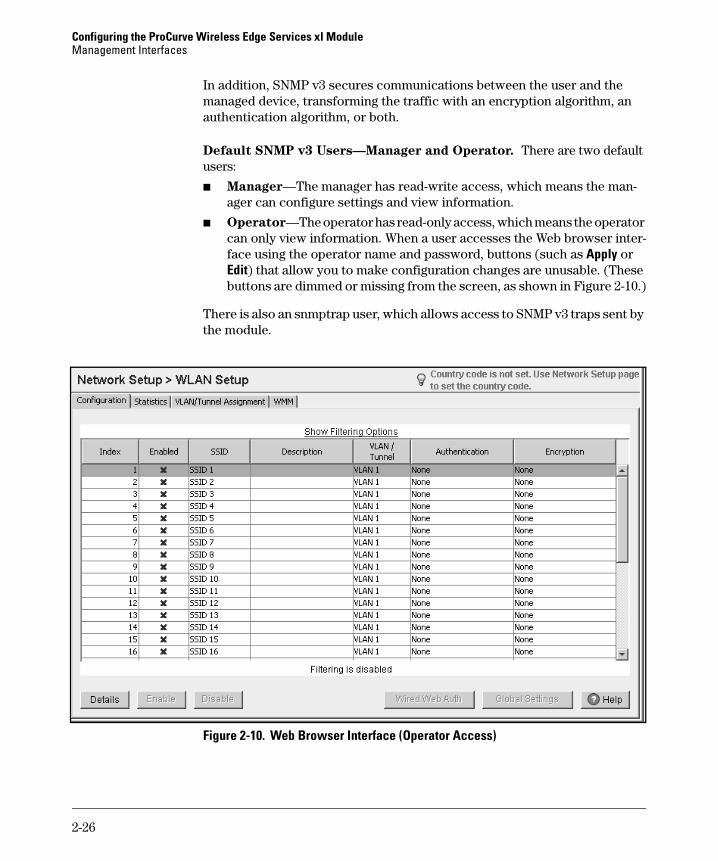
Default SNMP v3 Users—Manager and Operator. There are two default users:
■ Manager—The manager has read-write access, which means the man-ager can configure settings and view information.
■ Operator—The operator has read-only access, which means the operator can only view information. When a user accesses the Web browser inter-face using the operator name and password, buttons (such as Apply or Edit) that allow you to make configuration changes are unusable. (These buttons are dimmed or missing from the screen, as shown in Figure 2-10.)
There is also an snmptrap user, which allows access to SNMP v3 traps sent by the module.
Figure 2-10. Web Browser Interface (Operator Access)
2-26

Configuring the ProCurve Wireless Edge Services xl ModuleManagement Interfaces
The operator user is particularly useful if you want to assign a new IT staff member the task of monitoring certain module functions; however, you do not want this IT staff member to change the existing configuration. In this case, you could give this IT staff member the password for the operator user but reserve the manager user password for only senior-level IT staff.
To learn how to add new SNMP v3 users, see “Configuring Web-Users” on page 2-40.
Controlling Management Access to the Module
This section teaches you how to control Web management access to the Wireless Edge Services xl Module. It explains how to:
■ enable and disable HTTP and HTTPS access
■ configure the internal FTP server
■ choose SNMP versions
■ change passwords for the default SNMP v3 users (manager and operator)
■ create new Web-Users—users allowed to access the module’s Web browser interface with various privileges
Enabling HTTP and HTTPS Access to the Module
As described in “Security” on page 2-24, the Wireless Edge Services xl Module includes an HTTP server and an HTTPS server, which run the module’s Web browser interface. (Access to the interface is controlled by SNMP v3.)
By default, both servers are enabled. You can disable either or both of these servers. (Of course, if you disable both, you will only be able to configure the module through the CLI.)
Follow these steps to enable and disable HTTP and HTTPS:
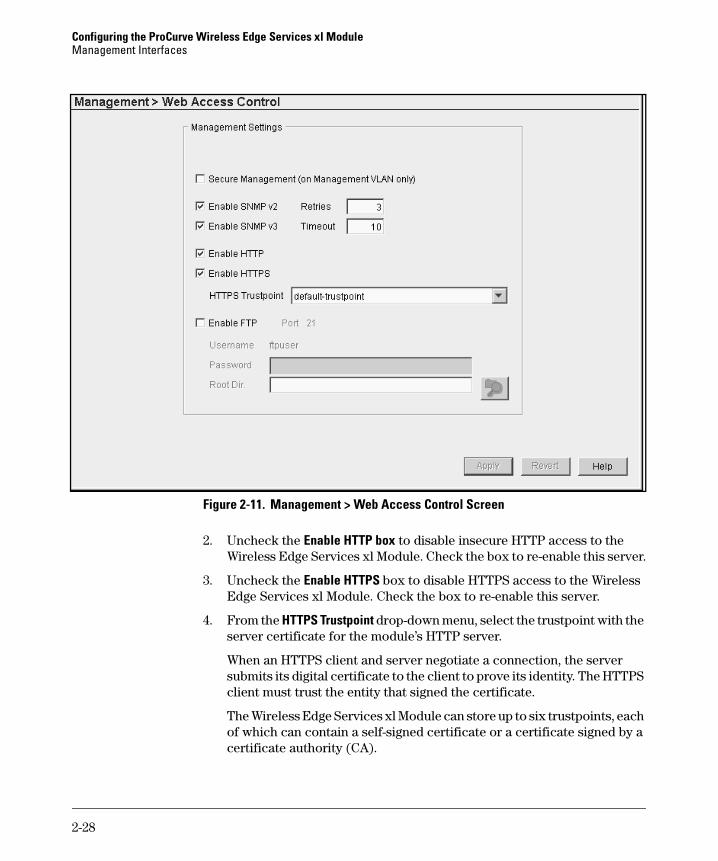
1. Select Management > Web Access Control.
2-27
Configuring the ProCurve Wireless Edge Services xl ModuleManagement Interfaces
Figure 2-11. Management > Web Access Control Screen
2. Uncheck the Enable HTTP box to disable insecure HTTP access to the Wireless Edge Services xl Module. Check the box to re-enable this server.
3. Uncheck the Enable HTTPS box to disable HTTPS access to the Wireless Edge Services xl Module. Check the box to re-enable this server.
4. From the HTTPS Trustpoint drop-down menu, select the trustpoint with the server certificate for the module’s HTTP server.
When an HTTPS client and server negotiate a connection, the server submits its digital certificate to the client to prove its identity. The HTTPS client must trust the entity that signed the certificate.
The Wireless Edge Services xl Module can store up to six trustpoints, each of which can contain a self-signed certificate or a certificate signed by a certificate authority (CA).
2-28
Configuring the ProCurve Wireless Edge Services xl ModuleManagement Interfaces
By default, the HTTPS server submits the self-signed certificate in the default-trustpoint. The HTTPS Trustpoint drop-down menu includes this trustpoint and any other trustpoint configured on the module.
The drop-menu also includes the <Create New Certificate> option. Select this option to open the Certificates Wizard, which guides you through the process of creating or installing a certificate. For more information about digital certificates and the Certificates Wizard, see “Digital Certificates” on page 2-165.
5. Click the Apply button.
N o t e By default, users can reach the Wireless Edge Services xl Module’s Web browser interface at any IP address configured on the module. Secure man-agement forces the module to open sessions only with users that destine their traffic to the module’s management VLAN IP address.
To enable this option, check the Secure Management (or Management VLAN only) box in the Management > Web Access Control screen. Then click the Apply button.
Choosing SNMP Versions
As described in “SNMP Support” on page 2-24, the Wireless Edge Services xl Module supports both SNMP v2 and SNMP v3. By default, both versions are enabled. You can disable either version.
For example, you might disable SNMP v2 to avoid sending management data in plaintext. Before disabling SNMP v2, make sure that your SNMP server supports SNMP v3 and that it knows the username and password for an SNMP v3 user configured on the module.
Take care when disabling SNMP v3: because this protocol controls communi-cations between management stations and the Java applet, disabling SNMP v3 disables all access to the Web browser interface. You must then configure the module through the CLI. To re-enable Web access, enter this global configuration mode command: snmp-server manager v3.
To enable and disable either (or both) SNMP versions, as well as to configure various other options, follow these steps:
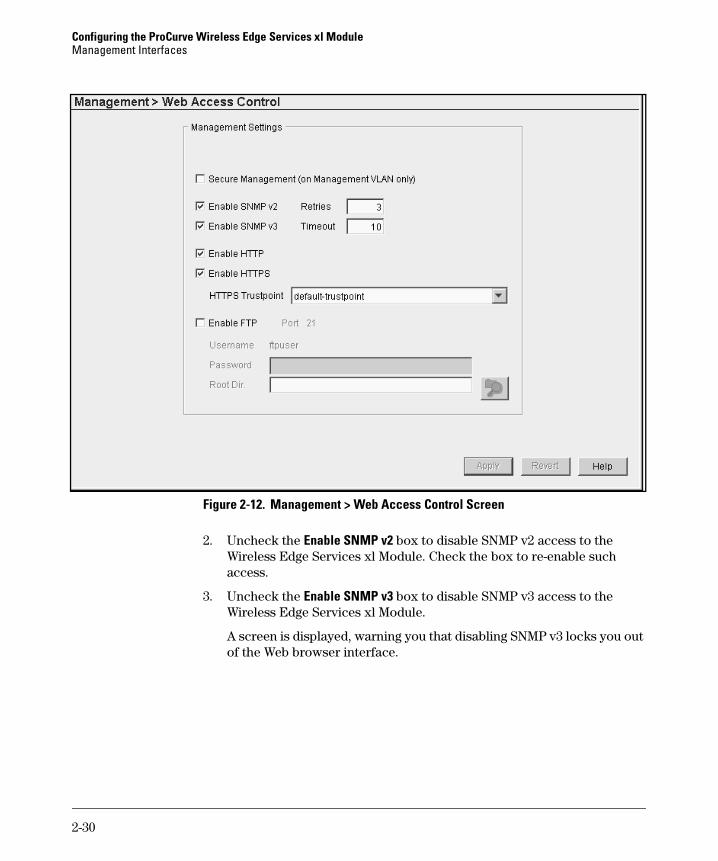
1. Select Management > Web Access Control.
2-29
Configuring the ProCurve Wireless Edge Services xl ModuleManagement Interfaces
Figure 2-12. Management > Web Access Control Screen
2. Uncheck the Enable SNMP v2 box to disable SNMP v2 access to the Wireless Edge Services xl Module. Check the box to re-enable such access.
3. Uncheck the Enable SNMP v3 box to disable SNMP v3 access to the Wireless Edge Services xl Module.
A screen is displayed, warning you that disabling SNMP v3 locks you out of the Web browser interface.
2-30

Configuring the ProCurve Wireless Edge Services xl ModuleManagement Interfaces
Figure 2-13. Disable SNMP V3 Warning
If you are sure that you want to disable SNMP v3 and Web access, click the Yes button. You have one more chance to change your mind: you must click the Apply button in the Management > Web Access Control to actually disable the server.
4. Configure other SNMP options:
a. In the Retries field, enter the number of times that the Wireless Edge Services xl Module should re-attempt to send an SNMP message that times out.
The default value is 3.
b. In the Timeout field, specify in seconds how long the module should wait before timing out an SNMP message.
The default value is 10 seconds.
5. Click the Apply button.
Choosing SNMP versions is only one step to configuring SNMP:
■ See “Configuring Web-Users” on page 2-40 to learn how to create SNMP v3 users.
■ See “SNMP Traps and Error Reporting” on page 2-108 to learn how to set up SNMP traps and configure SNMP communities.
2-31
Configuring the ProCurve Wireless Edge Services xl ModuleManagement Interfaces
Setting Up the Internal FTP Server
The Wireless Edge Services xl Module includes an FTP server, which can send files stored in the module’s flash memory to FTP clients. For example, you could upload a configuration file directly from one module to another—eliminating the middle step of transferring the file to an external FTP server.
The FTP server has these properties:
■ Port—The server listens on the standard FTP port, 21. You cannot alter the port number.
■ Username—The default username is “ftpuser” and cannot be altered.
■ Password—The FTP client must submit the correct password to receive the requested file.
■ Root directory—The Wireless Edge Services xl Module searches this directory for requested files. You can specify the module’s entire flash memory or a directory within the flash.
By default, the FTP server is disabled.
Follow these steps to set up the internal server:
1. Select Management > Web Access Control.
2. Check the Enable FTP box.
2-32

Configuring the ProCurve Wireless Edge Services xl ModuleManagement Interfaces
Figure 2-14. Setting Up the Internal FTP Server
3. In the Password box, enter a string, which can include alphanumeric and special characters.
4. In the Root Dir field, specify the name of the directory with the files that clients will request.
For example, enter flash:/.
If the file is stored in a directory within flash, the client must request the file with the correct extension.
You can click the browse button to search for a different directory or to create a new directory. See the steps below for more information on this option.
5. Click the Apply button.
Browse button
2-33
Configuring the ProCurve Wireless Edge Services xl ModuleManagement Interfaces
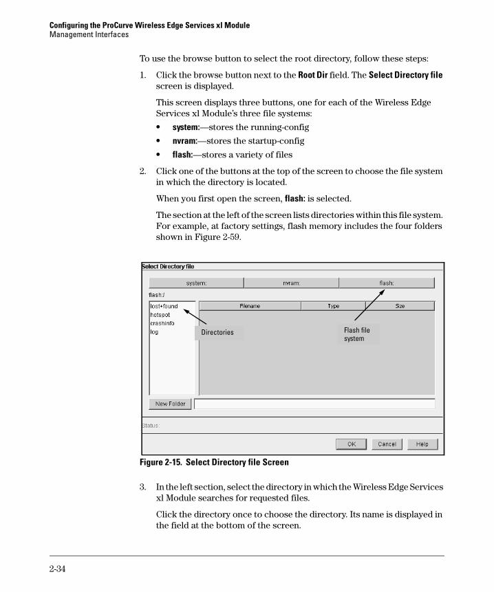
To use the browse button to select the root directory, follow these steps:
1. Click the browse button next to the Root Dir field. The Select Directory file screen is displayed.
This screen displays three buttons, one for each of the Wireless Edge Services xl Module’s three file systems:
• system:—stores the running-config
• nvram:—stores the startup-config
• flash:—stores a variety of files
2. Click one of the buttons at the top of the screen to choose the file system in which the directory is located.
When you first open the screen, flash: is selected.
The section at the left of the screen lists directories within this file system. For example, at factory settings, flash memory includes the four folders shown in Figure 2-59.
Figure 2-15. Select Directory file Screen
3. In the left section, select the directory in which the Wireless Edge Services xl Module searches for requested files.
Click the directory once to choose the directory. Its name is displayed in the field at the bottom of the screen.
Flash file system
Directories
2-34
Configuring the ProCurve Wireless Edge Services xl ModuleManagement Interfaces
Click the directory twice to view and select subdirectories within that directory. To return to the original directory, click [up one level], which is displayed in the left section with the subdirectories.
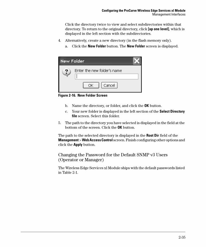
4. Alternatively, create a new directory (in the flash memory only).
a. Click the New Folder button. The New Folder screen is displayed.
Figure 2-16. New Folder Screen
b. Name the directory, or folder, and click the OK button.
c. Your new folder is displayed in the left section of the Select Directory file screen. Select this folder.
5. The path to the directory you have selected is displayed in the field at the bottom of the screen. Click the OK button.
The path to the selected directory is displayed in the Root Dir field of the Management > Web Access Control screen. Finish configuring other options and click the Apply button.
Changing the Password for the Default SNMP v3 Users (Operator or Manager)
The Wireless Edge Services xl Module ships with the default passwords listed in Table 2-1.
2-35
Configuring the ProCurve Wireless Edge Services xl ModuleManagement Interfaces
Table 2-1. Default Passwords for the Operator and Manager Users
To protect your network, you should change the passwords for both users. Because the usernames and passwords are managed through SNMP v3, you must select a password that meets SNMP v3 standards: the password must be at least eight characters.
The password does not only authenticate the user. The password also func-tions as the key for the following algorithms that secure SNMP v3 communi-cations:
■ Hash Message Authentication Code-Message Digest 5 (HMAC-MD5), a hash algorithm that ensures data integrity
■ Cipher Block Chaining-Data Encryption Standard (CBC-DES), an encryp-tion algorithm that ensures data privacy
You can change the passwords either through the SNMP v3 settings or through the Web-User settings. The most recent configuration takes precedence.
Changing Passwords for Default Users Through SNMP v3. To change the passwords through the SNMP v3 settings, complete these steps:
1. Select Management > SNMP Access and click the V3 tab.
User Password
operator operator
manager procurve
2-36

Configuring the ProCurve Wireless Edge Services xl ModuleManagement Interfaces
Figure 2-17. Management > SNMP Access > V3 Screen
2. Select the username that you want to modify, and then click the Edit button. The Edit SnmpV3 screen is displayed.
2-37

Configuring the ProCurve Wireless Edge Services xl ModuleManagement Interfaces
Figure 2-18. Edit SnmpV3 Screen
3. In the Old Password field, enter the current password.
4. In the New Password and Confirm Password fields, enter the new password.
5. Click the OK button.
If you change the password for the manager user, you are logged out of the Web browser interface and must enter the new password in order to log back in to the interface.
2-38
Configuring the ProCurve Wireless Edge Services xl ModuleManagement Interfaces
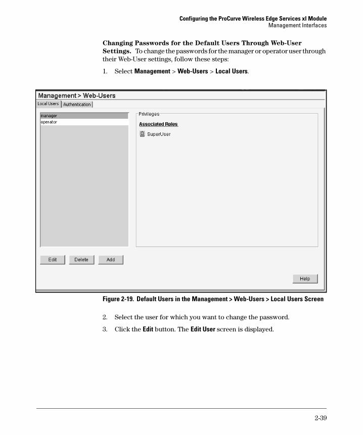
Changing Passwords for the Default Users Through Web-User
Settings. To change the passwords for the manager or operator user through their Web-User settings, follow these steps:
1. Select Management > Web-Users > Local Users.
Figure 2-19. Default Users in the Management > Web-Users > Local Users Screen
2. Select the user for which you want to change the password.
3. Click the Edit button. The Edit User screen is displayed.
2-39
Configuring the ProCurve Wireless Edge Services xl ModuleManagement Interfaces
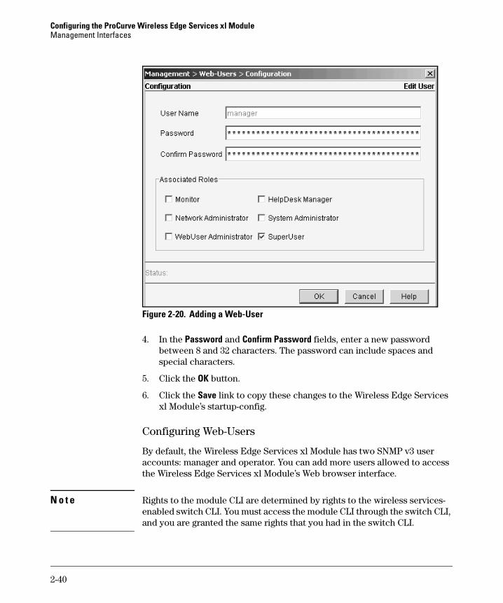
Figure 2-20. Adding a Web-User
4. In the Password and Confirm Password fields, enter a new password between 8 and 32 characters. The password can include spaces and special characters.
5. Click the OK button.
6. Click the Save link to copy these changes to the Wireless Edge Services xl Module’s startup-config.
Configuring Web-Users
By default, the Wireless Edge Services xl Module has two SNMP v3 user accounts: manager and operator. You can add more users allowed to access the Wireless Edge Services xl Module’s Web browser interface.
N o t e Rights to the module CLI are determined by rights to the wireless services-enabled switch CLI. You must access the module CLI through the switch CLI, and you are granted the same rights that you had in the switch CLI.
2-40
Configuring the ProCurve Wireless Edge Services xl ModuleManagement Interfaces
The Wireless Edge Services module can authenticate these users against a local list of users, or you can have a RADIUS server authenticate the users.
By default, the module uses its local list to authenticate the users.
In either case, you must add users to the local list to assign the user a role, which determines the user’s rights.
Web-User Roles. You can select one or more of six roles for a user:
■ Monitor—read-only rights (the default account, operator, has this role):
• view settings and statistics, including detailed information
• export statistics and other device information
■ HelpDesk Manager—read-only rights and the ability to collect trouble-shooting information:
• view settings and statistics, including detailed information
• export statistics and other device information
• configure logging (Management > System Logging screens)
• transfer core and panic snapshots (Troubleshooting screens)
■ Network Administrator—read-write rights to most of the Wireless Edge Services xl Module’s capabilities:
• view settings and statistics, including detailed information
• export statistics and other device information
• complete any task in the Network Setup screens, including:– add, delete, and edit VLAN interfaces– configure Internet Protocol settings (such as routes)– configure radio and radio adoption default settings– add, delete, and edit WLANs– set up redundancy and Layer 3 mobility groups– configure DHCP services– configure the internal RADIUS server
• complete most tasks in the Security screens, including:– create Media Access Control (MAC) filters– add and delete ACLs and apply them to interfaces (not editing
existing ACLs)– configure dynamic NAT
• complete all tasks in the Special screens, except configure sFlow
2-41
Configuring the ProCurve Wireless Edge Services xl ModuleManagement Interfaces
■ System Administrator—read-only rights and rights to management tasks:
• view settings and statistics, including detailed information
• export statistics and other device information
• complete limited tasks in the Network Setup screens:– add, delete, and edit VLAN interfaces– configure Internet Protocol settings (such as routes)
• complete any task in the Management screens, including:– control access to the Web browser interface, including adding and
editing Web-users– configure the Update Server– manage configuration files and software images– install licenses – add digital certificates– configure SNMP and system logging
• set up secure Network Time Protocol (NTP) (Special > Secure NTP screens)
■ WebUser Administrator—rights to add guest user accounts to the Wireless Edge Services xl Module’s internal RADIUS database
The database must already include at least one guest group.
■ SuperUser—complete read-write access to the module
The default user account, manager, has this role. A SuperUser can com-plete any task that any other type of user can complete.
You can assign a user more than one role. For example, you could make a user both a HelpDesk Manager and a System Administrator. However, the WebUser Administrator can only play that single role.
Adding a Web-User. Follow these steps to add a Web-User:
1. Select Management > Web-Users > Local Users.
Initially, the screen lists the two default SNMPv3 users. If you select a user, the user’s roles display in the Privileges section.
2-42

Configuring the ProCurve Wireless Edge Services xl ModuleManagement Interfaces
Figure 2-21. Management > Web-Users > Local Users Screen
2. Click the Add button. The Add User screen is displayed.
2-43
Configuring the ProCurve Wireless Edge Services xl ModuleManagement Interfaces
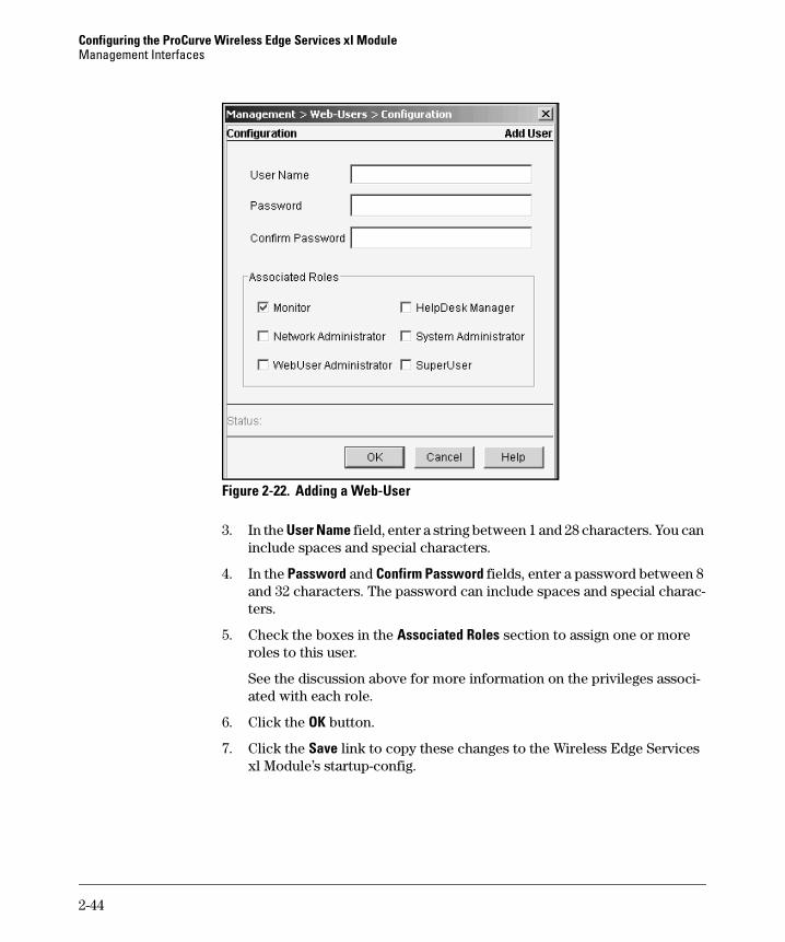
Figure 2-22. Adding a Web-User
3. In the User Name field, enter a string between 1 and 28 characters. You can include spaces and special characters.
4. In the Password and Confirm Password fields, enter a password between 8 and 32 characters. The password can include spaces and special charac-ters.
5. Check the boxes in the Associated Roles section to assign one or more roles to this user.
See the discussion above for more information on the privileges associ-ated with each role.
6. Click the OK button.
7. Click the Save link to copy these changes to the Wireless Edge Services xl Module’s startup-config.
2-44
Configuring the ProCurve Wireless Edge Services xl ModuleManagement Interfaces
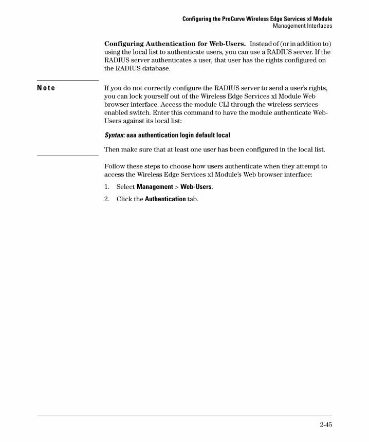
Configuring Authentication for Web-Users. Instead of (or in addition to) using the local list to authenticate users, you can use a RADIUS server. If the RADIUS server authenticates a user, that user has the rights configured on the RADIUS database.
N o t e If you do not correctly configure the RADIUS server to send a user’s rights, you can lock yourself out of the Wireless Edge Services xl Module Web browser interface. Access the module CLI through the wireless services-enabled switch. Enter this command to have the module authenticate Web-Users against its local list:
Syntax: aaa authentication login default local
Then make sure that at least one user has been configured in the local list.
Follow these steps to choose how users authenticate when they attempt to access the Wireless Edge Services xl Module’s Web browser interface:
1. Select Management > Web-Users.
2. Click the Authentication tab.
2-45
Configuring the ProCurve Wireless Edge Services xl ModuleManagement Interfaces
Figure 2-23. Configuring Authentication for Web-Users
3. Choose the primary authentication method from the Preferred method drop-down menu.
You can choose local (which is the list of local users configured on the Local Users tab) or radius.
4. If you want to use both authentication methods, choose the other method from the Alternate method drop-down menu.
If the preferred method fails, the alternate is attempted. Note that “fails” means that the authentication service is unavailable, not that the user’s authentication attempt fails.
5. Optionally, check the If authentication services are unavailable, allow read-only access box.
All users are granted read-only (monitor) access when the selected authentication services are unavailable.
2-46

Configuring the ProCurve Wireless Edge Services xl ModuleManagement Interfaces
If you do not check the box and authentication services become unavailable, users will have not access to the Web browser interface at all. (They must access the module CLI from the wireless services-enabled switch CLI.)
6. Click the Apply button.
7. If you have selected RADIUS for either authentication method, you must specify the RADIUS server:
a. Click the Add button. The Add RADIUS Server screen is displayed.
Figure 2-24. Specifying the RADIUS Server To Authenticate Web-Users
b. Specify the server’s IP address in the Radius Server IP Address field.
c. Enter your server’s port in the Radius Server Port field.
Typically, enter 1812. The valid range is from 0 to 65535.
d. In the next field, specify the number of times that the module attempts to connect the RADIUS server if it does not receive a reply.
For example, if you enter 3, the module attempts to reach the RADIUS server four times, at the most. It then considers the authentication service unavailable. The valid range is from 0 to 100.
2-47

Configuring the ProCurve Wireless Edge Services xl ModuleManagement Interfaces
e. In the next field, specify how long the module waits for a reply from the RADIUS server before retrying (or, on the final retry, declaring the authentication service unavailable).
The timeout value is in seconds; specify a number from 1 to 1000.
f. In the next field, enter the shared secret.
This string must match the secret specified for the Wireless Edge Services xl Module in the list of clients on the RADIUS server.
g. Click the OK button.
8. Click the Save link to copy these changes to the Wireless Edge Services xl Module’s startup-config.
Logging In to the Module as a WebUser Administrator
WebUser Administrators, with their very limited rights, access a single screen, from which they can manage guest accounts on the local RADIUS database.
N o t e A guest account is a temporary user account, and the user must belong to a guest group.
Before the WebUser Administrator can add guests accounts, a user with Network Administrator or SuperUser privileges must create a guest group on the local RADIUS database.
For more information about the Wireless Edge Services xl Module’s internal RADIUS server, see Chapter 11: RADIUS Server.
To log in as a WebUser administrator, access the Wireless Edge Services xl Module’s Login screen, and enter the username and password for a user with this role.
The screen illustrated in Figure 2-28 is displayed.
2-48

Configuring the ProCurve Wireless Edge Services xl ModuleManagement Interfaces
Figure 2-25. Guest Registration Screen
From this screen, the WebUser Administrator can:
■ create guest accounts
■ view all guest accounts
■ delete guest accounts
■ print records for the guest accounts added during the current manage-ment session
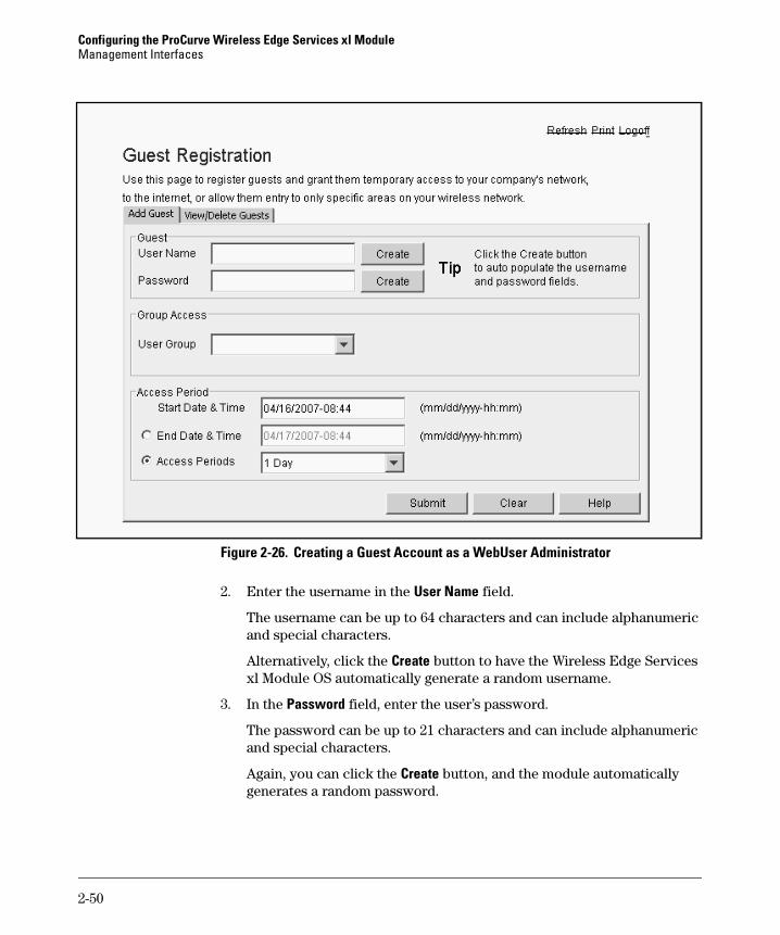
Creating Guest Accounts on the Local RADIUS Database
Follow these steps to add a guest user account:
1. Log in as the WebUser Administrator and access the Guest Registration screen.
2-49
Configuring the ProCurve Wireless Edge Services xl ModuleManagement Interfaces
Figure 2-26. Creating a Guest Account as a WebUser Administrator
2. Enter the username in the User Name field.
The username can be up to 64 characters and can include alphanumeric and special characters.
Alternatively, click the Create button to have the Wireless Edge Services xl Module OS automatically generate a random username.
3. In the Password field, enter the user’s password.
The password can be up to 21 characters and can include alphanumeric and special characters.
Again, you can click the Create button, and the module automatically generates a random password.
2-50

Configuring the ProCurve Wireless Edge Services xl ModuleManagement Interfaces
4. In the User Group drop-down menu, select the name of a guest group policy.
The group policy determines the days of the week and times of day at which the user is allowed to access the network. The group policy can also dictate a dynamic VLAN assignment. (However, dynamic assignment must be enabled on the WLAN to which the guest connects for this setting to take effect.)
The WebUser Administrator cannot create groups. Before the WebUser Administrator creates guest user accounts, someone must log into the Wireless Edge Services xl Module with SuperUser or Network Adminis-trator rights and create at least one guest group.
5. Guest accounts are temporary. Specify the period of validity in the Access Period section:
a. In the Start Date & Time field, choose when the account becomes active.
Enter the date in this format, in which MM is the number of the month, DD is the date, and YYYY is the year:
MM/DD/YYYY
After the date, enter a hyphen (-) and the time in this format, in which HH is the hour in the 24-hour clock and MM is the minutes:
HH:MM
For example, enter:
02/17/2007-08:00
By default, the account’s start date and time is the current time.
b. Specify the date and time at which the account expires (that is, the user can no longer connect) in one of two ways:– Enter an exact date and time in the Expiry Date & Time field.
Use the same format as for the Start Date and Time field. Of course, the expiry time must be later than the start time.
– Specify how long the account remains active from the Access Periods drop-down menu.
You can choose a length from one to six days. You can also choose one to three weeks or one to three months.
The Wireless Edge Services xl Module OS automatically sets the expiry date and time based on start date and time and the speci-fied period of validity.
The Wireless Edge Services xl Module automatically clears out expired accounts every 24 hours. In the meantime, however, no one can use the expired account to connect.
2-51

Configuring the ProCurve Wireless Edge Services xl ModuleManagement Interfaces
6. Click the Submit button.
7. The interface asks you to confirm the creation of the account. Click the Yes button.
At any time before you submit the guest account, you can click the Clear button to erase the settings.
When you are finished managing the guest accounts, click the Logoff link. You do not need to take any further step to save your changes to the startup-config. Clicking the Submit button and confirming the creation of the account commits automatically does so.
Viewing and Deleting Guest Accounts
The WebUser Administrator can also view guest accounts already configured on the Wireless Edge Services xl Module’s local RADIUS database. And he or she can delete these accounts.
Follow these steps:
1. Log in as the WebUser Administrator and access the Guest Registration screen.
2. Click the View/Delete Guests tab.
2-52

Configuring the ProCurve Wireless Edge Services xl ModuleManagement Interfaces
Figure 2-27. Viewing and Deleting Guest Accounts as the WebUser Administrator
3. The screen displays a list of all guest user accounts and the start and end time for these accounts. When you select an account, the Assigned Groups section displays the group of which the user is a member.
4. To delete a user, select the user and click the Delete button.
5. A screen is displayed, informing you that the RADIUS server must restart in order to implement the change. Click the Yes button to confirm the restart. (The server will become very briefly unavailable.)
When you are finished managing the guest accounts, click the Logoff link. You do not need to take any further step to save your changes to the startup-config.
2-53
Configuring the ProCurve Wireless Edge Services xl ModuleManagement Interfaces
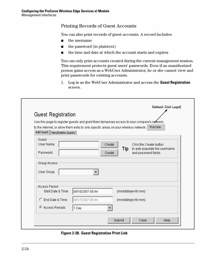
Printing Records of Guest Accounts
You can also print records of guest accounts. A record includes:
■ the username
■ the password (in plaintext)
■ the time and date at which the account starts and expires
You can only print accounts created during the current management session. This requirement protects guest users’ passwords. Even if an unauthorized person gains access as a WebUser Administrator, he or she cannot view and print passwords for existing accounts.
1. Log in as the WebUser Administrator and access the Guest Registration screen.
Figure 2-28. Guest Registration Print Link
Print link
2-54
Configuring the ProCurve Wireless Edge Services xl ModuleManagement Interfaces
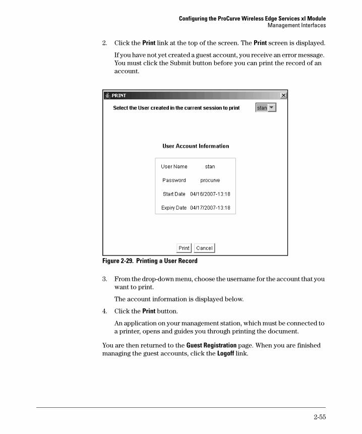
2. Click the Print link at the top of the screen. The Print screen is displayed.
If you have not yet created a guest account, you receive an error message. You must click the Submit button before you can print the record of an account.
Figure 2-29. Printing a User Record
3. From the drop-down menu, choose the username for the account that you want to print.
The account information is displayed below.
4. Click the Print button.
An application on your management station, which must be connected to a printer, opens and guides you through printing the document.
You are then returned to the Guest Registration page. When you are finished managing the guest accounts, click the Logoff link.
2-55

Configuring the ProCurve Wireless Edge Services xl ModuleRadio Port Adoption
Radio Port Adoption
By default, the Wireless Edge Services xl Module automatically adopts radio ports (RPs) that it detects on the network. For more security, you can disable automatic RP adoption and configure the module to adopt only those RPs for which you manually enter the MAC address.
The module can adopt RPs that are in the Radio Port VLAN (Layer 2 adoption) or in a different VLAN across a subnetwork boundary (Layer 3 adoption). Figure 2-30 illustrates when to use each type of adoption. In either case, your network must meet certain requirements in order for the module to detect the RP.
Figure 2-30. Layer 2 Versus Layer 3 Adoption
2-56

Configuring the ProCurve Wireless Edge Services xl ModuleRadio Port Adoption
Network Requirements for Layer 2 Adoption
Before the Wireless Edge Services xl Module can adopt an RP that is con-nected to your network, the module must detect that RP. Detection is depen-dent upon network connectivity: all the network interfaces between the module and the RP must be correctly configured to carry traffic in the Radio Port VLAN.
■ The Wireless Edge Services xl Module’s downlink port must be a tagged member of the Radio Port VLAN (by default, VLAN 2100).
■ The switch port that connects to the RP must be an untagged member of the Radio Port VLAN.
■ Each switch interface that carries traffic between the RP and the module must be either a tagged or an untagged member of the Radio Port VLAN, as your network requires.
For example, you may attach the RPs to a Power over Ethernet (PoE)-compatible infrastructure switch, which is connected, in turn, to the wireless services-enabled switch. The uplink port on the infrastructure switch must be able to carry traffic from the Radio Port VLAN. If the uplink port is carrying traffic from other VLANs, you must make that port a tagged member of the Radio Port VLAN.
Auto-Provisioning on the Wireless Services-Enabled Switch
The wireless-enabled switch automatically creates a default Radio Port VLAN—VLAN 2100—when you install the Wireless Edge Services xl Module in the ProCurve Switch 5300xl chassis. If VLAN 2100 is already being used, the wireless services-enabled switch uses the next available VLAN.
In addition to creating the default Radio Port VLAN, the wireless services-enabled switch automatically configures the module’s downlink port as a tagged member of VLAN 2100. The downlink port handles the traffic sent to and from RPs.
If you attach RPs to a PoE module that is installed in the wireless services-enabled switch, the switch automatically configures each RP’s switch port as an untagged member of the default Radio Port VLAN. (Because the RP does not support 802.1Q, it must be an untagged member of the Radio Port VLAN.)
When the appropriate VLAN memberships are established, the RPs can trans-mit traffic to the Wireless Edge Services xl Module, and the module can, in turn, detect the RPs. (See Figure 2-31.) (For more information about the communications between the RPs and the wireless services-enabled switch, see Chapter 1: Introduction.)
2-57
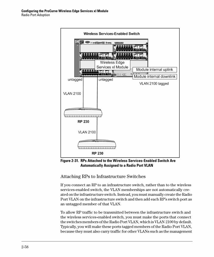
Configuring the ProCurve Wireless Edge Services xl ModuleRadio Port Adoption
Figure 2-31. RPs Attached to the Wireless Services-Enabled Switch Are Automatically Assigned to a Radio Port VLAN
Attaching RPs to Infrastructure Switches
If you connect an RP to an infrastructure switch, rather than to the wireless services-enabled switch, the VLAN memberships are not automatically cre-ated on the infrastructure switch. Instead, you must manually create the Radio Port VLAN on the infrastructure switch and then add each RP’s switch port as an untagged member of that VLAN.
To allow RP traffic to be transmitted between the infrastructure switch and the wireless services-enabled switch, you must make the ports that connect the switches members of the Radio Port VLAN, which is VLAN 2100 by default. Typically, you will make these ports tagged members of the Radio Port VLAN, because they must also carry traffic for other VLANs such as the management
2-58
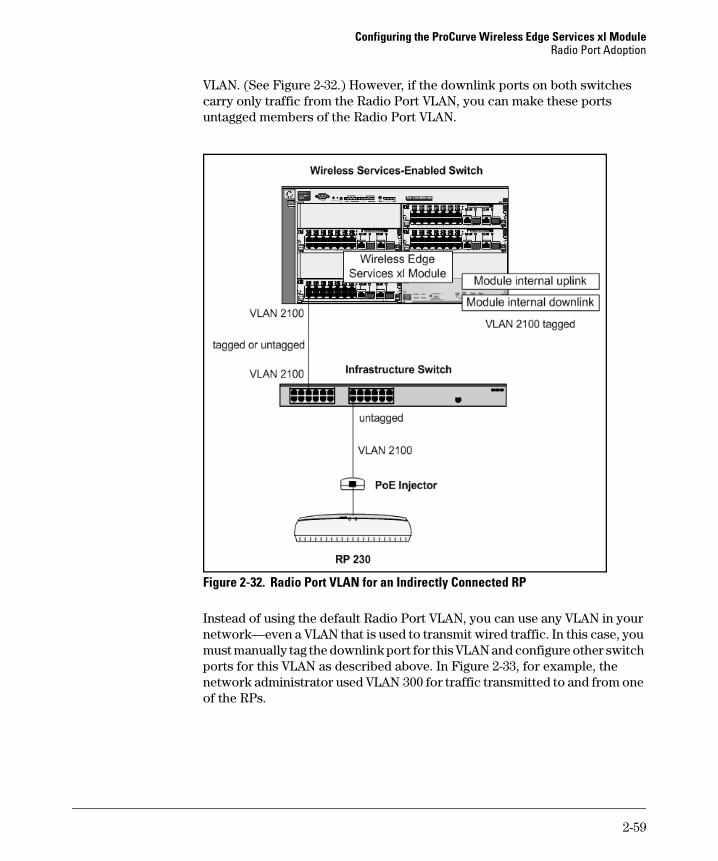
Configuring the ProCurve Wireless Edge Services xl ModuleRadio Port Adoption
VLAN. (See Figure 2-32.) However, if the downlink ports on both switches carry only traffic from the Radio Port VLAN, you can make these ports untagged members of the Radio Port VLAN.
Figure 2-32. Radio Port VLAN for an Indirectly Connected RP
Instead of using the default Radio Port VLAN, you can use any VLAN in your network—even a VLAN that is used to transmit wired traffic. In this case, you must manually tag the downlink port for this VLAN and configure other switch ports for this VLAN as described above. In Figure 2-33, for example, the network administrator used VLAN 300 for traffic transmitted to and from one of the RPs.
2-59
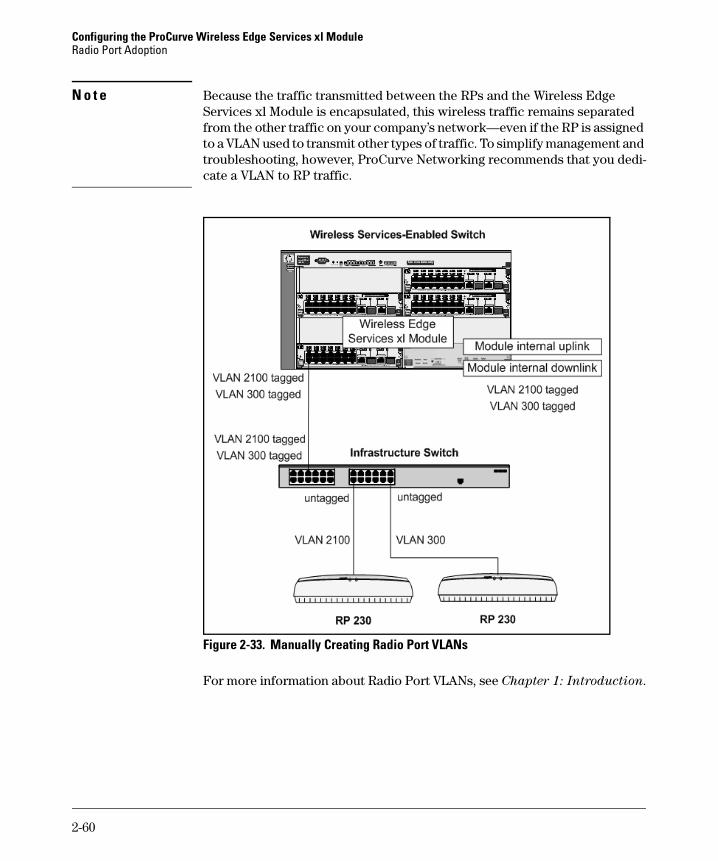
Configuring the ProCurve Wireless Edge Services xl ModuleRadio Port Adoption
N o t e Because the traffic transmitted between the RPs and the Wireless Edge Services xl Module is encapsulated, this wireless traffic remains separated from the other traffic on your company’s network—even if the RP is assigned to a VLAN used to transmit other types of traffic. To simplify management and troubleshooting, however, ProCurve Networking recommends that you dedi-cate a VLAN to RP traffic.
Figure 2-33. Manually Creating Radio Port VLANs
For more information about Radio Port VLANs, see Chapter 1: Introduction.
2-60

Configuring the ProCurve Wireless Edge Services xl ModuleRadio Port Adoption
N o t e You might also need to perform some configuration tasks on the wireless services-enabled switch, such as raising the maximum number of VLANs. For help on completing configuration tasks on the wireless services-enabled switch, use the following guides:
■ ProCurve Series 6400cl Switches, 5300xl Switches, and 3400cl Switches
Management and Configuration Guide
■ ProCurve Series 6400cl Switches, 5300xl Switches, and 3400cl Switches
Advanced Traffic Management Guide
Network Requirements for Layer 3 Adoption
As discussed in “Network Requirements for Layer 2 Adoption” on page 2-57, RPs can be adopted at Layer 2 as long as you attach them to an infrastructure switch that is in the same VLAN (Layer 2 domain) as the wireless services-enabled switch. The messages that the RPs send to become adopted, which are Layer 2 broadcasts, can reach the Wireless Edge Services xl Module.
Sometimes, however, you may want to attach RPs to switches that are on a different subnetwork than the Wireless Services xl Module, requiring a Layer 3 device, such as a router, to establish communications. In this case, Layer 3 adoption is required. Figure 2-34 shows several RPs that require Layer 3 adoption.
2-61
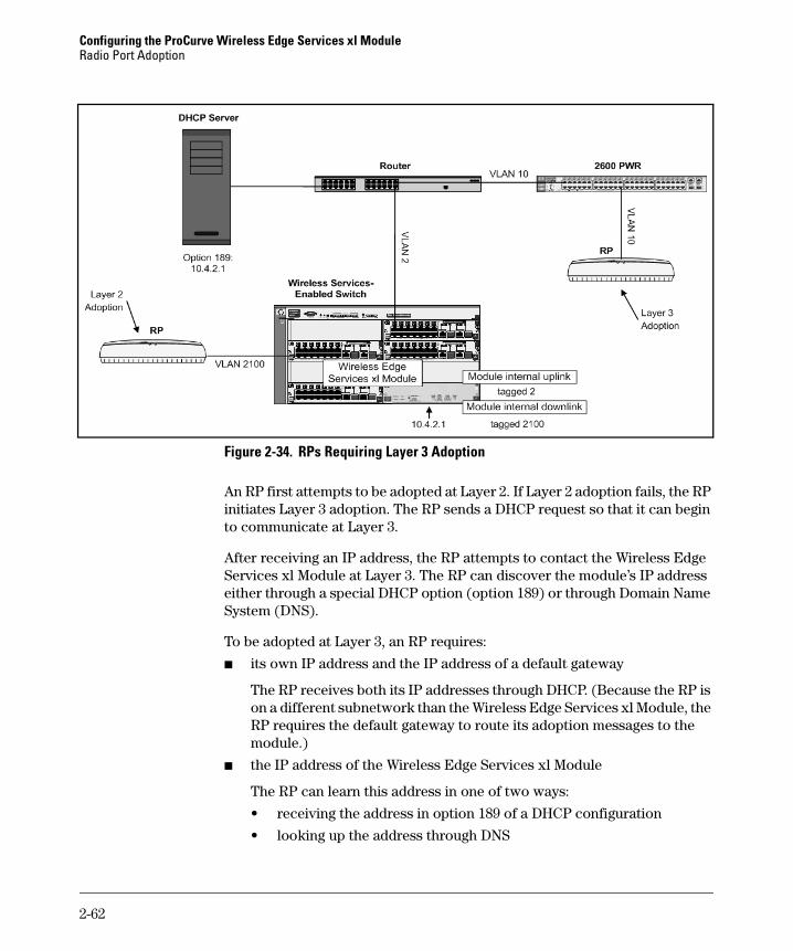
Configuring the ProCurve Wireless Edge Services xl ModuleRadio Port Adoption
Figure 2-34. RPs Requiring Layer 3 Adoption
An RP first attempts to be adopted at Layer 2. If Layer 2 adoption fails, the RP initiates Layer 3 adoption. The RP sends a DHCP request so that it can begin to communicate at Layer 3.
After receiving an IP address, the RP attempts to contact the Wireless Edge Services xl Module at Layer 3. The RP can discover the module’s IP address either through a special DHCP option (option 189) or through Domain Name System (DNS).
To be adopted at Layer 3, an RP requires:
■ its own IP address and the IP address of a default gateway
The RP receives both its IP addresses through DHCP. (Because the RP is on a different subnetwork than the Wireless Edge Services xl Module, the RP requires the default gateway to route its adoption messages to the module.)
■ the IP address of the Wireless Edge Services xl Module
The RP can learn this address in one of two ways:
• receiving the address in option 189 of a DHCP configuration
• looking up the address through DNS
2-62

Configuring the ProCurve Wireless Edge Services xl ModuleRadio Port Adoption
■ the correct bootloader code
The bootloader code allows the RP to request a DHCP configuration and contact the Wireless Edge Services xl Module at Layer 3. If the RP did not ship with this code, it must first be adopted at Layer 2 by a Wireless Edge Services xl Module that is running software version 02.XX.
The instructions for enabling Layer 3 adoption explain how to determine your RP’s bootloader code version, and if necessary, update the code.
N o t e This guide refers to the process of adopting and configuring an RP before installing it in its final location as pre-adoption.
In addition to ensuring that your RP meets the requirements for Layer 3 adoption, you must ensure that your network meets the following require-ments:
■ DHCP server that sends one of these two configurations to the RP:
• an IP address, a default gateway address, and option 189, which includes the IP address of up to three Wireless Edge Services xl Modules
• an IP address, a default gateway address, a domain suffix, and a DNS server address
■ router that acts as the default gateway for the RP and can reach the Wireless Edge Services xl Module
■ any necessary IP helper addresses on infrastructure devices so that the RP can reach the DHCP server
■ either the internal uplink or downlink port on the Wireless Edge Services xl Module (but not both) tagged for the VLAN on which the module has the address that the RP contacts
■ a PoE device to provide the RP with power
■ optionally, a DNS server that maps the name that the RP knows for the Wireless Edge Services xl Module to the module’s IP address (required only if you select the DNS strategy)
• By default, the RP sends a DNS request for this name:
PROCURVE-WESM
The RP appends the domain suffix that it received through DHCP. For example:
PROCURVE-WESM.procurve.com
• You can change the name that the RP looks up. However, this option requires you to pre-adopt the RP at Layer 2.
2-63
Configuring the ProCurve Wireless Edge Services xl ModuleRadio Port Adoption
N o t e If a firewall separates your RPs from your Wireless Edge Services xl Module, you must ensure that this firewall allows the RPs adoption messages. The RPs send these messages on UDP port 24576; do not filter this port.
The next sections describe in more detail the two strategies for enabling Layer 3 adoption of RPs.
Enabling Layer 3 Adoption Through DHCP Option 189
Using DHCP option 189 to adopt RPs at Layer 3 has these advantages:
■ By specifying the IP addresses of up to three Wireless Edge Services xl Modules, you ensure high availability. If one module happens to be down, the RP can be adopted by another module.
■ Even if your Wireless Edge Services xl Modules use custom hostnames, you do not have to pre-adopt RPs. The RPs receive the modules’ IP addresses directly in option 189, so they do not need to send DNS requests.
However, this strategy does require some extra setup: you must define the private option 189 on your server and you must add the option to the DHCP configuration that the RP will receive. Refer to your DHCP server’s documen-tation for instructions on adding private options. You must set up the option so that its code is 189 and its value type is string.
Complete these steps to enable Layer 3 adoption:
1. Ensure that the RP has the proper bootloader code.
You can check your RP’s bootloader code version through the CLI of the switch to which it attaches. For example, enter this command on a ProCurve 5300xl Switch:
ProCurve# show lldp info remote-device <port number>
Replace <port number> with the number of the port to which the RP connects. The CLI displays the RP’s boot code in the System Description field as the HwBoot Version. For example, the bootloader code for an RP that was last adopted by a version 01.XX module is 0.4.
If the RP has the old boot code (0.4), you must have a Wireless Edge Services xl Module that runs version 02.XX software pre-adopt the RP at Layer 2. As part of the adoption process, this module will automatically update the RP’s bootloader code, as you can check in the Device Informa-tion > Radio Adoption Statistics screen (see Figure 2-35).
The code automatically updates.
2-64

Configuring the ProCurve Wireless Edge Services xl ModuleRadio Port Adoption
Figure 2-35. Checking an RP’s Bootloader Code Through the Module’s Web Browser Interface
With the new bootloader code, the RP can complete Layer 3 adoption. You can now install the RP in its final location, and as long as you set up other requirements described below, the RP will be adopted at Layer 3.
2. On your DHCP server, you can create a fixed configuration specifically for the RP, or you can add option 189 to a pool already configured for other stations.
You can easily allow the RP to use the same pool as other stations. The DHCP server does not send the 189 option unless the device requests it.
If, however, for whatever reason, you want to create a fixed configuration for the RP, you should specify the RP’s Ethernet MAC address as the client ID. You can find this MAC address on the undercarriage of a ProCurve RP 210 or 230 or the top face of a ProCurve RP 220.
3. Whichever type of configuration you choose for the RP, add option 189 to the configuration. For the option’s value, specify up to three IP addresses of Wireless Edge Services xl Modules. Separate the addresses with spaces. For example:
10.4.1.30 10.4.1.40 10.4.2.35
Boot code
2-65
Configuring the ProCurve Wireless Edge Services xl ModuleRadio Port Adoption
4. Ensure that all necessary helper addresses are in place in your network infrastructure so that the RP’s DHCP request can reach the server.
5. Ensure that the RP’s default gateway can reach the IP addresses specified in option 189.
6. One of the Wireless Edge Services xl Module’s internal ports must be tagged for the VLAN on which RPs messages arrive—that is, the VLAN on which the module has the IP address specified in option 189.
The module’s uplink port is probably already tagged for this VLAN. If so, the RP is adopted on the uplink port without further configuration.
Otherwise, you can tag the VLAN on the uplink or downlink port but not both.
C a u t i o n Never tag the uplink and downlink ports for the same VLAN.
7. Install the RP in its final location, connecting it to a PoE device.
Enabling Layer 3 Adoption Through DNS Lookup
The DNS strategy has the advantage that the RP can receive a DHCP config-uration that is probably already in place on your network’s DHCP server. In fact, the RP might be able to connect to the network and immediately be adopted at Layer 3. However, for this to occur, your DNS server must map the default DNS name known by RPs to the Wireless Edge Services xl Module’s IP address. If you have changed the module’s DNS name, you must pre-adopt the RPs and configure the module to push down the new DNS name to them (explained in step 4 on page 2-68).
Follow these steps to enable Layer 3 adoption:
1. Ensure that the RP has the proper bootloader code.
You can check your RP’s boot code through the CLI of the switch to which it attaches. For example, enter this command on a ProCurve 5300xl Switch:
ProCurve# show lldp info remote-device <port number>
Replace <port number> with the number of the port to which the RP connects. The CLI displays the RP’s boot code in the System Description
field as the HwBoot Version. For example, the bootloader code for an RP that was last adopted by a version 01.XX module is 0.4.
2-66

Configuring the ProCurve Wireless Edge Services xl ModuleRadio Port Adoption
If the RP has the old boot code (0.4), you must have a Wireless Edge Services xl Module that runs version 02.XX software pre-adopt the RP at Layer 2. As part of the adoption process, this module will automatically update the RP’s bootloader code, as you can check in the Device Informa-tion > Radio Adoption Statistics screen (see Figure 2-35).
The code automatically updates.
Figure 2-36. Checking an RP’s Bootloader Code Through the Module’s Web Browser Interface
With the new bootloader code, the RP can complete Layer 3 adoption. You can now install the RP in its final location, and as long as you set up other requirements described below, the RP will be adopted at Layer 3.
2. Verify that your DHCP server has a configuration that the RPs can use:
• IP address in the RPs’ subnetwork
• IP address of a default gateway
• IP address of a DNS server
• typically, a default domain name
3. Check the configuration of your network’s DNS server, if necessary adding an entry that maps the Wireless Edge Services xl Module’s hostname to its IP address.
Boot code
2-67

Configuring the ProCurve Wireless Edge Services xl ModuleRadio Port Adoption
4. If you choose a different name for your module than the default name known by the RPs, you must configure the new name on the RPs:
a. Have the module adopt the RPs at Layer 2.
b. Access the module CLI and enter these commands:
ProCurve(wireless-services-C)# configureProCurve(wireless-services-C)(config)# wirelessProCurve(wireless-services-C)(config-wireless)# radio dns-name <name> [XX:XX:XX:XX:XX:XX]
Replace <name> with the name specified for the module on the DNS server. The name can be up to 127 characters. Enclose the string with quotation marks (“ ”) if you want to include spaces in the name. For example, you might enter the following: “Company XYZ Module”
The RP requests a DNS lookup of this name as part of Layer 3 adoption. The exact request is the name that you enter followed by the domain name suffix that the RP receives from the DHCP server.
Optionally, specify the MAC address of a single RP to have the module send the DNS name to that RP only. Otherwise, the module sends the name to all RPs adopted at that time. These RPs, if they later must perform Layer 3 adoption, will send the new name in requests to the DNS server.
N o t e The radio dns-name command pushes the name to RPs as a one-time event. If an RP is adopted after you enter the command, you must enter it again to affect that RP.
5. Ensure that all necessary IP helper addresses are in place in your network infrastructure so that the RP’s DHCP request can reach the server.
6. Ensure that the RP’s default gateway can reach the IP addresses known by the DNS server.
7. One of the Wireless Edge Services xl Module’s internal ports must be tagged for the VLAN on which RPs’ messages arrive—that is, the VLAN on which the module has the IP address specified on the DNS server.
The module’s uplink port is probably already tagged for this VLAN. The RP can be adopted on the uplink port.
C a u t i o n Do not tag both the uplink and downlink port for the VLAN because wireless traffic might then bypass ProCurve Identity Driven Manager (IDM) settings.
8. Install the RP in its final location, connecting it to a PoE device.
2-68
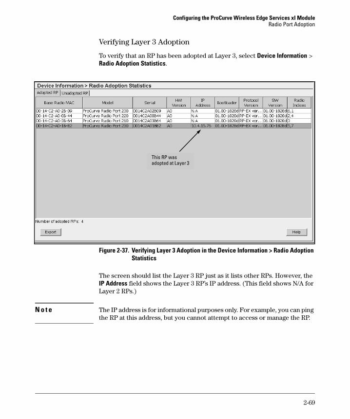
Configuring the ProCurve Wireless Edge Services xl ModuleRadio Port Adoption
Verifying Layer 3 Adoption
To verify that an RP has been adopted at Layer 3, select Device Information > Radio Adoption Statistics.
Figure 2-37. Verifying Layer 3 Adoption in the Device Information > Radio Adoption Statistics
The screen should list the Layer 3 RP just as it lists other RPs. However, the IP Address field shows the Layer 3 RP’s IP address. (This field shows N/A for Layer 2 RPs.)
N o t e The IP address is for informational purposes only. For example, you can ping the RP at this address, but you cannot attempt to access or manage the RP.
This RP was adopted at Layer 3
2-69

Configuring the ProCurve Wireless Edge Services xl ModuleRadio Port Adoption
Automatic or Manual Adoption of RPs
Once an RP can transmit traffic to the Wireless Edge Services xl Module, the module can detect and adopt it. Automatic adoption simplifies deployment, especially if your network includes many RPs. After the Wireless Edge Ser-vices xl Module adopts an RP, it sends the radio adoption default configuration to it. You can then customize settings for certain RPs. (To learn how to configure RP settings, see Chapter 3: Radio Port Configuration.)
There is one possible drawback to automatically adopting RPs, however. The Wireless Edge Services xl Module could potentially adopt an unauthorized RP. This unauthorized RP would be treated exactly as an authorized RP, receiving settings for your network’s WLANs and sending traffic into the Ethernet network.
If you can tightly control your wireless services-enabled switch and all infrastructure switches, you can prevent someone from attaching a rogue RP to the network and adding access to your wireless services in authorized areas. If you are worried about rogue RPs, you can manually adopt RPs.
Although manually adopting RPs can tighten security, it also requires more administrative effort. You must determine the best option for your particular network environment.
You can also use a combination of methods. For example, install and automat-ically adopt some RPs. Then enable manual adoption and manually add the remaining RPs. The RPs that you previously adopted automatically remain adopted.
N o t e If you create a redundancy group and decide to disable automatic RP adoption, you should ensure that you disable automatic RP adoption on both the Wireless Edge Services xl Module and the Redundant Wireless Services xl Module. Otherwise, the Redundant Wireless Services xl Module will automat-ically adopt RPs. For more information about configuring redundancy groups, see Chapter 10: Redundancy Groups.
2-70

Configuring the ProCurve Wireless Edge Services xl ModuleRadio Port Adoption
Configuring Manual Adoption for RPs
To manually adopt RPs, you must edit the global settings for RPs. Complete these steps:
1. Select Network Setup > Radio and click the Configuration tab.
Figure 2-38. Network Setup > Radio Screen
2. Click the Global Settings button. The Global screen is displayed.
2-71

Configuring the ProCurve Wireless Edge Services xl ModuleRadio Port Adoption
Figure 2-39. Network Setup > Radio > Global Settings Screen
3. Uncheck the Adopt unconfigured radios automatically box.
4. Click the OK button to apply the change to the running-config.
5. Find the MAC address of the RPs that you want to manually adopt by selecting Device Information > Radio Adoption Statistics and clicking the Unadopted tab. The unadopted RPs and their MAC addresses are listed on this screen.
6. Select the unadopted RP that you want to adopt.
You can skip this step if you want to adopt an RP that the Wireless Edge Services xl Module cannot yet detect.
2-72

Configuring the ProCurve Wireless Edge Services xl ModuleRadio Port Adoption
Figure 2-40. Device Information > Radio Adoption Statistics Screen
7. Click the Adopt button at the bottom of the screen. The Add Radio screen is displayed.
Figure 2-41. Add Radio Screen
2-73

Configuring the ProCurve Wireless Edge Services xl ModuleRadio Port Adoption
8. If you selected an unadopted RP before clicking the Add button, the RP MAC Address field displays the MAC address of that RP. Otherwise, enter the RP’s Ethernet MAC address.
9. In the Radio Settings section, check the boxes for the radio types that you want—802.11a or 802.11bg (or both).
10. For each radio type that you select, in the corresponding Radio Index field enter a number to identify this RP.
11. Click the OK button.
You can also manually add a radio from the Network Setup > Radio screen. Follow these steps:
1. Select Network Setup > Radio > Configuration.
Note that the screen informs you that automatic adoption is disabled. You must manually add radios.
Figure 2-42. Network Setup > Radio Screen (Manual Adoption)
Manually adopt a radio
2-74

Configuring the ProCurve Wireless Edge Services xl ModuleRadio Port Adoption
2. In the RP MAC Address field, enter the MAC address for the RP’s Ethernet interface.
3. In the Radio Settings section, check the boxes for the radio types that you want—802.11a or 802.11bg (or both).
4. For each radio type that you select, in the corresponding Radio Index field enter a number to identify this RP.
5. Click the OK button. The RP’s radios are added to the Network Setup > Radio screen, but it takes a few seconds for the green check mark to be displayed in the Adopted field.
Controlling Which Wireless Edge Services xl Module Adopts Particular RPs—Adoption Preference ID
Your Wireless LAN System can include multiple Wireless Edge Services xl Modules. In this case, you might want to control which module adopts which RPs.
Adoption preference IDs control the adoption process.
Each module should have its own adoption preference ID. Set this ID by clicking the Global Settings button in the Network Setup > Radio > Configuration screen. Then enter a value from 1 to 65535 in the Module Adoption Preference ID field.
Figure 2-43. Global Settings Screen
As an RP attempts to become adopted, modules defer the RP to the module that has the same ID as the RP. (However, should no module have a matching ID, the RP eventually becomes adopted by any module in the system.)
2-75
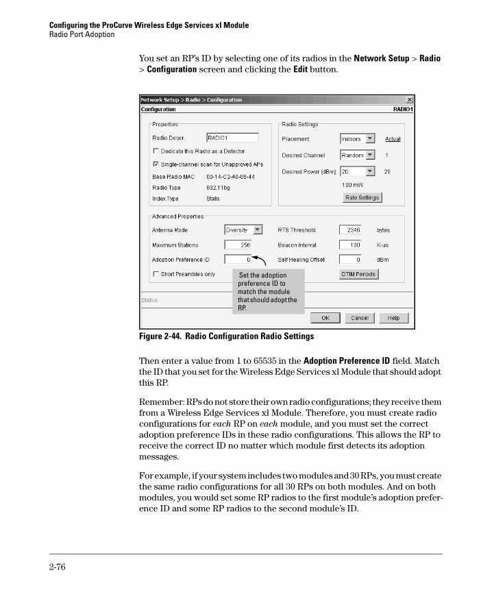
Configuring the ProCurve Wireless Edge Services xl ModuleRadio Port Adoption
You set an RP’s ID by selecting one of its radios in the Network Setup > Radio > Configuration screen and clicking the Edit button.
Figure 2-44. Radio Configuration Radio Settings
Then enter a value from 1 to 65535 in the Adoption Preference ID field. Match the ID that you set for the Wireless Edge Services xl Module that should adopt this RP.
Remember: RPs do not store their own radio configurations; they receive them from a Wireless Edge Services xl Module. Therefore, you must create radio configurations for each RP on each module, and you must set the correct adoption preference IDs in these radio configurations. This allows the RP to receive the correct ID no matter which module first detects its adoption messages.
For example, if your system includes two modules and 30 RPs, you must create the same radio configurations for all 30 RPs on both modules. And on both modules, you would set some RP radios to the first module’s adoption prefer-ence ID and some RP radios to the second module’s ID.
Set the adoption preference ID to match the module that should adopt the RP.
2-76
Configuring the ProCurve Wireless Edge Services xl ModuleRadio Port Adoption
You can create a radio configuration manually by clicking the Add button in the Network Setup > Radio > Configuration screen and entering the RP’s Ethernet MAC address. You can then edit the configuration and set the adoption preference ID to match the module that should adopt that RP.
For a more efficient alternative, have one module pre-adopt all RPs and edit the radio configurations on that module. Then copy those configurations to other modules in the Wireless LAN System.
For more information on configuring adoption preference IDs, see “Setting up Adoption Preference IDs to Control RP Adoption” on page 10-24 of Chapter 10: Redundancy Groups. These instructions focus on the special case of multiple Wireless Edge Services xl Modules and Redundant Wireless Services xl Modules that form a redundancy group; however, they also apply to modules that are not in a redundancy group but are part of the same Wireless LAN System.
802.1X Authentication for RPs
To prevent rogue RPs from being adopted, you can also enforce 802.1X authentication on your network switch ports. The ProCurve RPs 210, 220, and 230 include an 802.1X client so that they can connect to ports that enforce such authentication. Using MD5 authentication, the client automatically sends the RP’s credentials when the RP connects to a network device. The switch to which the RP connects forwards the credentials to an authentication server, and if the credentials are correct, allows the RP to join the network.
The authentication server may store a VLAN setting for the RP, which it sends to the switch after the RP authenticates. Such dynamic configuration of the Radio Port VLAN can replace auto-provisioning on the wireless services-enabled switch or manual configuration on an infrastructure switch. (See “Communicating with RPs: Radio Port VLANs” on page 1-8 of Chapter 1:
Introduction for more information about configuring Radio Port VLANs.)
N o t e When you implement 802.1X on a port, auto-provisioning is disabled on that port. You must either manually set the port to the correct VLAN for the RP or configure the VLAN assignment on the RADIUS server.
However, the wireless services-enabled switch can continue to implement auto provisioning on ports that do not enforce 802.1X.
2-77
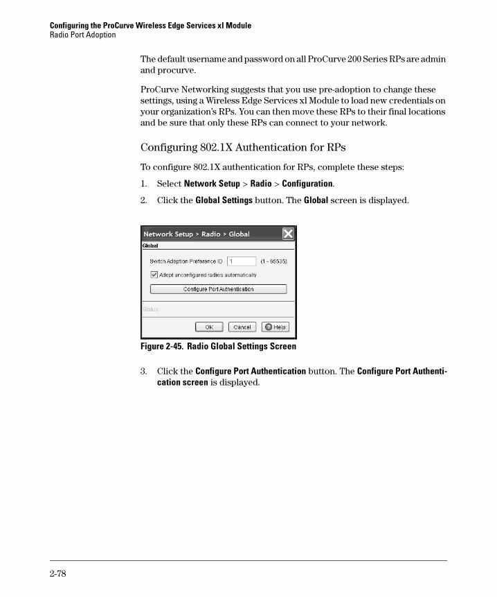
Configuring the ProCurve Wireless Edge Services xl ModuleRadio Port Adoption
The default username and password on all ProCurve 200 Series RPs are admin and procurve.
ProCurve Networking suggests that you use pre-adoption to change these settings, using a Wireless Edge Services xl Module to load new credentials on your organization’s RPs. You can then move these RPs to their final locations and be sure that only these RPs can connect to your network.
Configuring 802.1X Authentication for RPs
To configure 802.1X authentication for RPs, complete these steps:
1. Select Network Setup > Radio > Configuration.
2. Click the Global Settings button. The Global screen is displayed.
Figure 2-45. Radio Global Settings Screen
3. Click the Configure Port Authentication button. The Configure Port Authenti-cation screen is displayed.
2-78
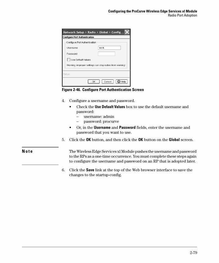
Configuring the ProCurve Wireless Edge Services xl ModuleRadio Port Adoption
Figure 2-46. Configure Port Authentication Screen
4. Configure a username and password.
• Check the Use Default Values box to use the default username and password:– username: admin– password: procurve
• Or, in the Username and Password fields, enter the username and password that you want to use.
5. Click the OK button, and then click the OK button on the Global screen.
N o t e The Wireless Edge Services xl Module pushes the username and password to the RPs as a one-time occurrence. You must complete these steps again to configure the username and password on an RP that is adopted later.
6. Click the Save link at the top of the Web browser interface to save the changes to the startup-config.
2-79

Configuring the ProCurve Wireless Edge Services xl ModuleSystem Maintenance
System Maintenance
The Web browser interface allows you to manage:
■ software images
■ configuration files
■ SNMP support
■ password encryption
Software Images
The Wireless Edge Services xl Module maintains two software images:
■ primary
■ secondary
Typically, the primary image loads when the Wireless Edge Services xl Module is rebooted. However, you can configure the module to reboot with either the primary or the secondary image.
The two images provide failover capabilities in the event that one software image becomes corrupted. If a software image fails to initialize completely during two consecutive reboots, the Wireless Edge Services xl Module auto-matically boots with the other image.
Having two images also simplifies the update process. For example, you can boot the Wireless Edge Services xl Module with the secondary image and then update the primary image. Likewise, you can boot the module with the primary image and update the secondary image. After you upgrade the software and reboot the module, the module, by default, loads the upgraded image.
ProCurve Networking uses the following naming convention for software image files:
WS.xx.yy
The xx is replaced with numbers that indicate a major release of the software image. The yy is replaced with numbers that indicate a minor release of the software.
2-80

Configuring the ProCurve Wireless Edge Services xl ModuleSystem Maintenance
Viewing the Software Images
To view the version of the primary and secondary images, access the Management > System Maint.—Software screen. (See Figure 2-47.)
Figure 2-47. Management > System Maint.—Software Screen
The Management > System Maint.—Software screen includes the following fields:
■ Image—This field indicates whether the image is the primary or secondary image.
■ Version—This field displays the version number of the image file.
■ Current Boot—This field indicates whether or not the image was used the last time that the Wireless Edge Services xl Module was rebooted. A green check mark indicates that the image was used; a red x indicates that the image was not used.
■ Next Boot—This field determines whether the software image will be used to boot the Wireless Edge Services xl Module the next time the module is reloaded. A green check mark indicates that the image will be used; a red x indicates that the image will not be used.
2-81

Configuring the ProCurve Wireless Edge Services xl ModuleSystem Maintenance
■ Built Time—This field reports the date and time that this software image was created.
■ Install Time—This field reports the date and time that this software image was updated on the Wireless Edge Services xl Module.
Selecting the Software Image That Is Used to Reboot
You can specify which software image the Wireless Edge Services xl Module will use the next time it is rebooted—the primary or the secondary. Complete these steps:
1. Select Management > System Maint.—Software.
2. Select the software image that the Wireless Edge Services xl Module should use to boot. For example, if you want the module to boot with the secondary image, select that image.
3. Click the Edit button at the bottom of the screen.
Figure 2-48. Update Software Image Dialog Box
4. Check the Use this software on next reboot box, and then click the OK button.
5. Click the Save link at the top of the Web browser interface to save this change to the startup-config.
Changing the Image Failover Setting
When the Wireless Edge Services xl Module reboots, it attempts to initialize the software image that you have selected for the next reboot. If this attempt fails, the module tries one more time to initialize the software image. If this second consecutive attempt fails, by default the module automatically reboots using the other software image.
2-82
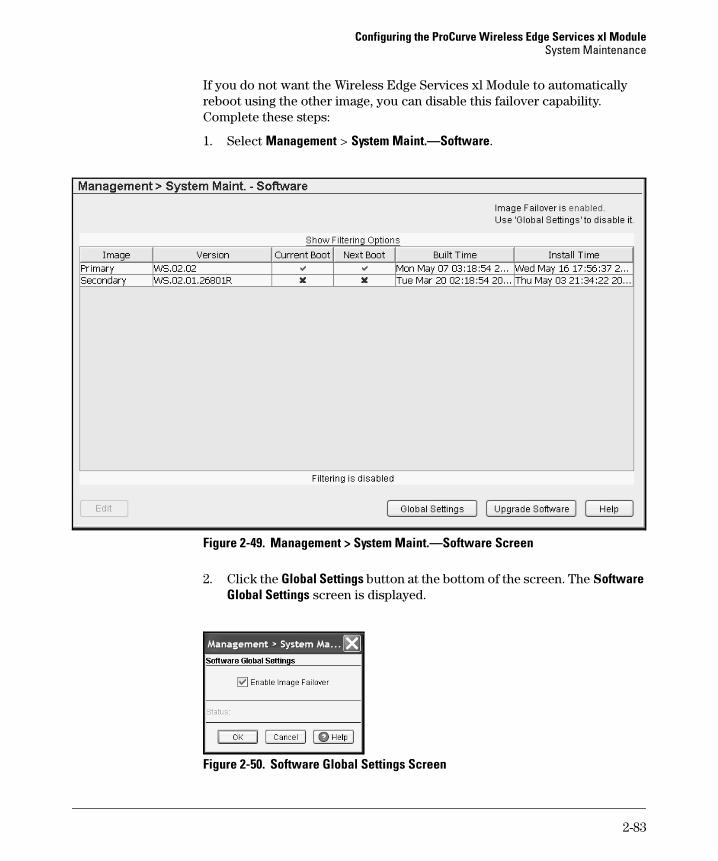
Configuring the ProCurve Wireless Edge Services xl ModuleSystem Maintenance
If you do not want the Wireless Edge Services xl Module to automatically reboot using the other image, you can disable this failover capability. Complete these steps:
1. Select Management > System Maint.—Software.
Figure 2-49. Management > System Maint.—Software Screen
2. Click the Global Settings button at the bottom of the screen. The Software Global Settings screen is displayed.
Figure 2-50. Software Global Settings Screen
2-83

Configuring the ProCurve Wireless Edge Services xl ModuleSystem Maintenance
3. Uncheck the Enable Image Failover box, and then click the OK button. The change is applied to the running-config.
4. Click the Save link at the top of the Web browser interface to save the changes to the startup-config.
Manually Updating the Software Image
ProCurve Networking periodically updates the software image for the Wire-less Edge Services xl Module. You can configure the module to automatically contact an Update Server and download the new image when the module is rebooted, or you can manually update the image. (To configure settings for automatic updates, see “Update Server” on page 2-98.)
To manually update an image, complete these steps:
1. Select Management > System Maint.—Software.
2. Click the Upgrade Software button at the bottom of the screen. The Update screen is displayed.
The software image that you upload will automatically copy to the image not currently in use.
Figure 2-51. Upgrade Software Image Screen
3. In the From field, accept the default setting, Server.
4. In the File field, enter the name of the new image file.
5. In the Using field, use the drop-down menu to select FTP or TFTP, depending on the type of server that you have.
2-84

Configuring the ProCurve Wireless Edge Services xl ModuleSystem Maintenance
6. In the Port field, if needed, change the port number for your FTP or TFTP server. In most cases, the defaults (port 21 for FTP, port 69 for TFTP) should apply to your server.
7. In the IP Address field, enter the IP address of the FTP or TFTP server.
8. If you are using an FTP server, enter the login credentials for that server.
a. In the User ID field, enter the username.
b. In the Password field, enter the password for this username.
9. In the Path field, enter the path where the new image file is saved. If you are using an FTP server and the image file is saved at the server’s root level, enter a period followed by a slash (./). If the image file resides at a different level on the FTP server, enter the complete path. (If you are using a TFTP server, this field may not be required.)
10. Click the Do Upgrade button.
Configuration Files
The Wireless Edge Services xl Modules ships with a factory default startup-config file. Factory default settings include:
■ support for HTTP and HTTPS
■ support for SNMP v1, v2, and v3
■ DHCP-assigned IP address for the default management interface (VLAN 1)
As you configure the Wireless Edge Services xl Module and save changes, these changes are saved to the startup-config. From the Web browser inter-face, you can view the commands included in the startup-config file, or you can return the startup-config file to factory default settings.
For backup purposes, you can save the startup-config file to:
■ FTP server
■ TFTP server
■ workstation’s hard disk
In addition, you can save multiple configuration files and store them in the module’s internal flash. As Table 2-2 shows, configuration files are stored in two locations in the module’s internal flash.
2-85

Configuring the ProCurve Wireless Edge Services xl ModuleSystem Maintenance
Table 2-2. Configuration Files Stored in Internal Flash
Viewing Configuration Files
To view a configuration file, select Management > System Maint.—Config Files. As shown in Figure 2-52, this screen displays the following information about each configuration file saved in flash:
■ Name■ Size (Bytes)■ Created—date and time when the file was created
■ Modified—date and time when the file was last changed
Figure 2-52. Management > System Maint.—Config Files
To view the contents of a configuration file, select the file and click the View button at the bottom of the screen. For example, you might want to view the startup-config file. (See Figure 2-53.)
Name of Configuration File Location in Internal Flash
startup-config NVRAM
other configuration files flash
2-86
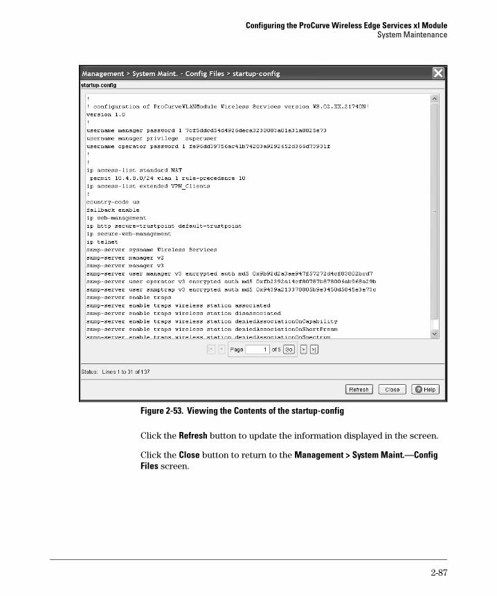
Configuring the ProCurve Wireless Edge Services xl ModuleSystem Maintenance
Figure 2-53. Viewing the Contents of the startup-config
Click the Refresh button to update the information displayed in the screen.
Click the Close button to return to the Management > System Maint.—Config Files screen.
2-87
Configuring the ProCurve Wireless Edge Services xl ModuleSystem Maintenance
Transferring, or Copying, Files
The Web browser interface allows you to transfer, or copy, configuration files. You simply specify a source and a destination for the transfer. Valid selections are listed in Table 2-3:
Table 2-3. Transferring Files to and from the Wireless Edge Services xl Module
When you select a source, the Web browser interface displays the fields that are needed to copy a configuration file from that source. Likewise, when you select a destination, the Web browser interface displays the fields that are needed to copy a file to that destination. For example, to copy a file from a TFTP server, you must specify fields such as the IP address and the name of the file.
Transferring Configuration Files from an FTP or TFTP Server to the Wireless Edge Services xl Module
To upload a configuration file from an FTP or a TFTP server to the Wireless Edge Services xl Module, complete these steps:
1. Select Management > System Maint.—Config Files.
2. Click the Transfer Files button at the bottom of the screen. The Transfer screen is displayed. (See Figure 2-54.)
From (Source) To (Destination)
Server—either an FTP or a TFTP server Wireless Edge Services xl Module
Wireless Edge Services xl Module • Wireless Edge Services xl Module• Local disk• Server—either an FTP or a TFTP server
2-88

Configuring the ProCurve Wireless Edge Services xl ModuleSystem Maintenance
Figure 2-54. Management > System Maint.—Config Files > Transfer Screen
3. In the Source section, specify the source as an FTP or a TFTP server:
a. In the From field, use the drop-down menu to select Server.b. In the File field, enter the name of the configuration file.
c. In the Using field, use the drop-down menu to select either FTP or TFTP.
d. In the Port field, if needed, change the port number for your FTP or TFTP server. In most cases, the defaults (port 21 for FTP, port 69 for TFTP) should apply to your server.
e. In the IP Address field, enter the IP address of the FTP or TFTP server.
f. If you are using an FTP server, enter the login credentials.i. In the User ID field, enter the username for the FTP server.ii. In the Password field, enter the password for this username.
g. In the Path field, enter the path where the configuration file is saved on the server.
If you are using an FTP server and the configuration file is saved at the server’s root level, enter a period followed by a slash (./). If the configuration file resides at a different level on the FTP server, enter the complete path. If you are using a TFTP server, this field may not be required. However, enter the path if the file is stored in a subdirec-tory on the TFTP server.
2-89
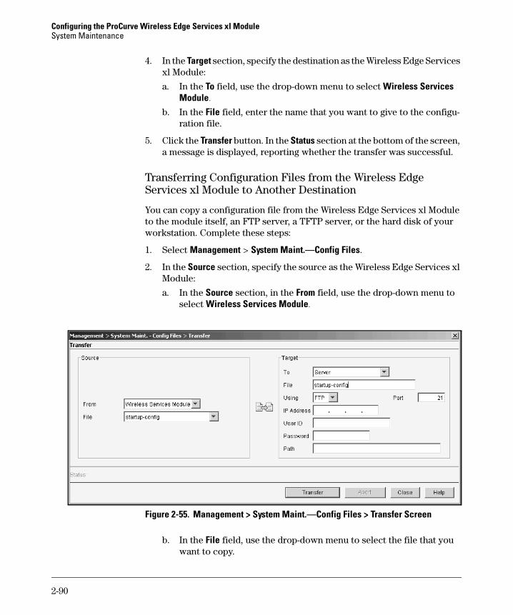
Configuring the ProCurve Wireless Edge Services xl ModuleSystem Maintenance
4. In the Target section, specify the destination as the Wireless Edge Services xl Module:
a. In the To field, use the drop-down menu to select Wireless Services Module.
b. In the File field, enter the name that you want to give to the configu-ration file.
5. Click the Transfer button. In the Status section at the bottom of the screen, a message is displayed, reporting whether the transfer was successful.
Transferring Configuration Files from the Wireless Edge Services xl Module to Another Destination
You can copy a configuration file from the Wireless Edge Services xl Module to the module itself, an FTP server, a TFTP server, or the hard disk of your workstation. Complete these steps:
1. Select Management > System Maint.—Config Files.
2. In the Source section, specify the source as the Wireless Edge Services xl Module:
a. In the Source section, in the From field, use the drop-down menu to select Wireless Services Module.
Figure 2-55. Management > System Maint.—Config Files > Transfer Screen
b. In the File field, use the drop-down menu to select the file that you want to copy.
2-90

Configuring the ProCurve Wireless Edge Services xl ModuleSystem Maintenance
3. In the Target section, specify the destination. Choose a destination from the To drop-down menu:
• Wireless Services Module—copy the file to another location on the module
• Server—copy the file to an external FTP or TFTP server
• Local Disk—copy the file to the workstation on which you are running the Web browser
The Target fields below change depending on the target type. The following three sections give you guidelines for filling in the necessary information.
Copying a File to the Wireless Edge Services xl Module. You can copy a file on the Wireless Edge Services xl Module to an new location on the module. For example, you might want to copy a logo used for Web-Auth on one WLAN to another WLAN. Follow these steps:
1. Complete steps 1 to 3 in “Transferring Configuration Files from the Wireless Edge Services xl Module to Another Destination” on page 2-90.
2. In the File field, enter the name that you want to give to the configuration file.
The filename should include the path for the location in the module’s memory to which you want to save the file.
3. You can use the browse button to search the module’s directory and even create a new folder for the file. See “Managing the Directory Structure and Browsing for Files” on page 2-94 for more information.
4. Click the Transfer button. In the Status section at the bottom of the screen, a message is displayed, reporting whether the transfer was successful.
2-91
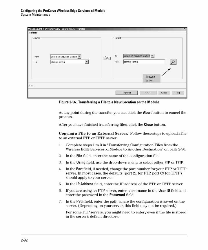
Configuring the ProCurve Wireless Edge Services xl ModuleSystem Maintenance
Figure 2-56. Transferring a File to a New Location on the Module
At any point during the transfer, you can click the Abort button to cancel the process.
After you have finished transferring files, click the Close button.
Copying a File to an External Server. Follow these steps to upload a file to an external FTP or TFTP server:
1. Complete steps 1 to 3 in “Transferring Configuration Files from the Wireless Edge Services xl Module to Another Destination” on page 2-90.
2. In the File field, enter the name of the configuration file.
3. In the Using field, use the drop-down menu to select either FTP or TFTP.
4. In the Port field, if needed, change the port number for your FTP or TFTP server. In most cases, the defaults (port 21 for FTP, port 69 for TFTP) should apply to your server.
5. In the IP Address field, enter the IP address of the FTP or TFTP server.
6. If you are using an FTP server, enter a username in the User ID field and enter the password in the Password field.
7. In the Path field, enter the path where the configuration is saved on the server. (Depending on your server, this field may not be required.)
For some FTP servers, you might need to enter / even if the file is stored in the server’s default directory.
Browse button
2-92
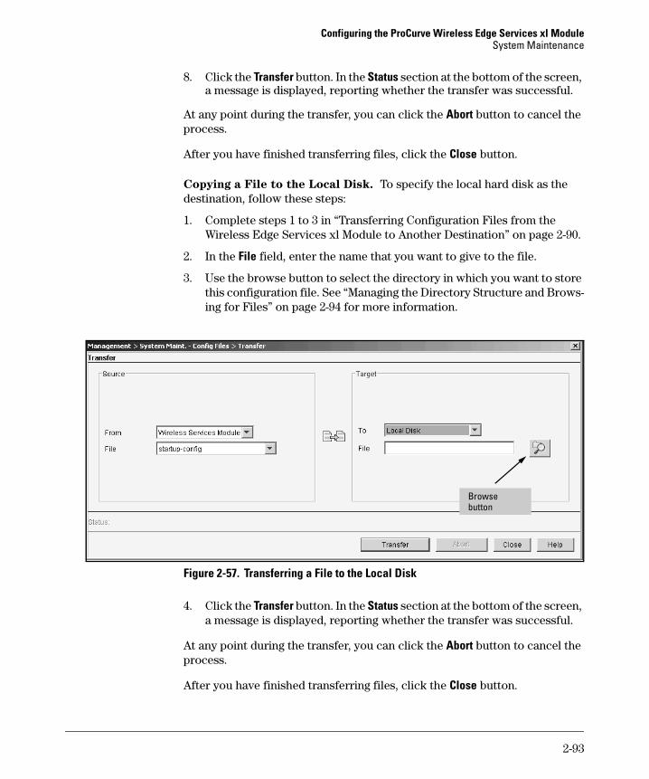
Configuring the ProCurve Wireless Edge Services xl ModuleSystem Maintenance
8. Click the Transfer button. In the Status section at the bottom of the screen, a message is displayed, reporting whether the transfer was successful.
At any point during the transfer, you can click the Abort button to cancel the process.
After you have finished transferring files, click the Close button.
Copying a File to the Local Disk. To specify the local hard disk as the destination, follow these steps:
1. Complete steps 1 to 3 in “Transferring Configuration Files from the Wireless Edge Services xl Module to Another Destination” on page 2-90.
2. In the File field, enter the name that you want to give to the file.
3. Use the browse button to select the directory in which you want to store this configuration file. See “Managing the Directory Structure and Brows-ing for Files” on page 2-94 for more information.
Figure 2-57. Transferring a File to the Local Disk
4. Click the Transfer button. In the Status section at the bottom of the screen, a message is displayed, reporting whether the transfer was successful.
At any point during the transfer, you can click the Abort button to cancel the process.
After you have finished transferring files, click the Close button.
Browse button
2-93
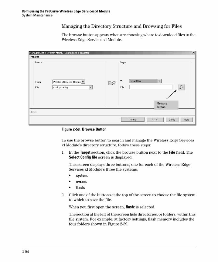
Configuring the ProCurve Wireless Edge Services xl ModuleSystem Maintenance
Managing the Directory Structure and Browsing for Files
The browse button appears when are choosing where to download files to the Wireless Edge Services xl Module.
Figure 2-58. Browse Button
To use the browse button to search and manage the Wireless Edge Services xl Module’s directory structure, follow these steps:
1. In the Target section, click the browse button next to the File field. The Select Config file screen is displayed.
This screen displays three buttons, one for each of the Wireless Edge Services xl Module’s three file systems:
• system:• nvram:• flash:
2. Click one of the buttons at the top of the screen to choose the file system to which to save the file.
When you first open the screen, flash: is selected.
The section at the left of the screen lists directories, or folders, within this file system. For example, at factory settings, flash memory includes the four folders shown in Figure 2-59.
Browse button
2-94
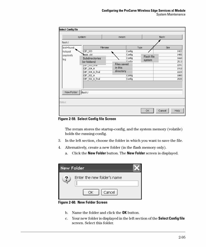
Configuring the ProCurve Wireless Edge Services xl ModuleSystem Maintenance
Figure 2-59. Select Config file Screen
The nvram stores the startup-config, and the system memory (volatile) holds the running-config.
3. In the left section, choose the folder in which you want to save the file.
4. Alternatively, create a new folder (in the flash memory only).
a. Click the New Folder button. The New Folder screen is displayed.
Figure 2-60. New Folder Screen
b. Name the folder and click the OK button.
c. Your new folder is displayed in the left section of the Select Config file screen. Select this folder.
Flash file system Subdirectories
(or folders)Files saved in this directory
2-95

Configuring the ProCurve Wireless Edge Services xl ModuleSystem Maintenance
5. Choose the filename.
The path to the folder you have selected is displayed in the field at the bottom of the screen. Files in this folder display to the right. You can select one of these files and write over it, or you can choose a new file. To create a new file, add the filename to the path in the field at the bottom of the screen. For example: flash/myfolder/configA.
6. Click the OK button.
7. The path and filename that you have selected are displayed in the File field.
8. Click the Transfer button. In the Status section at the bottom of the screen, a message is displayed, reporting whether the transfer was successful.
Deleting a Configuration File
From the Management > System Maint.—Config Files screen, you can delete any configuration file that is stored in flash—except the startup-config file. To delete a configuration file, complete these steps:
1. Select the configuration file and click the Delete button. As shown in Figure 2-61, you will be prompted to confirm that you want to delete this configuration file.
Figure 2-61. Confirm File Delete Prompt
2. Click the Yes button to delete the file.
2-96
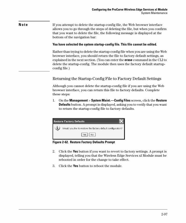
Configuring the ProCurve Wireless Edge Services xl ModuleSystem Maintenance
N o t e If you attempt to delete the startup-config file, the Web browser interface allows you to go through the steps of deleting the file, but when you confirm that you want to delete the file, the following message is displayed at the bottom of the navigation bar:
You have selected the system startup-config file. This file cannot be edited.
Rather than trying to delete the startup-config file when you are using the Web browser interface, you should return the file to factory default settings, as explained in the next section. (You can enter the erase command in the CLI to delete the startup-config. The module then uses the factory default startup-config file.)
Returning the Startup-Config File to Factory Default Settings
Although you cannot delete the startup-config file if you are using the Web browser interface, you can return this file to factory defaults. Complete these steps:
1. On the Management > System Maint.—Config Files screen, click the Restore Defaults button. A prompt is displayed, asking you to verify that you want to return the startup-config file to factory defaults.
Figure 2-62. Restore Factory Defaults Prompt
2. Click the Yes button if you want to revert to factory settings. A prompt is displayed, telling you that the Wireless Edge Services xl Module must be rebooted in order for the change to take effect.
3. Click the Yes button to reboot the module.
2-97

Configuring the ProCurve Wireless Edge Services xl ModuleSystem Maintenance
Update Server
The Wireless Edge Services xl Module can communicate with an Update Server, on which you can store backup copies of the software image and the configuration file for your Wireless Edge Services xl Module. If the module’s software image or configuration file becomes corrupted, you can reboot the module, and it will retrieve the necessary file from the Update Server—provided you have configured the Update Server settings correctly and copied the necessary files to the Update Server.
When you configure the Update Server on the Wireless Edge Services xl Module, you define the following:
■ IP address of the Update Server
■ protocol of the Update Server (FTP or TFTP)
■ server username and password (for the FTP server)
■ location of the software image on the Update Server
■ software image that the module should use
■ location of the configuration file
■ location of a redundancy configuration file—a common configuration for an entire redundancy group, an optional supplement to (not replacement for) the configuration file
Checking the Software Image File
When the Wireless Edge Services xl Module reboots, it checks the Update Server settings that you have configured to ensure that it is using the correct software image. If the module is already using the software image that you specified, it simply reboots and then checks the configuration file. (See “Checking the Configuration File” on page 2-99.)
However, if you have specified a different software image for the Update Server settings, the module requests that image from the Update Server. For example, if you configure the Update Server settings and specify that the software image is WS.02.02, the module first checks its own software image file to see if it is using WS.02.02. If the module is using WS.02.02, it reboots with this image. If the module is using a different image—such as WS.02.01—it contacts the Update Server and requests the WS.02.02 image. If the Update Server has the WS.02.02 image and sends it, the module boots with WS.02.02.
2-98

Configuring the ProCurve Wireless Edge Services xl ModuleSystem Maintenance
Whenever the module requests the software image file from the Update Server, it also requests the configuration file. The configuration file that the Update Server sends must be exactly the same as the startup-config saved on the module. You can ensure that these files are the same by always saving the latest startup-config to the Update Server.
Checking the Configuration File
The configuration file is handled slightly differently from the software image. For the configuration file, the Update Server is designed to recover a corrupted configuration file. It is not intended to deploy new configurations.
You cannot define the configuration file in the Update Server settings. The Wireless Edge Services xl Module always requests the startup-config. When you define the File Name (with Path) field in the Update Server settings, you define the location of the startup-config file on the Update Server.
Whatever name you give the file that you save to the Update Server, it should always contain the same configuration that is saved on the module’s startup-config. When you change the startup-config, you should immediately copy the new file to the Update Server.
When you save the startup-config file and the Update Server is enabled, the Wireless Edge Services xl Module saves a checksum of the startup-config. When the Wireless Edge Services xl Module reboots, it compares the check-sum it saved with the checksum of the startup-config that it loads. If the two checksums match, the module boots normally with the startup-config.
If the startup-config is corrupted, the checksums will not match, and the module will request the configuration file from the location specified in the Update Server settings. When the module receives the configuration file from the Update Server, it compares the checksum that it saved for the startup-config with this file’s checksum. If the two checksums match, the module loads the configuration file that it received from the Update Server.
If the two checksums do not match, the module assumes that the Update Server does not have the correct configuration file. The module boots with the factory default startup-config.
However, you can configure the Wireless Edge Services xl Module to ignore the checksum and always use the startup-config file sent by the Update Server. This option is called forcing the config update.
2-99

Configuring the ProCurve Wireless Edge Services xl ModuleSystem Maintenance
Avoiding Problems in Using the Update Server
To ensure that the Wireless Edge Services xl Module does not boot with the wrong software image or the factory default settings, follow these guidelines:
■ Keep the Update Server settings current.
For example, if you upgrade the software image on the Wireless Edge Services xl Module, you must save the new software image to the Update Server and change the software image file defined in the module’s Update Server settings. If the Update Server settings specify an older software image, the module will attempt to use this older software image the next time that it is rebooted.
Alternatively, you can also force the Update Server to upload the config-uration file whether or not the checksum matches. While perhaps less secure, this option prevents the Wireless Edge Services xl Module from reverting to factory default settings when you do not follow the above guidelines exactly.
■ Ensure that the Update Server is available when the Wireless Edge Services xl Module reboots.
If the module must request an image or configuration file but the Update Server is unavailable for any reason, the module uses its current image to reboot and loads the factory default startup-config.
■ Ensure that the latest software image and a file named “startup-config” are saved on the Update Server.
Problems can occur if the Update Server does not have the specified software image or a file name “startup-config.” In this case, the module boots with its primary image and the factory defaults.
2-100
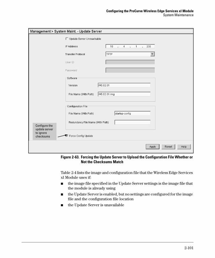
Configuring the ProCurve Wireless Edge Services xl ModuleSystem Maintenance
Figure 2-63. Forcing the Update Server to Upload the Configuration File Whether or Not the Checksums Match
Table 2-4 lists the image and configuration file that the Wireless Edge Services xl Module uses if:
■ the image file specified in the Update Server settings is the image file that the module is already using
■ the Update Server is enabled, but no settings are configured for the image file and the configuration file location
■ the Update Server is unavailable
Configure the update server to ignore checksums
2-101

Configuring the ProCurve Wireless Edge Services xl ModuleSystem Maintenance
Table 2-4. Image and Configuration Files Loaded When an Update Server Is Defined
If the Wireless Edge Services xl Module cannot reach the Update Server, it disables the Update Server settings. On the Management > System Maint.—Update Server screen, the Update Server Unreachable box is checked. To enable the Update Server once again, you must manually uncheck this box.
Image and Configuration File on Module at Reboot
Image File Defined on Update Server Screen and Checksum of Startup-Config
Image and Configuration File Stored on Update Server
Image and Configuration File Used to Reboot Module
Image 1Startup-config
Image 1Startup-config
Does not matterDoes not matter
Image 1Startup-config
Image 1Startup-config
Not setStartup-config
Does not matterDoes not matter
Image 1Startup-config
Image 1Corrupted startup-config
Image 1Startup-config
Does not matterUpdate Server is unavailable or file location is incorrect
Image 1Factory default startup-config
Image 1Corrupted startup-config
Image 2Startup-config
Update Server is unavailable or file locations are incorrect
Image 1Factory default startup-config
Image 1Startup-config
Image 2Startup-config
Update Server is unavailable or file locations are incorrect
Image 1Factory default startup-config
2-102

Configuring the ProCurve Wireless Edge Services xl ModuleSystem Maintenance
Table 2-5 shows which software image and configuration file are loaded in other circumstances.
Table 2-5. Image and Configuration Files Loaded When an Update Server Is Defined
Image and Configuration File on Module at Reboot
Image File Defined on Update Server Screen and Checksum of Startup-Config
Image and Configuration File Stored on Update Server
Image and Configuration File Used to Reboot Module
Image 1Startup-config
Image 2Startup-config
Image 2Matches startup-config
Image 2Startup-config
Image 1Startup-config
Image 2Startup-config
Image 2Does not match startup-config
Image 2Factory default startup-config
Image 1Corrupted startup-config
Image 1Startup-config
Does not matterMatches startup-config
Image 1Startup-config
Image 1Corrupted startup-config
Image 1Startup-config
Does not matterDoes not match startup-config
Image 1Factory default startup-config
Image 1Startup-config
Image 2Startup-config
Image 3Matches startup-config
Image 1Factory default startup-config
Image 1Startup-config
Image 2Startup-config
Image 3Does not match startup-config
Image 1Factory default startup-config
Image 1Corrupted startup-config
Image 2Startup-config
Image 2Matches startup-config
Image 2Startup-config
Image 1Corrupted startup-config
Image 2Startup-config
Image 2Does not match startup-config
Image 2Factory default startup-config
2-103

Configuring the ProCurve Wireless Edge Services xl ModuleSystem Maintenance
Configuring the Update Server Settings
To configure the Update Server settings, complete these steps:
1. Select Management > System Maint.—Update Server.
Figure 2-64. Management > System Maint.—Update Server Screen
2. Check the Update Server Unreachable box if you do not want the Wireless Edge Services xl Module to use the Update Server.
3. In the IP Address field, enter the IP address of the FTP or TFTP server on which the software image is saved.
4. In the Transfer Protocol field, use the drop-down menu to specify whether the Update Server is an FTP server or a TFTP server.
2-104
Configuring the ProCurve Wireless Edge Services xl ModuleSystem Maintenance
5. Enter the login credentials for the FTP server.
a. In the User ID field, enter the username.
b. In the Password field, enter the password for this username.
6. In the Software section, configure the version number, filename and path for the software image.
a. In the Version field, enter the version of the software image that is stored on the FTP or TFTP server.
b. In the File Name (with Path) field, enter the name of the file that contains the software image and the path to that filename (if the path is required by the Update Server). If you are using an FTP server and the configuration file is saved at the server’s root level, enter a period followed by a slash (./) for the path. If the configuration file resides at a different level on the FTP server, enter the complete path. (If you are using a TFTP server, this field may not be required.)
7. In the Configuration File section, in the File Name (with Path) field, enter the name of the file that contains the configuration and the path to that filename (if the path is required by the Update Server).
8. If your Wireless Edge Services xl Module is a member of a redundancy group, you should store a common configuration for all members on the Update Server. Specify the name and path for this common configuration in the Redundancy File Name (with Path) field.
The file specified in the File Name (with Path) field should include individ-ualized settings, such as IP address, for this particular module. You must specify the individualized configuration. The redundancy configuration alone is not sufficient.
9. Click the Apply button to save your changes to the running-config.
10. Click the Save button in the navigation bar to save your changes to the startup-up config.
Password Encryption
The Wireless Edge Services xl Module might store a variety of passwords. Encryption prevents someone from accessing the module’s configuration file (whether through the CLI or an insecurely transmitted file) and reading the passwords.
2-105
Configuring the ProCurve Wireless Edge Services xl ModuleSystem Maintenance
By default, only two types of passwords are encrypted when you view the configuration:
■ SNMP v3 user passwords
■ Web-User passwords (encrypted by SHA)
Other types display in plaintext, by default:
■ passwords for users in the local RADIUS database
■ shared secrets for the RADIUS servers specified in WLAN settings
■ shared secret for globally configured RADIUS servers (used for authenti-cation, authorization, and accounting [AAA])
■ WEP keys
■ WPA/WPA2 preshared keys (PSK)
However, you can configure SHA256-AES256 encryption for these five types of passwords. In addition to obscuring the passwords in the configuration file, encryption protects passwords that the module might send over the wire to facilitate seamless Layer 2 roaming for Web-Auth.
To enable password encryption, configure the encryption secret. The Wireless Edge Services xl Module uses this secret to encrypt:
■ all previously configured passwords of the five types listed above
The SNMP v3 and Web-User passwords (by default, encrypted) are unaf-fected by the password encryption configuration.
■ all new passwords of the five types listed above
■ all Web-Auth passwords that the module sends to other modules in order to facilitate roaming
Make sure to configure the same password on all modules.
To configure the encryption key, follow these steps:
1. Select Management.
2-106
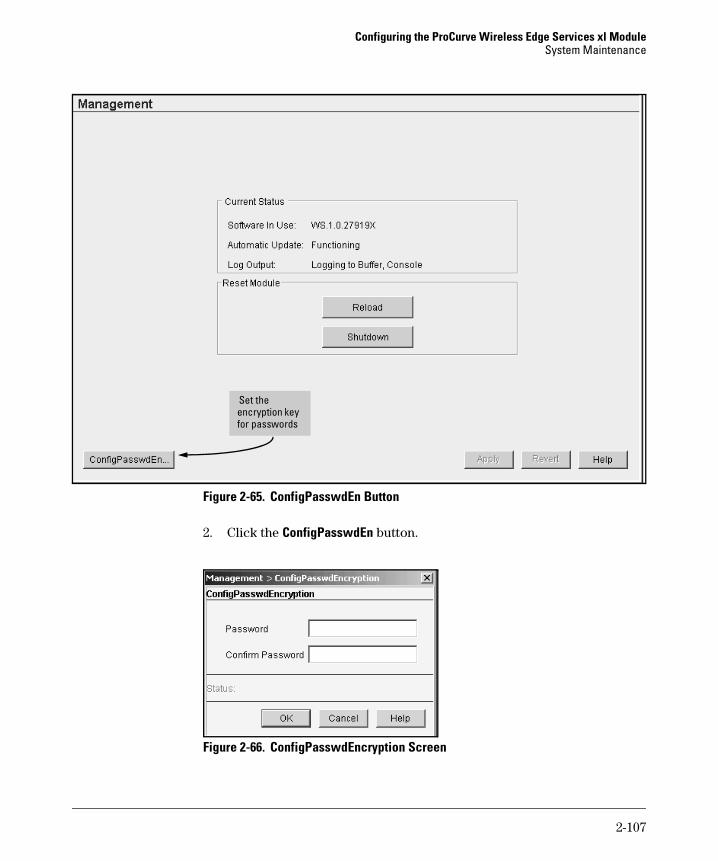
Configuring the ProCurve Wireless Edge Services xl ModuleSystem Maintenance
Figure 2-65. ConfigPasswdEn Button
2. Click the ConfigPasswdEn button.
Figure 2-66. ConfigPasswdEncryption Screen
Set the encryption key for passwords
2-107
Configuring the ProCurve Wireless Edge Services xl ModuleSNMP Traps and Error Reporting
3. Set the key that encrypts passwords in the Password and Confirm Password fields.
The key can be between 8 and 32 alphanumeric and special characters.
4. Click the OK button.
To disable password encryption, you must access the CLI and enter this command from the global configuration mode context:
ProCurve(wireless-services-C)(config)# no password-encryption
All previously configured passwords, as well as all new passwords, now are displayed in plaintext.
You cannot disable password encryption from the Web browser interface.
SNMP Traps and Error Reporting
SNMP is an industry-standard protocol that allows you to manage and monitor a variety of network devices from a central location. Specifically, you can configure these SNMP-compliant devices and apply consistent security and management policies to these devices across your network. By default, the Wireless Edge Services xl Module supports SNMP v1, v2, and v3.
In addition to providing support for SNMP applications, SNMP v3 is required for the Web browser interface to function. If you attempt to disable support for SNMP v3, a warning message is displayed. Disabling SNMP v3 also disables the applet required for the Web browser interface, and you will be logged out. You will be unable to access the Web browser interface until you enable SNMP v3 again.
SNMP support also enables you to set up alarms on the Wireless Edge Services xl Module. You simply enable the SNMP traps for the alarms you want to log. (For more information, see “Enabling SNMP Traps” on page 2-113.)
SNMP Communities
The Wireless Edge Services xl Modules uses the following community names:
■ public
■ private
■ trap
2-108

Configuring the ProCurve Wireless Edge Services xl ModuleSNMP Traps and Error Reporting
Each community name is assigned an access control, which determines the operations an SNMP server can complete on the Wireless Edge Services xl Module:
■ Read-only—The SNMP server can retrieve information from the module.
■ Read-write—The SNMP server can retrieve information and modify the configuration settings.
By default, the public and trap communities have read-only access, and the private community has read-write access.
The Wireless Edge Services xl Module uses the following SNMP v1/c2 com-munity names:
■ public
■ private
■ trap
You can also set up traps using the SNMP v3 trap user.
Modifying SNMP v2 Communities
By default, the Wireless Edge Services xl Module names the read-only community “public” and the read-write community “private.” To change the community name or access control setting for these communities, complete these steps:
1. Select Management > SNMP Access > v1/v2c.
2-109
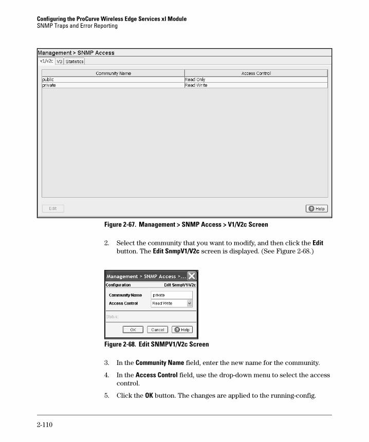
Configuring the ProCurve Wireless Edge Services xl ModuleSNMP Traps and Error Reporting
Figure 2-67. Management > SNMP Access > V1/V2c Screen
2. Select the community that you want to modify, and then click the Edit button. The Edit SnmpV1/V2c screen is displayed. (See Figure 2-68.)
Figure 2-68. Edit SNMPV1/V2c Screen
3. In the Community Name field, enter the new name for the community.
4. In the Access Control field, use the drop-down menu to select the access control.
5. Click the OK button. The changes are applied to the running-config.
2-110

Configuring the ProCurve Wireless Edge Services xl ModuleSNMP Traps and Error Reporting
6. Click the Save link at the top of the Web browser interface to save the changes to the startup-config.
SNMP Statistics
You can view a number of SNMP statistics. To understand these statistics, you should know the five basic messages exchanged between SNMP servers and agents:
■ GET—SNMP servers send a GET message to request information about a setting.
■ GET-NEXT—SNMP servers send a GET-NEXT message to request infor-mation about several SNMP objects in the device.
■ SET—SNMP servers send a SET message to modify a configuration setting. Servers must have read-write access to make configuration changes.
■ GET-RESPONSE—In response to a GET, GET-NEXT, or SET message, SNMP agents send a GET-RESPONSE message. This message includes one of the following:
• requested information
• confirmation that the requested change was made
• error that explains why the agent cannot supply the requested infor-mation or make the requested change
■ TRAP—SNMP agents use TRAP messages to report events.
Many SNMP statistics reference these messages.
To view SNMP statistics, select Management > SNMP Access and click the Statistics tab.
2-111
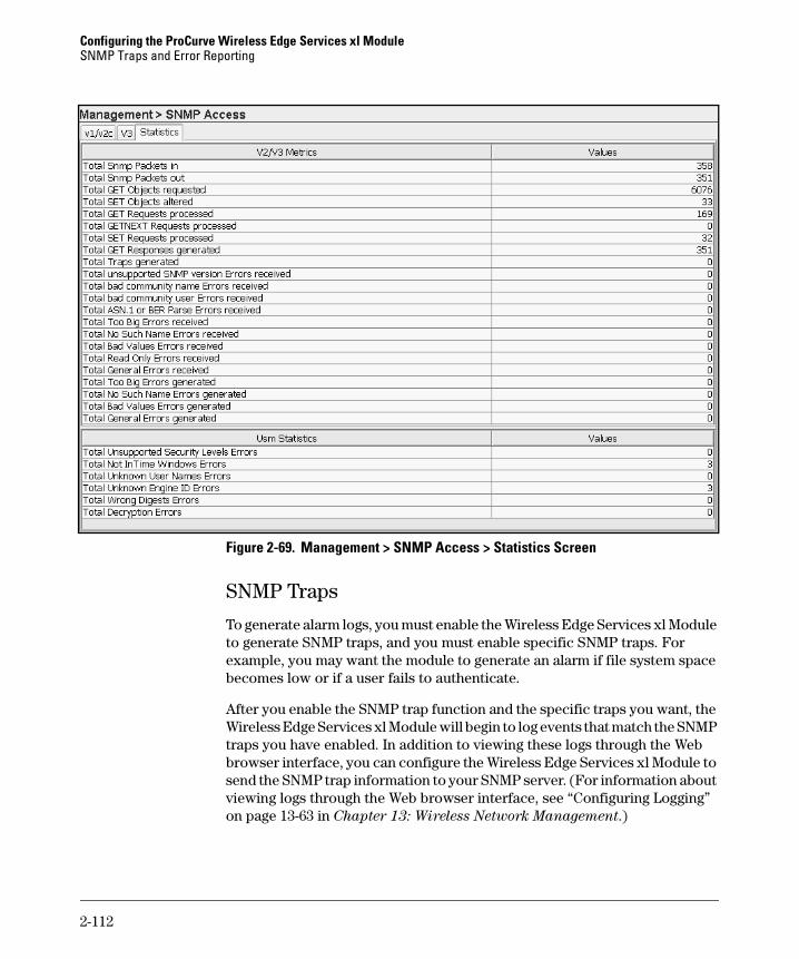
Configuring the ProCurve Wireless Edge Services xl ModuleSNMP Traps and Error Reporting
Figure 2-69. Management > SNMP Access > Statistics Screen
SNMP Traps
To generate alarm logs, you must enable the Wireless Edge Services xl Module to generate SNMP traps, and you must enable specific SNMP traps. For example, you may want the module to generate an alarm if file system space becomes low or if a user fails to authenticate.
After you enable the SNMP trap function and the specific traps you want, the Wireless Edge Services xl Module will begin to log events that match the SNMP traps you have enabled. In addition to viewing these logs through the Web browser interface, you can configure the Wireless Edge Services xl Module to send the SNMP trap information to your SNMP server. (For information about viewing logs through the Web browser interface, see “Configuring Logging” on page 13-63 in Chapter 13: Wireless Network Management.)
2-112

Configuring the ProCurve Wireless Edge Services xl ModuleSNMP Traps and Error Reporting
Enabling SNMP Traps
By default, all SNMP traps are disabled. To enable SNMP traps, complete these steps:
1. Select Management > SNMP Trap Configuration and click the Configuration tab.
Figure 2-70. Management > SNMP Trap Configuration Screen
The SNMP traps for the Wireless Edge Services xl Module are divided into the following categories:
• Redundancy
• Miscellaneous
• NSM
• Mobility
• DHCP
• Radius
2-113

Configuring the ProCurve Wireless Edge Services xl ModuleSNMP Traps and Error Reporting
• SNMP
• Wireless
2. Check the Allow Traps to be generated box.
3. To view the SNMP traps in a category, click the Plus ( + ) sign next to the category. To view the SNMP traps in all categories, click the Expand all items button.
4. To enable all the traps, select All Traps and click the Enable all sub-items button.
5. To enable all the SNMP traps in a category, select the category and click the Enable all sub-items button.
6. To enable a specific SNMP trap, select the trap and click the Enable button or double-click the trap. A green check mark is displayed next to enabled traps. A red x is displayed next to disabled traps.
Figure 2-71. Enabling SNMP Traps on the Management > SNMP Trap Configuration Screen
2-114
Configuring the ProCurve Wireless Edge Services xl ModuleSNMP Traps and Error Reporting
7. Click the Apply button to save the change to the running-config.
8. Click the Save link at the top of the Web browser interface to save the changes to the startup-config.
Disabling SNMP Traps
To disable an SNMP trap that you previously enabled, complete these steps:
1. Select Management > SNMP Trap Configuration and click the Configuration tab.
2. To disable a specific SNMP trap, expand the SNMP category. Select the SNMP trap that you want to disable, and then click the Disable button or double-click the SNMP trap.
3. To disable all the SNMP traps in a category, select the category and click the Disable all sub-items button.
4. Click the Apply button to save the change to the running-config.
5. Click the Save link at the top of the Web browser interface to save the changes to the startup-config.
Setting Thresholds
You can set the thresholds that determine when SNMP traps are generated. Select Management > SNMP Trap Configuration and click the Wireless Statistics Thresholds tab.
2-115

Configuring the ProCurve Wireless Edge Services xl ModuleSNMP Traps and Error Reporting
Figure 2-72. Management > SNMP Trap Configuration > Wireless Statistics Thresholds Screen
Table 2-6 shows which thresholds you can set for stations, radios, and WLANs, and for the Wireless Edge Services xl Module itself.
2-116
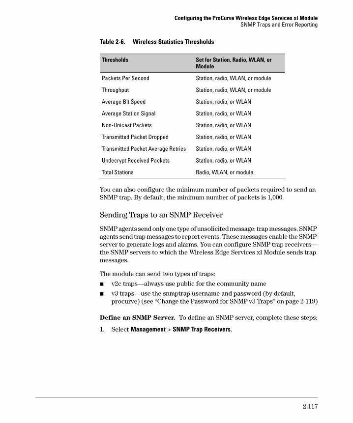
Configuring the ProCurve Wireless Edge Services xl ModuleSNMP Traps and Error Reporting
Table 2-6. Wireless Statistics Thresholds
You can also configure the minimum number of packets required to send an SNMP trap. By default, the minimum number of packets is 1,000.
Sending Traps to an SNMP Receiver
SNMP agents send only one type of unsolicited message: trap messages. SNMP agents send trap messages to report events. These messages enable the SNMP server to generate logs and alarms. You can configure SNMP trap receivers—the SNMP servers to which the Wireless Edge Services xl Module sends trap messages.
The module can send two types of traps:
■ v2c traps—always use public for the community name
■ v3 traps—use the snmptrap username and password (by default, procurve) (see “Change the Password for SNMP v3 Traps” on page 2-119)
Define an SNMP Server. To define an SNMP server, complete these steps:
1. Select Management > SNMP Trap Receivers.
Thresholds Set for Station, Radio, WLAN, or Module
Packets Per Second Station, radio, WLAN, or module
Throughput Station, radio, WLAN, or module
Average Bit Speed Station, radio, or WLAN
Average Station Signal Station, radio, or WLAN
Non-Unicast Packets Station, radio, or WLAN
Transmitted Packet Dropped Station, radio, or WLAN
Transmitted Packet Average Retries Station, radio, or WLAN
Undecrypt Received Packets Station, radio, or WLAN
Total Stations Radio, WLAN, or module
2-117
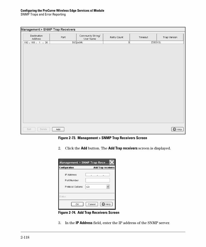
Configuring the ProCurve Wireless Edge Services xl ModuleSNMP Traps and Error Reporting
Figure 2-73. Management > SNMP Trap Receivers Screen
2. Click the Add button. The Add Trap receivers screen is displayed.
Figure 2-74. Add Trap Receivers Screen
3. In the IP Address field, enter the IP address of the SNMP server.
2-118
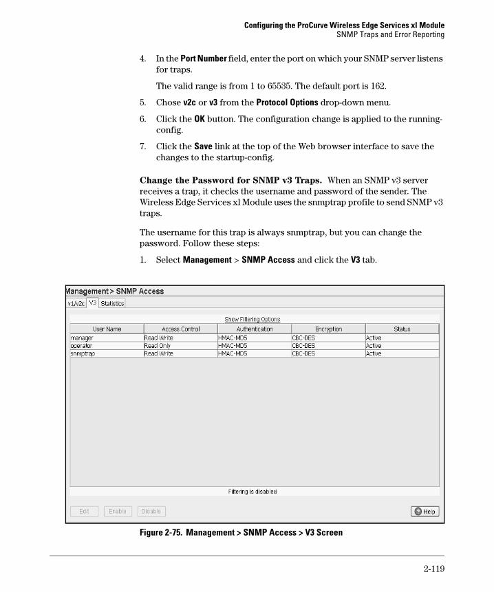
Configuring the ProCurve Wireless Edge Services xl ModuleSNMP Traps and Error Reporting
4. In the Port Number field, enter the port on which your SNMP server listens for traps.
The valid range is from 1 to 65535. The default port is 162.
5. Chose v2c or v3 from the Protocol Options drop-down menu.
6. Click the OK button. The configuration change is applied to the running-config.
7. Click the Save link at the top of the Web browser interface to save the changes to the startup-config.
Change the Password for SNMP v3 Traps. When an SNMP v3 server receives a trap, it checks the username and password of the sender. The Wireless Edge Services xl Module uses the snmptrap profile to send SNMP v3 traps.
The username for this trap is always snmptrap, but you can change the password. Follow these steps:
1. Select Management > SNMP Access and click the V3 tab.
Figure 2-75. Management > SNMP Access > V3 Screen
2-119

Configuring the ProCurve Wireless Edge Services xl ModuleSNMP Traps and Error Reporting
2. Select the snmptrap user and click the Edit button.
Figure 2-76. Changing the Password for SNMP v3 Traps
3. In the Old Password field, enter the current password—by default, procurve.
4. In the New Password and Confirm Password fields, enter the new password.
5. Click the OK button.
2-120
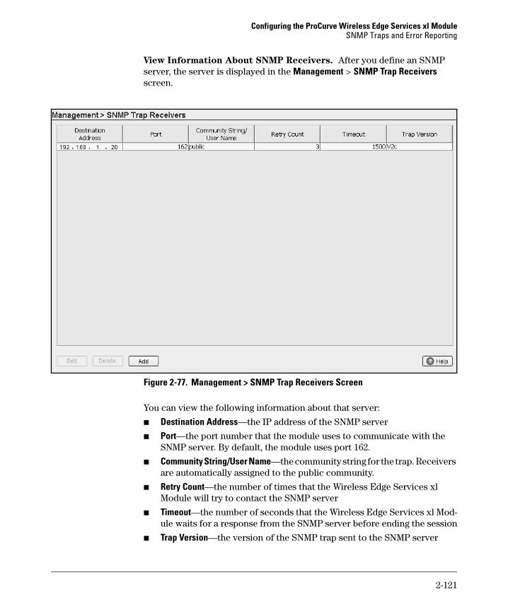
Configuring the ProCurve Wireless Edge Services xl ModuleSNMP Traps and Error Reporting
View Information About SNMP Receivers. After you define an SNMP server, the server is displayed in the Management > SNMP Trap Receivers screen.
Figure 2-77. Management > SNMP Trap Receivers Screen
You can view the following information about that server:
■ Destination Address—the IP address of the SNMP server
■ Port—the port number that the module uses to communicate with the SNMP server. By default, the module uses port 162.
■ Community String/User Name—the community string for the trap. Receivers are automatically assigned to the public community.
■ Retry Count—the number of times that the Wireless Edge Services xl Module will try to contact the SNMP server
■ Timeout—the number of seconds that the Wireless Edge Services xl Mod-ule waits for a response from the SNMP server before ending the session
■ Trap Version—the version of the SNMP trap sent to the SNMP server
2-121
Configuring the ProCurve Wireless Edge Services xl ModuleSNMP Traps and Error Reporting
Edit an SNMP Trap Receiver. If you define an SNMP trap receiver and later need to change its IP address, complete these steps:
1. Select Management > SNMP Trap Receivers.
2. Click the Edit button.
3. You can change these settings:
• IP address
• port
To change the SNMP version, you must delete the receiver from the Management > SNMP Trap Receivers screen and re-add it with the correct version.
4. Click the OK button.
5. Click the Save link at the top of the Web browser interface to save the changes to the startup-config.
2-122
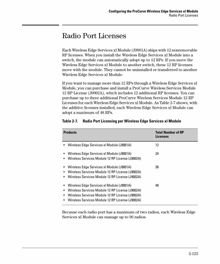
Configuring the ProCurve Wireless Edge Services xl ModuleRadio Port Licenses
Radio Port Licenses
Each Wireless Edge Services xl Module (J9001A) ships with 12 nonremovable RP licenses. When you install the Wireless Edge Services xl Module into a switch, the module can automatically adopt up to 12 RPs. If you move the Wireless Edge Services xl Module to another switch, these 12 RP licenses move with the module. They cannot be uninstalled or transferred to another Wireless Edge Services xl Module.
If you want to manage more than 12 RPs through a Wireless Edge Services xl Module, you can purchase and install a ProCurve Wireless Services Module 12 RP License (J9002A), which includes 12 additional RP licenses. You can purchase up to three additional ProCurve Wireless Services Module 12 RP Licenses for each Wireless Edge Services xl Module. As Table 2-7 shows, with the additive licenses installed, each Wireless Edge Services xl Module can adopt a maximum of 48 RPs.
Table 2-7. Radio Port Licensing per Wireless Edge Services xl Module
Because each radio port has a maximum of two radios, each Wireless Edge Services xl Module can manage up to 96 radios.
Products Total Number of RP Licenses
• Wireless Edge Services xl Module (J9001A) 12
• Wireless Edge Services xl Module (J9001A)• Wireless Services Module 12 RP License (J9002A)
24
• Wireless Edge Services xl Module (J9001A)• Wireless Services Module 12 RP License (J9002A)• Wireless Services Module 12 RP License (J9002A)
36
• Wireless Edge Services xl Module (J9001A)• Wireless Services Module 12 RP License (J9002A)• Wireless Services Module 12 RP License (J9002A)• Wireless Services Module 12 RP License (J9002A)
48
2-123

Configuring the ProCurve Wireless Edge Services xl ModuleRadio Port Licenses
If you install additional RP licenses on a Wireless Edge Services xl Module, these licenses remain with the module if you move the module:
■ from one slot to another slot in the same wireless services-enabled switch
■ from one wireless services-enabled switch to another
It is possible, however, to move additive licenses—those purchased through the Wireless Services Module 12 RP License—from one Wireless Edge Ser-vices xl Module to another. For example, suppose your company’s marketing department moved from the North building to the South building at your company’s main office. Both buildings have a wireless services-enabled switch: the Wireless Edge Services xl Module in the North building has 24 RP licenses, and the Wireless Edge Services xl Module in the South building has 12 RP licenses. After you move the marketing department, there are fewer users in the North building, so you no longer need as many RP licenses in the North building. With the added users in the South building, however, you need more RP licenses on that Wireless Edge Services xl Module.
2-124
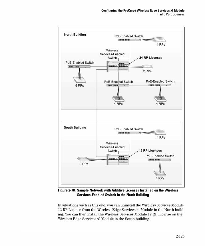
Configuring the ProCurve Wireless Edge Services xl ModuleRadio Port Licenses
Figure 2-78. Sample Network with Additive Licenses Installed on the Wireless Services-Enabled Switch in the North Building
In situations such as this one, you can uninstall the Wireless Services Module 12 RP License from the Wireless Edge Services xl Module in the North build-ing. You can then install the Wireless Services Module 12 RP License on the Wireless Edge Services xl Module in the South building.
2-125
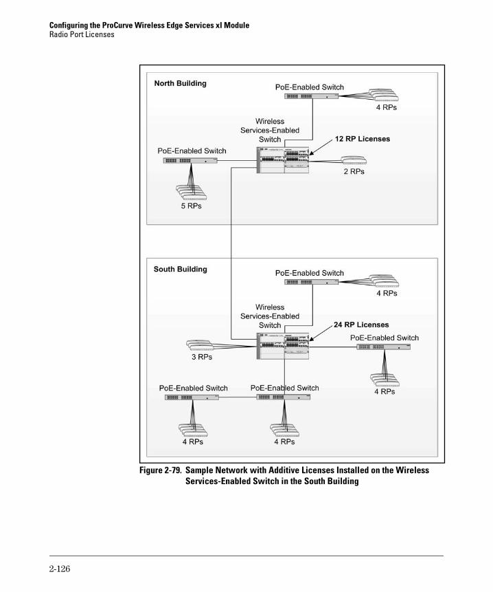
Configuring the ProCurve Wireless Edge Services xl ModuleRadio Port Licenses
Figure 2-79. Sample Network with Additive Licenses Installed on the Wireless Services-Enabled Switch in the South Building
2-126
Configuring the ProCurve Wireless Edge Services xl ModuleRadio Port Licenses
Only the Wireless Edge Services xl Module (J9001A) has RP licenses. The Redundant Wireless Services xl Module does not include radio port licenses and cannot independently adopt radio ports. When the Redundant Wireless Services xl Module is configured as part of a Redundancy Group, however, it can adopt radio ports under certain circumstances (such as if the Wireless Edge Services xl Module fails).
Installing or Uninstalling Licenses on a Wireless Edge Services xl Module
You can use one of the following methods to install or uninstall RP licenses on the Wireless Edge Services xl Module:
■ Manual method—You can use either the Web browser interface or the CLI to manually install and manage the Wireless Services Module 12 RP License. You may want to use the manual installation method if you are managing a small number of RP licenses or if you do not currently use ProCurve Manager.
■ ProCurve Manager—You can use ProCurve Manager to install and uninstall the Wireless Services Module 12 RP License. If you do not currently use ProCurve Manager, you may find it worth installing. The CD-ROM that accompanies your licenses contains a free copy of ProCurve Manager.
This management and configuration guide focuses on using the Web browser interface for the Wireless Edge Services xl Module.
Registering on the My ProCurve Web Portal
Whichever method you use to install or uninstall the Wireless Services Module 12 RP License, you must register on the My ProCurve Web portal (http://my.procurve.com). Registration is free and allows you to manage not only the Wireless Services Module 12 RP License but also licenses for other ProCurve products.
The My ProCurve Web portal allows you to:
■ generate a license
■ view the licenses that you have registered
■ view your license history
■ uninstall a license
■ export license information to a spreadsheet
2-127
Configuring the ProCurve Wireless Edge Services xl ModuleRadio Port Licenses
If you have not yet registered with the My ProCurve Web portal, visit http://my.procurve.com and follow the registration instructions.
Understanding the Numbers: IDs and Keys
Installing and uninstalling the Wireless Services Module 12 RP License involves several different numbers:
■ Registration ID—The Wireless Services Module 12 RP License includes a registration ID. You do not input this number to install the license. Instead, you enter this number on the My ProCurve Web portal, which then generates the license key that you enter to install the Wireless Services Module 12 RP License.
■ Hardware ID—This number identifies the Wireless Edge Services xl Module. It includes the module’s serial number and an identifier for the additional license.
■ License key—The My ProCurve Web portal generates the license key after you enter both the registration ID and the hardware ID. You must enter this number to enable the RPs that you are licensing.
■ Uninstall verification key—This number is generated if you uninstall a radio port license from a ProCurve device. If you want to install the Wireless Services Module RP License on another module, you use the uninstall verification key to generate a new registration ID on the My ProCurve portal.
Installing RP Licenses
If you decide to use the manual method to install the Wireless Services Module 12 RP License, you must be able to access the My ProCurve Web portal and the Web browser interface for the Wireless Edge Services xl Module. For convenience, you should open two browsers so that you can move easily between the portal and the Web browser interface.
After you open two Web browsers, complete these steps:
1. Locate the registration ID for the Wireless Services Module 12 RP License and place it within easy reach.
2. Access the My ProCurve Web portal at http://my.procurve.com and sign in.
3. On the main My ProCurve page, click My Software. (See Figure 2-80.)
2-128
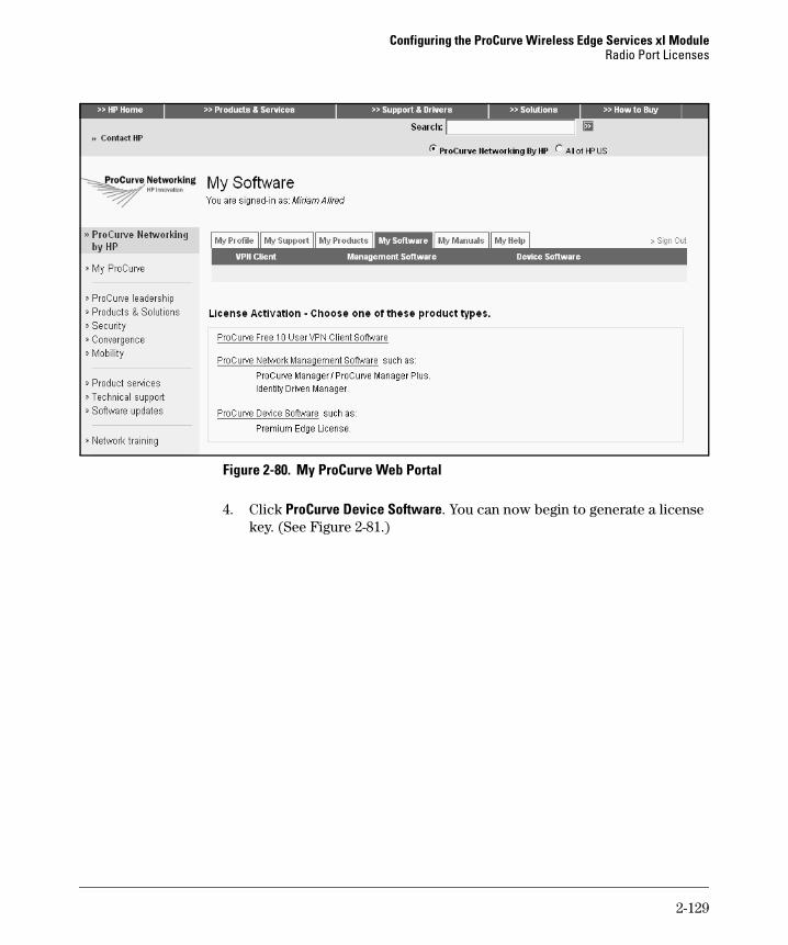
Configuring the ProCurve Wireless Edge Services xl ModuleRadio Port Licenses
Figure 2-80. My ProCurve Web Portal
4. Click ProCurve Device Software. You can now begin to generate a license key. (See Figure 2-81.)
2-129
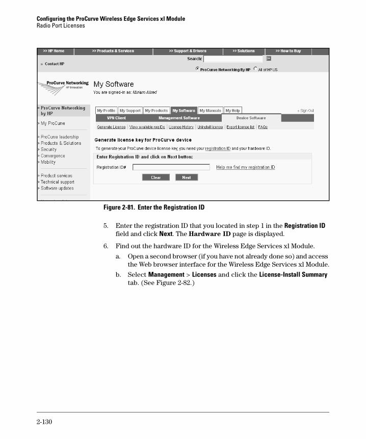
Configuring the ProCurve Wireless Edge Services xl ModuleRadio Port Licenses
Figure 2-81. Enter the Registration ID
5. Enter the registration ID that you located in step 1 in the Registration ID field and click Next. The Hardware ID page is displayed.
6. Find out the hardware ID for the Wireless Edge Services xl Module.
a. Open a second browser (if you have not already done so) and access the Web browser interface for the Wireless Edge Services xl Module.
b. Select Management > Licenses and click the License-Install Summary tab. (See Figure 2-82.)
2-130

Configuring the ProCurve Wireless Edge Services xl ModuleRadio Port Licenses
Figure 2-82. The License-Install Summary Screen
c. Click the Install button at the bottom of the screen. The Install License (Step 1 and Step 2) screen is displayed. (See Figure 2-83.)
Figure 2-83. The Install License (Step 1 and Step 2) Screen
2-131
Configuring the ProCurve Wireless Edge Services xl ModuleRadio Port Licenses
d. In the Step 1—Generate Hardware ID section, click the Gen-Hw-ID button.
e. When a number is displayed in the System Generated Hardware Id field, copy it (using Ctrl-C) or write it down. (Copying the number is easier and more accurate.) You must enter this number on the My ProCurve Web portal.
7. Return to the My ProCurve Web portal. In the Enter Hardware ID# field, paste (using Ctrl-V) or enter the hardware ID.
8. Enter notes in the Customer Notes field. This field is optional. For example, you might want to enter a short description that explains where this Wireless Edge Services xl Module is located. These notes are stored, along with the registration ID number, in your account on the My ProCurve Web portal.
9. Click the Next button. The License Agreement page is displayed.
10. Read the license terms. If you agree to these terms, check the I agree to the license terms box.
11. Click the Generate License button. The My ProCurve Web portal generates a license key and displays it on the License Key Confirmation page. In addition, the portal emails you the license key.
12. Copy the license key (Ctrl-C) from the screen or write it down.
13. Return to the Install License (Step 1 and Step 2) screen in the Web browser interface for the Wireless Edge Services xl Module.
14. In the Step 2—Install License Key section, enter the license key and click the Lic-Install button. A message confirms a successful installation or identifies a problem that prevented the license from installing.
15. If you have successfully installed the Wireless Services Module 12 RP License, click the Close button. The new license is now listed on the Management > Licenses screen.
Removing RP Licenses
If you want to transfer the Wireless Services Module 12 RP License from one Wireless Edge Services xl Module to another, you must first access the Web interface browser and uninstall the license. During this process, the module generates an uninstall verification key. You must copy or record this key so that you can enter it on the My ProCurve Web portal. The Web portal, in turn, uses this key to generate a new verification key, which you can use to install the Wireless Services Module 12 RP License on the new Wireless Edge Ser-vices xl Module.
2-132

Configuring the ProCurve Wireless Edge Services xl ModuleRadio Port Licenses
To simplify the process of uninstalling a license, you may want to use two Web browsers as you complete these steps:
1. Access the Web browser interface for the Wireless Edge Services xl Module.
2. Select Management > Licenses and click the License-Install Summary tab.
3. Highlight the license that you want to uninstall and click the Uninstall button at the bottom of the screen. The Un-Install License screen is displayed. (See Figure 2-84.)
Figure 2-84. Un-Install License Screen
4. For Feature-Group, accept the default setting of radio ports.
5. For FG-specific-data, enter 12. FG is short for Feature-Group, and this field specifies the number of RP licenses.
6. Click the Lic-Uninstall button. A warning message is displayed, reminding you that if stations are associated with RPs that use these licenses, the stations will lose their network connection.
Figure 2-85. Warning Message Displayed When You Attempt to Uninstall Licenses
7. Click the Yes button if you want to continue the process of uninstalling the licenses.
2-133
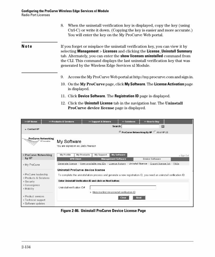
Configuring the ProCurve Wireless Edge Services xl ModuleRadio Port Licenses
8. When the uninstall verification key is displayed, copy the key (using Ctrl-C) or write it down. (Copying the key is easier and more accurate.) You will enter the key on the My ProCurve Web portal.
N o t e If you forget or misplace the uninstall verification key, you can view it by selecting Management > Licenses and clicking the License_Uninstall Summary tab. Alternately, you can enter the show licenses uninstalled command from the CLI. This command displays the last uninstall verification key that was generated by the Wireless Edge Services xl Module.
9. Access the My ProCurve Web portal at http://my.procurve.com and sign in.
10. On the My ProCurve page, click My Software. The License Activation page is displayed.
11. Click Device Software. The Registration ID page is displayed.
12. Click the Uninstall License tab in the navigation bar. The Uninstall
ProCurve device license page is displayed.
Figure 2-86. Uninstall ProCurve Device License Page
2-134

Configuring the ProCurve Wireless Edge Services xl ModuleRadio Port Licenses
13. Paste (using Ctrl-V) or enter the uninstall verification key in the Uninstall verification ID# field, and the click the Next button. The My ProCurve Web portal generates and displays a new registration ID. The portal emails the registration ID to you and maintains a record of it.
14. To view your registration IDs, click the View available reg IDS link on the My ProCurve Web portal.
To transfer the Wireless Services Module 12 RP License to another Wireless Edges Services xl Module, complete the installation steps described in “Install-ing RP Licenses” on page 2-128.
Redundancy Groups and RP Licensing
To ensure high availability of your company’s wireless services, you can create a redundancy group, which can include up to 12 Wireless Edge Services xl Modules or Redundant Wireless Services xl Modules. If one module fails, the others provide failover capabilities. To eliminate a single point of failure, you should install at least some of the modules in different switches. In the unlikely event that one wireless services-enabled switch fails, the module installed in the remaining wireless services-enabled switch will continue to provide ser-vices for mobile users.
The group must include at least one Wireless Edge Services xl Module, because Redundant Wireless Services xl Modules do not have RP licenses, and on their own, cannot adopt RPs. When you create a redundancy group, the RP licenses assigned to the Wireless Edge Services xl Module with the highest number of licenses is the total number of licenses for the redundancy group. All modules (both primary and redundant) share the group’s licenses among them.
For this reason, a redundancy group should usually include one Wireless Edge Services xl Module and one or two Redundant Wireless Services xl Modules.
2-135
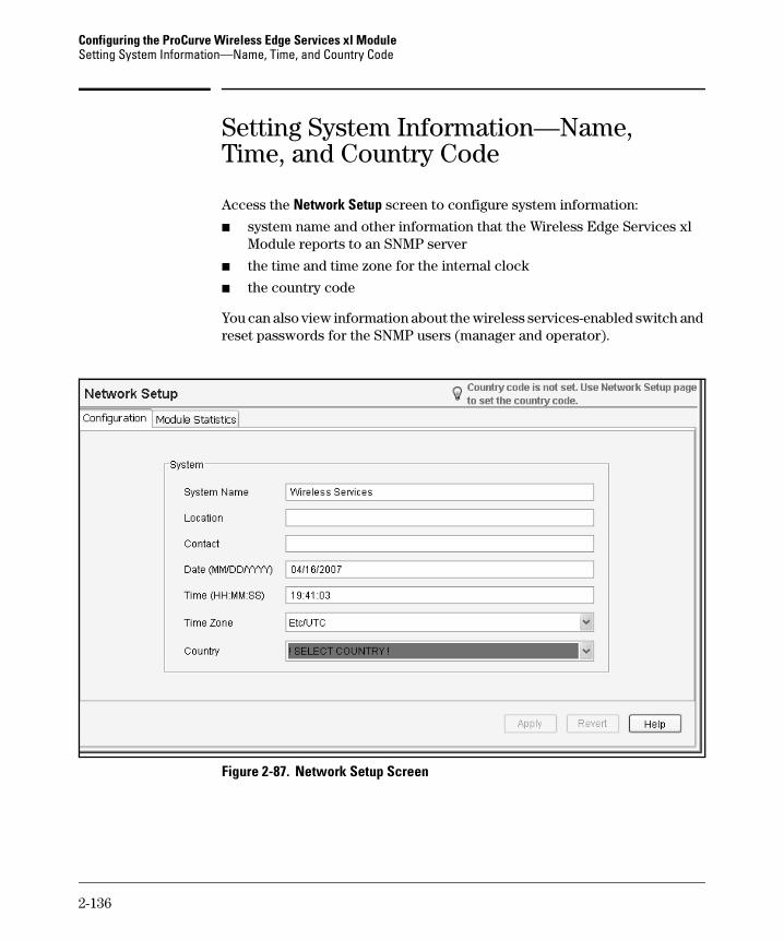
Configuring the ProCurve Wireless Edge Services xl ModuleSetting System Information—Name, Time, and Country Code
Setting System Information—Name, Time, and Country Code
Access the Network Setup screen to configure system information:
■ system name and other information that the Wireless Edge Services xl Module reports to an SNMP server
■ the time and time zone for the internal clock
■ the country code
You can also view information about the wireless services-enabled switch and reset passwords for the SNMP users (manager and operator).
Figure 2-87. Network Setup Screen
2-136

Configuring the ProCurve Wireless Edge Services xl ModuleSetting System Information—Name, Time, and Country Code
Follow these steps to configure the system information, which the Wireless Edge Services xl Module reports to an SNMP server:
1. Name the module by entering a string in the System Name field.
The string can include spaces and special characters.
The default name is “Wireless Services.” Note that, by default, RPs send DNS requests for “Wireless Services” when attempting to be adopted at Layer 3. See “Enabling Layer 3 Adoption Through DNS Lookup” on page 2-66 to learn how to change the name that RPs request.
2. Enter a string in the Location field to identify where the module is installed.
3. Enter a string in the Contact field to identify the person responsible for managing this module.
4. Click the Apply button.
Follow these steps to configure the internal clock manually:
1. Enter the current date in the Date field.
Enter the date in this format, in which MM is the number of the month, DD is the date, and YYYY is the year:
MM/DD/YYYY
2. Enter the current time in the Time field.
Use this format, in which HH is the hour in the 24-hour clock and MM is the minutes:
HH:MM
3. Choose your time zone from the Time Zone drop-down menu.
The menu lists many countries and cities from which you can choose. You can also choose a time relative to Greenwich Mean Time (GMT)—for example, GMT -8.
4. Click the Apply button.
N o t e The Wireless Edge Services xl Module can also receive the date and time from a time server. You must set the time zone manually, however, for the module to receive the correct time. See “Enabling Secure Network Time Protocol (NTP)” on page 2-138.
2-137
Configuring the ProCurve Wireless Edge Services xl ModuleEnabling Secure Network Time Protocol (NTP)
The country code configures the Wireless Edge Services xl Module to choose legal channels and transmit powers for RP radios. You must set the country code before the module can adopt RPs. Follow these steps:
1. From the Country drop-down menu, select your country. (See Figure 2-87.)
2. The Wireless Edge Services xl Module OS warns you that you must select the correct country code. Click the OK button.
3. Click the Apply button.
Enabling Secure Network Time Protocol (NTP)
Because the Wireless Edge Services xl Module supports NTP, you can config-ure the module to take its time from an NTP server. This ensures that the module is always using the correct time, which helps you maintain and monitor your company’s wireless services. The module can function as a secure NTP client, which means that it accepts the time only from authenti-cated sources.
In addition to receiving the time, the Wireless Edge Services xl Module can act as a secure NTP server for other devices. Receiving a highly accurate time by communicating with other NTP servers or NTP peers, or both, the module serves this time to clients.
Secure NTP Overview
NTP is used to synchronize the clocks of computer systems to another server or reference time source, such as a radio or satellite receiver or modem. NTP data packets use a 64-bit timestamp to provide a high degree of accuracy relative to Coordinated Universal Time (UTC). The server might receive its time via a Global Positioning System (GPS) receiver, for example.
Typical NTP configurations use multiple redundant servers and diverse net-work paths to ensure accuracy and reliability. The NTP client software runs continuously in the background and periodically receives updates from one or more servers. The client software ignores responses from servers that appear to be sending the wrong time and averages the results from those that appear to be correct.
2-138

Configuring the ProCurve Wireless Edge Services xl ModuleEnabling Secure Network Time Protocol (NTP)
NTP Modes and Communications
NTP relies on the standard client-server relationship:
■ Clients send time requests to servers.
■ Servers respond with the time.
The Wireless Edge Services xl Module can operate as both a client and a server. To configure the module as a client, you must configure an NTP neighbor that acts as the module’s server.
NTP defines two additional modes:
■ Peer mode—Peers operate on an equal level. Peers act as both clients and servers to each other. They send each other control queries either to synchronize their clocks entirely or simply to exchange information.
■ Broadcast mode—Broadcast mode is similar to client-server mode. Rather than responding to direct time requests, however, a server broad-casts time information.
To configure your Wireless Edge Services xl Module to act as a peer to another NTP device, add that device as an NTP neighbor in peer mode.
If your network includes an NTP server that operates in broadcast mode, you can enable your module to listen for these broadcasts.
NTP Hierarchy
NTP uses a hierarchical system of 16 clock stratum levels (numbered 0 through 15) to define:
■ the distance (number of “hops”) from the reference clock to the Secure NTP server
■ the associated accuracy
Figure 2-88 illustrates the top four NTP clock stratum levels.
2-139

Configuring the ProCurve Wireless Edge Services xl ModuleEnabling Secure Network Time Protocol (NTP)
Figure 2-88. NTP Clock Stratum Levels
The devices at stratum 0 are GPS clocks or other radio clocks. These devices are not attached to the network but are locally connected to computers.
Computers at stratum 1 are attached to stratum 0 devices. Stratum 1 devices can act as time servers for timing requests from stratum 2 servers via NTP.
Computers at stratum 2 send NTP requests to stratum 1 servers. Normally, a stratum 2 computer will reference a number of stratum 1 servers and use the NTP algorithm to gather the best data sample, dropping any stratum 1 servers that seem obviously wrong. Stratum 2 computers are peers to other stratum 2 computers, providing more stable and robust time for all devices in the peer group. Stratum 2 computers normally act as servers for stratum 3 NTP requests.
Computers at stratum 3 and higher employ exactly the same NTP functions of peering and data sampling as stratum 2, and can themselves act as servers for higher strata, potentially up to 16 levels (stratum 0 through stratum 15).
2-140
Configuring the ProCurve Wireless Edge Services xl ModuleEnabling Secure Network Time Protocol (NTP)
Several organizations on the Internet offer NTP servers at stratums 1 through 3. Some require you to purchase the service, and others grant it for free. You can configure your Wireless Edge Services xl Module to communi-cate with one of these servers and then, acting as a server, pass the time on to clients in your network.
When you configure your Wireless Edge Services xl Module to act as the master clock, it uses its internal clock to set the time. In this case, you must set this clock’s stratum. (See “Configuring Secure NTP Options” on page 2-144.)
Secure NTP Enhancements
Knowing the correct time is not only crucial for proper network functioning but also for security. Most security protocols involve timestamps to prevent replay attacks. If an attacker can tamper with your network’s NTP implemen-tation, then he or she may be able to circumvent protections built into otherwise secure protocols. Secure NTP provides several mechanisms for ensuring that devices receive the time from trusted sources:
■ ACLs—You can apply ACLs to control the sources from which the Wire-less Edge Services xl Module accepts particular types of NTP messages.
■ Authentication—If you configure the module to require authentication, it accepts the time only from neighbors that prove they are legitimate. Neighbors authenticate their messages by adding a message authentica-tion code that is generated using an encryption key. In addition to requir-ing authentication, the module can authenticate to other NTP hosts.
Encryption for authentication comes in two varieties:
• With symmetric keys—You manually set the same key on the mod-ule and its neighbor or client. Each message exchanged includes a message authentication code that is generated using this key.
• With autokey—The Wireless Edge Services xl Module and the neigh-bor or client use the public key infrastructure (PKI) algorithm to automatically generate encryption keys.
The client sends the public key associated with its digital certificate to the secure NTP server. The server uses a fast algorithm and a private value to create a cookie, which it encrypts with the client’s public key and returns to the client. Both the client and the server then use the cookie to generate a list of keys for creating message authentication codes.
2-141
Configuring the ProCurve Wireless Edge Services xl ModuleEnabling Secure Network Time Protocol (NTP)
By encrypting the cookie with the client’s public key, the server ensures that only the client can use the cookie. The client, for its part, must initially trust the server. After this initial trust, the client knows that the same server is sending the time because only that server has the cookie that generates the correct keys.
Configuring a Secure NTP Server
As an NTP server, the Wireless Edge Services xl Module sends the time to stations and devices that request this information. To obtain the correct time, it can use its internal clock, exchange messages with other servers in your network (called its NTP neighbors), or both.
To configure secure NTP, first determine the module’s function in your net-work’s NTP implementation:
1. If the Wireless Edge Services xl Module simply needs to accept the time from an NTP server, complete one of the tasks below:
• Enable the module to listen for NTP broadcasts.
• Configure the module to request the time from NTP servers:– Add up to three NTP neighbors in server mode.– For additional security, require authentication.
When you require symmetric key authentication, first configure a key that matches each server’s key.
When you require autokey authentication, make sure that your module has the appropriate certificate.
■ If the module should act as an NTP server, complete these tasks:
• If you want the module to use its internal clock to serve the time, configure it to act as the master clock.
• Or, apply ACLs to control access to the module’s NTP services.
• Optionally, require authentication for neighbors, configuring one of the following options for keys:– For auto-key, enable the feature and make sure that the module
has the necessary public and private keys (stored in a server certificate in a trustpoint configuration).
– Manually create symmetric keys.
2-142

Configuring the ProCurve Wireless Edge Services xl ModuleEnabling Secure Network Time Protocol (NTP)
• Add up to three neighbors. The correct neighbor configuration depends on your network’s NTP implementation:– Your module acts as the master clock and is your network’s only
time server. No neighbors are required.– Your module acts as your network’s only time server and receives
its time from one or more servers on the Internet. Specify up to three Internet servers as neighbors in server mode.
– Your module works with other NTP servers in your network. You can add a combination of up to three servers and peers. For example, you might configure an NTP server on the Internet as a neighbor in server mode and two other NTP servers on your LAN as neighbors in peer mode.
2-143
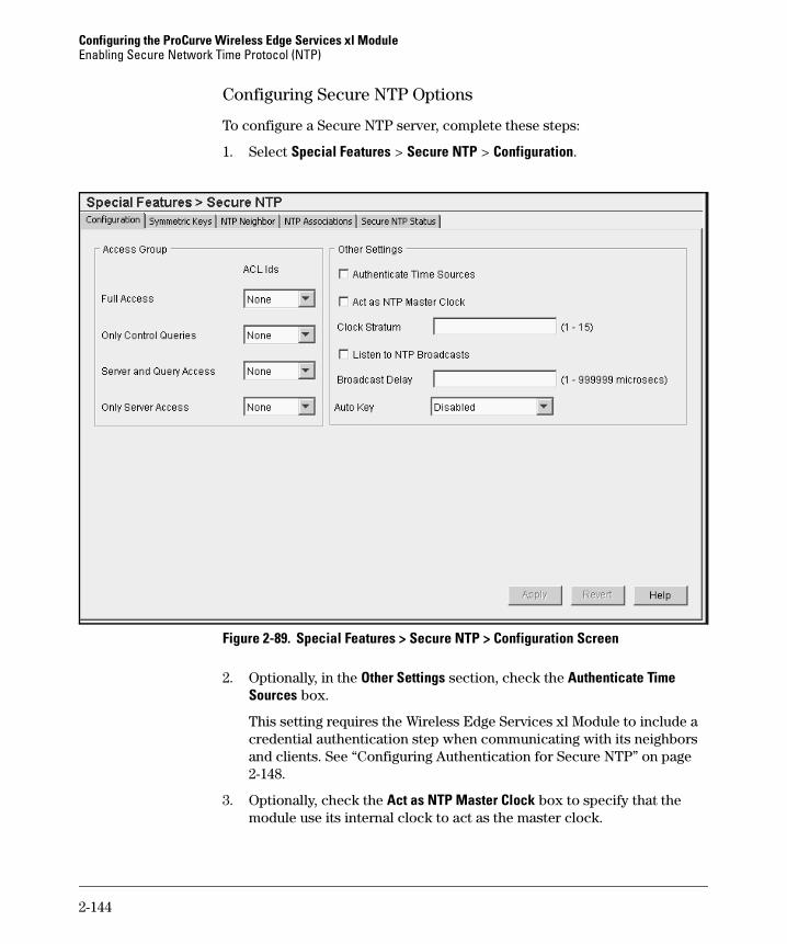
Configuring the ProCurve Wireless Edge Services xl ModuleEnabling Secure Network Time Protocol (NTP)
Configuring Secure NTP Options
To configure a Secure NTP server, complete these steps:
1. Select Special Features > Secure NTP > Configuration.
Figure 2-89. Special Features > Secure NTP > Configuration Screen
2. Optionally, in the Other Settings section, check the Authenticate Time Sources box.
This setting requires the Wireless Edge Services xl Module to include a credential authentication step when communicating with its neighbors and clients. See “Configuring Authentication for Secure NTP” on page 2-148.
3. Optionally, check the Act as NTP Master Clock box to specify that the module use its internal clock to act as the master clock.
2-144

Configuring the ProCurve Wireless Edge Services xl ModuleEnabling Secure Network Time Protocol (NTP)
If you enable your module to act as the master clock, it can serve the time whether or not it receives the time from another server or peer.
4. If you checked the Act as NTP Master Clock box (in step 3), in the Clock Stratum field enter how many hops (from 1 to 15) the Wireless Edge Services xl Module is from an NTP time source.
Valid values are from 1 to 15, although your clock stratum value should be at least 2 (because you are not actually connected to a stratum 0 device). Typically, you should set the stratum somewhat higher (for example, to 10): the Wireless Edge Services xl Module automatically chooses the NTP resource with the lowest stratum number, and its internal clock should not take precedence over a more robust clock.
The NTP-enabled module compares the time reported by several sources and does not synchronize to a time source whose time is significantly different than others, even if its stratum is lower. You do not need to worry that your module will synchronize to an NTP server that is not synchro-nized itself.
5. Check the Listen to NTP Broadcasts box to allow the Wireless Edge Services xl Module to receive the time from an NTP broadcast server.
The module and the NTP broadcast server must be on the same subnet-work.
6. If you check the Listen to NTP Broadcasts box, you have the option of setting the broadcast delay in the Broadcast Delay field.
By default, the Wireless Edge Services xl Module exchanges a series of packets with the broadcast server to estimate the average delay to the server. With this information, the module knows by how much to offset the time it receives from the server.
Alternatively, you can manually specify the estimated delay to the server by entering a value between 1 and 999999 microseconds in the Broadcast Delay field.
7. Click the Apply button.
You can now set up optional security mechanisms (see “Applying ACLs to NTP Services” on page 2-146 and “Configuring Authentication for Secure NTP” on page 2-148) and add neighbors (see “Configuring NTP Neighbors” on page 2-152).
2-145
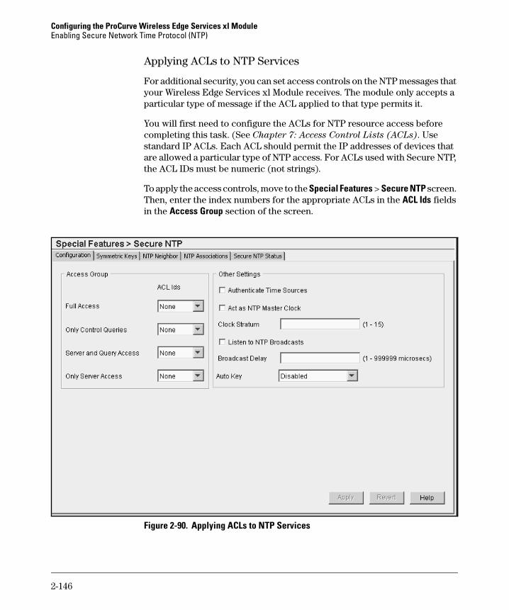
Configuring the ProCurve Wireless Edge Services xl ModuleEnabling Secure Network Time Protocol (NTP)
Applying ACLs to NTP Services
For additional security, you can set access controls on the NTP messages that your Wireless Edge Services xl Module receives. The module only accepts a particular type of message if the ACL applied to that type permits it.
You will first need to configure the ACLs for NTP resource access before completing this task. (See Chapter 7: Access Control Lists (ACLs). Use standard IP ACLs. Each ACL should permit the IP addresses of devices that are allowed a particular type of NTP access. For ACLs used with Secure NTP, the ACL IDs must be numeric (not strings).
To apply the access controls, move to the Special Features > Secure NTP screen. Then, enter the index numbers for the appropriate ACLs in the ACL Ids fields in the Access Group section of the screen.
Figure 2-90. Applying ACLs to NTP Services
2-146
Configuring the ProCurve Wireless Edge Services xl ModuleEnabling Secure Network Time Protocol (NTP)
You can control four types of access to NTP resources:
■ Full Access—The Wireless Edge Services xl Module accepts all messages from devices permitted by the associated ACL and will synchronize with these devices. This is typically the type of access that you would grant your NTP neighbors.
■ Only Control Queries—The module accepts only control queries from devices permitted by the ACL. NTP peers might exchange both time requests and control queries, so you should usually grant NTP peers full access instead.
■ Server and Query Access—The module accepts both time requests and control queries from devices permitted by the ACL, but does not synchro-nize with these devices.
■ Only Server Access—The module only accepts time requests from these devices. Grant this type of access to authorized NTP clients—which might be any device in the world or only devices in your LAN.
Table 2-8 summarizes these types of access control.
Table 2-8. Controlling NTP Access
To grant no access of a particular type, leave the respective ACL ID at 0.
Field Queries That Permitted Devices Can Send
Can the Module Synchronize with Permitted Devices?
Type of Devices for Which the Access Control Is Used
Full Access Time requests and control queries
Yes Trusted Secure NTP servers
Only Control Queries Control queries No Secure NTP servers (which might be vulnerable to attack or less accurate)
Server and Query Access Time requests and control queries
No Secure NTP servers in a peer relationship (which might be vulnerable to attack or less accurate)
Only Server Access Time queries No Any device on the Internet or any device in your network
2-147

Configuring the ProCurve Wireless Edge Services xl ModuleEnabling Secure Network Time Protocol (NTP)
Configuring Authentication for Secure NTP
When the Wireless Edge Services xl Module requires authentication for secure NTP, it drops all NTP packets unless they are encrypted with the correct key. Authentication ensures that the server providing system time to the Wireless Edge Services xl Module is trusted.
You have two options for configuring authentication:
■ Using auto key—NTP devices authenticate with digital certificates, which they use to generate encryption keys automatically.
■ Using symmetric keys—You manually specify the keys that NTP devices use to encrypt communications.
Configuring Auto Key for Secure NTP. To configure auto key, follow these steps:
1. Select Special Features > Secure NTP. Configure initial settings as described in “Configuring Secure NTP Options” on page 2-144.
2. Select the Configuration tab.
2-148

Configuring the ProCurve Wireless Edge Services xl ModuleEnabling Secure Network Time Protocol (NTP)
Figure 2-91. Enabling Auto Key for Secure NTP
3. In the Auto Key field, use the drop-down menu to enable auto key:
• Host Enabled—The Wireless Edge Services xl Module requires clients and neighbors to use auto key to authenticate themselves.
• Client only Enabled—The module uses auto key only to authenticate itself to a server.
4. Click the Apply button.
5. To enable the module to use auto key with a particular neighbor, follow these steps:
a. Click the Neighbor tab.
b. Select the neighbor and click the Edit button. (Or, add a new neighbor. See “Configuring NTP Neighbors” on page 2-152.)
c. Select AutoKey Authentication.
d. Click the OK button.
2-149
Configuring the ProCurve Wireless Edge Services xl ModuleEnabling Secure Network Time Protocol (NTP)
6. Click the Save link.
7. Make sure that your Wireless Edge Services xl Module has the proper certificates. See “Digital Certificates” on page 2-165.
Adding Symmetric Keys. Symmetric key authentication uses a single (sym-metric) key for encryption and decryption. Because both the sender and the receiver must know the same key, it is also referred to as shared key cryptog-raphy. The secure NTP devices use the symmetric key to authenticate their communications: they only accept packets that have been encrypted with the shared key.
To set up symmetric keys on the Wireless Edge Services xl Module, first configure keys and assign them a numeric key ID value. When you configure NTP neighbors (see “Configuring NTP Neighbors” on page 2-152), you will specify the symmetric key by entering its numeric key ID.
To add a symmetric key, complete these steps:
1. Select Special Features > Secure NTP. Configure initial settings as described in “Configuring Secure NTP Options” on page 2-144.
2. Select the Symmetric Keys tab.
2-150

Configuring the ProCurve Wireless Edge Services xl ModuleEnabling Secure Network Time Protocol (NTP)
Figure 2-92. Special Features > Secure NTP > Symmetric Keys Screen
3. Click the Add button. The ADD screen is displayed. (See Figure 2-93.)
Figure 2-93. Add Symmetric Key Screen
4. In the Key ID field, enter the key ID, from 1 through 65534.
2-151

Configuring the ProCurve Wireless Edge Services xl ModuleEnabling Secure Network Time Protocol (NTP)
5. In the Key Value field, enter any string up to 32 characters for the authen-tication key value.
This key must match the key configured on the neighbor for which you specify this key ID.
6. To define this key as a trusted key, check the Trusted Key box.
The Wireless Edge Services xl Module considers a neighbor that uses this key to be a trusted source. Manually create a symmetric trusted key when you know a neighbor’s public key, but cannot guarantee that the module can automatically obtain that key securely from the neighbor.
7. Click the OK button. The new key is now listed in the section of the Special Features > Secure NTP > Symmetric Keys screen.
Configuring NTP Neighbors
The Wireless Edge Services xl Module receives the time from NTP resources, or neighbors. You can define a neighbor in one of two ways:
■ A peer—The module and the neighbor can both send time requests and responses to each other. The two synchronize with each other.
■ A server—The module acts as a client to the neighbor. It sends time requests to the neighbor and synchronizes to it. (The neighbor does not synchronize with the module.)
To configure an NTP neighbor, complete these steps:
1. Select Special Features > Secure NTP and click the NTP Neighbor tab.
2-152
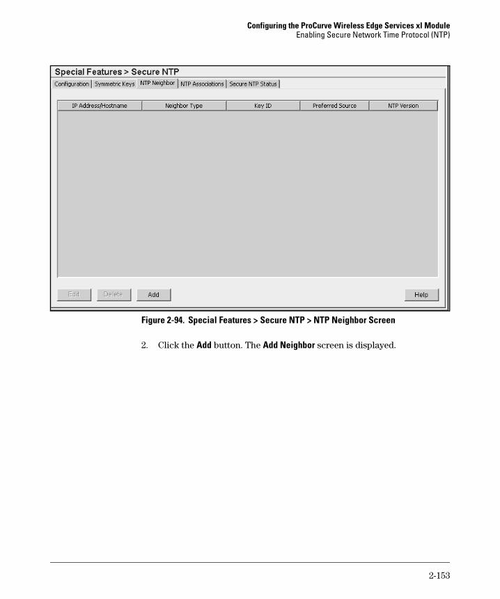
Configuring the ProCurve Wireless Edge Services xl ModuleEnabling Secure Network Time Protocol (NTP)
Figure 2-94. Special Features > Secure NTP > NTP Neighbor Screen
2. Click the Add button. The Add Neighbor screen is displayed.
2-153

Configuring the ProCurve Wireless Edge Services xl ModuleEnabling Secure Network Time Protocol (NTP)
Figure 2-95. Add Neighbor Screen
3. Select the neighbor type:
• Peer—A peer is another NTP server in a close relationship with your Wireless Edge Services xl Module. The module synchronizes with its peers, and at any given moment only one peer in the group acts as the NTP server.
• Server—Select this type if the NTP neighbor is a server to which the Wireless Edge Services xl Module acts as a client.
• Broadcast Server—Instead of adding a neighbor, selecting this option actually configures the module itself to act as a broadcast server. See “Configuring the Wireless Edge Services xl Module as a Broadcast Server” on page 2-155.
4. To specify the IP address or hostname of the neighbor, do one of the following:
• Click IP Address and enter the IP address of the peer or server.
• Click Hostname to enter the fully qualified domain name (FQDN) of the peer or server.
2-154

Configuring the ProCurve Wireless Edge Services xl ModuleEnabling Secure Network Time Protocol (NTP)
5. In the NTP Version field, use the drop-down menu to select the version of NTP to use with this configuration.
Although the latest version of the NTP implementation is NTPv4, the official Internet standard is NTPv3.
6. Select the authentication method:
• No Authentication—No authentication is used.
• AutoKey Authentication—The Wireless Edge Services xl Module and the neighbor automatically generate the keys that authenticate their communications, using digital certificates to secure the automatic process.
This option is not available when Broadcast Server is selected as the neighbor type in step 3.
• Symmetric Key Authentication—The module and the neighbor authen-ticate communications with the same shared key.
7. If you selected Symmetric Key Authentication in step 6, in the Key ID field enter the symmetric key ID.
The key ID references the symmetric key that you created earlier for this neighbor. (See “Adding Symmetric Keys” on page 2-150.) The key value for the symmetric key must be the same for both the sender and the receiver.
8. Check the Preferred Source box if the neighbor is a preferred NTP resource.
Preferred sources are contacted before non-preferred resources. You can specify more than one preferred source.
This option is not available when Broadcast Server is selected as the neighbor type (see step 3).
9. Click the OK button. The neighbor is now listed on the Special Features > Secure NTP > NTP Neighbor screen.
Configuring the Wireless Edge Services xl Module as a Broadcast Server
To enable the Wireless Edge Services xl Module to act as a broadcast server, follow these steps:
1. Select Special Features > Secure NTP and click the NTP Neighbor tab.
2-155
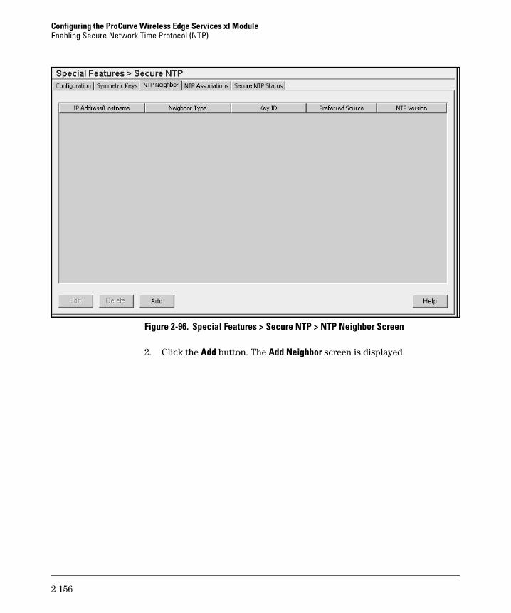
Configuring the ProCurve Wireless Edge Services xl ModuleEnabling Secure Network Time Protocol (NTP)
Figure 2-96. Special Features > Secure NTP > NTP Neighbor Screen
2. Click the Add button. The Add Neighbor screen is displayed.
2-156

Configuring the ProCurve Wireless Edge Services xl ModuleEnabling Secure Network Time Protocol (NTP)
Figure 2-97. Add Neighbor Screen
3. Select Broadcast Server for the neighbor type.
4. In the IP Address field, enter the broadcast address for the module’s subnetwork.
For example, you want the module to run the broadcast server on its VLAN 8 interface, which has the address 10.4.8.30/24. Enter 10.4.8.255.
5. In the NTP Version field, use the drop-down menu to select the version of NTP to use with this configuration.
Although the latest version of the NTP implementation is NTPv4, the official Internet standard is NTPv3.
6. Choose the authentication mode required by clients: No Authentication or Symmetric Key Authentication.
When you implement NTP in broadcast mode, it is recommended to configure your clients to require authentication. Otherwise, they might receive the time from a rogue server.
Autokey authentication is not an option for broadcast services on the Wireless Edge Services xl Module.
2-157
Configuring the ProCurve Wireless Edge Services xl ModuleEnabling Secure Network Time Protocol (NTP)
7. If you selected Symmetric Key Authentication in step 6, in the Key ID field enter the symmetric key ID.
The key ID references the symmetric key that you created earlier. (See “Adding Symmetric Keys” on page 2-150). You must configure clients in this network to match the key referenced by the ID.
8. Click the OK button. The broadcast server is now listed on the Special Features > Secure NTP > NTP Neighbor screen.
Viewing NTP Associations and Status
The interaction between the Wireless Edge Services xl Module and an NTP resource (typically, one of the module’s neighbors) constitutes an association. As described in “Configuring NTP Neighbors” on page 2-152, associations come in two modes:
■ Peer association—The module synchronizes to the resource or allows the resource to synchronize to it.
■ Server association—Only the module synchronizes to the other resource, which is the NTP server.
To view your NTP associations, select Special Features > Secure NTP and click the NTP Associations tab.
2-158
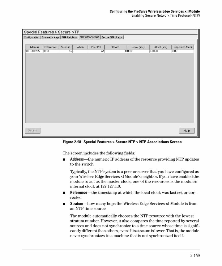
Configuring the ProCurve Wireless Edge Services xl ModuleEnabling Secure Network Time Protocol (NTP)
Figure 2-98. Special Features > Secure NTP > NTP Associations Screen
The screen includes the following fields:
■ Address—the numeric IP address of the resource providing NTP updates to the switch
Typically, the NTP system is a peer or server that you have configured as your Wireless Edge Services xl Module’s neighbor. If you have enabled the module to act as the master clock, one of the resources is the module’s internal clock at 127.127.1.0.
■ Reference—the timestamp at which the local clock was last set or cor-rected
■ Stratum—how many hops the Wireless Edge Services xl Module is from an NTP time source
The module automatically chooses the NTP resource with the lowest stratum number. However, it also compares the time reported by several sources and does not synchronize to a time source whose time is signifi-cantly different than others, even if its stratum is lower. That is, the module never synchronizes to a machine that is not synchronized itself.
2-159

Configuring the ProCurve Wireless Edge Services xl ModuleEnabling Secure Network Time Protocol (NTP)
■ When—the number of seconds since a message has been received from the remote resource
■ Peer Poll—the maximum interval between successive messages, in sec-onds (always a power of 2 value, such as 8 or 64)
■ Reach—the status of the last eight NTP messages displayed in octal format
If an NTP packet reaches the resource successfully, the packet is assigned the value of 1. Otherwise, it is assigned a value of 0. The results for eight packets make up an eight-digit binary number. That number, expressed in octal format, is the reach status.
You hope to see 377 for the reach status. This value indicates that all of the last eight messages have reached the remote NTP device successfully, producing this binary number: 11111111, which in octal is 377. If the most recent NTP packet were lost, but the previous seven successful, the reach status would be 376 (11111110).
The lost packet continues to be tracked over the next eight NTP messages. In this example, if the next three packets were successful, the reach status would become 370 (11110111). However, if the next three packets were to fail as well, the reach status would become 360 (11110000).
Note that as the 0 indicating the lost packet shifts, the reach status decreases no matter the success of the following packets. Therefore, a decreasing value in the Reach column does not necessary indicate that packets are no longer reaching the remote resource. For example, just before the status returns to 377, it would read 177 (01111111).
■ Delay (sec)—the round-trip delay (in seconds) for NTP broadcasts between the NTP resource and the module
■ Offset (sec)—the calculated offset (in seconds) between the clock on the module and the NTP resource
The module adjusts its clock to match the server’s time value. The offset gravitates toward zero over time, but never completely reduces its offset to zero.
■ Dispersion (sec)—how scattered the time offsets are (in seconds) from a Secure NTP time server
To view more detailed information about a particular NTP association, select the association and click the Details button. The Details screen is displayed. (See Figure 2-99.)
2-160

Configuring the ProCurve Wireless Edge Services xl ModuleEnabling Secure Network Time Protocol (NTP)
Figure 2-99. Details Screen
The Details screen includes the following additional information:
■ Association—state of the association
■ Sanity—an indicator of the “sanity” of NTP packets
The sanity indicates whether the time sent by the resource seems reason-able based on time from other resources.
■ Validity—an indicator of the validity of NTP packets
■ Authority—the relationship between the module and the remote resource
If the Authority is master, the module will synchronize to the resource.
■ Leap State—indicates if the module has received notice that a leap second will be inserted
2-161

Configuring the ProCurve Wireless Edge Services xl ModuleEnabling Secure Network Time Protocol (NTP)
■ Host Mode—the Wireless Edge Services xl Module’s mode:
client—The module is associated with a resource that operates in server mode. The module polls the server, but does not respond to polls from the server. If the server sends valid NTP packets, the module may synchronize with it.
server—The module allows itself to be polled by clients that want to synchronize with it. The module does not poll the clients.
active—The module is in a peer association with the NTP resource. That is, both the module and the other resource can send and respond to polls.
■ Peer Mode—the mode of the other NTP resource in the association
The peer might operate in any of the modes described for the host mode. If the mode is “unspec,” the Wireless Edge Services xl Module cannot reach the peer.
■ Host Poll—the maximum interval between successive polls received from the remote resource
To find this interval in seconds, subtract 1 from the value listed and raise the new value to the power of 2. For example, if the value is 7, the maximum interval in seconds is 64.
■ Peer Poll—the maximum interval between successive polls sent to the remote resource
The interval in seconds is calculated from the value shown, as described for the host poll.
The Details screen also shows timestamps for the most recent NTP exchange:
■ Reference Time—the time at which the local clock was last set or cor-rected, in 64-bit timestamp format
■ Org Time—the origination time at which the request departed the client for the server, in 64-bit timestamp format
■ Receive Time—the time at which the request arrived at the server, in 64-bit timestamp format
■ Transmit Time—the time at which the reply departed the server for the client, in 64-bit timestamp format
2-162

Configuring the ProCurve Wireless Edge Services xl ModuleEnabling Secure Network Time Protocol (NTP)
By tracking timestamps for all NTP exchanges, the Wireless Edge Services xl Module calculates the following:
■ Root Delay—a 32-bit signed fixed-point number indicating the total round-trip delay to the primary reference source, in seconds with fraction point between bits 15 and 16
Note that this variable can take on both positive and negative values, depending on the relative time and frequency offsets. The values that normally are displayed in this field range from negative values of a few milliseconds to positive values of several hundred milliseconds.
■ Root Dispersion—a 32-bit unsigned fixed-point number indicating the nom-inal error relative to the primary reference source, in seconds with frac-tion point between bits 15 and 16
The values that normally are displayed in this field range from 0 to several hundred milliseconds.
■ Delay—the number of milliseconds required for NTP packets to make the round-trip from the module to the remote server and back
The delay is an important factor when the module selects the “best” server. Minimizing delay is one reason why you want to pick servers that are close to you.
■ Offset—the difference in milliseconds between the clocks in your host and the remote resource
As clocks synchronize, the offset decreases. Your mode and the mode of the peer, as well as other factors, dictate whether the module synchronizes to the remote resource.
■ Dispersion—a measure, in seconds, of how scattered the time offsets have been from a given time server
■ Precision—an eight-bit signed integer indicating the precision of the local clock, in seconds to the nearest power of two
The values that normally are displayed in this field range from -6 for mains-frequency clocks to -20 for microsecond clocks found in some worksta-tions.
To refresh the screen, click the Refresh button.
To close the screen, click the Close button.
2-163
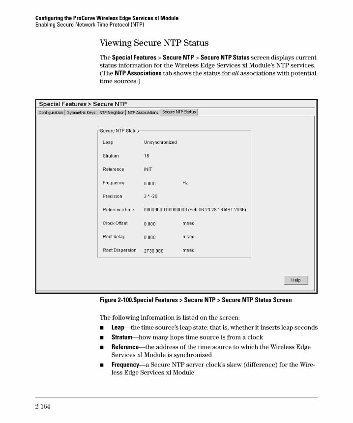
Configuring the ProCurve Wireless Edge Services xl ModuleEnabling Secure Network Time Protocol (NTP)
Viewing Secure NTP Status
The Special Features > Secure NTP > Secure NTP Status screen displays current status information for the Wireless Edge Services xl Module’s NTP services. (The NTP Associations tab shows the status for all associations with potential time sources.)
Figure 2-100.Special Features > Secure NTP > Secure NTP Status Screen
The following information is listed on the screen:
■ Leap—the time source’s leap state: that is, whether it inserts leap seconds
■ Stratum—how many hops time source is from a clock
■ Reference—the address of the time source to which the Wireless Edge Services xl Module is synchronized
■ Frequency—a Secure NTP server clock’s skew (difference) for the Wire-less Edge Services xl Module
2-164
Configuring the ProCurve Wireless Edge Services xl ModuleDigital Certificates
■ Precision—the precision (accuracy) of the Wireless Edge Services xl Module’s time clock, in Hz
The values that normally are displayed in this field range from -6 for mains-frequency clocks to -20 for microsecond clocks found in some worksta-tions.
■ Reference time—the timestamp at which the local clock was last set or corrected
■ Clock Offset—the calculated offset, in seconds, between the module and the source
The module adjusts its clock to match the server’s time value. The offset gravitates toward zero over time, but is never completely reduced to zero.
■ Root delay—the total round-trip delay, in seconds
This variable can take on both positive and negative values, depending on the relative time and frequency offsets. The values that normally are displayed in this field range from negative values of a few milliseconds to positive values of several hundred milliseconds.
■ Root Dispersion—the nominal error relative to the primary time source, in seconds
The values that normally are displayed in this field range from 0 through several hundred milliseconds.
Digital Certificates
The Wireless Edge Services xl Module supports digital certificates, which are used to identify a host uniquely.
The Wireless Edge Services xl Module uses certificates for several purposes:
■ HTTPS access—The module’s server certificate authenticates the mod-ule to your Web browser.
■ RADIUS authentication services—802.1X authentication with Exten-sible Authentication Protocol (EAP) requires mutual authentication. In other words, the module’s RADIUS authentication server must send a server certificate and authenticate to supplicants.
■ Autokey authentication for secure NTP—The module sends its cer-tificate to the secure NTP server to authenticate itself and generate keys to secure NTP exchanges.
2-165
Configuring the ProCurve Wireless Edge Services xl ModuleDigital Certificates
Overview
Digital certificates rely on asymmetric encryption with public/private key pairs. Data encrypted by a private key must be decrypted by the corresponding public key. A host “signs” data by encrypting it with its private key—something only it can do because only it knows the private key. Other hosts verify the signature by decrypting the signature with the public key.
A digital certificate ties a public key to a particular host’s identity. Typically, a trusted third-party, called the certificate authority (CA), issues certificates. A less secure option is a self-signed certificate, which is issued by the host itself. In either case, the issuer of a certificate is referred to as a trustpoint.
A certificate itself consists of:
■ the host’s identification information
■ the host’s public key
■ the function used to hash the certificate
■ the CA’s digital signature
A host authenticates itself by sending its certificate, to which it appends its digital signature. It creates the digital signature by hashing the certificate and then encrypting the hash with its private key.
When the peer receives the digital certificate, the peer extracts the host’s public key and hash function. The peer decrypts and unhashes the signature and compares it to the certificate. If the signature and certificate match, the peer knows that no one has tampered with the certificate en route.
To fully authenticate a host, the peer must also have the CA’s certificate in its system. This certificate includes the CA’s public key, which the peer uses to verify the CA’s signature. A genuine CA signature attests that the holder of a certificate is who it says it is. CAs also issue certificate revocation lists (CRLs), which list certificates that are no longer valid.
Because a host can freely distribute its public key, it can authenticate itself to anyone who trusts the host’s CA. However, no one can pose as the host, because only the host’s unshared, private key can encrypt and “sign” the certificate.
2-166
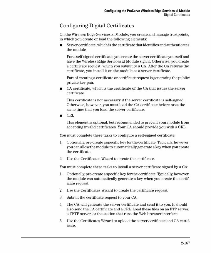
Configuring the ProCurve Wireless Edge Services xl ModuleDigital Certificates
Configuring Digital Certificates
On the Wireless Edge Services xl Module, you create and manage trustpoints, in which you create or load the following elements:
■ Server certificate, which is the certificate that identifies and authenticates the module
For a self-signed certificate, you create the server certificate yourself and have the Wireless Edge Services xl Module sign it. Otherwise, you create a certificate request, which you submit to a CA. After the CA returns the certificate, you install it on the module as a server certificate.
Part of creating a certificate or certificate request is generating the public/private key pair.
■ CA certificate, which is the certificate of the CA that issues the server certificate
This certificate is not necessary if the server certificate is self-signed. Otherwise, however, you must load the CA certificate before or at the same time that you load the server certificate.
■ CRL
This element is optional, but recommended to prevent your module from accepting invalid certificates. Your CA should provide you with a CRL.
You must complete these tasks to configure a self-signed certificate:
1. Optionally, pre-create a specific key for the certificate. Typically, however, you can allow the module to automatically generate a key when you create the certificate.
2. Use the Certificates Wizard to create the certificate.
You must complete these tasks to install a server certificate signed by a CA:
1. Optionally, pre-create a specific key for the certificate. Typically, however, the module can automatically generate a key when you create the certif-icate request.
2. Use the Certificates Wizard to create the certificate request.
3. Submit the certificate request to your CA.
4. The CA will generate the server certificate and send it to you. It should also send the CA certificate and a CRL. Load these files on an FTP server, a TFTP server, or the station that runs the Web browser interface.
5. Use the Certificates Wizard to upload the server certificate and CA certif-icate.
2-167

Configuring the ProCurve Wireless Edge Services xl ModuleDigital Certificates
6. Use the CLI to upload the CRL.
You access the Certificates Wizard, as well as manage trustpoints, in the Management > Certificate Management screen.
Figure 2-101.Management > Certificate Management Screen
The Management > Certificate Management screen has two main tabs:
■ Trustpoints—This screen lists the trustpoints on the Wireless Edge Ser-vices xl Module and the certificates associated with each trustpoint. The left panel displays all trustpoints configured on your module. Initially, the only trustpoint is the “default-trustpoint.” The right panel displays the details for the certificates in the selected trustpoint: the module’s own certificate (Server Certificate) and the CA certificate (CA Root Certificate).
2-168

Configuring the ProCurve Wireless Edge Services xl ModuleDigital Certificates
■ Keys—This screen lists the key pairs that have been created on the Wireless Edge Services xl Module. You can associate a key pair with a trustpoint, and the module includes the public key for that pair in the self-signed certificate or the certificate request. (The Keys tab is shown in Figure 2-114 on page 2-191.)
Using the Certificates Wizard
Use the Certificates Wizard to:
■ create a new certificate, either as a self-signed certificate or a certificate request to be sent to a CA
■ upload a certificate (either a server certificate or a CA certificate) from an external source
■ delete trustpoints, certificates, or keys
You can complete all necessary tasks for creating or installing certificates through the Certificates Wizard. However, if you want to create a specific key for a particular certificate, you must do so first in the Management > Certificate Management > Keys screen.
To run the Certificates Wizard, complete these steps:
1. Select Management > Certificate Management and click the Trustpoints tab
2. Click the Certificates Wizard button. The Certificates Wizard Welcome screen is displayed.
2-169

Configuring the ProCurve Wireless Edge Services xl ModuleDigital Certificates
Figure 2-102.Certificates Wizard Welcome Screen
On this screen, you can select the certificate operations that you want to perform, which are documented in the following sections.
Creating Certificates
On the Certificates Wizard Welcome screen, you can select the Create a new certificate option to do the following:
■ create a self-signed certificate
■ prepare a certificate request to send to a certificate authority
2-170

Configuring the ProCurve Wireless Edge Services xl ModuleDigital Certificates
Creating a Self-Signed Certificate. To create a new self-signed certifi-cate, complete these steps:
1. On the Certificates Wizard Welcome screen, in the Select a certificate operation section, select Create a new certificate.
2. Click the Next button. The screen shown in Figure 2-103 is displayed.
Figure 2-103.Certificate Wizard Options Screen (Self-Signed Certificate)
3. In the Select a certificate operation section, select Generate a self-signed certificate.
2-171

Configuring the ProCurve Wireless Edge Services xl ModuleDigital Certificates
4. In the Select a trustpoint for the new certificate section, select one of the following:
• Use existing trustpoint—You can select a trustpoint that you have created previously from the drop-down menu. (This option is avail-able only when an existing trustpoint does not have a current certifi-cate.)
• Create a new trustpoint—Enter the trustpoint name in the field.
5. In the Specify a key for your new certificate section, select one of the following:
• Automatically generate a key—Generate a key specifically for this certificate.
• Use existing key—Use a key that you created previously; select the key from the drop-down menu.
• Create a new key—Create a new key for this certificate that you can also use for future certificates.– In the Key Label field, enter a name for the key.– In the Key Size field, enter the key size, from 1,024 through
2,048 bytes.
N o t e You can also create keys in a separate procedure; see “Creating a Key” on page 2-190 for information.
6. Click the Next button. The screen shown in Figure 2-104 is displayed.
2-172
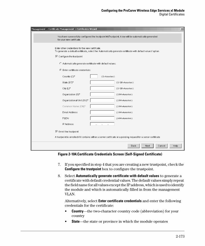
Configuring the ProCurve Wireless Edge Services xl ModuleDigital Certificates
Figure 2-104.Certificate Credentials Screen (Self-Signed Certificate)
7. If you specified in step 4 that you are creating a new trustpoint, check the Configure the trustpoint box to configure the trustpoint.
8. Select Automatically generate certificate with default values to generate a certificate with default credential values. The default values simply repeat the field name for all values except the IP address, which is used to identify the module and which is automatically filled in from the management VLAN.
Alternatively, select Enter certificate credentials and enter the following credentials for the certificate:
• Country—the two-character country code (abbreviation) for your country
• State—the state or province in which the module operates
2-173

Configuring the ProCurve Wireless Edge Services xl ModuleDigital Certificates
• City—the city in which the module operates
• Organization—your organization (typically your company name)
• Organizational Unit—your organizational unit (typically your depart-ment name)
• Common Name—the URL that you use to access the Web browser interface
The text that you enter must replicate the URL exactly and cannot include spaces or special characters other than periods ( . ) and hyphens ( - ). For example: WirelessServices.procurve.com
• Email Address—a valid email address for you or the person responsi-ble for managing the Wireless Edge Services xl Module (optional)
• FQDN—the module’s fully qualified domain name (optional)
• IP Address—the IP address for the certificate (optional)
9. Check the Enroll the trustpoint box to create the self-signed certificate.
If you do not enroll the trustpoint at this time, you will be able to select the trustpoint as an existing trustpoint when you run the Certificates Wizard in the future. (See step 4.) However, the information that you entered will be lost.
10. Click the Next button. The completion screen that is displayed summa-rizes the operations that you have performed using the Certificates Wiz-ard.
11. Click the Finish button.
Creating a Certificate Request to Send to a CA. Instead of creating a self-signed certificate for a trustpoint, you can upload a certificate signed by a CA. A certificate signed by a trusted CA carries more validity than a self-signed certificate. Also, if your company has a full PKI, your Wireless Edge Services xl Module should have a certificate issued by your company’s CA.
To obtain a certificate signed by a CA, you must first generate a certificate request. Complete these steps:
1. On the Certificates Wizard Welcome screen, in the Select a certificate operation section, select Create a new certificate.
2. Click the Next button. The screen shown in Figure 2-105 is displayed.
2-174
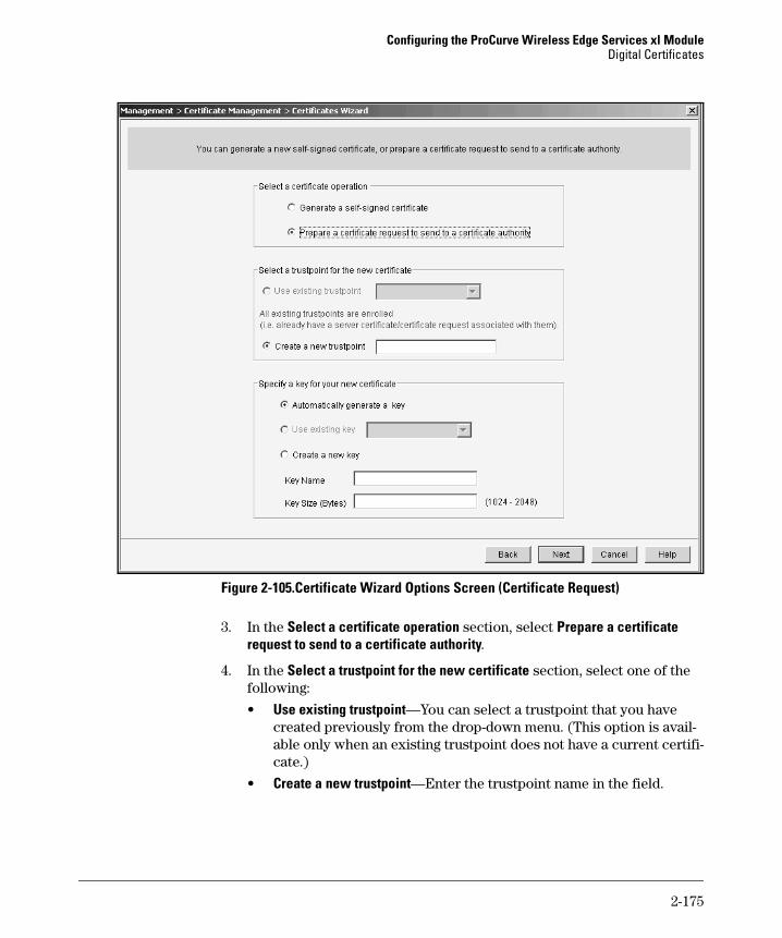
Configuring the ProCurve Wireless Edge Services xl ModuleDigital Certificates
Figure 2-105.Certificate Wizard Options Screen (Certificate Request)
3. In the Select a certificate operation section, select Prepare a certificate request to send to a certificate authority.
4. In the Select a trustpoint for the new certificate section, select one of the following:
• Use existing trustpoint—You can select a trustpoint that you have created previously from the drop-down menu. (This option is avail-able only when an existing trustpoint does not have a current certifi-cate.)
• Create a new trustpoint—Enter the trustpoint name in the field.
2-175

Configuring the ProCurve Wireless Edge Services xl ModuleDigital Certificates
5. You must include a public key in the certificate request. In the Specify a key for your new certificate section, select one of the following:
• Automatically generate a key—Generate a key specifically for this certificate.
• Use existing key—Use a key pair that you created previously; select the key from the drop-down menu.
• Create a new key—Create a new key pair for this certificate that you can also use for future certificates.– In the Key Label field, enter a name for the key.– In the Key Size field, enter the key size, from 1,024 through 2,048
bytes.
N o t e You can also create keys in a separate procedure; see “Creating a Key” on page 2-190 for information.
6. Click the Next button. The screen shown in Figure 2-106 is displayed.
2-176
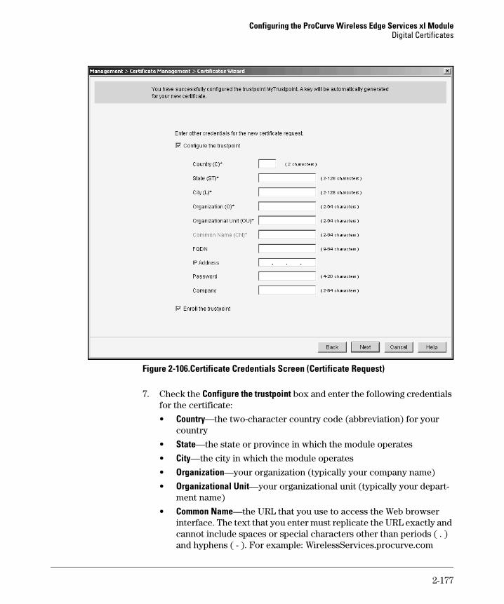
Configuring the ProCurve Wireless Edge Services xl ModuleDigital Certificates
Figure 2-106.Certificate Credentials Screen (Certificate Request)
7. Check the Configure the trustpoint box and enter the following credentials for the certificate:
• Country—the two-character country code (abbreviation) for your country
• State—the state or province in which the module operates
• City—the city in which the module operates
• Organization—your organization (typically your company name)
• Organizational Unit—your organizational unit (typically your depart-ment name)
• Common Name—the URL that you use to access the Web browser interface. The text that you enter must replicate the URL exactly and cannot include spaces or special characters other than periods ( . ) and hyphens ( - ). For example: WirelessServices.procurve.com
2-177

Configuring the ProCurve Wireless Edge Services xl ModuleDigital Certificates
• Email Address—a valid email address for you or the person responsi-ble for managing the Wireless Edge Services xl Module (optional)
• FQDN—the module’s fully qualified domain name (optional)
• IP Address—the IP address for the certificate (optional)
• Password—a password that must be entered to install the certificate (optional; only specify a password if requested by your CA)
N o t e Do not type special characters in any of the certificate credential fields; some CAs may not create a certificate if the credentials contain special characters. This includes most nonalphanumeric characters; however, periods ( . ) and hyphens ( - ) are allowed.
Also, optional fields may not be optional for your particular CA. For example, some CA’s require certain subject alternate names for server certificates. Check your CA’s requirements before configuring the certificate request.
8. Check the Enroll the trustpoint box to generate the certificate request.
If you do not enroll the trustpoint at this time, you will be able to select the trustpoint as an existing trustpoint when you run the Certificates Wizard in the future. (See step 4.) However, the information that you entered will be lost.
9. Click the Next button. The screen shown in Figure 2-107 is displayed.
The screen shows the certificate request, which is in Base 64–encoded PKCS#10 format.
2-178

Configuring the ProCurve Wireless Edge Services xl ModuleDigital Certificates
Figure 2-107.Copy or Save Certificate Request
10. To save the text of the certificate request to send to a CA, you can do either (or both) of the following:
• Check the Copy the certificate request to clipboard box; after you click the Next button in step 11, you can paste the text into a text file.
• Check the Save the certificate request box to upload the certificate request to an external server or the local disk of the station running the Web browser.
To save the certificate request to an external server, follow these steps:i. In the To drop-down menu, select Server.ii. Choose a name for the request and enter it in the File field.
2-179

Configuring the ProCurve Wireless Edge Services xl ModuleDigital Certificates
iii. Choose FTP or TFTP from the Using drop-down menu, and if necessary choose the port for your server. (The default port is usually correct.)
iv. Specify the server’s IP address.v. For FTP, enter the username and password.vi. Leave the Path field blank to save to the server’s base directory.
Or enter a valid directory path on the server.
To save the certificate request to the workstation running the Web browser, follow these steps:i. In the To drop-down menu, select Local Disk.ii. Choose a name for the request and enter it in the File field with a
valid path. For example: C:/myrequest. Alternatively, click the browse button and browse for the directory in which to save the request.
11. Click the Next button. A completion screen summarizes the certificate request operation that you have performed.
12. Click the Finish button.
Uploading a Certificate to the Module
After a CA issues your company a certificate, you must upload the certificate to the Wireless Edge Services xl Module. You can upload the certificate from an FTP server, a TFTP server, or your local workstation. The certificate should be in Privacy Enhanced Mail (PEM) or Distinguished Encoding Rules (DER) format.
To upload a certificate using the Certificates Wizard, complete these steps:
1. On the Certificates Wizard Welcome screen, in the Select a certificate operation section, select Upload an external certificate.
2-180

Configuring the ProCurve Wireless Edge Services xl ModuleDigital Certificates
Figure 2-108.Certificates Wizard—Uploading a Certificate
2. Click the Next button. The screen shown in Figure 2-109 is displayed.
2-181
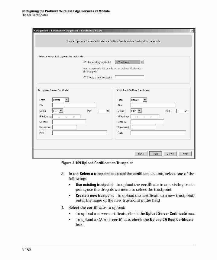
Configuring the ProCurve Wireless Edge Services xl ModuleDigital Certificates
Figure 2-109.Upload Certificate to Trustpoint
3. In the Select a trustpoint to upload the certificate section, select one of the following:
• Use existing trustpoint—to upload the certificate to an existing trust-point; use the drop-down menu to select the trustpoint
• Create a new trustpoint—to upload the certificate to a new trustpoint; enter the name of the new trustpoint in the field
4. Select the certificates to upload:
• To upload a server certificate, check the Upload Server Certificate box.
• To upload a CA root certificate, check the Upload CA Root Certificate box.
2-182

Configuring the ProCurve Wireless Edge Services xl ModuleDigital Certificates
You can select either or both certificates to upload. However, you can only upload a certain type of certificate if the selected trustpoint does not already include that type. If you want to upload a new certificate, first delete the current certificate. See “Deleting Trustpoints, Certificates, and Keys” on page 2-183.
5. For each certificate that you will upload, specify the certificate file source:
To upload the certificate from an external server, follow these steps:i. In the From drop-down menu, select Server.ii. In the File field, enter the name of the certificate as stored on the
server.iii. Choose FTP or TFTP from the Using drop-down menu, and if
necessary choose the port for your server. (The default port is usually correct.)
iv. Specify the server’s IP address.v. For FTP, enter the username and password.vi. Leave the Path field blank if the file is in the server’s base direc-
tory. Or enter a valid directory path on the server.
To upload the certificate from the workstation running the Web browser, follow these steps:i. In the From drop-down menu, select Local Disk.ii. In the File field, enter the certificate filename with a valid path.
For example: C:/mycert.der. Alternatively, click the browse but-ton and browse for the certificate.
6. Click the Next button. The completion screen summarizes the certificate upload operation that you have performed.
7. Click the Finish button.
Deleting Trustpoints, Certificates, and Keys
To delete selected trustpoints, certificates, and keys using the Certificates Wizard, complete these steps:
1. On the Certificates Wizard Welcome screen, in the Select a certificate operation section, click Delete Operations.
2-183
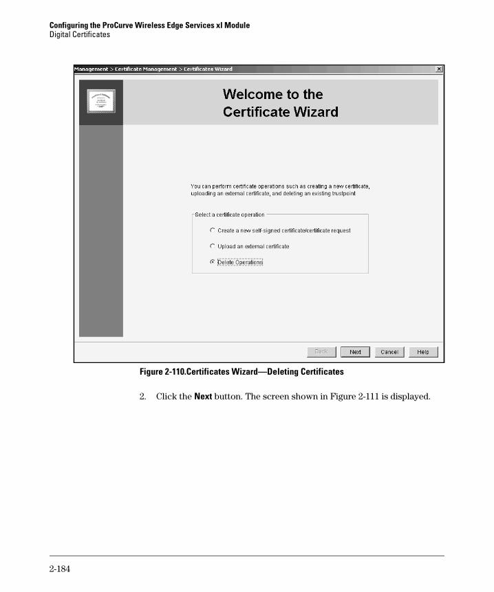
Configuring the ProCurve Wireless Edge Services xl ModuleDigital Certificates
Figure 2-110.Certificates Wizard—Deleting Certificates
2. Click the Next button. The screen shown in Figure 2-111 is displayed.
2-184
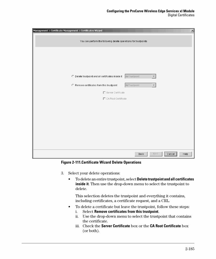
Configuring the ProCurve Wireless Edge Services xl ModuleDigital Certificates
Figure 2-111.Certificate Wizard Delete Operations
3. Select your delete operations:
• To delete an entire trustpoint, select Delete trustpoint and all certificates inside it. Then use the drop-down menu to select the trustpoint to delete.
This selection deletes the trustpoint and everything it contains, including certificates, a certificate request, and a CRL.
• To delete a certificate but leave the trustpoint, follow these steps:i. Select Remove certificates from this trustpoint. ii. Use the drop-down menu to select the trustpoint that contains
the certificate.iii. Check the Server Certificate box or the CA Root Certificate box
(or both).
2-185

Configuring the ProCurve Wireless Edge Services xl ModuleDigital Certificates
4. Click the Next button.
5. On the confirmation screen, click the Next button to confirm the deletion. Or, click the Cancel button to cancel the deletion.
6. After the deletion is complete, on the completion screen that is displayed, click the Finish button.
7. Click the Save link at the top of the Web browser interface to save the changes to the startup-config.
Uploading a CRL to a Trustpoint
If you have created a trustpoint based on an external CA, you should upload the CA’s CRL to the trustpoint. The CRL lists certificates that the CA issued but has since revoked. You configure the location to which the CA publishes the CRL, and the Wireless Edge Services xl Module periodically checks this location for the most recent CRL.
Use this command, entered from the global configuration mode context:
ProCurve(wireless-services-C)# crypto pki import <trustpoint name> crl <URL> <hours>
Replace <trustpoint name> with the name of the trustpoint to which you want to save the CRL. You can enter the URL as a reference to an HTTP publication point or a file on an FTP or TFTP server. For FTP and TFTP servers, include the filename, path, and (for FTP) login information. For <hours> enter a value from 1 to 168 to set how often the module updates the CRL.
Transferring Trustpoints
You can transfer trustpoints either:
■ from the Wireless Edge Services xl Module to an FTP or TFTP server
■ from a server to the Wireless Edge Services xl Module
You can transfer trustpoints to a secure location for archiving. Transferring trustpoints to an external server is recommended to ensure that server certif-icate information is available if problems are encountered with the Wireless Edge Services xl Module.
You can also transfer an entire trustpoint to the module. For example, you might want to move a trustpoint from one module to another. You would save the trustpoint on the first module out to an external server and then transfer the trustpoint from the external server to the second module.
2-186

Configuring the ProCurve Wireless Edge Services xl ModuleDigital Certificates
When you transfer a trustpoint, you copy these elements (if included in that particular trustpoint):
■ server certificate
■ CA certificate
■ CRL
Transferring Trustpoints from the Wireless Edge Services xl Module to a Server
To transfer a trustpoint from the Wireless Edge Services xl Module to a server, complete these steps:
1. Select Manager > Certificate Management and click the Trustpoints tab.
2. Click the Transfer Trustpoints button. The Transfer Trustpoints screen is displayed.
3. In the Source section, select Wireless Services Module from the From drop-down menu.
4. Choose the trustpoint from the drop-down menu below.
Figure 2-112.Transfer Trustpoints from Wireless Module
5. In the Target section, the To drop-down menu displays Server. In the File field, specify a name for the trustpoint file. The default filename is the name of the trustpoint being transferred.
2-187

Configuring the ProCurve Wireless Edge Services xl ModuleDigital Certificates
6. From the Using drop-down menu, select the protocol for the trustpoint transfer, either FTP or TFTP.
7. In the Port field, enter the respective FTP or TFTP port number; the default port number (port 21 for FTP, port 69 for TFTP) should apply in most cases.
8. In the IP Address field, enter the IP address of the FTP or TFTP server.
9. If you are using an FTP server, enter the login credentials.
a. In the User ID field, enter the username for your account on the FTP server.
b. In the Password field, enter the password for this username.
10. In the Path field, enter the path where the trustpoint will be stored on the server. (If you are using a TFTP server, this field may not be required.)
11. Click the Transfer button. In the Status section at the bottom of the screen, a message is displayed, reporting whether the transfer was successful.
12. After the trustpoint transfer is complete, click the Close button.
Transferring Trustpoints from a Server to the Wireless Edge Services xl Module
To transfer a trustpoint from an external server to the Wireless Edge Services xl Module, complete these steps:
1. Select Manager > Certificate Management and click the Trustpoints tab.
2. Click the Transfer Trustpoints button. The Transfer Trustpoints screen is displayed.
2-188
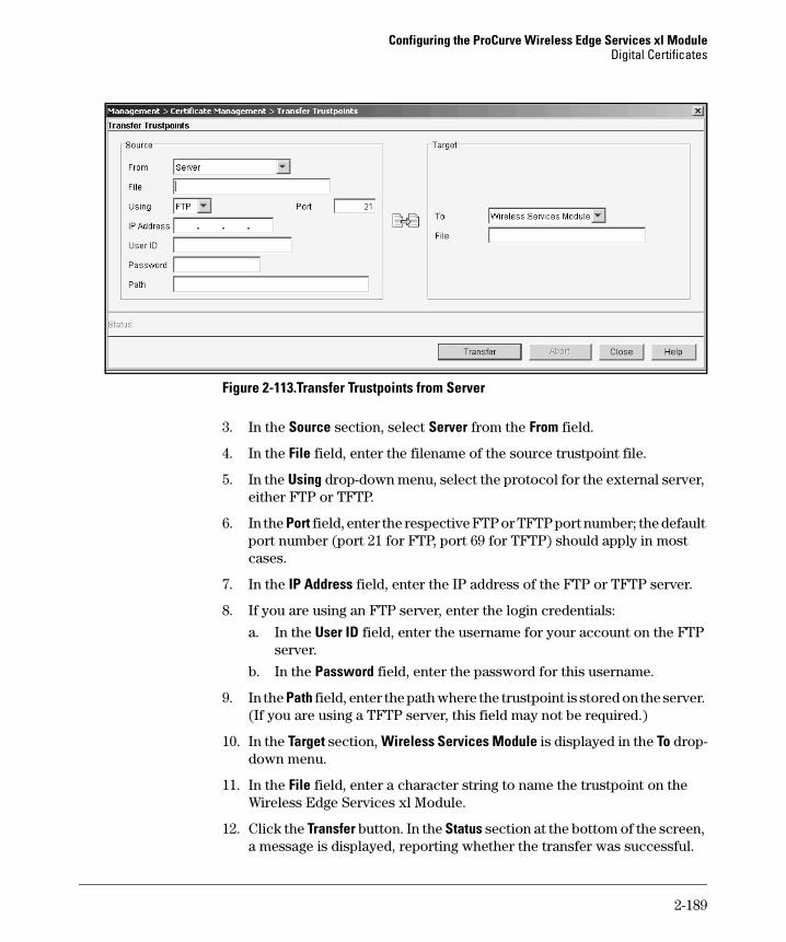
Configuring the ProCurve Wireless Edge Services xl ModuleDigital Certificates
Figure 2-113.Transfer Trustpoints from Server
3. In the Source section, select Server from the From field.
4. In the File field, enter the filename of the source trustpoint file.
5. In the Using drop-down menu, select the protocol for the external server, either FTP or TFTP.
6. In the Port field, enter the respective FTP or TFTP port number; the default port number (port 21 for FTP, port 69 for TFTP) should apply in most cases.
7. In the IP Address field, enter the IP address of the FTP or TFTP server.
8. If you are using an FTP server, enter the login credentials:
a. In the User ID field, enter the username for your account on the FTP server.
b. In the Password field, enter the password for this username.
9. In the Path field, enter the path where the trustpoint is stored on the server. (If you are using a TFTP server, this field may not be required.)
10. In the Target section, Wireless Services Module is displayed in the To drop-down menu.
11. In the File field, enter a character string to name the trustpoint on the Wireless Edge Services xl Module.
12. Click the Transfer button. In the Status section at the bottom of the screen, a message is displayed, reporting whether the transfer was successful.
2-189
Configuring the ProCurve Wireless Edge Services xl ModuleDigital Certificates
13. After the trustpoint transfer is complete, click the Close button.
Certificate Keys
A certificate relies on a public/private key pair. You can use the same key pair for multiple certificates, or you can use a different pair for each certificate.
When you configure certificate requests and self-signed certificates, you can automatically create a public/private key pair for the certificate. You can also create a named key pair for that certificate and use the key pair for future certificates. You manage named key pairs from the The Management > Certif-icate Management > Keys screen. From this screen you can:
■ create new keys or delete existing keys
■ transfer keys to a secure location for archiving
■ upload keys from an external server
Creating a Key
This section explains how to use the Management > Certificate Management > Keys screen to create keys.
N o t e You can also create keys within the Certificates Wizard when you create certificate requests and self-signed certificates; see “Creating Certificates” on page 2-170 for more information.
To create a key, complete these steps:
1. Select Management > Certificate Management and click the Keys tab.
2-190
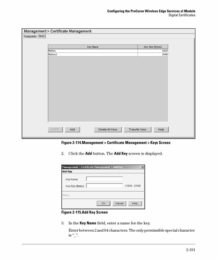
Configuring the ProCurve Wireless Edge Services xl ModuleDigital Certificates
Figure 2-114.Management > Certificate Management > Keys Screen
2. Click the Add button. The Add Key screen is displayed.
Figure 2-115.Add Key Screen
3. In the Key Name field, enter a name for the key.
Enter between 2 and 64 characters. The only permissible special character is “_”.
2-191
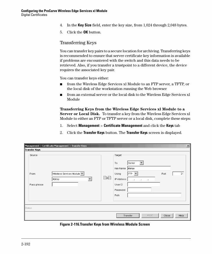
Configuring the ProCurve Wireless Edge Services xl ModuleDigital Certificates
4. In the Key Size field, enter the key size, from 1,024 through 2,048 bytes.
5. Click the OK button.
Transferring Keys
You can transfer key pairs to a secure location for archiving. Transferring keys is recommended to ensure that server certificate key information is available if problems are encountered with the switch and this data needs to be retrieved. Also, if you transfer a trustpoint to a different device, the device requires the associated key pair.
You can transfer keys either:
■ from the Wireless Edge Services xl Module to an FTP server, a TFTP, or the local disk of the workstation running the Web browser
■ from an external server or the local disk to the Wireless Edge Services xl Module
Transferring Keys from the Wireless Edge Services xl Module to a
Server or Local Disk. To transfer a key from the Wireless Edge Services xl Module to either an FTP or TFTP server or a local disk, complete these steps:
1. Select Management > Certificate Management and click the Keys tab
2. Click the Transfer Keys button. The Transfer Keys screen is displayed.
Figure 2-116.Transfer Keys from Wireless Module Screen
2-192

Configuring the ProCurve Wireless Edge Services xl ModuleDigital Certificates
3. In the Source section, in the From field, use the drop-down menu to select Wireless Services Module.
4. Use the next drop-down menu to select the key to be transferred.
5. In the Pass phrase field, enter a passphrase, which can include spaces and special characters.
The passphrase encrypts the key pair, and, although optional, is recom-mended for security. In order to decrypt and use the key, a person must know the correct passphrase.
6. In the Target section, from the To drop-down menu, select the target for the key transfer, either Server or Local Disk.
7. In the File field, enter the filename of the target key file. The default filename is the name of the key being transferred.
8. If you specified a server target in step 6, specify the following for the key transfer target:
a. In the Using drop-down menu, select the protocol for the key transfer, either FTP or TFTP.
b. In the Port field, enter the respective FTP or TFTP port number; the default port number (port 21 for FTP, port 69 for TFTP) should apply in most cases.
c. In the IP Address field, enter the IP address of the FTP or TFTP server.
d. If you are using an FTP server, enter the login credentials.i. In the User ID field, enter the username for your account on the
FTP server.ii. In the Password field, enter the password for this username.
e. In the Path field, enter the path where the key will be saved on the server. (If you are using a TFTP server, this field may not be required.)
9. If you specified Local Disk in step 6, click the browse button to choose the directory in which to save the key.
10. Click the Transfer button. In the Status section at the bottom of the screen, a message is displayed, reporting whether the transfer was successful.
11. After the key transfer is complete, click the Close button.
Transferring Keys from a Server or Local Disk to the Wireless Edge
Services xl Module. To transfer a key from either a server or a local disk to the Wireless Edge Services xl Module, complete these steps:
1. Select Management > Certificate Management and click the Keys tab
2. Click the Transfer Keys button. The Transfer Keys screen is displayed.
2-193

Configuring the ProCurve Wireless Edge Services xl ModuleDigital Certificates
Figure 2-117.Transfer Keys from Server or Local Disk Screen
3. In the Source section, in the From field, use the drop-down menu to select either Server or Local Disk.
4. In the File field, enter the filename of the source key file. If you selected Local Disk as the source in step 3, include the path with the filename.
5. If you selected Server as the source in step 3, in the Source section, specify the following for the key transfer source:
a. From the Using drop-down menu, select the protocol for the key transfer, either FTP or TFTP.
b. In the Port field, enter the respective FTP or TFTP port number; the default port number (port 21 for FTP, port 69 for TFTP) should apply in most cases.
c. In the IP Address field, enter the IP address of the FTP or TFTP server.
d. If you are using an FTP server, enter the login credentials:i. In the User ID field, enter the username for your account on the
FTP server.ii. In the Password field, enter the password for this username.
e. In the Path field, enter the path where the key is stored on the server. (If you are using a TFTP server, this field may not be required.)
The fields in this step do not apply to key transfers from a local disk source.
2-194

Configuring the ProCurve Wireless Edge Services xl ModuleDigital Certificates
6. In the Pass phrase field, enter the passphrase to encrypt the key.
Unless you enter the correct passphrase, the Wireless Edge Services xl Module cannot install the key. However, if the key has not been encrypted, leave this field empty.
7. In the Target section, in the File field, enter the filename of the target key file.
8. Click the Transfer button. In the Status section at the bottom of the screen, a message is displayed, reporting whether the transfer was successful.
9. After the key transfer is complete, click the Close button.
2-195

Configuring the ProCurve Wireless Edge Services xl ModuleDigital Certificates
2-196