
CONCEPTUAL PLAN - Environmental Clearance
36
Project: ANANYA PALM BEACH CONCEPTUAL PLAN Promoter: Prabhukrupa Realties Private Limited 1| Page CONCEPTUAL PLAN 1.0 INTRODUCTION “Ananya Palm Beach” Residential Apartment cum Guest House Project of M/s Prabhukrupa Realties Private Limited at Mouza- Sipasurubuli , Tehsil -Puri Sadar & District- Puri, State- Odisha. It is Residential Apartment cum Guest House Project for expansion of approved built up area of 18596.33 sqm vide PKDA letter no. 231 dated 29.03.2016 to 3,53,699.98 sft or 32,859.52 sqm (including services area , stilt and basement areas) and FAR Area of 25461.56 m2 (excluding services area , stilt and basement areas) as per PKDA letter no. 63 dated 07.02.2019. Total land area of the project is 9267.30 sqm or 2.289 Acres. M/s Prabhukrupa Realties Private Limited is coming with a “Ananya Palm Beach” Residential Apartment cum Guest House Project over Plot No. Plot No.- 268 (P) & Khata No.- 2 corresponding to Consolidation Khata Nos.-17/1, 17/2, 17/3 and 17/6, Plot Nos. - 581/1446 (P), 581/1447 (P), 581/1448 (P), 581/1451(P), 1.1 SITE LOCATION AND SURROUNDINGS The Residential Apartment cum Guest House Project over an area of 9267.30 sqm or 2.289 Acres will be located at Mouza-Sipasurubuli, Thana-Puri Sadar in Puri district of Odisha. The Geographical coordinates of the project site is 19°47'24.65"N & 85°47'3.20"E. The nearest airport is Biju Pattanaik Airport which is 50.40 km away from the project site towards NNE direction. Puri railway station is 6.13 km away from the project site towards NE direction. (Source of information: - Google Earth Image) 1.2 CONNECTIVITY Existing road network will be utilized for transportation. Site is easily approachable by National Highway-316 Road; hence, no new road is required. The nearest airport is Biju Pattanaik Airport which is 50.40 km away from the project site towards NNE direction. Puri railway station is 6.13 km away from the project site towards NE direction. (Aerial distance)
-
Upload
khangminh22 -
Category
Documents
-
view
2 -
download
0
Transcript of CONCEPTUAL PLAN - Environmental Clearance

Project: ANANYA PALM BEACH CONCEPTUAL PLANPromoter: Prabhukrupa Realties Private Limited
1 | P a g e
CONCEPTUAL PLAN1.0 INTRODUCTION
“Ananya Palm Beach” Residential Apartment cum Guest House Project of M/s PrabhukrupaRealties Private Limited at Mouza- Sipasurubuli , Tehsil -Puri Sadar & District- Puri, State-Odisha.It is Residential Apartment cum Guest House Project for expansion of approved built up area of18596.33 sqm vide PKDA letter no. 231 dated 29.03.2016 to 3,53,699.98 sft or 32,859.52 sqm(including services area , stilt and basement areas) and FAR Area of 25461.56 m2 (excludingservices area , stilt and basement areas) as per PKDA letter no. 63 dated 07.02.2019. Total landarea of the project is 9267.30 sqm or 2.289 Acres.M/s Prabhukrupa Realties Private Limited is coming with a “Ananya Palm Beach” ResidentialApartment cum Guest House Project over Plot No. Plot No.- 268 (P) & Khata No.- 2corresponding to Consolidation Khata Nos.-17/1, 17/2, 17/3 and 17/6, Plot Nos. - 581/1446 (P),581/1447 (P), 581/1448 (P), 581/1451(P),1.1 SITE LOCATION AND SURROUNDINGS
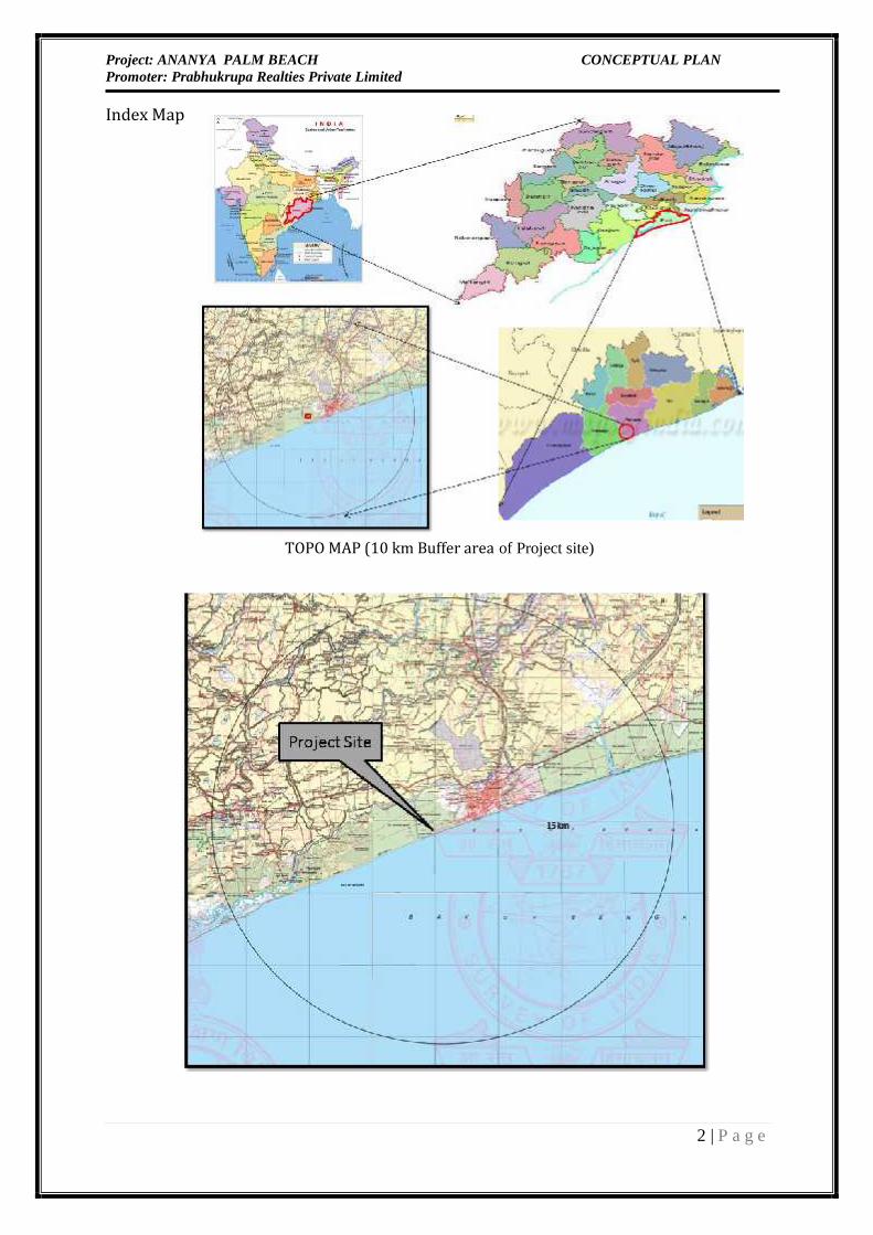
The Residential Apartment cum Guest House Project over an area of 9267.30 sqm or 2.289 Acreswill be located at Mouza-Sipasurubuli, Thana-Puri Sadar in Puri district of Odisha. TheGeographical coordinates of the project site is 19°47'24.65"N & 85°47'3.20"E.The nearest airport is Biju Pattanaik Airport which is 50.40 km away from the project sitetowards NNE direction. Puri railway station is 6.13 km away from the project site towards NEdirection.(Source of information: - Google Earth Image)1.2 CONNECTIVITY
Existing road network will be utilized for transportation. Site is easily approachable by NationalHighway-316 Road; hence, no new road is required.The nearest airport is Biju Pattanaik Airport which is 50.40 km away from the project sitetowards NNE direction. Puri railway station is 6.13 km away from the project site towards NEdirection. (Aerial distance)
Project: ANANYA PALM BEACH CONCEPTUAL PLANPromoter: Prabhukrupa Realties Private Limited
2 | P a g e
Index Map
TOPO MAP (10 km Buffer area of Project site)

Project: ANANYA PALM BEACH CONCEPTUAL PLANPromoter: Prabhukrupa Realties Private Limited
3 | P a g e
1.3 AREA STATEMENTPlot area of project is estimated to be 9267. 30 m2 or 2.29 Acres. Proponent has permission for construction
of 18596.33 m2 area at Mouza Sipasurubuli , Puri vide PKDA letter no. 231 dated 29.03.2016 & are planning to
increase built-up area to 3,53,699.98 sft or 32,859.52 sqm (including services area , stilt and basement areas)
and FAR Area is 25461.56 m2 (excluding services area , stilt and basement areas) as per PKDA letter no. 63
dated 07.02.2019.The detailed Area Statement is provided below:Table 1: Area & Project Details
S.No. Particulars Area (in m2)1. Plot Area 9267.3 m2or 2.29 Acres2. Proposed Ground Coverage (51.35%) 4758.59 m23. Approved F.A.R 2.754. Proposed Built Up Area 32,859.52 sqm (including services area ,stilt and basement areas)25461.56 m2` (excluding Basement, Stilt& Services area)5. Landscape Area (@ 20.11 % of the plot area) 1863.39 m2`6. Total Parking Provided(Basement & stilt & rooftop parking) 6009.04 m2`7. Area of internal roads , Ramp area /Paved area(22.41 % of total area ) 2077.021 m2`8. Maximum height of building 78.6 feet or 23.9 m9. Total no. of Units 470 Dwelling Units + 60 (guest room)=530 Units10. No. of Floors Basement + G/Stilt+ 711. No. of Blocks Total 1 Block (B+G/S+7)12. Total Project Cost 54.00 Cr
1.4 BUILT UP AREA DETAILS
Table No. -2: The details of BUA are given below:
AREA CALCULATION FORFAR GROSS AREA DEDUCTIONS SERVICE AREA NET FLOOR
AREAGr Floor Commercial 7,549.97 7,549.97Gr Floor Residental 10,154.03 10,154.03First Floor Residental 22,336.79 1,260.67 21,076.12

Project: ANANYA PALM BEACH CONCEPTUAL PLANPromoter: Prabhukrupa Realties Private Limited
4 | P a g e
First Floor Commercial 20,190.35 417.02 3,334.64 16,438.69Second Floor Residental 26,573.07 1,497.15 25,075.92Second Floor Commercial 8,309.79 244.49 2,421.50 5,643.80Third Floor Residental 35,945.95 1,708.34 34,237.61Third Floor Commercial 6,588.97 208.55 2,906.92 3,473.50Fourth Floor Residental 39,816.50 1,684.03 528.38 37,604.09Fifth Floor Residental 39,816.50 1,684.03 528.38 37,604.09Sixth Floor Residental 26,575.21 1,387.07 25,188.14Sixth Floor Commercial 13,241.29 296.96 528.38 12,415.95Seventh Floor Residental 26,575.21 1,387.07 25,188.14Seventh Floor Commercial 13,241.29 296.96 528.38 12,415.95
296,914.92 12,072.34 10,776.58 274,066.00Proposed FAR 2.75
1.5 POPULATION DENSITYThe population of the project will be 1907 persons. The detailed population breakup isgiven below:Table 3: Population Break up
S.NO. DESCRIPTION OCCUPANCY No Of PAX/ Unit TotalUnits PAXAPARTMENT BLOCK & GUEST ROOM1 APARTMENT 1 BHK (@135L/PAX) 308 4 12322 APARTMENT 2 BHK (@135L/PAX) 7 5 353 STUDIO APARTMENT (@135L/PAX) 155 2 3104 GUEST ROOM (@200L/PAX) 60 2 120SERVICE5 BANQUET (16500 SF) (@15L/PAX) L.S. 150

Project: ANANYA PALM BEACH CONCEPTUAL PLANPromoter: Prabhukrupa Realties Private Limited
5 | P a g e
6 OFFICES STAFFS (@45L/PAX) L.S. 207 BOH STAFFS (@ 70L/PAX) L.S. 208 VISITORS (@15L/PAX) 201.6 WATER REQUIREMENT
The total water requirement is approx. 248 KLD (domestic + flushing), out of which total domestic water(Cold + Hot Water) requirement is 169 KLD & Treated waste water reuse = 134 KLD.So the total fresh water requirement is 169 KLD (daily basis).1.6.1 Plumbing Systems (Water Supply & Drainage)
Table 4: Reference StandardNational Building Code of India Part IX September 2016Codes & Design GuidelinesI International Plumbing Code 2009 EditionII Uniform Plumbing Code of India 2011 EditionIII Energy Conservation Building Code 2017 Edition (Revised on May 2008)
1.6.2 Approaches to PlanningThe Plumbing services for the project shall be designed keeping in view the following: Requirement of adequate and equal pressure of cold & hot water in Studio Apartments and GuestHouse, Kitchen, Public toilets and other designated areas. The water storage tank capacity shall be adequate to ensure availability of water for min. one anda half days’ requirement. Recycling of treated wastewater (from in house sewage treatment plant) for makeup to coolingtowers, if any, for flushing & for horticulture water use. Implementation of requirements of CGWA and also MoEF relating to rainwater harvesting, waterconservation, etc. Levels of roads / pavements and other services in the area. Water supply provision for Landscape layout. Water conservation using low flow fixtures.

Project: ANANYA PALM BEACH CONCEPTUAL PLANPromoter: Prabhukrupa Realties Private Limited
6 | P a g e
1.6.3 System Requirements Water treatment plant (WTP) to ensure that the chemical and bacteriological parameters ofwater supply in the Apartment cum Guest House is in accordance with World Health Organization(WHO) standards. Since, quality of Ground water is not potable, WTP shall be very basic,comprising of filters and hypo dosing units. However, WTP system design shall be verified forsuitability prior to installation in accordance to latest water analysis report. The water distribution system for domestic water, flushing water and hot water shall be throughgravity feed to ensure minimum pressure of 2 bar to the most hydraulically remote fixture duringminimum pressure and maximum flow conditions. The maximum pressure permitted to fixtureswill be 4.5 bar. Top three floors immediately after the terrace level and shall be fed from thebooster pump system to ensure the minimum pressure. Sewage and sullage collection & conveyance system based on ASPE standard and applicableguidelines by NBC. Storm / rain water drainage system from the roof terrace and various levels of the building,including balcony drains, fountain drains by means of draining, storing part rain water, its re-useand surface run-off water to rain water recharge pits. Sewage treatment plant for treatment of sewage & sullage waste. The plant shall comprise ofpreliminary, secondary (chemical & biological) and tertiary treatment units waste water. Thetreated effluent shall be recycled and reused for flushing and Landscape requirement of theComplex. As per commitment to MoEF, it will be ensured earned to provide on line UV treatmentSystem in tertiary treatment plant of STP.Appropriate flow restrictors shall be provided for economizing the water consumption and flow rate/flow resistors requirements as per LEED certified fixtures. The flow resistors shall be typically sized forfollowing flow / discharge.Reduction in water consumption 20% to 30%; we have considered 20% reduced waterConsumption then Flow to Sewer 80% of Maximum flow.Therefore,Flow to Sewer: 205 KL X 80% = 164 KLAccording to the Building Bye laws STP capacity should be 20% higher,then STP size = 164 + (164 x20%) = 196.8 KLDsay, 200 KLD
1.6.4 Source, Storage, Type, and Treatment of WaterThis concept note on the planning & design of water supply system is based on the assumption that waterof required quantity available of municipal supply, and Storm water Storage Tank.

Project: ANANYA PALM BEACH CONCEPTUAL PLANPromoter: Prabhukrupa Realties Private Limited
7 | P a g e
1.6.5 Water Storage SizingIt is proposed to provide more than two days water storagecapacity based on ultimate requirement. The incoming mainfrom supply water shall be led into firewater tanks fromwhere it shall be allowed to over flow raw water tankthereafter the water shall be treated and stored in domesticwater storage tanks. The water Storage capacities of the tanksare as follows:Table 5: UNDERGROUND WATER STORAGESl.no. . Description Capacity (Lts.)a. Fire Reserve (as per NBC) 2 Nos. 75,000 Ltsb. Raw water Storage 2 Nos. 50,000 Ltsc. Domestic (Treated) Water Storage 2 Nos. 90,000 Ltsd. Flushing Water Storage (Part of STP) 1 No. 50,000 Ltse. Fire Reserve 2 Nos. 10,000 Ltsf. Domestic Water Storagei Phase #1 1 No. 21,000 Ltsii Phase #2 1 No. 21,000 Ltsiii Phase #3 2 No. 12,500 Ltsiv Phase #4 1 No. 12,500 Ltsg Flushing Water Storagei Phase #1 1 No. 10,000 Ltsii Phase #2 1 No. 10,000 Ltsiii Phase #3 2 Nos. 7,500 Ltsiv Phase #4 1 No. 10,000 Lts
1.6.6 Water Type & Treatment
Water treatment plant shall be provided in accordance with the various requirements of use.The various types / quality of water and their water treatment plant are as follows:
Project: ANANYA PALM BEACH CONCEPTUAL PLANPromoter: Prabhukrupa Realties Private Limited
8 | P a g e
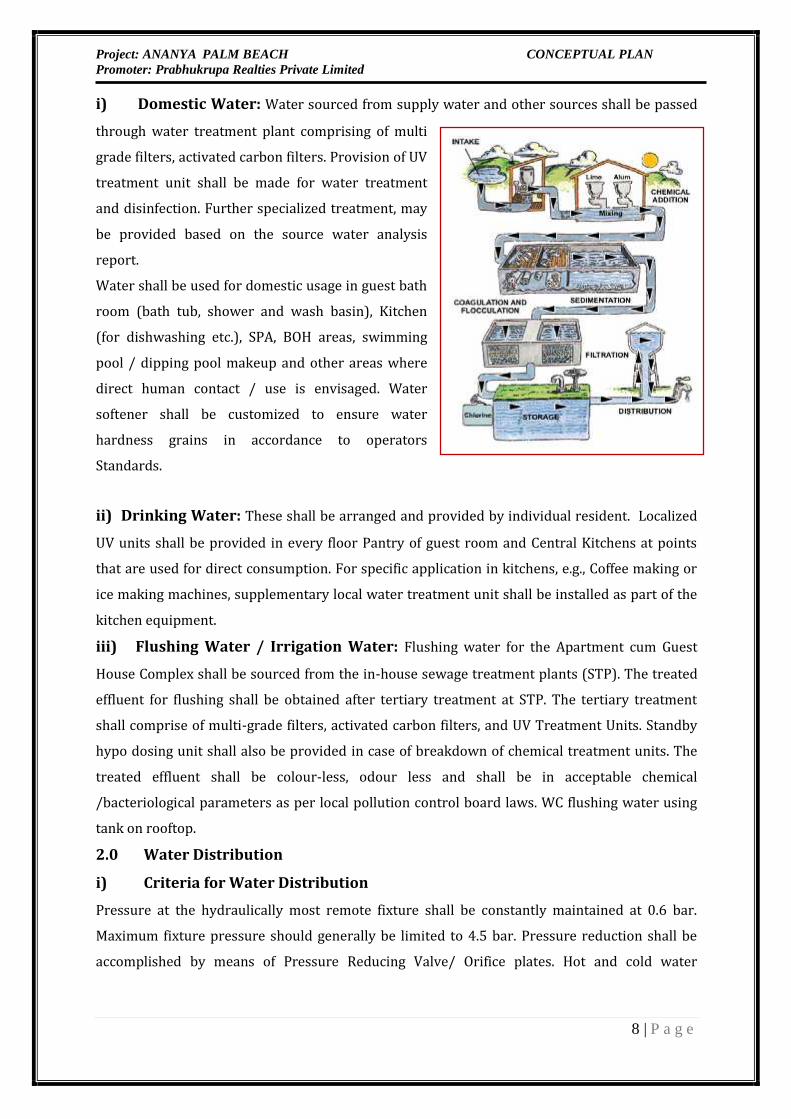
i) Domestic Water: Water sourced from supply water and other sources shall be passedthrough water treatment plant comprising of multigrade filters, activated carbon filters. Provision of UVtreatment unit shall be made for water treatmentand disinfection. Further specialized treatment, maybe provided based on the source water analysisreport.Water shall be used for domestic usage in guest bathroom (bath tub, shower and wash basin), Kitchen(for dishwashing etc.), SPA, BOH areas, swimmingpool / dipping pool makeup and other areas wheredirect human contact / use is envisaged. Watersoftener shall be customized to ensure waterhardness grains in accordance to operatorsStandards.ii) Drinking Water: These shall be arranged and provided by individual resident. LocalizedUV units shall be provided in every floor Pantry of guest room and Central Kitchens at pointsthat are used for direct consumption. For specific application in kitchens, e.g., Coffee making orice making machines, supplementary local water treatment unit shall be installed as part of thekitchen equipment.iii) Flushing Water / Irrigation Water: Flushing water for the Apartment cum GuestHouse Complex shall be sourced from the in-house sewage treatment plants (STP). The treatedeffluent for flushing shall be obtained after tertiary treatment at STP. The tertiary treatmentshall comprise of multi-grade filters, activated carbon filters, and UV Treatment Units. Standbyhypo dosing unit shall also be provided in case of breakdown of chemical treatment units. Thetreated effluent shall be colour-less, odour less and shall be in acceptable chemical/bacteriological parameters as per local pollution control board laws. WC flushing water usingtank on rooftop.2.0 Water Distribution
i) Criteria for Water DistributionPressure at the hydraulically most remote fixture shall be constantly maintained at 0.6 bar.Maximum fixture pressure should generally be limited to 4.5 bar. Pressure reduction shall beaccomplished by means of Pressure Reducing Valve/ Orifice plates. Hot and cold water
Project: ANANYA PALM BEACH CONCEPTUAL PLANPromoter: Prabhukrupa Realties Private Limited
9 | P a g e
equipment, pumps, controls, distribution piping, etc, would be engineered to minimize systempressure fluctuations.ii) Cold Water Distribution (Following options are feasible for water
distribution)Water distribution for domestic water supply for the Complex shall be designed on principle ofzoning to ensure availability of minimal residual pressure at all user outlets.The water distribution system for domestic and flushing water supply to all buildings shall bethrough gravity feed.Domestic and flushing water tanks at the terrace level of each building shall receive waterthrough Hydro pneumatic/Centrifugal pumps installed at plumbing plant room and STPrespectively of individual society to transfer the water. However, flushing water tank shall havethe provision to receive water through non-return valve from adjacent domestic water tank incase of shortfall of STP treated water. The system shall also have float valve at the OHRs andSolenoid valve.Underground water storage tank and pump room housing fire pumps, water treatment plant,transfer pumps shall be proposed in underground.All inlets, outlets, washouts, vents, ball cocks, overflows control valves and all such other pipingconnections including level indicator shall be provided for underground water storage tanks.Full way gate valves of approved make shall be provided as close to the underground tank aspracticable on every outlet pipe from the storage tank, except the overflow pipe. Overflow andvent pipes shall terminate with mosquito proof grating.The overflow pipe shall be so placed as to allow the discharge of water being readily seen.The overflow pipe shall be of size as indicated. A stop valve shall also be provided in the inletwater connection to the tank. The outlet pipes shall be fixed approximately 100mm above thebottom of the tank towards which the floor of the tank is sloping to enable the tank to be nearlyemptied for cleaning at clean out pipe at base.The pipe sizing shall be based on fixture unit calculation as per NBC standard. The pipe size ofriser shall be restricted to nearest 4” size to optimize on capital cost, and for ease of installationand maintenance. However, the maximum velocity in the water supply piping shall not exceed2.4 m/second. Water meters (if required) shall be provided in identified areas for waterconsumption recording for efficient monitoring and assessment. Head losses through watermeter shall be accounted for in water distributions calculations.Colour coding for flushing, domestic, irrigation and hot water supply piping shall be ensured forclear identification of the piping.
Project: ANANYA PALM BEACH CONCEPTUAL PLANPromoter: Prabhukrupa Realties Private Limited
10 | P a g e
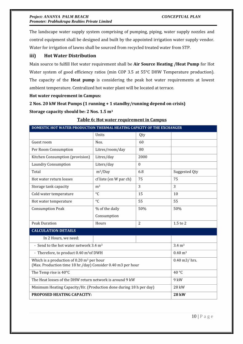
The landscape water supply system comprising of pumping, piping, water supply nozzles andcontrol equipment shall be designed and built by the appointed irrigation water supply vendor.Water for irrigation of lawns shall be sourced from recycled treated water from STP.iii) Hot Water DistributionMain source to fulfill Hot water requirement shall be Air Source Heating /Heat Pump for HotWater system of good efficiency ratios (min COP 3.5 at 55°C DHW Temperature production).The capacity of the Heat pump is considering the peak hot water requirements at lowestambient temperature. Centralized hot water plant will be located at terrace.Hot water requirement in Campus:
2 Nos. 20 kW Heat Pumps (1 running + 1 standby/running depend on crisis)
Storage capacity should be: 2 Nos. 1.5 m3
Table 6: Hot water requirement in Campus
DOMESTIC HOT WATER PRODUCTION THERMAL HEATING CAPICITY OF THE EXCHANGERUnits QtyGuest room Nos. 60Per Room Consumption Litres/room/day 80Kitchen Consumption (provision) Litres/day 2000Laundry Consumption Liters/day 0Total m3/Day 6.8 Suggested QtyHot water return losses cf liste (en W par ch) 75 75Storage tank capacity m3 3 3Cold water temperature °C 15 10Hot water temperature °C 55 55Consumption Peak % of the dailyConsumption 50% 50%Peak Duration Hours 2 1.5 to 2CALCULATION DETAILSIn 2 Hours, we need:- Send to the hot water network 3.4 m3 3.4 m3- Therefore, to product 0.40 m3of DWH 0.40 m3Which is a production of 0.20 m3 per hour(Max. Production time 18 hr./day) Consider 0.40 m3 per hour 0.40 m3/ hrs.The Temp rise is 40°C 40 °CThe Heat losses of the DHW return network is around 9 kW 9 kWMinimum Heating Capacity/Hr. (Production done during 18 h per day) 28 kWPROPOSED HEATING CAPACITY: 28 kW
Project: ANANYA PALM BEACH CONCEPTUAL PLANPromoter: Prabhukrupa Realties Private Limited
11 | P a g e
Hot water return piping and pumping arrangement shall be made for energy conservation andsystem efficiency. Provision of plate type heat exchanger shall be made for primary andsecondary circuit segregation.However, Solar water heating system to compensate 20% of the total hot water demandequivalent to following capacities shall be provided for preheating the cold water make-up tohot water mixing tank for meeting the hot water demand.iv) Solar hot water: 2000 LPDSolar water heating system generate huge amount of energy directly from sunlight, it is noiseless and does not produce any environmental pollution. The Solar System comprises of heatcollectors, heat exchanger, heat store, pumps and other allied equipment. The heat collectionefficiency of the collectors being of prime importance; hence the collectors shall be preferably ofmarine grade aluminum for tray and copper tubes for capillaries to facilitate high transmittancewith high absorber surfaces having absorbivity of more than 94%. Once the heat has beeneffectively collected by collectors, it is transferred though heat transfer medium such as thermicfluid. Thermic fluid, heated in the collectors shall pass through a coil, which in turns shall heatthe water in a tank.
Project: ANANYA PALM BEACH CONCEPTUAL PLANPromoter: Prabhukrupa Realties Private Limited
12 | P a g e
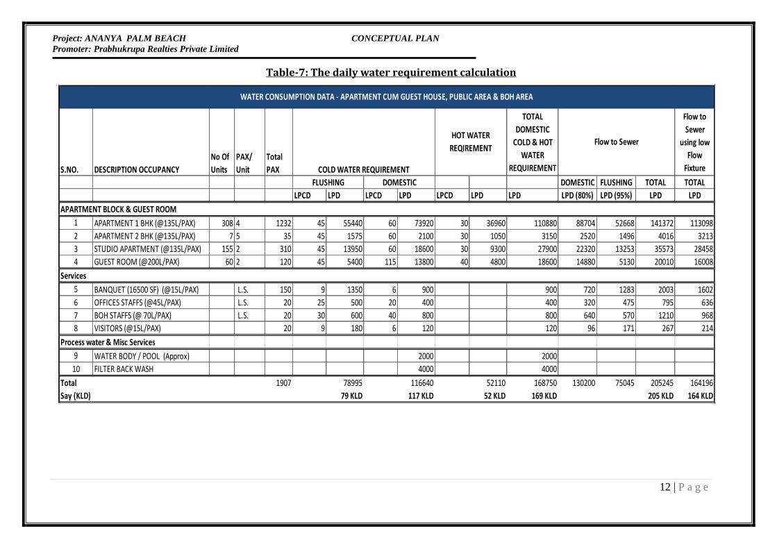
Table-7: The daily water requirement calculation
S.NO. DESCRIPTION OCCUPANCYNo OfUnits
PAX/Unit
TotalPAX
TOTALDOMESTIC
COLD & HOTWATER
REQUIREMENT
Flow toSewer
using lowFlow
FixtureDOMESTIC FLUSHING TOTAL TOTAL
LPCD LPD LPCD LPD LPCD LPD LPD LPD (80%) LPD (95%) LPD LPDAPARTMENT BLOCK & GUEST ROOM
1 APARTMENT 1 BHK (@135L/PAX) 308 4 1232 45 55440 60 73920 30 36960 110880 88704 52668 141372 1130982 APARTMENT 2 BHK (@135L/PAX) 7 5 35 45 1575 60 2100 30 1050 3150 2520 1496 4016 32133 STUDIO APARTMENT (@135L/PAX) 155 2 310 45 13950 60 18600 30 9300 27900 22320 13253 35573 284584 GUEST ROOM (@200L/PAX) 60 2 120 45 5400 115 13800 40 4800 18600 14880 5130 20010 16008
Services5 BANQUET (16500 SF) (@15L/PAX) L.S. 150 9 1350 6 900 900 720 1283 2003 16026 OFFICES STAFFS (@45L/PAX) L.S. 20 25 500 20 400 400 320 475 795 6367 BOH STAFFS (@ 70L/PAX) L.S. 20 30 600 40 800 800 640 570 1210 9688 VISITORS (@15L/PAX) 20 9 180 6 120 120 96 171 267 214
Process water & Misc Services9 WATER BODY / POOL (Approx) 2000 200010 FILTER BACK WASH 4000 4000
Total 1907 78995 116640 52110 168750 130200 75045 205245 164196Say (KLD) 79 KLD 117 KLD 52 KLD 169 KLD 205 KLD 164 KLD
WATER CONSUMPTION DATA - APARTMENT CUM GUEST HOUSE, PUBLIC AREA & BOH AREA
HOT WATERREQIREMENT
FLUSHING DOMESTICCOLD WATER REQUIREMENT
Flow to Sewer

Project: ANANYA PALM BEACH CONCEPTUAL PLANPromoter: Prabhukrupa Realties Private Limited
13 | P a g e
Figure 1: Water Balance Diagram
v) Wastewater Generation & Treatment
Table no.-8: Wastewater Generation & TreatmentS.No. Particular Quantity (KLD)
1 Total Water Requirement 248 KLD
2 Fresh Water Requirement 169 KLD
3 Waste Water Generation 205 KLD
4 Waste Water Generated due Low Flow Fixture 164 KLD
5 Treated Water recovered 148 KLD
STP Treated wastewater utilization
5 Landscaping 40 KLD
6 Flushing 79 KLD
7 General Washing 15 KLD
8 Excess treated water Discharge 14 KLD (Dry season)
69 KLD (Rainy season)
STP Treated Water for Re-use
14 KLDExcessive
treatedwaste water
in Dryseason and69 KLD
discharge inrainy season
FreshWater 169
KLD
102+2+60=164 KLD
Waste Water
STP Capacity20% higher
(STPCapacity:200 KLD)Treated
WasteWater 134
KLD
60 KLD
Landscaping – 40 KLD
Flushing – 79 KLD
Road washing – 15 KLD
102 KLD
2 KLD
Residential Cum Guest House 160.8KLD
Visitor, Club, Staff – 2.2 KLD
Swimming Pool – 2 KLD
Domestic Filter Backwash– 4 KLD

Project: ANANYA PALM BEACH CONCEPTUAL PLANPromoter: Prabhukrupa Realties Private Limited
14 | P a g e
3.0 Sewage, Sullage and storm water drainageThe following parameters/ site conditions shall be kept in mind when designing the sewage,sullage and storm water drainage system: Natural slope of the area; Layout of different facility in the complex; Sub-soil water table; Soil condition; Provision of Sewage lifting station; Provision of venting arrangement for manholes; Construction of manholes & laying of pipes considering ground condition; Termination of vent cowl at terrace level; Provision of adequate slope for horizontal header in the under slung pipes especially fortoilets.
3.1 Sewage & Sullage Waste DrainageThe soil and waste shall be carried down in separate independently vented pipes (in the shaft).Single pipe system although has been designed for running at the basement level. the sanitary,waste & vent system shall be water tight and gas tight designed to prevent escape of foul gas andodour from various fixtures. Provision of ASP vertical vent shall be made for hygiene, safetyconsiderations, and to avoid entry of foul smell into occupied areas.Vent system shall be designed to facilitate escape of gases and odour from all parts of sanitary andwaste system to the atmosphere at a point above the building and to allow admittance of air to allpart of the system, so that siphonage, aspiration or back pressure conditions do not cause loss ofseal at traps. It is proposed to use cast iron pipe for soil / waste drainage. Although as per Clientsrequirement the same will be designed with SWR – Type B. The soil & waste piping shall beunder-slung (in the ceiling slab of floor below) and the horizontal header shall be subsequentlyconnected to the vertical stack located inside the associated pipe shaft which shall be coordinatedcarefully with other services and in consultation with Architect. Care shall be taken to avoid piperuns in electrical switch rooms and other critical areas.Provision for cleaning and rodding eyes shall be made at strategic locations to allow the systemmaintenance. These cleaning & rodding eyes shall be located in BOH areas, in ceiling space andshall be remote from kitchen / pantry and other critical areas.Stainless steel grease interceptors are proposed for kitchen waste. The design of grease inceptorsshall be in accordance with ASPE standard and shall include cleanout at entry and exit. The covershall be non-slip. Provision of independent vent shall be made to avoid odour / smell nuisance inthe surrounding areas.The construction of manhole, gully trap & catch basin shall be in accordance to the soil conditionat site..

Project: ANANYA PALM BEACH CONCEPTUAL PLANPromoter: Prabhukrupa Realties Private Limited
15 | P a g e
3.2 Design Criteria
The system shall be designed as per following design criteria stipulated in the “Manual forSewerage & Treatment” published by the Central Public Health and Environment EngineeringOrganization, Ministry of Urban Development, Govt. of India, IS-SP/35(S&T)-1987 and Nationaland International practices on the subject.4.0 Sewage Treatment PlantSewerage Treatment Plant shall be compact, odour free and shall consume low power. Plant shallbe installed below/above ground level as required & shall generate minimum amount of excesssludge and also construction shall be suitable for sub-zero temperature climatic conditions.Following parameters shall be adopted for the design of sewage treatment plant.4.1 SEWAGE TREATMENT TECHNOLOGY
Volume of Treated Water received from STP
As per calculation designing the STP it is considered that 80 % of domestic water and FlushingWater consumed gets converted in to sewage. Based on this fundamental the capacity of STP shallbe 200 m3/day.The entire treated sewage will be recycled/re-used for horticulture, flushing and General washingand DG Set cooling.STP based on MBBR technology with capacity of 200 KLD will be installed for wastewatertreatment. Physico chemical characteristics of influent and effluent are given as:Table no. 9- Physico chemical characteristics o f Inlet And Outlet
Parameters Inlet (mg/l) Outlet (mg/l)
pH 7.5 - 8.5 6.0-8.5
Suspended solids 250-400 <10 mg/l
BOD 250 - 450 <20 mg/l
COD 600-800 <50 mg/l
Oil & Grease 50-100 <5 mg/l
Detergent 10-50 <5 mg/l
Turbidity Less than 1 NTU
E coil Removal Remove to the level of log 6

Project: ANANYA PALM BEACH CONCEPTUAL PLANPromoter: Prabhukrupa Realties Private Limited
16 | P a g e
4.2 SEWAGE TREATMENT BY MBBR PROCESS – PROCESS DETAILSThe waste water to be let into the bar screen chamber before letting to the collection tank. Thewastewater from the kitchen and the toilets to be let to the oil and grease separator before lettingto the collection tank.The wastewater goes through the following processes:4.3 BRIEF DESCRIPTION OF THE SYSTEMThe proposed biological treatment system is based on the advanced MBBR technology.The design and detailing of the MBBR Waste Water Treatment plant is done In such a way thatprovides maximum treatment efficiency and process stability.This proposed MBBR technology offer distinct advantage over other technologies likeconventional activated sludge process, bio-towers, and others. The salient features of sewagetreatment technology, offered by WSPL, are as follows: A Very compact design for modular units Maximum treatment efficiency No smell or bad Odour. Excellent process stability for the shock loads Minimum reactor volume and area requirements Fully digested minimum excess sludge production Minimum process control, operation and maintenance Treated wastewater can be reused / recycled for gardening horticulture, toilet flushingand cooling tower make up water Economically viable units for the cost effective solutions
4.4 Expected Removal at Various Stages:Efficiency of Treatment Unit:1. Biological TreatmentBOD Removal = 85 – 90%COD Removal = 70 – 80%2. Tertiary TreatmentBOD Removal = 80 – 90% of residualS. S Removal = 90 – 95%

Project: ANANYA PALM BEACH CONCEPTUAL PLANPromoter: Prabhukrupa Realties Private Limited
17 | P a g e
4.5 BRIEF WRITE UP ON THE STP PROCESS:The scheme proposed for the treatment of sewage is a compact and effective Sewage TreatmentPlant using the revolutionary “Moving Bed Bio Reactor (MBBR)” technology. The conceptunderlining the Moving Bed bioreactor is to provide continuously operating bio-film reactor,which is non-cloggable does not require backwashing and has a very low-pressure drop. This isachieved by growing the bio-film on smaller carrier elements that move along with the wastewater in the reactor. The air stream constantly keeps the bio media is in suspension and at thesame time provides the required oxygen to the biomass.The system uses specially designed bio-media, which provides a large surface area for biologicalgrowth. The bio-media is made of plastic material, which has a very long life. The media iscylindrical in shape and provides a large surface area in the given volume. The media providesabout 800 m2 effective area for growth of the bio film per m3 of volume.The proposed system will consist of the following major stages:1. Sewage Collection and Pumping System2. Manual Bar Screen and Grit Chamber3. Aeration Tank and Tube-deck Settlers4. Filtration System5. Disinfection System
1. Sewage Collection and Pumping System:Raw sewage will enter the raw sewage sump. Raw sewage transfer pumps will pump the sewageto the STP through the screen and grit removing stages. One Pump will be on duty and the otherstandby.2. Manual Bar Screen and Grit Chamber:A combination of coarse and fine screens will be provided for removal of floating debris from thesewage. The coarse screen will have spacing of 10 mm and will be periodically cleaned. The finescreen will have a spacing of 5 mm and will also be periodically cleaned. The outlet from theScreen Chamber is let into the sewage treatment system.3. Sewage Treatment System:The proposed Sewage Treatment System will have the following major components:a. MBBR Bio Reactor Unitsb. Tube Settler Unit.c. Aeration Systema. MBBR Bioreactors: The MBBR Aeration tanks are located next to each other. Each of thetanks will be provided with aeration pipelines at the bottom, which will be in stainless steel andare manifold to cover half the periphery of the tank. Aeration tank is filled with a specific
Project: ANANYA PALM BEACH CONCEPTUAL PLANPromoter: Prabhukrupa Realties Private Limited
18 | P a g e
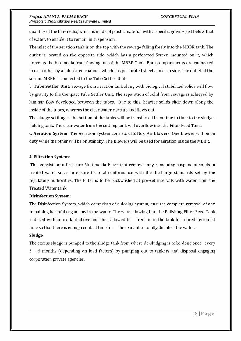
quantity of the bio-media, which is made of plastic material with a specific gravity just below thatof water, to enable it to remain in suspension.The inlet of the aeration tank is on the top with the sewage falling freely into the MBBR tank. Theoutlet is located on the opposite side, which has a perforated Screen mounted on it, whichprevents the bio-media from flowing out of the MBBR Tank. Both compartments are connectedto each other by a fabricated channel, which has perforated sheets on each side. The outlet of thesecond MBBR is connected to the Tube Settler Unit.b. Tube Settler Unit: Sewage from aeration tank along with biological stabilized solids will flowby gravity to the Compact Tube Settler Unit. The separation of solid from sewage is achieved bylaminar flow developed between the tubes. Due to this, heavier solids slide down along theinside of the tubes, whereas the clear water rises up and flows out.The sludge settling at the bottom of the tanks will be transferred from time to time to the sludge-holding tank. The clear water from the settling tank will overflow into the Filter Feed Tank.c. Aeration System: The Aeration System consists of 2 Nos. Air Blowers. One Blower will be onduty while the other will be on standby. The Blowers will be used for aeration inside the MBBR.4. Filtration System:This consists of a Pressure Multimedia Filter that removes any remaining suspended solids intreated water so as to ensure its total conformance with the discharge standards set by theregulatory authorities. The Filter is to be backwashed at pre-set intervals with water from theTreated Water tank.Disinfection System:The Disinfection System, which comprises of a dosing system, ensures complete removal of anyremaining harmful organisms in the water. The water flowing into the Polishing Filter Feed Tankis dosed with an oxidant above and then allowed to remain in the tank for a predeterminedtime so that there is enough contact time for the oxidant to totally disinfect the water.
SludgeThe excess sludge is pumped to the sludge tank from where de-sludging is to be done once every3 – 6 months (depending on load factors) by pumping out to tankers and disposal engagingcorporation private agencies.
Project: ANANYA PALM BEACH CONCEPTUAL PLANPromoter: Prabhukrupa Realties Private Limited
19 | P a g e
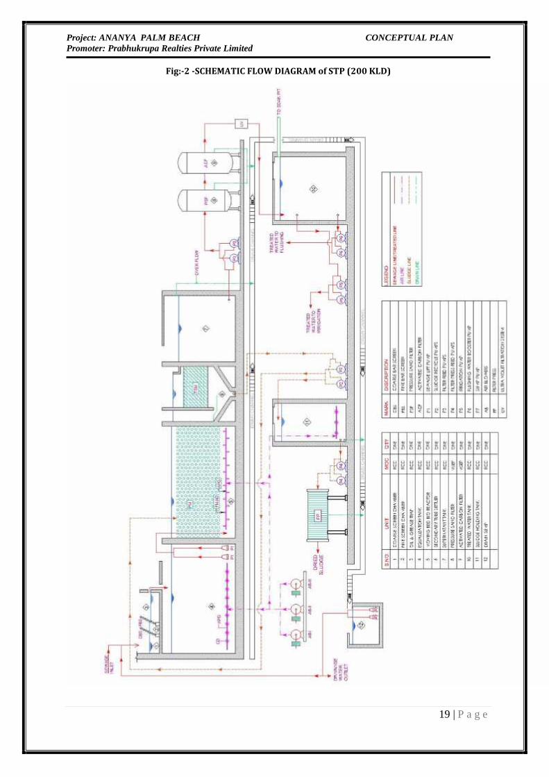
Fig:-2 -SCHEMATIC FLOW DIAGRAM of STP (200 KLD)

Project: ANANYA PALM BEACH CONCEPTUAL PLANPromoter: Prabhukrupa Realties Private Limited
20 | P a g e
5.0 RAIN WATER HARVESTINGThe storm water disposal system for the premises shall be self-sufficient to avoid anycollection/stagnation and flooding of water. Storm water drainage plan of the project is enclosed.The amount of storm water run-off depends upon many factors such as intensity and duration ofprecipitation, characteristics of the tributary area and the time required for such flow to reach thedrains. The drains shall be located near the carriage way along either side of the roads. Taking theadvantage of road camber, the rainfall run off from roads shall flow towards the drains. Stormwater from different areas be connected to adjacent drain by a pipe through catch basins.Separate and independent rain water drainage system shall be provided for collecting rain waterfrom terrace, paved area, lawns and roads. Independent rain water down takes of appropriatesize and number shall be provided in close coordination with Architect. Perforated pipe drainagesystem shall be provided for open-to-sky courtyard/lawn. The storm water runoff from thebasement ramp shall be separately collected and connected to sump at basement. Drain channelshall be provided in the basement level car parking and plant room areas within the floor fillabove the raft. Drain channels shall be provided with adequate slope to affect self cleaningvelocity and shall terminate in sumps. For each sump, 1 no. submersible pumps (1 working) and astand by trolley mounted sump pump (for emergency purpose) shall be provided for disposal ofcollected run-off. Pumps shall be installed in identified sumps and shall be operated by Hi-Lo levelswitches with automatic changeover between both pumps.The storm water disposal system for the premises shall be self-sufficient to avoid anycollection/stagnation and flooding of water. Storm water drainage plan of the project is enclosed.The amount of storm water run-off depends upon many factors such as intensity and duration ofprecipitation, characteristics of the tributary area and the time required for such flow to reach thedrains. The drains shall be located near the carriage way along either side of the roads. Taking theadvantage of road chamber, the rainfall run off from roads shall flow towards the drains. Stormwater from different areas be connected to adjacent drain by a pipe through catch basins.The major objective of rain water harvesting is to collect available run–off from roof duringrainfall in monsoon period without any health hazard, if any. The rainfall during monsoon infirst 7 to 10 minutes duration having dust palliatives and acid rain must be drained out to thedrainage network.The roof area is 4758 Sq.m. out of total land area of about 9267 Sq.m, the average annualrainfall from past ten years’ rainfall record is 1576 mm. About 80% of rainfall occurs duringmonsoon in four months considering a loss of 20% due to evaporation, percolation, and evapo-transpiration etc., the composite run off co-efficient may be taken as 0.80. The run-off availableis therefore, 4758.59 x 1.576 x 0.8 (cum) = 5999.63 cum. in 4 months. Therefore, the average dailycollection is 5999.63 / 120 = 50 cu m.

Project: ANANYA PALM BEACH CONCEPTUAL PLANPromoter: Prabhukrupa Realties Private Limited
21 | P a g e
U.G.R., having capacities of 300 cum** should be sufficient to store 6-day collection. This will beprovided with arrangement of draining out the over flow water into storm water drain.** According build bye law, Storage requirements @ 6 Cum / 100 sq. m Roof area. Total Roof Area= 4758.59 Sq.m, Rain water Storage Tank = (4758.59/100) x 6 Cu = 285.51 Cum5.1 AREA CALCULATIONBased on the area statement received from the Architectural Layout, the gross area receiving therainfall for the entire Complex is as follows:Roof Areas 4758.59 m2Green Area 1863.39 m2Roads & Pathways & other services 2645.3 m2Total area 9267.3 m2As per data made available by the Indian Meteorological Department (IMD), the maximum rainfallintensity can exceed more than 80 mm/hr but it occurs once in a few years. The average rainfall intensityis 40 (Avg.) mm which generally occurs in one hour.5.2 RAINFALL & TEMPERATURE DATA OF PURI AS PER INDIA METEOROLOGICAL DEPARTMENT
5.3 RUN OFF (RAIN WATER) CALCULATIONThe runoff is being assessed as per following formula:Runoff = Catchment’s Area * Runoff coefficient * RainfallThe run off coefficient plays an important role in assessing the run off availability and depends on thecatchment characteristics. General values as given in The Gazette of India dated July 28, 2001 are asfollows:S. No. Type of Catchment Runoff Coefficient1. Roof Top 0.802. Green Area 0.203. Roads & Pathways 0.50However, for the purpose of calculations, the higher value of runoff coefficient is being consideredin view of unpredictable nature of rainfall for arriving at total storage volumes.

Project: ANANYA PALM BEACH CONCEPTUAL PLANPromoter: Prabhukrupa Realties Private Limited
22 | P a g e
5.4 Rain Water Harvesting Calculation for the Proposed Residential Apartment
cum Guest House
Sl. No. Source Area (m2)Rainwater to begenerated (m3)
annuallyRemarks
1 Roof 4758.59 5999.63 Recharged to deeperaquifer throughrecharging well2 Paved 2645.30 2084.49 Recharged to shallowaquifer3 Plantation 1863.39 587.34
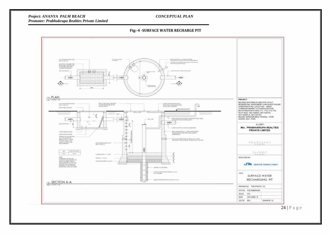
Total 8671.46Roof top water will be store in rainwater harvesting storage tank having capacity of 300 cum.Rain water from green belt area and paved, road area will be recharge to ground water aftertreatment. Suitable No. of Rainwater Recharged pit having effective depth shall have to beprovided. Although the same will depend on the Water Permeability report of the Soil at site.Since the existing topography is congenial to surface disposal, a network of storm water pipedrains is planned adjacent to roads. Proposed storm water system consists of pipe drain, catchbasin and seepage pits at regular intervals for rain water harvesting and ground waterrecharging. All building roof water will be brought down through rain water pipes.At the bottom of the recharge pit a filter media is provided to avoid choking of the recharge pit.Total 7 nos Rain Water Harvesting structures are being proposed for artificial rain waterrecharge within the project premises. Therefore, it has been calculated to provide storm watercollection or recharge pit for storm water harvesting at selected locations, which will catch themaximum run-off water and roof water from the area. Since the existing topography is congenialto surface disposal, a network of storm water pipe drains is planned adjacent to roads. Proposedstorm water system consists of pipe drain, catch basins and seepage pits at regular intervals forrain water harvesting and ground water recharging. All building roof water will be brought downthrough rain water pipes.

Project: ANANYA PALM BEACH CONCEPTUAL PLANPromoter: Prabhukrupa Realties Private Limited
23 | P a g e
Fig:-3 -RAINWATER STORAGE CUM RECHARGE PIT
Project: ANANYA PALM BEACH CONCEPTUAL PLANPromoter: Prabhukrupa Realties Private Limited
24 | P a g e
Fig:-4 -SURFACE WATER RECHARGE PIT

Project: ANANYA PALM BEACH CONCEPTUAL PLANPromoter: Prabhukrupa Realties Private Limited
25 | P a g e
FIG:-5 -SITE DRAINAGE SHEMATIC LAYOUT

Project: ANANYA PALM BEACH CONCEPTUAL PLANPromoter: Prabhukrupa Realties Private Limited
26 | P a g e
6.0 PARKING FACILITIESAdequate provision will be made for car parking at the project site. There shall also beadequate parking provisions for visitors so as not to disturb the traffic and allow smoothmovement at the site.Table no. 10: Parking Facilities
RESIDENTAL AREA (APPROVED)No. of Flats in Phase 1,2 & 3 upto S+S Floors 315.00 FlatsNo. of Parking units (315/6 Flats=52.50 53.00 UnitsCommercial Area (Approved) 3,453.51 Sq.Ft. 320.84 Sqm.Parking area required (320.84/140=2.29) 3.00 UnitsTotal Parking Units Required 56.00 UnitsParking Area Required @40.5 Sqm./ParkingUnit 24,412.75 Sq.Ft.
COMMERCIALAREA
RESIDENTALAREAFAR Area in all Phases of Floors 6 & 7(Proposed) 24,831.90 50,376.28FAR Area in Phase 4 of Floors S to 5(Proposed) 29,652.45 33,881.37
Total 54,484.35 84,257.65
@35% @25%19,069.52 21,064.41total Parking AreaRequired 64,546.69 Sq.Ft.
Total ParkingArea Provided 64,680.90 Sq.Ft.
6009.05sqm
However, following measures will be adopted for smooth traffic movements:
Provisions of fully internalized parking including the parking facilities for the visitors. Guided traffic ways within the project site. Speed humps will be installed for speed restrictions inside the project area. Separate entry/exit points to avoid traffic congestions

Project: ANANYA PALM BEACH CONCEPTUAL PLANPromoter: Prabhukrupa Realties Private Limited
27 | P a g e
FIG NO.-6- PARKING PLAN AT BASEMENT

Project: ANANYA PALM BEACH CONCEPTUAL PLANPromoter: Prabhukrupa Realties Private Limited
28 | P a g e
FIG NO.-7- PARKING PLAN AT GROUND/STILT FLOOR

Project: ANANYA PALM BEACH CONCEPTUAL PLANPromoter: Prabhukrupa Realties Private Limited
29 | P a g e
FIG NO.-8- PARKING PLAN AT TERRACE FLOOR

Project: ANANYA PALM BEACH CONCEPTUAL PLANPromoter: Prabhukrupa Realties Private Limited
30 | P a g e
7.0 POWER REQUIREMENT
The power supply shall be supplied by CESU. The maximum demand load is estimated at 2500KVA & connected load is estimated at 3980 KW.Details of D.G SetsProvision of Power backup for the project will be through DG sets of total capacity 1500 KVA (2Nos. of 250 KVA & 2 Nos. of 500 KVA) Silent DG Set. The proposed DG sets will be equipped withacoustic enclosure to minimize noise generation and adequate stack height for proper dispersion.Noise Control Measures for DG sets:Adequate exhaust mufflers will be provided as per norms to limit the noise.During operation vehicular movement and operation of DG sets are the major sources of noisepollution. But both these activities- DG set and vehicular movement will not have any significantimpact on the people residing in the area. Since DG set will not be operational continuously andmoreover it will be placed away from residential settlements and will be enclosed with suitableenclosures, hence no or minimal impact will be anticipated. It is envisaged that the movement ofthe motor vehicles will be restricted to designated carriageways only.8.0 SOLID WASTE GENERATION
Construction PhaseSolid waste would be generated both during the construction as well as during the operationphase. The solid waste expected to be generated during the construction phase will comprise ofexcavated materials, used bags, bricks, concrete, MS rods, tiles, wood etc. The following steps areproposed to be followed for the management solid waste: Construction yards are proposed for storage of construction materials. The excavated material such as topsoil and stones will be stacked for reuse during laterstages of construction Excavated top soil will be stored in temporary constructed soil bank and will be reusedfor landscaping of the group housing project. Remaining soil shall be utilized for refilling / roadwork / rising of site level atlocations/ selling to outside agency for construction of roads etc.

Project: ANANYA PALM BEACH CONCEPTUAL PLANPromoter: Prabhukrupa Realties Private Limited
31 | P a g e
Solid Waste
ConstructionWaste
Constructionwaste,
Broken Bricks,Waste Plaster
EmptyCementBags
Used in re-filling,raising site level
Use for Roadmaking
ExcavatedSoil
Top soil conservedfor landscaping,
balance used in re-filling
Figure 9: Solid Waste Management Scheme (Construction Phase)
Operation PhaseDuring the operation phase, waste will comprise domestic as well as agricultural waste.The solid waste generated from the project shall be mainly domestic waste and estimatedquantity of the waste shall be approx. 911.5 kg per day @ 0.50 kg per capita per day forresidential population (@ 0.30 kg per capita per day for visitors, Staff & club area .Landscape wastes @ 0.2 kg/acre/day will be disposed in project premises). Followingarrangements will be made at the site in accordance to Municipal Solid Wastes(Management and Handling) Rules, 2000 and amended Rules, 2016.

Project: ANANYA PALM BEACH CONCEPTUAL PLANPromoter: Prabhukrupa Realties Private Limited
32 | P a g e
Table 11: Calculation of Solid Waste Generation In Operation phaseS.NO. DESCRIPTIONOCCUPANCY NoOfUnitsPAX/Unit TotalNo. ofpersons Total Garbage in Kg. Biodegradedable (Kg) Non-biodegradedable(Kg)
APARTMENT BLOCK & GUEST ROOM1 APARTMENT 1 BHK(@135L/PAX) 308 4 1232 [email protected] 616 369.6 246.42 APARTMENT 2 BHK(@135L/PAX) 7 5 35 [email protected] 17.5 10.5 73 STUDIO APARTMENT(@135L/PAX) 155 2 310 [email protected] 155 93 624 GUEST ROOM(@200L/PAX) 60 2 120 [email protected] 60 36 24SERVICE5 BANQUET (16500 SF)(@15L/PAX) L.S. 150 [email protected] 45 15 306 OFFICES STAFFS(@45L/PAX) L.S. 20 [email protected] 6 2 47 BOH STAFFS (@70L/PAX) L.S. 20 [email protected] 6 2 48 VISITORS(@15L/PAX) 20 [email protected] 6 2 4Total 911.5 303.8 607.7Collection and Segregation of waste1. A door to door collection system will be provided for collection of domestic waste incolored bins from household units.2. The local vendors will be hired to provide separate colored bins for dry recyclablesand Bio-Degradable waste.3. Litter bin will also be provided in open areas like parks etc. Treatment of waste
The various forms of solid waste generated will be collected, handled and disposed off in amanner so as to cause minimal environmental impact. Municipal solid waste will besegregated as dry and wet waste. The wet waste will be used for composting/vermiculture or given to piggeries as feed. The dry garbage will be disposed of to themunicipal garbage collection systemHence, the Municipal Solid Waste Management will be conducted as per the guidelines Recyclable wastesi. Grass Recycling – The cropped grass will be spread on the green area. It will act asmanure after decomposition.ii. Recyclable wastes like paper, plastic, metals etc. will be sold off to recyclables.
Disposal

Project: ANANYA PALM BEACH CONCEPTUAL PLANPromoter: Prabhukrupa Realties Private Limited
33 | P a g e
Recyclable and non-recyclable wastes will be disposed through Govt. approved agency.Hence, the Municipal Solid Waste Management will be conducted as per the guidelines ofSolid Wastes Management Rules, 2016. A Solid waste management Scheme is depicted inthe following figure for the project.
GREEN AREAThe project being a well-planned activity will result in organized open spaces and greenareas. The green area will comprise of evergreen tall and ornamental trees andornamental shrubs to be planted inside the premises. The green area will be developedapprox. 20.11 % of the total plot area (1863.39 sqm). The biodiversity in the area willincrease due to the proposed green areas. Total green area measures 1863.39 sqm of theplot area which will be area under tree plantation & gardening within the residentialplots and along the roads. Evergreen tall and ornamental trees and ornamental shrubswill be planted inside the premises. 100 Trees will be planted around the projectpremises. Some of the trees are suggested for plantation:
Figure 10: Solid Waste Management Scheme (Operation Phase)

Project: ANANYA PALM BEACH CONCEPTUAL PLANPromoter: Prabhukrupa Realties Private Limited
34 | P a g e
Proposed to be planted in landscape area
DETAILS OF CONSTRUCTION MATERIALS
List of building materials being used at site:1. Coarse sand2. Fine sand3. Stone aggregate4. Stone for masonry work5. Cement6. Reinforcement steel7. Pipe scaffolding (cup lock system)8. Bricks9. CLC fly ash blocks10. Crazy (white marble) in grey cement11. P.V.C. conduit12. MDS, MCBs13. PVC overhead water tanks14. 2 1/2'’ thick red color paver tiles15. PPR (ISI marked)16. PVC waste water lines17. S.W. sewer line up to main sewer18. PVC rain water down take19. Stainless steel sink in kitchen20. Joinery hardware- ISI marked
Botanical Name Common Name
Delonix regia GulmoharAlbizzia lebbek SirisCassia fistula AmaltasFicus elastic Rubber tree
Dalbergia sissoo ShishamPterospermumacerifolium Kanak Champa
Grevillearobusta Silver oak

Project: ANANYA PALM BEACH CONCEPTUAL PLANPromoter: Prabhukrupa Realties Private Limited
35 | P a g e
LIST OF MACHINERY USED DURING CONSTRUCTION
(i) Dumper(ii) Concrete mixer with hopper(iii) Excavator(iv) Concrete Batching Plant(v) Cranes(vi) Road roller(vii) Bulldozer(viii) RMC Plant(ix) Tower Cranes(x) Hoist(xi) Labor Lifts(xii) Pile Boring Machines(xiii) Concrete pressure pumps(xiv) Mobile transit mixerCER PLAN
M/s Prabhukrupa Realties Private Limited has been focusing on CSR front for over a decadeand has contributed significantly on various fronts namely: Education, Skill Training, TreePlantation, Outside Development etc. The Company has a CSR department and has been workingrelentlessly for the socio economical development in the area where the Company is developingits housing projects.Proposal for Residential Apartment cum Guest House Project:The Company intends to spend an amount of Rs. 100 Lacs approximately in building upinfrastructure of a Govt. School along with other developmental works, childreneducation, and skill training.

Project: ANANYA PALM BEACH CONCEPTUAL PLANPromoter: Prabhukrupa Realties Private Limited
36 | P a g e
BUDGET FOR LABOURS
Details of facility provided for the labors with budgetary estimations
S. No. Description Budget allocation undervarious activities (In Rs. lacs)1. Accommodation & Basic Facilities:A provision of temporary facilities 4
2. Drinking Water 23. Sanitation facility including;Temporary toilet with soak pitsystem and temporary PVC/HDPEbathrooms. At the working siteseparate bathroom/toilets forladies and gents.1
4. Medical Facility 15. Safeguard: PPE 16. Medical Examination of Workers 1Total 10.0