Computer Graphics
58
Computer Graphics Chapter 4 b f h Attributes of Graphics Primitives Somsak Walairacht, Computer Engineering, KMITL 1
-
Upload
khangminh22 -
Category
Documents
-
view
0 -
download
0
Transcript of Computer Graphics

Computer Graphics
Chapter 4b f hAttributes of Graphics Primitives
Somsak Walairacht, Computer Engineering, KMITL 1

Outline
OpenGL State Variables OpenGL State Variables Point Attributes
Li Att ib t Line Attributes Fill-Area Attributes
Scan-Line Polygon-Fill Algorithm Fill Methods for Areas with Irregular Boundaries Fill Methods for Areas with Irregular Boundaries
Character AttributesAntialiasing Antialiasing
Computer Graphics 2

Introduction
A parameter that affects the way a A parameter that affects the way a primitive is to be displayed is referred t Att ib t P tto as an Attribute Parameter
For example, lines can be dotted or For example, lines can be dotted or dashed, fat or thin, and blue or orangeA i ht b fill d Areas might be filled
Text can appear from left to right,Text can appear from left to right, slanted diagonally, or in vertical
Computer Graphics 3
OpenGL State Variablesp
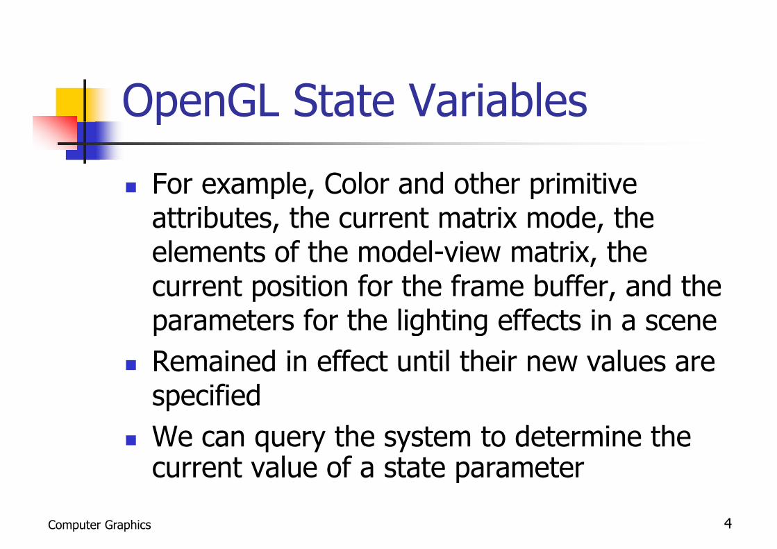
For example Color and other primitive For example, Color and other primitive attributes, the current matrix mode, the l t f th d l i t i thelements of the model-view matrix, the
current position for the frame buffer, and the parameters for the lighting effects in a scene
Remained in effect until their new values are Remained in effect until their new values are specifiedW th t t d t i th We can query the system to determine the current value of a state parameter
Computer Graphics 4

Point Attributes
Two attributes for points: Two attributes for points: color and size
Color components are set with RGB l i d i t l t blvalues or an index into a color table
Size is an integer multiple of the pixel Size is an integer multiple of the pixel size
Computer Graphics 5

Line Attributes
Three basic attributes: Three basic attributes: color, width, and style, , y
Additionally, lines may be generated ith th ff t hwith other effects, such as
pen and brush strokespen and brush strokes
Computer Graphics 6

Line Attributese bu es
Computer Graphics 7

Line Attributese bu es
Computer Graphics 8
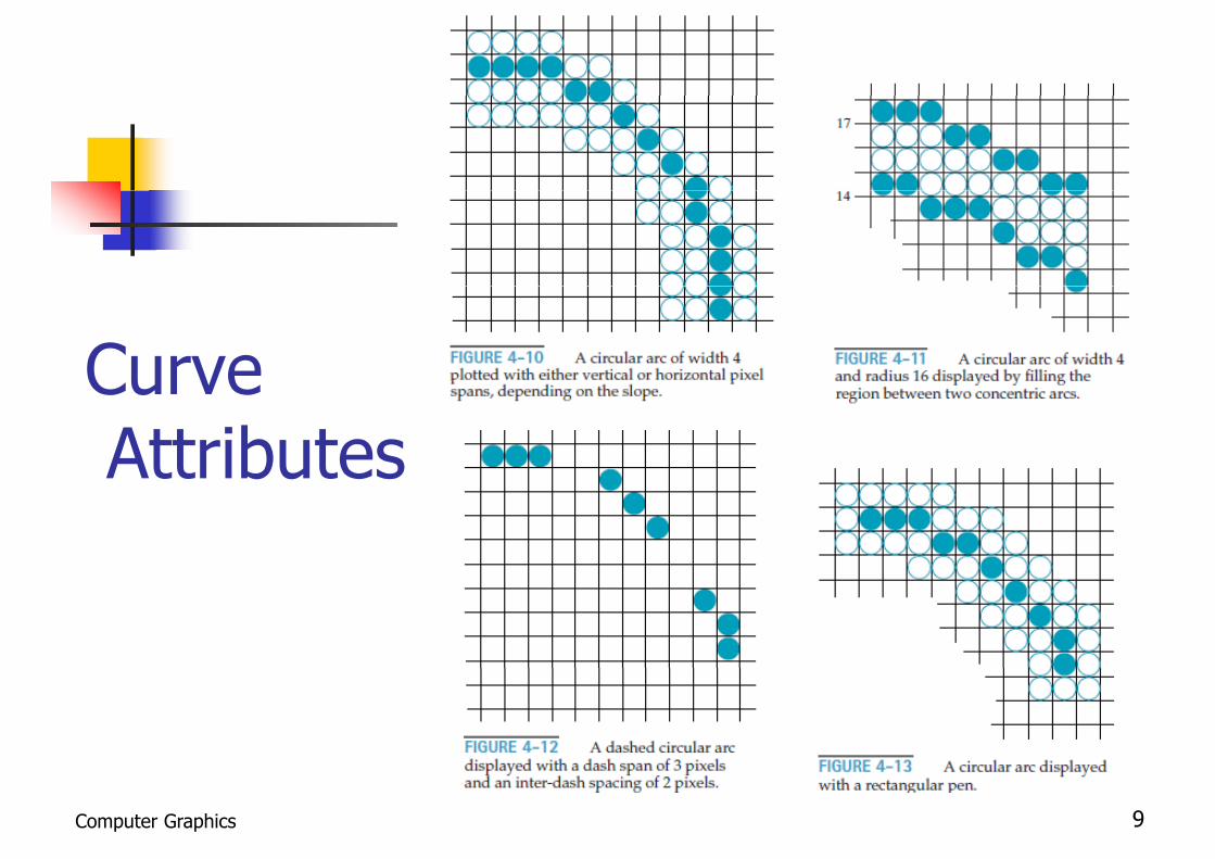
CurveCurveAttributesAttributes
Computer Graphics 9

Fill-Area Attributes
Most graphics packages limit fill areas Most graphics packages limit fill areas to polygons, because they are describedwith linear equationsFurther restriction requires fill areas to Further restriction requires fill areas to be convex
Computer Graphics 10

Fill-Area Attributes (2)( )
There are two basic procedures for filling an There are two basic procedures for filling an area on raster systems1 (simple shape) 1 (simple shape) Determines the overlap intervals for scan lines
that cross the areathat cross the area Pixel positions along these overlap intervals are
set to the fill colorset to the fill color 2 (not so simple shape)
Start from a given interior position and “paint” outward pixel-by-pixel until boundary
Computer Graphics 11

Fill-Area Attributes (3)
The scan-line approach is usually
( )
The scan-line approach is usually applied to simple shapes such as circles
i ith l li b d ior regions with polyline boundaries General graphics packages use this fill g p p g
method While using a starting interior point it is While using a starting interior point, it is
useful for filling areas with morel b d i d i i t ticomplex boundaries and in interactive
painting systemsComputer Graphics 12

Fill Stylesy
Computer Graphics 13

Color-Blended Fill Regionsg
Foreground color (or pattern) could be Foreground color (or pattern) could be combined with background colors
Using a transparency factor that determines how much of thedetermines how much of the background should be mixed with thegobject color
Computer Graphics 14

Color-Blended Fill Regions (2)g ( )
Simple logical or replace operations Simple logical or replace operations
Computer Graphics 15

Color-Blended Fill Regions (3)g ( ) Algorithm using color-blending (Soft-fill or Tint-fill algorithms)g g g ( g ) A foreground color F with a single background color B The current RGB color P of each pixel within the area to be
refilled is some linear combination of F and Brefilled is some linear combination of F and BP = tF + (1 − t)Bwhere 0 < t < 1 (the transparency factor)
P = (PR, PG, PB), F = (FR, FG, FB), B = (BR, BG, BB)t = Pk − Bk / Fk − Bkwhere k = R G or B and Fk ≠ Bkwhere k = R, G, or B, and Fk ≠ Bk
Similarly, a foreground color is to be merged with multiple b k d lbackground color
P = t0F + t1 B1+(1 − t0 − t1)B2 where t0+ t1+(1 − t0− t1) = 1
Computer Graphics 16
where t0 t1 (1 t0 t1) 1

General Scan-Line Polygon-FillGeneral Scan Line Polygon Fill Algorithmg
A scan line fill of a region is performed by A scan-line fill of a region is performed by first determining the intersection positions of th b d i f th fill i ith ththe boundaries of the fill region with the screen scan lines
Then the fill colors are applied to each section of a scan line that lies within the interior ofof a scan line that lies within the interior ofthe fill regionTh li fill l ith id tifi th The scan-line fill algorithm identifies the same interior regions as the odd-even rule
Computer Graphics 17

General Scan-Line Polygon-FillGeneral Scan Line Polygon Fill Algorithm (2)g ( )
Basic scan line procedure: 2 steps Basic scan-line procedure: 2 steps1. Edge intersections are sorted from left to right2. Then the pixel positions between, and including,
each intersection pair are set to the specified fill lcolor
Odd=interior, otherwise = exterior
Sort x-intersection ascending
Computer Graphics 18

General Scan-Line Polygon-FillGeneral Scan Line Polygon Fill Algorithm (3)g ( ) To split those vertices that should be counted as one p
intersection When the endpoint y coordinates of the two edges are
increasing, the y value of the upper endpoint for the currentincreasing, the y value of the upper endpoint for the current edge is decreased by 1
When the endpoint y values are monotonically decreasing, the y coordinate of the upper endpoint of the edge following thecoordinate of the upper endpoint of the edge following the current edge is decreased by 1
nextcurrent
currentnext
Computer Graphics 19

General Scan-Line Polygon-FillGeneral Scan Line Polygon Fill Algorithm (4)g ( )
Coherence properties can be used inการเกี่ยวพนั,การเชื่อมโยง
Coherence properties can be used in computer-graphics algorithms to reduce processingIt often involves incremental It often involves incremental calculations applied along a single scan pp g gline or between successive scan lines
Computer Graphics 20

Determining Fill-Area EdgeDetermining Fill Area Edge Intersections
T i li i th l ft Two successive scan lines crossing the left edge of a triangleTh l f thi d The slope of this edge
m = (yk+1−yk)/(xk+1−xk) The change in y coordinates
yk+1−yk = 1 Each successive x intercept can thus be
calculated by adding the inverse of the slope d di t th t i tand rounding to the nearest integerxk+1 = xk+1/m
Computer Graphics 21

Coherence Methods Method 1 m=7/3
int counter dx dyMethod 1counter = 0counter += dxIf t d th {
int counter, dx, dy
If counter ≥ dy then {x++, counter -= dy }
y++y++ Method 2
counter = 0 counter += 2dxIf counter ≥ dy then {
x++ counter -= 2dy }x++, counter -= 2dy }y++
[1] [2]
Computer Graphics 22
[1] [2]
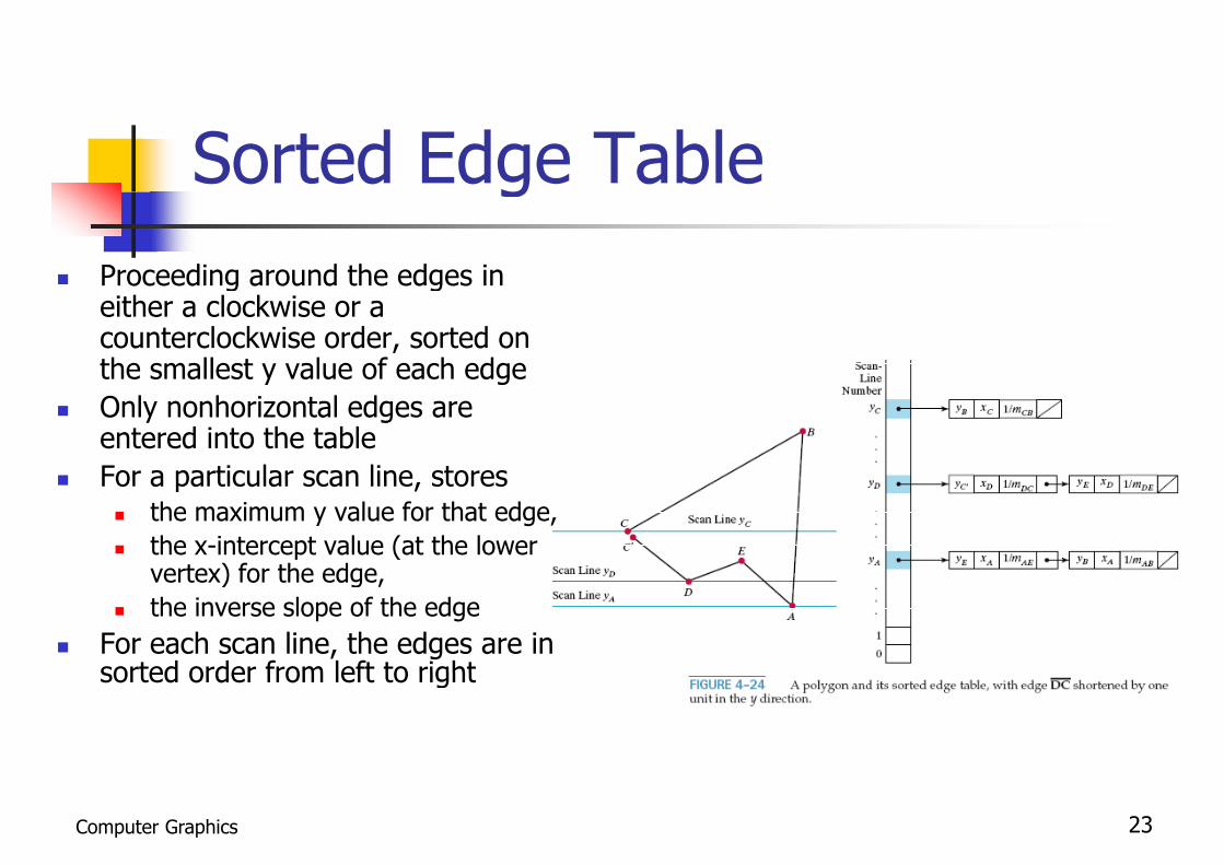
Sorted Edge Tableg Proceeding around the edges in g g
either a clockwise or a counterclockwise order, sorted on the smallest y value of each edgey g
Only nonhorizontal edges are entered into the table
For a particular scan line stores For a particular scan line, stores the maximum y value for that edge, the x-intercept value (at the lower
vertex) for the edgevertex) for the edge, the inverse slope of the edge
For each scan line, the edges are in sorted order from left to rightsorted order from left to right
Computer Graphics 23

Sorted Edge Table (2)g ( )
Computer Graphics 24

Sorted Edge Table (3)g ( ) Process the scan lines from Process the scan lines from
the bottom of the polygon to its top -> active edge li f h lilist for each scan line
For a scan line contains all edges crossed usesedges crossed, uses iterative coherence calculations to obtain the edge intersections
For each scan line, fill i t i i l t i t tinterior pixel at x-intercept values from left to right
Computer Graphics 25

Scan-Line Fill of ConvexScan Line Fill of Convex Polygonsyg
Uses coordinate extents to determine which Uses coordinate extents to determine which edges cross a scan lineIntersection calculations with these edges Intersection calculations with these edges then determine the interior pixel span
Any vertex crossing is counted as a single point
Some graphics packages restrict fill areas to be trianglesg This makes filling even easier
Computer Graphics 26

Scan-Line Fill for Regions withScan Line Fill for Regions with Curved Boundaries
For simple curves such as circles or ellipses apply fill For simple curves such as circles or ellipses, apply fill methods for convex polygons
Each scan line cross just two boundary intersections Each scan line cross just two boundary intersections Determine these two intersection points using the
incremental calculations in the midpoint methodp Simply fill in the horizontal pixel spans Applies symmetric property between quadrantsApplies symmetric property between quadrants
Computer Graphics 27

Fill Methods For Areas withFill Methods For Areas withIrregular Boundariesg
Boundary fill algorithm is employed in Boundary-fill algorithm, is employed in interactive painting packages, where interior points are easily selectedSelect a fill color specify the boundary Select a fill color, specify the boundary color, and pick an interior point, p p
Computer Graphics 28

Fill Methods For Areas withFill Methods For Areas withIrregular Boundaries (2)g ( )
Two methods for processing Two methods for processing neighboring pixels from a
t t t iticurrent test position 4-connected : pixel positions that
are right, left, above, and below the current pixel
8-connected : Neighboring positions to be tested includes the four diagonal pixels
Computer Graphics 29
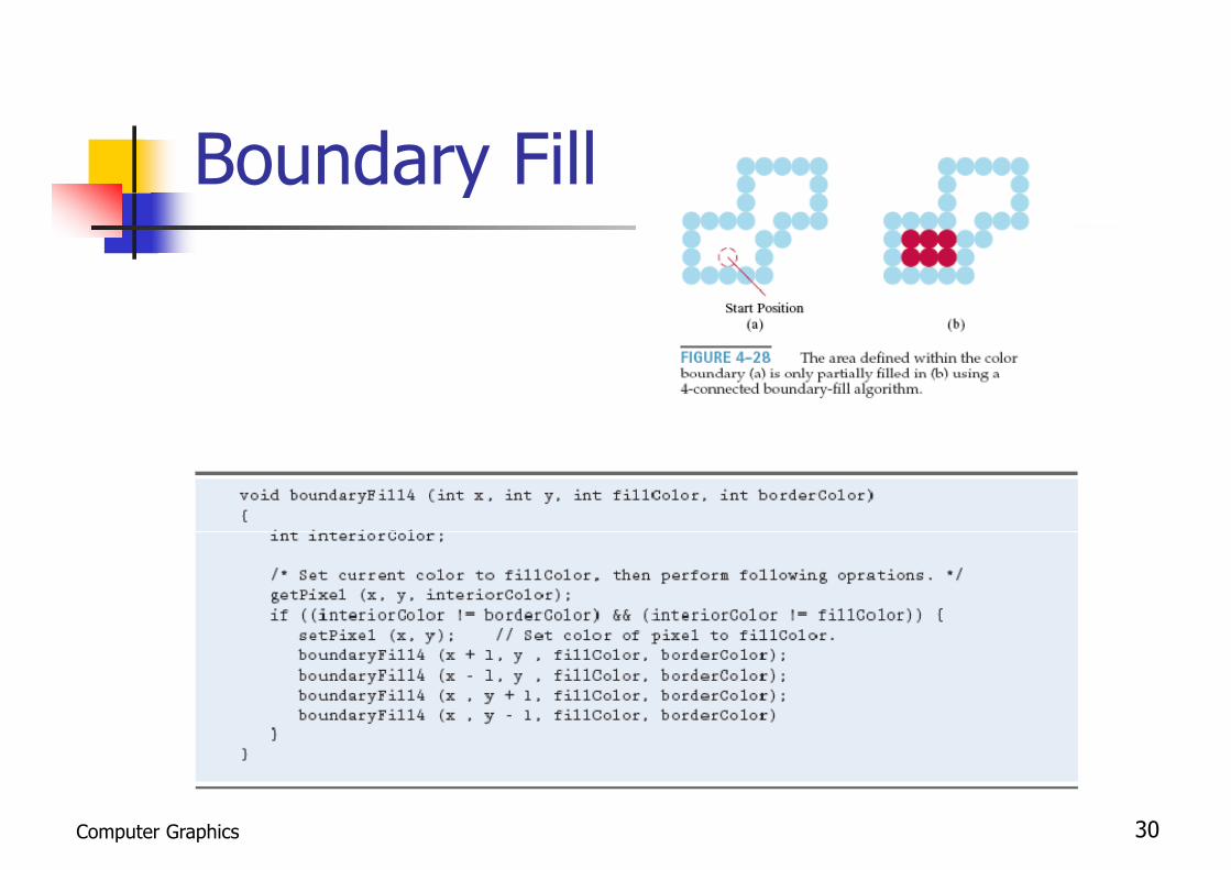
Boundary Filly
Computer Graphics 30

Flood-Fill Algorithmg
Paints areas by replacing a specified interior color Paints areas by replacing a specified interior color instead of searching for a particular boundary color
Starting from a specified interior point (x, y) and Starting from a specified interior point (x, y) and reassign all pixel values to a given interior color
Using either a 4-connected or 8-connected approachg pp
Computer Graphics 31

Character Renderingg
Letters digits non-alphanumeric Letters, digits, non alphanumeric
Font – overall design style of a set of characters Times New Roman, Courier, Arial
Fonts can vary in appearanceo ts ca a y appea a ce Normal, Bold, Italic
Rendering techniques Rendering techniques Bitmap font Outlined fonts - Examples are PostScript Type 1 and Type 3 Outlined fonts Examples are PostScript Type 1 and Type 3
fonts, TrueType and OpenType.
Computer Graphics 38

Character Attributes
Characters with attributes such as font size color Characters with attributes such as font, size, color, and orientation Color settings for displayed text can be stored in the system g p y y
attribute list Adjusts text size by scaling the overall dimensions (height
and width) of characters or by scaling only the height or theand width) of characters or by scaling only the height or the width
Computer Graphics 39

Character Attributes (2)( )
The orientation for a character string The orientation for a character string can be set according to the direction of a character up vector
Computer Graphics 40

About “Point”bou o Font size usually denoted in point (e g 10-point 12- Font size usually denoted in point (e.g. 10 point, 12
point) Denotes height of the characters in inchesg
A term from typographySmallest unit of measure Smallest unit of measure
We are concerned with desktop publishing (DTP) l ll d hpoint, also called the PostScript point
Not the original typographical point
1 DTP point = 1/72 of an inch or approx 0.0139 inch
Computer Graphics 41

Antialiasingg
Jagged or stair step appearance Jagged or stair-step appearance happens because the sampling process digitizes coordinate points on an object to discrete integer pixel positionsto discrete integer pixel positions
This distortion due to low-frequency q ysampling (undersampling) is called aliasingaliasing
Computer Graphics 42

Aliasingg Starting with a continuous signal, then sample the signal at g g , p g
discreet points Those samples are then used to reconstruct a new signal
It is intended to represent the original signal It is intended to represent the original signal However, the reconstructed signals are a false representation of
the original signals
In the English language, When a person uses a false name, it is known as an alias So, it was adapted in signal analysis to apply to falsely represented
signals Aliasing in computer graphics usually results in visually
distracting artifacts A lot of effort goes into trying to stop it
Computer Graphics 43
g y g p This is known as antialiasing

Nyquist Frequencyyqu s eque y Theoretically, in order to adequately Theoretically, in order to adequately
reconstruct a signal of frequency x, the original signal must be sampled with a g g pfrequency of greater than 2x
This is known as the Nyquist Sampling yq p gFrequency or Nyquist Limit
However, this is assuming that we are doing a somewhat idealized sampling and reconstruction
In practice, it’s probably a better idea to sample signals at a minimum of 4x
Computer Graphics 48

Nyquist Sampling Frequencyyq p g q y
To avoid losing information from such To avoid losing information from such periodic objects, we need to set the sampling frequency to at least twice that of the highest frequency occurringthat of the highest frequency occurring in the object
fs = 2 fmax
Computer Graphics 49

Nyquist Sampling Intervalyq p g
The sampling interval should be no The sampling interval should be no larger than one-half the cycle interval
/ 2xs = xcycle / 2where x l = 1/ fwhere xcycle 1/ fmax
Computer Graphics 50

Antialiasing (2)g ( )
To increase sampling rate simply To increase sampling rate, simplydisplays objects at higher resolution
Limitations: How big the frame buffer How big the frame buffer Refresh rate 60 fps or more
d f l Modify pixel intensities Appropriately varying the intensities of Appropriately varying the intensities of
pixels along the boundaries of primitives
Computer Graphics 52

Antialiasing (3)g ( )
Pre-filtering Pre-filtering Filter before sampling- determine pixels
f th ti i lfrom the continuous signal Disadvantage: percent calculation
introduces complexity
Post-filtering Post filtering Filter after sampling- determine pixels from
the disc eet samples of the contin o sthe discreet samples of the continuous signal
Computer Graphics 53

Antialiasing (4)g ( )
Supersampling (or Post-filtering) Supersampling (or Post filtering) use multiple sample points across the finer grid to determine
an appropriate intensity level for each screen pixel Area sampling (or Pre-filtering)
by calculating the areas of overlap of each pixel with the bj t t b di l dobjects to be displayed
Pixel phasingHardware approach Hardware approach
by shifting the display location of pixel areas(“micropositioning” the electron beam in relation to object ( p g jgeometry)
Computer Graphics 54

Supersampling Straight-LineSupersampling Straight Line Segmentsg Divide each pixel into a number of subpixels andDivide each pixel into a number of subpixels and
count the number of subpixels that overlap the line pathTh i t it l l f h i l i th t t The intensity level for each pixel is then set to a value that is proportional to this subpixel count
1
3
22
13 1
Computer Graphics 55

Supersampling Straight-LineSupersampling Straight Line Segments : Advantageg g
Represent the line with finite width Represent the line with finite width The number of possible intensity levels for
each pixel is equal to the total number ofeach pixel is equal to the total number of subpixels within the pixel area
Computer Graphics 56

Supersampling Straight-LineSupersampling Straight Line Segments : Advantage (2)g g ( )
Since a particular line might cross several Since a particular line might cross several different color areas
We can average subpixel intensities to obtain pixel color settingsp g Ex. 5 subpixels within a particular pixel area are
determined to be inside a red line and thedetermined to be inside a red line and the remaining 4 subpixels fall within a blue backgroundbac g ou d
pixelcolor = (5 · red + 4 · blue) / 9
Computer Graphics 57

Subpixel Weighting Maskp g g By giving more weight to subpixels near the center ofBy giving more weight to subpixels near the center of
a pixel area Since these subpixels are to be more important in
d t i i th ll i t it f i ldetermining the overall intensity of a pixel Intensities calculated for each of the 9 subpixels
Center subpixel is weighted by a factor of 1/4 Center subpixel is weighted by a factor of 1/4 Top, bottom, and side subpixels are each of 1/8 Corner subpixels are each weighted by 1/16 p g y
Computer Graphics 58

Area Sampling Straight-LineArea Sampling Straight Line Segmentsg
A method for estimating pixel overlap areas A method for estimating pixel overlap areas The pixel with grid coordinates (10, 20) is about 90%
covered by the line area, so its intensity would be setcovered by the line area, so its intensity would be set to 90% of the maximum intensity
Similarly (10, 21) would be set to 15%y ( , )
Computer Graphics 59
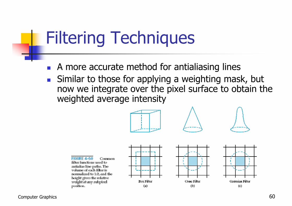
Filtering Techniquesg q
A more accurate method for antialiasing lines A more accurate method for antialiasing lines Similar to those for applying a weighting mask, but
now we integrate over the pixel surface to obtain thenow we integrate over the pixel surface to obtain the weighted average intensity
Computer Graphics 60

Pixel Phasingg
With the technique by moving With the technique by moving (micropositioning) pixel positions closer to the line pathThe electron beam is typically shifted by The electron beam is typically shifted by ¼, ½, or ¾ of a pixel diameter to plot , , p ppoints closer to the true path of a line or object edgeor object edge
Computer Graphics 61

Pixel Phasing (2)g ( )
Computer Graphics 62

Compensating for LineCompensating for Line Intensity Differencesy
The diagonal line is longer than the The diagonal line is longer than the horizontal line by a factor of 2
By adjusting the intensity of each line according to its slopeaccording to its slope
Horizontal and vertical lines would be di l d ith th l t i t itdisplayed with the lowest intensity, while 45◦ lines would be given the ghighest intensity
Computer Graphics 63

Antialiasing Area Boundariesg
Smooth area boundaries by shifting Smooth area boundaries by shifting pixel positions
Adjust pixel intensity at a boundary according to the percent of the interioraccording to the percent of the interior
Adjustments, based on the percent of Adjustments, based on the percent of pixel area coverage
Computer Graphics 64

Antialiasing Area Boundaries (2)g ( )
Supersampling methods Supersampling methods Along the two scan lines, 3 of the subpixel
areas are inside the boundary So we set the pixel intensity at 75% So we set the pixel intensity at 75%
Computer Graphics 65

Antialiasing Area Boundaries (3)g ( )
Determining the percentage of pixel Determining the percentage of pixel area within a fill region
By Pitteway and Watkinson, based on the midpoint line algorithmthe midpoint line algorithm
Computer Graphics 66

Overlap Area of the Pixelp
Parameter p Parameter py - ymid = p = [m(xk + 1) + b] − (yk +0.5) + (1 − m)
Pixel at yk is nearer if p < 1 − m, d t + 1 i if > 1and at yk + 1 is nearer if p > 1 − m
The interior part of the pixelarea = m · xk + b − yk + 0 5area = m xk + b yk + 0.5
By evaluating p, we also determine the percentage of area coverage for the current pixel
Computer Graphics 67

OpenGL Antialiasing Functionsp g
To activate the antialiasing routines To activate the antialiasing routinesglEnable (primitiveType);where primitiveType is GL_POINT_SMOOTH,
GL_LINE_SMOOTH, or GL_POLYGON_SMOOTH
Color-blending operations Color-blending operationsglEnable (GL_BLEND);glBlendFunc
(GL_SRC_ALPHA, GL_ONE_MINUS_SRC_ALPHA);
Computer Graphics 68

End of Chapter 4p
Computer Graphics 71