Agent-Oriented Software Engineering Methodologies and Systems Track
Upload
independentCategory
view
0download
0
0360-131 S%6 53.00 + 0.00 Per@llon Press Ltd
ENGOL--ENGINEERING-G RAPHICS-O RIENTED LANGUAGE: THE CORE OF A “COMPUTATIONAL
ENGINEERING GRAPHICS” IMPLEMENTATION
HAROLD P. SANTO CMEST, Instituto Superior Tecnico. Universidade Tecnica de Lisboa, 1096 Lisboa Codex. Portugal
Abstract-The renewed interest in Engineering Graphics (EG) provided by the advent of Computer Graphics (CG) has given birth to a practically new discipline, cafled herein ~omputationai Engin~ring Graphics (CEG), that results from a weighted combination of EG, CG and Computational Geometry.
This 80’s traditional EG counterpart has up-graded the teaching and learning of Graphics, embracing the basis, methods, algorithms and tools of CAD/CAE.
Representing more than CAI/CAL in EG, CEG requires an appropriate graphical system and. above all, a compatible graphical language to aid students in their studies and projects.
In this paper such a language, ENGOL, is briefly described, supported by illustrations that exemplify its principal features.
INTRODUCTION
There is little doubt in any concerned educator’s mind with regard to the role, effect, influence and significance of computers at all levels of instruction, so that one can speak of Education in terms of BC and AC (i.e. Before and After Computers).
Computers have brought never-thought-of possibilities, new teaching and learning methods, new ways to approach pedagogy and didactics, modernization of theories and courses taught-all those seeming cliches-but, most of all, they have caused the appearance of actual new disciplines, even outside the field of computer science and engineering itself.
One outstanding area which computers are nearly turning upside-down is Engineering Design, broadly considered. CAD, CAM, CAE, among all those associated non-standardized acronyms, are certainly the most widely known recent fields of applied engineering science, originated by the arrival of those “electronic brains”. Unfortunately, as almost always, universities have not followed the pace of the ever-growing R&D efforts of industry and the professional world, due to the unspoken “ivory tower” syndrome and the “generation gap” that is difficult to avoid but urgent to close, in order to prevent or diminish the risk of academia and industry becoming competitors, instead of complementary allies.
Happily, though some will fall behind and others will sit and wait, a few gifted and/or privileged educators will certainly push forward. paving the way for the coming generations, and providing inspiration for younger instructors. Many of those are indeed shaping the future of engineering (computer-aided) design education and promoting the needed and welcome changes in engineering curricula worldwide, through the implementation of introductory CAD/Computer Graphics courses [l, 23.
The foundation of engineering design and related disciplines lies undoubtably on Graphics and Geometry, in their widest sense. And in fact Engineering Graphics (EG) has been taught for many decades, furnishing adequate background for professionals, educators and investigators. But today, in the computer age, in the PC era, on the threshold of the ‘Age of Aquarius’, is Engineering Graphics out of place? Is Graphics doomed? Is Graphics dead?
The answer is a loud and clear NO. As a matter of fact, Graphics, just like the caterpillar that turned into a butterfly, has resurrected for better days of glory. It is now developing its full potential, starting to show all its once hidden sides, because the computer has come to wipe out the dust and webs, making it glow anew. Dreams of yesterday are commonplace these days and the designer is no longer restrained from expressing and materializing the whole of his/her concepts, ideas and plans for the betterment of Society.
101

wilf help to introduce future profess~o~~~s to the rea! world of their careers from the very start. Furthermore it is afso a soIuti5n which can give back scientific interest, theoretiea’! foundatjon and, above all, the respectability and credibility which the engineering graphics is so very much lacking today. Research and theses will be justified and pursued, the Graphics instructors will not be so underrated as they have been and the engineering community will gain in every aspect for, despite its detractors, any work in engineering js immaterial without a ~ra~h~~~geornet~~ basis.
CEG can provide afso the ba~~g~o~~d for an advanced CAD specia~tg course aud they% together, can form a ~rn~~ete set of Eng~ne~~~~~ Design d~s~~~~~~es~ pre~a~ng p~s~e~t~ve ~rof~s~ona~s~ researchers and r;durators for the E~g~~~~~ng of Tomorrows And this is no Iesser matter, It is part of a wider spectrum which has to do with a whole up-dating of Engineering curricula everywhere that will be discussed in a forthcoming paper [9].
From the successfu’i experiences referred to in the previous section, a ~~~~~~m-orjented command-structured language has been created primarily to suit the need of students of Engineering Graphics/Drawing/Design and named ENGOL (for BVgineering-Gmphics-Oriented Language). Incorporating the main topics and notions of CEG, ENGGL constitutes therefore the ‘core’ of the oourse im~~~rn~n~a~ion brieBy outlined.
The d~v~~o~rne~t of ENGOL-starrezS in f982-4erived from a ~rn~~~~ed graphical system- ~~~AT~~~ fltq -which was ~ns~~~~~d to aid students in their ~r~~rn~n~ e&rts, to facilitate the writing of ~~~~i~at~on programs and the el~~r~tj5~ of evaluation projects,
Experience had shown that, in spite of SXMPATICU, the students lost precious time with testing and fine-tuning of programs. CAL/CAL literally got lost then, and this reinforced the urgency and pertinenee to implement a student-oriented graphical language, to overcome the problems encountered, enrich the course and increase the available working tools.
ENG0L was conceived with these fztc~s in mind, ~orn~r~s~~~ the following basic concepts and ~?ab~~~t~es:
* sirnp~~eity of structure: obvious, ~~~~-~o-rn~~F~~~ &~m~~~~ names; o a coherent covering of the whole spectrum of EG apphcetions, with Strai~J~~~~~~~~d addition
of options; *a much reduced number of command parameters; * ~rgan~~atin~ of individual subsets in a standard fashion, to anticipate professional procedures; * utifization in ;8n interactive ~~s~~-f~e~d~y wax + an extensive ~ser~~ontro~~ed rmmericat output fdatat-base, parameters, ~ra~sfo~at~on
mat&es,. _ .); l a multiple eh&e of output devices (‘%eenes” displayed on screen before being drawn by a
plotter or through a “screen dump” unit); * an ability to compose complex objects or “scenes” by juxtaposition of primitives (user-defined
or provided by the system); I an easy and direct input and chaxrge or correion of the ~rn~~~~~~-~ho~~~~ &%-base; t a Mock strucQ.,tred oqganizadon to eliSminaSe size limitatIans.
One of ENGQL”s highlights is the ~o~s~bj~ity it offers the student to choose tiny ~r~j~~~~o~ to represent the %~ne” desired, for the language incorporates $ complete matrix fo~uiat~on of the planar geometric projections, included in [B].
This feature helps to make up fdr skill flaws and constitutes an invaluable aid For the strengthening of one’s intuition and the sharpening of 321 vision-a formative demand surely overkxkd in recent time--since the user is free to experiment virtually ad ~~~~it~rn~ changing parameters at will, seeing %hat turns out to cheek his/her inner ‘*feelings”.
The ~oss~b~~~~~~s ~~~rnemted above are, in the present stage of d~ve~o~rne~~, p~rf~~rned by the commands ind~~a~~d in Table I.

ENGOL--ENgineering-Graphics-Unented Language
Table 1. Command structure
Level I Level 2 Level 3 Parameters
DATA (OLD) NEW CHANGE &HECK DEMO
Name of data file Id Id
TYPE LINES (POLYGONS)
COMPOSE Names of files to merge
TRANSFORM ROTATE ALPHA BETA GAMMA TRANSLATE TY TZ SCALE : SY SZ REFLECT RX RY RZ SHEAR Sb SC Sd Sf Sg Sh
DISPLAY (SCREEN) Name of file to dtspfay PRINTER Id.
HIDE DASHEDLINES SKELETON ANGLE (t60 degrees) OPENSURFACE (ALL)
PLOT
PROJECTION
LAYOUT
FRONT POSTERIOR SUPERIOR INFERIOR LEFT RIGHT (ISOM~i~~ WMETRfC TRIMETRIC CAVALlER CABINET GENERIC CLINOGRAPHIC PARALLEL ANGULAR OBLIQUE
(M)
A(=?“lO’) 3(=41’2.v A(= 1 i’%‘) B(= 16‘) B(=457 B( = 45”) RB BETA R B ZC TX TY TZ BETA ZC TX TY TZ ALPHA BETA ZC TX TY TZ
Name of fde to plot A4 NOBORDER
HIDE same as DISPLAY
QUIT
EXIT
PROJECTION
DATABASE PROJECTIONDATA (ALL)
same as DISPLAY
The default options, indicated in parenthesis, are in summary:
DATA-“” old” file, polygons format DISPLAY-on screen, wire-frame representation PRINT-all HIDE-all PRUJECT~~N-isometric projection PLOT-A3 layout
It can be seen that the student can readily obtain results with just one command: DISPLAY (that is, the database is the default file, in “polygons’ format, the result is a wire-frame isometric projection on the screen, with no associated line-printer output).
As for the meaning of the transformation and projection parameters, the unfamiliar reader is addressed to the current literature or Refs [gl and [l 11. The command names are hopefully elf-explanatory so no further comments are introduced.
Lastly it should be stressed that the scope of ENGOL is larger than this concise overview can imply. Indeed, applications are not limited to educational purposes but apply also to professional
106 HAROLD P. SANTO
and investigational requirements, so that a commercial version, suitable for architects and engineers, has become available. To respond more efficiently to the needs of consultants and researchers, extensions being currently studied are surface-fitting, drawing of shadows, shades and contour-lines, and automatic mesh generation (for finite-element or -difference analysis).
EXAMPLES
The most important features of ENGOL are illustrated by the following figures:
IBLIOUE PROJECTION A-50 LsO.75 ISOMETRIC PROJECTION A.35264 B-45
kz h--l-l ‘ARALLEL A=C B=90 G:O ZV= 18
‘ERSPECTIVE TX=0 TY=O TZ=O LEFT SIDE A=0 B=90 G=O
G=O
Fig. 1. Shows four projections of a structural module of a bridge.
OBLIOUE A:-20 3=20 G=O zv=zo
PERSPECTIVE TX =O TY=O TZ =O
OBLIOUE A=-20 B=50 G=O
PERSPECTIVE TX=0 TY=O TZ;O zv=20
ANGULAR A=0 B=55 G=O ZVz17 PERSPECTIVE TX = -1.5 TY =0 TZ=O
OBLIOUE A*20 B=35 G=O zv=20
PERSPECTIVE TX.0 TY=O TZ.0
Fig. 2. Four more proJections of the same module.

ENGOL-E~~n~~ng-Graphjcs-U~ented Language to7
OBLIOUE A.-12 El.50 G.0 ZV.45 PERSPECTIVE TX.0 TY*0 TZ.0
OBLIOUE As20 B*40 G.0 ZV.40 PERSPECTIVE TX.0 TYaO TZ-0
PARALLEL A.0 8.90 G.0 ZV.30 PERSPECTIVE TX=0 TY.2 TZ.0
ANGULAR A.0 b-60 G-0 ZV.40 PERSPECTlVE TX.0 TY.-6.5 TZ.0
Fig. 3. Taking the module as a prim&&e, a complex object 1s formed by the COMPOSE command and represented in four projections.
X Z 7 Y
OBLIQUE PERSPECTIVE:A=-15 B=30 G-180 ZV=17 TX=0 TY=O TZ=O
;~pz.~- ENGOL LANGUAGE LUIS SILVA DATE 02/01/85
JTL-INIC PERSPECTIVA TRACADO COM AS ARESTAS AUXILIARES NOME DO POLIEDRO E’ JOAO
Fig 4. An object with curved parts, approximated by rectangles.

108
r
HAROLD P. SANTO
OBLIQUE PERSPECTIVE. A.40 B--40 G=O ZV=25 TX-0 TY’O TZ’O
CMEST ENGOL LANGUAGE LUIS ANTONIO SILVA p DATE 2/2/W
UTL-INIC
Fig. 5. The former object used as a primttive with the COMPOSE command, to represent a simple “exploded” view of a part; common edges of adjacent faces suppressed with use of the SKELETON option (that is, whenever the angle between two adjoining faces is greater than the parameter ANGLE
(default = 160”). then common edge is not drawn).
DIMETRiC.Q~20.204 8.112.208 G’O PROJECTION
:MEST DATE 13/02/85
TL-INIC
Fig. 6. A sphere wtth an opening, modeled by quadrilaterals, generated by an appropriate routine.

ENGOL-E~ginee~ng-Graphics-scented Language 109
DIMETRIC PROJECTIOFI- A.20204 8’*12 208 G-0
CMEST LUIS ANTONIO SILVA
UTL-INIC
Fig. 7. Skeletal view of the sphere.
OELIOUE PERSPECTIVE :A~50 B-15 G=-90 zV=gO
Tx=O TY=O TZ=O
Fig. 8. Skeletal view of a TV tower (Johannesburg).
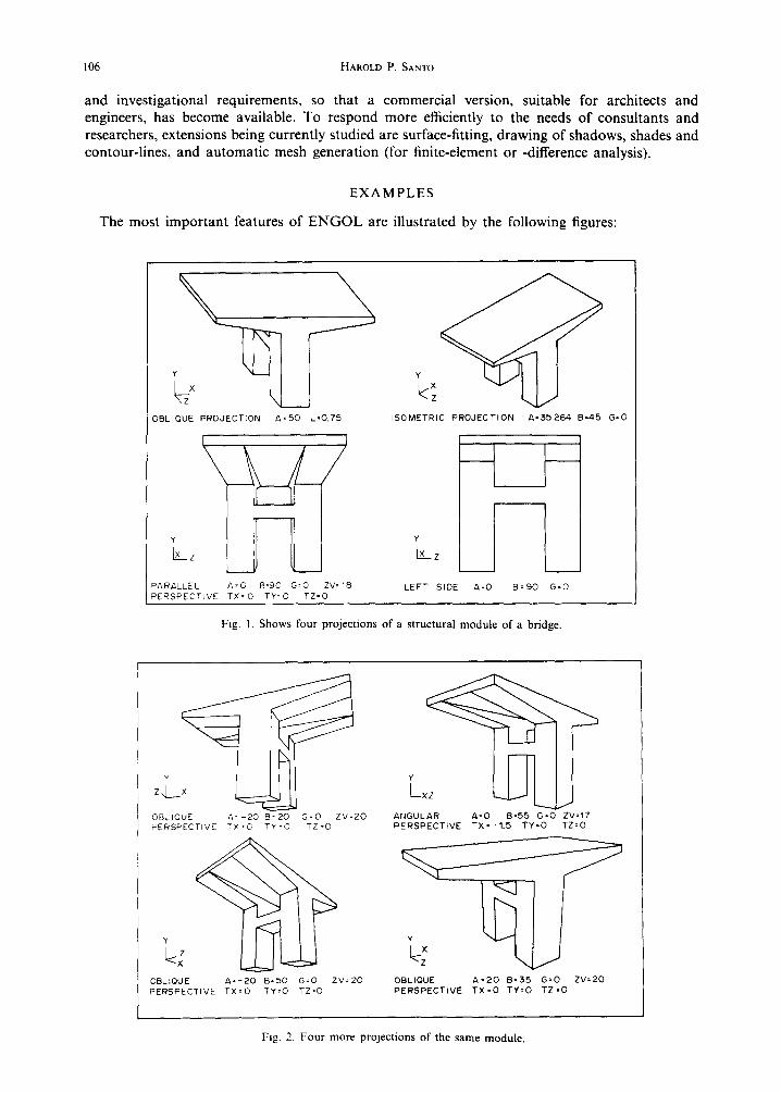
HAROLD P. SANTA
ANGULAR PERSPECTIVE A=0 S-30 G-30 2~~28531
TX.0 TY*O TZ.0
Fg. 9. Angular perspective of six .5-pointed stars (COMPOSE command).
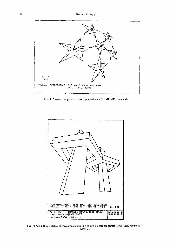
PERSPECTIVA -ALFA * -x).00 BETA - 45.00 OBLIOUA TX . 000 TY
~W.~LI :pcgoo - 0.00 12 . tc. so0
UTL - IST HAROLD SANTOIJOAO CEIA/ Dept. Eng CIVII L”‘S S’LVA
DATA:aB-M-II5 HoRA’O~‘20:13
mwcgem ENGOL CMEST-IST
Fig. 10. Oblique perspectrve of ?hree Interpenetrating objects on graphic printer (PRINTER command- LeveI 2).

ENGOL-~~gine~rlng-Graphics-Urlented Language 111
HAROLB SAKi
1=t!E5T- ISI
~O~~~EIlR~~ SURFACE{ S! MTk __________ __c..______ ----
NUtiBER OF VERTICES = 52 NlMBER OF FhCES = 32 MIX M, OF VERTS~F~~ES = 3
mRBIiiTES ilF THE VERTICES ___________ _.. __- _-__---e
VERT A Y

112 HAROLD P. SANTO
TWOLOCi PF THE FACES ________ __ De_ _____
FACE
i
3 4 f 6 7 a ,q
1E il 11 i3 14 15 16 i' I.
15 14 2G 21 ? 5 A& 23 24 2s 26 27
28 29 30 31 32
3
3
i 1 1 1 1 i
;
i 1 1 I 1 1 1 1 1 1 1 i 1 1 1 1 1 1 1 1 1 1 1
a 7
C J 8 = J :I 4 4 4 4 4 4 4 4 4 4 4 4 4 4 4 4 4 4 4 4 4 4 4 4 4 4 4 4 4 4
i : 3 4 5 ~ j5
6 9 10 11 ii
i3 14 15 16 i7 16 24 3tn 23 2;; 21 20 25 29 28 27 26 39 34 33 32 31 i 18 19 2 2 ly 2G : 3 23 :1 ; 4 21 37 YY 5 5 ;2 I3 5 6 23 36 35
35 _. Jb 24 7
? 24 18 i 9 13 ,3 26
1G il 2g 27 11 13 29 26 8 25 29 12 a 9 26 25
13 3G 34 1; 13 14 31 30 14 i5 32 31 i5 16 33 32 16 1; 34 33 37 38 39 4G 45 48 47 46 37 45 46 38 38 46 4i 39 39 47 48 43 37 40 48 45 41 42 43 44 49 52 51 50 41 44 52 49 41 49 5G 42 42 50 51 43 43 51 52 44

DEF Z
5.48101 it.54a G.%BX
-0.50879 -2.55328 -2*7:252 -G.$jG?Z3 3J5443 3.77712 4.59303 1.63142
-3.62579 0. G3ti26
-Q&7483 -3.29GGG -L.4&3% -1.3G~B ‘.fi5953 9.03542 I. 75200
t4.f438f E9.25117 I~*~4~7G B.fG65f 3.43148 i,5?+is C.E:5985 2.42303

114 i-i.4~0~~ P. SANTO
Acknuw~edgemenrs-For the steady support in his computer graphics research and appli~tions the author is indebted to Dr Antonio R. G. Lamas, Secretary of CMEST-Center for Structural Mechanics and Engineering of the Technical University of Lisbon and head of the “Line of Investigation” within which the present project is being carried out.
The contribution of student Luis A. Silva in the implementation of the Apple II version of ENGOL, used to obtain the pictures of his own conception included is this paper, is also gratefully acknowledged.
The teaching experiences reported ocurred under the agreement of Professor Jaime de Oliveira, coordinator of the Engineering Graphics Section of Instituto Superior Tecnico, Technical University of Lisbon.
REFERENCES
I. CunnIngham S., Computer graphics education directory. Siggraph’s CG (Oct. 1984). 2. Richards L. G., Engineering education: a status report on the CAD/CAM Revolution. IEEE CC & A (Feb. 1985). 3. Santo H. P., Engineering graphics + computer graphics = computational engineering graphics? World Conference on
Computers in Education. Norfolk, U.S.A. (Aug. 1985). 4. Eide A. R. er al., Engineering Graphics Fundamentals. McGraw-Hill (1985). 5. Earle J. H., Geometry for Engineers. Addison-Wesley (1984). 6. Ryan D. L., Computer-Aided Graphics and Design. Marcel Dekker (1979). 7. Barr R. E. et ui., Computer graphics and CAD in a freshman engineering program. Engineermg Education (Feb. 1984). 8. Santo H. P., M&odos Grbjicos e Geometria Computocionais-Znicia@o Orientada, Vol. 1: Concertos Bbsicos (Computer
Graphics-A Guided Znitiation ). Dinalivro, Lisbon (1985). 9. Santo H. P., Computer-Aided Besigrt Education within undergraduate Engineer&g Programs. CMEST Report (1985).
10. Santo H. P. and Costa J. M., SZMPATZCO-Sistema SIMp~z~cudo PAssivo para Trutamento de Informac6o Gr&ca par COmpurudor. AEIST, Lisbon (1982).
1 I. Foley J. D. Van Dam A., Fundrrmenrals of Interactive Computer Graphics. Addison-Wesley (1982).
Copyright © 2022 FDOKUMEN