The Ballistic Performance of Laminated SiC Ceramics ... - MDPI

Applied Mathematical Modelling 35 (2011) 1829–1845
Contents lists available at ScienceDirect
Applied Mathematical Modelling
journal homepage: www.elsevier .com/locate /apm
Compressive and thermal postbuckling behaviors of laminated plateswith piezoelectric fiber reinforced composite actuators
Hui-Shen Shen a,b,⇑, Zheng Hong Zhu c
a School of Ocean and Civil Engineering, Shanghai Jiao Tong University, Shanghai 200030, People’s Republic of Chinab State Key Laboratory of Ocean Engineering, Shanghai Jiao Tong University, Shanghai 200030, People’s Republic of Chinac Department of Earth and Space Science and Engineering, York University, 4700 Keele Street, Toronto, Ontario, Canada M3J 1P3
a r t i c l e i n f o
Article history:Received 15 March 2010Received in revised form 16 September 2010Accepted 4 October 2010Available online 13 October 2010
Keywords:Hybrid laminated plateSmart materialsTemperature-dependent propertiesBucklingPostbuckling
0307-904X/$ - see front matter � 2010 Elsevier Incdoi:10.1016/j.apm.2010.10.013
⇑ Corresponding author at: School of Ocean anTel.: +86 21 62933020.
E-mail address: [email protected] (H.-S. S
a b s t r a c t
This paper studied compressive postbuckling under thermal environments and thermalpostbuckling due to a uniform temperature rise for a shear deformable laminated platewith piezoelectric fiber reinforced composite (PFRC) actuators based on a higher ordershear deformation plate theory that includes thermo-piezoelectric effects. The materialproperties are assumed to be temperature-dependent and the initial geometric imperfec-tion of the plate is considered. The compressive and thermal postbuckling behaviors of per-fect, imperfect, symmetric cross-ply and antisymmetric angle-ply laminated plates withfully covered or embedded PFRC actuators are conducted under different sets of thermaland electric loading conditions. The results reveal that, the applied voltage usually has asmall effect on the postbuckling load–deflection relationship of the plate with PFRC actu-ators in the compressive buckling case, whereas the effect of applied voltage is more pro-nounced for the plate with PFRC actuators, compared to the results of the same plate withmonolithic piezoelectric actuators.
� 2010 Elsevier Inc. All rights reserved.
1. Introduction
Piezoelectric materials are extensively used in aerospace and other industries [1] in the quest for lightweight flexiblestructures with self-controlling and/or self-monitoring capabilities. Piezoelectric fiber reinforced composites (PFRCs) havethe potential to provide various sensing functions for nondestructive testing and may be used as sensing elements for struc-tural health monitoring and adaptive material systems [2]. By taking advantage of the direct and converse piezoelectric ef-fects, hybrid composite structures with embedded or surface-bonded piezoelectric sensors and actuators can adapt harshenvironmental condition by combining the traditional advantages of composite laminates with the inherent capability ofpiezoelectric materials.
Shape or vibration control of laminated plates with integrated piezoelectric sensors and actuators has been identified asan important field of study in recent years [3–7]. However, relatively few works have been done on the compressive and/orthermal buckling of laminated composite plates containing piezoelectric layers. Oh et al. [8] studied thermal postbucklingbehavior of laminated plates with top and/or bottom piezoelectric actuators subjected to thermal and electric loads. In theiranalysis, the nonlinear finite element equations were formulated based on the layerwise displacement model but theirnumerical results were only for thin plates of perfect initial configurations. Shen [9,10] analyzed compressive and thermal
. All rights reserved.
d Civil Engineering, Shanghai Jiao Tong University, Shanghai 200030, People’s Republic of China.
hen).

1830 H.-S. Shen, Z. Hong Zhu / Applied Mathematical Modelling 35 (2011) 1829–1845
postbuckling of shear deformable laminated plates with fully covered or embedded piezoelectric actuators subjected to com-bined mechanical, electrical and thermal loads. The higher order shear deformation plate theory was adopted and the initialgeometric imperfection of plates was accounted. It is found that the control voltage has a small effect on the postbucklingload–deflection relationship of shear deformable piezolaminated plates with immovable unloaded edges, and almost no ef-fect on the postbuckling load–deflection relationships of the same plate with movable edges. Varelis and Saravanos [11] pre-sented a theoretical analysis for the prebuckling and postbuckling responses of laminated composite plates withpiezoelectric actuators and sensors. Kapuria and Achary [12,13] employed 3-D elasticity and zigzag theory for linearcompressive and thermal buckling of laminated plates containing piezoelectric layers. Akhras and Li [14] studied 3-Dthermal buckling of piezoelectric antisymmetric angle-ply laminates by using a finite layer method. Moreover, bucklingoptimization of laminated plates with integrated piezoelectric actuators can be found in Correia et al. [15]. Assessment ofthird order smeared and zigzag theories for buckling and vibration of symmetrically laminated hybrid angle-ply platescontaining piezoelectric layers can be found in Dumir et al. [16]. In the aforementioned studies, however, the materialproperties are assumed to be independent of the temperature and the electric fields.
The commonly used piezoceramics are brittle and usually used as patched actuators and sensors. For large scale structuralcontrol applications such as aerospace structures, monolithic piezoelectric actuators and sensors suffer from certain short-comings with regard to tailorable anisotropic actuation. PFRCs have been introduced to address these concerns. The nonlin-ear static and dynamic analyses of hybrid laminated plates with distributed PFRC actuators were performed by Ray andMallik [17], Shivakumar and Ray [18,19], Xia and Shen [20] and Shen [21]. Note that if the transverse direction electric fieldcomponent EZ is applied, the buckling control of hybrid laminated plates mainly depends on the piezoelectric coefficients e31
and e32. However, it remains unclear if the applied voltage has the same effect on the postbuckling behavior of hybrid lam-inated plates with PFRC actuators and this motivates the current investigation.
The present paper extends the previous works [9,10] to the case of shear deformable laminated plates with PFRC actua-tors. Compressive postbuckling under thermal environments and thermal postbuckling due to a uniform temperature riseare investigated with only one non-zero electric field component EZ. The postbuckling analysis of laminated plates is basedon Reddy’s higher order shear deformation plate theory with von Kármán-type of kinematic nonlinearity. The thermo-pie-zoelectric effects are also included and the material properties are assumed to be temperature-dependent. The initial geo-metric imperfection of the plate is taken into account but, for simplicity, its form is assumed to be the same as the initialbuckling mode of the plate.
2. Mathematical modeling
2.1. Effective material properties of PFRCs
A number of micromechanics models that have been proposed for the determination of effective properties of piezoelec-tric composites based on the rule of mixture [22], Mori Tanaka scheme [23], self-consistent method [24]. It is worthy to notethat the rule of mixture is simple and convenient to be applied for predicting the overall material properties and responses ofthe structures. Let us assume that the PFRC layer be made of piezoelectric fiber and the matrix be isotropic. The effectiveYoung’s modulus, shear modulus and Poisson’s ratio can be expressed in terms of a micro-mechanical model [20,21] bythe rule of mixture, such that,
E11 ¼ Vf Ef11 þ VmEm; ð1aÞ
1E22¼ Vf
Ef22
þ Vm
Em � Vf Vm
m2f Em=Ef
22 þ m2mEf
22=Em � 2mf mm
Vf Ef22 þ VmEm
; ð1bÞ
1Gij¼ Vf
Gfij
þ Vm
Gm ðij ¼ 12;13 and 23Þ; ð1cÞ
m12 ¼ Vf mf þ Vmmm; ð1dÞ
where Ef11; Ef
22; Gf12; Gf
13; Gf23 and mf are the Young’s moduli, shear moduli and Poisson’s ratio of the piezoelectric fiber, while
Em, Gm and mm are the corresponding properties for the matrix, respectively. Vf and Vm are the fiber and matrix volume frac-tions and must satisfy the unity condition of Vf + Vm = 1. Similarly, the effective thermal expansion coefficients in the longi-tudinal and transverse directions may be written by [25].
a11 ¼Vf E
f11a
f11 þ VmEmam
Vf Ef11 þ VmEm
; ð2aÞ
a22 ¼ ð1þ mf ÞVf af22 þ ð1þ mmÞVmam � m12a11; ð2bÞ
where af11; af
22 and am are thermal expansion coefficients of the fiber and the matrix respectively, and the effective piezo-electric moduli e31 and e32 can be expressed by [26].

H.-S. Shen, Z. Hong Zhu / Applied Mathematical Modelling 35 (2011) 1829–1845 1831
e31 ¼ Vf ef31 � ðVmVf =HÞ Cf
13 � Cm13
� �VmCf
22 þ Vf Cm22
� �ef
33 � VmCf23 þ Vf C
m23
� �ef
31
h inþ Cf
12 � Cm12
� �VmCf
33 þ Vf Cm33
� �ef
31 � VmCf23 þ Vf Cm
23
� �ef
33
h io; ð3aÞ
e32 ¼ ef31þðVm=HÞ Cf
22 VmCf23þVf Cm
23
� �ef
33� VmCf33þVf Cm
33
� �ef
31
h i�Cf
23 VmCf22þVf C
m22
� �ef
33� VmCf23þVf Cm
23
� �ef
31
h in o;
ð3bÞ
in which
H ¼ VmCf22 þ Vf C
m22
� �VmCf
33 þ Vf Cm33
� �� VmCf
23 þ Vf Cm23
� �2; ð3cÞ
and ef31 and ef
33 are the piezoelectric coefficients of the fiber, and Cfij and Cm
ij are the elastic constants of the fiber and the ma-trix, respectively. The relation between Cf
ij ði; j ¼ 1� 6Þ and Ef11; Ef
22; Gf12; Gf
13 and Gf23 can be found in Reddy [27] and other
textbooks.It is assumed that the material property of matrix Cm
ij ði; j ¼ 1� 6Þ is a function of temperature, so that all effective mate-rial properties of PFRCs are temperature dependant.
2.2. Governing equations of hybrid laminated plates
Consider a rectangular plate of length a and width b with a constant thickness t, which consists of N plies, one of whichmay be PFRC, as shown in Fig. 1. The plate is assumed to be geometrically imperfect, and is subjected to mechanical, thermaland electric loads. As usual, the coordinate system has its origin at one corner of the plate. Let U, V and W be the plate dis-placements parallel to a right-hand set of axes (X,Y,Z), where X is longitudinal and Z is perpendicular to the plate. Define Wx
and Wy are the rotations of the mid-plane normal about the Y and X axes, respectively. Furthermore, denote the initial geo-metric imperfection by W*(X,Y) and the additional deflection by W(X,Y). The stress resultants are defined byNx ¼ F ;YY ; Ny ¼ F ;XX and Nxy ¼ �F ;XY , where F(X,Y) is the stress function and a comma denotes partial differentiation with re-spect to the corresponding coordinates.
Reddy [28] presented a theoretical formulation of laminated plates with monolithic piezoelectric layers as sensors oractuators using the classical and shear deformable laminated plate theories. This kind of model is usually referred as toequivalent single-layer piezoelectric plate theory which can accurately predict the global structural responses (deflection,buckling and vibration) of the laminates. In the present study the formulations are based on Reddy’s higher order sheardeformation plate theory [29]. This theory assumes that the transverse shear strains present a parabolical distribution acrossthe plate thickness. The advantages of this theory over the first order shear deformation theory are that the number of inde-pendent unknowns ðU; V ; W; Wx and WyÞ is the same as in the first order shear deformation theory, and no shear correctionfactors are required. By considering Reddy’s higher order shear deformation plate theory and thermo-piezoelectric effects,the governing differential equations for a laminated hybrid plate can be derived in terms of a stress function F, two rotationsWx and Wy, and a transverse displacement W . They are [9,10]
eL11ðWÞ � eL12ðWxÞ � eL13ðWyÞ þ eL14ðFÞ � eL15ðNpÞ � eL16ðMpÞ ¼ eLðW þW�; FÞ; ð4ÞeL21ðFÞ þ eL22ðWxÞ þ eL23ðWyÞ � eL24ðWÞ � eL25ðNpÞ ¼ �12eLðW þ 2W�;WÞ; ð5ÞeL31ðWÞ þ eL32ðWxÞ � eL33ðWyÞ þ eL34ðFÞ � eL35ðNpÞ � eL36ðSpÞ ¼ 0; ð6ÞeL41ðWÞ � eL42ðWxÞ þ eL43ðWyÞ þ eL44ðFÞ � eL45ðNpÞ � eL46ðSpÞ ¼ 0: ð7Þ
Note that the geometric nonlinearity in the von Kármán sense is given in terms of eL( ) in Eqs. (4) and (5), and the other linearoperators eLij( ) are defined as in [9,10].
Fig. 1. Configuration of a laminated plate with a PFRC layer.

1832 H.-S. Shen, Z. Hong Zhu / Applied Mathematical Modelling 35 (2011) 1829–1845
In the above equations, the equivalent thermo-piezoelectric loads are defined by
NP
MP
PP
SP
2666437775 ¼
NT
MT
PT
ST
2666437775þ
NE
ME
PE
SE
2666437775; ð8Þ
where NT ; MT ; PT ; ST and NE; ME; PE; SE are the forces, moments and higher order moments caused by the elevated tem-perature and electric field, respectively.
Moreover, the plate is considered to be at an isothermal state and the temperature field can be assumed uniformly dis-tributed in the plate, accordingly.
For the plate type piezoelectric material, only the transverse electric field component EZ is dominant, and EZ is defined asEZ = �U, Z, where U is the potential field. If the voltage applied to the actuator is in the thickness only, then [28]
EZ ¼Vk
hp; ð9Þ
where Vk is the applied voltage across the kth ply, and hp is the thickness of the PFRC layer.The forces and moments caused by elevated temperature or electric field are defined by
NTx
NTy
NTxy
MTx
MTy
MTxy
PTx
PTy
PTxy
26643775 ¼XN
k¼1
Z tk
tk�1
Ax
Ay
Axy
264375
k
ð1; Z; Z3ÞDTdZ; ð10aÞ
STx
STy
STxy
26643775 ¼
MTx
MTy
MTxy
26643775� 4
3t2
PTx
PTy
PTxy
26643775; ð10bÞ
where DT is the temperature rise from a reference temperature corresponding to zero thermal strain, and
NEx
NEy
NExy
MEx
MEy
MExy
PEx
PEy
PExy
26643775 ¼XN
k¼1
Z tk
tk�1
Bx
By
Bxy
264375
k
ð1; Z; Z3ÞVk
hpdZ; ð11aÞ
SEx
SEy
SExy
26643775 ¼
MEx
MEy
MExy
26643775� 4
3t2
PEx
PEy
PExy
26643775; ð11bÞ
in which
Ax
Ay
Axy
264375 ¼ � Q11 Q12 Q 16
Q12 Q22 Q 26
Q16 Q26 Q 66
264375 c2 s2
s2 c2
2cs �2cs
264375 a11
a22
� �; ð12aÞ
Bx
By
Bxy
264375 ¼ � Q 11 Q 12 Q 16
Q 12 Q 22 Q 26
Q 16 Q 26 Q 66
264375 c2 s2
s2 c2
2cs �2cs
264375 d31
d32
� �; ð12bÞ
c ¼ cos h; s ¼ sin h; ð12cÞ
where h is the lamination angle with respect to the plate X axis, a11 and a22 are the thermal expansion coefficients measuredin the longitudinal and transverse directions for kth ply, d31 and d32 are the piezoelectric strain constants of kth ply, and canbe obtained by [28]
0 0 e31
0 0 e32
0 0 0
264375
k
¼0 0 d31
0 0 d32
0 0 0
264375
k
Q11 Q 12 0Q12 Q 22 00 0 Q 66
264375
k
; ð13Þ

H.-S. Shen, Z. Hong Zhu / Applied Mathematical Modelling 35 (2011) 1829–1845 1833
in which e31 and e32 are given in detail in Eq. (4), and Q ij are the transformed elastic constants, defined by
Q 11
Q 12
Q 22
Q 16
Q 26
Q 66
26666666664
37777777775¼
c4 2c2s2 s4 4c2s2
c2s2 c4 þ s4 c2s2 �4c2s2
s4 2c2s2 c4 4c2s2
c3s cs3 � c3s �cs3 �2csðc2 � s2Þcs3 c3s� cs3 �c3s 2csðc2 � s2Þc2s2 �2c2s2 c2s2 ðc2 � s2Þ2
26666666664
37777777775
Q11
Q12
Q22
Q66
2666437775; ð14aÞ
Q 44
Q 45
Q 55
264375 ¼ c2 s2
�cs cs
s2 c2
264375 Q44
Q55
� �; ð14bÞ
where
Q 11 ¼E11
ð1� m12m21Þ; Q 22 ¼
E22
ð1� m12m21Þ; Q 12 ¼
m21E11
ð1� m12m21Þ; Q 44 ¼ G23; Q55 ¼ G13; Q 66 ¼ G12: ð14cÞ
E11, E22, G12, G13, G23, m12 and m21 have their usual meanings, in particular for a PFRC layer they are given in detail in Eq. (1).Consider the compressive postbuckling of a plate under thermal environments and the thermal postbuckling due to a uni-
form temperature rise. All four edges of the plate are assumed to be simply supported. It has been reported [9] that the con-trol voltage has almost no effect on the postbuckling load–deflection relationships of the plate with ‘‘movable” in-planeboundary condition. Therefore, only ‘‘immovable” in-plane boundary condition (i.e. two unloaded edges being immovablein the Y direction) is considered for compressive buckling case, and for thermal buckling case all four edges are assumedto be simply supported with no in-plane displacements.
For both cases the associated boundary conditions can be expressed as:
X = 0, a:
W ¼ Wy ¼ 0; ð15aÞNxy ¼ 0; Mx ¼ Px ¼ 0; ð15bÞZ b
0NxdY þ P ¼ 0 ðfor compressive bucklingÞ; ð15cÞ
U ¼ 0 ðfor thermal bucklingÞ; ð15dÞ
Y = 0, b:
W ¼ Wx ¼ 0; ð15eÞNxy ¼ 0; My ¼ Py ¼ 0; ð15fÞV ¼ 0; ð15gÞ
where P is a compressive edge load in the X direction, Mx and My are the bending moments and Px and Py are the higher ordermoments as defined in [29].
The average end-shortenings are given by
Dx
a¼ � 1
ab
Z b
0
Z a
0
@U@X
dXdY ¼ � 1ab
Z b
0
Z a
0A�11
@2F
@Y2 þ A�12@2F
@X2 þ B�16 �4
3t2 E�16
� �@Wx
@Yþ @Wy
@X
!� 8
3t2 E�16@2W@X@Y
" #(
�12
@W@X
!2
� @W@X
@W�
@X� A�11NP
x þ A�12NPy
� �9=;dXdY; ð16aÞ
Dy
b¼ � 1
ab
Z a
0
Z b
0
@V@Y
dYdX ¼ � 1ab
Z a
0
Z b
0A�22
@2F
@X2 þ A�12@2F
@Y2 þ B�26 �4
3t2 E�26
� �@Wx
@Yþ @Wy
@X
!� 8
3t2 E�26@2W@X@Y
" #(
�12
@W@Y
!2
� @W@Y
@W�
@Y� ðA�12NP
x þ A�22NPyÞ
9=;dYdX; ð16bÞ
where Dx and Dy are plate end-shortening displacements in the X and Y directions, and for compressive buckling case Dy
must be zero while for thermal buckling case both Dx and Dy must be zero.

1834 H.-S. Shen, Z. Hong Zhu / Applied Mathematical Modelling 35 (2011) 1829–1845
In the above equations, the reduced stiffness matrices A�ijh i
; B�ijh i
; D�ijh i
; E�ijh i
; F�ijh i
and H�ijh i
are functions of temperature,determined through the relationship [30]
A� ¼ A�1;B� ¼ �A�1B;D� ¼ D� BA�1B;E� ¼ �A�1E;F� ¼ F� EA�1B;H� ¼ H� EA�1E; ð17Þ
where Aij, Bij, etc., are the plate stiffnesses, defined by
ðAij;Bij;Dij; Eij; Fij;HijÞ ¼XN
k¼1
Z tk
tk�1
ðQijÞkð1; Z; Z2; Z3; Z4; Z6ÞdZ ði; j ¼ 1;2;6Þ; ð18aÞ
ðAij;Dij; FijÞ ¼XN
k¼1
Z tk
tk�1
ðQijÞkð1; Z2; Z4ÞdZ ði; j ¼ 4;5Þ: ð18bÞ
It is evident that, for symmetrically hybrid laminated plates, no extension-flexural coupling exists, and B�ij; E�ij are all zero-valued.
2.3. Solution procedure
Eqs. (4)–(7) can be solved by means of a perturbation technique. Before carrying out the solution process, it is convenientfirst to define the following dimensionless quantities
x ¼ pXa; y ¼ pY
b; b ¼ a
b; ðW;W�Þ ¼ ðW;W�Þ
D�11D�22A�11A�22
� 1=4 ; F ¼ F
½D�11D�22�1=2 ;
ðWx;WyÞ ¼ap
ðWx;WyÞD�11D�22A�11A�22
� 1=4 ; k14 ¼D�22
D�11
� �1=2
; c24 ¼A�11
A�22
� �1=2
; c5 ¼ �A�12
A�22;
ðcT1; cT2; cP1; cP2Þ ¼a2
p2
ATx ;A
Ty ;B
Px ;B
Py
� �D�11D�22
� 1=2 ;
ðMx; PxÞ ¼a2
p2
1
D�11 D�11D�22A�11A�22
� 1=4 Mx;4
3t2 Px
� �;
kx ¼Pb
4p2 D�11D�22
� 1=2 ; ðdx; dyÞ ¼Dx
a;Dy
b
� �b2
4p2 D�11D�22A�11A�22
� 1=2 ; kT ¼ a0DT; ð19Þ
where a0 is an arbitrary reference value, and let
ATx
ATy
" #¼ �
XN
k¼1
Z tk
tk�1
Ax
Ay
� �k
dZ; ð20aÞ
BPx
BPy
" #DV ¼ �
XN
k¼1
Z tk
tk�1
Bx
By
� �k
Vk
tkdZ; ð20bÞ
The nonlinear Eqs. (4)–(7) may then be written in dimensionless forms as:
L11ðWÞ � L12ðWxÞ � L13ðWyÞ þ c14L14ðFÞ ¼ c14b2LðW þW�; FÞ; ð21Þ
L21ðFÞ þ c24L22ðWxÞ þ c24L23ðWyÞ � c24L24ðWÞ ¼ �12c24b
2LðW þ 2W�;WÞ; ð22Þ
L31ðWÞ þ L32ðWxÞ � L33ðWyÞ þ c14L34ðFÞ ¼ 0; ð23ÞL41ðWÞ � L42ðWxÞ þ L43ðWyÞ þ c14L44ðFÞ ¼ 0; ð24Þ
where all dimensionless linear operators Lij() and nonlinear operatorL( ) are defined as in [9,10].The boundary conditions expressed by Eq. (15) become
x = 0, p:
W ¼ Wy ¼ 0; ð25aÞF ;xy ¼ Mx ¼ Px ¼ 0; ð25bÞ1p
Z p
0b2 @
2F@y2 dyþ 4kxb
2 ¼ 0 ðfor compressive bucklingÞ; ð25cÞ
dx ¼ 0 ðfor thermal bucklingÞ: ð25dÞ
y = 0, p:

Table 2Comparconditio
mon
PFRC
a Diff
H.-S. Shen, Z. Hong Zhu / Applied Mathematical Modelling 35 (2011) 1829–1845 1835
W ¼ Wx ¼ 0; ð25eÞF ;xy ¼ My ¼ Py ¼ 0; ð25fÞdy ¼ 0; ð25gÞ
Table 1Comparisons of buckling load and thermal buckling temperature for a (±60)2T antisymmetricangle-ply laminated plate subjected to uniaxial compression or uniform temperature rise(a = 1.5 m, b = 0.6 m, t = 0.008 m).
Source ðNxÞcr (�105 N/m) (D T)cr(�C)
Chen and Yu [36] Analytical 5.96837 (2,1)a 11.300 (1,1)ANSYS 5.96225 (2,1) 11.308 (1,1)
Present 5.96327 (2,1) 11.298 (1,1)
a Buckling mode (m,n).
isons of buckling loads Pcr (kN) for perfect piezolaminated square plates (b/t = 40) under thermal environments and three sets of electric loadingns.
DT (�C) Vf VU = VL(V) (P/(0/90)2)s (0/P/90/0/90)s (P/((±45)4/P)
olithic piezoelectric layer 0 1.0 �100 6.022. (�3.0%)a 5.6430(�3.2%) 5.2566(�0.9%)0 6.2065 5.8275 5.3064+100 6.3910(+3.0%) 6.0120(+3.2%) 5.3562(+0.9%)
100 1.0 �100 4.7995(�3.7%) 4.3844(�4.0%) 4.8298(�1.0%)0 4.9828 4.5676 4.8810+100 5.1660(+3.7%) 4.7509(+4.0%) 4.9321(+1.0%)
200 1.0 �100 3.5634(�4.9%) 3.1114(�5.5%) 4.3782(�1.2%)0 3.7455 3.2935 4.4308+100 3.9276(+4.9%) 3.4756(+5.5%) 4.4834(+1.2%)
layer 0 0.4 �100 3.6894(�0.7%) 4.3864(�0.6%) 3.6892(+4.9%)0 3.7173 4.4142 3.5150+100 3.7451(+0.7%) 4.4421(+0.6%) 3.3408(�4.9%)
0.6 �100 3.9056(�1.1%) 4.5061(�1.0%) 3.9660(+6.6%)0 3.9507 4.5512 3.7187+100 3.9958(+1.1%) 4.5963(+1.0%) 3.4734(�6.6%)
0.8 �100 4.2469(�1.8%) 4.6884(�1.6%) 4.2205(+5.1%)0 4.3260 4.7674 4.0171+100 4.4050(+1.8%) 4.8465(+1.6%) 3.8138(�5.1%)
0.9 �100 4.6179(�2.4%) 4.8845(�2.2%) 4.4209(+2.6%)0 4.7305 4.9970 4.3081+100 4.8430(+2.4%) 5.1096(+2.2%) 4.1952(�2.6%)
100 0.4 �100 2.2880(�1.1%) 2.9541(�0.8%) 3.2526(+6.2%)0 2.3134 2.9795 3.0626+100 2.3388(+1.1%) 3.0049(+0.8%) 2.8725(�6.2%)
0.6 �100 2.5041(�1.6%) 3.0765(�1.3%) 3.5059(+8.3%)0 2.5454 3.1177 3.2367+100 2.5866(+1.6%) 3.1589(+1.3%) 2.9675(�8.3%)
0.8 �100 2.8484(�2.5%) 3.2679(�2.2%) 3.7300(+6.4%)0 2.9228 3.3424 3.5069+100 2.9973(+2.5%) 3.4168(+2.2%) 3.2838(�6.4%)
0.9 �100 3.2320(�3.2%) 3.4824(�3.0%) 3.9167(�3.3%)0 3.3401 3.5905 3.7914+100 3.4481(+3.2%) 3.6985(+3.0%) 3.6661(�3.3%)
200 0.4 �100 0.8955(�2.4%) 1.5307(�1.4%) 2.8041(+8.1%)0 0.9180 1.5532 2.5950+100 0.9404(+2.4%) 1.5756(+1.4%) 2.3858(�8.1%)
0.6 �100 1.1091(�3.2%) 1.6536(�2.2%) 3.0337(+10.8%)0 1.1458 1.6902 2.7369+100 1.1824(+3.2%) 1.7269(+2.2%) 2.4401(�10.8%)
0.8 �100 1.4501(�4.5%) 1.8484(�3.6%) 3.2233(+8.3%)0 1.5193 1.9175 2.9765+100 1.5884(+4.5%) 1.9867(+3.6%) 2.7296(�8.3%)
0.9 �100 1.8381(�5.3%) 2.0739(�4.7%) 3.3905(+4.3%)0 1.9411 2.1768 3.2503+100 2.0440(+5.3%) 2.2797(+4.7%) 3.1100(�4.3%)
erence = 100%[Pcr(�100 V) � Pcr(0 V)]/Pcr(0 V).

1836 H.-S. Shen, Z. Hong Zhu / Applied Mathematical Modelling 35 (2011) 1829–1845
and the unit end-shortening relationships become:
Table 3Comparloading
mon
PFRC
a Diff
dx ¼ �1
4p2b2c24
Z p
0
Z p
0c2
24b2 @
2F@y2 � c5
@2F@x2 þ c24c223 b
@Wx
@yþ @Wy
@x
� �� 2c24c516b
@2W@x@y
" #(
�12c24
@W@x
� �2
� c24@W@x
@W�
@xþ ðc2
24cT1 � c5cT2ÞDT þ ðc224cP1 � c5cP2ÞDV
)dxdy; ð26aÞ
dy ¼ �1
4p2b2c24
Z p
0
Z p
0
@2F@x2 � c5b
2 @2F@y2 þ c24c230 b
@Wx
@yþ @Wy
@x
� �� 2c24c526b
@2W@x@y
" #(
�12c24b
2 @W@y
� �2
� c24b2 @W@y
@W�
@yþ ðcT2 � c5cT1ÞDT þ ðcP2 � c5cP1ÞDV
)dydx: ð26bÞ
Because DV and DT are assumed uniform in the plate, the thermo-piezoelectric coupling in Eqs. (4)–(7) vanishes but termsDV and DT intervene in Eq. (26).
By applying Eqs. (21)–(26), the compressive and thermal postbuckling behavior of perfect or imperfect, hybrid laminatedplates can be solved by a two-step perturbation technique, where the small perturbation parameter has no physical meaningat the first step and is then replaced by a dimensionless deflection at the second step. The essence of this procedure, in thepresent case, is to assume that
Wðx; y; eÞ ¼Xj¼1
ejwjðx; yÞ; Fðx; y; eÞ ¼Xj¼0
ejfjðx; yÞ;
Wxðx; y; eÞ ¼Xj¼1
ejwxjðx; yÞ; Wyðx; y; eÞ ¼Xj¼1
ejwyjðx; yÞ; ð27Þ
where e is a small perturbation parameter and the first term of wj(x,y) is assumed to have the form
w1ðx; yÞ ¼ Að1Þ11 sin mx sin ny; ð28Þ
and the initial geometric imperfection is assumed to have a similar form
W�ðx; y; eÞ ¼ ea�11 sin mx sin ny ¼ elAð1Þ11 sin mx sin ny; ð29Þ
where l ¼ a�11=Að1Þ11 is the imperfection parameter.By substituting Eq. (27) into Eqs. (21)–(24) and collecting terms of the same order of e, we obtain a sets of perturbation
equations, the details of which may be found in [31]. By to solving these perturbation equations of each order using Eqs. (28)and (29), the amplitudes of the terms wj(x,y), fj(x,y), wxj(x,y) and wyj (x,y) can be determined step by step. As a result, up to4th-order asymptotic solutions can be obtained:
W ¼ e Að1Þ11 sin mx sin nyh i
þ e3 Að3Þ13 sin mx sin 3nyþ Að3Þ31 sin 3mx sin nyh i
þ e4½Að4Þ22 sin 2mx sin 2ny
þ Að4Þ24 sin 2mx sin 4nyþ Að4Þ42 sin 4mx sin 2ny� þ Oðe5Þ; ð30Þ
isons of buckling temperatures DTcr(�C) for perfect piezolaminated square plates (b/t = 40) under uniform temperature rise and three sets of electricconditions.
Vf VU = VL(V) (P/(0/90)2)s (0/P/90/0/90)s (P/((±45)4/P)
olithic piezoelectric layer 1.0 �100 229.94(�6.3%)a 212.15(�6.7%) 287.73(�4.9%)0 245.45 227.47 302.57+100 260.93(+6.3%) 242.76(+6.7%) 317.40(+4.9%)
layer 0.4 �100 114.42(�16.0% ) 137.99(�13.8%) 174.66(�11.3%)0 136.31 160.09 196.92+100 159.06(+16.7%) 183.08(+14.4%) 220.15(+11.8%)
0.6 �100 112.76(�22.3%) 132.89(�19.7%) 172.52(�16.0%)0 145.22 165.57 205.47+100 179.60(+23.7%) 200.25(�20.9%) 240.60(+17.1%)
0.8 �100 127.21(�20.3%) 141.94(�18.6%) 186.45(�14.9%)0 159.57 174.39 219.06+100 193.58(+21.3%) 208.55(+19.6%) 253.56(+15.7%)
0.9 �100 149.40(�14.8%) 158.17(�14.1%) 208.10(�11.1%)0 175.43 184.18 234.03+100 202.25(+15.3%) 211.00(+14.9%) 260.86(+11.5%)
erence = 100%[DTcr(�100 V)DTcr(0 V)]/DTcr(0 V).

Fig. 2.and (b)
H.-S. Shen, Z. Hong Zhu / Applied Mathematical Modelling 35 (2011) 1829–1845 1837
F ¼ �Bð0Þ00y2
2� bð0Þ00
x2
2þ e Bð1Þ11 cos mx cos nyh i
þ e2 �Bð2Þ00y2
2� bð2Þ00
x2
2þ Bð2Þ20 cos 2mxþ Bð2Þ02 cos 2ny
� �þ e3 Bð3Þ13 cos mx cos 3nyþ Bð3Þ31 cos 3mx cos ny
h iþ e4 �Bð4Þ00
y2
2� bð4Þ00
x2
2þ Bð4Þ20 cos 2mxþ Bð4Þ02 cos 2ny
�þBð4Þ22 cos 2mx cos 2nyþ Bð4Þ40 cos 4mxþ Bð4Þ04 cos 4nyþ Bð4Þ24 cos 2mx cos 4nyþ Bð4Þ42 cos 4mx cos 2ny
iþ Oðe5Þ; ð31Þ
Wx ¼ e Cð1Þ11 cos mx sin nyh i
þ e2 Cð2Þ02 sin 2nyh i
þ e3 Cð3Þ13 cos mx sin 3nyþ Cð3Þ31 cos 3mx sin nyh i
þ e4 Cð4Þ02 sin 2nyþ Cð4Þ04 sin 4nyþ Cð4Þ22 cos 2mx sin 2nyþ Cð4Þ24 cos 2mx sin 4nyþ Cð4Þ42 cos 4mx sin 2nyh i
þ Oðe5Þ; ð32Þ
Wy ¼ e Dð1Þ11 sin mx cos nyh i
þ e2 Dð2Þ20 sin 2mxh i
þ e3 Dð3Þ13 sin mx cos 3nyþ Dð3Þ31 sin 3mx cos nyh i
þ e4 Dð4Þ20 sin 2mxþ Dð4Þ40 sin 4mxþ Dð4Þ22 sin 2mx cos 2nyþ Dð4Þ24 sin 2mx cos 4nyþ Dð4Þ42 sin 4mx cos 2nyh i
þ Oðe5Þ:
ð33Þ
Comparisons of postbuckling behavior of (P/(0/90)2)S laminated square plates with PFRC and monolithic piezoelectric actuators: (a) load–deflectionload-shortening (— perfect plate; -- - imperfect plate for which the order of curves is the same as the perfect plate).

1838 H.-S. Shen, Z. Hong Zhu / Applied Mathematical Modelling 35 (2011) 1829–1845
It should be noted that all coefficients in Eqs. (30)–(33) are related and can be written as functions of Að1Þ11 but, for the sake ofbrevity, the detailed expressions are not shown.
For the thermal buckling problem, substituting Eqs. (30)–(33) into the boundary conditions (25d) and (25g) leads to thethermal postbuckling equilibrium path
Fig. 3.deflecti
kT ¼ kð0Þ þ kð2Þ Að1Þ11 e� �2
þ kð4Þ Að1Þ11 e� �4
þ � � � ð34Þ
In Eq. (34), Að1Þ11 e� �
is taken as the second perturbation parameter relating to the dimensionless maximum deflectionWm.From Eq. (30), taking (x,y)=(p/2m,p/2n) yields,
Að1Þ11 e ¼Wm þH1W2m þ � � � ð35Þ
Eq. (34) may then be re-written as:
kT ¼ kð0ÞT þ kð2ÞT W2m þ kð4ÞT W4
m þ � � � ð36Þ
Similarly, for the compressive buckling problem, substituting Eqs. (30)–(33) into the boundary condition (25c) and Eq. (26a)leads to the postbuckling equilibrium path
Comparisons of postbuckling behavior of (0/P/90/0/90)S laminated square plates with PFRC and monolithic piezoelectric actuators: (a) load–on and (b) load-shortening (— perfect plate; --- imperfect plate for which the order of curves is the same as the perfect plate).

Fig. 4.and (b)
H.-S. Shen, Z. Hong Zhu / Applied Mathematical Modelling 35 (2011) 1829–1845 1839
kx ¼ kð0Þx þ kð2Þx W2m þ kð4Þx W4
m þ � � � ; ð37Þ
and
dx ¼ dð0Þx þ dð2Þx W2m þ dð4Þx W4
m þ � � � ð38Þ
The symbols kðiÞT ; kðiÞx and dðiÞx ði ¼ 0;2;4; . . .Þ in Eqs. (36)–(38) are related to the material properties and are all functions oftemperature with details being given in Appendix B of [9,10].
Eqs. (36), (37) and (38) can be employed to obtain numerical results for the thermal and compressive postbuckling load–deflection and/or load-end-shortening relationships of simply supported hybrid laminated plates with PFRC actuators. Thebuckling load of a perfect plate can readily be obtained by setting l = 0 (or W�=t ¼ 0Þ, while taking Wm = 0 (or W=t ¼ 0Þ. Inthe present case, the minimum load (called buckling load) and corresponding buckling mode (m,n) can be determined bycomparing axial loads (or temperature) [obtained from Eq. (37) or Eq. (36)] under various values of (m,n) that determinethe number of half-waves in the X and Y directions. The main difference herein is that the PFRC stiffness are evaluated basedon a micro-mechanical model and the stiffness matrixes of hybrid laminated plates are altered. Note that in the present
Comparisons of postbuckling behavior of (P/(±45)4/P) laminated square plates with PFRC and monolithic piezoelectric actuators: (a) load–deflectionload-shortening (— perfect plate; -- - imperfect plate for which the order of curves is the same as the perfect plate).

1840 H.-S. Shen, Z. Hong Zhu / Applied Mathematical Modelling 35 (2011) 1829–1845
study the material properties of each ply are assumed to be temperature dependent, but the temperature must not reach theCurie temperature.
3. Numerical results and discussions
Numerical results are presented in this section for perfect and imperfect, symmetric cross-ply and antisymmetricangle-ply laminated plates with fully covered or embedded PFRC layers. PZT-5A is selected for the piezoelectric fiber andthe material properties of which are [32]: Cf
11 ¼ Cf22 ¼ 121 GPa; Cf
33 ¼ 111 GPa; Cf12 ¼ 75:4 GPa; Cf
13 ¼ Cf23 ¼ 75:2
GPa; Cf44 ¼ Cf
55 ¼ 21:1 GPa; Cf66 ¼ 22:6 GPa; ef
31 ¼ ef32 ¼ �5:4 c=m2
; ef33 ¼ 15:8 c=m2, and af
11 ¼ af22 ¼ 1:5� 10�6=
�C. Thematerial properties of matrix are assumed to be Cm
11 ¼ Cm22 ¼ Cm
33 ¼ ð5:407� 0:0047TÞ GPa, in which T = T0 + DT andT0 = 25 �C(room temperature), Cm
12 ¼ Cm13 ¼ Cm
23 ¼ 0:515Cm11; Cm
44 ¼ Cm55 ¼ Cm
66 ¼ 0:242Cm11 and am = 45.0 � 10�6/�C. The monolithic piezo-
electric layer is also considered as a comparator, the corresponding material properties are in a fixed value of fiber volumefraction Vf = 1 in Eqs. (1)–(3), i.e. E11 = E22 = 61.5 GPa, G12 = 22.6 GPa, G13 = G23 = 21.1 GPa, a11 = a22 = 1.5 � 10�6/�C,m12 = 0.35, and d31 = d32 = �2.39 � 10�10 m/V. Graphite/epoxy composite material is selected for the substrate orthotropiclayers and its material properties are assumed to be linear functions of temperature change [33], i.e.
Fig. 5.shorten
Effect of plate thickness ratio b/t on the postbuckling of (P/(0/90)2)S laminated square plate with PFRC actuators: (a) load–deflection and (b) load-ing (— perfect plate; --- imperfect plate for which the order of curves is the same as the perfect plate).

Fig. 6.perfect
H.-S. Shen, Z. Hong Zhu / Applied Mathematical Modelling 35 (2011) 1829–1845 1841
E11ðTÞ ¼ E110ð1þ E111DTÞ; E22ðTÞ ¼ E220ð1þ E221DTÞ;G12ðTÞ ¼ G120ð1þ G121DTÞ; G13ðTÞ ¼ G130ð1þ G131DTÞ; G23ðTÞ ¼ G230ð1þ G231DTÞ;a11ðTÞ ¼ a110ð1þ a111DTÞ; a22ðTÞ ¼ a220ð1þ a221DTÞ; ð39Þ
where E110, E220, G120, G130, G230, a110, a220, E111, E221, G121, G131, G231, a111, a221 are constants. Typical values adopted, as givenin [8], are: E110 = 150 GPa, E220 = 9.0 GPa, G120 = G130 = 7.1 GPa, G230 = 2.5 GPa, m12 = 0.3, a110 = 1.1 � 10�6/�C,a220 = 25.2 � 10�6/�C and E111 = �0.0005, E221 = G121 = G131 = G231 = �0.0002, a111 = a221 = 0.0005, respectively.
The accuracy and effectiveness of the present method for the compressive and thermal postbuckling analyses of lami-nated plates, excluding thermo-piezoelectric effects, were examined by many comparison studies given in Shen[9,10,30,31,33–35]. These comparisons show that the results from present method are in good agreement with existing re-sults. In addition, the buckling load ðNxÞcr and thermal buckling temperature (DT)cr for a (±60)2T antisymmetric angle-plyrectangular laminated plate subjected to uniaxial compression or uniform temperature rise are calculated and comparedin Table 1 with analytical and finite element results obtained by Chen and Yu [36]. The geometric parameter and materialproperties adopted here are a = 1.5 m, b = 0.6 m, t = 0.008 m, E11 = 215.3 GPa,E22 = 144.1 GPa, G12 = G13 = 54.39 GPa,G23 = 45.92 GPa, m12 = 0.195, a11 = 10.615 � 10�6/�C and a22 = 15.997 � 10�6/�C. It can be seen that the present results agreewell but slightly lower than those of Chen and Yu [36].
Effect of plate aspect ratio on the postbuckling of (P/(0/90)2)S laminated plates with PFRC actuators: (a) load–deflection and (b) load-shortening (—plate; --- imperfect plate for which the order of curves is the same as the perfect plate).

1842 H.-S. Shen, Z. Hong Zhu / Applied Mathematical Modelling 35 (2011) 1829–1845
A parametric study has been carried out and typical results are shown in Tables 2 and 3, and Figs. 2–11. For these exam-ples, the plate width-to-thickness ratio b/t = 40 and 60, the total thickness of the plate t = 1.2 mm whereas the thickness ofpiezoelectric layers is 0.1 mm, and all other orthotropic layers are of equal thickness. It should be noted that in all figures W*/t denotes the dimensionless maximum initial geometric imperfection of the plate.
Table 2 gives the buckling loads Pcr(kN) for perfect, (0/90)2S symmetric cross-ply and (±45)4T antisymmetric angle-plylaminated square plates with symmetrically fully covered or embedded PFRC layers, referred to as (P/(0/90)2)S, (0/P/90/0/90)S and (P/(±45)4/P), subjected to uniaxial compression. In this example, the corresponding buckling mode is found to be(m,n) = (1,1). Three thermal environmental conditions, referred to as I, II and III, are considered. For case I, DT = 0 �C andfor case II, DT = 100 �C, and for case III, DT = 200 �C. Four values of the fiber volume fraction Vf(=0.4,0.6,0.8 and 0.9) are con-sidered. The control voltage with the same sign is also applied to both upper and lower PFRC layers, referred to as VU and VL.Three electric loading cases are considered. Here VU = VL = 0 Volt means the buckling under a grounding condition. Themonolithic piezoelectric layer, i.e. Vf = 1.0, as previously used in [9,10], is included for direct comparison. The differencesin brackets show the effect of applied voltage on the buckling loads of the plate with PFRC layers and monolithic piezoelec-tric layers, respectively. It can be found that the buckling load of the (P/(±45)4/P) plate is the lowest one among the three
Fig. 7. Comparisons of thermal postbuckling load–deflection curves of (P/(0/90)2)S laminated square plates with PFRC and monolithic piezoelectricactuators (— perfect plate; --- imperfect plate for which the order of curves is the same as the perfect plate).
Fig. 8. Comparisons of thermal postbuckling load–deflection curves of (0/P/90/0/90)S laminated square plates with PFRC and monolithic piezoelectricactuators (— perfect plate; --- imperfect plate for which the order of curves is the same as the perfect plate).

H.-S. Shen, Z. Hong Zhu / Applied Mathematical Modelling 35 (2011) 1829–1845 1843
under environmental condition I, when PFRC actuators were used. In contrast, the buckling load of the (P/(±45)4/P) plate isthe highest one among the three under environmental conditions II and III. It can be seen that the effect of applied voltage onthe buckling load of (P/(0/90)2)S and (0/P/90/0/90)S plates with PFRC actuators is less than that of the same two plates withmonolithic piezoelectric actuators. In contrast, the result is inversed for the (P/(±45)4/P) plate and for the (P/(0/90)2)S plateunder DT = 200 �C and Vf = 0.9. In the present example, the negative applied voltage decreases, whereas positive applied volt-age increases the buckling load for the (P/(0/90)2)S and (0/P/90/0/90)S plates. In contrast, for the (P/(±45)4/P) plate with PFRCactuators, the result is inversed. It can also be seen that the buckling loads are increased with increase in volume fraction Vf,but decreased with increase in temperature. The percentage decrease is about 71% for the (P/(0/90)2)S plate, about 63% forthe (0/P/90/0/90)S plate, and about 26% for the (P/(±45)4/P) one from temperature changes from D T = 0 �C to DT = 200 �Cunder the same volume fraction Vf = 0.6. Then Table 3 gives the buckling temperatures DTcr(�C) for the same three piezola-minated plates subjected to a uniform temperature rise. Note that, for the thermal buckling problem, since the materialproperties are temperature-dependent, an iterative numerical procedure is necessary, as previously reported in Shen[10,31,33]. Now the effect of applied voltage on the buckling temperature of a plate with PFRC actuators is larger than thatwith monolithic piezoelectric actuators. Unlike in the compressive buckling case, the negative applied voltage decreases,
Fig. 9. Comparisons of thermal postbuckling load–deflection curves of (P/(±45)4/P) laminated square plates with PFRC and monolithic piezoelectricactuators (— perfect plate; --- imperfect plate for which the order of curves is the same as the perfect plate).
Fig. 10. Effect of plate width-to-thickness ratio b/t on the thermal postbuckling of (P/(0/90)2)S laminated square plate with PFRC actuators (— perfect plate;-- - imperfect plate for which the order of curves is the same as the perfect plate).

1844 H.-S. Shen, Z. Hong Zhu / Applied Mathematical Modelling 35 (2011) 1829–1845
whereas positive applied voltage increases the buckling temperature for all three plates under various values of fiber volumefraction Vf. This is because, in the present example, PZT-5A have minus values of ef
31 and ef32, so that an extension occurs
when the negative voltage is applied and an additional edge compressive stress is caused by edges restrained. It is also foundthat the increase in buckling temperature is about 29% for the (P/(0/90)2)S plate, about 15% for the (0/P/90/0/90)S plate, andabout 19% for the (P/(±45)4/P) one, from Vf = 0.4 to Vf = 0.9.
Figs. 2–4 show, respectively, the compressive postbuckling load–deflection and load-shortening relationships for(P/(0/90)2)S, (0/P/90/0/90)S and (P/(±45)4/P) square plates with two different kinds of piezoelectric actuators under environ-mental condition DT = 100 �C. In these figures three cases of control voltages, i.e. VU = VL = �100, 0 and +100 Volt, are applied.Hence, in each of figures six solid curves are for the perfect plate (W*/t = 0), and six dash curves are for the imperfect plate(W*/t = 0.1), for which the order of curves is the same as the perfect plate. It can be found that the buckling load as well aspostbuckling strength of a plate with PFRC actuators (Vf = 0.6) is much lower than that of the plate with monolithicpiezoelectric actuators. The applied voltage has a small effect on the postbuckling load–deflection curves for the(P/(0/90)2)S and (0/P/90/0/90)S plates with PFRC actuators, compared to the results of the same two plates with monolithicpiezoelectric actuators. In contrast, for the (P/(±45)4/P) plate, the result is inversed.
Figs. 5 and 6 show, respectively, the effects of plate width-to-thickness ratio b/t(=40 and 60) and aspect ratio b(=1.0 and2.0) on the postbuckling behavior of (P/(0/90)2)S laminated plates with PFRC actuators (Vf = 0.6) under environmental con-dition DT = 100 �C and three electric loading cases. Like in the case of monolithic piezoelectric actuators, the effect of appliedvoltage is more pronounced for the thin plate than for the moderately thick plate, and is also more pronounced for the rect-angular plate than for the square plate. It is worth noting that, in the present example, the rectangular plate has a bucklingmode (m,n) = (2,1), whereas the square plate buckles with (m,n) = (1,1).
Figs. 7–9 present, respectively, thermal postbuckling load–deflection relationships of the same three plates subjected to auniform temperature rise and three electric loads. It can be seen that positive applied voltages increase the buckling tem-perature and decrease the postbuckled deflection, whereas the negative applied voltages decrease the buckling temperatureand induce more large postbuckled deflections. Similar to the compressive buckling case, the buckling temperature as well aspostbuckling strength of the plate with PFRC actuators (Vf = 0.6) is lower than that of the plate with monolithic piezoelectricactuators. Unlike in the compressive buckling case, the effect of applied voltage is more pronounced for all three plates withPFRC actuators, compared to the results of these plates with monolithic piezoelectric actuators.
Figs. 10 and 11 are thermal postbuckling results for the (P/(0/90)2)S laminated plates with PFRC actuators (Vf = 0.6) anal-ogous to the compressive postbuckling results of Figs. 5 and 6. Like in the compressive buckling case, the buckling load andpostbuckling strength are increased by decreasing plate width-to-thickness ratio. Unlike in the compressive buckling case,the effect of applied voltage is more pronounced for the square plate than for the rectangular plate, and both rectangular andsquare plates have buckling mode (m,n) = (1,1).
4. Concluding remarks
This paper conducts a fully nonlinear compressive and thermal postbuckling analyses for laminated hybrid plates withPFRC actuators. Numerical calculations have been done for perfect and imperfect, symmetric cross-ply and antisymmetric
Fig. 11. Effect of plate aspect ratio on the thermal postbuckling of (P/(0/90)2)S laminated plates with PFRC actuators (— perfect plate; --- imperfect plate forwhich the order of curves is the same as the perfect plate).
H.-S. Shen, Z. Hong Zhu / Applied Mathematical Modelling 35 (2011) 1829–1845 1845
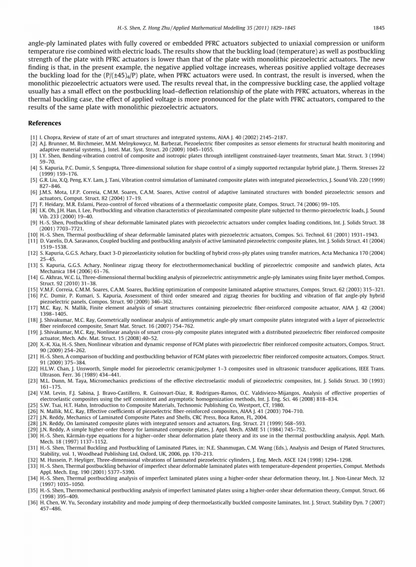
angle-ply laminated plates with fully covered or embedded PFRC actuators subjected to uniaxial compression or uniformtemperature rise combined with electric loads. The results show that the buckling load (temperature) as well as postbucklingstrength of the plate with PFRC actuators is lower than that of the plate with monolithic piezoelectric actuators. The newfinding is that, in the present example, the negative applied voltage increases, whereas positive applied voltage decreasesthe buckling load for the (P/(±45)4/P) plate, when PFRC actuators were used. In contrast, the result is inversed, when themonolithic piezoelectric actuators were used. The results reveal that, in the compressive buckling case, the applied voltageusually has a small effect on the postbuckling load–deflection relationship of the plate with PFRC actuators, whereas in thethermal buckling case, the effect of applied voltage is more pronounced for the plate with PFRC actuators, compared to theresults of the same plate with monolithic piezoelectric actuators.
References
[1] I. Chopra, Review of state of art of smart structures and integrated systems, AIAA J. 40 (2002) 2145–2187.[2] A.J. Brunner, M. Birchmeier, M.M. Melnykowycz, M. Barbezat, Piezoelectric fiber composites as sensor elements for structural health monitoring and
adaptive material systems, J. Intel. Mat. Syst. Struct. 20 (2009) 1045–1055.[3] I.Y. Shen, Bending-vibration control of composite and isotropic plates through intelligent constrained-layer treatments, Smart Mat. Struct. 3 (1994)
59–70.[4] S. Kapuria, P.C. Dumir, S. Sengupta, Three-dimensional solution for shape control of a simply supported rectangular hybrid plate, J. Therm. Stresses 22
(1999) 159–176.[5] G.R. Liu, X.Q. Peng, K.Y. Lam, J. Tani, Vibration control simulation of laminated composite plates with integrated piezoelectrics, J. Sound Vib. 220 (1999)
827–846.[6] J.M.S. Mota, I.F.P. Correia, C.M.M. Soares, C.A.M. Soares, Active control of adaptive laminated structures with bonded piezoelectric sensors and
actuators, Comput. Struct. 82 (2004) 17–19.[7] F. Heidary, M.R. Eslami, Piezo-control of forced vibrations of a thermoelastic composite plate, Compos. Struct. 74 (2006) 99–105.[8] I.K. Oh, J.H. Han, I. Lee, Postbuckling and vibration characteristics of piezolaminated composite plate subjected to thermo-piezoelectric loads, J. Sound
Vib. 233 (2000) 19–40.[9] H.-S. Shen, Postbuckling of shear deformable laminated plates with piezoelectric actuators under complex loading conditions, Int. J. Solids Struct. 38
(2001) 7703–7721.[10] H.-S. Shen, Thermal postbuckling of shear deformable laminated plates with piezoelectric actuators, Compos. Sci. Technol. 61 (2001) 1931–1943.[11] D. Varelis, D.A. Saravanos, Coupled buckling and postbuckling analysis of active laminated piezoelectric composite plates, Int. J. Solids Struct. 41 (2004)
1519–1538.[12] S. Kapuria, G.G.S. Achary, Exact 3-D piezoelasticity solution for buckling of hybrid cross-ply plates using transfer matrices, Acta Mechanica 170 (2004)
25–45.[13] S. Kapuria, G.G.S. Achary, Nonlinear zigzag theory for electrothermomechanical buckling of piezoelectric composite and sandwich plates, Acta
Mechanica 184 (2006) 61–76.[14] G. Akhras, W.C. Li, Three-dimensional thermal buckling analysis of piezoelectric antisymmetric angle-ply laminates using finite layer method, Compos.
Struct. 92 (2010) 31–38.[15] V.M.F. Correia, C.M.M. Soares, C.A.M. Soares, Buckling optimization of composite laminated adaptive structures, Compos. Struct. 62 (2003) 315–321.[16] P.C. Dumir, P. Kumari, S. Kapuria, Assessment of third order smeared and zigzag theories for buckling and vibration of flat angle-ply hybrid
piezoelectric panels, Compos. Struct. 90 (2009) 346–362.[17] M.C. Ray, N. Mallik, Finite element analysis of smart structures containing piezoelectric fiber-reinforced composite actuator, AIAA J. 42 (2004)
1398–1405.[18] J. Shivakumar, M.C. Ray, Geometrically nonlinear analysis of antisymmetric angle-ply smart composite plates integrated with a layer of piezoelectric
fiber reinforced composite, Smart Mat. Struct. 16 (2007) 754–762.[19] J. Shivakumar, M.C. Ray, Nonlinear analysis of smart cross-ply composite plates integrated with a distributed piezoelectric fiber reinforced composite
actuator, Mech. Adv. Mat. Struct. 15 (2008) 40–52.[20] X.-K. Xia, H.-S. Shen, Nonlinear vibration and dynamic response of FGM plates with piezoelectric fiber reinforced composite actuators, Compos. Struct.
90 (2009) 254–262.[21] H.-S. Shen, A comparison of buckling and postbuckling behavior of FGM plates with piezoelectric fiber reinforced composite actuators, Compos. Struct.
91 (2009) 375–384.[22] H.L.W. Chan, J. Unsworth, Simple model for piezoelectric ceramic/polymer 1–3 composites used in ultrasonic transducer applications, IEEE Trans.
Ultrason. Ferr. 36 (1989) 434–441.[23] M.L. Dunn, M. Taya, Micromechanics predictions of the effective electroelastic moduli of piezoelectric composites, Int. J. Solids Struct. 30 (1993)
161–175.[24] V.M. Levin, F.J. Sabina, J. Bravo-Castillero, R. Guinovart-Diaz, R. Rodrigues-Ramos, O.C. Valdiviezo-Mijangos, Analysis of effective properties of
electroelastic composites using the self consistent and asymptotic homogenization methods, Int. J. Eng. Sci. 46 (2008) 818–834.[25] S.W. Tsai, H.T. Hahn, Introduction to Composite Materials, Technomic Publishing Co, Westport, CT, 1980.[26] N. Mallik, M.C. Ray, Effective coefficients of piezoelectric fiber-reinforced composites, AIAA J. 41 (2003) 704–710.[27] J.N. Reddy, Mechanics of Laminated Composite Plates and Shells, CRC Press, Boca Raton, FL, 2004.[28] J.N. Reddy, On laminated composite plates with integrated sensors and actuators, Eng. Struct. 21 (1999) 568–593.[29] J.N. Reddy, A simple higher-order theory for laminated composite plates, J. Appl. Mech. ASME 51 (1984) 745–752.[30] H.-S. Shen, Kármán-type equations for a higher–order shear deformation plate theory and its use in the thermal postbuckling analysis, Appl. Math.
Mech. 18 (1997) 1137–1152.[31] H.-S. Shen, Thermal Buckling and Postbuckling of Laminated Plates, in: N.E. Shanmugan, C.M. Wang (Eds.), Analysis and Design of Plated Structures,
Stability, vol. 1, Woodhead Publishing Ltd, Oxford, UK, 2006, pp. 170–213.[32] M. Hussein, P. Heyliger, Three-dimensional vibrations of laminated piezoelectric cylinders, J. Eng. Mech. ASCE 124 (1998) 1294–1298.[33] H.-S. Shen, Thermal postbuckling behavior of imperfect shear deformable laminated plates with temperature-dependent properties, Comput. Methods
Appl. Mech. Eng. 190 (2001) 5377–5390.[34] H.-S. Shen, Thermal postbuckling analysis of imperfect laminated plates using a higher-order shear deformation theory, Int. J. Non-Linear Mech. 32
(1997) 1035–1050.[35] H.-S. Shen, Thermomechanical postbuckling analysis of imperfect laminated plates using a higher-order shear deformation theory, Comput. Struct. 66
(1998) 395–409.[36] H. Chen, W. Yu, Secondary instability and mode jumping of deep thermoelastically buckled composite laminates, Int. J. Struct. Stability Dyn. 7 (2007)
457–486.
Copyright © 2022 FDOKUMEN