Anglers Will Face "Slot Limit" for Striped Bass in 2020-2021
Upload
khangminh22Category
view
0download
0
University of Windsor University of Windsor
Scholarship at UWindsor Scholarship at UWindsor
Electronic Theses and Dissertations Theses, Dissertations, and Major Papers
1-1-1993
Compressive resistance and block shear strength of anglers. Compressive resistance and block shear strength of anglers.
Krishna Kishore Sankisa University of Windsor
Follow this and additional works at: https://scholar.uwindsor.ca/etd
Recommended Citation Recommended Citation Sankisa, Krishna Kishore, "Compressive resistance and block shear strength of anglers." (1993). Electronic Theses and Dissertations. 6743. https://scholar.uwindsor.ca/etd/6743
This online database contains the full-text of PhD dissertations and Masters’ theses of University of Windsor students from 1954 forward. These documents are made available for personal study and research purposes only, in accordance with the Canadian Copyright Act and the Creative Commons license—CC BY-NC-ND (Attribution, Non-Commercial, No Derivative Works). Under this license, works must always be attributed to the copyright holder (original author), cannot be used for any commercial purposes, and may not be altered. Any other use would require the permission of the copyright holder. Students may inquire about withdrawing their dissertation and/or thesis from this database. For additional inquiries, please contact the repository administrator via email ([email protected]) or by telephone at 519-253-3000ext. 3208.

COMPRESSIVE RESISTANCE AND BLOCK SHEAR STRENGTH OF ANGLES
by
KRISHNA KISHORE SANKISA
A Thesis submitted to the
Faculty of Graduate Studies and Research through the Department of
Civil and Environmental Engineering in Partial Fulfillment of the Requirements for
the Degree of Master of Applied Science at the University of Windsor
Windsor, Ontario, Canada June 1993
Reproduced with permission of the copyright owner. Further reproduction prohibited without permission.

UMI Number: EC55038
INFORMATION TO USERS
The quality of this reproduction is dependent upon the quality of the copy
submitted. Broken or indistinct print, colored or poor quality illustrations
and photographs, print bleed-through, substandard margins, and improper
alignment can adversely affect reproduction.
In the unlikely event that the author did not send a complete manuscript
and there are missing pages, these will be noted. Also, if unauthorized
copyright material had to be removed, a note will indicate the deletion.
UMI Microform E C 55038 Copyright 2010 by ProQuest LLC
All rights reserved. This microform edition is protected against unauthorized copying under Title 17, United States Code.
ProQuest LLC 789 East Eisenhower Parkway
P.O. Box 1346 Ann Arbor, Ml 48106-1346
Reproduced with permission of the copyright owner. Further reproduction prohibited without permission.

A c y 7 5 0 &
KRISHNA KISHORE SANKISA1993
C ) Copy rights reserved
Reproduced with permission of the copyright owner. Further reproduction prohibited without permission.

I hereby declare that I am the sole author of this document.
I authorize the University of Windsor to lend this document to other institutions or individuals for the purpose of scholarly research.
KRISHNA KISHORE SANKISA
I further authorize the University of Windsor to reproduce this document by photocopying or by other means, in total or in part, at the request of other institutions or individuals for the purpose of scholarly research.
KRISHNA KISHORE SANKISA
Reproduced with permission of the copyright owner. Further reproduction prohibited without permission.

THE UNIVERSITY OF WINDSOR requires the signatures of all persons using or photocopying this document. Please sign below, and give address and date.
Reproduced with permission of the copyright owner. Further reproduction prohibited without permission.

ABSTRACT
This investigation deals with two distinct topics:
compressive resistance of 60° angles and block shear
strength of 90° angles.
Angles have been used as leg, diagonal and horizontal
members in lattice towers for a long time. Lattice towers
with triangular base (as compared to rectangular base
towers)are more economical but the leg members have to be
bent inwards to 60° (either by cold forming or by
schifflerizing) to enable the connections between the
bracing members and leg members without the necessity to
use bent gusset plates. The results of 19 cold-formed 60°
angles and 19 hot-rolled schifflerized angles tested under
concentric axial compression are presented. For the
finite element analysis, a commercially available software.
"ABAQUS" has been used for non-linear solution using a
Newtonian approach with eight node shell elements. The
FEM solutions are in satisfactory agreement with the
vi
Reproduced with permission of the copyright owner. Further reproduction prohibited without permission.

experimental failure loads. Suitable effective width has
been suggested for cold-formed 60° angles and for
schifflerized angles.
Eccentric tension is one of the most common types of
loading for bracing members of lattice towers. Lately,
block shear mode of failure of angle members has drawn the
attention of the designers. The results of tests on 63
single angle members under eccentric tension of different
sizes (with bolt holes located either on or outside the
centre line of connected leg of the angles) are presented.
The results are in agreement with Clause 13.2 of CAN/CSA-
S16.1-M89.
The effect of pre-tensioning of bolts on tensile
strength was also investigated. It was found that there
is a 5% to 15% increase in the failure loads of angle
specimens with pre-tensioned bolts as compared to
specimens with snug tight bolts.
vii
Reproduced with permission of the copyright owner. Further reproduction prohibited without permission.

to my parents
viii
Reproduced with permission of the copyright owner. Further reproduction prohibited without permission.

ACKNOWLEDGEMENTS
The author wishes to express his sincere gratitude to
his advisor Dr. Murty K.S. Madugula, Department of Civil
and Environmental Engineering, for his guidance and
patient encouragement during the investigation.
The author would also like to thank Mr. Frank Kiss,
technician in the Dept. of Civil & Environmental
Engineering. Special thanks are due to Messrs. Steve
Duncan and Antonio Montanino for their help during the
tests on 60° angles. I would like thank Ms. Jayalakshmi
Sreedharan, Computing Consultant for her help with ABAQUS.
Special thanks are due to Mr. Seshu Adluri and other
friends for their timely and unstinted help during various
stages of the thesis.
The author is also thankful to Mr. Donald G.
Marshall, Vice-President-Engineering, LeBlanc & Royle
Telcom Inc., Oakville, Ontario, and Mr. K.Penfold, Manager
ix
Reproduced with permission of the copyright owner. Further reproduction prohibited without permission.

of Engineering, Trylon Manufacturing Ltd., Elmira, Ontario
for supplying free of charge the test specimens used in
the investigation.
Finally, the author wishes to acknowledge the
financial support provided by the Natural Sciences and
Engineering Research Council of Canada.
x
Reproduced with permission of the copyright owner. Further reproduction prohibited without permission.
TABLE OF CONTENTS
ABSTRACT ............................................. vi
DEDICATION ........................................... viii
ACKNOWLEDGEMENTS .................................... ix
LIST OF TABLES ..................................... xvi
LIST OF FIGURES .................. xx
NOTATION ..............................................xxiv
Chapter 1: INTRODUCTION................................ 1
1.1 General ................................... 1
1.2 Angles as Compression members.............. 1
1.3 Angles as Tension members.................. 4
1.4 Objectives.................................. 7
1.4.1 Compression Resistance .............. 7
1.4.2 Block Shear Strength ................ 8
1.5 Arrangement of Thesis...................... 8
xi
Reproduced with permission of the copyright owner. Further reproduction prohibited without permission.

Chapter 2: LITERATURE REVIEW......................... 10
2.1 General .................................... 10
2.1.1 Concentric Load: Elastic Buckling.. 10
2.1.2 Concentric Load: Inelastic Buckling.. 12
2.2 Compression Tests on 60° Angles.............. 13
2.3 Design Specifications........................ 15
2.3.1 CAN/CSA-S37-M86 ....................... 16
2.3.2 ANSI/ASCE 10-90 and ASCE Manual No.52 .18
2. 3.2.1 Maximum w/t Ratio..................... 18
2.3.3 AISC-LRFD (1986) 19
2.3.3.1 Flexural buckling ....................20
2.3.3.2 Torsional-Flexural buckling ......... 20
2.3.3.3 Reduction Factor Q ....................21
2.3.4 BS 5950: Part 1: 1985...................22
2.4 Tension Members ............................ 24
2.5 Tensile tests on Angles..................... 26
2.6 Specification for Members Under Tension ...31
2.6.1 CAN/CSA-S16.1-M89 .................... 31
2.6.2 ANSI/ASCE 10-90 and ASCE Manual No.52..33
xii
Reproduced with permission of the copyright owner. Further reproduction prohibited without permission.

Chapter 3: FINITE ELEMENT ANALYSIS ............... 34
3.1 Introduction ............................ 34
3.2 Finite Element Analysis.................. 35
3.3 Modelling of the Test Setup ............ 36
Chapter 4: EXPERIMENTAL INVESTIGATION .............. 41
4.1 General..................................... 41
4.2 Fabrication of Test Specimen ............. 41
4.3 Testing of Compression Members ........... 43
4.4 Testing of Tension Members................ 4 6
4.5 Tension Test Set-up ....................... 4 8
4.6 Tests on Effect of Pre-tensioning
on bolts .................................. 50
Chapter 5: DISCUSSION OF RESULTS .................. 52
5.1 General ................................... 52
5.2 Properties ............................... 52
5.2.1 Geometric Properties of
Cold-formed 60° Angles ............. 52
5.2.2 Geometric Properties of
xiii
Reproduced with permission of the copyright owner. Further reproduction prohibited without permission.
Schifflerized Angles ............... 54
5.2.3 Mechanical Properties............... 57
5.3 Comparison of Experimental and
Finite Element Loads....................... 57
5.4 Comparison of Experimental Loads with
Specifications................................ 58
5.4.1 CAN/CSA-S37-M86 ......................
5.4.2 ANSI/ASCE 10-90 and ASCE Manual No.52..59
5.4.3 AISC-LRFD(1986) 60
5.4.4 BS 5950: Part 1:1985 .................. 61
5.5 Torsional-flexural buckling............... 62
5.6 Mechanical Properties of Angles
Under Tension ............................. 64
5.7 Tension Members............................ 65
5.7.1 Comparison of Results of Tension
Members with CAN/CSA-S16.1-M89 ...... 65
5.7.2 ANSI/ASCE 10-90 and ASCE Manual No.52..66
5.7.3 Effect of Pre-tensioning of bolts .. 67
Chapter 6: CONCLUSIONS & RECOMMENDATIONS.......... 69
xiv
Reproduced with permission of the copyright owner. Further reproduction prohibited without permission.

6.1 Conclusions ................................ 69
6.2 Compressive Resistance ...................... 69
6.3 Block Shear Strength ...................... 71
6.4 Recommendations for Further Research....... </^2
REFERENCES.................... 74
TABLES................................................ 78
FIGURES............................................... Ill
Appendix A: FINITE ELEMENT MODEL OF
60° ANGLE USING ABAQUS.................. 150
Appendix B: FINITE ELEMENT ANALYSIS FOR
SCHIFFLERIZED 102x102x6.4 mm ANGLE '
DATA CHECK RUN........................... 157
Appendix C: FINITE ELEMENT ANALYSIS
FOR SCHIFFLERIZED 102x102x6.4 mm ANGLE
LAST PAGE OF OUTPUT ...................... 169
Appendix D: FORTRAN PROGRAM TO CALCULATE
PROPERTIES OF 60° ANGLES................ 171
Appendix E: FORTRAN PROGRAM TO CALCULATE
COMPRESSIVE RESISTANCE OF 60° ANGLES 174
VITA AUCTORIS ........................................ 180
xv
Reproduced with permission of the copyright owner. Further reproduction prohibited without permission.

LIST OF TABLES
xvi
Reproduced with permission of the copyright owner. Further reproduction prohibited without permission.

5.1a Properties of cold formed 60° AngleNominal size 38x38x3.2 mm (#C1)...................78
5.1b Properties of cold formed 60° AngleNominal size 38x38x3.2 mm (#C2)...................79
5.1c Properties of cold formed 60° AngleNominal size 38x38x3.2 mm (#C3)...................80
5.2a Properties of cold formed 60° AngleNominal size 51x51x4.8 mm (#C4).................. 81
5.2b Properties of cold formed 60° AngleNominal size 51x51x4.8 mm (#C5).................. 82
5.2c Properties of cold formed 60° AngleNominal size 51x51x4.8 mm (#C6).................. 83
5.3a Properties of schifflerized AngleNominal size 76x76x6.4 mm (#H1).................. 84
5.3b Properties of schifflerized AngleNominal size 76x76x4.8 mm (#H2).................. 85
5.3c Properties of schifflerized AngleNominal size 7 6x76x4.8 mm (#H3).................. 86
5.3d Properties of schifflerized AngleNominal size 76x76x4.8 mm (#H4).................. 87
5.4a Properties of schifflerized AngleNominal size 102x102x6.4 mm (#H5)................88
5.4b Properties of schifflerized AngleNominal size 102x102x6.4 mm (#H6)................89
5.4c Properties of schifflerized AngleNominal size 102x102x6.4 mm (#H7)................90
5.5 Yield stress values of 60° Angles................. 91
5.6 Finite Element AnalysisFailure Loads of 60° Angles .................... 92
5.7a Failure Loads of Cold-formed 60° Angles' According to CAN/CSA-S37 ....................... 93
xvii
Reproduced with permission of the copyright owner. Further reproduction prohibited without permission.

5.7b Failure Loads of Schifflerized AnglesAccording to CAN/CSA-S37 ....................... 94
5.8a Failure Loads of Cold-formed 60° AnglesAccording to ASCE Manual No. 52 ................. 95
5.8b Failure Loads of Schifflerized AnglesAccording to ASCE Manual No. 52 ................. 96
5.9a Failure Loads of Cold-formed 60° AnglesAccording to AISC-LRFD ......................... 97
5.9b Failure Loads of Schifflerized AnglesAccording to AISC-LRFD ......................... 98
5.10a Failure Loads of Cold-formed 60° AnglesAccording to BS 5950: Part 1 ................... 99
5.10b Failure Loads of Schifflerized AnglesAccording to BS 5950: Part 1 .................... 100
5.11 Dimensions and Properties of 90° Angles withOne Bolt Connection ............................ 101
5.12 Yield & Tensile strength of 90° AnglesWith One Bolt Connection ........................103
5.13 Dimensions and Properties of 90° Angles withTwo Bolt Connection ............................ 105
5.14 Yield stress & Tensile strength of 90° Angles With Two Bolt Connection ....................... 10 6
5.15 Failure Loads of 90° Angles withOne Bolt Connection ............................. 107
5.16 Failure Loads of 90° Angles withTwo Bolt Connection ............................. 109
xviii
Reproduced with permission of the copyright owner. Further reproduction prohibited without permission.

5.17 Tensile Strength of Bolted Eccentrically Loaded angles ............................
xix
Reproduced with permission of the copyright owner. Further reproduction prohibited without permission.

LIST OF FIGURES
xx
Reproduced with permission of the copyright owner. Further reproduction prohibited without permission.
Fig.1.1 Typical self-supportingantenna tower ............................ Ill
Fig.1.2a Typical cross-section ofa cold-formed 60° angle .................. 112
Fig.1.2b Typical cross-section ofa schifflerized angle ................... 113
Fig.1.3 Rollers used for schifflerization ....... 114
Fig.1.4 Angle under eccentric tension ........... 115
Fig.1.5 Different types of failureof tension members ....................... 116
Fig. 1.6 End, edge and combinedmode failure ............................. 117
Fig.3.1 Finite element model of testset-up for 60° angle .................... 118
Fig.3.2 Finite element model showing theelements of 60° angle ................... 119
Fig.3.3 Residual stress distribution over thecross-section of schifflerized angle .... 120
Fig.3.4 Residual stress distribution overthe thickness of schifflerized angle .... 121
Fig.4.1 Experimental set-up for testing60° angle ................................ 122
Fig.4.2 Circular plates bolted tothe Gilmore plate ........................ 123
xx i
Reproduced with permission of the copyright owner. Further reproduction prohibited without permission.

Fig.4.3 Top base plate with load cellscrew and bottom base platewith jack cover .......................... 124
Fig.4.4 Solid blocks, base plates andcircular plates used in the set-up ..... 125
Fig.4.5 Close-up of base plate withsolid and supporting angles ............. 126
Fig.4.6 Circular plate, hydraulic jackand end set-up ........................... 127
Fig. 4.7 Close-up of end set-up with 60° angle ... 128
Fig. 4.8 60° Angle under test ..................... 129
Fig.4.9 Cold-formed 1.5x1.5x1/8 inch(Cl#l) angle after failureby torsional-flexural buckling .......... 130
Fig.4.10 Schifflerized angle 4x4xl/4 inch(H7#l) after failure by torsional-flexural buckling ........................ 131
Fig.4.11 All the 60° angles after failure ....... 132
Fig.4.12 End-fixture for testing angles undereccentric tension ...................... 133
Fig.4.13 Front view of the End-fixturefor testing angles under tension ........ 134
Fig. 4.14 Top view of the End-fixture for testingangles under tension ..................... 135
Fig.4.15a Photo showing the End-fixture for testingangles under eccentric tension .......... 136
xxii
Reproduced with permission of the copyright owner. Further reproduction prohibited without permission.

Fig.4.15b Angle under eccentric tension 137
Fig. 4.16 Edge mode of failure of51x51x4.8 mm angles ..................... 138
Fig. 4.17 End mode of failure of7 9x7 9x8 mm angle ......................... 139
Fig.4.18 Combined mode of failure of79x79x6.4 mm angle ....................... 14 0
Fig.4.19 Bottom end fixture for testingeffect of pre-tension on angles .......... 141
Fig.4.20 Cold-formed angles (65x65x4 mm)with snug tight bolts after failure ..... 142
Fig.4.21 Cold-formed angles (65x65x4 mm)withpre-tensioned bolts after failure ....... 143
Fig.4.22 Hot-rolled angles (65x65x6.4 mm) withsnug tight bolts after failure .......... 144
Fig.4.23 Hot-rolled angles (65x65x6.4 mm) withpre-tensioned bolts after failure ......... 145
Fig.4.24 Graph showing load-elongation curves for 65x65x4 mm angles with snug tight and pre-tensioned bolts ........................ 14 6
Fig.4.25 Graph showing load-elongation curves for65x65x6.4 mm angles with snug tight and pre-tensioned bolts ........................ 147
Fig. 4.26 Stress-strain curve for 60° angles......... 148
Fig.4.27 Stress-strain curve for 90° angles ........ 14 9
Reproduced with permission of the copyright owner. Further reproduction prohibited without permission.

NOTATIONThe following symbols are used in the thesis:
Ag = gross cross-sectional area
An = net cross-sectional area
A„„ = effective net cross-sectional areane
a ' = reduced effective net cross-sectional areane
a = length of unbent portion of the schifflerized Angle (Fig.1.2b)
b = length of bent portion of the Schifflerized Angle (Fig.1.2b)
c = fillet radius of schifflerized angle
Cr = compressive resistance of 60° angles
Cw = warping Constant
E = modulus of elasticity
Fu = Tensile strength
Fy = Yield stress of Steel
Fy' = effective yield stress
G = shear modulus
g = gauge distance
xx iv
Reproduced with permission of the copyright owner. Further reproduction prohibited without permission.

Iu = moment of inertia about major (u-u) axis
Iv = moment of inertia about minor (v-v) axis
I = polar moment of inertia of 60° angles about centroid
I = polar moment of inertia of 60° angles about shear centre
J = Saint-Venant's torsion constant
Ku = effective length factor of 60° angles about u-u axis
Kv = effective length factor of 60° angles about v-v axis
K,. = effective length factor of 60° angle for torsional buckling
L = length of the column
p = pitch
Pu = Euler's buckling load about u-u axis
Pv = Euler's buckling load about v-v axis
R = outer bend radius of 60° cold-formed angle
ru = radius of gyration about u-u axis
rv = radius of gyration about v-v axis
t,T = thickness of the leg of the angle member
uc = distance of the centroid of the 60° angle member from the heel (Fig.1.2a and 1.2b)
u3 = distance of the shear centre from centroid of the 60° angle member (Fig.1.2a and 1.2b)
X X V
Reproduced with permission of the copyright owner. Further reproduction prohibited without permission.

w = flat width of the 60° angle for use in width thickness ratio
k = slenderness parameter
$ = resistance factor
xxv i
Reproduced with permission of the copyright owner. Further reproduction prohibited without permission.
1
CHAPTER 1
INTRODUCTION
1.1 Geperal
One of the most commonly used members in structural
engineering are steel angles. Angles are used both as
compression and tension members. These members play a
very important role in resisting forces. Angles are
widely used in latticed communication and electrical
transmission towers.
1.2 Angles as compression members
One of the ways the communication and electrical
transmission towers are constructed is to have one leg
member at each vertex of an equilateral triangle (Fig.1.1)
braced by diagonal and horizontal members. The two leg
plates of each of the three angle leg members in lattice
Reproduced with permission of the copyright owner. Further reproduction prohibited without permission.
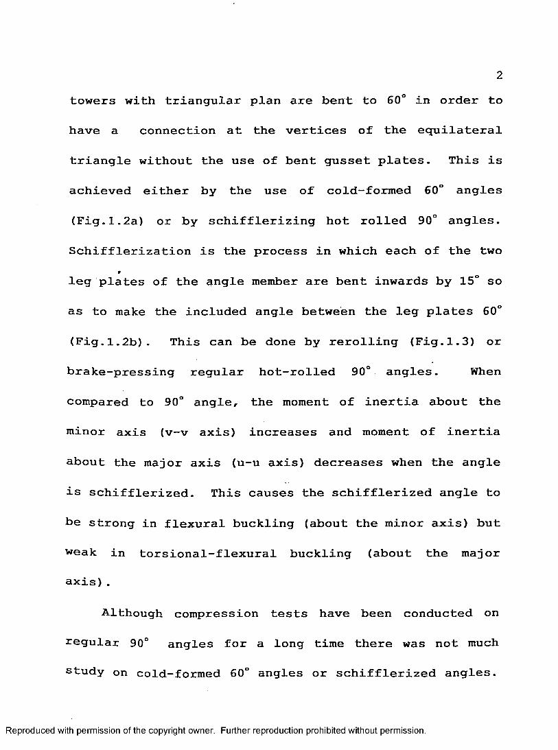
towers with triangular plan are bent to 60° in order to
have a connection at the vertices of the equilateral
triangle without the use of bent gusset plates. This is
achieved either by the use of cold-formed 60° angles
(Fig.1.2a) or by schifflerizing hot rolled 90° angles.
Schifflerization is the process in which each of the two *
leg plates of the angle member are bent inwards by 15° so
as to make the included angle between the leg plates 60°
(Fig.1.2b). This can be done by rerolling (Fig.1.3) or
brake-pressing regular hot-rolled 90° angles. When
compared to 90° angle, the moment of inertia about the
minor axis (v-v axis) increases and moment of inertia
about the major axis (u-u axis) decreases when the angle
is schifflerized. This causes the schifflerized angle to
be strong in flexural buckling (about the minor axis) but
weak in torsional-flexural buckling (about the major
axis).
Although compression tests have been conducted on
regular 90° angles for a long time there was not much
study on cold-formed 60° angles or schifflerized angles.
Reproduced with permission of the copyright owner. Further reproduction prohibited without permission.

The only published work on the compressive strength of
schifflerized angles was done at the University of Windsor
(Adluri 1990) in which 18 specimens were tested with ideal
pinned-end conditions. Of the eighteen specimens, only
nine failed in torsional-flexural buckling. Also, in
actual practice, the angles are bolted to other members *
and the capacity of schifflerized angles could be
different from tests based on ideal pinned-end conditions.
Therefore, it was felt necessary to conduct tests with
fixed end conditions to get an upper bound to the
compressive resistance of schifflerized angles.
Since cold-formed 60° angles are being increasingly
used in short (up to 30 m height) guyed towers, there is
also a need to study the behaviour of cold-formed 60°
angles.
From earlier research on schifflerized angles (Fig.
1.2b), the flat width recommended in width-to-thickness
ratio calculation was W = b (unbent portion) for use in
CAN/CSA-S37-M86. Since industries have their own
standards for bent and unbent portions, a suitable width
Reproduced with permission of the copyright owner. Further reproduction prohibited without permission.
for schifflerized angles which does not vary from
fabricator to fabricator is required.
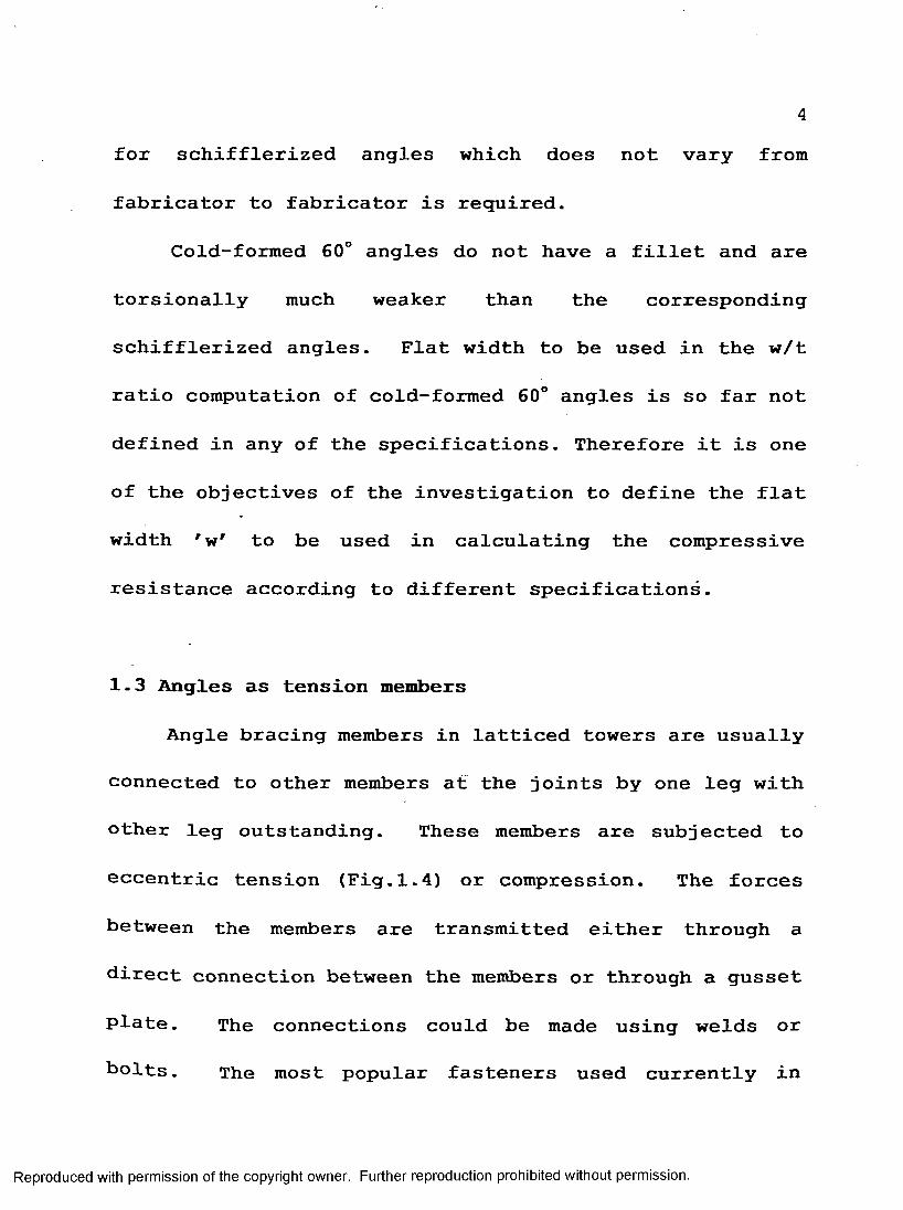
Cold-formed 60° angles do not have a fillet and are
torsionally much weaker than the corresponding
schif flerized angles. Flat width to be used in the w/t
ratio computation of cold-formed 60° angles is so far not
defined in any of the specifications. Therefore it is one
of the objectives of the investigation to define the flat
width ' w' to be used in calculating the compressive
resistance according to different specifications.
1.3 Angles as tension members
Angle bracing members in latticed towers are usually
connected to other members at the joints by one leg with
other leg outstanding. These members are subjected to
eccentric tension (Fig.1.4) or compression. The forces
between the members are transmitted either through a
direct connection between the members or through a gusset
plate. The connections could be made using welds or
holts. The most popular fasteners used currently in
Reproduced with permission of the copyright owner. Further reproduction prohibited without permission.

communication and electrical transmission tower industry
are high strength bolts. In the case of bolted
connections, the load at service conditions is transmitted
to the member from the connection or vice-versa through
the friction or bearing between bolts and the member. At
failure, the loads are transmitted through bearing between
the bolt shank and part of inner surface of bolt hole.
Until recently, design of single angles in eccentric
tension was being carried out by computing the product of
a typical contribution of the area of the cross-section
and the material strength. Usually, this would mean
checking for two cases, viz. the yielding of gross section
or rupture of net section (with or without the effect of
shear lag) as shown in Fig. 1.5a. Only rarely is the
design based on equations for biaxial bending and tension.
This has been the practice for nearly a century before the
mid 198 0s. In recent years however, this practice has
come under increasing scrutiny by researchers, utilities,
and code writers. As a result of this, the block shear
effect has been identified as a new and dominant mode of
Reproduced with permission of the copyright owner. Further reproduction prohibited without permission.

failure in many practical cases. This has led to the
revision of several North American design specifications
and manuals to incorporate this mode of failure in routine
design calculations. The block shear failure may be
defined as failure along a section at least a part of
which is parallel to the load and is hence assumed to be
in shear (Fig. 1.5 b & c) . The remaining part of the
section will be in direct tension (perpendicular to the
direction of the load application in the case of the angle
members). The failure path in block shear mode generally
follows the centres of the bolt holes farthest from the
free corner of the connected leg. The present
investigation is concerned with the design of angles for
block shear failure. Angles in eccentric tension can also
fail by edge (Fig. 1.6a), end (Fig. 1.6b) or combined
(Fig.i.6c) mode.
As mentioned earlier, block shear was not taken into
account till recently while calculating the tensile
resistance of members. CAN/CSA-S16.1 considered this type
°f failure in its 1989 edition based on investigations on
Reproduced with permission of the copyright owner. Further reproduction prohibited without permission.

beams and gusset plates. Canadian Standards Association
Technical Committee on Antenna Towers (S37) suggested that
tests be conducted on angles to confirm the block shear
failure for angles in latticed towers.
1.4 Obj ectives
The following are the objectives of the study:
1.4.1 Compressive Resistance:
(a) To carry out compression tests on different sizes
of 60° angles (both cold-formed and schifflerized angles)
failing in torsional-flexural buckling.
(b) To compare the values obtained from finite
element analysis with experimental results.
(c) To compare the experimental results with values
computed from CAN/CSA-S37-M86r I AISC-LRFD-1986, ASCE
Manual No.52 (1988) same as ANSI/ASCE 10-90, and BS-5950:
Part 1:1985.
(d) To suggest a suitable flat width for
schifflerized angles and cold-formed angles for use in the
Reproduced with permission of the copyright owner. Further reproduction prohibited without permission.

8calculation of their compressive resistance.
1.4.2 Block Shear Strength:
(a) To determine block shear strength by conducting
tension tests on eccentrically loaded angles with one or
two bolts at the ends.
(b) To study the effect of pre-tensioning of the
bolts on block shear strength of angle members, since the
bolts in communication towers are pre-tensioned, while
those in electrical transmission towers are usually snug
tight.
1-5 Arrangement of the thesis
Chapter 2 deals with literature review consisting of
five sections. Of these sections 2.1 to 2.3 deal with
compressive resistance of 60° angles while sections 2.4
and 2.5 deal with block shear strength of 90° angles.
Chapter 3 deals with Finite Element Analysis of 60°
angles.
Chapter 4 deals with Experimental Investigation of 60°
Reproduced with permission of the copyright owner. Further reproduction prohibited without permission.
angles under compression and 90° angles under eccentric
tension. Sections 4.1 to 4.3 deal with compressive
resistance of 60° angles. Sections4.4 and 4.5 deal with
block shear strength of tension members. Section 4.6
deals with the effect of pre-tensioning of bolts.
Chapter 5 is about discussion of results. Sections
5.1 to 5.5 is about properties and results of 60° angles.
Sections 5.6 and 5.7 deal with the mechanical properties
and results of tension members.
Conclusions from the present investigation and
recommendations for further research are given in
Chapter 6.
Reproduced with permission of the copyright owner. Further reproduction prohibited without permission.
10
CHAPTER 2
LITERATURE REVIEW
2.1 General
2.1.1 Concentric load : Elastic buckling
Concentrically loaded equal leg 60° angles (which are
singly symmetric) fail either by:
(i) flexural buckling about the minor axis (v-v
axis); or by
(ii) flexural buckling about the major axis (u-u
axis) and simultaneous twisting about the centre of
rotation, which lies on the major axis close to the
shear centre (Fig.1.2a and 1.2b)
Euler flexural buckling load about minor axis is
Reproduced with permission of the copyright owner. Further reproduction prohibited without permission.

II. Ai.P = --- —" {KvLf
Critical torsional-flexural buckling load Ptf can be
obtained by solving the following quadratic equation
(Timoshenko and Gere, 1961, equation 5.39)
P *-(P,+P)P¥+P,P,= 0 (2.2){1,+1,+Au,2) 9 *
where,
p = ^ EI« (2.3)
p ^ E (2 4) (KrL)2
The quadratic equation (2.2) provides two values for
Ptf' one of which is smaller and the other larger than Pu
and pfc.
The smaller of the two values is the torsional-flexural
buckling load.
Reproduced with permission of the copyright owner. Further reproduction prohibited without permission.
122.1.2 Concentric Loading : Inelastic Buckling
In case of inelastic flexural buckling, the failure
capacity can be estimated by replacing E by the tangent
modulus Et in the formula for elastic flexural
buckling(Eq. 2.1). For torsional and torsional-flexural
buckling also E can be replaced by ET, however there is no
consensus on the value to be used for the shear modulus in
the inelastic range. For the sake of simplicity, Bleich
suggested the use of GT the tangent shear modulus, in
place of G. This approach leads to conservative results
and also makes it possible to use readily the equations of
elastic torsional and torsional-flexural buckling for
inelastic buckling by replacing E by ET and G by GT.
Classical formulae are only applicable to ideal
columns. For columns having very high kL/r ratios,
Euler's formula is applicable. Real columns have
imperfections (residual stresses, out-of-straightness etc.)
and the classical inelastic formulae cannot be applied.
Reproduced with permission of the copyright owner. Further reproduction prohibited without permission.
132.2 Compression Tests on 60° Angles
To the best of the author's knowledge no published
literature was found on compressive tests on cold-formed
angles.
The only published work found on concentrically
loaded schifflerized angles was carried out at the
University of Windsor in 1989-90 (Adluri, 1990). A total
of 18 schifflerized angles were tested. The suggested
formula for the flat width W for use in CAN/CSA-S37-M86 is
the width of the bent portion of the schifflerized angle
(Dimension b of Fig 1.2). Out of the 18 specimens nine
failed in torsional-flexural buckling and nine failed in
flexural buckling. Five sizes of angles were tested viz.
127x127x8 mm, 102x102x6.4 mm, 89x89x8 mm,76x76x3.2 mm,/
76x76x6.4 mm, of 300 and 400 MPa nominal yield strength
with slenderness ratios varying between 50 and 95.
Adluri, Madugula and Monforton (1990) conducted a
finite element analysis on the compressive resistance of
schifflerized angles. The results of the finite element
Reproduced with permission of the copyright owner. Further reproduction prohibited without permission.

14analysis were compared to the experimental results. The
angles were modelled using eight-node shell elements with
six degrees of freedom at each node. A non-linear
analysis was conducted. In this case, buckling is
indicated by excessive deformations and consequent
reduction in the load carrying capacity.
Adluri and Madugula (1991a) presented formulae for
computing the properties of schifflerized angles. The
geometric properties of the schifflerized angles were
calculated by idealizing the cross-section into
rectangular segments. The properties given were the
cross-sectional area, moment of inertia, centroidal
distance, distance between shear centre and the centroid,
radius of gyration, Saint-Venant's torsion constant, and
warping constant.
Adluri and Madugula (1991 b,c) have presented tables
which provide the design axial compressive strength of
schifflerized angles according to AISC-LRFD(1986)and
according to CAN/CSA-S37-M8 6. The tables demarcate
between the flexural and torsional-flexural buckling
Reproduced with permission of the copyright owner. Further reproduction prohibited without permission.

15loads.
Adluri, Madugula, and Monforton (1992) published a
paper regarding the proper selection of width to be used
in the width-thickness ratio as there is ambiguity
regarding the width to be considered in width-thickness
ratio in ASCE Manual No.52.
2.3 Design Specifications
As there is no specified effective width W for
cold-formed 60° angles, the following various effective
widths were tried to find an optimum one for various
specifications (Fig.1.2a):
(i) W = B
(ii) W = B + (R -0.5 T)ri/6
(iii) W = B + (R -0.5 T)n/3
For schifflerized angles the width tried was W=a+b-t-
c (Fig.1.2b) for CAN/CSA-S37-M8 6, AISC-LRFD and
BS5950:Part 1:1985. For ASCE Manual NO.52 (ANSI/ASCE 10-
90) the width tried is W=a+b.
The following are some of design specifications for
Reproduced with permission of the copyright owner. Further reproduction prohibited without permission.

16computing compressive resistance Cr of 60° angles:
2.3.1 CAN/CSA—S37—M86
Maximum w/t ratio =25
Effective yield stress-F^
(1) When
(2) When
w
F ;= F ,[1 .6 7 7 -0 .6 7 7 U -)] (2 .6)
(3) When
380
f t *< ^ 2 5 ; / 56415
(2.7)
Reproduced with permission of the copyright owner. Further reproduction prohibited without permission.

17where, Fy is the yield stress in MPa.
Factored axial compressive resistance - Cr
OCX *0.15, Cr = <bAgF'y (2-81
0.15< X 1.0, Cr = $AgFy (1.035-0.202X -0.222X2) <2- 9>
1.0 <X *2.0, Cy =4>A Fj(-0.111 +0.636X"1 +0.087X"2) (2.10)
2.0<X 3.6, C^^A^CO.OOO+O.Sm-2) (2.11)
3.6<X, (2 12)
r r
where,
Fy (2.13)ic2F
As can been seen, CAN/CSA-S37-M86 does not consider
torsional-flexural buckling explicitly as a mode of
failure. To overcome this, effective yield stress F ’ is
Reproduced with permission of the copyright owner. Further reproduction prohibited without permission.

18used in place of Fy to reduce the compression resistance
of the member with large width-to-thickness ratios.
2.3.2 ANSI/ASCE 10-90 and ASCE Manual No.52
The ultimate compressive strength Pult of axially
loaded compression members shall be:
»’*«» — (2.14)* rv
2860^ when (2.15)(KLlrv)*
where
Fy
2-3.2.1 Maximum w/t Ratio
The ratio w/t, where w=flat width and t=thickness of
the leg, shall not exceed 25. If w/t exceeds (w/t)iim
given by
Reproduced with permission of the copyright owner. Further reproduction prohibited without permission.

19
(w/«)llm=-7=r ! (2.17)
then the ultimate strength Pult shall be computed with F
replaced in the above eqs 2.14 and 2.16 with Fy given by
^ = [ 1 . 6 7 7 - 0 . 6 7 7 when tf)|tn (2.18)
p/ 9500 . w. 144when T ~7= (2.19)(WO * <JFy
where F is the yield stress in ksi
2.3.3 AISC-LRFD (1986)
C^OJBSA^ (2 .20)
For flexural buckling Fcr is given in section 2.3.3.1
and for torsional-flexural buckling in section 2.3.3.2.
Reproduced with permission of the copyright owner. Further reproduction prohibited without permission.

202.3.3.1 Flexural Buckling
For X y/Q <. 1.5,
F ^ =(0.658°x<2) Fy Q (2.21)
For X t/q > 1.5,
er 1 y (2.22)
where.
_ KLrx \
yE
(2.23)
The values of factor Q which depend on width-
thickness ratios are given in section 2.3.3.3.
^ -3.3.2 Torsional—Flexural Buckling
The nominal critical stress Fcr is determined as
follows:
a. For Xe tTq 1.5:
Reproduced with permission of the copyright owner. Further reproduction prohibited without permission.

21
Fcr=(?(0.658Oi* V ,
b. For Xe Vq > 1.5:
F =[P-877]Fer 1 ,2 J Je
where,
Fy = specified minimum yield stress of steel
Fe = critical torsional elastic buckling stress
2-3.3.3 Reduction Factor Q
When w/t 76/VFy, (where Fy is in ksi.).
When 76//Fy < w/t < 155//Fy;
(2.24)
(2.25)
(2.26)
(2.27)
Reproduced with permission of the copyright owner. Further reproduction prohibited without permission.

22
Q =1.340 -0.00447(w/t) yjFy (2.28)
When w/t £ 155/VFy ;
<?=15500/[Fv(wA)2] (2.29)
2.3.4 BS 5950 : Part 1:1985
The compressive resistance Cr of an angle section is
given by
Cr=AgFer (2.30)
When w/t £ 11.5 V(275/Fy),
Fcr is obtained from Perry strut formula
D F.F,Fcr =---- ’ (2.31)
where.
Reproduced with permission of the copyright owner. Further reproduction prohibited without permission.

23where, FE is Euler strength; Fy is the design strength; i]
is the Perry factor.
The Perry factor tj for flexural buckling under load
should be obtained from:
il =0.0055(1 -X0) z 0 (2.33)
where the limiting slenderness ratio,
(2.34)F,
When w/t exceeds the limiting value, a reduction factor
given by the lesser of
11a+b ."4 (2.35)
t 275Fy
and
Reproduced with permission of the copyright owner. Further reproduction prohibited without permission.

24
192(a+b) -4275
N ^
(2.36)
is applied to yield stress (a and b as per Fig.1.2).
2.4 Tension Members
A member (without any holes) when subjected to
concentric axial tension, attains its strength when all
the fibres of the cross-section have yielded (uniform
tensile stress). The strength in tension Tu is given by
T« = A,
where,
= gross cross-sectional area
If a tension member has holes (for rivets and bolts
etc-), the gross area should be reduced. This reduced
area is referred to as net area. In this case the tensile
stress distribution is not uniform, but the stress reaches
a constant value Fy, as the fibres reach yield strain.
Reproduced with permission of the copyright owner. Further reproduction prohibited without permission.

25
The strength i n tension of the members with holes is
given by Tu = Fu An
where Fu = Tensile strength of the material
A = Net area of the cross-sectionn
However it is possible that the gross area may yield
before the net section reaches tensile strength. This
means that the gross area yielding (Fy Ag) could control
the design of the member.
Concentric axial load in tension members can seldom
be obtained in actual structures: either the connections
may not be concentric or the member it self may not be
straight, resulting in eccentric loading.
In case bending takes place about some plane other
than one through a principal axis then, stress ' f' at any
point is given by
f = P/Ag ± Muv/Iu ± Mvu/Iv
where Mu and Mv are components of moment about u and v
principal axes respectively, Iu and Iv are the respective
moments of inertia about these axes, and u,v are the
coordinates of any point.
Reproduced with permission of the copyright owner. Further reproduction prohibited without permission.

262.5 Tensile tests on angles
One of earliest tests on angles in tension was
carried out by Batho(1915). During the experiments on
single angle members, it was found that the effect of end
constraints was insignificant.
Young(1935) after a study suggested that for a single
angle connected by one leg the following factor 7 e7 be
applied to the net section area:
e = 1.0 - 0.18(u/c)
in which 'u7 and 'c7 are the widths of the unconnected
and connected legs, respectively.
Nelson(1953) carried out tension tests on eighteen
angles. He noted that the length of the specimen or the
end attachment had no significant effect.
In 1969, Marsh developed a theoretical expression for
the net effective area of an angle connected by one leg
subjected to a tensile force. Theoretically obtained
results were compared with some of the test results on
aluminium angles; good agreement was observed for angles
connected by the longer leg, whereas the prediction was
Reproduced with permission of the copyright owner. Further reproduction prohibited without permission.
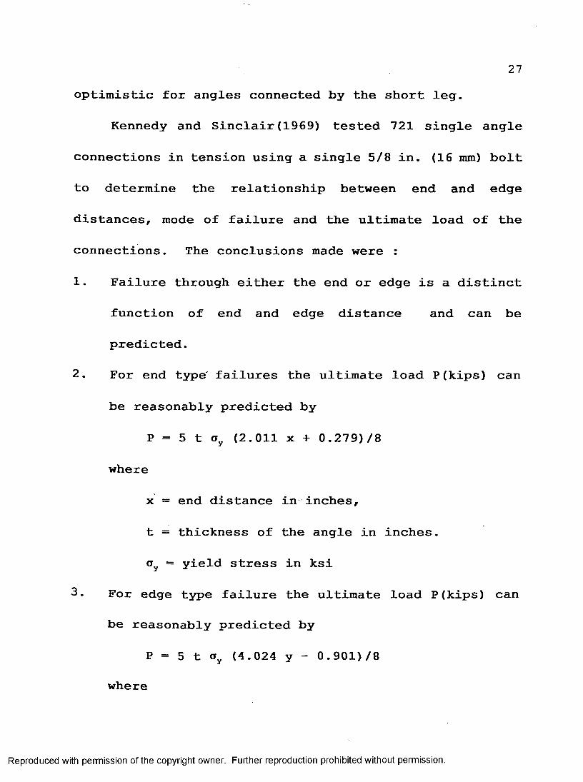
27optimistic for angles connected by the short leg.
Kennedy and Sinclair(1969) tested 721 single angle
connections in tension using a single 5/8 in. (16 mm) bolt
to determine the relationship between end and edge
distances, mode of failure and the ultimate load of the
connections. The conclusions made were :
1. Failure through either the end or edge is a distinct
function of end and edge distance and can be
predicted.
2. For end type failures the ultimate load P(kips) can
be reasonably predicted by
P = 5 t ay (2.011 x + 0.279)/8
where
x = end distance in inches,
t = thickness of the angle in inches.
oy = yield stress in ksi
3. For edge type failure the ultimate load P(kips) can
be reasonably predicted by
P = 5 t oy (4.024 y - 0.901)/8
where
Reproduced with permission of the copyright owner. Further reproduction prohibited without permission.

28y = the edge distance in inches.
4. Failure in bearing occurs at a nominal bearing stress
equal to approximately 4.5 times the yield stress.
5. Bearing stress equal to 2.25 times the yield stress
can produce insignificant hole elongation depending
upon end and edge distances. However such bearing
stress cannot be developed with an end distance less
than one inch (25.4 mm) or edge distance less than
5/8 in.(16 mm).
6. The development of local stresses in the immediate
neighbourhood of the hole, equal to or greater than
the yield stress, is not a reliable indication of
approaching failure of the connections.
Hardash and Bjorhovde (1985) demonstrated that all
segments in a fracture path which may consist of a series
of segments, some loaded primarily in tension and others
primarily in shear, fracture simultaneously.
Madugula and Mohan (1989) presented results of tests
Reproduced with permission of the copyright owner. Further reproduction prohibited without permission.

29conducted by Western Area Power Adminstration (WAPA) and
Bonneville Power Administration (BPA) separately on
various 90° angles. WAPA conducted tests on 29 specimens.
Twelve specimens failed at loads less than the various
code specifications; this is due to failure of specimens
in block shear (which was not considered with the earlier
specifications) rather than net section failure. The
net area taken by various specifications is different.
Most of the specifications take the effective area of the
angles in tension connected by one leg to be less, than the
actual net area. The conclusions of the paper are given
below :
(1) In the case of unequal leg angles in tension
connected by one leg, distinction should be made between
failure loads of angles connected by long leg and by short
leg. Failure loads are higher if long leg is connected.
(2) For certain combinations of edge distance, end
distance, and pitch, block shear mode of failure may
govern instead of net section failure.
(3) The specification give unduly conservative values
Reproduced with permission of the copyright owner. Further reproduction prohibited without permission.

30for failure loads of angles in eccentric tension connected
by close tolerance bolts (fitted bolts).
Epstein (1992) conducted tests on 38 different
connections for various types of failure. There were 3
specimens, each consisting of a pair of angles, tested for
each connection. The angle sizes tested were 152x152x8
mm, 152x102x8 mm, 152x89x8 mm, 127x127x8 mm, 127x89x8 mm,
and 127x76x8 mm. Epstein also studied the effect of
staggering of bolts. The connection consisted of a pair
of angles connected by two rows of 19 mm(3/4 in.) bolts,
each row having two bolts. The edge distance for all
connections was 38 m m (1.5 in.)and the pitch was 76mm(3
in.). The failures of the angle members were classified
into five different categories:
(a) block shear,
(b) predominantly block shear with some net section,
(c) predominantly net section with some block shear,
(d) net section, and
(e) boltshear plus block shear.
Failure of equal leg angles in short connections were
Reproduced with permission of the copyright owner. Further reproduction prohibited without permission.

31all by block shear. As the length of the connection
increased, the failure mode was tending to be
predominantly through net section. Failures for longest
connection were all through net section.
2.6 Specifications for Members Under Tension
2.6.1 CAN/CSA—S16.1—M89
According to Clause 12.3.1 the effective net area
shall be calculated as follows:
(a) for a segment normal to the force
A ^ W . T (2.37)
Wn = Width of the member under tension
T = Thickness of the member
(b) For a segment parallel to the force
A„j=0.6£„r (2.38)
Ln = Length of the member under shear
The factored tensile resistance, Tr, developed by a
member subjected to an axial tension force shall be
taken as the least of
Reproduced with permission of the copyright owner. Further reproduction prohibited without permission.

32
(0 Trl =*AgFy
(li) Tr2 =0.85Q>AneFu
(2.39)
(2.40)
, (2.41)(in) Tr3 =0.85 $AneFu
where
Anr, = A. + A„,ne nl n2
In the above equation Ane' = 0.75 Ane for angles having
one or two bolts.
The angles can also fail by bearing. Bearing resistance
is given by
Br=+TneF„ (2.42)
where,
Ane = Net cross-sectional area
Ag = Gross cross-sectional area
Reproduced with permission of the copyright owner. Further reproduction prohibited without permission.

33Fy = Yield stress
Fu = Tensile strength
e = end distance.
2.6.2 ANSI/ASCE 10-90 and ASCE Manual No.52
In case of ASCE Manual No.52 block shear failure is
to be taken into account only if the centroid of the bolt
pattern is not located between the heel of the angle and
the centre line of the connected leg. However according
to ANSI/ASCE-10-90 block shear failure is to be taken into
account if the centroid of the bolt pattern on the
connected leg is outside the centre of gravity of the
angle. In the majority of cases the centroid of the bolt
hole is outside the centre of gravity of the member, hence
according to ANSI/ASCE 10-90 it is almost always necessary
to consider block shear mode of failure for members in
tension.
Reproduced with permission of the copyright owner. Further reproduction prohibited without permission.

34
CHAPTER 3
FINITE ELEMENT ANALYSIS
3.1 Introduction
Finite*element analysis was conducted and the results
compared with the experimental results. If there, is good
agreement between the two, compression resistance of any
size and length angle can be predicted by a finite element
analysis without the need to carry out physical tests.
This chapter deals with the finite element analysis of 60°
angles.
Even though cold-formed 60° angles and schifflerized
angles could be considered simple members,it is difficult
to determine their compressive strength. A commercial
finite element package "ABAQUS" has been used to analyze
the members.
Reproduced with permission of the copyright owner. Further reproduction prohibited without permission.

35Non-linearity of both material and geometry was
considered in the analysis of both cold formed and
schifflerized angles. The variation of residual stresses
along the leg width and through the thickness was assumed
similar to ECCS recommendations (ECCS 1985) as shown in
Fig.3.3 and Fig.3.4.
3.2 Finite Element Analysis
First the data regarding the member known as model
data was created. This consists of input for nodes,
elements, boundary conditions, element properties, and
material properties.
After the data regarding the model was created, data
regarding the loading was given. A non-linear analysis
was carried out for a static case of loading. The loading
was applied in several increments. At each increment,
non-linear equations were solved using Newtonian
techniques.
A series of linear problems were solved to obtain
non-linear solution. Many techniques such as Matthies and
Reproduced with permission of the copyright owner. Further reproduction prohibited without permission.

36Strang(1979) are available to tackle non-linear problems.
Presently Newtonian techniques are widely being used. For
any displacement configuration the nodal displacements
were represented by the vector {U} and {Fo} and {F^
represent vectors of external nodal loads and internal
resisting forces respectively. [K] represents the tangent
stiffness.
The vector of the unbalanced portion of the nodal
forces is given by
{Fu} = {Fe} + {F,}
where {Fu} gives the error in the solution.
The iterative solution according to Newtonian
techniques is as follows:
{ Fuj } = { Fe3 } + { F,3 }
A r1 = [K3]"1 Fu3
r3+1 = r3 + A r3
F±3+1 = function of r3+1
3.3 Modelling of the test setup
The first step in modelling of a 60° angle (Fig. 4.1)
Reproduced with permission of the copyright owner. Further reproduction prohibited without permission.

37
was to generate nodes along the cross-section of the
angle. The cross-section was divided into sixteen parts
i.e., having seventeen nodes along the cross-section.
This set of nodes were copied to form a new set of nodes
such that the distance between the two sets of nodes was
the length of the 60° angle. Nodes were generated between
these two sets of nodes. The number of rows of nodes
generated was eleven (Appendix A).
The next step was to generate elements along the
cross-section. Eight-node shell elements were used to
model the 60° angle. Eight elements were generated along
the cross-section and five such rows of elements were
generated along the length of the 60° angle (Fig. 3.1).
When shell elements are used, the elements are generated
along the centre plane of the member and the thickness is
provided to the member using shell section options.
Next the nodes of the base plate (Fig. 4.1) were
developed. Five nodes each were generated along the
length and the width of the plate, consisting of 25 nodes
in total. Four-node shell elements were used to develop
Reproduced with permission of the copyright owner. Further reproduction prohibited without permission.

38the elements of the base plate. The base plate consisted
of 16 elements. This set of nodes and elements were
copied to generate a new set of nodes and elements
representing the top base plate. The nodes and elements
of the base plate represent the centre plane of the base
plate. The distance between two base plates represents
the thickness of the plate plus the length of the test
specimen. The model was generated such that the centroid
of the base plate passes through the centroid 60° angle.
Solid steel blocks (Fig.4.1) supporting the angle
were modelled as trapezoidal blocks. Four-node shell
elements were used to generate the elements along the
centre plane of the blocks. The solid blocks were in
contact with the 60° angle.
Next the lateral supporting 90° angles (Fig.4.1) were
modelled using four-node shell elements. These lateral
supporting angles were in contact with the 60° angle.
As mentioned earlier when shell elements are used,
centre plane elements of the members are generated.
Therefore the thicknesses of the members are provided
Reproduced with permission of the copyright owner. Further reproduction prohibited without permission.

39using shell properties- The complete set up is shown in
Fig.4.1.
The boundary condition option was used to fix the
base plates. Five nodes of the each base plate (four
corner nodes and centre node) were fixed. The bottom base
plate was free to move in the direction of the application
of the load.
For the nodes of the base plates, solid blocks, and
lateral supporting angles which are in contact with the
60° angle, multi-point constraints were used so that
displacements and rotations were the same for all the
nodes at the point of contact. Multi-point constraint was
also used to fix the solid blocks and supporting angles to
the base plates. Next the material properties of the
members were described. The elastic and plastic
properties of the 60° angles were the modulus of
elasticity and the yield stress.
A Fortran program was written for the residual
stresses in hot-rolled schifflerized angle.
While conducting the experiments the loads are
Reproduced with permission of the copyright owner. Further reproduction prohibited without permission.

40invariably eccentric. This eccentricity can be achieved
in different ways. In this investigation a load of
magnitude l/1000th of the expected failure load was
applied at mid height at the heel in the direction of the
minor axis for torsional-flexural buckling. This method
gave better results when compared to others.
The model was loaded through the centroid of the 60°
angle.
The model of the member is shown in Fig. 3.1 and
Fig. 3.2. The ABAQUS input is shown in Appendix A, data
check run is given in the Appendix B and the last page of
the output is given in Appendix C.
From the input in Appendix A, the expected failure
load is applied in increments. For example for the
4x4xl/4 in. (102x102x6.4 mm) angle of length 1520 mm the
expected failure load was 350 kN. This expected failure
load was applied in increments on the specimen. Form the
last page of the output in Appendix C the total time
completed is 0.725. Therefore the failure load was
calculated as 0.725 times 350 kN i.e., 254 kN.
Reproduced with permission of the copyright owner. Further reproduction prohibited without permission.

41
CHAPTER 4
EXPERIMENTAL INVESTIGATION
4.1 General
The sizes of 60° angles tested for compression are
38x38x3.2 mm (1.5x1.5x1/8 in.), 51x51x4.8 mm (2x2x3/16
in.), 76x76x4.8 mm (3x3x3/16 in.), 76x76x6.4 mm (3x3xl/4
in.) and 102x102x6.4 mm (4x4xl/4 in.) nominal dimensions.
Out of these 38x38x3.2 mm and 51x51x4.8mm angles were
cold-formed, while 76x7 6x4.8 mm, 7 6x76x6.4 mm and
102x102x6.4 mm angles were hot-rolled. The column 1/r
ratios varied from 40 to 89. A total of 38 specimens were
tested, 19 each of cold-formed and hot-rolled angles.
4.2 Fabrication of Test Specimens
Different slenderness ratios for each specimen were
Reproduced with permission of the copyright owner. Further reproduction prohibited without permission.

42included in the test program. The lengths of the
specimens varied from 370 mm to 2140 mm depending on the
size of the 60° angle. The cold-formed specimens were
marked with starting letter "C" (for example Cl#l) and
hot-rolled specimens are marked with starting letter "H"
(for example Hl#l).
The following are the different lengths included in
the investigation:
38x38x3.2 mm Cold-formed 60° angles
Cl : Length of the specimen of group Cl 900 mm
C2 : Length of the specimen of group C2 630 mm
C3 : Length of the specimen of group C3 370 mm
51x51x4.8 mm Cold-formed 60° angles
C4 : Length of the specimen of group C4 1350 mm
C5 : Length of the specimen of group C5 874 mm
C6 : Length of the specimen of group C6 4 04 mm
7 6x7 6x6.4 mm Schifflerized angle
HI : Length of the specimen of group HI 1220 mm
7 6x7 6x4.8 mm Schifflerized angle
H2 : Length of the specimen of group H2 1870 mm
Reproduced with permission of the copyright owner. Further reproduction prohibited without permission.

43H3 : Length of the specimen of group H3 1530 mm
H4 : Length of the specimen of group H4 732 mm
102x102x6.4 mm Schifflerized angle
H5 : Length of the specimen of group H5 2140 mm
H6 : Length of the specimen of group H6 1960 mm
H7 : Length of the specimen of group H7 1520 mm
Third number denotes the number of the specimen for that
group. The ends of the members were milled to be
perfectly parallel to each other and perpendicular to the
longitudinal axis.
4.3 Testing of Compression Members
Fixed end conditions were created by using assembly
of plates and blocks. A solid block and two 90° angles of
size 63x63x8 mm and length 100mm were used to create fixed
end conditions at each end. A circular plate of diameter
330 mm and thickness 40 mm was fastened to the Gilmore
platen (Fig.4.2). A 445 kN capacity hydraulic jack was
then placed on the circular plate. On top of the
hydraulic jack was placed a square base plate (280x280x24
Reproduced with permission of the copyright owner. Further reproduction prohibited without permission.

44
nun) with a circular collar(Fig.4.3). This circular collar
was used to centre and support the square base plate on
top of the hydraulic jack. The solid block was bolted to
the base plate such that it directly passed through the
centroid of the base plate which coincided with the
centroid of the angle specimen. Separate solid blocks
were used depending on the size of the 60° angle
(Fig. 4.4). The 60° angle was then placed in contact with
the solid block such that the centroid of the angle
specimen passed through the centroid of the base plate
(Fig.4.5). Two 90° angles(lateral supports) which can
slide over the base plate were brought in contact with the
60° angle specimen and bolted to the base plate. A
similar arrangement of solid block and 90° angles was also
made at the top. The top base plate was connected to the
load cell. The base plate was supported and positioned
through the centre line of the load cell by a collar screw
(Fig. 4.3). The load cell was in turn connected to the
circular plate of diameter 330 mm and thickness 4 0 mm.
This circular plate was connected to top Gilmore platen.
Reproduced with permission of the copyright owner. Further reproduction prohibited without permission.
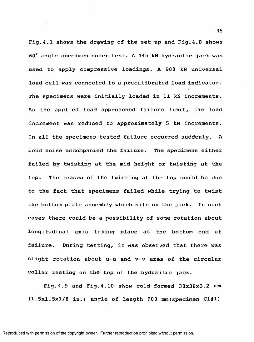
45Fig.4.1 shows the drawing of the set-up and Fig.4.8 shows
60° angle specimen under test. A 445 kN hydraulic jack was
used to apply compressive loadings. A 900 kN universal
load cell was connected to a precalibrated load indicator.
The specimens were initially loaded in 11 kN increments.
As the applied load approached failure limit, the load
increment was reduced to approximately 5 kN increments.
In all the specimens tested failure occurred suddenly. A
loud noise accompanied the failure. The specimens either
failed by twisting at the mid height or twisting at the
top. The reason of the twisting at the top could be due
to the fact that specimens failed while trying to twist
the bottom plate assembly which sits on the jack. In such
cases there could be a possibility of some rotation about
longitudinal axis taking place at the bottom end at
failure. During testing, it was observed that there was
slight rotation about u-u and v-v axes of the circular
collar resting on the top of the hydraulic jack.
Fig.4.9 and Fig.4.10 show cold-formed 38x38x3.2 mm
(1.5x1.5x1/8 in.) angle of length 900 mm(specimen Cl#l)
Reproduced with permission of the copyright owner. Further reproduction prohibited without permission.

46and 102x102x6.4 ram (4x4xl/4 in.) schifflerized angle of
length 1520mm (specimen H7#l) after failure respectively.
For the purpose of comparison, an untested specimen from
the same group was placed beside the failed specimen in
both the photographs. All the specimens tested after
failure are shown in Fig.4.11.
SSRC(1988) guidelines for column testing recommend
loading by a mechanical pump so as to facilitate constant
rate of loading. However in the present case loading was
done using a flat jack operated using a hand pump. The
load cell was calibrated twice during test program and the
average of both was taken to calculate test failure loads.
The end plate assembly described was found to be
adequate for torsional-flexural buckling. The solid
blocks and support angles provided enough support.The
solid blocks also prevented against accidental kicking-out
of the member.
4.4 Testing of Tension Members
The sizes of 90° angles tested in tension were
Reproduced with permission of the copyright owner. Further reproduction prohibited without permission.

4751x38x4.8 mm (2x1.5x3/16 in.), 51x51x6.4 mm (2x2xl/4 in.),
51x51x4.8 mm (2x2x3/16 in.), 63x51x4.8 mm (2.5x2x3/16
in.), 63x51x6.4 mm (2.5x2xl/4 in.), 63x63x4.8 mm
(2.5x2.5x3/16 in.), 63x63x6.4 mm (2.5x2.5x1/4 in.),
63x63x8.0 mm (2.5x2.5x5/16 in.), 76x76x4.8 mm (3x3x3/16
in.), 76x76x6.4 mm (3x3xl/4 in.), 89x89x6.4 mm
(3.5x3.5x1/4 in.), and 89x89x8.0 mm (3.5x3.5x5/16 in.)
nominal dimensions.
Three specimens were tested for each size. To
accommodate the specimens in the test equipment available
the specimens were of length 11 1/4 in. for single bolt
connection or 15 1/4 in. for double bolts connection.
The specimens were fabricated in an actual tower
fabricating facility so as to resemble the field
conditions. The holes were punched at gauges normally
used by the industry. The size of the hole punched was
for 5/8 in. (16 ram) bolts. Out of 63 specimens tested 45
were single bolt connection and 18 were double bolt
connections. The end distance was 29 mm (1 1/8 in.) for
specimens connected by single bolt and in case of double
Reproduced with permission of the copyright owner. Further reproduction prohibited without permission.

48bolts end distance was 25.4 mm ( 1 in.), the pitch was
50.8 mm (2 in.).The edge distance varied from 29 mm (1 1/8
in.) to 44 mm (1 3/4 in.). Two bolts were used where it
was felt that the single bolt would fail before the
failure of the member. Table 5.11 and 5.13 give the
properties of the angle specimens connected by single and
double bolts respectively.
4.5 Tension Test setup
The end fixtures consisted of bar of size 100x100x25
mm. To this bar, two bars of sizes 108x100x25 and
108x48x25 mm were welded 10 mm apart. On these two bars,
two 18.2 mm size holes were drilled. To the bar of size
100x100x25 mm a rod of diameter 36 mm and length of 210 mm
was welded. This rod was fastened to the Tinius Olsen
testing machine. Fig.4.12,4.13 and 4.14 show the
isometric, front and top view of the end fixture giving the
details of the dimensions. Fig.4.15a shows the photo of
the end fixture attached to the testing machine. The
angle specimen to be tested was placed in between the two
Reproduced with permission of the copyright owner. Further reproduction prohibited without permission.

49bars which are 10 mm apart. The angle specimen was held in
position with help of 5/8 in. (16 mm) size bolts at each
end and tensile force was applied (Fig.4.15b).
The failure occurred in one of the following three
ways:
(1) Edge mode
(2) End mode (bearing failure)
(3) Combined mode (block shear failure)
For many of the members, considerable elongation of the
bolt hole was observed after the test.
In case of edge failure (Fig 4.16) splitting of the
member started at the hole and progressed to the toe of
the member. On further application of load, specimens
failed by combined mode. In case of end failure
(Fig. 4.17) material piled up in front of the hole or the
end tore out. The combined mode (Fig.4.18) (block shear
failure) is one in which both edge and end failure
occurred.
Reproduced with permission of the copyright owner. Further reproduction prohibited without permission.

50
4.5 Tests on the Effect of Pre-tensioning of Bolts
The effect of pre-tensioning of bolts on the strength
was also investigated. Seven tests consisting of 14
specimens were conducted.
For studying the effect of pre-tensioning, the
specimens were chosen from a stock of cold-formed and hot-
rolled 90° angles. The cold-formed angles were of size
65x65x4 mm and 55x35x3 mm while the hot-rolled angles were
of size 63x63x6.4 mm (2 1/2x2 l/2xl/4 in.). The specimens
were cut using a band saw. Holes were drilled in the
specimens for 19 mm bolts. These were loaded in double
shear. The cold-formed angle of size 65x65x4 mm and hot-
rolled angle of size 2 1/2x2 l/2xl/4 in. (63x63x6.4 mm)
had both the end and edge distance equal to 28 mm. Two
sets of specimens were tested for each size. One set for
each size were snug tight while the other set had been
pretensioned. The total elongation of the joints at
either end was measured using dial gauges. This movement
is also representative of the movements of the bolts. The
specimens were mounted on to the test setup which
Reproduced with permission of the copyright owner. Further reproduction prohibited without permission.

consisted of a 25 mm (1 in.) top gusset plate attached to
a test frame. A similar bottom gusset plate was attached
to the load cell mounted on a 900 kN (200 kip) hydraulic
pump (Fig.4.19). One angle was placed on either side of
the 25 mm gusset plate. The load was applied in gradual
increments and the elongations had been noted. As
expected all the specimens exhibited hole elongations.
The failed specimens are shown in Fig.4.20 to Fig.4.23.
The mode of failure of the specimens was by block shear.
Figure 4.24 shows the load-elongation curves for 65x65x4
mm cold-formed 90° angles with snug tight and pre
tensioned bolts while Fig.4.25 shows similar curves for
63x63x6.4 mm hot-rolled 90° angles.
For both compression and tension specimens tension
tests were conducted on the standard size coupons. The
coupons were taken from the same stock as that of
specimens. The stress versus strain curve was plotted on
a X-Y electronic recorder. Stress-strain curves for
tensile coupons are shown in Figs. 4.26 and 4.27.
Reproduced with permission of the copyright owner. Further reproduction prohibited without permission.

52
CHAPTER 5
DISCUSSION OF RESULTS
5.1 General
This chapter deals with the results of the
experimental investigation regarding the compressive
resistance of the 60° angles and the block shear strength
of 90° angles under eccentric tension. This chapter also
compares the results obtained from finite element
modelling of the 60° angles. The finite element analysis
results and calculated values according to various
specifications are compared with the experimental results,
thus helping to understand the results and interpret their
implication.
5-2 Properties
5.2.1 Geometric Properties of Cold-formed 60° Angles
The cold-formed angles are manufactured by bending a
Reproduced with permission of the copyright owner. Further reproduction prohibited without permission.
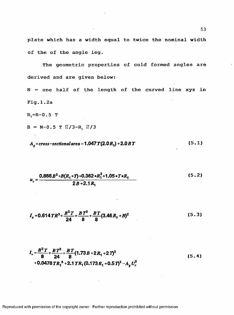
53plate which has a width equal to twice the nominal width
of the of the angle leg.
The geometric properties of cold formed angles are
derived and are given below:
N = one half of the length of the curved line xyz in
Fig.1.2a
Rj=R-0 . 5 T
B = N-0.5 T n/3-R! n/3
A cross-sectional area=1.0477’(2.0I?1) +2.0 B T (5.1)
_ 0.866i?2 +!?(/?., +1) +0.362 +1.05 (5-2)“c 2B +2.1
/B=0.614r/23+ ^ ^ + ^ - + ^ ( 3 . 4 6 J 2 1 +Bf (5 -3>24 8 8 1
Iy , b ^ + ^ + b z ^ 7 3 b + z r ^ 21), ( 5 4 )
+0.0478 T R f +2.1 TJJ1 (0.173/ +0.51)2 -A t l f c
Reproduced with permission of the copyright owner. Further reproduction prohibited without permission.
54
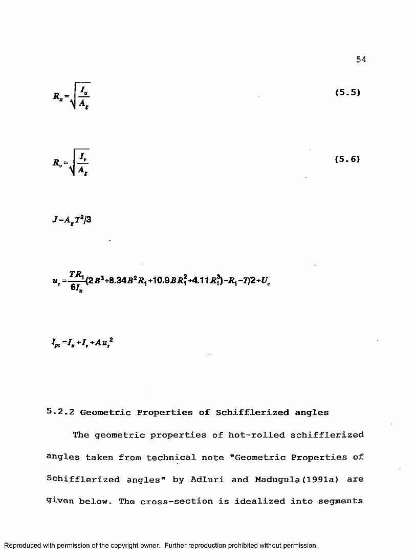
R = L l (5-5)" w .
R.= 7v (5.6)V \ A g
j =Ag r2/3
u, =-^(2.B3+8.345*^ +10.95^+4.11 R^-R, -Tj2+Uc 6 / «
Ipt=Iu+I*+Auti
5.2.2 Geometric Properties of Schifflerized angles
The geometric properties of hot-rolled schifflerized
angles taken from technical note "Geometric Properties of
Schifflerized angles" by Adluri and Madugula(1991a) are
9iven below. The cross-section is idealized into segments
Reproduced with permission of the copyright owner. Further reproduction prohibited without permission.

of four rectangles by ignoring the toe and filet radii.
Ag= cross-sectional area = 2t(a+b-t/2)
d=leg width= a+b
uc =2(a-ll2)2+4b(a-tl2)+fib* +_£_ (5 7)4/2(fl+/>-//2) /2
I. - 2(IU1 +I„2)
where.
< 5 - 8 )
and
(5.9)
where,
Ivl =£*L+*-l+bt{(a W +y/3-]Z 48 16 ^ 4J (5.10)
and
Reproduced with permission of the copyright owner. Further reproduction prohibited without permission.

56
, (5.1D”2 24 6
I =/ *A u2 (5.13)pi pc A g S
a - ± +tt (5.14)4c3+12c2i+6v'2ci2+2i3 y'2 ‘
where c—a-t/2
r« =>
rv =
J = ± ( a + b-tl2)t3
(5.15)
(5.16)
(5.17)
The properties used in computing member strengths are
Reproduced with permission of the copyright owner. Further reproduction prohibited without permission.

57listed in Tables 5.1a to 5.4c. Appendix D gives the
Fortran programs used to calculate the properties.
5.2.3 Mechanical Properties
The mechanical properties of the material tested were
taken from the results obtained from the tensile
coupons (as per ASTM standards). The sample stress-strain
curves for the coupons are presented in Fig. 4.26 and 4.27.
The actual yield stress values are found to be 0.33% to
26.33% higher than the corresponding nominal values. The
value of Young's Modulus is taken as 200 GPa as per
established practice. The yield stress of the tensile
coupons of 60° angles is given in Table 5.5.
5.3 Comparison of Experimental & Finite Element Loads
The finite element results of the members have been
given in Table 5.6. Out of the several specimens tested
for each length, the geometrical properties of one was
selected arbitrarily and a finite element analysis was
carried out on this specimen. For most of the specimens
Reproduced with permission of the copyright owner. Further reproduction prohibited without permission.

FEM results were within 10% of the experimental results.
The reason for large angle specimens having low value
could be due to the end fixtures not able to provide full
fixity. In the finite element analysis the support angles
might have yielded. The finite element analysis gave
satisfactory results when compared to the experimental
load values.
5.4 Comparison of Experimental Loads with Specifications
Appendix E gives the Fortran programs used to
calculate the compressive resistance using various
specifications.
5.4.1 CAN/CSA-S37-M86
CAN/CSA-S37 refers to clause 13.3.1 of SI6.1 to
calculate the member capacities. As mentioned in chapter
2, three different widths were used for cold formed 60°
angles to find a suitable width to be used in calculation.
These are shown as Case-I, Case-II, Case-Ill in Table
5.7a. Since rotation might have taken place at the bottom
Reproduced with permission of the copyright owner. Further reproduction prohibited without permission.

59support, for each case the k has been taken as 0.7. For
38x38x3.2 mm cold-formed angles the values obtained for
Case-Ill are closer to the experimental values. In case
of 51x51x4.8 mm cold-formed angles width-thickness ratio
was below 200/v'Fy. Therefore f ’ = Fy for all the cases.
For schifflerized angles, width used for calculating
failure loads is W=b+a-t-c (Fig.1.2b) (shown as Case-I in
table 5.7b). In case of schifflerized angles the lateral
supports are not sufficient to provide full fixity.
The value of was taken as 1. Table 5.7a and 5.7b
compares the values with the experimental results for
cold-formed and schifflerized angles respectively.
5.4.2 ANSI/ASCE 10-90 and ASCE Manual No.52
The Structural Stability Research Council formula for
ultimate strength of the concentrically loaded columns in
the inelastic range was adopted to calculate the
capacities of the members.
For cold-formed angles as mentioned earlier three
Reproduced with permission of the copyright owner. Further reproduction prohibited without permission.

different widths in width-thickness ratios were chosen to
determine the compressive resistance. These are shown as
Case-I, Case-II, Case-Ill in Table 5.8a. For each case
the values are shown for k=0.7. The values obtained for
cold formed angles using W=B+(R-0.5 T)n/3 gave values
very close to the experimental failure loads. In case of
schifflerized angles the width used was W=a+b (Fig.1.2b).
The column strength calculated from the formulae for
K=0.7 are given in the Table 5.8b. For schifflerized
angles also the results obtained with the above mentioned
width gave values which are in satisfactory agreement with
the experimental results.
5.4.3 AISC-LRFD (1986)
Calculation of the compressive resistance for
concentrically loaded columns according to AISC load and
resistance factor design is based on a modified approach
compared to the allowable stress design (ASD). The ASD is
based on SSRC column curve No.2. AISC takes in to account
the torsional-flexural buckling which was not the case
Reproduced with permission of the copyright owner. Further reproduction prohibited without permission.
61with CAN-CSA-S37.
The width assumed for cold-formed angles is the same
as mentioned in the above two specifications. These are
shown as Case-I,Case-II and Case-Ill in Table 5.9a. In
case of cold-formed members with w=B+(R-0.5 T)n/3 , the
results from the formulae for K=0.7 were very close to the
experimental values.
For schifflerized angles the width taken is W=a+b-t-
c (Fig. 1.2b). The values obtained are in very good
agreement with the experimental results.
The value of O taken was 1.0. The column capacities
were calculated from the formulae for K=0.7. Table 5.9a
and 5.9b compare the experimental results and the results
obtained from AISC load and resistance factor design
specifications for cold-formed and schifflerized angles
respectively.
5.4.4 BS 5950: Parti :1985
According to British practice, Perry-Robertson
formulae were used for calculating the critical stresses
Reproduced with permission of the copyright owner. Further reproduction prohibited without permission.

62for different slenderness ratio and yield stresses.
Three different widths were assumed for cold-formed
angles to find a suitable width for calculation. These
are shown as Case-I,Case-II and Case-Ill in Table 5.10a.
For cold-formed angles for W=B (Fig.1.2a) the experimental
results were very close to the experimental results
obtained for K=0.7.
In case of schifflerized angles the width assumed is
W=a+b-t-c (Fig.1.2b). The calculated values are in
satisfactory agreement with experimental results.
The experimental results and values obtained from the
specification for values of K=0.7 are given in Table 5.10a
and 5.10b for cold-formed and schifflerized angles
respectively.
5.5 Torsional-flexural Buckling
Clause 6.2.5.1 of CAN/CSA-S37-M86 does not consider
torsional-flexural buckling as a mode of failure. To
overcome this phenomena, effective yield stress is taken
into consideration so as to reduce the compressive
Reproduced with permission of the copyright owner. Further reproduction prohibited without permission.

63resistance of the member.
It is necessary to take into account torsional-
flexural buckling to calculate the compressive resistance.
The suggested modification by Sankisa, Adluri and Madugula
(1993)is to replace slenderness parameter X by Atf
v' N * V
where F ' is given by eq. (2.5) to (2.7) depending on w/t
ratios.
Euler buckling stress about major axis
(KLjrl)
Torsional elastic buckling stress
Reproduced with permission of the copyright owner. Further reproduction prohibited without permission.

64
F =± ( n2l £ r +GJ)V {KtL?
H =1 -A ut2l Ip>
Table 5.7a and 5.7b show the values calculated by
taking into account torsional-flexural buckling for cold-
formed and schifflerized angles respectively. Case-IV in
Table 5.7a- shows the value calculated for cold-formed
angles for k=0.7. Case-II in Table 5.7b shows the values
obtained for schifflerized angles. The values calculated
by accounting for torsional-flexural buckling for both
cold-formed and schifflerized angles were less than the
experimental values. For cold-formed, W=B+(R-0.5T)n/3 was
used in calculating the values.
Sankisa, Adluri, Madugula (1993) presented the above
results obtained at SSRC conference held at Milwaukee.
5.6 Mechanical Properties of Angles Under Tension
The value of the Young's modulus is taken as 200 000
Reproduced with permission of the copyright owner. Further reproduction prohibited without permission.

65MPa as per established practice. Tables 5.12 and 5.14
list the yield and tensile strength of the members under
tension.
5.7 Tension Members
5.7.1 Comparison of Experimental Loads with CAN/CSA-S16.1
The member capacities were calculated according
to the CAN/CSA-S16.1-M89. Except for size 2 1/2x2 l/2xl/4
in. angle specimens(Mark No. 29#1,#2 and #3) for a gauge
distance of 1 1/4 in. the experimental values were higher
than those calculated from the specifications. The
failure loads calculated are according to the gross area
yielding, net section fracture with shear lag, block shear
failure and bearing failure. TR1 in Tables 5.15 and 5.16
is the failure load calculated according to gross area
yielding. TR2 in the Tables 5.15 and 5.16 is the failure
load calculated according to block shear failure. TR3 in
the Tables 5.15 and 5.16 is the failure load calculated
according to net section failure with shear lag. BR in
the tables is the failure load calculated according to
Reproduced with permission of the copyright owner. Further reproduction prohibited without permission.

66bearing (end mode) failure. MIN in the above mentioned
tables is the minimum failure load obtained from the
mentioned failure modes. Pexp is the experimental failure
load.
5.7.2 ANSI/ASCE 10-90 and ASCE Manual No.52
ASCE Manual No. 52 mentions that block shear should
be taken into account as failure mode only if centre of
the bolt holes is outside the centre line of the connected
leg. According to ANSI/ASCE 10-90, block shear mode of
failure is to be taken in to account if the centroid of
the bolt hole is outside the centre of gravity of the
member.
Tables 5.15 and 5.16 give the failure loads. Thirty-
six specimens under eccentric tension failed in end
failure mode, twenty-seven failed by block shear (combined
mode of edge and end failure).
The results from the above tests were presented as
technical report to Canadian Standards Association
Technical committee on Antenna, Towers and Antenna
Reproduced with permission of the copyright owner. Further reproduction prohibited without permission.

67supporting structures by Sankisa, Adluri, Madugula (1992).
5.7.3 Effect of Pre-tensioning of Bolts
The experimental results of the effect of pre
tensioning of the bolts are discussed here. The increase
in load between the case of the bolt pre-tensioning and
snug tight is about 5.12% to 15.12%. Table 5.17 presents
the results of the tests. Typical load elongation curves
are shown in Fig.4.24 and 4.25. Curves for pre-tensioned
and snug tight cases show essentially similar trends. The
results could be interpreted as an indication to the
possibility of a slight increase in the load capacity for
angles with pre-tensioned bolts. This increase can be
attributed to the friction due to some residual tensile
force in the bolt at the time of failure. This might
explain the seemingly constant difference in load capacity
for all the seven tests.
Results obtained from this investigation were
presented as technical report to Canadian Standards
Association Committee on Antenna, Towers and Antenna
Reproduced with permission of the copyright owner. Further reproduction prohibited without permission.

68supporting structures
Madugula(1992).
by Adluri, Sankisa and
Reproduced with permission of the copyright owner. Further reproduction prohibited without permission.

69
CHAPTER 6
CONCLUSIONS AND RECOMMENDATIONS
6.1 Conclusions
Tests on 19 cold-formed 60° and 19 schifflerized
angles under axial compression and 63 tests on 90° angles
under eccentric tension were conducted.
From the observations and results obtained from the
investigation, the following conclusions are made:
6.2 Compressive Resistance
1. The FEM results of the 60° angles obtained are in
satisfactory agreement with the experimental results.
2. Based on a "flat width" used for cold-formed and
schifflerized angles, the compressive strength calculated
using various standard specifications for 60° angles is
Reproduced with permission of the copyright owner. Further reproduction prohibited without permission.

70summarized below:
(a) For calculating the compressive resistance
according to CAN/CSA-S37-M86 the flat width recommended
for cold-formed angles is W=B+(R-0.5 T)n/3 (Fig.1.2b) and
for schifflerized angles is W=a+b-t-c (Fig.1.2a).
(b) The flat width suggested for ASCE Manual
No. 52 (ANSI/ASCE 10-90) for compressive capacity for
cold-formed 60° angles is W=B+(R-0.5 T)n/3 (Fig.1.2a).
In case of schifflerized angles W=a+b (Fig.1.2b) is
recommended.
(c) For calculating the compressive resistance
according to AISC-LRFD-1986 for cold-formed 60° angles,
flat width recommended is W=B+(R-0.5 T)n/3 (Fig.1.2b).
For schifflerized angles the suggested flat width is
W=a+b-t-c.
(d) For BS 5950: Part 1: 1985, the flat width to
be used for calculating the compressive resistance for
cold-formed 60° angles is W=B (Fig.1.2a) and for
schifflerized angles, W=a+b-t-c.
Reproduced with permission of the copyright owner. Further reproduction prohibited without permission.

6.3 Block shear Strength:
(a) The experimental results are in good
agreement with the values predicted by CAN/CSA-S16.1-M89.
(b) When the gauge line is outside the centre of
gravity of the member, block shear should be taken into
account. Therefore the Clause 5.10.2 in ANSI/ASCE 10-90
is more appropriate.
(c) Special attention should be given for end
mode of failure for angles connected by single or double
bolts.
(d) The cold-formed 90° angles exhibited a 10% to
15% increase in the load capacity for the case of pre-
tensioned bolts when compared to the case of snug-tight
bolts. Hot-rolled 90° angles showed 5% increase in
ultimate load of members with pre-tensioned bolts relative
to that of members with snug tight bolts. Difference in
results between cold-formed and hot-rolled angles is due
to the difference in plastic flow under the head.
Reproduced with permission of the copyright owner. Further reproduction prohibited without permission.

6.4 Recommendations for Further Research
From the experience obtained from the present
investigation, the following issues can be pursued for
further research:
Compressive Resistance:
1. Extensive tests should be conducted on 60° angles
with bolted connections.
2. The actual residual stress pattern should be
determined for the 60° angles.
Block shear Strength:
1. In case of tension members extensive experiments
should be conducted with varying end distance and
using more bolts to have a better understanding of
various types of failures.
2. Due to machine limitations, short specimens were used
in the present investigation. Longer specimens
should be tested to represent realistically members
used in actual structures.
3. in case of pre-tensioning of bolts, the present study
is limited in scope and hence is not completely
Reproduced with permission of the copyright owner. Further reproduction prohibited without permission.

conclusive. It is necessary to conduct
extensive research.
more
Reproduced with permission of the copyright owner. Further reproduction prohibited without permission.

74
REFERENCES
1. ABAQUS Version 4.8, 1989, User's Manual, Parts 1, 2,3 & 4, Habet, Karlson & Soresen, Inc., 100 MedwayS t . , Providence, RI 02906-4402, USA.
2. Adluri,S.M.R 1990. Ultimate strength of Schifflerized angles, M.A.Sc. Thesis, University of Windsor, Windsor, Ontario, Canada.
3. Adluri,S.M.R., Madugula,M.K.S., and Monforton,G.R.,1990. Finite element failure analysis ofschifflerized angles, Computers and Structures, Vol.4, No.5, pp.1087-1093, Great Britain.
4. Adluri,S.M.R., and Madugula,M.K.S., 1991a. Geometricproperties of schifflerized angles, J. Construct.Steel Research 18 (1991) 71-83, Great Britain.
5. Adluri,S.M.R., Madugula,M.K.S., 1991b. Designstrength of schifflerized angle struts, Engineering Journal, AISC,2nd Quarter 1991/Volume No.28.
6. Adluri,S.M.R and Madugula,M.K.S 1991c. Factored axial compressive resistance of schifflerized angles, Canadian Journal of Civil Engineering, Volume 18,No.6, pp.926-932. Canada.
7. Adluri,S.M.R, Madugula,M.K.S, Monforton,G.R., 1992.Schifflerized angle struts. Journal of Structural Engineering, ASCE, Vol.118,No.7,pp.1920-1936, New York, USA.
Reproduced with permission of the copyright owner. Further reproduction prohibited without permission.

758 . Adluri,S.M.R., Sankisa, Krishna K., MadugularM.K.S.,
1992. Effect of Bolt Pretension on the tensile strength, Technical report submitted to the CSA committee on Antennas, Towers and Antenna supporting Structures (CAN/CSA-S37).
9. American Institute of Steel Construction,1986. Load and resistance factor design for structural steel buildings, Chicago, II., USA.
10. American Society of Civil Engineers, 1988. Guide for design of steel transmission towers, Manuals and reports on engineering practice-No.52, (ASCE Manual No.52), Second Ed., New York.
11. American Society of Civil Engineers, 1992. Design of latticed steel transmission structures ANSI/ASCE 10- 90, ANSI/ASCE standard, New york.
12. Batho,C., 1915. The effect of the end connections on the distribution of stress in certain tension members. Journal of Franklin Institute,Philadelphia, Pennslyvania. U.S.A, 180(2), August,129-172.
13. BS 5950: Part 1:1985, British Standard Structural use of steelwork in Building, Part 1. Code of practice for design in simple and continuous construction: hot rolled sections. British Standards Institution, London, UK, 1985.
14. CAN/CSA-S37-M8 6, Antennas, Towers a n d AntennaSupporting Structures, Canadian standardsAssociation, Rexdale, Ont., 1993.
15. Canadian Standards Association,1989. Limit states design of steel structures, CAN/CSA-S16.1-M89, National Standard of Canada, Rexdale, Ont., Canada.
Reproduced with permission of the copyright owner. Further reproduction prohibited without permission.

7616. ECCS-(European Convention for Constructional
Steelwork)1985 Technical Committee 8-Structural Stability (WG 8.1-Components). Recommendations for Angles in Lattice Towers, Publication No.39.
17. Epstein,H.I.1992. An experimental study of block shear failure of angles in tension, American Institute of Steel Construction, Engineering Journal, Vol.28, No.2,pp.75-84, Chicago,II.,USA.
18. Hardash,S., and Bjorhovde,R.1985. New designcriteria for gusset plates in tension, American Institute of Steel Construction, Engineering Journal, Vol.22, No.2, pp.77-94, Chicago,II.,USA.
19. Kennedy,J.B., and Sinclair,G.R. 1969. Ultimate capacity of Single bolted angle connections. Journal of Structural Division, American Society . of Civil Engineers, Vol.95, N0 .ST8, pp.1645-1660, New York.
20. Madugula,M.K.S., and Mohan S.,1988. Angles in eccentric tension. Journal of Structural Engineering, American Society of Civil Engineers, Vol.114, No.STIO, Oct.,p.2387-2396, New York.
21. Madugula,Murty K.S. and Kennedy, John B.,1985. Single and Compound Angle Members:Structural Analysis and Design, Elsevier Applied Science Publishers, London.
22. Marsh,C., 1969. Singles angle members in tension and compression. Journal of the Structural Division, ASCE, 95 (ST5), May, 1043-1049.
23. Matthies, H., Strang, G., (1979). The Solution of Nonlinear Finite Element Equations, Int. Journal for Numerical Methods in Engineering, vol.14, 1613-1626.
24. Nelson,H.M., 1953. Angles in tension. British
Reproduced with permission of the copyright owner. Further reproduction prohibited without permission.

77
Constructional Steelwork Association, Publication No.7 , UK, pp. 8-18.
25. Sankisa, Krishna.K., A d l u r i ,S .M .R .,and Madugula,M.K.S., 1993. Further studies on the compressive strength of 60° equal leg steel angles, Proceedings of Structural Stability Research Council Annual Technical session, April 5-7, Milwaukee, WI,USA. (To be published).
26. Sankisa, Krishna K., Adluri,S.M.R., and Madugula,M.K.S., 1992. Block shear effect on the design of single angles in eccentric tension, Technical report submitted to CSA technical committee on Antennas, Towers and Antenna supporting structures.
27. SSRC-Structural Stability Research Council, Guide to Stability Design Criteria for Metal Structures, 4th ed.Galambos, Theodore V., editor., John Wiley & sons, 1988.
28. Timoshenko, S.P. and Gere,J.M.,1961. Theory of Elastic Stability, McGraw-Hill Book Company. Newyork, NY, USA.
29. Young,C.R., 1935. Elementary structural problems in steel and timber. John Wiley & Sons, Inc.,New York, NY, Second Edition.
Reproduced with permission of the copyright owner. Further reproduction prohibited without permission.

Table 5.1a Properties of Cold-formed 60° AngleNominal size 38x38x3.2 mm
PROPERTY Cl#l Cl#2 C1I3
Flat LegWidth 'b' (nun) 27.48 27.36 27.24
Radius (mm) 13.0 13.0 13.0
Thickness (mm) 3.18 3.16 3.06
Area (mm*) 250.8 248.5 240.2
u (mm) 14.40 14.40 14.30
I„in (10s mm4) 0.023 0.022 0.021
I (10s nun4) 0.056 0.055 0.054
Ipj (10s mm4) 0.093 0.092 0.089
r„ (mm) 15.0 14.9 14.9
r„ (mm) 9.5 9.5 9.5
J (104 mm4) 0.0845 0.0827 0.0750
Length (mm) 900 900 900
Note: Refer to Fig. 1.2a for explanation of notations
Reproduced with permission of the copyright owner. Further reproduction prohibited without permission.

Table 5.1b Properties of Cold-formed 60° AngleNominal size 38x38x3.2 mm
PROPERTY C2#l C2#2 C2#3
Plat LegWidth 'b' (mm) 26.38 26.90 26.30
Radius (mm) 13.0 13.0 13.0
Thickness (mm) 3.02 2.98 3.04
Area (mm2) 232.0 232.1 233.0
ue (mm) 13.90 14.10 13.90
IBtn (10* mm*) 0.020 0.021 0.020
I«.» f10‘ 0.050 0.051 0.050
Ip, (10* mm1) 0.083 0.085 0.083
r„ (mm) 14.70 14.80 14.70
rv (mm) 9.30 9.40 9.30
J (10* mm1) 0.0705 0.0687 0.0717
Length (mm) 630 630 630
Note: Refer to Fig. 1.2a for explanation of notations
Reproduced with permission of the copyright owner. Further reproduction prohibited without permission.

Table 5.1c Properties of Cold-formed 60° AngleNominal size 38x38x3.2 mm
PROPERTY C3#l C3#2 C3#3
Flat LegWidth 'b' (mm) 26.12 25.76 26.48
Radius (mm) 15.0 15.0 15.0
Thickness (mm) 3.00 2.94 3.06
Area (nun2) 228.9 222.4 235.5
uc (mm) 13.80 13.60 14.00
I . (10* mm4) 0.019 0.019 0.020
I... (10s mm4) 0.049 0.047 0.051
I (10* mm4) 0.081 0.078 0.084
ru (mm) 14.60 14.50 14.70
r (mm) 9.20 9.10 9.30
J (104 mm4) 0.0687 0.0641 0.0735
Length (mm) 370 370 370
Note: Refer to Fig. 1.2a for explanation of notations
Reproduced with permission of the copyright owner. Further reproduction prohibited without permission.

Table 5.2a Properties of Cold-formed 60° AngleNominal size 51x51x4.8 mm
PROPERTY C4#l C4#2 C4#3
Flat LegWidth 'b' (mm) 39.58 39.16 38.32
Radius (mm)' 15.0 15.0 15.0
Thickness (mm) 4.82 4.78 4.72
Area (nunJ) 488.4 500.6 486.7
u (mm) 20.30 20.30 19.90
I,ln (10* mm*) , 0.074 0.080 0.076
I.„ (10* mm*) 0.158 0.183 0.174
Ip. (10* mm*) 0.264 0.298 0.282
ru (mm) 18.00 19.10 18.90
rv (mm) 12.30 12.70 12.50
J (10* mm*) 3.783 3.813 3.614
Length (mm) 1350 1350 1350
Note: Refer to Fig. 1.2a for explanation of notations
Reproduced with permission of the copyright owner. Further reproduction prohibited without permission.

Table 5.2b Properties of Cold-formed 60° AngleNominal size 51x51x4.8 mm
PROPERTY C5#l C5#2 C5#3
Flat LegWidth 'b' (mm) 39.08 38.82 39.50
Radius (mm) 15.0 15.0 15.0
Thickness (mm) 4.88 4.78 4.82
Area (mm2) 509.6 497.4 507.7
u_ (mm) 20.30 20.20 20.50
I,in (10s urn4) 0.081 0.079 0.083
I.„ (10* mm4) 0.185 0.180 0.187
I (10s mm4) 0.300 0.292 0.304
rn (mm) 19.10 19.00 19.20
r (mm) 12.60 12.60 12.80
J (104 mm4) 4.046 3.788 3.932
Length (mm) 874 874 874
Note: Refer to Fig. 1.2a for explanation of notations
Reproduced with permission of the copyright owner. Further reproduction prohibited without permission.

83
Table 5.2c Properties of Cold-formed 60° AngleNominal size 51x51x4.8 mm
PROPERTY C6#l C6#2 C6#3 C6-4
Flat Leg Width 'b' (mm) 37.78 37.56 38.42 38.30
Radius (mm) 15.0 15.0 15.0 15.0
Thickness (mm) 4.68 4.62 4.84 4.70
Area (mm2) 477.7 469.8 499.5 484.5
uc (mm) 19.70 19.60 20.00 19.90
I,In (10* mm1) 0.073 0.071 0.078 0.075
I»«x <10‘ ™m4) 0.168 0.164 0.178 0.173
Ip. (10* mm4) 0.272 0.266 0.289 0.281
r„ (mm) 18.80 18.70 18.90 18.90
rv (mm) 12.30 12.30 12.50 12.50
J (104 mm4) 3.343 3.488 3.900 3.568
Length (mm) 404 404 404 404
Note: Refer to Fig. 1.2a for explanation of notations
Reproduced with permission of the copyright owner. Further reproduction prohibited without permission.
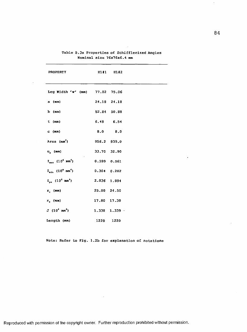
Table 5.3a Properties of Schifflerized AnglesHomlnal size 76x76x6.4 mm
PROPERTY Hl#l Hl#2
Leg Width 'w' (mm) 77.02 75.06
a (mm)
b (mm)
t (mm)
c (mm)
Area (mm*)
u_ (mm)
<10* mm4)
I.ln (10* mm")
Ip. (10‘ mm4)
r„ (mm)
r. (mm)
J (104 mm4)
Length (mm)
24.18 24.18
52.84 50.88
6.48
8.0
956.2
33.70
0.599
0.304
2.036
25.00
17.80
1.338
1220
6.54
8.0
939.0
32.90
0.561
0.282
1.894
24 .50
17.30
1.339
1220
Note: Refer to Fig. 1.2b for explanation of notations
Reproduced with permission of the copyright owner. Further reproduction prohibited without permission.

Table 5.3b Properties of Schifflerized AnglesNominal size 76x76x4.8 mm
PROPERTY H2f1 H2#2
Leg Width 'w' (mm) 75.92 75.88
a (mm) 16.00 16.00
b (mm) 59.92 59.88
t (mm) 4.78 4.74
C (mm) 8.0 8.0
Area (mm*) 702.9 696.9
u (mm) 33.30 33.20
I.„ (10* mm4) 0.395 0.391
I.tn (10* mm4) 0.230 0.228
Ipl (10* mm4) 1.458 1.444
r„ (mm) 23.70 23.70
r (mm) 18.10 18.10
J (104 mm4) 0.535 0.522
Length (mm) 1870 1870
Note: Refer to Fig. 1.2b for explanation of notations
Reproduced with permission of the copyright owner. Further reproduction prohibited without permission.

86
Table 5.3c Properties of Schifflerized AnglesNominal size 76x76x4.8 mm
PROPERTY H3I1 H3#2 H3#3
Leg Width 'w' (mm) 76.20 75.98 75.72
a (mm) 16.00 16.00 16.00
b (mm) 60.20 59.98 59.72
t (mm) 4.82 4.72 4.84
C (mm) 8.0 8.0 8.0
Area (mmJ) 711.3 695.0 709.5
uc (nun) 33.40 33.20 33.20
I.,, (10® mm®) 0.402 0.391 0.396
I,,ln (10* nun®) 0.235 0.228 0.231
Ip, (10* nun*) 1.485 1.445 1.462
r„ (mm) 23.80 23.70 23.60
rv (mm) 18.20 18.10 18.00
J (10* mm*) 0.551 0.516 0.554
Length (mm) 1530 1530 1530
Note: Refer to Fig. 1.2b for explanation of notations
Reproduced with permission of the copyright owner. Further reproduction prohibited without permission.

87
Table 5.3d Properties of Schlfflerized AnglesNominal size 76x76x4.8 mm
PROPERTY H4#l H4#2 H4#3
Leg width 'w' (mm) 76.62 76.44 76.56
a (mm) 16.00 16.00 16.00
b (mm) 60.62 60.44 60.06
t (mm) 4.68 4.66 4.72
c (mm) 8.0 8.0 8.0
Area (nun2) 695.3 690.7 700.4
ue (mm) 33.50 33.40 33.50
I.„ (10* mm4) 0.398 0.394 0.400
ImiR (10* mm*) 0.232 0.230 0.234
Ip. (10* mm*) 1.471 1.455 1.478
ru (mm) 23.90 23.90 23.90
rv (mm) 18.30 18.20 18.30
J (10* mm*) 0.508 0.500 0.520
Length (mm) 732 732 732
Note: Refer to Pig. 1.2b for explanation of notations
Reproduced with permission of the copyright owner. Further reproduction prohibited without permission.

Table 5.4a Properties of Schifflerized AnglesNominal size 102x102x6.4 mm
PROPERTY H5I1 H5#2 H5#3
Leg Width ' v'
a (mm)
b (mm)
t (mm)
c (mm)
Area (mm1)
u, (mm)
I.„ (10* mm4)
I.ln (10* mm4)
I (10* mm4)
r„ (mm)
r (mm)
J (104 mm4)
(mm) 101.42 101.26 102.06
24.17 24.17 24.17
77.25 77.09 77.89
6.56 6.46 6.52
10.0 10.0 10.0
1287.6 1266.5 1288.4
44.2 44.00 44.40
1.327 1.303 1.344
0.744 0.730 0.755
4.796 4.708 4.862
32.10 32.10 32.30
24.00 24.00 24.20
1.847 1.762 1.826
Length (mm) 2140 2140 2140
Note: Refer to Fig. 1.2b for explanation of notations
Reproduced with permission of the copyright owner. Further reproduction prohibited without permission.

Table 5.4b Properties of Schifflerized AnglesNominal size 102x102x6.4 mm
PROPERTY H6#l H6#2
Leg Width ' w ' (mm)
a (mm)
b (mm)
t (mm)
C (mm)
Area (mmJ)
u, (mm)
I (10‘ mm4)
I . (10‘ mm4)
Ip, (10* mm4)
ru (mm)
r (mm)
J (104 mm4)
Length (mm)
102.56
24.17
78.38
6.38
10.0
1268.0
44 .60
1.337
0.752
4.840
32.50
24.30
1.720
1960
102.76
24.17
78.58
6.42
10.0
1278.2
44.70
1.352
0.761
4.896
32.50
24.40
1.756
1960
Note: Refer to Fig. 1.2b for explanation of notations
Reproduced with permission of the copyright owner. Further reproduction prohibited without permission.

90
Table 5.4c Properties of Schifflerized Angles Nominal size 102x102x6.4 mm
PROPERTY H7I1 H7#2 H7#3 H 7 M
Leg Width 'v' (mm) 103.90 102.90 101.60 103.80
a (mm) 24.17 24.17 24.17 24.17
b (mm) 79.72 78.72 77.43 79.63
t (mm) 6.36 6.56 . 6.42 6.36
c (mm) 10.0 10.0 10.0 10.0
Area (nun2) 1281.0 1307.1 1263.1 1279.0
uc (mm) 45.10 44.80 44.20 45.10
I„„ (10* mm4) 1.383 1.383 1.308 1.380
I„ln (10* mm4) 0.781 0.799 0.734 0.779
Ip, (10* mm4) 5.020 5.012 4.730 5.001
r„ (mm) 32.90 32.50 32.20 32.80
rv (mm) 24.70 24.40 24.10 24.70
J (104 mm4) 1.727 1.875 1.736 1.726
Length (mm) 1520 1520 1520 1520
Note: Refer to Fig. 1.2b for explanation of notations
Reproduced with permission of the copyright owner. Further reproduction prohibited without permission.

Table 5.5Yield Stress Values of 60° Angles
size Fy(in.) (MPa)
1.5x1.5x1/8 Cl-1 3141.5x1.5x1/8 Cl-2 3141.5x1.5x1/8 Cl-3 3031.5x1.5x1/8 C2-1 3031.5x1.5x1/8 C2-2 3031.5x1.5x1/8 C2-3 3371.5x1.5x1/8 C3-1 3371.5x1.5x1/8 C3-2 3371.5x1.5x1/8 C3-3 337
2x2x3/16 C4-1 3032x2x3/16 C4-2 3012x2x3/16 C4-3 3062x2x3/16 C5-1 3032x2x3/16 C5-2 3012x2x3/16 C5-3 3062x2x3/16 C6-1 3122x2x3/16 C6-2 3122x2x3/16 C6-3 3122x2x3/16 C6-4 312
3x3xl/4 Hl-1 3603x3xl/4 Hl-2 3603x3x3/16 H2-1 3783x3x3/16 H2-2 3783x3x3/16 H3-1 3793x3x3/16 H3-2 3793x3x3/16 H3-3 3793x3x3/16 H4-1 3783x3x3/16 H4-2 3783x3x3/16 H4-3 378
4x4xl/4 H5-1 3604x4x1/4 H5-2 3614x4xl/4 H5-3 3794x4xl/4 H6-1 3514x4x1/4 H6-2 3514x4xl/4 H7-1 3614x4xl/4 H7-2 3604x4xl/4 H7-3 3514x4xl/4 H7-4 361
Reproduced with permission of the copyright owner. Further reproduction prohibited without permission.

Table 5.6Finite Element Analysis Failure Loads of 60° Angles
(in.) (kN)
1.5x1.5x1/8" Cl#l 59.21.5x1.5x1/8" C2#3 62.31.5x1.5x1/8" C3I3 61.3
2x2x3/16 C4 #2 116.62x2x3/16 C5#l 126.02x2x3/16 C6f3 120.0
3x3x1/4 HItl 251.73x3x3/16 H2#2 165.93x3x3/16 H3#3 179.03x3x3/16 H4 #3 196.0
4x4x1/4 H5I3 239.14x4xl/4 H6I1 236.04x4xl/4 H7#3 254.0
Reproduced with permission of the copyright owner. Further reproduction prohibited without permission.

Table 5.7a Failure Loads of Cold-formed 60° Angles According to CAN/CSA-S37
size Calculated Failure Load Pexp(in.) (kN) (kN)
Case-I Case-II Case-Ill Case-IVk=0.7 k=0.7 k=0.7 k=0.7
1.5x1.5x1/8 Cl#l 56.79 56.79 54.15 47.26 49.61.5x1.5x1/8 Cl #2 55.96 55.96 53.28 46.65 48.01.5x1.5x1/8 Cl#3 52.65 52.65 50.45 42.87 49.6
1.5x1.5x1/8 C2#l 59.17 59.17 55.52 43.58 56.41.5x1.5x1/8 C2#2 59.56 59.56 54.79 42.14 56.41.5x1.5x1/8 C2#3 65.00 65.00 59.18 45.88 68.7
1.5x1.5x1/8 C3#l 72.07 72.07 64.40 45.71 78.81.5x1.5x1/8 C3#2 69.79 69.79 61.76 43.63 73.21.5x1.5x1/8 C3#3 74.35 74.35 67.06 47.81 70.4
2x2x3/16 C4#l 95.57 95.57 95.57 97.88 118.02x2x3/16 C4#2 100.48 100.48 100.48 99.76 116.92x2x3/16 C4*3 97.28 97.28 97.28 97.61 113.5
2x2x3/16 C5#l 129.42 129.42 129.42 111.74 134.82x2x3/16 C5#2 125.43 125.43 125.43 107.52 135.92x2x3/16 C5#3 130.31 130.31 130.31 110.82 138.2
2x2x3/16 C6#l 143.11 143.11 .. 143.11 109.66 157.22x2x3/16 C6#2 140.68 140.68 140.68 107.22 159.42x2x3/16 C6#3 149.81 149.81 149.81 116.24 163.92x2x3/16 C6#4 145.32 145.32 145.32 110.93 166.2
Case-I: W=BCase-II; W=B+(R-0.5 T)lt/6Case-lii: W=B+(R-0.5 T)it/3Case-IV: W=B+(R-0.5 T)it/3 (Torsional-Flexural Buckling)
Reproduced with permission of the copyright owner. Further reproduction prohibited without permission.

Table 5.7b Failure Loads of Schifflerized Angles
According to CAN/CSA-S37
size Calculated Failure Loads P.xp(in.) (kN) (kN)
Case-I Case-II k=0 .7 k=0.7
3x3xl/43x3xl/4
Hl#lHl#2
279.09271.00
227.8228.6
260.8269.2
3x3x3/163x3x3/16
H2#lH2#2
144.60142.58
105.1103.1
141.5 146.0
3x3x3/163x3x3/163x3x3/16
H3#lH3#2H3#3
167.53160.78167.93
113.6107.8115.0
148.2148.8140.4
3x3x3/163x3x3/163x3x3/16
H4#lH4#2H4#3
192.10190.56195.58
114.2113.0116.9
201.3204.2207.2
4x4xl/44x4xl/44x4xl/4
H5#lH5#2H5#3
292.04284.56295.91
209.1201.7207.5
280.4263.6274.8
4x4xl/44x 4x 1/4
H6#lH6#2
289.91293.76
197.6200.5
263.6258.0
4x4x1/4 4x4xl/4 4x 4x1/4 4x 4x 1/4
H7#lH7#2H7#3H7#4
318.67 337.51 319.30318.67
202.7220.7 209.2202.7
295.0318.5300.0298.5
Case-I = Flexural Buckling Case-II = Torsional-Flexural Buckling
Reproduced with permission of the copyright owner. Further reproduction prohibited without permission.
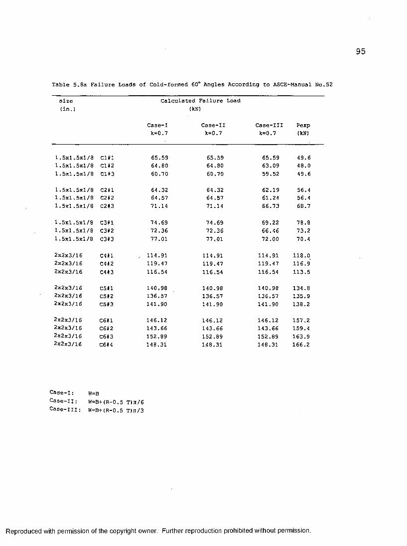
Table 5.8a Failure Loads of Cold-formed 60° Angles According to ASCE-Manual No.52
size (in.)
Calculated Failure Load (kN)
Case-I Case-II k=0.7 k=0.7
Case-Illk=0.7
Pexp(kN)
1.5x1.5x1/8 Cl#l 65.59 65.59 65.59 49.61.5x1.5x1/8 Cl #2 64.80 64.80 63.09 48.01.5x1.5x1/8 Cl#3 60.70 60.70 59.52 49.6
1.5x1.5x1/8 C2#l 64.32 64.32 62.19 56.41.5x1.5x1/8 C2#2 64.57 64 .57 61.24 56.41.5x1.5x1/8 C2#3 71.14 71.14 66.73 68.7
1.5x1.5x1/8 C3#l 74.69 74.69 69.22 78.81.5x1.5x1/8 C3#2 72.36 72.36 66.46 73.21.5x1.5x1/8 C3#3 77.01 77.01 72.00 70.4
2x2x3/16 C4#l .. 114.91 114.91 114.91 118.02x2x3/16 C4#2 119.47 119.47 119.47 116.92x2x3/16 C4#3 116.54 116.54 116.54 113.5
2x2x3/16 C5#l 140.98 140.98 140.98 134.82x2x3/16 C5#2 136.57 136.57 136.57 135.92x2x3/16 C5#3 141.90 141.90 141.90 138.2
2x2x3/16 C6#l 146.12 146.12 146.12 157.22x2x3/16 C6#2 143.66 143.66 143.66 159.42x2x3/16 C6#3 152.89 152.89 152.89 163.92x2x3/16 C6#4 148.31 1.4 8.31 148.31 166.2
Case-I: W=BCase-II; W=B+(R-0.5 T)n/6Case-Ill: W=B+(R-0.5 T)n/3
Reproduced with permission of the copyright owner. Further reproduction prohibited without permission.
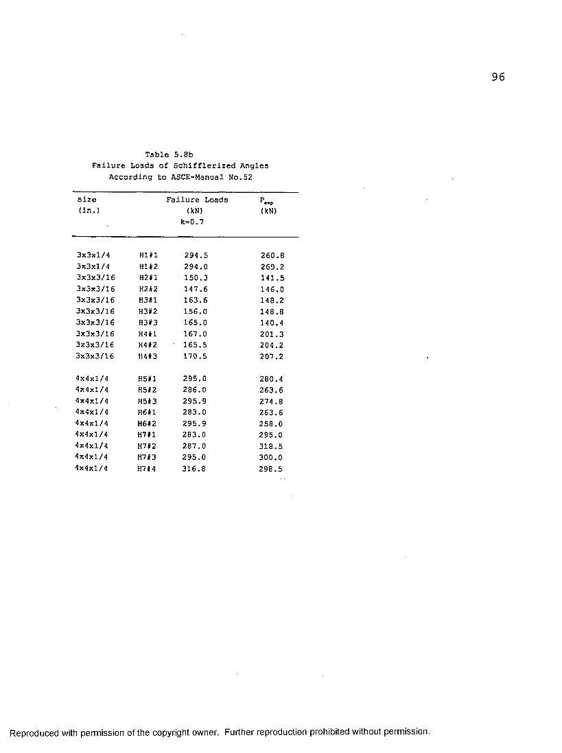
Table 5.8bFailure Loads of Schifflerized Angles
According to ASCE-Manual No.52
size Failure Loads P.xp(in.) (kN) (kN)
k=0 .7
3x3xl/4 Hl#l 294.5 260.83x3xl/4 Hl#2 294.0 269.23x3x3/16 H2#l 150.3 141.53x3x3/16 H2#2 147.6 146.03x3x3/16 H3#l 163.6 148.23x3x3/16 H3#2 156.0 148.83x3x3/16 H3#3 165.0 140.43x3x3/16 H4#l 167.0 201.33x3x3/16 H4#2 ' 165.5 204.23x3x3/16 H4#3 170.5 207.2
4x4xl/4 H5#l 295.0 280.44x4xl/4 H5#2 286.0 263.64x4x1/4 H5#3 295.9 274.84x4x1/4 H6#l 283.0 263.64x4x1/4 H6#2 295.9 258.04x4x1/4 H7#l 283.0 295.04x4xl/4 H7#2 287.0 318.54x4x1/4 H7#3 295.0 300.04x4xl/4 H7#4 316.8 298.5
Reproduced with permission of the copyright owner. Further reproduction prohibited without permission.

Table 5.9a Failure Loads of Cold-formed 60° Angles According to AISC-LRFD
size Failure Load(in.) (kN)
Case-I Case-II Case-Ill Pexpk=0.7 k=0.7 k=0.7 (kN)
1.5x1.5x1/8 Cl#l 1.5x1.5x1/8 Cl#2 1.5x1.5x1/8 Cl#3
1.5x1.5x1/8 C2#l 1.5x1.5x1/8 C2#21.5x1.5x1/8 C2#3
1.5x1.5x1/8 C3#l 1.5x1.5x1/8 C3#21.5x1.5x1/8 C3#3
2x2x3/16 C4#l 2x2x3/16 C4 #2 2x2x3/16 C4#32x2x3/16 C5#l 2x2x3/16 C5#22x2x3/16 C5#3
2x2x3/16 C6#l 2x2x3/16 C6#22x2x3/16 C6#32x2x3/16 C6#4
50.6 50.649.9 49.946.9 46.9
51.8 51.852.2 52.257.1 57.1
62.2 62.260.2 60.264.1 64.1
86.6 86.690.6 90.688.0 88.0
113.5 113.5109.9 109.9114.2 114.2
122.6 122.6120.5 120.5128.3 128.3124.4 124.4
49.4 49.648.7 48.045.9 49.6
50.2 56.450.0 56.454.4 68.7
58.8 78.856.7 73.260.9 70.4
86.6 118.090.6 116.988.0 113.5
113.5 134.8109.9 135.9114.2 138.2
122.6 157.2120.5 159.4128.3 163.9124.4 166.2
Case-I: W=BCase-II: W=B+(R-0.5 T)ji/6Case-Ill: W=B+(R-0.5 T)n/3
Reproduced with permission of the copyright owner. Further reproduction prohibited without permission.

Table 5.9bFailure Loads of Schifflerized Angles
According to AISC-LRFD
size Failure Loads P,sp(in.) (kN) (kN)
k=0.7
3x3xl/4 HI#1 245.5 260.83x3xl/4 HI #2 238.7 269.2
3x3x3/16 H2#l 139.8 141.53x3x3/16 H2#2 138.3 146.0
3x3x3/16 H3#l 161.2 148.23x3x3/16 H3#2 156.0 148.83x3x3/16 H3#3 160.7 140.4
3x3x3/16 H4#l 187.5 201.33x3x3/16 H4#2 186.2 204.23x3x3/16 H4 #3 189.8 207.2
4x4xl/4 H5#l 276.3 280.44x4xl/4 H5»2 270.9 263.64x4x1/4 H5#3 284.5 274.8
4x4xl/4 H6#l 277.4 263.64x4xl/4 H6#2 280.5 258.0
4x4xl/4 H7#l 309.8 295.04x4x1/4 H7#2 320.5 318.54x4xl/4 H7»3 302.5 300.04x4xl/4 H7#4 309.6 298.5
Reproduced with permission of the copyright owner. Further reproduction prohibited without permission.
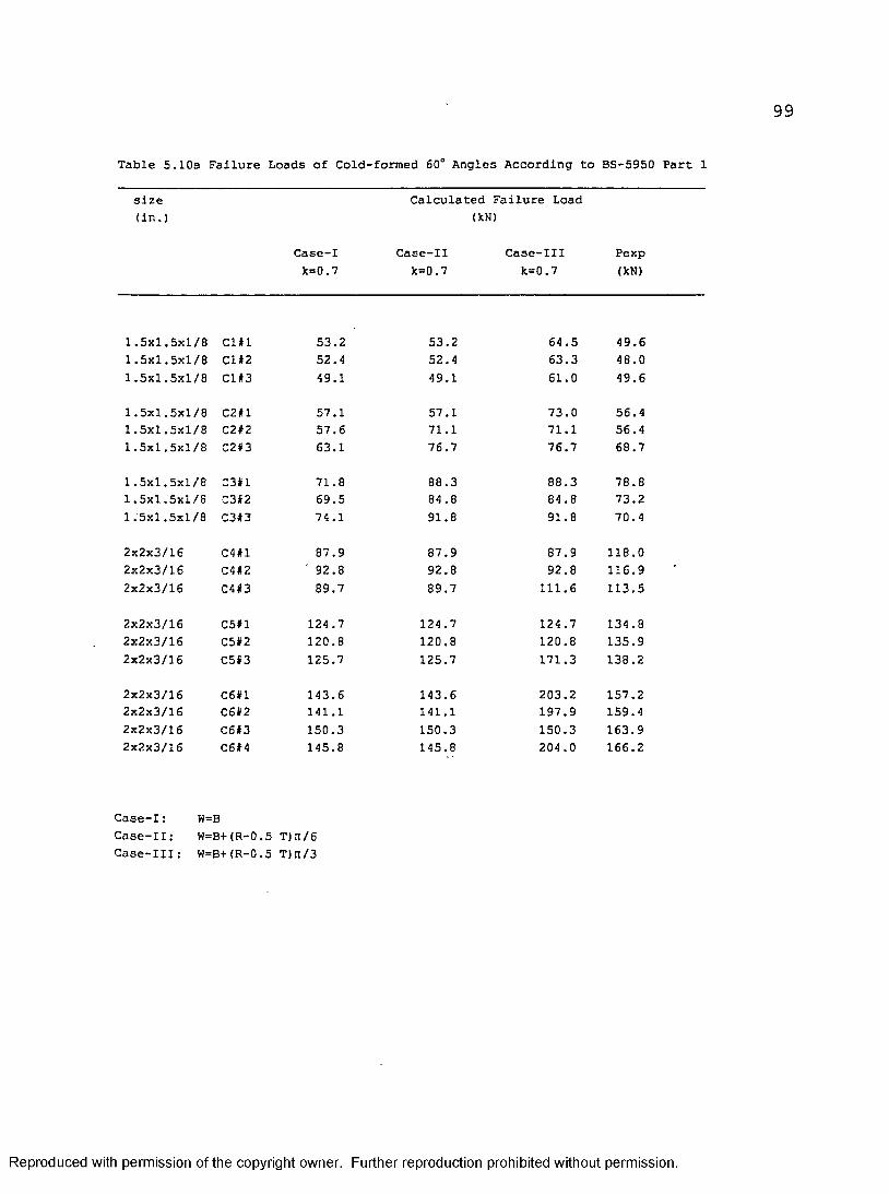
Table 5.10a Failure Loads of Cold-formed 60° Angles According to BS-5950 Part 1
size (in.)
Case-I Case-II Case-Ill Pexpk=0.7 k=0.7 k=0.7 (kN)
Calculated Failure Load (kN)
1.5x1.5x1/8 1.5x1.5x1/8 1.5x1.5x1/8
Cl#lCl#2Cl#3
53.252.449.1
53.252.449.1
64.563.361.0
49.6 48.049.6
1.5x1.5x1/8 1.5x1.5x1/8 1.5x1.5x1/8
C2#lC2#2C2#3
57.1 57.663.1
57.171.1 76.7
73.071.1 76.7
56.456.4 68.7
1.5x1.5x1/8 1.5x1.5x1/8 1.5x1.5x1/8
C3#lC3#2C3#3
71.8 69.5 74.1
88.3 84 .8 91.8
88.384.891.8
78.873.270.4
2x2x3/162x2x3/162x2x3/16
C4#lC4#2C4#3
87.992.889.7
87.992.889.7
87.992.8
111.6
118.0116.9113.5
2x2x3/162x2x3/162x2x3/16
C5#lC5#2C5#3
124.7120.8 125.7
124.7120.8 125.7
124.7120.8 171.3
134.8135.9 138.2
2x2x3/162x2x3/162x2x3/162x2x3/16
C6#lC6#2C6#3C6#4
143.6141.1150.3145.8
143.6141.1150.3145.8
203.2 197.9150.3 204 .0
157.2 159.4 163.9166.2
Case-I: W=BCase-II: W=B+(R-0.5 T)n/6Case-Ill: W=B+(R-0.5 T)n/3
Reproduced with permission of the copyright owner. Further reproduction prohibited without permission.

Table 5.10bFailure Loads of Schifflerized Angles
According to BS-5950 Part 1
size Failure Loads P„p(in.) <kN) (kN)
k=0.7
3x3xl/4 Hl#l 271.4 260.83x3xl/4 Hl#2 263.0 269.23x3x3/16 H2#l 126.6 141.53x3x3/16 H2#2 124.7 146.03x3x3/16 H3#l 148.7 148.23x3x3/16 H3#2 142.5 148.83x3x3/16 H3#3 149.2 140.43x3x3/16 H4#l 177.6 201.33x3x3/16 H4 #2 176.2 204.33x3x3/16 H4#3 180.7 207.2
4x4xl/4 H5#l 269.5 280.44x4xl/4 H5#2 262.1 263.64x4xl/4 H5#3 272.2 274.84x4xl/4 H6#l 268.4 263.64x4xl/4 H6#2 272.2 258.04x4xl/4 H7#l 300.5 295.04x4xl/4 H7#2 319.6 318.04x4xl/4 H7#3 303.0 300.04x4xl/4 H7#4 300.5 298.5
Reproduced with permission of the copyright owner. Further reproduction prohibited without permission.

101
Table 5.11Dimensions and Properties of 90° Angles with one bolt connection
size Specimen A B T Area E D(in.) Mark t1™*! <lnm (Sq.mm) (mm) (mm)
2x1.5x3/162x1.5x3/162x1.5x3/16
22#12 2 * 2
2213
50.5450.7250.96
38.3638.5838.82
4.844.924.99
386386386
28.6029.3228.56
28.7828.5228.76
2x2x3/162x2x3/162x2x3/16
23#1231223#3
51.2250.8450.90
50.8651.0250.64
5.305.385.42
522522522
28.7629.8229.44
29.3229.0228.64
2x2x3/162x2x3/162x2x3/16
24#124#224*3
50.32‘51.1250.96
51.0651.1050.34
4 .48 4.32 4.56
442442442
28.5028.9628.72
28.7229.0428.76
2x2x1/4 2x2xl/4 2x2xl/4
25# 1 25#2 25#3
50.2450.3250.02
51.0451.5050.50
6.166.286.12
583583583
29.6429.4428.58
28.7428.6028.68
2.5x2x3/162.5x2x3/162.5x2x3/16
26#126#22613
63.2662.9863.32
50.9051.0051.18
4.744.664.82
522522522
28.5228.5429.30
31.8031.9632.02
2.5x2xl/4 2 .5x2xl/4 2 .5x2xl/4
271127#22713
61.8861.7662.18
52.6452.7452.52
6.086.086.10
664664664
28.5028.4828.54
31.6631.6031.74
2.5x2.5x3/162.5x2.5x3/162.5x2.5x3/16
2811281228#3
63.5263.4063.50
63.1863.1263.10
4 .54 4.60 4.52
571571571
29.4828.5029.32
31.9832.1432.02
2.5x2.5x1/4 2.5x2.5x1/4 2.5x2.5x1/4
29*129#229#3
63.4063.3663.60
63.6063.60 63.40
6.266.286.30
737737737
29.3029.4830.24
32.1231.12 31.80
2.5x2.5x5/16 2.5x2.5x5/16 2.5x2.5x5/16
30#130#23013
62.6864.7864.72
64.7062.4262.50
8.027.927.96
930930930
29.8229.6029.32
30.7231.0831.02
3x3x3/163x3x3/163x3x3/16
31A#131A#231A#3
76.4876.5076.22
77.1477.0677.32
4.624.444.56
688688688
29.8029.3229.46
39.8438.1038.32
3x3x3/163x3x3/163x3x3/16
31C#131C#231C#3
75.8275.7476.32
76.8076.9876.90
4.60 4 .54 4.44
692692692
29.5029.1029.84
44 .64 44.24 44.96
contd.
Reproduced with permission of the copyright owner. Further reproduction prohibited without permission.

102Table 5.11
Dimensions and Properties of 90° Angles with one bolt connection
site Specimen A B T Area E D(in.) Mark (mm) (mm) (mm) (mm Sq.) (mm) (i
3x3xl/4 32A#1 76.18 76.32 6.24 909 29.72 38.243x3xl/4 32A#2 76.10 76.18 6.18 909 29.26 38.303x3xl/4 32AI3 76.48 76.02 6.06 909 29.12 38.52
3x3xl/4 32C#1 76.10 76.04 6.20 908 28.86 44.723x3xl/4 32CI2 76.60 75.28 6.22 908 29.44 44 .723x3xl/4 32C#3 76.32 76.48 6.26 908 29.22 44 .36
3.5x3.5x1/4 3301 89.80 88.78 6.12 1100 29.46 45.363.5x3.5x1/4 3302 89.12 89.80 6.24 1100 29.78 45.123.5x3.5x1/4 3303 90.20 89.00 6.28 1100 28.98 45.42
3 .5x3.5x5/16 3401 88.60 90.08 7.76 1328 29.50 44.163.5x3.5x5/16 3402 88.54 89.92 7.82 1328 29.76 44 .003.5x3.5x5/16 3403 89.20 89.78 7.70 1328 29.28 44 .66
A = CONNECTED LEG B = UNCONNECTED LEG T = THICKNESS E = END DISTANCE D = EDGE DISTANCE Gauge = A - D
Reproduced with permission of the copyright owner. Further reproduction prohibited without permission.

Table 5.12Yield and Tensile Strength of 90° Angles with
one bolt connection
size Fy Fu(in.) (MPa) (MPa)
2x1.5x3/16 #1 346 5092x1.5x3/16 #2 346 5092x1.5x3/16 #3 346 509
2x2x3/16 #1 335 4812x2x3/16 #2 335 4812x2x3/16 #3 335 481
2x2x3/16 #1 371 5272x2x3/16 #2 371 5272x2x3/16 #3 371 527
2x2xl/4 #1 362 5382x2x1/4 #2 362 5382x2x1/4 #3 362 538
2.5x2x3/16 #1 387 5602.5x2x3/16 #2 387 5602.5x2x3/16 #3 387 560
2.5x2xl/4 #1 394 5442.5x2xl/4 #2 394 5442.5x2xl/4 #3 394 544
2.5x2.5x3/16 #1 353 5122.5x2.5x3/16 #2 353 5122.5x2.5x3/16 13 353 512
2.5x2.5x1/4 #1 440 5492.5x2.5x1/4 #2 440 5492.5x2.5x1/4 #3 440 549
2.5x2.5x5/16 #1 419 5852.5x2.5x5/16 #2 419 5852.5x2.5x5/16 #3 419 585
3x3x3/16 #1 344 5153x3x3/16 #2 344 5153x3x3/16 #3 344 515
3x3x3/16 #1 360 5253x3x3/16 #2 360 5253x3x3/16 #3 360 525
Note: Refer Table 5.11 for Specimen Markcontd.
Reproduced with permission of the copyright owner. Further reproduction prohibited without permission.
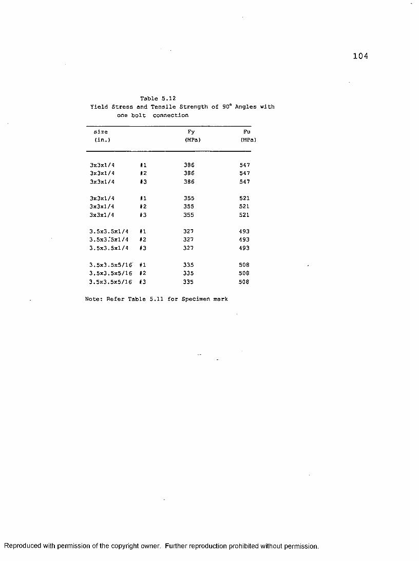
Table 5.12Yield Stress and Tensile Strength of 90° Angles with
one bolt connection
size Fy Fu(in.) (MPa) (MPa)
3x3xl/4 #1 386 5473x3xl/4 #2 386 5473x3xl/4 #3 386 547
3x3xl/4 #1 355 5213x3xl/4 #2 355 5213x3xl/4 #3 355 521
3.5x3.5x1/4 #1 327 4933.5x3.'5x1/4 #2 327 4933.5x3.5x1/4 #3 327 493
3.5x3.5x5/16 #1 335 5083.5x3.5x5/16 #2 335 5083.5x3.5x5/16 #3 335 508
Note: Refer Table 5.11 for Specimen mark
Reproduced with permission of the copyright owner. Further reproduction prohibited without permission.

105
Table 5.13Dimensions and Properties of 90° Angles with Two bolt Connection
s*ze Specimen A B T Area E D P
(in.) Mark (mm) (mm) (mm) (Sq.mm) (mm) (mm) (mm)
3x3x3/16 31BI1 77.08 76.30 4.56 689 24.92 50.74 45.303x3x3/16 31BI2 76.10 76.98 4.62 689 24.80 50.88 43.963x3x3/16 31BI3 76.36 76.22 4.48 689 24.74 50.82 44.54
3x3xl/4 32BI1 76.12 76.10 6.24 912 24.12 51.60 44.543x3xl/4 32BI2 76.04 76.34 6.18 912 24.44 51.58 44.243x3xl/4 32BI3 76.26 76.26 6.34 912 24 .50 51.22 44.80
3.5x3.5x1/4 33A#1 88.34 89.62 6.18 1084 24.28 51.34 44.003.5x3.5x1/4 33AI2 89.50 88.12 6.26 1084 24.08 51.80 45.303.5x3.5x1/4 33A#3 87.76 89.76 6.24 1084 24.50 51.32 44.00
3.5x3.5x1/4 33B#1 88.28 89.44 6.10 1088 23.96 51.82 56.303.5x3.5x1/4 33BI2 88.62 89.52 6.20 1088 25.08 51.70 56.503.5x3.5x1/4 33B#3 89.4 6 88.00 6.18 1088 24 .84 - 51.14 57.50
3.5x3.5x5/16 34AI1 90.30 89.40 7.80 1336 25.08 52.12 46.403.5x3.5x5/16 34AI2 90.02 88.82 7.76 1336 25.30 51.62 44.323.5x3.5x5/16 34AI3 90.36 88.72 7.72 1336 25.26 51.70 45.60
3.5x3.5x5/16 34B.il 88.68 89.46 7.98 1333 25.50 50.72 57.663.5x3.5x5/16 34B#2 89.54 89.00 8.12 1333 24.86 51.30 57.303.5x3.5x5/16 34B»3 88.78 89.56 8.18 1333 24.56 51.10 57.08
A = CONNECTED LEG B = UNCONNECTED LEG T = THICKNESS E = END DISTANCE D = EDGE DISTANCE P = PITCH Gauge = A - D
Reproduced with permission of the copyright owner. Further reproduction prohibited without permission.

Table 5.14Yield stress and Tensile Strength of 90° Angles
with Two bolt Connection
size Fy Fu(in.) (MPa) (MPa)
3x3x3/16 #1 360 5223x3x3/16 #2 360 5223x3x3/16 #3 360 522
3x3xl/4 #1 379 5393x3xl/4 #2 379 5393x3xl/4 #3 379 539
3.5x3.5x1/4 #1 328 5443.5x3.5x1/4 #2 328 5443.5x3.5x1/4 #3 328 544
3.5x3.5x1/4 #1 334 5003.5x3.5x1/4 #2 334 5003.5x3.5x1/4 #3 334 500
3.5x3.5x5/16 #1 333 5143.5x3.5x5/16 t2 333 5143.5x3.5x5/16 #3 333 514
3.5x3.5x5/16 #1 448 5663.5x3.5x5/16 #2 448 5663.5x3.5x5/16 #3 448 566
Note: Refer Table 5.13 for Specimen Mark
Reproduced with permission of the copyright owner. Further reproduction prohibited without permission.

107
Table 5.15 : Failure Loads of 90° Angles with one bolt connection
size TR1 TR2 TR3 BR MIN P„p(in.) (nun) (kN) (kN) (kN) (kN) (kN)
2x1.5x3/16 #1 133.7 62.5 93.8 70.4 62.5 65.22x1.5x3/16 #2 133.7 63.9 93.2 73.4 63.9 66.22x1.5x3/16 #3 133.7 64.3 92.8 72.5 64.3 65.6
2x2x3/16 #1 174.6 66.1 127.5 73.4 66.1 70.22x2x3/16 #2 174.6 67.8 127.0 77.2 . 67.8 68.62x2x3/16 #3 174.6 67.0 126.8 76.8 67.0 68.9
2x2x3/16 #1 164.0 59.7 118.1 67.3 59.7 67.82x2x3/16 #2 164.0 61.1 117.6 69.0 61.1 66.12x2x3/16 #3 164.0 58.7 119.2 66.0 58.7 65.4
2x2xl/4 #1 211.0 85.6 157.2 98.1 85.6 95.72x2xl/4 #2 211.0 86.6 156.4 99.4 86.6 88.42x2xl/4 #3 211.0 83.1 157.5 94.0 83.1 84.0
2.5x2x3/16 #1 201.7 74.0 152.1 75.7 74.0 75.22.5x2x3/16 #2 201.7 73.1 152.7 74.4 73.1 73.22.5x2x3/16 #3 201.7 76.8 151.5 79.0 76.8 78.2
2.5x2xl/4 *1 261.6 91.9 188.2 94.3 91.9 91.72,5x2xl/4 #2 261.6 91.7 188.2 94.3 91.7 91.72.5x2xl/4 #3 261.6 92.5 188.0 94.8 92.5 93.1
2.5x2.5x3/16 #1 201.6 66.3 156.3 68.5 66.3 71.02.5x2.5x3/16 #2 201.6 66.3 155.9 67.1 66.3 70.12.5x2.5x3/16 #3 201.6 65.9 156.4 67.8 65.9 67.3
2.5x2.5x1/4 #1 324.0 98.2 213.9 100.8 98.2 89.62.5x2.5x1/4 #2 324.0 95.9 213.8 101.7 95.9 92.82.5x2.5x1/4 #3 324.0 99.6 213.6 104.7 99.6 95.3
2.5x2.5x5/16 #1 390.0 129.7 286.7 139.9 129.7 133.02.5x2.5x5/16 #2 390.0 129.0 287.4 137.2 129.0 129.32.5x2.5x5/16 #3 390.0 128.7 287.1 136.5 128.7 131.7
3x3x3/16 #1 237.0 84.1 195.3 70.9 70.9 73.33x3x3/16 #2 237.0 76.9 196.5 67.0 67.0 71.03x3x3/16 #3 237.0 79.6 195.7 69.2 69.2 71.2
3x3x3/16 #1 249.0 94.9 200.6 71.2 71.2 72.03x3x3/16 #2 249.0 92.3 201.0 69.3 69.3 73.23x3x3/16 #3 249.0 92.6 201.7 69.5 69.5 72.3
Note: Refer Table 5.11 for Specimen Markcmtd.
Reproduced with permission of the copyright owner. Further reproduction prohibited without permission.

108
Table 5.15 : Failure Loads of 90° Angles with one bolt connection
size TR1 TR2 TR3 BR MIN P« p(in.) (mm) (kN) (kN) (kN) (kN) (kN)
3x3xl/4 #1 350.4 116.0 273.1 101.4 101.4 99.73x3xl/4 #2 350.4 114.2 273.5 98.9 98.9 100.53x3xl/4 #3 350.4 112.4 274.3 96.5 96.5 101.2
3x3xl/4 #1 322.4 126.2 260.1 93.3 93.3 100.53x3xl/4 #2 322.4 127.6 259.9 95.4 95.4 101.53x3xl/4 #3 322.4 127.0 259.7 95.3 95.3 99.5
3.5x3.5x1/4 #1 360.1 120.4 306.9 88.9 88.9 99.13.5x3.5x1/4 #2 360.1 122.6 306.2 91.6 91.6 98.43.5x3.5x1/4 #3 360.1 123.0 305.9 89.7 89.7 96.9
3.5x3.5x5/16 #1 445.4 153.2 379.3 116.2 116.2 123.13.5x3.5x5/16 #2 445.4 154.4 378.9 118.1 118.1 122.63.5x3.5x5/16 #3 445.4 153.2 379.7 114.4 114.4 120.7
Note:Refer Table 5.11 for Specimen mark
TR1 = A, Fy TR2 = 0.85 A„. F„TR3 = 0.85 A„. Fu BR = T Fu EMIN = Minimum load from the above formulae
Reproduced with permission of the copyright owner. Further reproduction prohibited without permission.

109
Table 5.16 : Failure Loads of 90° Angles with two bolt connection
size TR1 TR2 TR3 BR MIN P.xp(in.) (mm) (kN) (kN) (kN) (kN) (kN)
3x3x3/16 #1 247.9 131.0 198.8 118.7 118.7 125.63x3x3/16 #2 247.9 131.2 198.4 119.7 119.7 135.13x3x3/16 #3 247.9 127.7 199.4 115.8 115.8 128.5
3x3xl/4 #1 345.8 184.6 270.0 162.1 162.1 187.83x3xl/4 #2 345.8 182.8 270.4 162.7 162.7 197.53x3xl/4 #3 345.8 187.6 269.3 167.3 167.3 191.8
3.5x3.5x1/4 #1 355.0 183.4 332.8 163.3 163.3 181.13.5x3.5x1/4 #2 355.0 189.0 332.2 164.1 164.1 176.33.5x3.5x1/4 #3 355.0 185.5 332.4 166.4 166.4 174.0
3.5x3.5x1/4 #1 363.2 186.0 307.3 146.0 146.0 180.43.5x3.5x1/4 #2 363.2 190.8 306.7 155.4 155.4 185.53.5x3.5x1/4 #3 363.2 190.0 306.8 153.4 _ 153.4 190.5
3.5x3.5x5/16 #1 444.7 227.6 386.0 200.9 200.9 229.73.5x3.5x5/16 #2 444.7 220.9 386.3 201.6 201.6 222.73.5x3.5x5/16 #3 444.7 222.6 386.5 200.3 200.3 228.0
3.5x3.5x5/16 #1 596.9 278.1 423.0 230.3 230.3 247.83.5x3.5x5/16 #2 596.9 282.9 422.0 228.4 228.4 245.13.5x3.5x5/16 #3 596.9 282.9 421.6 227.4 227.4 249.9
Note: Refer to Table 5.13 for Specimen Mark
TR1 = A, Fy TR2 = 0.85 An. F„TR3 = 0.85 Ane Fu BR = 2.0 T F„ EMIN = Minimum from the above formulae
Reproduced with permission of the copyright owner. Further reproduction prohibited without permission.

110
Table 5.17 Tensile Strength of Bolted Eccentrically Loaded Angles
Size End Dist. Edge Dist. Bolt Preload Failure Load Increase Dueto Preload
(mm) (mm) (kN) (kN)
65x65x4 mm 30 3065x65x4 mm 30 3055x35x3 mm 30 2855x35x3 mm 30 28
2.5x2.5x1/4 in. 30 302.5x2.5x1/4 in. 30 302.5x2.5x1/4 in. 30 30
NO 122YES 136 14NO 86YES 99 13
NO 215YES 226 11YES 228 13
Reproduced with permission of the copyright owner. Further reproduction prohibited without permission.

Fig. 1-1 Typical self-supporting antenna tower
Reproduced with permission of the copyright owner. Further reproduction prohibited without permission.

112
Reproduced with permission of the copyright owner. Further reproduction prohibited without permission.

Reproduced with permission of the copyright owner. Further reproduction prohibited without permission.
u
U *U = Major axis V-V = Minor axis
o = Unbent portion of the leg b = Bent por ti o n of the leg t = Thickness c = Fillet radius C - Centroid of the Angle s = Shear Centre
Fig. 1.2b Typical cross-section of a schifflerizedangle
113

114
Fig.1.3 Rollers used for schifflerization
Reproduced with permission of the copyright owner. Further reproduction prohibited without permission.

C L
115
Reproduced with permission of the copyright owner. Further reproduction prohibited without permission.
Fig- 1-4
Angle
under
eccentric
tens
ion

116
QJ
QJinocn
QJZ3-
aQJ_dinl_JoGO
a a
o ol_)QJinQJ
Reproduced with permission of the copyright owner. Further reproduction prohibited without permission.
Fig.
1.5
Diff
erent
types
of fa
ilur
eof
tension
memb
ers

QJ
QJ
QJC_
U_ _Q
QJ£_
QJ ' 'cn a
117
Reproduced with permission of the copyright owner. Further reproduction prohibited without permission.
Fig.
1.6
Endr
edge
and
combin
ed
mode
of fa
ilur
e

a8a.qus FFLERISED 60 DEGREE ANGLE. S I ZE 4 » 4 * 1 / 4 . LENG!VERSION 4-7-22 OATE' 3MAR 93 TIME-- 0•• 28•• 13
Fig. 3.1 Finite element model of test set-up foir 60° angle
Reproduced with permission of the copyright owner. Further reproduction prohibited without permission.

LU119
o
LulX'XLl.o
X
£
X
Bf)
o
Reproduced with permission of ,he copyright owner. Further reproduofion prohibited without permission.
Fig. 3.2
Finite
element
model
showing
the
elements of
60° an
gle

0.25
Fy
1 2 0I
LD rxj
CD
CD
CD
0)A
U03 03> r-l0 DiCc 90•rl •aJJ 039 N
43 •H•H MU 03V Hco (4-1•rl (4-4V •rl4=n Oto to03 0u «wjj 0to a0.9 •H9 JJV 0•H 03CO (00 1Cm CO(0m 0• Um O•&•Hfcj
Reproduced with permission of the copyright owner. Further reproduction prohibited without permission.

1 2 1
! I
Reproduced with permission of the copyright owner. Further reproduction prohibited without permission.
Fig.
3.4
Residual
stress
dist
ribu
tion
over
the
thickness
of sc
hiff
leri
zed
angl
e
020721

Fig. 4.1 Experimental set-
GlInore PlateCircular Plate (0=330 nn, T=40 nn)Base Plate (280x280x24 nn)Supporting Angle (60x60xB nn)Supporting BlockHydraulic JackLoad Cel I60 AngIe
for testing 60° angle

123
Fig. 4.2 Circular plates bolted to the Gilmore plate
Reproduced with permission of the copyright owner. Further reproduction prohibited without permission.

124
Fig. 4.3Top base plate with load cell screw and
bottom base plate with jack cover
Reproduced with permission of the copyright owner. Further reproduction prohibited without permission.

125
Fig. 4.4 Solid blocks, base plates and circular plates
used, in the set-up
Reproduced with permission of the copyright owner. Further reproduction prohibited without permission.

1 26
Fig. 4.5 Close-up of base plate with solid and
supporting angles
Reproduced with permission of the copyright owner. Further reproduction prohibited without permission.

127
60000*0000'OOOOQ.oSoo
Fig. 4.6Circular plate, hydraulic jack and end set-up
Reproduced with permission of the copyright owner. Further reproduction prohibited without permission.

Fig. 4.7Close-up of end set-up with 60° angle
Reproduced with permission of the copyright owner. Further reproduction prohibited without permission.
Fig. 4.8 60° Angle under test
Reproduced with permission of the copyright owner. Further reproduction prohibited without permission.

130
Fig. 4.9 Cold-formed 1.5x1.5x1/8 in. Cl#l angle after
failure by torsional-flexural buckling
Reproduced with permission of the copyright owner. Further reproduction prohibited without permission.

Fig. 4.10 Schifflerized angle (4x4xl/4 in.) after failure by torsional-flexural buckling
Reproduced with permission of the copyright owner. Further reproduction prohibited without permission.

Fig- 4.11 All the 60° angles after failure
Reproduced with permission of the copyright owner. Further reproduction prohibited without permission.

Reproduced with permission of the copyright owner. Further reproduction prohibited without permission.

Reproduced with permission of the copyright owner. Further reproduction prohibited without permission.
108.00 210.00 130.00
D = 62.000 = 36.0025.00 i
h A t
25.00I
Dimension in mm.
Fig.4.13 Front view of the End-fixture for testing angles under tension
150.00
I
134

135
OJ
C•HC0•HCOC0e•HQ
tJln•H4J03d)VM0>4-10)U34-)X O•H ■•H14-4 CQ1 aa)CW M<1) a)4-> a3*4-40 03a)3 H0) tn•H c> nJQa0EhtH••
•rl
Reproduced with permission of the copyright owner. Further reproduction prohibited without permission.

1 3 6
Fig4.15a Photo showing the End-fixtnro -p
angles under Eccentric "tens tMt±a®
Reproduced with permission of the copyright owner. Further reproduction prohibited without permission.

137
Fig. 4. 15b Angle under eccentric tension
Reproduced with permission of the copyright owner. Further reproduction prohibited without permission.
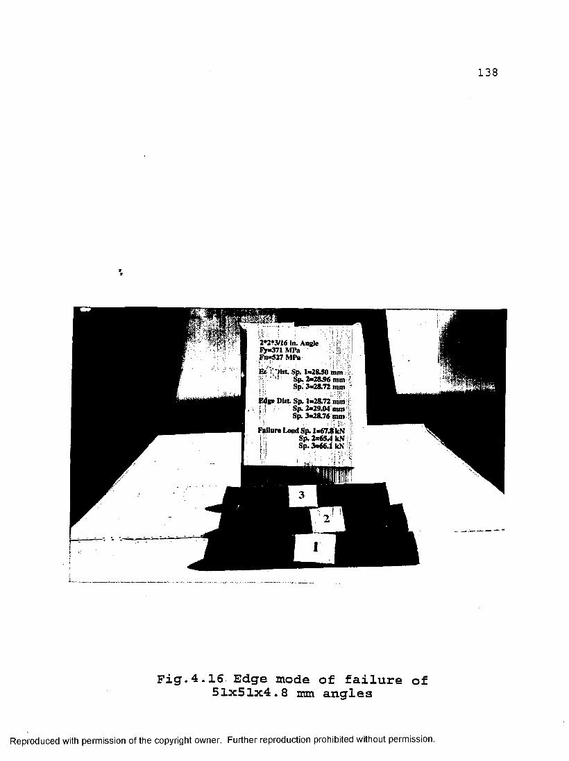
138
2*2*3/16 In. Angle i>*371 MPa Fu*527 MPa
ElfX'tist. Sp 1*2840 mm . Sp. 2«2UK mm| - Sp. 3*28.72 mm
Edge Diat Sp. 1*28.72 mm j ; | ■ Sp. 2*29.04 mm
Sp 3*28.76 mm
Failure Load Sp. 1*67.8 kN | v Sp 2*654 kNm Sp. 3*66.1 kN
Fig.4.16 Edge mode of failure of 51x51x4.8 mm angles
Reproduced with permission of the copyright owner. Further reproduction prohibited without permission.

139
3.5*3.5*5/16 in. Angle Fy=333 MPa Fu=514 MPa
End Dist. Sp. 3=25.26 nini Edge Dist. Sp. 3=45.60 mm Pitch Sp. 3=51.70 mm
Fail Load Sp. 3=228.0 kN
Fig.4.17 End mode of failure of 7 9x7 9x8 mm angle
Reproduced with permission of the copyright owner. Further reproduction prohibited without permission.

140
Fig.4.18 Combined mode of failure of 79x7 9x6.4 mm angle
Reproduced with permission of the copyright owner. Further reproduction prohibited without permission.

141
Fig. 4.19 Bottom end fixture for testing effect of
pre—tension on angles
Reproduced with permission of the copyright owner. Further reproduction prohibited without permission.
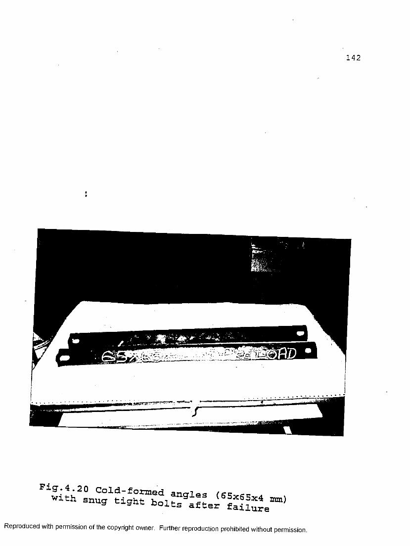
Fig.4.20 Cold-formed anoles fg5v cc a \ with snug tight b o l ^ a f
Reproduced with permission of the copyright owner. Further reproduction prohibited without permission.

I
Fig.4.21 Cold-formed angles (65x65x4 mm)with pre-tensioned bolts after failure
Reproduced with permission of the copyright owner. Further reproduction prohibited without permission.

144
Fig.4.22 Hot-rolled angles (S5xSS,-s . , .snug tight bolts after failure Wlth
Reproduced with permission of the copyright owner. Further reproduction prohibited without permission.

145
Fig.4.23 Hot-rolled angles (65x65x6.4 mm) with pre-tensioned bolts after failure
Reproduced with permission of the copyright owner. Further reproduction prohibited without permission.

1 4 612 0 -
10 0-
z-X'
"Ooo_l
0.0 2.5 5.0 7.5 10.0 1 2 . 515.0Average Jo in t E longat ion (m m )
SNUG TIGHT PRETENSIONED
LOAD - ELONGATION CURVE FOR 9 0 COLD FORMED ANGLES
Fig.4.24 Graph showing load-elongation curves for 65x65x4 mm angles with snug tight and
pre-tensioned boltsReproduced with permission of the copyright owner. Further reproduction prohibited without permission.

1 4 7
2 5 0 2 2 5 2 0 0
~ 175I 150u 1 3 5g 1 0 0
-J 7 5 5 0 2 5
0
A v e r a g e J o i n t E l o n g a t i o n ( m m )
— •==--£- SNUG TIGHT £ ~ t5t PRETENSIONED
LOAD - ELONGATION CURVE FOR 90 HOT ROLLED ANGLES
Ficr.4.25 Graph showing load-elongation curves for 65x65x6.4 nun angles with snug tight and
pre-tensioned boltsReproduced with permission of the copyright owner. Further reproduction prohibited without permission.
\—I LO
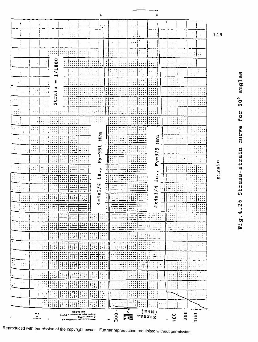
r
JJ
inm
' Z (®aw;® 555 sss:r:?sm
oCNmReproduced with permission of the copyright owner. Further reproduction prohibited without permission.
Fig.
4.26
Stre
es-s
trai
n curve
for
60°
angl
es
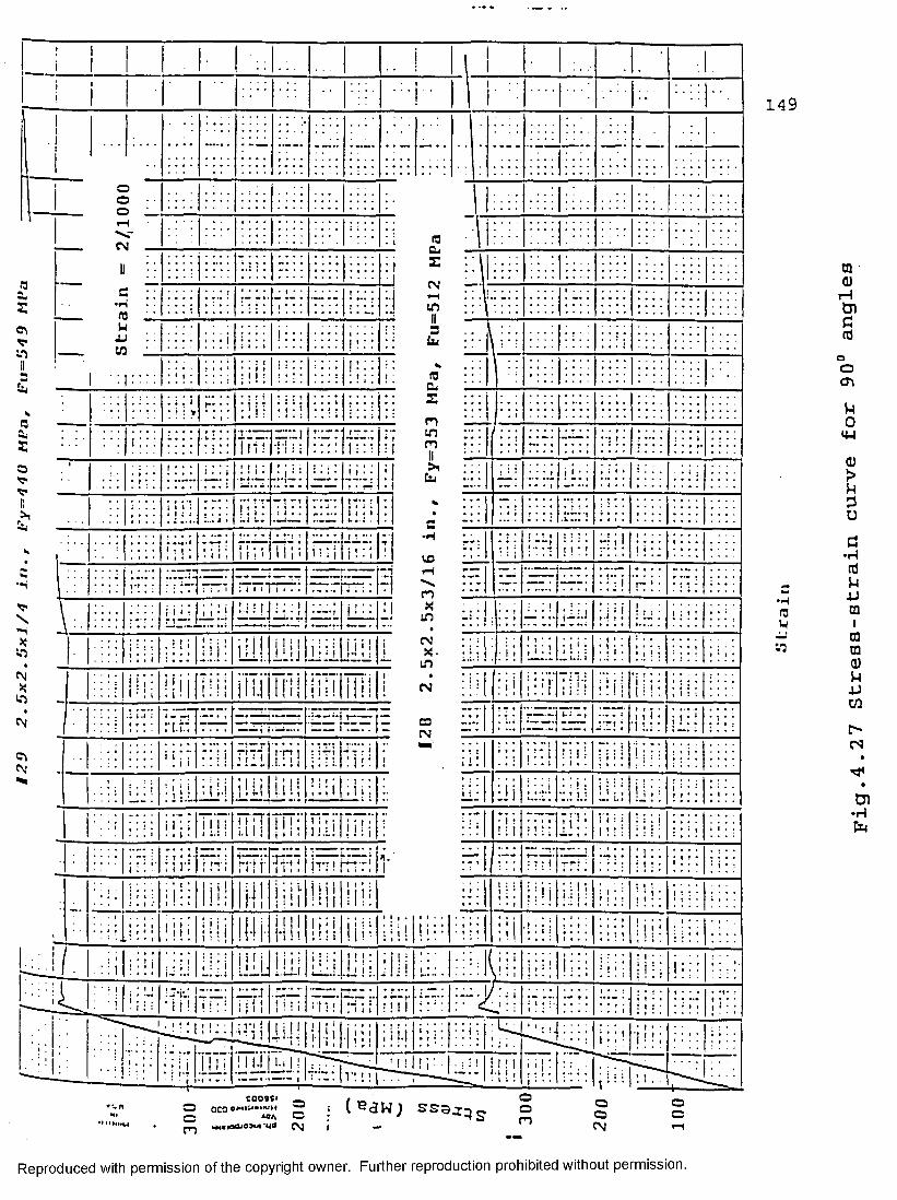
129
2.5x2.15x1/4
in.,
Lry=44U
MPa,
Lru —
549
MPa
CNJCM
mjj
n
in
aCN
! I I
cooaci _O 0C0 o»iiw**i»um ^c AC* OvM.racuojoi ud (\)(eaw; ss9>:;js m
149
m0)rHtnc(d
oO
u0
a)>u20
S•Hrt
mm Umm
•H V(3 mR iJJ toVJ m
CL)u4Jcn
r*-cs
•
t
Cl•H
Reproduced with permission of the copyright owner. Further reproduction prohibited without permission.
Appendix A
FINITE ELEMENT MODEL
OF 60° ANGLES
USING ABAQUS
Reproduced with permission of the copyright owner. Further reproduction prohibited without permission.

151
TTT1 "*T"T -Trrr- ti—:yarjTu:';i r)Q>;a• * = | jcris'iT':'.*4 = i 61>jG
SCiJI ccLE°:SEC' 63 3:3* = = ANGLE.SIZE 4• o a t a CHECK■ a::c: T«iT. = *unil.'i,."'''*-i :"-,unTn»y-'.:n! 4 =
1/4.LENGTH
• N*'*' =««N0O=S =0= £CHIccL = =I2 = 2 ANGLE ANP BASE PLATE• »C3riE3I\ 'AT = S 0= A * A « I/AC.OEl, 4 1.
9 . 0 .00, -26 .17, C.CO. -3 9 .25 , 0 .00, -2 4 .33 , 0 .00 ,
t 41 , - I s .J . 1251 4° , - 1 5 . 0 . -125
_=£J.AiiC_ -137790 «.coac13.595 * . A3C'-M
1 91 < 99 , ■15.0._r 15. Oj_*N3=N.NSET=S°1 141 .1A9.2 *NG=N.NSET=S°2 1 9 I .15Q.2
12s.00 . . -12 5_.O.rj.
-125 .3 0 -1 25.00
12 5.30 _JL21iO£I-
•NP ILL.NSETs30T°IT SOI .SP 2.A. 10 »NGE*I, MSET = 3OTAN 1 .9 .2
M 1-
o.17,2 17.25,2
Nllu° : P g 1 0° QQ . P! 0 5 CT; P7T A V ■ SH T ET . N CW.5E T = 7 3° A N
") I •NCO0*.CHANGE NUUEE==10002.OLP SET=3CT°L. SH!FT. NEWSET=TO=pL 1 550.030000_________________________ _____________________________0.00• NSET, NSFT=TOPAN,GENERATE 10001,1000°,2
J
1000° .10017.7____________iboTTTl0 C 2 5.510025.10C33.2•NEILL ,NSET=S°ARBOTAN. TO0AS', 10 . 1000«' * N 0 D 2 S e 0 FTS0L I'0~SL0CtC•NOO E10501.10509.
TO 5 5 1', 10555, 12501. 12 50 5j_ 12 5 51,
30.000. 3 0 . OOP.3 0 . OOC, 30.000,
14°0 •00. 1A90.00,
'1 4 9 0 .OPT
-2 3 .73, - 23 .7 3 ,
- 11 .3 211.32
12.555, 1A90.00,•NGEN.NSET = 3110501 .10505 . 2______•INGENTV5?T = 3310551.10555.2 •NEILL.NSET=BB1 B1.R2.5.10 _______'•NGrNTVSET=S312501.12505.2 *NGEN,NSET=B412551.12555.2
36.596.35.595,
- 2 3 . 7 3 , - 2 3 . 7 3 .
3 5. 595T35.595,
-44.4244.42
- 11 .3 211.32
*=V4*.4 244.42
«NTTL'l, NSETVutf2P3.B4.5.10•NODE••NOr'P S EOP SU°°0= TING ANGLES **NCD-S- FOR* SUP POETI7,’3— ANGLE ONf 13001, 4 .0000. 1C.°1.1 900°. 4.000C. - 1 4 . 1 0 .19017, 4 .0003. - 7 6 . °2 .___
T 9 3 o n ----------CTTOOrTO 2 5. o r.1930°, 4 .0000. 3 .000.19317, 4 .0000. - 6 5 . 3 2 .19401, 4 .0000. 39 .20.1360°;--------- 4 .0000. n . i ° ' ;19617. 4 .0000. - 4 ° . 1 3 .
106.60 = 1.36 5 7.97 77. 74 62. 50 29.01 57.69
~ 42.45** S.°6C
Reproduced with permission of the copyright owner. Further reproduction prohibited without permission.
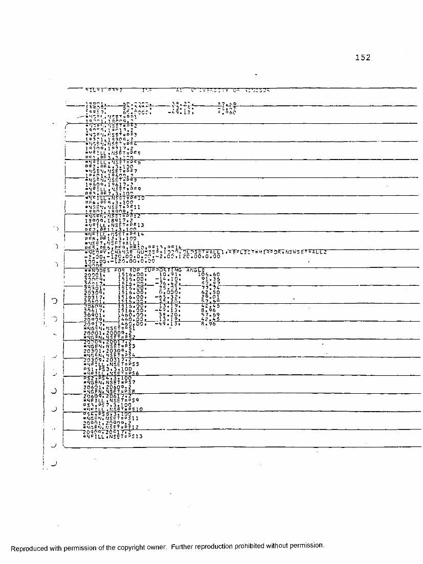
152
: Y G s
. =3 7, so.roco, ‘CTsDCti Q " V « inrPQ.'»‘ -r-rrh-H iTrte?--l1!''"'. 1 ar 1 7, 2 « N G C N. N S E T =oc3_l_a?ri. 15300. 2__*NGcNrNScT = o"C61 B 3 Oo.1??17,2• V = ’LL .NOOTsPCe . PC I .9=3.3.120
7 o ?«-VilTfJ--05.13,
J_7^o -2.4TT s .=*0
•N=ILL,NS=T=p = 60 = 2 . 00 4 ,3.1 DO •NGEN,MS=7=oo?_10 601, 19609,2,___«NG=N, \'S'ET *De?19600.19617.2 •N c ILL «NSET=P=9 P n , s c 7 . 3 . 100
“ •^ 0 lTXTWr?'TTireT2P F A .e= q ,3 ,190 •NGEN, N S = T = P F l 11 a art i . i qono . 7"Tw .NsrrTstrr-1 9 0 9 0 .18017.2 * N C I!_L » NSET= p f 13 p c 7 . pe 1 1 . 3 . 1 ort
') !
• N C !LL ,NSET=PC 14 P = R .PF12.3. 100 *NS=T,NSFT=ALL1j »NCn °V,CHANGE N U “ 2EP= 1 039, OLD -7.00,-120.0 0 ,0 .0 0 ,- 2 .0 0 ,1 2 0 .! 190.00,-120.00,0.00 1 *>jnn =
3r T s A L L l , R E = L E C T = MfPS3P.,NSWSETaALL2 0 0 ,0 . 0 0
! •«N9D=S FOR TOP SUPPORTING AN GL =2 0 0 0 1 , 1516.00, 10.91, 106.6027999. 1516.00, -14.10, 91.3679917. 1516.00, -76.42. 5 7. 9 7
, 20301, 1516.00, 2 5.01, 77. 7420309, 1516.00, 0 . 0 0 0 , 62.5020317. 1516.00, -65.32, 29.0179601. 1516.00, 3°.20, 57.6920605, 1516.00, 13.19, 42.4529617, 1516.00. -49.13, 8.9620901, 1460.00. 39.20, 57.6920909. 1460.00, 13.19, 42.452 0 ° 1 7, 1460.00, -49.13, 8 . 96•NGEN,NSET = °S1 -20001.20009.2•NGEN.NSET=PS2-------?iJ7t^5T20017,2•NGEN,NSET=PS320301.20309,2•NGEN.NSFT=PS4
O
J
J
u
•NFILL,NSET=PS5 PS1 » PS 3 » 3,100 'MFTLL ,N'S9T ;PS-6_^ S ? .PS 4,3,100 •NGEN,NSET = PS7 20601,20609,2 ■NGEN.NSET = PSB" 2 0 6 0 9 7 2 0 6 T T T F •NFILL,NSET=PS9 PS9,PS 7,3,100 *NfJ_LL .NSFtSpsIO■^STTp-S' 3.3. 100 • N G E N , N S E T = P S 1 120001, 2 0 °0o ,2•NGEN,NS=T=Pgl2*209 0’®T2 0 01TT2” * N C ILL,NSET=PS13
Reproduced with permission of the copyright owner. Further reproduction prohibited without permission.

153
Tim pt® n urnrpTTTv-T* .v: nosor'pt 1 . oc 1 * . -a . , r-n •N^ILL•\STt = BS 1 4p ?° . °S12•3.1?oNSET. NSE7=ALL3P c 6 . 5t Ij C 9 c v . c'HAN*,= \"JV = S = = 1 37 : . D L D S S T s A L L 3 . r EcL=CT='
1 4 2 0 . 3 0 , - 120. 0 0 , 7 . O'- , l A ’ r . o r , 1 2 9 . 0 0 . 0 . 9 91620.00 ,-izo.CO.C.OO-««c jjrv ojt^' = --it— s A\GVr »clcm='JT.TYbc=<:P0*5oi.l.5.2C??«2CCl.?.!0^5.?rC3.1001 5005^1 7?2^.2021,20]7.Io. 1021.29 !9. 1017iTLTFSTTL S ? T * 5 A NGL V5001,5 .2000. 100,4,A,1 5005 .5 ,2000,ICO,4,4,1 «*n cucmtp cn: RiJSE_p l_ J. •** C**CLCMCfjT C0L « c l 5 ME N tVtYp'E = S 4 R 1.141.151,15?.143 *=LGEN.ELSET=RLATE1 1 .4, I? , 1 Gj_4_, 2,1-— q-rnBT; ?L"I="M = NTJ $ h 1 f 7 r A ; , 0 l 0 « = 7 H f> L A T ? 1' re hI’RT 'Tl D E S = 1 C 0S CYN ? W S t T = P l'4 t S 1 «icL cMc,-Ts"ens TR I A NGUL A 0 BLOCKS «clbmENT.TYbc=S4R_£0i ; 10 531. 1 05 11.I-19.H3-J-1 0 L3,|-----------------------------------------------P01 , 12501,1 2S1 1,125 13,1 2 5' 3■ELGEN.ELSET=TRI1601.6, 10.1.2,2 «100geiV^. i.=| 5CT = TP I 2---------- ------ -----------------------------------------30 1,6,10,1,2,2,100«ici_pur.MTS r0D SUPPORTING ANGLE?«cfpME N T , T Y ° E sS4R_I90J. 900.1 j 1.5003j L5 LO3 j_1.51 01______________________________________________■ 1005,1 900°,incil,lglll,ltl09 loox ,1 9 301 .1P303.1 3403 .1 ?4C1 1035,1930?,19311,15411, 13409 1Q41 .15601 .1 3403.1 P7Q3 . 13701106 6,19603.13611,19211.19700 1201,’ 0001,20003.20103,20101 1205 ,20009.2001 1 .20111 .20109 m i .70301 J.2.0.3i2j.2J.M3 » 20401.1 2 3 5 .2 0 309,2 0 3 1 1 . 2 0 4 1 1 ,2 0409 12 6 W 2 0601. 2 0603, 2 0 703. 2 07011265.2 0 6 0 9 , 2 0 6 1 1 . 2 0 7 1 1 .207CO _*£LS-EN-»-cl.SF.T=9i>NGLp----------1001 .3 , 100,10.4,2,11005,3 , 100,10,4,2.1 1031 ,3 «100.10.4,2,1 ._10.3.5j 3 i 1.00 ,1 0 , 4 ,.2jJ— 1061 ,3*100,10,4,2,1 1065 .3 , 100.10,4,2,1 •PLGEN.ELSET=RANGLE3 1201 .3.100.10.4.2. 1--1205 .3 . 100. 10.4,2,1 1231 .3 .100,10.4,2.11235.3.100,10,4,2,1 JJL&l-il-J-} 0.0jJ 0jJta.2jl 12 65,3 , 100 , 10_, 4 , 2,1i = LC0PY, ELEMENT SHI FT = 1000 , OLD S S T = R A NGL E1 .SHIFT NODE S = 1 CO 0, \'E WS E T= R A NGL E2 *ELC0PY,ELEMENT SHIFTslO00,OLDS5T=RANGLE3.SHIFT NODES=1000,NEWSST=RANGLE4ftIh|!Il!k Lst gi:g3TgyW5LS---■ELSET ,EL5ST=TP. I TRI1 ,T R 1 2"SANG'LfPLATETTTPT, RANGlTE ■ELSET,ELSET=?nTELEl5001 ,5002 , 5003 , 5004, 5005 ,5.006, 5007 , 5003 - C l o 5 1 ' 0 5 7 5 1-06-.-5107.510S. C l Apt =1 ccr = aRTCI F*eLSET,FLSET=3DTEL£POTELFl,H0T=LE2"t p-1 f fs-I ‘1 G ifi-p-A-vi g r = u r■MATERIAL,NA«E=M1
Reproduced with permission of the copyright owner. Further reproduction prohibited without permission.

154
7J TTV r - i : I YACI • r%T T f
“TOO . =*3,:.30 *°L 4 ST IC 351 .0 IfL._________________________ __*-LiS'i(T 20C .0=3.0.??*"1T^ T 4L.NAur=H3*cLic*rr
7 T ) . 0- T7CT30-------------------------------------------------------*°L 4 S’!- TC300.00‘S^ELL SgCTI?‘;.TLS = ~ = SA‘.,?L~t,,aT = =;lAL = *-,1■776 2 Vi'S•SHELL SECTInN,cLSET=Tc; j, MATER IAL = M260.00*SUE LL SECTION. SLS=T=-R J p ,w-t = ; I AL = N2 ~ 0700= 0700•SHELL SECTION,ELS-S.00•SHCIL S E C T T H N . E L S E T= P L 4 TC I , M A T r R T A l a M ?
;=t =c a n SLE.w 4TSRIAL=m3
£fP-30.• M P C »7, 1052 3. 165*Mp7* 12S2 3* 101~t>t> *mpc7,193?9.17?*mo r __7, 1 0 3 O <5,155*WP£7,2030°.10175* M 0£_____ ___
-7 «*2 1 30 0 » 101 5 5 *MPC7 , 1 , IP 6017.33.1 9 6 Q-Ly , 1 0 C O 1.216617,10033.20601 * M, P C_7jJia50.1j-2-----7.10505.5 7, 12501 .10009 7,12506,10025 •aQMNOAPV___”3 65 » 1 . 610165.2.6161.1.6160, 1,610169.2.6191.1.6 1019?.2.61 3 977 • 6 10ie 9 , 2 . 6155.1.6
>-6_‘17 577 . 6 10175.2.6 «***■* ««»•««SUBROUTINE POR C.A« CUL ATT h q THE P.FS TOUAL STRESSrtYPE=S TRESS',‘USER. . . . AL CO^D i t i U n S,•USER SUBROUTINES SUBROUTINE SIGINI(SIGMA.COOROS.NTENS,NCRDS.NOEL)OTMENST ON S I G M A ( N T E N S ) ♦C O O R D S (N C R D S 3________________
W=7'0 07T64=22.63 A1=0.5*A W1=0.5«WT V STITT v = 351 .0PI = 3. 161692656 0=W-T/2.Q_______"a AC=A-T/?.0
Reproduced with permission of the copyright owner. Further reproduction prohibited without permission.

1 5 5
T nb_
zcifnci .1 T.!",»' 30:35*1Ts(sr.':T.15 ) oi = PS - • er ( fno? OS (’ )«*'3*r'3'l5''B{3) r e ? x . i T : c r ^ - 'xpx7T'£*cI -------------ELSE X! =AES( C T I ^ S C3 ) l - C / l .4 14
Y1 = A?S t 000=0? (3 ) )-'./l .414x = (so=y(xi * » ’*»! «*o )*o/~ca CDENDIF!F{ X.LE . 0 . 5 =4 tc.ma M 1 = 0. ?4*v «( a. »x-l . )______— EOTSIGMA(n=C.25*Y«(3.-4.«X)EN01cTF( X . r,T . A 1 . AND . x . o . ilJ.IH = N________________________O f P P . l T . n THENS I3MA( 1)=S I G U A( n + 0 .3*( Y+l. 5*Y*( DP.-A ) / 7)
ELSE_______ SLC* A M lsETSMAf n - * 0 .?»f-V-*-l )/7)■> cTrfyeCfjrtIP RETURNEND_______________________________________
• PLOT*DETAIL»ELSET=20TTPUSE*no a u . si H *■* ____V I E W ^O IN T , D? c I NI T I ON = MOD A L AXIS ROTATION''
15 *0 *0 * * 0**g©ASe*yj eyj_ P H TMT .^gP!NTTins«SMnnAL AXIS 0 OT A T I *7* N _*°ic'v,2 Sr|iN|T,OEFINITION = «COAL AXIS ROTATION 0 . 0 . 1 5 . 0 . 0 . 0 • ERA RgE"V I = W ' POINT .DEFINI T I0N=M 00AL AXIS ROYATTlJO 30.5.15.0*0.0 *= RASC• Y_! FH PnTNT.n = FTNITI0N = 00AL A X T S ROTATION.
' 4 5 . 0 . 1 5 . 0 , 0 . 0*= R A Sc* V I = W ' P O I N T , 0 E F I N I T I 0 N = M 0 D A L AXIS R O T A T I O N CL.5 C.Q«-Q-..Q------------------------------------—* c p a
•VIE W~ P O I N T . D E F I N I T I O N S GOAL AXIS R O T A T I O N °0.0.45.0,0.0..•.ERASE ------ -------------------------------------------------------------• PLOT• ORA M« NODENUM* V I CW POINT,DEFINITION=MOPAL AXIS POTATION 1 4.0.0. .0 .________________________________________-fCD ASP•VIEW POINT.DEFINITION=YODAL AXIS ROTATION• V _ T = wn P niN T . OFFTNTTION = YOD 41— 4X1 S . 3.014IJ-O-N- 0 . 0 . 1 5 . 0 . 0 . 0« c o a Sc•VIEW'POINT,OEFINITION=MOOAL AXIS ROTATION •»n.0.1 4. 0.0.0_______________ ______• ^ I EW' POI NT, 0EFI NI TI 0N=u0DAL AXIS ROTATION 4 5*0*1 5 « 0 * 0 • 0
- v 9 1 c w p o "i n t ’ , d e f i n I t i o n = k‘ oo_al a x i s r o t a r r c r r r60.0.30.0.0.0f t P O A C C*V_L£_W prtT M T . nccTNTTTPNg^ODAL AXIS RO T A T I O N
T 0 . P . 4 T . C . 0 . 0*E° ASE •°L0T
-*■v tt w_ p o p r r r o m tctti o o it t t x T r^ 'O T at t o1t30*0*0**0*
Reproduced with permission of the copyright owner. Further reproduction prohibited without permission.

156
T^"• V T CW 31T>|T -~o it i tr,r?T?rrE=INIT1 ayrc i"TiTTT* = - i s =•VIEW POINT,?E = I.\TTIDV = ,,00AL iXIS ROTATION c.«r.o.r'•'I'Tr•VIEW oniNT,?5 = INITI?V = w?’'iL AXIS ROTATION 4 S . 0 ,1 5 . C . 0 . 0'■*VTEW"'-'_'i 6?.0.30.0.0.0
■AS:TAP»r _ j r— — ^ |-—
•VIEW Pn;-j-r<n = CT,!ITIO,.'-,'?r-L AXIS ROTATinN
•*Toir,5E° LOADS * S T E 0« N L GEO”"* ST AT I (r.^TOIT^TTn MT3U^2’”.7 •CLOAD501 7,3 .350.00«gL pa INT,ELSET=SANjLS«g RS3UENY=0'EL RPJNT. CLSET = RANGLE . = = = 3UE\Y = 0 j = 1 pr T N T . ELSET=TRI1.CR = QU=MY = 0ic\_ OR JNT,ELSET=T°12.FRE3U=M Y=0 S .jn r,c PRINT,coPQUENCV=0___________“fTC►END S T E°• r t c p , n l GEO m , j N C = 0 5 C ______________________* S TATTT VPT OL = 2'5'O.0~. '■'TOC^TT'OOTOo . 1 , 1 . 0 . 0 . 0 0 1 . 0 . 1*CLOAD101 4 5 . 1 .-350.53_____________________________ _- -iTTTOT ► PLOT MODE » F ILL* NO- - ' 5 HR I NK » c ACTOR = C • 3** * z m m . c_a_cj op = i _ . _ 5 _____________________________ _• «i .rfcT A H L , ElTS E t"= s a ’i UE ***VIEW POINT,OEFINITION=u OOEL a x i s r o t a t i o n **45.3*«« kjOc RASE_____________________________________________***C ONTCUR * *5 11.4***NOOE PRINT.PPE0UENCY=0** R F_____________________________________"Vo l o t *0FTAIL.5LSET=SAN5LE ‘CONTOUR,DEFORMR 1 1 , 4_________________________________ _____________"*EL PR'I"NT, :LScT = S ANGLE .FR = OUENCY = 0 ; = L prinT.ELSET = rangle »c RE0UENY=0
"V=L p5_["NTTeTS"ET=TRTTTERToO5NT*”0 “•EL PRINT,ELSET=TRI2.PRE0UENY=0•NODE PRINT,FRE3UENCY=0 RF•END STEP
II
Reproduced with permission of the copyright owner. Further reproduction prohibited without permission.

Appendix B
FINITE ELEMENT ANALYSIS
FOR SCHIFFLERIZED
102x102x6.4 MM ANGLE
DATA CHECK RUN
Reproduced with permission of the copyright owner. Further reproduction prohibited without permission.

158
ABACUS PRODUCTION VERSION 9-7-22 DATE 2BAPR 93 TIME 1:97:99 PAGE
ABAOUS
THIS PROGRAM HAS BEEN DEVELOPED BYHIBBITT« KARLSSON AND SORENSEN, INC. 100 MEDWAY STREET PROVIDENCE, R •I. 02906
THIS IS A PROPRIETARY PROGRAM AND IS MADE AVAILABLE FOR INTEPNAL USE AT UNIVERSITY OF WINDSOR. UNDER THE TERMS OF THE ACADEMIC LICENSE AGREEMENT WITH H.K.S. ALL USAGE MUST BE UNDER THE DIRECT SUPERVISION AND CONTROL OF THE OESIGNATEO USER.THE DESIGNATED USER IS DR. GEORGE ABDEL-SAYEO.ANY NON-ACADEMIC USAGE OF THE PROGRAM REQUIRES PAYMENT OF A MONTHLY CHARGE. ASSISTANCE AND OTHER INFORMATION MAY BE OBTAINED FROM THE OESIGNATED USER.
FOR ASSISTANCE OR ANY OTHER INFORMATION CALL 901— 861— 0B20
..I
J
» NOTICE •THIS IS ABAOUS VERSION 9-7.
SOME INPUT OATA OPTIONS AND USER SUBROUTINE INTERFACES ARE INCOMPATIBLE WITH VERSION 9-5.PLEASE MAKE SURE YOU ARE USING VERSION 9-6 OR 9-7 MANUALS.
* • • •
Reproduced with permission of the copyright owner. Further reproduction prohibited without permission.

159
ABAOUS PRODUCTION VERSION 4-7-22 DATE 28APR 93 TIME 1:47:44 PAGEFOR USE AT UNIVERSITY OF WINDSOR UNDER ACADEMIC LICENSE FROM HKS, INC.
•PREPRINT,ECHO*NO.MODEL*NO.HISTORY*NO
;
i
t v.
Reproduced with permission of the copyright owner. Further reproduction prohibited without permission.
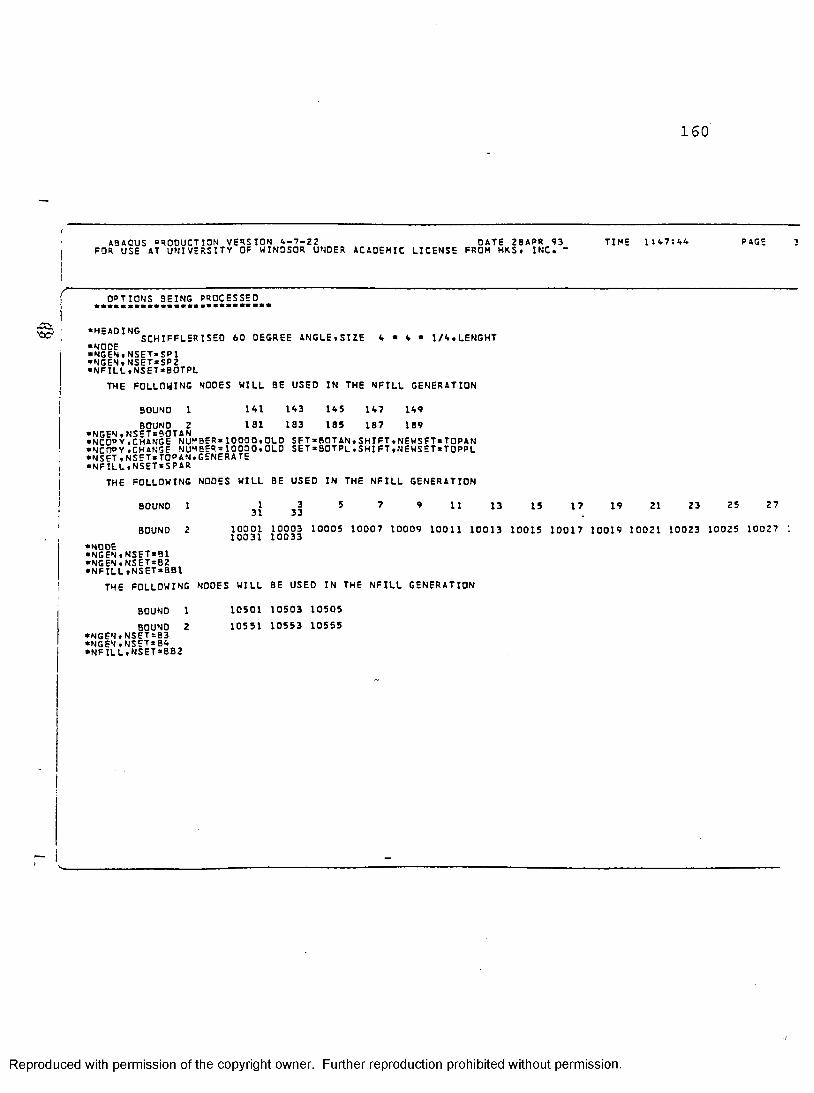
160
ABACUS PRODUCT ION VERSION A-7-22 OATE 28APR 93FOR USE AT UNIVERSITY OF WINDSOR UNDER ACADEHIC LICENSE FROM HRS« INC. “ TIME 1:A7:AA PAGE
OPTIONS BEING PROCESSED
•HEADING SCHIFFLERISED 60 OEGREE ANGLE.SIZE•NOOE•NGEN»NSET«5P1•NGEN.NSET*SP2•NFILL.NSET*BOTPL
A • A • 1/A.LENGHT
THE FOLLOWING NOOES WILL BE USED IN THE NFILL GENERATION
BOUNO 1A11S1
1 A3 183
1A5185
1A7187
IA9 189BOUNO Z *NGEN.NSET=90TAN •NCD°Y,CHANGE NUMBER*10000.OLD SFT.ROTAN,SHIFT.NEWSFT.TOPAN • NCOPY.CHANGE NUMBER.10000.OLD SET*BOTPL.SHIFT»NEWSET*TOPPL •NSET.NSET.TOPAN.GENERATE •NFILL.NSET=SPAR
THE FOLLOWING NODES WILL BE USED IN THE NFILL GENERATION
I31 333 1110001 10003 10005 10007 10009 10011 10013 10015 10017 10019 10021 10023 10025 10027 10031 10033
BOUNO 1
BOUND 2•NODE •NGEN.NSET»B1 •NGEN.NSET.B2 •NFILL.NSET.BBl
THE FOLLOWING NODES WILL BE USED IN THE NFILL GENERATION
13 15 17 19 21 23 25 27
BOUNO 1BOUNO 2 •NGEN♦NSET.B3 •NGEN.NSET.BA •NFILL.NSET.BB2
10501 10503 10505 10551 10553 10555
Reproduced with permission of the copyright owner. Further reproduction prohibited without permission.

161
.CCt
ABAOUS PRODUCTION VERSION A-7-22 OATS 28APR 93 TIME 1:A7:AA PAGEFOR USE 4T UNIVERSITY OF WINDSOR UNDER ACAOEMIC LICENSE FROM HKS. INC.SCHIFFLERISED 60 DEGREE ANGLE.SIZE A • A • 1/A.LENGHTTHE FOLLOWING NODES WILL BE USED IN THE NFILL GENERATION___________________________________________________
■•NODE^ •NGEN.NSET*PF1*NGEN.NSET*o F2 *NGEN.NSET=PF3 *NGEN.NSET*PFA •NFILL.NSET-PF5THE FOLLOWING NODES WILL BE USED IN THE NFILL GENERATION
BOUNO 1 16001 18003 1B005 13007 1B009BOUNO 2 18301 1B303 1B305 1B307 18309•NFILL.NSET=PF6
THE FOLLOWING NODES WILL BE USED IN THE NFILL GENERATION
BOUND 1 18009 18011 18013 18015 18017BOUNO 2 18309 18311 18313 1B315 18317•NGEN.NSET*PF7•n g e n .n s e t *p f b•NFILL.NSET *PF9
THE FOLLOWING NODES WILL BE USED IN THE NFILL GENERATION
BOUND 1 18301 18303 18305 1B307 18309BOUNO 2 18601 18603 18605 18607 1B609•NFILL.NSETsPFlO
THE FOLLOWING NOOES WILL BE USED IN THE NFILL GENERATION
BOUNO 1 12501 12503 12505BOUNO 2 12551 12553 12555
BOUNO 1 18309 18311 18313 18315 18317BOUND 2 ... . . 5ET*PFI1 •NGEN.NSET*PF12BOUND 2 16609 18611 18613 1B615 18617*NGEN.NSET*PFI1
r- !
Reproduced with permission of the copyright owner. Further reproduction prohibited without permission.

16 2
ABAOUS PRODUCTION VERSION a-7-22 DATE 2BAPP 93FOP. USE AT UNIVERSITY OF WINDSOR UNDER ACAOEMIC LICENSE FROM HKS. INC.SCHTFFLERISED 60 DEGREE ANGLE.SIZE A * A • 1/A.LENGHT■NFILL.NSET*PF13
TIME 1 :A7:AA PAGE
IHh FOLLUW1NG NODES W ILL BE USED 'IN THE NF ILL'~GEN ER~AT ION
BOUND 1BOUND 2 •NFILL.NSET*PF1A
18601 18603 18605 18607 18609 13901 18903 18905 18907 18909
THE FOLLOWING NODES WILL BE USED IN THE NFILL GENERATION
BOUNO 18609 18611 18613 18615 18617 18909 18911 18913 18915 18917BOUND 2 «NSET,NSET=ALL1•NCOPY,CHANGE NUMBER*1000.0LDSET=ALL1.REFLECT«MIRROR,NEWSET*ALL2 •NODE•NGEN.NSET*PSl •NGEN.NSET*PS2 •NGEN.NSET«PS3 •NGEN.NSET=PSA •NFILL.NSET*PS5
THE FOLLOWING NODES WILL BE USED IN THE NFILL GENERATION
BOUNO 1BOUNO 2 •NFILL.NSET*PS6
20001 20003 20005 20007 20009 20301 20303 20305 20307 20309
THE FOLLOWING NODES WILL BE USED IN THE NFILL GENERATION
BOUND 1BOUNO 2 •NGEN »NSET = PS7 •NGEN.NSET=PS8
•NFILL.NSET*PS9
20009 20011 20013 20015 20017 20309 20311 20313 20315 20317
THE FOLLOWING NODES WILL BE USED IN THE NFILL GENERATION
BOUND 1 20301 20303 20305 20307 20309BOUND 2 20601 20603 20605 20607 20609
Reproduced with permission of the copyright owner. Further reproduction prohibited without permission.

163
ABAOUS PRODUCTION VERSION A-7-22 OATE 2BAPR 93FOR USE AT UNIVERSITY OF WINDSOR UNDER ACADEMIC LICENSE FROM HKS. INC. TIME i :a 7:aa PAGE
SC H IFc l FRISED 60 DEGREE ANGLE.SIZE •NFILL.NSET*PS10 A • A • l/A.LENGHT
TH E " FOLLOW ING NODE S'WILL BE "USS0~IN '-TH6 NP ILL GBNERA TION '
BOUNDBOUND 2 •NGEN,NSET*PS11 •NGEN.NSET*PS12 •NFILL.NSETrPS13
20309 20311 20313 20315 20317 20609 20611 20613 20615 20617
THE FOLLOWING NOOES WILL BE USED IN THE NFILL GENERATION
BOUNO 1 *BOUND 2 •NFILL.NSET=PS1A
20601 20603 20605 20607 20609 20901 20903 20905 20907 20909
THE FOLLOWING NODES WILL BE USED IN THE NFILL GENERATION
BOUND 20609 20611 20613 20615 20617 20909 20911 20913 20915 20917BOUND 2
• NCOPY^CHANGE NUMBER*1000.OLDSET*ALL3.REFLECT*MIRROR.NEWSET = ALLA •FLEMENT,TYPE*S8R•ELGEN.ELSET*SANGLE •p. c m ENT.TYPE*SAR *e|_GEN. ELSET* PL ATE1• El COPY.e l e m e n t SHIFT*5 0,OLDSET.PLATE1.SHIFT NODES*10000,NEWSET*PLATE1 •ELEMENT.TYPE=SAR•FLGEN.ELSET-TRII •ELGEN.ELSET=TRI2 •ELEMENT,TYPE=SAR •ELGEN,ELSET*RANGLE1 *cig c n .ELSET=RANGLE3• fLCOPY.ELEMENT SHIFT»1000,OLDSET*RANGLE1.SHIFT NODES*1000.NEWSET*RANGLE2 •f l COPY.ELE“ENT SHIFT*1000.0LOSET«RANGLE3.SHIFT NODES*1000,NEWSET*RANGLEA •ELSET , ELSET = RANGLE•ELSET.ELSETaTRI •ELSET.ELSET=ALL •MATERIAL.NAHE*M1 •ELASTIC •PLASTIC■MATERIAL.NAME*M2
Reproduced with permission of the copyright owner. Further reproduction prohibited without permission.
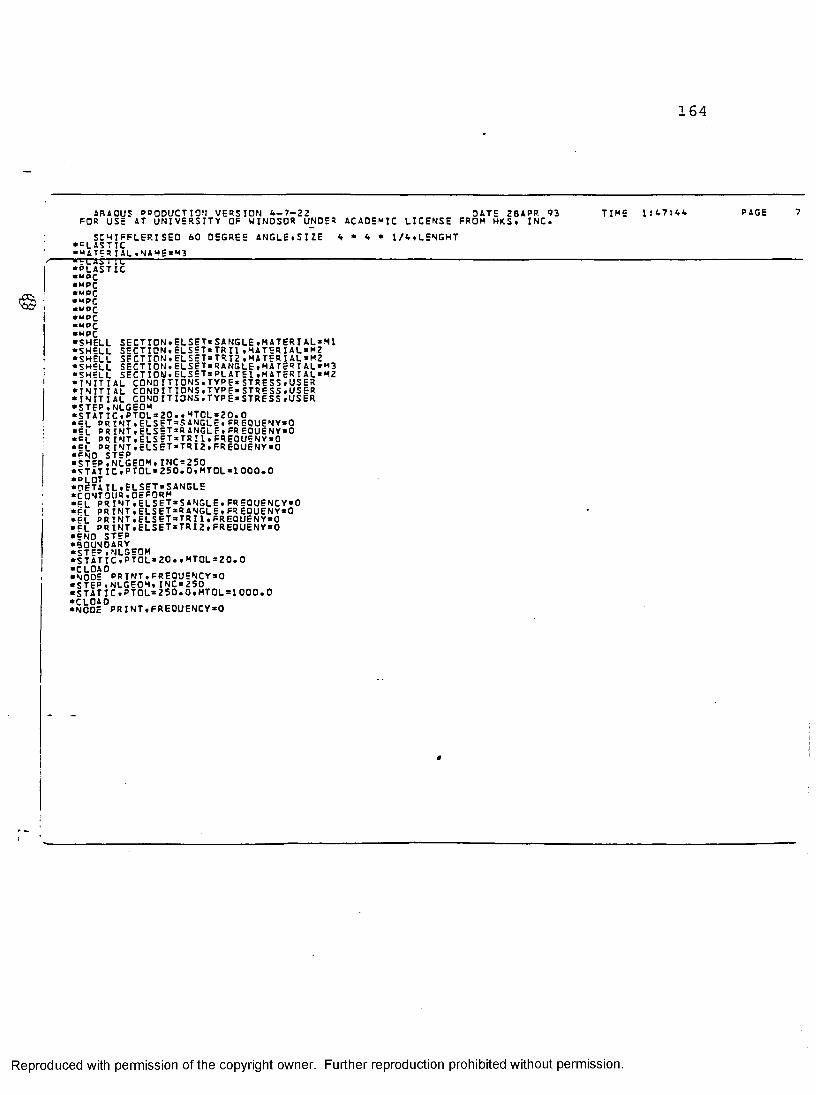
164
ABAOUS PRODUCT I ON VERSION <— 7-22 DATE 28APP. 93 TIME IsATsFL PAGEFOR USE AT UNIVERSITY OF WINDSOR UNDER ACADEMIC LICENSE FROM HKS , INC.SCHIFFLEP.I SED 60 DEGREE ANGLE .SIZE < , • < , » l/L.LENGHT *CLASTIC• M A T = 3 I A L . N A M E . M 3
•e l a s ric-------------------------------------------------------------------------------------------------------------------•PLASTIC• •PC• MPC *UPC• M P C■ MPC• MPC■ MPC •MPC•SHELL SECTI0N.ELSET.SANGLE.HATERIAL»M1 •SHELL SECTION.ELSET.TRU.MATER IAL=M2 •SHELL SFCTION.ELSET.TRI2,MATERIAL*M2 •SHELL SECTI0N.ELSET.RANGLE.MATERIAL.M3 •SHELL SECTION.EL SET.PLATEI.MATERIAL«M2 •INITIAL CONDITIONS.TYPE*STRESS.USER •INITIAL CONDITIONS.TYPE* STRESS.USER •INITIAL CONDITIONS,TYPE*STRESS.USER •STEP,NLGEOM•STATIC.PTOL*20..MTDL*20.0 •CL PRINT.ELSET.SANGLE.FREQUENY.Q •f l PR INT.ELSET.RANGLE.FREOUENY.O •CL PRINT,ELSET.TRI1.FRE0UENY.0■ cL PR INT.ELSET.TRI2,FRE0UENY = 0 •FNO STEP•STEP.NLGEOM,INC.250•STATIC.PTOL*250.O.MTOL*l000.0• PLOT•OETAIL.ELSET.SANGLE •CONTOUR.OEFORM•FL PR I NT.ELSET.SANGLE.FREOUENCY.O •FL PRINT,ELSET.RANGLE.FREOUENY.O •EL PRINT,ELSETaTRIl.FREOUENY.O .cl PRINT,ELSET.TRI2,FREOUENY.O •ENO STEP •90UN0ARY •STEP.NLGEOM•STATIC «PTOL= 20..MT0L.20.0 •CLOAO•NODE PRINT,FREOUENCY.O •STEP,NLGEOM.INC*250 •STATIC,PTOL*250.0»MT0L=1000.0 •CLOAO•NODE PRINT,FREOUENCY.O
«
Reproduced with permission of the copyright owner. Further reproduction prohibited without permission.

165
ABAOUS PRODUCTION VERSION A-7-22 - DATE 28APR 93POR USE AT UNIVERSITY OF WINDSOR UNOER ACADEMIC LICENSE FROM HKS. INC. TIME 1:a 7:aa PAGE
SCHIFFLERISED 60 DEGREE ANGLE.SIZE A • A •
----------------- H L S H----------- P L O T — I— n r
l/A.LENGHT
•PLOT•ORAW « ELNUU
PLOT FRAME CONSISTS OF ALL ELEMENTSALL SIZES ARE IN PLOTTER UNITSFRAME SIZE PICTURE SIZEPOSITION OF LOWER LEFT HAND CORNER OF PICTUREPOSITION OF START OF TITLEPOSITION OF UPPER LEFT HAND CORNER OF VARIABLE LISTPOSITION OF AXISSIZE OF CHARACTERSWIDTH OF PAPER STRIP BETWEEN FRAHES NUMBER OF COLORS AVAILABLE 1
X— 01RECTION Y-OIRECTION
POINT.OEF POINT.OEF POINT,OEF POINT.DEF POINT.DEF POINT,OEF POINT,OEF
•VIEW •VIEW •VIEW •VIEW •VIEW •VIEW •VIEW •PLOT•ORAW.NODENUM
TNITTONINITION»INITION*INITION*IN ITION*INITION*INITION*
MODAL AXIS MODAL AXIS MODAL AXIS MODAL AXIS MODAL AXIS MODAL AXIS MODAL AXIS
ROTATIONROTATIONROTATIONROTATIONROTATIONROTATIONROTATION
10.0007.00003.00001.5000 0.100001.5000
10.0007.00002.0000 1.0000 S.0000 1.50000.16000 5.0000
PLOT FRAME CONSISTS OF ALL ELEMENTSALL SIZES ARE IN PLOTTER UNITSFRAME SIZE PICTURE SIZEPOSITION OF LOWER LEFT HAND CORNER OF PICTUREPOSITION OF START OF TITLEPOSITION OF UPPER LEFT HANO CORNER OF VARIABLE LISTPOSITION OF AXISSIZE OF CHARACTERS
X-DIRECTION Y-DIRECTION1 0 . 0 0 07.00003.0000 1 .50000.10000 1.5000
10.0007.00002.0000 1.0000 8.0000 1.50000.16000
Reproduced with permission of the copyright owner. Further reproduction prohibited without permission.

166
PAGEA3A0US PRODUCTION VERSION 4-7-22 OATE 2 BA PR 93 TIME 1:47:44FOR USE AT UNIVERSITY OF WINDSOR UNDER ACAOEMIC LICENSE FROM HKS. INC.SCHIFFLERISED 60 DEGREE ANGLE.SIZE 4 * 4 * 1/4.LENGHTWIDTH OF PAPER STRIR BETWEEN FRA“ES 5.0000
m e V iew ANGLES ARE 1.5 7 0 . 785 -O.OOOE*00
•VIEW •VIEW •VIEW •VIEW • VIEW •VIEW •VIEW •PLOT •ORAW
NUMBER OF COLORS AVAILABLEPOINTPOINTPOINTPOINTPOINTPOINTPOINT
.DEFIN.DEFIN.DEFIN.DEFIN.OEFIN.DEFIN.DEFIN
ITION*ITION*ITION*ITION*ITION*ITION*ITION*
MODAL AXIS MODAL AXIS MODAL AXIS MODAL AXIS MODAL AXIS MODAL AXIS MODAL AXIS
ROTATIONROTATIONROTATIONROTATIONROTATIONROTATIONROTATION
PLOT FRAME CONSISTS OF ALL ELEMENTSALL SIZES ARE IN PLOTTER UNITSFRAME SIZE PICTURE SIZEPOSITION OF LOWER LEFT HAND CORPOSITION OF START OF TITLEPOSITION OF UPPER LEFT HAND CORPOSITION OF AXISSIZE OF CHARACTERS WIDTH OF PAPER STRIPTHE VIEW ANGLES ARE
X— DIRECTION Y—OIRECTION1 0 . 0 0 0 1 0 . 0 0 07.0000 7.0000OF PICTURE 3.0000 2 . 0 0 0 01.5000 1 . 0 0 0 0DF VARIABLE LIST 0 . 1 0 0 0 0 8 . 0 0 0 01.5000 1.5000
BETWEEN FRAMES1.57 0.7B5
0.160005.0000O.OOOE+OO
NUMBER OF COLORS AVAILABLE•VIEW POINT,DEPTNITION*HODAL AXIS •VIEW POINT,DEFINITION*MODAL AXIS •VIEW POINT,DEFINITION*MOOAL AXIS •VIEW °OINT,DEFINITION*MODAL AXIS •VIPW POINT,DEFINITION«MODAL AXIS •VIEW POINT,DEFINITIONsHODAL AXIS
ROTATIONROTATIONROTATIONROTATIONROTATIONROTATION
1
Reproduced with permission of the copyright owner. Further reproduction prohibited without permission.

167
' ABAOUS PRODUCTION VERSION 4-7-22 DATE 23APR 93 TIME 1:47:44 PAGE 1CPOR USE AT UNIVERSITY OF WINDSOR UNDER ACADEMIC LICENSE FROM HKS. INC.; SCHIFFLERISED 60 DEGREE ANGLE.SIZE A * A • 1/4,LENGHTI>------------------------------------ W A V E F R O N T--- M I N I M I t A 'T- I'-O'-W---------------------------------------------
NUMBER OF NODES 593NUMBER OF ELEMENTS 380ORIGINAL MAXIMUM 0.0.F WAVEFRONT ESTIMATED AS 162i ORIGINAL RMS D.O.F WAVEFRONT ESTIMATED AS 108SEARCH FOR POSSIBLE STARTING NODES IS COMPLETEDPHERIPHERAL DIAMETER IS OEFINED BY NODES 19017 20917WAVEFRONT OPTIMIZED BY CHOOSING 20917 AS THE STARTING NODE
* P R O B L E M S I Z E
NUMBER OF ELEMENTS IS 380NUMBER OF NODES IS 593TOTAL NUMBER OF VARIABLES IN THE MODEL 3558(OEGREES OF FREEDOM PLUS ANY LAGRANGE MULTIPLIER VARIABLES)M A X I M U M D.O.F. WAVEFRONT ESTIMATED AS 144RMS WAVEFRONJ ESTIMATED AS 96
FILE SIZES - THESE VALUES ARE IN WORDS AND ARE CONSERVATIVE UPPER BOUNDSUNIT LENGTH
2 35053919 11554821 18538022 1B538025 6840026 6840028 22B00
IF THE RESTART FILE IS WRITTEN. ITS LENGTH WILL BE APPROXIMATELY 109102 WORDS WRITTEN IN THE PRE PROGRAM PLUS 75240 WORDS WRITTEN AT THE BEGINNING OF EACH STEPPLUS 232007 WORDS FOR EACH INCREMENT WRITTEN TO THE RESTART FILE
Reproduced with permission of the copyright owner. Further reproduction prohibited without permission.

168
I
©i
)
ASAOUS PRODUCT TON VERSION 4-7-22 DATE 28APR 93 TIME 1:47:44 PAGEFOR USE AT UNIVERSITY OF WINDSOR UNDER ACADEMIC LICENSE FROM HKS. INC.SCHIFFLSRISED 60 DEGREE ANGLE.SIZE 4 « 4 • 1/4.LENGHT
-ALLOC A TED~WORKS PACE-------------------------------------------------------------- 23CZ23-------------------------------
THIS IS A DATA CHECK RUN. ANALYSIS ENOS.
Reproduced with permission of the copyright owner. Further reproduction prohibited without permission.

Appendix C
FINITE ELEMENT ANALYSIS
FOR SCHIFFLERIZED
102x102x6.4 MM ANGLE
LAST PAGE OF THE OUTPUT
Reproduced with permission of the copyright owner. Further reproduction prohibited without permission.
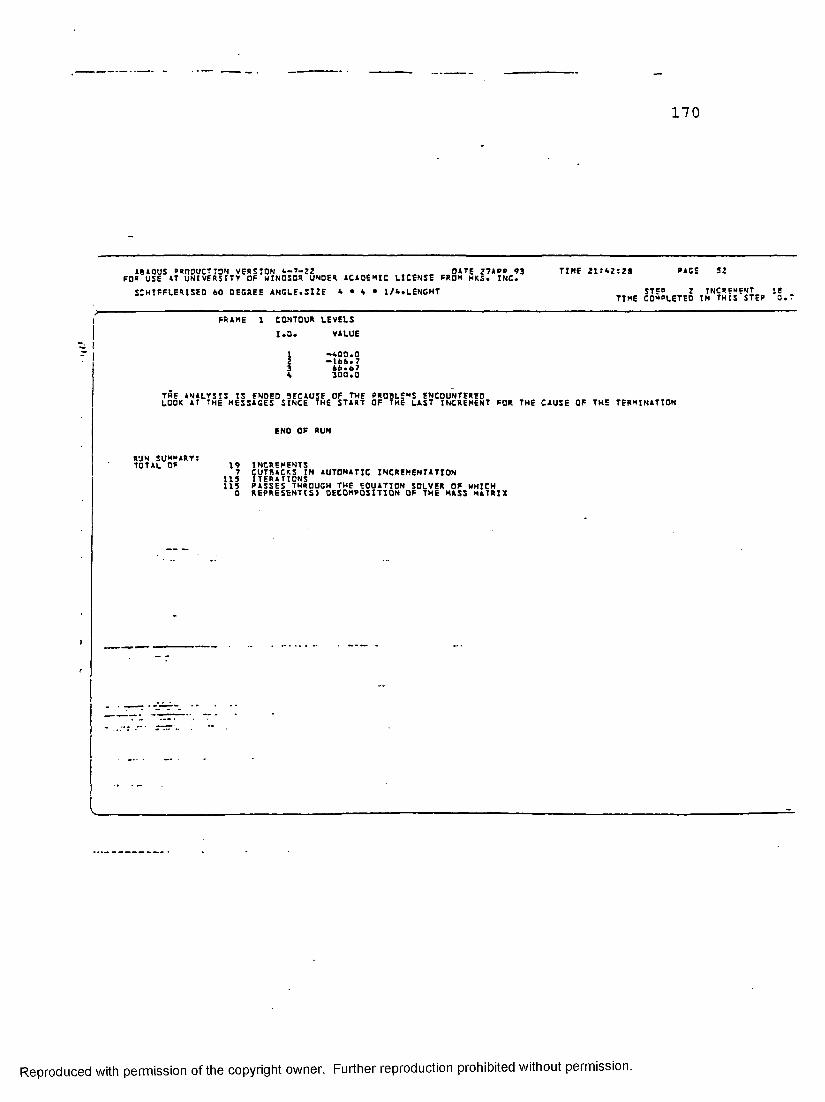
170
ABAOUS RROOUCTTON VERSION A-i-JZ DATE 27APR 63 TINE 21:62:29 RASE 52FOR USE AT UNIVERSITY OF HINOSOR UNDER ACAOSNIC LICENSE FROM HKS. INC.
SCHIFFLERISED 60 DECREE A N C LE.SHE 6 - 6 • l/A.LENCHT ^ S T g J ^ g ftN«*;*MTgp ^
? .1 FRAMEII j
THE ANALYSIS IS ENOEO BECAUSE OF THE PROBLEMS ENCOUNTEREDLOOK AT THE MESSAGES SINCE THE START OF THE LAST INCREMENT FOR THE CAUSE OF THE TERMINATION
ENO OF RUN
RUN SUMMARY:TOTAL OF 19 INCREMENTS
CONTOUR LEVELS1*0* VALUE
I •400*02 •166*73 66*67A 300*0
7 CUTBACKS IN AUTOMATIC INCREMENTATION 115 ITERATIONS115 PASSES THROUGH THE EQUATION SOLVER OF WHICH 0 REPRESENTS) DECOMPOSITION OF THE HASS MATRIX
Reproduced with permission of the copyright owner. Further reproduction prohibited without permission.

Appendix D
FORTRAN PROGRAM TO CALCULATE
THE PROPERTIES OF
60° ANGLES
Reproduced with permission of the copyright owner. Further reproduction prohibited without permission.

172FI LE: S H SHU CORTRAN A1 UN I VERS ITY OF WINDSOR
C . .r... PP.OPERTI SS Oc COLD FOPMEO ANGLESR=AL I U . I V . I P C . I O S . J . L OPEN(UNIT=P , f i i _E= ' /PCOLD DATA A'
-I-=4-
SESODPIO S ES00023 S5S00030 SESC0040 -SF-SOtW-5S- SES00060 SES00070 SESOOOSO SES00090 SFSOO100 SES00110 S E SOD 120 SES00I30s esooi aoSES00150 SESOO 160 SES00170 SESOOISO SES00190 SES00200 SES00210 SFS00220 SES00230 SES00240 SES00250 SES00260 SES00270 SES00280 SES00290 SES00300 SES00310
1) SES00323 SES00330 SES00340 SES00350 SES00360
100C..C . .C . .
20
REA0<9, * ) A iT«L iRR = 13 “H FOR 1 . 5 X 1 . 5 X 1 / 3 I N . , R=15 MM FOR 2X2X3/ 16 I N . ANGLESPI =3 . 1416 R l = = - 0 . 5 * T 3 = A - 0 . 5 * T - R l * P T / 3 . 0 Al = 2 . 0 * T * ( 3 + l . 0 4 ? * ( R 1 ) )IU = 0.614*t*(p.*-3)+9*(T**3)/8.0+(3**3)*T/2A.0+( (3*T )/3.0)*<3+3 . 4 6 4 * ( R 1 ) ) * * 2UC=(0 . 366* ( E * * 2 ) * ? * ( R 1 + T ) + 0 . 3 6 2 * ( R 1 ) * * 2 +1 . 0 5 « { T * ( P 1 ) ) ) / ( 2 . 0 * 3 + 2 « l * ( R l ) )I V = ( ? * * 3 ) * t / 3 . 0 + f * ( T* “ 3 ) / 2 4■ 0+ ( ( 5 * T 1 / R . 0 ) * ( i . 73*a + 2 . 0 « P i + 2 * T ) * * + 0 . 4 7 ? * T * ( R 1 * * 3 ) + 2 . 1 * T * R 1 * ( 0 . 1 7 3 * R l + 0 . 5 * T ) « * 2 - A l * ( UC ) * * 2 J = ( A 1 * T * * 2 ) / 3 . 0US=( ( T* R 1 ) / ( 6 . 0 * I U ) > * ( 2 . 3 * ( 3 * * 3 > + S . 3 4 * ( 3 * * 2 ) * R 1 + 1 0 . 9 * 3 * (R1* * 2 ) +4 . 1 1 * R 1 * * 3 ) - R 1 - T / 2 . 0 * U CIPS*IU+IV+A1 *CUS**2 )IPC=IV+IU , %RU= SORT( IU/A I )RV=S0°T( I V/ A1)I U= I U / 1 0 0 0 0 0 0 . 0iv=iv/ioocoon.oI PS= I PS/ 1000000 . 0I ° C = I P L / 1 0 0 0 0 0 0 . 0WRITE( 6 , 2 0 ) 3 . U C . U S , A l , I U , I V , I P C . I PS. RU. RV. JFORMAT ( F 5 . 2 . I X , F 4 . 1 , 1 X , e^ . i , 1X, F 6 . 1 , 4 ( F 1 2 . 9 ) , 2 ( 1 X , F 4 . 1) , 1X , F6 .I F { I . LE. 19) GO TO ICOSTOPEND
Reproduced with permission of the copyright owner. Further reproduction prohibited without permission.

nnn
17 3
c IL F : KK10 COP.TRAM A1 UN I VERS I TV OF WINDSOR-
. . r n f i n d the “ i n t m u m r a d i u s of g y r a t i o n for d i f f e r e n t s p e c i m e n s
. . 0 C SCHI=F|_ERIZED ANGLESLINES ADDED 5 . 6 . 7, 3. 9 . 1 0 .11 , 1 2 . IS . 19 . 2 1. 2 5
0 c A L I V . I V I . I V 2 . I U 1 . I U 2 . I U . J . I P S---------------------OnEM(UMI-T - q . F-I -L=- ' / - K-K-lOO- DATA A* )-------------------------------------------------------------
1 = 1100 READC0 . * ) W. A. T
9 = W-A C = A—0• 9 * T
jCCi I U l = ( ? * T * * 3 / 1 6 . C ) + ( ( P * * 3 ) * T ) / A 3 « 0 +' C - * B * T * ( ( 3 / A . 3 ) + ( A - T / 2 . O ) / S 0 R T ( 2 . 0 ) ) * * 2
IU2 = ( C A - T / 2 , 0 ) » T . * i ) / 2 A . 0 + ( T * ( A - T / 2 . 0 ) * * 3 ) / 6 . 0 I U = 2 . n * { I U l + I U 2 )I V l = ( 9 * T * * 3 / A 3 . > + ( 3 . * ( R * * 3 ) * T ) / A B . + B * T * ( ( C A - T / 2 . ) / SQRT(2 . ) +
* S 0 R T C 3 . ) * B / A . 0 ) * * 2 )IV2 = ( (A-T/2 . )*t «*3) /2A.0+(T*( A-T/2. )**3) /6.U l = ( 2 . = ( A - T / 2 . ) * *2- ‘- A . * 9 * ( A - T / 2 . ) + S 0 R T ( 6 . ) * 9 * * 2 ) / ( A . *SORT{2 . ) ** (A + n—T/2.)) + T/SORT( 2.)US= ( ( 0 . 732* ( 3 . 0 * ( C * * 2 ) * ( ° * * 2 ) + 1 . A I A * C * ( B * * 3 ) ) > /
« ( A . * C* C* C + 1 2 . * C « C * ? - * - 3 . A O * C * B * S + 2 . * 9 * B * 3 ) ) - T « 0 . 7 0 7 * U l A 1 = 2 . * T * ( A + 9 - T / 2 . )
• I V = 2 . * ( I V I * I V 2 ) —A 1 * ( U 1 —T / S 0 R T { 2 . ) ) * * 2I t>S=I V+I U+Al *US*US R V= SOPT( I V / A1 )RU=S0RT( IW/A1)J=(2.0/3.0)*(A+B-T/2.0)*T**3 IU=IU/1000000 IV= IV/1000000 IPS=IPS/1000000 c WRITE(6.20) Ul» IV2.IV.RV,IV1.A1WRITE( 6 . 2 0 ) W * A * 3 » T . A 1 . U 1 » U S . I U . I V . I ° S * R U « R V « J
20 FDRMAT(a ( I X . F 6 . 2 ) . 3 ( 1 X . F 6 . 1 ) * 3 ( 1 X , F 7 . 5 ) » 2 ( I X . F A . 1 ) . 1 X . F 8 . 1 )i = r 1I F ( I . L E . 20 ) GO TO 100STOPEMO
K K 100 010 KK100 020 KK100 030 KKIOOOAO .jcK-voo-aso- KK100060 KK100070 KK 100080 KK100090 KK100100 KK 1 00110 KK100 120 KK 100 1 30 KK10C1A0 KK 100150 K K100160 KK100170 KK100190 KK 100190 KK100200 KK100 210 KK100220 KK100230 KK1002A0 KK100250 KK100 260 K K 100 2 70 KK100230 KK100 290 KK100 300 KK100 310 KK100 320 KK100 330 KK100 3AO KK100 350 KK100 360
Reproduced with permission of the copyright owner. Further reproduction prohibited without permission.
174
Appendix E
FORTRAN PROGRAM
TO CALCULATE THE COMPRESSIVE
RESISTANCE OF 60° ANGLES
ACCORDING TO VARIOUS SPECIFICATIONS
Reproduced with permission of the copyright owner. Further reproduction prohibited without permission.

175
CTT? 1 ll-jau —t-’. - r £ i Tjsrvs'i’siTv --e- :n vt.-sph— ....... — ......
r rriMD&cpPT\/: nc i>r A * r - 1 :e ‘ir. tn ri*1 1 1 r I n -«r. « 1 n( C w = = LAT HIDTH 0= T-4= LEG £ l Li r* * o
-=AL < • L,LAwT'i«Ll r LOr'C 2 jOOr'HUVITsa.cjLEs'/sCLOAD DATA A') CTr 1 r » "9 r c VJR I T = { 6 . * ) * C AV/CS A-> 1 f. * ' L C 0 S r>WR I Tc (<,,») .K = -,7i clc???c 7oWRITB( 6 .») '---------------------------------------- • £ i n r n q o rjW ! T ; ( 6 (*) ' C9 o • £ i n ri**eflWO 1 MBWVMVVBBBWMMMawMaxaMaXBMWVSaWBMaat f c l "C c i o :ICO REA0(.9,*) B*A,T,RtAl,L,=Y.P,FE,RA r Lprrn 7 ]DI=3.1A16 cic^oiz?RA1=0A-T*0.5 C L n *3 01 3 ■?< = 0.7 CL’K".' 1 AT;== 2 0 0 0 0 0 . 0 0 C LO""1=nI F C I .LE. 19) T H EN CL000160c • • w=s CL0DC170c.. W=3+KAI=pI/6.0 CLUociyoW=5+RAl*PI/3.0 CL°C0' 0,1
ELSE CLOOO 2001 Vi = ?-T-CR CLCCC21?• i'lUli- C,1 1 'Hr. 2 d "X = W/T CL00C23IY=200.Q/S0RT(CY) CL0002A02=3BD.O/SCRT(cY) C LOCO 2 50:*-(X . L c . YJ T Hr N - t L L’OO 260
FY1=FY C LOCO 2 70ELSE CLOCC2S0IF ( X .GT. Y . A NO. x .LE. 2) TH = n CLroor°oFY1 = F V * ( I'.'b 77- 0 '• S"7 7* { X / V'J) “ - ...... .. LLUC’.’JL-:.'ELSE CLOOD310=Y1=56A0C.0/(X*X) CL0C0320ENOI F CLC00339hN'.UF “ ■" " "■■ LLU'JI.'iAJLA H D A = ( ( K * L ) / D )«S0RT(FY1/(PI*PI*C)) CLD003E0Ll=1/LAMDA CLP00360iftlamda .gt. c.a .and. l a uoa .le. o.i?) thfn CL000370LK=1.0*A1 *>'Y 1 ' ' ■ '"LLL'L'U 380ELSE CL000390IF(LAMDA .GT. 0.15 .AND. L AMDA .LF. 1.0) THEN CLC00A00CR=1.0*A1*=Y1*( 1 .03 5-0. 2 02 *L A «0 A-C . 2 2 2 *L A «0 A * L A'••0 A ) C L 000A 10tLSt '"CLD00A20IF(LAM0A .GT. 1.0 .AND. LAMDA .LE. 2.0) THEN CLOOOA30CR = 1.0*Al»FYl*(-0. 1 11 + 0 . 6 3 6 +L1+0.0S 7 * L 1 * L 1 ) CL 000 AAO= LSE CLC00A50IFtLAMDA .GT. 2 .T) .AND. LAMDA .LE. 3.6) THEN C LUO0 A 60C R = 1 . 0 * A 1 « F Y 1 « ( 0 . 0 0 9 + 0 . 877+L1+L1) CL000A70ELSE C L 000 A 80CR=1.0»A1*FY1«L1*L1 CLOOOAOOENDIF C LOOO 50"0END IF CL000510ENDIF CLOOO 520
- fNOIF C L 000 5 30tp. = CR/100C1.0 L L (JCJ'J b A O'c*** WRITE(99,20) CR,U,LAMDA,FY1 „ CL000550WRITE(6.20) CR.P CL0005602 0 FORMAT ( 1X . ?rSX.F 6 .2)) CLOOO 5 70
1 = 1 + 1 CLOOObSUI F (I .LE. 38) GOTO 100 CL000590STOP CL000600END CL000610
i- hIii
j LiiJ V.
Reproduced with permission of the copyright owner. Further reproduction prohibited without permission.

176
"FT1T: CT’ICSi ••%a--:*A-j A: u \ I v r RTTT7 T = “ JI '.'5 SUV ----
C ro'issr^ry: r = TT'TA\'Cr pp A? ANGLE' 4C0r''7TMG +0 CA v/crA-ElA.1 r 4N * 0 0 1 01 C Ta< 1 N(*, I n H ACCOUNT T?p’ 1 0 ,:Al--CzXU=.AL r.UC<LIN5 C A.N*.xiC2 -'PEAL K.L.LAMOA,LI.<T,Jos,j1 0PEN(0NIT=5,P!Li='/CANCSA DATA A') r 4 .'f.n -4 ft
T = 1 C A N + * c /— WRlTE( 6 .*l •CAN/CSA-ilb.l • £ i > n ~ WRITE(6 .*) 'K = 0.7• CANrPC70WRITE(6 .*) ------------------------------------------- _ . C A NOO CSCWRIT=( 6 .») ' - ' LA«DA PY] W * C AND~ ''Qn
— - WP'IT = '(6 .*)' ------------------------------------------- _ 1 CVNOOIpjino P?A0(9.*) 9,A.T.PN,P.A1.L.FY.P,FA.RA.US.IPS.J CANOC 1 1 *
PI=3.1A16 CANTO 120IO'=td$*iD0 CC 0 0 CANOO 1 E'’R 1 =R 4-6.5*f " " CANOClAnK = 0. 7 CANOO150KT=0.7 CANOO1505=200000.00 C ANOD 170
' - '”0=77 300.0 * *CAf.'0013DIF(I .LE. 1°) THEN CANQn 100
W=?+R1*P1/3.0 C A N 00 200= LSE .... ... ..... CAN0021°
ENDI c X = W/TV=20C.O/SORT(=V5_T5r9TT0TS3»T(TVT I=(X .LE. Y) THEN FY1=FY= 1 (C
iFfY .gt; v .and. "sr-vLE'. ~n " ih encv 1= PY*(1.677-0.677«(X/Y))ELSEPV1=56ROO.O/(X«X)__________________
CAN00230 CAN002A0 CANC0250 CANCDOiO C A N O O 270 CAN00280 CAN00290" C"A N CTC'TT.TTT CAN0C310 CAN00320 CAN0C330 TTNCTTTW CAN00350 C ANDO 360 C A NPO 3 70
ENDIFF U - ((PI**2)*E*(PU**2)) / ( (K*L)**2)FT=(1.0/TPS)*( (fP!**2)*E)/( ( KT*L )**? )+G*J)FT= I . P-'A I * I US * * 7T/13JVFTF = ((PU+c T) / ( 2 . 0 * H ) )*(1. - S O R T (1-((A .C * CU * F T * H )/ ( CFU+PT)**2)))) L A M 0 4 = ( ( K * L ) /R)*S05T(FY1/(PI*PI*=))LAMQAsSORTf FV1 / ( FTC) )________________________________ -__________________
'L A N ’JC'TV. CAN003°0 CANC04P9 CAN00410 CAN0DT,7rr CAN00A30 CANOOAAO CANOOAEO
o L c...LE. 0.151 THEN■rTTi'/L'AWErr IF(LAMDA .GT. 0.0 .AND. LAMOA
CR = 1 .0-*Al*PYl PL SF IF (LAMDA .GT. 0.15 7AND. T A M D A . I 'V T T iC ') THENCR=1.0*A1*FY1« Cl.0 3 5 - 0 . 2 0 2 *LAMDA-O.2 2 2 * L A M O A * L A M D A ) ELSEIF (LAMDA .GT. 1.0 .AND. LAMDA .LE. 2.0) THEN
c r = n u * a t * f y 1 *T = o Y n r+ c ;v 3 6 *u r+ c to 's t • t r m n -------------ELSEIF(LAMDA .GT. 2.0 .AND. LAMDA .LE. 3.6) THEN C R=1.0*A1«FY1«(0.009+0. S77«L1«L1)____________
CANOOA60 CANO O A 70 CAN00A90 CANOOAPQ ■fA-NTOOSOT CAN00510 CANOO 520 CAN00530 "CANCC5A& CAN00550 CAN00560 CAN00570 TSNOO'5'SU- CAN00590 CAN00600 CAN00610
ELSECR=1.0*A1*FY1*L1*L1„ENDIF
ENDIFCR=CR/1000.0
F12.A';i V.F12.A) 38) GOTO 100
TA'.NOO'EEO' CAN00630 CANOO 6A0 CAN00650
TS~ FORMA 1 = 1 + 1 IF( I .LE S TOP END "CTNCr6TT
Reproduced with permission of the copyright owner. Further reproduction prohibited without permission.

177
^ILE: ATCELU" AT ' U V T V E = S T T Y ' 0 = ' VJINTSDP-
F a ' i : i = = I PAH nv l ^ r r MANUAL N O . 5? A'C-rrr SiS-
100
PEAL Li<0 ° E N (U_NI t=_o .f I u = = • /PCk7A.-. DATA _A •JWSIT = (f>.*) ' ACC: MANUAL * 52 • WPITEC6.*) ' K = C • 7'° E A P ( 9 .«) 3 . A . T . R . A 2 . L . CY. P . F E . B A"kwrr s=a/25. a t =T/25.A •A=A/25.4 9T= R A’/ 2 57ST P. A 1 =P A-T*0 • 5 FR=FR/25.4 :■=(! .LE. 1°)t h ; n
A SCTT ASCC0030 ASC00P40 AS COO050 “ASTTOOOST- ASCCO 0 70 ASC00090 ASC000P0 IHCOOTCJO A S C O O 110 A S C O O 120 ASCOO 130
I ‘'IT3C00140 A S C O O 150 A S C 00160 A S C O O 170 ASCOO 19 0 ASC001°0 ASC00200 ASCOO 210 T S C 0 0 2 7 0 - ASC00230 ASC00240 A SCOO 250
c • • c • •
w=1W=B+RA1*°I/6.0 W=?+RAl*PI/3.0_E.l.S£____________w=9ENDIF
R=R/25.4Al = A l / 6 4 5 . 16____L=L/25.4 <=Y=FY*0.1449797 X = W/Tv = 8 0 . 0 / S QP.T(PYl
ASC0026O ASCOO 2 70 ASC002S0 ASC00290 "A'SC'00'30!r ASCOO 310 ACC00320 .A S C C O
"1
3
Do23J
o
o
PI=3.-141 6 E=2fl°°5.955 2=144.0/SORT(FY)IE (X .ST. Z5 . OJ GOT CL-2D.QF C R = ( 1 .677-0.677»( X/Y))«FY FCRl=9500.00/{(X )«*2)I F (X .LT. Y )THEN
FY = CY ELSEIF { x .r,E.’ Y .AND. X .LE. Z 1 THEN FY=FCP.ELSE
A SC 00 3 40 ASC00350 ASCC0360 A SC 00 3 70 ASC00390 ASCOO 390 ASC00400
r ~ FYsFCRl ASL'JU4'2U( ENDIF ASC004301 ENDIF * ' ASC00440' CC = PI * S O R T ( ff 2 . 0 * E ) / cV)) ASC004501------- SL=(K*L)/R A6L004601 t IF(CC .GE. SL) THEN ASCC0470
F A = ( 1 ,0-0.5‘ ((S L / C C ) * * 2 ))«FY ASC00480Fl SF A S C 00 490V----- Ps = ( 2 S 6 0 0 C . 0 )/((s l ) **2; ASLOU 600ENDIF ASCOO 510C R = A 1*FA ASCOO 520CR=CP*4.450 ASC00530WRITEC6.20) Lk A 6 LOU 640
2 0 FORMAT (1X.F12.2) ASC00550GOTO 300 ASC00560
2 0 0 W R I T E C 6 .*) 'W/T GT 25.0' ASC00570300 I = I-t-l A 6 0 0 U 6 0 0
IC (I .LE. 38) GOTO 100 ASC005°0STOP ASC00600END ASC00610
.
I3 1i
Ou
Reproduced with permission of the copyright owner. Further reproduction prohibited without permission.
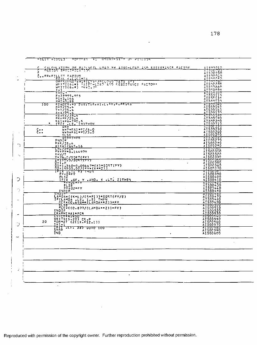
178
" = Tl=: AISCUD----FTrrrrT^— ' U\'IV = - ' V 3 = 'VI • ~ ’J ........ ......"
1 ? c Ur =L m i " =v aisc-loao a*,t> rfsist*vc= = ac tor a * r nn o i r.- : ".'i' ■' 2 -«A ! S 00030
C..=5rFILL=T RADIUS A t c on i~,a iA t e an r c ■>nDRvjiujjr-a^sjic-i/orin.i} o a T A A*) a T SOOcbo
1 W=TT=Cf..») ,ATS'--LDAO A VO RESISTANCE FACTOR* A I S 00070WE I TEC 6 .*) •* = ;:. 7* A I S30O3r>1 = 1 A I?000aC< = 0 . a is oo i co
1 F=2?°R5.R55 A I SOD 110°I=3.146 AIS00120
1 RUT=n.Q 5 A T Sf'O 1 30100 5 = 40(0.*) A . A, T, ft. A'l .L . =Y,R , PR ,RA AISOo Ia o
P=R/25.4 a I SCO 150T=T/25.4 AI SCO 160A=A/?5.4 AT S001 7”>RA=RA/25.4 AT SCO isoFR===/25.4 A I S 0 D 1 o 0! RA1=RA-T*D.F a:soo 2 0 d* * T=(T .L=. 1 0 )TUCV ATS00210
W=3 a: 500 2 2 ';C.. W = P + P.A1 « = I/S.O A I SOD 2 30C.. W=P+PAl*PI/3.0 A ! S00240
FI SE A ISOO 2 50W=4-T-FR A I 6 :.'U 2 60
END I = A IS00 2 70P=R/25.4 A ISOO 2 50
! A1=A1/645. 16 A ISOO 2°0L = L/25 .4 a 1 i'JU 3ui»
1 FY=FY*0.144R7P A ISOO 310X = W / T A I SCO 320Y=76.0/SORT(FY) A IS00330
1 L - ISS-.O/bUm IFY) A1 SCO340 "0 = 1 . 0 A ISOO 35001 = 1 .340-0.0044 7*(X) •'SORT (FY) AIS0036002=15500.0C/(=Y*(X**2)) ATS 0 0 3701 M X .127.' YJ TWbV A ISUU 3P D
, FY=C*FY AIS003R0FL Sc A IS00400
J IFfX .GF. Y .AND. X .LT. Z)THEN 4IS00410FY='J1*FY A 1 Sl'U 420FUSE AIS00430=Y=02*FY A I SC0440
FNDIF A IS00450c.n U i t- ...AT SO046ULA»D4=((K*L)/(R«PI>)*SORT(FY/E> AIS00470IF(LAMDA .l e . 1.5) t h e n A I SCO 480
FCR=(0.658*»(LAMDA**2))»FY A!S004P06 L Sb A I SUU 54'U=CR=((0.877/(LAM0A*«2))*FY) AISOO 510
ENDIF A ISOO 520CR=PUI«A 1 *Frp A ISOO 5 30i_s=L“*7r.4 b0 ..... .. A 1 SU'J 54UWRIT = ( i.,2 0 ) Cft.p A ISOO 550
20 =ORMAT (2(1X.F12.1)) A ! SOO 560J I = T * 1 A ISOO 570. 1P(T .Lb. bb) bUl'J 100' ATSDO 5 b01 STOP A ISOO 590i END AIS00600
!!iiiliJl
v |1ij •
Reproduced with permission of the copyright owner. Further reproduction prohibited without permission.
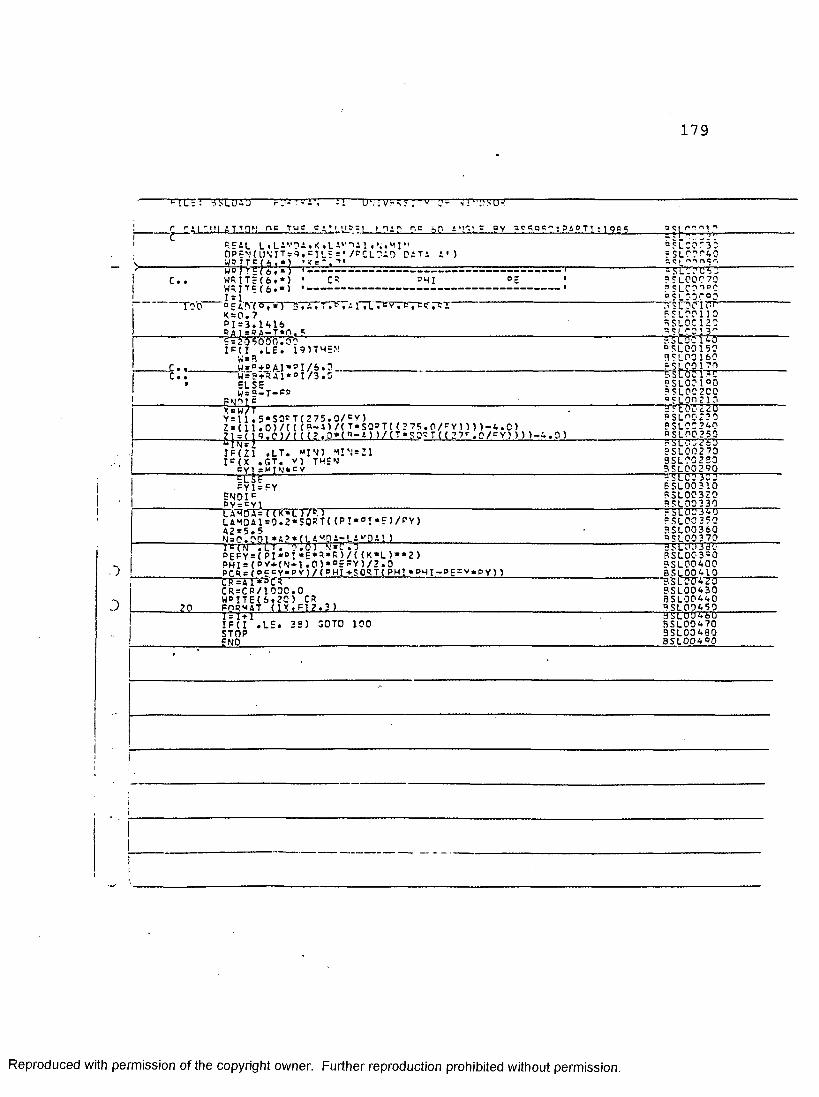
179
m m T'TcnTT- mrnT rn . m TT "TT”TIM Vr<.^ : ’ v
m A T T DM nc Tug CA!L*J3 = L [ n 1 ft r,g !*Lr P V *^SQ??:9&PTl;1QQgC=AL L«LA*-'?A«K»LA Al 4 ^
a?ico'-3Pv .. 0PFN(UNITs9,s i l ==*/PCLPAO DATA A’) rSLOOOAC
c . . WRITE(6 .*) • C ~ PHI ° E • a a LPOC 70
y ?-0— I = 1 dpi 3 p o a0 E A 0 (a 7 *) r' . a . TT* , a iTLTfv^ K = 0 . 7 PI=3.1416 P A 1=BA-T*n. 9
" BSL'Dcio'- 9 ? LOO 110 5SLPC120 acL0C!3^
r . .
9=205000.00 IF(I .l e . 19)T H E N Vi= 9W=o+RAl»ST/6 .D
sslOc IaO ° SLOP 150 BSLOO160 ? SLCO170
c..> W=9+RAl*°I/3.0E L S EW=9-T- fpPW'lT C
5SLOC1PC 9 SLOP 1°0 a aLPC 200 aSL0n210
Y=li.5*S0eTC275.0/cV)Z=(11.0)/C({«-»)/(T*SO=T((275.0/*Yn))-4.0) ?ja(^9.P)/r<f?.0«(P-A))/(T»SQRTU2 7'-.p/eY))))-9.0>IFC21 .LT. «IN) M!N=;i I = {x .GT. v) THEN^ * M!N*P V ---------
FY1=FY ENDI cPY = = Y1__________ __________________
Xa"h s t= (( k * 'l r /cnLAMDA1=0.2«S0RT( (PI*PI*f )/PY) 42=5.5N=0.001 *A?*fI AHpA-LA^DAl )
PSLO0230 ? SLOP ?A0 0 SLOP 2 50 ? S LOS VST) 9SL00270 9SL00 2 20 9 5 LOO 2 90F'SL'coxro”BSLOO 310 93L00320 9SL00330 ' FSLOrJW PSL00350 9SL00360 a SLOP 3 70
T E (N V ll T. 0.0 > N=C.O PgFY=(PI,,DI*E*9*R)/((K*L)**2)PHI=( p v +(n *1.0)*°c FY5/2.0Pr9=fo=FY*PY)/(PHI+SORT(PH!*PHI-PE=v«PY)5xvipT'rsCR = C R/1000.0 WB ITE(6 .20 ) CR .FORMAT (IX.FI?.3)______________________________
• J
D
3SL'irjm~BSL00390PSL00A00BSL00410'■rOTTATTT9SL00430b s l o o a a oPSL0QA50itr+rIF(I .LE. 3 9) SOTO 100
STOPEND______________________
asLoOwu9SL00A70 9SL00480 BSL004 9Q
Reproduced with permission of the copyright owner. Further reproduction prohibited without permission.

180
Name
Place Of Birth
Year Of Birth9
Education
VITA AUCTORIS
Krishna Kishore Sankisa
Palakol, Andhra Pradesh, INDIA
March 5, 1970
Bharatiya Vidya Bhavan's Public
School, Andhra Pradesh, INDIA
1985-1987
Osraania University, Hyderabad, INDIA
1987-1991 B.E.
University of Windsor, Windsor, ON
1991-1993 M.A.Sc.
Reproduced with permission of the copyright owner. Further reproduction prohibited without permission.
Copyright © 2022 FDOKUMEN