
Comprehensive Modeling and Analysis of Permanent Magnet Synchronous Generator-Wind Turbine System...
8
Abstract—With a growing penetration of Permanent Magnet Synchronous Wind Turbine Generations (PMSG-WT) into the modern power system, a comprehensive modeling and analysis of PMSG-WT is required to investigate its dynamic stability and interaction between large wind farm and power grids. In this work, a complete detailed MW-class variable speed Wind Turbine System based on a Permanent Magnet Synchronous Generator and a full-scale IGBT Voltage Source Converter is developed for PSCAD/EMTDC simulation study. This control scheme comprises both the mostly applied Maximum Point Power Tracking Operation and Double PWM active/reactive power independent control strategy. Moreover, a DC-link over- voltage protection scheme is designed and implemented in this model. A two mass drive train model is integrated into this WT model to achieve a reasonably accurate simulation on the transient stability of PMSG-WT. The feasibility of the established PMSG-WT physical model plus the effectiveness of proposed control and protection scheme are evaluated through a series of simulation studies under both variable wind speed conditions and a three-phase grid disturbance. Simulation results demonstrate that the PMSG-WT model possesses desirable capabilities of operation at the maximum power point as well as enhanced Low Voltage Ride Through Function (LVRT). Index Terms—Modeling, PMSG-WT, Low Voltage Ride Through Capability (LVRT), MPPT I. INTRODUCTION ith high penetration of wind power resources in the modern power grid, Permanent Magnet Synchronous Generator Wind Turbine System (PMSG-WT) with full power back to back converters will increasingly become a promising and popular wind turbine technology because of its high power density, gearless structure as well as flexible controllability for maximum wind power extraction and grid support. Therefore, a PMSG-WT system is expected to This work was supported in part by NSF Grant 0844707. Ziping Wu are with the Department of Electrical and Computer Engineering, University of Denver, Denver, CO 80210 USA (e-mail: [email protected]). Wenzhong Gao is with the Department of Electrical and Computer Engineering, University of Denver, Denver, CO 80210 USA (e-mail: [email protected]). Daye Yang is with Department of Power System, China Electric Power Research Institute, Beijing, China. Yan Shi is with Xinjiang Electric Power Company, Xinjiang, China. possess higher efficiency and reliability compared with that of DFIG Wind Turbine [1-5]. To better understand the impact of PMSG-WT operation on the power grid and the control system of PMSG-WT, detailed modeling and accurate simulation are critical. Up to now, there are a few papers focusing on a complete modeling and analysis on the PMSG WT system with a double PWM controls using PSCAD/EMTDC software. Some papers emphasize the converter control strategies of PMSG-WT without modeling of the mechanical component in details [6- 7][9]. And others simplify the grid-side converter model using the uncontrolled diode rectifier for the relevant PMSG study [3][8]. Additionally, several investigations have been carried out to improve the Low Voltage Ride Through (LVRT) Capability of PMSG-WT system. A chopper on the DC-link is adopted as a DC link over-voltage protection device [10][11]. An energy storage system is applied in Directly Driven Permanent Magnet Alternator to smooth out the power fluctuations and fulfill the LVRT function [7][12]. Therefore, it is essential to establish a comprehensive variable-speed PMSG WT model with two full rated PWM converters and LVRT function so that the dynamic behaviors of PMSG-WT system can be better assessed and analyzed. In this paper, a comprehensive and detailed MW-class variable speed wind turbine system equipped with a Permanent Magnet Synchronous Generator and a full-scale IGBT Voltage Source Converter (VSC) is developed for PSCAD/EMTDC simulation study on the dynamic characteristics of PMSG-WT. This control scheme comprises both the Maximum Efficiency Operation and Double PWM active/reactive power independent control strategy: the generator side converter can control the generator rotor speed to achieve the maximum power operating point while the grid side converter can maintain the dc-link capacitor voltage constant as well as reactive power exchanged with grid at desired power factor mode. Meanwhile, a DC-link over- voltage protection scheme is designed and implemented in this model. In addition, this WT model is also coupled with dynamic pitch control to regulate the output power according to the following curve in the Fig.1 so that it is capable of maintaining the optimal power operation over a wide range of Comprehensive Modeling and Analysis of Permanent Magnet Synchronous Generator- Wind Turbine System with Enhanced Low Voltage Ride Through Capability Ziping Wu, Student Member, IEEE, Wenzhong Gao, Senior Member, IEEE, Daye Yang, Yan Shi W 978-1-4673-0803-8/12/$31.00 ©2012 IEEE 2091
-
Upload
universityofdenverdu -
Category
Documents
-
view
0 -
download
0
Transcript of Comprehensive Modeling and Analysis of Permanent Magnet Synchronous Generator-Wind Turbine System...
Abstract—With a growing penetration of Permanent Magnet
Synchronous Wind Turbine Generations (PMSG-WT) into the modern power system, a comprehensive modeling and analysis of PMSG-WT is required to investigate its dynamic stability and interaction between large wind farm and power grids. In this work, a complete detailed MW-class variable speed Wind Turbine System based on a Permanent Magnet Synchronous Generator and a full-scale IGBT Voltage Source Converter is developed for PSCAD/EMTDC simulation study. This control scheme comprises both the mostly applied Maximum Point Power Tracking Operation and Double PWM active/reactive power independent control strategy. Moreover, a DC-link over-voltage protection scheme is designed and implemented in this model. A two mass drive train model is integrated into this WT model to achieve a reasonably accurate simulation on the transient stability of PMSG-WT. The feasibility of the established PMSG-WT physical model plus the effectiveness of proposed control and protection scheme are evaluated through a series of simulation studies under both variable wind speed conditions and a three-phase grid disturbance. Simulation results demonstrate that the PMSG-WT model possesses desirable capabilities of operation at the maximum power point as well as enhanced Low Voltage Ride Through Function (LVRT).
Index Terms—Modeling, PMSG-WT, Low Voltage Ride Through Capability (LVRT), MPPT
I. INTRODUCTION ith high penetration of wind power resources in the modern power grid, Permanent Magnet Synchronous
Generator Wind Turbine System (PMSG-WT) with full power back to back converters will increasingly become a promising and popular wind turbine technology because of its high power density, gearless structure as well as flexible controllability for maximum wind power extraction and grid support. Therefore, a PMSG-WT system is expected to
This work was supported in part by NSF Grant 0844707. Ziping Wu are with the Department of Electrical and Computer
Engineering, University of Denver, Denver, CO 80210 USA (e-mail: [email protected]). Wenzhong Gao is with the Department of Electrical and Computer Engineering, University of Denver, Denver, CO 80210 USA (e-mail: [email protected]). Daye Yang is with Department of Power System, China Electric Power Research Institute, Beijing, China. Yan Shi is with Xinjiang Electric Power Company, Xinjiang, China.
possess higher efficiency and reliability compared with that of DFIG Wind Turbine [1-5].
To better understand the impact of PMSG-WT operation on the power grid and the control system of PMSG-WT, detailed modeling and accurate simulation are critical. Up to now, there are a few papers focusing on a complete modeling and analysis on the PMSG WT system with a double PWM controls using PSCAD/EMTDC software. Some papers emphasize the converter control strategies of PMSG-WT without modeling of the mechanical component in details [6-7][9]. And others simplify the grid-side converter model using the uncontrolled diode rectifier for the relevant PMSG study [3][8]. Additionally, several investigations have been carried out to improve the Low Voltage Ride Through (LVRT) Capability of PMSG-WT system. A chopper on the DC-link is adopted as a DC link over-voltage protection device [10][11]. An energy storage system is applied in Directly Driven Permanent Magnet Alternator to smooth out the power fluctuations and fulfill the LVRT function [7][12]. Therefore, it is essential to establish a comprehensive variable-speed PMSG WT model with two full rated PWM converters and LVRT function so that the dynamic behaviors of PMSG-WT system can be better assessed and analyzed.
In this paper, a comprehensive and detailed MW-class variable speed wind turbine system equipped with a Permanent Magnet Synchronous Generator and a full-scale IGBT Voltage Source Converter (VSC) is developed for PSCAD/EMTDC simulation study on the dynamic characteristics of PMSG-WT. This control scheme comprises both the Maximum Efficiency Operation and Double PWM active/reactive power independent control strategy: the generator side converter can control the generator rotor speed to achieve the maximum power operating point while the grid side converter can maintain the dc-link capacitor voltage constant as well as reactive power exchanged with grid at desired power factor mode. Meanwhile, a DC-link over-voltage protection scheme is designed and implemented in this model.
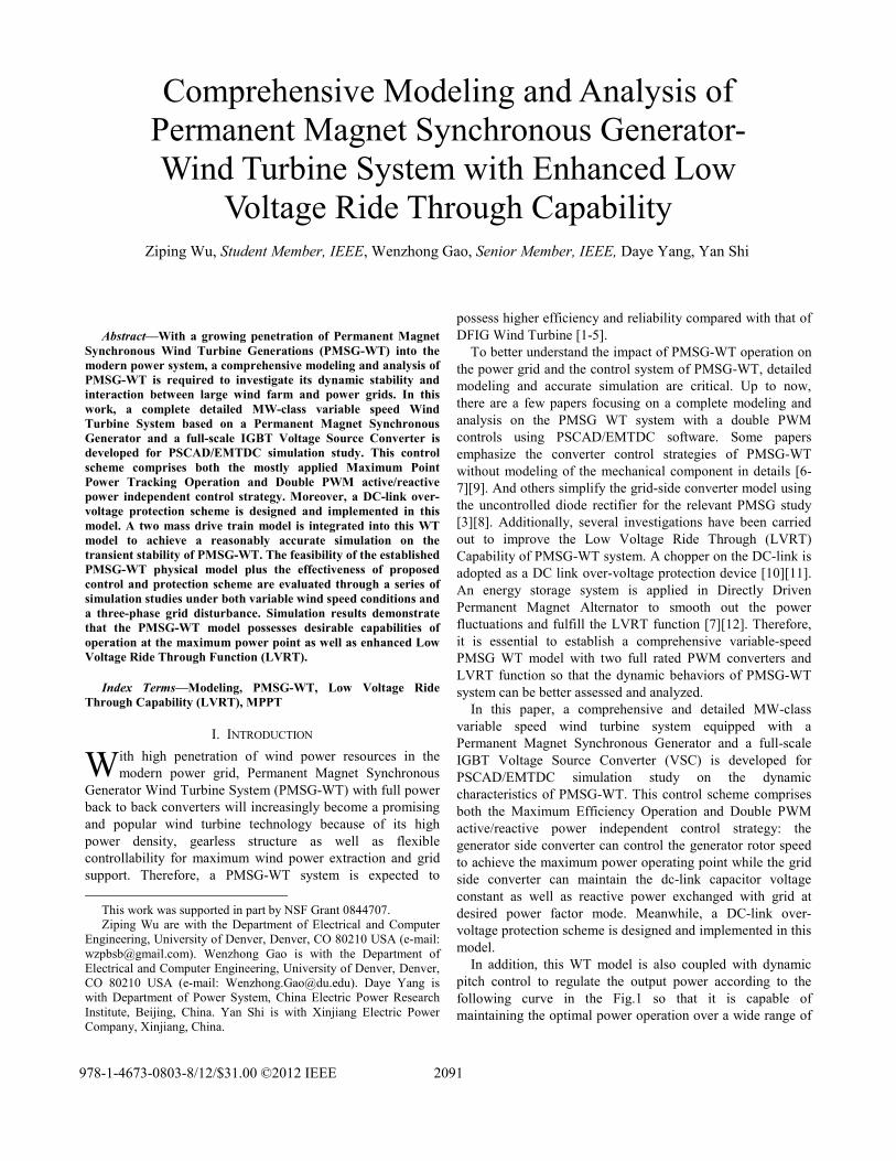
In addition, this WT model is also coupled with dynamic pitch control to regulate the output power according to the following curve in the Fig.1 so that it is capable of maintaining the optimal power operation over a wide range of
Comprehensive Modeling and Analysis of Permanent Magnet Synchronous Generator-Wind Turbine System with Enhanced Low
Voltage Ride Through Capability Ziping Wu, Student Member, IEEE, Wenzhong Gao, Senior Member, IEEE, Daye Yang, Yan Shi
W
978-1-4673-0803-8/12/$31.00 ©2012 IEEE 2091
wind speed conditions. A two mass drive train model is also integrated into this WT model to facilitate a more accurate simulation and analysis on the transient stability of PMSG-WT since shaft torsional oscillation is more likely to cause the speed and power fluctuations. The validity of the established model plus the proposed control and protection strategy for this PMSG-WT model are evaluated by simulation study under the conditions of varying wind speed and severe grid disturbances. Simulation results demonstrate that the presented PMSG-WT model possesses desirable capabilities of operation at the maximum power point. The DC-link over-voltage protection method is effective in protecting the converter from over voltage damage and thus enhancing the Low Voltage Ride Through (VLRT) Capacity under the grid fault condition as well. And reactive power support can also act as a desirable means to enhance LVRT capability by enhancing the grid voltage during the grid fault event.
windVcut inV − cut offV −
I II III
ratedV
ratedPIV
Fig.1. Operation modes of PMSG-WT system under different wind speed conditions
The operation modes are divided into 4 different operating zones according to the magnitude of wind speed as follow:
Zone I: P=0 The wind turbine does not rotate and produce no power when Vwind<Vcut-in
Zone II: P<Prated, P=f(Vwind) with 0β = The wind turbine operates with the maximum efficiency when Vcut-
in<Vwind<Vrated Zone III: P=Prated with > 0β Output power is
maintained at Prated via the dynamic pitch control when Vrated<Vwind<Vcut-off
Zone IV: P=0 The turbine is suspended by using mechanical brakes when Vwind>Vcut-out
It is necessary to be aware that the above curve is only suitable for the relatively ideal PMSG-WT system. For a practical system, the stator winding loss of generator and turbine should be also taken into account, so the actual power of PMSG at the rated wind speed is smaller than 1.5 MW rated capacity. On the other hand, the operational objective for the proposed PMSG-WT model is to utilize the wind power with maximum coefficients. Meanwhile, the pitch control is designed to regulate and maintain the generator power output within the rated power due to mechanical constraints and the converter current rating especially when the actual output exceeds the rated value at a high wind speed in Zone III.
II. MODELING OF PMSG-WT SYSTEM In this work, a 1.5 MW PMSG-WT system mainly consists
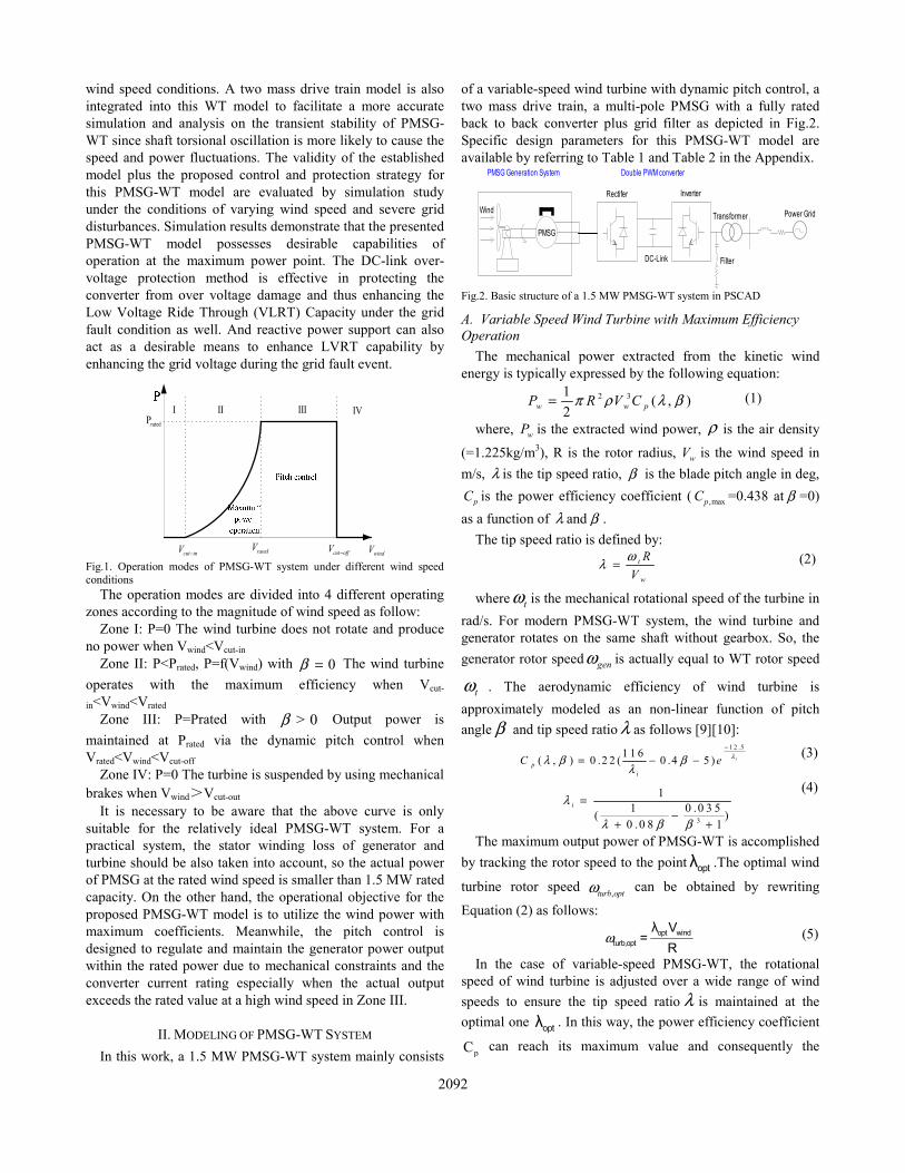
of a variable-speed wind turbine with dynamic pitch control, a two mass drive train, a multi-pole PMSG with a fully rated back to back converter plus grid filter as depicted in Fig.2. Specific design parameters for this PMSG-WT model are available by referring to Table 1 and Table 2 in the Appendix.
Fig.2. Basic structure of a 1.5 MW PMSG-WT system in PSCAD
A. Variable Speed Wind Turbine with Maximum Efficiency Operation
The mechanical power extracted from the kinetic wind energy is typically expressed by the following equation:
2 31 ( , )2w w pP R V Cπ ρ λ β= (1)
where, wP is the extracted wind power, ρ is the air density
(=1.225kg/m3), R is the rotor radius, wV is the wind speed in m/s, λ is the tip speed ratio, β is the blade pitch angle in deg,
pC is the power efficiency coefficient ( ,maxpC =0.438 at β =0) as a function of λ and β .
The tip speed ratio is defined by: t
w
RV
ωλ = (2)
where tω is the mechanical rotational speed of the turbine in rad/s. For modern PMSG-WT system, the wind turbine and generator rotates on the same shaft without gearbox. So, the generator rotor speed genω is actually equal to WT rotor speed
tω . The aerodynamic efficiency of wind turbine is approximately modeled as an non-linear function of pitch angle β and tip speed ratio λ as follows [9][10]:
1 2 .51 1 6( , ) 0 .2 2 ( 0 .4 5 ) ip
i
C e λλ β βλ
−
= − − (3)
3
11 0 .0 3 5( )
0 .0 8 1
iλ
λ β β
=−
+ +
(4)
The maximum output power of PMSG-WT is accomplished by tracking the rotor speed to the point optλ .The optimal wind
turbine rotor speed ,turb optω can be obtained by rewriting
Equation (2) as follows:
ω opt windturb,opt
λ V=
R (5)
In the case of variable-speed PMSG-WT, the rotational speed of wind turbine is adjusted over a wide range of wind speeds to ensure the tip speed ratio λ is maintained at the optimal one optλ . In this way, the power efficiency coefficient
pC can reach its maximum value and consequently the
PMSG Generation System
PMSG
Wind
Rectifer
Power GridTransformer
DC-Link
Inverter
Filter
Double PWM converter
2092
maximum mechanical power can be extracted from wind energy. Furthermore, the maximum power Pmax can be expressed as:
_2 3max
1 ( )2 opt
turb optp
opt
RP R C
ωρπ
λ= (6)
where optpC and optλ are optimum values of power coefficient
and optimal tip speed ratio, respectively. From this equation, it is obvious that the maximum power extracted from the wind is proportional to the cube of the WT rotational speed with the blade pitch angle β set to 0 deg. Thus, the optimal power operation of PMSG WT system can be achieved through the regulation of generator rotor speed [1].
B. Two Mass Drive Train Model To fully assess the dynamic characteristics of many masses
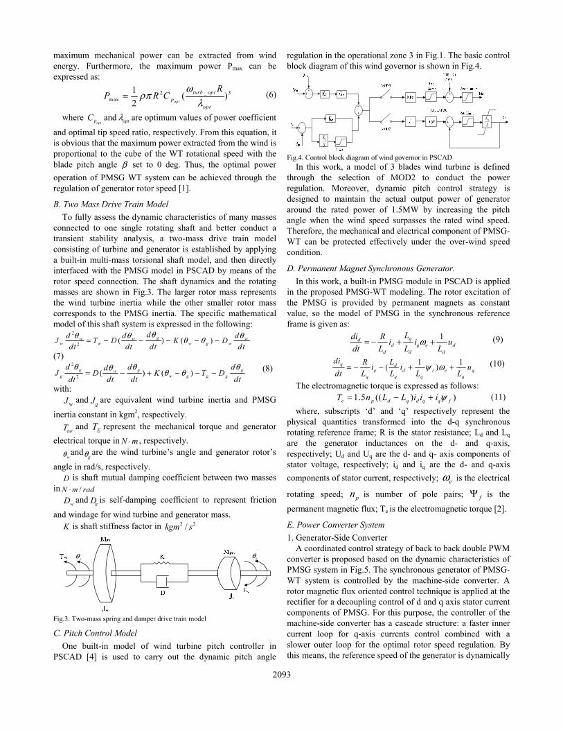
connected to one single rotating shaft and better conduct a transient stability analysis, a two-mass drive train model consisting of turbine and generator is established by applying a built-in multi-mass torsional shaft model, and then directly interfaced with the PMSG model in PSCAD by means of the rotor speed connection. The shaft dynamics and the rotating masses are shown in Fig.3. The larger rotor mass represents the wind turbine inertia while the other smaller rotor mass corresponds to the PMSG inertia. The specific mathematical model of this shaft system is expressed in the following:
2
2 ( ) ( )gw w ww w w g w
dd d dJ T D K Ddt dt dt dt
θθ θ θθ θ= − − − − −
(7) 2
2 ( ) ( )g g gwg w g g g
d d ddJ D K T Ddt dt dt dt
θ θ θθ θ θ= − + − − − (8)
with: wJ and gJ are equivalent wind turbine inertia and PMSG
inertia constant in kgm2, respectively.
turT and ET represent the mechanical torque and generator electrical torque in N m⋅ , respectively.
wθ andgθ are the wind turbine’s angle and generator rotor’s
angle in rad/s, respectively. D is shaft mutual damping coefficient between two masses
in /N m rad⋅
wD and gD is self-damping coefficient to represent friction
and windage for wind turbine and generator mass. K is shaft stiffness factor in 2 2/kgm s
wθ gθ
Fig.3. Two-mass spring and damper drive train model
C. Pitch Control Model One built-in model of wind turbine pitch controller in
PSCAD [4] is used to carry out the dynamic pitch angle
regulation in the operational zone 3 in Fig.1. The basic control block diagram of this wind governor is shown in Fig.4.
Fig.4. Control block diagram of wind governor in PSCAD In this work, a model of 3 blades wind turbine is defined
through the selection of MOD2 to conduct the power regulation. Moreover, dynamic pitch control strategy is designed to maintain the actual output power of generator around the rated power of 1.5MW by increasing the pitch angle when the wind speed surpasses the rated wind speed. Therefore, the mechanical and electrical component of PMSG-WT can be protected effectively under the over-wind speed condition.
D. Permanent Magnet Synchronous Generator. In this work, a built-in PMSG module in PSCAD is applied
in the proposed PMSG-WT modeling. The rotor excitation of the PMSG is provided by permanent magnets as constant value, so the model of PMSG in the synchronous reference frame is given as:
1qdd q e d
d d d
Ldi R i i udt L L L
ω= − + + (9)
1 1( )q dq d r e q
q q q q
di LR i i udt L L L L
ψ ω= − − + + (10)
The electromagnetic torque is expressed as follows: 1.5 (( ) )e p d q d q q fT n L L i i i ψ= − + (11)
where, subscripts ‘d’ and ‘q’ respectively represent the physical quantities transformed into the d-q synchronous rotating reference frame; R is the stator resistance; Ld and Lq are the generator inductances on the d- and q-axis, respectively; Ud and Uq are the d- and q- axis components of stator voltage, respectively; id and iq are the d- and q-axis components of stator current, respectively; eω is the electrical
rotating speed; pn is number of pole pairs; fΨ is the
permanent magnetic flux; Te is the electromagnetic torque [2].
E. Power Converter System 1. Generator-Side Converter
A coordinated control strategy of back to back double PWM converter is proposed based on the dynamic characteristics of PMSG system in Fig.5. The synchronous generator of PMSG-WT system is controlled by the machine-side converter. A rotor magnetic flux oriented control technique is applied at the rectifier for a decoupling control of d and q axis stator current components of PMSG. For this purpose, the controller of the machine-side converter has a cascade structure: a faster inner current loop for q-axis currents control combined with a slower outer loop for the optimal rotor speed regulation. By this means, the reference speed of the generator is dynamically
1KS
4KS
2093
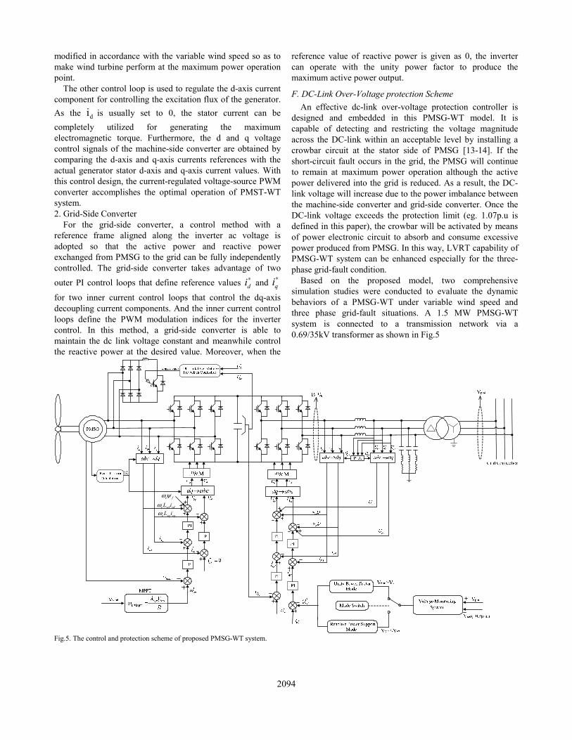
modified in accordance with the variable wind speed so as to make wind turbine perform at the maximum power operation point.
The other control loop is used to regulate the d-axis current component for controlling the excitation flux of the generator. As the di is usually set to 0, the stator current can be completely utilized for generating the maximum electromagnetic torque. Furthermore, the d and q voltage control signals of the machine-side converter are obtained by comparing the d-axis and q-axis currents references with the actual generator stator d-axis and q-axis current values. With this control design, the current-regulated voltage-source PWM converter accomplishes the optimal operation of PMST-WT system. 2. Grid-Side Converter
For the grid-side converter, a control method with a reference frame aligned along the inverter ac voltage is adopted so that the active power and reactive power exchanged from PMSG to the grid can be fully independently controlled. The grid-side converter takes advantage of two outer PI control loops that define reference values di
∗ and qi∗
for two inner current control loops that control the dq-axis decoupling current components. And the inner current control loops define the PWM modulation indices for the inverter control. In this method, a grid-side converter is able to maintain the dc link voltage constant and meanwhile control the reactive power at the desired value. Moreover, when the
reference value of reactive power is given as 0, the inverter can operate with the unity power factor to produce the maximum active power output.
F. DC-Link Over-Voltage protection Scheme An effective dc-link over-voltage protection controller is
designed and embedded in this PMSG-WT model. It is capable of detecting and restricting the voltage magnitude across the DC-link within an acceptable level by installing a crowbar circuit at the stator side of PMSG [13-14]. If the short-circuit fault occurs in the grid, the PMSG will continue to remain at maximum power operation although the active power delivered into the grid is reduced. As a result, the DC-link voltage will increase due to the power imbalance between the machine-side converter and grid-side converter. Once the DC-link voltage exceeds the protection limit (eg. 1.07p.u is defined in this paper), the crowbar will be activated by means of power electronic circuit to absorb and consume excessive power produced from PMSG. In this way, LVRT capability of PMSG-WT system can be enhanced especially for the three-phase grid-fault condition.
Based on the proposed model, two comprehensive simulation studies were conducted to evaluate the dynamic behaviors of a PMSG-WT under variable wind speed and three phase grid-fault situations. A 1.5 MW PMSG-WT system is connected to a transmission network via a 0.69/35kV transformer as shown in Fig.5
e fω ψ
e sd sdL iωe sq sqL iω
Fig.5. The control and protection scheme of proposed PMSG-WT system.
2094
III. SIMULATION STUDIES
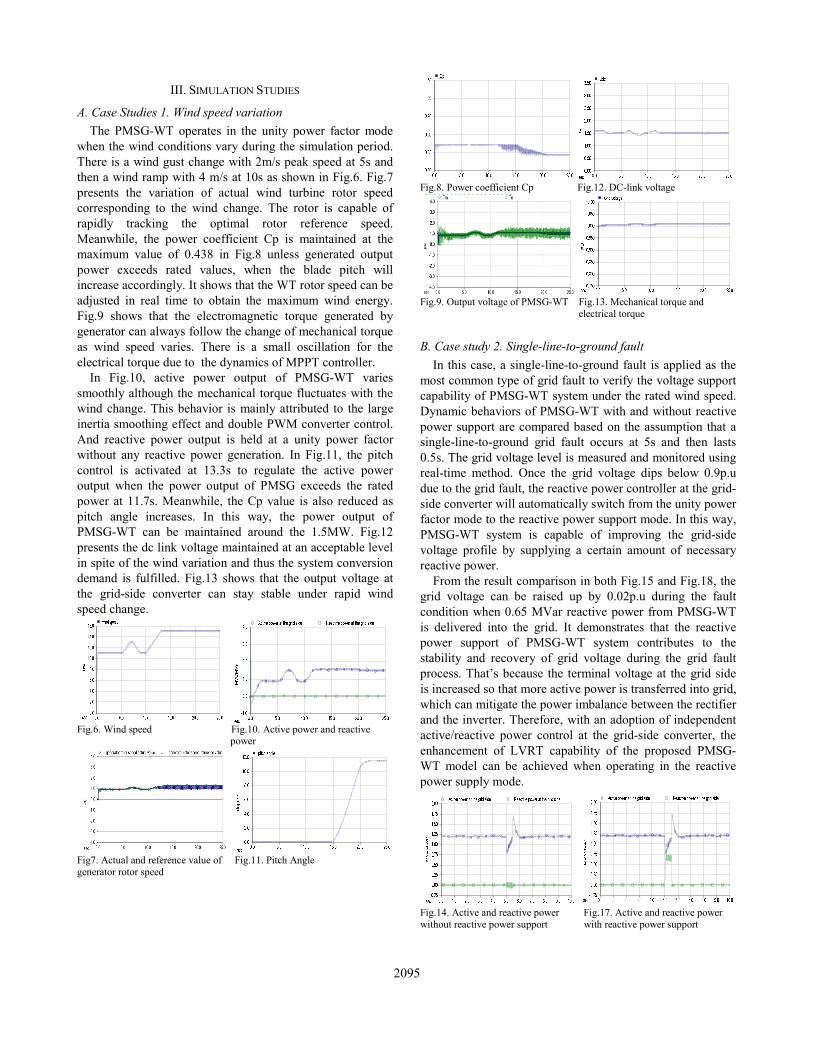
A. Case Studies 1. Wind speed variation The PMSG-WT operates in the unity power factor mode
when the wind conditions vary during the simulation period. There is a wind gust change with 2m/s peak speed at 5s and then a wind ramp with 4 m/s at 10s as shown in Fig.6. Fig.7 presents the variation of actual wind turbine rotor speed corresponding to the wind change. The rotor is capable of rapidly tracking the optimal rotor reference speed. Meanwhile, the power coefficient Cp is maintained at the maximum value of 0.438 in Fig.8 unless generated output power exceeds rated values, when the blade pitch will increase accordingly. It shows that the WT rotor speed can be adjusted in real time to obtain the maximum wind energy. Fig.9 shows that the electromagnetic torque generated by generator can always follow the change of mechanical torque as wind speed varies. There is a small oscillation for the electrical torque due to the dynamics of MPPT controller.
In Fig.10, active power output of PMSG-WT varies smoothly although the mechanical torque fluctuates with the wind change. This behavior is mainly attributed to the large inertia smoothing effect and double PWM converter control. And reactive power output is held at a unity power factor without any reactive power generation. In Fig.11, the pitch control is activated at 13.3s to regulate the active power output when the power output of PMSG exceeds the rated power at 11.7s. Meanwhile, the Cp value is also reduced as pitch angle increases. In this way, the power output of PMSG-WT can be maintained around the 1.5MW. Fig.12 presents the dc link voltage maintained at an acceptable level in spite of the wind variation and thus the system conversion demand is fulfilled. Fig.13 shows that the output voltage at the grid-side converter can stay stable under rapid wind speed change.
Fig.6. Wind speed Fig.10. Active power and reactive
power
Fig7. Actual and reference value of Fig.11. Pitch Angle generator rotor speed
Fig.8. Power coefficient Cp Fig.12. DC-link voltage
Fig.9. Output voltage of PMSG-WT Fig.13. Mechanical torque and electrical torque
B. Case study 2. Single-line-to-ground fault In this case, a single-line-to-ground fault is applied as the
most common type of grid fault to verify the voltage support capability of PMSG-WT system under the rated wind speed. Dynamic behaviors of PMSG-WT with and without reactive power support are compared based on the assumption that a single-line-to-ground grid fault occurs at 5s and then lasts 0.5s. The grid voltage level is measured and monitored using real-time method. Once the grid voltage dips below 0.9p.u due to the grid fault, the reactive power controller at the grid-side converter will automatically switch from the unity power factor mode to the reactive power support mode. In this way, PMSG-WT system is capable of improving the grid-side voltage profile by supplying a certain amount of necessary reactive power.
From the result comparison in both Fig.15 and Fig.18, the grid voltage can be raised up by 0.02p.u during the fault condition when 0.65 MVar reactive power from PMSG-WT is delivered into the grid. It demonstrates that the reactive power support of PMSG-WT system contributes to the stability and recovery of grid voltage during the grid fault process. That’s because the terminal voltage at the grid side is increased so that more active power is transferred into grid, which can mitigate the power imbalance between the rectifier and the inverter. Therefore, with an adoption of independent active/reactive power control at the grid-side converter, the enhancement of LVRT capability of the proposed PMSG-WT model can be achieved when operating in the reactive power supply mode.
Fig.14. Active and reactive power Fig.17. Active and reactive power without reactive power support with reactive power support
2095
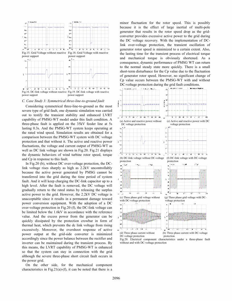
Fig.15. Grid Voltage without reactive Fig.18. Grid Voltage with reactive power support power support
Fig.16. DC-link voltage without reactive Fig.19. DC-link voltage with reactive power support power support
C. Case Study 3: Symmetrical three-line-to-ground fault Considering symmetrical three-line-to-ground as the most
severe type of grid fault, one dynamic simulation was carried out to testify the transient stability and enhanced LVRT capability of PMSG-WT model under this fault condition. A three-phase fault is applied on the 35kV feeder line at 5s lasting 0.3s. And the PMSG-WT system keeps operating at the rated wind speed. Simulation results are obtained for a comparison between the PMSG-WT system with DC voltage protection and that without it. The active and reactive power fluctuations, the voltage and current output of PMSG-WT as well as DC link voltage are shown in Fig.20. Fig.21 displays the dynamic behaviors of wind turbine rotor speed, torque and Cp in response to this fault.
In Fig.20 (b), without DC over-voltage protection, the DC-link voltage rises sharply as high as 2.2kV uncontrollably because the active power generated by PMSG cannot be transferred into the grid during the time period of system fault. And it will keep charging the DC-link capacitor up to a high level. After the fault is removed, the DC voltage will gradually return to the rated status by releasing the surplus active power to the grid. However, the 2.2kV DC voltage is unacceptable since it results in a permanent damage toward power conversion equipment. With the adoption of a DC over-voltage protection in Fig.20 (f), the DC-link voltage can be limited below the 1.6kV in accordance with the reference value. And the excess power from the generator can be quickly dissipated by the protection crowbar in form of thermal heat, which prevents the dc link voltage from rising excessively. Moreover, the overshoot response of active power output at the grid-side converter is minimized accordingly since the power balance between the rectifier and inverter can be maintained during the transient process. By this means, the LVRT capability of PMSG-WT is enhanced so that the system can stay in connection with the grid although the severe three-phase short circuit fault occurs in the power grid.
On the other side, for the mechanical component characteristics in Fig.21(a)-(f), it can be noted that there is a
minor fluctuation for the rotor speed. This is possibly because it is the effect of large inertial of multi-pole generator that results in the rotor speed drop as the grid-converter provides excessive active power to the grid during the DC voltage recovery. With the implementation of DC-link over-voltage protection, the transient oscillation of generator rotor speed is minimized to a certain extent. Also, the lasting time for the transient process of electrical torque and mechanical torque is obviously shortened. As a consequence, dynamic performance of PMSG WT can return to the normal steady state more quickly. There is a small short-term disturbance for the Cp value due to the fluctuation of generator rotor speed. However, no significant change of Cp value occurs between the PMSG-WT with and without DC-voltage protection during the grid fault conditions.
(a) Active and reactive power without (e) Active and reactive power with DC DC voltage protection voltage protection
(b) DC-link voltage without DC-voltage (f) DC-link voltage with DC-voltage protection protection
(c) Three phase grid voltage without (g) Three phase grid voltage with DC- with DC-voltage protection voltage protection
(d) Three phase current without (h) Three phase current with DC-voltage DC-voltage protection protection Fig.20. Electrical component characteristics under a three-phase fault without and with DC-voltage protection
2096
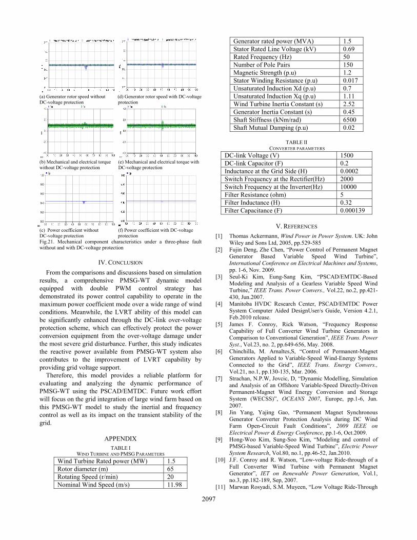
(a) Generator rotor speed without (d) Generator rotor speed with DC-voltage DC-voltage protection protection
(b) Mechanical and electrical torque (e) Mechanical and electrical torque with without DC-voltage protection DC-voltage protection
(c) Power coefficient without (f) Power coefficient with DC-voltage DC-voltage protection protection Fig.21. Mechanical component characteristics under a three-phase fault without and with DC-voltage protection
IV. CONCLUSION From the comparisons and discussions based on simulation
results, a comprehensive PMSG-WT dynamic model equipped with double PWM control strategy has demonstrated its power control capability to operate in the maximum power coefficient mode over a wide range of wind conditions. Meanwhile, the LVRT ability of this model can be significantly enhanced through the DC-link over-voltage protection scheme, which can effectively protect the power conversion equipment from the over-voltage damage under the most severe grid disturbance. Further, this study indicates the reactive power available from PMSG-WT system also contributes to the improvement of LVRT capability by providing grid voltage support.
Therefore, this model provides a reliable platform for evaluating and analyzing the dynamic performance of PMSG-WT using the PSCAD/EMTDC. Future work effort will focus on the grid integration of large wind farm based on this PMSG-WT model to study the inertial and frequency control as well as its impact on the transient stability of the grid.
APPENDIX TABLE I
WIND TURBINE AND PMSG PARAMETERS Wind Turbine Rated power (MW) 1.5 Rotor diameter (m) 65 Rotating Speed (r/min) 20 Nominal Wind Speed (m/s) 11.98
Generator rated power (MVA) 1.5 Stator Rated Line Voltage (kV) 0.69 Rated Frequency (Hz) 50 Number of Pole Pairs 150 Magnetic Strength (p.u) 1.2 Stator Winding Resistance (p.u) 0.017 Unsaturated Induction Xd (p.u) 0.7 Unsaturated Induction Xq (p.u) 1.11 Wind Turbine Inertia Constant (s) 2.52 Generator Inertia Constant (s) 0.45 Shaft Stiffness (kNm/rad) 6500 Shaft Mutual Damping (p.u) 0.02
TABLE II
CONVERTER PARAMETERS DC-link Voltage (V) 1500 DC-link Capacitor (F) 0.2 Inductance at the Grid Side (H) 0.0002 Switch Frequency at the Rectifier(Hz) 2000 Switch Frequency at the Inverter(Hz) 10000 Filter Resistance (ohm) 5 Filter Inductance (H) 0.32 Filter Capacitance (F) 0.000139
V. REFERENCES [1] Thomas Ackermann, Wind Power in Power System. UK: John
Wiley and Sons Ltd, 2005, pp.529-585 [2] Fujin Deng, Zhe Chen, “Power Control of Permanent Magnet
Generator Based Variable Speed Wind Turbine”, International Conference on Electrical Machines and Systems, pp. 1-6, Nov. 2009.
[3] Seul-Ki Kim, Eung-Sang Kim, “PSCAD/EMTDC-Based Modeling and Analysis of a Gearless Variable Speed Wind Turbine,” IEEE Trans. Power Convers., Vol.22, no.2, pp.421-430, Jun.2007.
[4] Manitoba HVDC Research Center, PSCAD/EMTDC Power System Computer Aided DesignUser/s Guide, Version 4.2.1, Feb.2010 release.
[5] James F. Conroy, Rick Watson, “Frequency Response Capability of Full Converter Wind Turbine Generators in Comparison to Conventional Generation”, IEEE Trans. Power Syst., Vol.23, no. 2, pp.649-656, May. 2008.
[6] Chinchilla, M. Arnaltes,S, “Control of Permanent-Magnet Generators Applied to Variable-Speed Wind-Energy Systems Connected to the Grid”, IEEE Trans. Energy Convers., Vol.21, no.1, pp.130-135, Mar. 2006.
[7] Strachan, N.P.W, Jovcic, D, “Dynamic Modelling, Simulation and Analysis of an Offshore Variable-Speed Directly-Driven Permanent-Magnet Wind Energy Conversion and Storage System (WECSS)”, OCEANS 2007, Europe, pp.1-6, Jun. 2007.
[8] Jin Yang, Yajing Gao, “Permanent Magnet Synchronous Generator Converter Protection Analysis during DC Wind Farm Open-Circuit Fault Conditions”, 2009 IEEE on Electrical Power & Energy Conference, pp.1-6, Oct.2009.
[9] Hong-Woo Kim, Sung-Soo Kim, “Modeling and control of PMSG-based Variable-Speed Wind Turbine”, Electric Power System Research, Vol.80, no.1, pp.46-52, Jan.2010.
[10] J.F. Conroy and R. Watson, “Low-voltage Ride-through of a Full Converter Wind Turbine with Permanent Magnet Generator”, IET on Renewable Power Generation, Vol.1, no.3, pp.182-189, Sep, 2007.
[11] Marwan Rosyadi, S.M. Muyeen, “Low Voltage Ride-Through
2097

Capability Improvement of Wind Farms using Variable Speed Permanent Magnet Wind Generator”, 2011 International Conference on Electrical Machines and Systems, pp.1-6, 2011.
[12] Kun Zhang, Yuping Duan, “Low Voltage Ride Through Control Strategy of Directly Driven Wind Turbine with Energy Storage System”, 2011 IEEE on Power and Energy Society General Meeting , pp.1-7, 2011.
[13] Janaka B. Ekanayake, Lee Holdsworth, Xue Guang Wu and Nicholas Jenkins, “Dynamic Modeling of Doubly Fed Induction Generator Wind Turbines”, IEEE Trans. Power Syst., vol. 18, no. 2, pp. 803-809, May 2003.
[14] Jianlin Li, HongHua Xu, et al., Power Electronic Converter Technology in Wind Power Generation, Beijing: China Machine Press, 2009, p.195.
Ziping Wu was born in Tianjin, China, in 1982. He received the B.E degree in thermal power engineering and M.S degree in electrical power engineering from North China Electric Power University, Beijing, China, in 2006 and 2009, respectively.
After graduation, he worked as an electrical engineer in China Electrical Power Research Institute from 2009 to 2011. His work mainly focused on the bulk power system modeling and
simulation as well as HVDC transmission engineering. Since 2011, he has been pursuing the Ph.D. degree in the Department of
Electrical and Computer Engineering, University of Denver. His current research interests include wind power generation, renewable energy, smart grid.
Wenzhong Gao (S’00–M’02–SM’03) received the M.S. and Ph.D. degrees in electrical and computer engineering specializing in electric power engineering from Georgia Institute of Technology, Atlanta, in 1999 and 2002, respectively. He is currently with the Department of Electrical and Computer Engineering, University of Denver, Colorado, USA. His current teaching and research interests include renewable energy and distributed generation,
smart grid, power system protection, power electronics applications in power systems, power system modeling and simulation, and hybrid electric propulsion systems. He is an Editor for IEEE Transactions on Sustainable Energy. He is the General Chair for The IEEE Symposium on Power Electronics and Machines in Wind Applications (PEMWA 2012).
2098