Complex magnetism of the Fe monolayer on Ir(111)
20
Complex magnetism of the Fe monolayer on Ir(111) This content has been downloaded from IOPscience. Please scroll down to see the full text. Download details: IP Address: 109.185.116.199 This content was downloaded on 01/10/2013 at 00:16 Please note that terms and conditions apply. 2007 New J. Phys. 9 396 (http://iopscience.iop.org/1367-2630/9/10/396) View the table of contents for this issue, or go to the journal homepage for more Home Search Collections Journals About Contact us My IOPscience
-
Upload
uni-hamburg -
Category
Documents
-
view
0 -
download
0
Transcript of Complex magnetism of the Fe monolayer on Ir(111)

Complex magnetism of the Fe monolayer on Ir(111)
This content has been downloaded from IOPscience. Please scroll down to see the full text.
Download details:
IP Address: 109.185.116.199
This content was downloaded on 01/10/2013 at 00:16
Please note that terms and conditions apply.
2007 New J. Phys. 9 396
(http://iopscience.iop.org/1367-2630/9/10/396)
View the table of contents for this issue, or go to the journal homepage for more
Home Search Collections Journals About Contact us My IOPscience
T h e o p e n – a c c e s s j o u r n a l f o r p h y s i c s
New Journal of Physics
Complex magnetism of the Fe monolayer on Ir(111)
Kirsten von Bergmann 1,3, Stefan Heinze 1, Matthias Bode 1,Gustav Bihlmayer 2, Stefan Blügel 2 and Roland Wiesendanger 1
1 Institute of Applied Physics, University of Hamburg, Jungiusstraße 11,20355 Hamburg, Germany2 Institut für Festkörperforschung, Forschungszentrum Jülich,52425 Jülich, GermanyE-mail: [email protected]
New Journal of Physics 9 (2007) 396Received 31 May 2007Published 31 October 2007Online athttp://www.njp.org/doi:10.1088/1367-2630/9/10/396
Abstract. The electronic and magnetic properties of Fe on Ir(111) have beeninvestigated experimentally by spin-polarized scanning tunneling microscopy(SP-STM) and theoretically by first-principles calculations based on densityfunctional theory. While the growth of an Fe monolayer is in-planecommensurate, deposition of a double-layer shows a rearrangement of atomsdue to strain relief accompanied by local variations of the electronic structure.Both stackings of the monolayer, i.e. face centered cubic (fcc) and hexagonalclosed packed (hcp), are observed experimentally. The magnetic structure of bothtypes is imaged with SP-STM. From these experiments, we propose a nanoscalemagnetic mosaic structure for the fcc-stacking with 15 atoms in the unit cell.For hcp-stacking, the tunneling spectra are similar to the fcc case, however, themagnetic contrast in the SP-STM images is not as obvious. In our first-principlescalculations, a collinear antiferromagnetic (AFM) state with a 15 atom in-planeunit cell (AFM 7 : 8 state) is found to be more favorable than the ferromagneticstate for both fcc- and hcp-stacking. Calculated SP-STM images and spectra arealso in good agreement with the experimental data for the fcc case. We performedspin spiral calculations which are mapped to a classical Heisenberg model toobtain the exchange-interaction constants. From these calculations, it is foundthat the AFM 7 : 8 state is energetically more favorable than all solutions of the
3 Author to whom any correspondence should be addressed.
New Journal of Physics 9 (2007) 396 PII: S1367-2630(07)51847-11367-2630/07/010396+19$30.00 © IOP Publishing Ltd and Deutsche Physikalische Gesellschaft

2
classical Heisenberg model. While the obtained magnetic exchange constants arerather similar for the fcc and hcp stacking, a comparison with the experimentsindicates that competing interactions could be responsible for the differencesobserved in the magnetically sensitive measurements.
Contents
1. Introduction 22. Methods used to investigate the system 3
2.1. Experimental method and instrumentation. . . . . . . . . . . . . . . . . . . . 32.2. Theoretical model and computational details. . . . . . . . . . . . . . . . . . . 5
3. Results 73.1. Growth and electronic structure in the low coverage regime. . . . . . . . . . . 83.2. Magnetic imaging of the fcc Fe monolayer on Ir(111). . . . . . . . . . . . . . 93.3. Mosaic structure: magnetic structure model on the basis of experimental results103.4. Electronic structure of the fcc and hcp Fe monolayer: experiment and calculation133.5. SS calculations for the Fe monolayer on Ir(111). . . . . . . . . . . . . . . . . 143.6. Magnetic imaging of the hcp Fe monolayer on Ir(111). . . . . . . . . . . . . . 16
4. Summary and conclusion 18Acknowledgments 19References 19
1. Introduction
Driven by the demand to fabricate magnetic structures on increasingly smaller length scales,magnetism in reduced dimensions is a topic of fundamental and practical relevance. Whilespatially averaging techniques have a long tradition in the investigation of magnetism [1]–[5],the major drawback of limited spatial resolution is obvious: especially when antiferromagnetic(AFM) or complex magnetic structures occur, these methods may not be sufficient, since theprobed sample volume is in these cases usually larger than one magnetic unit cell. In addition,a system with largely compensated magnetic moments might not respond to magnetic fieldsreadily available in standard laboratory equipment, thus one parameter to comfortably inducechanges in the sample cannot be exploited. Furthermore, these conventional methods do notonly lack spatial resolution, but they usually also have sensitivity problems when the amount ofmagnetic material is reduced.
However, the investigation of small magnetic structures—by experiment as well as bytheory—is essential for the understanding of fundamental aspects of magnetic interactions aswell as for the design of functional materials and tuning of their magnetic properties. It is wellknown that the local surrounding of the magnetic atoms in a sample has a large influence onthe magnetic properties: for instance Fe—which is ferromagnetic (FM) in the bulk with body-centered cubic (bcc) structure—was found to have a spin spiral (SS) ground state when it is ina face-centered cubic (fcc) environment [6, 7], or can even show a checkerboard AFM structurewhen deposited as a single atomic layer on W(001) [8, 9]. In addition to the symmetry, numberand distance of nearest neighbors also the hybridization can play a crucial role for the magneticproperties. Recent theoretical studies have demonstrated that the magnetic state in a monolayer
New Journal of Physics 9 (2007) 396 (http://www.njp.org/)
3
of Fe can be tuned by changing only the band filling of a 5d transition-metal substrate from FMto AFM, with complex non-collinear phases at the intermediate regime [10].
The investigation of magnetism in thin films and nanostructures on surfaces by spin-polarized scanning tunneling microscopy (SP-STM) has demonstrated the capability of thismethod to study AFM or even more complex magnetic structures down to the atomic scale [8],[11]–[16]. Even though multi-component [12] or reconstructed [15] samples can be studied withthis method, already the investigation of homoatomic monolayers of 3d transition metals on 5dsubstrates has recently revealed fascinating physics [14, 16] and allows an interpretation of theexperimental results based on the atomic scale magnetic structure [17]. While the formation of aFM or AFM state can be the result of a dominating nearest neighbor exchange interaction, com-plex magnetic structures often reflect a situation of competing magnetic interactions. Exchangeinteractions in a homoatomic monolayer on a substrate can be described by mapping the resultsof ab initio electronic structure calculations on a two-dimensional (2D) classical Heisenbergmodel. This makes it possible to search for the origin of a specific magnetic ground state,i.e. to find out which interactions compete or dominate. This, of course, facilitates a generalunderstanding of magnetism and might allow the tailoring of magnetic properties in the future.
Here, we study the system of Fe on the Ir(111) surface using SP-STM and densityfunctional theory. This system can be expected to show interesting magnetic structures dueto the modified symmetry of the grown Fe overlayers from a bcc structure in the bulk to a localhexagonal close packed (hcp) atom arrangement. In addition, the strong 3d–5d hybridizationbetween Fe and Ir is expected to change the exchange coupling in the Fe overlayer which couldlead to frustration and complex magnetic order.
The paper is organized as follows: in section2, the experimental and theoretical techniquesare introduced. The focus is on the constant-current mode of spin-resolved STM measurementsused for revealing atomic scale magnetic unit cells. We consider the behavior of a FM tip inan external magnetic field and the consequences for the observed SP-STM images. Then aphenomenological view of a possible origin of collinear and non-collinear magnetic structuresis given in terms of the classical Heisenberg model. To properly take into account the electronicstructure of the investigated systems we use calculations based on density functional theory totreat complex non-collinear magnetic structures. Section3 is dedicated to the experimental andtheoretical results obtained for the system of Fe on Ir(111). Measurements of the electronicstructure of a single Fe monolayer and a double-layer are shown. One focus of this paper is theobservation of faulted and unfaulted growth of the hexagonal monolayer and the measurementsof the electronic structure are compared to calculations of the vacuum density of states. Themagnetic structure for both stackings is investigated experimentally and theoretically andinterpreted in terms of exchange interactions. In section4, the results are summarized and aconclusion is given.
2. Methods used to investigate the system
2.1. Experimental method and instrumentation
SP-STM has proven to be a powerful tool to study magnetism of surfaces down to theatomic scale [8, 11, 14, 18]. When using a spin-polarized probe tip the tunnel current can bedescribed as
ISP= I0 [1 + PT · PS · mT · mS], (1)
New Journal of Physics 9 (2007) 396 (http://www.njp.org/)

4
Figure 1. Constant-current mode of operation for spin-resolved STMmeasurements of collinear antiferromagnets. Left and right panel with differentmagnetization direction of the tip show the same signal with a phase shift of halfa magnetic unit cell.
where I0 is the spin-averaged tunnel current andPT,S andmT,S are the spin polarization andthe unit vectors of the magnetization of tip (T) and sample (S), respectively [18, 19]. ForFM samples with different domains in the image area the spectroscopy mode can be usedto extract information about the magnetization directions of the domains: variations in thedifferential tunneling conductance dI /dU for electronically equivalent sample areas are thendue to different relative magnetization directions of tip and sample. The spin-polarizationP isenergy dependent and good conditions for magnetic imaging can be identified by performingfull d I /dU spectroscopy and choosing a bias voltageUb where the spin polarization of thetunnel current is large. It has been theoretically proposed [18] and experimentally demonstrated,that small magnetic unit cells can also be imaged in the constant-current mode and that the spin-polarized part may dominate for homoatomic metallic monolayers [8, 11, 14]. The path of thetip in the constant-current mode is sketched in figure1 for an AFM arrangement of magneticmoments and a tip with magnetization pointing essentially ‘up’ (left) and ‘down’ (right). Onecan see that in both cases the signal is qualitatively the same but exhibits a phase shift of half amagnetic period.
The experiments were performed in a low temperature scanning tunneling microscope(STM) with tip and sample held atT = 13 K [20]. A magnetic field of up toB = ±2.5 Tcan be applied perpendicular to the sample surface, i.e. along the tip axis. The STM chamberis connected to an ultra-high vacuum system with standard surface preparation and analysisdevices. All tips and samples are preparedin si tu. The Ir(111) surface was cleaned by cyclesof sputtering and annealing. Fe was evaporated from a rod heated by electron bombardmentand deposited on to the Ir(111) surface with a rate of approx. 0.5 atomic layers (AL) perminute at slightly elevated substrate temperature. We used chemically etched tungsten tipswhich were flashed to high temperaturein si tu. For the spin-resolved measurements magneticmaterial was deposited on to the tip apex. The magnetization direction of the thin magneticfilm on the tip is crucial for the investigation of the sample magnetization (see equation (1)and figure1). While usually Fe-coated W tips are magnetized perpendicular to the tip axis,i.e. they are sensitive to the in-plane magnetization of the sample, Gd- and low coverageCr-coated tips are magnetized along the tip axis [13]. To prove the magnetic origin ofa measured feature it is possible to use an external magnetic field to induce changes inthe system, for example to move domain walls in FM films [21, 22]. However, one hasto keep in mind that when using FM tips the external magnetic field might change themagnetization direction of the tip as well [8, 23]. This, at first sight a drawback, can bealso be taken advantage of when the magnetic structure of the sample remains unchanged
New Journal of Physics 9 (2007) 396 (http://www.njp.org/)

5
in the applied external field, as may be the case for antiferromagnets. In our experimentalset-up, the available out-of-plane external magnetic field ofB = ±2.5 T is expected to leavecommon metallic antiferromagnets unaffected, while it is able to change the sensitivity ofan Fe-coated W tip from in-plane to out-of-plane. As shown in figure1 and previous work[8, 14] this allows the demonstration of a phase shift of half a magnetic period forcollinear out-of-plane magnetic surfaces when reversing the external magnetic field using anFe-coated W tip.
2.2. Theoretical model and computational details
Even though it is nota priori clear that the Heisenberg model, which is based on the interactionbetween localized spins on a lattice, gives an adequate description for itinerant magnets such asthe 3d-transition metals, it is often used as a starting point to describe the system in terms of afew, dominant exchange interactions. In the classical Heisenberg model, the energy is given by
EH = −
∑i, j
Ji j Si · Sj . (2)
Ji j denotes the magnetic exchange coupling between local spin momentsSi andSj on arbitrarylattice sitesi and j , respectively. For many systemsJ1 = Ji,i +1, i.e. the nearest neighborinteraction, dominates and for positiveJ1 this leads to a FM ground state as sketched infigure 2(a) for 1D, while a negativeJ1 gives rise to antiparallel alignment of adjacent spins,figure 2(b). More complex magnetic states are expected when there are competing exchangeinteractions, for instance a FM nearest neighbor coupling and an AFM next-nearest neighborcoupling. This leads to a frustration of the system, since a perfect configuration maximizingall exchange contributions is impossible. Depending on the number and size of the competinginteractions, many different configurations are possible, from a collinear magnetic groundstate as sketched in figure2(c) to a continuous rotation of spins leading to non-collinear SSs,figure 2(d). In addition to competing exchange interactions also a geometrical frustration caninduce complex magnetic order in 2D: while an AFM coupling of neighboring spins on asquare lattice leads to a checkerboard arrangement of magnetic moments, figure2(e), a nearestneighbor AFM coupling on a triangular lattice leads to frustration. Depending on the interactionsbeyond the nearest neighbor, this can lead to different magnetic ground states such as thecollinear RW-AFM state, figure2(f) or the co-planar Néel state, figure2(g), with an angle of120◦ between adjacent moments.
All of these states can be described as flat SSs, which are the general solutions of theclassical Heisenberg model, equation (2), and are given by
Si = S(cos(qRi ), sin(qRi ), 0), (3)
whereS is the value of the spin moment,Ri is the position of lattice sitei , and the propagationdirection of the spiral is given by the SS vectorq, an arbitrary vector in the 2D Brillouin zone(2D-BZ). The energy dispersion of SSs,E(q), is related to the Fourier transformation of theexchange constants
E(q) = −N S2∑i 6=0
J0,i exp(−iqRi ), (4)
where N is the number of lattice sites and the sum is over all neighbors of a single sitechosen arbitrarily as the origin. The exchange constants can be obtained by fitting the calculated
New Journal of Physics 9 (2007) 396 (http://www.njp.org/)

6
Figure 2. Competing magnetic exchange interactions and geometricalfrustration. Dominating nearest neighbor exchange leads to FM (a) or AFM(b) structures but competing nearest and next-nearest neighbor exchange maylead to a variety of collinear (c) or non-collinear (d) magnetic states. While AFMnearest neighbor coupling can be realized on a square lattice (e) a hexagonalatom arrangement leads to frustration which can result, e.g. in a row-wise AFM(RW-AFM) state (f) or a non-collinear Néel state (g).
dispersions. For high symmetry points in the 2D-BZ of the hexagonal lattice, shown in figure3,we recover well-known magnetic configurations:q = 0, i.e. the0-point, corresponds to the FMstate, theK-point denotes the Néel state, and theM-point characterizes the RW-AFM state. Inthe 2D-BZ of the hexagonal lattice there are three equivalentM-points corresponding to RW-AFM states running along the three equivalent directions of the lattice. Within the Heisenbergmodel superpositions of such SSs corresponding to symmetry equivalentq-vectors, so-calledmulti-Q states, are energetically degenerate with the single SS. However, in itinerant magnetsthere can be spin interactions of higher order such as the biquadratic or the four-spin interactionwhich are beyond the Heisenberg model. These interactions can lift the degeneracy and favorspecific multi-Q states, e.g. for 1 monolayer (ML) Mn on Cu(111) a 3Q-state, i.e. a superpositionof three equivalent SSs, was predicted to be the ground state [24].
In order to understand the magnetic interactions of the system Fe on Ir(111), we haveperformed first-principles electronic structure calculations based on the density-functionaltheory. We have applied the full-potential linearized augmented plane wave (FLAPW) methodas it is implemented in theFLEUR code4. The exchange-correlation functional has been treated
4 http://www.flapw.de.
New Journal of Physics 9 (2007) 396 (http://www.njp.org/)

7
Figure 3. Sketch of a flat SS and the surface BZ for a 2D hexagonal lattice.
within the generalized-gradient approximation [25]. Within the FLEUR code, we can calculateflat SSs using the generalized Bloch theorem [26], and thus we can consider all solutions ofthe classical Heisenberg model in the search for the magnetic ground state. (Note that higher-order spin interactions beyond the Heisenberg model are implicitly contained in the exchange-correlation functional.) For these calculations, the surface was modeled by an asymmetric filmconsisting of one Fe layer in fcc or hexagonal closed packed (hcp) stacking on six layers ofIr(111). The lattice constant obtained for fcc Ir is 3.89 Å which is only 1% larger than theexperimental value. The equilibrium Fe–Ir interlayer distance for the FM state isd = 2.10 Åfor fcc-stacking andd = 2.09 Å for hcp-stacking. The SS calculations have been performedwith 120 basis functions per atom and 1024k‖ points in the full 2D-BZ. For calculations of themagnetic state containing 15 atoms in the 2D unit cell and in fcc-stacking we have used thesame structural parameters as above. In the case of hcp stacking, however, we considered onlyfour layers of the Ir(111) substrate due to the enormous computational costs. These calculationswere performed using 100 basis functions per atom and sixk‖ points in the irreducible wedgeof the 2D-BZ.
3. Results
This section will first address the growth and electronic structure of Fe on Ir(111) in thelow coverage regime. The magnetic properties of the fcc Fe monolayer are investigatedexperimentally and a model for the magnetic structure is proposed and tested based on our first-principles calculations. SS calculations are performed to scan a large portion of the magneticphase space and to analyze the exchange interactions. Finally, the experimental observationsand theoretical calculations for the two possible stackings of the Fe monolayer on Ir(111) arecompared.
New Journal of Physics 9 (2007) 396 (http://www.njp.org/)

8
Figure 4. Topography (a) and dI /dU map (b) of 1.2 AL Fe on Ir(111) measuredwith a W-tip; (c), (d) topography and (e), (f) dI /dU map of the island markedin (b) at indicated sample bias; (g) dI /dU spectroscopy of the substrate, themonolayer area and the 2 ML high island shown in (c)–(f): the filled symbolsrepresent a spectrum averaged over the whole 2 ML high island, the emptysymbols show the extreme variations in the dI /dU signal with lateral position.
3.1. Growth and electronic structure in the low coverage regime
Figure4 shows the topography (a) and a simultaneously acquired dI /dU map of 1.2 AL of Feon the Ir(111) substrate. At this sample area, the Ir(111) surface has a terrace width of around20 nm. It is nearly fully covered by one monolayer Fe. Only one type of stacking is observedand we believe that this is fcc while the hcp stacking is not present on this sample [14]. Islandsof the second monolayer show a triangular shape, most of them are connected to step edgesof the underlying Ir substrate. While the electronic structure of the Fe monolayer is spatiallyhomogeneous as visible in the dI /dU map (figure4(b)) the double-layer islands show variationsof the differential tunneling conductance. A closer view to the isolated double-layer islandmarked by the white rectangle in figure4(b) reveals that already in the topography (figure4(c))measured atU = +1 V a variation in the height is visible. We interpret this as a relaxation ofthe Fe double-layer due to the tensile strain of 9% (referred to nearest neighbor distance in bccFe and fcc Ir). While this is tolerated for the first monolayer which still grows pseudomorphic,the strain is released in the second monolayer via incorporation and rearrangement of atoms.A comparison of the topography images in figures4(c) and (d) show that—in addition to avariation in height due to the atomic structure—the electronic structure is not homogeneousleading to the observed strong voltage-dependent appearance of the islands. Although visiblein the entire studied voltage regime, this is particularly pronounced in a sample bias regime
New Journal of Physics 9 (2007) 396 (http://www.njp.org/)

9
Figure 5. fcc Fe monolayer on Ir(111) measured with an Fe-coated W-tip(a) without external magnetic field and (b) at the same sample area but withexternal field as indicated; (c), (d) measurements without applied field with out-of-plane sensitive tips (all:Ub = +50 mV).
within a few hundred millivolts below the Fermi-energy (EF), as is shown in the dI /dU mapsin figures4(e) and (f) measured at the sample bias as indicated.
The electronic structure of the Fe monolayer and the double-layer is strikingly different, ascan be seen in the dI /dU spectroscopy in figure4(g). While the Fe monolayer and the Ir(111)substrate both show one feature in the positive and one in the negative bias voltage regime,the double-layer shows an additional very pronounced peak aroundU = −0.2 V. While thedI /dU spectrum with the filled symbols shown in figure4(g) is averaged over many points(∼100 spectra) on the double-layer Fe island, the spectra with the empty symbols are takenat specific positions (averaged over ten spectra at equivalent positions). A comparison revealsthat the dI /dU intensity is largely altered depending on the exact position on the island. Thisdemonstrates the sensitivity of the dI /dU signal to the local surrounding of the atomic structureand indicates that it is responsible for the large variations in the electronic structure as seen infigures4(c)–(f) in addition to the relaxation [27].
3.2. Magnetic imaging of the fcc Fe monolayer on Ir(111)
To investigate the magnetic properties of the Fe monolayer [14] an Fe-coated tip—sensitiveto the in-plane component of the sample magnetization—was used. Without external magneticfield no distinct structure is observed as shown in the topography image in figure5(a). When anexternal magnetic field ofB = +2 T is applied to this system a superstructure appears as shownin figure 5(b) for the same sample area. Due to this applied external field the magnetizationdirection of the FM Fe-coated tip is turned towards the direction of the external magnetic field,i.e. the tip axis. The observed superstructure (figure5(b)) is of magnetic nature and can beinterpreted as originating from moments being nearly parallel to the tip magnetization at highintensity and nearly antiparallel to it where a minimum is measured (see figure1). However,the size of this superstructure does not directly correlate with the atomic distance, it doesnot even have the same symmetry as the hexagonal lattice: instead a nearly square magneticunit cell of 1 nm by 1 nm is observed. Since we do not observe this superstructure withoutexternal magnetic field (figure5(a)), i.e. with a tip sensitive to the in-plane magnetization of
New Journal of Physics 9 (2007) 396 (http://www.njp.org/)
10
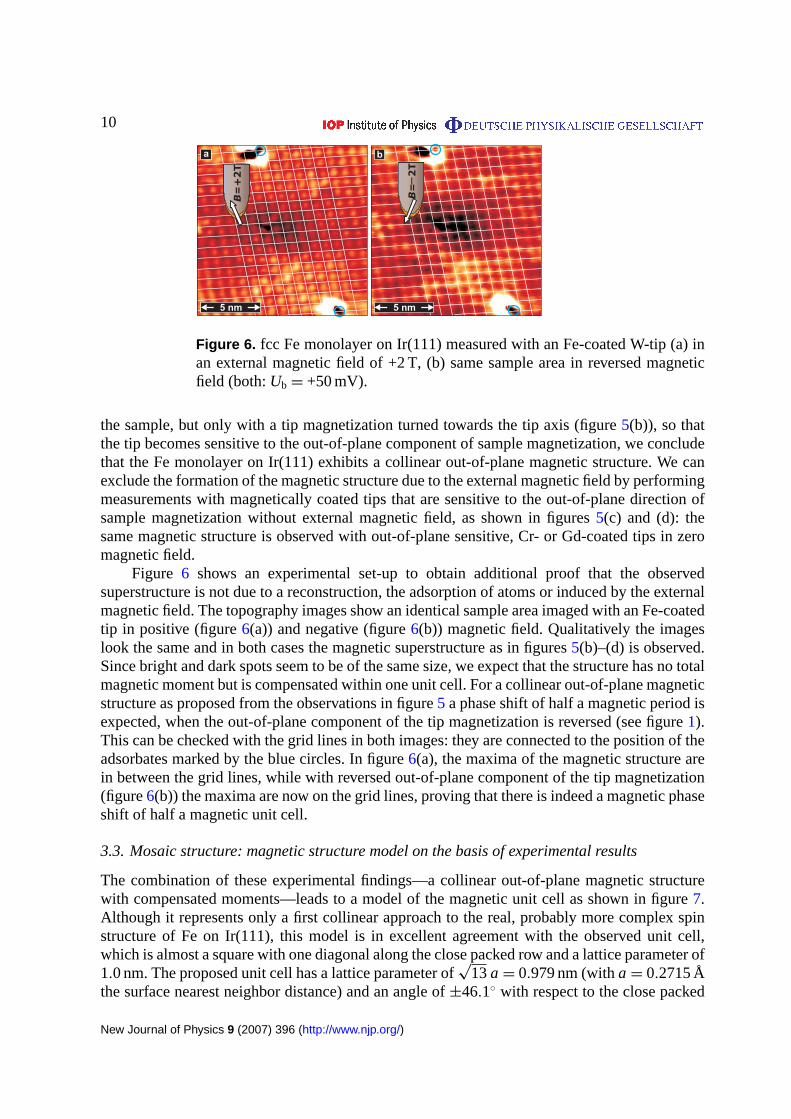
Figure 6. fcc Fe monolayer on Ir(111) measured with an Fe-coated W-tip (a) inan external magnetic field of +2 T, (b) same sample area in reversed magneticfield (both:Ub = +50 mV).
the sample, but only with a tip magnetization turned towards the tip axis (figure5(b)), so thatthe tip becomes sensitive to the out-of-plane component of sample magnetization, we concludethat the Fe monolayer on Ir(111) exhibits a collinear out-of-plane magnetic structure. We canexclude the formation of the magnetic structure due to the external magnetic field by performingmeasurements with magnetically coated tips that are sensitive to the out-of-plane direction ofsample magnetization without external magnetic field, as shown in figures5(c) and (d): thesame magnetic structure is observed with out-of-plane sensitive, Cr- or Gd-coated tips in zeromagnetic field.
Figure 6 shows an experimental set-up to obtain additional proof that the observedsuperstructure is not due to a reconstruction, the adsorption of atoms or induced by the externalmagnetic field. The topography images show an identical sample area imaged with an Fe-coatedtip in positive (figure6(a)) and negative (figure6(b)) magnetic field. Qualitatively the imageslook the same and in both cases the magnetic superstructure as in figures5(b)–(d) is observed.Since bright and dark spots seem to be of the same size, we expect that the structure has no totalmagnetic moment but is compensated within one unit cell. For a collinear out-of-plane magneticstructure as proposed from the observations in figure5 a phase shift of half a magnetic period isexpected, when the out-of-plane component of the tip magnetization is reversed (see figure1).This can be checked with the grid lines in both images: they are connected to the position of theadsorbates marked by the blue circles. In figure6(a), the maxima of the magnetic structure arein between the grid lines, while with reversed out-of-plane component of the tip magnetization(figure6(b)) the maxima are now on the grid lines, proving that there is indeed a magnetic phaseshift of half a magnetic unit cell.
3.3. Mosaic structure: magnetic structure model on the basis of experimental results
The combination of these experimental findings—a collinear out-of-plane magnetic structurewith compensated moments—leads to a model of the magnetic unit cell as shown in figure7.Although it represents only a first collinear approach to the real, probably more complex spinstructure of Fe on Ir(111), this model is in excellent agreement with the observed unit cell,which is almost a square with one diagonal along the close packed row and a lattice parameter of1.0 nm. The proposed unit cell has a lattice parameter of
√13a = 0.979 nm (witha = 0.2715 Å
the surface nearest neighbor distance) and an angle of±46.1◦ with respect to the close packed
New Journal of Physics 9 (2007) 396 (http://www.njp.org/)
11
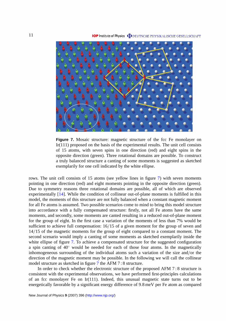
Figure 7. Mosaic structure: magnetic structure of the fcc Fe monolayer onIr(111) proposed on the basis of the experimental results. The unit cell consistsof 15 atoms, with seven spins in one direction (red) and eight spins in theopposite direction (green). Three rotational domains are possible. To constructa truly balanced structure a canting of some moments is suggested as sketchedexemplarily for one cell indicated by the white ellipse.
rows. The unit cell consists of 15 atoms (see yellow lines in figure7) with seven momentspointing in one direction (red) and eight moments pointing in the opposite direction (green).Due to symmetry reasons three rotational domains are possible, all of which are observedexperimentally [14]. While the condition of collinear out-of-plane moments is fulfilled in thismodel, the moments of this structure are not fully balanced when a constant magnetic momentfor all Fe atoms is assumed. Two possible scenarios come to mind to bring this model structureinto accordance with a fully compensated structure: firstly, not all Fe atoms have the samemoments, and secondly, some moments are canted resulting in a reduced out-of-plane momentfor the group of eight. In the first case a variation of the moments of less than 7% would besufficient to achieve full compensation: 16/15 of a given moment for the group of seven and14/15 of the magnetic moments for the group of eight compared to a constant moment. Thesecond scenario would imply a canting of some moments as sketched exemplarily inside thewhite ellipse of figure7. To achieve a compensated structure for the suggested configurationa spin canting of 40◦ would be needed for each of those four atoms. In the magneticallyinhomogeneous surrounding of the individual atoms such a variation of the size and/or thedirection of the magnetic moment may be possible. In the following we will call the collinearmodel structure as sketched in figure7 the AFM 7 : 8 structure.
In order to check whether the electronic structure of the proposed AFM 7 : 8 structure isconsistent with the experimental observations, we have performed first-principles calculationsof an fcc monolayer Fe on Ir(111). Indeed, this unusual magnetic state turns out to beenergetically favorable by a significant energy difference of 9.8 meV per Fe atom as compared
New Journal of Physics 9 (2007) 396 (http://www.njp.org/)
12
7:8
8:7
Color scaleinversion
Mosaic structure model Simulation Measurement
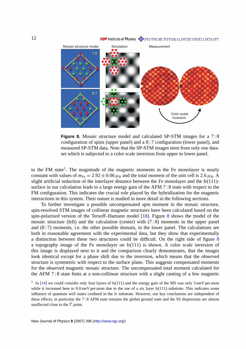
Figure 8. Mosaic structure model and calculated SP-STM images for a 7 : 8configuration of spins (upper panel) and a 8 : 7 configuration (lower panel), andmeasured SP-STM data. Note that the SP-STM images stem from only one data-set which is subjected to a color scale inversion from upper to lower panel.
to the FM state5. The magnitude of the magnetic moments in the Fe monolayer is nearlyconstant with values ofmFe = 2.92± 0.06µB and the total moment of the unit cell is 2.6µB. Aslight artificial reduction of the interlayer distance between the Fe monolayer and the Ir(111)-surface in our calculation leads to a large energy gain of the AFM 7 : 8 state with respect to theFM configuration. This indicates the crucial role played by the hybridization for the magneticinteractions in this system. Their nature is studied in more detail in the following sections.
To further investigate a possible uncompensated spin moment in the mosaic structure,spin-resolved STM images of collinear magnetic structures have been calculated based on thespin-polarized version of the Tersoff–Hamann model [18]. Figure 8 shows the model of themosaic structure (left) and the calculation (center) with (7 : 8) moments in the upper paneland (8 : 7) moments, i.e. the other possible domain, in the lower panel. The calculations areboth in reasonable agreement with the experimental data, but they show that experimentallya distinction between these two structures could be difficult. On the right side of figure8a topography image of the Fe monolayer on Ir(111) is shown. A color scale inversion ofthis image is displayed next to it and the comparison clearly demonstrates, that the imageslook identical except for a phase shift due to the inversion, which means that the observedstructure is symmetric with respect to the surface plane. This suggests compensated momentsfor the observed magnetic mosaic structure. The uncompensated total moment calculated forthe AFM 7 : 8 state hints at a non-collinear structure with a slight canting of a few magnetic
5 In [14] we could consider only four layers of Ir(111) and the energy gain of the MS was only 3 meV per atomwhile it increased here to 9.8 meV per atom due to the use of a six layer Ir(111) substrate. This indicates someinfluence of quantum well states confined in the Ir substrate. However, our key conclusions are independent ofthese effects, in particular the 7 : 8 AFM state remains the global ground state and the SS dispersions are almostunaffected close to the0 point.
New Journal of Physics 9 (2007) 396 (http://www.njp.org/)

13
Figure 9. Topography (a) and dI /dU map (b) of 0.7 AL Fe on Ir(111); (c) dI /dUmap of the island marked in (b).
moments. Simulations of SP-STM images using a simple model [17] are in agreement withsuch a structure.
3.4. Electronic structure of the fcc and hcp Fe monolayer: experiment and calculation
Samples with a coverage below 1 AL—such as the one displayed in figure9—show Femonolayer patches which can grow in two different in-plane commensurate stackings, fcc andhcp. Additionally, we can see that the step edges are decorated with about 30 nm wide rimsof Fe. The fcc and hcp islands can be distinguished in the topography image (figure9(a))and the corresponding dI /dU map (figure9(b)). The triangular shape of isolated islands ischaracteristic, with the two different types always pointing in opposite directions. In the dI /dUmap at +50 mV in figure9(b) and the closer view of the encircled island in figure9(c) one cansee that the stackings can be distinguished by their different electronic structure, which causesone to appear brighter than the other. The Fe grown at the step edges of the Ir(111) substrateis always the darker type. In contrast, the islands on the terraces are more often of the brightertype. This indicates that the Fe monolayer areas connected to the step edges grow kineticallyinduced and continue the atom arrangement of the Ir atoms, and they are the ones which weidentified as fcc. The monolayer type grown on the terraces is then the thermodynamicallystable configuration which we believe to be hcp in this case. Our interpretation is supportedby the first-principles calculations which favor the hcp-stacking by 7.6 meV per Fe atom in theFM state.
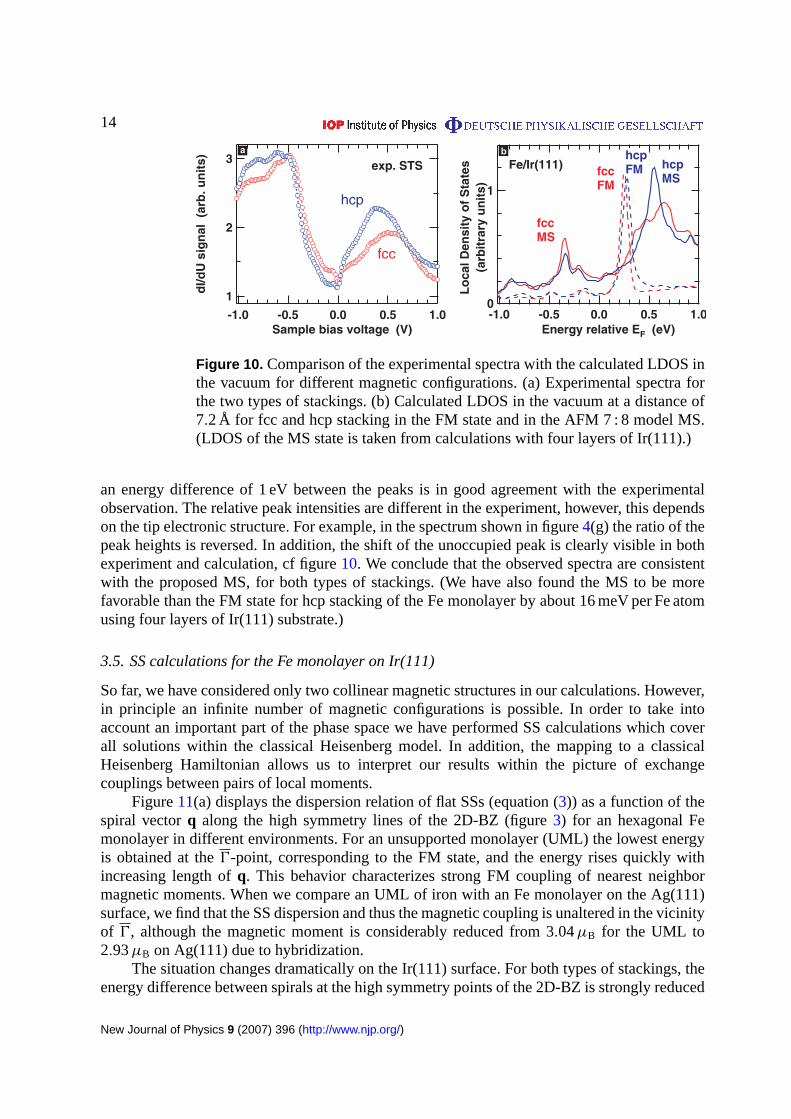
Figure10(a) shows the experimental spectra of both types of Fe monolayers which possesstwo distinct features in the occupied and unoccupied density of states at about±0.5 V. There isa clear shift of the unoccupied peak between the two stackings. Within the Tersoff–Hamannmodel [28] of STM we can directly compare these experimental spectra with theab initiocalculated local density of states (LDOS) in the vacuum, figure10(b). In the calculation, wehave considered different magnetic solutions for both types of stackings. For the FM state, weobserve a very sharp peak at an energy of about +0.25 eV above the Fermi level,EF, with avery small shift between the fcc and hcp stacking. For the AFM 7 : 8 structure, which servesas a model for the mosaic state (MS), the LDOS looks strikingly different. We find a narrowpeak at an energy of aboutEF − 0.35 eV for both stackings, while a broad feature is obtainedin the unoccupied states. It is shifted from +0.65 to +0.55 eV when we compare the fcc tothe hcp stacking. This double peak structure with a broad feature in the unoccupied states and
New Journal of Physics 9 (2007) 396 (http://www.njp.org/)
14
Figure 10. Comparison of the experimental spectra with the calculated LDOS inthe vacuum for different magnetic configurations. (a) Experimental spectra forthe two types of stackings. (b) Calculated LDOS in the vacuum at a distance of7.2 Å for fcc and hcp stacking in the FM state and in the AFM 7 : 8 model MS.(LDOS of the MS state is taken from calculations with four layers of Ir(111).)
an energy difference of 1 eV between the peaks is in good agreement with the experimentalobservation. The relative peak intensities are different in the experiment, however, this dependson the tip electronic structure. For example, in the spectrum shown in figure4(g) the ratio of thepeak heights is reversed. In addition, the shift of the unoccupied peak is clearly visible in bothexperiment and calculation, cf figure10. We conclude that the observed spectra are consistentwith the proposed MS, for both types of stackings. (We have also found the MS to be morefavorable than the FM state for hcp stacking of the Fe monolayer by about 16 meV per Fe atomusing four layers of Ir(111) substrate.)
3.5. SS calculations for the Fe monolayer on Ir(111)
So far, we have considered only two collinear magnetic structures in our calculations. However,in principle an infinite number of magnetic configurations is possible. In order to take intoaccount an important part of the phase space we have performed SS calculations which coverall solutions within the classical Heisenberg model. In addition, the mapping to a classicalHeisenberg Hamiltonian allows us to interpret our results within the picture of exchangecouplings between pairs of local moments.
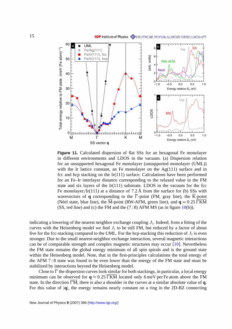
Figure11(a) displays the dispersion relation of flat SSs (equation (3)) as a function of thespiral vectorq along the high symmetry lines of the 2D-BZ (figure3) for an hexagonal Femonolayer in different environments. For an unsupported monolayer (UML) the lowest energyis obtained at the0-point, corresponding to the FM state, and the energy rises quickly withincreasing length ofq. This behavior characterizes strong FM coupling of nearest neighbormagnetic moments. When we compare an UML of iron with an Fe monolayer on the Ag(111)surface, we find that the SS dispersion and thus the magnetic coupling is unaltered in the vicinityof 0, although the magnetic moment is considerably reduced from 3.04µB for the UML to2.93µB on Ag(111) due to hybridization.
The situation changes dramatically on the Ir(111) surface. For both types of stackings, theenergy difference between spirals at the high symmetry points of the 2D-BZ is strongly reduced
New Journal of Physics 9 (2007) 396 (http://www.njp.org/)
15
8
6
4
2
0–1.0 –0.5 0.0 0.5 1.0
Neel
RW-AFM
FM SS
1
0–1.0 –0.5 0.0 0.5 1.0
Energy relative EF (eV)
Energy relative EF (eV)
MS
FM
60
50
40
30
20
10
0
Tot
al e
nerg
y re
lativ
e to
FM
sta
te (
meV
(F
e at
om)–
1 )
SS vector q
UML Fe/Ag(111) Fe/Ir(111), fcc Fe/Ir(111), hcp
M K MΓ
(arb
. uni
ts)
a b
c
LDO
SFigure 11. Calculated dispersion of flat SSs for an hexagonal Fe monolayerin different environments and LDOS in the vacuum. (a) Dispersion relationfor an unsupported hexagonal Fe monolayer (unsupported monolayer (UML))with the Ir lattice constant, an Fe monolayer on the Ag(111) surface and infcc and hcp stacking on the Ir(111) surface. Calculations have been performedfor an Fe–Ir interlayer distance corresponding to the relaxed value in the FMstate and six layers of the Ir(111) substrate. LDOS in the vacuum for the fccFe monolayer/Ir(111) at a distance of 7.2 Å from the surface for (b) SSs withwavevectors ofq corresponding to the0-point (FM, gray line), theK-point(Néel state, blue line), theM-point (RW-AFM, green line), andq = 0.250KM(SS, red line) and (c) the FM and the (7 : 8) AFM MS (as in figure10(b)).
indicating a lowering of the nearest neighbor exchange couplingJ1. Indeed, from a fitting of thecurves with the Heisenberg model we findJ1 to be still FM, but reduced by a factor of aboutfive for the fcc-stacking compared to the UML. For the hcp-stacking this reduction ofJ1 is evenstronger. Due to the small nearest-neighbor exchange interaction, several magnetic interactionscan be of comparable strength and complex magnetic structures may occur [10]. Neverthelessthe FM state remains the global energy minimum of all spin spirals and is the ground statewithin the Heisenberg model. Note, that in the first-principles calculations the total energy ofthe AFM 7 : 8 state was found to be even lower than the energy of the FM state and must bestabilized by interactions beyond the Heisenberg model.
Close to0 the dispersion curves look similar for both stackings, in particular, a local energyminimum can be observed forq ≈ 0.250KM located only 6 meV per Fe atom above the FMstate. In the direction0M, there is also a shoulder in the curves at a similar absolute value ofq.For this value of|q|, the energy remains nearly constant on a ring in the 2D-BZ connecting
New Journal of Physics 9 (2007) 396 (http://www.njp.org/)

16
the two points on the high symmetry lines [14]. Interestingly, the value of|q| on this ring-likelocal energy minimum corresponds to real space SSs with a period of 1.1 nm, close to the latticeconstant of the experimentally observed magnetic structure.
As discussed in section2.2, linear combinations of SSs, so-called multi-Q states, can gainenergy due to higher order spin interactions. The energy due to such terms can be on the orderof 15 meV atom−1 as has been calculated for 1 ML Mn on Cu(111) [24]. It is possible thatSSs on the ring-like energy plateau at|q| ≈ 0.250KM, can form multi-Q states with the same2D unit cell as the MS and compensated magnetic moments. This could also remove somefrustration from the uncompensated collinear AFM 7 : 8 state, which is probably only a collinearapproximation of a more complex, non-collinear magnetic arrangement which forms the mosaicstructure.
The connection between SSs at the local energy minimum and the MS can also be observedin the electronic structure. While the vacuum LDOS for SSs, figure11(b), correspondingto the Néel and the RW-AFM state display distinctive unoccupied peaks at +0.85 eV and+0.75 eV, respectively, the SS with|q| = 0.250KM possesses a double peak structure in closeresemblance to the AFM 7 : 8 state, cf figure11(c). Even the absolute peak positions are in goodagreement with the experiment, but is has to be noted that the exact energetic positions dependalso on the thickness of the Ir(111) substrate used in the calculations.
To conclude this section, we emphasize that the hybridization between the 3d-states of Feand the 5d-states of Ir is responsible for the strong suppression of the nearest-neighbor exchangeinteraction in the Fe monolayer. This dramatic modification enables exchange interactionsbeyond nearest-neighbors or even spin interactions of higher order to play a crucial role indetermining the magnetic ground state of the system. Predictions are therefore difficult sincevery accurate values for all competing terms are required which are only on the order of a fewmillielectronvolts. The exchange interactions for fcc- and hcp-stacking of the Fe monolayer arequite similar and in both cases we find the unusual MS to be significantly lower in total energythan all solutions of the Heisenberg model. However, for hcp-stacking the nearest-neighbor FMexchange is even smaller than for fcc which may lead to many metastable states very close intotal energy.
3.6. Magnetic imaging of the hcp Fe monolayer on Ir(111)
Figure12shows a spin-resolved measurement of a sample with fcc and hcp areas. An overviewof the topography is shown in figure12(a) with the corresponding dI /dU map in figure12(d).The closer views in figures12(b) and (c) are higher resolved images taken at the areas markedin figure 12(a) by the black boxes with the color scale adjusted to show the details of themonolayer areas. While in the fcc monolayer the mosaic structure is clearly resolved, a magneticsuperstructure is not as obvious for the hcp areas. Only in the fully differentiated images of thesame areas in figures12(e) and (f) one can see a similar magnetic structure, which is veryfaint and even disappears when going away from the borders of the patches. It seems as if themagnetic structure was induced by the fcc monolayer and double-layer areas connected withthe hcp area, but not as if it were a stable magnetic structure at the measuring temperature of13 K. The magnetic signal appears to vanish towards the center of the hcp monolayer. Thisindicates that the mosaic structure or a related magnetic structure is one out of several possiblemagnetic states in the hcp monolayer, but it needs to be stabilized by an adjacent fcc monolayeror by double-layer patches. This might reflect the very small energy differences calculated in the
New Journal of Physics 9 (2007) 396 (http://www.njp.org/)

17
Figure 12. fcc and hcp Fe monolayer on Ir(111): (a) topography and (d)corresponding dI /dU map; (b), (c) spin-sensitive images in indicated areas of(a) and (e), (f) same areas but fully differentiated for better visibility of heightvariations in fcc and hcp monolayer in one image.
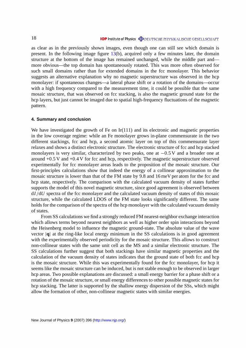
Figure 13. fcc Fe monolayer on Ir(111) measured with an Fe-coated W-tip atB = +2 T. (a) and (b) are measured at the same sample area with a time intervalof 4 min (both:Ub = +50 mV).
energy dispersion of the spin spirals and the correspondingly small nearest-neighbor exchangeinteraction (figure11(a)).
Considering the previous result raises also the question of the stability of a magneticstructure and its imaging by SP-STM. Figure13shows two subsequently acquired spin-resolvedtopography images of the fcc monolayer. All three possible rotational domains are present infigure 13(a), merging into one another on a rather small scale. As can be seen in the top partof the image the mosaic structure seems to be blurred and the spin-resolved contrast is not
New Journal of Physics 9 (2007) 396 (http://www.njp.org/)
18
as clear as in the previously shown images, even though one can still see which domain ispresent. In the following image figure13(b), acquired only a few minutes later, the domainstructure at the bottom of the image has remained unchanged, while the middle part and—more obvious—the top domain has spontaneously rotated. This was more often observed forsuch small domains rather than for extended domains in the fcc monolayer. This behaviorsuggests an alternative explanation why no magnetic superstructure was observed in the hcpmonolayer: if spontaneous changes—a lateral phase shift or a rotation of the domains—occurwith a high frequency compared to the measurement time, it could be possible that the samemosaic structure, that was observed on fcc stacking, is also the magnetic ground state for thehcp layers, but just cannot be imaged due to spatial high-frequency fluctuations of the magneticpattern.
4. Summary and conclusion
We have investigated the growth of Fe on Ir(111) and its electronic and magnetic propertiesin the low coverage regime: while an Fe monolayer grows in-plane commensurate in the twodifferent stackings, fcc and hcp, a second atomic layer on top of this commensurate layerrelaxes and shows a distinct electronic structure. The electronic structure of fcc and hcp stackedmonolayers is very similar, characterized by two peaks, one at−0.5 V and a broader one ataround +0.5 V and +0.4 V for fcc and hcp, respectively. The magnetic superstructure observedexperimentally for fcc monolayer areas leads to the proposition of the mosaic structure. Ourfirst-principles calculations show that indeed the energy of a collinear approximation to themosaic structure is lower than that of the FM state by 9.8 and 16 meV per atom for the fcc andhcp state, respectively. The comparison with the calculated vacuum density of states furthersupports the model of this novel magnetic structure, since good agreement is observed betweendI /dU spectra of the fcc monolayer and the calculated vacuum density of states of this mosaicstructure, while the calculated LDOS of the FM state looks significantly different. The sameholds for the comparison of the spectra of the hcp monolayer with the calculated vacuum densityof states.
From SS calculations we find a strongly reduced FM nearest-neighbor exchange interactionwhich allows terms beyond nearest neighbors as well as higher order spin interactions beyondthe Heisenberg model to influence the magnetic ground-state. The absolute value of the wavevector |q| at the ring-like local energy minimum in the SS calculations is in good agreementwith the experimentally observed periodicity for the mosaic structure. This allows to constructnon-collinear states with the same unit cell as the MS and a similar electronic structure. TheSS calculations further suggest that both stackings have similar magnetic properties and thecalculation of the vacuum density of states indicates that the ground state of both fcc and hcpis the mosaic structure. While this was experimentally found for the fcc monolayer, for hcp itseems like the mosaic structure can be induced, but is not stable enough to be observed in largerhcp areas. Two possible explanations are discussed: a small energy barrier for a phase shift or arotation of the mosaic structure, or small energy differences to other possible magnetic states forhcp stacking. The latter is supported by the shallow energy dispersion of the SSs, which mightallow the formation of other, non-collinear magnetic states with similar energies.
New Journal of Physics 9 (2007) 396 (http://www.njp.org/)
19
Acknowledgments
Financial support from the DFG (SFB 668), the Stifterverband für die Deutsche Wissenschaft,and the Interdisciplinary Nanoscience Center of Hamburg is gratefully acknowledged.
References
[1] Kortright J, Awschalom D, Stöhr J, Bader S, Idzerda Y, Parkin S, Schuller I K and Siegmann H-C 1999J. Magn. Magn. Mater.2077
[2] Fassbender J 2003Top. Appl. Phys.8759[3] Fruchart O and Thiaville A 2005C R Physique6 921[4] Harrison R 2006 Newtron diffractron of magnetic materialsNeutron Scattering in Earth Sciences(Reviews
in Mineralogy and Geochemistryvol 63) ed H-R Weull (Chantilly, VA: MSA) chapter 6, p 113[5] Srajer Get al2006J. Magn. Magn. Mater.3071[6] Tsunoda Y 1989J. Phys.: Condens. Matter1 10427[7] Knöpfle K, Sandratskii L M and Kübler J 2000Phys. Rev.B 625564[8] Kubetzka A, Ferriani P, Bode M, Heinze S, Bihlmayer G, von Bergmann K, Pietzsch O, Blügel S and
Wiesendanger R 2005Phys. Rev. Lett.94087204[9] Bode M, Vedmedenko E Y, von Bergmann K, Kubetzka A, Ferriani P, Heinze S and Wiesendanger R 2006
Nat. Mater.5 477[10] Ferriani P, Turek I, Heinze S, Bihlmayer G and Blügel S 2007Phys. Rev. Lett.at press (Preprint cond-
mat/0701241v1)[11] Heinze S, Bode M, Kubetzka A, Pietzsch O, Nie X, Blügel S and Wiesendanger R 2000Science2881805[12] Yang H, Smith A R, Prikhodko M and Lambrecht W R L 2002Phys. Rev. Lett.89226101[13] Bode M 2003Rep. Prog. Phys.66523[14] von Bergmann K, Heinze S, Bode M, Vedmedenko E Y, Bihlmayer G, Blügel S and Wiesendanger R 2006
Phys. Rev. Lett.96167203[15] Gao C L, Schlickum U, Wulfhekel W and Kirschner J 2007Phys. Rev. Lett.98107203[16] Bode M, Heide M, von Bergmann K, Ferriani P, Heinze S, Bihlmayer G, Kubetzka A, Pietzsch O, Blügel S
and Wiesendanger R 2007Nature447190[17] Heinze S 2006Appl. Phys.A 85407[18] Wortmann D, Heinze S, Kurz P, Bihlmayer G and Blügel S 2001Phys. Rev. Lett.864132[19] Slonczewski J C 1989Phys. Rev.B 396995[20] Pietzsch O, Kubetzka A, Haude D, Bode M and Wiesendanger R 2000Rev. Sci. Instrum.71424[21] Kubetzka A, Bode M, Pietzsch O and Wiesendanger R 2002Phys. Rev. Lett.88057201[22] Bode M, Heinze S, Kubetzka A, Pietzsch O, Nie X, Bihlmayer G, Blügel S and Wiesendanger R 2002
Phys. Rev. Lett.89237205[23] Pietzsch O, Kubetzka A, Bode M and Wiesendanger R 2001Science2922053[24] Kurz P, Bihlmayer G, Hirai K and Blügel S 2001Phys. Rev. Lett.861106[25] Perdew J P, Burke K and Ernzerhof M 1996Phys. Rev. Lett.773865[26] Kurz P, Förster F, Nordström L, Bihlmayer G and Blügel S 2004Phys. Rev.B 69024415[27] Meier F, von Bergmann K, Ferriani P, Wiebe J, Bode M, Hashimoto K, Heinze S and Wiesendanger R 2006
Phys. Rev.B 74195411[28] Tersoff J and Hamann D R 1985Phys. Rev.B 31805
New Journal of Physics 9 (2007) 396 (http://www.njp.org/)