Magnetism from conductors and enhanced nonlinear phenomena
21
/word/pap/wecs/magwires.doc at 03 February 1999 page 1 Magnetism from Conductors, and Enhanced Non-Linear Phenomena JB Pendry, AJ Holden, DJ Robbins, and WJ Stewart Abstract - We show that microstructures built from non-magnetic conducting sheets exhibit an effective magnetic permeability, μ eff , which can be tuned to values not accessible in naturally occurring materials, including large imaginary components of μ eff . The microstructure is on a scale much less than the wavelength of radiation, is not resolved by incident microwaves, and uses a very low density of metal so that structures can be extremely lightweight. Most of the structures are resonant due to internal capacitance and inductance, and resonant enhancement combined with compression of electrical energy into a very small volume greatly enhances the energy density at critical locations in the structure, easily by factors of a million and possibly by much more. Weakly non-linear materials placed at these critical locations will show greatly enhanced effects raising the possibility of manufacturing active structures whose properties can be switched at will between many states. Index Terms - effective permeability, non-linearity, photonic crystals JB Pendry is with The Blackett Laboratory, Imperial College, London, SW7 2BZ, UK. AJ Holden, DJ Robbins, and WJ Stewart are with GEC-Marconi Materials Technology Ltd, Caswell, Towcester, Northamptonshire, NN12 8EQ, UK.
-
Upload
independent -
Category
Documents
-
view
1 -
download
0
Transcript of Magnetism from conductors and enhanced nonlinear phenomena

/word/pap/wecs/magwires.doc at 03 February 1999 page 1
Magnetism from Conductors,and Enhanced Non-Linear Phenomena
JB Pendry, AJ Holden, DJ Robbins, and WJ Stewart
Abstract - We show that microstructures built from non-magnetic conducting sheets exhibitan effective magnetic permeability, µeff , which can be tuned to values not accessible in
naturally occurring materials, including large imaginary components of µeff . The
microstructure is on a scale much less than the wavelength of radiation, is not resolved byincident microwaves, and uses a very low density of metal so that structures can be extremelylightweight. Most of the structures are resonant due to internal capacitance and inductance,and resonant enhancement combined with compression of electrical energy into a very smallvolume greatly enhances the energy density at critical locations in the structure, easily byfactors of a million and possibly by much more. Weakly non-linear materials placed at thesecritical locations will show greatly enhanced effects raising the possibility of manufacturingactive structures whose properties can be switched at will between many states.
Index Terms - effective permeability, non-linearity, photonic crystals
JB Pendry is with The Blackett Laboratory, Imperial College, London, SW7 2BZ, UK.AJ Holden, DJ Robbins, and WJ Stewart are with GEC-Marconi Materials Technology Ltd, Caswell, Towcester,Northamptonshire, NN12 8EQ, UK.

/word/pap/wecs/magwires.doc at 03 February 1999 page 2
I. INTRODUCTION
In a sense every material is a composite, even if the individual ingredients consist of atoms andmolecules. The original objective in defining a permittivity, ε , and permeability, µ , was to presentan homogeneous view of the electromagnetic properties of a medium. Therefore it is only a smallstep to replace the atoms of the original concept with structure on a larger scale. We shall considerperiodic structures defined by a unit cell of characteristic dimensions a . The contents of the cell willdefine the effective response of the system as a whole.
Clearly there must be some restrictions on the dimensions of the cell. If we are concerned about theresponse of the system to electromagnetic radiation of frequency ω the conditions are easy todefine:
a c<< = −λ π ω2 01 (1)
If this condition were not obeyed there would be the possibility that internal structure of the mediumcould diffract as well as refract radiation giving the game away immediately. Long wavelengthradiation is too myopic to detect internal structure and in this limit an effective permittivity andpermeability is a valid concept. In the next section we shall discuss how the microstructure can berelated to ε µeff eff, .
In an earlier paper [1] we showed how a structure consisting of very thin infinitely long metal wiresarranged in a 3D cubic lattice could model the response of a dilute plasma, giving a negative εeff
below a plasma frequency somewhere in the gigahertz range. Theoretical analysis of this structurehas been confirmed by experiment [2]. Sievenpiper et al have also investigated plasma-like effects inmetallic structures [3,4].
Ideally we should like to proceed in the magnetic case by finding the magnetic analogue of a goodelectrical conductor: unfortunately there isn’t one! Nevertheless we can find some alternatives whichwe believe do give rise to interesting magnetic effects.
Why should we go to the trouble of microstructuring a material simply to generate a particular µeff ?
The answer is that atoms and molecules prove to be a rather restrictive set of elements from which tobuild a magnetic material. This is particularly true at frequencies in the gigahertz range where themagnetic response of most materials is beginning to tail off. Those materials, such as the ferrites, thatremain moderately active are often heavy, and may not have very desirable mechanical properties. Incontrast, we shall show, microstructured materials can be designed with considerable magneticactivity, both diamagnetic and paramagnetic, and can if desired be made extremely light.
There is another quite different motivation. We shall see that strong magnetic activity impliesstrongly inhomogeneous fields inside the material. In some instances this may result in local fieldstrengths many orders of magnitude larger than in free space. Doping the composite with non linearmaterial at the critical locations of field concentration gives enhanced non-linearity, reducing powerrequirements by the field enhancement factor. This is not an option available in a conventionalmagnetic material.
We show first how to calculate µeff for a system, then we propose some model structures which
have magnetic activity and give some numbers for these systems. Finally we show how electrostaticenergy can be strongly concentrated in these structures and hence the demonstrate potential forenhancing non linear effects.

/word/pap/wecs/magwires.doc at 03 February 1999 page 3
II. DEFINING AN EFFECTIVE PERMEABILITY
We are seeking to build structures with effective epsilon and mu,
B H
D Eave eff ave
ave eff ave
==
µ µε ε
0
0(2)
where we assume that the structure is on a scale much shorter than the wavelength of any radiationso that we can sensibly speak of an average value for all the fields. A key question is how do theaverages differ? Clearly if the structure is made of thin wires or sheets of metal then if the averageswere taken over the same regions of space, ε µeff eff, would always be unity. However we observe
that Maxwell’s equations,
∇ × = +∇ × = −
H DE B
∂ ∂∂ ∂
//
tt
(3)
may be applied in the integral form,
H dl D dS
E dl B dS
⋅ = +
⋅ = −
z zz zc s
c s
t
t
∂∂∂∂
.
.(4)
where the line integral is taken over a loop ‘c’ which encloses an area ‘s’.
This form of the equations immediately suggests a prescription for averaging the fields. Forsimplicity we shall assume that the periodic structure is described by a unit cell whose axes areorthogonal as shown in figure 1 below. Some of the arguments used in this section are similar tothose we used in deriving a finite difference model of Maxwell’s equations [5].
Figure 1. Unit cell of a periodic structure. We assume that the unit cell dimensions are muchsmaller that the wavelength of radiation, and average over local variations of the fields. In thecase of the B - field we average over the faces of the cell and in the case of the H - field, overone of the edges.
We choose to define the components of Have by averaging the H − field along each of the threeaxes of the unit cell. If we assume a simple cubic system,

/word/pap/wecs/magwires.doc at 03 February 1999 page 4
H a
H a
H a
ave xa
ave ya
ave za
b gb gb g
b gb g
b gb g
b gb g
= ⋅
= ⋅
= ⋅
−==
−==
−==
zzz
10,0,0
10,0,0
0,
10,0,0
0,0,
H dr
H dr
H dr
r
r
r
r
r
r
,0,0
,0(5)
There is only one caveat concerning the definition of the unit cell: its edges must not intersect withany of the structures contained within the unit cell. This leaves us free to cut the structure into awhole number of unit cells when we come to create a surface and ensures that the parallelcomponent of Have is continuous across the surface as required in a consistent theory of an effectivemedium.
To define Bave we average the B − field over each of the three faces of the unit cell defined asfollows:
Sx is the surface defined by the vectors y z,Sy is the surface defined by the vectors x z,Sz is the surface defined by the vectors x y,
Hence we define,
B a
B a
B a
ave x S
ave y S
ave z S
x
y
z
b gb gb g
= ⋅
= ⋅
= ⋅
−
−
−
zzz
2
2
2
B dS
B dS
B dS
(6)
The ratio defines the effective epsilon and mu from (2),
µ µ
µ µ
µ µ
eff x ave x ave x
eff y ave y ave y
eff z ave z ave z
B H
B H
B H
d i b g b gd i b g b gd i b g b g
=
=
=
0
0
0
(7)
Thus if we seek a large effect we must try to create fields that are as inhomogeneous as possible.
We shall explore various configurations of thin sheets of metal, derive µeff , and discuss the results
with a view to making the effect as large as possible.

/word/pap/wecs/magwires.doc at 03 February 1999 page 5
III. EXAMPLES OF MAGNETIC MICROSTRUCTURES
A. An Array of Cylinders
Figure 2. Model A consists of a square array of metallic cylinders designed to have magneticproperties in the direction parallel to the axes of the cylinders.
We start with a very simple structure for the purposes of illustration. Let us apply an external field,H0 , which we shall take to be parallel to the cylinders. We assume that the cylinders have aconducting surface so that a current, j , per unit length, flows. The field inside the cylinders is,
H H jr
aj= + −0
2
2π
(8)
where the second term on the right hand side is the field caused directly by the current, and the thirdterm is the result of the depolarising fields with sources at the remote ends of the cylinders. If thecylinders are very long the depolarising field will be uniformly spread over the unit cell, but will havethe same number of lines of force in it as the direct field inside the cylinders. We now calculate thetotal emf around the circumference of a cylinder:
emf rt
H jr
aj r j
i r H jr
aj r j
= − + −LNMM
OQPP−
= + + −LNMM
OQPP−
π µ ∂∂
π π σ
ωπ µ π πσ
20 0
2
2
20 0
2
2
2
2
(9)
where σ is the resistance of the cylinder surface per unit area. The net emf must balance andtherefore,
ji r H
i r ra
r
H
ra
i rr
= −
−LNMM
OQPP −
= −
−LNMM
OQPP +
ωπ µ
ωπ µ π π σ π σω µ
20 0
20
2
2
02
2 20
1 2 1 2(10)
We are now in a position to calculate the relevant averages. The average of the B-field over theentire unit cell is,
B Have = µ0 0 (11)

/word/pap/wecs/magwires.doc at 03 February 1999 page 6
However if we average the H-field over a line lying entirely outside the cylinders,
H Hr
aj H
r
a
H
ra
i rr
Hi
r
ra
ir
ave = − = − −
−LNMM
OQPP +
=+
−LNMM
OQPP +
0
2
2 0
2
20
2
2 20
00
2
20
1 2
1 2
1 2
π ππ σ
ω µ
σω µ
π σω µ
(12)
Hence we define,
µµ
π σω µσ
ω µ
π σω µeff
ave
ave
BH
ra
ir
ir
r
ai
r= =
− +
+= − +L
NMOQP−
0
2
20
0
2
2 0
11 2
1 2 1 12
(13)
For an infinitely conducting cylinder, or in the high frequency limit, µeff is reduced by the ratio of
the cylinder volume to the cell volume. This ratio of volumes will turn out to be the key factor indetermining the strength of the effect in all our models. Evidently in the present model µeff can
never be less than zero, or greater than unity. It should also be mentioned that to maximise the effectwe could have replaced the metallic cylinders with prisms of square cross section to maximise thevolume enclosed within the prism.
If the resistivity of the sheets is high then the additional contribution to µeff is imaginary but always
less than unity,
µ π ω µσ
σ ω µeff ir
ar≈ + >>1
2
30
2 0, (14)
A further point that should be noted is that all the structures we discuss have electrical as well asmagnetic properties. In this particular case we can crudely estimate for electric fields perpendicularto the cylinders,
ε πeff F
r
a= − = −
FHG
IKJ
−−
1 112
2
1
b g (15)
where F is the fraction of the structure not internal to a cylinder. In deriving (15) we assume thatthe cylinder is a perfect conductor, and neglect depolarising fields arising from interaction betweencylinders. Inclusion of εeff in our calculations removes one difficulty by ensuring that,
lim limω ω
ε µ→ ∞ → ∞
−= =c c clight eff eff0 012d i (16)
Evidently without εeff the velocity of light in the effective medium would have exceeded that in free
space. Most of the structures discussed in this paper have a similar εeff .

/word/pap/wecs/magwires.doc at 03 February 1999 page 7
B. A Capacitative Array of Sheets Wound on Cylinders
The previous structure showed a limited magnetic effect. Now we show how to extend the range ofmagnetic properties available to us by introducing capacitative elements into the structure. We takethe same structure of cylinders as before except that the cylinders are now built in a ‘split ring’configuration shown below in figure 3.
Figure 3. Model B consists of a square array of cylinders as for model A but with the differencethat the cylinders now have internal structure The sheets are divided into a ‘split ring’ structureand separated from each other by a distance d . In any one sheet there is a gap which preventscurrent from flowing around that ring.
The important point is that there is a gap which prevents current from flowing around any one ring.However there is a considerable capacitance between the two rings which enables current to flow,
Figure 4. When a magnetic field parallel to the cylinder is switched on it induces currents in the‘split rings’ as shown in the figure. The greater the capacitance between the sheets, the greaterthe current.
Detailed calculations give,
µ σω µ π µ ω
effF
ir Cr
= −+ −
11 2 3
0 20
2 3
(17)
where F is the fractional volume of the cell side occupied by the interior of the cylinder,
Fr
a= π 2
2 (18)
and C is the capacitance per unit area between the two sheets,

/word/pap/wecs/magwires.doc at 03 February 1999 page 8
Cd dc
= =εµ
0
02
0
1(19)
Hence,
µ
π
σω µ π ω
eff
ra
ir
dcr
= −+ −
11 2 3
2
2
0
02
2 2 3
(20)
Because we now have capacitance in the system which can balance the inductance present, µeff has
a resonant form which we sketch below in figure 5.
ω mp
µeff
ωω0
µeff =1
mp
Figure 5. The effective magnetic permeability for model B shows a resonant structure dictatedby the capacitance between the sheets and the magnetic inductance of the cylinder. We sketchthe typical form for a highly conducting sample, σ≈0 . Below the resonant frequency µeff is
enhanced, but above resonance µeff is less than unity and may be negative close to the
resonance.
Figure 5 illustrates the generic form of µeff for all the structures we present here.
We define ω 0 to be the frequency at which µeff diverges,
ωπ µ π0 2
03
02
2 33 3= =
Cr
dc
r(21)
and ω mp to be the ‘magnetic plasma frequency’
ωπ µ π π
mpCr F
dc
r ra
=−
=−
FHG
IKJ
3
1
3
12
03
02
2 32
2b g (22)
Note that the separation between ω 0 andω mp , which is a measure of the range of frequencies over
which we see a strong effect, is determined by
/word/pap/wecs/magwires.doc at 03 February 1999 page 9
Fr
a= −1
2
2π
(23)
the fraction of the structure not internal to a cylinder. As for the case A, the simple cylinder, the highfrequency limit is given by,
limω
µ ω π→ ∞
= −effr
ab g 1
2
2 (24)
We mention in passing that the system sustains longitudinal magnetic modes at the magnetic plasmafrequency, the analogue of the plasma modes of a gas of free electrical charges [6,7]. Of course, wehave no free magnetic poles, only the appearance of such as currents around the cylinders make thecylinder ends appear to support free magnetic poles in the fashion of a bar magnet.
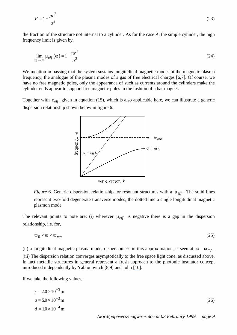
Together with εeff given in equation (15), which is also applicable here, we can illustrate a generic
dispersion relationship shown below in figure 6.
Figure 6. Generic dispersion relationship for resonant structures with a µeff . The solid lines
represent two-fold degenerate transverse modes, the dotted line a single longitudinal magneticplasmon mode.
The relevant points to note are: (i) wherever µeff is negative there is a gap in the dispersion
relationship, i.e. for,
ω ω ω0 < < mp (25)
(ii) a longitudinal magnetic plasma mode, dispersionless in this approximation, is seen at ω ω= mp .
(iii) The dispersion relation converges asymptotically to the free space light cone. as discussed above.In fact metallic structures in general represent a fresh approach to the photonic insulator conceptintroduced independently by Yablonovitch [8,9] and John [10].
If we take the following values,
r
a
d
= ×
= ×
= ×
−
−
−
2 0 10
50 10
10 10
3
3
4
.
.
.
m
m
m
(26)

/word/pap/wecs/magwires.doc at 03 February 1999 page 10
we get,
fmp mp= = ×−2 417 101 9π ωb g . Hz (27)
f fr
amp0
2
291 2 94 10= −
FHG
IKJ= ×π
. Hz (28)
Note that the frequency at which the structure is active corresponds to a free space wavelength of10cm, much greater that the 0.5cm separation between cylinders. This will be typical of thesecapacitative structures and implies that the effective medium approximation will be excellent.
C ‘Swiss Roll’ Capacitor
We take the same arrangement of cylinders on a square lattice as before except that the cylinders arenow build as follows:
Figure 7. In model C a metallic sheet is wound around each cylinder in a coil. Each turn of thecoil is spaced by a distance d from the previous sheet.
The important point is again that no current can flow around the coil except by virtue of the selfcapacitance,
Figure 8. When a magnetic field parallel to the cylinder is switched on it induces currents in thecoiled sheets as shown in the figure. Capacitance between the first and last turns of the coilenables current to flow.

/word/pap/wecs/magwires.doc at 03 February 1999 page 11
In this instance we find for the effective permeability,
µ σω µ π µ ω
π
σω µ π ω
effF
ir N r N C
ra
ir N
dcr N
= −+
−−
−
= −+
−−
−
11 2
11
2 1
11 2
1 2 1
0 2 30
2 2
2
2
0
02
2 3 2
b g b g
b g b g
(29)
where F is as before the fraction of the structure not internal to a cylinder, and the capacitance perunit area between the first and the last of the coils is,
Cd N dc N
=−
=−
εµ
0
0 0211
1b g b g (30)
The critical frequencies are,
ωπ µ π0 2 3
02
02
2 31
2 1 2 1=
−=
−r C N
dc
r Nb g b g (31)
ωπ µ π π
mpF r C N
dc
ra
r N
=−
=−
FHG
IKJ −
1
2 11 2 1
2 30
202
2
22 3b g b g
(32)
If we take the values we used before in (26),
r
a
d
= ×
= ×
= ×
−
−
−
2 0 10
50 10
10 10
3
3
4
.
.
.
m
m
mN = 11
(33)
we get,
f01
092 0 380 10= = ×−π ωb g . Hz (34)
fmp mp= = ×−2 0 539 101 9π ωb g . (35)
i.e. there is much more capacitance in this model and the range of active frequencies is an order ofmagnitude lower than it was in model C which used only two overlapping sheets.
Choosing an even smaller scale and reducing the number of turns in order to drive up the frequenciesto our range of interest,

/word/pap/wecs/magwires.doc at 03 February 1999 page 12
r
a
d
= ×
= ×
= ×
−
−
−
2 0 10
50 10
10 10
4
4
5
.
.
.
m
m
mN = 3
(36)
we get,
f09850 10= ×. Hz (37)
fmp = ×12 05 109. Hz (38)
Note that the free space wavelength at the plasma frequency is around 3cm and compare this to thevery much smaller spacing between cylinders of 0.05cm.
We shall now calculate the dispersion of µeff for various parameters. First let us take the parameters
given in equation (36). The resulting dispersion of µeff is shown below in figure 9
Figure 9. Dispersion with frequency of µeff for a Swiss roll structure, calculated for the
parameters shown in equation (36), assuming that the metal has zero resistivity.
Next we enquire what is the effect of making the sheets resistive? Below we present a series ofcalculations for various values of the resistivity, σ, given in Ω .

/word/pap/wecs/magwires.doc at 03 February 1999 page 13
Figure 10. Dispersion with frequency of µeff for a Swiss roll structure, calculated for the
parameters shown in equation (36), for various values of the resistivity of the sheets:0.1Ω, 2.0Ω, 5.0Ω, 10.0Ω .
In figure 10 we increase the resistivity from 01. Ω to 10 0. Ω . Note the broadening of the resonance,the complementary behaviour of µreal and µimag , dictated by Kramers Kronig, and how resistivity
limits the maximum effect achieved.
Next we explore the dependence on the radius of the cylinders. In figure 11 the radius of thecylinders is decreased, reducing the volume fraction occupied by the cylinders, and raising theresonant frequency by a factor of two. We also decrease d, the spacing between the sheets,increasing the capacitance in the system and bringing the resonant frequency back down to itsoriginal value.

/word/pap/wecs/magwires.doc at 03 February 1999 page 14
Figure 11. Dispersion with frequency of µeff for a Swiss roll structure. Top: calculated for the
parameters shown in equation (36), except that the resistivity of the sheets is now 2.0Ω , and theradius of the cylinders has been reduced from 2 0 10 4. × − m to 126 10 4. × − m , thus raising theresonant frequency by a factor of two. Bottom: d , the spacing between the sheets, has beenreduced to 0 25 10 5. × − m bringing the resonant frequency back to the original value.
Using capacitative cylindrical structures such as the Swiss roll structure we can adjust the magneticpermeability typically by a factor of two and, in addition if we desire, introduce an imaginarycomponent of the order of unity. The latter implies that an electromagnetic wave moving in such amaterial would decay to half its intensity within a single wavelength. This presumes that we areseeking broad-band effects that persist over the greater part of the 2-20GHz region. However if weare prepared to settle for an effect over a narrow range of frequencies spectacular enhancements ofthe magnetic permeability can be achieved, limited only be the resistivity of the sheets and by hownarrow a band we are willing to tolerate.

/word/pap/wecs/magwires.doc at 03 February 1999 page 15
III. AN ISOTROPIC MAGNETIC MATERIAL
The structures shown above give magnetic properties when the field is aligned along the axes of thecylinders, but have essentially zero magnetic response in other directions. They suffer from anotherpotential problem: if the alternate polarisation is considered where the electric field is not parallel tothe cylinders, the system responds like an effective metal because current is free to flow along thelength of the cylinders. For some applications this highly anisotropic behaviour may be undesirable.Therefore we redesign the system with a view to restoring isotropy, and minimising purely electricaleffects.
To this end we need a basic unit that is more easily packed into arrays than is a cylinder, and whichavoids the continuous electrical path provided by a metal cylinder. We propose an adaptation of the‘split ring’ structure in which the cylinder is replaced by a series of flat disks each of which retainsthe ‘split ring’ configuration but in slightly modified form: see figure 12. First we shall calculate theproperties of disks stacked in a square array as shown if figure 13. This structure is still anisotropic, aproblem we shall address in a moment, but by eliminating the continuous conducting path which thecylinders provided, it eliminates most of the electrical activity along this direction.
Figure 12. Left: a plan view of a split ring showing definitions of distances. Right a sequenceof split rings shown in their stacking sequence. Each split ring comprises two thin sheets ofmetal. The ring shown is a scaled up version defined by the parameters shown below infigure 13.

/word/pap/wecs/magwires.doc at 03 February 1999 page 16
Figure 13. Plan view of a split ring structure in a square array, lattice spacinga .
The two dimensional square array shown in figure 13 can be made by printing with metallic inks. Ifeach printed sheet is then fixed to a solid block of inert material, thickness a , the blocks can bestacked to give columns of rings. This would establish magnetic activity along the direction ofstacking, the z − axis. The unit cell of this structure is shown in figure 14 on the left.
How do we make a symmetrical structure? Start from the structure just described comprisingsuccessive layers of rings stacked along the z − axis. Next cut up the structure into a series of slabsthickness a , making incisions in the y z− plane and being careful to avoid slicing through any of therings. Each of the new slabs contains a layer of rings but now each ring is perpendicular to the planeof the slab and is embedded within. Print onto the surface of each slab another layer of rings andstack the slabs back together again. The unit cell of this second structure is shown in the middle offigure 14.
In the next step a third set of slabs is produced by cutting in the x z− plane, printing on the surfaceof the slabs, and reassembling. Finally we now have a structure with cubic symmetry whose unit cellis shown on the right of figure 14.
Figure 14. Building 3D symmetry: each successive re-stacking of the structure adds a ring toanother side of the unit cell.

/word/pap/wecs/magwires.doc at 03 February 1999 page 17
Of course an alternate method of manufacturing this structure would be to start from a set of cubesof the inert material and laboriously stick rings to their sides before assembling the cubes into alattice. The cut and paste method we suggest above is much more efficient.
Now let us calculate the effective permeability. First we need to calculate the capacitance betweenthe two elements of the split ring. We shall assume:
r c r d> > > >, (39)
l< r (40)
lncd
> > π (41)
Under these conditions we can calculate the capacitance between unit length of two parallel sectionsof the metallic strips:
Cc
d c
cd1
0
0 02
2 1 2= =επ πµ
ln ln (42)
The effective magnetic permeability we calculate on the assumption that the rings are sufficientlyclose together that the magnetic lines of force due to currents in the stacked rings, are essentially thesame as those in a continuous cylinder. This can only be true if the radius of the rings is of the sameorder as the unit cell side. We arrive at:
µ
π
σω µ π µ ω
π
σω µ πω
eff
ra
ri
C r
ra
ri c
cd
r
= −+ −
= −+ −
11
2 3 11 2 3
2
2
2
1
02
02
13
2
2
1
0
02
2 3
l l l l
ln
(43)
where σ1 is the resistance of unit length of the sheets measured around the circumference.
To give some examples let us choose a convenient set of parameters:
a
c
d
r
= 1.0 10 m
= 1.0 10 m
= 1.0 10 m
= 2.0 10 m
= 2.0 10 m
-2
-3
-4
-3
-3
×
×
×
×
×
l
(44)
Figures 12, 13 show the rings drawn to scale. These parameters do not quite satisfy all theinequalities, which is difficult to do with reasonable numbers, but note that the inequalities are onlyimportant to the accuracy of our formulae, not to the functioning of the structure. The resonantfrequency at which µeff diverges is given by,
ωπ
02 0
2
3
32 7 1= = ×lc
cd
rln. 1021 (45)
/word/pap/wecs/magwires.doc at 03 February 1999 page 18
or,
ω π= ×2 135. GHz (46)
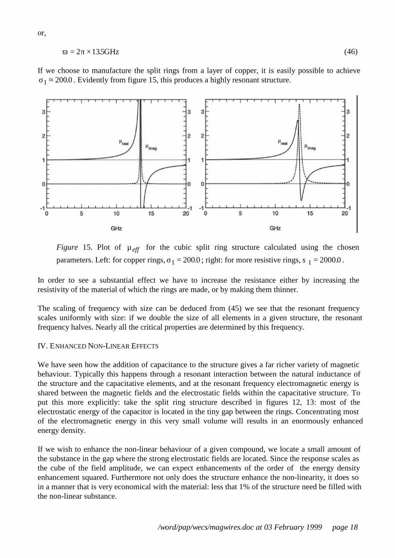
If we choose to manufacture the split rings from a layer of copper, it is easily possible to achieveσ1 200 0≈ . . Evidently from figure 15, this produces a highly resonant structure.
Figure 15. Plot of µeff for the cubic split ring structure calculated using the chosen
parameters. Left: for copper rings, σ1 200 0= . ; right: for more resistive rings, σ1 2000 0= . .
In order to see a substantial effect we have to increase the resistance either by increasing theresistivity of the material of which the rings are made, or by making them thinner.
The scaling of frequency with size can be deduced from (45) we see that the resonant frequencyscales uniformly with size: if we double the size of all elements in a given structure, the resonantfrequency halves. Nearly all the critical properties are determined by this frequency.
IV. ENHANCED NON-LINEAR EFFECTS
We have seen how the addition of capacitance to the structure gives a far richer variety of magneticbehaviour. Typically this happens through a resonant interaction between the natural inductance ofthe structure and the capacitative elements, and at the resonant frequency electromagnetic energy isshared between the magnetic fields and the electrostatic fields within the capacitative structure. Toput this more explicitly: take the split ring structure described in figures 12, 13: most of theelectrostatic energy of the capacitor is located in the tiny gap between the rings. Concentrating mostof the electromagnetic energy in this very small volume will results in an enormously enhancedenergy density.
If we wish to enhance the non-linear behaviour of a given compound, we locate a small amount ofthe substance in the gap where the strong electrostatic fields are located. Since the response scales asthe cube of the field amplitude, we can expect enhancements of the order of the energy densityenhancement squared. Furthermore not only does the structure enhance the non-linearity, it does soin a manner that is very economical with the material: less that 1% of the structure need be filled withthe non-linear substance.

/word/pap/wecs/magwires.doc at 03 February 1999 page 19
Note that there is a symmetry between, on the one hand the present structures designed to generate amagnetic permeability and within which we find enhanced electrostatic fields, and on the other handthe earlier thin wire structures [1,2] designed to generate a negative electrical permittivity, and withinwhich we find enhanced magnetic fields.
We shall now calculate the energy density in the capacitance between the two split rings in figures12,13. First we calculate the voltage between the two rings as a function of the incident magneticfield, H0 .
s=πr s=2πrs=0
Vout
Vout
Vin
Vin
Figure 16. The emf acting around one of the sheets of the split ring in figure 12 as a functionof the distance, s , around the ring. Vin denotes the emf on the inner ring, and Vout that on theouter ring. Note that this ring is cut at s = 0 so that the emf is discontinuous.
The electric field between the two halves of the ring is then of the order,
E rV dring ≈ −π 01 (47)
We calculate that,
Vi
C r
H
ra
ir C r
01
2 20
2
21
02
02
13
3
21 2 3
= −
−LNMM
OQPP + −
l
l lω π π σω µ π µ ω
(48)
Hence on substituting from (42) and (47) into (48):
Ec i
dr cd
H
ra
ir
c
r cd
ring ≈ −
−LNMM
OQPP + −
3
2 21 2 3
2
0 02
02
21
0
02
2 3
l
l l
µ
ω π σω µ πω
ln
ln
(49)
Now we argue that the electrostatic energy density in the incident electromagnetic field is equal tothe magnetic energy density, which in turn can be related to the electrostatic energy density in thering. Hence,
12 0
2
12 0
20
2 2 2
0
12 2
1
0 20
21
3
232
1 2 3ε
µε π
µω π
σω µ π µ ω
E
H
r d C ri
r C r
ring
ave=
+ −
−l
l l(50)
If we evaluate this formula on resonance we get a much simplified formula,

/word/pap/wecs/magwires.doc at 03 February 1999 page 20
resonant enhancement = QE
H
rdc
ring= =12 0 0
2
12 0 0 0
2
2 30
0
2
4
ε ω
µ ωπω µ
σb gb g l
(51)
Let us take as an example the parameters used to calculate figure 15,
d
rRct
= 1.0 10 m
= 2.0 10 m
= 2.0 10 m
10
-4
-3
-3
21
×
×
×
= =
= ×
l
σ
ω
1
02
200 0
71
.
.
(52)
Hence,
Qr
dc=LNMM
OQPP = ×πω µ
σ02 3
0
1 0
2
421853
l. 107 (53)
A more detail picture of enhancement as a function of frequency is shown in figure 17.
Figure 17. Enhancement of the energy density of the electric field within the gap between thesplit rings (see figures 12 and 13) for two different values of the resistivity of the metal sheet.The corresponding values of µeff are shown in figure 15.
For example: a beam of microwaves at 13.41GHz with power flux of 104 2wm− has an electric fieldstrength of the order of 2 103 1× −Vm in vacuo. If this beam were incident on, and entirelytransmitted into, our magnetic structure it would generate a field strength of the order of

/word/pap/wecs/magwires.doc at 03 February 1999 page 21
4 1010 1× −Vm in the space between the split rings, or of the order of 106 V between the edges ofthe two rings: more than enough to cause electrical breakdown in air! It is evident that thesestructures have considerable potential for enhancing non-linear phenomena. Furthermore the non-linear medium need only be present in the small volume within which the energy is concentrated,opening the possibility of using small quantities of expensive material, and reducing any requirementsof mechanical integrity that a larger structure would impose.
In passing we draw an analogy with surface enhanced Raman scattering (SERS), observed on roughmetallic surfaces, typically silver surfaces. The Raman signal from molecules adsorbed on thesesurfaces may be enhanced by factors of the order of 106 over that seen on insulating surfaces. TheRaman effect is proportional to the second power of the electromagnetic mode density at the surface,and it is known that roughness can enhance the local mode density by factors of up to 10 103 4− ,hence the spectacular Raman enhancement (see [11] for further details and references). A verysimilar local enhancement takes place in our system and, we expect, can be exploited in an analogousfashion.
In conclusion: we have shown how to design structures made from non-magnetic thin sheets ofmetal, which respond to microwave radiation as if they had an effective magnetic permeability. Awide range of permeabilties can be achieved by varying the parameters of the structures. Since theactive ingredient in the structure, the this metal film, comprises a very small fraction of the volume,typically 1104: , the structures may be very light, and reinforced with strong insulating material toensure mechanical strength, without adversely affecting their magnetic properties. It is likely that thestructures will be exploited for their ability to concentrate the electromagnetic energy in a very smallvolume, increasing its density by a huge factor, and greatly enhancing any non-linear effects present.
REFERENCES
[1] J.B. Pendry, A.J. Holden, W.J. Stewart, I. Youngs, “Extremely Low Frequency Plasmons inMetallic Meso Structures,” Phys. Rev. Lett. vol. 76, pp 4773-4776, 1996.
[2] J.B. Pendry, A.J. Holden, D.J. Robbins, and W.J. Stewart, “Low Frequency Plasmons in ThinWire Structures,” J. Phys. [Condensed Matter], vol. 10, pp 4785-4809, 1998.
[3] D.F. Sievenpiper, M.E. Sickmiller and E. Yablonovitch, “3D Wire mesh photonic crystals”Phys. Rev. Lett., vol. 76 pp 2480-2483, 1996.
[4] D.F. Sievenpiper, E. Yablonovitch, J.N. Winn, S. Fan, P.R. Villeneuve, and J.D.Joannopoulos, “3D Metallo-Dielectric Photonic Crystals with Strong Capacitive Couplingbetween Metallic Islands,” Phys. Rev. Lett., vol. 80, pp 2829-2832, 1998.
[5] J.B. Pendry “Calculating Photonic Band Structure” J. Phys. [Condensed Matter], vol. 8 pp1085-1108, 1996.
[6] D. Pines and D. Bohm, “A Collective Description of Electron Interactions: II Collective vsIndividual Particle Aspects of the Interactions,” Phys. Rev. vol. 85 pp 338-353, 1952.
[7] D. Bohm and D. Pines, “A Collective Description of Electron Interactions: III CoulombInteractions in a Degenerate Electron Gas,” Phys. Rev. vol. 92. pp 609-625, 1953.
[8] E. Yablonovitch, “Inhibited Spontaneous Emission in Solid State Physics and Electronics,”Phys. Rev. Lett., vol. 58, pp 2059-2062, 1987.
[9] E. Yablonovitch, “Photonic Band Gap Crystals,” J. Phys.: [Condensed Matter], vol. 5, pp2443-2460, 1993.
[10] S. John, “Strong Localisation of Photons in Certain Disordered Lattices,” Phys. Rev. Lett.,vol. 58, pp 2486-2489, 1987.
[11] F.J. Garcia Vidal and J.B. Pendry, “Collective Theory for Surface Enhanced RamanScattering,” Phys. Rev. Lett., vol. 77, pp 1163-1166, 1996.