Efficiency Assessment for Rehabilitated Francis Turbines ...

at SciVerse ScienceDirect
Renewable Energy 50 (2013) 7e19
Contents lists available
Renewable Energy
journal homepage: www.elsevier .com/locate/renene
Comparison of different numerical approaches to the study of the H-Darrieusturbines start-up
A. Rossetti*, G. PavesiUniversity of Padua, Department of Mechanical Engineering, Via Venezia 1, 35131 Padova (PD), Italy
a r t i c l e i n f o
Article history:Received 2 December 2011Accepted 7 June 2012Available online 16 July 2012
Keywords:VAWTDarrieusSelf-start3D effectsCFDBEM
* Corresponding author. Tel.: þ39 049 827 7474; faE-mail address: [email protected] (A. Rosse
0960-1481/$ e see front matter � 2012 Elsevier Ltd.http://dx.doi.org/10.1016/j.renene.2012.06.025
a b s t r a c t
Self-start capability is an important feature of wind turbines. It allows to obtain simpler and cheaperturbines not actively controlled. Different approaches to describe the self-start of an H-blade Darrieusrotor are presented and compared in the present work. The Blade Element Momentum (BEM) approachwas compared with two and three-dimensional CFD simulations. The tipespeed ratio versus powercoefficient curves and the evolution of the trust forces over a blade revolution highlighted the limits andthe strengths of each approach.
The BEM model showed remarkable limits to describe to describe the self-start behaviour of the testedgeometry. The principal limits of the BEM approach can be ascribed to the absence of well documentedaerofoil databases for low Reynolds number and the inadequate modelling of dynamics effects. The 2Dsimulation allowed to highlight the unsteady features of the flow fields, and the presence of a complexvortices pattern which interact with the blade. Furthermore the comparison between 2D and 3D datademonstrated the importance of 3D effects such as secondary flows and tip effects. These effects wereproved to have a positive effect on start-up, increasing the torque characteristic for tipespeed ratio of 1.The start-up capability of H-Darrieus appears to be influenced by many different factors, which includesecondary flows, three-dimensional aerodynamic effects and the finite aspect-ratio of the blades.
� 2012 Elsevier Ltd. All rights reserved.
1. Introduction
The increasing energy cost and the presence of support policytowards renewable energy are feeding the interest to develop smallpower wind turbines suitable for urban and suburban applications.The soft sound emissions, due to the lower optimum tipespeedratios compared with the three blades HAWT, the insensitivity tothe wind direction, and the lack of need of passive or active yawlcontrol are attractive aspects. Moreover, the easy accessibility ofthe electrical and mechanical part of the VAWT decreases themaintenance costs of the turbine. Notwithstanding, the higherperformances of the HAWT and the more complex structuraldesign of the VAWT, the Darrieus turbines presents manyadvantages when small applications in urban agglomerations areconsidered.
The ability of self-start is an important quality/property forsmall turbines, to obtain simpler and cheaper actively controlledturbines. The need of the turbine assisted launch causes energyexpense, could impact the turbine overall production and increases
x: þ39 049 827 6785.tti).
All rights reserved.
the control system complexity [1]. The self-start capability of fixedpitch Darrieus turbine is not completely documented yet andconflicting data and conclusions can be found. Baker [2] identifiedthe presence of a negative torque band, on a l range from 0.5 to 2,depending on the blade geometry consistently with the experi-mental data reported in literature [3]. Baker suggested the use ofinclined or wrapped blades and a series of desirable aerofoil sectionfeature to aid self-starting. Other authors [4,5] have pointed out theeffect of the blade Reynolds number on the self-start behaviour,demonstrating the positive effects of high Re numbers. This hasencouraged the construction of turbines with long chord bladesthat is with high solidity. The capability of high solidity Darrieus toself-start is consistent with some producers’ claims [6], but theexcessive increase in solidity leads to the decrease of the maximumpower coefficient. For the Troposkien blade turbine, the optimumsolidity was calculated by Strickland to be about 0.3, on the base ofBlade Element Momentum analyses [7] and confirmed by windtunnel experimental tests conducted by Sandia National Labora-tories [8]. Recent papers demonstrated the capability of self-starting of an H-blade, low solidity Darrieus in open section windtunnel at low Re [9,10]. The papers highlighted the difficulty ofpredicting self-start using analytical models, due to the uncertainlyof aerodynamic database at low Re and to the presence of complex

Table 1Reference geometry.
Aerofoil NACA 0018
Chord 0.083 [m]Span 0.600 [m]Diameter 0.750 [m]Moment of inertia 0.018 [kg m2]Turbine Ar. 0.80 [�]Blade Ar. 7.22 [�]
Fig. 1. Start-up characteristic of the reference rotor under constant wind of 6 [m/s].
A. Rossetti, G. Pavesi / Renewable Energy 50 (2013) 7e198
and unsteady phenomena at low tipespeed ratios [1,11]. In thesame way, the studies on the reduced aspect-ratio effects carriedout contradictory conclusions. Musgrove and Mays [5] suggesteda positive effect whereas Kirke [12] presented opposite argumen-tation based on theoretical considerations. Despite the apparentdiscrepancy between the cited papers, all concur to suggest that thefixed blade Darrieus could self-start but only under some circum-stances and with suitable geometry.
In this paper, different approaches to describe the self-start ofan H-blade Darrieus rotor are presented and compared. Thestart-up characteristics of the turbine are computed using botha Blade Element Momentum (BEM) model and 2D and 3D CFDanalyses. The 3D analyses are compared to 2D approach toidentify the effects of finite aspect-ratio on start-up process, tohighlight the strong 3D effects on start-up mechanics and theinadequacy of analytical models to predict self-start worsenedby the absence of accurate aerodynamic database for low Rey-nolds numbers.
2. Self-starting
Two different approaches can be distinguished in the self-starting definition. The first one defines the self-starting defini-tion on the basis of the output power delivered by the turbine.Ebert and Wood considered the starting process completed whenusable power extraction starts up [1]. In a similar way, Kirkedefined the self-starting feature as the capability to accelerate fromnot running to the point at which a useful output is produced [12].The second approach defines the starting as a function of thetipespeed ratio (TSR) l. Lunt identified the self-starting feature asthe turbine capability to reach a TSR greater than 1 [13]. Thisdefinition is based on the assumption that to reach TSR valuesgreater than 1 the turbine has to overcome the drag-driven motionand enter into the lift-driven motion. These definitions are limited.The first approach suffers from the absence of a precise thresholdfor the output power. Moreover, the output power depends on thewind velocity. On the basis of the given definition, every machinethat allows a drag-driven motion can be defined as self-startingunder high wind. As opposed to the second definition, whichassures the presence of a lift-driven behaviour, but does not assureany energy production.
For the present work a restrictive formulation was considered.The self-start capability of the turbine was defined as the ability toreach the escape velocity, starting from rest, under constant windspeed when no power extraction occurs in the start-up process.This definition is compatible with the previous definitions. Therequest to accelerate the turbine up to the escape velocity assuresthe presence of a net power production because the turbine over-steps the TSR with the maximum Cp and consequently the turbinegets to l greater than 1. Moreover the defined start-up capability isexplicitly related to the wind velocity and to the influence of theReynolds number on the start-up [4,5,14] and consistently allows todefine the minimum wind velocity at which the start-up takesplace.
3. Reference turbine
The reference turbine is an H-Darrieus 3-bladed rotor [10] withthe main geometrical characteristics listed in Table 1. According toHill, this Darrieus geometry was proved to be able to self-start witha constant wind of 6 [m/s] when no electrical load is applied to therotor. The turbine tipespeed ratio verses time from rest to theequilibrium velocity is reported in Fig. 1 [10].
The velocity trend shows a sequential behaviour. After quitea linear acceleration, due to the drag-driven motion of the turbine,
the rotor speed shows a relatively long plateau period before it isaccelerate by the lift-driven motion and reaches the equilibriumcondition. The small inertia of the rotor and the persistence in theplateau zone allows to exclude the inertial effects to help overcomethe dead zone. The experimental data are compatible both witha slightly positive torque for l in the range between 1.2 and 1.3 andwith the presence of a negative torque band in the same range.
In field test, the rise to overcome the dead zone could bereasonably explained bywind instability according to Baker [2], anda temporary drop in wind intensity results in an increase of l toa value outside the negative torque region. Despite significantfluctuation observed in field test, the wind tunnel test conditionsare carried out with marginal wind variation. According to thisobservation, only a small dead band in the range of l 1.2e1.3 couldmatch with the experimental data.
4. BEM-software
The Blade Element Momentum (BEM) model, originally pre-sented by Templin [15] and developed by Strickland [7], adaptedthe actuator disk approach to predict the performance of a Darrieusturbine. The model was improved over the years by many authors[16e19], to take into account dynamic stall and secondary effects.The BEM-software used for this paper was implemented in Matlab,according to the Double-Disk Multiple stream tubes presented byParaschivoiu. Moreover, the basic model was improved usingappropriate sub models to copy dynamic behaviour and secondaryeffects:
- Momentum equation: The original momentum equationresulting from the axial equilibrium of the turbine is inappro-priate for turbulent wake. The empirical momentum equationproposed by Glauert [17,20] was implemented to overcome theoriginal limits.
Table 2Benchmark geometry for the BEM-software.
Aerofoil NACA 0015
Chord 0.152 [m]Span 5.10 [m]Diameter 5.00 [m]
Fig. 3. 3D domain dimension.
A. Rossetti, G. Pavesi / Renewable Energy 50 (2013) 7e19 9
- Dynamic stall model: The dynamic stall wasmodelled accordingto Massè and Berg [21].
- Stream tube expansionmodel was implemented to improve thesoftware accuracy [18,19].
The aerodynamic profiles were characterized for different Rey-nolds numbers in the range from 40,000 to 1e7 and for an angle ofattach from 0� to 180� using the data published by Sheldahl andKlimas [22].
The BEMmodel was validated comparing themodel output withthe experimental data published by the Sandia National Laborato-ries for a 5 m rotor [23]. The geometrical features of the testgeometry are reported in Table 2, while the results of thecomparison are reported in Fig. 2.
5. CFD set-up
CFD commercial code Ansys CFX 12 [24] was used to analysetorque and power variations versus time at low tipespeed ratio.Both 2D and 3D unsteady analyses were carried out on the refer-ence geometry. Two different domains were defined for the 2D andthe 3D models, corresponding to the turbine rotor and the outerstationary domain. For the 3D domain only half of the turbine spanwas considered taking advantage of the symmetry of the system.The 3D domains and the main dimensions of the volume consid-ered are presented in Fig. 3. The 2D model was obtained extractingthe symmetry surface from the 3D domain of Fig. 3.
Unstructured mesh was employed for both the stationary androtating domains. Grid refinements were provided near thedomains interface as well as in the wake region downstream theturbine and near the rotor blades. A structured O-grid of hexahe-dral elements was adopted to improve the near wall accuracy. The3D mesh was obtained extruding the 2D mesh along the directionorthogonal to the symmetry plane and refinements were adoptednear the blade tip along the span direction.
Fig. 2. Comparison between the field data and BEM model for the Sandia 5 m turbinefor constant speed of 150 [rpm].
The final grid size was defined after grid sensitivity analyses onthe 2D case. The meshes were obtained scaling the averagedimension of elements except for the maximum height on blade,which was kept constant. The height of the first near wall elementwas selected to obtain y þ lower 5 for all the working conditions.The sensitivity study was also extended to the temporal dis-cretization, comparing results obtained using different time steps.The results of the sensitivity are reported for l ¼ 1 in Fig. 4. Onlysmall changes in the power coefficient were observed when morethan 100.000 nodes per layer and a time step smaller than 2�/uwere employed. Results of the sensitivity analyses encouraged theuse of the finest mesh for 2D simulation, while 100.000 nodes perlayer were assumed to be a good compromise between accuracyand computational time for the 3D case.
The mesh structure and refinements are presented in Fig. 5. Thegrid size and elements dimensions are reported in Tables 3 and 4for the different domains.
The inlet condition was set on the upwind face of the statordomain, imposing a constant wind profile equal to 6 [m/s] withstochastic turbulence of 5% of the free stream velocity. The staticatmospheric pressure was imposed on the remaining surfaces ofthe model. Symmetry was employed on both the lower and theupper faces for the 2D simulation, while for the 3D analyses it wassubstituted on the upper part with a static pressure condition.
Fig. 4. Sensitivity study results.

Fig. 5. Mesh structure; a) 2D analyses computational domain; b) 2D rotor detail; c) 2D O-grid structure detail; d) 3D mesh on blade tip.
Table 3elements dimension.
2D case 3D case
StatorMaximum element 80 [mm] 80 [mm]Elements on interface and wake 8 [mm] 12 [mm]
RotorMaximum element 8 [mm] 12 [mm]Maximum element on blade 100 [mm] 150 [mm]Maximum height on blade 40 [mm] 40 [mm]Expansion ratio 1.1 1.15
A. Rossetti, G. Pavesi / Renewable Energy 50 (2013) 7e1910
Time discretization was defined according to a sensitivity studypresented in Fig. 4. A time step dt corresponding to a 2� [deg] of therotor revolution was employed for all the analyses. The analyseswere carried out for a total time corresponding to at least 8complete revolutions of the rotor, to gain the independence of thesolution from the initial condition. Convergence to the periodicbehaviour of the system was monitored comparing the meanpower coefficient between two subsequent revolutions. For all theconsidered cases, this parameter was kept below the 3% of themean Cp.
The air was modelled as constant propriety gas at 25 [�C]. Aspecific attention was given to the turbulence model. The SASmodel was preferred to more classical turbulence models. Thismodel results in a compromise between LES and RANS formulation,providing LES-like behaviour in unsteady regions of the flow field
Table 4Mesh size per layer.
Stator2D model 29,788 nodes3D model 1,883,780 nodesRotor2D model 434,508 nodes3D model 6,986,796 nodes
and standard RANS capabilities in stable flow regions [25]. In orderto further improve the near wall flow model accuracy, thelaminareturbulent transition were modelled employing the twoequation model developed by Langtry and Menter [26,27].
6. Results
6.1. BEM model
The torque characteristic of the turbine calculated using theBEM model is plotted in Fig. 6.
Fig. 6. Tipespeed ratio curve predicted by the BEM model.

Fig. 7. Lift and trust forces calculated on the overall blade revolution; (a) l ¼ 1; (b) l ¼ 2.
Fig. 8. Lift characteristic of the NACA 0018 profile as described by different authors; a) lift coefficient versus incidence curves; b) characteristic points of the curves as function of theReynolds number.
A. Rossetti, G. Pavesi / Renewable Energy 50 (2013) 7e19 11
The results suggest that the model drastically overestimated thedead band of the turbine. The negative torque band extends froml ¼ 0.2 to l ¼ 3. Similar results were obtained by Hill [10], whichreports two distinct negative torque bands between 1.2 and 3 fora 0012 profile.
Fig. 9. Modified aerodynamic database according to the ViternaeCorrigan correlation.Fig. 10. Tipespeed ratio versus torque curve as predicted by the BEM model usingunmodified and modified aerodynamic data.

Fig. 12. Start-up characteristics expected using tipespeed ratio versus torque curveof Fig. 10.
Fig. 13. Tipespeed ratio versus torque curve. 2D CFD and BEM results.
Fig. 11. Lift and Trust forces calculated over a whole blade revolution using modified aerodynamic data; (a) l ¼ 1; (b) l ¼ 2.
A. Rossetti, G. Pavesi / Renewable Energy 50 (2013) 7e1912
The torque coefficient and the lift coefficient versus the bladeposition over the overall revolution are shown in Fig. 7. The nega-tive torque is caused by the sudden decrease of the lift in the after-stall region [2], till the increase of the tipespeed ratio decreases theangle of attack below the stall incidence (l > 3.5).
The drop of the lift in the after-stall region as reported bySheldahl and Klimas is, however, in contradiction with otherdatabases available in literature. Fig. 8 compares the lift coefficientcharacteristic of the NACA0018 profile for Reynolds number in theinterval 80.000e150.000.
Sheldahl and Klimas’ data report both the lower maximum liftand the higher lift loss in the after-stall region. The after-stall liftdrop is in accordance with recent data published by Timmer [28],but the data appear to overestimate the maximum lift. The dataproposed by Jacobs and Sherman [29] present values of maximumlift intermediate between the other two series of data. On the otherhand, the after-stall characteristic is strongly different and it showsa smoother transition to the full stalled zone.
Until Timmer, and Jacobs and Sherman’s data could not be usedeffectively for the present work due to the absence of low Reynoldsseries [Re < 1e5]. To evaluate the influence of the post-stall regionon the BEM results, the analyses were repeated using a databasederived from the Sheldahl and Klimas data, assuming the post-stall
Fig. 14. Trust force comparison between CFD and BEM for l ¼ 1.

Fig. 15. Blade loading charts for different blade positions.
A. Rossetti, G. Pavesi / Renewable Energy 50 (2013) 7e19 13

Fig. 16. Adimensional vorticity development for step of 20 [�] of the rotor displacement.
A. Rossetti, G. Pavesi / Renewable Energy 50 (2013) 7e1914
characteristic is in accordance with the model proposed by Viternaand Corrigan [30]. The blend between the original data and thepost-stall model were arranged to obtain a post-stall characteristicsimilar to the one observed in Jacobs and Sherman data. Theaerodynamic data obtained are compared to the original data in
Fig. 17. Flow streamline
Fig. 9.The torque curve obtained with the modified database isreported in Fig. 10.
The local modification of the aerodynamic data had strongimpact on the torque curve. The torque characteristic obtained withthe modified data presents always positive torque except for l ¼ 1
s in the 2D model.

Fig. 18. Trust force on a blade revolution for 2D and 3D CFD analyses.
Fig. 19. Trust force on a blade revolution for 2D and the symmetric blade section of the3D model.
A. Rossetti, G. Pavesi / Renewable Energy 50 (2013) 7e19 15
(M ¼ �3e�4 Nm). The torque versus the angular blade position(Fig. 11) still presents negative values, but the after-stall decrease ofthe lift has reduced impact on the overall torque.
The expected turbine start-up characteristic was computedby the torque curves obtained from the BEM model. The inte-gration of the Newton law was obtained using explicitRungeeKutta method of 2nd and 3rd order respectively. Thewind was assumed to be characterized by an average velocity of6 [m/s], with the integration being carried out by first consid-ering a constant wind value and subsequently a wind perturbedby a stochastic turbulence of 5 and 10%. The results are pre-sented in the Fig. 12. The characteristics predicted using Shel-dahl & Klimas data are clearly unable to predict the self-start ofthe turbine for both constant and turbulent wind. On thecontrary, the torque curves obtained with the modified datashow different responses for constant and turbulent wind. Thesmall negative band (Dl y 0.1) prevents the acceleration of therotor to exceed speeds greater than l ¼ 0.97 when a constantwind is considered. Otherwise, the superimposition of fluctu-ating terms to the reference wind velocity allows to overcomethe dead band and to accelerate the rotor. The start-up charac-teristics show only some similarities with the experimental datareported in Fig. 1, in the plateau and in the sudden accelerationwhen lift regime is reached. Both the original and modifieddata fail the comparison with experimental data in the linearregime overestimating the torque generated in the drag drivenmotion.
6.2. 2D CFD analyses
The torque prediction obtained from the 2D CFD analyses isshown in Fig. 13. The torque characteristic appears to be in goodagreement with the original BEMmodel for l� 1. For l> 1, the CFDresults show a sudden change in the slope of the torque curvetowards positive values. In this case, the dead band is limitedapproximately between 0.2 and 1.5. The BEM and CFD predictionsfor trust and lift force for l ¼ 1 are compared in Fig. 14. Despite thegood agreement of the BEM and CFD torque mean values, the detailcomparison of the trust force highlights important differences.
The blade load charts at the different angular position of Fig. 15can explain the differences between the two models and theaerodynamic behaviour of the profiles in CFD and the developmentof the vortices on the rotor reported in Fig. 16.
Starting from the q ¼ 0, both the analyses describe the increasein trust due to the increase of the blade lift (points a and a0 inFig. 14) followed by the rapid decrease due to development of thestall (points b and b0 in Fig. 14). Even though the two curvesdemonstrate qualitatively similar trends the CFD characteristic inFig. 14 is translated toward angular positions of about 10� higher.This is explainable considering the velocity component orthogonalto the undisturbed wind due to the vorticity induced by the windturbine and the expansion of the flow streamlines (Fig. 17) whichare computed in CFD model while they are not accounted accu-rately in the BEM approach. The deflection of the undisturbedwind reduces the effective incidence on the blades for small q
values and causes the delay of the trust ramp in CFD model.Consistently, the blade loading chart highlights the presence ofa small negative incidence when q ¼ 0� (Fig. 15). Differencesbetween the BEM and CFD for q ¼ 0 are also caused by thecurvature of the relative flow, which becomes manifestly visiblefor small incidences. Consistently, the loading characteristic showsthe inversion of the load direction between the blade nose and thetrailing edge.
Moreover, the CFD data show a remarkable delay in the bladestall that starts after about 40 degrees of rotation and 20� later than
the BEM model (Fig. 16). This increases the forces in a0 anddecreases the trust in b0 where stall occurs. The different blade stallcharacteristic is directly related to the dynamic effects, which aredominant at low tipespeed ratios [11,30] and are not adequatelyconsidered in the BEM.
The after-stall region up to q ¼ 180� is characterized in the BEMmodel by a continuous decrease in trust consistent with thedecrease of the relative velocity, while the CFD data show a morecomplex trend. The partial flow reattachment in the suction sidenear the leading edge (Fig.15 q¼ 80) causes a second increase of liftforce. This leads to a second peak of the trust c0 at about 80 degreesof rotation. Moreover, the stall vortices on the rear inner side of theprofile between 90 and 180� leads to the negative trust region d0.
On the second half of the rotation the blades encounter inci-dences similar to the ones on the front side of the rotor, withinversed order. The BEM description of the trust curve is then quitesymmetrical in respect of the position q ¼ 180. The negative peak ecorresponds to the peak b, and is associated to the full stallcondition for small incidence angels. The positive peak f corre-sponds to the peak a, and to the first flow reattachment to theprofiles. Peaks e and f present smaller values than a and b,consistently to the velocity reduction due to the use of the double
Fig. 20. Adimensional vorticity ðUc=lVÞ development for step of 20 [�] of the rotor displacement.
A. Rossetti, G. Pavesi / Renewable Energy 50 (2013) 7e1916
disk BEM model. The dynamic stall model also influences the trust.The decreasing values of incidence delays the reattachment of theflow and consistently increases the negative peak value e andpostpones and decreases the peak value f.
The accordance between the BEM and CFD is acceptable for thefirst part of the downwind side. Themain differences in the last partcould be related, as for small incidences in the upwind side, to thedynamic effects. In the CFD analyses, the flow is not reattached to
Fig. 21. 3D view of the dimensional vorticity (Uc=lV) for q
the blade (Fig. 16), leading to a flat zone of negative torque insteadof the peaks couple e and f.
6.3. 3D CFD analyses
A 3D analysis of the considered rotor was carried out for l¼ 1, tohighlight the three-dimensional effects on the start-up of theDarrieus rotors. The mean torque obtained for the 3D analysis was
¼ 120 [�]; a) positive vorticity; b) negative vorticity.

Fig. 22. Trust force on the six elements of the blade; a) sections S1 (tip) and S2; b) sections S3 and S4; c) section S5 and S6 (symmetry).
Fig. 23. Mean trust on a revolution for the six elements of the blade.
A. Rossetti, G. Pavesi / Renewable Energy 50 (2013) 7e19 17
T3D ¼ �0.0069 [Nm], which is significantly higher than the oneobtained by the 2D analysis of T2D ¼ �0.1633 [Nm]. Furthermore,although negative, this value could be in agreement with the self-start of the turbine as the result of the wind fluctuations, aspreviously discussed for BEM results. The comparison between 2Dand 3D trust curves are presented in Fig. 18. This comparison allowsto demonstrate the relevance of three-dimensional effects for lowtipespeed ratio and for the start-up characteristics.
To highlight the finite aspect-ratio impact and the 3D floweffects on the start-up characteristic, the blades were divided into 6regions of equal height H/12 ¼ 0.05 [m] from the blade tip (S1) tothe symmetry plane (S6). The forces calculated on each bladesection fi were post-processed and scaled to the overall bladelength to compare on the same scale the torque of either the 3D or2D cases:
Fi ¼H
H=12fi (1)
The obtained trusts on the section near to the symmetry planeare compared to the 2D results in Fig.19. The comparison highlightsthat the 3D effects do not influence only the external parts of theblade, but reaches the symmetry plane of the model. The four mainpeaks of the curve from a to d are the more affected. In particular,the first peak a00 is enforced, due to the increase of the dynamiceffects that delays the blade stall. Moreover, the trust in the after-stall positions is significantly reduced helping the increase of theoverall torque.
Both the reattachment peak c and the negative region d of the2D model are effectively reduced in the 3D model. The cause canbe found comparing the vorticity map of the 2D model (Fig. 16)with the corresponding map on the symmetry plane of the 3Dmodel shown in Fig. 20. Vortices appear reduced in intensity for allthe blade positions. Specifically, the absence of a strong and stablevortex near the blade trailing edge avoids the development of thenegative peak d0. The reduction of intensity of the vortex structureappears to be related to the higher instability of the vortex in thethree-dimensional models, due to the presence of cross flowcomponents along the blade. The vorticites field near the blade,for q ¼ 120 is shown in Fig. 21. The vortex structures and the stallsinvolve all the blade height and are highly three-dimensional.Consequently the assumption of two-dimensional flow appearsto restrictive. The presence of a flow expansion in the axialdirection, neglected in 2D analyses, destabilizes the vortexstructure even in the symmetry section.
Fig. 22 shows the trust in the six sections on an entire bladerevolution, while histogram in Fig. 23 compares the mean trust ofthe different sections. The intermediate sections between S3 andthe symmetry plane S6 (symmetry) present a similar tendency,
whereas the tip sections S1 and S2 show different trends witha positive trust mean force. The positive mean torque is mainly dueto the absence of the post-stall negative peak b (see Fig. 22a). Thedelay of the stall in the sections near the tip is caused by thepresence of a significant cross flow from the symmetry planetoward the blade tip, caused by both the streamline expansion andthe non-uniform blade loading between symmetry and tip. InFig. 24, the shears vectors on the external side of the blade areplotted for different position of the blade in the range q ¼ 0� e
q ¼ 100�. The external side of the blade corresponds to the pres-sure side for the upwind part of the rotor. Fig. 24 reports also thecolour map of the shear component along the turbine axis. Namedd, the angle between thewind velocity and the horizontal plane, thepresence of an angle d s 0 reduces the wind component on thehorizontal plane. Consistently, the local tipespeed ratio l* increasesaccording to:
l* ¼ uRVsinðdÞ (2)
and the local incidence i* angle decreases:
i* ¼ atan�
sin q
l*þ cos q
�(3)
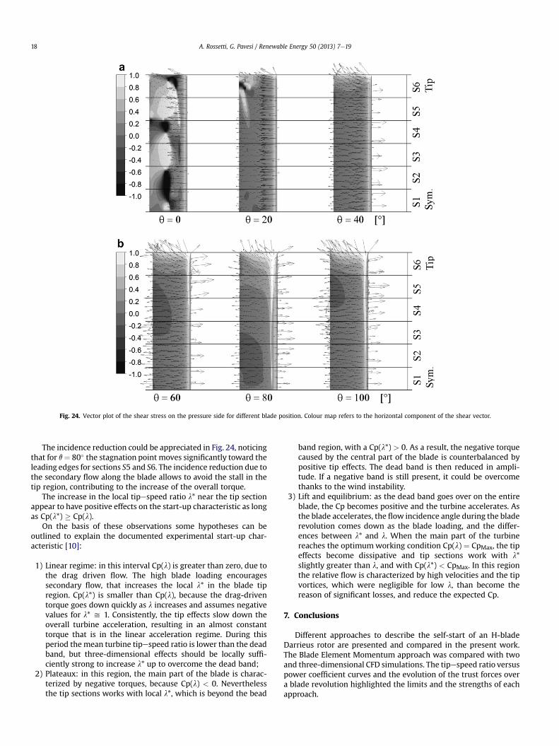
Fig. 24. Vector plot of the shear stress on the pressure side for different blade position. Colour map refers to the horizontal component of the shear vector.
A. Rossetti, G. Pavesi / Renewable Energy 50 (2013) 7e1918
The incidence reduction could be appreciated in Fig. 24, noticingthat for q¼ 80� the stagnation point moves significantly toward theleading edges for sections S5 and S6. The incidence reduction due tothe secondary flow along the blade allows to avoid the stall in thetip region, contributing to the increase of the overall torque.
The increase in the local tipespeed ratio l* near the tip sectionappear to have positive effects on the start-up characteristic as longas Cp(l*) � Cp(l).
On the basis of these observations some hypotheses can beoutlined to explain the documented experimental start-up char-acteristic [10]:
1) Linear regime: in this interval Cp(l) is greater than zero, due tothe drag driven flow. The high blade loading encouragessecondary flow, that increases the local l* in the blade tipregion. Cp(l*) is smaller than Cp(l), because the drag-driventorque goes down quickly as l increases and assumes negativevalues for l* y 1. Consistently, the tip effects slow down theoverall turbine acceleration, resulting in an almost constanttorque that is in the linear acceleration regime. During thisperiod themean turbine tipespeed ratio is lower than the deadband, but three-dimensional effects should be locally suffi-ciently strong to increase l* up to overcome the dead band;
2) Plateaux: in this region, the main part of the blade is charac-terized by negative torques, because Cp(l) < 0. Neverthelessthe tip sections works with local l*, which is beyond the bead
band region, with a Cp(l*) > 0. As a result, the negative torquecaused by the central part of the blade is counterbalanced bypositive tip effects. The dead band is then reduced in ampli-tude. If a negative band is still present, it could be overcomethanks to the wind instability.
3) Lift and equilibrium: as the dead band goes over on the entireblade, the Cp becomes positive and the turbine accelerates. Asthe blade accelerates, the flow incidence angle during the bladerevolution comes down as the blade loading, and the differ-ences between l* and l. When the main part of the turbinereaches the optimumworking condition Cp(l) ¼ CpMax, the tipeffects become dissipative and tip sections work with l*slightly greater than l, and with Cp(l*) < CpMax. In this regionthe relative flow is characterized by high velocities and the tipvortices, which were negligible for low l, than become thereason of significant losses, and reduce the expected Cp.
7. Conclusions
Different approaches to describe the self-start of an H-bladeDarrieus rotor are presented and compared in the present work.The Blade Element Momentum approach was compared with twoand three-dimensional CFD simulations. The tipespeed ratio versuspower coefficient curves and the evolution of the trust forces overa blade revolution highlighted the limits and the strengths of eachapproach.

A. Rossetti, G. Pavesi / Renewable Energy 50 (2013) 7e19 19
The BEM model showed noteworthy limits to describe the self-start behaviour of the tested geometry. This approach is stronglyrelayed to the aerodynamic database given as input to the modeland suffers of the absence of well documented aerofoil character-ization of aerodynamic profiles for a very low Reynolds number.The post-stall description zone, with incidences between 10 and 30[�], was demonstrated to have relevant influences on the dead bandzone of the rotor torque curve. Two different aerodynamic data-bases gave opposite results, neglecting or demonstrating thecapability of the reference geometry to achieve self-start.
The 2D analysis highlighted the presence of a complex vorticespattern, which interacted with the blades and strongly modifiedthe overall performance.
The CFD analyses proved the dynamic stall effected the flowfield more so than the model implemented into the BEM-softwareare able to predict. Furthermore 2D analyses allow to draw atten-tion to the effects of the streamline divergence on the incidenceangle on the blades, and the effects of the relative flow curvature,which are not accounted in the BEMmodels. 2D analyses describeda dead band for tipespeed ratio inside the range 0.2e1.5, neglectingthe capability of the reference geometry to achieve self-start.
3D analyses were conducted for tipespeed ratio equal to 1.Results showed the great importance of 3D effects for small tipe-speed ratio. When compared to the 2D results, three-dimensionalanalyses showed a significant reduction in the vortices intensityinside the rotor. This is ascribed to the instability of vortices whichwere subjects to secondary flows along the turbine axis. These flowcomponents were caused by the non-uniform blade loading, andcreated a flow from the symmetry plane toward the blade tip.Consistently the local incidence angle was reduced near the bladetip and the stall was avoided. Both the reduction of the vorticesintensity and the tip effects increased the rotor expected meantorque. The mean torque obtained was compatible with the self-start of the considered geometry, assuming the presence of smallfluctuation of the wind velocity.
The start-up capability of H-Darrieus appears to be the result ofmany different causes, which include: the blade profile, the Rey-nolds number, secondary flows and three-dimensional aero-dynamic effects. Collected data suggest that turbine start-up couldtake place when tip effects are sufficient to draw the turbineoutside the dead band. At the same time, they are dissipative fortipespeed ratio less than 1, and should not be so pronounced toavoid the acceleration of the turbine to tipespeed near the unity.This delicate equilibrium could explain the presence of contradic-tory experimental results.
References
[1] Ebert PR, Wood DH. Observations of the starting behaviour of a smallhorizontal-axis wind turbine. Renewable Energy 1997;12(3):245e57.
[2] Baker JR. Features to aid or enable self starting of fixed pitch low solidityvertical axis wind turbines. Journal of Wind Engineering and IndustrialAerodynamics 1983;15:369e80.
[3] Paraschivoiu I. Wind turbine design: with emphasis on Darrieus concept.Montreal: Polythecnic International Press; 2002. 289e296.
[4] Watson G R. The self-starting capabilities of low-solidity fixed pitch Darrieusrotors. BWEA workshop; 1979 April 19e20, Cranfield, UK, p. 32e39.
[5] Mays I, Musgrove PJ. Performance of the variable geometry vertical axis windturbine at high and low solidities. BWEA workshop; 1979 April 19e20,Cranfield, UK. p. 48e56.
[6] Ropatec. http://www.ropatec.com/index_n.php?pid¼01&lin¼3 [accessed11.30.2011].
[7] Strickland JH. The Darrieus turbine: a performance prediction model usingmultiple streamtubes. SAND75-0431. Albuquerque: Sandia National Labora-tories; 1975.
[8] Blackwell BF, Sheldhl RE. Wind tunnel performance for the Darrieus turbinewhit NACA0012 blades. SAND76-0130. Albuquerque: Sandia National Labo-ratories; 1976.
[9] Dominy R, Lunt P, Bickerdyke A, Dominy J. Selfstarting capability of a Darrieusturbine. Proceedings of the institution of mechanical engineers, part A. Journalof Power and Energy 2007;221:111e20.
[10] Hill N, Dominy J, Dominy R, Ingram G. Darrieus turbines: the physics of self-starting. Proceedings of the institution of mechanical engineers; part A.Journal of Power and Energy 2009;223:21e9.
[11] Paraschivoiu I, Allet A. Aerodynamic analyses of the darrieus wind turbinesincluding dynamic-stall effects. Journal of Propulsion and Power 1988;4:472e7.
[12] Kirke BK. Evaluation of self-starting vertical axis wind turbines for stand-alone applications. PhD thesis, School of Engineering, Griffith University,Australia; 1998.
[13] Lunt PAV. An aerodynamic model for vertical axis wind turbine. MEmgprojects report. UK: School of Engineering, University of Durham; 2005.
[14] Kirke BK, Lazauskas L. Enhancing the performance of vertical axis windturbine using a simple variable pitch system. Wind Engineering 1992;15:187e95.
[15] Templin RJ. Aerodynamic performance theory for the N RC vertical-axis windturbine. LTR-LA-160. National Research Council/National Aeronautical Estab-lishment; 1974.
[16] Paraschivoiu I. Double-multiple streamtube model for Darrieus wind turbines.Second DOE/NASA wind turbines dynamics workshop, NASA cp-2182, Clive-land, Ohio; February 1981 19e25.
[17] Paraschivoiu I, Delclaux F. Double-multiple streamtube model with recentimprovements. AIAA Journal of Energy 1983;7:250e5.
[18] Paraschivoiu I, Delclaux F, Beguier C, Fraunie P. Aerodynamic analysis of theDarrieus rotor including secondary effects. Journal of Energy 1983;7(5):416e22.
[19] Paraschivoiu I, Fraunie P, Beguier C. Streamtube expansion effects on theDarrieus wind turbine. AIAA Journal of Propulsion and Power 1985;1(2):150e5.
[20] Glauert H. A general theory of the autogyro. ARCR R&M, No. 1111; 1926.[21] Allet S, Halle I, Paraschivoiu I. Numerical simulation of dynamic stall around
an airfoil in Darrieus motion. Journal of Solar Energy Engineering 1999;121:69e76.
[22] Sheldahl RE, Klimas PC. Aerodynamic characteristics of seven symmetricalaerofoil sections through 180-degree angle of attack for use in aerodynamicanalysis of vertical axis wind turbines. SAND80-2114. Albuquerque: SandiaNational Laboratories; 1981.
[23] Sheldahl RE, Klimas PC, Feltz LV. Aerodynamic performance of a 5-metre-diameter Darrieus turbine with extruded NACA-0015 blades. SAND80-0179.Albuquerque: Sandia National Laboratories; 1980.
[24] Ansys CFX 12.0. Copyright Ansys Inc. http//www.ansys.com [accessed11.30.2011].
[25] Egorov Y, Menter F. Development and application of SST-SAS turbulencemodel in the DESIDER project. In. Second symposium on hybrid RANS-LESmethods, Corfu, Greece; 2007.
[26] Menter FR, Langtry RB, Likki SR, Suzen YB, Huang PG, Völker S. A correlationbased transition model using local variables part 1emodel formulation.ASME-GT2004-53452. Vienna, Austria: ASME TURBO EXPO; 2004.
[27] Menter FR, Langtry RB, Likki SR, Suzen YB, Huang PG, Völker S. A correlationbased transition model using local variables part 2etest cases and industrialapplications. ASME-GT2004-53452. Vienna, Austria: ASME TURBO EXPO;2004.
[28] Timmer WA. Two-dimensional low-Reynolds number wind tunnel results forairfoil NACA 0018. Wind Engineering, 32(6), p. 525e537.
[29] Jacobs EN, Sherman A. Airfoil section characteristics as affected by changes ofthe Reynolds number. NASA report, vol. 586; 1937.
[30] Viterna LA, Corrigan RD. Fixed pitch rotor performance of large horizontal axiswind turbines. In. DOE/NASA workshop on large horizontal axis windturbines, Cleveland, Ohio; July 1981.
Copyright © 2022 FDOKUMEN