Communication-Based Train Control System - ERA
125
1 Project Report on Communication-Based Train Control System Submitted by Vaneetpal Singh In partial fulfillment for the award of the degree Master of Science in Internetworking (From University of Alberta) Under the guidance of Juned Noonari September 2018 – March 2019
-
Upload
khangminh22 -
Category
Documents
-
view
1 -
download
0
Transcript of Communication-Based Train Control System - ERA
1
Project Report on
Communication-Based Train Control
System
Submitted by
Vaneetpal Singh
In partial fulfillment for the award of the degree
Master of Science in Internetworking
(From University of Alberta)
Under the guidance of
Juned Noonari
September 2018 – March 2019

2
ABSTRACT
The primary purpose of this report is to study different LRT components generally
related to telecommunications/data networking such as CBTC (Communications-
Based Train Control).
CBTC have a significant advantage over traditional signaling systems when it comes
to the real detection position of trains on the track. Traditional methods used to
divide the track into fixed blocks while in CBTC the block moves along with the
train giving us more accurate position increasing the overall capacity of the trains as
the time between two trains get reduced. Other subsystems include ATP (Automatic
Train Protection) and ATO (Automatic Train Operation). Other components include
interlocking which is communication of different switches and signals at the
crossings that prevents adverse movements.
For the report, I will be discussing train communication systems and related sub-
systems in detail. Also highlighting some of the shortcomings of these systems and
discussing technologies practiced in today’s LRT system along with their vendors
in brief.

3
Acknowledgment
First, I want to thank the All-Powerful God without whom nothing is possible.
I want to express my most profound appreciation to all those who provided me the
possibility to complete my report. Special gratitude I would like to give to my project
mentor Mr. Juned Noonari, this project could not have been possible without his
valuable contribution, encouragement and stimulating suggestions. His
approachability and co-operation provided me great confidence throughout this
project.
I am very grateful to Mr. Shahnawaz Mir for his guidance and helping me choose
my project, his cooperation in providing all the necessary information about the pr
oject and also for his support in the project.
I would like to thank my parents for their kind cooperation and support throughout
my project, which has kept me motivated and helped me complete my project.
My thanks and appreciations also go to my classmates who willingly helped me
with their skills.
Vaneetpal Singh

4
Table of Contents
ABSTRACT ............................................................................................................................................... 2
Acknowledgment .................................................................................................................................... 3
Table of Contents.................................................................................................................................... 4
List of Figures .......................................................................................................................................... 9
Definitions ............................................................................................................................................ 11
1. Introduction .................................................................................................................................. 29
1.1 Automatic Train Operation (ATO) ............................................................................................... 32
1.2 Automatic Train Protection (ATP) ............................................................................................... 34
1.3 Interlocking System ..................................................................................................................... 37
1.3.1 Characteristics of CBTC Interlocking System ........................................................................ 38
1.3.2 Challenges in CBTC Interlocking Development .................................................................... 39
2. Railway signaling systems ................................................................................................................. 40
2.1 European Rail Traffic Management System ................................................................................. 40
2.2 Communication-Based Train Control ........................................................................................... 41
2.3 CTCS / Chinese Train Control System ......................................................................................... 43
3.Why do we need cybersecurity in rail transit control systems? ...................................................... 46
3.1 Challenges ................................................................................................................................... 47
3.2 Shared infrastructure .................................................................................................................... 48
3.3 Systems with long life cycles ....................................................................................................... 48
3.4 Real-time and time-sensitive information ..................................................................................... 48
3.5 Where do the risks lie? ................................................................................................................. 48
3.6 Connectivity changes ................................................................................................................... 49
3.7 Malware contamination methods .................................................................................................. 49
3.8 Different approaches to cybersecurity ......................................................................................... 50
3.9 Assessment of enterprise IT with industrial control systems......................................................... 53

5
4. Cybersecurity approach .................................................................................................................... 55
4.1 Overview ..................................................................................................................................... 55
4.1.1 What needs protection? ........................................................................................................ 55
4.1.2 Protection philosophy ........................................................................................................... 55
4.2 Defense-in-Depth (layered defense)............................................................................................. 58
4.2.1 Threat types .......................................................................................................................... 59
4.2.2 Software embedded/included ............................................................................................... 59
4.2.3 Threat sources ...................................................................................................................... 60
4.2.4 Well known assaults .............................................................................................................. 60
4.3 In-depth detection ....................................................................................................................... 61
4.4 Risk zones for cybersecurity ......................................................................................................... 61
4.4.1 Defense - in - Depth Manufacturing Model DHS .................................................................... 62
4.5 The depth of defense for transport systems ................................................................................. 64
4.5.1 Distance ................................................................................................................................ 64
4.5.2 Communication ..................................................................................................................... 64
4.5.3 Power ................................................................................................................................... 65
4.5.4 People Everywhere ............................................................................................................... 65
4.5.5 Access to the property .......................................................................................................... 65
5. Testing Communications - Based Train Control ............................................................................. 66
5.1 Advantages and disadvantages of CBTC system............................................................................ 67
5.2 Various types of CBTC projects ..................................................................................................... 69
5.2.1 New Line Installation: Greenfield Project ............................................................................... 69
5.2.2 Migration of an existing line: Project Brownfield ................................................................... 69
5.3 CBTC Architecture ........................................................................................................................ 70
5.4 Environmental Tests .................................................................................................................... 71
5.4.1 EMC Tests ............................................................................................................................. 72

6
5.4.2 Climatic Conditions ............................................................................................................... 72
5.5 First Article Configuration Inspection ........................................................................................... 72
5.6 Factory Tests................................................................................................................................ 73
5.6.1 Factory Test Goals ................................................................................................................. 73
5.6.2 Factory Setup ........................................................................................................................ 74
5.6.3 Different Types of Factory Tests ............................................................................................ 74
5.7 On-Board Integration Tests .......................................................................................................... 77
5.7.1 Rolling Stock Characterization Tests ...................................................................................... 77
5.7.2 Mechanical and Electrical Tests ............................................................................................. 77
5.7.3 Static and Dynamic Post Installation Check Out Tests ............................................................ 77
5.8 Test Track .................................................................................................................................... 78
5.8.1 Use of the Test Track ............................................................................................................. 78
5.8.2 Test Track Equipment ............................................................................................................ 79
5.8.3 Location of the Test Track ..................................................................................................... 79
5.9 On-Site Tests................................................................................................................................ 80
5.9.1 Post Installation Check Out.................................................................................................... 80
5.9.2 DCS Tests .............................................................................................................................. 80
5.9.5 Localization Tests .................................................................................................................. 82
5.9.6 Integration Tests ................................................................................................................... 83
5.9.7 Functional Tests .................................................................................................................... 84
5.9.8 ATO Tests .............................................................................................................................. 86
5.9.9 ATS Tests............................................................................................................................... 86
5.9.10 Site Acceptance Tests .......................................................................................................... 87
5.9.11 Shadow Mode Tests ............................................................................................................ 87
5.9.12 Reliability, Availability, and Maintenance Tests ................................................................... 88
5.10 CBTC Test Duration .................................................................................................................... 89

7
5.11 Constraints on Field Tests .......................................................................................................... 90
6. Communication Availability in Communications-Based Train Control Systems............................. 92
6.1 Overview of CBTC and Data Communication System .................................................................... 92
6.2 Proposed Data Communication Systems with Redundancy .......................................................... 93
6.3 Analysis of the availability of the data communication system ..................................................... 96
6.4 Modeling of the behavior of the data communication system with DSPN ............................ 98
6.4.1 Introduction to DSPNs ........................................................................................................... 99
6.4.2 DSPN Formulation ................................................................................................................. 99
6.5 Numerical outcomes and discussions ......................................................................................... 102
6.5.1 Model Soundness ................................................................................................................ 103
6.5.2 Availability Improvement .................................................................................................... 104
7. CBTC Systems challenges ............................................................................................................ 106
8. Vendors and Technologies .......................................................................................................... 108
8.1 Thales - SelTrac .......................................................................................................................... 108
8.1.1 Transmission ....................................................................................................................... 109
8.1.2 Maintaining the position ..................................................................................................... 109
8.1.3 Control of traffic and speed ................................................................................................. 110
8.2 Bombardier - CITYFLO 650 ......................................................................................................... 113
8.2.1 CITYFLO 650 sub-systems: ................................................................................................... 114
Control room for EBI screen ................................................................................................. 114
EBI Lock computer-based interlocking .................................................................................. 114
Radio block center EBI Com .................................................................................................. 115
EBI Link wayside equipment for ATC ..................................................................................... 115
EBI Switch point machines.................................................................................................... 115
EBI Cabin equipment on board ............................................................................................. 115
ATO system .......................................................................................................................... 115
8
8.2.2 Advantages of CITYFLO 650: ................................................................................................ 116
Improved safety ................................................................................................................... 116
Higher automation levels ..................................................................................................... 116
Smooth design ..................................................................................................................... 116
Cost-effective solution ......................................................................................................... 116
8.2.3 Transit lines using the Cityflo 650 system: ........................................................................... 117
8.4 Alstom - Urbalis ......................................................................................................................... 118
8.5 Siemens - Trainguard MT CBTC .................................................................................................. 119
8.6 Nippon Signal – SPARCS ............................................................................................................. 120
9. Conclusion ................................................................................................................................... 123
10. References .............................................................................................................................. 124
9
List of Figures
Figure 1: A typical CBTC system
Figure 2: CBTC architecture
Figure 3: Automatic Train Operation
Figure 4: A braking curve or an active speed profile.
Figure 5: ETCS / ERTMS Level II system architecture.
Figure 6: Braking model construction and application.
Figure 7: level ERTMS: (i) level ERTMS 1, (ii) level ERTMS 2, (iii) level 3 ERTMS.
Figure 8: The relative representation of ATP technologies.
Figure 9. CTCS system architecture.
Figure 10: Assessment of Enterprise IT with Industrial Control Systems
Figure 11: Protection Priority
Figure 12: DHS Defense-in-Depth for Manufacturing
Figure13: basic configuration of WLAN-based data communication system
Figure 14 First proposed redundancy data communication system and no backup link.
Figure 15: Second proposed redundancy and backup data communication system.
Figure 16: CTMC model for the data communication system with a basic configuration.
Figure 17: CTMC model for the first proposed data communication system with
redundancy and no backup link.
Figure 18: DSPN model for the data communication system with a basic configuration.

10
Figure 19: DSPN model for the data communication system with redundancy and no
backup link.
Figure 20: DSPN model for the proposed data communication system with redundancy and
backup link.
Figure 21:
Comparison of CTMC and DSPN models for different configurations of redundancy.
Figure 22: The three WLAN - based data communication systems are not available.
Figure 23: CBTC was
moving block projects based on radio around the globe. Projects are color classified accord
ing to the supplier; those underlined are already in the CBTC operation
Figure 24: SPARCS System Configuration

11
Definitions
Alert Speed Limit
Representation of speed vs. location calculated by CBTC carborne equipment. It is used to
determine when the train operator should be advised to reduce speed by CBTC. The Alert Speed
Limit appears as the yellow zone's lower limit on the Speed Dial.
Alerter
Orange push button on the console of the Train Operator, which must be periodically depressed
and released while the train moves in ATO. If the button is not periodically depressed or the button
is held down for an extended period of time, emergency braking is triggered.
Always Reporting Block (ARB)
Failure of a track circuit indicating occupancy, even if it is vacant.
Anti-Bunching
The function that holds trains automatically (via CBTC Train Holds) when there are too many
trains in front of a station or when there is a CBTC wayside equipment failure (Zone Controller or
CBTC wayside radios) in front of a station. Designed to prevent trains from moving into congested
areas or areas with CBTC failures without an ATS operator taking specific action.
Automatic Route Setting (ARS)
ATS function for interlocking trains. Based on their predetermined schedule, trains are routed.
Automatic Train Operation (ATO)
Operating mode available within CBTC Mainline territory in which the train operates from the
starting point to the next stop point (whether due to a stop station, a red signal, a preceding train
or any other cause) without the Master Controller being manipulated by the Train Operator. When
a train stops in ATO mode, it returns to ATPM mode automatically.

12
Automatic Train Protection Manual (ATPM)
Available operating mode within CBTC Mainline territory in which the train is operated by the
CBTC Train Operator, applying service or emergency braking as necessary to prevent unsafe
conditions.
Automatic Train Regulation (ATR)
ATS function that regulates train service by adjusting station dwelling times and station speeds to
optimize schedule and headway performance.
Automatic Train Supervision (ATS)
Computer system installed at the Rail Control Center with remote dispatcher workstations. The
system monitors its controlled territory and performs non - vital functions like train tracks,
interlocking remote control, ARS, and ATR.
Auxiliary Wayside Protection (AWP)
Operating mode intended for use in CBTC Mainline Territory when a train cannot communicate
with the CBTC wayside equipment due to failure. The train remains located (except when
diverging over a switch) and is governed by local speed limits encoded in the OBCU that are
appropriate for the location of the train and wayside signals. AWP trains as flashing green signal
aspects have not been issued.
Auxiliary Wayside System (AWS)
CBTC Mainline territory signal system and CBTC yards. Provides CBTC-controlled train
interlocking functions and functions as the signal system for other trains. AWS includes facilities
for overriding wayside signals and displaying a flashing green signal aspect in CBTC Mainline
territory and for moving from yards to CBTC Mainline territory.
AWS Traffic
13
AWS logic coordinating the direction of operation on the interlocking track. Except that two
directional indicators are provided, similar to non-CBTC traffic. Relative directional indicator
alignment selects AWS mode of traffic (both in the same direction) or CBTC mode of traffic
(aligned in opposite directions).
AWS Traffic Mode
The condition of AWS traffic control in which:
All trains may enter the traffic section (regardless of operating mode or whether the train
is equipped with CBTC).
All trains must operate in the prescribed direction of traffic, except that a train that has just
cleared the interlock may end and proceed in the opposite direction through the interlock.
Blocked Zone (BZ)
A temporary CBTC speed limit where the speed limit is set to zero. Trains have to stop before they
enter the Blocked Zone. If a train is to travel through the Blocked Zone, the movement must be
done in Restricted Manual until the whole train is clear from the zone.
Carborne
Situated on the train.
Carborne Interface Unit (CIU)
Carborne equipment located in the top locker of each operating cab that:
(1) Connects the other CBTC Carborne equipment to the non - CBTC equipment on the train
(2) Controls the operation of the TOD and CRD equipment.
Carborne Controller
Carborne equipment's general name that governs train operation under CBTC.
CBTC Bypass
A mode of operation in which a train operates at normal velocities while CBTC controls are
disabled.

14
CBTC Limit
MAL type resulting from an internal obstacle (i.e.,
not a physical object) to CBTC operation. In overall, one of two conditions appear:
1. When the track is vacant in normal operation, there may be a limit to how far the zone
controller (ZC) can' see' ahead of the current location of a train. In this case, a CBTC Limit
Movement Authority Limit (MAL) will generally be far enough away to prevent the train
from slowing down. As the train proceeds, it will usually pass into the area where it is
possible to extend the MAL beyond that limit.
2. The CBTC Limit MAL represents the location of the virtual signal when CBTC Traffic
Mode is in effect. Generally speaking, the train will proceed to this location and either
reverse or wait for a movement authority to allow the train to continue.
CBTC Mainline Territory
Mainline territory fully equipped with CBTC wayside equipment to support operation in ATPM
and ATO modes (zone controller, transponders, radios, etc.).
CBTC Mode Switch
Rotary switch mounted at the top right of the console of the Train Operator used to select a control
mode.
CBTC Temporary Speed Restriction
(ATS) A speed limit imposed on trains operating in ATPM or ATO modes by an ATS operator.
The ATS operator sets the speed limit and legal speed limitations. Approaching trains are reduced
to the permissible speed before entering the restriction area of temporary speed, and the speed is
maintained at the limit value until the entire train is clear of the restriction area. There are two
types of temporary speed limitations for CBTC:
Slow Speed Order - trains may cross the ATO restriction area
Work zone – trains from the station are prevented from operating in ATO before the
restriction.

15
CBTC Territory
Line, a line portion, or yard in which CBTC operates. It includes the mainline territory of CBTC
and the yards of CBTC.
CBTC Traffic Mode
Traffic control condition in which:
Only ATO or ATPM trains equipped with CBTC can enter the traffic section. For other
trains, signals won't be clear.
Trains may operate in either direction under CBTC control within the traffic section.
CBTC Train Hold
An applicable condition where an ATS operator or an ATS anti - bunching function has determined
that a train should not leave a station. An indication of the CBTC Train Hold appears on the TOD;
the train cannot leave the station in ATO when a CBTC train hold is in effect.
CBTC Yard
(1) (Train Operation) The operating mode for use in yards equipped with CBTC. CBTC limits
train speed to 10 mph. Protection against red signals and overrunning the end of the track,
but not against tracks that have been occupied.
(2) (General) Yard equipped with CBTC wayside equipment to support operation in CBTC
Yard mode (zone controller, transponder, radio, etc.).
Civil Speed Limit
Speed limit resulting from the right - of - way's permanent feature (e.g., a curve).
Communications-Based Train Control (CBTC)
The train control system that allows trains to exchange messages with a controlling computer (the
Zone Controller) that provides train movement authority. CBTC incorporates a means by which,
apart from track circuits, the location of a train can be determined dynamically.

16
Console
(1) Desk designed as a workstation enclosure.
(2) 'Train Operator ' console: the TOD monitors and switches and indicator lights used to
control and monitor different functions within the operating cab.
Control Mode
The train operator selected status through the CBTC mode switch. Used to determine how CBTC
will operate in the operating mode.
• Normal
• AWP (Auxiliary Wayside Protection)
• Restricted manual.
COS File
A schedule or addition stored in the ATS system. The schedule or supplement has been encoded
in such a way that it can be loaded and used as a Current Operating Schedule readily (i.e., as a list
of trips).
Current Operating Schedule (COS)
The list of trips that ATS is currently using as the basis for its operation.
Delocalization
An event where a train loses track of its right-of-way location and can no longer update its location.
A regular occurrence when the train leaves CBTC Territory and enters the non-CBTC territory.
When a train located within CBTC Mainline Territory or a CBTC Yard is delocalized, it is a failure
and results in an application for an emergency brake.
Emergency Braking
Braking applied to protect a train from an unsafe condition (whether real, perceived, or inferred
by Carborne or wayside equipment because a safe operating condition is not fulfilled). Completed

17
by venting the atmosphere brake pipe. Once applied, it is not possible to release emergency braking
until the train is stopped. No plausible condition would make Emergency Braking unavailable if
necessary.
Fallback
Any action, procedure, operating mode, etc. used in case of equipment failure to maintain operation
(often under restrictive conditions).
Field Fallback Mode (FFM)
Field AWS equipment operating mode when communication with ATS is lost. In FFM, in response
to approaching trains, the interlocking aligns regular running routes. At non - terminal interlocking,
FFM is provided; Terminal Fallback Mode provides a similar terminal function.
Flashing Green (FG)
Signal aspect for ATO or ATPM trains. Corresponding indication (in accordance with Rule 6.17)
is 'Proceed as per Train Operator Display.' Despite Rule 6.17, FG does not authorize the train to
proceed. If the TOD indicates the train does not have the authority to move, it must stop.
Information Storage and Retrieval (IS&R)
The function relating to the storage and recovery of data developed during the operation of the
ATS territory (field sequences of events received, user commands, train register, and schedule
data, etc.). During operation, all data processed by ATS will be stored. It is possible to generate
predefined reports based on stored data at any time; it is also possible to define custom reports
containing data specific to a particular condition (for analysis, investigation, etc.).
Localized
The carborne equipment condition (especially the OBCU) when it has established the location of
the train along the right - of - way and is able to update it as the train moves.
Maintainer's Control Panel (MCP)

18
Control panel installed in relay rooms allowing the alignment of routes by an operator (usually a
signal maintainer) and otherwise an interlocking.
MAL Bar
Graphical device for displaying MAL distance on the Train Operator Display (TOD) and appears
with a graduated distance scale in the form of a colored vertical bar. The point at which the color
of the bar changes to red is the distance of the MAL.
MAL Distance
Distance from the current location of the train to its stop point of operation. Although the distance
between the train's location and its MAL location is not equal to the MAL distance, it represents
the practical application of the limit of the movement authority. To prevent a train from
overrunning the MAL distance, CBTC will use braking.
MAL Icon
The graphical device on the Train Operator Display (TOD) for displaying the MAL type. And
appears below the MAL bar as a symbol. The symbol shown corresponds to the type of MAL.
MAL Location
(CBTC Wayside) The location of the MAL obstruction.
MAL Type
Type of obstacle as identified in a Movement Authority Limit that a train has to stop for. Possible
types of MAL are:
• Train
• Home Signal
• Home Signal
• Train Stop
Manual Route (MR)

19
AWS / Signal control function (panel and MRS display pushbutton) for a non - CBTC train to
request an interlocked signal. If the Manual Route function in CBTC Mainline Territory is not
used when requesting a signal, the signal will only be apparent for CBTC trains.
Manual Route Setting (MRS)
Workstation display that allows the operator to control the interlocking directly (align and cancel
routes, moving switches, etc.).
Master Controller
Control device located in the operating cab that controls a train's acceleration and braking by the
train operator.
Movement Authority
Authorization to proceed to a specified location (MAL) inherent in the limits of the transmitted
movement authority.
Movement Authority Limit (MAL)
Message from the zone controller on a train to the OBCU authorizing the train to proceed to a
specific location (MAL location) and identifying the type of obstacle (MAL type) present at that
location where the train must stop.
Never Reporting Block (NRB)
Failure of a track circuit under which, although occupied, the track circuit indicates vacancy. An
NRB is a track circuit failure to detect a train, a dangerous condition. By comparing the reported
location of trains with AWS track circuit occupancy states, the zone controller is able to discern
NRBs.
Non-Reporting Train
(ATS) A train notifying ATS of its location. The train may lack CBTC equipment, its equipment
may fail, or it may operate under CBTC, but ATS cannot acquire train location data. Train
identifiers for trains that are not reported appear on ATS displays in yellow.

20
Non-Vital
Not critical for safety. Failure of a non - vital system may lead to operational disruption, but it
cannot lead to an unsafe condition.
Normal
Train-related mode of control when all equipment is in operation. The CBTC carborne equipment
will select a suitable mode of operation based on the location (or not) of the train from one of the
following:
Automatic Train Operation (ATO)
Automatic Train Protection Manual (ATPM)
CBTC Yard
Wayside Signal Protection (WSP)
Obstacle
Item to be protected by a movement authority limit from CBTC trains. There are two general types:
(1) The object on the right-of-way for which a train has to stop.
(2) Condition prevailing within the CBTC equipment relating to a specific location, so that
safe operation beyond that location cannot be guaranteed.
Offside Display (OSD)
Installed in the operating cab on the side opposite the TOD, instrument panel with digital displays
and individual indication lights. Provides train berthing and dwelling status information when
operating doors from that side of the operating cab.
Onboard Control Unit (OBCU)
Carborne computer device for CBTC-equipped train operation. Contains internal track
configuration database (grades, curves, legal speeds, locations of transponders, etc.) allowing
localization and calculation of speed profiles (including Alert Speed Limit and Braking Speed
Limit profiles). It determines permissible velocities based on internal data received from ZC and
MALs. A pair of OBCUs are located inside the lower equipment locker in the A1 car's operating
cab for each R143 unit. If either OBCU fails, the rest of the operation will be supported.

21
Operating Mode
CBTC carborne equipment status that determines whether and to what extent CBTC will regulate
train movements. Usually set by the CBTC equipment automatically. In the occurrence of system
failure, an alternate control mode may be selected by the Train Operator in the direction of the
Control Center, resulting in a change in operating mode.
Operating Profile
Representation of speed vs. location (stationing) associated with a train's actual movement as
determined by the actions of the train operator. In ATO mode, the operating profile is determined
by the carborne equipment.
Operational Stopping Point
Location of a short distance in approach to a limit of the movement authority (MAL) where a train
is ordered to stop under CBTC control. Calculated based on the MAL received from the Zone
Controller by the carborne CBTC equipment. With the improper operation, the operational stop
point may be overrun, but it is not possible to override the MAL itself (as long as the train remains
under CBTC control). The location of the operational stop point can generally be considered
equivalent to the MAL, as the operational stop-point represents a practical limit for the movement
of the train.
Optical Speed Measurement System (OSMES)
The device that scans the running rail to measure distance and speed mounted on the truck. Two
OSMES devices, one for each rail, are mounted on the A1 car's # 2 truck for each R143 unit.
Override
In CBTC, when a CBTC - controlled train approaches it, the process of causing a signal to clear
to flash green.
Programmable Logic Controller (PLC)

22
A device installed for non-vital logic for AWS in relay rooms: route selection, auxiliary switch
control, field fallback mode / terminal fallback mode, etc. Resolves commands received from ATS
or MCP (entry / exit selections, fleeting, etc.) into vital signal equipment commands (move back
switch, clear signal, etc.).
Rail Control Center (RCC)
Central NYCT subway supervisory office. ATS central equipment location.
Reporting Train
A train that reports to ATS about its position. Typically, but not necessarily, the train will be under
CBTC control: it may be in the operating mode of the Restricted Manual or AWP, but it can still
determine its location and report it. ATS displays show train identifiers for reporting trains in red.
Restricted Authority
(RA)Authorization issued to a train allowing it to proceed at restricted speed (10 mph) when there
is one of the following:
Failed track circuit
Red automatic or approach signal
Automatic stop arm for approach or automatic signal not reported in the precise position
Call-on displayed on the home signal
An ATS operator issues RAs for the first three conditions. It applies to all subsequent trains once
an RA is issued for one train, as long as the condition that resulted in the issuance of the RA
remains present. The field equipment also automatically issues RAs when a call-on is displayed
on a home signal.
Restricted Manual
(1) Control mode used to release a train from CBTC control in the event of CBTC failure. The
operating mode of the Restricted Manual (RM) is available in the Restricted Manual mode
of control.
(2) (RM) A mode in which CBTC control is disabled, but train speed is limited to 10 mph by
non-CBTC carborne equipment.
23
RM Lockout
Condition established on a train while operating in ATO or ATPM mode to prevent the train from
operating in Restricted Manual mode if CBTC communications are to fail. In order to prevent the
existence of an unsafe condition where CBTC Traffic Mode was in effect, communication is lost,
and a train proceeds in RM overruns the CBTC Limit and experiences a head-on collision. There
are two ways to release an RM lockout:
(1) Using the ATS RM Unlock command or
(2) Using the RM Release switch located in the operating cab on the front of the upper equip
ment lock.
RM Release
(1) Sealed switch mounted in the operating cab on the front of the upper equipment locker allowing
the train to operate in a restricted manual mode when the RM lockout is in place
(2) Use of the RM release switch to allow the train to continue in spite of the RM lockout.
RM Unlock
ATS command issued an RM lockout to a train.
Run
Train specification moving in one direction. One or more runs may consist of a trip. Multiple runs
allow the description of put-ins, layups, and turnback moves by a single trip (with a single Trip
ID). The following data are included in each run:
• Movement direction
• List of train locations visited
• Arrival and departure times at each location.
Safety Profile
Representation of speed vs. location (stationing) for a train that requires action by the train control
system (whether the signal or CBTC) to prevent an unsafe condition. The safety profile is not
consistent with normal operation.

24
Sieved
Condition applicable to a localized train when the zone controller has resolved the location of that
train's front: specifically, there is nothing between the train's front end and the track's front end
occupied by the train's front end. As long as the train is in ATPM or ATO mode and does not
occupy a track circuit adjacent to a non-CBTC train, the zone controller will be able to trigger
flashing green signals for that train once a train is sieved. Sieving is done by correlating the
reported location of the train with the occupancy of the track circuit when the train's front end is
approaching a designated sieving location. In general, there are sieving locations at the exit ends
of stations (in both directions) and at home signals.
Slow Speed Order
A temporary speed limitation imposed by the CBTC on a track section, usually due to a track
condition where workers are not on track. ATO is permitted, and in 5mph increments, the ATS
operator may set any permissible speed limit.
Speed Dial
Graphical device for displaying the permissible speed on the Train Operator Display. Includes a
digital indication and a colored arc analog speedometer dial to indicate admissibly, braking, and
prohibited speed ranges.
Station Restriction
MAL type used to avoid partial entry or departure of trains in stations. A Station Restriction
Movement Authority Limit (MAL) will be in effect at the station entrance for a train approaching
a station if the previous train is inside the station and has not started departing. The Station
Restriction MAL will hold the train in place for a train stopped at a station until there is sufficient
vacancy beyond the station to allow the train to clear the platform entirely. In this case, if a partial
move is desired, an ATS operator may grant a Station Restriction train exemption.
Station Stop and Stay

25
(1) MAL type used when an ATS operator has issued a train stop and stop command, and the
train is stopped at a station. Prevents the station from leaving the train.
(2) ATS command requested to prevent the train from leaving the station.
Terminal Fallback Mode (TFM)
Field AWS equipment operating mode when communication with ATS is lost. In response to
approaching trains, inbound routes are aligned in TFM, while outbound routes are aligned in
response to locally controlled starting lights. TFM is provided at terminals; in non-terminal
interlocking, the Field Fallback Mode provides a similar function.
Track Circuit
An electrical circuit that forms part of the running rails. Used by non - CBTC signaling systems
and AWS for train detection.
Traffic
Coordination of the operation direction on the interlocking track. Signal, AWS, or CBTC
equipment may be used.
Traffic Section
A track section between interlocking that provides AWS traffic.
Train Tracking
ATS works to determine a train's location on the mainline.
Transponder
A device attached between the running rails to the roadbed. Transponders contain messages that
are read through trains to allow the trains to become located and remain.
Transponder Interrogator Antenna (TIA)

26
Truck - mounted device that allows the OBCU of the train to read transponder data as the train
passes over them. One TIA is provided for each R143 unit on the A1 car's # 1 truck.
Trip
(ATS) Specification for one or more train movements (runs) performed by a single train consists
of a single Trip ID. The Current Operating Schedule is the list of journeys used by ATS as the
basis for their operation. For each trip, ATS tracks the following data:
Origin of trip data (e.g., schedule file number)
Trip ID
Scheduled departure time from origin
Scheduled arrival time at the destination
Crew ID
Status (e.g., not yet used, en route, completed)
Data required to describe each run
Trip ID
(ATS, Train Operation) Identifier for a trip, consisting of the following:
Type of movement (e.g., revenue trip, put-in, etc.)
Line ID
Scheduled departure time from origin
Origin Terminal
Destination Terminal
The Trip ID currently associated with a train is displayed on the TOD. It represents the train's
interval.
UFO Wayside Pushbutton
A pushbutton on the wayside at specific locations to allow an unfit train or a train with failed
CBTC equipment to proceed.

27
Unequipped and Failed Operation (UFO)
Operation of an unequipped train or train that has failed to carry CBTC equipment.
Unequipped Train
A train that lacks carborne equipment from CBTC.
Virtual Signal
Location on the interlocking track where trains operating under CBTC control may be ordered to
stop. An ATS operator may request or cancel virtual signals to coordinate train moving across the
same track in opposite directions while CBTC traffic mode is in effect.
Vital
Safety-critical: a vital system is one whose failure could result in persons or property being lost or
damaged. Accordingly, vital systems are designed to prevent any likely failure from leading to an
unsafe condition.
Wayside Cell Controller (WCC)
Computer device located on the wayside in signal rooms. Accepts ATS and ZC data and packages
as well as forwarding data to WRUs for transmission to the trains. It performs the reverse function
for train / WRU data received.
Wayside Radio Unit (WRU)
Radio transceiver and related equipment, installed in wayside installations. Receives transmission
data from WCC to trains and transmits data to trains via radio. Likewise, data received via radio
from trains to WCCs are forwarded.
Wayside Signal Protection (WSP)
The operating mode in the non - CBTC territory for CBTC - equipped trains. Trains operate at
average speed and are controlled by signals along the way.

28
Work Zone
A temporary speed limitation issued by the CBTC where workers are on track or can be expected
to appear on the track. ATO is prohibited, and there is always a speed limit of 10 mph.
Workstation
A computer device primarily intended to support communication with a human operator between
the ATS (or other similar) system. It includes a processor (in a console box), monitors, keyboard
, mouse, system connections, and other support devices.
Zone Controller (ZC)
Vital computer device located on the wayside in signal rooms. Establishes train - based movement
authority limits (MALs), including:
the reported position of the train for which the MAL is being issued
the reported positions of other trains
track occupancies
signal and train stop status
switch position
controls received from ATS (e.g., stop and stay

29
1. Introduction
Last decade saw a massive focus on rail transport due to the reasons such as environmental
awareness, increased urbanization, population growth, and it is a more energy-efficient, safer,
higher capacity, and more top speed transport alternative. Recent studies show that the European
rail market grew from 122 billion euro per year to roughly 150 billion euro in the period 2008-
2013, and is expected to increase to nearly 176 percent by 2017. Furthermore, it is projected that
a total of 1,077.8 km of rail tracks for the modern, communication-based signaling system CBTC
will be installed in the period 2011-2021, compared to only 188.9 km in 2001-2010.
Poor braking capabilities characterize rail traffic due to low rail friction, fixed track, and barriers
avoidance. Hence, the ultimate goal of a railway signaling system (or train control system) is to
prevent train collision and derailment.
Conventional railway signaling is based on color light signals and train detection with the help of
track circuits and axle counters. However, this technology is almost half a century old. It is
approaching its expiry in most of the installations worldwide and is responsible for most of the
delays experienced every day. Color light signals being an old technology is one reason why
modern signaling systems are rapidly replacing the conventional signaling systems.
Different means of telecommunication are used in modern, communication-based railway
signaling to transfer information on train control between the train and the wayside. Nowadays,
however, the term is used for radio-communication-based signaling almost exclusively. CBTC is
a modern signaling system based on radio communications. Using radio communication, it allows
high-resolution and real-time train track control information, which increases line capacity by
safely reducing the distance (headway) between trains traveling on the same line and minimizes
trackside equipment numbers. CBTC is today's first choice of railway operators for mass transit
operations, with more than 100 CBTC systems currently installed worldwide. Note that while
communication-based train control is a generic term, today the term CBTC is explicitly used to
imply mass transit systems, mostly using IEEE 802.11 Wireless LAN (WLAN) for radio
communication. CBTC systems are thus regarded as distinct from the European Rail Traffic

30
Management System (ERTMS)—another modern, communications-based signaling system
focused on mainline rail operations.
Figure 1: A typical CBTC system
Unlike many other research and development areas, the state-of-the-art in CBTC is driven by the
industry rather than the academia. Also, this being a highly competitive industry, the amount of
publicly available literature on this topic that openly discusses implementation details is highly
insufficient. The main contribution of this report is to provide a comprehensive tutorial as well as
a survey of the state-of-the-art radio communication in CBTC. The available industrial and
scientific literature on this topic was consulted for this purpose, besides the knowledge acquired
from the author’s own experience of working on the development of a CBTC system. Denmark is
currently one of Europe's front - runners as it undertakes a complete renewal of its entire railway
signaling before 2021, with an investment of EUR 3.2 billion. This renewal includes the
Copenhagen mass-transit network S-train, which will be equipped with a CBTC system. The new
signaling system is expected to enable higher capacity and an 80% reduction in signaling related
train delays. The paper aims for a pragmatic approach, occasionally using the Copenhagen S-train

31
project as a reference. Nonetheless, the information provided is generic and is not restricted to any
specific plan or supplier.
Wi-Fi, as a radio technology, primarily due to its cost-effectiveness. In contrast to radio
communication for non-safety related rail applications such as CCTV and onboard Internet, radio
communication for safety-related application such as train control imposes stronger reliability and
availability requirements. This paper discusses the historical reasons behind the success of Wi-Fi
as the actual technology for CBTC, despite its lack of support for mobility and susceptibility to
interference. It presents the best practices in the design and architecture of a CBTC radio
communication network and the actions to ensuring high system performance.
There has been an overall lack of standardization efforts for CBTC, the result of which is that
nearly all existing CBTC installations are incompatible, proprietary systems. Though there exists
an IEEE standard for CBTC, it has not gained much attention from CBTC suppliers due to its
limited scope.
Figure 2: CBTC architecture

32
The CBTC’s primary goal is to maximize capacity by reducing the time interval between trains.
Traditional signaling systems detect trains in separate track segments called' blocks,' each
protected by signals preventing a train from entering an occupied block. Because each block is a
fixed track section, these systems are called fixed block systems.
Several trains operate on the major routes are now fully equipped with an Automatic Train
Protection System (ATP) which monitors the driver safely and automatically stops the train in the
unfortunate event of a breach of authority (overrun or overrun). European rail companies have
acquired the European Rail Traffic Management System and the European Train Control System
(ETCS) throughout the last 15 years, and nowadays these are the officially recognized
interoperable ATP solutions. The next step is to help the driver manage trains directly by adding
automatic train operation to the ATP. ATO leads to more deterministic travel times, subsequent
ideal speed profiles that allow the operational flow on existing lines to increase and reduce energy
consumption ATO systems have been used in urban applications for a long time; while on the main
lines these systems are entirely new due to the diversity of trains and the complexity of the network.
Main Line ATO also has to meet the interoperability needs of several train operators operational
on the same interconnected infrastructure. The true challenge is to implement ATO functions with
the same level of ERTMS interoperability in complex mainline configurations.
1.1 Automatic Train Operation (ATO)
The rapid growth of communication, control and computer technologies in the last several decades
have led to the emergence of automatic train operation (ATO), for which the driver no longer has
to operate the control handle cautiously, in urban rail systems to replace traditional manual driving.
While railway knowledge is advancing, one hypothetically challenging and virtually significant
problem is how to use the ATO system to make the existing railway network more efficient with
higher capacity, lower cost, and improved service quality through optimized rail traffic
management and train operation.

33
Figure 3: Automatic Train Operation
Automatic train operation (ATO) is an active safety enrichment instrument used to automate train
operations. It is mainly used for automated guide transits and fast transit systems that make it easier
to ensure human safety. Most systems elected to maintain a driver (train operator) to alleviate risks
associated with failures or emergencies.
Several modern systems are connected to the ATC, and in many instances, the ATP system
supports normal signaling processes, such as track setting and train adjustment. The system is also
connected to the automatic train control system. Usually, the ATO and ATC / ATP systems work
together to keep the train within a tolerance level allowed for the schedule. When you move, and
station reside marginally, the combined service will adjust operating parameters such as the power
/ cost ratio to get a train back to its defined schedule.
The purposes of using ATO are significantly dissimilar for Urban and Main Line railway
operation, and consequently, the ATO functions will be various for both of them.
ATO is seen as being beneficial to attaining capacity increase and is therefore generally used in
urban applications. Previously, even though its practical feasibility is clear, ATO has been little
used on Main Line rail networks. What is the reason behind this?

34
Around the world, it is realized that Urban Operators want to implement ATO functions for various
distinct reasons:
• First, to achieve travel times and station operating times that are closer to the theoretically
possible optimum and less variable than once involved drivers. ATO makes it possible to reduce
the minimum operational progress for the line (e.g., by reducing the margin between functional
and technical progress) as well as the development of travel times. The latter benefit may even
decrease the number of trains needed on a line to meet the demand for capacity.
• As a following step, to use unsupervised turnback and depot operation to reduce the number of
drivers and trains required thus reducing staff costs and may leaving the transportation system less
exposed to disruption due to staff rostering issues.
•Next, some urban operators allow fully crewless service train operation to further reduce costs a
nd disruptive vulnerability, leaving the team free to deal with other issues.
• ATO enhances operational stability, thus limiting perturbation propagation and providing faster
recovery from disturbance.
ATO controls all phases of train operation from acceleration to accurate stoppage compared to
ATP, which only controls braking. At present, ATO is mainly installed in monorails and linear
metro stations. In combination with the Gates platform, ATO helps train operators operate without
a driver.
1.2 Automatic Train Protection (ATP)
ATP is a particular type of train protection system that continuously monitors the compatibility of
train speeds with the permitted signal speeds. If not, ATP triggers an emergency brake to stop the
train. Automatic Train Protection (ATP) is used in railway control to monitor train speed against
an authorized speed profile that is automatically developed on the onboard equipment by the
signaling subsystem (i.e., ground) information. The built-in control system installed in the train
cockpit is designed to ensure that the speed profiles are respected and the so-called "braking
curves" are developed to allow the train to slow down and brake before any stop signs or
emergency conditions (Figure 4).

35
Figure 4: A braking curve or an active speed profile.
In an instance of an inaccurate or late involvement by the train driver, which communicates with
the system by a Man Machine Interface (MMI), the onboard control system automatically
instructions the braking process, directly acting on train-borne apparels thru a precise interface,
specifically the Train Interface Unit.
(ETCS / ERTMS) European Train Control System / The European Railway Traffic Management
System is the most extensive international standard for the new railway signaling and control
systems. The rule offers the specification for an interoperable ATPS designed at refining both the
safety and the performance of railway tracks. ERTMS/ETCS specifies three stages of rising
complexity and performance, which can be executed as a single stage or together, with the lower
levels acting as fall-back schemes in case of inaccessibility of the higher ones. All around the
world, numerous projects based on different levels of ERTMS/ETCS have been established or are
still under construction, with ERTMS/ETCS level 2 description being the most effective. ETCS /
ERTMS level 2 is based on an innovative continuous radio signaling system using a separate
version of the GSM standard, namely GSM - R, as the most important means of communication
between the onboard and ground systems (Figure 5).

36
Figure 5: ETCS / ERTMS Level II system architecture.
For instance, concerning the braking curve of Figure 4, in ETCS / ERTMS the Target Point is
given by the so-called Movement Authority (MA) while the Maximum Speed is obtained by the
so-called Static Speed Profile (SSP). The difference between ETCS / ERTMS level I and II are
considerably given using transmission through which such information is obtained by the train. In
level 1 the MA and the SSP are discontinuously obtained via radio from the so-called balizes,
devices physically installed between the track lines and energized by the trains passing over them;
in level 2 the similar data is continuously transmitted by the ground system via messages using the
GSM-R network.

37
The onboard system logic builds the braking model using MA and SSP information together with
real train information, such as per axis weight and length. Then another module check that trains
speed is below the thresholds and, if not, commands electrical and emergency braking via the TIU
(Figure 6).
Figure 6: Braking model construction and application.
1.3 Interlocking System
Nowadays, with the rapid increase in passenger flow in the big city, it is believed that the most
effective approach to solving traffic problems is the urban rail transport system. The
Communications Based Train Control System (CBTC) has many advantages in terms of capacity,
density, efficiency, cost of operation and safety. It is, therefore, being adopted by more and more
railway management bodies. The CBTC system overcomes the fundamental limitations of
conventional railway signal systems based on track circuits. It employs continuous, high-capacity,
two-way train-to-wayside data communications and performs location determination of high-
resolution trains. Train-borne and wayside processors are therefore capable of enabling more
efficient use of transit infrastructure and vital functions to be implemented.
As a key CBTC subsystem, interlocking monitors and controls wayside devices such as track
circuits, signals, and switches, as well as setting up safe track routes for train passage under various
modes. It provides continuous routes for trains operating under limits of movement authority for
CBTC-equipped trains operating in moving block mode. When wayside CBTC equipment or
wayside-to-train data communication breaks, trains are supported by the interlocking system to

38
run in backup modes by sending movement authority to the electric line unit. In the event of a
system failure affecting a particular CBTC-equipped train operating within any area of CBTC
territory, interlocking shall establish a call-on or inter-station block route in which mode trains
under the control of a train operator may be capable of continuing safe operations.
CBTC interlocking system is obviously a typical safety-critical system with a high level of safety
integrity (SIL), and its software will inevitably increase in scale and functionality. System
requirements and design specifications are written in some natural language in classical software
engineering methods, and their inherent ambiguity can lead to different interpretations depending
on the reader. In addition, testing is cost-consuming, error propagation, and can hardly reach full
coverage for all design for such a large and complex system.
Model-Based Development (MBD) is a novel, promising method and process for software
development and testing as opposed to conventional software engineering measures. MBD
supports specific software requirements definition and designed model verification in which
formal process methods are commonly adopted. Mathematical techniques are formal methods,
often supported by tools of reasoning to ensure rigorous and efficient design, design and analysis
of computer systems. Evidence has shown that formal methods have been used more and more in
rail signaling over the past few years.
1.3.1 Characteristics of CBTC Interlocking System
The essential functions of interlocking equipment can ensure the safety of traffic, fulfill the right
interlocking relationships between track sections, switches, signals, platform doors, and other on-
track equipment, and prepare train routes. These functions have the ability to protect effectively
even for some illegal operation. CBTC systems allow trains to operate safely at much closer
headways in order to achieve more efficient use of transit infrastructure. It allows the interlocking
system to accommodate multiple train routes, while only one train usually occupies a route. In
addition, for CBTC equipped trains, they usually operate under the protection of the Zone
Controller (ZC) system within the limits of the moving authority (MA). On the contrary, they also
need to operate under the protection of an auxiliary wayside signal for trains not equipped with
train-borne CBTC equipment and/or trains with faulty train-borne CBTC equipment. In the CBTC

39
interlocking system, it determines that there are two signal modes: extinguish mode and light
mode.
1.3.2 Challenges in CBTC Interlocking Development
Because the architecture and functionality are substantial and sophisticated, the development of
the CBTC interlocking system has several problems. First, the complexity is embodied not only in
functionality but also in security. It needs experienced logic designers who can not only understand
the principles of interlocking but also imagine many potential security issues. They must try to
consider every possible occasion when creating control logic. Second, functional requirements and
design specifications are written in the natural language in conventional development. Although
different interlocking systems share a lot of standard rules, there are very likely inconsistencies
between different descriptions and the inherent ambiguity can lead to different interpretations
depending on the developers. Third, since the scale and scope of interlocking software have
become much more significant than ever before, it is difficult to detect design errors during the
modeling phase. It is time-consuming and inefficient to test all possible branches of interlocking
logic manually. Simulation and test methods can end up with many software flaws but cannot
guarantee the properties of the correct system including functional behavior, timing behavior,
performance characteristics, and internal structure. In order to analyze a system for the desired
properties, verification methods for the control logic are then proposed

40
2. Railway signaling systems
2.1 European Rail Traffic Management System
ERTMS is the most advanced signaling system available at present. The method for high-speed
trains has been developed. The driver can not see the road signals when the train goes faster than
200 km/h so that this information must be transmitted to the cabin of the train.
Additionally, this information must be continuous to improve safety. The ERTMS has been
developed to comply with both the requirements for cross-border interoperability (EBICAB, TBL,
AWS, ASFA, LZB). Currently, over 38 countries (mostly in Europe but not including China, Saudi
Arabia, South Korea, Taiwan, and Australia), 62,000 km of railways and 7,500 ERTMS-apparatus
are well aware of the system's popularity. ERTMS, therefore, increases interoperability, security,
and costs (only one method is necessary).
In the European Union Railways Agency (ERA), ERTMS was specified in a task force composed
of railway constructors and workers (UNISIG). ERTMS is organized in three stages: Stage 1 is a
punctual ATP with 500 meters of track marks or loops ahead of the signal. These loops can supply
variable or static data. Stage 2 is similar to a distance - to - go system (DTG), and now there are
two - way communications (via GSM -R radio) to remove track signals, but no track circuits.The
stage is finally a "moving block "system, and track circuits and signs can be transmitted. Stages 2
and 3, therefore, require GSM-R and an active network of transmitters on the path. A schematic
image of the three ERTMS levels is shown in Figure 7.

41
Figure 7: level ERTMS: (i) level ERTMS 1, (ii) level ERTMS 2, (iii) level 3 ERTMS.
Besides, ERTMS can source other data of interest to the driver, such as transitions between supply
phases, viaducts, and tunnels.
2.2 Communication-Based Train Control
Five grades of train automation also known as GoA levels, for automation grades, as shown in
EN62290 are as follows:
GoA 0, involves Manual operation with no automatic train protection.
GoA 1, Automatic Train Protection (ATP), includes the train driver to apply brakes and accelerate
but under the constraints of the system that increase the overall train safety;
GoA 2, Automatic Train Operation (ATO), the system controls the speed of the train, and the
driver is still in the cabin, performing auxiliary functions such as opening and closing doors— and
many other services.

42
GoA 3, Driverless Train Operation (DTO), the Attendant is free to move about the train and is not
necessarily available at the control cab to detect the presence of hazards ahead of the train
Finally, GoA4, Unattended Train Operation (UTO), no team is required on the train. For the
meantime, all the GoA levels have been accomplished by the metro systems; mainline and high-
speed trains remain in GoA 1 level (or ATP). The reason is that for a high - speed train operator,
higher GoA levels are not a significant advantage as they are for a metro operator (very short
headways, intensive workforce operations) (Figure 8).
Figure 8: ATP technology's relative representation.
The ATO functions (speed control, special maneuvers, door control) are therefore not related to
safety. But an ATO system means 8-10% more regular trains than an ATP driven by humans (plus
extra passenger comfort due to the smoothness of the speed curves).
Automatic Train Protection (ATP) may be separate or continuous: the driver only receives
"protection "from the system (speed monitoring and emergency brake if necessary) in some
specific cases along the track. In continuous mode, this happens in every aspect of the path. The
recommendation of UIC is to implement continuous ATP systems at a maximum speed of more

43
than 220 km / h or a pace of fewer than 120 seconds between the trains. In any case, for safety
purposes, the trend is to implement this type of ATP.
There are several features of the ATP technology: speed codes, distance to go, virtual track tracks
and moving block. The trackside system passes the highest speed to the board, which can be
reached on a certain railway circuit in speed codes. In distance-to-go systems, the train has a better
idea about its location on the track, which is then transmitted to the next train, and this better
knowledge of the location of the following train leads to a shorter distance among them. In virtual
rail track circuits (or fixed block), the area of the train is known with higher accuracy (less than
the real track circuit) by using odometry techniques. This accuracy, like before, leads to a shorter
path. Lastly, "moving block" techniques mean that only balizes and odometry are used to estimate
the train's position (no track circuits are needed), so that track circuit fragmentation is removed.
This moving block system is the most cutting-edge system, accounting for 15-20 percent more
capacity than the DTG.
In general, DTO and UTO modes are implemented via communication-based train control systems
(CBTC). This implementation is not a strict requirement, however, but a trend in the industry.
CBTC stands on two pillars: the two - way communication between train and trackside equipment
and the train's exact positioning. The positioning of trains in CBTC is not standardized. However,
a redundant method is widespread.
CBTC systems can provide headways less than 60 seconds (although zero dwell). External issues,
such as delays in rail switches and other operational functions, could limit this figure to the CBTC.
A famous remark is that it's not worth a short headway at a slow speed. The objective is to have
high average speeds as well as short travel between trains (no decline in safety).
2.3 CTCS / Chinese Train Control System
The CTCS / Chinese Train Control System is a requirement in the People's Republic of China's
train control systems. The CTCS is built on ERTMS, and some procedures are compatible with
the European Train Control System. Depending on the functional requirements and the
configuration of the equipment, the CTCS application level has been divided into 0–4 standards to

44
define the composition of the machine, transmission of information, applicable section, track
occupancy check, control mode and occlusion Various scales.
CTCS-0: Existing track circuits, universal cab signaling, and train control system. At level 0, the
primary signals are wayside, and the auxiliary signals are cab signals. The upgrade of the CTCS
level 0 wayside systems is unnecessary. The only way to achieve level 0 is to fit the onboard
system. Level 0 of CTCS is for trains with a speed of less than 120 km/h only.
CTCS-1: consists of the train's existing circuits, transponders, and ATP system. It is used for trains
at speeds between 120 and 160 km / h. The block signals can be removed at this level, and train
operation and safety are based on the onboard system, ATP controls the primary functions of the
train: maximum track speed and door opening. Transponders need to be installed online. The track
circuit requirements in blocks and stations are higher than in level 0. ATP control mode may be
the distance or speed steps.
CTCS-2: It comprises digital track circuits or multi-information analog track circuits,
transponders, and ATP systems. It is used in trains at speeds above 160 km / h. There are no more
wayside signals in the block for level 2. The ATP control mode is the distance to travel. The digital
path can convey more information than the analog path. The ATP system can get all the necessary
train control information. At this level, fixed block mode is still used.
CTCS-3: It consists of circuits GSM - R, transponder and ATP. Only for train occupancy and train
integrity control is the function of the track circuit at level 3. Track circuits no longer transmit train
information. All train operating information data is transmitted by GSM-R. GSM-R is the standard
core. The philosophy of a fixed block system continues to be used at this level.
CTCS-4: This highest level can be achieved with moving block system functionGSM - R transmits
train and wayside information. For train position, GPS or transponders are used. The onboard
system performs train integrity checking. Only in stations are track circuits used. To reduce the
cost of system maintenance, the number of roadside systems is reduced to a minimum. For the
different densities of train operation, dispatching trains on the same line can be very flexible.
Levels 2, 3 and 4 are compatible with the smaller scale backward. The CTCS-3 functionally
corresponds to ETCS level 2. Level 3 of the ETCS also indicates the CTCS-4 driving distance at
the migratory or absolute braking distances.

45
CTCS-3/ETCS and ERTMS level 2 shall be used on an almost 1000 km long high-speed line
between Wuhan and Guangzhou in the People's Republic of China. The contract for transport
equipment awarded in mid-2007 amounts to EUR 66 million (for installation, distribution, testing,
and commissioning) and contains the line equipment and equipment for 60 high-speed trains. In
January 2010, the system was commissioned. The CTCS has the following characteristics:
Openness: The ETCS description is the standard recognized by the European Union and the
International Railway Union; thus all suppliers of ETCS equipment can manufacture CTCS
equipment according to this standard.
Interoperability: Since uniform technical requirements manufacture all ETCS devices, different
equipment manufacturers can be easily integrated or directly used.
Compatibility: Although in locomotives with varying levels of ETCS systems the vehicle
equipment is different, the engines can operate on lines with different standards.
Scalability: With the addition of new hardware (modules) the original CTCS system equipment
can be easily upgraded to an advanced level; the unique train control equipment can be used
continuously in high - level systems (Figure 9).
Figure 9. CTCS system architecture.

46
3.Why do we need cybersecurity in rail transit control systems?
A transit organization is a very involved organization with the equipment moving along railroad
tracks. The method used to control and communicate located in roadside houses, stations, street
crossings, signal towers, tunnels, maintenance yards, power stations, refueling depots, storage
yards / plots, storage depots, and control rooms. There are also crucial segments of the control
system buried under or along the railway lines and signals transmitted by rail or by specific
elevated tracks.
A transit organization has to combine lots of systems, as well as the following:
access control systems
advertisement
(CCTV) closed-circuit television
control and communication
credit card processing
discovery systems for environmental threats (CO, CO2, poisons)
backup communications
emergency notice
emergency freshening systems
fare sales/collection
fire detection/alarms/fire suppression
grade crossings
lighting
traveler information schemes
people-moving systems
police dispatch
pumping systems
signals and train control
ticketing systems
traction control
elevators, escalators

47
Importance Zone Example System
Most Safety Critical
Most Public
Safety- Critical Security Zone
(SCSZ)
Field signaling and
interlocking
Fire, Life-Safety Security
Zone (FLSZ)
Fire detection/suppression
Operationally Critical
Security Zone
Traction power SCADA
Enterprise Zone Fare systems, turnstiles,
accounting systems,
schedule systems
External Zone Communication with the
Internet, business partners,
vendors and others
Many of these systems had no need or method of communication in the past. The connections
between them were usually direct connections so that one wire was connected to another device
without sharing communications – except the cable in which the cord was attached.
Today's environment has changed to ensure digital communication between devices and between
devices via Ethernet, Transmission Control Protocol / Internet Protocol (TCP / IP) or similar
networking standards. This standardization provides new skills. It also leads to unexpected paths
of attack on these critical systems. This recommended practice is intended to help transit agencies
identify their cyber-attack risks and increase knowledge in additional DHS, ISA, NIST and related
documents. It discovers the unique aspects of transit and discusses how well-defined cybersecurity
techniques can be applied to keep the systems of transit agencies operational and controlled.
3.1 Challenges
Transit agencies have been running their operations for dozens to more than 100 years and have
dealt with a wide range of problems and threats with an excellent record of safety, on-time
performance and reliability. Today's challenge is to raise awareness of cyber security and cyber
48
defense measures in the culture of the transit agency in the same way that security has been added
to the culture of manufacturing and transport and will reduce the risks of cybersecurity incidents
and possible liability in the event of an event for transit agencies and their supplier base.
3.2 Shared infrastructure
Due to the vast distances crossed by transit agencies, the same physical communication channels
tend to be used and, in some cases, multiplexing technologies are used for different operations.
This reuse can create cyber attack vectors. Other shared infrastructure-such as broadcasting over
well-known frequencies via radio signals and transmission "in the clear," i.e., unencrypted comma
3.3 Systems with long life cycles
Some transit systems elements have a very long life, measured in decades, not years. Regular
reputation schedules in several years can completely replace business systems. However, for
decades, transit systems have not been significantly replaced.
3.4 Real-time and time-sensitive information
Control systems by nature have requirements that are not common in traditional IT systems in real
time and time-sensitive. In many cases, control systems are also expected to have no downtime.
The risk of unintentionally disrupting system functions is antivirus, whitelisting, firewall and other
current cyber-defense technologies that can inject delays in communication or block the execution
of programs and must, therefore, be carefully assessed.
3.5 Where do the risks lie?
Traditionally, transportation agencies have thought about their communication and management
systems proprietary (security through obscurity) and not connected to the outside world and are
therefore presumed safe. This assumption and attitude are not valid or acceptable anymore.

49
3.6 Connectivity changes
Until recently, control system security could be addressed by carefully restricting physical access
to control system elements, such as modems, terminals and control computers, and relying on
obscurity. Systems were mainly implemented using proprietary hardware and software
communicating non-standard protocols over private modem lines and were not linked to other
methods, such as IT and business systems or the outside world. To compromise the system,
particular knowledge and access to locked rooms would be required. If successful, attacks would
usually be isolated to a remote site, could not be easily propagated and could not be stored.
Components and architectures of modern control systems are virtually indistinguishable from
components and construction of business information systems. Servers and workstations use
standard hardware and operating system technology off-the-shelf. Servers and workstations use
open system architectures and off-the-shelf commercial software. For interprocess and remote site
communication via wired and wireless connections, TCP / IP and other available business standard
protocols (often not secured) are used. For practically every component of a modern control
system, information and products are widely open to the general public.
3.7 Malware contamination methods
Vulnerabilities exist even for unconnected systems by the following means of infection with seco
ndary malware:
Supply chain Objectionable software/functions may already be
embedded or pre-loaded
In off-the-shelf equipment. Vendors may deliver infected
or un-validated
software.
Human factors Negligent use of portable media (USB) for unsanctioned
data/program
transfer.
Inadequate physical security Who touches or can touch equipment that is "protected?"

50
Inadequate configuration
management
Unidentified networks may be made through a change to
the system.
Unexpected/indirect
connections
There are paths from one organization to another that
may not be expected
alternatively, understood.
Malware Infection Methods
Once restricted to traditional IT systems and personal computers, extensive use of open and off-
the-shelf technologies exposes systems to vulnerabilities. Agencies can no longer rely on the
protection of proprietary networks, hardware, and software. Open standards and the proliferation
of readily available tools (legitimate and malicious) facilitate things for people with malicious
intentions. Hacking the system is no longer necessary. Users only need access and then can use
the tools available.
If not already in existence, connection with the outside world and business and enterprise systems
is inevitable. Both inside and outside the organization, agencies are facing increasing pressure to
obtain and share data. Public information systems and remote interfaces for business partners
enabled by the Web are a growing trend.
Full terrestrial area deployment of equipment, sometimes in unprotected public locations, presents
additional security vulnerability to transportation systems.
3.8 Different approaches to cybersecurity
There is a central difference in approach to protecting a business information system compared
with an industrial control system.
Business system: The company is most concerned about the confidentiality of information;
in other words, it does not want to make public, private information such as social security
numbers, credit card numbers, salaries or medical information. A company also needs to
know that the information has integrity when it receives the data, that it is the exact and
complete set of data. If the information is not available, the problem is uncomfortable, but
not critical. The company may ask its customer at another time to call back.

51
Confidentiality HIGH IMPORTANCE
Integrity HIGH IMPORTANCE
Availability Lower Importance
Business IT Priority
Control system: The control system needs information so that calculations can be made
so that trains can be stopped or started and crossing gates can be properly up and down.
The integrity of the data is essential, and its confidentiality may be the least important. In
some cases, integrity is as important as availability or more critical. It is always important,
for example, to know where the trains of the system are besides that the switches and
crossing gateways are in their precise position.
Confidentiality Lower Importance
Integrity HIGH IMPORTANCE
Availability HIGH IMPORTANCE
Transit Control System Priority
The table below summarizes the potential impact definitions for each cybersecurity objective—
confidentiality, integrity, and availability.
Security Objective Low Moderate High
Confidentiality:
Preservation of
authorized access to
and disclosure of
information,
including privacy
protection and
An unauthorized
revelation of
information could
be expected to have
limited adverse
effects on
organizational,
organizational or
It could be expected
that unauthorized
disclosure of data
will have serious
adverse effects on
corporate
operations, business
The unauthorized
disclosure of
information may
have a serious,
alternative,
disastrous impact on
business,
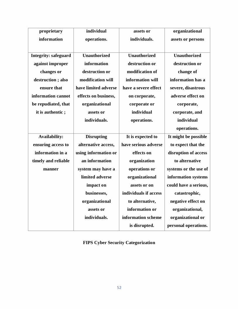
52
proprietary
information
individual
operations.
assets or
individuals.
organizational
assets or persons
Integrity: safeguard
against improper
changes or
destruction ; also
ensure that
information cannot
be repudiated, that
it is authentic ;
Unauthorized
information
destruction or
modification will
have limited adverse
effects on business,
organizational
assets or
individuals.
Unauthorized
destruction or
modification of
information will
have a severe effect
on corporate,
corporate or
individual
operations.
Unauthorized
destruction or
change of
information has a
severe, disastrous
adverse effect on
corporate,
corporate, and
individual
operations.
Availability:
ensuring access to
information in a
timely and reliable
manner
Disrupting
alternative access,
using information or
an information
system may have a
limited adverse
impact on
businesses,
organizational
assets or
individuals.
It is expected to
have serious adverse
effects on
organization
operations or
organizational
assets or on
individuals if access
to alternative,
information or
information scheme
is disrupted.
It might be possible
to expect that the
disruption of access
to alternative
systems or the use of
information systems
could have a serious,
catastrophic,
negative effect on
organizational,
organizational or
personal operations.
FIPS Cyber Security Categorization

53
3.9 Assessment of enterprise IT with industrial control systems
Figure 10 summarizes several cybersecurity topics as they apply to traditional IT systems and
industrial control systems. The critical differences between enterprise IT and ICS are the
following:
The difficulty of testing and applying patches to ICS because these systems affect the safety
of life and are designed to run uninterrupted 24 hours a day separately.
In comparison to many IT components that last only three to eight years, ICS systems
have a very elongated life cycle measured in years.
Note that the development of "secure systems" is not usually an integral part of the
development of industrial control systems. During the life cycle of hardware/software
development, however, it is practiced more.
Security Topic Information Technology Control Systems (ICU)
Antivirus and Mobile code Very common; easily
deployed and updated
Can be very difficult due to
the impact on ICS, legacy
systems cannot be fixed
Patch Management Effortlessly defined;
Enterprise-wide remote and
computerized
Very long runway to
successful patch install;
OEM specific; may impact
performance
Technology Support
Lifetime (Outsourcing)
2-3 years; numerous
vendors; global upgrades
10-20 years; same vendor
Cyber Security Testing and
Auditing (Methods)
Use modern methods Testing has to be tuned to
the system; modern
methods inappropriate for
ICS; fragile equipment
breaks

54
Change Management Regular and scheduled;
aligned with minimum-use
periods
Strategic scheduling; non-
trivial process due to
impact
Asset classification Common practice and done
annually; results drive
cybersecurity expenditure
Only performed when
obligated; critical asset
protection associated with
budget costs
Incident Response and
Forensics
Easily established and
organized; some regularity
requirements; implanted in
technology
Unusual beyond system
resumption activities; no
forensics beyond event re-
creation
Physical and
Environmental Security
Poor to excellent Excellent
Secure Systems
Development
An integral part of the
development process
Usually not an integral part
of systems development
Security Compliance Limited regulatory
Oversight
Specific regulatory
guidance
Figure 10: Assessment of Enterprise IT with Industrial Control Systems

55
4. Cybersecurity approach
4.1 Overview
Cybersecurity is well defined as a means of reducing the likelihood of success and the severity of
the impact of a cyber attack on the control systems of the transport sector through risk mitigation.
4.1.1 What needs protection?
Transit systems are compound and consist of equipment, people, policies and processes that
transport people safely and predictably. There are many protections nowadays, mostly focused on
physical passenger security and the transit system's assets. Any device using a digital processor
generally communicates with digital tools, connects to a communication network via a wired or
wireless connection or can be protected.
A rail transit system is comprised of numerous components:
1. Control signaling system: Signals, road crossings, as well as speed controls.
2. Communications: Between and amongst operating trains, crews, station attendants,
police, and the operations center
3. Stations: Underneath ground, at grade, or above ground. A system may be a blend of these
station types.
4. Notification methods: Symbols, electronic signs, public address (PA) systems, alarms and
other sorts of displays
5. Train-sets: These may be powered by different ways and may have separate locomotives.
6. Traction power systems: For electrified railways
7. Transportation: Rails that guide the train-set, which comprises switches to change
track/guide and several additional devices built into the pathway/guide to guarantee
wheel placement, and, end of track bumpers.
4.1.2 Protection philosophy
Even with unlimited resources, protecting everything at the same level would not make sense.
The question is how best to prioritize the method of protection of a transit agency.

56
The most critical systems for rail protection are those with the highest risk to life and property:
For example, the control and communication systems that allow the train or train operator to start,
control the speed of the train or stop the train. Transit agencies must also ensure that trains run on
their prescribed routes and that all crossings are monitored and protected adequately.
Rail systems incorporate many levels of safety via redundant circuits, fail-safe control systems
(vital logic) and other mitigation measures. The role of cybersecurity is to certify that these general
systems cannot be deceived into making a wrong decision and that no one other than their owner
/operator can directly control these systems. Another objective is to reduce the likelihood of human
error, such as forgetting to update a part of the system or using an incorrect update.
The following are critical protective fragments:
Anticipation: Keeping anybody or whatever from changing with the system
Tamper detection: Spot if an unlawful change has been made or is being made
Auditable: Control who, what, where, when and how if someone does interfere with the
operation
Tamper detection and auditability ensure suitable employees are alerted of unauthorized
or abnormal activity and can respond promptly to take action as required
Also, transit agencies need to identify those systems, devices, and processes that are most
important or are most easily corrupted.
Figure 11 shows the systems that need the most protection and the least protection. It is based on
the likelihood of a successful attack and the negative impact of such an attack.
Figure 11: Protection Priority

57
4.1.2.1 Cybersecurity culture
Many cybersecurity breaches happen unintentionally when the wrong person has access to a
critical system; people do not pay attention to what they are doing, or when outsiders have access
to computer systems via a virus, malware or phishing attack (e.g., by clicking on a link in an email).
To protect its passengers, staff, and assets, it is crucial that the cybersecurity culture of a transit
agency remains on top of the evolving threat landscape. Agencies must be linked to official sources
and non-official sources that warn of potential
Just as transit organizations created a safety-centered culture— saving lives and reducing accidents
and the severity of accidents— they need to foster and build a culture of cybersecurity. This
culture's evolution includes:
1. A program of awareness
2. A program of training
3. Evaluation of threats to cybersecurity
4. A reduction in the area of the attack (number of places and ways in which someone
can attack transit systems)
5. Addressing a cybersecurity program: Risks, mitigation, software/firmware update,
monitoring, and detection;
6. The ability to control compliance through logs and change management systems to be
audited.
4.1.2.2 Cyclical review
Cybersecurity is a threat set that is changing rapidly. People who want to disrupt transit systems
or access them continue to find new ways to cause harm.
There needs to be a program that regularly examines:
Threats
Strengths
Weaknesses
Resources

58
The objectives of the program are to define, protect and reduce the probability of an incident
involving cybersecurity. These reviews should be integrated into internal procedures, processes,
and operations.
4.2 Defense-in-Depth (Layered Defense)
It is thought that it is safest for an agency to protect its most valuable and important assets to have
layers of guards so that outsiders do not have direct access to the most valuable assets of an agency.
Defense-in-Depth implements multiple security levels to provide backup layers if a security
control fails or if new or unaddressed vulnerabilities are exploited. This strategy was developed
by the National Security Agency (NSA), and the Department of Homeland Security Control
Systems Security Program (DHS-CSSP) has adopted a recommended practice.
In-depth defense is the suggested strategy to secure communication and control systems in the
transport sector. Deep defense is a real-world strategy for accomplishing cybersecurity objectives
in today's highly networked environments. It is a strategy for best practices in that it relies on
today's technologies and techniques being used intelligently. The method recommends a balance
between volume, rate, performance and protective operational considerations. Many cybersecurity
circumstances are addressed appropriately by:
Increase the time and number of exploits required to compromise a system successfully;
Increase the likelihood of attacks being detected and blocked;
Ensuring a better alignment of security policies and procedures with the organizational
structure of the agency;
Direct support for the identification and implementation of risk (or impact) zones for
cybersecurity.
A transit agency must define zones and give each zone its protective layer to use the
Defense-in-Depth model successfully, A region may be contained in another area, or a
parallel area may be separated from another area. An area has a boundary or interface point
that protects information and transactions when they cross the edges of the zone.
Transit agencies must combine defense in depth with detection in depth, an agreement program,
and an audit database to ensure that all parts of the layered defense are appropriately configured
and function properly.
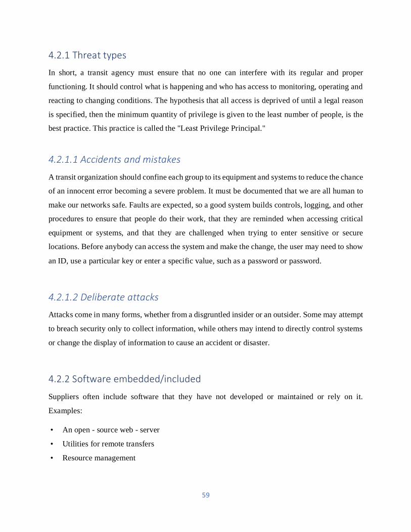
59
4.2.1 Threat types
In short, a transit agency must ensure that no one can interfere with its regular and proper
functioning. It should control what is happening and who has access to monitoring, operating and
reacting to changing conditions. The hypothesis that all access is deprived of until a legal reason
is specified, then the minimum quantity of privilege is given to the least number of people, is the
best practice. This practice is called the "Least Privilege Principal."
4.2.1.1 Accidents and mistakes
A transit organization should confine each group to its equipment and systems to reduce the chance
of an innocent error becoming a severe problem. It must be documented that we are all human to
make our networks safe. Faults are expected, so a good system builds controls, logging, and other
procedures to ensure that people do their work, that they are reminded when accessing critical
equipment or systems, and that they are challenged when trying to enter sensitive or secure
locations. Before anybody can access the system and make the change, the user may need to show
an ID, use a particular key or enter a specific value, such as a password or password.
4.2.1.2 Deliberate attacks
Attacks come in many forms, whether from a disgruntled insider or an outsider. Some may attempt
to breach security only to collect information, while others may intend to directly control systems
or change the display of information to cause an accident or disaster.
4.2.2 Software embedded/included
Suppliers often include software that they have not developed or maintained or rely on it.
Examples:
• An open - source web - server
• Utilities for remote transfers
• Resource management
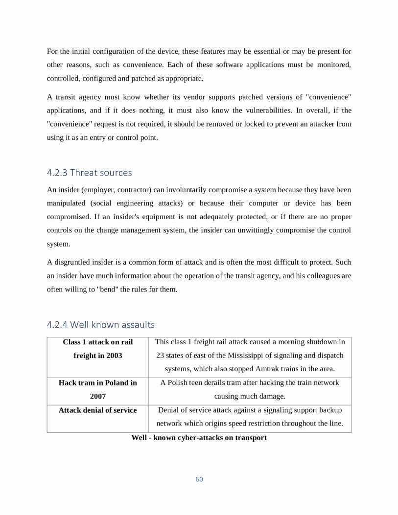
60
For the initial configuration of the device, these features may be essential or may be present for
other reasons, such as convenience. Each of these software applications must be monitored,
controlled, configured and patched as appropriate.
A transit agency must know whether its vendor supports patched versions of "convenience"
applications, and if it does nothing, it must also know the vulnerabilities. In overall, if the
"convenience" request is not required, it should be removed or locked to prevent an attacker from
using it as an entry or control point.
4.2.3 Threat sources
An insider (employer, contractor) can involuntarily compromise a system because they have been
manipulated (social engineering attacks) or because their computer or device has been
compromised. If an insider's equipment is not adequately protected, or if there are no proper
controls on the change management system, the insider can unwittingly compromise the control
system.
A disgruntled insider is a common form of attack and is often the most difficult to protect. Such
an insider have much information about the operation of the transit agency, and his colleagues are
often willing to "bend" the rules for them.
4.2.4 Well known assaults
Class 1 attack on rail
freight in 2003
This class 1 freight rail attack caused a morning shutdown in
23 states of east of the Mississippi of signaling and dispatch
systems, which also stopped Amtrak trains in the area.
Hack tram in Poland in
2007
A Polish teen derails tram after hacking the train network
causing much damage.
Attack denial of service Denial of service attack against a signaling support backup
network which origins speed restriction throughout the line.
Well - known cyber-attacks on transport

61
4.3 In-depth detection
Detection-in-Depth is a critical concept that supports Defense-in-Depth. Detection in depth is a
way to detect that an intruder has accessed a transit facility. For each zone and a protective layer,
methods of detection must be created. The principal of the least privilege tells us to block all
outbound traffic first and then generate an authorization for known and necessary outbound
connections. Isolation devices (e.g., firewall3) have many rules in many IT environments to
prevent unauthorized connections to the protected area, but there are often no rules to prevent
outbound connections. Malware benefits from this lack of protection as it makes an outbound
connection to its creator after the malware infects a device. The creator then controls the infected
machine completely.
4.4 Risk zones for cybersecurity
A successful defense-in-depth approach requires agencies to divide the components and functions
of the control system into separate areas based on specific security requirements. To simplify the
application of consistent controls, the types of zones be limited. Each zone requires a unique focus
and strategy on security.
Hardware, software, and networks segment architectural security zones into physically distinct
areas with explicit links. Each structural area is usually managed by a separate business unit and
protected by a dedicated device, maybe a firewall or other controlled device.
The segmented system of cybersecurity risk zones (also known as impact zones) functions in
separate impact areas with well-defined data exchange. Risk zones for cybersecurity present
particular planning challenges because they exist within and potentially across each architectural
area. In the security organization and monitoring of a specific cybersecurity risk zone, different
business units may need to establish joint responsibilities.

62
4.4.1 Defense - in - Depth Manufacturing Model DHS
DHS Zone Model for Manufacturing
The simplified IT architecture provided data sharing, data acquisition, exchange of peer-to-peer
data and other business activities. Though, the security of any given system was constructed on
the fact that few, if any, understood the complex architecture or operational mechanism of the local
area network (LAN) control system resources. This model of "security by obscurity" does not
address inside threats, but it has generally worked well in environments with no external
communication connections, allowing an organization to focus on physical security to protect its
system.
What changed? The control domain is nowadays connected to the IT infrastructure of the company,
and there are few, if any, organizations that have no Internet connection. Therefore, it is
conceivable and possible for someone who acts remotely to access and modify a control system in
today's interconnected environment.
It is challenging to combine a modern IT architecture with a control system. There are probably
no cybersecurity countermeasures in place in the control system network. How can the risk be

63
assessed and reasonable countermeasures developed to ensure the efficient and safe operation of a
plant while still benefiting from a very integrated IT architecture? The objectives are to minimize
the ability:
For an attack attempt to go undetected;
For an attack to succeed; and
For an attacker to learn about the IT and control systems of the plant and its security.
Figure 12: DHS Defense-in-Depth for Manufacturing

64
4.5 The depth of defense for transport systems
There are several differences between a rail transport system and a single production site:
Distance
Communication
Power
People
Access to property
4.5.1 Distance
A rail system asylums vast distances, and each section of the railing system must communicate
with its adjacent segments and with the control center for operations (and the control center for
backup services). Transit agencies are experts in their systems ' physical security aspects.
Cybersecurity adds to the security program a new dimension.
Also, a rail system contains self-contained rooms for equipment located along the tracks, known
as signal bungalows and roads.
4.5.2 Communication
Different means of communication:
Wired connection
Wireless connection
The different types of wiring can be located underground, above ground, or through signals sent
directly through the track.
The transit agency should communicate with maintenance crews on the track or close ; with
engineers / drivers (if applicable) ; between the train and also the facet of the track ; and
between management and signal instrumentality, like signals, crossing gates, track
circuits, numerous maintenance and detection instrumentality, displays of traveler data,
displays of emergency data, advertising displays, advertising displays, etc.

65
Most of the communication needs to be done along elongated distances and in all kinds of weather,
where line-of-sight communication can be problematic due to nature (snow, plant growth, downed
trees), and in an electrically noisy atmosphere that is difficult to safeguard.
4.5.3 Power
A transit system often has its electricity traction stations. Local utilities have power feeds that need
to be coordinated. Power is shared by catenaries or third rail. All other equipment, plus lighting,
communications, and signals require additional power. There are differences between an electric
railway system and most other commercial systems; the free ground is the most common
difference.
4.5.4 People Everywhere
A transport system's purpose is to move people. They are the system's precious cargo and must be
delivered safely. Relatively few people need access to the site in a manufacturing environment,
and their movements can be carefully controlled. Transit systems have many huge public areas,
including entrances, exits, platforms, waiting for areas and facilities (toilets, cafes) which must be
accessible to all. Other areas, such as equipment and power rooms, tracks, signaling systems,
employee and areas need to be restricted.
Though a manufacturing plant has people to operate and secure the plant, the vast number of people
who use it and the immediate impact of an attack on passengers can make transport system a much
more compelling target.
4.5.5 Access to the property
Regardless of its size, a manufacturing site can mostly restrict who has physical access to it. On
the other hand, the assets of the transport system are publicly available. There is physical security-
a great deal to keep the public from dangerous areas, such as power sources, third rails, overhead
wiring, train tracks and so on - but it is impossible to keep certain people away from the assets of
the transport system. Transit agencies must focus on preventing and detecting people who have
access to critical areas, such as signal bungalows, road equipment, and communication bays.

66
5. Testing Communications - Based Train Control
The most advanced train control system for urban rail infrastructure is communications-based train
control (CBTC). It differs significantly from conventional relay signaling systems and is more
complicated than most cab signaling systems. There are numerous and highly complex CBTC
functions with customized project details. They cannot be tested at any location for all possible
conditions. Knowledge of the CBTC system and experience in commissioning train control are
essential to carry out sufficient tests to detect most problems, but allow the earliest possible start
of revenue service. The testing strategy proposed by the CBTC supplier is the result of years of
experience with the aim of minimizing costly field tests and demonstrating that the system will
function appropriately in revenue services. Despite the many experiments carried out before the
revenue service, it is inevitable that during the first months of the operation of the CBTC system,
operational challenges will be faced.
CBTC suppliers have CBTC products that correspond to a specific system architecture with core
functions tested and operated on many transit properties in revenue service. Most transit agencies
require proven service technology to be customized. The level of customization of the CBTC
system for the project is one of the main factors in the number of issues in the system. Inevitably,
on every CBTC project, customized functions are where most of the errors are found. They may
have to do with design or implementation. Some customizations are inevitable, for instance,
fitment of the carbon equipment onto the train, or for taking advantage of new improved
functionality of the product. CBTC suppliers prefer to deploy a system that has been intensively
tested in previous projects as close as possible to their product. A transit agency often insists on
buying a CBTC system off - the - shelf, but ends up requiring many customized functions.
Understanding that the system is a proven technology tailored for the project is critical to optimize
the tests.
In the factory, CBTC testing is done intensively. The factory setup allows nearly all functions and
situations to be tested. The functions that may not be utterly testable in the factory are related to
the carbon controller (CC) interfaces and the field characteristics such as train localization and
radio coverage. In an ideal world, apart from these items, the field tests would only be to
demonstrate to the transit agency that the system meets the requirements of the contract.

67
Today, most of the current CBTC projects are migration projects with the goal to increase revenue
service performance by replacing an existing signaling system that has reached the end of life with
the state-of-the-art CBTC technology. In almost all upgrade projects, the transit agency requires
that the transition to the CBTC system be performed with the least amount of impact on train
service. This constraint increases the project's complexity due to limited access to the track. In
those cases, CBTC testing must be optimized to the extreme to be able to deploy the system while
maintaining service. The recent IEEE STD 1474.4-2011 Recommended Practice for Functional
Testing of a Communications-Based Train Control (CBTC) System provides a good reference and
describes how and where CBTC functions should be tested. However, it does not explain the
sequence of tests in the context of a project where CBTC is deployed on transit property.
5.1 Advantages and disadvantages of CBTC system
The main reasons for selecting CBTC technology for a transit agency are:
Safety: CBTC includes continuous automatic train protection (ATP). Many conventional
signaling systems enforce the speed of the train only at specific locations using grade time
signals. After the train engineer accepts such signal, the train may then be operated to its
maximum speed until the next red signal resulting in intermittent speed control that relies
on human intervention not supervised by any system.
Throughput: CBTC uses a moving or fixed virtual block system that enables trains to
follow each other, resulting in improved headway performance strictly. More than one
CBTC-equipped train can occupy an individual track circuit at any time for projects with
track circuits, whereas one or more track circuits between trains are required for
conventional signaling systems. A goal of CBTC migration in busy transit systems is to
improve the minimum gap between trains.
Automatic train operation: The CBTC system includes an ATO mode that enables the CC
to control the movement of the train without the train engineer controlling the rolling stock
master controller. The ATO mode provides a smoother ride for passengers, results in more
predictable operation, and enables energy saving. ATO operation can be associated with a
driverless operation for additional benefits. Other types of train control implementations
also allow ATO.

68
Positive train control (PTC) compliant: CBTC is a type of PTC, including work zone and
enforcement of slow speed order that complies with the U.S. Railway Safety Improvement
Act of 2008. Congress. Congress. Congress. CBTC is, therefore, under the jurisdiction of
the Federal Railroad Administration, a potential PTC solution for U.S. railroads.
High availability of the system: CBTC includes redundancy and integrated diagnostic
systems that report automatic train supervision (ATS) status of most equipment. With other
types of train control implementations, these functions are also possible.
Reduced maintenance costs: CBTC has fewer equipment than conventional signals,
especially on the trackside.
CBTC has been in use throughout the world for more than 30 years and is now a proven
technology.
For transit agencies, CBTC technology also presents several challenges:
The initial investment cost of the technology deployment may be higher than other train control
types. CBTC design, hardware, installation, and testing usually take years of effort and longer than
expected.
The transit agency cannot modify the system for various reasons. The first reason is technical:
within the agency, there may not be the computer skills required. The second reason is the
responsibility: the original manufacturer of equipment (OEM) is responsible for providing the
transit agency with a safe system. Transit agencies don't want to take responsibility for changing
a complex system like this. Any change must be made by the OEM. Note that significant transit
agencies like New York City Transit, as well as Regie Autonome des Transports Parisiens, are
making efforts to specify product interoperability and compatibility across multiple CBTC
vendors.
CBTC technology is very different from traditional relay-based signaling system and must,
therefore, be adapted to it by the transit agency. It requires new engineering and maintenance staff
skills as well as a new transit agency organization.

69
5.2 Various types of CBTC projects
5.2.1 New Line Installation: Greenfield Project
The term "greenfield project" refers to the case of a new line being built by a transit agency. The
railway project involves all aspects of railway engineering, including civil engineering, track
installation, traction power system, rolling stock and signaling system. CBTC began to be
implemented on such projects in the early 1980s. CBTC was applied to lines already in service
only after the technology was considered mature and experience was sufficient.
While new line schedules are becoming increasingly challenging, testing the signaling system on
a greenfield project is facilitated with easier access to the track than on a project where passenger
service line is used. In addition to being the only advantage of testing on greenfield projects, the
flexibility of track access is by far the most important. Depending on previous tests and software
development, access can be more frequent and reorganized at the last minute. During testing, there
is no transport department to interface with, which is usually a very time-consuming interface.
Another advantage is that the interfaced system may also be under development in order to resolve
interface design problems by changing the CBTC or other systems. For new or new transit systems,
new lines are often more likely to embrace new technology and accept the testing method
recommended by CBTC suppliers.
The disadvantage of greenfield projects is that the signaling system is dependent on other systems
as the last part of a complete transportation system. The result is that the signaling project is
planned without any slack to absorb previous system delays with a very compressed schedule.
Another challenge for projects on new lines is that the other systems may not work correctly during
the CBTC tests, which also require track access. In particular, the rolling stock may be ready for
CBTC testing, but not for revenue operations, and if a train is stranded during testing, the
remaining rolling stock issues may affect CBTC testing.
5.2.2 Migration of an existing line: Project Brownfield
The cost of building a new line is very high in large cities where the railway infrastructure was
created decades ago, and the time to develop a new line is very long. In just a few years, transit

70
agencies prefer to improve the capacity of existing lines. Buying new trains with better
performance and more passenger space is an opportunity to improve the capacity of the line. The
transit agency may decide, in addition to or instead of buying new trains, to upgrade to CBTC
technology in order to increase capacity by minimizing the gap between trains. Upgrading an
existing line's signaling system is called a brownfield project.
The biggest challenge on a migration project is to get enough track access to install and test the
new system while maintaining the operation of revenue service. Tracks are used to transport
passengers during revenue service hours, and maintenance actions are carried out during off-hours
or non-peak hours to support revenue service operation. For the duration of the CBTC project field
activities, installation and testing must be integrated with the maintenance schedule of the existing
transportation system.
Transit agencies can plan to convert to CBTC just one line or their entire system. Several migration
approaches have been used that have an impact on the testing strategy. One method is to deploy
CBTC on a line that is not very busy to learn about the system and minimize the risk of CBTC
being implemented on a busier line, usually under intense political scrutiny. Another approach is
to use CBTC directly on the most active line as a result of the need to improve capacity as quickly
as possible. These brownfield projects on busy lines are at the highest planning risk and require
both an experienced CBTC supplier and a CBTC-friendly transit agency. Some of the very
ambitious projects failed or were significantly delayed, lasting over ten years. Finally, another
approach is to have mega projects where all lines are upgraded simultaneously using one or more
suppliers, where test results on the first line can be used to cut the total test time for the other lines.
5.3 CBTC Architecture
CBTC is composed of four subsystems:
Carborne Controller (CC): The CC is located on board the train, also known as the On-
Board Controller Unit (OBCU). It is responsible for determining the speed of the train, the
location of the train and for enforcing the speed limit based on the limit of the movement
authority (MAL).

71
Zone controller (ZC): The ZCs are located in the mechanical rooms. Based on the
information received from trains and other subsystems such as the interlocking, they are
responsible for calculating and providing the MAL to the CC. To provide full line
coverage, there are several ZCs per project. They exchange information directly or through
an external signal system, field equipment such as switches, with the onboard controllers
in their territory and control.
ATS system: The train operations are regulated by the ATS system. It includes an
Operations Control Center (OCC) human-machine interface with operators.
Data communication system (DCS): The DCS includes the wayside communication
network as well as the wayside communication system train.
5.4 Environmental Tests
CBTC equipment is subject to its first set of tests at the end of the design and before starting the
production of the equipment: environmental tests. The various types of environmental testing are
as follows:
Electromagnetic Compatibility (EMC) tests
Climatic condition tests
Mechanical condition tests
Abrasive condition tests
Transit agencies and suppliers of CBTC set up an environmental test plan to agree on which
equipment belongs to each category. The equipment category is used to define the test
requirements as described in the relevant test standard. Any specific condition of a particular
railroad environment is also identified and tested on the basis of field measurements.
A common practice in CBTC projects is to accept the supplier's test results during their testing of
the product or for another project. This is the only time it is possible to consider test results from
other projects. It is necessary to analyze very carefully the difference between the equipment tested
on other projects and the equipment for the current project during this process.

72
5.4.1 EMC Tests
The goal of the EMC laboratory qualification tests is to verify the level of electromagnetic
immunity, that is, susceptibility, and the electromagnetic emissions of the CBTC equipment. These
tests are performed in a certified laboratory. There are two primary standards for this activity:
(1) CENELEC (European Committee for Electrotechnical Standardization) Standard
EN50121 Railway Applications Electromagnetic Compatibility and
(2) International Electro-Technical Commission IEC 62236[with the same title. The standard’s
criteria may need to be adapted to take into account the specificities of CBTC in a railroad
environment. For instance, some CBTC radios use the 5.8 GHz frequency so the test should
be performed up to 6 GHz instead of the 1 GHz as currently required in the standards.
5.4.2 Climatic Conditions
Verifications of climatic conditions are associated with extreme tests of temperature and humidity.
MIL-STD-810F Test Method Standard for Environmental Engineering Considerations and
Laboratory Tests test cycles of very cold then ambient temperatures and periods of sweltering then
ambient temperatures.
5.5 First Article Configuration Inspection
First Article Configuration Inspection (FACI) is the first check using real equipment by the transit
agency that happens in CBTC projects. This activity occurs toward the end of the design phase of
the project after the equipment has been designed on paper and before starting mass production.
The FACI’s goal is to verify that production hardware complies with design configuration,
drawings, and software design. It provides a means to confirm that all documentation is ready for
mass production. It also includes evaluations of maintainability and accessibility. This activity
typically takes place at the point of the assembly after completion of environmental qualification
tests of the prototypes.

73
5.6 Factory Tests
Verification and validation, as defined in the International Council on Systems Engineering
Handbook, should be done as much as possible in the factory.
CBTC systems allow this type of intensive factory testing and only a few parts cannot be
thoroughly tested in the factory. For instance, the interface with the rolling stock cannot be
thoroughly examined in the factory. Other components that cannot be tested are the radio coverage
and the database for field data. Functions related to the management of a large number of trains
are also difficult to test at the system level. Despite the use of powerful tools such as integrated
system factory setup and simulators, it is frequent that anomalies that could have been discovered
in the platform are discovered on-site.
5.6.1 Factory Test Goals
Test all internal interfaces: All messages including commands and controls between ATS
and CC, ATS and ZC, as well as CC and ZC are tested using real equipment. When using
real equipment, the term "target equipment testing" is used. However, the term "host
machine test" is used when the actual software is run on a machine that emulates only real
equipment.
Test every function of the CBTC: Based on the system functional requirement, all features
are tested at a minimum of one location on the line.
Test external interfaces as much as possible: Interface between the ZC and the wayside
conventional signaling system needs to be tested thoroughly. The most numerous interfaces
concern the ATS, which requires real or simulated systems to exercise the interface in the
factory. The CBTC supplier may develop those simulators based on their knowledge of the
external system, or the supplier of the external network may provide the simulator.
Perform failure scenarios, especially those who are challenging to perform onsite: for
instance, using simulated equipment allows for corrupt messages not possible on-site with
the real equipment.
Support field testing by reproducing issues: The field team’s goal is to demonstrate that the
system works correctly and not necessarily to investigate matters. Once a problem has been

74
detected on-site, it is reported to the factory test team that reproduces and analyzes it with
the help of the designers and developers who are available in the same office.
5.6.2 Factory Setup
It is essential to include real hardware for each subsystem in the system factory setup. It should
consist of ATS servers, redundancy checking CCs, and ZCs to check redundancy and ZC territorial
handover. There should be at least two real CCs and two real ZCs in the factory setup. Note that
trains can run over the entire line during the test, but since there are only a few real ZCs on the
factory setup, the ZCs are selected as the real ZCs for the zone under test, while the others are
simulated. If the project includes a Solid-State Interlocking (SSI) or an interlocking interface
programmable logic controller, they should also be included. Having a complete factory setup on
site is a good practice that is required for large projects. It allows field teams to run pre-tests before
using track access and to familiarize themselves with the system (training, visits) for all staff
involved in the project. For each new version, it can be used for regression checks witnessed by
the transit agency. Although the investment cost is significant, during the project, it is a valuable
asset, and after the project, it can be handed over to the transit agency.
5.6.3 Different Types of Factory Tests
5.6.3.1 Product Factory Tests
CBTC suppliers, as discussed earlier, use products that are likely to be applied simultaneously to
several projects. The product team uses a virtual line with all possible configurations for the track
layout. Therefore, the database used for a specific project is different from the database used.
Product-level tests can be very detailed; they test functions that are not part of the transit agency's
known system or subsystem specifications and include shallow-level failure scenarios. The
product team is also responsible for verifying that on the target equipment the software is running
correctly.

75
5.6.3.2 CBTC Supplier Internal Factory Testing
Even before the design is finalized and the final database is produced, factory testing begins with
the first version of the software. The CBTC supplier runs all the tests, completes reports describing
all known anomalies and provides them to the transit agency before the factory acceptance test
(FAT) witnessed by the transit agency. The transit agency may decide to hold or postpone the
witness tests on the basis of the report.
5.6.3.3 Factory Acceptance Test
The FAT is a substantial check on the status of the project and provides a preview of the success
rate for the remaining tests to be carried out. It is performed as much as possible on a software
version, considering that subsequent field tests will help to identify problems and that there may
still be some remaining design issues. Depending on the project, from a few days to a few weeks,
the FAT is witnessed by the transit agency anywhere. For each subsystem, a FAT may be required
before a FAT system. In most cases, however, a witnessed FAT subsystem is done for the DCS
alone. Since the ATS is the system operator interface and can be tested without a real CC or a real
ZC, the agency may also need a separate ATS FAT. Indeed, with real ATS and simulated
interfaces, all ATS functions can be tested. Because most advanced ATS function tests require a
complete line and a large number of trains, having the real ATS equipment during the ATS FAT
may be preferable only.
5.6.3.4 Description of the Tests to Be Performed
The interfaces are related to the first tests to be carried out. Sometimes this phase is referred to as
integration testing because it checks all commands and all controls between the actual equipment.
Before proceeding to functional tests, this first phase is carried out. This phase may be internal to
the supplier of the CBTC since it does not verify any functional requirements. The core CBTC
functions are then tested, such as train location, train tracks, and enforcement of movement
authority. It is essential to repeat some of the core function tests at all locations. For example, the
location of the train should be performed in each direction on the entire line and across each
crossover. Finally, testing is carried out on the most advanced and project-specific functions.

76
5.6.3.5 Major Challenges of Factory Tests
A significant concern for the transit agency is that the factory tests be representative of real-life
conditions. There are two obstacles to representative tests:
(1) The technical aspect of using environment simulators, especially where the DCS is very
simplified in the factory setup, and
(2) The tests are performed by testers usually not familiar with train operation and therefore
may react very differently than the future train operators.
A common problem for CBTC system testing is to assume that the factory setup is responsible for
the failure and to reboot all the equipment frequently to have a clean starting point that gives more
chances of passing the test. Signaling systems are running continuously in operation and cannot
be rebooted. Transit agencies may need endurance tests over several days to cope with this issue.
Due to the limited number of real CCs and real ZCs, endurance tests are still relatively far from
the endurance of the real-life system.
Successful FAT witnessing is a prerequisite for beginning on-site functional testing. Some issues
concerning implementation or design will be detected at the end of the tests. It is a delicate topic
to decide which issues need to be resolved before the software is sent on site. CBTC suppliers tend
to minimize the impact of problems, although the transit agency wants to correct all known errors.
The concern of the transit agency may be to avoid wasting track access by having conditions on
the test due to a software defect or the need to repeat the same test after a problem has been
corrected. Another concern of a transit agency is to maintain an excellent reputation in the transit
agency for the project. If the first on-site software used contains too many errors visible to train
operators during the tests, the agency staff may be less than enthusiastic about using CBTC in
future revenue service.

77
5.7 On-Board Integration Tests
5.7.1 Rolling Stock Characterization Tests
Although it is not part of the verification and validation, CBTC suppliers should verify and
determine the characteristics of rolling stock through field activities. On the basis of tests and other
considerations, the transit agency and rolling stock manufacturer decide what the guaranteed
emergency brake rate is and what the maximum acceleration rate on leveled track is. The CBTC
supplier, however, is not sufficient to adjust its train model used for proper ATO. CBTC suppliers
perform so-called characterization tests for rolling stock. The train is controlled by a special CC
software. This unique software sends commands to the train propulsion and brake system and then
speed sensors collect data on train reactions on board the train. CBTC experts analyze the data
after the tests to determine the characteristics of the train model. This activity requires multiple
test campaigns to verify results with the actual CC software during ATO tests.
5.7.2 Mechanical and Electrical Tests
The first train or first two trains are used as prototypes for the first time fitting the carbon
equipment in the train. This task includes verifications of the mechanical fit in the car body, such
as checking all mounting devices for alignment. Once the mechanical interface is verified, and
problems are resolved, verification of the electrical test is performed. Electrical testing begins with
tests at shallow levels, such as powering the equipment. Use a special CC software to exercise all
hardwire inputs and outputs. There is also verification of communication with other electronic
systems on board the trains. Usually, this prototype test lasts a couple of weeks.
5.7.3 Static and Dynamic Post Installation Check Out Tests
Installation tests can be considered CC Post Installation Check Out (PICO) tests where the
hardware equipment and the installation are verified. This activity is performed for each train using
a special CC software dedicated to testing along with the first version of the real CC software. In
order to verify the speed sensors, a small train movement is involved. In most projects, all trains

78
are tested with essential CBTC functions, including. Testing ATO on each train is critical because,
as noted before, the train characterization test was performed on a limited number of trains. The
parameters may have to be fine-tuned to manage the complete train fleet. To perform verification
of CBTC core functions on each train, other equipment, such as radio and ZC, need to be available
for at least one location, for instance, on a test track. Similar to the electrical tests described above,
all hardwire input, and outputs are exercised using a particular software communication to verify
that the train was appropriately wired. Installing and checking CBTC equipment on a train can be
performed in a couple of days when there is no problem. A single test shift is typically sufficient
for verifying essential CBTC functions.
5.8 Test Track
5.8.1 Use of the Test Track
In brownfield projects, a test track is typically used for testing the CBTC system before using
mainline tracks. For several purposes, the test track can be used:
CC tests: To verify the design of the CC/rolling stock interface after the first-board
equipment has been installed.
System tests: To test most CBTC functions.
Car by car CC installation verification: To integrate the CC on each train, each train is
tested on the test track for core functions in order to verify the interface between CBTC
and rolling stock.
Training: To train the train operators to control the train under CBTC.The test track has to
be long enough to serve this purpose.
System regression tests: To test new CBTC software versions during the deployment phase,
as well as after the CBTC has started revenue service.

79
5.8.2 Test Track Equipment
IEEE CBTC testing recommendations provide a comprehensive description of the capabilities of
an ideal test track. All CBTC equipment must be equipped with a test track: transponders must be
installed on the roadbed, radio access points must be installed near the track, and a network must
also be deployed to communicate between the CC and the ZC in the technical room. To test most
CBTC functions, there must also be an ATS server and a workstation available to set up a slow
speed order, for example.
Ideally, all possible configurations are included in the test track layout. For example, there are all
possible types of signals. It is also useful to switch between tracks. It is common to include one or
more virtual platforms in the test track database to test door operation and some of the functions
of the ATS trip assignment. There are no virtual platforms in the tracks. They are for testing
purposes only in the database. The test track length is a crucial element in determining which
functions on the test track are testable. The train must have sufficient distance to run at speed close
to the mainline operating speeds to properly test the ATO operation. Although not all possible
configurations are included in the test track, a test track is a must in brownfield projects to help
avoid wasting mainline track access at project start. The test track is the first track section available
for testing in greenfield projects.
5.8.3 Location of the Test Track
The test track can be located in the yard area with a specific ability to be configured as mainline
in order to test the mainline functions such as ATO. Express tracks can also be used as test tracks
during nonpeak hours. Another option is to use a test track outside the property of the transit
agency. With this option, track access is much easier than on the final site, the tests can be
performed during the day time, and the test track can be long and include switches, grades, and
any other configurations. However, travel is required for performing the tests and transportation
of rolling stock is necessary. Another issue with remote test track is that the design and installation
investment for the test track is not going to be used in the final system. A test track connected to
the rolling stock manufacturer plant was used. The rolling stock manufacturer used the test track
for several other projects at the same time.

80
5.9 On-Site Tests
5.9.1 Post Installation Check Out
Before functional testing can begin, verification of the hardware installation is performed on every
piece of equipment of the CBTC. For instance, cable and wiring, grounding, and power to the
equipment are tested in what is called PICO test. This test is performed for each piece of equipment
and constitutes the transition between the installation phase and the testing phase.
Even though this test targets hardware verification, each equipment is booted in order to verify
that the operating system on CC, ZC, and ATS work appropriately and the identification of each
equipment is correct. Also, the network configuration may also be tested. The current software
version at the time of the PICO is installed for the CC, ZC, and ATS in preparation of functional
tests. The software version used during PICO is the factory version at the time of the test; it does
not have to be subject to FAT beforehand as no functional test is performed.
This test starts with the first equipment being installed on the property and continues throughout
the project. Once a part of the system is in revenue service, care should be taken with PICO
because, though very unlikely, adding equipment on the network may affect part of the system in
revenue service. To mitigate the risk of service disruption, after one part of the CBTC system is in
revenue service, PICO tests are performed during no-rush hours.
5.9.2 DCS Tests
The DCS contains two parts: one for the wayside network between equipment in mechanical rooms
and the control center, and the other for the radio system which may also include a separate
wayside network system.
5.9.3 Wayside Network Tests
Among the different CBTC subsystems, the first subsystem to be installed and subject to test is
the DCS. To perform testing of the DCS, fiber optic between locations must be installed and
verified by the installation team. In the technical rooms, network switches are installed, and PICO

81
tests performed beforehand. The network management system (NMS) that administrates the
network and is provided by the network supplier must also be present before network tests are
planned. Tests on the network may include the following:
Checking of the configuration of each switch
Verification of connectivity
Verification of data transfer
Verification of NMS capability
Failure scenario of one node to test reconfiguration of the network
Latency tests
Throughput tests
During the DCS factory tests on the network, the same tests are performed but on a simplified
version of the system with far fewer switches. The factory configuration is supposed to be
representative of the on-site network. Ideally, PICO tests of the network equipment are performed
first; then the network is tested before performing PICO of the other CBTC equipment (CC, ZC,
ATS) so that communication between equipment can be checked during PICO.
5.9.4 Radio Tests
The radio tests are dependent on the type of radio being used on the project. Where the radio
system uses a different wayside network than the wayside network used for other communication
between technical rooms, the radio wayside network is tested with the same method as explained
in the previous paragraph. After the radio wayside network is tested, radio access points are subject
to PICO test that includes a power emission test.
Following radio wayside network and access point PICO tests, the radio system tests are
performed. First, radio coverage is verified using a train equipped with CBTC. In most CBTC
projects, the radio system uses redundant architecture to provide redundant paths for
communication. Redundancy may be both on board the train where there is a radio system at each
end of the train and on the wayside where access points may have several frequencies. Where there
is frequency diversity, access points of each frequency are installed alternatively along the tracks.
A radio tool onboard the test train is used to measure the electromagnetic field with the radio link.

82
On some projects, the radio tool can also be used to send, almost continuously, data packets
through the network to monitor the number of packet losses. Both ends of the trains may be
connected to the tool so that the tests are performed in parallel for each end. In order to verify radio
coverage, the first test is done with the access points of only one frequency. Access points for other
frequencies are turned off. This test is repeated for each frequency. When performing this coverage
test, it is preferable that the train runs at a low speed. This test also verifies that the transition
between access points is performed seamlessly. The worst-case configuration for radio coverage
may be identified and tested. It corresponds to a specific location where access points can be far
apart, and there may be one or two masking trains between the train under test and the near access
points. Test at maximum operating speeds is also performed. Finally, radio coverage with both
train antennas and all access points is verified everywhere.
Testing the radio system is very important to prepare future functional tests of the CBTC system.
Where there is a gap of coverage, functional tests other than localization tests are complicated to
perform. Radio tests can be done with a train that is not controlled by the CBTC, meaning that it
is possible to test the radio system with a train in revenue service running in the bypass mode in
between other revenue trains. Depending on the CBTC product, radio coverage can be performed
before or after or during train localization tests. However, in most projects, strain localization is
tested first to help identify the location of radio coverage gaps.
5.9.5 Localization Tests
Localization tests verify that the train can initiate its localization correctly and that the train
maintains knowledge on its position on the entire network. Train localization initialization is
performed by running over several transponders located on the roadbed; then an odometer system
is used to compute the train position based on the distance traveled from the last transponder. The
odometer has some uncertainty, typically a small percentage of the distance traveled since the last
transponder. To avoid having a significant position uncertainty that diminishes
CBTCperformance, transponders are located on the roadbed at maximum every thousand feet.
Each time the train runs over a transponder, the localization error has reset to the minimum. In
addition to an equipped train, the prerequisite to start localization tests is to have the transponder
installed on the roadbed.

83
Similar to the radio tests, localization tests can be done with a train in the bypass mode where the
CBTC is not controlling the train. Where the radio network is not available, or the interlocking is
not yet connected to the CBTC, the train may delocalize on diverging switches because positions
of the switches are unknown. Train localization is reinitiated soon after traversing a switch, thanks
to transponders being placed close to the switch area. Complete localization tests are possible only
after the switch positions are provided to the ZC and the ZC communicates with the CC through
the radio.
The localization function and radio test are the first two tests to be performed in the field. They
are the foundation of CBTC. Though they represent only a few of the CBTC functions, these tests
constitute a large portion of the track access time because the tests are performed on all tracks in
both travel directions.
5.9.6 Integration Tests
5.9.6.1 Integration Tests: Internal to CBTC
The term “integration” is used when verifying that new equipment is connected to the system and
when checking functional communication between two subsystems. The transit agency does not
always witness this test. To perform this test with the CC, radio coverage must have been checked
already. Depending on the status of the communication network at the time of the PICO, the
internal integration test is performed as part of the PICO or later. For instance, this test verifies
that the ATS can monitor the status of the equipment, and that commands can be sent to the
equipment, basic commands such as active unit switch over. Where track access is minimal; the
goal of this test is to prepare for functional testing, which involves more resources such as test
personnel and trains.
5.9.6.2 Integration Tests: External to CBTC
For hard-wired external interfaces to the CBTC, all inputs and outputs are tested during this
integration phase. The functional part is left aside as much as possible to facilitate testing. For

84
instance, all track circuits and switch positions are verified. External interface tests can be
performed independently from the localization and the radio tests. Ideally, they are performed in
parallel. For data communication interface tests such as an interface to an SSI, there may be a
difference between the transit agency that prefers to test every bit and the CBTC suppliers who
want only to sample the bit map. The argument from the CBTC suppliers to perform only sample
tests is that each bit was previously tested in the factory. The argument from the transit agency is
that the factory tests are not witnessed and the configuration files may have changed since the
factory tests. In an ideal world where every change is tracked and retested factory, there is no need
for testing all external digital interfaces. Because external interfaces may involve another supplier,
retest after every new version might not happen in the factory and field testing is then necessary.
The decision is project-dependent based on how much each interface changes and how well the
CBTC supplier works with the external system provider.
5.9.7 Functional Tests
After the localization tests, the radio tests, and the interface tests, CBTC functional test can begin.
Except for the ATO, in an ideal world, the CBTC system should be working correctly. Indeed, all
functional tests may be performed in the factory, and, therefore, the functional tests need only to
be performed to demonstrate the functions to the transit agency for acceptance of the system.
However, in the real world, several months of testing and corrections are required. It is common
that the transit agency requires that most tests be performed in the field even though they were
already performed in the factory. When all functions work correctly, performing site acceptance
tests can be done within weeks. The first functional test to be performed is trained tracks; it can
also be done with a train in the bypass mode not being controlled by the CBTC system. Tracking
the ZC and the ATS is tested at the same time and can be considered a low-level CBTC test. If the
communication is ready and the equipment has been subjected to PICO, the tracking tests may be
accomplished at the equivalent time as the localization tests. Following the train tracks, the CBTC
essential functions are verified, although at the same time all field device positions are checked.
For instance, the verification that the CC does not let a train pass a red interlocking signal is
performed for each interlocking signal. Safety-related field items such as interlocking switch
position or track circuit boundaries are verified. The test goal is to verify the presence of the field

85
item in the database, and that the proper type of item has been set up in the database. The actual
position of the field item in the database is only demonstrated, which is not proven by test. The
position of field equipment in the database is validated, thanks to a rigorous process of verification
of the surveyed data and database creation. Once all the essential functions are verified, more
advanced tests can be performed. Failure scenarios of the CBTC and ATS are performed. Also, in
safety-related functional tests are performed. The art of testing CBTC is in choosing the functions
to be tested along with what needs to be repeated at every location in the field. Because CBTC is
such a complex system, it is not possible to verify each function in all conditions at every field
location. Tests must focus on safety-related functions to build confidence in the system. Factory
tests are not sufficient to provide enough confidence to the transit authority to let a system start
revenue service without witnessing on-site that the system behaves safely. Therefore, all field
items related to safety such as interlocking areas and all safety functions such as work zone
restriction should be tested. The dilemma about how much to test starts with safety functions that
are not related to the database, for instance, slow speed order and work zone. There is a near
considerable number of slow speed order, speed selection, and start and end points. How many
slow speed order tests to conduct depends on the design of the system so the CBTC supplier should
indicate the type of test to perform. It is common to perform a slow speed order test for each ZC,
where only one test should be sufficient because the same software runs on every ZC; only the
database changes from one ZC to another.
Regarding the non-safety-related functions, minimum tests are performed to limit track access. For
instance, the test to open and close the train door from the ATS when the train is berthed at platform
does not need to be done for each platform. However, the safety-related function to check that the
CC enables door opening on the proper side of the track and only within the platform boundary is
performed for each platform.
Most of the CBTC issues found on-site are not related to any pre-identified tests. The tests that
verify the CBTC requirements have already been performed in the factory, and, therefore, it is
unlikely that a new error that cannot be discovered in a factory is found on-site. Special tests that
were not identified during the development of the factory and field test procedures, because they
do not correspond to any requirement, are where most issues are detected in the field. It is vital to
have conventional procedures to use during testing, but most issues will not correspond to a

86
specific test step in an official procedure. The majority of the problems are found during the first
runs using CBTC and are evident; for instance, the CC does not the brakes or the ZC does not
provide the MAL. After the first months of debugging, the performance of functional tests is more
likely to reveal design issues than implementation ones.
5.9.8 ATO Tests
ATO is used in most CBTC projects. ATO tests are performed first on the test track to verify that
the ATO software can control the train accurately such as maintain appropriate speed and make
proper station stopping accuracy without being overridden by the ATP function. To test every
speed and every change of civil speed, ATO tests should be performed on each track and in both
directions.
During ATO testing, station stopping accuracy is also verified. It is preferable to perform the
CBTC necessary functional tests in the ATO mode rather than performing the test when the train
engineer is controlling the train under ATP supervision. Doing so, both the stopping point of the
train and the field item locations are checked. As the ATO mode may not be available for testing
at the time CBTC essential functions are tested, the test may need to start in a manual mode of
operation.
5.9.9 ATS Tests
Except for integration tests when each command and control is verified, most ATS functions
require the other CBTC subsystems to work correctly. Some main advanced ATS functions include
automatic train routing used for setting up routes and managing train junctions and trip assignment
based on the train operating schedule. For driverless projects, the ATS is needed to perform CBTC
functional tests, and the project's schedule must be attentive to have all CC, ZC, and ATS from the
factory ready for field testing at the same time. Because of all ATS functions, except route setting
and interface testing discussed before, can be tested very well in the factory, specific tests of the
ATS can be limited on-site. The advanced ATS functions such as train regulation are part of CBTC
system tests where the CC and the ZC are also tested at the same time. The route setting function
is particular because a specific check must be done for each interlocking signal on-site to confirm

87
that the routes are set early enough so that the test train does not have to slow down in front of a
red signal.
5.9.10 Site Acceptance Tests
Depending on the project, the transit agency witnesses and approves results of only the functional
and external interface tests, or all tests, including the PICO and both internal and external
integration tests. The site acceptance tests are written based on the system functional specifications
derived from the contract. All requirements that can be tested on-site are tested, and additional
tests identified by the CBTC suppliers should also be performed. To meet the revenue service
target date, it is common practice for the first version of the CBTC software not to include all
functions. Advanced functions, often related to the ATS, are pushed to a later stage. Any non-
urgent issue detected on the first version is corrected in the version that includes the advanced
functions. Before the site acceptance tests, the transit agency may want to witness a sample of the
debugging phase of the CBTC tests to stay informed on the progress and to increase the transit
agency knowledge of the system. This corresponds to the phase where test procedures are checked
before being performed officially and when issues are investigated and solved by the suppliers.
5.9.11 Shadow Mode Tests
A concept used in CBTC migration projects is to monitor the performance of the CBTC system
for an extended period, although it is not yet controlling the trains or any field devices. This period
is called “shadow mode,” “ghost mode,” or “monitor mode.” All inputs are active and connected
to the CBTC equipment, but the CBTC CC is not controlling the train, and the interlocking system
is not applying any commands from the ZC. This type of test starts before starting revenue service
and typically lasts several months. This phase helps demonstrate the reliability and availability of
the CBTC system, and it helps build confidence among the stakeholders for the project. When
certification for revenue service is approved, trains controlled by the CBTC without passengers
are introduced in between revenue service trains. Once the shadow mode period is completed
successfully, passenger revenue service can begin for the CBTC system provided the safety
certificated was obtained previously.

88
5.9.12 Reliability, Availability, and Maintenance Tests
5.9.12.1 Reliability and Availability Demonstration
The goal of the reliability and availability demonstration is to demonstrate, toward the end of the
project that the characteristics of the system meet the contract requirements regarding reliability
and availability, calculated in terms of mean time among failures (MTBF) mean time between
functional failures (MTBF), or other measurements defined in the contract. In CBTC projects, the
demonstration generally lasts at least six months and begins immediately after revenue service has
started on the entire line. All equipment needs to be installed and turned on continuously for the
test to be representative. Six-month duration is the minimum length to measure the reliability with
a good level of confidence.
The success of the test may be a condition to exit the warranty period, which is typically two years
after the last CBTC equipment has entered revenue service. Availability is calculated using the
total test time minus the observed downtime due to CBTC failures divided by the total test time.
Definitions of MTBF and MTBF are the number of failures and the number of functional failures
over the accumulated operating time for one type of equipment. The definitions apply to the entire
life of the system and would not be representative of the system in a 6-month test. Therefore, it is
common that CBTC contract requires specific criteria based on a one-sided chi-square test with
90% or 95% of confidence level. This test has several other names such as goodness-of-fit tests.
Both the CBTC supplier and the transit agency should agree on the terms and conditions of the
test when signing the contract(s) or before starting the demonstration.
5.9.12.2 Maintainability Demonstration
Maintainability is the ease with which creation can be maintained. Maintainability demonstration
is performed after the transit agency maintenance personnel have been trained. It can be performed
before or after the system has started revenue service; for instance, it can be done during the
reliability and availability demonstration. The maintainability demonstration serves two purposes:
verify that the meantime to repair (MTTR) meets the contract requirement and show that the
training and maintenance manuals are adequate.

89
To verify the MTTR, the equipment to be tested has to be agreed by the CBTC provider and the
transit agency. One approach is to use a statistical method for sampling the population of CBTC
items. Producer and consumer risks are used to determine the sample size. Once the number of
items to be tested is calculated, the agency and the supplier choose the equipment randomly to be
tested. This method is based on the failure rates and the number of identical items in the system.
In this method, the agency can decide on testing the items that will represent a high percentage of
maintenance actions.
When the test is performed, a failure is introduced on purpose and the transit agency maintenance
personnel repairs without the assistance of the CBTC supplier team. It is a moral rehearsal to have
several teams of maintenance personnel doing the same corrective action and use the mean repair
time for the same correction. The results are gathered in a report after the tests, and an MTTR is
calculated based on the mean of the repair duration observed on-site. One of the possible positive
outcomes can be updated maintenance procedures.
MTTR is usually required for the complete CBTC system. An issue with the mathematical
approach proposed in [18] is that as the number of CCs is much larger than the other subsystems,
most of the maintenance will thus be on the CC and the mathematical method results in choosing
only CC equipment. The analysis should be performed subsystem by the subsystem to avoid this
issue.
5.10 CBTC Test Duration
The duration of the field CBTC testing phase depends on various factors, and it is not possible to
define test duration without knowing project specifics. However, based on the examples from
projects in the last decade in different countries by different suppliers, a range of duration is
provided in this section.
As discussed previously, CBTC projects are of two types: greenfield projects on new lines and
brownfield projects on existing lines where revenue service must be maintained during the project.
For greenfield projects, the total duration of the project can is planned in as little as two years,
whereas the minimum time for a brownfield project is about five years. CBTC projects are often
90
more difficult than anticipated and significant delays are very common, especially with brownfield
projects where a 5-year project is considered successful when executed in less than seven years.
The experienced delay between the first CBTC field tests and the revenue service is at least one
year. For brownfield projects where CBTC starts revenue service on a section by section basis, the
testing phase for the full line may last up to several years.
To have an earlier revenue service date, a common practice is to postpone the inclusion of
advanced functions in the first CBTC versions used for revenue service. The advanced functions
and subsequent changes are tested after the CBTC starts revenue service. Therefore, in addition to
fixing issues discovered during the first months of revenue service, the supplier performs tests for
these advanced functions. It is worth noting that in many projects, CBTC testing is not entirely
over when CBTC starts revenue service. Converging to the final error-free service may take as
much time as initial field testing.
5.11 Constraints on Field Tests
Testing CBTC is a difficult task for several reasons. The most common issues encountered are as
follows:
Difficulty in obtaining track access: This is especially true on brownfield projects where
the line is already in revenue service. The tracks are used during the day for revenue service
operations and during the night or off-peak times for maintenance. For greenfield projects,
track access is relatively easier to obtain, but still, it is competitive because all other
subsystems may also need the tracks to complete their installation and tests.
Coordination with the installation: During integration tests, where field elements are
verified one by one, a prerequisite is, of course, the equipment installation. The long-term
planning, including the equipment installation order, must be reviewed carefully to match
with the test planning. Because CBTC projects are enormous with many stakeholders and
companies involved, testing may be planned, and testers discover that the equipment to be
tested is not installed. Communication between installation and test teams is essential and
usually requires some adjustments at the beginning of the project.

91
SSI interface: CBTC can be used as a standalone system, or it can be overlayed over the
conventional signaling system. When the CBTC system is overlayed over a conventional
signaling system, the system is considerably more complex and requires more testing, but
the significant impact is the potential delay of the interlocking deployment. Renewing a
relay-based interlocking with ANSI is a challenge. Adding to this challenge, the new
interlocking functions that manage the CBTC system make the SSI project very difficult
and subject to potential delays. CBTC functions need the interlocking to be tested
thoroughly, and, therefore, any delay in the interlocking project may directly affect the
ability to test the CBTC system.
Other common issues that may impact the testing are as follows:
FAT: It is required that the FAT be successful before tests can be performed on-site.
Depending on when the design is finalized and to a lesser extent depending on the efforts
on factory tests by the CBTC supplier, the FAT maybe delayed which has the potential to
delay the beginning of field tests. Note that a delay in finalizing design might also affect
installation.
Support from the factory: An essential factor in the success of field testing is the ability of
the field team to obtain support from the factory test team and the designers. During the
field-testing phase, the field team identifies and report issues to the factory team. The
factory test team then analyzes the issues and fixes them in a new version; help from the
designers may be necessary. New versions of software and patches are frequent and
required to converge error-free software. The time delay between detection of an issue and
the next software version containing the fix are critical and dependent on CBTC supplier
factory teams. Projects that are linked to special events such as the Olympic Games cannot
be delayed and therefore are priorities for the company. While priority project is being
taken care of; other projects might suffer from a lack of resources.

92
6. Communication Availability in Communications-Based Train Control
Systems
One of the critical subsystems for communication-based train control (CBTC) is a data
communication system, which is the basis for train control. CBTC has adopted some wireless
communication technologies, such as the Global System for Mobile Communications (GSM-R)
and the local wireless network (WLAN). WLAN is commonly used for urban mass transit systems
due to free off-the-shelf commercial equipment, open standards, and interoperability.
CBTC systems have strict communication availability requirements. While less service
availability in commercial wireless networks means less revenue and poor service quality, train
derailment, collision or even catastrophic loss of life or assets could be caused in CBTC systems.
It is hence essential to ensure the availability of train-ground communication in CBTC systems.
Several WLAN - based CBTC systems are deployed worldwide, including Alcatel's Las Vegas
Monorail and Siemens ' Beijing Metro Line 10. Most system integrators claim that their systems
use redundancy. However, due to confidential considerations, they do not reveal redundancy
details. Also, the analysis of availability is mostly ignored in CBTC systems literature.
6.1 Overview of CBTC and Data Communication System
Figure 13 shows a simplified view of the CBTC system. This system ensures continuous two -
way, wireless communication between each train station adapter and the roadside AP rather than
the conventional fixed block circuit. In general, the railway line is divided into areas. Each area is
controlled by a zone controller (ZC) and has a wireless system. Each train's identity, location,
direction, and speed is transmitted to the ZC. The wireless connection between each train and the
ZC must be continuous in order to ensure that the ZC is always aware of the locations of all trains
in its area. In theory, two successive trains can travel as close as a couple of meters together as
long as they travel at the same speed and have the same braking capacity.
The primary purpose of data communication systems is to connect every component of CBTC
systems: onboard ZCs, railway APs, and train equipment. Figure 13 shows a basic configuration
of the WLAN data communication system. The backbone network of the data communication

93
system, which mainly includes Ethernet switches and fiber optic cabling, is based on the IEEE
802.3 standard by the philosophy of open standards and interoperability. By IEEE 802.11, the
wireless portions of the data communication system consisting of railway APs and train SAs are
based.
Figure13: basic configuration of WLAN-based data communication system
Wireless connections are more prone to channel degradation in railway environments, in contrast
to the backbone network. The low reliability of the data communication system's wireless portion
is mainly due to the following:
1. Transmission errors due to dynamic channel fading in railway environments.
2. Handoffs that take place every time the train crosses the border of two successive APs’s
coverage areas. The communication link will be lost for a short period during the handoff
process.
6.2 Proposed Data Communication Systems with Redundancy
Two different kinds of links for the data communication system:
1. Active link: The link between an SA and its associated AP is currently used.

94
2. Backup link: A link that is not currently used between an SA and its related AP, but can
be used in the event of an active link failure.
If more than one AP covers the SA, the active link is linked to the AP by the SA, which provides
a better signal-to-noise ratio (SNR). In the occurrence of an active link failure, the SA may be
associated with another AP. This link is called a backup link.
The primary configuration data communication system is shown in Figure 13. Only one AP with
the directional antenna is deployed at each location in this system. The train's head-directional
antenna is linked to the SA. Only one active train connection is available at any time. In the basic
configuration, there is no backup link.
We propose two redundancy data communication systems. Figure 14 shows the first proposed
system. In this system, two APs with one directional antenna is used at each location, which is
connected to two backbone networks (i.e., the backbone network 1 and the backbone network 2).
Two directional antennas (i.e., head antenna and tail antenna) are connected on the train to two
separate SAs. The two APs at each location have different SSIDs, and the two SA on the train also
have different SSIDs. SAs can normally only associate the same SSID with the AP. In this
redundancy configuration, there is no backup link. There are two active connections between the
train and the ground. If only one of the active links fails due to deep channel fading or handoff,
the communication will not be interrupted. We assume that there is no chance of transfers
occurring at the same time in both SAs. This assumption is reasonable in practice since the APs
can be deployed so that if one SA is on the edge of the coverage, the other is still covered by
another AP. We call this system redundant and no backup link as a data communication system.

95
Figure 14 First proposed redundancy data communication system and no backup link.
The second proposed redundancy system is shown in Figure 15. Only one AP with a directional
antenna is used at each location in this system. At each end of the train, two directional antennas,
i.e., head antenna and tail antenna, are connected to the independent SA. The same SSID applies
to all SAs and APs in the system. The AP space in the second system is halved compared to the
first proposed system to ensure that two APs cover any SA on the train. For both the head SA and
the tail SA, there is an active link and backup link. If the active link fails, the corresponding only
if all four links fail will the communication be interrupted. We call this system the redundancy and
backup link data communication system.
We use the data communication system as an example to illustrate how to implement it in practice
with redundancy and no backup link (as shown in Figure 14). Two active connections normally

96
exist between the train and the ground. We connect each end of the active connection to a network
adapter in real systems.
Figure 15: Second proposed redundancy and backup data communication system.
As shown in Figure 15, the train and ground equipment have two network adapters. A high-level
protocol between the train and the ground must be designed to keep the data from one active link
and to remove redundant data from the other active link. If only one of the active links fails,
communication will not be interrupted.
6.3 Analysis of the availability of the data communication system
The availability of the system is the likelihood that the system will operate at a given time. It is
mainly used in repairable systems where short service interruptions can be tolerated.
The data communication system based on WLAN is modeled as a CTMC. We define the link sta
te as s = I j, k), where I is the number of active links, j is the number of failed links caused by the
deep fading of the channel, and k is the number of failed links caused by the transfer.
According to CTMC theory, let Ps (t ) be the unconditional probability of the CTMC being in state
s at time t. Then the row vector,
P(t ) = [P1(t ), P2(t ), ..., Ps (t )] (1)

97
Represents the transient state probability vector of the CTMC. Given P(0), the behavior of the
CTMC can be described by the following Kolmogorov differential equation:
d/dt P(t ) = P(t )×Q (2)
Where:
P(0) represents the initial probability vector (at time t = 0) of the CTMC
Q is the infinitesimal generator matrix
Q =[qss_ ] represents the transition rate from state s to state s′
The diagonal elements are q q ss ss ss = −_ __ _
The CTMC model for a data communication system with a basic configuration is shown in Figure
16. In this model, the state (1,0,0) is the only service state where the only existing link is active,
λ1 is the deep channel fading rate, λ2 is the handoff rate, μ1 is the fading recovery rate, and μ2 is
the handoff recovery rate.
The infinitesimal generator matrix for this model is
Q1 =
−(𝛾1 + 𝛾2) 𝛾1 𝛾2𝜇1 −𝜇1 0𝜇2 0 −𝜇2
With the same link state s = (i, j, k), the CTMC model for the first proposed data communication
system with redundancy and no backup link is shown in Figure 17.
Figure 16: CTMC model for the data communication system with a basic configuration.
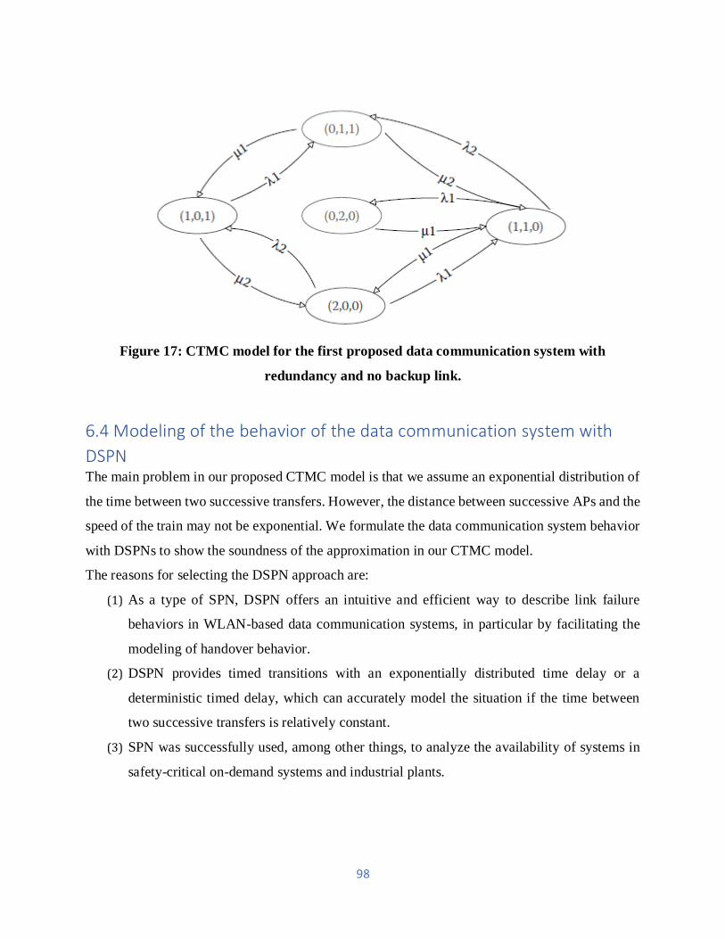
98
Figure 17: CTMC model for the first proposed data communication system with
redundancy and no backup link.
6.4 Modeling of the behavior of the data communication system with
DSPN The main problem in our proposed CTMC model is that we assume an exponential distribution of
the time between two successive transfers. However, the distance between successive APs and the
speed of the train may not be exponential. We formulate the data communication system behavior
with DSPNs to show the soundness of the approximation in our CTMC model.
The reasons for selecting the DSPN approach are:
(1) As a type of SPN, DSPN offers an intuitive and efficient way to describe link failure
behaviors in WLAN-based data communication systems, in particular by facilitating the
modeling of handover behavior.
(2) DSPN provides timed transitions with an exponentially distributed time delay or a
deterministic timed delay, which can accurately model the situation if the time between
two successive transfers is relatively constant.
(3) SPN was successfully used, among other things, to analyze the availability of systems in
safety-critical on-demand systems and industrial plants.

99
6.4.1 Introduction to DSPNs
A Petri net is a two-party graph with two types of nodes called places and transitions, represented
by circles and rectangles (or bars). Arcs connecting places to transitions are called input arcs, while
output arcs are called output arcs from transitions to places. An arc, referred to as multiplicity or
weight, can be associated with a non-negative integer (default value is 1). Places correspond to the
system's state variables, while transitions correspond to actions that induce state changes. A place
may contain tokens depicted in the Petri net by dots. The state of the Petri net is defined by its
marking, represented by a vector M = (l1, l2,..., lk), where lk M pk = () is the number of tokens in
place pk. M) (here is a mapping function from a location to the number of tokens assigned to it. If
the number of tokens in each of its input locations is greater than the weight of its corresponding
input arc, a transition is enabled. An enabled transition can fire, and the weight of the
corresponding input arcs is moved from the input place to the output place.
SPNs are one type of Petri network in which each transition involves an exponentially distributed
time delay. Generalized SPNs (GSPNs) extend the modeling power of SPN and divide the
transitions into two classes: Exponentially distributed timed transitions (represented by blank
rectangles), which are used to model the random delays associated with the performance of
activities, and immediate transitions (represented by bars), which are devoted to the representation
of logical actions that do not consume DSPN further extends GSPN by allowing timed transitions
to be delayed exponentially or delayed by a deterministic timing (represented by filled rectangles).
The rate of firing of timed transitions may depend on the marking.
6.4.2 DSPN Formulation
The corresponding DSPN is shown in Figure 18 for the data communication system with a basic
configuration. Place Pactive shows the number of active links and has one token initially. When
the only token is in Pactive, the system is in service. The Pfading tokens indicate the number of
failed links caused by deep channel fading, and the Phandoff tokens indicate the number of failed
links caused by the transfer. Tfading is an exponentially distributed timed transition that refers to
a process of fading. A token will move from Pactive to Pfading when it fires. Tfading recovery is
the exponentially distributed timed transition that indicates a fading recovery process. A token will
move from Pfading to Pactive when it fires. Transition Thandoff is a deterministic timed service

100
process transition. A token will move from Pactive to Phandoff when it fires. Thandoff recovery
is the exponentially distributed timed transition that indicates a recovery process. A token will
move from Phandoff to Pactive when it fires.
Figure 19 also shows the DSPN model for data communication systems with redundancy settings.
In this DSPN model, place Pactive initially has two tokens compared to the DSPN for basic
configuration. The system is only operational if Pactive has a token in it. The explanation of other
places and transitions in the model is the same as the basic configuration DSPN model. The
corresponding DSPN is displayed in Figure 20 for data communication systems with redundancy
and backup link configurations.
Compared to two other models, a place Pbackup is added to this DSPN model. The tokens in
Pbackup indicate the number of backup links, and two tokens in Pbackup initially correspond to
two active links. If an active link fails due to deep channel fading or handover, after an
exponentially distributed time, a backlink becomes active. Two transitions Tb frecovery and Tb
hrecovery indicate this process. The explanation of other locations and transitions in the model is
the same as the two previous DSPN models.
Figure 18: DSPN model for the data communication system with a basic configuration.

101
Figure 19: DSPN model for the data communication system with redundancy and no
backup link.
Figure 20: DSPN model for the proposed data communication system with redundancy and
backup link.

102
6.5 Numerical outcomes and discussions
Numerical results show the validity of our models of availability. Finally, there is an improvement
in the availability of the proposed systems.
APs are usually used in CBTC systems to overlap their coverage areas to reduce the shadow zone.
In our numerical examples, for the first proposed data communication system with redundancy
and no backup link, the distance between two successive APs is l= 200 m, then the distance for the
second proposed data communication system with redundancy and the backup link is l= 100 m.
The speed of the train determines the transfer rate. Due to the distance l between two successive
APs and the velocity of the train v, the average time between two successive handovers is l / v,
which gives (1 / 2)= (l / v).
The delivery end rate μ2 is also determined by the delivery time. Due to the average delivery time
Th, μ2= l / Th can be calculated. The table below shows other parameters used for the CTMC
model.
The average transition time for an exponentially distributed transition is the reciprocal transition
rate for the DSPN model parameters. All exponentially distributed transition times in our DSPN
models such as Tfading and Tfading recovery can, therefore, be calculated from the parameters
described above in the CTMC models. Moreover, for the deterministic transitions of Thandoff, as
the average time between two successive deliveries is indicated, it can be calculated as Thandoff l
v=/.
Notation Definition Value
𝜸1 Channel fading rate 0.01s-1
𝜸𝟐 Handoff rate Determined by train
velocity
𝝁1 Channel fading recovery
rate
0.2s-1
𝝁𝟑 Backup to active rate 0.2s-1
Table: Parameters in numerical examples

103
6.5.1 Model Soundness
Given all the parameters of the CTMC and DSPN models, Figure 21 illustrates the lack of
availability of different configurations in the two proposed models. As we can see from the figure,
the difference in availability between the two models changes with the parameters of the model,
and in most cases, the difference is not significant. Compared to the DSPN model, the
unavailability error in the CTMC model is because, in the CTMC model, which is not very accurate
in real systems, the time between two successive transfers is assumed to be exponentially
distributed.
Figure 21: Comparison of CTMC and DSPN models for different configurations of
redundancy.

104
6.5.2 Availability Improvement
Figure 22 shows that the three data communication systems are not available when the train speed
changes from 20 to 100 km / h. We calculate the system's unavailability with semi-redundancy for
comparison, where only one SA is installed on the train. As shown in the figure, the unavailability
of the system increases with the speed of the train. The increase of the system unavailability is
because the higher the speed, the more frequently the delivery takes place, which increases the
delivery rate. The unavailability of all three systems is therefore increased. In particular, the
existing system with basic configuration is unavailable at different train speeds by more than 5
percent. In practice, such a high level of unavailability would not be acceptable. By contrast, with
a wide range of train speeds, the proposed data communication systems can reduce the
unavailability below 1 percent. Figure 22 also shows that the second proposed data communication
system with redundancy and a backup link is better available than the first, although the second
system is more frequently transferred. This is because the likelihood of successful transitions from
a backup link to an active link is much higher than the likelihood of deep channel fading. When a
handover occurs on one of the active links, the corresponding backup link is activated before the
other active link fades genuinely. The system will therefore only become unavailable if all four
links fail. Our proposed redundancy configurations always perform better than the semi-
redundancy scheme.

105
Figure 22: The three WLAN - based data communication systems are not available.
The availability of services in CBTC systems is an important issue. To improve the availability of
CBTC communication, we proposed two WLAN-based data communication systems with
redundancy configurations. Each system was modeled as a CTMC. The data communication
system behavior was modeled with DSPN to check the soundness of the CTMC model. Different
systems of data communication were compared. The results also show that the two proposed
redundancy configurations significantly improve system availability and the redundancy
configuration achieves the best performance with the backup link at the head and tail of the train.

106
7. CBTC Systems challenges
Although CBTC systems have many advantages, several significant research challenges remain
to be addressed in order to make CBTC systems safer, more reliable and more efficient. The
primary challenge of a CBTC system is for radio communication between any train to interrupt all
or part of the system to enter a failed condition until the problem is solved. Equipment malfunction,
electromagnetic interference, low signal strength, many transfer or communication medium
saturation can affect communication failures. Building a wireless network train control system is
a challenging task.
Wireless networks can significantly affect train control performance due to unreliable wireless
communication and train mobility. That's why CBTC systems implemented radio communication
systems for the first time in 2003 when the technology needed for critical applications was mature
enough.
With the emerging services over large industrial, scientific and medical radio bands (i.e., 2,4 and
5,8 GHz) and potential disruption over critical CBTC services, the international community is
increasingly under pressure to reserve a frequency band specifically for radio-based urban rail
systems. Such a decision would help standardize these critical systems and make CBTC systems
available on the market.
Another challenge is systems with poor line-of-sight or limitations of spectrum / bandwidth. To
enhance the service, the number of transponders that may be required are more significant than
expected. Usually, the application of CBTC to existing tunnel transit systems that were not
designed to support it from the outset is more problematic. An alternative method for improving
tunnel system availability is the use of leaky feeder cable, which achieves a more reliable radio
link while having higher initial costs.
Because a CBTC system requires high availability and mainly allows graceful degradation, it may
be possible to provide a secondary signaling method to ensure some level of non-degraded service
when partial or complete CBTC is not available. This is particularly relevant for brownfield
implementations, at least temporarily, it is not possible to control the design of infrastructure and
coexistence with legacy systems.
There are numerous hazards that need to be taken seriously in CBTC systems due to CBTC's
distinctive features, including an open wireless transmission medium, nomadic trains, and lack of
dedicated security protection infrastructure. Therefore, the involvement of intelligence in CBTC

107
presents new security challenges in addition to the vulnerabilities and threats of traditional wireless
systems.
Authentication is an essential requirement for many security issues, which is critical to integrity,
confidentiality, and non-repudiation. Furthermore, the security experience of traditional wired and
wireless networks indicates the importance of multi-level protection as there are always some weak
points in the system, regardless of what is used for prevention-based approaches (e.g.,
authentication). This is particularly true for CBTC systems, given autonomous train functions with
low physical security.
Detection-based approaches [e.g., intrusion detection systems (IDSs)], serving as the second
protective wall, can effectively help identify malicious activities to solve this problem. For CBTC
systems, both prevention-based approaches and detection-based approaches need to be studied
carefully. Furthermore, if the system becomes unavailable, there is the likelihood of human error
and improper recovery procedures for application. Therefore, enhancing the safety education and
training of the operator is essential, ensuring the safe operation of trains.

108
8. Vendors and Technologies
Figure 23: CBTC was moving block projects based on radio around the globe. Projects are
color classified according to the supplier; those underlined are already in the CBTC
operation
8.1 Thales - SelTrac
SelTrac system solutions can quickly meet the needs of more people to move faster and increase their
revenue potential, ranging from fully automated, integrated solutions to upgradable solutions and
overlay re - signaling techniques to exceed the limitations of conventional fixed block designs.
SelTrac system solutions are flexible and adaptable, allowing customers to use a full, high - end system
or gradual upgrade of functionality over time, without interrupting operation, to be used for any kind
or size of rolling stock and with specific guidance. Such a decision would help to standardize these
critical systems and make CBTC systems available on the market. It is easy to configure SelTrac to
meet the specific functional requirements of the operation. SelTrac addresses the different operator
requirements requiring automatic train protection (ATP), cab signaling or integrated flexibility CBTC

109
operations. SelTrac is a convenient and cost-effective solution, from merely replacing existing signals
to improving an existing fixed-block system's progress performance.
SelTrac is a digital signaling technology used to control railway traffic automatically. It was the
first fully automatic signaling system for moving blocks to be implemented commercially.
In the 1970s, brand SelTrac was developed for a GO-Urban network in the Greater Toronto Area
of Canada by Standard Elektrik Lorenz for the Krauss-Maffei Transurban. Although the GO-Urban
project failed, a UTDC-led consortium carried out the Transurban efforts and adapted them to the
ICTS. The first to use this technology were SkyTrac's Toronto, Ontario, Vancouver, British
Columbia, and Scarborough networks. SelTrac was mainly sold and produced in Toronto by
Alcatel. After purchasing many of Alcatel's non-telephony assets, SelTrac is now sold by Thales.
New versions have been produced for various markets, and SelTrac is now used worldwide for
rolling stock control.
8.1.1 Transmission
The innovative SelTrac system was based on inductive loops providing both a channel of
communication and positioning information. Typically, an inductive loop is only used as a
communication system, with electromagnets in automobiles or stations generating currents in the
loop that can be recited at a distant location.
In SelTrac's case, the central mainframe sent statistics to the cars on a 1200 bit / s 36 kHz carrier,
while the cars on a 56 kHz carrier were 600 bit / s. Separate antennas are used for transmission
and receipt. The two wire inductive loop system was vulnerable to vandalism, and the control
signal is transmitted by IEEE 802.11 (Wi-Fi) access points in new SelTrac versions at radio
frequency inside the running rails
8.1.2 Maintaining the position
SelTrac has introduced a "twist" to the basic concept of inductive loops. The loop of SelTrac has
regularly crossed into a lozenge, shaped areas of fixed size instead of a straight wire loop which
runs down the rail.

110
A phase change in the signal caused by these crossover points can be detected by the vehicle
communication system so that they can be placed within one of these sub-loops. Usually, the loops
are about 25 meters long. By counting axle revolutions, the position in the loop can be further
measured. The vehicles transmit this position information in the loops in addition to IDs, speed,
direction, and other data. This scheme is not precise enough for the positioning of the station.
Additional accuracy is provided by the "station alignment boards" that the train tries to capture
directly next to a sensor. The vehicle is slowed down when a station arrives to allow the onboard
sensors to capture the board, and the vehicle stops automatically at a constant speed when viewed.
For example, if, due to ice on the rails, the train passes the board, the train must be manually
reversed to capture it again.
8.1.3 Control of traffic and speed
The railway is divided into control "blocks" in traditional train control with signals in each. Blocks
are intended to stop the heaviest or fastest trains completely. If a train stops in the next block, the
next train will always have time to stop before it reaches the next block. Careful adjustment of the
spacing of blocks is necessary; when signals are placed too close together, train speeds need to be
reduced, in order to stop them in time, but further spacing also means that trains are spread and
track capacity decrease
SelTrac keeps a moving block system between vehicles automatically. In this system, the blocks '
initial and end points are not static, and the trains are moving along. This enables the central control
system to estimate a point in the road where each train can move safely without additional
instructions – that would be the next set of signals in a fixed block system, but it is continually
updated with SelTrac.
In concept, this system could eradicate the "brick wall" criterion and permit trains to run as close
to each other as the speed of communication would allow, but a further spacing is typically
obligatory in practice. Computers were costly when originally designed, and data storage was
limited. By this model, all control was centralized by the original SelTrac used on the ICTS. The
blocks and safe target points were calculated for each vehicle after receiving location data from a
vehicle, and this information was then transmitted to the vehicles through the inductive loop. This
data is used by onboard control to calculate a safe rate to move to the next target and change its

111
current speed. The system was designed to reduce as much as possible the complexity and therefore
the cost of the vehicle controllers.
Much more data can be stored in modern systems in vehicle controllers. The track layout, speed
limits and additional data are now known to them. For example, this allows controllers to make
much better decisions about their speed, accelerating ahead of a tilt.
In many railways around the world, SelTrac is installed, including:
Ankara Metro Line M1 1997 SelTrac CBTC DTO
Beijing Subway Line 4 2009 SelTrac CBTC/R (radio) ATO with Attendant
Busan–Gimhae Light Rail Transit 2011 SelTrac CBTC/R UTO
Canadian Pacific Railway - BC North Line 1990 ATCS Radio-Based Train Protection
Detroit People Mover 1987 SelTrac CBTC UTO
Dubai Metro – Red and Green Lines 2009/2011 SelTrac CBTC UTO
Edmonton Light Rail Transit 2014 SelTrac CBTC/R ATP
Guangzhou Metro
o Line 3 2009/10 SelTrac CBTC DTO
o Line 9 2017 SelTrac CBTC DTO
o Line 14 2017 SelTrac CBTC DTO
o Line 21 2017 SelTrac CBTC DTO
Hong Kong International Airport APM 2014/15 SelTrac CBTC/R UTO
Hong Kong MTR
o West Rail Line 2003 SelTrac CBTC DTO
o Ma On Shan Line 2004 SelTrac CBTC DTO
o Disneyland Resort Line 2005 SelTrac CBTC/R UTO
o Ko.wloon Southern Link (West Rail Line) 2009 SelTrac CBTC DTO
Hyderabad Metro Rail (Lines 1, 2, 3) 2017 SelTrac CBTC/R STO
Incheon Subway Line 2 2014 SelTrac CBTC/R UTO
Istanbul Metro M4 Kadikoy-Kartal Line 2012 SelTrac CBTC STO
Jacksonville Skyway ASE 1998 SelTrac CBTC UTO

112
John F. Kennedy International Airport AirTrain JFK APM 2003 SelTrac CBTC UTO
Kuala Lumpur Rapid Rail
o Kelana Jaya Line 1998/2014 SelTrac CBTC UTO
o Ampang Line 2015 SelTrac CBTC/R DTO/UTO
Las Vegas Monorail 2004 SelTrac CBTC/R UTO
London Docklands Light Railway 1995 SelTrac CBTC DTO
o Lewisham Extension 1999
o London City Airport Extension 2005
o Woolwich Arsenal Extension 2009
o Stratford Extension 2011
London Underground
o Jubilee line 2011 SelTrac TBTC STO
o Northern line 2014 SelTrac TBTC STO
o Metropolitan, District, Circle, Hammersmith & City 2021 SelTrac CBTC STO
o Piccadilly line originally planned 2014 - a project currently postponed
Manaus Monorail 2015 SelTrac CBTC UTO
Mecca Metro 2011 SelTrac CBTC UTO
Newark Liberty International Airport AirTrain Newark 1996/2001 SelTrac CBTC UTO
New York City Subway
o BMT Canarsie Line – Phase III 2006 Interoperability Program SelTrac CBTC/R
STO
o IRT Flushing Line 2016 SelTrac CBTC/R STO
Ottawa O-Train Confederation Line 2018 SelTrac CBTC/R STO
Paris Metro Line 13 – Ouragan 2012 SelTrac CBTC/R DTO
SFMTA Muni Metro (Market Street Subway) 1997 SelTrac CBTC DTO
São Paulo Metro Line 17 2014 SelTrac CBTC UTO
Seoul Metropolitan Subway Shinbundang Line 2011 SelTrac CBTC/R UTO
Shanghai Metro
o Line 6 2011 SelTrac CBTC/R STO

113
o Line 8 2011 SelTrac CBTC/R STO
o Line 9 2011 SelTrac CBTC/R STO
o Line 7 2010 SelTrac CBTC/R STO
o Line 11 2010 SelTrac CBTC/R STO
Singapore MRT
o North-South Line 2017/2018 SelTrac CBTC/R DTO
o East-West Line 2017/2018 SelTrac CBTC/R DTO
Tampa International Airport APM 1992 SelTrac CBTC UTO
Toronto rapid transit 2008/10 SelTrac Speed/Signal Safeguard
o Line 3 Scarborough 1985 SelTrac CBTC DTO
Toronto streetcar electronic track switching system
Vancouver TransLink SkyTrain
o Vancouver SkyTrain - Expo Line 1985 SelTrac CBTC UTO
o Vancouver SkyTrain - Millennium Line 2002 SelTrac CBTC UTO
o Vancouver SkyTrain - Canada Line 2009 SelTrac CBTC UTO
o Vancouver SkyTrain - Evergreen Line 2016 SelTrac CBTC UTO
Walt Disney World Monorail 1989 SelTrac ATP Disney/TGI
Washington Dulles Airport AeroTrain APM 2009 SelTrac CBTC/R UTO
Wuhan Metro Line 1 2004/10 SelTrac CBTC DTO
8.2 Bombardier - CITYFLO 650
For all urban operations, CITYFLO solutions offer the full range of ATC technologies and
operating modes. CITYFLO delivers the highest level of safety from trams to light rail
vehicles, monorails and high - capacity meters while meeting the operator's dema nd for
flexible, high - performance and cost-effective solutions.
Improved operational performance is achieved by automated functionality at varying levels:
Automatic train protection (ATP) to control vital, critical safety features
The actual train - driving functions are automatic train operation (ATO)

114
Automatic train monitoring (ATS), including routing, scheduling,
and monitoring of faults
CITYFLO 650 Signaling is a Bombardier Transportation designed CBTC system. It uses bi -
directional radio communication between trains and wayside equipment as well as right moving
block technology to control train operation. Trains report their position via radio, and via a radio
link, a wayside signaling system provides the trains with movement authorities.
The CITYFLO 650 solution covers the full range of operating modes up to driverless (DTO) or
unattended (UTO) modes and is designed to move advanced metro operations in blocks and
moving automated people (APM). State-of-the-art wireless technology is used to achieve track-to-
train communication. Bombardier supports system optimization and upgrade, provides a new
dimension in overlay capability, and addresses the capacity challenge with its pioneering advances
in communications-based train control (CBTC) solutions. The CITYFLO 650 system operates or
is being delivered worldwide on 40 lines.
8.2.1 CITYFLO 650 sub-systems:
Control room for EBI screen
EBI Screen control room system supervises the vehicle. This is a modern computer -
based control and supervision system that allows the operator to give commands on
both regular display screens and large rear projection screens via a mouse or
keyboard with the facility to display the vehicle position and optional wayside
objects. The control room for the EBI Screen also provides train control for the
system.
EBI Lock computer-based interlocking
Either the built-in interlocking function can be used, or the CITYFLO 650 solution
can additionally add interlocking capabilities on EBI Lock or comply with local
standards. The built-in interlocking function of CITYFLO 650 is located alongside
the regional ATP wayside.

115
Radio block center EBI Com
CITYFLO 650 is divided into geographical regions on the side of the solution. Each
region has duplicated ATP and ATO equipment for trains in that region performing
ATP and ATO functions. Each region has one or maybe more radios to receive
position transmission from the trains and to provide them with movement authority .
EBI Link wayside equipment for ATC
The information required from the track to normalize the system's position errors is passed
to the train through standardization point baizes located at certain points in the middle of
the track. These tags give the train a precise position as it passes and allows the train.
EBI Switch point machines
Depending on what is most suitable for the particular market, a regular railway point
machine from the EBI Switch point machine range can be used.
EBI Cabin equipment on board
The onboard devices include the VATP and VATO EBI cab systems, which allow the
continuous monitoring and updating of this information with the help of a modern ATP
system, via radio transmissions. The ATP moving block system has an American public
transport safety certification. A system approval by CENELEC is also expected.
ATO system
The CITYFLO 650 solution has a full-automatic DTO / UTO system that allows for the
continuous change in driving strategy that can automatically be selected during the journey
through the control room of the EBI screen. The ATO system enables trains with a typical
accuracy of +/-15 cm to stop precision at stations.
116
8.2.2 Advantages of CITYFLO 650:
Improved safety
Because of its simple, reliable contactless TWC systems, CITYFLO 650 allows shorter,
more consistent headways. Furthermore, CITYFLO 650 meets the following industry
standards: designed and certified to specific CENELEC standards, non - IEC electrical
standards: EN 50121, 50155, EN 50128 and other relevant EN standards; and IEEE 1474
CBTC standards.
Higher automation levels
As the train travels at a safe distance from other trains, the ATO system fully exploits the
system's potential capacity. It reduces energy consumption and track and vehicle wear. The
ATO system provides platforms with precise stopping, automatic door operation, and
terminal automatic turnback.
Smooth design
The driverless moving block technology from CITYFLO 650 provides as standard flexible
headways with the ability to dynamically change headways. System updates can be
effectively managed and securely distributed remotely to trains anywhere in the CBTC
network, critical to updating large fleets. The solution provides support and training tailor-
made after - sales. It is easy to incorporate modifications such as system expansion or track
changes.
Cost-effective solution
Because of its simple, reliable and contactless TWC systems, the CITYFLO 650 solution
is cost-effective to install and eliminate wayside equipment.

117
8.2.3 Transit lines using the Cityflo 650 system:
Seattle Tacoma Int'l Airport, SeaTac, USA
Sacramento Int'l Airport, Sacramento, USA
San Francisco Int'l Airport, San Francisco, USA
McCarran Int'l Airport, Las Vegas, NV, USA
Phoenix Int'l Airport, Phoenix, USA
Dallas/Fort Worth Int'l Airport, Dallas, USA
SEPTA Subway-Surface Trolley Lines, USA
Heathrow Int'l Airport, UK
Bangkok Gold Line feeder system, Thailand
Dubai Int'l Airport, United Arab Emirates
King Abdulaziz Int'l Airport, Jeddah, Saudi Arabia
King Abdullah Financial District Monorail, Riyadh, Saudi Arabia
Tiradentes Monorail, São Paulo, Brazil
Line 5, São Paulo Metro, Brazil
Metro Tunnel, South Yarra - Dandenong and Sunbury - South Kensington - Melbourne,
Australia
MRTA Pink Line and Yellow Line, Thailand
Munich Airport, Germany
Üsküdar-Ümraniye-Çekmeköy Line, Turkey
Line 7, Delhi Metro, India
Bangkok Gold Line feeder system, Thailand
Dubai Int'l Airport, United Arab Emirates
King Abdulaziz Int'l Airport, Jeddah, Saudi Arabia
King Abdullah Financial District Monorail, Riyadh, Saudi Arabia
Tiradentes Monorail, São Paulo, Brazil
Line 5, São Paulo Metro, Brazil
Metro Tunnel, South Yarra - Dandenong and Sunbury - South Kensington - Melbourne,
Australia
MRTA Pink Line and Yellow Line, Thailand

118
Munich Airport, Germany
Üsküdar-Ümraniye-Çekmeköy Line, Turkey
Line 7, Delhi Metro, India
8.4 Alstom - Urbalis
URBALIS is a system that protects trains from automatic train control (or ATC). It consists of two
sub-systems: the (disembarked) ATC Sol and the (boarded) ATC Board. There are several
transmission modes between the ATC Sol and the ATC Board, for example, rail transmission or
radio wave transmission. URBALIS uses a technique of transmission by guide waves in radio
transmissions, a technique that allows for a reliable and efficient solution in all tunnel types.
URBALIS is a solution for CBTC (Communication Based Train Control).
The ATC Sol guarantees safety movement authorizations for trains. One function is to locate the
trains on the network and create a protective zone around them. A second function is to send
movement permits to the trains. To eliminate any risk of an accident, these authorizations must be
established and transmitted safely.
The ATC Board consists of two components: the ATP (Automatic Train Protection) security
component and the ATO (Automatic Train Operation) functional component. The ATP
permanently verifies the train's safety context (doors closed outside the passenger exchange zones),
the validity of the train's movement authorizations, and ensures that the train is driven in
accordance with safety rules. Among the rules, the ATP verifies that from the security points
(restrictive signals, other trains) the train can stop upstream.
Once a safety condition is no longer validated or respected, an emergency brake is applied by the
ATP until a complete stop is reached by train. The ATO manages the train running as well as the
automatic piloting and driver piloting assistance system. This paper describes both the automatic
piloting system and the piloting assistance system. The automatic piloting system enables train
driving by adhering as strictly as possible to the safety guidelines without sacrificing passenger
comfort and high performance. The assistance system displays the speed guidelines to the driver
that enable the former to adhere to the train's travel time. URBALIS evolution also has a mixed
piloting mode where the automatic piloting system can take over or leave the driver's responsibility
to drive the train.

119
Therefore, ALSTOM Transport has defined and designed a new automatic piloting system by
prioritizing various achievable performances in a strict priority: performance.
1. Optimize train driving within safety limits.
2. Control the stop performance at a station.
3. Control the time taken between stations.
4. Control train intervals.
5. Optimize driving to conserve energy.
URBALIS piloting system improvements were identified after analyzing the evolution of urban
transport system performance needs. The performance needs are more significant and more
prominent, process management and performance follow-up have been put in place to control the
performance level and ensure possible and observable performance on-site in commercial
operation.
The simulator X-DrivE was developed to support process management and performance follow-
up and validate all URBALIS piloting system improvements. The application domains are varied,
and the on-site performance is consistent with the factory studies: train, metro and tram, heavy or
light metro, and steep slopes.
In addition, the time taken to refining the URBALIS piloting system was reduced by a factor of
three thanks to the performance management process and the simulator X-DrivE. The work in the
factory and the use of endurance tests (robustness) contributed to this time again in the execution
and refinement of the system.
The organization put in place, the performance management process, as well as the representative
simulator X-DrivE, currently allow us to focus our efforts on the great project of the future: energy
consumption optimization.
8.5 Siemens - Trainguard MT CBTC
Trainguard MT CBTC has been developed by Siemens Transportation Systems (formerly Matra
Transport International and now integrated into Siemens Mobility). It allows the automation of the
trains to move fast and less time between trains through the mobile block system.

120
Siemens has created a modular system with Trainguard that can be deployed universally for
conventional train control. Optimized lead times, timeliness and reliable track - to - train
transmission is the most critical safety and operational functions.The modular train control system
Trainguard MT delivers the foundation for attractive, reliable and efficient mass transit systems to
be signaled.
Trainguard MT is based on Simi's reliable computers and proven automatic train control solutions
such as Trainguard LZB 700 M and Meteor, demonstrating Siemens ' radio-based train control
expertise. Trainguard MT is compatible with various operating control systems, interlocking
designs, and track vacancy detection systems thanks to standardized interfaces.
Trainguard MT CBTC fast transit lines:
Algiers Metro
Barcelona Metro line 9
Budapest Metro Line M2 and M4
Buenos Aires Underground, Line C
MTR East Rail line extension (Open in 2021)
New York City Subway L train
Paris Métro Line 14, under the name of "SAET."
São Paulo Metro, Line 4
8.6 Nippon Signal – SPARCS
Nippon Signal was set up in 1928, the year after the operation of Japan's first subway line.
Rail signals have been a basis for our business since then. We have made a concerted effort to
ensure safety and accuracy in rail operations following our commitment to failed technologies,
ranging from Shinkansen trains among the fastest in the world to public train networks with the
highest density timetables in the world.
Nippon Signal has a range of equipment, including interlocking systems for controlling railway
points and signal lights, track circuits and brake shoes, in addition to rails signaling systems such
as ATP systems and operational controls.

121
Figure 24: SPARCS System Configuration
Nippon Signal has created its own form of CBTC, called SPARCS. They also use new technologies
based on their wealth of experience and accumulated technologies to support safe, reliable and
environmentally friendly rail transport, such as the development of SPARCS (Radio
Communication System Simple - Structure and High - Performance ATP), a train control system
of the next generation. Nippon Signal will continue to help build an environmentally friendly
society and actively pursue overseas business development.
NIPPON SIGNAL first acquired the Beijing Subway Line 15 SIL4 certification from the National
Traffic Safety and Environment Laboratory in Japanese companies in September 2012.
NIPPON SIGNAL has developed the latest CBTC (Communications-Based Train Control)
Railway Signal Systems. SPARCS, which is the CBTC of NIPPON SIGNAL, is ready to serve all
over the world with its unique features.
SPARCS Function:
Train schedule monitoring

122
Based on the actual train operation in ATS, the practical train schedule is generated and supervised.
The basic train schedule is planned by the traffic dispatcher supported by the scheduling system
for train schedules. ATS prepares the route setting order for train departure. The train schedule
will be adjusted if the train schedule is changed based on operation regulation.
Train tracking
All trains are always tracked on the basis of train detection data and data receiving train number
and geographically indicate train location and train number on terminal display and mimic panel.
Route Setting
The route setting function has three setting modes. One is the train - based automatic route setting
mode, one is the ATS system's manual route setting, and the other is the ARS (Automatic Route
Setting) manual route setting mode.
Operation adjusting
ATS supports the traffic dispatcher and adjusts the operation automatically when an accident
disturbs the train operation. ATS system performs optimum train schedule changes for traffic
display operation adjustment automatically and provides all the train entry, stepping, and
cancelation and change schedule functions required.
Rapid transit lines with SPARCS:
Beijing Subway line 15, 2010

123
9. Conclusion
Modern CBTC systems are more dependable and less likely to fail than old train systems because
of the technological developments and the experience gained over the past 30 years. Typically,
CBTC systems have fewer equipment on the side of their routes and have improved their
diagnostic and monitoring tools to facilitate their implementation and, above all, their
maintenance.
CBTC technology develops more compact systems and simpler architectures using the latest
technology and components. For example, the advent of modern electronics enabled redundancy
to ensure that individual failures do not affect operational availability. These systems also provide
full flexibility in operating schedules or schedules and enable urban rail operators to respond faster
and more resourcefully to specific traffic demands and address congestion issues. Indeed,
automatic operating systems are able to significantly reduce progress as compared to manual
driving systems and improve traffic capacity.
Finally, it should be noted that CBTC systems are energy efficient compared to traditional
manually-driven systems. Significant energy savings to reduce energy consumption can result in
new features such as automated driving strategies or better adaptation of the transport offer to
actual demand.

124
10. References
1. http://www.tsd.org/cbtc/
2. https://en.wikipedia.org/wiki/Communications-based_train_control#cite_note-
collaboration-18
3. https://en.wikipedia.org/wiki/SelTrac
4. https://www.thalesgroup.com/en/train-control-cbtc
5. http://www.signal.co.jp/english/products/railway.html
6. https://www.smartrailworld.com/expert-focus-what-is-communication-based-train-
control-cbtc
7. http://www.railsystem.net/communications-based-train-control-cbtc/
8. https://www.omicsonline.org/open-access/automatic-train-protection-systems-2169-
0316.1000120.php?aid=20757
9. http://www.irse.org/knowledge/publicdocuments/2.06%20Bienfait%20-
%20Automatic%20Train%20Operation%20for%20ETCS.pdf
10. https://en.wikipedia.org/wiki/Automatic_train_operation
11. https://www.railjournal.com/in_depth/automatic-train-control-takes-to-the-main-line
12. https://ieeexplore.ieee.org/document/1460843
13. https://www.crcpress.com/Advances-in-Communications-Based-Train-Control-
Systems/Yu/p/book/9781138894501
14. https://www.google.com/search?q=Advances+in+Communications-
Based+Train+Control+Systems&oq=Advances+in+Communications-
Based+Train+Control+Systems&aqs=chrome..69i57j69i61j69i60l2j69i59l2.7061j1j7&so
urceid=chrome&ie=UTF-8
15. https://www.apta.com/resources/standards/Documents/APTA-SS-CCS-RP-001-10.pdf
16. IEEE. IEEE Std 1474.4-2011: IEEE recommended practice for functional testing of a
communications-based train control (CBTC) system. IEEE, New York, 2011.
17. http://ieeexplore.ieee.org/iel5/6026201/6026202/06026203.pdf
18. Rumsey. Implementing CBTC on an operating transit system. American Public
Transportation Association Rail Conference, Montreal, Quebec, Canada, June 2014.
19. K. Diemunsch. Migration to communication based train control. American Public
Transportation Association Rail Conference, Montreal, Quebec, Canada, June 2014.

125
20. IEEE. IEEE Std 1474.1: IEEE standard for communications-based train control (CBTC)
performance and functional requirements. IEEE. New York, 2004.
21. IEEE. IEEE Std 1474.2: IEEE standard for operator interface requirements in
communications-based train control (CBTC) systems. IEEE. New York, 2003.
22. IEEE. IEEE Std 1474.3: IEEE recommended practice for communications-based train
control (CBTC) system design and functional allocations. IEEE. New York, 2008.
23. M. Aquado, E. Jacob, P. Saiz, J. J. Unzilla, M. V. Hiquero, and J. Matias. Railway
signaling systems and new trends in wireless data communication. In Proceedings of the
IEEE VTC’2005-Fall, Dallas, TX, September 2005.
24. F. Whitwam. Integration of wireless network technology with signaling in the rail transit
industry. Alcatel Telecommunications Review, 1(1):43–48, 2003.
25. L. Zhu, F. R. Yu, B. Ning, and T. Tang. Cross-layer handoff design in MIMOenabled
WLANs for communication-based train control (CBTC) systems. IEEE Journal on
Selected Areas in Communication, 30(4):719–728, 2012.
26. P. Bellavista, M. Cinque, D. Cotroneo, and L. Foschini. Self-adaptive handoff
management for mobile streaming continuity. IEEE Transactions on Network and
Service Management, 6(2):80–94, 2009.
27. T. Xu, T. Tang, C. Gao, and B. Cai. Dependability analysis of the data communication
system in train control system. Science in China, 52-9:2605–2618, 2009.
28. E. Kuun. Open standards for CBTC and CCTV radio based communication. Technical
Forums of Alcatel, 2(1):99–108, 2004.
29. https://www.cmu.edu/iso/governance/guidelines/data-classification.html
30. https://www.apta.com/resources/standards/documents/apta-ss-ccs-rp-002-13.pdf
31. M. Aquado, E. Jacob, P. Saiz, J. J. Unzilla, M. V. Hiquero, and J. Matias. Railway signaling
systems and new trends in wireless data communication. In Proceedings of the IEEE
VTC’2005-Fall, Dallas, TX, September 2005.
32. https://www.intechopen.com/books/modern-railway-engineering/transmission-based-
signaling-systems