COMMUNICAITON SYSTEMS – SEC1303 - Sathyabama ...
206
SCHOOL OF ELECTRICAL AND ELECTRONICS DEPARTMENT OF ELECTRONICS AND COMMUNICATION ENGINEERING COMMUNICAITON SYSTEMS – SEC1303 UNIT – 1 TELEPHONE COMMUNICATION
-
Upload
khangminh22 -
Category
Documents
-
view
3 -
download
0
Transcript of COMMUNICAITON SYSTEMS – SEC1303 - Sathyabama ...

SCHOOL OF ELECTRICAL AND ELECTRONICS
DEPARTMENT OF ELECTRONICS AND COMMUNICATION ENGINEERING
COMMUNICAITON SYSTEMS – SEC1303
UNIT – 1
TELEPHONE COMMUNICATION
2
1. TELEPHONE COMMUNICATION
Telephones - Standard Telephone and local loop - Electronics Telephone - Telephone
System- Cordless Telephone -Telephone Facsimile - Fax Machine Operation - Paging
System -Cellular Telephone system - Digital cellular Telephone system - ISDN.
1.1 Introduction
Telecommunication means “communications at a distance”. Tele in Greek means at
a distance Electrical communications by wire, radio, or light (fiber optics).
1.2 Telephones
The telephone system was designed for full-duplex analog communication of voice
signals. Today, this system is still primarily used for voice, but it employs mostly digital
techniques, not only in signal transmission but also in control operations. The telephone
system permits any telephone to connect with any other telephone in the world.
A telephone line or telephone circuit (or just line or circuit within the industry) is a
single-user circuit on a telephone communication system. This is the physical wire or
other signaling medium connecting the user's telephone apparatus to the
telecommunications network, and usually also implies a single telephone number for
billing purposes reserved for that user. Telephone lines are used to deliver landline
telephone service and Digital subscriber line (DSL) phone cable service to the premises.
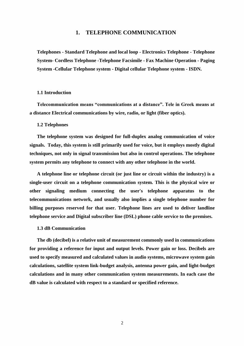
1.3 dB Communication
The db (decibel) is a relative unit of measurement commonly used in communications
for providing a reference for input and output levels. Power gain or loss. Decibels are
used to specify measured and calculated values in audio systems, microwave system gain
calculations, satellite system link-budget analysis, antenna power gain, and light-budget
calculations and in many other communication system measurements. In each case the
dB value is calculated with respect to a standard or specified reference.
3
1.4 Local loop
The Local Loop in a telephone network (sometimes referred to as the "last mile" of
the network) is the bit that connects home to local telephone exchange. It refers literally
to the copper cables that run from home to the telephone exchange. Standard telephones
are connected to the telephone system by way of a two-wire, twisted-pair cable that
terminates at the local exchange or central office. As many as 10,000 telephone lines can
be connected to a single central office. The two-wire, twisted-pair connection between the
telephone and central office is referred to as the local loop or subscriber loop. The circuits
in the telephone and at the central office form a complete electric circuit, or loop.
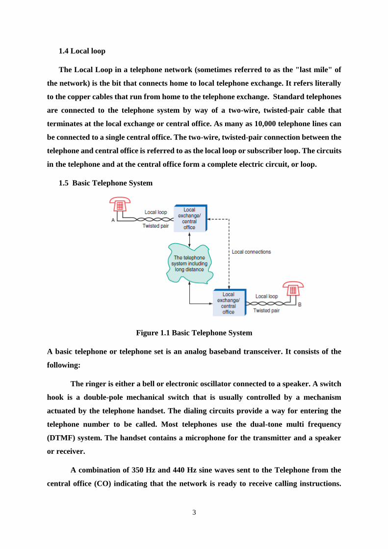
1.5 Basic Telephone System
Figure 1.1 Basic Telephone System
A basic telephone or telephone set is an analog baseband transceiver. It consists of the
following:
The ringer is either a bell or electronic oscillator connected to a speaker. A switch
hook is a double-pole mechanical switch that is usually controlled by a mechanism
actuated by the telephone handset. The dialing circuits provide a way for entering the
telephone number to be called. Most telephones use the dual-tone multi frequency
(DTMF) system. The handset contains a microphone for the transmitter and a speaker
or receiver.
A combination of 350 Hz and 440 Hz sine waves sent to the Telephone from the
central office (CO) indicating that the network is ready to receive calling instructions.
4
The hybrid is a special transformer used to convert signals from the four wires from the
transmitter and receiver into a signal suitable for a single two-line pair to the local loop.
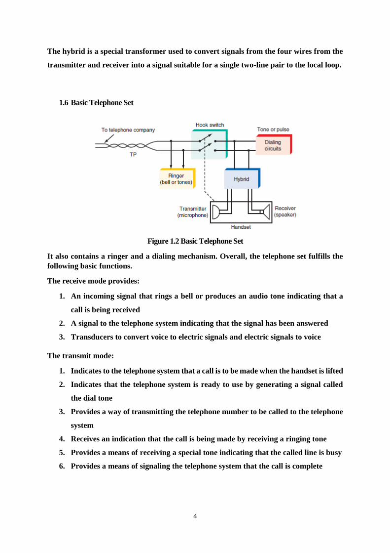
1.6 Basic Telephone Set
Figure 1.2 Basic Telephone Set
It also contains a ringer and a dialing mechanism. Overall, the telephone set fulfills the
following basic functions.
The receive mode provides:
1. An incoming signal that rings a bell or produces an audio tone indicating that a
call is being received
2. A signal to the telephone system indicating that the signal has been answered
3. Transducers to convert voice to electric signals and electric signals to voice
The transmit mode:
1. Indicates to the telephone system that a call is to be made when the handset is lifted
2. Indicates that the telephone system is ready to use by generating a signal called
the dial tone
3. Provides a way of transmitting the telephone number to be called to the telephone
system
4. Receives an indication that the call is being made by receiving a ringing tone
5. Provides a means of receiving a special tone indicating that the called line is busy
6. Provides a means of signaling the telephone system that the call is complete
5
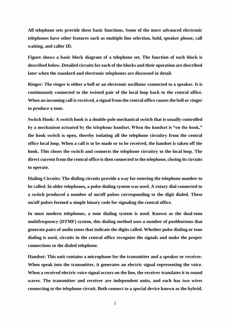
All telephone sets provide these basic functions. Some of the more advanced electronic
telephones have other features such as multiple line selection, hold, speaker phone, call
waiting, and caller ID.
Figure shows a basic block diagram of a telephone set. The function of each block is
described below. Detailed circuits for each of the blocks and their operation are described
later when the standard and electronic telephones are discussed in detail.
Ringer: The ringer is either a bell or an electronic oscillator connected to a speaker. It is
continuously connected to the twisted pair of the local loop back to the central office.
When an incoming call is received, a signal from the central office causes the bell or ringer
to produce a tone.
Switch Hook: A switch hook is a double-pole mechanical switch that is usually controlled
by a mechanism actuated by the telephone handset. When the handset is “on the hook,”
the hook switch is open, thereby isolating all the telephone circuitry from the central
office local loop. When a call is to be made or to be received, the handset is taken off the
hook. This closes the switch and connects the telephone circuitry to the local loop. The
direct current from the central office is then connected to the telephone, closing its circuits
to operate.
Dialing Circuits: The dialing circuits provide a way for entering the telephone number to
be called. In older telephones, a pulse dialing system was used. A rotary dial connected to
a switch produced a number of on/off pulses corresponding to the digit dialed. These
on/off pulses formed a simple binary code for signaling the central office.
In most modern telephones, a tone dialing system is used. Known as the dual-tone
multifrequency (DTMF) system, this dialing method uses a number of pushbuttons that
generate pairs of audio tones that indicate the digits called. Whether pulse dialing or tone
dialing is used, circuits in the central office recognize the signals and make the proper
connections to the dialed telephone.
Handset: This unit contains a microphone for the transmitter and a speaker or receiver.
When speak into the transmitter, it generates an electric signal representing the voice.
When a received electric voice signal occurs on the line, the receiver translates it to sound
waves. The transmitter and receiver are independent units, and each has two wires
connecting to the telephone circuit. Both connect to a special device known as the hybrid.
6
Hybrid: The hybrid circuit is a special transformer used to convert signals from the four
wires from the transmitter and receiver to a signal suitable for a single two-line pair to
the local loop. The hybrid permits full duplex, i.e., simultaneous send and receive, analog
communication on the two-wire line. The hybrid also provides a side tone from the
transmitter to the receiver so that the speaker can hear her or his voice in the receiver.
This feedback permits automatic voice-level adjustment.
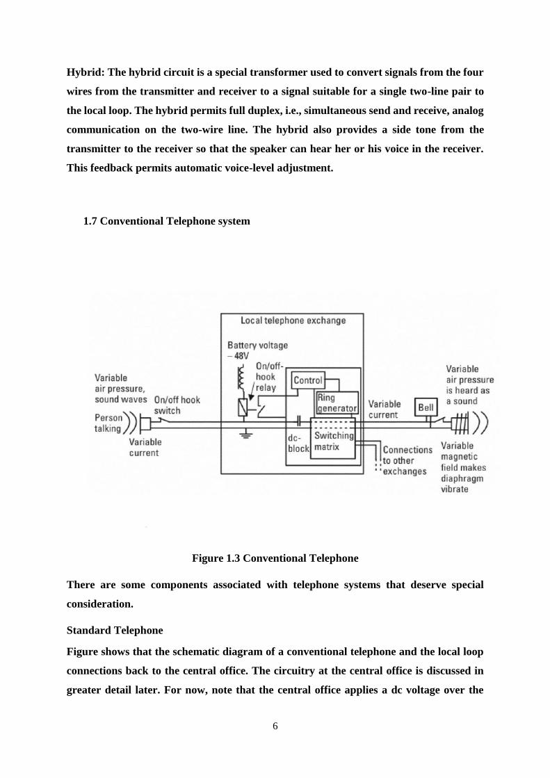
1.7 Conventional Telephone system
Figure 1.3 Conventional Telephone
There are some components associated with telephone systems that deserve special
consideration.
Standard Telephone
Figure shows that the schematic diagram of a conventional telephone and the local loop
connections back to the central office. The circuitry at the central office is discussed in
greater detail later. For now, note that the central office applies a dc voltage over the
7
twisted-pair line to the telephone. This dc voltage is approximately 248 V with respect to
ground in the open-circuit condition. When a subscriber picks up the telephone, the
switch hook closes, connecting the circuitry to the telephone line. The load represented
by the telephone circuitry causes current to low in the local loop and the voltage inside
the telephone to drop to approximately 5 to 6 V.
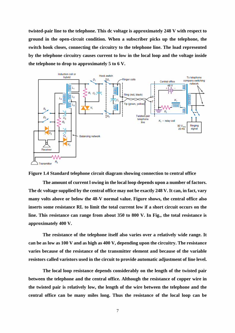
Figure 1.4 Standard telephone circuit diagram showing connection to central office
The amount of current l owing in the local loop depends upon a number of factors.
The dc voltage supplied by the central office may not be exactly 248 V. It can, in fact, vary
many volts above or below the 48-V normal value. Figure shows, the central office also
inserts some resistance RL to limit the total current low if a short circuit occurs on the
line. This resistance can range from about 350 to 800 V. In Fig., the total resistance is
approximately 400 V.
The resistance of the telephone itself also varies over a relatively wide range. It
can be as low as 100 V and as high as 400 V, depending upon the circuitry. The resistance
varies because of the resistance of the transmitter element and because of the variable
resistors called varistors used in the circuit to provide automatic adjustment of line level.
The local loop resistance depends considerably on the length of the twisted pair
between the telephone and the central office. Although the resistance of copper wire in
the twisted pair is relatively low, the length of the wire between the telephone and the
central office can be many miles long. Thus the resistance of the local loop can be
8
anywhere from 1000 to 1800 V, depending upon the distance. The local loop length can
vary from a few thousand feet up to about 18,000 ft.
Finally, the frequency response of the local loop is approximately 300 to 3400 Hz.
This is sufficient to pass voice frequencies that produce full intelligibility. An unloaded
twisted pair has an upper cutoff frequency of about 4000 Hz. But this cutoff varies
considerably depending upon the overall length of the cable. When long runs of cable are
used, special loading coils are inserted into the line to compensate for excessive roll-off at
the higher frequencies.
The two wires used to connect telephones are labeled tip and ring. These
designations refer to the plug used to connect telephones to one another at the central
office. At one time, large groups of telephone operators at the central office used plugs
and jacks at a switchboard to connect one telephone to another manually.
The tip wire is green and is usually connected to ground; the ring wire is red. Many
telephone cables into a home or an office also contain a second twisted pair if a separate
telephone line is to be installed. These wires are usually color-coded black and yellow.
Black and yellow correspond to ring and tip, respectively, where yellow is ground. Other
color combinations are used in telephone wiring.
Ringer circuitry connected directly to the tip and ring local loop wires is the ringer.
The ringer in most older telephones is an electromechanical bell. A pair of
electromagnetic coils is used to operate a small hammer that alternately strikes two small
metallic bells. When an incoming call is received, a voltage from the central office
operates the electromagnetic coils, which in turn operate the hammer to ring the bells.
The bells make the familiar tone produced by most standard telephones. In Figure the
ringing coils are connected in series with a capacitor C1. This allows the ac ringing voltage
to be applied to the coils but blocks the 48 V of direct current, thus minimizing the current
drain on the 48 V of power supplied at the central office. The ringing voltage supplied by
the central office is a sine wave of approximately 90 Vrms at a frequency of about 20 Hz.
These are the nominal values, because the actual ringing voltage can vary from
approximately 80 to 100 Vrms with a frequency somewhere in the 15- to 30-Hz range.
This ac signal is supplied by a generator at the central office.

9
The ringing voltage is applied in series with the 248-V dc signal from the central
office power supply. The ringing signal is connected to the local loop line by way of a
transformer T1. The transformer couples the ringing signal into its secondary winding
where it appears in series with the 48-V dc supply voltage.
The standard ringing sequence is shown in Figure. In U.S. telephones, the ringing
voltage occurs for 1 s followed by a 3-s interval. Telephones in other parts of the world
use different ringing sequences. For example, in the United Kingdom, the standard ring
sequence is a higher-frequency tone occurring more frequently, and it consists of two
ringing pulses 400 ms long, separated by 200 ms. This is followed by a 2-s interval of quiet
before the tone sequence repeats.
Figure 1.5 Telephone ringing sequence. (a) United States and Europe. (b) United
Kingdom
Transmitter:
The transmitter is the microphone into which speak during a telephone call. In a
standard telephone, this microphone uses a carbon element that effectively translates
acoustical vibrations into resistance changes. The resistance changes, in turn, produce
current variations in the local loop representing the speaker’s voice. A dc voltage must
be applied to the transmitter so that current flows through it during operation. The 48 V
from the central office is used in this case to operate the transmitter. The resulting ac
voice signal produced on the telephone line is approximately 1 to 2 Vrms.
Receiver: The receiver, or earpiece, is basically a small permanent-magnet speaker. A
thin metallic diaphragm is physically attached to a coil that rests inside a permanent
10
magnet. Whenever a voice signal comes down a telephone line, it develops a current in
the receiver coil. The coil produces a magnetic field that interacts with the permanent-
magnet field. The result is vibration of the diaphragm in the receiver, which converts the
electric signal to the acoustic energy that supplies the voice to the ear. As it comes in over
the local loop lines, the voice signal has an amplitude of approximately 0.5 to 1 Vrms.
Hybrid:
The hybrid is a transformer like device that is used to simultaneously transmit and
receive on a single pair of wires. The hybrid, which is also sometimes referred to as an
induction coil, is really several transformers combined into a single unit. The windings
on the transformers are connected in such a way that signals produced by the transmitter
are put on the two-wire local loop but do not occur in the receiver. In the same way, the
transformer windings permit a signal to be sent to the receiver, but the resulting voltage
is not applied to the transmitter.
In practice, the hybrid windings are set up so that a small amount of the voice
signal produced by the transmitter does occur in the receiver. This provides feedback to
the speaker so that she or he may speak with normal loudness. The feedback from the
transmitter to the receiver is referred to as the side tone. If the side tone were not
provided, there would be no signal in the receiver and the person speaking would have
the sensation that the telephone line was dead. By hearing his or her own voice in the
receiver at a moderate level, the caller can speak at a normal level. Without the side tone,
the speaker tends to speak more loudly, which is unnecessary.
Automatic Voice Level Adjustment: Because of the wide variation in the different loop
lengths of the two telephones connected to each other, the circuit resistances will vary
considerably, thereby causing a wide variation in the transmitted and received voice
signal levels. All telephones contain some type of component or circuit that provides
automatic voice level adjustment so that the signal levels are approximately the same
regardless of the loop lengths. In the standard telephone, this automatic loop length
adjustment is handled by components called varistors. These are labeled V1, V2, and V3
in Figure.
A varistor is a nonlinear resistance element whose resistance changes depending
upon the amount of current passing through it. When the current passing through the
11
varistor increases, its resistance decreases. A decrease in current causes the resistance to
increase.
The varistors are usually connected across the line. In Figure, varistor V1 is
connected in series with resistor R1. This varistor automatically shunts some of the
current away from the transmitter and the receiver. If the loop is long, the current will
be relatively low and the voltage at the telephone will be low. This causes the resistance
of the varistor to increase, thus shunting less current away from the transmitter and
receiver. On short local loops, the current will be high and the voltage at the telephone
will be high. This causes the varistor resistance to decrease; thus more current is shunted
away from the transmitter and receiver. The result is a relatively constant level of
transmitted or received speech. Note that a second varistor V3 is used in the balancing
network. The balancing network (C3, C4, R2) works in conjunction with the hybrid to
provide the side tone discussed earlier. The varistor adjusts the level of the side tone
automatically.
Pulse Dialing:
The term dialing is used to describe the process of entering a telephone number to
be called. In older telephones, a rotary dial was used. In more modern telephones,
pushbuttons that generate electronic tones are used for “dialing.”
The use of a rotary dialing mechanism produces what is known as pulse dialing.
Rotating the dial and releasing it cause a switch contact to open and close at a fixed rate,
producing current pulses in the local loop. These current pulses are detected by the
central office and used to operate the switches that connect the dialing telephone to the
called telephone. While most telephone companies still support pulse dialing, most dial
phones have been long retired. Pulse dialing is no longer widely used.
Tone Dialing:
Although some dial telephones are still in use and all central offices can
accommodate them, most modern telephones use a dialing system known as Touch- Tone.
It uses pairs of audio tones to create signals representing the numbers to be dialed. This
dialing system is referred to as the dual-tone multifrequency (DTMF) system. A typical
DTMF keyboard on a telephone is shown in Fig. 18-5. Most telephones use a standard
12
keypad with 12 buttons or switches for the numbers 0 through 9 and the special symbols
* and #. The DTMF system also accommodates four additional keys for special
applications.
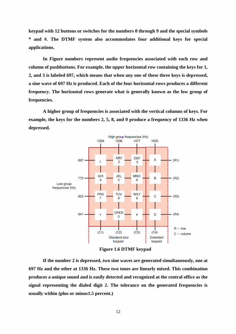
In Figure numbers represent audio frequencies associated with each row and
column of pushbuttons. For example, the upper horizontal row containing the keys for 1,
2, and 3 is labeled 697, which means that when any one of these three keys is depressed,
a sine wave of 697 Hz is produced. Each of the four horizontal rows produces a different
frequency. The horizontal rows generate what is generally known as the low group of
frequencies.
A higher group of frequencies is associated with the vertical columns of keys. For
example, the keys for the numbers 2, 5, 8, and 0 produce a frequency of 1336 Hz when
depressed.
Figure 1.6 DTMF keypad
If the number 2 is depressed, two sine waves are generated simultaneously, one at
697 Hz and the other at 1336 Hz. These two tones are linearly mixed. This combination
produces a unique sound and is easily detected and recognized at the central office as the
signal representing the dialed digit 2. The tolerance on the generated frequencies is
usually within (plus or minus1.5 percent.)
13
1.8 Telephone System
Most of us take telephone service for granted, as we do other so-called utilities,
e.g., electric power. In the United States, telephone service is excellent. But this is certainly
not the case in many other countries in the world.
When we refer to the telephone system, we are talking about the organizations and
facilities involved in connecting telephone to the called telephone regardless of where it
might be in United States or anywhere else in the world. The telephone system is called
the Public Switched Telephone Network (PSTN). The telephone system referred to as the
Plain Old Telephone Service (POTS). A number of different companies are involved in
long-distance calls, although a single company is usually responsible for local calls in a
given area. These companies make up the telephone system, and they design, build,
maintain, and operate all the facilities and equipment used in providing universal
telephone service. A vast array of equipment and technology are employed. Practically
every conceivable type of electronic technology is used to implement worldwide telephone
service, and that continues to change as Internet calling known as Voice over Internet
Protocol (VoIP) grows.
The telephone, a small but relatively complex entity, is nothing compared to the
massive system that backs it up. The telephone system can connect any two telephones in
the world, and most people can only speculate on the method by which this connection
takes place. It takes place on many levels and involves an incredible array of systems and
technology. Obviously, it is difficult to describe such a massive system here. However, in
this brief section, we attempt to describe the technical complexities of interconnecting
telephones, the central office and the subscriber line interface that connect each user to
the telephone system, the hierarchy of interconnections within the telephone system, and
the major elements and general operation of the telephone system. Long-distance
operation and special telephone interconnection systems such as the PBX are also
discussed. VoIP is introduced.
Subscriber Interface Most telephones are connected to a local central office by
way of the two-line, twisted pair local loop cable. The central office contains all the
equipment that operates the telephone and connects it to the telephone system that makes
the connection to any other telephone.

14
Each telephone connected to the central office is provided with a group of basic
circuits that power the telephone and provide all the basic functions, such as ringing, dial
tone, and dialing supervision. These circuits are collectively referred to as the subscriber
interface or the subscriber line interface circuit (SLIC). In older central office systems,
the subscriber interface circuits used discrete components. Today, most functions of the
subscriber line interface are implemented by one or perhaps two integrated circuits plus
supporting equipment. The subscriber line interface is also referred to as the line side
interface.
The SLIC provides seven basic functions generally referred to as BORSCHT.
The (telephone) line interface is often referred to as a BORSCHT circuit.
This acronym describes the functional requirements of a standard telephone line
interface. The tip and ring leads of the telephone set are wired through some protection
devices to the line interface located in the peripheral module. This interface must perform
the following functions:
B Battery feed
O Over voltage protection
R Ringing
S Supervision & Signaling
C Coding
H Hybrid
T Test
Line Cards
Line cards are the single most common component in a telephone office. It is a very
complex device that contains a wide range of technologies.
Figure 1.7 SLIC
15
Many of these functions can be integrated into a single IC, often called a SLIC chip
(subscriber line interface chip). SLICs have been available for the PBX market for over
a decade. Recently however, they have also become available for the central office
environment as well.
B - Battery Feed
Most domestic appliances are powered from an electric utility grid. The notable
exception to this is the telephone. This is because the telephone should still operate in the
event of a power failure. Indeed, the telephone is vital in case of disaster or emergency.
The telephone office provides a nominal -48 volt dc feed to power the phone. This
magnitude is considered the maximum safe dc operating potential. It would not be in the
telephone company’s best interest to provide a dc voltage, which could electrocute its
customers, or it’s own employees. A negative potential was chosen to reduce corrosive
action on buried cables.
Multi-function telephones cannot always be powered from the telephone exchange
and often require an alternate power source. For this reason, sophisticated line interfaces
such as ISDN SAA interfaces have a ‘fail to POTS’ mode. If the electric power fails, the
complex phone cannot function to full capacity. The telephone exchange can sense the
local power outage through the telephone loop and switches to POTS only service.
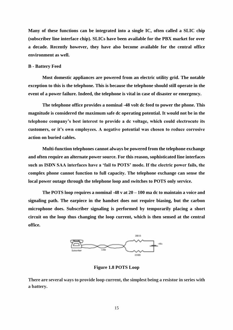
The POTS loop requires a nominal -48 v at 20 – 100 ma dc to maintain a voice and
signaling path. The earpiece in the handset does not require biasing, but the carbon
microphone does. Subscriber signaling is performed by temporarily placing a short
circuit on the loop thus changing the loop current, which is then sensed at the central
office.
Figure 1.8 POTS Loop
There are several ways to provide loop current, the simplest being a resistor in series with
a battery.

16
Figure 1.9 Loop current
Another way to provide loop current is by an electronic current source.
Although this method is quite complex, it has become quite popular with the
advent of high voltage bipolar technology. One of the more difficult requirements to meet
is the 60-dB longitudinal line balance requirement. To achieve this, the impedance to
ground on each side of the loop, must match within 0.1%. This is easy to do with laser
trimmed thick film resistors, but a bit tricky with current sources.
Figure 1.10 BORSCHT functions in the subscriber line interface at the central office
A standard telephone requires a minimum of about 20 ma. This means that the
maximum possible loop resistance is about 2000 . In actual practice, the loop is
generally limited to 1250 W. The maximum loop length is determined by the wire
gauge.
O - Over-voltage Protection
The two major types of over-voltage that can occur are lightning strikes and power
line contact. In both cases, the circuit must either recover or fail-safe. Under no
circumstances can a surge be allowed to propagate further into the system, or create a
fire.
17
Initial surge protection is provided at the MDF by gas tubes and/or carbon
blocks, which arc if the applied voltage exceeds a few hundred volts. Since these devices
take a finite time to respond, high-speed diodes are also used at the line circuit inputs.
R - Ringing
Ringing is often provided by means of a dedicated ringing generator that is
connected onto the loop by means of a relay. It is possible to generate ringing voltages at
the line interface if the current generators have a high enough voltage source available to
them. Or alternately, a switching converter with step up capability can be place on the
interface.
S - Supervision & Signaling
The central office must supervise the loop in order to identify customer requests
for service. A request for service is initiated by going off-hook. This simply draws loop
current from the CO. Loop current at the far-end is monitored during ringing to enable
the CO to disconnect the ringing generator when the phone is answered. The office
continues to monitor the loop current at both ends of the connection throughout the call,
to determine when the call is terminated by hanging up.
Signaling is a way to inform the CO what the customer wants. The two basic
signaling methods used in customer loops are dial pulse and touch-tone. It is interesting
to note that preferred customer loop signaling method in analog exchanges is digital,
while the preferred method in digital exchanges is analog.
MF Signaling Tones
Two tones are used to perform the signaling function to eliminate the possibility
that speech be interpreted as a signal. At one time DTMF decoders were costly and bulky
devices located in a common equipment bay, but today with the advent of LSI technology,
this function can be performed on a chip. An example is the Mitel MT8865 DTMF filter,
and MT8860 DTMF decoder.
Positions 11 to 14 are not presently being used.
C - Coding
18
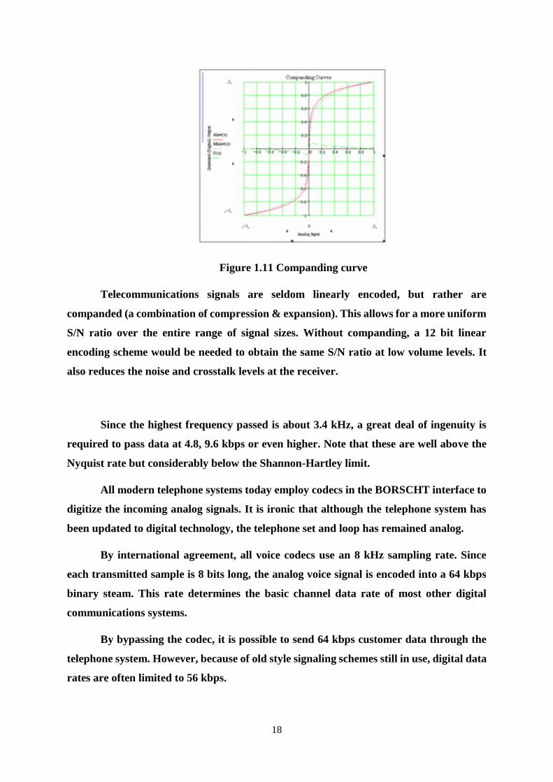
Figure 1.11 Companding curve
Telecommunications signals are seldom linearly encoded, but rather are
companded (a combination of compression & expansion). This allows for a more uniform
S/N ratio over the entire range of signal sizes. Without companding, a 12 bit linear
encoding scheme would be needed to obtain the same S/N ratio at low volume levels. It
also reduces the noise and crosstalk levels at the receiver.
Since the highest frequency passed is about 3.4 kHz, a great deal of ingenuity is
required to pass data at 4.8, 9.6 kbps or even higher. Note that these are well above the
Nyquist rate but considerably below the Shannon-Hartley limit.
All modern telephone systems today employ codecs in the BORSCHT interface to
digitize the incoming analog signals. It is ironic that although the telephone system has
been updated to digital technology, the telephone set and loop has remained analog.
By international agreement, all voice codecs use an 8 kHz sampling rate. Since
each transmitted sample is 8 bits long, the analog voice signal is encoded into a 64 kbps
binary steam. This rate determines the basic channel data rate of most other digital
communications systems.
By bypassing the codec, it is possible to send 64 kbps customer data through the
telephone system. However, because of old style signaling schemes still in use, digital data
rates are often limited to 56 kbps.
19
H – Hybrid
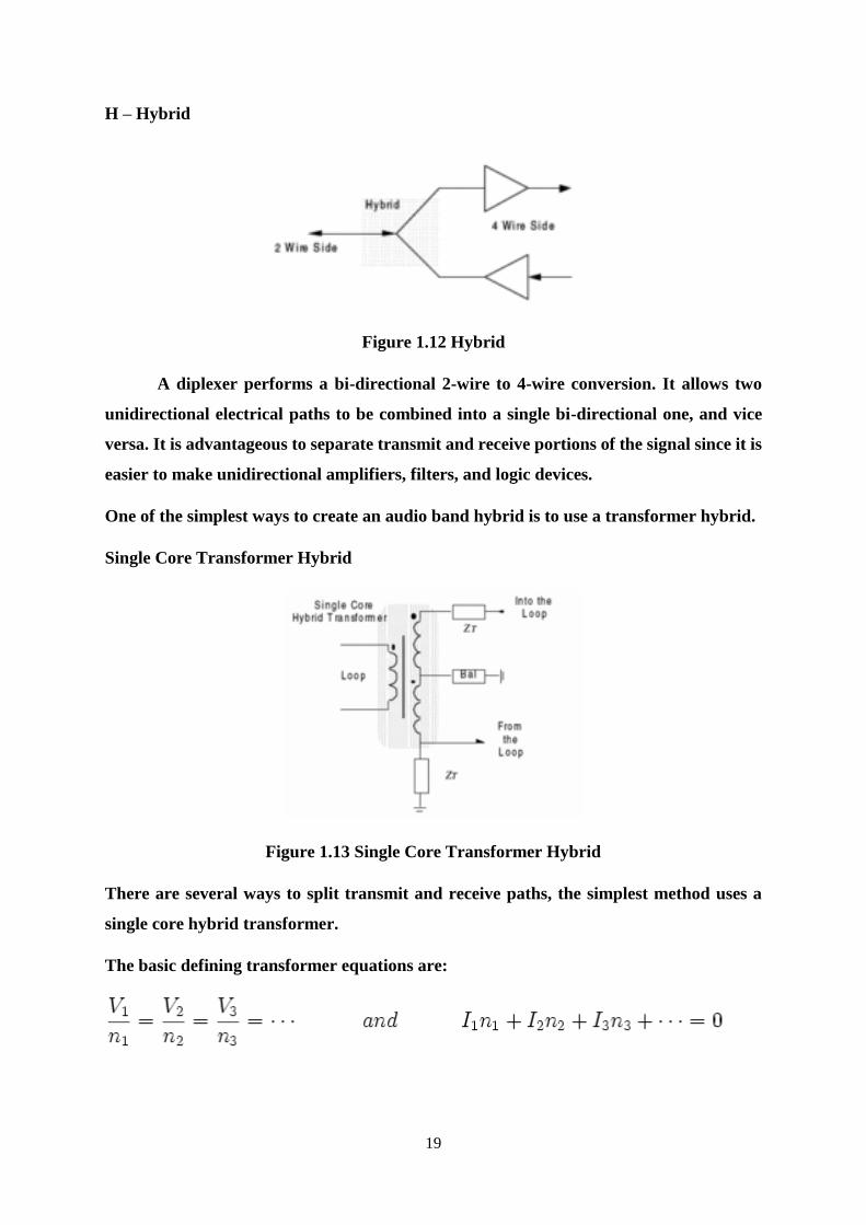
Figure 1.12 Hybrid
A diplexer performs a bi-directional 2-wire to 4-wire conversion. It allows two
unidirectional electrical paths to be combined into a single bi-directional one, and vice
versa. It is advantageous to separate transmit and receive portions of the signal since it is
easier to make unidirectional amplifiers, filters, and logic devices.
One of the simplest ways to create an audio band hybrid is to use a transformer hybrid.
Single Core Transformer Hybrid
Figure 1.13 Single Core Transformer Hybrid
There are several ways to split transmit and receive paths, the simplest method uses a
single core hybrid transformer.
The basic defining transformer equations are:
20
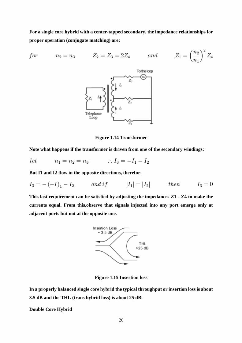
For a single core hybrid with a center-tapped secondary, the impedance relationships for
proper operation (conjugate matching) are:
Figure 1.14 Transformer
Note what happens if the transformer is driven from one of the secondary windings:
But I1 and I2 flow in the opposite directions, therefor:
This last requirement can be satisfied by adjusting the impedances Z1 - Z4 to make the
currents equal. From this,observe that signals injected into any port emerge only at
adjacent ports but not at the opposite one.
Figure 1.15 Insertion loss
In a properly balanced single core hybrid the typical throughput or insertion loss is about
3.5 dB and the THL (trans hybrid loss) is about 25 dB.
Double Core Hybrid

21
When properly balanced, a 2-core network can achieve a THL of 50 dB while the
insertion loss remains at about 3.5 dB. It has better performance than the single core
device, but is bulkier and more expensive.
Balancing Networks :
All telecom equipment is tested and characterized against standard impedance
terminations. These impedances are based on line surveys and are approximate
equivalent circuit representations of the outside cabling plant.
T – Testing: In order to maintain a high degree of service (99.999%), the equipment must
be capable of detecting and repairing faults before the customer is even aware that there
may be a problem. As a result, a separate test buss and access relay is provided on a line
interface. Tests may be performed in a bridged mode or with the loop and line card
disconnected from each other. Testing can be done in three basic directions:
From the line interface looking out towards the subscriber loop
From the loop connection looking into the line card
From the central office side of the line card .These tests are generally automated
and are conducted late at night when there is little chance that the customer will
request service, thus interrupting the test. Some of the scheduled tests may
include:
o Transmit and receive levels
o Transmit and receive frequency response
o Insertion loss
o Trans-hybrid loss
o Quantization distortion
Aliasing distortion Some other tests that may be performed when commissioning
a line or when a complaint is lodged, include:
o Impulse noise test
o C-message noise
o Longitudinal balance
22
Repeaters
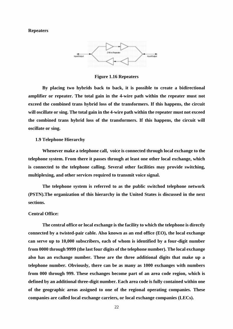
Figure 1.16 Repeaters
By placing two hybrids back to back, it is possible to create a bidirectional
amplifier or repeater. The total gain in the 4-wire path within the repeater must not
exceed the combined trans hybrid loss of the transformers. If this happens, the circuit
will oscillate or sing. The total gain in the 4-wire path within the repeater must not exceed
the combined trans hybrid loss of the transformers. If this happens, the circuit will
oscillate or sing.
1.9 Telephone Hierarchy
Whenever make a telephone call, voice is connected through local exchange to the
telephone system. From there it passes through at least one other local exchange, which
is connected to the telephone calling. Several other facilities may provide switching,
multiplexing, and other services required to transmit voice signal.
The telephone system is referred to as the public switchod telephone network
(PSTN).The organization of this hierarchy in the United States is discussed in the next
sections.
Central Office:
The central office or local exchange is the facility to which the telephone is directly
connected by a twisted-pair cable. Also known as an end office (EO), the local exchange
can serve up to 10,000 subscribers, each of whom is identified by a four-digit number
from 0000 through 9999 (the last four digits of the telephone number). The local exchange
also has an exchange number. These are the three additional digits that make up a
telephone number. Obviously, there can be as many as 1000 exchanges with numbers
from 000 through 999. These exchanges become part of an area code region, which is
defined by an additional three-digit number. Each area code is fully contained within one
of the geographic areas assigned to one of the regional operating companies. These
companies are called local exchange carriers, or local exchange companies (LECs).

23
Operational Relationships:
The LECs provide telephone services to designated geographic areas referred to
as local access and transport areas (LATAs). The United States is divided into
approximately 200 LATAs. The LATAs are defined within the individual states making
up the seven operating regions. The LECs provide the telephone service for the LATAs
within their regions but do not provide long-distance service for the LATAs. Long-
distance service is provided by long-distance carriers known as interexchange carriers
(IXCs). The IXCs are the familiar long-distance carriers, such as AT&T, Verizon and
Sprint. Long-distance carriers must be used for the interconnection for any inter- LATA
connections. The LECs can provide telephone service within the LATAs that are part of
their operating region, but links between LATAs within a region, even though they may
be directly adjacent to one another, must be made through an IXC.
Each LATA contains a serving, or point-of-presence (POP), office that is used to
provide the interconnections to the IXCs. The local exchanges communicate with one
another via individual trunks. And all local exchanges connect to an LEC central offi ce,
which provides trunks to the POP. At the POP, the long-distance carriers can make their
interface connections. The POPs must provide equal access for any long-distance carrier
desiring to connect. Many POPs are connected to multiple IXCs, but in many areas, only
one IXC serves a POP.
Figure summarizes the hierarchy just discussed. Individual telephones within a
LATA connect to the local exchange or central office by way of the two-wire local loop.
The central offices within an LATA are connected to one another by trunks. These trunks
may be standard baseband twisted-pair cables run underground or on telephone poles,
but they may also be coaxial cable, fiber-optic cable, or microwave radio links. In some
areas, two or more central offices are located in the same building or physical facility.
Trunk interconnections are usually made by cables. The local exchanges are also
connected to an LEC central office when a connection cannot be made between two local
exchanges that are not directly trunked. The call passes from the local exchange to the
LEC central office, where the connection is made to the other local exchange. The LEC
central office is also connected to the POP. Depending upon the organization of the LEC
within the LATA, the LEC central office may contain the POP. Note in Figure that the
POP provides the connections to the long-distance carriers, or IXCs. The “cloud”
24
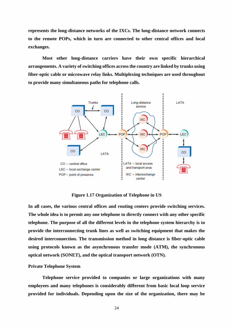
represents the long-distance networks of the IXCs. The long-distance network connects
to the remote POPs, which in turn are connected to other central offices and local
exchanges.
Most other long-distance carriers have their own specific hierarchical
arrangements. A variety of switching offices across the country are linked by trunks using
fiber-optic cable or microwave relay links. Multiplexing techniques are used throughout
to provide many simultaneous paths for telephone calls.
Figure 1.17 Organization of Telephone in US
In all cases, the various central offices and routing centers provide switching services.
The whole idea is to permit any one telephone to directly connect with any other specific
telephone. The purpose of all the different levels in the telephone system hierarchy is to
provide the interconnecting trunk lines as well as switching equipment that makes the
desired interconnection. The transmission method in long distance is fiber-optic cable
using protocols known as the asynchronous transfer mode (ATM), the synchronous
optical network (SONET), and the optical transport network (OTN).
Private Telephone System
Telephone service provided to companies or large organizations with many
employees and many telephones is considerably different from basic local loop service
provided for individuals. Depending upon the size of the organization, there may be
25
dozens, hundreds, or even thousands of telephones required. It is simply not economical
to provide each telephone in the organization with its own separate local loop connection
to the central office. It is also an inefficient use of expensive facilities to use a remote
central office for intercompany communication. For example, an individual in one office
often may need to make an intercompany call to a person in another office, which may be
only a few doors down the hall or a couple of floors away. Making this connection through
the local exchange is wasteful.
This problem is solved by the use of private telephone systems within a company
or organization. Private telephone systems implement telephone service among the
telephones in the organization and provide one or more local loop connections to the
central office. The two basic types of private telephone systems are known as key systems
and private branch exchanges.
Key Systems:
Key systems are small telephone systems designed to serve from 2 to 50 user
telephones within an organization. Commercially available systems usually have
provisions for 6, 10, 12, or 50 telephones. Simple key telephone systems are made up of
the individual telephone units generally referred to as stations, all of which are connected
to a central answering station. The central answering station is connected to one or more
local loop lines known as trunks back to the local exchange. Most systems also contain a
central electronic switching unit that makes all the internal and external connections.
The telephone sets in a key system typically have a group of pushbuttons that allow
each telephone to select two or more outgoing trunking lines. Phone calls are made in the
usual way.
26
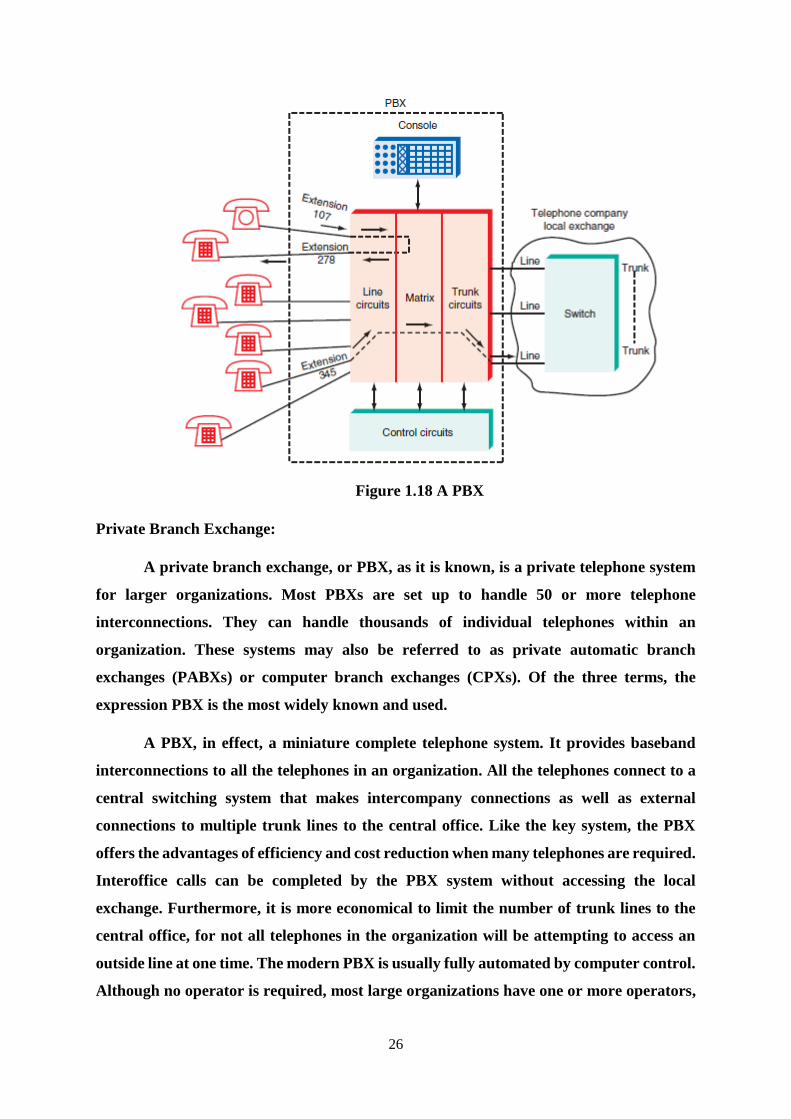
Figure 1.18 A PBX
Private Branch Exchange:
A private branch exchange, or PBX, as it is known, is a private telephone system
for larger organizations. Most PBXs are set up to handle 50 or more telephone
interconnections. They can handle thousands of individual telephones within an
organization. These systems may also be referred to as private automatic branch
exchanges (PABXs) or computer branch exchanges (CPXs). Of the three terms, the
expression PBX is the most widely known and used.
A PBX, in effect, a miniature complete telephone system. It provides baseband
interconnections to all the telephones in an organization. All the telephones connect to a
central switching system that makes intercompany connections as well as external
connections to multiple trunk lines to the central office. Like the key system, the PBX
offers the advantages of efficiency and cost reduction when many telephones are required.
Interoffice calls can be completed by the PBX system without accessing the local
exchange. Furthermore, it is more economical to limit the number of trunk lines to the
central office, for not all telephones in the organization will be attempting to access an
outside line at one time. The modern PBX is usually fully automated by computer control.
Although no operator is required, most large organizations have one or more operators,
27
answer incoming telephone calls and route them appropriately with a control console.
However, some PBXs are automated so that the individual user’s telephone whose
extension is the last four digits of the telephone number can be called directly from
outside.
From the figure, the PBX is made up of line circuits that are similar to the
subscriber line interface circuits discussed earlier. The matrix is the electronic switch that
connects any phone to any other phone in the system. It also permits conference calls. The
trunk circuits interface to the local loop lines to the central office. All the circuits are
under the control of a central computer dedicated to the operation of the PBX.
An alternative to the PBX is known as Centrex. This service, normally provided
by the local telephone company, performs the function of a PBX but uses special
equipment, and most of the switching is carried out by the local exchange switching
equipment over special trunk lines. Its advantage over a standard PBX is that the high
initial cost of PBX equipment can be avoided by leasing the Centrex equipment from the
telephone company.
Electronic Telephones
Today, all new telephones are electronic, and they use integrated circuit
technology. The development of the microprocessor has also affected telephone design.
Although simple electronic telephones do not contain a microprocessor, most multiple-
line and full-feature telephones do. A built-in microprocessor permits automatic control
of the telephone’s functions and provides features such as telephone number storage and
automatic dialing and redialing that are not possible in conventional telephones.
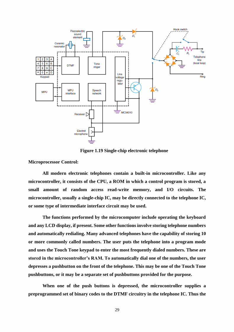
IC Electronic Telephone: The major components of a typical electronic telephone circuit
are shown in Figure. Most of the functions are implemented with circuits contained
within a single IC. In the Figure, note that the Touch Tone keypad drives a DTMF tone
generator circuit. An external crystal or ceramic resonator provides an accurate
frequency reference for generating the dual dialing tones.
The tone ringer is driven by the 20-Hz ringing signal from the phone line and
drives a piezoelectric sound element. The IC also contains a built-in line voltage regulator.
It takes the dc voltage from the local loop and stabilizes it to provide a constant voltage
28
to the internal electronic circuits. An external zener diode and transistor provide bias to
the electret microphone.
The internal speech network contains a number of amplifiers and related circuits
that fully duplicate the function of a hybrid in a standard telephone. This IC also contains
a microcomputer interface. The box labeled MPU is a single-chip microprocessing unit.
Although it is not necessary to use a microprocessor, if automatic dialing and other
functions are implemented, this circuit is capable of accommodating them.
Finally, note the bridge rectifier and hook switch circuit. The twisted pair from
the local loop is connected to the tip and ring. Both the 48-V dc and 20-Hz ring voltages
will be applied to this bridge rectifier. For direct current, the bridge rectifier provides
polarity protection for the circuit, ensuring that the bridge output voltage is always
positive. When the ac ringing voltage is applied, the bridge rectifier it into a pulsating dc
voltage. The hook switch is shown with the telephone on the hook or in the “hung-up”
position. Thus the dc voltage is not connected to the circuit at this time.
However, the ac ringing voltage will be coupled through the resistor and capacitor
to the bridge, where it will be rectified and applied to the two zener diodes D1 and D2
that drive the tone ringer circuit.
When the telephone is taken off the hook, the hook switch closes, providing a dc
path around the resistor and capacitor R1 and C1. The path to the tone ringer is broken,
and the output of the bridge rectifier is connected to zener diode D3 and the line voltage
regulator. Thus the circuits inside the IC are powered up, and calls may be received or
made.
29
Figure 1.19 Single-chip electronic telephone
Microprocessor Control:
All modern electronic telephones contain a built-in microcontroller. Like any
microcontroller, it consists of the CPU, a ROM in which a control program is stored, a
small amount of random access read-write memory, and I/O circuits. The
microcontroller, usually a single-chip IC, may be directly connected to the telephone IC,
or some type of intermediate interface circuit may be used.
The functions performed by the microcomputer include operating the keyboard
and any LCD display, if present. Some other functions involve storing telephone numbers
and automatically redialing. Many advanced telephones have the capability of storing 10
or more commonly called numbers. The user puts the telephone into a program mode
and uses the Touch Tone keypad to enter the most frequently dialed numbers. These are
stored in the microcontroller’s RAM. To automatically dial one of the numbers, the user
depresses a pushbutton on the front of the telephone. This may be one of the Touch Tone
pushbuttons, or it may be a separate set of pushbuttons provided for the purpose.
When one of the push buttons is depressed, the microcontroller supplies a
preprogrammed set of binary codes to the DTMF circuitry in the telephone IC. Thus the
30
number is automatically dialed. Other features implemented by the microcontroller are
caller ID and an answering machine.
Voice Mail. Previously called an answering machine, this feature is implemented
on most electronic phones. The microcontroller automatically answers the call after a
preprogrammed number of rings and saves the voice message. In older answering
machines, the message was recorded on a tape cassette. But in modern phones, the voice
message is digitized, compressed, and then stored in a small l ash ROM ready for replay.
The outgoing message is also stored there.
Caller ID:
Caller ID, also known as the calling line identification service, is a feature that is
now widely implemented on most electronic telephones. With this feature, any calling
number will be displayed on an LCD readout when the phone is ringing. This allows to
identify the caller. The caller ID service sends a digitized version of the calling number to
phone during the first and second rings. The data transmitted includes the date, time, and
calling number. Data is transmitted by FSK, where a binary 1 (mark) is a 1200-Hz tone
and a binary 0 (space) is a 2200-Hz tone. The data rate is 1200 bps.
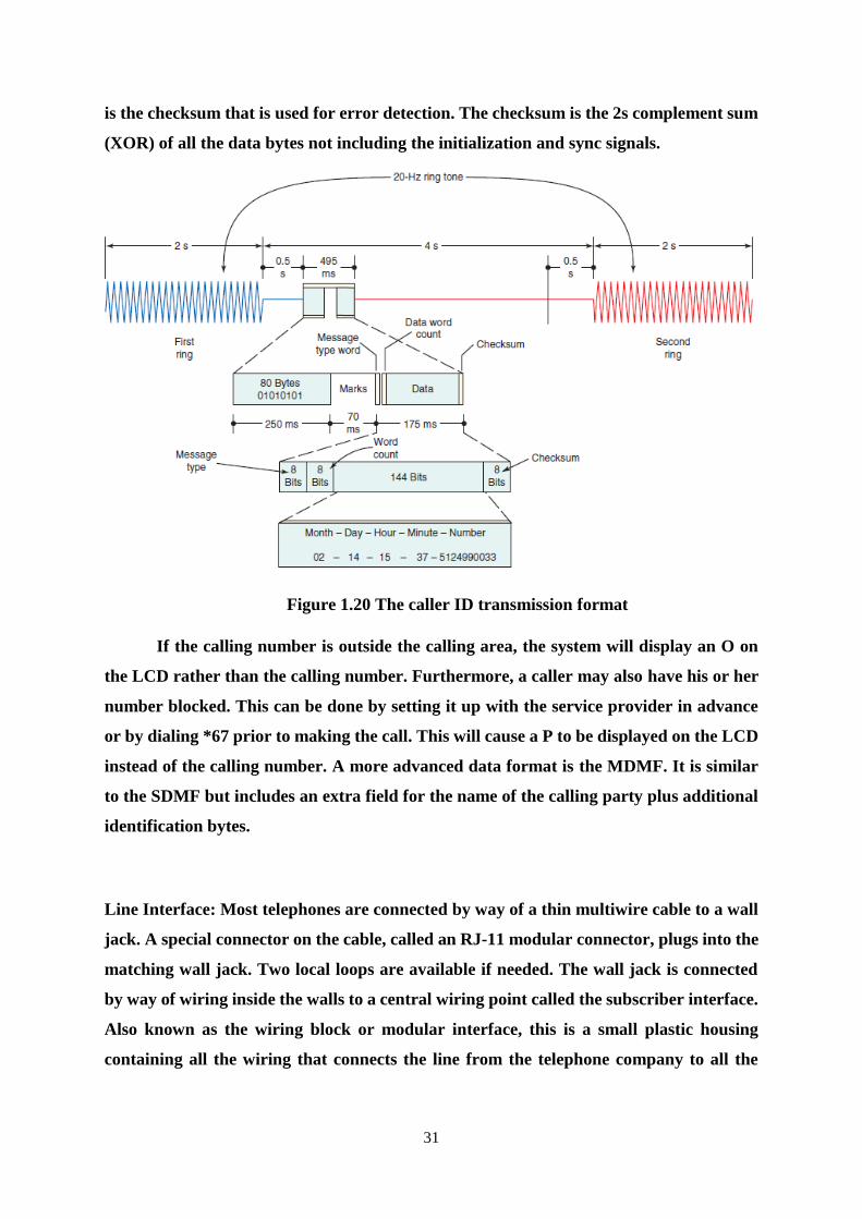
There are two message formats in use, the single-data message format (SDMF)
and the multiple-data message format (MDMF). The SDMF is illustrated in Figure. One-
half second after the first ring, 80 bytes of alternating 0s and 1s (hex 05) is transmitted
for 250 ms followed by 70 ms of mark symbols. These two signals provide initialization
and synchronization of the caller ID circuitry in the phone. This is followed by 1 byte
describing the message type. This is usually a binary 4 (00000100), indicating the SDMF.
This is followed by a byte containing the message length, usually the number of
digits in the calling number. Next the data is transmitted. This is the date, time, and the
10-digit phone number transmitted as ASCII bytes with the least significant digit first.
The data format is 2 digits for the month, 2 digits for the day, 2 digits for the hour
(military time), 2 digits for the minutes, and up to 10 digits for the calling number. For
example, if the date is February 14, the time is 3:37 p.m., and the calling number is 512-
499-0033, the data sequence would be 021415375124990033. The final byte in the message
31
is the checksum that is used for error detection. The checksum is the 2s complement sum
(XOR) of all the data bytes not including the initialization and sync signals.
Figure 1.20 The caller ID transmission format
If the calling number is outside the calling area, the system will display an O on
the LCD rather than the calling number. Furthermore, a caller may also have his or her
number blocked. This can be done by setting it up with the service provider in advance
or by dialing *67 prior to making the call. This will cause a P to be displayed on the LCD
instead of the calling number. A more advanced data format is the MDMF. It is similar
to the SDMF but includes an extra field for the name of the calling party plus additional
identification bytes.
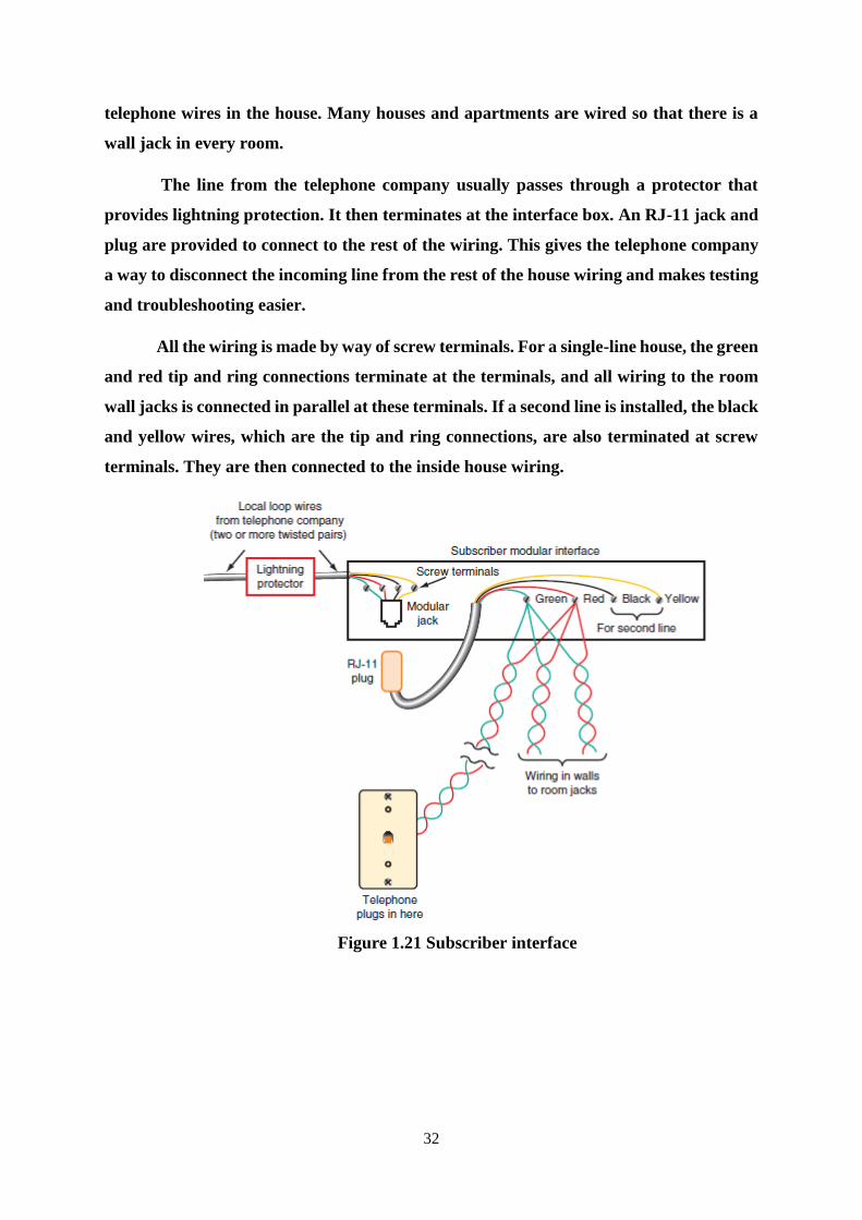
Line Interface: Most telephones are connected by way of a thin multiwire cable to a wall
jack. A special connector on the cable, called an RJ-11 modular connector, plugs into the
matching wall jack. Two local loops are available if needed. The wall jack is connected
by way of wiring inside the walls to a central wiring point called the subscriber interface.
Also known as the wiring block or modular interface, this is a small plastic housing
containing all the wiring that connects the line from the telephone company to all the
32
telephone wires in the house. Many houses and apartments are wired so that there is a
wall jack in every room.
The line from the telephone company usually passes through a protector that
provides lightning protection. It then terminates at the interface box. An RJ-11 jack and
plug are provided to connect to the rest of the wiring. This gives the telephone company
a way to disconnect the incoming line from the rest of the house wiring and makes testing
and troubleshooting easier.
All the wiring is made by way of screw terminals. For a single-line house, the green
and red tip and ring connections terminate at the terminals, and all wiring to the room
wall jacks is connected in parallel at these terminals. If a second line is installed, the black
and yellow wires, which are the tip and ring connections, are also terminated at screw
terminals. They are then connected to the inside house wiring.
Figure 1.21 Subscriber interface
33
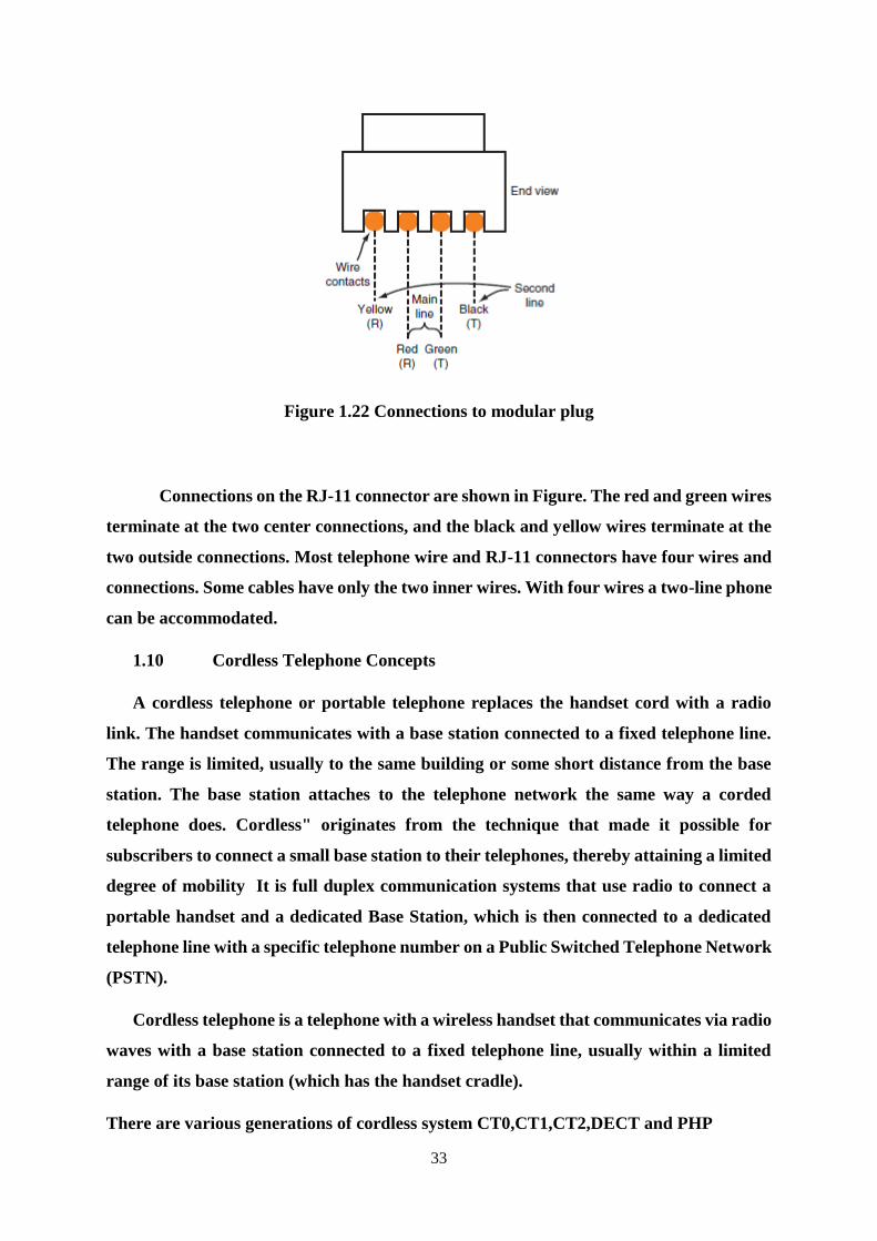
Figure 1.22 Connections to modular plug
Connections on the RJ-11 connector are shown in Figure. The red and green wires
terminate at the two center connections, and the black and yellow wires terminate at the
two outside connections. Most telephone wire and RJ-11 connectors have four wires and
connections. Some cables have only the two inner wires. With four wires a two-line phone
can be accommodated.
1.10 Cordless Telephone Concepts
A cordless telephone or portable telephone replaces the handset cord with a radio
link. The handset communicates with a base station connected to a fixed telephone line.
The range is limited, usually to the same building or some short distance from the base
station. The base station attaches to the telephone network the same way a corded
telephone does. Cordless" originates from the technique that made it possible for
subscribers to connect a small base station to their telephones, thereby attaining a limited
degree of mobility It is full duplex communication systems that use radio to connect a
portable handset and a dedicated Base Station, which is then connected to a dedicated
telephone line with a specific telephone number on a Public Switched Telephone Network
(PSTN).
Cordless telephone is a telephone with a wireless handset that communicates via radio
waves with a base station connected to a fixed telephone line, usually within a limited
range of its base station (which has the handset cradle).
There are various generations of cordless system CT0,CT1,CT2,DECT and PHP
34
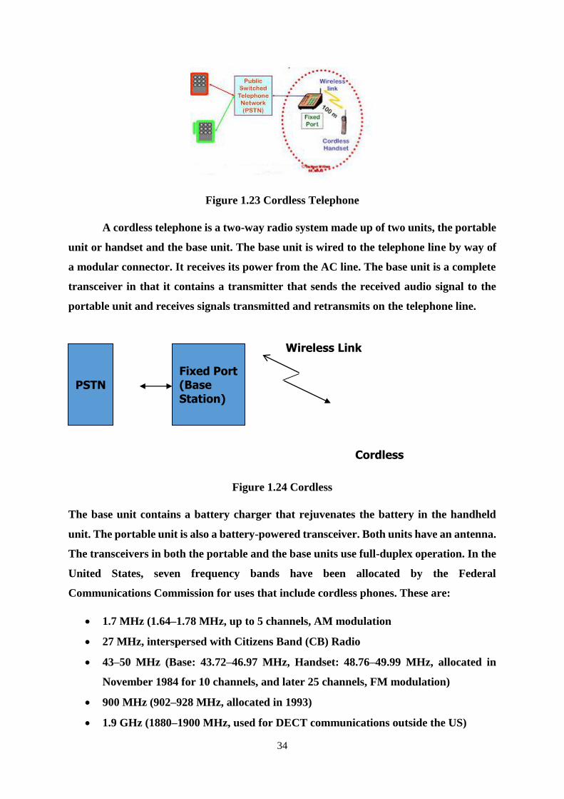
Figure 1.23 Cordless Telephone
A cordless telephone is a two-way radio system made up of two units, the portable
unit or handset and the base unit. The base unit is wired to the telephone line by way of
a modular connector. It receives its power from the AC line. The base unit is a complete
transceiver in that it contains a transmitter that sends the received audio signal to the
portable unit and receives signals transmitted and retransmits on the telephone line.
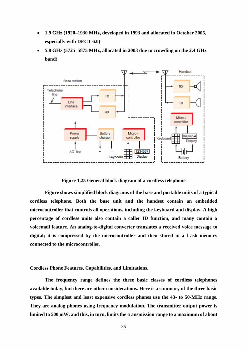
Figure 1.24 Cordless
The base unit contains a battery charger that rejuvenates the battery in the handheld
unit. The portable unit is also a battery-powered transceiver. Both units have an antenna.
The transceivers in both the portable and the base units use full-duplex operation. In the
United States, seven frequency bands have been allocated by the Federal
Communications Commission for uses that include cordless phones. These are:
1.7 MHz (1.64–1.78 MHz, up to 5 channels, AM modulation
27 MHz, interspersed with Citizens Band (CB) Radio
43–50 MHz (Base: 43.72–46.97 MHz, Handset: 48.76–49.99 MHz, allocated in
November 1984 for 10 channels, and later 25 channels, FM modulation)
900 MHz (902–928 MHz, allocated in 1993)
1.9 GHz (1880–1900 MHz, used for DECT communications outside the US)
Fixed Port (Base
Station)
PSTN
Wireless Link
Cordless Handset
35
1.9 GHz (1920–1930 MHz, developed in 1993 and allocated in October 2005,
especially with DECT 6.0)
5.8 GHz (5725–5875 MHz, allocated in 2003 due to crowding on the 2.4 GHz
band)
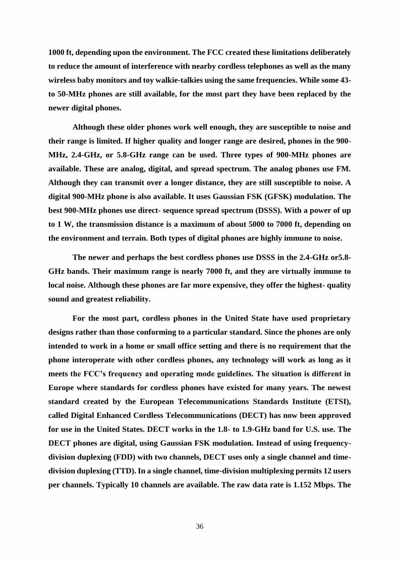
Figure 1.25 General block diagram of a cordless telephone
Figure shows simplified block diagrams of the base and portable units of a typical
cordless telephone. Both the base unit and the handset contain an embedded
microcontroller that controls all operations, including the keyboard and display. A high
percentage of cordless units also contain a caller ID function, and many contain a
voicemail feature. An analog-to-digital converter translates a received voice message to
digital; it is compressed by the microcontroller and then stored in a l ash memory
connected to the microcontroller.
Cordless Phone Features, Capabilities, and Limitations.
The frequency range defines the three basic classes of cordless telephones
available today, but there are other considerations. Here is a summary of the three basic
types. The simplest and least expensive cordless phones use the 43- to 50-MHz range.
They are analog phones using frequency modulation. The transmitter output power is
limited to 500 mW, and this, in turn, limits the transmission range to a maximum of about
36
1000 ft, depending upon the environment. The FCC created these limitations deliberately
to reduce the amount of interference with nearby cordless telephones as well as the many
wireless baby monitors and toy walkie-talkies using the same frequencies. While some 43-
to 50-MHz phones are still available, for the most part they have been replaced by the
newer digital phones.
Although these older phones work well enough, they are susceptible to noise and
their range is limited. If higher quality and longer range are desired, phones in the 900-
MHz, 2.4-GHz, or 5.8-GHz range can be used. Three types of 900-MHz phones are
available. These are analog, digital, and spread spectrum. The analog phones use FM.
Although they can transmit over a longer distance, they are still susceptible to noise. A
digital 900-MHz phone is also available. It uses Gaussian FSK (GFSK) modulation. The
best 900-MHz phones use direct- sequence spread spectrum (DSSS). With a power of up
to 1 W, the transmission distance is a maximum of about 5000 to 7000 ft, depending on
the environment and terrain. Both types of digital phones are highly immune to noise.
The newer and perhaps the best cordless phones use DSSS in the 2.4-GHz or5.8-
GHz bands. Their maximum range is nearly 7000 ft, and they are virtually immune to
local noise. Although these phones are far more expensive, they offer the highest- quality
sound and greatest reliability.
For the most part, cordless phones in the United State have used proprietary
designs rather than those conforming to a particular standard. Since the phones are only
intended to work in a home or small office setting and there is no requirement that the
phone interoperate with other cordless phones, any technology will work as long as it
meets the FCC’s frequency and operating mode guidelines. The situation is different in
Europe where standards for cordless phones have existed for many years. The newest
standard created by the European Telecommunications Standards Institute (ETSI),
called Digital Enhanced Cordless Telecommunications (DECT) has now been approved
for use in the United States. DECT works in the 1.8- to 1.9-GHz band for U.S. use. The
DECT phones are digital, using Gaussian FSK modulation. Instead of using frequency-
division duplexing (FDD) with two channels, DECT uses only a single channel and time-
division duplexing (TTD). In a single channel, time-division multiplexing permits 12 users
per channels. Typically 10 channels are available. The raw data rate is 1.152 Mbps. The

37
latest version of the DECT phone is 6.0, and these phones are available in the United
States.
Facsimile Machine
It scans the contents of a document (as an image, not text) to create electronic
signals. Scanning is done electronically and the scanned signal is converted into a binary
signal. These signals are then sent to the destination (another FAX machine) in an orderly
manner using telephone lines. At the destination, the signals are reconverted into a replica
of the original document. Note that FAX provides image of a static document unlike the
image provided by television of objects that might be dynamic. Today's modern fax
machine is a high-tech electro- optical machine. Digital transmission with standard
modem techniques is used.
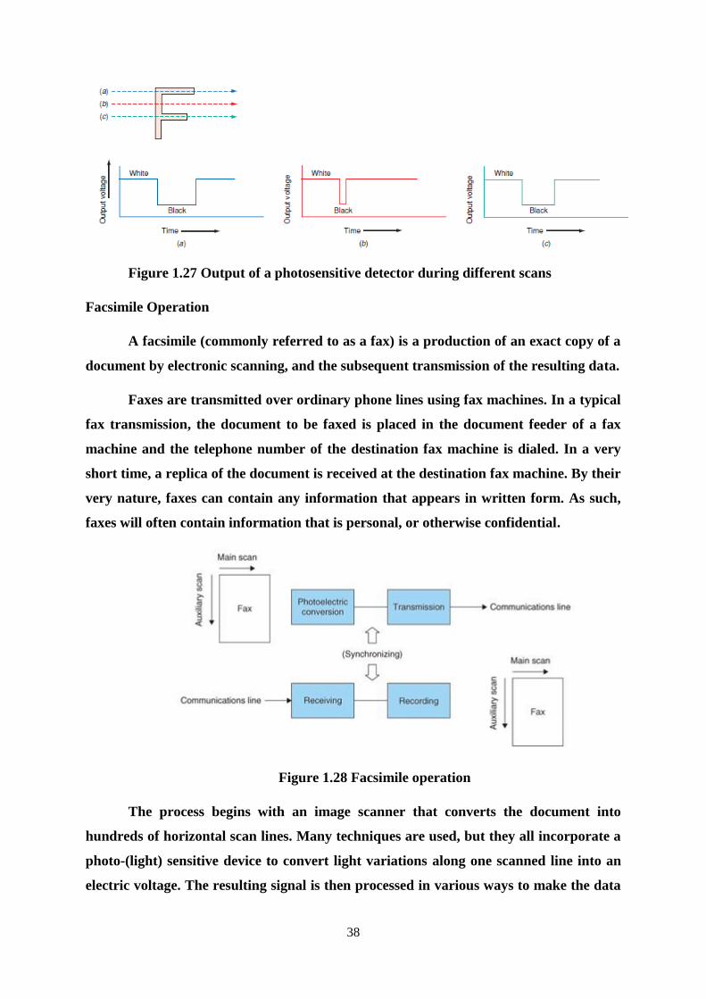
Figure 1.26 Components of a facsimile system
Figure shows how a printed letter might have been scanned. Assume that the letter
F is black on a white background. The output of a photodetector as it scans across line a
is shown in Fig. (a). The output voltage is high for white and low for black. The output
of the photodetector is also shown for scan lines b and c. The output of the photodetector
is used to modulate a carrier, and the resulting signal is put on the telephone line. The
resolution of the transmission is determined by the number of scan lines per vertical inch.
The greater the number of lines scanned, the higher the detail transmitted and the higher
the quality of reproduction. Older systems had a resolution of 96 lines per inch (LPI), and
the new systems have 200 LPI.
38
Figure 1.27 Output of a photosensitive detector during different scans
Facsimile Operation
A facsimile (commonly referred to as a fax) is a production of an exact copy of a
document by electronic scanning, and the subsequent transmission of the resulting data.
Faxes are transmitted over ordinary phone lines using fax machines. In a typical
fax transmission, the document to be faxed is placed in the document feeder of a fax
machine and the telephone number of the destination fax machine is dialed. In a very
short time, a replica of the document is received at the destination fax machine. By their
very nature, faxes can contain any information that appears in written form. As such,
faxes will often contain information that is personal, or otherwise confidential.
Figure 1.28 Facsimile operation
The process begins with an image scanner that converts the document into
hundreds of horizontal scan lines. Many techniques are used, but they all incorporate a
photo-(light) sensitive device to convert light variations along one scanned line into an
electric voltage. The resulting signal is then processed in various ways to make the data
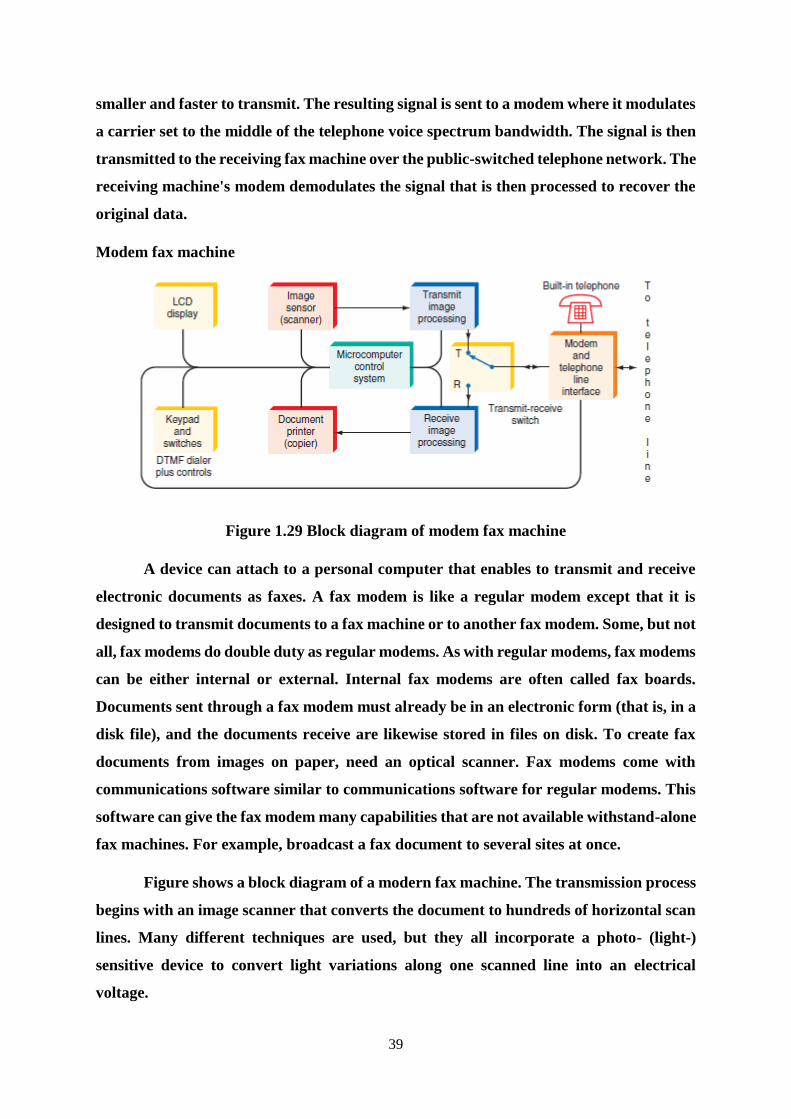
39
smaller and faster to transmit. The resulting signal is sent to a modem where it modulates
a carrier set to the middle of the telephone voice spectrum bandwidth. The signal is then
transmitted to the receiving fax machine over the public-switched telephone network. The
receiving machine's modem demodulates the signal that is then processed to recover the
original data.
Modem fax machine
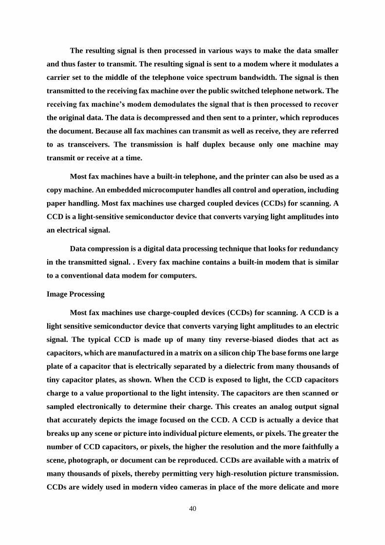
Figure 1.29 Block diagram of modem fax machine
A device can attach to a personal computer that enables to transmit and receive
electronic documents as faxes. A fax modem is like a regular modem except that it is
designed to transmit documents to a fax machine or to another fax modem. Some, but not
all, fax modems do double duty as regular modems. As with regular modems, fax modems
can be either internal or external. Internal fax modems are often called fax boards.
Documents sent through a fax modem must already be in an electronic form (that is, in a
disk file), and the documents receive are likewise stored in files on disk. To create fax
documents from images on paper, need an optical scanner. Fax modems come with
communications software similar to communications software for regular modems. This
software can give the fax modem many capabilities that are not available withstand-alone
fax machines. For example, broadcast a fax document to several sites at once.
Figure shows a block diagram of a modern fax machine. The transmission process
begins with an image scanner that converts the document to hundreds of horizontal scan
lines. Many different techniques are used, but they all incorporate a photo- (light-)
sensitive device to convert light variations along one scanned line into an electrical
voltage.
40
The resulting signal is then processed in various ways to make the data smaller
and thus faster to transmit. The resulting signal is sent to a modem where it modulates a
carrier set to the middle of the telephone voice spectrum bandwidth. The signal is then
transmitted to the receiving fax machine over the public switched telephone network. The
receiving fax machine’s modem demodulates the signal that is then processed to recover
the original data. The data is decompressed and then sent to a printer, which reproduces
the document. Because all fax machines can transmit as well as receive, they are referred
to as transceivers. The transmission is half duplex because only one machine may
transmit or receive at a time.
Most fax machines have a built-in telephone, and the printer can also be used as a
copy machine. An embedded microcomputer handles all control and operation, including
paper handling. Most fax machines use charged coupled devices (CCDs) for scanning. A
CCD is a light-sensitive semiconductor device that converts varying light amplitudes into
an electrical signal.
Data compression is a digital data processing technique that looks for redundancy
in the transmitted signal. . Every fax machine contains a built-in modem that is similar
to a conventional data modem for computers.
Image Processing
Most fax machines use charge-coupled devices (CCDs) for scanning. A CCD is a
light sensitive semiconductor device that converts varying light amplitudes to an electric
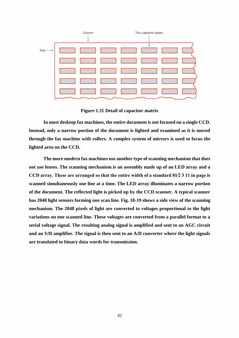
signal. The typical CCD is made up of many tiny reverse-biased diodes that act as
capacitors, which are manufactured in a matrix on a silicon chip The base forms one large
plate of a capacitor that is electrically separated by a dielectric from many thousands of
tiny capacitor plates, as shown. When the CCD is exposed to light, the CCD capacitors
charge to a value proportional to the light intensity. The capacitors are then scanned or
sampled electronically to determine their charge. This creates an analog output signal
that accurately depicts the image focused on the CCD. A CCD is actually a device that
breaks up any scene or picture into individual picture elements, or pixels. The greater the
number of CCD capacitors, or pixels, the higher the resolution and the more faithfully a
scene, photograph, or document can be reproduced. CCDs are available with a matrix of
many thousands of pixels, thereby permitting very high-resolution picture transmission.
CCDs are widely used in modern video cameras in place of the more delicate and more

41
expensive vidicon tubes. In the video camera (camcorder), the lens focuses the entire scene
on a CCD matrix. This same approach is used in some fax machines. In one type of fax
machine, the document to be transmitted is placed face down as it might be in a copy
machine. The document is then illuminated with brilliant light from a xenon or
fluorescent bulb. A lens system focuses the reflected light on a CCD. The CCD is then
scanned, and the resulting output is an analog signal whose amplitude is proportional to
the amplitude of the reflected light.
Figure 1.30 A charge-coupled device is used to scan documents in modern fax machines-
Cross section
42
Figure 1.31 Detail of capacitor matrix
In most desktop fax machines, the entire document is not focused on a single CCD.
Instead, only a narrow portion of the document is lighted and examined as it is moved
through the fax machine with rollers. A complex system of mirrors is used to focus the
lighted area on the CCD.
The more modern fax machines use another type of scanning mechanism that does
not use lenses. The scanning mechanism is an assembly made up of an LED array and a
CCD array. These are arranged so that the entire width of a standard 81⁄2 3 11 in page is
scanned simultaneously one line at a time. The LED array illuminates a narrow portion
of the document. The reflected light is picked up by the CCD scanner. A typical scanner
has 2048 light sensors forming one scan line. Fig. 18-19 shows a side view of the scanning
mechanism. The 2048 pixels of light are converted to voltages proportional to the light
variations on one scanned line. These voltages are converted from a parallel format to a
serial voltage signal. The resulting analog signal is amplified and sent to an AGC circuit
and an S/H amplifier. The signal is then sent to an A/D converter where the light signals
are translated to binary data words for transmission.

43
Figure 1.32 Scanning mechanism in a fax machine
Figure 1.33 LED/CCD scanner mechanism in a modern fax machine
44
1.11 Data Compression
An enormous amount of data is generated by scanning one page of a document. A
typical 81⁄2 3 11 in page represents about 40,000 bytes of data. This can be shortened by
a factor of 10 or more with data compression techniques. Furthermore, because of the
narrow bandwidth of telephone lines, data rates are limited. That is why it takes so long
to transmit one page of data. Developments in high-speed modems have helped reduce
the transmission time, but the most important developments are data compression
techniques that reduce the overall amount of data, which significantly decreases the
transmission time and telephone charges.
Data compression is a digital data processing technique that looks for redundancy
in the transmitted signal. White space or continuous segments of the page that are the
same shade produce continuous strings of data words that are the same. These can be
eliminated and transmitted as a special digital code that is significantly faster to transmit.
Other forms of data compression use various mathematical algorithms to reduce the
amount of data to be transmitted.
The data compression is carried out by a digital signal processing (DSP) chip. This
is a high-speed microprocessor with embedded ROM containing the compression
program. The digital data from the A/D converter is passed through the DSP chip, from
which comes a significantly shorter string of data that represents the scanned image. This
is what is transmitted, and in far less time than the original data could be transmitted. At
the receiving end, the demodulated signal is decompressed. Again, this is done through a
DSP chip especially programmed for this function. The original data signal is recovered
and sent to the printer.
Modems
Every fax machine contains a built-in modem that is similar to a conventional data
modem for computers. These modems are optimized for fax transmission and reception.
And they follow international standards so that any fax machine can communicate with
any other fax machine. A number of different modulation schemes are used in fax
systems. Analog fax systems use AM or FM.
Digital fax uses PSK or QAM. To ensure compatibility between fax machines of
different manufacturers, facsimile standards have been developed for speed, modulation
45
methods, and resolution by the International Telegraph and Telephone Consultative
Committee, better known by its French abbreviation, CCITT. The CCITT is now known
as the ITU-T, or International Telecommunications Union. The ITU-T fax standards are
divided into four groups:
1. Group 1 (G1 or GI): Analog transmission using frequency modulation where
white is 1300 Hz and black is 2100 Hz. Most North American equipment uses 1500 Hz for
white and 2300 Hz for black. The scanning resolution is 96 lines per inch (LPI). Average
transmission speed is 6 minutes per page (81⁄2 3 11 in or A4 metric size, which is slightly
longer than 11 in).
2. Group 2 (G2 or GII): Analog transmission using FM or vestigial sideband AM.
The vestigial sideband AM uses a 2100-Hz carrier. The lower sideband and part of the
upper sideband are transmitted. Resolution is 96 LPI. Transmission speed is 3 min or less
for an 81⁄2 3 11 in or A4 page.
3. Group 3 (G3 or GIII): Digital transmission using PCM black and white only or
upto 32 shades of gray. PSK or QAM to achieve transmission speeds of up to 9600 Bd.
Resolution’s 200 LPI. Transmission speed is less than 1 minute per page, with 15 to 30 s
being typical.
4. Group 4 (G4 or GIV): Digital transmission, 56 kbps, resolution up to 400 LPI,
and speed of transmission less than 5 s. The older G1 and G2 machines are no longer
used. The most common configuration is group 3. Most G3 machines can also read the
G2 format.
The G4 machines are not yet widely used. They are designed to use digital
transmission only with no modem over very wideband dedicated digital-grade telephone
lines. Both G3 and G4 formats also employ digital data compression methods that shorten
the binary data stream considerably, thereby speeding up page transmission. This is
important because shorter transmission times cut long-distance telephone charges and
reduce operating costs.
Fax Machine Operation
Figure shows simplified block diagram of the transmitting circuits in a modern
G3 fax transceiver. The analog output from the CCD array is serialized and fed to an A/D
converter that translates the continuously varying light intensity into a stream of binary
46
numbers. Sixteen gray scale values between white and black are typical. The binary data
is sent to a DSP digital data compression circuit as described earlier. The binary output
in serial data format is used to modulate a carrier that is transmitted over the telephone
lines. The techniques are similar to those employed in modems. Speeds of 2400/4800 and
7200/9600 Bd are common.
Most systems use some form of PSK or QAM to achieve very high data rates on
voice-grade lines. In the receiving portion of the fax machine, the received signal is
demodulated and then sent to DSP circuits, where the data compression is removed and
the binary signals are restored to their original form. The signal is then applied to a
printing mechanism. The most common fax printer today is an ink jet printer like those
popularly used with PCs. In the high-priced machines, laser scanning of an
electrosensitive drum, similar to the drum used in laser printers, produces output copies
by using the proven techniques of xerography. The control logic in Figure is usually an
embedded microcomputer.
Besides all the internal control functions it implements, it is used for
“handshaking” between the two machines that will communicate. This ensures
compatibility. Handshaking is usually carried out by exchanging different audio tones.
The called machine responds with tones designating its capability. The calling machine
compares this to its own standards and then either initiates the transmission or terminates
it because of incompatibility. If the transmission proceeds, the calling machine sends
synchronizing signals to ensure that both machines start at the same time.
The called machine acknowledges the receipt of the sync signal, and transmission
begins. All the protocols for establishing communication and sending and receiving the
data are standardized by the ITU-T. Transmission is half duplex. As improvements have
been made in picture resolution quality, transmission speed, and cost, facsimile machines
have become much more popular. The units can be easily attached with standard RJ-11
modular connectors to any telephone system. In most business applications, the fax
machine is typically dedicated to a single line. Most fax machines feature fully automatic
operation with microprocessor-based control. A document can be sent to a fax machine
automatically. The sending machine simply dials the receiving machine and initiates the
transmission. The receiving machine answers the initial call and then reproduces the
document before hanging up.
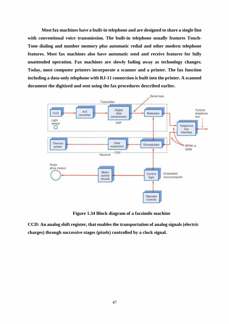
47
Most fax machines have a built-in telephone and are designed to share a single line
with conventional voice transmission. The built-in telephone usually features Touch-
Tone dialing and number memory plus automatic redial and other modern telephone
features. Most fax machines also have automatic send and receive features for fully
unattended operation. Fax machines are slowly fading away as technology changes.
Today, most computer printers incorporate a scanner and a printer. The fax function
including a data-only telephone with RJ-11 connection is built into the printer. A scanned
document the digitized and sent using the fax procedures described earlier.
Figure 1.34 Block diagram of a facsimile machine
CCD: An analog shift register, that enables the transportation of analog signals (electric
charges) through successive stages (pixels) controlled by a clock signal.
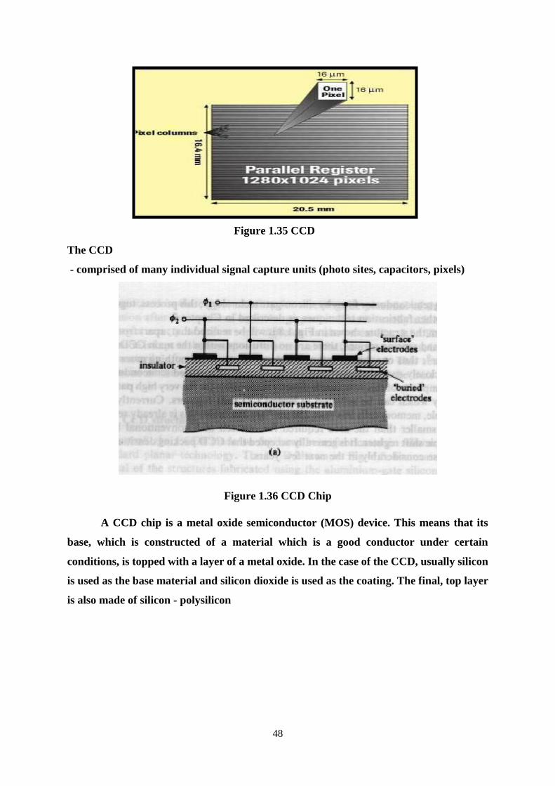
48
Figure 1.35 CCD
The CCD
- comprised of many individual signal capture units (photo sites, capacitors, pixels)
Figure 1.36 CCD Chip
A CCD chip is a metal oxide semiconductor (MOS) device. This means that its
base, which is constructed of a material which is a good conductor under certain
conditions, is topped with a layer of a metal oxide. In the case of the CCD, usually silicon
is used as the base material and silicon dioxide is used as the coating. The final, top layer
is also made of silicon - polysilicon
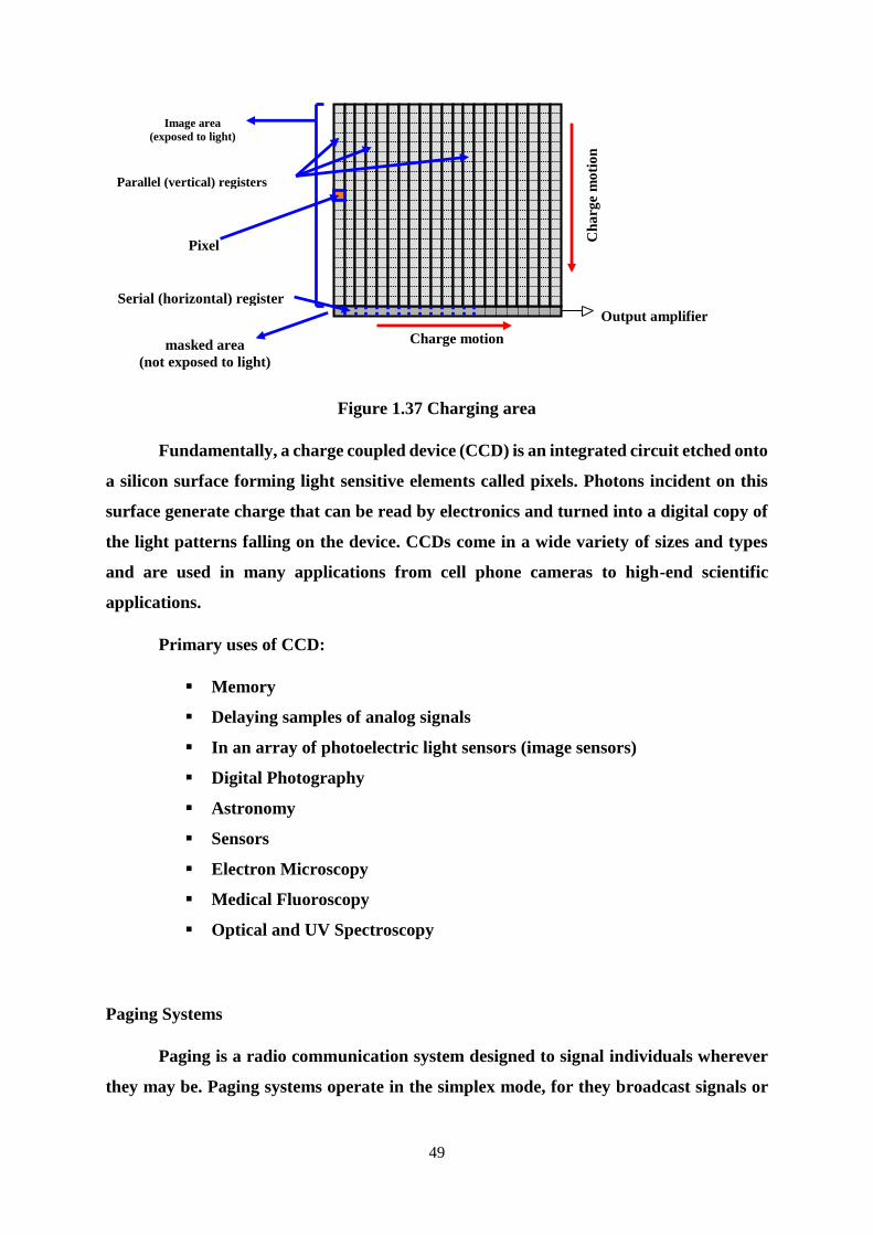
49
Figure 1.37 Charging area
Fundamentally, a charge coupled device (CCD) is an integrated circuit etched onto
a silicon surface forming light sensitive elements called pixels. Photons incident on this
surface generate charge that can be read by electronics and turned into a digital copy of
the light patterns falling on the device. CCDs come in a wide variety of sizes and types
and are used in many applications from cell phone cameras to high-end scientific
applications.
Primary uses of CCD:
Memory
Delaying samples of analog signals
In an array of photoelectric light sensors (image sensors)
Digital Photography
Astronomy
Sensors
Electron Microscopy
Medical Fluoroscopy
Optical and UV Spectroscopy
Paging Systems
Paging is a radio communication system designed to signal individuals wherever
they may be. Paging systems operate in the simplex mode, for they broadcast signals or
Charge motion
Ch
arg
e m
oti
on
Serial (horizontal) register
Parallel (vertical) registers
Pixel
Image area
(exposed to light)
Output amplifier
masked area
(not exposed to light)
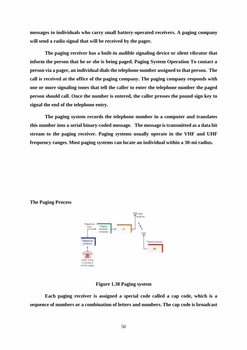
50
messages to individuals who carry small battery-operated receivers. A paging company
will send a radio signal that will be received by the pager.
The paging receiver has a built-in audible signaling device or silent vibrator that
inform the person that he or she is being paged. Paging System Operation To contact a
person via a pager, an individual dials the telephone number assigned to that person. The
call is received at the office of the paging company. The paging company responds with
one or more signaling tones that tell the caller to enter the telephone number the paged
person should call. Once the number is entered, the caller presses the pound sign key to
signal the end of the telephone entry.
The paging system records the telephone number in a computer and translates
this number into a serial binary-coded message. The message is transmitted as a data bit
stream to the paging receiver. Paging systems usually operate in the VHF and UHF
frequency ranges. Most paging systems can locate an individual within a 30-mi radius.
The Paging Process
Figure 1.38 Paging system
Each paging receiver is assigned a special code called a cap code, which is a
sequence of numbers or a combination of letters and numbers. The cap code is broadcast
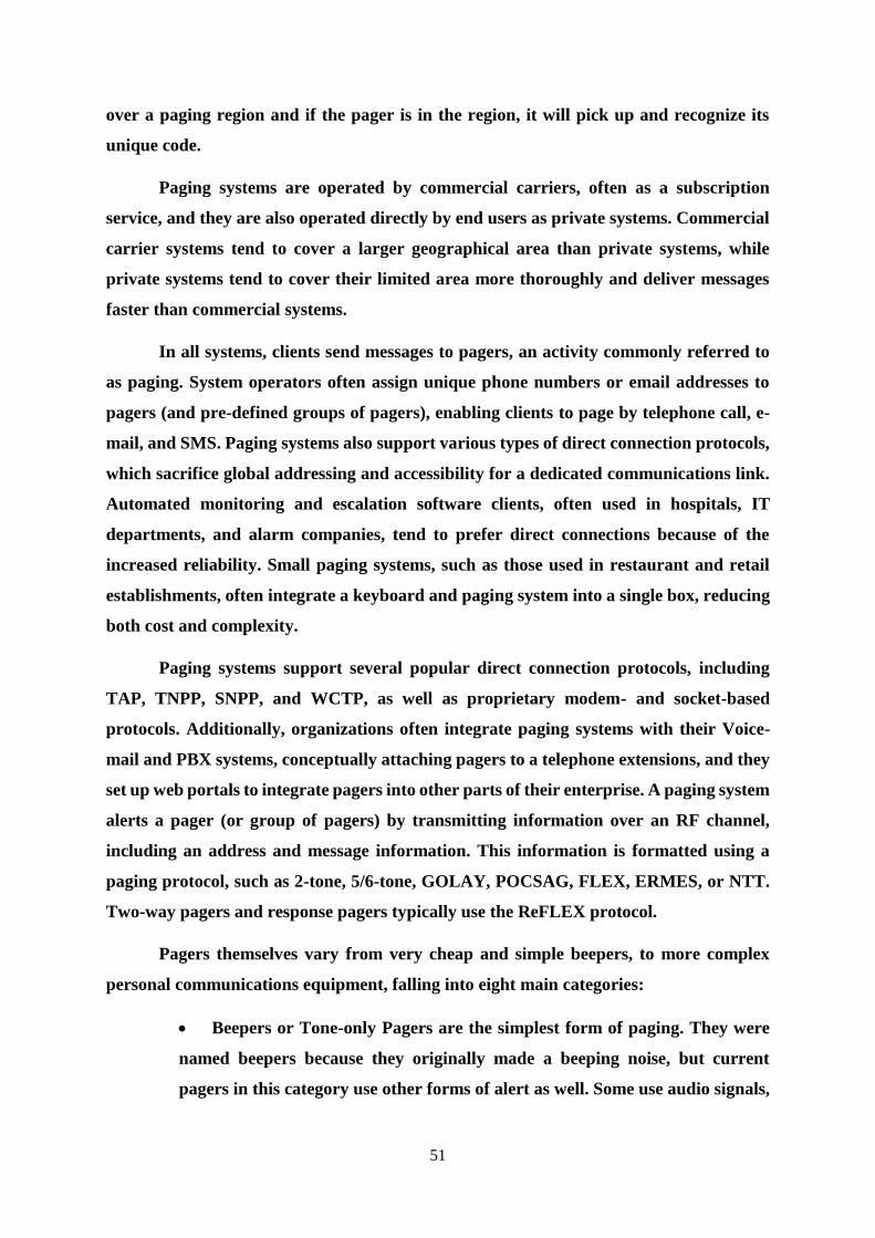
51
over a paging region and if the pager is in the region, it will pick up and recognize its
unique code.
Paging systems are operated by commercial carriers, often as a subscription
service, and they are also operated directly by end users as private systems. Commercial
carrier systems tend to cover a larger geographical area than private systems, while
private systems tend to cover their limited area more thoroughly and deliver messages
faster than commercial systems.
In all systems, clients send messages to pagers, an activity commonly referred to
as paging. System operators often assign unique phone numbers or email addresses to
pagers (and pre-defined groups of pagers), enabling clients to page by telephone call, e-
mail, and SMS. Paging systems also support various types of direct connection protocols,
which sacrifice global addressing and accessibility for a dedicated communications link.
Automated monitoring and escalation software clients, often used in hospitals, IT
departments, and alarm companies, tend to prefer direct connections because of the
increased reliability. Small paging systems, such as those used in restaurant and retail
establishments, often integrate a keyboard and paging system into a single box, reducing
both cost and complexity.
Paging systems support several popular direct connection protocols, including
TAP, TNPP, SNPP, and WCTP, as well as proprietary modem- and socket-based
protocols. Additionally, organizations often integrate paging systems with their Voice-
mail and PBX systems, conceptually attaching pagers to a telephone extensions, and they
set up web portals to integrate pagers into other parts of their enterprise. A paging system
alerts a pager (or group of pagers) by transmitting information over an RF channel,
including an address and message information. This information is formatted using a
paging protocol, such as 2-tone, 5/6-tone, GOLAY, POCSAG, FLEX, ERMES, or NTT.
Two-way pagers and response pagers typically use the ReFLEX protocol.
Pagers themselves vary from very cheap and simple beepers, to more complex
personal communications equipment, falling into eight main categories:
Beepers or Tone-only Pagers are the simplest form of paging. They were
named beepers because they originally made a beeping noise, but current
pagers in this category use other forms of alert as well. Some use audio signals,
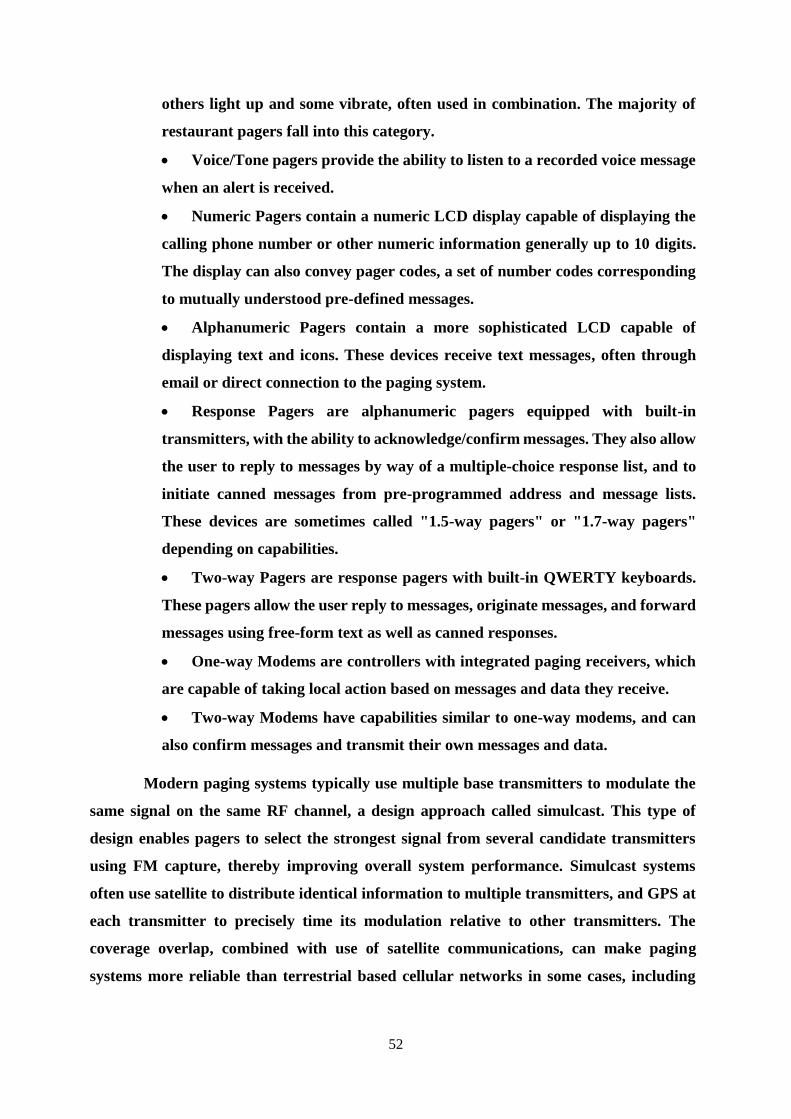
52
others light up and some vibrate, often used in combination. The majority of
restaurant pagers fall into this category.
Voice/Tone pagers provide the ability to listen to a recorded voice message
when an alert is received.
Numeric Pagers contain a numeric LCD display capable of displaying the
calling phone number or other numeric information generally up to 10 digits.
The display can also convey pager codes, a set of number codes corresponding
to mutually understood pre-defined messages.
Alphanumeric Pagers contain a more sophisticated LCD capable of
displaying text and icons. These devices receive text messages, often through
email or direct connection to the paging system.
Response Pagers are alphanumeric pagers equipped with built-in
transmitters, with the ability to acknowledge/confirm messages. They also allow
the user to reply to messages by way of a multiple-choice response list, and to
initiate canned messages from pre-programmed address and message lists.
These devices are sometimes called "1.5-way pagers" or "1.7-way pagers"
depending on capabilities.
Two-way Pagers are response pagers with built-in QWERTY keyboards.
These pagers allow the user reply to messages, originate messages, and forward
messages using free-form text as well as canned responses.
One-way Modems are controllers with integrated paging receivers, which
are capable of taking local action based on messages and data they receive.
Two-way Modems have capabilities similar to one-way modems, and can
also confirm messages and transmit their own messages and data.
Modern paging systems typically use multiple base transmitters to modulate the
same signal on the same RF channel, a design approach called simulcast. This type of
design enables pagers to select the strongest signal from several candidate transmitters
using FM capture, thereby improving overall system performance. Simulcast systems
often use satellite to distribute identical information to multiple transmitters, and GPS at
each transmitter to precisely time its modulation relative to other transmitters. The
coverage overlap, combined with use of satellite communications, can make paging
systems more reliable than terrestrial based cellular networks in some cases, including
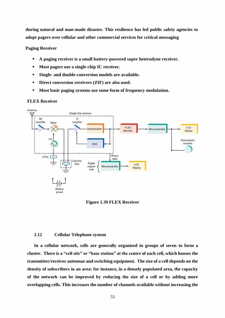
53
during natural and man-made disaster. This resilience has led public safety agencies to
adopt pagers over cellular and other commercial services for critical messaging
Paging Receiver
A paging receiver is a small battery-powered super heterodyne receiver.
Most pagers use a single-chip IC receiver.
Single- and double-conversion models are available.
Direct conversion receivers (ZIF) are also used.
Most basic paging systems use some form of frequency modulation.
FLEX Receiver
Figure 1.39 FLEX Receiver
1.12 Cellular Telephone system
In a cellular network, cells are generally organized in groups of seven to form a
cluster. There is a “cell site” or “base station” at the centre of each cell, which houses the
transmitter/receiver antennae and switching equipment. The size of a cell depends on the
density of subscribers in an area: for instance, in a densely populated area, the capacity
of the network can be improved by reducing the size of a cell or by adding more
overlapping cells. This increases the number of channels available without increasing the
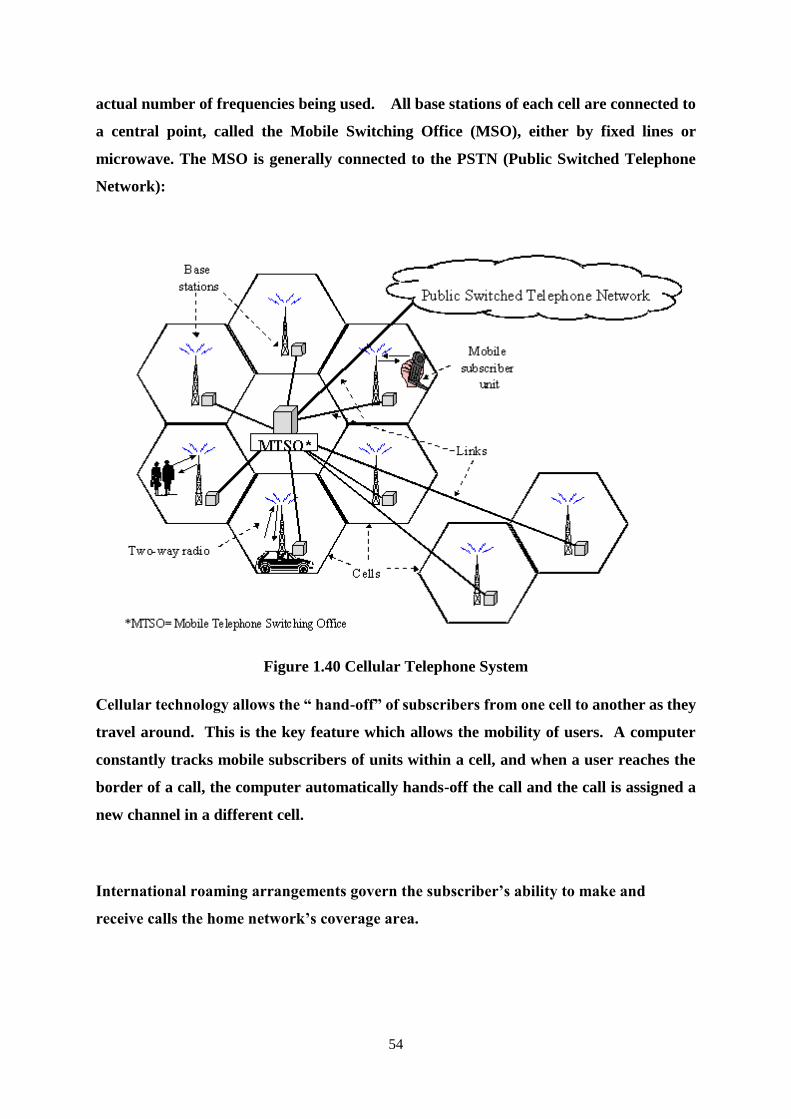
54
actual number of frequencies being used. All base stations of each cell are connected to
a central point, called the Mobile Switching Office (MSO), either by fixed lines or
microwave. The MSO is generally connected to the PSTN (Public Switched Telephone
Network):
Figure 1.40 Cellular Telephone System
Cellular technology allows the “ hand-off” of subscribers from one cell to another as they
travel around. This is the key feature which allows the mobility of users. A computer
constantly tracks mobile subscribers of units within a cell, and when a user reaches the
border of a call, the computer automatically hands-off the call and the call is assigned a
new channel in a different cell.
International roaming arrangements govern the subscriber’s ability to make and
receive calls the home network’s coverage area.
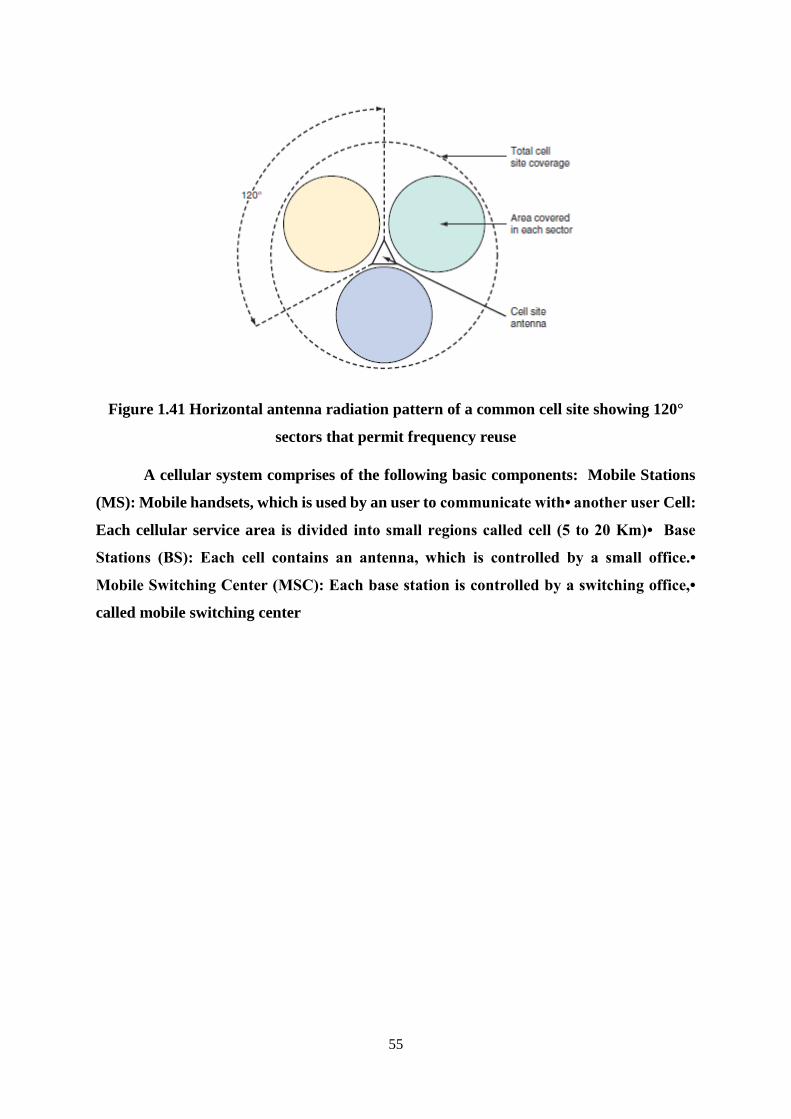
55
Figure 1.41 Horizontal antenna radiation pattern of a common cell site showing 120°
sectors that permit frequency reuse
A cellular system comprises of the following basic components: Mobile Stations
(MS): Mobile handsets, which is used by an user to communicate with• another user Cell:
Each cellular service area is divided into small regions called cell (5 to 20 Km)• Base
Stations (BS): Each cell contains an antenna, which is controlled by a small office.•
Mobile Switching Center (MSC): Each base station is controlled by a switching office,•
called mobile switching center
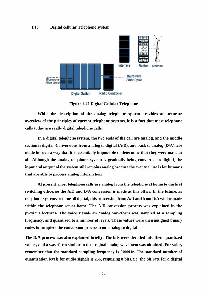
56
1.13 Digital cellular Telephone system
Figure 1.42 Digital Cellular Telephone
While the description of the analog telephone system provides an accurate
overview of the principles of current telephone systems, it is a fact that most telephone
calls today are really digital telephone calls.
In a digital telephone system, the two ends of the call are analog, and the middle
section is digital. Conversions from analog to digital (A/D), and back to analog (D/A), are
made in such a way that it is essentially impossible to determine that they were made at
all. Although the analog telephone system is gradually being converted to digital, the
input and output of the system still remains analog because the eventual use is for humans
that are able to process analog information.
At present, most telephone calls are analog from the telephone at home to the first
switching office, so the A/D and D/A conversion is made at this office. In the future, as
telephone systems become all digital, this conversion from A/D and from D/A will be made
within the telephone set at home. The A/D conversion process was explained in the
previous lectures- The voice signal- an analog waveform was sampled at a sampling
frequency, and quantized to a number of levels. These values were then assigned binary
codes to complete the conversion process from analog to digital
The D/A process was also explained briefly. The bits were decoded into their quantized
values, and a waveform similar to the original analog waveform was obtained. For voice,
remember that the standard sampling frequency is 8000Hz. The standard number of
quantization levels for audio signals is 256, requiring 8 bits. So, the bit rate for a digital
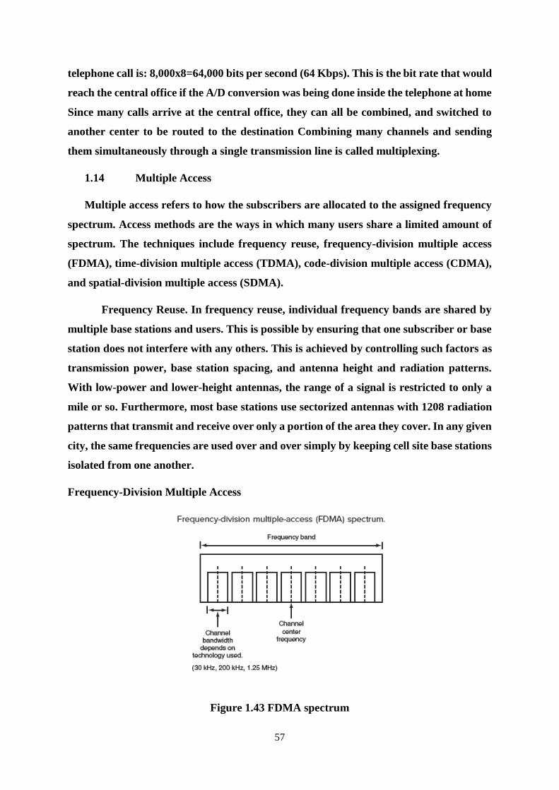
57
telephone call is: 8,000x8=64,000 bits per second (64 Kbps). This is the bit rate that would
reach the central office if the A/D conversion was being done inside the telephone at home
Since many calls arrive at the central office, they can all be combined, and switched to
another center to be routed to the destination Combining many channels and sending
them simultaneously through a single transmission line is called multiplexing.
1.14 Multiple Access
Multiple access refers to how the subscribers are allocated to the assigned frequency
spectrum. Access methods are the ways in which many users share a limited amount of
spectrum. The techniques include frequency reuse, frequency-division multiple access
(FDMA), time-division multiple access (TDMA), code-division multiple access (CDMA),
and spatial-division multiple access (SDMA).
Frequency Reuse. In frequency reuse, individual frequency bands are shared by
multiple base stations and users. This is possible by ensuring that one subscriber or base
station does not interfere with any others. This is achieved by controlling such factors as
transmission power, base station spacing, and antenna height and radiation patterns.
With low-power and lower-height antennas, the range of a signal is restricted to only a
mile or so. Furthermore, most base stations use sectorized antennas with 1208 radiation
patterns that transmit and receive over only a portion of the area they cover. In any given
city, the same frequencies are used over and over simply by keeping cell site base stations
isolated from one another.
Frequency-Division Multiple Access
Figure 1.43 FDMA spectrum

58
FDMA systems are like frequency- division multiplexing in that they allow many
users to share a block of spectrum by simply dividing it up into many smaller channels.
Each channel of a band is given an assigned number or is designated by the center
frequency of the channel. One subscriber is assigned to each channel. Typical channel
widths are 30 kHz, 200 kHz, 1.25 MHz, and 5 MHz. There are usually two similar bands,
one for uplink and the other for downlink.
Time-Division Multiple Access: TDMA relies on digital signals and operates on a single
channel. Multiple users use different time slots. Because the audio signal is sampled at a
rapid rate, the data words can be interleaved into different time slots, Of the two common
TDMA systems in use, one allows three users per frequency channel and the other allows
eight users per channel.
Figure 1.44 TDMA
Code-Division Multiple Access
Figure 1.45 CDMA
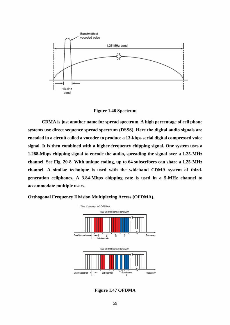
59
Figure 1.46 Spectrum
CDMA is just another name for spread spectrum. A high percentage of cell phone
systems use direct sequence spread spectrum (DSSS). Here the digital audio signals are
encoded in a circuit called a vocoder to produce a 13-kbps serial digital compressed voice
signal. It is then combined with a higher-frequency chipping signal. One system uses a
1.288-Mbps chipping signal to encode the audio, spreading the signal over a 1.25-MHz
channel. See Fig. 20-8. With unique coding, up to 64 subscribers can share a 1.25-MHz
channel. A similar technique is used with the wideband CDMA system of third-
generation cellphones. A 3.84-Mbps chipping rate is used in a 5-MHz channel to
accommodate multiple users.
Orthogonal Frequency Division Multiplexing Access (OFDMA).
Figure 1.47 OFDMA
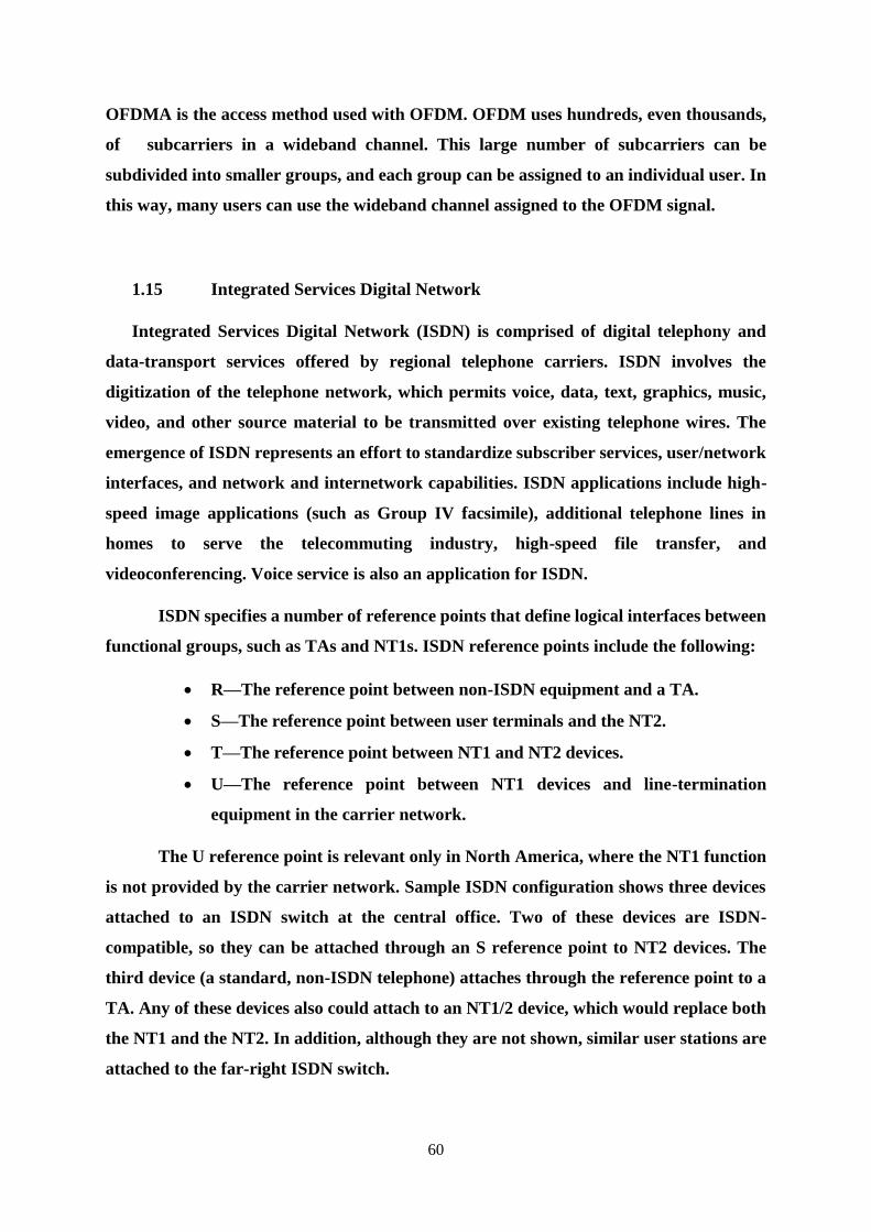
60
OFDMA is the access method used with OFDM. OFDM uses hundreds, even thousands,
of subcarriers in a wideband channel. This large number of subcarriers can be
subdivided into smaller groups, and each group can be assigned to an individual user. In
this way, many users can use the wideband channel assigned to the OFDM signal.
1.15 Integrated Services Digital Network
Integrated Services Digital Network (ISDN) is comprised of digital telephony and
data-transport services offered by regional telephone carriers. ISDN involves the
digitization of the telephone network, which permits voice, data, text, graphics, music,
video, and other source material to be transmitted over existing telephone wires. The
emergence of ISDN represents an effort to standardize subscriber services, user/network
interfaces, and network and internetwork capabilities. ISDN applications include high-
speed image applications (such as Group IV facsimile), additional telephone lines in
homes to serve the telecommuting industry, high-speed file transfer, and
videoconferencing. Voice service is also an application for ISDN.
ISDN specifies a number of reference points that define logical interfaces between
functional groups, such as TAs and NT1s. ISDN reference points include the following:
R—The reference point between non-ISDN equipment and a TA.
S—The reference point between user terminals and the NT2.
T—The reference point between NT1 and NT2 devices.
U—The reference point between NT1 devices and line-termination
equipment in the carrier network.
The U reference point is relevant only in North America, where the NT1 function
is not provided by the carrier network. Sample ISDN configuration shows three devices
attached to an ISDN switch at the central office. Two of these devices are ISDN-
compatible, so they can be attached through an S reference point to NT2 devices. The
third device (a standard, non-ISDN telephone) attaches through the reference point to a
TA. Any of these devices also could attach to an NT1/2 device, which would replace both
the NT1 and the NT2. In addition, although they are not shown, similar user stations are
attached to the far-right ISDN switch.
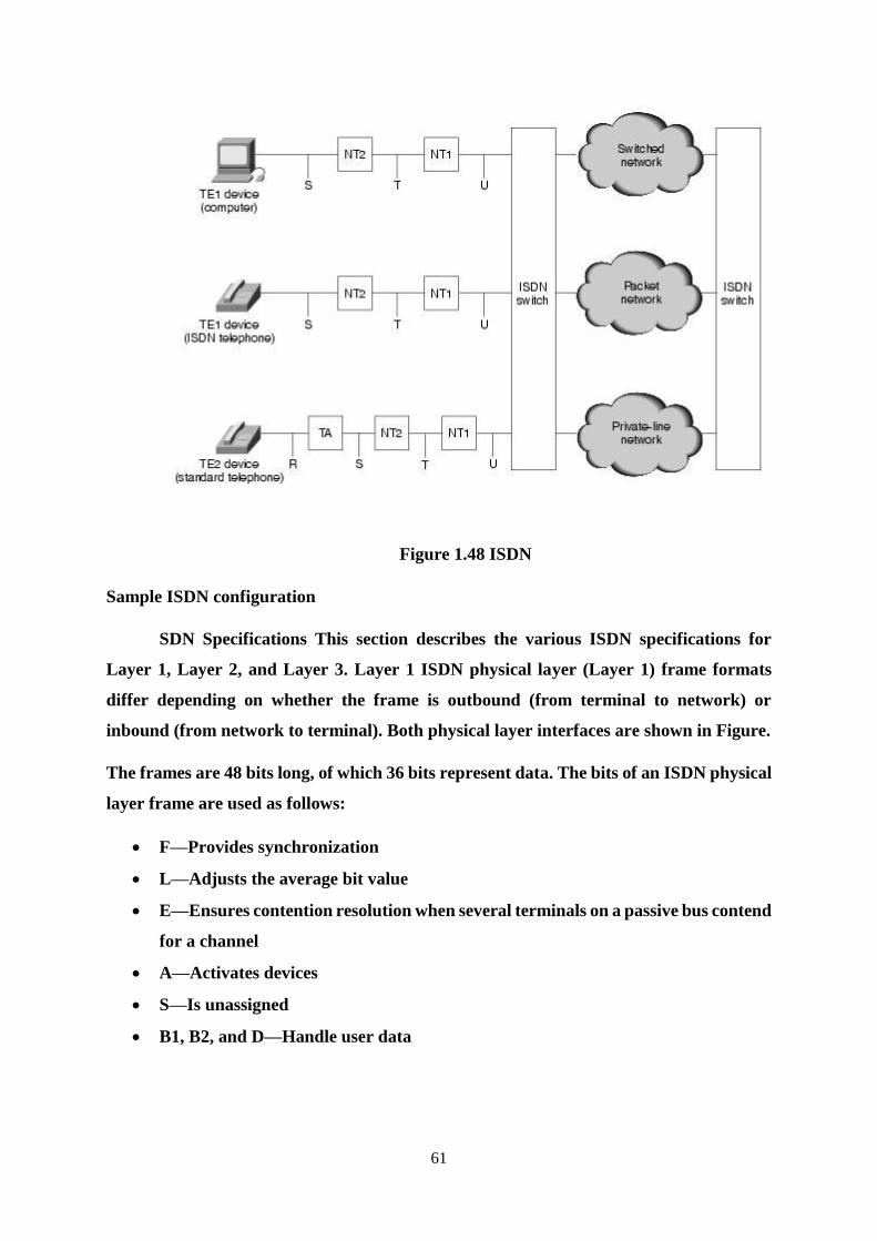
61
Figure 1.48 ISDN
Sample ISDN configuration
SDN Specifications This section describes the various ISDN specifications for
Layer 1, Layer 2, and Layer 3. Layer 1 ISDN physical layer (Layer 1) frame formats
differ depending on whether the frame is outbound (from terminal to network) or
inbound (from network to terminal). Both physical layer interfaces are shown in Figure.
The frames are 48 bits long, of which 36 bits represent data. The bits of an ISDN physical
layer frame are used as follows:
F—Provides synchronization
L—Adjusts the average bit value
E—Ensures contention resolution when several terminals on a passive bus contend
for a channel
A—Activates devices
S—Is unassigned
B1, B2, and D—Handle user data
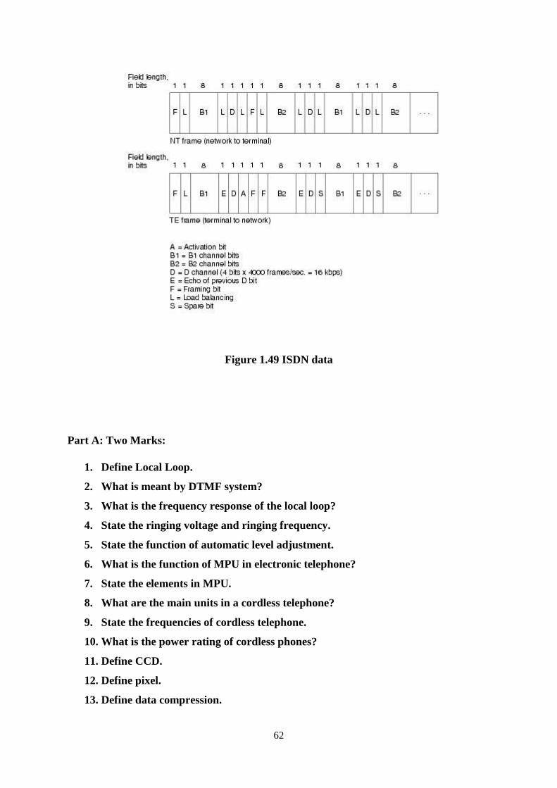
62
Figure 1.49 ISDN data
Part A: Two Marks:
1. Define Local Loop.
2. What is meant by DTMF system?
3. What is the frequency response of the local loop?
4. State the ringing voltage and ringing frequency.
5. State the function of automatic level adjustment.
6. What is the function of MPU in electronic telephone?
7. State the elements in MPU.
8. What are the main units in a cordless telephone?
9. State the frequencies of cordless telephone.
10. What is the power rating of cordless phones?
11. Define CCD.
12. Define pixel.
13. Define data compression.
63
14. Define modem.
15. State FAX standards.
16. State the scanning rate of FAX machines.
Part B:
1. Explain the operation of a telephone circuit.
2. Explain the construction and operation of the electronic telephone and cordless
phones with suitable diagrams.
3. Explain the operation of fax machine with suitable diagrams.
4. Explain the operation of cellular telephone unit.
5. Explain the construction and operation of paging system.
6. Explain in detail about ISDN.
REFERENCES
[1] Louis. E. Frenzel, Communication Electronics Principles and applications, 4th
Edition, Tata McGraw Hill Publications, 2014.
[2] Dennis Roody and John Coolen, Electronic Communications, 4th edition, Prentice
Hall of India, 2002.
[3] B. P. Lathi, Modern Digital and Analog Communication Systems, 3rd Edition,
Oxford University Press, 2007.
[4] B. Sklar, Digital Communications Fundamentals and Applications, 2nd Edition,
Pearson Education 2007.
[5] R. M. Joany, T. Vino and L. Magthelin Therase, Substratal Rudiments of
Telecommunication Systems, LAP LAMBERT Academic Publishing, ISBN-13 :
978-3330352087, 2017.
SCHOOL OF ELECTRICAL AND ELECTRONICS
DEPARTMENT OF ELECTRONICS AND COMMUNICATION ENGINEERING
COMMUNICAITON SYSTEMS – SEC1303
UNIT – 2
TELEVISION COMMUNICATION
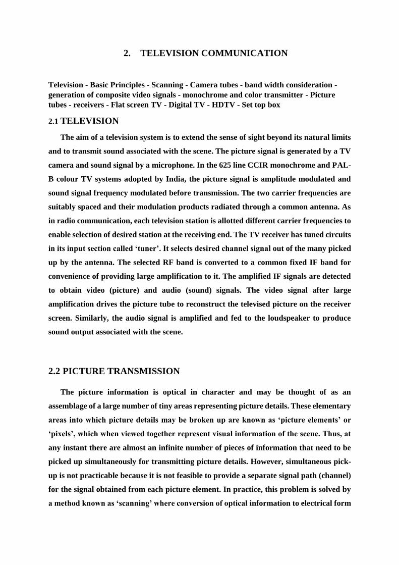
2. TELEVISION COMMUNICATION
Television - Basic Principles - Scanning - Camera tubes - band width consideration -
generation of composite video signals - monochrome and color transmitter - Picture
tubes - receivers - Flat screen TV - Digital TV - HDTV - Set top box
2.1 TELEVISION
The aim of a television system is to extend the sense of sight beyond its natural limits
and to transmit sound associated with the scene. The picture signal is generated by a TV
camera and sound signal by a microphone. In the 625 line CCIR monochrome and PAL-
B colour TV systems adopted by India, the picture signal is amplitude modulated and
sound signal frequency modulated before transmission. The two carrier frequencies are
suitably spaced and their modulation products radiated through a common antenna. As
in radio communication, each television station is allotted different carrier frequencies to
enable selection of desired station at the receiving end. The TV receiver has tuned circuits
in its input section called ‘tuner’. It selects desired channel signal out of the many picked
up by the antenna. The selected RF band is converted to a common fixed IF band for
convenience of providing large amplification to it. The amplified IF signals are detected
to obtain video (picture) and audio (sound) signals. The video signal after large
amplification drives the picture tube to reconstruct the televised picture on the receiver
screen. Similarly, the audio signal is amplified and fed to the loudspeaker to produce
sound output associated with the scene.
2.2 PICTURE TRANSMISSION
The picture information is optical in character and may be thought of as an
assemblage of a large number of tiny areas representing picture details. These elementary
areas into which picture details may be broken up are known as ‘picture elements’ or
‘pixels’, which when viewed together represent visual information of the scene. Thus, at
any instant there are almost an infinite number of pieces of information that need to be
picked up simultaneously for transmitting picture details. However, simultaneous pick-
up is not practicable because it is not feasible to provide a separate signal path (channel)
for the signal obtained from each picture element. In practice, this problem is solved by
a method known as ‘scanning’ where conversion of optical information to electrical form
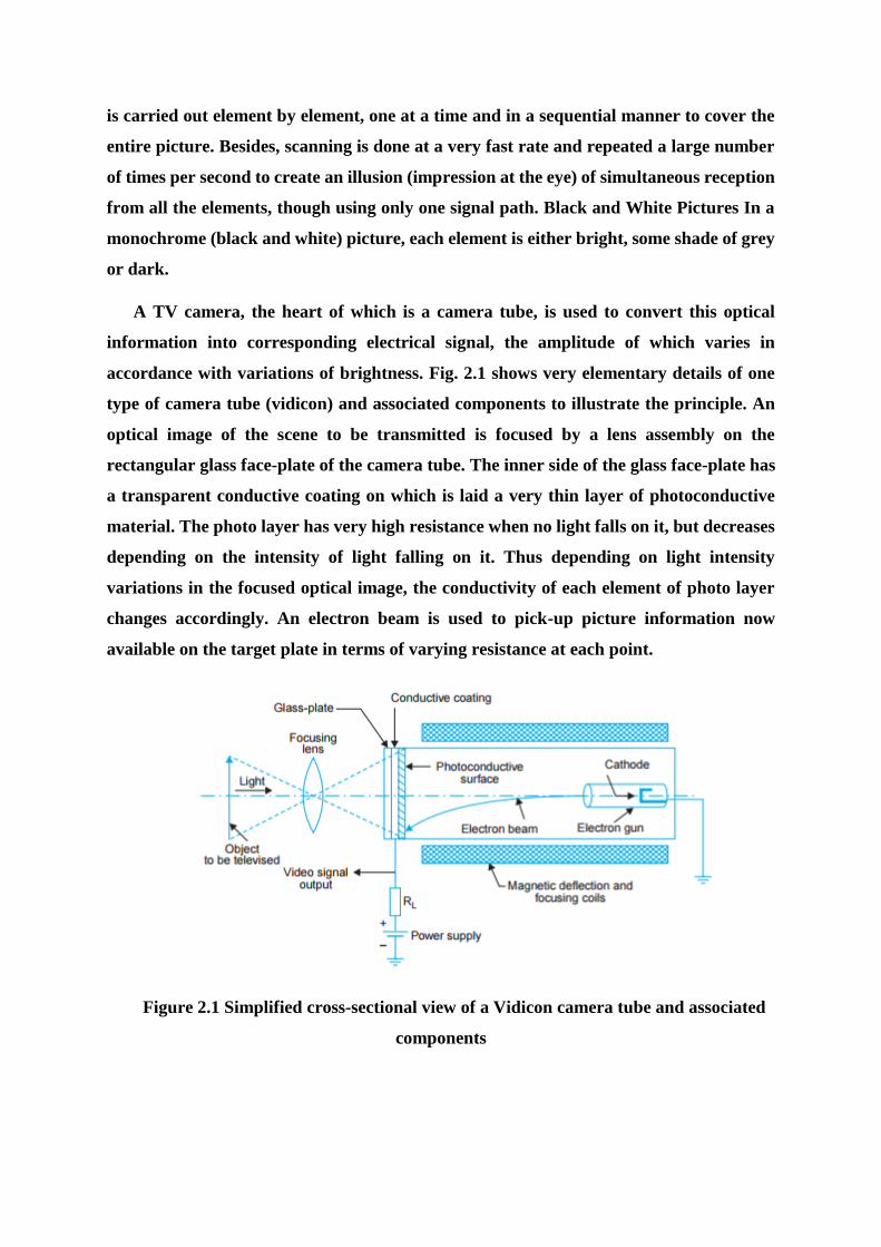
is carried out element by element, one at a time and in a sequential manner to cover the
entire picture. Besides, scanning is done at a very fast rate and repeated a large number
of times per second to create an illusion (impression at the eye) of simultaneous reception
from all the elements, though using only one signal path. Black and White Pictures In a
monochrome (black and white) picture, each element is either bright, some shade of grey
or dark.
A TV camera, the heart of which is a camera tube, is used to convert this optical
information into corresponding electrical signal, the amplitude of which varies in
accordance with variations of brightness. Fig. 2.1 shows very elementary details of one
type of camera tube (vidicon) and associated components to illustrate the principle. An
optical image of the scene to be transmitted is focused by a lens assembly on the
rectangular glass face-plate of the camera tube. The inner side of the glass face-plate has
a transparent conductive coating on which is laid a very thin layer of photoconductive
material. The photo layer has very high resistance when no light falls on it, but decreases
depending on the intensity of light falling on it. Thus depending on light intensity
variations in the focused optical image, the conductivity of each element of photo layer
changes accordingly. An electron beam is used to pick-up picture information now
available on the target plate in terms of varying resistance at each point.
Figure 2.1 Simplified cross-sectional view of a Vidicon camera tube and associated
components
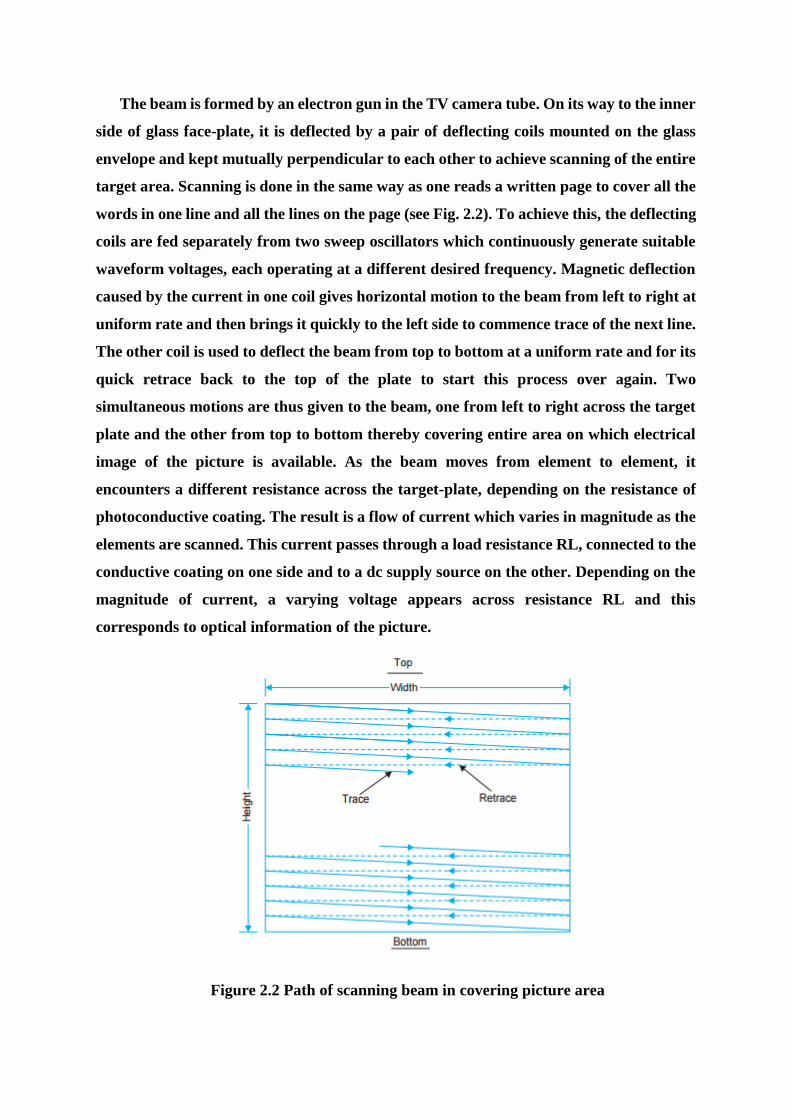
The beam is formed by an electron gun in the TV camera tube. On its way to the inner
side of glass face-plate, it is deflected by a pair of deflecting coils mounted on the glass
envelope and kept mutually perpendicular to each other to achieve scanning of the entire
target area. Scanning is done in the same way as one reads a written page to cover all the
words in one line and all the lines on the page (see Fig. 2.2). To achieve this, the deflecting
coils are fed separately from two sweep oscillators which continuously generate suitable
waveform voltages, each operating at a different desired frequency. Magnetic deflection
caused by the current in one coil gives horizontal motion to the beam from left to right at
uniform rate and then brings it quickly to the left side to commence trace of the next line.
The other coil is used to deflect the beam from top to bottom at a uniform rate and for its
quick retrace back to the top of the plate to start this process over again. Two
simultaneous motions are thus given to the beam, one from left to right across the target
plate and the other from top to bottom thereby covering entire area on which electrical
image of the picture is available. As the beam moves from element to element, it
encounters a different resistance across the target-plate, depending on the resistance of
photoconductive coating. The result is a flow of current which varies in magnitude as the
elements are scanned. This current passes through a load resistance RL, connected to the
conductive coating on one side and to a dc supply source on the other. Depending on the
magnitude of current, a varying voltage appears across resistance RL and this
corresponds to optical information of the picture.
Figure 2.2 Path of scanning beam in covering picture area
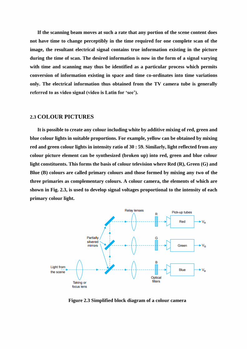
If the scanning beam moves at such a rate that any portion of the scene content does
not have time to change perceptibly in the time required for one complete scan of the
image, the resultant electrical signal contains true information existing in the picture
during the time of scan. The desired information is now in the form of a signal varying
with time and scanning may thus be identified as a particular process which permits
conversion of information existing in space and time co-ordinates into time variations
only. The electrical information thus obtained from the TV camera tube is generally
referred to as video signal (video is Latin for ‘see’).
2.3 COLOUR PICTURES
It is possible to create any colour including white by additive mixing of red, green and
blue colour lights in suitable proportions. For example, yellow can be obtained by mixing
red and green colour lights in intensity ratio of 30 : 59. Similarly, light reflected from any
colour picture element can be synthesized (broken up) into red, green and blue colour
light constituents. This forms the basis of colour television where Red (R), Green (G) and
Blue (B) colours are called primary colours and those formed by mixing any two of the
three primaries as complementary colours. A colour camera, the elements of which are
shown in Fig. 2.3, is used to develop signal voltages proportional to the intensity of each
primary colour light.
Figure 2.3 Simplified block diagram of a colour camera
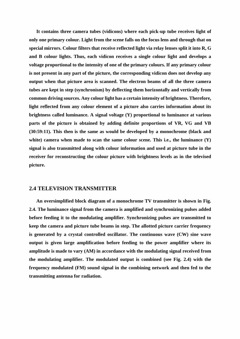
It contains three camera tubes (vidicons) where each pick-up tube receives light of
only one primary colour. Light from the scene falls on the focus lens and through that on
special mirrors. Colour filters that receive reflected light via relay lenses split it into R, G
and B colour lights. Thus, each vidicon receives a single colour light and develops a
voltage proportional to the intensity of one of the primary colours. If any primary colour
is not present in any part of the picture, the corresponding vidicon does not develop any
output when that picture area is scanned. The electron beams of all the three camera
tubes are kept in step (synchronism) by deflecting them horizontally and vertically from
common driving sources. Any colour light has a certain intensity of brightness. Therefore,
light reflected from any colour element of a picture also carries information about its
brightness called luminance. A signal voltage (Y) proportional to luminance at various
parts of the picture is obtained by adding definite proportions of VR, VG and VB
(30:59:11). This then is the same as would be developed by a monochrome (black and
white) camera when made to scan the same colour scene. This i.e., the luminance (Y)
signal is also transmitted along with colour information and used at picture tube in the
receiver for reconstructing the colour picture with brightness levels as in the televised
picture.
2.4 TELEVISION TRANSMITTER
An oversimplified block diagram of a monochrome TV transmitter is shown in Fig.
2.4. The luminance signal from the camera is amplified and synchronizing pulses added
before feeding it to the modulating amplifier. Synchronizing pulses are transmitted to
keep the camera and picture tube beams in step. The allotted picture carrier frequency
is generated by a crystal controlled oscillator. The continuous wave (CW) sine wave
output is given large amplification before feeding to the power amplifier where its
amplitude is made to vary (AM) in accordance with the modulating signal received from
the modulating amplifier. The modulated output is combined (see Fig. 2.4) with the
frequency modulated (FM) sound signal in the combining network and then fed to the
transmitting antenna for radiation.
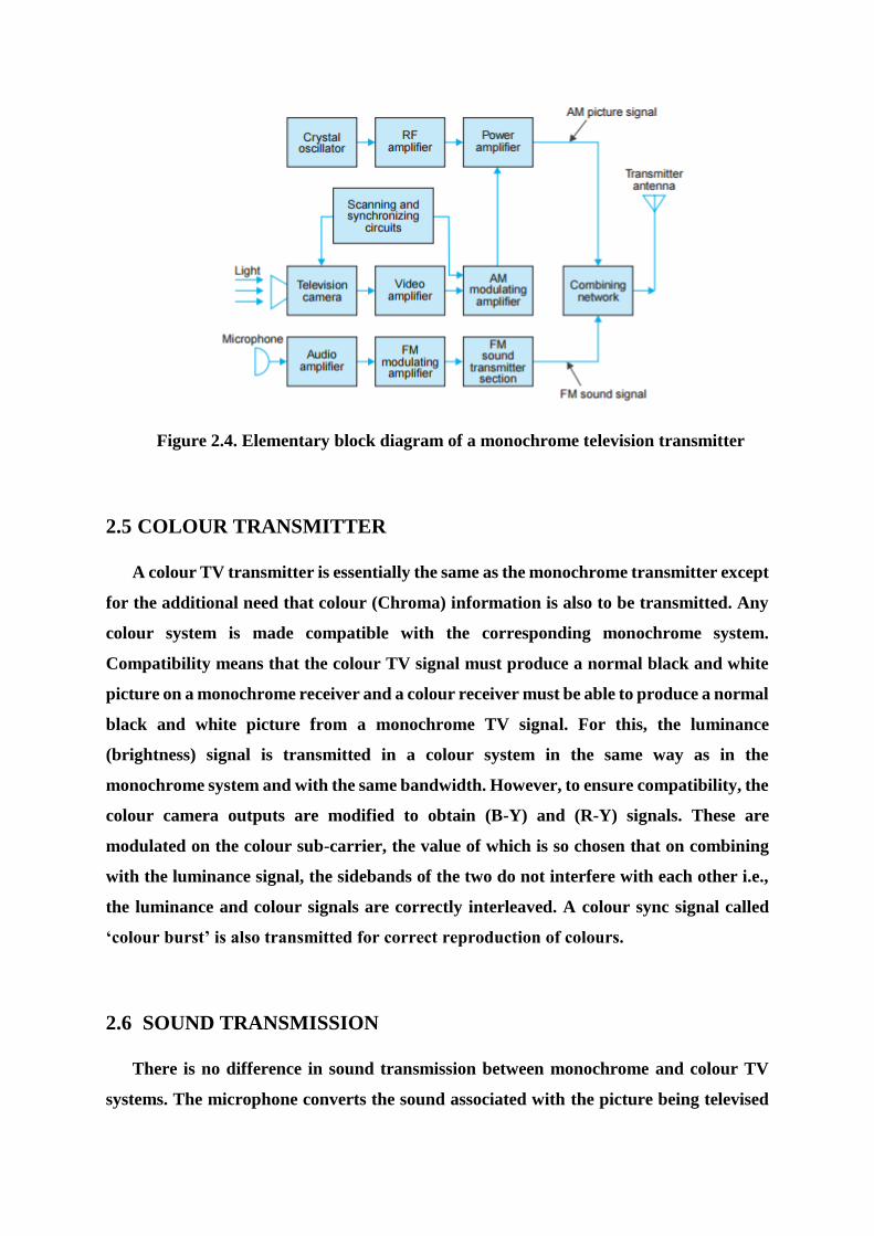
Figure 2.4. Elementary block diagram of a monochrome television transmitter
2.5 COLOUR TRANSMITTER
A colour TV transmitter is essentially the same as the monochrome transmitter except
for the additional need that colour (Chroma) information is also to be transmitted. Any
colour system is made compatible with the corresponding monochrome system.
Compatibility means that the colour TV signal must produce a normal black and white
picture on a monochrome receiver and a colour receiver must be able to produce a normal
black and white picture from a monochrome TV signal. For this, the luminance
(brightness) signal is transmitted in a colour system in the same way as in the
monochrome system and with the same bandwidth. However, to ensure compatibility, the
colour camera outputs are modified to obtain (B-Y) and (R-Y) signals. These are
modulated on the colour sub-carrier, the value of which is so chosen that on combining
with the luminance signal, the sidebands of the two do not interfere with each other i.e.,
the luminance and colour signals are correctly interleaved. A colour sync signal called
‘colour burst’ is also transmitted for correct reproduction of colours.
2.6 SOUND TRANSMISSION
There is no difference in sound transmission between monochrome and colour TV
systems. The microphone converts the sound associated with the picture being televised
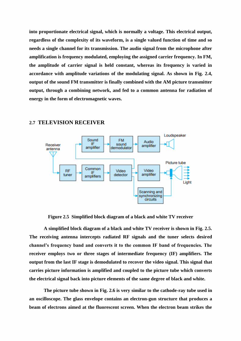
into proportionate electrical signal, which is normally a voltage. This electrical output,
regardless of the complexity of its waveform, is a single valued function of time and so
needs a single channel for its transmission. The audio signal from the microphone after
amplification is frequency modulated, employing the assigned carrier frequency. In FM,
the amplitude of carrier signal is held constant, whereas its frequency is varied in
accordance with amplitude variations of the modulating signal. As shown in Fig. 2.4,
output of the sound FM transmitter is finally combined with the AM picture transmitter
output, through a combining network, and fed to a common antenna for radiation of
energy in the form of electromagnetic waves.
2.7 TELEVISION RECEIVER
Figure 2.5 Simplified block diagram of a black and white TV receiver
A simplified block diagram of a black and white TV receiver is shown in Fig. 2.5.
The receiving antenna intercepts radiated RF signals and the tuner selects desired
channel’s frequency band and converts it to the common IF band of frequencies. The
receiver employs two or three stages of intermediate frequency (IF) amplifiers. The
output from the last IF stage is demodulated to recover the video signal. This signal that
carries picture information is amplified and coupled to the picture tube which converts
the electrical signal back into picture elements of the same degree of black and white.
The picture tube shown in Fig. 2.6 is very similar to the cathode-ray tube used in
an oscilloscope. The glass envelope contains an electron-gun structure that produces a
beam of electrons aimed at the fluorescent screen. When the electron beam strikes the
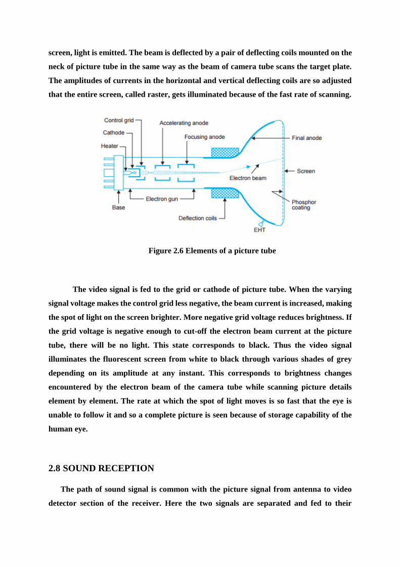
screen, light is emitted. The beam is deflected by a pair of deflecting coils mounted on the
neck of picture tube in the same way as the beam of camera tube scans the target plate.
The amplitudes of currents in the horizontal and vertical deflecting coils are so adjusted
that the entire screen, called raster, gets illuminated because of the fast rate of scanning.
Figure 2.6 Elements of a picture tube
The video signal is fed to the grid or cathode of picture tube. When the varying
signal voltage makes the control grid less negative, the beam current is increased, making
the spot of light on the screen brighter. More negative grid voltage reduces brightness. If
the grid voltage is negative enough to cut-off the electron beam current at the picture
tube, there will be no light. This state corresponds to black. Thus the video signal
illuminates the fluorescent screen from white to black through various shades of grey
depending on its amplitude at any instant. This corresponds to brightness changes
encountered by the electron beam of the camera tube while scanning picture details
element by element. The rate at which the spot of light moves is so fast that the eye is
unable to follow it and so a complete picture is seen because of storage capability of the
human eye.
2.8 SOUND RECEPTION
The path of sound signal is common with the picture signal from antenna to video
detector section of the receiver. Here the two signals are separated and fed to their

respective channels. The frequency modulated audio signal is demodulated after at least
one stage of amplification. The audio output from the FM detector is given due
amplification before feeding it to the loudspeaker.
2.9 COLOUR RECEIVER
A colour receiver is similar to the black and white receiver as shown in Fig. 2.7. The
main difference between the two is the need of a colour or Chroma subsystem. It accepts
only the colour signal and processes it to recover (B-Y) and (R-Y) signals. These are
combined with the Y signal to obtain VR, VG and VB signals as developed by the camera
at the transmitting end. VG becomes available as it is contained in the Y signal. The three
colour signals are fed after sufficient amplification to the colour picture tube to produce
a colour picture on its screen.
Figure 2.7. An oversimplified block diagram of a colour receiver
As shown in Fig. 2.7, the colour picture tube has three guns corresponding to the three
pick-up tubes in the colour camera. The screen of this tube has red, green and blue
phosphors arranged in alternate stripes. Each gun produces an electron beam to
illuminate corresponding colour phosphor separately on the fluorescent screen. The eye
then integrates the red, green and blue colour information and their luminance to
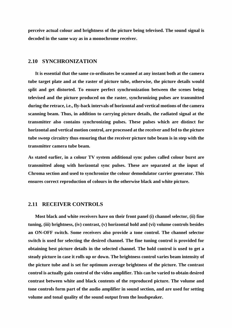
perceive actual colour and brightness of the picture being televised. The sound signal is
decoded in the same way as in a monochrome receiver.
2.10 SYNCHRONIZATION
It is essential that the same co-ordinates be scanned at any instant both at the camera
tube target plate and at the raster of picture tube, otherwise, the picture details would
split and get distorted. To ensure perfect synchronization between the scenes being
televised and the picture produced on the raster, synchronizing pulses are transmitted
during the retrace, i.e., fly-back intervals of horizontal and vertical motions of the camera
scanning beam. Thus, in addition to carrying picture details, the radiated signal at the
transmitter also contains synchronizing pulses. These pulses which are distinct for
horizontal and vertical motion control, are processed at the receiver and fed to the picture
tube sweep circuitry thus ensuring that the receiver picture tube beam is in step with the
transmitter camera tube beam.
As stated earlier, in a colour TV system additional sync pulses called colour burst are
transmitted along with horizontal sync pulses. These are separated at the input of
Chroma section and used to synchronize the colour demodulator carrier generator. This
ensures correct reproduction of colours in the otherwise black and white picture.
2.11 RECEIVER CONTROLS
Most black and white receivers have on their front panel (i) channel selector, (ii) fine
tuning, (iii) brightness, (iv) contrast, (v) horizontal hold and (vi) volume controls besides
an ON-OFF switch. Some receivers also provide a tone control. The channel selector
switch is used for selecting the desired channel. The fine tuning control is provided for
obtaining best picture details in the selected channel. The hold control is used to get a
steady picture in case it rolls up or down. The brightness control varies beam intensity of
the picture tube and is set for optimum average brightness of the picture. The contrast
control is actually gain control of the video amplifier. This can be varied to obtain desired
contrast between white and black contents of the reproduced picture. The volume and
tone controls form part of the audio amplifier in sound section, and are used for setting
volume and tonal quality of the sound output from the loudspeaker.
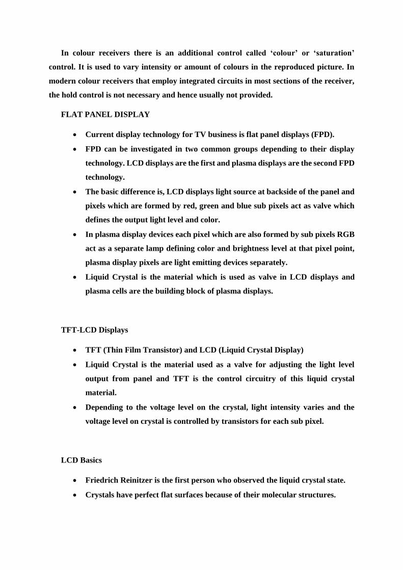
In colour receivers there is an additional control called ‘colour’ or ‘saturation’
control. It is used to vary intensity or amount of colours in the reproduced picture. In
modern colour receivers that employ integrated circuits in most sections of the receiver,
the hold control is not necessary and hence usually not provided.
FLAT PANEL DISPLAY
Current display technology for TV business is flat panel displays (FPD).
FPD can be investigated in two common groups depending to their display
technology. LCD displays are the first and plasma displays are the second FPD
technology.
The basic difference is, LCD displays light source at backside of the panel and
pixels which are formed by red, green and blue sub pixels act as valve which
defines the output light level and color.
In plasma display devices each pixel which are also formed by sub pixels RGB
act as a separate lamp defining color and brightness level at that pixel point,
plasma display pixels are light emitting devices separately.
Liquid Crystal is the material which is used as valve in LCD displays and
plasma cells are the building block of plasma displays.
TFT-LCD Displays
TFT (Thin Film Transistor) and LCD (Liquid Crystal Display)
Liquid Crystal is the material used as a valve for adjusting the light level
output from panel and TFT is the control circuitry of this liquid crystal
material.
Depending to the voltage level on the crystal, light intensity varies and the
voltage level on crystal is controlled by transistors for each sub pixel.
LCD Basics
Friedrich Reinitzer is the first person who observed the liquid crystal state.
Crystals have perfect flat surfaces because of their molecular structures.
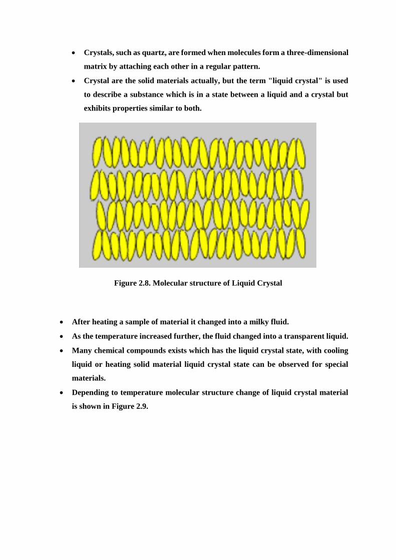
Crystals, such as quartz, are formed when molecules form a three-dimensional
matrix by attaching each other in a regular pattern.
Crystal are the solid materials actually, but the term "liquid crystal" is used
to describe a substance which is in a state between a liquid and a crystal but
exhibits properties similar to both.
Figure 2.8. Molecular structure of Liquid Crystal
After heating a sample of material it changed into a milky fluid.
As the temperature increased further, the fluid changed into a transparent liquid.
Many chemical compounds exists which has the liquid crystal state, with cooling
liquid or heating solid material liquid crystal state can be observed for special
materials.
Depending to temperature molecular structure change of liquid crystal material
is shown in Figure 2.9.
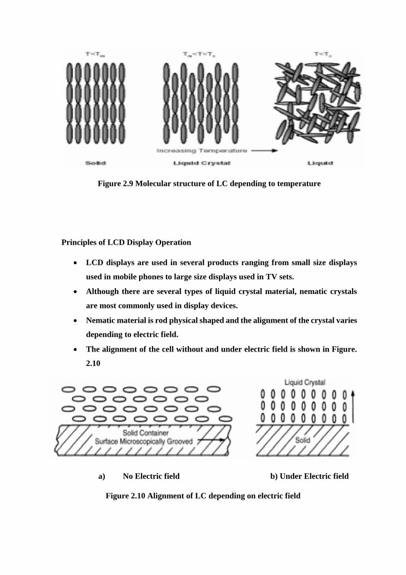
Figure 2.9 Molecular structure of LC depending to temperature
Principles of LCD Display Operation
LCD displays are used in several products ranging from small size displays
used in mobile phones to large size displays used in TV sets.
Although there are several types of liquid crystal material, nematic crystals
are most commonly used in display devices.
Nematic material is rod physical shaped and the alignment of the crystal varies
depending to electric field.
The alignment of the cell without and under electric field is shown in Figure.
2.10
a) No Electric field b) Under Electric field
Figure 2.10 Alignment of LC depending on electric field
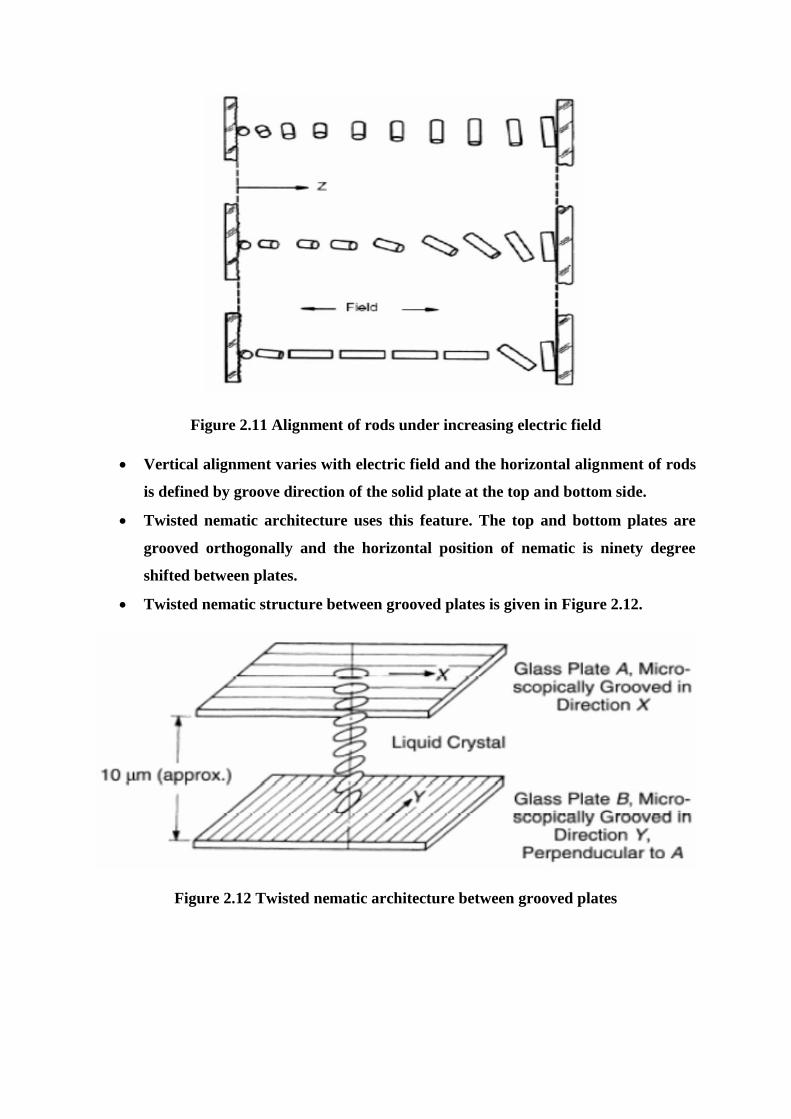
Figure 2.11 Alignment of rods under increasing electric field
Vertical alignment varies with electric field and the horizontal alignment of rods
is defined by groove direction of the solid plate at the top and bottom side.
Twisted nematic architecture uses this feature. The top and bottom plates are
grooved orthogonally and the horizontal position of nematic is ninety degree
shifted between plates.
Twisted nematic structure between grooved plates is given in Figure 2.12.
Figure 2.12 Twisted nematic architecture between grooved plates
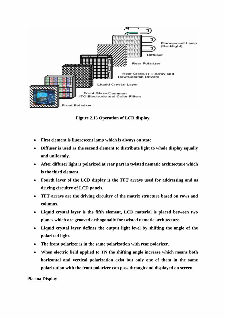
Figure 2.13 Operation of LCD display
First element is fluorescent lamp which is always on state.
Diffuser is used as the second element to distribute light to whole display equally
and uniformly.
After diffuser light is polarized at rear part in twisted nematic architecture which
is the third element.
Fourth layer of the LCD display is the TFT arrays used for addressing and as
driving circuitry of LCD panels.
TFT arrays are the driving circuitry of the matrix structure based on rows and
columns.
Liquid crystal layer is the fifth element, LCD material is placed between two
planes which are grooved orthogonally for twisted nematic architecture.
Liquid crystal layer defines the output light level by shifting the angle of the
polarized light.
The front polarizer is in the same polarization with rear polarizer.
When electric field applied to TN the shifting angle increase which means both
horizontal and vertical polarization exist but only one of them in the same
polarization with the front polarizer can pass through and displayed on screen.
Plasma Display
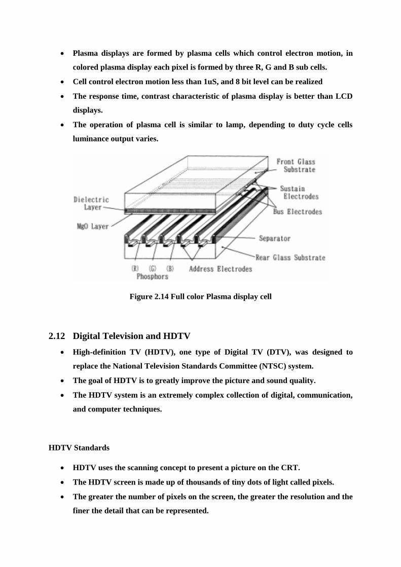
Plasma displays are formed by plasma cells which control electron motion, in
colored plasma display each pixel is formed by three R, G and B sub cells.
Cell control electron motion less than 1uS, and 8 bit level can be realized
The response time, contrast characteristic of plasma display is better than LCD
displays.
The operation of plasma cell is similar to lamp, depending to duty cycle cells
luminance output varies.
Figure 2.14 Full color Plasma display cell
2.12 Digital Television and HDTV
High-definition TV (HDTV), one type of Digital TV (DTV), was designed to
replace the National Television Standards Committee (NTSC) system.
The goal of HDTV is to greatly improve the picture and sound quality.
The HDTV system is an extremely complex collection of digital, communication,
and computer techniques.
HDTV Standards
HDTV uses the scanning concept to present a picture on the CRT.
The HDTV screen is made up of thousands of tiny dots of light called pixels.
The greater the number of pixels on the screen, the greater the resolution and the
finer the detail that can be represented.
HDTV uses progressive line scanning, in which each line is scanned one at a time
from top to bottom.
HDTV Transmission Concepts
In HDTV both the video and the audio signals must be digitized by A/D converters
and transmitted serially to the receiver.
Because of the very high frequency of video signals, special techniques must be
used to transmit the video signal over a standard 6-MHz bandwidth TV channel.
Multiplexing techniques must be used because both video and audio must be
transmitted over the same channel.
HDTV Transmission Concepts: HDTV Transmitter
In an HDTV transmitter, the video from the camera consists of the R, G, and B
signals that are converted to the luminance and chrominance signals.
These are digitized by A/D converters.
The resulting signals are serialized and sent to a data compressor.
MPEG-2 is the data compression method used in HDTV.
The signal is next sent to a data randomizer.
The random serial signal is passed through a Reed-Solomon (RS) error detection
and correction circuit.
The signal is next fed to a trellis encoder.
Each audio channel is sampled at a 48-kbps rate.
The video and audio data streams are packetized.
The packets are multiplexed with some synchronizing signals to form the final
signal to be transmitted.
The modulation scheme used in HDTV is 8-VSB.
The modulated signal is up-converted by a mixer to the final transmission
frequency, which is one of the standard TV channels in the VHF or UHF range.
A linear power amplifier is used to boost the signal level prior to transmission by
the antenna.
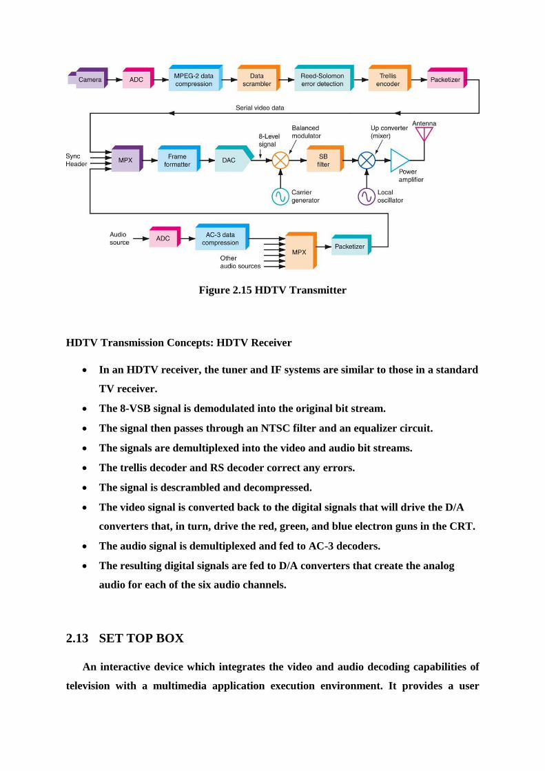
Figure 2.15 HDTV Transmitter
HDTV Transmission Concepts: HDTV Receiver
In an HDTV receiver, the tuner and IF systems are similar to those in a standard
TV receiver.
The 8-VSB signal is demodulated into the original bit stream.
The signal then passes through an NTSC filter and an equalizer circuit.
The signals are demultiplexed into the video and audio bit streams.
The trellis decoder and RS decoder correct any errors.
The signal is descrambled and decompressed.
The video signal is converted back to the digital signals that will drive the D/A
converters that, in turn, drive the red, green, and blue electron guns in the CRT.
The audio signal is demultiplexed and fed to AC-3 decoders.
The resulting digital signals are fed to D/A converters that create the analog
audio for each of the six audio channels.
2.13 SET TOP BOX
An interactive device which integrates the video and audio decoding capabilities of
television with a multimedia application execution environment. It provides a user

friendly interface offering personalized multimedia services and regular cable TV
service.
Digital video networks(DVN)
Digital television advantage.
Digital video delivery requirements
– High bandwidth.
– Fibre cable, satellite, broadcast and computer networks can be used.
Traditional cable networks analogue systems and their drawbacks.
Satellite and terrestrial networks.
Internet suitability for interactive network and drawback.
DVN need to deliver a high bandwidth stream into consumer homes and a low bandwidth
communication layer for interaction between the STB user and the service provider.
Cable operators approach for DVN.
– Need to extend unidirectional coaxial networking with a communication
path from subscriber home to cable service gateways that can control the
content being sent to subscriber.
– Advantage of video compression technology.
– Constraints with cable networks.
Telephone companies approach.
– Advantage with telephone companies.
Already have set up for P2P and technology for control and
service gateways to manage wide area switched star networks.
– Drawback.
Low bandwidth between head end equipment and consumer’s
home.
Set Top Box Hardware Architecture.
Requirements based on functionality.
– Should have MPEG-2 sub-system to decode MPEG-2 video and audio.
– Should enable user to download custom applications and execute them on
the STB which requires a general purpose microprocessor in the STB with
an architecture that supports control of the different devices.

Various hardware components.
Figure 2.16 Block Diagram of SET TOP Box (IRD) With CI SLOT
Figure 2.17 Detailed Block Diagram of SET TOP Box (IRD) With CI SLOT
STB software architecture
For personalized interactive services, a set top box should be addressable in the
video dial-tone network, thus providing P2P communication between a video and
information provider and a user. It should also have the ability to download client
applications and execute them locally.
The control software on the set top box ties together all the hardware components
into a functioning unit.
STB software has two parts.
– System software which provides the DAVID application programming
interface.
– Application software that provides cable TV functionality or some other
personalized multimedia service.
DAVID system software includes.
– Operating system (os-9) kernel.
– Device drivers.
– File manager.
REFERENCES
[1] Louis. E. Frenzel, Communication Electronics Principles and applications, 4th
Edition, Tata McGraw Hill Publications, 2014.
[2] Dennis Roody and John Coolen, Electronic Communications, 4th edition, Prentice
Hall of India, 2002.
[3] R. Gulati, Monochrome and colour television, 2nd Edition, New age international
2005.
[4] B. P. Lathi, Modern Digital and Analog Communication Systems, 3rd Edition,
Oxford University Press, 2007.
[5] B. Sklar, Digital Communications Fundamentals and Applications, 2nd Edition,
Pearson Education 2007.
SCHOOL OF ELECTRICAL AND ELECTRONICS
DEPARTMENT OF ELECTRONICS AND COMMUNICATION ENGINEERING
COMMUNICAITON SYSTEMS – SEC1303
UNIT – 3
SATELLITE COMMUNICATION

3. SATELLITE COMMUNICATION
Satellite basics - Orbit dynamics - Types of Satellite Orbits - Satellite system - System
calculation - satellite subsystem and earth station subsystem - Satellite Frequency band -
Satellite Applications - Noise in satellite communication system - multiple access method
- FDMA and TDMA system.
3.1 Satellite Basics
A satellite is a manmade object that orbits another large object like planet.
A communication satellite is a station in space that is used for telecommunication,
radio and television signals.
Passive Satellite - A passive satellite only reflects received radio signals back to
earth.
Active Satellite - An active satellite acts as a REPEATER; it amplifies signals
received and then retransmits them back to earth.
The advantages of satellite communication over terrestrial communication are:
The coverage area of a satellite greatly exceeds that of a terrestrial system.
Transmission cost of a satellite is independent of the distance from the
center of the coverage area.
Satellite to Satellite communication is very precise.
Higher Bandwidths are available for use.
The disadvantages of satellite communication:
Launching satellites into orbit is costly.
Satellite bandwidth is gradually becoming used up.
There is a larger propagation delay in satellite communication than in
terrestrial communication
Satellite communications are comprised of 2 main Components
1. The Satellite
This is the earth segment. The ground station's job is two-fold.
In the case of transmitting station, terrestrial data in the form of baseband signals,
is passed through a baseband processor, an up converter, a high powered
amplifier, and through a parabolic dish antenna up to an orbiting satellite.
In receiving station, works in the reverse fashion, ultimately converting signals
received through the parabolic antenna to base band signal.
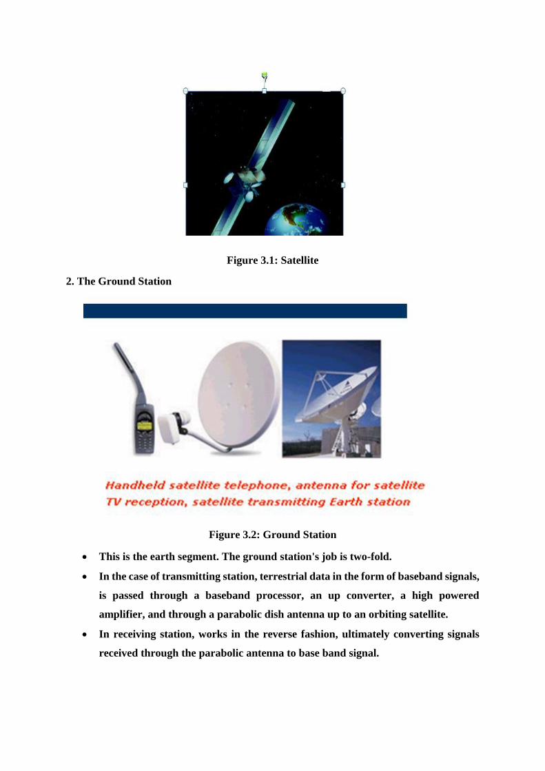
Figure 3.1: Satellite
2. The Ground Station
Figure 3.2: Ground Station
This is the earth segment. The ground station's job is two-fold.
In the case of transmitting station, terrestrial data in the form of baseband signals,
is passed through a baseband processor, an up converter, a high powered
amplifier, and through a parabolic dish antenna up to an orbiting satellite.
In receiving station, works in the reverse fashion, ultimately converting signals
received through the parabolic antenna to base band signal.

Satellite work
Two Stations on Earth want to communicate through radio broadcast but
are too far away to use conventional means.
The two stations can use a satellite as a relay station for their
communication
One Earth Station sends a transmission to the satellite. This is called a
Uplink.
The satellite Transponder converts the signal and sends it down to the
second earth station. This is called a Downlink
Figure 3.3: Uplink and Downlink
3.2 Satellite Orbit dynamics
The ability to launch a satellite and keep it in orbit depends upon following well-
known physical and mathematical laws that are referred to collectively as orbital
dynamics.
Principles of Satellite Orbits and Positioning
For the satellite to go into orbit around the earth, it is given both vertical and
forward motion.
However, gravity tends to pull the satellite toward the earth.
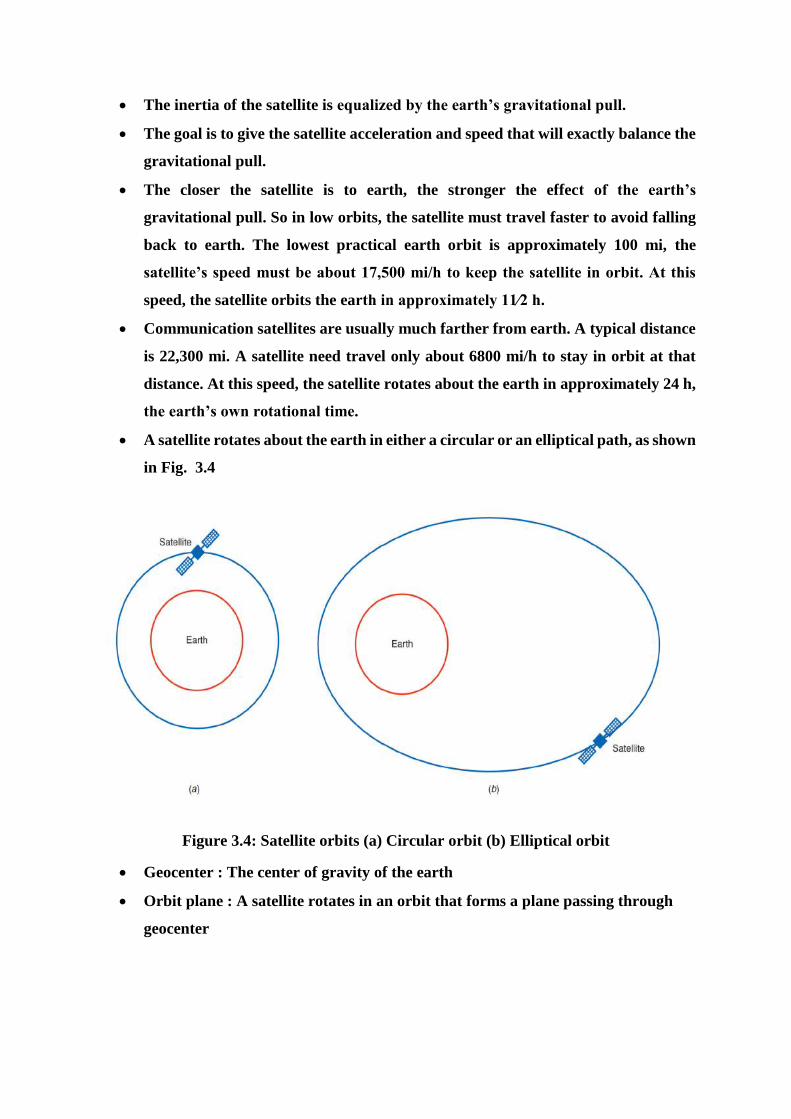
The inertia of the satellite is equalized by the earth’s gravitational pull.
The goal is to give the satellite acceleration and speed that will exactly balance the
gravitational pull.
The closer the satellite is to earth, the stronger the effect of the earth’s
gravitational pull. So in low orbits, the satellite must travel faster to avoid falling
back to earth. The lowest practical earth orbit is approximately 100 mi, the
satellite’s speed must be about 17,500 mi/h to keep the satellite in orbit. At this
speed, the satellite orbits the earth in approximately 11⁄2 h.
Communication satellites are usually much farther from earth. A typical distance
is 22,300 mi. A satellite need travel only about 6800 mi/h to stay in orbit at that
distance. At this speed, the satellite rotates about the earth in approximately 24 h,
the earth’s own rotational time.
A satellite rotates about the earth in either a circular or an elliptical path, as shown
in Fig. 3.4
Figure 3.4: Satellite orbits (a) Circular orbit (b) Elliptical orbit
Geocenter : The center of gravity of the earth
Orbit plane : A satellite rotates in an orbit that forms a plane passing through
geocenter
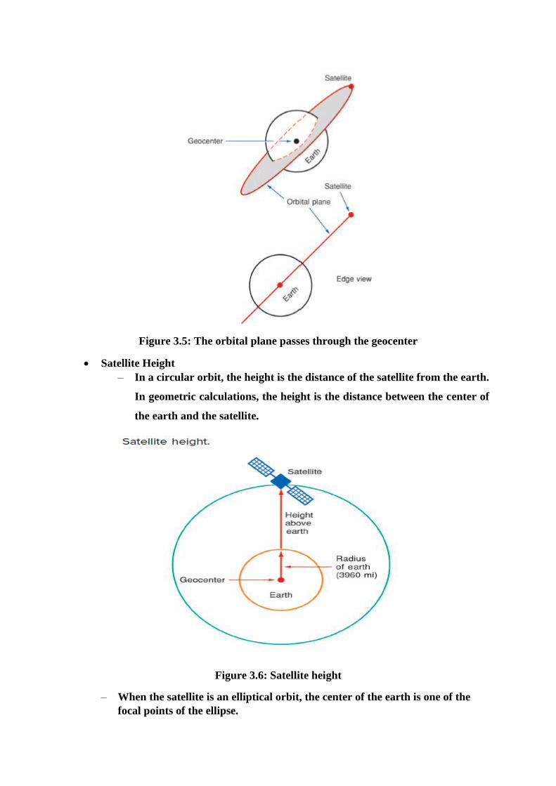
Figure 3.5: The orbital plane passes through the geocenter
Satellite Height
– In a circular orbit, the height is the distance of the satellite from the earth.
In geometric calculations, the height is the distance between the center of
the earth and the satellite.
Figure 3.6: Satellite height
– When the satellite is an elliptical orbit, the center of the earth is one of the
focal points of the ellipse.

The two points of greatest interest are the highest point above the earth (the apogee)
and the lowest point (the perigee).
Figure 3.7: Elliptical orbit showing apogee and perigee
Satellite Speed
– Satellite speed varies depending upon the distance of the satellite from the
earth.
– For a circular orbit the speed is constant, but for an elliptical orbit the speed
varies depending upon the height.
– Low earth satellites of about 100 mi in height have a speed of about 17,500
mi/hr.
– Very high satellites such as communication satellites typically travel at speeds
of about 6800 mi/hr.
Angle of Inclination
– The angle of inclination of a satellite orbit is the angle formed between the line
that passes through the center of the earth and the north pole, and a line that
passes through the center of the earth but that is also perpendicular to the
orbital plane.
– It is also defined as the angle between the equatorial plane and the satellite
orbital plane as the satellite enters the northern hemisphere.
– When the satellite has an angle of inclination, the orbit is said to be ascending
or descending.
– Angle of inclination is 0 ° then satellite directly above equator
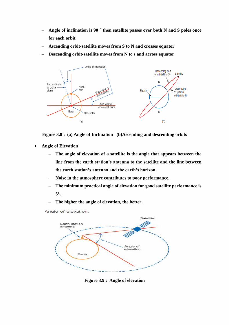
– Angle of inclination is 90 ° then satellite passes over both N and S poles once
for each orbit
– Ascending orbit-satellite moves from S to N and crosses equator
– Descending orbit-satellite moves from N to s and across equator
Figure 3.8 : (a) Angle of Inclination (b)Ascending and descending orbits
Angle of Elevation
– The angle of elevation of a satellite is the angle that appears between the
line from the earth station’s antenna to the satellite and the line between
the earth station’s antenna and the earth’s horizon.
– Noise in the atmosphere contributes to poor performance.
– The minimum practical angle of elevation for good satellite performance is
5°.
– The higher the angle of elevation, the better.
Figure 3.9 : Angle of elevation
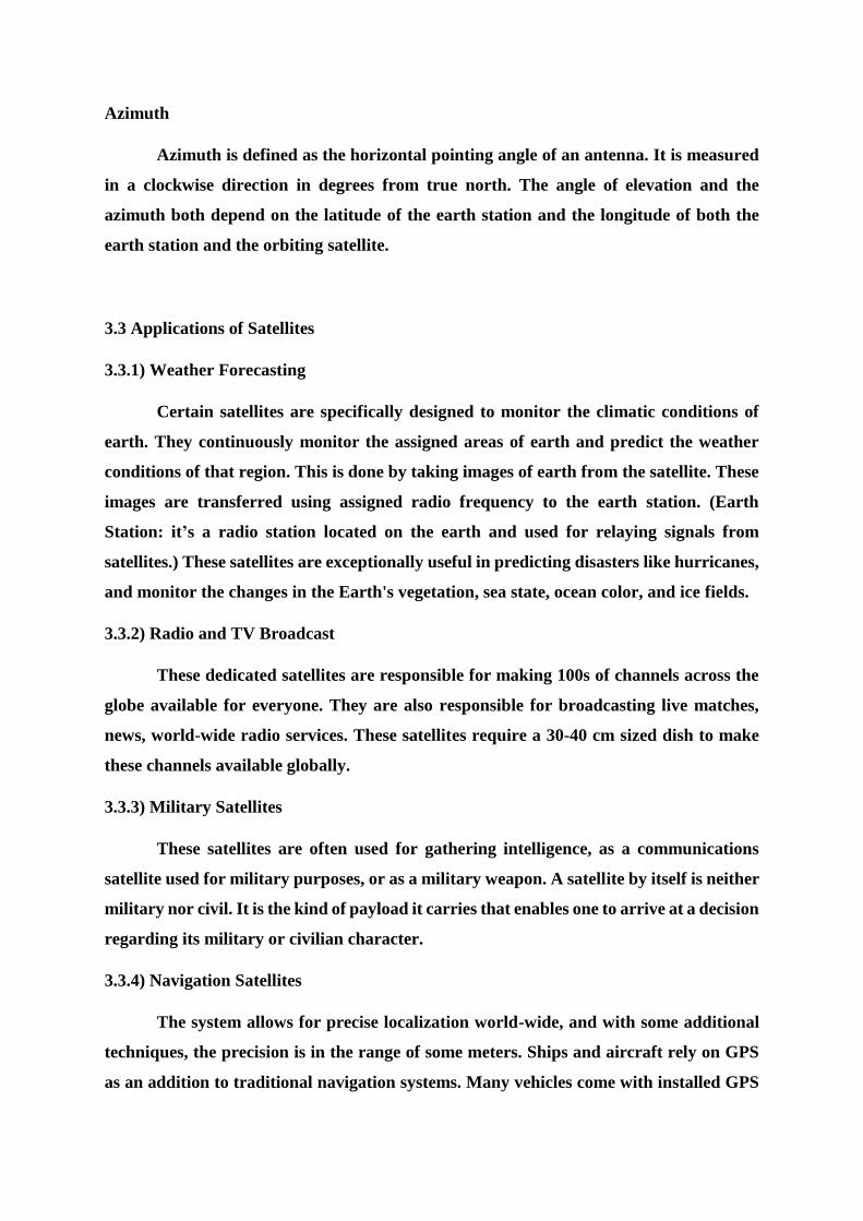
Azimuth
Azimuth is defined as the horizontal pointing angle of an antenna. It is measured
in a clockwise direction in degrees from true north. The angle of elevation and the
azimuth both depend on the latitude of the earth station and the longitude of both the
earth station and the orbiting satellite.
3.3 Applications of Satellites
3.3.1) Weather Forecasting
Certain satellites are specifically designed to monitor the climatic conditions of
earth. They continuously monitor the assigned areas of earth and predict the weather
conditions of that region. This is done by taking images of earth from the satellite. These
images are transferred using assigned radio frequency to the earth station. (Earth
Station: it’s a radio station located on the earth and used for relaying signals from
satellites.) These satellites are exceptionally useful in predicting disasters like hurricanes,
and monitor the changes in the Earth's vegetation, sea state, ocean color, and ice fields.
3.3.2) Radio and TV Broadcast
These dedicated satellites are responsible for making 100s of channels across the
globe available for everyone. They are also responsible for broadcasting live matches,
news, world-wide radio services. These satellites require a 30-40 cm sized dish to make
these channels available globally.
3.3.3) Military Satellites
These satellites are often used for gathering intelligence, as a communications
satellite used for military purposes, or as a military weapon. A satellite by itself is neither
military nor civil. It is the kind of payload it carries that enables one to arrive at a decision
regarding its military or civilian character.
3.3.4) Navigation Satellites
The system allows for precise localization world-wide, and with some additional
techniques, the precision is in the range of some meters. Ships and aircraft rely on GPS
as an addition to traditional navigation systems. Many vehicles come with installed GPS
receivers. This system is also used, e.g., for fleet management of trucks or for vehicle
localization in case of theft.
3.3.5) Global Telephone
One of the first applications of satellites for communication was the establishment
of international telephone backbones. Instead of using cables it was sometimes faster to
launch a new satellite. But, fiber optic cables are still replacing satellite communication
across long distance as in fiber optic cable, light is used instead of radio frequency, hence
making the communication much faster (and of course, reducing the delay caused due to
the amount of distance a signal needs to travel before reaching the destination.). Using
satellites, to typically reach a distance approximately 10,000 kms away, the signal needs
to travel almost 72,000 kms, that is, sending data from ground to satellite and (mostly)
from satellite to another location on earth. This causes substantial amount of delay and
this delay becomes more prominent for users during voice calls.
3.3.6) Connecting Remote Areas
Due to their geographical location many places all over the world do not have
direct wired connection to the telephone network or the internet (e.g., researchers on
Antarctica) or because of the current state of the infrastructure of a country. Here the
satellite provides a complete coverage and (generally) there is one satellite always present
across a horizon.
3.3.7) Global Mobile Communication
The basic purpose of satellites for mobile communication is to extend the area of
coverage. Cellular phone systems, such as AMPS and GSM (and their successors) do not
cover all parts of a country. Areas that are not covered usually have low population where
it is too expensive to install a base station. With the integration of satellite communication,
however, the mobile phone can switch to satellites offering world-wide connectivity to a
customer. Satellites cover a certain area on the earth. This area is termed as a „footprint‟
of that satellite. Within the footprint, communication with that satellite is possible for
mobile users. These users communicate using a Mobile-User-Link (MUL). The base-
stations communicate with satellites using a Gateway-Link (GWL). Sometimes it becomes
necessary for satellite to create a communication link between users belonging to two
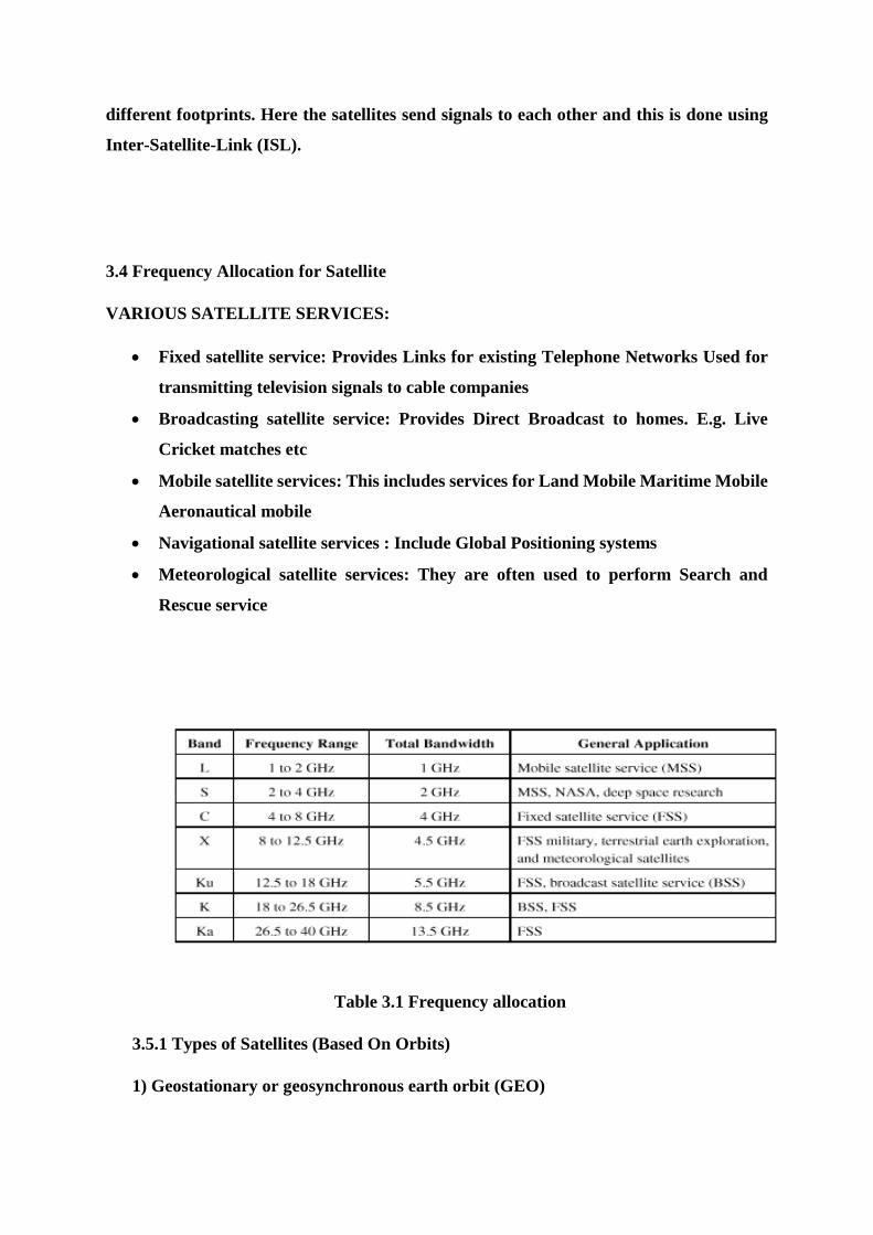
different footprints. Here the satellites send signals to each other and this is done using
Inter-Satellite-Link (ISL).
3.4 Frequency Allocation for Satellite
VARIOUS SATELLITE SERVICES:
Fixed satellite service: Provides Links for existing Telephone Networks Used for
transmitting television signals to cable companies
Broadcasting satellite service: Provides Direct Broadcast to homes. E.g. Live
Cricket matches etc
Mobile satellite services: This includes services for Land Mobile Maritime Mobile
Aeronautical mobile
Navigational satellite services : Include Global Positioning systems
Meteorological satellite services: They are often used to perform Search and
Rescue service
Table 3.1 Frequency allocation
3.5.1 Types of Satellites (Based On Orbits)
1) Geostationary or geosynchronous earth orbit (GEO)
GEO satellites are synchronous with respect to earth. Looking from a fixed point from
Earth, these satellites appear to be stationary. These satellites are placed in the space
in such a way that only three satellites are sufficient to provide connection throughout
the surface of the Earth (that is; their footprint is covering almost 1/3rd of the Earth).
The orbit of these satellites is circular.
There are three conditions which lead to geostationary satellites. Lifetime expectancy
of these satellites is 15 years.
1) The satellite should be placed 37,786 kms (approximated to 36,000 kms) above the
surface of the earth.
2) These satellites must travel in the rotational speed of earth, and in the direction of
motion of earth, that is eastward.
3) The inclination of satellite with respect to earth must be 00.
Geostationary satellite in practical is termed as geosynchronous as there are multiple
factors which make these satellites shift from the ideal geostationary condition.
1) Gravitational pull of sun and moon makes these satellites deviate from their orbit.
Over the period of time, they go through a drag. (Earth‟s gravitational force has no
effect on these satellites due to their distance from the surface of the Earth.)
2) These satellites experience the centrifugal force due to the rotation of Earth,
making them deviate from their orbit.
3) The non-circular shape of the earth leads to continuous adjustment of speed of
satellite from the earth station.
These satellites are used for TV and radio broadcast, weather forecast and also, these
satellites are operating as backbones for the telephone networks.
Disadvantages of GEO: Northern or southern regions of the Earth (poles) have more
problems receiving these satellites due to the low elevation above a latitude of 60°, i.e.,
larger antennas are needed in this case. Shading of the signals is seen in cities due to
high buildings and the low elevation further away from the equator limit transmission
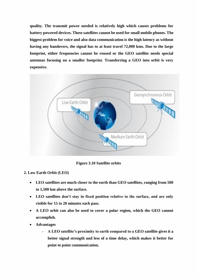
quality. The transmit power needed is relatively high which causes problems for
battery powered devices. These satellites cannot be used for small mobile phones. The
biggest problem for voice and also data communication is the high latency as without
having any handovers, the signal has to at least travel 72,000 kms. Due to the large
footprint, either frequencies cannot be reused or the GEO satellite needs special
antennas focusing on a smaller footprint. Transferring a GEO into orbit is very
expensive.
Figure 3.10 Satellite orbits
2. Low Earth Orbit (LEO)
LEO satellites are much closer to the earth than GEO satellites, ranging from 500
to 1,500 km above the surface.
LEO satellites don’t stay in fixed position relative to the surface, and are only
visible for 15 to 20 minutes each pass.
A LEO orbit can also be used to cover a polar region, which the GEO cannot
accomplish.
Advantages
– A LEO satellite’s proximity to earth compared to a GEO satellite gives it a
better signal strength and less of a time delay, which makes it better for
point to point communication.
A LEO satellite’s smaller area of coverage is less of a waste of bandwidth
Disadvantages
– A network of LEO satellites is needed, which can be costly
– LEO satellites have to compensate for Doppler shifts cause by their relative
movement.
– Atmospheric drag effects LEO satellites, causing gradual orbital
deterioration.
3. Medium Earth Orbit (MEO)
A MEO satellite is in orbit somewhere between 8,000 km and 18,000 km above the
earth’s surface.
MEO satellites are similar to LEO satellites in functionality.
MEO satellites are visible for much longer periods of time than LEO satellites,
usually between 2 to 8 hours.
MEO satellites have a larger coverage area than LEO satellites.
Advantage
– A MEO satellite’s longer duration of visibility and wider footprint means
fewer satellites are needed in a MEO network than a LEO network.
Disadvantage
– A MEO satellite’s distance gives it a longer time delay and weaker signal
than a LEO satellite, though not as bad as a GEO satellite.
4. Molniya Orbit Satellites
Used by Russia for decades.
Molniya Orbit is an elliptical orbit. The satellite remains in a nearly fixed position
relative to earth for eight hours.
A series of three Molniya satellites can act like a GEO satellite.
Useful in near polar regions.
5. High Altitude Platform (HAP)
One of the newest ideas in satellite communication.
A blimp or plane around 20 km above the earth’s surface is used as a satellite.
HAPs would have very small coverage area, but would have a comparatively
strong signal.
Cheaper to put in position, but would require a lot of them in a network
6. Prograde orbit: This orbit is with an inclination of less than 90°. Its direction is the
same as the direction as the rotation of the primary (planet).
7. Retrograde orbit:
This orbit is with an inclination of more than 90°. Its direction is counter to the direction
of rotation of the planet. Only few satellites are launched into retrograde orbit because
the quantity of fuel required to launch them is much greater than for a prograde orbit.
This is because when the rocket starts out on the ground, it already has an eastward
component of velocity equal to the rotational velocity of the planet at its launch latitude.
8. Polar Orbits
This orbit passes above or nearly above both poles (north and south pole) of the planet
on each of its revolutions. Therefore it has an inclination of (or very close to) 90 degrees.
These orbits are highly inclined in shape
3.6 Multiple Access Techniques
Multiple accesses is defined as the technique where in more than one pair of earth
stations can simultaneously use a satellite transponder. It is a technique used to explore
the satellite’s geometric advantages and is at the core of satellite networking. In a wireless
communication system, radio resources must be provided in each cell to assure the
interchange of data between the mobile terminal and the base station. Uplink is from the
mobile users to the base station and downlink is from the base station to the mobile users.
Each transmitting terminal employs different resources of the cell. A multiple access
scheme is a method used to distinguish among different simultaneous transmissions in a
cell. A radio resource can be a different time interval, a frequency interval or a code with
a suitable power level.
a) FREQUENCY DIVISION MULTIPLE ACCESS (FDMA)
FDMA is a channel access method used in multiple-access protocols as a
channelization protocol. FDMA gives users an individual allocation of one or several
frequency bands, or channels. Multiple Access systems coordinate access between
multiple users.
Key features of FDMA are:
FDMA requires high-performing filters in the radio hardware, in contrast
to TDMA and CDMA.
FDMA is not vulnerable to the timing problems that TDMA has. Since a
predetermined frequency band is available for the entire period of
communication, stream data (a continuous flow of data that may not be
packetized) can easily be used with FDMA.
Due to the frequency filtering, FDMA is not sensitive to near-far problem
which is pronounced for CDMA.
Each user transmits and receives at different frequencies as each user gets
a unique frequency slot
It is important to distinguish between FDMA and frequency-division
duplexing (FDD). While FDMA allows multiple users simultaneous access
to a certain system, FDD refers to how the radio channel is shared between
the uplink and downlink (for instance, the traffic going back and forth
between a mobile-phone and a base-station).
Furthermore, frequency-division multiplexing (FDM) should not be
confused with FDMA. The former is a physical layer technique that
combines and transmits low-bandwidth channels through a high-
bandwidth channel. FDMA, on the other hand, is an access method in the
data link layer.
FDMA also supports demand assignment in addition to fixed assignment.
Demand assignment allows all users apparently continuous access of the
radio spectrum by assigning carrier frequencies on a temporary basis using
a statistical assignment process. The first FDMA demand-assignment
system for satellite was developed by COMSAT for use on the Intelsat
series IVA and V satellites.
In this scheme, a bandwidth is assigned to an earth station and is divided
into n segments to manage the network traffic.
Advantages of FDMA:
Uses existing hardware and hence this technology is cost efficient
Network timing is not required, hence making the system less complex.
No restrictions regarding the type of baseband type of modulation is there.
Disadvantage of FDMA
Inter modulation noise in the transponder leads to interference with other
links sharing new spectrum and thus reduces the capacity of satellite.
Flexibility in channel allocation is less (as seen in MCPC, but not in SCPC).
Uplink power control is required to maintain the link quality.
As strong and weak carriers, both are used, weak carriers are often
suppressed.
b) TIME DIVISION MULTIPLE ACCESS (TDMA)
Time division multiple access (TDMA) is a channel access method for shared
medium networks. It allows several users to share the same frequency channel by dividing
the signal into different time slots. The users transmit in rapid succession, one after the
other, each using his own time slot. This allows multiple stations to share the same
transmission medium (e.g. radio frequency channel) while using only a part of its channel
capacity.
TDMA is a type of Time-division multiplexing, with the special point that instead
of having one transmitter connected to one receiver, there are multiple transmitters. In
the case of the uplink from a mobile phone to a base station this becomes particularly
difficult because the mobile phone can move around and vary the timing advance
required to make its transmission match the gap in transmission from its peers.
Features of TDMA
Shares single carrier frequency with multiple users
Non-continuous transmission makes handoff simpler
Slots can be assigned on demand in dynamic TDMA
Less stringent power control than CDMA due to reduced intra cell interference
Higher synchronization overhead than CDMA
Advanced equalization may be necessary for high data rates if the channel is
"frequency selective" and creates inter-symbol interference
Cell breathing (borrowing resources from adjacent cells) is more complicated than
in CDMA
Frequency/slot allocation complexity
Pulsating power envelop: Interference with other devices
For satellite communication TDMA works in the following manner.
TDMA systems are used in commercial satellite applications. The first system type
is the classic TDMA implementation employing a single modulated carrier
occupying the full transponder’s bandwidth.
This system is most common for TDMA networks and is also most efficient from
a capacity standards point.
Each user is allocated a specific time slot for transmission due to which
overlapping is avoided.
System capacity is increased as only a single carrier is present at any given time.
Disadvantage is that the messages need to be stored, compressed and transmitted
during one or more specific time slots. At network level, all transmissions must be
synchronized to avoid collision between the bursts.
(Burst: It is a term used in a number of information technology contexts to mean
a specific amount of data sent or received in one intermittent time.)
An earth station has a full access to a transponder during its allocated time slot.
Transmissions are in frame format.
On receiving al the bursts, earth station removes the data addresses from it.
Guard time is used to separate time-slots. The time-slot size depends on the traffic
requirements.
TDMA also works on demand- assign method.
Advantages:
Here, satellite power utilizations can be maximized as inter modulation noise is
minimum.
Uplink power control is not required.
Transmission plans and capacity management is done by the satellite are very
flexible.
The digital format of TDMA allows utilization of all advantages of digital
techniques.
Disadvantages
It requires a network wide time synchronization which makes the entire system
very complex.
Analog of digital conversions are required.
Interface with analog terrestrial plan is expected.
FDMA & TDMA
In situations where connectivity is required between multiple spot beams, then
routing of signal to an appropriate beam is done by having frequency-to-beam
correspondence.
Sub-bands are made and each of them provides a unique route between two spot
beams.
Here transponders can be accessed in FDMA or TDMA mode. As each earth
station have to hop between transponders to route the traffic to the desired spot
beam this technique is called transponder hopping.
For n spot beams, n2transponders are required.
To make this work, flexibility in altering the frequency bands is required. This is
done by using switchable routing method.
In switchable routing method, channels are switched as desired in order to change
the available bandwidth of each beam.
A programmable switch located on the satellite router bursts to spot beams
according to a set plan.
The earth station can direct its transmission to any spot by transmitting in the
appropriate time slot.
Beams are arranged in non-overlapping time-slots.
c) CODE DIVISION MULTIPLE ACCESS (CDMA)
CDMA uses a modulation technique called spread spectrum. Here all the users
transmit signals simultaneously on the multiple access schemes.(Spread
Spectrum: It refers to a modulation technique that converts the baseband signal
to a modulated signal with a spectrum bandwidth that covers or is spread over the
band orders of magnitude larger than that normally necessary to transmit the
baseband signal itself.)
It could be used as a multiple access system by giving each user a unique pseudo
random code rather than a unique carrier frequency or time slot.
All the users contribute to the noise background.
To detect the desired signal in the presence of all the interferences, the composite
signal is cross-correlated with the known pseudo random number spreading
sequence.
The net performance is improved essentially by the ration of the un-spread signal
bandwidth.
Features of CDMA are:
Highly resistant to interferences and thus satellite spacing could be reduced
considerably without causing unacceptable degradation in the received signal
quality.
Spread spectrum sequences are resistant to multiple noises present in the mobile
terminals.
Small antennas can be used without any interference issues from the neighboring
CDMA is a very secure form of communication.
Implementing CDMA
CDMA technique could be implemented in two forms: Direct sequence spread
spectrum and Frequency hopping spread spectrum.
The property of pseudo random sequences is used by CDMA.
i) Pseudo-Random Sequences
They are a set of signals which appear ti be a set of random sequences. They are
repeated over a time interval, say of Tr.
In order to use such pseudo (false) random sequences signals in digital form, shift
registers are required. These shift registers could be used for maximum length of
code of the value p=(2m-1),where m-bit register is used.
This is also called maximum length linear shift register sequence.
These sequences have 2m-1 ones and 2m-1-1zeros that are places randomly, thus
making the entire sequence look random.
ii) Direct Sequence Spread Spectrum (DSSS)
Definition: Direct sequence spread spectrum is a modulation technique where the
transmitted signal takes up more bandwidth then the information signal that is
being modulated.
Direct sequence spread spectrum transmissions multiply the data being
transmitted by a „noise‟ signal.
The noise signal is the pseudo random sequence and has a frequency much higher
than that of the original signal. It thus spreads the energy of the original signal
into a much wider band
The resultant signal appears like noise which could be reconstructed to the
original signal at the receiving end by multiplying it by the same pseudo random
sequence. This process is known as de-spreading. For de-spreading to work
correctly, the transmitter and receiver must be synchronized.
Sometimes while sending the signal from the transmitter‟s end, other noises like
inter modulation noise and thermal noise are transmitted to the receiver. This is
also called as narrow-band interference.
The receiving signal is given as:
Rx (t) = C1 (t) + C2 (t) + …. + Cn (t) Where: Cn (t) is the received signal from the
nth transmitter n (t) is the system noise
iii) Frequency Hopping Spread Spectrum (FHSS)
It is a method of transmitting radio signals by rapidly switching a carrier among
many frequency channels, using the pseudo random sequences (which are known
to both transmitter and receiver).
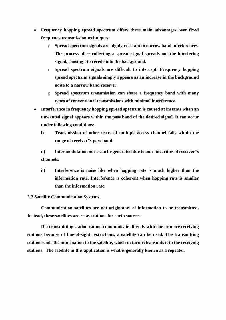
Frequency hopping spread spectrum offers three main advantages over fixed
frequency transmission techniques:
o Spread spectrum signals are highly resistant to narrow band interferences.
The process of re-collecting a spread signal spreads out the interfering
signal, causing t to recede into the background.
o Spread spectrum signals are difficult to intercept. Frequency hopping
spread spectrum signals simply appears as an increase in the background
noise to a narrow band receiver.
o Spread spectrum transmission can share a frequency band with many
types of conventional transmissions with minimal interference.
Interference in frequency hopping spread spectrum is caused at instants when an
unwanted signal appears within the pass band of the desired signal. It can occur
under following conditions:
i) Transmission of other users of multiple-access channel falls within the
range of receiver‟s pass band.
ii) Inter modulation noise can be generated due to non-linearities of receiver‟s
channels.
ii) Interference is noise like when hopping rate is much higher than the
information rate. Interference is coherent when hopping rate is smaller
than the information rate.
3.7 Satellite Communication Systems
Communication satellites are not originators of information to be transmitted.
Instead, these satellites are relay stations for earth sources.
If a transmitting station cannot communicate directly with one or more receiving
stations because of line-of-sight restrictions, a satellite can be used. The transmitting
station sends the information to the satellite, which in turn retransmits it to the receiving
stations. The satellite in this application is what is generally known as a repeater.
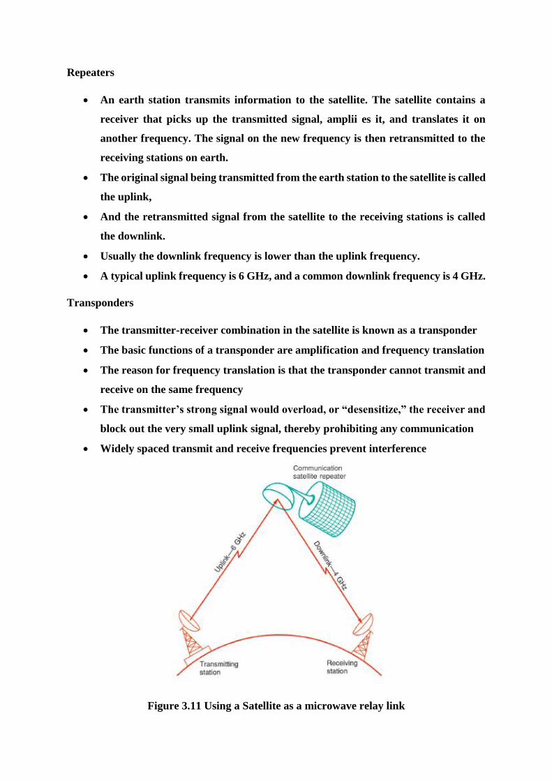
Repeaters
An earth station transmits information to the satellite. The satellite contains a
receiver that picks up the transmitted signal, amplii es it, and translates it on
another frequency. The signal on the new frequency is then retransmitted to the
receiving stations on earth.
The original signal being transmitted from the earth station to the satellite is called
the uplink,
And the retransmitted signal from the satellite to the receiving stations is called
the downlink.
Usually the downlink frequency is lower than the uplink frequency.
A typical uplink frequency is 6 GHz, and a common downlink frequency is 4 GHz.
Transponders
The transmitter-receiver combination in the satellite is known as a transponder
The basic functions of a transponder are amplification and frequency translation
The reason for frequency translation is that the transponder cannot transmit and
receive on the same frequency
The transmitter’s strong signal would overload, or “desensitize,” the receiver and
block out the very small uplink signal, thereby prohibiting any communication
Widely spaced transmit and receive frequencies prevent interference
Figure 3.11 Using a Satellite as a microwave relay link
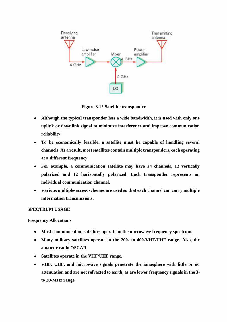
Figure 3.12 Satellite transponder
Although the typical transponder has a wide bandwidth, it is used with only one
uplink or downlink signal to minimize interference and improve communication
reliability.
To be economically feasible, a satellite must be capable of handling several
channels. As a result, most satellites contain multiple transponders, each operating
at a different frequency.
For example, a communication satellite may have 24 channels, 12 vertically
polarized and 12 horizontally polarized. Each transponder represents an
individual communication channel.
Various multiple-access schemes are used so that each channel can carry multiple
information transmissions.
SPECTRUM USAGE
Frequency Allocations
Most communication satellites operate in the microwave frequency spectrum.
Many military satellites operate in the 200- to 400-VHF/UHF range. Also, the
amateur radio OSCAR
Satellites operate in the VHF/UHF range.
VHF, UHF, and microwave signals penetrate the ionosphere with little or no
attenuation and are not refracted to earth, as are lower frequency signals in the 3-
to 30-MHz range.

Most widely used satellite communication bands is the C band. The uplink
frequencies are 5.925 to 6.425 GHz. In any general discussion of the C band, the
uplink is generally said to be 6 GHz. The downlink is in the 3.7- to 4.2-GHz range.
But again, in any general discussion of the C band, the downlink is nominally said
to be 4 GHz. Occasionally, the C band is referred to by the designation 6/4 GHz
Currently, the Ku band is receiving the most attention. The uplinks are in the 14-
to 14.5-GHz range, and the downlinks are from 11.7 to 12.2 GHz. You will see the
Ku band designated as 14/12 GHz.
Use of the Ka band is also increasing. Most new communication satellites will
operate in the Ku band
Two other bands of interest are the X and L bands. The military uses the X band
for its satellites and radar. The L band is used for navigation as well as marine
and aeronautical communication and radar.
Numerous techniques have been developed to effectively increase the bandwidth
and signal-carrying capacity of the satellite. Two of these techniques are known as
frequency reuse and spatial isolation.
Frequency Reuse.
One system for effectively doubling the bandwidth and information carrying
capacity of a satellite is known as frequency reuse.
When an allocated frequency band is filled, additional capacity can be achieved
by reuse of the frequency spectrum. By increasing the size of an antenna (i.e..
increasing the antenna gain) the beamwidth of the antenna is also reduced. Thus
different beams of the same frequency can be directed to different geographical
areas of the earth. This is called frequency reuse.
In this system, a communication satellite is provided with two identical sets of 12
transponders. The first channel in one transponder operates on the same channel
as the first transponder in the other set, and so on. The two systems, although
operating on exactly the same frequencies, are isolated from each other by the use
of special antenna techniques.
One technique for keeping transmissions separate is to use different antenna
polarizations.
For example, a vertically polarized antenna will not respond to a horizontally
polarized signal and vice versa. Or a left-hand circularly polarized (LHCP)
antenna will not respond to a right-hand circularly polarized (RHCP) signal and
vice versa.
Another technique is to use spatial isolation. By using narrow beam or spot beam
antennas, the area on the earth covered by the satellite can be divided up into
smaller segments. Earth stations in each segment may actually use the same
frequency, but because of the very narrow beam widths of the antennas, there is
no interference between adjacent segments. This technique is referred to a spatial-
division multiple access (SDMA) in that access to the satellite depends on location
and not frequency.
3.8 Satellite Subsystems
All satellite communication systems consist of two basic parts, the satellite or
spacecraft and two or more earth stations.
The satellite performs the function of a radio repeater or relay station.
Two or more earth stations may communicate with one another through the
satellite rather than directly point-to-point on the earth.
1. communication subsystem -The heart of a communication satellite
2. The following are essential to the self-sustaining nature of the satellite.
3. The power subsystem
4. The telemetry tracking and command subsystems
5. The antenna subsytem
6. The propulsion subsystem
7. The attitude stabilization subsystems.
The solar panels supply the electric power for the spacecraft. They drive
regulators that distribute dc power to all other subsystems. And they charge the
batteries that operate the satellite during eclipse periods. And ac-to-dc converters
and dc-to-ac inverters are used to supply special voltages to some subsystems.
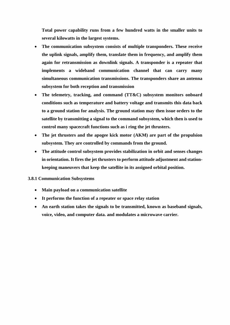
Total power capability runs from a few hundred watts in the smaller units to
several kilowatts in the largest systems.
The communication subsystem consists of multiple transponders. These receive
the uplink signals, amplify them, translate them in frequency, and amplify them
again for retransmission as downlink signals. A transponder is a repeater that
implements a wideband communication channel that can carry many
simultaneous communication transmissions. The transponders share an antenna
subsystem for both reception and transmission
The telemetry, tracking, and command (TT&C) subsystem monitors onboard
conditions such as temperature and battery voltage and transmits this data back
to a ground station for analysis. The ground station may then issue orders to the
satellite by transmitting a signal to the command subsystem, which then is used to
control many spacecraft functions such as i ring the jet thrusters.
The jet thrusters and the apogee kick motor (AKM) are part of the propulsion
subsystem. They are controlled by commands from the ground.
The attitude control subsystem provides stabilization in orbit and senses changes
in orientation. It fires the jet thrusters to perform attitude adjustment and station-
keeping maneuvers that keep the satellite in its assigned orbital position.
3.8.1 Communication Subsystems
Main payload on a communication satellite
It performs the function of a repeater or space relay station
An earth station takes the signals to be transmitted, known as baseband signals,
voice, video, and computer data. and modulates a microwave carrier.
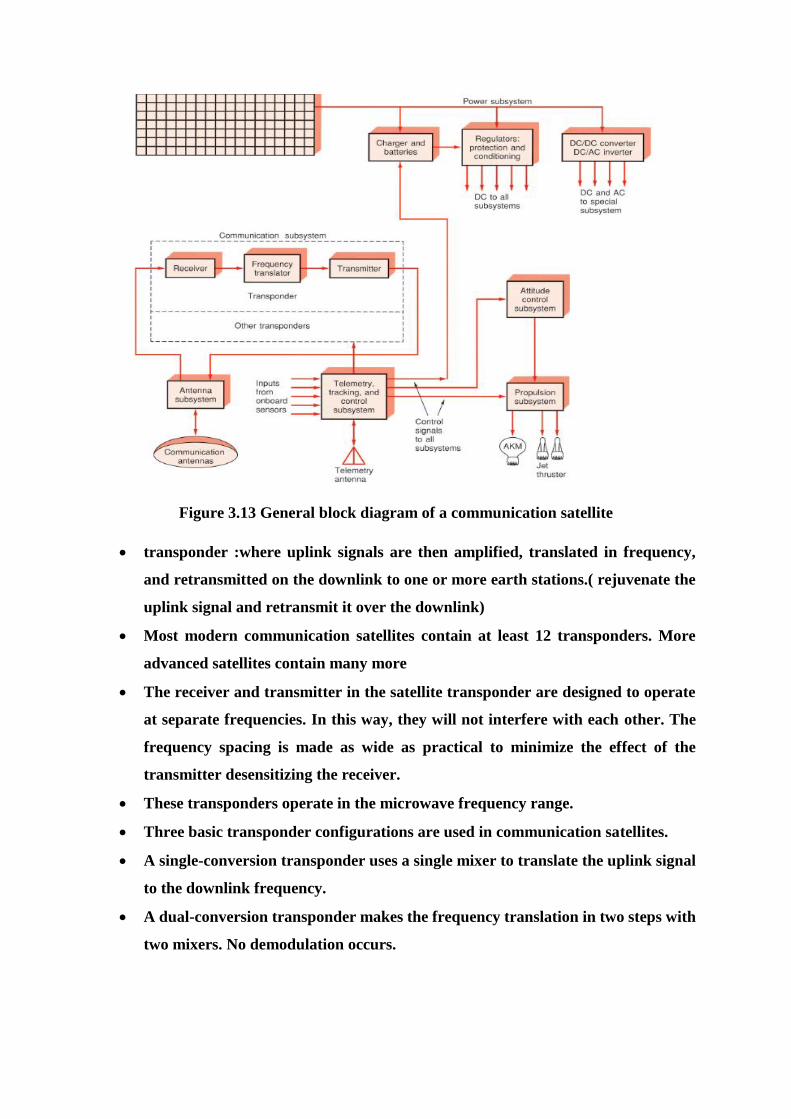
Figure 3.13 General block diagram of a communication satellite
transponder :where uplink signals are then amplified, translated in frequency,
and retransmitted on the downlink to one or more earth stations.( rejuvenate the
uplink signal and retransmit it over the downlink)
Most modern communication satellites contain at least 12 transponders. More
advanced satellites contain many more
The receiver and transmitter in the satellite transponder are designed to operate
at separate frequencies. In this way, they will not interfere with each other. The
frequency spacing is made as wide as practical to minimize the effect of the
transmitter desensitizing the receiver.
These transponders operate in the microwave frequency range.
Three basic transponder configurations are used in communication satellites.
A single-conversion transponder uses a single mixer to translate the uplink signal
to the downlink frequency.
A dual-conversion transponder makes the frequency translation in two steps with
two mixers. No demodulation occurs.

A regenerative repeater demodulates the uplink signal after the frequency is
translated to some lower intermediate frequency. The recovered baseband signal
is then used to modulate the downlink signal
Multichannel Configurations.
Virtually all modern communication satellites contain multiple transponders. This
permits many more signals to be received and transmitted. There are two basic
multichannel architectures in use in communication satellites.
1.Broadband System
2.The Fully channelized system
1.1 Broadband System
A typical communication satellite spectrum is 500 MHz wide. This is typically
divided into 12 separate channels, each with a bandwidth of 36 MHz. The
center frequency spacing between adjacent channels is 40 MHz, thereby
providing a 4-MHz spacing between channels to minimize adjacent channel
interference
A wideband repeater (Fig.) is designed to receive any signal transmitted within
the 500-MHz total bandwidth.
The receive antenna is connected to a low-noise amplifier (LNA) as in every
transponder.
Very wideband tuned circuits are used so that the entire 500-MHz bandwidth
is received and amplified.
A low-noise amplifier, usually a GaAs FET, provides gain.
A mixer translates all incoming signals to their equivalent lower downlink
frequencies.
In a C-band communication satellite, the incoming signals are located between
5.925 and 6.425 MHz.
A local oscillator operating at the frequency of 2.225 GHz is used to translate
the inputs to the 3.7- to 4.2-GHz range.
A wideband amplifier following the mixer amplifies this entire spectrum
1.2 Channelization Process
The channelization process occurs in the remainder of the transponder. To
achieve the high power levels, the channelization process is used.
For example, in a 12-channel satellite, 12 bandpass filters, each centered on
one of the 12 channels, are used to separate all the various received signals.
Fig. shows the 12 basic channels with their center frequencies, each having a
bandwidth of 36 MHz. The bandpass filters separate out the unwanted mixer
output signals and retain only the difference signals.
Then individual high-power amplifiers (HPAs) are used to increase the signal
level.
The high-power amplifiers in most transponders are traveling-wave tubes that
inherently have limited bandwidth. They operate well over a small range but
cannot deal with the entire 500-MHz bandwidth allocated to a satellite.
Figure 3.14 A broadband multiple-channel repeater
3.8.2 Power Subsystem
Today virtually every satellite uses solar panels for its basic power source.
Solar panels are large arrays of photocells connected in various series and parallel
circuits to create a powerful source of direct current.
Early solar panels could generate hundreds of watts of power. Today huge solar
panels are capable of generating many kilowatts.
A key requirement is that the solar panels always be pointed toward the sun.
Solar panels generate a direct current that is used to operate the various
components of the satellite.
However, the dc power is typically used to charge secondary batteries that act as
a buffer. When a satellite goes into an eclipse or when the solar panels are not
properly positioned, the batteries take over temporarily and keep the satellite
operating
Special dc-to-dc converters are used to translate the lower dc voltage of the solar
panels to the
higher dc voltage required by the TWTs.
Manipulated with various controls to ensure that they are correctly oriented with
respect to the sun
3.8.3 Telemetry, Command, and Control Subsystems
All satellites have a telemetry, command, and control (TC&C) subsystem that
allows a ground station to monitor and control conditions in the satellite
The telemetry system:
Report the status of the onboard subsystems to the ground station
Typically consists of various electronic sensors for measuring temperatures,
radiation levels, power supply voltages, and other key operating characteristics
Both analog and digital sensors may be used. The sensors are selected by a
multiplexer and then converted to a digital signal, which then modulates an
internal transmitter
This transmitter sends the telemetry information back to the earth station, where
it is recorded and monitored.
With this information, the ground station then determines the operational status
of the satellite at all times

A command and control system:
Permits the ground station to control the satellite
Typically, the satellite contains a command receiver that receives control signals
from an earth station transmitter
The control signals are made up of various digital codes that tell the satellite what
to do
Various commands may initiate a telemetry sequence, activate thrusters for
attitude correction, reorient an antenna, or perform other operations as required
by the special equipment specific to the mission. Usually, the control signals are
processed by an onboard computer
Most satellites contain a small digital computer, usually microprocessor-based,
that acts as a central control unit for the entire satellite
Figure 3.15 General block diagram of a satellite telemetry unit
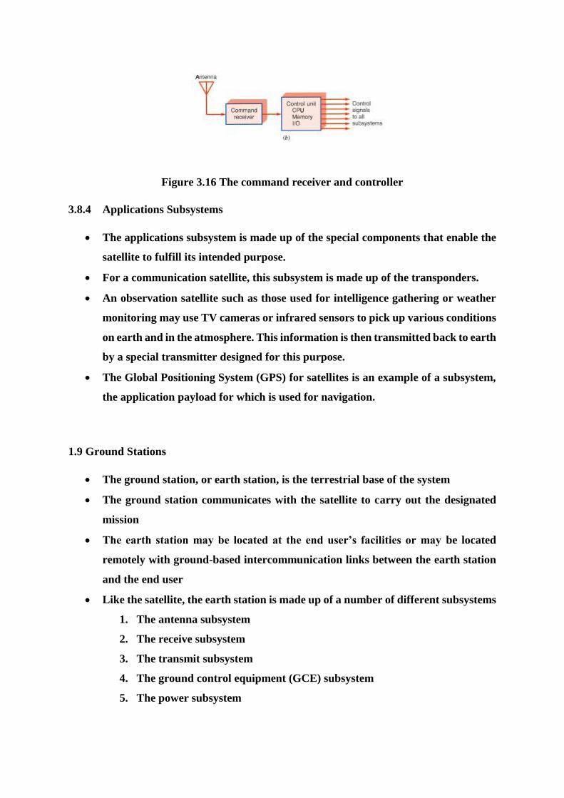
Figure 3.16 The command receiver and controller
3.8.4 Applications Subsystems
The applications subsystem is made up of the special components that enable the
satellite to fulfill its intended purpose.
For a communication satellite, this subsystem is made up of the transponders.
An observation satellite such as those used for intelligence gathering or weather
monitoring may use TV cameras or infrared sensors to pick up various conditions
on earth and in the atmosphere. This information is then transmitted back to earth
by a special transmitter designed for this purpose.
The Global Positioning System (GPS) for satellites is an example of a subsystem,
the application payload for which is used for navigation.
1.9 Ground Stations
The ground station, or earth station, is the terrestrial base of the system
The ground station communicates with the satellite to carry out the designated
mission
The earth station may be located at the end user’s facilities or may be located
remotely with ground-based intercommunication links between the earth station
and the end user
Like the satellite, the earth station is made up of a number of different subsystems
1. The antenna subsystem
2. The receive subsystem
3. The transmit subsystem
4. The ground control equipment (GCE) subsystem
5. The power subsystem

Figure 3.17 General block diagram of an earth station
3.9.1 Antenna Subsystems
All earth stations have a relatively large parabolic dish antenna that is used for
sending and receiving signals to and from the satellite
Early satellite systems, Huge high-gain antennas were required to pick up minute
signals from the satellite. The earth station dishes were 80 to 100 ft or more in
diameter. Antennas of this size are still used in some satellite systems today, and
even larger antennas have been used for deep-space probes
Modern satellites now transmit with much more power. Advances have also been
made in receiver components and circuitry
For that reason, smaller earth station antennas are now practical. In some
applications, antennas having as small as 18-in diameter can be used
The antenna in an earth station must be possible to adjust its azimuth and
elevation so that the antenna can be properly aligned with the satellite. Earth
stations supporting geosynchronous satellites can generally be fixed in position,
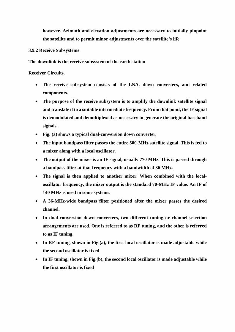
however. Azimuth and elevation adjustments are necessary to initially pinpoint
the satellite and to permit minor adjustments over the satellite’s life
3.9.2 Receive Subsystems
The downlink is the receive subsystem of the earth station
Receiver Circuits.
The receive subsystem consists of the LNA, down converters, and related
components.
The purpose of the receive subsystem is to amplify the downlink satellite signal
and translate it to a suitable intermediate frequency. From that point, the IF signal
is demodulated and demultiplexed as necessary to generate the original baseband
signals.
Fig. (a) shows a typical dual-conversion down converter.
The input bandpass filter passes the entire 500-MHz satellite signal. This is fed to
a mixer along with a local oscillator.
The output of the mixer is an IF signal, usually 770 MHz. This is passed through
a bandpass filter at that frequency with a bandwidth of 36 MHz.
The signal is then applied to another mixer. When combined with the local-
oscillator frequency, the mixer output is the standard 70-MHz IF value. An IF of
140 MHz is used in some systems.
A 36-MHz-wide bandpass filter positioned after the mixer passes the desired
channel.
In dual-conversion down converters, two different tuning or channel selection
arrangements are used. One is referred to as RF tuning, and the other is referred
to as IF tuning.
In RF tuning, shown in Fig.(a), the first local oscillator is made adjustable while
the second oscillator is fixed
In IF tuning, shown in Fig.(b), the second local oscillator is made adjustable while
the first oscillator is fixed
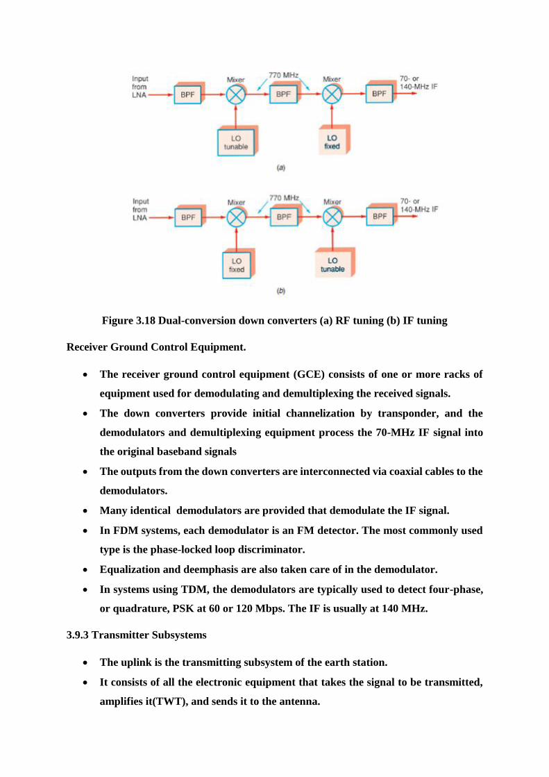
Figure 3.18 Dual-conversion down converters (a) RF tuning (b) IF tuning
Receiver Ground Control Equipment.
The receiver ground control equipment (GCE) consists of one or more racks of
equipment used for demodulating and demultiplexing the received signals.
The down converters provide initial channelization by transponder, and the
demodulators and demultiplexing equipment process the 70-MHz IF signal into
the original baseband signals
The outputs from the down converters are interconnected via coaxial cables to the
demodulators.
Many identical demodulators are provided that demodulate the IF signal.
In FDM systems, each demodulator is an FM detector. The most commonly used
type is the phase-locked loop discriminator.
Equalization and deemphasis are also taken care of in the demodulator.
In systems using TDM, the demodulators are typically used to detect four-phase,
or quadrature, PSK at 60 or 120 Mbps. The IF is usually at 140 MHz.
3.9.3 Transmitter Subsystems
The uplink is the transmitting subsystem of the earth station.
It consists of all the electronic equipment that takes the signal to be transmitted,
amplifies it(TWT), and sends it to the antenna.
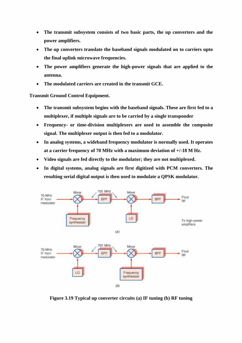
The transmit subsystem consists of two basic parts, the up converters and the
power amplifiers.
The up converters translate the baseband signals modulated on to carriers upto
the final uplink microwave frequencies.
The power amplifiers generate the high-power signals that are applied to the
antenna.
The modulated carriers are created in the transmit GCE.
Transmit Ground Control Equipment.
The transmit subsystem begins with the baseband signals. These are first fed to a
multiplexer, if multiple signals are to be carried by a single transponder
Frequency- or time-division multiplexers are used to assemble the composite
signal. The multiplexer output is then fed to a modulator.
In analog systems, a wideband frequency modulator is normally used. It operates
at a carrier frequency of 70 MHz with a maximum deviation of +/-18 M Hz.
Video signals are fed directly to the modulator; they are not multiplexed.
In digital systems, analog signals are first digitized with PCM converters. The
resulting serial digital output is then used to modulate a QPSK modulator.
Figure 3.19 Typical up converter circuits (a) IF tuning (b) RF tuning
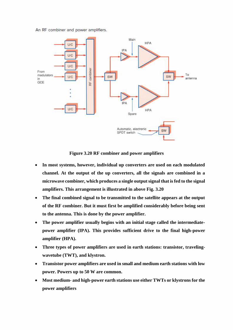
Figure 3.20 RF combiner and power amplifiers
In most systems, however, individual up converters are used on each modulated
channel. At the output of the up converters, all the signals are combined in a
microwave combiner, which produces a single output signal that is fed to the signal
amplifiers. This arrangement is illustrated in above Fig. 3.20
The final combined signal to be transmitted to the satellite appears at the output
of the RF combiner. But it must first be amplified considerably before being sent
to the antenna. This is done by the power amplifier.
The power amplifier usually begins with an initial stage called the intermediate-
power amplifier (IPA). This provides sufficient drive to the final high-power
amplifier (HPA).
Three types of power amplifiers are used in earth stations: transistor, traveling-
wavetube (TWT), and klystron.
Transistor power amplifiers are used in small and medium earth stations with low
power. Powers up to 50 W are common.
Most medium- and high-power earth stations use either TWTs or klystrons for the
power amplifiers
3.9.4 Power Subsystems
Most earth stations receive their power from the normal ac mains.
Standard power supplies convert the ac power to the dc voltages required to
operate all subsystems.
This subsystem operates power supplies that distribute a variety of dc voltages to
the other equipment However, most earth stations have backup power supplies.
Smaller systems may use uninterruptible power supplies (UPS), which derive their
main power from batteries.
Large battery arrays drive dc-to-ac inverters that produce the ac voltages for the
system.
3.9.5 Telemetry and Control Subsystems
The telemetry equipment consists of a receiver and the recorders and indicators
that display the telemetry signals.
The signal may be received by the main antenna or a separate telemetry antenna.
A separate receiver on a frequency different from that of the communication
channels is used for telemetry purposes.
The telemetry signals from the various sensors and transducers in the satellite are
multiplexed onto a single carrier and are sent to the earth station.
The earth station receiver demodulates and demultiplexes the telemetry signals
into the individual outputs.
These are then recorded and sent to various indicators, such as strip chart
recorders, meters, and digital displays.
Signals may be in digital form or converted to digital. They can be sent to a
computer where they can be further processed and stored.
The control subsystem permits the ground station to control the satellite. This
system usually contains a computer for entering the commands that modulate a
carrier that is amplified and fed to the main antenna.
The command signals can make adjustments in the satellite attitude, turn
transponders off and on, actuate redundant circuits if the circuits they are backing
up fail, and so on.
The instrumentation subsystem is in effect an extension of the telemetry system.
Besides relaying information about the satellite itself, the telemetry system may be
used to send back information related to various scientific experiments being
conducted on the satellite
3.9.6 Very Small-Aperture Terminal
A very small-aperture terminal (VSAT) is a miniature low-cost satellite ground
station.
In the past, most ground stations were large and expensive. But over the years,
semiconductor and other technology breakthroughs have greatly reduced the size
and cost of ground stations.
The VSAT is one result. These units are extremely small and mount on the top or
side of a building and in some versions even fit into a suitcase.
A VSAT is a full receive-transmit earth station. Receive-only (RO) VSATs are also
available for special applications such as digital video broadcasts (DVBs).
The most common application of VSATs today is in connecting many remote
company or organization sites to a main computer system. For example, most gas
stations and retail stores use VSATs as point-of-sale (PoS) terminals to transmit
sales transaction information to the home office, check customer credit cards, and
relay inventory data.
Companies such as Shell, Wal-Mart, and Barnes & Noble all use VSATs.
Most stores that sell lottery tickets use a VSAT as do most tollbooths using
SpeedPass and other radio-frequency identification (RFID) of vehicles for tolls.
Broadcast companies like Fox, CNN, ABC, CBS, NBC, and others use VSATs for
remote news gathering and reporting.
A good example of a RO VSAT is the settop box receiver used by consumers for
Direct Broadcast Satellite (DBS) TV reception.

3.10 Satellite Stabilization
Satellite Stabilization
The satellite once placed in its orbit, experiences various perturbing torques.
These include gravitational forces from other bodies like solar and lunar attraction,
magnetic field interaction, solar radiation pressure, etc. Due to these factors, the satellite
orbit tends to drift and its orientation also changes. The satellite's position thus needs to
be controlled both in the east-west as well as the north-south directions. The east-west
location needs to be maintained to prevent radio frequency (RF) interference from
neighboring satellites. It may be mentioned here that in the case of a geostationary
satellite, a 10 drift in the east or west direction is equivalent to a drift of about 735 km
along the orbit. The north-south orientation has to be maintained to have proper satellite
inclination. The attitude and orbit control system maintains the satellite position and its
orientation and keeps the antenna correctly pointed in the desired direction. The orbit
control is performed by firing thrusters in the desired direction or by releasing a jet of
gas. It is also referred to as station keeping.
Commonly employed techniques for satellite attitude control include:
1. Spin stabilization
2. Three-axis or body stabilization
Spin Stabilization
With spin stabilization, the entire spacecraft rotates around its own vertical axis,
spinning like a top. This keeps the spacecraft's orientation in space under control. The
advantage of spin stabilization is that it is a very simple way to keep the spacecraft pointed
in a certain direction. The spinning spacecraft resists perturbing forces, which tend to be
small in space, just like a gyroscope or a top
In a spin-stabilized satellite, the satellite body is spun at a rate between 30 and 100
rpm about an axis perpendicular to the orbital plane. Like a spinning top, the rotating
body offers inertial stiffness, which prevents the satellite from drifting from its desired
orientation. Spin-stabilized satellites are generally cylindrical in shape. For stability, the
satellite should be spun about its major axis, having a maximum moment of inertia. To
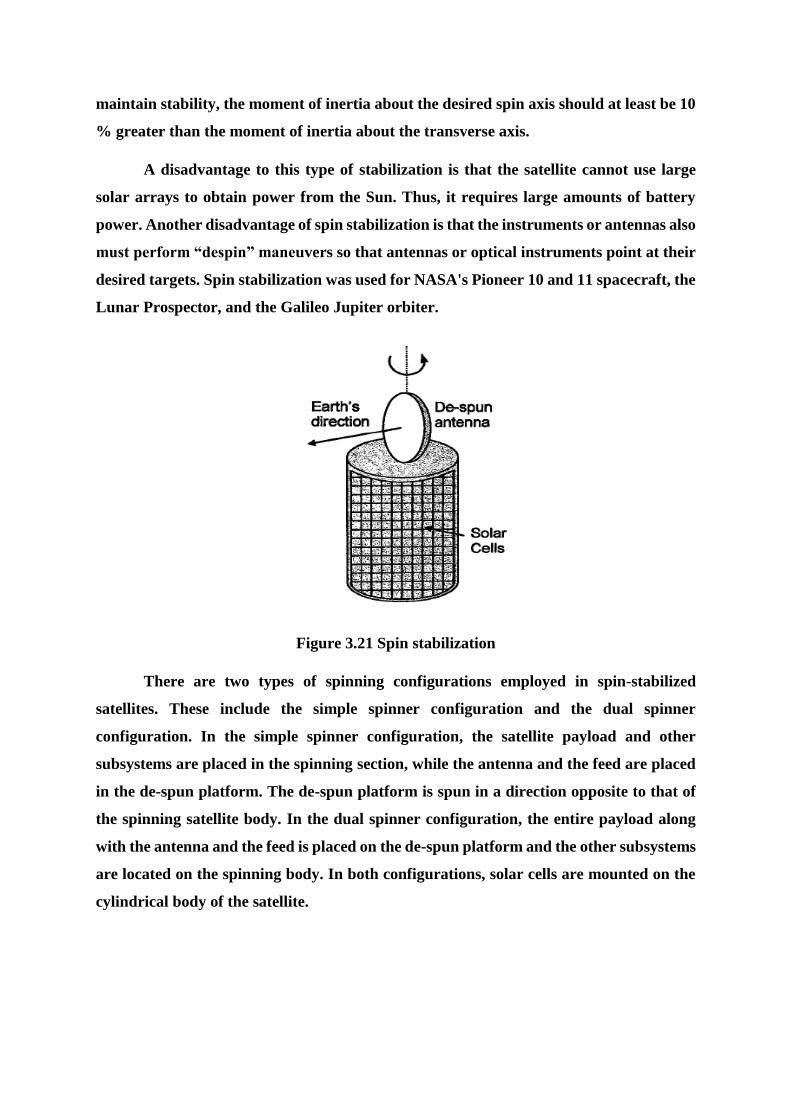
maintain stability, the moment of inertia about the desired spin axis should at least be 10
% greater than the moment of inertia about the transverse axis.
A disadvantage to this type of stabilization is that the satellite cannot use large
solar arrays to obtain power from the Sun. Thus, it requires large amounts of battery
power. Another disadvantage of spin stabilization is that the instruments or antennas also
must perform “despin” maneuvers so that antennas or optical instruments point at their
desired targets. Spin stabilization was used for NASA's Pioneer 10 and 11 spacecraft, the
Lunar Prospector, and the Galileo Jupiter orbiter.
Figure 3.21 Spin stabilization
There are two types of spinning configurations employed in spin-stabilized
satellites. These include the simple spinner configuration and the dual spinner
configuration. In the simple spinner configuration, the satellite payload and other
subsystems are placed in the spinning section, while the antenna and the feed are placed
in the de-spun platform. The de-spun platform is spun in a direction opposite to that of
the spinning satellite body. In the dual spinner configuration, the entire payload along
with the antenna and the feed is placed on the de-spun platform and the other subsystems
are located on the spinning body. In both configurations, solar cells are mounted on the
cylindrical body of the satellite.
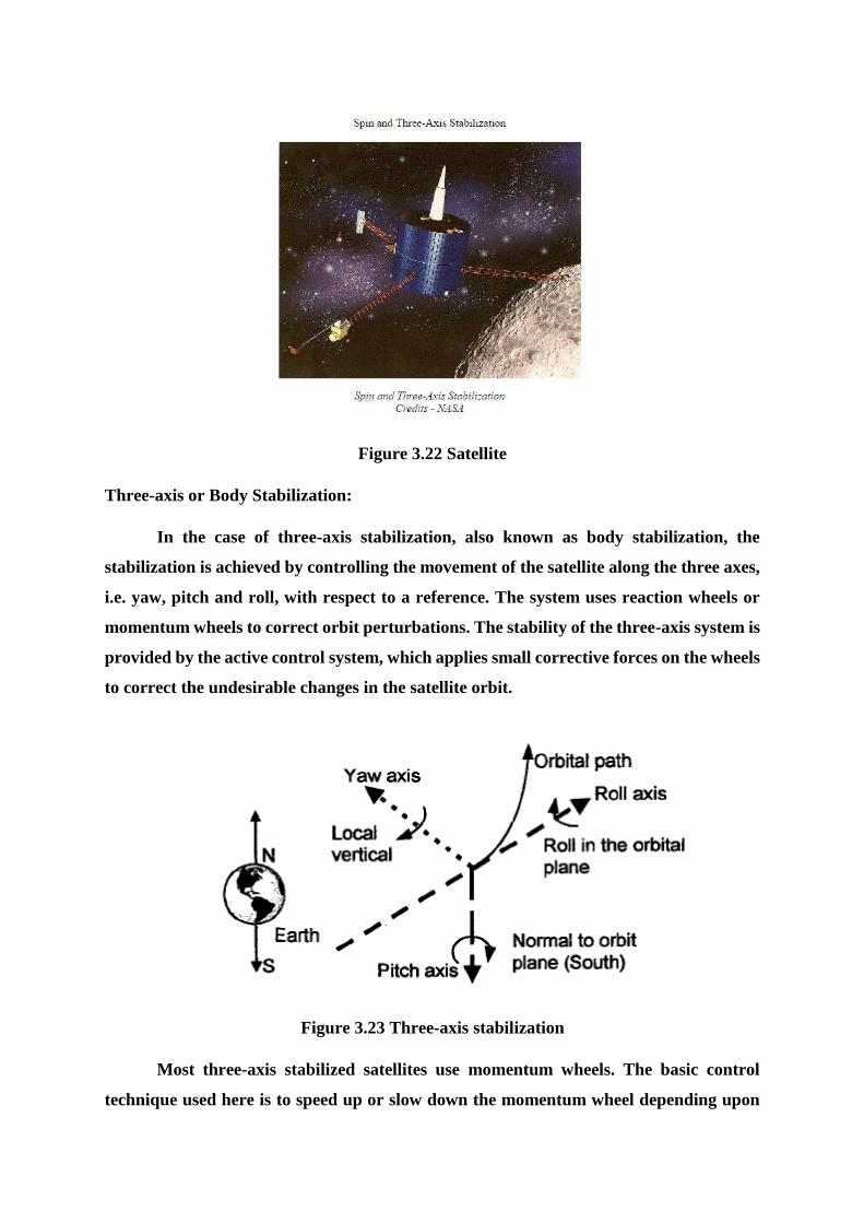
Figure 3.22 Satellite
Three-axis or Body Stabilization:
In the case of three-axis stabilization, also known as body stabilization, the
stabilization is achieved by controlling the movement of the satellite along the three axes,
i.e. yaw, pitch and roll, with respect to a reference. The system uses reaction wheels or
momentum wheels to correct orbit perturbations. The stability of the three-axis system is
provided by the active control system, which applies small corrective forces on the wheels
to correct the undesirable changes in the satellite orbit.
Figure 3.23 Three-axis stabilization
Most three-axis stabilized satellites use momentum wheels. The basic control
technique used here is to speed up or slow down the momentum wheel depending upon
the direction in which the satellite is perturbed. The satellite rotates in a direction
opposite to that of speed change of the wheel. For example, an increase in speed of the
wheel in the clockwise direction will make the satellite rotate in a counterclockwise
direction. The momentum wheels rotate in one direction and can be twisted by a gimbal
motor to provide the required dynamic force on the satellite.
An alternative approach is to use reaction wheels. Three reaction wheels are used,
one for each axis. They can be rotated in either direction depending upon the active
correction force. The satellite body is generally box shaped for three-axis stabilized
satellites. Antennae are mounted on the Earth-facing side and on the lateral sides
adjacent to it. These satellites use flat solar panels mounted above and below the satellite
body in such a way that they always point towards the sun, which is an obvious
requirement.
An advantage of 3-axis stabilization is that optical instruments and antennas can
point at desired targets without having to perform “despin” maneuvers.
Comparison between Spin-stabilized and Three-axis Stabilized Satellites
1. In comparison to spin-stabilized satellites, three-axis stabilized satellites have
more power generation capability and more additional mounting area available
for complex antennae structures.
2. Spin-stabilized satellites are simpler in design and less expensive than three-axis
stabilized satellites.
3. Three-axis stabilized satellites have the disadvantage that the extendible solar
array used in these satellites is unable to provide power when the satellite is in the
transfer orbit. As the array is still stored inside the satellite during this time.
Station Keeping
Station keeping is the process of maintenance of the satellite's orbit against
different factors that can cause temporal drift. Satellites need to have their orbits
adjusted from time to time because the satellite, even though initially placed in the correct
orbit, can undergo a progressive drift due to some natural forces such as minor

gravitational perturbations due to the sun and moon, solar radiation pressure, Earth
being an imperfect sphere, etc. The orbital adjustments are usually made by releasing
jets of gas or by firing small rockets tied to the body of the satellite. In the case of spin-
stabilized satellites, station keeping in the north-south direction is maintained by firing
thrusters parallel to the spin axis in a continuous mode. The east-west station keeping is
obtained by firing thruster’s perpendicular to the spin axis. In the case of three-axis
stabilization, station keeping is achieved by firing thrusters in the east-west or the north-
south direction in a continuous mode.
3.11 Noise in satellite system
Equivalent Isotropic Radiated Power
A key parameter in link budget calculations is the equivalent isotropic radiated
power, conventionally denoted as EIRP. The Maximum power flux density at
some distance r from a transmitting antenna of gain G is
An isotropic radiator with an input power equal to GPS would produce the same
flux density. Hence this product is referred to as the equivalent isotropic
radiated power, or
EIRP is often expressed in decibels relative to one watt, or dBW. Let PS be in
watts; then
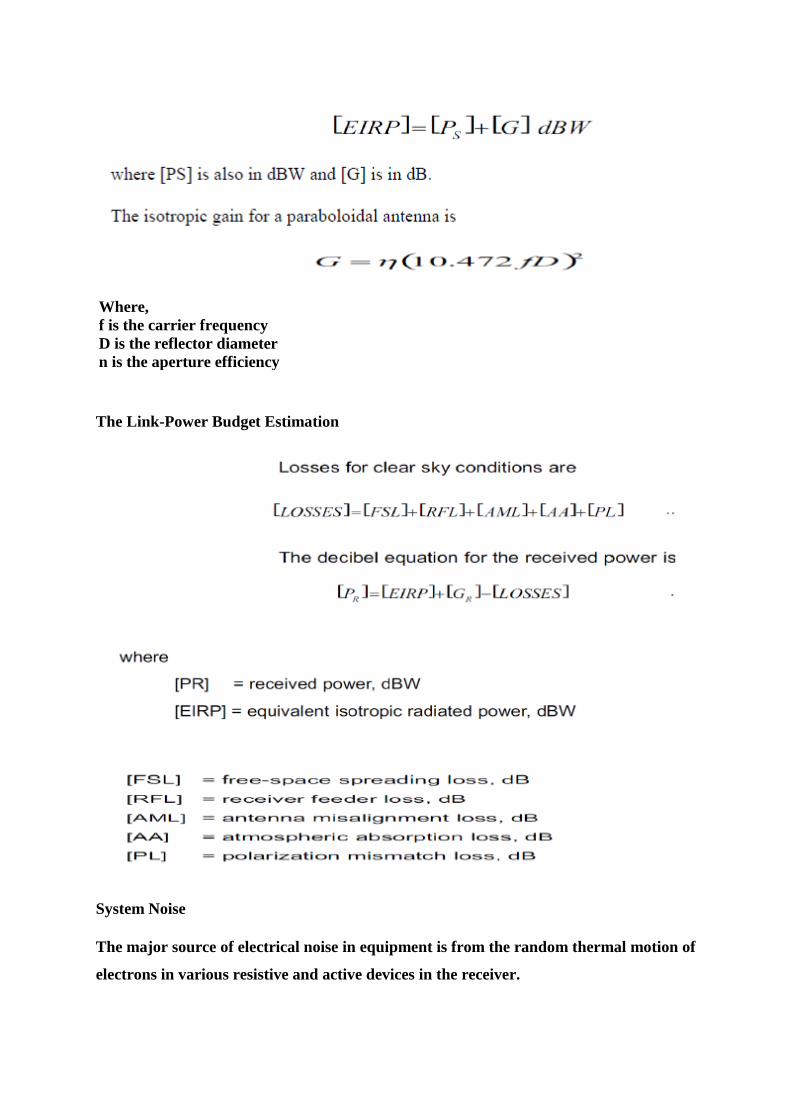
Where,
f is the carrier frequency
D is the reflector diameter
n is the aperture efficiency
The Link-Power Budget Estimation
System Noise
The major source of electrical noise in equipment is from the random thermal motion of
electrons in various resistive and active devices in the receiver.
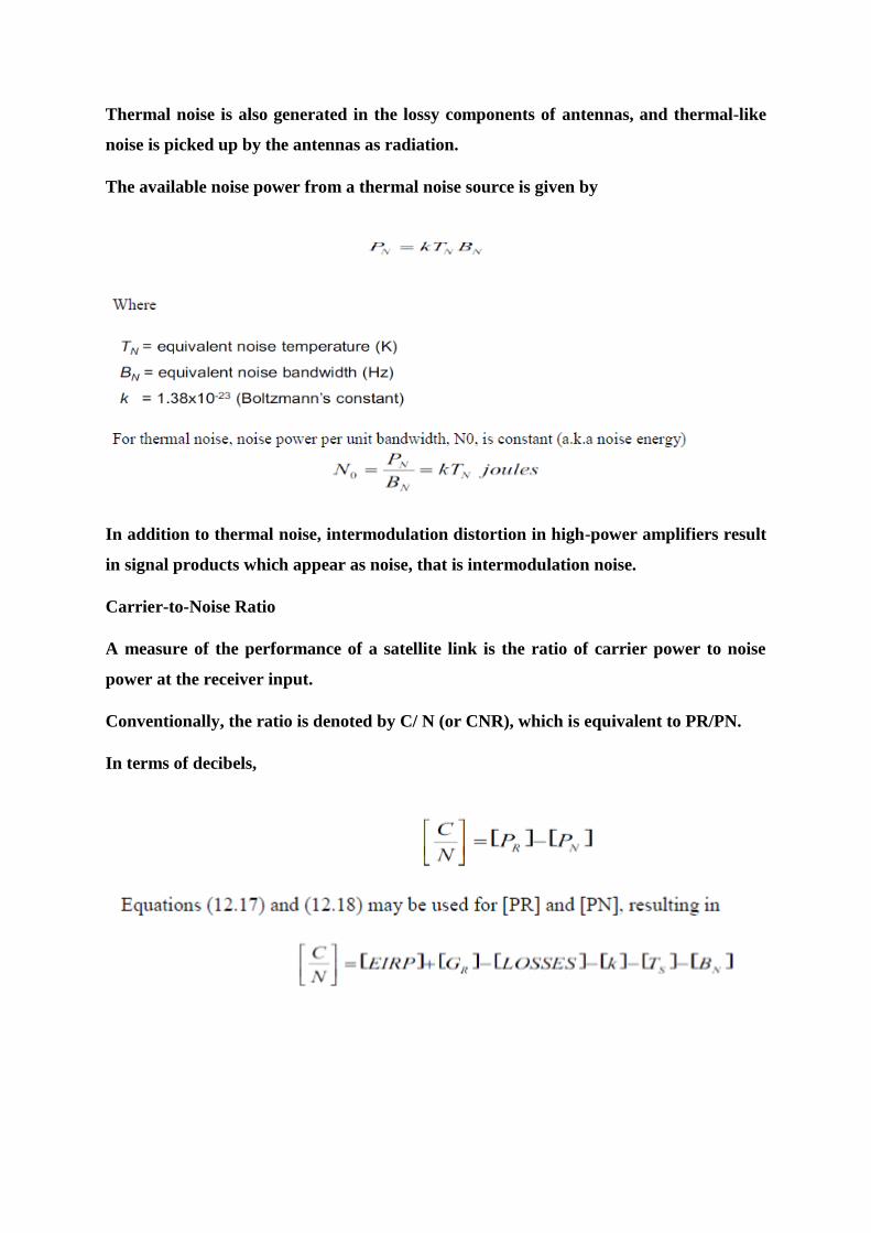
Thermal noise is also generated in the lossy components of antennas, and thermal-like
noise is picked up by the antennas as radiation.
The available noise power from a thermal noise source is given by
In addition to thermal noise, intermodulation distortion in high-power amplifiers result
in signal products which appear as noise, that is intermodulation noise.
Carrier-to-Noise Ratio
A measure of the performance of a satellite link is the ratio of carrier power to noise
power at the receiver input.
Conventionally, the ratio is denoted by C/ N (or CNR), which is equivalent to PR/PN.
In terms of decibels,
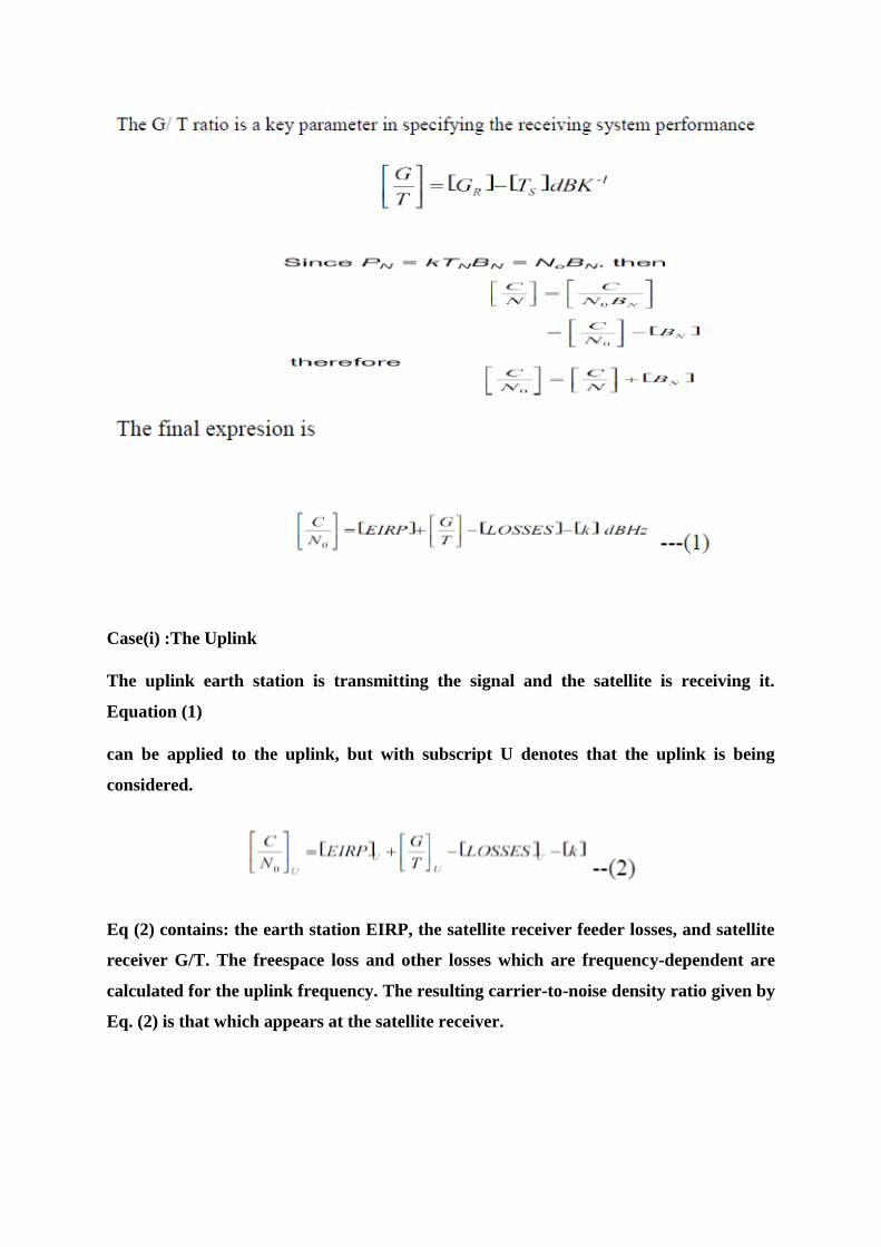
Case(i) :The Uplink
The uplink earth station is transmitting the signal and the satellite is receiving it.
Equation (1)
can be applied to the uplink, but with subscript U denotes that the uplink is being
considered.
Eq (2) contains: the earth station EIRP, the satellite receiver feeder losses, and satellite
receiver G/T. The freespace loss and other losses which are frequency-dependent are
calculated for the uplink frequency. The resulting carrier-to-noise density ratio given by
Eq. (2) is that which appears at the satellite receiver.
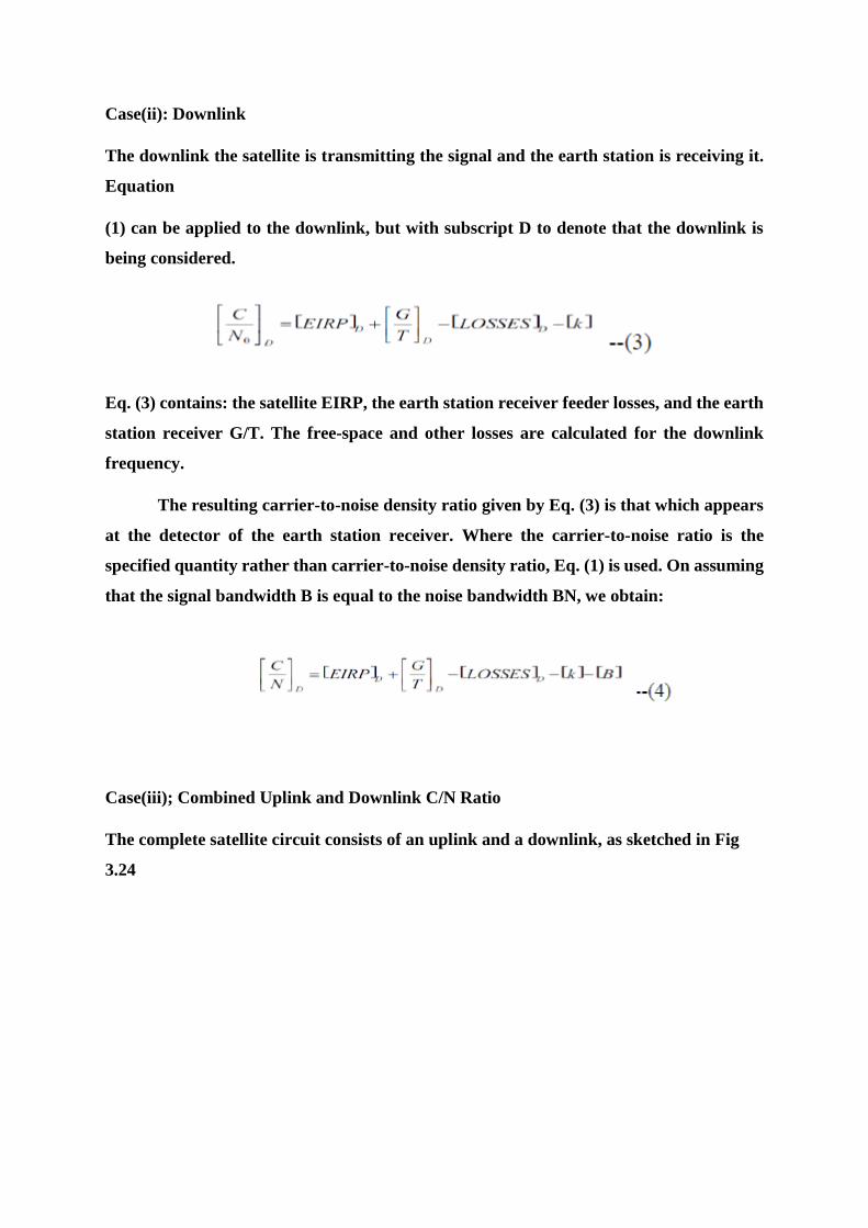
Case(ii): Downlink
The downlink the satellite is transmitting the signal and the earth station is receiving it.
Equation
(1) can be applied to the downlink, but with subscript D to denote that the downlink is
being considered.
Eq. (3) contains: the satellite EIRP, the earth station receiver feeder losses, and the earth
station receiver G/T. The free-space and other losses are calculated for the downlink
frequency.
The resulting carrier-to-noise density ratio given by Eq. (3) is that which appears
at the detector of the earth station receiver. Where the carrier-to-noise ratio is the
specified quantity rather than carrier-to-noise density ratio, Eq. (1) is used. On assuming
that the signal bandwidth B is equal to the noise bandwidth BN, we obtain:
Case(iii); Combined Uplink and Downlink C/N Ratio
The complete satellite circuit consists of an uplink and a downlink, as sketched in Fig
3.24

Figure 3.24 (a) combined uplink and downlink
(b) power flow diagram
Noise will be introduced on the uplink at the satellite receiver input.
PNU = noise power per unit bandwidth
PRU = average carrier at the same point
The carrier-to-noise ratio on the uplink is
Note that power levels, and not decibels, are being used.
PR = carrier power at the end of the space link
= the received carrier power for the downlink.
= K x the carrier power input at the satellite
Where
K = the system power gain from satellite input to earth station input. This includes the
satellite transponder and transmit antenna gains, the downlink losses, and the earth
station receive antenna gain and feeder losses.

The noise at the satellite input also appears at the earth station input multiplied
by K, and in addition, the earth station introduces its own noise, denoted by PND. Thus
the end-of-link noise is KPNU + PND.
The C/No ratio for the downlink alone, not counting the KPNU contribution, is
PR/PND, and the combined C/No ratio at the ground receiver is PR/(KPNU + PND).
The power flow diagram is shown in Fig 3.24
The combined carrier-to-noise ratio can be determined in terms of the individual
link values. To show this, it is more convenient to work with the noise-to-carrier ratios
rather than the carrier-to noise ratios, and these must be expressed as power ratios, not
decibels.
Denoting the combined noise-to-carrier ratio value by No/C, the uplink value by
(No/C)U, and the downlink value by (No/C)D then,
Equation (4) shows that to obtain the combined value of C/N0, the reciprocals of the
individual values must be added to obtain the N0/C ratio and then the reciprocal of this
taken to get C/N0.
The reason for this reciprocal of the sum of the reciprocals method is that a single
signal power is being transferred through the system, while the various noise powers
which are present are additive.
Similar reasoning applies to the carrier-to-noise ratio, C/ N.
REFERENCES
[1] Louis. E. Frenzel, Communication Electronics Principles and applications, 4th
Edition, Tata McGraw Hill Publications, 2014.
[2] Dennis Roody and John Coolen, Electronic Communications, 4th edition, Prentice
Hall of India, 2002.
[3] R. Gulati, Monochrome and colour television, 2nd Edition, New age international
2005.
[4] B. P. Lathi, Modern Digital and Analog Communication Systems, 3rd Edition,
Oxford University Press, 2007.
[5] B. Sklar, Digital Communications Fundamentals and Applications, 2nd Edition,
Pearson Education 2007.
SCHOOL OF ELECTRICAL AND ELECTRONICS
DEPARTMENT OF ELECTRONICS AND COMMUNICATION ENGINEERING
COMMUNICAITON SYSTEMS – SEC1303
UNIT – 4
RADAR COMMUNICATION
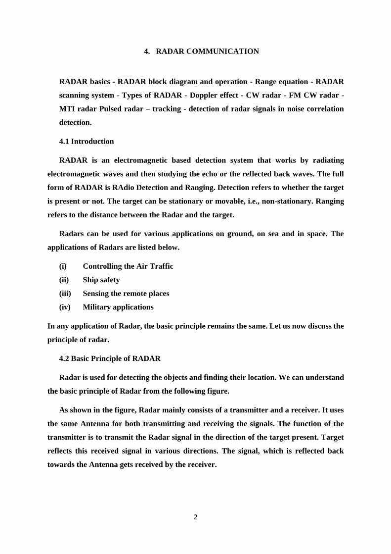
2
4. RADAR COMMUNICATION
RADAR basics - RADAR block diagram and operation - Range equation - RADAR
scanning system - Types of RADAR - Doppler effect - CW radar - FM CW radar -
MTI radar Pulsed radar – tracking - detection of radar signals in noise correlation
detection.
4.1 Introduction
RADAR is an electromagnetic based detection system that works by radiating
electromagnetic waves and then studying the echo or the reflected back waves. The full
form of RADAR is RAdio Detection and Ranging. Detection refers to whether the target
is present or not. The target can be stationary or movable, i.e., non-stationary. Ranging
refers to the distance between the Radar and the target.
Radars can be used for various applications on ground, on sea and in space. The
applications of Radars are listed below.
(i) Controlling the Air Traffic
(ii) Ship safety
(iii) Sensing the remote places
(iv) Military applications
In any application of Radar, the basic principle remains the same. Let us now discuss the
principle of radar.
4.2 Basic Principle of RADAR
Radar is used for detecting the objects and finding their location. We can understand
the basic principle of Radar from the following figure.
As shown in the figure, Radar mainly consists of a transmitter and a receiver. It uses
the same Antenna for both transmitting and receiving the signals. The function of the
transmitter is to transmit the Radar signal in the direction of the target present. Target
reflects this received signal in various directions. The signal, which is reflected back
towards the Antenna gets received by the receiver.
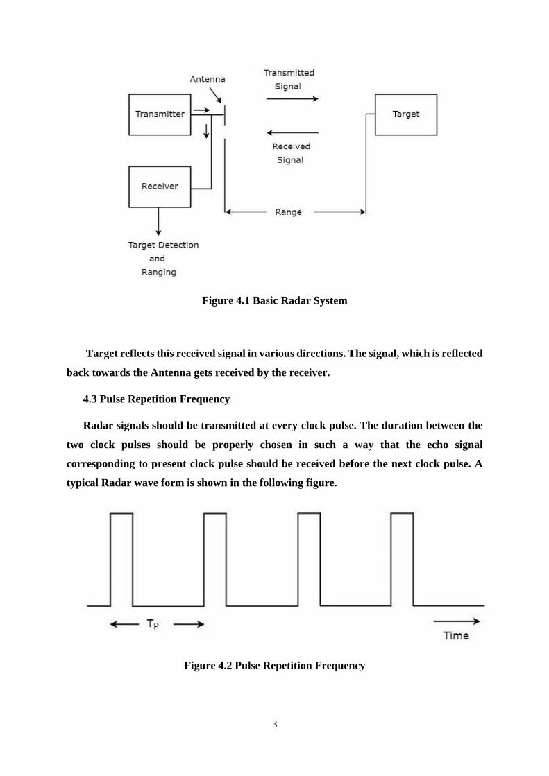
3
Figure 4.1 Basic Radar System
Target reflects this received signal in various directions. The signal, which is reflected
back towards the Antenna gets received by the receiver.
4.3 Pulse Repetition Frequency
Radar signals should be transmitted at every clock pulse. The duration between the
two clock pulses should be properly chosen in such a way that the echo signal
corresponding to present clock pulse should be received before the next clock pulse. A
typical Radar wave form is shown in the following figure.
Figure 4.2 Pulse Repetition Frequency
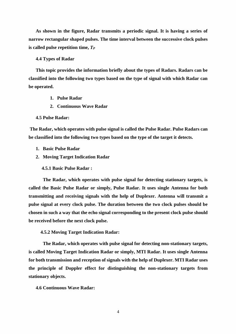
4
As shown in the figure, Radar transmits a periodic signal. It is having a series of
narrow rectangular shaped pulses. The time interval between the successive clock pulses
is called pulse repetition time, TP
4.4 Types of Radar
This topic provides the information briefly about the types of Radars. Radars can be
classified into the following two types based on the type of signal with which Radar can
be operated.
1. Pulse Radar
2. Continuous Wave Radar
4.5 Pulse Radar:
The Radar, which operates with pulse signal is called the Pulse Radar. Pulse Radars can
be classified into the following two types based on the type of the target it detects.
1. Basic Pulse Radar
2. Moving Target Indication Radar
4.5.1 Basic Pulse Radar :
The Radar, which operates with pulse signal for detecting stationary targets, is
called the Basic Pulse Radar or simply, Pulse Radar. It uses single Antenna for both
transmitting and receiving signals with the help of Duplexer. Antenna will transmit a
pulse signal at every clock pulse. The duration between the two clock pulses should be
chosen in such a way that the echo signal corresponding to the present clock pulse should
be received before the next clock pulse.
4.5.2 Moving Target Indication Radar:
The Radar, which operates with pulse signal for detecting non-stationary targets,
is called Moving Target Indication Radar or simply, MTI Radar. It uses single Antenna
for both transmission and reception of signals with the help of Duplexer. MTI Radar uses
the principle of Doppler effect for distinguishing the non-stationary targets from
stationary objects.
4.6 Continuous Wave Radar:
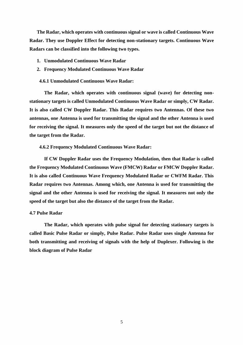
5
The Radar, which operates with continuous signal or wave is called Continuous Wave
Radar. They use Doppler Effect for detecting non-stationary targets. Continuous Wave
Radars can be classified into the following two types.
1. Unmodulated Continuous Wave Radar
2. Frequency Modulated Continuous Wave Radar
4.6.1 Unmodulated Continuous Wave Radar:
The Radar, which operates with continuous signal (wave) for detecting non-
stationary targets is called Unmodulated Continuous Wave Radar or simply, CW Radar.
It is also called CW Doppler Radar. This Radar requires two Antennas. Of these two
antennas, one Antenna is used for transmitting the signal and the other Antenna is used
for receiving the signal. It measures only the speed of the target but not the distance of
the target from the Radar.
4.6.2 Frequency Modulated Continuous Wave Radar:
If CW Doppler Radar uses the Frequency Modulation, then that Radar is called
the Frequency Modulated Continuous Wave (FMCW) Radar or FMCW Doppler Radar.
It is also called Continuous Wave Frequency Modulated Radar or CWFM Radar. This
Radar requires two Antennas. Among which, one Antenna is used for transmitting the
signal and the other Antenna is used for receiving the signal. It measures not only the
speed of the target but also the distance of the target from the Radar.
4.7 Pulse Radar
The Radar, which operates with pulse signal for detecting stationary targets is
called Basic Pulse Radar or simply, Pulse Radar. Pulse Radar uses single Antenna for
both transmitting and receiving of signals with the help of Duplexer. Following is the
block diagram of Pulse Radar
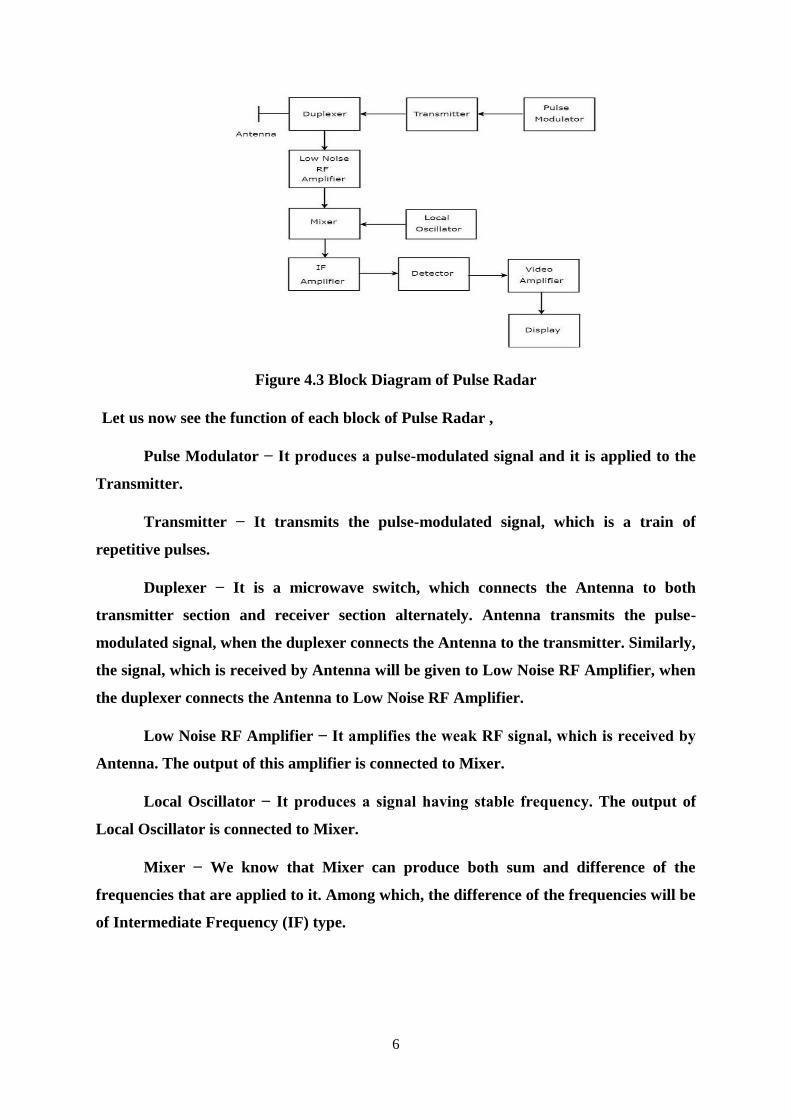
6
Figure 4.3 Block Diagram of Pulse Radar
Let us now see the function of each block of Pulse Radar ,
Pulse Modulator − It produces a pulse-modulated signal and it is applied to the
Transmitter.
Transmitter − It transmits the pulse-modulated signal, which is a train of
repetitive pulses.
Duplexer − It is a microwave switch, which connects the Antenna to both
transmitter section and receiver section alternately. Antenna transmits the pulse-
modulated signal, when the duplexer connects the Antenna to the transmitter. Similarly,
the signal, which is received by Antenna will be given to Low Noise RF Amplifier, when
the duplexer connects the Antenna to Low Noise RF Amplifier.
Low Noise RF Amplifier − It amplifies the weak RF signal, which is received by
Antenna. The output of this amplifier is connected to Mixer.
Local Oscillator − It produces a signal having stable frequency. The output of
Local Oscillator is connected to Mixer.
Mixer − We know that Mixer can produce both sum and difference of the
frequencies that are applied to it. Among which, the difference of the frequencies will be
of Intermediate Frequency (IF) type.
7
IF Amplifier − IF amplifier amplifies the Intermediate Frequency (IF) signal. The
IF amplifier shown in the figure allows only the Intermediate Frequency, which is
obtained from Mixer and amplifies it. It improves the Signal to Noise Ratio at output.
Detector − It demodulates the signal, which is obtained at the output of the IF
Amplifier.
Video Amplifier − As the name suggests, it amplifies the video signal, which is
obtained at the output of detector.
Display − In general, it displays the amplified video signal on CRT screen.
4.8 Doppler Effect
If the target is not stationary, then there will be a change in the frequency of the
signal that is transmitted from the Radar and that is received by the Radar. This effect is
known as the Doppler effect. According to the Doppler effect, we will get the following
two possible cases.
1. The frequency of the received signal will increase, when the target moves
towards the direction of the Radar.
2. The frequency of the received signal will decrease, when the target moves away
from the Radar.
4.8.1 Derivation of Doppler Frequency
The distance between Radar and target is nothing but the Range of the target or
simply range, R. Therefore, the total distance between the Radar and target in a two-way
communication path will be 2R, since Radar transmits a signal to the target and
accordingly the target sends an echo signal to the Radar.
If λ is one wave length, then the number of wave lengths N that are present in a
two-way communication path between the Radar and target will be equal to 2R/λ.
We know that one wave length λ corresponds to an angular excursion of 2π
radians. So, the total angle of excursion made by the electromagnetic wave during the
two-way communication path between the Radar and target will be equal to 4πR/λ
radians.
Following is the mathematical formula for angular frequency, ω
8
ω=2πf Eq 4.1
Following equation shows the mathematical relationship between the angular frequency
ω and phase angle ϕ,
ω=dϕ/dt Eq 4.2
Equate the right hand side terms of Eq 4.1 and Eq 4.2 since the left hand side terms
of those two equations are same.
2πf=dϕ/dt
f=(1/2π) dϕ/dt Eq 4.3
Substitute, f=fd and ϕ=4πR/λ in Eq 4.3
fd=1/2π * d/dt(4πR/λ)
⇒fd=(1/2π) * (4π/λ) dR/dt
fd=2Vr/λ Eq 4.4
Where, fd is the Doppler frequency Vr is the relative velocity.
We can find the value of Doppler frequency fd by substituting the values of Vr
and λ in Eq 4.4
Substitute, λ=C/f in Eq4.4
fd=(2Vr) / (C/f)
fd=(2Vrf) / C Eq 4.5
where, f is the frequency of transmitted signal ,C is the speed of light and it is equal
to 3×10⁸m/sec .We can find the value of Doppler frequency, fd by substituting the values
of Vr, f and C in Eq 4.5.
Note: Both Eq 4.4 and Eq 4.5 show the formulae of Doppler frequency, fd. We can
use either Eq 4.4 or Eq 4.5 for finding Doppler frequency, fd based on the given data.
4.9 Continuous Wave Radar
The Radar, which operates with continuous signal (wave) for detecting non-
stationary targets, is called Continuous Wave Radar or simply CW Radar. This Radar

9
requires two Antennas. Among which, one Antenna is used for transmitting the signal
and the other Antenna is used for receiving the signal.
Figure 4.4 Block Diagram of Continuous Wave Radar
The block diagram of CW Doppler Radar contains a set of blocks and the function
of each block is mentioned below.
CW Transmitter − It produces an analog signal having a frequency of fo. The
output of CW Transmitter is connected to both transmitting Antenna and Mixer-I.
Local Oscillator − It produces a signal having a frequency of fl. The output of
Local Oscillator is connected to Mixer-I.
Mixer-I − Mixer can produce both sum and difference of the frequencies that are
applied to it. The signals having frequencies of fo and fl are applied to Mixer-I. So, the
Mixer-I will produce the output having frequencies fo+fl or fo−fl.
Side Band Filter − As the name suggests, side band filter allows a particular side
band frequencies − either upper side band frequencies or lower side band frequencies.
The side band filter shown in the above figure produces only upper side band frequency,
i.e., fo+fl.

10
Mixer-II − Mixer can produce both sum and difference of the frequencies that are
applied to it. The signals having frequencies of fo+fl and fo±fd are applied to Mixer-II. So,
the Mixer-II will produce the output having frequencies of 2fo+fl±fd or fl±fd.
IF Amplifier − IF amplifier amplifies the Intermediate Frequency (IF) signal. The
IF amplifier shown in the figure allows only the Intermediate Frequency, fl±fd and
amplifies it.
Detector − It detects the signal, which is having Doppler frequency, fd.
Doppler Amplifier − As the name suggests, Doppler amplifier amplifies the signal,
which is having Doppler frequency, fd.
Indicator − It indicates the information related relative velocity and whether the
target is inbound or outbound. CW Doppler Radars give accurate measurement of
relative velocities. Hence, these are used mostly, where the information of velocity is more
important than the actual range.
4.10 FMCW Doppler Radar
If CW Doppler Radar uses the Frequency Modulation, then that Radar is called
FMCW Doppler Radar or simply, FMCW Radar. It is also called Continuous Wave
Frequency Modulated Radar or CWFM Radar. It measures not only the speed of the
target but also the distance of the target from the Radar.
FMCW Radar is mostly used as Radar Altimeter in order to measure the exact height
while landing the aircraft. The following figure shows the block diagram of FMCW
Radar,
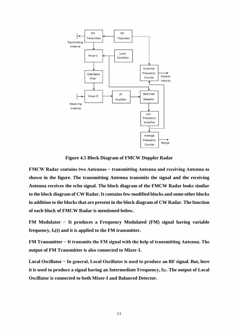
11
Figure 4.5 Block Diagram of FMCW Doppler Radar
FMCW Radar contains two Antennas − transmitting Antenna and receiving Antenna as
shown in the figure. The transmitting Antenna transmits the signal and the receiving
Antenna receives the echo signal. The block diagram of the FMCW Radar looks similar
to the block diagram of CW Radar. It contains few modified blocks and some other blocks
in addition to the blocks that are present in the block diagram of CW Radar. The function
of each block of FMCW Radar is mentioned below.
FM Modulator − It produces a Frequency Modulated (FM) signal having variable
frequency, fo(t) and it is applied to the FM transmitter.
FM Transmitter − It transmits the FM signal with the help of transmitting Antenna. The
output of FM Transmitter is also connected to Mixer-I.
Local Oscillator − In general, Local Oscillator is used to produce an RF signal. But, here
it is used to produce a signal having an Intermediate Frequency, fIF. The output of Local
Oscillator is connected to both Mixer-I and Balanced Detector.
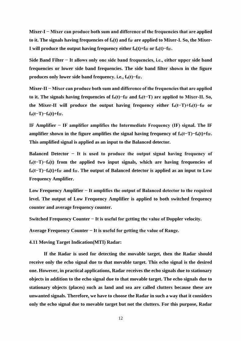
12
Mixer-I − Mixer can produce both sum and difference of the frequencies that are applied
to it. The signals having frequencies of fo(t) and fIF are applied to Mixer-I. So, the Mixer-
I will produce the output having frequency either fo(t)+fIF or fo(t)−fIF.
Side Band Filter − It allows only one side band frequencies, i.e., either upper side band
frequencies or lower side band frequencies. The side band filter shown in the figure
produces only lower side band frequency. i.e., fo(t)−fIF.
Mixer-II − Mixer can produce both sum and difference of the frequencies that are applied
to it. The signals having frequencies of fo(t)−fIF and fo(t−T) are applied to Mixer-II. So,
the Mixer-II will produce the output having frequency either fo(t−T)+fo(t)−fIF or
fo(t−T)−fo(t)+fIF.
IF Amplifier − IF amplifier amplifies the Intermediate Frequency (IF) signal. The IF
amplifier shown in the figure amplifies the signal having frequency of fo(t−T)−fo(t)+fIF.
This amplified signal is applied as an input to the Balanced detector.
Balanced Detector − It is used to produce the output signal having frequency of
fo(t−T)−fo(t) from the applied two input signals, which are having frequencies of
fo(t−T)−fo(t)+fIF and fIF. The output of Balanced detector is applied as an input to Low
Frequency Amplifier.
Low Frequency Amplifier − It amplifies the output of Balanced detector to the required
level. The output of Low Frequency Amplifier is applied to both switched frequency
counter and average frequency counter.
Switched Frequency Counter − It is useful for getting the value of Doppler velocity.
Average Frequency Counter − It is useful for getting the value of Range.
4.11 Moving Target Indication(MTI) Radar:
If the Radar is used for detecting the movable target, then the Radar should
receive only the echo signal due to that movable target. This echo signal is the desired
one. However, in practical applications, Radar receives the echo signals due to stationary
objects in addition to the echo signal due to that movable target. The echo signals due to
stationary objects (places) such as land and sea are called clutters because these are
unwanted signals. Therefore, we have to choose the Radar in such a way that it considers
only the echo signal due to movable target but not the clutters. For this purpose, Radar
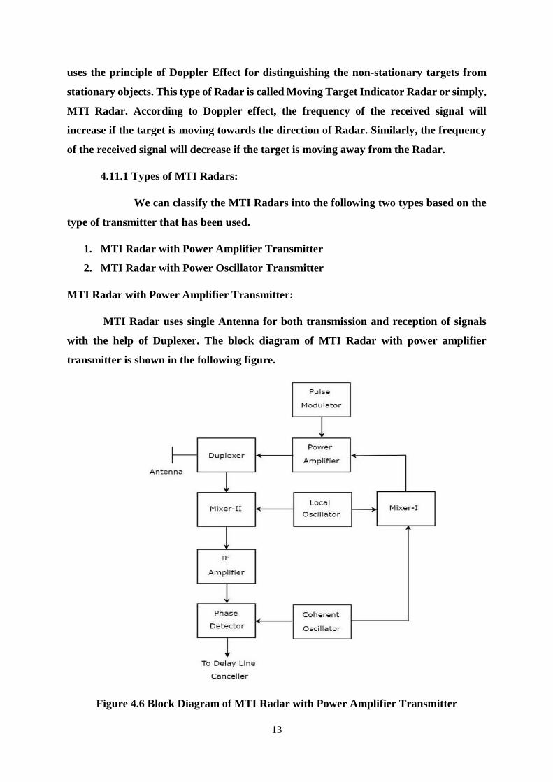
13
uses the principle of Doppler Effect for distinguishing the non-stationary targets from
stationary objects. This type of Radar is called Moving Target Indicator Radar or simply,
MTI Radar. According to Doppler effect, the frequency of the received signal will
increase if the target is moving towards the direction of Radar. Similarly, the frequency
of the received signal will decrease if the target is moving away from the Radar.
4.11.1 Types of MTI Radars:
We can classify the MTI Radars into the following two types based on the
type of transmitter that has been used.
1. MTI Radar with Power Amplifier Transmitter
2. MTI Radar with Power Oscillator Transmitter
MTI Radar with Power Amplifier Transmitter:
MTI Radar uses single Antenna for both transmission and reception of signals
with the help of Duplexer. The block diagram of MTI Radar with power amplifier
transmitter is shown in the following figure.
Figure 4.6 Block Diagram of MTI Radar with Power Amplifier Transmitter
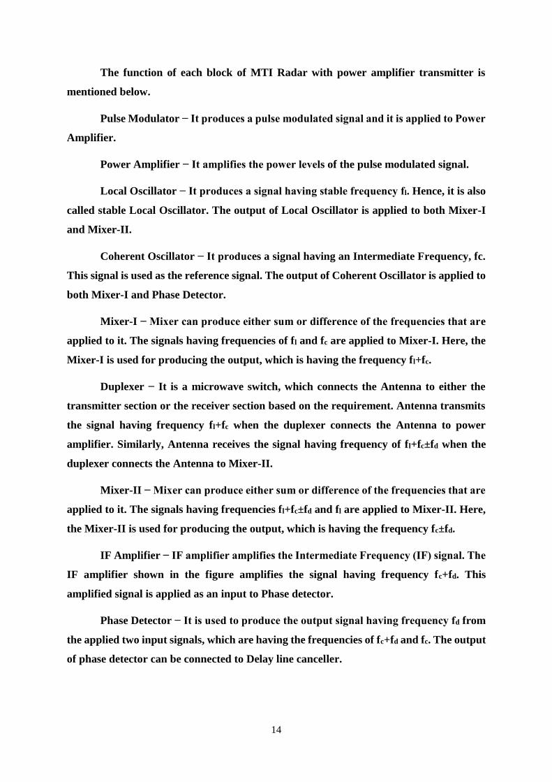
14
The function of each block of MTI Radar with power amplifier transmitter is
mentioned below.
Pulse Modulator − It produces a pulse modulated signal and it is applied to Power
Amplifier.
Power Amplifier − It amplifies the power levels of the pulse modulated signal.
Local Oscillator − It produces a signal having stable frequency fl. Hence, it is also
called stable Local Oscillator. The output of Local Oscillator is applied to both Mixer-I
and Mixer-II.
Coherent Oscillator − It produces a signal having an Intermediate Frequency, fc.
This signal is used as the reference signal. The output of Coherent Oscillator is applied to
both Mixer-I and Phase Detector.
Mixer-I − Mixer can produce either sum or difference of the frequencies that are
applied to it. The signals having frequencies of fl and fc are applied to Mixer-I. Here, the
Mixer-I is used for producing the output, which is having the frequency fl+fc.
Duplexer − It is a microwave switch, which connects the Antenna to either the
transmitter section or the receiver section based on the requirement. Antenna transmits
the signal having frequency fl+fc when the duplexer connects the Antenna to power
amplifier. Similarly, Antenna receives the signal having frequency of fl+fc±fd when the
duplexer connects the Antenna to Mixer-II.
Mixer-II − Mixer can produce either sum or difference of the frequencies that are
applied to it. The signals having frequencies fl+fc±fd and fl are applied to Mixer-II. Here,
the Mixer-II is used for producing the output, which is having the frequency fc±fd.
IF Amplifier − IF amplifier amplifies the Intermediate Frequency (IF) signal. The
IF amplifier shown in the figure amplifies the signal having frequency fc+fd. This
amplified signal is applied as an input to Phase detector.
Phase Detector − It is used to produce the output signal having frequency fd from
the applied two input signals, which are having the frequencies of fc+fd and fc. The output
of phase detector can be connected to Delay line canceller.
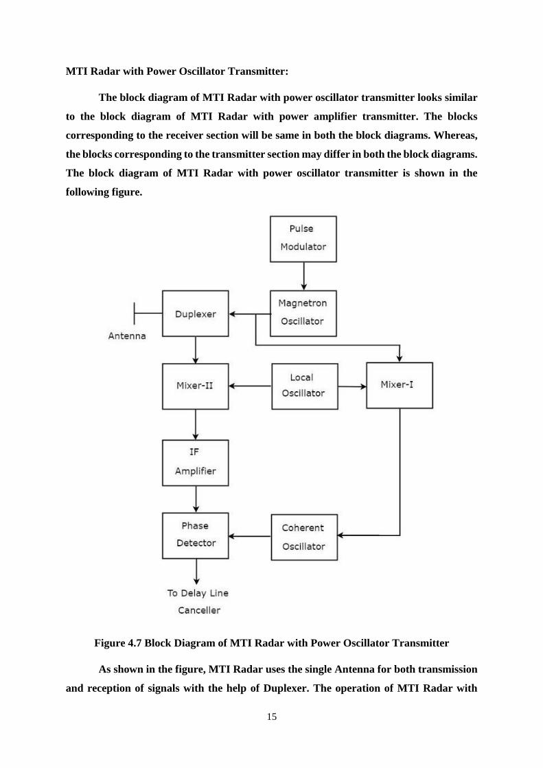
15
MTI Radar with Power Oscillator Transmitter:
The block diagram of MTI Radar with power oscillator transmitter looks similar
to the block diagram of MTI Radar with power amplifier transmitter. The blocks
corresponding to the receiver section will be same in both the block diagrams. Whereas,
the blocks corresponding to the transmitter section may differ in both the block diagrams.
The block diagram of MTI Radar with power oscillator transmitter is shown in the
following figure.
Figure 4.7 Block Diagram of MTI Radar with Power Oscillator Transmitter
As shown in the figure, MTI Radar uses the single Antenna for both transmission
and reception of signals with the help of Duplexer. The operation of MTI Radar with

16
power oscillator transmitter is mentioned below. The output of Magnetron Oscillator and
the output of Local Oscillator are applied to Mixer-I. This will further produce an IF
signal, the phase of which is directly related to the phase of the transmitted signal. The
output of Mixer-I is applied to the Coherent Oscillator. Therefore, the phase of Coherent
Oscillator output will be locked to the phase of IF signal. This means, the phase of
Coherent Oscillator output will also directly relate to the phase of the transmitted signal.
So, the output of Coherent Oscillator can be used as reference signal for comparing the
received echo signal with the corresponding transmitted signal using phase detector. The
above tasks will be repeated for every newly transmitted signal.
4.12 Delay Line Cancellers
As the name suggests, delay line introduces a certain amount of delay. So, the delay
line is mainly used in Delay line canceller in order to introduce a delay of pulse repetition
time. Delay line canceller is a filter, which eliminates the DC components of echo signals
received from stationary targets. This means, it allows the AC components of echo signals
received from non-stationary targets, i.e., moving targets.
Types of Delay Line Cancellers:
Delay line cancellers can be classified into the following two types based on the
number of delay lines that are present in it.
1. Single Delay Line Canceller
2. Double Delay Line Canceller
Single Delay Line Canceller: The combination of a delay line and a subtractor is known
as Delay line canceller. It is also called single Delay line canceller. The block diagram of
MTI receiver with single Delay line canceller is shown in the figure below.
Figure 4.8 Single Delay Line Cancellor
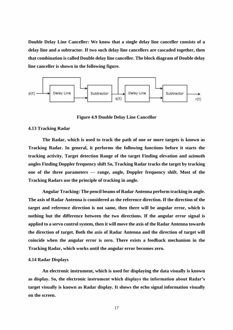
17
Double Delay Line Canceller: We know that a single delay line canceller consists of a
delay line and a subtractor. If two such delay line cancellers are cascaded together, then
that combination is called Double delay line canceller. The block diagram of Double delay
line canceller is shown in the following figure.
Figure 4.9 Double Delay Line Cancellor
4.13 Tracking Radar
The Radar, which is used to track the path of one or more targets is known as
Tracking Radar. In general, it performs the following functions before it starts the
tracking activity. Target detection Range of the target Finding elevation and azimuth
angles Finding Doppler frequency shift So, Tracking Radar tracks the target by tracking
one of the three parameters — range, angle, Doppler frequency shift. Most of the
Tracking Radars use the principle of tracking in angle.
Angular Tracking: The pencil beams of Radar Antenna perform tracking in angle.
The axis of Radar Antenna is considered as the reference direction. If the direction of the
target and reference direction is not same, then there will be angular error, which is
nothing but the difference between the two directions. If the angular error signal is
applied to a servo control system, then it will move the axis of the Radar Antenna towards
the direction of target. Both the axis of Radar Antenna and the direction of target will
coincide when the angular error is zero. There exists a feedback mechanism in the
Tracking Radar, which works until the angular error becomes zero.
4.14 Radar Displays
An electronic instrument, which is used for displaying the data visually is known
as display. So, the electronic instrument which displays the information about Radar’s
target visually is known as Radar display. It shows the echo signal information visually
on the screen.
18
Types of Radar Displays:
In this section, we will learn about the different types of Radar Displays. The
Radar Displays can be classified into the following types.
A-Scope It is a two dimensional Radar display. The horizontal and vertical
coordinates represent the range and echo amplitude of the target respectively. In A-
Scope, the deflection modulation takes place. It is more suitable for manually tracking
Radar.
B-Scope It is a two dimensional Radar display. The horizontal and vertical
coordinates represent the azimuth angle and the range of the target respectively. In B-
Scope, intensity modulation takes place. It is more suitable for military Radars.
C-Scope It is a two-dimensional Radar display. The horizontal and vertical
coordinates represent the azimuth angle and elevation angle respectively. In C-Scope,
intensity modulation takes place.
D-Scope If the electron beam is deflected or the intensity-modulated spot appears
on the Radar display due to the presence of target, then it is known as blip. C-Scope
becomes D-Scope, when the blips extend vertically in order to provide the distance.
E-Scope It is a two-dimensional Radar display. The horizontal and vertical
coordinates represent the distance and elevation angle respectively. In E-Scope, intensity
modulation takes place.
F-Scope If the Radar Antenna is aimed at the target, then F-Scope displays the
target as a centralized blip. So, the horizontal and vertical displacements of the blip
represent the horizontal and vertical aiming errors respectively.
G-Scope If the Radar Antenna is aimed at the target, then G-Scope displays the
target as laterally centralized blip. The horizontal and vertical displacements of the blip
represent the horizontal and vertical aiming errors respectively.
H-Scope It is the modified version of B-Scope in order to provide the information
about elevation angle of the target. It displays the target as two blips, which are closely
spaced. This can be approximated to a short bright line and the slope of this line will be
proportional to the sine of the elevation angle.
19
I-Scope If the Radar Antenna is aimed at the target, then I-Scope displays the
target as a circle. The radius of this circle will be proportional to the distance of the target.
If the Radar Antenna is aimed at the target incorrectly, then I-Scope displays the target
as a segment instead of circle. The arc length of that segment will be inversely
proportional to the magnitude of pointing error.
J-Scope It is the modified version of A-Scope. It displays the target as radial
deflection from time base.
K-Scope It is the modified version of A-Scope. If the Radar Antenna is aimed at
the target, then K-Scope displays the target as a pair of vertical deflections, which are
having equal height. If the Radar Antenna is aimed at the target incorrectly, then there
will be pointing error. So, the magnitude and the direction of the pointing error depends
on the difference between the two vertical deflections.
L-Scope If the Radar Antenna is aimed at the target, then L-Scope displays the
target as two horizontal blips having equal amplitude. One horizontal blip lies to the right
of central vertical time base and the other one lies to the left of central vertical time base.
M-Scope It is the modified version of A-Scope. An adjustable pedestal signal has
to be moved along the baseline till it coincides the signal deflections, which are coming
from the horizontal position of the target. In this way, the target’s distance can be
determined.
N-Scope It is the modified version of K-Scope. An adjustable pedestal signal is
used for measuring distance.
O-Scope It is the modified version of A-Scope. We will get O-Scope, by including
an adjustable notch to A-Scope for measuring distance.
P-Scope It is a Radar display, which uses intensity modulation. It displays the
information of echo signal as plan view. Range and azimuth angle are displayed in polar
coordinates. Hence, it is called the Plan Position Indicator or the PPI display.
R-Scope It is a Radar display, which uses intensity modulation. The horizontal
and vertical coordinates represent the range and height of the target respectively. Hence,
it is called Range-Height Indicator or RHI display.
20
4.15 Radar Range Equation
Radar range equation is useful to know the range of the target theoretically.
Derivation of Radar Range Equation
The standard form of Radar range equation is also called as simple form of Radar range
equation. Now, let us derive the standard form of Radar range equation.
We know that power density is nothing but the ratio of power and area. So, the power
density, Pdi at a distance, R from the Radar can be mathematically represented as –
𝑷𝒅𝒊 = 𝑷𝒕
𝟒 𝝅𝑹𝟐 ……………..Eq: 1
Where,
Pt is the amount of power transmitted by the Radar transmitter
The above power density is valid for an isotropic Antenna. In general, Radars use
directional Antennas. Therefore, the power density, Pdd due to directional Antenna will
be –
𝑷𝒅𝒅 = 𝑷𝒕𝑮
𝟒 𝝅𝑹𝟐 ……………..Eq: 2
Target radiates the power in different directions from the received input power.
The amount of power, which is reflected back towards the Radar depends on its cross
section. So, the power density Pde of echo signal at Radar can be mathematically
represented as –
𝑷𝒅𝒆 = 𝑷𝒅𝒅 (𝝈
𝟒 𝝅𝑹𝟐) ……………..Eq: 3
Substitute, Equation 2 (𝑷𝒅𝒅) in Equation 3.
𝑷𝒅𝒆 =𝑷𝒕𝑮
𝟒 𝝅𝑹𝟐 (𝝈
𝟒 𝝅𝑹𝟐) ……………..Eq: 4
The amount of power, 𝑷𝒓 received by the Radar depends on the effective aperture,
𝑨𝒆 of the receiving Antenna.
𝑷𝒓 = 𝑷𝒅𝒆 𝑨𝒆 ……………..Eq: 5
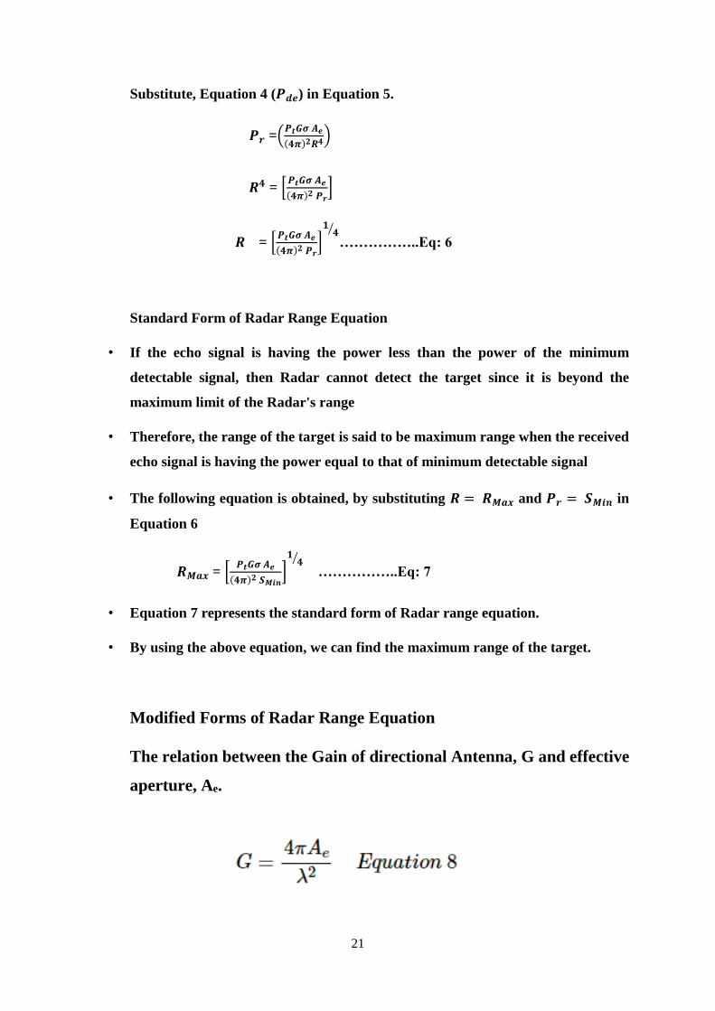
21
Substitute, Equation 4 (𝑷𝒅𝒆) in Equation 5.
𝑷𝒓 =(𝑷𝒕𝑮𝝈 𝑨𝒆
(𝟒𝝅)𝟐𝑹𝟒)
𝑹𝟒 = [𝑷𝒕𝑮𝝈 𝑨𝒆
(𝟒𝝅)𝟐 𝑷𝒓]
𝑹 = [𝑷𝒕𝑮𝝈 𝑨𝒆
(𝟒𝝅)𝟐 𝑷𝒓]
𝟏𝟒⁄
……………..Eq: 6
Standard Form of Radar Range Equation
• If the echo signal is having the power less than the power of the minimum
detectable signal, then Radar cannot detect the target since it is beyond the
maximum limit of the Radar's range
• Therefore, the range of the target is said to be maximum range when the received
echo signal is having the power equal to that of minimum detectable signal
• The following equation is obtained, by substituting 𝑹 = 𝑹𝑴𝒂𝒙 and 𝑷𝒓 = 𝑺𝑴𝒊𝒏 in
Equation 6
𝑹𝑴𝒂𝒙 = [𝑷𝒕𝑮𝝈 𝑨𝒆
(𝟒𝝅)𝟐 𝑺𝑴𝒊𝒏]
𝟏𝟒⁄
……………..Eq: 7
• Equation 7 represents the standard form of Radar range equation.
• By using the above equation, we can find the maximum range of the target.
Modified Forms of Radar Range Equation
The relation between the Gain of directional Antenna, G and effective
aperture, Ae.
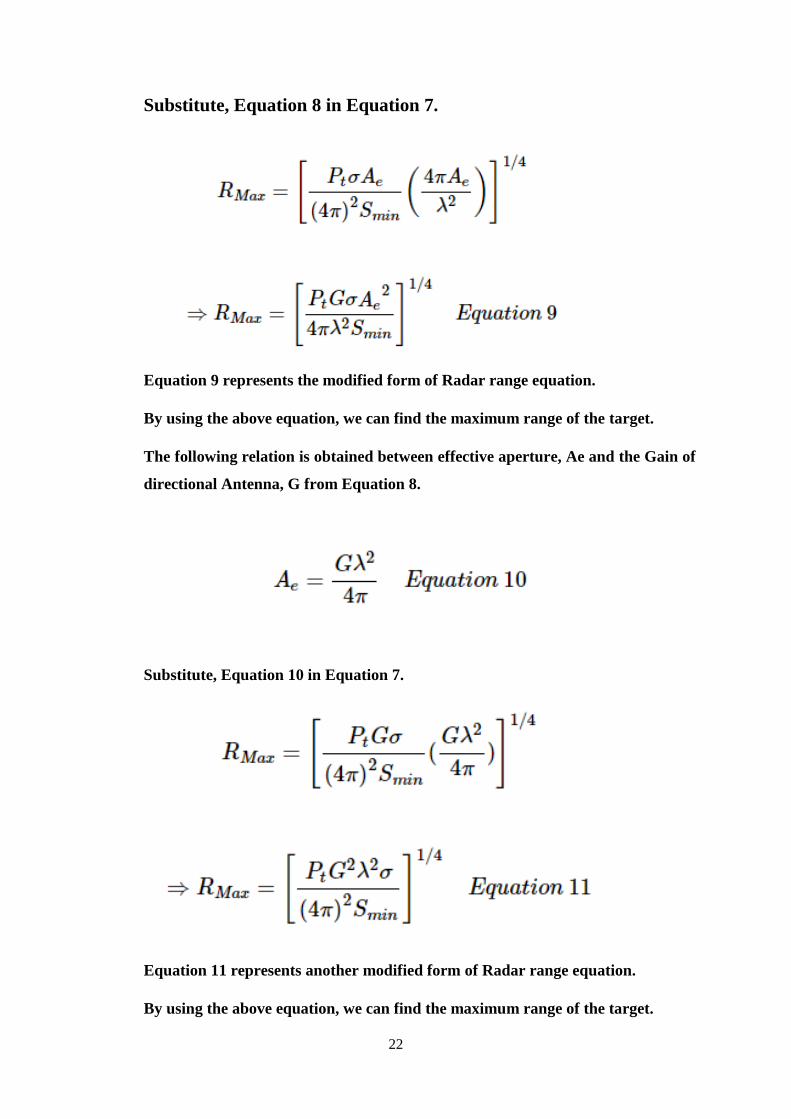
22
Substitute, Equation 8 in Equation 7.
Equation 9 represents the modified form of Radar range equation.
By using the above equation, we can find the maximum range of the target.
The following relation is obtained between effective aperture, Ae and the Gain of
directional Antenna, G from Equation 8.
Substitute, Equation 10 in Equation 7.
Equation 11 represents another modified form of Radar range equation.
By using the above equation, we can find the maximum range of the target.
23
Problem 1
Calculate the maximum range of Radar for the following specifications −
Peak power transmitted by the Radar, Pt=250KW
Gain of transmitting Antenna, G=4000
Effective aperture of the receiving Antenna, Ae=4m2
Radar cross section of the target, σ=25m2
Power of minimum detectable signal, Smin=10−12W
Solution
We can use the following standard form of Radar range equation in order to calculate
the maximum range of Radar for given specifications.
RMax=[PtGσAe(4π)2Smin]1/4
Substitute all the given parameters in above equation.
RMax=[(250×103)(4000)(25)(4)(4π)2(10−12)]1/4
⇒RMax=158 KM
Therefore, the maximum range of Radar for given specifications is 158 KM.
Problem 2
Calculate the maximum range of Radar for the following specifications.
Operating frequency, f=10 GHZ
Peak power transmitted by the Radar, Pt=400KW
Effective aperture of the receiving Antenna, Ae=5m2
Radar cross section of the target, σ=30m2
Power of minimum detectable signal, Smin=10−10W
Solution
We know the following formula for operating wavelength, λλ in terms of operating
frequency, f.
Λ = Cf
Substitute, C=3×10⁸ m/sec and f=10 GHZ in above equation.

24
λ=3×10⁸ / 10×109
⇒λ=0.03m
So, the operating wavelength, λ is equal to 0.03m, when the operating
frequency, ff is 10GHZ.
We can use the following modified form of Radar range equation in order to calculate
the maximum range of Radar for given specifications.
RMax=[PtσAe2 / 4πλ2Smin]1/4
Substitute, the given parameters in the above equation.
RMax=[(400×103)(30)(52) / 4π(0.003)2(10)−10]1/4
⇒RMax=128 KM
Therefore, the maximum range of Radar for given specifications is 128KM.
Part A: Two Marks:
1. What is radar?
2. List the applications of RADAR.
3. Investigate Doppler effect or Doppler shift.
4. Interpret the main reasons for the failure of the simple form of the radar
equation?
5. Evaluate the operation of duplexer?
6. Interpret the Radar range equation and mention the factors that influence the
range of radar system.
7. Test the assumptions. Do we have to make in formulating the radar range
equation? Study the maximum unambiguous range?
8. Compare primary and secondary radars.
9. List the merits and demerits of CW radar?
10. Quote the applications of FMCW Radar?
11. Compare CW Radar and pulsed Radar.
12. Summarize various scanning system used in Radar.
13. Draw the block diagram of Pulsed radar.

25
14. List out the types of display systems used in RADAR.
15. Figure out the features of PPI display?
16. Resolve the function of COHO & STALO in MTI Radar?
17. Analyse the expression for peak power, average power and echo power.
Part B:
1. Investigate about the basic functional units of a Radar and its working principle
in detecting targets.
2. Attribute an expression for the Radar range equation and discuss the factors
that affects range of radar
3. Interpret the working principle of pulsed radar and compare its performance
with CW radar.
4. Articulate the idea of Moving Target Indicator radar. What is the significance of
echo canceller?
5. Consider the following i) Doppler effect used in CW radar and ii) CFAR
receiver
6. Investigate the principle and working of unmodulated CW Radar and
Frequency Modulated CW Radar
7. Draw the block diagram of MTI radar and explain in detail.
8. Resolve the criteria used to analyse the performance of RADAR systems.
9. Analyse the importance of digital signal processing techniques in the
performance of RADAR.
References:
1. Merill I Skolnik, Introduction to Radar Systems, 3rd Edition, Mc Graw Hill
2002
2. Nadav Levanon, and Eli Mozeson. Radar signals. Wiley. com, 2004.
3. Hao He, Jian Li, and Petre Stoica. Waveform design for active sensing systems: a
computational approach. Cambridge University Press, 2012.
4. Solomon W. Golomb, and Guang Gong. Signal design for good correlation: for
wireless communication, cryptography, and radar. Cambridge University Press,
2005.
5. Swords, Seán S., "Technical History of the Beginnings of Radar", IEE History of
Technology Series, Vol. 6, London: Peter Peregrinus, 1986.
SCHOOL OF ELECTRICAL AND ELECTRONICS
DEPARTMENT OF ELECTRONICS AND COMMUNICATION ENGINEERING
COMMUNICAITON SYSTEMS – SEC1303
UNIT – 5
WIRELESS COMMUNICATION
2
5. WIRELESS COMMUNICATION
Review of IEEE standards – Bluetooth – Piconet - Bluetooth Usage models - Bluetooth
Architecture – IR – Ultrasonic - Ultrasonic Production - Applications of Ultrasonic –
RF - WiFi- ZigBee - ZigBee Architecture - ZigBee Network Topologies.
5.1 Introduction
Wireless communication is the transfer of information between two or more
points that are not connected by an electrical conductor. The most common wireless
technologies use radio. With radio waves distances can be short, such as a few meters
for television or as far as thousands or even millions of kilometers for deep-space radio
communications. It encompasses various types of fixed, mobile, and portable
applications, including two-way radios, cellular telephones, personal digital assistants
(PDAs), and wireless networking. Other examples of applications of radio wireless
technology include GPS units, garage door openers, wireless computer mouse,
keyboards and headsets, headphones, radioreceivers, satellite, television, broadcast
television and cordless telephones. Somewhat less common methods of achieving
wireless communications include the use of other electromagnetic wireless
technologies, such as light, magnetic, or electric fields or the use of sound.
Wireless communication has the following advantages:
i. Communication has enhanced to convey the information quickly to the
consumers.
ii. Working professionals can work and access Internet anywhere and
anytime without carrying cables or wires wherever they go. This also
helps to complete the work anywhere on time and improves the
productivity.
iii. Doctors, workers and other professionals working in remote areas can
be in touch with medical centres through wireless communication.
iv. iv. Urgent situation can be alerted through wireless communication.
The affected regions can be provided help and support with the help of
these alerts through wireless communication.
v. Wireless networks are cheaper to install and maintain.

3
Disadvantages:
The growth of wireless network has enabled us to use personal devices anywhere
and anytime. This has helped mankind to improve in every field of life but this has
led many threats as well. Wireless network has led to many security threats to
mankind. It is very easy for the hackers to grab the wireless signals that are spread
in the air. It is very important to secure the wireless network so that the information
cannot be exploited by the unauthorized users. This also increases the risk to lose
information. Strong security protocols must be created to secure the wireless signals
like WPA and WPA2. Another way to secure the wireless network is to have wireless
intrusion prevention system.
5.2 Types of wireless communication:
The different types of wireless communication technologies include:
Infrared (IR) wireless communication:
IR wireless communication communicates data or information in devices
or systems through infrared (IR) radiation. Infrared is electromagnetic energy at
a wavelength that is longer than that of red light.
Working: IR wireless is used for short and medium-range communications and
security control. For IR communication to work, the systems mostly operate
inline-of-sight mode which means that there must be no obstruction between the
transmitter (source) and receiver (destination). Infrared is used in television
remote controls and security systems. In the electromagnetic spectrum, infrared
radiation lies between microwaves and visible light, therefore, they can be used as
a source of communication. A photo LED transmitter and a photodiode receptor
are required for successful IR communication. The LED transmitter transmits the
infrared signal in the form of non-visible light, which is captured and retrieved as
information by the photo receptor. In this way, the information between the source
and the target is transferred. The source and/or destination can be laptops, mobile
phones, televisions, security systems and any other device that supports wireless
communication.
Review of IEEE standards:
IEEE Standards documents are developed within the IEEE Societies and
the Standards Coordinating Committees of the IEEE Standards Association
(IEEE-SA) Standards Board. The IEEE develops its standards through a
4
consensus development process, approved by the American National Standards
Institute, which brings together volunteers representing varied viewpoints and
interests to achieve the final product. Volunteers are not necessarily members of
the Institute and serve without compensation. While the IEEE administers the
process and establishes rules to promote fairness in the consensus development
process, the IEEE does not independently evaluate, test, or verify the accuracy of
any of the information or the soundness of any judgments contained in its
standards. IEEE had close to 900 active standards, with 500 standards under
development. One of the more notable are the IEEE 802 LAN/MAN group of
standards, with the widely used computer networking standards for both wired
(ethernet, aka IEEE 802.3) and wireless (IEEE 802.11 and IEEE 802.16) networks.
Wireless Local Area Networks (W-LAN)
IEEE 802.11 WLAN uses ISM band (5.275-5.825GHz). Uses 11Mcps DS-
SS spreading and 2Mbps user data rates (will fallback to 1Mbps in noisy
conditions). IEEE 802.11a standard provides up to 54Mbps throughput in the
5GHz band. The DS-SS IEEE 802.11b has been called Wi-Fi which has limited
range. A typical Wi-Fi home router using 802.11b or 802.11g with a stock antenna
might have a range of 32 m (120 ft) indoors and 95 m (300 ft) outdoors. Range also
varies with frequency band. IEEE 802.11g uses Complementary Code Keying
Orthogonal Frequency Division Multiplexing (CCK-OFDM) standards in both
2.4GHz and 5GHz bands.
WiMax
Provides upto 70 Mb/sec symmetric broadband speed without the need for
cables. The technology is based on the IEEE 802.16 standard (also called
WirelessMAN). WiMAX can provide broadband wireless access (BWA) up to 30
miles (50 km) for fixed stations, and 3 - 10 miles (5 - 15 km) for mobile stations. In
contrast, the WiFi/802.11 wireless local area network standard is limited in most
cases to only 100 - 300 feet (30 - 100m). The 802.16 specification applies across a
wide range of the RF spectrum, and WiMAX could function on any frequency
below 66 GHz (higher frequencies would decrease the range of a Base Station to a
few hundred meters in an urban environment).
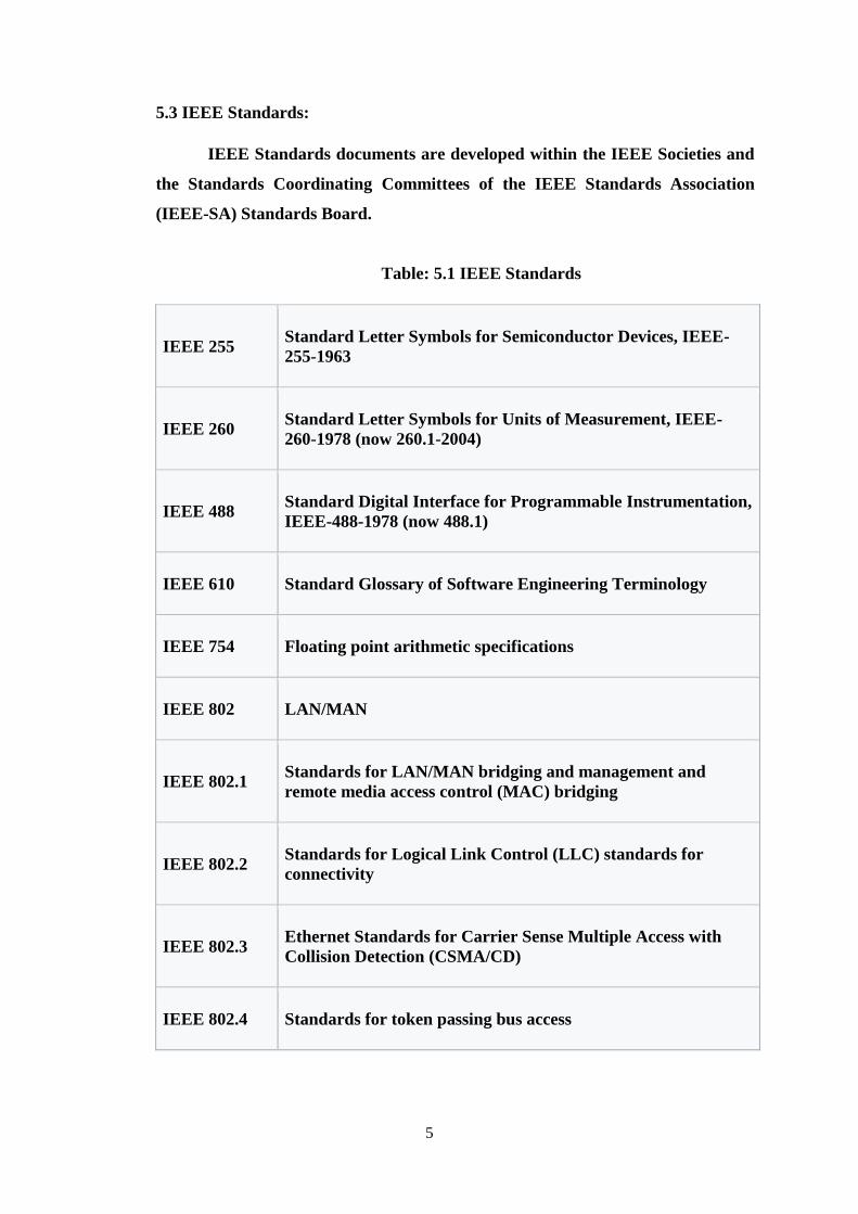
5
5.3 IEEE Standards:
IEEE Standards documents are developed within the IEEE Societies and
the Standards Coordinating Committees of the IEEE Standards Association
(IEEE-SA) Standards Board.
Table: 5.1 IEEE Standards
IEEE 255
Standard Letter Symbols for Semiconductor Devices, IEEE-
255-1963
IEEE 260
Standard Letter Symbols for Units of Measurement, IEEE-
260-1978 (now 260.1-2004)
IEEE 488
Standard Digital Interface for Programmable Instrumentation,
IEEE-488-1978 (now 488.1)
IEEE 610 Standard Glossary of Software Engineering Terminology
IEEE 754 Floating point arithmetic specifications
IEEE 802 LAN/MAN
IEEE 802.1
Standards for LAN/MAN bridging and management and
remote media access control (MAC) bridging
IEEE 802.2
Standards for Logical Link Control (LLC) standards for
connectivity
IEEE 802.3
Ethernet Standards for Carrier Sense Multiple Access with
Collision Detection (CSMA/CD)
IEEE 802.4 Standards for token passing bus access
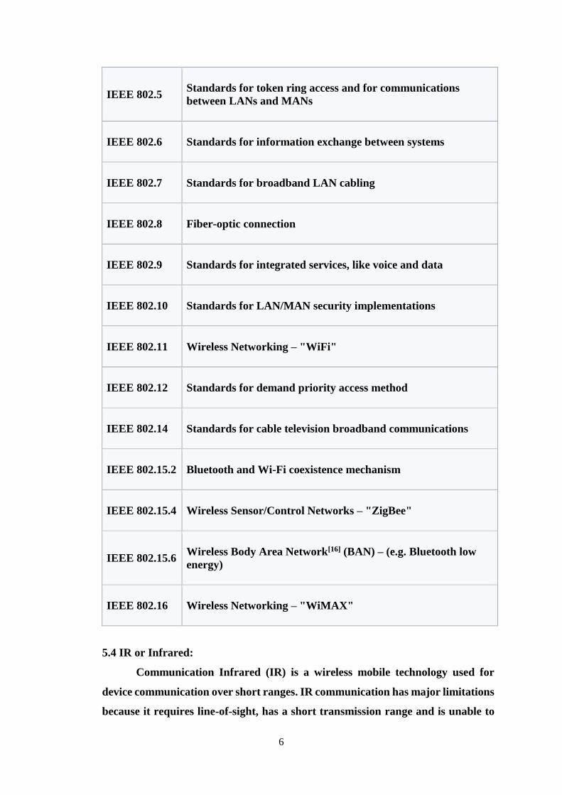
6
IEEE 802.5
Standards for token ring access and for communications
between LANs and MANs
IEEE 802.6 Standards for information exchange between systems
IEEE 802.7 Standards for broadband LAN cabling
IEEE 802.8 Fiber-optic connection
IEEE 802.9 Standards for integrated services, like voice and data
IEEE 802.10 Standards for LAN/MAN security implementations
IEEE 802.11 Wireless Networking – "WiFi"
IEEE 802.12 Standards for demand priority access method
IEEE 802.14 Standards for cable television broadband communications
IEEE 802.15.2 Bluetooth and Wi-Fi coexistence mechanism
IEEE 802.15.4 Wireless Sensor/Control Networks – "ZigBee"
IEEE 802.15.6
Wireless Body Area Network[16] (BAN) – (e.g. Bluetooth low
energy)
IEEE 802.16 Wireless Networking – "WiMAX"
5.4 IR or Infrared:
Communication Infrared (IR) is a wireless mobile technology used for
device communication over short ranges. IR communication has major limitations
because it requires line-of-sight, has a short transmission range and is unable to
7
penetrate walls. IR transceivers are quite cheap and serve as short-range
communication solutions. Because of IR's limitations, communication interception
is difficult. The IR detector is only looking for infrared that’s flashing on and off
38,500 times per second. It has built-in optical filters that allow very little light
except the 980 nm infrared. It also has an electronic filter that only allows signals
around 38.5 kHz to pass through. This is the type of signal produced by the remote
control. This prevents IR interference from common sources such as sunlight and
indoor lighting. IR, or infrared, communication is a common, inexpensive, and
easy to use wireless communication technology. IR light is very similar to visible
light, except that it has a slightlty longer wavelength. This means IR is
undetectable to the human eye - perfect for wireless communication. IR radiation
is simply light that we cannot see, which makes it great for communication. IR
sources are all around us. The sun, light bulbs, or any anything with heat is very
bright in the IR spectrum. The IR signal is modulated. Modulating a signal is like
assigning a pattern to data, so that the receiver knows to listen. A common
modulation scheme for IR communication is something called 38 kHz modulation.
There are very few natural sources that have the regularity of a 38 kHz signal, so
an IR transmitter sending data at that frequency would stand out among the
ambient IR. 38 kHz modulated IR data is the most common, but other frequencies
can be used.
5.5 Bluetooth:
BWT-enabled devices operate in the unrestricted 2.4-gigahertz (GHz)
Industrial, Science, Medical (ISM) band. The ISM band ranges between 2.400 GHz
and 2.483 GHz. BWT-enabled devices use seventy-nine 1-megahertz frequencies
(from 2.402 to 2.480 GHz) in the ISM band as shown in Fig. 10. BWT-enabled
devices use a technique called frequency hopping to minimize eavesdropping and
interference from other networks that use the ISM band. With frequency hopping,
the data is divided into small pieces called packets. The transmitter and receiver
exchange a data packet at one frequency, and then they hop to another frequency
to exchange another packet. They repeat this process until all the data is
transmitted. BWT devices randomly hop between frequencies up to 1600 times per
second—much faster than other types of devices that use the ISM band. This means
that if another device, such as a 2.4-GHz cordless phone, interferes with a BWT
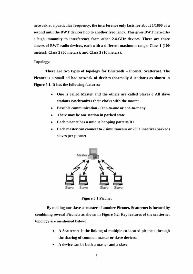
8
network at a particular frequency, the interference only lasts for about 1/1600 of a
second until the BWT devices hop to another frequency. This gives BWT networks
a high immunity to interference from other 2.4-GHz devices. There are three
classes of BWT radio devices, each with a different maximum range: Class 1 (100
meters); Class 2 (50 meters); and Class 3 (10 meters).
Topology:
There are two types of topology for Bluetooth – Piconet, Scatternet. The
Piconet is a small ad hoc network of devices (normally 8 stations) as shown in
Figure 5.1. It has the following features:
One is called Master and the others are called Slaves o All slave
stations synchronizes their clocks with the master.
Possible communication - One-to-one or one-to-many
There may be one station in parked state
Each piconet has a unique hopping pattern/ID
Each master can connect to 7 simultaneous or 200+ inactive (parked)
slaves per piconet.
Figure 5.1 Piconet
By making one slave as master of another Piconet, Scatternet is formed by
combining several Piconets as shown in Figure 5.2. Key features of the scatternet
topology are mentioned below:
A Scatternet is the linking of multiple co-located piconets through
the sharing of common master or slave devices.
A device can be both a master and a slave.
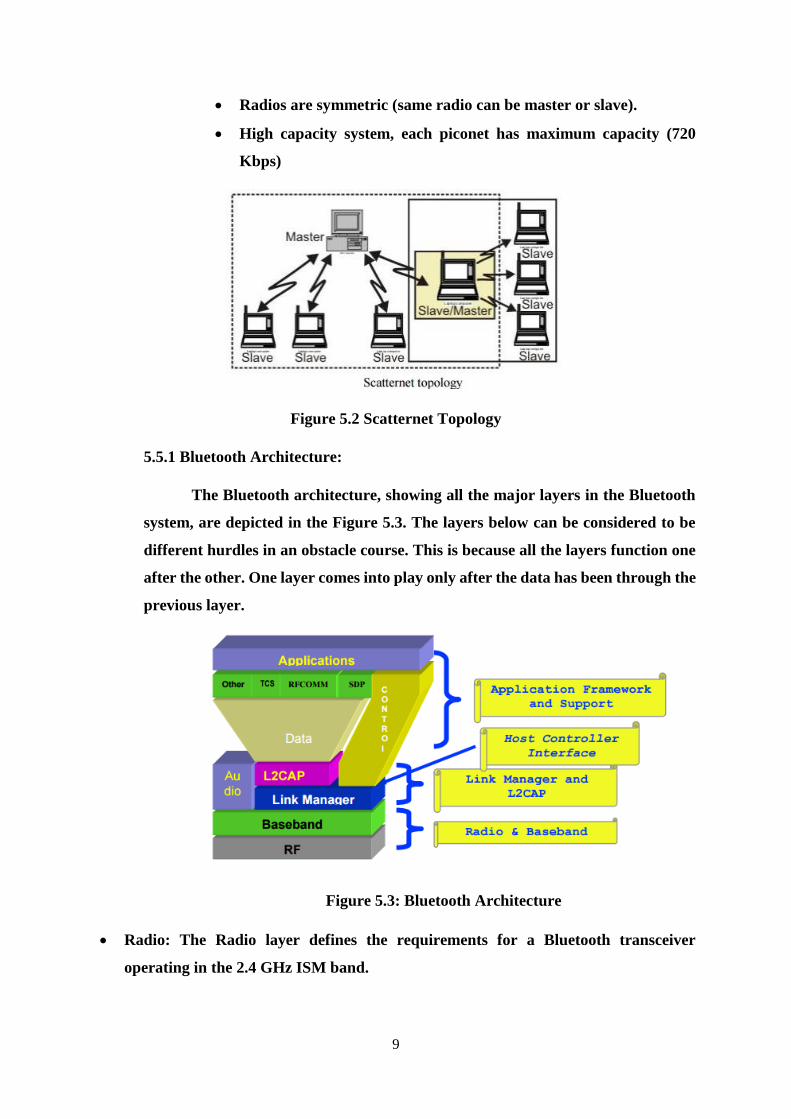
9
Radios are symmetric (same radio can be master or slave).
High capacity system, each piconet has maximum capacity (720
Kbps)
Figure 5.2 Scatternet Topology
5.5.1 Bluetooth Architecture:
The Bluetooth architecture, showing all the major layers in the Bluetooth
system, are depicted in the Figure 5.3. The layers below can be considered to be
different hurdles in an obstacle course. This is because all the layers function one
after the other. One layer comes into play only after the data has been through the
previous layer.
Figure 5.3: Bluetooth Architecture
Radio: The Radio layer defines the requirements for a Bluetooth transceiver
operating in the 2.4 GHz ISM band.
10
Baseband: The Baseband layer describes the specification of the Bluetooth Link
Controller (LC), which carries out the baseband protocols and other low-level link
routines. It specifies Piconet/Channel definition, “Low-level” packet definition,
Channel sharing.
LMP: The Link Manager Protocol (LMP) is used by the Link Managers (on either
side) for link set-up and control.
HCI: The Host Controller Interface (HCI) provides a command interface to the
Baseband Link Controller and Link Manager, and access to hardware status and
control registers.
L2CAP: Logical Link Control and Adaptation Protocol (L2CAP) supports higher
level protocol multiplexing, packet segmentation and reassembly, and the conveying
of quality of service information.
RFCOMM: The RFCOMM protocol provides emulation of serial ports over the
L2CAP protocol. The protocol is based on the ETSI standard TS 07.10.
SDP: The Service Discovery Protocol (SDP) provides a means for applications to
discover, which services are provided by or available through a Bluetooth device. It
also allows applications to determine the characteristics of those available services.
Bluetooth Layers Layer 1:
Radio Layer This is the lowest layer in the Bluetooth protocol stack. Bluetooth
uses a technique called frequency hopping, as explained in the context of wireless LANs,
in establishing radio links with other Bluetooth devices. Suppose we have a data packet
then the whole packet is never transmitted at the same frequency. It is always split into
different parts and transmitted at different frequencies. This is the frequency hopping
technique. This partly gives the necessary protection to the transmitted data and avoids
tampering. Standard hop values are 79 hops, which are spaced at an interval of 1 MHz.
Transmitter characteristics: Each device is classified into 3 power classes, Power Class 1,
2 & 3.
• Power Class 1: is designed for long range (~100m) devices, with a max output
power of 20 dBm,
• Power Class 2: for ordinary range devices (~10m) devices, with a max output
power of 4 dBm,
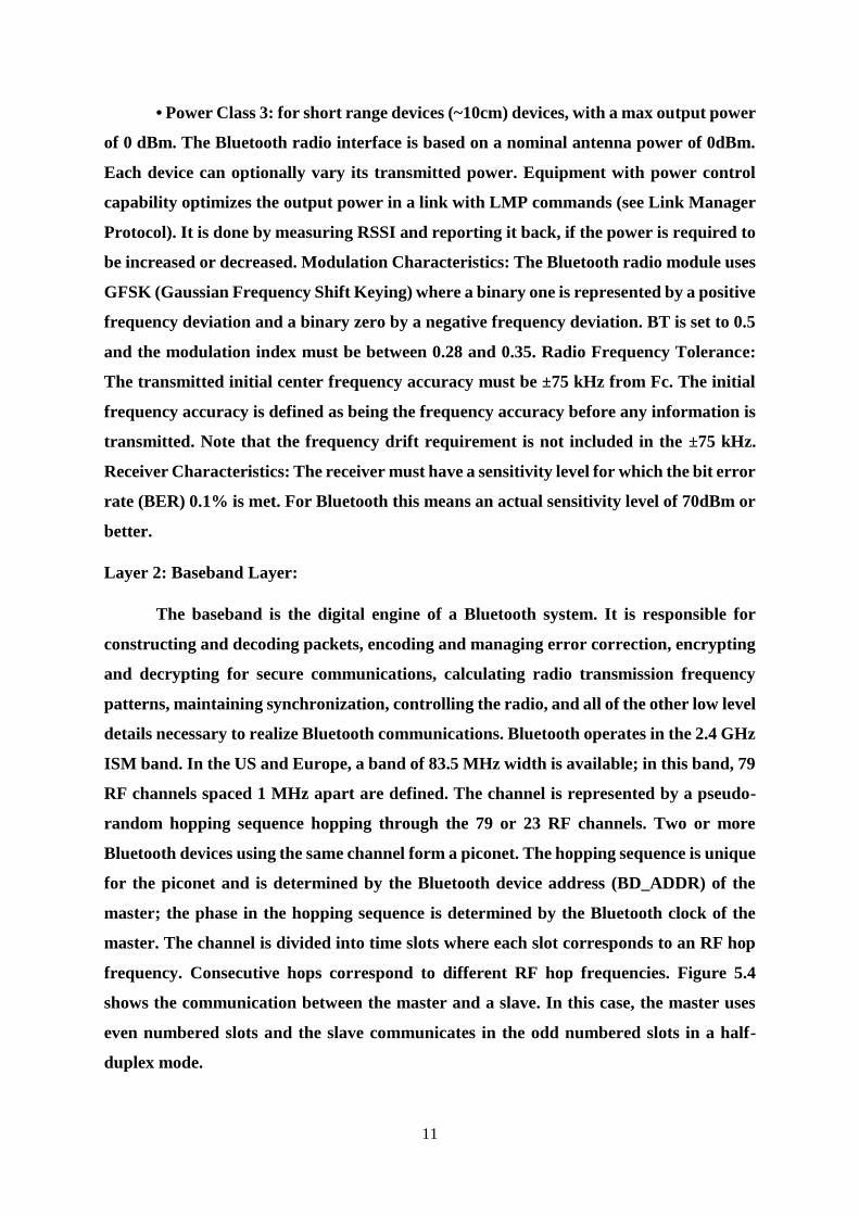
11
• Power Class 3: for short range devices (~10cm) devices, with a max output power
of 0 dBm. The Bluetooth radio interface is based on a nominal antenna power of 0dBm.
Each device can optionally vary its transmitted power. Equipment with power control
capability optimizes the output power in a link with LMP commands (see Link Manager
Protocol). It is done by measuring RSSI and reporting it back, if the power is required to
be increased or decreased. Modulation Characteristics: The Bluetooth radio module uses
GFSK (Gaussian Frequency Shift Keying) where a binary one is represented by a positive
frequency deviation and a binary zero by a negative frequency deviation. BT is set to 0.5
and the modulation index must be between 0.28 and 0.35. Radio Frequency Tolerance:
The transmitted initial center frequency accuracy must be ±75 kHz from Fc. The initial
frequency accuracy is defined as being the frequency accuracy before any information is
transmitted. Note that the frequency drift requirement is not included in the ±75 kHz.
Receiver Characteristics: The receiver must have a sensitivity level for which the bit error
rate (BER) 0.1% is met. For Bluetooth this means an actual sensitivity level of 70dBm or
better.
Layer 2: Baseband Layer:
The baseband is the digital engine of a Bluetooth system. It is responsible for
constructing and decoding packets, encoding and managing error correction, encrypting
and decrypting for secure communications, calculating radio transmission frequency
patterns, maintaining synchronization, controlling the radio, and all of the other low level
details necessary to realize Bluetooth communications. Bluetooth operates in the 2.4 GHz
ISM band. In the US and Europe, a band of 83.5 MHz width is available; in this band, 79
RF channels spaced 1 MHz apart are defined. The channel is represented by a pseudo-
random hopping sequence hopping through the 79 or 23 RF channels. Two or more
Bluetooth devices using the same channel form a piconet. The hopping sequence is unique
for the piconet and is determined by the Bluetooth device address (BD_ADDR) of the
master; the phase in the hopping sequence is determined by the Bluetooth clock of the
master. The channel is divided into time slots where each slot corresponds to an RF hop
frequency. Consecutive hops correspond to different RF hop frequencies. Figure 5.4
shows the communication between the master and a slave. In this case, the master uses
even numbered slots and the slave communicates in the odd numbered slots in a half-
duplex mode.
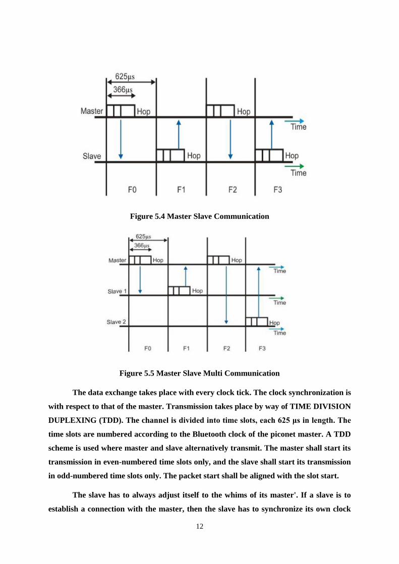
12
Figure 5.4 Master Slave Communication
Figure 5.5 Master Slave Multi Communication
The data exchange takes place with every clock tick. The clock synchronization is
with respect to that of the master. Transmission takes place by way of TIME DIVISION
DUPLEXING (TDD). The channel is divided into time slots, each 625 μs in length. The
time slots are numbered according to the Bluetooth clock of the piconet master. A TDD
scheme is used where master and slave alternatively transmit. The master shall start its
transmission in even-numbered time slots only, and the slave shall start its transmission
in odd-numbered time slots only. The packet start shall be aligned with the slot start.
The slave has to always adjust itself to the whims of its master'. If a slave is to
establish a connection with the master, then the slave has to synchronize its own clock
13
according to that of the master. In the multiple-slave scenario, the slave uses even
numbered slots, but only one slave communicates in the next odd-numbered slot if the
packet in the previous slot was addressed to it. This is shown in Figure 5.5.
The Baseband handles three types of links: SCO (Synchronous Connection-
Oriented): The SCO link is a symmetric point to-point link between a master and a single
slave in the piconet. The master maintains the SCO link by using reserved slots at regular
intervals (circuit switched type). The SCO link mainly carries voice information. The
master can support up to three simultaneous SCO links while slaves can support two or
three SCO links. SCO packets are never retransmitted. SCO packets are used for 64 kB/s
speech transmission. Polling-based (TDD) packet transmissions: In this link type one slot
is of 0.625msec (max 1600 slots/sec) and master/slave slots (even-/odd-numbered slots)
ACL (Asynchronous Connection-Less) link: The ACL link is a point-tomultipoint link
between the master and all the slaves participating on the piconet. In the slots not
reserved for the SCO links, the master can establish an ACL link on a per-slot basis to
any slave, including the slave already engaged in an SCO link (packet switched type).
Only a single ACL link can exist. For most ACL packets, packet retransmission is applied.
Device Addressing: Four possible types of addresses can be assigned to bluetooth
units.
• BD_ADDR: Bluetooth Device Address: Each Bluetooth transceiver is allocated
a unique 48-bit device address. It is divided into a 24-bit LAP field, a 16-bit NAP field
and a 8-bit UAP field.
• AM_ADDR: Active Member Address: It is a 3-bit number. It is only valid as long
as the slave is active on the channel. It is also sometimes called the MAC address of a
Bluetooth unit.
• PM_ADDR: Parked Member Address: It is a 8-bit member (master-local)
address that separates the parked slaves. The PM_ADDR is only valid as long as the slave
is parked.
• AR_ADDR: Access Request Address: This is used by the parked slave to
determine the slave-to master half slot in the access window it is allowed to send access
request messages in. It is only valid as long as the slave is parked and is not necessarily
unique.
14
Layer 3: Link Manager Protocol:
The Link Manager is responsible for managing the physical details for Bluetooth
connections. It is responsible for creating the links, monitoring their health, and
terminating them gracefully upon command or failure. The link manager is implemented
in a mix of hardware and software. The Link Manager carries out link setup,
authentication, link configuration and other protocols. It discovers other remote LM’s
and communicates with them via the Link Manager Protocol (LMP). To perform its
service provider role, the LM uses the services of the underlying Link Controller (LC).
The Link Manager Protocol essentially consists of a number of PDU (protocol Data
Units), which are sent from one device to another, determined by the AM_ADDR in the
packet header.
Layer 4: Host Controller Interface:
This is the layer of the stack that contains the firmware i.e. the software that
actually controls all the activities happening in the Baseband and Radio layers. It
provides a common interface between the Bluetooth host and a Bluetooth module. It
manages the hardware links with the scatternets. It also contains the drivers for the
hardware devices used in the connection. Basically the BIOS is loaded in the HCI Layer.
Logical Link Control and Adaptation Protocol:
The Logical Link Control and Adaptation Layer Protocol (L2CAP) is layered
over the Baseband Protocol and resides in the data link layer.The L2CAP is the big
picture brains of a Bluetooth system. It manages the high level aspects of each connection
(who is connected to who, whether to use encryption or not, what level of performance is
required, etc.). In addition it is responsible for converting the format of data as necessary
between the APIs and the lower level Bluetooth protocols. The L2CAP is implemented in
software and can execute either on the host system processor or on a local processor in
the Bluetooth system. L2CAP provides connection oriented and connectionless data
services to upper layer protocols with protocol multiplexing capability, segmentation and
reassembly operation, and group abstractions. L2CAP permits higher-level protocols and
applications to transmit and receive L2CAP data packets up to 64 kilobytes in length.
Two link types are supported for the Baseband layer: Synchronous Connection-Oriented
(SCO) links and Asynchronous Connection-Less (ACL) links. SCO links support realtime
15
voice traffic using reserved bandwidth. ACL links support best effort traffic. The L2CAP
Specification is defined for only ACL links and no support for SCO links is planned.
Layer 6: Radio Frequency Communication (RFCOMM):
This is the most important layer in the Bluetooth architecture. RFCOMM takes
care of the communication channel between two devices or between a master and a slave.
It connects the serial ports of all the devices according to the requirement. RFCOMM
basically has to accommodate two kinds of devices:
1. Communication end-points such as computers or printers.
2. Devices that are a part of communication channel such as Modems.
RFCOMM protocol is not aware of the distinction between these two kinds of
devices. Hence to prevent any loss of data, it passes on all the information to both the
devices. The devices in turn distinguish between the data and filter it out. Layer 7: Service
Discovery Protocol The service discovery protocol (SDP) provides a means for
applications to discover which services are available and to determine the characteristics
of those available services. A specific Service Discovery protocol is needed in the
Bluetooth environment, as the set of services that are available changes dynamically
based on the RF proximity of devices in motion, qualitatively different from service
discovery in traditional network-based environments. The service discovery protocol
defined in the Bluetooth specification is intended to address the unique characteristics of
the Bluetooth environment. Bluetooth is basically a universal protocol. Manufacturers
may embed Bluetooth ports in their devices. SDP is very important when devices from
different companies and from different parts of the world are brought together. The
devices try to recognize each other through SDP. Telephony Control Protocol Spec (TCS)
Basic function of this layer is call control (setup & release) and group management for
gateway serving multiple devices. Application Program Interface (API) libraries These
are software modules which connect the host application program to the Bluetooth
communications system. As such they reside and execute on the same processing resource
as the host system application.
16
5.6 Introduction to Ultrasonics
The word ultrasonic combines the Latin roots ultra, meaning ‘beyond’ and
sonic, or sound. The sound waves having frequencies above the audible range i.e.
above 20,000Hz are called ultrasonic waves. Generally these waves are called as high
frequency waves. The field of ultrasonics have wide applications in imaging, detection
and navigation. The broad sectors of society that regularly apply ultrasonic
technology are the medical community, industry, the military and private citizens.
Ultrasound can be modulated to carry an audio signal (like radio signals are
modulated). This is often used to carry messages underwater, in underwater diving
communicators, and short-range (under five miles) communication with submarines;
the received ultrasound signal is decoded into audible sound by a modulated-
ultrasound receiver. A modulated ultrasound receiver is a device that receives a
modulated ultrasound signal and decodes it for use as sound, navigational-position
information, etc. Its function is somewhat like that of a radio receiver Ultrasound
imaging is a direct, non-reconstructive form of imaging where image formation is
obtained by localizing an ultrasonic wave to a small volume in 3D space. Two
dimension of localization are performed by diffraction (focusing), as in optics. One
dimension is performed by pulsing, as in RADAR. The ultrasonic wave is produced
by electrical excitation of a piezoelectric transducer, which is usually transmitted to
the body through an impedance matching gel. Ultrasonic waves are detected by the
same transducer and converted into an electrical signal for processing and display.
5.6.1 Properties of ultrasonic waves
They have a high energy content.
Just like ordinary sound waves, ultrasonic waves get reflected, refracted and
absorbed.
They can be transmitted over longer distances with no appreciable loss of energy.
If an arrangement is made to form stationary waves of ultrasonics in a liquid, it serves
as a diffraction grating. It is called an acoustic grating.
They produce intense heating effect when passed through a substance.
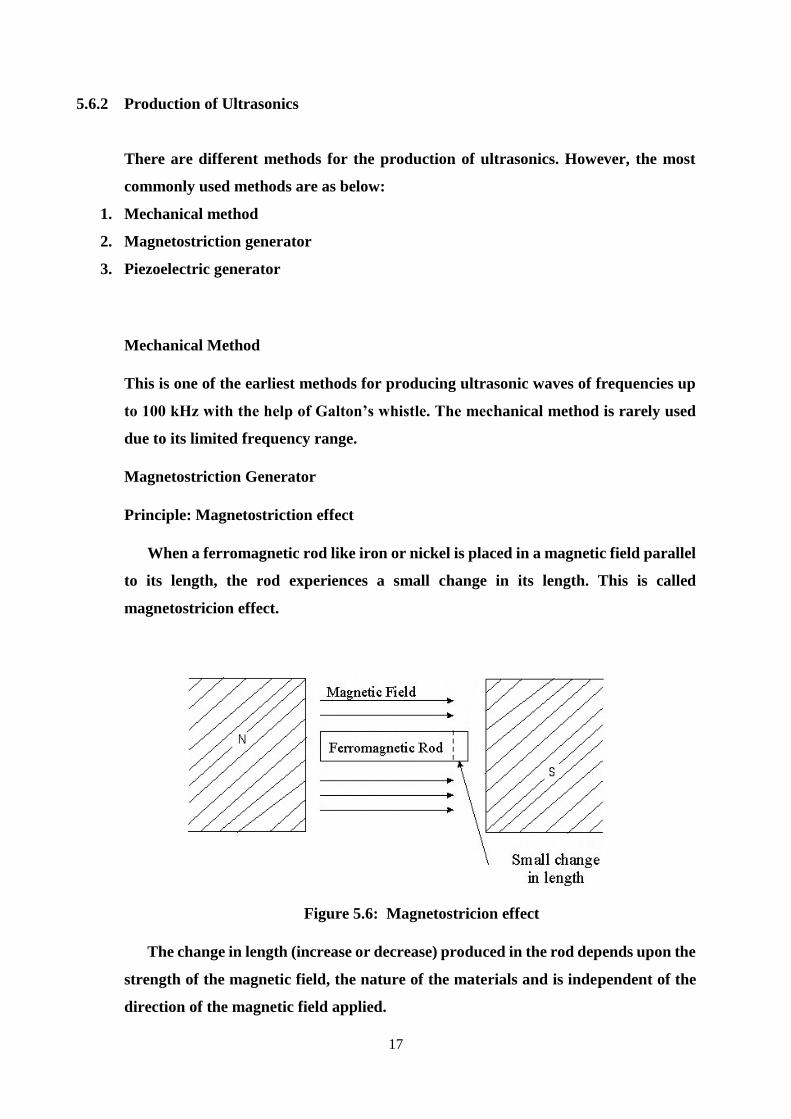
17
5.6.2 Production of Ultrasonics
There are different methods for the production of ultrasonics. However, the most
commonly used methods are as below:
1. Mechanical method
2. Magnetostriction generator
3. Piezoelectric generator
Mechanical Method
This is one of the earliest methods for producing ultrasonic waves of frequencies up
to 100 kHz with the help of Galton’s whistle. The mechanical method is rarely used
due to its limited frequency range.
Magnetostriction Generator
Principle: Magnetostriction effect
When a ferromagnetic rod like iron or nickel is placed in a magnetic field parallel
to its length, the rod experiences a small change in its length. This is called
magnetostricion effect.
Figure 5.6: Magnetostricion effect
The change in length (increase or decrease) produced in the rod depends upon the
strength of the magnetic field, the nature of the materials and is independent of the
direction of the magnetic field applied.
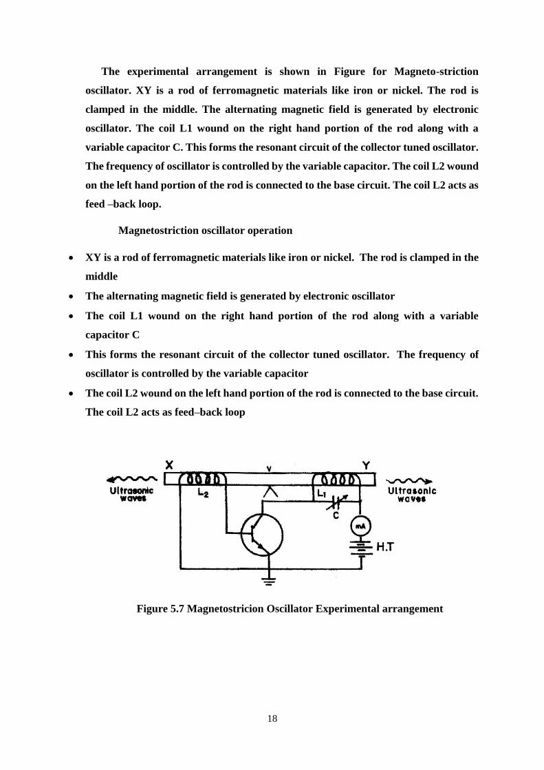
18
The experimental arrangement is shown in Figure for Magneto-striction
oscillator. XY is a rod of ferromagnetic materials like iron or nickel. The rod is
clamped in the middle. The alternating magnetic field is generated by electronic
oscillator. The coil L1 wound on the right hand portion of the rod along with a
variable capacitor C. This forms the resonant circuit of the collector tuned oscillator.
The frequency of oscillator is controlled by the variable capacitor. The coil L2 wound
on the left hand portion of the rod is connected to the base circuit. The coil L2 acts as
feed –back loop.
Magnetostriction oscillator operation
XY is a rod of ferromagnetic materials like iron or nickel. The rod is clamped in the
middle
The alternating magnetic field is generated by electronic oscillator
The coil L1 wound on the right hand portion of the rod along with a variable
capacitor C
This forms the resonant circuit of the collector tuned oscillator. The frequency of
oscillator is controlled by the variable capacitor
The coil L2 wound on the left hand portion of the rod is connected to the base circuit.
The coil L2 acts as feed–back loop
Figure 5.7 Magnetostricion Oscillator Experimental arrangement
19
Magnetostriction oscillator operation
When High Tension (H.T) battery is switched on, the collector circuit
oscillates with a frequency,
1
1f
2 L C
This alternating current flowing through the coil L1 produces an alternating
magnetic field along the length of the rod. The result is that the rod starts vibrating
due to magnetostrictive effect.
The frequency of vibration of the rod is given by
1
2
Yn
l
where = length of the rod
= Young’s modulus of the rod material and
= density of rod material
The capacitor C is adjusted so that the frequency of the oscillatory circuit is
equal to natural frequency of the rod and thus resonance takes place.
Now the rod vibrates longitudinally with maximum amplitude and generates
ultrasonic waves of high frequency from its ends.
Advantages
The design of this oscillator is very simple and its production cost is low.
At low ultrasonic frequencies, the large power output can be produced without the
risk of damage of the oscillatory circuit.
Disadvantages
It has low upper frequency limit and cannot generate ultrasonic frequency above
3000 kHz (ie. 3MHz).
The frequency of oscillations depends on temperature.
There will be losses of energy due to hysteresis and eddy current.
l
Y
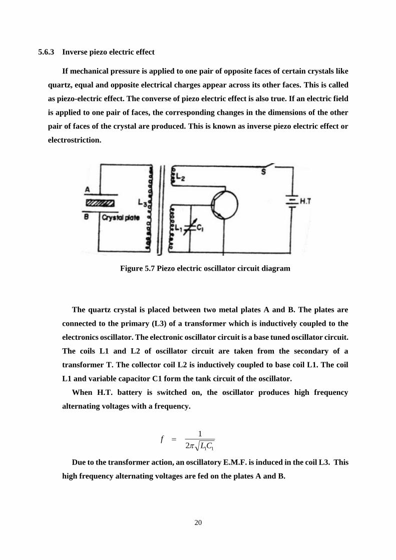
20
5.6.3 Inverse piezo electric effect
If mechanical pressure is applied to one pair of opposite faces of certain crystals like
quartz, equal and opposite electrical charges appear across its other faces. This is called
as piezo-electric effect. The converse of piezo electric effect is also true. If an electric field
is applied to one pair of faces, the corresponding changes in the dimensions of the other
pair of faces of the crystal are produced. This is known as inverse piezo electric effect or
electrostriction.
Figure 5.7 Piezo electric oscillator circuit diagram
The quartz crystal is placed between two metal plates A and B. The plates are
connected to the primary (L3) of a transformer which is inductively coupled to the
electronics oscillator. The electronic oscillator circuit is a base tuned oscillator circuit.
The coils L1 and L2 of oscillator circuit are taken from the secondary of a
transformer T. The collector coil L2 is inductively coupled to base coil L1. The coil
L1 and variable capacitor C1 form the tank circuit of the oscillator.
When H.T. battery is switched on, the oscillator produces high frequency
alternating voltages with a frequency.
112
1
CLf
Due to the transformer action, an oscillatory E.M.F. is induced in the coil L3. This
high frequency alternating voltages are fed on the plates A and B.
21
Inverse piezo-electric effect takes place and the crystal contracts and expands
alternatively. The crystal is set into mechanical vibrations. The frequency of the
vibration is given by
Y
l
Pn
2
where P = 1,2,3,4 … etc. for fundamental, first over tone, second over tone etc.,
Y = Young’s modulus of the crystal and
ρ = density of the crystal
The variable condenser C1 is adjusted such that the frequency of the applied AC
voltage is equal to the natural frequency of the quartz crystal, and thus resonance takes
place. The vibrating crystal produces longitudinal ultrasonic waves of large amplitude.
Advantages
1. Ultrasonic frequencies as high as 5 x 10⁸Hz or 500 MHz can be obtained with this
arrangement.
2. The output of this oscillator is very high.
3. It is not affected by temperature and humidity.
Disadvantages
1. The cost of piezo electric quartz is very high
2. The cutting and shaping of quartz crystal are very complex.
5.6.4 Applications of Ultrasonic Waves in Engineering
(1) Detection of flaws in metals (Non Destructive Testing –NDT)
Principle
Ultrasonic waves are used to detect the presence of flaws or defects in the form of
cracks, blowholes porosity etc., in the internal structure of a material.
By sending out ultrasonic beam and by measuring the time interval of the reflected
beam, flaws in the metal block can be determined.
Experimental setup
It consists of an ultrasonic frequency generator and a cathode ray oscilloscope
(CRO),transmitting transducer(A), receiving transducer(B) and an amplifier.
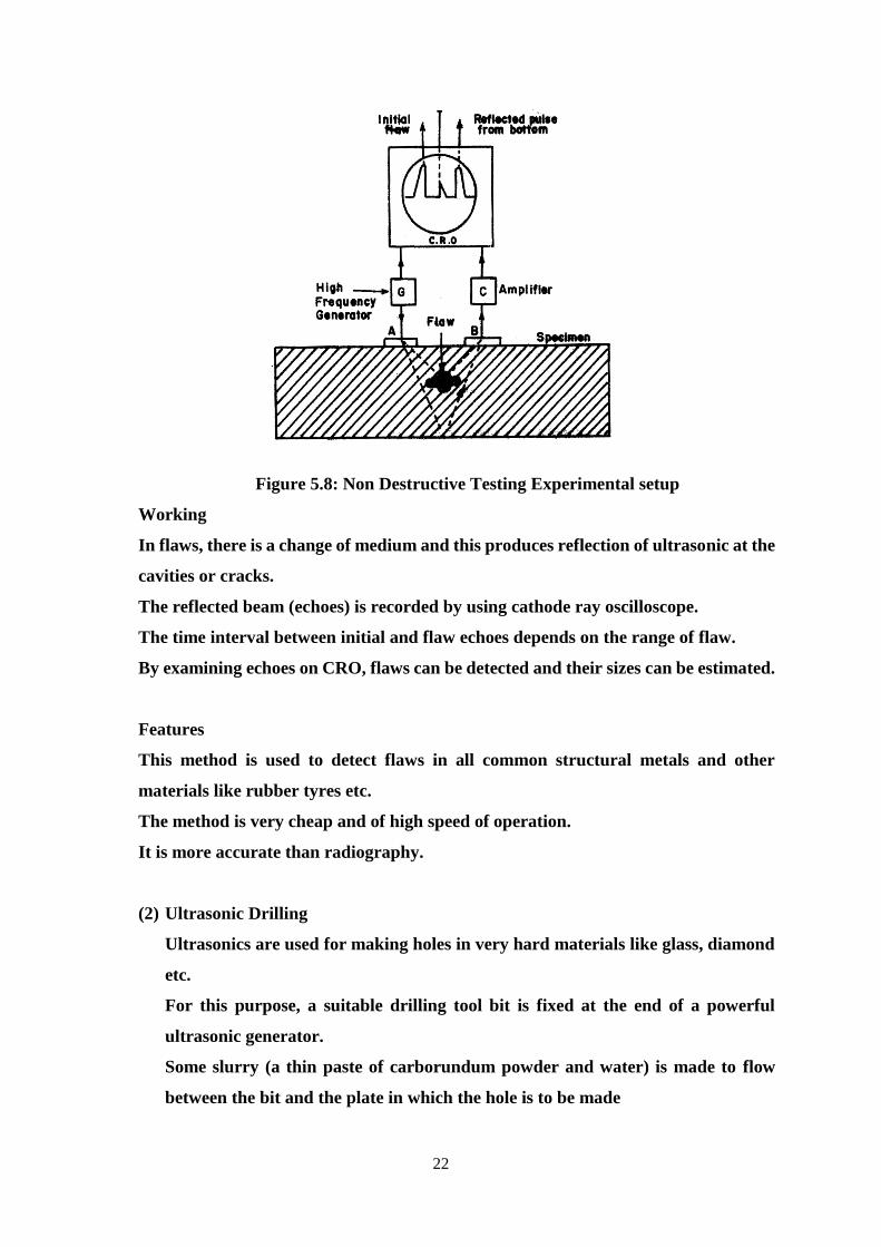
22
Figure 5.8: Non Destructive Testing Experimental setup
Working
In flaws, there is a change of medium and this produces reflection of ultrasonic at the
cavities or cracks.
The reflected beam (echoes) is recorded by using cathode ray oscilloscope.
The time interval between initial and flaw echoes depends on the range of flaw.
By examining echoes on CRO, flaws can be detected and their sizes can be estimated.
Features
This method is used to detect flaws in all common structural metals and other
materials like rubber tyres etc.
The method is very cheap and of high speed of operation.
It is more accurate than radiography.
(2) Ultrasonic Drilling
Ultrasonics are used for making holes in very hard materials like glass, diamond
etc.
For this purpose, a suitable drilling tool bit is fixed at the end of a powerful
ultrasonic generator.
Some slurry (a thin paste of carborundum powder and water) is made to flow
between the bit and the plate in which the hole is to be made
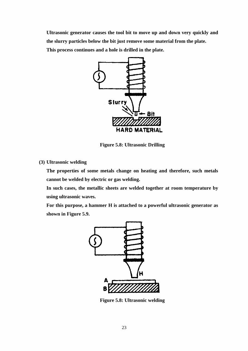
23
Ultrasonic generator causes the tool bit to move up and down very quickly and
the slurry particles below the bit just remove some material from the plate.
This process continues and a hole is drilled in the plate.
Figure 5.8: Ultrasonic Drilling
(3) Ultrasonic welding
The properties of some metals change on heating and therefore, such metals
cannot be welded by electric or gas welding.
In such cases, the metallic sheets are welded together at room temperature by
using ultrasonic waves.
For this purpose, a hammer H is attached to a powerful ultrasonic generator as
shown in Figure 5.9.
Figure 5.8: Ultrasonic welding
24
(4) Ultrasonic soldering
Metals like aluminium cannot be directly soldered. However, it is possible to
solder such metals by ultrasonic waves.
An ultrasonic soldering iron consists of an ultrasonic generator having a tip fixed
at its end which can be heated by an electrical heating element.
The tip of the soldering iron melts solder on the aluminium and the ultrasonic
vibrator removes the aluminium oxide layer.
The solder thus gets fastened to clear metal without any difficulty.
(5) Ultrasonic cutting and machining
Ultrasonic waves are used for cutting and machining.
(6) Ultrasonic cleaning
It is the most cheap technique employed for cleaning various parts of the machine,
electronic assembles, armatures, watches etc., which cannot be easily cleaned by
other methods.
(7) SONAR
SONAR is a technique which stands for Sound Navigation and Ranging.
It uses ultrasonics for the detection and identification of under water objects.
The method consists of sending a powerful beam of ultrasonics in the suspected
direction in water. By noting the time interval between the emission and receipt
of beam after reflection, the distance of the object can be easily calculated.
The change in frequency of the echo signal due to the Doppler effect helps to
determine the velocity of the body and its direction. Measuring the time interval
(t) between the transmitted pulses and the received pulse, the distance between
the transmitter and the remote object is determined using the formula., where v
is the velocity of sound in sea water. The same principle is used to find the depth
of the sea.
Applications of SONAR
Sonar is used in the location of shipwrecks and submarines on the bottom of the
sea.
It is used for fish-finding application.
It is used for seismic survey.
25
Worked Problem
A quartz crystal of thickness 1 mm is vibrating at resonance. Calculate the
fundamental frequency. Given Y for quartz = 7.9 x 10¹⁰ Nm-2 and ρ for quartz
= 2650 kg m-3.
The frequency of the vibration
Y
t
Pf
2
Here P = 1
2650
109.7
001.02
1 10
f
= 2.72998 x 10⁶ Hz
The fundamental frequency of the quartz crystal = 2.730 x 10⁶ Hz = 2.73 MHz.
5.7 RF Characteristics
All RF waves have characteristics that vary to define the wave. Some of these
properties can be modified to modulate information onto the wave. These properties are
wavelength, frequency, amplitude, and phase.
Wavelength
The wavelength of an RF wave is calculated as the distance between two adjacent
identical points on the wave. For example, Figure.1 shows a standard sine wave. Point
A and Point B mark two identical points on the wave, and the distance between them is
defined as the wavelength. The wavelength is frequently measured as the distance from
one crest of the wave to the next. The wavelength dictates the optimum size of the
receiving antenna, and it determines how the RF wave will interact with its
environment. For example, an RF wave will react differently when it strikes an object
that is large in comparison to the wavelength from when it strikes an object that is small
in comparison to the wavelength. The wavelength and the frequency are interrelated.
In fact for a given medium, if wavelength is known, the frequency can be calculated and
if frequency is known, wavelength can be calculated. One of the great discoveries in the
history of electromagnetism is that electromagnetic waves travel at the speed of light.
Since the speed of light is 299,792,458 meters per second, and this is the speed at which
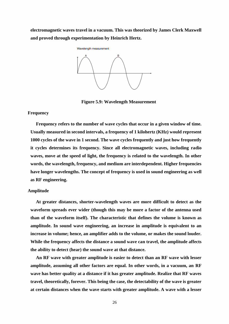
26
electromagnetic waves travel in a vacuum. This was theorized by James Clerk Maxwell
and proved through experimentation by Heinrich Hertz.
Figure 5.9: Wavelength Measurement
Frequency
Frequency refers to the number of wave cycles that occur in a given window of time.
Usually measured in second intervals, a frequency of 1 kilohertz (KHz) would represent
1000 cycles of the wave in 1 second. The wave cycles frequently and just how frequently
it cycles determines its frequency. Since all electromagnetic waves, including radio
waves, move at the speed of light, the frequency is related to the wavelength. In other
words, the wavelength, frequency, and medium are interdependent. Higher frequencies
have longer wavelengths. The concept of frequency is used in sound engineering as well
as RF engineering.
Amplitude
At greater distances, shorter-wavelength waves are more difficult to detect as the
waveform spreads ever wider (though this may be more a factor of the antenna used
than of the waveform itself). The characteristic that defines the volume is known as
amplitude. In sound wave engineering, an increase in amplitude is equivalent to an
increase in volume; hence, an amplifier adds to the volume, or makes the sound louder.
While the frequency affects the distance a sound wave can travel, the amplitude affects
the ability to detect (hear) the sound wave at that distance.
An RF wave with greater amplitude is easier to detect than an RF wave with lesser
amplitude, assuming all other factors are equal. In other words, in a vacuum, an RF
wave has better quality at a distance if it has greater amplitude. Realize that RF waves
travel, theoretically, forever. This being the case, the detectability of the wave is greater
at certain distances when the wave starts with greater amplitude. A wave with a lesser
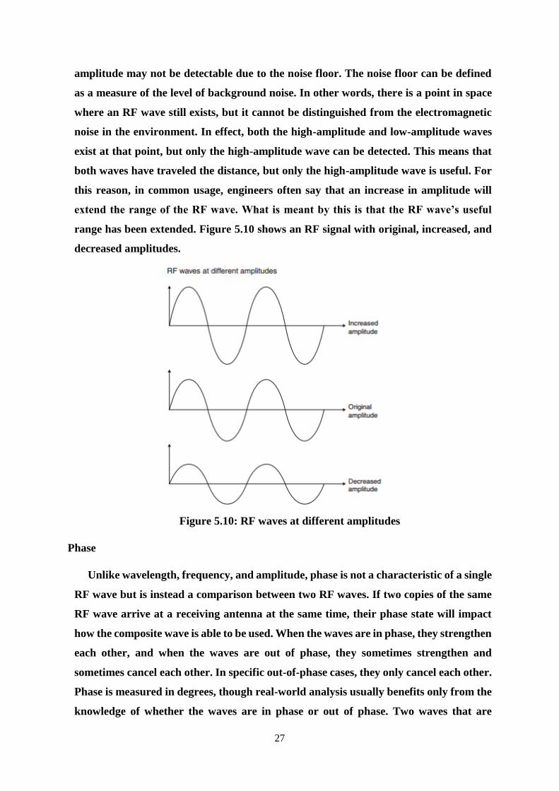
27
amplitude may not be detectable due to the noise floor. The noise floor can be defined
as a measure of the level of background noise. In other words, there is a point in space
where an RF wave still exists, but it cannot be distinguished from the electromagnetic
noise in the environment. In effect, both the high-amplitude and low-amplitude waves
exist at that point, but only the high-amplitude wave can be detected. This means that
both waves have traveled the distance, but only the high-amplitude wave is useful. For
this reason, in common usage, engineers often say that an increase in amplitude will
extend the range of the RF wave. What is meant by this is that the RF wave’s useful
range has been extended. Figure 5.10 shows an RF signal with original, increased, and
decreased amplitudes.
Figure 5.10: RF waves at different amplitudes
Phase
Unlike wavelength, frequency, and amplitude, phase is not a characteristic of a single
RF wave but is instead a comparison between two RF waves. If two copies of the same
RF wave arrive at a receiving antenna at the same time, their phase state will impact
how the composite wave is able to be used. When the waves are in phase, they strengthen
each other, and when the waves are out of phase, they sometimes strengthen and
sometimes cancel each other. In specific out-of-phase cases, they only cancel each other.
Phase is measured in degrees, though real-world analysis usually benefits only from the
knowledge of whether the waves are in phase or out of phase. Two waves that are
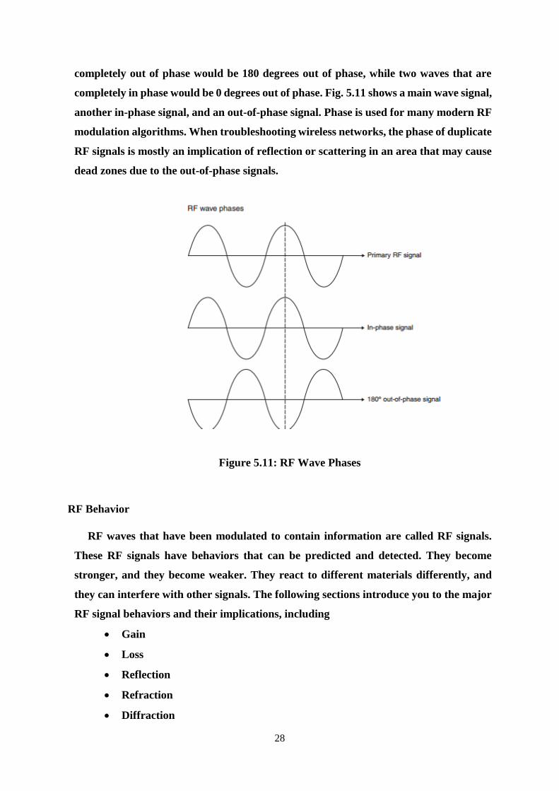
28
completely out of phase would be 180 degrees out of phase, while two waves that are
completely in phase would be 0 degrees out of phase. Fig. 5.11 shows a main wave signal,
another in-phase signal, and an out-of-phase signal. Phase is used for many modern RF
modulation algorithms. When troubleshooting wireless networks, the phase of duplicate
RF signals is mostly an implication of reflection or scattering in an area that may cause
dead zones due to the out-of-phase signals.
Figure 5.11: RF Wave Phases
RF Behavior
RF waves that have been modulated to contain information are called RF signals.
These RF signals have behaviors that can be predicted and detected. They become
stronger, and they become weaker. They react to different materials differently, and
they can interfere with other signals. The following sections introduce you to the major
RF signal behaviors and their implications, including
Gain
Loss
Reflection
Refraction
Diffraction
29
Scattering
Absorption
VSWR
Return
Amplification and Attenuation
Wave Propagation
Free Space Path Loss
Delay Spread
Gain
Gain is defined as the positive relative amplitude difference between two RF wave
signals (hereinafter known as only RF signals). Amplification is an active process used
to increase an RF signal’s amplitude and, therefore, results in gain. There are two basic
types of gain: active and passive. Both types can be intentional, and passive gain can
also be unintentional. Fig.3 shows an example of a signal that demonstrates both gain
and loss.
Active Gain
Active gain is achieved by placing an amplifier in-line between the RF signal
generator (such as an access point) and the propagating antenna. Usually measure the
gain is measured in decibel (dB). For example, an amplifier may provide 6 dB of gain to
the incoming RF signal. To determine the actual power of the signal after passing
through the amplifier, the original power of the signal should be known from the RF
generator and then perform the appropriate RF math.
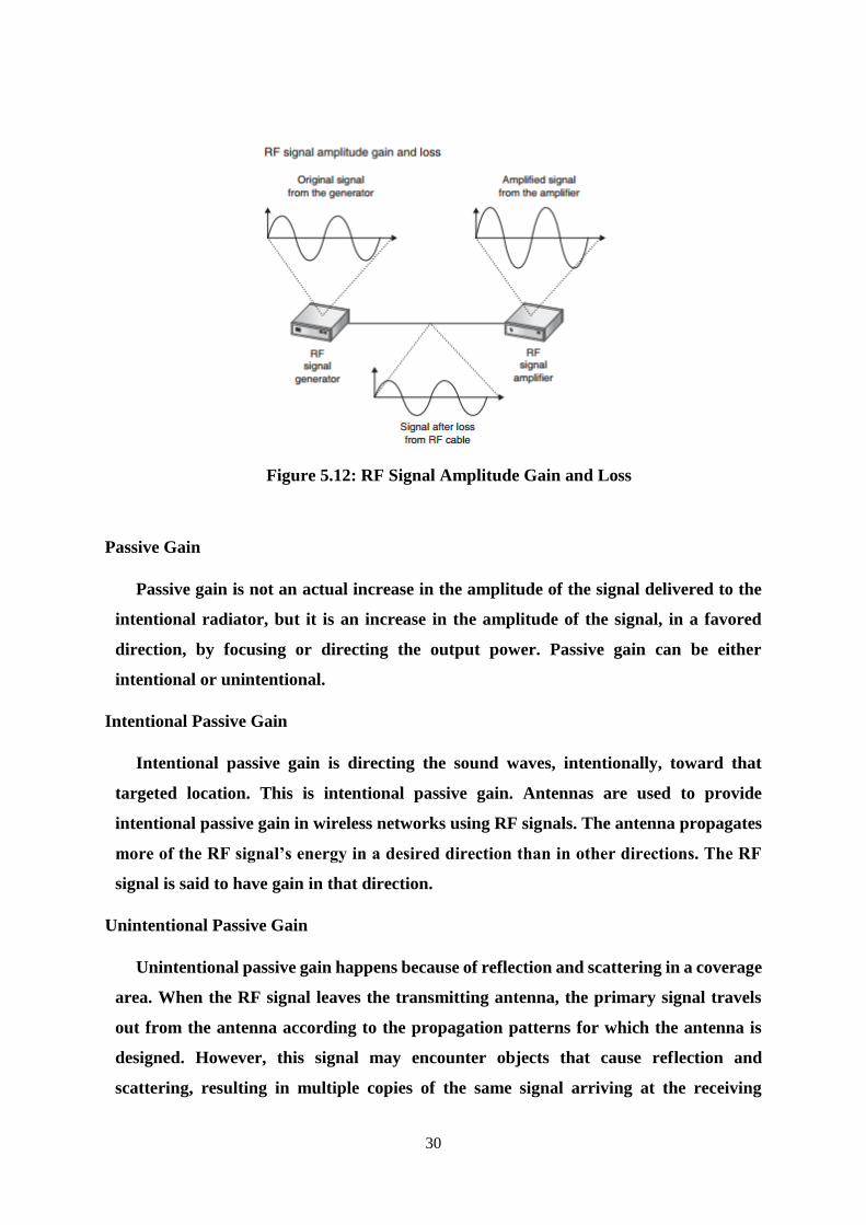
30
Figure 5.12: RF Signal Amplitude Gain and Loss
Passive Gain
Passive gain is not an actual increase in the amplitude of the signal delivered to the
intentional radiator, but it is an increase in the amplitude of the signal, in a favored
direction, by focusing or directing the output power. Passive gain can be either
intentional or unintentional.
Intentional Passive Gain
Intentional passive gain is directing the sound waves, intentionally, toward that
targeted location. This is intentional passive gain. Antennas are used to provide
intentional passive gain in wireless networks using RF signals. The antenna propagates
more of the RF signal’s energy in a desired direction than in other directions. The RF
signal is said to have gain in that direction.
Unintentional Passive Gain
Unintentional passive gain happens because of reflection and scattering in a coverage
area. When the RF signal leaves the transmitting antenna, the primary signal travels
out from the antenna according to the propagation patterns for which the antenna is
designed. However, this signal may encounter objects that cause reflection and
scattering, resulting in multiple copies of the same signal arriving at the receiving
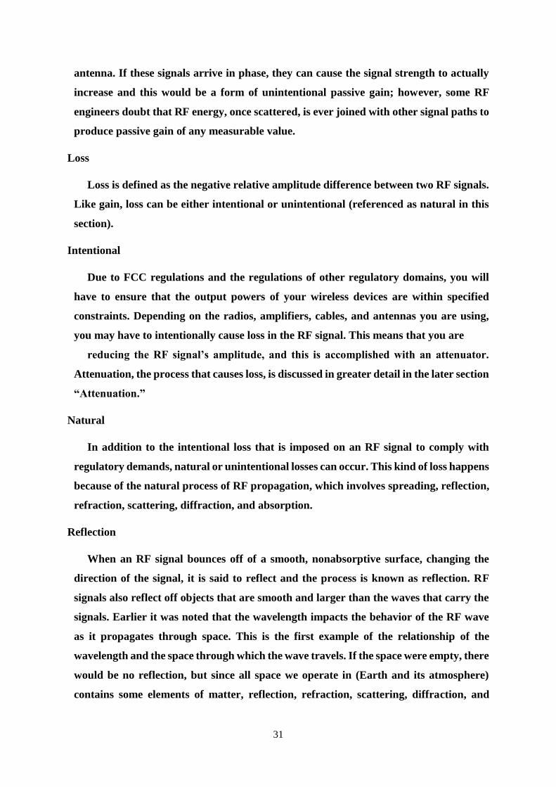
31
antenna. If these signals arrive in phase, they can cause the signal strength to actually
increase and this would be a form of unintentional passive gain; however, some RF
engineers doubt that RF energy, once scattered, is ever joined with other signal paths to
produce passive gain of any measurable value.
Loss
Loss is defined as the negative relative amplitude difference between two RF signals.
Like gain, loss can be either intentional or unintentional (referenced as natural in this
section).
Intentional
Due to FCC regulations and the regulations of other regulatory domains, you will
have to ensure that the output powers of your wireless devices are within specified
constraints. Depending on the radios, amplifiers, cables, and antennas you are using,
you may have to intentionally cause loss in the RF signal. This means that you are
reducing the RF signal’s amplitude, and this is accomplished with an attenuator.
Attenuation, the process that causes loss, is discussed in greater detail in the later section
“Attenuation.”
Natural
In addition to the intentional loss that is imposed on an RF signal to comply with
regulatory demands, natural or unintentional losses can occur. This kind of loss happens
because of the natural process of RF propagation, which involves spreading, reflection,
refraction, scattering, diffraction, and absorption.
Reflection
When an RF signal bounces off of a smooth, nonabsorptive surface, changing the
direction of the signal, it is said to reflect and the process is known as reflection. RF
signals also reflect off objects that are smooth and larger than the waves that carry the
signals. Earlier it was noted that the wavelength impacts the behavior of the RF wave
as it propagates through space. This is the first example of the relationship of the
wavelength and the space through which the wave travels. If the space were empty, there
would be no reflection, but since all space we operate in (Earth and its atmosphere)
contains some elements of matter, reflection, refraction, scattering, diffraction, and
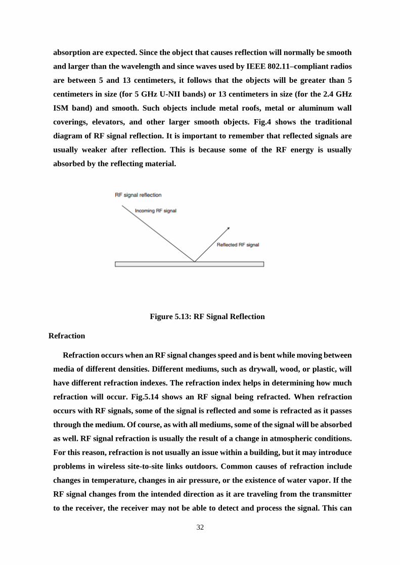
32
absorption are expected. Since the object that causes reflection will normally be smooth
and larger than the wavelength and since waves used by IEEE 802.11–compliant radios
are between 5 and 13 centimeters, it follows that the objects will be greater than 5
centimeters in size (for 5 GHz U-NII bands) or 13 centimeters in size (for the 2.4 GHz
ISM band) and smooth. Such objects include metal roofs, metal or aluminum wall
coverings, elevators, and other larger smooth objects. Fig.4 shows the traditional
diagram of RF signal reflection. It is important to remember that reflected signals are
usually weaker after reflection. This is because some of the RF energy is usually
absorbed by the reflecting material.
Figure 5.13: RF Signal Reflection
Refraction
Refraction occurs when an RF signal changes speed and is bent while moving between
media of different densities. Different mediums, such as drywall, wood, or plastic, will
have different refraction indexes. The refraction index helps in determining how much
refraction will occur. Fig.5.14 shows an RF signal being refracted. When refraction
occurs with RF signals, some of the signal is reflected and some is refracted as it passes
through the medium. Of course, as with all mediums, some of the signal will be absorbed
as well. RF signal refraction is usually the result of a change in atmospheric conditions.
For this reason, refraction is not usually an issue within a building, but it may introduce
problems in wireless site-to-site links outdoors. Common causes of refraction include
changes in temperature, changes in air pressure, or the existence of water vapor. If the
RF signal changes from the intended direction as it are traveling from the transmitter
to the receiver, the receiver may not be able to detect and process the signal. This can
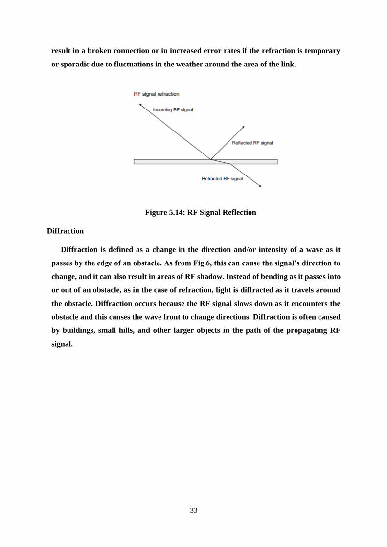
33
result in a broken connection or in increased error rates if the refraction is temporary
or sporadic due to fluctuations in the weather around the area of the link.
Figure 5.14: RF Signal Reflection
Diffraction
Diffraction is defined as a change in the direction and/or intensity of a wave as it
passes by the edge of an obstacle. As from Fig.6, this can cause the signal’s direction to
change, and it can also result in areas of RF shadow. Instead of bending as it passes into
or out of an obstacle, as in the case of refraction, light is diffracted as it travels around
the obstacle. Diffraction occurs because the RF signal slows down as it encounters the
obstacle and this causes the wave front to change directions. Diffraction is often caused
by buildings, small hills, and other larger objects in the path of the propagating RF
signal.
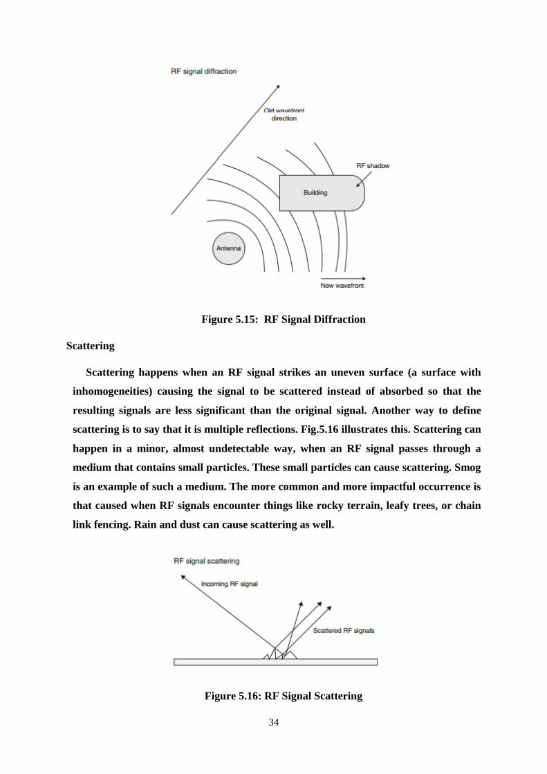
34
Figure 5.15: RF Signal Diffraction
Scattering
Scattering happens when an RF signal strikes an uneven surface (a surface with
inhomogeneities) causing the signal to be scattered instead of absorbed so that the
resulting signals are less significant than the original signal. Another way to define
scattering is to say that it is multiple reflections. Fig.5.16 illustrates this. Scattering can
happen in a minor, almost undetectable way, when an RF signal passes through a
medium that contains small particles. These small particles can cause scattering. Smog
is an example of such a medium. The more common and more impactful occurrence is
that caused when RF signals encounter things like rocky terrain, leafy trees, or chain
link fencing. Rain and dust can cause scattering as well.
Figure 5.16: RF Signal Scattering
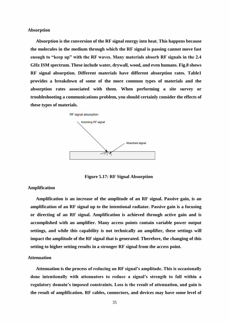
35
Absorption
Absorption is the conversion of the RF signal energy into heat. This happens because
the molecules in the medium through which the RF signal is passing cannot move fast
enough to “keep up” with the RF waves. Many materials absorb RF signals in the 2.4
GHz ISM spectrum. These include water, drywall, wood, and even humans. Fig.8 shows
RF signal absorption. Different materials have different absorption rates. Table1
provides a breakdown of some of the more common types of materials and the
absorption rates associated with them. When performing a site survey or
troubleshooting a communications problem, you should certainly consider the effects of
these types of materials.
Figure 5.17: RF Signal Absorption
Amplification
Amplification is an increase of the amplitude of an RF signal. Passive gain, is an
amplification of an RF signal up to the intentional radiator. Passive gain is a focusing
or directing of an RF signal. Amplification is achieved through active gain and is
accomplished with an amplifier. Many access points contain variable power output
settings, and while this capability is not technically an amplifier, these settings will
impact the amplitude of the RF signal that is generated. Therefore, the changing of this
setting to higher setting results in a stronger RF signal from the access point.
Attenuation
Attenuation is the process of reducing an RF signal’s amplitude. This is occasionally
done intentionally with attenuators to reduce a signal’s strength to fall within a
regulatory domain’s imposed constraints. Loss is the result of attenuation, and gain is
the result of amplification. RF cables, connectors, and devices may have some level of
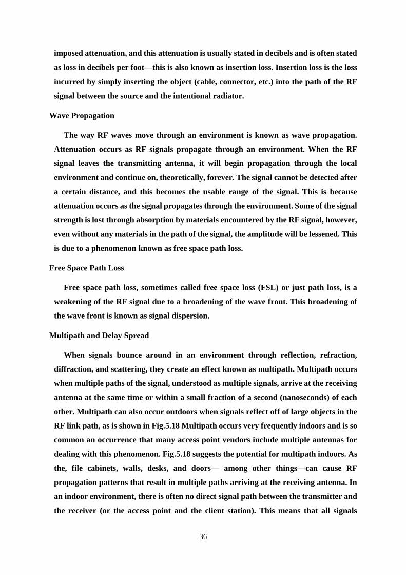
36
imposed attenuation, and this attenuation is usually stated in decibels and is often stated
as loss in decibels per foot—this is also known as insertion loss. Insertion loss is the loss
incurred by simply inserting the object (cable, connector, etc.) into the path of the RF
signal between the source and the intentional radiator.
Wave Propagation
The way RF waves move through an environment is known as wave propagation.
Attenuation occurs as RF signals propagate through an environment. When the RF
signal leaves the transmitting antenna, it will begin propagation through the local
environment and continue on, theoretically, forever. The signal cannot be detected after
a certain distance, and this becomes the usable range of the signal. This is because
attenuation occurs as the signal propagates through the environment. Some of the signal
strength is lost through absorption by materials encountered by the RF signal, however,
even without any materials in the path of the signal, the amplitude will be lessened. This
is due to a phenomenon known as free space path loss.
Free Space Path Loss
Free space path loss, sometimes called free space loss (FSL) or just path loss, is a
weakening of the RF signal due to a broadening of the wave front. This broadening of
the wave front is known as signal dispersion.
Multipath and Delay Spread
When signals bounce around in an environment through reflection, refraction,
diffraction, and scattering, they create an effect known as multipath. Multipath occurs
when multiple paths of the signal, understood as multiple signals, arrive at the receiving
antenna at the same time or within a small fraction of a second (nanoseconds) of each
other. Multipath can also occur outdoors when signals reflect off of large objects in the
RF link path, as is shown in Fig.5.18 Multipath occurs very frequently indoors and is so
common an occurrence that many access point vendors include multiple antennas for
dealing with this phenomenon. Fig.5.18 suggests the potential for multipath indoors. As
the, file cabinets, walls, desks, and doors— among other things—can cause RF
propagation patterns that result in multiple paths arriving at the receiving antenna. In
an indoor environment, there is often no direct signal path between the transmitter and
the receiver (or the access point and the client station). This means that all signals
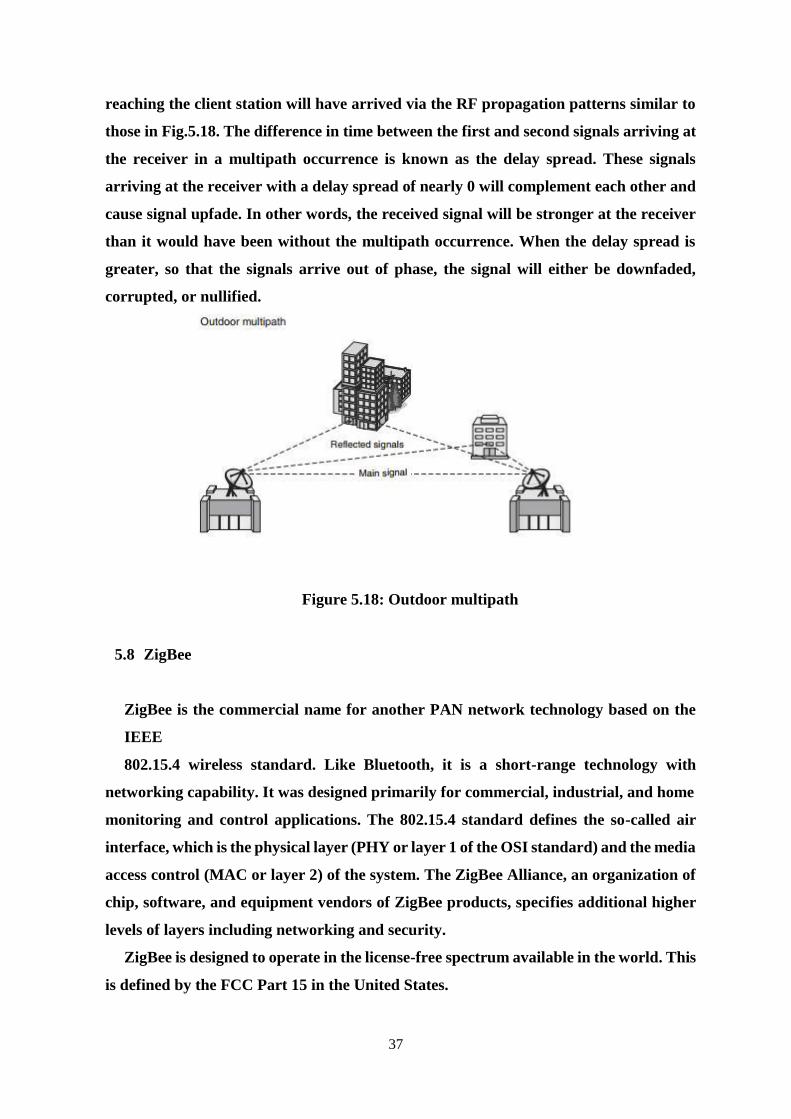
37
reaching the client station will have arrived via the RF propagation patterns similar to
those in Fig.5.18. The difference in time between the first and second signals arriving at
the receiver in a multipath occurrence is known as the delay spread. These signals
arriving at the receiver with a delay spread of nearly 0 will complement each other and
cause signal upfade. In other words, the received signal will be stronger at the receiver
than it would have been without the multipath occurrence. When the delay spread is
greater, so that the signals arrive out of phase, the signal will either be downfaded,
corrupted, or nullified.
Figure 5.18: Outdoor multipath
5.8 ZigBee
ZigBee is the commercial name for another PAN network technology based on the
IEEE
802.15.4 wireless standard. Like Bluetooth, it is a short-range technology with
networking capability. It was designed primarily for commercial, industrial, and home
monitoring and control applications. The 802.15.4 standard defines the so-called air
interface, which is the physical layer (PHY or layer 1 of the OSI standard) and the media
access control (MAC or layer 2) of the system. The ZigBee Alliance, an organization of
chip, software, and equipment vendors of ZigBee products, specifies additional higher
levels of layers including networking and security.
ZigBee is designed to operate in the license-free spectrum available in the world. This
is defined by the FCC Part 15 in the United States.
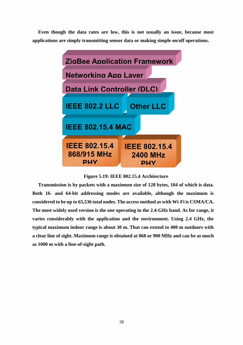
38
Even though the data rates are low, this is not usually an issue, because most
applications are simply transmitting sensor data or making simple on/off operations.
Figure 5.19: IEEE 802.15.4 Architecture
Transmission is by packets with a maximum size of 128 bytes, 104 of which is data.
Both 16- and 64-bit addressing modes are available, although the maximum is
considered to be up to 65,536 total nodes. The access method as with Wi-Fi is CSMA/CA.
The most widely used version is the one operating in the 2.4-GHz band. As for range, it
varies considerably with the application and the environment. Using 2.4 GHz, the
typical maximum indoor range is about 30 m. That can extend to 400 m outdoors with
a clear line of sight. Maximum range is obtained at 868 or 900 MHz and can be as much
as 1000 m with a line-of-sight path.
IEEE 802.15.4
868/915 MHz
PHY
IEEE 802.15.4
2400 MHz
PHY
IEEE 802.15.4 MAC
IEEE 802.2 LLC Other LLC
Data Link Controller (DLC)
Networking App Layer
ZigBee Application Framework
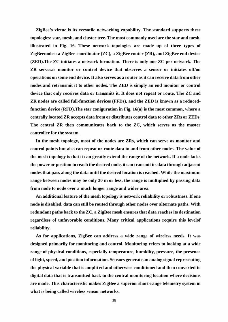
39
ZigBee’s virtue is its versatile networking capability. The standard supports three
topologies: star, mesh, and cluster tree. The most commonly used are the star and mesh,
illustrated in Fig. 16. These network topologies are made up of three types of
ZigBeenodes: a ZigBee coordinator (ZC), a ZigBee router (ZR), and ZigBee end device
(ZED).The ZC initiates a network formation. There is only one ZC per network. The
ZR servesas monitor or control device that observes a sensor or initiates off/on
operations on some end device. It also serves as a router as it can receive data from other
nodes and retransmit it to other nodes. The ZED is simply an end monitor or control
device that only receives data or transmits it. It does not repeat or route. The ZC and
ZR nodes are called full-function devices (FFDs), and the ZED is known as a reduced-
function device (RFD).The star coniguration in Fig. 16(a) is the most common, where a
centrally located ZR accepts data from or distributes control data to other ZRs or ZEDs.
The central ZR then communicates back to the ZC, which serves as the master
controller for the system.
In the mesh topology, most of the nodes are ZRs, which can serve as monitor and
control points but also can repeat or route data to and from other nodes. The value of
the mesh topology is that it can greatly extend the range of the network. If a node lacks
the power or position to reach the desired node, it can transmit its data through adjacent
nodes that pass along the data until the desired location is reached. While the maximum
range between nodes may be only 30 m or less, the range is multiplied by passing data
from node to node over a much longer range and wider area.
An additional feature of the mesh topology is network reliability or robustness. If one
node is disabled, data can still be routed through other nodes over alternate paths. With
redundant paths back to the ZC, a ZigBee mesh ensures that data reaches its destination
regardless of unfavorable conditions. Many critical applications require this levelof
reliability.
As for applications, ZigBee can address a wide range of wireless needs. It was
designed primarily for monitoring and control. Monitoring refers to looking at a wide
range of physical conditions, especially temperature, humidity, pressure, the presence
of light, speed, and position information. Sensors generate an analog signal representing
the physical variable that is amplii ed and otherwise conditioned and then converted to
digital data that is transmitted back to the central monitoring location where decisions
are made. This characteristic makes ZigBee a superior short-range telemetry system in
what is being called wireless sensor networks.
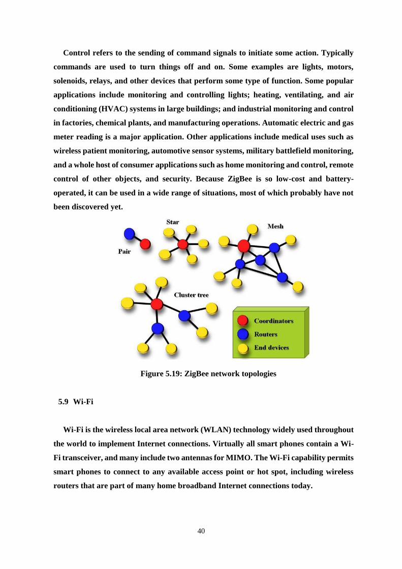
40
Control refers to the sending of command signals to initiate some action. Typically
commands are used to turn things off and on. Some examples are lights, motors,
solenoids, relays, and other devices that perform some type of function. Some popular
applications include monitoring and controlling lights; heating, ventilating, and air
conditioning (HVAC) systems in large buildings; and industrial monitoring and control
in factories, chemical plants, and manufacturing operations. Automatic electric and gas
meter reading is a major application. Other applications include medical uses such as
wireless patient monitoring, automotive sensor systems, military battlefield monitoring,
and a whole host of consumer applications such as home monitoring and control, remote
control of other objects, and security. Because ZigBee is so low-cost and battery-
operated, it can be used in a wide range of situations, most of which probably have not
been discovered yet.
Figure 5.19: ZigBee network topologies
5.9 Wi-Fi
Wi-Fi is the wireless local area network (WLAN) technology widely used throughout
the world to implement Internet connections. Virtually all smart phones contain a Wi-
Fi transceiver, and many include two antennas for MIMO. The Wi-Fi capability permits
smart phones to connect to any available access point or hot spot, including wireless
routers that are part of many home broadband Internet connections today.

41
Wi-Fi Characteristics
This section describes basic characteristics that are common to all Wi-Fi networks.
Operating Frequency
There are two signaling frequencies currently used by Wi-Fi networks:
• 2.4 GHz - Comprises 14 channels, each with a bandwidth of approximately 20 to 22
MHz operating in the ISM band. 802.11b/g networks operate in the 2.4 GHz band. It is
a crowded frequency because many devices other than 802.11 devices operate in it. For
example, Bluetooth as well as many consumer products such as microwaves, telephones,
garage door openers, baby monitors, etc.
• 5 GHz - Comprises 13 channels, each with a bandwidth of approximately 20 MHz
operating in the U-NII band. 802.11a networks operate in the 5 GHz band. Currently,
this band is less crowded than 2.4 GHz, but this is likely to change as the wireless market
continues to grow.
Higher frequency signals have higher attenuation passing through obstacles than do
lower frequency signals. This is because some of the energy of the electromagnetic field
transfers into the material of the obstacle (cement walls, foliage, etc.) which reduces the
strength of the signal.
Signal Strength and Range
Received signal strength is a function of the power output of the transmitter, the
frequency used, the distance travelled by the signal, and the path loss that occurs before
the signal is received.
Received signal strength, and thus usable range, can vary from moment to moment
because propagation characteristics are dynamic and unpredictable. This means that
small changes in the environment can result in huge changes to Rx signal strength. The
critical thing is received signal-to-noise ratio. Noise is a function of interfering source
strength, proximity, and bandwidth. Additionally, all receivers contain an inherent
noise source caused by fundamental physical processes such as random thermal motion
of charge carriers. In practice, Rx signal-to-noise ratio (SNR) is required for higher
transmission speed. SNR is more important than absolute Rx signal strength.
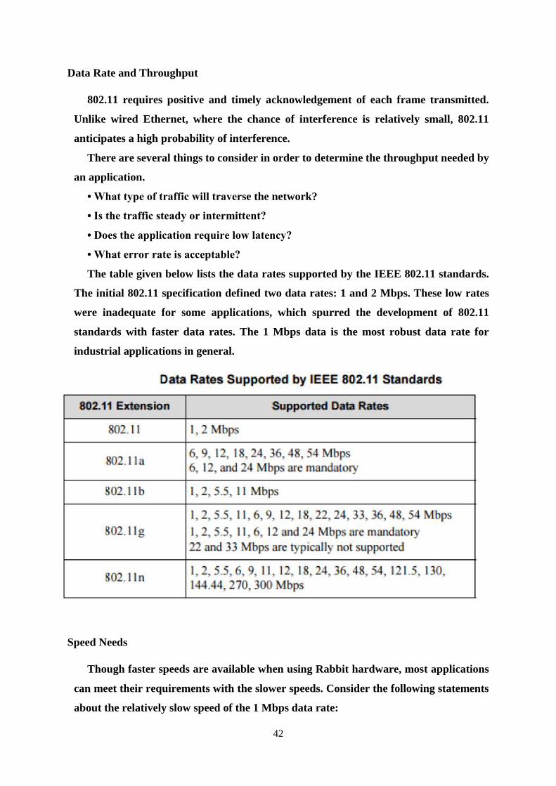
42
Data Rate and Throughput
802.11 requires positive and timely acknowledgement of each frame transmitted.
Unlike wired Ethernet, where the chance of interference is relatively small, 802.11
anticipates a high probability of interference.
There are several things to consider in order to determine the throughput needed by
an application.
• What type of traffic will traverse the network?
• Is the traffic steady or intermittent?
• Does the application require low latency?
• What error rate is acceptable?
The table given below lists the data rates supported by the IEEE 802.11 standards.
The initial 802.11 specification defined two data rates: 1 and 2 Mbps. These low rates
were inadequate for some applications, which spurred the development of 802.11
standards with faster data rates. The 1 Mbps data is the most robust data rate for
industrial applications in general.
Speed Needs
Though faster speeds are available when using Rabbit hardware, most applications
can meet their requirements with the slower speeds. Consider the following statements
about the relatively slow speed of the 1 Mbps data rate:
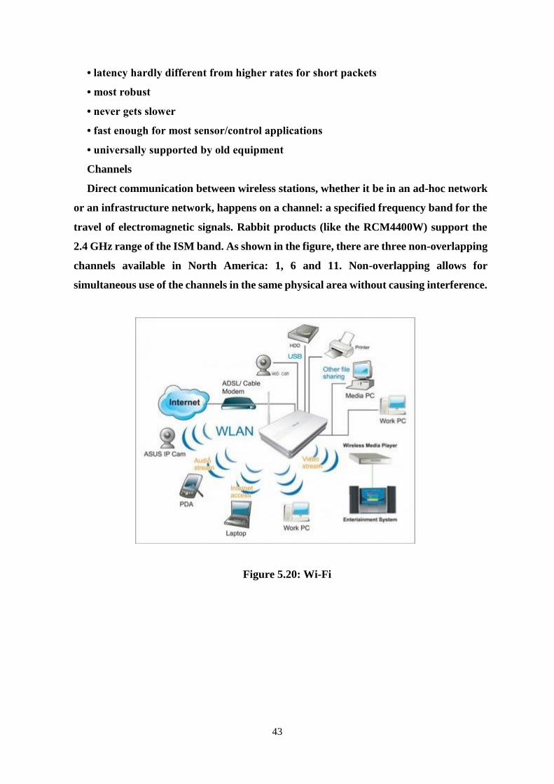
43
• latency hardly different from higher rates for short packets
• most robust
• never gets slower
• fast enough for most sensor/control applications
• universally supported by old equipment
Channels
Direct communication between wireless stations, whether it be in an ad-hoc network
or an infrastructure network, happens on a channel: a specified frequency band for the
travel of electromagnetic signals. Rabbit products (like the RCM4400W) support the
2.4 GHz range of the ISM band. As shown in the figure, there are three non-overlapping
channels available in North America: 1, 6 and 11. Non-overlapping allows for
simultaneous use of the channels in the same physical area without causing interference.
Figure 5.20: Wi-Fi

44
REFERENCES
[1] Louis. E. Frenzel, Communication Electronics Principles and applications, 4th
Edition, Tata McGraw Hill Publications, 2014.
[2] Dennis Roody and John Coolen, Electronic Communications, 4th edition, Prentice
Hall of India, 2002.
[3] R. Gulati, Monochrome and colour television, 2nd Edition, New age international
2005.
[4] B. P. Lathi, Modern Digital and Analog Communication Systems, 3rd Edition,
Oxford University Press, 2007.
[5] B. Sklar, Digital Communications Fundamentals and Applications, 2nd Edition,
Pearson Education 2007.