SCSX1025 – Wireless and Mobile Networks - Sathyabama
157
SATHYABAMA UNIVERSITY (Established under Section 3, UGC Act 1956) DEPARTMENT OF COMPUTER SCIENCE & ENGINEERING DATASTRUCTURES LAB MANUAL SATHYABAMA UNIVERSITY 1
-
Upload
khangminh22 -
Category
Documents
-
view
4 -
download
0
Transcript of SCSX1025 – Wireless and Mobile Networks - Sathyabama

SATHYABAMA UNIVERSITY(Established under Section 3, UGC Act 1956)
DEPARTMENT OF COMPUTER SCIENCE & ENGINEERING
DATASTRUCTURES LAB MANUAL
SATHYABAMA UNIVERSITY
1
SCSX1025 – Wireless and Mobile Networks

SCSX1025 – Wireless and Mobile Networks
UNIT- I
INTRODUCTION
Medium access control – SDMA – FDMA – TDMA – CDMA – Telecommunication systems – GSM –
DECT – TETRA & UMTS – Satellite systems – LEO – MEO – GEO – Handover.
MEDIUM ACCESS CONTROL Medium Access Control comprises all mechanisms that regulate user access to a medium using TDM,FDM (or)
CDM.
Motivation for a specialized MAC Carrier Sense Multiple Access with Collision Detection(CSMA/CD)
� A sender senses the medium wire (or) coaxial cable to see if it is free.
� If the medium is busy the sender waits until it is free.
� If the medium is free the sender starts transmitting data and continues to listen into the medium.
� If a sender detects a collision while sending it stops at once and sends a jamming signal.
CSMA/CD scheme fail in wireless networks � signal strength decreases proportional to the square of the distance
� The sender would apply CS and CD, but the collisions happen at the receiver
� It might be the case that a sender cannot ‚hear‛ the collision, i.e., CD does not work
� Furthermore, CS might not work if, e.g., a terminal is ‚hidden‛
Hidden and exposed terminals Hidden terminals:
Consider the scenario with three mobile phones as shown in figure. The transmission range of A reaches B,
but not C. Similarly the transmission range of C reaches B, but not A. Finally, the transmission range of B
reaches A and C, i.e., A cannot detect C and vice versa.
A starts sending to B, C does not receive this transmission. C also wants to send something to B and senses
the medium. The medium appears to be free, the carrier sense fails. C also starts sending causing a collision at
B. But A cannot detect this collision at B and continues with its transmission. A is hidden for C and vice
versa.

Exposed terminals: While hidden terminals may cause collisions, the next effect only causes unnecessary delay. Now consider the
situation that B sends something to A and C wants to transmit data to some other mobile phone outside the
interference ranges of A and B. C senses the carrier and detects that the carrier is busy (B’s signal). C
postpones its transmission until it detects the medium as being idle again. But as A is outside the interference
range of C, waiting is not necessary. Causing a ‘collision’ at B does not matter because the collision is too
weak to propagate to A. In this situation, C is exposed to B.
Near and far terminals: Consider the situation as shown in following Figure. A and B are both sending with the same transmission
power. As the signal strength decreases proportionally to the square of the distance, B’s signal drowns out A’s
signal. As a result, C cannot receive A’s transmission.
The near/far effect is a severe problem of wireless networks using CDM. All signals should arrive at the
receiver with more or less the same strength. Otherwise (referring again to the party example of chapter 2) a
person standing closer to somebody could always speak louder than a person further away.
Even if the senders were separated by code, the closest one would simply drown out the others. Precise power
control is needed to receive all senders with the same strength at a receiver.
=============================================================================
SDMA (Space Division Multiple Access)
� Space Division Multiple Access (SDMA) is used for allocating a separated space to users in wireless
networks. A typical application involves assigning an optimal base station to a mobile phone user. The
mobile phone may receive several base stations with different quality.
� Typically, SDMA is never used in isolation but always in combination with one or more other
schemes.
� The basis for the SDMA algorithm is formed by cells and sectorized antennas which constitute the
infrastructure implementing space division multiplexing (SDM)
� A new application of SDMA comes up together with beam-forming antenna arrays. Single users are
separated in space by individual beams. This can improve the overall capacity of a cell
==============================================================================
FDMA (Frequency division multiple access)
• Frequency division multiple access (FDMA) comprises all algorithms allocating frequencies to
transmission channels according to the frequency division multiplexing (FDM) scheme.
• Channels can be assigned to the same frequency at all times i.e pure FDMA or change frequencies
according to a certain pattern i.e FDMA combined with TDMA.
• FDM is often used for simultaneous access to the medium by base station and mobile station in
cellular networks. Here the two partners typically establish a duplex channel, i.e., a channel that
allows for simultaneous transmission in both directions.
• The two directions, mobile station to base station and vice versa are now separated using different
frequencies. This scheme is then called frequency division duplex (FDD).
• Both partners have to know the frequencies in advance; they cannot just listen into the medium. The
two frequencies are also known as uplink, i.e.,frequency from mobile station to base station, and as
downlink, i.e., frequency from base station to mobile station.
======================================================================
TDMA (Time Division Multiple Access)
• Compared to FDMA, time division multiple access (TDMA) offers a much more flexible scheme,
which comprises all technologies that allocate certain time slots for communication.
• Now tuning in to a certain frequency is not necessary, i.e., the receiver can stay at the same frequency
the whole time. Using only one frequency, and thus very simple receivers and transmitters, many
different algorithms exist to control medium access.
• As already mentioned, listening to different frequencies at the same time is quite difficult, but listening
to many channels separated in time at the same frequency is simple.

• Now synchronization between sender and receiver has to be achieved in the time domain. Again this
can be done by using a fixed pattern similar to FDMA techniques, i.e., allocating a certain time slot for
a channel, or by using a dynamic allocation scheme.
• Dynamic allocation schemes require an identification for each transmission as this is the case for
typical wired MAC schemes (e.g., sender address) or the transmission has to be announced
beforehand. MAC addresses are quite often used as identification. This enables a receiver in a
broadcast medium to recognize if it really is the intended receiver of a message. Fixed schemes do not
need an identification.
1.Fixed TDM:
• The simplest algorithm for using TDM is allocating time slots for channels in a fixed pattern.
• This results in a fixed bandwidth and is the typical solution for wireless phone systems.
• The only crucial factor is accessing the reserved time slot at the right moment.
• In ths shown figure Fixed TDM patterns are used to implement multiple access and a duplex channel
between a base station and mobile station.
• Assigning different slots for uplink and downlink using the same frequency is called Time division
duplex (TDD).
• The base station uses one out of 12 slots for the downlink whereas the mobile station uses one out of
12 different slots for the uplink.
• Uplink and downlink are separated in time. Up to 12 different mobile stations can use the same
frequency without interference using this scheme.
• Each connection is allotted its own up-and downlink pair.
Different TDMA Schemes are explained below
1.Classical Aloha: • As mentioned above, TDMA comprises all mechanisms controlling medium access according to
TDM. But what happens if TDM is applied without controlling access? This is exactly what the classical
Aloha scheme does, a scheme which was invented at the University of Hawaii and was used in the
ALOHANET for wireless connection of several stations.
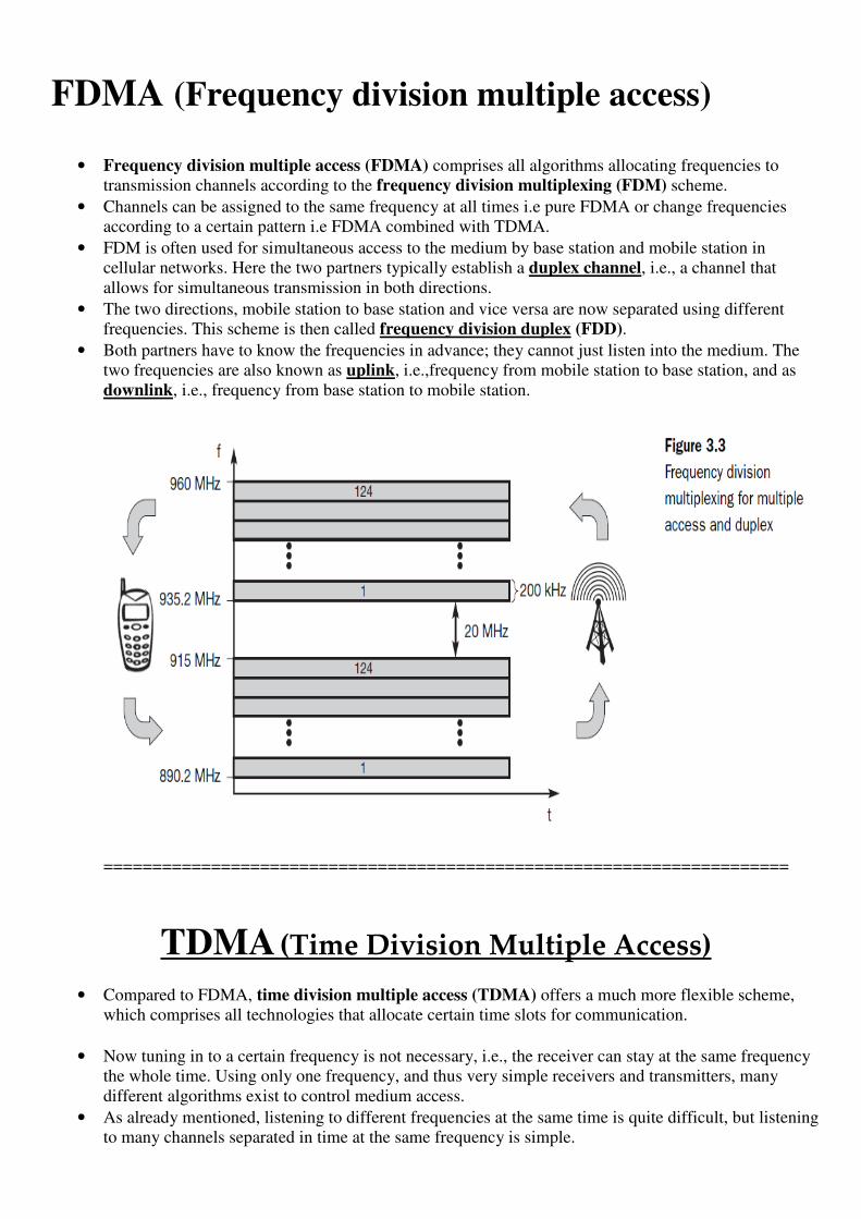
• Here each station can access the medium at any time as shown in the following Figure.
• If two or more stations access the medium at the same time, a collision occurs and the transmitted data
is destroyed. Resolving this problem is left to higher layers.
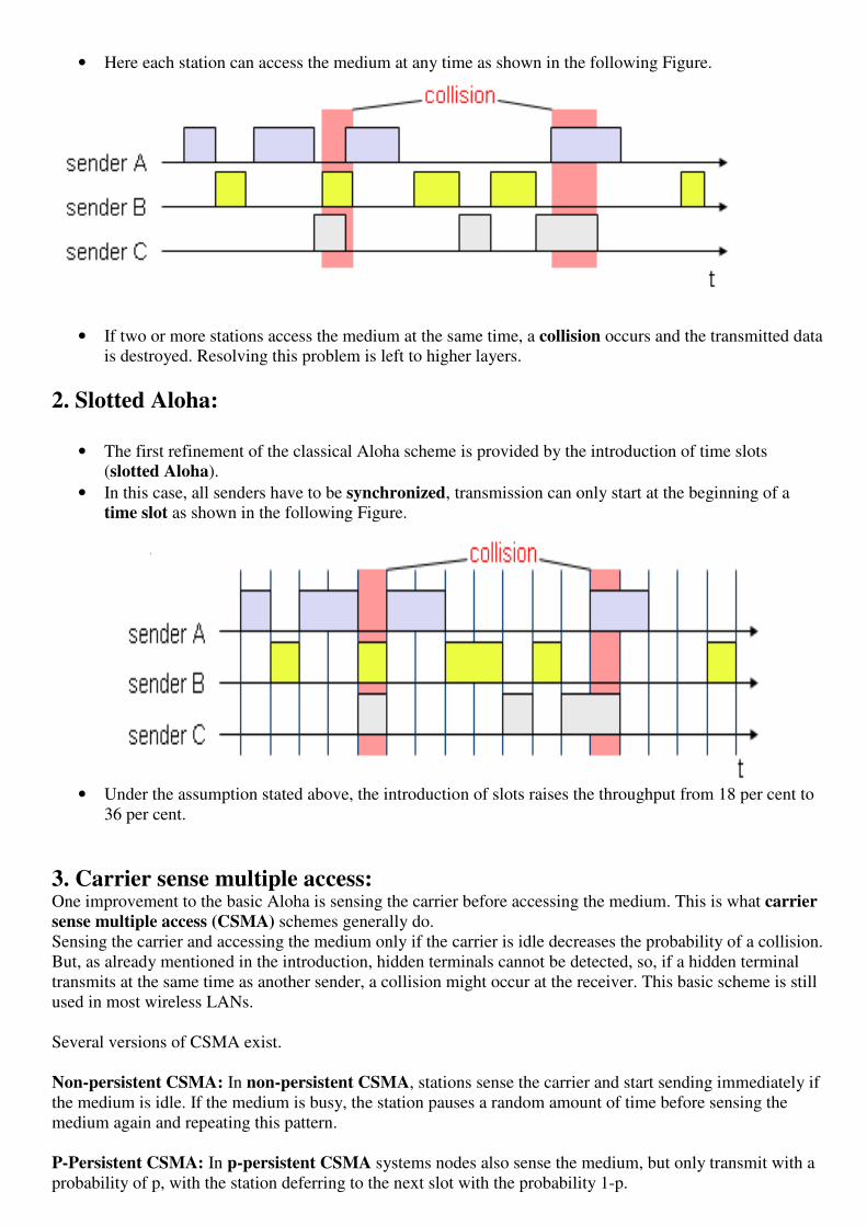
2. Slotted Aloha:
• The first refinement of the classical Aloha scheme is provided by the introduction of time slots
(slotted Aloha).
• In this case, all senders have to be synchronized, transmission can only start at the beginning of a
time slot as shown in the following Figure.
• Under the assumption stated above, the introduction of slots raises the throughput from 18 per cent to
36 per cent.
3. Carrier sense multiple access: One improvement to the basic Aloha is sensing the carrier before accessing the medium. This is what carrier
sense multiple access (CSMA) schemes generally do.
Sensing the carrier and accessing the medium only if the carrier is idle decreases the probability of a collision.
But, as already mentioned in the introduction, hidden terminals cannot be detected, so, if a hidden terminal
transmits at the same time as another sender, a collision might occur at the receiver. This basic scheme is still
used in most wireless LANs.
Several versions of CSMA exist.
Non-persistent CSMA: In non-persistent CSMA, stations sense the carrier and start sending immediately if
the medium is idle. If the medium is busy, the station pauses a random amount of time before sensing the
medium again and repeating this pattern.
P-Persistent CSMA: In p-persistent CSMA systems nodes also sense the medium, but only transmit with a
probability of p, with the station deferring to the next slot with the probability 1-p.

1-persistent CSMA: In 1-persistent CSMA systems, all stations wishing to transmit access the medium at
the same time, as soon as it becomes idle. This will cause many collisions if many stations wish to send and
block each other.
4. Demand assigned multiple access A general improvement of Aloha access systems can also be achieved by reservation mechanisms and
combinations with some (fixed) TDM patterns.
Channel efficiency is only 18% for Aloha, 36% for Slotted Aloha but Reservation can increase efficiency to
80%
During the reservation period,
• The stations can reserve future slots.
• Sending within this reserved time-slot is possible without collision
• Reservation also causes higher delays.
Examples for reservation algorithms:
• Explicit Reservation according to Roberts (Reservation-ALOHA)
• Implicit Reservation (PRMA)
• Reservation-TDMA
1.Explicit Reservation (Reservation Aloha) :
• A scheme typical for satellite systems.
• DAMA, as shown below has two modes.
o ALOHA mode for reservation (collisions possible)
o Reserved mode for data transmission within successful reserved slots (no collisions
possible)
• It is important for all stations to keep the reservation list consistent at any point in time and, therefore,
all stations have to synchronize from time to time
2. PRMA ( packet reservation multiple access):
• An example for an implicit reservation scheme is packet reservation multiple access (PRMA).
Here, slots can be reserved implicitly according to the following scheme. A certain number of slots
forms a frame.
• The following Figure shows eight slots in a frame. The frame is repeated in time (forming frames one
to five in the example), i.e., a fixed TDM pattern is applied.
• Here certain number of slots form a frame, frames are repeated.
• Stations compete for empty slots according to the slotted aloha principle.
• Once a station reserves a slot successfully, this slot is automatically assigned to this station in all
following frames as long as the station has data to send.
• Competition for this slots starts again as soon as the slot was empty in the last frame.
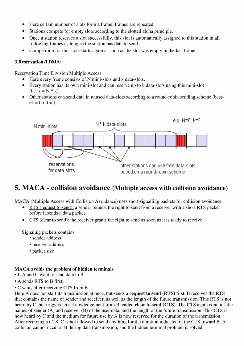
3.Reservation-TDMA:
Reservation Time Division Multiple Access
• Here every frame consists of N mini-slots and x data-slots.
• Every station has its own mini-slot and can reserve up to k data-slots using this mini-slot
(i.e. x = N * k).
• Other stations can send data in unused data-slots according to a round-robin sending scheme (best-
effort traffic)
5. MACA - collision avoidance (Multiple access with collision avoidance) MACA (Multiple Access with Collision Avoidance) uses short signalling packets for collision avoidance
• RTS (request to send): a sender request the right to send from a receiver with a short RTS packet
before it sends a data packet
• CTS (clear to send): the receiver grants the right to send as soon as it is ready to receive
Signaling packets contains
• sender address
• receiver address
• packet size
MACA avoids the problem of hidden terminals • If A and C want to send data to B
• A sends RTS to B first
• C waits after receiving CTS from B
Here A does not start its transmission at once, but sends a request to send (RTS) first. B receives the RTS
that contains the name of sender and receiver, as well as the length of the future transmission. This RTS is not
heard by C, but triggers an acknowledgement from B, called clear to send (CTS). The CTS again contains the
names of sender (A) and receiver (B) of the user data, and the length of the future transmission. This CTS is
now heard by C and the medium for future use by A is now reserved for the duration of the transmission.
After receiving a CTS, C is not allowed to send anything for the duration indicated in the CTS toward B. A
collision cannot occur at B during data transmission, and the hidden terminal problem is solved.

Still, collisions can occur during the sending of an RTS. Both A and C could send an RTS that collides at B.
RTS is very small compared to the data transmission, so the probability of a collision is much lower.
MACA also avoids the problem of exposed terminals
With MACA, B has to transmit an RTS first (as shown in Figure) containing the name of the receiver (A) and
the sender (B). C does not react to this message as it is not the receiver, but A acknowledges using a CTS
which identifies B as the sender and A as the receiver of the following data transmission. C does not receive
this CTS and concludes that A is outside the detection range. C can start its transmission assuming it will not
cause a collision at A. The problem with exposed terminals is solved without fixed access patterns or a base
station.
6. ISMA (Inhibit Sense Multiple Access) Current state of the medium is signaled via a ‚busy tone‛
• The base station signals on the downlink (base station to terminals) if the medium is free or not
• Terminals must not send if the medium is busy
• Terminals can access the medium as soon as the busy tone stops
• The base station signals collisions and successful transmissions via the busy tone and acknowledgements,
respectively (media access is not coordinated within this approach)
===================================================
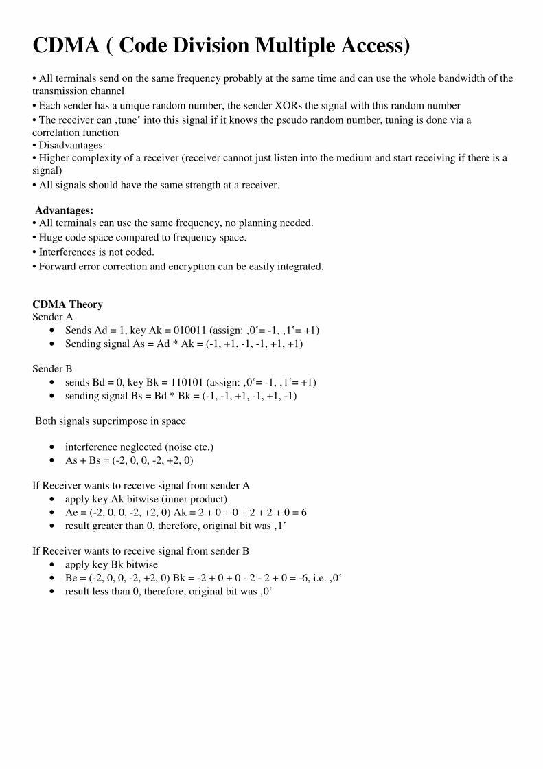
CDMA ( Code Division Multiple Access) • All terminals send on the same frequency probably at the same time and can use the whole bandwidth of the
transmission channel
• Each sender has a unique random number, the sender XORs the signal with this random number
• The receiver can ‚tune‛ into this signal if it knows the pseudo random number, tuning is done via a
correlation function
• Disadvantages:
• Higher complexity of a receiver (receiver cannot just listen into the medium and start receiving if there is a
signal)
• All signals should have the same strength at a receiver.
Advantages:
• All terminals can use the same frequency, no planning needed.
• Huge code space compared to frequency space.
• Interferences is not coded.
• Forward error correction and encryption can be easily integrated.
CDMA Theory
Sender A
• Sends Ad = 1, key Ak = 010011 (assign: ‚0‛= -1, ‚1‛= +1)
• Sending signal As = Ad * Ak = (-1, +1, -1, -1, +1, +1)
Sender B
• sends Bd = 0, key Bk = 110101 (assign: ‚0‛= -1, ‚1‛= +1)
• sending signal Bs = Bd * Bk = (-1, -1, +1, -1, +1, -1)
Both signals superimpose in space
• interference neglected (noise etc.)
• As + Bs = (-2, 0, 0, -2, +2, 0)
If Receiver wants to receive signal from sender A
• apply key Ak bitwise (inner product)
• Ae = (-2, 0, 0, -2, +2, 0) Ak = 2 + 0 + 0 + 2 + 2 + 0 = 6
• result greater than 0, therefore, original bit was ‚1‛
If Receiver wants to receive signal from sender B
• apply key Bk bitwise
• Be = (-2, 0, 0, -2, +2, 0) Bk = -2 + 0 + 0 - 2 - 2 + 0 = -6, i.e. ‚0‛
• result less than 0, therefore, original bit was ‚0‛

CDMA on signal level II

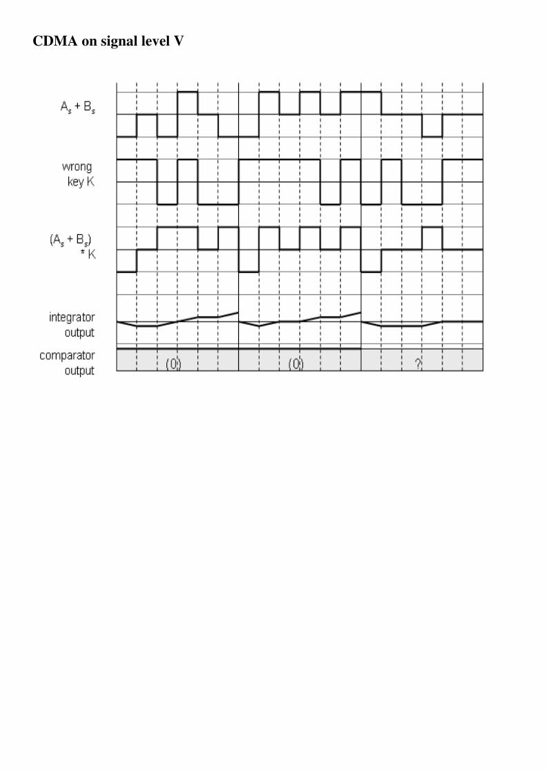
CDMA on signal level V

Comparison of SDMA/TDMA/FDMA/CDMA
==============================================

Telecommunication systems
1. GSM (Global system for mobile communication)
• Global system for mobile communication founded in 1982.
• Most successful Digital Mobile Telecommunication System.
• Used by over 800 million people in more than 190 countries.
Goals
• Provide a mobile phone system that allows users to roam throughout Europe.
• Provide voice services compatible to ISDN and other PSTN systems
• ISDN :- Integrated Service Digital Network PSTN :- Public Switched Telephone Network
• GSM is a typical 2nd generation system replacing the 1st generation Analog System
• GSM has initially been deployed in Europe using
• Uplink :- 890 – 915 Mhz & Downlink :- 935 – 960 Mhz � called GSM 900
• Uplink :- 1710 – 1785 Mhz & Downlink :- 1805 – 1880 Mhz � called Digital Cellular (DCS)
• GSM system mainly used in the US at 1900 Mhz �Uplink :- 1850 – 1910 Mhz & Downlink :- 1930 –
1990 Mhz � called Personal Communication Service (PCS)
•
Here we have to discuss about services, architecture and protocols of GSM
1. MOBILE SERVICES
GSM permits the integration of different voice and data services and the interworking with existing networks
Categories of services
GSM has defined 3 different categories
a. Bearer services
b. Tele services
c. Supplementary Services
• A mobile station (MS) is connected to the GSM-PLMN(Public Land Mobile Network) via the Um
interface.

• GSM – PLMN is the infra structure needed for the GSM networks
• GSM-PLMN network is connected to transit network.
• Ex- ISDN (or) PSTN
• There may be a additional network the source/destination network before another terminal TE is
connected.
• Bearer services comprise all services of data between the interfaces to the network.
• U,S and R interfaces used as a reference for Transparent transmission of data.
• Within the Mobile Station(MS),Mobile Terminal (MT) performs all network specific tasks
(TDMA,FDMA,Coding etc) and offers an interface for Data transmission (s) to the terminal TS.
a. Bearer Services • GSM specifies different mechanism for data transmission
• Data rate [ upto 9600 bit/s ] for Non-Voice services.
Bearer Service permits
a) Transparent
b) Non-Transparent
c) Synchronous
d) Asynchronous Data transmission
i) Transparent :-
• Transparent Bearer services only use the functions of the physical layer to transmit data.
• Data transmission has a constant delay and throughput of no transmission errors occurs
• The only mechanism to increase transmission quality is the use of forward error correction (FEC),
which codes redundancy into the data stream and helps to reconstruct the original data in case of
transmission errors.
• Depending on the FEC, data rates of 2.4, 4.8, or 9.6 kbit/s are possible. Transparent bearer services do
not try to recover lost data in case of, for example, shadowing or interruptions due to handover.
ii).Non-transparent bearer services:-
• use protocols of layers two and three to implement error correction and flow control.
• These services use the transparent bearer services, adding a radio link protocol (RLP).
• This protocol comprises mechanisms of high-level data link control (HDLC).
iii).Synchronous Bearer Services:0 Data transmission can be full-duplex, synchronous with data rates of 1.2, 2.4, 4.8, and 9.6 kbit/s

iv). Asynchronous Bearer Services:- Full-duplex, asynchronous from 300 to 9,600 bit/s .
b. Tele services GSM mainly focuses on voice-oriented tele services.
These comprise
1) Encrypted voice transmission,
2) Message services, and
3) Basic data communication with terminals as known from the PSTN or ISDN (e.g., fax).
The main service is telephony.
The primary goal of GSM
• The provision of high-quality digital voice transmission, offering at least the typical bandwidth of 3.1
kHz of analog phone systems.
• Another service offered by GSM is the emergency number.
a) The same number can be used throughout Europe.
b) This service is mandatory for all providers and free of charge. This connection also has the highest
priority, possibly pre-empting other connections, and will automatically be set up with the closest
emergency center.
• A useful service for very simple message transfer is the short message service (SMS)
a) which offers transmission of messages of up to 160 characters.
b) SMS messages do not use the standard data channels of GSM but exploit unused capacity in the
signalling channels.
c) Sending and receiving of SMS is possible during data or voice transmission.
d) SMS was in the GSM standard from the beginning.
• The successor of SMS, the enhanced message service (EMS),
This offers a larger message size (e.g., 760 characters, concatenating several SMs), formatted text, and
the transmission of animated pictures, small images and ring tones in a standardized way.
• EMS never really took off as the multimedia message service (MMS) was available.
MMS offers the transmission of larger pictures (GIF, JPG, WBMP), short video clips etc. and comes
with mobile phones that integrate small cameras.
C.Supplementary services
• GSM providers can offer supplementary services. Similar to ISDN networks, these services offer
various enhancements for the standard telephony service, and may vary from provider to provider.
• Typical services are user identification, call redirection, or forwarding of ongoing calls.
• Standard ISDN features such as closed user groups and multiparty communication may be available.
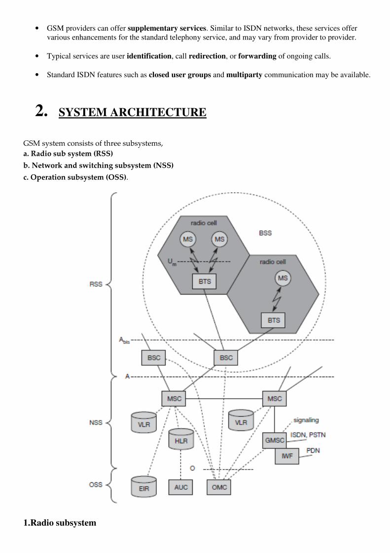
2. SYSTEM ARCHITECTURE
GSM system consists of three subsystems,
a. Radio sub system (RSS)
b. Network and switching subsystem (NSS)
c. Operation subsystem (OSS).
1.Radio subsystem

• The radio subsystem (RSS) comprises all radio specific entities, i.e., the mobile stations (MS), Base
transceiver station(BTS) and the base station subsystem (BSS).
• The connection between the RSS and the NSS via the A interface (solid lines) and the connection to
the OSS via the O interface (dashed lines).
• The A interface is typically based on circuit-switched PCM-30 systems.
Base station subsystem (BSS): • A GSM network comprises many BSSs, each controlled by a base station controller (BSC).
• The BSS performs all functions necessary to maintain radio connections to an MS, coding/decoding of
• voice, and rate adaptation to/from the wireless network part. Besides a BSC, the BSS contains several
BTSs.
Base transceiver station (BTS): • A BTS comprises all radio equipment, i.e., antennas, signal processing, amplifiers necessary for radio
transmission.
• A BTS can form a radio cell or, using sectorized antennas, several cells and is connected to MS via the
Um interface (ISDN U interface for mobile use), and to the BSC via the Abis interface.
• The Um interface contains all the mechanisms necessary for wireless transmission (TDMA, FDMA
etc.)
• The Abis interface consists of 16 or 64 kbit/s connections.
Base station controller (BSC): • The BSC basically manages the BTSs.
• It reserves radio frequencies, handles the handover from one BTS to another within the BSS, and
performs paging of the MS.
• The BSC also multiplexes the radio channels onto the fixed network connections at the A interface.
Mobile station (MS): • The MS comprises all user equipment and software needed for communication with a GSM network.
• An MS consists of user independent hard- and software and of the subscriber identity module (SIM),
which stores all user-specific data that is relevant to GSM.3 While an MS can be identified via the
international mobile equipment identity (IMEI), a user can personalize any MS using his or her
SIM,
• The SIM card contains many identifiers and tables, such as card-type, serial number, a list of
subscribed services, a personal identity number (PIN), a PIN unblocking key (PUK), an
authentication key Ki, and the international mobile subscriber identity (IMSI).
• The PIN is used to unlock the MS. Using the wrong PIN three times will lock the SIM.

• In such cases, the PUK is needed to unlock the SIM. The MS stores dynamic information while logged
onto the GSM system, such as, e.g., the cipher key Kc and the location information consisting of a
temporary mobile subscriber identity (TMSI) and the location area identification (LAI).
b. Network and switching subsystem • The ‚heart‛ of the GSM system is formed by the network and switching subsystem (NSS).
• The NSS connects the wireless network with standard public networks, performs handovers between
different BSSs, comprises functions for worldwide localization of users and supports charging,
accounting, and roaming of users between different providers in different countries.
• The NSS consists of the following switches and databases:
Mobile services switching center (MSC):- • MSCs are high-performance digital ISDN switches.
• They set up connections to other MSCs and to the BSCs via the A interface, and form the fixed
backbone network of a GSM system.
• Typically, an MSC manages several BSCs in a geographical region.
• A gateway MSC (GMSC) has additional connections to other fixed networks, such as PSTN and
ISDN.
• Using additional interworking functions (IWF), an MSCcan also connect to public data networks
(PDN) such as X.25.
Home location register (HLR):- • The HLR is the most important database in a GSM system as it stores all user-relevant information.
• This comprises static information, such as the mobile subscriber ISDN number (MSISDN),
subscribed services (e.g., call forwarding, roaming restrictions, GPRS), and the international mobile
subscriber identity (IMSI).
• Dynamic information is also needed, e.g., the current location area (LA) of the MS, the mobile
subscriber roaming number (MSRN), the current VLR and MSC.
• As soon as an MS leaves its current LA, the information in the HLR is updated.
• All these user-specific information elements only exist once for each user in a single HLR, which also
supports charging and accounting.
Visitor location register (VLR): • The VLR associated to each MSC is a dynamic database which stores all important information
needed for the MS users currently in the LA that is associated to the MSC (e.g., IMSI, MSISDN, HLR
address).
• The typical use of HLR and VLR for user localization .
• Some VLRs in existence, are capable of managing up to one million customers.

c. Operation subsystem • The third part of a GSM system, the operation subsystem (OSS), contains the necessary functions for
network operation and maintenance.
• The OSS possesses network entities of its own and accesses other entities via SS7 signalling
Operation and maintenance center (OMC):
• The OMC monitors and controls all other network entities via the O interface
• Typical OMC management functions are traffic monitoring, status reports of network entities,
subscriber and security management, or accounting and billing.
• OMCs use the concept of telecommunication management network (TMN) as standardized by the
ITU-T.
Authentication centre (AuC): • The radio interface and mobile stations are particularly vulnerable, a separate AuC has been defined to
protect user identity and data transmission.
• The AuC contains the algorithms for authentication as well as the keys for encryption and generates
the values needed for user authentication in the HLR.
• The AuC may, in fact, be situated in a special protected part of the HLR.
Equipment identity register (EIR): • The EIR is a database for all IMEIs, i.e., it stores all device identifications registered for this network.
• MSs are mobile, they can be easily stolen. With a valid SIM, anyone could use the stolen MS. The EIR
has a blacklist of stolen (or locked) devices.
• In theory an MS is useless as soon as the owner has reported a theft.
• Unfortunately, the blacklists of different providers are not usually synchronized and the illegal use of a
device in another operator’s network is possible (the reader may speculate as to why this is the case).
• The EIR also contains a list of valid IMEIs (white list), and a list of malfunctioning devices (gray list).
GSM – PROTOCOL ARCHITECTURE OF SIGNALING
Layer 1, the physical layer, handles all radio specifies functions.
This includes the creation of bursts according to the five different formats.
• Multiplexing
• Synchronization with BTS � detection of idle channels,
• Measurement of the channel quality on the downlink.

• The physical layer at Um uses GMSK for digital modulation
• Perform encryption/decryption of data,
• Synchronization also includes the correction of the individual path delay between and MS and the
BTS.
• All MSs within a cell use the same BTS and this must be synchronized to this BTS.
• The BTS generates the time-structure of frames, slots etc.
• Channel coding makes extensive use of different forward error correction (FEC) schemes.
• FEC adds redundancy to user data, allowing for the detection and correction of selected errors.
• The power of an FEC scheme depends on the amount of redundancy.
LAPDm
• LAPDm protocol has been defined at the Um from link access procedure for the D-channel (LAPD) in
ISDN system, which is a version of HDLC.
• LAPDm is a lightweight LAPD because it does not need synchronization flags or check summing for
error detection.

• LAPDm offers reliable data transfer over connections.
• Re-sequencing of data frames, and
• flow control
• LAPDm include segmentation and reassembly of data and acknowledged/unacknowledged data
transfer.
RR (Radio Resources)
• The lowest sublayer is the radio resource management (RR).
• RR’, is implemented in the BTS, the remainder is situated in the BSC.
• The functions of RR’ are supported
� Setup
� maintenance and
� release of radio channels.
• RR also directly accesses the physical layer for radio information and offers are reliable connection to
the next higher layer.
Mobility management (MM)
• Contains functions for
• Registration
• Authentication
• Identification
• Location updating.
Call Management (CM)
The call management (CM) layer contains three entities
o Call control (CC)
o Short massage service (SMS) and
o Supplementary service (SS).
PCM (Pulse Code Modulation )
• Data transmission at the physical layer typically uses pulse code modulation (PCM) systems.
• PCM systems offer transparent 64 kbit/s channels.
• GSM also allow for the submultiplexing of four 16 kbit/s channels into a single 64 kbit/s channel.
SS7 (Signaling system No.7)
• SS7 is used for signaling between an MSC and a BSC.
• It transfers all management information between
• MSCs,
• HLR,s
• VLRs,

• AUC,
• EIR and OMC.
DECT (digital enhanced cordless telecommunications)
• Another fully digital cellular network is the digital enhanced cordless telecommunications (DECT),
• Formally also called digital European cordless telephone and digital European cordless
telecommunications.
• DECT replaces older analog cordless phone systems such as CT1 and CT1 +.
• DECT is also a more powerful alternative to the digital system CT2, which is mainly used in the UK.
• DECT is mainly used in
� Offices
� On campus at trade shows, or
� In the home.
• DECT works at a frequency range of 1880-1990 mhz offering 120 full-duplex channels.
• Time frequency range is subdivided into 10 carrier frequencies using FDMS ,each frame being divided
into 24 slots using TDMA.
• The frequency range is subdivided into 10 carrier frequencies using FDMS ,each frame being divided
into 24 slots using TDMA.
DECT SYSTEM ARCHITECTURE

Global Network:
A global network connects the local communication structure to the outside world and offers its services via
the interface D1.
Global networks could be
� Integrated services digital networks (ISDN)
� Public switched telephone networks(PSTN)
� Public land mobile networks (PLMN),
� GSM or packet switched public data network (PSPDN).
Services Transportation of data
Translation of addresses and
Routing of data between the local networks

Local networks :
• DECT context offer local communication services that can include
• Simple switching to intelligent call forwarding.
• Address translation
• DECT system itself is quite simple
• All typical network functions have to be integrated in the local or global network where the databases
� Home data base (HDB)
� Visitor data base (VDB) are also located.
• Both databases support mobility with functions that are similar to those in the HLR and VLR in
GSM systems.
• Incoming calls are automatically forwarded to the current subsystem responsible for the DECT
user, and the current VDB informs the HDB about changes in location.
• The DECT core network consists of the Fixed radio termination (FT) and Portable radio
termination (PT), for providing multiplexing service.
• FT and PT cover layers one to three at the fixed network side and mobile network side
respectively.
• Additionally, several portable applications (PA) can be implemented on a device.
PROTOCOL ARCHITECTURE
The DECT protocol reference architecture follows the OSI reference model.
The layers are
� The physical layer
� Medium access control
� Data link control 8 for both the control plane (C-Plane) and the user plane (U-Plane).
� Network layer for the control plane (C-Plane)only
DECT protocol layers

DECT multiplex and frame structure
i) Physical layer

The Physical layer comprises of functions like
� Modulation/demodulation
� Incoming signal detection
� Sender/receiver synchronization
� Collection of status information for the management plane.
TDMA Frame Structure:
• Each frame has a duration of 10 ms and contains 12 slots for the downlink and 12 slots for the uplink
in the basic connection mode.
• If a mobile node receives data in slot s, it returns data in slot s+12.
• An advanced connection mode allows different allocation schemes.
• Each slot has a duration of 0.4167 ms and can contain several different physical packets.
• Typically, 420 bits are used for data; the remaining 52s are left as guard space.
• The 420 bits are again divided into a 32 bit synchronization pattern followed by the data field D.
• The fields for data transmission now use these remaining 388 bits for
� Network control (A field)
� User data (B field)
� Transfer of the transmission quality (X field).
• The network control is transmitted with a data rate depends on additional error correction mechanisms.
Simplex Bearers
� The simplex bearer provides a data rate of 32kbit/s in unprotected mode.
� Using a 16bit CRC checksum c for a data block of 64bit in the protected mode reduces the data rate to
256 kbit.s.
Duplex Bearer
� A duplex bearer service is produced by coming two simplex bearers.
� DECT also defines bearer types with higher throughputs by combining slots
e.g., the double duplex bearer offers 80kbit/s full – duplex.
ii) Medium access control layer
The medium access control (MAC) layer
• Establishes Maintains and releases channels for higher layers by activating and deactivating physical
channels.
• MAC multiplexes several logical channels onto physical channels.
• Logical channels exist for Signaling network, control User data transmission, Paging or Sending
broadcast messages.

• Additional service offered include
� Segmentation / reassembly of packets and
� Error control / error correction.
iii) Data link control layer Creates and maintains reliable connections between the mobile terminal and the base station.
Two services have been defined for the C-plane:-
� A connectionless broadcast service for paging.
� Point- to point protocol.
Several service exist for the U- Plane,
� Forward error correction service
� Rate adaptation services
� Services for future enhancements.
iv) Network layer DECT is similar to those in ISDN and GSM and only exists for the C- plane.
Provides services
� Request
� Check
� Reserve
� Control and Release resources at the fixed station connection to the fixed network
v) Mobility Management (MM)
The mobility management (MM) with in the network layer is responsible for
� Identity management
� Authentication and
� The management of the location data bases.
vi) Call Control (CC) Call control (CC) handles
� �Connection setup
� �Release and
� �Negotiation.
vii) COMS (Connection Oriented Message service & Connectionless oriented message service (CLM) Transfer data to and from the interworking unit that connects the DECT system with the outside world.
==============================================================================
TETRA (terrestrial trunked radio)

• Trunked radio systems constitute another method of wireless data transmission.
• These systems use many different radio carriers but only assign a specific carrier to a certain user for a
short period of time according to demand.
• These types of radio systems typically offer interfaces to the fixed telephone network, i.e., voice and
data services, but are not publicly accessible.
• These systems are not only simpler than most other networks, they are also reliable and relatively
cheap to set up and operate.
• TETRA offers two standards:
� the Voice+Data (V+D) service and
� the packet data optimized (PDO) service
• While V+D offers circuit-switched voice and data transmission, PDO only offers packet data
transmission, either connection-oriented
• TETRA also offers bearer services of up to 28.8 kbit/s for unprotected data transmission and 9.6 kbit/s
for protected transmission. Examples for end-to-end services are call forwarding, call barring,
identification, call hold, call priorities, emergency calls and group joins.
• The system architecture of TETRA is very similar to GSM. Via the radio interface Um, the mobile
station (MS) connects to the switching and management infrastructure (SwMI), which contains
the user data bases (HDB, VDB), the base station, and interfaces to PSTN, ISDN, or PDN.
• The following figure shows the typical TDMA frame structure of TETRA.
• Each frame consists of four slots (four channels in the V+D service per carrier), with a frame duration
of 56.67 ms.
• Each slot carries 510 bits within 14.17 ms, i.e., 36 kbit/s. 16 frames together with one control frame
(CF) form a multiframe, and finally, a hyperframe contains 60 multiframes.
• To avoid sending and receiving at the same time, TETRA shifts the uplink for a period of two slots
compared to the downlink.
• TETRA offers additional services like group call, acknowledged group call, broadcast call, and
discreet listening.
• These features are currently not available in GSM or other typical mobile telephone networks, so
TETRA is complementary to other systems.
• TETRA has been chosen by many government organizations in Europe and China.
==============================================================================
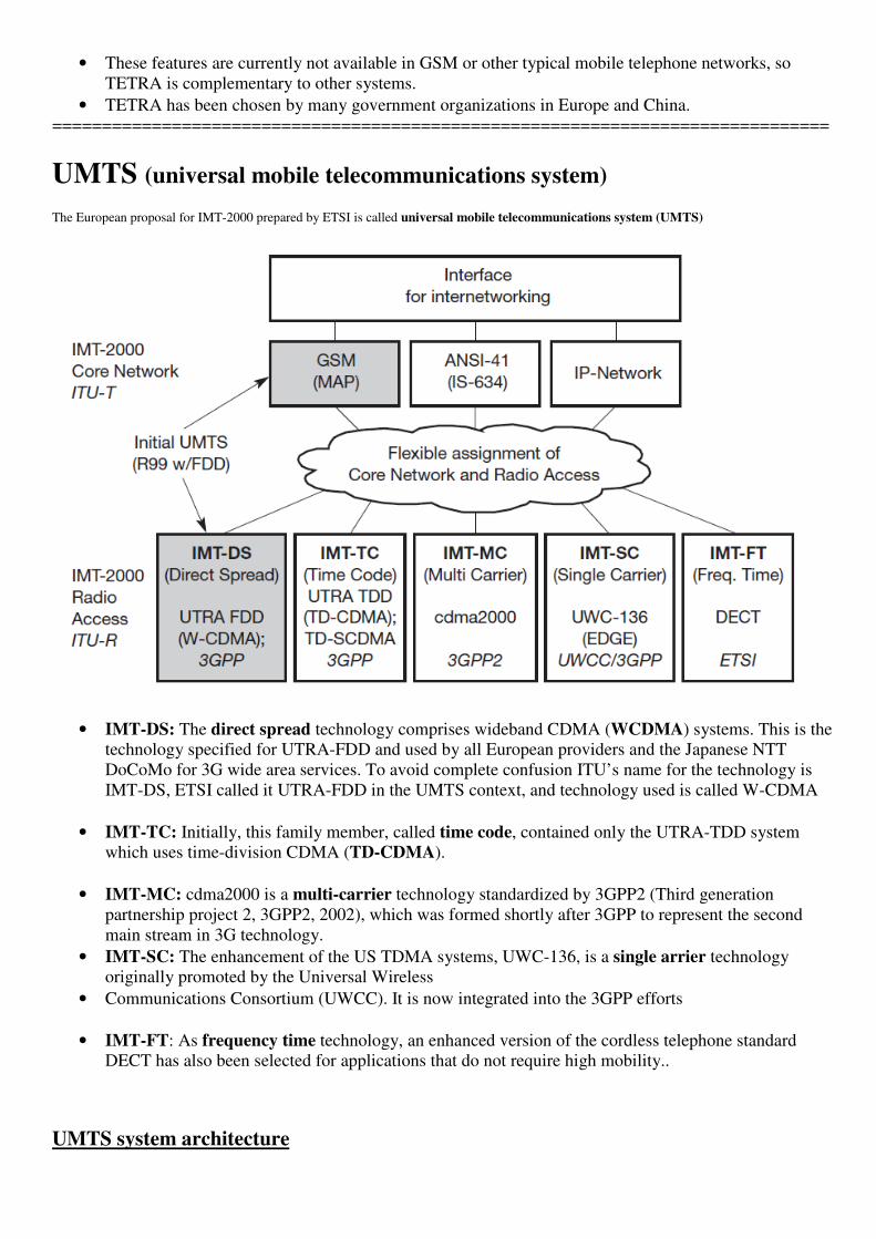
UMTS (universal mobile telecommunications system) The European proposal for IMT-2000 prepared by ETSI is called universal mobile telecommunications system (UMTS)
• IMT-DS: The direct spread technology comprises wideband CDMA (WCDMA) systems. This is the
technology specified for UTRA-FDD and used by all European providers and the Japanese NTT
DoCoMo for 3G wide area services. To avoid complete confusion ITU’s name for the technology is
IMT-DS, ETSI called it UTRA-FDD in the UMTS context, and technology used is called W-CDMA
• IMT-TC: Initially, this family member, called time code, contained only the UTRA-TDD system
which uses time-division CDMA (TD-CDMA).
• IMT-MC: cdma2000 is a multi-carrier technology standardized by 3GPP2 (Third generation
partnership project 2, 3GPP2, 2002), which was formed shortly after 3GPP to represent the second
main stream in 3G technology.
• IMT-SC: The enhancement of the US TDMA systems, UWC-136, is a single arrier technology
originally promoted by the Universal Wireless
• Communications Consortium (UWCC). It is now integrated into the 3GPP efforts
• IMT-FT: As frequency time technology, an enhanced version of the cordless telephone standard
DECT has also been selected for applications that do not require high mobility..
UMTS system architecture

The UTRA network (UTRAN) handles cell level mobility and comprises several radio network subsystems
(RNS). The functions of the RNS include radio channel ciphering and deciphering, handover control, radio
resource management etc. The UTRAN is connected to the user equipment (UE) via the radio interface Uu
(which is comparable to the Um interface in GSM). Via the Iu interface (which is similar to the A interface in
GSM), UTRAN communicates with the core network (CN).
The CN contains functions for inter-system handover, gateways to other networks (fixed or wireless), and
performs location management if there is no dedicated connection between UE and UTRAN.
UMTS domains and interfaces
The user equipment domain is assigned to a single user and comprises all the functions that are needed to
access UMTS services.Within this domain are the USIM domain and the mobile equipment domain. The
USIM domain contains the SIM for UMTS which performs functions for encryption and authentication of
users, and stores all the necessary user-related data for UMTS. Typically, this USIM belongs to a service
provider and contains a micro processor for an enhanced program execution environment (USAT, UMTS SIM
application toolkit). The end device itself is in the mobile equipment domain. All functions for radio
transmission as well as user interfaces are located here.
The infrastructure domain is shared among all users and offers UMTS services to all accepted users. This
domain consists of the access network domain, which contains the radio access networks (RAN), and the
core network domain, which contains access network independent functions. The core network domain can
be separated into three domains with specific tasks. The serving network domain comprises all functions
currently used by a user for accessing UMTS services.

All functions related to the home network of a user, e.g., user data look-up, fall into the home network
domain. Finally, the transit network domain may be necessary if, for example, the serving network cannot
directly contact the home network. All three domains within the core network may be in fact the same
physical network. These domains only describe functionalities.
==============================================================================
SATELLITE SYSTEM
GEO stationary (Geosynchronous) are the backbone of broadcasting in the sky.
Rotation is synchronous to the rotation of the earth, so they appear to be pinned to a certain location.
APPLICATIONS � Traditionally
� Weather Forecasting
� Several satellite deliver pictures of the earth using ex.Infra red (or) Visible lights
Without the help of satellite the forecasting of hurricanes would be impossible.
� Radio and TV broadcast satellites
� Hundreds of radio and TV programs are available via satellite.
� Cheaper to install
� No extra fees have to be paid for this service.
� Satellite dishes have diameters of 30-40cm in central Europe.
� Military satellites
� Many communication links are managed via satellite because they are much safer from attack by
enemies.
� Satellites for navigation and localization (e.g., GPS)
� The global positioning system (GPS) is now-a-days well-known and available for everyone.
All ships and aircraft rely on GPS as an addition to traditional navigation Systems
Trucks and cars come with installed GPS receivers.
� Telecommunication
� Global telephone Backbones
� Applications of satellite for communication was the establishment of international telephone
backbones
� Satellites are increasingly being replaced by fiber optical cables crossing the oceans.
� The signal to a geostationary satellite has to travel about 72,000 km from a sender via the satellite
� Global mobile communication
� Satellite is the support of global mobile data communication.
� Connections for communication in remote places or underdeveloped areas
� Due to their geographical location many places allover the world do not have
� Direct wired connection to the telephone network or the internet.
� Satellites now offer a simple and quick connection to global networks.
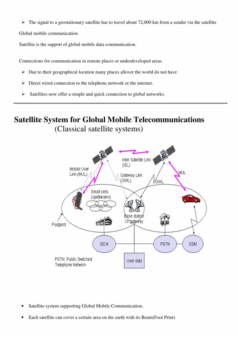
Satellite System for Global Mobile Telecommunications
(Classical satellite systems)
• Satellite system supporting Global Mobile Communication.
• Each satellite can cover a certain area on the earth with its Beam(Foot Print)

• Within the foot print communication with the satellite is possible for mobile users via a Mobile User
Link (MUL)
• The Base station controlling the satellite and acting as gateway to other networks via the Gateway
Link (GWL).
• Satellites may be able to communicate directly with each other via Intersatellite Links (ISL).
• Saving extra links for satellite to earth can reduce latency for data packets and voice data.
BASICS
• Satellites orbit around the earth
• Orbits can be circular (or) Elliptical.
• Satellites in circular orbits always keep the same distance to the earths surface following a simple law.
• �The attractive force Fg of the earth due to gravity equals m.g(R/r)2 �The centrifugal force Fc trying
to pull the satellite away equals. m.r.w2
� Attractive force Fg = m g (R/r)²
� Centrifugal force Fc = m r ²
� m: mass of the satellite
� R: radius of the earth (R = 6370 km)
� r: distance to the center of the earth
� g: acceleration of gravity (g = 9.81 m/s²)
� w : angular velocity ( = 2 f, f: rotation frequency)Stable orbit
� Fg = Fc i.e both forces must be equal
The distance r (i.e distance between satellite and center of the earth)
TYPES OF SATELLITE ORBITS
Four different types of satellite orbits can be identified depending on the shape and diameter of the orbit

� GEO (Geostationary orbit or Geosynchronous Orbit) i.e. 36000 km above earth surface
� LEO (Low Earth Orbit) i.e. 500 - 1500 km
� MEO (Medium Earth Orbit) or ICO (Intermediate Circular Orbit) i.e 6000 - 20000 km
� HEO (Highly Elliptical Orbit) elliptical orbits
a. GEO (Geo stationary satellites)
• Orbit have a distance of at most 36,000 km to earth surface, orbit in equatorial plane (inclination 0°)
• Complete rotation exactly one day, satellite is synchronous to earth rotation.
� Fix antenna positions, no adjusting necessary
� Satellites typically have a large footprint (up to 34% of earth surface!), therefore difficult to reuse
frequencies
� Bad elevations in areas with latitude above 60° due to fixed position above the equator
� High transmit power needed
� High latency due to long distance (ca. 275 ms)
� �The equation for the distance between earth and satellite R=(g.R2/ (2.π.f)2)1/3
� & The period of 24 hours f=1/24h the resulting distance is 35,786 km.
� The orbit must have an inclination of 0 degrees.
Advantages
• Three GEO satellites are enough for a complete coverage of almost any spot on earth.
• Senders and Receivers can use fixed antenna positions no adjusting is needed.
• GEOs are idle for TV and Radio Broadcasting
• GEOs typically do not need a handover due to the large foot print.
Disadvantages • Northern (or) Southern regions of the earth have more problems receiving these satellites due to the
low elevation above a latitude of 600
i.e Larger antennas are needed in the case.
• The transmit power needed is relatively high which causes problems for battery powered devices.
• GEO satellite needs special antennas focusing on an smaller Footprint.
• Transferring a GEO into orbit is very expensive.
b.LEO (Low Earth Orbit) systems
• LEO satellite were mainly used for espionage.
• Several of the new satellite system rely on this class using attitudes of 500-1500 km.
• LEOs circulate on a lower orbit.
� Visibility of a satellite ca. 10 - 40 minutes
� Global radio coverage possible latency comparable with terrestrial long distance connections, ca. 5
- 10 ms
� Smaller footprints, better frequency reuse but now handover necessary from one satellite to
another.
� Many satellites necessary for global coverage more complex systems due to moving satellites
Advantages • Transmission rates of about 2,400 bit/s can be enough for voice communication.
• LEOs even provide this bandwidth for mobile terminals with omni-directional antennas using low
transmit power in the range of 1w.
• The delay for packets delivered via a LEO is relatively low(approx 10ms)
• The delay is comparable to long-distance wired connections (5-10ms).

• LEOS allow for better frequency reuse.
• LEOS can provide a much higher elevation in Polar Regions and so better global coverage.
Disadvantages • The biggest problem of the LEO concept is the need for many satellites if global coverage is to be
reached.
• Several concepts involve 50-200 or even more satellites in orbit.
• The high number of satellites combined with the fast movements results in a high complexity of the
whole satellite system.
c.MEO(Medium Earth Orbit) systems
• MEO operate at a distance of about 5,000 – 12,000 km.
• MEOS can be positioned somewhere between LEOS and GEOs both in terms of their orbit.
• Comparison with LEO systems:
� Slower moving satellites
� Less satellites needed
� Simpler system designfor many connections no hand-over needed
� Higher latency, ca. 70 - 80 ms
� Higher sending power needed
� Special antennas for small footprints needed
Advantages • Using orbits around 10,000 km the system only requires a dozen satellites which is more than a GEO
system.
• These satellites move more slowly relative to the earth’s rotation alloeing a simplex system design.
Disadvantage
• Due to the larger distance to the earth delay increases to about 70-80 ms.
• The satellites needed higher transmit power and special antennas for smaller footprints.
d. HEO(Highly Elliptical Orbit) System
• This class comprises all satellites with non-circular orbits.
• A few commercial communication systems using satellites with elliptical orbits are planned.
• These systems have their perigree over larger cities to improve communication quality.
=================================================================================
HANDOVER IN SATELLITE SYSTEMS
Handover in satellite systems compared to cellular terrestrial mobile phone networks caused by the movement
of the satellites
� Intra satellite handover
• Handover from one spot beam to another
• Mobile station still in the footprint of the satellite, but in another cell.
� Inter satellite handover
• A user leaves the footprint of a satellite.
• Handover can also take place between satellites if they support ISL.
• High transmission quality for Handover frequency.
• High elevation angles imply frequent Handovers.
� Gateway handover
• The satellite might move away from the current gateway.
• The satellite has to connect to another gateway.
� Inter system handover
• Handover from the satellite network to a terrestrial cellular network
• It is cheaper and offer lower latency.
• Current systems allow for the use of dual-mode mobile phones.
• Handover between satellite systems and teresstraial systems or viceversa.


SCSX1025 – Wireless and Mobile Networks
UNIT-2
Broadcast Systems – Cyclic Repetition Of Data – Digital Audio Broadcasting – Digital Video Broadcasting –
Wireless LAN – Infrared Vs Radio Transmission – IEEE 802.11 – Hyper LAN – Bluetooth.
Broadcast systems
• Unidirectional distribution systems or broadcast systems are an extreme version of asymmetric
communication systems. Quite often, bandwidth limitations, differences in transmission power, or cost
factors prevent a communication system from being symmetrical.
• Symmetrical communication systems offer the same transmission capabilities in both communication
directions, i.e., the channel characteristics from A to B are the same as from B to A.
• This symmetry is necessary for a telephone service, but many other applications do not require the same
characteristics for both directions of information transfer.
• Consider a typical client/server environment. Typically, the client needs much more data from the server
than the server needs from the client.Today’s most prominent example of this is the world wide web.
Millions of users download data using their browsers (clients) from web servers. A user only returns
information to the server from time to time.
• A special case of asymmetrical communication systems are unidirectional broadcast systems where
typically a high bandwidth data stream exists from one sender to many receivers.
• The following Figure shows a simple broadcast scenario. A sender tries to optimize the transmitted packet
stream for the access patterns of all receivers without knowing their exact requirements.

• All packets are then transmitted via a broadcast to all receivers. Each receiver now picks up the packets
needed and drops the others or stores them for future use respectively.
Cyclical repetition of data
• A broadcast sender of data does not know when a receiver starts to listen to the transmission. While for
radio or television this is no problem (if you do not listen you will not get the message).
• But transmission of other important information, such as traffic or weather conditions, has to be repeated to
give receivers a chance to receive this information after having listened for a certain amount of time (like
the news every full hour)
• The cyclical repetition of data blocks sent via broadcast is often called a broadcast disk. The different
types of broadcast disks are
� Flat disk
� Skewed disk
� Multi-disk
The sender repeats the three data blocks A, B, and C in a cycle.
Using a flat disk, all blocks are repeated one after another. Every block is transmitted for an equal amount of time,
the average waiting time for receiving a block is the same for A, B, and C.
Skewed disks favour one or more data blocks by repeating them once or several times. This raises the probability
of receiving a repeated block (here A) if the block was corrupted the first time.
Finally, multi-disks distribute blocks that are repeated more often than others evenly over the cyclic pattern. This
Minimizes the delay if a user wants to access, e.g., block A.
=================================================================================
Digital audio broadcasting (DAB)
• DAB systems can use Single Frequency Networks (SFN)
i.e., all senders transmitting the same radio program operate at the same frequency.
• Using an SFN is very frequency efficient as a single-audio station only needs one frequency throughout
the whole country.

• DAB uses VHF and UHF frequency bands (depending on national regulations) e.g., the terrestrial TV
channels 5 to 12 (174-230 MHz) � L-band (1452-1492 MHz).
• The modulation scheme used is DQPSK.
• DAB uses FEC to reduce the error rate and introduces guard space reduce ISI to a minimum.
• DAB can even benefit from multipath propagation by recombining the signals from different paths.
• DAB can transmit up to six stereo audio programmes with data rate of 192 kbit/s each.
• Depending on the redundancy coding, a data service with rates up to 1.5 Mbit/s is available as an
alternative.
• For the DAB transmission system, audio is just another type of data (besides different coding schemes).
Transport Mechanisms: DAB uses two basic transport mechanisms
a.MSC (Main Service Channel)
b. FIC ( Fast Information Channel)
a.Main service channel (MSC):
• The MSC carries all user data (e.g., audio, multimedia data).
• The MSC consists of common interleaved frames (CIF)
i.e., data fields of 55,296 bits that are sent every 24 ms (this interval depends on the
transmission mode.
• A CIF with a size of 64 bits, which form the smallest addressable unit within a DAB system.
b. Fast information channel (FIC):
• The FIC contains fast information blocks (FIB) with 256 bits each (16 bit checksum).
• An FIC carries all control information which is required for interpreting the configuration and content of
the MSC.
Transport Mode: Two transport modes have been defined for the MSC.
a. Stream Mode
b. Packet Mode
a. Stream mode
• Offers a transparent data transmission from the source to the destination with a fixed rate in a sub channel.
• A sub channel is a part of the MSC and comprises several CUs within a CIF. The fixed data rate can be
multiples of 8 kbit/s.
b. packet mode
• Transfers data in addressable blocks (packets).
• These blocks are used to convey MSC data within a sub channel.

DAB Service
• DAB defines many service information structures accompanying an audio stream.
• This program associated data (PAD) can contain
� Program information
� control information
� Still pictures for display on a small LCD
� Title display etc.
• Audio coding uses PCM with a stream can have bit rates ranging from 8 kbit/s to 384 kbit/s.
• Audio data is interleaved for better burst tolerance!.
DAB Frame Structure
• Each frame has a duration TF of 24, 48, or 96 ms depending on the transmission mode.
• DAB defines four different transmission modes, each of which has certain strengths that make it more
efficient for either
� Cable
� Terrestrial or
� Satellite transmission
• Within each frame, 76 or 153 symbols are transmitted using 192, 384, 768, or 1,536 different carriers for
COFDM.
• The guard intervals Td protecting each symbol can be 31,62, 123, or 246 s.
3 parts of Frame Each frame consists of three parts.
The synchronization channels(SC) :-
• Marks the start of a frame.
• It consists of a null symbol and a phase reference symbol to synchronize the receiver.
The fast information channel (FIC) :-
• Containing control data in the FIBs.
The main service channel (MSC) :-
• Carries audio and data service components.
Components of a DAB Sender DAB Sender
• Audio services are encoded (MPEG compression) and coded for transmission (FEC).
• All data services are multiplexed and also coded with redundancy.
• The MSC multiplexer combines all user data streams and forwards them to the transmission multiplexer.
• The unit creates the frame structure by interleaving the FIC.

• Finally, OFDM coding is applied and the DAB signal is transmitted.
• DAB does not require fixed, pre-determined allocation of channels with certain properties to service.
DAB Multiplexer
The DAB multiplexer dynamically interleaves data from all different sources.
To inform the receiver about the current configuration of the MSC carrying the different data streams, the
FIC sends multiplex configuration information (MCI).
• Initially, DAB transmits six audio programmes of different quality together with nine data services.
• Each audio program has its PAD.
In the example
� Audio 1,2 and 3 have � high quality
� 4 and 5� lower quality while
� 6 has� the lowest quality.
• Programmes 1 to 3 could, e.g., be higher quality, classic transmission, while program 6 could be voice
transmission (news etc).
Multi-media object transfer protocol
• A problem which technologies like DAB are facing is the broad range of different receiver capabilities.
• Receivers could be simple audio-only devices with single-line text displays or more advanced radios with
extra color graphics displays.
• DAB receivers can also be adapters in multimedia PCs.
• However, all different types of receivers should at least be able to recognize all program associated and
program-independent data, and process some of this data.
• To solve this program, DAB defines a common standard for data transmission, the multi-media object
transfer (MOT) protocol .
Primary Goal of MOT
The primary goal of MOT is the support of data formats used in other multi-media systems (e.g., on line services,
Internet, CD-Rom).
Example :-
1. Formats are multi-media
2. Hypermedia information coding experts group (MHEG)
3. Java,Joint photographic experts group (JPEG)
4. American standard code for information interchange (ASCII)
5. Moving pictures expert group (MPEG)
6. Hypertext markup language (HTML)
7. Hypertext transfer protocol (HYYP)
8. Bitmap (BMP)
9. Graphics interchange format (GIF).

• MOT data is transferred in MOT objects consisting of a header core, a header extension, and a body.
a.Header core
• This 7 byte field contains the sizes of the header and the body, and the content type of the object.
• Depending on this header information, the receiver, may decide if it has enough resources (memory, CPU
power, display etc.,) available to decode and further process the object.
b.Header extension
• The extension field of variable size contains additional handling data for the object, such as,e.g.,
� The repetition distance to support advanced caching strategies
� The segmentation information, and
� The priority of the data. ( a receiver can decide which data to cache and which to replace).
c. Body
• Arbitary data can be transferred in the variable body.
MOT Repetition Schemes
a.Object Repetition:-
• DAB can repeat objects several times.
• A consists of 4 segments (A1,A2,A3,A4)
• Simple repetition patterns :- A1A2A3A4A1A2A3A4
b.Interleaved Objects :-
• To mitigate burst error problems
� DAB can also interleave segments from different objects.
� Interleaving the objects A,B & C could result in the pattern A1B1C1A2B2C2.
c.Segment repetition :-
• If some segments are more important thatn others.
• DAB can repeat these segments more often Ex: A1A1A2A2A2A3A4A4.
d.Header repetiation :-
• Useful to retransmit the header several times.
• The receiver can synchronize with the data stream as soon as it receives the header and can start decoding .
• A patterns could be HA1A2HA3A4HA5A6
=================================================================================
DIGITAL VIDEO BROADCASTING SYSYTEM (DVB)
.
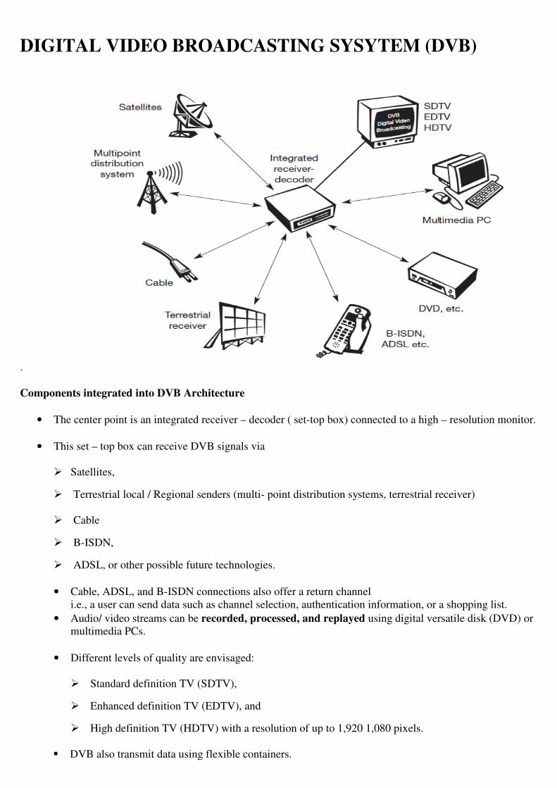
Components integrated into DVB Architecture
• The center point is an integrated receiver – decoder ( set-top box) connected to a high – resolution monitor.
• This set – top box can receive DVB signals via
� Satellites,
� Terrestrial local / Regional senders (multi- point distribution systems, terrestrial receiver)
� Cable
� B-ISDN,
� ADSL, or other possible future technologies.
• Cable, ADSL, and B-ISDN connections also offer a return channel
i.e., a user can send data such as channel selection, authentication information, or a shopping list.
• Audio/ video streams can be recorded, processed, and replayed using digital versatile disk (DVD) or
multimedia PCs.
• Different levels of quality are envisaged:
� Standard definition TV (SDTV),
� Enhanced definition TV (EDTV), and
� High definition TV (HDTV) with a resolution of up to 1,920 1,080 pixels.
� DVB also transmit data using flexible containers.
� These containers are basically MPEG-2 frames that do not restrict the type of information.
� DVB sends service information contained in its data stream, which specifies the content of a container.
The following contents have been defined.
Network Information table (NIT)
• NIT lists the services of a provider and contains additional information for set- top boxes.
Service description table (SDT)
• SDT lists names and parameters for each service within an MPEG multiplex channel.
Even information table (EIT)
• EIT contains status information about the current transmission and some addition information for set-top boxes.
Time and date table (TDT)
• TDT contains update information for set-top boxes.
• As shown in figure an MPEG-2/2 container can store different types of data.
• It either contains a single channel for HDTV, multiple channels for EDTV or SDTV, or arbitrary multi-
media data (data broadcasting).
DVB data broadcasting
• The MEPG-2 transport stream is able to carry arbitrary data within packets with a fixed length of 188 byte
(184 byte payload)
• ETSI (1999c) define several profiles for data broadcasting which can be used, eg., for high bandwidth
mobile Internet services.
Data pipe
• Simple, asynchronous end – to – end delivery of data; data is directly inserted in the payload of MPEG2
transport packets.
Data Streaming
• Streaming– oriented, asynchronous, synchronized (synchronization with other stream, e.g., audio/video
possible), or Synchronous (data and clock regeneration at receiver possible) end –to-end delivery of data.
Multi protocol encapsulation
• Transport of arbitrary data network protocols on top of the MPEG-2 transport stream;
• Optimized for IP,
• Support for 48 bit MAC address, unicast, multi-cast, and broadcast.
Data carousels
• Periodic transmission of data.

Object carousels
• Periodic transmission of objects;
• Platform independent,
• Compatible with the object request broker (ORB) framework as defined by CORBA (2002).
DVB for high- speed internet access A part from this data/multi-media broadcasting, DVB can be also used for
� High band width
� Asymmetrical Internet access.
• An information provider, eg., video store, offers its data to potential customers with the help of a service
provider.
• If a customer wants to download high- volume information, the information provider transmits this
information to a satellite provider via a service provider.
• In fixed networks this is done using leased lines because high bandwidth and QoS guarantees are needed.
• The satellite provider now multiplexes this data stream together with other digital TV channels and
transmits it to the customer via satellite
• Provider now multiplexes this data stream together with other digital TV channels and transmits it to the
customer via satellite and a satellite receiver.
• The customer can now receive the request information with the help of a DVB adapter inside a multi-
media PC.
• The return channel for requests etc. can be a standard TCP/IP connection via the internet as this channel
only requires a low bandwidth.

• Typical data rates per user are 5-30 Mbit/s for the downlink via satellite and return channel with 33 kbit/s
using a standard modem, 64 kbit/s with ISDN, or several 100 kbit/s using DSL. One advantage of this
approach is that
• It is transmitted along with the TV programs using free space in the transmitted data stream, so it does not
require additional lines or hardware per customer.
• This factor is particularly important for remote areas or developing countries where high bandwidth wired
access such as ADSL is not available.
• A clear disadvantage of the approach, however, is the shared medium ‘satellite’.
• If a lot of user request data stream via DVB, they all have to share the satellite’s bandwidth.
• This system cannot give hard Qos guarantees to all users without being very expensive.
=================================================================================
WLAN
Some advantage of WLAN (or) Characteristics of WLAN
Flexibility
• Within radio coverage, nodes can communicate without further restriction.
• Radio waves can penetrate walls, senders and receivers can be placed anywhere.
• Sometimes wiring is difficult if firewalls separate buildings.
• Penetration of a firewalls is only permitted at certain points to prevent fire from spreading too fast.
Planning
• Only wireless ad-hoc networks allow for communication without previous planning any wired network
needs wiring plans.
• As long as devices follow the same standard they can communicate.
• For wired networks, additional cabling with the right plug and probably interworking units such as
switches have to be provided
Design
• Wireless networks allow for the design of small, independent devices which can for example be put into a
pocket.
• Cables not only restrict users but also designers of small PDAs, notepads etc.
• Wireless senders and receivers can be hidden in historic buildings.
i.e., current networking technology can be introduced without being visible.
Robustness

• Wireless networks can survive disasters e.g., earthquakes or user pulling a plug.
• If the wireless devices survive people can still communicate.
• Networks requiring a wired infrastructure will usually break down completely.
Cost
• After providing wireless access to the infrastructure via an access point for the first user, adding, additional
users to a wireless network will not increase the cost.
=================================================================================
INFRARED VS RADIO TRANSMISSION
Infrared
• Infra red technology uses diffuse light reflected at walls, furniture etc, or directed light if a line-of-sight
(LOS) exists between sender and receiver.
• Senders can be simple light emitting diodes (LEDs) or laser diodes.
• Photodiodes act as receivers.
• Details about infra red technology, such as modulation, channel impairments etc.
Advantage • Infra red technology are its simple and extremely cheap senders and receivers which are integrated into
nearly all mobile devices available today.
• PDAs, laptops, notebooks, mobile phones etc, have an infrared data association (IrDA) interface.
• Data Rates
� Version 1.0 implements data rates of up to 115 kbit/s,
� IrDA 1.1 defines higher data rates of 1.152 and 4 Mbit/s.
• No license are needed for infra red technology and shielding is very simple.
• Electrical devices do not interfere with infrared transmission.
Disadvantages
• Infra red transmission are its low bandwidth compared to other LAN technologies.
• Typically, IrDA devices are internally connected to a serial port limiting transfer rates to 115 kbits/s.
• Even 4 Mbit/s is not a particularly high data rate.

• However, their main disadvantage is that infra red is quite easily shielded.
• Infra red transmission cannot penetrate walls or other obstacles.
Radio wave transmission
Advantages
• Radio transmission include the long-term experiences made with radio transmission for wide area
networks e.g., microwave links) and mobile cellular phone.
• Radio transmission can cover larger areas and can penetrate (thinner) walls, furniture, plants etc.
• Additional coverage is gained by reflection. Radio typically does not need a LOS if the frequencies are not
too high.
• Furthermore, current radio-based products offer much higher transmission rates (e.g. 54 Mbit/s) than infra
red (directed laser links, which offer data rate well above 100 Mbit/s.
• These are not considered here as it is very difficult to use them with mobile devices.
Disadvantages
• Again, the main advantages is also a big disadvantage of radio transmission. Shielding is not so simple.
• Radio transmission can interfere with other senders, or electrical devices can destroy data transmitted via
radio.
• Additionally radio transmission is only permitted in certain frequency bands.
• Very limited ranges of license-free bands are not the same in all countries.
• A lot of harmonization is going on due to market pressure.

=================================================================================
IEEE 802.11
• The IEEE standard 802.11 (IEEE, 1999) specifies the most famous family of WLANs in which many
products are available.
• The primary goal of the standard was the specification of a simple and robust WLAN which offers time-
bounded and asynchronous services. The MAC layer should be able to operate with multiple physical
layers, each of which exhibits a different medium sense and transmission characteristic.
System architecture:
Wireless networks can exhibit two different basic system architectures
� Infrastructures – Based
� Ad-hoc
a.Components of an infrastructure based

STA (Station)
• Several nodes called stations (STA)
• STA are connected to access points (AP) stations (or) terminals with access mechanisms to the wireless
medium and radio contact to the AP.
BSS (Basic Service Set)
• A Group of stations using the same radio frequency..
• The example two BSSs (i.e.) BSS1 and BSS2 - which are connected via a distribution system. � AP
(Access Point)
• A distribution system connects several BSSs via the AP to form a single network and thereby extends the
wireless coverage area.
Distributed System
• Interconnection network to form one logical network (ESS :- Extended Service Set) based on several BSS.
• Extended service set (ESS) has its own identifier, the ESSID.
• The ESSID is the ‘name’ of a network and is used to separate different networks.
• Without knowing the ESSID it should not be possible to participate in the WLAN.
Portal
• Bridge to other wired networks.

• The distribution system connects the wireless networks via the APs with a portal which forms the
interworking unit to other LANs.
Distributed System Services
• Stations can select an AP and associate with it.
• The APs support roaming
ie. Changing access points, the distribution system handles data transfer between the different APs.
• APs provide
� Synchronization within a BSS
� Support power management &
� Can control medium access to support time-bounded service.
b. AD-HOC WIRELESS LANS
IBSSs:-
• IEEE802.11 allows the building of ad-hoc networks between stations � thus forming one or more
independent BSSs(IBSS).
• IBSSs comprises a group of stations using same radio frequency.
� Station STA1,STA2 and STA3 are in IBSS1
� Stations STA4 and STA5 are in IBSS2.
i.e For example STA 3 can directly communicate with STA2 but not with STA5
• IEEE 802.11 does not specify any special nodes that support
� Routing
� Forwarding of data
� Exchange of topology information
PROTOCOL ARCHITECTURE of IEEE802.11

802.11 - Layers and functions Layers IEEE802.11 standard only covers the
a. Physical Layer (PHY)
b. Medium Access Layer (MAC)
a. Physical Layer (PHY)
• The physical layer is subdivided into
� Physical layer convergence protocol (PLCP) and
� Physical medium dependent sub layer PMD.
PLCP:-
• The PLCP sub layer provides a carrier sense signal called clear channel assessment (CCA) and
• Provides a common PHY service access point (SAP) independent of the transmission technology.
PMD:-
• PMD sub layer handles
� Modulation
� Encoding/decoding of signals.
b. MAC Layer (MAC)
• The basic tasks of the MAC layer comprise
� Medium access
� Fragmentation of user data &
� Encryption.
Functions Protocol sub layers support standard specifies management layers and the station management.
MAC Management � Roaming
� Controls authentication mechanisms
� Encryption
� Synchronization
� Power management
� Maintains the MAC management information base (MIB)
PHY Management
• Channel tuning or selection
• MIB maintenance
•
Station Management
• Coordination of all Management Functions.
PHYSICAL LAYER of IEEE 802.11
• IEEE 802.11 supports three different physical layers
� One layer based on Infra Red .
� Two layers based on Radio Transmission.
• All PHY variants include the provision off the clear channel assessment signal (CCA).
• CCA is needed for the MAC mechanisms
� Controlling medium access
� Indicates if the medium is currently idle.
MEDIUM ACCESS CONTROL LAYER OF IEEE 802.11
• The MAC layer has to fulfill several tasks.
• It has to
� Control medium access, but it can Also offer support for roaming,
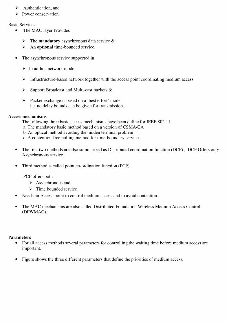
� Authentication, and
� Power conservation.
Basic Services
• The MAC layer Provides
� The mandatory asynchronous data service &
� An optional time-bounded service.
• The asynchronous service supported in
� In ad-hoc network mode
� Infrastructure-based network together with the access point coordinating medium access.
� Support Broadcast and Multi-cast packets &
� Packet exchange is based on a ‘best effort’ model
i.e. no delay bounds can be given for transmission..
Access mechanisms
The following three basic access mechanisms have been define for IEEE 802.11;
a. The mandatory basic method based on a version of CSMA/CA
b. An optical method avoiding the hidden terminal problem
c. A contention-free polling method for time-boundary service.
• The first two methods are also summarized as Distributed coordination function (DCF) , DCF Offers only
Asynchronous service
• Third method is called point co-ordination function (PCF).
PCF offers both
� Asynchronous and
� Time bounded service
• Needs an Access point to control medium access and to avoid contention.
• The MAC mechanisms are also called Distributed Foundation Wireless Medium Access Control
(DFWMAC).
Parameters
• For all access methods several parameters for controlling the waiting time before medium access are
important.
• Figure shows the three different parameters that define the priorities of medium access.

• The value of the parameters depend on the PHY and are defined in relation to a slot time.
• Slot time is derived from the medium
� Propagation delay,
� Transmitter delay, and
� Other PHY dependent parameters.
• Slot time is 50s for FHSS and 20s for DSSS.
Medium
• The medium can be busy or idle (which is detected by the CCA).
• If the medium is busy this can be due to data frames or other control frames.
• During a contention phase several nodes try to access the medium.
Short Inter-frame spacing (SIFS):
• The shortest waiting time for medium access (so the highest priority) is defined for short control messages
such as
� Acknowledgements off data packets or
� Polling responses.
• For DSSS SIFS is 10s and for FHSS it is 28s.
PCF inter-frame spacing (PIFS):

• A waiting time between DIFS and SIFS (and thus a medium priority) is used for a time-bounded service.
• An access point polling other nodes only has to wait PIFS for medium access.
• PIFS is defined as SIFS plus one slot times.
DCF inter-frame spacing (DIFS):
• Parameter denotes the longest waiting time and has the lowest priority for access medium.
• This waiting tome is used for asynchronous data service within a contention period.
• DIFs is defined as SIFS plus two slot times.
MAC frames
• The basic structure of an IEEE 802.11 MAC data frame together with the content of the frame control
field.
Frame control:
• The first 2 bytes serve several purposes. They contain several sub-fields as explained after the MAC frame.
Duration/ID:
• If the field value is less than 32, 768, the duration field contains the value indicating the period of time in
which the medium is occupied (in s).
• This field is used for setting the NAV for the virtual reservation mechanism using RTS/CTS and during
fragmentation.
• Certain values above 32, 768 are reserved for identifiers.
Address 1 to 4:
• The four address fields contain standard IEEE 802 MAC address (48 bit each), as they are known from
other 802.x LANs.

• The meaning of each address depends on the DS bits in the frame control field and is explained in more
detail in a separate paragraph.
Sequence control:
• Due to the acknowledgement mechanism frames may be duplicated. Therefore a sequence number is used
to filter duplicates.
Data:
• The MAC frame may contain arbitrary data (max. 2,312 byte), which is transferred transparently from a
sender to the receiver(s).
Checksum (CRC):
• Finally, a 32 bit checksum is used to protect the frame as it is common practice in all 802.x networks.
The frame control field shown in figure contains the following fields:
Protocol version:
• This 2 bit field indicates the current protocol version and is fixed to 0 by now.
• It major versions to the standard make it incompatible with the current version, this value will be
increased.
Type:
• The type field determines the function of a frame: management (=00), control (=10). The value 1 is
reserved.
• Each type has several subtypes as indicated in the following field.
Subtype:
• Example subtypes for management frames are: 0000 for associated request, 1000 for beacon.
• RTS is a control frame with subtype 1011, CTS is coded as 1100. user data is transmitted as data frame
with subtype 0000. All details can be found in IEEE, 1999.
More Fragments:
• This field is set to 1 in all data or management frames that have another fragment of the current MSDU to
follow.
Retry:
• If the current frame is a retransmission of an earlier frame, this bit is set to 1.
• With the help of this bit it may be simpler for receivers to eliminate duplicate frames.
Power management:
• This field indicates the mode of a station after successful transmission of a frame.
• Set to 1 the field indicates that the station goes into power – save mode.
• If the field is set to 0, the station stays active.

More data:
• In general, this field is used to indicate a receiver that a sender has more data to send than the current
frame.
• This can be used by an access point to indicate to a station in power-save mode that more packets are
buffered.
• Or it can be used by a station to indicate to an access point after being polled that more polling is
necessary as the station has more data ready to transmit.
Wired equivalent privacy (WEP):
• This field indicates that the standard security mechanism of 802 .11 is applied.
• However, due to many weaknesses found in the WEP algorithm higher layer security should be used to
secure an 802.11 network (Borisov,2001).
Order: • If this bit is set to 1 the received frames must be processed in strict order.
Table :- gives an over view of the four possible bit value of the DS bit sand the associated Interpretation of
the four address fields. Table 7.1 Interpretation of the MAC addresses in an 802.11 MAC frame.
3 Control Packets
• Three control packets as examples for many special packets defined in the standard.
• The acknowledgement packet (ACK) is used to acknowledge the correct reception of a data frame.
• The receiver address is directly copied form the address 2 field of the immediately previous frame.
• If no more fragments follow for a certain frame the duration fields is set to 0.
• Otherwise the duration value of the previous frame (minus the time required to transmit the ACK minus
(SIFs) is stored in the duration field.

.
• For the MACA algorithm the RTS / CTS packets are needed.
• These packets have to reserve the medium to avoid collisions.
• Therefore, the request to send (RTS) packet contains the receiver address of the intended recipient of the
following data transfer and the transmitter address of the station transmitting the RTS packet.
• The duration (in s) comprises the time to send the CTS, data, and ACK plus three SIFS.
• The immediately following clear to send (CTS) frame copies the transmitter address from the RTS packet
into its receiver address field.
• Additionally, it reads the duration field, subtracts the time to send the CTS and a SIFS and wires the result
into its own duration field.
=================================================================================
HIPERLAN
• HIPERLAN stands for high performance local area network.
• HIPERLAN 1 as a WLAN allowing for node mobility and supporting ad-hoc and infrastructure-based
topologies.
• HIPERLAN 1 was originally one out of four HIPERLANs, former HIPERLANs 2, 3, and 4 are now
called HiperLAN2, HIPERACCESS, and HIPERLINK.
• HIPERLAN 1 as a wireless LAN supporting priorities and packet life time for data transfer at 23.5 Mbit/s,
including forwarding mechanisms, topology discovery, user data encryption, network identification and
power conservation mechanisms.
• HIPERLAN 1 should operate at 5.1–5.3 GHz with a range of 50 m in buildings at 1 W transmit power.

• The service offered by a HIPERLAN 1 is compatible with the standard MAC services known from IEEE
802.x LANs. Addressing is based on standard 48 bit MAC addresses.
Innovative Features
• HIPERLAN 1 do not offer is its ability to forward data packets using several relays.
• Relays can extend the communication on the MAC layer beyond the radio range.
• For power conservation a node may set up a specific wake-up pattern.
• Determines at what time the node is ready to receive
• other times the node can turn off its receiver and save energy.
• These nodes are called p-savers or p-supporters
• p-supporters :- contain information about the wake-up patterns of all the p-saver at the moment the p-
saver is awake.
Medium Access Scheme • The medium access scheme of HIPERLAN 1 is EY-NPMA scheme that provides QoS and a powerful
prioritization scheme.
• Elimination - yield non preemptive priority multiple access (EY-NPMA) is the Heart of the channel
access providing Priorities and Different Access Schemes
• EY-NPMA divides the medium access of different competing nodes into three phases.
1. Prioritization: Determine the highest priority of a data packet ready to be sent by competing
nodes.
2. Contention: Eliminate all but one of the contenders, if more than one sender has the highest
current priority.
The contention phase is further subdivided into an elimination phase and a yield phase.
Elimination phase: -
� Is to eliminate as many contending nodes as possible (but surely not all).
� The result of the elimination phase is a more or less constant number of remaining nodes almost
independent of the initial number of competing nodes.
Yield Phase:-
� Completes the work of the elimination phases with the goal of only one remaining nodes
3. Transmission: Finally, transmit the packet of the remaining node.
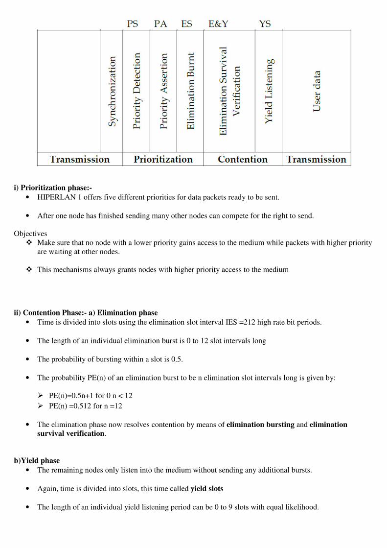
i) Prioritization phase:-
• HIPERLAN 1 offers five different priorities for data packets ready to be sent.
• After one node has finished sending many other nodes can compete for the right to send.
Objectives
� Make sure that no node with a lower priority gains access to the medium while packets with higher priority
are waiting at other nodes.
� This mechanisms always grants nodes with higher priority access to the medium
ii) Contention Phase:- a) Elimination phase
• Time is divided into slots using the elimination slot interval IES =212 high rate bit periods.
• The length of an individual elimination burst is 0 to 12 slot intervals long
• The probability of bursting within a slot is 0.5.
• The probability PE(n) of an elimination burst to be n elimination slot intervals long is given by:
� PE(n)=0.5n+1 for 0 n < 12
� PE(n) =0.512 for n =12
• The elimination phase now resolves contention by means of elimination bursting and elimination
survival verification.
b)Yield phase
• The remaining nodes only listen into the medium without sending any additional bursts.
• Again, time is divided into slots, this time called yield slots
• The length of an individual yield listening period can be 0 to 9 slots with equal likelihood.
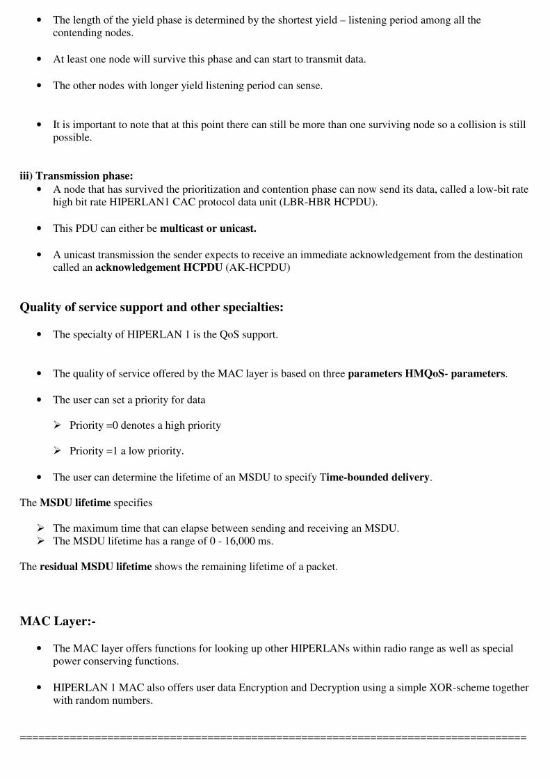
• The length of the yield phase is determined by the shortest yield – listening period among all the
contending nodes.
• At least one node will survive this phase and can start to transmit data.
• The other nodes with longer yield listening period can sense.
• It is important to note that at this point there can still be more than one surviving node so a collision is still
possible.
iii) Transmission phase:
• A node that has survived the prioritization and contention phase can now send its data, called a low-bit rate
high bit rate HIPERLAN1 CAC protocol data unit (LBR-HBR HCPDU).
• This PDU can either be multicast or unicast.
• A unicast transmission the sender expects to receive an immediate acknowledgement from the destination
called an acknowledgement HCPDU (AK-HCPDU)
Quality of service support and other specialties:
• The specialty of HIPERLAN 1 is the QoS support.
• The quality of service offered by the MAC layer is based on three parameters HMQoS- parameters.
• The user can set a priority for data
� Priority =0 denotes a high priority
� Priority =1 a low priority.
• The user can determine the lifetime of an MSDU to specify Time-bounded delivery.
The MSDU lifetime specifies
� The maximum time that can elapse between sending and receiving an MSDU.
� The MSDU lifetime has a range of 0 - 16,000 ms.
The residual MSDU lifetime shows the remaining lifetime of a packet.
MAC Layer:-
• The MAC layer offers functions for looking up other HIPERLANs within radio range as well as special
power conserving functions.
• HIPERLAN 1 MAC also offers user data Encryption and Decryption using a simple XOR-scheme together
with random numbers.
=================================================================================

Bluetooth Bluetooth technology discussed here aims at so-called ad-hoc piconets, which are local area networks with a very
limited coverage and without the need for an infrastructure.
Bluetooth development started, a study group within IEEE 802.11 discussed wireless personal area networks
(WPAN) under the following five criteria:
• Market potential: How many applications, devices, vendors, customers are available for a certain
technology?
• Compatibility: Compatibility with IEEE 802.
• Distinct identity: Originally, the study group did not want to establish a second 802.11 standard.
However, topics such as, low cost, low power, or small form factor are not addressed in the 802.11
standard.
• Technical feasibility: Prototypes are necessary for further discussion, so the study group would not rely on
paper work.
• Economic feasibility: Everything developed within this group should be cheaper than other solutions and
allow for high-volume production.
User Scenarios
Connection Of peripheral Devices:-
• Most devices are connected to a desktop computer via wires.
Ex: Keyboard , Mouse,Joystick , Headset & Speakers.
Disadvantages
o Each device has its own type of cable.
o Different plugs are needed
o Wires block office space.
• In a wireless network no wires are needed for data transmission
• Batteries now have to replace the power supply.
Bridging of Networks

• Using wireless piconets a mobile phone can be connected to a Laptop.
• The Mobile phones will not have full WLAN adapters built in but could have a Bluetooth Chip.
• The Mobile Phone can then act as a bridge between the local piconet Ex: Global GSM Network.
ARCHITECTURE
• Bluetooth operates in the 2.4GHz ISM band.
• Services offered by MAC & Physical layer are completely different
Networking
• Bluetooth operates on 79channels in the 2.4GHz band with 1MHz carrier spacing.
• Each device performs Frequency Hopping with 1600 hops/s in a pseudo random fashion.
• The context of Bluetooth is a Piconet(Piconet is a collection of Bluetooth devices which are synchronized
to the same hopping sequence).
Master(M):-
One device in the Piconet can act as Master(M).
Slave(S):-
• All the other devices connected to the Master must act as Slave(S).
• The Master determines the hopping pattern in the Piconet and the slaves have to synchronize to this
pattern.
• Each piconet has a unique hopping pattern.

• If a device wants to participate it has to synchronize.
Two additional types of devices are
Parked Devices(P):-
� Cannot actively participate in the Piconet (They do not have a connection).
� It can be reactivated within some milliseconds.
Stand-By(SB):-
� Devices in SB do not participate in the Piconet.
• Each piconet has exactly one Master and up to seven simultaneous slaves.
• More than 200 devices can be parked.
• All active devices have to use the same hopping sequence they must be synchronized.
• The first steps involves a Master sending its clock and device ID.
• All Bluetooth devices have the same networking capabilities
i.e They can be Master or Slave.
• The unit establishing the piconet automatically becomes the Master, all other device will be the Slave.
• The hopping pattern is determined by the device ID – 48 bit Worldwide Unique Identifier.
• The phase in the hopping pattern is determined by the Master’s clock.
• After adjusting the Internal clock according to the Master a device may participate in the Piconet.
• All active devices are assigned a 3-bit active member address (AMA).
• All parked devices use on 8-bit Parked Member Address (PMA).
• All users within one piconet have the same hopping sequence and share the same 1MHZ channel.

• As more users join the piconet the throughput per user drops quickly this led to the idea of forming groups
of piconets called Scatternet.
Explanation:-
• The Scatternet consists of two piconets in which one device participates in two different piconets.
• Both Piconets use a different hopping sequence always determined by the Master of the Piconet.
• Bluetooth applies FH-CDMA for separation of Piconets.
• All Piconet can share the total of 80MHz Bandwidth available.
• Adding more piconets leads to
� performance degradation &
� More Collisions
• A collision occurs if two or more piconets use the same carrier frequency at the same time.
• If a device wants to participate in more than one piconet it has to synchronize to the hopping sequence of
the piconet it wants to take part in.
• If a device acts as slave in one piconet it simply starts to synchronize with the hopping sequence of the
piconet it wants to join.
• After synchronize with the hopping sequence it acts as a slave in this piconet
• Before leaving one piconet a slave informs the current master that it will be unavailable for a certain
amount of time. The remaining devices in the Piconet continue to communicate as usual.
• A Master can also leave its Piconet and act as a Piconet all traffic within this piconet is suspended until the
master returns.

The core protocols of Bluetooth comprise the following elements:
Radio: Specification of the air interface i.e. frequencies, and transmit power.
Baseband: Description of basic
� connection establishment,
� packet formats
� timing and
� basic QoS parameters
Link manager protocol:
Link set-up and management between devices including security functions and parameter negotiation.
Logical link control and adaptation protocol (L2 CAP):
Adaptation of higher layers to the baseband (connectionless and connection –oriented services).
Service discovery protocol:
• Device discovery in close proximity plus querying of service characteristics.
• On top of L2CAP is the cable replacement protocol RFCOMM
� Emulates a serial line interface following the EIA-232 (formerly RS-232) standards
� Supports multiple serial parts over a single physical channel.
• TCS BIN:- The Telephony Control Protocol Specification.
Binary (TCSBIN) –
Describes a Bit-oriented protocol that defines
� Call Control
� Signaling for the establishment of voice and data calls between Bluetooth devices.
� Describes Mobility & Group Management Functions.
Host Controller Interface (HCI):
• HCI between the Baseband and L2CAP provides a command interface to the Baseband Controller &
Link Manager.
• Access to the Hardware Status & Control Registers.
• The HCI can be seen as the Hardware / Software Boundary.
RADIO LAYER
Bluetooth devices will be integrated into typical mobile devices and rely on battery power.
This requires
• Small, low power chips which can be built into handheld devices.
• The combined use for data and voice transmission has to be reflected in the design.
i.e., Bluetooth has to support multi-media data.

• Bluetooth uses the license-free frequency band at 2.4 GHz allowing for worldwide operation with some
minor adaptations to national restrictions.
• The time between two hops is called a slot which is an interval of 625 s.
• Each slot uses a different frequency.
• Bluetooth uses 79 hop carriers equally spaced with 1 MHz.
LINK MANAGER PROTOCOL
The Link Manager Protocol (LMP) manages various aspects of
• The Radio Link between a Master and a Slave
• The Current parameter setting of the Devices.
Functions :-
Authentication , Pairing & Encryption:-
• Authentication is handled in the Baseband.
• LMP has to control the exchange of Random Numbers and Signed Responses.
• The Pairing Service is needed to establish an intial trust relationship between two devices that have never
communicated before.
• The result of pairing is a Link Key ( This may be changed , Accepted (or) Rejected)
• LMP is not directly involved in the encryption process but sets the
� Encryption Mode ( No Encryption , Point-to-point, Broadcast).
� Key Size
� Random Speed
Power control:-
• A Bluetooth device can measure the received signal strength.
• Depending on this signal level the device can direct the sender of the measured signal to increase or
decrease it transmit power.
SECURITY • A radio interface is by nature easy to access.
• Bluetooth devices can transmit private data, e.g., schedules between a PDA and a mobile phone.
• A user clearly does not want another person to eavesdrop the data transfer.
Security Features • Challenge Response routine for Authentication
• A stream cipher for encryption
• Session key generation
• Each connection may require a
� One way
� Two-way or
� No authentication using the challenge-Response Routine
=================================================================================


SCSX1025 – Wireless and Mobile Networks
UNIT-3
Mobile network layer – Mobile IP – Dynamic host configuration protocol – Adhoc networks –
Routing – Destination sequence distance vector – Dynamic source routing – Hierarchical
algorithms – Alternative metrics.
MOBILE NETWORK LAYER
MOBILE IP
1.1 Goals For Mobile IP
• The Internet is the network for global data communication with hundreds of millions of users.
The reason is quite simple:
• You will not receive a single packet as soon as you leave your home network,
• ie., The network your computer is configured for, and reconnect your computer (wireless or wired) at
another place.
• A host sends an IP packet with the header containing a destination address besides other fields.
• The destination address not only determines the receiver of the packet, but also the physical subnet of
the receiver.
• Routers in the Internet now look at the destination addresses of incoming pack-ets and forward them
according to internal look-up tables.
• To avoid an explosion of routing tables, only prefixes are stored and further optimizations are applied.
• Otherwise a router would have to store the addressed of all computers in the Internet which is obviously
not feasible.
• As long as the receiver can be reached within its physical subnet it gets the packets as soon as it moves
outside the subnet, no packet will reach it anymore.
• Thus a host needs a so called topologically correct address.
� Quick 'Solutions'
• Assigning the computer a new topologically correct IP address.
• So moving to a new location would also mean assigning a new address.
• Now the problem is that nobody knows of this new address.
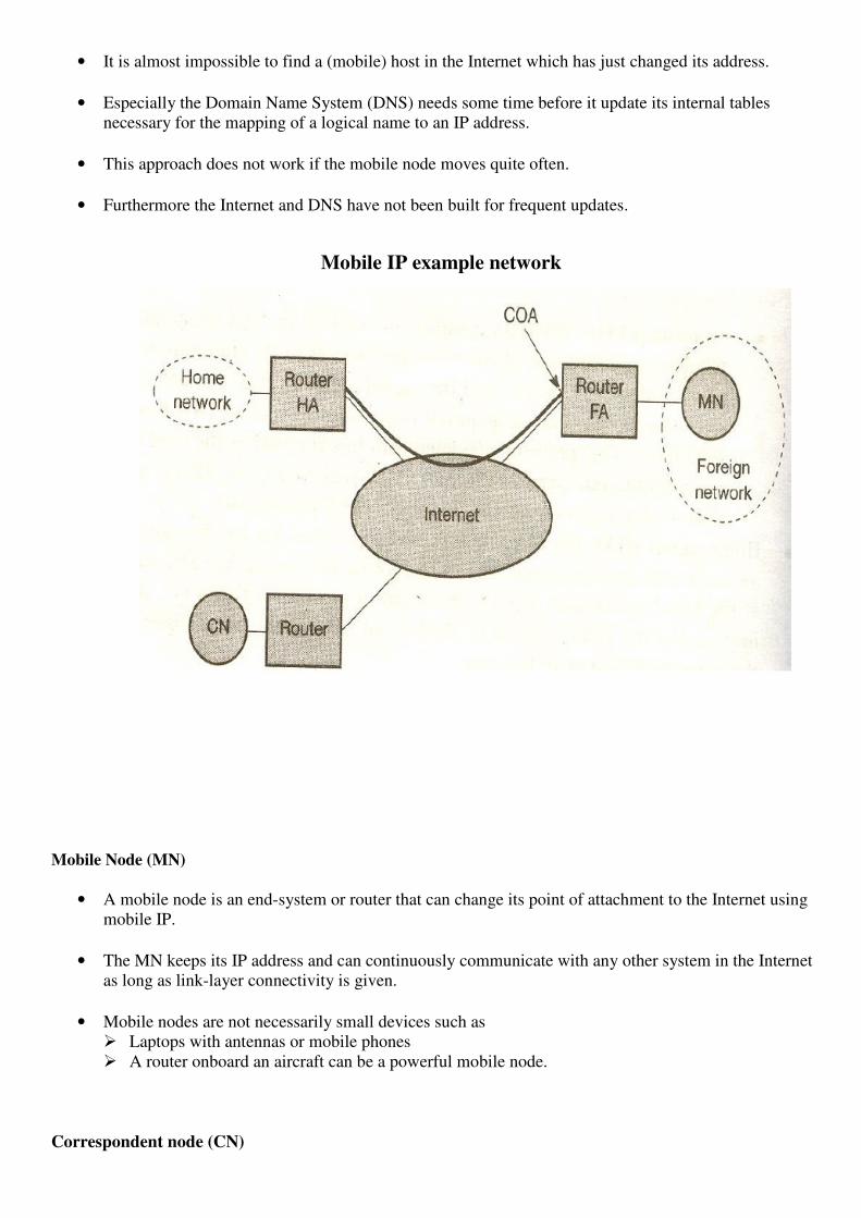
• It is almost impossible to find a (mobile) host in the Internet which has just changed its address.
• Especially the Domain Name System (DNS) needs some time before it update its internal tables
necessary for the mapping of a logical name to an IP address.
• This approach does not work if the mobile node moves quite often.
• Furthermore the Internet and DNS have not been built for frequent updates.
Mobile IP example network
Mobile Node (MN)
• A mobile node is an end-system or router that can change its point of attachment to the Internet using
mobile IP.
• The MN keeps its IP address and can continuously communicate with any other system in the Internet
as long as link-layer connectivity is given.
• Mobile nodes are not necessarily small devices such as
� Laptops with antennas or mobile phones
� A router onboard an aircraft can be a powerful mobile node.
Correspondent node (CN)

• At least one partner is needed for communication.
• In the following the CN represents this partner for the MN.
• The CN can be a fixed or mobile node.
Home network
• The home network is the subnet the MN belongs to with respect to its IP address.
• Within the home network no mobile IP support is needed.
Foreign network
• The foreign network is the current sub net the MN visits and which is not the home network.
Foreign agent (FA)
• The FA can provide several-services to the MN during its visit in the foreign network.
• The FA can have the COA thus acting as tunnel endpoint and forwarding packets to the MN.
• The FA can be the default router for the MN.
• FAs can also provide security services for they belong to the foreign network.
• An FA is implemented on a router for the sub net the MN attaches to.
Care-of address (COA):
• The COA defines the current location of the MN from an IP point of view.
• All IP packets sent to the MN are delivered to the COA not directly to the IP address of the MN.
• Packet delivery toward the MN is done using a tunnel.
• Therefore, to be more precise, the COA marks the tunnel endpoint.
ie., the address where packets exit the tunnel.
There are two different possibilities for the location of the COA:
a. Foreign agent COA:
• The COA could be located at the FA, i.e., the COA is an IP address of the FA.
• Thus the FA is the tunnel end-point and forwards packets to the MN.
• Many MN using the FA can share this COA as common COA .
b. Co-located COA:
• The COA is called co-located if the MN temporarily acquired an additional IP address which acts as
COA.
• This address is now topologically correct, and the tunnel endpoint is at the MN.

• Co-located addresses can be acquired using services such as DHCP.
Home agent (HA):
• The HA provides several services for the MN and is located in the home network.
• The tunnel for packets toward the MN starts at the HA. Furthermore, the HA maintains a location
registry, i.e., it is informed of the MN's location by the current COA.
Three alternatives for the implementation of an HA exist. 1. The HA can be implemented on a router that is responsible for the home network.
- This is obviously the best position, because without optimizations to mobile
- IP all packets for the MN have to go through the router
2. If changing the router's software is not possible, the HA could also be implemented on an arbitrary node in
the subnet.
- A disadvantage of this solution is the double crossing of the router by the packet if the MN is in a
foreign network.
- A packet for the MN comes in via the router; the HA sends it through the tunnel which again crosses
the router.
3. Finally, a home network is not necessary at all.
- The HA could be again on the 'router' but this time only acting as a manager for MNs belonging to a
virtual home network.
- All MNs are always in a foreign network with this solution.
- A CN is connected via a router to the Internet, as are the home network and the foreign network.
- The HA is implemented on the router connecting the home network with the Internet, an FA is
implemented on the router to the foreign network.
- The MN is currently in the foreign network.
- The tunnel for packets toward the MN starts at the HA and ends at the FA, for the FA has the COA.
1.2 IP Packet delivery.
Internet Packet delivery to and from the MN .
A correspondent node CN wants to send an IP packet to the MN.
One of the requirements of mobile IP was to support hiding the mobility of the MN.
Step 1 :-
• Therefore, CN does not need to know anything about the MN's current location and sends the packet as
usual to the IP address of MN (step 1).
• This means that CN sends an IP packet with
o MN as destination address and
o CN as source address.
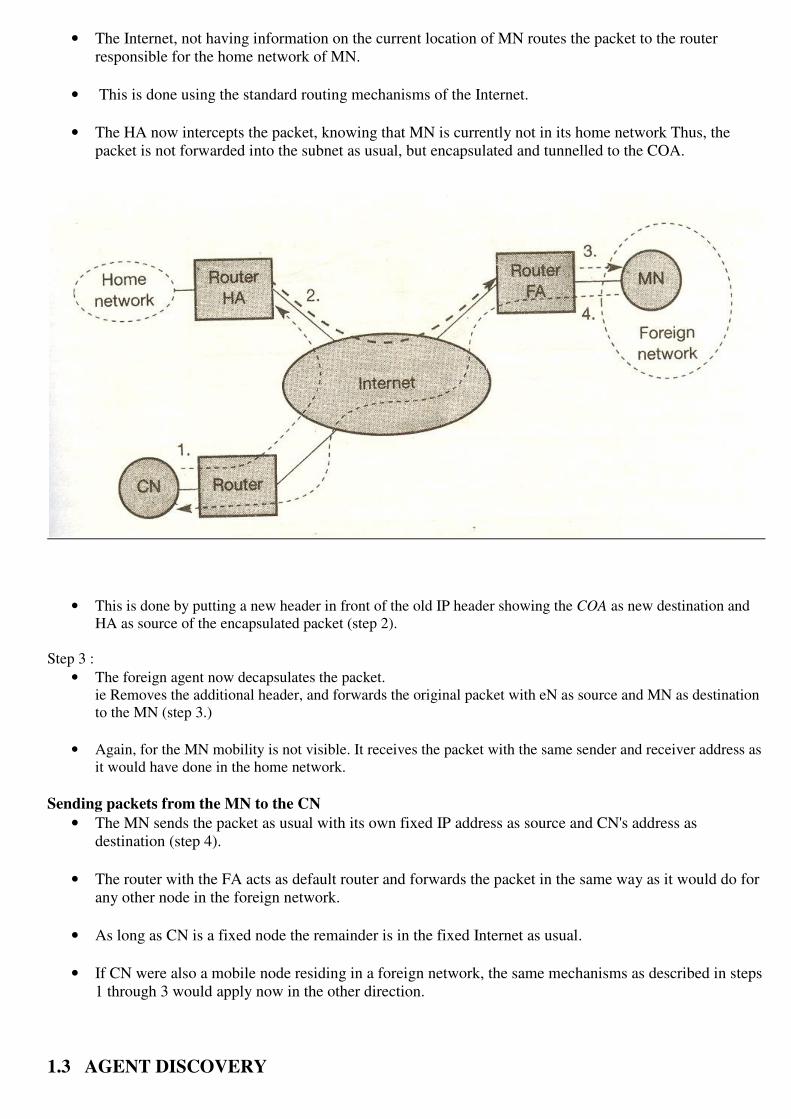
• The Internet, not having information on the current location of MN routes the packet to the router
responsible for the home network of MN.
• This is done using the standard routing mechanisms of the Internet.
• The HA now intercepts the packet, knowing that MN is currently not in its home network Thus, the
packet is not forwarded into the subnet as usual, but encapsulated and tunnelled to the COA.
• This is done by putting a new header in front of the old IP header showing the COA as new destination and
HA as source of the encapsulated packet (step 2).
Step 3 :
• The foreign agent now decapsulates the packet.
ie Removes the additional header, and forwards the original packet with eN as source and MN as destination
to the MN (step 3.)
• Again, for the MN mobility is not visible. It receives the packet with the same sender and receiver address as
it would have done in the home network.
Sending packets from the MN to the CN
• The MN sends the packet as usual with its own fixed IP address as source and CN's address as
destination (step 4).
• The router with the FA acts as default router and forwards the packet in the same way as it would do for
any other node in the foreign network.
• As long as CN is a fixed node the remainder is in the fixed Internet as usual.
• If CN were also a mobile node residing in a foreign network, the same mechanisms as described in steps
1 through 3 would apply now in the other direction.
1.3 AGENT DISCOVERY

• An MN after moving is how to find a foreign agent.
• How does the MN discover that it has moved
For the purpose mobile IP describes Two methods
a. Agent Advertisement
b. Agent solicitation
• These advertisement messages can be seen as a beacon broadcast into subnet.
• For these advertisements Internet Control Message Protocol (ICMP) messages are used with some mobility
extensions.
• Routers in the fixed network implementing this standard also advertise their routing service periodically to
the attached links.
Agent advertisement packet (RFC 1256 + mobility extension)
• The upper part represents the ICMP packet & Lower part is the extension needed for
mobility(Mobility Extensions).
• Mobile nodes must be reached with the appropriate link layer address.
• The TTL field of the IP packet is set to 1 for all advertisements to avoid forwarding them.
i.e TTL Field = 1 (for all advertisements to avoid forwarding them)
• The IP destination address according to standard router advertisements can be either to
224.0.0.1 = which multicast address for all systems on a link
255.255.255.255 = which broadcast address for all systems on a link.
Fields in the ICMP part
• Type :- The Type is set to 9
• Code :- Code can be 0 if the agent routes traffic from non-mobile nodes
Code = 16 if it does not route anything other then mobile
• #Address :- The number of addresses advertised with this packet is in #addresses .
• Lifetime :- denotes the length of time this advertisement is valid.
• Preference :- Preference levels for each address help a node to choose the router that is
the most eager one to get a new node.
Extension for Mobility has the following fields
• Type :- Type is set to 16
• Length :- Length depends on the number of COAs provided with the message and equals 6 + 4*
(number of addresses)
• Sequence Number :- An agent shows the total number of advertisements sent since initialization in the
sequence number.
• Registration Lifetime :- The agent can specify the maximum lifetime in seconds a node can request
during registration.
• R - Bit :- The R bit ( Registration) shows if a registration with this agent is required even when using a
collocated CAOA at the MN.
B - Bit :- If the agent is currently too busy to accept new
registrations it can set the B bit.
H & F Bit :- The two bits denote if the agent offers services as Home agent ( H) & Foreign agent (F) on the
link where the advertisement has been sent.
M & G Bit :- Bits M & G specify the method of encapsulation used for the tunnel.
r - Bit :- The field r at the same bit position is set to zero and must be ignored.
T - Bit :- The T field indicates that reverse tunneling is supported by the FA.
COAs :- A Foreign agent setting F bit must advertise atleast one COA.
b. Agent Solicitations

� If no agent advertisement are present
� The inter-arrival time is too high &
� MN has to received a COA by other means The Mobile Node must perform Agent Solicitations.
• These solicitations are based on RFC1256(Request For Command) for router solicitations.
• Care must be taken that to ensure that these solicitation messages do not flood the network.
• A mobile node can search an FA endlessly sending out solicitation messages.
• A mobile node can send out three solicitations one per second as soon as it enters a new network.
• Before an MN even gets a new address many packets will be lost without additional mechanisms.
• If a node does not receive an answer to its solicitations it must decrease the rate of solicitations
exponentially to avoid flooding the network.
• After these steps of advertisements or solicitations the MN can now receive a COA either one for an FA
or a Co-Located COA.
• MN knows its location and the capabilities of the agent.
• The next step for the MN is the registration with the HA if the MN is in a foreign network.
1.4. REGISTRATION
Having received a COA the MN has to register with the HA.
Purpose:- The registration is to inform the HA of the current location for correct forwarding of Packets.
2 ways for Registration:- Registration can be done in two different ways depending on the location of the COA.
1. If the COA is at the FA , registration is done as
� The MN sends its registration request containing the COA to the FA which is forwarding the request to
HA.
� The HA now sets up a mobility binding containing the mobile node’s home IP address and the current
COA.
� Additionally the mobility binding contains lifetime of the registration which is negotiated during the
registration process.
� Registration expires automatically after the lifetime and is deleted so an MN should re-register before
expiration.
� This avoid mobility bindings which are no longer used.
� After setting up the mobility binding the HA sends a reply message back to the FA which forwards it to
the MN.

2. If the COA is co-located registration can be simpler
a. Registration Request:-
� The MN may send the request directly to the HA and Vice versa.
� The registration procedure for MNs returning to their home network.
� They also register directly with the HA.
� If the MN received an agent advertisement from the FA it should register via this FA if the R bit is set in
the advertisement.
� UDP packets are used for registration requests.
� The IP source address of the packet is set to the interface address of the MN
� The IP destination address is that of the FA or HA. (depending on the location of the COA).
� The UDP destination port is set to 434.
1 b. Registration Request:- The fields relevant for Mobile IP Registration Request follow as UDP Data are
defined as Type :- Type field is set to 1 for a registration request.
S - Bit : - * S bit an MN can specify if it wants the HA to retain prior mobility bindings. * This allows
simultaneous bindings. * Bits denote the requested behavior for packet forwarding.
B – Bit : - * B bit indicates that an MN wants to receive the broadcast packets which have been received by the
HA in the home network.

D- Bit :- * If an MN uses a co-located COA it also takes care of the decapsulation at the tunnel endpoint.
M & G Bit :- denote the
� Use of minimal encapsulation or
� Generic routing encapsulation.
T – Bit :- indicates reverse tunneling r & x :- this bits are set to zero.
Lifetime :- * denotes the validity of the registration in seconds. * A value of zero indicates for deregistration. *
All bits indicates Infinity.
Home Address :- is the fixed IP address of the MN.
Home Agent :- is the IP address of the HA and COA represents the tunnel endpoint.
Identification :- * The 64 bit identification is generated by the MN to identify a request and match it with
registration replies.
b. Registration Reply: The fields relevant for Mobile IP Registration Reply are defined as
Type :- Type field is set to 3 for a registration reply.
Code :- indicates the result of the registration request.
Lifetime :- denotes the validity of the registration in seconds.
Home Address & Agent :- are the addresses of the MN and the HA
.
Identification :- * The 64 bit identification is generated by the MN to identify a request and match it with registration replies.
* This field is used for protection against replay attacks of registrations.
Extensions :- The extensions must at lest contain parameters for authentication.

1.5. TUNNELING AND ENCAPSULATION
• A Tunnel establishes a virtual pipe for data packets between a tunnel entry and a tunnel endpoint.
• Packets entering a tunnel are forwarded inside the tunnel and leave the tunnel unchanged.
i.e sending a packet through a tunnel is achieved by using encapsulation.
Encapsulation:- The mechanism of taking a packet consisting of packet header and data and putting it
into the data part of a new packet.
Decapsulation:- The reverse process operation taking the packet out of the data part of another packet
is called decapsulation.
• Encapsulation and Decapsulation are the operations typically performed when a packet is transferred
from a Higher protocol layer to Lower protocol layer and
from a Lower protocol layer to Higher protocol layer.
IP Encapsulation The HA takes the original packet with the MN as destination puts it into the data part and
sets the new header is also called the Outer Header.
� There is an Inner Header which can be identical to the original header
� An inner header can be computed during encapsulation.

1.6. REVERSE TUNNELING
• The MN can directly send its packets to the CN as in any other standard IP situation.
• The destination address in the packets is that of CN.
• There are several severe problems associated with this simple solution
Firewalls :-
• All companies & institutions secure their internal networks (intranet) connected to the internet with the
help of a firewall.
• All data To and From the intranet must pass through the firewall.
• Firewall can be set up to filter out malicious addresses from an administrator’s point of view.
• Firewalls only allow packets with topologically correct addresses to pass.
• Firewall provides a simple protection against misconfigured systems of unknown addresses.
• Firewalls often filter packets coming from outside containing a source address from computers of the
internal network.
• Complications arise through the use of private addresses inside the intranet and the translation into
global addresses when communicating the intranet. This network address translation to hide internal
resources.
Multicast :-
• Reverse tunnels are needed for the MN to participate in a Multicast group.
• The nodes in the home network might participate in a multicast group.
• An MN in a foreign network cannot transmit multicast packets in a way that they emanate from its home
network without reverse tunnel.
• The foreign network might not even provide the technical infrastructure for multicast communication.
TTL :-
• An MN sending packets with a certain TTL while still in its home network.
• The TTL might be low enough so that no packet is transmitted outside a certain region.
• If the MN now moves to a foreign network this TTL might be too low for the packets to reach the same
node as before.
• Mobile IP is no longer transparent if a user has to adjust the TTL while moving.
• A reverse tunnel is needed that represents only one hop.

1.7 IPv6
• Mobile IP was originally designed for IP version 4 & IP version 6 .
• Security with regards to authentication which is now a required features for all IPv6 nodes.
• Every IPv6 node masters address auto configuration - The mechanisms for acquiring a COA are
already built in.
• Neighbor discovery as a mechanism mandatory for every node is also included in the specification.
• Every IPv6 node can send binding updates to another node, so the MN can send its current COA
directly to the CN and HA.
• These mechanisms are an integral part of IPv6.
• A Soft handover is possible with IPv6.
• The MN sends its new COA to the old router servicing the MN at the old COA
• The old router encapsulates all incoming packets for the MN and forwards them to the new COA.
• Mobile IP in IPv6 networks requires very few additional mechanisms of CN,MN,&HA.
• CN :- A CN able to process binding updates
i.e To create or to update an entry in the routing cache.
• MN :- The MN itself has to be able to decapsulates packets o detect when it needs a new COA and to
determine when to send binding updates to the HA & CA.
• HA :- A HA must be able to encapsulate packets.
DYNAMIC HOST CONFIGURATION PROTOCOL
• The Dynamic Host Protocol (DHCP,RFC 2131) mainly used
� To simply the installation &
� Maintenance of networked computers.
• If a new computer is connected to a network DHCP can provide it with all the
necessary Information for full system integration into the network
e.g:- Addresses of DNS server
� Default router
� Subnet Mask
� Domain name &
� IP address
• Providing an IP address makes DHCP very attractive for mobile IP as well source of care-of –address.

• DHCP clients send a request to a server to which the server responds.
• A client sends requests using MAC broadcasts to reach all devices in the LAN.
• A DHCP relay might be needed to forward requests across inter-working units to a DHCP server.
• The client broadcasts a DHCP DISCOVER into subnet. There may be relay to forwards this broadcast.
• Two servers receive this broadcast and determine the configuration they offer to the client.

• Servers reply to the client’s request with DHCPOFFER and offer a list of configuration parameters.
• The client can now choose one of the configurations offered.
• The client in turn replies to the servers accepting one of the configurations and rejecting the others using
DHCP REQUEST.
• If a server receives a DHCP REQUEST with a rejection it can free the reserved configuration for other
possible clients.
• The server with the configuration accepted by the client now confirms the configuration with DHCP
ACK.This completes the initialization phase.
• If a client leaves the subnet it should release the configuration received by the server using DHCP
RELEASE.
• Now the server can free the context stored for the client and offer the configuration again.
• The configuration a client from a server is only leased for a certain amount of time it has to be
reconfirmed from time to time.
DHCP Features
• DHCP supporting the acquisition of care-of-addresses for mobile nodes.
• A DHCP server should located in the subnet of the access point of the mobile node .
• DHCP relay should provide forwarding of the Messages.
• RFC 3118 specifies authentication for DHCP messages which is needed to protect mobile nodes from
malicious DHCP servers.
Mobile ad-hoc networks Mobile IP requires, e.g., a home agent, tunnels, and default routers. DHCP requires servers and broadcast
capabilities of the medium reaching all participants or relays to servers. Cellular phone networks require base
stations, infrastructure networks etc.
However, there may be several situations where users of a network cannot rely on an infrastructure, it is too
expensive, or there is none at all. In these situations mobile ad-hoc networks are the only choice. It is important
to note that this section focuses on so-called multi-hop ad-hoc networks when describing adhoc networking.
The ad-hoc setting up of a connection with an infrastructure is not the main issue here. These networks should
be mobile and use wireless communications.
Examples for the use of such mobile, wireless, multi-hop ad-hoc networks, which are only called ad-hoc
networks here for simplicity, are:
Instant infrastructure: Unplanned meetings, spontaneous interpersonal communications etc. cannot rely on
any infrastructure. Infrastructures need planning and administration. It would take too long to set up this kind of
infrastructure; therefore, ad-hoc connectivity has to be set up.
● Disaster relief: Infrastructures typically break down in disaster areas. Hurricanes cut phone and power lines,
floods destroy base stations, fires burn servers. Emergency teams can only rely on an infrastructure they can

set up themselves. No forward planning can be done, and the set-up must be extremely fast and reliable. The
same applies to many military activities, which is, to be honest, one of the major driving forces behind mobile
ad-hoc networking research.
● Remote areas: Even if infrastructures could be planned ahead, it is sometimes too expensive to set up an
infrastructure in sparsely populated areas. Depending on the communication pattern, ad-hoc networks or
satellite infrastructures can be a solution.
● Effectiveness: Services provided by existing infrastructures might be too expensive for certain applications.
If, for example, only connectionoriented cellular networks exist, but an application sends only a small status
information every other minute, a cheaper ad-hoc packet-oriented network might be a better solution.
Registration procedures might take too long, and communication overheads might be too high with existing
networks. Application-tailored ad-hoc networks can offer a better solution.
This has led to creation of a working group at the IETF that is focussing on mobile ad-hoc networking, called
MANET. The following fig shows the relation of MANET to mobile IP and DHCP.
While mobile IP and DHCP handle the connection of mobile devices to a fixed infrastructure,
MANET comprises mobile routers, too. Mobile devices can be connected either directly with an infrastructure
using Mobile IP for mobility support and DHCP as a source of many parameters, such as an IP address.
MANET research is responsible for developing protocols and components to enable ad-hoc networking
between mobile devices. It should be noted that the separation of end system and router is only a logical
separation. Typically, mobile nodes in an adhoc scenario comprise routing and end system functionality.
Routing

• In wireless networks using an infrastructure cells have been defined. within a cell the base station can reach
all mobile nodes.
• In ad-hoc networks each node must be able to forward data for other nodes.
Ad-hoc network
At a certain time t1 the network topology consists of five nodes N1 to N5.
� Nodes are connected depending upon the current transmission characteristics between them.
� In this network N4 can receive N1 over a good link.
� But N1 receive N4 via a weak link.
� Links do not necessarily have the same characteristics in both directions.
Reason: ��Different antenna characteristics or transmit power. N1 cannot receive N2 at all N2 receives a signal from N1.
At a certain time t2 the network topology consists of five nodes N1 to N5.This situation can change quite fast
� N1 cannot receive N4 any longer
� N4 receives N1 only via a weak link.
� But N1 has as asymmetric but bi-directional link to N2 that did not exist before.
The Fundamental differences between wired networks and ad-hoc networks related to routing are.
Asymmetric Links
• Node A receives a signal from node B.
• But this does not tell anything about the quality of the connection in reverse.
• Node B might
� Receive nothing
� Have a weak link
� Even have a better link than the reverse direction.
• Routing information collected for one direction is of almost no use for the other direction.

Redundant Links
• Wired networks too have a redundant links to survive link failures.
• There is only some redundancy in wired networks which additionally are controlled by a network
administrator.
• In ad-hoc networks nobody controls redundancy so there might be many redundant links up to the
extreme of a completely meshed topology.
• Routing algorithms for wired networks can handle some redundancy but a high redundancy can cause a
large computational overhead for routing table updates.
Interference
• In wired networks links exist only where a wire exists and connections are planned by network
administrators.
• In wireless ad-hoc networks links come and go depending on transmission characteristics one
transmission might interfere with another and nodes might overhear the transmissions of other nodes.
• Interference creates new problems by ‘unplanned ‘links between nodes. If two close-by nodes forward
two transmissions they might interfere and destroy each other.
• On the other hand interference might also help routing.
Dynamic Topology:-
• Greatest problem for routing arises from the highly dynamic topology.
• The mobile nodes might move as shown in figure or medium characteristics might change.
• This result in frequent changes in topology so snapshots are valid only for a very short period of time.
• In ad-hoc networks the routing tables must somehow reflect these frequent changes in topology and
routing algorithms have to be updated.
• Routing algorithm used in wired networks would either react much too slowly or generate too many
updates to reflect all changes in topology.
============================================================================
DSDV ( Distance Sequence Distance Vector)
• Distance Sequence Distance Vector (DSDV) routing is an enhancement to distance vector routing for
ad-hoc networks.
• DSDV can be considered historically however an on-demand version (ad-hoc on-demand distance
vector AODV ) is among the protocols .
• Distance Vector Routing is used as routing information protocol (RIP) in wired networks.
• It performs extremely poorly with certain network changes due to the count-to-infinity problem.
• Each node exchanges its neighbor table periodically with its neighbors.
• Changes at one node in the network propagate slowly through the network (step-by-step with every
exchange).
• The strategies to avoid this problem which used in fixed networks (poisoned-reverse / split-horizon) do
not help in the case of wireless ad-hoc networks due to the rapidly changing topology.
• This might create loops or unreachable regions within the network.
DSDV adds two things to the Distance Vector Algorithm
Sequence Numbers :-
• Each routing advertisement comes with a sequence number.
• Within ad-hoc networks advertisements may propagate
• along many paths.
• Sequence numbers help to apply the advertisements in correct order.
• This avoids the loops that are likely with the unchanged distance vector algorithm.
Damping :-
• Transient changes in topology that are of short duration should not destabilize the routing mechanism.
• Advertisements containing changes in the topology currently stored.
• A node waits with dissemination if these changes are probably unstable.
• Waiting time depends in the time between the first the first and the best announcement of a path to a
certain destination.
==============================================================================
DYNAMIC SOURCE ROUTING (DSR)
Dynamic Source Routing (DSR) divides the task of routing into two separate problems
Route Discovery :- A node only tries to discover a route to a destination if it has to
send something to this destination and there is currently no known route.
Route Maintenance:-
If a node is continuously sending packets via a route it has to make sure that the route is held upright.
As soon as a node detects problems with the current route it has to find an alternative.
Basic Principle
• The basic principle of source routing is also used in fixed networks e.g Token ring
• Dynamic source routing eliminates all periodic routing updates and works as follows
• If a node needs to discover a route it broadcasts a route request with a unique identifies and the
destination address as parameters.

• Any node that receives a route does the following
� If a node has already received the request (which is identified using the unique identifier) it drops
the request packet.
� If the node recognizes its own address as the destination the request has reached its target.
� Otherwise the node appends its own address to a list of traversed hops in the packet and broadcasts
this updated route request.
• Using this approach the route request collects a list of addresses representation of a possible path on its
way towards the destination.
• As soon as the request reaches the destination it can return the request packet containing the list to the
receiver using this list in reverse order.
• One condition for this is that the links work bi-directionally.
• If this is not the case and the destination node does not currently maintain a route back to the initiator of
the request it has to start a route discovery by itself.
• The destination may receive several lists containing different paths from the initiator.It could return the
best path the first several paths to offer the initiator a choice.
� N1 broadcasts the request ((N1),id=42,target=N3)
� N2 & N4 receive this request.
� N2 then broascasts ((N1,N2),id=42,target=N3),
� N4 broadcasts((N!,N4),id=42,target=N3) &
� N5 receive N2's broadcast N1,N2 & N5 receive N4's broadcast.
� N3 recognizes itself as target
� N4 broadcasts((N!,N2,N5),id=42,target=N3)
� N3&N4 receive N5's broadcast.
� N1,N2 & N5 drop N4's broadcast packet because they all recognize an already received route
request .
� N4 drops N5's broadcast
� N3 recognizes(N1,N2,N5) as an alternate but longer route.
� N3 now has to return the path(N1,N2,N3) to N1.
� This is simple assuming symmetric links working in both directions
� N3 can forward the information using the list in reverse order.
Algorithm:-
• The basic algorithm for route discovery each route request could contain a counter.
* Every node rebroadcasting the request increments the counter by one. * Knowing the maximum
network diameter nodes can drop a request if the counter reaches this number.
* A node can cache path fragments from recent requests.
* These fragments can now be used to answer other route requests much faster.
• A node can also update this cache from packet headers while forwarding other packets

• If a node overheads transmission from other nodes it can also use this information for shortening routes.
• After a route has been discovered it has to be maintained for as long as the node sends packets along this
route. Depending on layer two mechanisms different approaches can be taken
• If the link layer uses an acknowledgement the node can interpret this acknowledgement as an intact
route.
• If possible the node could also listen to the next node forwarding the packet so getting a passive
acknowledgement.
• A node could request an explicit acknowledgement.
==============================================================================
ALTERNATIVE METRICS
• In a fixed networks e.g. Bandwidth can also be a factor for the routing metric.
• Due to the varying link quality and the fact that different transmissions can interface other metrics can
be more useful.
• One other metric called least interference routing (LIR)
� LIR ( Least Interference Routing) :-
• LIR is very simple to implement only information from direct neighbors necessary.
• Takes possible interference into account.
• Calculate the cost of path based on the No. of stations that can receive a transmission.
� MMRCR:- (Max-Min Residual Capacity routing) Calculate the cost of path based on a probability function of successful; transmissions and interference.
� LRR (Least Resistance Routing) Calculate the cost of path based on interference,jamming & other transmissions.
Ad-hoc Network Topology
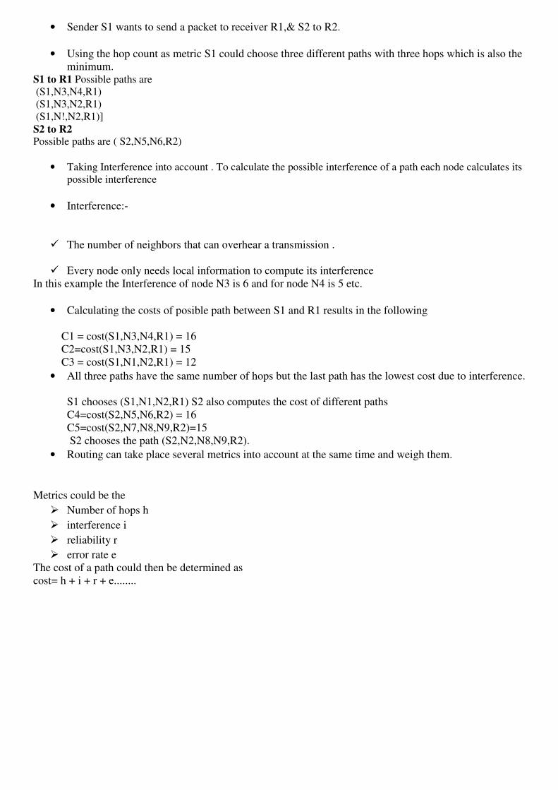
• Sender S1 wants to send a packet to receiver R1,& S2 to R2.
• Using the hop count as metric S1 could choose three different paths with three hops which is also the
minimum. S1 to R1 Possible paths are
(S1,N3,N4,R1)
(S1,N3,N2,R1)
(S1,N!,N2,R1)]
S2 to R2 Possible paths are ( S2,N5,N6,R2)
• Taking Interference into account . To calculate the possible interference of a path each node calculates its
possible interference
• Interference:-
� The number of neighbors that can overhear a transmission .
� Every node only needs local information to compute its interference
In this example the Interference of node N3 is 6 and for node N4 is 5 etc.
• Calculating the costs of posible path between S1 and R1 results in the following
C1 = cost(S1,N3,N4,R1) = 16
C2=cost(S1,N3,N2,R1) = 15
C3 = cost(S1,N1,N2,R1) = 12
• All three paths have the same number of hops but the last path has the lowest cost due to interference.
S1 chooses (S1,N1,N2,R1) S2 also computes the cost of different paths
C4=cost(S2,N5,N6,R2) = 16
C5=cost(S2,N7,N8,N9,R2)=15
S2 chooses the path (S2,N2,N8,N9,R2).
• Routing can take place several metrics into account at the same time and weigh them.
Metrics could be the
� Number of hops h
� interference i
� reliability r
� error rate e
The cost of a path could then be determined as
cost= h + i + r + e........

SCSX1025 – Wireless and Mobile Networks
UNIT-4
Mobile transport layer – Traditional TCP – Indirect TCP – Snooping TCP – Mobile TCP –
fast retransmit/fast recovery – Transmission/timeout freezing – Selective retransmission –
Transaction oriented TCP.
Mobile transport layer
TRADITIONAL TCP
There are several mechanisms of the transmission control protocol that influence the efficiency of TCP in a
mobile environment.
1.1 Congestion Control
• A Transport layer protocol such as TCP had been designed for fixed networks with fixed end-systems.
• Data transmission takes place using
� Network adapters
� Fiber Optics
� Copper wires
� Special Hardware for routers.
• This Hardware typically works without introducing transmission errors.
• If the software is mature enough it will not drop packets of flip flops bits, so if a packet on its way from a
sender to a receiver is lost in a fixed network it is not because of hardware or software errors.
• Therefore the packet loss in a fixed network is due to a temporary overload at some point in the
transmission path. i.e. a state of congestion at a anode.
• Congestion may appear from time to tile even in carefully designed networks.
• The packet buffers of a router are filled and the router cannot forwards the packets fast enough because the
sum of the inputs rates of packets destined for one output link is higher than the capacity of the output link.
• The only thing a router can do in this situation is to drop packets.
• A dropped packet is lost for transmission and the receiver notices a gap in the packet stream.
• Now the receiver does not directly tell the sender which packet is missing but continues to acknowledge all in-
sequence packets up to the missing one.
• The sender notices the missing acknowledgement for ht lost packet and assumes a packet loss due to
congestion.
• Retransmitting the missing packets of the continuing at full sending rate would now be unwise as this might
only increase the congestion.
• Although it is not guaranteed that all packets of the TCP connection take the same way through the network.

• To migrate congestion TCP slows down the transmission rate dramatically.
• All other TCP connections experiencing the same congestion do exactly the same so the congestion is soon
resolved.
• Even under heavy load TCP guarantees at least sharing of the Bandwidth.
1.2 Slow Start
• TCP’s reaction to a missing acknowledgement is quite drastic but it is necessary to get rid of congestion
quickly.
• The behavior shows after the detection of congestion is called Slow start.
• The sender always calculates a Congestion window for a receiver.
• The start size of the congestion window is one segment (TCP Packet).
• The sender sends one packet and waits for acknowledgement. If this acknowledgement arrives the sender
increases the congestion window by one now sending two packets (congestion window=2). After arrival of
the two corresponding acknowledgements now the congestion window equals 4.
• This scheme doubles the congestion window every time the acknowledgements come back which takes one
Round Trip Time (RIT).This is called the exponential growth of the congestion window in the slow start
mechanism.
• It is too dangerous to double the congestion window each time because the steps might become too large.
• The exponential growth stops at the Congestion Threshold.
• The congestion window reaches the congestion threshold further increase of the transmission rate is only
linear by adding 1 to the congestion window each time the acknowledgements come back.
1.3 Fast Retransmit / Fast Recovery
• A sender receiving continuous acknowledgements for the same packets. This informs the sender of two
things.
� One is that the receiver got all packets up to the acknowledged packet in sequence.
� And the next is that the receiver continuously receives something from the sender.
Fast Retransmit
• In TCP a receiver sends acknowledgement only if it receives any packet from the sender.
• Receiving continuous acknowledgements from a receiver also shows that the receiver continuously
receives something from the sender.
• The gap in the packet stream is not due to severe congestion but a simple packet loss due to a transmission
error.
• The sender can now retransmit the missing packet(s) before the timer expires. This is called Fast
Retransmit.
Fast Recovery

• The receipt of acknowledgements shows that there is no congestion to justify a slow start.
• The sender can continue with the current congestion window.
• The sender performs a Fast Recovery from the packet loss.
• This mechanism can improve the efficiency of TCP dramatically.
• The other reason for activating slow start is a time-out due to a missing acknowledgement.
• TCP using Fast Retransmit / Fast Recovery interprets this congestion in the network and activates the slow
start mechanism.
1.4 Implications on Mobility
• Mobility itself can cause packet loss.
• There are many situations where a soft handover from one access point to another is not possible for a
mobile end-system.
• The TCP mechanism detecting missing acknowledgements via time-outs and concluding packet loss due
the congestion cannot distinguish between the different causes. This fundamental design problem in
TCP.
=================================================================================
Indirect TCP or I-TCP
• I-TCP Segments a TCP connection into a fixed and a wireless part
• Wireless Part a Mobile Host connected via a wireless link and a Access Point to the ‚Wired ‚Internet where the
correspondent node resides.
• Standard TCP is used between the fixed computer and the Access Point.
• Between the Access Point and the Mobile host a special TCP adapted to wireless links .
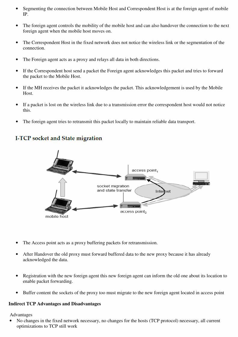
• Segmenting the connection between Mobile Host and Correspondent Host is at the foreign agent of mobile
IP.
• The foreign agent controls the mobility of the mobile host and can also handover the connection to the next
foreign agent when the mobile host moves on.
• The Correspondent Host in the fixed network does not notice the wireless link or the segmentation of the
connection.
• The Foreign agent acts as a proxy and relays all data in both directions.
• If the Correspondent host send a packet the Foreign agent acknowledges this packet and tries to forward
the packet to the Mobile Host.
• If the MH receives the packet it acknowledges the packet. This acknowledgement is used by the Mobile
Host.
• If a packet is lost on the wireless link due to a transmission error the correspondent host would not notice
this.
• The foreign agent tries to retransmit this packet locally to maintain reliable data transport.
• The Access point acts as a proxy buffering packets for retransmission.
• After Handover the old proxy must forward buffered data to the new proxy because it has already
acknowledged the data.
• Registration with the new foreign agent this new foreign agent can inform the old one about its location to
enable packet forwarding.
• Buffer content the sockets of the proxy too must migrate to the new foreign agent located in access point
Indirect TCP Advantages and Disadvantages
Advantages
• No changes in the fixed network necessary, no changes for the hosts (TCP protocol) necessary, all current
optimizations to TCP still work

• Transmission errors on the wireless link do not propagate into the fixed network
• simple to control, mobile TCP is used only for one hop, between a foreign agent and a mobile host
• Therefore, a very fast retransmission of packets is possible, the short delay on the mobile hop is known.
Disadvantages
• Loss of end-to-end semantics, an acknowledgement to a sender does now not any longer mean that a receiver
really got a packet, foreign agents might crash
• Higher latency possible due to buffering of data with the foreign agent and forwarding to a new foreign agent
• High trust at foreign agent; end-to-end encryption impossible. ========================================================================================
Snooping TCP
• The foreign agent buffers all packets with Destination mobile host.
• Additionally ‘snoops’ the packet flow in both directions to recognize acknowledgements.
• The reason for buffering the packets toward the mobile node is to enable the foreign agent to perform a
local transmission in case of packet loss on the wireless link.
• The foreign agent buffers every packet until it receives an acknowledgement from the mobile host.
• If the foreign agent does not receive an acknowledgement from the mobile host within a certain amount of
time either the packet or the acknowledgement has been lost.
• Alternatively the foreign agent could receive a duplicate ACK which also shows the loss of a packet.
• Now the foreign agent
� Retransmits the packet directly from the buffer.
� Performing a much faster retransmission compared to the correspondent host.
� The time out for acknowledgements can be much shorter because it reflects only the delay of one hop
plus processing time.

• To remain transparent the foreign agent must not acknowledge data to the correspondent host.
• The correspondent host believe that the mobile host had received the data would violate the end-to end
semantic in case of a foreign agent failure.
• The foreign agent can filter the duplicate acknowledgements to avoid unnecessary retransmissions of data
from the correspondent host.
• If the foreign agent now crashes the time-out of the correspondent host still works and triggers a
retransmission.
• The foreign agent may discard duplicates of packets already retransmitted locally and acknowledged
by the mobile host. This avoids unnecessary traffic on the wireless link.
Data transfer from the mobile host to the correspondent host
• The foreign agent snoops into the packet stream to detect gaps in the sequence numbers of TCP.
• As soon as the foreign agent detects a missing packet it returns negative acknowledgements (NACK) to the
mobile host.
• The mobile host can now retransmit the missing packet immediately.
• Reordering of packets is done automatically at the correspondent host by TCP.
Advantages
• The end-to-end TCP semantic is preserved. No matte that the foreign agent crashes.
• The correspondent host does not need to be changed.
� Most of the enhancements are in the foreign agent.
� Supporting only the foreign stream from the correspondent host to the mobile host does not even
require changes in the mobile host.
• It does not need a handover of state as soon as the mobile host moves to another foreign agent.
• It does not matter if the next foreign agent uses the enhancement or not. If not the approach automatically
falls back to the standard solution.
Disadvantages
• Snooping TCP does not isolate the behavior of the wireless link as well as I-TCP.
• Using negative acknowledgements between the foreign agent and the mobile host assumes additional
mechanisms on the mobile host.
• All efforts for snooping and buffering data may be useless if certain encryption schemes are applied.
� Using IP encapsulation security payload the TCP protocol header will be encrypted -> snooping the
sequence number will no longer work.
================================================================================

Mobile TCP
• The M-TCP ( Mobile TCP ) approach has the same goals as Indirect TCP & Snooping TCP
• To prevent the sender window from shrinking if bit errors or disconnection but not congestion cause
current problems.
M-TCP wants to
� improve overall throughput to lower the delay to maintain end-to-end semantics of TCP &
� Provide a more efficient handover.
� Additionally M-TCP is especially adapted to the problems arising From lengthy or Frequent
disconnections.
• M-TCP splits the TCP connection into 2 parts
• An unmodified TCP is used on the standard host-supervisory host(SH) connection.
• While an optimized TCP is used on the SH_MH connection.The supervisory host is responsible for
exchanging data between both parts similar to the proxy in I-TCP.
• The M-TCP approach assumes a relatively low bit error rate on the wireless link.Therefore it does not
perform caching / retransmission of data via the SH.
• If a packet is lost on the wireless link it has to be retransmitted by the original sender.This maintains the
TCP end-to-end semantics.
• The SH monitors all packets sent to the MH and ACKs returned from the MH
• If the SH does not receive an ACK for some time, it assumes that the MH is disconnected.
• It then chokes the sender by setting the sender’s window size to 0.
• Setting the window size = 0 ---> forces the sender to go into persistent mode.
• As soon as the SH detects connectivity again it reopens the window of the sender to the old value.
• The sender can continue sending at full speed. This mechanism does not require changes to the sender‘s
TCP.
• The wireless side uses an adapted TCP that can recover from packet loss much faster.
• This modified TCP does not use slow start thus M-TCP needs a Bandwidth Manager to implement fair
sharing over the wireless link.
Advantages
• It maintains the TCP end-to-end semantics. The SH does not send any ACK itself but forwards the ACKs
from the MH.
• If the MH is disconnected it
� Avoids useless retransmissions slow start or
� Breaking connections by simply shrinking the sender’s window to 0.
�
Disadvantages
• The SH does not act as proxy as in I-TCP packet loss on the wireless link due to bit errors is propagated to
the sender.
� M-TCP assumes a low bit error rate which is not always a valid assumption.
• A modified TCP on the wireless link not only requires modifications to the MH protocol software but also
new network elements link the bandwidth manager.
===============================================================================================
Fast Retransmit / Fast Recovery Moving to a new foreign agent can cause packet loss or time out at
� Mobile hosts or
� Corresponding hosts.
TCP concludes
� Congestion and
� Slow start although there is no congestion.
• The mechanisms of fast recovery / fast retransmit a host can use after receiving duplicate
acknowledgements thus concluding a packet without congestion.
Retransmit behavior on mobile host & correspondent host
• As soon as the mobile host registers at a new foreign agent using mobile IP it starts sending duplicated
acknowledgements to correspondent hosts.
• The proposal is to send three duplicates.
• This forces the correspondent host to go into fast retransmit mode and not to slow start .
i.e The correspondent host continues to send with the same rate it did before the mobile host moved to
another foreign agent.
• As the mobile host may also go into slow start after moving to a new foreign agent this approach
additionally puts the mobile host into fast retransmit.
• The mobile host retransmits all unacknowledged packets using the current congestion window size without
going into slow start.
Advantages
• This approach is simple
• Only minor changes in the mobile hosts software already result in a performance increase.
• No foreign agent or correspondent host has to be changed.
Disadvantages
• This scheme is the insufficient isolation of packet losses.
• Forcing fast retransmission increases the efficiency but retransmitted packets still have to cross the whole
network between correspondent host and mobile host.
• If the handover from one foreign agent to another takes a longer time, the correspondent host will have
already started retransmission.
===============================================================================================
Transmission / Time-Out Freezing
• The approach so far can handle short interruptions of the connection either due to
� Handover &
� Transmission errors on the wireless link
• Some were designed for longer interruptions of transmission.
• The MAC layers has already noticed connection problems before the connection is actually interrupted
from a TCP point of view. • Additionally MAC layer knows the reason for the interruption is not caused congestion.
• TCP can now stop sending and freezes the current state of its congestion window and further timers.
• If the MAC layers notices the upcoming interruption early enough both the mobile and correspondent host
can be informed.
• With a fast interruption of the wireless link additional mechanisms in the access point needed to inform the
correspondent host of the reason for interruption.
• Otherwise the correspondent host goes into the slow start assuming congestion and finally breaks the
connection.
• As soon as the MAC layer detects connectivity again it signals TCP that it can resume operation at exactly
the same point where it had been forced to stop.
Advantages
• This approach offers a way to resume TCP connections even after longer interruptions of the connection.
• It is independent of any other TCP mechanisms such as acknowledgements or sequence numbers so it can
be used together with encrypted data.
Disadvantages • The software on the mobile host has to be changed to be more effective the correspondent host cannot
remain unchanged.
• All mechanisms rely on the capability of the MAC layer to detect future interruptions.
• Freezing state of TCP does not help in case of some encryption schemes that use time-dependent random
numbers.
• These schemes need resynchronization after interruption.
=================================================================================

Selective Retransmission
• A very useful extension of TCP is the use of selective retransmission
• TCP acknowledgements are cumulative
i.e they acknowledge in-order receipt of packets up to a certain packet.
• If a single packet is lost the sender has to retransmit everything starting from the lost packet - Go-Back-n
Retransmission.
• This obviously wastes bandwidth not just in the case of a mobile network but for any network.
• TCP can indirectly request a selective retransmission of packets.
• The receiver can acknowledge single packets not only trains of in-sequence packets.
• The sender can now determine precisely which packet is needed and can retransmit it.
• Advantage This approach is obvious:-
� A sender retransmits only the lost packets.
� This lower bandwidth requirements and is extremely helpful in slow wireless links.
� The gain in efficiency is not restricted to wireless links and mobile environments.
� Using selective retransmission is also beneficial in all other networks.
Disadvantage
• While memory sizes and CPU performance permanently increase the bandwidth of the air interface
remains almost the same.
• The higher complexity is no real disadvantage any longer as it was in the early days of TCP.
• More complex software on the receiver side because now more buffer is necessary to resequence data and
to wait for gaps to be filled.
===============================================================================================
Transaction-Oriented TCP
• If the application requires reliable transport of the packets it may use TCP.
• Using TCP requires packets over the wireless link.
� TCP uses a three-way handshake to establish the connection.
� At least one additional packet is usually needed for transmission of the request &

� Requires three more packets to close the connection via a three-way handshake.
� Assuming connections with a lot of traffic or with a long duration this overhead is minimal.
• First TCP connection has to be established &
• HTTP request can be transmitted
• If GPRS is used as wide area transport system one-way delays of 500 ms and more are quite common.
• The set-up of a TCP connection takes far more than a second. This development of a Transaction-oriented
TCP.
• T/TCP can combine packets for
� Connection establishment &
� Connection Release with user data packets.
• This can reduce the number of packets.
Advantage & Disadvantages
• For certain applications is the reduction in the overhead which standard TCP is not the original TCP
anymore so it requires changes in the mobile host and all the correspondent hosts. This is major
disadvantage.
• An additional scheme that can be used to reduce TCP overhead is header compression.
• Using tunneling schemes as in mobile IP together with TCP header remain unchanged for every packet.
• Header compression experiences difficulties when error rates are high due to the loss of the common
context between sender and receiver.
================================================================================


COMPARISON BETWEEN CLASSICAL TCP

SCSX1025 – Wireless and Mobile Networks
Unit 5
WAP & WLL
WWW- WAP- WAP Architecture – WAP Protocols – VOIP service for mobile N/W– WLL
I. WWW:
A. Introduction
• World Wide Web
• The WWW is essentially a huge client-server system with millions of servers
distributed worldwide.
• Each server maintains a collection of documents; each document is stored as a
file (although documents can also be generated on request).
• A server accepts requests for fetching a document and transfers it to the client.
In addition, it can also accept requests for storing new documents.
• The simplest way to refer to a document is by means of a reference called a
Uniform Resource Locator (URL).
• A URL is comparable to an IOR in CORBA and a contact address in Globe.
• It specifies where a document is located, often by embedding the DNS name of
its associated server along with a file name by which the server can look up the
document in its local file system.
Figure1. Overall organization of web
• In the above figure,

• A client interacts with Web servers through a special application known as a
browser. A browser is responsible for properly displaying a document.
• Also, a browser accepts input from a user mostly by letting the user select a
reference to another document, which it then subsequently fetches and displays.
B. Document Model
• In Web, all information is represented by means of documents.
• There are many ways in which a document can be expressed.
• Some documents are as simple as an ASCII text file, while others are expressed
by a collection of scripts that are automatically executed when the document is
down-loaded into a browser.
• However, most important is that a document can contain references to other
documents. Such references are known as hyperlinks.
• When a document is displayed in a browser, hyperlinks to other documents can
be shown explicitly to the user. The user can then select a link by clicking on it.
• Selecting a hyperlink results in a request to fetch the document that is sent to the
server where the referenced document is stored.
• From there, it is subsequently transferred to the user’s machine and displayed by
the browser. The new document may either replace the current one or be
displayed in a new pop-up window.
• Most Web documents are expressed by means of a special language called
Hyper Text Markup Language or simply HTML
<HTML> <!-- Start of HTML document -->
<BODY> <!-- Start of the main body -->
<H1>Hello World</H1> <!-- Basic text to be displayed -->
<P> <!-- Start of new paragraph -->
<SCRIPT type = "text/javascript"> <!-- Identify scripting language -->
document.writeln("<H1>Hello World</H1>"); // Write a line of text
</SCRIPT> <!-- End of scripting section -->
</P> <!-- End of paragraph section -->
</BODY> <!-- End of main body -->
</HTML> <!-- End of HTML section -->

Figure 2. A simple Web page embedding a script written in JavaScript.
• Although most Web documents are still expressed in HTML, an alternative
language that also matches the DOM is XML, which stands for the Extensible
Markup Language.
• Unlike HTML, XML is used only to structure a document; it contains no keywords
to format a document such as centering a paragraph or presenting text in italics.
• Another important difference with HTML is that XML can be used to define
arbitrary structures.
• In other words, it provides the means to define different document types.
(1) <!ELEMENT article (title, author+, journal)>
(2) <!ELEMENT title (#PCDATA)>
(3) <!ELEMENT author (name, affiliation?)>
(4) <!ELEMENT name (#PCDATA)>
(5) <!ELEMENT affiliation (#PCDATA)>
(6) <!ELEMENT journal(jname, volume, number?, month?, pages, year)>
(7) <!ELEMENT jname (#PCDATA)>
(8) <!ELEMENT volume (#PCDATA)>
(9) <!ELEMENT number (#PCDATA)>
(10) <!ELEMENT month (#PCDATA)>
(11) <!ELEMENT pages (#PCDATA)>
(12) <!ELEMENT year (#PCDATA)>
Figure 3. An XML definition for referring to a journal article
C. Document Types
• There are many other types of documents besides HTML and XML
• For example, a script can also be considered as a document. Other examples
include documents formatted in Postscript or PDF, images in JPEG or GIF, or
audio documents in MP3 format.
• The type of document is often expressed in the form of a MIME type. MIME
stands for Multipurpose Internet Mail Extensions and was originally developed to
provide information on the content of a message body that was sent as part of
electronic mail.

Figure 4. Six top-level MIME types and some common subtypes.
D. Architectural Overview
• The combination of HTML or XML with scripting provides a powerful means for
expressing documents.
Figure 5. The principle of using server-side CGI programs.

• User interact by means of the Common Gateway Interface or simply CGI .
• CGI defines a standard way by which a Web server can execute a program
taking user data as input.
• Usually, user data come from an HTML form; it specifies the program that is to
be executed at the server side, along with parameter values that are filled in by
the user.
• Once the form has been completed, the program’s name and collected
parameter values are sent to the server
• When the server sees the request, it starts the program named in the request
and passes it the parameter values. At that point, the program simply does its
work and generally returns the results in the form of a document that is sent back
to the user ’s browser to be displayed.
• After processing the data, the program generates an HTML document and
returns that document to the server. The server will then pass the document to
the client.
• An interesting observation is that to the server, it appears as if it is asking the
CGI program to fetch a document. In other words, the server does nothing else
but delegate the fetching of a document to an external program.
E. Communication
• All communication in the Web between clients and servers is based on the
Hypertext Transfer Protocol( HTTP).
• HTTP is a relatively simple client-server protocol; a client sends a request
message to a server and waits for a response message.
1. HTTP Connections
• HTTP is based on TCP. Whenever a client issues a request to a server, it
sets up a TCP connection to the server and sends its request message
along that connection.
• The same connection is used for receiving the response. By using TCP as
its underlying protocol, HTTP need not be concerned about lost requests
and responses.
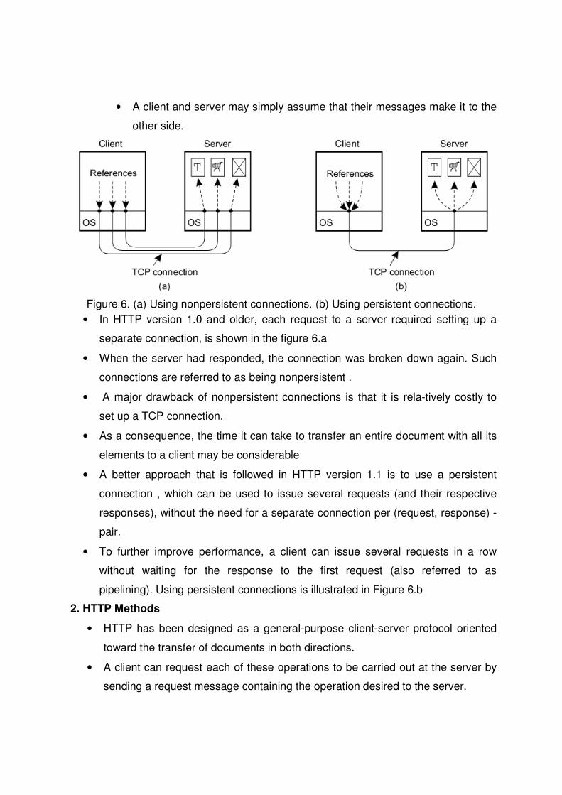
• A client and server may simply assume that their messages make it to the
other side.
Figure 6. (a) Using nonpersistent connections. (b) Using persistent connections.
• In HTTP version 1.0 and older, each request to a server required setting up a
separate connection, is shown in the figure 6.a
• When the server had responded, the connection was broken down again. Such
connections are referred to as being nonpersistent .
• A major drawback of nonpersistent connections is that it is rela-tively costly to
set up a TCP connection.
• As a consequence, the time it can take to transfer an entire document with all its
elements to a client may be considerable
• A better approach that is followed in HTTP version 1.1 is to use a persistent
connection , which can be used to issue several requests (and their respective
responses), without the need for a separate connection per (request, response) -
pair.
• To further improve performance, a client can issue several requests in a row
without waiting for the response to the first request (also referred to as
pipelining). Using persistent connections is illustrated in Figure 6.b
2. HTTP Methods
• HTTP has been designed as a general-purpose client-server protocol oriented
toward the transfer of documents in both directions.
• A client can request each of these operations to be carried out at the server by
sending a request message containing the operation desired to the server.

• A list of the most commonly used request messages is given in the following
diagram
Figure 7. Operations supported by HTTP
3. HTTP Messages
• All communication between a client and server takes place through messages.
• HTTP recognizes only request and response messages. A request message
con-sists of three parts, as shown in the following figure
Figure 8. (a) HTTP request message. (b) HTTP response message.

F. Processes
• The Web makes use of only two kinds of processes: browsers by which users
can access Web documents and have them displayed on their local screen, and
Web servers, which respond to browser requests.
1. Client
• The most important Web client is a piece of software called a Web browser,
which enables a user to navigate through Web pages by fetching those pages
from servers and subsequently displaying them on the user’s screen.
• A browser typically provides an interface by which hyperlinks are displayed in
such a way that the user can easily select them through a single mouse click.
• Web browsers are, in principle, simple programs. However, because they need
to be able to handle a wide variety of document types and also provide an easy-
to-use interface to users, they are generally complex pieces of software.
Figure 9 . Using a plug-in in a Web browser.
• One of the problems that Web browser designers have to face is that a browser
should be easily extensible so that it, in principle, can support any type of
document that is returned by a server.
• The approach followed in most cases is to offer facilities for what are known as
plug-ins.
• A plug-in is a small program that can be dynamically loaded into a browser for
handling a specific document type. The latter is generally given as a MIME type.
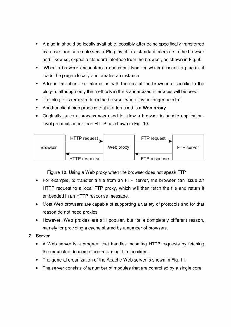
• A plug-in should be locally avail-able, possibly after being specifically transferred
by a user from a remote server.Plug-ins offer a standard interface to the browser
and, likewise, expect a standard interface from the browser, as shown in Fig. 9.
• When a browser encounters a document type for which it needs a plug-in, it
loads the plug-in locally and creates an instance.
• After initialization, the interaction with the rest of the browser is specific to the
plug-in, although only the methods in the standardized interfaces will be used.
• The plug-in is removed from the browser when it is no longer needed.
• Another client-side process that is often used is a Web proxy
• Originally, such a process was used to allow a browser to handle application-
level protocols other than HTTP, as shown in Fig. 10.
Figure 10. Using a Web proxy when the browser does not speak FTP
• For example, to transfer a file from an FTP server, the browser can issue an
HTTP request to a local FTP proxy, which will then fetch the file and return it
embedded in an HTTP response message.
• Most Web browsers are capable of supporting a variety of protocols and for that
reason do not need proxies.
• However, Web proxies are still popular, but for a completely different reason,
namely for providing a cache shared by a number of browsers.
2. Server
• A Web server is a program that handles incoming HTTP requests by fetching
the requested document and returning it to the client.
• The general organization of the Apache Web server is shown in Fig. 11.
• The server consists of a number of modules that are controlled by a single core

• module. The core module accepts incoming HTTP requests, which it
subsequently passes to the other modules in a pipelined fashion. In other words,
the core module determines the flow of control for handling a request.
Figure 11. General organization of the Apache Web server.
• For each incoming request, the core module allocates a request record with
fields for the document reference contained in the HTTP request, the associated
HTTP request headers, HTTP response headers, and so on.
• Each module operates on the record by reading and modifying fields as
appropriate. Finally, when all modules have done their share in processing the
request, the last one returns the requested document to the client.
• Apache servers are highly configurable; numerous modules can be included to
assist in processing an incoming HTTP request.
• To support this flexibility, the following approach is taken. Each module is
required to provide one or more handlers that can be invoked by the core
module.
• Handlers are all alike in the sense that they take a pointer to a request record
as their sole input parameter.
• They are also the same in the sense that they can read and modify the fields in
a request record. In order to invoke the appropriate handler at the right time,
processing HTTP requests is broken down into several phases.
• A module can register a handler for a specific phase. Whenever a phase is
reached, the core module inspects which handlers have been registered for that
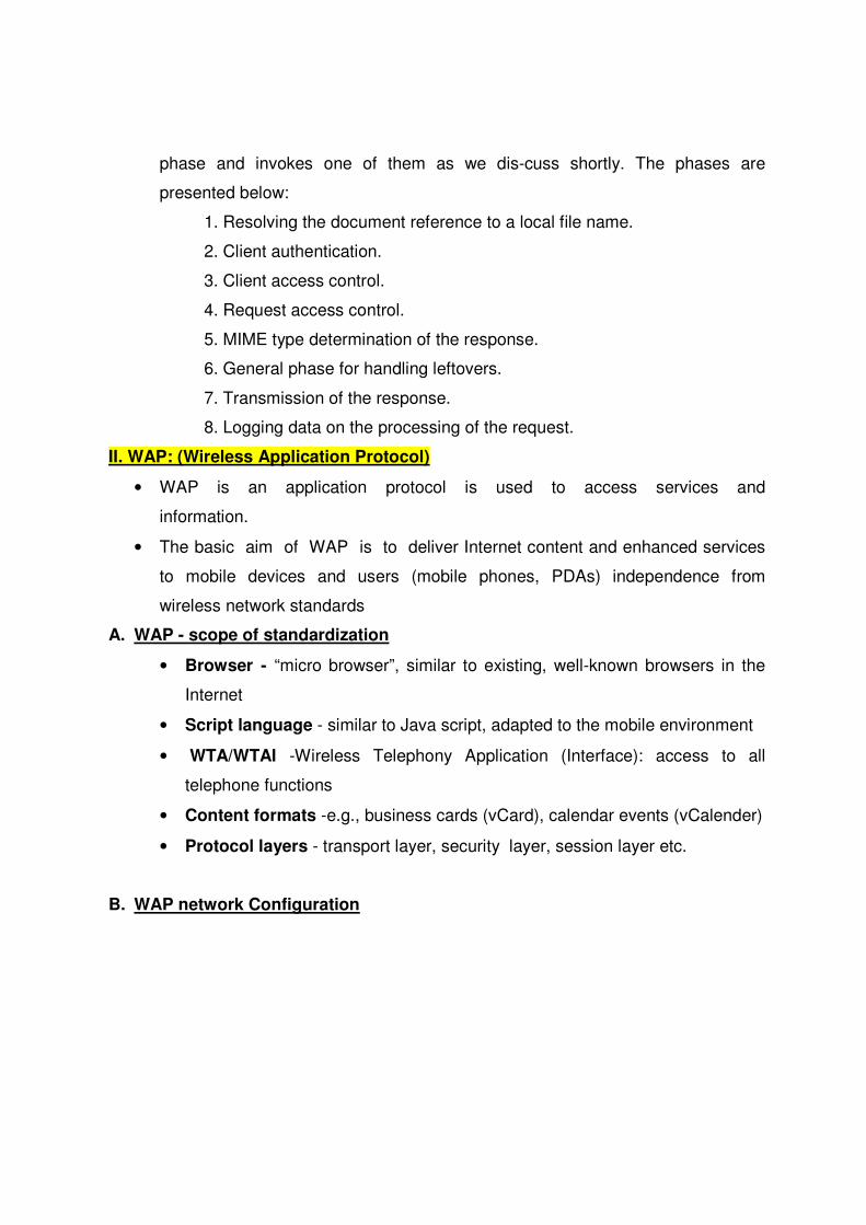
phase and invokes one of them as we dis-cuss shortly. The phases are
presented below:
1. Resolving the document reference to a local file name.
2. Client authentication.
3. Client access control.
4. Request access control.
5. MIME type determination of the response.
6. General phase for handling leftovers.
7. Transmission of the response.
8. Logging data on the processing of the request.
II. WAP: (Wireless Application Protocol)
• WAP is an application protocol is used to access services and
information.
• The basic aim of WAP is to deliver Internet content and enhanced services
to mobile devices and users (mobile phones, PDAs) independence from
wireless network standards
A. WAP - scope of standardization
• Browser - “micro browser”, similar to existing, well-known browsers in the
Internet
• Script language - similar to Java script, adapted to the mobile environment
• WTA/WTAI -Wireless Telephony Application (Interface): access to all
telephone functions
• Content formats -e.g., business cards (vCard), calendar events (vCalender)
• Protocol layers - transport layer, security layer, session layer etc.
B. WAP network Configuration

Figure 12. WAP network configuration
• A WAP handset communicates to the origin server through the mobile
network.
• The origin server is standard HTTP server /web server
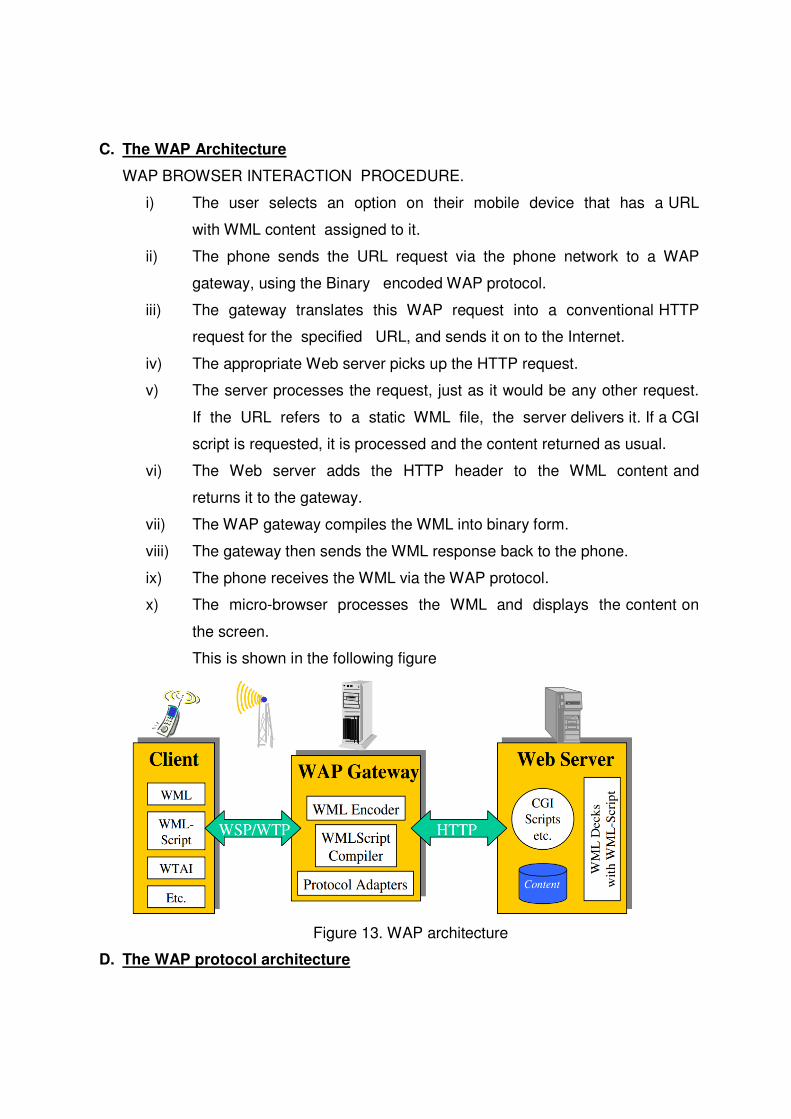
C. The WAP Architecture
WAP BROWSER INTERACTION PROCEDURE.
i) The user selects an option on their mobile device that has a URL
with WML content assigned to it.
ii) The phone sends the URL request via the phone network to a WAP
gateway, using the Binary encoded WAP protocol.
iii) The gateway translates this WAP request into a conventional HTTP
request for the specified URL, and sends it on to the Internet.
iv) The appropriate Web server picks up the HTTP request.
v) The server processes the request, just as it would be any other request.
If the URL refers to a static WML file, the server delivers it. If a CGI
script is requested, it is processed and the content returned as usual.
vi) The Web server adds the HTTP header to the WML content and
returns it to the gateway.
vii) The WAP gateway compiles the WML into binary form.
viii) The gateway then sends the WML response back to the phone.
ix) The phone receives the WML via the WAP protocol.
x) The micro-browser processes the WML and displays the content on
the screen.
This is shown in the following figure
Figure 13. WAP architecture
D. The WAP protocol architecture

• WAP specifies architecture based on layers that follow the OSI model
fairly closely. The WAP model, orstack as it is commonly known, is illustrated
below in Figure 11.
Figure 13.WAP 1.X reference model and protocol Stack
1. WAE (Wireless Application Environment):
• WAE enables a spectrum of applications to be supported over WAP.
• WAE has two main elements, namely:
(a) user agents, and
(b) services and formats.
• The former includes the WML and WTA (Wireless Telephone
Application) user agents. The latter consists of WML Scripts, image
formats, etc.
• A user agent can take the form of a Web browser. The WML user
agent is responsible for the interpretation of WML and WML Script.
WAP employs the same addressing model as in the Internet, that is, it
use Uniformed Resource Locators (URLs).
• A URL uniquely identifies an available resource. WAP also uses Uniform
Resource Identifiers (URIs) to address resources that are not accessed
via well-known protocols.
The logical model of the WAE is shown in the figure

Figure 14. WAE Logical model
2. WDP (Wireless Datagram Protocol):
• WDP is the transport layer protocol in WAP.
• It has the same functionality provided by the Internet User Datagram
Protocol (UDP).
• Whether WAP uses UDP or WDP, datagram delivery services are
provided by port number functionality and the characteristics of different
bearer services are hidden from the upper layers.
• WDP can be extended to provide segmentation and reassembly
functions.
• WCMP (wireless Control Message Protocol) is used for control/error
report (similar to ICMP in the TCP/IP protocol suite)
• Goals :
o create a worldwide interoperable transport system by adapting
WDP to the different underlying technologies
o transmission services, such as SMS in GSM might change, new
services can replace the old ones
• Transport layer protocol within the WAP architecture
o uses the Service Primitive
o T-UnitData.req .ind

o uses transport mechanisms of different bearer technologies
o offers a common interface for higher layer protocols
o allows for transparent communication despite different technologies
o addressing uses port numbers
Figure 15. WDP service primitives
o Destination and source address are unique addresses for the receiver and sender of
the user data. These could be MSISDNs (i.e., a telephone number), IP addresses, or
any other unique identifiers.
o The T-DUnitdata.ind service primitive indicates the reception of data. Here
destination address and port are only optional parameters.
o If a higher layer requests a service the WDP cannot fulfill, this error is indicated with
the T-DError.ind service primitive as shown in Figure
o An error code (EC) is returned indicating the reason for the error to the higher layer.
WDP is not allowed to use this primitive to indicate problems with the bearer service.
o It is only allowed to use the primitive to indicate local problems, such as a user data
size that is too large.
o If any errors happen when WDP datagrams are sent from one WDP entity to another
(e.g. the destination is unreachable, no application is listening to the specified
destination port etc.), the wireless control message protocol (WCMP) provides error
handling mechanisms for WDP
3. WTLS: Wireless Transport Layer Security
o Goals

- Provide mechanisms for secure transfer of content, for applications
needing privacy, identification, message integrity and non-repudiation
- Provide support for protection against denial-of-service attacks
- WTLS
- is based on the TLS/SSL (Transport Layer Security) protocol
- optimized for low-bandwidth communication channels
- provides
� privacy (encryption)
� data integrity (MACs)
� authentication (public-key and symmetric)
- Employs special adapted mechanisms for wireless usage
� Long lived secure sessions
� Optimised handshake procedures
- Provides simple data reliability for operation over datagram bearers
Figure 16. WTLS establishing a secure session
• The first step is to initiate the session with the SEC-Create primitive.
• Parameters are source address (SA), source port (SP) of the originator, destination
address (DA), destination port (DP) of the peer.
• The originator proposes a key exchange suite (KES) (e.g., RSA , DH, ECC ), a cipher suite
(CS) (e.g., DES, IDEA ), and a compression method (CM) (currently not further specified).

• The peer answers with parameters for the sequence number mode (SNM), the key
refresh cycle (KR) (i.e., how often keys are refreshed within this secure session), the
session identifier (SID) (which is unique with each peer), and the selected key exchange
suite (KES’), cipher suite (CS’), compression method (CM’).
• The peer also issues a SEC-Exchange primitive. This indicates that the peer wishes to
perform public-key authentication with the client, i.e., the peer requests a client
certificate (CC) from the originator.
Figure 17. WTLS datagram transfer
• After setting up a secure connection between two peers, user data can be exchanged.
This is done using the simple SEC-Unitdata primitive as shown in Figure.
• SEC-Unitdata has exactly the same function as T-DUnitdata on the WDP layer, namely
it transfers a datagram between a sender and a receiver.
• This data transfer is still unreliable, but is now secure. This shows that WTLS can be
easily plugged into the protocol stack on top of WDP.
• The higher layers simply use SEC-Unitdata instead of T-DUnitdata. The parameters are
the same here: source address (SA), source port (SP), destination address (DA),
destination port (DP), and user data (UD).
4. Wireless transaction protocol
� Goals
– different transaction services that enable applications to select reliability,
efficiency levels
– low memory requirements, suited to simple devices (< 10kbyte )
– efficiency for wireless transmission
� WTP Services and Protocols
– supports peer-to-peer, client/server and multicast applications
– efficient for wireless transmission

– support for different communication scenarios
– class 0: unreliable message transfer
• unconfirmed Invoke message with no Result message
• a datagram that can be sent within the context of an existing
Session
– class 1: reliable message transfer without result message
• confirmed Invoke message with no Result message
• used for data push, where no response from the destination is
expected
– class 2: reliable message transfer with exactly one reliable result message
• confirmed Invoke message with one confirmed Result message
• a single request produces a single reply
� WTP (Transaction)
– provides reliable data transfer based on request/reply paradigm
• no explicit connection setup or tear down
• optimized setup (data carried in first packet of protocol exchange)
• seeks to reduce 3-way handshake on initial request
– supports
• header compression
• segmentation /re-assembly
• retransmission of lost packets
• selective-retransmission
• port number addressing (UDP ports numbers)
• flow control
– message oriented (not stream)
– supports an Abort function for outstanding requests
– supports concatenation of PDUs
– supports User acknowledgement or Stack acknowledgement option
• acks may be forced from the WTP user (upper layer)
• default is stack ack
� uses the service primitives
– T-TRInvoke.req .cnf. .ind .res
– T-TRResult.req .cnf .ind .res
– T-Abort.req .ind
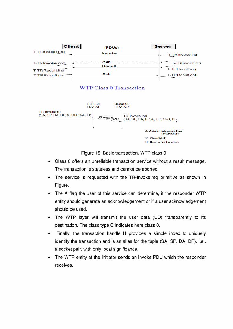
Figure 18. Basic transaction, WTP class 0
• Class 0 offers an unreliable transaction service without a result message.
The transaction is stateless and cannot be aborted.
• The service is requested with the TR-Invoke.req primitive as shown in
Figure.
• The A flag the user of this service can determine, if the responder WTP
entity should generate an acknowledgement or if a user acknowledgement
should be used.
• The WTP layer will transmit the user data (UD) transparently to its
destination. The class type C indicates here class 0.
• Finally, the transaction handle H provides a simple index to uniquely
identify the transaction and is an alias for the tuple (SA, SP, DA, DP), i.e.,
a socket pair, with only local significance.
• The WTP entity at the initiator sends an invoke PDU which the responder
receives.

• The WTP entity at the responder then generates a TR-Invoke.ind
primitive with the same parameters as on the initiator’s side, except for H’
which is now the local handle for the transaction on the responder’s side
Figure 19. Basic transaction, WTP class 1, with no user and user
acknowledgement
• The responder signals the incoming invoke PDU via the TR-Invoke.ind primitive to
the higher layer and acknowledges automatically without user intervention.
• The specification also allows the user on the responder’s side to acknowledge, but
this acknowledgement is not required.
• For the initiator the transaction ends with the reception of the acknowledgement.
The responder keeps the transaction state for some time to be able to retransmit
the acknowledgement if it receives the same invoke PDU again indicating a loss
of the acknowledgement.
• If a user of the WTP class 1 service on the initiator’s side requests a user
acknowledgement on the responder’s side.
• Now the WTP entity on the responder’s side does not send an acknowledgement
automatically, but waits for the TR-Invoke.res service primitive from the user.
• This service primitive must have the appropriate local handle H’ for identification of
the right transaction.

• The WTP entity can now send the ack PDU. Typical uses for this transaction class
are reliable push services.
Figure 20. . Basic transaction, WTP class 2, with no user and no hold on
Figure 21. Basic transaction, WTP class 2, with user acknowledgement

Figure 22. WTP Class 2 Transaction, hold on, no user ack.
• The basic transaction of class 2 without-user acknowledgement. Here, a user
on the initiator’s side requests the service and the WTP entity sends the
invoke PDU to the responder.
• The WTP entity on the responder’s side indicates the request with the TR-
Invoke.ind primitive to a user.
• The responder now waits for the processing of the request, the user on the
responder’s side can finally give the result UD* to the WTP entity on the
responder side using TR-Result.req.
• The result PDU can now be sent back to the initiator, which implicitly
acknowledges the invoke PDU.
• The initiator can indicate the successful transmission of the invoke message
and the result with the two service primitives TR-Invoke.cnf and TR-Result.ind.
• A user may respond to this result with TR-Result.res. An acknowledgement
PDU is then generated which finally triggers the TR-Result.cnf primitive on the
responder’s side.
• This example clearly shows the combination of two reliable services (TR-
Invoke and TR-Result) with an efficient data transmission/acknowledgement
5. WSP (Wireless Session Protocol):

• The WSP provides both connection-oriented and connectionless
services.
• It is optimized for low-bandwidth networks with relatively long latency.
WSP is a binary version of HTTP version 1.1, but with the additions of:
(a) session migrations, (b) header caching, etc.
• WAP connection mode allows the establishment of sessions between a
client and the WAP gateway or proxy.
• It can handle session interruptions as a result of mobility and re-
establish session states at a later point in time.
• Header caching allows better bearer utilization since in HTTP; most of
the requests contain static headers that need to be re-sent again.
� Goals
– HTTP 1.1 functionality
• Request/reply, content type negotiation, ...
– support of client/server transactions, push technology
– key management, authentication, Internet security services
� WSP Services
– provides shared state between client and server, optimizes content
transfer

– session management (establish, release, suspend, resume)
– efficient capability negotiation
– content encoding
– push
� WSP/B (Browsing)
– HTTP/1.1 functionality - but binary encoded
– exchange of session headers
– push and pull data transfer asynchronous requests
• HTTP 1.1 and WSP
� HTTP 1.1
– extensible request/reply methods
– extensible request/reply headers
– content typing
– composite objects
– asynchronous requests
� WSP enhancements beyond HTTP
– binary header encoding
– session headers
– confirmed and non-confirmed data push
– capability negotiation
– suspend and resume
– fully asynchronous requests
– connectionless service
� Why Not HTTP?
– encoding not compact enough, inefficient capability negotiation
– no push facility
• WSP Overview
� Header Encoding
– compact binary encoding of headers, content type identifiers and other
well-known textual or structured values

– reduces the data actually sent over the network
� Capabilities (are defined for):
– message size, client and server
– protocol options: Confirmed Push Facility, Push Facility, Session Suspend
Facility, Acknowledgement headers
– maximum outstanding requests
– extended methods
– header code pages
� Suspend and Resume
– server knows when client can accept a push
– multi-bearer devices
– dynamic addressing allows the release of underlying bearer resources
WSP/ B Session establishment
Figure 23. WSP/B session establishment
• The session establishment of WSP/B using WTP class 2 transactions. With the S-
Connect.req primitive, a client can request a new session.
• Parameters are the server address (SA), the client address (CA), and the optional
client header (CH) and requested capabilities (RC).
• The session layer directly uses the addressing scheme of the layer below. TR-
SAP and S-SAP can be directly mapped.

• WTP transfers the connect PDU to the server S-SAP where an S-Connect.ind
primitive indicates a new session.
• Parameters are the same, but now the capabilities are mandatory. If the server
accepts the new session it answers with an S-Connect.res, parameters are an
optional server header (SH) with the same function as the client header and the
negotiated capabilities (NC) needed for capability negotiation.
• WTP now transfers the connreply PDU back to the client; S-Connect.cnf confirms
the session establishment and includes the server header (if present) and the
negotiated capabilities from the server.
• WSP/B includes several procedures to refuse a session or to abort session
establishment.
Figure 24. WSP/ session suspend / resume
• A client suspends a session with S-Suspend.req, WTP transfers the
suspend PDU to the server with a class 0 transaction, i.e., unconfirmed
and unreliable.
• WSP/B will signal the suspension with S-Suspend.ind on the client and
server side. The only parameter is the reason R for suspension. Reasons
can be a user request or a suspension initiated by the service provider.
• a client can later resume a suspended session with S-Resume.req.
Parameters are server address (SA) and client address (CA).

• If SA and CA are not the same as before suspending this session, it is the
responsibility of the service user to map the addresses accordingly so that
the same server instance will be contacted.
• Resuming a session is a confirmed operation. It is up to the server’s
operator how long this state is conserved
Figure 25. WSP/ B session termination
• Terminating a session is done by using the S-Disconnect.req
service primitive.
• This primitive aborts all current method or push transactions used
to transfer data. Disconnection is indicated on both sides using S-
Disconnect.ind.
• The reason R for disconnection can be, e.g., network error,
protocol error, peer request, congestion, and maximum SDU size
exceeded.
• S-Disconnect.ind can also include parameters that redirect the
session to another server where the session may continue.

Figure 26. WSP/ B method invoke
• The S-MethodInvoke primitive is used to request that an operation is
executed by the server.
• The result, if any, is sent back using the S-MethodResult primitive .
• A client requests an operation with S-MethodInvoke.req. Parameters are the
client transaction identifier CTID to distinguish between pending transactions,
the method M identifying the requested operation at the server, and the
request URI .
• Additional headers and bodies can be sent with this primitive. The WTP class
2 transaction service now transports the method PDU to the server.
• A method PDU can be either a get PDU or a post PDU as defined in Fielding
(1999). Get PDUs are used for HTTP/1.1 GET, OPTIONS, HEAD, DELETE
and TRACE methods, and other methods that do not send content to the
server.
• A post PDU is used for HTTP/1.1 POST and PUT and other methods that
send content to the server

Figure 27. WSP/ B over WTP- method invocation
• The S-MethodInvoke.req primitive triggers the TR-Invoke.req primitive, the
parameters of the WSP layer are the user data of the WTP layer.
• The invoke PDU of the WTP layer carries the method PDU of the WSP layer
inside.
• In contrast to a pure layered communication model, the lower WTP layer is
involved in the semantics of the higher layer primitives and does not consider
them as pure data only.
• For the confirmation of its service primitives the WSP layer has none of its own
PDUs but uses the acknowledgement PDUs of the WTP layer as shown. S-
MethodInvoke.res triggers TR-Invoke.res, the ack PDU is transferred to the
initiator, here TR-Invoke.cnf confirms the invoke service and triggers the S-
MethodInvoke.cnf primitive which confirms the method invocation service.
• This mingling of layers saves a lot of redundant data flow but still allows a
separation of the tasks between the two layers.
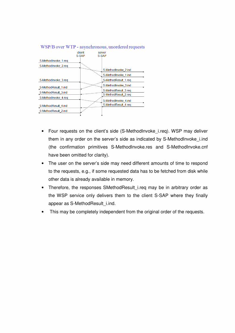
• Four requests on the client’s side (S-MethodInvoke_i.req). WSP may deliver
them in any order on the server’s side as indicated by S-MethodInvoke_i.ind
(the confirmation primitives S-MethodInvoke.res and S-MethodInvoke.cnf
have been omitted for clarity).
• The user on the server’s side may need different amounts of time to respond
to the requests, e.g., if some requested data has to be fetched from disk while
other data is already available in memory.
• Therefore, the responses SMethodResult_i.req may be in arbitrary order as
the WSP service only delivers them to the client S-SAP where they finally
appear as S-MethodResult_i.ind.
• This may be completely independent from the original order of the requests.

• The server sends unsolicited data with the S-Push.req primitive to the client.
Parameters are the push header (PH) and the push body (PB) again, these are the
header and the body known from HTTP.
• The unreliable, unconfirmed WTP class 0 transaction service transfers the push
PDU to the client where S-Push.ind indicates the push event. A more reliable push
service offers the S-ConfirmedPush primitive .
• Here the server has to determine the push using a server push identifier (SPID). This
helps to distinguish between different pending pushes.
• The reliable WTP class 1 transaction service is now used to transfer the confpush
PDU to the client.
• On the client’s side a client push identifier (CPID) is used to distinguish between
different pending pushes.
• Shows the three service primitives available for connectionless session
service: S-Unit-MethodInvoke.req to request an operation on a server, S-Unit-
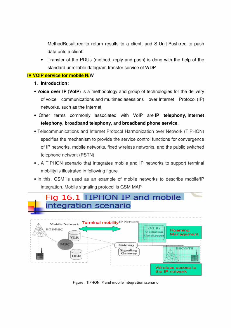
MethodResult.req to return results to a client, and S-Unit-Push.req to push
data onto a client.
• Transfer of the PDUs (method, reply and push) is done with the help of the
standard unreliable datagram transfer service of WDP
IV VOIP service for mobile N/W
1. Introduction:
• Voice over IP (VoIP) is a methodology and group of technologies for the delivery
of voice communications and multimediasessions over Internet Protocol (IP)
networks, such as the Internet.
• Other terms commonly associated with VoIP are IP telephony, Internet
telephony, broadband telephony, and broadband phone service.
• Telecommunications and Internet Protocol Harmonization over Network (TIPHON)
specifies the mechanism to provide the service control functions for convergence
of IP networks, mobile networks, fixed wireless networks, and the public switched
telephone network (PSTN).
• „ A TIPHON scenario that integrates mobile and IP networks to support terminal
mobility is illustrated in following figure
• In this, GSM is used as an example of mobile networks to describe mobile/IP
integration. Mobile signaling protocol is GSM MAP
Figure : TIPHON IP and mobile integration scenario

• “Terminal mobility” „- A terminal can be moved around the service area without
losing contact with the system
• „ “User mobility” „ Using various types of terminals, a user can move around the
service area without losing contact with the system
2. GSM on the Net (terminal mobility) „
• The GSM on the Net architecture is illustrated in Figure 16.2, which
consists of GSM and corporate networks.
• “terminal mobility” & “user mobility” „
• The network elements of GSM on the Net are described here:
o Service node.
o Access node.
o GSM/BTS.
o Gateway.
o Terminal equipment
3. The iGSM Wireless VoIP Solution (user mobility ) „
• Another TIPHON scenario supporting user mobility for GSM subscribers
to access VoIP services.

• The iGSM solution is different from GSM on the Net in the following
aspects:
i. iGSM is a value-added service to the public GSM networks
ii. The iGSM network does not introduce wireless access equipment
in the IP network, iGSM is implemented using standard platforms
(general IP gateway/gatekeeper).
• iGSM Service (GSM + H.323 (IP) netorks)
o „ A GSM subscriber ordering the iGSM service can enjoy the
standard GSM service when he or she is in the GSM network „
o When the person moves to the IP network (without a GSM mobile
station), he or she can utilize an H.323 terminal (IP phone or a PC)
to receive an incoming call to his or her MSISDN (mobile ISDN
number)
� „ The GSM roaming mechanism determines whether the
subscriber is in the GSM network or IP network
4. The H.323 Network
• Figure 16.3 illustrates an H.323 system, where the terminal, gateway,
gatekeeper, and multipoint control unit are called endpoints.
i. Terminal.
ii. Gateway. „
iii. Gatekeeper.
iv. Multipoint control unit (MCU).
v. Multipoint controller (MC).
vi. Multipoint processor (MP).

5. The iGSM Architecture „
• Figure 16.4 illustrates the iGSM architecture, where the GSM network is
not modified. „
• In the IP network, an iGSM gateway is implemented to perform two major
functions besides the standard H.323 mechanisms:
o „ GSM MAP and H.225 RAS (registration, admission, and status)
protocol translation.
o „ GSM /PSTN /IP call setup and release

6. iGSM Procedures and Message Flows
• „ Every iGSM subscriber has a record in the database, which consists of the
following fields: „
i. MSISDN of the MS „
ii. Transport address of the H.323 terminal for the subscriber in the IP
network
iii. Password of the iGSM subscriber „
iv. HLR address (ISDN number) of the iGSM subscriber
v. IMSI (international mobile station identity) of the MS
vi. User profile, which indicates the service features and restrictions of the
iGSM subscriber
vii. Presence indication of the iGSM subscriber in the IP network
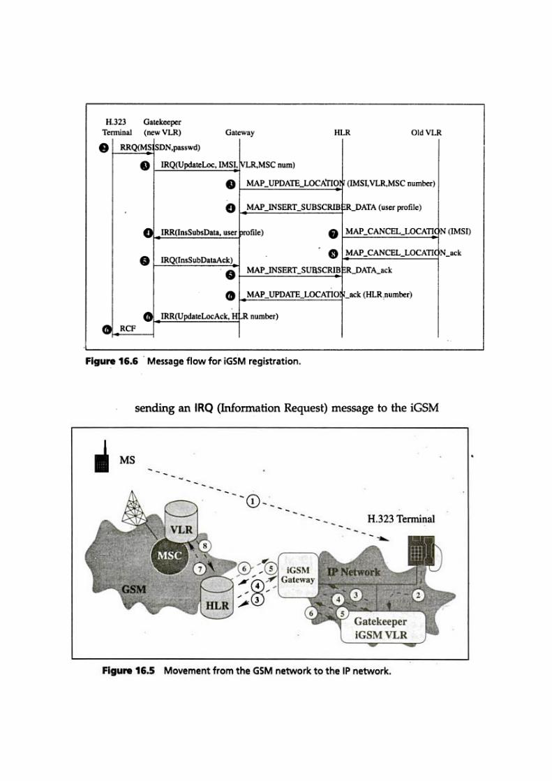

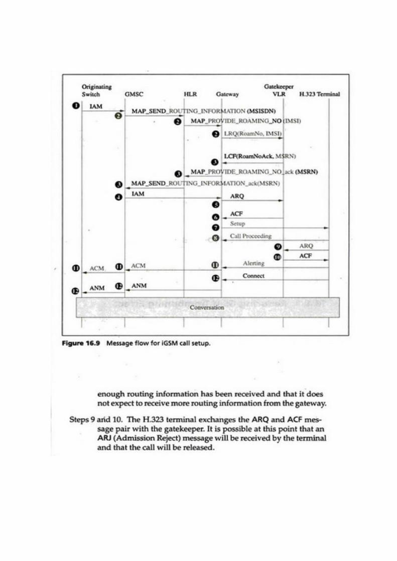


Deregistration
• „ When an iGSM subscriber moves from the IP network to the GSM
network „
• He or she performs the registration in the GSM network (misrouting may
occur) „
• The iGSM gatekeeper is the “old VLR ” and the deregistration actions are
modified
V. WLL
- WLL is a system that connects subscribers to the local telephone station wirelessly.
� Systems WLL is based on:
� Cellular
� Satellite (specific and adjunct)
� Microcellular
� Other names
� Radio In The Loop (RITL)
� Fixed-Radio Access (FRA).

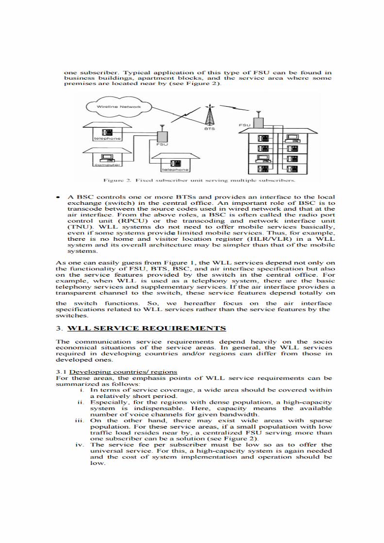
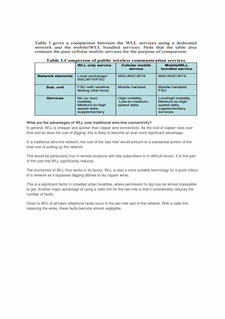
What are the advantages of WLL over traditional wire-line connectivity?
In general, WLL is cheaper and quicker than copper wire connectivity. As the cost of copper rises over
time and so does the cost of digging, this is likely to become an ever more significant advantage.
In a traditional wire-line network, the cost of the 'last mile' would amount to a substantial portion of the
total cost of putting up the network.
This would be particularly true in remote locations with few subscribers or in difficult terrain. It is this part
of the cost that WLL significantly reduces.
The economics of WLL thus works in its favour. WLL is also a more suitable technology for a quick rollout
of a network as it bypasses digging ditches to lay copper wires.
This is a significant factor in crowded urban localities, where permission to dig may be almost impossible
to get. Another major advantage of using a radio link for the last mile is that it considerably reduces the
number of faults.
Close to 90% of all basic telephone faults occur in the last mile part of the network. With a radio link
replacing the wires, these faults become almost negligible.