CHLORO ALKALI INDUSTRIES-SCHA 1305 - Sathyabama ...
150
1 SCHOOL OF BIO AND CHEMICAL ENGINEERING DEPARTMENT OF CHEMICAL ENGINEERING UNIT – 1 INTRODUCTION - CHLORO ALKALI INDUSTRIES-SCHA 1305
-
Upload
khangminh22 -
Category
Documents
-
view
0 -
download
0
Transcript of CHLORO ALKALI INDUSTRIES-SCHA 1305 - Sathyabama ...
1
SCHOOL OF BIO AND CHEMICAL ENGINEERING
DEPARTMENT OF CHEMICAL ENGINEERING
UNIT – 1 INTRODUCTION - CHLORO ALKALI INDUSTRIES-SCHA 1305

2
Process Equipment Symbols
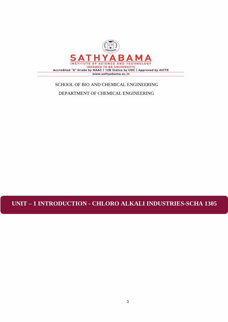
UnitOperation SchematicRepresentation Comments
1. Distillation
(a) Batch
Utilized for intermittent operation and handling small volumes
of feed and product
(b) ContinuosFractionator
Suitable for high volume continuous separation of complex mixtures
eg. petroleum fraction
2. Drying ofSolids
(a) SprayDrier
Employed for large capacity operation on liquid feed to give powered, spherical,free flowing product ;used in prodution of pigments, detergents,synthetic resins and misc inorganic salts
3
UnitOperation SchematicRepresentation Comments
(b) RotaryDrier
Suitable for drying free flowing granular solids which do not dust or stick ; high temp models are kilns for calcining cement, lime, etc.
( c ) Tunnel Driver
Best suited to drying pastes or powders in trays ; also used
to dry pottery, lumber, leather, etc., In sheet shaped forms
3. Evaporation
(a) OpenPan
Used for small batches ; often of viscous mat’s ;
such designs are easy to clean

4
UnitOperation SchematicRepresentation Comments
4. Extraction
(a) Liquid -liquid
Used to contact solvent and feed to give raffinate and extract ; widely adapted to removal of
napthenes from lube oil fractions Using solvents such as furfural
( b) Solid-Liquid
(Leaching)
Involves removal of a solute from a Solidbymeansofaliquidso;lventOften used in ore treatment to Recover metal values
5. FluidHandling
( a )Centrifugal pump
Mostwidelyusedforliquidsofall types;simpleinconstructionand maintenance

5
UnitOperation SchematicRepresentation Comments
(b) Reciprocating Pump
Or Compressor
Generally used for higher pressure delivery ; may be used for metering or proportioning
( c ) Jet Ejector
Used for lower pressure operation or production of vacuum ; steam often used as motive fluid
6. Fluid - Solid Contacting (
a ) Fixed Bed
Most widely used type of catalytic rector ; used with precious metal catalysts to minimize attrition losses ; catalyst usually in form of pellets

6
UnitOperation SchematicRepresentation Comments
6 . Fluid Bed
Used to contact finely divided solids with reactant gases e.g., Cracking catalyst with oil vapor and then with air ; also used in roasting of sulfide ores to give oxides
and SO2
7. Fluid - SolidSeparation
( a ) Centrifugation
Used to separate very finely divided solids from liquid or liquids from liquid emulsions
( b ) Setting Tank
Simple device used to remove large particles from gas stream by simple setting in low velocity zone
7
UnitOperation SchematicRepresentation Comments
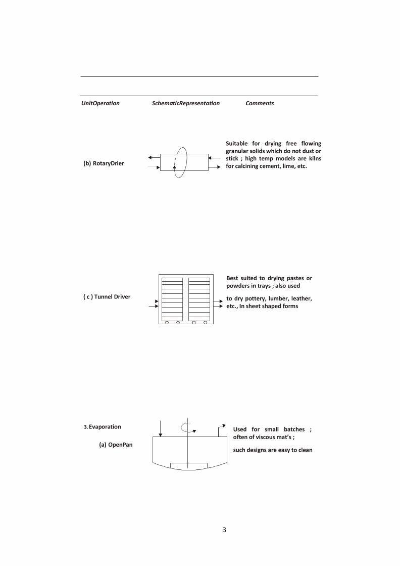
( c ) Wet Scrubber
Effective means of removing
suspended particles from gas
stream by contact with liquid
shower
( d ) Crystallizer
Hot, nearly-saturated
solutions are stirred and
cooled to effect nuclea-
tion and crystal growth ;
widely used with inorganic
salts.
( e ) Filter ( Rotary )
Vacuum applied to interior of
drum pulls filtrate out of cake;
used to separate minerals from
slurries, pulp fibers from water,
etc.
8
UnitOperation SchematicRepresentation Comments
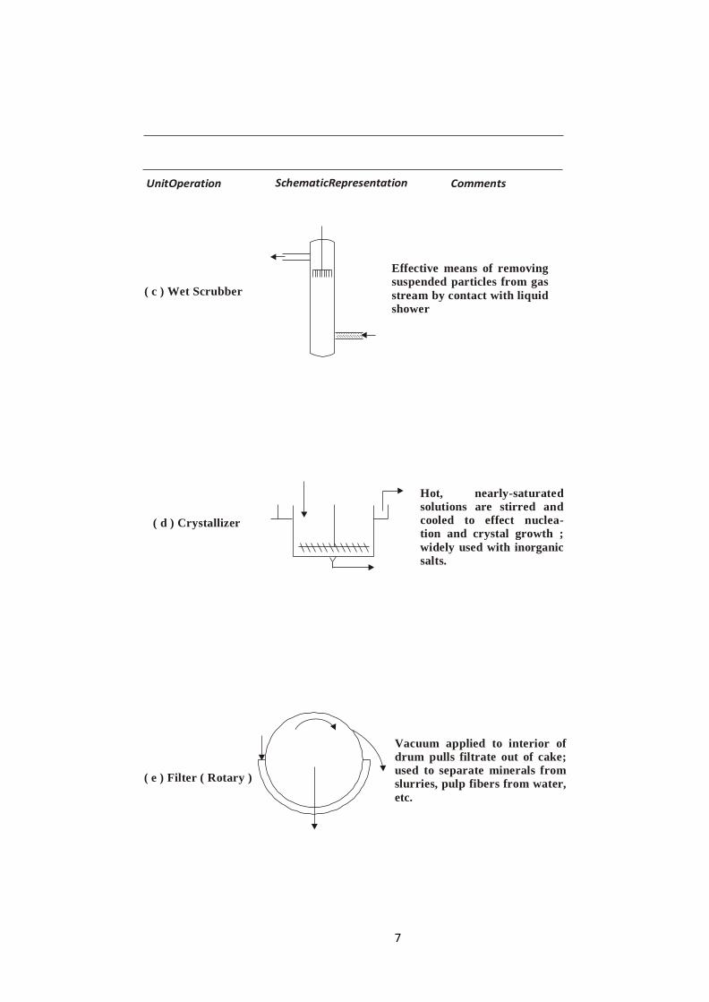
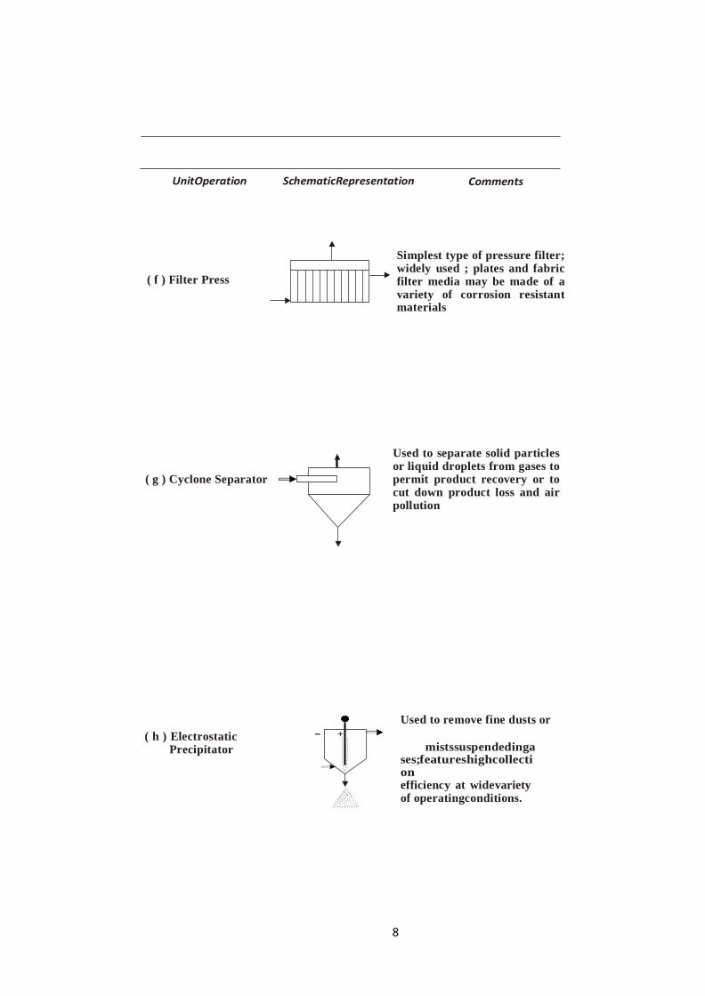
( f ) Filter Press
Simplest type of pressure filter; widely used ; plates and fabric filter media may be made of a variety of corrosion resistant materials
( g ) Cyclone Separator
Used to separate solid particles or liquid droplets from gases to permit product recovery or to cut down product loss and air pollution
( h ) Electrostatic
Precipitator
Used to remove fine dusts or
- +
mistssuspendedingases;featureshighcollection
efficiency at widevariety of operatingconditions.

9
UnitOperation SchematicRepresentation Comments
( j )Thickener
-Classifier
Used to separate slurry into sludges and clear liquids ; used widely in mineral industries and in sewage effluent clarification
8 . FluidStorage
( a ) Gas Holders
Used for low pressure storage of gases at constant pressure using
liquid seal ( usually water )
( b ) Tanks
Widely used for storage of liquids of all types , usually at atmospheric pressure ; may have floating roof

10
UnitOperation SchematicRepresentation Comments
( c ) Pressurized
Spheres
Used for pressurized storage of liquified gases or high vapor pressure liquids to permit safe storage with no vaporlosses
( d ) Underground
Caverns
Used for large volume storage of liquids or of liquified gases
9 . Gas-LiquidContacting
( a ) Absorption
( Solvent )
( b ) Stripping
Used for taking up a soluble gas in a solvent liquid and producing a solution plus a lean exit gas ;e.g.,Used in H2S removal from hydro-
carbons
( Solution )
Used for removing a soluble gas from solution by counter-current contact with an inert gas ; used to recover solute gas and regenerate solvent for subsequent absorption step

11
UnitOperation SchematicRepresentation Comments
10. Heat Exchange
( a ) Fired Heater Used to heat petroleum fraction
to distillation or cracking
temperatures in direct fired
tubes.
( b ) Reboiler
Uses natural circulation to
circulate fractionating tower
bottom in heat exchange with
steam ,e.g., to provide
necessary heat forfractionation
( c ) Condenser
Usually water-cooled tubular
construction to provide reflux
and overhead product from
fractionating column

12
UnitOperation SchematicRepresentation Comments
( d ) Shell And Tube
Exchanger Common type of device for
process heat exchange
( e ) Jacketed Kettle
Common construction for
reaction kettles ; water or
brine may be used for cooling ;
hot water, oil or Dowtherm
for heating
( f ) Direct Mixing
( Quenching )
Features intimate contact of
coolant fluid ( e.g., water )
with process gases to give
quick quench, e.g.,in
hydrocarbon pyrolysis to
acetylene

13
UnitOperation SchematicRepresentation Comments
11. Membrane
Separation
( a )Dialysis
Used to separate malt’s in
sol’s having widely
different mole.
E.g., Caustic from sugar or cellulose
( b ) Gaseous
Diffusion
Uses micro porous (e.g., Ni )
barriers in multistage operation to separate light (e.g., U235F6 ) from heavy (e.g., U235F6 )components
12. Mixing
( a ) Agitation
May be used for liquid - liquid or
solid - solid mixing in single or
multiple compartments ; widely
used in processindustries
-
-
-
-
+
+
2 3 5 U F 6
2 3 5
U F6
F 6 U 2 3 5
14
UnitOperation SchematicRepresentation Comments
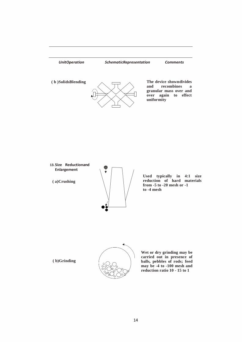
( b )SolidsBlending The device showndivides
and recombines a granular mass over and over again to effect uniformity
13. Size Reductionand Enlargement
( a)Crushing
( b)Grinding
Used typically in 4:1 size reduction of hard materials from -5 to -20 mesh or -1 to -4 mesh
Wet or dry grinding may be carried out in presence of balls, pebbles of rods; feed may be -4 to -100 mesh and reduction ratio 10 - 15 to 1

15
UnitOperation SchematicRepresentation Comments
( c ) Pelletizing
14. Solids Handling
( a ) Pneumatic Conveying
( b ) Bucket Elevators
Used to make tablets from
powders of Medicinals, cata-
Catalysts, etc
Used originally for grain; now used widely for cement, catalysts, coke and powdered
chemicals
Used for elevating materials; can be used for moving
powdered or granular mat’ls to and from storage or between reaction vessels
as in moving bed catalytic processes

16
UnitOperation SchematicRepresentation Comments
(c)Screwconveyor
Versatile ; can be used to mix and heat or cool ; can be operated underpressure ; useful for powders or sticky material.
( d ) Belt Conveyor
Can be used to handle large volumes over long distances economically ; used near horizontal ; belting may be fabric or rubber
15. Solid / Solid Separation
( a ) Screening
Wire , plastic or fabric screens are used to separate solids of varying sizes
Dil
ute
Ste
am

17
UnitOperation SchematicRepresentation Comments
( b ) Elutriation
May be used to remove fines from a solid by passage of a gas to fluidize and transport the fines
(c)FrothFloatation
( d ) Jigging
Finely ground (- 50 mesh) ores are suspend in water in presence of floating reagents (e.g.., RCOONa) and blow with air ; desired product collects in froth.
One of the oldest processes used for separation of minerals from lighter gangues as a well as for separating coal from heavier contaminants
Gas
Hot flame at 18000C
Hot
end

18
UnitOperation SchematicRepresentation Comments
( e ) Magnetic Separation
Used to remove tramp iron from feed to subsequent grinding and
pulverizing steps; also used to concentrate magnetic
iron ores
MANUFCATURE OF SODA ASH
S S
N

19
Figure 1.1 Manufacture of soda ash by Solvay process

20
CHLORINE -CAUSTIC SODA
21
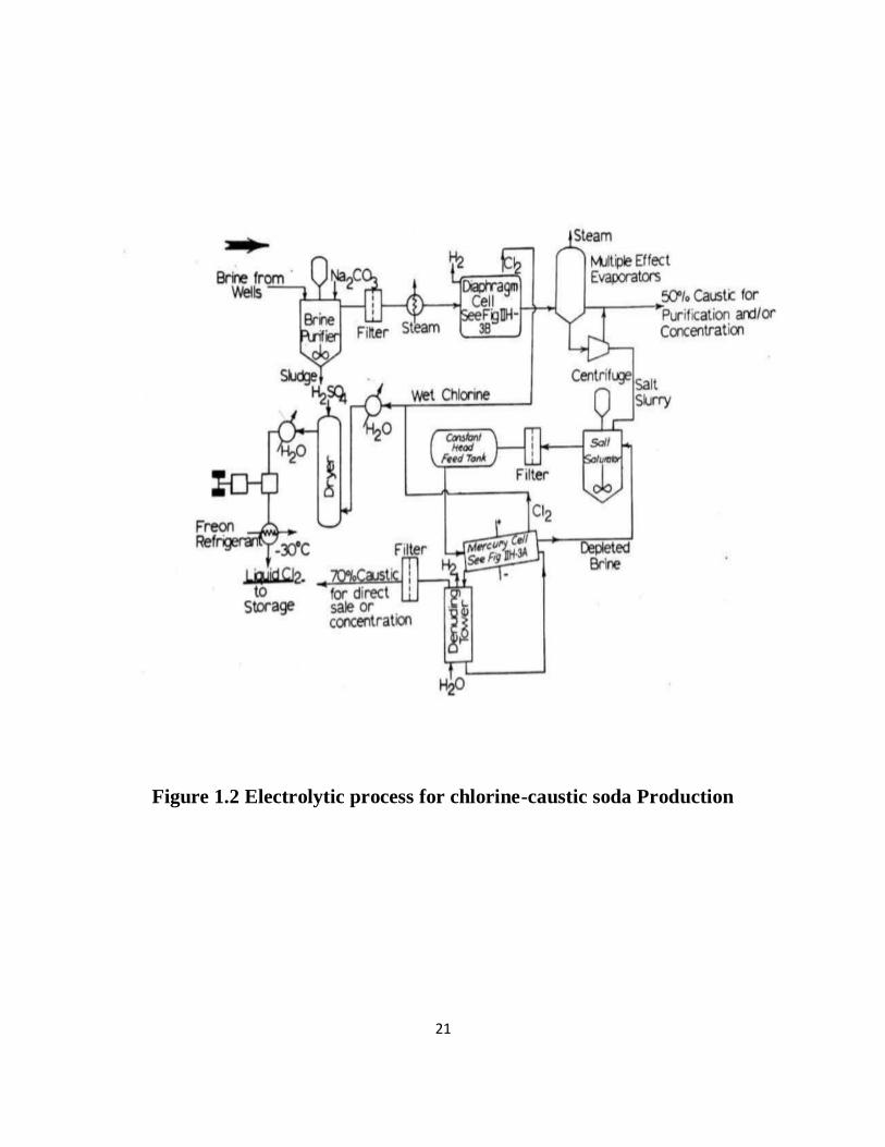
Figure 1.2 Electrolytic process for chlorine-caustic soda Production
22
REFERENCES
1. Gopala Rao M. and Marshall Sittig, “Dryden's Outlines of Chemical Technology”, 3rd
Edition, East West Press, New Delhi, 2008.
2. George T. Austin, “Shreve's Chemical Process Industries”, 8th Edition, McGraw Hill
International Editions, Singapore, 2002
3. https://nptel.ac.in/courses/103/107/103107082/
4. https://nptel.ac.in/courses/103/106/103106108/

1
SCHOOL OF BIO AND CHEMICAL ENGINEERING
DEPARTMENT OF CHEMICAL ENGINEERING
UNIT – 2 SULPHUR, SULPHURIC ACID AND SILICATE INDUSTRIES
SCHA1305

2
SULFURIC ACID
INTRODUCTION
Sulfuric acid (H2SO4) is a highly corrosive strong mineral acid. It is a colorless to slightly
yellow viscous liquid which is soluble in water at all concentrations. It is one of the most
important heavy industrial chemicals due to it has a number of large-scale uses
particularly in the phosphate fertilizer industry. About 60 % of the sulfuric acid produced
is utilized in fertilizer manufacture.
Sulfuric acid was called "oil of vitriol" by Medieval. The study of vitriol began in ancient
times. Sumerians had a list of types of vitriol that classified according to substance's
colour.
Johann Glauber prepared sulfuric acid by burning sulfur together with saltpeter (potassium
nitrate, KNO3), in the presence of steam in the 17thcentury. Decomposition of saltpeter
followed by oxidation produces SO3, which combines with water to produce sulfuric acid.
Joshua Ward used the method for the first large- scale production of sulfuric acid in 1736.
John Roebuck, produce less expensive and stronger sulfuric acid in lead-lined chambers in
1746. The strength of sulfuric acid by this method is 65%. After several refinements, this
method, called the "lead chamber process" or "chamber process", remained the standard
for sulfuric acid production for almost two centuries.
The process was modified by Joseph Louis Gay-Lussac and John Glover which improved
concentration to 78%. However, the manufacture of some dyes and other chemical
processes require a more concentrated product. Throughout the 18th century, this could
only be made by dry distilling minerals in a technique similar to the original
alchemicalprocesses.
Pyrite (iron disulfide, FeS2) was heated in air to yield iron(II) sulfate, FeSO4, which was
oxidized by further heating in air to form iron(III) sulfate, Fe2(SO4)3, which, when heated
to 4800C, decomposed to iron(III) oxide and sulfur trioxide, which could be passed
through water to yield sulfuric acid in any concentration. But the production expenses are
veryhigh.
More economical process i.e. the contact process was patented by Peregrine Phillips in
1831. Today, nearly all of the world's sulfuric acid is produced using thismethod.
MANUFACTURE
The Industrial manufacture of sulfuric acid is done mainly by two processes
1. The Lead Chamberprocess

3
2. The Contactprocess
1. The lead chamberprocess
The Lead Chamber process for the manufacture of sulfuric acid dates back
about 200 years. Although less efficient than the contact process, it is still of
considerable commercial importance.
Raw Materials
Basis: 1000kg Sulfuric acid
(98% yield) Sulfur =400kg
Air =399kg
Manufacture
Sulfur dioxide is obtained by burning sulfur or by roasting pyrites. There are
two function of burner
1. To oxidize sulfur to maximumextent
2. To produce and constant supply of gas containing maximum
concentration ofSO2
The burner of the furnace should expose large surface of melted sulfur and should be
provided secondary air in order to burn sublimed burner. This is necessary due to low heat of
combustion and high vapour pressure of sulfur. At about 4000C, pyrite (FeS2) decompose in
to FeS and sulfur vapour, the later oxidized to SO2 in presence of excess air. The residual
Solvent to purification andre-useConc. H2SO4
TarNitrated
Acid
Solvent
containing
diacetyleneChamber Acid
Figure:
Manufa
cture of
Acetyle
ne by
Wulff
ProcessWatrer Spray
Compress
orChambe
r I
BoilerCha
mber II
Chamber III
To Chimney
Nitre Pot
Burners
Conc. Acid Chamber Acid
Figure: Manufacturing of Sulfuric acid by Chamber process
4
FeS also oxidizes to Fe2O3 and SO2. Iron oxide (Fe2O3) slightly catalyzed oxidation of SO2
to SO3. Burner gas should contain sufficient oxygen for carry out further oxidation of SO2 to
SO3.
The burner gases which contain SO2, N2, O2 and dust or fine particle of pyrites are passed
through dust chamber followed by Cottrell electrical precipitator or centrifugal separator in
order to remove dust or fine particle of ore. Dust chambers are provided with horizontal
shelves or baffles followed by filtration through crushed coke or similar material.
Now, burner gases are passed through niter oven made of cast iron in which equimolecular
proportion of NaNO3 and H2SO4 is heated. Resulting nitric acid reacts with SO2 to give
mixture of nitric oxide (NO) and nitrogen dioxide (NO2) which are carried with burner
gases.In modern plant oxides of nitrogen are produced by passing mixture of ammonia and
air through heated platinum gauze acting as catalyst (same as manufacture of HNO3 by
ammonia oxidation process)
After passing burner gases to dust chamber and niter oven, they pass through 5 meter square
and 10 -15meter high Glower tower which is packed with flint stone, quartz, tile or acid
resisting bricks. The packing in the tower is loosely stacked at the bottom to facilitate mixing
of hot gases. The hot burner gases passes up this tower is at 450 - 6500C and dilute H2SO4
from the lead chamber and nitrosyl sulfuric acid from Gay-Lussac tower are made to trickle
down the Glower tower by means of sprayers. Here, burner gases are cooled down to 70-
800C, dilute chamber acid is concentrated up to 78% and nitrosyl sulfuric acid (nitrous
vitriol) is denitrated by action of water.
The tower acid is drawn off from the bottom of the tower and collected in the container
called acid egg. The acid from base of Glower tower is cooled to 400C by air coolers.
The mixture of SO2, Oxides of nitrogen and air is then passed to series of rectangular vessels
made of lead (lead chamber) having 15-45 meter length, 6-7 meter width and 7 meter
length. The number of chambers depends upon the size of plant, but usually they are 3 to 6 in
number. The chambers are arranged in two parallel rows. Steam from low pressure boiler or
pure filtered water is sprayed from top of the chamber. Mixture of gases is converted into
H2SO4 having 65-70%v strength is collected at the bottom of the chamber. Dilute sulfuric
acid obtained in any of the chamber is called chamber acid. A part of chamber acid is
pumped to Glower tower, and the rest is sent forconcentration.
The unabsorbed remaining gases contain oxides of nitrogen and SO2 from
lead chamber are then passed through Gay-Lussac tower at the top of which
Glower acid is sprayed to recover oxides of nitrogen.
The oxides of nitrogen recovered in the form of nitroso sulfuric acid are
pumped to Glower tower to again regenerate oxides of nitrogen.
When pyrite is used as raw material, the chamber acid may contain arsenious
oxide (from pyrite), lead sulfate from lead chamber are removed by treatment

5
Bin
of H2S and dilution of acid respectively. Dilute acid may be further
concentrated into Glower tower.
.CEMENT MANUFACTURE
MANUFACTURE
It involves the following steps
1. Mixing of rawmaterial
2. Burning
3. Grinding
4. Storage andpackaging
1. Mixing of raw material
Mixing can be done by any one of the following two processes
(a) Dryprocess
(b) Wetprocess
a) DryProcess
Lime stone or chalk and clay are crushed into gyratory crusher to get 2-5 cm size pieces.
Crushed material is ground to get fine particle into ball mill or tube mill. Each material after
screening stored in a separate hopper. The powder is mixed in require proportions to get dry
raw mix which is stored in silos (storage tank) and kept ready to be fed into the rotary kiln.
Raw materials are mixed in required proportions so that average composition of the final
product is maintained properly.
Calcareous
materials Generato
rArgillaceou
s material
Scrub
berJaw
Crusher
Jaw Crusher
D
r
y
e
rB
in
W
a
st
e
F
i
g
u
r
e
:
M
a
n
u
f
a
c
t
Silo
Gypsum
Hot air
out Off
GasRotar
y kiln
Fuel
Gas
Stack
Gas
Cooling
Excess FuelPacka
ging and
storage
Dim
eth
ylfo
rm
ami
deM
ixer
Acetyl
enePulv
erizer
AirH
ot air
in
WaterClinker for
grinding
GasFigure: Manufacturing of Cement by Dry
Process

6
Bin
b) Wetprocess
Raw materials are crushed, powdered and stored in silos. The clay is washed with
water in wash mills to remove adhering organic matter. The washed clay is stored
separately. Powdered lime stone and wet clay are allowed to flow in channel and
transfer to grinding mills where they are intimately mixed and paste is formed
known as slurry. Grinding may be done either in ball mill or tube mill or both. Then
slurry is led to correcting basin where chemical composition may be adjusted. The
slurry contains 38-40% water stored in storage tank and kept ready for feeding to a
rotarykiln.
Comparison of dry process and wet process
Criteria Dry process Wet process
Hardness of raw material Quite hard Any type of raw material
Fuel consumption Low High
Time of process Lesser Higher
Quality Inferior quality Superior quality
Cost of production High Low
Overall cost Costly Cheaper
Physical state Raw mix (solid) Slurry (liquid)
The remaining two operations burning and grinding are same for both the process.
2. Burning
Burning is carried out in rotary kiln which rotating at 1-2 rpm at its longitudinal axis. Rotary
kiln is steel tubes having diameter in between 2.5-3.0meter and length varies from 90-
TarCalca
reous
materials
Argillaceous
material
Jaw Crusher Jaw Crusher
Water Water
Bin Bin Silo
Gypsum
Hot air
out Rotary kiln
Packaging
and storage
Mixer
Pulverizer
Figure: Manufacturing of Cement by Wet Process
Hotair Clinkerfor
in grinding

7
120meter. The inner side of kiln is lined with refractory bricks. The kiln is rested on roller
bearing and supported columns of masonry or concrete in slightly inclined position at
gradient of 1 in 25 to 1 in 30. The raw mix or corrected slurry is injected into the kiln from its
upper end. Burning fuel like powdered coal or oil or hot gases are forced through the lower
end of the kiln so long hot flame is produced.
Due to inclined position and slow rotation of the kiln, the material charged from upper end is
moving towards lower end (hottest zone) at a speed of 15meter/hour. As gradually descends
the temperature is rises. In the upper part, water or moisture in the material is evaporated at
4000C temperature, so it is known as drying zone.
In the central part (calcination zone), temperature is around 10000C, where decomposition of
lime stone takes place. After escapes of CO2, the remaining material in the forms small
lumps called nodules.
CaCO3 CaO +CO2
The lower part (clinkering zone) have temperature in between 1500-17000C where lime and
clay are reacts to yielding calcium aluminates and calcium silicates. This aluminates and
silicates of calcium fuse to gather to form small and hard stones are known as clinkers. The
size of the clinker is varies from 5-10mm.
2CaO+SiO2 Ca2SiO4 (dicalcium silicate (C2S)) 3CaO+SiO2
Ca3SiO5 (tricalcium silicate(C3S))
3CaO+Al2O3 Ca3Al2O6 (dicalcium aluminate(C2A))
4CaO + Al2O3+Fe2O3 Ca4Al2Fe2O10
(tetracalciumaluminoferrite(C4AF))
As clinkers are coming from burning zone, they are very hot. The clinkers are cooled down
by air admitting counter current direction at the base of rotary kiln. Resulting hot air is used
for burning powdered coal or oil and cooled clinkers are collected in small trolleys or in
small rotary kiln.
3. Grinding
Cooled clinkers are ground to fine powder in ball mill or tube mill. 2-3% powdered gypsum
is added as retarding agent during final grinding. So that, resulting cement does not settle
quickly, when comes in contact with water. After initial set, cement - water paste becomes
stiff, but gypsum retards the dissolution of tri-calcium aluminates by forming tricalcium
sulfoaluminate which is insoluble and prevents too early further reactions of setting and
hardening.
3CaO.Al2O3+xCaSO4.7H2O 3CaO.Al2O3.xCaSO4.7H2O
4. Storage andpackaging
The ground cement is stored in silos, from which it is marketed either in container load or
50kg bags.

8
Pretreatments to raw material
Wetprocess
Cement manufacture by wet process used either chalk or lime stone as one of the raw
material. Following treatment should be given to them before its use. The remaining
procedure after the treatment is same forboth.
Chock should be finely broken up and dispersed in water in a wash mill. The clay is also
broken up and mixed with water in wash mill. The two mixtures are now pumped so as to
mix in predetermined proportions and pass through a series of screens. The resulting cement
slurry flows into storage tanks.
Limestone should be blasted, then crushed, usually in two progressively smaller crushers
(initial and secondary crushers), and then fed into a ball mill with the clay dispersed in water.
The resultant slurry is pumped into storagetanks.
Impurity profile of raw materials
The amount of different components in Portland cement as oxides is tabulated in table:
1which shows that CaO and SiO2 by far constitute the major part of the finalproduct.About
one-third of the raw meal mass can be attributed to Loss on Ignition (LOI), which is almost
exclusively due to the calcination of the CaCO3 used as a precursor for forming CaO. This
corresponds to the fact that the raw meal contains about 75 wt% of CaCO3.
The mass loss in the calcination process corresponds to a raw meal to cement clinker ratio of
about 1.5, if the raw meal is dry when fed into the kiln system. The raw meal composition
stated in table: 1 is usually obtained by blending limestone and clay (clay being rich in Si, Fe
and Al oxides). If needed, correctives like sand and iron ore can be added to the raw meal in
order to achieve the correct composition.
In order to ensure the proper quality of the final product, the amount of certain minor
components is limited. Column 4 in table: 1 shows some general upper limits for certain
elements, but the exact amount that can be allowed depends on a wide range of factors such
as what the cement will be used for, the amount of other impurities, production facilities and
so on, which is why the acceptable amount must be determined from case to case. The limits
stated in table: 1 cannot be exceeded significantly, and in many cases it is actually desirable
to be well beow these limits.
Components Content in clinker Content in raw meal Impurity limits
Wt. % Wt. % Wt. %
CaO 63.8-70.1 ~43
SiO2 19.7-24.3 ~14
Al2O3 3.8-6.8 ~4

9
Fe2O3 1.3-1.6 ~5
MgO 0.0-4.5 5
SO3 0.2-2.1 4.5
K2O 0.3-1.8 0.8 as (NaO2)e*
Na2O 0.0-0.3 0.8 as (NaO2)e*
Mn2O3 0.0-0.7 0.5
TiO2 0.2-0.5
P2O5 0.0-0.3 0.2
CO2 0.0-0.8
H2O 0.0-1.1
Cl2 0.1
LOI 0.1-1.6 ~34 3
*(NaO2)e, the effective amount of alkali, is calculated as 0.658(%K2O) + %Na2O.
Table :1 Composition of Portland cement clinker and raw meal and impurities limit
If the raw materials used in this process contain sulfide, can lead to emissions of
SO2 from the preheater tower. SO2 emissions are most often caused by the
oxidation of pyritic sulfide, which occurs between 300 and 6000C. Of the formed
SO2, around 50% is often said to be emitted from the preheater. However, large
variations

10
in this number have been observed, with the circulation of CaO from the calciner
given as the main reason for thisphenomenon.
Also, the chlorine level in raw material should be below 0.1% , if it will exceed
then free chlorine will accumulate in rotarykiln.
K2O and Na2O, known as the alkalis have been found to react with the reactive
silica found in some aggregates, the products of the reaction causing increase in
volume leading to disintegration of the concrete. The increase in the alkalis
percentage has been observed to affect the setting time and the rate of the gain of
strength of cement.
SO3 form low percentage of cement weight. SO3 comes from the gypsum added
(2-6% by weight) during grinding of the clinker, and from the impurities in the raw
materials, also from the fuel used through firing process.
MgO, present in the cement by 1-4%, which comes from the magnesia compounds
present in the raw materials. MgO by 5%, to control the expansion resulted from
the hydration of this compound in the hardened concrete. When the magnesia is in
amorphous form, it has no harmful effect on the concrete.
Other minor compounds such as TiO2, Mn2O3, P2O5 represent < 1%, and they
have little importance.
Engineering aspects Cyclone preheater
The raw materials are preheated or calcined in preheater or series of cyclones
before entering to the rotary kiln. A preheater, also called as suspension preheater is
a heat exchanger in which the moving crushed powder is dispersed in a stream of
hot gas coming from the rotary kiln. Common arrangement of series of cyclones is
shown infigure.

11
The heat transfer of hot kiln gases to raw meal is takes place in co-current. The raw materials
are heated upto 8000C within a less than a minutes. About 40% of the calcite is decarbonated
during the heat transfer.
The quality and quantity of fuel used in the kiln can be reduced by introducing a
proportion of the fuel into preheater. 50 – 65 % of the total amount of fuel is
introduced into preheater or precalciner which is often carried out by hot air ducted
fromcooler.

12
The fuel in the precaliner is burnt at relatively low temperature, there so heat
transfer to the raw meal is very efficient. The material has residence time in the
hottest zone of a few seconds and its exit temperature is about 9000C, 90 – 95% of
calcite is decomposed. Ash from the fuel burn in the precalciner is effectively
incorporated into mix.
Advantages of precalination
Decrease the size ofkiln
Decrease in capitalcost
Increase in rate of material passes to thekiln.
Decrease in rate of heat provided which ultimately lengthens the life of
refractorylining
Less NOx is formed, since much of the fuel is burnt at a low temperature,
and with some designs NOx formed in the kiln may be reduced
tonitrogen.
Rotary Kiln
Rotary kiln is a tube, sloping at 3 – 4 % from the horizontal and rotating at 1 – 4
revolution/minute into which material enters at the upper end and then slides, rolls
and flows counter to the hot gas produced by a flame at the lower or front end.
The kiln is lined with refractory bricks. The type and size of the bricks may vary
depending up on the length of rotary kiln and the maximum temperature employed.
Further, arranging the bricks in a ring requires perfect closing of the ring which is
difficult, time consuming and expensive. Two types of the joints, the radial and
axial joints are used for bricks. The redial joints are between the brick in each ring
and axial joints are between the successive rings. The bricks are coated with thin
layer of clinker for extending the life as well asinsulation.
The rotary kiln used which precalciner is 50 – 100 meter long having length to
diameter (L/D) ratio between 10 to 15. The kiln having very small L/D ratio
ensures rapid clinker formation and quick reaction run without recrystallization
phenomena. Due to this higher hydraulic activity of cement is achieved.
Conveyors
The following types of conveyors are used during the cement manufacturing process.
Beltconveyor
Bucketconveyor
Screwconveyor
Roll
er conveyor
13
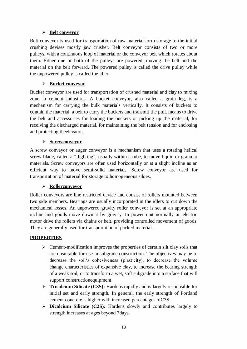
Belt conveyor
Belt conveyor is used for transportation of raw material form storage to the initial
crushing devises mostly jaw crusher. Belt conveyor consists of two or more
pulleys, with a continuous loop of material or the conveyor belt which rotates about
them. Either one or both of the pulleys are powered, moving the belt and the
material on the belt forward. The powered pulley is called the drive pulley while
the unpowered pulley is called the idler.
Bucket conveyor
Bucket conveyor are used for transportation of crushed material and clay to mixing
zone in cement industries. A bucket conveyor, also called a grain leg, is a
mechanism for carrying the bulk materials vertically. It consists of buckets to
contain the material, a belt to carry the buckets and transmit the pull, means to drive
the belt and accessories for loading the buckets or picking up the material, for
receiving the discharged material, for maintaining the belt tension and for enclosing
and protecting theelevator.
Screwconveyor
A screw conveyor or auger conveyor is a mechanism that uses a rotating helical
screw blade, called a "flighting", usually within a tube, to move liquid or granular
materials. Screw conveyors are often used horizontally or at a slight incline as an
efficient way to move semi-solid materials. Screw conveyor are used for
transportation of material for storage to homogeneous siloes.
Rollerconveyor
Roller conveyors are line restricted device and consist of rollers mounted between
two side members. Bearings are usually incorporated in the idlers to cut down the
mechanical losses. An unpowered gravity roller conveyor is set at an appropriate
incline and goods move down it by gravity. In power unit normally an electric
motor drive the rollers via chains or belt, providing controlled movement of goods.
They are generally used for transportation of packed material.
PROPERTIES
Cement-modification improves the properties of certain silt clay soils that
are unsuitable for use in subgrade construction. The objectives may be to
decrease the soil‘s cohesiveness (plasticity), to decrease the volume
change characteristics of expansive clay, to increase the bearing strength
of a weak soil, or to transform a wet, soft subgrade into a surface that will
support constructionequipment.
Tricalcium Silicate (C3S): Hardens rapidly and is largely responsible for
initial set and early strength. In general, the early strength of Portland
cement concrete is higher with increased percentages ofC3S.
Dicalcium Silicate (C2S): Hardens slowly and contributes largely to
strength increases at ages beyond 7days.

14
Tricalcium Aluminate (C3A): Liberates a large amount of heat during
the first few days of hardening and together with C3S and C2S may
somewhat increase the early strength of the hardening cement. It affects
settingtime.
TetracalciumAluminoferrite (C4AF): Contributes very slightly to
strength gain. However, acts as a flux during manufacturing. Contributes
to the colour effects that makes cementgray.
CEMENT CLASSIFICATION
7. Puzzolanacement
Puzzolana is a volcanic powder. It is found in Italy near Vesuvius. It resembles surkhi
which is prepared by burning bricks made from ordinary soils. It can also be processed from
shales and certain types of clays. Puzzolana material should be used in between10 to30%.
Advantage
Evolves less heat duringsetting
Possesses higher tensilestrength
Imparts higher degree of watertightness
Attains comprehensive strength withage
Can resist action ofsulfates
Imparts plasticity and workability to mortar and concrete prepared fromit.
Offers great resistance toexpansion
It ischeap
Disadvantages
Compressive strength in early days isless
Possesses less resistance to erosion and weatheringaction
This cement is used to prepare mass concrete of lean mix and for marine structures. It is
also used in sewage works and for laying concrete under water.
8. Hydrophobiccement
It contains hydrophobic admixtures such as acidol, naphthelene soap, oxidized petroleum
etc., which decrease the wetting ability of cement grains and form a thin film around cement
grains. When water is added to hydrophobic cement, the absorption films are torn off the
surface and they do not in any way, prevent the normal hardening of cement. However, in
initial stage, the gain in strength is less as hydrophobic films on cement grains prevent the
interaction with water. However, its strength after 28 days is equal to that of ordinary
Portland cement.

15
When hydrophobic cement is used, the line fine pores in concrete are uniformly distributed
and thus the frost resistance and the water resistance of such concrete are considerably
increased.
9. Expandingcement
It is produced by adding an expanding medium like sulfoaluminate and establishing agent
to ordinary cement. Hence this cement expands whereas other cements shrink.
It is used for the construction of water retaining structures and for repairing the damaged
concrete surfaces.
10. Low heatcement
Considerable heat is produced during the setting action of cement. It contains lower
percentage of tricalcium aluminate (C3A) and higher percentage of dicalcium silicate (C2S)
which reduce the amount of heat produced.
This type of cement possesses less compressive strength. Initial setting time is about one
hour and usual setting time is about 10 hours. It is mainly used for mass concrete work.
11. Quick settingcement
It is produced by adding a small percentage of aluminium sulfates and by finely grinding the
cement. Percentage of gypsum or retarder for setting action is also greatly reduced. Addition
of aluminium sulfate and fineness of grinding accelerate the setting of cement. The setting
action of cement starts within five minutes addition of water and it becomes hard like stone
in less than 30 minutes. Mixing and placing of concrete should be completed within very
short period. This cement is used lay concrete under static water or running water.
12. Sulfate resistingcement
In this cement percentage of tricalcium aluminate is kept below 5 to 6% which increase in
resisting power againstsulphates.
CEMENT
CHEMICAL COMPOSITION
According to IS: 269-1975, composition of ordinary Portland cement should satisfy the
following conditions
Ratio of percentage of lime to that of silica, alumina and iron oxide shall be in
between 0.66 - 1.02 which is calculated by the formula asfollow
Ratio of percentage of alumina to that of iron oxide shall not be less than0.66
Weight of insoluble residue shall not exceed2%
Weight of magnesia shall be less than6%

16
Total sulfur content shall not be more than2.75%
Total loss on ignition shall not exceed4%.
PHYSICAL REQUIREMENT
Setting time
Initial : Not less than 30 minutes Final
: Not more than 600minutes
Compressive strength
Compressive strength of 1:3 cement mortar cube of cement and sand.
3 days : Not less than1.6 kg/mm2 7 days : Not less an .2 kg/mm2
Soundness
It expresses the expansivity of the cement set in 24 hours between 250C and 1000C.
Un-aeratedcement : Maximum
10mm Aeratedcement : Maximum5mm
Fineness
It should not less than 215m2/kg
SETTING AND HARDENING OF CEMENT
The setting and hardening of cement is due to hydration and hydrolysis of its constituents.
The hydration products of cement are cementious but not cement. The heats of hydration of
cement constituents decides the formulation of cement for different applications as well as
useful in preventing the water in cement paste from freezing in winter and in accelerating
the setting and hardening processes. If heat liberated is not dissipated rapidly particularly in
large constructions like dam serious stress cracking may occur. Further, the knowledge of
reaction speed is important, because it determines the time of setting and hardening.
On hydration, the cement constituents generally give rise to hydrated calcium silicate (CSH)
obtained as poorly crystallized gels (3CaO.3SiO23H2O) commonly known as tobermorite
gels having structural resemblance to the mineral tobermorite found in Tobermory,
Scotland.
When cement is gauged with water, the C3A, C3S and C3SF phases reacts very rapidly and
gauging water becomes saturated with Ca(OH)2 formed in hydration reactions. The C2S
phase hydrated rather slowly. The initial settling is attributed to the reaction of C3A, C3S
andC3AF.

17
When the cement powder comes into contact with the water in the paste, two phenomena
takes place
Setting: After 25hours
Hardening: After one year, but proceeds to completion only afterdecades
The reactions take place when cement first comes into contact with water, are as follows
C3A+6H2O C3A.6H2O ------------------------- (1)
C3AF+nH2O CF.(n-6)H2O+C3A.6H2O ------ (2)
C3S+H2O C2S+C.H2O ------------------------- (3)
The fluxes are therefore the first components to be hydrated, with evolution of large amount
of heat. The alite react after few hours of contact with water.
During the second stage setting process stops and the hardening process starts. Hardening
involves both the reaction in which tetracalcium aluminate hydrate.
is formed and the hydration of the original belite after dicalcium silicate formed in reaction
(3) has been hydrated
C3A.6H2O + C.H2O + 6H2O C4A.13H2O ---- (4)
C2S+nH2O C2S.nH2O ---- (5)
Reaction (5) takes place between setting and hardening, while the same reaction is much
slower in case of belite present in the clinker, and components manufactured from the
cement attain their definitive compactness and mechanical strength after one year.
Overall, the water in the cement paste, which initially served to soak it and to make it fluid,
is consumed by the cement at certain rate, depending on its structural characteristics, which
bring hydrolysis of cement constituents, act as water of crystallization via hydration reaction
and in promotion of colloidal phenomena
Reaction (4) tends to occur on its own at the expense of the free lime in the surroundings as
the lime which is formed in reaction (3) is insufficient, at least at the start, to furnish large
amounts of calcium hydroxide demanded by high rate of reaction (1) which leads to the
promoter (C3A.6H2O) of reaction (4) itself.
However, when there is shortage of free lime, decalcification of dicalcium silicate occurs
into compounds which are poorer in lime (C3S2 and CS type) which by hydration more
rapidly than C2S to form. To avoid these serious irregularities in the hardening and setting
of the cement, it is necessary to preclude the environment from becoming a large consumer
of C.H2O by improving it from the C3A.6H2O which is formed by reaction(1)

18
C3A.6H2O + 3CaSO4.2H2O +19H2OC3A.3CaSO4.31H2O ------------- (6)
Gypsum is capable of combining with tricalcium aluminate hydrate as in reaction (6). The
calcium sulfoaluminate which is formed concurrently with C4A.13H2O from reaction (4)
indirectly stabilize the C2A, and moreover can be leadvia reaction (5) to mass getting the
highest possible mechanical properties. For, these reasons, gypsum is considered as an
essential additive with the aim of regularizing the setting and hardening ofcement.
Further, the setting properties of cement depend on the proportions of alumina and ferric
oxide in it, greater proportion of these bringing about acceleration of setting process. The
setting time to the cement is controlled by grinding about 2-5% of gypsum with the cement
clinker. The setting time is not directly influence by gypsum; a small increase beyond limit,
it may produces large increase in setting time, also large amount of it leads to cracking of set
cement due
to expansion. Plaster of Paris and anhydrite also retard the setting of cement but they are
more vigorous in theiraction.
Among the substances that affect the setting time of Portland cement containing gypsum as
retarder, some retard the process (sugar) and some accelerate the process (CO2, Alkali
carbonates &chlorides and alkaline-earth metals except Ca, NaOH, KOH etc.), some retard
the set at low concentrations and accelerate the process at high concentrations (CaCl2,
NH4Cl, FeCl3 etc.)
USES
In the production of concrete, it plays a crucial role in setting and hardening
theconcrete.
On being mixed with other aggregates, Portland cement begins to serve a dual
purpose. First, it provides for the concrete products to be workable when wet and
second, it provides them to be durable whendry.
It is also brought into usage in mortars, plasters, screeds and grouts as a material
which can be squeezed into gaps to consolidate thestructures.
Civil (piers, docks, retaining walls, silos, warehousing, poles, pylons,fencing)
Building (floors, beams, columns, roofing, piles, bricks, mortar, panels,plaster)
Transport (roads, pathways, crossings, bridges, sleepers, viaducts, tunnels,
stabilization, runways,parking)
Agriculture (buildings, processing, housing, feedlots,irrigation)
Water (pipes, culverts, kerbing, drains, canals, weirs, dams, tanks,pools)
Used by the retaining walls and the precast concrete block walls as a major
component to build a strong foundation ofconcrete.
By mixing it with water, Portland cement literally turns into a plastic stone and
thereby it can be used for purposes and in places where stone was to be used and
that too by keeping within the financiallimits.
Concrete casing, made by utilizing Portland cement, they can be effectively protect
the surface from air, water orcorrosion.

19
Due to its ability to prevent corrosion, it is also put to use in ships, tanks and
bunkers.
It may be moulded to obtain a hard and fire-proof material which may be employed
in designing buildings, shop floors, reservoirs and otherfoundations.
Any structure that is meant to support huge amounts of weight will bring Portland
cement into use. These structures range from ground floors of multi- storey
buildings to bridge floors and from bridge spans todams.
A blaze or an overwhelming fire may leave a structure completely burnt but with
the use of Portland cement, this can beprevented.
GLASS INDUSTRIES
INTRODUCTION
When silica or quartz is heated up to 16500C it melts to a colourless liquid which on cooling
gives glass. This fused mass is highly sensitive to temperature change therefore it requires
special heat treatment so that ordinary glass can be manufacture which is much stable to
temperature change. The glass of various commercial qualities is prepared by heating sand
or quartz along with metal oxide orcarbonates.
TYPES OF GLASSES
1. Soda-lime or softglasses
The raw materials are silica (sand), calcium carbonate and soda ash. Their approximate
composition is Na2O.CaO.6SiO2. About 90% of all glasses produced belong to soda lime
glass. The low cost, low melting point soda-lime glass has resistant to de-vitrification and to
water. However, they have poor resistance to common reagents like acids.
Uses: They are used as window glass, electric bulbs, plate glass, bottles, jars, building
blocks and cheaper tablewares, where high temperature resistance and chemical stability are
required.
2. Potash-lime or hardglasses
Silica (sand), calcium carbonate and potassium carbonate are the basic raw material for
potash lime glass. Their approximate composition is K2O.CaO.6SiO2. They possess high
melting point, fuse with difficulty and have good resistance to acids, alkalis and other
solvents compare to ordinary glasses.
Uses: These glasses are costlier than soda-lime glasses and are used for chemical apparatus,
combustion tubes, etc., which are to be used for heating operations.
3. Lead glass or Flintglass
Instead of calcium oxide, lead oxide is fused with silica. As much as 80% of lead oxide is
incorporated for dense optical glasses. In addition, K2O is used instead of sodium oxide. So,
its approximate composition isK2O.PbO.6SiO2. Lead glass is

20
more expensive than ordinary lime-soda glass, but it is much easier to shape and to work
with. Lead glass has a lower softening temperature and higher refractive index than soda
glass. It has excellent electrical properties. It is bright, lustrous and possesses high specific
gravity (3 to 3.3).
Uses: Lead glasses are used for high quantity table wares, optical lenses, neon sign tubing,
cathode ray tubes, electrical insulators and in the art objects because of their high luster.
High lead content glasses are used for extra dense optical glasses, for windows and shields
to protect personnel from X-rays and gamma rays in medical and atomic energy
fieldsrespectively.
4. Borosilicate glass or Pyrex glass or Jenaglass
It is the most common of the hard glasses of commerce which contain virtually only silica
and borax with a small amount of alumina and still less alkaline oxides. Borosilicate glass
has the followingcomposition.
Component SiO2 B2O3 Al2O3 K2O Na2O
Percentage 80.5 13 3 3 0.5
Boron and aluminium oxides substitutes Na2O and CaO used the lime-soda glasses which
results in a glass of low thermal coefficient of expansion, and high chemical resistance.
Borosilicate glasses have a very much higher softening point and excellent resistivity to
shock.
Uses: They are used in pipelines for corrosive liquids, gauge glasses, superior laboratory
apparatus, kitchenwares, chemical plants, television tubes, electrical insulators etc.
5. 96% Silicaglass
It is produced and shaped as typical borosilicate glass, having dimensions bigger than
desired. The heat treatment to the article, separate the glass into two layers, one consisting
mainly of silica and the other of the alkali oxides and borates. Then article is dipped in hot
acid which dissolves away the alkali oxides and boron oxide layer, leaving behind a fine
porous structure consisting of about 96% silica, 3% B2O3 and traces of other materials. This
glass is then washed carefully and annealed to 12000C. The shrinkage of about 14% takes
place and hard firm shape is produced which is almost gaslight. The translucent 96% glass,
if it is so desired heated to a higher temperature and made almost transparent orclear.
It is expensive than other types of glasses. The expansion coefficient is very low which
accounts for its high resistance to thermal shot. The softening temperature is about 15000C.
They possess high chemical resistance to most corrosive agents. They are corroded by only
HF, hot H3PO4 and concentrated alkalinesolutions.
Uses: They are used where high temperature resistance is required and articles can be safely
used at temperature up to 8000C. They are used for the constructed chemical plants,
laboratory crucibles, induction furnace linings, electrical insulators.
21
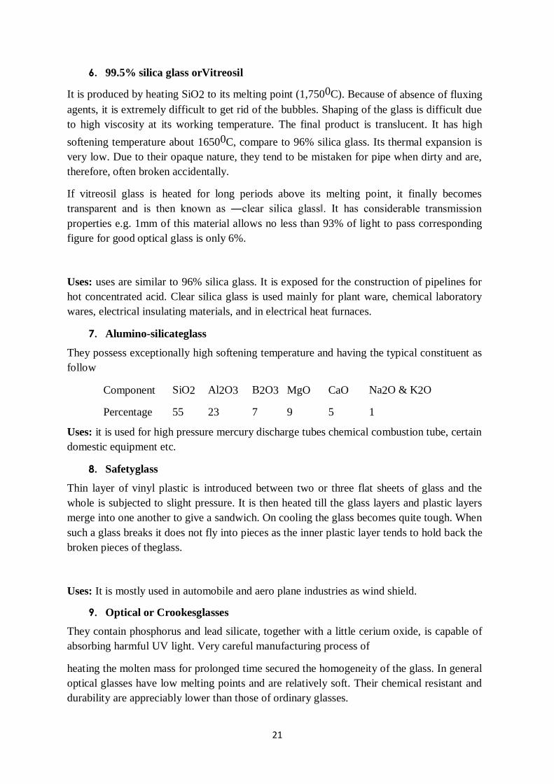
6. 99.5% silica glass orVitreosil
It is produced by heating SiO2 to its melting point (1,7500C). Because of absence of fluxing
agents, it is extremely difficult to get rid of the bubbles. Shaping of the glass is difficult due
to high viscosity at its working temperature. The final product is translucent. It has high
softening temperature about 16500C, compare to 96% silica glass. Its thermal expansion is
very low. Due to their opaque nature, they tend to be mistaken for pipe when dirty and are,
therefore, often broken accidentally.
If vitreosil glass is heated for long periods above its melting point, it finally becomes
transparent and is then known as ―clear silica glass‖. It has considerable transmission
properties e.g. 1mm of this material allows no less than 93% of light to pass corresponding
figure for good optical glass is only 6%.
Uses: uses are similar to 96% silica glass. It is exposed for the construction of pipelines for
hot concentrated acid. Clear silica glass is used mainly for plant ware, chemical laboratory
wares, electrical insulating materials, and in electrical heat furnaces.
7. Alumino-silicateglass
They possess exceptionally high softening temperature and having the typical constituent as
follow
Component SiO2 Al2O3 B2O3 MgO CaO Na2O & K2O
Percentage 55 23 7 9 5 1
Uses: it is used for high pressure mercury discharge tubes chemical combustion tube, certain
domestic equipment etc.
8. Safetyglass
Thin layer of vinyl plastic is introduced between two or three flat sheets of glass and the
whole is subjected to slight pressure. It is then heated till the glass layers and plastic layers
merge into one another to give a sandwich. On cooling the glass becomes quite tough. When
such a glass breaks it does not fly into pieces as the inner plastic layer tends to hold back the
broken pieces of theglass.
Uses: It is mostly used in automobile and aero plane industries as wind shield.
9. Optical or Crookesglasses
They contain phosphorus and lead silicate, together with a little cerium oxide, is capable of
absorbing harmful UV light. Very careful manufacturing process of
heating the molten mass for prolonged time secured the homogeneity of the glass. In general
optical glasses have low melting points and are relatively soft. Their chemical resistant and
durability are appreciably lower than those of ordinary glasses.

22
Uses: Used for manufacture of lenses.
10. Polycrystalline glass orPyroceram
It is the most recent development of producing glass by adding one or more nucleating
agents to a special or convectional glass batch. Then it is shaped into desired form and
subjected to controlled heat treatment.
The nucleating agents induced the formation of a large number of sub- microscopic
crystalline which act as centers for further crystal growth. Crystalline glass is not ductile,
but it has much greater impact strength than ordinary glass. It exhibits high strength and
considerable hardness and can be formed and shaped into articles by any methods of
manufacturing.
11. Toughenedglass
It is made by dipping articles still hot in an oil bath, so that certain chilling takes place.
There so, outer layers of the articles shrink and acquire a state of compression; while the
inner layers are in a state of tension. Such a glass is more elastic and capable of
withstanding mechanical and thermal shocks. When such a glass breaks, it does not fly but
is reduced to fine powder.
Uses: It is used for window shields of fast moving vehicles like cars, trucks, aeroplane;
window shields of furnaces, automatic opening doors and large show cases.
12. Insulatingglass
It is a transparent unit prepared by using two or more plates of glass separated by 6-13 mm
thick gap, field up with dehydrated air and then thematically sealing around the edges. This
provides a high insulation against heat. Thus, if such a glass is used for separating
apartments, it does not transmit heat and consequently the apartments will remain cool
during summer and warm during winter.
Uses: It is used as thermal insulating materials
13. Wiredglass
It is formed by embedding a wire mesh at the center of the glass sheet during casting due to
this when glass breaks it do not fall into splinters. Additionally, it is more fire resistant than
ordinaryglass.
Uses: It is used mainly for making fire-resisting doors, windows, skylights, roofs
14. Laminatedglass
It is made by pressing or bonding together two or more sheets /plates of glass with one or
more alternating layer of bonding material like plastic resin, asphalt or synthetic rubber.
The essential qualities of the laminated glass are
It is shatter-proof, i.e. its pieces do not fly off when suddenlybroken.
It is shock-proof, i.e. it can with stand sudden changes of temperature and pressure
withoutbreaking.

23
A bullet-resistant laminated glass is manufactured by pressing together several layers of
glass with vinyl resins in alternate layers. Ordinary, thickness of such glass varies from 12.7
mm - 76.5 mm. Even thicker types are made for specificuses.
Uses: As safety glass in aircrafts, automobiles, helicopters, submarines. Bullet resistant
lamination glass finds application in making automobile wind screens, looking windows etc.
15. Glasswool
It is a fibrous wool-like material composed of intermingled fine threads or filaments of glass
which is completely free from alkali. Glass filaments are obtained by forcing molten mass of
glass through small orifice of average diameter of 0.005 - 0.007mm continuously which is
sent to rapidly revolving drum resulting in wool like form. It has low electrical conductivity
and eight times higher tensile strength than steel. It does not absorb moisture and it is
completely heatproof.
Uses: It is employed for heat insulation purpose, e.g., insulation of metal pipe lines, motors,
vacuum cleaners, walls and roofs of houses. Being resistant to chemicals, glass wool is used
for filtration of corrosive liquids like acids and acidic solution. It is used for electrical and
sound insulation. It is also employed in air filter as dust filtering material. It is also used for
manufacturing fiber-glass, by blending with plastic resins.
16. PhotosensitiveGlass
It is UV sensitive high alumina soda lime glass. The positive in UV region on glass is
developed by thermal treatment only at 540-550°C. The desired photo activity in UV region
can be obtained by admixture of high alumina soda lime glass with small amounts of Cu2O
NaCN.SnO2 and abeitic acid in appropriate amounts. A blue colour is promoted by NaCN
absence of tin oxide. In presence of tin oxide an impression in red is observed. By
manipulation the ingredients in glass, brown and yellow images can also be possible. A
potash alumina glass mixed with LiSiO3, cerium
andsilver,saltsinappropriateproportionshavealsobeenusedasphotosensitive glass.
17. Photochromicglass
Large number of microscopic particles of silver halides trapped in the three dimensional
silicate networks in fixed concentration. On exposure light, temporary colour centers
consisting of silver particles only are produced and these add quickly producing total
darkness. The intensity of darkness depends upon the concentration of silver. Because
reversible darkening is controlled by the radiations in the UV region quite abundant in day
light, the photo blackening does not occurs markedly in the lamp light night.
18. Fiber glass
Fiber glass is nothing but molten glass process mechanically to a flexible thread of filament.
A hot platinum nozzle filled with molten glass forces out the fluid in the form of a thin
continuous thread which when caught by a rapidly moving disc gets converted into fiber
through elongation and twist given by the disc fabrics made of glass are bad conductors of

24
heat and electricity and are noninflammable. Hence articles made of fiber glass are
fireproof.
Uses: Such type of glass is used in textiles and reinforcing and can be spun into yarn,
gathered into a mat, and made into insulation and a great variety of other products may be
with it.
MANUFACTURE OF GLASS
RAW MATERIAL
The raw material in manufacture of glass may be selected from the following.
Sand, soda ash, calcium oxide, fled spar, borax, magnesia, zinc, alumina, lead oxide,
manganese oxide, selenium metal, broken glass, fluxes, colouring agent, reducing agent,
oxidizing agentetc.
Oxide should satisfy following conditions
Every oxygen atom must be attached with 2-4 cations e.g. SiO2, B2O3, GeO2,
P2O5 andAs2O5
The oxygen polyhedral must share the corner position and not theedge.
At least three corners of each tetrahedron must beshare.
The oxides used for glass manufacture are classified into following groups
a) Networkformer
b) Networkmodifier
c) Intermediate glassformers
d) Oxidizingagent
e) Refiningagent
f) Cullet
g) Colouringagent
a) Network former
These are oxides of elements which are surrounded by four oxygen atoms in the tetrahedral
chain forming glass.
b) Networkmodifier
These are large diameter elements having higher co-ordination number. On simple melting
they do not give glass but in presence of other network forming oxides they can give glassy
products easily. The important network modifiers are oxides of alkali metal, alkaline earth
metals, lead, zincetc.
Intermediate glass formers
They do not give glass on melting but in presence of some network formers using their co-
ordination number they start giving glass. E.g., Oxides of aluminum, silica

25
c) Oxidizingagent
Material like sodium nitrate or certain peroxides are used to reduce the colour of impurities
like iron oxides and manganese oxide
d) Refiningagent
To reduce or to eliminate quantity of air bubbles from molten glass refining agents like
arsenic oxide or small amount of feldspar is added to glass.
e) Cullet
Waste or broken glass species are called cullet. In normal glass production 33% of charge is
broken glasses. Recycling of cullet increases the rate of production.
f) Colouringagent
Metal oxide is added as colourant during manufacture of colour glasses e. g. oxides of
chromium and iron give green glass while copper and cobalt give blue glass.
Lime stone +Cullets
Soda ash
+
Sand
Proportioning
Tank
Hot flame at 18000C
Hot end
Cool end
Gas Air Hot Hotgases gases
Forming & Shaping
Tank Furnace Cooler
Anealing
Glass
Finishing
Figure :Manufacture of Glass

26
REFERENCES
1. Gopala Rao M. and Marshall Sittig, “Dryden's Outlines of Chemical Technology”, 3rd
Edition, East West Press, New Delhi, 2008.
2. George T. Austin, “Shreve's Chemical Process Industries”, 8th Edition, McGraw Hill
International Editions, Singapore, 2002
3. https://nptel.ac.in/courses/103/107/103107082/
4. https://nptel.ac.in/courses/103/106/103106108/

1
SCHOOL OF BIO AND CHEMICAL ENGINEERING
DEPARTMENT OF CHEMICAL ENGINEERING
UNIT – 3 INDUSTRIAL GASES AND PAINTS- SCHA1305

2
CARBON DIOXIDE
INTRODUCTION
Carbon dioxide (CO2) is composed of two oxygen atoms covalently bonded to
a single carbon atom. It is a trace gas with a concentration of 0.039% by
volume in atmosphericair.
In the seventeenth century, Jan Baptist Van Helmont observed that during
burning of charcoal in the closed vessel, the mass of the resulting ash was
much less than that of the original charcoal. His explanation was that the rest
of the charcoal had been transmuted into an invisible substance termed as
"gas" or "wild spirit"
Carbon dioxide‘s properties were studied by Joseph Black in 1750. He found
that limestone could be heated or treated with acids to yield a gas (fixed air).
He observed that gas was denser than air and supported neither flame nor
animal life. Black also found that when bubbled through an aqueous solution
of lime, it would precipitate calcium carbonate. Based on this phenomena he
illustrate that CO2 is produced by animal respiration and microbial
fermentation. Joseph Priestley, in 1772 invented the soda water preparation by
dripping sulfuric acid on chalk in order to produce carbon dioxide, and forcing
the gas to dissolve by agitating a bowl of water in contact with the gas.
Humphry Davy and Michael Faraday first liquefied CO2 at elevated pressure
in 1823. While in 1834 Charles Thilorier solidifies CO2, in pressurized
container of liquid carbondioxide.
In higher animals, the carbon dioxide travels in the blood from the body's
tissues to the lungs where it is breathed out. CO2 is an end product in
organisms that obtain energy from breaking down sugars, fats and amino acids
with oxygen as part of their metabolism, in a process known as cellular
respiration. This includes all plants, animals, many fungi and some bacteria.
During photosynthesis, plants, algae, and Cyanobacteria absorb carbon
dioxide, light, and water to produce carbohydrate energy for themselves and
oxygen as a waste product. However, in darkness, photosynthesis cannot
occur, and during the resultant respiration small amounts of carbon dioxide are
produced.
Carbon dioxide is also produced by combustion of coal or hydrocarbons, the
fermentation of liquids and the breathing of humans and animals. In addition,
it is emitted from volcanoes, hot springs, geysers and other places where the
earth‘scrust is thin; and is freed from carbonate rocks by dissolution. CO2 is
also found in lakes at depth under the sea, and commingled with oil and gas
deposits.

3
SOURCES OF CO2
By burning of carbonaceousmaterials
C+O2 CO2 (10 to18% Pure) ΔH = -23.16kcals
In the production of H2 by steam water gas 16% pure CO2 isobtained.
In manufacture of alcohol (ethanol) by the fermentation process. 99.9
% pure CO2 isobtained.
In calcinations of CaCO3 40% CO2 isobtained
1000°C
CaCO3 CaO + CO2(40%)
MANUFACTURE
Raw materials
Coke
or coal
Air
Reaction
C+O2 CO2 (10 to18% Pure) ΔH = - 23.16kcals
Manufacture
Coke, coal, fuel or gas is burned under a standard water-tube boiler for the production of 200-
250psig steam. The flue gases containing 10-18% CO2 are taken from the boiler at 3450C
and passed through two packed towers where they are cooled and cleaned by water. After
passing through the scrubbing towers, the cooled flue gases pass through a booster blower
and into the base of the absorption tower in which CO2 is absorbed selectively by a solution
Water From Coolers
CO2 free flue gas
CO2 to
Purification
Cooler
250 psig
Steam to
turbine driver
Ethanolamine
Solution
Cooler Flue
Gase
Coke 12-18% CO2
Water Boiler
Exhaust steam
from turbine
Reboiler Flue gas
Scrubbers
Blower Pumps
Heat Exchange
Reactivator
Absorber
Girbotolrecovery unit
Figure: Manufacture of Carbon dioxide from Coke
4
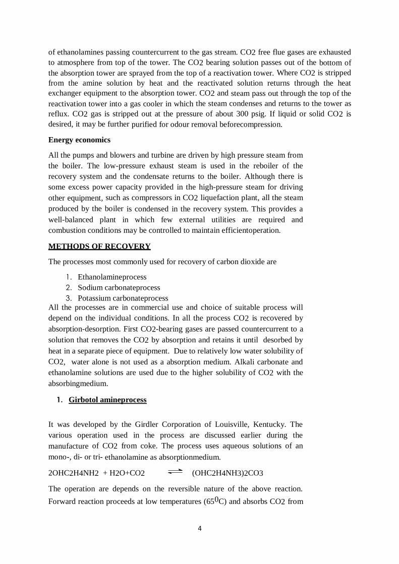
of ethanolamines passing countercurrent to the gas stream. CO2 free flue gases are exhausted
to atmosphere from top of the tower. The CO2 bearing solution passes out of the bottom of
the absorption tower are sprayed from the top of a reactivation tower. Where CO2 is stripped
from the amine solution by heat and the reactivated solution returns through the heat
exchanger equipment to the absorption tower. CO2 and steam pass out through the top of the
reactivation tower into a gas cooler in which the steam condenses and returns to the tower as
reflux. CO2 gas is stripped out at the pressure of about 300 psig. If liquid or solid CO2 is
desired, it may be further purified for odour removal beforecompression.
Energy economics
All the pumps and blowers and turbine are driven by high pressure steam from
the boiler. The low-pressure exhaust steam is used in the reboiler of the
recovery system and the condensate returns to the boiler. Although there is
some excess power capacity provided in the high-pressure steam for driving
other equipment, such as compressors in CO2 liquefaction plant, all the steam
produced by the boiler is condensed in the recovery system. This provides a
well-balanced plant in which few external utilities are required and
combustion conditions may be controlled to maintain efficientoperation.
METHODS OF RECOVERY
The processes most commonly used for recovery of carbon dioxide are
1. Ethanolamineprocess
2. Sodium carbonateprocess
3. Potassium carbonateprocess
All the processes are in commercial use and choice of suitable process will
depend on the individual conditions. In all the process CO2 is recovered by
absorption-desorption. First CO2-bearing gases are passed countercurrent to a
solution that removes the CO2 by absorption and retains it until desorbed by
heat in a separate piece of equipment. Due to relatively low water solubility of
CO2, water alone is not used as a absorption medium. Alkali carbonate and
ethanolamine solutions are used due to the higher solubility of CO2 with the
absorbingmedium.
1. Girbotol amineprocess
It was developed by the Girdler Corporation of Louisville, Kentucky. The
various operation used in the process are discussed earlier during the
manufacture of CO2 from coke. The process uses aqueous solutions of an
mono-, di- or tri- ethanolamine as absorptionmedium.
2OHC2H4NH2 + H2O+CO2 (OHC2H4NH3)2CO3
The operation are depends on the reversible nature of the above reaction.
Forward reaction proceeds at low temperatures (650C) and absorbs CO2 from

5
the gas in the absorber. The amine solution, rich in CO2, passes out of the
bottom of the tower and through heat exchanger, where it is preheated by hot,
lean solution returning from the re-activator. Then solution passes
countercurrent to a stream of CO2 and steam, which strips CO2 out of the
solution. As the solution reaches to bottom of the tower, where heat is supplied
by a steam heated or direct fired re-boiler, it has been reactivated. This hot
solution (1400C) passes out of the tower, through the heat exchanger and
cooler, and returns to the absorber tower. In the case of flue gases containing
oxygen, small side stream of solution is passed through re-distillation unit,
where the oxidation products are removed and the distilled amine is returned
to the process.
Advantages
Complete removal of carbondioxide
Regeneration up to 100% with moderate steam consumption ispossible
Higher absorption of CO2 in thesolution
Lower operatingcost
2. Sodium carbonateprocess
Na2CO3 + H2O+CO2 2NaHCO3
Recovery of pure carbon dioxide from gases containing other diluents, such as
nitrogen and carbon monoxide, is based on the reversibility of the above
reaction. This reaction proceeds to the right at low temperatures and takes
place in the absorber where the CO2 bearing gases are passed countercurrent
to sodium carbonate solution. CO2 absorption rate depends up on temperature,
pressure, partial pressure of CO2 in the gas, and solution strength. Reverse
reaction will proceed when heat is applied and is carried out in lye boiler. A
heat exchanger serves to preheat the strong lye as it approaches the boiler and
cool the weak lye returning to the absorber. Additional weak lye cooling is
accomplished in lye cooler to permit the reaction to proceed further to the right
in the absorber. CO2 gas and water vapour released from the solution in the
boiler pass through steam condenser where the water condenses out and
returns to the system. The cool CO2 proceeds to the gas holder
andcompressors.
Engineering aspects
Absorber
Absorber is constructed by a carbon-steel filled with coke, raschig rings, or
steel turnings. The weak solution is spread from top of the bed and contacts
the gas intimately on the way down. In another variation tower filled with
sodium carbonate solution and allow the gas to bubble up through the liquid.

6
Later provides better gas and liquid contact but high power is required to force
the gas through the tower.
Lye boiler
The lye boiler may be a direct fired boiler or a steam heated boiler. The
separation efficiency may be increased by adding a tower section with bubble-
cap trays. For better efficiency and conversion, series of absorbers are used
and designed to re-circulate the lye over it and only 20-25% of solution
flowing over this tower passes through the lyeboiler.
3. Potassium carbonateprocess
As potassium bicarbonate has more solubility than its corresponding sodium
salt, it provides better absorption of CO2 than other process. Operation and
equipment layout of process are similar to sodium carbonate process.
Variations of the potassium carbonate process have come into commercial use
in recent years.
Hot potassium carbonate process
Absorbent solution flows directly from the lye boiler to the absorber without
cooling. This process used for removing CO2 from NH3 synthesis gas
mixtures, and from natural gas. These gas streams are treated at 250 psig, or
higher pressure which increases the partial pressure of CO2 so that the hot
K2CO3 solution (20-30%) will absorb substantial amount of CO2 at 1100C.
The solution sends to the CO2 stripping tower operating at or near
atmospheric pressure. Part of the absorbed CO2 flashes out of the solution as it
enters the stripping tower, and the balance is stripped from the solution by
steam. The overall energy requirements for CO2 recovery by the hot
carbonate process are lower than for other processes when the gases being
scrubbed have high carbon dioxide partialpressures.
Use of additives
This variation has been developed by Vetrocoke in Italy. Use of various
additives like amino acids, arsenic trioxide, and selenium and tellurium oxides
in hot potassium carbonate absorbent solution which increase CO2 absorption
rate, and decrease the steam required for stripping CO2 from the solution. The
Vetrocoke processes have also employed air stripping for removing CO2 from
additive
containing hot potassium carbonate solutions in cases in which CO2 is not
recovered as a pure gas.
PURIFICATION

7
H2O H2O Na2CO3
Impure
CO2
Hot 99%
CO2
HeatExchanger Packed Tower 1
SO2 & Dust
-Packed
Tower 2
2Heat
Exchanger
+Cool
er Elect
rode
sStea
m
Figure: Manufacturing of Hydrogen by
Electrolytic ProcessFigure: Purification of Low
% CO2 containing gases
99%
stored
CO2
Carbon dioxide obtained in the impure state can be purified by different ways.
There are two main categories for purification of carbon dioxide.
1. Purification of low % CO2 containinggas.
2. Purification of high % CO2 containinggas.
1. Purification of low % CO2 containinggas
18% hot CO2 gas passes through exchanger to lower the temperature. Then it is passes
through rubber in which the water is percolated from the top to remove SO2 and dust
particles. Then the gas passes through two packed towers where the gas is scrubbed with
Na2CO3 solution and absorbed in it to form NaHCO3 solution in second tower. Solution is
heated in heat exchanger to remove absorbed carbon dioxide. This carbon dioxide is then
cooled in cooler and stored.
2. Purification of high % CO2 containinggas
Gases are first compressed to 80psi pressure and passes through a scrubber to remove
organic matters with KMnO4. The gas is then dehydrated using silica gel or activated
alumina or conc. H2SO4 by passing through dehydration tower. Then the gas passes through
an oil scrubber to remove bad odour of gas. Now the gas is, compressed in two stages, 80 psi
to 300 psi and 300 psi to 900 psi for getting compressed gas or liquid respectively. For liquid
CO2 the temperature is brought down much below 31.1°C. After compression by cooling of
CO2, the liquid is stored at -10° C temperature. If the liquid CO2 is passes through an
expansion tank and pressure is released then the solid CO2 is formed at -40° Ctemperature.
Sc
rub
be
r
KMnO4 Conc. H2SO4
Impure
CO2
Compressor
Dehydration
tower
Organic matter
Compressors Solid CO2
Figure: Purification of high % CO2 containing gases
Sc
rub
be
r
Oil
Sc
rub
be
r
Co
ole
r
Ex
pa
ns
ion
tan
k

8
PROPERTIES
Molecular formula
Molecular weight
Appearance
Odour
: CO2
:44.01gm/mole
: Colourlessgas
: Odourlessgas
Boiling point : -570C
Melting point : -780C
Density : 1. 977kg/m3 @ 1atm and 00C
USES
Solubility : Soluble in water
As solid CO2 in refrigerationprocess
Liquid CO2 is needed incarbonated.
Used in creating inertatmosphere.
As fireextinguisher
Gaseous CO2 used as a neutralizingagent
Gaseous CO2 is the basic raw material for production of Na2CO3,NaHCO3
OXYGEN AND NITROGEN
INTRODUCTION
Oxygen
Oxygen (O2) composed of two atoms of the element at (O) bind to form dioxygen, a very
pale blue, odorless, tasteless diatomic gas. Diatomic oxygen gas constitutes 20.8% of the
volume of air. It is necessary to sustain global life.
Oxygen is the highly reactive nonmetallic element that readily forms compounds or oxides
with almost all other elements. Oxygen is a strong oxidizing agent and has the second-
highest electronegativity after fluorine than of all the elements. By mass, after hydrogen and
helium, oxygen is the third-most abundant element in the universe. Free oxygen is too
chemically reactive to appear on Earth without the photosynthetic action of living
organisms, which use the energy of sunlight to produce elemental oxygen from water.
Elemental O2 only began to accumulate in the atmosphere after the evolutionary appearance
of these organisms, roughly 2.5 billion years ago.
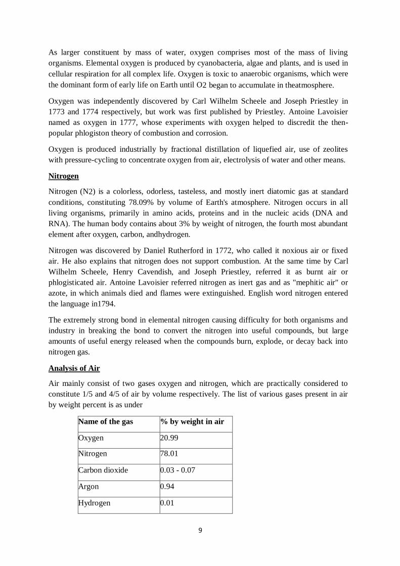
9
As larger constituent by mass of water, oxygen comprises most of the mass of living
organisms. Elemental oxygen is produced by cyanobacteria, algae and plants, and is used in
cellular respiration for all complex life. Oxygen is toxic to anaerobic organisms, which were
the dominant form of early life on Earth until O2 began to accumulate in theatmosphere.
Oxygen was independently discovered by Carl Wilhelm Scheele and Joseph Priestley in
1773 and 1774 respectively, but work was first published by Priestley. Antoine Lavoisier
named as oxygen in 1777, whose experiments with oxygen helped to discredit the then-
popular phlogiston theory of combustion and corrosion.
Oxygen is produced industrially by fractional distillation of liquefied air, use of zeolites
with pressure-cycling to concentrate oxygen from air, electrolysis of water and other means.
Nitrogen
Nitrogen (N2) is a colorless, odorless, tasteless, and mostly inert diatomic gas at standard
conditions, constituting 78.09% by volume of Earth's atmosphere. Nitrogen occurs in all
living organisms, primarily in amino acids, proteins and in the nucleic acids (DNA and
RNA). The human body contains about 3% by weight of nitrogen, the fourth most abundant
element after oxygen, carbon, andhydrogen.
Nitrogen was discovered by Daniel Rutherford in 1772, who called it noxious air or fixed
air. He also explains that nitrogen does not support combustion. At the same time by Carl
Wilhelm Scheele, Henry Cavendish, and Joseph Priestley, referred it as burnt air or
phlogisticated air. Antoine Lavoisier referred nitrogen as inert gas and as "mephitic air" or
azote, in which animals died and flames were extinguished. English word nitrogen entered
the language in1794.
The extremely strong bond in elemental nitrogen causing difficulty for both organisms and
industry in breaking the bond to convert the nitrogen into useful compounds, but large
amounts of useful energy released when the compounds burn, explode, or decay back into
nitrogen gas.
Analysis of Air
Air mainly consist of two gases oxygen and nitrogen, which are practically considered to
constitute 1/5 and 4/5 of air by volume respectively. The list of various gases present in air
by weight percent is as under
Name of the gas % by weight in air
Oxygen 20.99
Nitrogen 78.01
Carbon dioxide 0.03 - 0.07
Argon 0.94
Hydrogen 0.01

10
Neon 0.0015
Helium and Krypton 0.01 - 0.02
Except CO2 the concentration of all the gases listed above are present in air are constant.
However water vapoursand traces of ozone and iodine are present in air in variable amounts.
Also, composition of air also depends on altitude and distance to sea, in neighbourhood of
industry, built up urban areas, nearby volcanic phenomena. Other gases such as CO, H2S
and NO2 are also present in air.The critical temperature and critical pressure of some gases
are as follows.
Sr.
No.
Gases Critical temperature
(0C)
Critical pressure
(atm.)
1. Ethylene +9.5 50.65
2. Methane -82.85 45.6
3. Nitrogen -147.13 33.49
4. Hydrogen -239.9 12.8
5. Oxygen -118.75 49.7
6. Acetylene +35.5 61.55
7. Ammonia +132.5 112.3
8. Carbon monoxide -138.7 34.6
9. Carbon dioxide +31.3 72.9
Liquefaction of air by Joule - Thomson effect
Compressed
Air
Water
Water
Nozzl
e
Pisto
n
Liquid
Air
Figure: Liquefaction of Air by Joule Thomson effect

11
CO2 free air is compressed to 200atm and is cooled by water. The condensed water is
removed by passing through activated alumina. Then air is passed through inner coil of heat
exchangers. The valve with nozzle is provided at the end of the inner coil. Then gas is
allowed to suddenly expand by opening the valve, which result in decrease of temperature
of air. After expanding the cold air goes out through the outer coil, is then recompressed to
200atm pressure, cooled by water
andthenagainallowedtotransversetheinnercoil.Thetemperatureofthe
incoming air further falls due to the presence of cold air in the outer coil. Now as the cooled
air suddenly expands through the nozzle, the air suffers cooling, the temperature becomes
lower than in the first operation. The colder air now passes through the outer coil producing
an atmosphere of lower temperature. Hence when the cooled compressed air passes
repeatedly through the inner coil and subsequently undergoes Joule-Thomson effect, the
temperature of the air further drops. In this way progressive cooling takes place until the
temperature of air falls below the critical temperature of oxygen and nitrogen. When this
happens air undergoes liquefaction in the inner coil, so on opening the valve liquid air falls
in the container. A part of liquid air evaporates, through the outer coil, maintaining the low
temperature below the critical temperature.
MANUFACTURE
Oxygen in pure condition is obtained as a byproduct in the manufacture of H2 by
electrolytic process is described in Module: 2, Lecture: 4. Oxygen and nitrogen are usually
separated by rectification of liquidair.
Linde's process (O2 and N2)
The first rectification of N2 and O2 using Joule Thomson effect was carried out by Linde in
1906. After six year Claude rectified them by combined effect of external work and internal
work in cooling the air to liquefaction point.
Raw materials
Basis: 1000kg Oxygen (95%)
Air =3600Nm3
Steam =1750kg
Coolingwater =5000kg
Electricity =450-480KWH
Manufacture

12
Cold Gaseous Nitrogen
Compressed Air
Water
Water
Nozzle Piston
Compressed Air
Liquid Air
Figure:Manufacturing of Nitrogen & Oxygen by Linde's
Process
The distillation tower is specially designed bubble cap tray double columns arranged one
above another. The two distillation columns are having intermediate distillation dome for
effective separation of liquid enriched with O2. The column feed is liquefied air at 200atm
pressure introduced at the bottom of the column. Since the boiling point of O2 (-183OC)
and N2 (-195OC) are very low, column does not require any external heating. Distillation
take place only due to release of vacuum. Thus a number of recycling from lower column to
upper column and lower column to dome is required. The construction of dome includes
number of internal pipes so that distillate of the lower column collides to the roof and is
returned back to the column as reflux. The compressed air which arrives from the first
section of the plant which acts as the heating fluid in the heater at the base of the
enrichment column. The same air, always contained within a tube, passes out from the Iower
column of the tower only to reenter it higher up after the pressure to which it is subjected is

13
reduced by means of a valve, resulting in the lowering of its temperature. Nitrogen with a
small oxygen impurity collects at the top of the enrichment column, and after expansion to
atmospheric pressure; this nitrogen is sent to back as the reflux in the rectification column
situated above. The liquid which collects in the heater at the base of the enrichment column
is fed, after expansion to atmospheric pressure onto a suitable plate of the
rectificationcolumn.
Only after number of recycling, liquid with 82% concentration of O2 is taken in outer part
of dome. This liquid goes to further rectification in upper column where it is refluxed with
N2 rich liquid coming from lower column. The final separation in the upper column takes
place which has less number of trays. Gaseous N2 is the top product of the column and the
bottom product is liquid O2.

14
Tn-1
Pn+1
liquid L2, temperature Tn-1,
vapour V2
Pn Tn liquidL,temperatureTn,vapourV
Tn+1
Pn-1
liquid L1, temperature Tn+1,
vapour V1
Figure: Section of a plate rectification column
Claude process
In Claude process, progressive cooling of compressed air is done by external work and Joule
- Thomson effect. 70% of air is cooled by external work and 30% by Joule - Thomson
effect.
Two variants of Claude process Molecular sieve variant
Cooling of air is brought about primarily by expansion with the performance of work.
Therefore, there is no need to equip the plant with cycles that use refrigerants or make use of
very high pressures which are employed when free expansion is used, in order to
producecooling.
Evaporation to diffusion
Cooling of the air can be adopted such as causing liquids which can evaporate to diffuse air.
It is then safe to reabsorb them when necessary.
Operation of a rectification column
V2
L2
V
L
V1
L1

15
Rectification is carried out in a 'plate column', which is tall cylindrical structure inside
which repeated condensations and evaporations take place on plates, which lead to a
continuous change in the composition of the binary system throughout the length of the
column. This is continued until one of its pure components exists at top of the column and
the other at the bottom of the column.
For better understanding of rectification of binary mixture a small section of column is
shown in figure which is formed by three plates: an intermediate plate Pn. and two collateral
plates Pn-1 and Pn+1 which are arranged below and above the plate Pn respectively.
V1, V,andV2 be the vapours which, as they pass toward the top of the column,
leave the plates Pn-1, Pn, and Pn+1respectively
L1, L, and L2 be the liquids which, as they pass down the column, descend from
the plates Pn-1, Pn, and Pn+1respectively
Tn+1, Tn and Tn-1 be the temperatures of the plates Pn-1, Pn, and Pn+1respectively
The rectification of liquid mixture is exclusively on the basis of heat exchange of the
different fraction present in liquid form as well as vapour form. As shown in the diagram
plate Pn is considered as the reference plate having temperature Tn and liquid composition
L, vapour composition V. As pressure is released the more volatile component i. e. N2 is
evaporated out partly and goes to the upper plate Pn+1. The composition of liquid L2 is
having less concentration of N2 at temperature Tn-1. Similarly liquid below the reference
plate is Pn-1 has higher concentration of O2 and vapour V1 having higher composition of
O2 at temperatureTn+1.
Thus the separation of more volatile component N2 in vapour form and low volatile
component O2 in the liquid form is achieved.
Finally:
The liquids which fall down from the plates toward the heater in the base of the
column (L2, L, L1) become progressively richer in the less volatile
component(oxygen)
The vapours which rise toward the top of the column (V1, V, V2) gradually
become enriched in the more volatile component(nitrogen)
Subsequently, in a column fitted with a suitable number of plates, O2 is obtained in pure
state at the base of the column and the N2 is obtained in a practically pure state at the top of
the column.
For, perfect operation of a rectification column always requires that:
The liquid should always be introduced onto a plate which supports a liquid of
the same composition as that of the feedstock liquid Part of the distillate from the
top of the column is recycled in the form of a 'reflux' with the aim of repeated
washing on all of the plates which refine the vapours moving towards the top of the
column

16
Condensation medium
The separation of liquid air into nitrogen and oxygen is not as simple as the fractionation of
any other binary mixture. Because the separation is carried out at very low temperature
around -2000C. It is difficult to find a suitable medium for the refluxing of a liquid air
distillate at this temperature. The only possible media for the condensation of the reflux
would be liquid helium or liquid hydrogen, the use of which is clearly unacceptable on both
economic and operational grounds.
Engineering aspects
Two-section fractionating tower
Designing a fractionating tower consisting of two columns which are arranged one above
the other is the economically acceptable solution. The upper column is about twice the
height of the lower column, and both of them are fitted with plates spaced at intervals. The
average numerical ratio of the repartitioning between the two columns is42-25.
The upper column has all the requisites of a rectification column, while the lower column
functions as a simple enrichment column. As a bottom reboiler, the lower column has a
boiler with a curved base. There is no condenser at the top of the rectification column, and it
is closed by means of a gently curved cover with an outlet aperture.
Fundamentally, one is concerned with two columns, one being situated above the other,
working at different pressures
Lower column operating at6atm
Upper column operates only slightly above atmosphericpressure
The heat exchanger provided between the two columns acts as a condenser with respect to
the lower column and a boiler with respect to the upper column precisely as a result of the
two different pressures which appertain in the two compartments.
More precisely: the upper column is supplied with a feedstock of a composition which is
proportionate with that of the liquid situated on the plate where the feedstock is let in, and
receives a suitable reflux at the top, while the lower column is fed almost normally but is
not refluxed, and , instead of leading to practically pure components, it produces a liquid
which is enriched in the oxygen at the bottom and in the nitrogen at the top of
thecolumn.The shape of the plates differs according to the type of plant in which they
operate.
Linde method
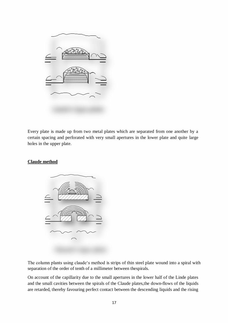
17
Every plate is made up from two metal plates which are separated from one another by a
certain spacing and perforated with very small apertures in the lower plate and quite large
holes in the upper plate.
Claude method
The column plants using claude‘s method is strips of thin steel plate wound into a spiral with
separation of the order of tenth of a millimeter between thespirals.
On account of the capillarity due to the small apertures in the lower half of the Linde plates
and the small cavities between the spirals of the Claude plates,the down-flows of the liquids
are retarded, thereby favouring perfect contact between the descending liquids and the rising
Linde's type plate
Claude's type plate

18
vapours. Material of constriction should be chosen in such a way that can resist very low
temperature.
PROPERTIES
Oxygen
Molecularformula :O2
Molecularweight :32gm/mole
Appearance : Colourlessgas
Odour :Odourless
Boilingpoint :-182.950C
Meltingpoint :-218.790C
Density : 1.429gm/L(00C,101.325kPa)
Solubility : Sparingly soluble inwater
Nitrogen
Molecularformula :N2
Molecularweight :28gm/mole
Appearance : Colourlessgas
Odour : Odourlessgas
Boilingpoint :-195.790C
Meltingpoint :-2100C
Density : 1.251gm/L(00C,101.325kPa)
Solubility : Slightly soluble inwater
USES
Oxygen
It is used to produce oxyacetylene flame to cutting and welding themetals
Used in L. D. process for steelproduction
Used for artificial respiration in case ofpatients
Used for mountain climbers and high attitude aero planesflights
Nitrogen
Used in manufacture of synthetic ammonia, nitricacid
Used in manufacture organic nitrates like propellants andexplosives,
Synthetically produced nitrates are key ingredients of industrialfertilizers
Used in producing nitrogenoxide.
Applied to create inertatmosphere.
HYDROGEN
INTRODUCTION
Hydrogen (H2) is colourless, odourless, tasteless, non-toxic, nonmetallic, highly
combustible diatomic gas. Atomic hydrogen is found rare on Earth because it readily forms

19
covalent compounds with most elements, water and organic compounds. Hydrogen plays an
important role in acid basechemistry.
The most common isotope of hydrogen is protium (1H) with a single proton and no
neutrons. As the only neutral atom with an analytic solution to the Schrödinger equation, the
study of the energetics and bonding of the hydrogen atom played a key role in the
development of quantummechanics.
Robert Boyle produced hydrogen by reaction between iron filings and dilute acid in 1671.
Henry Cavendish identified hydrogen gas as a discrete substance in 1766. He named the gas
from a metal-acid reaction as "flammable air". The name hydrogen was given by Antoine
Lavoisier in 1783, when he and Laplace reproduced Cavendish's finding that water is
produced when hydrogen is burned. Antoine- Laurent de Lavoisier produced hydrogen by
reacting flux of steam with metallic iron through an incandescent iron tube heated in a fire.
Anaerobic oxidation of iron by the protons of water at high temperature can be
schematically represented by the set of following reactions
Fe+H2O FeO +H2
2 Fe +3H2O Fe2O3 + 3H2
3 Fe +4H2O Fe3O4 + 4H2
Hydrogen was first liquefied by James Dewar in 1898 by using regenerative cooling in the
vacuum flask. He produced solid hydrogen the next year. Deuterium was discovered in
December 1931 by Harold Urey, and tritium was prepared in 1934 by Ernest Rutherford,
Mark Oliphant, and Paul Harteck. Heavy water, which consists of deuterium in the place of
regular hydrogen, was discovered by Urey's group in 1932. François Isaac de Rivaz built the
first internal combustion engine powered by a mixture of hydrogen and oxygen in 1806.
MANUFACTURE
The various method used for production of hydrogen gas are as follows.
1. Electrolyticprocess
2. Lane process or iron steamprocess
3. Steam hydrocarbonprocess
4. Liquefaction of coal gas and coke ovengas
5. Bosch process or water gas-steamprocess
1. ElectrolyticProcess
Pure hydrogen along with oxygen is manufactured by electrolytic process. It is also
obtained as a by-product in the production of caustic soda by electrolysis of aqueous
solution of sodium chloride as discussed in Module: 3, Lecture: 9. Heavy water may be
prepared on a large scale by burning deuterium separated from hydrogen obtained
byelectrolysis.

20
Reactions
In acidulated water
H2SO4 2H+ +SO4-2
At cathode
2H++2H2O 2[H3O]+
[H3O]++e- H+ +
H2O H++H+ H2
At anode
SO4-2 SO4 +2e-
SO4+H2O H2SO4 +O-2
O-2+O-2 O2
In KOH solution
KOH K+ +OH¯
At cathode
K++e- K
K+H2O KOH +
H+ H+H+ H2
At anode
2OH¯ H2O +
O-2 O-2+O-2 O2
In Ba(OH)2 solution
Ba(OH)2 Ba+2 +2OH¯
At cathode
Ba+2+2e- Ba
Ba+H2O Ba(OH)2 +H2
At anode
2OH¯ 2OH +2e-
2OH¯ O-2 +
H2O O-2+O-2 O2

21
Manufacture
Construction
Both unipolar and bipolar cells are used for electrolysis. In case of unipolar cells, iron
elsheets and nickel coated iron sheets are used as cathodes and anodes respectively. Both
anodes and cathodes are placed close to one another to prevent the loss of voltage. Asbestos
diaphragm is placed between anode and cathodecompartment.
In case of bipolar cells the same sheet act as both anode and cathode as the electrodes are
connected in series. The cell is partitioned by vertical iron sheet; the anode side of the sheet
is electroplated with nickel. Vertical asbestos sheet as diaphragm is placed between the
anode side and cathode side of former sheet. The same sheet acts as anode of one cell and
cathode of the cell behind it. The anode and cathode compartments are connected to two
separate horizontal pipes by means of standpipes, to lead away oxygen and hydrogen
respectively. 250 cells are connected in series, and current of 10000amp is passed to operate
the cells. The purity of H2 and O2 are 99.95% and 99.6%respectively.
Working
Pure hydrogen can be manufacture by electrolysis of brine or water. Since water is non-
conductor of electricity and can be made conductor by addition of small quantities of pure
H2SO4 or KOH or Ba(OH)2. 2:1 volume of H2(g) and O2(g) are simultaneously liberated at
cathode and anode respectively
Produced hydrogen contains small quantity of oxygen, which can be removed by passing the
gas over the catalyst gently heated palladium asbestos. The gas obtained by electrolysis is
very pure and used for hydrogenation ofoils.
H2O2
H2 O H2
Gas Collecting
Bells
Diaphrams
Isolation and Packing

22
Engineering aspect
The energy consumption is high due to resistance cause by the bubbling. This is somewhat
mitigated by conducting electrolysis under pressure. The decomposition voltage is 1.23
volts, so that the evolution of 2gms of hydrogen 53.6amp.hour is necessary. Hence to
generate 1000litre of H2 at 180C and 1atm pressure 2.8KWH are required because of
overvoltage of the electrode and ohmic resistance of the electrolyte and diaphragm
2. Lane process or steam hydrogen process
Rawmaterial
Iron Steam
Reaction
Fe3O4 + CO+H2 Fe +2FeO + CO2 +
H2O Fe + 2FeO+2H2O Fe3O4 +2H2

23
Manufacture
Iron oxide and water gases are charged to fire bricks lined generator which is heated
externally by burning of producer gas or other gaseous fuel. The first action is endothermic
and the second action is exothermic. The temperature is maintained in both actions at 6500C,
first by heating the iron oxide and second by passing superheated steam through the iron
forming iron oxide by the heat of the reaction and that of the steam. The reducing gas is
passed through the heated iron oxide from the bottom of the generator. The spent gas coming
out of the generator is burnt, and the hot products of combustion are sent through the super
heater which is a chamber filled with checker work. The time cycle is 20 minutes, then excess
of steam is passed through the super heater from the bottom and then passes through the mass
of iron from above, the hydrogen goes out through the pipe at the bottom of the generator.
The time cycle of passing steam is 10 minutes. The hot hydrogen from the generator is cooled
by passing through a cooler. The excess of steam condenses and dissolves the H2S, which is
practically completely removed. The gas is then scrubbed with weak NaOH solution to
remove CO2 and then mixed with steam is passed over heated iron oxide catalyst to convert
CO to CO2. The gas is then scrubbed with weak NaOH solution for the second time; pure
hydrogen gas is thus produced.
Kinetics
The production of hydrogen depends upon the exothermic reaction between red hot iron
and steam. The continuity of production with the help of same mass of iron is maintained by
reducing with water gas, the iron oxide produced by the iron-steam reaction, and repeating
the cycle of oxidation and reduction. In actual practice the iron oxide is not completely
reduced, and the water gas is not completelyoxidized.
Engineering aspects
The iron mass must have a large exposed surface, and should be resistant to disintegration.
Such mass of iron was produced by calcining FeCO3 (spathic iron ore) and then reducing
the iron oxide to spongy iron having a large surface.
Combustion
Air
Purge
Steam
Stack Valve
Charging
door Process Steam
Cleaning
door Reheating Air
Hydrogen
outlet
Super Heater
Figure: Manufacturing of Hydrogen by Lane Process
Heat
Exchanger
Contact
Material

24
ACETYLENE
INTRODUCTION
Acetylene (C2H2) is colorless gas used as a fuel and a chemical building block. As an
alkyne, acetylene is unsaturated because its two carbon atoms are bonded together in a triple
bond having CCH bond angles of 1800. It is unstable in pure form and thus is usually
handled as a solution. Pure acetylene is odorless, but commercial grades usually have a
marked odor due toimpurities.
In 1836 acetylene identified as a "new carburet of hydrogen" by Edmund Davy. The name
"acetylene" was given by Marcellin Berthelot in 1860. He prepared acetylene by passing
vapours of organic compounds (methanol, ethanol, etc.) through a red-hot tube and collecting
the effluent. He also found acetylene was formed by sparking electricity through mixed
cyanogen and hydrogen gases. Berthelot later obtained acetylene directly by passing
hydrogen between the poles of a carbonarc.
MANUFACTURE
Acetylene manufacture by following processes
1. From calciumcarbide
2. From paraffin hydrocarbons by pyrolysis (Wulffprocess)
3. From natural gas by partial oxidation (Sachasseprocess)
Nowadays acetylene is mainly manufactured by the partial oxidation of natural gas (methane)
or side product in ethylene stream from cracking of hydrocarbons. Acetylene, ethylene
mixture is explosive and poison Zigler Natta catalyst. There so acetylene is selectively
hydrogenated into ethylene, usually using Pd-Ag catalysts.
Acetylene was the main source of organic chemicals in the chemical industry until 1950. It
was first prepared by the hydrolysis of calcium carbide, a reaction discovered by Friedrich
Wöhler in 1862.
CaC2+2H2O Ca(OH)2 +C2H2
Calcium carbide production requires extremely high temperatures, ~20000C, necessitating
the use of an electric arc furnace.
Also hydrocarbon cracking is carried out in an electric arc furnace. In which electric arc
provides energy at very high flux density so that reaction time can be kept at a minimum.
There so the design of the electro-thermal furnace is one of the important factors.
In one design (Huels process) gaseous feedstock enters the furnace tangentially through a
turbulence chamber, then passes with a rotary motion through pipe in which the arc is passed
between a bell shaped cathode and anode pipe. The rotary motion of the gas causes the arc to

25
rotate and thus reducing fouling. The arc is operated at 8000kw D.C. at 7000volts and
1150amp cathodes are said to last 800hours while anodes only150hours.
In other design, fresh hydrocarbon and recycle gas are fed to the arc. The effluent reaction
gases are quenched and purified. 35%w purified acetylene along with 17%w ethylene and
10%w carbon black, H2 and other products in minor amount is obtained in one pass through
furnace.
The difference is that the arc is rotated by means of an external magnetic coil, and quenching
is carried by propane and water in 1stand 2ndstep respectively. Some propane cracking
improves the yield of acetylene. The propane quench cools the arc gases to 10950C in
0.0001 to 0.0004 sec while the water quench cools the mixture to 3000C in 0.001 to 0.003
sec. Power consumption is 12.36kwhr/kg of pure acetylene. 21-22%v acetylene is obtained
in the productgases.
1. From calcium carbide Raw materials
Basis: 1000 cu ft. acetylene
Calciumcarbide(85%) = 100kg Water =815kg
Sources of raw material
Calcium carbide is manufactured from lime and coke in 60:40 ratio in electric furnace at
2000-21000C temperature.
Reaction
CaC2+2H2O Ca(OH)2+C2H2 ΔH = -32.5kcals
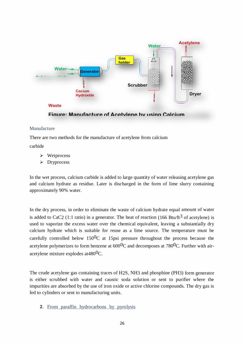
26
Manufacture
There are two methods for the manufacture of acetylene from calcium
carbide
Wetprocess
Dryprocess
In the wet process, calcium carbide is added to large quantity of water releasing acetylene gas
and calcium hydrate as residue. Later is discharged in the form of lime slurry containing
approximately 90% water.
In the dry process, in order to eliminate the waste of calcium hydrate equal amount of water
is added to CaC2 (1:1 ratio) in a generator. The heat of reaction (166 Btu/ft3 of acetylene) is
used to vaporize the excess water over the chemical equivalent, leaving a substantially dry
calcium hydrate which is suitable for reuse as a lime source. The temperature must be
carefully controlled below 1500C at 15psi pressure throughout the process because the
acetylene polymerizes to form benzene at 6000C and decomposes at 7800C. Further with air-
acetylene mixture explodes at4800C.
The crude acetylene gas containing traces of H2S, NH3 and phosphine (PH3) form generator
is either scrubbed with water and caustic soda solution or sent to purifier where the
impurities are absorbed by the use of iron oxide or active chlorine compounds. The dry gas is
fed to cylinders or sent to manufacturing units.
2. From paraffin hydrocarbons by pyrolysis
Water Acetylene
Gas holder
Water
Calciumcarbide
GeneratorArgillaceous
material
ScrubberJaw Crusher
Cacium Hydroxide Dryer
Bin
Waste
Figure: Manufacture of Acetylene by using Calcium
carbideBin

27
(Wulff process) Rawmaterials
Basis: 1000kg acetylene (100%)
Natural gas = 262000Sef
Steam (600psig) = 26308kg
Electricity =140kWH
Cooling water =25000gal
Process water =200gal
Solvent (make up) =2.95kg
Reaction
C4H10 C2H2 + C2H4 + CO +H2
C2H4 C2H2 +H2
2CH4 C2H2 + 3H2 ΔH = +96.7kcals
Manufacture
Dilute Steam
Off
GasRota
ry kiln Fuel Gas
Stack Gas
Cooling Excess FuelPackaging and
storage
DimethylformamideMixer
AcetylenePulverizer
AirHot
air
in
WaterClinker
for
grinding
GasFig
ure:
Man
ufa
ctur
ing
of
Ce
me
nt
by
Dry
Pro
ces
s
Hydrocarbon
feed
Furnace Tar trap
Electrostatic
Precipitator
TarCalc
areo
us
mate
rials
Solvent to purification andre-useConc. H2SO4
TarNitr
ated
Acid
Solvent
containing
diacetyleneChamber Acid
Figure: Manufacture of Acetylene by Wulff
ProcessWatrer Spray
Compressor
Chamber I
BoilerCha
mber II
Ab
so
rbe
r
Ab
so
rbe
r
Stab
ilize
r
Strp
pin
g
Co
lou
mn

28
In the Wulff process acetylene may be produced by thermal decomposition of
hydrocarbons such as methane, ethane, propane, butane, ethylene etc.
Pyrolysis is carried out in the Wulff regenerative furnace which is a rectangular steel box filled
with refractory bricks checker work. Before the hydrocarbon feed is sent to the chamber, it is
diluted with steam (up to 1:8 ratios). The feed is carried through the chamber at sub-atmospheric
pressure by virtue of a large vacuum pump. Which reduced the residence time as little as 0.03
sec; cracked gas leaves the chamber at about 370°C. The maximum temperature in the furnace
just after the heating cycle approaches 1315°C. The furnace is operated in four minutes cycle in
which the checker work is first heated for one minute and then feed gas pyrolyzed for one
minute. The same sequence of operation is then done in reverse direction through the furnace. To
facilitate reversal of the gas flow, fuel gas burners and hydrocarbon feed pipes are located on
each side of the combustion chamber. To allow continuous flow of cracked gases to the
purification train, two furnaces are usually operated on staggered cycles. Cooled cracked gases
from the chamber are then further quenched in a tar trap, where steam and various tars are
removed. The gas is compressed to atmospheric pressure, passed through a knock-out forum and
electrostatic precipitator, and sent to the recovery system.
Usually diacetylene and acetylene are separated by absorption in DMF (dimethyl formamide).
By proper adjustment of solvent ratio and temperature, diacetylene may be removed in the first
scrubbing column. In the acetylene absorber small quantities of ethylene, CO2 and higher
acetylenes are also absorbed. Most of the acetylene-free off-gases used for various heat
exchanging operation like used as fuel for the steam boilers, for combustion chamber heatingetc.
Acetylene rich solution is sent to stabilizer, where less soluble components are removed by
stripping. Acetylene is then removed from the solvent in a second stripping column. The solvent
is readied for reuse by stripping out high boilers by blowing with off gas from the acetylene
absorber-followed by rectification.
Usually, off-gas from the acetylene recovery system is used as fuel for heating the combustion
chamber. The volume of off-gas is much more than is required for fuel, so it may be either
recycled to the furnace or used as a raw material for some other operation.
Yield of acetylene (98.5 to 99.3 % purity) varies with the hydrocarbon feed stock used. Average
yields for the once-through process are 22.5 kg per 100kg
methane, 38.6 kg per 100kg ethane, and 35.5kg per 100kg propane. The off-gas is principally
ethylene, carbon monoxide, hydrogen and methane.
Kinetics and thermodynamics
The principal conditions which must be considered are as follows

29
Energy requirement to convert hydrocarbons to acetylene is very high and which can be supplied
by very high temperature. For paraffinic feedstock, the heat of formation for a gram atom carbon
in acetylene decreases with the increasing length of the chain and it increases in the case of
olefinic hydrocarbons. The heat of formation is of the order of magnitude required for the
dissociation ofsteam.
2CH4 +174,000Btu C2H2 +3H2
The formation of acetylene begins at a relatively high temperature; in the case of methane occurs
around 8150C. The temperature required decreases with the increase in the number of carbon
atoms of the hydrocarbonfeed.
The decomposition of hydrocarbons to carbon and hydrogen begins at relatively low
temperatures. E.g. decomposition of methane occurs at 4500C. Hence, the decomposition into
the elements proceeds in competition with the formation of acetylene. However, the rate of
acetylene formation is greater than that of the decomposition reaction. There so care should be
taken that the hydrocarbon feed must reach at relatively high temperatures (above 6750C) in the
shortest possible time and then the attained equilibrium must be immediately quenched to about
2850C in order to preserve the acetylene formed. The time interval for the reaction should be of
the order ofmilliseconds.
3. From natural gas by partial oxidation (Sachasse
process) Rawmaterials
Basis: 1000kg acetylene (99.5%) plus 340000 Cu ft. off gas (345 Btu/Cu ft.)
Natural gas
Oxygen (95%)
Solvent
= 190000 Sef
= 5400kg
= 2.3kg
Power = 15000kWH
Steam = 4535.9kg
Water (cooling) = 22710liter
Reaction
CH4+2O2 CO2 +2H2O
2CH4 C2H2+3H2 ΔH = + 79.8kcals
Manufacture
Re
ac
tor
Stri
pp
er
Rec
tify
ing
Co
lum
n

30
Acetylene may be produced from a variety of hydrocarbon feed stocks (natural gas, LPG,
naphtha, fuel oil, even crude oil) by high-temperature cracking. Heat for the cracking operation
is developed by partial oxidation of the feed stock with oxygen. The heat evolved cracks the
excess hydrocarbon to acetylene. After rapid quenching with water, the acetylene is separated
from the gas stream by absorption-desorption in a suitable solvent. The process is known as
Sachasse process using natural gas as rawmaterial.
Natural gas (1mole) and low purity oxygen (0.65moles 95%O2) are preheated
separately to 5100C and fed to a specially designed burner.
The converter is vertical cylindrical unit built in three sections
Mixingchamber
Flameroom
Quenchchamber
After rapid and through mixing of oxygen and methane in the mixing chamber, the gases are fed
to the flame room through the portal in a burner block designed to prevent back travel or blow-
off. The heat of combustion heats the gases to 15500C to allow cracking of the excess methane
to acetylene. The residence time is 0.001 to 0.01 seconds. The decomposition of acetylene is
prevented by rapid quenching of the resulting gases with water to 380C. Thecooledeffluent gases
on the dry basis contain 8% acetylene, 54% H2, 26% CO, 5% CH4, 4% CO2 and 3% N2 and
higher acetylenes. These gases are run to a filter where using carbon black, acetylene of 99.5%
or higher purity is produced (23.5kg/1000kg of acetylene is separated and purified in a manner as
described for the Wulff process).
PROPERTIES
Water Off
Gas Acetylene
Oxygen Preheate
r
Soot Filter
Natural
Gas Preheate
r
Water Cooler
Soot
Recycle Water Polymer Solvent
Filter
Figure:ManufacturingofAcetylenefromNaturalGas
31
Molecularformula :C2H2
Molecularweight :26.04gm/mole
Appearance : Colourlessgas
Odour : Odourlessgas
Boilingpoint : -840C (sublimationpoint)
Meltingpoint : [email protected]
Density :1.097kg/m3
Solubility : Soluble in acetone andDMF
It is transported under high pressure in acetone soaked on porous
material packed in steelcylinders
It is lighter thanair
It is somewhat poisonous innature
It burns with luminous flame and forms explosive mixture withair
USES
In the chemical manufacture of acrylonitrile, vinyl chloride, vinyl
acetate, acrylatesetc.
In manufacture of acetaldehyde, trichloroethylene, acetic acid, polyvinyl
alcohol, perchloroethyleneetc.
In manufacture of propagryl alcohol, butyrolactone, vinyl pyrrolidineetc.
In metallurgy industries for welding andcutting
REFERENCES:
1. Gopala Rao M. and Marshall Sittig, “Dryden's Outlines of Chemical Technology”, 3rd
Edition, East West Press, New Delhi, 2008.
2. George T. Austin, “Shreve's Chemical Process Industries”, 8th Edition, McGraw Hill
International Editions, Singapore, 2002
3. https://nptel.ac.in/courses/103/107/103107082/
4. https://nptel.ac.in/courses/103/106/103106108/

1
SCHOOL OF BIO AND CHEMICAL ENGINEERING
DEPARTMENT OF CHEMICAL ENGINEERING
UNIT – 4 NATURAL PRODUCTS- SCHA1305

2
4.1 EDIBLE AND ESSENTIALOILS
Oils are organic molecule of carbon, hydrogen, oxygen and sometimes nitrogen and sulfur.
It is composed of long chain fatty acids and esters (glyceride ester) as well as derivative
ofglycerine, long chain fatty alcohol, sulfate and sulfonates. Oils like caster oil, linseed oil
are non edible and oils like ground nut oil, coconut oil are edible . Oil is used in producing
vanaspati ghee, soaps and detergents, cosmetics, medicines, polymers, paints and varnishes
and in many other applications.
4.1.1 VEGETABLE OILEXTRACTION
Raw material: Seeds of oilseed plant
Figure 4.1 Flow sheet for vegetable oil extraction
3
Functional role of various processes
Cleaner and dehulling:
4.1.1.1 Mechanical cleaning is done to remove stones and other undesirablematerial.
4.1.1.2 Dehulling remove hulls, dry outer covering ofseed.
Cracking rolls:
4.1.1.3 Crushing rolls crush the oil seeds and gets flacked seeds.
Digester:
4.1.1.4 100 parts of flaked seeds are thoroughly mixed with 5-10 parts of water by rotating
blades.
4.1.1.5 Softening by means of heat and moisture is donehere.
4.1.1.6 Steam is added for heatingpurpose.
4.1.1.7 Acid is formed by hydrolysis ofester.
4.1.1.8 The seeds get swollenup.
Expeller:
4.1.1.9 The swollen seeds are crushed under greatpressure.
4.1.1.10 Cells of seeds get ruptured and oil isreleased.
4.1.1.11The tapering shape ensures more application of pressure on theseeds
4.1.1.12The oil depleted cake is either sent for solvent extraction or used as animalfeed.
4.1.1.13Oil is sent forpurification.
Mix tank:
4.1.1.14The extracted oil is treated with alkali like NaOH or Na2CO3 to remove fattyacids.
4.1.1.15 It also removes heavy metals, which can start oxidation ofoil.
Centrifuge:
4.1.1.16Acids are separated in centrifugeseparator.
4.1.1.17These separated acids are used as foots for soapmanufacturing.
Rotary filter:
4.1.1.18 The clear oil is treated with some bleaching agent like”Fullers Earth
4
Carbon” in filter aid before rotaryfilter.
4.1.1.19Rotary drum filter is used for removal of seed particles which may bepresent.
4.1.1.20This finished oil isproduced.
4.1.1.21From this process around 1-2% oil content remains in the meal.
Extractor:
4.1.1.22The flaked seeds or oil extracted seeds from crushing rolls are fed on a movingbed.
4.1.1.23 Oil depleted cake is also added in extractor.
4.1.1.24The solvent extracts oil from theseeds.
4.1.1.25 The wet meal (the left seed part) is collected in the middle and is sent for
solvent removal.
Solvent removal:
4.1.1.26Steam is used to extract solvent carried by the oilseeds.
4.1.1.27The rotating blades ensure better exposure tosteam.
4.1.1.28The solvent free meal is sent to dryer and then used as animalfeed.
4.1.1.29Solvent is collected from top and is recycled after cooling it in heatexchanger.
Flash film evaporator:
4.1.1.30The solvent is preheated bysteam.
4.1.1.31Oil is concentrated here by evaporating the more volatile component(hexane).
4.1.1.32The hexane is recycled back to extractor after heatrecovery.
4.1.1.33The use of flash evaporator reduces the cost of vacuum strippingcolumn.
Vacuum stripping column:
4.1.1.34The oil from flash evaporator is fedhere.
4.1.1.35The stripping is done by steam i.e. steam carries away thehexane.
4.1.1.36 And it is under vacuum for the reason that the boiling point of hexane and
oil are close to eachother.
4.1.1.37Jet ejector is used here to generatevacuum.
4.1.1.38The hexane is recycledagain.
4.1.1.39Oil produced here is either directly used or sent forpurification.

5
4.1.2 HYDROGENATION OFOIL
Hydrogenation process is used to remove double bonds and to make fats and oil saturated.
Hydrogenation also raises its melting point and improves its resistance to rancid oxidation.
The most common end product of hydrogenation is Vanaspati ghee. Other products
include vegetable ghee, hardened industrial oils and partially hydrogenated liquid oil.
Raw material: Oils which is to be saturated and pure hydrogen.

6
Figure 4.2 flow sheet for hydrogenation of oil
Functional role of main units
Hydrogenator:
4.1.2.1 Oil is fed to thehydrogenator.
4.1.2.2 Hydrogen, and steam is introduced init.
4.1.2.3 The catalyst oil slurry of concentration 5 to 15 kg per ton of oil is alsoput.
4.1.2.4 The reaction is slightly exothermic so steam is sometimes turnedoff.
Deodorizer:
4.1.2.5 The hydrogenated oil is now fed to vacuum steamdeodorizer.
4.1.2.6 It operates in continuousbasis.

7
Finishing
4.1.2.7 Oil colour is removed by treating with fuller’s earth orcarbon.
4.1.2.8 It is then filtered, mixed with somevitamins.
4.1.2.9 Now the finished oil is sent for packaging andstorage.
4.2 SOAPS AND DETERGENTS
4.2.1 Introduction
Soaps are sodium or potassium salts of fatty acid. Common fatty acids used are oleic acid,
stearic acid, palmitic acid, lauric acid and myristic acid . Soaps are used for human
comfort, cleanliness and for industrial use. Soap is a surface active agent or surfactant. The
soap molecules contain both hydrophilic part and hydrophobic part. The hydrophilic part
of soap is carboxylate head group and hydrophobic part is aliphatic chain. The dirt or
grease is cleaned by key mechanism. Most marketed bar soaps contains TiO2 as an
opacifier or as a whitener. A variety of dyes are also used to produce coloursoaps.

8
Figure 4.3 Flow sheet of manufacture of soaps, fatty acids and glycerin
Functional role of various processes
Hydrolyser
4.2.1.1 The fat and catalyst are mixed together and enter thehydrolyser.
4.2.1.2 Hot water is addedhere.
4.2.1.3 Intimate mixing is required for the water oil immisciblephase.
4.2.1.4 Water has 10 – 15% solubility in oil andfats.
4.2.1.5 Temperature is maintained at 230˚C - 250˚C and pressure at 40 – 45 atm for
reaction between water and organiccompound.
4.2.1.6 The fatty acids stream is produced as top product while glycerin stream is
produced as bottom product.

9
Fatty acid
stream block
Flash tank:
4.2.1.7 Fatty acids from the hydrolyser enters the steam flash tank to remove water &
concentrate the fattyacids.
Vacuum still:
4.2.1.8 The concentrated fatty acids enter a high vacuumstill.
4.2.1.9 Jet ejecter is used to generate vacuum in thestill.
4.2.1.10Wastes are separated from thebottom.
4.2.1.11 Fatty acid is also taken out as a marketableproduct.
Mixer:
4.2.1.12Fatty acid produced from vacuum still is now pumped tomixer.
4.2.1.13 Base such as NaOH or KOH is mixed in appropriate proportions and mixedthoroughly.
4.2.1.14After mixing a viscous mass isproduced.
Blender:
4.2.1.15 The viscous mass from the mixer is sent to theblender.
4.2.1.16 Ingredients like scents, anti fungal&anti bacterial chemicals etc. is mixed in
theblender.
4.2.1.17 The blender removes the solid mass which is then sentto:
4.2.1.18 Chipping rolls: to manufacture soapstrips.
4.2.1.19 Spray dryer: To get soap powder (used in manufacture of liquidsoaps).
4.2.1.20 Bar Press Stock: To press and cut the viscous mass into bars ofsoap.
Glycerin
stream block
Ion Exchange:
4.2.1.2115 – 20% glycerin along with impurities from the hydrolyser goes for ionexchange.
4.2.1.22Here salt and colour is removed fromglycerin.
Triple effect evaporator:

10
4.2.1.23The product stream from ion exchanger is sent to triple effectevaporator.

11
4.2.1.24The glycerin solution is concentrated inevaporator.
Vacuum still:
4.2.1.25 The glycerin obtained from vacuum still is called yellow glycerin. It is
used for industrial use.
4.2.1.26 The steam produced from evaporator is used in vacuum still to further
concentrate the glycerin.
Mixer:
4.2.1.27For removing color, yellow glycerin is treated with activated carbon inmixer.
Filter:
4.2.1.28Activated carbon is separated from thesolution.
4.2.1.2999% white glycerin is produced. The yield is 30 – 35kg per ton of soapproduced.
4.2.2 DETERGENTS
Detergents have better surface tension lowering action than soaps. Due to excessive
foaming, it is unable to reduce organic content of sewage effluent. Biodegradation of
detergent is an important environmental factor. Detergents react with hard water ions.
Detergents are of four types - anionic, cationic, non- ionic and amphoteric. Most common
type is anionic which is generally made up of sodium salts of an organic sulfate
orsulfonate.

12
4.3 PULP, PAPER AND SUGAR
4.3.1 INTRODUCTION
Chemical industry is one of the oldest industries and playing an important role in the
social, cultural and economic growth of a nation and in providing basic needs of
humankind - food, shelter and clothing have become an indispensable part of our life. The
chemical industry is a key contributor to the world economy and produces more than 8000
products, which is a vital part of agricultural and industrial development in India and has
key linkages with several other downstream industries such as automotive, consumer
durables, engineering and food processing. Organic chemicals are one of the important
sectors of the Indian chemical industry, which provide a vital development role by
providing petroleum products, chemical feedstock, basic chemicals, intermediates, and
important products like polymer, synthetic fibre, synthetic rubber, paints, varnish,
pesticides and explosives, dyes, specialty chemicals. Major feed stocks for chemical
industries are coal, petroleum, biomass, oils and fats, sulphur, salt, lime stone, rock
phosphateetc.
A process engineer at operation in chemical plant shall have a deeper understanding of the
technology on which the process plant is built to produce the profit making chemicals. A
chemical engineer with sound knowledge in process technology has the following distinct
advantages:
Ability to clearly distinguish the functional role and importance of various processes and
operations in the processplant
Technical knowledge with respect to the selection of important parameters such as
Temperature, Pressure and underlying physical principles of aprocess.
Ability to distinguish various process streams and their conditions of operation
(Temperature, pressure andphases)
Basic knowledge for process troubleshooting and necessary safety precautions associated
to aprocess/operation.
To master chemical process technology five crucial steps are involved namely:
a) Raw-Materials and reactions: A chosen process route to manufacture desired chemicals with

13
appropriate purities will eventually lead to preparing a list of raw-materials and utilities.
Thereby, prominent reactions can be also known.

14
b) Conceptual process flow-sheet: A conceptual process flow-sheet where a chemical engineer
has an abstract representation of the actual process flow-sheet will enable quicker learning. A
conceptual process flow-sheet typically constitute the followingattributes:
- Raw-material purification (Solid-fluid operations such as cyclone separators, bag filtersetc.)
- Raw-material processing (Heat exchange operations such as furnace heating, coolingetc.)
- Raw-material to product transformation (Reaction operations using CSTR, PFR, PBR and
Batch reactors)
- Product purification (In separation processes such as flash, distillation, absorption and
extraction)
- Product processing (heat exchangers, phase changeunits)
- Recycle of un-reacted raw-materials as recycle streams to the reactionoperations.
c) Process intensification in the form of heat-integration, stream utilization and waste reduction
and multiple recycle streams: These options are in fact optional and they enrich the energy
enhancement and waste reduction efficiency ofa
process plant. Originally, chemical plants developed without such process intensification
policies have been subjected to rigorous research and case study investigations to identify
opportunities for cost reduction and better energy/waste management.
d) Additional critical issues related to various unitoperations/processes
- Safety issues: What safety issues are most relevant and need frequentmonitoring
e) Alternate technologies: For a desired function of a process unit, can thereby alternate
technologies that could reduce the cost and even then provide the same functional role and
desired flow rates and compositions of the emanatingstreams.

15
Figure4.4 Structure of Organic ChemicalIndustry
4.2 Process Technology in the Manufacture of Pulp andPaper
Acquisition of Raw Material: Hard wood, soft wood, bagasse, wheat and Ricestraw,
sabai grassetc.
Raw Material Preparation :Debarking, Chipping, Cutting,Screening
16
Pulping
1. Chemical: Sulphate (Kraft), Soda Pulping, SulphatePulping
2. Semi Chemical:NSSC
3. Mechanical Pulping: Stone Ground Wood (SGW)
Thermo Mechanical Pulp(TMP)
Refiner Mechanical Pulp(RMP)
Cold Soda Refiner Mechanical Pulp
(CRMP) Sulfite: Acid Sulfite higher % of
free SO2 (Ca, Mg, Na, Ammoniabase)
Bisulfite: (little or no free
SO2 (Ca, Mg, Na,
Ammoniabase)
Washing and Screening: 3-4 stage washing, screening andcenricleaning
Bleaching: CEHH, CEH, CEHD for chemical pulp Hydrogen peroxide, Sodium
peroxide, Hydrosulfite for mechanical
Stock preparation: Beating and refining for imparting suitable properties by making
paper, addition of sizing chemicals, colour and additives
Paper Making: Conversion of pulp from stock preparation into a sheet of paper using
Fourdrinier Machine or Mould machine
Chemical Recovery: Concentration of spent liquor, burning, causticising and
classification ofliquors
Powergeneration
Waste paper processing: sorting, ,screening, hydro pulping, screening and
centricleaning
Chlorine generation and Bleach liquorPreparation
4.3 PREPARATION OF WOOD PULP BY SULFATE (KRAFT)PROCESS
What is pulp?
4.3.1 Pulp is a commercial fibrous material obtained from bamboo, wood, bagasse (waste
material) etc. by mechanical and chemicalmeans.
4.3.2 Pulping means disintegration of bulky fibrous material to smallfibres.
4.3.3 There are mainly three modes of production ofpulp:
(a) Mechanical
(b) Chemical
(c) Semichemical
Sulfate (Kraft) Pulping Process
4.3.4 Most popularly usedprocess.
17
4.3.5 This is an alkalineprocess.
4.3.6 Na2SO4 is added to the cooking liquor. So its common name is sulfateprocess.
4.3.7 The presence of sodium sulfide makes bleaching of pulp easier and the paper produced
has betterstrength.
Chemical reactions involved
(i) Digestion (hydrolysis and solubilization oflignin)
R-R’ +NaOH R”COONa + ROH
R-R’+ Na2S Mercaptans
(ii) Chemical recovery from blackliquor
(a) Smelting
2NaR + air Na2CO3 +
CO2 (lignin)
Na2SO4 +2C Na2S +2CO2
(fromR) (whiteliquor)
(b) Causticizing
Na2CO3 (aq) + Ca(OH)2(s) 2NaOH (aq) + CaCO3(s)
(greenliquor) (whiteliquor)
CaCO3 CaO + CO2
CaO +H2O
Ca(OH)2
Functional role of various processes
Chipper bin:-
Chips are fed in thisdevice.
Cut logs are conveyed to the chipper where rotary disks with heavy knives reducethe
wood to size 2-5cm flatchips.
Size reduction is done to maximize penetration of processchemicals.
18
Digester tower: -
Continuous digester tower is 25 – 30 mtall.
Chips are preheated with volatilizing turpentine and non-condensablegases.
For controlling digestion temperature, cooking liquor is withdrawn as side streamsand
circulated through heatexchanger.
Digestion is done to free lignin and other non-cellulosiccontent.
Cooking time is about one and a half hours at170°C.
To avoid mechanical weakening of fibres, digested chips are cooled with recycledblack
liquor.
Temperature is maintained at 140-180°C and pressure at about 10atm.
Bottom temperature is maintained at65°C
Blow down valve:-
This valve reduces the pressure of the stream from 80 atm to 1atm before enteringblow
tank.
Blow tank:-
When hot pulp slurry is passed to the blow tank, heat is recovered in the form ofsteam.
The chips are preheated with this recoveredsteam.
The blow tank has high concentration of pulp and low concentration ofwater.
Screens:-
Pulp is screened so as to remove wood knots and undigestedresidues.
Series of filters
Pulp is filtered to separate black liquor for chemical recoveryplant.
Black liquor is also recycled back to digester for cooling the digestedchips.
Hot water is added to second filter for betterfiltration.
Bleaching of pulp To produce white paper, the pulp is bleached. The chemicals used to
bleach pulp must be environment friendly. Bleaching with chlorine produces dioxins and
other undesirable products. So, nowadays pulp is bleached with hydrogen peroxide, ozone,
chlorine dioxide, oxygen etc. The objective of bleaching is to remove small fractions of
lignin that remains afterdigestion.

19
Figure 4.5 Flow sheet of manufacture of pulp by kraft process
4.4 CHEMICAL RECOVERY FROM BLACKLIQUOR
Introduction The black liquor (lignin-rich) produced from the Sulfate pulp production
contains 95-98% of digested chemicals. To reduce air and water pollution and to balance
economy of operation, these chemicals should be removed before disposal.
In chemical recovery process, black liquor is concentrated, burned and limed.

20
Functional role of various units
Multi effect evaporator
4.4.1 It is a series of single effectevaporators.
4.4.2 Multi-effect evaporator and disc evaporator concentrate the black liquor from 15-18% solid to 60-65%solid.
Figure4.6 Flow sheet of chemical recovery from black liquor
Mix tank
4.4.3 It is designed with two agitators to mix theproduct.
4.4.4 Make up chemicals (Na2SO4 + S) areadded.
Boiler
4.4.5 It produces moltenslag.
4.4.6 Here organic carbon present in black liquor isburned.
4.4.7 High pressure 28 atm to 30atm steam isproduced.
4.4.8 The reaction that takes place inside furnaceis

21
Na2SO4+2C Na2S +2CO2
Dissolving tank
4.4.9 The molten chemical smelt dissolve immediately with cold water and yield green liquor
(aqueousNa2CO3).
Clarifier
4.4.10 It is used for filtering.
4.4.11 It separates calcium carbonate sludge and whiteliquor.
4.4.12 Filtering medium is monelmetal.
Washing tank
4.4.13 Impurities are washed away in this tank afterclarifying.
Causticizing tank
4.4.14 It precipitates limemud.
4.4.15 Carbonate is causticized by addingCa(OH)2
4.5 PRODUCTION OFPAPER
Paper is a sheet material made of fibers which are held together by hydrogen bonds. In wet
process, fiber suspension in water is made and it is then made into sheet and dried. Paper
making process is generally done on Fourdrinier machine.

22
Figure 4.7 Flow sheet of production of paper
Functional role of various units
Beater
4.5.1 Beater mechanically disintegrates the pulp fibers to make paper stronger, uniform, dense,
opaqueetc.
4.5.2 It consists of metal blades attached with rotatingdrum.
4.5.3 Finely ground fillers (to increase brightness, flexibility, softness and weight) and coloring
agents are alsoadded.
Jordan
4.5.4 It is a conical refiner or Jordan engine.
4.5.5 Metal bars and stones are set inside.
4.5.6 Here, pulp is deformed, defibered anddispersed.
Web forming
4.5.7 99.5% water fiber slurry are made to run on an endless belt at a speed of 50m/min to
500m/min.
4.5.8 Pulp fibers are arranged into web.
4.5.9 Water is drained out bygravity.
4.5.10 Shaking motion is provided for better interlocking of fibers onmat.
4.5.11 White water is collected and it is reused to conserve water and additives and to avoid
pollution.
Pressing
4.5.12 Free water is removed by pressing with pressure roll, water mark roll and suctionroll.
4.5.13 Water content is reduced to 60-65%water.
Drying
4.5.14 Additional water is removed by smoothing rolls and series of steam- heated metal drying
rolls.
4.5.15 Water is reduced from 60-65% to5-6%.
Finishing
4.5.16 Here paper is passed through a series of calendaring rolls for producing smoothpaper.
4.5.17 It is wounded on a large windingroll.
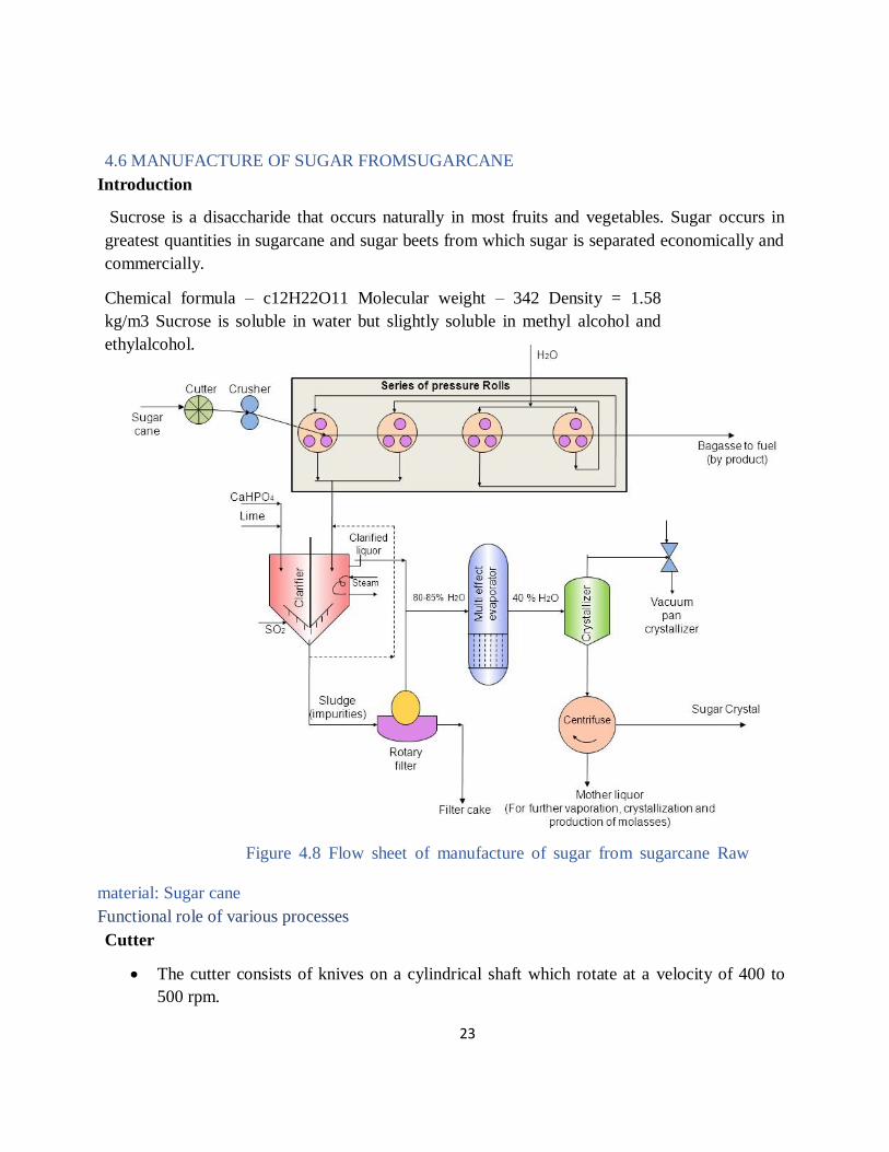
23
4.6 MANUFACTURE OF SUGAR FROMSUGARCANE
Introduction
Sucrose is a disaccharide that occurs naturally in most fruits and vegetables. Sugar occurs in
greatest quantities in sugarcane and sugar beets from which sugar is separated economically and
commercially.
Chemical formula – c12H22O11 Molecular weight – 342 Density = 1.58
kg/m3 Sucrose is soluble in water but slightly soluble in methyl alcohol and
ethylalcohol.
Figure 4.8 Flow sheet of manufacture of sugar from sugarcane Raw
material: Sugar cane
Functional role of various processes
Cutter
The cutter consists of knives on a cylindrical shaft which rotate at a velocity of 400 to
500 rpm.

24
The knives cut the canes into smallpieces.
Crusher
Canes are shreddedhere.
It consists of two rollers rotating in oppositedirection.
Series of Pressure mills
Crushed canes are passed through four pressure mills to extractjuice.
Each pressure mill is made up of cast ironrolls.
Rolls are grooved and the width decreases from first roll to thelast.
Make up water added in the third and fourth mill is recycled back to the first twomills.
About 85-90% of juice present in cane isextracted.
Bagasses are produced as byproduct.
Clarifier
In general two methods of clarification are available for the manufacture of white sugar,
namely, Sulfitation process and Carbonationprocess.
The juice now comes tothickener.
To precipitate the colloids, calcium phosphate(CaHPO4) is added followed by milk of
lime.
The milk of lime used has 9 to 10% strength and about 400mg CaO/litrealkalinity.
Apart from maintaining pH about 7, SO2 gas also acts as a bleachingagent.
Phosphoric acid or CO2 can also be substituted as acidifying agent depending upon the
type of extractedjuice.
At the bottom of clarifier, mud (impurities) are settled anddrained.
Steam is used to slightly heat thejuice.
Rotary filter
The underflow mud from the bottom of thickener is passed to a continuous rotary filter
press to recover sugarsolution.
This sugar solution if it is clear, is passed to multieffect evaporator or otherwise recycled
back toclarifier.
The filter cake produced is used forfertilizer.
Multieffect evaporator
The clarified liquor overflows to the 3-4 forward feed multieffectevaporator.

25
Here juice is concentrated from 80-85% H2O to 40% H2O to make juice readyfor
crystallization.
A vacuum of 63cm is maintained in the lasteffect.
Crystallizer
The clarified concentrated sugar solution comes tocrystallizer.
The sugar solution is further boiled in vacuum pans at vapor temperature of 57˚Cuntil
fine cloud of crystals isseen.
Crystallization is completed in vacuum panunit.
Centrifuge
The mixture of crystals and syrup is calledmasscuite.
The masscuite from crystallizer is centrifuged in basket type centrifuged to basket type to
centrifuge remove mother liquor (molasses) which is abyproduct.
The high grade sugar crystals are obtainedhere.
The centrifuge speed is maintained at 800 to 1000rpm.
4.7 STARCH AND STARCHDERIVATIVES.
Introduction
Starch consists of a chain of D-glucopyranosyl units. It is used in the manufacture of
textiles, paper, adhesives, insecticides, paints, soaps, explosives, and derivatives as dextrins,
nitrostarch and corn sugar. Chemical formula- C6H10O5 Starch gets hydrolysed by acids,
alkalis and enzymes giving dextrin, dextrose. Starch forms gels with water within several
minutes at 60- 80˚C. The major source of starch is maizekernels.

26
Figure 4.9 Flow sheet of manufacture of starch
Functional role of various processes
Air cleaner:-
At first, maize kernel containing 60-65% starch is introduced in aircleaner.
Air is passed through the bottom of cleaner.
Steeped tank:-
Air cleaned maize kernel is passed to steeped tank to make itsoft.
50-55˚C water and 0.15-0.3% SO2 isadded.
Here SO2 acts as abacteriostatic.
Steeping is done to yield high production and quality ofstarch.
The residence time is 40-50hours.
Grinding mill:-
The soft grains are passed through coarse grinding mill to rupture thecells.

27
The floating germ oil from the tank isremoved.
Buhrstonemill:-
The kernel is then wet ground in buhrstonemill.
This mill completely disrupts the cells of endosperm and release starchgranules.
Nylon screen:
The wet ground kernel is then passed through nyloncloth.
Water washes the starch through thescreens.
The fibre and hulls is left over on the nylonscreen.
Two stage centrifuge:
The gluten is water insolubleprotein.
Gluten is a light fraction which is separated in two-stagecentrifuge.
Rotary filter:
Water starch mixture is then passed then passed to continuous rotaryfilter.
Starch is separated as filter cake which is of yellow colored and contains high amounts of
protein.
Other products can also be made by hydrolysis ofstarch.
Dryer:
Starch as filter cake is dried and powdered in dryer with the introduction of steam in
dryer and produced as pearlstarch.
DEXTRINMANUFACTURING
Dextrin is a carbohydrate with the same general formula as starch. Dextrins are
polysaccharides and are produced by the hydrolysis of starch by heat and by acid. Their
nature and chemical behavior depend upon the kind of starch from which they are
produced. For commercial use dextrin is prepared by heating and drying starch and then
treating this starch with HCl to produce a colorless to yellowish, tasteless and odorless
powder which when mixed with water, forms a strong adhesive paste.
Typically the Littleford Day Dextrin process follows these processing steps:
1. Product (starch) is charged into the Littleford Day Ploughshare® Processor Unit. Once the
plows and jacket heating are initiated, hot air drying of the starch to the proper moisture level
begins.

28
2. After the prescribed moisture is removed and the dry starch has reached the
required temperature, the Anhydrous (HCl gas) is injected onto thestarch.
3. After a predetermined reaction time and temperature the product is then ready for
additional processing or for cooling anddischarging.
Figure 4.10 Flow sheet of manufacture of Dextrin
REFERENCES:
1. Gopala Rao M. and Marshall Sittig, “Dryden's Outlines of Chemical Technology”, 3rd
Edition, East West Press, New Delhi, 2008.
2. George T. Austin, “Shreve's Chemical Process Industries”, 8th Edition, McGraw Hill
International Editions, Singapore, 2002
3. https://nptel.ac.in/courses/103/107/103107082/
4. https://nptel.ac.in/courses/103/106/103106108/

1
SCHOOL OF BIO AND CHEMICAL ENGINEERING
DEPARTMENT OF CHEMICAL ENGINEERING
UNIT – 5 SYNTHETIC ORGANIC CHEMICALS SCHA1305

2
UNIT 5 SYNTHETIC ORGANIC CHEMICALS
Methane and synthesis gas, ethylene, acetylene and propylene. Aromatic chemicals - Benzene, toluene
and xylene. Production of thermo-plastic and thermo-setting resins: polyethylene, polypropylene, and
Polyvinylchloride, Polymers and their engineering applications. Polyamides and polyesters and processes
for the production of natural and synthetic rubber.
5.1 INTRODUCTION
Polymer: Polymers are large chain molecules having a high molecular weight in the range of 103 to
107.These are made up of a single unit or a molecule, which is repeated several times within the
chainedstructure.
Monomer : A monomer is the single unit or the molecule which is repeated in the polymer chain. It is
the basic unit which makes up thepolymer.
Thermosetting Polymer : There are some polymers which, when heated, decompose, and hence,
cannot be reshaped. Such polymers have a complex 3-D network (cross-linked or branched) and are
called Thermosetting Polymers. They are generally insoluble in solvents and have good heat
resistance quality. Thermosetting polymers include phenol-formaldehyde, urea- aldehyde, silicones
and allyls.
Thermoplastic Polymer : The polymers in this category are composed of monomers which are linear
or have moderate branching. They can be melted repeatedly and casted into various shapes and
structures. They are soluble in solvents, but do not have appreciable thermal resistance properties.
Vinyls, cellulose derivatives, polythene and polypropylene fall into the category of thermoplastic
polymers.
5.2 POLYMER CLASSIFICATION
Polymers are generally classified on the basis of
i. Physical and chemical structures.
3
ii. Preparation methods.
iii. Physical properties.
iv. Applications.
5.2.1 Classification According To Physical And Chemical Structures:
1. On the basis of functionality or degree of polymerization:
The functionality of a monomer or its degree of polymerization determines the final polymer that
will be formed due to the combination of the monomers. The number of reactive bonds or groups
that are available for coupling will determine whether the monomer will be mono-, bi-, tri-, or
polyfunctional.
a. Monofunctional or unifunctional: When a single reactive group is present in the monomer
molecule, then it is termed as monofunctional or unifunctional. However a monofunctional group
cannot lead to the propagation of a polymer chain. For example , in carboxylic acid, CH3COOH,
the –COOH group is the monofunctionalgroup.

4
b. Bi functional : When two reactive groups are present in the monomer molecule, then it is
termed as bi functional. More often than not, polymerization reaction with bi functinal groups
occur when a double bond splits to couple with another double bonded monomer. If a double
bonded molecule is present, then the polymer would be–
c. Trifunctional : When a monomer contains three groups that are reactive, then it is termed as
trifunctional. It is important to note that a trifunctional polymer may be a mixture of
monofunctional and bifunctional monomerstructures.
Let us consider the reaction of phenol and formaldehyde to form trimethyl phenol.

5
In the figure , the three formaldehyde molecules contain three reactive groups in the form of -OH
groups. These reactive groups get attached to the positions 1, 2 and 3 in the phenol molecule.
2. On the basis of physical structure :
a. Linear polymers : These polymers have a linear structure. Only bifunctional monomers can
form linearpolymers.
They are generally thermoplastic polymers, and except for very high molecular weight materials,
they are soluble in solvents.
Cross –linked polymers : These polymers have a 3-D network structure. Only bi-functional and
tri-functional monomers can form cross-linked polymers. Elastomeric properties are generally
endowed in polymers have cross-linkage across the linearchains.

6
Thermosetting polymers having high thermal resistance and mechanical strength may be formed
if the cross-linking among the monomer groups is extensive.
b. Branched –chain polymer : When there is no cross-linking in a polymer molecule , yet,
branches arise from the parent polymer chain , then the polymer formed is called a branched –
chainpolymer.

7
A small amount of trifunctional impurities in a bifunctional monomer may cause branching.
Branching may create several physical properties in a polymer such as decrease of solubility in
solvents, rise in the softening point and also the reduction in thermoplastic properties.
3. On the basis of chemical reactions :
Depending upon the basis on which monomers undergo chemical reactions to form polymers,
polymers can be further subdivided.

8
Polycondensation Reaction : It is a stepwise process in which the monomers react by
eliminating small molecules like H2O, NH3, CH2O and NaCl in a repetitive manner . Indefinite
growth of the polymer occurs at both ends. The condensation reaction terminates when one of
the reacting molecules is completely consumed in the reaction. In general, bifunctional
monomers with different functional groups undergo such reactions. One common example of a
condensation reaction is the esterification reaction. Benzoic acid reacts with ethanol undergoing
condensation reaction to give Ethyl benzoate, expelling one molecule of water (H2O). The
polymer formed after the reaction (in this case, ethyl benzoate) is called the condensation
polymer.
Addition Reaction : These reactions occur by the formation of rapid formation of rapid chains
and no elimination of small molecules occur. Such reactions generally occur among double or
triple-bonded molecules, or oxo-ringcompounds.
Addition reactions can be further of three types—
i. StepReactions
ii. ChainReactions
iii. IonicReations
i .Step Reactions : In step reactions, a π bond is broken and two new σ bonds are formed. The
substrate of an electrophilic addition reaction must have a double bond or triple bond.
ii .Chain Reactions : In chain addition reactions, the polymer is formed in a single step and
within the fraction of a second. The chain kinetics occur in 4 steps – Initiation, Propagation,
Transfer andTermination.
Variations of Chain Addition Reaction :
If we consider ‘M' and ‘N' be two monomeric species, then the chain addition reaction can be of
the following types –
Homopolymerization
If only M and N are present,

9
Copolymerization
If M and N are present together,
Random type
MM MN NNN MM N M MM NN……
Alternating type
M N M N M N M N M………
Block Polymerization
In this type, multimers resulting from straight polymerization coupled together in blocks.
Graft Polymerization
These have a structure which differs from block polymers ; and are formed from M and N
multimers.

10
In Graft polymerization, β – or X - radiation or chemically reactive functional groups ensue
the formation of reactive radicals on the main chain or on the grafted section.
Reaction Kinetics :
Let,
A – radical source
B – monomer molecule
*- activated
Bm , Bn – growing monomer molecule chain of lengths ‘m' and ‘n'.
X – any solvent , impurity, etc. which can act as transferable energyspecies.
Initiation It is the rate – controlling step in the chain Addition Reaction. This stage is
relatively slow and requires energy for breaking and forming the bonds. The energy is
supplied as thermal energy or in the form of radiations ( α -, β -, or ¥ - rays). However , by
using a catalyst, the activation energy required can be substantiallylowered.
Propagation These reactions occur between the already formed free radicals and an inactive
monomer. With low activation energy, there is more probability of reaction or collision
between the species. As a result, rapid reactions occur to attain the given degree of
polymerization.
Chain Transfer Reaction

11
In this reaction , one radical of the multiplying chain terminates and without the loss of any
number of free radicals, a new chain begins. These reactions control the degree of
polymerization and the rate of branching of thepolymers.
Branching usually occurs at higher temperature, with the reaction of a multimer with a dead
chain, followed by lengthening of the branch due to successive monomer addition.
Chain Termination
A chain terminates with the net loss of one free radical. It may occur by the collision of growing
chains with coupling or disproportionation. However , if a growing chain collides with an
initiation radical, undesirable impurities or the wall of the reaction vessel, then it might also
terminate.
iii .Ionic Reaction :These are similar to chain addition reaction with free radicals , however ;
instead of neutral, unpaired electrons, they have a positive or negative charge. A co-catalyst may
be used, which is usually a trace of H2O, which is necessary to produce ionization, as the
reaction cannot occur in absolute dry conditions.An example of ionic addition reaction is the
preparation of polyisobutylene with boron trifluoridecatalyst.
Initiation

12
Propagation
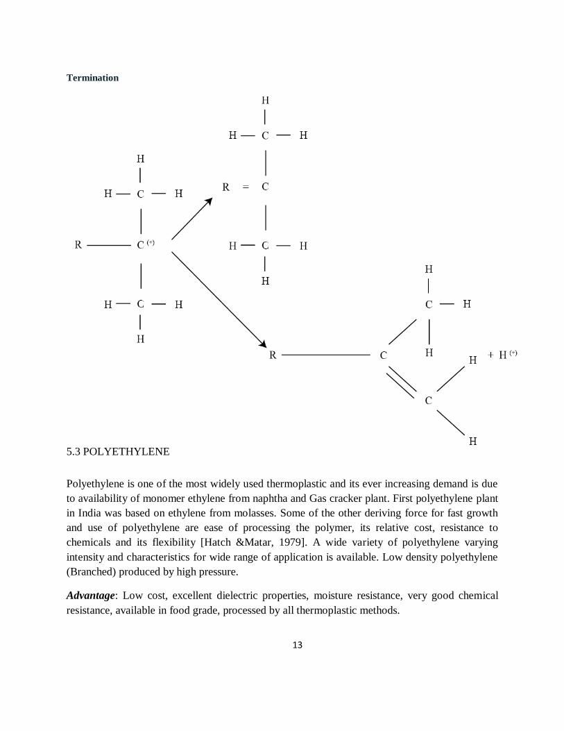
13
Termination
5.3 POLYETHYLENE
Polyethylene is one of the most widely used thermoplastic and its ever increasing demand is due
to availability of monomer ethylene from naphtha and Gas cracker plant. First polyethylene plant
in India was based on ethylene from molasses. Some of the other deriving force for fast growth
and use of polyethylene are ease of processing the polymer, its relative cost, resistance to
chemicals and its flexibility [Hatch &Matar, 1979]. A wide variety of polyethylene varying
intensity and characteristics for wide range of application is available. Low density polyethylene
(Branched) produced by high pressure.
Advantage: Low cost, excellent dielectric properties, moisture resistance, very good chemical
resistance, available in food grade, processed by all thermoplastic methods.

14
UNIPOL Process
The process produces low density polyethylene and high density polyethylene using low
pressurein gas phase. Wide range of polyethylene is produced using proprietary solid and slurry
catalyst. The process produces wide range of polyethylene in a gas phase, fluidised bed reactor
using proprietary solid and slurry catalyst. Gaseous ethylene, comonomer and catalyst are fed to
fluidised bed reactor containing a fluidized bed of growing polymer particles operating at
25kg/cm2 and 100oC. Polymer density is easily controlled from 0.915 to 0.97 g/cm. Process
flow diagram for polyethylene manufacture is given in Figure4.1

15
Figure 5.1: Fluidized-bed Gas Phase PE Process.
POLYPROPYLENE
Polypropylene is a low density semi-crystalline stereo-regular polymer which exists in three
forms- isotactic, syndiotactic and atactic. Polypropylene was discovered in March 1954 by
Professor Giulio Natta demand of polypropylene is growing at a much faster rate due to its
strong demand per capita consumption of polypropylene is given in Figure4.2

16
Figure 5.2: Polypropylene Process
UNIPOL Process: The process produces homopolymer, random copolymer and impact
copolymer polypropylene. Polymerisation takes place in a fluidized bed reactor using slurry
reactor (TiCl4 supported on MgCl2 in slurry form in mineral oil. Co-catalyst TEAL, purified
propylene and ethylene incase of random PP), purified H2 and selectivity control agent is
continuously fed to the reactor. Temperature 35oC and pressure 33 kg /cm2 is maintained in the
reactor. Figure 4.3 illustrate the Unipol process for manufacturing of polypropylene.

17
Figure 5.3: Polypropylene by Unipol process
5.4 POLYVINYLCHLORIDE
Polyvinyl chloride is second largest (after polyethylene) and most versatile of all
thermoplastics. Despite various environmental issues raised time to time PVC has enjoyed
onstant growth in demand because of its unique properties which include durability, ease of
processing and cost effectiveness PVC has been facing innumerable challenges to its usage
and growth. With use of suitable additives like stabilizer and plasticisers can be made rigid or
flexible for a variety of end uses and can be processed by all types of processing methods It
contains about 56.8percent chlorine and balance being hydrocarbon. A major portion of the
chlorine produced in the world is used in the manufacture of PVC. The potential for growth
in PVC consumption is enormous. With the addition of plasticizers, fillers, reinforcements,
lubricants and stabilizer, PVC may be formulated into flexible, rigid, elastomer or
foamedcompound
Process Technology for PVC
18
The basic monomer for manufacture of PVC is vinyl chloride which is made from either
acetylene or ethylene. However, ethylene is the chief source of vinyl chloride throughout
world.
Varioussourcesofethylenearenaphthagascracking,acetylenerouteandalcoholroute.Figure
4.4 illustrates the process flow diagram of PVC manufacturing. Using a free radical initiator,
PVC can be made with any of four general methods of polymerisation – suspension,
emulsion, bulkandsolutionpolymerisesvinylchloridemonomer.However,bulkofPVCismadeby
suspension polymerisation. Most resins produced by the suspension polymerisation are in the
range of 125 - 165 microns in diameter while those produced by bulk polymerization process
are in the range of 1 micron diameter Suspension polymerization of PVC has significant
advantages such as low investment, large reactor technology, clean reactor wall technology,
low personal requirement,environmentallysafe Vinyl chloride is copolymerized with other
monomers to improve quality of the resin. When vinyl acetate is used as copolymer, polymer
is more stable to light and heat than the homopolymer of vinyl chloride. With vinylidene
chloride has a higher melting point than homopolymer and may be spun into afibre
Figure 5.4: Flow Diagram for Manufacturing of PVC
Suspension Polymerisation Process
Suspension polymerization of PVC manufacture involves dispersion of vinyl chloride
monomer in water along with a suspending agent polyvinyl chloride. Polymeristion is
initiated by activators at temperature around 40-70oC heat produced is continuously removed
using heat transfer medium. After the polymerization is completed the suspension is

19
transferred to degassing unit where unreacted monomer is removed, purified, condensed and
recycled. Polymer is from suspension is separated by centrifuging and dried by hotair.
5.6 POLYSTYRENE
Solution (bulk) polymerization: Solution (bulk) polymerization is commonly referred to as
mass polymerization in the industry. The vast majority of all polystyrene produced today is
produced via this technology. The common solvents used in this process are the styrene
monomer itself and ethyl benzene. The two types of mass polymerization are batch and
continuous, of which continuous mass is by far the most popular. Batch mass polymerization
consists of a polymerization section containing agitated vessels polymerizing up to 80%
conversion in a batch method. The polymerized solution is then pumped to a batch finishing
section for either devolatisation or plate and frame final polymerization and grinding. The
most widelyused
process for polymerization of polystyrene today is the continuous mass process. This solution
is continuously prepared in a holding vessel and will then be injected into the reactor system.

20
Typical feed to the first reactor would consist of 50 weight percent styrene monomer, 100
ppm water (based on styrene weight), 2000 ppm boron trifluoride (based on styrene weight),
with the balance being organic solvent. The polymerization reaction gives off heat that is
carried away from the reactors by jacketing them with a heat transfer fluid. The temperature
of the reactants should not vary by more than 15 0 C throughout the reactor series.
Temperature control is very important in this reaction because as the reaction temperature
increases, the average molecular weight of the polystyrene decreases. The reaction
temperature range is 40-70 0 C. Temperature can also be controlled by intermediate shell and
tube heat exchangers. Monomer conversions of up to 85wt% polystyrene are obtainable in
these reactors.
Figure 5.5: flow diagram for manufacturing of
polystyrene 5.7 ABS (Acrylonitrile-Butadiene-Styrene)
ABS may be processed into end products by most thermoplastic processing methods such as
injection and compression moulding, extrusion, blow moulding and calendering. Other
operationssuchasvacuumforming,vapourmetallizing,plating,hotstampingandpaintingmay also
be carried out. ABS's light weight and ability to be injection molded and extruded make it

21
useful in manufacturing products such as drain-waste-vent (DWV) pipe systems, musical
instruments (recorders, plastic clarinets, and piano movements), golf club heads (because of
its good shock absorbance), automotive trim components, automotive bumper bars, medical
devices for blood access, enclosures for electrical and electronic assemblies, protective
headgear, whitewater canoes, buffer edging for furniture and joinery panels, luggage and
protective carrying cases, small kitchen appliances, and toys, Household and consumer goods
are the major applications of ABS. Keyboard keycaps are commonly made out ofABS.
Figure 5.6: flow diagram for manufacturing of ABS
4.8 TEFLON
PTFE is one of a class of plastics known as fluoropolymers. A polymer is a compound
formed by a chemical reaction which combines particles into groups of repeating large
molecules. Many common synthetic fibers are polymers, such as polyester and nylon. PTFE
is the polymerized form of tetrafluoroethylene.
Raw Materials
PTFE is polymerized from the chemical compound tetrafluoroethylene, or TFE.
Manufacturing Process

22
PTFE can be produced in a number of ways, depending on the particular traits desired for
theend product. Many specifics of the process are proprietary secrets of the manufacturers.
There are
twomainmethodsofproducingPTFE.Oneissuspensionpolymerization.Inthismethod,the TFE is
polymerized in water, resulting in grains of PTFE. The grains can be further processed into
pellets which can be molded. In the dispersion method, the resulting PTFE is a milky paste
which can be processed into a fine powder. Both the paste and powder are used in coating
applications.
Making the TFE
STEP 1: Manufacturers of PTFE begin by synthesizing TFE. The three ingredients of TFE,
fluorspar, hydrofluoric acid, and chloroform are combined in a chemical reaction chamber
heated to between 1094-1652°F (590-900°C). The resultant gas is then cooled, and distilled to
remove any impurities.
Teflon con be used on a wide variety of cookware.
Suspension Polymerization
STEP 2 :The reaction chamber is filled with purified water and a reaction agent or
initiator, a chemical that will set off the formation of the polymer. The liquid TFE is
piped into the reaction chamber. As the TFE meets the initiator, it begins to
polymerize. The resulting PTFE forms solid grains that float to the surface of the
water. As this is happening, the reaction chamber is mechanically shaken. The
chemical reaction inside the chamber gives off heat, so the chamber is cooled by the
circulation of cold water or another coolant in a jacket around its outsides. Controls
automatically shut off the supply of TFE after a certain weight inside the chamber is
reached. The water is drained out of the chamber, leaving a mess of stringy PTFE
which looks somewhat like gratedcoconut.

23
STEP 3 :the PTFE is dried and fed into a mill. The mill pulverizes the PTFE with
rotating blades, producing a material with the consistency of wheat flour. This fine
powder is difficult to mold. It has "poor flow," meaning it cannot be processed easily
in automatic equipment. Like unsifted wheat flour, it might have both lumps and air
pockets. So manufacturers convert this fine powder into larger granules by a process
called agglomeration. This can be done in several ways. One method is to mix the
PTFE powder with a solvent such as acetone and tumble it in a rotating drum. The
PTFE grains stick together, forming small pellets. The pellets are then dried in an
oven.
STEP 4: The PTFE pellets can be molded into parts using a variety of techniques.
However, PTFE may be sold in bulk already pre-molded into so-called billets, which
are solid cylinders of PTFE. The billets may be 5 ft (1.5 m) tall. These can be cut into
sheets or smaller blocks, for further molding. To form the billet, PTFE pellets are
poured into a cylindrical stainless steel mold. The mold is loaded onto a hydraulic
press, which is something like a large cabinet equipped with weighted ram. The ram
drops down into the mold and exerts force on the PTFE. After a certain time period,
the mold is removed from the press and the PTFE is unmolded. It is allowed to rest,
then placed in an oven for a final step calledsintering.
STEP 5: The molded PTFE is heated in the sintering oven for several hours, until it
gradually reaches a temperature of around 680°F (360°C). This is above the melting
point of PTFE. The PTFE particles coalesce and the material becomes gel-like. Then
the PTFE is gradually cooled. The finished billet can be shipped to customers, who
will slice or shave it into smaller pieces, for furtherprocessing.
Dispersion polymerization
STEP 6 : Polymerization of PTFE by the dispersion method leads to either fine
powder or a paste-like substance, which is more useful for coatings and finishes. TFE
is introduced into a water-filled reactor along with the initiating chemical. Instead of
being vigorously shaken, as in the suspension process, the reaction chamber is only
agitated gently. The PTFE forms into tiny beads. Some of the water is removed, by
filtering or by adding chemicals which cause the PTFE beads to settle. The result is a
milky substance called PTFE dispersion. It can be used as a liquid, especially in
applications like fabric finishes. Or it may be dried into a fine powder used to
coatmetal.

24
5.8 EPOXYRESINS.
Most common epoxy resins are produced from a reaction between epichlorohydrin (ECH)
and bisphenol-A (BPA), though the latter may be replaced by other raw materials (such as
aliphatic glycols, phenol and o-cresol novolacs) to produce specialty
resins. The epoxy resins can be obtained in either liquid or solid states. The two processes
are similar. Firstly ECH and BPA are charged into a reactor. A solution of 20-40% caustic
soda is added to thereactionvesselasthesolutionisbroughttotheboilingpoint.After the
evaporation of unreacted ECH, the two phases are separated by adding an inert solvent such
as methylisobutylketone (MIBK). The resin is then washed with water and the solvent is
removed by vacuum distillation.The producers will add the specific additivesto create a
formula that lend special properties such as flexibility, viscosity, color, adhesiveness, and
fastercuring, depending on a particular application.
In order to convert epoxy resins into a hard, infusible, and rigid material, it is necessary to
cure the resin with hardener. Epoxy resins can cure at practically any temperature from 5-
150oC depending on the choice of curing agent. Primary and secondary amines are widely
used to cure epoxy resins.
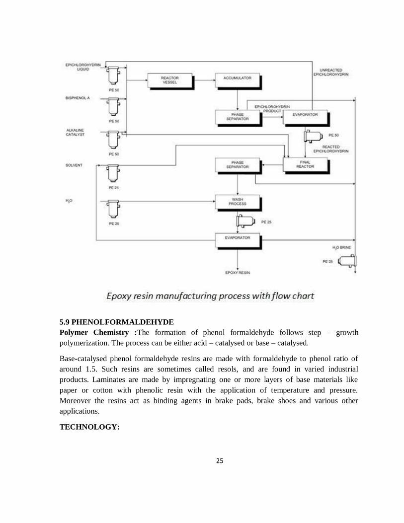
25
5.9 PHENOLFORMALDEHYDE
Polymer Chemistry :The formation of phenol formaldehyde follows step – growth
polymerization. The process can be either acid – catalysed or base – catalysed.
Base-catalysed phenol formaldehyde resins are made with formaldehyde to phenol ratio of
around 1.5. Such resins are sometimes called resols, and are found in varied industrial
products. Laminates are made by impregnating one or more layers of base materials like
paper or cotton with phenolic resin with the application of temperature and pressure.
Moreover the resins act as binding agents in brake pads, brake shoes and various other
applications.
TECHNOLOGY:
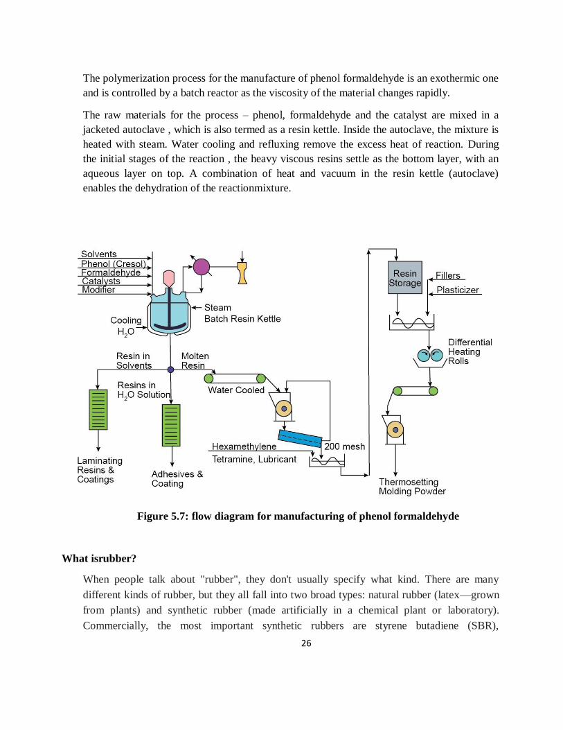
26
The polymerization process for the manufacture of phenol formaldehyde is an exothermic one
and is controlled by a batch reactor as the viscosity of the material changes rapidly.
The raw materials for the process – phenol, formaldehyde and the catalyst are mixed in a
jacketed autoclave , which is also termed as a resin kettle. Inside the autoclave, the mixture is
heated with steam. Water cooling and refluxing remove the excess heat of reaction. During
the initial stages of the reaction , the heavy viscous resins settle as the bottom layer, with an
aqueous layer on top. A combination of heat and vacuum in the resin kettle (autoclave)
enables the dehydration of the reactionmixture.
Figure 5.7: flow diagram for manufacturing of phenol formaldehyde
What isrubber?
When people talk about "rubber", they don't usually specify what kind. There are many
different kinds of rubber, but they all fall into two broad types: natural rubber (latex—grown
from plants) and synthetic rubber (made artificially in a chemical plant or laboratory).
Commercially, the most important synthetic rubbers are styrene butadiene (SBR),
27
polyacrylics, and polyvinyl acetate (PVA); other kinds include polyvinyl chloride (PVC),
polychloroprene (better known as neoprene), and various types of polyurethane. Although
natural rubber and synthetic rubbers are similar in some ways, they're made by entirely
differentprocesses
Natural rubber is made from a runny, milky white liquid called latex that oozes from
certain plants when you cut into them. (Common dandelions, for example, produce latex; if
you snap off their stems, you can see the latex dripping out from them. In theory, there's no
reason why we couldn't make rubber by growing dandelions, though we'd need an awful lot
of them.) Although there are something like 200 plants in the world that produce latex, over
99 percent of the world's natural rubber is made from the latex that comes from a tree species
called Heveabrasiliensis, widely known as the rubber tree. This latex is about one third water
and one third rubber particles held in a form known as a colloidal suspension. Natural rubber
is a polymer of isoprene (also known as 2-methylbuta-1,3-diene) with the chemical formula
(C5H8)n. To put it more simply, it's made of many thousands of basic C5H8units (the
monomer of isoprene) loosely joined to make long, tangled chains. These chains of
molecules can be pulled apart and untangled fairly easily, but they spring straight back
together if you release them—and that's what makes rubber elastic. and chemically
quitedifferent.
Synthetic rubbers are made in chemical plants using petrochemicals as their starting point.
One of the first (and still one of the best known) is neoprene (the brand name for
polychloroprene), made by reacting together acetylene and hydrochloric acid. Emulsion
styrene-butadiene rubber (E-SBR), another synthetic rubber, is widely used for making
vehicletires.
5.10 STYRNE BUTADIENE RUBBER(SBR)
Polymer Chemistry: The production of Styrene Butadiene Rubber (SBR) follows addition
polymerization. Its glass transition temperature is approximately -55°C, but may vary with
the Styrene content. It can be used extensively within the temperature range of -40 to 100°C.
It may be blended with natural rubber or can be used by itself. It has good abrasion resistance
properties and the addition of additives may endow it with aging stability
TECHNOLOGY:
SBR is produced by the copolymerization of Butadiene and Styrene by emulsion
polymerization in 3: 1 weight ratio. The fresh and recycle monomers are purified by 20 %

28
aqueous caustic purification. Then the stream is continuously passed through 6 to 12 glass –
lined or stainless steel reactors. The residence time in these reactors ranges from 5 to 15
hours.
Steam heating, water cooling and refrigeration are carried out in these reactors. These
reactors are equipped for producing both cold and hot SBR. Cold SBR is produced at 5°C and
1 atm gage by refrigeration techniques ; whereas hot SBR is manufactured at 50°C , and 3-4
atmgage.
The polymerization product is then stripped with chemical inhibitors and the latex resulting
from the reactors are collected in blow down tanks. The latex is then sent to a falling film
stripper to remove the butadiene ; and the bottoms are fed to a perforated plate column where
styrene is stripped out.
The monomer – free emulsion is then added with certain compounding ingredients in blend
tanks. The latex is coagulated to rubber. The crumbs of rubber float onto shaker screens
where the catalyst , emulsifiers and other solubles are removed by the action with wash water.
The crumbs are dried in continuous belt dryers with hot air and are subsequently pressed into
bales.

29
Figure 5.8 : flow diagram for manufacturing of styrne butadiene rubber (sbr)
5.11 POLYBUTADIENE
Stream of steam cracker is major source of butadiene. Other routes for butadiene
manufacture are
Catalytic dehydrogenation of
butenesCatalytic dehydrogenation
of butane
With the availability of butadiene from cracker plant, manufacture of polybutadiene has
increased significantly in recent years. Polybutadiene is made by free radical emulsions,
alkali methyl solution and transition metal coordination solution processes. Most processes
are based on solution process. Large volume use of polybutadiene rubber has been primarily
in blend with other polymers. Blend with SBR or natural rubber has improved crack
resistance. Cracking and abrasion resistance is verygood.
It is characterized with high abrasion and crack resistance, better resistance to heat
degradation and blowouts, good hysteresis properties, large scale use in tyre tread,
modification of plastics,conveyor& V-belts, sports goods, foot wear material, 90 percent in
tyre industry.
POLYISOPRENE
Polyisoprene is one of the most well known natural elastomers derived from the sap of the
heavea tree. However, synthetic polyisoprne is made by polymerization of isoprene. Isoprene
is recovered from the C5 fraction of naphtha cracker. Isoprene can be also made
Isoprene polymerisation is carried out in an inert hydrocarbon solvent (aliphatic solvents).
Basic steps in manufacture of polystyrene are – raw material preparation and purification,
polymerisation, catalyst deactivation and removal, solvent recovery, polymer drying.
Polymerisation catalysts are either of the coordination (Zeigler) or alkyl lithium types.
Coordination catalysts are trialkyl aluminium/titanium tetrachloride. Often polymerisation
short stops and anti oxidant is added. The solvent remaining is stripped off.
Poly isoprene has good uncured track, high pure gum tensile strength, high resilience, low
hysteresis, good hot tear strength. Tyre market is the major consumer of polyisoprene, a

30
substitute of natural rubber in the tread of truck, aircraft and off the road tyres, for dipped
goods, adhesive, extruded thread.
Figure 5.9 Process flow diagramme of Acrylonitrile Rubber ( Nitrile rubber)
5.12 NEOPRENE (POLYCHLOROPRENE):
Chloroprene is made either via acetylene route or from butadiene. Butadiene process is
commonly used.
Acetylene route involves dimerisation of acetylene to monovinyl acetylene followed by reaction of
monovinyl acetylene with HCl.
Chloroprene from butadiene involves three steps
Chlorination of Butadiene: Various steps involved
are
Chorination of Butadiene- 1,4 dichloro 2-butene and3,4-dichloro 1-
butene Isomerisation of 1,4 dichloro2-butene to 3,4-dichloro 1-butene

31
Dehydrochlorination of 3, 4-dichloro1-butene to chloroprene in presence of caustic
soda resulting in formation of chloroprene(CH2CH-CCL=CH2
Polychloroprene is made by emulsion polymerisation process using resin acid soap
emulsifier. Polymerisation is carried out at 40 oC in presence of sulphur. Some of the
major applicationof polychloroprene is in adhesives, transportation industry, wire and
cable, construction industry, hose andbelting.
Uses : Adhesives, transportation industry (Automotive – gaskets, V-belts, shock absorber
covers, wire jackets, molded seats, aviation-wire cable, gaskets, seats etc., rail brake hose,
track mountings.
5.13 SILICON RUBBER(POLYSILOXANES)
Silicon elastomer are made by ring opening reaction caused by action of alkali on monomer
acyclic siloxane characterised by exceptional mechanical and electrical performance under
extreme temperature condition. Used in aerospace, appliances, electrical industry,
construction industry, automotive industry, gaskets sealings, spark plug boots, hose, rubber
rolls.
5.14 What is a RubberCompound?
Sometimes, there is a misconception that a rubber compound is one ingredient and is the
same for every different polymer type. This could not be further from the truth. A rubber
compound could be a combination of 3 to 15 different ingredients of thousands of different
compositions andvendors.
A typical rubber formation based on parts per hundred is:
Polymer 100 phr
Filler 30 – 60 phr
Antioxidant 1 – 3 phr
Antiozonants 1 – 3 phr
Oil 5 – 30 phr
Cure 5 – 10 phr
Polymers:
32
The most important ingredient in a rubber compound, polymers give the
bases
forchemical,physicalandmoldingproperties.Typicalpolymersaredistinguishedbychemical
performance and viscosity rating. An example for a Nitrile (Buna-N) compound is the amount
of Acrylonitrile (ACN). The higher the ACN, the more oil resistance. These polymers are
then sold with varying ACN content. The Mooney viscosity can vary to give better
processing performance.
Filler:
Carbon Black is one of the most common fillers. This gives the rubber
compoundphysicalstrengthanditsblackcolor.Therearevariousparticlesizesandsurface
activities. Changing the particle size can increase physical properties while also increasing
compression set.
White clays and Mineral fillers are used for colored compounds. This helps
makes the compound white to add the desired color requested. These types of fillers are
typically less reinforcing than carbon black. Blending of these fillers with carbon black helps
reduce cost of the overall compound.
Antioxidant:

33
Antioxidants help protect the compound from high temperature while in use
and while the compound is being mixed. These ingredients can absorb free radicals that can
breakthe
polymers bonds and reduce service life of the compound
Antiozonants:
Themostcommonantiozonantiswax,usedtobloomoutonthesurfaceafter
molding to protect the rubber from ozone attack. A common example can be seen when
purchasing new tires. The surface of a new tire will have a wax feel or show a slight haze.
Oil (processing aids):
Various oils are used to help incorporate all the dry ingredients used in the
rubbercompounding.Theyalsohelptoreducetheviscosityoftheoverallcompoundtohelp
with molding. Adding more oil can also lower the hardness of the rubber. Thus, lower Shore
A compounds will typically have more oil in the formulation.
Cures:
Sulfur is the most common curative for rubber compounds. Rubber
polymers are just entangled hydrocarbon chains than won’t hold shape. Back in1839,
Goodyeardiscovered that rubber chains can be bonded together by heating the rubber with
sulfur, called vulcanization. Bonds of carbon – sulfur – carbon are formed.

34
Another common vulcanizing agent, peroxide creates direct bonds to the carbon chains
forming carbon – carbon bonds. These bonds take more energy to break, thus typically giving
higher service temperatures and low compression sets. Some polymers can only be cross-
linked with peroxides
There are many other ingredients that can be used to give different properties. Because of all
the combinations, not all compounds are the same. Rubber compounding is a science to
assure required properties by varying the ratios of ingredients and compensating for the
interactions. This is why most compounders consider their rubber formulations proprietary. It
can take hundreds of variations and hours of testing to perfect the mechanical properties
while maintaining goodprocessing.
5.15 VISCOSERAYON
Polymer Chemistry: The raw material for the production of Viscose rayon is wood pulp.
However, the manufacturing process emits toxic effluents which have adverse environmental
effects. Because of its cellulosic base , it has some properties which are similar to those of cotton
and any other natural cellulosic fibres. It has moderate resistance to acids and alkalis. However,
it may be damaged by relatively weak acids. Moreover, due to the inelasticity of fibers, it has
poor abrasionresistance.
Technology
The raw materials used in this process are cellulose wood pulp sheets or cotton linters. These are
placed in a steeping press with contact in aqueous NaOH Solution for a period of 2 – 4 hours at
normal room temperature. A hydraulic ram presses out the excess alkali and the sheets are
shredded to crumbs and aged for 2 – 3 days. The aging process has its direct consequence on the
viscosity of the solution.
Later CS2 is added in a rotating drum mixer over a period of 3 hours. The orange cellulose
xanthate which forms is transferred to a solubilizer , wherein it is mixed into dilute caustic . The
mixing of cellulose xanthate and dilute caustic yields a orange colored viscous solution which

35
contains 7 – 8 % cellulose and 6.5 – 7 % NaOH. It is digested at room temperature for 4-5 days.
Thereafter , the solution is filtered and fed to spinning machines.
The spinning is carried out in extrusion spinnerettes , which are made up of platinum or gold
alloys. The orifices of these spinnerets have a diameter of 0.1 – 0.2 mm. for continuous filament
yarns and of diameter 0.05 – 0.1 mm for short fibre shapes. The solution extruded from the
spinnerette is contacted with an acid bath which precipitates the filaments without causing them
to break or stick together. The processing treatments of washing, desulphurizing, bleaching and
conditioning takes place continuously and in order after the filaments are wound on a series of
plastic rolls.
Figure 5.10 Manufacture of Viscose Rayon
5.16 NYLON

36
Polymer Chemistry : Nylon 66 (or 6,6 - Nylon) is a condensation polymer formed by the
condensation polymerization of Adipic acid (a dibasic acid) and hexamethylene diamine (a
diamine). In the nomenclature, the first number refers to the number of carbon atoms in the
diamine and the second number designates the number of carbon atoms in the dibasic acid.
Nylon – 6 is a polymer of caprolactum . The number refers to the total carbon atoms in the ring,
which can vary from 5 to 12. Both Nylon – 6 and Nylon – 66 have similar properties and can be
used as thin films and fibres; and for extrusion and injection molding in plastics. The major
difference in the physical properties of these two nylons is that the melting point of Nylon – 66 is
40 – 45°C higher than Nylon – 6. Moreover, Nylon – 66 is harder, rigid and its abrasive –
resistance is lower than that of Nylon – 6.
Technology In the production of Nylon – 66, first, the amine and acid is mixed in an aqueous
solution , with the pH adjusted at 7.8 to form Nylon salt. The salt is then concentrated under
vacuum. It is thereafter charged to an autoclave where the rest of the water is removed. The
temperature is gradually increased to 280 o C in the autoclave to complete the polymerization
and the water of condensation isremoved.
The final product has a molecular weight of 12000 – 16000. It is extruded as ribbons onto
chilling rolls. Then, it is sent to a chipper which produces small chips, which possesses the
convenience of storage and rehandling. These chips are melted, metered through high pressure
pumps. After filtration, these are passed via a melt spinnerette to produce nylon fibers. Upon
cooling , these filaments harden and are wound on bobbins at a rate of 750 metres per minute or
even higher. Inorder to give the fibre desirable textile properties, the threads are stretched to
about 4 times its originallength.
The production of Nylon – 6 is similar to that of Nylon – 66 , the only difference being the
nature of polymerization. Nylon – 6 is manufactured by the step – wise condensation of
caprolactum with no net water removal. However, to maintain the thermal equilibrium between
monomer and polymer at the melting and spinning temperatures is the only difficult task.
Monomer retained on the fibres accounts upto 10% , so the fibres are water – washed to remove
the soluble caprolactum retained.

37
Figure 5.11 Manufacture of Nylon
5.17 CUPRAAMMONIUMRAYON:
Cupraammonium rayon is made from reaction of Cellulose with copper salt and ammonia. After
bleaching celullose is added in ammonical solution of copper sulphate resulting in formation of
cuprammonium cellulose which is spun into water and the yarn is washed with acid to remove
traces of ammonia and dried. Process flow diagram for the manufacture of cuprammoium rayon
is given in Figure 5.3

38
Figure 5.12 Manufacture of cupraammonium rayon
5.18 ACETATERAYON
The purified cotton linters or cellulose is fed to the acetylator containing acetic anhydride and
acetic acid and conc. Sulphuric acid and acelylation is carried out at 25-30oC. The reaction
mixture called acid dope is allowed for ripening for about 10-20 hrs. During reopening
conversion of acetate groups takes place. After reopening, the mixture is diluted with water with
continuous stirring. During the process flakes acetate rayon is precipitated which is dried and
send to spinning bath where dry spinning of acetate rayon takes place by dissolving in solvent
and passing troughspinnerated. The solvent is evaporates by hot air. The dope coming from the
spinnerate is passed downwards to feed roller and finally to bobbin where spinning is done at
higher speed.
Raw Material Purified cotton linters, wood pulp, acetic anhydride, acetic acid and sulfuric acid.
Process Steps Activation with Acetic Acid: The process involves steeping of purified cotton in
acetic acid which makes. Swelling and makes cellulose more reactive

39
Acetylation: The pretreated cotton with acetic acid is then acetylated with excess acetic acid,
acetic anhydride, with sulphuric acid to promote the reaction.
One part of purified cellulose
Three part of acetic anhydride
Five parts of acetic acid
Sulfuric acid 0.1 part (as catalyst)
Reaction exothermic
Temperature 20 oC for the first hour
25-30oC for the next 7-8 h
Hydrolysis of Triacetate: The triacetate formed is hydrolysed to convert triacetate to diacetate.
The resultant mixture is poured in water to precipitate the cellulose acetate
DP 350-400
2.35 – 2.4 acetyl groups per anhydro glucose unit.
Spinning: Secondary acetate is dissolved in acetone, fitered, dearerated and passed through
spinerrate in hot air environment, which evaporates the solvent.
Economical Production
Low cost and availability of acetic acid and acetic anhydride
Recovery of acetic acid
Recovery of acetone
Process flow diagram for the manufacture of acetate Rayon is given in Figure 5.4

40
Figure 5.13 Manufacture of acetate rayon
5.21 POLYETHYLENE TEREPHTHALTE(POLYESTER)
Polyethylene Terephthalate (PET) from DMT
PET from DMT is made by transesterification route by reaction of dimethyl terephthalate with
ethylene glycol followed by poly-condensation. Polyester through trans esterification route was
more common earlier due to non-availability of purified terephthalic acid. During
transesterification, methanol obtained as by product. Figure 5.5 describes the manufacturing
process of polyester from DMT.

41
Figure 5.14Manufacture of polyester
5.22 ACRYLICFIBRE
Acrylic fibres are third largest class of synthetic fibre after polyester and nylons.
Process Technology
Manufacturing process shown in Figure 5.6 The manufacturing process can be broadly
divided into two parts:

42
Polymerisation: Polymerisation includes copolymer composition, catalyst system,
polymerisation reaction and monomer recovery. Major polymerisation processes are bulk
polymerisation, suspension polymerisation, emulsion polymerisation and solution
polymerisation. Most of the acrylic polymers manufactured for fiber grade are made through
suspension polymerisation that gives high percentage of conversion, better product whiteness,
shorter residence time and easy control of polymerisation. Emulsion polymerization is used
incase of modified acrylic fibre. Inorganic compounds such as persulphate, chlorates or hydrogen
peroxide are used as radical generators. Redox initiation is normaaly used in production of
acrylic fibre. The most common redox system consist of ammonium or potassium persulphate
(oxidizer), sodium bisulphate (reducing agent) and ferric or ferrous ion(catalyst)
Spinning: Spinning includes solution/dope preparation, spinning techniques and finishing
operation including after treatment, cutting and bailing.
Dry Spinning: In dry spinning of acrylic fibre dimethyl formamide (DMF) is used. The DMF
spin dope contains the polymer in the DMF, thermal stabilizers, delustrant. It passed through
spinnerate placed at top of the solvent removal tower. The DMF evaporated by circulating inert
gas through tower at about 300-35 oC to remove the solvent
Wet Spinning: In wet spinning sodium thiocyanate are commonly used as solvent. Wet spinning
fiber is spun into a liquid bath containing a solvent non-solvent mixture called coagulant.
Nonsolvent is usually water. The fibre emerging from spin bath are washed and dried followed
by cutting andbailing.

43
Figure 5.15Manufacture of acrylic fibre
REFERENCES
1. Gopala Rao M. and Marshall Sittig, “Dryden's Outlines of Chemical Technology”, 3rd
Edition, East West Press, New Delhi, 2008.
2.George T. Austin, “Shreve's Chemical Process Industries”, 8th Edition, McGraw Hill
International Editions, Singapore, 2002
3. https://nptel.ac.in/courses/103/107/103107082/
4. https://nptel.ac.in/courses/103/106/103106108/


![Synthesis of [(4-Chloro-5H-1,2,3-dithiazol-5-ylidene)amino]azines](https://static.fdokumen.com/doc/165x107/6344ded56cfb3d4064096a20/synthesis-of-4-chloro-5h-123-dithiazol-5-ylideneaminoazines.jpg)