
Number Systems
261
1 Number Systems The study of number systems is important from the viewpoint of understanding how data are represented before they can be processed by any digital system including a digital computer. It is one of the most basic topics in digital electronics. In this chapter we will discuss different number systems commonly used to represent data. We will begin the discussion with the decimal number system. Although it is not important from the viewpoint of digital electronics, a brief outline of this will be given to explain some of the underlying concepts used in other number systems. This will then be followed by the more commonly used number systems such as the binary, octal and hexadecimal number systems. 1.1 Analogue Versus Digital There are two basic ways of representing the numerical values of the various physical quantities with which we constantly deal in our day-to-day lives. One of the ways, referred to as analogue, is to express the numerical value of the quantity as a continuous range of values between the two expected extreme values. For example, the temperature of an oven settable anywhere from 0 to 100 °C may be measured to be 65 °C or 64.96 °C or 64.958 °C or even 64.9579 °C and so on, depending upon the accuracy of the measuring instrument. Similarly, voltage across a certain component in an electronic circuit may be measured as 6.5 V or 6.49 V or 6.487 V or 6.4869 V. The underlying concept in this mode of representation is that variation in the numerical value of the quantity is continuous and could have any of the infinite theoretically possible values between the two extremes. The other possible way, referred to as digital, represents the numerical value of the quantity in steps of discrete values. The numerical values are mostly represented using binary numbers. For example, the temperature of the oven may be represented in steps of 1 °C as 64 °C, 65 °C, 66 °C and so on. To summarize, while an analogue representation gives a continuous output, a digital representation produces a discrete output. Analogue systems contain devices that process or work on various physical quantities represented in analogue form. Digital systems contain devices that process the physical quantities represented in digital form. Digital Electronics: Principles, Devices and Applications Anil K. Maini © 2007 John Wiley & Sons, Ltd. ISBN: 978-0-470-03214-5
-
Upload
khangminh22 -
Category
Documents
-
view
0 -
download
0
Transcript of Number Systems

1Number Systems
The study of number systems is important from the viewpoint of understanding how data are representedbefore they can be processed by any digital system including a digital computer. It is one of themost basic topics in digital electronics. In this chapter we will discuss different number systemscommonly used to represent data. We will begin the discussion with the decimal number system.Although it is not important from the viewpoint of digital electronics, a brief outline of this will begiven to explain some of the underlying concepts used in other number systems. This will then befollowed by the more commonly used number systems such as the binary, octal and hexadecimalnumber systems.
1.1 Analogue Versus DigitalThere are two basic ways of representing the numerical values of the various physical quantities withwhich we constantly deal in our day-to-day lives. One of the ways, referred to as analogue, is toexpress the numerical value of the quantity as a continuous range of values between the two expectedextreme values. For example, the temperature of an oven settable anywhere from 0 to 100 °C may bemeasured to be 65 °C or 64.96 °C or 64.958 °C or even 64.9579 °C and so on, depending upon theaccuracy of the measuring instrument. Similarly, voltage across a certain component in an electroniccircuit may be measured as 6.5 V or 6.49 V or 6.487 V or 6.4869 V. The underlying concept in thismode of representation is that variation in the numerical value of the quantity is continuous and couldhave any of the infinite theoretically possible values between the two extremes.
The other possible way, referred to as digital, represents the numerical value of the quantity in stepsof discrete values. The numerical values are mostly represented using binary numbers. For example,the temperature of the oven may be represented in steps of 1 °C as 64 °C, 65 °C, 66 °C and so on.To summarize, while an analogue representation gives a continuous output, a digital representationproduces a discrete output. Analogue systems contain devices that process or work on various physicalquantities represented in analogue form. Digital systems contain devices that process the physicalquantities represented in digital form.
Digital Electronics: Principles, Devices and Applications Anil K. Maini© 2007 John Wiley & Sons, Ltd. ISBN: 978-0-470-03214-5

2 Digital Electronics
Digital techniques and systems have the advantages of being relatively much easier to design andhaving higher accuracy, programmability, noise immunity, easier storage of data and ease of fabricationin integrated circuit form, leading to availability of more complex functions in a smaller size. Thereal world, however, is analogue. Most physical quantities – position, velocity, acceleration, force,pressure, temperature and flowrate, for example – are analogue in nature. That is why analoguevariables representing these quantities need to be digitized or discretized at the input if we want tobenefit from the features and facilities that come with the use of digital techniques. In a typical systemdealing with analogue inputs and outputs, analogue variables are digitized at the input with the helpof an analogue-to-digital converter block and reconverted back to analogue form at the output using adigital-to-analogue converter block. Analogue-to-digital and digital-to-analogue converter circuits arediscussed at length in the latter part of the book. In the following sections we will discuss variousnumber systems commonly used for digital representation of data.
1.2 Introduction to Number SystemsWe will begin our discussion on various number systems by briefly describing the parameters that arecommon to all number systems. An understanding of these parameters and their relevance to numbersystems is fundamental to the understanding of how various systems operate. Different characteristicsthat define a number system include the number of independent digits used in the number system,the place values of the different digits constituting the number and the maximum numbers that canbe written with the given number of digits. Among the three characteristic parameters, the mostfundamental is the number of independent digits or symbols used in the number system. It is known asthe radix or base of the number system. The decimal number system with which we are all so familiarcan be said to have a radix of 10 as it has 10 independent digits, i.e. 0, 1, 2, 3, 4, 5, 6, 7, 8 and 9.Similarly, the binary number system with only two independent digits, 0 and 1, is a radix-2 numbersystem. The octal and hexadecimal number systems have a radix (or base) of 8 and 16 respectively.We will see in the following sections that the radix of the number system also determines the othertwo characteristics. The place values of different digits in the integer part of the number are given byr0, r1, r2, r3 and so on, starting with the digit adjacent to the radix point. For the fractional part, theseare r−1, r−2, r−3 and so on, again starting with the digit next to the radix point. Here, r is the radixof the number system. Also, maximum numbers that can be written with n digits in a given numbersystem are equal to rn.
1.3 Decimal Number SystemThe decimal number system is a radix-10 number system and therefore has 10 different digits orsymbols. These are 0, 1, 2, 3, 4, 5, 6, 7, 8 and 9. All higher numbers after ‘9’ are represented in termsof these 10 digits only. The process of writing higher-order numbers after ‘9’ consists in writing thesecond digit (i.e. ‘1’) first, followed by the other digits, one by one, to obtain the next 10 numbersfrom ‘10’ to ‘19’. The next 10 numbers from ‘20’ to ‘29’ are obtained by writing the third digit (i.e.‘2’) first, followed by digits ‘0’ to ‘9’, one by one. The process continues until we have exhausted allpossible two-digit combinations and reached ‘99’. Then we begin with three-digit combinations. Thefirst three-digit number consists of the lowest two-digit number followed by ‘0’ (i.e. 100), and theprocess goes on endlessly.
The place values of different digits in a mixed decimal number, starting from the decimal point, are100, 101, 102 and so on (for the integer part) and 10−1, 10−2, 10−3 and so on (for the fractional part).

Number Systems 3
The value or magnitude of a given decimal number can be expressed as the sum of the various digitsmultiplied by their place values or weights.
As an illustration, in the case of the decimal number 3586.265, the integer part (i.e. 3586) can beexpressed as
3586 = 6×100 +8×101 +5×10² +3×103 = 6+80+500+3000 = 3586
and the fractional part can be expressed as
265 = 2×10⁻¹ +6×10⁻² +5×10−3 = 0�2+0�06+0�005 = 0�265
We have seen that the place values are a function of the radix of the concerned number system andthe position of the digits. We will also discover in subsequent sections that the concept of each digithaving a place value depending upon the position of the digit and the radix of the number system isequally valid for the other more relevant number systems.
1.4 Binary Number SystemThe binary number system is a radix-2 number system with ‘0’ and ‘1’ as the two independent digits.All larger binary numbers are represented in terms of ‘0’ and ‘1’. The procedure for writing higher-order binary numbers after ‘1’ is similar to the one explained in the case of the decimal number system.For example, the first 16 numbers in the binary number system would be 0, 1, 10, 11, 100, 101, 110,111, 1000, 1001, 1010, 1011, 1100, 1101, 1110 and 1111. The next number after 1111 is 10000, whichis the lowest binary number with five digits. This also proves the point made earlier that a maximumof only 16 (= 24� numbers could be written with four digits. Starting from the binary point, the placevalues of different digits in a mixed binary number are 20, 21, 22 and so on (for the integer part) and2−1, 2−2, 2−3 and so on (for the fractional part).
Example 1.1
Consider an arbitrary number system with the independent digits as 0, 1 and X. What is the radix ofthis number system? List the first 10 numbers in this number system.
Solution• The radix of the proposed number system is 3.• The first 10 numbers in this number system would be 0, 1, X, 10, 11, 1X, X0, X1, XX and 100.
1.4.1 Advantages
Logic operations are the backbone of any digital computer, although solving a problem on computercould involve an arithmetic operation too. The introduction of the mathematics of logic by GeorgeBoole laid the foundation for the modern digital computer. He reduced the mathematics of logic to abinary notation of ‘0’ and ‘1’. As the mathematics of logic was well established and had proved itselfto be quite useful in solving all kinds of logical problem, and also as the mathematics of logic (alsoknown as Boolean algebra) had been reduced to a binary notation, the binary number system had aclear edge over other number systems for use in computer systems.
4 Digital Electronics
Yet another significant advantage of this number system was that all kinds of data could beconveniently represented in terms of 0s and 1s. Also, basic electronic devices used for hardwareimplementation could be conveniently and efficiently operated in two distinctly different modes. Forexample, a bipolar transistor could be operated either in cut-off or in saturation very efficiently.
Lastly, the circuits required for performing arithmetic operations such as addition, subtraction,multiplication, division, etc., become a simple affair when the data involved are represented in theform of 0s and 1s.
1.5 Octal Number SystemThe octal number system has a radix of 8 and therefore has eight distinct digits. All higher-ordernumbers are expressed as a combination of these on the same pattern as the one followed in the caseof the binary and decimal number systems described in Sections 1.3 and 1.4. The independent digitsare 0, 1, 2, 3, 4, 5, 6 and 7. The next 10 numbers that follow ‘7’, for example, would be 10, 11, 12,13, 14, 15, 16, 17, 20 and 21. In fact, if we omit all the numbers containing the digits 8 or 9, or both,from the decimal number system, we end up with an octal number system. The place values for thedifferent digits in the octal number system are 80, 81, 82 and so on (for the integer part) and 8−1, 8−2,8−3 and so on (for the fractional part).
1.6 Hexadecimal Number SystemThe hexadecimal number system is a radix-16 number system and its 16 basic digits are 0, 1, 2, 3,4, 5, 6, 7, 8, 9, A, B, C, D, E and F. The place values or weights of different digits in a mixedhexadecimal number are 160, 161, 162 and so on (for the integer part) and 16−1, 16−2, 16−3 and so on(for the fractional part). The decimal equivalent of A, B, C, D, E and F are 10, 11, 12, 13, 14 and 15respectively, for obvious reasons.
The hexadecimal number system provides a condensed way of representing large binary numbersstored and processed inside the computer. One such example is in representing addresses of differentmemory locations. Let us assume that a machine has 64K of memory. Such a memory has 64K (= 216
= 65 536) memory locations and needs 65 536 different addresses. These addresses can be designatedas 0 to 65 535 in the decimal number system and 00000000 00000000 to 11111111 11111111 in thebinary number system. The decimal number system is not used in computers and the binary notationhere appears too cumbersome and inconvenient to handle. In the hexadecimal number system, 65 536different addresses can be expressed with four digits from 0000 to FFFF. Similarly, the contents of thememory when represented in hexadecimal form are very convenient to handle.
1.7 Number Systems – Some Common TermsIn this section we will describe some commonly used terms with reference to different number systems.
1.7.1 Binary Number System
Bit is an abbreviation of the term ‘binary digit’ and is the smallest unit of information. It is either ‘0’or ‘1’. A byte is a string of eight bits. The byte is the basic unit of data operated upon as a single unitin computers. A computer word is again a string of bits whose size, called the ‘word length’ or ‘wordsize’, is fixed for a specified computer, although it may vary from computer to computer. The wordlength may equal one byte, two bytes, four bytes or be even larger.

Number Systems 5
The 1’s complement of a binary number is obtained by complementing all its bits, i.e. by replacing0s with 1s and 1s with 0s. For example, the 1’s complement of (10010110)2 is (01101001)2. The 2’scomplement of a binary number is obtained by adding ‘1’ to its 1’s complement. The 2’s complementof (10010110)2 is (01101010)2.
1.7.2 Decimal Number System
Corresponding to the 1’s and 2’s complements in the binary system, in the decimal number system wehave the 9’s and 10’s complements. The 9’s complement of a given decimal number is obtained bysubtracting each digit from 9. For example, the 9’s complement of (2496)10 would be (7503)10. The10’s complement is obtained by adding ‘1’ to the 9’s complement. The 10’s complement of (2496)10
is (7504)10.
1.7.3 Octal Number System
In the octal number system, we have the 7’s and 8’s complements. The 7’s complement of a givenoctal number is obtained by subtracting each octal digit from 7. For example, the 7’s complement of(562)8 would be (215)8. The 8’s complement is obtained by adding ‘1’ to the 7’s complement. The 8’scomplement of (562)8 would be (216)8.
1.7.4 Hexadecimal Number System
The 15’s and 16’s complements are defined with respect to the hexadecimal number system. The 15’scomplement is obtained by subtracting each hex digit from 15. For example, the 15’s complement of(3BF)16 would be (C40)16. The 16’s complement is obtained by adding ‘1’ to the 15’s complement.The 16’s complement of (2AE)16 would be (D52)16.
1.8 Number Representation in BinaryDifferent formats used for binary representation of both positive and negative decimal numbers includethe sign-bit magnitude method, the 1’s complement method and the 2’s complement method.
1.8.1 Sign-Bit Magnitude
In the sign-bit magnitude representation of positive and negative decimal numbers, the MSB representsthe ‘sign’, with a ‘0’ denoting a plus sign and a ‘1’ denoting a minus sign. The remaining bits representthe magnitude. In eight-bit representation, while MSB represents the sign, the remaining seven bitsrepresent the magnitude. For example, the eight-bit representation of +9 would be 00001001, and thatfor −9 would be 10001001. An n−bit binary representation can be used to represent decimal numbersin the range of −(2n−1 − 1) to +(2n−1 − 1). That is, eight-bit representation can be used to representdecimal numbers in the range from −127 to +127 using the sign-bit magnitude format.

6 Digital Electronics
1.8.2 1’s Complement
In the 1’s complement format, the positive numbers remain unchanged. The negative numbers areobtained by taking the 1’s complement of the positive counterparts. For example, +9 will be representedas 00001001 in eight-bit notation, and −9 will be represented as 11110110, which is the 1’s complementof 00001001. Again, n-bit notation can be used to represent numbers in the range from −(2n−1 − 1)to +(2n−1 − 1) using the 1’s complement format. The eight-bit representation of the 1’s complementformat can be used to represent decimal numbers in the range from −127 to +127.
1.8.3 2’s Complement
In the 2’s complement representation of binary numbers, the MSB represents the sign, with a ‘0’used for a plus sign and a ‘1’ used for a minus sign. The remaining bits are used for representingmagnitude. Positive magnitudes are represented in the same way as in the case of sign-bit or 1’scomplement representation. Negative magnitudes are represented by the 2’s complement of theirpositive counterparts. For example, +9 would be represented as 00001001, and −9 would be writtenas 11110111. Please note that, if the 2’s complement of the magnitude of +9 gives a magnitude of −9,then the reverse process will also be true, i.e. the 2’s complement of the magnitude of −9 will give amagnitude of +9. The n-bit notation of the 2’s complement format can be used to represent all decimalnumbers in the range from +(2n−1 − 1) to −(2n−1�. The 2’s complement format is very popular as it isvery easy to generate the 2’s complement of a binary number and also because arithmetic operationsare relatively easier to perform when the numbers are represented in the 2’s complement format.
1.9 Finding the Decimal EquivalentThe decimal equivalent of a given number in another number system is given by the sum of allthe digits multiplied by their respective place values. The integer and fractional parts of the givennumber should be treated separately. Binary-to-decimal, octal-to-decimal and hexadecimal-to-decimalconversions are illustrated below with the help of examples.
1.9.1 Binary-to-Decimal Conversion
The decimal equivalent of the binary number (1001.0101)2 is determined as follows:
• The integer part = 1001• The decimal equivalent = 1 × 20 + 0 × 21 + 0 × 22 + 1 × 23 = 1 + 0 + 0 + 8 = 9• The fractional part = .0101• Therefore, the decimal equivalent = 0 × 2−1 + 1 × 2−2 + 0 × 2−3 + 1 × 2−4 = 0 + 0.25 + 0
+ 0.0625 = 0.3125• Therefore, the decimal equivalent of (1001.0101)2 = 9.3125
1.9.2 Octal-to-Decimal Conversion
The decimal equivalent of the octal number (137.21)8 is determined as follows:
• The integer part = 137• The decimal equivalent = 7 × 80 + 3 × 81 + 1 × 82 = 7 + 24 + 64 = 95

Number Systems 7
• The fractional part = .21• The decimal equivalent = 2 × 8−1 + 1 × 8−2 = 0.265• Therefore, the decimal equivalent of (137.21)8 = (95.265)10
1.9.3 Hexadecimal-to-Decimal Conversion
The decimal equivalent of the hexadecimal number (1E0.2A)16 is determined as follows:
• The integer part = 1E0• The decimal equivalent = 0 × 160 + 14 × 161 + 1 × 162 = 0 + 224 + 256 = 480• The fractional part = 2A• The decimal equivalent = 2 × 16−1 + 10 × 16−2 = 0.164• Therefore, the decimal equivalent of (1E0.2A)16 = (480.164)10
Example 1.2
Find the decimal equivalent of the following binary numbers expressed in the 2’s complement format:
(a) 00001110;(b) 10001110.
Solution(a) The MSB bit is ‘0’, which indicates a plus sign.
The magnitude bits are 0001110.The decimal equivalent = 0×20 +1×21 +1×22 +1×23 +0×24 +0×25 +0×26
= 0+2+4+8+0+0+0 = 14
Therefore, 00001110 represents +14(b) The MSB bit is ‘1’, which indicates a minus sign
The magnitude bits are therefore given by the 2’s complement of 0001110, i.e. 1110010The decimal equivalent = 0×20 +1×21 +0×22 +0×23 +1×24 +1×25
+1×26
= 0+2+0+0+16+32+64 = 114
Therefore, 10001110 represents −114
1.10 Decimal-to-Binary ConversionAs outlined earlier, the integer and fractional parts are worked on separately. For the integer part,the binary equivalent can be found by successively dividing the integer part of the number by 2and recording the remainders until the quotient becomes ‘0’. The remainders written in reverse orderconstitute the binary equivalent. For the fractional part, it is found by successively multiplying thefractional part of the decimal number by 2 and recording the carry until the result of multiplicationis ‘0’. The carry sequence written in forward order constitutes the binary equivalent of the fractional

8 Digital Electronics
part of the decimal number. If the result of multiplication does not seem to be heading towards zero in thecase of the fractional part, the process may be continued only until the requisite number of equivalent bitshas been obtained. This method of decimal–binary conversion is popularly known as the double-dabblemethod. The process can be best illustrated with the help of an example.
Example 1.3
We will find the binary equivalent of (13.375)10.
Solution• The integer part = 13
Divisor Dividend Remainder2 13 —2 6 12 3 02 1 1— 0 1
• The binary equivalent of (13)10 is therefore (1101)2• The fractional part = .375• 0.375 × 2 = 0.75 with a carry of 0• 0.75 × 2 = 0.5 with a carry of 1• 0.5 × 2 = 0 with a carry of 1• The binary equivalent of (0.375)10 = (.011)2• Therefore, the binary equivalent of (13.375)10 = (1101.011)2
1.11 Decimal-to-Octal ConversionThe process of decimal-to-octal conversion is similar to that of decimal-to-binary conversion. Theprogressive division in the case of the integer part and the progressive multiplication while workingon the fractional part here are by ‘8’ which is the radix of the octal number system. Again, the integerand fractional parts of the decimal number are treated separately. The process can be best illustratedwith the help of an example.
Example 1.4
We will find the octal equivalent of (73.75)10�
Solution• The integer part = 73
Divisor Dividend Remainder8 73 —8 9 18 1 1— 0 1

Number Systems 9
• The octal equivalent of (73)10 = (111)8• The fractional part = 0.75• 0.75 × 8 = 0 with a carry of 6• The octal equivalent of (0.75)10 = (.6)8• Therefore, the octal equivalent of (73.75)10= (111.6)8
1.12 Decimal-to-Hexadecimal ConversionThe process of decimal-to-hexadecimal conversion is also similar. Since the hexadecimal numbersystem has a base of 16, the progressive division and multiplication factor in this case is 16. Theprocess is illustrated further with the help of an example.
Example 1.5
Let us determine the hexadecimal equivalent of (82.25)10�
Solution• The integer part = 82
Divisor Dividend Remainder16 82 —16 5 2— 0 5
• The hexadecimal equivalent of (82)10 = (52)16• The fractional part = 0.25• 0.25 × 16 = 0 with a carry of 4• Therefore, the hexadecimal equivalent of (82.25)10 = (52.4)16
1.13 Binary–Octal and Octal–Binary ConversionsAn octal number can be converted into its binary equivalent by replacing each octal digit with itsthree-bit binary equivalent. We take the three-bit equivalent because the base of the octal numbersystem is 8 and it is the third power of the base of the binary number system, i.e. 2. All we have thento remember is the three-bit binary equivalents of the basic digits of the octal number system. A binarynumber can be converted into an equivalent octal number by splitting the integer and fractional partsinto groups of three bits, starting from the binary point on both sides. The 0s can be added to completethe outside groups if needed.
Example 1.6
Let us find the binary equivalent of (374.26)8 and the octal equivalent of (1110100.0100111)2�
Solution• The given octal number = (374.26)8• The binary equivalent = (011 111 100.010 110)2= (011111100.010110)2

10 Digital Electronics
• Any 0s on the extreme left of the integer part and extreme right of the fractional part of the equivalentbinary number should be omitted. Therefore, (011111100.010110)2= (11111100.01011)2• The given binary number = (1110100.0100111)2• (1110100.0100111)2 = (1 110 100.010 011 1)2
= (001 110 100.010 011 100)2 = (164.234)8
1.14 Hex–Binary and Binary–Hex ConversionsA hexadecimal number can be converted into its binary equivalent by replacing each hex digit with itsfour-bit binary equivalent. We take the four-bit equivalent because the base of the hexadecimal numbersystem is 16 and it is the fourth power of the base of the binary number system. All we have then toremember is the four-bit binary equivalents of the basic digits of the hexadecimal number system. Agiven binary number can be converted into an equivalent hexadecimal number by splitting the integerand fractional parts into groups of four bits, starting from the binary point on both sides. The 0s canbe added to complete the outside groups if needed.
Example 1.7
Let us find the binary equivalent of (17E.F6)16 and the hex equivalent of (1011001110.011011101)2.
Solution• The given hex number = (17E.F6)16
• The binary equivalent = (0001 0111 1110.1111 0110)2
= (000101111110.11110110)2
= (101111110.1111011)2
• The 0s on the extreme left of the integer part and on the extreme right of the fractional part havebeen omitted.
• The given binary number = (1011001110.011011101)2
= (10 1100 1110.0110 1110 1)2
• The hex equivalent = (0010 1100 1110.0110 1110 1000)2 = (2CE.6E8)16
1.15 Hex–Octal and Octal–Hex ConversionsFor hexadecimal–octal conversion, the given hex number is firstly converted into its binary equivalentwhich is further converted into its octal equivalent. An alternative approach is firstly to convert thegiven hexadecimal number into its decimal equivalent and then convert the decimal number into anequivalent octal number. The former method is definitely more convenient and straightforward. Foroctal–hexadecimal conversion, the octal number may first be converted into an equivalent binarynumber and then the binary number transformed into its hex equivalent. The other option is firstly toconvert the given octal number into its decimal equivalent and then convert the decimal number intoits hex equivalent. The former approach is definitely the preferred one. Two types of conversion areillustrated in the following example.
Example 1.8
Let us find the octal equivalent of (2F.C4)16 and the hex equivalent of (762.013)8�

Number Systems 11
Solution• The given hex number = (2F.C4)16.• The binary equivalent = (0010 1111.1100 0100)2 = (00101111.11000100)2
= (101111.110001)2 = (101 111.110 001)2 = (57.61)8.• The given octal number = (762.013)8.• The octal number = (762.013)8 = (111 110 010.000 001 011)2
= (111110010.000001011)2
= (0001 1111 0010.0000 0101 1000)2 = (1F2.058)16.
1.16 The Four AxiomsConversion of a given number in one number system to its equivalent in another system has been discussedat length in the preceding sections. The methodology has been illustrated with solved examples. Thecomplete methodology can be summarized as four axioms or principles, which, if understood properly,would make it possible to solve any problem related to conversion of a given number in one number systemto its equivalent in another number system. These principles are as follows:
1. Whenever it is desired to find the decimal equivalent of a given number in another number system,it is given by the sum of all the digits multiplied by their weights or place values. The integer andfractional parts should be handled separately. Starting from the radix point, the weights of differentdigits are r0, r1, r2 for the integer part and r−1, r−2, r−3 for the fractional part, where r is the radixof the number system whose decimal equivalent needs to be determined.
2. To convert a given mixed decimal number into an equivalent in another number system, the integerpart is progressively divided by r and the remainders noted until the result of division yields azero quotient. The remainders written in reverse order constitute the equivalent. r is the radix ofthe transformed number system. The fractional part is progressively multiplied by r and the carryrecorded until the result of multiplication yields a zero or when the desired number of bits has beenobtained. The carrys written in forward order constitute the equivalent of the fractional part.
3. The octal–binary conversion and the reverse process are straightforward. For octal–binaryconversion, replace each digit in the octal number with its three-bit binary equivalent. Forhexadecimal–binary conversion, replace each hex digit with its four-bit binary equivalent. Forbinary–octal conversion, split the binary number into groups of three bits, starting from the binarypoint, and, if needed, complete the outside groups by adding 0s, and then write the octal equivalentof these three-bit groups. For binary–hex conversion, split the binary number into groups of fourbits, starting from the binary point, and, if needed, complete the outside groups by adding 0s, andthen write the hex equivalent of the four-bit groups.
4. For octal–hexadecimal conversion, we can go from the given octal number to its binary equivalentand then from the binary equivalent to its hex counterpart. For hexadecimal–octal conversion, wecan go from the hex to its binary equivalent and then from the binary number to its octal equivalent.
Example 1.9
Assume an arbitrary number system having a radix of 5 and 0, 1, 2, L and M as its independent digits.Determine:
(a) the decimal equivalent of (12LM.L1);(b) the total number of possible four-digit combinations in this arbitrary number system.

2Binary Codes
The present chapter is an extension of the previous chapter on number systems. In the previouschapter, beginning with some of the basic concepts common to all number systems and an outlineon the familiar decimal number system, we went on to discuss the binary, the hexadecimal andthe octal number systems. While the binary system of representation is the most extensively usedone in digital systems, including computers, octal and hexadecimal number systems are commonlyused for representing groups of binary digits. The binary coding system, called the straight binarycode and discussed in the previous chapter, becomes very cumbersome to handle when used torepresent larger decimal numbers. To overcome this shortcoming, and also to perform many otherspecial functions, several binary codes have evolved over the years. Some of the better-known binarycodes, including those used efficiently to represent numeric and alphanumeric data, and the codesused to perform special functions, such as detection and correction of errors, will be detailed in thischapter.
2.1 Binary Coded DecimalThe binary coded decimal (BCD) is a type of binary code used to represent a given decimal numberin an equivalent binary form. BCD-to-decimal and decimal-to-BCD conversions are very easy andstraightforward. It is also far less cumbersome an exercise to represent a given decimal number inan equivalent BCD code than to represent it in the equivalent straight binary form discussed in theprevious chapter.
The BCD equivalent of a decimal number is written by replacing each decimal digit in the integerand fractional parts with its four-bit binary equivalent. As an example, the BCD equivalent of (23.15)10
is written as (0010 0011.0001 0101)BCD. The BCD code described above is more precisely knownas the 8421 BCD code, with 8, 4, 2 and 1 representing the weights of different bits in the four-bitgroups, starting from MSB and proceeding towards LSB. This feature makes it a weighted code,which means that each bit in the four-bit group representing a given decimal digit has an assigned
Digital Electronics: Principles, Devices and Applications Anil K. Maini© 2007 John Wiley & Sons, Ltd. ISBN: 978-0-470-03214-5

20 Digital Electronics
Table 2.1 BCD codes.
Decimal 8421 BCD code 4221 BCD code 5421 BCD code
0 0000 0000 00001 0001 0001 00012 0010 0010 00103 0011 0011 00114 0100 1000 01005 0101 0111 10006 0110 1100 10017 0111 1101 10108 1000 1110 10119 1001 1111 1100
weight. Other weighted BCD codes include the 4221 BCD and 5421 BCD codes. Again, 4, 2, 2 and1 in the 4221 BCD code and 5, 4, 2 and 1 in the 5421 BCD code represent weights of the relevantbits. Table 2.1 shows a comparison of 8421, 4221 and 5421 BCD codes. As an example, (98.16)10
will be written as 1111 1110.0001 1100 in 4221 BCD code and 1100 1011.0001 1001 in 5421 BCDcode. Since the 8421 code is the most popular of all the BCD codes, it is simply referred to as theBCD code.
2.1.1 BCD-to-Binary Conversion
A given BCD number can be converted into an equivalent binary number by first writing its decimalequivalent and then converting it into its binary equivalent. The first step is straightforward, and thesecond step was explained in the previous chapter. As an example, we will find the binary equivalentof the BCD number 0010 1001.0111 0101:
• BCD number: 0010 1001.0111 0101.• Corresponding decimal number: 29.75.• The binary equivalent of 29.75 can be determined to be 11101 for the integer part and .11 for the
fractional part.• Therefore, (0010 1001.0111 0101)BCD = (11101.11)2.
2.1.2 Binary-to-BCD Conversion
The process of binary-to-BCD conversion is the same as the process of BCD-to-binary conversionexecuted in reverse order. A given binary number can be converted into an equivalent BCD numberby first determining its decimal equivalent and then writing the corresponding BCD equivalent. As anexample, we will find the BCD equivalent of the binary number 10101011.101:
• The decimal equivalent of this binary number can be determined to be 171.625.• The BCD equivalent can then be written as 0001 0111 0001.0110 0010 0101.

Binary Codes 21
2.1.3 Higher-Density BCD Encoding
In the regular BCD encoding of decimal numbers, the number of bits needed to represent a givendecimal number is always greater than the number of bits required for straight binary encoding of thesame. For example, a three-digit decimal number requires 12 bits for representation in conventionalBCD format. However, since 210 > 103, if these three decimal digits are encoded together, only 10bits would be needed to do that. Two such encoding schemes are Chen-Ho encoding and the denselypacked decimal. The latter has the advantage that subsets of the encoding encode two digits in theoptimal seven bits and one digit in four bits like regular BCD.
2.1.4 Packed and Unpacked BCD Numbers
In the case of unpacked BCD numbers, each four-bit BCD group corresponding to a decimal digit isstored in a separate register inside the machine. In such a case, if the registers are eight bits or wider,the register space is wasted.
In the case of packed BCD numbers, two BCD digits are stored in a single eight-bit register. Theprocess of combining two BCD digits so that they are stored in one eight-bit register involves shiftingthe number in the upper register to the left 4 times and then adding the numbers in the upper and lowerregisters. The process is illustrated by showing the storage of decimal digits ‘5’ and ‘7’:
• Decimal digit 5 is initially stored in the eight-bit register as: 0000 0101.• Decimal digit 7 is initially stored in the eight-bit register as: 0000 0111.• After shifting to the left 4 times, the digit 5 register reads: 0101 0000.• The addition of the contents of the digit 5 and digit 7 registers now reads: 0101 0111.
Example 2.1
How many bits would be required to encode decimal numbers 0 to 9999 in straight binary and BCDcodes? What would be the BCD equivalent of decimal 27 in 16-bit representation?
Solution• Total number of decimals to be represented = 10 000 = 104 = 213�29.• Therefore, the number of bits required for straight binary encoding = 14.• The number of bits required for BCD encoding = 16.• The BCD equivalent of 27 in 16-bit representation = 0000000000100111.
2.2 Excess-3 CodeThe excess-3 code is another important BCD code. It is particularly significant for arithmetic operationsas it overcomes the shortcomings encountered while using the 8421 BCD code to add two decimaldigits whose sum exceeds 9. The excess-3 code has no such limitation, and it considerably simplifiesarithmetic operations. Table 2.2 lists the excess-3 code for the decimal numbers 0–9.
The excess-3 code for a given decimal number is determined by adding ‘3’ to each decimaldigit in the given number and then replacing each digit of the newly found decimal number by

22 Digital Electronics
Table 2.2 Excess-3 code equivalent of decimal numbers.
Decimal number Excess-3 code Decimal number Excess-3 code
0 0011 5 10001 0100 6 10012 0101 7 10103 0110 8 10114 0111 9 1100
its four-bit binary equivalent. It may be mentioned here that, if the addition of ‘3’ to a digitproduces a carry, as is the case with the digits 7, 8 and 9, that carry should not be takenforward. The result of addition should be taken as a single entity and subsequently replacedwith its excess-3 code equivalent. As an example, let us find the excess-3 code for the decimalnumber 597:
• The addition of ‘3’ to each digit yields the three new digits/numbers ‘8’, ‘12’ and ‘10’.• The corresponding four-bit binary equivalents are 1000, 1100 and 1010 respectively.• The excess-3 code for 597 is therefore given by: 1000 1100 1010 = 100011001010.
Also, it is normal practice to represent a given decimal digit or number using the maximum numberof digits that the digital system is capable of handling. For example, in four-digit decimal arithmetic,5 and 37 would be written as 0005 and 0037 respectively. The corresponding 8421 BCD equivalentswould be 0000000000000101 and 0000000000110111 and the excess-3 code equivalents would be0011001100111000 and 0011001101101010.
Corresponding to a given excess-3 code, the equivalent decimal number can be determined byfirst splitting the number into four-bit groups, starting from the radix point, and then subtracting0011 from each four-bit group. The new number is the 8421 BCD equivalent of the givenexcess-3 code, which can subsequently be converted into the equivalent decimal number. As anexample, following these steps, the decimal equivalent of excess-3 number 01010110.10001010 wouldbe 23.57.
Another significant feature that makes this code attractive for performing arithmetic operations isthat the complement of the excess-3 code of a given decimal number yields the excess-3 code for 9’scomplement of the decimal number. As adding 9’s complement of a decimal number B to a decimalnumber A achieves A – B, the excess-3 code can be used effectively for both addition and subtractionof decimal numbers.
Example 2.3
Find (a) the excess-3 equivalent of (237.75)10 and (b) the decimal equivalent of the excess-3 number110010100011.01110101.
Solution(a) Integer part = 237. The excess-3 code for (237)10 is obtained by replacing 2, 3 and 7 with the
four-bit binary equivalents of 5, 6 and 10 respectively. This gives the excess-3 code for (237)10
as: 0101 0110 1010 = 010101101010.

Binary Codes 23
Fractional part = .75. The excess-3 code for (.75)10 is obtained by replacing 7 and 5 with the four-bitbinary equivalents of 10 and 8 respectively. That is, the excess-3 code for (.75)10 = .10101000.Combining the results of the integral and fractional parts, the excess-3 code for(237.75)10 = 010101101010.10101000.
(b) The excess-3 code = 110010100011.01110101 = 1100 1010 0011.0111 0101.Subtracting 0011 from each four-bit group, we obtain the new number as: 1001 0111 0000.01000010.Therefore, the decimal equivalent = (970.42)10.
2.3 Gray CodeThe Gray code was designed by Frank Gray at Bell Labs and patented in 1953. It is an unweightedbinary code in which two successive values differ only by 1 bit. Owing to this feature, the maximumerror that can creep into a system using the binary Gray code to encode data is much less than theworst-case error encountered in the case of straight binary encoding. Table 2.3 lists the binary andGray code equivalents of decimal numbers 0–15. An examination of the four-bit Gray code numbers,as listed in Table 2.3, shows that the last entry rolls over to the first entry. That is, the last and thefirst entry also differ by only 1 bit. This is known as the cyclic property of the Gray code. Althoughthere can be more than one Gray code for a given word length, the term was first applied to aspecific binary code for non-negative integers and called the binary-reflected Gray code or simply theGray code.
There are various ways by which Gray codes with a given number of bits can be remembered.One such way is to remember that the least significant bit follows a repetitive pattern of ‘2’ (11,00, 11, � � � ), the next higher adjacent bit follows a pattern of ‘4’ (1111, 0000, 1111, � � � ) and soon. We can also generate the n-bit Gray code recursively by prefixing a ‘0’ to the Gray codefor n −1 bits to obtain the first 2n−1 numbers, and then prefixing ‘1’ to the reflected Gray codefor n −1 bits to obtain the remaining 2n−1 numbers. The reflected Gray code is nothing but thecode written in reverse order. The process of generation of higher-bit Gray codes using the reflect-and-prefix method is illustrated in Table 2.4. The columns of bits between those representing theGray codes give the intermediate step of writing the code followed by the same written in reverseorder.
Table 2.3 Gray code.
Decimal Binary Gray Decimal Binary Gray
0 0000 0000 8 1000 11001 0001 0001 9 1001 11012 0010 0011 10 1010 11113 0011 0010 11 1011 11104 0100 0110 12 1100 10105 0101 0111 13 1101 10116 0110 0101 14 1110 10017 0111 0100 15 1111 1000

24 Digital Electronics
Table 2.4 Generation of higher-bit Gray code numbers.
One-bit Gray code Two-bit Gray code Three-bit Gray code Four-bit Gray code
0 0 00 00 000 000 00001 1 01 01 001 001 0001
1 11 11 011 011 00110 10 10 010 010 0010
10 110 110 011011 111 111 011101 101 101 010100 100 100 0100
100 1100101 1101111 1111110 1110010 1010011 1011001 1001000 1000
2.3.1 Binary–Gray Code Conversion
A given binary number can be converted into its Gray code equivalent by going through the followingsteps:
1. Begin with the most significant bit (MSB) of the binary number. The MSB of the Gray codeequivalent is the same as the MSB of the given binary number.
2. The second most significant bit, adjacent to the MSB, in the Gray code number is obtained byadding the MSB and the second MSB of the binary number and ignoring the carry, if any. That is,if the MSB and the bit adjacent to it are both ‘1’, then the corresponding Gray code bit would be a‘0’.
3. The third most significant bit, adjacent to the second MSB, in the Gray code number is obtainedby adding the second MSB and the third MSB in the binary number and ignoring the carry, if any.
4. The process continues until we obtain the LSB of the Gray code number by the addition of the LSBand the next higher adjacent bit of the binary number.
The conversion process is further illustrated with the help of an example showing step-by-stepconversion of (1011)2 into its Gray code equivalent:
Binary 1011Gray code 1- - -Binary 1011Gray code 11- -Binary 1011Gray code 111-Binary 1011Gray code 1110

Binary Codes 25
2.3.2 Gray Code–Binary Conversion
A given Gray code number can be converted into its binary equivalent by going through the followingsteps:
1. Begin with the most significant bit (MSB). The MSB of the binary number is the same as the MSBof the Gray code number.
2. The bit next to the MSB (the second MSB) in the binary number is obtained by adding the MSB in thebinary number to the second MSB in the Gray code number and disregarding the carry, if any.
3. The third MSB in the binary number is obtained by adding the second MSB in the binary numberto the third MSB in the Gray code number. Again, carry, if any, is to be ignored.
4. The process continues until we obtain the LSB of the binary number.
The conversion process is further illustrated with the help of an example showing step-by-stepconversion of the Gray code number 1110 into its binary equivalent:
Gray code 1110Binary 1- - -Gray code 1110Binary 10 - -Gray code 1110Binary 101Gray code 1110Binary 1011
2.3.3 n-ary Gray Code
The binary-reflected Gray code described above is invariably referred to as the ‘Gray code’. However,over the years, mathematicians have discovered other types of Gray code. One such code is the n-aryGray code, also called the non-Boolean Gray code owing to the use of non-Boolean symbols forencoding. The generalized representation of the code is the (n, k�-Gray code, where n is the numberof independent digits used and k is the word length. A ternary Gray code (n = 3) uses the values 0,1 and 2, and the sequence of numbers in the two-digit word length would be (00, 01, 02, 12, 11, 10,20, 21, 22). In the quaternary (n = 4) code, using 0, 1, 2 and 3 as independent digits and a two-digitword length, the sequence of numbers would be (00, 01, 02, 03, 13, 12, 11, 10, 20, 21, 22, 23, 33, 32,31, 30). It is important to note here that an (n, k�-Gray code with an odd n does not exhibit the cyclicproperty of the binary Gray code, while in case of an even n it does have the cyclic property.
The (n, k�-Gray code may be constructed recursively, like the binary-reflected Gray code, or may beconstructed iteratively. The process of generating larger word-length ternary Gray codes is illustrated inTable 2.5. The columns between those representing the ternary Gray codes give the intermediate steps.
2.3.4 Applications
1. The Gray code is used in the transmission of digital signals as it minimizes the occurrence oferrors.
2. The Gray code is preferred over the straight binary code in angle-measuring devices. Use ofthe Gray code almost eliminates the possibility of an angle misread, which is likely if the

26 Digital Electronics
Table 2.5 Generation of a larger word-length ternary Gray code.
One-digit ternary code Two-digit ternary code Three-digit ternary code
0 0 00 00 0001 1 01 01 0012 2 02 02 002
2 12 12 0121 11 11 0110 10 10 0100 20 20 0201 21 21 0212 22 22 022
22 12221 12120 12010 11011 11112 11202 10201 10100 10000 20001 20102 20212 21211 21110 21020 22021 22122 222
angle is represented in straight binary. The cyclic property of the Gray code is a plus in thisapplication.
3. The Gray code is used for labelling the axes of Karnaugh maps, a graphical technique used forminimization of Boolean expressions.
4. The use of Gray codes to address program memory in computers minimizes power consumption.This is due to fewer address lines changing state with advances in the program counter.
5. Gray codes are also very useful in genetic algorithms since mutations in the code allow for mostlyincremental changes. However, occasionally a one-bit change can result in a big leap, thus leadingto new properties.
Example 2.4
Find (a) the Gray code equivalent of decimal 13 and (b) the binary equivalent of Gray code number1111.

Binary Codes 27
Solution(a) The binary equivalent of decimal 13 is 1101.
Binary–Gray conversion
Binary 1101Gray 1- - -Binary 1101Gray 10 - -Binary 1101Gray 101 –Binary 1101Gray 1011
(b) Gray–binary conversion
Gray 1111Binary 1- - -Gray 1111Binary 10- -Gray 1111Binary 101-Gray 1111Binary 1010
Example 2.5
Given the sequence of three-bit Gray code as (000, 001, 011, 010, 110, 111, 101, 100), write the nextthree numbers in the four-bit Gray code sequence after 0101.
SolutionThe first eight of the 16 Gray code numbers of the four-bit Gray code can be written by appending ‘0’to the eight three-bit Gray code numbers. The remaining eight can be determined by appending ‘1’ tothe eight three-bit numbers written in reverse order. Following this procedure, we can write the nextthree numbers after 0101 as 0100, 1100 and 1101.
2.4 Alphanumeric CodesAlphanumeric codes, also called character codes, are binary codes used to represent alphanumericdata. The codes write alphanumeric data, including letters of the alphabet, numbers, mathematicalsymbols and punctuation marks, in a form that is understandable and processable by a computer. Thesecodes enable us to interface input–output devices such as keyboards, printers, VDUs, etc., with thecomputer. One of the better-known alphanumeric codes in the early days of evolution of computers,when punched cards used to be the medium of inputting and outputting data, is the 12-bit Hollerithcode. The Hollerith code was used in those days to encode alphanumeric data on punched cards.The code has, however, been rendered obsolete, with the punched card medium having completelyvanished from the scene. Two widely used alphanumeric codes include the ASCII and the EBCDICcodes. While the former is popular with microcomputers and is used on nearly all personal computersand workstations, the latter is mainly used with larger systems.
28 Digital Electronics
Traditional character encodings such as ASCII, EBCDIC and their variants have a limitation interms of the number of characters they can encode. In fact, no single encoding contains enoughcharacters so as to cover all the languages of the European Union. As a result, these encodings donot permit multilingual computer processing. Unicode, developed jointly by the Unicode Consortiumand the International Standards Organization (ISO), is the most complete character encoding schemethat allows text of all forms and languages to be encoded for use by computers. Different codes aredescribed in the following.
2.4.1 ASCII code
The ASCII (American Standard Code for Information Interchange), pronounced ‘ask-ee’, is strictly aseven-bit code based on the English alphabet. ASCII codes are used to represent alphanumeric datain computers, communications equipment and other related devices. The code was first published asa standard in 1967. It was subsequently updated and published as ANSI X3.4-1968, then as ANSIX3.4-1977 and finally as ANSI X3.4-1986. Since it is a seven-bit code, it can at the most represent128 characters. It currently defines 95 printable characters including 26 upper-case letters (A to Z),26 lower-case letters (a to z), 10 numerals (0 to 9) and 33 special characters including mathematicalsymbols, punctuation marks and space character. In addition, it defines codes for 33 nonprinting, mostlyobsolete control characters that affect how text is processed. With the exception of ‘carriage return’and/or ‘line feed’, all other characters have been rendered obsolete by modern mark-up languages andcommunication protocols, the shift from text-based devices to graphical devices and the elimination ofteleprinters, punch cards and paper tapes. An eight-bit version of the ASCII code, known as US ASCII-8or ASCII-8, has also been developed. The eight-bit version can represent a maximum of 256 characters.
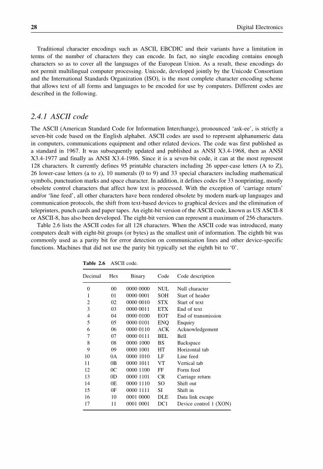
Table 2.6 lists the ASCII codes for all 128 characters. When the ASCII code was introduced, manycomputers dealt with eight-bit groups (or bytes) as the smallest unit of information. The eighth bit wascommonly used as a parity bit for error detection on communication lines and other device-specificfunctions. Machines that did not use the parity bit typically set the eighth bit to ‘0’.
Table 2.6 ASCII code.
Decimal Hex Binary Code Code description
0 00 0000 0000 NUL Null character1 01 0000 0001 SOH Start of header2 02 0000 0010 STX Start of text3 03 0000 0011 ETX End of text4 04 0000 0100 EOT End of transmission5 05 0000 0101 ENQ Enquiry6 06 0000 0110 ACK Acknowledgement7 07 0000 0111 BEL Bell8 08 0000 1000 BS Backspace9 09 0000 1001 HT Horizontal tab
10 0A 0000 1010 LF Line feed11 0B 0000 1011 VT Vertical tab12 0C 0000 1100 FF Form feed13 0D 0000 1101 CR Carriage return14 0E 0000 1110 SO Shift out15 0F 0000 1111 SI Shift in16 10 0001 0000 DLE Data link escape17 11 0001 0001 DC1 Device control 1 (XON)

Binary Codes 29
Table 2.6 (continued).
Decimal Hex Binary Code Code description
18 12 0001 0010 DC2 Device control 219 13 0001 0011 DC3 Device control 3 (XOFF)20 14 0001 0100 DC4 Device control 421 15 0001 0101 NAK Negative acknowledgement22 16 0001 0110 SYN Synchronous idle23 17 0001 0111 ETB End of transmission block24 18 0001 1000 CAN Cancel25 19 0001 1001 EM End of medium26 1A 0001 1010 SUB Substitute27 1B 0001 1011 ESC Escape28 1C 0001 1100 FS File separator29 1D 0001 1101 GS Group separator30 1E 0001 1110 RS Record separator31 1F 0001 1111 US Unit separator32 20 0010 0000 SP Space33 21 0010 0001 ! Exclamation point34 22 0010 0010 " Quotation mark35 23 0010 0011 # Number sign, octothorp, pound36 24 0010 0100 $ Dollar sign37 25 0010 0101 % Percent38 26 0010 0110 & Ampersand39 27 0010 0111 ’ Apostrophe, prime40 28 0010 1000 ( Left parenthesis41 29 0010 1001 ) Right parenthesis42 2A 0010 1010 * Asterisk, ‘star’43 2B 0010 1011 + Plus sign44 2C 0010 1100 , Comma45 2D 0010 1101 - Hyphen, minus sign46 2E 0010 1110 . Period, decimal Point, ‘dot’47 2F 0010 1111 / Slash, virgule48 30 0011 0000 0 049 31 0011 0001 1 150 32 0011 0010 2 251 33 0011 0011 3 352 34 0011 0100 4 453 35 0011 0101 5 554 36 0011 0110 6 655 37 0011 0111 7 756 38 0011 1000 8 857 39 0011 1001 9 958 3A 0011 1010 : Colon59 3B 0011 1011 ; Semicolon60 3C 0011 1100 < Less-than sign61 3D 0011 1101 = Equals sign62 3E 0011 1110 > Greater-than sign63 3F 0011 1111 ? Question mark64 40 0100 0000 @ At sign65 41 0100 0001 A A
(continued overleaf)

30 Digital Electronics
Table 2.6 (continued).
Decimal Hex Binary Code Code description
66 42 0100 0010 B B67 43 0100 0011 C C68 44 0100 0100 D D69 45 0100 0101 E E70 46 0100 0110 F F71 47 0100 0111 G G72 48 0100 1000 H H73 49 0100 1001 I I74 4A 0100 1010 J J75 4B 0100 1011 K K76 4C 0100 1100 L L77 4D 0100 1101 M M78 4E 0100 1110 N N79 4F 0100 1111 O O80 50 0101 0000 P P81 51 0101 0001 Q Q82 52 0101 0010 R R83 53 0101 0011 S S84 54 0101 0100 T T85 55 0101 0101 U U86 56 0101 0110 V V87 57 0101 0111 W W88 58 0101 1000 X X89 59 0101 1001 Y Y90 5A 0101 1010 Z Z91 5B 0101 1011 [ Opening bracket92 5C 0101 1100 \ Reverse slash93 5D 0101 1101 ] Closing bracket94 5E 0101 1110 ∧ Circumflex, caret95 5F 0101 1111 _ Underline, underscore96 60 0110 0000 ` Grave accent97 61 0110 0001 a a98 62 0110 0010 b b99 63 0110 0011 c c
100 64 0110 0100 d d101 65 0110 0101 e e102 66 0110 0110 f f103 67 0110 0111 g g104 68 0110 1000 h h105 69 0110 1001 i i106 6A 0110 1010 j j107 6B 0110 1011 k k108 6C 0110 1100 l l109 6D 0110 1101 m m110 6E 0110 1110 n n111 6F 0110 1111 o o112 70 0111 0000 p p113 71 0111 0001 q q114 72 0111 0010 r r

Binary Codes 31
Table 2.6 (continued).
Decimal Hex Binary Code Code description
115 73 0111 0011 s s116 74 0111 0100 t t117 75 0111 0101 u u118 76 0111 0110 v v119 77 0111 0111 w w120 78 0111 1000 x x121 79 0111 1001 y y122 7A 0111 1010 z z123 7B 0111 1011 { Opening brace124 7C 0111 1100 � Vertical line125 7D 0111 1101 } Closing brace126 7E 0111 1110 ∼ Tilde127 7F 0111 1111 DEL Delete
Looking at the structural features of the code as reflected in Table 2.6, we can see that the digits 0 to9 are represented with their binary values prefixed with 0011. That is, numerals 0 to 9 are representedby binary sequences from 0011 0000 to 0011 1001 respectively. Also, lower-case and upper-caseletters differ in bit pattern by a single bit. While upper-case letters ‘A’ to ‘O’ are represented by 01000001 to 0100 1111, lower-case letters ‘a’ to ‘o’ are represented by 0110 0001 to 0110 1111. Similarly,while upper-case letters ‘P’ to ‘Z’ are represented by 0101 0000 to 0101 1010, lower-case letters ‘p’to ‘z’ are represented by 0111 0000 to 0111 1010.
With widespread use of computer technology, many variants of the ASCII code have evolved overthe years to facilitate the expression of non-English languages that use a Roman-based alphabet. Insome of these variants, all ASCII printable characters are identical to their seven-bit ASCII coderepresentations. For example, the eight-bit standard ISO/IEC 8859 was developed as a true extensionof ASCII, leaving the original character mapping intact in the process of inclusion of additional values.This made possible representation of a broader range of languages. In spite of the standard sufferingfrom incompatibilities and limitations, ISO-8859-1, its variant Windows-1252 and the original seven-bitASCII continue to be the most common character encodings in use today.
2.4.2 EBCDIC code
The EBCDIC (Extended Binary Coded Decimal Interchange Code), pronounced ‘eb-si-dik’, is anotherwidely used alphanumeric code, mainly popular with larger systems. The code was created by IBM toextend the binary coded decimal that existed at that time. All IBM mainframe computer peripheralsand operating systems use EBCDIC code, and their operating systems provide ASCII and Unicodemodes to allow translation between different encodings. It may be mentioned here that EBCDIC offersno technical advantage over the ASCII code and its variant ISO-8859 or Unicode. Its importance in theearlier days lay in the fact that it made it relatively easier to enter data into larger machines with punchcards. Since, punch cards are not used on mainframes any more, the code is used in contemporarymainframe machines solely for backwards compatibility.
It is an eight-bit code and thus can accommodate up to 256 characters. Table 2.7 gives the listing ofcharacters in binary as well as hex form in EBCDIC. The arrangement is similar to the one adoptedfor Table 2.6 for the ASCII code. A single byte in EBCDIC is divided into two four-bit groups called

32 Digital Electronics
Table 2.7 EBCDIC code.
Decimal Hex Binary Code Code description
0 00 0000 0000 NUL Null character1 01 0000 0001 SOH Start of header2 02 0000 0010 STX Start of text3 03 0000 0011 ETX End of text4 04 0000 0100 PF Punch off5 05 0000 0101 HT Horizontal tab6 06 0000 0110 LC Lower case7 07 0000 0111 DEL Delete8 08 0000 10009 09 0000 1001
10 0A 0000 1010 SMM Start of manual message11 0B 0000 1011 VT Vertical tab12 0C 0000 1100 FF Form feed13 0D 0000 1101 CR Carriage return14 0E 0000 1110 SO Shift out15 0F 0000 1111 SI Shift in16 10 0001 0000 DLE Data link escape17 11 0001 0001 DC1 Device control 118 12 0001 0010 DC2 Device control 219 13 0001 0011 TM Tape mark20 14 0001 0100 RES Restore21 15 0001 0101 NL New line22 16 0001 0110 BS Backspace23 17 0001 0111 IL Idle24 18 0001 1000 CAN Cancel25 19 0001 1001 EM End of medium26 1A 0001 1010 CC Cursor control27 1B 0001 1011 CU1 Customer use 128 1C 0001 1100 IFS Interchange file separator29 1D 0001 1101 IGS Interchange group separator30 1E 0001 1110 IRS Interchange record separator31 1F 0001 1111 IUS Interchange unit separator32 20 0010 0000 DS Digit select33 21 0010 0001 SOS Start of significance34 22 0010 0010 FS Field separator35 23 0010 001136 24 0010 0100 BYP Bypass37 25 0010 0101 LF Line feed38 26 0010 0110 ETB End of transmission block39 27 0010 0111 ESC Escape40 28 0010 100041 29 0010 100142 2A 0010 1010 SM Set mode43 2B 0010 1011 CU2 Customer use 244 2C 0010 110045 2D 0010 1101 ENQ Enquiry46 2E 0010 1110 ACK Acknowledge47 2F 0010 1111 BEL Bell48 30 0011 0000

Binary Codes 33
Table 2.7 (continued).
Decimal Hex Binary Code Code description
49 31 0011 000150 32 0011 0010 SYN Synchronous idle51 33 0011 001152 34 0011 0100 PN Punch on53 35 0011 0101 RS Reader stop54 36 0011 0110 UC Upper case55 37 0011 0111 EOT End of transmission56 38 0011 100057 39 0011 100158 3A 0011 101059 3B 0011 1011 CU3 Customer use 360 3C 0011 1100 DC4 Device control 461 3D 0011 1101 NAK Negative acknowledge62 3E 0011 111063 3F 0011 1111 SUB Substitute64 40 0100 0000 SP Space65 41 0100 000166 42 0100 001067 43 0100 001168 44 0100 010069 45 0100 010170 46 0100 011071 47 0100 011172 48 0100 100073 49 0100 100174 4A 0100 1010 � c Cent sign75 4B 0100 1011 . Period, decimal point76 4C 0100 1100 < Less-than sign77 4D 0100 1101 ( Left parenthesis78 4E 0100 1110 + Plus sign79 4F 0100 1111 � Logical OR80 50 0101 0000 & Ampersand81 51 0101 000182 52 0101 001083 53 0101 001184 54 0101 010085 55 0101 010186 56 0101 011087 57 0101 011188 58 0101 100089 59 0101 100190 5A 0101 1010 ! Exclamation point91 5B 0101 1011 $ Dollar sign92 5C 0101 1100 * Asterisk93 5D 0101 1101 ) Right parenthesis94 5E 0101 1110 ; Semicolon95 5F 0101 1111 ∧ Logical NOT96 60 0110 0000 - Hyphen, minus sign
(continued overleaf )

34 Digital Electronics
Table 2.7 (continued).
Decimal Hex Binary Code Code description
97 61 0110 0001 / Slash, virgule98 62 0110 001099 63 0110 0011
100 64 0110 0100101 65 0110 0101102 66 0110 0110103 67 0110 0111104 68 0110 1000105 69 0110 1001106 6A 0110 1010107 6B 0110 1011 , Comma108 6C 0110 1100 % Percent109 6D 0110 1101 _ Underline, underscore110 6E 0110 1110 > Greater-than sign111 6F 0110 1111 ? Question mark112 70 0111 0000113 71 0111 0001114 72 0111 0010115 73 0111 0011116 74 0111 0100117 75 0111 0101118 76 0111 0110119 77 0111 0111120 78 0111 1000121 79 0111 1001 ‘ Grave accent122 7A 0111 1010 : Colon123 7B 0111 1011 # Number sign, octothorp, pound124 7C 0111 1100 @ At sign125 7D 0111 1101 ’ Apostrophe, prime126 7E 0111 1110 = Equals sign127 7F 0111 1111 “ Quotation mark128 80 1000 0000129 81 1000 1001 a a130 82 1000 1010 b b131 83 1000 1011 c c132 84 1000 1100 d d133 85 1000 0101 e e134 86 1000 0110 f f135 87 1000 0111 g g136 88 1000 1000 h h137 89 1000 1001 i i138 8A 1000 1010139 8B 1000 1011140 8C 1000 1100141 8D 1000 1101142 8E 1000 1110143 8F 1000 1111144 90 1001 0000145 91 1001 0001 j j

Binary Codes 35
Table 2.7 (continued).
Decimal Hex Binary Code Code description
146 92 1001 0010 k k147 93 1001 0011 l l148 94 1001 0100 m m149 95 1001 0101 n n150 96 1001 0110 o o151 97 1001 0111 p p152 98 1001 1000 q q153 99 1001 1001 r r154 9A 1001 1010155 9B 1001 1011156 9C 1001 1100157 9D 1001 1101158 9E 1001 1110159 9F 1001 1111160 A0 1010 0000161 A1 1010 0001 ∼ Tilde162 A2 1010 0010 s s163 A3 1010 0011 t t164 A4 1010 0100 u u165 A5 1010 0101 v v166 A6 1010 0110 w w167 A7 1010 0111 x x168 A8 1010 1000 y y169 A9 1010 1001 z z170 AA 1010 1010171 AB 1010 1011172 AC 1010 1100173 AD 1010 1101174 AE 1010 1110175 AF 1010 1111176 B0 1011 0000177 B1 1011 0001178 B2 1011 0010179 B3 1011 0011180 B4 1011 0100181 B5 1011 0101182 B6 1011 0110183 B7 1011 0111184 B8 1011 1000185 B9 1011 1001186 BA 1011 1010187 BB 1011 1011188 BC 1011 1100189 BD 1011 1101190 BE 1011 1110191 BF 1011 1111192 C0 1100 0000 { Opening brace193 C1 1100 0001 A A
(continued overleaf)

36 Digital Electronics
Table 2.7 (continued).
Decimal Hex Binary Code Code description
194 C2 1100 0010 B B195 C3 1100 0011 C C196 C4 1100 0100 D D197 C5 1100 0101 E E198 C6 1100 0110 F F199 C7 1100 0111 G G200 C8 1100 1000 H H201 C9 1100 1001 I I202 CA 1100 1010203 CB 1100 1011204 CC 1100 1100205 CD 1100 1101206 CE 1100 1110207 CF 1100 1111208 D0 1101 0000 } Closing brace209 D1 1101 0001 J J210 D2 1101 0010 K K211 D3 1101 0011 L L212 D4 1101 0100 M M213 D5 1101 0101 N N214 D6 1101 0110 O O215 D7 1101 0111 P P216 D8 1101 1000 Q Q217 D9 1101 1001 R R218 DA 1101 1010219 DB 1101 1011220 DC 1101 1100221 DD 1101 1101222 DE 1101 1110223 DF 1101 1111224 E0 1110 0000 \ Reverse slant225 E1 1110 0001226 E2 1110 0010 S S227 E3 1110 0011 T T228 E4 1110 0100 U U229 E5 1110 0101 V V230 E6 1110 0110 W W231 E7 1110 0111 X X232 E8 1110 1000 Y Y233 E9 1110 1001 Z Z234 EA 1110 1010235 EB 1110 1011236 EC 1110 1100237 ED 1110 1101238 EE 1110 1110239 EF 1110 1111240 F0 1111 0000 0 0241 F1 1111 0001 1 1

Binary Codes 37
Table 2.7 (continued).
Decimal Hex Binary Code Code description
242 F2 1111 0010 2 2243 F3 1111 0011 3 3244 F4 1111 0100 4 4245 F5 1111 0101 5 5246 F6 1111 0110 6 6247 F7 1111 0111 7 7248 F8 1111 1000 8 8249 F9 1111 1001 9 9250 FA 1111 1010 �251 FB 1111 1011252 FC 1111 1100253 FD 1111 1101254 FE 1111 1110255 FF 1111 1111 eo
nibbles. The first four-bit group, called the ‘zone’, represents the category of the character, while thesecond group, called the ‘digit’, identifies the specific character.
2.4.3 Unicode
As briefly mentioned in the earlier sections, encodings such as ASCII, EBCDIC and their variantsdo not have a sufficient number of characters to be able to encode alphanumeric data of all forms,scripts and languages. As a result, these encodings do not permit multilingual computer processing.In addition, these encodings suffer from incompatibility. Two different encodings may use the samenumber for two different characters or different numbers for the same characters. For example, code4E (in hex) represents the upper-case letter ‘N’ in ASCII code and the plus sign ‘+’ in the EBCDICcode. Unicode, developed jointly by the Unicode Consortium and the International Organization forStandardization (ISO), is the most complete character encoding scheme that allows text of all formsand languages to be encoded for use by computers. It not only enables the users to handle practicallyany language and script but also supports a comprehensive set of mathematical and technical symbols,greatly simplifying any scientific information exchange. The Unicode standard has been adopted bysuch industry leaders as HP, IBM, Microsoft, Apple, Oracle, Unisys, Sun, Sybase, SAP and many more.
Unicode and ISO-10646 Standards
Before we get on to describe salient features of Unicode, it may be mentioned that another standardsimilar in intent and implementation to Unicode is the ISO-10646. While Unicode is the brainchild ofthe Unicode Consortium, a consortium of manufacturers (initially mostly US based) of multilingualsoftware, ISO-10646 is the project of the International Organization for Standardization. Althoughboth organizations publish their respective standards independently, they have agreed to maintaincompatibility between the code tables of Unicode and ISO-10646 and closely coordinate any furtherextensions.

3Digital Arithmetic
Having discussed different methods of numeric and alphanumeric data representation in the first twochapters, the next obvious step is to study the rules of data manipulation. Two types of operationthat are performed on binary data include arithmetic and logic operations. Basic arithmetic operationsinclude addition, subtraction, multiplication and division. AND, OR and NOT are the basic logicfunctions. While the rules of arithmetic operations are covered in the present chapter, those related tologic operations will be discussed in the next chapter.
3.1 Basic Rules of Binary Addition and SubtractionThe basic principles of binary addition and subtraction are similar to what we all know so well inthe case of the decimal number system. In the case of addition, adding ‘0’ to a certain digit producesthe same digit as the sum, and, when we add ‘1’ to a certain digit or number in the decimal numbersystem, the result is the next higher digit or number, as the case may be. For example, 6 + 1 in decimalequals ‘7’ because ‘7’ immediately follows ‘6’ in the decimal number system. Also, 7 + 1 in octalequals ‘10’ as, in the octal number system, the next adjacent higher number after ‘7’ is ‘10’. Similarly,9 + 1 in the hexadecimal number system is ‘A’. With this background, we can write the basic rules ofbinary addition as follows:
1. 0 + 0 = 0.2. 0 + 1 = 1.3. 1 + 0 = 1.4. 1 + 1 = 0 with a carry of ‘1’ to the next more significant bit.5. 1 + 1 + 1 = 1 with a carry of ‘1’ to the next more significant bit.
Table 3.1 summarizes the sum and carry outputs of all possible three-bit combinations. We havetaken three-bit combinations as, in all practical situations involving the addition of two larger bit
Digital Electronics: Principles, Devices and Applications Anil K. Maini© 2007 John Wiley & Sons, Ltd. ISBN: 978-0-470-03214-5

48 Digital Electronics
Table 3.1 Binary addition of three bits.
A B Carry- Sum Carry- A B Carry- Sum Carry-in (Cin) out (Co) in (Cin) out (Co)
0 0 0 0 0 1 0 0 1 00 0 1 1 0 1 0 1 0 10 1 0 1 0 1 1 0 0 10 1 1 0 1 1 1 1 1 1
numbers, we need to add three bits at a time. Two of the three bits are the bits that are part of the twobinary numbers to be added, and the third bit is the carry-in from the next less significant bit column.
The basic principles of binary subtraction include the following:
1. 0 − 0 = 0.2. 1 − 0 = 1.3. 1 − 1 = 0.4. 0 − 1 = 1 with a borrow of 1 from the next more significant bit.
The above-mentioned rules can also be explained by recalling rules for subtracting decimal numbers.Subtracting ‘0’ from any digit or number leaves the digit or number unchanged. This explainsthe first two rules. Subtracting ‘1’ from any digit or number in decimal produces the immediatelypreceding digit or number as the answer. In general, the subtraction operation of larger-bit binarynumbers also involves three bits, including the two bits involved in the subtraction, called the minuend(the upper bit) and the subtrahend (the lower bit), and the borrow-in. The subtraction operationproduces the difference output and borrow-out, if any. Table 3.2 summarizes the binary subtractionoperation. The entries in Table 3.2 can be explained by recalling the basic rules of binary subtractionmentioned above, and that the subtraction operation involving three bits, that is, the minuend (A�,the subtrahend (B� and the borrow-in (Bin�, produces a difference output equal to (A − B − Bin�.It may be mentioned here that, in the case of subtraction of larger-bit binary numbers, the leastsignificant bit column always involves two bits to produce a difference output bit and the borrow-out
Table 3.2 Binary subtraction.
Inputs Outputs
Minuend Subtrahend Borrow-in Difference Borrow-out(A) (B) (Bin) (D) (Bo)
0 0 0 0 00 0 1 1 10 1 0 1 10 1 1 0 11 0 0 1 01 0 1 0 01 1 0 0 01 1 1 1 1

Digital Arithmetic 49
bit. The borrow-out bit produced here becomes the borrow-in bit for the next more significant bitcolumn, and the process continues until we reach the most significant bit column. The addition andsubtraction of larger-bit binary numbers is illustrated with the help of examples in sections 3.2 and 3.3respectively.
3.2 Addition of Larger-Bit Binary NumbersThe addition of larger binary integers, fractions or mixed binary numbers is performed columnwisein just the same way as in the case of decimal numbers. In the case of binary numbers, however, wefollow the basic rules of addition of two or three binary digits, as outlined earlier. The process ofadding two larger-bit binary numbers can be best illustrated with the help of an example.
Consider two generalized four-bit binary numbers (A3 A2 A1 A0� and (B3 B2 B1 B0�, with A0 and B0
representing the LSB and A3 and B3 representing the MSB of the two numbers. The addition of thesetwo numbers is performed as follows. We begin with the LSB position. We add the LSB bits andrecord the sum S0 below these bits in the same column and take the carry C0, if any, to the next columnof bits. For instance, if A0 = 1 and B0 = 0, then S0 = 1 and C0 = 0. Next we add the bits A1 and B1
and the carry C0 from the previous addition. The process continues until we reach the MSB bits. Thefour steps are shown ahead. C0, C1, C2 and C3 are carrys, if any, produced as a result of adding first,second, third and fourth column bits respectively, starting from LSB and proceeding towards MSB. Asimilar procedure is followed when the given numbers have both integer as well as fractional parts:
(C0� (C1� (C0�1. A3 A2 A1 A0 2. A3 A2 A1 A0
B3 B2 B1 B0 B3 B2 B1 B0
S0 S1 S0
(C2� (C1� (C0� (C2� (C1� (C0�3. A3 A2 A1 A0 4. A3 A2 A1 A0
B3 B2 B1 B0 B3 B2 B1 B0
S2 S1 S0 C3 S3 S2 S1 S0
3.2.1 Addition Using the 2’s Complement Method
The 2’s complement is the most commonly used code for processing positive and negative binarynumbers. It forms the basis of arithmetic circuits in modern computers. When the decimal numbers tobe added are expressed in 2’s complement form, the addition of these numbers, following the basiclaws of binary addition, gives correct results. Final carry obtained, if any, while adding MSBs shouldbe disregarded. To illustrate this, we will consider the following four different cases:
1. Both the numbers are positive.2. Larger of the two numbers is positive.3. The larger of the two numbers is negative.4. Both the numbers are negative.

50 Digital Electronics
Case 1
• Consider the decimal numbers +37 and +18.• The 2’s complement of +37 in eight-bit representation = 00100101.• The 2’s complement of +18 in eight-bit representation = 00010010.• The addition of the two numbers, that is, +37 and +18, is performed as follows
00100101+ 00010010
00110111
• The decimal equivalent of (00110111)2 is (+55), which is the correct answer.
Case 2
• Consider the two decimal numbers +37 and -18.• The 2’s complement representation of +37 in eight-bit representation = 00100101.• The 2’s complement representation of −18 in eight-bit representation = 11101110.• The addition of the two numbers, that is, +37 and −18, is performed as follows:
00100101+ 11101110
00010011
• The final carry has been disregarded.• The decimal equivalent of (00010011)2 is +19, which is the correct answer.
Case 3
• Consider the two decimal numbers +18 and −37.• −37 in 2’s complement form in eight−bit representation = 11011011.• +18 in 2’s complement form in eight−bit representation = 00010010.• The addition of the two numbers, that is, −37 and +18, is performed as follows:
11011011+ 00010010
11101101
• The decimal equivalent of (11101101)2, which is in 2’s complement form, is −19, which is thecorrect answer. 2’s complement representation was discussed in detail in Chapter 1 on numbersystems.
Case 4
• Consider the two decimal numbers −18 and −37.• −18 in 2’s complement form is 11101110.• −37 in 2’s complement form is 11011011.• The addition of the two numbers, that is, −37 and −18, is performed as follows:

Digital Arithmetic 51
11011011+ 11101110
11001001
• The final carry in the ninth bit position is disregarded.• The decimal equivalent of (11001001)2, which is in 2’s complement form, is −55, which is the
correct answer.
It may also be mentioned here that, in general, 2’s complement notation can be used to performaddition when the expected result of addition lies in the range from −2n−1 to +(2n−1 − 1), n beingthe number of bits used to represent the numbers. As an example, eight-bit 2’s complement arithmeticcannot be used to perform addition if the result of addition lies outside the range from −128 to +127.Different steps to be followed to do addition in 2’s complement arithmetic are summarized as follows:
1. Represent the two numbers to be added in 2’s complement form.2. Do the addition using basic rules of binary addition.3. Disregard the final carry, if any.4. The result of addition is in 2’s complement form.
Example 3.1
Perform the following addition operations:
1. (275.75)10+ (37.875)10�2. (AF1.B3)16+ (FFF.E)16�
Solution1. As a first step, the two given decimal numbers will be converted into their equivalent binary
numbers (decimal-to-binary conversion has been covered at length in Chapter 1, and therefore thedecimal-to-binary conversion details will not be given here):
(275.75)10 = (100010011.11)2 and (37.875)10 = (100101.111)2
The two binary numbers can be rewritten as (100010011.110)2 and (000100101.111)2 to have thesame number of bits in their integer and fractional parts. The addition of two numbers is performedas follows:
100010011�110000100101�111100111001�101
The decimal equivalent of (100111001.101)2 is (313.625)10.

52 Digital Electronics
2. (AF1.B3)16 = (101011110001.10110011)2 and (FFF.E)16 = (111111111111.1110)2. (111111111111.1110)2 can also be written as (111111111111.11100000)2 to have the same number of bits inthe integer and fractional parts. The two numbers can now be added as follows:
0101011110001�101100110111111111111�111000001101011110001�10010011
The hexadecimal equivalent of (1101011110001.10010011)2 is (1AF1.93)16, which is equal to thehex addition of (AF1.B3)16 and (FFF.E)16.
Example 3.2
Find out whether 16-bit 2’s complement arithmetic can be used to add 14 276 and 18 490.
SolutionThe addition of decimal numbers 14 276 and 18 490 would yield 32 766. 16-bit 2’s complementarithmetic has a range of −215 to +(215 − 1), i.e. −32 768 to +32 767. The expected result is insidethe allowable range. Therefore, 16-bit arithmetic can be used to add the given numbers.
Example 3.3
Add −118 and −32 firstly using eight-bit 2’s complement arithmetic and then using 16-bit 2’scomplement arithmetic. Comment on the results.
Solution• −118 in eight-bit 2’s complement representation = 10001010.• −32 in eight-bit 2’s complement representation = 11100000.• The addition of the two numbers, after disregarding the final carry in the ninth bit position, is
01101010. Now, the decimal equivalent of (01101010)2, which is in 2’s complement form, is +106.The reason for the wrong result is that the expected result, i.e. −150, lies outside the range ofeight-bit 2’s complement arithmetic. Eight-bit 2’s complement arithmetic can be used when theexpected result lies in the range from −27 to + (27 − 1), i.e. −128 to +127. −118 in 16-bit 2’scomplement representation = 1111111110001010.
• −32 in 16-bit 2’s complement representation = 1111111111100000.• The addition of the two numbers, after disregarding the final carry in the 17th position, produces
1111111101101010. The decimal equivalent of (1111111101101010)2, which is in 2’s complementform, is −150, which is the correct answer. 16-bit 2’s complement arithmetic has produced thecorrect result, as the expected result lies within the range of 16-bit 2’s complement notation.
3.3 Subtraction of Larger-Bit Binary NumbersSubtraction is also done columnwise in the same way as in the case of the decimal number system.In the first step, we subtract the LSBs and subsequently proceed towards the MSB. Wherever thesubtrahend (the bit to be subtracted) is larger than the minuend, we borrow from the next adjacent

Digital Arithmetic 53
higher bit position having a ‘1’. As an example, let us go through different steps of subtracting (1001)2
from (1100)2.In this case, ‘1’ is borrowed from the second MSB position, leaving a ‘0’ in that position. The
borrow is first brought to the third MSB position to make it ‘10’. Out of ‘10’ in this position,‘1’ is taken to the LSB position to make ‘10’ there, leaving a ‘1’ in the third MSB position.10 − 1 in the LSB column gives ‘1’, 1 − 0 in the third MSB column gives ‘1’, 0 − 0 in the secondMSB column gives ‘0’ and 1 − 1 in the MSB also gives ‘0’ to complete subtraction. Subtractionof mixed numbers is also done in the same manner. The above-mentioned steps are summarizedas follows:
1. 1 1 0 0 2. 1 1 0 01 0 0 1 1 0 0 1
1 1 1
3. 1 1 0 0 4. 1 1 0 01 0 0 1 1 0 0 1
0 1 1 0 0 1 1
3.3.1 Subtraction Using 2’s Complement Arithmetic
Subtraction is similar to addition. Adding 2’s complement of the subtrahend to the minuend anddisregarding the carry, if any, achieves subtraction. The process is illustrated by considering sixdifferent cases:
1. Both minuend and subtrahend are positive. The subtrahend is the smaller of the two.2. Both minuend and subtrahend are positive. The subtrahend is the larger of the two.3. The minuend is positive. The subtrahend is negative and smaller in magnitude.4. The minuend is positive. The subtrahend is negative and greater in magnitude.5. Both minuend and subtrahend are negative. The minuend is the smaller of the two.6. Both minuend and subtrahend are negative. The minuend is the larger of the two.
Case 1
• Let us subtract +14 from +24.• The 2’s complement representation of +24 = 00011000.• The 2’s complement representation of +14 = 00001110.• Now, the 2’s complement of the subtrahend (i.e. +14) is 11110010.• Therefore, +24 − (+14) is given by
00011000+ 11110010
00001010
with the final carry disregarded.• The decimal equivalent of (00001010)2 is +10, which is the correct answer.

54 Digital Electronics
Case 2
• Let us subtract +24 from +14.• The 2’s complement representation of +14 = 00001110.• The 2’s complement representation of +24 = 00011000.• The 2’s complement of the subtrahend (i.e. +24) = 11101000.• Therefore, +14 − (+24) is given by
00001110+ 11101000
11110110
• The decimal equivalent of (11110110)2, which is of course in 2’s complement form, is −10 whichis the correct answer.
Case 3
• Let us subtract −14 from +24.• The 2’s complement representation of +24 = 00011000 = minuend.• The 2’s complement representation of −14 = 11110010 = subtrahend.• The 2’s complement of the subtrahend (i.e. −14) = 00001110.• Therefore, +24 − (−14) is performed as follows:
00011000+ 00001110
00100110
• The decimal equivalent of (00100110)2 is +38, which is the correct answer.
Case 4
• Let us subtract −24 from +14.• The 2’s complement representation of +14 = 00001110 = minuend.• The 2’s complement representation of −24 = 11101000 = subtrahend.• The 2’s complement of the subtrahend (i.e. −24) = 00011000.• Therefore, +14 − (−24) is performed as follows:
00001110+ 00011000
00100110
• The decimal equivalent of (00100110)2 is +38, which is the correct answer.
Case 5
• Let us subtract −14 from −24.• The 2’s complement representation of −24 = 11101000 = minuend.

Digital Arithmetic 55
• The 2’s complement representation of −14=11110010 = subtrahend.• The 2’s complement of the subtrahend = 00001110.• Therefore, −24 − (−14) is given as follows:
11101000+ 00001110
11110110
• The decimal equivalent of (11110110)2, which is in 2’s complement form, is −10, which is thecorrect answer.
Case 6
• Let us subtract −24 from −14.• The 2’s complement representation of −14 = 11110010 = minuend.• The 2’s complement representation of −24=11101000 = subtrahend.• The 2’s complement of the subtrahend = 00011000.• Therefore, −14 − (−24) is given as follows:
11110010+ 00011000
00001010
with the final carry disregarded.• The decimal equivalent of (00001010)2, which is in 2’s complement form, is +10, which is the
correct answer.
It may be mentioned that, in 2’s complement arithmetic, the answer is also in 2’s complementnotation, only with the MSB indicating the sign and the remaining bits indicating the magnitude. In2’s complement notation, positive magnitudes are represented in the same way as the straight binarynumbers, while the negative magnitudes are represented as the 2’s complement of their straight binarycounterparts. A ‘0’ in the MSB position indicates a positive sign, while a ‘1’ in the MSB positionindicates a negative sign.
The different steps to be followed to do subtraction in 2’s complement arithmetic are summarizedas follows:
1. Represent the minuend and subtrahend in 2’s complement form.2. Find the 2’s complement of the subtrahend.3. Add the 2’s complement of the subtrahend to the minuend.4. Disregard the final carry, if any.5. The result is in 2’s complement form.6. 2’s complement notation can be used to perform subtraction when the expected result of subtraction
lies in the range from −2n−1 to +(2n−1 − 1), n being the number of bits used to represent thenumbers.

56 Digital Electronics
Example 3.4
Subtract (1110.011)2 from (11011.11)2 using basic rules of binary subtraction and verify the result byshowing equivalent decimal subtraction.
SolutionThe minuend and subtrahend are first modified to have the same number of bits in the integer andfractional parts. The modified minuend and subtrahend are (11011.110)2 and (01110.011)2 respectively:
11011�110− 01110�011
01101�011
The decimal equivalents of (11011.110)2 and (01110.011)2 are 27.75 and 14.375 respectively. Theirdifference is 13.375, which is the decimal equivalent of (01101.011)2.
Example 3.5
Subtract (a) (−64)10 from (+32)10 and (b) (29.A)16 from (4F.B)16. Use 2’s complement arithmetic.
Solution:(a) (+32)10in 2’s complement notation = (00100000)2.
(−64)10 in 2’s complement notation = (11000000)2.The 2’s complement of (−64)10 = (01000000)2.(+32)10 − (−64)10 is determined by adding the 2’s complement of (−64)10 to (+32)10.Therefore, the addition of (00100000)2 to (01000000)2 should give the result. The operation isshown as follows:
00100000+ 01000000
01100000
The decimal equivalent of (01100000)2 is +96, which is the correct answer as +32 − (−64) = +96.(b) The minuend = (4F.B)16 = (01001111.1011)2.
The minuend in 2’s complement notation = (01001111.1011)2.The subtrahend = (29.A)16 = (00101001.1010)2.The subtrahend in 2’s complement notation = (00101001.1010)2.The 2’s complement of the subtrahend = (11010110.0110)2.(4F.B)16 − (29.A)16 is given by the addition of the 2’s complement of the subtrahend to theminuend.
01001111�1011+ 11010110�0110
00100110�0001
with the final carry disregarded. The result is also in 2’s complement form. Since the result is apositive number, 2’s complement notation is the same as it would be in the case of the straightbinary code.The hex equivalent of the resulting binary number = (26.1)16, which is the correct answer.

Digital Arithmetic 57
3.4 BCD Addition and Subtraction in Excess-3 CodeBelow, we will see how the excess-3 code can be used to perform addition and subtraction operationson BCD numbers.
3.4.1 Addition
The excess-3 code can be very effectively used to perform the addition of BCD numbers. The steps tobe followed for excess-3 addition of BCD numbers are as follows:
1. The given BCD numbers are written in excess-3 form by adding ‘0011’ to each of the four-bitgroups.
2. The two numbers are then added using the basic laws of binary addition.3. Add ‘0011’ to all those four-bit groups that produce a carry, and subtract ‘0011’ from all those
four-bit groups that do not produce a carry during addition.4. The result thus obtained is in excess-3 form.
3.4.2 Subtraction
Subtraction of BCD numbers using the excess-3 code is similar to the addition process discussedabove. The steps to be followed for excess-3 substraction of BCD numbers are as follows:
1. Express both minuend and subtrahend in excess-3 code.2. Perform subtraction following the basic laws of binary subtraction.3. Subtract ‘0011’ from each invalid BCD four-bit group in the answer.4. Subtract ‘0011’ from each BCD four-bit group in the answer if the subtraction operation of the
relevant four-bit groups required a borrow from the next higher adjacent four-bit group.5. Add ‘0011’ to the remaining four-bit groups, if any, in the result.6. This gives the result in excess-3 code.
The process of addition and subtraction can be best illustrated with the help of following examples.
Example 3.6
Add (0011 0101 0110)BCD and (0101 0111 1001)BCD using the excess-3 addition method and verify theresult using equivalent decimal addition.
SolutionThe excess-3 equivalents of 0011 0101 0110 and 0101 0111 1001 are 0110 1000 1001 and 1000 10101100 respectively. The addition of the two excess-3 numbers is given as follows:
0110 1000 10011000 1010 1100
1111 0011 0101
After adding 0011 to the groups that produced a carry and subtracting 0011 from the groups that didnot produce a carry, we obtain the result of the above addition as 1100 0110 1000. Therefore, 1100

58 Digital Electronics
0110 1000 represents the excess-3 code for the true result. The result in BCD code is 1001 0011 0101,which is the BCD equivalent of 935. This is the correct answer as the addition of the given BCDnumbers 0011 0101 0110 = (356)10 and 0101 0111 1001 = (579)10 yields (935)10 only.
Example 3.7
Perform (185) 10− (8)10 using the excess-3 code.
Solution• (185)10 = (0001 1000 0101)BCD.The excess-3 equivalent of (0001 1000 0101)BCD = 0100 1011
1000.• (8)10 = (008)10 = (0000 0000 1000)BCD. The excess-3 equivalent of (0000 0000 1000)BCD = 0011
0011 1011.• Subtraction is performed as follows:
0100 1011 1000− 0011 0011 1011
0001 0111 1101
• In the subtraction operation, the least significant column of four-bit groups needed a borrow, whilethe other two columns did not need any borrow. Also, the least significant column has produced aninvalid BCD code group. Subtracting 0011 from the result of this column and adding 0011 to theresults of other two columns, we get 0100 1010 1010. This now constitutes the result of subtractionexpressed in excess-3 code.
• The result in BCD code is therefore 0001 0111 0111.• The decimal equivalent of 0001 0111 0111 is 177, which is the correct result.
3.5 Binary MultiplicationThe basic rules of binary multiplication are governed by the way an AND gate functions when thetwo bits to be multiplied are fed as inputs to the gate. Logic gates are discussed in detail in the nextchapter. As of now, it would suffice to say that the result of multiplying two bits is the same as theoutput of the AND gate with the two bits applied as inputs to the gate. The basic rules of multiplicationare listed as follows:
1. 0 × 0 = 0.2. 0 × 1 = 0.3. 1 × 0 = 0.4. 1 × 1 = 1.
One of the methods for multiplication of larger-bit binary numbers is similar to what we arefamiliar with in the case of decimal numbers. This is called the ‘repeated left-shift and add’ algorithm.Microprocessors and microcomputers, however, use what is known as the ‘repeated add and right-shift’algorithm to do binary multiplication as it is comparatively much more convenient to implement thanthe ‘repeated left-shift and add’ algorithm. The two algorithms are briefly described below. Also, binarymultiplication of mixed binary numbers is done by performing multiplication without considering the
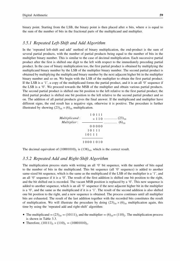
Digital Arithmetic 59
binary point. Starting from the LSB, the binary point is then placed after n bits, where n is equal tothe sum of the number of bits in the fractional parts of the multiplicand and multiplier.
3.5.1 Repeated Left-Shift and Add Algorithm
In the ‘repeated left-shift and add’ method of binary multiplication, the end-product is the sum ofseveral partial products, with the number of partial products being equal to the number of bits in themultiplier binary number. This is similar to the case of decimal multiplication. Each successive partialproduct after the first is shifted one digit to the left with respect to the immediately preceding partialproduct. In the case of binary multiplication too, the first partial product is obtained by multiplying themultiplicand binary number by the LSB of the multiplier binary number. The second partial product isobtained by multiplying the multiplicand binary number by the next adjacent higher bit in the multiplierbinary number and so on. We begin with the LSB of the multiplier to obtain the first partial product.If the LSB is a ‘1’, a copy of the multiplicand forms the partial product, and it is an all ‘0’ sequence ifthe LSB is a ‘0’. We proceed towards the MSB of the multiplier and obtain various partial products.The second partial product is shifted one bit position to the left relative to the first partial product; thethird partial product is shifted one bit position to the left relative to the second partial product and soon. The addition of all partial products gives the final answer. If the multiplicand and multiplier havedifferent signs, the end result has a negative sign, otherwise it is positive. The procedure is furtherillustrated by showing (23)10 × (6)10 multiplication.
Multiplicand �Multiplier �
1 0 1 1 1× 1 1 0
0 0 0 0 01 0 1 1 1
1 0 1 1 1
1 0 0 0 1 0 1 0
�������������� �23�10
�������������� �6�10
The decimal equivalent of (10001010)2 is (138)10, which is the correct result.
3.5.2 Repeated Add and Right-Shift Algorithm
The multiplication process starts with writing an all ‘0’ bit sequence, with the number of bits equalto the number of bits in the multiplicand. This bit sequence (all ‘0’ sequence) is added to anothersame-sized bit sequence, which is the same as the multiplicand if the LSB of the multiplier is a ‘1’, andan all ‘0’ sequence if it is a ‘0’. The result of the first addition is shifted one bit position to the right,and the bit shifted out is recorded. The vacant MSB position is replaced by a ‘0’. This new sequence isadded to another sequence, which is an all ‘0’ sequence if the next adjacent higher bit in the multiplieris a ‘0’, and the same as the multiplicand if it is a ‘1’. The result of the second addition is also shiftedone bit position to the right, and a new sequence is obtained. The process continues until all multiplierbits are exhausted. The result of the last addition together with the recorded bits constitutes the resultof multiplication. We will illustrate the procedure by doing (23)10 × (6)10 multiplication again, thistime by using the ‘repeated add and right-shift’ algorithm:
• The multiplicand = (23)10 = (10111)2 and the multiplier = (6)10= (110)2. The multiplication processis shown in Table 3.3.
• Therefore, (10111)2 × (110)2 = (10001010)2.

60 Digital Electronics
Table 3.3 Multiplication using the repeated add and right-shift algorithm.
1 0 1 1 1 Multiplicand1 1 0 Multiplier
0 0 0 0 0 Start+ 0 0 0 0 0
0 0 0 0 0 Result of first addition
0 0 0 0 0 0 (Result of addition shifted one bit to right)+ 1 0 1 1 1
1 0 1 1 1 Result of second addition
0 1 0 1 1 10 (Result of addition shifted one bit to right)+ 1 0 1 1 1
1 0 0 0 1 0 Result of third addition
0 1 0 0 0 1 010 (Result of addition shifted one bit to right)
Example 3.8
Multiply (a) �100�01�2 × �10�1�2 by using the ‘repeated add and left-shift’ algorithm and (b) (2B)16×�3�16 by using the ‘add and right-shift’ algorithm. Verify the results by showing equivalent decimalmultiplication.
Solution(a) As a first step, we will multiply (10001)2 by (101)2. The process is shown as follows:
1 0 0 0 1× 1 0 1
1 0 0 0 10 0 0 0 0
1 0 0 0 1
1 0 1 0 1 0 1
The multiplication result is then given by placing the binary point three bits after the LSB, whichgives (1010.101)2 as the final result. Also, (100.01)2 = (4.25)10 and (10.1)2 = (2.5)10. Moreover,(4.25)10 × (2.5)10 = (10.625)10 and (1010.101)2 equals (10.625)10, which verifies the result.
(b) (2B)16 = 00101011 = 101011 and (3)16 = 0011 = 11.Different steps involved in the multiplication process are shown in Table 3.4.The result of multiplication is therefore (10000001)2. Also, (2B)16 = (43)10 and (3)16 = (3)10.Therefore, (2B)16 × (3)16 = (129)10. Moreover, (10000001)2 = (129)10, which verifies the result.
3.6 Binary DivisionWhile binary multiplication is the process of repeated addition, binary division is the process ofrepeated subtraction. Binary division can be performed by using either the ‘repeated right-shift and

Digital Arithmetic 61
Table 3.4 Example 3.8.
1 0 1 0 1 1 Multiplicand1 1 Multiplier
0 0 0 0 0 0 Start+ 1 0 1 0 1 1
1 0 1 0 1 1 Result of first addition
0 1 0 1 0 1 1 (Result of addition shifted one bit to right)+ 1 0 1 0 1 1
1 0 0 0 0 0 0 Result of second addition
0 1 0 0 0 0 0 01 (Result of addition shifted one bit to right)
subtract’ or the ‘repeated subtract and left-shift’ algorithm. These are briefly described and suitablyillustrated in the following sections.
3.6.1 Repeated Right-Shift and Subtract Algorithm
The algorithm is similar to the case of conventional division with decimal numbers. At the outset,starting from MSB, we begin with the number of bits in the dividend equal to the number of bits inthe divisor and check whether the divisor is smaller or greater than the selected number of bits inthe dividend. If it happens to be greater, we record a ‘0’ in the quotient column. If it is smaller, wesubtract the divisor from the dividend bits and record a ‘1’ in the quotient column. If it is greater andwe have already recorded a ‘0’, then, as a second step, we include the next adjacent bit in the dividendbits, shift the divisor to the right by one bit position and again make a similar check like the one madein the first step. If it is smaller and we have made the subtraction, then in the second step we appendthe next MSB of the dividend to the remainder, shift the divisor one bit to the right and again make asimilar check. The options are again the same. The process continues until we have exhausted all thebits in the dividend. We will illustrate the algorithm with the help of an example. Let us consider thedivision of (100110)2 by (1100)2. The sequence of operations needed to carry out the above divisionis shown in Table 3.5. The quotient = 011 and the remainder = 10.
Table 3.5 Binary division using the repeated right-shift and subtract algorithm.
Quotient
First step 0 1 0 0 1 1 0 Dividend−1 1 0 0 Divisor
Second step 1 1 0 0 1 1 First five MSBs of dividend−1 1 0 0 Divisor shifted to right
0 1 1 1 First subtraction remainderThird step 1 0 1 1 1 0 Next MSB appended
−1 1 0 0 Divisor right shifted
0 0 1 0 Second subtraction remainder

62 Digital Electronics
Table 3.6 Binary division using the repeate subtract and left-shiftalgorithm.
Quotient 1 0 0 1 1 0−1 1 0 0
0 1 1 0 1 Borrow exists+1 1 0 0
1 0 0 1 Final carry ignored
1 0 0 1 1 Next MSB appended−1 1 0 0
1 0 1 1 1 No borrow
0 1 1 1 0 Next MSB appended−1 1 0 0
1 0 0 0 1 0 No borrow
3.6.2 Repeated Subtract and Left-Shift Algorithm
The procedure can again be best illustrated with the help of an example. Let us consider solving theabove problem using this algorithm. The steps needed to perform the division are as follows. We beginwith the first four MSBs of the dividend, four because the divisor is four bits long. In the first step, wesubtract the divisor from the dividend. If the subtraction requires borrow in the MSB position, enter a‘0’ in the quotient column; otherwise, enter a ‘1’. In the present case there exists a borrow in the MSBposition, and so there is a ‘0’ in the quotient column. If there is a borrow, the divisor is added to theresult of subtraction. In doing so, the final carry, if any, is ignored. The next MSB is appended to theresult of the first subtraction if there is no borrow, or to the result of subtraction, restored by addingthe divisor, if there is a borrow. By appending the next MSB, the remaining bits of the dividend areone bit position shifted to the left. It is again compared with the divisor, and the process is repeated.It goes on until we have exhausted all the bits of the dividend. The final remainder can be furtherprocessed by successively appending 0s and trying subtraction to get fractional part bits of the quotient.The different steps are summarized in Table 3.6. The quotient = 011 and the remainder = 10.
Example 3.9
Use the ‘repeated right-shift and subtract’ algorithm to divide (110101)2 by (1011)2. Determine boththe integer and the fractional parts of the quotient. The fractional part may be determined up to threebit places.
SolutionThe sequence of operations is given in Table 3.7. The operations are self-explanatory.
• The quotient = 100.110.• Now, (110101)2 = (53)10 and (1011)2 = (11)10.• (53)10 divided by (11)10 gives (4.82)10.• (100.110)2 = (4.75)10, which matches with the expected result to a good approximation.

Digital Arithmetic 63
Table 3.7 Example 3.9.
Quotient
First step 1 1 1 0 1 0 1 Dividend−1 0 1 1 Divisor
0 0 1 0 First subtraction
Second step 0 0 0 1 0 0 Next MSB appended−1 0 1 1 Divisor right shifted
Third step 0 0 0 1 0 0 1 Next MSB appended−1 0 1 1 Divisor right shifted
0 0 1 0 0 1 All bits exhausted
1 0 0 1 0 0 1 0 ‘0’ appended−1 0 1 1 Divisor right shifted
0 1 1 1 Second subtraction
Fourth step 1 0 1 1 1 0 ‘0’ appended−1 0 1 1 Divisor right shifted
0 0 0 1 1 Third subtraction
Fifth step 0 0 0 0 1 1 0 ‘0’ appended−1 0 1 1 Divisor right shifted
0 0 1 1 Fourth subtraction
Example 3.10
Use the ‘repeated subtract and left-shift’ algorithm to divide (100011)2 by (100)2 to determine both theinteger and fractional parts of the quotient. Verify the result by showing equivalent decimal division.Determine the fractional part to two bit places.
SolutionThe sequence of operations is given in Table 3.8. The operations are self-explanatory.
• The quotient = (1000.11)2 = (8.75)10.• Now, (100011)2 = (35)10 and (100)2 = (4)10.• (35)10 divided by (4)10 gives (8.75)10 and hence is verified.
Example 3.11
Divide (AF)16 by (09)16 using the method of ‘repeated right shift and subtract’, bearing in mind thesigns of the given numbers, assuming that we are working in eight-bit 2’s complement arithmetic.
Solution• The dividend = (AF)16.• As it is a negative hexadecimal number, the magnitude of this number is determined by its 2’s
complement (or more precisely by its 16’s complement in hexadecimal number language).

64 Digital Electronics
Table 3.8 Example 3.10.
Quotient 1 0 0 0 1 1 Dividend−1 0 0 Divisor
1 0 0 0 No borrow
0 0 0 0 Next MSB appended−1 0 0
0 1 0 0 Borrow exists+1 0 0
0 0 0 Final carry ignored0 0 0 1 Next MSB appended−1 0 0
0 1 0 1 Borrow exists+ 1 0 0
0 0 1 Final carry ignored0 0 1 1 Next MSB appended− 1 0 0
0 1 1 1 Borrow exists+1 0 0
0 1 1 Final carry ignored0 1 1 0 ‘0’ appended
− 1 0 0
1 0 1 0 No borrow
0 1 0 0 ‘0’ appended−1 0 0
1 0 0 0 No borrow
• The 16’s complement of (AF)16 = (51)16.• The binary equivalent of (51)16 = 01010001 = 1010001.• The divisor = (09)16.• It is a positive number.• The binary equivalent of (09)16 = 00001001.• As the dividend is a negative number and the divisor a positive number, the quotient will be a
negative number. The division process using the ‘repeated right-shift and subtract’ algorithm isgiven in Table 3.9.
• The quotient = 1001 = (09)16.• As the quotient should be a negative number, its magnitude is given by the 16’s complement of
(09)16, i.e. (F7)16.• Therefore, (AF)16 divided by (09)16 gives (F7)16.
3.7 Floating-Point ArithmeticBefore performing arithmetic operations on floating-point numbers, it is necessary to make a few checks,such as finding the signs of the two mantissas, checking any possible misalignment of exponents, etc.

4Logic Gates and Related Devices
Logic gates are electronic circuits that can be used to implement the most elementary logic expressions,also known as Boolean expressions. The logic gate is the most basic building block of combinationallogic. There are three basic logic gates, namely the OR gate, the AND gate and the NOT gate. Otherlogic gates that are derived from these basic gates are the NAND gate, the NOR gate, the EXCLUSIVE-OR gate and the EXCLUSIVE-NOR gate. This chapter deals with logic gates and some related devicessuch as buffers, drivers, etc., as regards their basic functions. The treatment of the subject matter ismainly with the help of respective truth tables and Boolean expressions. The chapter is adequatelyillustrated with the help of solved examples. Towards the end, the chapter contains application-relevantinformation in terms of popular type numbers of logic gates from different logic families and theirfunctional description to help application engineers in choosing the right device for their application. Pinconnection diagrams are given on the companion website at http://www.wiley.com/go/maini_digital.Different logic families used to hardware-implement different logic functions in the form of digitalintegrated circuits are discussed in the following chapter.
4.1 Positive and Negative LogicThe binary variables, as we know, can have either of the two states, i.e. the logic ‘0’ state or thelogic ‘1’ state. These logic states in digital systems such as computers, for instance, are represented bytwo different voltage levels or two different current levels. If the more positive of the two voltage orcurrent levels represents a logic ‘1’ and the less positive of the two levels represents a logic ‘0’, thenthe logic system is referred to as a positive logic system. If the more positive of the two voltage orcurrent levels represents a logic ‘0’ and the less positive of the two levels represents a logic ‘1’, thenthe logic system is referred to as a negative logic system. The following examples further illustrate thisconcept.
Digital Electronics: Principles, Devices and Applications Anil K. Maini© 2007 John Wiley & Sons, Ltd. ISBN: 978-0-470-03214-5

70 Digital Electronics
If the two voltage levels are 0 V and +5 V, then in the positive logic system the 0 V represents alogic ‘0’ and the +5 V represents a logic ‘1’. In the negative logic system, 0 V represents a logic ‘1’and +5 V represents a logic ‘0’.
If the two voltage levels are 0 V and −5 V, then in the positive logic system the 0 V represents alogic ‘1’ and the −5 V represents a logic ‘0’. In the negative logic system, 0 V represents a logic ‘0’and −5 V represents a logic ‘1’.
It is interesting to note, as we will discover in the latter part of the chapter, that a positive OR is anegative AND. That is, OR gate hardware in the positive logic system behaves like an AND gate inthe negative logic system. The reverse is also true. Similarly, a positive NOR is a negative NAND,and vice versa.
4.2 Truth TableA truth table lists all possible combinations of input binary variables and the corresponding outputs ofa logic system. The logic system output can be found from the logic expression, often referred to asthe Boolean expression, that relates the output with the inputs of that very logic system.
When the number of input binary variables is only one, then there are only two possible inputs, i.e.‘0’ and ‘1’. If the number of inputs is two, there can be four possible input combinations, i.e. 00, 01, 10and 11. Figure 4.1(b) shows the truth table of the two-input logic system represented by Fig. 4.1(a). Thelogic system of Fig. 4.1(a) is such that Y = 0 only when both A = 0 and B = 0. For all other possibleinput combinations, output Y = 1. Similarly, for three input binary variables, the number of possibleinput combinations becomes eight, i.e. 000, 001, 010, 011, 100, 101, 110 and 111. This statement canbe generalized to say that, if a logic circuit has n binary inputs, its truth table will have 2n possibleinput combinations, or in other words 2n rows. Figure 4.2 shows the truth table of a three-input logiccircuit, and it has 8 (= 23� rows. Incidentally, as we will see later in the chapter, this is the truth tableof a three-input AND gate. It may be mentioned here that the truth table of a three-input AND gate asgiven in Fig. 4.2 is drawn following the positive logic system, and also that, in all further discussionthroughout the book, we will use a positive logic system unless otherwise specified.
LogicSystem
A
0
0
1
1
B
0
1
0
1
Y
0
1
1
1
Y
(a)
(b)
A
B
Figure 4.1 Two-input logic system.

Logic Gates and Related Devices 71
A
0
0
0
0
1
1
1
1
B
0
0
1
1
0
0
1
1
C
0
1
0
1
0
1
0
1
Y
0
0
0
0
0
0
0
1
Figure 4.2 Truth table of a three-input logic system
4.3 Logic GatesThe logic gate is the most basic building block of any digital system, including computers. Each oneof the basic logic gates is a piece of hardware or an electronic circuit that can be used to implementsome basic logic expression. While laws of Boolean algebra could be used to do manipulation withbinary variables and simplify logic expressions, these are actually implemented in a digital systemwith the help of electronic circuits called logic gates. The three basic logic gates are the OR gate, theAND gate and the NOT gate.
4.3.1 OR Gate
An OR gate performs an ORing operation on two or more than two logic variables. The OR operationon two independent logic variables A and B is written as Y = A+B and reads as Y equals A OR Band not as A plus B. An OR gate is a logic circuit with two or more inputs and one output. The outputof an OR gate is LOW only when all of its inputs are LOW. For all other possible input combinations,the output is HIGH. This statement when interpreted for a positive logic system means the following.The output of an OR gate is a logic ‘0’ only when all of its inputs are at logic ‘0’. For all other possibleinput combinations, the output is a logic ‘1’. Figure 4.3 shows the circuit symbol and the truth tableof a two-input OR gate. The operation of a two-input OR gate is explained by the logic expression
Y = A+B (4.1)
As an illustration, if we have four logic variables and we want to know the logical output of (A +B +C +D�, then it would be the output of a four-input OR gate with A, B, C and D as its inputs.
Y=A+BA
B
A
0
0
1
1
B
0
1
0
1
Y
0
1
1
1
Figure 4.3 Two-input OR gate.

72 Digital Electronics
Y=A+B+CABC
(a)
Y=A+B+C+D
A
C
(b)
D
A
0
0
0
0
1
1
1
1
B
0
0
1
1
0
0
1
1
C
0
1
0
1
0
1
0
1
Y
0
1
1
1
1
1
1
1
(c)
B
Figure 4.4 (a) Three-input OR gate, (b) four-input OR gate and (c) the truth table of a three-input OR gate.
Figures 4.4(a) and (b) show the circuit symbol of three-input and four-input OR gates. Figure 4.4(c)shows the truth table of a three-input OR gate. Logic expressions explaining the functioning of three-input and four-input OR gates are Y = A+B+C and Y = A+B+C +D.
Example 4.1
How would you hardware-implement a four-input OR gate using two-input OR gates only?
SolutionFigure 4.5(a) shows one possible arrangement of two-input OR gates that simulates a four-input ORgate. A, B, C and D are logic inputs and Y 3 is the output. Figure 4.5(b) shows another possiblearrangement. In the case of Fig. 4.5(a), the output of OR gate 1 is Y 1 = (A + B�. The second
Y1A
BCD
12 Y2
3 Y3
(a)
Y1
Y2
Y3
A
B
C
D(b)
3
1
2
Figure 4.5 Example 4.1.

Logic Gates and Related Devices 73
OR gate produces the output Y 2 = �Y 1 + C� = �A + B + C�. Similarly, the output of OR gate 3 isY 3 = �Y 2+D� = �A+B+C +D�. In the case of Fig. 4.5(b), the output of OR gate 1 is Y 1 = �A+B�.The second OR gate produces the output Y 2 = �C +D�. Output Y 3 of the third OR gate is given by�Y 1+Y 2� = �A+B+C +D�.
Example 4.2
Draw the output waveform for the OR gate and the given pulsed input waveforms of Fig. 4.6(a).
SolutionFigure 4.6(b) shows the output waveform. It can be drawn by following the truth table of the OR gate.
4.3.2 AND Gate
An AND gate is a logic circuit having two or more inputs and one output. The output of an AND gateis HIGH only when all of its inputs are in the HIGH state. In all other cases, the output is LOW. Wheninterpreted for a positive logic system, this means that the output of the AND gate is a logic ‘1’ onlywhen all of its inputs are in logic ‘1’ state. In all other cases, the output is logic ‘0’. The logic symboland truth table of a two-input AND gate are shown in Figs 4.7(a) and (b) respectively. Figures 4.8(a)and (b) show the logic symbols of three-input and four-input AND gates respectively. Figure 4.8(c)gives the truth table of a four-input AND gate.
The AND operation on two independent logic variables A and B is written as Y = A�B and readsas Y equals A AND B and not as A multiplied by B. Here, A and B are input logic variables and Y isthe output. An AND gate performs an ANDing operation:
a b c d e f g h i j k
'1'
'0''1'
'0'
(a)t
a b c d e f g h i j k
(b)
'1'
'0'
Figure 4.6 Example 4.2.

74 Digital Electronics
A
0
0
1
1
B
0
1
0
1
Y
0
0
0
1
(b)
A
BY=A.B
(a)
Figure 4.7 Two-input AND gate.
AB Y=A.B.C
(a)
C
AB Y=A.B.C.D
(b)
CD
A
0
0
0
0
0
0
0
0
1
1
1
1
1
1
1
1
B
0
0
0
0
1
1
1
1
0
0
0
0
1
1
1
1
C
0
0
1
1
0
0
1
1
0
0
1
1
0
0
1
1
D
0
1
0
1
0
1
0
1
0
1
0
1
0
1
0
1
Y
0
0
0
0
0
0
0
0
0
0
0
0
0
0
0
1
(c)
Figure 4.8 (a) Three-input AND gate, (b) four-input AND gate and (c) the truth table of a four-input AND gate.

Logic Gates and Related Devices 75
• for a two-input AND gate, Y = A�B;• for a three-input AND gate, Y = A�B�C;• for a four-input AND gate, Y = A�B�C�D.
If we interpret the basic definition of OR and AND gates for a negative logic system, we have aninteresting observation. We find that an OR gate in a positive logic system is an AND gate in a negativelogic system. Also, a positive AND is a negative OR.
Example 4.3
Show the logic arrangement for implementing a four-input AND gate using two-input AND gates only.
SolutionFigure 4.9 shows the hardware implementation of a four-input AND gate using two-input AND gates.The output of AND gate 1 is Y 1 = A�B� The second AND gate produces an output Y 2 given byY 2 = Y 1�C = A�B�C. Similarly, the output of AND gate 3 is Y = Y 2.D = A�B�C�D and hence theresult.
4.3.3 NOT Gate
A NOT gate is a one-input, one-output logic circuit whose output is always the complement of theinput. That is, a LOW input produces a HIGH output, and vice versa. When interpreted for a positivelogic system, a logic ‘0’ at the input produces a logic ‘1’ at the output, and vice versa. It is also knownas a ‘complementing circuit’ or an ‘inverting circuit’. Figure 4.10 shows the circuit symbol and thetruth table.
The NOT operation on a logic variable X is denoted as X or X′. That is, if X is the input to a NOTcircuit, then its output Y is given by Y = X or X′ and reads as Y equals NOT X. Thus, if X = 0� Y = 1and if X = 1� Y = 0.
Example 4.4
For the logic circuit arrangements of Figs 4.11(a) and (b), draw the output waveform.
SolutionIn the case of the OR gate arrangement of Fig. 4.11(a), the output will be permanently in logic ‘1’state as the two inputs can never be in logic ‘0’ state together owing to the presence of the inverter.In the case of the AND gate arrangement of Fig. 4.11(b), the output will be permanently in logic ‘0’state as the two inputs can never be in logic ‘1’ state together owing to the presence of the inverter.
A
B
Y1
CD
Y2
Y=A.B.C.D
12
3
Figure 4.9 Implementation of a four-input AND gate using two-input AND gates.

76 Digital Electronics
Y=X
X
X
(a)
X
0
1
Y
1
0
(b)
Y=X
Figure 4.10 (a) Circuit symbol of a NOT circuit and (b) the truth table of a NOT circuit.
(a)
(b)
Figure 4.11 Example 4.4.
4.3.4 EXCLUSIVE-OR Gate
The EXCLUSIVE-OR gate, commonly written as EX-OR gate, is a two-input, one-output gate. Figures4.12(a) and (b) respectively show the logic symbol and truth table of a two-input EX-OR gate. As canbe seen from the truth table, the output of an EX-OR gate is a logic ‘1’ when the inputs are unlike anda logic ‘0’ when the inputs are like. Although EX-OR gates are available in integrated circuit formonly as two-input gates, unlike other gates which are available in multiple inputs also, multiple-inputEX-OR logic functions can be implemented using more than one two-input gates. The truth table ofa multiple-input EX-OR function can be expressed as follows. The output of a multiple-input EX-ORlogic function is a logic ‘1’ when the number of 1s in the input sequence is odd and a logic ‘0’ whenthe number of 1s in the input sequence is even, including zero. That is, an all 0s input sequence alsoproduces a logic ‘0’ at the output. Figure 4.12(c) shows the truth table of a four-input EX-OR function.The output of a two-input EX-OR gate is expressed by
Y = �A⊕B� = AB+AB (4.2)

Logic Gates and Related Devices 77
A
BY=A B+
A
0
0
1
1
B
0
1
0
1
Y
0
1
1
0
(a)
(b)
A
0
0
0
0
0
0
0
0
1
1
1
1
1
1
1
1
B
0
0
0
0
1
1
1
1
0
0
0
0
1
1
1
1
C
0
0
1
1
0
0
1
1
0
0
1
1
0
0
1
1
D
0
1
0
1
0
1
0
1
0
1
0
1
0
1
0
1
Y
0
1
1
0
1
0
0
1
1
0
0
1
0
1
1
0
(c)
Figure 4.12 (a) Circuit symbol of a two-input EXCLUSIVE-OR gate, (b) the truth table of a two-inputEXCLUSIVE-OR gate and (c) the truth table of a four-input EXCLUSIVE-OR gate
Example 4.5
How do you implement three-input and four-input EX-OR logic functions with the help of two-inputEX-OR gates?
SolutionFigures 4.13(a) and (b) show the implementation of a three-input EX-OR logic function and a four-inputEX-OR logic function using two-input logic gates:
• For Fig. 4.13(a), the output Y 1 is given by A ⊕ B. The final output Y is given by Y = �Y 1⊕C� =�A⊕B�⊕C = A⊕B⊕C.
• Figure 4.13(b) can be explained on similar lines.

78 Digital Electronics
A
B
Y1
Y
(a)
Y1Y2
Y
A
BCD
(b)
C
Figure 4.13 (a) Three-input EX-OR gate and (b) a four-input EX-OR gate.
Example 4.6
How can you implement a NOT circuit using a two-input EX-OR gate?
SolutionRefer to the truth table of a two-input EX-OR gate reproduced in Fig. 4.14(a). It is clear from the truthtable that, if one of the inputs of the gate is permanently tied to logic ‘1’ level, then the other inputand output perform the function of a NOT circuit. Figure 4.14(b) shows the implementation.
OutputInput
'1'
(b)
A
0
0
1
1
B
0
1
0
1
Y
0
1
1
0
(a)
Figure 4.14 Implementation of a NOT circuit using an EX-OR gate.

Logic Gates and Related Devices 79
4.3.5 NAND Gate
NAND stands for NOT AND. An AND gate followed by a NOT circuit makes it a NAND gate [Fig.4.15(a)]. Figure 4.15(b) shows the circuit symbol of a two-input NAND gate. The truth table of aNAND gate is obtained from the truth table of an AND gate by complementing the output entries [Fig.4.15(c)]. The output of a NAND gate is a logic ‘0’ when all its inputs are a logic ‘1’. For all otherinput combinations, the output is a logic ‘1’. NAND gate operation is logically expressed as
Y = A�B (4.3)
In general, the Boolean expression for a NAND gate with more than two inputs can be written as
Y = �A�B�C�D���� (4.4)
4.3.6 NOR Gate
NOR stands for NOT OR. An OR gate followed by a NOT circuit makes it a NOR gate [Fig. 4.16(a)].The truth table of a NOR gate is obtained from the truth table of an OR gate by complementing theoutput entries. The output of a NOR gate is a logic ‘1’ when all its inputs are logic ‘0’. For all other inputcombinations, the output is a logic ‘0’. The output of a two-input NOR gate is logically expressed as
Y = �A+B� (4.5)
A
0
0
1
1
B
0
1
0
1
Y
1
1
1
0
(c)
A
B
(a)
A
B
(b)
Y=A.B
Figure 4.15 (a) Two-input NAND implementation using an AND gate and a NOT circuit, (b) the circuit symbolof a two-input NAND gate and (c) the truth table of a two-input NAND gate.

80 Digital Electronics
YA
(a)
B
A
(b)
BY=A+B
A
0
0
1
1
B
0
1
0
1
Y
1
0
0
0
(c)
Figure 4.16 (a) Two-input NOR implementation using an OR gate and a NOT circuit, (b) the circuit symbol ofa two-input NOR gate and (c) the truth table of a two-input NOR gate.
In general, the Boolean expression for a NOR gate with more than two inputs can be written as
Y = �A+B+C +D���� (4.6)
4.3.7 EXCLUSIVE-NOR Gate
EXCLUSIVE-NOR (commonly written as EX-NOR) means NOT of EX-OR, i.e. the logic gate thatwe get by complementing the output of an EX-OR gate. Figure 4.17 shows its circuit symbol alongwith its truth table.
The truth table of an EX-NOR gate is obtained from the truth table of an EX-OR gate bycomplementing the output entries. Logically,
Y = �A⊕B� = �A�B+A�B� (4.7)
(a)
Y=A B+
B
A
A
0
0
1
1
B
0
1
0
1
Y
1
0
0
1
(b)
Figure 4.17 (a) Circuit symbol of a two-input EXCLUSIVE-NOR gate and (b) the truth table of a two-inputEXCLUSIVE-NOR gate.

Logic Gates and Related Devices 81
The output of a two-input EX-NOR gate is a logic ‘1’ when the inputs are like and a logic ‘0’when they are unlike. In general, the output of a multiple-input EX-NOR logic function is a logic‘0’ when the number of 1s in the input sequence is odd and a logic ‘1’ when the number of 1s in theinput sequence is even including zero. That is, an all 0s input sequence also produces a logic ‘1’ atthe output.
Example 4.7
Show the logic arrangements for implementing:
(a) a four-input NAND gate using two-input AND gates and NOT gates;(b) a three-input NAND gate using two-input NAND gates;(c) a NOT circuit using a two-input NAND gate;(d) a NOT circuit using a two-input NOR gate;(e) a NOT circuit using a two-input EX-NOR gate.
Solution(a) Figure 4.18(a) shows the arrangement. The logic diagram is self-explanatory. The first step is to get
a four-input AND gate using two-input AND gates. The output thus obtained is then complementedusing a NOT circuit as shown.
(b) Figure 4.18(b) shows the arrangement, which is again self-explanatory. The first step is to get atwo-input AND from a two-input NAND. The output of the two-input AND gate and the thirdinput then feed the inputs of another two-input NAND to get the desired output.
(c) Shorting the inputs of the NAND gives a one-input, one-output NOT circuit. This is because whenall inputs to a NAND are at logic ‘0’ level the output is a logic ‘1’, and when all inputs to a NANDare at logic ‘1’ level the output is a logic ‘0’. Figure 4.18(c) shows the implementation.
(d) Again, shorting the inputs of a NOR gate gives a NOT circuit. From the truth table of a NOR gateit is evident that an all 0s input to a NOR gate gives a logic ‘1’ output and an all 1s input gives alogic ‘0’ output. Figure 4.18(d) shows the implementation.
(e) It is evident from the truth table of a two-input EX-NOR gate that, if one of the inputs is permanentlytied to a logic ‘0’ level and the other input is treated as the input, then it behaves as a NOT circuitbetween input and output [Fig. 4.18(e)]. When the input is a logic ‘0’, the two inputs become 00,which produces a logic ‘1’ at the output. When the input is at logic ‘1’ level, a 01 input producesa logic ‘0’ at the output.
Example 4.8
How do you implement a three-input EX-NOR function using only two-input EX-NOR gates?
SolutionFigure 4.19 shows the arrangement. The first two EX-NOR gates implement a two-input EX-ORgate using two-input EX-NOR gates. The second EX-NOR gate here has been wired as a NOTcircuit. The output of the second gate and the third input are fed to the two inputs of the thirdEX-NOR gate.

82 Digital Electronics
A
B
CD
Y=A.B.C.D
(a)
Y=A.B.C
(b)
A.B A.BA
BC
A
(c)
Y=A A
(d)
(e)
Input A
'0'
Y=A
Y=A
Figure 4.18 Example 4.7.
Figure 4.19 Example 4.8.
4.3.8 INHIBIT Gate
There are many situations in digital circuit design where the passage of a logic signal needs to beeither enabled or inhibited depending upon certain other control inputs. INHIBIT here means that thegate produces a certain fixed logic level at the output irrespective of changes in the input logic level.As an illustration, if one of the inputs of a four-input NOR gate is permanently tied to logic ‘1’ level,then the output will always be at logic ‘0’ level irrespective of the logic status of other inputs. Thisgate will behave as a NOR gate only when this control input is at logic ‘0’ level. This is an example ofthe INHIBIT function. The INHIBIT function is available in integrated circuit form for an AND gate,

104 Digital Electronics
4.13.2 AND Gate
An AND gate is commonly used as an ENABLE or INHIBIT gate to allow or disallow passage ofdata from one point in the circuit to another. One such application of enabling operation, for instance,is in the measurement of the frequency of a pulsed waveform or the width of a given pulse with thehelp of a counter. In the case of frequency measurement, a gating pulse of known width is used toenable the passage of the pulse waveform to the counter’s clock input. In the case of pulse widthmeasurement, the pulse is used to enable the passage of the clock input to the counter. Figure 4.49shows the arrangement.
4.13.3 EX-OR/EX-NOR Gate
EX-OR and EX-NOR logic gates are commonly used in parity generation and checking circuits. Figures4.50(a) and (b) respectively show even and odd parity generator circuits for four-bit data. The circuitsare self-explanatory.
The parity check operation can also be performed by similar circuits. Figures 4.51(a) and (b)respectively show simple even and odd parity check circuits for a four-bit data stream. In the circuitsshown in Fig. 4.51, a logic ‘0’ at the output signifies correct parity and a logic ‘1’ signifies one-biterror. Parity generator/checker circuits are available in IC form. 74180 in TTL and 40101 in CMOSare nine-bit odd/even parity generator/checker ICs. Parity generation and checking circuits are furtherdiscussed in Chapter 7 on arithmetic circuits.
Figure 4.49 Application of an AND gate.
Figure 4.50 Parity generation using EX-OR/EX-NOR gates.

Logic Gates and Related Devices 105
Figure 4.51 Parity check using EX-OR and EX-NOR gates.
4.13.4 Inverter
CMOS inverters are commonly used to build square-wave oscillators for generating clock signals.These clock generators offer good stability, operation over a wide supply voltage range (3–15 V) andfrequency range (1 Hz to in excess of 15 MHz), low power consumption and an easy interface to otherlogic families.
The most fundamental circuit is the ring configuration of any odd number of inverters. Figure 4.52shows one such circuit using three inverters. Inverting gates such as NAND and NOR gates can alsobe used instead. This configuration does not make a practical oscillator circuit as its frequency ofoscillation is highly susceptible to variation with temperature, supply voltage and external loading. Thefrequency of oscillation is given by the equation
f = 1/�2ntp� (4.12)
where n is the number of inverters and tp is the propagation delay per gate.
Output
Figure 4.52 Square-wave oscillator using a ring configuration.

106 Digital Electronics
Figure 4.53(a) shows a practical oscillator circuit. The frequency of oscillation in this case is givenby Equation (4.13) (the duty cycle of the waveform is approximately 50 %):
f = 1/2C�0�405Req +0�693R1� (4.13)
where Req = R1.R2/(R1 +R2�.Figure 4.53(b) shows another circuit using two inverters instead of three inverters. The frequency
of oscillation of this circuit is given by the equation
f = 1/2�2RC (4.14)
The circuits shown in Fig. 4.53 are not as sensitive to supply voltage variations as the one shown inFig. 4.52. Figure 4.54 shows yet another circuit that is configured around a single Schmitt inverter. Thecapacitor charges (when the output is HIGH) and discharges (when the output is LOW) between the
Figure 4.53 Square-wave oscillator with external components.
Figure 4.54 Schmitt inverter based oscillator.

Logic Gates and Related Devices 107
Figure 4.55 Crystal oscillator.
two threshold voltages. The frequency of oscillation, however, is sensitive to supply voltage variations.It is given by the equation
f = 1/RC (4.15)
Figure 4.55 shows a crystal oscillator configured around a single inverter as the active element. Any oddnumber of inverters can be used. A larger number of inverters limits the highest attainable frequencyof oscillation to a lower value.
4.14 Application-Relevant InformationTable 4.1 lists the commonly used type numbers along with the functional description and the logicfamily. The pin connection diagrams and the functional tables of the more popular type numbers aregiven in the companion website.
Table 4.1 Functional index of logic gates.
Type number Function Logic family
7400 Quad two-input NAND gate TTL7401 Quad two-input NAND gate (open collector) TTL7402 Quad two-input NOR gate TTL7403 Quad two-input NAND gate (open collector) TTL7404 Hex inverter TTL7405 Hex inverter (open collector) TTL7408 Quad two-input AND gate TTL7409 Quad two-input AND gate (open collector) TTL7410 Triple three-input NAND gate TTL
(Continued overleaf)

110 Digital Electronics
(c) a three-input NAND with an open collector output;(d) a four-input INHIBIT gate.
7. Define the fan-out specification of a logic gate. Which parameters would you need to know fromthe data sheet of a logic gate to determine for yourself the fan-out in case it is not mentioned in thedata sheet? Explain the procedure for determining the fan-out specification from those parameters.What are the consequences of exceeding the fan-out specification?
8. What is the main significance of IEEE/ANSI symbols when compared with the conventional ones?Draw the ANSI symbols for four-input OR, two-input AND, two-input EX-OR and two-inputNAND gates.
Problems1. What is the only input combination that:
(a) Will produce a logic ‘1’ at the output of an eight-input AND gate?(b) Will produce a logic ‘0’ at the output of a four-input NAND gate?(c) Will produce a logic ‘1’ at the output of an eight-input NOR gate?(d) Will produce a logic ‘0’ at the output of a four-input OR gate?
(a) 11111111; (b) 1111; (c) 00000000; (d) 0000
2. Draw the truth table of the logic circuit shown in Fig. 4.56.
Y
A
B
C
D
Figure 4.56 Problem 2.
A
0
0
0
0
0
0
0
0
1
1
1
1
1
1
1
1
B
0
0
0
0
1
1
1
1
0
0
0
0
1
1
1
1
C
0
0
1
1
0
0
1
1
0
0
1
1
0
0
1
1
D
0
1
0
1
0
1
0
1
0
1
0
1
0
1
0
1
Y
1
0
1
0
1
0
1
1
1
0
1
1
1
0
1
1
Figure 4.57 Solution of problem 2.

Logic Gates and Related Devices 111
3. Redraw the logic circuit of Fig. 4.56 using IEEE/ANSI symbols.
>1
A
B
C
D
& 1
& Y
Figure 4.58 Solution to problem 3.
4. Refer to Fig. 4.59(a). The ENABLE waveforms applied at A and B inputs are respectively shownin Figs 4.59(b) and (c). What is the output state of inverter 3 and inverter 4 at (i) t = 3 ms and (ii)t = 5 ms?
(i) The output of inverter 3 = high Z, while the output of inverter 4 = logic ‘1’(ii) The output of inverter 3 = logic ‘0’, while the output of inverter 4 = high Z
Figure 4.59 Problem 4.

112 Digital Electronics
Figure 4.59 (Continued)
Y'1'
Y
(a)
(b)
(c)
(d)
'0'
A
Y
A
A
A
Y
Figure 4.60 Solution to problem 5.
5. Draw logic implementation of an inverter using (i) two-input NAND, (ii) two-input NOR,(iii) two-input EX-OR and (iv) two-input EX-NOR.
(i) Fig. 4.60(a); (ii) Fig. 4.60(b); (iii) Fig. 4.60(c); (iv) Fig. 4.60(d)

Logic Gates and Related Devices 113
A
B
CDEFGH
ABABC
ABCDABCDE
ABCDEFABCDEFGH
Y
ABCDEFG
Y=ABCDEFGH
(a)
A
BAB
C
D
CD
ABCD
E
FEF
G
H
GHEFGH
ABCDEFGHY
Y=ABCDEFGH
(b)
Figure 4.61 Solution to problem 6.
A
B
C
D
E
F
G
H
Y
'1'
Y = A B C D E F G H+ + + + + + +
Figure 4.62 Solution to problem 7.

6Boolean Algebra andSimplification Techniques
Boolean algebra is mathematics of logic. It is one of the most basic tools available to the logic designerand thus can be effectively used for simplification of complex logic expressions. Other useful andwidely used techniques based on Boolean theorems include the use of Karnaugh maps in what is knownas the mapping method of logic simplification and the tabular method given by Quine–McCluskey. Inthis chapter, we will have a closer look at the different postulates and theorems of Boolean algebraand their applications in minimizing Boolean expressions. We will also discuss at length the mappingand tabular methods of minimizing fairly complex and large logic expressions.
6.1 Introduction to Boolean AlgebraBoolean algebra, quite interestingly, is simpler than ordinary algebra. It is also composed of a set ofsymbols and a set of rules to manipulate these symbols. However, this is the only similarity betweenthe two. The differences are many. These include the following:
1. In ordinary algebra, the letter symbols can take on any number of values including infinity. InBoolean algebra, they can take on either of two values, that is, 0 and 1.
2. The values assigned to a variable have a numerical significance in ordinary algebra, whereas in itsBoolean counterpart they have a logical significance.
3. While ‘.’ and ‘+’ are respectively the signs of multiplication and addition in ordinary algebra, inBoolean algebra ‘.’ means an AND operation and ‘+’ means an OR operation. For instance, A+Bin ordinary algebra is read as A plus B, while the same in Boolean algebra is read as A OR B. Basiclogic operations such as AND, OR and NOT have already been discussed at length in Chapter 4.
Digital Electronics: Principles, Devices and Applications Anil K. Maini© 2007 John Wiley & Sons, Ltd. ISBN: 978-0-470-03214-5

190 Digital Electronics
4. More specifically, Boolean algebra captures the essential properties of both logic operations suchas AND, OR and NOT and set operations such as intersection, union and complement. As anillustration, the logical assertion that both a statement and its negation cannot be true has acounterpart in set theory, which says that the intersection of a subset and its complement is a null(or empty) set.
5. Boolean algebra may also be defined to be a set A supplied with two binary operations of logicalAND (��, logical OR (V), a unary operation of logical NOT (¬� and two elements, namelylogical FALSE (0) and logical TRUE (1). This set is such that, for all elements of this set,the postulates or axioms relating to the associative, commutative, distributive, absorption andcomplementation properties of these elements hold good. These postulates are described in thefollowing pages.
6.1.1 Variables, Literals and Terms in Boolean Expressions
Variables are the different symbols in a Boolean expression. They may take on the value ‘0’ or ‘1’.For instance, in expression (6.1), A, B and C are the three variables. In expression (6.2), P, Q, R andS are the variables:
A+A�B+A�C +A�B�C (6.1)
�P +Q���R+S���P +Q+R� (6.2)
The complement of a variable is not considered as a separate variable. Each occurrence of a variableor its complement is called a literal. In expressions (6.1) and (6.2) there are eight and seven literalsrespectively. A term is the expression formed by literals and operations at one level. Expression (6.1)has five terms including four AND terms and the OR term that combines the first-level AND terms.
6.1.2 Equivalent and Complement of Boolean Expressions
Two given Boolean expressions are said to be equivalent if one of them equals ‘1’ only when theother equals ‘1’ and also one equals ‘0’ only when the other equals ‘0’. They are said to be thecomplement of each other if one expression equals ‘1’ only when the other equals ‘0’, and vice versa.The complement of a given Boolean expression is obtained by complementing each literal, changingall ‘.’ to ‘+’ and all ‘+’ to ‘.’, all 0s to 1s and all 1s to 0s. The examples below give some Booleanexpressions and their complements:
Given Boolean expression
A�B+A�B (6.3)
Corresponding complement
�A+B���A+B� (6.4)
Given Boolean expression
�A+B���A+B� (6.5)

Boolean Algebra and Simplification Techniques 191
Corresponding complement
A�B+A�B (6.6)
When ORed with its complement the Boolean expression yields a ‘1’, and when ANDed with itscomplement it yields a ‘0’. The ‘.’ sign is usually omitted in writing Boolean expressions and isimplied merely by writing the literals in juxtaposition. For instance, A.B would normally be writtenas AB.
6.1.3 Dual of a Boolean Expression
The dual of a Boolean expression is obtained by replacing all ‘.’ operations with ‘+’ operations, all‘+’ operations with ‘.’ operations, all 0s with 1s and all 1s with 0s and leaving all literals unchanged.The examples below give some Boolean expressions and the corresponding dual expressions:
Given Boolean expression
A�B+A�B (6.7)
Corresponding dual
�A+B���A+B� (6.8)
Given Boolean expression
�A+B���A+B� (6.9)
Corresponding dual
A�B+A�B (6.10)
Duals of Boolean expressions are mainly of interest in the study of Boolean postulates and theorems.Otherwise, there is no general relationship between the values of dual expressions. That is, both ofthem may equal ‘1’ or ‘0’. One may even equal ‘1’ while the other equals ‘0’. The fact that the dualof a given logic equation is also a valid logic equation leads to many more useful laws of Booleanalgebra. The principle of duality has been put to ample use during the discussion on postulates andtheorems of Boolean algebra. The postulates and theorems, to be discussed in the paragraphs to follow,have been presented in pairs, with one being the dual of the other.
Example 6.1
Find (a) the dual of A�B+B�C +C�D and (b) the complement of ��A�B+C��D+E��F .
Solution(a) The dual of A�B+B�C +C�D is given by �A+B���B+C���C +D�.(b) The complement of ��A�B+C��D+E��F is given by ��A+B��C +D��E +F .

192 Digital Electronics
Example 6.2
Simplify �A�B+C�D����A+B���C +D���
Solution• Let �A�B+C�D� = X.• Then the given expression reduces to X�X.• Therefore, �A�B+C�D����A+B���C +D�� = 0.
6.2 Postulates of Boolean AlgebraThe following are the important postulates of Boolean algebra:
1. 1�1 = 1� 0+0 = 0.2. 1�0 = 0�1 = 0� 0+1 = 1+0 = 1.3. 0�0 = 0� 1+1 = 1.4. 1 = 0 and 0 = 1.
Many theorems of Boolean algebra are based on these postulates, which can be used to simplifyBoolean expressions. These theorems are discussed in the next section.
6.3 Theorems of Boolean AlgebraThe theorems of Boolean algebra can be used to simplify many a complex Boolean expression andalso to transform the given expression into a more useful and meaningful equivalent expression. Thetheorems are presented as pairs, with the two theorems in a given pair being the dual of each other.These theorems can be very easily verified by the method of ‘perfect induction’. According to thismethod, the validity of the expression is tested for all possible combinations of values of the variablesinvolved. Also, since the validity of the theorem is based on its being true for all possible combinationsof values of variables, there is no reason why a variable cannot be replaced with its complement, orvice versa, without disturbing the validity. Another important point is that, if a given expression isvalid, its dual will also be valid. Therefore, in all the discussion to follow in this section, only one ofthe theorems in a given pair will be illustrated with a proof. Proof of the other being its dual is implied.
6.3.1 Theorem 1 (Operations with ‘0’ and ‘1’)
(a) 0�X = 0 and (b) 1+X = 1 (6.11)
where X is not necessarily a single variable – it could be a term or even a large expression.Theorem 1(a) can be proved by substituting all possible values of X, that is, 0 and 1, into the given
expression and checking whether the LHS equals the RHS:
• For X = 0, LHS = 0.X = 0.0 = 0 = RHS.• For X = 1, LHS = 0.1 = 0 = RHS.
Thus, 0.X = 0 irrespective of the value of X, and hence the proof.Theorem 1(b) can be proved in a similar manner. In general, according to theorem 1, 0.(Boolean
expression) = 0 and 1 + (Boolean expression) = 1. For example, 0��A�B + B�C + C�D� = 0 and 1 +�A�B+B�C +C�D� = 1, where A, B and C are Boolean variables.

Boolean Algebra and Simplification Techniques 193
6.3.2 Theorem 2 (Operations with ‘0’ and ‘1’)
(a) 1�X = X and (b) 0+X = X (6.12)
where X could be a variable, a term or even a large expression. According to this theorem, ANDing aBoolean expression to ‘1’ or ORing ‘0’ to it makes no difference to the expression:
• For X = 0, LHS = 1.0 = 0 = RHS.• For X = 1, LHS = 1.1 = 1 = RHS.
Also, 1.(Boolean expression) = Boolean expression and 0 + (Boolean expression) = Boolean expression.For example,
1� �A+B�C +C�D� = 0+ �A+B�C +C�D� = A+B�C +C�D�
6.3.3 Theorem 3 (Idempotent or Identity Laws)
(a) X�X�X� .X = X and �b�X +X +X +· · ·+X = X (6.13)
Theorems 3(a) and (b) are known by the name of idempotent laws, also known as identity laws.Theorem 3(a) is a direct outcome of an AND gate operation, whereas theorem 3(b) represents an ORgate operation when all the inputs of the gate have been tied together. The scope of idempotent lawscan be expanded further by considering X to be a term or an expression. For example, let us applyidempotent laws to simplify the following Boolean expression:
�A�B�B+C�C���A�B�B+A�B+C�C� = �A�B+C���A�B+A�B+C�
= �A�B+C���A�B+C� = A�B+C
6.3.4 Theorem 4 (Complementation Law)
(a) X�X = 0 and (b) X +X = 1 (6.14)
According to this theorem, in general, any Boolean expression when ANDed to its complement yieldsa ‘0’ and when ORed to its complement yields a ‘1’, irrespective of the complexity of the expression:
• For X = 0, X = 1. Therefore, X�X = 0�1 = 0.• For X = 1, X = 0. Therefore, X�X = 1�0 = 0.
Hence, theorem 4(a) is proved. Since theorem 4(b) is the dual of theorem 4(a), its proof is implied.The example below further illustrates the application of complementation laws:
�A+B�C��A+B�C� = 0 and �A+B�C�+ �A+B�C� = 1

194 Digital Electronics
Example 6.3
Simplify the following:
�1+L�M +L�M +L�M����L+M���L�M�+L�M��L+M���
Solution• We know that (1 + Boolean expression) = 1.• Also, �L�M� is the complement of �L+M� and �L�M� is the complement of �L+M�.• Therefore, the given expression reduces to 1.(0 + 0) = 1.0 = 0.
6.3.5 Theorem 5 (Commutative Laws)
(a) X +Y = Y +X and (b) X�Y = Y�X (6.15)
Theorem 5(a) implies that the order in which variables are added or ORed is immaterial. That is, theresult of A OR B is the same as that of B OR A. Theorem 5(b) implies that the order in which variablesare ANDed is also immaterial. The result of A AND B is same as that of B AND A.
6.3.6 Theorem 6 (Associative Laws)(a) X + �Y +Z� = Y + �Z +X� = Z + �X +Y�
and
(b) X��Y�Z� = Y��Z�X� = Z��X�Y� (6.16)
Theorem 6(a) says that, when three variables are being ORed, it is immaterial whether we do this byORing the result of the first and second variables with the third variable or by ORing the first variablewith the result of ORing of the second and third variables or even by ORing the second variable withthe result of ORing of the first and third variables. According to theorem 6(b), when three variablesare being ANDed, it is immaterial whether you do this by ANDing the result of ANDing of the firstand second variables with the third variable or by ANDing the result of ANDing of the second andthird variables with the first variable or even by ANDing the result of ANDing of the third and firstvariables with the second variable.
For example,
A�B+ �C�D+E�F� = C�D+ �A�B+E�F� = E�F + �A�B+C�D�
Also
A�B��C�D�E�F� = C�D��A�B�E�F� = E�F��A�B�C�D�
Theorems 6(a) and (b) are further illustrated by the logic diagrams in Figs 6.1(a) and (b).

Boolean Algebra and Simplification Techniques 195
Y
ZX
X+(Y+Z)YZ
XZ+(X+Y)
(a)
Y
ZX
X.(Y.Z)X
YZ
(X.Y).Z
(b)
Figure 6.1 Associative laws.
6.3.7 Theorem 7 (Distributive Laws)
(a) X��Y +Z� = X�Y +X�Z and (b) X +Y�Z = �X +Y���X +Z� (6.17)
Theorem 7(b) is the dual of theorem 7(a). The distribution law implies that a Boolean expression canalways be expanded term by term. Also, in the case of the expression being the sum of two or morethan two terms having a common variable, the common variable can be taken as common as in the caseof ordinary algebra. Table 6.1 gives the proof of theorem 7(a) using the method of perfect induction.Theorem 7(b) is the dual of theorem 7(a) and therefore its proof is implied. Theorems 7(a) and (b) arefurther illustrated by the logic diagrams in Figs 6.2(a) and (b). As an illustration, theorem 7(a) can beused to simplify A�B+A�B+A�B+A�B as follows:
A�B+A�B+A�B+A�B = A��B+B�+A��B+B� = A�1+A�1 = A+A = 1
Table 6.1 Proof of distributive law.
X Y Z Y+Z XY XZ X(Y+Z) XY+XZ
0 0 0 0 0 0 0 00 0 1 1 0 0 0 00 1 0 1 0 0 0 00 1 1 1 0 0 0 01 0 0 0 0 0 0 01 0 1 1 0 1 1 11 1 0 1 1 0 1 11 1 1 1 1 1 1 1

196 Digital Electronics
Y
ZX
X
Y
Z
X.Y+X.Z
(a)
Y
ZX
X+Y.Z
X
Y
Z
(X+Y).(X+Z)
(b)
X.(Y+Z)
Figure 6.2 Distributive laws.
Theorem 7(b) can be used to simplify �A+B���A+B���A+B���A+B� as follows:
�A+B���A+B���A+B���A+B� = �A+B�B���A+B�B� = �A+0���A+0� = A�A = 0
6.3.8 Theorem 8
(a) X�Y +X�Y = X and (b) �X +Y���X +Y � = X
This is a special case of theorem 7 as
X�Y +X�Y = X��Y +Y � = X�1 = X and �X +Y���X +Y � = X +Y�Y = X +0 = X
This theorem, however, has another very interesting interpretation. Referring to theorem 8(a), thereare two two-variable terms in the LHS expression. One of the variables, Y , is present in all possiblecombinations in this expression, while the other variable, X, is a common factor. The expressionthen reduces to this common factor. This interpretation can be usefully employed to simplify many acomplex Boolean expression.
As an illustration, let us consider the following Boolean expression:
A�B�C�D+A�B�C�D+A�B�C�D+A�B�C�D+A�B�C�D+A�B�C�D+A�B�C�D+A�B�C�D

Boolean Algebra and Simplification Techniques 197
In the above expression, variables B, C and D are present in all eight possible combinations, andvariable A is the common factor in all eight product terms. With the application of theorem 8(a),this expression reduces to A. Similarly, with the application of theorem 8(b), �A+B +C���A+B +C���A+B+C���A+B+C� also reduces to A as the variables B and C are present in all four possiblecombinations in sum terms and variable A is the common factor in all the terms.
6.3.9 Theorem 9
(a) �X+Y ��Y = X�Y and �b� X�Y +Y = X +Y (6.18)
�X +Y ��Y = X�Y +Y �Y = X�Y
Theorem 9(b) is the dual of theorem 9(a) and hence stands proved.
6.3.10 Theorem 10 (Absorption Law or Redundancy Law)
(a) X +X�Y = X and �b� X��X +Y� = X (6.19)
The proof of absorption law is straightforward:
X +X�Y = X��1+Y� = X�1 = X
Theorem 10(b) is the dual of theorem 10(a) and hence stands proved.The crux of this simplification theorem is that, if a smaller term appears in a larger term, then the
larger term is redundant. The following examples further illustrate the underlying concept:
A+A�B+A�B�C +A�B�C +C�B�A = A
and
�A+B+C���A+B���C +B+A� = A+B
6.3.11 Theorem 11
(a) Z�X +Z�X�Y = Z�X +Z�Y
and
(b) �Z +X���Z +X +Y� = �Z +X���Z +Y� (6.20)
Table 6.2 gives the proof of theorem 11(a) using the method of perfect induction. Theorem 11(b) is thedual of theorem 11(a) and hence stands proved. A useful interpretation of this theorem is that, when
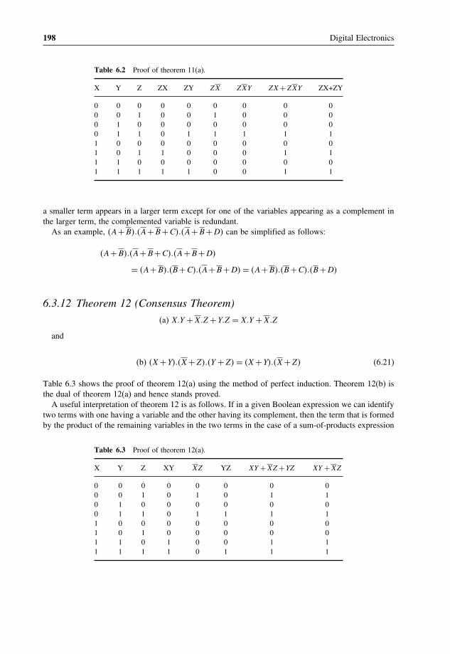
198 Digital Electronics
Table 6.2 Proof of theorem 11(a).
X Y Z ZX ZY ZX ZXY ZX +ZXY ZX+ZY
0 0 0 0 0 0 0 0 00 0 1 0 0 1 0 0 00 1 0 0 0 0 0 0 00 1 1 0 1 1 1 1 11 0 0 0 0 0 0 0 01 0 1 1 0 0 0 1 11 1 0 0 0 0 0 0 01 1 1 1 1 0 0 1 1
a smaller term appears in a larger term except for one of the variables appearing as a complement inthe larger term, the complemented variable is redundant.
As an example, �A+B���A+B+C���A+B+D� can be simplified as follows:
�A+B���A+B+C���A+B+D�
= �A+B���B+C���A+B+D� = �A+B���B+C���B+D�
6.3.12 Theorem 12 (Consensus Theorem)
(a) X�Y +X�Z +Y�Z = X�Y +X�Z
and
(b) �X +Y���X +Z���Y +Z� = �X +Y���X +Z� (6.21)
Table 6.3 shows the proof of theorem 12(a) using the method of perfect induction. Theorem 12(b) isthe dual of theorem 12(a) and hence stands proved.
A useful interpretation of theorem 12 is as follows. If in a given Boolean expression we can identifytwo terms with one having a variable and the other having its complement, then the term that is formedby the product of the remaining variables in the two terms in the case of a sum-of-products expression
Table 6.3 Proof of theorem 12(a).
X Y Z XY XZ YZ XY +XZ +YZ XY +XZ
0 0 0 0 0 0 0 00 0 1 0 1 0 1 10 1 0 0 0 0 0 00 1 1 0 1 1 1 11 0 0 0 0 0 0 01 0 1 0 0 0 0 01 1 0 1 0 0 1 11 1 1 1 0 1 1 1

Boolean Algebra and Simplification Techniques 199
or by the sum of the remaining variables in the case of a product-of-sums expression will be redundant.The following example further illustrates the point:
A�B�C +A�C�D+B�C�D+B�C�D+A�C�D = A�B�C +A�C�D+B�C�D
If we consider the first two terms of the Boolean expression, B�C�D becomes redundant. If we considerthe first and third terms of the given Boolean expression, A�C�D becomes redundant.
Example 6.4
Prove that A�B�C�D + A�B�C�D + A�B�C�D + A�B�C�D + A�B�C�D�E + A�B�C�D�E + A�B�C�D�E canbe simplified to A�B�
Solution
A�B�C�D+A�B�C�D+A�B�C�D+A�B�C�D+A�B�C�D�E +A�B�C�D�E +A�B�C�D�E
=A�B�C�D+A�B�C�D+A�B�C�D+A�B�C�D
=A�B��C�D+C�D+C�D+C�D� = A�B
• A�B�C�D appears in A�B�C�D�E, A�B�C�D appears in A�B�C�D�E and A�B�C�D appears inA�B�C�D�E.
• As a result, all three five-variable terms are redundant.• Also, variables C and D appear in all possible combinations and are therefore redundant.
6.3.13 Theorem 13 (DeMorgan’s Theorem)
(a) �X1 +X2 +X3 + +Xn� = X1�X2�X3 � �Xn (6.22)
(b) �X1�X2�X3� �Xn� = �X1 +X2 +X3 + +Xn� (6.23)
According to the first theorem the complement of a sum equals the product of complements, whileaccording to the second theorem the complement of a product equals the sum of complements. Figures6.3(a) and (b) show logic diagram representations of De Morgan’s theorems. While the first theoremcan be interpreted to say that a multi-input NOR gate can be implemented as a multi-input bubbledAND gate, the second theorem, which is the dual of the first, can be interpreted to say that a multi-inputNAND gate can be implemented as a multi-input bubbled OR gate.
DeMorgan’s theorem can be proved as follows. Let us assume that all variables are in a logic ‘0’state. In that case
LHS = �X1 +X2 +X3 + · · · +Xn� = �0+0+0+ · · · +0� = 0 = 1
RHS = X1�X2�X3 � �Xn = 0�0�0 � � 0 = 1�1�1� �1 = 1
Therefore, LHS = RHS.Now, let us assume that any one of the n variables, say X1, is in a logic HIGH state:

200 Digital Electronics
X1X2
Xn
X1X2
Xn
(a)
X1X2
X3
X1X2
Xn
(b)
Figure 6.3 DeMorgan’s theorem.
LHS = �X1 +X2 +X3 + · · ·Xn� = �1+0+0+· · ·+0� = 1 = 0
RHS = X1�X2�X3� �Xn = 1�0�0� �0 = 0�1�1� �1 = 0
Therefore, again LHS = RHS.The same holds good when more than one or all variables are in the logic ‘1’ state. Therefore,
theorem 13(a) stands proved. Since theorem 13(b) is the dual of theorem 13(a), the same also standsproved. Theorem 13(b), though, can be proved on similar lines.
6.3.14 Theorem 14 (Transposition Theorem)
(a) X�Y +X�Z = �X +Z���X +Y�
and
(b) �X +Y���X +Z� = X�Z +X�Y (6.24)
This theorem can be applied to any sum-of-products or product-of-sums expression having two terms,provided that a given variable in one term has its complement in the other. Table 6.4 gives the proofof theorem 14(a) using the method of perfect induction. Theorem 14(b) is the dual of theorem 14(a)and hence stands proved.
As an example,
A�B+A�B = �A+B���A+B� and A�B+A�B = �A+B���A+B�
Incidentally, the first expression is the representation of a two-input EX-OR gate, while the secondexpression gives two forms of representation of a two-input EX-NOR gate.

Boolean Algebra and Simplification Techniques 201
Table 6.4 Proof of theorem 13(a).
X Y Z XY XZ X+Z X +Y XY +XZ (X+Z)�X +Y�
0 0 0 0 0 0 1 0 00 0 1 0 1 1 1 1 10 1 0 0 0 0 1 0 00 1 1 0 1 1 1 1 11 0 0 0 0 1 0 0 01 0 1 0 0 1 0 0 01 1 0 1 0 1 1 1 11 1 1 1 0 1 1 1 1
6.3.15 Theorem 15
(a) X�f�X�X�Y�Z� � = X�f�1� 0� Y�Z� � (6.25)
(b) X +f�X�X�Y�Z� � = X +f�0� 1� Y�Z� � (6.26)
According to theorem 15(a), if a variable X is multiplied by an expression containing X and X inaddition to other variables, then all Xs and Xs can be replaced with 1s and 0s respectively. This wouldbe valid as X�X = X and X�1 = X. Also, X�X = 0 and X�0 = 0. According to theorem 15(b), if avariable X is added to an expression containing terms having X and X in addition to other variables,then all Xs can be replaced with 0s and all Xs can be replaced with ls. This is again permissible asX +X as well as X +0 equals X. Also, X +X and X +1 both equal 1.
This pair of theorems is very useful in eliminating redundancy in a given expression. An importantcorollary of this pair of theorems is that, if the multiplying variable is X in theorem 15(a), then allXs will be replaced by 0s and all Xs will be replaced by ls. Similarly, if the variable being added intheorem 15(b) is X, then Xs and Xs in the expression are replaced by 1s and 0s respectively. In thatcase the two theorems can be written as follows:
(a) X�f�X�X�Y�Z� � = X�f�0� 1� Y�Z� � (6.27)
(b) X +f�X�X�Y�Z� � = X +f�1� 0� Y�Z� � (6.28)
The theorems are further illustrated with the help of the following examples:
1. A��A�B+A�C + �A+D���A+E�� = A��0�B+1�C + �0+D���1+E�� = A��C +D�.2. A+ �A�B+A�C + �A+B���A+E�� = A+ �0�B+1�C + �0+B���1+E�� = A+C +B.
6.3.16 Theorem 16
(a) f�X�X�Y� �Z� = X�f�1� 0� Y� �Z�+X�f�0� 1� Y� �Z� (6.29)
(b) f�X�X�Y� �Z� = �X +f�0� 1� Y� �Z���X +f�1� 0� Y� �Z�� (6.30)

202 Digital Electronics
The proof of theorem 16(a) is straightforward and is given as follows:
f�X�X�Y� �Z� = X�f�X�X�Y� �Z�+X�f�X�X�Y� �Z�
= X�f�1� 0� Y� �Z�+X�f�0� 1� Y� �Z���Theorem 15(a)�
Also
f�X�X�Y� �Z� = �X +f�X�X�Y� �Z���X + �f�X�X�Y� �Z��
= �X +f�0� 1� Y� �Z���X +f�1� 0� Y� �Z���Theorem 15(b)�
6.3.17 Theorem 17 (Involution Law)
X = X (6.31)
Involution law says that the complement of the complement of an expression leaves the expressionunchanged. Also, the dual of the dual of an expression is the original expression. This theorem formsthe basis of finding the equivalent product-of-sums expression for a given sum-of-products expression,and vice versa.
Example 6.5
Prove the following:
1. L��M +N�+L�P�Q = �L+P�Q���L+M +N��2. �A�B+C +D���D+ �E +F��G� = D��A�B+C�+D�G��E +F��
Solution1. Let us assume that L = X� �M +N� = Y and P�Q = Z.
The LHS of the given Boolean equation then reduces to X�Y +X�Z.Applying the transposition theorem,
X�Y +X�Z = �X +Z���X +Y� = �L+P�Q��L+M +N� = RHS
2. Let us assume D = X�A�B+C = Y and �E +F��G = Z.The LHS of given the Boolean equation then reduces to �X +Y���X +Z�.Applying the transposition theorem,
�X +Y���X +Z� = X�Z +X�Y = D�G��E +F�+D��A�B+C� = RHS

Boolean Algebra and Simplification Techniques 203
(A+B)
A
B
Figure 6.4 Example 6.6.
Example 6.6
Starting with the Boolean expression for a two-input OR gate, apply Boolean laws and theorems tomodify it in such a way as to facilitate the implementation of a two-input OR gate by using two-inputNAND gates only.
Solution• A two-input OR gate is represented by the Boolean equation Y = �A+B�,
where A and B are the input logic variables and Y is the output.• Now��A+B� = �A+B� Involution law
= �A�B� DeMorgan’s theorem
= ��A�A���B�B�� Idempotent law• Figure 6.4 shows the NAND gate implementation of a two-input OR gate.
Example 6.7
Apply suitable Boolean laws and theorems to modify the expression for a two-input EX-OR gate insuch a way as to implement a two-input EX-OR gate by using the minimum number of two-input NANDgates only.
Solution• A two-input EX-OR gate is represented by the Boolean expression Y = A�B+A�B.
• Now�A�B+A�B = A�B+A�B Involution law
= A�B�A�B DeMorgan’s law
= �B��A+B����A��A+B��
= �B�A�B���A�A�B� �6�32�
• Equation (6.32) is in a form that can be implemented with NAND gates only.• Figure 6.5 shows the logic diagram.

204 Digital Electronics
AB+AB– –
A.AB–———–
A
B
AB––
B .AB–———–
Figure 6.5 Example 6.7.
6.4 Simplification TechniquesIn this section, we will discuss techniques other than the application of laws and theorems of Booleanalgebra discussed in the preceding paragraphs of this chapter for simplifying or more preciselyminimizing a given complex Boolean expression. The primary objective of all simplification proceduresis to obtain an expression that has the minimum number of terms. Obtaining an expression with theminimum number of literals is usually the secondary objective. If there is more than one possiblesolution with the same number of terms, the one having the minimum number of literals is the choice.The techniques to be discussed include:
(a) the Quine–McCluskey tabular method;(b) the Karnaugh map method.
Before we move on to discuss these techniques in detail, it would be relevant briefly to describesum-of-products and product-of-sums Boolean expressions. The given Boolean expression will be ineither of the two forms, and the objective will be to find a minimized expression in the same or theother form.
6.4.1 Sum-of-Products Boolean Expressions
A sum-of-products expression contains the sum of different terms, with each term being either asingle literal or a product of more than one literal. It can be obtained from the truth table directlyby considering those input combinations that produce a logic ‘1’ at the output. Each such inputcombination produces a term. Different terms are given by the product of the corresponding literals.The sum of all terms gives the expression. For example, the truth table in Table 6.5 can be representedby the Boolean expression
Y = A �B�C +A�B�C +A�B�C +A�B�C (6.33)
Considering the first term, the output is ‘1’ when A = 0�B = 0 and C = 0. This is possible only whenA, B and C are ANDed. Also, for the second term, the output is ‘1’ only when B, C and A are ANDed.Other terms can be explained similarly. A sum-of-products expression is also known as a mintermexpression.

Boolean Algebra and Simplification Techniques 205
Table 6.5 truth table of boolean expression ofequation 6.33.
A B C Y
0 0 0 10 0 1 00 1 0 00 1 1 11 0 0 01 0 1 11 1 0 11 1 1 0
6.4.2 Product-of-Sums Expressions
A product-of-sums expression contains the product of different terms, with each term being either asingle literal or a sum of more than one literal. It can be obtained from the truth table by consideringthose input combinations that produce a logic ‘0’ at the output. Each such input combination gives aterm, and the product of all such terms gives the expression. Different terms are obtained by takingthe sum of the corresponding literals. Here, ‘0’ and ‘1’ respectively mean the uncomplemented andcomplemented variables, unlike sum-of-products expressions where ‘0’ and ‘1’ respectively meancomplemented and uncomplemented variables.
To illustrate this further, consider once again the truth table in Table 6.5. Since each term in thecase of the product-of-sums expression is going to be the sum of literals, this implies that it is goingto be implemented using an OR operation. Now, an OR gate produces a logic ‘0’ only when all itsinputs are in the logic ‘0’ state, which means that the first term corresponding to the second row ofthe truth table will be A+B+C. The product-of-sums Boolean expression for this truth table is givenby �A+B+C���A+B+C���A+B+C���A+B+C�.
Transforming the given product-of-sums expression into an equivalent sum-of-products expressionis a straightforward process. Multiplying out the given expression and carrying out the obvioussimplification provides the equivalent sum-of-products expression:
�A+B+C���A+B+C���A+B+C���A+B+C�
= �A�A+A�B+A�C +B�A+B�B+B�C +C�A+C�B+C�C���A�A+A�B+A�C +B�A+B�B
+B�C +C�A+C�B+C�C
= �A+B�C +B�C���A+B�C +C�B� = A�B�C +A�B�C +A�B�C +A�B�C
A given sum-of-products expression can be transformed into an equivalent product-of-sums expressionby (a) taking the dual of the given expression, (b) multiplying out different terms to get the sum-of-products form, (c) removing redundancy and (d) taking a dual to get the equivalent product-of-sumsexpression. As an illustration, let us find the equivalent product-of-sums expression of the sum-of-products expression
A�B+A�B
The dual of the given expression = �A+B���A+B�:
�A+B���A+B� = A�A+A�B+B�A+B�B = 0+A�B+B�A+0 = A�B+A�B

206 Digital Electronics
The dual of �A�B+A�B� = �A+B���A+B�. Therefore
A�B+A�B = �A+B���A+B�
6.4.3 Expanded Forms of Boolean Expressions
Expanded sum-of-products and product-of-sums forms of Boolean expressions are useful not onlyin analysing these expressions but also in the application of minimization techniques such as theQuine–McCluskey tabular method and the Karnaugh mapping method for simplifying given Booleanexpressions. The expanded form, sum-of-products or product-of-sums, is obtained by including allpossible combinations of missing variables.
As an illustration, consider the following sum-of-products expression:
A�B+B�C +A�B�C +A�C
It is a three-variable expression. Expanded versions of different minterms can be written as follows:
• A�B = A�B��C +C� = A�B�C +A�B�C�• B�C = B�C��A+A� = B�C�A+B�C�A�• A�B�C is a complete term and has no missing variable.• A�C = A�C��B+B� = A�C�B+A�C�B.
The expanded sum-of-products expression is therefore given by
A�B�C +A�B�C +A�B�C +A�B�C +A�B�C +A�B�C +A�B�C = A�B�C +A�B�C
+A�B�C +A�B�C +A�B�C +A�B�C
As another illustration, consider the product-of-sums expression
�A+B���A+B+C +D�
It is four-variable expression with A, B, C and D being the four variables. A+B in this case expandsto �A+B+C +D���A+B+C +D���A+B+C +D���A+B+C +D�.
The expanded product-of-sums expression is therefore given by
�A+B+C +D���A+B+C +D���A+B+C +D���A+B+C +D���A+B+C +D�
= �A+B+C +D���A+B+C +D���A+B+C +D���A+B+C +D�
6.4.4 Canonical Form of Boolean Expressions
An expanded form of Boolean expression, where each term contains all Boolean variables in their trueor complemented form, is also known as the canonical form of the expression.
As an illustration, f�A�B�C� = A�B�C + A�B�C + A�B�C is a Boolean function of three variablesexpressed in canonical form. This function after simplification reduces to A�B +A�B�C and loses itscanonical form.

Boolean Algebra and Simplification Techniques 207
6.4.5 and � Nomenclature
� and notations are respectively used to represent sum-of-products and product-of-sums Booleanexpressions. We will illustrate these notations with the help of examples. Let us consider the followingBoolean function:
f�A�B�C�D� = A�B�C +A�B�C�D+A�B�C�D+A�B�C�D
We will represent this function using � notation. The first step is to write the expanded sum-of-productsgiven by
f�A�B�C�D� = A�B�C��D+D�+A�B�C�D+A�B�C�D+A�B�C�D
= A�B�C�D+A�B�C�D+A�B�C�D+A�B�C�D+A�B�C�D
Different terms are then arranged in ascending order of the binary numbers represented by variousterms, with true variables representing a ‘1’ and a complemented variable representing a ‘0’. Theexpression becomes
f�A�B�C�D� = A�B�C�D+A�B�C�D+A�B�C�D+A�B�C�D+A�B�C�D
The different terms represent 0001, 0101, 1000, 1001 and 1111. The decimal equivalent of these termsenclosed in the � then gives the � notation for the given Boolean function. That is, f�A�B�C�D� =∑
1� 5� 8� 9� 15.The complement of f�A, B, C, D�, that is,f ′(A, B, C, D�, can be directly determined from � notation
by including the left-out entries from the list of all possible numbers for a four-variable function.That is,
f ′�A�B�C�D� = ∑0� 2� 3� 4� 6� 7� 10� 11� 12� 13� 14
Let us now take the case of a product-of-sums Boolean function and its representation in nomenclature. Let us consider the Boolean function
f�A�B�C�D� = �B+C +D���A+B+C +D���A+B+C +D�
The expanded product-of-sums form is given by
�A+B+C +D���A+B+C +D���A+B+C +D���A+B+C +D�
The binary numbers represented by the different sum terms are 0011, 1011, 1100 and 0111 (true andcomplemented variables here represent 0 and 1 respectively). When arranged in ascending order, thesenumbers are 0011, 0111, 1011 and 1100. Therefore,
f�A�B�C�D� = ∏3� 7� 11� 12 and f ′�A�B�C�D� = ∏
0� 1� 2� 4� 5� 6� 8� 9� 10� 13� 14� 15
An interesting corollary of what we have discussed above is that, if a given Boolean functionf�A,B,C� is given by f�A�B�C� = ∑
0� 1� 4� 7, then
f�A�B�C� = ∏2� 3� 5� 6 and f ′�A�B�C� = ∑
2� 3� 5� 6 = ∏0� 1� 4� 7

208 Digital Electronics
Optional combinations can also be incorporated into � and nomenclature using suitable identifiers;� or d are used as identifiers. For example, if f�A�B�C� = A�B�C +A�B�C +A�B�C and A�B�C�A�B�Care optional combinations, then
f�A�B�C� = ∑0� 4� 5+∑
�
3� 7 = ∑0� 4� 5+∑
d
3� 7
f�A�B�C� = ∏1� 2� 6+∏
�
3� 7 = ∏1� 2� 6+∏
d
3� 7
Example 6.8
For a Boolean function f�A�B� =∑0� 2� prove that f�A�B� =∏
1� 3 and f ′�A�B� =∑1� 3 = ∏
0� 2.
Solution• f�A�B� = ∑
0� 2 =A�B+A�B = B��A+A� = B.• Now,
∏1� 3 = �A+B���A+B� = A�A+A�B+B�A+B�B = A�B+A�B+B = B.
• Now,∑
1� 3 = A�B+A�B = B��A+A� = B�and
∏0� 2 =�A+B���A+B� = A�A+A�B+B�A+B�B = A�B+A�B+B = B.
• Therefore,∑
1� 3 = ∏0� 2.
• Also, f�A�B� = B.• Therefore, f ′�A�B� = B or f ′�A�B� = ∑
1� 3 = ∏0� 2.
6.5 Quine–McCluskey Tabular MethodThe Quine–McCluskey tabular method of simplification is based on the complementation theorem,which says that
X�Y +X�Y = X (6.34)
where X represents either a variable or a term or an expression and Y is a variable. This theoremimplies that, if a Boolean expression contains two terms that differ only in one variable, then they canbe combined together and replaced with a term that is smaller by one literal. The same procedure isapplied for the other pairs of terms wherever such a reduction is possible. All these terms reducedby one literal are further examined to see if they can be reduced further. The process continuesuntil the terms become irreducible. The irreducible terms are called prime implicants. An optimumset of prime implicants that can account for all the original terms then constitutes the minimizedexpression. The technique can be applied equally well for minimizing sum-of-products and product-of-sums expressions and is particularly useful for Boolean functions having more than six variables asit can be mechanized and run on a computer. On the other hand, the Karnaugh mapping method, to bediscussed later, is a graphical method and becomes very cumbersome when the number of variablesexceeds six.
The step-by-step procedure for application of the tabular method for minimizing Boolean expressions,both sum-of-products and product-of-sums, is outlined as follows:
1. The Boolean expression to be simplified is expanded if it is not in expanded form.2. Different terms in the expression are divided into groups depending upon the number of 1s they have.
True and complemented variables in a sum-of-products expression mean ‘1’ and ‘0’ respectively.
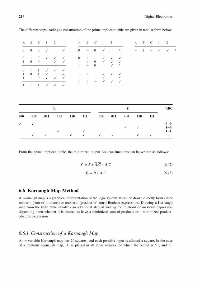
216 Digital Electronics
The different steps leading to construction of the prime implicant table are given in tabular form below:
A B C 1 2 A B C 1 2 A B C 1 2
0 0 0 � � 0 − 0 � * − 1 − � � *
0 1 0 � � � 0 1 − � � �1 0 0 � � − 1 0 � � �
1 − 0 � *
0 1 1 � � �1 0 1 � � − 1 1 � � �1 1 0 � � � 1 − 1 � *
1 1 − � � �1 1 1 � � �
Y1 Y2 ABC
000 010 011 101 110 111 010 011 100 110 111
� � 0−0� � 1−0
� � 1−1� � � � � � � � −1−
From the prime implicant table, the minimized output Boolean functions can be written as follows:
Y1 = B+A�C +A�C (6.42)
Y2 = B+A�C (6.43)
6.6 Karnaugh Map MethodA Karnaugh map is a graphical representation of the logic system. It can be drawn directly from eitherminterm (sum-of-products) or maxterm (product-of-sums) Boolean expressions. Drawing a Karnaughmap from the truth table involves an additional step of writing the minterm or maxterm expressiondepending upon whether it is desired to have a minimized sum-of-products or a minimized product-of-sums expression.
6.6.1 Construction of a Karnaugh Map
An n-variable Karnaugh map has 2n squares, and each possible input is allotted a square. In the caseof a minterm Karnaugh map, ‘1’ is placed in all those squares for which the output is ‘1’, and ‘0’

Boolean Algebra and Simplification Techniques 217
is placed in all those squares for which the output is ‘0’. 0s are omitted for simplicity. An ‘X’ isplaced in squares corresponding to ‘don’t care’ conditions. In the case of a maxterm Karnaugh map,a ‘1’ is placed in all those squares for which the output is ‘0’, and a ‘0’ is placed for input entriescorresponding to a ‘1’ output. Again, 0s are omitted for simplicity, and an ‘X’ is placed in squarescorresponding to ‘don’t care’ conditions.
The choice of terms identifying different rows and columns of a Karnaugh map is not unique for agiven number of variables. The only condition to be satisfied is that the designation of adjacent rowsand adjacent columns should be the same except for one of the literals being complemented. Also, theextreme rows and extreme columns are considered adjacent. Some of the possible designation styles fortwo-, three- and four-variable minterm Karnaugh maps are given in Figs 6.6, 6.7 and 6.8 respectively.
The style of row identification need not be the same as that of column identification as long as itmeets the basic requirement with respect to adjacent terms. It is, however, accepted practice to adopt auniform style of row and column identification. Also, the style shown in Figs 6.6(a), 6.7(a) and 6.8(a)is more commonly used. Some more styles are shown in Fig. 6.9. A similar discussion applies formaxterm Karnaugh maps.
Having drawn the Karnaugh map, the next step is to form groups of 1s as per the followingguidelines:
1. Each square containing a ‘1’ must be considered at least once, although it can be considered asoften as desired.
2. The objective should be to account for all the marked squares in the minimum number of groups.3. The number of squares in a group must always be a power of 2, i.e. groups can have 1, 2, 4� 8, 16,
squares.4. Each group should be as large as possible, which means that a square should not be accounted for
by itself if it can be accounted for by a group of two squares; a group of two squares should not bemade if the involved squares can be included in a group of four squares and so on.
5. ‘Don’t care’ entries can be used in accounting for all of 1-squares to make optimum groups. Theyare marked ‘X’ in the corresponding squares. It is, however, not necessary to account for all ‘don’tcare’ entries. Only such entries that can be used to advantage should be used.
B B
A
A
(a)
B B
A
A
(b)
B B
A
A
(c)
B B
A
A
(d)
Figure 6.6 Two-variable Karnaugh map.

218 Digital Electronics
BC BC BC BC
A
A
(a)
BC BC BC BC
A
A
(b)
BC BC BC BC
A
A
(c)
BC BC BC BC
A
A
(d)
Figure 6.7 Three-variable Karnaugh map.
C D CD CD CD
AB
AB
AB
AB
(a)
C D CD CD CD
AB
AB
AB
AB
(b)
C D CD CD CD
AB
AB
AB
AB
(c)
C D CD CD CD
AB
AB
AB
AB
(d)
Figure 6.8 Four-variable Karnaugh map.

Boolean Algebra and Simplification Techniques 219
AB
CD
AB
AB
CDCD
AB
CD
AB
CD
AB
AB
CDCD
AB
CD
A
CC
A
D
BB
D
AB
CD
00
00
01
11
10
01 11 10
Figure 6.9 Different styles of row and column identification.
Having accounted for groups with all 1s, the minimum ‘sum-of-products’ or ‘product-of-sums’expressions can be written directly from the Karnaugh map.
Figure 6.10 shows the truth table, minterm Karnaugh map and maxterm Karnaugh map of theBoolean function of a two-input OR gate. The minterm and maxterm Boolean expressions for thetwo-input OR gate are as follows:
Y = A+B (maxterm or product-of-sums) (6.44)
Y = A�B+A�B+A�B (minterm or sum-of-products) (6.45)
Figure 6.11 shows the truth table, minterm Karnaugh map and maxterm Karnaugh map of the three-variable Boolean function
Y = A�B�C +A�B�C +A�B�C +A�B�C (6.46)
Y = �A+B+C���A+B+C���A+B+C���A+B+C� (6.47)

220 Digital Electronics
Truth table
A
0
0
1
1
B
0
1
0
1
Y
0
1
1
1
Sum-of-products K-map
BAA
B
111
Product-of-sums K-map
BAA
B
1
Figure 6.10 Two-variable Karnaugh maps.
A
0
0
0
0
1
1
1
1
B
0
0
1
1
0
0
1
1
C
0
1
0
1
0
1
0
1
Y
1
0
1
0
1
0
1
0
Sum-of-products K-map
BC BC BC
AA
1
1
1
1
BC
Product-of-sums K-map
B+C B+C B+C
AA
1
1
1
1
B+C
Figure 6.11 Three-variable Karnaugh maps.
Figure 6.12 shows the truth table, minterm Karnaugh map and maxterm Karnaugh map of the four-variable Boolean function
Y = A�B�C�D+A�B�C�D+A�B�C�D+A�B�C�D+A�B�C�D+A�B�C�D+A�B�C�D+A�B�C�D (6.48)
Y = �A+B+C +D���A+B+C +D���A+B+C +D���A+B+C +D�
��A+B+C +D���A+B+C +D���A+B+C +D���A+B+C +D�(6.49)
To illustrate the process of forming groups and then writing the corresponding minimized Booleanexpression, Figs 6.13(a) and (b) respectively show minterm and maxterm Karnaugh maps for theBoolean functions expressed by equations (6.50) and (6.51). The minimized expressions as deducedfrom Karnaugh maps in the two cases are given by Equation (6.52) in the case of the minterm Karnaughmap and Equation (6.53) in the case of the maxterm Karnaugh map:
Y = A�B�C�D+A�B�C�D+A�B�C�D+A�B�C�D+A�B�C�D+A�B�C�D+A�B�C�D+A�B�C�D (6.50)
Y = �A+B+C +D���A+B+C +D���A+B+C +D���A+B+C +D���A+B+C +D�
��A+B+C +D���A+B+C +D���A+B+C +D���A+B+C +D���A+B+C +D� (6.51)
Y = B�D+B�D (6.52)
Y = D��A+B� (6.53)

Boolean Algebra and Simplification Techniques 221
Truth table
A
0
0
0
0
0
0
0
0
1
1
1
1
1
1
1
1
B
0
0
0
0
1
1
1
1
0
0
0
0
1
1
1
1
C
0
0
1
1
0
0
1
1
0
0
1
1
0
0
1
1
D
0
1
0
1
0
1
0
1
0
1
0
1
0
1
0
1
Y
1
1
0
0
1
1
0
0
1
1
0
0
1
1
0
0
Sum-of-products K-map
AB
1
1
1
1
1
1
1
1
AB
AB
CDCD CDCD
AB
Product-of-sums K-map
A+B
1
1
1
1
1
1
1
1
A+B
A+B
C+DC+D C+DC+D
A+B
Figure 6.12 Four-variable Karnaugh maps.
Figure 6.13 Group formation in minterm and maxterm Karnaugh maps.

222 Digital Electronics
6.6.2 Karnaugh Map for Boolean Expressions with a Larger Number ofVariables
The construction of Karnaugh maps for a larger number of variables is a complex and cumbersomeexercise, although manageable up to six variables. Five- and six-variable representative Karnaughmaps are shown in Figs 6.14(a) and (b) respectively. One important point to remember while forminggroups in Karnaugh maps involving more than four variables is that terms equidistant from thecentral horizontal and central vertical lines are considered adjacent. These lines are shown thickerin Figs 6.14(a) and (b). Squares marked ‘X’ in Figs 6.14(a) and (b) are adjacent and thereforecan be grouped.
Boolean expressions with more than four variables can also be represented by more than one four-variable map. Five-, six-, seven- and eight-variable Boolean expressions can be represented by two,four, eight and 16 four-variable maps respectively. In general, an n-variable Boolean expression canbe represented by 2n−4 four-variable maps. In such multiple maps, groups are made as before, exceptthat, in addition to adjacencies discussed earlier, corresponding squares in two adjacent maps are alsoconsidered adjacent and can therefore be grouped. We will illustrate the process of formation of groupsin multiple Karnaugh maps with a larger number of variables with the help of examples. Consider thefive-variable Boolean function given by the equation
Y =A�B�C�D�E +A�B�C�D�E +A�B�C�D�E +A�B�C�D�E +A�B�C�D�E +A�B�C�D�E +A�B�C�D�E
+A�B�C�D�E +A�B�C�D�E (6.54)
Figure 6.14 Five-variable and six-variable Karnaugh maps.
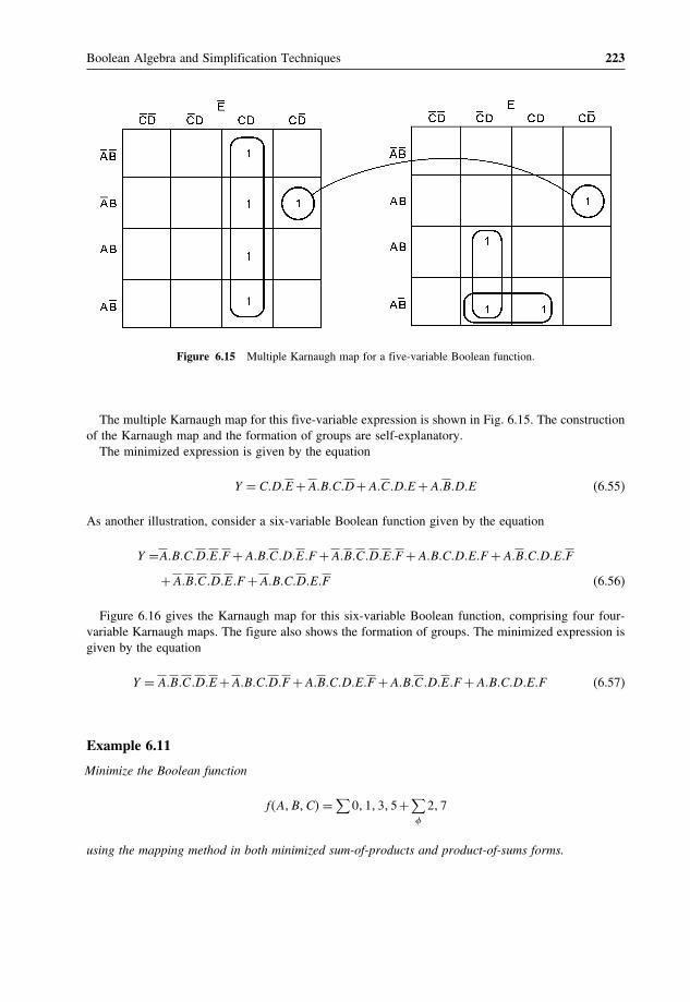
Boolean Algebra and Simplification Techniques 223
Figure 6.15 Multiple Karnaugh map for a five-variable Boolean function.
The multiple Karnaugh map for this five-variable expression is shown in Fig. 6.15. The constructionof the Karnaugh map and the formation of groups are self-explanatory.
The minimized expression is given by the equation
Y = C�D�E +A�B�C�D+A�C�D�E +A�B�D�E (6.55)
As another illustration, consider a six-variable Boolean function given by the equation
Y =A�B�C�D�E�F +A�B�C�D�E�F +A�B�C�D�E�F +A�B�C�D�E�F +A�B�C�D�E�F
+A�B�C�D�E�F +A�B�C�D�E�F (6.56)
Figure 6.16 gives the Karnaugh map for this six-variable Boolean function, comprising four four-variable Karnaugh maps. The figure also shows the formation of groups. The minimized expression isgiven by the equation
Y = A�B�C�D�E +A�B�C�D�F +A�B�C�D�E�F +A�B�C�D�E�F +A�B�C�D�E�F (6.57)
Example 6.11
Minimize the Boolean function
f�A�B�C� = ∑0� 1� 3� 5+∑
�
2� 7
using the mapping method in both minimized sum-of-products and product-of-sums forms.

224 Digital Electronics
Figure 6.16 Multiple Karnaugh map for a six-variable Boolean function.
Solution• f�A�B�C� = ∑
0� 1� 3� 5+∑
�
2� 7 = ∏4� 6+∏
�
2� 7.
• From given Boolean functions in � and notation, we can write sum-of-products and product-of-sums Boolean expressions as follows:
f�A�B�C� = A�B�C +A�B�C +A�B�C +A�B�C (6.58)
f�A�B�C� = �A+B+C���A+B+C� (6.59)

Boolean Algebra and Simplification Techniques 225
Figure 6.17 Example 6.11.
• The ‘don’t care’ input combinations for the sum-of-products Boolean expression are A�B�C�A�B�C.• The ‘don’t care’ input combinations for the product-of-sums expression are �A+B+C���A+B+C�.• The Karnaugh maps for the two cases are shown in Figs 6.17(a) and (b).• The minimized sum-of-products and product-of-sums Boolean functions are respectively given by
the equations
f�A�B�C� = C +A (6.60)
f�A�B�C� = A+C (6.61)
6.6.3 Karnaugh Maps for Multi-Output Functions
Karnaugh maps can be used for finding minimized Boolean expressions for multi-output functions. Tobegin with, a Karnaugh map is drawn for each function following the guidelines described in the earlierpages. In the second step, two-function Karnaugh maps are drawn. In the third step, three-functionKarnaugh maps are drawn. The process continues until we have a single all-function Karnaugh map.As an illustration, for a logic system having four outputs, the first step would give four Karnaugh mapsfor individual functions. The second step would give six two-function Karnaugh maps (1−2, 1−3,1−4, 2−3, 2−4 and 3−4). The third step would yield four three−function Karnaugh maps (1−2−3,1−2−4, 1−3−4 and 2−3−4) and lastly we have one four-function Karnaugh map. A multifunctionKarnaugh map is basically an intersection of the Karnaugh maps of the functions involved. That is, a‘1’ appears in a square of a multifunction map only if a ‘1’ appears in the corresponding squares of themaps of all the relevant functions. To illustrate further, a two-function map involving functions 1 and2 would be an intersection of maps for functions 1 and 2. In the two-function map, squares will havea ‘1’ only when the corresponding squares in functions 1 and 2 also have a ‘1’. Figure 6.18 illustratesthe formation of a three-function Karnaugh map from three given individual functions.

226 Digital Electronics
Figure 6.18 Three-function Karnaugh map.
The formation of groups begins with the largest multifunction map, which is nothing but theintersection of maps of all individual functions. Then we move to the Karnaugh maps one step downthe order. The process continues until we reach the maps corresponding to individual functions. Thegroups in all the Karnaugh maps other than the largest map are formed subject to the condition that,once a group is identified in a certain function, then the same cannot be identified in any map of asubset of that function. For example, a group identified in a four-function map cannot be identifiedin a three-, two- or one-function map. With the formation of groups, prime implicants are identified.These prime implicants can be compiled in the form of a table along with input combinations ofdifferent output functions in the same way as for the tabular method to write minimized expressions. Ifthe expressions corresponding to different output functions are not very complex, then the minimizedexpressions can even be written directly from the set of maps.
Example 6.12
Using Karnaugh maps, write the minimized Boolean expressions for the output functions of a two-outputlogic system whose outputs Y1 and Y2 are given by the following Boolean functions:
Y1 = A�B�C +A�B�C +A�B�C +A�B�C (6.62)
Y2 = A�B�C +A�B�C +A�B�C +A�B�C +A�B�C (6.63)
SolutionThe individual Karnaugh maps and the two-function map are shown in Fig. 6.19 along with theformation of groups. The prime implicant table along with the input combinations for the two outputfunctions is given below:
Y1 Y2 Prime implicants000 010 100 111 000 001 101 110 111
� � 0 0 0� � 1 1 1
� � 0 − 0� � − 0 0
� � 1 1 −� � − 0 1

Boolean Algebra and Simplification Techniques 227
1 1
1
AB AB AB AB
C
C
1 1
1 1
AB AB AB AB
C
C
1 1
1
AB AB AB AB
C
C1
Y2 Y2-1Y1
Figure 6.19 Example 6.12.
The minimized expressions for Y1 and Y2 are as follows:
Y1 = B�C +A�C +A�B�C (6.64)
Y2 = A�B+A�B�C +B�C (6.65)
Example 6.13
Write the simplified Boolean expression given by the Karnaugh map shown in Fig. 6.20.
Solution• The Karnaugh map is shown in Fig. 6.21.• Consider the group of four 1s at the top left of the map. It yields a term A�C.• Consider the group of four 1s, two on the extreme left and two on the extreme right. This group
yields a term A�D.• The third group of two 1s is in the third row of the map. The third row corresponds to the intersection
of A and B, as is clear from the map. Therefore, this group yields a term ABC.• The simplified Boolean expression is given by A�C +A�D+A�B�C.
Figure 6.20 Example 6.13.

228 Digital Electronics
1 11
1 1
11
1
CC
B
A
A
D
D
B
Figure 6.21 Solution to example 6.13.
Example 6.14
Minimizing a given Boolean expression using the Quine–McCluskey tabular method yields the followingprime implicants: −0−0, −1−1, 1−10 and 0−00. Draw the corresponding Karnaugh map.
Solution• As is clear from the prime implicants, the expression has four variables. If the variables are assumed
to be A, B, C and D, then the given prime implicants correspond to the following terms:
1. −0−0 → B�D.2. −1−1 → B�D.3. 1−10 → A�C�D.4. 0−00 → A�C�D.
• The Karnaugh map can now be drawn as shown in Fig. 6.22.
Example 6.15
A�B+C�D is a simplified Boolean expression of the expression A�B�C�D+A�B�C�D+A�B. Determineif there are any ‘don’t care’ entries.
SolutionThe expanded version of the given expression is given by the equation

Boolean Algebra and Simplification Techniques 229
1 1
1
1
11
11
1 1
CD
AB
A
A
AB
AB
BB
AB
CD
D
D
CD CD
Figure 6.22 Solution to example 6.14.
Figure 6.23 Example 6.15.
A�B�C�D+A�B�C�D+A�B��C�D+C�D+C�D+C�D� (6.66)
= A�B�C�D+A�B�C�D+A�B�C�D+A�B�C�D+A�B�C�D+A�B�C�D �6�63�
The Karnaugh map for this Boolean expression is shown in Fig. 6.23. Now, if it is to be a simplifiedversion of the expression A�B + C�D, then the lowermost square in the CD column should not beempty. This implies that there is a ‘don’t care’ entry. This has been reflected in the map by puttingX in the relevant square. With the groups formed along with the ‘don’t care’ entry, the simplifiedexpression becomes the one stated in the problem.

230 Digital Electronics
Review Questions1. Read the following statements carefully. For each one of these, identify the law associated with it.
Define the law and illustrate the same with one or two examples.
(a) While a NAND gate is equivalent to a bubbled OR gate, a NOR gate is equivalent to a bubbledAND gate.
(b) When all the inputs of an AND gate or an OR gate are tied together to get a single-input,single-output gate, both AND and OR gates with all their inputs tied together produce an outputthat is the same as the input.
(c) When a variable is ORed with its complement the result is a logic ‘1’, and when it is ANDedwith its complement the result is a logic ‘0’, irrespective of the logic status of the variable.
(d) When two variables are ANDed and the result of the AND operation is ORed with one of thevariables, the result is that variable. Also, when two variables are ORed and the result of theOR operation is ANDed with one of the variables, the result is that variable.
2. Write both sum-of-products and product-of-sums Boolean expressions for (a) a two-input ANDgate, (b) a two-input NAND-gate, (c) a two-input EX-OR gate and (d) a two-input NOR gate fromtheir respective truth tables.
3. What do you understand by canonical and expanded forms of Boolean expressions? Illustrate withexamples.
4. With the help of an example, prove that in an n-variable Karnaugh map, a group formed with 2n−m
1s will yield a term having m literals, where m = 1, 2, 3, , n.5. With the help of an example, prove that the dual of the complement of a Boolean expression is the
same as the complement of the dual of the same.
Problems1. Simplify the following Boolean expressions:
(a) A�B�C +A�B�C +A�B�C +A�B�C +A�B�C +A�B�C +A�B�C +A�B�C;(b) �A+B+C���A+B+C���C +D���C +D+E�.
(a) 1; (b) �A+B���C +D�
2. (a) Find the dual of A�B�C�D+A�B�C�D+A�B�C�D.(b) Find the complement of A+ ��B+C��D+E��F .
�a� �A+B+C +D���A+B+C +D���A+B+C +D�� �b�A���B�C +D��E +F�
3. The dual of the complement of a certain Boolean expression is given by A�B�C + D�E + B�C�E.Find the expression.
A�B�C +D�E +B�C�E
4. Consider the Boolean expression given by
B�C�D�E+B�C�D�E +A�B�C�E +A�B�C�D�E +A�B�C�D�E +A�B�C�D�E +A�B�D�E
+A�B�C�D�E +A�B�C�D�E

Boolean Algebra and Simplification Techniques 231
The simplified version of this Boolean expression is given by B�E +B�D�E +B�D�E. Determine ifthere are any ‘don’t care’ entries. If yes, find them.
Yes, A�B�C�D�E�A�B�C�D�E�A�B�C�D�E5. Write minterm and maxterm Boolean functions expressed by f�A�B�C� = 0, 3, 7
minterm: A�B�C +A�B�C +A�B�C +A�B�C +A�B�Cmaxterm:�A+B+C���A+B+C���A+B+C�
6. Write a simplified maxterm Boolean expression for 0, 4, 5, 6, 7, 10, 14 using the Karnaughmapping method.
�A+B���A+B+C +D���A+C +D�
7. Simplify the following Boolean functions using the Quine–McCluskey tabulation method:
(a) f (A, B, C, D, E, F, G) = � (20, 21, 28, 29, 52, 53, 60, 61);(b) f (A, B, C, D, E, F) = � (6, 9, 13,18,19, 25, 26, 27, 29, 41, 45, 57, 61).
(a� A�C�E�F ; (b� C�E�F +A�B�D�E +A�B�C�D�E�F
8. (a) Simplify the Boolean function f�X�Y�Z� = Y�Z+X�Z for the ‘don’t care’ condition expressedas X�Y +X�Y�Z +X�Y �Z.
(b) Simplify the Boolean function given by f�A�B�C� = �A+B+C���A+B+C���A+B+C� forthe don’t care condition expressed as �A+B���A+B+C�.
(a) 1; (b) A�C
Further Reading1. Holdsworth, B. and Woods, C. (2002) Digital Logic Design, Newnes, Oxford, UK.2. Chen, W.-K. (2003) Logic Design, CRC Press, FL, USA.3. Floyd, T. L. (2005) Digital Fundamentals, Prentice-Hall Inc., USA.4. Tokheim, R. L. (1994) Schaum’s Outline Series of Digital Principles, McGraw-Hill Companies Inc., USA.

7Arithmetic Circuits
Beginning with this chapter, and in the two chapters following, we will take a comprehensive lookat various building blocks used to design more complex combinational circuits. A combinationallogic circuit is one where the output or outputs depend upon the present state of combination ofthe logic inputs. The logic gates discussed in Chapter 4 constitute the most fundamental buildingblock of a combinational circuit. More complex combinational circuits such as adders and subtractors,multiplexers and demultiplexers, magnitude comparators, etc., can be implemented using a combinationof logic gates. However, the aforesaid combinational logic functions and many more, including morecomplex ones, are available in monolithic IC form. A still more complex combinational circuit maybe implemented using a combination of these functions available in IC form. In this chapter, wewill cover devices used to perform arithmetic and other related operations. These include adders,subtractors, magnitude comparators and look-ahead carry generators. Particular emphasis is placedupon the functioning and design of these combinational circuits. The text has been adequatelyillustrated with the help of a large number of solved problems, the majority of which are designoriented.
7.1 Combinational CircuitsA combinational circuit is one where the output at any time depends only on the present combinationof inputs at that point of time with total disregard to the past state of the inputs. The logic gate is themost basic building block of combinational logic. The logical function performed by a combinationalcircuit is fully defined by a set of Boolean expressions. The other category of logic circuits, calledsequential logic circuits, comprises both logic gates and memory elements such as flip-flops. Owing tothe presence of memory elements, the output in a sequential circuit depends upon not only the presentbut also the past state of inputs. Basic building blocks of sequential logic circuits are described indetail in Chapters 10 and 11.
Figure 7.1 shows the block schematic representation of a generalized combinational circuit havingn input variables and m output variables or simply outputs. Since the number of input variables is
Digital Electronics: Principles, Devices and Applications Anil K. Maini© 2007 John Wiley & Sons, Ltd. ISBN: 978-0-470-03214-5

234 Digital Electronics
CombinationalLogic
'n'Inputs
'm'Outputs
Figure 7.1 Generalized combinational circuit.
n, there are 2n possible combinations of bits at the input. Each output can be expressed in terms ofinput variables by a Boolean expression, with the result that the generalized system of Fig. 7.1 can beexpressed by m Boolean expressions. As an illustration, Boolean expressions describing the functionof a four-input OR/NOR gate are given as
Y1 �OR output� = A+B+C +D and Y2 �NOR output� = A+B+C +D
Also, each of the input variables may be available as only the normal input on the input linedesignated for the purpose. In that case, the complemented input, if desired, can be generated by usingan inverter, as shown in Fig. 7.2(a), which illustrates the case of a four-input, two-output combinationalfunction. Also, each of the input variables may appear in two wires, one representing the normal literaland the other representing the complemented one, as shown in Fig. 7.2(b).
In combinational circuits, input variables come from an external source and output variables feed anexternal destination. Both source and destination in the majority of cases are storage registers, and these
CombinationalLogic
CombinationalLogic
(a)
(b)
Figure 7.2 Combinational circuit with normal and complemented inputs.

Arithmetic Circuits 235
HalfAdder-Subtractor
A
B
Y1Y2
Y3
Y4
Figure 7.3 Two-input, four-output combinational circuit.
storage devices provide both normal as well as complemented outputs of the stored binary variable. Asan illustration, Fig. 7.3 shows a simple two-input (A, B�, four-output (Y1, Y2, Y3, Y4� combinational logiccircuit described by the following Boolean expressions
Y1 = A�B+A�B (7.1)
Y2 = A�B+A�B (7.2)
Y3 = A�B (7.3)
Y4 = A�B (7.4)
The implementation of these Boolean expressions needs both normal as well as complementedinputs. Incidentally, the combinational circuit shown is that of a half-adder–subtractor, with A and Brepresenting the two bits to be added or subtracted and Y1� Y2, Y3, Y4 representing SUM, DIFFERENCE,CARRY and BORROW outputs respectively. Adder and subtractor circuits are discussed in Sections7.3, 7.4 and 7.5.
7.2 Implementing Combinational LogicThe different steps involved in the design of a combinational logic circuit are as follows:
1. Statement of the problem.2. Identification of input and output variables.3. Expressing the relationship between the input and output variables.4. Construction of a truth table to meet input–output requirements.5. Writing Boolean expressions for various output variables in terms of input variables.6. Minimization of Boolean expressions.7. Implementation of minimized Boolean expressions.
These different steps are self-explanatory. One or two points, however, are worth mentioning here. Thereare various simplification techniques available for minimizing Boolean expressions, which have beendiscussed in the previous chapter. These include the use of theorems and identities, Karnaugh mapping,the Quinne–McCluskey tabulation method and so on. Also, there are various possible minimized forms

236 Digital Electronics
of Boolean expressions. The following guidelines should be followed while choosing the preferredform for hardware implementation:
1. The implementation should have the minimum number of gates, with the gates used having theminimum number of inputs.
2. There should be a minimum number of interconnections, and the propagation time should be theshortest.
3. Limitation on the driving capability of the gates should not be ignored.
It is difficult to generalize as to what constitutes an acceptable simplified Boolean expression. Theimportance of each of the above-mentioned aspects is governed by the nature of application.
7.3 Arithmetic Circuits – Basic Building BlocksIn this section, we will discuss those combinational logic building blocks that can be used to performaddition and subtraction operations on binary numbers. Addition and subtraction are the two mostcommonly used arithmetic operations, as the other two, namely multiplication and division, arerespectively the processes of repeated addition and repeated subtraction, as was outlined in Chapter2 dealing with binary arithmetic. We will begin with the basic building blocks that form the basis ofall hardware used to perform the aforesaid arithmetic operations on binary numbers. These includehalf-adder, full adder, half-subtractor, full subtractor and controlled inverter.
7.3.1 Half-Adder
A half-adder is an arithmetic circuit block that can be used to add two bits. Such a circuit thus has twoinputs that represent the two bits to be added and two outputs, with one producing the SUM outputand the other producing the CARRY. Figure 7.4 shows the truth table of a half-adder, showing allpossible input combinations and the corresponding outputs.
The Boolean expressions for the SUM and CARRY outputs are given by the equations
SUM S = A�B+A�B (7.5)
CARRY C = A�B (7.6)
An examination of the two expressions tells that there is no scope for further simplification. Whilethe first one representing the SUM output is that of an EX-OR gate, the second one representing the
Figure 7.4 Truth table of a half-adder.
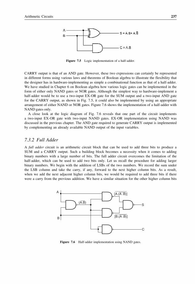
Arithmetic Circuits 237
Figure 7.5 Logic implementation of a half-adder.
CARRY output is that of an AND gate. However, these two expressions can certainly be representedin different forms using various laws and theorems of Boolean algebra to illustrate the flexibility thatthe designer has in hardware-implementing as simple a combinational function as that of a half-adder.We have studied in Chapter 6 on Boolean algebra how various logic gates can be implemented in theform of either only NAND gates or NOR gates. Although the simplest way to hardware-implement ahalf-adder would be to use a two-input EX-OR gate for the SUM output and a two-input AND gatefor the CARRY output, as shown in Fig. 7.5, it could also be implemented by using an appropriatearrangement of either NAND or NOR gates. Figure 7.6 shows the implementation of a half-adder withNAND gates only.
A close look at the logic diagram of Fig. 7.6 reveals that one part of the circuit implementsa two-input EX-OR gate with two-input NAND gates. EX-OR implementation using NAND wasdiscussed in the previous chapter. The AND gate required to generate CARRY output is implementedby complementing an already available NAND output of the input variables.
7.3.2 Full Adder
A full adder circuit is an arithmetic circuit block that can be used to add three bits to produce aSUM and a CARRY output. Such a building block becomes a necessity when it comes to addingbinary numbers with a large number of bits. The full adder circuit overcomes the limitation of thehalf-adder, which can be used to add two bits only. Let us recall the procedure for adding largerbinary numbers. We begin with the addition of LSBs of the two numbers. We record the sum underthe LSB column and take the carry, if any, forward to the next higher column bits. As a result,when we add the next adjacent higher column bits, we would be required to add three bits if therewere a carry from the previous addition. We have a similar situation for the other higher column bits
A
B
S
C
(A.B)
[A.(A .B)]
[B.(A .B)]
Figure 7.6 Half-adder implementation using NAND gates.
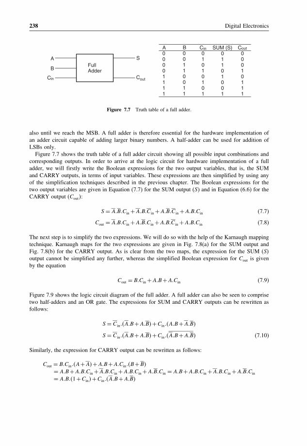
238 Digital Electronics
A
B
SFullAdder
Cin Cout
A00001111
B00110011
C01010101
in SUM (S)01101001
C00010111
out
Figure 7.7 Truth table of a full adder.
also until we reach the MSB. A full adder is therefore essential for the hardware implementation ofan adder circuit capable of adding larger binary numbers. A half-adder can be used for addition ofLSBs only.
Figure 7.7 shows the truth table of a full adder circuit showing all possible input combinations andcorresponding outputs. In order to arrive at the logic circuit for hardware implementation of a fulladder, we will firstly write the Boolean expressions for the two output variables, that is, the SUMand CARRY outputs, in terms of input variables. These expressions are then simplified by using anyof the simplification techniques described in the previous chapter. The Boolean expressions for thetwo output variables are given in Equation (7.7) for the SUM output (S) and in Equation (6.6) for theCARRY output (Cout�:
S = A�B�Cin +A�B�C in +A�B�C in +A�B�Cin (7.7)
Cout = A�B�Cin +A�B�Cin +A�B�C in +A�B�Cin (7.8)
The next step is to simplify the two expressions. We will do so with the help of the Karnaugh mappingtechnique. Karnaugh maps for the two expressions are given in Fig. 7.8(a) for the SUM output andFig. 7.8(b) for the CARRY output. As is clear from the two maps, the expression for the SUM (S�output cannot be simplified any further, whereas the simplified Boolean expression for Cout is givenby the equation
Cout = B�Cin +A�B+A�Cin (7.9)
Figure 7.9 shows the logic circuit diagram of the full adder. A full adder can also be seen to comprisetwo half-adders and an OR gate. The expressions for SUM and CARRY outputs can be rewritten asfollows:
S = C in��A�B+A�B�+Cin��A�B+A�B�
S = C in��A�B+A�B�+Cin��A�B+A�B� (7.10)
Similarly, the expression for CARRY output can be rewritten as follows:
Cout = B�Cin��A+A�+A�B+A�Cin��B+B�
= A�B+A�B�Cin +A�B�Cin +A�B�Cin +A�B�Cin = A�B+A�B�Cin +A�B�Cin +A�B�Cin
= A�B��1+Cin�+Cin��A�B+A�B�

Arithmetic Circuits 239
1
1
1
1
CinCin
Cin
A B
AB
A B
(a)
A B
A B
11
CinCin
Cin
A B
AB
A B
(b)
A B
A B 1
1
Figure 7.8 Karnaugh maps for the sum and carry-out of a full adder.
Cout = A�B+Cin��A�B+A�B� (7.11)
Boolean expression (7.10) can be implemented with a two-input EX-OR gate provided that one ofthe inputs is Cin and the other input is the output of another two-input EX-OR gate with A and Bas its inputs. Similarly, Boolean expression (7.11) can be implemented by ORing two minterms. Oneof them is the AND output of A and B. The other is also the output of an AND gate whose inputsare Cin and the output of an EX-OR operation on A and B. The whole idea of writing the Booleanexpressions in this modified form was to demonstrate the use of a half-adder circuit in building a fulladder. Figure 7.10(a) shows logic implementation of Equations (7.10) and (7.11). Figure 7.10(b) isnothing but Fig. 7.10(a) redrawn with the portion of the circuit representing a half-adder replaced with ablock.
The full adder of the type described above forms the basic building block of binary adders. However,a single full adder circuit can be used to add one-bit binary numbers only. A cascade arrangement ofthese adders can be used to construct adders capable of adding binary numbers with a larger numberof bits. For example, a four-bit binary adder would require four full adders of the type shown in Fig.7.10 to be connected in cascade. Figure 7.11 shows such an arrangement. (A3A2A1A0� and (B3B2B1B0�are the two binary numbers to be added, with A0 and B0 representing LSBs and A3 and B3 representingMSBs of the two numbers.

240 Digital Electronics
S
Cin
Cin
A
A
B
B
(a)
(b)
CinCout
Cin
A
B
B
A
A
AB
B
Cin
Cin
Figure 7.9 Logic circuit diagram of a full adder.
7.3.3 Half-Subtractor
We have seen in Chapter 3 on digital arithmetic how subtraction of two given binary numbers canbe carried out by adding 2’s complement of the subtrahend to the minuend. This allows us to doa subtraction operation with adder circuits. We will study the use of adder circuits for subtractionoperations in the following pages. Before we do that, we will briefly look at the counterparts ofhalf-adder and full adder circuits in the half-subtractor and full subtractor for direct implementation ofsubtraction operations using logic gates.
A half-subtractor is a combinational circuit that can be used to subtract one binary digit from anotherto produce a DIFFERENCE output and a BORROW output. The BORROW output here specifieswhether a ‘1’ has been borrowed to perform the subtraction. The truth table of a half-subtractor, asshown in Fig. 7.12, explains this further. The Boolean expressions for the two outputs are given bythe equations

Arithmetic Circuits 241
A
(a)
(b)
S
Cout
Cin
B
HalfAdder
HalfAdder
Cin
A
B
S
Cout
Sum
Carry
Sum
Carry
Figure 7.10 Logic implementation of a full adder with half-adders.
FA
Cout
B3
S3 S2 S1 S0
B2 B1 B0A3 A2 A1 A0
CinFA FA FA
Figure 7.11 Four-bit binary adder.
D = A�B+A�B (7.12)
Bo = A�B (7.13)
It is obvious that there is no further scope for any simplification of the Boolean expressions givenby Equations (7.12) and (7.13). While the expression for the DIFFERENCE (D� output is that of

242 Digital Electronics
A0011
B0101
D0110
Bo0100
A
B
D=A–BHalf
SubtractorBo
Figure 7.12 Half-subtractor.
A
BD=A–B
Bo
Figure 7.13 Logic diagram of a half-subtractor.
an EX-OR gate, the expression for the BORROW output (Bo� is that of an AND gate with inputA complemented before it is fed to the gate. Figure 7.13 shows the logic implementation of ahalf-subtractor. Comparing a half-subtractor with a half-adder, we find that the expressions for theSUM and DIFFERENCE outputs are just the same. The expression for BORROW in the case ofthe half-subtractor is also similar to what we have for CARRY in the case of the half-adder. Ifthe input A, that is, the minuend, is complemented, an AND gate can be used to implement theBORROW output. Note the similarities between the logic diagrams of Fig. 7.5 (half-adder) and Fig. 7.13(half-subtractor).
7.3.4 Full Subtractor
A full subtractor performs subtraction operation on two bits, a minuend and a subtrahend, and also takesinto consideration whether a ‘1’ has already been borrowed by the previous adjacent lower minuend bitor not. As a result, there are three bits to be handled at the input of a full subtractor, namely the two bitsto be subtracted and a borrow bit designated as Bin. There are two outputs, namely the DIFFERENCEoutput D and the BORROW output Bo. The BORROW output bit tells whether the minuend bit needsto borrow a ‘1’ from the next possible higher minuend bit. Figure 7.14 shows the truth table of a fullsubtractor.
The Boolean expressions for the two output variables are given by the equations
D = A�B�Bin +A�B�Bin +A�B�Bin +A�B�Bin (7.14)
Bo = A�B�Bin +A�B�Bin +A�B�Bin +A�B�Bin (7.15)

Arithmetic Circuits 243
Figure 7.14 Truth table of a full subtractor.
1
1
1
1
BinBin
Bin
AB
AB
AB
(a)
AB
AB
1
1
1
1
BinBin
Bin
AB
AB
AB
(b)
AB
AB
Figure 7.15 Karnaugh maps for difference and borrow outputs.
The Karnaugh maps for the two expressions are given in Fig. 7.15(a) for DIFFERENCE output D andin Fig. 7.15(b) for BORROW output Bo. As is clear from the two Karnaugh maps, no simplificationis possible for the difference output D. The simplified expression for Bo is given by the equation
Bo = A�B+A�Bin +B�Bin (7.16)

244 Digital Electronics
(b)
D
Bo
Bin DB
A
A
Bin
B
(a)
Bo
D
D
Bo
A
BHS
HSA
BBout
Figure 7.16 Logic implementation of a full subtractor with half-subtractors.
If we compare these expressions with those derived earlier in the case of a full adder, we find that theexpression for DIFFERENCE output D is the same as that for the SUM output. Also, the expression forBORROW output Bo is similar to the expression for CARRY-OUT Co. In the case of a half-subtractor,the A input is complemented. By a similar analysis it can be shown that a full subtractor can beimplemented with half-subtractors in the same way as a full adder was constructed using half-adders.Relevant logic diagrams are shown in Figs 7.16(a) and (b) corresponding to Figs 7.10(a) and (b)respectively for a full adder.
Again, more than one full subtractor can be connected in cascade to perform subtraction on twolarger binary numbers. As an illustration, Fig. 7.17 shows a four-bit subtractor.
7.3.5 Controlled Inverter
A controlled inverter is needed when an adder is to be used as a subtractor. As outlined earlier,subtraction is nothing but addition of the 2’s complement of the subtrahend to the minuend. Thus, thefirst step towards practical implementation of a subtractor is to determine the 2’s complement of thesubtrahend. And for this, one needs firstly to find 1’s complement. A controlled inverter is used to find1’s complement. A one-bit controlled inverter is nothing but a two-input EX-OR gate with one of itsinputs treated as a control input, as shown in Fig. 7.18(a). When the control input is LOW, the inputbit is passed as such to the output. (Recall the truth table of an EX-OR gate.) When the control inputis HIGH, the input bit gets complemented at the output. Figure 7.18(b) shows an eight-bit controlledinverter of this type. When the control input is LOW, the output (Y7 Y6 Y5 Y4 Y3 Y2 Y1 Y0� is the same asthe input (A7 A6 A5 A4 A3 A2 A1 A0�. When the control input is HIGH, the output is 1’s complement

Arithmetic Circuits 245
FS
Bout
B3
D3 D2 D1 D0
B2 B1 B0
A3 A2 A1 A0
Bin = 0FS FS FS
Figure 7.17 Four-bit subtractor.
Figure 7.18 (a) One-bit controlled inverter and (b) eight-bit controlled inverter.
of the input. As an example, 11010010 at the input would produce 00101101 at the output when thecontrol input is in a logic ‘1’ state.
7.4 Adder–SubtractorSubtraction of two binary numbers can be accomplished by adding 2’s complement of the subtrahendto the minuend and disregarding the final carry, if any. If the MSB bit in the result of addition is

246 Digital Electronics
Figure 7.19 Four-bit adder-subtractor.
a ‘0’, then the result of addition is the correct answer. If the MSB bit is a ‘1’, this implies that theanswer has a negative sign. The true magnitude in this case is given by 2’s complement of the result ofaddition.
Full adders can be used to perform subtraction provided we have the necessary additional hardwareto generate 2’s complement of the subtrahend and disregard the final carry or overflow. Figure 7.19shows one such hardware arrangement. Let us see how it can be used to perform subtraction of twofour-bit binary numbers. A close look at the diagram would reveal that it is the hardware arrangementfor a four-bit binary adder, with the exception that the bits of one of the binary numbers are fed throughcontrolled inverters. The control input here is referred to as the SUB input. When the SUB input is inlogic ‘0’ state, the four bits of the binary number (B3 B2 B1 B0� are passed on as such to the B inputs ofthe corresponding full adders. The outputs of the full adders in this case give the result of addition of thetwo numbers. When the SUB input is in logic ‘1’ state, four bits of one of the numbers, (B3 B2 B1 B0� inthe present case, get complemented. If the same ‘1’ is also fed to the CARRY-IN of the LSB full adder,what we finally achieve is the addition of 2’s complement and not 1’s complement. Thus, in the adderarrangement of Fig. 7.19, we are basically adding 2’s complement of (B3 B2 B1 B0� to (A3 A2 A1 A0�. Theoutputs of the full adders in this case give the result of subtraction of the two numbers. The arrangementshown achieves A−B. The final carry (the CARRY-OUT of the MSB full adder) is ignored if it is notdisplayed.
For implementing an eight-bit adder–subtractor, we will require eight full adders and eight two-inputEX-OR gates. Four-bit full adders and quad two-input EX-OR gates are individually available inintegrated circuit form. A commonly used four-bit adder in the TTL family is the type number 7483.Also, type number 7486 is a quad two-input EX-OR gate in the TTL family. Figure 7.20 shows afour-bit binary adder–subtractor circuit implemented with 7483 and 7486. Two each of 7483 and 7486can be used to construct an eight-bit adder–subtractor circuit.
7.5 BCD AdderA BCD adder is used to perform the addition of BCD numbers. A BCD digit can have any of theten possible four-bit binary representations, that is, 0000, 0001, � � � , 1001, the equivalent of decimalnumbers 0, 1, � � � , 9. When we set out to add two BCD digits and we assume that there is an inputcarry too, the highest binary number that we can get is the equivalent of decimal number 19 (9 + 9 + 1).

Arithmetic Circuits 247
Figure 7.20 Four-bit adder-subtractor.
This binary number is going to be (10011)2. On the other hand, if we do BCD addition, we wouldexpect the answer to be (0001 1001)BCD. And if we restrict the output bits to the minimum required, theanswer in BCD would be (1 1001)BCD. Table 7.1 lists the possible results in binary and the expectedresults in BCD when we use a four-bit binary adder to perform the addition of two BCD digits. It isclear from the table that, as long as the sum of the two BCD digits remains equal to or less than 9, thefour-bit adder produces the correct BCD output.
The binary sum and the BCD sum in this case are the same. It is only when the sum is greater than9 that the two results are different. It can also be seen from the table that, for a decimal sum greaterthan 9 (or the equivalent binary sum greater than 1001), if we add 0110 to the binary sum, we canget the correct BCD sum and the desired carry output too. The Boolean expression that can apply thenecessary correction is written as
C = K +Z3�Z2 +Z3�Z1 (7.17)
Equation (7.17) implies the following. A correction needs to be applied whenever K = 1. This takescare of the last four entries. Also, a correction needs to be applied whenever both Z3 and Z2 are ‘1’.This takes care of the next four entries from the bottom, corresponding to a decimal sum equal to

248 Digital Electronics
Table 7.1 Results in binary and the expected results in BCD using a four-bit binary adder to perform the additionof two BCD digits.
Decimal sum Binary sum BCD sum
K Z3 Z2 Z1 Z0 C S3 S2 S1 S0
0 0 0 0 0 0 0 0 0 0 01 0 0 0 0 1 0 0 0 0 12 0 0 0 1 0 0 0 0 1 03 0 0 0 1 1 0 0 0 1 14 0 0 1 0 0 0 0 1 0 05 0 0 1 0 1 0 0 1 0 16 0 0 1 1 0 0 0 1 1 07 0 0 1 1 1 0 0 1 1 18 0 1 0 0 0 0 1 0 0 09 0 1 0 0 1 0 1 0 0 1
10 0 1 0 1 0 1 0 0 0 011 0 1 0 1 1 1 0 0 0 112 0 1 1 0 0 1 0 0 1 013 0 1 1 0 1 1 0 0 1 114 0 1 1 1 0 1 0 1 0 015 0 1 1 1 1 1 0 1 0 116 1 0 0 0 0 1 0 1 1 017 1 0 0 0 1 1 0 1 1 118 1 0 0 1 0 1 1 0 0 019 1 0 0 1 1 1 1 0 0 1
12, 13, 14 and 15. For the remaining two entries corresponding to a decimal sum equal to 10 and11, a correction is applied for both Z3 and Z1, being ‘1’. While hardware-implementing, 0110 can beadded to the binary sum output with the help of a second four-bit binary adder. The correction logic asdictated by the Boolean expression (7.17) should ensure that (0110) gets added only when the aboveexpression is satisfied. Otherwise, the sum output of the first binary adder should be passed on as suchto the final output, which can be accomplished by adding (0000) in the second adder. Figure 7.21shows the logic arrangement of a BCD adder capable of adding two BCD digits with the help of twofour-bit binary adders and some additional combinational logic.
The BCD adder described in the preceding paragraphs can be used to add two single-digitBCD numbers only. However, a cascade arrangement of single-digit BCD adder hardware can beused to perform the addition of multiple-digit BCD numbers. For example, an n-digit BCD adderwould require n such stages in cascade. As an illustration, Fig. 7.22 shows the block diagram ofa circuit for the addition of two three-digit BCD numbers. The first BCD adder, labelled LSD(Least Significant Digit), handles the least significant BCD digits. It produces the sum output(S3 S2 S1 S0�, which is the BCD code for the least significant digit of the sum. It also producesan output carry that is fed as an input carry to the next higher adjacent BCD adder. This BCDadder produces the sum output (S7 S6 S5 S4�, which is the BCD code for the second digit of thesum, and a carry output. This output carry serves as an input carry for the BCD adder representingthe most significant digits. The sum outputs (S11 S10 S9 S8� represent the BCD code for the MSD ofthe sum.

Arithmetic Circuits 249
Figure 7.21 Single-digit BCD adder.
Figure 7.22 Three-digit BCD adder.
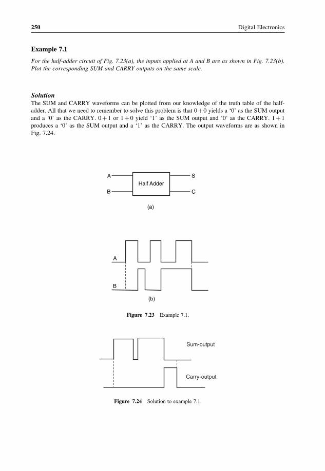
250 Digital Electronics
Example 7.1
For the half-adder circuit of Fig. 7.23(a), the inputs applied at A and B are as shown in Fig. 7.23(b).Plot the corresponding SUM and CARRY outputs on the same scale.
SolutionThe SUM and CARRY waveforms can be plotted from our knowledge of the truth table of the half-adder. All that we need to remember to solve this problem is that 0+0 yields a ‘0’ as the SUM outputand a ‘0’ as the CARRY. 0 + 1 or 1 + 0 yield ‘1’ as the SUM output and ‘0’ as the CARRY. 1 + 1produces a ‘0’ as the SUM output and a ‘1’ as the CARRY. The output waveforms are as shown inFig. 7.24.
Half AdderSA
B C
(a)
A
B
(b)
Figure 7.23 Example 7.1.
Sum-output
Carry-output
Figure 7.24 Solution to example 7.1.

Arithmetic Circuits 251
Example 7.2
Given the relevant Boolean expressions for half-adder and half-subtractor circuits, design a half-adder–subtractor circuit that can be used to perform either addition or subtraction on two one-bitnumbers. The desired arithmetic operation should be selectable from a control input.
SolutionBoolean expressions for the half-adder and half-subtractor are given as follows:
Half-adder
SUM output= AB+AB and CARRY output= AB
Half-subtractor
DIFFERENCE output = AB+AB and BORROW output= AB
If we use a controlled inverter for complementing A in the case of the half-subtractor circuit, thenthe same hardware can also be used to add two one-bit numbers. Figure 7.25 shows the logic circuitdiagram. When the control input is ‘0’, input variable A is passed uncomplemented to the input of theNAND gate. In this case, the AND gate generates the CARRY output of the addition operation. TheEX-OR gate generates the SUM output. On the other hand, when the control input is ‘1’, the ANDgate generates the BORROW output and the EX-OR gate generates the DIFFERENCE output. Thus,‘0’ at the control input makes it a half-adder, while ‘1’ at the control input makes it a half-subtractor.
Example 7.3
Refer to Fig. 7.26. Write the simplified Boolean expressions for DIFFERENCE and BORROW outputs.
Carry/Borrow
Sum/Difference
Control:0/1
A
B
Figure 7.25 Solution to example 7.2.
HAA
BC BORROW
DIFFERENCE
HS
SUM
Figure 7.26 Example 7.3.

252 Digital Electronics
SolutionLet us assume that the two inputs to the half-subtractor circuit are X and Y , with X equal to theSUM output of the half-adder and Y equal to C. DIFFERENCE and BORROW outputs can then beexpressed as follows:
DIFFERENCE output = X ⊕Y = X�Y +X�Y and BORROW output = X�Y
Also, X = A�B+A�B and Y = C�Substituting the values of X and Y , we obtain
DIFFERENCE output = �A�B+A�B��C + �A�B+A�B��C = �A�B+A�B��C + �A�B+A�B��C
= A�B�C +A�B�C +A�B�C +A�B�C
BORROW output = X�Y = �A�B+A�B��C = �A�B+A�B��C = A�B�C +A�B�C
Example 7.4
Design an eight-bit adder–subtractor circuit using four-bit binary adders, type number 7483, and quadtwo-input EX-OR gates, type number 7486. Assume that pin connection diagrams of these ICs areavailable to you.
SolutionIC 7483 is a four-bit binary adder, which means that it can add two four-bit binary numbers. In order toadd two eight-bit numbers, we need to use two 7483s in cascade. That is, the CARRY-OUT (pin 14) ofthe 7483 handling less significant four bits is fed to the CARRY-IN (pin 13) of the 7483 handling moresignificant four bits. Also, if (A0 � � � A7� and (B0 � � � B7� are the two numbers to be operated upon, andif the objective is to compute A − B, bits B0, B1, B2, B3, B4, B5, B6 and B7 are complemented usingEX-OR gates. One of the inputs of all EX-OR gates is tied together to form the control input. Whenthe control input is in logic ‘1’ state, bits B0 to B7 get complemented. Also, feeding this logic ‘1’ to theCARRY-IN of lower 7483 ensures that we get 2’s complement of bits (B0 � � � B7�. Therefore, whenthe control input is in logic ‘1’ state, the two’s complement of (B0 � � � B7� is added to (A0 � � � A7�. Theoutput is therefore A−B. A logic ‘0’ at the control input allows (B0 � � � B7� to pass through EX-ORgates uncomplemented, and the output in that case is A+B. Figure 7.27 shows the circuit diagram.
Example 7.5
The logic diagram of Fig. 7.28 performs the function of a very common arithmetic building block.Identify the logic function.
SolutionWriting Boolean expressions for X and Y ,
X = �A�B���A�B� = �A�B+A�B� = A�B+A�B and Y = �A+B� = A�B
Boolean expressions for X and Y are those of a half-adder. X and Y respectively represent SUM andCARRY outputs.

Arithmetic Circuits 253
Figure 7.27 Solution to example 7.4.
A
B
X
Y
Figure 7.28 Example 7.5.
Example 7.6
Design a BCD adder circuit capable of adding BCD equivalents of two-digit decimal numbers. Indicatethe IC type numbers used if the design has to be TTL logic family compatible.
SolutionThe desired BCD adder is a cascaded arrangement of two stages of the type of BCD adder discussedin the previous pages. Figure 7.29 shows the logic diagram, and it follows the generalized cascadedarrangement discussed earlier and shown in Fig. 7.22 for a three-digit BCD adder. The BCD adderof Fig. 7.21 can be used to add four-bit BCD equivalents of two single-digit decimal numbers. Acascaded arrangement of two such stages, where the output C of Fig. 7.21 (CARRY-OUT) is fed tothe CARRY-IN of the second stage, is shown in Fig. 7.29. In terms of IC type numbers, IC 7483 canbe used for four-bit binary adders as shown in the diagram, IC 7408 can be used for implementing

254 Digital Electronics
OutputCarry
S7
B7B6B5B4 A7A6A5A4
7483(4-BitBinaryAdder)
7483(4-BitBinaryAdder)
Z7 Z6 Z5 Z4
S6 S5 S4 S3
B3 B2B1B0 A3A2A1A0
Z3 Z2 Z1 Z0
S2 S1 S0
Carry In7483(4-BitBinaryAdder)
7483(4-BitBinaryAdder)
Figure 7.29 Example 7.6.
the required four two-input AND gates (IC 7408 is a quad two-input AND) and IC 7432 can be usedto implement the required two three-input OR gates. IC 7432 is a quad two-input OR. Two two-inputOR gates can be connected in cascade to get a three-input OR gate.
7.6 Carry Propagation–Look-Ahead Carry GeneratorThe four-bit binary adder described in the previous pages can be used to add two four-bit binarynumbers. Multiple numbers of such adders are used to perform addition operations on larger-bit binarynumbers. Each of the adders is composed of four full adders (FAs) connected in cascade. The blockschematic arrangement of a four-bit adder is reproduced in Fig. 7.30(a) for reference and furtherdiscussion. This type of adder is also called a parallel binary adder because all the bits of the augendand addend are present and are fed to the full adder blocks simultaneously. Theoretically, the additionoperation in various full adders takes place simultaneously. What is of importance and interest to users,more so when they are using a large number of such adders in their overall computation system, iswhether the result of addition and carry-out are available to them at the same time. In other words, weneed to see if this addition operation is truly parallel in nature. We will soon see that it is not. It is infact limited by what is known as carry propagation time. Refer to Figs 7.30(a) and (b). Figure 7.30(b)shows the logic diagram of a full adder. Here, Ci and Ci+1 are the input and output CARRY; Pi andGi are two new binary variables called CARRY PROPAGATE and CARRY GENERATE and will beaddressed a little later.
For i=1, the diagram in Fig. 7.30(b) is that of the LSB full adder of Fig. 7.30(a). We can see here thatC2, which is the output CARRY of FA (1) and the input CARRY for FA (2), will appear at the output aftera minimum of two gate delays plus delay due to the half adder after application of Ai, Bi and Ci inputs.

Arithmetic Circuits 255
B4
C4FA(4)
A4
S4
B3
C3FA(3)
A3
S3
B2
C2FA(2)
A2
S2
B1
C1FA(1)
A1
S1C5
(a)
Ai
Bi
Ci(b)
Ci+1
SiPi
Gi
Figure 7.30 Four-bit binary adder.
The steady state of C2 will be delayed by two gate delays after the appearance of C1. Similarly, C3 and C4
steady state will be four and six gate delays respectively after C1. And final carry C5 will appear after eightgate delays.
Extending it a little further, let us assume that we are having a cascade arrangement of two four-bitadders to be able to handle eight-bit numbers. Now, C5 will form the input CARRY to the secondfour-bit adder. The final output CARRY C9 will now appear after 16 gate delays. This carry propagationdelay limits the speed with which two numbers are added. The outputs of any such adder arrangementwill be correct only if signals are given enough time to propagate through gates connected betweeninput and output. Since subtraction is also an addition process and operations like multiplication anddivision are also processes involving successive addition and subtraction, the time taken by an additionprocess is very critical.
One of the possible methods for reducing carry propagation delay time is to use faster logic gates.But then there is a limit below which the gate delay cannot be reduced. There are other hardware-related techniques, the most widely used of which is the concept of look-ahead carry. This conceptattempts to look ahead and generate the carry for a certain given addition operation that would

256 Digital Electronics
otherwise have resulted from some previous operation. In order to explain the concept, let us definetwo new binary variables: Pi called CARRY PROPAGATE and Gi called CARRY GENERATE.Binary variable Gi is so called as it generates a carry whenever Ai and Bi are ‘1’. Binary variablePi is called CARRY PROPAGATE as it is instrumental in propagation of Ci to Ci+1. CARRY,SUM, CARRY GENERATE and CARRY PROPAGATE parameters are given by the followingexpressions:
Pi = Ai ⊕Bi (7.18)
Gi = Ai�Bi (7.19)
Si = Pi ⊕Ci (7.20)
Ci+1 = Pi�Ci +Gi (7.21)
In the next step, we write Boolean expressions for the CARRY output of each full adder stage in thefour-bit binary adder. We obtain the following expressions:
C2 = G1 +P1�C1 (7.22)
C3 = G2 +P2�C2 = G2 +P2��G1 +P1�C1� = G2 +P2�G1 +P1�P2�C1 (7.23)
C4 = G3 +P3�C3 = G3 +P3��G2 +P2�G1 +P1�P2�C1�
C4 = G3 +P3�G2 +P3�P2�G1 +P1�P2�P3�C1 (7.24)
From the expressions for C2, C3 and C4 it is clear that C4 need not wait for C3 and C2 to propagate.Similarly, C3 does not wait for C2 to propagate. Hardware implementation of these expressions givesus a kind of look-ahead carry generator. A look-ahead carry generator that implements the aboveexpressions using AND-OR logic is shown in Fig. 7.31.
Figure 7.32 shows the four-bit adder with the look-ahead carry concept incorporated. The blocklabelled look-ahead carry generator is similar to that shown in Fig. 7.31. The logic gates shown to theleft of the block represent the input half-adder portion of various full adders constituting the four-bitadder. The EX-OR gates shown on the right are a portion of the output half-adders of various fulladders.
All sum outputs in this case will be available at the output after a delay of two levels of logicgates. 74182 is a typical look-ahead carry generator IC of the TTL logic family. This IC can beused to generate relevant carry inputs for four four-bit binary adders connected in cascade to performoperation on two 16-bit numbers. Of course, the four-bit adders should be of the type so as to produceCARRY GENERATE and CARRY PROPAGATE outputs. Figure 7.33 shows the arrangement. Inthe figure shown, Cn is the CARRY input, G0, G1, G2 and G3 are CARRY GENERATE inputsfor 74182 and P0, P1, P2 and P3 are CARRY PROPAGATE inputs for 74182. Cn+x, Cn+y andCn+z are the CARRY outputs generated by 74182 for the four-bit adders. The G and P outputsof 74182 need to be cascaded. Figure 7.34 shows the arrangement needed for adding two 64-bitnumbers.

Arithmetic Circuits 257
C4
C3
C2
P3G3
P2
G2
P1
G1
C1
Figure 7.31 Look-ahead carry generator.
Example 7.7
If the CARRY GENERATE Gi and CARRY PROPAGATE Pi are redefined as Pi = �Ai + Bi) andGi = AiBi� show that the CARRY output Ci+1 and the SUM output Si of a full adder can be expressedby the following Boolean functions:
Ci+1 = �Ci�Gi +Pi� = Gi +Pi�Ci and Si = �Pi�Gi�⊕Ci
Solution
Ci+1 = �Ci�Gi +Pi� = �Ci��Ai�Bi�+ �Ai +Bi��
= �Ci��Ai�Bi���Ai +Bi��
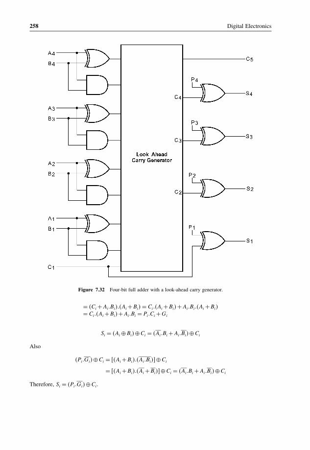
258 Digital Electronics
Figure 7.32 Four-bit full adder with a look-ahead carry generator.
= �Ci +Ai�Bi���Ai +Bi� = Ci��Ai +Bi�+Ai�Bi��Ai +Bi�= Ci��Ai +Bi�+Ai�Bi = Pi�Ci +Gi
Si = �Ai ⊕Bi�⊕Ci = �Ai�Bi +Ai�Bi�⊕Ci
Also
�Pi�Gi�⊕Ci = ��Ai +Bi���Ai�Bi��⊕Ci
= ��Ai +Bi���Ai +Bi��⊕Ci = �Ai�Bi +Ai�Bi�⊕Ci
Therefore, Si = �Pi�Gi�⊕Ci.

Arithmetic Circuits 259
Figure 7.33 IC 74182 interfaced with four four-bit adders.
Figure 7.34 Look-ahead carry generation for adding 64-bit numbers.

260 Digital Electronics
7.7 Arithmetic Logic Unit (ALU)The arithmetic logic unit (ALU) is a digital building block capable of performing both arithmetic aswell as logic operations. Arithmetic logic units that can perform a variety of arithmetic operationssuch as addition, subtraction, etc., and logic functions such as ANDing, ORing, EX-ORing, etc., ontwo four-bit numbers are usually available in IC form. The function to be performed is selectable fromfunction select pins. Some of the popular type numbers of ALU include 74181, 74381, 74382, 74582(all from the TTL logic family) and 40181 (from the CMOS logic family). Functional details of theseICs are given in the latter part of the chapter under the heading of Application-Relevant Information.More than one such IC can always be connected in cascade to perform arithmetic and logic operationson larger bit numbers.
7.8 MultipliersMultiplication of binary numbers is usually implemented in microprocessors and microcomputers byusing repeated addition and shift operations. Since the binary adders are designed to add only twobinary numbers at a time, instead of adding all the partial products at the end, they are added twoat a time and their sum is accumulated in a register called the accumulator register. Also, when themultiplier bit is ‘0’, that very partial product is ignored, as an all ‘0’ line does not affect the final result.The basic hardware arrangement of such a binary multiplier would comprise shift registers for themultiplicand and multiplier bits, an accumulator register for storing partial products, a binary paralleladder and a clock pulse generator to time various operations.
Figure 7.35 4 × 4 bit multiplier.

Arithmetic Circuits 261
Binary multipliers are also available in IC form. Some of the popular type numbers in the TTLfamily include 74261 which is a 2 × 4 bit multiplier (a four-bit multiplicand designated as B0,B1,B2,B3 and B4, and a two-bit multiplier designated as M0, M1 and M2�.
The MSBs B4 and M2 are used to represent signs. 74284 and 74285 are 4 × 4 bit multipliers. Theycan be used together to perform high-speed multiplication of two four-bit numbers. Figure 7.35 showsthe arrangement. The result of multiplication is often required to be stored in a register. The size ofthis register (accumulator) depends upon the number of bits in the result, which at the most can beequal to the sum of the number of bits in the multiplier and multiplicand. Some multiplier ICs havean in-built register.
Many microprocessors do not have in their ALU the hardware that can perform multiplicationor other complex arithmetic operations such as division, determining the square root, trigonometricfunctions, etc. These operations in these microprocessors are executed through software. Forexample, a multiplication operation may be accomplished by using a software program that doesmultiplication through repeated execution of addition and shift instructions. Other complex operationsmentioned above can also be executed with similar programs. Although the use of software reducesthe hardware needed in the microprocessor, the computation time in general is higher in thecase of software-executed operations when compared with the use of hardware to perform thoseoperations.
7.9 Magnitude ComparatorA magnitude comparator is a combinational circuit that compares two given numbers and determineswhether one is equal to, less than or greater than the other. The output is in the form of three binaryvariables representing the conditions A = B�A > B and A < B, if A and B are the two numbers beingcompared. Depending upon the relative magnitude of the two numbers, the relevant output changesstate. If the two numbers, let us say, are four-bit binary numbers and are designated as (A3 A2 A1 A0�and (B3 B2 B1 B0�, the two numbers will be equal if all pairs of significant digits are equal, that is,A3 = B3, A2 = B2�A1 = B1 and A0 = B0. In order to determine whether A is greater than or less thanB� we inspect the relative magnitude of pairs of significant digits, starting from the most significantposition. The comparison is done by successively comparing the next adjacent lower pair of digits ifthe digits of the pair under examination are equal. The comparison continues until a pair of unequaldigits is reached. In the pair of unequal digits, if Ai = 1 and Bi = 0, then A > B, and if Ai = 0,Bi = 1 then A < B. If X, Y and Z are three variables respectively representing the A = B, A > Band A < B conditions, then the Boolean expression representing these conditions are given by theequations
X = x3�x2�x1�x0 where xi = Ai�Bi +Ai�Bi (7.25)
Y = A3�B3 +x3�A2�B2 +x3�x2�A1�B1 +x3�x2�x1�A0�B0 (7.26)
Z = A3�B3 +x3�A2�B2 +x3�x2�A1�B1 +x3�x2�x1�A0�B0 (7.27)
Let us examine equation (7.25). x3 will be ‘1’ only when both A3 and B3 are equal. Similarly, conditionsfor x2, x1 and x0 to be ‘1’ respectively are equal A2 and B2, equal A1 and B1 and equal A0 and B0.ANDing of x3, x2, x1 and x0 ensures that X will be ‘1’ when x3, x2, x1 and x0 are in the logic ‘1’state. Thus, X = 1 means that A = B. On similar lines, it can be visualized that equations (7.26) and

262 Digital Electronics
Figure 7.36 Four-bit magnitude comparator.
(7.27) respectively represent A > B and A < B conditions. Figure 7.36 shows the logic diagram of afour-bit magnitude comparator.
Magnitude comparators are available in IC form. For example, 7485 is a four-bit magnitudecomparator of the TTL logic family. IC 4585 is a similar device in the CMOS family. 7485 and 4585have the same pin connection diagram and functional table. The logic circuit inside these devicesdetermines whether one four-bit number, binary or BCD, is less than, equal to or greater than asecond four-bit number. It can perform comparison of straight binary and straight BCD (8-4-2-1)codes. These devices can be cascaded together to perform operations on larger bit numbers without thehelp of any external gates. This is facilitated by three additional inputs called cascading or expansioninputs available on the IC. These cascading inputs are also designated as A = B, A > B and A < Binputs. Cascading of individual magnitude comparators of the type 7485 or 4585 is discussed in thefollowing paragraphs. IC 74AS885 is another common magnitude comparator. The device is an eight-bit magnitude comparator belonging to the advanced Schottky TTL family. It can perform high-speedarithmetic or logic comparisons on two eight-bit binary or 2’s complement numbers and produces twofully decoded decisions at the output about one number being either greater than or less than the other.More than one of these devices can also be connected in a cascade arrangement to perform comparisonof numbers of longer lengths.

Arithmetic Circuits 263
7.9.1 Cascading Magnitude Comparators
As outlined earlier, magnitude comparators available in IC form are designed in such a way thatthey can be connected in a cascade arrangement to perform comparison operations on numbers oflonger lengths. In cascade arrangement, the A = B, A > B and A < B outputs of a stage handlingless significant bits are connected to corresponding inputs of the next adjacent stage handling moresignificant bits. Also, the stage handling least significant bits must have a HIGH level at the A = Binput. The other two cascading inputs (A > B and A < B� may be connected to a LOW level. Wewill illustrate the concept by showing the arrangement of an eight-bit magnitude comparator using twofour-bit magnitude comparators of the type 7485 or 4585. Figure 7.37 shows the cascaded arrangementof the two comparators. We can see the three comparison outputs of the comparator handling lesssignificant four bits of the two numbers being connected to the corresponding cascading inputs of thecomparator handling more significant four bits of the two numbers. Also, cascading inputs of the lesssignificant comparator have been connected to a HIGH or LOW level as per the guidelines mentionedin the previous paragraph.
Operation of this circuit can be explained by considering the functional table of IC 7485 or IC 4585as shown in Table 7.2. The two numbers being compared here are (A7 � � � A0) and (B7 � � � B0�. Theless significant comparator handles (A3, A2, A1, A0� and (B3, B2, B1, B0�, and the more significantcomparator handles (A7, A6, A5, A4� and (B7, B6, B5, B4�. Let us take the example of the two numbersbeing such that A7 > B7. From the first-row entry of the function table it is clear that, irrespectiveof the status of other bits of the more significant comparator, and also regardless of the status of itscascading inputs, the final output produces a HIGH at the A > B output and a LOW at the A < B andA = B outputs. Since the status of cascading inputs of the more significant comparator depends uponthe status of comparison bits of the less significant comparator, the cascade arrangement produces thecorrect output for A7 > B7 regardless of the status of all other comparison bits. On similar lines, thecircuit produces a valid output for any given status of comparison bits.
Example 7.8
Design a two-bit magnitude comparator. Also, write relevant Boolean expressions.
Figure 7.37 Cascading of individual magnitude comparators.

264 Digital Electronics
Table 7.2 Functional table of IC 7485 or IC 4585.
Comparison inputs Cascading inputs Outputs
A3,B3 A2,B2 A1,B1 A0,B0 A > B A < B A=B A > B A < B A=B
A3 > B3 X X X X X X HIGH LOW LOWA3 < B3 X X X X X X LOW HIGH LOWA3 = B3 A2 > B2 X X X X X HIGH LOW LOWA3 = B3 A2 < B2 X X X X X LOW HIGH LOWA3 = B3 A2 = B2 A1 > B1 X X X X HIGH LOW LOWA3 = B3 A2 = B2 A1 < B1 X X X X LOW HIGH LOWA3 = B3 A2 = B2 A1 = B1 A0 > B0 X X X HIGH LOW LOWA3 = B3 A2 = B2 A1 = B1 A0 < B0 X X X LOW HIGH LOWA3 = B3 A2 = B2 A1 = B1 A0 = B0 HIGH LOW LOW HIGH LOW LOWA3 = B3 A2 = B2 A1 = B1 A0 = B0 LOW HIGH LOW LOW HIGH LOWA3 = B3 A2 = B2 A1 = B1 A0 = B0 LOW LOW HIGH LOW LOW HIGHA3 = B3 A2 = B2 A1 = B1 A0 = B0 X X HIGH LOW LOW HIGHA3 = B3 A2 = B2 A1 = B1 A0 = B0 HIGH HIGH LOW LOW LOW LOWA3 = B3 A2 = B2 A1 = B1 A0 = B0 LOW LOW LOW HIGH HIGH LOW
SolutionLet A�A1A0� and B �B1B0� be the two numbers. If X, Y and Z represent the conditions A = B�A > Band A < B respectively (that is, X = 1, Y = 0 and Z = 0 for A =B; X= 0, Y = 1 and Z = 0 forA > B; and X = 0, Y = 0 and Z = 1 for A < B), then expressions for X, Y and Z can be written asfollows:
X = x1.x0 where x1 = A1�B1 +A1�B1 and x0 = A0�B0 +A0�B0
Y = A1�B1 +x1�A0�B0
Z = A1�B1 +x1�A0�B0
Figure 7.38 shows the logic diagram of the two-bit comparator.
Example 7.9
Hardware-implement a three-bit magnitude comparator having one output that goes HIGH when thetwo three-bit numbers are equal. Use only NAND gates.
SolutionThe equivalence condition of the two three-bit numbers is given by the equation X = x2.x1.x0, wherex2 = A2�B2 +A2�B2, x1 = A1�B1 +A1�B1 and x0 = A0�B0 +A0�B0.
Figure 7.39 shows the logic diagram. x2, x1 and x0 are respectively given by EX-NOR operation of(A2, B2�, (A1, B1� and (A0, B0�. These are then ANDed to get X.

Arithmetic Circuits 265
A1
X(A=B)
B1
A0B0
Y(A>B)
Z(A<B)
X1
Figure 7.38 Solution to example 7.8.
Figure 7.39 Solution to example 7.9.

8Multiplexers and Demultiplexers
In the previous chapter, we described at length those combinational logic circuits that can be usedto perform arithmetic and related operations. This chapter takes a comprehensive look at yet anotherclass of building blocks used to design more complex combinational circuits, and covers buildingblocks such as multiplexers and demultiplexers and other derived devices such as encoders anddecoders. Particular emphasis is given to the operational basics and use of these devices to design morecomplex combinational circuits. Application-relevant information in terms of the list of commonly usedintegrated circuits available in this category, along with their functional description is given towardsthe end of the chapter. The text has been adequately illustrated with the help of a large number ofsolved examples.
8.1 MultiplexerA multiplexer or MUX, also called a data selector, is a combinational circuit with more than oneinput line, one output line and more than one selection line. There are some multiplexer ICs thatprovide complementary outputs. Also, multiplexers in IC form almost invariably have an ENABLEor STROBE input, which needs to be active for the multiplexer to be able to perform its intendedfunction. A multiplexer selects binary information present on any one of the input lines, dependingupon the logic status of the selection inputs, and routes it to the output line. If there are n selection lines,then the number of maximum possible input lines is 2n and the multiplexer is referred to as a 2n-to-1multiplexer or 2n × 1 multiplexer. Figures 8.1(a) and (b) respectively show the circuit representationand truth table of a basic 4-to-1 multiplexer.
To familiarize readers with the practical multiplexer devices available in IC form, Figs 8.2 and 8.3respectively show the circuit representation and function table of 8-to-1 and 16-to-1 multiplexers. The8-to-1 multiplexer of Fig. 8.2 is IC type number 74151 of the TTL family. It has an active LOWENABLE input and provides complementary outputs. Figure 8.3 refers to IC type number 74150 ofthe TTL family. It is a 16-to-1 multiplexer with active LOW ENABLE input and active LOW output.
Digital Electronics: Principles, Devices and Applications Anil K. Maini© 2007 John Wiley & Sons, Ltd. ISBN: 978-0-470-03214-5
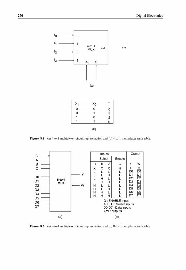
270 Digital Electronics
(a)
(b)
0
4-to-1MUX O/P
X1 X0
Y1
2
3
0011
X10101
X0I0I1I2I3
Y
I0
I1
I2
I3
Figure 8.1 (a) 4-to-1 multiplexer circuit representation and (b) 4-to-1 multiplexer truth table.
8-to-1MUX
GABC
D0D1D2D3D4D5D6D7
(a) (b)
W
Y
XLLLLHHHH
LD0D1D2D3D4D5D6D7
Output
Y W
Enable
G
Select
C B A
Inputs
XLLHHLLHH
XLHLHLHLH
HLLLLLLLL
HD0D1D2D3D4D5D6D7
G : ENABLE inputA, B, C : Select inputsD0-D7 : Data inputsY,W : outputs
Figure 8.2 (a) 8-to-1 multiplexer circuit representation and (b) 8-to-1 multiplexer truth table.

Multiplexers and Demultiplexers 271
16-to-1MUX
GABCD
D0D1D2D3D4D5D6D7D8D9
D10D11D12D13D14D15
W
XLLLLLLLLHHHHHHHH
XLLLLHHHHLLLLHHHH
XLLHHLLHHLLHHLLHH
XLHLHLHLHLHLHLHLH
HLLLLLLLLLLLLLLLL
HD0D1D2D3D4D5D6D7D8D9
D10D11D12D13D14D15
OutputWEnable
G
Select
D C B A
Inputs
(a) (b)
Figure 8.3 (a) 16-to-1 multiplexer circuit representation and (b) 16-to-1 multiplexer truth table.
8.1.1 Inside the Multiplexer
We will briefly describe the type of combinational logic circuit found inside a multiplexer byconsidering the 2-to-1 multiplexer in Fig. 8.4(a), the functional table of which is shown in Fig.8.4(b). Figure 8.4(c) shows the possible logic diagram of this multiplexer. The circuit functions asfollows:
• For S = 0, the Boolean expression for the output becomes Y = I0.• For S = 1, the Boolean expression for the output becomes Y = I1.
Thus, inputs I0 and I1 are respectively switched to the output for S = 0 and S = 1. Extending theconcept further, Fig. 8.5 shows the logic diagram of a 4-to-1 multiplexer. The input combinations 00,01, 10 and 11 on the select lines respectively switch I0, I1, I2 and I3 to the output.The operation of thecircuit is governed by the Boolean function (8.1). Similarly, an 8-to-1 multiplexer can be representedby the Boolean function (8.2):
Y = I0�S1�S0 + I1�S1�S0 + I2�S1�S0 + I3�S1�S0 (8.1)
Y = I0�S2�S1�S0 + I1�S2�S1�S0 + I2�S2�S1�S0 + I3�S2�S1�S0 + I4�S2�S1�S0
+I5�S2�S1�S0 + I6�S2�S1�S0 + I7�S2�S1�S0 (8.2)
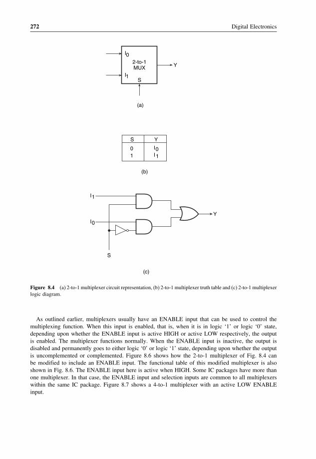
272 Digital Electronics
2-to-1MUX Y
S
I0
I1
(a)
01
S
I0I1
Y
(b)
I1
YI0
S
(c)
Figure 8.4 (a) 2-to-1 multiplexer circuit representation, (b) 2-to-1 multiplexer truth table and (c) 2-to-1 multiplexerlogic diagram.
As outlined earlier, multiplexers usually have an ENABLE input that can be used to control themultiplexing function. When this input is enabled, that is, when it is in logic ‘1’ or logic ‘0’ state,depending upon whether the ENABLE input is active HIGH or active LOW respectively, the outputis enabled. The multiplexer functions normally. When the ENABLE input is inactive, the output isdisabled and permanently goes to either logic ‘0’ or logic ‘1’ state, depending upon whether the outputis uncomplemented or complemented. Figure 8.6 shows how the 2-to-1 multiplexer of Fig. 8.4 canbe modified to include an ENABLE input. The functional table of this modified multiplexer is alsoshown in Fig. 8.6. The ENABLE input here is active when HIGH. Some IC packages have more thanone multiplexer. In that case, the ENABLE input and selection inputs are common to all multiplexerswithin the same IC package. Figure 8.7 shows a 4-to-1 multiplexer with an active LOW ENABLEinput.

Multiplexers and Demultiplexers 273
Y
I0
I1
I2
I3
S1
S0
0011
S10101
S0I0I1I2I3
Y
Figure 8.5 Logic diagram of a 4-to-1 multiplexer.
I1
Y
I0
S EN
X01
S
011
EN
0I0I1
Y
Figure 8.6 2-to-1 multiplexer with an ENABLE input.
8.1.2 Implementing Boolean Functions with Multiplexers
One of the most common applications of a multiplexer is its use for implementation of combinationallogic Boolean functions. The simplest technique for doing so is to employ a 2n-to-1 MUX to implementan n-variable Boolean function. The input lines corresponding to each of the minterms present in theBoolean function are made equal to logic ‘1’ state. The remaining minterms that are absent in theBoolean function are disabled by making their corresponding input lines equal to logic ‘0’. As anexample, Fig. 8.8(a) shows the use of an 8-to-1 MUX for implementing the Boolean function givenby the equation
f�A�B�C� = ∑2� 4� 7 (8.3)

274 Digital Electronics
Y
I0
I1
I2
I3
S1 S0 EN
X0011
S1X0101
10000
0
S0 EN
I0I1I2I3
Y
Figure 8.7 4-to-1 multiplexer with an ENABLE input.
In terms of variables A, B and C, equation (8.3) can be written as follows:
f�A�B�C� = A�B�C +A�B�C +A�B�C (8.4)
As shown in Fig. 8.8, the input lines corresponding to the three minterms present in the given Booleanfunction are tied to logic ‘1’. The remaining five possible minterms absent in the Boolean function aretied to logic ‘0’.
However, there is a better technique available for doing the same. In this, a 2n-to-1 MUX can beused to implement a Boolean function with n + 1 variables. The procedure is as follows. Out of n +1 variables, n are connected to the n selection lines of the 2n-to-1 multiplexer. The left-over variableis used with the input lines. Various input lines are tied to one of the following: ‘0’, ‘1’, the left-overvariable and the complement of the left-over variable. Which line is given what logic status can beeasily determined with the help of a simple procedure. The complete procedure is illustrated for theBoolean function given by equation (8.3).
It is a three-variable Boolean function. Conventionally, we will need to use an 8-to-1 multiplexerto implement this function. We will now see how this can be implemented with a 4-to-1 multiplexer.The chosen multiplexer has two selection lines. The first step here is to determine the truth table ofthe given Boolean function, which is shown in Table 8.1.
In the next step, two of the three variables are connected to the two selection lines, with the higher-order variable connected to the higher-order selection line. For instance, in the present case, variablesB and C are the chosen variables for the selection lines and are respectively connected to selectionlines S1 and S0. In the third step, a table of the type shown in Table 8.2 is constructed. Under the inputsto the multiplexer, minterms are listed in two rows, as shown. The first row lists those terms whereremaining variable A is complemented, and second row lists those terms where A is uncomplemented.This is easily done with the help of the truth table.
The required minterms are identified or marked in some manner in this table. In the giventable, these entries have been highlighted. Each column is inspected individually. If neither mintermof a certain column is highlighted, a ‘0’ is written below that. If both are highlighted, a ‘1’ is

Multiplexers and Demultiplexers 275
(b)
4-to-1MUX
F
C
I0I1I2I3
S1 S0
A
B
8-to-1MUX
F
I0I1I2I3I4I5I6I7
A B C
'1'
(a)
'0’
Figure 8.8 Hardware implementation of the Boolean function given by equation (8.3).
Table 8.1 Truth table.
Minterm A B C f(A,B,C)
0 0 0 0 01 0 0 1 02 0 1 0 13 0 1 1 04 1 0 0 15 1 0 1 06 1 1 0 07 1 1 1 1
written. If only one is highlighted, the corresponding variable (complemented or uncomplemented)is written. The input lines are then given appropriate logic status. In the present case, I0, I1,I2 and I3 would be connected to A, 0, A and A respectively. Figure 8.8(b) shows the logicimplementation.

276 Digital Electronics
Table 8.2 Implementation table formultiplexers.
I0 I1 I2 I3
A 0 1 2 3A 4 5 6 7
A 0 A A
Table 8.3 Implementation table for multiplexers.
I0 I1 I2 I3
C 0 2 4 6C 1 3 5 7
0 C C C
It is not necessary to choose only the leftmost variable in the sequence to be used as input tothe multiplexer. Any of the variables can be used provided the implementation table is constructedaccordingly. In the problem illustrated above, A was chosen as the variable for the input lines,and accordingly the first row of the implementation table contained those entries where ‘A’ wascomplemented and the second row contained those entries where A was uncomplemented. If weconsider C as the left-out variable, the implementation table will be as shown in Table 8.3.
Figure 8.9 shows the hardware implementation. For the case of B being the left-out variable, theimplementation table is shown in Table 8.4 and the hardware implementation is shown in Fig. 8.10.
4-to-1MUX
F
A B
I0I1I2I3
S1 S0C
'0’
Figure 8.9 Hardware implementation using a 4-to-1 multiplexer.
Table 8.4 Implementation table for multiplexers.
I0 I1 I2 I3
B 0 1 4 5B 2 3 6 7
B 0 B B

Multiplexers and Demultiplexers 277
B
F
I0I1I2I3
S1 S0
A C
4-to-1MUX
'0’
Figure 8.10 Hardware implementation using a 4-to-1 multiplexer.
Figure 8.11 Multiplexer for parallel-to-serial conversion.
8.1.3 Multiplexers for Parallel-to-Serial Data Conversion
Although data are processed in parallel in many digital systems to achieve faster processing speeds,when it comes to transmitting these data relatively large distances, this is done serially. The parallelarrangement in this case is highly undesirable as it would require a large number of transmissionlines. Multiplexers can possibly be used for parallel-to-serial conversion. Figure 8.11 shows one sucharrangement where an 8-to-1 multiplexer is used to convert eight-bit parallel binary data to serialform. A three-bit counter controls the selection inputs. As the counter goes through 000 to 111, themultiplexer output goes through I0 to I7. The conversion process takes a total of eight clock cycles. Inthe figure shown, the three-bit counter has been constructed with the help of three toggle flip-flops.A variety of counter circuits of various types and complexities are, however, available in IC form.Flip-flops and counters are discussed in detail in Chapters 10 and 11 respectively.
Example 8.1
Implement the product-of-sums Boolean function expressed by �1,2,5 by a suitable multiplexer.

278 Digital Electronics
Solution• Let the Boolean function be f�A�B�C� = ∏
1� 2� 5.• The equivalent sum-of-products expression can be written as f�A�B�C� = ∑
0� 3� 4� 6� 7.
The truth table for the given Boolean function is given in Table 8.5. The given function can beimplemented with a 4-to-1 multiplexer with two selection lines. Variables A and B are chosen for theselection lines. The implementation table as drawn with the help of the truth table is given in Table 8.6.Figure 8.12 shows the hardware implementation.
Table 8.5 Truth table.
C B A f(A,B,C)
0 0 0 10 0 1 00 1 0 00 1 1 11 0 0 11 0 1 01 1 0 11 1 1 1
Table 8.6 Implementation table.
I0 I1 I2 I3
C 0 1 2 3C 4 5 6 7
1 0 C 1
4-to-1MUX
F
A
B
I0I1I2I3
S1 S0
CY
'0’
'1’
Figure 8.12 Example 8.1.

Multiplexers and Demultiplexers 279
8-to-1MUX
S2
I0 I2 I3
S1S0
I1 I4 I5 I6 I7
A
B
C
D
1
Y
Figure 8.13 Example 8.2.
Example 8.2
Figure 8.13 shows the use of an 8-to-1 multiplexer to implement a certain four-variable Booleanfunction. From the given logic circuit arrangement, derive the Boolean expression implemented by thegiven circuit.
SolutionThis problem can be solved by simply working backwards in the procedure outlined earlier for designingthe multiplexer-based logic circuit for a given Boolean function. Here, the hardware implementationis known and the objective is to determine the corresponding Boolean expression.
From the given logic circuit, we can draw the implementation table as given in Table 8.7. Theentries in the first row (0, 1, 2, 3, 4, 5, 6, 7) and the second row (8, 9, 10, 11, 12, 13, 14, 15) areso because the selection variable chosen for application to the inputs is the MSB variable D. Entriesin the first row include all those minterms that contain D, and entries in the second row include allthose minterms that contain D. After writing the entries in the first two rows, the entries in the thirdrow can be filled in by examining the logic status of different input lines in the given logic circuitdiagram. Having completed the third row, relevant entries in the first and second rows are highlighted.The Boolean expression can now be written as follows:
Y = ∑2� 4� 9� 10 = D�C�B�A+D�C�B�A+D�C�B�A+D�C�B�A
= C�B�A��D+D�+D�C�B�A+D�C�B�A
= C�B�A+D�C�B�A+D�C�B�A
Table 8.7 Implementation table.
I0 I1 I2 I3 I4 I5 I6 I7
D 0 1 2 3 4 5 6 7D 8 9 10 11 12 13 14 15
0 D 1 0 D 0 0 0

280 Digital Electronics
8.1.4 Cascading Multiplexer Circuits
There can possibly be a situation where the desired number of input channels is not available in ICmultiplexers. A multiple number of devices of a given size can be used to construct multiplexers thatcan handle a larger number of input channels. For instance, 8-to-1 multiplexers can be used to construct16-to-1 or 32-to-1 or even larger multiplexer circuits. The basic steps to be followed to carry out thedesign are as follows:
1. If 2n is the number of input lines in the available multiplexer and 2N is the number of input lines inthe desired multiplexer, then the number of individual multiplexers required to construct the desiredmultiplexer circuit would be 2N−n.
2. From the knowledge of the number of selection inputs of the available multiplexer and that of thedesired multiplexer, connect the less significant bits of the selection inputs of the desired multiplexerto the selection inputs of the available multiplexer.
3. The left-over bits of the selection inputs of the desired multiplexer circuit are used to enable ordisable the individual multiplexers so that their outputs when ORed produce the final output. Theprocedure is illustrated in solved example 8.3.
Example 8.3
Design a 16-to-1 multiplexer using two 8-to-1 multiplexers having an active LOW ENABLE input.
SolutionA 16-to-1 multiplexer can be constructed from two 8-to-1 multiplexers having an ENABLEinput. The ENABLE input is taken as the fourth selection variable occupying the MSB position.Figure 8.14 shows the complete logic circuit diagram. IC 74151 can be used to implement an 8-to-1multiplexer.
The circuit functions as follows. When S3 is in logic ‘0’ state, the upper multiplexer is enabled andthe lower multiplexer is disabled. If we recall the truth table of a four-variable Boolean function, S3
would be ‘0’ for the first eight entries and ‘1’ for the remaining eight entries. Therefore, when S3 = 0the final output will be any of the inputs from D0 to D7, depending upon the logic status of S2, S1 andS0. Similarly, when S3 = 1 the final output will be any of the inputs from D8 to D15, again dependingupon the logic status of S2, S1 and S0. The circuit therefore implements the truth table of a 16-to-1multiplexer.
8.2 EncodersAn encoder is a multiplexer without its single output line. It is a combinational logic function that has2n (or fewer) input lines and n output lines, which correspond to n selection lines in a multiplexer.The n output lines generate the binary code for the possible 2n input lines. Let us take the case of anoctal-to-binary encoder. Such an encoder would have eight input lines, each representing an octal digit,and three output lines representing the three-bit binary equivalent. The truth table of such an encoderis given in Table 8.8. In the truth table, D0 to D7 represent octal digits 0 to 7. A, B and C representthe binary digits.

Multiplexers and Demultiplexers 281
8-to-1MUX
I0I1
I7
D0D1D2D3D4D5D6D7
S0
S1
S2
8-to-1MUX
I0I1
I7
D8D9
D10D11D12D13D14D15
S0
S1
S2
E
ES3
S2S1S0
Y
Y
F
Figure 8.14 Example 8.3.
The eight input lines would have 28 = 256 possible combinations. However, in the case of anoctal-to-binary encoder, only eight of these 256 combinations would have any meaning. The remainingcombinations of input variables are ‘don’t care’ input combinations. Also, only one of the input linesat a time is in logic ‘1’ state. Figure 8.15 shows the hardware implementation of the octal-to-binaryencoder described by the truth table in Table 8.8. This circuit has the shortcoming that it produces anall 0s output sequence when all input lines are in logic ‘0’ state. This can be overcome by having anadditional line to indicate an all 0s input sequence.
8.2.1 Priority Encoder
A priority encoder is a practical form of an encoder. The encoders available in IC form are allpriority encoders. In this type of encoder, a priority is assigned to each input so that, when morethan one input is simultaneously active, the input with the highest priority is encoded. We willillustrate the concept of priority encoding with the help of an example. Let us assume that the octal-to-binary encoder described in the previous paragraph has an input priority for higher-order digits.Let us also assume that input lines D2, D4 and D7 are all simultaneously in logic ‘1’ state. Inthat case, only D7 will be encoded and the output will be 111. The truth table of such a priority

282 Digital Electronics
A
B
C
D0 D1 D2 D3 D4 D5 D6 D7
Figure 8.15 Octal-to-binary encoder.
Table 8.8 Truth table of an encoder.
D0 D1 D2 D3 D4 D5 D6 D7 A B C
1 0 0 0 0 0 0 0 0 0 00 1 0 0 0 0 0 0 0 0 10 0 1 0 0 0 0 0 0 1 00 0 0 1 0 0 0 0 0 1 10 0 0 0 1 0 0 0 1 0 00 0 0 0 0 1 0 0 1 0 10 0 0 0 0 0 1 0 1 1 00 0 0 0 0 0 0 1 1 1 1
encoder will then be modified to what is shown in Table 8.9. Looking at the last row of thetable, it implies that, if D7 = 1, then, irrespective of the logic status of other inputs, the output is111 as D7 will only be encoded. As another example, Fig. 8.16 shows the logic symbol and truthtable of a 10-line decimal to four-line BCD encoder providing priority encoding for higher-orderdigits, with digit 9 having the highest priority. In the functional table shown, the input line withhighest priority having a LOW on it is encoded irrespective of the logic status of the other inputlines.

Multiplexers and Demultiplexers 283
Table 8.9 Priority encoder.
D0 D1 D2 D3 D4 D5 D6 D7 A B C
1 0 0 0 0 0 0 0 0 0 0X 1 0 0 0 0 0 0 0 0 1X X 1 0 0 0 0 0 0 1 0X X X 1 0 0 0 0 0 1 1X X X X 1 0 0 0 1 0 0X X X X X 1 0 0 1 0 1X X X X X X 1 0 1 1 0X X X X X X X 1 1 1 1
Figure 8.16 10-line decimal to four-line BCD priority encoder.
Some of the encoders available in IC form provide additional inputs and outputs to allow expansion.IC 74148, which is an eight-line to three -line priority encoder, is an example. ENABLE-IN (EI) andENABLE-OUT (EO) terminals on this IC allow expansion. For instance, two 74148s can be cascadedto build a 16-line to four-line priority encoder.

284 Digital Electronics
Example 8.4
We have an eight-line to three-line priority encoder circuit with D0�D1�D2�D3�D4�D5�D6 and D7 asthe data input lines. the output bits are A (MSB), B and C (LSB). Higher-order data bits have beenassigned a higher priority, with D7 having the highest priority. If the data inputs and outputs are activewhen LOW, determine the logic status of output bits for the following logic status of data inputs:
(a) All inputs are in logic ‘0’ state.(b) D1 to D 4 are in logic ‘1’ state and D5 to D7 are in logic ‘0’ state.(c) D7 is in logic ‘0’ state. The logic status of the other inputs is not known.
Solution(a) Since all inputs are in logic ‘0’ state, it implies that all inputs are active. Since D7 has the highest
priority and all inputs and outputs are active when LOW, the output bits are A = 0, B = 0 andC = 0.
(b) Inputs D5 to D7 are the ones that are active. among these, D7 has the highest priority. Therefore,the output bits are A = 0, B = 0 and C = 0.
(c) D7 is active. Since D7 has the highest priority, it will be encoded irrespective of the logic statusof other inputs. Therefore, the output bits are A = 0, B = 0 and C = 0.
Example 8.5
Design a four-line to two-line priority encoder with active HIGH inputs and outputs, with priorityassigned to the higher-order data input line.
SolutionThe truth table for such a priority encoder is given in Table 8.10, with D0, D1, D2 and D3 as datainputs and X and Y as outputs.
The Boolean expressions for the two output lines X and Y are given by the equations
X = D2�D3 +D3 = D2 +D3 (8.5)
Y = D1�D2�D3 +D3 = D1�D2 +D3 (8.6)
Figure 8.17 shows the logic diagram that implements the Boolean functions given in equations (8.5)and (8.6).
Table 8.10 Example 8.5.
D0 D1 D2 D3 X Y
1 0 0 0 0 0X 1 0 0 0 1X X 1 0 1 0X X X 1 1 1

Multiplexers and Demultiplexers 285
X
D1
D3
D2
Y
Figure 8.17 Example 8.5.
8.3 Demultiplexers and DecodersA demultiplexer is a combinational logic circuit with an input line, 2n output lines and n select lines. Itroutes the information present on the input line to any of the output lines. The output line that gets theinformation present on the input line is decided by the bit status of the selection lines. A decoder is aspecial case of a demultiplexer without the input line. Figure 8.18(a) shows the circuit representationof a 1-to-4 demultiplexer. Figure 8.18(b) shows the truth table of the demultiplexer when the inputline is held HIGH.
A decoder, as mentioned earlier, is a combinational circuit that decodes the information on n inputlines to a maximum of 2n unique output lines. Figure 8.19 shows the circuit representation of 2-to-4,3-to-8 and 4-to-16 line decoders. If there are some unused or ‘don’t care’ combinations in the n-bitcode, then there will be fewer than 2n output lines. As an illustration, if there are three input lines, it
(b)
I/P
1111
A0011
B0101
D01000
D10100
D20010
D30001
1-to-4DEMUX
I/P line
A B
D0D1D2D3
Select O/P
(a)
Figure 8.18 1-to-4 demultiplexer.
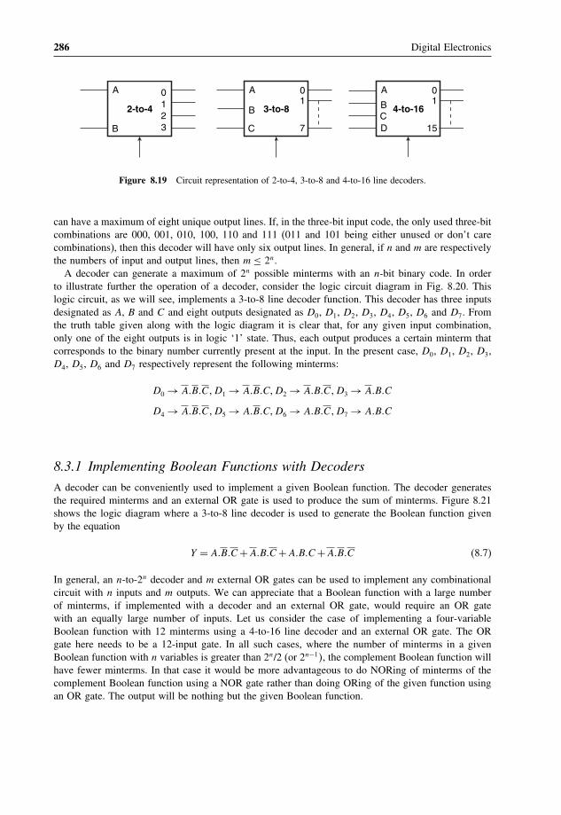
286 Digital Electronics
0123
2-to-4
A
B
01
7
3-to-8
A
B
C
01
15
4-to-16
A
BCD
Figure 8.19 Circuit representation of 2-to-4, 3-to-8 and 4-to-16 line decoders.
can have a maximum of eight unique output lines. If, in the three-bit input code, the only used three-bitcombinations are 000, 001, 010, 100, 110 and 111 (011 and 101 being either unused or don’t carecombinations), then this decoder will have only six output lines. In general, if n and m are respectivelythe numbers of input and output lines, then m ≤ 2n.
A decoder can generate a maximum of 2n possible minterms with an n-bit binary code. In orderto illustrate further the operation of a decoder, consider the logic circuit diagram in Fig. 8.20. Thislogic circuit, as we will see, implements a 3-to-8 line decoder function. This decoder has three inputsdesignated as A, B and C and eight outputs designated as D0, D1, D2, D3, D4, D5, D6 and D7. Fromthe truth table given along with the logic diagram it is clear that, for any given input combination,only one of the eight outputs is in logic ‘1’ state. Thus, each output produces a certain minterm thatcorresponds to the binary number currently present at the input. In the present case, D0, D1, D2, D3,D4, D5, D6 and D7 respectively represent the following minterms:
D0 → A�B�C�D1 → A�B�C�D2 → A�B�C�D3 → A�B�C
D4 → A�B�C�D5 → A�B�C�D6 → A�B�C�D7 → A�B�C
8.3.1 Implementing Boolean Functions with Decoders
A decoder can be conveniently used to implement a given Boolean function. The decoder generatesthe required minterms and an external OR gate is used to produce the sum of minterms. Figure 8.21shows the logic diagram where a 3-to-8 line decoder is used to generate the Boolean function givenby the equation
Y = A�B�C +A�B�C +A�B�C +A�B�C (8.7)
In general, an n-to-2n decoder and m external OR gates can be used to implement any combinationalcircuit with n inputs and m outputs. We can appreciate that a Boolean function with a large numberof minterms, if implemented with a decoder and an external OR gate, would require an OR gatewith an equally large number of inputs. Let us consider the case of implementing a four-variableBoolean function with 12 minterms using a 4-to-16 line decoder and an external OR gate. The ORgate here needs to be a 12-input gate. In all such cases, where the number of minterms in a givenBoolean function with n variables is greater than 2n/2 (or 2n−1�, the complement Boolean function willhave fewer minterms. In that case it would be more advantageous to do NORing of minterms of thecomplement Boolean function using a NOR gate rather than doing ORing of the given function usingan OR gate. The output will be nothing but the given Boolean function.

Multiplexers and Demultiplexers 287
Figure 8.20 Logic diagram of a 3-to-8 line decoder.

288 Digital Electronics
Y3-to-8Decoder
22
21
20
01234567
A
B
C
Figure 8.21 Implementing Boolean functions with decoders.
8.3.2 Cascading Decoder Circuits
There can possibly be a situation where the desired number of input and output lines is not availablein IC decoders. More than one of these devices of a given size may be used to construct a decoderthat can handle a larger number of input and output lines. For instance, 3-to-8 line decoders can beused to construct 4-to-16 or 5-to-32 or even larger decoder circuits. The basic steps to be followed tocarry out the design are as follows:
1. If n is the number of input lines in the available decoder and N is the number of input lines in thedesired decoder, then the number of individual decoders required to construct the desired decodercircuit would be 2N−n.
2. Connect the less significant bits of the input lines of the desired decoder to the input lines of theavailable decoder.
3. The left-over bits of the input lines of the desired decoder circuit are used to enable or disable theindividual decoders.
4. The output lines of the individual decoders together constitute the output lines, with the outputs ofthe less significant decoder constituting the less significant output lines and those of the higher–order decoders constituting the more significant output lines. The concept is further illustrated insolved example 8.8, which gives the design of a 4-to-16 decoder using 3-to-8 decoders.
Example 8.6
Implement a full adder circuit using a 3-to-8 line decoder.
SolutionA decoder with an OR gate at the output can be used to implement the given Boolean function. Thedecoder should at least have as many input lines as the number of variables in the Boolean functionto be implemented. The truth table of the full adder is given in Table 8.11, and Fig. 8.22 shows thehardware implementation.
From the truth table, Boolean functions for SUM and CARRY outputs are given by the followingequations:
Sum output S = � 1� 2� 4� 7 (8.8)
Carry output Co = � 3� 5� 6� 7 (8.9)

Multiplexers and Demultiplexers 289
Table 8.11 Example 8.6.
A B C S Co
0 0 0 0 00 0 1 1 00 1 0 1 00 1 1 0 11 0 0 1 01 0 1 0 11 1 0 0 11 1 1 1 1
3-to-8Decoder
22
21
20
S
Co
0
1
2
3
4
5
6
7
A
B
C
Figure 8.22 Example 8.6.
Example 8.7
A combinational circuit is defined by F = � 0, 2, 5, 6, 7. Hardware implement the Boolean function Fwith a suitable decoder and an external OR/NOR gate having the minimum number of inputs.
SolutionThe given Boolean function has five three-variable minterms. This implies that the function can beimplemented with a 3-to-8 line decoder and a five-input OR gate. Also, F will have only threethree-variable minterms, which means that F could also be implemented by considering mintermscorresponding to the complement function and using a three-input NOR gate at the output. The secondoption uses a NOR gate with fewer inputs and therefore is used instead. F = � 0, 2, 5, 6, 7. Therefore,F = � 1, 3, 4.
Figure 8.23 shows the hardware implementation of Boolean function F .

290 Digital Electronics
3-to-8Decoder
22
21
20
F
0
1
2
3
4
5
6
7
C
A
B
Figure 8.23 Example 8.7.
Example 8.8
Construct a 4-to-16 line decoder with two 3-to-8 line decoders having active LOW ENABLE inputs.
SolutionLet us assume that A (LSB), B, C and D (MSB) are the input variables for the 4-to-16 line decoder.Following the steps outlined earlier, A (LSB), B and C (MSB) will then be the input variables for thetwo 3-to-8 line decoders. If we recall the 16 possible input combinations from 0000 to 1111 in thecase of a 4-to-16 line decoder, we find that the first eight combinations have D = 0, with CBA goingthrough 000 to 111. The higher-order eight combinations all have D = 1, with CBA going through 000to 111. If we use the D-bit as the ENABLE input for the less significant 3-to-8 line decoder and theD-bit as the ENABLE input for the more significant 3-to-8 line decoder, the less significant 3-to-8line decoder will be enabled for the less significant eight of the 16 input combinations, and the moresignificant 3-to-8 line decoder will be enabled for the more significant of the 16 input combinations.Figure 8.24 shows the hardware implementation. One of the output lines D0 to D15 is activated as theinput bit sequence DCBA goes through 0000 to 1111.
Example 8.9
Figure 8.25 shows the logic symbol of IC 74154, which is a 4-to-16 line decoder/demultiplexer. Thelogic symbol is in ANSI/IEEE format. Determine the logic status of all 16 output lines for the followingconditions:
(a) D = HIGH, C = HIGH, B = LOW, A = HIGH, G1 = LOW and G2 = LOW.(b) D = HIGH, C = HIGH, B = LOW, A = HIGH, G1 = HIGH and G2 = HIGH.(c) D = HIGH, C = HIGH, B = LOW, A = HIGH, G1 = HIGH and G2 = HIGH.
SolutionIt is clear from the given logic symbol that the device has active HIGH inputs, active LOW outputsand two active LOW ENABLE inputs. Also, both ENABLE inputs need to be active for the decoderto function owing to the indicated ANDing of the two ENABLE inputs.

Multiplexers and Demultiplexers 291
3-to-8Decoder
22
21
20
D0D1D2D3D4D5D6D7
3-to-8Decoder
D8D9D10D11D12D13D14D15
E
22
21
20
E
C
B
A
D
Figure 8.24 Example 8.8.
0123456789
101112131415
74154
1(A)
2(B)
4(C)
8(D)
&G1
G2
Figure 8.25 Example 8.9.

292 Digital Electronics
(a) Since both ENABLE inputs are active, the decoder outputs will therefore be active depending uponthe logic status of the input lines. For the given logic status of the input lines, decoder output line13 will be active and therefore LOW. All other output lines will be inactive and therefore in thelogic HIGH state.
(b) Since neither ENABLE input is active, all decoder outputs will be inactive and in the logic HIGHstate.
(c) The same as (b).
Example 8.10
The decoder of example 8.9 is to be used as a 1-of-16 demultiplexer. A logically compatible pulsedwaveform is to be switched between output line 9 and line 15 when the logic status of an externalcontrol input is LOW and HIGH respectively. Draw the logic diagram indicating the logic status ofENABLE inputs and DCBA inputs and the point of application of the pulsed waveform.
SolutionFigure 8.26 shows the logic diagram. When the external control input is in the logic LOW state, D =HIGH, C = LOW, B = LOW and A = HIGH. This means that output line 9 is activated. Whenthe external control input is in the logic HIGH state, D = HIGH, C = HIGH, B = HIGH and A =HIGH. This means that output line 15 is activated. In the logic diagram shown in Fig. 8.26, the twoENABLE inputs are tied together and the pulsed waveform is applied to a common point. This meansthat either both ENABLE inputs are active (when the input waveform is in the logic LOW state) orinactive (when the input waveform is in the logic HIGH state). Thus, when the input waveform is inthe logic LOW state, output line 9 will be in the logic LOW state and all other output lines will be inthe logic HIGH state provided the external control input is also in the logic LOW state. If the external
0123456789
101112131415
74154
1(A)
2(B)
4(C)
8(D)
&
ExternalControl
G1G2
'1’
Figure 8.26 Example 8.10.
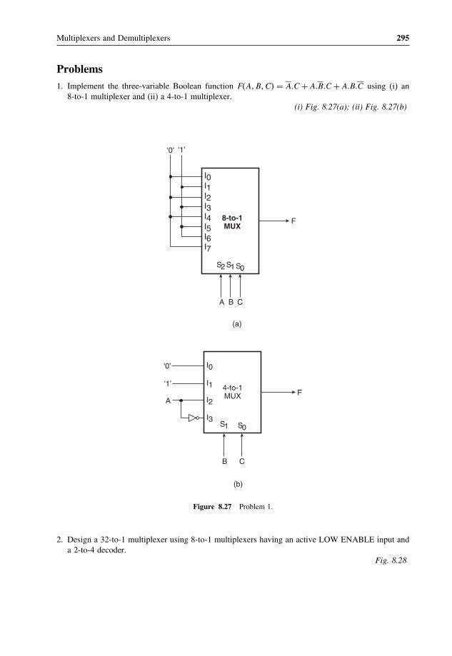
Multiplexers and Demultiplexers 295
Problems1. Implement the three-variable Boolean function F�A�B�C� = A�C + A�B�C + A�B�C using (i) an
8-to-1 multiplexer and (ii) a 4-to-1 multiplexer.(i) Fig. 8.27(a); (ii) Fig. 8.27(b)
8-to-1MUX
F
I0I1I2I3I4I5I6I7
S2 S1 S0
A B C
(a)
4-to-1MUX
I0
I1
I2
I3S1 S0
B C
(b)
AF
'0’ '1’
'0’
'1’
Figure 8.27 Problem 1.
2. Design a 32-to-1 multiplexer using 8-to-1 multiplexers having an active LOW ENABLE input anda 2-to-4 decoder.
Fig. 8.28

296 Digital Electronics
8-to-1MUX
I0I1
I7
D0
D7
S2S1S0E
S0S1S2
Y
F
8-to-1MUX
I0I1
I7
D8
D15
S2S1S0E
8-to-1MUX
I0I1
I7
D16
D23
S2S1S0E
8-to-1MUX
I0I1
I7
D24
D31
S2S1S0E
S1
S2
0
1
2
3
2-to-4Decoder
S4
S3
Y
Y
Y
Figure 8.28 Answer to problem 2.

Multiplexers and Demultiplexers 297
3. Determine the function performed by the combinational circuit of Fig. 8.29.
Figure 8.29 Problem 3.
4-to-1 multiplexer
4. Implement a full subtractor combinational circuit using a 3-to-8 decoder and external NOR gates.Fig. 8.30
3-to-8Decoder
22
21
20
Difference
Borrow Out
0
1
2
3
4
5
6
7
A
B
Bin
Figure 8.30 Answer to problem 4.
10Flip-Flops and Related Devices
Having discussed combinational logic circuits at length in previous chapters, the focus in the presentchapter and in Chapter 11 will be on sequential logic circuits. While a logic gate is the most basicbuilding block of combinational logic, its counterpart in sequential logic is the flip-flop. The chapterbegins with a brief introduction to different types of multivibrator, including the bistable multivibrator,which is the complete technical name for a flip-flop, the monostable multivibrator and the astablemultivibrator. The flip-flop is not only used individually for a variety of applications; it also formsthe basis of many more complex logic functions. Counters and registers, to be covered in Chapter 11are typical examples. There is a large variety of flip-flops having varying functional tables, inputclocking requirements and other features. In this chapter, we will discuss all these basic types offlip-flop in terms of their functional aspects, truth tables, salient features and application aspects. Thetext is suitably illustrated with a large number of solved examples. Application-relevant information,including a comprehensive index of flip-flops and related devices belonging to different logic families,is given towards the end of the chapter. Pin connection diagrams and functional tables are given in thecompanion website.
10.1 MultivibratorMultivibrators, like the familiar sinusoidal oscillators, are circuits with regenerative feedback, with thedifference that they produce pulsed output. There are three basic types of multivibrator, namely thebistable multivibrator, the monostable multivibrator and the astable multivibrator.
10.1.1 Bistable Multivibrator
A bistable multivibrator circuit is one in which both LOW and HIGH output states are stable.Irrespective of the logic status of the output, LOW or HIGH, it stays in that state unless a change is
Digital Electronics: Principles, Devices and Applications Anil K. Maini© 2007 John Wiley & Sons, Ltd. ISBN: 978-0-470-03214-5
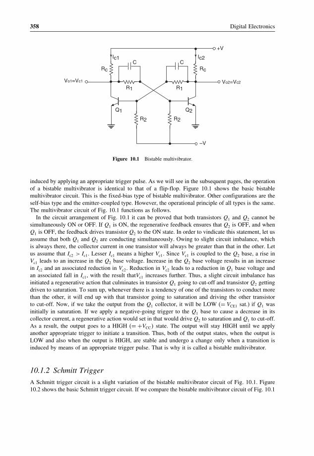
358 Digital Electronics
+V
V =Vo2 c2
Q2
Ic2CC
R1
Ic1
Rc
V =Vo1 c1
–V
R2 R2
Q1
Rc
R1
Figure 10.1 Bistable multivibrator.
induced by applying an appropriate trigger pulse. As we will see in the subsequent pages, the operationof a bistable multivibrator is identical to that of a flip-flop. Figure 10.1 shows the basic bistablemultivibrator circuit. This is the fixed-bias type of bistable multivibrator. Other configurations are theself-bias type and the emitter-coupled type. However, the operational principle of all types is the same.The multivibrator circuit of Fig. 10.1 functions as follows.
In the circuit arrangement of Fig. 10.1 it can be proved that both transistors Q1 and Q2 cannot besimultaneously ON or OFF. If Q1 is ON, the regenerative feedback ensures that Q2 is OFF, and whenQ1 is OFF, the feedback drives transistor Q2 to the ON state. In order to vindicate this statement, let usassume that both Q1 and Q2 are conducting simultaneously. Owing to slight circuit imbalance, whichis always there, the collector current in one transistor will always be greater than that in the other. Letus assume that Ic2 > Ic1� Lesser Ic1 means a higher Vc1� Since Vc1 is coupled to the Q2 base, a rise inVc1 leads to an increase in the Q2 base voltage. Increase in the Q2 base voltage results in an increasein Ic2 and an associated reduction in Vc2� Reduction in Vc2 leads to a reduction in Q1 base voltage andan associated fall in Ic1, with the result thatVc1 increases further. Thus, a slight circuit imbalance hasinitiated a regenerative action that culminates in transistor Q1 going to cut-off and transistor Q2 gettingdriven to saturation. To sum up, whenever there is a tendency of one of the transistors to conduct morethan the other, it will end up with that transistor going to saturation and driving the other transistorto cut-off. Now, if we take the output from the Q1 collector, it will be LOW (= VCE1 sat.) if Q1 wasinitially in saturation. If we apply a negative-going trigger to the Q1 base to cause a decrease in itscollector current, a regenerative action would set in that would drive Q2 to saturation and Q1 to cut-off.As a result, the output goes to a HIGH (= +VCC� state. The output will stay HIGH until we applyanother appropriate trigger to initiate a transition. Thus, both of the output states, when the output isLOW and also when the output is HIGH, are stable and undergo a change only when a transition isinduced by means of an appropriate trigger pulse. That is why it is called a bistable multivibrator.
10.1.2 Schmitt Trigger
A Schmitt trigger circuit is a slight variation of the bistable multivibrator circuit of Fig. 10.1. Figure10.2 shows the basic Schmitt trigger circuit. If we compare the bistable multivibrator circuit of Fig. 10.1

Flip-Flops and Related Devices 359
Vcc
Vo
Q2
C
R2
Rc1
Vin
Re R1
Q1
Rc2
Figure 10.2 Schmitt trigger circuit.
with the Schmitt trigger circuit of Fig. 10.2, we find that coupling from Q2 collector to Q1 base in thecase of a bistable circuit is absent in the case of a Schmitt trigger circuit. Instead, the resistance Re
provides the coupling. The circuit functions as follows.When Vin is zero, transistor Q1 is in cut-off. Coupling from Q1 collector to Q2 base drives transistor
Q2 to saturation, with the result that Vo is LOW. If we assume that VCE2 (sat.) is zero, then the voltageacross Re is given by the equation
Voltage across Re = �VCC�Re/�Re +Rc2�� (10.1)
This is also the emitter voltage of transistor Q1. In order to make transistor Q1 conduct, Vin must beat least 0.7 V more than the voltage across Re. That is,
Vin�min�� = �VCC�Re/�Re +Rc2��+0�7 (10.2)
When Vin exceeds this voltage, Q1 starts conducting. The regenerative action again drives Q2 to cut-off.The output goes to the HIGH state. Voltage across Re changes to a new value given by the equation
Voltage across Re = �VCC�Re/�Re +Rc1�� (10.3)
Vin = �VCC�Re/�Re +Rc1��+0�7 (10.4)
Transistor Q1 will continue to conduct as long as Vin is equal to or greater than the value given byEquation (10.4). If Vin falls below this value, Q1 tends to come out of saturation and conduct lessheavily. The regenerative action does the rest, with the process culminating in Q1 going to cut-offand Q2 to saturation. Thus, the state of output (HIGH or LOW) depends upon the input voltage level.

360 Digital Electronics
Vin
VUTVLT
VCE (sat)@
Vcc
Vo
0
Figure 10.3 Transfer characteristics of a Schmitt trigger.
The HIGH and LOW states of the output correspond to two distinct input levels given by Equations(10.2) and (10.4) and therefore the values of Rc1,Rc2,Re and VCC� The Schmitt trigger circuit of Fig.10.2 therefore exhibits hysteresis. Figure 10.3 shows the transfer characteristics of the Schmitt triggercircuit. The lower trip point VLT and the upper trip point VUT of these characteristics are respectivelygiven by the equations
VLT = �VCC�Re/�Re +Rc1��+0�7 (10.5)
VUT = �VCC�Re/�Re +Rc2��+0�7 (10.6)
10.1.3 Monostable Multivibrator
A monostable multivibrator, also known as a monoshot, is one in which one of the states is stableand the other is quasi-stable. The circuit is initially in the stable state. It goes to the quasi-stable statewhen appropriately triggered. It stays in the quasi-stable state for a certain time period, after whichit comes back to the stable state. Figure 10.4 shows the basic monostable multivibrator circuit. Thecircuit functions as follows. Initially, transistor Q2 is in saturation as it gets its base bias from +VCC
through R� Coupling from Q2 collector to Q1 base ensures that Q1 is in cut-off. Now, if an appropriatetrigger pulse induces a transition in Q2 from saturation to cut-off, the output goes to the HIGH state.This HIGH output when coupled to the Q1 base turns Q1 ON. Since there is no direct coupling fromQ1 collector to Q2 base, which is necessary for a regenerative process to set in, Q1 is not necessarily

Flip-Flops and Related Devices 361
Q2
C
RRc1
–V
R2
Q1
RC2
R1
+VCC
C1
Vo
Figure 10.4 Monostable multivibrator.
in saturation. However, it conducts some current. The Q1 collector voltage falls by Ic1Rc1 and the Q2
base voltage falls by the same amount, as the voltage across a capacitor (C in this case) cannot changeinstantaneously. To sum up, the moment we applied the trigger, Q2 went to cut-off and Q1 startedconducting. But now there is a path for capacitor C to charge from VCC through R and the conductingtransistor. The polarity of voltage across C is such that the Q2 base potential rises. The moment the Q2
base voltage exceeds the cut-in voltage, it turns Q2 ON, which, owing to coupling through R1, turnsQ1 OFF. And we are back to the original state, the stable state. Whenever we trigger the circuit intothe other state, it does not stay there permanently and returns back after a time period that dependsupon R and C. The greater the time constant RC, the longer is the time for which it stays in the otherstate, called the quasi-stable state.
10.1.3.1 Retriggerable Monostable Multivibrator
In a conventional monostable multivibrator, once the output is triggered to the quasi-stable state byapplying a suitable trigger pulse, the circuit does not respond to subsequent trigger pulses as long asthe output is in quasi-stable state. After the output returns to its original state, it is ready to respondto the next trigger pulse. There is another class of monostable multivibrators, called retriggerablemonostable multivibrators. These respond to trigger pulses even when the output is in the quasi-stablestate. In this class of monostable multivibrators, if n trigger pulses with a time period of Tt areapplied to the circuit, the output pulse width, that is, the time period of the quasi-stable state, equals(n− 1)Tt +T , where T is the output pulse width for the single trigger pulse and Tt < T . Figure 10.5shows the output pulse width in the case of a retriggerable monostable multivibrator for repetitive triggerpulses.

362 Digital Electronics
Trigger Pulses
Output Pulse
Tt T
Figure 10.5 Retriggerable monostable multivibrator output for repetitive trigger pulses.
10.1.4 Astable Multivibrator
In the case of an astable multivibrator, neither of the two states is stable. Both output states are quasi-stable. The output switches from one state to the other and the circuit functions like a free-runningsquare-wave oscillator. Figure 10.6 shows the basic astable multivibrator circuit. It can be proved that,in this type of circuit, neither of the output states is stable. Both states, LOW as well as HIGH, arequasi-stable. The time periods for which the output remains LOW and HIGH depends upon R2C2 andR1C1 time constants respectively. For R1C1 = R2C2, the output is a symmetrical square waveform.The circuit functions as follows. Let us assume that transistor Q2 is initially conducting, that is, theoutput is LOW. Capacitor C2 in this case charges through R2 and the conducting transistor from VCC,and, the moment the Q1 base potential exceeds its cut-in voltage, it is turned ON. A fall in Q1 collector
C1 C2Vo
VCC
Rc2R2
Q1
Rc1
Q2
R1
Figure 10.6 Astable multivibrator.
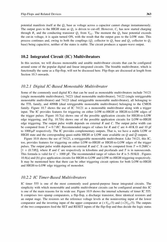
Flip-Flops and Related Devices 363
potential manifests itself at the Q2 base as voltage across a capacitor cannot change instantaneously.The output goes to the HIGH state as Q2 is driven to cut-off. However, C1 has now started chargingthrough R1 and the conducting transistor Q1 from VCC. The moment the Q2 base potential exceedsthe cut-in voltage, it is again turned ON, with the result that the output goes to the LOW state. Thisprocess continues and, owing to both the couplings (Q1 collector to Q2 base and Q2 collector to Q1
base) being capacitive, neither of the states is stable. The circuit produces a square-wave output.
10.2 Integrated Circuit (IC) MultivibratorsIn this section, we will discuss monostable and astable multivibrator circuits that can be configuredaround some of the popular digital and linear integrated circuits. The bistable multivibrator, which isfunctionally the same as a flip-flop, will not be discussed here. Flip-flops are discussed at length fromSection 10.3 onwards.
10.2.1 Digital IC-Based Monostable Multivibrator
Some of the commonly used digital ICs that can be used as monostable multivibrators include 74121(single monostable multivibrator), 74221 (dual monostable multivibrator), 74122 (single retriggerablemonostable multivibrator) and 74123 (dual retriggerable monostable multivibrator), all belonging tothe TTL family, and 4098B (dual retriggerable monostable multivibrator) belonging to the CMOSfamily. Figure 10.7 shows the use of IC 74121 as a monostable multivibrator along with a triggerinput. The IC provides features for triggering on either LOW-to-HIGH or HIGH-to-LOW edges ofthe trigger pulses. Figure 10.7(a) shows one of the possible application circuits for HIGH-to-LOWedge triggering, and Fig. 10.7(b) shows one of the possible application circuits for LOW-to-HIGHedge triggering. The output pulse width depends on external R and C. The output pulse width canbe computed from T = 0�7 RC. Recommended ranges of values for R and C are 4–40 K � and 10 pfto 1000 �F respectively. The IC provides complementary outputs. That is, we have a stable LOW orHIGH state and the corresponding quasi-stable HIGH or LOW state available on Q and Q outputs.
Figure 10.8 shows the use of 74123, a retriggerable monostable multivibrator. Like 74121, this IC,too, provides features for triggering on either LOW-to-HIGH or HIGH-to-LOW edges of the triggerpulses. The output pulse width depends on external R and C. It can be computed from T = 0.28RC×[1 + (0.7/R)], where R and C are respectively in kiloohms and picofarads and T is in nanoseconds.This formula is valid for C > 1000 pF. The recommended range of values for R is 5–50 K� . Figures10.8(a) and (b) give application circuits for HIGH-to-LOW and LOW-to-HIGH triggering respectively.It may be mentioned here that there can be other triggering circuit options for both LOW-to-HIGHand HIGH-to-LOW edge triggering of monoshot.
10.2.2 IC Timer-Based Multivibrators
IC timer 555 is one of the most commonly used general-purpose linear integrated circuits. Thesimplicity with which monostable and astable multivibrator circuits can be configured around this ICis one of the main reasons for its wide use. Figure 10.9 shows the internal schematic of timer IC 555.It comprises two opamp comparators, a flip-flop, a discharge transistor, three identical resistors andan output stage. The resistors set the reference voltage levels at the noninverting input of the lowercomparator and the inverting input of the upper comparator at (+VCC/3) and (+2VCC/3). The outputsof the two comparators feed the SET and RESET inputs of the flip-flop and thus decide the logic status

364 Digital Electronics
B Q
GND
A1
A2
74121
Vcc
CEXT
Output
C+
Q
+VccR
(a)
B Q
GND
A1
A2
74121
Vcc
CEXT
/CEXTREXT
Output
C+
Q
+VccR
(b)
/CEXTREXT
Figure 10.7 74121 as a monoshot.
of its output and subsequently the final output. The flip-flop complementary outputs feed the outputstage and the base of the discharge transistor. This ensures that when the output is HIGH the dischargetransistor is OFF, and when the output is LOW the discharge transistor is ON. Different terminalsof timer 555 are designated as ground (terminal 1), trigger (terminal 2), output (terminal 3), reset(terminal 4), control (terminal 5), threshold (terminal 6), discharge (terminal 7) and +VCC (terminal 8).With this background, we will now describe the astable and monostable circuits configured aroundtimer 555.
10.2.2.1 Astable Multivibrator Using Timer IC 555
Figure 10.10(a) shows the basic 555 timer based astable multivibrator circuit. Initially, capacitor C isfully discharged, which forces the output to go to the HIGH state. An open discharge transistor allowsthe capacitor C to charge from +VCC through R1 and R2. When the voltage across C exceeds +2VCC/3,the output goes to the LOW state and the discharge transistor is switched ON at the same time.
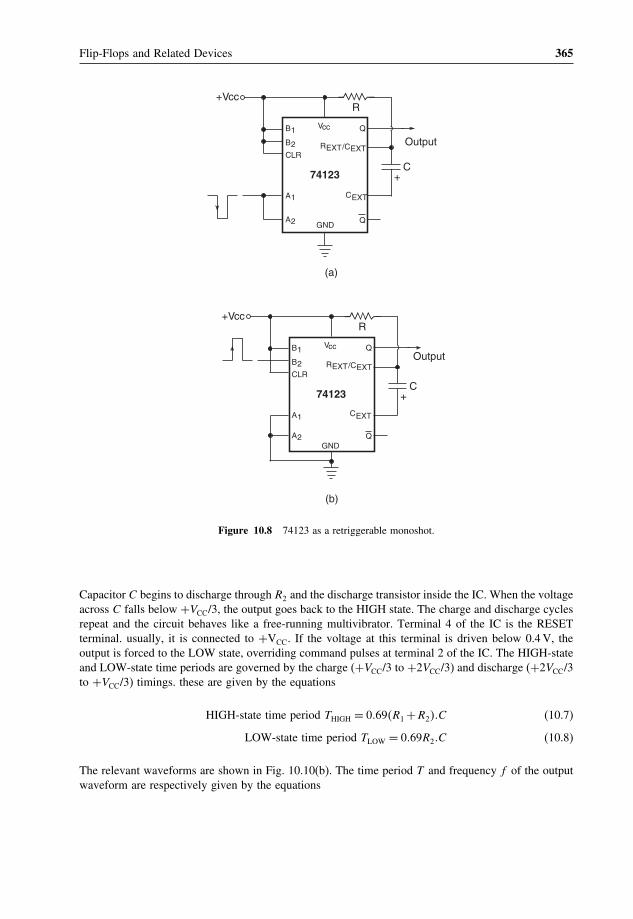
Flip-Flops and Related Devices 365
Q
GND
A1
A2
74123
Vcc
CEXT
Output
C+
Q
+VccR
(a)
REXT
B1
B2CLR
Q
GND
A1
A2
74123
Vcc
CEXT
Output
C+
Q
+VccR
(b)
B1
B2CLR
/CEXT
REXT/CEXT
Figure 10.8 74123 as a retriggerable monoshot.
Capacitor C begins to discharge through R2 and the discharge transistor inside the IC. When the voltageacross C falls below +VCC/3, the output goes back to the HIGH state. The charge and discharge cyclesrepeat and the circuit behaves like a free-running multivibrator. Terminal 4 of the IC is the RESETterminal. usually, it is connected to +VCC. If the voltage at this terminal is driven below 0.4 V, theoutput is forced to the LOW state, overriding command pulses at terminal 2 of the IC. The HIGH-stateand LOW-state time periods are governed by the charge (+VCC/3 to +2VCC/3) and discharge (+2VCC/3to +VCC/3) timings. these are given by the equations
HIGH-state time period THIGH = 0�69�R1 +R2��C (10.7)
LOW-state time period TLOW = 0�69R2�C (10.8)
The relevant waveforms are shown in Fig. 10.10(b). The time period T and frequency f of the outputwaveform are respectively given by the equations

366 Digital Electronics
–
+
5K
–
+
5K
5K
VCC(Pin-8)
Reset (Pin-4)
Output (Pin-3)OutputStage
FF
DischargeTransistor
Ground (Pin-1)
Control(Pin-5)
Threshold(Pin-6)
Trigger(Pin-2)
Discharge(Pin-7)
23
VCC
13
VCC
Vref (int)
Figure 10.9 Internal schematic of timer IC 555.
Time period T = 0�69�R1 +2R2��C (10.9)
Frequency F = 1/ �0�69�R1 +2R2��C� (10.10)
Remember that, when the astable multivibrator is powered, the first-cycle HIGH-state time period isabout 30 % longer, as the capacitor is initially discharged and it charges from 0 (rather than +VCC/3)to +2VCC/3.
In the case of the astable multivibrator circuit in Fig. 10.10(a), the HIGH-state time period is alwaysgreater than the LOW-state time period. Figures 10.10(c) and (d) show two modified circuits where theHIGH-state and LOW-state time periods can be chosen independently. For the astable multivibratorcircuits in Fig. 10.10(c) and (d), the two time periods are given by the equations
HIGH-state time period = 0�69R1�C (10.11)
LOW-state time period = 0�69R2�C (10.12)
For R1 = R2 = R
T = 1�38RC and f = 1/1�38RC (10.13)

Flip-Flops and Related Devices 367
R1
tONtOFF
t
— VCC13
— VCC23
vC
vo
t
(a)
(b)
R2
2,6
7 8 4 3
5 1
0.01
C
+VCC
555
o
vo
Figure 10.10 (a) Astable multivibrator using timer IC 555, (b) astable multivibrator relevant waveforms and(c, d) modified versions of the astable multivibrator using timer IC 555.
10.2.2.2 Monostable Multivibrator Using Timer IC 555
Figure 10.11(a) shows the basic monostable multivibrator circuit configured around timer 555. A triggerpulse is applied to terminal 2 of the IC, which should initially be kept at +VCC. A HIGH at terminal2 forces the output to the LOW state. A HIGH-to-LOW trigger pulse at terminal 2 holds the output inthe HIGH state and simultaneously allows the capacitor to charge from +VCC through R. Rememberthat a LOW level of the trigger pulse needs to go at least below +VCC/3. When the capacitor voltageexceeds +2VCC/3, the output goes back to the LOW state. We will need to apply another trigger pulse to

368 Digital Electronics
R1
(c)
R2
2,6
7 8 4 3
5 1
0.01C
+VCC
555
vo
R1
(d)
R2
2,6
7
84 3
5 1
0.01C
+VCC
555
vo
D
Figure 10.10 (continued).
terminal 2 to make the output go to the HIGH state again. Every time the timer is appropriately triggered,the output goes to the HIGH state and stays there for the time it takes the capacitor to charge from0 to +2VCC/3. This time period, which equals the monoshot output pulse width, is given by the equation
T = 1�1RC (10.14)

Flip-Flops and Related Devices 369
555
+VCC
486,7 3
5 12
+VCC
Triggerinput
vo
Output
—VCC
VC
23
t
t
t
R
C
(a)
(b)
vo
vc
Trigger
0.01
T
Figure 10.11 (a) Monostable multivibrator using timer 555 and (b) monostable multivibrator relevant waveforms.
Figure 10.11(b) shows the relevant waveforms for the circuit of Fig. 10.11(a).It is often desirable to trigger a monostable multivibrator either on the trailing (HIGH-to-LOW) or
leading (LOW-to-HIGH) edges of the trigger waveform. In order to achieve that, we will need anexternal circuit between the trigger waveform input and terminal 2 of timer 555. The external circuitensures that terminal 2 of the IC gets the required trigger pulse corresponding to the desired edge of

370 Digital Electronics
(a)
51
6, 7555
4, 82
0.01
D
C
VCC
3
R
TriggerI/p
vo
R1
C1
TriggerI/P
Atpin-2
VCC
+0.7
VCC
0
0
(b)
Figure 10.12 555 monoshot triggering on trailing edges.
the trigger waveform. Figure 10.12(a) shows the monoshot configuration that can be triggered on thetrailing edges of the trigger waveform. R1–C1 constitutes a differentiator circuit. One of the terminalsof resistor R1 is tied to +VCC, with the result that the amplitudes of differentiated pulses are +VCC to+2VCC and +VCC to ground, corresponding to the leading and trailing edges of the trigger waveformrespectively. Diode D clamps the positive-going differentiated pulses to about +0.7 V. The net result isthat the trigger terminal of timer 555 gets the required trigger pulses corresponding to HIGH-to-LOWedges of the trigger waveform. Figure 10.12(b) shows the relevant waveforms.
Figure 10.13(a) shows the monoshot configuration that can be triggered on the leading edgesof the trigger waveform. The R1–C1 combination constitutes the differentiator producing positiveand negative pulses corresponding to LOW-to-HIGH and HIGH-to-LOW transitions of the triggerwaveform. Negative pulses are clamped by the diode, and the positive pulses are applied to the base ofa transistor switch. The collector terminal of the transistor feeds the required trigger pulses to terminal2 of the IC. Figure 10.13(b) shows the relevant waveforms.
For the circuits shown in Figs 10.12 and 10.13 to function properly, the values of R1 and C1
for the differentiator should be chosen carefully. Firstly, the differentiator time constant should bemuch smaller than the HIGH time of the trigger waveform for proper differentiation. Secondly, thedifferentiated pulse width should be less than the expected HIGH time of the monoshot output.

Flip-Flops and Related Devices 371
R
6, 7555
842
Q
R2
R3
VCC
C1TriggerI/P
Afterdifferentiator
TriggerI/P
VCC
0
VCC
C0.01
51
3
DR1
–0.7
VCC
0
At Pin-2
0
(a)
(b)
vo
Figure 10.13 555 monoshot triggering on leading edges.
Example 10.1
The pulsed waveform of Fig. 10.14(b) is applied to the RESET terminal of the astable multivibratorcircuit of Fig. 10.14(a). Draw the output waveform.
SolutionThe circuit shown in Fig. 10.14(a) is an astable multivibrator with a 500 Hz symmetrical waveformapplied to its RESET terminal. The RESET terminal is alternately HIGH and LOW for 1.0 ms. Whenthe RESET input is LOW, the output is forced to the LOW state. When the RESET input is HIGH, anastable waveform appears at the output. The HIGH and LOW time periods of the astable multivibratorare determined as follows:

372 Digital Electronics
0.01
15
5552,6
8
37
40.01 Fµ
14.5K
14.5K
1ms 1ms
(a)
(b)
+Vcc
vo
Figure 10.14 Example 10.1.
Figure 10.15 Solution to example 10.1.
HIGH time = 0�69×14�5×103 ×0�01×10−6 = 100 �s
LOW time = 0�69×14�5×103 ×0�01×10−6 = 100 �s
The astable output is thus a 5 kHz symmetrical waveform. Every time the RESET terminal goes toHIGH for 1.0 ms, five cycles of 5 kHz waveform appear at the output. Figure 10.15 shows the outputwaveform appearing at terminal 3 of the timer IC.
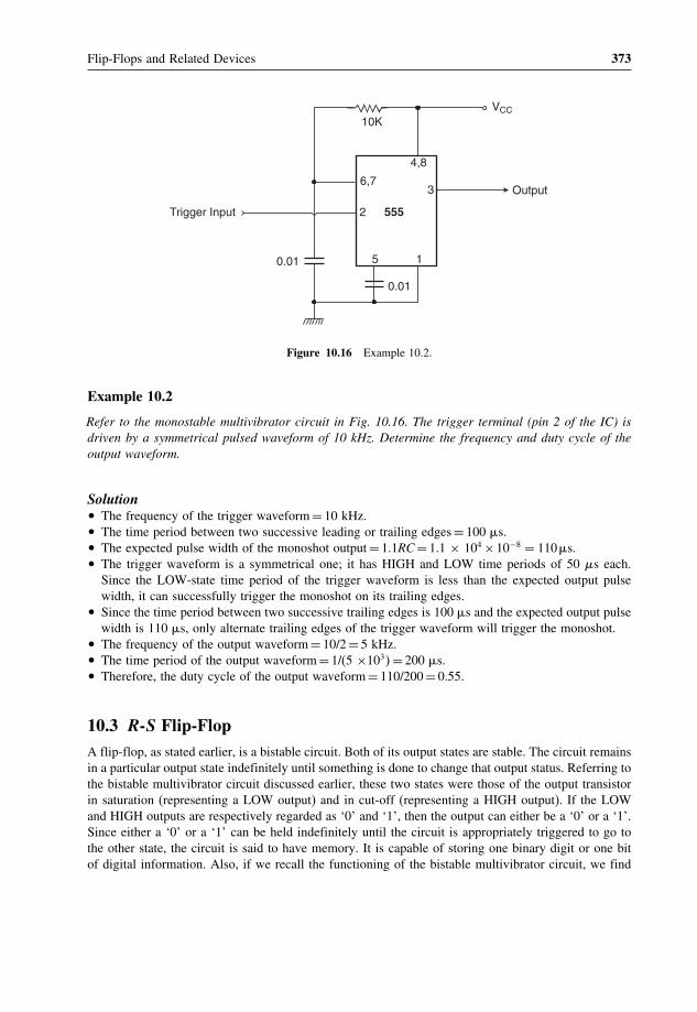
Flip-Flops and Related Devices 373
4,8
6,73
2
15
VCC
0.01
Trigger Input 555
10K
Output
0.01
Figure 10.16 Example 10.2.
Example 10.2
Refer to the monostable multivibrator circuit in Fig. 10.16. The trigger terminal (pin 2 of the IC) isdriven by a symmetrical pulsed waveform of 10 kHz. Determine the frequency and duty cycle of theoutput waveform.
Solution• The frequency of the trigger waveform = 10 kHz.• The time period between two successive leading or trailing edges = 100 �s.• The expected pulse width of the monoshot output = 1.1RC = 1.1 × 104 ×10−8 = 110 �s.• The trigger waveform is a symmetrical one; it has HIGH and LOW time periods of 50 s each.
Since the LOW-state time period of the trigger waveform is less than the expected output pulsewidth, it can successfully trigger the monoshot on its trailing edges.
• Since the time period between two successive trailing edges is 100 �s and the expected output pulsewidth is 110 �s, only alternate trailing edges of the trigger waveform will trigger the monoshot.
• The frequency of the output waveform = 10/2 = 5 kHz.• The time period of the output waveform = 1/(5 ×103� = 200 �s.• Therefore, the duty cycle of the output waveform = 110/200 = 0.55.
10.3 R-S Flip-FlopA flip-flop, as stated earlier, is a bistable circuit. Both of its output states are stable. The circuit remainsin a particular output state indefinitely until something is done to change that output status. Referring tothe bistable multivibrator circuit discussed earlier, these two states were those of the output transistorin saturation (representing a LOW output) and in cut-off (representing a HIGH output). If the LOWand HIGH outputs are respectively regarded as ‘0’ and ‘1’, then the output can either be a ‘0’ or a ‘1’.Since either a ‘0’ or a ‘1’ can be held indefinitely until the circuit is appropriately triggered to go tothe other state, the circuit is said to have memory. It is capable of storing one binary digit or one bitof digital information. Also, if we recall the functioning of the bistable multivibrator circuit, we find

374 Digital Electronics
that, when one of the transistors was in saturation, the other was in cut-off. This implies that, if we hadtaken outputs from the collectors of both transistors, then the two outputs would be complementary.In the flip-flops of various types that are available in IC form, we will see that all these devices offercomplementary outputs usually designated as Q and Q�
The R-S flip-flop is the most basic of all flip-flops. The letters ‘R’ and ‘S’ here stand for RESETand SET. When the flip-flop is SET, its Q output goes to a ‘1’ state, and when it is RESET it goes toa ‘0’ state. The Q output is the complement of the Q output at all times.
10.3.1 R-S Flip-Flop with Active LOW Inputs
Figure 10.17(a) shows a NAND gate implementation of an R-S flip-flop with active LOW inputs. Thetwo NAND gates are cross-coupled. That is, the output of NAND 1 is fed back to one of the inputsof NAND 2, and the output of NAND 2 is fed back to one of the inputs of NAND 1. The remaininginputs of NAND 1 and NAND 2 are the S and R inputs. The outputs of NAND 1 and NAND 2 arerespectively Q and Q outputs.
The fact that this configuration follows the function table of Fig. 10.17(c) can be explained. We willlook at different entries of the function table, one at a time.
Let us take the case of R = S = 1 (the first entry in the function table). We will prove that, forR = S = 1, the Q output remains in its existing state. In the truth table, Qn represents the existing stateand Qn+1 represents the state of the flip-flop after it has been triggered by an appropriate pulse at theR or S input. Let us assume that Q = 0 initially. This ‘0’ state fed back to one of the inputs of gate 2ensures that Q = 1. The ‘1’ state of Q fed back to one of the inputs of gate 1 along with S = 1 ensuresthat Q = 0. Thus, R = S = 1 holds the existing stage. Now, if Q was initially in the ‘1’ state and notthe ‘0’ state, this ‘1’ fed back to one of the inputs of gate 2 along with R = 1 forces Q to be in the ‘0’state. The ‘0’ state, when fed back to one of the inputs of gate 1, ensures that Q remains in its existingstate of logic ‘1’. Thus, whatever the state of Q, R = S = 1 holds the existing state.
Let us now look at the second entry of the function table where S = 0 and R = 1. We can see thatsuch an input combination forces the Q output to the ‘1’ state. On similar lines, the input combinationS = 1 and R = 0 (third entry of the truth table) forces the Q output to the ‘0’ state. It would beinteresting to analyse what happens when S = R = 0. This implies that both Q and Q outputs shouldgo to the ‘1’ state, as one of the inputs of a NAND gate being a logic ‘0’ should force its output to thelogic ‘1’ state irrespective of the status of the other input. This is an undesired state as Q and Q outputsare to be the complement of each other. The input condition (i.e. R = S = 0) that causes such a situationis therefore considered to be an invalid condition and is forbidden. Figure 10.17(b) shows the logicsymbol of such a flip-flop. The R and S inputs here have been shown as active LOW inputs, which isobvious as this flip-flop of Fig. 10.17(a) is SET (that is, Q = 1) when S = 0 and RESET (that is, Q = 0)when R = 0. Thus, R and S are active when LOW. The term CLEAR input is also used sometimes inplace of RESET. The operation of the R-S flip-flop of Fig. 10.17(a) can be summarized as follows:
1. SET = RESET = 1 is the normal resting condition of the flip-flop. It has no effect on the output state ofthe flip-flop. Both Q and Q outputs remain in the logic state they were in prior to this input condition.
2. SET = 0 and RESET = 1 sets the flip-flop. Q and Q respectively go to the ‘1’ and ‘0’ state.3. SET = 1 and RESET = 0 resets or clears the flip-flop. Q and Q respectively go to the ‘0’ and ‘1’ state.4. SET = RESET = 0 is forbidden as such a condition tries to set (that is, Q = 1 ) and reset (that
is, Q = 1) the flip-flop at the same time. To be more precise, SET and RESET inputs in the R-Sflip-flop cannot be active at the same time.
The R-S flip-flop of Fig. 10.17(a) is also referred to as an R-S latch. This is because any combinationat the inputs immediately manifests itself at the output as per the truth table.

Flip-Flops and Related Devices 375
SQ
Q—
R2
1
S
R
Q
Q—
OperationMode
No change
SET
RESET
Forbidden
S
1
0
1
0
R
1
1
0
0
Qn+1Qn
1
0
—
(a)
(b)
(c)
RSFF
Figure 10.17 R-S flip-flop with active LOW inputs.
10.3.2 R-S Flip-Flop with Active HIGH Inputs
Figure 10.18(a) shows another NAND gate implementation of the R-S flip-flop. Figures 10.18(b) and(c) respectively show its circuit symbol and function table. Such a circuit would have active HIGHinputs. The input combination R = S = 1 would be forbidden as SET and RESET inputs in an R-Sflip-flop cannot be active at the same time.

376 Digital Electronics
S
Q
QR
S
R
Q
OperationMode
No change
SET
RESET
Forbidden
S
0
1
0
1
R
0
0
1
1
Qn+1
Q
1
0
—
n
(a)
(b)
(c)
RSFF
Q
Figure 10.18 R-S flip-flop with active HIGH inputs.
The R-S flip-flops (or latches) of Figs 10.17(a) and 10.18 (a) may also be implemented with NORgates. The NOR gate counterparts of Fig. 10.17(a) and Fig. 10.18(a) are respectively shown in Figs10.19(a) and (b).
So far we have discussed the operation of an R-S flip-flop with the help of its logic diagram and thefunction table on lines similar to the case of combinational circuits. We do, however, appreciate that asequential circuit would be better explained if we expressed its output (immediately after it was clocked)in terms of its present output and its inputs. The function tables of Figs 10.17(c) and 10.18(c) maybe redrawn as shown in Figs 10.20(a) and (b) respectively. This new form of representation is knownas the characteristic table. Having done this, we could even write simplified Boolean expressions,

Flip-Flops and Related Devices 377
SQ
R
(b)
SQ
R
(a)
Q
Q
Figure 10.19 NOR implementation of an R-S flip-flop.
called characteristic equations, using any of the minimization techniques, such as Karnaugh mapping.The K-maps for the characteristic tables of Figs 10.20(a) and (b) are given in Figs 10.20(c) and (d)respectively. Characteristic equations for R-S flip-flops with active LOW and active HIGH inputs aregiven by the equations
Qn+1 = S +R�Qn and S +R = 1 (10.15)
Qn+1 = S +R�Qn and S�R = 0 (10.16)
S+R = 1 indicates that R = S = 0 is a prohibited entry. Similarly, S�R = 0 only indicates that R = S = 1is a prohibited entry.
10.3.3 Clocked R-S Flip-Flop
In the case of a clocked R-S flip-flop, or for that matter any clocked flip-flop, the outputs changestates as per the inputs only on the occurrence of a clock pulse. The clocked flip-flop could be alevel-triggered one or an edge-triggered one. The two types are discussed in the next section. For the

378 Digital Electronics
S
0
0
1
1
0
0
1
1
Qn+10
0
1
Indeter
1
0
1
Indeter
Qn
0
0
0
0
1
1
1
1
R
0
1
0
1
0
1
0
1
S
0
0
1
1
0
0
1
1
Qn+1Indeter
1
0
0
Indeter
1
0
1
Qn
0
0
0
0
1
1
1
1
R
0
1
0
1
0
1
0
1
X
X
1
1 1
00 01 11 10
SRQn
0
1
X
X
1
11
00 01 11 10
SRQn
0
1
(c)
(d)
(b)
(a)
Figure 10.20 (a) Characteristic table of an R-S flip-flop with active LOW inputs, (b) the characteristic table ofan R-S flip-flop with active HIGH inputs, (c) the K-map solution of an R-S flip-flop with active LOW inputs and(d) the K-map solution of an R-S flip-flop with active HIGH inputs.

Flip-Flops and Related Devices 379
time being, let us first see how the flip-flop of the previous section can be transformed into a clockedflip-flop. Figure 10.21(a) shows the logic implementation of a clocked flip-flop that has active HIGHinputs. The function table for the same is shown in Fig. 10.21(b) and is self-explanatory.
The basic flip-flop is the same as that shown in Fig. 10.17(a). The two NAND gates at the inputhave been used to couple the R and S inputs to the flip-flop inputs under the control of the clocksignal. When the clock signal is HIGH, the two NAND gates are enabled and the S and R inputs arepassed on to flip-flop inputs with their status complemented. The outputs can now change states as perthe status of R and S at the flip-flop inputs. For instance, when S = 1 and R = 0 it will be passed on as0 and 1 respectively when the clock is HIGH. When the clock is LOW, the two NAND gates producea ‘1’ at their outputs, irrespective of the S and R status. This produces a logic ‘1’ at both inputs of theflip-flop, with the result that there is no effect on the output states. Figure 10.22(a) shows the clockedR-S flip-flop with active LOW R and S inputs. The logic implementation here is a modification ofthe basic R-S flip-flop in Fig. 10.18(a). The truth table of this flip-flop, as given in Fig. 10.22(b), isself-explanatory.
S Q
R 2
1
(a)
Clk
R
0
0
1
1
0
0
1
1
Qn+1QnQnQn
Qn
Qn
0
1
Invalid
S
0
0
0
0
1
1
1
1
Clk
0
1
0
1
0
1
0
1
(b)
Q
Figure 10.21 Clocked R-S flip-flop with active HIGH inputs.

380 Digital Electronics
S Q
R
FFClk
(c)
Q
Figure 10.21 (continued).
(a)
R
0
0
1
1
0
0
1
1
Qn+1Qn
Qn
Qn
QnQn
Invalid
1
0
S
0
0
0
0
1
1
1
1
Clk
0
1
0
1
0
1
0
1
(b)
S Q
Q–
R 2
1
Clk
Figure 10.22 Clocked R-S flip-flop with active LOW inputs.

Flip-Flops and Related Devices 381
S Q
R Q–
FFClk
(c)
Figure 10.22 (continued).
10.4 Level-Triggered and Edge-Triggered Flip-FlopsIn a level-triggered flip-flop, the output responds to the data present at the inputs during the time theclock pulse level is HIGH (or LOW). That is, any changes at the input during the time the clock is active(HIGH or LOW) are reflected at the output as per its function table. The clocked R-S flip-flop describedin the preceding paragraphs is a level-triggered flip-flop that is active when the clock is HIGH.
In an edge-triggered flip-flop, the output responds to the data at the inputs only on LOW-to-HIGHor HIGH-to-LOW transition of the clock signal. The flip-flop in the two cases is referred to as positiveedge triggered and negative edge triggered respectively. Any changes in the input during the timethe clock pulse is HIGH (or LOW) do not have any effect on the output. In the case of an edge-triggered flip-flop, an edge detector circuit transforms the clock input into a very narrow pulse that isa few nanoseconds wide. This narrow pulse coincides with either LOW-to-HIGH or HIGH-to-LOWtransition of the clock input, depending upon whether it is a positive edge-triggered flip-flop or anegative edge-triggered flip-flop. This pulse is so narrow that the operation of the flip–flop can beconsidered to have occurred on the edge itself.
Figure 10.23 shows the clocked R-S flip-flop of Fig. 10.21 with the edge detector block incorporatedin the clock circuit. Figures 10.24 (a) and (b) respectively show typical edge detector circuits for positive
S Q
Q—
R
Clk EdgeDetector
Figure 10.23 Edge-triggered R-S flip-flop.

382 Digital Electronics
and negative edge triggering. The width of the narrow pulse generated by this edge detector circuit isequal to the propagation delay of the inverter. Figure 10.25 shows the circuit symbol for the flip-flop ofFig. 10.23 for the positive edge-triggered mode [Fig. 10.25(a)] and the negative edge-triggered mode[Fig. 10.25(b)].
10.5 J -K Flip-FlopA J -K flip-flop behaves in the same fashion as an R-S flip-flop except for one of the entries in thefunction table. In the case of an R-S flip-flop, the input combination S = R = 1 (in the case of aflip-flop with active HIGH inputs) and the input combination S = R = 0 (in the case of a flip-flopwith active LOW inputs) are prohibited. In the case of a J -K flip-flop with active HIGH inputs, theoutput of the flip-flop toggles, that is, it goes to the other state, for J = K = 1 . The output toggles forJ = K = 0 in the case of the flip-flop having active LOW inputs. Thus, a J -K flip-flop overcomes theproblem of a forbidden input combination of the R-S flip-flop. Figures 10.26(a) and (b) respectivelyshow the circuit symbol of level-triggered J -K flip-flops with active HIGH and active LOW inputs,along with their function tables. Figure 10.27 shows the realization of a J -K flip-flop with an R-Sflip-flop.
The characteristic tables for a J -K flip-flop with active HIGH J and K inputs and a J -K flip-flopwith active LOW J and K inputs are respectively shown in Figs 10.28(a) and (b)� The correspondingKarnaugh maps are shown in Fig. 10.28(c) for the characteristics table of Fig. 10.28(a) and in Fig.10.28(d) for the characteristic table of Fig. 10.28(b). The characteristic equations for the Karnaughmaps of Figs 10.28(c) and (d) are respectively
Qn+1 = J�Qn +K�Qn (10.17)
Qn+1 = J�Qn +K�Qn (10.18)
10.5.1 J -K Flip-Flop with PRESET and CLEAR Inputs
It is often necessary to clear a flip-flop to a logic ‘0’ state (Qn = 0) or preset it to a logic ‘1’ state(Qn = 1 ). An example of how this is realized is shown in Fig. 10.29(a). The flip-flop is cleared (that is,Qn = 0) whenever the CLEAR input is ‘0’ and the PRESET input is ‘1’. The flip-flop is preset to thelogic ‘1’ state whenever the PRESET input is ‘0’ and the CLEAR input is ‘1’. Here, the CLEAR andPRESET inputs are active when LOW. Figure 10.29(b) shows the circuit symbol of this presettable,clearable, clocked J -K flip-flop. Figure 10.29(c) shows the function table of such a flip-flop. It isevident from the function table that, whenever the PRESET input is active, the output goes to the ‘1’state irrespective of the status of the clock, J and K inputs. Similarly, when the flip-flop is cleared, thatis, the CLEAR input is active, the output goes to the ‘0’ state irrespective of the status of the clock, Jand K inputs. In a flip-flop of this type, both PRESET and CLEAR inputs should not be made activeat the same time.
10.5.2 Master–Slave Flip-Flops
Whenever the width of the pulse clocking the flip-flop is greater than the propagation delay of theflip-flop, the change in state at the output is not reliable. In the case of edge-triggered flip-flops, thispulse width would be the trigger pulse width generated by the edge detector portion of the flip-flop

Flip-Flops and Related Devices 383
Clk—–
Clk
Clk—–
Clk
Clk—–
Clk
Clk—–
Clk
(a)
(b)
Figure 10.24 (a) Positive edge-triggered edge detector circuits and (b) negative edge-triggered edge detectorcircuits.

384 Digital Electronics
FF
Q—
QS
R
Clk
FF
Q—
QS
R
Clk
(a)
(b)
Figure 10.25 (a) Circuit symbol of a positive edge-triggered R-S flip-flop and (b) the circuit symbol of a negativeedge-triggered R-S flip-flop.
and not the pulse width of the input clock signal. This phenomenon is referred to as the raceproblem. As the propagation delays are normally very small, the likelihood of the occurrence ofa race condition is reasonably high. One way to get over this problem is to use a master–slaveconfiguration. Figure 10.30(a) shows a master–slave flip-flop constructed with two J -K flip-flops.The first flip-flop is called the master flip-flop and the second is called the slave. The clock tothe slave flip-flop is the complement of the clock to the master flip-flop. When the clock pulseis present, the master flip-flop is enabled while the slave flip-flop is disabled. As a result, themaster flip-flop can change state while the slave flip-flop cannot. When the clock goes LOW, themaster flip-flop gets disabled while the slave flip-flop is enabled. Therefore, the slave J -K flip-flopchanges state as per the logic states at its J and K inputs. The contents of the master flip-flopare therefore transferred to the slave flip-flop, and the master flip-flop, being disabled, can acquirenew inputs without affecting the output. As would be clear from the description above, a master–slave flip-flop is a pulse-triggered flip-flop and not an edge-triggered one. Figure 10.30(b) showsthe truth table of a master–slave J -K flip-flop with active LOW PRESET and CLEAR inputs andactive HIGH J and K inputs. The master–slave configuration has become obsolete. The newer ICtechnologies such as 74LS, 74AS, 74ALS, 74HC and 74HCT do not have master–slave flip-flops in theirseries.

Flip-Flops and Related Devices 385
Q
K
J
ClkFF
(a)
Operation Mode
SET
RESET
NO CHANGE
TOGGLE
J
1
0
0
1
K
0
1
0
1
Clk
1
1
1
1
1
0
Qn
Qn
Q
K
J
Clk FF
(b)
Operation Mode
SET
RESET
NO CHANGE
TOGGLE
J
0
1
1
0
K
1
0
1
0
Clk
1
1
1
1
1
0
Qn
Qn—
—Q
Q
Qn+1
Qn+1
Figure 10.26 (a) J -K flip-flop active HIGH inputs and (b) J -K flip-flop active LOW inputs.
QS
Q–
RK
J
FF
Figure 10.27 Realization of a J -K flip-flop using an R-S flip-flop.
Example 10.3
Draw the circuit symbol of the flip-flop represented by the function table of Fig. 10.31(a).
SolutionThe first three entries of the function table indicate that the J -K flip-flop has active HIGH PRESETand CLEAR inputs. Referring to the fourth and fifth entries of the function table, it has active LOWJ and K inputs. The seventh row of the function table confirms this. The output responds to positive(LOW-to-HIGH) edges of the clock input. Thus, the flip-flop represented by the given function tableis a presettable, clearable, positive edge-triggered flip-flop with active HIGH PRESET and CLEAR

386 Digital Electronics
J
0
0
1
1
0
0
1
1
Qn+10
0
1
1
1
0
1
0
Qn0
0
0
0
1
1
1
1
K
0
1
0
1
0
1
0
1
J
0
0
1
1
0
0
1
1
Qn+11
1
0
0
0
1
0
1
Qn0
0
0
0
1
1
1
1
K
0
1
0
1
0
1
0
1
1
1
1
00 01 11 10Qn
0
1
00 01 11 10JK
Qn
0
1
(c)
(d)
(a)
(b)
JK
1
1 1
1 1
Figure 10.28 (a) Characteristic table of a J -K flip-flop with active HIGH inputs, (b) the characteristic table ofa J -K flip-flop with active LOW inputs, (c) the K-map solution of a J -K flip-flop with active HIGH inputs and(d) the K-map solution of a J -K flip-flop with active LOW inputs.

Flip-Flops and Related Devices 387
(a)
JQ
QK
Clk
CLEAR
PRESET
Q
K
J
Clk FF
Pr
Cl
(b)
PR
0
1
0
1
1
1
1
1
CL
1
0
0
1
1
1
1
1
CLK
X
X
X
1
1
1
1
0
J
X
X
X
0
1
0
1
X
K
X
X
X
0
0
1
1
X
Qn+1
1
0
---
Qn
1
0
Qn
Qn+1
0
1
---
0
1
Qn
Qn
Toggle
(c)
Q—
Figure 10.29 J -K flip-flop with PRESET and CLEAR inputs.

388 Digital Electronics
Q
Q–K
J
Clk MasterFF
Q
Q–K
J
Clk SlaveFF
(a)
PR
0
1
0
1
1
1
1
CLR
1
0
0
1
1
1
1
CLK
X
X
X
J
X
X
X
0
1
0
1
K
X
X
X
0
0
1
1
Qn+1
1
0
Qn
1
0
Qn+1
0
1
0
1
Qn
Toggle
Unstable
(b)
Figure 10.30 Master–slave flip-flop.
PR
1
0
1
0
0
0
0
CLR
0
1
1
0
0
0
0
CLK
X
X
X
J
X
X
X
0
1
1
0
K
X
X
X
1
0
1
0
Qn+1
1
0
1
0
Qn
Qn+1
0
1
0
1
Qn
Toggle
Unstable
Q
QK
J
Clk FF
Pr
Cl
(a) (b)
Figure 10.31 Example 10.3.

Flip-Flops and Related Devices 389
and active LOW J and K inputs. Figure 10.31(b) shows the circuit symbol of the flip-flop representedby this truth table.
Example 10.4
The 100 kHz square waveform of Fig. 10.32(a) is applied to the clock input of the flip-flops shown inFigs. 10.32(b) and (c). If the Q output is initially ‘0’, draw the Q output waveform in the two cases.Also, determine the frequency of the Q output in the two cases.
a b c d e f g h i j k l m n
(a)
Q
Q–
K
J
Clk FF
(b)
Q
Q–
K
J
Clk FF
(c)
Figure 10.32 Example 10.4.

390 Digital Electronics
b d f h lj
a c e g ki
(a)
(b)
n
m
Figure 10.33 Solution to example 10.4.
SolutionRefer to the flip-flop of Fig. 10.32(b). Q is initially ‘0’. This makes the J and K inputs be initially ‘1’and ‘0’ respectively. With the first trailing edge of the clock input, Q goes to the ‘1’ state. Thus, Jand K acquire a logic status of ‘0’ and ‘1’ respectively. With the next trailing edge of the clock input,Q goes to logic ‘0’. This process continues, and Q alternately becomes ‘1’ and ‘0’. The Q outputwaveform for this case is shown in Fig. 10.33(a). In the case of the flip-flop of Fig. 10.32(c), J and Kare initially ‘0’ and ‘1’ respectively. Thus, J is active. With the first leading edge of the clock input,Q and therefore J go to the logic ‘1’ state. The second leading edge forces Q to go to the logic ‘0’state as now it is the K input that is in the logic ‘0’ state and active. This circuit also behaves in thesame way as the flip-flop of Fig. 10.32(b). The output goes alternately to the logic ‘0’ and ‘1’ state.However, the transitions occur on the leading edge of the clock input. Figure 10.33(b) shows the Qoutput waveform for this case. The frequency of the Q output waveform in the two cases is equal tohalf the frequency of the clock input, for obvious reasons, and is therefore 50 kHz.
10.6 Toggle Flip-Flop (T Flip-Flop)The output of a toggle flip-flop, also called a T flip-flop, changes state every time it is triggered atits T input, called the toggle input. That is, the output becomes ‘1’ if it was ‘0’ and ‘0’ if it was ‘1’.

Flip-Flops and Related Devices 391
Figures 10.34(a) and (b) respectively show the circuit symbols of positive edge-triggered and negativeedge-triggered T flip-flops, along with their function tables.
If we consider the T input as active when HIGH, the characteristic table of such a flip-flop is shownin Fig. 10.34(c). If the T input were active when LOW, then the characteristic table would be as shownin Fig. 10.34(d). The Karnaugh maps for the characteristic tables of Figs 10.34(c) and (d) are shownin Figs 10.34(e) and (f) respectively. The characteristic equations as written from the Karnaugh mapsare as follows:
Qn+1 = T�Qn +T�Qn (10.19)
Qn+1 = T�Qn +T�Qn (10.20)
It is obvious from the operational principle of the T flip-flop that the frequency of the signal at theQ output is half the frequency of the signal applied at the T input. A cascaded arrangement of nTflip-flops, where the output of one flip-flop is connected to the T input of the following flip-flop, canbe used to divide the input signal frequency by a factor of 2n. Figure 10.35 shows a divide-by-16circuit built around a cascaded arrangement of four T flip-flops.
10.6.1 J-K Flip-Flop as a Toggle Flip-Flop
If we recall the function table of a J -K flip-flop, we will see that, when both J and K inputs of theflip-flop are tied to their active level (‘1’ level if J and K are active when HIGH, and ‘0’ level when Jand K are active when LOW), the flip-flop behaves like a toggle flip-flop, with its clock input servingas the T input. In fact, the J -K flip-flop can be used to construct any other flip-flop. That is why it isalso sometimes referred to as a universal flip-flop. Figure 10.36 shows the use of a J -K flip-flop as aT flip-flop.
Example 10.5
Refer to the cascaded arrangement of two T flip-flops in Fig. 10.37(a). Draw the Q output waveformfor the given input signal. If the time period of the input signal is 10 ms, find the frequency of theoutput signal? If, in the flip-flop arrangement of Fig. 10.37(a), FF-2 were positive edge triggered,draw the Q output waveform.
SolutionThe Q output waveform is shown in Fig. 10.37(b) along with the Q output of FF-1. The output of thefirst T flip-flop changes state for every negative-going edge of the input clock waveform. Its frequencyis therefore half the input signal frequency. The output of the first flip-flop acts as the clock inputfor the second T flip-flop in the cascade arrangement. The second flip-flop, too, toggles for everynegative-going edge of the waveform appearing at its input. The final output thus has a frequency thatis one-fourth of the input signal frequency:
• Now the time period of the input signal = 10 ms.• Therefore, the frequency = 100 kHz.• The frequency of the output signal = 25 kHz.

392 Digital Electronics
Q
T FF
T Q
0
1
n Q
1
0
n+1
(a)
Q
T FF
T Q
0
1
n Q
1
0
n+1
(b)
T
0
1
0
1
Q
0
0
1
1
n Q
0
1
1
0
n+1
(c)
T
0
1
0
1
Q
0
0
1
1
n Q
1
0
0
1
n+1
(d)
Figure 10.34 (a) Positive edge-triggered toggle flip-flop, (b) a negative edge-triggered toggle flip-flop, (c, d)characteristic tables of level-triggered toggle flip-flops and (e, f) Karnaugh maps for characteristic tables (c, d).

Flip-Flops and Related Devices 393
1
1
10Qn
T
0
1
(e)
1
1
10Qn
T
0
1
(f)
Figure 10.34 (continued).
FFT
Q
FFT
Q
FFT
Q
FFT
Q
Figure 10.35 Cascade arrangement of T flip-flops.
Q
Clk FF
J
K
T
Q
'1'
Figure 10.36 J -K flip-flop as a T flip-flop.

394 Digital Electronics
Q
T FF-1Input
(a)
Q
T FF-2
Output
Input
(b)
Output ofFirst Flip Flop
Final Output
Figure 10.37 Example 10.5.
When the second flip-flop (FF-2) is a positive edge-triggered one, it will respond to the LOW-to-HIGHedges of the waveform appearing at its T input, which is the waveform appearing at the Q output ofFF-1. The relevant waveforms in this case are shown in Fig. 10.38.
10.7 D Flip-FlopA D flip-flop, also called a delay flip-flop, can be used to provide temporary storage of one bit ofinformation. Figure 10.39(a) shows the circuit symbol and function table of a negative edge-triggeredD flip-flop. When the clock is active, the data bit (0 or 1) present at the D input is transferred tothe output. In the D flip-flop of Fig. 10.39, the data transfer from D input to Q output occurs onthe negative-going (HIGH-to-LOW) transition of the clock input. The D input can acquire new status

Flip-Flops and Related Devices 395
Input
Output
Figure 10.38 Example 10.5.
when the clock is inactive, which is the time period between successive HIGH-to-LOW transitions.The D flip-flop can provide a maximum delay of one clock period.
The characteristic table and the corresponding Karnaugh map for the D flip-flop of Fig. 10.39(a)are shown in Figs 10.39(c) and (d) respectively. The characteristic equation is as follows:
Qn+1 = D (10.21)
10.7.1 J -K Flip-Flop as D Flip-Flop
Figure 10.40 shows how a J -K flip-flop can be used as a D flip-flop. When the D input is a logic‘1’, the J and K inputs are a logic ‘1’ and ‘0’ respectively. According to the function table of theJ -K flip-flop, under these input conditions, the Q output will go to the logic ‘1’ state when clocked.Also, when the D input is a logic ‘0’, the J and K inputs are a logic ‘0’ and ‘1’ respectively. Again,according to the function table of the J -K flip-flop, under these input conditions, the Q output will goto the logic ‘0’ state when clocked. Thus, in both cases, the D input is passed on to the output whenthe flip-flop is clocked.
10.7.2 D Latch
In a D latch, the output Q follows the D input as long as the clock input (also called the ENABLEinput) is HIGH or LOW, depending upon the clock level to which it responds. When the ENABLEinput goes to the inactive level, the output holds on to the logic state it was in just prior to theENABLE input becoming inactive during the entire time period the ENABLE input is inactive.

396 Digital Electronics
D
0
1
0
1
Q
0
0
1
1
n Q
0
1
0
1
n+1
(c)
1
1
10Qn
D
0
1
Q = Dn+1
(d)
Q
FF
D
0
1
Clk
0
1
(b)
D
(a)
Clk
Q
Figure 10.39 D flip-flop.

Flip-Flops and Related Devices 397
Q
Clk FF
J
K
D
Figure 10.40 J -K flip-flop as a D flip-flop.
Q
Enable FF
DEnable
D-Input
Q-Output
(a)
Q
ClkFF
DCLK
D-Input
Q-Output
(b)
Figure 10.41 Comparison between a D-type latch and a D flip-flop.
A D flip-flop should not be confused with a D latch. In a D flip-flop, the data on the D input aretransferred to the Q output on the positive- or negative-going transition of the clock signal, dependingupon the flip-flop, and this logic state is held at the output until we get the next effective clocktransition. The difference between the two is further illustrated in Figs 10.41(a) and (b) depicting thefunctioning of a D latch and a D flip-flop respectively.

398 Digital Electronics
Enable
D
To-otherD-Latches
Q–
Q
Figure 10.42 Example 10.6.
Example 10.6
Figure 10.42 shows the internal logic circuit diagram of one of the four D latches of a four-bit Dlatch in IC 7475. (a) Give an argument to prove that the Q output will track the D input only whenthe ENABLE input is HIGH. (b) Also, prove that the Q output holds the value it had just before theENABLE input went LOW during the time the ENABLE input is LOW.
Solution(a) When the ENABLE input is HIGH, the upper AND gate is enabled while the lower AND gate is
disabled. The outputs of the upper and lower AND gates are D and logic ‘0’ respectively. Theyconstitute inputs of the NOR gate whose output is D . The Q output is therefore D.
(b) When the ENABLE input goes LOW, the upper AND gate is disabled (with its output going tologic ‘0’) and the lower AND gate is enabled (with its output becoming the same as the Q outputowing to the feedback). The NOR gate output in this case is Q , which means that the Q outputholds its state as long as the ENABLE input is LOW.
10.8 Synchronous and Asynchronous InputsMost flip-flops have both synchronous and asynchronous inputs. Synchronous inputs are those whoseeffect on the flip-flop output is synchronized with the clock input. R, S, J , K and D inputs are allsynchronous inputs. Asynchronous inputs are those that operate independently of the synchronousinputs and the input clock signal. These are in fact override inputs as their status overrides the statusof all synchronous inputs and also the clock input. They force the flip-flop output to go to a predefinedstate irrespective of the logic status of the synchronous inputs. PRESET and CLEAR inputs areexamples of asynchronous inputs. When active, the PRESET and CLEAR inputs place the flip-flop Qoutput in the ‘1’ and ‘0’ state respectively. Usually, these are active LOW inputs. When it is desiredthat the flip-flop functions as per the status of its synchronous inputs, the asynchronous inputs are keptin their inactive state. Also, both asynchronous inputs, if available on a given flip-flop, are not madeactive simultaneously.

11Counters and Registers
Counters and registers belong to the category of MSI sequential logic circuits. They have similararchitecture, as both counters and registers comprise a cascaded arrangement of more than one flip-flop with or without combinational logic devices. Both constitute very important building blocks ofsequential logic, and different types of counter and register available in integrated circuit (IC) form areused in a wide range of digital systems. While counters are mainly used in counting applications, wherethey either measure the time interval between two unknown time instants or measure the frequency ofa given signal, registers are primarily used for the temporary storage of data present at the output of adigital circuit before they are fed to another digital circuit. We are all familiar with the role of differenttypes of register used inside a microprocessor, and also their use in microprocessor-based applications.Because of the very nature of operation of registers, they form the basis of a very important class ofcounters called shift counters. In this chapter, we will discuss different types of counter and register asregards their operational basics, design methodology and application-relevant aspects. Design aspectshave been adequately illustrated with the help of a large number of solved examples. A comprehensivefunctional index of a large number of integrated circuit counters and registers is given towards the endof the chapter.
11.1 Ripple (Asynchronous) CounterA ripple counter is a cascaded arrangement of flip-flops where the output of one flip-flop drives theclock input of the following flip-flop. The number of flip-flops in the cascaded arrangement dependsupon the number of different logic states that it goes through before it repeats the sequence, a parameterknown as the modulus of the counter.
In a ripple counter, also called an asynchronous counter or a serial counter, the clock input is appliedonly to the first flip-flop, also called the input flip-flop, in the cascaded arrangement. The clock inputto any subsequent flip-flop comes from the output of its immediately preceding flip-flop. For instance,the output of the first flip-flop acts as the clock input to the second flip-flop, the output of the secondflip-flop feeds the clock input of the third flip-flop and so on. In general, in an arrangement of n
Digital Electronics: Principles, Devices and Applications Anil K. Maini© 2007 John Wiley & Sons, Ltd. ISBN: 978-0-470-03214-5

412 Digital Electronics
Q1
FF1
J
K
Q2
FF2
J
K
Qn-1
FF(n-1)
J
K
Qn
FF(n)
J
K
1
Clock
Figure 11.1 Generalized block schematic of n-bit binary ripple counter.
flip-flops, the clock input to the nth flip-flop comes from the output of the (n−1)th flip-flop for n > 1.Figure 11.1 shows the generalized block schematic arrangement of an n-bit binary ripple counter.
As a natural consequence of this, not all flip-flops change state at the same time. The secondflip-flop can change state only after the output of the first flip-flop has changed its state. That is, thesecond flip-flop would change state a certain time delay after the occurrence of the input clock pulseowing to the fact that it gets its own clock input from the output of the first flip-flop and not fromthe input clock. This time delay here equals the sum of propagation delays of two flip-flops, the firstand the second flip-flops. In general, the nth flip-flop will change state only after a delay equal ton times the propagation delay of one flip-flop. The term ‘ripple counter’ comes from the mode inwhich the clock information ripples through the counter. It is also called an ‘asynchronous counter’as different flip-flops comprising the counter do not change state in synchronization with the inputclock.
In a counter like this, after the occurrence of each clock input pulse, the counter has to wait for atime period equal to the sum of propagation delays of all flip-flops before the next clock pulse canbe applied. The propagation delay of each flip-flop, of course, will depend upon the logic family towhich it belongs.
11.1.1 Propagation Delay in Ripple Counters
A major problem with ripple counters arises from the propagation delay of the flip-flops constitutingthe counter. As mentioned in the preceding paragraphs, the effective propagation delay in a ripplecounter is equal to the sum of propagation delays due to different flip-flops. The situation becomesworse with increase in the number of flip-flops used to construct the counter, which is the case in largerbit counters. Coming back to the ripple counter, an increased propagation delay puts a limit on themaximum frequency used as clock input to the counter. We can appreciate that the clock signal timeperiod must be equal to or greater than the total propagation delay. The maximum clock frequencytherefore corresponds to a time period that equals the total propagation delay. If tpd is the propagationdelay in each flip-flop, then, in a counter with N flip-flops having a modulus of less than or equalto 2N , the maximum usable clock frequency is given by fmax = 1/(N × tpd�. Often, two propagationdelay times are specified in the case of flip-flops, one for LOW-to-HIGH transition (tpLH� and theother for HIGH-to-LOW transition (tpHL� at the output. In such a case, the larger of the two should beconsidered for computing the maximum clock frequency.
As an example, in the case of a ripple counter IC belonging to the low-power Schottky TTL (LSTTL)family, the propagation delay per flip-flop typically is of the order of 25 ns. This implies that a four-bit

Counters and Registers 413
ripple counter from this logic family can not be clocked faster than 10 MHz. The upper limit on theclock frequency further decreases with increase in the number of bits to be handled by the counter.
11.2 Synchronous CounterIn a synchronous counter, also known as a parallel counter, all the flip-flops in the counter changestate at the same time in synchronism with the input clock signal. The clock signal in this case issimultaneously applied to the clock inputs of all the flip-flops. The delay involved in this case is equalto the propagation delay of one flip-flop only, irrespective of the number of flip-flops used to constructthe counter. In other words, the delay is independent of the size of the counter.
11.3 Modulus of a CounterThe modulus (MOD number) of a counter is the number of different logic states it goes through beforeit comes back to the initial state to repeat the count sequence. An n-bit counter that counts throughall its natural states and does not skip any of the states has a modulus of 2n. We can see that suchcounters have a modulus that is an integral power of 2, that is, 2, 4, 8, 16 and so on. These can bemodified with the help of additional combinational logic to get a modulus of less than 2n.
To determine the number of flip-flops required to build a counter having a given modulus, identifythe smallest integer m that is either equal to or greater than the desired modulus and is also equalto an integral power of 2. For instance, if the desired modulus is 10, which is the case in a decadecounter, the smallest integer greater than or equal to 10 and which is also an integral power of 2 is16. The number of flip-flops in this case would be 4, as 16 = 24. On the same lines, the number offlip-flops required to construct counters with MOD numbers of 3, 6, 14, 28 and 63 would be 2, 3, 4, 5and 6 respectively. In general, the arrangement of a minimum number of N flip-flops can be used toconstruct any counter with a modulus given by the equation
�2N −1 + 1� ≤ modulus ≤ 2N (11.1)
11.4 Binary Ripple Counter – Operational BasicsThe operation of a binary ripple counter can be best explained with the help of a typical counter ofthis type. Figure 11.2(a) shows a four-bit ripple counter implemented with negative edge-triggeredJ-K flip-flops wired as toggle flip-flops. The output of the first flip-flop feeds the clock input of thesecond, and the output of the second flip-flop feeds the clock input of the third, the output of whichin turn feeds the clock input of the fourth flip-flop. The outputs of the four flip-flops are designated asQ0 (LSB flip-flop), Q1, Q2 and Q3 (MSB flip-flop). Figure 11.2(b) shows the waveforms appearing atQ0, Q1, Q2 and Q3 outputs as the clock signal goes through successive cycles of trigger pulses. Thecounter functions as follows.
Let us assume that all the flip-flops are initially cleared to the ‘0’ state. On HIGH-to-LOW transitionof the first clock pulse, Q0 goes from ‘0’ to ‘1’ owing to the toggling action. As the flip-flops usedare negative edge-triggered ones, the ‘0’ to ‘1’ transition of Q0 does not trigger flip-flop FF1. FF1,along with FF2 and FF3, remains in its ‘0’ state. So, on the occurrence of the first negative-goingclock transition, Q0 = 1, Q1 = 0, Q2 = 0 and Q3 = 0.
On the HIGH-to-LOW transition of the second clock pulse, Q0 toggles again. That is, it goes from‘1’ to ‘0’. This ‘1’ to ‘0’ transition at the Q0 output triggers FF1, the output Q1 of which goes from ‘0’

414 Digital Electronics
Q0
FF0
J
K
(a)
Q1
FF1
J
K
Q2
FF2
J
K
Q3
FF3
J
K
1
Clock
Q0 Q1 Q2 Q3
1 2 3 4 5 6 7 8 9 10 11 12 13 14 15 16
Clock-Input
Q0-Output
Q1-Output
Q2-Output
Q3-Output
(b)
Figure 11.2 Four-bit binary ripple counter.
to ‘1’. The Q2 and Q3 outputs remain unaffected. Therefore, immediately after the occurrence of thesecond HIGH-to-LOW transition of the clock signal, Q0 = 0, Q1 = 1, Q2 = 0 and Q3 = 0. On similarlines, we can explain the logic status of Q0, Q1, Q2 and Q3 outputs immediately after subsequent clocktransitions. The logic status of outputs for the first 16 relevant (HIGH-to-LOW in the present case)clock signal transitions is summarized in Table 11.1.
Thus, we see that the counter goes through 16 distinct states from 0000 to 1111 and then, on theoccurrence of the desired transition of the sixteenth clock pulse, it resets to the original state of 0000from where it had started. In general, if we had N flip-flops, we could count up to 2N pulses before thecounter resets to the initial state. We can also see from the Q0, Q1, Q2 and Q3 waveforms, as shown

Counters and Registers 415
Table 11.1 Output logic states for different clock signal transitionsfor a four-bit binary ripple counter.
Clock signal transition number Q0 Q1 Q2 Q3
After first clock transition 1 0 0 0After second clock transition 0 1 0 0After third clock transition 1 1 0 0After fourth clock transition 0 0 1 0After fifth clock transition 1 0 1 0After sixth clock transition 0 1 1 0After seventh clock transition 1 1 1 0After eighth clock transition 0 0 0 1After ninth clock transition 1 0 0 1After tenth clock transition 0 1 0 1After eleventh clock transition 1 1 0 1After twelfth clock transition 0 0 1 1After thirteenth clock transition 1 0 1 1After fourteenth clock transition 0 1 1 1After fifteenth clock transition 1 1 1 1After sixteenth clock transition 0 0 0 0
in Fig. 11.2(b), that the frequencies of the Q0, Q1, Q2 and Q3 waveforms are f/2,f/4, f/8 and f/16respectively. Here, f is the frequency of the clock input. This implies that a counter of this type can beused as a divide-by-2N circuit, where N is the number of flip-flops in the counter chain. In fact, such acounter provides frequency-divided outputs of f/2N , f/2N−1, f/2N−2, f/2N−3, � � � , f /2 at the outputsof the N th, (N− 1)th, (N − 2)th, (N− 3)th, � � � , first flip-flops. In the case of a four-bit counter of thetype shown in Fig. 11.2(a), outputs are available at f/2 from the Q0 output, at f/4 from the Q1 output,at f/8 from the Q2 output and at f/16 from the Q3 output. It may be noted that frequency division isone of the major applications of counters.
Example 11.1
A four-bit binary ripple counter of the type shown in Fig. 11.2(a) is initially in the 0000 state beforethe clock input is applied to the counter. The clock pulses are applied to the counter at some timeinstant t1 and then again removed some time later at another time instant t2. The counter is observedto read 0011. How many negative-going clock transitions have occurred during the time the clock wasactive at the counter input?
SolutionIt is not possible to determine the number of clock edges – it could have been 3, 19, 35, 51, 67,83 � � � – as there is no means of finding out whether the counter has recycled or not from thegiven data. Remember that this counter would come back to the 0000 state after every 16 clockpulses.

416 Digital Electronics
Example 11.2
It is desired to design a binary ripple counter of the type shown in Fig. 11.1 that is capable of countingthe number of items passing on a conveyor belt. Each time an item passes a given point, a pulse isgenerated that can be used as a clock input. If the maximum number of items to be counted is 6000,determine the number of flip-flops required.
Solution• The counter should be able to count a maximum of 6000 items.• An N -flip-flop would be able to count up to a maximum of 2N − 1 counts.• On the 2N th clock pulse, it will get reset to all 0s.• Now, 2N − 1 should be greater than or equal to 6000.• That is, 2N − 1 ≥ 6000, which gives N ≥ log 6001/log 2 ≥ 3.778/0.3010 ≥ 12.55.• The smallest integer that satisfies this condition is 13.• Therefore, the minimum number of flip-flops required=13
11.4.1 Binary Ripple Counters with a Modulus of Less than 2N
An N -flip-flop binary ripple counter can be modified, as we will see in the following paragraphs, tohave any other modulus less than 2N with the help of simple externally connected combinational logic.We will illustrate this simple concept with the help of an example.
Consider the four-flip-flop binary ripple counter arrangement of Fig. 11.3(a). It uses J-K flip-flopswith an active LOW asynchronous CLEAR input. The NAND gate in the figure has its output connectedto the CLEAR inputs of all four flip-flops. The inputs to this three-input NAND gate are from the Qoutputs of flip-flops FF0, FF1 and FF2. If we disregard the NAND gate for some time, this counterwill go through its natural binary sequence from 0000 to 1111. But that is not to happen in the presentarrangement. The counter does start counting from 0000 towards its final count of 1111. The counterkeeps counting as long as the asynchronous CLEAR inputs of the different flip-flops are inactive. Thatis, the NAND gate output is HIGH. This is the case until the counter reaches 0110. With the seventhclock pulse it tends to go to 0111, which makes all NAND gate inputs HIGH, forcing its output toLOW. This HIGH-to-LOW transition at the NAND gate output clears all flip-flop outputs to the logic‘0’ state, thus disallowing the counter to settle at 0111. From the eighth clock pulse onwards, thecounter repeats the sequence. The counter thus always counts from 0000 to 0110 and resets back to0000. The remaining nine states, which include 0111, 1000, 1001, 1010, 1011, 1100, 1101, 1110 and1111, are skipped, with the result that we get an MOD-7 counter.
Figure 11.3(b) shows the timing waveforms for this counter. By suitably choosing NAND inputs,one can get a counter with any MOD number less than 16. Examination of timing waveforms alsoreveals that the frequency of the Q2 output is one-seventh of the input clock frequency.
The waveform at the Q2 output is, however, not symmetrical as it would be if the counter were togo through its full binary sequence. The Q3 output stays in the logic LOW state. It is expected to beso because an MOD-7 counter needs a minimum of three flip-flops. That is why the fourth flip-flop,which was supposed to toggle on the HIGH-to-LOW transition of the eighth clock pulse, and on everysuccessive eighth pulse thereafter, never gets to that stage. The counter is cleared on the seventh clockpulse and every successive seventh clock pulse thereafter.
As another illustration, if the NAND gate used in the counter arrangement of Fig. 11.3(a) is atwo-input NAND and its inputs are from the Q1 and Q3 outputs, the counter will go through 0000 to1001 and then reset to 0000 again, as, the moment the counter tends to switch from the 1001 to the1010 state, the NAND gate goes from the ‘1’ to the ‘0’ state, clearing all flip-flops to the ‘0’ state.

Counters and Registers 417
Q0
FF0
J
K
Q1
FF1
J
K
Q2
FF2
J
K
Q3
FF3
J
K
1
Clock In
Q0
Clk
Clear
Clk
Clear
Clk
Clear
Clk
Clear
Q1 Q2 Q3
1 2 3 4 5 6 7 8 9 10 11 12
Clock In
1
1
1
Q0
0
Q1
0
Q2
0
Q3
1
0
NANDOutput
0
(a)
(b)
Figure 11.3 Binary ripple counter with a modulus of less than 2N .

418 Digital Electronics
Steps to be followed to design any binary ripple counter that starts from 0000 and has a modulus ofX are summarized as follows:
1. Determine the minimum number of flip-flops N so that 2N ≥ X� Connect these flip-flops as abinary ripple counter. If 2N = X, do not go to steps 2 and 3.
2. Identify the flip-flops that will be in the logic HIGH state at the count whose decimal equivalent isX. Choose a NAND gate with the number of inputs equal to the number of flip-flops that wouldbe in the logic HIGH state. As an example, if the objective were to design an MOD-12 counter,then, in the corresponding count, that is, 1100, two flip-flops would be in the logic HIGH state.The desired NAND gate would therefore be a two-input gate.
3. Connect the Q outputs of the identified flip-flops to the inputs of the NAND gate and the NANDgate output to asynchronous clear inputs of all flip-flops.
11.4.2 Ripple Counters in IC Form
In this section, we will look at the internal logic diagram of a typical binary ripple counter and see howclose its architecture is to the ripple counter described in the previous section. Let us consider binaryripple counter type number 74293. It is a four-bit binary ripple counter containing four master–slave-type J-K flip-flops with additional gating to provide a divide-by-2 counter and a three-stage MOD-8counter. Figure 11.4 shows the internal logic diagram of this counter. To get the full binary sequenceof 16 states, the Q output of the LSB flip-flop is connected to the B input, which is the clock input ofthe next higher flip-flop. The arrangement then becomes the same as that shown in Fig. 11.2(a), withthe exception of the two-input NAND gate of Fig. 11.4, which has been included here for providingthe clearing features. The counter can be cleared to the 0000 logic state by driving both RESET inputs tothe logic HIGH state. Tables 11.2 and 11.3 respectively give the functional table and the count sequence.
Example 11.3
Refer to the binary ripple counter of Fig. 11.5. Determine the modulus of the counter and also thefrequency of the flip-flop Q3 output.
QAJ
K
Input-A
R0(1)
QA
Clk
QBJ
K
QB
Clk
QCJ
K
QC
Clk
QDJ
K
QD
Clk
R0(2)
Input-B
Figure 11.4 Logic diagram of IC 74293.

Counters and Registers 419
Table 11.2 Functional table for binary ripple counter, type number 74293.
RESET inputs Outputs
R0(1) R0(2) QD QC QB QA
H H L L L LL X CountX L Count
Table 11.3 Count sequence for binary ripple counter, type number 74293.
Count Outputs
QD QC QB QA
0 L L L L1 L L L H2 L L H L3 L L H H4 L H L L5 L H L H6 L H H L7 L H H H8 H L L L9 H L L H
10 H L H L11 H L H H12 H H L L13 H H L H14 H H H L15 H H H H
Solution• The counter counts in the natural sequence from 0000 to 1011.• The moment the counter goes to 1100, the NAND output goes to the logic ‘0’ state and immediately
clears the counter to the 0000 state.• Thus, the counter is not able to stay in the 1100 state. It has only 12 stable states from 0000 to 1011.• Therefore, the modulus of the counter=12.• The Q3 output is the input clock frequency divided by 12.• Therefore, the frequency of the Q3 output waveform =1.2×10³/12=100 kHz.
Example 11.4
Design a binary ripple counter that counts 000 and 111 and skips the remaining six states, that is,001, 010, 011, 100, 101 and 110. Use presentable, clearable negative edge-triggered J-K flip-flopswith active LOW PRESET and CLEAR inputs. Also, draw the timing waveforms and determine thefrequency of different flip-flop outputs for a given clock frequency, fc�

420 Digital Electronics
Q0
FF0
J
K
Q1
FF1
J
K
Q2
FF2
J
K
Q3
FF3
J
K
1.2MHZ
1
Clk
Cl
Clk
Cl
Clk
Cl
Clk
Cl
Figure 11.5 Example 11.3.
SolutionThe counter is required to go to the 111 state from the 000 state with the first relevant clocktransition. The second transition brings it back to the 000 state. That is, the three flip-flops togglefrom logic ‘0’ state to logic ‘1’ state with every odd-numbered clock transition, and also the threeflip-flops toggle from logic ‘1’ state to logic ‘0’ state with every even-numbered clock transition.Figure 11.6(a) shows the arrangement. The PRESET inputs of the three flip-flops have been tied tothe NAND output whose inputs are QA�QB and QC� Every time the counter is in the 000 state andis clocked, the NAND output momentarily goes from logic ‘1’ state to logic ‘0’ state, thus presettingthe QA�QB and QC outputs to the logic ‘1’ state. The timing waveforms as shown in Fig. 11.6(b) areself-explanatory.
The QA, QBand QCwaveforms are identical, and each of them has a frequency of fc/2, where fc isthe clock frequency.
Example 11.5
Refer to the binary ripple counter arrangement of Fig. 11.7. Write its count sequence if it is initiallyin the 0000 state. Also draw the timing waveforms.
SolutionThe counter is initially in the 0000 state. With the first clock pulse, Q0 toggles from the ‘0’ to the ‘1’state, which means Q0 toggles from ‘1’ to ‘0’. Since Q0 here feeds the clock input of next flip-flop,flip-flop FF1 also toggles. Thus, Q1 goes from ‘0’ to ‘1’. Since flip-flops FF2 and FF3 are also clockedfrom complementary outputs of their immediately preceding flip-flops, they also toggle. Thus, thecounter moves from the 0000 state to the 1111 state with the first clock pulse.
With the second clock pulse, Q0 toggles again, but the other flip-flops remain unaffected forobvious reasons and the counter is in the 1110 state. With subsequent clock pulses, the counterkeeps counting downwards by one LSB at a time until it reaches 0000 again, after which the processrepeats. The count sequence is given as 0000, 1111, 1110, 1101,1100, 1011, 1010, 1001, 1000,

Counters and Registers 421
QA
FF0
J
K
'1'
ClockClk
Cl
Pr
QA
QB
FFB
J
K
Clk
Cl
Pr
QB
QC
FFC
J
K
Clk
Cl
Pr
QC
(a)
Clock
(b)
QA
QB
QC
Preset
Figure 11.6 Example 11.4.
0111, 0110, 0101, 0100, 0011, 0010, 0001 and 0000. The timing waveforms are shown in Fig.11.8. Thus, we have a four-bit counter that counts in the reverse sequence, beginning with themaximum count. This is a DOWN counter. This type of counter is discussed further in the subsequentparagraphs.

422 Digital Electronics
Q0
FF0
J
K
‘1’
Clock
Q0(LSB)
Clk
Q1
FF1
J
K
Q1
Clk
Q2
FF2
J
K
Q2
Clk
Q3
FF3
J
K
Q3(MSB)
Clk
Q0 Q1 Q2 Q3
Input
Figure 11.7 Counter schematic, example 11.5.
ClockInput
Q0
Q1
Q2
Q3
Figure 11.8 Timing waveforms, example 11.5.
From what we have discussed for a binary ripple counter, including the solved examples given tosupplement the text, we can make the following observations:
1. If the flip-flops used to construct the counter are negative (HIGH-to-LOW) edge triggered and theclock inputs are fed from Q outputs, the counter counts in the normal upward count sequence.
2. If the flip-flops used to construct the counter are negative edge triggered and the clock inputs arefed from Q outputs, the counter counts in the reverse or downward count sequence.
3. If the flip-flops used to construct the counter are positive (LOW-to-HIGH) edge triggered and theclock inputs are fed from Q outputs, the counter counts in the reverse or downward count sequence.
4. If the flip-flops used to construct the counter are positive edge triggered and the clock inputs arefed from the Q outputs, the counter counts in the normal upward count sequence.

Counters and Registers 423
11.5 Synchronous (or Parallel) CountersRipple counters discussed thus far in this chapter are asynchronous in nature as the different flip-flops comprising the counter are not clocked simultaneously and in synchronism with the clockpulses. The total propagation delay in such a counter, as explained earlier, is equal to the sum ofpropagation delays due to different flip-flops. The propagation delay becomes prohibitively large ina ripple counter with a large count. On the other hand, in a synchronous counter, all flip-flops in thecounter are clocked simultaneously in synchronism with the clock, and as a consequence all flip-flopschange state at the same time. The propagation delay in this case is independent of the number offlip-flops used.
Since the different flip-flops in a synchronous counter are clocked at the same time, there needs tobe additional logic circuitry to ensure that the various flip-flops toggle at the right time. For instance,if we look at the count sequence of a four-bit binary counter shown in Table 11.4, we find thatflip-flop FF0 toggles with every clock pulse, flip-flop FF1 toggles only when the output of FF0 isin the ‘1’ state, flip-flop FF2 toggles only with those clock pulses when the outputs of FF0 and FF1are both in the logic ‘1’ state and flip-flop FF3 toggles only with those clock pulses when Q0�Q1
and Q2 are all in the logic ‘1’ state. Such logic can be easily implemented with AND gates. Figure11.9(a) shows the schematic arrangement of a four-bit synchronous counter. The timing waveformsare shown in Fig. 11.9(b). The diagram is self-explanatory. As an example, ICs 74162 and 74163are four-bit synchronous counters, with the former being a decade counter and the latter a binarycounter.
A synchronous counter that counts in the reverse or downward sequence can be constructed in asimilar manner by using complementary outputs of the flip-flops to drive the J and K inputs of thefollowing flip-flops. Refer to the reverse or downward count sequence as given in Table 11.5. As isevident from the table, FF0 toggles with every clock pulse, FF1 toggles only when Q0 is logic ‘0’,FF2 toggles only when both Q0 and Q1 are in the logic ‘0’ state and FF3 toggles only when Q0, Q1
and Q2 are in the logic ‘0’ state.Referring to the four-bit synchronous UP counter of Fig. 11.9(a), if the J and K inputs of flip-flop
FF1 are fed from the Q0 output instead of the Q0 output, the inputs to the two-input AND gate are Q0
and Q1 instead of Q0 and Q1, and the inputs to the three-input AND gate are Q0, Q1 and Q2 insteadof Q0, Q1 and Q2�, we get a counter that counts in reverse order. In that case it becomes a four-bitsynchronous DOWN counter.
Table 11.4 Count sequence of a four-bit binary counter.
Count Q3 Q2 Q1 Q0 Count Q3 Q2 Q1 Q0
0 0 0 0 0 8 1 0 0 01 0 0 0 1 9 1 0 0 12 0 0 1 0 10 1 0 1 03 0 0 1 1 11 1 0 1 14 0 1 0 0 12 1 1 0 05 0 1 0 1 13 1 1 0 16 0 1 1 0 14 1 1 1 07 0 1 1 1 15 1 1 1 1

424 Digital Electronics
Q0
FF0
J
K
1
Clock
Clk
Q1
FF1
J
K
Clk
Q0 Q1
(a)
Q2
FF2
J
K
Clk
Q2
Q3
FF3
J
K
Clk
Q3
Clock
(b)
Q0
Q1
Q2
Q3
Figure 11.9 Four-bit synchronous counter.

Counters and Registers 425
Table 11.5 Reverse or downward count sequence synchronous counter.
Count Q3 Q2 Q1 Q0 Count Q3 Q2 Q1 Q0
0 0 0 0 0 8 1 0 0 01 1 1 1 1 9 0 1 1 12 1 1 1 0 10 0 1 1 03 1 1 0 1 11 0 1 0 14 1 1 0 0 12 0 1 0 05 1 0 1 1 13 0 0 1 16 1 0 1 0 14 0 0 1 07 1 0 0 1 15 0 0 0 1
11.6 UP/DOWN CountersCounters are also available in integrated circuit form as UP/DOWN counters, which can be madeto operate as either UP or DOWN counters. As outlined in Section 11.5, an UP counter is one thatcounts upwards or in the forward direction by one LSB every time it is clocked. A four-bit binaryUP counter will count as 0000, 0001, 0010, 0011, 0100, 0101, 0110, 0111, 1000, 1001, 1010, 1011,1100, 1101, 1110, 1111, 0000, 0001, � � � and so on. A DOWN counter counts in the reverse directionor downwards by one LSB every time it is clocked. The four-bit binary DOWN counter will count as0000, 1111, 1110, 1101, 1100, 1011, 1010, 1001, 1000, 0111, 0110, 0101, 0100, 0011, 0010, 0001,0000, 1111, � � � and so on.
Some counter ICs have separate clock inputs for UP and DOWN counts, while others have a singleclock input and an UP/DOWN control pin. The logic status of this control pin decides the countingmode. As an example, ICs 74190 and 74191 are four-bit UP/DOWN counters in the TTL family witha single clock input and an UP/DOWN control pin. While IC 74190 is a BCD decade counter, IC74191 is a binary counter. Also, ICs 74192 and 74193 are four-bit UP/DOWN counters in the TTLfamily, with separate clock input terminals for UP and DOWN counts. While IC 74192 is a BCDdecade counter, IC 74193 is a binary counter.
Figure 11.10 shows a three-bit binary UP/DOWN counter. This is only one possible logicarrangement. As we can see, the counter counts upwards when UP control is logic ‘1’ and DOWN
Q0J
K
1
Clk
Q0
Q1J
K
Clk
Q1
Q0
Q0
Q2J
K
ClkClockInput
UP-Control
DOWNControl
Figure 11.10 Four-bit UP/DOWN counter.

426 Digital Electronics
Q0J
K
1
ClkClockInput FF0
Q1J
K
Clk FF1
Q2J
K
Clk FF2
Up/DownControl
Figure 11.11 Three-bit UP/DOWN counter with a common clock input.
control is logic ‘0’. In this case the clock input of each flip-flop other than the LSB flip-flop is fedfrom the normal output of the immediately preceding flip-flop. The counter counts downwards whenthe UP control input is logic ‘0’ and DOWN control is logic ‘1’. In this case, the clock input ofeach flip-flop other than the LSB flip-flop is fed from the complemented output of the immediatelypreceding flip-flop. Figure 11.11 shows another possible configuration for a three-bit binary rippleUP/DOWN counter. It has a common control input. When this input is in logic ‘1’ state the countercounts downwards, and when it is in logic ‘0’ state it counts upwards.
11.7 Decade and BCD CountersA decade counter is one that goes through 10 unique output combinations and then resets as theclock proceeds further. Since it is an MOD-10 counter, it can be constructed with a minimum of fourflip-flops. A four-bit counter would have 16 states. By skipping any of the six states by using somekind of feedback or some kind of additional logic, we can convert a normal four-bit binary counter intoa decade counter. A decade counter does not necessarily count from 0000 to 1001. It could even countas 0000, 0001, 0010, 0101, 0110, 1001, 1010, 1100, 1101, 1111, 0000, � � � In this count sequence, wehave skipped 0011, 0100, 0111, 1000, 1011 and 1110.
A BCD counter is a special case of a decade counter in which the counter counts from 0000to 1001 and then resets. The output weights of flip-flops in these counters are in accordance with8421-code. For instance, at the end of the seventh clock pulse, the counter output will be 0111, whichis the binary equivalent of decimal 7. In other words, different counter states in this counter arebinary equivalents of the decimal numbers 0 to 9. These are different from other decade countersthat provide the same count by using some kind of forced feedback to skip six of the natural binarycounts.
11.8 Presettable CountersPresettable counters are those that can be preset to any starting count either asynchronously(independently of the clock signal) or synchronously (with the active transition of the clock signal).The presetting operation is achieved with the help of PRESET and CLEAR (or MASTER RESET)inputs available on the flip-flops. The presetting operation is also known as the ‘preloading’ or simplythe ‘loading’ operation.

Counters and Registers 427
Presettable counters can be UP counters, DOWN counters or UP/DOWN counters. Additionalinputs/outputs available on a presettable UP/DOWN counter usually include PRESET inputs, fromwhere any desired count can be loaded, parallel load (PL) inputs, which when active allow the PRESETinputs to be loaded onto the counter outputs, and terminal count (TC) outputs, which become activewhen the counter reaches the terminal count.
Figure 11.12 shows the logic diagram of a four-bit presettable synchronous UP counter. The dataavailable on P3, P2, P1 and P0 inputs are loaded onto the counter when the parallel load (PL� inputgoes LOW.
When the PL input goes LOW, one of the inputs of all NAND gates, including the four NAND gatesconnected to the PRESET inputs and the four NAND gates connected to the CLEAR inputs, goes tothe logic ‘1’ state. What reaches the PRESET inputs of FF3, FF2, FF1 and FF0 is P3� P2� P1 and P0
respectively, and what reaches their CLEAR inputs is P3, P2, P1 and P0 respectively. Since PRESETand CLEAR are active LOW inputs, the counter flip-flops FF3, FF2, FF1 and FF0 will respectively beloaded with P3, P2, P1 and P0. For example, if P3 = 1, the PRESET and CLEAR inputs of FF3 will bein the ‘0’ and ‘1’ logic states respectively. This implies that the Q3 output will go to the logic ‘1’ state.Thus, FF3 has been loaded with P3. Similarly, if P3 = 0, the PRESET and CLEAR inputs of flip-flopFF3 will be in the ‘1’ and ‘0’ states respectively. The flip-flop output (Q3 output) will be cleared tothe ‘0’ state. Again, the flip-flop is loaded with P3 logic status when the PL input becomes active.
Counter ICs 74190, 74191, 74192 and 74193 are asynchronously presettable synchronous UP/DOWNcounters. Many synchronous counters use synchronous presetting whereby the counter is preset orloaded with the data on the active transition of the same clock signal that is used for counting.Presettable counters also have terminal count (TC� outputs, which allow them to be cascaded togetherto get counters with higher MOD numbers. In the cascade arrangement, the terminal count output ofthe lower-order counter feeds the clock input of the next higher-order counter. Cascading of countersis discussed in Section 11.10.
Q0J
K
Clk FF0
Pr
Clr
P0
Q1J
K
Clk FF1
Pr
Clr
P1
Q2J
K
Clk FF2
Pr
Clr
P2
Q3J
K
Clk FF3
Pr
Clr
P3
PL
Clockin
1
Figure 11.12 Four-bit presettable, clearable counter.
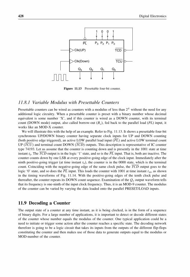
428 Digital Electronics
Clk(UP)
Clk(Down)
TCD
TCU
P3 P2 P1 P0
Q3 Q2 Q1 Q0
PL
01 10
Figure 11.13 Presettable four-bit counter.
11.8.1 Variable Modulus with Presettable Counters
Presettable counters can be wired as counters with a modulus of less than 2N without the need for anyadditional logic circuitry. When a presettable counter is preset with a binary number whose decimalequivalent is some number ‘X’, and if this counter is wired as a DOWN counter, with its terminalcount (DOWN mode) output, also called borrow-out (Bo�, fed back to the parallel load (PL) input, itworks like an MOD-X counter.
We will illustrate this with the help of an example. Refer to Fig. 11.13. It shows a presettable four-bitsynchronous UP/DOWN binary counter having separate clock inputs for UP and DOWN counting(both positive edge triggered), an active LOW parallel load input (PL� and active LOW terminal countUP (TCU� and terminal count DOWN (TCD� outputs. This description is representative of IC countertype 74193. Let us assume that the counter is counting down and is presently in the 1001 state at timeinstant t0. The TCD output is in the logic ‘1’ state, and so is the PL input. That is, both are inactive. Thecounter counts down by one LSB at every positive-going edge of the clock input. Immediately after theninth positive-going trigger (at time instant t9�, the counter is in the 0000 state, which is the terminalcount. Coinciding with the negative-going edge of the same clock pulse, the TCD output goes to thelogic ‘0’ state, and so does the PL input. This loads the counter with 1001 at time instant t10, as shownin the timing waveforms of Fig. 11.14. With the positive-going edges of the tenth clock pulse andthereafter, the counter repeats its DOWN count sequence. Examination of the Q3 output waveform tellsthat its frequency is one-ninth of the input clock frequency. Thus, it is an MOD-9 counter. The modulusof the counter can be varied by varying the data loaded onto the parallel PRESET/LOAD inputs.
11.9 Decoding a CounterThe output state of a counter at any time instant, as it is being clocked, is in the form of a sequenceof binary digits. For a large number of applications, it is important to detect or decode different statesof the counter whose number equals the modulus of the counter. One typical application could be aneed to initiate or trigger some action after the counter reaches a specific state. The decoding networktherefore is going to be a logic circuit that takes its inputs from the outputs of the different flip-flopsconstituting the counter and then makes use of those data to generate outputs equal to the modulus orMOD-number of the counter.

Counters and Registers 429
Clk(D)
Q0
Q1
Q2
Q3
TCDorPL
t0 t1 t2 t3 t4 t5 t6 t7 t8 t9 t10
Figure 11.14 Timing waveforms for the counter of Fig. 11.13.
Depending upon the logic status of the decoded output, there are two basic types of decoding,namely active HIGH decoding and active LOW decoding. In the case of the former the decoder outputsare normally LOW, and for a given counter state the corresponding decoder output goes to the logicHIGH state. In the case of active LOW decoding, the decoder outputs are normally HIGH and thedecoded output representing the counter state goes to the logic LOW state.
We will further illustrate the concept of decoding a counter with the help of an example. Considerthe two-stage MOD-4 ripple counter of Fig. 11.15(a). This counter has four possible logic states, whichneed to be decoded. These include 00, 01, 10 and 11. Let us now consider the arrangement of fourtwo-input AND gates as shown in Fig. 11.15(b) and what their outputs look like as the counter clockgoes through the first four pulses. Before we proceed further, we have two important observations tomake. Firstly, the number of AND gates used in the decoder network equals the number of logic statesto be decoded, which further equals the modulus of the counter. Secondly, the number of inputs toeach AND gate equals the number of flip-flops used in the counter. We can see from the waveformsof Fig. 11.15(b) that, when the counter is in the 00 state, the AND gate designated ‘0’ is in the logicHIGH state and the outputs of the other gates designated ‘1’, ‘2’ and ‘3’ are in the logic LOW state.Similarly, for 01, 10 and 11 states of the counter, the outputs of gates 1, 2 and 3 are respectively inthe logic HIGH state. This is incidentally active HIGH decoding. We can visualize that, if the ANDgates were replaced with NAND gates, with the inputs to the gates remaining the same, we would getan active LOW decoder. For a counter that uses N flip-flops and has a modulus of ‘X’, the decoderwill have ‘X’ number of N -input AND or NAND gates, depending upon whether we want an activeHIGH or active LOW decoder.

430 Digital Electronics
A B BA
1
2
3
0
(b)
A
FFA
J
K
B
FFB
J
K
1
Clock
A B
(a)
Figure 11.15 MOD-4 ripple counter with decoding logic.

Counters and Registers 431
Output0
Output1
Output2
Output3
Output4
Output5
Output6
Output7
Output8
Output9
A
A
B
B
C
C
D
D
Input D
Input C
Input B
Input A
Figure 11.16 Logic diagram of four-line BCD-to-decimal decoder (IC 7442).
Figure 11.16 shows the logic diagram of a four-line BCD to decimal decoder with active low outputs.Full decoding of valid input logic states ensures that all outputs remain off or inactive for all invalidinput conditions. Table 11.6 gives the functional table of the decoder of Fig. 11.16. The logic diagramshown in Fig. 11.16 is the actual logic diagram of IC 7442, which is a four-line BCD to decimaldecoder in the TTL family.
The decoding gates used to decode the states of a ripple counter produce glitches (or spikes) in thedecoded waveforms. These glitches basically result from the cumulative propagation delay as we movefrom one flip-flop to the next in a ripple counter. It can be best illustrated with the help of the MOD-4counter shown in Fig. 11.17. The timing waveforms are shown in Fig. 11.18 and are self-explanatory.

432 Digital Electronics
Table 11.6 Functional table of the decoder of Fig. 11.16.
Decimal number BCD input Decimal output
D C B A 0 1 2 3 4 5 6 7 8 9
0 L L L L L H H H H H H H H H1 L L L H H L H H H H H H H H2 L L H L H H L H H H H H H H3 L L H H H H H L H H H H H H4 L H L L H H H H L H H H H H5 L H L H H H H H H L H H H H6 L H H L H H H H H H L H H H7 L H H H H H H H H H H L H H8 H L L L H H H H H H H H L H9 H L L H H H H H H H H H H L
Invalid H L H L H H H H H H H H H HInvalid H L H H H H H H H H H H H HInvalid H H L L H H H H H H H H H HInvalid H H L H H H H H H H H H H HInvalid H H H L H H H H H H H H H HInvalid H H H H H H H H H H H H H H
Figure 11.17 MOD-4 counter with decoding gates.
We can see the appearance of glitches at the output of decoding gates that decode X0 and X2 states�Thisproblem for all practical purposes is absent in synchronous counters. Theoretically, it can even existin a synchronous counter if the flip-flops used have different propagation delays.
One way to overcome this problem is to use a strobe signal which keeps the decoding gates disableduntil all flip-flops have reached a stable state in response to the relevant clock transition. To implement

Counters and Registers 433
Clock
A-Output
B-Output
X0
X1
X2
X3
Figure 11.18 Glitch problem in decoders.
this, each of the decoding gates will have an additional input. This additional input of all decodinggates is tied together and the strobe signal applied to the common point.
One such decoder with additional strobe inputs to take care of glitch-related problems is IC 74154,which is a four-line to 16-line decoder in the TTL family. Figure 11.19 shows the internal logicdiagram of IC 74154. We can see all NAND gates having an additional input line, which is controlledby strobe inputs G1 and G2.
11.10 Cascading CountersA cascade arrangement allows us to build counters with a higher modulus than is possible with asingle stage. The terminal count outputs allow more than one counter to be connected in a cascadearrangement. In the following paragraphs, we will examine some such cascade arrangements in thecase of binary and BCD counters.
11.10.1 Cascading Binary Counters
In order to construct a multistage UP counter, all counter stages are connected in the count UP mode.The clock is applied to the clock input of a lowest-order counter, the terminal count UP (TCU), alsocalled the carry-out (Co�, of this counter is applied to the clock input of the next higher counter stage

434 Digital Electronics
0
1
2
3
4
5
6
7
8
9
10
11
12
13
14
15
A B C D
A
B
D
D
C
A
B
C
G
A
A
A
B
B
B
C
C
C
D
D
D
G1
G2
Inputs Outputs
Figure 11.19 Logic diagram of IC 74154.

Counters and Registers 435
CLK(UP)
CLK(DOWN)
TCU
TCD
P3 P2 P1 P0
Q3 Q2 Q1 Q0
Lower Order Counter
CLK(UP)
CLK(DOWN)
TCU
TCD
P3 P2 P1 P0
Q3 Q2 Q1 Q0
Higher Order Counter
PLPL
CLK(UP)
CLK(DOWN)
TCU
TCD
P3 P2 P1 P0
Q3 Q2 Q1 Q0
Lower Order Counter
CLK(UP)
CLK(DOWN)
TCU
TCD
P3 P2 P1 P0
Q3 Q2 Q1 Q0
Higher Order Counter
PLPL
(a)
(b)
Figure 11.20 Cascading binary counters.
and the process continues. If it is desired to build a multistage DOWN counter, all counters are wiredas DOWN counters, the clock is applied to the clock input of the lowest-order counter and the terminalcount DOWN (TCD), also called the borrow-out (Bo�, of the lowest-order counter is applied to theclock input of the next higher counter stage. The process continues in the same fashion, with the TCDoutput of the second stage feeding the clock input of the third stage and so on. The modulus of themultistage counter arrangement equals the product of the moduli of individual stages. Figures 11.20(a)and (b) respectively show two-stage arrangements of four-bit synchronous UP and DOWN countersrespectively.
11.10.2 Cascading BCD Counters
BCD counters are used when the application involves the counting of pulses and the result of countingis to be displayed in decimal. A single-stage BCD counter counts from 0000 (decimal equivalent‘0’) to 1001 (decimal equivalent ‘9’) and thus is capable of counting up to a maximum of ninepulses. The output in a BCD counter is in binary coded decimal (BCD) form. The BCD output needs

436 Digital Electronics
BCDCounter
Clk
D C B A
1000's Counter
BCDCounter
Clk
D C B A
100's Counter
BCDCounter
Clk
D C B A
10's Counter
BCDCounter
Clk
D C B A
1's Counter
Input
Figure 11.21 Cascading BCD counters.
to be decoded appropriately before it can be displayed. Decoding a counter has been discussed inthe previous section. Coming back to the question of counting pulses, more than one BCD counterstage needs to be used in a cascade arrangement in order to be able to count up to a larger numberof pulses. The number of BCD counter stages to be used equals the number of decimal digits inthe maximum number of pulses we want to count up to. With a maximum count of 9999 or 3843,both would require a four-stage BCD counter arrangement with each stage representing one decimaldigit.
Figure 11.21 shows a cascade arrangement of four BCD counter stages. The arrangement works asfollows. Initially, all four counters are in the all 0s state. The counter representing the decimal digit of1’s place is clocked by the pulsed signal that needs to be counted. The successive flip-flops are clockedby the MSB of the immediately previous counter stage. The first nine pulses take 1’s place counter to1001. The tenth pulse resets it to 0000, and ‘1’ to ‘0’ transition at the MSB of 1’s place counter clocks10’s place counter. 10’s place counter gets clocked on every tenth input clock pulse. On the hundredthclock pulse, the MSB of 10’s counter makes a ‘1’ to ‘0’ transition which clocks 100’s place counter.This counter gets clocked on every successive hundredth input clock pulse. On the thousandth inputclock pulse, the MSB of 100’s counter makes ‘l’ to ‘0’ transition for the first time and clocks 1000’splace counter. This counter is clocked thereafter on every successive thousandth input clock pulse.With this background, we can always tell the output state of the cascade arrangement. For example,immediately after the 7364th input clock pulse, the state of 1000’s, 100’s, 10’s and 1’s BCD counterswould respectively be 0111, 0011, 0110 and 0100.
Example 11.6
Figure 11.22 shows a cascade arrangement of two 74190s. Both the UP/DOWN counters are wiredas UP counters. What will be the logic status of outputs designated as A, B, C, D, E, F, G and H afterthe 34th clock pulse?
SolutionThe cascade arrangement basically constitutes a two-stage BCD counter that can count from 0 to 99.The counter shown on the left forms 1’s place counter, while the one on the right is 10’s place counter.The ripple clock (RC� output internally enabled by the terminal count � TC� clocks 10’s place counteron the tenth clock pulse and thereafter on every successive tenth clock pulse. At the end of the 34thclock pulse, 1’s counter stores the binary equivalent of ‘4’ and 10’s counter stores the binary equivalentof ‘3’. Therefore, the logic status of A, B, C, D, E, F , G and H outputs will be 0, 0, 1, 0, 1,1, 0 and0 respectively.

Counters and Registers 437
Q3 Q2 Q1 Q0
U/D
CE
GND
CP
RC
TC
74190
VCC PLP
ABCD
Q3 Q2 Q1 Q0
U/D
CE
GND
CP
RC
TC
74190
VCC
+VCC
PLP
H G F E
Figure 11.22 Cascade arrangement of two 74190s (example 11.6).
Q3 Q2 Q1 Q0
Clk(Down)
Clk(Up)
74193
1 MRor
Clear
P3 P2 P1 P0PL
TCDor
BO
0 1 01
Figure 11.23 Presettable counter (example 11.7).
Example 11.7
Determine the modulus of the presettable counter shown in Fig. 11.23. If the counter were initially inthe 0110 state, what would be the state of the counter immediately after the eighth clock pulse be?
Solution• This presettable counter has been wired as a DOWN counter.• The preset data input is 0110.• Therefore, the modulus of the counter is 6 (the decimal equivalent of 0110).• Now, the counter is initially in the 0110 state.• Therefore, at the end of the sixth clock pulse, immediately after the leading edge of the sixth clock
pulse, the counter will be in the 0000 state.

438 Digital Electronics
• A HIGH-to-LOW transition at the TCD output,coinciding with the trailing edge of the sixth clockpulse, loads 0110 to the counter output.
• Therefore, immediately after the leading edge of the eighth clock pulse, the counter will be in the0100 state.
11.11 Designing Counters with Arbitrary SequencesSo far we have discussed different types of synchronous and asynchronous counters. A large varietyof synchronous and asynchronous counters are available in IC form, and some of these have beenmentioned and discussed in the previous sections. The counters discussed hitherto count in either thenormal binary sequence with a modulus of 2N or with slightly altered binary sequences where one ormore of the states are skipped. The latter type of counter has a modulus of less than 2N , N being thenumber of flip-flops used. Nevertheless, even these counters have a sequence that is either upwards ordownwards and not arbitrary. There are applications where a counter is required to follow a sequencethat is arbitrary and not binary. As an example, an MOD-10 counter may be required to follow thesequence 0000, 0010, 0101, 0001, 0111, 0011, 0100, 1010, 1000, 1111, 0000, 0010 and so on. In suchcases, the simple and seemingly obvious feedback arrangement with a single NAND gate discussedin the earlier sections of this chapter for designing counters with a modulus of less than 2N cannot beused.
There are several techniques for designing counters that follow a given arbitrary sequence. In thepresent section, we will discuss in detail a commonly used technique for designing synchronouscounters using J-K flip-flops or D flip-flops. The design of the counters basically involves designinga suitable combinational logic circuit that takes its inputs from the normal and complemented outputsof the flip-flops used and decodes the different states of the counter to generate the correct logic statesfor the inputs of the flip-flops such as J , K, D, etc. But before we illustrate the design procedure withthe help of an example, we will explain what we mean by the excitation table of a flip-flop and thestate transition diagram of a counter. An excitation table in fact can be drawn for any sequential logiccircuit, but, once we understand what it is in the case of a flip-flop, which is the basic building blockof sequential logic, it would be much easier for us to draw the same for more complex sequentialcircuits such as counters, etc.
11.11.1 Excitation Table of a Flip-Flop
The excitation table is similar to the characteristic table that we discussed in the previous chapter onflip-flops. The excitation table lists the present state, the desired next state and the flip-flop inputs(J , K, D, etc.) required to achieve that. The same for a J-K flip-flop and a D flip-flop are shown inTables 11.7 and 11.8 respectively. Referring to Table 11.7, if the output is in the logic ‘0’ state and itis desired that it goes to the logic ‘1’ state on occurrence of the clock pulse, the J input must be inthe logic ‘1’ state and the K input can be either in the logic ‘0’ or logic ‘1’ state. This is true as, fora ‘0’ to ‘1’ transition, there are two possible input conditions that can achieve this. These are J = 1,K = 0 (SET mode) and J = K = 1 (toggle mode), which further leads to J = 1� K = X (either 0or 1). The other entries of the excitation table can be explained on similar lines.
In the case of a D flip-flop, the D input is the same as the logic status of the desired next state. Thisis true as, in the case of a D flip-flop, the D input is transferred to the output on the occurrence of theclock pulse, irrespective of the present logic status of the Q output.

Counters and Registers 439
Table 11.7 Excitation table of a J-K flip-flop.
Present Next state J Kstate (Qn) (Qn+1)
0 0 0 X0 1 1 X1 0 X 11 1 X 0
Table 11.8 Excitation table of a D flip-flop.
Present Next state Dstate (Qn) (Qn+1)
0 0 00 1 11 0 01 1 1
11.11.2 State Transition Diagram
The state transition diagram is a graphical representation of different states of a given sequentialcircuit and the sequence in which these states occur in response to a clock input. Different states arerepresented by circles, and the arrows joining them indicate the sequence in which different statesoccur. As an example, Fig. 11.24 shows the state transition diagram of an MOD-8 binary counter.
11.11.3 Design Procedure
We will illustrate the design procedure with the help of an example. We will do this for an MOD-6synchronous counter design, which follows the count sequence 000, 010, 011, 001, 100, 110, 000,010, � � � :
000 001
101 100
111
110
010
011
Figure 11.24 State transition diagram for an MOD-8 binary counter.

440 Digital Electronics
1. Determine the number of flip-flops required for the purpose. Identify the undesired states. In thepresent case, the number of flip-flops required is 3 and the undesired states are 101 and 111
2. Draw the state transition diagram showing all possible states including the ones that are not desired.The undesired states should be depicted to be transiting to any of the desired states. We have chosenthe 000 state for this purpose. It is important to include the undesired states to ensure that, if thecounter accidentally gets into any of these undesired states owing to noise or power-up, the counterwill go to a desired state to resume the correct sequence on application of the next clock pulse.Figure 11.25 shows the state transition diagram
110
100
010
011
000
001
101 111
Figure 11.25 State transition diagram.
3. Draw the excitation table for the counter, listing the present states, the next states correspondingto the present states and the required logic status of the flip-flop inputs (the J and K inputs if thecounter is to be implemented with J-K flip-flops). The excitation table is shown in Table 11.9
Table 11.9 Excitation table.
Present Next Inputsstate state
C B A C B A JC KC JB KB JA KA
0 0 0 0 1 0 0 X 1 X 0 X0 0 1 1 0 0 1 X 0 X X 10 1 0 0 1 1 0 X X 0 1 X0 1 1 0 0 1 0 X X 1 X 01 0 0 1 1 0 X 0 1 X 0 X1 0 1 0 0 0 X 1 0 X X 11 1 0 0 0 0 X 1 X 1 0 X1 1 1 0 0 0 X 1 X 1 X 1

Counters and Registers 441
The circuit excitation table can be drawn very easily once we know the excitation table of theflip-flop to be used for building the counter. For instance, let us look at the first row of the excitationtable (Table 11.9). The counter is in the 000 state and is to go to 010 on application of a clockpulse. That is, the normal outputs of C, B and A flip-flops have to undergo ‘0’ to ‘0’, ‘0’ to ‘1’ and‘0’ to ‘0’ transitions respectively. Referring to the excitation table of a J-K flip-flop, the desiredtransitions can be realized if the logic status of JA, KA, JB, KB, JC and KC is as shown in theexcitation table.
4. The next step is to design the logic circuits for generating JA, KA, JB, KB, JC and KC inputs fromavailable A, A, B, B, C and C outputs. This can be done by drawing Karnaugh maps for each oneof the inputs, minimizing them and then implementing the minimized Boolean expressions. TheKarnaugh maps for JA, KA, JB, KB, JC and KC are respectively shown in Figs 11.26(a), (b), (c),(d), (e) and (f). The minimized Boolean expressions are as follows:
X
A
BC
1
X
X
X
A
BC
BC
BC
(a)
X
A
BC
1
X
X
X
A
BC
BC
BC
(b)
1
1
A
BC
X
X
A
BC
BC
BC
(c)
1
1
X
X
A
BC
X
A
BC
BC
BC
(d)
1
1
X
X
X
1
X
A
BC 1
X
X
A
BC
BC
BC
(e)
X
A
BC
X
X
A
BC
BC
BC
(f)
1
1
X
X
1
Figure 11.26 Karnaugh maps.

442 Digital Electronics
JA = B�C (11.2)
KA = B + C (11.3)
JB = A (11.4)
KB = A + C (11.5)
JC = A�B (11.6)
KC = A + B (11.7)
The above expressions can now be used to implement combinational circuits to generate JA, KA,JB, KB, JC and KC inputs. Figure 11.27 shows the complete counter circuit
C
ClkFF-C
JC
KCC
ClkFF-B
JB
KBB
B
ClkFF-A
JA
KAA
A
Clock-In
Figure 11.27 Counter with an arbitrary sequence.
The design procedure illustrated above can be used to design a synchronous counter for any givencount sequence with the condition that no state occurs more than once in one complete cycle of thegiven count sequence as the design cannot handle a situation where a particular present state has morethan one future state.

Counters and Registers 443
Table 11.10 Example 11.8.
Present state(Qn)
Next state(Qn+1)
Inputs
X1 X2
0 0 0 00 1 0 11 0 1 X1 1 X 1
X=don’t care condition.
Example 11.8
Table 11.10 gives the excitation table of a certain flip-flop having X1 and X2 as its inputs. Draw thecircuit excitation table of an MOD-5 synchronous counter using this flip-flop for the count sequence000, 001, 011, 101, 110, 000, � � � If the present state is an undesired one, it should transit to 110 onapplication of a clock pulse. Design the counter circuit using the flip-flop whose excitation circuit isgiven in Table 11.10.
Solution• The circuit excitation table is shown in Table 11.11.• The number of flip-flops required is 3.• X1 (A) and X2 (A) are the inputs of flip-flop A, which is also the LSB flip-flop.• X1 (B) and X2 (B) represent the inputs to flip-flop B.• X1 (C) and X2 (C) are the inputs to flip-flop C, which is also the MSB flip-flop.• The next step is to draw Karnaugh maps, one each for different inputs to the three flip-flops.• Figures 11.28(a) to (f) show the Karnaugh maps for X1 (A), X2 (A), X1 (B), X2 (B), X1 (C) and X2
(C) respectively.• The minimized expressions are as follows:
X1�A� = A (11.8)
X2�A� = A + B�C (11.9)
X1�B� = B (11.10)
X2�B� = A + B + C (11.11)
X1�C� = C (11.12)
X2�C� = B + C (11.13)
• Figure 11.29 shows the circuit implementation.
Example 11.9
Design a synchronous counter that counts as 000, 010, 101, 110, 000, 010, � � � Ensure that the unusedstates of 001, 011, 100 and 111 go to 000 on the next clock pulse. Use J-K flip-flops. What will thecounter hardware look like if the unused states are to be considered as ‘don’t care’s.

444 Digital Electronics
Table 11.11 Example 11.8.
Present state Next state Inputs
C B A C B A X1(A) X2(A) X1(B) X2(B) X1(C) X2(C)
0 0 0 0 0 1 0 1 0 0 0 00 0 1 0 1 1 X 1 0 1 0 00 1 0 1 1 0 0 0 X 1 0 10 1 1 1 0 1 X 1 1 X 0 11 0 0 1 1 0 0 0 0 1 X 11 0 1 1 1 0 1 X 0 1 X 11 1 0 0 0 0 0 0 1 X 1 X1 1 1 1 1 0 1 X X 1 X 1
X=don’t care condition.
A
BC X
A
BC
BC
BC
(a)
1
1
X
A
BC
X
A
BC
BC
BC
1
1
X
1
A
BC
1
A
BC
BC
BC
(c)
1
X
A
BC
X
A
BC
BC
BC
(d)
1
1
1
1
X
1
(b)
A
BC
A
BC
BC
BC
(e)
1 X
XX
A
BC
X
A
BC
BC
BC
(f)
1
1
1
1
1
X
Figure 11.28 Karnaugh maps (example 11.8).

Counters and Registers 445
C
ClkFF-C
X (C)1
C
Clock
B
ClkFF-B
B
A
ClkFF-A
AX (C)2
X (B)1
X (B)2
X (A)1
X (A)2
Figure 11.29 Counter circuit (example 11.8).
Table 11.12 Example 11.9.
Present state Next state Inputs
C B A C B A JA KA JB KB JC KC
0 0 0 0 1 0 0 X 1 X 0 X0 0 1 0 0 0 X 1 0 X 0 X0 1 0 1 0 1 1 X X 1 1 X0 1 1 0 0 0 X 1 X 1 0 X1 0 0 0 0 0 0 X 0 X X 11 0 1 1 1 0 X 1 1 X X 01 1 0 0 0 0 0 X X 1 X 11 1 1 0 0 0 X 1 X 1 X 1
Solution• The number of flip-flops required is three.• Table 11.12 shows the desired circuit excitation table.• The Karnaugh maps for JA, KA, JB, KB, JC and KC are shown in Figs 11.30(a) to (f) respectively�• The simplified Boolean expressions are as follows:
JA = B�C (11.14)
KA = 1 (11.15)

446 Digital Electronics
X
A
CB
1 X
X
X
A
CB
CB
CB
(a)
X
A
1
X
X
X
A
(b)
1
1
A
X
X
A
(c)
1
X
X
1 1
X
A
1
X
A
(d)
1
1
1
X
X
A
X
X
A
(e)
1
X
X
CB
CB
CB
CB
CB
CB
CB
CB
CB
CB
CB
CB
CB
CB
CB
CB
X
A
1
X
X
X
A
(f)
1
CB
CB
CB
CB
1
Figure 11.30 Karnaugh maps (example 11.9).
JB = A�C + A�C (11.16)
KB = 1 (11.17)
JC = A�B (11.18)
KC = A + B (11.19)
• The hardware implementation is shown in Fig. 11.31.• In the case where the unused inputs are considered as ‘don’t cares’, the circuit excitation table is
modified to that shown in Table 11.13.• Modified Karnaugh maps are shown in Fig. 11.32.• The minimized Boolean expressions are derived from the Karnaugh maps of Figs 11.32(a) to (f).• Minimized expressions for JA, KA, JB, KB, JC and KC respectively are as follows:
JA = B�C (11.20)
KA = 1 (11.21)
JB = 1 (11.22)
KB = 1 (11.23)
JC = B (11.24)
KC = A (11.25)
• Figure 11.33 shows the hardware implementation.

Counters and Registers 447
Figure 11.31 Hardware implementation of the counter circuit (example 11.9).
Table 11.13 Example 11.9.
Present state Next state Inputs
C B A C B A JA KA JB KB JC KC
0 0 0 0 1 0 0 X 1 X 0 X0 0 1 X X X X X X X X X0 1 0 1 0 1 1 X X 1 1 X0 1 1 X X X X X X X X X1 0 0 X X X X X X X X X1 0 1 1 1 0 X 1 1 X X 01 1 0 0 0 0 0 X X 1 X 11 1 1 X X X X X X X X X
11.12 Shift RegisterA shift register is a digital device used for storage and transfer of data. The data to be stored could bethe data appearing at the output of an encoding matrix before they are fed to the main digital systemfor processing or they might be the data present at the output of a microprocessor before they are fed

448 Digital Electronics
X
A
CB
1 X
X
X
A
CB
CB
CB
(a)
X
A
X
X
X
A
(b)
1
X
A
X
A
(d)
1
1
X
X
A
X
A
(e)
1
X
X
CB
CB
CB
CB
CB
CB
CB
CB
CB
CB
CB
CB
X
A
X
X
X
A
(f)
CB
CB
CB
CB
X
X
X
X
A
X
X
X
A
(b)
1
CB
CB
CB
CB
X
X
X
1
X
X X
X
X
X
1
X
Figure 11.32 Modified Karnaugh maps (example 11.9).
Figure 11.33 Hardware implementation of the counter circuit (example 11.9).
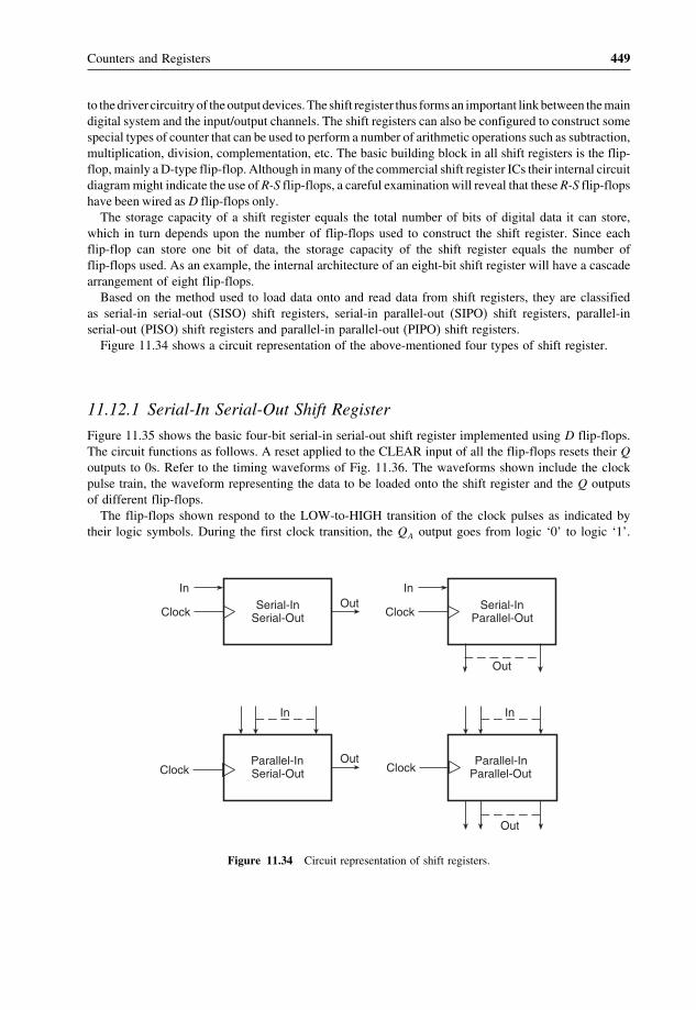
Counters and Registers 449
to the driver circuitry of the output devices. The shift register thus forms an important link between the maindigital system and the input/output channels. The shift registers can also be configured to construct somespecial types of counter that can be used to perform a number of arithmetic operations such as subtraction,multiplication, division, complementation, etc. The basic building block in all shift registers is the flip-flop, mainly a D-type flip-flop. Although in many of the commercial shift register ICs their internal circuitdiagram might indicate the use of R-S flip-flops, a careful examination will reveal that these R-S flip-flopshave been wired as D flip-flops only.
The storage capacity of a shift register equals the total number of bits of digital data it can store,which in turn depends upon the number of flip-flops used to construct the shift register. Since eachflip-flop can store one bit of data, the storage capacity of the shift register equals the number offlip-flops used. As an example, the internal architecture of an eight-bit shift register will have a cascadearrangement of eight flip-flops.
Based on the method used to load data onto and read data from shift registers, they are classifiedas serial-in serial-out (SISO) shift registers, serial-in parallel-out (SIPO) shift registers, parallel-inserial-out (PISO) shift registers and parallel-in parallel-out (PIPO) shift registers.
Figure 11.34 shows a circuit representation of the above-mentioned four types of shift register.
11.12.1 Serial-In Serial-Out Shift Register
Figure 11.35 shows the basic four-bit serial-in serial-out shift register implemented using D flip-flops.The circuit functions as follows. A reset applied to the CLEAR input of all the flip-flops resets their Qoutputs to 0s. Refer to the timing waveforms of Fig. 11.36. The waveforms shown include the clockpulse train, the waveform representing the data to be loaded onto the shift register and the Q outputsof different flip-flops.
The flip-flops shown respond to the LOW-to-HIGH transition of the clock pulses as indicated bytheir logic symbols. During the first clock transition, the QA output goes from logic ‘0’ to logic ‘1’.
Serial-InSerial-Out
In
ClockOut Serial-In
Parallel-Out
In
Clock
Out
Parallel-InSerial-Out
In
Out Parallel-InParallel-Out
In
Out
ClockClock
Figure 11.34 Circuit representation of shift registers.

450 Digital Electronics
QAD
CL
QBD
CL
QCD
CL
Clk
QDD
CL
Data In
Clock
Clear
Data Out
Clk Clk Clk
Figure 11.35 Serial-in, serial-out shift register.
Clock
Clear
Data Input1 0
Q -OutputA
0 1
Q -OutputB
Q -OutputC
Q -OutputD
Figure 11.36 Timing waveforms for the shift register of Fig. 11.35.
The outputs of the other three flip-flops remain in the logic ‘0’ state as their D inputs were in the logic‘0’ state at the time of clock transition. During the second clock transition, the QA output goes fromlogic ‘1’ to logic ‘0’ and the QB output goes from logic ‘0’ to logic ‘1’, again in accordance with thelogic status of the D inputs at the time of relevant clock transition.
Thus, we have seen that a logic ‘1’ that was present at the data input prior to the occurrence of thefirst clock transition has reached the QB output at the end of two clock transitions. This bit will reachthe QD output at the end of four clock transitions. In general, in a four-bit shift register of the type

Counters and Registers 451
Table 11.14 Contents of four-bit serial-in serial-out shift register for the first eight clock cycles.
Clock QA QB QC QD
Initial contents 0 0 0 0After first clock transition 1 0 0 0After second clock transition 0 1 0 0After third clock transition 0 0 1 0After fourth clock transition 1 0 0 1After fifth clock transition 0 1 0 0After sixth clock transition 0 0 1 0After seventh clock transition 0 0 0 1After eighth clock transition 0 0 0 0
shown in Fig. 11.35, a data bit present at the data input terminal at the time of the nth clock transitionreaches the QD output at the end of the (n+4)th clock transition. During the fifth and subsequentclock transitions, data bits continue to shift to the right, and at the end of the eighth clock transitionthe shift register is again reset to all 0s. Thus, in a four-bit serial-in serial-out shift register, it takesfour clock cycles to load the data bits and another four cycles to read the data bits out of the register.The contents of the register for the first eight clock cycles are summarized in Table 11.14. We can seethat the register is loaded with the four-bit data in four clock cycles, and also that the stored four-bitdata are read out in the subsequent four clock cycles.
IC 7491 is a popular eight-bit serial-in serial-out shift register. Figure 11.37 shows its internalfunctional diagram, which is a cascade arrangement of eight R-S flip-flops. Owing to the inverterbetween the R and S inputs of the data input flip-flop, it is functionally the same as a D flip-flop.The data to be loaded into the register serially can be applied either at A or B input of the NANDgate. The other input is then kept in the logic HIGH state to enable the NAND gate. In that case, datapresent at A or B get complemented as they appear at the NAND output. Another inversion providedby the inverter, however, restores the original status so that for a logic ‘1’ at the data input there is alogic ‘1’ at the SET input of the flip-flop and a logic ‘0’ at the RESET input of the flip-flop, and fora logic ‘0’ at the data input there is a logic ‘0’ at the SET input and a logic ‘1’ at the RESET inputof the flip-flop. The NAND gate provides only a gating function, and, if it is not required, the twoinputs of the NAND can be shorted to have a single-line data input. The shift register responds to theLOW-to-HIGH transitions of the clock pulses.
Q0S
R Q0
C
Q1S
R Q1
C
Q2S
R Q2
C
Q3S
R Q3
C
Q4S
R Q4
C
Q5S
R Q5
C
Q6S
R Q6
C
Q7S
R Q7
C
Clock
AB
Figure 11.37 Logic diagram of IC 7491.

452 Digital Electronics
Q0D
CD
CP
Q1 Q2 Q3 Q4 Q5 Q6 Q7
Clock
AB
MR
D
CP
CD
D
CP
CD
D
CP
CD
D
CP
CD
D
CP
CD
D
CP
CD
Q7Q6Q5Q4
D
CP
CD
Q3Q2Q1Q0
Figure 11.38 Logic diagram of IC 74164.
11.12.2 Serial-In Parallel-Out Shift Register
A serial-in parallel-out shift register is architecturally identical to a serial-in serial-out shift registerexcept that in the case of the former all flip-flop outputs are also brought out on the IC terminals.Figure 11.38 shows the logic diagram of a typical serial-in parallel-out shift register. In fact, the logicdiagram shown in Fig. 11.38 is that of IC 74164, a popular eight-bit serial-in parallel-out shift register.The gated serial inputs A and B control the incoming serial data, as a logic LOW at either of the inputsinhibits entry of new data and also resets the first flip-flop to the logic LOW level at the next clockpulse. Logic HIGH at either of the inputs enables the other input, which then determines the state ofthe first flip-flop.
Data at the serial inputs may be changed while the clock input is HIGH or LOW, and theregister responds to LOW-to-HIGH transition of the clock. Figure 11.39 shows the relevant timingwaveforms.
11.12.3 Parallel-In Serial-Out Shift Register
We will explain the operation of a parallel-in serial-out shift register with the help of the logic diagramof a practical device available in IC form. Figure 11.40 shows the logic diagram of one such shiftregister. The logic diagram is that of IC 74166, which is an eight-bit parallel/serial-in, serial-out shiftregister belonging to the TTL family of devices.
The parallel-in or serial-in modes are controlled by a SHIFT/LOAD input. When the SHIFT/LOADinput is held in the logic HIGH state, the serial data input AND gates are enabled and the circuitbehaves like a serial-in serial-out shift register. When the SHIFT/LOAD input is held in the logic LOWstate, parallel data input AND gates are enabled and data are loaded in parallel, in synchronism withthe next clock pulse. Clocking is accomplished on the LOW-to-HIGH transition of the clock pulse viaa two-input NOR gate. Holding one of the inputs of the NOR gate in the logic HIGH state inhibitsthe clock applied to the other input. Holding an input in the logic LOW state enables the clock to beapplied to the other input. An active LOW CLEAR input overrides all the inputs, including the clock,and resets all flip-flops to the logic ‘0’ state. The timing waveforms shown in Fig. 11.41 explain bothserial-in, serial-out as well as parallel-in, serial-out operations.

Counters and Registers 453
Figure 11.39 Timing waveforms of IC 74164.
11.12.4 Parallel-In Parallel-Out Shift Register
The hardware of a parallel-in parallel-out shift register is similar to that of a parallel-in serial-outshift register. If in a parallel-in serial-out shift register the outputs of different flip-flops are broughtout, it becomes a parallel-in parallel-out shift register. In fact, the logic diagram of a parallel-inparallel-out shift register is similar to that of a parallel-in serial-out shift register. As an example, IC74199 is an eight-bit parallel-in parallel-out shift register. Figure 11.42 shows its logic diagram. Wecan see that the logic diagram of IC 74199 is similar to that of IC 74166 mentioned in the previoussection, except that in the case of the former the flip-flop outputs have been brought out on the ICterminals.

454 Digital Electronics
Figure 11.40 Logic diagram of 74166.

Counters and Registers 455
Figure 11.41 Timing waveforms of IC 74166.
11.12.5 Bidirectional Shift Register
A bidirectional shift register allows shifting of data either to the left or to the right. This is madepossible with the inclusion of some gating logic having a control input. The control input allowsshifting of data either to the left or to the right, depending upon its logic status.
11.12.6 Universal Shift Register
A universal shift register can be made to function as any of the four types of register discussed inprevious sections. That is, it has serial/parallel data input and output capability, which means that it canfunction as serial-in serial-out, serial-in parallel-out, parallel-in serial out and parallel-in parallel-outshift registers.
IC 74194 is a common four-bit bidirectional universal shift register. Figure 11.43 shows the logicdiagram of Ic 74194. the device offers four modes of operation, namely (a) inhibit clock, (b) shiftright, (c) shift left and (d) parallel load. Clocking of the device is inhibited when both the mode controlinputs S1 and S0 are in the logic LOW state. shift right and shift left operations are accomplished

456 Digital Electronics
Figure 11.42 Logic diagram of IC 74199.

Fig
ure
11.4
3L
ogic
diag
ram
ofIC
7419
4.

458 Digital Electronics
synchronously with LOW-to-HIGH transition of the clock with S1 LOW and S0 HIGH (for shiftright) and S1 HIGH and S0 LOW (for shift left). Serial data are entered in the case of shift right andshift left operations at the corresponding data input terminals. Parallel loading is also accomplishedsynchronously with LOW-to-HIGH clock transitions by applying four bits of data and then drivingthe mode control inputs S1 and S0 to the logic HIGH state. Data are loaded into corresponding flip-flops and appear at the outputs with LOW-to-HIGH clock transition. Serial data flow is inhibitedduring parallel loading. Different modes of operation are apparent in the timing waveforms ofFig. 11.44.
Figure 11.44 Timing waveforms of IC 74194.

Counters and Registers 459
11.13 Shift Register CountersWe have seen that both counters and shift registers are some kinds of cascade arrangement offlip-flops. A shift register, unlike a counter, has no specified sequence of states. However, if theserial output of the shift register is fed back to the serial input, we do get a circuit that exhibits aspecified sequence of states. The resulting circuits are known as shift register counters. Dependingupon the nature of the feedback, we have two types of shift register counter, namely the ring counterand the shift counter, also called the Johnson counter. These are briefly described in the followingparagraphs.
11.13.1 Ring Counter
A ring counter is obtained from a shift register by directly feeding back the true output of the outputflip-flop to the data input terminal of the input flip-flop. If D flip-flops are being used to constructthe shift register, the ring counter, also called a circulating register, can be constructed by feedingback the Q output of the output flip-flop back to the D input of the input flip-flop. If J-K flip-flopsare being used, the Q and Q outputs of the output flip-flop are respectively fed back to the J and Kinputs of the input flip-flop. Figure 11.45 shows the logic diagram of a four-bit ring counter. Let usassume that flip-flop FF0 is initially set to the logic ‘1’ state and all other flip-flops are reset to thelogic ‘0’ state. The counter output is therefore 1000. With the first clock pulse, this ‘1’ gets shifted tothe second flip-flop output and the counter output becomes 0100. Similarly, with the second and thirdclock pulses, the counter output will become 0010 and 0001. With the fourth clock pulse, the counteroutput will again become 1000. The count cycle repeats in the subsequent clock pulses. Circulatingregisters of this type find wide application in the control section of microprocessor-based systemswhere one event should follow the other. The timing waveforms for the circulating register of Figure11.45, as shown in Fig. 11.46, further illustrate their utility as a control element in a digital system togenerate control pulses that must occur one after the other sequentially.
Q0
FF0
D
CK
Q1
FF1
D
CK
Q2
FF2
D
CK
Q3
FF3
D
CK
Q0 Q1 Q2 Q3
Figure 11.45 Four-bit ring counter.

460 Digital Electronics
Clock
Q -Output0
Q -Output1
Q -Output2
Q -Output3
Figure 11.46 Timing waveforms of the four-bit ring counter.
11.13.2 Shift Counter
A shift counter on the other hand is constructed by having an inverse feedback in a shift register. Forinstance, if we connect the Q output of the output flip-flop back to the K input of the input flip-flopand the Q output of the output flip-flop to the J input of the input flip-flop in a serial shift register,the result is a shift counter, also called a Johnson counter. If the shift register employs D flip-flops,the Q output of the output flip-flop is fed back to the D input of the input flip-flop. If R-S flip-flopsare used, the Q output goes to the R input and the Q output is connected to the S input. Figure 11.47shows the logic diagram of a basic four-bit shift counter.
Let us assume that the counter is initially reset to all 0s. With the first clock cycle, the outputs willbecome 1000. With the second, third and fourth clock cycles, the outputs will respectively be 1100,1110 and 1111. The fifth clock cycle will change the counter output to 0111. The sixth, seventh andeighth clock pulses successively change the outputs to 0011, 0001 and 0000. Thus, one count cycle
Q0
FF0
J
CK
Q0K
Q1
FF1
J
CK
Q1K
Q2
FF2
J
CK
Q2K
Q3
FF3
J
CK
Q3K
Clock
Figure 11.47 Four-bit shift counter.

Counters and Registers 461
Clock-Input
Q -Output0
Q -Output1
Q -Output2
Q -Output3
Figure 11.48 Timing waveforms of the shift counter.
is completed in eight cycles. Figure 11.48 shows the timing waveforms. Different output waveformsare identical except for the fact that they are shifted from the immediately preceding one by one clockcycle. Also, the time period of each of these waveforms is 8 times the period of the clock waveform.That is, this shift counter behaves as a divide-by-8 circuit.
In general, a shift counter comprising n flip-flops acts as a divide-by-2n circuit. Shift counters canbe used very conveniently to construct counters having a modulus other than the integral power of 2.
Example 11.10
Refer to Fig. 11.49, which shows an application circuit of eight-bit serial-in serial-out shift registertype IC 7491 along with the waveform applied at the shorted A and B inputs:
(a) What will be the data bit present at the output at the end of the eleventh LOW-to-HIGH transitionof the clock waveform?
(b) If there is a logic ‘1’ at the end of the nth LOW-to-HIGH clock transition at the Q3 output, whatwill the Q5 output at the end of the (n + 2)th transition be?
Solution(a) At the end of the eighth LOW-to-HIGH clock transition, the data bits loaded into the register
will be 10110010, with the ‘0’ on the extreme right appearing at the Q7 output (refer to the logicdiagram of IC 7491 shown in Fig. 11.37). The ninth clock transition will shift this ‘0’ out of theregister, and the next adjacent bit (that is, ‘1’) will take its place on the Q7 output. Each subsequentclock pulse will shift the bits one step towards the right, with the result that at the end of theeleventh clock transition the Q7 output will be a logic ‘0’.
(b) It will be a logic ‘1’ only. The Q3 output will be shifted two bit positions to the right by two clocktransitions.

462 Digital Electronics
7491
A
B
CP9
11
12
5VCC
GND
13 SerialOut
+VCC
10
Figure 11.49 Example 11.10.
Example 11.11
Determine the number of flip-flops required to construct (a) a MOD-10 ring counter and (b) a MOD-10Johnson counter. Also, write the count sequence in the two cases.
Solution(a) The modulus of a ring counter is the same as the number of bits (or flip-flops). Therefore, the
number of flip-flops required=10. The count sequence is 1000000000, 0100000000, 0010000000,0001000000, 0000100000, 0000010000, 0000001000, 0000000100, 0000000010, 0000000001 andback to 1000000000.
(b) The modulus of a Johnson counter is twice the number of flip-flops. Therefore, the number offlip-flops=5. The count sequence is 00000, 10000, 11000, 11100, 11110, 11111, 01111, 00111,00011, 00001 and back to 00000.
Example 11.12
Refer to the logic circuit of Fig. 11.50. Determine the modulus of this counter and write its countingsequence.
SolutionThe LSB of the five-bit ring counter feeds the clock input of the J-K flip-flop that has been wired asa toggle flip-flop. The ring counter has a modulus of 5, and the J-K flip-flop works like a divide-by-2circuit. The modulus of the counter circuit obtained by the cascade arrangement of the two is therefore10. The counting sequence of this arrangement is given in Table 11.15.

Counters and Registers 463
A B C D E
5-BitRing CounterCP
CP JKFlip Flop
F
1
F
Clock
A B C D E
J
K
LSBMSB
Figure 11.50 Example 11.12.
Table 11.15 Example 11.11.
Clock pulse Outputs
A B C D E F
1 1 0 0 0 0 02 0 1 0 0 0 03 0 0 1 0 0 04 0 0 0 1 0 05 0 0 0 0 1 06 1 0 0 0 0 17 0 1 0 0 0 18 0 0 1 0 0 19 0 0 0 1 0 1
10 0 0 0 0 1 1
11 1 0 0 0 0 0
It is very simple to write the count sequence. Firstly, we write the first 10 states of the ring counteroutput (designated by A, B, C, D and E�. The logic status of F can be written by examining the logicstatus of E. F toggles whenever E undergoes ‘1’ to ‘0’ transition.
Example 11.13
Refer to the logic circuit arrangement of Fig. 11.51 built around an eight-bit serial-in/parallel-outshift register, type number 74164. A and B are the data inputs. The serial data feeding the registerare obtained by an ANDing operation of A and B inputs inside the IC. MR is an active LOW masterreset. Write the logic status of register outputs for the first eight clock pulses. Q0 represents the firstflip-flop in this serial shift register.