Zážitková letová příručka Airbus A320 - realne-simulatory.cz
Upload
khangminh22Category
view
0download
0
AFF A320 systemsONTAP SystemsNetAppApril 15, 2022
This PDF was generated from https://docs.netapp.com/us-en/ontap-systems/a320/install-setup.html onApril 15, 2022. Always check docs.netapp.com for the latest.

Table of Contents
AFF A320 System Documentation . . . . . . . . . . . . . . . . . . . . . . . . . . . . . . . . . . . . . . . . . . . . . . . . . . . . . . . . . . . . 1
Install and setup . . . . . . . . . . . . . . . . . . . . . . . . . . . . . . . . . . . . . . . . . . . . . . . . . . . . . . . . . . . . . . . . . . . . . . . . 1
Maintain . . . . . . . . . . . . . . . . . . . . . . . . . . . . . . . . . . . . . . . . . . . . . . . . . . . . . . . . . . . . . . . . . . . . . . . . . . . . . 17

AFF A320 System Documentation
Install and setup
Start here: Choose your installation and setup experience
For most configurations, you can choose from different content formats.
• Quick steps
A printable PDF of step-by-step instructions with live links to additional content.
• Video steps
Video step-by-step instructions.
• Detailed steps
Online step-by-step instructions with live links to additional content.
If your system is in a MetroCluster IP configuration, see the Install MetroCluster IP Configuration instructions.
Quick guide - AFF A320
This guide gives graphic instructions for a typical installation of your system from racking
and cabling, through initial system bring-up. Use this guide if you are familiar with
installing NetApp systems.
Access the Installation and Setup Instructions PDF poster:
AFF A320 Systems Installation and Setup Instructions
Videos - AFF A320
There are two videos; one showing how to rack and cable your system and one showing
an example of using the System Manager Guided Setup to perform initial system
configuration.
Video one of two: Hardware installation and cabling
The following video shows how to install and cable your new system.
NetApp video: AFF A320 Installation and setup
Video two of two: Performing end-to-end software configuration
The following video shows end-to-end software configuration for systems running ONTAP 9.2 and later.
NetApp video: Software configuration for vSphere NAS datastores for FAS/AFF systems running ONTAP 9.2
1

Detailed guide - AFF A320
This guide gives detailed step-by-step instructions for installing a typical NetApp system.
Use this guide if you want more detailed installation instructions.
Prepare for installation
To install your AFF A320 system, you need to create an account, register the system, and
get license keys. You also need to inventory the appropriate number and type of cables
for your system and collect specific network information.
You need to have access to the Hardware Universe for information about site requirements as well as
additional information on your configured system. You might also want to have access to the Release Notes for
your version of ONTAP for more information about this system.
NetApp Hardware Universe
Find the Release Notes for your version of ONTAP 9
You need to provide the following at your site:
• Rack space for the storage system
• Phillips #2 screwdriver
• Additional networking cables to connect your system to your network switch and laptop or console with a
Web browser
• A laptop or console with an RJ-45 connection and access to a Web browser
1. Unpack the contents of all boxes.
2. Record the system serial number from the controllers.
3. Set up your account:
a. Log in to your existing account or create an account.
b. Register your system.
NetApp Product Registration
4. Inventory and make a note of the number and types of cables you received.
The following table identifies the types of cables you might receive. If you receive a cable not listed in
the table, see the Hardware Universe to locate the cable and identify its use.
NetApp Hardware Universe
2

Type of
cable…
Part number and length Connector
type
For…
100 GbE cable
(QSF(28)
X66211A-05 (112-00595), 0.5m
X66211A-1 (112-00573), 1m
X66211A-2 (112-00574), 2m
X66211A-5 (112-00574), 5m
Storage, cluster
interconnect/HA, and Ethernet
data (order-dependent)
40 GbE cable X66211A-1 (112-00573), 1m;
X66211A-3 (112-00543),3m;
X66211A-5 (112-00576), 5m
Storage, cluster
interconnect/HA, and Ethernet
data (order-dependent)
Ethernet cable
- MPO
X66200-2 (112-00326), 2m
X66250-5 (112-00328), 5m
X66250-30 (112-00331), 30m
Ethernet cable (order
dependent)
Optical cables SR:
X6553-R6 (112-00188), 2m
X6554-R6 (112-00189), 15m
X6537-R6 (112-00091), 30m
LR:
X66250-3 (112-00342), 2m
X66260-5 (112-00344), 5m
X66260-30 (112-00354), 30m
FC configurations (order-
dependent)
RJ-45 (order
dependent)
X6585-R6 (112-00291), 3m
X6562-R6 (112-00196), 5m
Management network
Micro-USB
console cable
Not applicable Console connection used during
software setup if laptop or
console does not support
network discovery.
Power cables Not applicable Powering up the system
5. Download and complete the Cluster configuration worksheet.
3
Cluster Configuration Worksheet
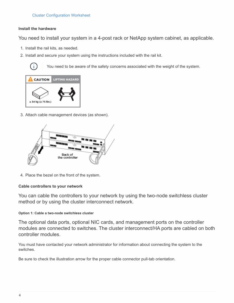
Install the hardware
You need to install your system in a 4-post rack or NetApp system cabinet, as applicable.
1. Install the rail kits, as needed.
2. Install and secure your system using the instructions included with the rail kit.
You need to be aware of the safety concerns associated with the weight of the system.
3. Attach cable management devices (as shown).
4. Place the bezel on the front of the system.
Cable controllers to your network
You can cable the controllers to your network by using the two-node switchless cluster
method or by using the cluster interconnect network.
Option 1: Cable a two-node switchless cluster
The optional data ports, optional NIC cards, and management ports on the controller
modules are connected to switches. The cluster interconnect/HA ports are cabled on both
controller modules.
You must have contacted your network administrator for information about connecting the system to the
switches.
Be sure to check the illustration arrow for the proper cable connector pull-tab orientation.
4

As you insert the connector, you should feel it click into place; if you do not feel it click, remove
it, turn it around and try again.
1. You can used the illustration or the step-by step instructions to complete the cabling between the
controllers and to the switches:
Step Perform on each controller module
Cable the cluster/HA ports to each other with the 100 GbE (QSFP28)
cable:
• e0a to e0a
• e0d to e0d
5

Step Perform on each controller module
If you are using your onboard ports for a data network connection,
connect the 100GbE or 40Gbe cables to the appropriate data network
switches:
• e0g and e0h
If you are using your NIC cards for Ethernet or FC connections,
connect the NIC card(s) to the appropriate switches:
6

Step Perform on each controller module
Cable the e0M ports to the management network switches with the
RJ45 cables.
DO NOT plug in the power cords at this point.
2. Cable your storage: Cabling controllers to drive shelves
Option 2: Cabling a switched cluster
The optional data ports, optional NIC cards, and management ports on the controller
modules are connected to switches. The cluster interconnect/HA ports are cabled on to
the cluster/HA switch.
You must have contacted your network administrator for information about connecting the system to the
switches.
Be sure to check the illustration arrow for the proper cable connector pull-tab orientation.
As you insert the connector, you should feel it click into place; if you do not feel it click, remove
it, turn it around and try again.
1. You can used the illustration or the step-by step instructions to complete the cabling between the
controllers and to the switches:
7

Step Perform on each controller module
Cable the cluster/HA ports to the cluster/HA switch with the 100 GbE
(QSFP28) cable:
• e0a on both controllers to the cluster/HA switch
• e0d on both controllers to the cluster/HA switch
8

Step Perform on each controller module
If you are using your onboard ports for a data network connection, connect the
100GbE or 40Gbe cables to the appropriate data network switches:
• e0g and e0h
If you are using your NIC cards for Ethernet or FC connections, connect the
NIC card(s) to the appropriate switches:
9

Step Perform on each controller module
Cable the e0M ports to the management network switches with the RJ45
cables.
DO NOT plug in the power cords at this point.
2. Cable your storage: Cabling controllers to drive shelves
Cable controllers to drive shelves
You must cable the controllers to your shelves using the onboard storage ports.
Option 1: Cable the controllers to a single drive shelf
You must cable each controller to the NSM modules on the NS224 drive shelf.
Be sure to check the illustration arrow for the proper cable connector pull-tab orientation.
As you insert the connector, you should feel it click into place; if you do not feel it click, remove
it, turn it around and try again.
1. You can use the illustration or the step-by-step instructions to cable your controllers to a single shelf.
10

Step Perform on each controller module
Cable controller A to the shelf
11
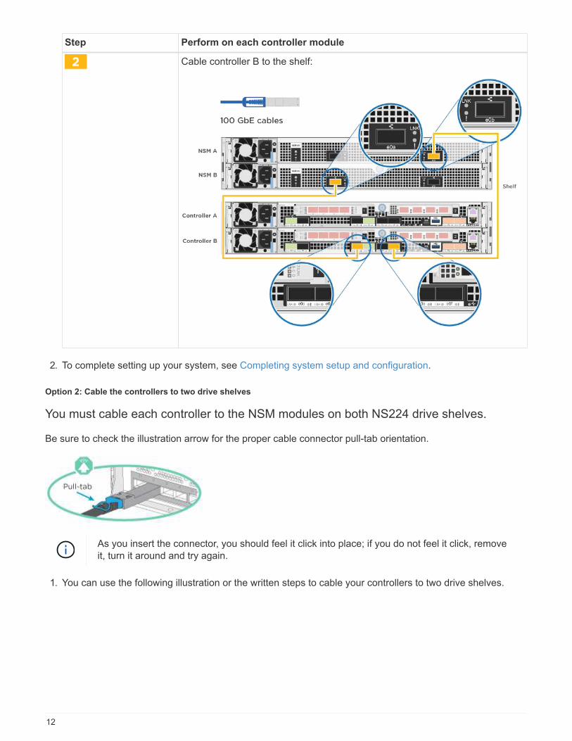
Step Perform on each controller module
Cable controller B to the shelf:
2. To complete setting up your system, see Completing system setup and configuration.
Option 2: Cable the controllers to two drive shelves
You must cable each controller to the NSM modules on both NS224 drive shelves.
Be sure to check the illustration arrow for the proper cable connector pull-tab orientation.
As you insert the connector, you should feel it click into place; if you do not feel it click, remove
it, turn it around and try again.
1. You can use the following illustration or the written steps to cable your controllers to two drive shelves.
12

Step Perform on each controller module
Cable controller A to the shelves:
13

Step Perform on each controller module
Cable controller B to the shelves:
2. To complete setting up your system, see Completing system setup and configuration.
Complete system setup and configuration
You can complete the system setup and configuration using cluster discovery with only a
connection to the switch and laptop, or by connecting directly to a controller in the system
and then connecting to the management switch.
Option 1: Completing system setup and configuration if network discovery is enabled
If you have network discovery enabled on your laptop, you can complete system setup
and configuration using automatic cluster discovery.
1. Plug the power cords into the controller power supplies, and then connect them to power sources on
different circuits.
The system begins to boot. Initial booting may take up to eight minutes
2. Make sure that your laptop has network discovery enabled.
See your laptop’s online help for more information.
3. Use the following animation to connect your laptop to the Management switch.
Connecting your laptop to the Management switch
4. Select an ONTAP icon listed to discover:
14
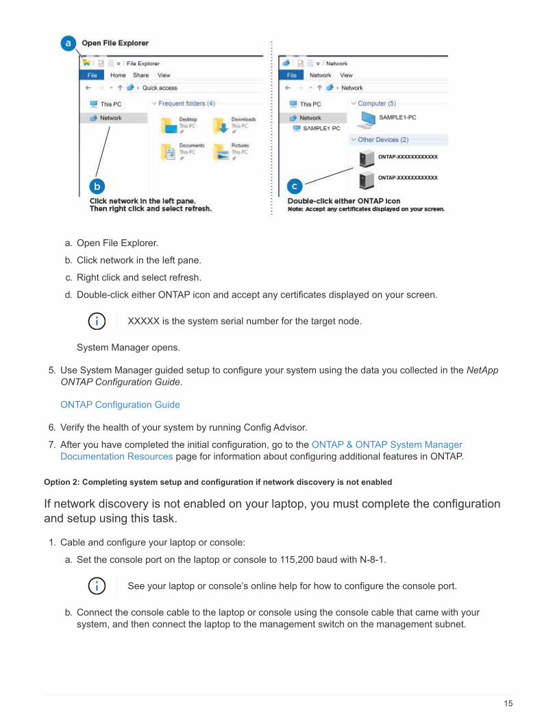
a. Open File Explorer.
b. Click network in the left pane.
c. Right click and select refresh.
d. Double-click either ONTAP icon and accept any certificates displayed on your screen.
XXXXX is the system serial number for the target node.
System Manager opens.
5. Use System Manager guided setup to configure your system using the data you collected in the NetApp
ONTAP Configuration Guide.
ONTAP Configuration Guide
6. Verify the health of your system by running Config Advisor.
7. After you have completed the initial configuration, go to the ONTAP & ONTAP System Manager
Documentation Resources page for information about configuring additional features in ONTAP.
Option 2: Completing system setup and configuration if network discovery is not enabled
If network discovery is not enabled on your laptop, you must complete the configuration
and setup using this task.
1. Cable and configure your laptop or console:
a. Set the console port on the laptop or console to 115,200 baud with N-8-1.
See your laptop or console’s online help for how to configure the console port.
b. Connect the console cable to the laptop or console using the console cable that came with your
system, and then connect the laptop to the management switch on the management subnet.
15

c. Assign a TCP/IP address to the laptop or console, using one that is on the management subnet.
2. Use the following animation to set one or more drive shelf IDs:
Setting drive shelf IDs
3. Plug the power cords into the controller power supplies, and then connect them to power sources on
different circuits.
The system begins to boot. Initial booting may take up to eight minutes
4. Assign an initial node management IP address to one of the nodes.
If the management
network has DHCP…
Then…
Configured Record the IP address assigned to the new controllers.
Not configured a. Open a console session using PuTTY, a terminal server, or the equivalent
for your environment.
Check your laptop or console’s online help if you do not
know how to configure PuTTY.
b. Enter the management IP address when prompted by the script.
5. Using System Manager on your laptop or console, configure your cluster:
a. Point your browser to the node management IP address.
The format for the address is https://x.x.x.x.
b. Configure the system using the data you collected in the NetApp ONTAP Configuration guide.
ONTAP Configuration Guide
6. Verify the health of your system by running Config Advisor.
16

7. After you have completed the initial configuration, go to the ONTAP & ONTAP System Manager
Documentation Resources page for information about configuring additional features in ONTAP.
Maintain
Boot media
Overview of boot media replacement - AFF A320
The boot media stores a primary and secondary set of system (boot image) files that the
system uses when it boots. Depending on your network configuration, you can perform
either a nondisruptive or disruptive replacement.
You must have a USB flash drive, formatted to FAT32, with the appropriate amount of storage to hold the
image_xxx.tgz file.
You also must copy the image_xxx.tgz file to the USB flash drive for later use in this procedure.
• The nondisruptive and disruptive methods for replacing a boot media both require you to restore the var
file system:
◦ For nondisruptive replacement, the HA pair must be connected to a network to restore the var file
system.
◦ For disruptive replacement, you do not need a network connection to restore the var file system, but
the process requires two reboots.
• You must replace the failed component with a replacement FRU component you received from your
provider.
• It is important that you apply the commands in these steps on the correct node:
◦ The impaired node is the node on which you are performing maintenance.
◦ The healthy node is the HA partner of the impaired node.
Check onboard encryption keys - AFF A320
Prior to shutting down the impaired controller and checking the status of the onboard
encryption keys, you must check the status of the impaired controller, disable automatic
giveback, and check the version of ONTAP that is running.
If you have a cluster with more than two nodes, it must be in quorum. If the cluster is not in quorum or a healthy
controller shows false for eligibility and health, you must correct the issue before shutting down the impaired
controller; see the NetApp Encryption overview with the CLI.
Steps
1. Check the status of the impaired controller:
◦ If the impaired controller is at the login prompt, log in as admin.
◦ If the impaired controller is at the LOADER prompt and is part of HA configuration, log in as admin on
the healthy controller.
◦ If the impaired controller is in a standalone configuration and at LOADER prompt, contact
mysupport.netapp.com.
17
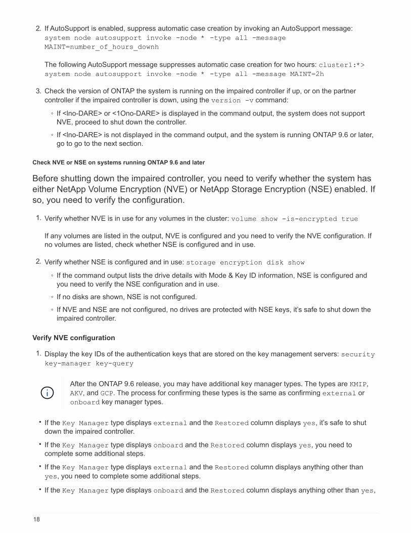
2. If AutoSupport is enabled, suppress automatic case creation by invoking an AutoSupport message:
system node autosupport invoke -node * -type all -message
MAINT=number_of_hours_downh
The following AutoSupport message suppresses automatic case creation for two hours: cluster1:*>
system node autosupport invoke -node * -type all -message MAINT=2h
3. Check the version of ONTAP the system is running on the impaired controller if up, or on the partner
controller if the impaired controller is down, using the version -v command:
◦ If <lno-DARE> or <1Ono-DARE> is displayed in the command output, the system does not support
NVE, proceed to shut down the controller.
◦ If <lno-DARE> is not displayed in the command output, and the system is running ONTAP 9.6 or later,
go to go to the next section.
Check NVE or NSE on systems running ONTAP 9.6 and later
Before shutting down the impaired controller, you need to verify whether the system has
either NetApp Volume Encryption (NVE) or NetApp Storage Encryption (NSE) enabled. If
so, you need to verify the configuration.
1. Verify whether NVE is in use for any volumes in the cluster: volume show -is-encrypted true
If any volumes are listed in the output, NVE is configured and you need to verify the NVE configuration. If
no volumes are listed, check whether NSE is configured and in use.
2. Verify whether NSE is configured and in use: storage encryption disk show
◦ If the command output lists the drive details with Mode & Key ID information, NSE is configured and
you need to verify the NSE configuration and in use.
◦ If no disks are shown, NSE is not configured.
◦ If NVE and NSE are not configured, no drives are protected with NSE keys, it’s safe to shut down the
impaired controller.
Verify NVE configuration
1. Display the key IDs of the authentication keys that are stored on the key management servers: security
key-manager key-query
After the ONTAP 9.6 release, you may have additional key manager types. The types are KMIP,
AKV, and GCP. The process for confirming these types is the same as confirming external or
onboard key manager types.
• If the Key Manager type displays external and the Restored column displays yes, it’s safe to shut
down the impaired controller.
• If the Key Manager type displays onboard and the Restored column displays yes, you need to
complete some additional steps.
• If the Key Manager type displays external and the Restored column displays anything other than
yes, you need to complete some additional steps.
• If the Key Manager type displays onboard and the Restored column displays anything other than yes,
18
you need to complete some additional steps.
1. If the Key Manager type displays onboard and the Restored column displays yes, manually back
up the OKM information:
a. Go to advanced privilege mode and enter y when prompted to continue: set -priv advanced
b. Enter the command to display the key management information: security key-manager
onboard show-backup
c. Copy the contents of the backup information to a separate file or your log file. You’ll need it in
disaster scenarios where you might need to manually recover OKM.
d. Return to admin mode: set -priv admin
e. Shut down the impaired controller.
2. If the Key Manager type displays external and the Restored column displays anything other than
yes:
a. Restore the external key management authentication keys to all nodes in the cluster: security
key-manager external restore
If the command fails, contact NetApp Support.
mysupport.netapp.com
b. Verify that the Restored column equals yes for all authentication keys: security key-
manager key-query
c. Shut down the impaired controller.
3. If the Key Manager type displays onboard and the Restored column displays anything other than
yes:
a. Enter the onboard security key-manager sync command: security key-manager onboard
sync
Enter the customer’s onboard key management passphrase at the prompt. If the
passphrase cannot be provided, contact NetApp Support. mysupport.netapp.com
b. Verify the Restored column shows yes for all authentication keys: security key-manager
key-query
c. Verify that the Key Manager type shows onboard, and then manually back up the OKM
information.
d. Go to advanced privilege mode and enter y when prompted to continue: set -priv advanced
e. Enter the command to display the key management backup information: security key-
manager onboard show-backup
f. Copy the contents of the backup information to a separate file or your log file. You’ll need it in
disaster scenarios where you might need to manually recover OKM.
g. Return to admin mode: set -priv admin
h. You can safely shut down the controller.
19

Verify NSE configuration
1. Display the key IDs of the authentication keys that are stored on the key management servers: security
key-manager key-query -key-type NSE-AK
After the ONTAP 9.6 release, you may have additional key manager types. The types are KMIP,
AKV, and GCP. The process for confirming these types is the same as confirming external or
onboard key manager types.
• If the Key Manager type displays external and the Restored column displays yes, it’s safe to shut
down the impaired controller.
• If the Key Manager type displays onboard and the Restored column displays yes, you need to
complete some additional steps.
• If the Key Manager type displays external and the Restored column displays anything other than
yes, you need to complete some additional steps.
• If the Key Manager type displays external and the Restored column displays anything other than
yes, you need to complete some additional steps.
1. If the Key Manager type displays onboard and the Restored column displays yes, manually back
up the OKM information:
a. Go to advanced privilege mode and enter y when prompted to continue: set -priv advanced
b. Enter the command to display the key management information: security key-manager
onboard show-backup
c. Copy the contents of the backup information to a separate file or your log file. You’ll need it in
disaster scenarios where you might need to manually recover OKM.
d. Return to admin mode: set -priv admin
e. You can safely shut down the controller.
2. If the Key Manager type displays external and the Restored column displays anything other than
yes:
a. Enter the onboard security key-manager sync command: security key-manager external
sync
If the command fails, contact NetApp Support.
mysupport.netapp.com
b. Verify that the Restored column equals yes for all authentication keys: security key-
manager key-query
c. You can safely shut down the controller.
3. If the Key Manager type displays onboard and the Restored column displays anything other than
yes:
a. Enter the onboard security key-manager sync command: security key-manager onboard
sync
Enter the customer’s onboard key management passphrase at the prompt. If the passphrase
cannot be provided, contact NetApp Support.
20
mysupport.netapp.com
b. Verify the Restored column shows yes for all authentication keys: security key-manager
key-query
c. Verify that the Key Manager type shows onboard, and then manually back up the OKM
information.
d. Go to advanced privilege mode and enter y when prompted to continue: set -priv advanced
e. Enter the command to display the key management backup information: security key-
manager onboard show-backup
f. Copy the contents of the backup information to a separate file or your log file. You’ll need it in
disaster scenarios where you might need to manually recover OKM.
g. Return to admin mode: set -priv admin
h. You can safely shut down the controller.
Shut down the node - AFF A320
After completing the NVE or NSE tasks, you need to complete the shutdown of the
impaired node. Shut down or take over the impaired controller using the appropriate
procedure for your configuration.
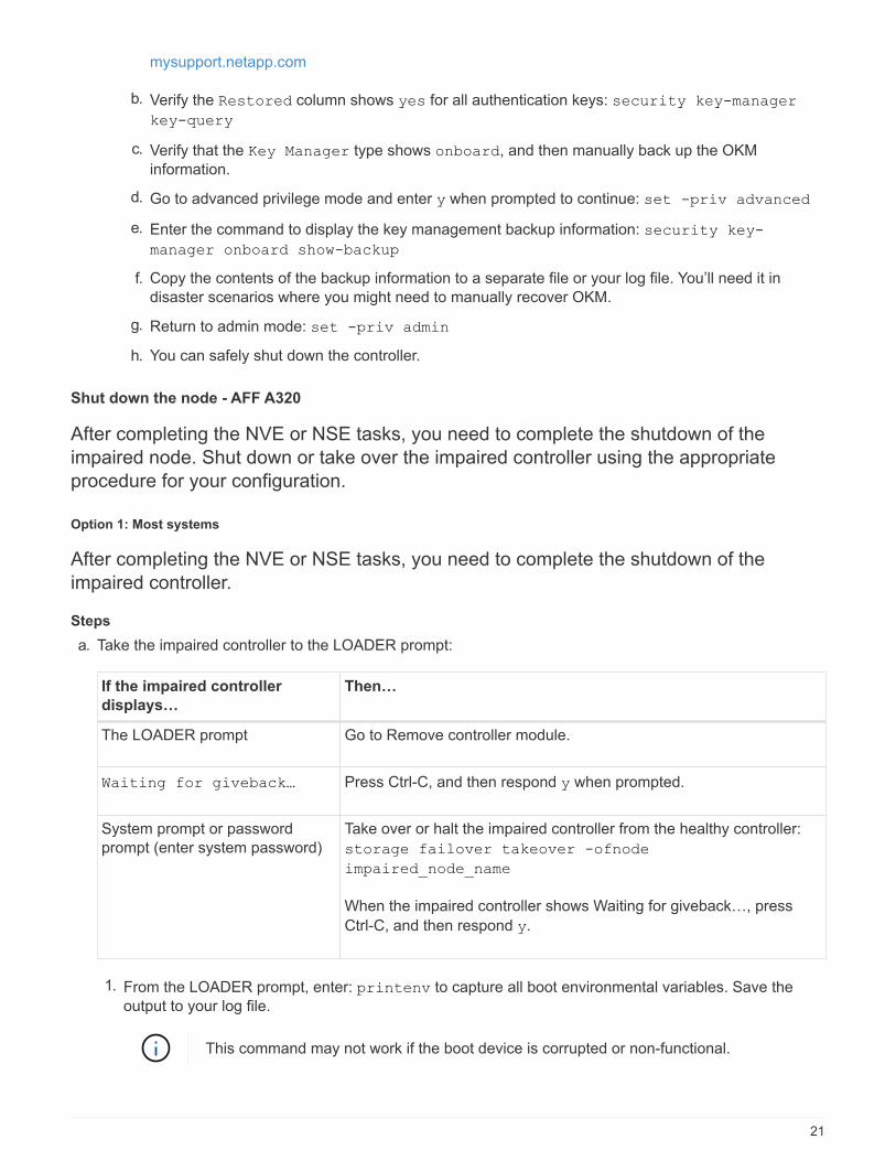
Option 1: Most systems
After completing the NVE or NSE tasks, you need to complete the shutdown of the
impaired controller.
Steps
a. Take the impaired controller to the LOADER prompt:
If the impaired controller
displays…
Then…
The LOADER prompt Go to Remove controller module.
Waiting for giveback… Press Ctrl-C, and then respond y when prompted.
System prompt or password
prompt (enter system password)
Take over or halt the impaired controller from the healthy controller:
storage failover takeover -ofnode
impaired_node_name
When the impaired controller shows Waiting for giveback…, press
Ctrl-C, and then respond y.
1. From the LOADER prompt, enter: printenv to capture all boot environmental variables. Save the
output to your log file.
This command may not work if the boot device is corrupted or non-functional.
21

Option 2: System is in a MetroCluster
Do not use this procedure if your system is in a two-node MetroCluster configuration.
To shut down the impaired controller, you must determine the status of the controller and, if necessary, take
over the controller so that the healthy controller continues to serve data from the impaired controller storage.
• If you have a cluster with more than two nodes, it must be in quorum. If the cluster is not in quorum or a
healthy controller shows false for eligibility and health, you must correct the issue before shutting down the
impaired controller; see the Administration overview with the CLI.
• If you have a MetroCluster configuration, you must have confirmed that the MetroCluster Configuration
State is configured and that the nodes are in an enabled and normal state (metrocluster node show).
Steps
1. If AutoSupport is enabled, suppress automatic case creation by invoking an AutoSupport message:
system node autosupport invoke -node * -type all -message
MAINT=number_of_hours_downh
The following AutoSupport message suppresses automatic case creation for two hours: cluster1:*>
system node autosupport invoke -node * -type all -message MAINT=2h
2. Disable automatic giveback from the console of the healthy controller: storage failover modify
–node local -auto-giveback false
3. Take the impaired controller to the LOADER prompt:
If the impaired controller is
displaying…
Then…
The LOADER prompt Go to Remove controller module.
Waiting for giveback… Press Ctrl-C, and then respond y when prompted.
System prompt or password
prompt (enter system password)
Take over or halt the impaired controller from the healthy controller:
storage failover takeover -ofnode
impaired_node_name
When the impaired controller shows Waiting for giveback…, press
Ctrl-C, and then respond y.
Replace the boot media - AFF A320
To replace the boot media, you must remove the impaired controller module, install the replacement boot
media, and transfer the boot image to a USB flash drive.
Step 1: Remove the controller module
To access components inside the controller module, you must remove the controller
module from the chassis.
1. If you are not already grounded, properly ground yourself.
22

2. Unplug the controller module power supply from the power source.
3. Loosen the hook and loop strap binding the cables to the cable management device, and then unplug the
system cables and SFPs (if needed) from the controller module, keeping track of where the cables were
connected.
Leave the cables in the cable management device so that when you reinstall the cable management
device, the cables are organized.
4. Remove and set aside the cable management devices from the left and right sides of the controller module.
5. Remove the controller module from the chassis:
a. Insert your forefinger into the latching mechanism on either side of the controller module.
b. Press down on the orange tab on top of the latching mechanism until it clears the latching pin on the
chassis.
The latching mechanism hook should be nearly vertical and should be clear of the chassis pin.
c. Gently pull the controller module a few inches toward you so that you can grasp the controller module
sides.
d. Using both hands, gently pull the controller module out of the chassis and set it on a flat, stable
surface.
Step 2: Replace the boot media
You must locate the boot media in the controller module, and then follow the directions to
replace it.
1. Open the air duct and locate the boot media using the following illustration or the FRU map on the
23

controller module:
2. Locate and remove the boot media from the controller module:
a. Press the blue button at the end of the boot media until the lip on the boot media clears the blue button.
b. Rotate the boot media up and gently pull the boot media out of the socket.
1. Check the boot media to make sure that it is seated squarely and completely in the socket.
If necessary, remove the boot media and reseat it into the socket.
3. Lock the boot media in place:
a. Rotate the boot media down toward the motherboard.
b. Placing a finger at the end of the boot media by the blue button, push down on the boot media end to
engage the blue locking button.
c. While pushing down on the boot media, lift the blue locking button to lock the boot media in place.
4. Close the air duct.
Step 3: Transfer the boot image to the boot media using a USB flash drive
The replacement boot media that you installed does not have a boot image, so you need
to transfer a boot image using a USB flash drive.
• You must have a USB flash drive, formatted to MBR/FAT32, with at least 4GB capacity
• A copy of the same image version of ONTAP as what the impaired controller was running. You can
download the appropriate image from the Downloads section on the NetApp Support Site
◦ If NVE is enabled, download the image with NetApp Volume Encryption, as indicated in the download
button.
◦ If NVE is not enabled, download the image without NetApp Volume Encryption, as indicated in the
24

download button.
• If your system is an HA pair, you must have a network connection.
• If your system is a stand-alone system you do not need a network connection, but you must perform an
additional reboot when restoring the var file system.
1. Download and copy the appropriate service image from the NetApp Support Site to the USB flash
drive.
a. Download the service image to your work space on your laptop.
b. Unzip the service image.
If you are extracting the contents using Windows, do not use winzip to extract the
netboot image. Use another extraction tool, such as 7-Zip or WinRAR.
There are two folders in the unzipped service image file:
▪ boot
▪ efi
c. Copy the efi folder to the top directory on the USB flash drive.
The USB flash drive should have the efi folder and the same Service Image (BIOS) version of what
the impaired controller is running.
d. Remove the USB flash drive from your laptop.
2. If you have not already done so, close the air duct.
3. Align the end of the controller module with the opening in the chassis, and then gently push the
controller module halfway into the system.
4. Reinstall the cable management device and recable the system, as needed.
When recabling, remember to reinstall the media converters (SFPs or QSFPs) if they were removed.
5. Plug the power cable into the power supply and reinstall the power cable retainer.
6. Insert the USB flash drive into the USB slot on the controller module.
Make sure that you install the USB flash drive in the slot labeled for USB devices, and not in the USB
console port.
7. Complete the reinstallation of the controller module:
a. Make sure the latch arms are locked in the extended position.
b. Using the latch arms, push the controller module into the chassis bay until it stops.
Do not push down on the latching mechanism at the top of the latch arms. Doing so
with raise the locking mechanism and prohibit sliding the controller module into the
chassis.
c. Press down and hold the orange tabs on top of the latching mechanism.
d. Gently push the controller module into the chassis bay until it is flush with the edges of the chassis.
The latching mechanism arms slide into the chassis.
25

The controller module begins to boot as soon as it is fully seated in the chassis.
e. Release the latches to lock the controller module into place.
f. If you have not already done so, reinstall the cable management device.
8. Interrupt the boot process by pressing Ctrl-C to stop at the LOADER prompt.
If you miss this message, press Ctrl-C, select the option to boot to Maintenance mode, and then halt
the node to boot to LOADER.
9. From the LOADER prompt, boot the recovery image from the USB flash drive: boot_recovery
The image is downloaded from the USB flash drive.
10. When prompted, either enter the name of the image or accept the default image displayed inside the
brackets on your screen.
11. After the image is installed, start the restoration process:
a. Record the IP address of the impaired node that is displayed on the screen.
b. Press y when prompted to restore the backup configuration.
c. Press y when prompted to overwrite /etc/ssh/ssh_host_dsa_key.
12. From the partner node in advanced privilege level, start the configuration synchronization using the IP
address recorded in the previous step: system node restore-backup -node local -target
-address impaired_node_IP_address
13. If the restore is successful, press y on the impaired node when prompted to use the restored copy?.
14. Press y when you see confirm backup procedure was successful, and then press y when prompted to
reboot the node.
15. Verify that the environmental variables are set as expected.
a. Take the node to the LOADER prompt.
From the ONTAP prompt, you can issue the command system node halt -skip-lif-migration-before
-shutdown true -ignore-quorum-warnings true -inhibit-takeover true.
b. Check the environment variable settings with the printenv command.
c. If an environment variable is not set as expected, modify it with the setenv environment-
variable-name changed-value command.
d. Save your changes using the savenv command.
e. Reboot the node.
16. With the rebooted impaired node displaying the Waiting for giveback… message, perform a
giveback from the healthy node:
26

If your system is in… Then…
An HA pair After the impaired node is displaying the Waiting for
giveback… message, perform a giveback from the healthy node:
a. From the healthy node: storage failover giveback
-ofnode partner_node_name
The impaired node takes back its storage, finishes booting, and
then reboots and is again taken over by the healthy node.
If the giveback is vetoed, you can consider
overriding the vetoes.
ONTAP 9 High-Availability Configuration Guide
b. Monitor the progress of the giveback operation by using the
storage failover show-giveback command.
c. After the giveback operation is complete, confirm that the HA
pair is healthy and that takeover is possible by using the
storage failover show command.
d. Restore automatic giveback if you disabled it using the storage
failover modify command.
17. Exit advanced privilege level on the healthy node.
Boot the recovery image - AFF A320
You must boot the ONTAP image from the USB drive, restore the file system, and verify
the environmental variables.
1. From the LOADER prompt, boot the recovery image from the USB flash drive: boot_recovery
The image is downloaded from the USB flash drive.
2. When prompted, either enter the name of the image or accept the default image displayed inside the
brackets on your screen.
3. Restore the var file system:
27
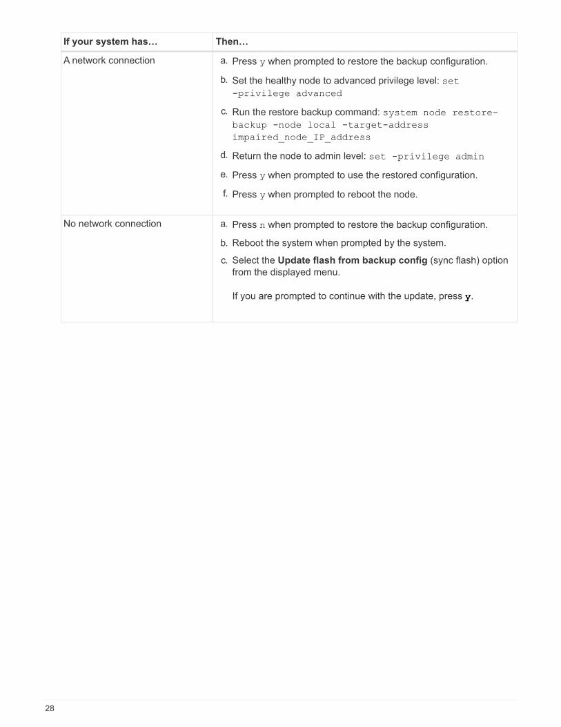
If your system has… Then…
A network connection a. Press y when prompted to restore the backup configuration.
b. Set the healthy node to advanced privilege level: set
-privilege advanced
c. Run the restore backup command: system node restore-
backup -node local -target-address
impaired_node_IP_address
d. Return the node to admin level: set -privilege admin
e. Press y when prompted to use the restored configuration.
f. Press y when prompted to reboot the node.
No network connection a. Press n when prompted to restore the backup configuration.
b. Reboot the system when prompted by the system.
c. Select the Update flash from backup config (sync flash) option
from the displayed menu.
If you are prompted to continue with the update, press y.
28

If your system has… Then…
No network connection and is in a
MetroCluster IP configuration
a. Press n when prompted to restore the backup configuration.
b. Reboot the system when prompted by the system.
c. Wait for the iSCSI storage connections to connect.
You can proceed after you see the following messages:
date-and-time [node-
name:iscsi.session.stateChanged:notice]:
iSCSI session state is changed to Connected
for the target iSCSI-target (type:
dr_auxiliary, address: ip-address).
date-and-time [node-
name:iscsi.session.stateChanged:notice]:
iSCSI session state is changed to Connected
for the target iSCSI-target (type:
dr_partner, address: ip-address).
date-and-time [node-
name:iscsi.session.stateChanged:notice]:
iSCSI session state is changed to Connected
for the target iSCSI-target (type:
dr_auxiliary, address: ip-address).
date-and-time [node-
name:iscsi.session.stateChanged:notice]:
iSCSI session state is changed to Connected
for the target iSCSI-target (type:
dr_partner, address: ip-address).
d. Select the Update flash from backup config (sync flash) option
from the displayed menu.
If you are prompted to continue with the update, press y.
4. Ensure that the environmental variables are set as expected:
a. Take the node to the LOADER prompt.
b. Check the environment variable settings with the printenv command.
c. If an environment variable is not set as expected, modify it with the setenv
environment_variable_name changed_value command.
d. Save your changes using the savenv command.
5. The next depends on your system configuration:
◦ If your system has onboard keymanager, NSE or NVE configured, go to Post boot media replacement
steps for OKM, NSE, and NVE
29
◦ If your system does not have onboard keymanager, NSE or NVE configured, complete the steps in this
section.
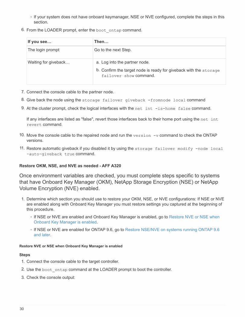
6. From the LOADER prompt, enter the boot_ontap command.
If you see… Then…
The login prompt Go to the next Step.
Waiting for giveback… a. Log into the partner node.
b. Confirm the target node is ready for giveback with the storage
failover show command.
7. Connect the console cable to the partner node.
8. Give back the node using the storage failover giveback -fromnode local command
9. At the cluster prompt, check the logical interfaces with the net int -is-home false command.
If any interfaces are listed as "false", revert those interfaces back to their home port using the net int
revert command.
10. Move the console cable to the repaired node and run the version -v command to check the ONTAP
versions.
11. Restore automatic giveback if you disabled it by using the storage failover modify -node local
-auto-giveback true command.
Restore OKM, NSE, and NVE as needed - AFF A320
Once environment variables are checked, you must complete steps specific to systems
that have Onboard Key Manager (OKM), NetApp Storage Encryption (NSE) or NetApp
Volume Encryption (NVE) enabled.
1. Determine which section you should use to restore your OKM, NSE, or NVE configurations: If NSE or NVE
are enabled along with Onboard Key Manager you must restore settings you captured at the beginning of
this procedure.
◦ If NSE or NVE are enabled and Onboard Key Manager is enabled, go to Restore NVE or NSE when
Onboard Key Manager is enabled.
◦ If NSE or NVE are enabled for ONTAP 9.6, go to Restore NSE/NVE on systems running ONTAP 9.6
and later.
Restore NVE or NSE when Onboard Key Manager is enabled
Steps
1. Connect the console cable to the target controller.
2. Use the boot_ontap command at the LOADER prompt to boot the controller.
3. Check the console output:
30
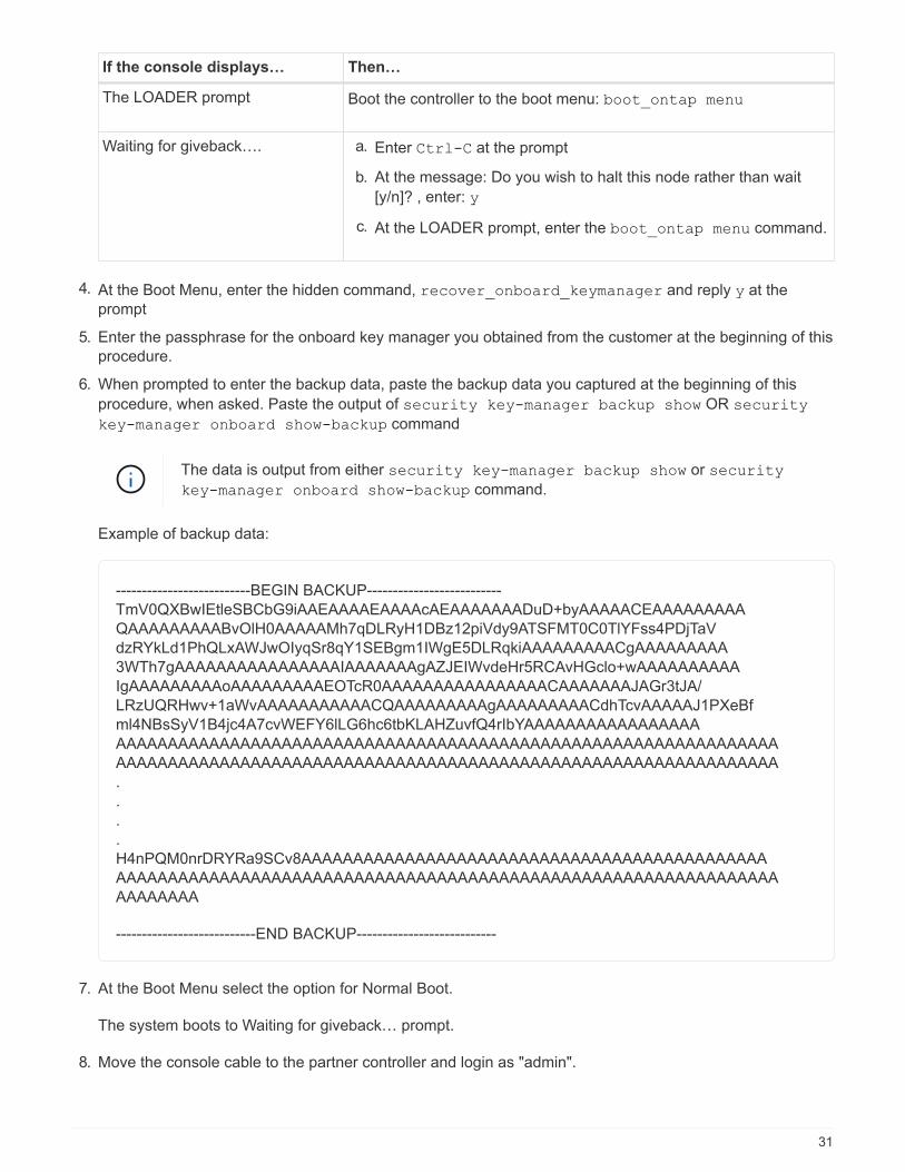
If the console displays… Then…
The LOADER prompt Boot the controller to the boot menu: boot_ontap menu
Waiting for giveback…. a. Enter Ctrl-C at the prompt
b. At the message: Do you wish to halt this node rather than wait
[y/n]? , enter: y
c. At the LOADER prompt, enter the boot_ontap menu command.
4. At the Boot Menu, enter the hidden command, recover_onboard_keymanager and reply y at the
prompt
5. Enter the passphrase for the onboard key manager you obtained from the customer at the beginning of this
procedure.
6. When prompted to enter the backup data, paste the backup data you captured at the beginning of this
procedure, when asked. Paste the output of security key-manager backup show OR security
key-manager onboard show-backup command
The data is output from either security key-manager backup show or security
key-manager onboard show-backup command.
Example of backup data:
--------------------------BEGIN BACKUP--------------------------
TmV0QXBwIEtleSBCbG9iAAEAAAAEAAAAcAEAAAAAAADuD+byAAAAACEAAAAAAAAA
QAAAAAAAAABvOlH0AAAAAMh7qDLRyH1DBz12piVdy9ATSFMT0C0TlYFss4PDjTaV
dzRYkLd1PhQLxAWJwOIyqSr8qY1SEBgm1IWgE5DLRqkiAAAAAAAAACgAAAAAAAAA
3WTh7gAAAAAAAAAAAAAAAAIAAAAAAAgAZJEIWvdeHr5RCAvHGclo+wAAAAAAAAAA
IgAAAAAAAAAoAAAAAAAAAEOTcR0AAAAAAAAAAAAAAAACAAAAAAAJAGr3tJA/
LRzUQRHwv+1aWvAAAAAAAAAAACQAAAAAAAAAgAAAAAAAAACdhTcvAAAAAJ1PXeBf
ml4NBsSyV1B4jc4A7cvWEFY6lLG6hc6tbKLAHZuvfQ4rIbYAAAAAAAAAAAAAAAAA
AAAAAAAAAAAAAAAAAAAAAAAAAAAAAAAAAAAAAAAAAAAAAAAAAAAAAAAAAAAAAAAA
AAAAAAAAAAAAAAAAAAAAAAAAAAAAAAAAAAAAAAAAAAAAAAAAAAAAAAAAAAAAAAAA
.
.
.
.
H4nPQM0nrDRYRa9SCv8AAAAAAAAAAAAAAAAAAAAAAAAAAAAAAAAAAAAAAAAAAAAA
AAAAAAAAAAAAAAAAAAAAAAAAAAAAAAAAAAAAAAAAAAAAAAAAAAAAAAAAAAAAAAAA
AAAAAAAA
---------------------------END BACKUP---------------------------
7. At the Boot Menu select the option for Normal Boot.
The system boots to Waiting for giveback… prompt.
8. Move the console cable to the partner controller and login as "admin".
31

9. Confirm the target controller is ready for giveback with the storage failover show command.
10. Giveback only the CFO aggregates with the storage failover giveback -fromnode local
-only-cfo-aggregates true command.
◦ If the command fails because of a failed disk, physically disengage the failed disk, but leave the disk in
the slot until a replacement is received.
◦ If the command fails because of an open CIFS sessions, check with customer how to close out CIFS
sessions.
Terminating CIFS can cause loss of data.
◦ If the command fails because the partner "not ready", wait 5 minutes for the NVMEMs to synchronize.
◦ If the command fails because of an NDMP, SnapMirror, or SnapVault process, disable the process. See
the appropriate Documentation Center for more information.
11. Once the giveback completes, check the failover and giveback status with the storage failover show
and `storage failover show-giveback` commands.
Only the CFO aggregates (root aggregate and CFO style data aggregates) will be shown.
12. Move the console cable to the target controller.
a. If you are running ONTAP 9.6 or later, run the security key-manager onboard sync:
b. Run the security key-manager onboard sync command and then enter the passphrase when
prompted.
c. Enter the security key-manager key query command to see a detailed view of all keys stored
in the onboard key manager and verify that the Restored column = yes/true for all authentication
keys.
If the Restored column = anything other than yes/true, contact Customer Support.
d. Wait 10 minutes for the key to synchronize across the cluster.
13. Move the console cable to the partner controller.
14. Give back the target controller using the storage failover giveback -fromnode local
command.
15. Check the giveback status, 3 minutes after it reports complete, using the storage failover show
command.
If giveback is not complete after 20 minutes, contact Customer Support.
16. At the clustershell prompt, enter the net int show -is-home false command to list the logical
interfaces that are not on their home controller and port.
If any interfaces are listed as false, revert those interfaces back to their home port using the net int
revert command.
17. Move the console cable to the target controller and run the version -v command to check the ONTAP
versions.
18. Restore automatic giveback if you disabled it by using the storage failover modify -node local
-auto-giveback true command.
32

Restore NSE/NVE on systems running ONTAP 9.6 and later
Steps
1. Connect the console cable to the target controller.
2. Use the boot_ontap command at the LOADER prompt to boot the controller.
3. Check the console output:
If the console displays… Then…
The login prompt Go to Step 7.
Waiting for giveback… a. Log into the partner controller.
b. Confirm the target controller is ready for
giveback with the storage failover show
command.
4. Move the console cable to the partner controller and give back the target controller storage using the
storage failover giveback -fromnode local -only-cfo-aggregates true local
command.
◦ If the command fails because of a failed disk, physically disengage the failed disk, but leave the disk in
the slot until a replacement is received.
◦ If the command fails because of an open CIFS sessions, check with customer how to close out CIFS
sessions.
Terminating CIFS can cause loss of data.
◦ If the command fails because the partner "not ready", wait 5 minutes for the NVMEMs to synchronize.
◦ If the command fails because of an NDMP, SnapMirror, or SnapVault process, disable the process. See
the appropriate Documentation Center for more information.
5. Wait 3 minutes and check the failover status with the storage failover show command.
6. At the clustershell prompt, enter the net int show -is-home false command to list the logical
interfaces that are not on their home controller and port.
If any interfaces are listed as false, revert those interfaces back to their home port using the net int
revert command.
7. Move the console cable to the target controller and run the version -v command to check the ONTAP
versions.
8. Restore automatic giveback if you disabled it by using the storage failover modify -node local
-auto-giveback true command.
9. Use the storage encryption disk show at the clustershell prompt, to review the output.
10. Use the security key-manager key query command to display the key IDs of the authentication
keys that are stored on the key management servers.
◦ If the Restored column = yes/true, you are done and can proceed to complete the replacement
process.
33

◦ If the Key Manager type = external and the Restored column = anything other than yes/true,
use the security key-manager external restore command to restore the key IDs of the
authentication keys.
If the command fails, contact Customer Support.
◦ If the Key Manager type = onboard and the Restored column = anything other than yes/true,
use the security key-manager onboard sync command to re-sync the Key Manager type.
Use the security key-manager key query command to verify that the Restored column =
yes/true for all authentication keys.
11. Connect the console cable to the partner controller.
12. Give back the controller using the storage failover giveback -fromnode local command.
13. Restore automatic giveback if you disabled it by using the storage failover modify -node local
-auto-giveback true command.
Return the failed part to NetApp - AFF A320
After you replace the part, you can return the failed part to NetApp, as described in the
RMA instructions shipped with the kit. Contact technical support at NetApp Support, 888-
463-8277 (North America), 00-800-44-638277 (Europe), or +800-800-80-800
(Asia/Pacific) if you need the RMA number or additional help with the replacement
procedure.
Chassis
Overview of chassis replacement - AFF A320
To replace the chassis, you must move the fans and controller modules from the impaired
chassis to the new chassis of the same model as the impaired chassis.
All other components in the system must be functioning properly; if not, you must contact technical support.
• You can use this procedure with all versions of ONTAP supported by your system.
• This procedure is written with the assumption that you are moving the controller modules to the new
chassis, and that the chassis is a new component from NetApp.
• This procedure is disruptive. For a two-node cluster, you will have a complete service outage and a partial
outage in a multi-node cluster.
Shut down the controllers - AFF A320
You must shut down the controller or controller in the chassis prior to moving them to the
new chassis.
About this task
• If you have a cluster with more than two controllers, it must be in quorum. If the cluster is not in quorum or
a healthy controller shows false for eligibility and health, you must correct the issue before shutting down
the impaired controller; see the Administration overview with the CLI.
34

• If AutoSupport is enabled, suppress automatic case creation by invoking an AutoSupport message:
system node autosupport invoke -node * -type all -message
MAINT=number_of_hours_downh
The following AutoSupport message suppresses automatic case creation for two hours: cluster1:*>
system node autosupport invoke -node * -type all -message MAINT=2h
Steps
1. If your system has two controller modules, disable the HA pair.
If your system is running
clustered ONTAP with…
Then…
Two controllers in the cluster cluster ha modify -configured false storage failover
modify -node node0 -enabled false
More than two controllers in the
clusterstorage failover modify -node node0 -enabled false
2. Halt the controller, pressing y when you are prompted to confirm the halt: system node halt -node
node_name
The confirmation message looks like the following:
Warning: This operation will cause controller "node-name" to be marked
as unhealthy. Unhealthy nodes do not participate in quorum voting. If
the controller goes out of service and one more controller goes out of
service there will be a data serving failure for the entire cluster.
This will cause a client disruption. Use "cluster show" to verify
cluster state. If possible bring other nodes online to improve the
resiliency of this cluster.
Do you want to continue? {y|n}:
You must perform a clean system shutdown before replacing the chassis to avoid losing
unwritten data in the nonvolatile memory (NVMEM/NVRAM). Depending on your system, if
the NVMEM/NVRAM LED is flashing, there is content in the NVMEM/NVRAM that has not
been saved to disk. You need to reboot the controller and start from the beginning of this
procedure. If repeated attempts to cleanly shut down the controller fail, be aware that you
might lose any data that was not saved to disk.
3. Where applicable, halt the second controller to avoid a possible quorum error message in an HA pair
configuration: system node halt -node second_node_name -ignore-quorum-warnings true
-skip-lif-migration-before-shutdown true
Answer y when prompted.
35

Replace hardware - AFF A320
Move the fans, hard drives, and controller module or modules from the impaired chassis
to the new chassis, and swap out the impaired chassis from the equipment rack or
system cabinet with the new chassis of the same model as the impaired chassis.
Step 1: Remove the controller modules
To replace the chassis, you must remove the controller modules from the old chassis.
1. If you are not already grounded, properly ground yourself.
2. Release the power cable retainers, and then unplug the cables from the power supplies.
3. Loosen the hook and loop strap binding the cables to the cable management device, and then unplug the
system cables and SFPs (if needed) from the controller module, keeping track of where the cables were
connected.
Leave the cables in the cable management device so that when you reinstall the cable management
device, the cables are organized.
4. Remove and set aside the cable management devices from the left and right sides of the controller module.
5. Remove the controller module from the chassis:
a. Insert your forefinger into the latching mechanism on either side of the controller module.
b. Press down on the orange tab on top of the latching mechanism until it clears the latching pin on the
chassis.
The latching mechanism hook should be nearly vertical and should be clear of the chassis pin.
c. Gently pull the controller module a few inches toward you so that you can grasp the controller module
sides.
d. Using both hands, gently pull the controller module out of the chassis and set it on a flat, stable
surface.
6. Repeat these steps for the other controller module in the chassis.
Step 2: Move the fans
To move the fan modules to the replacement chassis when replacing the chassis, you must perform a specific
sequence of tasks.
1. If you are not already grounded, properly ground yourself.
2. Remove the bezel (if necessary) with two hands, by grasping the openings on each side of the bezel, and
then pulling it toward you until the bezel releases from the ball studs on the chassis frame.
3. Press down the release latch on the fan module cam handle, and then rotate the cam handle downward.
The fan module moves a little bit away from the chassis.
4. Pull the fan module straight out from the chassis, making sure that you support it with your free hand so
that it does not swing out of the chassis.
The fan modules are short. Always support the bottom of the fan module with your free hand
so that it does not suddenly drop free from the chassis and injure you.
36
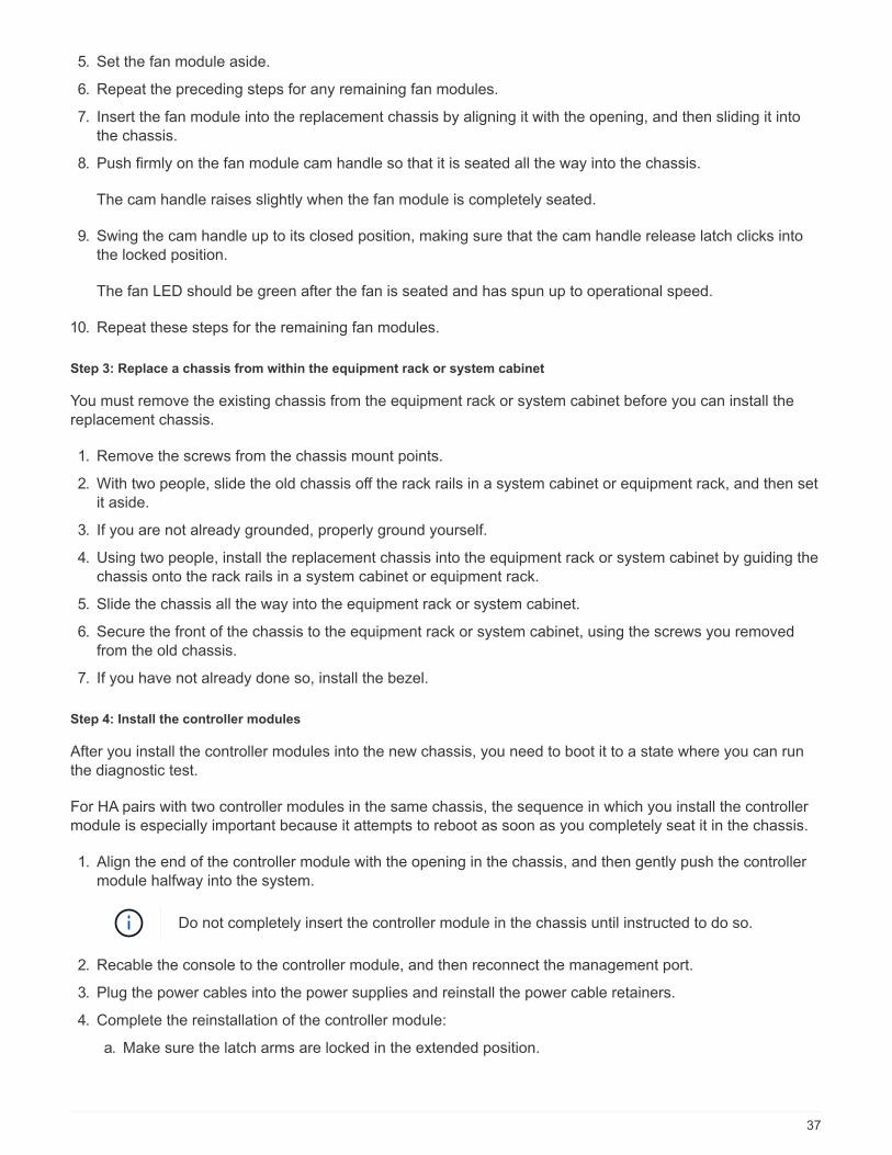
5. Set the fan module aside.
6. Repeat the preceding steps for any remaining fan modules.
7. Insert the fan module into the replacement chassis by aligning it with the opening, and then sliding it into
the chassis.
8. Push firmly on the fan module cam handle so that it is seated all the way into the chassis.
The cam handle raises slightly when the fan module is completely seated.
9. Swing the cam handle up to its closed position, making sure that the cam handle release latch clicks into
the locked position.
The fan LED should be green after the fan is seated and has spun up to operational speed.
10. Repeat these steps for the remaining fan modules.
Step 3: Replace a chassis from within the equipment rack or system cabinet
You must remove the existing chassis from the equipment rack or system cabinet before you can install the
replacement chassis.
1. Remove the screws from the chassis mount points.
2. With two people, slide the old chassis off the rack rails in a system cabinet or equipment rack, and then set
it aside.
3. If you are not already grounded, properly ground yourself.
4. Using two people, install the replacement chassis into the equipment rack or system cabinet by guiding the
chassis onto the rack rails in a system cabinet or equipment rack.
5. Slide the chassis all the way into the equipment rack or system cabinet.
6. Secure the front of the chassis to the equipment rack or system cabinet, using the screws you removed
from the old chassis.
7. If you have not already done so, install the bezel.
Step 4: Install the controller modules
After you install the controller modules into the new chassis, you need to boot it to a state where you can run
the diagnostic test.
For HA pairs with two controller modules in the same chassis, the sequence in which you install the controller
module is especially important because it attempts to reboot as soon as you completely seat it in the chassis.
1. Align the end of the controller module with the opening in the chassis, and then gently push the controller
module halfway into the system.
Do not completely insert the controller module in the chassis until instructed to do so.
2. Recable the console to the controller module, and then reconnect the management port.
3. Plug the power cables into the power supplies and reinstall the power cable retainers.
4. Complete the reinstallation of the controller module:
a. Make sure the latch arms are locked in the extended position.
37

b. Using the latch arms, push the controller module into the chassis bay until it stops.
c. Press down and hold the orange tabs on top of the latching mechanism.
d. Gently push the controller module into the chassis bay until it is flush with the edges of the chassis.
The latching mechanism arms slide into the chassis.
The controller module begins to boot as soon as it is fully seated in the chassis.
e. Release the latches to lock the controller module into place.
f. Recable the power supply.
g. If you have not already done so, reinstall the cable management device.
h. Interrupt the normal boot process by pressing Ctrl-C.
5. Repeat the preceding steps to install the second controller into the new chassis.
Complete the restoration and replacement process - AFF A320
You must verify the HA state of the chassis, run diagnostics, and return the failed part to
NetApp, as described in the RMA instructions shipped with the kit.
Step 1: Verify and set the HA state of the chassis
You must verify the HA state of the chassis, and, if necessary, update the state to match your system
configuration.
1. In Maintenance mode, from either controller module, display the HA state of the local controller module and
chassis: ha-config show
The HA state should be the same for all components.
2. If the displayed system state for the chassis does not match your system configuration:
a. Set the HA state for the chassis: ha-config modify chassis HA-state
The value for HA-state can be one of the following:
▪ ha
▪ mcc
▪ mccip
▪ non-ha
b. Confirm that the setting has changed: ha-config show
3. If you have not already done so, recable the rest of your system.
4. Reinstall the bezel on the front of the system.
Step 2: Run diagnostics
After you have replaced a component in your system, you should run diagnostic tests on that component.
Your system must be at the LOADER prompt to start diagnostics.
38

All commands in the diagnostic procedures are issued from the node where the component is being replaced.
1. If the node to be serviced is not at the LOADER prompt, reboot the node: system node halt -node
node_name
After you issue the command, you should wait until the system stops at the LOADER prompt.
2. At the LOADER prompt, access the special drivers specifically designed for system-level diagnostics to
function properly: boot_diags
3. Select Scan System from the displayed menu to enable running the diagnostics tests.
4. Select Test system from the displayed menu to run diagnostics tests.
5. Select the test or series of tests from the various sub-menus.
6. Proceed based on the result of the preceding step:
◦ If the test failed, correct the failure, and then rerun the test.
◦ If the test reported no failures, select Reboot from the menu to reboot the system.
Step 3: Return the failed part to NetApp
After you replace the part, you can return the failed part to NetApp, as described in the RMA instructions
shipped with the kit. Contact technical support at NetApp Support, 888-463-8277 (North America), 00-800-44-
638277 (Europe), or +800-800-80-800 (Asia/Pacific) if you need the RMA number or additional help with the
replacement procedure.
Controller module
Overview of controller module replacement - AFF A320
You must review the prerequisites for the replacement procedure and select the correct
one for your version of the ONTAP operating system.
• All drive shelves must be working properly.
• The healthy controller must be able to take over the controller that is being replaced (referred to in this
procedure as the “impaired controller”).
• If your system is in a MetroCluster configuration, you must review the section Choosing the correct
recovery procedure to determine whether you should use this procedure.
If this is the procedure you should use, note that the controller replacement procedure for a controller in a
four or eight node MetroCluster configuration is the same as that in an HA pair. No MetroCluster-specific
steps are required because the failure is restricted to an HA pair and storage failover commands can be
used to provide nondisruptive operation during the replacement.
• You must replace the failed component with a replacement FRU component you received from your
provider.
• You must be replacing a controller module with a controller module of the same model type. You cannot
upgrade your system by just replacing the controller module.
• You cannot change any drives or drive shelves as part of this procedure.
• In this procedure, the boot device is moved from the impaired controller to the replacement controller so
that the replacement controller will boot up in the same version of ONTAP as the old controller module.
39

• It is important that you apply the commands in these steps on the correct systems:
◦ The impaired controller is the controller that is being replaced.
◦ The replacement controller is the new controller that is replacing the impaired controller.
◦ The healthy controller is the surviving controller.
• You must always capture the controller’s console output to a text file.
This provides you a record of the procedure so that you can troubleshoot any issues that you might
encounter during the replacement process.
Shut down the impaired controller - AFF A320
Shut down or take over the impaired controller using the appropriate procedure for your
configuration.
Option 1: Most configurations
To shut down the impaired controller, you must determine the status of the controller and, if necessary, take
over the controller so that the healthy controller continues to serve data from the impaired controller storage.
About this task
If you have a cluster with more than two nodes, it must be in quorum. If the cluster is not in quorum or a healthy
controller shows false for eligibility and health, you must correct the issue before shutting down the impaired
controller; see the Administration overview with the CLI.
Steps
1. If AutoSupport is enabled, suppress automatic case creation by invoking an AutoSupport message:
system node autosupport invoke -node * -type all -message
MAINT=number_of_hours_downh
The following AutoSupport message suppresses automatic case creation for two hours: cluster1:*>
system node autosupport invoke -node * -type all -message MAINT=2h
2. Disable automatic giveback from the console of the healthy controller: storage failover modify
–node local -auto-giveback false
3. Take the impaired controller to the LOADER prompt:
If the impaired controller is
displaying…
Then…
The LOADER prompt Go to Remove controller module.
Waiting for giveback… Press Ctrl-C, and then respond y when prompted.
40
If the impaired controller is
displaying…
Then…
System prompt or password
prompt (enter system password)
Take over or halt the impaired controller from the healthy controller:
storage failover takeover -ofnode
impaired_node_name
When the impaired controller shows Waiting for giveback…, press
Ctrl-C, and then respond y.
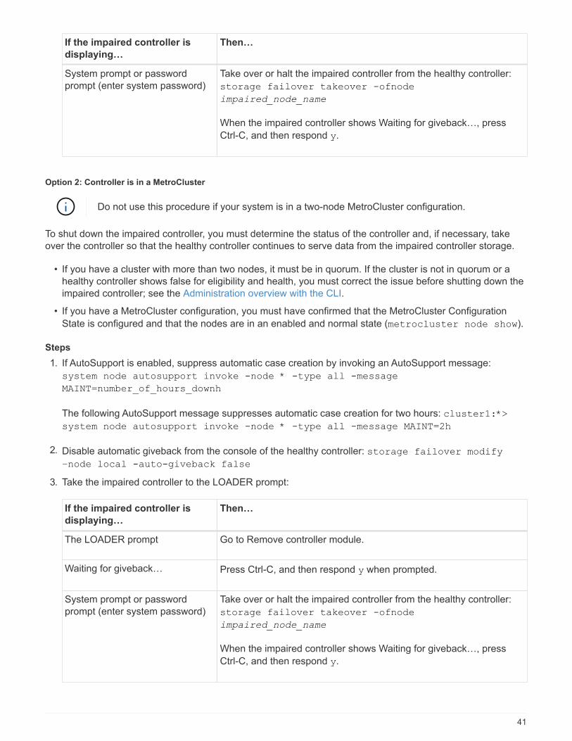
Option 2: Controller is in a MetroCluster
Do not use this procedure if your system is in a two-node MetroCluster configuration.
To shut down the impaired controller, you must determine the status of the controller and, if necessary, take
over the controller so that the healthy controller continues to serve data from the impaired controller storage.
• If you have a cluster with more than two nodes, it must be in quorum. If the cluster is not in quorum or a
healthy controller shows false for eligibility and health, you must correct the issue before shutting down the
impaired controller; see the Administration overview with the CLI.
• If you have a MetroCluster configuration, you must have confirmed that the MetroCluster Configuration
State is configured and that the nodes are in an enabled and normal state (metrocluster node show).
Steps
1. If AutoSupport is enabled, suppress automatic case creation by invoking an AutoSupport message:
system node autosupport invoke -node * -type all -message
MAINT=number_of_hours_downh
The following AutoSupport message suppresses automatic case creation for two hours: cluster1:*>
system node autosupport invoke -node * -type all -message MAINT=2h
2. Disable automatic giveback from the console of the healthy controller: storage failover modify
–node local -auto-giveback false
3. Take the impaired controller to the LOADER prompt:
If the impaired controller is
displaying…
Then…
The LOADER prompt Go to Remove controller module.
Waiting for giveback… Press Ctrl-C, and then respond y when prompted.
System prompt or password
prompt (enter system password)
Take over or halt the impaired controller from the healthy controller:
storage failover takeover -ofnode
impaired_node_name
When the impaired controller shows Waiting for giveback…, press
Ctrl-C, and then respond y.
41
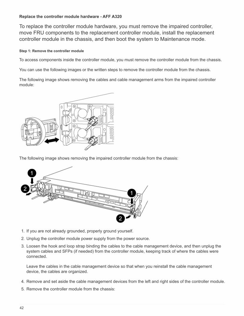
Replace the controller module hardware - AFF A320
To replace the controller module hardware, you must remove the impaired controller,
move FRU components to the replacement controller module, install the replacement
controller module in the chassis, and then boot the system to Maintenance mode.
Step 1: Remove the controller module
To access components inside the controller module, you must remove the controller module from the chassis.
You can use the following images or the written steps to remove the controller module from the chassis.
The following image shows removing the cables and cable management arms from the impaired controller
module:
The following image shows removing the impaired controller module from the chassis:
1. If you are not already grounded, properly ground yourself.
2. Unplug the controller module power supply from the power source.
3. Loosen the hook and loop strap binding the cables to the cable management device, and then unplug the
system cables and SFPs (if needed) from the controller module, keeping track of where the cables were
connected.
Leave the cables in the cable management device so that when you reinstall the cable management
device, the cables are organized.
4. Remove and set aside the cable management devices from the left and right sides of the controller module.
5. Remove the controller module from the chassis:
42

a. Insert your forefinger into the latching mechanism on either side of the controller module.
b. Press down on the orange tab on top of the latching mechanism until it clears the latching pin on the
chassis.
The latching mechanism hook should be nearly vertical and should be clear of the chassis pin.
c. Gently pull the controller module a few inches toward you so that you can grasp the controller module
sides.
d. Using both hands, gently pull the controller module out of the chassis and set it on a flat, stable
surface.
Step 2: Move the power supplies
You must move the power supply from the impaired controller module to the replacement controller module
when you replace a controller module.
1. Rotate the cam handle such that it can be used to pull power supply out of the controller module while
pressing the blue locking tab.
The power supply is short. Always use two hands to support it when removing it from the
controller module so that it does not suddenly swing free from the controller module and
injure you.
2. Move the power supply to the new controller module, and then install it.
3. Using both hands, support and align the edges of the power supply with the opening in the controller
module, and then gently push the power supply into the controller module until the locking tab clicks into
place.
The power supplies will only properly engage with the internal connector and lock in place one way.
To avoid damaging the internal connector, do not use excessive force when sliding the
power supply into the system.
Step 3: Move the NVDIMM battery
To move the NVDIMM battery from the impaired controller module to the replacement controller module, you
must perform a specific sequence of steps.
You can use the following illustration or the written steps to move the NVDIMM battery from the impaired
controller module to the replacement controller module.
43

1. Locate the NVDIMM battery in the controller module.
2. Locate the battery plug and squeeze the clip on the face of the battery plug to release the plug from the
socket, and then unplug the battery cable from the socket.
3. Grasp the battery and press the blue locking tab marked PUSH, and then lift the battery out of the holder
and controller module.
4. Move the battery to the replacement controller module.
5. Align the battery module with the opening for the battery, and then gently push the battery into slot until it
locks into place.
Do not plug the battery cable back into the motherboard until instructed to do so.
Step 4: Move the boot media
You must locate the boot media, and then follow the directions to remove it from the impaired controller module
and insert it into the replacement controller module.
You can use the following illustration or the written steps to move the boot media from the impaired controller
module to the replacement controller module.
44

1. Open the air duct and locate the boot media using the following illustration or the FRU map on the
controller module:
2. Locate and remove the boot media from the controller module:
a. Press the blue button at the end of the boot media until the lip on the boot media clears the blue button.
b. Rotate the boot media up and gently pull the boot media out of the socket.
3. Move the boot media to the new controller module, align the edges of the boot media with the socket
housing, and then gently push it into the socket.
4. Check the boot media to make sure that it is seated squarely and completely in the socket.
If necessary, remove the boot media and reseat it into the socket.
5. Lock the boot media in place:
a. Rotate the boot media down toward the motherboard.
b. Placing a finger at the end of the boot media by the blue button, push down on the boot media end to
engage the blue locking button.
c. While pushing down on the boot media, lift the blue locking button to lock the boot media in place.
Step 5: Move the DIMMs
You need to locate the DIMMs, and then move them from the impaired controller module to the replacement
controller module.
You must have the new controller module ready so that you can move the DIMMs directly from the impaired
controller module to the corresponding slots in the replacement controller module.
You can use the following illustrations or the written steps to move the DIMMs from the impaired controller
module to the replacement controller module.
45
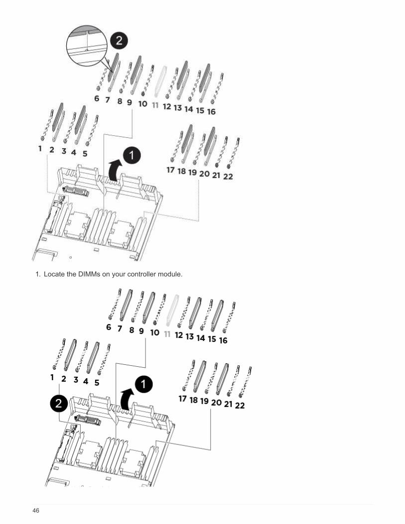
1. Locate the DIMMs on your controller module.
46

Air duct
• System DIMMs slots: 2,4, 7, 9, 13, 15, 18, and
20
• NVDIMM slot: 11
The NVDIMM looks significantly
different than system DIMMs.
2. Note the orientation of the DIMM in the socket so that you can insert the DIMM in the replacement
controller module in the proper orientation.
3. Verify that the NVDIMM battery is not plugged into the new controller module.
4. Move the DIMMs from the impaired controller module to the replacement controller module:
Make sure that you install the each DIMM into the same slot it occupied in the impaired
controller module.
a. Eject the DIMM from its slot by slowly pushing apart the DIMM ejector tabs on either side of the DIMM,
and then slide the DIMM out of the slot.
Carefully hold the DIMM by the edges to avoid pressure on the components on the
DIMM circuit board.
b. Locate the corresponding DIMM slot on the replacement controller module.
c. Make sure that the DIMM ejector tabs on the DIMM socket are in the open position, and then insert the
DIMM squarely into the socket.
The DIMMs fit tightly in the socket, but should go in easily. If not, realign the DIMM with the socket and
reinsert it.
d. Visually inspect the DIMM to verify that it is evenly aligned and fully inserted into the socket.
e. Repeat these substeps for the remaining DIMMs.
5. Plug the NVDIMM battery into the motherboard.
Make sure that the plug locks down onto the controller module.
Step 6: Move the PCIe risers
You must move the PCIe risers, with the PCIe cards installed in them, from the impaired controller module to
the replacement controller module.
You can use the following illustration or the written steps to move the PCIe risers from the impaired controller
module to the replacement controller module.
47
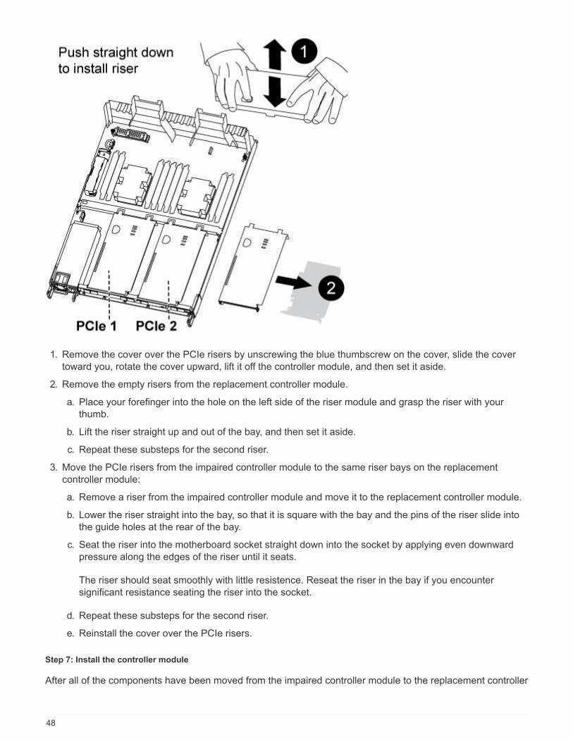
1. Remove the cover over the PCIe risers by unscrewing the blue thumbscrew on the cover, slide the cover
toward you, rotate the cover upward, lift it off the controller module, and then set it aside.
2. Remove the empty risers from the replacement controller module.
a. Place your forefinger into the hole on the left side of the riser module and grasp the riser with your
thumb.
b. Lift the riser straight up and out of the bay, and then set it aside.
c. Repeat these substeps for the second riser.
3. Move the PCIe risers from the impaired controller module to the same riser bays on the replacement
controller module:
a. Remove a riser from the impaired controller module and move it to the replacement controller module.
b. Lower the riser straight into the bay, so that it is square with the bay and the pins of the riser slide into
the guide holes at the rear of the bay.
c. Seat the riser into the motherboard socket straight down into the socket by applying even downward
pressure along the edges of the riser until it seats.
The riser should seat smoothly with little resistence. Reseat the riser in the bay if you encounter
significant resistance seating the riser into the socket.
d. Repeat these substeps for the second riser.
e. Reinstall the cover over the PCIe risers.
Step 7: Install the controller module
After all of the components have been moved from the impaired controller module to the replacement controller
48

module, you must install the replacement controller module into the chassis, and then boot it to Maintenance
mode.
You can use the following illustration or the written steps to install the replacement controller module in the
chassis.
1. If you have not already done so, close the air duct at the rear of the controller module and reinstall the
cover over the PCIe cards.
2. Align the end of the controller module with the opening in the chassis, and then gently push the controller
module halfway into the system.
Do not completely insert the controller module in the chassis until instructed to do so.
3. Cable the management and console ports only, so that you can access the system to perform the tasks in
the following sections.
You will connect the rest of the cables to the controller module later in this procedure.
4. Complete the reinstallation of the controller module:
a. Make sure the latch arms are locked in the extended position.
b. Using the latch arms, push the controller module into the chassis bay until it stops.
c. Press down and hold the orange tabs on top of the latching mechanism.
d. Gently push the controller module into the chassis bay until it is flush with the edges of the chassis.
The latching mechanism arms slide into the chassis.
The controller module begins to boot as soon as it is fully seated in the chassis.
e. Release the latches to lock the controller module into place.
f. Recable the power supply.
g. If you have not already done so, reinstall the cable management device.
h. Interrupt the normal boot process by pressing Ctrl-C.
Restore and verify the system configuration - AFF A320
After completing the hardware replacement and booting to Maintenance mode, you verify
the low-level system configuration of the replacement controller and reconfigure system
49
settings as necessary.
Step 1: Set and verify the system time after replacing the controller module
You should check the time and date on the replacement controller module against the healthy controller
module in an HA pair, or against a reliable time server in a stand-alone configuration. If the time and date do
not match, you must reset them on the replacement controller module to prevent possible outages on clients
due to time differences.
About this task
It is important that you apply the commands in the steps on the correct systems:
• The replacement node is the new node that replaced the impaired node as part of this procedure.
• The healthy node is the HA partner of the replacement node.
Steps
1. If the replacement node is not at the LOADER prompt, halt the system to the LOADER prompt.
2. On the healthy node, check the system time: show date
The date and time are given in GMT.
3. At the LOADER prompt, check the date and time on the replacement node: show date
The date and time are given in GMT.
4. If necessary, set the date in GMT on the replacement node: set date mm/dd/yyyy
5. If necessary, set the time in GMT on the replacement node: set time hh:mm:ss
6. At the LOADER prompt, confirm the date and time on the replacement node: show date
The date and time are given in GMT.
Step 2: Verify and set the HA state of the controller module
You must verify the HA state of the controller module and, if necessary, update the state to match your system
configuration.
1. In Maintenance mode from the new controller module, verify that all components display the same HA
state: ha-config show
The HA state should be the same for all components.
2. If the displayed system state of the controller module does not match your system configuration, set the HA
state for the controller module: ha-config modify controller ha-state
The value for HA-state can be one of the following:
◦ ha
◦ mcc
◦ mccip
50

◦ non-ha
3. If the displayed system state of the controller module does not match your system configuration, set the HA
state for the controller module: ha-config modify controller ha-state
4. Confirm that the setting has changed: ha-config show
Step 3: Run diagnostics
After you have replaced a component in your system, you should run diagnostic tests on that component.
Your system must be at the LOADER prompt to start diagnostics.
All commands in the diagnostic procedures are issued from the controller where the component is being
replaced.
1. If the controller to be serviced is not at the LOADER prompt, reboot the controller: system node halt
-node node_name
After you issue the command, you should wait until the system stops at the LOADER prompt.
2. At the LOADER prompt, access the special drivers specifically designed for system-level diagnostics to
function properly: boot_diags
3. Select Scan System from the displayed menu to enable running the diagnostics tests.
4. Select Test system from the displayed menu to run diagnostics tests.
5. Select the test or series of tests from the various sub-menus.
6. Proceed based on the result of the preceding step:
◦ If the test failed, correct the failure, and then rerun the test.
◦ If the test reported no failures, select Reboot from the menu to reboot the system.
During the boot process, you might see the following prompts:
▪ A prompt warning of a system ID mismatch and asking to override the system ID.
▪ A prompt warning that when entering Maintenance mode in an HA configuration you must ensure
that the healthy controller remains down.
You can safely respond y to these prompts.
Recable the system and reassign disks - AFF A320
Continue the replacement procedure by recabling the storage and confirming disk
reassignment.
Step 1: Recable the system
After running diagnostics, you must recable the controller module’s storage and network connections.
Steps
1. Recable the system.
2. Verify that the cabling is correct by using Active IQ Config Advisor.
51
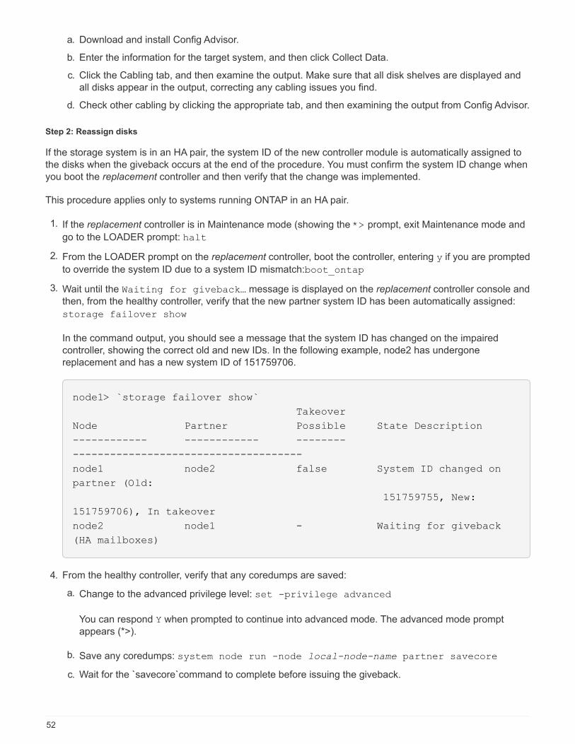
a. Download and install Config Advisor.
b. Enter the information for the target system, and then click Collect Data.
c. Click the Cabling tab, and then examine the output. Make sure that all disk shelves are displayed and
all disks appear in the output, correcting any cabling issues you find.
d. Check other cabling by clicking the appropriate tab, and then examining the output from Config Advisor.
Step 2: Reassign disks
If the storage system is in an HA pair, the system ID of the new controller module is automatically assigned to
the disks when the giveback occurs at the end of the procedure. You must confirm the system ID change when
you boot the replacement controller and then verify that the change was implemented.
This procedure applies only to systems running ONTAP in an HA pair.
1. If the replacement controller is in Maintenance mode (showing the *> prompt, exit Maintenance mode and
go to the LOADER prompt: halt
2. From the LOADER prompt on the replacement controller, boot the controller, entering y if you are prompted
to override the system ID due to a system ID mismatch:boot_ontap
3. Wait until the Waiting for giveback… message is displayed on the replacement controller console and
then, from the healthy controller, verify that the new partner system ID has been automatically assigned:
storage failover show
In the command output, you should see a message that the system ID has changed on the impaired
controller, showing the correct old and new IDs. In the following example, node2 has undergone
replacement and has a new system ID of 151759706.
node1> `storage failover show`
Takeover
Node Partner Possible State Description
------------ ------------ --------
-------------------------------------
node1 node2 false System ID changed on
partner (Old:
151759755, New:
151759706), In takeover
node2 node1 - Waiting for giveback
(HA mailboxes)
4. From the healthy controller, verify that any coredumps are saved:
a. Change to the advanced privilege level: set -privilege advanced
You can respond Y when prompted to continue into advanced mode. The advanced mode prompt
appears (*>).
b. Save any coredumps: system node run -node local-node-name partner savecore
c. Wait for the `savecore`command to complete before issuing the giveback.
52

You can enter the following command to monitor the progress of the savecore command: system
node run -node local-node-name partner savecore -s
d. Return to the admin privilege level: set -privilege admin
5. Give back the controller:
a. From the healthy controller, give back the replaced controller’s storage: storage failover
giveback -ofnode replacement_node_name
The replacement controller takes back its storage and completes booting.
If you are prompted to override the system ID due to a system ID mismatch, you should enter y.
If the giveback is vetoed, you can consider overriding the vetoes.
Find the High-Availability Configuration content for your version of ONTAP 9
b. After the giveback has been completed, confirm that the HA pair is healthy and that takeover is
possible: storage failover show
The output from the storage failover show command should not include the System ID changed
on partner message.
6. Verify that the disks were assigned correctly: storage disk show -ownership
The disks belonging to the replacement controller should show the new system ID. In the following
example, the disks owned by node1 now show the new system ID, 1873775277:
node1> `storage disk show -ownership`
Disk Aggregate Home Owner DR Home Home ID Owner ID DR Home ID
Reserver Pool
----- ------ ----- ------ -------- ------- ------- -------
--------- ---
1.0.0 aggr0_1 node1 node1 - 1873775277 1873775277 -
1873775277 Pool0
1.0.1 aggr0_1 node1 node1 1873775277 1873775277 -
1873775277 Pool0
.
.
.
7. Verify that the expected volumes are present for each controller: vol show -node node-name
8. If you disabled automatic takeover on reboot, enable it from the healthy controller: storage failover
modify -node replacement-node-name -onreboot true
53

Complete system restoration - AFF A320
To restore your system to full operation, you must restore the NetApp Storage Encryption
configuration (if necessary), and install licenses for the new controller, and return the
failed part to NetApp, as described in the RMA instructions shipped with the kit.
Step 1: Install licenses for the replacement controller in ONTAP
You must install new licenses for the replacement node if the impaired node was using ONTAP features that
require a standard (node-locked) license. For features with standard licenses, each node in the cluster should
have its own key for the feature.
About this task
Until you install license keys, features requiring standard licenses continue to be available to the replacement
node. However, if the impaired node was the only node in the cluster with a license for the feature, no
configuration changes to the feature are allowed. Also, using unlicensed features on the node might put you
out of compliance with your license agreement, so you should install the replacement license key or keys on
the replacement node as soon as possible.
Before you begin
The licenses keys must be in the 28-character format.
You have a 90-day grace period in which to install the license keys. After the grace period, all old licenses are
invalidated. After a valid license key is installed, you have 24 hours to install all of the keys before the grace
period ends.
Steps
1. If you need new license keys, obtain replacement license keys on the NetApp Support Site in the My
Support section under Software licenses.
The new license keys that you require are automatically generated and sent to the email
address on file. If you fail to receive the email with the license keys within 30 days, you
should contact technical support.
2. Install each license key: system license add -license-code license-key, license-key...
3. Remove the old licenses, if desired:
a. Check for unused licenses: license clean-up -unused -simulate
b. If the list looks correct, remove the unused licenses: license clean-up -unused
Step 2: Restore Storage and Volume Encryption functionality
After replacing the controller module or NVRAM module for a storage system that you previously configured to
use Storage or Volume Encryption, you must perform additional steps to provide uninterrupted Encryption
functionality. You can skip this task on storage systems that do not have Storage or Volume Encryption
enabled.
Step
1. Restore Storage or Volume Encryption functionality by using the appropriate procedure in NetApp
Encryption overview with the CLI.
2. Use one of the following procedures, depending on whether you are using onboard or external key
management:
54

◦ Restore onboard key management encryption keys
◦ Restore external key management encryption keys
Step 3: Verify LIFs and registering the serial number
Before returning the replacement node to service, you should verify that the LIFs are on their home ports, and
register the serial number of the replacement node if AutoSupport is enabled, and reset automatic giveback.
Steps
1. Verify that the logical interfaces are reporting to their home server and ports: network interface show
-is-home false
If any LIFs are listed as false, revert them to their home ports: network interface revert
2. Register the system serial number with NetApp Support.
◦ If AutoSupport is enabled, send an AutoSupport message to register the serial number.
◦ If AutoSupport is not enabled, call NetApp Support to register the serial number.
3. If automatic giveback was disabled, reenable it: storage failover modify -node local -auto
-giveback true
Step 4: Return the failed part to NetApp
After you replace the part, you can return the failed part to NetApp, as described in the RMA instructions
shipped with the kit. Contact technical support at NetApp Support, 888-463-8277 (North America), 00-800-44-
638277 (Europe), or +800-800-80-800 (Asia/Pacific) if you need the RMA number or additional help with the
replacement procedure.
Replace a DIMM - AFF A320
You must replace a DIMM in the controller module when your system registers an
increasing number of correctable error correction codes (ECC); failure to do so causes a
system panic.
All other components in the system must be functioning properly; if not, you must contact technical support.
You must replace the failed component with a replacement FRU component you received from your provider.
Step 1: Shut down the controller
Shut down or take over the impaired controller using the appropriate procedure for your
configuration.
Option 1: Most configurations
To shut down the impaired controller, you must determine the status of the controller and,
if necessary, take over the controller so that the healthy controller continues to serve data
from the impaired controller storage.
About this task
If you have a cluster with more than two nodes, it must be in quorum. If the cluster is not in quorum or a healthy
55

controller shows false for eligibility and health, you must correct the issue before shutting down the impaired
controller; see the Administration overview with the CLI.
Steps
1. If AutoSupport is enabled, suppress automatic case creation by invoking an AutoSupport message:
system node autosupport invoke -node * -type all -message
MAINT=number_of_hours_downh
The following AutoSupport message suppresses automatic case creation for two hours: cluster1:*>
system node autosupport invoke -node * -type all -message MAINT=2h
2. Disable automatic giveback from the console of the healthy controller: storage failover modify
–node local -auto-giveback false
3. Take the impaired controller to the LOADER prompt:
If the impaired controller is
displaying…
Then…
The LOADER prompt Go to Remove controller module.
Waiting for giveback… Press Ctrl-C, and then respond y when prompted.
System prompt or password
prompt (enter system password)
Take over or halt the impaired controller from the healthy controller:
storage failover takeover -ofnode
impaired_node_name
When the impaired controller shows Waiting for giveback…, press
Ctrl-C, and then respond y.
Option 2: Controller is in a MetroCluster
Do not use this procedure if your system is in a two-node MetroCluster configuration.
To shut down the impaired controller, you must determine the status of the controller and, if necessary, take
over the controller so that the healthy controller continues to serve data from the impaired controller storage.
• If you have a cluster with more than two nodes, it must be in quorum. If the cluster is not in quorum or a
healthy controller shows false for eligibility and health, you must correct the issue before shutting down the
impaired controller; see the Administration overview with the CLI.
• If you have a MetroCluster configuration, you must have confirmed that the MetroCluster Configuration
State is configured and that the nodes are in an enabled and normal state (metrocluster node show).
Steps
1. If AutoSupport is enabled, suppress automatic case creation by invoking an AutoSupport message:
system node autosupport invoke -node * -type all -message
MAINT=number_of_hours_downh
The following AutoSupport message suppresses automatic case creation for two hours: cluster1:*>
system node autosupport invoke -node * -type all -message MAINT=2h
56

2. Disable automatic giveback from the console of the healthy controller: storage failover modify
–node local -auto-giveback false
3. Take the impaired controller to the LOADER prompt:
If the impaired controller is
displaying…
Then…
The LOADER prompt Go to Remove controller module.
Waiting for giveback… Press Ctrl-C, and then respond y when prompted.
System prompt or password
prompt (enter system password)
Take over or halt the impaired controller from the healthy controller:
storage failover takeover -ofnode
impaired_node_name
When the impaired controller shows Waiting for giveback…, press
Ctrl-C, and then respond y.
Step 2: Remove the controller module
To access components inside the controller module, you must remove the controller
module from the chassis.
1. If you are not already grounded, properly ground yourself.
2. Unplug the controller module power supply from the power source.
3. Loosen the hook and loop strap binding the cables to the cable management device, and then unplug the
system cables and SFPs (if needed) from the controller module, keeping track of where the cables were
connected.
Leave the cables in the cable management device so that when you reinstall the cable management
device, the cables are organized.
4. Remove and set aside the cable management devices from the left and right sides of the controller module.
5. Remove the controller module from the chassis:
57

a. Insert your forefinger into the latching mechanism on either side of the controller module.
b. Press down on the orange tab on top of the latching mechanism until it clears the latching pin on the
chassis.
The latching mechanism hook should be nearly vertical and should be clear of the chassis pin.
c. Gently pull the controller module a few inches toward you so that you can grasp the controller module
sides.
d. Using both hands, gently pull the controller module out of the chassis and set it on a flat, stable surface.
Step 3: Replace system DIMMs
Replacing a system DIMM involves identifying the target DIMM through the associated
error message, locating the target DIMM using the FRU map on the air duct or the lit LED
on the motherboard, and then replacing the DIMM.
1. Rotate the air duct to the open position.
2. Locate the DIMMs on your controller module.
58

Air duct
• System DIMMs slots: 2,4, 7, 9, 13, 15, 18, and
20
• NVDIMM slot: 11
The NVDIMM looks significantly
different than system DIMMs.
3. Note the orientation of the DIMM in the socket so that you can insert the replacement DIMM in the proper
orientation.
4. Eject the DIMM from its socket by slowly pushing apart the two DIMM ejector tabs on either side of the
DIMM, and then slide the DIMM out of the socket.
Carefully hold the DIMM by the edges to avoid pressure on the components on the DIMM
circuit board.
5. Remove the replacement DIMM from the antistatic shipping bag, hold the DIMM by the corners, and align it
to the slot.
The notch among the pins on the DIMM should line up with the tab in the socket.
6. Make sure that the DIMM ejector tabs on the connector are in the open position, and then insert the DIMM
squarely into the slot.
59
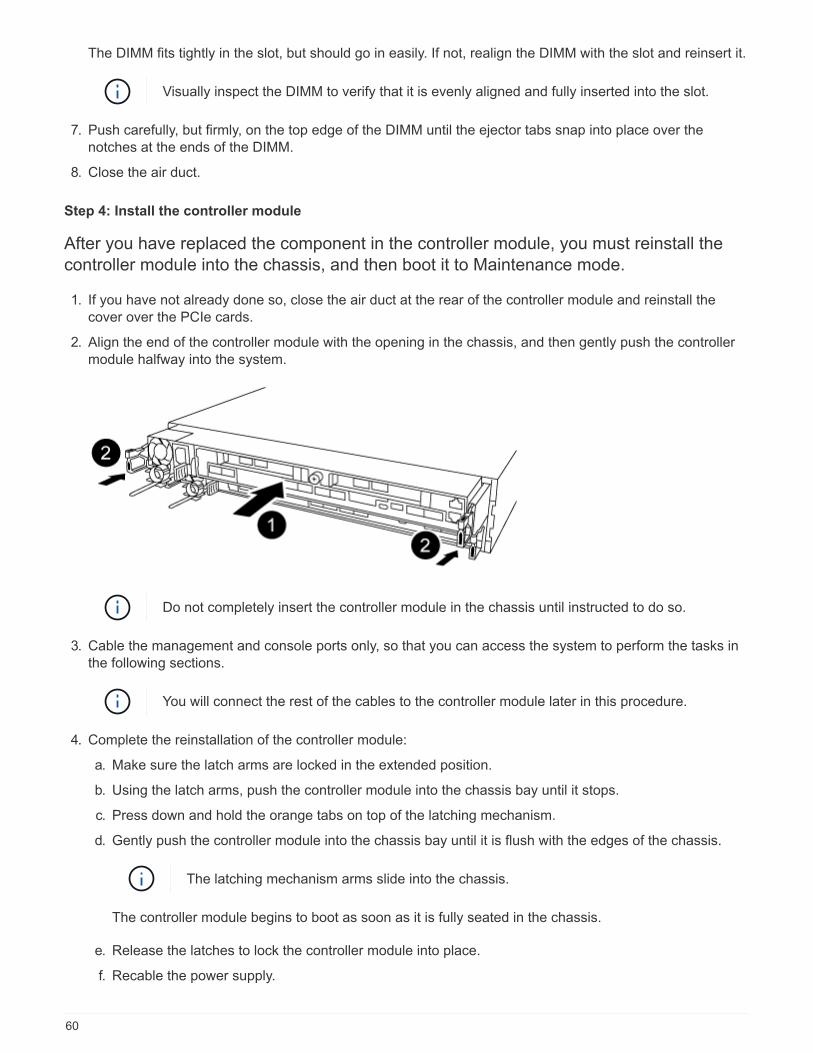
The DIMM fits tightly in the slot, but should go in easily. If not, realign the DIMM with the slot and reinsert it.
Visually inspect the DIMM to verify that it is evenly aligned and fully inserted into the slot.
7. Push carefully, but firmly, on the top edge of the DIMM until the ejector tabs snap into place over the
notches at the ends of the DIMM.
8. Close the air duct.
Step 4: Install the controller module
After you have replaced the component in the controller module, you must reinstall the
controller module into the chassis, and then boot it to Maintenance mode.
1. If you have not already done so, close the air duct at the rear of the controller module and reinstall the
cover over the PCIe cards.
2. Align the end of the controller module with the opening in the chassis, and then gently push the controller
module halfway into the system.
Do not completely insert the controller module in the chassis until instructed to do so.
3. Cable the management and console ports only, so that you can access the system to perform the tasks in
the following sections.
You will connect the rest of the cables to the controller module later in this procedure.
4. Complete the reinstallation of the controller module:
a. Make sure the latch arms are locked in the extended position.
b. Using the latch arms, push the controller module into the chassis bay until it stops.
c. Press down and hold the orange tabs on top of the latching mechanism.
d. Gently push the controller module into the chassis bay until it is flush with the edges of the chassis.
The latching mechanism arms slide into the chassis.
The controller module begins to boot as soon as it is fully seated in the chassis.
e. Release the latches to lock the controller module into place.
f. Recable the power supply.
60

g. If you have not already done so, reinstall the cable management device.
h. Interrupt the normal boot process by pressing Ctrl-C.
Step 5: Run diagnostics
After you have replaced a system DIMM in your system, you should run diagnostic tests
on that component.
Your system must be at the LOADER prompt to start diagnostics.
All commands in the diagnostic procedures are issued from the controller where the component is being
replaced.
1. If the controller to be serviced is not at the LOADER prompt, reboot the controller: system node halt
-node node_name
After you issue the command, you should wait until the system stops at the LOADER prompt.
2. At the LOADER prompt, access the special drivers specifically designed for system-level diagnostics to
function properly: boot_diags
3. Select Scan System from the displayed menu to enable running the diagnostics tests.
4. Select Stress-Test system from the displayed menu.
5. Select an option from the displayed sub-menu and run the test.
6. Proceed based on the result of the preceding step:
◦ If the test failed, correct the failure, and then rerun the test.
◦ If the test reported no failures, select Reboot from the menu to reboot the system.
Step 6: Restore the controller module to operation after running diagnostics
After completing diagnostics, you must recable the system, give back the controller
module, and then reenable automatic giveback.
1. Recable the system, as needed.
If you removed the media converters (QSFPs or SFPs), remember to reinstall them if you are using fiber
optic cables.
2. Return the controller to normal operation by giving back its storage: storage failover giveback
-ofnode impaired_node_name
3. If automatic giveback was disabled, reenable it: storage failover modify -node local -auto
-giveback true
Step 7: Return the failed part to NetApp
After you replace the part, you can return the failed part to NetApp, as described in the
RMA instructions shipped with the kit. Contact technical support at NetApp Support, 888-
463-8277 (North America), 00-800-44-638277 (Europe), or +800-800-80-800
(Asia/Pacific) if you need the RMA number or additional help with the replacement
61

procedure.
Hot-swap a fan module - AFF A320
To swap out a fan module without interrupting service, you must perform a specific
sequence of tasks.
You must replace the fan module within two minutes of removing it from the chassis. System
airflow is disrupted and the controller module or modules shut down after two minutes to avoid
overheating.
1. If you are not already grounded, properly ground yourself.
2. Remove the bezel (if necessary) with two hands, by grasping the openings on each side of the bezel, and
then pulling it toward you until the bezel releases from the ball studs on the chassis frame.
3. Identify the fan module that you must replace by checking the console error messages and looking at the
Attention LED on each fan module.
4. Press down the release latch on the fan module cam handle, and then rotate the cam handle downward.
The fan module moves a little bit away from the chassis.
5. Pull the fan module straight out from the chassis, making sure that you support it with your free hand so
62
that it does not swing out of the chassis.
The fan modules are short. Always support the bottom of the fan module with your free hand
so that it does not suddenly drop free from the chassis and injure you.
6. Set the fan module aside.
7. Insert the replacement fan module into the chassis by aligning it with the opening, and then sliding it into
the chassis.
8. Push firmly on the fan module cam handle so that it is seated all the way into the chassis.
The cam handle raises slightly when the fan module is completely seated.
9. Swing the cam handle up to its closed position, making sure that the cam handle release latch clicks into
the locked position.
The Attention LED should not be lit after the fan is seated and has spun up to operational speed.
10. Align the bezel with the ball studs, and then gently push the bezel onto the ball studs.
Replace an NVDIMM - AFF A320
You must replace the NVDIMM in the controller module when your system registers that
the flash lifetime is almost at an end or that the identified NVDIMM is not healthy in
general; failure to do so causes a system panic.
All other components in the system must be functioning properly; if not, you must contact technical support.
You must replace the failed component with a replacement FRU component you received from your provider.
Step 1: Shut down the impaired controller
Shut down or take over the impaired controller using the appropriate procedure for your
configuration.
Option 1: Shut down the controller
To shut down the impaired controller, you must determine the status of the controller and,
if necessary, take over the controller so that the healthy controller continues to serve data
from the impaired controller storage.
About this task
If you have a cluster with more than two nodes, it must be in quorum. If the cluster is not in quorum or a healthy
controller shows false for eligibility and health, you must correct the issue before shutting down the impaired
controller; see the Administration overview with the CLI.
Steps
1. If AutoSupport is enabled, suppress automatic case creation by invoking an AutoSupport message:
system node autosupport invoke -node * -type all -message
MAINT=number_of_hours_downh
The following AutoSupport message suppresses automatic case creation for two hours: cluster1:*>
63
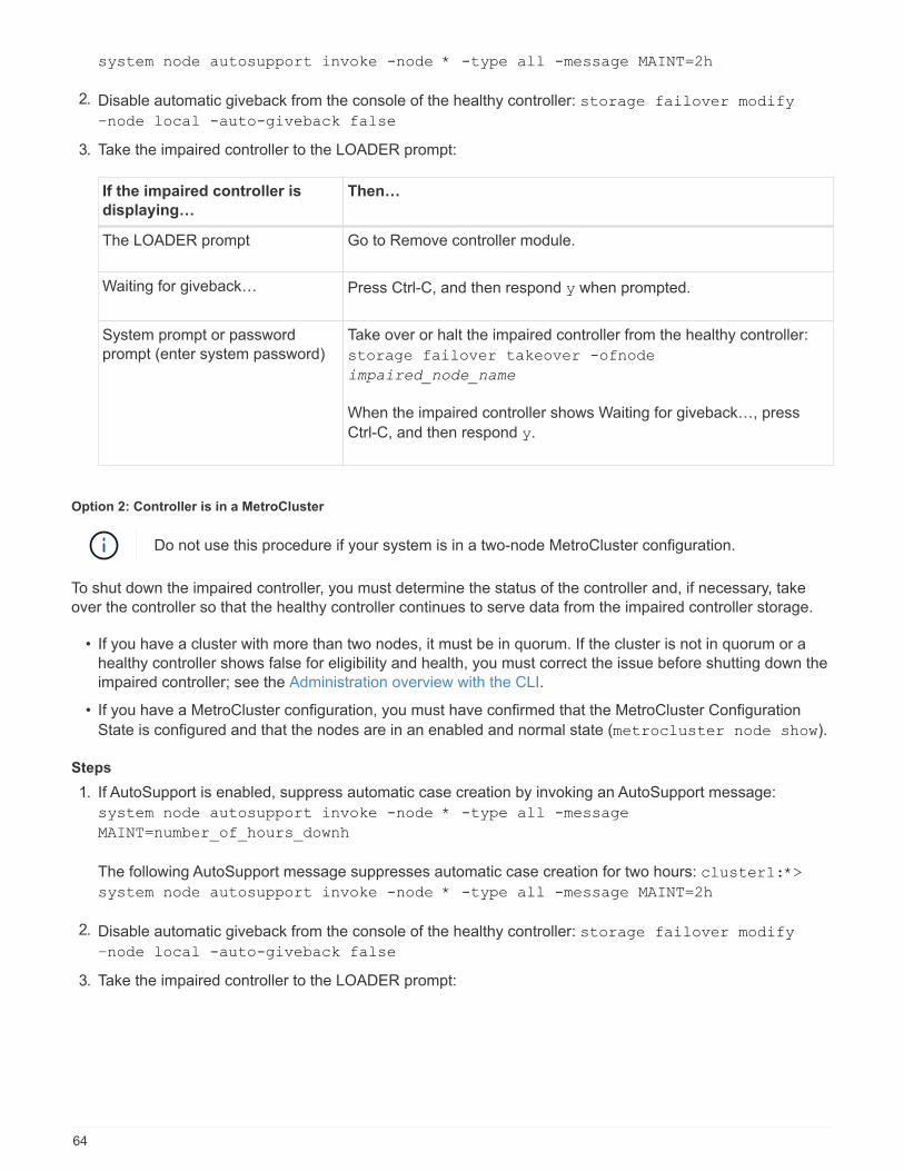
system node autosupport invoke -node * -type all -message MAINT=2h
2. Disable automatic giveback from the console of the healthy controller: storage failover modify
–node local -auto-giveback false
3. Take the impaired controller to the LOADER prompt:
If the impaired controller is
displaying…
Then…
The LOADER prompt Go to Remove controller module.
Waiting for giveback… Press Ctrl-C, and then respond y when prompted.
System prompt or password
prompt (enter system password)
Take over or halt the impaired controller from the healthy controller:
storage failover takeover -ofnode
impaired_node_name
When the impaired controller shows Waiting for giveback…, press
Ctrl-C, and then respond y.
Option 2: Controller is in a MetroCluster
Do not use this procedure if your system is in a two-node MetroCluster configuration.
To shut down the impaired controller, you must determine the status of the controller and, if necessary, take
over the controller so that the healthy controller continues to serve data from the impaired controller storage.
• If you have a cluster with more than two nodes, it must be in quorum. If the cluster is not in quorum or a
healthy controller shows false for eligibility and health, you must correct the issue before shutting down the
impaired controller; see the Administration overview with the CLI.
• If you have a MetroCluster configuration, you must have confirmed that the MetroCluster Configuration
State is configured and that the nodes are in an enabled and normal state (metrocluster node show).
Steps
1. If AutoSupport is enabled, suppress automatic case creation by invoking an AutoSupport message:
system node autosupport invoke -node * -type all -message
MAINT=number_of_hours_downh
The following AutoSupport message suppresses automatic case creation for two hours: cluster1:*>
system node autosupport invoke -node * -type all -message MAINT=2h
2. Disable automatic giveback from the console of the healthy controller: storage failover modify
–node local -auto-giveback false
3. Take the impaired controller to the LOADER prompt:
64

If the impaired controller is
displaying…
Then…
The LOADER prompt Go to Remove controller module.
Waiting for giveback… Press Ctrl-C, and then respond y when prompted.
System prompt or password
prompt (enter system password)
Take over or halt the impaired controller from the healthy controller:
storage failover takeover -ofnode
impaired_node_name
When the impaired controller shows Waiting for giveback…, press
Ctrl-C, and then respond y.
Step 2: Remove the controller module
To access components inside the controller module, you must remove the controller
module from the chassis.
1. If you are not already grounded, properly ground yourself.
2. Unplug the controller module power supply from the power source.
3. Loosen the hook and loop strap binding the cables to the cable management device, and then unplug the
system cables and SFPs (if needed) from the controller module, keeping track of where the cables were
connected.
Leave the cables in the cable management device so that when you reinstall the cable management
device, the cables are organized.
4. Remove and set aside the cable management devices from the left and right sides of the controller module.
5. Remove the controller module from the chassis:
65

a. Insert your forefinger into the latching mechanism on either side of the controller module.
b. Press down on the orange tab on top of the latching mechanism until it clears the latching pin on the
chassis.
The latching mechanism hook should be nearly vertical and should be clear of the chassis pin.
a. Gently pull the controller module a few inches toward you so that you can grasp the controller module
sides.
b. Using both hands, gently pull the controller module out of the chassis and set it on a flat, stable
surface.
Step 3: Replace the NVDIMM
To replace the NVDIMM, you must locate it in the controller module using the NVDIMM
map label on top of the air duct or locating it using the LED next to the NVDIMM, and then
replace it following the specific sequence of steps.
The NVDIMM LED blinks while destaging contents when you halt the system. After the destage
is complete, the LED turns off.
66
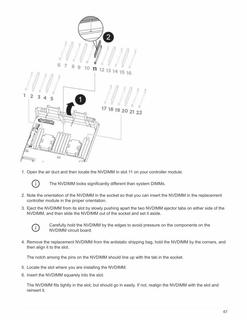
1. Open the air duct and then locate the NVDIMM in slot 11 on your controller module.
The NVDIMM looks significantly different than system DIMMs.
2. Note the orientation of the NVDIMM in the socket so that you can insert the NVDIMM in the replacement
controller module in the proper orientation.
3. Eject the NVDIMM from its slot by slowly pushing apart the two NVDIMM ejector tabs on either side of the
NVDIMM, and then slide the NVDIMM out of the socket and set it aside.
Carefully hold the NVDIMM by the edges to avoid pressure on the components on the
NVDIMM circuit board.
4. Remove the replacement NVDIMM from the antistatic shipping bag, hold the NVDIMM by the corners, and
then align it to the slot.
The notch among the pins on the NVDIMM should line up with the tab in the socket.
5. Locate the slot where you are installing the NVDIMM.
6. Insert the NVDIMM squarely into the slot.
The NVDIMM fits tightly in the slot, but should go in easily. If not, realign the NVDIMM with the slot and
reinsert it.
67

Visually inspect the NVDIMM to verify that it is evenly aligned and fully inserted into the slot.
7. Push carefully, but firmly, on the top edge of the NVDIMM until the ejector tabs snap into place over the
notches at the ends of the NVDIMM.
8. Close the air duct.
Step 4: Install the controller module
After you have replaced the component in the controller module, you must reinstall the
controller module into the chassis, and then boot it to Maintenance mode.
1. If you have not already done so, close the air duct at the rear of the controller module and reinstall the
cover over the PCIe cards.
2. Align the end of the controller module with the opening in the chassis, and then gently push the controller
module halfway into the system.
Do not completely insert the controller module in the chassis until instructed to do so.
3. Cable the management and console ports only, so that you can access the system to perform the tasks in
the following sections.
You will connect the rest of the cables to the controller module later in this procedure.
4. Complete the reinstallation of the controller module:
a. Make sure the latch arms are locked in the extended position.
b. Using the latch arms, push the controller module into the chassis bay until it stops.
c. Press down and hold the orange tabs on top of the latching mechanism.
d. Gently push the controller module into the chassis bay until it is flush with the edges of the chassis.
The latching mechanism arms slide into the chassis.
The controller module begins to boot as soon as it is fully seated in the chassis.
e. Release the latches to lock the controller module into place.
f. Recable the power supply.
g. If you have not already done so, reinstall the cable management device.
h. Interrupt the normal boot process by pressing Ctrl-C.
Step 5: Run diagnostics
After you have replaced the NVDIMM in your system, you should run diagnostic tests on
that component.
Your system must be at the LOADER prompt to start diagnostics.
All commands in the diagnostic procedures are issued from the controller where the component is being
replaced.
68
1. If the controller to be serviced is not at the LOADER prompt, reboot the controller: system node halt
-node node_name
After you issue the command, you should wait until the system stops at the LOADER prompt.
2. At the LOADER prompt, access the special drivers specifically designed for system-level diagnostics to
function properly: boot_diags
3. Select Scan System from the displayed menu to enable running the diagnostics tests.
4. Select Test Memory from the displayed menu.
5. Select NVDIMM Test from the displayed menu.
6. Proceed based on the result of the preceding step:
◦ If the test failed, correct the failure, and then rerun the test.
◦ If the test reported no failures, select Reboot from the menu to reboot the system.
Step 6: Restore the controller module to operation after running diagnostics
After completing diagnostics, you must recable the system, give back the controller
module, and then reenable automatic giveback.
1. Recable the system, as needed.
If you removed the media converters (QSFPs or SFPs), remember to reinstall them if you are using fiber
optic cables.
2. Return the controller to normal operation by giving back its storage: storage failover giveback
-ofnode impaired_node_name
3. If automatic giveback was disabled, reenable it: storage failover modify -node local -auto
-giveback true
Step 7: Return the failed part to NetApp
After you replace the part, you can return the failed part to NetApp, as described in the
RMA instructions shipped with the kit. Contact technical support at NetApp Support, 888-
463-8277 (North America), 00-800-44-638277 (Europe), or +800-800-80-800
(Asia/Pacific) if you need the RMA number or additional help with the replacement
procedure.
Replace the NVDIMM battery - AFF A320
To replace the NVDIMM battery, you must remove the controller module, remove the
battery, replace the battery, and then reinstall the controller module.
All other components in the system must be functioning properly; if not, you must contact technical support.
Step 1: Shut down the controller
Shut down or take over the impaired controller using the appropriate procedure for your
configuration.
69

Option 1: Most configurations
To shut down the impaired controller, you must determine the status of the controller and,
if necessary, take over the controller so that the healthy controller continues to serve data
from the impaired controller storage.
About this task
If you have a cluster with more than two nodes, it must be in quorum. If the cluster is not in quorum or a healthy
controller shows false for eligibility and health, you must correct the issue before shutting down the impaired
controller; see the Administration overview with the CLI.
Steps
1. If AutoSupport is enabled, suppress automatic case creation by invoking an AutoSupport message:
system node autosupport invoke -node * -type all -message
MAINT=number_of_hours_downh
The following AutoSupport message suppresses automatic case creation for two hours: cluster1:*>
system node autosupport invoke -node * -type all -message MAINT=2h
2. Disable automatic giveback from the console of the healthy controller: storage failover modify
–node local -auto-giveback false
3. Take the impaired controller to the LOADER prompt:
If the impaired controller is
displaying…
Then…
The LOADER prompt Go to Remove controller module.
Waiting for giveback… Press Ctrl-C, and then respond y when prompted.
System prompt or password
prompt (enter system password)
Take over or halt the impaired controller from the healthy controller:
storage failover takeover -ofnode
impaired_node_name
When the impaired controller shows Waiting for giveback…, press
Ctrl-C, and then respond y.
Option 2: Controller is in a MetroCluster
Do not use this procedure if your system is in a two-node MetroCluster configuration.
To shut down the impaired controller, you must determine the status of the controller and, if necessary, take
over the controller so that the healthy controller continues to serve data from the impaired controller storage.
• If you have a cluster with more than two nodes, it must be in quorum. If the cluster is not in quorum or a
healthy controller shows false for eligibility and health, you must correct the issue before shutting down the
impaired controller; see the Administration overview with the CLI.
• If you have a MetroCluster configuration, you must have confirmed that the MetroCluster Configuration
State is configured and that the nodes are in an enabled and normal state (metrocluster node show).
70

Steps
1. If AutoSupport is enabled, suppress automatic case creation by invoking an AutoSupport message:
system node autosupport invoke -node * -type all -message
MAINT=number_of_hours_downh
The following AutoSupport message suppresses automatic case creation for two hours: cluster1:*>
system node autosupport invoke -node * -type all -message MAINT=2h
2. Disable automatic giveback from the console of the healthy controller: storage failover modify
–node local -auto-giveback false
3. Take the impaired controller to the LOADER prompt:
If the impaired controller is
displaying…
Then…
The LOADER prompt Go to Remove controller module.
Waiting for giveback… Press Ctrl-C, and then respond y when prompted.
System prompt or password
prompt (enter system password)
Take over or halt the impaired controller from the healthy controller:
storage failover takeover -ofnode
impaired_node_name
When the impaired controller shows Waiting for giveback…, press
Ctrl-C, and then respond y.
Step 2: Remove the controller module
To access components inside the controller module, you must remove the controller
module from the chassis.
1. If you are not already grounded, properly ground yourself.
2. Unplug the controller module power supply from the power source.
3. Loosen the hook and loop strap binding the cables to the cable management device, and then unplug the
system cables and SFPs (if needed) from the controller module, keeping track of where the cables were
connected.
71

Leave the cables in the cable management device so that when you reinstall the cable management
device, the cables are organized.
4. Remove and set aside the cable management devices from the left and right sides of the controller module.
5. Remove the controller module from the chassis:
a. Insert your forefinger into the latching mechanism on either side of the controller module.
b. Press down on the orange tab on top of the latching mechanism until it clears the latching pin on the
chassis.
The latching mechanism hook should be nearly vertical and should be clear of the chassis pin.
a. Gently pull the controller module a few inches toward you so that you can grasp the controller module
sides.
b. Using both hands, gently pull the controller module out of the chassis and set it on a flat, stable
surface.
Step 3: Replace the NVDIMM battery
To replace the NVDIMM battery, you must remove the failed battery from the controller
module and install the replacement battery into the controller module.
72

1. Open the air duct and locate the NVDIMM battery.
2. Locate the battery plug and squeeze the clip on the face of the battery plug to release the plug from the
socket, and then unplug the battery cable from the socket.
3. Grasp the battery and press the blue locking tab marked PUSH, and then lift the battery out of the holder
and controller module.
4. Remove the replacement battery from its package.
5. Align the battery module with the opening for the battery, and then gently push the battery into slot until it
locks into place.
6. Plug the battery plug back into the controller module, and then close the air duct.
Step 4: Install the controller module
After you have replaced the component in the controller module, you must reinstall the
controller module into the chassis, and then boot it to Maintenance mode.
1. If you have not already done so, close the air duct at the rear of the controller module and reinstall the
cover over the PCIe cards.
2. Align the end of the controller module with the opening in the chassis, and then gently push the controller
module halfway into the system.
73

Do not completely insert the controller module in the chassis until instructed to do so.
3. Cable the management and console ports only, so that you can access the system to perform the tasks in
the following sections.
You will connect the rest of the cables to the controller module later in this procedure.
4. Complete the reinstallation of the controller module:
a. Make sure the latch arms are locked in the extended position.
b. Using the latch arms, push the controller module into the chassis bay until it stops.
c. Press down and hold the orange tabs on top of the latching mechanism.
d. Gently push the controller module into the chassis bay until it is flush with the edges of the chassis.
The latching mechanism arms slide into the chassis.
The controller module begins to boot as soon as it is fully seated in the chassis.
e. Release the latches to lock the controller module into place.
f. Recable the power supply.
g. If you have not already done so, reinstall the cable management device.
h. Interrupt the normal boot process by pressing Ctrl-C.
Step 5: Run diagnostics
After you have replaced a component in your system, you should run diagnostic tests on
that component.
Your system must be at the LOADER prompt to start diagnostics.
All commands in the diagnostic procedures are issued from the controller where the component is being
replaced.
1. If the controller to be serviced is not at the LOADER prompt, reboot the controller: system node halt
-node node_name
After you issue the command, you should wait until the system stops at the LOADER prompt.
74

2. At the LOADER prompt, access the special drivers specifically designed for system-level diagnostics to
function properly: boot_diags
3. Select Scan System from the displayed menu to enable running the diagnostics tests.
4. Select Test system from the displayed menu to run diagnostics tests.
5. Proceed based on the result of the preceding step:
◦ If the scan show problems, correct the issue, and then rerun the scan.
◦ If the scan reported no failures, select Reboot from the menu to reboot the system.
Step 6: Restore the controller module to operation after running diagnostics
After completing diagnostics, you must recable the system, give back the controller
module, and then reenable automatic giveback.
1. Recable the system, as needed.
If you removed the media converters (QSFPs or SFPs), remember to reinstall them if you are using fiber
optic cables.
2. Return the controller to normal operation by giving back its storage: storage failover giveback
-ofnode impaired_node_name
3. If automatic giveback was disabled, reenable it: storage failover modify -node local -auto
-giveback true
Step 7: Return the failed part to NetApp
After you replace the part, you can return the failed part to NetApp, as described in the
RMA instructions shipped with the kit. Contact technical support at NetApp Support, 888-
463-8277 (North America), 00-800-44-638277 (Europe), or +800-800-80-800
(Asia/Pacific) if you need the RMA number or additional help with the replacement
procedure.
Replace a PCIe card - AFF A320
To replace a PCIe card, you must disconnect the cables from the cards, remove the SFP
and QSFP modules from the cards before removing the riser, reinstall the riser, and then
reinstall the SFP and QSFP modules before cabling the cards.
• You can use this procedure with all versions of ONTAP supported by your system
• All other components in the system must be functioning properly; if not, you must contact technical support.
Step 1: Shut down the impaired controller
Shut down or take over the impaired controller using the appropriate procedure for your
configuration.
75

Option 1: Most configurations
To shut down the impaired controller, you must determine the status of the controller and,
if necessary, take over the controller so that the healthy controller continues to serve data
from the impaired controller storage.
About this task
If you have a cluster with more than two nodes, it must be in quorum. If the cluster is not in quorum or a healthy
controller shows false for eligibility and health, you must correct the issue before shutting down the impaired
controller; see the Administration overview with the CLI.
Steps
1. If AutoSupport is enabled, suppress automatic case creation by invoking an AutoSupport message:
system node autosupport invoke -node * -type all -message
MAINT=number_of_hours_downh
The following AutoSupport message suppresses automatic case creation for two hours: cluster1:*>
system node autosupport invoke -node * -type all -message MAINT=2h
2. Disable automatic giveback from the console of the healthy controller: storage failover modify
–node local -auto-giveback false
3. Take the impaired controller to the LOADER prompt:
If the impaired controller is
displaying…
Then…
The LOADER prompt Go to Remove controller module.
Waiting for giveback… Press Ctrl-C, and then respond y when prompted.
System prompt or password
prompt (enter system password)
Take over or halt the impaired controller from the healthy controller:
storage failover takeover -ofnode
impaired_node_name
When the impaired controller shows Waiting for giveback…, press
Ctrl-C, and then respond y.
Option 2: Controller is in a MetroCluster
Do not use this procedure if your system is in a two-node MetroCluster configuration.
To shut down the impaired controller, you must determine the status of the controller and, if necessary, take
over the controller so that the healthy controller continues to serve data from the impaired controller storage.
• If you have a cluster with more than two nodes, it must be in quorum. If the cluster is not in quorum or a
healthy controller shows false for eligibility and health, you must correct the issue before shutting down the
impaired controller; see the Administration overview with the CLI.
• If you have a MetroCluster configuration, you must have confirmed that the MetroCluster Configuration
State is configured and that the nodes are in an enabled and normal state (metrocluster node show).
76

Steps
1. If AutoSupport is enabled, suppress automatic case creation by invoking an AutoSupport message:
system node autosupport invoke -node * -type all -message
MAINT=number_of_hours_downh
The following AutoSupport message suppresses automatic case creation for two hours: cluster1:*>
system node autosupport invoke -node * -type all -message MAINT=2h
2. Disable automatic giveback from the console of the healthy controller: storage failover modify
–node local -auto-giveback false
3. Take the impaired controller to the LOADER prompt:
If the impaired controller is
displaying…
Then…
The LOADER prompt Go to Remove controller module.
Waiting for giveback… Press Ctrl-C, and then respond y when prompted.
System prompt or password
prompt (enter system password)
Take over or halt the impaired controller from the healthy controller:
storage failover takeover -ofnode
impaired_node_name
When the impaired controller shows Waiting for giveback…, press
Ctrl-C, and then respond y.
Step 2: Remove the controller module
To access components inside the controller module, you must remove the controller
module from the chassis.
1. If you are not already grounded, properly ground yourself.
2. Unplug the controller module power supply from the power source.
3. Loosen the hook and loop strap binding the cables to the cable management device, and then unplug the
system cables and SFPs (if needed) from the controller module, keeping track of where the cables were
connected.
77

Leave the cables in the cable management device so that when you reinstall the cable management
device, the cables are organized.
4. Remove and set aside the cable management devices from the left and right sides of the controller module.
5. Remove the controller module from the chassis:
a. Insert your forefinger into the latching mechanism on either side of the controller module.
b. Press down on the orange tab on top of the latching mechanism until it clears the latching pin on the
chassis.
The latching mechanism hook should be nearly vertical and should be clear of the chassis pin.
a. Gently pull the controller module a few inches toward you so that you can grasp the controller module
sides.
b. Using both hands, gently pull the controller module out of the chassis and set it on a flat, stable
surface.
Step 3: Replace a PCIe card
You must remove the PCIe riser containing the failed PCIe card from the controller
module, remove the failed PCIe card from the riser, install the replacement PCIe card in
the riser, and then reinstall the riser into the controller module.
78
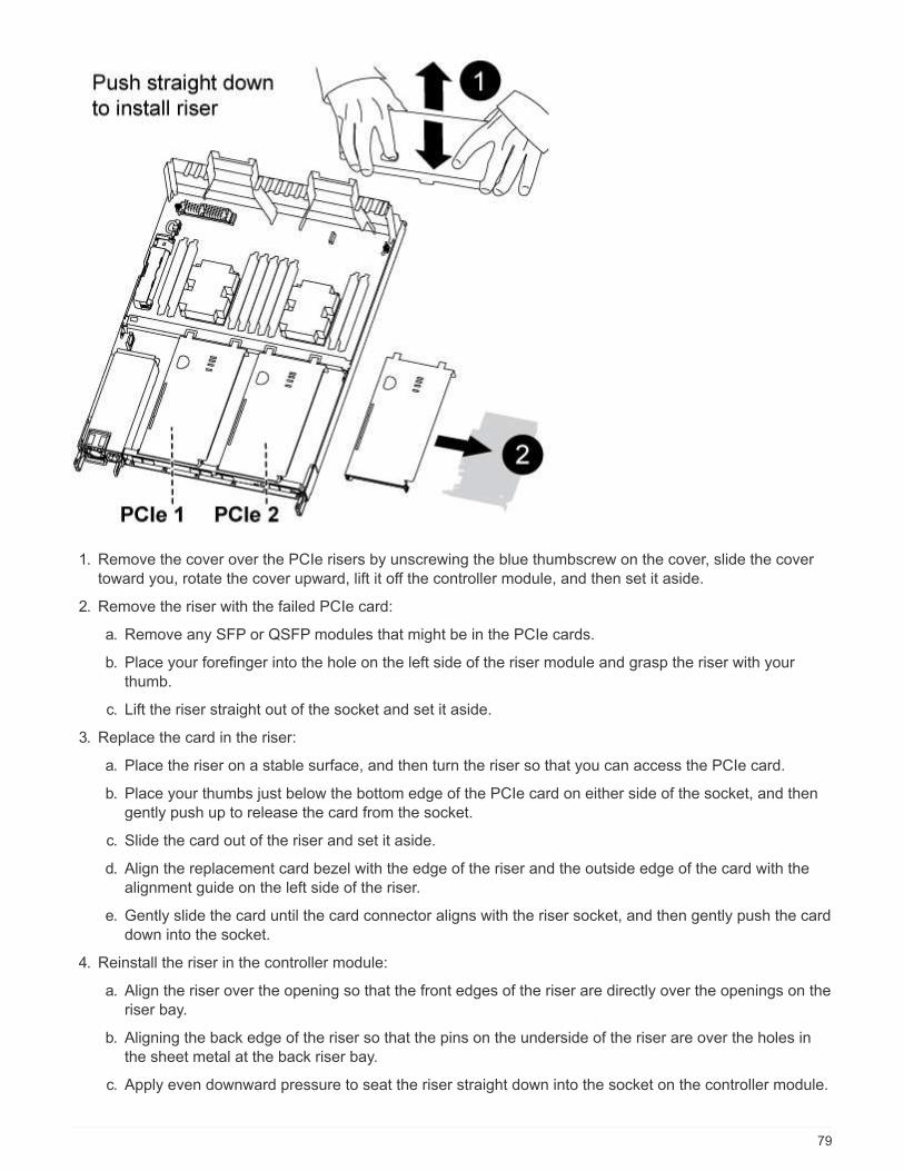
1. Remove the cover over the PCIe risers by unscrewing the blue thumbscrew on the cover, slide the cover
toward you, rotate the cover upward, lift it off the controller module, and then set it aside.
2. Remove the riser with the failed PCIe card:
a. Remove any SFP or QSFP modules that might be in the PCIe cards.
b. Place your forefinger into the hole on the left side of the riser module and grasp the riser with your
thumb.
c. Lift the riser straight out of the socket and set it aside.
3. Replace the card in the riser:
a. Place the riser on a stable surface, and then turn the riser so that you can access the PCIe card.
b. Place your thumbs just below the bottom edge of the PCIe card on either side of the socket, and then
gently push up to release the card from the socket.
c. Slide the card out of the riser and set it aside.
d. Align the replacement card bezel with the edge of the riser and the outside edge of the card with the
alignment guide on the left side of the riser.
e. Gently slide the card until the card connector aligns with the riser socket, and then gently push the card
down into the socket.
4. Reinstall the riser in the controller module:
a. Align the riser over the opening so that the front edges of the riser are directly over the openings on the
riser bay.
b. Aligning the back edge of the riser so that the pins on the underside of the riser are over the holes in
the sheet metal at the back riser bay.
c. Apply even downward pressure to seat the riser straight down into the socket on the controller module.
79

d. Reinstall the PCIe riser cover on the controller module.
Sep 4: Install the controller module
After you have replaced the component in the controller module, you must reinstall the
controller module into the chassis, and then boot it to Maintenance mode.
1. If you have not already done so, close the air duct at the rear of the controller module and reinstall the
cover over the PCIe cards.
2. Align the end of the controller module with the opening in the chassis, and then gently push the controller
module halfway into the system.
Do not completely insert the controller module in the chassis until instructed to do so.
3. Cable the management and console ports only, so that you can access the system to perform the tasks in
the following sections.
You will connect the rest of the cables to the controller module later in this procedure.
4. Complete the reinstallation of the controller module:
a. Make sure the latch arms are locked in the extended position.
b. Using the latch arms, push the controller module into the chassis bay until it stops.
c. Press down and hold the orange tabs on top of the latching mechanism.
d. Gently push the controller module into the chassis bay until it is flush with the edges of the chassis.
The latching mechanism arms slide into the chassis.
The controller module begins to boot as soon as it is fully seated in the chassis.
e. Release the latches to lock the controller module into place.
f. Recable the power supply.
g. If you have not already done so, reinstall the cable management device.
h. Interrupt the normal boot process by pressing Ctrl-C.
80

Step 5: Restore the controller module to operation
After completing diagnostics, you must recable the system, give back the controller
module, and then reenable automatic giveback.
1. Recable the system, as needed.
If you removed the media converters (QSFPs or SFPs), remember to reinstall them if you are using fiber
optic cables.
2. Return the controller to normal operation by giving back its storage: storage failover giveback
-ofnode impaired_node_name
3. If automatic giveback was disabled, reenable it: storage failover modify -node local -auto
-giveback true
Step 6: Return the failed part to NetApp
After you replace the part, you can return the failed part to NetApp, as described in the
RMA instructions shipped with the kit. Contact technical support at NetApp Support, 888-
463-8277 (North America), 00-800-44-638277 (Europe), or +800-800-80-800
(Asia/Pacific) if you need the RMA number or additional help with the replacement
procedure.
Replace a power supply - AFF A320
Replacing a power supply (PSU) involves disconnecting the target PSU from the power
source, unplugging the power cable, removing the old PSU and installing the replacement
PSU, and then reconnecting the replacement PSU to the power source.
• The power supplies are redundant and hot-swappable.
• This procedure is written for replacing one power supply at a time.
It is a best practice to replace the power supply within two minutes of removing it from the
chassis. The system continues to function, but ONTAP sends messages to the console
about the degraded power supply until the power supply is replaced.
• Power supplies are auto-ranging.
81

Figure 1. Steps
1. If you are not already grounded, properly ground yourself.
2. Identify the power supply you want to replace, based on console error messages or through the LEDs on
the power supplies.
3. Disconnect the power supply:
a. Open the power cable retainer, and then unplug the power cable from the power supply.
b. Unplug the power cable from the power source.
4. Remove the power supply:
a. Rotate the cam handle so that it can be used to pull the power supply out of the chassis.
b. Press the blue locking tab to release the power supply from the chassis.
c. Using both hands, pull the power supply out of the chassis, and then set it aside.
5. Using both hands, support and align the edges of the power supply with the opening in the controller
module, and then gently push the power supply into the controller module until the locking tab clicks into
place.
The power supplies will only properly engage with the internal connector and lock in place one way.
To avoid damaging the internal connector, do not use excessive force when sliding the
power supply into the system.
6. Rotate the cam handle so that it is flush against the power supply.
7. Reconnect the power supply cabling:
a. Reconnect the power cable to the power supply and the power source.
b. Secure the power cable to the power supply using the power cable retainer.
Once power is restored to the power supply, the status LED should be green.
8. After you replace the part, you can return the failed part to NetApp, as described in the RMA instructions
shipped with the kit. Contact technical support at NetApp Support, 888-463-8277 (North America), 00-800-
44-638277 (Europe), or +800-800-80-800 (Asia/Pacific) if you need the RMA number or additional help
with the replacement procedure.
82

Replace the real-time clock battery - AFF A320
You replace the real-time clock (RTC) battery in the controller module so that your
system’s services and applications that depend on accurate time synchronization
continue to function.
• You can use this procedure with all versions of ONTAP supported by your system
• All other components in the system must be functioning properly; if not, you must contact technical support.
Step 1: Shut down the controller
You can shut down or take over the impaired controller using different procedures,
depending on the storage system hardware configuration.
Option 1: Most configurations
To shut down the impaired controller, you must determine the status of the controller and,
if necessary, take over the controller so that the healthy controller continues to serve data
from the impaired controller storage.
About this task
If you have a cluster with more than two nodes, it must be in quorum. If the cluster is not in quorum or a healthy
controller shows false for eligibility and health, you must correct the issue before shutting down the impaired
controller; see the Administration overview with the CLI.
Steps
1. If AutoSupport is enabled, suppress automatic case creation by invoking an AutoSupport message:
system node autosupport invoke -node * -type all -message
MAINT=number_of_hours_downh
The following AutoSupport message suppresses automatic case creation for two hours: cluster1:*>
system node autosupport invoke -node * -type all -message MAINT=2h
2. Disable automatic giveback from the console of the healthy controller: storage failover modify
–node local -auto-giveback false
3. Take the impaired controller to the LOADER prompt:
If the impaired controller is
displaying…
Then…
The LOADER prompt Go to Remove controller module.
Waiting for giveback… Press Ctrl-C, and then respond y when prompted.
83

If the impaired controller is
displaying…
Then…
System prompt or password
prompt (enter system password)
Take over or halt the impaired controller from the healthy controller:
storage failover takeover -ofnode
impaired_node_name
When the impaired controller shows Waiting for giveback…, press
Ctrl-C, and then respond y.
Option 2: Controller is in a MetroCluster
Do not use this procedure if your system is in a two-node MetroCluster configuration.
To shut down the impaired controller, you must determine the status of the controller and, if necessary, take
over the controller so that the healthy controller continues to serve data from the impaired controller storage.
• If you have a cluster with more than two nodes, it must be in quorum. If the cluster is not in quorum or a
healthy controller shows false for eligibility and health, you must correct the issue before shutting down the
impaired controller; see the Administration overview with the CLI.
• If you have a MetroCluster configuration, you must have confirmed that the MetroCluster Configuration
State is configured and that the nodes are in an enabled and normal state (metrocluster node show).
Steps
1. If AutoSupport is enabled, suppress automatic case creation by invoking an AutoSupport message:
system node autosupport invoke -node * -type all -message
MAINT=number_of_hours_downh
The following AutoSupport message suppresses automatic case creation for two hours: cluster1:*>
system node autosupport invoke -node * -type all -message MAINT=2h
2. Disable automatic giveback from the console of the healthy controller: storage failover modify
–node local -auto-giveback false
3. Take the impaired controller to the LOADER prompt:
If the impaired controller is
displaying…
Then…
The LOADER prompt Go to Remove controller module.
Waiting for giveback… Press Ctrl-C, and then respond y when prompted.
System prompt or password
prompt (enter system password)
Take over or halt the impaired controller from the healthy controller:
storage failover takeover -ofnode
impaired_node_name
When the impaired controller shows Waiting for giveback…, press
Ctrl-C, and then respond y.
84
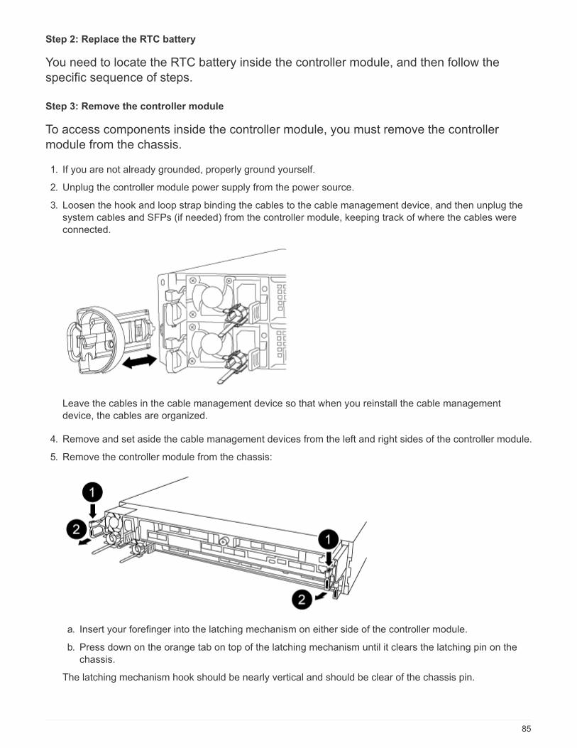
Step 2: Replace the RTC battery
You need to locate the RTC battery inside the controller module, and then follow the
specific sequence of steps.
Step 3: Remove the controller module
To access components inside the controller module, you must remove the controller
module from the chassis.
1. If you are not already grounded, properly ground yourself.
2. Unplug the controller module power supply from the power source.
3. Loosen the hook and loop strap binding the cables to the cable management device, and then unplug the
system cables and SFPs (if needed) from the controller module, keeping track of where the cables were
connected.
Leave the cables in the cable management device so that when you reinstall the cable management
device, the cables are organized.
4. Remove and set aside the cable management devices from the left and right sides of the controller module.
5. Remove the controller module from the chassis:
a. Insert your forefinger into the latching mechanism on either side of the controller module.
b. Press down on the orange tab on top of the latching mechanism until it clears the latching pin on the
chassis.
The latching mechanism hook should be nearly vertical and should be clear of the chassis pin.
85

a. Gently pull the controller module a few inches toward you so that you can grasp the controller module
sides.
b. Using both hands, gently pull the controller module out of the chassis and set it on a flat, stable
surface.
Step 4: Replace the RTC battery
1. Remove the PCIe cover.
a. Unscrew the blue thumbscrew located above the onboard ports at the back of the controller module.
b. Slide the cover toward you and rotate the cover upward.
c. Remove the cover and set it aside.
2. Locate, remove, and then replace the RTC battery:
a. Using the FRU map, locate the RTC battery on the controller module.
b. Gently push the battery away from the holder, rotate it away from the holder, and then lift it out of the
holder.
Note the polarity of the battery as you remove it from the holder. The battery is marked
with a plus sign and must be positioned in the holder correctly. A plus sign near the
holder tells you how the battery should be positioned.
c. Remove the replacement battery from the antistatic shipping bag.
86

d. Note the polarity of the RTC battery, and then insert it into the holder by tilting the battery at an angle
and pushing down.
3. Visually inspect the battery to make sure that it is completely installed into the holder and that the polarity is
correct.
4. Reinstall the PCIe cover on the controller module.
Step 5: Reinstall the controller module and setting time/date after RTC battery replacement
After you replace a component within the controller module, you must reinstall the
controller module in the system chassis, reset the time and date on the controller, and
then boot it.
1. If you have not already done so, close the air duct or controller module cover.
2. Align the end of the controller module with the opening in the chassis, and then gently push the controller
module halfway into the system.
Do not completely insert the controller module in the chassis until instructed to do so.
3. Recable the system, as needed.
If you removed the media converters (QSFPs or SFPs), remember to reinstall them if you are using fiber
optic cables.
4. If the power supplies were unplugged, plug them back in and reinstall the power cable retainers.
5. Complete the reinstallation of the controller module:
a. Make sure the latch arms are locked in the extended position.
b. Using the latch arms, push the controller module into the chassis bay until it stops.
Do not push down on the latching mechanism at the top of the latch arms. Doing so with
raise the locking mechanism and prohibit sliding the controller module into the chassis.
c. Press down and hold the orange tabs on top of the latching mechanism.
d. Gently push the controller module into the chassis bay until it is flush with the edges of the chassis.
The latching mechanism arms slide into the chassis.
The controller module begins to boot as soon as it is fully seated in the chassis.
e. Release the latches to lock the controller module into place.
f. If you have not already done so, reinstall the cable management device.
g. Halt the controller at the LOADER prompt.
6. Reset the time and date on the controller:
a. Check the date and time on the healthy controller with the show date command.
b. At the LOADER prompt on the target controller, check the time and date.
c. If necessary, modify the date with the set date mm/dd/yyyy command.
d. If necessary, set the time, in GMT, using the set time hh:mm:ss command.
87

e. Confirm the date and time on the target controller.
7. At the LOADER prompt, enter bye to reinitialize the PCIe cards and other components and let the
controller reboot.
8. Return the controller to normal operation by giving back its storage: storage failover giveback
-ofnode impaired_node_name
9. If automatic giveback was disabled, reenable it: storage failover modify -node local -auto
-giveback true
Step 6: Return the failed part to NetApp
After you replace the part, you can return the failed part to NetApp, as described in the
RMA instructions shipped with the kit. Contact technical support at NetApp Support, 888-
463-8277 (North America), 00-800-44-638277 (Europe), or +800-800-80-800
(Asia/Pacific) if you need the RMA number or additional help with the replacement
procedure.
88

Copyright Information
Copyright © 2022 NetApp, Inc. All rights reserved. Printed in the U.S. No part of this document
covered by copyright may be reproduced in any form or by any means-graphic, electronic, or
mechanical, including photocopying, recording, taping, or storage in an electronic retrieval system-
without prior written permission of the copyright owner.
Software derived from copyrighted NetApp material is subject to the following license and disclaimer:
THIS SOFTWARE IS PROVIDED BY NETAPP “AS IS” AND WITHOUT ANY EXPRESS OR IMPLIED
WARRANTIES, INCLUDING, BUT NOT LIMITED TO, THE IMPLIED WARRANTIES OF
MERCHANTABILITY AND FITNESS FOR A PARTICULAR PURPOSE, WHICH ARE HEREBY
DISCLAIMED. IN NO EVENT SHALL NETAPP BE LIABLE FOR ANY DIRECT, INDIRECT,
INCIDENTAL, SPECIAL, EXEMPLARY, OR CONSEQUENTIAL DAMAGES (INCLUDING, BUT NOT
LIMITED TO, PROCUREMENT OF SUBSTITUTE GOODS OR SERVICES; LOSS OF USE, DATA, OR
PROFITS; OR BUSINESS INTERRUPTION) HOWEVER CAUSED AND ON ANY THEORY OF
LIABILITY, WHETHER IN CONTRACT, STRICT LIABILITY, OR TORT (INCLUDING NEGLIGENCE OR
OTHERWISE) ARISING IN ANY WAY OUT OF THE USE OF THIS SOFTWARE, EVEN IF ADVISED OF
THE POSSIBILITY OF SUCH DAMAGE.
NetApp reserves the right to change any products described herein at any time, and without notice.
NetApp assumes no responsibility or liability arising from the use of products described herein,
except as expressly agreed to in writing by NetApp. The use or purchase of this product does not
convey a license under any patent rights, trademark rights, or any other intellectual property
rights of NetApp.
The product described in this manual may be protected by one or more U.S. patents,
foreign patents, or pending applications.
RESTRICTED RIGHTS LEGEND: Use, duplication, or disclosure by the government is subject to
restrictions as set forth in subparagraph (c)(1)(ii) of the Rights in Technical Data and
Computer Software clause at DFARS 252.277-7103 (October 1988) and FAR 52-227-19 (June 1987).
Trademark Information
NETAPP, the NETAPP logo, and the marks listed at http://www.netapp.com/TM are trademarks of
NetApp, Inc. Other company and product names may be trademarks of their respective owners.
89
Copyright © 2022 FDOKUMEN