COMMISSION DELEGATED REGULATION (EU) 2018/ 989
54
COMMISSION DELEGATED REGULATION (EU) 2018/989 of 18 May 2018 amending and correcting Delegated Regulation (EU) 2017/654 supplementing Regulation (EU) 2016/1628 of the European Parliament and of the Council with regard to technical and general requirements relating to emission limits and type-approval for internal combustion engines for non-road mobile machinery (Text with EEA relevance) THE EUROPEAN COMMISSION, Having regard to the Treaty on the Functioning of the European Union, Having regard to Regulation (EU) 2016/1628 of the European Parliament and of the Council of 14 September 2016 on requirements relating to gaseous and particulate pollutant emission limits and type-approval for internal combustion engines for non-road mobile machinery, amending Regulations (EU) No 1024/2012 and (EU) No 167/2013, and amending and repealing Directive 97/68/EC ( 1 ), and in particular Article 25(4)(a-d), Article 26(6), Article 42(4)(b) and Article 43(5) thereof, Whereas: (1) In order to enable the use of certain fuels legally marketed in some Member States without imposing an additional burden on manufacturers, the permitted content of fatty-acid methyl ester (‘FAME’) should be 8,0 % v/v instead of 7,0 % v/v. (2) In order to ensure consistency with Article 7(2) of Commission Implementing Regulation (EU) 2017/656 ( 2 ), where an existing RLL test report is submitted to obtain a Stage V type approval in accordance with that Article, it should be permitted to use the same version of ‘F’ test type cycle for the purposes of checking the conformity of production of engines type-approved on that cycle. (3) In order to improve the testing procedures for engines without an after-treatment system, specific requirements for determining deterioration factors should be established for engines without an after-treatment system. (4) In order to consider all possible emission control strategies, the technical requirements relating to emission control strategies should include the base emission control strategy and not only the auxiliary emission control strategy. (5) Emission control strategies' requirements were originally laid down for engines subject to a transient cycle. However, those requirements are not suitable for engines only subject to the NRSC which are not tested on a transient cycle. Existing engine transient emission control strategies should therefore be adapted to those engines by distinguishing between the conditions on the emission test (steady-state only) and any other operating conditions (transient). (6) In order to take into account the regeneration of an after-treatment system during the demonstration based on random point selection in accordance with point 3 of Annex V to Commission Delegated Regulation (EU) 2017/654 ( 3 ) and to clarify that an engine after-treatment system may regenerate before the emission test cycle is run, the test requirements referred to in point 4 of Annex V of Delegated Regulation (EU) 2017/654 should be modified accordingly with new specific provisions on regeneration. (7) In addition, to reduce the likelihood of regeneration during the test, the minimum sample time when the discrete-mode NRSC is used for the demonstration based on random point selection in accordance with point 3 of Annex V to Delegated Regulation (EU) 2017/654 should be reduced to 3 minutes per point. 18.7.2018 L 182/61 Official Journal of the European Union EN ( 1 ) OJ L 252, 16.9.2016, p. 53. ( 2 ) Commission Implementing Regulation (EU) 2017/656 of 19 December 2016 laying down the administrative requirements relating to emission limits and type-approval of internal combustion engines for non-road mobile machinery in accordance with Regulation (EU) 2016/1628 of the European Parliament and of the Council (OJ L 102, 13.4.2017, p. 364). ( 3 ) Commission Delegated Regulation (EU) 2017/654 of 19 December 2016 supplementing Regulation (EU) 2016/1628 of the European Parliament and of the Council with regard to technical and general requirements relating to emission limits and type-approval for internal combustion engines for non-road mobile machinery (OJ L 102, 13.4.2017, p. 1).
-
Upload
khangminh22 -
Category
Documents
-
view
0 -
download
0
Transcript of COMMISSION DELEGATED REGULATION (EU) 2018/ 989

COMMISSION DELEGATED REGULATION (EU) 2018989
of 18 May 2018
amending and correcting Delegated Regulation (EU) 2017654 supplementing Regulation (EU) 20161628 of the European Parliament and of the Council with regard to technical and general requirements relating to emission limits and type-approval for internal combustion engines for
non-road mobile machinery
(Text with EEA relevance)
THE EUROPEAN COMMISSION
Having regard to the Treaty on the Functioning of the European Union
Having regard to Regulation (EU) 20161628 of the European Parliament and of the Council of 14 September 2016 on requirements relating to gaseous and particulate pollutant emission limits and type-approval for internal combustion engines for non-road mobile machinery amending Regulations (EU) No 10242012 and (EU) No 1672013 and amending and repealing Directive 9768EC (1) and in particular Article 25(4)(a-d) Article 26(6) Article 42(4)(b) and Article 43(5) thereof
Whereas
(1) In order to enable the use of certain fuels legally marketed in some Member States without imposing an additional burden on manufacturers the permitted content of fatty-acid methyl ester (lsquoFAMErsquo) should be 80 vv instead of 70 vv
(2) In order to ensure consistency with Article 7(2) of Commission Implementing Regulation (EU) 2017656 (2) where an existing RLL test report is submitted to obtain a Stage V type approval in accordance with that Article it should be permitted to use the same version of lsquoFrsquo test type cycle for the purposes of checking the conformity of production of engines type-approved on that cycle
(3) In order to improve the testing procedures for engines without an after-treatment system specific requirements for determining deterioration factors should be established for engines without an after-treatment system
(4) In order to consider all possible emission control strategies the technical requirements relating to emission control strategies should include the base emission control strategy and not only the auxiliary emission control strategy
(5) Emission control strategies requirements were originally laid down for engines subject to a transient cycle However those requirements are not suitable for engines only subject to the NRSC which are not tested on a transient cycle Existing engine transient emission control strategies should therefore be adapted to those engines by distinguishing between the conditions on the emission test (steady-state only) and any other operating conditions (transient)
(6) In order to take into account the regeneration of an after-treatment system during the demonstration based on random point selection in accordance with point 3 of Annex V to Commission Delegated Regulation (EU) 2017654 (3) and to clarify that an engine after-treatment system may regenerate before the emission test cycle is run the test requirements referred to in point 4 of Annex V of Delegated Regulation (EU) 2017654 should be modified accordingly with new specific provisions on regeneration
(7) In addition to reduce the likelihood of regeneration during the test the minimum sample time when the discrete-mode NRSC is used for the demonstration based on random point selection in accordance with point 3 of Annex V to Delegated Regulation (EU) 2017654 should be reduced to 3 minutes per point
1872018 L 18261 Official Journal of the European Union EN
(1) OJ L 252 1692016 p 53 (2) Commission Implementing Regulation (EU) 2017656 of 19 December 2016 laying down the administrative requirements relating to
emission limits and type-approval of internal combustion engines for non-road mobile machinery in accordance with Regulation (EU) 20161628 of the European Parliament and of the Council (OJ L 102 1342017 p 364)
(3) Commission Delegated Regulation (EU) 2017654 of 19 December 2016 supplementing Regulation (EU) 20161628 of the European Parliament and of the Council with regard to technical and general requirements relating to emission limits and type-approval for internal combustion engines for non-road mobile machinery (OJ L 102 1342017 p 1)
(8) For the purpose of comprehensiveness the manufacturer should include in the information folder as set out in Part A of Annex I to Implementing Regulation (EU) 2017656 demonstration reports documenting the demonstrations conducted pursuant to specific technical requirements and procedures set out in Delegated Regulation (EU) 2017654
(9) The reference to the provisions of Regulation (EU) 20161628 requiring that deterioration factors are taken into account in the emission laboratory test results set out in Article 4 of Delegated Regulation (EU) 2017654 is incorrect and should be corrected
(10) To ensure consistency of Regulation (EU) 20161628 and all Delegated and Implementing Regulations adopted pursuant to that Regulation some requirements applicable to engine-after-treatment system families should also be applicable to engine families or groups of engine families
(11) Certain changes should be made to provisions containing contradictions or redundant information and certain references should be corrected
(12) Following the publication of Delegated Regulation (EU) 2017654 further errors of different types such as terminology and numbering have been detected and need to be corrected
(13) Delegated Regulation (EU) 2017654 should therefore be amended and corrected accordingly
HAS ADOPTED THIS REGULATION
Article 1
Amendments to Delegated Regulation (EU) 2017654
Delegated Regulation (EU) 2017654 is amended as follows
(1) the following Article 20a is inserted
lsquoArticle 20a
Transitional provisions
1 Notwithstanding the application of the provisions of this Regulation as amended by Commission Delegated Regulation (EU) 2018989 approval authorities shall until 31 December 2018 also continue to grant EU type- approvals to engine types or engine families in accordance with this Regulation in its version applicable on 6 August 2018
2 Notwithstanding the application of the provisions of this Regulation as amended by Commission Delegated Regulation (EU) 2018989 the Member States shall until 30 June 2019 also permit the placing on the market of engines based on an engine type approved in accordance with this Regulation in its version applicable on 6 August 2018rsquo
(2) Annex I is amended in accordance with Annex I to this Regulation
(3) Annex II is amended in accordance with Annex II to this Regulation
(4) Annex III is amended in accordance with Annex III to this Regulation
(5) Annex IV is amended in accordance with Annex IV to this Regulation
(6) Annex V is amended in accordance with Annex V to this Regulation
(7) Annex VI is amended in accordance with Annex VI to this Regulation
(8) Annex VII is amended in accordance with Annex VII to this Regulation
(9) Annex VIII is amended in accordance with Annex VIII to this Regulation
(10) Annex IX is amended in accordance with Annex IX to this Regulation
(11) Annex XIII is amended in accordance with Annex X to this Regulation
(12) Annex XV is amended in accordance with Annex XI to this Regulation
1872018 L 18262 Official Journal of the European Union EN
Article 2
Corrections to Delegated Regulation (EU) 2017654
Delegated Regulation (EU) 2017654 is corrected as follows
(1) Article 4 is replaced by the following
lsquoArticle 4
Methodology for adapting the emission laboratory test results to include the deterioration factors
The emission laboratory test results shall be adapted to include the deterioration factors comprising those related with the measurement of the particle number (PN) and with gaseous-fuelled engines referred to in Article 25(1)(c) of Regulation (EU) 20161628 in accordance with the methodology laid down in Annex III to this Regulationrsquo
(2) Annex I is corrected in accordance with Annex XII to this Regulation
(3) in Annex II point 332 is replaced by the following
lsquo332 The initial assessment and verification of product conformity arrangements may also be carried out in cooperation with the approval authority of another Member State or the appointed body designated for this purpose by the approval authorityrsquo
(4) Annex III is corrected in accordance with Annex XIII to this Regulation
(5) Annex IV is corrected in accordance with Annex XIV to this Regulation
(6) Annex V is corrected in accordance with Annex XV to this Regulation
(7) Annex VI is corrected in accordance with Annex XVI to this Regulation
(8) Annex VII is corrected in accordance with Annex XVII to this Regulation
(9) Annex VIII is corrected in accordance with Annex XVIII to this Regulation
Article 3
Entry into force
This Regulation shall enter into force on the twentieth day following that of its publication in the Official Journal of the European Union
This Regulation shall be binding in its entirety and directly applicable in all Member States
Done at Brussels 18 May 2018
For the Commission
The President Jean-Claude JUNCKER
1872018 L 18263 Official Journal of the European Union EN
ANNEX I
Annex I to Delegated Regulation (EU) 2017654 is amended as follows
(1) point 122 is replaced by the following
lsquo122 In the absence of either a standard from the European Committee for Standardization (ldquoCEN standardrdquo) for non-road gas-oil or a table of fuel properties for non-road gas-oil in Directive 9870EC of the European Parliament and of the Council () the diesel (non-road gas-oil) reference fuel in Annex IX shall represent market non-road gas-oils with a sulphur content not greater than 10 mgkg cetane number not less than 45 and a fatty-acid methyl ester (ldquoFAMErdquo) content not greater than 80 vv Except where otherwise permitted in accordance with points 1221 123 and 124 the manufacturer shall make a corresponding declaration to the end-users in accordance with the requirements in Annex XV that operation of the engine on non-road gas-oil is limited to those fuels with a sulphur content not greater than 10 mgkg (20 mgkg at point of final distribution) cetane number not less than 45 and a FAME content not greater than 80 vv The manufacturer may optionally specify other parameters (eg for lubricity)
() Directive 9870EC of the European Parliament and of the Council of 13 October 1998 relating to the quality of petrol and diesel fuels and amending Council Directive 9312EEC (OJ L 350 28121998 p 58)rsquo
(2) point 1221 is amended as follows
(a) the first paragraph is replaced by the following
lsquoThe engine manufacturer shall not indicate at any time that an engine type or engine family may be operated within the Union on market fuels other than those that comply with the requirements in this point unless the manufacturer additionally complies with the requirement in point 123rsquo
(b) point (c) is replaced by the following
lsquo(c) In the case of diesel (non-road gas-oil) Directive 9870EC and also both a cetane number not less than 45 and FAME not greater than 80 vvrsquo
(3) point 2414 is deleted
1872018 L 18264 Official Journal of the European Union EN
ANNEX II
Annex II to Delegated Regulation (EU) 2017654 is amended as follows
(1) the following point 6231 is inserted
lsquo6231 Notwithstanding point 623 in the case of engines of category RLL where an existing test report is used for type-approval in accordance with Article 7(2) of Implementing Regulation (EU) 2017656 the per cent load and power and the weighting factor for the mode number of the test cycle type F for the purpose of this Annex may be the same as that used for the type-approval testrsquo
(2) in point 624 the words lsquo as determined in accordance with Annex IIIrsquo are replaced by the words lsquothat were determined in accordance with Annex IIIrsquo
(3) in point 64 the third sentence is replaced by the following
lsquoFor engines fuelled with natural gasbiomethane (NG) or liquefied petroleum gas (LPG) including dual-fuel engines the tests shall be performed with at least two of the reference fuels for each gaseous-fuelled engine except in the case of a gaseous-fuelled engine with a fuel-specific type-approval where only one reference fuel is required as described in Appendix 1 to Annex Irsquo
1872018 L 18265 Official Journal of the European Union EN
ANNEX III
Annex III to Delegated Regulation (EU) 2017654 is amended as follows
(1) points 313 and 314 are replaced by the following
lsquo313 The test engine shall represent the emission deterioration characteristics of the engine families that will apply the resulting deterioration factors for type approval The engine manufacturer shall select one engine representing the engine family group of engine families or engine-after-treatment system family as determined in accordance with point 312 for testing over the service accumulation schedule referred to in point 322 which shall be reported to the approval authority before any testing commences
314 If the approval authority decides that the worst case emissions of the engine family group of engine families or engine-after-treatment system family can be better characterised by another test engine the test engine to be used shall be selected jointly by the approval authority and the engine manufacturerrsquo
(2) point 321 is replaced by the following
lsquo321 General
Deterioration factors applicable to an engine family group of engine families or an engine-after-treatment system family shall be developed from the selected engines based on a service accumulation schedule that includes periodic testing for gaseous and particulate emissions over each test cycle applicable to the engine category as given in Annex IV to Regulation (EU) 20161628 In the case of non-road transient test cycles for engines of category NRE (ldquoNRTCrdquo) only the results of the hot-start run of the NRTC (ldquohot-start NRTCrdquo) shall be usedrsquo
(3) in point 3252 the last paragraph is replaced by the following
lsquoWhere emission values are used for engine families in the same group of engine families or engine-after-treatment family but with different emission durability periods then the emission values at the emission durability period end point shall be recalculated for each emission durability period by extrapolation or interpolation of the regression equation as determined in point 3251rsquo
(4) in point 3261 the last paragraph is deleted
(5) the following point 32611 is inserted
lsquo32611 Notwithstanding point 3261 for PN either an additive DF of 00 or a multiplicative DF of 10 may be used in conjunction with the results of previous DF testing that did not establish a value for PN if both of the following conditions are fulfilled
(a) the previous DF test was conducted on engine technology that would have qualified for inclusion in the same engine after-treatment system family as set out in point 312 as the engine family to which it is intended to apply the DFs and
(b) the test results were used in a previous type-approval granted before the applicable EU type-approval date given in Annex III to Regulation (EU) 20161628rsquo
1872018 L 18266 Official Journal of the European Union EN
ANNEX IV
Annex IV to Delegated Regulation (EU) 2017654 is amended as follows
(1) the following points 2231 and 224 are inserted
lsquo2231 Notwithstanding point 223 in the case of engine (sub-)categories that are not subject to non-road transient test cycles for EU type-approval purposes the base emission control strategy may identify when transient operating conditions occur and apply the corresponding emission control strategy In this case this emission control strategy shall be included in the overview of the base emission control strategy required by point 14 of Annex I to Implementing Regulation (EU) 2017656 and in the confidential information on emission control strategy set out in Appendix 2 to that Annex
224 The manufacturer shall demonstrate to the technical service at the time of the EU type-approval test that the operation of the base emission control strategy complies with the provisions of this section on the basis of the documentation referred to in point 26rsquo
(2) in point 26 the paragraph under the heading is deleted
(3) the following points 261 and 262 are inserted
lsquo261 The manufacturer shall comply with the documentation requirements laid down in point 14 of Part A of Annex I to Implementing Regulation (EU) 2017656 and Appendix 2 to that Annex
262 The manufacturer shall ensure that all documents used for this purpose are marked with an identification number and date of issue The manufacturer shall notify to the approval authority whenever the particulars recorded are changed In this case it shall issue either a updated version of the documents concerned where the relevant pages are marked clearly showing the date of revision and the nature of the amendment or alternatively a new consolidated version accompanied by an index containing a detailed description and date of each amendmentrsquo
(4) Appendix 1 is amended as follows
(a) point 221 is replaced by the following
lsquo221 Monitoring for reagent level in the storage tank shall be conducted under all conditions where measurement is technically feasible (for instance under all conditions when a liquid reagent is not frozen)rsquo
(b) the following points 222 and 223 are inserted
lsquo222 Reagent freeze protection shall apply at ambient temperatures at or below 266 K (ndash 7 degC)
223 All elements of the NOx control diagnostic system other than those listed in points 221 and 222 shall at a minimum be operational at the applicable control conditions set out in point 24 of this Annex for each engine category The diagnostic system shall remain operational outside of this range where technically possiblersquo
(c) the following point 23224 is inserted
lsquo23224 Evaluation of the design criteria may be performed in a cold chamber test cell using an entire non- road mobile machinery or parts representative of those to be installed on a non-road mobile machinery or based on field testsrsquo
(d) point 2323 is replaced by the following
lsquo2323 Activation of the operator warning and inducement system for a non-heated systemrsquo
(e) the following points 23231 and 23232 are inserted
lsquo23231 The operator warning system described in points 4 to 49 shall be activated if no reagent dosing occurs at an ambient temperature le 266 K (ndash 7 degC)
23232 The severe inducement system as referred to in point 54 shall be activated if no reagent dosing occurs within a maximum of 70 minutes after engine start at an ambient temperature le 266 K (ndash 7 degC)rsquo
(f) points 233 2331 and 2332 are deleted
1872018 L 18267 Official Journal of the European Union EN
(g) in point 5211 the following point (ea) is inserted
lsquo(ea) A description of the connection for and method to read the records referred to in point (e) shall be included in the information folder set out in Part A of Annex I to Implementing Regulation (EU) 2017656rsquo
(h) point 95 is replaced by the following
lsquo95 As an alternative to the monitoring requirements set out in point 92 the manufacturer may monitor for failures using a NOx sensor located in the exhaust system In this case
(a) the NOx value at which the NCM shall be detected shall not exceed the lower of either the applicable NOx limit multiplied by 225 or the applicable NOx limit plus 15 gkWh For engine sub-categories with a combined HC and NOx limit the applicable NOx limit value for the purpose of this point shall be the combined limit value for HC and NOx reduced by 019 gkWh
(b) a single warning may be used including where messages are used the statement ldquohigh NOx ndash root cause unknownrdquo
(c) in point 941 the maximum number of engine operating hours between the activation of the operator warning system and the activation of the low-level inducement system shall be reduced to 10
(d) in point 942 the maximum number of engine operating hours between the activation of the operator warning system and the activation of the severe inducement system shall be reduced to 20rsquo
(i) points 1031 to 10331 are replaced by the following
lsquo1031 The compliance of the warning system activation shall be demonstrated by performing two tests lack of reagent and one failure category identified in sections 7 8 or 9
1032 Selection of the failure to be tested among those referred to in sections 7 8 or 9
10321 The approval authority shall select one failure category In the case that a failure is selected from points 7 or 9 the additional requirements set out in points 10322 or 10323 shall apply respectively
10322 For the purpose of demonstrating the activation of the warning system in case of a wrong reagent quality a reagent shall be selected with a dilution of the active ingredient at least as dilute as that communicated by the manufacturer in accordance with the requirements set out in points 7 to 733
10323 For the purpose of demonstrating the activation of the warning system in case of failures that may be attributed to tampering and are defined in section 9 the selection shall be performed in accordance with the following requirements
103231 The manufacturer shall provide the approval authority with a list of such potential failures
103232 The failure to be considered in the test shall be selected by the approval authority from the list referred to in point 103231
1033 Demonstration
10331 For the purpose of this demonstration a separate test shall be performed for the lack of reagent and the failure selected in accordance with points 1032 to 103232rsquo
(j) the following points 105 and 1051 are inserted
lsquo105 Documentation of the demonstration
1051 A demonstration report shall document the demonstration of the NCD system The report shall
(a) identify the failures examined
(b) describe the demonstration performed including the applicable test cycle
(c) confirm that the applicable warnings and inducements were activated as required by this regulation and
(d) be included in the information folder as set out in Part A of Annex I of Implementing Regulation (EU) 2017656rsquo
1872018 L 18268 Official Journal of the European Union EN
(k) points 11411 and 114111 are replaced by the following
lsquo11411 To comply with the requirements of this Appendix the system shall contain counters to record the number of hours during which the engine has been operated while the system has detected any of the following NCM
(a) an incorrect reagent quality
(b) an interruption of reagent dosing activity
(c) an impeded EGR valve
(d) a failure of the NCD system
114111 The manufacturer may use one or more counters for grouping the NCMs indicated in point 11411rsquo
(l) the following points 134 and 1341 are added
lsquo134 Documentation of the demonstration
1341 A demonstration report shall document the demonstration of the minimum acceptable reagent concenshytration The report shall
(a) identify the failures examined
(b) describe the demonstration performed including the applicable test cycle
(c) confirm that the pollutant emissions arising from this demonstration did not exceed the NOx threshold specified in point 711
(d) be included in the information folder as set out in Part A of Annex I to Implementing Regulation (EU) 2017656rsquo
(5) Appendix 2 is amended as follows
(a) points 2 to 45 are replaced by the following
lsquo2 General requirements
The requirements of Appendix 1 apply to engines in scope of this Appendix except as set out in points 3 and 4 of this Appendix
3 Exceptions to the requirements of Appendix 1
In order to account for safety concerns the operator inducement system set out in points 5 and 113 of Appendix 1 shall not apply to engines under the scope of this Appendix The requirement to store data in an on-board computer log set out in point 4 of this Appendix shall apply wherever the inducement would have been activated in accordance with points 23232 63 73 84 and 94 of Appendix 1
4 Requirement for storing incidents of engine operation with inadequate reagent injection or reagent quality
41 The on-board computer log must record in non-volatile computer memory or counters the total number and duration of all incidents of engine operation with inadequate reagent injection or reagent quality in a manner to ensure that the information cannot be intentionally deleted
411 It shall be possible for national inspection authorities to read these records with a scan tool
412 A description of the connection for and method to read these records shall be included in the information folder as set out in Part A of Annex I of Implementing Regulation (EU) 2017656
42 The duration of an incident of inadequate reagent level recorded in the on-board computer log as specified in point 41 in place of an inducement in accordance with point 63 of Appendix 1 shall commence when the reagent tank becomes empty that is when the dosing system is unable to draw further reagent from the tank or at any level below 25 of its nominally full capacity at the discretion of the manufacturer
43 The duration of an incident recorded in the on-board computer log as specified in point 41 in place of the inducement specified in points 63 73 84 and 94 of Appendix 1 shall commence when the respective counter reaches the value for severe inducement in Table 44 of Appendix 1
1872018 L 18269 Official Journal of the European Union EN
44 The duration of an incident recorded in the on-board computer log as specified in point 41 in place of the inducement specified in point 23232 of Appendix 1 shall commence when inducement would have commenced
45 The duration of an incident recorded in the on-board computer log as specified in point 41 shall end when the incident has been remediedrsquo
(b) the following point 46 is inserted
lsquo46 When conducting a demonstration pursuant to section 104 of Appendix 1 the demonstration shall be conducted in accordance with the requirements applicable to demonstration of the severe inducement system but the demonstration of severe inducement system shall be replaced by a demonstration of the storage of an incident of engine operation with inadequate reagent injection or reagent qualityrsquo
(6) Appendix 4 is amended as follows
(a) point 221 is replaced by the following
lsquo221 The PCD system shall at a minimum be operational at the applicable control conditions set out in point 24 of Annex IV for each engine category The diagnostic system shall remain operational outside of this range where technically possiblersquo
(b) point 31 is replaced by the following
lsquo31 The OEM shall provide to all end-users of new non-road mobile machinery written instructions about the emission control system and its correct operation as required in Annex XVrsquo
(c) the following point 54 is inserted
lsquo54 A description of the connection for and method to read these records shall be included in the information folder as set out in Part A of Annex I of Implementing Regulation (EU) 2017656rsquo
(d) point 921 is replaced by the following
lsquo921 In the case where engines of an engine family belong to a PCD engine family that has already been EU type-approved in accordance with point 236 (Figure 48) the compliance of that engine family is deemed to be demonstrated without further testing provided the manufacturer demonstrates to the authority that the monitoring systems necessary for complying with the requirements of this Appendix are similar within the considered engine and PCD engine families
Figure 48
Previously demonstrated conformity of a PCD engine family
rsquo
1872018 L 18270 Official Journal of the European Union EN
(e) in point 93362 point (a) is replaced by the following
lsquo(a) the requested test-cycle results in a monitor that will run in real world operation conditions andrsquo
(f) the following points 936 and 9361 are added
lsquo936 Documentation of the demonstration
9361 A demonstration report shall document the demonstration of the PCD system The report shall
(a) identify the failures examined
(b) describe the demonstration performed including the applicable test cycle
(c) confirm that the applicable warnings were activated as required by this regulation
(d) be included in the information folder as set out in Part A of Annex I to Implementing Regulation (EU) 2017656rsquo
1872018 L 18271 Official Journal of the European Union EN
ANNEX V
Annex V to Delegated Regulation (EU) 2017654 is amended as follows
(1) point 212 is amended as follows
(a) Figure 52 is replaced by the following
lsquoFigure 52
Control area for variable-speed engines of category NRE with maximum net power lt 19 kW and variable-speed engines of category IWA with maximum net power lt 300 kW
speed C lt 2 400 rpm
Key
1 Engine Control Area 2 All Emissions Carve-Out
3 PM Carve-Out a of maximum net power
b of maximum torquersquo
1872018 L 18272 Official Journal of the European Union EN
(b) Figure 53 is replaced by the following
lsquoFigure 53
Control area for variable-speed engines of category NRE with maximum net power lt 19 kW and variable-speed engines of category IWA with maximum net power lt 300 kW
speed C ge 2 400 rpm
Key
1 Engine Control Area 2 All Emissions Carve-Out
3 PM Carve-Out a Percent of maximum net power
b Percent of maximum torquersquo
(2) the following point 31 is inserted
lsquo31 For the purpose of the random selections required in point 3 acknowledged statistical methods of randomishyzation shall be usedrsquo
(3) point 4 is amended as follows
(a) the introductory wording is replaced by the following
lsquoThe test shall be carried out immediately after the applicable NRSC as followsrsquo
(b) point (a) is replaced by the following
lsquo(a) the test of the randomly selected torque and speed points shall either be carried out immediately after the discrete-mode NRSC test sequence described in points (a) to (e) of point 7812 of Annex VI but before the post test procedures (f) or after the ramped modal non-road steady- state test cycle (ldquoRMCrdquo) test sequence described in points (a) to (d) of point 7823 of Annex VI but before the post test procedures (e) as relevantrsquo
(c) points (e) and (f) are replaced by the following
lsquo(e) for gaseous and PN if applicable summation calculations Nmode in equations (7-64) or (7-131) and (7-178) shall be set to 1 and a weighting factor of 1 shall be used
(f) for PM calculations the multiple filter method shall be used for summation calculations Nmode in equations (7-67) or (7-134) shall be set to 1 and a weighting factor of 1 shall be usedrsquo
1872018 L 18273 Official Journal of the European Union EN
(4) the following point 5 is added
lsquo5 Regeneration
In the case that a regeneration event occurs during or immediately preceding the procedure set out in point 4 upon completion of that procedure the test may be voided at the request of the manufacturer irrespective of the cause of the regeneration In this case the test shall be repeated The same torque and speed points shall be used although the running order may be changed It shall not be deemed necessary to repeat any torque and speed points for which a pass result has already been obtained The following procedure shall be used for repeating the test
(a) The engine shall be operated in a manner to ensure that the regeneration event has completed and where applicable the soot load in the particulate after-treatment system has been re-established
(b) The engine warm-up procedure shall be performed in accordance with point 7811 of Annex VI
(c) The test procedure specified in point 4 shall be repeated commencing at the stage referred to in point 4(b)rsquo
1872018 L 18274 Official Journal of the European Union EN
ANNEX VI
Annex VI to Delegated Regulation (EU) 2017654 is amended as follows
(1) point 1 is replaced by the following
lsquo1 Introduction
This Annex describes the method of determining emissions of gaseous and particulate pollutants from the engine to be tested and the specifications related to the measurement equipment As from section 6 the numbering of this Annex is consistent with the numbering of the Global technical regulation No 11 () (GTR No 11) and UNECE Regulation No 9604 series of amendments () Annex 4B However some points of the GTR No 11 are not needed in this Annex or are modified in accordance with the technical progress
() Global technical regulation No 11 on Engine Emissions from agricultural and forestry tractors and from non- road mobile machinery under the Global Registry created on 18 November 2004 pursuant to Article 6 of the Agreement concerning the establishing of global technical regulations for wheeled vehicles equipment and parts which can be fitted andor be used on wheeled vehicles
() Regulation No 96 of the Economic Commission for Europe of the United Nations (UNECE) mdash Uniform provisions concerning the approval of compression ignition (CI) engines to be installed in agricultural and forestry tractors and in non-road mobile machinery with regard to the emissions of pollutants by the enginersquo
(2) in point 51 the second third and fourth paragraphs are replaced by the following
lsquoThe measured values of gaseous and particulate pollutants and of CO2 exhausted by the engine refer to the brake- specific emissions in grams per kilowatt-hour (gkWh) or number per kilowatt-hour (kWh) for PN
The gaseous and particulate pollutants that shall be measured are those for which limit values are applicable to the engine sub-category being tested as set out in Annex II to Regulation (EU) 20161628 The results inclusive of
(a) the crankcase emissions determined in accordance with section 610 if relevant
(b) the adjustment factors for infrequent regeneration of the after-treatment system determined in accordance with section 66 if relevant and
(c) as the final step of the calculation the deterioration factor determined in accordance with Annex III
shall not exceed the applicable limit values
The CO2 shall be measured and reported for all engine sub-categories as required by Article 43(4) of Regulation (EU) 20161628rsquo
(3) point 52511 is replaced by the following
lsquo52511 Calculation of MTS
In order to calculate the MTS the transient mapping procedure shall be performed in accordance with point 74 The MTS is then determined from the mapped values of engine speed versus power MTS shall be calculated by means of one of the following options
(a) Calculation based upon low speed and high speed values
MTS = nlo + 095 (nhi ndash nlo) (6-1)
where
nhi is the high speed as defined in Article 1(12)
nlo is the low speed as defined in Article 1(13)
(b) Calculation based upon the longest vector method
MTS = ni (6-2)
where
ni is the average of the lowest and highest speeds at which (n2normi + P2
normi) is equal to 98 of the maximum value of (n2
normi + P2normi)
1872018 L 18275 Official Journal of the European Union EN
If there is only one speed at which the value of (n2normi + P2
normi) is equal to 98 of the maximum value of (n2
normi + P2normi)
MTS = ni (6-3)
where
ni is the speed at which the maximum value of (n2normi + P2
normi) occurs
where
n is the engine speed
i is an indexing variable that represents one recorded value of an engine map
nnormi is an engine speed normalized by dividing it by nPmax
Pnormi is an engine power normalized by dividing it by Pmax
nPmax is the average of the lowest and highest speeds at which power is equal to 98 of Pmax
Linear interpolation shall be used between the mapped values to determine
(i) the speeds where power is equal to 98 of Pmax If there is only one speed at which power is equal to 98 of Pmax nPmax shall be the speed at which Pmax occurs
(ii) the speeds where (n2normi + P2
normi) is equal to 98 of the maximum value of (n2normi + P2
normi)rsquo
(4) point 5252 is amended as follows
(a) the first paragraph is replaced by the following
lsquoThe rated speed is defined in Article 3(29) of Regulation (EU) 20161628 Rated speed for variable-speed engines subject to an emission test other than those tested on a constant-speed NRSC defined in Article 1(31) of this Regulation shall be determined from the applicable mapping procedure set out in point 76 of this Annex Rated speed for variable-speed engines tested on a constant-speed NRSC shall be declared by the manufacturer according to the characteristics of the engine Rated speed for constant-speed engines shall be declared by the manufacturer according to the characteristics of the governor Where an engine type equipped with alternative speeds as permitted by Article 3(21) of Regulation (EU) 20161628 is subject to an emission test each alternative speed shall be declared and testedrsquo
(b) the third paragraph is replaced by the following
lsquoFor engines of category NRSh the 100 test speed shall be within plusmn 350 rpm of the rated speed declared by the manufacturerrsquo
(5) point 5253 is amended as follows
(a) the introductory wording of the first paragraph is replaced by the following
lsquoWhere required the maximum torque speed determined from the maximum torque curve established by the applicable engine mapping procedure in point 761 or 762 shall be one of the followingrsquo
(b) in the last paragraph the words lsquoengines of category NRS or NRShrsquo are replaced by the words lsquoengines of category NRSrsquo
(6) in point 62 the first paragraph is replaced by the following
lsquoA charge-air cooling system with a total intake-air capacity that represents production engines in-use installation shall be used Any laboratory charge-air cooling system shall be designed to minimize accumulation of condensate Any accumulated condensate shall be drained and all drains shall be completely closed before emission testing The drains shall be kept closed during the emission test Coolant conditions shall be maintained as follows
(a) a coolant temperature of at least 293 K (20 degC) shall be maintained at the inlet to the charge-air cooler throughout testing
1872018 L 18276 Official Journal of the European Union EN
(b) at the rated speed and full load the coolant flow rate shall be set to achieve an air temperature within plusmn 5 K (plusmn 5 degC) of the value designed by the manufacturer after the charge-air coolers outlet The air- outlet temperature shall be measured at the location specified by the manufacturer This coolant flow rate set point shall be used throughout testing
(c) if the engine manufacturer specifies pressure-drop limits across the charge-air cooling system it shall be ensured that the pressure drop across the charge-air cooling system at engine conditions specified by the manufacturer is within the manufacturers specified limit(s) The pressure drop shall be measured at the manufacturers specified locationsrsquo
(7) point 634 is replaced by the following
lsquo634 Determination of auxiliary power
Where applicable as per point 632 and 633 the values of auxiliary power and the measurementcalcushylation method for determining auxiliary power shall be submitted by the engine manufacturer for the whole operating area of the applicable test cycles and approved by the approval authorityrsquo
(8) point 6623 is amended as follows
(a) the last sentence of the first paragraph is replaced by the following
lsquoThe exact procedure to determine this frequency shall be agreed by the approval authority based upon good engineering judgementrsquo
(b) the title of Figure 61 is replaced by the following
lsquoFigure 61
Scheme of infrequent regeneration with n number of measurements and nr number of measurements during regenerationrsquo
(c) equation (6-9) and the legend thereof are replaced by the following
lsquoew frac14n e thorn nr er
n thorn nr (6-9)
Where
n is the number of tests in which regeneration does not occur
nr is the number of tests in which regeneration occurs (minimum one test)
e is the average specific emission from a test in which the regeneration does not occur [gkWh or kWh]
er is the average specific emission from a test in which the regeneration occurs [gkWh or kWh]rsquo
(d) equations (6-10) and (6-11) are replaced by the following
lsquokrum frac14ew
e (upward adjustment factor) (6-10)
krdm frac14ew
er (downward adjustment factor) (6-11)rsquo
(a) equations (6-12) and (6-13) are replaced by the following
lsquokrua frac14 ew minus e (upward adjustment factor) (6-12)
krda frac14 ew minus er (downward adjustment factor) (6-13)rsquo
(9) in point 6624 in the third paragraph point (b) is replaced by the following
lsquo(b) Upon request by the manufacturer the approval authority may account for regeneration events differently than pursuant to point (a) However this option only applies to events that occur extremely infrequently and which cannot be practically addressed using the adjustment factors described in point 6623rsquo
(10) point 7311 is amended as follows
(a) the heading is replaced by the following
lsquo7311 General requirements for preconditioning the sampling system and the enginersquo
1872018 L 18277 Official Journal of the European Union EN
(b) the following paragraph is added
lsquoEngines fitted with an after-treatment system may be operated prior to cycle-specific preconditioning set out in points 73111 to 73114 so that the after-treatment system is regenerated and where applicable the soot load in the particulate after-treatment system is re-establishedrsquo
(11) point 73115 is deleted
(12) points 7312 to 7315 are replaced by the following
lsquo7312 Engine cool-down (NRTC)
A natural or forced cool-down procedure may be applied For forced cool-down good engineering judgment shall be used to set up systems to send cooling air across the engine to send cool oil through the engine lubrication system to remove heat from the coolant through the engine cooling system and to remove heat from an exhaust after-treatment system In the case of a forced after-treatment cool down cooling air shall not be applied until the exhaust after-treatment system has cooled below its catalytic activation temperature Any cooling procedure that results in unrepresentative emissions is not permitted
7313 Verification of HC contamination
If there is any presumption of an essential HC contamination of the exhaust gas measuring system the contamination with HC may be checked with zero gas and the hang-up may then be corrected If the amount of contamination of the measuring system and the background HC system has to be checked it shall be conducted within 8 hours of starting each test-cycle The values shall be recorded for later correction Before this check the leak check has to be performed and the FID analyzer has to be calibrated
7314 Preparation of measurement equipment for sampling
The following steps shall be taken before emission sampling begins
(a) Leak checks shall be performed within 8 hours prior to emission sampling in accordance with point 8187
(b) For batch sampling clean storage media shall be connected such as evacuated bags or tare-weighed filters
(c) All measurement instruments shall be started in accordance with the instrument manufacturers instructions and good engineering judgment
(d) Dilution systems sample pumps cooling fans and the data-collection system shall be started
(e) The sample flow rates shall be adjusted to desired levels using bypass flow if desired
(f) Heat exchangers in the sampling system shall be pre-heated or pre-cooled to within their operating temperature ranges for a test
(g) Heated or cooled components such as sample lines filters chillers and pumps shall be allowed to stabilize at their operating temperatures
(h) Exhaust gas dilution system flow shall be switched on at least 10 minutes before a test sequence
(i) Calibration of gas analyzers and zeroing of continuous analyzers shall be carried out in accordance with the procedure of point 7315
(j) Any electronic integrating devices shall be zeroed or re-zeroed before the start of any test interval
7315 Calibration of gas analyzers
Appropriate gas analyzer ranges shall be selected Emission analyzers with automatic or manual range switching are allowed During a test using transient (NRTC or LSI-NRTC) test cycles or RMC and during a sampling period of a gaseous emission at the end of each mode for discrete-mode NRSC testing the range of the emission analyzers shall not be switched Also the gains of an analyzers analogue operational amplifier(s) shall not be switched during a test cycle
1872018 L 18278 Official Journal of the European Union EN
All continuous analyzers shall be zeroed and spanned using internationally-traceable gases that meet the specifications of point 951 FID analyzers shall be spanned on a carbon number basis of one (C1)rsquo
(13) the following point 7316 is inserted
lsquo7316 PM filter preconditioning and tare weighing
The procedures for PM filter preconditioning and tare weighing shall be performed in accordance with point 823rsquo
(14) point 74 is replaced by the following
lsquo74 Test cycles
The EU type-approval test shall be conducted using the appropriate NRSC and where applicable NRTC or LSI-NRTC specified in Article 18 of Regulation (EU) 20161628 and Annex IV thereto The technical specifishycations and characteristics of the NRSC NRTC and LSI-NRTC are laid down in Annex XVII of this Regulation and the method for determination of the torque power and speed settings for these test cycles set out in section 52rsquo
(15) point 75 is amended as follows
(a) in the first paragraph point (h) is replaced by the following
lsquo(h) PM filter(s) shall be pre-conditioned weighed (empty weight) loaded re-conditioned again weighed (loaded weight) and then samples shall be evaluated in accordance with the pre-test (point 7316) and post-test (point 7322) proceduresrsquo
1872018 L 18279 Official Journal of the European Union EN
(b) Figure 64 is replaced by the following
lsquoFigure 64
Test sequence
rsquo
(16) in point 7512 points (a) and (b) are replaced by the following
lsquo(a) If the engine stalls anywhere during the cold start run of the NRTC the entire test shall be voided
(b) If the engine stalls anywhere during the hot-start run of the NRTC only this run shall be voided The engine shall be soaked in accordance with point 783 and the hot-start run repeated In this case the cold-start run does not need to be repeatedrsquo
1872018 L 18280 Official Journal of the European Union EN
(17) point 7812 is amended as follows
(a) point (b) is replaced by the following
lsquo(b) Each mode has a mode length of at least 10 minutes In each mode the engine shall be stabilised for at least 5 minutes Gaseous emissions and where applicable PN shall be sampled for 1 to 3 minutes at the end of each mode and PM emissions shall be sampled in accordance with point (c)
Notwithstanding the previous paragraph when either testing spark ignition engines using cycles G1 G2 or G3 or when conducting measurements in accordance with Annex V of this Regulation each mode has a mode length of at least 3 minutes In this case gaseous emissions and where applicable PN shall be sampled for at least the last 2 minutes of each mode and PM emissions shall be sampled in accordance with point (c) The mode length and sampling time may be extended to improve accuracy
The mode length shall be recorded and reportedrsquo
(b) in point (c) the first paragraph is replaced by the following
lsquoFor PM emissions the PM sampling may be done either with the single filter method or with the multiple filter method Since the results of the methods may differ slightly the method used shall be declared with the resultsrsquo
(18) in point 7824 the last sentence of the first paragraph is replaced by the following
lsquoWhen conducting testing of engines of reference power greater than 560 kW the regression line tolerances of Table 62 and the point deletion of Table 63 may be usedrsquo
(19) in point 7835 Table 63 is replaced by the following
lsquoTable 63
Permitted point deletions from regression analysis
Event Conditions (n = engine speed T = torque) Permitted point deletions
Minimum operator demand (idle point)
nref = nidle
and
Tref = 0
and
Tact gt (Tref ndash 002 Tmaxmappedtorque)
and
Tact lt (Tref + 002 Tmaxmappedtorque)
speed and power
Minimum operator demand
nact le 102 nref and Tact gt Tref
or
nact gt nref and Tact le Tref
or
nact gt 102 nref and Tref lt Tact le (Tref + 002 Tmaxmappedtorque)
power and either torque or speed
Maximum operator demand
nact lt nref and Tact ge Tref
or
nact ge 098 nref and Tact lt Tref
or
nact lt 098 nref and Tref gt Tact ge (Tref ndash 002 Tmaxmappedtorque)
power and either torque or speed
Where
nref is the reference speed (see section 772)
nidle is the idle speed
nact is the actual (measured) speed
Tref is the reference torque (see section 772)
Tact is the actual (measured) torque
Tmaxmappedtorque is the highest value of torque on the full-load torque curve mapped in accordance with section 76rsquo
1872018 L 18281 Official Journal of the European Union EN
(20) in point 812 Table 64 is amended as follows
(a) the row referring to point 81114 is replaced by the following
lsquo81114 Sample dryer NO2 penetrashytion (chiller)
Upon initial installation and after major maintenancersquo
(b) the row referring to point 81121 is replaced by the following
lsquo8112 Sample dryer verification For thermal chillers upon installation and after major maintenance For osmotic membranes upon installation within 35 days of testing and after major maintenancersquo
(21) point 817 is replaced by the following
lsquo817 Measurement of engine parameters and ambient conditions
Internal quality procedures traceable to recognised national or international standards shall be applied Otherwise the following procedures applyrsquo
(22) in point 81841(f) the first paragraph is replaced by the following
lsquoCFV or SSV may alternatively be removed from its permanent position for calibration as long as the following requirements are met when installed in the CVSrsquo
(23) in point 81851(a) point (iv) is replaced by the following
lsquo(iv) The hydrocarbon contamination verification in the sample system shall be performed as described in point 7313rsquo
(24) in point 81854 the first and second sentence below the heading are replaced by the following
lsquoVacuum side leak check verification of the HC sampling system may be performed in accordance with point (g) If this procedure is used the HC contamination procedure set out in point 7313 may be usedrsquo
(25) point 81858 is deleted
(26) point 81912 is replaced by the following
lsquo81912 Measurement principles
H2O can interfere with an NDIR analyzers response to CO2 If the NDIR analyzer uses compensation algorithms that utilize measurements of other gases to meet this interference verification these other measurements shall be conducted simultaneously to test the compensation algorithms during the analyzer interference verificationrsquo
(27) in point 81914 point (b) is replaced by the following
lsquo(b) A humidified test gas shall be created by bubbling zero air that meets the specifications set out in point 951 through distilled water in a sealed vessel If the sample is not passed through a dryer control the vessel temperature to generate an H2O content in the test gas at least as high as the maximum expected during testing If the sample is passed through a dryer during testing control the vessel temperature to generate an H2O content in the test gas at least as high as the maximum expected at the outlet of the dryer in accordance with point 932311rsquo
(28) point 81924(b) is replaced by the following
lsquo(b) A humidified CO2 test gas shall be created by bubbling a CO2 span gas through distilled water in a sealed vessel If the sample is not passed through a dryer the vessel temperature shall be controlled to generate an H2O content in the test gas at least as high as the maximum expected during testing If the sample is passed through a dryer during testing the vessel temperature shall be controlled to generate an H2O content in the test gas at least as high as the maximum expected at the outlet of the dryer in accordance with point 932311 A CO2 span gas concentration shall be used at least as high as the maximum expected during testingrsquo
1872018 L 18282 Official Journal of the European Union EN
(29) point 811013 is amended as follows
(a) in point (b) the last sentence is replaced by the following
lsquoWith the FID fuel and airflow rates set at the manufacturers recommendations a span gas shall be introduced to the analyzerrsquo
(b) point (c) is amended as follows
(i) point (i) is replaced by the following
lsquo(i) The response at a given FID fuel flow shall be determined from the difference between the span gas response and the zero gas responsersquo
(ii) in point (ii) the last sentence is replaced by the following
lsquoThe span and zero response at these FID fuel flows shall be recordedrsquo
(30) in point 811024(a) the second sentence is deleted
(31) point 811115 is amended as follows
(a) point (e) is replaced by the following
lsquo(e) The NO span gas shall be humidified by bubbling it through distilled water in a sealed vessel If the humidified NO span gas sample does not pass through a sample dryer for this verification test the vessel temperature shall be controlled to generate an H2O content in the span gas approximately equal to the maximum mole fraction of H2O expected during emission testing If the humidified NO span gas sample does not pass through a sample dryer the quench verification calculations in point 811123 scale the measured H2O quench to the highest mole fraction of H2O expected during emission testing If the humidified NO span gas sample passes through a dryer for this verification test the vessel temperature shall be controlled to generate an H2O content in the span gas at least as high as the maximum expected at the outlet of the dryer in accordance with point 932311 In this case the quench verification calculations set out in point 811123 do not scale the measured H2O quenchrsquo
(b) the last sentence of point (f) is replaced by the following lsquoNote that the sample dryer shall meet the sample dryer verification check in point 8112rsquo
(32) in point 811134(g) the introductory wording is replaced by the following
lsquoThis difference shall be multiplied by the ratio of the expected mean HC concentration to the HC concentration measured during the verification The analyzer meets the interference verification of this point if this result is within plusmn 2 of the NOx concentration expected at the emission limit value as set out in equation (6-25)rsquo
(33) in point 811142 the words lsquocooling bathrsquo are replaced by the words lsquosample dryerrsquo
(34) point 8112 is replaced by the following
lsquo8112 Sample dryer verification
If a humidity sensor for continuous monitoring of dew point at the sample dryer outlet is used this check does not apply as long as it is ensured that the dryer outlet humidity is below the minimum values used for quench interference and compensation checks
If a sample dryer is used as allowed in point 93231 to remove water from the sample gas the performance shall be verified upon installation after major maintenance for thermal chillers For osmotic membrane dryers the performance shall be verified upon installation after major maintenance and within 35 days of testing
Water can inhibit an analyzers ability to properly measure the exhaust component of interest and thus is sometimes removed before the sample gas reaches the analyzer For example water can negatively interfere with a CLDs NOx response through collisional quenching and can positively interfere with an NDIR analyzer by causing a response similar to CO
1872018 L 18283 Official Journal of the European Union EN
The sample dryer shall meet the specifications as determined in point 93231 for dew point Tdew and absolute pressure ptotal downstream of the osmotic-membrane dryer or thermal chiller
The following sample dryer verification procedure method shall be used to determine sample dryer performance or good engineering judgment shall be used to develop a different protocol
(i) polytetrafluoroethylene (ldquoPTFErdquo) or stainless steel tubing shall be used to make necessary connections
(ii) N2 or purified air shall be humidified by bubbling it through distilled water in a sealed vessel that humidifies the gas to the highest sample dew point that is estimated during emission sampling
(iii) The humidified gas shall be introduced upstream of the sample dryer
(iv) The humidified gas temperature downstream of the vessel shall be maintained at least 5 K (5 degC) above its dew point
(v) The humidified gas dew point Tdew and pressure ptotal shall be measured as close as possible to the inlet of the sample dryer to verify that the dew point is the highest that was estimated during emission sampling
(vi) The humidified gas dew point Tdew and pressure ptotal shall be measured as close as possible to the outlet of the sample dryer
(vii) The sample dryer meets the verification if the result of point (d)(vi) of this section is less than the dew point corresponding to the sample dryer specifications as determined in point 93231 plus 2 K (2 degC) or if the mol fraction from (d)(vi) is less than the corresponding sample dryer specifications plus 0002 molmol or 02 volume Note for this verification sample dew point is expressed in absolute temperature Kelvinrsquo
(35) points 81121 to 811225 are deleted
(36) the following points 8113 to 811325 are inserted
lsquo8113 PM measurements
81131 PM balance verifications and weighing process verification
811311 Scope and frequency
This section describes three verifications
(a) Independent verification of PM balance performance within 370 days prior to weighing any filter
(b) Zero and span of the balance within 12 h prior to weighing any filter
(c) Verification that the mass determination of reference filters before and after a filter weighing session be less than a specified tolerance
811312 Independent verification
The balance manufacturer (or a representative approved by the balance manufacturer) shall verify the balance performance within 370 days of testing in accordance with internal audit procedures
811313 Zeroing and spanning
Balance performance shall be verified by zeroing and spanning it with at least one calibration weight and any weights that are used shall meet the specifications in point 952 to perform that verification A manual or automated procedure shall be used
(a) A manual procedure requires that the balance shall be used in which the balance shall be zeroed and spanned with at least one calibration weight If normally mean values are obtained by repeating the weighing process to improve the accuracy and precision of PM measurements the same process shall be used to verify balance performance
(b) An automated procedure is carried out with internal calibration weights that are used automatically to verify balance performance These internal calibration weights shall meet the specifications in point 952 to perform that verification
1872018 L 18284 Official Journal of the European Union EN
811314 Reference sample weighing
All mass readings during a weighing session shall be verified by weighing reference PM sample media (eg filters) before and after a weighing session A weighing session may be as short as desired but no longer than 80 hours and may include both pre- and post-test mass readings Successive mass determinations of each reference PM sample media shall return the same value within plusmn 10 microg or plusmn 10 of the expected total PM mass whichever is higher Should successive PM sample filter weighing events fail that criterion all individual test filter mass readings mass readings occurring between the successive reference filter mass determinations shall be invalidated These filters may be re-weighed in another weighing session Should a post-test filter be invalidated then the test interval is void That verification shall be performed as follows
(a) At least two samples of unused PM sample media shall be kept in the PM-stabilization environment These shall be used as references Unused filters of the same material and size shall be selected for use as references
(b) References shall be stabilized in the PM stabilization environment References shall be considered stabilized if they have been in the PM-stabilization environment for a minimum of 30 min and the PM-stabilization environment has been within the specifications of point 9344 for at least the preceding 60 min
(c) The balance shall be exercised several times with a reference sample without recording the values
(d) The balance shall be zeroed and spanned A test mass shall be placed on the balance (eg calibration weight) and then removed ensuring that the balance returns to an acceptable zero reading within the normal stabilization time
(e) Each of the reference media (eg filters) shall be weighed and their masses recorded If normally mean values are obtained by repeating the weighing process to improve the accuracy and precision of reference media (eg filters) masses the same process shall be used to measure mean values of sample media (eg filters) masses
(f) The balance environment dew point ambient temperature and atmospheric pressure shall be recorded
(g) The recorded ambient conditions shall be used to correct results for buoyancy as described in point 81132 The buoyancy-corrected mass of each of the references shall be recorded
(h) Each of the reference medias (eg filters) buoyancy-corrected reference mass shall be subtracted from its previously measured and recorded buoyancy-corrected mass
(i) If any of the reference filters observed mass changes by more than that allowed under this section all PM mass determinations made since the last successful reference media (eg filter) mass validation shall be invalidated Reference PM filters may be discarded if only one of the filters mass has changed by more than the allowable amount and a special cause for that filters mass change can be positively identified which would not have affected other in-process filters Thus the validation can be considered a success In that case the contaminated reference media shall not be included when determining compliance with paragraph (j) of this point but the affected reference filter shall be discarded and replaced
(j) If any of the reference masses change by more than that allowed under point 811314 all PM results that were determined between the two times that the reference masses were determined shall be invalidated If reference PM sample media is discarded in accordance with point (i) at least one reference mass difference that meets the criteria set out in point 811314 shall be available Otherwise all PM results that were determined between the two times that the reference media (eg filters) masses were determined shall be invalidated
81132 PM sample filter buoyancy correction
811321 General
PM sample filter shall be corrected for their buoyancy in air The buoyancy correction depends on the sample media density the density of air and the density of the calibration weight used to calibrate the balance The buoyancy correction does not account for the buoyancy of the PM itself because the mass of PM typically accounts for only (001 to 010) of the total weight A correction to this small fraction of mass would be at the most 0010 The buoyancy-corrected values are the tare masses of
1872018 L 18285 Official Journal of the European Union EN
the PM samples These buoyancy-corrected values of the pre-test filter weighing are subsequently subtracted from the buoyancy-corrected values of the post-test weighing of the corresponding filter to determine the mass of PM emitted during the test
811322 PM sample filter density
Different PM sample filter have different densities The known density of the sample media shall be used or one of the densities for some common sampling media shall be used as follows
(a) For PTFE-coated borosilicate glass a sample media density of 2 300 kgm3 shall be used
(b) For PTFE membrane (film) media with an integral support ring of polymethylpentene that accounts for 95 of the media mass a sample media density of 920 kgm3 shall be used
(c) For PTFE membrane (film) media with an integral support ring of PTFE a sample media density of 2 144 kgm3 shall be used
811323 Air density
Because a PM balance environment shall be tightly controlled to an ambient temperature of 295 plusmn 1 K (22 plusmn 1 degC) and a dew point of 2825 plusmn 1 K (95 plusmn 1 degC) air density is primarily function of atmospheric pressure Therefore a buoyancy correction is specified that is only a function of atmospheric pressure
811324 Calibration weight density
The stated density of the material of the metal calibration weight shall be used
811325 Correction calculation
The PM sample filter shall be corrected for buoyancy by means of equation (6-27)
mcor frac14 muncor
1 minus ρairρweight
1 minus ρairρmedia
0
1
A (6-27)
Where
mcor is the PM sample filter mass corrected for buoyancy
muncor is the PM sample filter mass uncorrected for buoyancy
ρair is the density of air in balance environment
ρweight is the density of calibration weight used to span balance
ρmedia is the density of PM sample filter
with
ρair frac14pabs Mmix
R Tamb (6-28)
Where
pabs is the absolute pressure in balance environment
Mmix is the molar mass of air in balance environment
R is the molar gas constant
Tamb is the absolute ambient temperature of balance environmentrsquo
(37) in point 93211 the first sentence is replaced by the following
lsquoWhen used in accordance with point 93111 the internal volume of the mixing chamber shall not be less than ten times the individual cylinder swept volume of the engine under testrsquo
1872018 L 18286 Official Journal of the European Union EN
(38) in point 9322 point (b) is replaced by the following
lsquo(b) For THC transfer lines a wall temperature tolerance throughout the entire line of (464 plusmn 11) K [(191 plusmn 11) degC] shall be maintained If sampled from raw exhaust gas an unheated insulated transfer line may be connected directly to a probe The length and insulation of the transfer line shall be designed to cool the highest expected raw exhaust gas temperature to no lower than 191 degC as measured at the transfer line outlet For dilute sampling a transition zone between the probe and transfer line of up to 092 m in length is allowed to transition the wall temperature to (464 plusmn 11) K [(191 plusmn 11) degC]rsquo
(39) in point 932311 the last paragraph is replaced by the following
lsquoFor the highest expected water vapour concentration Hm the water removal technique shall maintain humidity at le 5 g waterkg dry air (or about 08 volume H2O) which is 100 relative humidity at 2771 K (39 degC) and 1013 kPa This humidity specification is equivalent to about 25 relative humidity at 298 K (25 degC) and 1013 kPa This may be demonstrated by either
(a) measuring the temperature at the outlet of the sample dryer or
(b) measuring humidity at a point just upstream of the CLD or
(c) performing the verification procedure in point 8112rsquo
(40) in point 93343 the second sentence is replaced by the following
lsquoSample temperature shall be controlled to a 320 plusmn 5 K (47 plusmn 5 degC) tolerance as measured anywhere within 200 mm upstream or 200 mm downstream of the PM filter mediarsquo
(41) in point 9344 in point (b) the last sentence is replaced by the following
lsquoThis value shall be used to calculate the PM sample filter buoyancy correction in point 81132rsquo
(42) in point 9412 the last sentence is replaced by the following
lsquoWhere more than one instrument for a particular measurement is specified one of them will be identified by the approval authority upon application as the reference for showing that an alternative procedure is equivalent to the specified procedurersquo
(43) in point 9413 the first sentence is replaced by the following
lsquoData from multiple instruments to calculate test results for a single test may be used for all measurement instruments described in this point with prior approval of the approval authorityrsquo
(44) in point 94532 the first sentence is replaced by the following
lsquoFor the purpose of controlling of a partial flow dilution system to extract a proportional raw exhaust gas sample a flow meter response time faster than indicated in Table 68 is requiredrsquo
(45) in point 946 the last sentence is replaced by the following
lsquoThe NDIR-based system shall meet the calibration and verifications set out in point 8191 or 8192 as applicablersquo
(46) in point 9412 the paragraph below the heading is replaced by the following
lsquoA FTIR (Fourier transform infrared) analyser NDUV or laser infrared analyser may be used in accordance with Appendix 4rsquo
(47) point 9511(a) is amended as follows
(a) point (i) is replaced by the following
lsquo(i) 2 contamination measured relative to the mean concentration expected at the emission limit value For example if a CO concentration of 1000 μmolmol is expected then it would be allowed to use a zero gas with CO contamination less than or equal to 2 000 μmolmolrsquo
(b) in point (iii) in Table 69 the third row is replaced by the following
lsquoCO2 le 10 micromolmol le 10 micromolmolrsquo
1872018 L 18287 Official Journal of the European Union EN
(48) in point 9511(c) point (i) is replaced by the following
lsquo(i) CH4 balance purified synthetic air andor N2 (as applicable)rsquo
(49) in point 9512 point (b) is replaced by the following
lsquo(b) Calibration gases may be relabelled and used after their expiration date if it is approved in advance by approval authorityrsquo
(50) in point 9513 the second paragraph below the heading is deleted
(51) Appendix 1 is amended as follows
(a) in point 134 the first sentence is replaced by the following
lsquoFor particle number measurement exhaust gas mass flow rate determined according to any of the methods described in points 2161 to 2164 of Annex VII is used for controlling the partial flow dilution system to take a sample proportional to the exhaust gas mass flow ratersquo
(b) in point 21333 the first sentence is replaced by the following
lsquoControl heated stages to constant nominal operating temperatures within the range specified in point 21332 to a tolerance of plusmn 10 K (plusmn 10 degC)rsquo
(c) in point 214 figure 610 is replaced by the following
lsquoFigure 610
Schematic of recommended particle sampling system ndash Full flow sampling
rsquo
(52) in Appendix 3 in point 3 in the second paragraph the first sentence is replaced by the following
lsquoThe torque broadcast by the ECU shall be accepted without correction if at each point where measurements were taken the factor calculated from dividing the torque value from the dynamometer by the torque value from the ECU is not less than 093 (ie a maximum difference of 7 )rsquo
(53) Appendix 4 is amended as follows
(a) in point 427 the last sentence is replaced by the following
lsquoThe expiration date of the calibration gases shall be recordedrsquo
(b) in point 428 point (j) is replaced by the following
lsquo(j) Analyser shall have combined interference within plusmn 2 of the applicable mean value of ammonia (NH3) specified in point 34 of Annex IVrsquo
1872018 L 18288 Official Journal of the European Union EN
(54) Appendix 5 is amended as follows
(a) in point 24 figure 6-11 is replaced by the following
lsquoFigure 6-11
Illustration of system responses
rsquo
(b) the following point 25 is added
lsquo25 Step input time is the time at which there is a change in the parameter being measuredrsquo
1872018 L 18289 Official Journal of the European Union EN
ANNEX VII
Annex VII to Delegated Regulation (EU) 2017654 is amended as follows
(1) point 21 is replaced by the following
lsquo21 Measurement of gaseous emissions in raw exhaust gasrsquo
(2) in point 211 equation (7-1) is replaced by the following
lsquoqmgasi frac14 kh k ugas qmewi cgasi 3 600 (7-1)rsquo
(3) in point 213 equation (7-4) is replaced by the following
lsquokwa frac14
1 minus 12442Hathorn11119wH
qmfiqmadi
7734thorn12442Hathornqmfi
qmadikf 1 000
0
1
A
1 minus prpb
(7-4)rsquo
(4) in point 2152 equation (7-13) is replaced by the following
lsquoMei frac14
1 thornqmfi
qmawi
qmfiqmawi
α4
thornε2
thornδ2
12011thorn100794αthorn159994εthorn140067δthorn32065γthorn
Ha 10 minus 3
2100794thorn159994thorn
1Ma
1thornHa 10 minus 3
(7-13)rsquo
(5) in point 2164 in the legend of equation (7-21) the row corresponding to the term lsquowCrsquo is replaced by the following
lsquowC = carbon content of fuel [ mass] (see equation (7-82) of point 3331 or table 73)rsquo
(6) in point 223 in the legend of equation (7-34) the rows corresponding to the terms lsquoMdawrsquo and lsquoMrwrsquo are replaced by the following
lsquoMdaw = molar mass of dilution air [gmol] (see equation (7-144) of point 393)
Mrw = molar mass of raw exhaust gas [gmol] (see Appendix 2 point (5)rsquo
(7) point 231 is replaced by the following
lsquo231 Transient (NRTC and LSI-NRTC) test cycles and RMC
The particulate mass shall be calculated after buoyancy correction of the particulate sample mass in accordance with point 811325 of Annex VIrsquo
(8) in point 23112 equation (7-46) is replaced by the following
lsquoqmedfi frac14 qmewi rdi (7-46)rsquo
(9) point 2411 is amended as follows
(a) in the legend of equation (7-59) the following row is added
lsquoΔti = the measurement interval [s]rsquo
(b) in the legend of equation (7-60) the row corresponding to the term lsquoTiAUXrsquo is replaced by the following
lsquoTiAUX = corresponding value of torque required to drive auxiliaries determined in accordance with equation (6-18) of Annex VIrsquo
(10) in point 2412 the legend of equation (7-64) is amended as follows
(a) the row corresponding to the term lsquoPirsquo is replaced by the following
lsquoPi = engine power for the mode i [kW] calculated by adding to the measured power Pmeas [kW] the power required to drive auxiliaries PAUX [kW] determined in accordance with equation (6-8) of Annex VI (Pi = Pmeas + PAUX)rsquo
1872018 L 18290 Official Journal of the European Union EN
(b) the following row is added
lsquoNmode = number of modes in applicable discrete-mode NRSCrsquo
(11) point 2422 is amended as follows
(a) equation (7-66) is replaced by the following
lsquoePM frac14qmPM
PNmode
i frac14 1ethPi WFiTHORN
(7-66)rsquo
(b) the legend of equation (7-66) is amended as follows
(i) the row corresponding to the term lsquoPirsquo is replaced by the following
lsquoPi = engine power for the mode i [kW] calculated by adding to the measured power Pmeas [kW] the power required to drive auxiliaries PAUX [kW] determined in accordance with equation (6-8) of Annex VI (Pi = Pmeas + PAUX)rsquo
(ii) the following row is added
lsquoNmode = number of modes in applicable discrete-mode NRSCrsquo
(c) equation (7-67) is replaced by the following
lsquoePM frac14
PNmode
i frac14 1ethqmPMi WFiTHORN
PNmode
i frac14 1ethPi WFiTHORN
(7-67)rsquo
(d) the legend of equation (7-67) is amended as follows
(i) the row corresponding to the term lsquoPirsquo is replaced by the following
lsquoPi = engine power for the mode i [kW] calculated by adding to the measured power Pmeas [kW] the power required to drive auxiliaries PAUX [kW] determined in accordance with equation (6-8) of Annex VI (Pi = Pmeas + PAUX)rsquo
(ii) the following row is added
lsquoNmode = number of modes in applicable discrete-mode NRSCrsquo
(12) in point 334 the first paragraph is replaced by the following
lsquoFor HC measurement xTHC[THC-FID] shall be calculated by using the initial THC contamination concentration xTHC[THC-FID]init from point 7313 of Annex VI by means of equation (7-83)rsquo
(13) in point 335 the last sentence is replaced by the following
lsquoA certain flow-weighted mean concentration of an emission at the emission limit value might be already expected based on previous testing with similar engines or testing with similar equipment and instrumentsrsquo
(14) point 35 is replaced by the following
lsquo35 Measurement of gaseous emissions in raw exhaust gasrsquo
(15) in point 353 in point (c) equation (7-113) is replaced by the following
lsquo nexh frac14
mfuel WC eth1 thorn XH2OexhdryTHORN
Mc XCcombdry
(7-113)rsquo
(16) point 361 is replaced by the following
lsquo361 Emission mass calculation and background correction
The calculation of gaseous emissions mass mgas [gtest] as a function of molar emissions flow rates shall be calculated as follows
(a) Continuous sampling varying flow rate shall be calculated by means of equation (7-106)
mgas frac141f
Mgas XN
i frac14 1
nexhi Xgasi [see equation (7-106)]
1872018 L 18291 Official Journal of the European Union EN
Where
Mgas = generic emission molar mass [gmol]
nexhi = instantaneous exhaust gas molar flow rate on a wet basis [mols]
xgasi = instantaneous generic gas molar concentration on a wet basis [molmol]
f = data sampling rate [Hz]
N = number of measurements [-]
(b) Continuous sampling constant flow rate shall be calculated by means of equation (7-107)
mgas frac14 Mgas nexh xgas Δt [see equation (7-107)]
Where
Mgas = generic emission molar mass [gmol]
nexh = exhaust gas molar flow rate on a wet basis [mols]
xgas = mean gaseous emission molar fraction on a wet basis [molmol]
Δt = time duration of test interval
(c) Batch sampling regardless the flow rate is varying or constant shall be calculated by means of equation (7-108)
mgas frac141f
Mgas xgas
XN
i frac14 1
nexhi [see equation (7-108)]
Where
Mgas = generic emission molar mass [gmol]
nexhi = instantaneous exhaust gas molar flow rate on a wet basis [mols]
xgas = mean gaseous emission molar fraction on a wet basis [molmol]
f = data sampling rate [Hz]
N = number of measurements [-]
(d) In case of diluted exhaust gas calculated values for mass of the pollutants shall be corrected by subtracting the mass of background emissions due to dilution air
(i) Firstly the molar flow rate of dilution air nairdil [mols] shall be determined over the test interval This may be a measured quantity or a quantity calculated from the diluted exhaust gas flow and the flow-weighted mean fraction of dilution air in diluted exhaust gas xdil=exh
(ii) The total flow of dilution air nairdil [mol] shall be multiplied by the mean concentration of background emission This may be a time-weighted mean or a flow-weighted mean (eg a proporshytionally sampled background) The product of nairdil and the mean concentration of a background emission is the total amount of a background emission
(iii) If the result is a molar quantity it shall be converted to a mass of the background emission mbkgnd [g] by multiplying it by emission molar mass Mgas [gmol]
(iv) Total background mass shall be subtracted from total mass to correct for background emissions
(v) The total flow of dilution air may be determined by a direct flow measurement In this case the total mass of background shall be calculated using the dilution air flow nairdil The background mass shall be subtracted from the total mass The result shall be used in brake-specific emission calculations
1872018 L 18292 Official Journal of the European Union EN
(vi) The total flow of dilution air may be determined from the total flow of diluted exhaust gas and a chemical balance of the fuel intake air and exhaust gas as described in point 34 In this case the total mass of background shall be calculated using the total flow of diluted exhaust gas ndexh Then this result shall be multiplied by the flow-weighted mean fraction of dilution air in diluted exhaust gas xdil=exh
Considering the two cases (v) and (vi) equations (7-115) and (7-116) shall be used
mbkgnd frac14 Mgas xgasdil nairdil or mbkgnd frac14 Mgas xdil=exh xbkgnd ndexh (7-115)
mgascor = mgas ndash mbkgnd (7-116)
where
mgas = total mass of the gaseous emission [g]
mbkgnd = total background masses [g]
mgascor = mass of gas corrected for background emissions [g]
Mgas = molecular mass of generic gaseous emission [gmol]
xgasdil = gaseous emission concentration in dilution air [molmol]
nairdil = dilution air molar flow [mol]
xdil=exh = flow-weighted mean fraction of dilution air in diluted exhaust gas [molmol]
xbkgnd = gas fraction of background [molmol]
ndexh = total flow of diluted exhaust gas [mol]rsquo
(17) in point 363 point (b) is amended as follows
(a) in point (i) the introductory wording is replaced by the following
lsquoPDP molar flow rate Based upon the speed at which the Positive Displacement Pump (PDP) operates for a test interval the corresponding slope a1 and intercept a0 [-] as calculated with the calibration procedure set out in point 392 shall be used to calculate molar flow rate
n [mols] by means of equation (7-117)rsquo
(b) in point (ii) the introductory wording is replaced by the following
lsquoSSV molar flow rate Based on the Cd versus Re equation determined in accordance with point 394 the Sub-
Sonic Venturi (SSV) molar flow rate during an emission test n [mols] shall be calculated by means of equation
(7-119)rsquo
(c) in point (iii) the introductory wording is replaced by the following
lsquoCFV molar flow rate To calculate the molar flow rate through one venturi or one combination of venturis its respective mean Cd and other constants determined in accordance with point 395 shall be used The calculation of its molar flow rate
n [mols] during an emission test shall be calculated by means of equation
(7-120)rsquo
(18) point 3811 is amended as follows
(a) equation (7-126) is replaced by the following
lsquoWact frac14XN
i frac14 1
Pi Δti frac141f
1
3 600
1103
2 π60
XN
i frac14 1
ethni TiTHORN (7-126)rsquo
(b) in the legend of equation (7-126) the following row is added
lsquoΔti = the measurement interval [s]rsquo
(c) the legend of equation (7-127) is replaced by the following
lsquoWhere
Timeas is the measured value of instantaneous engine torque
TiAUX is the corresponding value of torque required to drive auxiliaries determined in accordance with point 7723(b) of Annex VIrsquo
1872018 L 18293 Official Journal of the European Union EN
(19) in point 3812 the legend of equation (7-131) is amended as follows
(a) the row corresponding to the term lsquoPirsquo is replaced by the following
lsquoPi = engine power for the mode i [kW] calculated by adding to the measured power Pmeas [kW] the power required to drive auxiliaries PAUX [kW] determined in accordance with equation (6-8) of Annex VI (Pi = Pmeas + PAUX)rsquo
(b) the following row is added
lsquoNmode = number of modes in applicable discrete-mode NRSCrsquo
(20) point 38221 is amended as follows
(a) equation (7-133) is replaced by the following
lsquoePM frac14
mPM
PNmode
i frac14 1ethPi WFiTHORN
(7-133)rsquo
(b) the legend of equation (7-133) is amended as follows
(i) the row corresponding to the term lsquoPirsquo is replaced by the following
lsquoPi = engine power for the mode i [kW] calculated by adding to the measured power Pmeas [kW] the power required to drive auxiliaries PAUX [kW] determined in accordance with equation (6-8) of Annex VI (Pi = Pmeas + PAUX)rsquo
(ii) the following row is added
lsquoNmode = number of modes in applicable discrete-mode NRSCrsquo
(21) point 38222 is amended as follows
(a) equation (7-134) is replaced by the following
lsquoePM frac14
PNmode
i frac14 1eth
mPMi WFiTHORN
PNmode
i frac14 1ethPi WFiTHORN
(7-134)rsquo
(b) the legend of equation (7-134) is amended as follows
(i) the row corresponding to the term lsquoPirsquo is replaced by the following
lsquoPi = engine power for the mode i [kW] calculated by adding to the measured power Pmeas [kW] the power required to drive auxiliaries PAUX [kW] determined in accordance with equation (6-8) of Annex VI (Pi = Pmeas + PAUX)rsquo
(ii) the following row is added
lsquoNmode = number of modes in applicable discrete-mode NRSCrsquo
(22) in point 393 in point (a) equation (7-140) is replaced by the following
lsquoCd frac14 nref
ffiffiffiffiffiffiffiffiffiffiffiffiffiffiffiffiffiffiffiffiffiffiffiffiffiffiffiffiffiffiffiffiffiffiffiZ Mmix R Tin
p
Cf At pin (7-140)rsquo
1872018 L 18294 Official Journal of the European Union EN
(23) in Appendix 3 in point 5 the following Table 79 and Table 710 are added
lsquoTable 7-9
Critical F values Fcrit90 versus N ndash 1 and Nref ndash 1 at 90 per cent confidence
N ndash 1 1 2 3 4 5 6 7 8 9 10 12 15 20 24 30 40 60 120 1000+
Nref ndash 1
1 3986 4950 5359 5583 5724 5820 5890 5943 5985 6019 6070 6122 6174 6200 6226 6252 6279 6306 6332
2 8526 9000 9162 9243 9293 9326 9349 9367 9381 9392 9408 9425 9441 9450 9458 9466 9475 9483 9491
3 5538 5462 5391 5343 5309 5285 5266 5252 5240 5230 5216 5200 5184 5176 5168 5160 5151 5143 5134
4 4545 4325 4191 4107 4051 4010 3979 3955 3936 3920 3896 3870 3844 3831 3817 3804 3790 3775 3761
5 4060 3780 3619 3520 3453 3405 3368 3339 3316 3297 3268 3238 3207 3191 3174 3157 3140 3123 3105
6 3776 3463 3289 3181 3108 3055 3014 2983 2958 2937 2905 2871 2836 2818 2800 2781 2762 2742 2722
7 3589 3257 3074 2961 2883 2827 2785 2752 2725 2703 2668 2632 2595 2575 2555 2535 2514 2493 2471
8 3458 3113 2924 2806 2726 2668 2624 2589 2561 2538 2502 2464 2425 2404 2383 2361 2339 2316 2293
9 3360 3006 2813 2693 2611 2551 2505 2469 2440 2416 2379 2340 2298 2277 2255 2232 2208 2184 2159
10 3285 2924 2728 2605 2522 2461 2414 2377 2347 2323 2284 2244 2201 2178 2155 2132 2107 2082 2055
11 3225 2860 2660 2536 2451 2389 2342 2304 2274 2248 2209 2167 2123 2100 2076 2052 2026 2000 1972
12 3177 2807 2606 2480 2394 2331 2283 2245 2214 2188 2147 2105 2060 2036 2011 1986 1960 1932 1904
13 3136 2763 2560 2434 2347 2283 2234 2195 2164 2138 2097 2053 2007 1983 1958 1931 1904 1876 1846
14 3102 2726 2522 2395 2307 2243 2193 2154 2122 2095 2054 2010 1962 1938 1912 1885 1857 1828 1797
15 3073 2695 2490 2361 2273 2208 2158 2119 2086 2059 2017 1972 1924 1899 1873 1845 1817 1787 1755
16 3048 2668 2462 2333 2244 2178 2128 2088 2055 2028 1985 1940 1891 1866 1839 1811 1782 1751 1718
17 3026 2645 2437 2308 2218 2152 2102 2061 2028 2001 1958 1912 1862 1836 1809 1781 1751 1719 1686
18 3007 2624 2416 2286 2196 2130 2079 2038 2005 1977 1933 1887 1837 1810 1783 1754 1723 1691 1657
19 2990 2606 2397 2266 2176 2109 2058 2017 1984 1956 1912 1865 1814 1787 1759 1730 1699 1666 1631
20 2975 2589 2380 2249 2158 2091 2040 1999 1965 1937 1892 1845 1794 1767 1738 1708 1677 1643 1607
21 2961 2575 2365 2233 2142 2075 2023 1982 1948 1920 1875 1827 1776 1748 1719 1689 1657 1623 1586
20 2949 2561 2351 2219 2128 2061 2008 1967 1933 1904 1859 1811 1759 1731 1702 1671 1639 1604 1567
1872018 L 18295
Official Journal of the European U
nion EN
N ndash 1 1 2 3 4 5 6 7 8 9 10 12 15 20 24 30 40 60 120 1000+
23 2937 2549 2339 2207 2115 2047 1995 1953 1919 1890 1845 1796 1744 1716 1686 1655 1622 1587 1549
24 2927 2538 2327 2195 2103 2035 1983 1941 1906 1877 1832 1783 1730 1702 1672 1641 1607 1571 1533
25 2918 2528 2317 2184 2092 2024 1971 1929 1895 1866 1820 1771 1718 1689 1659 1627 1593 1557 1518
26 2909 2519 2307 2174 2082 2014 1961 1919 1884 1855 1809 1760 1706 1677 1647 1615 1581 1544 1504
27 2901 2511 2299 2165 2073 2005 1952 1909 1874 1845 1799 1749 1695 1666 1636 1603 1569 1531 1491
28 2894 2503 2291 2157 2064 1996 1943 1900 1865 1836 1790 1740 1685 1656 1625 1593 1558 1520 1478
29 2887 2495 2283 2149 2057 1988 1935 1892 1857 1827 1781 1731 1676 1647 1616 1583 1547 1509 1467
30 2881 2489 2276 2142 2049 1980 1927 1884 1849 1819 1773 1722 1667 1638 1606 1573 1538 1499 1456
40 2835 2440 2226 2091 1997 1927 1873 1829 1793 1763 1715 1662 1605 1574 1541 1506 1467 1425 1377
60 2791 2393 2177 2041 1946 1875 1819 1775 1738 1707 1657 1603 1543 1511 1476 1437 1395 1348 1291
120 2748 2347 2130 1992 1896 1824 1767 1722 1684 1652 1601 1545 1482 1447 1409 1368 1320 1265 1193
1000+ 2706 2303 2084 1945 1847 1774 1717 1670 1632 1599 1546 1487 1421 1383 1342 1295 1240 1169 1000
Table 7-10
Critical F values Fcrit95 versus N ndash 1 and Nref ndash 1 at 95 per cent confidence
N ndash 1 1 2 3 4 5 6 7 8 9 10 12 15 20 24 30 40 60 120 1000+
Nref ndash 1
1 1614 1995 2157 2245 2301 2339 2367 2388 2405 2418 2439 2459 2480 2490 2501 2511 2522 2532 2543
2 1851 1900 1916 1924 1929 1933 1935 1937 1938 1939 1941 1942 1944 1945 1946 1947 1947 1948 1949
3 1012 9552 9277 9117 9014 8941 8887 8845 8812 8786 8745 8703 8660 8639 8617 8594 8572 8549 8526
4 7709 6944 6591 6388 6256 6163 6094 6041 5999 5964 5912 5858 5803 5774 5746 5717 5688 5658 5628
5 6608 5786 5410 5192 5050 4950 4876 4818 4773 4735 4678 4619 4558 4527 4496 4464 4431 4399 4365
6 5987 5143 4757 4534 4387 4284 4207 4147 4099 4060 4000 3938 3874 3842 3808 3774 3740 3705 3669
7 5591 4737 4347 4120 3972 3866 3787 3726 3677 3637 3575 3511 3445 3411 3376 3340 3304 3267 3230
8 5318 4459 4066 3838 3688 3581 3501 3438 3388 3347 3284 3218 3150 3115 3079 3043 3005 2967 2928
9 5117 4257 3863 3633 3482 3374 3293 3230 3179 3137 3073 3006 2937 2901 2864 2826 2787 2748 2707
10 4965 4103 3708 3478 3326 3217 3136 3072 3020 2978 2913 2845 2774 2737 2700 2661 2621 2580 2538
1872018 L 18296
Official Journal of the European U
nion EN
N ndash 1 1 2 3 4 5 6 7 8 9 10 12 15 20 24 30 40 60 120 1000+
11 4844 3982 3587 3357 3204 3095 3012 2948 2896 2854 2788 2719 2646 2609 2571 2531 2490 2448 2405
12 4747 3885 3490 3259 3106 2996 2913 2849 2796 2753 2687 2617 2544 2506 2466 2426 2384 2341 2296
13 4667 3806 3411 3179 3025 2915 2832 2767 2714 2671 2604 2533 2459 2420 2380 2339 2297 2252 2206
14 4600 3739 3344 3112 2958 2848 2764 2699 2646 2602 2534 2463 2388 2349 2308 2266 2223 2178 2131
15 4543 3682 3287 3056 2901 2791 2707 2641 2588 2544 2475 2403 2328 2288 2247 2204 2160 2114 2066
16 4494 3634 3239 3007 2852 2741 2657 2591 2538 2494 2425 2352 2276 2235 2194 2151 2106 2059 2010
17 4451 3592 3197 2965 2810 2699 2614 2548 2494 2450 2381 2308 2230 2190 2148 2104 2058 2011 1960
18 4414 3555 3160 2928 2773 2661 2577 2510 2456 2412 2342 2269 2191 2150 2107 2063 2017 1968 1917
19 4381 3522 3127 2895 2740 2628 2544 2477 2423 2378 2308 2234 2156 2114 2071 2026 1980 1930 1878
20 4351 3493 3098 2866 2711 2599 2514 2447 2393 2348 2278 2203 2124 2083 2039 1994 1946 1896 1843
21 4325 3467 3073 2840 2685 2573 2488 2421 2366 2321 2250 2176 2096 2054 2010 1965 1917 1866 1812
22 4301 3443 3049 2817 2661 2549 2464 2397 2342 2297 2226 2151 2071 2028 1984 1938 1889 1838 1783
23 4279 3422 3028 2796 2640 2528 2442 2375 2320 2275 2204 2128 2048 2005 1961 1914 1865 1813 1757
24 4260 3403 3009 2776 2621 2508 2423 2355 2300 2255 2183 2108 2027 1984 1939 1892 1842 1790 1733
25 4242 3385 2991 2759 2603 2490 2405 2337 2282 2237 2165 2089 2008 1964 1919 1872 1822 1768 1711
26 4225 3369 2975 2743 2587 2474 2388 2321 2266 2220 2148 2072 1990 1946 1901 1853 1803 1749 1691
27 4210 3354 2960 2728 2572 2459 2373 2305 2250 2204 2132 2056 1974 1930 1884 1836 1785 1731 1672
28 4196 3340 2947 2714 2558 2445 2359 2291 2236 2190 2118 2041 1959 1915 1869 1820 1769 1714 1654
29 4183 3328 2934 2701 2545 2432 2346 2278 2223 2177 2105 2028 1945 1901 1854 1806 1754 1698 1638
30 4171 3316 2922 2690 2534 2421 2334 2266 2211 2165 2092 2015 1932 1887 1841 1792 1740 1684 1622
40 4085 3232 2839 2606 2450 2336 2249 2180 2124 2077 2004 1925 1839 1793 1744 1693 1637 1577 1509
60 4001 3150 2758 2525 2368 2254 2167 2097 2040 1993 1917 1836 1748 1700 1649 1594 1534 1467 1389
120 3920 3072 2680 2447 2290 2175 2087 2016 1959 1911 1834 1751 1659 1608 1554 1495 1429 1352 1254
1000+ 3842 2996 2605 2372 2214 2099 2010 1938 1880 1831 1752 1666 1571 1517 1459 1394 1318 1221 1000rsquo
1872018 L 18297
Official Journal of the European U
nion EN
(24) Appendix 5 is amended as follows
(a) in point 22 in the legend of equation (7-178) the row corresponding to the term lsquoPirsquo is replaced by the following
lsquoPi = engine power for the mode i [kW] calculated by adding to the measured power Pmeas [kW] the power required to drive auxiliaries PAUX [kW] determined in accordance with equation (6-8) of Annex VI (Pi = Pmeas + PAUX)rsquo
(b) in point 23 the first sentence is replaced by the following
lsquoThe final NRSC and weighted average NRTC test results shall be rounded in one step to three significant figures in accordance with ASTM E 29ndash06Brsquo
1872018 L 18298 Official Journal of the European Union EN
ANNEX VIII
Annex VIII to Delegated Regulation (EU) 2017654 is amended as follows
(1) in point 4222 in the last paragraph the following sentence is added
lsquoA description of the connection for and method to read those records shall be included in the information folder as set out in Part A of Annex I of Implementing Regulation (EU) 2017656rsquo
(2) in point 451 point (b) is replaced by the following
lsquo(b) In case of a Type 2 engine the resulting difference between the highest and the lowest maximum GERcycle within the family shall never exceed the range set out in point 2415 of Annex IX to Implementing Regulation (EU) 2017656 except as permitted by point 31rsquo
(3) point 641 is replaced by the following
lsquo641 The manufacturer shall present the approval authority with evidence showing that the GERcycle span of all members of the dual-fuel engine family remains within the range set out in point 2415 of Annex IX to Implementing Regulation (EU) 2017656 or in the case of engines with an operator-adjustable GERcycle satisfy the requirements of point 65 (for example through algorithms functional analyses calculations simulations results of previous tests etc)rsquo
(4) the following point 68 is inserted
lsquo68 Documentation of the demonstration
A demonstration report shall document the demonstration conducted pursuant to points 61 to 671 The report shall
(a) describe the demonstration performed including the applicable test cycle
(b) be included in the information folder as set out in Part A of Annex I of Implementing Regulation (EU) 2017656rsquo
(5) Appendix 2 is amended as follows
(a) in point 71321 the introductory wording of the first paragraph is replaced by the following
lsquoIn the case that the exact equations are applied to calculate instantaneous values of ugas in accordance with paragraph 7132(a) then when calculating the mass per test of a gaseous emission for transient (NRTC and LSI-NRTC) test cycles and RMC ugas shall be included in the summation in equation (7-2) of point 212 of Annex VII by means of equation (8-1)rsquo
(b) in point 7133 the second paragraph is replaced by the following
lsquoThe requirements of point 8212 of Annex VI shall apply for controlling the dilution ratio In particular if the combined transformation time of the exhaust gas flow measurement and the partial flow system exceeds 03 s look-ahead control based on a pre-recorded test run shall be used In this case the combined rise time shall be le 1 s and the combined delay time le 10 s Except in the case that the exhaust gas mass flow is measured directly the determination of exhaust gas mass flow shall use values of α γ δ and ε determined in accordance with point 7153rsquo
(c) in point 7134 in the paragraph under the heading the first sentence is replaced by the following
lsquoThe flow meter referred to in points 9453 and 9454 of Annex VI shall not be sensitive to the changes in exhaust gas composition and densityrsquo
(d) in point 7141 the heading is replaced by the following
lsquo7141 Determination of the background corrected concentrationsrsquo
(e) point 7152 is replaced by the following
lsquo7152 Calculation of the fuel mixture components
Equations (8-2) to (8-7) shall be used to calculate the elemental composition of the fuel mixture
qmf = qmf1 + qmf2 (8-2)
wH frac14wH1 qmf1 thorn wH2 qmf2
qmf1 thorn qmf2 (8-3)
1872018 L 18299 Official Journal of the European Union EN
wC frac14wC1 qmf1 thorn wC2 qmf2
qmf1 thorn qmf2 (8-4)
wS frac14wS1 qmf1 thorn wS2 qmf2
qmf1 thorn qmf2 (8-5)
wN frac14wN1 qmf1 thorn wN2 qmf2
qmf1 thorn qmf2 (8-6)
wO frac14wO1 qmf1 thorn wO2 qmf2
qmf1 thorn qmf2 (8-7)
where
qmf1 is the fuel mass flow rate of fuel 1 [kgs]
qmf2 is the fuel mass flow rate of fuel 2 [kgs]
wH is the hydrogen content of fuel [ mass]
wC is the carbon content of fuel [ mass]
wS is the sulphur content of fuel [ mass]
wN is the nitrogen content of fuel [ mass]
wO is the oxygen content of fuel [ mass]rsquo
(f) the following point 7153 is inserted
lsquo7153 Calculation of the molar ratios of H C S N and O related to C for the fuel mixture
The calculation of the atomic ratios (especially the HC-ratio α) is given in Annex VII by means of equations (8-8) to (8-11)
α frac14 119164 wH
wC (8-8)
γ frac14 037464 wS
wC (8-9)
δ frac14 085752 wN
wC (8-10)
ε frac14 075072 wO
wC (8-11)
where
wH is the hydrogen content of fuel mass fraction [gg] or [ mass]
wC is the carbon content of fuel mass fraction [gg] or [ mass]
wS is the sulphur content of fuel mass fraction [gg] or [ mass]
wN is the nitrogen content of fuel mass fraction [gg] or [ mass]
wO is the oxygen content of fuel mass fraction [gg] or [ mass]
α is the molar hydrogen ratio (HC)
γ is the molar sulphur ratio (SC)
δ is the molar nitrogen ratio (NC)
ε is the molar oxygen ratio (OC)
referring to a fuel CΗαΟεΝδSγrsquo
1872018 L 182100 Official Journal of the European Union EN
(g) in point 723 in the first paragraph the last sentence is replaced by the following
lsquoThe instantaneous molar component ratios shall be input in the equations (7-88) (7-90) and (7-91) of Annex VII for the continuous chemical balancersquo
(h) in point 7231 the introductory wording of equation (8-16) is replaced by the following
lsquoIn cases where exhaust gas mass flow rate is calculated based on the mixed fuel rate then wC in equation (7-113) of Annex VII shall be calculated by means of equation (8-16)rsquo
1872018 L 182101 Official Journal of the European Union EN
ANNEX IX
In point 2 of Appendix 2 of Annex IX to Delegated Regulation (EU) 2017654 the introductory wording before equation (9-5) is replaced by the following
lsquoThe value of Sλ may be determined from the ratio of the ratio of the stoichiometric composition of oxygen and methane to the ratio of the stoichiometric composition of oxygen and the fuel blend supplied to the engine as set out in equation (9-5)rsquo
1872018 L 182102 Official Journal of the European Union EN
ANNEX X
In Annex XIII to Delegated Regulation (EU) 2017654 point 1 is amended as follows
(1) in point (1) the introductory wording is replaced by the following
lsquo(1) EU type-approvals granted on the basis of Regulation (EC) No 5952009 of the European Parliament and of the Council () and its implementing measures where a technical service confirms that the engine type meets
() Regulation (EC) No 5952009 of the European Parliament and of the Council of 18 June 2009 on type-approval of motor vehicles and engines with respect to emissions from heavy duty vehicles (Euro VI) and on access to vehicle repair and maintenance information and amending Regulation (EC) No 7152007 and Directive 200746EC and repealing Directives 801269EEC 200555EC and 200578EC (OJ L 188 1872009 p 1)rsquo
(2) in point (2) the introductory wording is replaced by the following
lsquo(2) type-approvals in conformity with UNECE Regulation No 4906 series of amendments () where a technical service confirms that the engine type meets
() Regulation No 49 of the Economic Commission for Europe of the United Nations (UNECE) mdash Uniform provisions concerning the measures to be taken against the emission of gaseous and particulate pollutants from compression-ignition engines and positive ignition engines for use in vehicles (OJ L 171 2462013 p 1rsquo
1872018 L 182103 Official Journal of the European Union EN
ANNEX XI
In point 3(15) of Annex XV to Delegated Regulation (EU) 2017654 point (a) is replaced by the following
lsquo(a) where the engine is to be operated within the Union on diesel or non-road gas-oil a statement indicating that a fuel with sulphur content not greater than 10 mgkg (20 mgkg at point of final distribution) cetane number not less than 45 and a FAME content not greater than 8 vv shall be usedrsquo
1872018 L 182104 Official Journal of the European Union EN
ANNEX XII
Annex I to Delegated Regulation (EU) 2017654 is corrected as follows
(1) point 241 is replaced by the following
lsquo241 Engines fuelled with CNG and designed for operation on either the range of H-gases or on the range of L-gasesrsquo
(2) points 252 and 2521 are replaced by the following
lsquo252 Fuel-specific dual-fuel engine fuelled with Liquefied Natural Gas (LNG)
2521 For a dual-fuel engine family where the engines are calibrated for a specific LNG gas composition resulting in a λ-shift factor not differing by more than 3 from the λ-shift factor of the G20 fuel specified in Annex IX and the ethane content of which does not exceed 15 the parent engine shall only be tested on the G20 reference gas fuel or on the equivalent fuel created using an admixture of pipeline gas with other gases as specified in Appendix 1 of Annex IXrsquo
1872018 L 182105 Official Journal of the European Union EN
ANNEX XIII
Annex III to Delegated Regulation (EU) 2017654 is corrected as follows
(1) point 312 is replaced by the following
lsquo312 Engines from different engine families may be further combined into families based on the type of exhaust after-treatment system utilised or where no after-treatment is used based upon the similarity of the technical characteristics of the emission control system Engines of different bore and stroke different configuration different air management systems or different fuel systems may be considered equivalent in respect to emissions deterioration characteristics if the manufacturer provides data to the approval authority that there is a reasonable technical basis for such determination In order to place engine families having similar technical specifications and installation for the exhaust after-treatment systems into the same engine after- treatment system family the manufacturer shall provide data to the approval authority that demonstrates that the emissions reduction performance of such engines is similarrsquo
(2) in point 3413 the second sentence is replaced by the following
lsquoThe approval authority shall not refuse to approve maintenance requirements that are reasonable and technically necessary including but not limited to those identified in point 3414rsquo
1872018 L 182106 Official Journal of the European Union EN
ANNEX XIV
Annex IV to Delegated Regulation (EU) 2017654 is corrected as follows
(1) point 231 is replaced by the following
lsquo231 An auxiliary emission control strategy may be activated by an engine or a non-road mobile machinery provided that the auxiliary emission control strategyrsquo
(2) Appendix 1 is corrected as follows
(a) point 231 is replaced by the following
lsquo231 It is permitted to use a heated or a non-heated reagent tank and dosing system A heated system shall meet the requirements of points 2322 to 23224 A non-heated system shall meet the requirements of point 2323rsquo
(b) point 2322 is replaced by the following
lsquo2322 Design criteria for a heated system
A heated system shall be so designed that it meets the performance requirements set out in points 232 to 23224 when tested using the procedure definedrsquo
(c) point 31 is replaced by the following
lsquo31 The OEM shall provide to all end-users of new non-road mobile machinery written instructions about the emission control system and its correct operation in accordance with Annex XVrsquo
(d) point 7111 is replaced by the following
lsquo7111 The value of CDmin specified by the manufacturer shall be used during the demonstration set out in section 13 and recorded in Part C of the information document specified in Annex I to Implementing Regulation (EU) 2017656rsquo
(e) points 9 to 9232 are replaced by the following
lsquo9 Other failures that may be attributed to tampering
91 In addition to the level of reagent in the reagent tank the reagent quality and the interruption of dosing the following failures shall be monitored because they may be attributed to tampering
(a) failures of the NOx Control Diagnostic (NCD) system as described in point 921
(b) failures of the exhaust gas recirculation (EGR) valve as described in point 922
92 Monitoring requirements and counters
921 NCD system
9211 The NOx Control Diagnostic (NCD) system shall be monitored for electrical failures and for removal or deactivation of any sensor that prevents it from diagnosing any other failures set out in sections 6 to 8 (component monitoring)
A non-exhaustive list of sensors that affect the diagnostic capability are those directly measuring NOx concentration urea quality sensors ambient sensors and sensors used for monitoring reagent dosing activity reagent level or reagent consumption
9212 A counter shall be attributed to each of the monitoring failures The NCD system counters shall count the number of engine operating hours when the DTC associated to a malfunction of the NCD system is confirmed to be active Different NCD system failures may be grouped into a single counter
92121 The manufacturer may group the NCD system failure together with one or more of the systems listed in sections 7 8 and point 922 into a single counter
9213 Details of the NCD system counter(s) activation and deactivation criteria and mechanisms are described in section 11
1872018 L 182107 Official Journal of the European Union EN
922 Impeded EGR valve
9221 The exhaust gas recirculation (EGR) system shall be monitored for an impeded EGR valve
9222 A counter shall be attributed to an impeded EGR valve The EGR valve counter shall count the number of engine operating hours when the DTC associated to an impeded EGR valve is confirmed to be active
92221 The manufacturer may group the impeded EGR valve failure together with one or more of the systems listed in sections 7 8 and point 921 into a single counter
9223 Details of the EGR valve counter activation and deactivation criteria and mechanisms are described in section 11rsquo
(f) point 1021 is replaced by the following
lsquo1021 The demonstration that the monitoring systems for other members of the NCD engine family are similar may be performed by presenting to the approval authorities such elements as algorithms functional analyses etcrsquo
(g) point 1023 is replaced by the following
lsquo1023 In the case where engines of an engine family belong to an NCD engine family that has already been EU type-approved as referred to in point 1021 (Figure 43) the compliance of that engine family is deemed to be demonstrated without further testing provided the manufacturer demonstrates to the authority that the monitoring systems necessary for complying with the requirements of this Appendix are similar within the considered engine and NCD engine families
Table 41
Illustration of the content of the demonstration process in accordance with the provisions in points 103 and 104
Mechanism demonstration elements
Warning system activation specified in point 103
mdash 2 activation tests (incl lack of reagent)
mdash Supplementary demonstration elements as appropriate
Low-level inducement activation specishyfied in point 104
mdash 2 activation tests (incl lack of reagent)
mdash Supplementary demonstration elements as appropriate
mdash 1 torque reduction test
Severe inducement activation specified in point 104
mdash 2 activation tests (incl lack of reagent)
mdash Supplementary demonstration elements as appropriatersquo
(h) point 103352 is replaced by the following
lsquo103352 The demonstration of the warning system activation is deemed to be accomplished if at the end of each demonstration test performed in accordance with point 1033 the warning system has been properly activated and the DTC for the selected failure has got the ldquoconfirmed and activerdquo statusrsquo
(i) points 1042 and 1043 are replaced by the following
lsquo1042 The test sequence shall demonstrate the activation of the inducement system in case of the failure selected by the approval authority from the list as referred to in point 10321 for the test of the warning system
1043 For the purpose of this demonstration
(a) the manufacturer shall in agreement with the approval authority be permitted to accelerate the test by simulating the achievement of a certain number of operating hours
(b) the achievement of the torque reduction required for low-level inducement may be demonstrated at the same time as the general engine performance approval process performed in accordance with this Regulation A separate torque measurement during the inducement system demonstration is not required in this case
1872018 L 182108 Official Journal of the European Union EN
(c) the low-level inducement if applicable shall be demonstrated in accordance with the requirements of point 1045
(d) the severe inducement shall be demonstrated in accordance with the requirements of point 1046rsquo
(j) point 133 is replaced by the following
lsquo133 The pollutant emissions resulting from this test shall not exceed the NOx threshold specified in point 711rsquo
(3) Appendix 4 is corrected as follows
(a) point 2323 is replaced by the following
lsquo2323 In cases where more than the period of running time indicated in Table 45 is required for the monitors to accurately detect and confirm a PCM (eg monitors using statistical models or with respect to fluid consumption on the non-road mobile machinery) the approval authority may permit a longer period for monitoring provided the manufacturer justifies the need for the longer period (for example by technical rationale experimental results in-house experience etc)rsquo
(b) point 61 is replaced by the following
lsquo61 The PCD system shall detect the complete removal of the particulate after-treatment system inclusive of the removal of any sensors used to monitor activate de-activate or modulate its operationrsquo
1872018 L 182109 Official Journal of the European Union EN
ANNEX XV
Point 1 of Annex V to Delegated Regulation (EU) 2017654 is corrected as follows
(1) the second and third paragraphs are replaced by the following
lsquoThis Annex sets out the technical requirements relating to the area associated with the relevant NRSC within which the amount by which the emissions shall be permitted to exceed the emission limits set out in Annex II to Regulation (EU) 20161628 is controlled
When an engine is tested in the manner set out in test requirements of section 4 the emission of gaseous and particulate pollutants sampled at any randomly selected point within the applicable control area set out in section 2 shall not exceed the applicable emission limit values in Annex II to Regulation (EU) 20161628 multiplied by a factor of 20rsquo
(2) the last paragraph is replaced by the following
lsquoThe installation instructions provided by the manufacturer to the OEM in accordance with Annex XIV shall identify the upper and lower boundaries of the applicable control area and shall include a statement to clarify that the OEM shall not install the engine in such a way that it constrains the engine to operate permanently at only combinations of speed and torque outside of the control area for the torque curve corresponding to the approved engine type or engine familyrsquo
1872018 L 182110 Official Journal of the European Union EN
ANNEX XVI
Annex VI to Delegated Regulation (EU) 2017654 is corrected as follows
(1) in point 5256 the second paragraph is replaced by the following
lsquoWhere the governor installed on the engine is used the 100 speed shall be the engine governed speed as defined in Article 1(24)rsquo
(2) point 631 is replaced by the following
lsquo631 Basis for emission measurement
The basis of specific emissions measurement is uncorrected net power as defined in Article 3(25) of Regulation (EU) 20161628rsquo
(3) in point 633 the last sentence of the second paragraph is replaced by the following
lsquoThe power absorbed by auxiliaries shall be used to adjust the set values and to calculate the work produced by the engine over the test cycle in accordance with point 7713 or point 7723(b)rsquo
(4) in point 7421 the two paragraphs below Figure 63 are replaced by the following
(a) point (a) is replaced by the following
lsquo(a) the cold start run shall commence after either the engine and exhaust after-treatment systems have cooled down to room temperature after natural engine cool down or after forced cool down and the engine coolant and oil temperatures exhaust after-treatment systems and all engine control devices are stabilized between 293 K and 303 K (20 degC and 30 degC) The measurement of the emissions for this run shall be started with the start of the cold enginersquo
(b) point (c) is replaced by the following
lsquo(c) the hot-start run shall commence immediately after the soak period with the cranking of the engine The gaseous analyzers shall be switched on at least 10 seconds before the end of the soak period to avoid switching signal peaks The measurement of emissions for this run shall be started in parallel with the cranking of the engine
Brake specific emissions expressed in (gkWh) or number per kilowatt-hour (kWh) for PN shall be determined by using the procedures set out in this section for both the cold start run and hot-start run of the test cycle Composite weighted emissions shall be computed by weighting the cold-start run results by 10 and the hot-start run results by 90 as detailed in Annex VIIrsquo
(5) in point 76 the words lsquoas defined in Article 2(12)rsquo are replaced by the words lsquoas defined in Article 1(12)rsquo
(6) in point 7631 in point (b) the fourth and fifth sentences are replaced by the following
lsquoThe power recorded shall not exceed the rated power as defined in Article 3(27) of Regulation (EU) 20161628 by more than 125 If this value is exceeded the manufacturer shall revise the declared rated powerrsquo
(7) in point 7723 in the legend of equation (6-16) the second row is replaced by the following
lsquomaxtorque is the maximum torque for the respective test speed taken from the engine mapping performed in accordance with point 762 adjusted where necessary in accordance with point 7723(b)rsquo
(8) in point 8235 the last sentence is replaced by the following
lsquoHowever if a PM mass of 400 μg or more is expected then the sample media shall be stabilised for at least 60 minrsquo
(9) in point 921(c) point (i) is replaced by the following
lsquo(i) For removing background PM the diluent shall be filtered with high-efficiency particulate air (HEPA) filters that have an initial minimum collection efficiency specification of 9997 (see Article 1(19) for procedures related to HEPA-filtration efficiencies)rsquo
1872018 L 182111 Official Journal of the European Union EN
(10) in point 922(g) the last paragraph is replaced by the following
lsquoFor PM sampling the already proportional flow coming from CVS goes through secondary dilution (one or more) to achieve the requested overall dilution ratio as shown in Figure 67 and set out in point 9232rsquo
(11) in point 9231 in the first paragraph the last sentence is replaced by the following
lsquoThese need to satisfy other criteria such as in points 8186 (periodic calibration) and 8212 (validation) for varying dilution PFD and point 8145 as well as Table 65 (linearity verification) and point 81857 (verification) for constant dilution PFDrsquo
(12) in point 9233 the last paragraph is replaced by the following
lsquoThe system may be used also for a previously diluted exhaust gas where via a constant dilution-ratio an already proportional flow is diluted (see Figure 67) This is the way of performing secondary dilution from a CVS tunnel to achieve the necessary overall dilution ratio for PM samplingrsquo
(13) in Appendix 4 in point 341 the last sentence is replaced by the following
lsquoThe difference between the pre-test and post-test results shall be less than 2 of full scalersquo
1872018 L 182112 Official Journal of the European Union EN
ANNEX XVII
Annex VII to Delegated Regulation (EU) 2017654 is corrected as follows
(1) point 2411 is corrected as follows
(a) equation (7-59) is replaced by the following
lsquoWact frac14XN
i frac14 1
Pi Δti frac141f
1
3 600
1103
2 π60
XN
i frac14 1
ethni TiTHORN (7-59)rsquo
(2) point 395 is replaced by the following
lsquo395 CFV calibration
Some CFV flow meters consist of a single venturi and some consist of multiple venturis where different combinations of venturis are used to meter different flow rates For CFV flow meters that consist of multiple venturis either calibration of each venturi independently to determine a separate discharge coefficient Cd for each venturi or calibration of each combination of venturis as one venturi may be performed In the case where a combination of venturis is calibrated the sum of the active venturi throat areas is used as At the square root of the sum of the squares of the active venturi throat diameters as dt and the ratio of the venturi throat to inlet diameters is the ratio of the square root of the sum of the active venturi throat diameters (dt) to the diameter of the common entrance to all of the venturis (D) To determine the Cd for a single venturi or a single combination of venturis the following steps shall be performed
(a) With the data collected at each calibration set point an individual Cd for each point shall be calculated using equation (7-140)
(b) The mean and standard deviation of all the Cd values shall be calculated in accordance with equations (7-155) and (7-156)
(c) If the standard deviation of all the Cd values is less than or equal to 03 of the mean Cd then the mean Cd shall be used in equation (7-120) and the CFV shall be used only down to the lowest r measured during calibration
r = 1 ndash (Δppin) (7-148)
(d) If the standard deviation of all the Cd values exceeds 03 of the mean Cd the Cd values corresponding to the data point collected at the lowest r measured during calibration shall be omitted
(e) If the number of remaining data points is less than seven corrective action shall be taken by checking calibration data or repeating the calibration process If the calibration process is repeated checking for leaks applying tighter tolerances to measurements and allowing more time for flows to stabilize is recommended
(f) If the number of remaining Cd values is seven or greater the mean and standard deviation of the remaining Cd values shall be recalculated
(g) If the standard deviation of the remaining Cd values is less than or equal to 03 of the mean of the remaining Cd that mean Cd shall be used in equation (7-120) and the CFV values only down to the lowest r associated with the remaining Cd shall be used
(h) If the standard deviation of the remaining Cd still exceeds 03 of the mean of the remaining Cd values the steps set out in points (d) to (g) shall be repeatedrsquo
(3) in Appendix 6 equation (7-180) is replaced by the following
lsquocNH3 = (01 times cNH3cold) + (09 times cNH3hot) (7-180)rsquo
1872018 L 182113 Official Journal of the European Union EN
ANNEX XVIII
Annex VIII to Delegated Regulation (EU) 2017654 is corrected as follows
(1) in point 46 the words lsquoas required byrsquo are deleted
(2) in Appendix 2 in point 4 in the third paragraph below the heading the last sentence is replaced by the following
lsquoThis shall be compensated via one of the methods described in point 7rsquo
1872018 L 182114 Official Journal of the European Union EN
- COMMISSION DELEGATED REGULATION (EU) 2018989 of 18 May 2018 amending and correcting Delegated Regulation (EU) 2017654 supplementing Regulation (EU) 20161628 of the European Parliament and of the Council with regard to technical and general requirements relating to emission limits and type-approval for internal combustion engines for non-road mobile machinery (Text with EEA relevance)
-
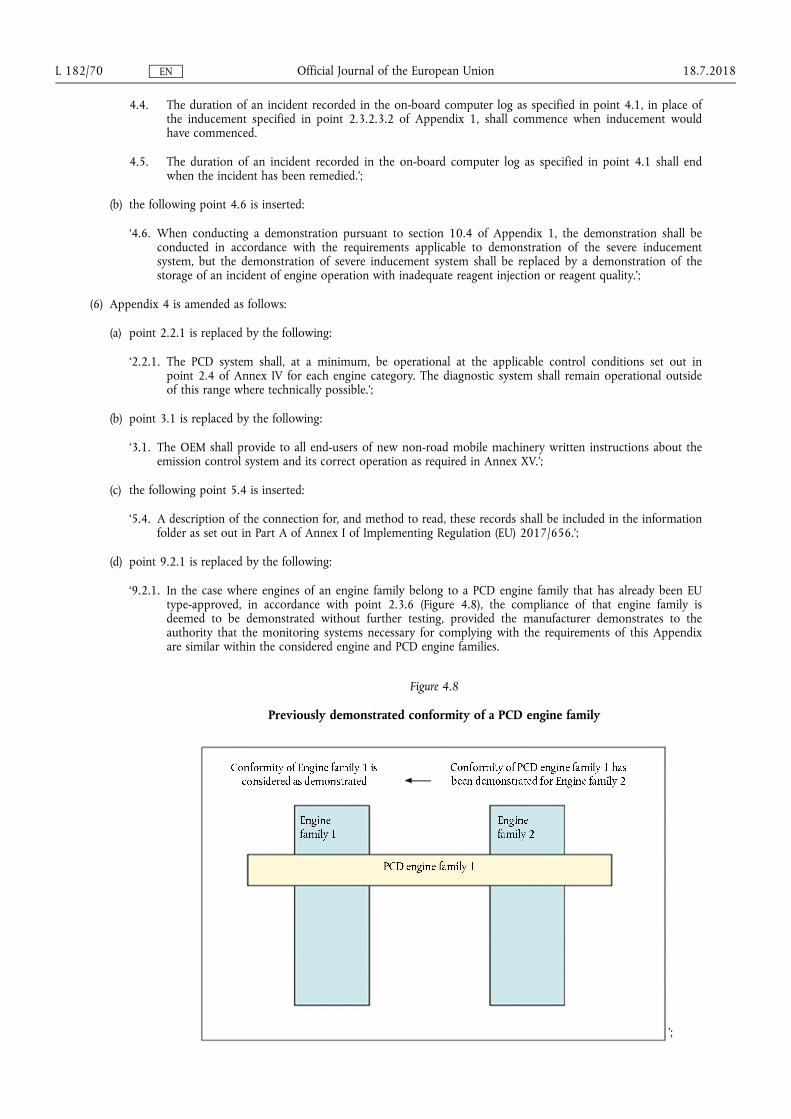
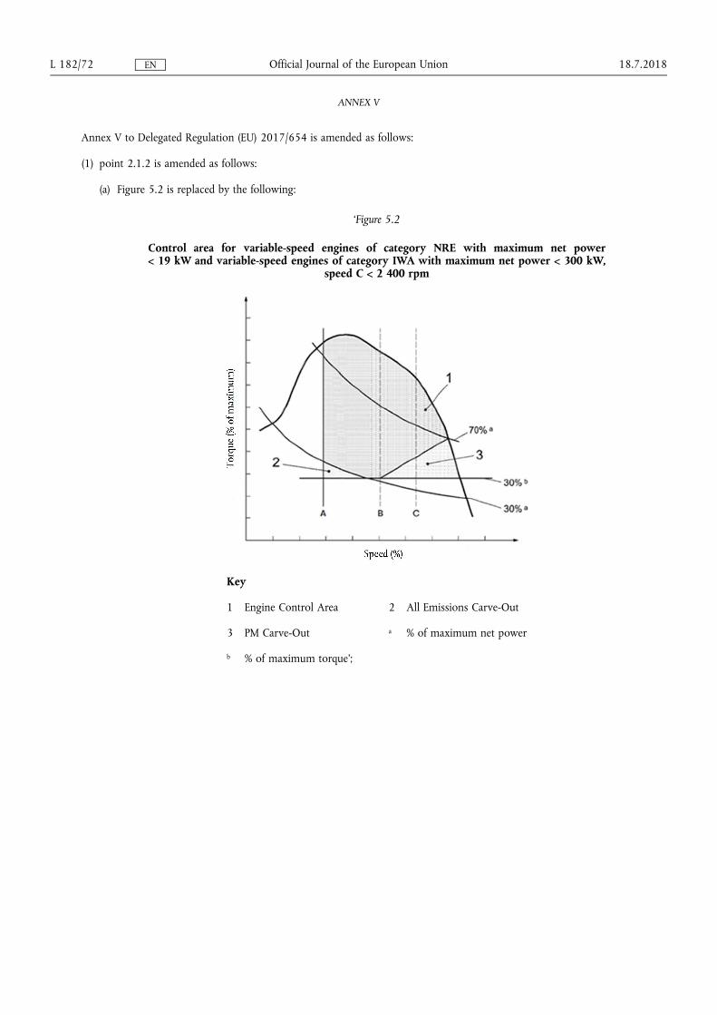
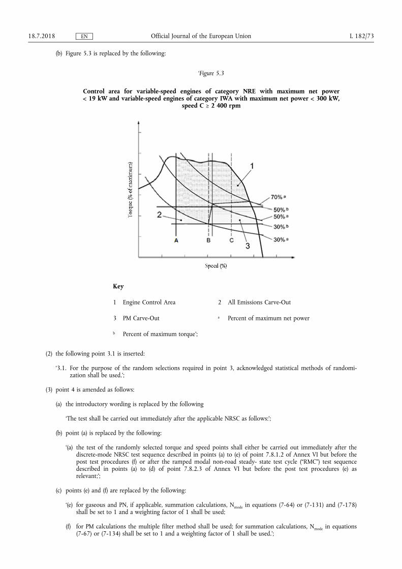
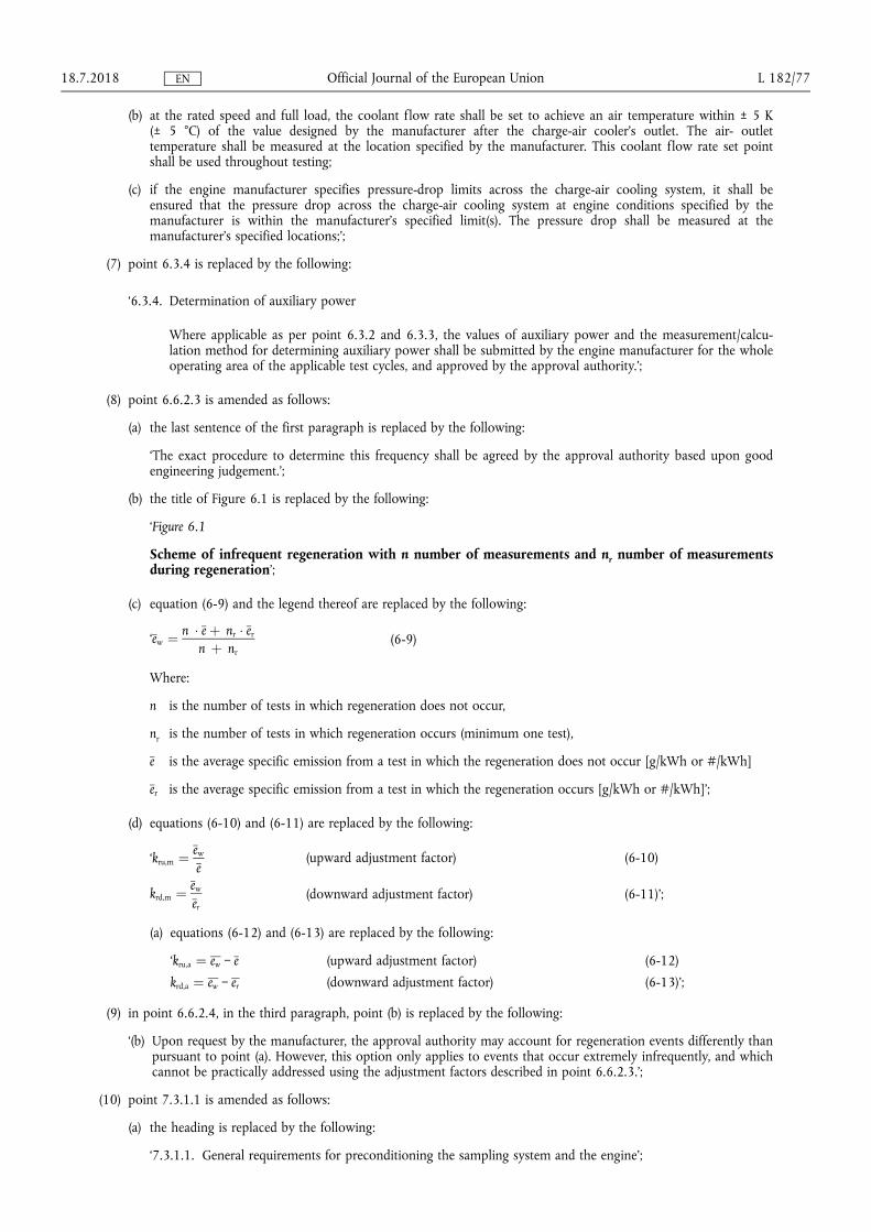
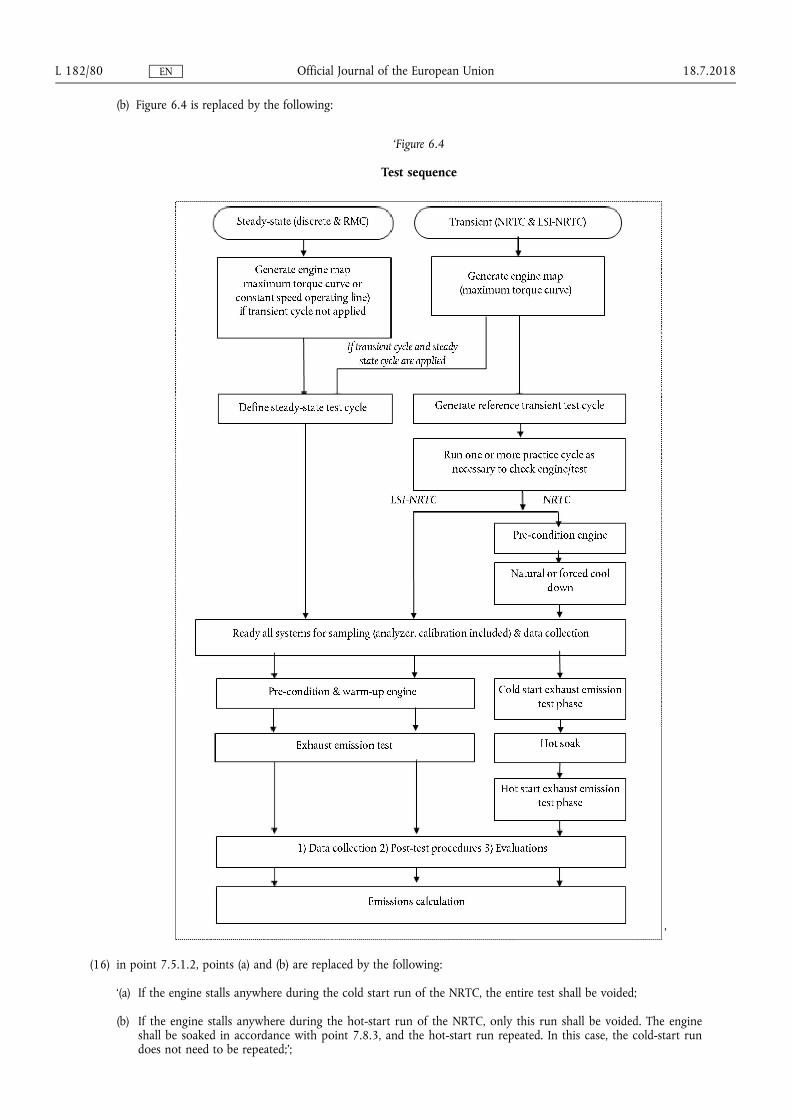
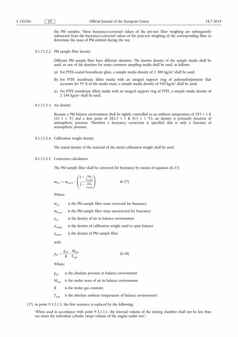
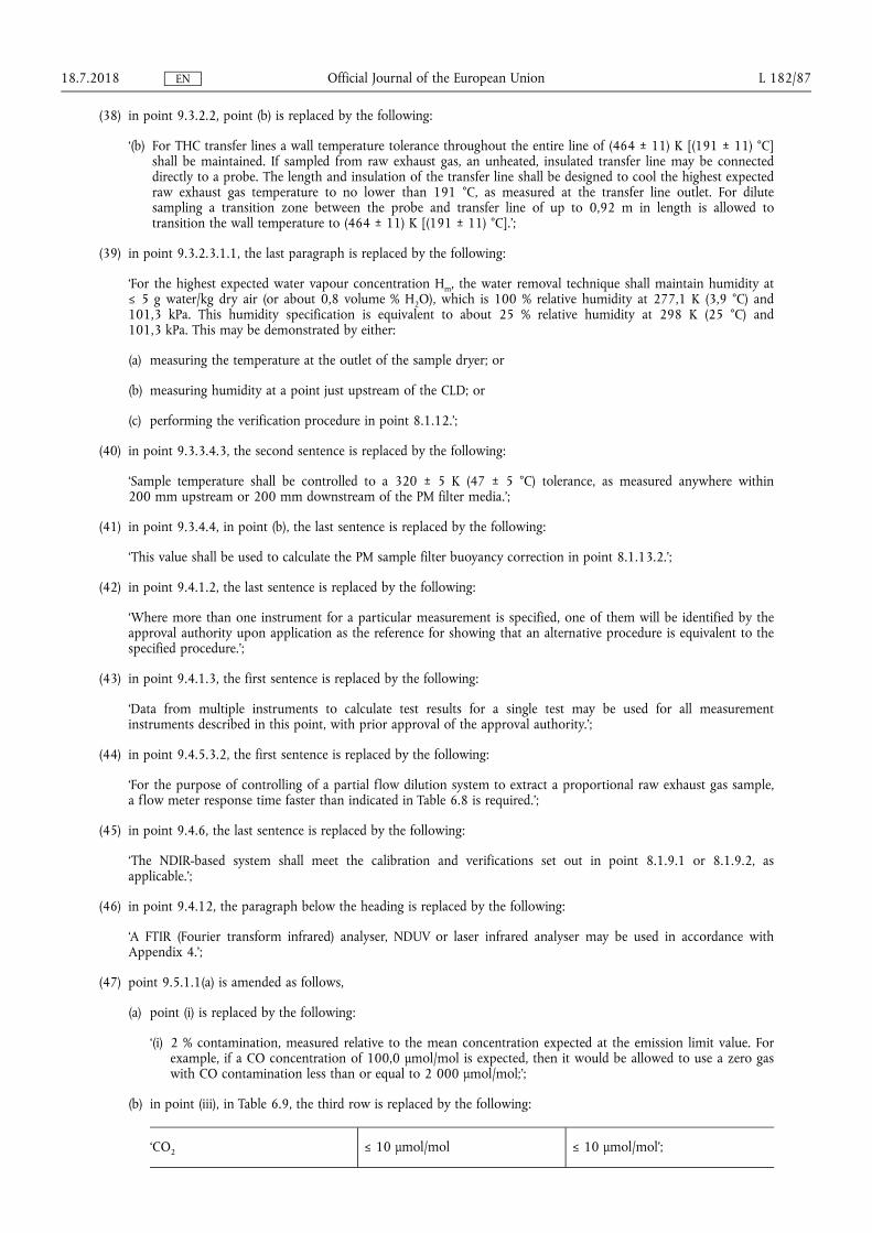
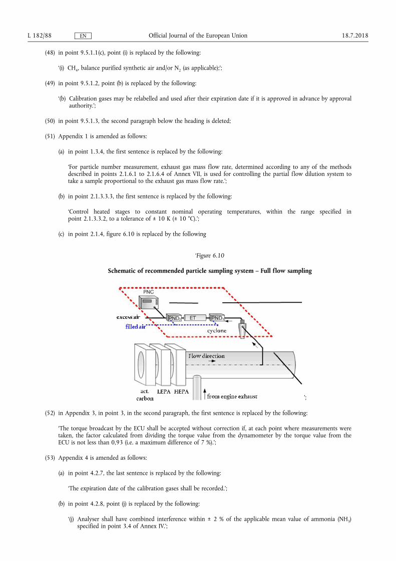
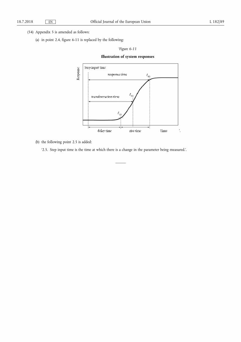
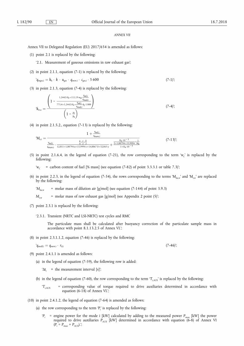
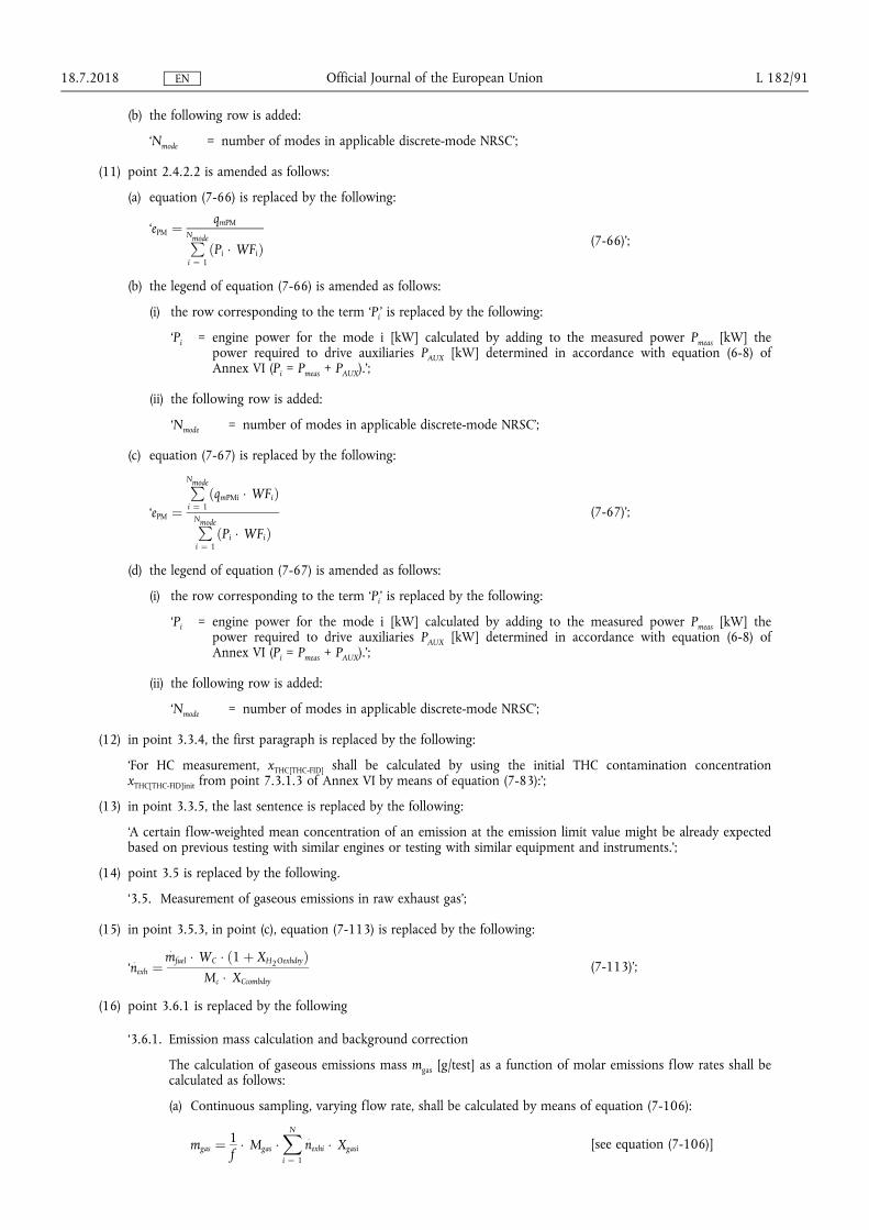
(b) the following row is added
lsquoNmode = number of modes in applicable discrete-mode NRSCrsquo
(11) point 2422 is amended as follows
(a) equation (7-66) is replaced by the following
lsquoePM frac14qmPM
PNmode
i frac14 1ethPi WFiTHORN
(7-66)rsquo
(b) the legend of equation (7-66) is amended as follows
(i) the row corresponding to the term lsquoPirsquo is replaced by the following
lsquoPi = engine power for the mode i [kW] calculated by adding to the measured power Pmeas [kW] the power required to drive auxiliaries PAUX [kW] determined in accordance with equation (6-8) of Annex VI (Pi = Pmeas + PAUX)rsquo
(ii) the following row is added
lsquoNmode = number of modes in applicable discrete-mode NRSCrsquo
(c) equation (7-67) is replaced by the following
lsquoePM frac14
PNmode
i frac14 1ethqmPMi WFiTHORN
PNmode
i frac14 1ethPi WFiTHORN
(7-67)rsquo
(d) the legend of equation (7-67) is amended as follows
(i) the row corresponding to the term lsquoPirsquo is replaced by the following
lsquoPi = engine power for the mode i [kW] calculated by adding to the measured power Pmeas [kW] the power required to drive auxiliaries PAUX [kW] determined in accordance with equation (6-8) of Annex VI (Pi = Pmeas + PAUX)rsquo
(ii) the following row is added
lsquoNmode = number of modes in applicable discrete-mode NRSCrsquo
(12) in point 334 the first paragraph is replaced by the following
lsquoFor HC measurement xTHC[THC-FID] shall be calculated by using the initial THC contamination concentration xTHC[THC-FID]init from point 7313 of Annex VI by means of equation (7-83)rsquo
(13) in point 335 the last sentence is replaced by the following
lsquoA certain flow-weighted mean concentration of an emission at the emission limit value might be already expected based on previous testing with similar engines or testing with similar equipment and instrumentsrsquo
(14) point 35 is replaced by the following
lsquo35 Measurement of gaseous emissions in raw exhaust gasrsquo
(15) in point 353 in point (c) equation (7-113) is replaced by the following
lsquo nexh frac14
mfuel WC eth1 thorn XH2OexhdryTHORN
Mc XCcombdry
(7-113)rsquo
(16) point 361 is replaced by the following
lsquo361 Emission mass calculation and background correction
The calculation of gaseous emissions mass mgas [gtest] as a function of molar emissions flow rates shall be calculated as follows
(a) Continuous sampling varying flow rate shall be calculated by means of equation (7-106)
mgas frac141f
Mgas XN
i frac14 1
nexhi Xgasi [see equation (7-106)]
1872018 L 18291 Official Journal of the European Union EN
Where
Mgas = generic emission molar mass [gmol]
nexhi = instantaneous exhaust gas molar flow rate on a wet basis [mols]
xgasi = instantaneous generic gas molar concentration on a wet basis [molmol]
f = data sampling rate [Hz]
N = number of measurements [-]
(b) Continuous sampling constant flow rate shall be calculated by means of equation (7-107)
mgas frac14 Mgas nexh xgas Δt [see equation (7-107)]
Where
Mgas = generic emission molar mass [gmol]
nexh = exhaust gas molar flow rate on a wet basis [mols]
xgas = mean gaseous emission molar fraction on a wet basis [molmol]
Δt = time duration of test interval
(c) Batch sampling regardless the flow rate is varying or constant shall be calculated by means of equation (7-108)
mgas frac141f
Mgas xgas
XN
i frac14 1
nexhi [see equation (7-108)]
Where
Mgas = generic emission molar mass [gmol]
nexhi = instantaneous exhaust gas molar flow rate on a wet basis [mols]
xgas = mean gaseous emission molar fraction on a wet basis [molmol]
f = data sampling rate [Hz]
N = number of measurements [-]
(d) In case of diluted exhaust gas calculated values for mass of the pollutants shall be corrected by subtracting the mass of background emissions due to dilution air
(i) Firstly the molar flow rate of dilution air nairdil [mols] shall be determined over the test interval This may be a measured quantity or a quantity calculated from the diluted exhaust gas flow and the flow-weighted mean fraction of dilution air in diluted exhaust gas xdil=exh
(ii) The total flow of dilution air nairdil [mol] shall be multiplied by the mean concentration of background emission This may be a time-weighted mean or a flow-weighted mean (eg a proporshytionally sampled background) The product of nairdil and the mean concentration of a background emission is the total amount of a background emission
(iii) If the result is a molar quantity it shall be converted to a mass of the background emission mbkgnd [g] by multiplying it by emission molar mass Mgas [gmol]
(iv) Total background mass shall be subtracted from total mass to correct for background emissions
(v) The total flow of dilution air may be determined by a direct flow measurement In this case the total mass of background shall be calculated using the dilution air flow nairdil The background mass shall be subtracted from the total mass The result shall be used in brake-specific emission calculations
1872018 L 18292 Official Journal of the European Union EN
(vi) The total flow of dilution air may be determined from the total flow of diluted exhaust gas and a chemical balance of the fuel intake air and exhaust gas as described in point 34 In this case the total mass of background shall be calculated using the total flow of diluted exhaust gas ndexh Then this result shall be multiplied by the flow-weighted mean fraction of dilution air in diluted exhaust gas xdil=exh
Considering the two cases (v) and (vi) equations (7-115) and (7-116) shall be used
mbkgnd frac14 Mgas xgasdil nairdil or mbkgnd frac14 Mgas xdil=exh xbkgnd ndexh (7-115)
mgascor = mgas ndash mbkgnd (7-116)
where
mgas = total mass of the gaseous emission [g]
mbkgnd = total background masses [g]
mgascor = mass of gas corrected for background emissions [g]
Mgas = molecular mass of generic gaseous emission [gmol]
xgasdil = gaseous emission concentration in dilution air [molmol]
nairdil = dilution air molar flow [mol]
xdil=exh = flow-weighted mean fraction of dilution air in diluted exhaust gas [molmol]
xbkgnd = gas fraction of background [molmol]
ndexh = total flow of diluted exhaust gas [mol]rsquo
(17) in point 363 point (b) is amended as follows
(a) in point (i) the introductory wording is replaced by the following
lsquoPDP molar flow rate Based upon the speed at which the Positive Displacement Pump (PDP) operates for a test interval the corresponding slope a1 and intercept a0 [-] as calculated with the calibration procedure set out in point 392 shall be used to calculate molar flow rate
n [mols] by means of equation (7-117)rsquo
(b) in point (ii) the introductory wording is replaced by the following
lsquoSSV molar flow rate Based on the Cd versus Re equation determined in accordance with point 394 the Sub-
Sonic Venturi (SSV) molar flow rate during an emission test n [mols] shall be calculated by means of equation
(7-119)rsquo
(c) in point (iii) the introductory wording is replaced by the following
lsquoCFV molar flow rate To calculate the molar flow rate through one venturi or one combination of venturis its respective mean Cd and other constants determined in accordance with point 395 shall be used The calculation of its molar flow rate
n [mols] during an emission test shall be calculated by means of equation
(7-120)rsquo
(18) point 3811 is amended as follows
(a) equation (7-126) is replaced by the following
lsquoWact frac14XN
i frac14 1
Pi Δti frac141f
1
3 600
1103
2 π60
XN
i frac14 1
ethni TiTHORN (7-126)rsquo
(b) in the legend of equation (7-126) the following row is added
lsquoΔti = the measurement interval [s]rsquo
(c) the legend of equation (7-127) is replaced by the following
lsquoWhere
Timeas is the measured value of instantaneous engine torque
TiAUX is the corresponding value of torque required to drive auxiliaries determined in accordance with point 7723(b) of Annex VIrsquo
1872018 L 18293 Official Journal of the European Union EN
(19) in point 3812 the legend of equation (7-131) is amended as follows
(a) the row corresponding to the term lsquoPirsquo is replaced by the following
lsquoPi = engine power for the mode i [kW] calculated by adding to the measured power Pmeas [kW] the power required to drive auxiliaries PAUX [kW] determined in accordance with equation (6-8) of Annex VI (Pi = Pmeas + PAUX)rsquo
(b) the following row is added
lsquoNmode = number of modes in applicable discrete-mode NRSCrsquo
(20) point 38221 is amended as follows
(a) equation (7-133) is replaced by the following
lsquoePM frac14
mPM
PNmode
i frac14 1ethPi WFiTHORN
(7-133)rsquo
(b) the legend of equation (7-133) is amended as follows
(i) the row corresponding to the term lsquoPirsquo is replaced by the following
lsquoPi = engine power for the mode i [kW] calculated by adding to the measured power Pmeas [kW] the power required to drive auxiliaries PAUX [kW] determined in accordance with equation (6-8) of Annex VI (Pi = Pmeas + PAUX)rsquo
(ii) the following row is added
lsquoNmode = number of modes in applicable discrete-mode NRSCrsquo
(21) point 38222 is amended as follows
(a) equation (7-134) is replaced by the following
lsquoePM frac14
PNmode
i frac14 1eth
mPMi WFiTHORN
PNmode
i frac14 1ethPi WFiTHORN
(7-134)rsquo
(b) the legend of equation (7-134) is amended as follows
(i) the row corresponding to the term lsquoPirsquo is replaced by the following
lsquoPi = engine power for the mode i [kW] calculated by adding to the measured power Pmeas [kW] the power required to drive auxiliaries PAUX [kW] determined in accordance with equation (6-8) of Annex VI (Pi = Pmeas + PAUX)rsquo
(ii) the following row is added
lsquoNmode = number of modes in applicable discrete-mode NRSCrsquo
(22) in point 393 in point (a) equation (7-140) is replaced by the following
lsquoCd frac14 nref
ffiffiffiffiffiffiffiffiffiffiffiffiffiffiffiffiffiffiffiffiffiffiffiffiffiffiffiffiffiffiffiffiffiffiffiZ Mmix R Tin
p
Cf At pin (7-140)rsquo
1872018 L 18294 Official Journal of the European Union EN
(23) in Appendix 3 in point 5 the following Table 79 and Table 710 are added
lsquoTable 7-9
Critical F values Fcrit90 versus N ndash 1 and Nref ndash 1 at 90 per cent confidence
N ndash 1 1 2 3 4 5 6 7 8 9 10 12 15 20 24 30 40 60 120 1000+
Nref ndash 1
1 3986 4950 5359 5583 5724 5820 5890 5943 5985 6019 6070 6122 6174 6200 6226 6252 6279 6306 6332
2 8526 9000 9162 9243 9293 9326 9349 9367 9381 9392 9408 9425 9441 9450 9458 9466 9475 9483 9491
3 5538 5462 5391 5343 5309 5285 5266 5252 5240 5230 5216 5200 5184 5176 5168 5160 5151 5143 5134
4 4545 4325 4191 4107 4051 4010 3979 3955 3936 3920 3896 3870 3844 3831 3817 3804 3790 3775 3761
5 4060 3780 3619 3520 3453 3405 3368 3339 3316 3297 3268 3238 3207 3191 3174 3157 3140 3123 3105
6 3776 3463 3289 3181 3108 3055 3014 2983 2958 2937 2905 2871 2836 2818 2800 2781 2762 2742 2722
7 3589 3257 3074 2961 2883 2827 2785 2752 2725 2703 2668 2632 2595 2575 2555 2535 2514 2493 2471
8 3458 3113 2924 2806 2726 2668 2624 2589 2561 2538 2502 2464 2425 2404 2383 2361 2339 2316 2293
9 3360 3006 2813 2693 2611 2551 2505 2469 2440 2416 2379 2340 2298 2277 2255 2232 2208 2184 2159
10 3285 2924 2728 2605 2522 2461 2414 2377 2347 2323 2284 2244 2201 2178 2155 2132 2107 2082 2055
11 3225 2860 2660 2536 2451 2389 2342 2304 2274 2248 2209 2167 2123 2100 2076 2052 2026 2000 1972
12 3177 2807 2606 2480 2394 2331 2283 2245 2214 2188 2147 2105 2060 2036 2011 1986 1960 1932 1904
13 3136 2763 2560 2434 2347 2283 2234 2195 2164 2138 2097 2053 2007 1983 1958 1931 1904 1876 1846
14 3102 2726 2522 2395 2307 2243 2193 2154 2122 2095 2054 2010 1962 1938 1912 1885 1857 1828 1797
15 3073 2695 2490 2361 2273 2208 2158 2119 2086 2059 2017 1972 1924 1899 1873 1845 1817 1787 1755
16 3048 2668 2462 2333 2244 2178 2128 2088 2055 2028 1985 1940 1891 1866 1839 1811 1782 1751 1718
17 3026 2645 2437 2308 2218 2152 2102 2061 2028 2001 1958 1912 1862 1836 1809 1781 1751 1719 1686
18 3007 2624 2416 2286 2196 2130 2079 2038 2005 1977 1933 1887 1837 1810 1783 1754 1723 1691 1657
19 2990 2606 2397 2266 2176 2109 2058 2017 1984 1956 1912 1865 1814 1787 1759 1730 1699 1666 1631
20 2975 2589 2380 2249 2158 2091 2040 1999 1965 1937 1892 1845 1794 1767 1738 1708 1677 1643 1607
21 2961 2575 2365 2233 2142 2075 2023 1982 1948 1920 1875 1827 1776 1748 1719 1689 1657 1623 1586
20 2949 2561 2351 2219 2128 2061 2008 1967 1933 1904 1859 1811 1759 1731 1702 1671 1639 1604 1567
1872018 L 18295
Official Journal of the European U
nion EN
N ndash 1 1 2 3 4 5 6 7 8 9 10 12 15 20 24 30 40 60 120 1000+
23 2937 2549 2339 2207 2115 2047 1995 1953 1919 1890 1845 1796 1744 1716 1686 1655 1622 1587 1549
24 2927 2538 2327 2195 2103 2035 1983 1941 1906 1877 1832 1783 1730 1702 1672 1641 1607 1571 1533
25 2918 2528 2317 2184 2092 2024 1971 1929 1895 1866 1820 1771 1718 1689 1659 1627 1593 1557 1518
26 2909 2519 2307 2174 2082 2014 1961 1919 1884 1855 1809 1760 1706 1677 1647 1615 1581 1544 1504
27 2901 2511 2299 2165 2073 2005 1952 1909 1874 1845 1799 1749 1695 1666 1636 1603 1569 1531 1491
28 2894 2503 2291 2157 2064 1996 1943 1900 1865 1836 1790 1740 1685 1656 1625 1593 1558 1520 1478
29 2887 2495 2283 2149 2057 1988 1935 1892 1857 1827 1781 1731 1676 1647 1616 1583 1547 1509 1467
30 2881 2489 2276 2142 2049 1980 1927 1884 1849 1819 1773 1722 1667 1638 1606 1573 1538 1499 1456
40 2835 2440 2226 2091 1997 1927 1873 1829 1793 1763 1715 1662 1605 1574 1541 1506 1467 1425 1377
60 2791 2393 2177 2041 1946 1875 1819 1775 1738 1707 1657 1603 1543 1511 1476 1437 1395 1348 1291
120 2748 2347 2130 1992 1896 1824 1767 1722 1684 1652 1601 1545 1482 1447 1409 1368 1320 1265 1193
1000+ 2706 2303 2084 1945 1847 1774 1717 1670 1632 1599 1546 1487 1421 1383 1342 1295 1240 1169 1000
Table 7-10
Critical F values Fcrit95 versus N ndash 1 and Nref ndash 1 at 95 per cent confidence
N ndash 1 1 2 3 4 5 6 7 8 9 10 12 15 20 24 30 40 60 120 1000+
Nref ndash 1
1 1614 1995 2157 2245 2301 2339 2367 2388 2405 2418 2439 2459 2480 2490 2501 2511 2522 2532 2543
2 1851 1900 1916 1924 1929 1933 1935 1937 1938 1939 1941 1942 1944 1945 1946 1947 1947 1948 1949
3 1012 9552 9277 9117 9014 8941 8887 8845 8812 8786 8745 8703 8660 8639 8617 8594 8572 8549 8526
4 7709 6944 6591 6388 6256 6163 6094 6041 5999 5964 5912 5858 5803 5774 5746 5717 5688 5658 5628
5 6608 5786 5410 5192 5050 4950 4876 4818 4773 4735 4678 4619 4558 4527 4496 4464 4431 4399 4365
6 5987 5143 4757 4534 4387 4284 4207 4147 4099 4060 4000 3938 3874 3842 3808 3774 3740 3705 3669
7 5591 4737 4347 4120 3972 3866 3787 3726 3677 3637 3575 3511 3445 3411 3376 3340 3304 3267 3230
8 5318 4459 4066 3838 3688 3581 3501 3438 3388 3347 3284 3218 3150 3115 3079 3043 3005 2967 2928
9 5117 4257 3863 3633 3482 3374 3293 3230 3179 3137 3073 3006 2937 2901 2864 2826 2787 2748 2707
10 4965 4103 3708 3478 3326 3217 3136 3072 3020 2978 2913 2845 2774 2737 2700 2661 2621 2580 2538
1872018 L 18296
Official Journal of the European U
nion EN
N ndash 1 1 2 3 4 5 6 7 8 9 10 12 15 20 24 30 40 60 120 1000+
11 4844 3982 3587 3357 3204 3095 3012 2948 2896 2854 2788 2719 2646 2609 2571 2531 2490 2448 2405
12 4747 3885 3490 3259 3106 2996 2913 2849 2796 2753 2687 2617 2544 2506 2466 2426 2384 2341 2296
13 4667 3806 3411 3179 3025 2915 2832 2767 2714 2671 2604 2533 2459 2420 2380 2339 2297 2252 2206
14 4600 3739 3344 3112 2958 2848 2764 2699 2646 2602 2534 2463 2388 2349 2308 2266 2223 2178 2131
15 4543 3682 3287 3056 2901 2791 2707 2641 2588 2544 2475 2403 2328 2288 2247 2204 2160 2114 2066
16 4494 3634 3239 3007 2852 2741 2657 2591 2538 2494 2425 2352 2276 2235 2194 2151 2106 2059 2010
17 4451 3592 3197 2965 2810 2699 2614 2548 2494 2450 2381 2308 2230 2190 2148 2104 2058 2011 1960
18 4414 3555 3160 2928 2773 2661 2577 2510 2456 2412 2342 2269 2191 2150 2107 2063 2017 1968 1917
19 4381 3522 3127 2895 2740 2628 2544 2477 2423 2378 2308 2234 2156 2114 2071 2026 1980 1930 1878
20 4351 3493 3098 2866 2711 2599 2514 2447 2393 2348 2278 2203 2124 2083 2039 1994 1946 1896 1843
21 4325 3467 3073 2840 2685 2573 2488 2421 2366 2321 2250 2176 2096 2054 2010 1965 1917 1866 1812
22 4301 3443 3049 2817 2661 2549 2464 2397 2342 2297 2226 2151 2071 2028 1984 1938 1889 1838 1783
23 4279 3422 3028 2796 2640 2528 2442 2375 2320 2275 2204 2128 2048 2005 1961 1914 1865 1813 1757
24 4260 3403 3009 2776 2621 2508 2423 2355 2300 2255 2183 2108 2027 1984 1939 1892 1842 1790 1733
25 4242 3385 2991 2759 2603 2490 2405 2337 2282 2237 2165 2089 2008 1964 1919 1872 1822 1768 1711
26 4225 3369 2975 2743 2587 2474 2388 2321 2266 2220 2148 2072 1990 1946 1901 1853 1803 1749 1691
27 4210 3354 2960 2728 2572 2459 2373 2305 2250 2204 2132 2056 1974 1930 1884 1836 1785 1731 1672
28 4196 3340 2947 2714 2558 2445 2359 2291 2236 2190 2118 2041 1959 1915 1869 1820 1769 1714 1654
29 4183 3328 2934 2701 2545 2432 2346 2278 2223 2177 2105 2028 1945 1901 1854 1806 1754 1698 1638
30 4171 3316 2922 2690 2534 2421 2334 2266 2211 2165 2092 2015 1932 1887 1841 1792 1740 1684 1622
40 4085 3232 2839 2606 2450 2336 2249 2180 2124 2077 2004 1925 1839 1793 1744 1693 1637 1577 1509
60 4001 3150 2758 2525 2368 2254 2167 2097 2040 1993 1917 1836 1748 1700 1649 1594 1534 1467 1389
120 3920 3072 2680 2447 2290 2175 2087 2016 1959 1911 1834 1751 1659 1608 1554 1495 1429 1352 1254
1000+ 3842 2996 2605 2372 2214 2099 2010 1938 1880 1831 1752 1666 1571 1517 1459 1394 1318 1221 1000rsquo
1872018 L 18297
Official Journal of the European U
nion EN
(24) Appendix 5 is amended as follows
(a) in point 22 in the legend of equation (7-178) the row corresponding to the term lsquoPirsquo is replaced by the following
lsquoPi = engine power for the mode i [kW] calculated by adding to the measured power Pmeas [kW] the power required to drive auxiliaries PAUX [kW] determined in accordance with equation (6-8) of Annex VI (Pi = Pmeas + PAUX)rsquo
(b) in point 23 the first sentence is replaced by the following
lsquoThe final NRSC and weighted average NRTC test results shall be rounded in one step to three significant figures in accordance with ASTM E 29ndash06Brsquo
1872018 L 18298 Official Journal of the European Union EN
ANNEX VIII
Annex VIII to Delegated Regulation (EU) 2017654 is amended as follows
(1) in point 4222 in the last paragraph the following sentence is added
lsquoA description of the connection for and method to read those records shall be included in the information folder as set out in Part A of Annex I of Implementing Regulation (EU) 2017656rsquo
(2) in point 451 point (b) is replaced by the following
lsquo(b) In case of a Type 2 engine the resulting difference between the highest and the lowest maximum GERcycle within the family shall never exceed the range set out in point 2415 of Annex IX to Implementing Regulation (EU) 2017656 except as permitted by point 31rsquo
(3) point 641 is replaced by the following
lsquo641 The manufacturer shall present the approval authority with evidence showing that the GERcycle span of all members of the dual-fuel engine family remains within the range set out in point 2415 of Annex IX to Implementing Regulation (EU) 2017656 or in the case of engines with an operator-adjustable GERcycle satisfy the requirements of point 65 (for example through algorithms functional analyses calculations simulations results of previous tests etc)rsquo
(4) the following point 68 is inserted
lsquo68 Documentation of the demonstration
A demonstration report shall document the demonstration conducted pursuant to points 61 to 671 The report shall
(a) describe the demonstration performed including the applicable test cycle
(b) be included in the information folder as set out in Part A of Annex I of Implementing Regulation (EU) 2017656rsquo
(5) Appendix 2 is amended as follows
(a) in point 71321 the introductory wording of the first paragraph is replaced by the following
lsquoIn the case that the exact equations are applied to calculate instantaneous values of ugas in accordance with paragraph 7132(a) then when calculating the mass per test of a gaseous emission for transient (NRTC and LSI-NRTC) test cycles and RMC ugas shall be included in the summation in equation (7-2) of point 212 of Annex VII by means of equation (8-1)rsquo
(b) in point 7133 the second paragraph is replaced by the following
lsquoThe requirements of point 8212 of Annex VI shall apply for controlling the dilution ratio In particular if the combined transformation time of the exhaust gas flow measurement and the partial flow system exceeds 03 s look-ahead control based on a pre-recorded test run shall be used In this case the combined rise time shall be le 1 s and the combined delay time le 10 s Except in the case that the exhaust gas mass flow is measured directly the determination of exhaust gas mass flow shall use values of α γ δ and ε determined in accordance with point 7153rsquo
(c) in point 7134 in the paragraph under the heading the first sentence is replaced by the following
lsquoThe flow meter referred to in points 9453 and 9454 of Annex VI shall not be sensitive to the changes in exhaust gas composition and densityrsquo
(d) in point 7141 the heading is replaced by the following
lsquo7141 Determination of the background corrected concentrationsrsquo
(e) point 7152 is replaced by the following
lsquo7152 Calculation of the fuel mixture components
Equations (8-2) to (8-7) shall be used to calculate the elemental composition of the fuel mixture
qmf = qmf1 + qmf2 (8-2)
wH frac14wH1 qmf1 thorn wH2 qmf2
qmf1 thorn qmf2 (8-3)
1872018 L 18299 Official Journal of the European Union EN
wC frac14wC1 qmf1 thorn wC2 qmf2
qmf1 thorn qmf2 (8-4)
wS frac14wS1 qmf1 thorn wS2 qmf2
qmf1 thorn qmf2 (8-5)
wN frac14wN1 qmf1 thorn wN2 qmf2
qmf1 thorn qmf2 (8-6)
wO frac14wO1 qmf1 thorn wO2 qmf2
qmf1 thorn qmf2 (8-7)
where
qmf1 is the fuel mass flow rate of fuel 1 [kgs]
qmf2 is the fuel mass flow rate of fuel 2 [kgs]
wH is the hydrogen content of fuel [ mass]
wC is the carbon content of fuel [ mass]
wS is the sulphur content of fuel [ mass]
wN is the nitrogen content of fuel [ mass]
wO is the oxygen content of fuel [ mass]rsquo
(f) the following point 7153 is inserted
lsquo7153 Calculation of the molar ratios of H C S N and O related to C for the fuel mixture
The calculation of the atomic ratios (especially the HC-ratio α) is given in Annex VII by means of equations (8-8) to (8-11)
α frac14 119164 wH
wC (8-8)
γ frac14 037464 wS
wC (8-9)
δ frac14 085752 wN
wC (8-10)
ε frac14 075072 wO
wC (8-11)
where
wH is the hydrogen content of fuel mass fraction [gg] or [ mass]
wC is the carbon content of fuel mass fraction [gg] or [ mass]
wS is the sulphur content of fuel mass fraction [gg] or [ mass]
wN is the nitrogen content of fuel mass fraction [gg] or [ mass]
wO is the oxygen content of fuel mass fraction [gg] or [ mass]
α is the molar hydrogen ratio (HC)
γ is the molar sulphur ratio (SC)
δ is the molar nitrogen ratio (NC)
ε is the molar oxygen ratio (OC)
referring to a fuel CΗαΟεΝδSγrsquo
1872018 L 182100 Official Journal of the European Union EN
(g) in point 723 in the first paragraph the last sentence is replaced by the following
lsquoThe instantaneous molar component ratios shall be input in the equations (7-88) (7-90) and (7-91) of Annex VII for the continuous chemical balancersquo
(h) in point 7231 the introductory wording of equation (8-16) is replaced by the following
lsquoIn cases where exhaust gas mass flow rate is calculated based on the mixed fuel rate then wC in equation (7-113) of Annex VII shall be calculated by means of equation (8-16)rsquo
1872018 L 182101 Official Journal of the European Union EN
ANNEX IX
In point 2 of Appendix 2 of Annex IX to Delegated Regulation (EU) 2017654 the introductory wording before equation (9-5) is replaced by the following
lsquoThe value of Sλ may be determined from the ratio of the ratio of the stoichiometric composition of oxygen and methane to the ratio of the stoichiometric composition of oxygen and the fuel blend supplied to the engine as set out in equation (9-5)rsquo
1872018 L 182102 Official Journal of the European Union EN
ANNEX X
In Annex XIII to Delegated Regulation (EU) 2017654 point 1 is amended as follows
(1) in point (1) the introductory wording is replaced by the following
lsquo(1) EU type-approvals granted on the basis of Regulation (EC) No 5952009 of the European Parliament and of the Council () and its implementing measures where a technical service confirms that the engine type meets
() Regulation (EC) No 5952009 of the European Parliament and of the Council of 18 June 2009 on type-approval of motor vehicles and engines with respect to emissions from heavy duty vehicles (Euro VI) and on access to vehicle repair and maintenance information and amending Regulation (EC) No 7152007 and Directive 200746EC and repealing Directives 801269EEC 200555EC and 200578EC (OJ L 188 1872009 p 1)rsquo
(2) in point (2) the introductory wording is replaced by the following
lsquo(2) type-approvals in conformity with UNECE Regulation No 4906 series of amendments () where a technical service confirms that the engine type meets
() Regulation No 49 of the Economic Commission for Europe of the United Nations (UNECE) mdash Uniform provisions concerning the measures to be taken against the emission of gaseous and particulate pollutants from compression-ignition engines and positive ignition engines for use in vehicles (OJ L 171 2462013 p 1rsquo
1872018 L 182103 Official Journal of the European Union EN
ANNEX XI
In point 3(15) of Annex XV to Delegated Regulation (EU) 2017654 point (a) is replaced by the following
lsquo(a) where the engine is to be operated within the Union on diesel or non-road gas-oil a statement indicating that a fuel with sulphur content not greater than 10 mgkg (20 mgkg at point of final distribution) cetane number not less than 45 and a FAME content not greater than 8 vv shall be usedrsquo
1872018 L 182104 Official Journal of the European Union EN
ANNEX XII
Annex I to Delegated Regulation (EU) 2017654 is corrected as follows
(1) point 241 is replaced by the following
lsquo241 Engines fuelled with CNG and designed for operation on either the range of H-gases or on the range of L-gasesrsquo
(2) points 252 and 2521 are replaced by the following
lsquo252 Fuel-specific dual-fuel engine fuelled with Liquefied Natural Gas (LNG)
2521 For a dual-fuel engine family where the engines are calibrated for a specific LNG gas composition resulting in a λ-shift factor not differing by more than 3 from the λ-shift factor of the G20 fuel specified in Annex IX and the ethane content of which does not exceed 15 the parent engine shall only be tested on the G20 reference gas fuel or on the equivalent fuel created using an admixture of pipeline gas with other gases as specified in Appendix 1 of Annex IXrsquo
1872018 L 182105 Official Journal of the European Union EN
ANNEX XIII
Annex III to Delegated Regulation (EU) 2017654 is corrected as follows
(1) point 312 is replaced by the following
lsquo312 Engines from different engine families may be further combined into families based on the type of exhaust after-treatment system utilised or where no after-treatment is used based upon the similarity of the technical characteristics of the emission control system Engines of different bore and stroke different configuration different air management systems or different fuel systems may be considered equivalent in respect to emissions deterioration characteristics if the manufacturer provides data to the approval authority that there is a reasonable technical basis for such determination In order to place engine families having similar technical specifications and installation for the exhaust after-treatment systems into the same engine after- treatment system family the manufacturer shall provide data to the approval authority that demonstrates that the emissions reduction performance of such engines is similarrsquo
(2) in point 3413 the second sentence is replaced by the following
lsquoThe approval authority shall not refuse to approve maintenance requirements that are reasonable and technically necessary including but not limited to those identified in point 3414rsquo
1872018 L 182106 Official Journal of the European Union EN
ANNEX XIV
Annex IV to Delegated Regulation (EU) 2017654 is corrected as follows
(1) point 231 is replaced by the following
lsquo231 An auxiliary emission control strategy may be activated by an engine or a non-road mobile machinery provided that the auxiliary emission control strategyrsquo
(2) Appendix 1 is corrected as follows
(a) point 231 is replaced by the following
lsquo231 It is permitted to use a heated or a non-heated reagent tank and dosing system A heated system shall meet the requirements of points 2322 to 23224 A non-heated system shall meet the requirements of point 2323rsquo
(b) point 2322 is replaced by the following
lsquo2322 Design criteria for a heated system
A heated system shall be so designed that it meets the performance requirements set out in points 232 to 23224 when tested using the procedure definedrsquo
(c) point 31 is replaced by the following
lsquo31 The OEM shall provide to all end-users of new non-road mobile machinery written instructions about the emission control system and its correct operation in accordance with Annex XVrsquo
(d) point 7111 is replaced by the following
lsquo7111 The value of CDmin specified by the manufacturer shall be used during the demonstration set out in section 13 and recorded in Part C of the information document specified in Annex I to Implementing Regulation (EU) 2017656rsquo
(e) points 9 to 9232 are replaced by the following
lsquo9 Other failures that may be attributed to tampering
91 In addition to the level of reagent in the reagent tank the reagent quality and the interruption of dosing the following failures shall be monitored because they may be attributed to tampering
(a) failures of the NOx Control Diagnostic (NCD) system as described in point 921
(b) failures of the exhaust gas recirculation (EGR) valve as described in point 922
92 Monitoring requirements and counters
921 NCD system
9211 The NOx Control Diagnostic (NCD) system shall be monitored for electrical failures and for removal or deactivation of any sensor that prevents it from diagnosing any other failures set out in sections 6 to 8 (component monitoring)
A non-exhaustive list of sensors that affect the diagnostic capability are those directly measuring NOx concentration urea quality sensors ambient sensors and sensors used for monitoring reagent dosing activity reagent level or reagent consumption
9212 A counter shall be attributed to each of the monitoring failures The NCD system counters shall count the number of engine operating hours when the DTC associated to a malfunction of the NCD system is confirmed to be active Different NCD system failures may be grouped into a single counter
92121 The manufacturer may group the NCD system failure together with one or more of the systems listed in sections 7 8 and point 922 into a single counter
9213 Details of the NCD system counter(s) activation and deactivation criteria and mechanisms are described in section 11
1872018 L 182107 Official Journal of the European Union EN
922 Impeded EGR valve
9221 The exhaust gas recirculation (EGR) system shall be monitored for an impeded EGR valve
9222 A counter shall be attributed to an impeded EGR valve The EGR valve counter shall count the number of engine operating hours when the DTC associated to an impeded EGR valve is confirmed to be active
92221 The manufacturer may group the impeded EGR valve failure together with one or more of the systems listed in sections 7 8 and point 921 into a single counter
9223 Details of the EGR valve counter activation and deactivation criteria and mechanisms are described in section 11rsquo
(f) point 1021 is replaced by the following
lsquo1021 The demonstration that the monitoring systems for other members of the NCD engine family are similar may be performed by presenting to the approval authorities such elements as algorithms functional analyses etcrsquo
(g) point 1023 is replaced by the following
lsquo1023 In the case where engines of an engine family belong to an NCD engine family that has already been EU type-approved as referred to in point 1021 (Figure 43) the compliance of that engine family is deemed to be demonstrated without further testing provided the manufacturer demonstrates to the authority that the monitoring systems necessary for complying with the requirements of this Appendix are similar within the considered engine and NCD engine families
Table 41
Illustration of the content of the demonstration process in accordance with the provisions in points 103 and 104
Mechanism demonstration elements
Warning system activation specified in point 103
mdash 2 activation tests (incl lack of reagent)
mdash Supplementary demonstration elements as appropriate
Low-level inducement activation specishyfied in point 104
mdash 2 activation tests (incl lack of reagent)
mdash Supplementary demonstration elements as appropriate
mdash 1 torque reduction test
Severe inducement activation specified in point 104
mdash 2 activation tests (incl lack of reagent)
mdash Supplementary demonstration elements as appropriatersquo
(h) point 103352 is replaced by the following
lsquo103352 The demonstration of the warning system activation is deemed to be accomplished if at the end of each demonstration test performed in accordance with point 1033 the warning system has been properly activated and the DTC for the selected failure has got the ldquoconfirmed and activerdquo statusrsquo
(i) points 1042 and 1043 are replaced by the following
lsquo1042 The test sequence shall demonstrate the activation of the inducement system in case of the failure selected by the approval authority from the list as referred to in point 10321 for the test of the warning system
1043 For the purpose of this demonstration
(a) the manufacturer shall in agreement with the approval authority be permitted to accelerate the test by simulating the achievement of a certain number of operating hours
(b) the achievement of the torque reduction required for low-level inducement may be demonstrated at the same time as the general engine performance approval process performed in accordance with this Regulation A separate torque measurement during the inducement system demonstration is not required in this case
1872018 L 182108 Official Journal of the European Union EN
(c) the low-level inducement if applicable shall be demonstrated in accordance with the requirements of point 1045
(d) the severe inducement shall be demonstrated in accordance with the requirements of point 1046rsquo
(j) point 133 is replaced by the following
lsquo133 The pollutant emissions resulting from this test shall not exceed the NOx threshold specified in point 711rsquo
(3) Appendix 4 is corrected as follows
(a) point 2323 is replaced by the following
lsquo2323 In cases where more than the period of running time indicated in Table 45 is required for the monitors to accurately detect and confirm a PCM (eg monitors using statistical models or with respect to fluid consumption on the non-road mobile machinery) the approval authority may permit a longer period for monitoring provided the manufacturer justifies the need for the longer period (for example by technical rationale experimental results in-house experience etc)rsquo
(b) point 61 is replaced by the following
lsquo61 The PCD system shall detect the complete removal of the particulate after-treatment system inclusive of the removal of any sensors used to monitor activate de-activate or modulate its operationrsquo
1872018 L 182109 Official Journal of the European Union EN
ANNEX XV
Point 1 of Annex V to Delegated Regulation (EU) 2017654 is corrected as follows
(1) the second and third paragraphs are replaced by the following
lsquoThis Annex sets out the technical requirements relating to the area associated with the relevant NRSC within which the amount by which the emissions shall be permitted to exceed the emission limits set out in Annex II to Regulation (EU) 20161628 is controlled
When an engine is tested in the manner set out in test requirements of section 4 the emission of gaseous and particulate pollutants sampled at any randomly selected point within the applicable control area set out in section 2 shall not exceed the applicable emission limit values in Annex II to Regulation (EU) 20161628 multiplied by a factor of 20rsquo
(2) the last paragraph is replaced by the following
lsquoThe installation instructions provided by the manufacturer to the OEM in accordance with Annex XIV shall identify the upper and lower boundaries of the applicable control area and shall include a statement to clarify that the OEM shall not install the engine in such a way that it constrains the engine to operate permanently at only combinations of speed and torque outside of the control area for the torque curve corresponding to the approved engine type or engine familyrsquo
1872018 L 182110 Official Journal of the European Union EN
ANNEX XVI
Annex VI to Delegated Regulation (EU) 2017654 is corrected as follows
(1) in point 5256 the second paragraph is replaced by the following
lsquoWhere the governor installed on the engine is used the 100 speed shall be the engine governed speed as defined in Article 1(24)rsquo
(2) point 631 is replaced by the following
lsquo631 Basis for emission measurement
The basis of specific emissions measurement is uncorrected net power as defined in Article 3(25) of Regulation (EU) 20161628rsquo
(3) in point 633 the last sentence of the second paragraph is replaced by the following
lsquoThe power absorbed by auxiliaries shall be used to adjust the set values and to calculate the work produced by the engine over the test cycle in accordance with point 7713 or point 7723(b)rsquo
(4) in point 7421 the two paragraphs below Figure 63 are replaced by the following
(a) point (a) is replaced by the following
lsquo(a) the cold start run shall commence after either the engine and exhaust after-treatment systems have cooled down to room temperature after natural engine cool down or after forced cool down and the engine coolant and oil temperatures exhaust after-treatment systems and all engine control devices are stabilized between 293 K and 303 K (20 degC and 30 degC) The measurement of the emissions for this run shall be started with the start of the cold enginersquo
(b) point (c) is replaced by the following
lsquo(c) the hot-start run shall commence immediately after the soak period with the cranking of the engine The gaseous analyzers shall be switched on at least 10 seconds before the end of the soak period to avoid switching signal peaks The measurement of emissions for this run shall be started in parallel with the cranking of the engine
Brake specific emissions expressed in (gkWh) or number per kilowatt-hour (kWh) for PN shall be determined by using the procedures set out in this section for both the cold start run and hot-start run of the test cycle Composite weighted emissions shall be computed by weighting the cold-start run results by 10 and the hot-start run results by 90 as detailed in Annex VIIrsquo
(5) in point 76 the words lsquoas defined in Article 2(12)rsquo are replaced by the words lsquoas defined in Article 1(12)rsquo
(6) in point 7631 in point (b) the fourth and fifth sentences are replaced by the following
lsquoThe power recorded shall not exceed the rated power as defined in Article 3(27) of Regulation (EU) 20161628 by more than 125 If this value is exceeded the manufacturer shall revise the declared rated powerrsquo
(7) in point 7723 in the legend of equation (6-16) the second row is replaced by the following
lsquomaxtorque is the maximum torque for the respective test speed taken from the engine mapping performed in accordance with point 762 adjusted where necessary in accordance with point 7723(b)rsquo
(8) in point 8235 the last sentence is replaced by the following
lsquoHowever if a PM mass of 400 μg or more is expected then the sample media shall be stabilised for at least 60 minrsquo
(9) in point 921(c) point (i) is replaced by the following
lsquo(i) For removing background PM the diluent shall be filtered with high-efficiency particulate air (HEPA) filters that have an initial minimum collection efficiency specification of 9997 (see Article 1(19) for procedures related to HEPA-filtration efficiencies)rsquo
1872018 L 182111 Official Journal of the European Union EN
(10) in point 922(g) the last paragraph is replaced by the following
lsquoFor PM sampling the already proportional flow coming from CVS goes through secondary dilution (one or more) to achieve the requested overall dilution ratio as shown in Figure 67 and set out in point 9232rsquo
(11) in point 9231 in the first paragraph the last sentence is replaced by the following
lsquoThese need to satisfy other criteria such as in points 8186 (periodic calibration) and 8212 (validation) for varying dilution PFD and point 8145 as well as Table 65 (linearity verification) and point 81857 (verification) for constant dilution PFDrsquo
(12) in point 9233 the last paragraph is replaced by the following
lsquoThe system may be used also for a previously diluted exhaust gas where via a constant dilution-ratio an already proportional flow is diluted (see Figure 67) This is the way of performing secondary dilution from a CVS tunnel to achieve the necessary overall dilution ratio for PM samplingrsquo
(13) in Appendix 4 in point 341 the last sentence is replaced by the following
lsquoThe difference between the pre-test and post-test results shall be less than 2 of full scalersquo
1872018 L 182112 Official Journal of the European Union EN
ANNEX XVII
Annex VII to Delegated Regulation (EU) 2017654 is corrected as follows
(1) point 2411 is corrected as follows
(a) equation (7-59) is replaced by the following
lsquoWact frac14XN
i frac14 1
Pi Δti frac141f
1
3 600
1103
2 π60
XN
i frac14 1
ethni TiTHORN (7-59)rsquo
(2) point 395 is replaced by the following
lsquo395 CFV calibration
Some CFV flow meters consist of a single venturi and some consist of multiple venturis where different combinations of venturis are used to meter different flow rates For CFV flow meters that consist of multiple venturis either calibration of each venturi independently to determine a separate discharge coefficient Cd for each venturi or calibration of each combination of venturis as one venturi may be performed In the case where a combination of venturis is calibrated the sum of the active venturi throat areas is used as At the square root of the sum of the squares of the active venturi throat diameters as dt and the ratio of the venturi throat to inlet diameters is the ratio of the square root of the sum of the active venturi throat diameters (dt) to the diameter of the common entrance to all of the venturis (D) To determine the Cd for a single venturi or a single combination of venturis the following steps shall be performed
(a) With the data collected at each calibration set point an individual Cd for each point shall be calculated using equation (7-140)
(b) The mean and standard deviation of all the Cd values shall be calculated in accordance with equations (7-155) and (7-156)
(c) If the standard deviation of all the Cd values is less than or equal to 03 of the mean Cd then the mean Cd shall be used in equation (7-120) and the CFV shall be used only down to the lowest r measured during calibration
r = 1 ndash (Δppin) (7-148)
(d) If the standard deviation of all the Cd values exceeds 03 of the mean Cd the Cd values corresponding to the data point collected at the lowest r measured during calibration shall be omitted
(e) If the number of remaining data points is less than seven corrective action shall be taken by checking calibration data or repeating the calibration process If the calibration process is repeated checking for leaks applying tighter tolerances to measurements and allowing more time for flows to stabilize is recommended
(f) If the number of remaining Cd values is seven or greater the mean and standard deviation of the remaining Cd values shall be recalculated
(g) If the standard deviation of the remaining Cd values is less than or equal to 03 of the mean of the remaining Cd that mean Cd shall be used in equation (7-120) and the CFV values only down to the lowest r associated with the remaining Cd shall be used
(h) If the standard deviation of the remaining Cd still exceeds 03 of the mean of the remaining Cd values the steps set out in points (d) to (g) shall be repeatedrsquo
(3) in Appendix 6 equation (7-180) is replaced by the following
lsquocNH3 = (01 times cNH3cold) + (09 times cNH3hot) (7-180)rsquo
1872018 L 182113 Official Journal of the European Union EN
ANNEX XVIII
Annex VIII to Delegated Regulation (EU) 2017654 is corrected as follows
(1) in point 46 the words lsquoas required byrsquo are deleted
(2) in Appendix 2 in point 4 in the third paragraph below the heading the last sentence is replaced by the following
lsquoThis shall be compensated via one of the methods described in point 7rsquo
1872018 L 182114 Official Journal of the European Union EN
- COMMISSION DELEGATED REGULATION (EU) 2018989 of 18 May 2018 amending and correcting Delegated Regulation (EU) 2017654 supplementing Regulation (EU) 20161628 of the European Parliament and of the Council with regard to technical and general requirements relating to emission limits and type-approval for internal combustion engines for non-road mobile machinery (Text with EEA relevance)
-
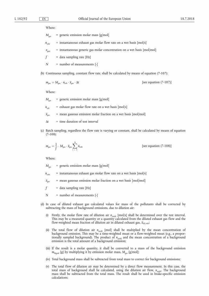
Where
Mgas = generic emission molar mass [gmol]
nexhi = instantaneous exhaust gas molar flow rate on a wet basis [mols]
xgasi = instantaneous generic gas molar concentration on a wet basis [molmol]
f = data sampling rate [Hz]
N = number of measurements [-]
(b) Continuous sampling constant flow rate shall be calculated by means of equation (7-107)
mgas frac14 Mgas nexh xgas Δt [see equation (7-107)]
Where
Mgas = generic emission molar mass [gmol]
nexh = exhaust gas molar flow rate on a wet basis [mols]
xgas = mean gaseous emission molar fraction on a wet basis [molmol]
Δt = time duration of test interval
(c) Batch sampling regardless the flow rate is varying or constant shall be calculated by means of equation (7-108)
mgas frac141f
Mgas xgas
XN
i frac14 1
nexhi [see equation (7-108)]
Where
Mgas = generic emission molar mass [gmol]
nexhi = instantaneous exhaust gas molar flow rate on a wet basis [mols]
xgas = mean gaseous emission molar fraction on a wet basis [molmol]
f = data sampling rate [Hz]
N = number of measurements [-]
(d) In case of diluted exhaust gas calculated values for mass of the pollutants shall be corrected by subtracting the mass of background emissions due to dilution air
(i) Firstly the molar flow rate of dilution air nairdil [mols] shall be determined over the test interval This may be a measured quantity or a quantity calculated from the diluted exhaust gas flow and the flow-weighted mean fraction of dilution air in diluted exhaust gas xdil=exh
(ii) The total flow of dilution air nairdil [mol] shall be multiplied by the mean concentration of background emission This may be a time-weighted mean or a flow-weighted mean (eg a proporshytionally sampled background) The product of nairdil and the mean concentration of a background emission is the total amount of a background emission
(iii) If the result is a molar quantity it shall be converted to a mass of the background emission mbkgnd [g] by multiplying it by emission molar mass Mgas [gmol]
(iv) Total background mass shall be subtracted from total mass to correct for background emissions
(v) The total flow of dilution air may be determined by a direct flow measurement In this case the total mass of background shall be calculated using the dilution air flow nairdil The background mass shall be subtracted from the total mass The result shall be used in brake-specific emission calculations
1872018 L 18292 Official Journal of the European Union EN
(vi) The total flow of dilution air may be determined from the total flow of diluted exhaust gas and a chemical balance of the fuel intake air and exhaust gas as described in point 34 In this case the total mass of background shall be calculated using the total flow of diluted exhaust gas ndexh Then this result shall be multiplied by the flow-weighted mean fraction of dilution air in diluted exhaust gas xdil=exh
Considering the two cases (v) and (vi) equations (7-115) and (7-116) shall be used
mbkgnd frac14 Mgas xgasdil nairdil or mbkgnd frac14 Mgas xdil=exh xbkgnd ndexh (7-115)
mgascor = mgas ndash mbkgnd (7-116)
where
mgas = total mass of the gaseous emission [g]
mbkgnd = total background masses [g]
mgascor = mass of gas corrected for background emissions [g]
Mgas = molecular mass of generic gaseous emission [gmol]
xgasdil = gaseous emission concentration in dilution air [molmol]
nairdil = dilution air molar flow [mol]
xdil=exh = flow-weighted mean fraction of dilution air in diluted exhaust gas [molmol]
xbkgnd = gas fraction of background [molmol]
ndexh = total flow of diluted exhaust gas [mol]rsquo
(17) in point 363 point (b) is amended as follows
(a) in point (i) the introductory wording is replaced by the following
lsquoPDP molar flow rate Based upon the speed at which the Positive Displacement Pump (PDP) operates for a test interval the corresponding slope a1 and intercept a0 [-] as calculated with the calibration procedure set out in point 392 shall be used to calculate molar flow rate
n [mols] by means of equation (7-117)rsquo
(b) in point (ii) the introductory wording is replaced by the following
lsquoSSV molar flow rate Based on the Cd versus Re equation determined in accordance with point 394 the Sub-
Sonic Venturi (SSV) molar flow rate during an emission test n [mols] shall be calculated by means of equation
(7-119)rsquo
(c) in point (iii) the introductory wording is replaced by the following
lsquoCFV molar flow rate To calculate the molar flow rate through one venturi or one combination of venturis its respective mean Cd and other constants determined in accordance with point 395 shall be used The calculation of its molar flow rate
n [mols] during an emission test shall be calculated by means of equation
(7-120)rsquo
(18) point 3811 is amended as follows
(a) equation (7-126) is replaced by the following
lsquoWact frac14XN
i frac14 1
Pi Δti frac141f
1
3 600
1103
2 π60
XN
i frac14 1
ethni TiTHORN (7-126)rsquo
(b) in the legend of equation (7-126) the following row is added
lsquoΔti = the measurement interval [s]rsquo
(c) the legend of equation (7-127) is replaced by the following
lsquoWhere
Timeas is the measured value of instantaneous engine torque
TiAUX is the corresponding value of torque required to drive auxiliaries determined in accordance with point 7723(b) of Annex VIrsquo
1872018 L 18293 Official Journal of the European Union EN
(19) in point 3812 the legend of equation (7-131) is amended as follows
(a) the row corresponding to the term lsquoPirsquo is replaced by the following
lsquoPi = engine power for the mode i [kW] calculated by adding to the measured power Pmeas [kW] the power required to drive auxiliaries PAUX [kW] determined in accordance with equation (6-8) of Annex VI (Pi = Pmeas + PAUX)rsquo
(b) the following row is added
lsquoNmode = number of modes in applicable discrete-mode NRSCrsquo
(20) point 38221 is amended as follows
(a) equation (7-133) is replaced by the following
lsquoePM frac14
mPM
PNmode
i frac14 1ethPi WFiTHORN
(7-133)rsquo
(b) the legend of equation (7-133) is amended as follows
(i) the row corresponding to the term lsquoPirsquo is replaced by the following
lsquoPi = engine power for the mode i [kW] calculated by adding to the measured power Pmeas [kW] the power required to drive auxiliaries PAUX [kW] determined in accordance with equation (6-8) of Annex VI (Pi = Pmeas + PAUX)rsquo
(ii) the following row is added
lsquoNmode = number of modes in applicable discrete-mode NRSCrsquo
(21) point 38222 is amended as follows
(a) equation (7-134) is replaced by the following
lsquoePM frac14
PNmode
i frac14 1eth
mPMi WFiTHORN
PNmode
i frac14 1ethPi WFiTHORN
(7-134)rsquo
(b) the legend of equation (7-134) is amended as follows
(i) the row corresponding to the term lsquoPirsquo is replaced by the following
lsquoPi = engine power for the mode i [kW] calculated by adding to the measured power Pmeas [kW] the power required to drive auxiliaries PAUX [kW] determined in accordance with equation (6-8) of Annex VI (Pi = Pmeas + PAUX)rsquo
(ii) the following row is added
lsquoNmode = number of modes in applicable discrete-mode NRSCrsquo
(22) in point 393 in point (a) equation (7-140) is replaced by the following
lsquoCd frac14 nref
ffiffiffiffiffiffiffiffiffiffiffiffiffiffiffiffiffiffiffiffiffiffiffiffiffiffiffiffiffiffiffiffiffiffiffiZ Mmix R Tin
p
Cf At pin (7-140)rsquo
1872018 L 18294 Official Journal of the European Union EN
(23) in Appendix 3 in point 5 the following Table 79 and Table 710 are added
lsquoTable 7-9
Critical F values Fcrit90 versus N ndash 1 and Nref ndash 1 at 90 per cent confidence
N ndash 1 1 2 3 4 5 6 7 8 9 10 12 15 20 24 30 40 60 120 1000+
Nref ndash 1
1 3986 4950 5359 5583 5724 5820 5890 5943 5985 6019 6070 6122 6174 6200 6226 6252 6279 6306 6332
2 8526 9000 9162 9243 9293 9326 9349 9367 9381 9392 9408 9425 9441 9450 9458 9466 9475 9483 9491
3 5538 5462 5391 5343 5309 5285 5266 5252 5240 5230 5216 5200 5184 5176 5168 5160 5151 5143 5134
4 4545 4325 4191 4107 4051 4010 3979 3955 3936 3920 3896 3870 3844 3831 3817 3804 3790 3775 3761
5 4060 3780 3619 3520 3453 3405 3368 3339 3316 3297 3268 3238 3207 3191 3174 3157 3140 3123 3105
6 3776 3463 3289 3181 3108 3055 3014 2983 2958 2937 2905 2871 2836 2818 2800 2781 2762 2742 2722
7 3589 3257 3074 2961 2883 2827 2785 2752 2725 2703 2668 2632 2595 2575 2555 2535 2514 2493 2471
8 3458 3113 2924 2806 2726 2668 2624 2589 2561 2538 2502 2464 2425 2404 2383 2361 2339 2316 2293
9 3360 3006 2813 2693 2611 2551 2505 2469 2440 2416 2379 2340 2298 2277 2255 2232 2208 2184 2159
10 3285 2924 2728 2605 2522 2461 2414 2377 2347 2323 2284 2244 2201 2178 2155 2132 2107 2082 2055
11 3225 2860 2660 2536 2451 2389 2342 2304 2274 2248 2209 2167 2123 2100 2076 2052 2026 2000 1972
12 3177 2807 2606 2480 2394 2331 2283 2245 2214 2188 2147 2105 2060 2036 2011 1986 1960 1932 1904
13 3136 2763 2560 2434 2347 2283 2234 2195 2164 2138 2097 2053 2007 1983 1958 1931 1904 1876 1846
14 3102 2726 2522 2395 2307 2243 2193 2154 2122 2095 2054 2010 1962 1938 1912 1885 1857 1828 1797
15 3073 2695 2490 2361 2273 2208 2158 2119 2086 2059 2017 1972 1924 1899 1873 1845 1817 1787 1755
16 3048 2668 2462 2333 2244 2178 2128 2088 2055 2028 1985 1940 1891 1866 1839 1811 1782 1751 1718
17 3026 2645 2437 2308 2218 2152 2102 2061 2028 2001 1958 1912 1862 1836 1809 1781 1751 1719 1686
18 3007 2624 2416 2286 2196 2130 2079 2038 2005 1977 1933 1887 1837 1810 1783 1754 1723 1691 1657
19 2990 2606 2397 2266 2176 2109 2058 2017 1984 1956 1912 1865 1814 1787 1759 1730 1699 1666 1631
20 2975 2589 2380 2249 2158 2091 2040 1999 1965 1937 1892 1845 1794 1767 1738 1708 1677 1643 1607
21 2961 2575 2365 2233 2142 2075 2023 1982 1948 1920 1875 1827 1776 1748 1719 1689 1657 1623 1586
20 2949 2561 2351 2219 2128 2061 2008 1967 1933 1904 1859 1811 1759 1731 1702 1671 1639 1604 1567
1872018 L 18295
Official Journal of the European U
nion EN
N ndash 1 1 2 3 4 5 6 7 8 9 10 12 15 20 24 30 40 60 120 1000+
23 2937 2549 2339 2207 2115 2047 1995 1953 1919 1890 1845 1796 1744 1716 1686 1655 1622 1587 1549
24 2927 2538 2327 2195 2103 2035 1983 1941 1906 1877 1832 1783 1730 1702 1672 1641 1607 1571 1533
25 2918 2528 2317 2184 2092 2024 1971 1929 1895 1866 1820 1771 1718 1689 1659 1627 1593 1557 1518
26 2909 2519 2307 2174 2082 2014 1961 1919 1884 1855 1809 1760 1706 1677 1647 1615 1581 1544 1504
27 2901 2511 2299 2165 2073 2005 1952 1909 1874 1845 1799 1749 1695 1666 1636 1603 1569 1531 1491
28 2894 2503 2291 2157 2064 1996 1943 1900 1865 1836 1790 1740 1685 1656 1625 1593 1558 1520 1478
29 2887 2495 2283 2149 2057 1988 1935 1892 1857 1827 1781 1731 1676 1647 1616 1583 1547 1509 1467
30 2881 2489 2276 2142 2049 1980 1927 1884 1849 1819 1773 1722 1667 1638 1606 1573 1538 1499 1456
40 2835 2440 2226 2091 1997 1927 1873 1829 1793 1763 1715 1662 1605 1574 1541 1506 1467 1425 1377
60 2791 2393 2177 2041 1946 1875 1819 1775 1738 1707 1657 1603 1543 1511 1476 1437 1395 1348 1291
120 2748 2347 2130 1992 1896 1824 1767 1722 1684 1652 1601 1545 1482 1447 1409 1368 1320 1265 1193
1000+ 2706 2303 2084 1945 1847 1774 1717 1670 1632 1599 1546 1487 1421 1383 1342 1295 1240 1169 1000
Table 7-10
Critical F values Fcrit95 versus N ndash 1 and Nref ndash 1 at 95 per cent confidence
N ndash 1 1 2 3 4 5 6 7 8 9 10 12 15 20 24 30 40 60 120 1000+
Nref ndash 1
1 1614 1995 2157 2245 2301 2339 2367 2388 2405 2418 2439 2459 2480 2490 2501 2511 2522 2532 2543
2 1851 1900 1916 1924 1929 1933 1935 1937 1938 1939 1941 1942 1944 1945 1946 1947 1947 1948 1949
3 1012 9552 9277 9117 9014 8941 8887 8845 8812 8786 8745 8703 8660 8639 8617 8594 8572 8549 8526
4 7709 6944 6591 6388 6256 6163 6094 6041 5999 5964 5912 5858 5803 5774 5746 5717 5688 5658 5628
5 6608 5786 5410 5192 5050 4950 4876 4818 4773 4735 4678 4619 4558 4527 4496 4464 4431 4399 4365
6 5987 5143 4757 4534 4387 4284 4207 4147 4099 4060 4000 3938 3874 3842 3808 3774 3740 3705 3669
7 5591 4737 4347 4120 3972 3866 3787 3726 3677 3637 3575 3511 3445 3411 3376 3340 3304 3267 3230
8 5318 4459 4066 3838 3688 3581 3501 3438 3388 3347 3284 3218 3150 3115 3079 3043 3005 2967 2928
9 5117 4257 3863 3633 3482 3374 3293 3230 3179 3137 3073 3006 2937 2901 2864 2826 2787 2748 2707
10 4965 4103 3708 3478 3326 3217 3136 3072 3020 2978 2913 2845 2774 2737 2700 2661 2621 2580 2538
1872018 L 18296
Official Journal of the European U
nion EN
N ndash 1 1 2 3 4 5 6 7 8 9 10 12 15 20 24 30 40 60 120 1000+
11 4844 3982 3587 3357 3204 3095 3012 2948 2896 2854 2788 2719 2646 2609 2571 2531 2490 2448 2405
12 4747 3885 3490 3259 3106 2996 2913 2849 2796 2753 2687 2617 2544 2506 2466 2426 2384 2341 2296
13 4667 3806 3411 3179 3025 2915 2832 2767 2714 2671 2604 2533 2459 2420 2380 2339 2297 2252 2206
14 4600 3739 3344 3112 2958 2848 2764 2699 2646 2602 2534 2463 2388 2349 2308 2266 2223 2178 2131
15 4543 3682 3287 3056 2901 2791 2707 2641 2588 2544 2475 2403 2328 2288 2247 2204 2160 2114 2066
16 4494 3634 3239 3007 2852 2741 2657 2591 2538 2494 2425 2352 2276 2235 2194 2151 2106 2059 2010
17 4451 3592 3197 2965 2810 2699 2614 2548 2494 2450 2381 2308 2230 2190 2148 2104 2058 2011 1960
18 4414 3555 3160 2928 2773 2661 2577 2510 2456 2412 2342 2269 2191 2150 2107 2063 2017 1968 1917
19 4381 3522 3127 2895 2740 2628 2544 2477 2423 2378 2308 2234 2156 2114 2071 2026 1980 1930 1878
20 4351 3493 3098 2866 2711 2599 2514 2447 2393 2348 2278 2203 2124 2083 2039 1994 1946 1896 1843
21 4325 3467 3073 2840 2685 2573 2488 2421 2366 2321 2250 2176 2096 2054 2010 1965 1917 1866 1812
22 4301 3443 3049 2817 2661 2549 2464 2397 2342 2297 2226 2151 2071 2028 1984 1938 1889 1838 1783
23 4279 3422 3028 2796 2640 2528 2442 2375 2320 2275 2204 2128 2048 2005 1961 1914 1865 1813 1757
24 4260 3403 3009 2776 2621 2508 2423 2355 2300 2255 2183 2108 2027 1984 1939 1892 1842 1790 1733
25 4242 3385 2991 2759 2603 2490 2405 2337 2282 2237 2165 2089 2008 1964 1919 1872 1822 1768 1711
26 4225 3369 2975 2743 2587 2474 2388 2321 2266 2220 2148 2072 1990 1946 1901 1853 1803 1749 1691
27 4210 3354 2960 2728 2572 2459 2373 2305 2250 2204 2132 2056 1974 1930 1884 1836 1785 1731 1672
28 4196 3340 2947 2714 2558 2445 2359 2291 2236 2190 2118 2041 1959 1915 1869 1820 1769 1714 1654
29 4183 3328 2934 2701 2545 2432 2346 2278 2223 2177 2105 2028 1945 1901 1854 1806 1754 1698 1638
30 4171 3316 2922 2690 2534 2421 2334 2266 2211 2165 2092 2015 1932 1887 1841 1792 1740 1684 1622
40 4085 3232 2839 2606 2450 2336 2249 2180 2124 2077 2004 1925 1839 1793 1744 1693 1637 1577 1509
60 4001 3150 2758 2525 2368 2254 2167 2097 2040 1993 1917 1836 1748 1700 1649 1594 1534 1467 1389
120 3920 3072 2680 2447 2290 2175 2087 2016 1959 1911 1834 1751 1659 1608 1554 1495 1429 1352 1254
1000+ 3842 2996 2605 2372 2214 2099 2010 1938 1880 1831 1752 1666 1571 1517 1459 1394 1318 1221 1000rsquo
1872018 L 18297
Official Journal of the European U
nion EN
(24) Appendix 5 is amended as follows
(a) in point 22 in the legend of equation (7-178) the row corresponding to the term lsquoPirsquo is replaced by the following
lsquoPi = engine power for the mode i [kW] calculated by adding to the measured power Pmeas [kW] the power required to drive auxiliaries PAUX [kW] determined in accordance with equation (6-8) of Annex VI (Pi = Pmeas + PAUX)rsquo
(b) in point 23 the first sentence is replaced by the following
lsquoThe final NRSC and weighted average NRTC test results shall be rounded in one step to three significant figures in accordance with ASTM E 29ndash06Brsquo
1872018 L 18298 Official Journal of the European Union EN
ANNEX VIII
Annex VIII to Delegated Regulation (EU) 2017654 is amended as follows
(1) in point 4222 in the last paragraph the following sentence is added
lsquoA description of the connection for and method to read those records shall be included in the information folder as set out in Part A of Annex I of Implementing Regulation (EU) 2017656rsquo
(2) in point 451 point (b) is replaced by the following
lsquo(b) In case of a Type 2 engine the resulting difference between the highest and the lowest maximum GERcycle within the family shall never exceed the range set out in point 2415 of Annex IX to Implementing Regulation (EU) 2017656 except as permitted by point 31rsquo
(3) point 641 is replaced by the following
lsquo641 The manufacturer shall present the approval authority with evidence showing that the GERcycle span of all members of the dual-fuel engine family remains within the range set out in point 2415 of Annex IX to Implementing Regulation (EU) 2017656 or in the case of engines with an operator-adjustable GERcycle satisfy the requirements of point 65 (for example through algorithms functional analyses calculations simulations results of previous tests etc)rsquo
(4) the following point 68 is inserted
lsquo68 Documentation of the demonstration
A demonstration report shall document the demonstration conducted pursuant to points 61 to 671 The report shall
(a) describe the demonstration performed including the applicable test cycle
(b) be included in the information folder as set out in Part A of Annex I of Implementing Regulation (EU) 2017656rsquo
(5) Appendix 2 is amended as follows
(a) in point 71321 the introductory wording of the first paragraph is replaced by the following
lsquoIn the case that the exact equations are applied to calculate instantaneous values of ugas in accordance with paragraph 7132(a) then when calculating the mass per test of a gaseous emission for transient (NRTC and LSI-NRTC) test cycles and RMC ugas shall be included in the summation in equation (7-2) of point 212 of Annex VII by means of equation (8-1)rsquo
(b) in point 7133 the second paragraph is replaced by the following
lsquoThe requirements of point 8212 of Annex VI shall apply for controlling the dilution ratio In particular if the combined transformation time of the exhaust gas flow measurement and the partial flow system exceeds 03 s look-ahead control based on a pre-recorded test run shall be used In this case the combined rise time shall be le 1 s and the combined delay time le 10 s Except in the case that the exhaust gas mass flow is measured directly the determination of exhaust gas mass flow shall use values of α γ δ and ε determined in accordance with point 7153rsquo
(c) in point 7134 in the paragraph under the heading the first sentence is replaced by the following
lsquoThe flow meter referred to in points 9453 and 9454 of Annex VI shall not be sensitive to the changes in exhaust gas composition and densityrsquo
(d) in point 7141 the heading is replaced by the following
lsquo7141 Determination of the background corrected concentrationsrsquo
(e) point 7152 is replaced by the following
lsquo7152 Calculation of the fuel mixture components
Equations (8-2) to (8-7) shall be used to calculate the elemental composition of the fuel mixture
qmf = qmf1 + qmf2 (8-2)
wH frac14wH1 qmf1 thorn wH2 qmf2
qmf1 thorn qmf2 (8-3)
1872018 L 18299 Official Journal of the European Union EN
wC frac14wC1 qmf1 thorn wC2 qmf2
qmf1 thorn qmf2 (8-4)
wS frac14wS1 qmf1 thorn wS2 qmf2
qmf1 thorn qmf2 (8-5)
wN frac14wN1 qmf1 thorn wN2 qmf2
qmf1 thorn qmf2 (8-6)
wO frac14wO1 qmf1 thorn wO2 qmf2
qmf1 thorn qmf2 (8-7)
where
qmf1 is the fuel mass flow rate of fuel 1 [kgs]
qmf2 is the fuel mass flow rate of fuel 2 [kgs]
wH is the hydrogen content of fuel [ mass]
wC is the carbon content of fuel [ mass]
wS is the sulphur content of fuel [ mass]
wN is the nitrogen content of fuel [ mass]
wO is the oxygen content of fuel [ mass]rsquo
(f) the following point 7153 is inserted
lsquo7153 Calculation of the molar ratios of H C S N and O related to C for the fuel mixture
The calculation of the atomic ratios (especially the HC-ratio α) is given in Annex VII by means of equations (8-8) to (8-11)
α frac14 119164 wH
wC (8-8)
γ frac14 037464 wS
wC (8-9)
δ frac14 085752 wN
wC (8-10)
ε frac14 075072 wO
wC (8-11)
where
wH is the hydrogen content of fuel mass fraction [gg] or [ mass]
wC is the carbon content of fuel mass fraction [gg] or [ mass]
wS is the sulphur content of fuel mass fraction [gg] or [ mass]
wN is the nitrogen content of fuel mass fraction [gg] or [ mass]
wO is the oxygen content of fuel mass fraction [gg] or [ mass]
α is the molar hydrogen ratio (HC)
γ is the molar sulphur ratio (SC)
δ is the molar nitrogen ratio (NC)
ε is the molar oxygen ratio (OC)
referring to a fuel CΗαΟεΝδSγrsquo
1872018 L 182100 Official Journal of the European Union EN
(g) in point 723 in the first paragraph the last sentence is replaced by the following
lsquoThe instantaneous molar component ratios shall be input in the equations (7-88) (7-90) and (7-91) of Annex VII for the continuous chemical balancersquo
(h) in point 7231 the introductory wording of equation (8-16) is replaced by the following
lsquoIn cases where exhaust gas mass flow rate is calculated based on the mixed fuel rate then wC in equation (7-113) of Annex VII shall be calculated by means of equation (8-16)rsquo
1872018 L 182101 Official Journal of the European Union EN
ANNEX IX
In point 2 of Appendix 2 of Annex IX to Delegated Regulation (EU) 2017654 the introductory wording before equation (9-5) is replaced by the following
lsquoThe value of Sλ may be determined from the ratio of the ratio of the stoichiometric composition of oxygen and methane to the ratio of the stoichiometric composition of oxygen and the fuel blend supplied to the engine as set out in equation (9-5)rsquo
1872018 L 182102 Official Journal of the European Union EN
ANNEX X
In Annex XIII to Delegated Regulation (EU) 2017654 point 1 is amended as follows
(1) in point (1) the introductory wording is replaced by the following
lsquo(1) EU type-approvals granted on the basis of Regulation (EC) No 5952009 of the European Parliament and of the Council () and its implementing measures where a technical service confirms that the engine type meets
() Regulation (EC) No 5952009 of the European Parliament and of the Council of 18 June 2009 on type-approval of motor vehicles and engines with respect to emissions from heavy duty vehicles (Euro VI) and on access to vehicle repair and maintenance information and amending Regulation (EC) No 7152007 and Directive 200746EC and repealing Directives 801269EEC 200555EC and 200578EC (OJ L 188 1872009 p 1)rsquo
(2) in point (2) the introductory wording is replaced by the following
lsquo(2) type-approvals in conformity with UNECE Regulation No 4906 series of amendments () where a technical service confirms that the engine type meets
() Regulation No 49 of the Economic Commission for Europe of the United Nations (UNECE) mdash Uniform provisions concerning the measures to be taken against the emission of gaseous and particulate pollutants from compression-ignition engines and positive ignition engines for use in vehicles (OJ L 171 2462013 p 1rsquo
1872018 L 182103 Official Journal of the European Union EN
ANNEX XI
In point 3(15) of Annex XV to Delegated Regulation (EU) 2017654 point (a) is replaced by the following
lsquo(a) where the engine is to be operated within the Union on diesel or non-road gas-oil a statement indicating that a fuel with sulphur content not greater than 10 mgkg (20 mgkg at point of final distribution) cetane number not less than 45 and a FAME content not greater than 8 vv shall be usedrsquo
1872018 L 182104 Official Journal of the European Union EN
ANNEX XII
Annex I to Delegated Regulation (EU) 2017654 is corrected as follows
(1) point 241 is replaced by the following
lsquo241 Engines fuelled with CNG and designed for operation on either the range of H-gases or on the range of L-gasesrsquo
(2) points 252 and 2521 are replaced by the following
lsquo252 Fuel-specific dual-fuel engine fuelled with Liquefied Natural Gas (LNG)
2521 For a dual-fuel engine family where the engines are calibrated for a specific LNG gas composition resulting in a λ-shift factor not differing by more than 3 from the λ-shift factor of the G20 fuel specified in Annex IX and the ethane content of which does not exceed 15 the parent engine shall only be tested on the G20 reference gas fuel or on the equivalent fuel created using an admixture of pipeline gas with other gases as specified in Appendix 1 of Annex IXrsquo
1872018 L 182105 Official Journal of the European Union EN
ANNEX XIII
Annex III to Delegated Regulation (EU) 2017654 is corrected as follows
(1) point 312 is replaced by the following
lsquo312 Engines from different engine families may be further combined into families based on the type of exhaust after-treatment system utilised or where no after-treatment is used based upon the similarity of the technical characteristics of the emission control system Engines of different bore and stroke different configuration different air management systems or different fuel systems may be considered equivalent in respect to emissions deterioration characteristics if the manufacturer provides data to the approval authority that there is a reasonable technical basis for such determination In order to place engine families having similar technical specifications and installation for the exhaust after-treatment systems into the same engine after- treatment system family the manufacturer shall provide data to the approval authority that demonstrates that the emissions reduction performance of such engines is similarrsquo
(2) in point 3413 the second sentence is replaced by the following
lsquoThe approval authority shall not refuse to approve maintenance requirements that are reasonable and technically necessary including but not limited to those identified in point 3414rsquo
1872018 L 182106 Official Journal of the European Union EN
ANNEX XIV
Annex IV to Delegated Regulation (EU) 2017654 is corrected as follows
(1) point 231 is replaced by the following
lsquo231 An auxiliary emission control strategy may be activated by an engine or a non-road mobile machinery provided that the auxiliary emission control strategyrsquo
(2) Appendix 1 is corrected as follows
(a) point 231 is replaced by the following
lsquo231 It is permitted to use a heated or a non-heated reagent tank and dosing system A heated system shall meet the requirements of points 2322 to 23224 A non-heated system shall meet the requirements of point 2323rsquo
(b) point 2322 is replaced by the following
lsquo2322 Design criteria for a heated system
A heated system shall be so designed that it meets the performance requirements set out in points 232 to 23224 when tested using the procedure definedrsquo
(c) point 31 is replaced by the following
lsquo31 The OEM shall provide to all end-users of new non-road mobile machinery written instructions about the emission control system and its correct operation in accordance with Annex XVrsquo
(d) point 7111 is replaced by the following
lsquo7111 The value of CDmin specified by the manufacturer shall be used during the demonstration set out in section 13 and recorded in Part C of the information document specified in Annex I to Implementing Regulation (EU) 2017656rsquo
(e) points 9 to 9232 are replaced by the following
lsquo9 Other failures that may be attributed to tampering
91 In addition to the level of reagent in the reagent tank the reagent quality and the interruption of dosing the following failures shall be monitored because they may be attributed to tampering
(a) failures of the NOx Control Diagnostic (NCD) system as described in point 921
(b) failures of the exhaust gas recirculation (EGR) valve as described in point 922
92 Monitoring requirements and counters
921 NCD system
9211 The NOx Control Diagnostic (NCD) system shall be monitored for electrical failures and for removal or deactivation of any sensor that prevents it from diagnosing any other failures set out in sections 6 to 8 (component monitoring)
A non-exhaustive list of sensors that affect the diagnostic capability are those directly measuring NOx concentration urea quality sensors ambient sensors and sensors used for monitoring reagent dosing activity reagent level or reagent consumption
9212 A counter shall be attributed to each of the monitoring failures The NCD system counters shall count the number of engine operating hours when the DTC associated to a malfunction of the NCD system is confirmed to be active Different NCD system failures may be grouped into a single counter
92121 The manufacturer may group the NCD system failure together with one or more of the systems listed in sections 7 8 and point 922 into a single counter
9213 Details of the NCD system counter(s) activation and deactivation criteria and mechanisms are described in section 11
1872018 L 182107 Official Journal of the European Union EN
922 Impeded EGR valve
9221 The exhaust gas recirculation (EGR) system shall be monitored for an impeded EGR valve
9222 A counter shall be attributed to an impeded EGR valve The EGR valve counter shall count the number of engine operating hours when the DTC associated to an impeded EGR valve is confirmed to be active
92221 The manufacturer may group the impeded EGR valve failure together with one or more of the systems listed in sections 7 8 and point 921 into a single counter
9223 Details of the EGR valve counter activation and deactivation criteria and mechanisms are described in section 11rsquo
(f) point 1021 is replaced by the following
lsquo1021 The demonstration that the monitoring systems for other members of the NCD engine family are similar may be performed by presenting to the approval authorities such elements as algorithms functional analyses etcrsquo
(g) point 1023 is replaced by the following
lsquo1023 In the case where engines of an engine family belong to an NCD engine family that has already been EU type-approved as referred to in point 1021 (Figure 43) the compliance of that engine family is deemed to be demonstrated without further testing provided the manufacturer demonstrates to the authority that the monitoring systems necessary for complying with the requirements of this Appendix are similar within the considered engine and NCD engine families
Table 41
Illustration of the content of the demonstration process in accordance with the provisions in points 103 and 104
Mechanism demonstration elements
Warning system activation specified in point 103
mdash 2 activation tests (incl lack of reagent)
mdash Supplementary demonstration elements as appropriate
Low-level inducement activation specishyfied in point 104
mdash 2 activation tests (incl lack of reagent)
mdash Supplementary demonstration elements as appropriate
mdash 1 torque reduction test
Severe inducement activation specified in point 104
mdash 2 activation tests (incl lack of reagent)
mdash Supplementary demonstration elements as appropriatersquo
(h) point 103352 is replaced by the following
lsquo103352 The demonstration of the warning system activation is deemed to be accomplished if at the end of each demonstration test performed in accordance with point 1033 the warning system has been properly activated and the DTC for the selected failure has got the ldquoconfirmed and activerdquo statusrsquo
(i) points 1042 and 1043 are replaced by the following
lsquo1042 The test sequence shall demonstrate the activation of the inducement system in case of the failure selected by the approval authority from the list as referred to in point 10321 for the test of the warning system
1043 For the purpose of this demonstration
(a) the manufacturer shall in agreement with the approval authority be permitted to accelerate the test by simulating the achievement of a certain number of operating hours
(b) the achievement of the torque reduction required for low-level inducement may be demonstrated at the same time as the general engine performance approval process performed in accordance with this Regulation A separate torque measurement during the inducement system demonstration is not required in this case
1872018 L 182108 Official Journal of the European Union EN
(c) the low-level inducement if applicable shall be demonstrated in accordance with the requirements of point 1045
(d) the severe inducement shall be demonstrated in accordance with the requirements of point 1046rsquo
(j) point 133 is replaced by the following
lsquo133 The pollutant emissions resulting from this test shall not exceed the NOx threshold specified in point 711rsquo
(3) Appendix 4 is corrected as follows
(a) point 2323 is replaced by the following
lsquo2323 In cases where more than the period of running time indicated in Table 45 is required for the monitors to accurately detect and confirm a PCM (eg monitors using statistical models or with respect to fluid consumption on the non-road mobile machinery) the approval authority may permit a longer period for monitoring provided the manufacturer justifies the need for the longer period (for example by technical rationale experimental results in-house experience etc)rsquo
(b) point 61 is replaced by the following
lsquo61 The PCD system shall detect the complete removal of the particulate after-treatment system inclusive of the removal of any sensors used to monitor activate de-activate or modulate its operationrsquo
1872018 L 182109 Official Journal of the European Union EN
ANNEX XV
Point 1 of Annex V to Delegated Regulation (EU) 2017654 is corrected as follows
(1) the second and third paragraphs are replaced by the following
lsquoThis Annex sets out the technical requirements relating to the area associated with the relevant NRSC within which the amount by which the emissions shall be permitted to exceed the emission limits set out in Annex II to Regulation (EU) 20161628 is controlled
When an engine is tested in the manner set out in test requirements of section 4 the emission of gaseous and particulate pollutants sampled at any randomly selected point within the applicable control area set out in section 2 shall not exceed the applicable emission limit values in Annex II to Regulation (EU) 20161628 multiplied by a factor of 20rsquo
(2) the last paragraph is replaced by the following
lsquoThe installation instructions provided by the manufacturer to the OEM in accordance with Annex XIV shall identify the upper and lower boundaries of the applicable control area and shall include a statement to clarify that the OEM shall not install the engine in such a way that it constrains the engine to operate permanently at only combinations of speed and torque outside of the control area for the torque curve corresponding to the approved engine type or engine familyrsquo
1872018 L 182110 Official Journal of the European Union EN
ANNEX XVI
Annex VI to Delegated Regulation (EU) 2017654 is corrected as follows
(1) in point 5256 the second paragraph is replaced by the following
lsquoWhere the governor installed on the engine is used the 100 speed shall be the engine governed speed as defined in Article 1(24)rsquo
(2) point 631 is replaced by the following
lsquo631 Basis for emission measurement
The basis of specific emissions measurement is uncorrected net power as defined in Article 3(25) of Regulation (EU) 20161628rsquo
(3) in point 633 the last sentence of the second paragraph is replaced by the following
lsquoThe power absorbed by auxiliaries shall be used to adjust the set values and to calculate the work produced by the engine over the test cycle in accordance with point 7713 or point 7723(b)rsquo
(4) in point 7421 the two paragraphs below Figure 63 are replaced by the following
(a) point (a) is replaced by the following
lsquo(a) the cold start run shall commence after either the engine and exhaust after-treatment systems have cooled down to room temperature after natural engine cool down or after forced cool down and the engine coolant and oil temperatures exhaust after-treatment systems and all engine control devices are stabilized between 293 K and 303 K (20 degC and 30 degC) The measurement of the emissions for this run shall be started with the start of the cold enginersquo
(b) point (c) is replaced by the following
lsquo(c) the hot-start run shall commence immediately after the soak period with the cranking of the engine The gaseous analyzers shall be switched on at least 10 seconds before the end of the soak period to avoid switching signal peaks The measurement of emissions for this run shall be started in parallel with the cranking of the engine
Brake specific emissions expressed in (gkWh) or number per kilowatt-hour (kWh) for PN shall be determined by using the procedures set out in this section for both the cold start run and hot-start run of the test cycle Composite weighted emissions shall be computed by weighting the cold-start run results by 10 and the hot-start run results by 90 as detailed in Annex VIIrsquo
(5) in point 76 the words lsquoas defined in Article 2(12)rsquo are replaced by the words lsquoas defined in Article 1(12)rsquo
(6) in point 7631 in point (b) the fourth and fifth sentences are replaced by the following
lsquoThe power recorded shall not exceed the rated power as defined in Article 3(27) of Regulation (EU) 20161628 by more than 125 If this value is exceeded the manufacturer shall revise the declared rated powerrsquo
(7) in point 7723 in the legend of equation (6-16) the second row is replaced by the following
lsquomaxtorque is the maximum torque for the respective test speed taken from the engine mapping performed in accordance with point 762 adjusted where necessary in accordance with point 7723(b)rsquo
(8) in point 8235 the last sentence is replaced by the following
lsquoHowever if a PM mass of 400 μg or more is expected then the sample media shall be stabilised for at least 60 minrsquo
(9) in point 921(c) point (i) is replaced by the following
lsquo(i) For removing background PM the diluent shall be filtered with high-efficiency particulate air (HEPA) filters that have an initial minimum collection efficiency specification of 9997 (see Article 1(19) for procedures related to HEPA-filtration efficiencies)rsquo
1872018 L 182111 Official Journal of the European Union EN
(10) in point 922(g) the last paragraph is replaced by the following
lsquoFor PM sampling the already proportional flow coming from CVS goes through secondary dilution (one or more) to achieve the requested overall dilution ratio as shown in Figure 67 and set out in point 9232rsquo
(11) in point 9231 in the first paragraph the last sentence is replaced by the following
lsquoThese need to satisfy other criteria such as in points 8186 (periodic calibration) and 8212 (validation) for varying dilution PFD and point 8145 as well as Table 65 (linearity verification) and point 81857 (verification) for constant dilution PFDrsquo
(12) in point 9233 the last paragraph is replaced by the following
lsquoThe system may be used also for a previously diluted exhaust gas where via a constant dilution-ratio an already proportional flow is diluted (see Figure 67) This is the way of performing secondary dilution from a CVS tunnel to achieve the necessary overall dilution ratio for PM samplingrsquo
(13) in Appendix 4 in point 341 the last sentence is replaced by the following
lsquoThe difference between the pre-test and post-test results shall be less than 2 of full scalersquo
1872018 L 182112 Official Journal of the European Union EN
ANNEX XVII
Annex VII to Delegated Regulation (EU) 2017654 is corrected as follows
(1) point 2411 is corrected as follows
(a) equation (7-59) is replaced by the following
lsquoWact frac14XN
i frac14 1
Pi Δti frac141f
1
3 600
1103
2 π60
XN
i frac14 1
ethni TiTHORN (7-59)rsquo
(2) point 395 is replaced by the following
lsquo395 CFV calibration
Some CFV flow meters consist of a single venturi and some consist of multiple venturis where different combinations of venturis are used to meter different flow rates For CFV flow meters that consist of multiple venturis either calibration of each venturi independently to determine a separate discharge coefficient Cd for each venturi or calibration of each combination of venturis as one venturi may be performed In the case where a combination of venturis is calibrated the sum of the active venturi throat areas is used as At the square root of the sum of the squares of the active venturi throat diameters as dt and the ratio of the venturi throat to inlet diameters is the ratio of the square root of the sum of the active venturi throat diameters (dt) to the diameter of the common entrance to all of the venturis (D) To determine the Cd for a single venturi or a single combination of venturis the following steps shall be performed
(a) With the data collected at each calibration set point an individual Cd for each point shall be calculated using equation (7-140)
(b) The mean and standard deviation of all the Cd values shall be calculated in accordance with equations (7-155) and (7-156)
(c) If the standard deviation of all the Cd values is less than or equal to 03 of the mean Cd then the mean Cd shall be used in equation (7-120) and the CFV shall be used only down to the lowest r measured during calibration
r = 1 ndash (Δppin) (7-148)
(d) If the standard deviation of all the Cd values exceeds 03 of the mean Cd the Cd values corresponding to the data point collected at the lowest r measured during calibration shall be omitted
(e) If the number of remaining data points is less than seven corrective action shall be taken by checking calibration data or repeating the calibration process If the calibration process is repeated checking for leaks applying tighter tolerances to measurements and allowing more time for flows to stabilize is recommended
(f) If the number of remaining Cd values is seven or greater the mean and standard deviation of the remaining Cd values shall be recalculated
(g) If the standard deviation of the remaining Cd values is less than or equal to 03 of the mean of the remaining Cd that mean Cd shall be used in equation (7-120) and the CFV values only down to the lowest r associated with the remaining Cd shall be used
(h) If the standard deviation of the remaining Cd still exceeds 03 of the mean of the remaining Cd values the steps set out in points (d) to (g) shall be repeatedrsquo
(3) in Appendix 6 equation (7-180) is replaced by the following
lsquocNH3 = (01 times cNH3cold) + (09 times cNH3hot) (7-180)rsquo
1872018 L 182113 Official Journal of the European Union EN
ANNEX XVIII
Annex VIII to Delegated Regulation (EU) 2017654 is corrected as follows
(1) in point 46 the words lsquoas required byrsquo are deleted
(2) in Appendix 2 in point 4 in the third paragraph below the heading the last sentence is replaced by the following
lsquoThis shall be compensated via one of the methods described in point 7rsquo
1872018 L 182114 Official Journal of the European Union EN
- COMMISSION DELEGATED REGULATION (EU) 2018989 of 18 May 2018 amending and correcting Delegated Regulation (EU) 2017654 supplementing Regulation (EU) 20161628 of the European Parliament and of the Council with regard to technical and general requirements relating to emission limits and type-approval for internal combustion engines for non-road mobile machinery (Text with EEA relevance)
-
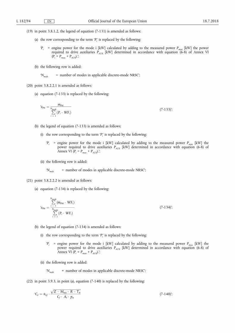
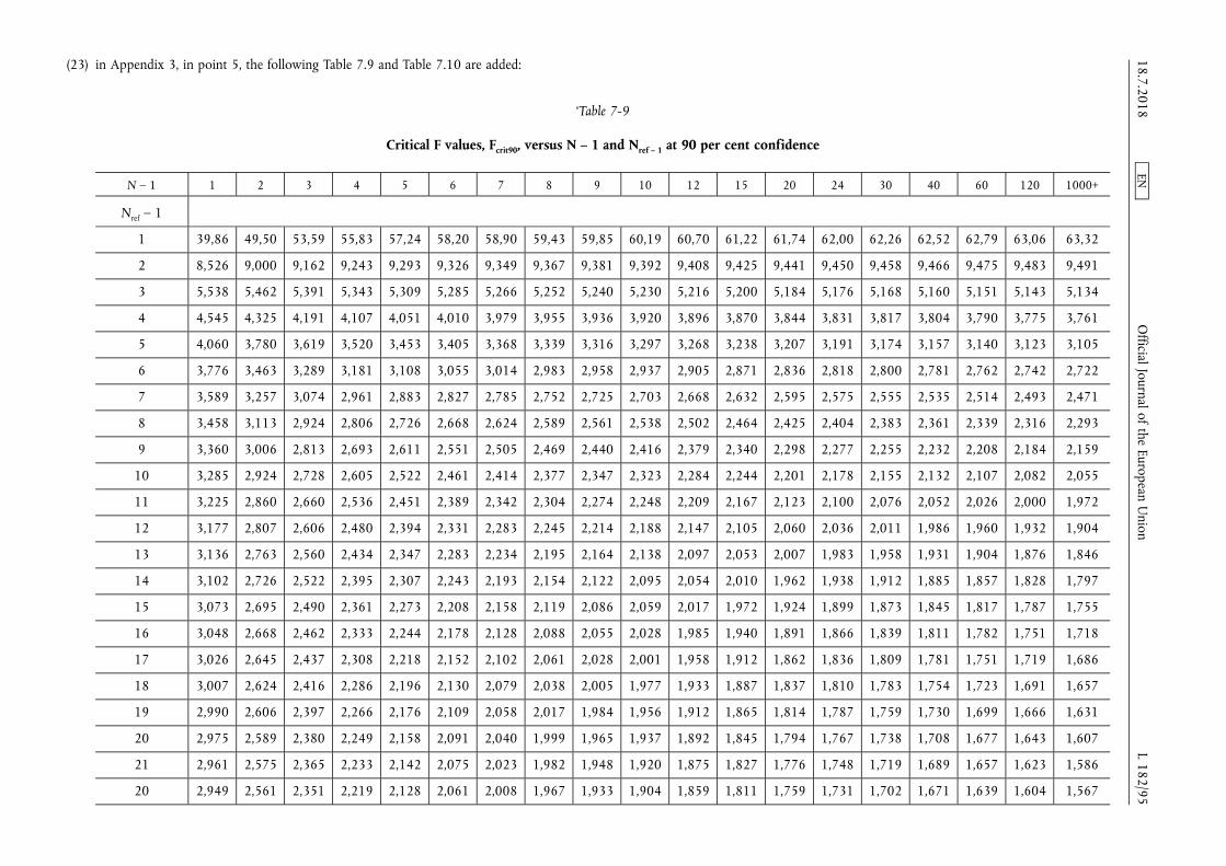
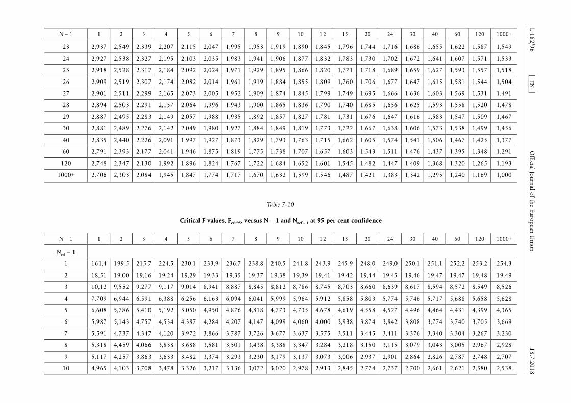
N ndash 1 1 2 3 4 5 6 7 8 9 10 12 15 20 24 30 40 60 120 1000+
23 2937 2549 2339 2207 2115 2047 1995 1953 1919 1890 1845 1796 1744 1716 1686 1655 1622 1587 1549
24 2927 2538 2327 2195 2103 2035 1983 1941 1906 1877 1832 1783 1730 1702 1672 1641 1607 1571 1533
25 2918 2528 2317 2184 2092 2024 1971 1929 1895 1866 1820 1771 1718 1689 1659 1627 1593 1557 1518
26 2909 2519 2307 2174 2082 2014 1961 1919 1884 1855 1809 1760 1706 1677 1647 1615 1581 1544 1504
27 2901 2511 2299 2165 2073 2005 1952 1909 1874 1845 1799 1749 1695 1666 1636 1603 1569 1531 1491
28 2894 2503 2291 2157 2064 1996 1943 1900 1865 1836 1790 1740 1685 1656 1625 1593 1558 1520 1478
29 2887 2495 2283 2149 2057 1988 1935 1892 1857 1827 1781 1731 1676 1647 1616 1583 1547 1509 1467
30 2881 2489 2276 2142 2049 1980 1927 1884 1849 1819 1773 1722 1667 1638 1606 1573 1538 1499 1456
40 2835 2440 2226 2091 1997 1927 1873 1829 1793 1763 1715 1662 1605 1574 1541 1506 1467 1425 1377
60 2791 2393 2177 2041 1946 1875 1819 1775 1738 1707 1657 1603 1543 1511 1476 1437 1395 1348 1291
120 2748 2347 2130 1992 1896 1824 1767 1722 1684 1652 1601 1545 1482 1447 1409 1368 1320 1265 1193
1000+ 2706 2303 2084 1945 1847 1774 1717 1670 1632 1599 1546 1487 1421 1383 1342 1295 1240 1169 1000
Table 7-10
Critical F values Fcrit95 versus N ndash 1 and Nref ndash 1 at 95 per cent confidence
N ndash 1 1 2 3 4 5 6 7 8 9 10 12 15 20 24 30 40 60 120 1000+
Nref ndash 1
1 1614 1995 2157 2245 2301 2339 2367 2388 2405 2418 2439 2459 2480 2490 2501 2511 2522 2532 2543
2 1851 1900 1916 1924 1929 1933 1935 1937 1938 1939 1941 1942 1944 1945 1946 1947 1947 1948 1949
3 1012 9552 9277 9117 9014 8941 8887 8845 8812 8786 8745 8703 8660 8639 8617 8594 8572 8549 8526
4 7709 6944 6591 6388 6256 6163 6094 6041 5999 5964 5912 5858 5803 5774 5746 5717 5688 5658 5628
5 6608 5786 5410 5192 5050 4950 4876 4818 4773 4735 4678 4619 4558 4527 4496 4464 4431 4399 4365
6 5987 5143 4757 4534 4387 4284 4207 4147 4099 4060 4000 3938 3874 3842 3808 3774 3740 3705 3669
7 5591 4737 4347 4120 3972 3866 3787 3726 3677 3637 3575 3511 3445 3411 3376 3340 3304 3267 3230
8 5318 4459 4066 3838 3688 3581 3501 3438 3388 3347 3284 3218 3150 3115 3079 3043 3005 2967 2928
9 5117 4257 3863 3633 3482 3374 3293 3230 3179 3137 3073 3006 2937 2901 2864 2826 2787 2748 2707
10 4965 4103 3708 3478 3326 3217 3136 3072 3020 2978 2913 2845 2774 2737 2700 2661 2621 2580 2538
1872018 L 18296
Official Journal of the European U
nion EN
N ndash 1 1 2 3 4 5 6 7 8 9 10 12 15 20 24 30 40 60 120 1000+
11 4844 3982 3587 3357 3204 3095 3012 2948 2896 2854 2788 2719 2646 2609 2571 2531 2490 2448 2405
12 4747 3885 3490 3259 3106 2996 2913 2849 2796 2753 2687 2617 2544 2506 2466 2426 2384 2341 2296
13 4667 3806 3411 3179 3025 2915 2832 2767 2714 2671 2604 2533 2459 2420 2380 2339 2297 2252 2206
14 4600 3739 3344 3112 2958 2848 2764 2699 2646 2602 2534 2463 2388 2349 2308 2266 2223 2178 2131
15 4543 3682 3287 3056 2901 2791 2707 2641 2588 2544 2475 2403 2328 2288 2247 2204 2160 2114 2066
16 4494 3634 3239 3007 2852 2741 2657 2591 2538 2494 2425 2352 2276 2235 2194 2151 2106 2059 2010
17 4451 3592 3197 2965 2810 2699 2614 2548 2494 2450 2381 2308 2230 2190 2148 2104 2058 2011 1960
18 4414 3555 3160 2928 2773 2661 2577 2510 2456 2412 2342 2269 2191 2150 2107 2063 2017 1968 1917
19 4381 3522 3127 2895 2740 2628 2544 2477 2423 2378 2308 2234 2156 2114 2071 2026 1980 1930 1878
20 4351 3493 3098 2866 2711 2599 2514 2447 2393 2348 2278 2203 2124 2083 2039 1994 1946 1896 1843
21 4325 3467 3073 2840 2685 2573 2488 2421 2366 2321 2250 2176 2096 2054 2010 1965 1917 1866 1812
22 4301 3443 3049 2817 2661 2549 2464 2397 2342 2297 2226 2151 2071 2028 1984 1938 1889 1838 1783
23 4279 3422 3028 2796 2640 2528 2442 2375 2320 2275 2204 2128 2048 2005 1961 1914 1865 1813 1757
24 4260 3403 3009 2776 2621 2508 2423 2355 2300 2255 2183 2108 2027 1984 1939 1892 1842 1790 1733
25 4242 3385 2991 2759 2603 2490 2405 2337 2282 2237 2165 2089 2008 1964 1919 1872 1822 1768 1711
26 4225 3369 2975 2743 2587 2474 2388 2321 2266 2220 2148 2072 1990 1946 1901 1853 1803 1749 1691
27 4210 3354 2960 2728 2572 2459 2373 2305 2250 2204 2132 2056 1974 1930 1884 1836 1785 1731 1672
28 4196 3340 2947 2714 2558 2445 2359 2291 2236 2190 2118 2041 1959 1915 1869 1820 1769 1714 1654
29 4183 3328 2934 2701 2545 2432 2346 2278 2223 2177 2105 2028 1945 1901 1854 1806 1754 1698 1638
30 4171 3316 2922 2690 2534 2421 2334 2266 2211 2165 2092 2015 1932 1887 1841 1792 1740 1684 1622
40 4085 3232 2839 2606 2450 2336 2249 2180 2124 2077 2004 1925 1839 1793 1744 1693 1637 1577 1509
60 4001 3150 2758 2525 2368 2254 2167 2097 2040 1993 1917 1836 1748 1700 1649 1594 1534 1467 1389
120 3920 3072 2680 2447 2290 2175 2087 2016 1959 1911 1834 1751 1659 1608 1554 1495 1429 1352 1254
1000+ 3842 2996 2605 2372 2214 2099 2010 1938 1880 1831 1752 1666 1571 1517 1459 1394 1318 1221 1000rsquo
1872018 L 18297
Official Journal of the European U
nion EN
(24) Appendix 5 is amended as follows
(a) in point 22 in the legend of equation (7-178) the row corresponding to the term lsquoPirsquo is replaced by the following
lsquoPi = engine power for the mode i [kW] calculated by adding to the measured power Pmeas [kW] the power required to drive auxiliaries PAUX [kW] determined in accordance with equation (6-8) of Annex VI (Pi = Pmeas + PAUX)rsquo
(b) in point 23 the first sentence is replaced by the following
lsquoThe final NRSC and weighted average NRTC test results shall be rounded in one step to three significant figures in accordance with ASTM E 29ndash06Brsquo
1872018 L 18298 Official Journal of the European Union EN
ANNEX VIII
Annex VIII to Delegated Regulation (EU) 2017654 is amended as follows
(1) in point 4222 in the last paragraph the following sentence is added
lsquoA description of the connection for and method to read those records shall be included in the information folder as set out in Part A of Annex I of Implementing Regulation (EU) 2017656rsquo
(2) in point 451 point (b) is replaced by the following
lsquo(b) In case of a Type 2 engine the resulting difference between the highest and the lowest maximum GERcycle within the family shall never exceed the range set out in point 2415 of Annex IX to Implementing Regulation (EU) 2017656 except as permitted by point 31rsquo
(3) point 641 is replaced by the following
lsquo641 The manufacturer shall present the approval authority with evidence showing that the GERcycle span of all members of the dual-fuel engine family remains within the range set out in point 2415 of Annex IX to Implementing Regulation (EU) 2017656 or in the case of engines with an operator-adjustable GERcycle satisfy the requirements of point 65 (for example through algorithms functional analyses calculations simulations results of previous tests etc)rsquo
(4) the following point 68 is inserted
lsquo68 Documentation of the demonstration
A demonstration report shall document the demonstration conducted pursuant to points 61 to 671 The report shall
(a) describe the demonstration performed including the applicable test cycle
(b) be included in the information folder as set out in Part A of Annex I of Implementing Regulation (EU) 2017656rsquo
(5) Appendix 2 is amended as follows
(a) in point 71321 the introductory wording of the first paragraph is replaced by the following
lsquoIn the case that the exact equations are applied to calculate instantaneous values of ugas in accordance with paragraph 7132(a) then when calculating the mass per test of a gaseous emission for transient (NRTC and LSI-NRTC) test cycles and RMC ugas shall be included in the summation in equation (7-2) of point 212 of Annex VII by means of equation (8-1)rsquo
(b) in point 7133 the second paragraph is replaced by the following
lsquoThe requirements of point 8212 of Annex VI shall apply for controlling the dilution ratio In particular if the combined transformation time of the exhaust gas flow measurement and the partial flow system exceeds 03 s look-ahead control based on a pre-recorded test run shall be used In this case the combined rise time shall be le 1 s and the combined delay time le 10 s Except in the case that the exhaust gas mass flow is measured directly the determination of exhaust gas mass flow shall use values of α γ δ and ε determined in accordance with point 7153rsquo
(c) in point 7134 in the paragraph under the heading the first sentence is replaced by the following
lsquoThe flow meter referred to in points 9453 and 9454 of Annex VI shall not be sensitive to the changes in exhaust gas composition and densityrsquo
(d) in point 7141 the heading is replaced by the following
lsquo7141 Determination of the background corrected concentrationsrsquo
(e) point 7152 is replaced by the following
lsquo7152 Calculation of the fuel mixture components
Equations (8-2) to (8-7) shall be used to calculate the elemental composition of the fuel mixture
qmf = qmf1 + qmf2 (8-2)
wH frac14wH1 qmf1 thorn wH2 qmf2
qmf1 thorn qmf2 (8-3)
1872018 L 18299 Official Journal of the European Union EN
wC frac14wC1 qmf1 thorn wC2 qmf2
qmf1 thorn qmf2 (8-4)
wS frac14wS1 qmf1 thorn wS2 qmf2
qmf1 thorn qmf2 (8-5)
wN frac14wN1 qmf1 thorn wN2 qmf2
qmf1 thorn qmf2 (8-6)
wO frac14wO1 qmf1 thorn wO2 qmf2
qmf1 thorn qmf2 (8-7)
where
qmf1 is the fuel mass flow rate of fuel 1 [kgs]
qmf2 is the fuel mass flow rate of fuel 2 [kgs]
wH is the hydrogen content of fuel [ mass]
wC is the carbon content of fuel [ mass]
wS is the sulphur content of fuel [ mass]
wN is the nitrogen content of fuel [ mass]
wO is the oxygen content of fuel [ mass]rsquo
(f) the following point 7153 is inserted
lsquo7153 Calculation of the molar ratios of H C S N and O related to C for the fuel mixture
The calculation of the atomic ratios (especially the HC-ratio α) is given in Annex VII by means of equations (8-8) to (8-11)
α frac14 119164 wH
wC (8-8)
γ frac14 037464 wS
wC (8-9)
δ frac14 085752 wN
wC (8-10)
ε frac14 075072 wO
wC (8-11)
where
wH is the hydrogen content of fuel mass fraction [gg] or [ mass]
wC is the carbon content of fuel mass fraction [gg] or [ mass]
wS is the sulphur content of fuel mass fraction [gg] or [ mass]
wN is the nitrogen content of fuel mass fraction [gg] or [ mass]
wO is the oxygen content of fuel mass fraction [gg] or [ mass]
α is the molar hydrogen ratio (HC)
γ is the molar sulphur ratio (SC)
δ is the molar nitrogen ratio (NC)
ε is the molar oxygen ratio (OC)
referring to a fuel CΗαΟεΝδSγrsquo
1872018 L 182100 Official Journal of the European Union EN
(g) in point 723 in the first paragraph the last sentence is replaced by the following
lsquoThe instantaneous molar component ratios shall be input in the equations (7-88) (7-90) and (7-91) of Annex VII for the continuous chemical balancersquo
(h) in point 7231 the introductory wording of equation (8-16) is replaced by the following
lsquoIn cases where exhaust gas mass flow rate is calculated based on the mixed fuel rate then wC in equation (7-113) of Annex VII shall be calculated by means of equation (8-16)rsquo
1872018 L 182101 Official Journal of the European Union EN
ANNEX IX
In point 2 of Appendix 2 of Annex IX to Delegated Regulation (EU) 2017654 the introductory wording before equation (9-5) is replaced by the following
lsquoThe value of Sλ may be determined from the ratio of the ratio of the stoichiometric composition of oxygen and methane to the ratio of the stoichiometric composition of oxygen and the fuel blend supplied to the engine as set out in equation (9-5)rsquo
1872018 L 182102 Official Journal of the European Union EN
ANNEX X
In Annex XIII to Delegated Regulation (EU) 2017654 point 1 is amended as follows
(1) in point (1) the introductory wording is replaced by the following
lsquo(1) EU type-approvals granted on the basis of Regulation (EC) No 5952009 of the European Parliament and of the Council () and its implementing measures where a technical service confirms that the engine type meets
() Regulation (EC) No 5952009 of the European Parliament and of the Council of 18 June 2009 on type-approval of motor vehicles and engines with respect to emissions from heavy duty vehicles (Euro VI) and on access to vehicle repair and maintenance information and amending Regulation (EC) No 7152007 and Directive 200746EC and repealing Directives 801269EEC 200555EC and 200578EC (OJ L 188 1872009 p 1)rsquo
(2) in point (2) the introductory wording is replaced by the following
lsquo(2) type-approvals in conformity with UNECE Regulation No 4906 series of amendments () where a technical service confirms that the engine type meets
() Regulation No 49 of the Economic Commission for Europe of the United Nations (UNECE) mdash Uniform provisions concerning the measures to be taken against the emission of gaseous and particulate pollutants from compression-ignition engines and positive ignition engines for use in vehicles (OJ L 171 2462013 p 1rsquo
1872018 L 182103 Official Journal of the European Union EN
ANNEX XI
In point 3(15) of Annex XV to Delegated Regulation (EU) 2017654 point (a) is replaced by the following
lsquo(a) where the engine is to be operated within the Union on diesel or non-road gas-oil a statement indicating that a fuel with sulphur content not greater than 10 mgkg (20 mgkg at point of final distribution) cetane number not less than 45 and a FAME content not greater than 8 vv shall be usedrsquo
1872018 L 182104 Official Journal of the European Union EN
ANNEX XII
Annex I to Delegated Regulation (EU) 2017654 is corrected as follows
(1) point 241 is replaced by the following
lsquo241 Engines fuelled with CNG and designed for operation on either the range of H-gases or on the range of L-gasesrsquo
(2) points 252 and 2521 are replaced by the following
lsquo252 Fuel-specific dual-fuel engine fuelled with Liquefied Natural Gas (LNG)
2521 For a dual-fuel engine family where the engines are calibrated for a specific LNG gas composition resulting in a λ-shift factor not differing by more than 3 from the λ-shift factor of the G20 fuel specified in Annex IX and the ethane content of which does not exceed 15 the parent engine shall only be tested on the G20 reference gas fuel or on the equivalent fuel created using an admixture of pipeline gas with other gases as specified in Appendix 1 of Annex IXrsquo
1872018 L 182105 Official Journal of the European Union EN
ANNEX XIII
Annex III to Delegated Regulation (EU) 2017654 is corrected as follows
(1) point 312 is replaced by the following
lsquo312 Engines from different engine families may be further combined into families based on the type of exhaust after-treatment system utilised or where no after-treatment is used based upon the similarity of the technical characteristics of the emission control system Engines of different bore and stroke different configuration different air management systems or different fuel systems may be considered equivalent in respect to emissions deterioration characteristics if the manufacturer provides data to the approval authority that there is a reasonable technical basis for such determination In order to place engine families having similar technical specifications and installation for the exhaust after-treatment systems into the same engine after- treatment system family the manufacturer shall provide data to the approval authority that demonstrates that the emissions reduction performance of such engines is similarrsquo
(2) in point 3413 the second sentence is replaced by the following
lsquoThe approval authority shall not refuse to approve maintenance requirements that are reasonable and technically necessary including but not limited to those identified in point 3414rsquo
1872018 L 182106 Official Journal of the European Union EN
ANNEX XIV
Annex IV to Delegated Regulation (EU) 2017654 is corrected as follows
(1) point 231 is replaced by the following
lsquo231 An auxiliary emission control strategy may be activated by an engine or a non-road mobile machinery provided that the auxiliary emission control strategyrsquo
(2) Appendix 1 is corrected as follows
(a) point 231 is replaced by the following
lsquo231 It is permitted to use a heated or a non-heated reagent tank and dosing system A heated system shall meet the requirements of points 2322 to 23224 A non-heated system shall meet the requirements of point 2323rsquo
(b) point 2322 is replaced by the following
lsquo2322 Design criteria for a heated system
A heated system shall be so designed that it meets the performance requirements set out in points 232 to 23224 when tested using the procedure definedrsquo
(c) point 31 is replaced by the following
lsquo31 The OEM shall provide to all end-users of new non-road mobile machinery written instructions about the emission control system and its correct operation in accordance with Annex XVrsquo
(d) point 7111 is replaced by the following
lsquo7111 The value of CDmin specified by the manufacturer shall be used during the demonstration set out in section 13 and recorded in Part C of the information document specified in Annex I to Implementing Regulation (EU) 2017656rsquo
(e) points 9 to 9232 are replaced by the following
lsquo9 Other failures that may be attributed to tampering
91 In addition to the level of reagent in the reagent tank the reagent quality and the interruption of dosing the following failures shall be monitored because they may be attributed to tampering
(a) failures of the NOx Control Diagnostic (NCD) system as described in point 921
(b) failures of the exhaust gas recirculation (EGR) valve as described in point 922
92 Monitoring requirements and counters
921 NCD system
9211 The NOx Control Diagnostic (NCD) system shall be monitored for electrical failures and for removal or deactivation of any sensor that prevents it from diagnosing any other failures set out in sections 6 to 8 (component monitoring)
A non-exhaustive list of sensors that affect the diagnostic capability are those directly measuring NOx concentration urea quality sensors ambient sensors and sensors used for monitoring reagent dosing activity reagent level or reagent consumption
9212 A counter shall be attributed to each of the monitoring failures The NCD system counters shall count the number of engine operating hours when the DTC associated to a malfunction of the NCD system is confirmed to be active Different NCD system failures may be grouped into a single counter
92121 The manufacturer may group the NCD system failure together with one or more of the systems listed in sections 7 8 and point 922 into a single counter
9213 Details of the NCD system counter(s) activation and deactivation criteria and mechanisms are described in section 11
1872018 L 182107 Official Journal of the European Union EN
922 Impeded EGR valve
9221 The exhaust gas recirculation (EGR) system shall be monitored for an impeded EGR valve
9222 A counter shall be attributed to an impeded EGR valve The EGR valve counter shall count the number of engine operating hours when the DTC associated to an impeded EGR valve is confirmed to be active
92221 The manufacturer may group the impeded EGR valve failure together with one or more of the systems listed in sections 7 8 and point 921 into a single counter
9223 Details of the EGR valve counter activation and deactivation criteria and mechanisms are described in section 11rsquo
(f) point 1021 is replaced by the following
lsquo1021 The demonstration that the monitoring systems for other members of the NCD engine family are similar may be performed by presenting to the approval authorities such elements as algorithms functional analyses etcrsquo
(g) point 1023 is replaced by the following
lsquo1023 In the case where engines of an engine family belong to an NCD engine family that has already been EU type-approved as referred to in point 1021 (Figure 43) the compliance of that engine family is deemed to be demonstrated without further testing provided the manufacturer demonstrates to the authority that the monitoring systems necessary for complying with the requirements of this Appendix are similar within the considered engine and NCD engine families
Table 41
Illustration of the content of the demonstration process in accordance with the provisions in points 103 and 104
Mechanism demonstration elements
Warning system activation specified in point 103
mdash 2 activation tests (incl lack of reagent)
mdash Supplementary demonstration elements as appropriate
Low-level inducement activation specishyfied in point 104
mdash 2 activation tests (incl lack of reagent)
mdash Supplementary demonstration elements as appropriate
mdash 1 torque reduction test
Severe inducement activation specified in point 104
mdash 2 activation tests (incl lack of reagent)
mdash Supplementary demonstration elements as appropriatersquo
(h) point 103352 is replaced by the following
lsquo103352 The demonstration of the warning system activation is deemed to be accomplished if at the end of each demonstration test performed in accordance with point 1033 the warning system has been properly activated and the DTC for the selected failure has got the ldquoconfirmed and activerdquo statusrsquo
(i) points 1042 and 1043 are replaced by the following
lsquo1042 The test sequence shall demonstrate the activation of the inducement system in case of the failure selected by the approval authority from the list as referred to in point 10321 for the test of the warning system
1043 For the purpose of this demonstration
(a) the manufacturer shall in agreement with the approval authority be permitted to accelerate the test by simulating the achievement of a certain number of operating hours
(b) the achievement of the torque reduction required for low-level inducement may be demonstrated at the same time as the general engine performance approval process performed in accordance with this Regulation A separate torque measurement during the inducement system demonstration is not required in this case
1872018 L 182108 Official Journal of the European Union EN
(c) the low-level inducement if applicable shall be demonstrated in accordance with the requirements of point 1045
(d) the severe inducement shall be demonstrated in accordance with the requirements of point 1046rsquo
(j) point 133 is replaced by the following
lsquo133 The pollutant emissions resulting from this test shall not exceed the NOx threshold specified in point 711rsquo
(3) Appendix 4 is corrected as follows
(a) point 2323 is replaced by the following
lsquo2323 In cases where more than the period of running time indicated in Table 45 is required for the monitors to accurately detect and confirm a PCM (eg monitors using statistical models or with respect to fluid consumption on the non-road mobile machinery) the approval authority may permit a longer period for monitoring provided the manufacturer justifies the need for the longer period (for example by technical rationale experimental results in-house experience etc)rsquo
(b) point 61 is replaced by the following
lsquo61 The PCD system shall detect the complete removal of the particulate after-treatment system inclusive of the removal of any sensors used to monitor activate de-activate or modulate its operationrsquo
1872018 L 182109 Official Journal of the European Union EN
ANNEX XV
Point 1 of Annex V to Delegated Regulation (EU) 2017654 is corrected as follows
(1) the second and third paragraphs are replaced by the following
lsquoThis Annex sets out the technical requirements relating to the area associated with the relevant NRSC within which the amount by which the emissions shall be permitted to exceed the emission limits set out in Annex II to Regulation (EU) 20161628 is controlled
When an engine is tested in the manner set out in test requirements of section 4 the emission of gaseous and particulate pollutants sampled at any randomly selected point within the applicable control area set out in section 2 shall not exceed the applicable emission limit values in Annex II to Regulation (EU) 20161628 multiplied by a factor of 20rsquo
(2) the last paragraph is replaced by the following
lsquoThe installation instructions provided by the manufacturer to the OEM in accordance with Annex XIV shall identify the upper and lower boundaries of the applicable control area and shall include a statement to clarify that the OEM shall not install the engine in such a way that it constrains the engine to operate permanently at only combinations of speed and torque outside of the control area for the torque curve corresponding to the approved engine type or engine familyrsquo
1872018 L 182110 Official Journal of the European Union EN
ANNEX XVI
Annex VI to Delegated Regulation (EU) 2017654 is corrected as follows
(1) in point 5256 the second paragraph is replaced by the following
lsquoWhere the governor installed on the engine is used the 100 speed shall be the engine governed speed as defined in Article 1(24)rsquo
(2) point 631 is replaced by the following
lsquo631 Basis for emission measurement
The basis of specific emissions measurement is uncorrected net power as defined in Article 3(25) of Regulation (EU) 20161628rsquo
(3) in point 633 the last sentence of the second paragraph is replaced by the following
lsquoThe power absorbed by auxiliaries shall be used to adjust the set values and to calculate the work produced by the engine over the test cycle in accordance with point 7713 or point 7723(b)rsquo
(4) in point 7421 the two paragraphs below Figure 63 are replaced by the following
(a) point (a) is replaced by the following
lsquo(a) the cold start run shall commence after either the engine and exhaust after-treatment systems have cooled down to room temperature after natural engine cool down or after forced cool down and the engine coolant and oil temperatures exhaust after-treatment systems and all engine control devices are stabilized between 293 K and 303 K (20 degC and 30 degC) The measurement of the emissions for this run shall be started with the start of the cold enginersquo
(b) point (c) is replaced by the following
lsquo(c) the hot-start run shall commence immediately after the soak period with the cranking of the engine The gaseous analyzers shall be switched on at least 10 seconds before the end of the soak period to avoid switching signal peaks The measurement of emissions for this run shall be started in parallel with the cranking of the engine
Brake specific emissions expressed in (gkWh) or number per kilowatt-hour (kWh) for PN shall be determined by using the procedures set out in this section for both the cold start run and hot-start run of the test cycle Composite weighted emissions shall be computed by weighting the cold-start run results by 10 and the hot-start run results by 90 as detailed in Annex VIIrsquo
(5) in point 76 the words lsquoas defined in Article 2(12)rsquo are replaced by the words lsquoas defined in Article 1(12)rsquo
(6) in point 7631 in point (b) the fourth and fifth sentences are replaced by the following
lsquoThe power recorded shall not exceed the rated power as defined in Article 3(27) of Regulation (EU) 20161628 by more than 125 If this value is exceeded the manufacturer shall revise the declared rated powerrsquo
(7) in point 7723 in the legend of equation (6-16) the second row is replaced by the following
lsquomaxtorque is the maximum torque for the respective test speed taken from the engine mapping performed in accordance with point 762 adjusted where necessary in accordance with point 7723(b)rsquo
(8) in point 8235 the last sentence is replaced by the following
lsquoHowever if a PM mass of 400 μg or more is expected then the sample media shall be stabilised for at least 60 minrsquo
(9) in point 921(c) point (i) is replaced by the following
lsquo(i) For removing background PM the diluent shall be filtered with high-efficiency particulate air (HEPA) filters that have an initial minimum collection efficiency specification of 9997 (see Article 1(19) for procedures related to HEPA-filtration efficiencies)rsquo
1872018 L 182111 Official Journal of the European Union EN
(10) in point 922(g) the last paragraph is replaced by the following
lsquoFor PM sampling the already proportional flow coming from CVS goes through secondary dilution (one or more) to achieve the requested overall dilution ratio as shown in Figure 67 and set out in point 9232rsquo
(11) in point 9231 in the first paragraph the last sentence is replaced by the following
lsquoThese need to satisfy other criteria such as in points 8186 (periodic calibration) and 8212 (validation) for varying dilution PFD and point 8145 as well as Table 65 (linearity verification) and point 81857 (verification) for constant dilution PFDrsquo
(12) in point 9233 the last paragraph is replaced by the following
lsquoThe system may be used also for a previously diluted exhaust gas where via a constant dilution-ratio an already proportional flow is diluted (see Figure 67) This is the way of performing secondary dilution from a CVS tunnel to achieve the necessary overall dilution ratio for PM samplingrsquo
(13) in Appendix 4 in point 341 the last sentence is replaced by the following
lsquoThe difference between the pre-test and post-test results shall be less than 2 of full scalersquo
1872018 L 182112 Official Journal of the European Union EN
ANNEX XVII
Annex VII to Delegated Regulation (EU) 2017654 is corrected as follows
(1) point 2411 is corrected as follows
(a) equation (7-59) is replaced by the following
lsquoWact frac14XN
i frac14 1
Pi Δti frac141f
1
3 600
1103
2 π60
XN
i frac14 1
ethni TiTHORN (7-59)rsquo
(2) point 395 is replaced by the following
lsquo395 CFV calibration
Some CFV flow meters consist of a single venturi and some consist of multiple venturis where different combinations of venturis are used to meter different flow rates For CFV flow meters that consist of multiple venturis either calibration of each venturi independently to determine a separate discharge coefficient Cd for each venturi or calibration of each combination of venturis as one venturi may be performed In the case where a combination of venturis is calibrated the sum of the active venturi throat areas is used as At the square root of the sum of the squares of the active venturi throat diameters as dt and the ratio of the venturi throat to inlet diameters is the ratio of the square root of the sum of the active venturi throat diameters (dt) to the diameter of the common entrance to all of the venturis (D) To determine the Cd for a single venturi or a single combination of venturis the following steps shall be performed
(a) With the data collected at each calibration set point an individual Cd for each point shall be calculated using equation (7-140)
(b) The mean and standard deviation of all the Cd values shall be calculated in accordance with equations (7-155) and (7-156)
(c) If the standard deviation of all the Cd values is less than or equal to 03 of the mean Cd then the mean Cd shall be used in equation (7-120) and the CFV shall be used only down to the lowest r measured during calibration
r = 1 ndash (Δppin) (7-148)
(d) If the standard deviation of all the Cd values exceeds 03 of the mean Cd the Cd values corresponding to the data point collected at the lowest r measured during calibration shall be omitted
(e) If the number of remaining data points is less than seven corrective action shall be taken by checking calibration data or repeating the calibration process If the calibration process is repeated checking for leaks applying tighter tolerances to measurements and allowing more time for flows to stabilize is recommended
(f) If the number of remaining Cd values is seven or greater the mean and standard deviation of the remaining Cd values shall be recalculated
(g) If the standard deviation of the remaining Cd values is less than or equal to 03 of the mean of the remaining Cd that mean Cd shall be used in equation (7-120) and the CFV values only down to the lowest r associated with the remaining Cd shall be used
(h) If the standard deviation of the remaining Cd still exceeds 03 of the mean of the remaining Cd values the steps set out in points (d) to (g) shall be repeatedrsquo
(3) in Appendix 6 equation (7-180) is replaced by the following
lsquocNH3 = (01 times cNH3cold) + (09 times cNH3hot) (7-180)rsquo
1872018 L 182113 Official Journal of the European Union EN
ANNEX XVIII
Annex VIII to Delegated Regulation (EU) 2017654 is corrected as follows
(1) in point 46 the words lsquoas required byrsquo are deleted
(2) in Appendix 2 in point 4 in the third paragraph below the heading the last sentence is replaced by the following
lsquoThis shall be compensated via one of the methods described in point 7rsquo
1872018 L 182114 Official Journal of the European Union EN
- COMMISSION DELEGATED REGULATION (EU) 2018989 of 18 May 2018 amending and correcting Delegated Regulation (EU) 2017654 supplementing Regulation (EU) 20161628 of the European Parliament and of the Council with regard to technical and general requirements relating to emission limits and type-approval for internal combustion engines for non-road mobile machinery (Text with EEA relevance)
-
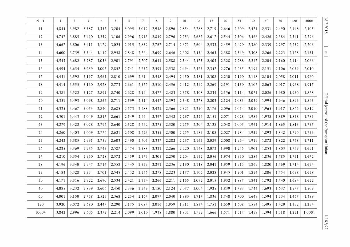
N ndash 1 1 2 3 4 5 6 7 8 9 10 12 15 20 24 30 40 60 120 1000+
11 4844 3982 3587 3357 3204 3095 3012 2948 2896 2854 2788 2719 2646 2609 2571 2531 2490 2448 2405
12 4747 3885 3490 3259 3106 2996 2913 2849 2796 2753 2687 2617 2544 2506 2466 2426 2384 2341 2296
13 4667 3806 3411 3179 3025 2915 2832 2767 2714 2671 2604 2533 2459 2420 2380 2339 2297 2252 2206
14 4600 3739 3344 3112 2958 2848 2764 2699 2646 2602 2534 2463 2388 2349 2308 2266 2223 2178 2131
15 4543 3682 3287 3056 2901 2791 2707 2641 2588 2544 2475 2403 2328 2288 2247 2204 2160 2114 2066
16 4494 3634 3239 3007 2852 2741 2657 2591 2538 2494 2425 2352 2276 2235 2194 2151 2106 2059 2010
17 4451 3592 3197 2965 2810 2699 2614 2548 2494 2450 2381 2308 2230 2190 2148 2104 2058 2011 1960
18 4414 3555 3160 2928 2773 2661 2577 2510 2456 2412 2342 2269 2191 2150 2107 2063 2017 1968 1917
19 4381 3522 3127 2895 2740 2628 2544 2477 2423 2378 2308 2234 2156 2114 2071 2026 1980 1930 1878
20 4351 3493 3098 2866 2711 2599 2514 2447 2393 2348 2278 2203 2124 2083 2039 1994 1946 1896 1843
21 4325 3467 3073 2840 2685 2573 2488 2421 2366 2321 2250 2176 2096 2054 2010 1965 1917 1866 1812
22 4301 3443 3049 2817 2661 2549 2464 2397 2342 2297 2226 2151 2071 2028 1984 1938 1889 1838 1783
23 4279 3422 3028 2796 2640 2528 2442 2375 2320 2275 2204 2128 2048 2005 1961 1914 1865 1813 1757
24 4260 3403 3009 2776 2621 2508 2423 2355 2300 2255 2183 2108 2027 1984 1939 1892 1842 1790 1733
25 4242 3385 2991 2759 2603 2490 2405 2337 2282 2237 2165 2089 2008 1964 1919 1872 1822 1768 1711
26 4225 3369 2975 2743 2587 2474 2388 2321 2266 2220 2148 2072 1990 1946 1901 1853 1803 1749 1691
27 4210 3354 2960 2728 2572 2459 2373 2305 2250 2204 2132 2056 1974 1930 1884 1836 1785 1731 1672
28 4196 3340 2947 2714 2558 2445 2359 2291 2236 2190 2118 2041 1959 1915 1869 1820 1769 1714 1654
29 4183 3328 2934 2701 2545 2432 2346 2278 2223 2177 2105 2028 1945 1901 1854 1806 1754 1698 1638
30 4171 3316 2922 2690 2534 2421 2334 2266 2211 2165 2092 2015 1932 1887 1841 1792 1740 1684 1622
40 4085 3232 2839 2606 2450 2336 2249 2180 2124 2077 2004 1925 1839 1793 1744 1693 1637 1577 1509
60 4001 3150 2758 2525 2368 2254 2167 2097 2040 1993 1917 1836 1748 1700 1649 1594 1534 1467 1389
120 3920 3072 2680 2447 2290 2175 2087 2016 1959 1911 1834 1751 1659 1608 1554 1495 1429 1352 1254
1000+ 3842 2996 2605 2372 2214 2099 2010 1938 1880 1831 1752 1666 1571 1517 1459 1394 1318 1221 1000rsquo
1872018 L 18297
Official Journal of the European U
nion EN
(24) Appendix 5 is amended as follows
(a) in point 22 in the legend of equation (7-178) the row corresponding to the term lsquoPirsquo is replaced by the following
lsquoPi = engine power for the mode i [kW] calculated by adding to the measured power Pmeas [kW] the power required to drive auxiliaries PAUX [kW] determined in accordance with equation (6-8) of Annex VI (Pi = Pmeas + PAUX)rsquo
(b) in point 23 the first sentence is replaced by the following
lsquoThe final NRSC and weighted average NRTC test results shall be rounded in one step to three significant figures in accordance with ASTM E 29ndash06Brsquo
1872018 L 18298 Official Journal of the European Union EN
ANNEX VIII
Annex VIII to Delegated Regulation (EU) 2017654 is amended as follows
(1) in point 4222 in the last paragraph the following sentence is added
lsquoA description of the connection for and method to read those records shall be included in the information folder as set out in Part A of Annex I of Implementing Regulation (EU) 2017656rsquo
(2) in point 451 point (b) is replaced by the following
lsquo(b) In case of a Type 2 engine the resulting difference between the highest and the lowest maximum GERcycle within the family shall never exceed the range set out in point 2415 of Annex IX to Implementing Regulation (EU) 2017656 except as permitted by point 31rsquo
(3) point 641 is replaced by the following
lsquo641 The manufacturer shall present the approval authority with evidence showing that the GERcycle span of all members of the dual-fuel engine family remains within the range set out in point 2415 of Annex IX to Implementing Regulation (EU) 2017656 or in the case of engines with an operator-adjustable GERcycle satisfy the requirements of point 65 (for example through algorithms functional analyses calculations simulations results of previous tests etc)rsquo
(4) the following point 68 is inserted
lsquo68 Documentation of the demonstration
A demonstration report shall document the demonstration conducted pursuant to points 61 to 671 The report shall
(a) describe the demonstration performed including the applicable test cycle
(b) be included in the information folder as set out in Part A of Annex I of Implementing Regulation (EU) 2017656rsquo
(5) Appendix 2 is amended as follows
(a) in point 71321 the introductory wording of the first paragraph is replaced by the following
lsquoIn the case that the exact equations are applied to calculate instantaneous values of ugas in accordance with paragraph 7132(a) then when calculating the mass per test of a gaseous emission for transient (NRTC and LSI-NRTC) test cycles and RMC ugas shall be included in the summation in equation (7-2) of point 212 of Annex VII by means of equation (8-1)rsquo
(b) in point 7133 the second paragraph is replaced by the following
lsquoThe requirements of point 8212 of Annex VI shall apply for controlling the dilution ratio In particular if the combined transformation time of the exhaust gas flow measurement and the partial flow system exceeds 03 s look-ahead control based on a pre-recorded test run shall be used In this case the combined rise time shall be le 1 s and the combined delay time le 10 s Except in the case that the exhaust gas mass flow is measured directly the determination of exhaust gas mass flow shall use values of α γ δ and ε determined in accordance with point 7153rsquo
(c) in point 7134 in the paragraph under the heading the first sentence is replaced by the following
lsquoThe flow meter referred to in points 9453 and 9454 of Annex VI shall not be sensitive to the changes in exhaust gas composition and densityrsquo
(d) in point 7141 the heading is replaced by the following
lsquo7141 Determination of the background corrected concentrationsrsquo
(e) point 7152 is replaced by the following
lsquo7152 Calculation of the fuel mixture components
Equations (8-2) to (8-7) shall be used to calculate the elemental composition of the fuel mixture
qmf = qmf1 + qmf2 (8-2)
wH frac14wH1 qmf1 thorn wH2 qmf2
qmf1 thorn qmf2 (8-3)
1872018 L 18299 Official Journal of the European Union EN
wC frac14wC1 qmf1 thorn wC2 qmf2
qmf1 thorn qmf2 (8-4)
wS frac14wS1 qmf1 thorn wS2 qmf2
qmf1 thorn qmf2 (8-5)
wN frac14wN1 qmf1 thorn wN2 qmf2
qmf1 thorn qmf2 (8-6)
wO frac14wO1 qmf1 thorn wO2 qmf2
qmf1 thorn qmf2 (8-7)
where
qmf1 is the fuel mass flow rate of fuel 1 [kgs]
qmf2 is the fuel mass flow rate of fuel 2 [kgs]
wH is the hydrogen content of fuel [ mass]
wC is the carbon content of fuel [ mass]
wS is the sulphur content of fuel [ mass]
wN is the nitrogen content of fuel [ mass]
wO is the oxygen content of fuel [ mass]rsquo
(f) the following point 7153 is inserted
lsquo7153 Calculation of the molar ratios of H C S N and O related to C for the fuel mixture
The calculation of the atomic ratios (especially the HC-ratio α) is given in Annex VII by means of equations (8-8) to (8-11)
α frac14 119164 wH
wC (8-8)
γ frac14 037464 wS
wC (8-9)
δ frac14 085752 wN
wC (8-10)
ε frac14 075072 wO
wC (8-11)
where
wH is the hydrogen content of fuel mass fraction [gg] or [ mass]
wC is the carbon content of fuel mass fraction [gg] or [ mass]
wS is the sulphur content of fuel mass fraction [gg] or [ mass]
wN is the nitrogen content of fuel mass fraction [gg] or [ mass]
wO is the oxygen content of fuel mass fraction [gg] or [ mass]
α is the molar hydrogen ratio (HC)
γ is the molar sulphur ratio (SC)
δ is the molar nitrogen ratio (NC)
ε is the molar oxygen ratio (OC)
referring to a fuel CΗαΟεΝδSγrsquo
1872018 L 182100 Official Journal of the European Union EN
(g) in point 723 in the first paragraph the last sentence is replaced by the following
lsquoThe instantaneous molar component ratios shall be input in the equations (7-88) (7-90) and (7-91) of Annex VII for the continuous chemical balancersquo
(h) in point 7231 the introductory wording of equation (8-16) is replaced by the following
lsquoIn cases where exhaust gas mass flow rate is calculated based on the mixed fuel rate then wC in equation (7-113) of Annex VII shall be calculated by means of equation (8-16)rsquo
1872018 L 182101 Official Journal of the European Union EN
ANNEX IX
In point 2 of Appendix 2 of Annex IX to Delegated Regulation (EU) 2017654 the introductory wording before equation (9-5) is replaced by the following
lsquoThe value of Sλ may be determined from the ratio of the ratio of the stoichiometric composition of oxygen and methane to the ratio of the stoichiometric composition of oxygen and the fuel blend supplied to the engine as set out in equation (9-5)rsquo
1872018 L 182102 Official Journal of the European Union EN
ANNEX X
In Annex XIII to Delegated Regulation (EU) 2017654 point 1 is amended as follows
(1) in point (1) the introductory wording is replaced by the following
lsquo(1) EU type-approvals granted on the basis of Regulation (EC) No 5952009 of the European Parliament and of the Council () and its implementing measures where a technical service confirms that the engine type meets
() Regulation (EC) No 5952009 of the European Parliament and of the Council of 18 June 2009 on type-approval of motor vehicles and engines with respect to emissions from heavy duty vehicles (Euro VI) and on access to vehicle repair and maintenance information and amending Regulation (EC) No 7152007 and Directive 200746EC and repealing Directives 801269EEC 200555EC and 200578EC (OJ L 188 1872009 p 1)rsquo
(2) in point (2) the introductory wording is replaced by the following
lsquo(2) type-approvals in conformity with UNECE Regulation No 4906 series of amendments () where a technical service confirms that the engine type meets
() Regulation No 49 of the Economic Commission for Europe of the United Nations (UNECE) mdash Uniform provisions concerning the measures to be taken against the emission of gaseous and particulate pollutants from compression-ignition engines and positive ignition engines for use in vehicles (OJ L 171 2462013 p 1rsquo
1872018 L 182103 Official Journal of the European Union EN
ANNEX XI
In point 3(15) of Annex XV to Delegated Regulation (EU) 2017654 point (a) is replaced by the following
lsquo(a) where the engine is to be operated within the Union on diesel or non-road gas-oil a statement indicating that a fuel with sulphur content not greater than 10 mgkg (20 mgkg at point of final distribution) cetane number not less than 45 and a FAME content not greater than 8 vv shall be usedrsquo
1872018 L 182104 Official Journal of the European Union EN
ANNEX XII
Annex I to Delegated Regulation (EU) 2017654 is corrected as follows
(1) point 241 is replaced by the following
lsquo241 Engines fuelled with CNG and designed for operation on either the range of H-gases or on the range of L-gasesrsquo
(2) points 252 and 2521 are replaced by the following
lsquo252 Fuel-specific dual-fuel engine fuelled with Liquefied Natural Gas (LNG)
2521 For a dual-fuel engine family where the engines are calibrated for a specific LNG gas composition resulting in a λ-shift factor not differing by more than 3 from the λ-shift factor of the G20 fuel specified in Annex IX and the ethane content of which does not exceed 15 the parent engine shall only be tested on the G20 reference gas fuel or on the equivalent fuel created using an admixture of pipeline gas with other gases as specified in Appendix 1 of Annex IXrsquo
1872018 L 182105 Official Journal of the European Union EN
ANNEX XIII
Annex III to Delegated Regulation (EU) 2017654 is corrected as follows
(1) point 312 is replaced by the following
lsquo312 Engines from different engine families may be further combined into families based on the type of exhaust after-treatment system utilised or where no after-treatment is used based upon the similarity of the technical characteristics of the emission control system Engines of different bore and stroke different configuration different air management systems or different fuel systems may be considered equivalent in respect to emissions deterioration characteristics if the manufacturer provides data to the approval authority that there is a reasonable technical basis for such determination In order to place engine families having similar technical specifications and installation for the exhaust after-treatment systems into the same engine after- treatment system family the manufacturer shall provide data to the approval authority that demonstrates that the emissions reduction performance of such engines is similarrsquo
(2) in point 3413 the second sentence is replaced by the following
lsquoThe approval authority shall not refuse to approve maintenance requirements that are reasonable and technically necessary including but not limited to those identified in point 3414rsquo
1872018 L 182106 Official Journal of the European Union EN
ANNEX XIV
Annex IV to Delegated Regulation (EU) 2017654 is corrected as follows
(1) point 231 is replaced by the following
lsquo231 An auxiliary emission control strategy may be activated by an engine or a non-road mobile machinery provided that the auxiliary emission control strategyrsquo
(2) Appendix 1 is corrected as follows
(a) point 231 is replaced by the following
lsquo231 It is permitted to use a heated or a non-heated reagent tank and dosing system A heated system shall meet the requirements of points 2322 to 23224 A non-heated system shall meet the requirements of point 2323rsquo
(b) point 2322 is replaced by the following
lsquo2322 Design criteria for a heated system
A heated system shall be so designed that it meets the performance requirements set out in points 232 to 23224 when tested using the procedure definedrsquo
(c) point 31 is replaced by the following
lsquo31 The OEM shall provide to all end-users of new non-road mobile machinery written instructions about the emission control system and its correct operation in accordance with Annex XVrsquo
(d) point 7111 is replaced by the following
lsquo7111 The value of CDmin specified by the manufacturer shall be used during the demonstration set out in section 13 and recorded in Part C of the information document specified in Annex I to Implementing Regulation (EU) 2017656rsquo
(e) points 9 to 9232 are replaced by the following
lsquo9 Other failures that may be attributed to tampering
91 In addition to the level of reagent in the reagent tank the reagent quality and the interruption of dosing the following failures shall be monitored because they may be attributed to tampering
(a) failures of the NOx Control Diagnostic (NCD) system as described in point 921
(b) failures of the exhaust gas recirculation (EGR) valve as described in point 922
92 Monitoring requirements and counters
921 NCD system
9211 The NOx Control Diagnostic (NCD) system shall be monitored for electrical failures and for removal or deactivation of any sensor that prevents it from diagnosing any other failures set out in sections 6 to 8 (component monitoring)
A non-exhaustive list of sensors that affect the diagnostic capability are those directly measuring NOx concentration urea quality sensors ambient sensors and sensors used for monitoring reagent dosing activity reagent level or reagent consumption
9212 A counter shall be attributed to each of the monitoring failures The NCD system counters shall count the number of engine operating hours when the DTC associated to a malfunction of the NCD system is confirmed to be active Different NCD system failures may be grouped into a single counter
92121 The manufacturer may group the NCD system failure together with one or more of the systems listed in sections 7 8 and point 922 into a single counter
9213 Details of the NCD system counter(s) activation and deactivation criteria and mechanisms are described in section 11
1872018 L 182107 Official Journal of the European Union EN
922 Impeded EGR valve
9221 The exhaust gas recirculation (EGR) system shall be monitored for an impeded EGR valve
9222 A counter shall be attributed to an impeded EGR valve The EGR valve counter shall count the number of engine operating hours when the DTC associated to an impeded EGR valve is confirmed to be active
92221 The manufacturer may group the impeded EGR valve failure together with one or more of the systems listed in sections 7 8 and point 921 into a single counter
9223 Details of the EGR valve counter activation and deactivation criteria and mechanisms are described in section 11rsquo
(f) point 1021 is replaced by the following
lsquo1021 The demonstration that the monitoring systems for other members of the NCD engine family are similar may be performed by presenting to the approval authorities such elements as algorithms functional analyses etcrsquo
(g) point 1023 is replaced by the following
lsquo1023 In the case where engines of an engine family belong to an NCD engine family that has already been EU type-approved as referred to in point 1021 (Figure 43) the compliance of that engine family is deemed to be demonstrated without further testing provided the manufacturer demonstrates to the authority that the monitoring systems necessary for complying with the requirements of this Appendix are similar within the considered engine and NCD engine families
Table 41
Illustration of the content of the demonstration process in accordance with the provisions in points 103 and 104
Mechanism demonstration elements
Warning system activation specified in point 103
mdash 2 activation tests (incl lack of reagent)
mdash Supplementary demonstration elements as appropriate
Low-level inducement activation specishyfied in point 104
mdash 2 activation tests (incl lack of reagent)
mdash Supplementary demonstration elements as appropriate
mdash 1 torque reduction test
Severe inducement activation specified in point 104
mdash 2 activation tests (incl lack of reagent)
mdash Supplementary demonstration elements as appropriatersquo
(h) point 103352 is replaced by the following
lsquo103352 The demonstration of the warning system activation is deemed to be accomplished if at the end of each demonstration test performed in accordance with point 1033 the warning system has been properly activated and the DTC for the selected failure has got the ldquoconfirmed and activerdquo statusrsquo
(i) points 1042 and 1043 are replaced by the following
lsquo1042 The test sequence shall demonstrate the activation of the inducement system in case of the failure selected by the approval authority from the list as referred to in point 10321 for the test of the warning system
1043 For the purpose of this demonstration
(a) the manufacturer shall in agreement with the approval authority be permitted to accelerate the test by simulating the achievement of a certain number of operating hours
(b) the achievement of the torque reduction required for low-level inducement may be demonstrated at the same time as the general engine performance approval process performed in accordance with this Regulation A separate torque measurement during the inducement system demonstration is not required in this case
1872018 L 182108 Official Journal of the European Union EN
(c) the low-level inducement if applicable shall be demonstrated in accordance with the requirements of point 1045
(d) the severe inducement shall be demonstrated in accordance with the requirements of point 1046rsquo
(j) point 133 is replaced by the following
lsquo133 The pollutant emissions resulting from this test shall not exceed the NOx threshold specified in point 711rsquo
(3) Appendix 4 is corrected as follows
(a) point 2323 is replaced by the following
lsquo2323 In cases where more than the period of running time indicated in Table 45 is required for the monitors to accurately detect and confirm a PCM (eg monitors using statistical models or with respect to fluid consumption on the non-road mobile machinery) the approval authority may permit a longer period for monitoring provided the manufacturer justifies the need for the longer period (for example by technical rationale experimental results in-house experience etc)rsquo
(b) point 61 is replaced by the following
lsquo61 The PCD system shall detect the complete removal of the particulate after-treatment system inclusive of the removal of any sensors used to monitor activate de-activate or modulate its operationrsquo
1872018 L 182109 Official Journal of the European Union EN
ANNEX XV
Point 1 of Annex V to Delegated Regulation (EU) 2017654 is corrected as follows
(1) the second and third paragraphs are replaced by the following
lsquoThis Annex sets out the technical requirements relating to the area associated with the relevant NRSC within which the amount by which the emissions shall be permitted to exceed the emission limits set out in Annex II to Regulation (EU) 20161628 is controlled
When an engine is tested in the manner set out in test requirements of section 4 the emission of gaseous and particulate pollutants sampled at any randomly selected point within the applicable control area set out in section 2 shall not exceed the applicable emission limit values in Annex II to Regulation (EU) 20161628 multiplied by a factor of 20rsquo
(2) the last paragraph is replaced by the following
lsquoThe installation instructions provided by the manufacturer to the OEM in accordance with Annex XIV shall identify the upper and lower boundaries of the applicable control area and shall include a statement to clarify that the OEM shall not install the engine in such a way that it constrains the engine to operate permanently at only combinations of speed and torque outside of the control area for the torque curve corresponding to the approved engine type or engine familyrsquo
1872018 L 182110 Official Journal of the European Union EN
ANNEX XVI
Annex VI to Delegated Regulation (EU) 2017654 is corrected as follows
(1) in point 5256 the second paragraph is replaced by the following
lsquoWhere the governor installed on the engine is used the 100 speed shall be the engine governed speed as defined in Article 1(24)rsquo
(2) point 631 is replaced by the following
lsquo631 Basis for emission measurement
The basis of specific emissions measurement is uncorrected net power as defined in Article 3(25) of Regulation (EU) 20161628rsquo
(3) in point 633 the last sentence of the second paragraph is replaced by the following
lsquoThe power absorbed by auxiliaries shall be used to adjust the set values and to calculate the work produced by the engine over the test cycle in accordance with point 7713 or point 7723(b)rsquo
(4) in point 7421 the two paragraphs below Figure 63 are replaced by the following
(a) point (a) is replaced by the following
lsquo(a) the cold start run shall commence after either the engine and exhaust after-treatment systems have cooled down to room temperature after natural engine cool down or after forced cool down and the engine coolant and oil temperatures exhaust after-treatment systems and all engine control devices are stabilized between 293 K and 303 K (20 degC and 30 degC) The measurement of the emissions for this run shall be started with the start of the cold enginersquo
(b) point (c) is replaced by the following
lsquo(c) the hot-start run shall commence immediately after the soak period with the cranking of the engine The gaseous analyzers shall be switched on at least 10 seconds before the end of the soak period to avoid switching signal peaks The measurement of emissions for this run shall be started in parallel with the cranking of the engine
Brake specific emissions expressed in (gkWh) or number per kilowatt-hour (kWh) for PN shall be determined by using the procedures set out in this section for both the cold start run and hot-start run of the test cycle Composite weighted emissions shall be computed by weighting the cold-start run results by 10 and the hot-start run results by 90 as detailed in Annex VIIrsquo
(5) in point 76 the words lsquoas defined in Article 2(12)rsquo are replaced by the words lsquoas defined in Article 1(12)rsquo
(6) in point 7631 in point (b) the fourth and fifth sentences are replaced by the following
lsquoThe power recorded shall not exceed the rated power as defined in Article 3(27) of Regulation (EU) 20161628 by more than 125 If this value is exceeded the manufacturer shall revise the declared rated powerrsquo
(7) in point 7723 in the legend of equation (6-16) the second row is replaced by the following
lsquomaxtorque is the maximum torque for the respective test speed taken from the engine mapping performed in accordance with point 762 adjusted where necessary in accordance with point 7723(b)rsquo
(8) in point 8235 the last sentence is replaced by the following
lsquoHowever if a PM mass of 400 μg or more is expected then the sample media shall be stabilised for at least 60 minrsquo
(9) in point 921(c) point (i) is replaced by the following
lsquo(i) For removing background PM the diluent shall be filtered with high-efficiency particulate air (HEPA) filters that have an initial minimum collection efficiency specification of 9997 (see Article 1(19) for procedures related to HEPA-filtration efficiencies)rsquo
1872018 L 182111 Official Journal of the European Union EN
(10) in point 922(g) the last paragraph is replaced by the following
lsquoFor PM sampling the already proportional flow coming from CVS goes through secondary dilution (one or more) to achieve the requested overall dilution ratio as shown in Figure 67 and set out in point 9232rsquo
(11) in point 9231 in the first paragraph the last sentence is replaced by the following
lsquoThese need to satisfy other criteria such as in points 8186 (periodic calibration) and 8212 (validation) for varying dilution PFD and point 8145 as well as Table 65 (linearity verification) and point 81857 (verification) for constant dilution PFDrsquo
(12) in point 9233 the last paragraph is replaced by the following
lsquoThe system may be used also for a previously diluted exhaust gas where via a constant dilution-ratio an already proportional flow is diluted (see Figure 67) This is the way of performing secondary dilution from a CVS tunnel to achieve the necessary overall dilution ratio for PM samplingrsquo
(13) in Appendix 4 in point 341 the last sentence is replaced by the following
lsquoThe difference between the pre-test and post-test results shall be less than 2 of full scalersquo
1872018 L 182112 Official Journal of the European Union EN
ANNEX XVII
Annex VII to Delegated Regulation (EU) 2017654 is corrected as follows
(1) point 2411 is corrected as follows
(a) equation (7-59) is replaced by the following
lsquoWact frac14XN
i frac14 1
Pi Δti frac141f
1
3 600
1103
2 π60
XN
i frac14 1
ethni TiTHORN (7-59)rsquo
(2) point 395 is replaced by the following
lsquo395 CFV calibration
Some CFV flow meters consist of a single venturi and some consist of multiple venturis where different combinations of venturis are used to meter different flow rates For CFV flow meters that consist of multiple venturis either calibration of each venturi independently to determine a separate discharge coefficient Cd for each venturi or calibration of each combination of venturis as one venturi may be performed In the case where a combination of venturis is calibrated the sum of the active venturi throat areas is used as At the square root of the sum of the squares of the active venturi throat diameters as dt and the ratio of the venturi throat to inlet diameters is the ratio of the square root of the sum of the active venturi throat diameters (dt) to the diameter of the common entrance to all of the venturis (D) To determine the Cd for a single venturi or a single combination of venturis the following steps shall be performed
(a) With the data collected at each calibration set point an individual Cd for each point shall be calculated using equation (7-140)
(b) The mean and standard deviation of all the Cd values shall be calculated in accordance with equations (7-155) and (7-156)
(c) If the standard deviation of all the Cd values is less than or equal to 03 of the mean Cd then the mean Cd shall be used in equation (7-120) and the CFV shall be used only down to the lowest r measured during calibration
r = 1 ndash (Δppin) (7-148)
(d) If the standard deviation of all the Cd values exceeds 03 of the mean Cd the Cd values corresponding to the data point collected at the lowest r measured during calibration shall be omitted
(e) If the number of remaining data points is less than seven corrective action shall be taken by checking calibration data or repeating the calibration process If the calibration process is repeated checking for leaks applying tighter tolerances to measurements and allowing more time for flows to stabilize is recommended
(f) If the number of remaining Cd values is seven or greater the mean and standard deviation of the remaining Cd values shall be recalculated
(g) If the standard deviation of the remaining Cd values is less than or equal to 03 of the mean of the remaining Cd that mean Cd shall be used in equation (7-120) and the CFV values only down to the lowest r associated with the remaining Cd shall be used
(h) If the standard deviation of the remaining Cd still exceeds 03 of the mean of the remaining Cd values the steps set out in points (d) to (g) shall be repeatedrsquo
(3) in Appendix 6 equation (7-180) is replaced by the following
lsquocNH3 = (01 times cNH3cold) + (09 times cNH3hot) (7-180)rsquo
1872018 L 182113 Official Journal of the European Union EN
ANNEX XVIII
Annex VIII to Delegated Regulation (EU) 2017654 is corrected as follows
(1) in point 46 the words lsquoas required byrsquo are deleted
(2) in Appendix 2 in point 4 in the third paragraph below the heading the last sentence is replaced by the following
lsquoThis shall be compensated via one of the methods described in point 7rsquo
1872018 L 182114 Official Journal of the European Union EN
- COMMISSION DELEGATED REGULATION (EU) 2018989 of 18 May 2018 amending and correcting Delegated Regulation (EU) 2017654 supplementing Regulation (EU) 20161628 of the European Parliament and of the Council with regard to technical and general requirements relating to emission limits and type-approval for internal combustion engines for non-road mobile machinery (Text with EEA relevance)
-
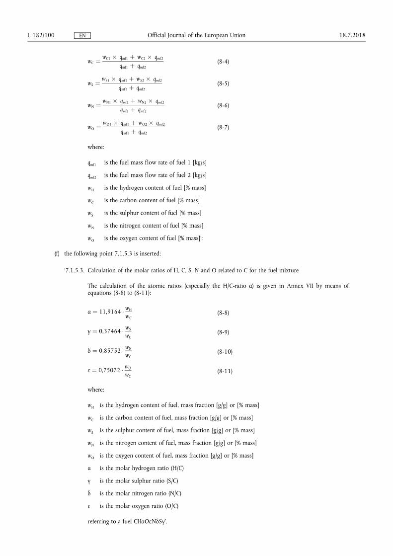
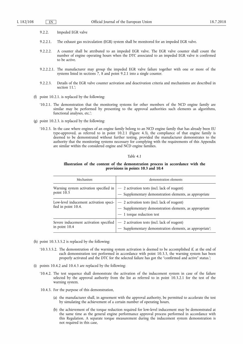