
ComCoast flood risk management schemes - Discomap EEA
88
ComCoast flood risk management schemes ComCoast WP 3
-
Upload
khangminh22 -
Category
Documents
-
view
5 -
download
0
Transcript of ComCoast flood risk management schemes - Discomap EEA

ComCoast flood risk management schemes ComCoast WP 3

ComCoast flood risk management schemes
ComCoast WP 3
This report was a collective effort of the different ComCoast members with their own dialects of ComCoast English. In addition, Gert Jan Akkerman of Royal Haskoning, Rob Steijn of Alkyon and Klaas de Groot of Arcadis have contributed to this report. This has resulted in a nice variety of different styles within the report. The ComCoast project is carried out in co-operation with ten partners. • Rijkswaterstaat (NL - leading partner) • Province of Zeeland (NL) • Province of Groningen (NL) • University of Oldenburg (D) • Environmental Agency (UK) • Ministry of the Flemish Community (B) • Danish Coastal Authority (DK) • Municipality of Hulst (NL) • Waterboard Zeeuwse Eilanden (NL) • Waterboard Zeeuws Vlaanderen (NL)
This report is an initiative of the ComCoast project, co-financed by the EU-Interreg IIIb North Sea Programme.

Page 3 - ComCoast WP3, ComCoast flood risk management schemes, Sept 2007
Work package 3
Civil engineering aspects
ComCoast flood risk management schemes
Final Report

Page 4 - ComCoast WP3, ComCoast flood risk management schemes, Sept 2007
Table of Contents
Preface 5 1. Introduction 6 2. Managed Realignment – Technical and Engineering 7 2.1 Abbotts Hall as technical case for COMCOAST 10 2.2 Perkpolder as technical case for COMCOAST 14 2.3 Juvre Enge as technical case for COMCOAST 22 3. Foreshore Recharge – Technical and Engineering 26 3.1 Horsey Island as technical case for COMCOAST 28
4. Regulated Tidal Exchange – Technical and Engineering 33 4.1 Breebaart as technical case for COMCOAST 34
5. Foreland Protection – Technical and Engineering 40 5.1 “Area Neßmersiel”as technical case for ComCoast 43
6. Overtopping dike summary 49 6.1 Ellewoutsdijk as technical case for COMCOAST 50 6.2 Hondsbossche and Pettemer sea defence as technical case for COMCOAST 54 7. Lippensbroek and Kruibeke-Bazel-Rupelmonde as technical case for COMCOAST 63 7.1 “Lippensbroek” as technical case for COMCOAST 63 7.2 “Kruibeke-Bazel-Rupelmonde” as technical case for COMCOAST 68 8. Overview ComCoast WP3 products 75

Page 5 - ComCoast WP3, ComCoast flood risk management schemes, Sept 2007
PrefacePrefacePrefacePreface
Mission Statement of ComCoastMission Statement of ComCoastMission Statement of ComCoastMission Statement of ComCoast
MISSION OF COMCOAST (= COMbined functions in COASTal defence zones)
ComCoast is a European project which develops and demonstrates innovative solutions for flood protection in
coastal areas.
ComCoast creates and applies new methodologies to evaluate multifunctional flood defence zones from an
economical and social point of view. A more gradual transition from sea to land creates benefits for a wider
coastal community and environment whilst offering economically and socially sound options. The aim of ComCoast
is to explore the spatial potentials for coastal defence strategies for current and future sites in the North Sea
Interreg IIIb region.
ComCoast Goals: ComCoast Goals: ComCoast Goals: ComCoast Goals:
• developing innovative technical flood defence solutions to incorporate the environment and the people and to guarantee the required safety level;
• improving and applying stakeholder engagement strategies with emphasis on public participation;
• applying best practice multifunctional flood management solutions to the ComCoast pilot sites;
• sharing knowledge across the Interreg IIIb North Sea region.
ComCoast Solutions: ComCoast Solutions: ComCoast Solutions: ComCoast Solutions:
Depending on the regional demands, ComCoast develops tailor-made solutions:
• to cope with the future increase of wave overtopping of the embankments;
• to improve the wave breaking effect of the fore shore e.g. by using recharge schemes;
• to create salty wetland conditions with tidal exchange in the primary sea defence using culvert constructions or by realigning the coastal defence system;
• to cope with the increasing salt intrusion
• to influence policy, planning and people
• to gain public support of multifunctional zones.
ComCoast runs from April 1, 2004 to December 31, 2007. The European Union Community Initiative
Programme Interreg IIIB North Sea Region and the project partners jointly finance the project costs of 5,8
million.
InformationInformationInformationInformation
Information on the ComCoast project can be obtained through the Project Management,
located at the Rijkswaterstaat in the Netherlands.
Address Address Address Address Rijkswaterstaat DWW Postbus 5044 2600 GA Delft The Netherlands [email protected] www.comcoast.org Project leader Project leader Project leader Project leader Frans Hamer Tel +31 15 251 8518 Project CommunicationProject CommunicationProject CommunicationProject Communication
Marjolein Lippe, CUR Bouw & Infra Tel +31 182 540 650

Page 6 - ComCoast WP3, ComCoast flood risk management schemes, Sept 2007
1.1.1.1. IntroductioIntroductioIntroductioIntroduction n n n
ComCoast aims among other things to develop innovative technical solutions that promote alternative uses of flood management sites. Within Work package three “Civil engineering aspects”, several desk studies have been carried out as well as field and laboratory tests to fulfill this aim.
a. Managed realignment, regulated tidal exchange, wave overtopping defence, foreland protection and foreshore
recharge are flood risk management schemes investigated within ComCoast. From the initial phase of the ComCoast project onwards, application of the ComCoast principle, (a more gradual transition from sea to land creating benefits for a wider coastal community and environment whilst offering economically and socially sound options) focused on pilot locations, e.g.: Ellewoutsdijk, Perkpolder, Brebaart, Abbotts Hall, Horsey Island, Neβmersiel, Rømo, Hondbossche and Pettemer Sea Defence, Kruibeke and Lippensbroek. Chapter 2 till 7 of this document gives a short description of the ComCoast schemes and the pilot locations, from a technical perspective.
b. Studies have been performed to assess the safety aspects of the ComCoast principle, by setting up a model for
safety assessment and carrying out case studies. c. As a reconnaissance of ComCoast application outside of Europe, a MSc. thesis was dedicated to the feasibility
of the ComCoast flood risk management schemes for New Orleans. d. In the effectiveness of ComCoast measures, mechanisms of wave reduction haven been explored. The
effectiveness gives an answer to the question whether a measure has any effect on the level of safety of a flood defence.
e. The memo (in Dutch) “ComCoast concept and the Dutch Flood defence act” gives a short answer to the
question whether an wave overtopping dike fits with the requirements under the Ducth Flood defence act. f. The overtopping dike as developed thus far in a technical sense, has been researched by desk studies and by
field and laboratory tests. Much attention was paid to the development of strengthening concepts for the overtopping dike. After the State-of-the-Art inventory (SOTA), the follow-up research was set out in the market as a competitive contest.
g. The Smart grass reinforcement idea was awarded for further installation and field testing at the Groningen sea
dike. Within this framework, the wave overtopping simulator was developed. The simulator as well as the erosion tests at the Groningen dike were highly successful. After the tests, a MSc. thesis was dedicated to the analysis of the measured wave overtopping characteristics.
h. The Crest Drainage Dike idea, with its storage and drainage facility at the dike crest, was awarded with further
laboratory testing. i. Theoretical models have been developed for the wave overtopping stability of grassed dikes (both unreinforced
and reinforced). The aforementioned studies (b. till i.) are briefly summarized in chapter 8. Al the studies are available at the ComCoast internet site (www.comcoast.org).

Page 7 - ComCoast WP3, ComCoast flood risk management schemes, Sept 2007
2.2.2.2. Managed Realignment Managed Realignment Managed Realignment Managed Realignment –––– Technical and Engineering Technical and Engineering Technical and Engineering Technical and Engineering
What is managed realignment?What is managed realignment?What is managed realignment?What is managed realignment? Managed realignment consists of altering the existing defences to allow a previously protected area of land to be flooded by the tides. The defences can be removed, set back landward, decreased in height, or strategically breached.
Why managed realignment?Why managed realignment?Why managed realignment?Why managed realignment? Flood and coastal defence reasons - Managed realignment can reduce the height and energy of the water by creating intertidal environments such as saltmarsh and mudflats. This can decrease the flood risk and sometimes reduce the required level of defence and maintenance. It can help in a long-term strategy of adapting to sea level rise. Environmental and legislation reasons - It can create valued intertidal habitats such as saltmarsh and mudflats, the type depending on the site characteristics. This could help meet the requirements of legislation such as The European Union Habitats Directive of 1994 and of any non-statutory plans.Economic reasons – There may be net benefits where there:
• are beneficial gains to commercial and recreational fisheries due to an increase in nursery habitat
• are recreational areas created where people can bird watch, fish, cycle and walk
• are beneficial gains to water quality by the area gained acting as a carbon sink
• is diversification of farmland to optimise brackish farming e.g. shellfish farming, saline tolerant crops etc
• is low value agricultural land.
• are existing defences whose maintenance is no longer justified.
• is a topography that needs smaller/no new defences, reducing the building and maintenance costs.
• is a topography that allows natural succession to the desired ecosystem and does not require future engineering works to produce it.
• is no nearby development so counterwalls are not needed, reducing the building and maintenance costs.
• are few delays when obtaining the necessary consents.
• is adequate knowledge about the site characteristics to correctly predict the impacts managed realignment will have on the site and further along the coast. Otherwise costly extra research or maintenance of the site may be needed.
How do you do managed realignment?How do you do managed realignment?How do you do managed realignment?How do you do managed realignment? There are two main types of managed realignment. The method chosen is dependent on the site characteristics. 1) Breach or remove seaward defence and allow inundation back to higher ground
• This can be used when there is rising ground and hard geology behind the existing defence, or when there is rising ground and soft geology behind the existing defence and erosion protection is not required.
• Existing land drainage in the higher ground may need to be modified to account for possible saltwater intrusion.
• If the higher ground is a very steep slope then stabilisation measures may be needed to protect against possible erosion and instability.
2) Breach or remove seaward defence and allow inundation back to new defence
• This can be used when there is rising ground and soft geology behind the existing defence and erosion protection would be required.
Both types are carried out through either embankment realignment or breaching. 1. Embankment Realignment – The existing defences are removed and flooding is allowed back to either higher
ground or a new line of defences that are set further back. It forms a wide, dissipative intertidal area. It produces greater wave action so sedimentation rates are less and it is more suited to the creation of mudflats and pioneer saltmarsh.
2. Embankment Breaching – Sections of the existing defences are strategically removed, and flooding is allowed to either higher ground or a new line of defences that are set further back. The remaining existing defence limits to wave action inland, providing scour protection for the new defence, and increasing sedimentation and
Polder regions hilly regions

Page 8 - ComCoast WP3, ComCoast flood risk management schemes, Sept 2007
vegetation. If the old defence is to be removed it must be after the vegetation has become established, which can take up to ten years.
Design considerations
• New realigned defences – These should be designed as per the usual procedure for sea defences, using overtopping analysis and including an allowance for consequent erosion, deposition and sea level rise.
• Wave breaks – They can be used at sites vulnerable to wave action to decrease the erosion of sediment recently deposited in the intertidal area, or to decrease the erosion of the old defence.
• Creek networks – They can be left to develop naturally or can be artificially created. The latter has the advantages of increasing the distance of flow of the water and sediment so increasing sedimentation and vegetation, and aiding the drainage of water from the site. They can be formed to match old creeks identified from aerial photographs, and created with vertical sides and bends.
• Vegetation – Short vegetation or a ploughed field should be left to encourage quick establishment of new vegetation.
• Breaches – They should be placed where there are existing channels and should encourage even distribution of water over the site. They must not be open to the predominant wave direction to avoid scour and erosion. They need to be wide enough to allow the tide to exit on the ebb tide without causing negative consequences from increased flows in part of the tidal cycle. This is controlled by the velocities of the current. They may need to be very wide to achieve this. Having one breach will cause more sedimentation, but increased scour on both sides of the breach. The bed level of the breach should reflect the depth of seaward creeks, accounting for predicted changes once breached. The breach ends of earth embankments will need armouring if widening of the breaches is not desired. Breaches should be monitored and if there are problems with erosion or lack of inundation, the breach size should be increased.
• Drainage – Sluices must not be created in a location where they might silt up.
• Counterwalls – They should be constructed to protect surrounding development or sensitive areas.
• Impacts – Design must spread the impacts of the managed realignment to decrease the rate of change e.g. adding sediment to an inter-tidal site if it is predicted to erode quickly.
• Cost - The expense of removing or maintaining the old defence must be considered as it could prove a hazard if it is left to erode naturally.
• Navigation reasons – If modelling of the breaches is miscalculated, managed realignment could produce increased scour of the channel resulting in changes to navigation.
Where can we do managed realignment?Where can we do managed realignment?Where can we do managed realignment?Where can we do managed realignment?
Base line characteristics must be analysed to determine suitable sites which meet all the requirements, the impacts managed realignment will have on the site and nearby area, and to assist in the consequent design of the managed realignment.
Elevation – If the land receives less than 300 tidal inundations a year then saltmarsh will be created. If the land receives more than 300 tidal inundations a year then the land will turn into mud flats. Gradient – 0-2% for greater saltmarsh habitat diversity, and a seawards slope for marsh zonation. Site History – Previous saltmarsh on the site, or saltmarsh plants in adjacent areas indicates favourable chemical conditions. The more recent the history of saltmarsh the better, as there is less settling and drying out. Previous ploughed fields could influence erosion and deposition patterns. Soils – The less modified the original marsh soils, the higher the success rate. Saltmarshes require fine-grained soils but not sandy soils as the lack of nitrogen inhibits plant growth. Mudflats require sand or soft mud. Sediment budget – There must be enough sediment to develop saltmarshes without harming the coastline or estuary. Location and rate of sediment or erosion – This determines the bed level changes and habitat type. Longshore transport rate – It must be analysed to ensure it will not be adversely affected. Tidal cycle – Lags would restrict the habitat development. Tidal inundation – If it is too high or too low it can restrict habitat development. Tidal asymmetry – It will influence the net import/export of sediment in the estuary. Tidal Prism– This is the volume of water between the high and low tide. It is increased by managed realignment enlarging the inter-tidal area and it will affect the volume and velocity of water entering and leaving the estuary and the extreme water levels. A predicted increase of more than 5-10% in tidal prism could cause significant changes in morphology at the site; changing the amount of erosion and deposition in the deep water channels, in the existing intertidal areas, and at adjacent sites. Local wave regime – It influences erosion and deposition. Wave energy must be below the level that erodes saltmarsh. Site access – Access is needed for vehicles. It may not be practical or cost effective to carry out managed realignment in areas with harmful materials such as defences made of landfill. Land ownership – Landowners need to be willing to give up the land. The land can be bought or compensation given. Consents –The necessary consents must be able to be obtained for the area.

Page 9 - ComCoast WP3, ComCoast flood risk management schemes, Sept 2007
Surrounding areas – It is better if managed realignment is carried out as part of a strategic plan as this will maximise the benefits, since isolated sites can have adverse effects on adjacent areas. Urgency – It can take a long time to get the necessary consents so managed realignment should not be carried out if a delay would be detrimental in terms of flood risk or cost. Detailed knowledge and assessment available – Quantified base line characteristics, long term process data, detailed natural process knowledge, and accurate analysis techniques are needed to correctly predict the results of managed realignment, otherwise unexpected consequences can occur. Velocities that are higher than predicted can result in erosion of intertidal channels and the landwards side of the remaining defence, and widening of the breach. Different or little habitat may be created, and there may be untoward effects along the coast. The flood risk may not be reduced as desired. Case studiesCase studiesCase studiesCase studies A successful managed realignment – Abbotts Hall, Blackwater Estuary, Essex, UK. Abbotts Hall which is managed by the Essex Wildlife Trust purchased the land in 2000 with the aim to create a more sustainable coastal defence in partnership with a number of other organisations.
The development of saltmarsh, in the area opened up to tidal inundation by the breaching of some 3km of hard sea defences to realign the shoreline, has created nationally important habitat and provided a significant contribution to the national Biodiversity Action Plan (BAP) targets for saltmarsh creation. In addition, however, it has also provided a more sustainable approach to flood defence. By removing wave and tidal current energies saltmarsh has provided a natural flood defence. Moreover, managed realignment of the coastline can moderate tidal surges by allowing the surges to move sideways, thus alleviating pressure on flood defences elsewhere in the system.
It is anticipated that the saltmarsh created at Abbotts Hall and the rising ground behind the saltmarsh zone will, together, provide a ‘soft and flexible’ defence better able to respond to future sea level rise than the existing fixed, hard structures.
Good colonisation of the site was still achieved by halophytic plants and marine invertebrates, and there was an increase in bird numbers including oystercatchers, redshanks and lapwings, and in small mammals, particularly hares. By spring 2003 the site had been colonised by several pioneer saltmarsh species and over ten different species of fish. A less successful managed realignment - Tollesbury, Essex, UK. In the UK the Department for Environment Food and Rural Affairs had been looking for a site to trial managed realignment that involved building a large new defence wall and breaching the current defence to allow flooding back to the new defences. A potential site was found at Tollesbury and the arable farmland was purchased. In 1993 a new sluice was built in Tollesbury Brook which flowed through the site, and the new defence wall was constructed. The section of the old wall that was to be breached was lowered first in the hope that it would breach through overtopping. However it held firm and so was manually breached. After breaching, the force of the water eroded a cliff into the base of the new wall. The wall had to be refilled and armoured. It had not been armoured originally, as it had not been considered necessary since the old defence was not armoured. However the old wall was protected by higher land, salt marsh and salt tolerant vegetation, all protection that the new wall lacked. Currently the new intertidal area has some salt marsh but mainly only in a fringe in front of the new wall where the land is higher. The rest of the land is not saltmarsh as it’s elevation is less than the 2m that is required to develop saltmarsh in the area. The old defence is being eroded from the landward side due to the velocity of the ebb tide, and the wave action from the large fetch behind the old sea wall. It is feared that the wall will collapse. If it did then the resulting greater fetch and velocity would erode the original saltmarsh, and the new sea wall. The wall would then have to be more strongly armoured at a high cost. The Perkpolder Pilot, NL One of ComCoast’s pilot projects is a contribution to the plans for renovation of Perkpolder in the Netherlands. Part of these plans is a managed realignment scheme in order to create a nature area of 75 hectares. A new dike will be build landward of the present dike. The present dike will be breached. The breached dike will reduce the wave attack on the new dike. Salt marsh is expected to grow in between both dikes, creating a natural protection. For further details referred is to the Pilot Description of Perkpolder and the technical leaflet of Perkpolder.
Page 10 - ComCoast WP3, ComCoast flood risk management schemes, Sept 2007
2.12.12.12.1 Abbotts Hall as technical case for COMCOASTAbbotts Hall as technical case for COMCOASTAbbotts Hall as technical case for COMCOASTAbbotts Hall as technical case for COMCOAST
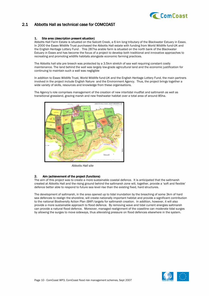
1.1.1.1. Site area (description presentSite area (description presentSite area (description presentSite area (description present situation) situation) situation) situation) Abbotts Hall Farm Estate is situated on the Salcott Creek, a 6 km long tributary of the Blackwater Estuary in Essex. In 2000 the Essex Wildlife Trust purchased the Abbotts Hall estate with funding from World Wildlife fund-UK and the English Heritage Lottery Fund . This 287ha arable farm is situated on the north bank of the Blackwater Estuary in Essex and has become the focus of a project to develop both traditional and innovative approaches to recreating and promoting wildlife habitats alongside economic farming practices. The Abbotts hall site pre breech was protected by a 3.5km stretch of sea wall requiring constant costly maintenance. The land behind the wall was largely low-grade agricultural land and the economic justification for continuing to maintain such a wall was negligible In addition to Essex Wildlife Trust, World Wildlife fund-UK and the English Heritage Lottery Fund, the main partners involved in the project include English Nature and the Environment Agency. Thus, the project brings together a wide variety of skills, resources and knowledge from these organisations. The Agency’s role comprises management of the creation of new intertidal mudflat and saltmarsh as well as transitional grassland, grazing marsh and new freshwater habitat over a total area of around 85ha.
Abbotts Hall site 2.2.2.2. Aim (achievement of the project (functions) Aim (achievement of the project (functions) Aim (achievement of the project (functions) Aim (achievement of the project (functions) The aim of this project was to create a more sustainable coastal defence. It is anticipated that the saltmarsh created at Abbotts Hall and the rising ground behind the saltmarsh zone will, together, provide a ‘soft and flexible’ defence better able to respond to future sea level rise than the existing fixed, hard structures. The development of saltmarsh, in the area opened up to tidal inundation by the breaching of some 3km of hard sea defences to realign the shoreline, will create nationally important habitat and provide a significant contribution to the national Biodiversity Action Plan (BAP) targets for saltmarsh creation. In addition, however, it will also provide a more sustainable approach to flood defence. By removing wave and tidal current energies saltmarsh can provide a natural flood defence. Moreover, managed realignment of the coastline can moderate tidal surges by allowing the surges to move sideways, thus alleviating pressure on flood defences elsewhere in the system.

Page 11 - ComCoast WP3, ComCoast flood risk management schemes, Sept 2007
Breach in the sea wall
2.1 Aim of COMCOAST-project activities: Main aim of the pilot area is as a lessons learnt site Project activities in Abbotts Hall: WP2: WP2: WP2: WP2: use Abbotts Hall as a pilot study for Socio Economic evaluation of the Comcoast concept in comparison with other concepts. . . . Evaluation criteria: Fisheries, Nutrients and Economics. WP3:WP3:WP3:WP3: to Evaluate the effect of a large managed realignment scheme on the hydrodynamics of the adjacent estuary to better inform the design of future realignment schemes was one of the key generic aims of the Abbotts Hall project. WP4: WP4: WP4: WP4: Stakeholder engagement and full public participatory action thorough the use of the state of the art visitor’s and education centre WP5: WP5: WP5: WP5: Collect information about the development in the area by monitoring during several years the: - fish migration - plants - birds - sedimentation 2.2 Overall achievements for Abbotts hall To achieve this objective a programme of monitoring and analysis was proposed to:
• Examine the effect of realignment on local tidal regime (i.e. tidal level and current velocity)
• Examine changes in creek morphology and any other changes in bathymetry due to erosion or accretion.
• Examine the effects of saltmarsh creation on the sediment budget of the system. Essentially, this programme of work required the determination of:
• Tidal level (heights)
• Tidal velocities (current speed and direction)
• Suspended solids levels (concentrations)
• Bathymetry (depth) of the Salcott Channel and adjacent estuary
• Topography (surface elevations) within the realignment site
• Characterisation (particle size distribution) of bed sediments in the adjacent estuary
• Determination of sediment flux through the primary breach over a tidal cycle
• Scour monitoring in the vicinity of the primary breach 3.3.3.3. Conditions Conditions Conditions Conditions Physical processes: Choosing where to locate this realignment was difficult, Abbotts Hall site was chosen for one reason as we had the funds in place to implement the scheme. Height above sea level is the critical element. Saltmarsh will not develop if the land to be inundated is at the wrong level. If it is too low one gets mudflat developing, while if it is too high the inundation does not take place and there is the possibility of erosion. Although mudflats provide a natural form of sea defence and a valuable habitat for invertebrates and birds, it can be perceived as an eyesore and risks
Page 12 - ComCoast WP3, ComCoast flood risk management schemes, Sept 2007
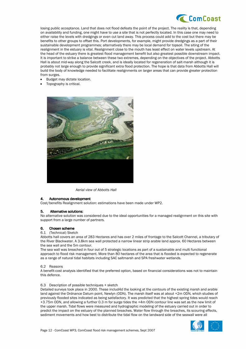
losing public acceptance. Land that does not flood defeats the point of the project. The reality is that, depending on availability and funding, one might have to use a site that is not perfectly located. In this case one may need to either raise the levels with dredgings or even cut land away. This process could add to the cost but there may be benefits to other groups to offset this. Port developments, for example, might provide dredgings as a part of their sustainable development programmes; alternatively there may be local demand for topsoil. The siting of the realignment in the estuary is vital. Realignment close to the mouth has least effect on water levels upstream. At the head of the estuary there is greatest flood management benefit but also greatest possible downstream impact. It is important to strike a balance between these two extremes, depending on the objectives of the project. Abbotts Hall is about mid-way along the Salcott creek, and is ideally located for regeneration of salt-marsh although it is probably not large enough to provide significant extra flood protection. The hope is that data from Abbotts Hall will build the body of knowledge needed to facilitate realignments on larger areas that can provide greater protection from surges.
• Budget may dictate location.
• Topography is critical.
Aerial view of Abbotts Hall
4.4.4.4. Autonomous developmentAutonomous developmentAutonomous developmentAutonomous development Cost/benefits Realignment solution: estimations have been made under WP2. 5.5.5.5. Alternative solutions: Alternative solutions: Alternative solutions: Alternative solutions: No alternative solution was considered due to the ideal opportunities for a managed realignment on this site with support from a large number of partners. 6.6.6.6. Chosen scheme Chosen scheme Chosen scheme Chosen scheme 6.1 (Technical) Sketch Abbotts hall covers an area of 283 Hectares and has over 2 miles of frontage to the Salcott Channel, a tributary of the River Blackwater. A 3.8km sea wall protected a narrow linear strip arable land approx. 60 Hectares between the sea wall and the 5m contour. The sea wall was breached in four out of 5 strategic locations as part of a sustainable and multi functional approach to flood risk management. More than 80 hectares of the area that is flooded is expected to regenerate as a range of natural tidal habitats including SAC saltmarsh and SPA freshwater wetlands. 6.2 Reasons A benefit-cost analysis identified that the preferred option, based on financial considerations was not to maintain this defence.
6.3 Description of possible techniques + sketch Detailed surveys took place in 2000. These includ4d the looking at the contours of the existing marsh and arable land against the Ordnance Datum point, Newlyn (ODN). The marsh itself was at about +2m ODN, which studies of previously flooded sites indicated as being satisfactory. It was predicted that the highest spring tides would reach +3.75m ODN, and allowing a further 0.3 m for surge tides the +4m ODN contour line was set as the new limit of the upper marsh. Tidal flows were measured and hydrographic modeling of the estuary carried out in order to predict the impact on the estuary of the planned breaches. Water flow through the breaches, its scouring effects, sediment movements and how best to distribute the tidal flow on the landward side of the seawall were all

Page 13 - ComCoast WP3, ComCoast flood risk management schemes, Sept 2007
modelled. As a result 5 breaches were proposed in the sea wall all approx 10meters wide. Behind three of the breaches both main and feeder creeks 1-2m wide and 1m deep were created to distribute the inflowing water, whilst at both ends of the site counter walls were made to protect neighboring land. A 1-meter high sill was also left at the bottom of one breach in order to retain some water on its landward side at low tide.
6.4 Execution manner Risks during design and construction: Before the old sea wall could be breached several pieces of construction were needed. Firstly there were spur walls at the astern and western borders of the farm to protect the neighboring properties. Secondly new creek systems were needed to promote the formation of new saltmarsh. Thirdly the breaches in the sea wall must be excavated allowing the tidal flooding of former arable land. A fourth item was the construction of a freshwater protection bund for an existing pond providing habitat for the great crested newt (a protected species) and the construction of a new fresh water lake to compensate for the loss of the ponds that were likely to become saline or brackish. This required the excavation of the lake site and the construction of a protective dam wall to be achieved by raising the height of the farm track. The track to the ship lock was also raised to maintain access to the old sea wall and preserve this interesting feature of the site. The final construction items were four viewing hides for visitors and timber jetty to replace the old slipway.
6.5 Management and maintenance aspects: same as now. Accessibility is good: with a good selection of public footpaths leading to the estuary and to the bird hides. Sensitivity to vandalism: this is not an issue as abboitts hall is only access by vehicle and Possibly because the area is far away from urban area and only nature loving people will take the travel to visit the area.
6.6 Effects on LNC-values (landscape, nature and culture values) during the execution negligible). 6.7 Consents, permission and licenses: Landward consents: made under the Local Planning Authority – Town and Country planning act, 1990. 2 planning applications were made; the first covered the construction of the spur walls, hides and jetty. The second planning application covered the excavation of the creek systems, the breaches to the sea wall and tidal flooding. Maps and drawings of the proposed constructions and excavations were submitted to support the planning applications as well as the environmental statement. Consent for land drainage was also required through the Env agency under the 1991 Water Resources Act and from natural England for coast protection works. 6.8 Costs/benefits: Land costs came to £2.7 million the managed realignment costs came to £645,000 (other costs: recreation, visitor center facilities: £430,000, this however is still yet to be constructed) 6.9 Recommendation This partnership has allowed a successful integrated approach to be taken towards coastal zone management in Essex. The work at Abbotts Hall has shown to be a cost effective, sustainable solution to coastal defence and also succeeded in producing major benefits towards the national biodiversity targets. It is hoped that the work at Abbotts Hall will set a precedent for others involved in coastal management in the future by sharing expertise gained as a result of this innovative project.
7.7.7.7. ReferencesReferencesReferencesReferences Sustanable Flood Defences- monitoring of the managed realignemnt scheme at Abbots Hall, Essex – Final report

Page 14 - ComCoast WP3, ComCoast flood risk management schemes, Sept 2007
2.22.22.22.2 Perkpolder as technical case for COMCOASTPerkpolder as technical case for COMCOASTPerkpolder as technical case for COMCOASTPerkpolder as technical case for COMCOAST
1.1.1.1. Site areaSite areaSite areaSite area
Figure 1 Location of pilot Perkpolder One of ComCoast’s 10 pilot projects is the renovation of Perkpolder in the Netherlands. Only a few years ago, Perkpolder was a busy ferry port on the Westerschelde estuary (see figure 1 to 3). But since the opening of the Westerschelde tunnel in 2003, the ferry has no longer been in use, and the port has become deserted.
Figure 2 Perkpolder aerial view The main use of the surrounding land is agricultural. Dikes protect the polders, which should be able to resist conditions that statistically will occur once every 4000 years . The height of the dikes is within the range of 9 to 10 m above Mean Sea Level (MSL). The level of the hinterland is within the range of 0 to 2 m above MSL. The Western Scheldt is a busy waterway to the port of Antwerp. The tidal range at the Western Scheldt is approximately 4.5 m.

Page 15 - ComCoast WP3, ComCoast flood risk management schemes, Sept 2007
Figure 3 Topographic map 2.2.2.2. Aim of the project PerkpolderAim of the project PerkpolderAim of the project PerkpolderAim of the project Perkpolder Three different parties saw opportunities for finding a new use for the location. The municipality of Hulst and the province of Zeeland wished to make use of the area in order to strengthen the economy and quality of life of the surrounding area. The Department of Waterways and Public Works saw excellent opportunities here for compensating the loss of nature-related value in the Westerschelde resulting from enlargement of the navigation channel. In addition, encouraged by the ComCoast project, the public-sector bodies involved saw opportunities for the use of innovative flood protection methods. The project partnersThe project partnersThe project partnersThe project partners The following public-sector bodies and private parties have decided to work together to develop the Perkpolder area:
• Gemeente Hulst (Municipality of Hulst)
• Rijkswaterstaat (Department of Transport, Public Works and Water Management)
• Provincie Zeeland (Province of Zeeland)
• Waterschap Zeeuws-Vlaanderen (District Water Board of Zeeuws-Vlaanderen)
• Domeinen (Government Properties Administration)
• ComCoast
• Projectontwikkelaar Rabo Vastgoed (Property developer Rabo Vastgoed)
• Projectontwikkelaar AM (Property developer AM)
• Staatsbosbeheer (Dutch Forestry Commission)
• Dienst Landelijk gebied (Department for Rural areas)
• Landscape architects and urban development planners Joint designJoint designJoint designJoint design The various parties involved participated in five workshops to first prepare a shared analysis of the area and then develop the Perkpolder Plan, under the guidance of an independent panel chairman. Each party temporarily let go of its own idea and participated in a creative process aimed at developing an integrated plan in accordance with the principles of urban and rural development planning. Landscape architects and urban planners worked out the results of each workshop and presented them during a following workshop. This approach kick-started the project and injected a great deal of creativity. The result was the formulation of a joint plan for Perkpolder in just a few

Page 16 - ComCoast WP3, ComCoast flood risk management schemes, Sept 2007
months. The private parties AM and Rabo Vastgoed have already carried out a feasibility study. All the parties involved intend to set out their mutual responsibilities and financial contributions in management agreements by the end of 2007 or beginning of 2008. 3.3.3.3. ConditionsConditionsConditionsConditions Physical conditionsPhysical conditionsPhysical conditionsPhysical conditions The area of interest is located along the Western Scheldt. The tidal range at the Western Scheldt is approximately 4.5 m at that location. The currents are tide dominated. The discharge of the river Scheldt itself is small, about 200 m3/s on average. The tidal prism (in and out flux of the estuary) is about 1 billion m3. Large amounts of sediments (silt and sand) are transported throughout the estuary day by day. The (design) wave conditions vary between 1 to 2 m (H sig), depending on location/orientation of the different stretches of the dike. SafetySafetySafetySafety Due to the Dutch law on water defences there is a guaranteed safety level of the hinterland. The safety level of this region is such that the dikes are able to resist storm conditions that will occur once every 4000 years (on the average).
4.4.4.4. Autonomous developmentAutonomous developmentAutonomous developmentAutonomous development SocioSocioSocioSocio----ecoecoecoeconomicnomicnomicnomic The autonomous development of the region is not very prosperous. This was in fact the reason to start up this project. Since the closure of the ferry port the area could use a socio economic impulse. PhysicalPhysicalPhysicalPhysical The water defenses around the former ferry port partly need to be renovated to stand the test for the next 50 years. The revetments have to be replaced by new ones. Adjacent to the ferry port, the water defences have already been renovated. Climate change and sea level rise will probably make it necessary to take action in order to maintain the safety level mentioned in Chapter 3. Traditionally the dikes would be heightened and the revetments would be reinforced. 5.5.5.5. Perkpolder Plan: the alternativePerkpolder Plan: the alternativePerkpolder Plan: the alternativePerkpolder Plan: the alternative ‘Enjoying the elements’ is the motto formulated by the participating parties for the Perkpolder Plan. Point of departure is that the landscape plays a critical role in facilitating the functionalities available in the area. The plan consists of the following elements (see figure 4 and 5):
• The heart of Perkpolder consists of an exclusive residential complex located on the raised open square of the old ferry, with a luxury hotel and a marina, surrounded by a newly developed area of natural beauty.
• A nature reserve, the ‘Eastern Perkpolder’, part of which lies outside the dikes, lies next to the heart of Perkpolder.
• The Eastern Perkpolder will be protected by a new dike which, in combination with the old one, will form a broad flood protection zone.
• Within the Greater Perkpolder Area, on the other side of the heart, holiday residential units will be visible as ‘guests’ in the landscape, surrounded by new saltwater areas of natural beauty.
• The existing beach on the Westerschelde will get a ‘quality upgrade’.
• A golf course will soon wind its way through the landscape.

Page 17 - ComCoast WP3, ComCoast flood risk management schemes, Sept 2007
Figure 4 Artist impression possible layout of the plan
Figure 5 Artist impression ‘Heart of Perkpolder’ 6.6.6.6. Chosen schemes: Design of the flood defence zoneChosen schemes: Design of the flood defence zoneChosen schemes: Design of the flood defence zoneChosen schemes: Design of the flood defence zone ComCoast has contributed to the design of the flood protection zone. It has also contributed to the development of the Perkpolder area by encouraging cooperation between the various parties as well as communication with the local population. To achieve the above, ComCoast took the following initiatives: To launch the process, ComCoast organized a design workshop, which provided the basis for the Perkpolder Plan. The ‘Hoge Ogen’ (high eyes) idea was developed during the workshop and is illustrated in figure 6.

Page 18 - ComCoast WP3, ComCoast flood risk management schemes, Sept 2007
Figure 6 The ‘Hoge Ogen’ idea ComCoast made sure that the Perkpolder Plan includes the development of a safe and enduring flood protection zone. There are three schemes of flood defence: 1. The heart of Perkpolder: an elevated bastion with houses (figure 7) An elevated bastion with houses, hotel and marina: the bastion is expected to have sufficient elevation to ensure that it will be safe from a rising sea water level for the next 200 years. The height of the bastion will be approximately 10 m above mean sea level (MSL)
Page 19 - ComCoast WP3, ComCoast flood risk management schemes, Sept 2007
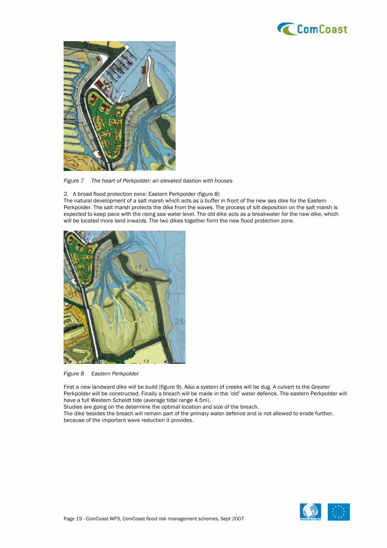
Figure 7 The heart of Perkpolder: an elevated bastion with houses 2. A broad flood protection zone: Eastern Perkpolder (figure 8) The natural development of a salt marsh which acts as a buffer in front of the new sea dike for the Eastern Perkpolder. The salt marsh protects the dike from the waves. The process of silt deposition on the salt marsh is expected to keep pace with the rising sea water level. The old dike acts as a breakwater for the new dike, which will be located more land inwards. The two dikes together form the new flood protection zone.
Figure 8 Eastern Perkpolder First a new landward dike will be build (figure 9). Also a system of creeks will be dug. A culvert to the Greater Perkpolder will be constructed. Finally a breach will be made in the ‘old’ water defence. The eastern Perkpolder will have a full Western Scheldt tide (average tidal range 4.5m). Studies are going on the determine the optimal location and size of the breach. The dike besides the breach will remain part of the primary water defence and is not allowed to erode further, because of the important wave reduction it provides.

Page 20 - ComCoast WP3, ComCoast flood risk management schemes, Sept 2007
Figure 9 Adjustment of the primary defence 3. A broad flood protection zone: Greater Perkpolder The Greater Perkpolder Area is also an example of a broad flood protection zone. In future, the dike can be modified to ensure that it will also withstand waves washing over the top. Under extreme conditions, the biggest waves would then be able to overtop the dike without compromising its safety. (At present the dike is high and strong enough). The manner in which the polder is now being structured already takes this aspect into account. A culvert will connect the Eastern and the Greater Perkpolder. A reduced tidal range of approximately 0,7m will be introduced to create a saltwater environment. The normal tidal range in the Western Scheldt is approximately 4.5m. Holiday residential units will be supported by posts or terps, and the newly developing natural landscape will flourish under the influence of a saltwater environment. ComCoast is now studying the possibilities for organizing and developing the Greater Perkpolder Area and which agreements need to be made in that regard.
Figure 10 Greater Perkpolder 7.7.7.7. Other contributions by ComCoastOther contributions by ComCoastOther contributions by ComCoastOther contributions by ComCoast ComCoast carried out a social cost-benefit analysis on the basis of index numbers. This analysis made it clear that the intended development of areas of natural beauty would add to the value of the residential units and the recreational opportunities. New jobs would be created in the region. On balance, the integrated plan would benefit the entire region. The results of this analysis provided an important impetus for the public-sector bodies involved to continue participating in the plan. ComCoast contributed to the municipality of Hulst’s communication plan and developed a joint communication strategy. As part of this strategy, a sounding board group was set up including socially relevant organizations, and the local population is being provided with information about the plans on a regular basis via information evenings, the municipality website, and the local newsletter. The international partners in ComCoast have provided knowledge and expertise for the Perkpolder pilot location. New insights and lessons learnedNew insights and lessons learnedNew insights and lessons learnedNew insights and lessons learned The Perkpolder project has provided insights which are important when it comes to developing new forms of coastal zone management:

Page 21 - ComCoast WP3, ComCoast flood risk management schemes, Sept 2007
Working together If the parties participating in a project really want to get things done, the project generally gets off to a good start. If all the parties involved participate in the design process, a solid plan with broad support can usually be formulated in a short period of time. In such a process, public-sector bodies and private organizations can complement each other quite nicely. At the start of the project, it’s important for the parties to commit themselves to working together. At a later stage, they must agree on the distribution of roles and responsibilities in executing the project. A decision-making process with the participation of many parties takes time; the existence of cultural differences between organizations also requires the necessary attention. Flood protection zone New methods for flood protection have a great impact on environmental planning. The probability of success is maximized when innovative plans for flood protection are part of an integrated regional development plan. On balance, a broad flood protection zone can provide space for housing, nature and recreation. In Perkpolder, for example, the development of new areas of natural beauty means that residential units will be situated within an attractive environmental landscape. To accomplish this, it was important during the design phase to ensure that the desired developments from the perspective of environmental and towns & country planning would be coordinated as effectively as possible with the construction of the flood protection system. Point of departure regarding the latter was that the construction would have to be capable of lasting for 50 years. A zone reserved for future use provides space to strengthen the dike for a period of 200 years. This means that the design will also be able to deal with a future rise in the sea level. Cost-benefit analysis The results of a social cost-benefit analysis can help public-sector bodies in taking relevant decisions. A broad flood protection zone with a variety of uses can result in a positive balance for society. Public participation and communication The presence of a local standard bearer for a project can instil the local population with confidence and enthusiasm. In Perkpolder, the chairman of the municipal project committee threw his weight behind the plan. It’s important to communicate regularly with the surrounding population and organizations, even if the parties involved need a great deal of time for study and/or negotiations. Long periods of ‘radio silence’ make people dissatisfied and/or suspicious. Personal communication, for example with landowners, is often very effective. The communication process regarding Perkpolder took place via information evenings, personal conversations and a website.

Page 22 - ComCoast WP3, ComCoast flood risk management schemes, Sept 2007
2.32.32.32.3 Juvre Enge as tas tas tas technical case for COMCOASTechnical case for COMCOASTechnical case for COMCOASTechnical case for COMCOAST
1.1.1.1. Site area (description of the present situation)Site area (description of the present situation)Site area (description of the present situation)Site area (description of the present situation) Juvre meadow is located in the north eastern part of the island Rømø in the Danish Wadden Sea.
Rømø Dam
New dike
Present dike
Juvre EngeJuvre EngeJuvre EngeJuvre Enge
Rømø
Juvre Meadow. To the right the only farm in the meadow is seen.
NorthNorthNorthNorth

Page 23 - ComCoast WP3, ComCoast flood risk management schemes, Sept 2007
• The dike was built in 1926-1928. It protects 640 Ha. If the dike are moved, the protected area is 220 ha.
• The area is presently used as conventional farmland (meadows). The area was covered by salt marsh vegetation before the building the dike
2.2.2.2. Aim (achievement of the project (functions), for examplAim (achievement of the project (functions), for examplAim (achievement of the project (functions), for examplAim (achievement of the project (functions), for example:)e:)e:)e:)
• The main aim is to reduce risk of flooding and to create safe homes for the citizens living in Juvre: If the buildings in the area are removed from the area, the flood risk is reduced for all the other inhabitants.
• One farm has to be moved from the area; buildings from a military offices and warehouse are located outside a new dike.
• Agriculture: salt water farming. At this moment the area behind the dike is being conventionally farmed. The plan is to have only grassing cows and sheep’s out side the dike.
• Fishing: fish farming is an activity in the area.
• Nature: The aim is to create a salt marsh with occasional flooding caused by the tides.
• Recreational purposes: New recreational opportunities with easy access.
• Alternative to traditional heightening of the dyke 3.3.3.3. Conditions Conditions Conditions Conditions
• Physical processes (hydrodynamic, morphology, sediments): No information
• Before any changes the safety are 30 years. 4.4.4.4. Autonomous developmentAutonomous developmentAutonomous developmentAutonomous development
• Future development: Not described. The Municipality (the local authority) has the authority after the restructuring of the local and regional authorities. There has not been taken any decision of the future development. The Pilot just shows a possible solution.
• Traditional solution: Reinforcement of the existing dike: Dike top is build up too +5,4 mDVR90 by laying out 0,5 m clay. The outer slop gets 0.5 m. clay, meaning that the slope is 1:3 and the inner slope is 1:2.
Blue: The old dike. Green: Proposal for moving the dike inland.
SSSSoooouuuu
Page 24 - ComCoast WP3, ComCoast flood risk management schemes, Sept 2007
The profile of the reinforced dike, with red the old profile.
• Cost/benefit (traditional solution): The cost for a traditional solution will be 13.2 mil. dkr. ≈ 1.8 mil. Euro (2003)
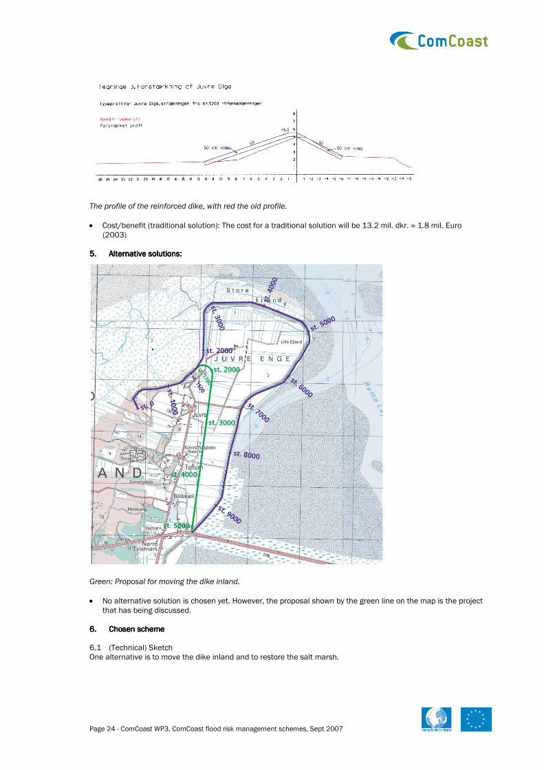
5.5.5.5. Alternative solutions: Alternative solutions: Alternative solutions: Alternative solutions:
Green: Proposal for moving the dike inland.
• No alternative solution is chosen yet. However, the proposal shown by the green line on the map is the project that has being discussed.
6.6.6.6. Chosen scheme Chosen scheme Chosen scheme Chosen scheme 6.1 (Technical) Sketch One alternative is to move the dike inland and to restore the salt marsh.

Page 25 - ComCoast WP3, ComCoast flood risk management schemes, Sept 2007
On the figure the new dike profile is shown. Left: The shore slope.
6.2 Reasons: The dike has not the right safety.
Page 26 - ComCoast WP3, ComCoast flood risk management schemes, Sept 2007
3.3.3.3. Foreshore Recharge Foreshore Recharge Foreshore Recharge Foreshore Recharge –––– Technical and Engineering Technical and Engineering Technical and Engineering Technical and Engineering
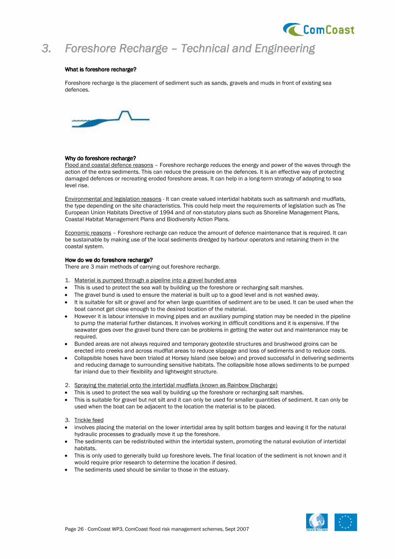
What is foreshore recharge?What is foreshore recharge?What is foreshore recharge?What is foreshore recharge? Foreshore recharge is the placement of sediment such as sands, gravels and muds in front of existing sea defences.
Why do foreshore recharge?Why do foreshore recharge?Why do foreshore recharge?Why do foreshore recharge? Flood and coastal defence reasons – Foreshore recharge reduces the energy and power of the waves through the action of the extra sediments. This can reduce the pressure on the defences. It is an effective way of protecting damaged defences or recreating eroded foreshore areas. It can help in a long-term strategy of adapting to sea level rise. Environmental and legislation reasons - It can create valued intertidal habitats such as saltmarsh and mudflats, the type depending on the site characteristics. This could help meet the requirements of legislation such as The European Union Habitats Directive of 1994 and of non-statutory plans such as Shoreline Management Plans, Coastal Habitat Management Plans and Biodiversity Action Plans. Economic reasons – Foreshore recharge can reduce the amount of defence maintenance that is required. It can be sustainable by making use of the local sediments dredged by harbour operators and retaining them in the coastal system. How do we do foreshore recharge?How do we do foreshore recharge?How do we do foreshore recharge?How do we do foreshore recharge? There are 3 main methods of carrying out foreshore recharge. 1. Material is pumped through a pipeline into a gravel bunded area
• This is used to protect the sea wall by building up the foreshore or recharging salt marshes.
• The gravel bund is used to ensure the material is built up to a good level and is not washed away.
• It is suitable for silt or gravel and for when large quantities of sediment are to be used. It can be used when the boat cannot get close enough to the desired location of the material.
• However it is labour intensive in moving pipes and an auxiliary pumping station may be needed in the pipeline to pump the material further distances. It involves working in difficult conditions and it is expensive. If the seawater goes over the gravel bund there can be problems in getting the water out and maintenance may be required.
• Bunded areas are not always required and temporary geotextile structures and brushwood groins can be erected into creeks and across mudflat areas to reduce slippage and loss of sediments and to reduce costs.
• Collapsible hoses have been trialed at Horsey Island (see below) and proved successful in delivering sediments and reducing damage to surrounding sensitive habitats. The collapsible hose allows sediments to be pumped far inland due to their flexibility and lightweight structure.
2. Spraying the material onto the intertidal mudflats (known as Rainbow Discharge)
• This is used to protect the sea wall by building up the foreshore or recharging salt marshes.
• This is suitable for gravel but not silt and it can only be used for smaller quantities of sediment. It can only be used when the boat can be adjacent to the location the material is to be placed.
3. Trickle feed
• involves placing the material on the lower intertidal area by split bottom barges and leaving it for the natural hydraulic processes to gradually move it up the foreshore.
• The sediments can be redistributed within the intertidal system, promoting the natural evolution of intertidal habitats.
• This is only used to generally build up foreshore levels. The final location of the sediment is not known and it would require prior research to determine the location if desired.
• The sediments used should be similar to those in the estuary.

Page 27 - ComCoast WP3, ComCoast flood risk management schemes, Sept 2007
Design characteristics Sediment size – The required sediment is site specific, and may depend on what is available from the dredging companies. Using sediment that matches the existing in size and characteristics will enable it to work in harmony with the natural processes. However coarser sediments may be preferred if the previous intertidal sediments were eroded, as the coarser sediment may be able to resist erosion better. Coarser sediments can produce a steeper profile but still dissipate wave energy. Conservation organisations can be against the introduction of gravel into intertidal environments because if the particle size of the recharge material is greater than the existing material the recharge material can move landward and smother any existing saltmarsh. To prevent this a barrier needs to be erected in front of the saltmarsh. This is not ideal, as it requires ongoing maintenance. Once the gravel gets to around 1m high, vegetation will form on it and stabilise it, halting its retreat. The alternative is to create a high, broad crested gravel bank from the recharge material, which may prevent it retreating. Sediment amount – The amount required depends on the site and the intended purpose of the foreshore recharge. A volume is calculated from the site area and depth required. The amount can be limited by the quantity of sediment that is available at a reasonable price. Process used and design of scheme – It depends on the site characteristics, the intended purpose of the foreshore recharge, the availability of sediment and equipment, the practical logistics of what the dredging companies can achieve, and the costs involved. Longevity – How long the foreshore recharge remains satisfactory depends on the site. A sheltered site should last longer than an exposed site. Sites should be revisited for monitoring within 5 to 10 years after the scheme completion. Where can we do foreshore recharge?Where can we do foreshore recharge?Where can we do foreshore recharge?Where can we do foreshore recharge? Foreshore recharge can be used on its own or with another coastal flood management technique. It is suitable at a variety of sites, on both sheltered and exposed coasts. There are some factors to consider. Economic – It is appropriate at sites where it is not economically justifiable to construct hard engineering defences at a higher cost. However, depending on the sediment and equipment costs, foreshore recharge can be more expensive than continuing to maintain defences. Some port authorities are willing to provide sediment at a reduced cost to prevent the need for them to dump at sea. Consents required – Permission might be required from the landowner and from the relevant environmental and planning organisations. Case StudiesCase StudiesCase StudiesCase Studies Successful Foreshore Recharge - Horsey Island, Hamford Water, Essex, UK Horsey Island is a large island in the Hamford water estuary. In the 1990s its saltmarsh and defences were severely damaged. To remedy the situation foreshore recharge was implemented. Disused Thames Lighter barges were placed on the foreshore to provide a wave break. 18000m³ of shingle and mud was sprayed onto the middle of the intertidal area in the gaps between the barges via rainbow discharge. It was sprayed by Harwich Haven Authority at high spring tide. This led to the creation of a new beach that would be able to roll back naturally since shingles were placed up to a level higher than the spring mean high water level. Silt and mud was pumped behind the sand bund to create a muddy backshore and contained by brushwood polder fencing. Monitoring has revealed a complete change in sediment characteristics at the site due to the coarse nature of the material used in the recharge. Within a year pioneer saltmash vegetation had colonised the muddy intertidal area. In 2005 another recharge programme was delivered and this time in collaboration with the landowner, English Nature, ComCoast and the Environment Agency, a new technique was trialed. An area of saltmarsh at Horsey Island had become very eroded and, due to its strategic importance of defending the surrounding defences, maintenance was needed. Sediments provided by Harwich Haven Port Authority were pumped on top of badly eroded saltmarsh via flexible collapsible pipes. Monitoring of the saltmarsh has shown new growth of saltmarsh plants within 3 months. It is considered one of the most successful schemes of its type in creating intertidal habitat and reducing flood maintenance costs. It has since been extended along the coast. Less successful foreshore recharge – Pewet Island, Dengie Peninsula, Essex, UK. The saltmarsh on the island was eroding. Foreshore recharge was implemented to decrease the erosion rate. 5000m³ of sand and gravels were placed on the intertidal foreshore via rainbow discharge in two phases in 1992 and 1995. It was placed during winter to minimise the impacts on breeding birds and recreational boat users. The material was placed in a heap and natural hydraulic processes were left to produce an equilibrium profile. Areas protected by the bank of material have ceased to be eroded laterally so it is acting as a good coastal defence. However the bank has rolled back and smothered some of the existing saltmarsh. This may have been because the bank was not high or broad crested enough to prevent wave overtopping. However, the scheme resulted in an increase in bird populations, particularly Little Tern, Oystercatcher and Ringed Plover.
Page 28 - ComCoast WP3, ComCoast flood risk management schemes, Sept 2007
3.13.13.13.1 Horsey Island as technical case for COMCOASTHorsey Island as technical case for COMCOASTHorsey Island as technical case for COMCOASTHorsey Island as technical case for COMCOAST
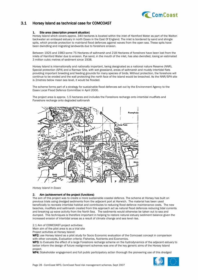
1.1.1.1. Site area (description present situation)Site area (description present situation)Site area (description present situation)Site area (description present situation) Horsey Island which covers approx. 340 hectares is located within the inlet of Hamford Water as part of the Walton backwater an embayed estuary in north Essex in the East Of England. The inlet is bordered by sand and shingle spits, which provide protection to mainland flood defences against waves from the open sea. These spits have been dwindling and migrating landwards due to foreshore erosion. Between 1925 and 1983 some 75 Hectares of saltmarsh and 218 Hectares of foreshore have been lost from the inlets of Hamford Water due to erosion. Pye sand, in the mouth of the inlet, has also dwindled, losing an estimated 3 million cubic metres of sediment since 1938. Horsey Island is internationally and nationally important, being designated as a national nature Reserve (NNR), Special protection (SPA) and a Ramsar Site, with wet grassland, areas of saltmarsh and muddy intertidal flats providing important breeding and feeding grounds for many species of birds. Without protection, the foreshore will continue to be eroded and the wall protecting the north face of the island would be breached. As the NNR/SPA site is 2metres below mean sea level, it would be flooded. The scheme forms part of a strategy for sustainable flood defences set out by the Environment Agency to the Essex Local Flood Defence Committee in April 2000. The project area is approx. 1.5 hectares and includes the Foreshore recharge onto intertidal mudflats and Foreshore recharge onto degraded saltmarsh
Horsey Island in Essex 2.2.2.2. Aim (achievement of the project (functions)Aim (achievement of the project (functions)Aim (achievement of the project (functions)Aim (achievement of the project (functions) The aim of this project was to create a more sustainable coastal defence. The scheme at Horsey has built on previous trials using dredged sediments from the adjacent port at Harwich. The material has been used beneficially to recreate intertidal habitat and contributes to reducing flood defence maintenance costs. The new beaches, mudflats and saltmarsh created from this approach act as natural flood defences reducing tidal currents and breaking up wave activity from the North Sea. The sediments would otherwise be taken out to sea and dumped. This techniques is therefore important in helping to restore natural estuary sediment balance given the increased erosion of intertidal areas as a result of climate change and sea level rise. 2.1 Aim of COMCOAST-project activities: Main aim of the pilot area is as a trial site Project activities at Horsey Island: WP2: WP2: WP2: WP2: use Horsey Island as a pilot study for Socio Economic evaluation of the Comcoast concept in comparison with other concepts. . . . Evaluation criteria: Fisheries, Nutrients and Economics. WP3:WP3:WP3:WP3: to Evaluate the effect of a large Foreshore recharge scheme on the hydrodynamics of the adjacent estuary to better inform the design of future realignment schemes was one of the key generic aims of the Horsey Island project. WP4: WP4: WP4: WP4: Stakeholder engagement and full public participatory action thorough the pioneering use of this dredged

Page 29 - ComCoast WP3, ComCoast flood risk management schemes, Sept 2007
material WP5: WP5: WP5: WP5: Collect information about the development in the area by monitoring during several years the:
• fish migration
• plants
• birds
• sedimentation
• Oyster farming
3. 3. 3. 3. ConditionsConditionsConditionsConditions Horsey Island is located within the inlet of Hamford water which us bordered by sand and shingle spits, which provide protection against waves from the open sea. These spits have been dwindling and migrating landwards due to foreshore erosion. Hydrodynamic and sedimentary regimeHydrodynamic and sedimentary regimeHydrodynamic and sedimentary regimeHydrodynamic and sedimentary regime- Horsey island provides protection against wave action for the majority of the Walton Backwaters and is of importance in reducing the rate of erosion of saltmarsh and foreshore within the estuarine system Ecology and nature conservationEcology and nature conservationEcology and nature conservationEcology and nature conservation---- the project area encompasses several different types of habitat types including intertidal, terrestrial and freshwater habitats. Fisheries Fisheries Fisheries Fisheries –––– commercial fishing activity in the Walton backwaters is dominated by the cultivation of native oysters and small scale herring, sprat and sole. WaterWaterWaterWater and soil/sediment quality and soil/sediment quality and soil/sediment quality and soil/sediment quality –––– nearby bathing waters are classified as good or excellent under the EC bathing Waters Directive. Dredged sediment is of good quality and is well documented Landscape and visual amenity Landscape and visual amenity Landscape and visual amenity Landscape and visual amenity –––– will only affect the landowner, boat users along the navigation and walkers on the north side of the estuary. Navigation Navigation Navigation Navigation –––– mainly used by recreational sailors
Aerial view of Horsey Island 4.4.4.4. Autonomous developmentAutonomous developmentAutonomous developmentAutonomous development
• Cost/benefits Foreshore recharge solution: estimations have been made under WP2. 5.5.5.5. Alternative solutions:Alternative solutions:Alternative solutions:Alternative solutions:
• No alternative solution was considered due to the topographical constraints and the ideal opportunities for securing beneficial use of dredged material on this site with support from a large number of partners.

Page 30 - ComCoast WP3, ComCoast flood risk management schemes, Sept 2007
6.6.6.6. Chosen sChosen sChosen sChosen scheme cheme cheme cheme 6.1 (Technical) Sketch
6.2 Reasons A benefit-cost analysis identified that the preferred option, based on financial considerations was to recharge the designated area using dredged material from the Harwich Haven Estuary. 6.3 Description of possible techniques + sketch The scheme was in 3 parts: Part 1 – foreshore recharge onto intertidal mudflats. Using 50,000m3 recharge material that was deposited to raise the level of the intertidal foreshore to that of high water spring tides. This has raised the level of the foreshore such that around 40% of the area will remain as intertidal mudflat while the remaining 60%, adjacent to the sea wall, may be colonised with saltmarsh vegetation. This will give extra protection to the adjacent seawall and the neighboring saltmarsh from extreme wave action. Part 2 – Foreshore recharge onto degraded saltmarsh, This relates top 6 hectares of salt marsh where on 150,000m3 material was placed at the highest astronomical tide level. 12 bush wood fences were erected across creeks to prevent migration of material into the channels. Mud was pumped onto the upper foreshore in the area of degraded saltmarsh, immediately to the Southwest of part 1. The required material was delivered to Horsey Island by a trailer dredger Sospan Dua which connected with the assistance of a multicat to a floating pipeline of approx 250m in length. At the shore the floating pipeline was connected to approx 300m of plastic rigid pipeline and then 200m of 410mm flexible plastic hose which transported the material to the required location at Horsey island. The connections were made using specially fabricated spigot connections. Deposition of the dredged material took place at high tide, both during the night and day and took around 12d days to complete. The timing of the works was carried out to minimise bird disturbance.

Page 31 - ComCoast WP3, ComCoast flood risk management schemes, Sept 2007
Pumping the dredged material onto the foreshore 6.4 Execution manner
• Risks during design and construction: Strict health and safety requirement had to be adhered to as the operation had risks concerning the distribution of the mud that was squirted onto the saltmarsh.
Concerns over the resuspension of the recharge material and the implications for Oyster fishermen and navigation channels also had to be considered. There were also concerns over the risk of pipeline failure and the accidental discharge of sediment onto excisting saltmarsh habitats.
Further concerns included:
• smothering of benthic invertebrates within the recharge area
• temporary reduction in bird food
• restrictions to commercial navigation 6.5 Management and maintenance aspects: same as now Accessibility is poor with access only possible by a causeway available at low tides and the island is privately owned. 6.6 Effects on LNC-values (landscape, nature and culture values) during the execution negligible). 6.7 Consents, permission and licenses: Landward consents: made under the Local Planning Authority – Town and Country planning act, 1990. An Environmental Impact Assessment was required. Maps and drawings of the proposed constructions and excavations were submitted to support the planning applications as well as the environmental statement. Application to Natural England under the Wildlife and Countryside Act 1981 incorporated as the CROW Act 2000. Consent for land drainage was also required through the Env agency under the 1991 Water Resources Act and from natural England for coast protection works. The foreshore recharge also required a licence under the Food and Environment Protection Act1985 part 11 (FEPA) and the Coast protection Act 1949

Page 32 - ComCoast WP3, ComCoast flood risk management schemes, Sept 2007
6.8 Costs/benefits: Harwich Haven Authority contributed £169,500 in dredged materials and the Environment Agency paid for works and materials at the Sum of £77,110 which will included EA retaining ownership of 200m of flexible, 410mm hose and connectors. This project has improved the level of flood defence in an economically viable and environmentally sustainable manner 6.9 Recommendation The scheme is intended to maintain and improve the quality of the intertidal mudflat and saltmarsh habitats in the area both for nature conservation and for flood defence benefits. 7.7.7.7. ReferencesReferencesReferencesReferences Sustanable flood defences- beneficial use of dredged mataerial at horsey island – report by Posford haskoning

Page 33 - ComCoast WP3, ComCoast flood risk management schemes, Sept 2007
4.4.4.4. Regulated Tidal ExRegulated Tidal ExRegulated Tidal ExRegulated Tidal Exchange change change change –––– Technical and Engineering Technical and Engineering Technical and Engineering Technical and Engineering
What is regulated tidal exchange?What is regulated tidal exchange?What is regulated tidal exchange?What is regulated tidal exchange? Regulated Tidal Exchange uses pipes, sluices or tidegates through existing tidal defences to allow seawater onto the land behind the defences in a controlled manner. This creates saline or brackish conditions behind the defence, gradually converting the area to saltmarsh or mudflats. Why do regulated tidal exchange?Why do regulated tidal exchange?Why do regulated tidal exchange?Why do regulated tidal exchange? Flood and coastal defence reasons
• The area behind the defences can be used as flood storage for surge events.
• It can be used as a first stage before managed realignment. It can minimise the impacts of the subsequent managed realignment by allowing sedimentation, vegetation colonisation and a change in habitat, producing an increase in height of low lying land in advance of the full tidal flooding from the main breach. This is particularly useful in large sites, where small sections can undergo regulated tidal exchange at a time before the main breach over the entire site. However it is important to ensure that the correct habitat is being created, one that will match that which will be created by the managed realignment. It may be an unnecessary prior expense if managed realignment could create the required habitat relatively quickly anyway.
• Regulated tidal exchange can be particularly effective if used in conjunction with an overtopping sea wall. This can decrease the tidal level in estuaries by allowing the surge tides to flow over the top of the wall into the saltmarsh area behind.
• Managed realignment may lead to erosion in some areas due to the higher volumes of water between the high and low tides and the increased velocity of the water. Regulated tidal exchange involves smaller volumes of water and can control the volume of tidal flooding and the number of tidal inundations so it may be a less damaging option.
Environmental and legislation reasons – It allows the land and local species to slowly undergo siltation and adjust their soil chemistry to the more saline conditions required by saltmarsh. It can create specific types of saltmarsh or mudflat habitat through careful control of the hydrological processes. It can help to meet compensatory habitat guidelines. Economic - It may be cheaper than managed realignment as a new defence does not need to be constructed. However maintaining the defence line could prove costly, especially if access to the defence has to be improved in order to carry out the regulated tidal exchange. How do you do regulated tidal exchange?How do you do regulated tidal exchange?How do you do regulated tidal exchange?How do you do regulated tidal exchange? Regulated tidal exchange involves the reversing of flow through a sluice in a controlled manner to regulate the amount, depth, and length of time of inundation. There are several techniques that can be used.
1. An open culvert with no tidal flap through the sea wall
• As long as the base of the pipe is around the mean low water mark then tidal water will flow in and out at every tide.
• A drop board can be placed on the landward side to prevent water flowing out of the culvert, creating a permanently flooded area. This would not produce salt marsh.
• It is relatively inexpensive as existing sluices can be utilised by leaving them open, and there are no maintenance costs. However pipe size is crucial to determine the tidal range inside the site therefore the existing sluice may not be sufficient.
2. Culverts with manually operated tidal flaps
• The water is let through into an impoundment at high tide over several high tides until the desired water level is reached.
• Impounding the water will not allow salt marsh to form
• It can result in a very restricted tidal range.
• It can be expensive to employ people to operate the tidal flaps.
3. Self regulating tidegates
• These have one moving part and an adjustable float system allowing the tidegates to stay open and float on flooding and ebbing tide until the specified desired water level has been reached, at which point the tidegate
Polder regions Hilly regions

Page 34 - ComCoast WP3, ComCoast flood risk management schemes, Sept 2007
will close and stay closed. When the tide recedes on the outside of the dyke, it automatically reopens allowing impounded water to flow out.
• There will be increased costs from ongoing maintenance. 4. Electronically operated tidegates
• Flow is regulated by a vertical lift, rectangular tidegate on the seaward side that opens and closes electronically at desired water levels, which are monitored by pressure sensors. The gate is normally open for a short period each rising and falling tide.
• There can be increased costs from ongoing maintenance. Design considerations. Size of pipes/gates – This determines the tidal cycle inside the site and the volumes of water which enter and leave the site. A small pipe can result in only a slight change in water levels. This produces little silting and so it is not conductive to saltmarsh formation.
Defence wall - The wall would need to be armoured on the landward side because of wave action and overtopping. Where can we do regulated tidal exchange?Where can we do regulated tidal exchange?Where can we do regulated tidal exchange?Where can we do regulated tidal exchange? Requirements for regulated tidal exchange include
• An existing sea defence such as a sea wall into which a pipe, sluice or tidegate could be integrated.
• A site area of no more than a few hectares in size because of the small hydraulic capacity of the sluices.
• Areas that could be flooded without flooding adjacent farmland. A bund may be required to be constructed behind the primary defence.
• A nearby source of seawater to permit seawater flushing. The seawater should ideally have enough suspended sediment to enable accretion at a higher rate than sea level rise.
• The site elevation should allow the required habitat to be created. On the Essex coast in the UK the desired elevation range for saltmarsh is between 1m above high water neap tide and 1.5m above high water spring tide. If the land is below that elevation then mudflats develop.
• It may be more preferable than managed realignment if a footpath needs to be maintained on the sea wall.
• If it is a location with unknown tidal, wave regime, sedimentation, or erosion effects then regulated tidal exchange is a good solution as the results can be controlled.
Case StudiesCase StudiesCase StudiesCase Studies A successful regulated tidal exchange – Northern Delaware Wetlands Rehabilitation Programme, USA. In 1992 a regulated tidal exchange scheme was started at 32 sites along the Christina and Delaware rivers. It aim was to restore 10,000 hectares of intertidal land to reduce shoreline erosion, improve water quality, increase and improve biodiversity, provide recreational and educational facilities and mosquito control. The scheme has been successful in all its aims. Particular success has been achieved in managing flood risk and increasing biodiversity. The number of fish species recorded has increased from 10 to more than 40.
4.14.14.14.1 Breebaart as technical case for COMCOASTBreebaart as technical case for COMCOASTBreebaart as technical case for COMCOASTBreebaart as technical case for COMCOAST
1.1.1.1. Site area (description present situation)Site area (description present situation)Site area (description present situation)Site area (description present situation) The polder Breebaart is situated in ten North-East corner of the Netherlands in the province of Groningen. In the east it is bordering the Dollard in the north the Ems estuary. The area is ca. 65 ha of which 9 ha is situated higher than 1m above average sea level (=1m+NAP) and 54 ha has an elevation of ca. 0.3 m+NAP. The area is used as nature reserve. The central creek is since 2001 connected with the sea by an automated culvert. In this way the tidal wave is reduced from 3 m at sea to 0.7 m in the polder. The primary dike is ca. 7.66 m+NAP high in the North and 8.66 m+NAP in the southern corner of Breebaart (average 8.15 m+NAP). This difference is made because the critical north-west direction of the wind blows the sea water higher up in the southern parts of the Dollard. The total length of the dike is 3.1 km of which ca 0.65 km is bordering the Ems. The other 2.45 km is bordering the Dollard. At the west side the area has a secondary dike of ca. 4.75 m+NAP. In this secondary dike a fish migration structure has been built in order to provide possibilities for fish to migrate from the fresh polder Fiemel, west of Breebaart, through Breebaart to the sea (and vice versa).The water management in the area is regulated by means of the automatic culvert. Some fresh water is entering the area through the fish migration structure.
Breebaart

Page 35 - ComCoast WP3, ComCoast flood risk management schemes, Sept 2007
2.2.2.2. Aim (achievement of the project (functions)Aim (achievement of the project (functions)Aim (achievement of the project (functions)Aim (achievement of the project (functions) The area Breebaart offers a good possibility for an overtopping primary dike. Because the presence of the secondary dike and the land use of brackish nature that can cope with overtopping salt water 2.1 Aim of COMCOAST-project activities: Main aim of the pilot area is to learn from the experience and developments in this existing example of a rather new brackish nature area with a limited tidal wave regulated by an automatic culvert. Project activities in Breebaart: WP2: WP2: WP2: WP2: use Breebaart as a pilot study for integral evaluation of the Comcoast concept in comparison with other concepts. . . . Evaluation criteria: Green, Money and Feeling. WP3: WP3: WP3: WP3: Use Breebaart area for applying the new developed computer tool to execute a safety analyses. Close to the Breebaart area the WP3 experiment with a wave overtopping machine has been executed. WP5: WP5: WP5: WP5: Collect information about the development in the area by monitoring during several years the:
• - fish migration
• - plants
• - birds
• - sedimentation 2.2 Aim of the owner of Breebaart (Stichting Groninger Landschap; an organization for nature conservation)
• The aim is to develop brackish nature. At this moment good results have already been achieved with birds (feeding, resting and breeding place) and fish migration.
• Recreation: There is one footpath in the northern region. Also on the sea dike walking is allowed. The rest of the area people can not enter. During the weekends the area is visited by up to 100-200 people each weekend.
• Nature education: The owner of the area (=Stichting Groninger landschap) has built an information centre west of Breebaart. Also a bird watch hut has been built in the area; this is accessible from the western dike.
Breeb
Ee
Do

Page 36 - ComCoast WP3, ComCoast flood risk management schemes, Sept 2007
3.3.3.3. Conditions Conditions Conditions Conditions
• Physical processes: The critical wind direction is north-west. In that situation the highest water levels can be expected. The waves in the Ems are in that situation higher than in the Dollard where a northwest wind means a seaward wind (“aflandig”). So for safety calculations the northern dike has to be calculated separately from the eastern dike. The Dollard is in normal situations a calm sedimentation area with very fine sediments resulting in heavy clay soils near the dike. At the moment the dikes fulfill the design standard of 1/4000. But with rising sea levels they have to be adapted. 4.4.4.4. Autonomous developmentAutonomous developmentAutonomous developmentAutonomous development
• The creek will silt up within ca 5 to 10 years.
• Traditional solution: raise the primary dike 5.5.5.5. Alternative solutions: Alternative solutions: Alternative solutions: Alternative solutions:
• The creek will silt up within ca 5 to 10 years (no alternative for this problem)?
• Overtopping resistant dyke; preferable with reinforced grass revetment that can be constructed fast and with little disturbance for the nature.
Cost/benefits overtopping resistant dike: estimations has been made under WP2 6.6.6.6. Chosen scheme Chosen scheme Chosen scheme Chosen scheme 6.1 (Technical) Sketch Breebaart is a regulated tidal scheme. Through a culvert under the primary dike, salt water can enter the area of Breebaart during high tide. The primary dike has a traditional design. In the future the option of an overtopping resistant dike might be very promising but no decision has been taken yet. The culvert opens and closes automatically but can also be operated and by remote control. The culvert is operated in a way that in the area there reduced tidal wave in the creek in the area. Besides the creek the only waterway is a small ditch to a “fish ladder”. This is the only connection with the hinterland. The hinterland for fish migration is a freshwater catchment area west of the secondary dike. The main land use in this hinterland is large-scale agriculture with grain as main crop. Through the fish ladder a small fresh water flow is entering the area. The function of this fresh flow is to lead fish to the fish ladder. 6.2 Reasons At the moment of the construction of Breebaart the primary dike existed already and the only possible (=payable) option for sea water intrusion was a culvert through the primary dike.
Culvert

Page 37 - ComCoast WP3, ComCoast flood risk management schemes, Sept 2007
6.3 Description of possible techniques + sketch
• Water management (water systems, dykes, culverts, pumps, ditches, etc.) The culvert to the sea is the only discharge possibility. So during high tide and during high sea levels due to north western storms the drainage capacity of the area is zero. Normally during decreasing tide the culvert opens automatically when the inside water level is above the target level of 0.15 m+NAP and closes when the water level becomes lower than -0.55 m+NAP. During rising tide the culvert opens when the inside water level is lower than –0.55 m+NAP and the sea level is higher than the inside water level. The culvert closes when the inside water level becomes higher than 0.15 m+NAP. The steering levels are not fixed et but we area looking for the combination with the highest flow velocities in order to have the highest Landward side of culvert in primary dike erosion (to minimize the silt problem)
• Dimension engineering structures the culvert dimensions are: length 95 m; with=2 m, height= 1 m; inside bottom level culvert= 1.25 m-NAP. Because of security regulation for a primary sea defense the culvert has two gates in line of 2 x 1 m. So when one gate fails the other can still close the culvert. Normally both gates open and close at the same time.
• Inundated area Two times a day the water level in the creek rises and lowers ca. 0.7 m. Normally outside the creek no area is inundated. The recent indicative safety analyses gives the following results on inundation during storms for the present climate: - 1 cm inundation : during a 1/700 year
storm; - 0.15 to 0.2 m inundation during a 1/4000 Seaward side of culvert in primary dike
year storm.
• In future: - Until 2100 the present traditional dike will fulfill the standard of a 1/4000 storm. - Until ca. 2200 a wide sea defense zone will fulfill the standard of 1/4000 year. This wide sea defense
zone have to consist of a an overtopping resistant primary dike and the present secondary dike of ca. 4.5 m above the ground level;
Remarks:
• - Final calculation have to be done with more detailed models (a.e. with an extension of PC ring and with dike failure included)
• - after new information about wave strength in the Waddensea new calculation might be necessary) 6.4 Execution manner
• Risks during design and construction during construction of the culvert the primary dike was excavated to below sea level. This is only possible outside the storm season. Outside the storm season the risk of inundation of the hinterland due to extreme high tide was not very high because of the secondary dike of ca. 4.5 m+NAP.
6.4.1 Management and maintenance aspects: same as now. Accessibility is good: a bitumen maintenance road runs along both sides of the dike. Sensitivity to vandalism: the maintenance road is normally close by a locked gate. Only by walking (500-1000 m) the culvert can be reached by everybody. The receiver for communication can easily be destructed. Until now this has never happened. Possibly because the area is far away from urban area and only nature loving people will take the travel to visit the area. 6.5 Effects on LNC-values (landscape, nature and culture values) during the execution (=limited) and the
exploitation phase (nil). 6.6 Consents, permission and licenses (RWS and water board, law on nature, … )

Page 38 - ComCoast WP3, ComCoast flood risk management schemes, Sept 2007
6.7 Costs/benefits costs: Culvert : € 736.030,- (other costs: like ground work creek, recreation, visitor center, fish migration facilities: € 1.493.390,-) 6.8 Recommendation The effect of silting up goes very quickly (within 5 – 10 years the creek will be silted up). This will require high costs for dredging or otherwise the infrastructure of the automated culvert will become useless because no water can enter the area anymore. This aspect needs high attention during design of new schemes of this type. 7.7.7.7. ReferencesReferencesReferencesReferences Veiligheidsberekeningen COMCOAST-concept Breebaart-polder; INFRAM; april 2006 Results of the indicaResults of the indicaResults of the indicaResults of the indicative safety analyses for polder Breebaart:tive safety analyses for polder Breebaart:tive safety analyses for polder Breebaart:tive safety analyses for polder Breebaart: With a simplified model, developed under COMCOAST, safety analyses have been executed for the Breebaart situation. The Northern Sea defence is the most critical part around Breebaart, so for this part of the sea defence the safety analyses has been executed. The results of the calculation are presented in the table. Table 1 Future inundation depth and overtopping flows by standard frequency (1/4000) for a wide defence zone
with an overtopping dike in Breebaart. (based on simplified safety-analyses model)
Inundation depth [m] Average overtopping flow [l/s/m]
Huidige situatie 0.005 0.68
2050 0.016 2.2
2100 0.047 6.4
2150 0.13 18
2200 0.33 45
As the secondary dike of Breebaart is rather high (up to 4 m above surface level) relatively high inundation depths can be accepted. From these indicative calculations it becomes clear that in Breebaart the most critical aspect of a wide sea defence zone will be the overtopping flow and not the inundation depth. If a reinforced grass cover can stand 45 l/s/m the COMCOAST wide defence zone in Breebaart will be sufficient to cope with the sea level rise until 2200. If the maximum allowable flow is only ca 20 l./s/m/ the system is only effective until ca. 2150.

Page 39 - ComCoast WP3, ComCoast flood risk management schemes, Sept 2007

Page 40 - ComCoast WP3, ComCoast flood risk management schemes, Sept 2007
5.5.5.5. Foreland Protection Foreland Protection Foreland Protection Foreland Protection –––– Technical and Engineering Technical and Engineering Technical and Engineering Technical and Engineering
What is foreland protection?What is foreland protection?What is foreland protection?What is foreland protection? Foreland protection is the protection against erosion and enhancing sedimentation by maintenance of a foreland i.e. a terrain level (above normal high tide) in front of a coastal defence system. It aims to reduce the impacts of wave attack and currents on the defence system, to enhance safety in case of dike breaching by providing a certain height level and to provide spatial options at the sea side of the defence system for strengthening of the defence system.
Figure 1 Sketch of foreland protection
Why do foreland protection?Why do foreland protection?Why do foreland protection?Why do foreland protection? Flood and coastal defence reasons – Foreland protection reduces the energy of the waves through its influence on wave propagation, e.g. resulting wave breaking over shallow area. This can reduce the stresses of the defences namely due to the reduced number on flood events reaching the defence system or due to rejection of tidal gullies eroding the outer dike foot. In case of a sufficient high level of the foreland this wave damping effect still exists during design water level conditions. It is an effective way of protecting coastal defence systems from so called
‘Schardeich’1111 situation that means coastal defence elements like a dike in close vicinity to the direct sea. In most
cases a Schardeich situation leads to costly technical food protections of the defence element e.g. heavy stone revetment. Additionally, after a dike breach the foreland level above high tide prevents the continuous flooding of the hinterland during normal tides and offers the opportunity to use the material of the salt marsh to repair the dike using soil material and halophytic vegetation sods (Generalplan Küstenschutz, 2007). Environmental and legislation reasons - It can create and/or protect valued intertidal habitats such as saltmarsh and mudflats, the type depending on the site characteristics. This could help meet the requirements of legislation such as The European Union Habitats Directive of 1994 and of non-statutory plans such as Shoreline Management Plans, Coastal Habitat Management Plans and Biodiversity Action Plans. Economic reasons – Foreland protection can reduce the amount of defence maintenance that is required due to the reduction of wave energy reaching the defence element. It can be sustainable using the foreland for grazing by cattle. Foreland protection safeguards many salt marsh areas for example in Lower Saxony which would naturally be erodes without measures. How do we do foreland protection?How do we do foreland protection?How do we do foreland protection?How do we do foreland protection? To maintain a wide foreland two approaches can be distinguished:
• Creating new foreland,
• Enhancing and protecting existing area. The three main management techniques that are applied today are: (1) the construction of salt marsh groynes, (2) the establishment of drainage furrows, and (3) the maintenance by grazing or mowing. Other techniques are possible like offshore breakwaters or revetments protecting the foreland. This leaflet will however focus on the three mentioned techniques. The aerial photo (figure 2) shows a section of the mainland coast close to Neßmersiel, Germany. From left to right: wadden sea, salt marsh groynes, salt marsh with drainage furrows, summer dike and outer slope of the main dike. The upper part of the picture shows unprotected and therefore eroded salt marsh areas.
1 In German a dike of which the outer slope or dike foot is very exposed to the sea is called Schardeich.

Page 41 - ComCoast WP3, ComCoast flood risk management schemes, Sept 2007
Figure 2: Mainland coast section Salt marsh groynes are permeable fences made of brushwood wedged between parallel rows of wooden piles reaching about 0.3 m above mean high water. In exposed tidal environments they may consist of stones as well. Normally, the groynes are arranged in fields with a size of about 200 x 200 m combined with a drainage system (see below). The technique of groyne fields is applied at many sites in the Dutch and German Wadden Sea, both along the mainland coast and on the back-barrier sides of the islands. In the Danish sector of the Wadden Sea, salt marsh groynes are constructed on a more limited scale. Salt marsh groynes function in that they reduce wave energy (turbulence) and significantly diminish tidal and storm surge current velocities. As a result, an artificial low-energy environment is created in the groyne fields where the sedimentation of suspended material is enhanced, and erosion of accumulated sediment is hindered. Further, the formation of cliffs along the seaward edge of the salt marshes is prevented, and existing cliffs are stabilized (Erchinger et al., 1996).
Drainage furrows are artificial ditches in salt marshes. Normally, they are structured in a hierarchical drainage system with a straight and evenly distributed channel pattern. The spacing and the cross sections of the drains vary significantly depending upon local circumstances. In areas with the most dense drainage patterns, the furrows may be spaced about 10 to 15 m. The width of drainage furrows varies between 2.0 and 0.4 m, the depth between 0.4 and 0.15 m. Drainage systems are applied extensively in the Dutch and German Wadden Sea, both along the mainland coast and on artificially influenced salt marshes of the back-barrier sides of the islands. Drainage furrows in the salt marsh pioneer zone function in that they improve the consolidation and aeration of the upper layer of the mud flats. Therewith, the ability for pioneer vegetation (Salicornia-Spartina communities) to germinate and grow is enhanced (Houwink 1999). As the aerated zone is shifted to a lower level in relation to the mean high water level, a seaward shift of the salt marsh edge of up to 200 m may occur (Dijkema et al.,1990). Thus, an indirect positive effect on sedimentation by increased vegetation growth is achieved. A direct positive effect of ditches on sedimentation rates, as sometimes stated, seems implausible. In order to function, they need to be cleaned as necessary. In those parts of the salt marshes, where a closed vegetation cover already exists, a furrow system is maintained to guarantee an appropriate drainage of the outer dike foot and to provide the possibility of grazing by cattle (see below). Drainage has no direct functionality for the protection of the salt marshes. Drainage furrows are artificial morphological structures that present an interference with natural dynamics. They boost the dewatering of the pioneer zone which results in a seaward shift of the area suitable for salt marsh development. They affect natural morphology, and, in existing salt marshes, they reduce the periods of salt water inundation (especially after storm surges) which influences the natural vegetation structure and the fauna. Livestock grazing (mostly extensively by sheep or cattle) is implemented on parts of the salt marshes and summer polders in front of dikes. In former times, land reclamation by groyne construction and controlled drainage aimed at creating new pasture mainly for agricultural purposes. The need of pasture decreased significantly in the recent years. For coastal defence, the main function of livestock grazing is the reduction of biomass. The remains of dead salt marsh vegetation are transported during storm surges to the outer dike slope. There it settles as flotsam and endangers the grass cover of dikes. Flotsam also provides a hiding and resting place for mice, which dig burrows into the dike. Significant effects of grazing, i.e., a reduction in the amount of flotsam on the dikes, can be demonstrated especially in areas with a tall herb vegetation. Extensive grazing enhances the soil stability against erosion whereas very intensive grazing affects the soil stability in a negative way (Erchinger et al., 1996). Even without grazing, salt marshes surfaces will not be eroded during storm surges. Where livestock grazing occurs, artificial drainage may become necessary if natural drainage is not sufficient (see above). Livestock grazing interferes with the natural development of salt marshes. It influences the stability and permeability of the soil as well as the vegetation structure. Extensive grazing in selected areas may increase the diversity of plant and animal species. [CPSL 2005]

Page 42 - ComCoast WP3, ComCoast flood risk management schemes, Sept 2007
“For natural salt marsh development and persistence on tidal flats, boundary conditions are an adequate supply of fine sediments, a low energy environment (waves and currents), regular saltwater conditions, and a moderate sea level rise. At present, about 396 km2 of salt marshes exist in the Wadden Sea (Essink et al.,2005, QSR update 2005). The majority of these are man-made, i.e. developed through management techniques. As a consequence of thousand years of dike building and land reclamation, most of the present mainland coastlines in the Wadden Sea, however, lie in more exposed positions. Hence, it is unlikely that the existing salt marshes would have developed here without the help of management techniques. Investigations on artificial salt marshes in the Dutch sector of the Wadden Sea suggest that the abandonment of the salt marsh works would, even in the present situation, result in a strong erosion or even disintegration of existing salt marshes (Dijkema 1997, Esselink 2000, Jansen-Stelder 2000).” [CPSL 2005] Design characteristics Durability – How long the foreland protection remains satisfactory depends on the site. A sheltered site should last longer than an exposed site. Sites of brushwood fences should be revisited for monitoring within 3 to 5 years after the scheme completion. Where can we do foreland protection?Where can we do foreland protection?Where can we do foreland protection?Where can we do foreland protection? Foreland protection can be used on its own or with another coastal flood management technique. It is suitable at a variety of sites on sheltered coasts. A shallow bathymetry in front of the coastal defence system is essential to use the mentioned approaches. Often foreland protection is applied at sites where eroding salt marshes in front of a dike lead to an increase pressure on the coastal defence system. There are some aspects to consider. Economic – The costs of a hard constructed slope revetment or outer dike foot which might be necessary in case of a totally eroded foreland (e.g. salt mash) should be compared with the constructions and maintenance costs of a brush wood system or small groyne system. Ecologic – Protecting salt marshes from disintegration or creating additional salt marshes preserves or forms environmental valuable biotopes. Consents required – Permission might be required and from the relevant environmental and planning organisations and if necessary from the landowner. Case StudiesCase StudiesCase StudiesCase Studies Germany Lower Saxony: Ostfriesland, Deichacht Norden Schleswig-Holstein: Dithmarschen See (Ministerium für ländliche Räume, Landesplanung, Landwirtschaft und Tourismus des Landes Schleswig-Holstein 2001) The Netherlands Area of Groninger wadden sea ReferencesReferencesReferencesReferences CPSL, 2005. Coastal Protection and Sea Level Rise - Solutions for sustainable coastal protection in the Wadden Sea region. Wadden Sea Ecosystem No. 21. Common Wadden Sea Secretariat, Trilateral Working Group on Coastal Protection and Sea Level Rise (CPSL), Wilhelmshaven, Germany. Dijkema, K.S., 1997. Impact prognosis for salt marshes from subsidence by gas extraction in the Wadden Sea. Journal of Coastal Research, 13/4: 1294-1304.
Dijkema, K.S., Bossinade, J.H., Bouwsema, P. & De Glopper, R.J., 1990. Salt marshes in the Netherlands Wadden Sea: rising high-tide levels and accretion enhancement. In: Beukema, J.J., Wolff, W.J. & Brouns, J.J.W.M. (Eds.), Expected Effects of Climatic Change on Marine Coastal Ecosystems. Kluwer Academic Publishers, Dordrecht: 173-188.
Erchinger, H.F., Coldewey, H.-G. & Meier, C. 1996. Interdisziplinäre Erforschung des Deichvorlandes im Forschungsvorhaben “Erosionsfestigkeit von Hellern”. Die Küste, Heft 58: 1-45. Esselink, P., 2000. Nature management of coastal salt marshes. Koeman en Bijkerk bv, Haren.
Essink, K., Dettmann, C., Farke, H., Laursen, K., Lüerßen, G., Marencic, H. & Wiersinga, W., 2005. Wadden Sea Quality Status Report 2004. Common Wadden Sea Secretariat, Wilhelmshaven. Wadden Sea Ecosystem, No 19, pp. 359. Generalplan Küstenschutz Niedersachsen / Bremen – Festland 2007 http://cdl.niedersachsen.de/blob/images/C36180448_L20.pdf

Page 43 - ComCoast WP3, ComCoast flood risk management schemes, Sept 2007
Houwink, E.J., 1999. Biological and abiotic factors influencing the settlement and survival of Salicornia dolichostachya in the intertidal pioneer zone. Mangroves and Salt Marshes, 3: pp. 97-206. Jansen-Stelder, B., 2000. A system analysis of salt marsh development along the mainland coast of the Dutch Wadden Sea. Netherlands. Resultaten wetenschappelijk onderzoek EVA II – Publieksversie. Ministerie van LNV, Den Haag. Geographical Studies 275,LNV, 2003.
Ministerium für ländliche Räume, Landesplanung, Landwirtschaft und Tourismus des Landes Schleswig-Holstein: Vorlandmanagementkonzept Erfahrungsbericht 1995 -2000, 2001. http://www.wattenmeer-nationalpark.de/themen/VMK_Erfahrungsbericht.pdf Thorenz, F., Carstens, R., 2004. Vorlandmanagement in Niedersachsen. HTG Jahrbuch 2004, Germany.
5.15.15.15.1 “Area Neßmersiel” as technical case for ComCoast “Area Neßmersiel” as technical case for ComCoast “Area Neßmersiel” as technical case for ComCoast “Area Neßmersiel” as technical case for ComCoast
Preliminary RemarPreliminary RemarPreliminary RemarPreliminary Remarksksksks
• Cases/pilots will be (shortly) described by means of this standard format so that results can be easily compared and discussed.
• Depending on the aims of this pilot not all aspects can be described. Table of contentsTable of contentsTable of contentsTable of contents 1.1.1.1. Site area (description presentSite area (description presentSite area (description presentSite area (description present situation) situation) situation) situation) The site area is situated in the north-western part of Germany in the coastal region of the federal state Niedersachsen (Lower Saxony) and stretches over approximately 9,4 km along the mainland coast. The area includes 3 adjoining polders, that are bounded by a primary dike in the north and a secondary dike in the south. Three summer polders in front of the primary dike are bounded by a summer dike in the north and the primary dike in the south. Map 1: location of the pilot in Germany

Page 44 - ComCoast WP3, ComCoast flood risk management schemes, Sept 2007
Map 2: overview of the pilot area Neßmersiel The polder area covers 694 ha, 16 % of which is covered by dikes. 40 % of the remaining 585 ha belong to the summer polders, 60 % to the polders behind the primary dike. 41 ha are situated below NN + 1,00 m, 544 ha between NN + 1,00 m and NN + 3,00 m. The level of NN +0 m is approx. mean sea level. The area has a slight slope in north-eastern direction. Furthermore the summer polders are situated 25 cm up to 50 cm above the elevation of the adjoining polders. Spatial use (type nature)Spatial use (type nature)Spatial use (type nature)Spatial use (type nature) Tourism Although tourism is of great importance in this coastal region, the touristic use within the site area is limited to hiking by foot or by bicycle on the paved paths along the inner slope of the primary dikes. The use of the summer dikes for this purpose is restricted to a few months. The trespassing of the summer-polders besides the paths is forbidden, due to its inclusion in the Nationalpark “Niedersächsisches Wattenmeer” (national park “Wadden Sea of Lower Saxony”) in 1986, which put this area under nature protection. The remaining polders and the secondary dike offer no specific attraction for tourists, so that the use by tourism is very limited. Agriculture The polders behind the primary dike are in intensive agricultural use. The fields can be accessed via ramps over the secondary dike. The agricultural use on the summer-polders as a nature conservation measure is an integral part of integrated foreland management. A maximum of 1,5 cattle per ha are allowed. The summer-dikes have an cattle stocking rate of 2,5 cows per ha. The primary dike is grazed by sheep for dike maintenance. Nature conservation Since the establishment of the Nationalpark “Niedersächsisches Wattenmeer” (national park “Wadden Sea of Lower Saxony”) in 1986, the foreland in front of the primary dike has been under nature protection. Additionally the complete national park has been acknowledged the status of a wetland of international importance and has been reported as “important bird area” according to the EU bird protection directive. In 1998 the national park has been reported as Flora-fauna-Habitat Directive area. The summer-polders are a significant saltmarsh habitat. In contrast to the summer-polders, the polders behind the primary dike are of no special interest for nature conservation. Nevertheless these polders provide an important resting place for visiting birds. Dikes The primary dike was strengthened in the middle of the 1980s. Within the pilot area the primary dike has been constructed around 300 m up to 700 m seawards. In the “Generalplan Küstenschutz” from 1973 a height of NN + 7,10 m was set for the primary dikes within the pilot area. In 2004 an interpretation of Laserscan measurement data showed top elevations between NN + 7,80 m and NN + 8,30 m. The outer slope is maintained at an average ratio of 1 : 6, the inner slope at a ratio of 1 : 3. The dike has a total length of 9,3 km.

Page 45 - ComCoast WP3, ComCoast flood risk management schemes, Sept 2007
Figure 3. Cross section of the primary dike The summer dikes have been strengthened in the same period as the primary dikes. While the heightening of the primary dikes had the purpose to improve the safety of the low-lying area behind the dike, the heightening of the summer dikes had the purpose to protect the foot of the dike and the outer slope as well as to extend the grazing period in the summer polders. The cross sections of the summer dikes possess an inner and outer slope with a ratio of 1 : 7. The dike top elevation varies between NN + 3,10 m and NN + 3,30 m. The total length of the summer dike within the site area is approximately 8,0 km. (see figure 4)
Figure 4. Cross section of the summer dike The secondary dikes represent the former primary dikes before their relocation in the middle of the 80ies. The dike crest has a constant elevation of NN + 5,00 m. The complete length is 8,4 km.

Page 46 - ComCoast WP3, ComCoast flood risk management schemes, Sept 2007
Water managementWater managementWater managementWater management Because of the intensive agricultural use of the polders south of the primary dike the dewatering of this part of the area was optimized in the course of the relocation of the primary dike in the middle of the 1980ies. At present the polders are connected with the dewatering system of the area south of the secondary dike. The primary dikes prevent an intrusion of salt water. Since the summer polders in front of the primary dikes are of important value for the development and protection of the salt marches, the intrusion of salt water has been regulated in an official document which has been part of the official approval of the plan concerning the strengthening of the dikes. Between November and February the ditches of the polders have to be flooded four times and further two times the whole area of the polders has to be flooded. In order to fulfill these requirements, the sluices are used to water and dewater the polder area.
Map 3: Schematic mapping of the dewatering system The western part of the “Westerneßmersieler Sommerpolder” is watered and dewatered by a sluice in the summer dike. It consists of 16 precast reinforced concrete elements and has a cross section of 3,00 m x 2,00 m (depth x height). On the outer side operates a pair of sluice gates, on the inner side a vertical lift gate can be operated manually. Map.4:Watering / dewatering system of the western part of the “Westerneßmersieler Sommerpolder”

Page 47 - ComCoast WP3, ComCoast flood risk management schemes, Sept 2007
The “Lütetsburger Sommerpolder” is connected with the western part of the “Westerneßmersieler Polder” via a sluice in the dam which separates the two polders and can only be watered and dewatered in conjunction with its adjoining summer polder. The sluice is a reinforced concrete structure with a square opening. (height: 2,00 m width: 2,00 m).The flow can be regulated manually with a lift gate. Map.5: watering / dewatering system of the
“Lütetsburger Sommerpolder” The eastern part of the “Westerneßmersieler Sommerpolder” can only be watered and dewatered in conjunction with the adjoining summer-polder “Osterneßmersieler Sommerpolder”. The two polders are separated by a dam. A sluice provides the connection of the ditch systems of both polders. A further sluice in the summer dike of the “Osterneßmersieler Sommerpolder” enables the controlled flooding of both polders. The abutments are made out of steel piles. The cross section has a height of 2,20m and a width of 4,50 m. The sluice gate consisting of three vertical lift gates operates fullyautomatically controlled by the inner and outer water level.
Map 6: watering / dewatering system of the eastern part of the “Westerneßmersieler Sommerpolder”
2.2.2.2. Aim of the Pilot “Neßmersiel”Aim of the Pilot “Neßmersiel”Aim of the Pilot “Neßmersiel”Aim of the Pilot “Neßmersiel” The main aim of WP5 “Neßmersiel” is to conduct a feasibility study for various future scenarios. The necessary technical investigations will be based on boundary conditions laid down in the future scenarios as well as the demands and restrictions of potential future developments in that area. 3.3.3.3. ConditionsConditionsConditionsConditions The current safety assessment based on the Niedersächsisches Deichgesetz (Lower Saxony Dike Act) is published in the “Generalplan Küstenschutz für den Regierungsbezirk Weser-Ems” from 1997. In the course of the year 2006 a revived version of this document is due to be published. At present the safety standard is fulfilled. The coastal defense system in the investigation area consists of the wadden islands, the wadden sea, the foreland (including the saltmarches, the summer dikes and the summer polders) and the primary dike. Nevertheless the hydrodynamic conditions on the mainland coast lead to a predominant erosion of the unprotected salt marshes in front of the summer dikes. Therefore, the existing brushwood groyne system plays an important role to prevent further erosion.
Page 48 - ComCoast WP3, ComCoast flood risk management schemes, Sept 2007
4.4.4.4. ReferencesReferencesReferencesReferences Niedersächsischer Minister für Ernährung, Landwirtschaft und Forsten: Generalplan Küstenschutz Niedersachsen; September 1973 Bezirksregierung Weser-Ems: Generalplan Küstenschutz für den Regierungsbezirk Weser-Ems; Januar 1997 Deichacht Norden: Das Bollwerk des Norderlandes; Soltau-Kurier-Norden 1989 ISBN 3-922365-83-3 Niedersächsisches Deichgesetz (NDG) in der Fassung vom 23. Februar 2004 CPSL, 2005. Coastal Protection and Sea Level Rise – Solutions for sustainable costal protection in the Wadden Sea Ecosystem No. 21. Common Wadden Sea Secretariat, Triliteral Working Group on Coastal Protection and Sea Level Rise (CPSL), Wilhelmshaven, Germany ISSN 0946-896X

Page 49 - ComCoast WP3, ComCoast flood risk management schemes, Sept 2007
6.6.6.6. Overtopping dike summaryOvertopping dike summaryOvertopping dike summaryOvertopping dike summary
What is an overtopping dikeWhat is an overtopping dikeWhat is an overtopping dikeWhat is an overtopping dike An overtopping dike is denoted here as a primary coastal defence that is able to cope with a substantial amount of wave overtopping, well above present wave overtopping standards. The overtopping dike is a the heart of the ComCoast concept for those schemes that envisage a wide coastal defence zone at the landward side of the primary dike. In this concept, the primary dike can be severely overtopped, but will not breach, whilst overall safety is obtained by the presence of the coastal defence zone as a whole. Polder regions Hilly regions Present grassed dikes generally show a wide cross-sectional profile with faint inner slopes. Hence, current overtopping standards for grassed dikes may generally be too conservative. Moreover, the overtopping dike can be strengthened by reinforcement of the crest and inner slope of the overtopping dike. As a consequence of substantial wave overtopping under extreme conditions, the multifunctional coastal zone should be made adaptive to occasional accommodation of salt water in that area. Such a spatial adaptation offers opportunities for salt or brackish ecosystems, recreation, living and wet agriculture. Why applying an oveWhy applying an oveWhy applying an oveWhy applying an overtopping dikertopping dikertopping dikertopping dike Climate change will cause ongoing sea level rise and increased wave attack at the primary coastal defences. This development requires an adequate response, e.g. traditionally by increase of the height of the primary defences and adaptation of the slopes. As an alternative, overtopping-resistant dikes may be applied. Most likely, these overtopping dikes will be more attractive in an economical, spatial and environmental sense. In addition, the overtopping dike may provide more safety against flooding than the single-line defences that nowadays exist by the mere presence of single coastal dikes. Safety increase will be obtained by the wider coastal zones at the one hand and by virtually breach-free overtopping dikes (when strengthened properly) at the other hand. These both aspects will increase the safety resiliency of the total coastal defence system. The overtopping dike can be combined well with measures that reduce wave overtopping further on the longer term, such as foreshore rehabilitation, wave breaking devices and the application of increased roughness at the outer slope of the dike. How to realize an overtopping dikeHow to realize an overtopping dikeHow to realize an overtopping dikeHow to realize an overtopping dike To allow moderate wave overtopping, present dikes may possibly be strong enough. The present grassed dike are the reference situation and verification in the near future of the maximum allowable overtopping rates is the first step to be made. This quantification should take into account the different dike geometries and compositions of core and grass/clay substrates in coherence with maintenance. More severe wave overtopping will require reinforcement measures, such as by geosynthetics, by open- asphalt systems or by open concrete systems. Examples of such measures have been elaborated in the SOTA study [1]. Within ComCoast a grass reinforcement system (Smart Grass Reinforcement, abbreviated SGR) has been developed and tested. During the field tests, the SGR proved to function very well. However, large scale installation of the SGR awaits still some further development when applied at existing dikes in the case that no reconstruction works are carried out: in that case the SGR has to be placed underneath the existing grass cover. As an alternative to grass reinforcement, or in combination with grass reinforcement, other ways of coping with increased wave overtopping may be pursued. An example of this is the provision of a storage and drainage facility at the dike crest (denoted: Crest Drainage Dike). One of these concepts has also been developed and tested in a laboratory under assignment of ComCoast. Where can an overtopping dike be realizedWhere can an overtopping dike be realizedWhere can an overtopping dike be realizedWhere can an overtopping dike be realized Overtopping dikes can be realized virtually at every location where nowadays grassed coastal dikes are present. Even when a wide coastal zone cannot be developed due to spatial restrictions, an overtopping dike can be realized. In that case the accommodation of overtopped sea water needs further attention, e.g. by a separate drainage and pumping facilities. Preferably the ComCoast concept should be adopted by providing a wide coastal defence zone, as this will add to coastal safety and to a positive spatial and environmental development.

Page 50 - ComCoast WP3, ComCoast flood risk management schemes, Sept 2007
Case studiesCase studiesCase studiesCase studies Ellewouts sea defence The seawall of the village of Ellewoutsdijk is in need of repairs. However, raising the dikes is not a viable option as that would mean doing away with an ancient fort. Innovative solutions are required in order to preserve safety. ComCoast together with other parties has investigated whether it would be possible to reinforce the dike coverings instead of raising them. That way, in extreme situations the highest waves could crash over the seaside dike without the inward dikes failing as a result. Hondsbossche and Pettemer Sea Defences The Hondsbossche and Pettemer Sea Defences area has been identified as one of the potential areas for application of the ComCoast principle. The Province of Noord-Holland initiated in 1999 a multi-disciplinary project (Kustvisie 2050 – ‘Perception of the Coast in 2050’) to ensure a sustainable and safe development of the coastal zone without introducing new safety problems. One item was related to the planning study for the improvement of these defences and included an environmental impact assessment. The principle aim of the project was to find a balance between dike fortification measures, spatial quality, and social acceptance. The overtopping dike has been selected as one of the preferred measures.
6.16.16.16.1 EllewoutsdijkEllewoutsdijkEllewoutsdijkEllewoutsdijk as technical case for COMCOASTas technical case for COMCOASTas technical case for COMCOASTas technical case for COMCOAST
1.1.1.1. Site area Site area Site area Site area One of ComCoast’s 10 pilot projects involves strengthening the dike near the village of Ellewoutsdijk in the Netherlands. Ellewoutsdijk is a small village located in the province of Zeeland in the south west of the Netherlands, along the north bank of the Westerschelde estuary (see figure 1).
Figure 1 Location of pilot Ellewoutsdijk
The sea defence consists of two more or less parallel embankments: a seaward and a landward embankment. Between the dikes lies a historic fort owned by the ‘Vereniging Natuurmonumenten’ (National Heritage and Monuments Association), see figure 2. The size of the area in between is about 1 hectare.
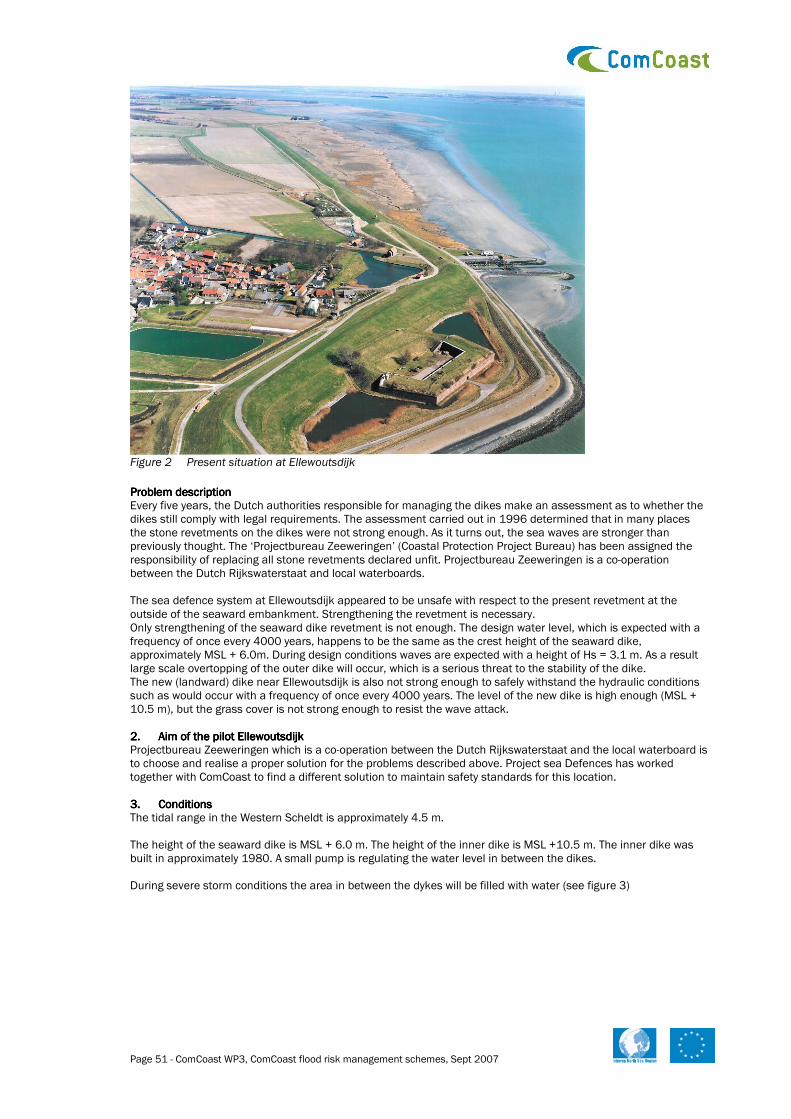
Page 51 - ComCoast WP3, ComCoast flood risk management schemes, Sept 2007
Figure 2 Present situation at Ellewoutsdijk
Problem description Problem description Problem description Problem description Every five years, the Dutch authorities responsible for managing the dikes make an assessment as to whether the dikes still comply with legal requirements. The assessment carried out in 1996 determined that in many places the stone revetments on the dikes were not strong enough. As it turns out, the sea waves are stronger than previously thought. The ‘Projectbureau Zeeweringen’ (Coastal Protection Project Bureau) has been assigned the responsibility of replacing all stone revetments declared unfit. Projectbureau Zeeweringen is a co-operation between the Dutch Rijkswaterstaat and local waterboards. The sea defence system at Ellewoutsdijk appeared to be unsafe with respect to the present revetment at the outside of the seaward embankment. Strengthening the revetment is necessary. Only strengthening of the seaward dike revetment is not enough. The design water level, which is expected with a frequency of once every 4000 years, happens to be the same as the crest height of the seaward dike, approximately MSL + 6.0m. During design conditions waves are expected with a height of Hs = 3.1 m. As a result large scale overtopping of the outer dike will occur, which is a serious threat to the stability of the dike. The new (landward) dike near Ellewoutsdijk is also not strong enough to safely withstand the hydraulic conditions such as would occur with a frequency of once every 4000 years. The level of the new dike is high enough (MSL + 10.5 m), but the grass cover is not strong enough to resist the wave attack. 2.2.2.2. Aim of the pilot EllewoutsdijkAim of the pilot EllewoutsdijkAim of the pilot EllewoutsdijkAim of the pilot Ellewoutsdijk Projectbureau Zeeweringen which is a co-operation between the Dutch Rijkswaterstaat and the local waterboard is to choose and realise a proper solution for the problems described above. Project sea Defences has worked together with ComCoast to find a different solution to maintain safety standards for this location. 3.3.3.3. ConditionsConditionsConditionsConditions The tidal range in the Western Scheldt is approximately 4.5 m. The height of the seaward dike is MSL + 6.0 m. The height of the inner dike is MSL +10.5 m. The inner dike was built in approximately 1980. A small pump is regulating the water level in between the dikes. During severe storm conditions the area in between the dykes will be filled with water (see figure 3)

Page 52 - ComCoast WP3, ComCoast flood risk management schemes, Sept 2007
Seaward dyke Landward dyke Figure 3 Situation during design storm conditions Calculations have indicated that statistically once every 50 years some waves will overtop the outer dike. During design storm conditions (1/4000 years) the outer water level will be equal to the crest height of the outer dyke. The waves will brake on the seaward dyke. Calculations have indicated that the transmitted wave height will be Hs = 1.1 m. The landward dyke therefore also needs to be reinforced, because a top layer of clay covered with grass is not sufficient. 4.4.4.4. Alternative solutionsAlternative solutionsAlternative solutionsAlternative solutions Three options were considered. 1. strengthen the present revetment of the outer side of the seaward dike and increase the crest height of this
dike with about 4 m. 2. strengthen the revetment of the landward dike (the crest height is sufficient) 3. strengthen the present revetment at the outside of the seaward dike and make the seaward dike overtopping
resistible. 5.5.5.5. Chosen schemeChosen schemeChosen schemeChosen scheme Chosen schemeChosen schemeChosen schemeChosen scheme Option 1 is hardly possible because there is not enough space to heighten the dike. Seaward the water depth increases rapidly towards MSL –30.0 m. Landwards no space is available because of the presence of the fortress (see figure 1). Option 2 would guarantee the safety of the hinterland, but there is no guarantee for the fortress and the area around. The fortress has historical and cultural value. Therefore option 3 was considered as best option. The present revetment will be strengthened as well as the crest and inner slope of this embankment. The seaward embankment protects the fortress and landward embankment against severe wave attacks and deals with overtopping water during severe storms. Technical designTechnical designTechnical designTechnical design A design has been made by the Project Sea Defenses (ref 1). Without going in too much detail the design of the overtopping dike will be discussed. figure 4 shows a cross section of the dike as it was before the execution of the works. On the lower stretch the outer slope is protected by rock (carefully placed into position). On the upper stretch and partly on the crest concrete blocks were used. A layer of clay and a grass cover only protects the inner slope.
Figure 4 Seaward dike: cross section BEFORE execution of the works Figure 5 shows the new situation. On the lower stretch of the outer side a layer of rock penetrated with asphalt has been put on top of the present revetment. On the upper stretch concrete blocks were placed on a filter layer and a geotextile. The old concrete blocks were removed first.

Page 53 - ComCoast WP3, ComCoast flood risk management schemes, Sept 2007
The crest was strengthened with asphalt. The protection of the inner slope of the seaward dyke is new compared to normal dyke reinforcements. A layer of open stone asphalt covered with soil will protect the inner slope. A protection with reinforced grass (smart grass reinforcement, see other WP3 documents) has been considered, but there is not yet enough experience with smart grass to apply it. The open structure of open stone asphalt with the cover of soil enables grass to grow on it. The inner slope of the dyke will look like a normal grass dyke.
Figure 5 Seaward dike: cross section AFTER execution of the works
The landward dike is partly protected with open asphalt as well. This was necessary as protection against the waves that will overtop the seaward dike during a super storm (as scheduled in figure 13). ResultsResultsResultsResults The Ellewoutsdijk project has been finished in summer 2007. For further details, please contact ComCoast ([email protected]). More information about the dike reinforcements at Ellewoutsdijk and in Zeeland in general can also be found at www.zeeweringen.nl. 6.6.6.6. ReferencesReferencesReferencesReferences 1. M.D. Groenewoud, Ontwerpnota Dijkverbetering Ellewoutsdijkpolder (Fort en Haven) (In Dutch), Projectbureau
Zeeweringen, PZDT-R-05008ontw, 2005.

Page 54 - ComCoast WP3, ComCoast flood risk management schemes, Sept 2007
Hondsbossche and Petten
Zeewering
6.26.26.26.2 Hondsbossche and Pettemer sea defence as technical case for COMCOASTHondsbossche and Pettemer sea defence as technical case for COMCOASTHondsbossche and Pettemer sea defence as technical case for COMCOASTHondsbossche and Pettemer sea defence as technical case for COMCOAST
1. 1. 1. 1. SiSiSiSite area (description present situation)te area (description present situation)te area (description present situation)te area (description present situation) The Hondsbossche Zeewering and the Pettemer Zeewering are two dike sections which are attached to each other in longshore direction. They are located in the Province of Noord Holland (figure 6) and close the gap in the chain of dunes (a former tidal inlet). The coastal defences are managed by the principal Waterboard named Hollands Noorderkwartier. Part of the land behind the Hondsbossche Zeewering is a nature reserve.
Figure 6 Location of the Hondsbossche and Pettemer Zeewering
Behind the Hondsbossche Zeewering there are three polders, with an average surface level of MSL –1 m and a total area of almost 5 km2.
Part of the land behind the Pettemer Zeewering is a residential area. Houses are located, 40 m from the inland toe of the dyke, over a length of 300 m.
Both dikes have been assigned the status of Zwakke Schakel (‘Weak Link’). This means that without structural strengthening measures, they no longer comply with the legal safety standards (“just but still safe under hydraulic conditions with a probability of occurrence of 10-4 per year).
The Hondsbossche Zeewering has a length of 4.6 km. The crest height is circa MSL +12 m with a typical slope above the berm (located at MSL +5 m) of 1:3 and 1:8 below the berm (figure 8).
Figure 7 Hondsbossche and Pettemer Zeewering on Google Maps The dike has been improved several times (e.g. in 1953, 1976 and 1987). More recently, in 2005 the dike has been strengthened by replacing the grass cover on the seaward side with basalton. The different elevations of the stones produce extra roughness and, hence, decreasing wave-run and overtopping. This measure was meant as temporary measure so that the safety measures are met for the time being. Additional measures are being developed to assure long term safety. Figure 8 Cross-section of the Hondsbossche
Zeewering
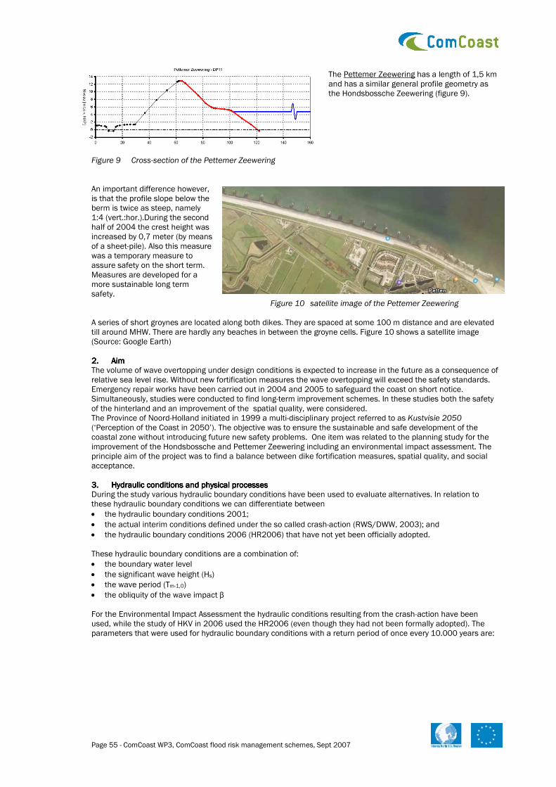
Page 55 - ComCoast WP3, ComCoast flood risk management schemes, Sept 2007
The Pettemer Zeewering has a length of 1,5 km and has a similar general profile geometry as the Hondsbossche Zeewering (figure 9).
Figure 9 Cross-section of the Pettemer Zeewering An important difference however, is that the profile slope below the berm is twice as steep, namely 1:4 (vert.:hor.).During the second half of 2004 the crest height was increased by 0,7 meter (by means of a sheet-pile). Also this measure was a temporary measure to assure safety on the short term. Measures are developed for a more sustainable long term safety. Figure 10 satellite image of the Pettemer Zeewering A series of short groynes are located along both dikes. They are spaced at some 100 m distance and are elevated till around MHW. There are hardly any beaches in between the groyne cells. Figure 10 shows a satellite image (Source: Google Earth) 2. 2. 2. 2. AimAimAimAim The volume of wave overtopping under design conditions is expected to increase in the future as a consequence of relative sea level rise. Without new fortification measures the wave overtopping will exceed the safety standards. Emergency repair works have been carried out in 2004 and 2005 to safeguard the coast on short notice. Simultaneously, studies were conducted to find long-term improvement schemes. In these studies both the safety of the hinterland and an improvement of the spatial quality, were considered. The Province of Noord-Holland initiated in 1999 a multi-disciplinary project referred to as Kustvisie 2050 (‘Perception of the Coast in 2050’). The objective was to ensure the sustainable and safe development of the coastal zone without introducing future new safety problems. One item was related to the planning study for the improvement of the Hondsbossche and Pettemer Zeewering including an environmental impact assessment. The principle aim of the project was to find a balance between dike fortification measures, spatial quality, and social acceptance. 3. 3. 3. 3. Hydraulic conditions and physical processesHydraulic conditions and physical processesHydraulic conditions and physical processesHydraulic conditions and physical processes During the study various hydraulic boundary conditions have been used to evaluate alternatives. In relation to these hydraulic boundary conditions we can differentiate between
• the hydraulic boundary conditions 2001;
• the actual interim conditions defined under the so called crash-action (RWS/DWW, 2003); and
• the hydraulic boundary conditions 2006 (HR2006) that have not yet been officially adopted. These hydraulic boundary conditions are a combination of:
• the boundary water level
• the significant wave height (Hs)
• the wave period (Tm-1,0)
• the obliquity of the wave impact β For the Environmental Impact Assessment the hydraulic conditions resulting from the crash-action have been used, while the study of HKV in 2006 used the HR2006 (even though they had not been formally adopted). The parameters that were used for hydraulic boundary conditions with a return period of once every 10.000 years are:

Page 56 - ComCoast WP3, ComCoast flood risk management schemes, Sept 2007
Location Water level (m) HR2006
Significant Height wave crest
Wave period HR2006 Tm-1,0 (s) HR2006
Wave angle β HR2006
Pettemer Zeewering 4.8 m 4.3 m 12.2 s 4 º
Uncertainty margin 3.9/4.45 m 12.0/12.2 s 1/7 º
Hondsbossche Zeewering 4.9 m 4.7 m 12.1 s 11º
Uncertainty margin 4.25/4.70 m 12.0/12.2 s 5/14 º
The study for the Hondsbossche and Pettemer Zeewering included two scenarios on climate change. Scenario A: the “Middle scenario” for climate change, and scenario B: the “Maximum scenario”. Both these scenarios include a foreseen tectonic subsidence of 0.10 m each 50 years. The climate change in these two scenarios would result in the following hydraulic boundary conditions for a 1/10.000 years occurrence: Hondsbossche zeewering
Scenario Dike Crest height (m + MSL)
Waterlevel (m + MSL)
Wave crest height Hm0
Wave period T m-1,0 (S)
Actual situation 12.00 4.90 4.70 12.10
A050 11.90 5.20 4.85 12.10
A100 11.80 5.50 5.00 12.10
B050 11.90 5.75 5.15 12.40
B100 11.80 6.15 5.35 12.40
B200 11.60 7.00 5.75 12.40
Pettemer Zeewering
Scenario Dike Crest height (m + MSL)
Waterlevel (+ MSL)
Wave crest height Hm0
Wave period T m-1,0 (S)
Actual situation 12.70 4.80 4.30 12.20
A050 12.60 5.10 4.45 12.20
A100 12.50 5.40 4.60 12.20
B050 12.60 5.65 4.75 12.50
B100 12.50 6.05 4.95 12.50
B200 12.30 6.90 5.35 12.50
For the Hondsbossche as well as for the Pettemer Zeewering the wave angle is not expected to change with a changing climate. 4. 4. 4. 4. Autonomous developmentAutonomous developmentAutonomous developmentAutonomous development The most important autonomous development is the relative sea level rise. This includes the accelerating eustatic sea level rise and the continuing land subsidence. Climate change is already reflected in the sea level rise. There is no statistical proof of changes in the wind or wave climate yet. Increased sea level rise will directly influence the water balance in the area behind the dikes. It is expected that sea water seepage will increase, leading to higher concentration of salt in ground and surface water. 5. 5. 5. 5. Alternative solutionsAlternative solutionsAlternative solutionsAlternative solutions 5.1. Decision making process The plans being drawn up within the scope of Kustvisie 2050 (2002) are carried out in accordance with the procedure for planning studies / environmental impact assessments. In the Initial Memorandum (Startnotitie, March, 2005) several measures are discussed and a selection of preferred measures is indicated. The environmental impact assessment (so-called “Integrale Beoordeling”) was published in December 2005 indicating the effects of these measures. In 2006 new hydraulic boundary conditions were published. These are revised every five years based on new data, modelling techniques and further information. In January 2007 a study was published on the implications of these new conditions in relation to potential measures. This evaluation provided information on the effects of individual as well as combinations of measures.The endeavour is to arrive at an outline solution that is broadly supported by the region. It will then be possible to detail the plans in 2007 and 2008. During the decision making process various actors where involved. The province of Noord Holland was asked by the Ministry of Transport, Public Works and Water Management to initiate this study. The province is responsible for the final decision and implementation of the measures. One of the objectives is to gain public support for the measures to be taken. The province put together a project team to develop solution strategies and to evaluate their effects. This project team consists of representatives from local governments, the water board, the Ministry of Transport, Public Works and Water Management, nature conservation groups, and several sectoral lobby groups. Furthermore public hearings were organised to openly discuss ideas and results (participative governance). The effects of the alternatives were studied in relation to various criteria relevant to decision making. These criteria included:

Page 57 - ComCoast WP3, ComCoast flood risk management schemes, Sept 2007
Criterion Aspects
Safety
• Do measures answer to the safety standards if climate change is more extreme then expected?
• Do measures allow for additional measures, if needed?
• The area that needs to be reserved for the upcoming 200 years for additional measures to maintain the safety standard
Coastal Morphology • The need for continuous sand nourishment (maintenance)
• The effect of the measures on large scale morphological processes
Other Soil and Water aspects
• Sweet-salt gradients in groundwater
• Effect on the quantity of sweet water in the dunes
• Effect on the area available for water storage
• Use of scarce resources for construction and maintenance
Nature • Available area with dynamic natural processes
• Effects on habitats and ecotypes (Natura 2000)
• Effect on protected species
Landscape and cultural values
• Continuity of existing cultural and archaeological values
Infrastructure • Effect of the measures on accessibility of the region
Recreation • Effects of measures on the potential for recreation
Living / housing • Effects of measures on the existing residential areas
Agriculture • Effects of the measures on existing agricultural activity in the region
5.2. Alternatives Five alternatives strategies for the Hondsbossche and Pettemer Zeewering were included in the environmental impact assessment. “Zero “Zero “Zero “Zero –––– alternative” alternative” alternative” alternative” Maintaining the safety standard considering an extreme weather event of 1/10.000 is part of the actual policy standard. This means that measures are needed as the situation on short notice does not comply with the requested safety standard (in spite of the emergency repair works carried out in 2004 and 2005). The zero alternative was considered to have a reference for comparison of the other alternatives. Classical dike enforcement measures, including demolition of houses are the core of this alternative. It does not consider spatial quality. Hence, taking into consideration the multiple goals of the project, the zero alternative is not considered to be realistic. For the Hondsbossche and Pettemer Zeewering the zero alternative consists of a technical construction to heighten and strengthen the dike. “Smooth Coast”“Smooth Coast”“Smooth Coast”“Smooth Coast” De Hondsbossche and Pettemer Zeewering actually form a seaward bastion that extends about 150-200 meter further into the sea in comparison with the surrounding sandy coastal stretch. By increasing the crest height and strengthening the dike in landward direction and further extending the sandy coast north of the dike 200 m westward (figure 11), a “smooth coastline” is formed. It is expected that this measure has a positive effect on the maintenance of the sandy coastline north of the dike as transport of sand around the dikes will no longer be obstructed by the bastion. The westward or seaward extension of the beach also offers opportunities for nature development. “Uprising dunes”“Uprising dunes”“Uprising dunes”“Uprising dunes” This alternative only includes landward measures, i.e. not within the morphologic dynamic part of the coastal system. The principle consideration here is that seaward fixed solutions morphologically tend to block ongoing sand transport, thereby introducing new erosion problems elsewhere. The Hondsbossche Zeewering is strengthened to allow for higher rates of wave overtopping under design conditions (10-4 y-1). Only during very rare weather conditions, washover will take place (wave overtopping). As the inner slope of the dike is reinforced, wave crest overtopping does not damage the dike and safety is assured. To meet the safety standard, this alternative combines the sea dike with a secondary dike located further inland (figure 12). When extreme wave overtopping occurs, this second dike will prevent the water from flooding a larger area.
Figure 11 Smooth Coast
Figure 12 Uprising dunes

Page 58 - ComCoast WP3, ComCoast flood risk management schemes, Sept 2007
Figure 13 sea dike with secondary dike
Depending on the quantity of water overtopping, the area behind the dike should be equipped for storing a certain amount of water (figure 13). This alternative includes measures to increase the crest height of the Pettemer Zeewering and widening the dike in landward direction, as the residential area behind the Pettemer Zeewering restricts the quantity of water to be stored. “Hard Coast”“Hard Coast”“Hard Coast”“Hard Coast” This alternative consists of structural measures on the seaward side of both dikes. Along both dikes, at a mutual spacing of some 800 m, groynes are placed. They have a length of some 550 meter in to sea with a crest height at MSL + 4 meter. The groyne cells will be nourished with suitable sand, so that a beach is formed in front of both dikes (figure 14). The width of the beaches is 130 m. The beaches reduce wave attack on the dikes during design conditions, in such a way that the dikes can stay as they are now. The idea behind the groynes is that they reduce the sand loss from the beaches. “Soft Coast”“Soft Coast”“Soft Coast”“Soft Coast” The inclusion of this alternative is a result of the advice given by the commission for the EIA and is based on the idea to extend the beach seaward without the groynes. The commission considered the construction and maintenance costs of the groynes to be too high and its positive effect on the maintenance costs too small. Moreover, this alternative is more in line with the preference of the National Government to start with identifying solutions that only include sand nourishment. The amount of sand needed equals the amount needed for the Hard Coast alternative. Seaward from the dikes a new beach of 130-140 wide is created (figure 15). Sand from future (re-)nourishment schemes will also benefit the sandy coastal stretches south and north of the dikes. More alternatives More alternatives More alternatives More alternatives During the environmental impact assessment two more alternatives were evaluated. The first is the combination of each alternative with the construction of a (new) marina at Petten. The second alternative goes one step further than Uprising Coast, by also making the Pettemer Zeewering an “overtopping dike” (figure 16). The overtopping water volume will be discharged through a new “canal” to the south, where it will be stored in the polders behind the Hondsbossche Zeewering.
The latter is a result of the COMCOAST project stimulating research on innovative measures to ensure coastal protection.
Evaluation Evaluation Evaluation Evaluation In the environmental impact assessment, the alternative “Smooth Coast” is evaluated as preferred alternative. Overall costs are lowest and it is considered as very positive for nature development, spatial quality and recreation. This alternative optionally includes the overtopping dike at the Hondsbossche and Pettemer Zeeweringen instead of increasing their respective crest heights. The EIA concluded that further study was needed to estimate incidental cost as a result of damage caused by overtopping. The alternative “Hard Coast” has no distinct added value. The groynes appeared not to reduce the maintenance cost, and are very expensive. This alternative turned out to be the most expensive one. It further scores negative on spatial quality and recreation and has no added value for nature.
Figure 14 Hard Coast
Figure 15 Soft Coast
Figure 16 sea dike with discharge canal

Page 59 - ComCoast WP3, ComCoast flood risk management schemes, Sept 2007
Also the “Uprising dunes”-alternative turned out to have no added value compared to the “Smooth Coast”- alternative, while the costs are higher. The measures for the Hondsbossche and Pettemer Zeewering serving as overtopping dikes are however feasible. Therefore, the EIA indicates that these measures should be further considered as a variation of the “Smooth Coast” alternative. The alternative “Soft Coast” has no added value compared to Smooth Coast. The limited coastal stretch near the sea dikes offers only little potential for dune development or spatial quality. In relation to the criteria nature, recreation and spatial quality, this alternative is ranked less preferable than Smooth Coast. Also, this alternative will create two new bastions of sand which, consequently, will result in an increase of maintenance costs. This alternative is slightly more expensive in comparison to Smooth Coast. According to the EIA, strengthening the coastal defence system can be combined with the development of a marina. This would also have a positive effect on the coastal protection. The main reason for not considering the marina further in the decision process is that it follows its own development course. For planning reasons it was thus decided to keep both projects (coastal safety and marina development) separated. 6. 6. 6. 6. Chosen scheme (or: the way towards Chosen scheme (or: the way towards Chosen scheme (or: the way towards Chosen scheme (or: the way towards a chosen scheme)a chosen scheme)a chosen scheme)a chosen scheme) Up to this moment no specific scheme has been selected. The decision making process is on-going based on the latest results of the study carried out. During the EIA the overtopping dike was evaluated positively for the Hondsbossche Zeewering as well as for the Pettemer Zeewering. This advice was adopted by the province of North Holland. However, for the dimensioning of these overtopping dikes the hydraulic boundary conditions of the so-called “crash-action” [RWS/DWW, 2003] were used. Results were characterized as provisional, pending the new hydraulic boundary conditions of 2006. When comparing the hydraulic boundary conditions of 2006 with the “crash-action” it becomes apparent that a significant increase of the wave intensity has to be considered. This is caused by a lower mean ground level used in the boundary conditions. Using these new conditions results in a considerable increase of overtopping waves under extreme conditions. This implicated that the feasibility of the overtopping dikes at the Hondsbossche and Pettemer Zeewering had to be re-evaluated as the overtopping dikes are only feasible up to a certain quantity of overtopping water. This is especially the case for the Pettemer Zeewering, where both the general public and the Waterboard principally objected this solution. The most recent study that has been carried out included an inventory of feasible measures in order to meet the safety standards. The process included an intensive interaction between stakeholders to ensure broad support for the final results. Table 1 presents the optional measures to meet the safety standards under the new hydraulic boundary conditions. Table 1. Alternatives to meet the safety standards under the new hydraulic boundary conditions.
Measure Result reconnaissance
B strengthening of the slopes of the dikes to allow for more overtopping water
C1 Increasing Crest height
C2 Coarsening of slopes
C3a Heightening the berm
C3b Extending the lower slope
C3c Construction of a more gentle slope
C4 construction(s) on berm / upper slope
R1 Construction of higher foreland
R2 Reduction of the wave period by constructing a detached breakwater
R3 Reduction of wave intensity by constructing a detached breakwater

Page 60 - ComCoast WP3, ComCoast flood risk management schemes, Sept 2007
During this phase of the study the following items were considered to evaluate the different options for the Hondsbossche and Pettemer Zeewering: 1. Effect of the measure: stand-alone or in combination with other measures; 2. Basic requirements:
a. measures are limited to (the direct surrounding of) the dikes b. both dikes are evaluated separately c. different measures can be combined d. the measures increase the sense of security for the actors directly involved e. natural (green) cover of inner slope f. limiting the hindrance of water during extreme and normal weather conditions g. preservation of residential area in Petten h. it should not frustrate a possible future development of a marina at Petten.
3. Feasibility; 4. Realization and completion period ; 5. Construction and maintenance costs.
At first the measures were evaluated in relation to the effect and up to what extend the basic requirements will be met. Table 2 score in relation to effect and basic requirements per dike (-- very bad, - bad, +/- slightly positive, + good, ++ very good)
Code Hondsbossche Pettemer
effects basic req. effects basic req. Remarks
B + +/- + -(f) Water hindrance near Petten, not suitable as individual measure, physical limitations; adaptations needed for overtopping water
C1 ++ ++(d) ++ +/-(d,g) Required reduction of overtopping water feasible, high dikes required, affects the residential area near Petten
C2 +/- +/- +/- +/- Possible to decrease the amount of overtopping water up to a half, hence, not an option as single measure, possible when combined
C3a - +/- - +/- Only a limited reduction of overtopping water is feasible Not suitable as measure.
C3b +/- +/- +/- +/- Not suitable as individual solutions, possible when combined
C3c +/- +/- +/- +/- Limited reduction of overtopping water; Not suitable as core measure
C4 + +(h) + +(h) Required reduction seems possible, additional study required
R1 ++ + ++ + Required reduction of overtopping water is feasible, easy to carry out by sand nourishment on the beach
R2 - +/- - +/- Very limited reduction of overtopping water feasible, not suitable as measure
R3 ++ -(a,h) ++ -(a,h) Required reduction of overtopping water feasible, an extremely high dam is needed, not suitable
R4 ++ -(a,h) ++ -(a,h) Required reduction is feasible (as R1 but more complex), both the breakwater and a higher foreland are needed.
In the table the effects for both dikes are equal. In relation to the basic requirements a distinction can be made between both dikes:
• for measure B water hindrance is foreseen in Petten (requirement f);
• with C1 the sense of safety is high (d), but problems are expected with the residential area near Petten (g);
• C4 also causes a sense of safety but should be further investigated
• R1 also provides good protection
• R3 and R4 conflict with the requirement to implement measures near or on the dike (a) and limit the possibilities for the Marina (h).
In this evaluation it was concluded that measures C2, C3a, C3b and R2/3/4 are less suitable. C2 has limited effect on wave overtopping but could be used as a back-up option if other measures do not provide the required effect. Heightening the berm (C3a) has a negligible effect and if a gentler slope is considered (C3c) the extension of the lower slope proves to be more effective. Therefore only C3b was studied in further detail. In relation to R2/3/4 it was calculated that a very high breakwater is required. The construction is expensive and will influence

Page 61 - ComCoast WP3, ComCoast flood risk management schemes, Sept 2007
the morphological processes along the coastline. It also conflicts with the basic requirements of posing no limitations to the possible future Marina and to carry out measures only on or in the vicinity of the dikes. Therefore these measures have not been taken into account for detailed study. Detailed studies of the remaining measures led to the following effects for the Hondsbossche and Pettemer Zeewering: Table 3. score in relation to the criteria for the Hondsbossche zeewering (-- very bad, - bad, +/- slightly positive, + good, ++ very good, n.a. not available)
Criteria Code 1)
effect 2) basic requirements
3) feasibility
4) realization 5) Costs
Remarks
B + +/- + + ++
C1 ++ ++(d) + +/- +/-
C3 +/- +/- +/- -- n.a. For this case not suitable
C4 + +(h) +/- - +/-
R1 ++ + + ++ +/- to + Costs relatively unsure
The relative scores indicate that measures B, C1 en R1 for the Hondsbossche Zeewering are comparable. Because of the uncertainty towards costs and realization, measure C4 is less preferable. Measure C3 is only relevant for the dike at Petten. This implies that for this dike either measure B, C1 or R1 is feasible. A combination of measures is possible, which may include C4. Table 4. score in relation to the criteria for the Pettemer Zeewering (-- very bad, - bad, +/- slightly positive, + good, ++ very good, n.a. not available)
Criteria Code 1)
effect 2) basic requirements
3) feasibility
4) realization 5) Costs
Remarks
B + -(f) - + ++ Not suitable
C1 ++ +/-(d, g)) + +/- +/-
C3 +/- +/- +/- -- +/-
C4 + +(h) +/- - +/- to +
R1 ++ + + ++ +/- to ++
In the case of the Pettemer Zeewering an overtopping dike now turned out to be not suitable, especially in relation to water hindrance during extreme and normal weather conditions. It is concluded that for this location either C1, C3, C4 or R1 are feasible. Also in this case combinations may be interesting. Proposed measurProposed measurProposed measurProposed measures and combinations of measureses and combinations of measureses and combinations of measureses and combinations of measures Based on the detailed study of the measures feasible for the Hondsbossche and Pettemer Zeewering, the following options have been presented to the decision makers: Hondsbossche ZeeweringHondsbossche ZeeweringHondsbossche ZeeweringHondsbossche Zeewering Table 5 overview of the selected alternatives for the Hondsbossche Zeewering
Individual measures Feasible combinations Measure
H1 H2 H3 H4 H5 H6 H7
B X X X
C1 X X X
C3 - - - - - - -
C4 X
R1 X X X
Alternative H1 – strengthening the dike to allow for an increase in overtopping . In this case the hindrance caused by overtopping water in the area behind the dike still has to be studied. The costs are expected to be in the order of 10 million Euro. Altenative H2 – Standard crest heightening. This alternative includes a standard landward heightening of the crest. Considering a maximum overflow of 1 l/m/s the crest should be heightened in the order of 6 to 8 meters (MSL + 18.5 / MSL +20.5). Costs are estimate at 50 to 70 million Euro. Alternative H3 – Constructions on berm and upper slope. In this alternative an innovative construction on the berm and upper slope to decrease wave crest height has been studied. This alternative still has to be designed and tested. Costs are presumably between 40 and 90 million Euro.

Page 62 - ComCoast WP3, ComCoast flood risk management schemes, Sept 2007
Alternative H4 – Construction of a higher foreland. An extended and higher foreland will decrease wave crest. Total costs are estimated between 60-140 million Euro. The estimation of maintenance costs is a significant uncertainty. Combination H5 – limited heightening of the crest with dike reinforcement for overtopping. In this combination a limited heightening of the dike is possible as more than 1 l/m/s is allowed to overtop the dike. In this case the crest height could correspond with the heightened crest at Petten. This optimized alternative has to be elaborated in detail. Costs are expected to be lower than with alternative H2. Combination H6 – Limited reinforcement for overtopping with construction of a foreland. The construction of a foreland will decrease wave crest height and, hence, the overflow of water during extreme weather events. This allows for only a limited reinforcement of the inner slop of the dike. Costs of this combination are between 40-80 million Euro. Combination H7 – limited heightening of the crest with construction of a foreland. By constructing a foreland, the design wave height at the toe of the dike decreases and a limited heightening of the crest on the dike will be sufficient. However, the functioning of the foreland in this combination, is uncertain. This could lead to high maintenance costs. Therefore, instead of this combination it is preferred to combine the heightening of the dike with a landward reinforcement of the dike (H5). Pettemer ZeeweringPettemer ZeeweringPettemer ZeeweringPettemer Zeewering In relation to the Pettemer Zeewering two individual measures and three combinations of measures are feasible. Table 5 Overview of the selected alternatives for the Pettemer Zeewering
Individual measures Feasible combinations Measure
P1 P2 P3 P4 P5
B - - - - -
C1 X X
C3 X X
C4 X
R1 X X X
Alternative P1 - Constructions on berm and upper slope Realize an innovative construction on the upper slope to decrease wave crest height. This construction still has to be designed and subsequently tested. Costs are estimated between 10 and 25 million Euro. Alternative P2 – Construction of an extended foreland An extensive and high foreland is realized near the dike. Total costs are presumably between 15 and 35 million Euro. As with the other alternatives including a foreland the maintenance costs are not certain. For the Pettemer Zeewering the following combinations of measures are feasible. Combination P3 – Limited heightening of the dike combined with a gentler slope This option includes a limited heightening of the dike. The heightening is limited by the space behind the dike that can be used without affecting the residential area. Considering the available space, the crest height of the dike can be increased up to MSL + 16. To further assure that overflow does not exceed 1 l/m/s the lower seaward slope will be extended. These measures cost between 30 to 60 million. Combination P4 – limited heightening of the crest in combination with a foreland As P3, but instead of an extension of the lower slope a foreland will be realized. This results in an estimated cost of 20 – 40 million. Combination P5 – extension of the lower slope in combination with a foreland In this combination a foreland will be realized alongside the extended lower slope of the dike. These costs mount up to a total of 30 – 60 million. As indicated before, the final choice still has to be made by the decision makers. Depending on the preference of the decision makers more study will be carried out to assure that all the information required for the decision making process becomes available. The planning for making a final choice for both dikes is 2007 and 2008. Works are expected to commence at the end of 2009. From 2011 onwards the safety of the hinterland will be restored again for at least one or two generations.

Page 63 - ComCoast WP3, ComCoast flood risk management schemes, Sept 2007
7.7.7.7. Lippensbroek and KruibekeLippensbroek and KruibekeLippensbroek and KruibekeLippensbroek and Kruibeke----BazelBazelBazelBazel----Rupelmonde as Rupelmonde as Rupelmonde as Rupelmonde as technical case for COMCOASTtechnical case for COMCOASTtechnical case for COMCOASTtechnical case for COMCOAST
In Belgium we have not our own pilot locations, but so called 'learning sites'. That means we have an agreement with our Belgian ComCoast partner to learn from each other, focussing on two locations that are dealing with problems and solutions such as other ComCoast pilot locations. These locations are Lippensbroek en Kruibeke.
7.17.17.17.1 “Lippensbroek” as technical case for COMCOAST“Lippensbroek” as technical case for COMCOAST“Lippensbroek” as technical case for COMCOAST“Lippensbroek” as technical case for COMCOAST
1.1.1.1. Site areaSite areaSite areaSite area PositionPositionPositionPosition The Lippensbroek area lies along the river Scheldt in Hamme (Belgium).
Figure. 1 Localization of the Lippensbroek area in Flanders The area is characterized by a flat topography with a small slope (southeast to northeast). In the center of the area a small depression is present. The ground level of the area is approximately 2,6 m TAW (dikes not included) and therefore the Lippensbroek area contains a profound lower ground level than the Naillenbroek (Northwest from the Lippensbroek area), which has a ground level of approx. 4,6 m TAW and the sweet water marsh ‘De Plaat’ (northeast from the Lippensbroek area), which has a ground level of approx. 5,5 m TAW. The dikes surrounding the area (before the works started) were as follows:
• A northeastern river dike, built according to the Sigmaplan standards, with a crown level of 8 m TAW (crown width of approx. 7 m) and a slope of 16/4.
• A northwestern dike between the Lippensbroek and the Naillenbroek area had a crown level of 7,8 m TAW (not according to the standards of the Sigmaplan), a crown width of approx. 5 m and a slope of approx. 7/4
• A southern dike was on the level of approx. 4,00 m TAW The Sigmaplan was designed to protect the Sea Scheldt basin against storm surges from the North Sea. This plan was initiated by the Council of Ministers on 18 February 1977 and involved 3 complementary options:
• Elevating and reinforcing the dikes
• Constructing a storm surge barrier downstream Antwerp
• Laying out 13 flood control areas The first section, namely the elevation and reinforcement of the dikes, is still in progress and has already contributed to better safety. The construction of the surge barrier has not been implemented because of the

Page 64 - ComCoast WP3, ComCoast flood risk management schemes, Sept 2007
negative results of an assessment study. When it comes to the FCA’s, twelve of them are already in use. The FCA in Kruibeke-Bazel-Rupelmonde, the last and with it’s 600 ha far out the largest flood control area of the Sigmaplan, is currently being implemented. HaHaHaHa The area is approximately 13 ha large. Because of the construction of the dikes surrounding the flood control area with controlled reduced tide, the area inside the dikes will be approximately 8 ha.
Figure 2 Situation map of the “Lippensbroek” area Spatial useSpatial useSpatial useSpatial use The idea was to design the area as a mudflat/salt marsh area by inducing a controlled reduced tide in the Lippensbroek area. Before the work started, 163 types of plants were registered. A logarithmic scarcity class showed that almost 3 of 4 of these species are numerously present in Flanders. The species that were mainly found in this area are those growing on strongly anthropogenic disordered places (41 types). Furthermore the area contained 25 types of species mainly growing on moderate nutritious wet grasslands, 24 types of species growing on banks and sweet and slightly brackish waters, 24 types of species growing in woods and 22 types of species growing on clearings, fringes and thickets. A small percentage of the species were typical for dry grasslands and rocks (9 types) and heath land and peat grounds (2 types). DikesDikesDikesDikes The dikes along the river Scheldt have a crown level of 8,00 m TAW and a crown width of 7m. The dike has a inner slope of 16/4. The center of the dike is surrounded by a layer of clay of 1m thick at the outer slope and 0,6m thick at the inner slope.

Page 65 - ComCoast WP3, ComCoast flood risk management schemes, Sept 2007
Water managementWater managementWater managementWater management A dewatering sluice was built in the late eighties. This sluice consists of a square shaft (2m x 2m) with a length of 40 m. The shaft has an opening at the riverside of 1,5m (height) by 2m (width) and is closed by a one-way valve. The floor of the sluice is situated at a level of 1,4 m TAW. In the middle of the shaft, the sluice can be closed by a spindle slide. The building of an inlet sluice was finalized in the summer of 2005. The floor of the sluice is situated at a level of 4 m TAW. This sluice consists of 3 shafts (width 1 m, height 1,90 m and length 12,10 m). Over a length of approx. 80 m the river dike is lowered to create an overflowing dike. The inner slope is protected by a fibred open stone asphalt layer (thickness 0,12 m).
Figure 3 Inlet sluice at Lippensbroek 2.2.2.2. Aim of the projectAim of the projectAim of the projectAim of the project
• This area has no, or negligible, influence on the reduction of inundations in the Scheldt estuary because of its small area. It does however serve as a pilot project for the realisation of the northern part of the flood control area in Kruibeke-Bazel-Rupelmonde.
• Nature: the area will be used as a reduced tidal area, to create a mudflat/salt marshland and see which habitats will start growing naturally under these conditions.
• Recreation: easy access. On top of the dike, surrounding the reduced tidal area.
• Alternative to traditional heightening of the dike. Being a small flood control area with the overflowing dike and serving as a pilot for the realisation of the 600ha flood control area KBR.
3.3.3.3. Conditions Conditions Conditions Conditions Physical processesPhysical processesPhysical processesPhysical processes Soil properties: The most important sediment depositions have a quaternary origin: alluvial clay and shifting sands from the Holocene and Aeolian (loamy) sand and loam from the Pleistocene. Under the quaternary sediments, marine sediments (stiff clay with local sand banks) are present, which were deposited during the Tertiary. Seasonal fluctuations of the groundwater table supply a yellow-grey discoloration of the soil. Under the lower boundary of these rust phenomena, the soil is permanently saturated and mostly reduced to gray-blue. During a small-scale soil research (1m under the ground level) it was seen that the soil consisted of approx. 33 - 34 % clay, 39 - 45 % silt en 5 - 16 % sand. The soil is also characterized by a high organic dust value (8,4 - 9,5 %), a small alkaline pH (7,5 - 8,1) and a connectivity value of approx. 140 - 250 µS.cm-1. Holocene clay, silt and peat were found in the Lippensbroek area until a depth of approx. 2,5 - 3,0 m under the ground level, while the Pleistocene sands reach approx. 14 m under the ground level.

Page 66 - ComCoast WP3, ComCoast flood risk management schemes, Sept 2007
Hydro-geological characteristics: Good water transporting layers alternate with poor water transporting layers. The Tertian formations form a poor water-transporting layer, while the quaternary sand top layer is the main water-carrying layer. The ground water level is situated on a non-profound depth (approx. 0,2 to 0,6 m under the ground level). Based on the chloride content (67 ± 22 mg/l) the water was characterized as sweet and based on the value of the conductivity (1168 ± 424 µS/cm) the water was characterized as weak sweet. The increased conductivity values (until 2000 µS.cm-1) and concentrations Sodium (until 450 mg/l), chloride (until 110 mg/l), calcium (until 226 mg/l) and sulfate (tot 510 mg/l) near the river dike illustrate a possible infiltration of the Scheldtwater in the soil of Lippensbroek.
Figure 4 Overview of the Lippensbroek area Safety Safety Safety Safety The Lippensbroek area has no, or negligible, influence on the reduction of inundations and this because of its small area. It does however serve as a pilot project for the realisation of the northern part of the flood control area in Kruibeke-Bazel-Rupelmonde. Flood control area means that, in case of a storm surge, the storm tide of Sea-Scheldt is truncated and flows over the overflow dike into the area in a controlled manner. A high ring dike around the CIA ensures that the Scheldt water remains in the inundation area. At low tide, the water flows back to the river through outlet sluices, thus emptying the area. Because of this truncation, the water level in Sea-Scheldt and the tributaries upstream is less high and the villages are better protected. At present, the inhabitants of the Sea-Scheldt basin are protected from floods, the average chance of occurrence being once every 70 years. As soon as the FCA KBR becomes operational, the level of safety will increase to just once every 350 years. 4.4.4.4. Autonomous developmentAutonomous developmentAutonomous developmentAutonomous development Without the construction of the flood control area, the Lippensbroek area would have remained agricultural land without any additional value to nature. Conclusions after 1,5 year of monitoringConclusions after 1,5 year of monitoringConclusions after 1,5 year of monitoringConclusions after 1,5 year of monitoring The system has been working since March 2006 and looks marvellous. The area is filled with reed, willow, creeks and Purple loosestrifes. It has become a popular feeding and nesting place for birds. Cyclists and hikers often pause at the site to enjoy the beautiful scenery and fish use the peace and quiet to lay eggs in the Lippensbroek water. The impact on the water quality is even more spectacular. The incoming water of the Scheldt often has terribly low oxygen levels. After the powerful inlet, this number increases with minimally 60%. In the time between high and low tide, the oxygen level keeps rising. This period of rest allows the sand particles to sink to the bottom and allows

Page 67 - ComCoast WP3, ComCoast flood risk management schemes, Sept 2007
optimal contact between air, light and the clear still water. The mud flats and marshes also heighten the amount of silicium in the water, thus preventing overgrowth of algae. Since the water storage is the main function of the Kruibeke site, sedimentation and erosion are also important monitoring themes in this pilot site. Test banks show that the pits in lower areas fill up quite quickly. In other parts ground washed away, thus forming a creek system. The central moat even got half a meter deeper. Although it’s too soon to draw final conclusions at this point, the preliminary evidence allows the assumption the theoretic models and predictions will prevail. Safety and Nature truly go hand in hand. 5.5.5.5. Chosen scheme Chosen scheme Chosen scheme Chosen scheme The construction of Hamme Lippenbroek was a joint venture of the Seascheldt Department of Waterwegen en Zeekanaal NV (Waterways and Seachannel NV) and the Agentschap voor Natuur en Bos (Agency for Nature and Forest). Technical SketchTechnical SketchTechnical SketchTechnical Sketch Before a reduced tidal area could be allowed, the dikes surrounding the area were raised and broadened. One uniform profile was obtained, with the following characteristics:
• inner slope of 12/4
• a crown level of 8,0 m TAW
• a crown width of 7 m TAW
• core of the dike surrounded by a clay layer of 1 m thickness at the riverside and 0,6 m thickness at the landside
• an approx. 0,4 m thick rubble layer. The height of this layer is designed to be 1 m above the high-water level when there is an average spring tide
• a 3 m wide road on the dike An outlet sluice was built in the late eighties. This sluice consists of a square shaft (2m x 2m) with a length of 40 m. The shaft has an opening at the riverside of 1,5m (height) by 2m (width) and is closed by a one-way valve. The floor of the sluice is situated at a level of 1,4 m TAW. In the middle of the shaft, the sluice can be closed by a spindle slide. The building of an inlet sluice was finalized in the summer of 2005. The floor of the sluice is situated at a level of 4 m TAW. This sluice consists of 3 shafts (width 1 m, height 1,90 m and length 12,10 m). Over a length of approx. 80 m the river dike is lowered to create an overflowing dike. The inner slope and crest are protected by a fibred open stone asphalt layer (thickness 0,12 m).
Figure 5 The inlet sluice and overflowing dike at Lippensbroek
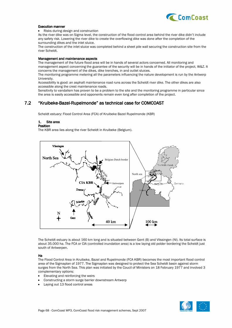
Page 68 - ComCoast WP3, ComCoast flood risk management schemes, Sept 2007
Execution mannerExecution mannerExecution mannerExecution manner
• Risks during design and construction As the river dike was on Sigma level, the construction of the flood control area behind the river dike didn’t include any safety risk. Lowering the river dike to create the overflowing dike was done after the completion of the surrounding dikes and the inlet sluice. The construction of the inlet sluice was completed behind a sheet pile wall securing the construction site from the river Scheldt. Management and maintenance aspectsManagement and maintenance aspectsManagement and maintenance aspectsManagement and maintenance aspects The management of the future flood area will be in hands of several actors concerned. All monitoring and management aspect concerning the guarantee of the security will be in hands of the initiator of the project, W&Z. It concerns the management of the dikes, dike trenches, in and outlet sluices. The monitoring programme metering all the parameters influencing the nature development is run by the Antwerp University. Accessibility is good: an asphalt maintenance road runs across the Scheldt river dike. The other dikes are also accessible along the crest maintenance roads. Sensitivity to vandalism has proven to be a problem to the site and the monitoring programme in particular since the area is easily accessible and opponents remain even long after completion of the project.
7.27.27.27.2 “Kruibeke“Kruibeke“Kruibeke“Kruibeke----BazelBazelBazelBazel----Rupelmonde” as technical case for COMCOASTRupelmonde” as technical case for COMCOASTRupelmonde” as technical case for COMCOASTRupelmonde” as technical case for COMCOAST
Scheldt estuary: Flood Control Area (FCA) of Kruibeke Bazel Rupelmonde (KBR) 1.1.1.1. Site areaSite areaSite areaSite area PositionPositionPositionPosition The KBR area lies along the river Scheldt in Kruibeke (Belgium).
The Scheldt estuary is about 160 km long and is situated between Gent (B) and Vlissingen (Nl). Its total surface is about 35.000 ha. The FCA or CIA (controlled inundation area) is a low laying old polder bordering the Scheldt just south of Antwerpen. HaHaHaHa The Flood Control Area in Kruibeke, Bazel and Rupelmonde (FCA KBR) becomes the most important flood control area of the Sigmaplan of 1977. The Sigmaplan was designed to protect the Sea Scheldt basin against storm surges from the North Sea. This plan was initiated by the Coucil of Ministers on 18 February 1977 and involved 3 complementary options:
• Elevating and reinforcing the weirs
• Constructing a storm surge barrier downstream Antwerp
• Laying out 13 flood control areas
Vlissingen
Gent
Antwerp
Belgian-Dutch borderNorth Sea
Schelde
Schelde
Schelde
Dender
Rupel
Durme
-
North sea
Vlissingen
Gent
Antwerpen
Belgian-Dutch border
Schelde
Schelde
Schelde
Dender
Rupel
Durme
North sea
N
40 km 100 km
CIA KBR
Vlissingen
Gent
Antwerp
Belgian-Dutch borderNorth Sea
Schelde
Schelde
Schelde
Dender
Rupel
Durme
-
North sea
Vlissingen
Gent
Antwerpen
Belgian-Dutch border
Schelde
Schelde
Schelde
Dender
Rupel
Durme
North sea
Vlissingen
Gent
Antwerp
Belgian-Dutch borderNorth Sea
Schelde
Schelde
Schelde
Dender
Rupel
Durme
-
North sea
Vlissingen
Gent
Antwerpen
Belgian-Dutch border
Schelde
Schelde
Schelde
Dender
Rupel
Durme
North sea
N
40 km 100 km
CIA KBR
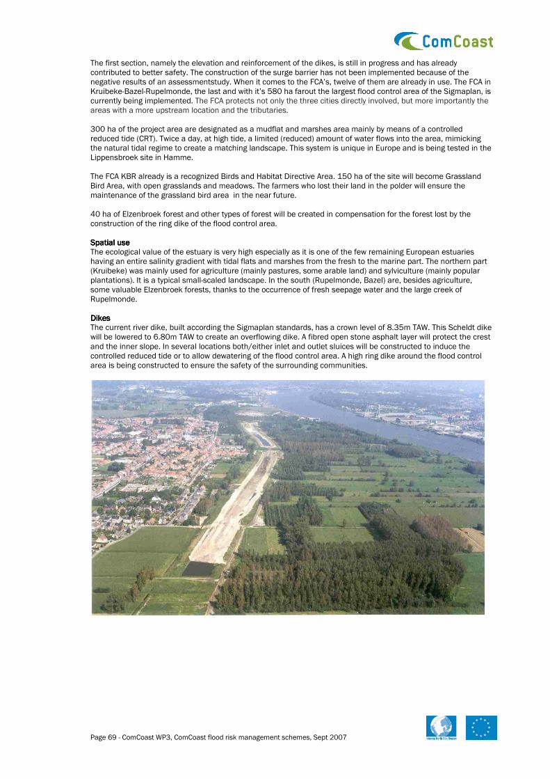
Page 69 - ComCoast WP3, ComCoast flood risk management schemes, Sept 2007
The first section, namely the elevation and reinforcement of the dikes, is still in progress and has already contributed to better safety. The construction of the surge barrier has not been implemented because of the negative results of an assessmentstudy. When it comes to the FCA’s, twelve of them are already in use. The FCA in Kruibeke-Bazel-Rupelmonde, the last and with it’s 580 ha farout the largest flood control area of the Sigmaplan, is currently being implemented. The FCA protects not only the three cities directly involved, but more importantly the areas with a more upstream location and the tributaries. 300 ha of the project area are designated as a mudflat and marshes area mainly by means of a controlled reduced tide (CRT). Twice a day, at high tide, a limited (reduced) amount of water flows into the area, mimicking the natural tidal regime to create a matching landscape. This system is unique in Europe and is being tested in the Lippensbroek site in Hamme. The FCA KBR already is a recognized Birds and Habitat Directive Area. 150 ha of the site will become Grassland Bird Area, with open grasslands and meadows. The farmers who lost their land in the polder will ensure the maintenance of the grassland bird area in the near future. 40 ha of Elzenbroek forest and other types of forest will be created in compensation for the forest lost by the construction of the ring dike of the flood control area. Spatial useSpatial useSpatial useSpatial use The ecological value of the estuary is very high especially as it is one of the few remaining European estuaries having an entire salinity gradient with tidal flats and marshes from the fresh to the marine part. The northern part (Kruibeke) was mainly used for agriculture (mainly pastures, some arable land) and sylviculture (mainly popular plantations). It is a typical small-scaled landscape. In the south (Rupelmonde, Bazel) are, besides agriculture, some valuable Elzenbroek forests, thanks to the occurrence of fresh seepage water and the large creek of Rupelmonde. DikesDikesDikesDikes The current river dike, built according the Sigmaplan standards, has a crown level of 8.35m TAW. This Scheldt dike will be lowered to 6.80m TAW to create an overflowing dike. A fibred open stone asphalt layer will protect the crest and the inner slope. In several locations both/either inlet and outlet sluices will be constructed to induce the controlled reduced tide or to allow dewatering of the flood control area. A high ring dike around the flood control area is being constructed to ensure the safety of the surrounding communities.

Page 70 - ComCoast WP3, ComCoast flood risk management schemes, Sept 2007
Water managementWater managementWater managementWater management Flood control area means that, in case of a storm surge, the storm tide of Sea-Scheldt is truncated and flows over the overflow dike into the area in a controlled manner. A high ring dike around the FCA ensures that the Scheldt water remains in the inundation area. At low tide, the water flows back to the river through outlet sluices, thus emptying the area. Because of this truncation, the water level in Sea-Scheldt and the tributaries upstream is less high and the estuary is better protected against inundations. Dewatering of the hinterland is guaranteed by the Barbierbeek stream and the northern and southern dewatering ditches. The Barbierbeek stream will continue to flow through the polder to the Scheldt by finding its way through the Kruibeke polder. Scheldt water flows in and out of the tidal areas twice each day. This has a positive effect on the development of different habitats, but of course it must not compromise safety. In case of an emergency, the FCA KBR must be empty to allow as big a portion of the storm surge as possible to flow into the area. The inflow sluices can be easily closed when an extreme storm is expected. A storm surge that floods the flood control area is expected on average once or twice a year. Another point of interest is the sludge in the Scheldt water. If this were to remain behind in the area, the terrain would rise too much and the water storage would decrease. Here, the design and the installation of the sluices offer the solution. The flood surge first flows into a big trench before spreading across the tidal area. As a result, most sand particles remain behind in the same spot. The enlarged discharging sluices further a speedy discharge at low tide. The strong current dislodges the sand particles, dragging them back to the Scheldt. The supply of water by the Barbierbeek stream reinforces this ‘flush’ effect of the water volume flowing out again rubbing the system of coves clean.
2.2.2.2. Aim of the projectAim of the projectAim of the projectAim of the project The Flood Control Area (FCA) in Kruibeke, Bazel and Rupelmonde will: Reduce flood risk in the Seascheldt Basin: Reduce flood risk in the Seascheldt Basin: Reduce flood risk in the Seascheldt Basin: Reduce flood risk in the Seascheldt Basin: At this point the inhabitants are protected against water levels with average return periods of 70 years. Once the FCA is operative, the level of protection will increase to once in 350 years. Support existing habitats and heighten ecologic values by creatingSupport existing habitats and heighten ecologic values by creatingSupport existing habitats and heighten ecologic values by creatingSupport existing habitats and heighten ecologic values by creating
• 300 ha of mudflat and salt mash
• 150 ha of birds grasslands area
• 40 ha of Elzenbroek and other types of forest Create recreational possibilities for Create recreational possibilities for Create recreational possibilities for Create recreational possibilities for all.all.all.all. This new nature reserve will be widely accessible for the public. Asphalt roads, cobbled paths and winding sandpaths, the FCA KBR has something for everyone. Service roads running alongside all the dikes will accommodate maintenance teams and strollers alike. Slow and fast traffic (mountain bikers, horsemen, cyclists) will be separated wherever possible. North of the Scheldelei, amateur fishermen can set their bait. They will likely also be allowed to cast their lines along the ditches aside of the ring dike. Those who have more patience can entrench themselves at one of the fishing places near the Rupelmondse or Bazelse creeks. 3.3.3.3. Conditions Conditions Conditions Conditions Safety Safety Safety Safety The safety of the inhabitants of the Scheldt basin is of primary concern in the creation of the flood control area. Also, extra opportunities for valuable nature and recreation in unique scenery play an important part.

Page 71 - ComCoast WP3, ComCoast flood risk management schemes, Sept 2007
The abbreviation ‘FCA’ stands for flood control area. In concrete terms, this means that, in case of a storm surge, the storm tide of Sea-Scheldt is truncated and flows over the overflow dike into the area in a controlled manner. A high ring dike around the FCA ensures that the Scheldt water remains in the inundation area. At low tide, the water flows back to the river through outlet locks, thus emptying the area. Because of this truncation, the water level in Sea-Scheldt and the tributaries upstream is less high and the villages are better protected.
At present, the inhabitants of the Sea-Scheldt basin are protected from floods, the average chance of occurrence being once every 70 years. As soon as the FCA KBR becomes operational, the level of safety will increase to just once every 350 years. Also, local drainage problems are being solved through the project. 4.4.4.4. Autonomous developAutonomous developAutonomous developAutonomous developmentmentmentment Without the construction of the flood control area, the Kruibeke-Bazel-Rupelmonde polder would have remained agricultural land without any additional value to nature or to the safety of the Scheldt estuary.

Page 72 - ComCoast WP3, ComCoast flood risk management schemes, Sept 2007
Ecology and biodiversity: Ecology and biodiversity: Ecology and biodiversity: Ecology and biodiversity: In the FCA with controlled reduced tide, the development of tidal flats and tidal marshes is expected. The use of high inlet sluices will create a wide range in inundation frequencies, favouring divers marsh ecology. Using high inlet sluices creates an opportunity to aerate at any time the estuarine water. Although the Scheldt can have very poor oxygen conditions, the polder will always be far from anaerobia. It can even function as a lung for the estuary. In the southern part, permanent exchange of estuarine water with the polder was not an option. The occurrence of the fresh seepage water creates other opportunities for nature development. Elzenbroek forest will be extended. Large grasslands with grazers will comprise a great biodiversity and will attract many birds. SocioSocioSocioSocio----economical aspects:economical aspects:economical aspects:economical aspects: Close to the city of Antwerpen, this large piece of nature will attract many visitors. A well-designed web of paths will guide walkers and bikers safely though the marshes and wetlands. 5.5.5.5. Chosen scheme Chosen scheme Chosen scheme Chosen scheme The Seascheldt Department of the Waterwegen en Zeekanaal NV (Waterways and Seachannel NV) has no official partners while constructing the FCA KBR. There is, however a managing commission that monitors the creation of nature habitats in the area. This Commission consists of:
• the Seascheldt Department (Waterways and Seachannel)
• the Agency for Nature and Forest
• the Kruibeke Municipality
• The Farmers Guild East Flanders
• Kruin – the local Nature Association
• Department for Sustainable Agriculture
• Department for Environment, Nature and Energy Policy
• Province of East-Flanders
• Planning and Nature conservation Service Technical SketchTechnical SketchTechnical SketchTechnical Sketch
• The river dike will be lowered to 6,80 ma TAW to allow the estuary to enter the polder during storm surges. A fibred open stone asphalt layer will protect the crest and the inner slope of the overflowing dike.
• A new ring dike at Sigma level (8.35m TAW) will protect the land behind and the 3 surrounding communities Kruibeke, Bazel and Rupelmonde.
• Outlets sluices will be constructed to evacuate the water out of the polder after a storm surge. A one-way valve at the river’s side will close the shafts of the outlet sluices.
• Special inlet constructions to allow estuarine water in the Kruibeke and Bazel polder in order to create a favourable reduced tidal regime.
• Measures to increase the groundwater table in the Rupelmonde polder and west Bazel polder will be taken. Together with the conversion from farmland to grassland, this will create the ideal living environment or habitat for birds.
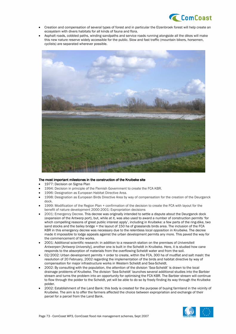
Page 73 - ComCoast WP3, ComCoast flood risk management schemes, Sept 2007
• Creation and compensation of several types of forest and in particular the Elzenbroek forest will help create an ecosystem with divers habitats for all kinds of fauna and flora.
• Asphalt roads, cobbled paths, winding sandpaths and service roads running alongside all the dikes will make this new nature reserve widely accessible for the public. Slow and fast traffic (mountain bikers, horsemen, cyclists) are separated wherever possible.
The most important milestones in the construction of the Kruibeke siteThe most important milestones in the construction of the Kruibeke siteThe most important milestones in the construction of the Kruibeke siteThe most important milestones in the construction of the Kruibeke site
• 1977: Decision on Sigma Plan
• 1994: Decision in principle of the Flemish Government to create the FCA KBR.
• 1996: Designation as European Habitat Directive Area.
• 1998: Designation as European Birds Directive Area by way of compensation for the creation of the Deurganck dock.
• 1999: Modification of the Region Plan + confirmation of the decision to create the FCA with layout for the benefit of nature development 2000-2001: Expropriation decisions
• 2001: Emergency Decree. This decree was originally intended to settle a dispute about the Deurganck dock (expansion of the Antwerp port), but, while at it, was also used to award a number of construction permits ‘for which compelling reasons of great public interest apply’, including in Kruibeke: a few parts of the ring-dike, two sand stocks and the bailey bridge + the layout of 150 ha of grasslands birds area. The inclusion of the FCA KBR in this emergency decree was necessary due to the relentless local opposition in Kruibeke. The decree made it impossible to lodge appeals against the urban development permits any more. This paved the way for the commencement of the works.
• 2001: Additional scientific research: in addition to a research station on the premises of Universiteit Antwerpen [Antwerp University], another one is built in the Scheldt in Kruibeke. Here, it is studied how cane responds to the absorption of materials from the overflowing Scheldt water and from the soil.
• 02/2002: Urban development permits + order to create, within the FCA, 300 ha of mudflat and salt mash: the resolution of 20 February, 2002 regarding the implementation of the birds and habitat directive by way of compensation for major infrastructure works in Western Scheldt and Sea-Scheldt.
• 2002: By consulting with the population, the attention of the division ‘Sea-Scheldt’ is drawn to the local drainage problems of Kruibeke. The division ‘Sea-Scheldt’ launches several additional studies into the Barbier stream and turns the problem into an opportunity for optimising the FCA KBR. The Barbier stream will continue to flow through the polder to the Scheldt, yet will be able to do so by freely finding its way through the Kruibeke polder.
• 2002: Establishment of the Land Bank: this body is created for the purpose of buying farmland in the vicinity of Kruibeke. The aim is to offer the farmers affected the choice between expropriation and exchange of their parcel for a parcel from the Land Bank.

Page 74 - ComCoast WP3, ComCoast flood risk management schemes, Sept 2007
• 2003: Commencement of the works: filling up of ground stock 1 using ground spoil originating from the excavation of the Ketenisse polder (this polder removal was carried out within the framework of nature compensation for the construction of a container quay in the port of Antwerp).
• 18/03/2003: Commencement of ring-dike works.
• 27/03/2003 Works stopped by mayor Denert.
• 28/03/2003 The court rejects the order on the grounds of being illegal and prohibits mayor Denert from committing any further acts of delay.
• 2004: Within the framework of the creation of the grasslands birds area, the division ‘Sea-Scheldt’ enters into maintenance contracts with farmers that were forced to give up parcels within dike boundaries for the creation of the FCA. In exchange for an indemnity and the proceeds of the parcel, they turn their fields into pastureland and, while working the grounds, are mindful of those birds and nesting places.
• 09/2004: Commencement of implementation of the Hamme Lippenbroek pilot project: the division ‘Sea-Scheldt’ creates a FCA with CRT (controlled reduced tide area) in Hamme. Universiteit Antwerpen [Antwerp University] gathers data allowing for the optimising of the CRT portion of the FCA KBR. The division ‘Nature’ ensures the financing.
• 2005: Creation of the management committee on grasslands birds in the FCA KBR. All sectors involved (agriculture, environment, the town of Kruibeke, division ‘Sea-Scheldt’, division ‘Nature’, Vlaamse Land Maatschappij [Flemish Land Agency]) get together every month to discuss the developments within the FCA KBR.
• 2005: An ‘Overall Plan’: integrated plan of implementation and timing of the FCA KBR is drawn up in preparation for the EER.
• 2006: Environmental Effects Report to obtain the remaining urban development permits is finished and approved.
• 2007: New building permits for the construction of the water inlet and outlet constructions, the realisation of the Bird Habitat Area and the completion of the ring dike.
Management and maintenance aspectsManagement and maintenance aspectsManagement and maintenance aspectsManagement and maintenance aspects The management of the future flood area will be in hands of several actors concerned. All monitoring and management aspect concerning the guarantee of the security will be in hands of the initiator of the project, W&Z. It concerns the management of the dikes, dike trenches, in and outlet sluices, A specific management commission FCA KBR will be charged with the implementation and the management of the nature compensations in the area. She will answer for the management of the mud flats and the salt marshes in the tidal areas and the meadow bird areas in the non tidal areas. In first place, in these non tidal areas extensive graze management is foreseen, in the form of maintenance contracts with farmers. Just at a second stage a presence or absence of integrated process management is foreseen with year-round grazing with horses and cattle. Concerning the management of the recreational infrastructures and the interpretation of the transition area between the flood area and the cuesta still further appointments with the local administration level have to be made.
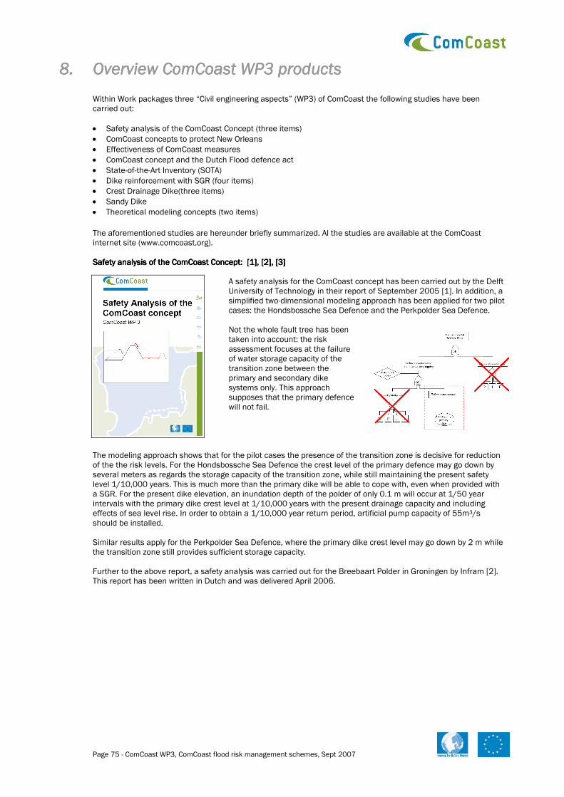
Page 75 - ComCoast WP3, ComCoast flood risk management schemes, Sept 2007
8.8.8.8. Overview ComCoast WP3 productsOverview ComCoast WP3 productsOverview ComCoast WP3 productsOverview ComCoast WP3 products
Within Work packages three “Civil engineering aspects” (WP3) of ComCoast the following studies have been carried out:
• Safety analysis of the ComCoast Concept (three items)
• ComCoast concepts to protect New Orleans
• Effectiveness of ComCoast measures
• ComCoast concept and the Dutch Flood defence act
• State-of-the-Art Inventory (SOTA)
• Dike reinforcement with SGR (four items)
• Crest Drainage Dike(three items)
• Sandy Dike
• Theoretical modeling concepts (two items)
The aforementioned studies are hereunder briefly summarized. Al the studies are available at the ComCoast internet site (www.comcoast.org). Safety analysis of the ComCoast Concept: [1], [2], [3]Safety analysis of the ComCoast Concept: [1], [2], [3]Safety analysis of the ComCoast Concept: [1], [2], [3]Safety analysis of the ComCoast Concept: [1], [2], [3]
A safety analysis for the ComCoast concept has been carried out by the Delft University of Technology in their report of September 2005 [1]. In addition, a simplified two-dimensional modeling approach has been applied for two pilot cases: the Hondsbossche Sea Defence and the Perkpolder Sea Defence.
Not the whole fault tree has been taken into account: the risk assessment focuses at the failure of water storage capacity of the transition zone between the primary and secondary dike systems only. This approach supposes that the primary defence will not fail.
The modeling approach shows that for the pilot cases the presence of the transition zone is decisive for reduction of the the risk levels. For the Hondsbossche Sea Defence the crest level of the primary defence may go down by several meters as regards the storage capacity of the transition zone, while still maintaining the present safety level 1/10,000 years. This is much more than the primary dike will be able to cope with, even when provided with a SGR. For the present dike elevation, an inundation depth of the polder of only 0.1 m will occur at 1/50 year intervals with the primary dike crest level at 1/10,000 years with the present drainage capacity and including effects of sea level rise. In order to obtain a 1/10,000 year return period, artificial pump capacity of 55m3/s should be installed. Similar results apply for the Perkpolder Sea Defence, where the primary dike crest level may go down by 2 m while the transition zone still provides sufficient storage capacity. Further to the above report, a safety analysis was carried out for the Breebaart Polder in Groningen by Infram [2]. This report has been written in Dutch and was delivered April 2006.

Page 76 - ComCoast WP3, ComCoast flood risk management schemes, Sept 2007
The Breebaart Polder has been developed into a wetland area, allowing water to enter from the Eems and Dollard Estuary into the Polder area. Safety is provided by the primary dike as well as the secondary dike that encloses the Polder.
The report describes a safety analysis of this Polder according the method from [1]. In the present case however, failure of the primary dike has been taken into account and has been defined conservatively at an overtopping event of 0.1 l/s/m. In the present situation the total system will fail with a chance of 1/200,000 years, which can be neglected. The return period for inundation of 0.01 m is only 1/6.000 years. The primary dike may be lowered by 1.8 m to attain the present safety standard (which is 1/4000 years at this location) for the whole system (provided that this dike will remain intact). For the present primary dike elevation and 1/4000 year event, a sea level rise of 0.6 m will cause only a limited inundation depth in the polder: 0.3 m.
A risk analysis was carried out as well by Infram for the pilot area in Germany at Neβmersiel [3].
The polder area of Neβmersiel is characterized by primairy dikes and former dikes that may act as secondary dikes and are stretched out over a length of more than 9 km. The width of the transition area between these dikes varies from 300 m to 660 m for the typical cross sections that have been considered.
The safety analysis focused on the capacity of the storage area for the 2% wave run up limiting condition of the secondary dike. Hence it was assumed that failure of the primary and secondary dike will not occur. For this condition failure of the storage capacity can be neglected (< 10-7). As a consequence, inundation depths can be neglected as well. Even after 0.6 m sea level rise failure due to shortage of storage capacity will be very small: 1/250,000 years.
ComCoast concepts to protect New Orleans [4]ComCoast concepts to protect New Orleans [4]ComCoast concepts to protect New Orleans [4]ComCoast concepts to protect New Orleans [4] In [4] a reconnaissance on the potential improvements for the defences of New Orleans St Bernard Parish area has been reported. These improvements focused on ComCoast-like solutions. This reconnaissance was carried out as a M.Sc. Thesis by M. Dijkman and reported in January 2007.
The defence system near St. Bernard Parish area is a broad coastal defence zone, as proposed in ComCoast, with primary and secondary dikes. Hence, analysis of the reasons of failure is highly relevant for the application of the ComCoast concept. Next, potential improvement to this coastal defence was being investigated, taking into account various ComCoast alternatives.
The failure analysis showed that the primary dike experienced most damage and most probably failed in an early stage. As a consequence surge protection was ineffective. Transitions between the dike and concrete structures proved especially vulnerable. In contrast, the secondary dikes generally had performed relatively well, with only some minor breaches.

Page 77 - ComCoast WP3, ComCoast flood risk management schemes, Sept 2007
For further analysis, an indicative simulation model was set up in order to predict the flooding depth in the residential area of St. Bernard Parish. Hindcast of the flooding depth due to Katrina proved to show a good agreement. An outcome of the study was that from the five ComCoast concepts investigated the concept of an overtopping resistant primary dike, as well as wetland restoration, can be feasible options to mitigate flooding risk for the St. Bernard Parish area. Where possible these options should be combined. From indicative modeling it appeared that the length of the restored wetland should be at least 25 km for sufficient reduction of the storm surge, in combination with relative small water depths. A sensitivity analysis showed that for the Katrina circumstances the surge height is the dominant parameter, rather than the wave height. Effectiveness of ComCoast measures [5]Effectiveness of ComCoast measures [5]Effectiveness of ComCoast measures [5]Effectiveness of ComCoast measures [5]
This study was carried out by Infram en reported in august 2007. Due to climate change the average sea level is expected to rise and the wind climate is expected to intensify. This will cause a more severe impact of waves on flood defences. Until now, conventional dike improvements (step-by-step heightening) compensate for increasing hydraulic loads or reduction in flood risk. However, with ongoing rise in sea level conventional dike improvement might not be the optimum way to strengthen coastal flood defences. From both economical and technical points of view, alternatives might be desired. The aim of this study is to determine the effectiveness of different wave impact reduction measures. The effectiveness gives an answer to the question whether a measure has any effect on the level of safety of a flood defence. Wave energy can be reduced before arriving at the embankment, wave energy can be absorbed at the outer slope by applying rough materials on the outer slope or wave overtopping can be admitted. In the latter case the inner slope of the embankment has to be strong enough to cope with the overtopped water. Apart from above mentioned measures there is also the possibility to raise the crest level of a dike to decrease the degree of overtopping.
This study takes into account three case study situations: Petten (North Sea), Sexbierum (Wadden Sea) and Noorddijk (Western Scheldt). These three situations are characteristic for three different loading situations in the Netherlands: an open sea, a shallow sea and an estuary. The question whether the measure is also efficient for society as a whole can only be answered when also costs and all other relevant effects (i.e. the effect on nature and environment, the perception of people on their safety level) are taken into account. The calculations show that the effectiveness of a breakwater or a reef (or foreshore) is only effective when they have large dimensions. This is caused by the fact that the difference in sea level in daily circumstances and storm conditions is large in the discussed case study situations. For a breakwater this means that the crest level should be relatively large. For a reef this means that the reef should be relatively wide. Since the wave heights in the Wadden Sea and the Western Scheldt are relatively small a lowcrested breakwater or a reef are not effective in these cases. ComCoast concept and the Dutch Flood Defence Act [6]ComCoast concept and the Dutch Flood Defence Act [6]ComCoast concept and the Dutch Flood Defence Act [6]ComCoast concept and the Dutch Flood Defence Act [6] The ComCoast solution of a more wave overtopping fits with the requirements under the Ducth Flood Defence Act. The more wave overtopping dike idea consists of strengthening of the dike instead of raising it. If the inner slope of the dike is also strengthened, wave overtopping during storm can occur causing little or o damage. Water will pass over the dike and onto the land beyond. If an inner dike is located behind the sea dike, this water can be properly collected and drained. Additional measures will have to be taken to collect and drain the water if there is no inner dike or if there are houses located immediately behind the dike. It is not necessary to adapt the Act in order to realize a more wave overtopping dike. The amount of water that is permitted to flow over the dike depends on different factors, i.e.:
1) The first (actual primary) dike must not fail, but remain in place and prevent flooding. ComCoast has investigated how to strengthen a dike in such a way that little or no damage will occur on the inner slope, with regard to the failure mechanism erosion and sliding of the inner slope. In order to guarantee the safety, other failure mechanisms must be taken into account.
2) The system of two dikes (actual primary dike and inner dike) and the area included between the two dikes forms the new “primary” sea defence, which must comply with the requirements under the Flood Defence Act.

Page 78 - ComCoast WP3, ComCoast flood risk management schemes, Sept 2007
3) The first dike should be passable and accessible during extreme conditions, which correspond to the conditions at the norm frequency as given in the Flood Defence Act.
StateStateStateState----ofofofof----thethethethe----Art inventory (SOTA) [7]Art inventory (SOTA) [7]Art inventory (SOTA) [7]Art inventory (SOTA) [7]
The SOTA was carried out by Royal Haskoning & Infram and the final report was delivered in September 2005. The SOTA comprises the acquisition of information relevant to ComCoast, with emphasis on WP3 and zooming in on a preliminary inventory of possible technical concepts for strengthening of overtopping dikes. The information scan involves 160 references on technical and general aspects, including the relevancy of these references for ComCoast against the background of different ComCoast options: foreshore recharge, wave overtopping reduction, strengthening of the defence system and managed realignment.
After an introduction of possible failure mechanism, emphasis has been laid at the identification of potential protection systems for the inner slope of the dikes, which have been summarized in Fact Sheets.
The following types of protection systems have been identified:
• Reinforced grass with open geotextile systems
• Gabion systems
• Open concrete block mattress systems
• Rockfill protection systems
• Pitched revetments
• Geosystem tubes and mattresses
• Open asphaltic systems
• Impervious asphaltic systems
• Concrete systems An illustrative outcome of a the preliminary analysis is the high potential feasibility of reinforcement of the present grassed slopes. The SOTA acknowledges the importance of a wider judgement framework, including the full scope of dike failure mechanisms (however, at later stages of the ComCoast research such a framework had not been taken into account). As a major conclusion the SOTA identifies the need for further targeted research and innovative solutions.

Page 79 - ComCoast WP3, ComCoast flood risk management schemes, Sept 2007
Reinforcement with SGR: Development of alternative overtoppingReinforcement with SGR: Development of alternative overtoppingReinforcement with SGR: Development of alternative overtoppingReinforcement with SGR: Development of alternative overtopping----resistant sea defences, elaboration of Smart resistant sea defences, elaboration of Smart resistant sea defences, elaboration of Smart resistant sea defences, elaboration of Smart Grass Reinforcement Concept [8]Grass Reinforcement Concept [8]Grass Reinforcement Concept [8]Grass Reinforcement Concept [8]
The development of a strengthening methodology with the SGR was done by the consortium of Royal Haskoning & Infram. The final report was delivered in November 2005. Specific knowledge of grass and geosynthetics was also incorporated, e.g. by FlevoGreenSupport and by Huesker Synthetic. The report deals with two new innovative ‘smart grass’ systems, i.e. grass/clay substrates that are reinforced with:
• a geogrid system
• a geocell system The denotation ‘smart grass’ relates to:
• significant reinforcement of the grass revetment
• easy installation with minimum disturbance
• high cost-effectiveness
• invisible
• durable
• no adverse environmental impacts The geogrid system is a very strong, open and fine-structured geosynthetic with maximum opportunities for adherence of grass roots. This system is to be placed underneath the upper part of the present grass layer after cutting and lifting of the grass roots. After recuperation of the grass roots during one growing season, the grass/clay/geogrid system (the SGR) is considered to be able to withstand extreme wave overtopping. The geocell system is characterized by a stiff cellular structure with sharp edges, that that can be pushed into the subsoil up to some distance below the surface of the grass/clay layer. This system provides shelter to the grass sods, rather than anchoring of the grass roots. The installation is somewhat simpler than the geogrid system but the geocell system lacks the stiffness in the direction of the attack of the overtopping waves. At the other hand, geocells are less vulnerable for irregular surfaces. The study compares the relative quality of both reinforcement systems with respect to the reference situation of natural grass covers at present dikes. The potential improvements in erosion resistance have been addressed after thorough analysis of critical wave overtopping data. These data, however, do almost fully relate to overflow situations and not to wave overtopping conditions. Strength improvement with the geogrid SGR may not be limited to improvement of surface erosion resistance but also to mitigation of other failure mechanisms such as slip failure. A major part of the study deals with the constructional aspects and risks related to the installation. Other items for the SGR that have been considered are: life time expectancy and functional sustainability, maintenance, indicative impacts on LNC values, relevant experience, required permits and indicative life cycle costs. The latter points to overall costs that can be at least a factor 10 lower than raising the dike crest with a similar safety improvement. Finally, the report sketches an indicative application of the SGR for a pilot location at the Hondsbossche Sea Defence. An overall conclusion is that the SGR may be highly feasible, but further development of the installation and field testing will be required to prove this feasibility. The report presents recommendations on further engineering, pilot testing and final testing at the Groningen sea dike that was to be due in 2007.

Page 80 - ComCoast WP3, ComCoast flood risk management schemes, Sept 2007
Reinforcement with SGR: PlacemenReinforcement with SGR: PlacemenReinforcement with SGR: PlacemenReinforcement with SGR: Placement of Smart Grass Reinforcement at Test Sections Groningen Sea Dyke [9] t of Smart Grass Reinforcement at Test Sections Groningen Sea Dyke [9] t of Smart Grass Reinforcement at Test Sections Groningen Sea Dyke [9] t of Smart Grass Reinforcement at Test Sections Groningen Sea Dyke [9]
In May 2006 the geogrid type SGR was placed at the test sections of the Groningen sea dike by the consortium of Royal Haskoning & Infram. This placement followed the winning of the competitive national contest.
The placement had a highly exploratory and innovative character. The formal report of the placement was delivered in November 2006. The collaborating market parties that participated in the development, i.e. FlevoGreenSupport and Huesker Synthetic, also participated actively in the placement as specialized contractors. Moreover, the Waterboard Hunze en Aa’s provided hosting and general services and incorporated assistance of a local contractor. Four students of the Technical College of Leeuwarden were assigned to the consortium as well and contributed in the preparations, the preliminary test set-up and the installation of the SGR at the test site.
Prior to installation of the SGR, an in-depth analysis was carried out for proper placement techniques and mitigation of risks for placement. This has been reported as an appendix to the report.
The installation of the SGR implied the provision of a 4 m wide reinforced section next to the unreinforced section. This reinforcement included part of the outer slope (anchoring), the crest and the inner slope up to a level of about 1.5 m above the service road. The provisional character of the installation included the placement methodology with ‘Big Rolls’. This method consisted of Big Rolls that were obtained by winding up a thin layer of grass that was cut from the site. After placement of the geosynthetic the Big Rolls were unwind by which the upper layer of the grass cover was reinstalled again. This methodology allowed a maximum thickness of the grass layer of 5 cm (which is not necessarily the optimum thickness). The cutting procedure was optimized at the site and worked satisfactorily as regards the extremely dry condition of the grass sods. Due to the extremely dry and hot month of July 2006, the reinforced grass section needed additional care during the summer: sprinkling with water and fertilization. For comparison reasons, this treatment was also applied at the unreinforced grass section. Adjacent to the test section with the SGR a small monitoring section of SGR was installed as well. This section allowed intermediate inspection of the intertwinement of the grass roots with the geosystem. Prior to the tests, it could be observed that grass roots had grown through the geosynthetic.

Page 81 - ComCoast WP3, ComCoast flood risk management schemes, Sept 2007
Reinforcement with SGR: Design, construction and calibration of the wave overtopping simulator [10] and further Reinforcement with SGR: Design, construction and calibration of the wave overtopping simulator [10] and further Reinforcement with SGR: Design, construction and calibration of the wave overtopping simulator [10] and further Reinforcement with SGR: Design, construction and calibration of the wave overtopping simulator [10] and further analysis of velocity and flow depth measurements [11]analysis of velocity and flow depth measurements [11]analysis of velocity and flow depth measurements [11]analysis of velocity and flow depth measurements [11]
An essential part for testing of the SGR was the wave overtopping simulator, a new device based on the concept of Dr J.W. van der Meer, developed further by Infram and constructed by Nijholt Steelworks Heerenveen. A 1 m wide prototype of this simulator was constructed in the summer of 2006, after which the 4 m wide simulator was realized. In December 2006 this simulator was pre-tested at the Groningen sea dike and was made ready for real testing from February 2007 onwards. The simulator proved to be successful during the tests.
The basic idea of the simulator is rather simple: a high storage tank that is filled with water, which is released from time to time to reproduce the wave overtopping tongues. The number of variables, however, is very large and need to be set accurately. By variation of the filling rate of the vessel, all overtopping tongues that can occur during a storm can be reproduced, i.e. the full stochastic distribution of the overtopping tongues.|A well-controlled process could be obtained by applying a fixed filling discharge, corresponding to the time-averaged overtopping rate (up to 50 l/s/m).
Knowledge on the stochastics of wave overtopping is sufficient nowadays. However, still some items need to be cleared on velocities and flow depths of the overtopping tongues at the inner slope of the dike. These could not be verified during the tests, due to malfunctioning of the measuring instruments as a consequence of the high turbulence and aeration of the flow. Design variables of the simulator were a.o.: the height of the simulator, the height of the outflow opening, the cross-sectional shape, the size and operation requirements of the valve and the geometry of the outflow section. To compensate for the decrease in pressure head during the outflow the cross-section was made wedge-shaped. The opening of the hydraulically powered opening valve of the simulator was done by joy-stick operation, following a prescribed timetable for each simulated storm. This timetable contained a schematic representations of all wave volumes to be reproduced during the storm. The simulator reproduced wave volumes up to 3.5 m3 per m width of the dike. The report gives a comprehensive review of the simulator design, calibration of a 1 m wide prototype simulator, construction and field performance, as well as a review of the measurements and analysis of the wave overtopping tongue characteristics. This analysis has been elaborated further and reported in-depth in the M.Sc. Thesis of G. Bosman [11].

Page 82 - ComCoast WP3, ComCoast flood risk management schemes, Sept 2007
In his thesis, Gijs Bosman analysed the measuring data from the ComCoast field tests. By applying an improved filtering technique, he succeeded in reducing some of the large scatter of the measuring data. However, the quality of the measurements remained poor, probably due to the difficult measuring circumstances (extreme turbulence, high aeration rate). Next, Bosman analysed a discrepancy between earlier wave overtopping data from Van Gent [11b] and from Schüttrumpf et al. [11c], under the guidance of Dr J.W. van der Meer. As a major outcome Bosman demonstrated that the discrepancy can be solved by some corrections in the measurements of Schüttrumpf and by taking into account the upstream slope angle of the dyke. These slopes were different in both research studies: 1:4 for Van Gent and 1:6 for Schüttrumpf. The analysis of Gijs Bosman resulted in new prediction formulae for wave overtopping behaviour, which included the effect of the upstream slope angle. These formulae can be used to set-up the wave overtopping simulator more accurately for further testing in the future.
Reinforcement with SGR: Wave overtopping erosion tests at Groningen Sea Dyke [12] Reinforcement with SGR: Wave overtopping erosion tests at Groningen Sea Dyke [12] Reinforcement with SGR: Wave overtopping erosion tests at Groningen Sea Dyke [12] Reinforcement with SGR: Wave overtopping erosion tests at Groningen Sea Dyke [12]
The erosion field tests on the SGR and the unreinforced grass at the Groningen sea dike were carried out February and March 2007. This timing was chosen such that the grass was at winter condition. The tests were carried out by the consortium of Royal Haskoning (leading party) and Infram. In addition, an erosion test on bare clay was carried out as well. Report [6] gives an a broad description of the test related issues and includes summaries of additional investigations (geotechnical, grass, infiltration), as well as a preliminary analysis of the results.
The Waterboard Hunze en Aa’s provided hosting and general services. Specialized assistance was obtained by Alterra (grass investigations), Delft Hydraulics (flow measuring equipment) and GeoDelft (soil mechanical and infiltration measurements). Two students, one of the Technical College of Leeuwarden and one of the Van Hall Institute were assigned to the consortium as well.
Due to the unique character of the tests, the field testing received ample local, national and international publicity. A special opening event was organized that boosted external communication and publicity. The arrangement basically included a 4 m wide test section with side walls and scaffolding to allow access, a measuring cabin on top of two storage containers, the wave overtopping simulator and a water circulation system with a maximum pump capacity of 720 m3/hour to fill the simulator. The test arrangement was shifted from the unreinforced to the reinforced (SGR) section, and finally to the bare clay section. A comprehensive measuring protocol was set up for quality assurance, safety control and risk mitigation. The erosion tests were mainly observation tests, so the progression of damage during the simulated 6-hour storms was continuously filmed and with intervals of 2 hours photographed and briefly reported. In addition, the velocities and flow depths of the overtopping tongues were measured. At a later stage these measurements proved to be erroneous however due to the high turbulence and aeration of the flow.

Page 83 - ComCoast WP3, ComCoast flood risk management schemes, Sept 2007
The test program comprised subsequent 6-hour simulated storms in real time, with increasing overtopping discharges. Time-averaged overtopping rates were:
• 0,1 l/s/m
• 1 l/s/m
• 10 l/s/m
• 20 l/s/m
• 30 l/s/m.
After these series no major damage could be observed, at the reinforced, as well at the unreinforced grass sections. Hence, a higher overtopping rate was simulated: 50 l/s/m (the effective overtopping being somewhat less however). As no damage was observed either at the 50 l/s/m test, artificial damage was introduced to the test sections: the grass cover was removed according to various patterns and poles and pickets were placed. At the unreinforced grass section, grass sods downstream of the bare spots were gradually dislodged and distinct gullies were formed that progressed quickly downstream the slope. In the SGR section, damage progression was much less: only limited removal of grass could be observed downstream of the largest bare spot, but gully formation in the subsoil did not occur. This can be explained from the effect of anchoring of the grass roots with the geogrid and the protective function of the geogrid for erosion of the under laying clay. The protection of the clay layer at bare spots by the SGR is in strong contrast to the erosion sensitivity of the bare clay layer without the SGR: at the bare clay section heavy erosion occurred at an overtopping rate of 10 l/s/m. Steep cliffs were formed that progressed towards the crest of the dike, the deepest with a of about 1 m. At the other hand, it must be acknowledged, that the residual strength of the clay layer was more than anticipated thus far. From infiltration tests it could be observed that the clay was rather permeable, in spite of the good clay quality. This was a.o. caused by numerous worm holes and small fissures that crisscrossed the clay layer The outcome of the tests are encouraging for the SGR. In addition, present sea dykes may also be stronger in coping with severe wave overtopping than anticipated thus far. The situation of artificial damage may well match real situations at sea dykes, at which some damage will occur anyhow (sheep, fences, burrowing animals). In that case the presence of the SGR may be decisive for ensuring the stability of the dike. In addition, the SGR may contribute to the resiliency of the dikes. Crest DraCrest DraCrest DraCrest Drainage Dike: theoretical studies [13], [14] and laboratory research [15], [16]inage Dike: theoretical studies [13], [14] and laboratory research [15], [16]inage Dike: theoretical studies [13], [14] and laboratory research [15], [16]inage Dike: theoretical studies [13], [14] and laboratory research [15], [16] In stead of strengthening the dike crest and inner slope, an other innovative way of dealing with increased wave overtopping is to adapt the dike in such a way that peak flows are reduced and the extra overtopping water is diverted away from the inner slope of the dike. This is the basic idea of the crest drainage dike, as proposed by Grontmij and Witteveen+Bos [13], as well as by DHV [14]. The concept by Grontmij and Witteveen+Bos has not been elaborated further, whilst the concept by DHV was selected for further research.
The concept of Grontmij and Witteveen+Bos [13], deals with a stilling basin near the downstream part of the crest. This stilling basin has three functions: 1. energy dissipation, reducing the flow velocities at the inner slope; 2. collection and redistribution of flow between overtopping flow and drainage flow; 3. attenuation of peak flows.
Typically, the stilling basin is provided with a steel slab for a better containment of the peak flows into the stilling basin. The embedment of the stilling basin into the crest of the dike will not affect the landscape.
Page 84 - ComCoast WP3, ComCoast flood risk management schemes, Sept 2007
More or less the same principle, however extended over the full width of the dike crest, is the Crest Drainage Dike concept, as proposed and developed by DHV. This principle aims at reducing the peak flows over the inner slope of the dike and provides draining facilities. The theoretical report [14] of DHV was formally presented in November 2005 within the framework of the national contest and was awarded with further laboratory research. The laboratory research was carried out by the Leichtweiß-Institute for Hydraulic Engineering and Water Resources (LWI) and the Technical University Delft (TUD).
The Crest Drainage Dyke typically shows a wide and shallow concrete crest, able to contain excess overtopping water and a drain that diverts a part of the excess water from the inner slope. This water can be drained towards the inner toe of the dike of to the outer slope.
The action is twofold:
• The water peak flows are attenuated by the buffer capacity of the basin at the crest;
• The drain adds further to the attenuation of the peak flows. After analysis of the wave overtopping characteristics, the design considerations focused on the required shape and width of the crest structure, on the position and dimensions of the drain facility and on the stability of crest and dike. Next in [14] a preliminary design has been presented, showing a concrete crest without and with a drain structure. The dimensions have been set at a time-averaged wave overtopping rate of 15 l/s/m. By the restricted depth of the concrete basin, e.g. 0.8 m, the crest can be used as a promenade. The cost estimate showed construction costs: order of magnitude € 1500 to 2000 per m dike, which is considerably lower than the costs for traditional dike reinforcement. In addition, maintenance costs have been assessed for cleaning of the concrete crest and for flushing of the drain pipes. In the M.Sc. Thesis of P. van Steeg [15] the wave overtopping aspects of the Crest Drainage Dyke have been investigated by theoretical and laboratory research. This report was issued in May 2007. The Thesis also addresses the physical background of the concept and presents a comprehensive analysis of the wave overtopping theory for traditional dikes. The laboratory tests sustain the theoretical background of a model that describes the overtopping attenuation. This model has been implemented in a numerical program. The numerical predictions proved to be well in line with the observations. Hence, the numerical program was used for two case studies: the Hondsbossche Sea Defence and the Perkpolder Sea Defence. These case studies show a better performance of the Crest Drainage Dike for the situation in which wave overtopping is relative frequent but not too intense, which is characteristic for the Perkpolder situation.

Page 85 - ComCoast WP3, ComCoast flood risk management schemes, Sept 2007
From the simulations it appears that the reduction in crest level by the Crest Drainage Dike is lower than assumed in [14]. As a consequence the dimensions of the crest basin, as well as the drainage capacity, should be increased for obtaining sufficient effectiveness. The small-scale hydraulic model tests at LWI [16], comprised the following work:
• Variation of shoreward slope to adopt various existing and design conditions
• throughout the partner countries of ComCoast;
• Optimisation of the shape and size of the basin, the side walls and the
• openings for seaward drainage; incl. variations of depth and width of the
• basin to explore the possibility of increasing the buffer capacity of the basin;
• Quantification of extreme storm conditions to optimise the amount of overtopping
• water trapped in the basin to the amount reaching the inner slope
• by accounting for most unfavourable wave grouping conditions;
• Identification of undesired outflow and other undesired conditions under
• the most unfavourable storm conditions;
• Measurement of the pressure field around the entire crest structure in order
• to identify possible weak spots for local erosion, incl. uplift pressures.
The results of the laboratory research at LWI [16] will be soon available. Sandy Dike [17]Sandy Dike [17]Sandy Dike [17]Sandy Dike [17]
The principle of the sandy dike is to provide a sandy sacrifice layer at the inner slope of the dike. This concept has been proposed within the national contest by Arcadis/Alkyon in their report of November 2005 [17].
The thickness of the sand layer determines the sacrifice capability, i.e. the overtopping rate that can be coped with. The limit state is attained when the scour profile reaches the original dike profile.
The effectiveness of the concept has been modeled in an indicative way and applied to two cases: the Hondsbossche Sea Defence and Westkappelle Sea Defence. For both cases, the computations indicate that a sand layer thickness of 2 m would be able to cope with a time-averaged overtopping of about 10 l/s/m for a 3-hours storm.
The sensitivity of scouring of the sandy layer is large for contraction of the overtopping volume, the overtopping rate, the erosion capacity of the sediment and three-dimensional scouring effects. To clarify this, additional research needs to be carried out. In [10] a cost estimate has been presented and amounts to about € 1000 per m dike, based on 4300 m rehabilitation of dike (Hondsbossche Sea Defence). This figure is very provisional however. Moreover the purchase of additional land for extension of the dike volume is an uncertain factor.

Page 86 - ComCoast WP3, ComCoast flood risk management schemes, Sept 2007
Theoretical modeling concepts [18]Theoretical modeling concepts [18]Theoretical modeling concepts [18]Theoretical modeling concepts [18]
A conceptual model for the effect of reinforced grass was derived by Delft Hydraulics, Infram, GeoDelft and Delft University of Technology (DUT) and reported early 2007. The conceptual model considers surface erosion resistance at the inner slope as well as shear failure parallel to the inner slope.
Surface erosion modeling focuses on unreinforced grass revetments and earlier research by Van den Bos [18b] has been reviewed. Typically, this model considers the erosion of bare spots of typically 0.2 m at which grass sods are not present. The outcome of this model is in line with the findings of the wave overtopping erosion tests [12], i.e. that no major damage will occur at an overtopping rate of 30 l/s/m.
The influence of the geogrid can be attributed via an additional cohesion coefficient in an expression for the critical erosion flow velocity, by which this velocity is increased..
In [18] shear failure parallel to the surface for unreinforced grass is not included. However, a more recent report [18c] reviews the superficial sliding model of Young [18d]. The critical thickness for this type of failure (‘turf sliding’) is about 0.2 m, but this method based on Young predicts no failure under the conditions as applied in the tests at the sea dike [12]. This corresponds to the findings of the tests. A set-up for a model that considers the effect of the geogrid for the failure mode of shear failure, is subject of the MSc. Thesis of Hinostroza [18e]. The model seems promising, but still needs further refinement and calibration in order to be usable for quantitative predictions. The thesis will be finished by December 2007. ReferencesReferencesReferencesReferences
[1] TNO/DUT: Safety Analysis of the ComCoast concept, ComCoast, WP3, September 2005. [2] Infram: Safety computation of the ComCoast Concept of Breebaart-polder, ComCoast, WP3, 05i105, April
2007. [3] Infram: Safety analysis of ComCoast Concept at Neβmersiel,ComCoast, WP3, 05i105, April 2006. [4] Dijkman, M: Protecting St. Bernard Parish, New Orleans, Revision of the Coastal Defence zone,Delft
University of Technology, MSc thesis, Arcadis, 1024086, January 2007. [5] Infram: Effectiveness of ComCoast measures,ComCoast, WP3, august 2007. [6] Rijkswaterstaat, Past ComCoast binnen de Wet op de Waterkering, ComCoast, WP3, juni 2007. [7] Royal Haskoning & Infram: State-of-the-art inventory,ComCoast, WP3, September 2005. [8] Royal Haskoning & Infram: Development of Alternative Overtopping-Resistant Sea Defences, Phase 2:
Elaboration of Smart Grass Reinforcement Concept, ComCoast, WP3, November 2005. [9] Royal Haskoning & Infram: Development of Alternative Overtopping-Resistant Sea Defences, Phase 3:
Placement of Smart Grass Reinforcement at Test Sections Groningen Sea Dyke, ComCoast, WP3, November 2005.
[10] Infram & Royal Haskoning: Development of Alternative Overtopping-Resistant Sea Defences, Design,
construction, calibration and use of the wave overtopping simulator, ComCoast, WP3, September 2007. [11] Bosman, G.: Velocity and flow depth variations during wave overtopping, Delft University of Technology,
MSc thesis, August 2007. [11b] Schüttrumpf, H., J Möller and H. Oumeraci, 2002: Overtopping flow parameters on the inner slope of
seadikes, ASCE, Proc. ICCE2002, Cardiff, UK. [11c] Gent, M.R.A. van, 2002: Wave overtopping events at dikes, ASCE, Proc. ICCE2002, Cardiff, UK.
Page 87 - ComCoast WP3, ComCoast flood risk management schemes, Sept 2007
[12] Infram & Royal Haskoning: Development of Alternative Overtopping-Resistant Sea Defences, Wave Overtopping Erosion Tests at Groningen Sea Dyke, ComCoast, WP3, September 2007.
[13] Grontmij & Witteveen +Bos: Approach to the innovative design of an overtopping discharge resistant
dike,ComCoast, WP3, I&M-99360784/MK/xs, rev.F0, May 2007. [14] DHV: Innovative concept overtopping dike: Crest Dainage Dike, Theoretical Study ComCoast, WP3,
November 2005. [15] Steeg, P, van: Wave overtopping aspects of the Crest Drainage Dike, A theoretical, numerical and
experimental research,Delft University of Technology, MSc thesis, May 2007. [16] LWI, Hydraulic Model Tests for Crest Drainage Dike,ComCoast, WP3, expected by oktober 2007. [17] Arcadis & Alkyon: Innovative concept of an overtopping resistant dike, Sandy dike, ComCoast, WP3,
110403/WA5/6N9/100090/001, November 2005. [18] Delft Hydraulics/Infram/GeoDelft/DUT: Conceptual model for reinforced grass on inner dike slopes,
ComCoast WP3, background report, 2007.
[18b] Bos, W. van den (2006): Erosion Resistance of grass revetments during wave overtopping, Delft University of Technology, MSc thesis (in Dutch), January 2006. [18c] Infram/Delft Hydraulics/GeoDelft: Wave overtopping and strength of inner slopes of dikes SBW, Rapport
Predictiespoor, 05i028, March 2007 (in Dutch). [18d] Young, M.J. (2005): Wave overtopping and grass cover layer failure on the inner slope of dikes,Unesco-IHE,
MSc Thesis WSE-CEPD-05.03, Delft. [18e] Hinostroza, S.M.: Reinforced grass on inner dike slopes, Delft University of Technology, MSc thesis,
expected by December 2007.

Page 88 - ComCoast WP3, ComCoast flood risk management schemes, Sept 2007
Copyright Copyright Copyright Copyright
ComCoast flood risk management schemes, September 2007
Copyright
All rights reserved. No part of this publication may be reproduced, stored in
a retrieval system, or transmitted, in any form of by any means, electronic,
mechanical, photocopying, recording and/or otherwise, without the prior
written permission of Rijkswaterstaat, lead partner of the ComCoast project.
It is allowed to quote data from this publication in order to be used in
articles, essays and books, unless the source of the quotation, and, insofar
as this has been published, the name of the author, are clearly mentioned: “
© ComCoast-publication ‘date’, Rijkswaterstaat, the Netherlands”.
Liability
Rijkswaterstaat and all contributors to this publication have taken every
possible care by the preparation of this publication. However, it cannot be
guaranteed that this publication is complete and/or free of faults. The use of
this publication and data from this publication is entirely for the user’s own
risk and Rijkswaterstaat hereby excludes any and all liability for any and all
damage which may result from the use of this publication or data from this
publication, except in so far as this damage is a result of intentional fault or
gross negligence of Rijkswaterstaat and/or the contributors.
Published by Rijkswaterstaat DWW,
PO BOX 5044, 2600 GA Delft, The Netherlands


![.Noah's Flood WTJ2004[1]](https://static.fdokumen.com/doc/165x107/631c39e73e8acd997705cf6b/noahs-flood-wtj20041.jpg)