Coatings in Dentistry—A Review of Some Basic Principles
22
Coatings 2012, 2, 138-159; doi:10.3390/coatings2030138 coatings ISSN 2079-6412 www.mdpi.com/journal/coatings/ Review Coatings in Dentistry—A Review of Some Basic Principles Karl-Johan M. Söderholm Department of Restorative Dental Sciences, College of Dentistry, 1395 Center Drive, PO Box 100415, Gainesville, FL 32610, USA; E-Mail: [email protected]; Tel.: +1-352-392-0575; Fax: +1-352-846-1643 Received: 8 May 2012; in revised form: 11 June 2012 / Accepted: 6 July 2012 / Published: 26 July 2012 Abstract: Different coatings are used in dentistry in an attempt to prevent caries, improve bonding of restorative materials to tooth tissues, and coat implant surfaces in efforts to speed up osseointegration. These are just a few of the many coating applications used in dentistry. The intention of this review is not to cover the entire field of different coatings used in dentistry, because that topic is just too big to be covered in one single paper. Therefore, this review aims to highlight some fundamental coating principles and present these principles to an audience consisting mainly of dentists. To do so, this review will focus on the fundamental principles of coatings, namely surface properties/adhesives in general, since these topics form the foundation for most coating procedures used in dentistry. Keywords: Lennard-Jones formula; silane coating; acid-base induced bonding 1. Introduction Different types of coatings are used in dentistry to prevent the development of carious lesions, tooth surfaces are coated with fluoride varnishes [1] and/or resins [2]. In the case of fluorides, fluoride ions may diffuse from the coating into the surface of the tooth, thereby improving the acid resistance of the tooth surface [3]. Different resins can also be used as adhesives to enhance bonding between tooth surfaces and different restorative materials [4,5]. By placing a coating on some surfaces one may also be able to modify a color and make a surface less receptive to staining [6]. In order to achieve chemical bonding between many ceramic surfaces and resins, silanes are used as coating agents [7,8]. Implants are often coated with different components to enhance the interaction between the implant and the surrounding bone [9,10]. Surfaces can also be bombarded with ions to increase the hardness of OPEN ACCESS
-
Upload
khangminh22 -
Category
Documents
-
view
2 -
download
0
Transcript of Coatings in Dentistry—A Review of Some Basic Principles

Coatings 2012, 2, 138-159; doi:10.3390/coatings2030138
coatings ISSN 2079-6412
www.mdpi.com/journal/coatings/
Review
Coatings in Dentistry—A Review of Some Basic Principles
Karl-Johan M. Söderholm
Department of Restorative Dental Sciences, College of Dentistry, 1395 Center Drive, PO Box 100415,
Gainesville, FL 32610, USA; E-Mail: [email protected]; Tel.: +1-352-392-0575;
Fax: +1-352-846-1643
Received: 8 May 2012; in revised form: 11 June 2012 / Accepted: 6 July 2012 /
Published: 26 July 2012
Abstract: Different coatings are used in dentistry in an attempt to prevent caries,
improve bonding of restorative materials to tooth tissues, and coat implant surfaces
in efforts to speed up osseointegration. These are just a few of the many coating
applications used in dentistry. The intention of this review is not to cover the entire field of
different coatings used in dentistry, because that topic is just too big to be covered in one
single paper. Therefore, this review aims to highlight some fundamental coating principles
and present these principles to an audience consisting mainly of dentists. To do so, this
review will focus on the fundamental principles of coatings, namely surface
properties/adhesives in general, since these topics form the foundation for most coating
procedures used in dentistry.
Keywords: Lennard-Jones formula; silane coating; acid-base induced bonding
1. Introduction
Different types of coatings are used in dentistry to prevent the development of carious lesions, tooth
surfaces are coated with fluoride varnishes [1] and/or resins [2]. In the case of fluorides, fluoride ions
may diffuse from the coating into the surface of the tooth, thereby improving the acid resistance of the
tooth surface [3]. Different resins can also be used as adhesives to enhance bonding between tooth
surfaces and different restorative materials [4,5]. By placing a coating on some surfaces one may also
be able to modify a color and make a surface less receptive to staining [6]. In order to achieve
chemical bonding between many ceramic surfaces and resins, silanes are used as coating agents [7,8].
Implants are often coated with different components to enhance the interaction between the implant
and the surrounding bone [9,10]. Surfaces can also be bombarded with ions to increase the hardness of
OPEN ACCESS

Coatings 2012, 2
139
the substrate surface and by doing so increase the wear resistance and decrease the friction of
orthodontic devices [11]. Bombardments of surfaces with silica coated particles have also been used in
attempts to improve adhesion between resin and ceramic and metal surfaces [12,13]. In addition to the
above clinical applications, coatings are also used in the dental laboratory to facilitate pouring of
impressions with gypsum as well as to facilitate investing wax patterns [14–16].
Based on these examples, it is obvious that coatings is an important topic in dentistry, and that some
kind of review of coatings could be useful. Such reviews are available, but they usually target specific
fields such as different implant coatings and ceramics [9,17–22]. Because there are so many different
types of coatings used in dentistry, a comprehensive review of all types of coatings could become very
voluminous. Therefore, the intention of this paper is to review the topic from a more fundamental point
rather than a specific coating procedural point of view. Consequently, this review will focus on the
fundamental principles of coatings, namely surface properties/adhesives in general, since these topics
form the foundation for most coating procedures.
2. The Surface
Different coatings can be applied as liquids, gases or solids and involve the formation of a
monolayer or several monolayers covering the original surface. The original surface is usually referred
to as the substrate. Combinations of coatings can also be used in order to achieve specific goals. For
example, one coating type can be used to improve the attachment of a second coating to a certain
substrate. Such initial coatings are performed during a so-called priming procedure, and that coating
agent is called a primer. Depending on the properties of a coating, different coatings are used to
improve surface properties such as appearance, adhesion, wettability, corrosion resistance, wear
resistance, scratch resistance and biological interaction.
The primary goal behind any coating is to change the surface properties of the original substrate.
For example, by use of ion-implantation, a surface can be bombarded and saturated with other
ions. These ions, as well as the surface stresses they induce when they are implanted, usually increase
the surface hardness [23]. They may also change the way the surface will interact with the
environment [24]. Titanium implants are often plasma coated with hydroxyapatite in an attempt to
speed up the healing process at the implant-bone interface [25]. Depending on the way a coating is
performed, different thicknesses of the coating can be formed.
When it comes to different coatings, the key challenge is how well the coating will interact with the
substrate and the surrounding environment. The quality of the substrate-coating bond may differ
considerable between different coating techniques. Stresses may also be developed between the
substrate and the coated layer; stresses that over time may cause failures in either the coated layer or
the surface layer of the substrate.
The more one approaches the topic of coating, the more obvious it becomes that the key factors
behind a successful coating are how strong the substrate-coating interface is, how well the coating can
resist physical stimuli and how well the outer surface of the coating interacts with the surrounding
environment. Whether it is an internal surface between a substrate and a coating or an external surface
between the coating and the surrounding environment, both these surfaces have their characteristic

Coatings 2012, 2
140
topography and composition. Surface topography as well as surface composition in turn interact,
because as the surface area increases, so does the number of atoms available for reactions.
Atoms/molecules isolated in space have unsaturated bonds available for reactions, while if the same
atoms/molecules form a cluster, the bonds inside that cluster are balanced by surrounding atoms and
molecules, leaving only the surface bonds available for reactions (Figure 1).
Figure 1. The isolated atoms/molecules to the left will form a cluster if the kinetic energy
of the atoms/molecules decreases below a certain level. During the cluster formation, most
of the reactive sites will stick together, leaving only the surface atoms/molecules available
for new bond formation.
The unsaturated bonds available on any exposed surface result in a certain level of surface reactivity,
usually referred to as surface energy. Surface energy follows thermodynamic rules, suggesting that
nature would like to decrease the energy and increase the entropy. As a consequence, if a liquid with
low surface energy is placed on a surface with high energy, the liquid will spread out on the solid
surface, and by doing so decrease the surface energy level and increase the entropy of the liquid
molecules (Figure 2). During this process a coating is formed.
Figure 2. When a liquid with low surface energy (blue spheres) are placed on a solid
surface with high surface energy, the blue spheres spread out and cover the green spheres.
By doing so, the surface energy of the system decreases while the entropy increases.
What happens in Figure 2 is that the blue spheres in contact with the green spheres remain bonded
to each other, while blue spheres from layers above the bonded blue-green layer are pulled forward in
order to establish new bonds with the green spheres. When that occurs, the liquid spreads over the
solid surface.

Coatings 2012, 2
141
The unit for surface energy is energy/area, often referred to as surface tension (force/length unit).
Depending on the size of the surface, different units are used. The interfacial energy and tension values
are usually expressed in either cgs (centimeter-gram-second) units or SI (meter-kilogram-second) units
as either (erg/cm2 or dynes/cm) or (mJ/m2 or mN/m), respectively. By simple unit conversion, it is seen
that surface energy and surface tension are equivalent. The values of these parameters range from close
to zero to as high as 2000. The lowest values are for liquefied gases. Most organic liquids at and below
their atmospheric boiling points range from 20 mN/m to 40 mN/m. The value for water at 20 °C is
around 73 mN/m, while the highest values are for molten salts and metals, which are generally several
hundred mN/m [26].
By considering differences in surface energy values, it is possible to draw numerous conclusions
regarding the behavior of a coating. For example, what would happen if we could control and change
the surface energy of the solid we would plan to coat? Under such circumstances, it would be possible
to decrease or increase the spreading of a liquid covering the surface. By increasing the surface energy
of the substrate, the surface would become easier to coat. Such an increase in reactivity would also
result in faster reactions with other low surface energetic atoms and molecules present in the
environment. The reaction with these atoms and molecules would in turn decrease the surface energy
below the original surface energy value of the substrate, making it then more difficult to achieve a
good coating with the intended coating material. This example shows the importance of a rigid product
control when coatings are performed.
An example in dentistry of a case where an environmentally related coating can affect the final
clinical outcome is when porcelain-fused-to-metal (PFM) crowns are made. If gold-rich alloys are used
for such PFM crowns, it is important to form an oxide film on the gold surface before the porcelain is
added. Because of the noble nature of gold, oxide-forming elements such as iron, indium and tin, in
concentrations below 1%, are therefore added to these alloys to promote the formation of a thin oxide
film on the gold surface. This oxide film is formed by keeping the gold coping in the oven for a certain
period of time before porcelain is added. However, when base metals are used as a substrate for
gold-rich alloys in PFM crowns, such an extra oxidation should not be performed. The reason is
simply that the less noble base metals oxidize much easier and form a significantly thicker oxide film
than the one formed on high noble metals for a certain oxidation time. Because of the lower strength of
a thicker oxide film, the failure frequency of debonded ceramic layers increased when the first base
metal alloys were introduced [27]. That problem was eliminated by excluding the metal oxidation step
for base metals during the formation of such PFM crowns.
When surface energy and surface tension are discussed, particularly in the case of surface tension, it
is usually assumed that surface tension is uniform for all surfaces that are isothermal and that they are
of the same composition. In general, that assumption is far from true because a solid surface may differ
in temperature and composition locally, explaining why a surface may not have the same surface
energy level at different locations. As a consequence, the coating film could have preferential
spreading directions during coating depending on the heterogeneity of the surface.
As an example of differences in surface reactivity, consider what happens during the silane
treatment of a silica surface [28]. The initial reactivity between silane and a silica surface can be
studied by mixing different concentrations of γ-methacryloxypropyltrimethoxy silane (γ-MPS) with
toluene and then mix specific amounts of these silane solutions with fixed amounts of pyrogenic silica.

Coatings 2012, 2
142
Because of the large surface area of the pyrogenic silica, it is possible to go from an incomplete
monolayer coating to multilayer coatings of γ-MPS on the silica surface. The FTIR peaks collected
from the different coating amounts can then be recorded to identify any differences in peak locations
among the different concentrations. The outcome reveals that the γ-MPS molecules in contact with the
silica surface orient themselves parallel to the colloidal silica surface with which the silane molecules
form two types of bonds (Figure 3). One of these bonds is a siloxane bridge formed via a condensation
reaction between silanol groups of both the silica surface and the hydrolyzed silane. Water forms
during this reaction and soon becomes recaptured by the silanol groups of the silica surface. These
water molecules are not available for additional hydrolyzation reactions of the unhydrolyzed silane
under the experimental conditions used in this example [28]. The intensity of the isolated OH-groups
on the silica surface decreases because of this reaction. Simultaneous with the condensation reaction,
the carbonyl groups of the γ-MPS molecules also form hydrogen bonds. This hydrogen bond formation
results in a peak shift of the carbonyl band from 1718–1720 cm−1 to 1700–1702 cm−1. This hydrogen
bond formation also occurs with the isolated OH-groups. After consumption of the isolated OH-groups,
no additional surface reaction occurs because no further OH-groups are available for additional
condensation reactions or hydrogen bond formation. By use of available information about the number
of OH-groups present on a silica surface [29], and the amount of γ-MPS that was needed to get a
molecular monolayer on the pyrogenic silica [28], it was possible to show that the bond distance
between the Si–OH group and the =CO group of the silane matched the spacing between the nearest
isolated OH-groups on the silica surface. This example suggests that the amount of silane needed for
filler treatment depends on the number of isolated OH-groups available on the filler surface as well as
the size of the silane molecule. The similarity in molecular size of the γ-MPS and the distance between
the isolated OH-groups presented on a silica surface may confirm and explain our empirical
knowledge that γ-MPS is one of the most efficient silanes when it comes to treating silica surfaces.
Figure 3. When a silica surface is coated with silane, the first monolayer deposited on the
surface orients itself parallel with the silica surface (red line) and forms a covalent bond via
a condensation reaction between one silanol group of the silica and one of the silanol
groups of the silane (B). In addition, a hydrogen bond forms also between the carbonyl
group of the silane and an isolated silanol group of the silica surface (A).
The above example reveals some important surface related considerations when it comes to
coatings [30,31]. First, some sites, in the above case the isolated OH-groups on the silica surface,
Coatings 2012, 2
143
should be able to interact with some groups available in the coating [31], in this case the silanol groups
of the silane molecule. The above example further shows that the spacing of the reactive groups on the
substrate surface coincided with the spacing of reactive sites of the silane molecule. If the spacing of
the reactive sites on the silica surface does not coincided with that of the reactive silane molecules,
only one end of the silane would be able to bond to the silica surface. Second, by orienting the
hydrocarbon silane chain surface along the ceramic surface, the surface becomes non-polar. The
hydrophobic surface explains why silane coated glass particles do not sink in water despite their higher
density (Figure 4).
Figure 4. Two jars of water to which equal amounts of silica glass particles (size ~ 1–2 μm)
were added. The particles added to the water in the left jar had been pretreated with γ-MPS,
while the ones in the right jar had not received any treatment. Despite a particle density of
2.8 g/cm3, the silane treated particles float on the water surface because of their
hydrophobic coating, while the untreated particles sedimented into the water. Photo was
taken 1 h after particles were added to water.
The way the silane reacts with the silica surface in the above example shows the importance of
considering local composition and surface energy variations when coatings are considered. For
example, from a dental point of view it should be noticed that the surface tension of water increases by
the presence of dissolved salts, although these increases are small for low concentrations. The surface
tension of water is usually decreased sharply by organic solvents. Both these considerations may vary
well affect common dental treatments such as enamel and dentin bonding.
3. The Origin of Surface Tension
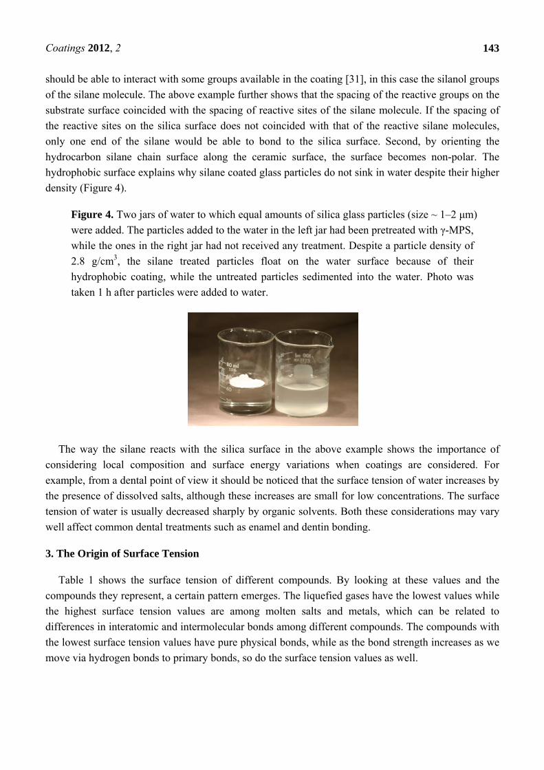
Table 1 shows the surface tension of different compounds. By looking at these values and the
compounds they represent, a certain pattern emerges. The liquefied gases have the lowest values while
the highest surface tension values are among molten salts and metals, which can be related to
differences in interatomic and intermolecular bonds among different compounds. The compounds with
the lowest surface tension values have pure physical bonds, while as the bond strength increases as we
move via hydrogen bonds to primary bonds, so do the surface tension values as well.
Coatings 2012, 2
144
Table 1. Surface tension values of materials in their liquid phase [26].
Liquid T (°C) Surface Tension (mN/m)
Helium −272 0.16 Hydrogen −254 2.4 Oxygen −183 13.2
Silicone (HMDs) 25 15.9 Ethanol 20 22.0 Water 20 72.7
Sodium chloride 801 114
Zinc 360 877
Iron 1520 1700
Different theoretical models can be used to describe the bonding behavior [32]. These models are
relatively similar to each other because they all are based on an equilibrium condition between
attraction and repulsion [33]. The weakest bonds are the so-called “van der Waals” forces, which are
purely physical bonds without any exchange of electrons between the atoms. Even though there are in
principle three types of van der Waals forces, the same physical model can be used to describe them.
According to that model, the attraction is proportional to a decrease in potential energy expressed
as U(r)vdW = −BvdW/r6, while the repulsion by an increase in potential energy is proportional to
U(r)rep = Brep/r12. Based on these relationships, the van der Waals interaction between a pair of these
molecules has the form shown in Figure 5.
The interaction only depends on the separation between the centers of the molecules when they are
in contact, a distance referred as to δ. At large separations, r > δ, where δ represents the distance when
attractive and repulsive potentials are equal, the interaction is attractive, U(r) < 0. For monatomic
molecules, this is due to van der Waals attraction, which falls of with separation of r−6. When r < δ,
overlap of the electron orbits of the two molecules gives rise to a repulsion which increases very
rapidly as the separation decreases. A common analytical representation of these two effects is
represented in Lennard-Jones [34,35] formula:
U(r) = 4 [{ / } − { / } ] The two parameters σ and ε provide a measure of the size and strength of the interaction between
the molecules, and the above formula is applicable for spherical, apolar or weekly polar molecules,
where the attractive force of interaction between two molecules is represented by the slope of the
potential energy function, expressed as:
Fattractive = dU/dr = −24 /r [2{ / } − { / } ]
The interpretation of the curve suggests that at the average distance of molecular separation in a gas
at standard conditions, the intermolecular forces are effectively zero. However, due to thermal motions
in the liquid, the average molecular separation does not coincide with an intermolecular force value at
zero and has instead a finite positive value and is displaced slightly to the right of line A in Figure 5.

Coatings 2012, 2
145
Figure 5. The upper curve is derived by combining U(r)vfW and U(r)rep. At a certain
distance, δ, these two energy levels balance each other, and an energy curve can be plotted,
for which the lowest energy level is equal to ε (Lennard-Jones formula). The derivative of
the energy with respect to the distance, r, between the two centers of gravities of the
atoms/molecules, when plotted as a function of r, forms the force curve shown in lower
graph. A comparison of the two curves reveals that when the force (dU/dr) is zero (lower
graph), the U(r) value is the lowest. Thus, at this r value, the average molecular separation
has occurred in the liquid (A). When the force curve reaches zero the next time (B), the
average molecular separation in its gas phase has been reached.
When it comes to hydrogen bond formation, such bonds require essential direct molecular contact,
and thus become more short ranged than attractive van der Waals forces [36]. An r-dependence curve
for such a bond would thus become very steep and have a deep potential minimum. Metallic bonds,
ionic bond and covalent bonds are even stronger at close range, and particularly ionic interaction
energies are long-ranged varying as 1/r as compared with 1/r6 for van der Waals energies. By
considering these aspects and thereby also the differences in interaction energies between different
types of bonds, it becomes clear that stronger molecular energy results in higher surface tension.

Coatings 2012, 2
146
Considering the above relationships regarding bond formation, it seems reasonable to assume that
the more atoms-molecules that are in close contact with the substrate surface, the more bond sites
would establish and the stronger the adhesion would become. For example, two rough solid surfaces in
contact with each other would be in intimate contact just at relatively few sites, while a liquid and a
gas would be able to approach a contact area up toward 100%. From that point of view, gases and
liquids should be able to form more van der Waals bond sites than the rough solids. However, a second
important consideration is also the quality of the bonds in the different materials. For example, a gold
foil coated with water has a contact area of almost 100%, but these bond sites are transmitted via weak
hydrogen bonds. If rather than being coated with water, the gold foil is covered with another gold foil,
the total foil-foil contact area is most likely substantially smaller than in the water-foil case. However,
because the two gold foils in intimate contact with each other establish metallic bonds at the contact
sites, and because the bonds transferring forces between the two foils are stronger than the hydrogen
bonds, the foils are more difficult to separate than the foil-water interaction.
4. Forces on Solids in Contact with Liquids
Even though gases, liquids and solids are all used as different coatings in dentistry, the most
commonly used precursor is a liquid [37].
When a liquid such as a sealant is placed on a tooth, its physical interaction with the tooth can vary
considerably from case to case making it more difficult to predict the outcome. For example, if a tooth
surface is flat, slightly inclined, and a drop of a sealant is placed on it, it may just ball up and roll of
leaving the surface as it was before it was exposed to a sealant. However, if the surface has been
etched and the sealant is partly stuck to the surface, it may flow down a cusp inclination as a rivulet.
Still differently, the sealant may spread out in all directions as a coherent film, sealing in the surface as
intended. If the surface is etched and can be described as porous surface, and it is put into contact with
the sealant, the sealant may be quickly imbibed into the enamel surface (like water into a sponge) or it
may not be. In fact, it may be possible to coat the porous enamel surface with a sealant with no sealant
entering the pores at all (e.g., saliva contaminated enamel). All these behaviors are important to
consider when it comes to coatings in general, because in order to achieve optimal bonding and
maximal seal, a coating has to wet and adapt to the substrate.
4.1. Young’s Equation
When coatings in general are discussed in the dental literature, a corner-stone tends to be to study
the ability of a liquid to wet a solid by use Young’s equation (Figure 6), first published in 1805. What
is often neglected is that Young’s equation is a rather crude approach, simply because it was developed
before the structure of atoms was known. Because of that, Young’s equation should be regarded as a
way to get a general feeling for surface energetic interactions, but far too crude when it comes to
explaining surface phenomena on a molecular level [38]. According to Young’s equation, the contact
angle of the liquid, θ, is related to the surface energies, i.e., the σ’s, of the three interfaces involved, in
which the system free energy minimization led to Young’s equation. By using “surface tension” rather
than “surface energy” and vectors to describe the magnitude and direction of the interfacial forces
represented by the surface tension, the equation becomes

Coatings 2012, 2
147
cos θ = (σSG – σSL)/σLG
where SG stands for solid-gas interface, SL for solid-liquid interface, and LG for liquid-gas interface.
From such a derivation it is noticed that the normal forces on the interline segment require that the
upward capillary force of σLGsin θ be balanced by an unsymmetrical stress in the underlying solid.
This force is often neglected, but could play a significant role when it comes to the development of
stresses in coated objects.
Figure 6. Force components at a gas-solid-liquid triple point. The blue arrow represents
the σSG surface tension, the red arrow the σSL, and the hypotenuse of the yellow arrows the
σLG. By knowing the contact angle of the liquid, the σLG vector can be split into a force
parallel to the solid surface (σLGcos θ) and one perpendicular to the surface (σLGsin θ). In
order to generate a force balance in vertical direction, the green force vector was
introduced, for which the magnitude then becomes σLGsin θ. By balancing the horizontal
forces, σSG = σSL + σLGcos θ, the expression can be rewritten as cos θ = (σSG – σSL)/ σLG.
By looking at Young’s equation, it seems that wettability predictions are relatively easy to perform.
However, reality has taught us that contact angle determinations are notoriously irreproducible
(Figure 7), which can be related to two key reasons [38].
The first reason is that only the uppermost surface layer of the solid is relevant when it comes to
determining the contact angle, while in reality, solid surfaces have often contaminations that bear little
resemblance to the bulk material beneath. Traces of adsorbing solutes in the fluid phases can play a
similar role. The second reason relates to the method used to measure the θ value. If it is measured as
the liquid advances over a surface the contact angle is larger than when it is receding. For example,
when a drop of liquid is deposited on a solid surface, θ may assume some finite value. Then as more
liquid is added, the interline remains fixed (or “pinned”) so that the apparent contact angle increases.
Finally, an angle is reached for which the interline “jumps” to a new position. The angle just before the
jump occurs is the “static advanced contact angle” and is generally the value reported in the literature.
The reverse situation occurs as liquid is withdrawn from that drop, leading to the “static reduced
contact angle.” Thus the contact angle values differ for an advancing drop vs. a receding drop. The
magnitude of the difference between θA and θR is usually quite large and referred to as contact angle
hysteresis. One way to see the differences between θA and θR is to watch a drop of liquid on a sloping
plane. As the drop moves down the plane, it develops two contact angles. One in the direction it

Coatings 2012, 2
148
moves, and one in the opposite direction. Of these two contact angles, the first one, the θA, is larger,
while the second one, the θR, is the smaller.
Figure 7. Surfaces are usually not absolutely flat as assumed by Young’s equation. As a
drop of water moves uphill (A), the contact angle at the liquid edge tends to be
under-estimated (light blue color) in relationship to a flat horizontal surface (red dotted
line). At the tip of the hill (B), the contact angle assumes a value which is equal to an
assumed flat surface. As the liquid edge moves downhill (C), the contact angle tends to
become over-estimated in relationship to the red horizontal line. The light-blue field
represents what would be perceived as contact angles at the different locations under the
assumption that the surface is flat.
Actual dental surfaces are generally both rough and energetically heterogeneous, and the
heterogeneity may be both non-uniform and anisotropic (Figure 8). In the latter case, the contact angle
may be different depending on the direction of observation. It seems as though the effect of striae of
Retzius and surface perkymata [39] could be important for enamel wettability, even though it is rarely
considered in the dental literature.
Figure 8 shows a close up picture of a cut enamel surface coated with a self-etching primer. The
conclusion we can draw from that picture is that even though the above explanations for contact
hysteresis are plausible, they do not provide, in general, for basic predictions of advancing and
receding contact angles. As a result of various heterogeneities present on a tooth surface, when a fluid
spreads on a surface it occurs through either advanced or receded spread across a solid surface at a
finite rate, and it generally does so in a series of jumps referred to as “stick-slip motion.”
The size scale of the surface heterogeneities is important. When these are large (>10 μm) and
regular, the hysteresis may take on a predictable character, but if the sizes of the heterogeneities are
sufficiently small (<1 μm), other types of analyses must be used. From a dental point of view, this
might be important to consider when dentin bonding is discussed and the wetting of the dentin surface
located under the exposed collagen is considered. Because the dentin tubuli have diameters ranging
from 1.2 μm at the dentin enamel junction to 2.5 μm near the pulp [39], and the content of the tubules
consist of a hydrogel [39], the dentin structure falls between the above limits. The same should also be
true for the enamel rod structure with interrod regions with spacings around 4 μm [39].

Coatings 2012, 2
149
Figure 8. Enamel trimmed with a sand-paper disk (right section) and on which a
self-etching primer has been placed (left section). By looking at the advancing edge of the
primer, one can see a wavy appearance. That appearance can be explained by considering
the behavior shown in Figure 7 and here occurring along the advancing edge. In this case,
different contact angles exist at different locations along the advancing edge of the primer.
Also, spreading can occur in both the x- and y-axes on a surface containing scratches and
different heterogeneities in surface wetting properties.
4.2. Wenzel’s Equation
To come to grip with surface roughness and its impact on wettability, Wenzel [40] already in 1936
assumed that the true solid surface area could be related to the nominal surface area. He did so by
multiplying the nominal surface area with a “rugosity factor”, r. By looking at Young’s equation from
a surface energy point of view, he could minimize the total free energy of the system, which led to a
modified form of Young’s equation in terms of the observed or apparent contact angle, viz.
Cos θapp = r (σSG – σSL)/σLG
The above formula is known as Wenzel’s equation. In order to be valid, the size scale of the
roughness must be sufficiently small. The liquid mass (drop) must also be large relative to the
size-scale of the roughness. Wenzel’s equation reveals that one can increase the wettability of a solid
by a wettable liquid (θ0 < 90), or decrease the wettability of a solid by liquid that does not wet it. Since
r > 1 for a roughened surface, if cos θ is positive (θ0 < 90), the cos θapp will be larger, viz.
cos θapp = r cos θ0
If the liquid is non-wetting, cos θ is negative, and cos θapp will become more negative if the surface
is roughened. The ability to change wetting characteristics by roughening is important in a number of
applications. In particular, if θapp can be made to go to 0°, wetting out will occur. The rugosity factor
required for this to occur is r = cos−1 θ, and since r-values up to 2.0 can readily be achieved, this is
often possible.

Coatings 2012, 2
150
4.3. Cassie and Baxter’s Equation
Cassie and Baxter [41] have developed a similar approach for chemically heterogeneous surfaces.
In the case of a surface with two types of heterogenicities, for which the intrinsic contact angles are
θ1 and θ2 respectively, minimization of the free energy leads to the Cassie-Baxter equation written as
Cos θapp = Φ1cos θ1 + Φ2cos θ2
The two terms, Φ1 and Φ2, represent the area fractions for the two types of surface. The formula can
readily be extended to the case of many different types of patches. One important case is that in which
pores in the surface lead to vapor gaps across which the liquid does not contact the solid. The effective
contact angle over such gaps is 180°, and if the area fraction of them is Φ2, the Cassie-Baxter
equation becomes
Cos θapp = Φ1cos θ1 − Φ2
Structures of this type are the ones that produce “ultra-hydrophobic” surfaces, which are defined as
θ > 130°. Many plant leaves, most notably those of the lotus flower, have ultra-hydrophobic surfaces
owing to a very fine surface structure coated with hydrophobic wax crystals of about 1 nm diameter.
Beads of water roll off the surface, collecting dirt particles as they go, so the lotus leaves are
self-cleaning in a process known as the “lotus effect.” This approach has been mimicked by
researchers who have developed sprays that can make wood, paper, masonry, leather, etc., water
repellant. Maybe future nanotechnology advances in dentistry could lead to such coatings that could be
placed on tooth surfaces and thus minimize plaque adhesion.
From the Cassie-Baxter equation, assume that an etched and rough tooth surface is coated with a
resin. The small pores on the surface may be prefilled by capillary condensation of the wetting liquid,
and the nominal area fraction of the filled pores may be taken as Φ2. Over this area, the contact angle is
0°, causing the Cassie-Baxter equation to take the form
Cos θapp = Φ1cos θ1 + Φ2
which usually results in wetting out, i.e., θ→0°.
Depending on circumstances, one may want to alter the wetting characteristics of a solid material.
All of these approaches can be understood in terms of Young’s equation
Cos θ = (σSG – σSL)/σL
For good wetting, cos θ should be as high as possible (θ→0°), and for poor wetting or non-wetting,
it should be as small (or as large negative value) (θ→180°) as possible.
4.4. Concluding Comments
To Promote Wetting
1. Roughen surface (if θ0 < 90°).
2. Reduce σL with surfactants.
3. Reduce σSL with surfactant adsorption to solid/liquid interface.
4. Chemically modify solid surface (oxygen enrichment).
Coatings 2012, 2
151
To Hinder Wetting
1. Roughen surface (if θ0 > 90°).
2. Increase σSL with surfactant adsorption to solid/liquid interface.
3. Chemically modify solid surface (fluorine enrichment).
When it comes to different coatings used to decrease adherence to cooking utilities and dental
instruments, the usual candidates are plastics, such as polyolefines, vinyls, fluorocarbon and silicones.
These are low surface energy, poorly wettable materials that are difficult to coat or to form adhesive
bonds with. Perhaps the simplest strategy for enhancing their wettability, if the initial contact angle is
<90° (i.e., the right hand side of Young’s equation is positive) is to roughen the surface. Recalling
Wenzel’s equation, roughening multiplies the right-hand side of Young’s equation by the factor r > 1.
Roughening may be accomplished through sanding, grit blasting, chemical etching or plasma etching.
When it comes to improving water wettability of Teflon™, sanding would not be an alternative. The
reason is simply that the smooth surface already exhibits a contact angle of about 110°, resulting in
that the right side of Wenzel’s equation becomes negative (see 1. under “To Hinder Wetting.”).
A surface such as a silicone impression can be difficult to pour with gypsum because water has a
higher surface energy than the silicone impression material. To facilitate such a wetting, the surface
tension of the water can be lowered, which can be accomplished by adding surfactants [14–16]. This
can be achieved by having surfactants present in the impression materials, which can leach out and mix
with the water of the gypsum when the impression is being poured [14]. Another approach is to coat
the surface of the set impression with a surfactant to promote wetting before it is poured [15,16]. For
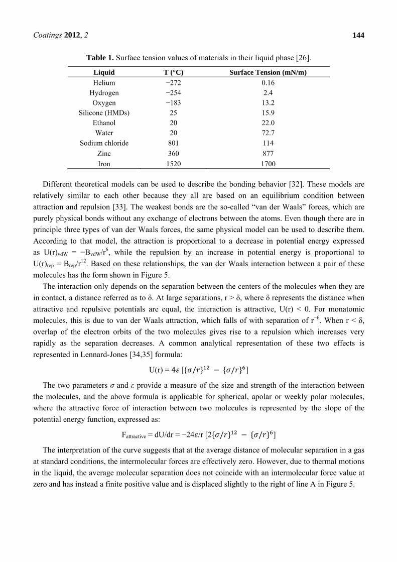
example, water wetting of such an impression can be promoted by the use of a polysorbate surfactant
such as Tween 20, which absorbs on the silicon surface when the impression is rinsed in a water
solution of this surfactant. After light surface drying, the surfactant molecules form a coating with their
hydrophobic molecular structure adhering to the silicone surface, resulting in a “tail-down”
configuration, exposing their hydrated hydrophilic groups to the gypsum, as shown in Figure 9.
Surfactants that promote water wetting by reduction of σL and/or σSL are termed “wetting agents.”
Compounds which adsorb at the solid-liquid interface and maintain favorable orientation of molecules
for promoting wetting when the solid is dried are termed “rewetting agents”.
Figure 9. (a) Chemical formula of Tween 20; (b) Tween 20 interacting with the
impression surface. Orange ellipses: hydrophobic part; Blue ellipses: hydrophilic part.
(a) (b)

Coatings 2012, 2
152
Wetting may also be promoted by chemically modifying the solid surface in various ways that
increase the dry surface energy, σS, decrease the interfacial energy σSl (against the liquid of interest,
usually water), or both. In view of the atomic wetting, increasing σS might be increased by increasing
the oxygen (or nitrogen) content of the surface. One approach is to treat the surface with plasma, i.e., a
gas under moderate vacuum subject to radio frequency waves which disrupt the molecules into free
radicals that react chemically with the solid surface. Oxygen-containing plasmas implant oxygen
functionality (usually in the form of carbonyl and hydroxyl groups) in otherwise low-energy surfaces
such as those of plastics and increase their surface energy and chemical reactivity. These types of
coatings are some examples of coatings being used to treat dental subgingival implant surfaces in an
attempt to make their surfaces more bioactive.
5. Adhesion and Adhesion Mechanisms
Based on the surface properties discussed so far, one can say that adhesion is an extension of
surface wettability and that it refers to solid surfaces sticking together by molecular attraction across
their common interface or a bridging solid or liquid. Because of the surface roughness and the presence
of contaminants of most solids there is usually little direct molecular contact between real solid
surfaces. Therefore there are relatively few points of true contact between the solids where molecular
interactions can occur. The size of the contact surface will depend on the softness of the materials and
the compressive force applied, but in general, sufficient intimacy can be achieved only if one of the
materials, the adhesive, is in liquid form. In other words, adhesion is often initiated through a
liquid-solid interaction [42]. In the case of adhesion, the solid surface to which the adhesive is applied
is termed the adherend (previously referred to as the substrate in connection to surface properties). In
the ideal case, the liquid adhesive completely contacts the solid over all its area, and by doing so the
adhesive displaces any physiosorbed contamination from the surface. One can further idealize the
assumption by assuming that as the liquid solidifies (cures) and remain in contact with the surface.
Wetting and spreading of the adhesive play a key role in the phenomenon of adhesion, but there is
much more to it than that [42]. Today it is believed that there are four principal mechanisms of
adhesion [26] (Figure 10). The first is contact adhesion, in which molecular interaction (physical,
acid-base or covalent) occurs across a more or less smooth, defined interface. This type of adhesion
can be related to the van der Waals interaction discussed earlier, and how the principles behind
Lennard-Jones formula can be extended to other bond types. It is to this physical/chemical mechanism
that most of what follows applies. The second adhesion mechanism is diffusion induced interface
adhesion, generally applicable to the bonding between polymeric adhesives and adherends. Again, the
surface first interacts as under the first type of adhesion. Then, if there is adequate mutual solubility
and adequate contact time between the adhesive and the surface, the mobile adhesive molecules (not
locked into a tightly cross-linked or crystallized structure) can diffuse into the solid surface, leading to
the formation of an interphase of some thickness. The third adhesion mechanism is mechanical
interlocking. In this case, the liquid adhesive penetrates the cavities of a rough or porous adherend, and
upon solidification the adhesive forms effective “hooks” holding the phases together. The final
adhesion mechanism proposed is that of electrostatic interaction across the interface. The contribution
of this mechanism is generally thought to be small. In many situations, two or more of the above

Coatings 2012, 2
153
mechanisms are important. It appears likely that while wetting behavior may directly relate to contact
adhesion (first type), that behavior must also play some role in the remaining mechanisms, because if
good physical intimacy between the phases is not achieved, it will be difficult for the remaining three
mechanisms to be effective.
Figure 10. Of these four adhesion mechanisms, (A) represents contact adhesion, in which
molecules interact (physical, acid-base or covalent), (B) diffusion induced interface
adhesion, (C) mechanical interlocking, and (D) electrostatic interaction across the
interface. Adhesion in general tend to use a combination of these four mechanisms.
Even though the practical consequences of adhesion, and the general approaches usually used to
describe it are macroscopic, its origin is molecular interaction. At the molecular level, adhesion
behavior often appears counter-intuitive, as pointed out by Kendall [43], who suggests three “Laws of
Molecular Adhesion” as follows:
1. All atoms and molecules adhere with considerable force. If two solid bodies approach to
nanometer separations across a vacuum, they will jump into contact.
2. The effect of contaminant “wetting” molecules is to reduce adhesion, or even to make the
bodies repel each other. It would thus appear that “adhesives” reduce molecular adhesion.
3. Molecular adhesion forces are of such short range that various factors, such as roughness,
Brownian motion, cracking, plastic deformation, etc., can have large effects on macroscopic
adhesion while molecular adhesion remains the same.
The first two of these “laws” can readily be understood by considering the section about van der
Waals forces discussed earlier. According to Lennard-Jones formula, attractive forces increase as
molecules approach each other. When molecules first come very close to each other, their electron
clouds start interacting preventing further attraction. At that point the molecules assume an equilibrium
where attractive and repulsive forces balance each other. The second law can be understood by
considering the effect of a thin film of low surface energy covering a surface. For example, when the
first space craft landed on the Moon it was noticed that dust particles bonded to the window surfaces,
something that did not occur on Earth. The reason for that difference can be explained by considering
the effect atmospheric atoms have on glass surfaces on Earth, while there is no such atmosphere on the
Moon containing such molecules [43]. The third law of molecular adhesion addresses how roughness
and surface contaminations of actual macroscopic surfaces prevent intimacy of contact, which is vital
due to the short range of the adhesive forces. If the system is subjected to stress (say shear stress),
micro-cracks will develop at the points of molecular contact. The Brownian motion or diffusion of
molecules or nano-sized portions of the material at the crack tip will continually probe the crack

Coatings 2012, 2
154
configuration. The existence of stresses biases the system against re-healing when microscopic motion
is in the direction of the advancing of the crack.
Many attempts have been made to quantify the strength or the durability of the bond between two
solids by use of different mechanical tests. Such adhesive strength values are of interest for actual
application, but are difficult to pin down, depending always on the method used for its measurement
and the condition of that measurement (e.g., peel test, lap test or pull out test) [42]. It is essential to
keep in mind that adhesion involves many things in addition to the chemistry and the physics of the
interface (or often an “interphase” of finite thickness in which the adhesive and the adherend have
inter-diffused). These include roughness and mechanical interlocking, electrostatic effects, and the
mechanics of the bulk phases near the boundary (e.g., the existence and level of residual stresses), and
the rheology of the disjoining event (plastic vs. brittle failure).
Minimizing the contact angle between adhesive and adherend is important for reasons other than
maximizing the work of adhesion [44]. Often the first step in the formation of a bond between two
solid surfaces by means of an adhesive is the establishment of a liquid bridge. The strength of this
“capillary adhesion” is directly proportional to cos θ. When the liquid bridge is cured to a solid, the
mechanical properties of the bonding are also dependent on the contact angle. The magnitude of the
stress concentration factor (local stress/applied stress) in a stressed lap joint increases quite sharply
with contact angle beyond about 30 degrees [26]. Furthermore, the locus of stress concentration moves
out to the edge of the adhesive layer when the contact angle increases. Such stress concentrations are
not unlike those that exist at the site of vapor inclusions or voids between adhesive and rough porous
surfaces, as shown in Figure 11.
Figure 11. The adhesive placed on the substrate surface in this drawing does not wet
the substrate surface. The reason could be unfavorable differences in surface tension
properties of the adhesive and the substrate, or the presence of contaminants. The defects
introduced will act as stress concentrators and increase the risk for catastrophic failure of
the adhesive-substrate connection.
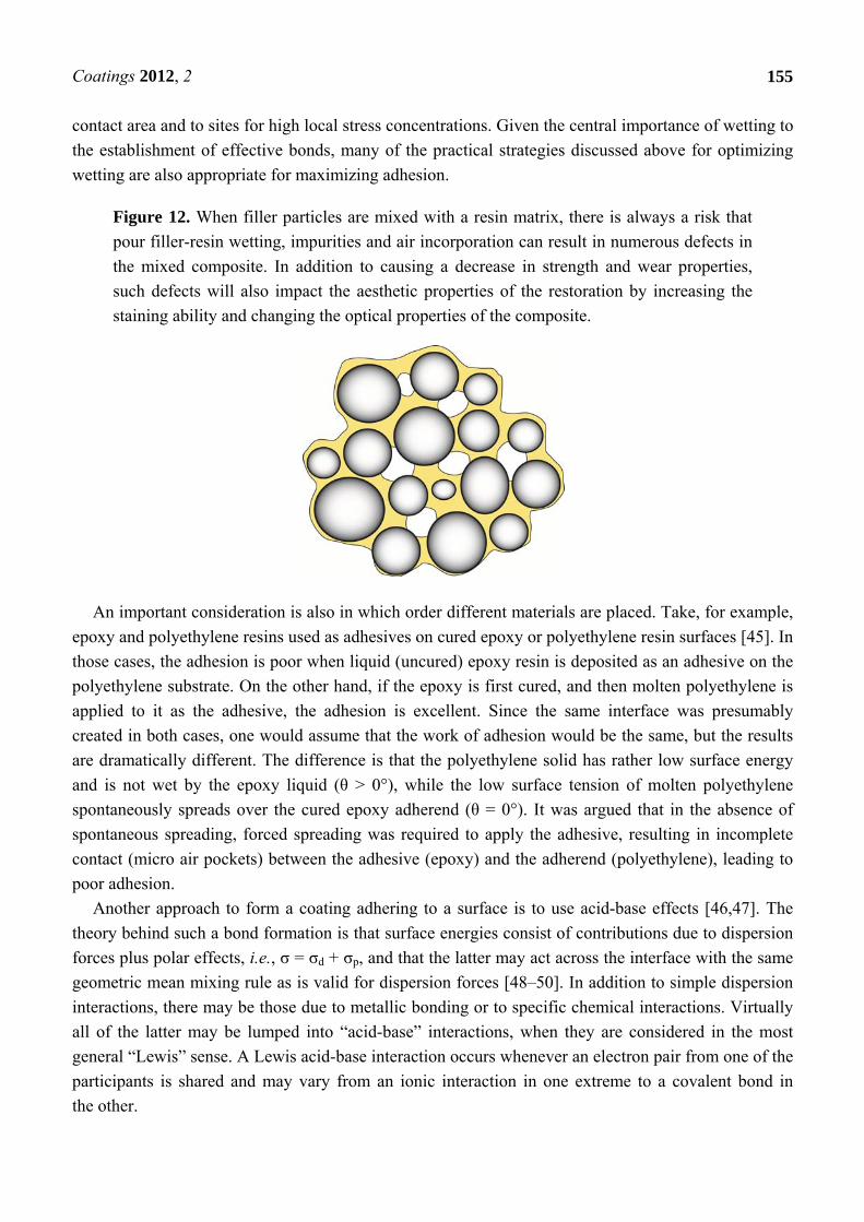
The presence of a row of such voids can lead to a zippering type of failure. Voids are also a serious
problem in the formation of composite materials as shown in Figure 12. The presence of such voids is
minimized when the contact angle is minimized and the best condition is of course θ = 0°.
It is clear in Wenzel’s formula that roughness of the adherend may be either favorable or
unfavorable to good practical adhesion, depending on wettability. If wetting is complete, roughness
will lead to greater molecular contact area, and possibly to mechanical interlocking. On the other hand,
if wetting is incomplete, roughness may produce air pockets or voids leading to reduced molecular
Coatings 2012, 2
155
contact area and to sites for high local stress concentrations. Given the central importance of wetting to
the establishment of effective bonds, many of the practical strategies discussed above for optimizing
wetting are also appropriate for maximizing adhesion.
Figure 12. When filler particles are mixed with a resin matrix, there is always a risk that
pour filler-resin wetting, impurities and air incorporation can result in numerous defects in
the mixed composite. In addition to causing a decrease in strength and wear properties,
such defects will also impact the aesthetic properties of the restoration by increasing the
staining ability and changing the optical properties of the composite.
An important consideration is also in which order different materials are placed. Take, for example,
epoxy and polyethylene resins used as adhesives on cured epoxy or polyethylene resin surfaces [45]. In
those cases, the adhesion is poor when liquid (uncured) epoxy resin is deposited as an adhesive on the
polyethylene substrate. On the other hand, if the epoxy is first cured, and then molten polyethylene is
applied to it as the adhesive, the adhesion is excellent. Since the same interface was presumably
created in both cases, one would assume that the work of adhesion would be the same, but the results
are dramatically different. The difference is that the polyethylene solid has rather low surface energy
and is not wet by the epoxy liquid (θ > 0°), while the low surface tension of molten polyethylene
spontaneously spreads over the cured epoxy adherend (θ = 0°). It was argued that in the absence of
spontaneous spreading, forced spreading was required to apply the adhesive, resulting in incomplete
contact (micro air pockets) between the adhesive (epoxy) and the adherend (polyethylene), leading to
poor adhesion.
Another approach to form a coating adhering to a surface is to use acid-base effects [46,47]. The
theory behind such a bond formation is that surface energies consist of contributions due to dispersion
forces plus polar effects, i.e., σ = σd + σp, and that the latter may act across the interface with the same
geometric mean mixing rule as is valid for dispersion forces [48–50]. In addition to simple dispersion
interactions, there may be those due to metallic bonding or to specific chemical interactions. Virtually
all of the latter may be lumped into “acid-base” interactions, when they are considered in the most
general “Lewis” sense. A Lewis acid-base interaction occurs whenever an electron pair from one of the
participants is shared and may vary from an ionic interaction in one extreme to a covalent bond in
the other.
Coatings 2012, 2
156
It might be interesting to notice that already in 1967 at the General Motors Symposium on
Interfaces, acid-base interaction was suggest as being key for successful car painting [51], which was
achieved when one surface (e.g., the metal surface of the car) acted as a base, while the paint acted as
an acid. The key, however, was to find the right balance between these two interactions. A too weak
interaction resulted in paint that pealed of, while a too strong acid resulted in a paint that pealed of
with a dissolved layer of metal.
The acid-base theory of adhesion has met with qualitative success. For example, when a basic
polymer film, poly(methyl methacrylate), PMMA, was cast against a basic soda glass substrate, poor
adhesion was obtained, but when the acidic polymer, post-chlorinated poly(vinyl chloride), CPVC,
was cast against the basic substrate, adhesion was very strong [26]. In dentistry, the acid-base bonding
approach is used when cements such as polycarboxylate and glass ionomers are used. In these cases,
the acidic polyalkeonic acids donate protons to the hydroxyapatite surface, where the protons react
with the hydroxyl groups and form water. As a result of this reaction, the polyalkeonic acid becomes
negatively charged and lines up parallel to the positively charge apatite surface. This behavior may
very well explain why clinical studies suggest that the best retention rate of bonded Class V
restorations are achieved with glass ionomers, a finding that might be related to the multiple charge
sizes along a single polyalkeonic acid molecule.
References
1. Koch, G.; Petersson, L.G.; Ryden, H. Effect of fluoride varnish (Duraphat) treatment every 6
months compared to weekly mouth-rinses with 0.2 percent NaF solution on dental caries—2-Year
clinical study. Swed. Dent. J. 1979, 3, 39–44.
2. Robinson, C. Filling without drilling. J. Dent. Res. 2011, 90, 1261–1263.
3. Cochrane, N.J.; Cai, F.; Huq, N.L.; Burrow, M.F.; Reynolds, E.C. New approaches to enhanced
remineralization of tooth enamel. J. Dent. Res. 2010, 89, 1187–1197.
4. Cardoso, M.V.; Neves, A.d.A.; Mine, A.; Coutinho, E.; Van Landuyt, K.; De Munck, J.;
Van Meerbeek, B. Current aspects on bonding effectiveness and stability in adhesive dentistry.
Aust. Dent. J. 2011, 56, 31–44.
5. De Munck, J.; Mine, A.; Poitevin, A.; Van Ende, A.; Cardoso, M.V.; Van Landuyt, K.L.;
Peumans, M.; Van Meerbeek, B. Meta-analytical review of parameters involved in dentin
bonding. J. Dent. Res. 2012, 91, 351–357.
6. Aeziman, H.T. Use of surface stains for ceramic restorations. Northwest Dent. 1971, 50, 215–220.
7. Lung, C.Y.K.; Matinlinna, J.P. Aspects of silane coupling agents and surface conditioning in
dentistry: An overview. Dent. Mater. 2012, 28, 467–477.
8. Roulet, J.F.; Soderholm, K.J.M.; Longmate, J. Effects of treatment and storage-conditions on
ceramic composite bond strength. J. Dent. Res. 1995, 74, 381–387.
9. Avila, G.; Misch, K.; Galindo-Moreno, P.; Wang, H.-L. Implant surface treatment using
biomimetic agents. Implant. Dent. 2009, 18, 17–23.
10. Junker, R.; Dimakis, A.; Thoneick, M.; Jansen, J.A. Effects of implant surface coatings and
composition on bone integration: A systematic review. Clin. Oral Implant. Res. 2009, 20,
185–206.

Coatings 2012, 2
157
11. Kula, K.; Phillips, C.; Gibilaro, A.; Proffit, W.R. Effect of ion implantation of TMA archwires on
the rate of orthodontic sliding space closure. Am. J. Orthodont. Dent. Orthop. 1998, 114,
577–580.
12. Kern, M.; Thompson, V.P. Sandblasting and silica coating of glass-infiltrated alumina ceramic—
Volume loss, morphology, and change in the surface-composition. J. Prosthet. Dent. 1994, 71,
453–461.
13. Vojvodic, D.; Jerolimov, V.; Celebic, A.; Catovic, A. Bond strengths of silicoated and acrylic
resin bonding systems to metal. J. Prosthet. Dent. 1999, 81, 1–6.
14. Balkenhol, M.; Haunschild, S.; Lochnit, G.; Woestmann, B. Surfactant release from hydrophilized
vinylpolysiloxanes. J. Dent. Res. 2009, 88, 668–672.
15. Al-Johani, A.; Clark, R.K.F.; Juszczyk, A.S.; Radford, D.R. Effect of surfactant on surface
hardness of dental stone and investment casts produced from polyvinyl siloxane duplicating
materials. Eur. J. Prosthodont. Restor. Dent. 2008, 16, 77–80.
16. Millar, B.J.; Dunne, S.M.; Nesbit, M. A composition of 3 wetting agents used to facilitate the
pouring of dies. J. Prosthet. Dent. 1995, 74, 341–344.
17. Cheruthazhekatt, S.; Cernak, M.; Slavicek, P.; Havel, J. Gas plasmas and plasma modified
materials in medicine. J. Appl. Biomed. 2010, 8, 55–66.
18. LeGeros, R.Z.; LeGeros, J.P. Calcium Phosphate bioceramics: Past, present and future. Key Eng.
Mater. 2003, 240–242, 3–10.
19. Matinlinna, J.P.; Vallittu, P.K. Bonding of resin composites to etchable ceramic surfaces—An
insight review of the chemical aspects on surface conditioning. J. Oral Rehabil. 2007, 34,
622–630.
20. Matinlinna, J.P.; Vallittu, P.K. Silane based concepts on bonding resin composite to metals.
J. Contemp. Dent. Pract. 2007, 8, 1–8.
21. Padial-Molina, M.; Galindo-Moreno, P.; Avila-Ortiz, G. Biomimetic ceramics in implant
dentistry. Minerva Biotech. 2009, 21, 173–186.
22. Popescu, S.M.; Popescu, F.-D.; Burlibasa, L. In vitro biocompatibility of zirconia. Metal. Int.
2010, 15, 14–25.
23. Kumar, N.; Kataria, S.; Dash, S.; Srivastava, S.K.; Das, C.R.; Chandramohan, P.; Tyagi, A.K.;
Nair, K.G.M.; Raj, B. Tribological properties of nitrogen ion implanted steel. Wear 2012, 274,
60–67.
24. Feng, K.; Cai, X.; Li, Z.; Chu, P.K. Improved corrosion resistance of stainless steel 316L by Ti
ion implantation. Mater. Lett. 2012, 68, 450–452.
25. Demnati, I.; Parco, M.; Grossin, D.; Fagoaga, I.; Drouet, C.; Barykin, G.; Combes, C.;
Braceras, I.; Goncalves, S.; Rey, C. Hydroxyapatite coating on titanium by a low energy plasma
spraying mini-gun. Surf. Coat. Tech. 2012, 206, 2346–2353.
26. Berg, J.C. An Introduction to Interfaces & Colloids: The Bridge to Nanoscience; World
Scientific: Hackensack, NJ, USA, 2010.
27. Craig, R.G. Restorative Dental Materials, 8th ed.; Mosby: St. Louis, MO, USA, 1989.
28. Soderholm, K.J.; Shang, S.W. Molecular orientation of silane at the surface of colloidal silica. J.
Dent. Res. 1993, 72, 1050–1054.

Coatings 2012, 2
158
29. Armistea, C.G.; Tyler, A.J.; Hambleton, F.H.; Mitchell, S.A.; Hockey, J.A. Surface hydroxylation
of silica. J. Phys. Chem. 1969, 73, 3947–3954.
30. Nilsson, A.; Pettersson, L.G.M. Chemical bonding on surfaces probed by X-ray emission
spectroscopy and density functional theory. Surf. Sci. Rep. 2004, 55, 49–167.
31. Stuart, M.A.C. Adsorbed polymers in colloidal systems—From static to dynamics. Polym. J.
1991, 23, 669–682.
32. Baldan, A. Adhesively-bonded joints and repairs in metallic alloys, polymers and composite
materials: Adhesives, adhesion theories and surface pretreatment. J. Mater. Sci. 2004, 39, 1–49.
33. Bishop, K.J.M.; Wilmer, C.E.; Soh, S.; Grzybowski, B.A. Nanoscale forces and their uses in
self-assembly. Small 2009, 5, 1600–1630.
34. Lennard-Jones, J.E. Processes of adsorption and diffusion on solid surfaces. Trans. Faraday Soc.
1932, 28, 333–358.
35. Lennard-Jones, J.E.; Devonshire, A.F. Critical phenomena in gases. Proc. Roy. Soc. Lond. Ser. A
1937, 163, 53–70.
36. Lloyd, T.B. Experimental procedures to characterize acid-base and dispersion force contributions
to solid wettability—A review. Colloid. Surf. A 1994, 93, 25–37.
37. Kumar, G.; Prabhu, K.N. Review of non-reactive and reactive wetting of liquids on surfaces. Adv.
Colloid Interface Sci. 2007, 133, 61–89.
38. Kwok, D.Y.; Neumann, A.W. Contact angle measurement and contact angle interpretation. Adv.
Colloid Interface Sci. 1999, 81, 167–249.
39. Ten Cate, A.R. Oral Histology: Development, Structure and Function, 5th ed.; Mosby: St. Louis,
MO, USA, 1998.
40. Wenzel, R.N. Resistance of solid surfaces to wetting by water. Ind. Eng. Chem. 1936, 28,
988–994.
41. Cassie, A.B.D.; Baxter, S. Wettability of porous surfaces. Trans. Faraday Soc. 1944, 40,
546–550.
42. Kinloch, A.J. Adhesion and Adhesives: Science and Technology; Chapman and Hall: London,
UK, 1987.
43. Kendall, K. Molecular Adhesion and Its Applications: The Sticky Universe; Kluwer Academic
Plenum Publishers: New York, NY, USA, 2001.
44. Oron, A.; Davis, S.H.; Bankoff, S.G. Long-scale evolution of thin liquid films. Rev. Mod. Phys.
1997, 69, 931–980.
45. Schonhorn, H.; Sharpe, L.H. Surface energetics adhesion and adhesive joints: III. Surface tension
of molten polyethylene. J. Polym. Sci. A 1965, 3, 569–576.
46. Owens, D.K.; Wendt, R.C. Estimation of surface free energy of polymers. J. Appl. Polym. Sci.
1969, 13, 1741–1753.
47. Mittal, K.L.; Anderson, H.R., Jr. Acid-Base Interactions: Relevance to Adhesion Science and
Technology; VSP BV: Utrecht, the Netherlands, 1991.
48. Shang, S.W.; Williams, J.W.; Soderholm, K.J.M. Work of adhesion influence on the rheological
properties of silica filled polymer composites. J. Mater. Sci. 1995, 30, 4323–4334.
49. Shang, S.W.; Williams, J.W.; Soderholm, K.J.M. How the work of adhesion affects the
mechanical-properties of silica-filled polymer composites. J. Mater. Sci. 1994, 29, 2406–2416.

Coatings 2012, 2
159
50. Shang, S.W.; Williams, J.W.; Soderholm, K.J.M. Using the bond-energy density to predict the
reinforcing ability of a composite. J. Mater. Sci. 1992, 27, 4949–4956.
51. Mittal, K.L.; Electrochemical Society. Adhesion Aspects of Polymeric Coatings; Plenum Press:
New York, NY, USA, 1983.
© 2012 by the authors; licensee MDPI, Basel, Switzerland. This article is an open access article
distributed under the terms and conditions of the Creative Commons Attribution license
(http://creativecommons.org/licenses/by/3.0/).