Coat-Endure-Manual.pdf - Sapcon Instruments
15
COAT-ENDURE Admittance Level Limit Switch INSTRUCTION MANUAL Version 2.3
-
Upload
khangminh22 -
Category
Documents
-
view
5 -
download
0
Transcript of Coat-Endure-Manual.pdf - Sapcon Instruments

COAT-ENDURE
Admittance Level Limit Switch
INSTRUCTION MANUAL
Version 2.3
Coat-Endure User Manual & Datasheet V 2.3
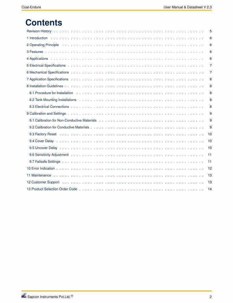
ContentsRevision History . . . . . . . . . . . . . . . . . . . . . . . . . . . . . . . . . . . . . . . . . . . . . . . . . . . . . 5
1 Introduction . . . . . . . . . . . . . . . . . . . . . . . . . . . . . . . . . . . . . . . . . . . . . . . . . . . . . . 6
2 Operating Principle . . . . . . . . . . . . . . . . . . . . . . . . . . . . . . . . . . . . . . . . . . . . . . . . . . 6
3 Features . . . . . . . . . . . . . . . . . . . . . . . . . . . . . . . . . . . . . . . . . . . . . . . . . . . . . . . . 6
4 Applications . . . . . . . . . . . . . . . . . . . . . . . . . . . . . . . . . . . . . . . . . . . . . . . . . . . . . . 6
5 Electrical Specifications . . . . . . . . . . . . . . . . . . . . . . . . . . . . . . . . . . . . . . . . . . . . . . . . 7
6 Mechanical Specifications . . . . . . . . . . . . . . . . . . . . . . . . . . . . . . . . . . . . . . . . . . . . . . . 7
7 Application Specifications . . . . . . . . . . . . . . . . . . . . . . . . . . . . . . . . . . . . . . . . . . . . . . . 8
8 Installation Guidelines . . . . . . . . . . . . . . . . . . . . . . . . . . . . . . . . . . . . . . . . . . . . . . . . . 8
8.1 Procedure for Installation . . . . . . . . . . . . . . . . . . . . . . . . . . . . . . . . . . . . . . . . . . . . . 8
8.2 Tank Mounting Installations . . . . . . . . . . . . . . . . . . . . . . . . . . . . . . . . . . . . . . . . . . . . 8
8.3 Electrical Connections . . . . . . . . . . . . . . . . . . . . . . . . . . . . . . . . . . . . . . . . . . . . . . . 8
9 Calibration and Settings . . . . . . . . . . . . . . . . . . . . . . . . . . . . . . . . . . . . . . . . . . . . . . . . 9
9.1 Calibration for Non-Conductive Materials . . . . . . . . . . . . . . . . . . . . . . . . . . . . . . . . . . . . . 9
9.2 Calibration for Conductive Materials . . . . . . . . . . . . . . . . . . . . . . . . . . . . . . . . . . . . . . . . 9
9.3 Factory Reset . . . . . . . . . . . . . . . . . . . . . . . . . . . . . . . . . . . . . . . . . . . . . . . . . . . 10
9.4 Cover Delay . . . . . . . . . . . . . . . . . . . . . . . . . . . . . . . . . . . . . . . . . . . . . . . . . . . . 10
9.5 Uncover Delay . . . . . . . . . . . . . . . . . . . . . . . . . . . . . . . . . . . . . . . . . . . . . . . . . . . 10
9.6 Sensitivity Adjustment . . . . . . . . . . . . . . . . . . . . . . . . . . . . . . . . . . . . . . . . . . . . . . . 11
9.7 Failsafe Settings . . . . . . . . . . . . . . . . . . . . . . . . . . . . . . . . . . . . . . . . . . . . . . . . . . 11
10 Error Indication . . . . . . . . . . . . . . . . . . . . . . . . . . . . . . . . . . . . . . . . . . . . . . . . . . . . 12
11 Maintenance . . . . . . . . . . . . . . . . . . . . . . . . . . . . . . . . . . . . . . . . . . . . . . . . . . . . . 13
12 Customer Support . . . . . . . . . . . . . . . . . . . . . . . . . . . . . . . . . . . . . . . . . . . . . . . . . . 13
13 Product Selection Order Code . . . . . . . . . . . . . . . . . . . . . . . . . . . . . . . . . . . . . . . . . . . . 14
Sapcon Instruments Pvt.Ltd. R© 2

Coat-Endure User Manual & Datasheet V 2.3
List of Figures1 Coat-Endure . . . . . . . . . . . . . . . . . . . . . . . . . . . . . . . . . . . . . . . . . . . . . . . . . . . . 6
2 Description of Parts . . . . . . . . . . . . . . . . . . . . . . . . . . . . . . . . . . . . . . . . . . . . . . . . 6
3 Dimensional Layout - Top Mounting . . . . . . . . . . . . . . . . . . . . . . . . . . . . . . . . . . . . . . . . 8
4 Dimensional Layout - Side Mounting . . . . . . . . . . . . . . . . . . . . . . . . . . . . . . . . . . . . . . . . 8
5 Electrical Connections . . . . . . . . . . . . . . . . . . . . . . . . . . . . . . . . . . . . . . . . . . . . . . . 9
6 DIP Switch . . . . . . . . . . . . . . . . . . . . . . . . . . . . . . . . . . . . . . . . . . . . . . . . . . . . . 10
7 Cover Delay Switch Position . . . . . . . . . . . . . . . . . . . . . . . . . . . . . . . . . . . . . . . . . . . . 10
8 Setting Cover Delay . . . . . . . . . . . . . . . . . . . . . . . . . . . . . . . . . . . . . . . . . . . . . . . . 10
9 Saving Cover Delay . . . . . . . . . . . . . . . . . . . . . . . . . . . . . . . . . . . . . . . . . . . . . . . . 10
10 Uncover Delay Switch Position . . . . . . . . . . . . . . . . . . . . . . . . . . . . . . . . . . . . . . . . . . . 11
11 Setting Uncover Delay . . . . . . . . . . . . . . . . . . . . . . . . . . . . . . . . . . . . . . . . . . . . . . . 11
12 Saving Uncover Delay . . . . . . . . . . . . . . . . . . . . . . . . . . . . . . . . . . . . . . . . . . . . . . . 11
13 Failsafe High . . . . . . . . . . . . . . . . . . . . . . . . . . . . . . . . . . . . . . . . . . . . . . . . . . . . 11
14 Failsafe Low . . . . . . . . . . . . . . . . . . . . . . . . . . . . . . . . . . . . . . . . . . . . . . . . . . . . 12
Sapcon Instruments Pvt.Ltd. R© 3

Coat-Endure User Manual & Datasheet V 2.3
List of Tables1 Electrical Specifications . . . . . . . . . . . . . . . . . . . . . . . . . . . . . . . . . . . . . . . . . . . . . . 7
2 Mechanical Specifications . . . . . . . . . . . . . . . . . . . . . . . . . . . . . . . . . . . . . . . . . . . . . 7
3 Application Specifications . . . . . . . . . . . . . . . . . . . . . . . . . . . . . . . . . . . . . . . . . . . . . 8
4 Switching Sensitivity . . . . . . . . . . . . . . . . . . . . . . . . . . . . . . . . . . . . . . . . . . . . . . . . 11
5 Error Indication . . . . . . . . . . . . . . . . . . . . . . . . . . . . . . . . . . . . . . . . . . . . . . . . . . . 13
Sapcon Instruments Pvt.Ltd. R© 4

Coat-Endure User Manual & Datasheet V 2.3
Revision History
Revision Date Author(s) Description
1.0 27 Jan 2014 RND First Version Editing
1.1 10 Aug 2014 MRK Applications Revision
1.2 29 May 2015 RND Features Revision
1.3 19 Nov 2015 RND Specs Revision
1.4 25 Jul 2016 RND Specs Revision
2.0 08 Jan 2017 BRND Revised Format
2.1 17 Oct 2017 BRND Branding Revisions
2.2 05 Feb 2018 MRK Marketing Revisions
2.3 11 Oct 2018 RND Specs Revisions
1
1
• Copyright: All content on this document, such as text, graphics, logos and images is the property of Sapcon Instruments Pvt. Ltd. The selection,arrangement and presentation of all materials on this document and the overall design of this document is the exclusive property of Sapcon InstrumentsPvt. Ltd.
• The images shown in this manual may differ from the actual instrument / housing in terms of dimensions, color and design. Please refer to GA drawingsfor dimensional details.
• Values (of performance) described in this manual were obtained under ideal testing conditions. Hence, they may differ under industrial environment andsettings.
General Instructions
• Instrument shouldn’t block the material filling inlet.
• Secure the cover of housing tightly. Tighten the cable glands. For side mounting, the cable glands should point downwards.
• For side mounting, provide a baffle to prevent the material from falling on the probe.
• When handling forks, do not lift them using their tines. While using them with solids, ensure that material size is less than 10mm.
• Deforming the shape of the tines may interfere with the fork’s operating frequency.
• Make all electrical connections as instructed in the manual. Don’t power on the device before verifying the connections.
Sapcon Instruments Pvt.Ltd. R© 5
Coat-Endure User Manual & Datasheet V 2.3
1 Introduction
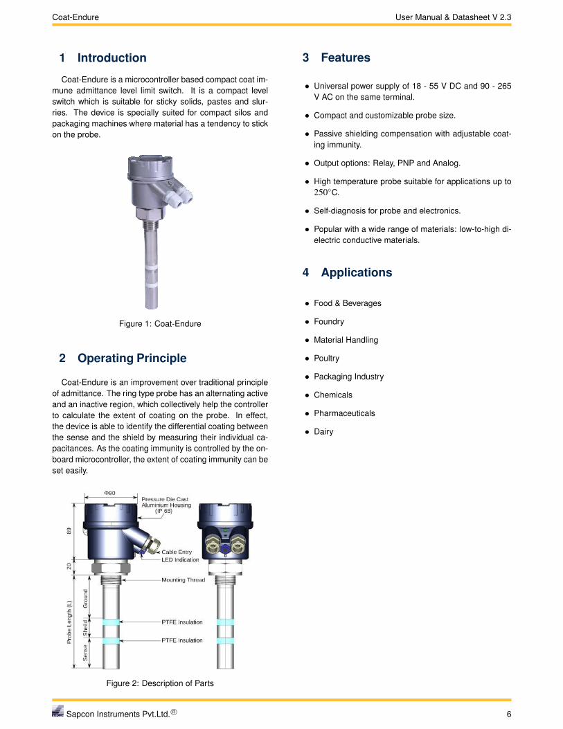
Coat-Endure is a microcontroller based compact coat im-mune admittance level limit switch. It is a compact levelswitch which is suitable for sticky solids, pastes and slur-ries. The device is specially suited for compact silos andpackaging machines where material has a tendency to stickon the probe.
Figure 1: Coat-Endure
2 Operating Principle
Coat-Endure is an improvement over traditional principleof admittance. The ring type probe has an alternating activeand an inactive region, which collectively help the controllerto calculate the extent of coating on the probe. In effect,the device is able to identify the differential coating betweenthe sense and the shield by measuring their individual ca-pacitances. As the coating immunity is controlled by the on-board microcontroller, the extent of coating immunity can beset easily.
Figure 2: Description of Parts
3 Features
• Universal power supply of 18 - 55 V DC and 90 - 265V AC on the same terminal.
• Compact and customizable probe size.
• Passive shielding compensation with adjustable coat-ing immunity.
• Output options: Relay, PNP and Analog.
• High temperature probe suitable for applications up to250◦C.
• Self-diagnosis for probe and electronics.
• Popular with a wide range of materials: low-to-high di-electric conductive materials.
4 Applications
• Food & Beverages
• Foundry
• Material Handling
• Poultry
• Packaging Industry
• Chemicals
• Pharmaceuticals
• Dairy
Sapcon Instruments Pvt.Ltd. R© 6

Coat-Endure User Manual & Datasheet V 2.3
5 Electrical Specifications
Please refer to Table 1 for Electrical Specifications.
PARAMETER VALUE
Input Power Supply 18 - 55V DC and 90 - 265V AC at 50Hz on same terminal
Output• Relay SPDT , PNP• Relay DPDT
Power Consumption• 1.5W (SPDT, PNP) at 24 V• 2.2W (DPDT) at 24 V
Switching Single-point level switching
Switching Indication Bi-color LED:Red - AlarmGreen - Normal
Fail-safe Field Selectable• Open - Fail-safe High (For High Level)• Close - Fail-safe Low (For Low Level)
Time Delay Setting 1 - 25 seconds (For both, Covered and Uncovered Delays)
Relay Rating 6 Amps at 230V AC
Table 1: Electrical Specifications
6 Mechanical Specifications
Please refer to Table 2 for Mechanical Specifications.
PARAMETER VALUE
Housing• SCUTE: Pressure die-cast aluminium weatherproof
(Rating IP-68)• FP2C: Cast aluminium, weatherproof & flameproof,
powder coated, suitable for Gas Groups IIA, IIB & IICas per IS-2148
Electrical Connector 2 x 1/2” BSP/NPT , PG 13.5
Operating Temperature 0◦C to 60◦C (Electronics)
Process Temperature Up to 250◦C
Operating Pressure Up to 10 bar
Mounting• Screwed: 1/2",1”,1 1/2", 3/4” BSP / NPT• Flanged: As per user specification
Probe Length 65 mm and (85 mm to 1500 mm)
Insulation Part PTFE / Full PTFE
Table 2: Mechanical Specifications
Sapcon Instruments Pvt.Ltd. R© 7

Coat-Endure User Manual & Datasheet V 2.3
7 Application Specifications
Please refer to Table 3 for Application Specifications.
PARAMETER VALUE
Response Time 1 second
Sensitivity Refer Table No. 4
Table 3: Application Specifications
8 Installation Guidelines
8.1 Procedure for InstallationFor quick and easy installation, follow the steps in the
order mentioned below:
1. Testing Electrical Connections: Before mounting thedevice on the tank, understand and test the connec-tions outside the tank for at least one piece. For detailson connections, refer to Figure 5 before connecting thedevice to outputs and power supply.
2. Mounting the Device: Correct mounting of the in-strument is critical to the operation of the instrument.Please refer to Tank Mounting Installation to mount theinstrument in the tank/silo or hopper. Coat-Endure isdesigned to work properly in metal-body tanks only,e.g. MS, SS or Aluminium tanks. Performance in plas-tic tanks might not be satisfactory.
3. Electrical Connections: Perform the electrical con-nections as mentioned earlier in Step 1.
4. Calibration and Settings:
• For non-conductive materials, Coat-Endure canbe calibrated in an empty process tank withoutthe application material.
• If the application material is conductive, Coat-Endure has to be calibrated with the material.
Time-delay and fail-safe selection should be done af-ter this stage. Section Calibration and Settings coverssettings in more detail.
5. Trial Run: Perform a trail run of the application pro-cess with the application material. In case of errorsor unsatisfactory output, refer to Section Error Indica-tions.
6. Finishing the Installation: Tighten the lid and the ca-ble entries on the instrument so that no moisture seepsinto the instrument.
8.2 Tank Mounting Installations
• Coat-Endure is designed to work in metal-body tanksonly, e.g. M.S., S.S. or Aluminium tanks. Performancein plastic tanks might not be satisfactory.
• The Coat-Endure probe can be installed in the ves-sel in both horizontal (side mounting) and vertical (topmounting) positions. Please refer to Figures 3 and 4.
• To prevent the ingress of moisture and water seepagein side mounting position, the cable entries should al-ways point downwards.
• Weatherproofness of enclosure is guaranteed only ifthe cover is in place and glands are adequately tight-ened. Damage due to accidental entry of water can beavoided if the instrument is installed in a rain shade.
• If the ambient temperature is high, the instrumentshould not be installed to receive direct sunlight. Ifsuch a position of shade is not available, a heat shieldshould be fitted above the instrument especially if theoperating temperature lies between 60◦C and 80◦C.
• Grounding part (S.S. material) of the probe should beexposed atleast 20mm inside the hopper after thread-ing/nozzle.
Figure 3: Dimensional Layout - Top Mounting
Figure 4: Dimensional Layout - Side Mounting
8.3 Electrical ConnectionsElectrical connections for the instrument will change with
the models. Please refer to figure 5 and the precautionsmentioned below before connecting the device.
Precautions for connecting Coat-Endure :
• Power Supply RatingMake sure the power supplied to the instrument iswithin the specified range mentioned in Table 1.
Sapcon Instruments Pvt.Ltd. R© 8

Coat-Endure User Manual & Datasheet V 2.3
• Connect EarthWhen supplying AC power, please make sure that thegrounding screw on the housing and the earth terminalare all connected to the plant’s earth.
• Power Supply Fluctuations & NoiseExternal noise or fluctuating power supplies could af-fect performance and shorten the life of the instrument.Use external line suppressors and fuse wires to con-tain the risk of damage to the circuit.
OP
EN
ENTER
COVER
UNCOVER
CALIBRATE
FAILSAFE
COAT-ENDURE
STATUSLED
RED
GREEN
L N E Relay-1 PNP
1 2 3 4 5 6 7 8 9
+ +-
NC C NO OUT-
AC Supply DC Supply
L (Live)
N (Neutral)
90-265 V AC 18-55 V DC
+
RL
(Available only in DC Power Supply)
(a) Electronics option SPDT Relay and PNP Output(SPN)
OP
EN
ENTER
COVER
UNCOVER
CALIBRATE
FAILSAFE
COAT-ENDURE
STATUSLED
RED
GREEN
L N E Relay-1
1 2 3 4 5 6 7 8 9
+ NC C NO-
AC Supply DC Supply
L (Live)
N (Neutral)
90-265 V AC 18-55 V DC
+
Relay-2NC C NO
(b) Electronics option DPDT Relay(D)
Figure 5: Electrical Connections
9 Calibration and Settings
The DIP switches for calibration and settings can be ac-cessed by opening the top aluminium cover. Procedure forcalibration Coat-Endure depends on the conductivity of theapplication material:
• Calibration for Non-Conductive MaterialsCalibration should be done without the application ma-terial. Once calibrated in the empty tank, the devicecan be used with a wide range of non-conductive ma-terials.
• Calibration for Conductive MaterialsFor applications using conductive materials (water,acid based pastes etc.), Coat-Endure needs to be cali-brated with the application material. This will make theinstrument specific to the application material i.e. if the
application material is changed; calibration should berepeated.
Note:Calibration in air is specific to the tank, if the tankchanges, the instrument needs to be calibratedagain.
9.1 Calibration for Non-Conductive MaterialsCoat-Endure needs to be calibrated inside the empty pro-
cess tank (i.e only air, no material). Calibrating the instru-ment outside the tank can cause malfunctions. Once cali-brated inside the empty tank, Coat-Endure can operate witha wide range of application materials without the need ofchanging its default sensitivity settings.
1. Make sure that all DIP switches are in the OPEN posi-tion.
2. To start with the calibration, set the CALIBRATE switchto CLOSE position (CLOSE is opposite of OPEN forDIP switch).
3. Make sure that the status LED is not blinking. A blink-ing LED here indicates Error.
4. Then press ENTER, the status LED will blink once inRED color.
5. Now set the CALIBRATE switch back to OPEN posi-tion.
6. Air calibration for Coat-Endure is now complete.
Now, test the calibration by filling in the material or drain-ing it out from the tank. Repeat the filling and draining toconfirm proper operation of the device.
Note:For certain application materials, Coat-Endure mightneed an adjustment to its settings. Refer to SectionSensitivity Adjustment for more details.
9.2 Calibration for Conductive MaterialsFill the tank with the application material such that the
probe is completely covered with the material.
1. Make sure that all DIP switches are in the OPEN posi-tion.
2. To start with the calibration, set the CALIBRATE andCOVER switches to CLOSE position (CLOSE is oppo-site of OPEN for DIP switch).
3. Make sure that the status LED is not blinking, a blinkingLED here indicates Error.
4. Then press ENTER, the status LED will blink once inRED color.
5. Now set the CALIBRATE and COVER switch back toOPEN position.
Sapcon Instruments Pvt.Ltd. R© 9

Coat-Endure User Manual & Datasheet V 2.3
6. Calibration for Coat-Endure is now complete.
Now, test the calibration by filling in the material or drainingit out from the tank. Repeat the filling and draining toconfirm proper operation of the device.
Note:For certain conductive application materials, Coat-Endure might need an adjustment to its settings. Re-fer to Section Sensitivity Adjustment for more details.
9.3 Factory Reset
To reset time delays and sensitivity values to default val-ues, follow the following steps:
1. Set the CALIBRATE, COVER and UNCOVER switchesto CLOSE position
2. PRESS and HOLD the ENTER key until the status LEDblinks.
3. Switch the CALIBRATE, COVER and UNCOVERswitches back to OPEN position.
4. This will set the time delay to 0 and the sensitivity levelto 3.
9.4 Cover Delay
When the application material covers the probe, thechangeover of the output can be delayed by a pre-determined time. This time is called COVER Delay. Fora different value of Cover Delay, the number of blinks canbe adjusted as per requirement.
Note:You can set the value of COVER DELAY between 1-25 secs.
Follow the below procedure for setting Cover Delay
1. Ensure that all DIP switches are in OPEN position asshown in Figure 6. Make sure that STATUS LED is notblinking for Error.
OP
EN
COVER
UNCOVER
CALIBRATE
FAILSAFE
Figure 6: DIP Switch
2. To set the Cover Delay, set the COVER switch toCLOSE position as shown in Figure 7.(CLOSE is the opposite of OPEN for a DIP switch.)The STATUS RED LED will glow.
3. Press ENTER and keep it pressed as shown in Figure8. The STATUS RED LED will start blinking. Count thenumber of blinks. After setting the value release theENTER key.
OP
EN
ENTER
COVER
UNCOVER
CALIBRATE
FAILSAFE
COAT-ENDURE
STATUS
LED
RED
GREEN
Figure 7: Cover Delay Switch Position
OP
EN
ENTER
COVER
UNCOVER
CALIBRATE
FAILSAFE
COAT-ENDURE
STATUS
LED
RED
GREEN
Figure 8: Setting Cover Delay
4. Delay is entered, but not saved. To save and test theCover Delay, set the COVER switch back to OPEN po-sition as shown in Figure 9. The STATUS LED willcome back to its original position.
OP
EN
ENTER
COVER
UNCOVER
CALIBRATE
FAILSAFE
COAT-ENDURE
STATUS
LED
RED
GREEN
Figure 9: Saving Cover Delay
5. To test, dip coat-endure into the application materialuntil the switching point is reached.
The STATUS LED will start blinking RED if the switchpoint is reached. It will blink for the number of seconds forwhich the cover delay is set. 1 blink is equal to 1 secondduring switching. A maximum of 25 seconds can be set.
9.5 Uncover Delay
When the application material uncovers coat-endure’sprobe, the changeover of the output can be delayed by apre-determined time. This time is called UNCOVER Delay.For a different value of Uncover Delay, the number of blinkscan be adjusted as per requirement.
Note:You can set the value of UNCOVER DELAY between1-25 secs.
Follow the below procedure for setting UncoverDelay
1. Ensure that all DIP switches are in OPEN position asshown in Figure 6. Make sure that STATUS LED is notblinking for Error.
2. To set the Uncover Delay, set the UNCOVER switch toCLOSE position as shown in Figure 10.
Sapcon Instruments Pvt.Ltd. R© 10

Coat-Endure User Manual & Datasheet V 2.3
(CLOSE is the opposite of OPEN for a DIP switch.)The STATUS RED LED will glow.
OP
EN
ENTER
COVER
UNCOVER
CALIBRATE
FAILSAFE
COAT-ENDURE
STATUS
LED
RED
GREEN
Figure 10: Uncover Delay Switch Position
3. Press ENTER and keep it pressed as shown in Figure11. The STATUS RED LED will start blinking. Countthe number of blinks. After setting the value releasethe ENTER key.
OP
EN
ENTER
COVER
UNCOVER
CALIBRATE
FAILSAFE
COAT-ENDURE
STATUS
LED
RED
GREEN
Figure 11: Setting Uncover Delay
4. Uncover Delay is entered, but not saved. To save andtest the Uncover Delay, set the UNCOVER switch backto OPEN position as shown in figure 12. The STATUSLED will come back to its original position.
OP
EN
ENTER
COVER
UNCOVER
CALIBRATE
FAILSAFE
COAT-ENDURE
STATUS
LED
RED
GREEN
Figure 12: Saving Uncover Delay
5. To test, dip coat-endure into the application materialuntil the switching point is achieved.
6. The STATUS LED will start blinking GREEN if theswitch point is achieved. It will blink for the numberof seconds for which the Uncover Delay is set.
9.6 Sensitivity Adjustment
The instrument has 5-point sensitivity level to suit a widerange of application materials. Sensitivity value should bedecided with respect to the dielectric constant and coatingthickness of the application material. Refer to table 4 forselecting a suitable value. By default, the sensitivity is setto 3 to suit a wide range of materials. Traverse the followingsteps to set the sensitivity of Coat-Endure -
1. Select a sensitivity value for the instrument as per table4.
DIELECTRICCONSTANT
COATINGTHICKNESS
SENSITIVITYVALUE
High High 1−3
Low High 3−5 (default)
High Low 1−2
Low Low 5
Table 4: Switching Sensitivity
2. Set the CALIBRATE switch to CLOSE position.
3. Also switch the UNCOVER switch to CLOSE position.
4. PRESS and HOLD the ENTER key, the status LED willstart blinking.
5. The first blink leaves the sensitivity value unchanged.
6. Start counting from the next blink up to the selectedsensitivity value.
7. Set the CALIBRATE and UNCOVER switches back toOPEN position.
8. Check operation of Coat-Endure by filling in and drain-ing out the material.
9. If the instrument does not switch when covered fullywith the material, try again with a higher value of sen-sitivity.
10. If the instrument switches when covered fully with thematerial, but does not switch back to normal statewhen uncovered, try again with a lower sensitivityvalue.
9.7 Failsafe Settings
In a condition of device failure, known errors and inputpower failure the outputs of the device resemble the ALARMcondition. This is meant to prevent overflow or dry run con-ditions in case of failures.
Prevent Overflow - High Level Switch Failsafe High (de-fault) is set by moving the Failsafe switch to OPEN position.
1. When not in contact with the material, LED turnsGREEN.
2. When in contact with the material, LED turns RED.
OP
EN
ENTER
COVER
UNCOVER
CALIBRATE
FAILSAFE
COAT-ENDURE
STATUS
LED
RED
GREEN
Figure 13: Failsafe High
Sapcon Instruments Pvt.Ltd. R© 11
Coat-Endure User Manual & Datasheet V 2.3
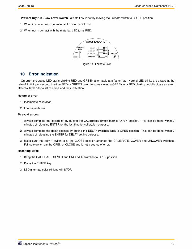
Prevent Dry run - Low Level Switch Failsafe Low is set by moving the Failsafe switch to CLOSE position
1. When in contact with the material, LED turns GREEN.
2. When not in contact with the material, LED turns RED.
OP
EN
ENTER
COVER
UNCOVER
CALIBRATE
FAILSAFE
COAT-ENDURE
STATUS
LED
RED
GREEN
Figure 14: Failsafe Low
10 Error IndicationOn error, the status LED starts blinking RED and GREEN alternately at a faster rate. Normal LED blinks are always at the
rate of 1 blink per second, in either RED or GREEN color. In some cases, a GREEN or a RED blinking could indicate an error.Refer to Table 5 for a list of errors and their indication.
Nature of error:
1. Incomplete calibration
2. Low capacitance
To avoid errors:
1. Always complete the calibration by putting the CALIBRATE switch back to OPEN position. This can be done within 2minutes of releasing ENTER for the last time for calibration purpose.
2. Always complete the delay settings by putting the DELAY switches back to OPEN position. This can be done within 2minutes of releasing the ENTER for DELAY setting purpose.
3. Make sure that only 1 switch is at the CLOSE position amongst the CALIBRATE, COVER and UNCOVER switches.Fail-safe switch can be OPEN or CLOSE and is not a source of error.
Resetting Error:
1. Bring the CALIBRATE, COVER and UNCOVER switches to OPEN position.
2. Press the ENTER key.
3. LED alternate color blinking will STOP.
Sapcon Instruments Pvt.Ltd. R© 12

Coat-Endure User Manual & Datasheet V 2.3
LED ERROR INDICATION DESCRIPTION TROUBLESHOOTING
RED-GREEN Blinking Calibration Error Recalibrate the instrument, makesure that the probe is calibrated inan empty metal-body tank.
RED Blinking Probe Short-Circuit Moisture deposition in the probeconnector. Clean the connectorand use the instrument.
GREEN Blinking Probe Open Remove the electronic insert fromthe housing and check the cableconnections of the probe.
3 Times GREEN Blinking and 1Red Blink
Illegal Key Combination Switch all DIP switches to openposition. Use only legal combina-tion of keys.
3 Times RED Blinking and 1GREEN Blink
Circuit Error Contact the Customer Support de-partment at Sapcon.
Table 5: Error Indication
11 MaintenanceThe electronics of this instrument needs no maintenance. When cleaning and checking the vessel, free the probe from
deposits. If the material has a tendency to form a hard sticky deposit, then the instrument must be checked more often. Makesure that the cable ducts and the lid are tightly sealed so that no moisture seeps into the instrument.
12 Customer Support
Thank you for going through the instructions given in this manual. To further ease the process of installation and use, wehave developed special demo videos which are hosted on YouTube.
Sapcon’s YouTube channel, SAPCON INSTRUMENTS, lists all these videos: https://goo.gl/dnxfcz
Should you require further information regarding installation, use or working of the instrument, please don’t hesitate to contactus. Kindly provide the following information at the time of contacting:
• Instrument Model and Serial Number
• Purchase Order Number and Date of Purchase
• Description of the query
• Your contact details
In an attempt to serve you better, we are open seven days a week (9:30am to 7:30pm). We are available at:
• www.sapconinstruments.com
• +91-731-4757575
Sapcon Instruments Pvt.Ltd. R© 13
Coat-Endure User Manual & Datasheet V 2.3
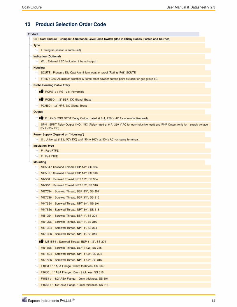
13 Product Selection Order Code
Product
CE : Coat Endure - Compact Admittance Level Limit Switch (Use in Sticky Solids, Pastes and Slurries)
Type
I : Integral (sensor in same unit)
Indication (Optional)
WL : External LED Indication infrared output
Housing
SCUTE : Pressure Die Cast Aluminium weather proof (Rating IP68) SCUTE
FP2C : Cast Aluminium weather & flame proof powder coated paint suitable for gas group IIC
Probe Housing Cable Entry
� PCPG13 : PG 13.5, Polyamide
� PCB5D : 1/2” BSP, DC Gland, Brass
PCN5D : 1/2” NPT, DC Gland, Brass
Output
� D : 2NO, 2NC DPDT Relay Output (rated at 6 A, 230 V AC for non-inductive load)
SPN : SPDT Relay Output 1NO, 1NC (Relay rated at 6 A, 230 V AC for non-inductive load) and PNP Output (only for supply voltage18V to 35V DC)
Power Supply (Depend on “Housing”)
U : Universal (18 to 55V DC) and (90 to 265V at 50Hz AC) on same terminals
Insulation Type
P : Part PTFE
F : Full PTFE
Mounting
MB5S4 : Screwed Thread, BSP 1/2”, SS 304
MB5S6 : Screwed Thread, BSP 1/2”, SS 316
MN5S4 : Screwed Thread, NPT 1/2”, SS 304
MN5S6 : Screwed Thread, NPT 1/2”, SS 316
MB75S4 : Screwed Thread, BSP 3/4”, SS 304
MB75S6 : Screwed Thread, BSP 3/4”, SS 316
MN75S4 : Screwed Thread, NPT 3/4”, SS 304
MN75S6 : Screwed Thread, NPT 3/4”, SS 316
MB10S4 : Screwed Thread, BSP 1”, SS 304
MB10S6 : Screwed Thread, BSP 1”, SS 316
MN10S4 : Screwed Thread, NPT 1”, SS 304
MN10S6 : Screwed Thread, NPT 1”, SS 316
� MB15S4 : Screwed Thread, BSP 1-1/2”, SS 304
MB15S6 : Screwed Thread, BSP 1-1/2”, SS 316
MN15S4 : Screwed Thread, NPT 1-1/2”, SS 304
MN15S6 : Screwed Thread, NPT 1-1/2”, SS 316
F10S4 : 1" ASA Flange, 10mm thickness, SS 304
F10S6 : 1” ASA Flange, 10mm thickness, SS 316
F15S4 : 1-1/2” ASA Flange, 10mm thickness, SS 304
F15S6 : 1-1/2” ASA Flange, 10mm thickness, SS 316
Sapcon Instruments Pvt.Ltd. R© 14

Coat-Endure User Manual & Datasheet V 2.3
Mounting
F20S4 : 2” ASA Flange, 10mm thickness, SS 304
F20S6 : 2” ASA Flange, 10mm thickness, SS 316
F25S4 : 2-1/2” ASA Flange, 10mm thickness, SS 304
F25S6 : 2-1/2” ASA Flange, 10mm thickness, SS 316
FA10S4 : 1” ANSI Flange, SS 304
FA10S6 : 1” ANSI Flange, SS 316
FA15S4 : 1-1/2” ANSI Flange, SS 304
FA15S6 : 1-1/2” ANSI Flange, SS 316
FA20S4 : 2” ANSI Flange, SS 304
FA20S6 : 2” ANSI Flange, SS 316
FA25S4 : 2-1/2” ANSI Flange, SS 304
FA25S6 : 2-1/2” ANSI Flange, SS 316
Sense
� S20S4 : 20mm Length, SS 304 (Only for Probe Length ≤ 150mm)
S20S6 : 20mm Length, SS 316 (Only for Probe Length ≤ 150mm)
� S40S4 : 40mm Length, SS 304 (Only for Probe Length ≥ 151mm)
S40S6 : 40mm Length, SS 316 (Only for Probe Length ≥ 151mm)
Shield (Depends on “Sense”)
� SH11S4 : 11mm Length, SS 304 (Only with “S20S4”)
SH11S6 : 11mm Length, SS 316 (Only with “S20S6”)
� SH20S4 : 20mm Length, SS 304 (Only with “S40S4”)
SH20S6 : 20mm Length, SS 316 (Only with “S40S6”)
Grounding Length (Depends on Probe Length ≥ 85mm or 0.85H)
� GS4 : SS 304
GS6 : SS 316
Operating Temperature
10T : Upto 100◦C
25T : Upto 250◦C
Standoff Material (Only with “25T”)
STGI : GI (Galvanized Iron)
� STS4 : SS 304
STS6 : SS 316
Probe Length
0.65H : 65mm
0.85H1.5H : 85mm to 150mm
1.5H15H : 151mm to 1500mm
CE-I-SCUTE-PCPG13-D-U-P-MB10S4-S20S4-SH11S4-10T-0.65HExample -
� Shows First Priority Entity
Sapcon Instruments Pvt.Ltd. R© 15